Proactive Caching and Forwarding Schemes for Seamless Handover in IEEE WAVE Networks
12
Hindawi Publishing Corporation International Journal of Distributed Sensor Networks Volume 2013, Article ID 627691, 11 pages http://dx.doi.org/10.1155/2013/627691 Research Article Proactive Caching and Forwarding Schemes for Seamless Handover in IEEE WAVE Networks Young-uk Chung, 1 Hyukjoon Lee, 2 Yong-Hoon Choi, 3 and Chungwon Lee 4 1 Department of Electronic Engineering, Kwangwoon University, 21 Kwangwoon-ro, Nowon-gu, Seoul 139-701, Republic of Korea 2 Department of Computer Engineering, Kwangwoon University, 21 Kwangwoon-ro, Nowon-gu, Seoul 139-701, Republic of Korea 3 School of Robotics, Kwangwoon University, 21 Kwangwoon-ro, Nowon-gu, Seoul 139-701, Republic of Korea 4 Department of Civil and Environmental Engineering, Seoul National University, 1 Gwanak-ro, Gwanak-gu, Seoul 151-742, Republic of Korea Correspondence should be addressed to Hyukjoon Lee; [email protected] Received 19 July 2013; Accepted 30 October 2013 Academic Editor: Floriano De Rango Copyright © 2013 Young-uk Chung et al. is is an open access article distributed under the Creative Commons Attribution License, which permits unrestricted use, distribution, and reproduction in any medium, provided the original work is properly cited. e IEEE Wireless Access for Vehicular Environment (WAVE) standard consists of the IEEE 802.11p and the IEEE 1609 specifications supporting fast link establishment as well as broadband data communication in vehicular environment. Although the standard has been widely accepted by industry as well as highway authorities in many countries to be used for the radio communication infrastructure of the next-generation Intelligent Transport System (ITS), it remains open for further enhancements such as seamless handover support. is paper presents two proactive caching and forwarding schemes for seamless handover in IEEE WAVE networks: one for straight highway sections and the other for crossroads and junctions. Practical and efficient handover procedures, based on the proposed schemes, are also presented. Specifically, an on-board unit (OBU) informs the old road-side unit (RSU) about its departure from the coverage area such that the old RSU can forward the buffered packets to candidate RSUs for proactive caching. In handover scenarios around crossroads and junctions, the IEEE 802.11f Move-notify message is used by the new RSU to request the rest of candidate RSUs to purge the cached packets in order to prevent the waste of radio resource. Simulation results show that the proposed schemes outperform conventional schemes. 1. Introduction anks to the recent advances in various technologies includ- ing wireless communication, sensors, controllers, and hard- ware and soſtware platforms, traveling in a car is becoming safer than ever as vehicles and roads are always connected and cooperatively exchange safety-related information. e IEEE WAVE is a suite of specifications for wireless access in ITS which comprises of the IEEE 802.11p and the IEEE 1609 supporting fast link establishment as well as broadband data communication of the maximum 27 Mbps between an OBU installed in a car moving at the maximum speed of 200 Km/h and an RSU deployed along roadways [1]. According to the specification of IEEE WAVE, the size of a safety-related application message is limited by a WAVE short message (WSM), which is defined to be 1,400 bytes. is allows the transmission of a WAVE message to be completed while a vehicle moves under the radio coverage of a single RSU. As a result, handover has been excluded from the specification. On the other hand, multimedia applications such as live highway CCTV video clips and Internet brows- ing, in which a sequence of multiple MAC protocol data units (MPDUs) is transmitted, require handover. Consequently, a growing amount of interest is being drawn towards seamless handover procedures in WAVE systems. Although there exists a basic handover operation described in the IEEE 802.11 specification, it cannot be used by the IEEE WAVE systems because it requires channel scanning, reassociation, and reauthentication procedures which have been excluded from the IEEE 802.11p specification in favor of instantaneous establishment of physical links between RSUs and OBUs.
Transcript of Proactive Caching and Forwarding Schemes for Seamless Handover in IEEE WAVE Networks

Hindawi Publishing CorporationInternational Journal of Distributed Sensor NetworksVolume 2013, Article ID 627691, 11 pageshttp://dx.doi.org/10.1155/2013/627691
Research ArticleProactive Caching and Forwarding Schemes for SeamlessHandover in IEEE WAVE Networks
Young-uk Chung,1 Hyukjoon Lee,2 Yong-Hoon Choi,3 and Chungwon Lee4
1 Department of Electronic Engineering, Kwangwoon University, 21 Kwangwoon-ro, Nowon-gu, Seoul 139-701, Republic of Korea2Department of Computer Engineering, Kwangwoon University, 21 Kwangwoon-ro, Nowon-gu, Seoul 139-701, Republic of Korea3 School of Robotics, Kwangwoon University, 21 Kwangwoon-ro, Nowon-gu, Seoul 139-701, Republic of Korea4Department of Civil and Environmental Engineering, Seoul National University, 1 Gwanak-ro, Gwanak-gu,Seoul 151-742, Republic of Korea
Correspondence should be addressed to Hyukjoon Lee; [email protected]
Received 19 July 2013; Accepted 30 October 2013
Academic Editor: Floriano De Rango
Copyright © 2013 Young-uk Chung et al. This is an open access article distributed under the Creative Commons AttributionLicense, which permits unrestricted use, distribution, and reproduction in any medium, provided the original work is properlycited.
The IEEE Wireless Access for Vehicular Environment (WAVE) standard consists of the IEEE 802.11p and the IEEE 1609specifications supporting fast link establishment as well as broadband data communication in vehicular environment. Althoughthe standard has been widely accepted by industry as well as highway authorities in many countries to be used for the radiocommunication infrastructure of the next-generation Intelligent Transport System (ITS), it remains open for further enhancementssuch as seamless handover support. This paper presents two proactive caching and forwarding schemes for seamless handover inIEEEWAVEnetworks: one for straight highway sections and the other for crossroads and junctions. Practical and efficient handoverprocedures, based on the proposed schemes, are also presented. Specifically, an on-board unit (OBU) informs the old road-side unit(RSU) about its departure from the coverage area such that the old RSU can forward the buffered packets to candidate RSUs forproactive caching. In handover scenarios around crossroads and junctions, the IEEE 802.11fMove-notifymessage is used by the newRSU to request the rest of candidate RSUs to purge the cached packets in order to prevent the waste of radio resource. Simulationresults show that the proposed schemes outperform conventional schemes.
1. Introduction
Thanks to the recent advances in various technologies includ-ing wireless communication, sensors, controllers, and hard-ware and software platforms, traveling in a car is becomingsafer than ever as vehicles and roads are always connectedand cooperatively exchange safety-related information. TheIEEE WAVE is a suite of specifications for wireless access inITS which comprises of the IEEE 802.11p and the IEEE 1609supporting fast link establishment as well as broadband datacommunication of the maximum 27Mbps between an OBUinstalled in a car moving at the maximum speed of 200Km/hand an RSU deployed along roadways [1].
According to the specification of IEEE WAVE, the sizeof a safety-related application message is limited by a WAVEshort message (WSM), which is defined to be 1,400 bytes.
This allows the transmission of a WAVE message to becompleted while a vehicle moves under the radio coverage ofa single RSU. As a result, handover has been excluded fromthe specification. On the other hand,multimedia applicationssuch as live highway CCTV video clips and Internet brows-ing, in which a sequence ofmultipleMAC protocol data units(MPDUs) is transmitted, require handover. Consequently, agrowing amount of interest is being drawn towards seamlesshandover procedures in WAVE systems. Although thereexists a basic handover operation described in the IEEE802.11 specification, it cannot be used by the IEEE WAVEsystems because it requires channel scanning, reassociation,and reauthentication procedures which have been excludedfrom the IEEE 802.11p specification in favor of instantaneousestablishment of physical links between RSUs and OBUs.

2 International Journal of Distributed Sensor Networks
WSA
RTS
CTS
ACK
Sync interval (100ms)
Channelbusy
RSU
OBUs
Backoff slots
Backoff slots
CCH interval (50ms) SCH interval (50ms)
Safetyapp
Safetyapp
DIFS
AIFS
AIFS
SIFSSIFSSIFS
Servicedata
Figure 1: Channel access procedure for the IEEE 802.11p.
A small number of research works exist in the literaturethat propose to use polling operations as means for an OBUto inform its presence under a new RSU (nRSU) in order tosupport handover procedure in the IEEEWAVE system [2, 3].Using polling operations is however equivalent to using thereassociation operations and hence is contrary to the designphilosophies of the IEEE 802.11p specification. Anotherdrawback of this approach is that handover delaymay becomevery large in case that the OBU fails to receive a poll messageor multiple OBUs attempt to send the association messagesnearly simultaneously.
One might also consider adopting the basic handoverscheme of the IEEE 802.11 standard in order to provide anIEEEWAVE network with handover operations. In this case,the delay performance of the IEEE 802.11 basic handover canbe improved by adopting fast handover schemes defined inthe amendment specifications such as IEEE 802.11 f/r whichsupport fast handover by reducing the delay in performingQoS negotiation as well as reassociation and reauthenticationwith a new AP [4, 5]. In addition, some proactive cachingand forwarding schemes, which attempt to make the oldAPs send the MS’s context information to the target APsbefore the link to the old AP breaks, can be considered [6–9]. Many of these schemes also try to choose a minimalnumber of target APs based on its location, direction, andneighbor graphs such that the overheads in proactive cachingand forwarding can be reduced [10–15]. These approachescan be further improved by taking advantage of the regularmobility patterns of vehicles moving on highways such thatproactive caching operation of data packets at the nRSU canbe simplified and performed efficiently. Around junctionsand crossroads, where several candidate nRSU exist, theproactive caching operations can be performedwith a limitedamount of overhead in terms of radio resource usage. In thispaper, we propose efficient proactive caching and forwardingschemes for the IEEE WAVE networks based on the designconcepts described above.
This paper is organized as follows. In Section 2, we givea brief background on the related technologies. Section 3explains the proposed scheme in detail. Section 4 describessimulation setup along with the simulation results. We finishour discussion with some concluding remarks.
2. Background
2.1. The IEEE 802.11p/P1609. The IEEE 802.11p and the IEEEP1609 standards, which comprise the IEEEWAVE standards,have been developed as the wireless communication tech-nology for ITS in North America. It operates in the 75MHzbandwidth at 5.850–5.925GHz frequency band. One of thethe seven channels of 10MHz band is assigned as the controlchannel (CCH) whose main usage is transmission of controland management messages including WSA (WAVE ServiceAnnouncement) messages (beacons) and broadcast of safety-related data. The other six channels are used as servicechannels (SCHs) used for nonsafety-related data includinggeneral Internet service.
The CCH and SCH interval of 50ms each alternatesto form a synch interval. The medium access procedureis based on the IEEE 802.11e priority access with randombackoff. According to the specification of IEEE P1609.3, datapacket transmission is allowed within a WAVE Basic ServiceSet (WBSS). An OBU or an RSU joins a WBSS as a user.A service provider broadcasts a WSA message periodicallyon CCH for all persistent services belonging to the WBSS.This message contains all the information identifying WAVEapplications as well as link parameters used by an RSU to jointhe WBSS (e.g., the ID of the WBSS, the SCH this WBSS willuse, and timing information for synchronization purposes).When an OBU joins a WBSS via an RSU, it should receivea WSA on CCH to learn about the parameters associatedwith the WBSS. The OBU may then switch to the WBSSsSCH to join the WBSS and transmit/receive service dataframes. Figure 1 illustrates channel access process of IEEEP1609.4/IEEE 802.11p MAC.
International Journal of Distributed Sensor Networks 3
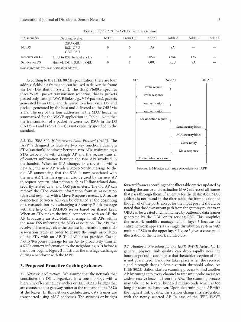
Table 1: IEEE P1609.3 WAVE four-address scheme.
TX scenario Sender/receiver To DS From DS Addr 1 Addr 2 Addr 3 Addr 4
No DSOBU-OBURSU-OBUOBU-RSU
0 0 DA SA — —
Receiver on DS OBU to RSU to host via DS 1 0 RSU OBU DA —Sender on DS Host via DS to RSU to OBU 0 1 OBU RSU SA —(SA: source address, DA: destination address).
According to the IEEE 802.11 specification, there are fouraddress fields in a frame that can be used to deliver the framevia DS (Distribution System). The IEEE P1609.3 specifiesthree WAVE packet transmission scenarios; that is, packetspassed only throughWAVE links (e.g., V2V packets), packetsgenerated by an OBU and delivered to a host via a DS, andpackets generated by the host and delivered to the OBU viaa DS. The use of the four addresses in the MAC header issummarized for the WAVE application in Table 1. Note thatthe transmission of a packet between two RSUs in the DS(To DS = 1 and From DS = 1) is not explicitly specified in thestandard.
2.2. The IEEE 802.11f Interaccess Point Protocol (IAPP). TheIAPP is designed to facilitate two key functions during aSTA’s (station’s) handover between two APs: maintaining aSTA’s association with a single AP and the secure transferof context information between the two APs involved inthe handoff. When an STA changes its association with anew AP, the new AP sends a Move-Notify message to theold AP announcing that the STA is now associated withthe new AP. This message can also be used by the new APto request context information such as IP flow-related data,security-related data, and QoS parameters. The old AP canremove the STA’s context information from its associationtable and responds with a Move-Response message. A secureconnection between APs can be obtained at the beginningof a reassociation by exchanging a Security Block messagewith the help of a RADIUS server based on shared keys.When an STA makes the initial connection with an AP, theAP broadcasts an Add-Notify message to all APs withinthe same ESS informing the STA’s association. The APs thatreceive this message clear the context information from theirassociation tables in order to ensure the single associationof the STA with an AP. The IAPP also provides Cache-Notify/Response message for an AP to proactively transfera STA’s context information to the neighboring APs before ahandover begins. Figure 2 illustrates the message exchangesduring a handover with the IAPP.
3. Proposed Proactive Caching Schemes
3.1. Network Architecture. We assume that the network thatconstitutes the DS is organized in a tree topology with ahierarchy of learning L2 switches or IEEE 802.1D bridges thatare connected to a gateway router at the root and to the RSUsat the leaves. In this network architecture, data frames aretransported using MAC addresses. The switches or bridges
STA New AP Old AP
Probe request
Probe response
Authentication
Authentication
Send security block
Move notify
Move response
Reassociation request
Reassociation response
ACK security block
Figure 2: Message exchange procedure for IAPP.
forward frames according to the filter table entries updated byreading the source and destinationMAC address of all framesthat pass through them. If an entry for the destination MACaddress is not found in the filter table, the frame is floodedthough all of the ports except for the input port. It should benoted that the downstreampath from the gateway router to anOBUcan be created andmaintained by outbound data framesgenerated by the OBU or its serving RSU. This simplifiesthe network mobility management of layer 3 because theentire network appears as a single distribution system withmultiple RSUs to the upper layer. Figure 3 gives a conceptualillustration of the network architecture.
3.2. Handover Procedure for the IEEE WAVE Networks. Ingeneral, physical link quality can drop rapidly near theboundary of radio coverage so that the stable reception of datais not guaranteed. Handover takes place when the receivedsignal strength drops below a certain threshold value. AnIEEE 802.11 station starts a scanning process to find anotherAP by tuning into every channel to transmit probe messagesand/or receive beacons from the APs. The scanning processmay take up to several hundred milliseconds which is toolong for seamless handover. Upon determining an AP withthe highest link quality, the station changes its associationwith the newly selected AP. In case of the IEEE WAVE

4 International Journal of Distributed Sensor Networks
RouterSwitch
RSU
Wired link
OBU Data packet
Wireless link
Packet delivery
Figure 3: Architecture of the IEEEWAVE networks.
networks, however, the scanning process is unnecessary sincean RSU should listen only to the CCH in order to join aWBSS by receiving a WSA message. Therefore, the handoverprocedure can be greatly simplified for the IEEE WAVEnetworks.
On the other hand, there is no explicit way for anOBU to make its presence known to the nRSU, since thereassociation/reauthentication operations have been omittedin the IEEE 802.11p standard. This brings up a number ofissues such as large delay experienced by other OBUs due torepeated retransmissions to the departing OBU and loss ofpackets buffered at the old RSU (oRSU). A straightforwardapproach to address these issues would be to introduce a newmanagement message that is used to inform the nRSU of theOBU’s entry into its radio coverage. This approach howeverhas several disadvantages; first, transmitting a managementmessage to a RSU to inform the OBU’s entry is equivalent tousing the reassociation operations and, hence, is contrary tothe design philosophies of the IEEE 802.11p specification, thatis, instantaneous link setup in theCCHwithout reassociation;second, the new message may have to be delayed up to 50msuntil the beginning of SCH interval because the unicast ofnonsafety-related data is not allowed in CCH. Note thatthis delay can be extended up to 150ms if the OBU fails toreceive a WSA message in the first CCH subframe; third,the new messages may suffer from high loss probabilitydue to collisions caused by the same messages transmittedsimultaneously by a number of OBUs; fourth, radio resourceof the oRSU may still be wasted by retransmissions until it isnotified of the RSU’s presence under the nRSU.
In this section, a simple but elegant approach to the issuesmentioned above is presented. Our approach takes advantageof the highway usage scenarios of WAVE networks, wherethere are always a limited number of candidate nRSUs. Morespecifically, there is only one candidate RSU in the case ofstraight highway sections and there are only a few candidateRSUs around a crossroad or a junction. Therefore, the OBU
merely inform the oRSU about its intention to break theconnection with the oRSU, such that the rest of data destinedto the OBU can be forwarded by the oRSU and proactivelycached by the candidate nRSUs even before the OBU beginto receive packets via the nRSU in the next SCH subframeas instructed by a WSA message. In what follows, we explainthe twoproactive caching and forwarding schemes alongwithtwo handover procedures for the two usage scenarios.
3.2.1. Straight Highway Section. In the straight highway usagescenario, the identification of the next RSU can be deter-mined, in advance, based on the identification of the currentRSU, since it can be assumed that the RSUs are deployed inan ordered fashion along a highway and the movement ofvehicles is unidirectional.
We propose to use the IEEE 802.11 disassociationmessageto trigger handover procedure. The disassociation messageis transmitted in the SCH by an OBU to signal its oRSUof its imminent departure from the coverage to switch tothe next RSU. Upon receiving the disassociation messagefrom the OBU, the RSU can stop transmitting data framesdestined to the OBU and, instead, forward them to the nRSUfor the last-hop transmission to the OBU. This also helpssave a significant amount of radio resource by preventing theRSUs from transmitting frames to nonexisting OBUs. Theaddress fields in the MAC header of the forwarded framesare set as follows: both the “From DS” and “To DS” flags areset; Address 1 is set to the nRSU’s address; Address 2 is setto the address of the oRSU’s address, and Address 3 is setto OBU’s address; (or broadcast address). Since this type ofaddress combination is never used for regular data/controlframes within a WAVE-enabled network, as explained inSection 2.1, the nRSU can distinguish the forwarded dataframes from the other frames. Having received the firstforwarded frame from the oRSU, the nRSU recognizes theOBU’s entry into its coverage and transmits a null data framewith the OBU’s address recorded in Address 3 through theL2 switch-populated backbone network up to the gateway(router) to other networks. This makes all the L2 switchesalong the path from the gateway router down to the nRSUupdate their filter table such that the OBU receives allsubsequent frames via the nRSU. Since the OBU can receivethe forwarded frames only after it receives a WSA messageand configures itself according to the information containedin the WSA, the nRSU transmits the forwarded data framesin the beginning of the next SCH.
It should be pointed out that no frames are expected to belost due to the connection break during a handover, unless thebuffer in the nRSU overflows or the nRSU’s retransmissioncount reaches the limit, since the OBU instructs the oRSUto forward the buffered frames to the nRSU. On the otherhand, the proactive caching of data frames at the nRSUcan cause a head-of-line blocking problem if the cachedframes are not sent out from the buffer and transmittedto the OBU in time, which can increase the average framedelay by a significant amount. Protocol overhead is minimalsince the only additional frame incurred by the proposedscheme a single disassociation message. Figure 4 shows the

International Journal of Distributed Sensor Networks 5
OBURSU(old)
RSU(new)
WSA MSG
DS
CCH
Data packet
Buffered packet Null data packet
Data packet
Handoverdecision
SCH
WSA MSGCCH
Cached packet
Data packet
SCH
WSA MSGCCH
Disasso. MSG...
...
Figure 4: Message exchange procedure of handover scheme for straight highway sections.
message sequence diagram of the handover scheme forstraight highway sections.
3.2.2. Crossroads and Junctions. As discussed in the previoussection, oRSU should be able to identify nRSU for a handoverscheme based on proactive caching to operate correctly andefficiently. Therefore, this scheme would fail to work whenthere aremultiple candidate nRSUs as in crossroads and junc-tions unless a fairly accurate target nRSU prediction schemeis available. There exist a large number of previous works inthe literature for determining target base stations based on themobility prediction ofmobile stations for handover inmobilecommunication systems [16]. Applying traditional locationprediction schemes to a practical handover procedure [17, 18]in vehicular environments may not be appropriate becauseof the relatively large processing delays. Recent studies haveanalyzed the movement patterns of passengers based onhistorical data [19–21]. Two types of approaches can currentlybe observed in existing literature: a microscopic approachand a macroscopic approach.Themicroscopic approach usesspeed, vehicle direction, and road information to estimate theexpected destination base station (BS) or AP. This approachis suited to rural environments but is less applicable inmetropolitan areas that have many intersections. In contrast,the macroscopic approach continually learns and observesthe movement attributes of vehicles, and an estimation ofthe destination BS or AP is made based on the outcome ofsuch learning. The vehicle movement pattern is ordinarilyanalyzed based on large amounts of trace data. For instance,by applying PCA (Principal Component Analysis) to originaldata, the low intrinsic dimensionality can be revealed asSun et al. utilized PCA to explore the space-time structureof aggregate human mobility [22]. However, this approachnot only requires complex mathematical and statistical pro-cessing methods to predict movement patterns but it is alsodifficult to maintain a sufficient amount of trace informationfor a specific vehicle.
Instead of trying to predict the nRSU, our schemeforwards data packets to all the candidate nRSUs bymulticast.A serious drawback of this approach is that all candidatenRSUs attempt to transmit the same packets because thereis no way of determining whether the OBU has enteredtheir radio coverage due to the lack of association procedure.This leads to a significant amount of delay as well as wasteof radio resource since transmission failure causes repeatedretransmissions as specified in the standard. The proposedscheme addresses this issue by making the nRSU notify theother candidate nRSUs that it has become the serving nRSUupon receiving a packet from the OBU. More specifically, theMove-Notify message of the IEEE 802.11f IAPP is used forcommunication between nRSU and the rest of the candidateRSUs. The nRSU recognizes that the OBU has entered itsradio coverage range when it receives the ACK for the firstpacket forwarded from the oRSU. The nRSU then sends aMove-Notify message to the other RSUs to announce thatit has now become the serving nRSU to all other candidatenRSUs. Upon receiving the Move-Notify message, the othernRSUs stop transmitting the cached packets to the OBU andpurge the packets from the cache. This prevents repeatedretransmissions and hence helps the candidate nRSUs avoidwasting radio resource. The nRSU also sends a null packetwith the OBU’s address recorded in Address 3 through theL2 switch-populated backbone network up to the gateway inorder to make all the L2 switches along the path from thegateway router down to the nRSU update their filter table.The proposed scheme based on the Move-Notify message assummarized in Figure 5.
In order to use multicast to forward packets to thecandidate nRSUs, the multicast address defined in the IEEE802.11 should be used.This multicast address can be assignedusing Internet Group Management Protocol (IGMP). Sincethe topology of theWAVEnetworks is not expected to changefrequently, multicast addresses can be assigned statically atthe time of RSU deployment. In other words, a multicast

6 International Journal of Distributed Sensor Networks
OBU Old RSUCandidate RSU1
(moving direction)
WSA MSG
Candidate RSU2
CCH
DS
Data packetHandoverdecision Buffered packet
SCH
WSA MSGCCH
Cached packet Cached packetACK Null data packet
Data packet
SCH
CCHWSA MSG
...
×
Move-notify MSG
Disassoc. MSG
Figure 5: Message handling procedure of the proposed handover scheme.
group can be formed for an RSU and all candidate RSUsand a multicast address can be allocated. Since the multi-cast address allocation is performed statically, it would notincrease the handover delay.
In summary, the main idea of the proposed scheme forseamless handover at crossroads and junctions is similarto that of straight highway segments, that is, data packetforwarding and for proactive caching at the nRSU. The onlydifference between the two schemes is that the oRSU mustnow forward packets to multiple candidate nRSUs, insteadof a single nRSU. The OBU receives the cached packets onlyfrom the nRSU from which it will have received a WSAmessage. All the other candidate nRSUs are refrained fromtransmitting the cached packets by receiving a notification ofthe OBU’s handover to the nRSU based on the IEEE 802.11fMove-Notify message. As with the scheme for the straighthighway section, the protocol overhead is minimal since theonly additional frame generated by the proposed scheme is asingle disassociation message.
4. Simulation
4.1. Simulation Setup. In order to evaluate the performanceof the proposed schemes, an extensive set of simulation wascarried out using ns-2.28 simulator with the IEEE 802.11eMAC modified to include the operations of the IEEE 802.11pand the proposed handover scheme. Simulation scenarioswere set up to reflect the OBUs installed in vehicles movingon highways with RSUs deployed on the shoulders andconnected to a L2 switch. Tables 2 and 3 lists some simulationand system parameters used in the simulation.
Figure 6(a) gives the conceptual illustration of the simu-lation scenarios of the straight highway sections.The networkconsists of 100OBUs which move along a highway in twolanes, five RSUs which are fixed on a side of the highway at2,000m apart, and an L2 switch which connects the RSUs via
Table 2: System parameters.
Parameter ValueCWMin (slots) 31Slot time (microseconds) 16SIFS time (microseconds) 32DIFS time (microseconds) 64Preamble length (bits) 120PLCP header length (bits) 24PLCP data rate (Mbps) 6Data rate (Mbps) 27Bandwidth (MHz) 10Operational frequency (GHz) 5.9Transmission range (m) 1,000
an Ethernet. We do not allow for a multitier wired backbonenetwork to exclude the processing and queuing delay effectsin the backbone and instead focus on the performance ofthe proposed schemes within a set of neighboring RSUs.The speeds of OBUs are set to be random within 10% rangeof 160 km/h and the distances between OBUs are set to berandom within 10 m range of 160.
Three different scenarios for crossroads and junctionsfrom 2-way to 4-way were used to evaluate the performanceswhile varying the number of vehicles, from one to five,diverging in each direction (Figure 6(b)). In each simulationscenario, all vehicles that were lined up with a randomintervehicular distance of 80∼120m started to move towardsRSU #1 at a random speed in the range of 140∼180Km/h.In all cases, the number of vehicles in each direction afterdivergence is the same and handover occurs only once. Thedata flow is a video stream of priority 1 (AC VI) transmittedat the rate of approximately 823Kbps with the packet size of1,144 bytes and the variable packet intervals.

International Journal of Distributed Sensor Networks 7
Table 3: Simulation parameters.
Parameters ValueWireless link speed (Mbps) 27Inter-RSU distance (m) 2000Transmission range (m) 1000Traffic type UDPVehicle speed (km/h) 144∼176Intervehicular distance (m) 150∼170, 80∼120Simulation duration 60Type of crossroads/junctions 2-way 3-way 4-wayNo. of RSUs 3 4 5No. of OBUs 2, 4, 6, 8, 10 3, 6, 9, 12, 15 4, 8, 12, 16, 20
10 cars
Switch
RSU Wired link
OBU
2000m
(150,. . .,170) m
Car speed: (144,. . .,176) km/h
(a)
⟨2-way⟩ ⟨3-way⟩ ⟨4-way⟩
(b)
Figure 6: Simulation scenarios. (a) Straight highway section and (b)three types of diverging roads.
4.2. Simulation Results
4.2.1. Straight Highway Section. We compare the perfor-mance of the proposed handover scheme to that of a poll-based scheme which is similar to the scheme presented in[19]. In the poll-based scheme, the OBU transmits a pollmessage destined to the gateway router, upon reception of aWSA message, in order to inform the nRSU of its presenceand force all of the upstream L2 switches to update their filtertables for the potential change of a downlink path from thegateway router the nRSU. Upon receiving the poll message,the nRSU sends a Move-notify message to request the oRSU
to send the buffered data frames. Simulations are repeatedwith different values of the inter-RSU distances in order tostudy the effect of handover delay on the performance ofapplication in terms of average packet delay, throughput andhandover delay.
It should be noted that the inter-RSU distance of less than2,000 m results in a partly overlapped RSU radio coverage.There are two kinds of traffic flows and each OBU receivesa single traffic flow during an entire simulation period. Oneof the traffic flows is a CBR traffic of the priority 2 (AC BE)with transmitted at the rate of 8 Kbps, with the packet size of100 bytes and the packet interval of 100ms. The other flow isa video stream of priority 1 (AC VI) transmitted at the rateof approximately 823 Kbps with the packet size of 1,144 bytesand the variable packet intervals.ThenumberOBUs receivingCBR traffic flows and video streams are the same.
The average packet delay is calculated by dividing thetotal transmission delay by the total number of packettransmission and the throughput is calculated by dividing thetotal amount of transmitted data by the total transmissiontime. The handover delay is calculated by measuring theinterval between the moment that an OBU receives the lastdata frame from the oRSU and the moment that the OBUreceives the first data frame from the nRSU.
In the simulations, we varied the inter-RSU distance by5m from 1,990m to 2,010m in order to study the perfor-mance of proactive caching used in the proposed handoverprotocol. Since the distance that a vehicle can move in 100msis approximately 4.4m, theOBU shouldwait for the next SCHto receive a frame from the nRSU.
All four graphs show that the performances of the twoschemes remain approximately the same when the inter-RSUdistance is less than 2,000m.This is because theOBU receivesdata frames in the immediate next SCH of the nRSU afterit fails to receive a frame from the oRSU, and the lengthof handover delay is too short to benefit from the proactivecaching. As the inter-RSU distance increases to 2,000m andhigher, the proposed scheme starts to outperform the poll-based scheme thanks to the proactive caching. Figure 7(a)shows that the average packet delay increases by a signif-icant amount in the case of proposed scheme indicatingthat more packets are delivered to the OBU by the nRSUdelayed by a certain amount of time. It should be noted that

8 International Journal of Distributed Sensor Networks
Poll-based schemeProposed scheme
0.8
0.6
0.4
0.2
01990 1995 2000 2005 2010
Aver
age p
acke
t del
ay (s
)
Inter-RSU distance
(a) Average packet delay versus inter-RSU distance
Poll-based schemeProposed scheme
1990 1995 2000 2005 2010
Inter-RSU distance
0.375
0.37
0.365
0.36
0.355
0.35
0.345
Thro
ughp
ut (M
bps)
(b) Throughput versus inter-RSU distance
Poll-based schemeProposed scheme
1990 1995 2000 2005 2010
Inter-RSU distance
HO
del
ay (s
)
0.5
0.4
0.3
0.2
0.1
0
(c) HO delay versus inter-RSU distance
Poll-based schemeProposed scheme
1990 1995 2000 2005 2010
Inter-RSU distance
98
97
96
95
94
93
92
Deli
very
ratio
(%)
(d) Delivery ratio versus inter-RSU distance
Figure 7: Performance of the proposed scheme and the poll-based scheme.
the dropped packets are excluded in calculating delay. Asshown in Figure 7(b), the throughput of the proposed schemeis higher for the proposed scheme. Figure 7(c) shows shorterhandover delay achieved by the proposed scheme. Namely,theOBUbegins to receive the buffered frames from the nRSUimmediately after receiving a WSA message according tothe proposed scheme, whereas the IEEE 802.11p with pollscheme should first send a poll message to bring the bufferedframes in the oRSU. A significant number of these packets areremoved due to the retransmission limit. This is reflected inFigure 7(d) as the lower delivery ratio for the IEEE 802.11pwith poll messages.
4.2.2. Crossroads and Junctions. In each simulation run,network throughput, average throughput per node, aver-age end-to-end packet delay, average handover delay, andpacket delivery ratio were measured. Unlike the case ofstraight highway sections, here we focus on the performanceimprovement achieved by sending Move-Notify messages tothe other candidate nRSUs in order to prevent them fromrepeatedly retransmitting cached data packets. This wouldresult in more efficient use of radio resource and, hence,superior performance. In order to compare the performanceof the proposed scheme to another scheme, ns-2 modulefor a simple multicast-based proactive caching scheme wasimplemented. As illustrated by the graphs in Figures 8(a) and
8(b), both the system andper-node throughput performancesof the proposed scheme are superior to the simple multicast-based scheme. It can be clearly noticed that the throughputsaturates rapidly when multicast-based scheme is used for 4-way diverging roadways, in which there are up to 15 vehiclesin total entering the coverage of the candidate nRSUs causinga significant amount of the wasteful consumption of radioresource by the repeated retransmission of cached packets asdescribed above.
In Figure 8(c), one can notice that the proposed schemeoutperforms the simple multicast-based scheme in terms ofaverage end-to-end packet delay in all scenarios. This againconfirms the effectiveness of preventing retransmissions ofthe cached packets by Move-Notify messages as in thethroughput results. The values on the curves are large inthis graph because both the cached packets as well as thepackets from the DS are delayed for a long period of time inthe interface queue before the candidate nRSUs remove thecached packets from the interface queues.
Similar observations can be made with handover delay asin Figure 8(d). Handover delay is the time difference betweenthe last packet reception under the oRSU and the first packetreception under the nRSU for the same data flow, and itis mainly affected by the time spent in the interface queueof the nRSU. Since an RSU can be an nRSU for a vehiclebut a candidate nRSU for the other vehicles at the same

International Journal of Distributed Sensor Networks 9
5
4
3
2
1
01 2 3 4 5
Number of cars per RSU
Thro
ughp
ut (M
bps)
(a) Network throughput versus number of cars in each direction
0.3
0.25
0.2
0.15
0.1
0.05
01 2 3 4 5
Number of cars per RSU
Thro
ughp
ut (M
bps)
(b) Per-node throughput versus number of cars in each direction
1 2 3 4 5
Number of cars per RSU
5
4
3
2
1
0
Del
ay (s
)
(c) Average packet delay versus number of cars in each direction
1 2 3 4 5
Number of cars per RSU
Del
ay (s
)2
1
0
2.5
1.5
0.5
(d) Handover delay versus number of cars in each direction
1 2 3 4 5
Number of cars per RSU
Proposed, 2 waysProposed, 3 waysProposed, 4 ways
Multicast-based, 2 waysMulticast-based, 3 waysMulticast-based, 4 ways
120
100
80
60
40
20
0
Deli
very
ratio
(%)
(e) Delivery ratio versus number of cars in each direction
Figure 8: Performance of proposed scheme and simple multicast-based scheme.

10 International Journal of Distributed Sensor Networks
time, its interface queues are quickly populated by the cachedpackets forwarded by the oRSU, and hence handover delayincreases rapidly.
In many cases, the length of interface queues becomesso large that overflows occur, which lead to a lower packetdelivery ratio as shown in Figure 8(e). As described earlier,the proposed scheme removes all cached packets in candidatenRSUs from its interface queue upon receiving aMove-Notifymessage.The simulation results confirm that this helps reducethe packet loss due to the congested queue significantly.
5. Conclusion
In this paper, we proposed a novel seamless handoverscheme for the IEEE802.11p-basednetworks deployed along ahighway with straight sections and crossroads. The proposedscheme usesmulticast to forward data packets to all candidateRSUs for proactive caching. The nRSU sends IEEE 802.11fMove-Notify messages to the other candidate RSU suchthat they can avoid waste of radio resources caused byrepeated retransmissions of data packets. This paper gavea brief overview on the related technologies and explainedthe proposed scheme in detail. We described simulationsetup along with the simulation results.The simulation resultshowed that proposed scheme have lower end-to-end andhandover delay and higher throughput and delivery ratiothan conventional proactive caching schemes.
We plan to carry out additional simulations to com-pare the performance of proposed scheme with a handoverscheme based on mobility prediction. As a future study, wewill further enhance the performance of proposed scheme byexploiting mobility model generated by user profiles as well.
Acknowledgments
This work was supported by the National Research Founda-tion of Korea (NRF) Grant funded by the Korea government(MEST) (no. 2010-0000281) and was conducted during thesabbatical year of Kwangwoon University in 2012.
References
[1] IEEE P802. 11pTM/D10. 0, Wireless LANMedium Access Con-trol (MAC) and Physical Layer (PHY) specifications Amend-ment 7: Wireless Access in Vehicular Environments, 2010.
[2] N. Choi, S. Choi, Y. Seok, T. Kwon, and Y. Choi, “A solicitation-based IEEE 802.11p MAC protocol for roadside to vehicularnetworks,” in Proceedings of theMobile Networking for VehicularEnvironments (MOVE ’07), pp. 91–96, May 2007.
[3] A. Bohm and M. Jonsson, “Handover in IEEE 802. 11p-based delay-sensitive vehicle-to-infrastructure communica-tion,” Research Report IDE-0924, School of Information Sci-ence, Computer and Electrical Engineering (IDE), HalmstadUniversity, Halmstad, Sweden, 2009.
[4] IEEE 802. 11f, “Recommended practice for multi-vendor accesspoint interoperability via an inter-access point protocol acrossdistribution systems supporting IEEE 802. 11 operation,” IEEEStandard, 2003.
[5] IEEE 802. 11r, “Wireless medium access control (MAC) andphysical layer (PHY) specifications: fast basic service set (BSS)transition,” IEEE 802. 11r-2008.
[6] H. S. Kim, S. H. Park, C. S. Park, J. W. Kim, and S. J. Ko,“Selective channel scanning for fast handoff in wireless LANusing neighbor graph,” in Proceedings of the InternationalTechnical Conference on Circuits/Systems, Computers and Com-munications (ITC-CSCC ’04), July 2004.
[7] J. Montavont, N. Montavont, and T. Noel, “Enhanced schemesfor L2 handover in IEEE 802.11 networks and their evaluations,”in Proceedings of the IEEE 16th International Symposium on Per-sonal, Indoor and Mobile Radio Communications (PIMRC ’05),vol. 3, pp. 1429–1434, Berlin, Germany, September 2005.
[8] C. Tseng, K. Chi, M. Hsieh, andH. Chang, “Location-based fasthandoff for 802.11 networks,” IEEE Communications Letters, vol.9, no. 4, pp. 304–306, 2005.
[9] A. Shimizu, S. Fukuzawa, T.Osafune,M.Hayashi, and S.Matsui,“Enhanced functions of 802.11 protocol for adaptation to com-munications between high speed vehicles and infrastructures,”in Proceedings of the 7th International Conference on IntelligentTransport Systems Telecommunications (ITST ’07), pp. 91–93,Seattle, Wash, USA, October 2007.
[10] E. Paik and Y. Choi, “Prediction-based fast handoff for mobileWLANs,” in Proceedings of the 10th IEEE International Confer-ence onTelecommunications (ICT ’03), vol. 1, pp. 748–753, Tahiti,French Polynesia, February 2003.
[11] M. Shin, A. Mishra, and W. Arbaugh, “Improving the latencyof 802. 11 hand-offs using neighbor graphs,” in Proceedingsof the 2nd ACM International Conference on Mobile Systems,Applications and Services (MobiSys ’04), June 2004.
[12] A.Mishra,M. Shin, andW. A. Arbaugh, “Context caching usingneighbor graphs for fast handoffs in a wireless network,” inProceedings of the IEEE 23rdAnnual Joint Conference of the IEEEComputer and Communications Societies (INFOCOM ’04), pp.351–361, March 2004.
[13] S. Pack and Y. Choi, “Fast handoff scheme based on mobilityprediction in public wireless LAN systems,” IEEE Proceedings,vol. 151, no. 5, pp. 489–495, 2004.
[14] S. Pack, H. Jung, T. Kwon, and Y. Choi, “SNC: a selectiveneighbor caching scheme for fast handoff in IEEE 802. 11 wire-less networks,” ACM Mobile Computing and CommunicationsReview, vol. 9, no. 4, pp. 39–49, 2005.
[15] J. Montavont and T. Noel, “IEEE 802.11 handovers assistedby GPS information,” in Proceedings of the IEEE InternationalConference on Wireless and Mobile Computing, Networking andCommunications (WiMob ’06), pp. 166–172, Montreal, Canada,June 2006.
[16] M. H. Sun and D. M. Blough, “Mobility prediction using futureknowledge,” Tech. Rep., School of Electrical and ComputerEngineering, Georgia Institute of Technology, Atlanta, Ga,USA.
[17] A. Aljadhai andT. F. Znati, “Predictivemobility support forQoSprovisioning inmobile wireless environments,” IEEE Journal onSelected Areas in Communications, vol. 19, no. 10, pp. 1915–1930,2001.
[18] T. Liu, P. Bahl, and I. Chlamtac, “Mobility modeling, locationtracking, and trajectory prediction in wireless ATM networks,”IEEE Journal on Selected Areas in Communications, vol. 16, no.6, pp. 922–936, 1998.
[19] I. F. Akyildiz and W. Wang, “The predictive user mobility pro-file framework for wireless multimedia networks,” IEEE/ACMTransactions on Networking, vol. 12, no. 6, pp. 1021–1035, 2004.

International Journal of Distributed Sensor Networks 11
[20] E. Natalizio and G. Aloi, “Exploiting recurrent paths of vehicu-lar users in a third generation cellular system urban scenario,”in Proceedings of the IEEE 17th International Symposium on Per-sonal, Indoor and Mobile Radio Communications (PIMRC ’06),pp. 1–5, September 2006.
[21] J. Harri, F. Filali, and C. Bonnet, “Mobility models for vehicularad hoc networks: a survey and taxonomy,” IEEE Communica-tions Surveys and Tutorials, vol. 11, no. 4, pp. 19–41, 2009.
[22] J. Sun, Y. Wang, H. Si, J. Yuan, and X. Shan, “Aggregatehumanmobilitymodeling using principal component analysis,”Journal ofWirelessMobile Networks, Ubiquitous Computing, andDependable Applications, vol. 1, no. 2-3, pp. 83–95.

International Journal of
AerospaceEngineeringHindawi Publishing Corporationhttp://www.hindawi.com Volume 2014
RoboticsJournal of
Hindawi Publishing Corporationhttp://www.hindawi.com Volume 2014
Hindawi Publishing Corporationhttp://www.hindawi.com Volume 2014
Active and Passive Electronic Components
Control Scienceand Engineering
Journal of
Hindawi Publishing Corporationhttp://www.hindawi.com Volume 2014
International Journal of
RotatingMachinery
Hindawi Publishing Corporationhttp://www.hindawi.com Volume 2014
Hindawi Publishing Corporation http://www.hindawi.com
Journal ofEngineeringVolume 2014
Submit your manuscripts athttp://www.hindawi.com
VLSI Design
Hindawi Publishing Corporationhttp://www.hindawi.com Volume 2014
Hindawi Publishing Corporationhttp://www.hindawi.com Volume 2014
Shock and Vibration
Hindawi Publishing Corporationhttp://www.hindawi.com Volume 2014
Civil EngineeringAdvances in
Acoustics and VibrationAdvances in
Hindawi Publishing Corporationhttp://www.hindawi.com Volume 2014
Hindawi Publishing Corporationhttp://www.hindawi.com Volume 2014
Electrical and Computer Engineering
Journal of
Advances inOptoElectronics
Hindawi Publishing Corporation http://www.hindawi.com
Volume 2014
The Scientific World JournalHindawi Publishing Corporation http://www.hindawi.com Volume 2014
SensorsJournal of
Hindawi Publishing Corporationhttp://www.hindawi.com Volume 2014
Modelling & Simulation in EngineeringHindawi Publishing Corporation http://www.hindawi.com Volume 2014
Hindawi Publishing Corporationhttp://www.hindawi.com Volume 2014
Chemical EngineeringInternational Journal of Antennas and
Propagation
International Journal of
Hindawi Publishing Corporationhttp://www.hindawi.com Volume 2014
Hindawi Publishing Corporationhttp://www.hindawi.com Volume 2014
Navigation and Observation
International Journal of
Hindawi Publishing Corporationhttp://www.hindawi.com Volume 2014
DistributedSensor Networks
International Journal of