


Principles Worsted Spinning - Forgotten Books
339
-
Upload
khangminh22 -
Category
Documents
-
view
3 -
download
0
Transcript of Principles Worsted Spinning - Forgotten Books


P R E FAC E
THE object of this book is not to give a mass of data of a type
that might be used in circumstances fixed by arbitrary rules,
but to attempt to formulate the principles that underlie the
many complicated processes involved in Worsted Spinning.
Data and full particulars of up-to-date'
machines are given
for each process,but they are there to show how far the writer ’ s
theories may be made to fit with facts,as they exist . The
figures as they stand are those suggested by Prince Smith
Sons . They may be taken as an illustration of the fact that in
this book there has been no attempt to make ex isting practice
fit w ith theory,unless it can be done consistently. N0 one
must ever look upon the figures or the theories as things of any
value in themselves,but only as a means by which all kinds of
men with different equ ipment,different means
,may reach a
common end .
The value of all theories will be most to those who check
each one by observation,on their own machines ; for it is
pointed out that those who prove that any well-accepted theory
is quite incorrect will do themselves the greatest service,
because they then will be in full position to avoid the errors
of their neighbours .
I f English worsted spinners wish to regain the lead that
once was theirs, in every section of their“ industry, they must

vi PREFA CE
prepare to show more elasticity in their grasp of widely differing
problems ; and be prepared to treat each problem on its
individual merits .
I t is to simplify the work of those who take this view,that
this book has been written ; for, like its predecessor, it is a first
attempt to shape new lines of thought, along which those who
wish to do so may reason for themselves .
The dearth of earlier theoretic work,regarding such obscure
and difficult subjects as drafts and doublings in the drawing
process,has left the author no alternative , but to put down his
own conclusions on this head, based on the observations of one
mam—himself. I t may be that they are not all correct. I t is
his hope that other thinking workers will now take up the
quest,and put the trade in ful l possession of the actual facts .
In less obscure departments of the trade,the case for and
against the various theories is stated with as little partiality as
possible ; and then as far as possible deductions made.
The greatest drawback to this system is quite obvious. In
practice every well-known principle : is overlapped by others ,
until the most important are hard to separate from those of
lesser '
value and therefore when a group is analyzed until each
separate theory stands alone (as in this book), the values of the
various theories may be seen in strong perspective or out of
true proportion.
From force of circumstance,it must be always true that
such a work as this is never quite complete and from the fact
that this is one man ’ s single—handed work,it stands to reason .
that it must be marked by visible omissions . Of this,no one
is ever likely to be more aware,than is the author. There is
one answer only to the charge . The man who does not dare
to write, until he feels his knowledge of his trade is quite

PRE FACE vii
complete,will go on gathering information all his life
,and end
by never writing anything at all .
Quite a long list of semi-scientific problems have cropped up
during the preparation of this book, that are not even mentioned,
because they still await solution at the hands of scientific
men.
Of these,the principal is that relating to the production and
effects of static electricity ; but in addition there are some
involved problems that concern the trade, and they, as men
tioned under their respective heads, await solution at the
hands of practical men .
All illustrations must be looked upon not as scale drawings ,
but as diagrams . Inmany cases they are drawn to scale ; but
all are made to illustrate some point, or points and structural
detail has been therefore made subordinate to perspicuity.
The number of the wheels in every train is accurate in every
case,showing the principle of every calculation ; but in some
cases where the number of teeth in various wheels made
calculations complex,they have been simplified in cases where
such alteration could be made without affecting any principle .
And that the book may be of use to those who do not under
stand our ounces,inches
,feet
,drams
, yards, and pounds, most
calculations have been made in both the metric and our own
systems .
For much important information of various kinds,as well
as for all his particulars of drawing boxes and of Spinning
frames,the writer is indebted to Messrs . Prince Smith Sons
,
who,with their usual courtesy
,at no small trouble to themselves
,
have made out full particulars of all machines in the concise and
very compact form in which they are presented under their
respective heads.

PRE FA CE
These must in no case be confused with any of the caleu
lations made from them . For those the writer is alone re
sponsible .
To Messrs . Hall Stells he also owes his thanks for
information,as well as for the loan of various spindles and
accessories from which six illustrations have been made,and for
an illustration of their trap motion .
The firm of Messrs . Arundel 85 Cc . ,of Stockport
,were kind
enough to send the necessary details of their patent winding
frame ; and Messrs. Lightowler and Keighley did the same
regarding their extremely useful warping m ill . The rollers
illustrated in the Appendixes were kindly lent for the purpose
by Messrs . I rvine Stott’ s Exors.
The following chapters contain only the barest reference to
processes with which the writer is not personally acquainted.
The firms here named are those with whom he was acquainted
inhis business days, and their machinery is therefore selected
to illustrate the various processes,not because it is the only
kind which does one type of work,but rather because its value
and its various possibilities are well known to the author.
HOWARD PRI ESTMAN .
June, 1906 .

C O N TE N T S
CHAPTER
HISTORYPAGE
MATERIAL AND QUALITIES
SPINDLE THEORI ES
DRAFTING AND BATCH
DRAWING
CONE DRAWING
SP INNING
DRY SPUN YARNS
TWI S'rI NG
WIN DIN G,REELING
,AND WARP ING
DEFECTS AND REMEDIES
APPENDIX A. CONE DRAWING
B. CONE 110v
C . PRESSIN G ROLLERS, SPOOLS, BOBBIN S, ETC.
INDEX


PR I N C I PLE S O F VVORSTED
S P I N N I N G
CHAPTER I
HI STORY
THE history of spinning has been written so often and so
thoroughly that there is little place for the purely historical
part of it here ; but it is probably worth while to point ou t
the great antiquity of hand-spinning in all parts of the civilized
and unciv ilized world , and to Show the relation of the different
methods to one another,and their common relation to modern
machinery .
One thing above all others must strike every investigator
in this branch of knowledge ; we go to the East to discover
the earliest records,if not the earliest traces of the arts of
spinning and weaving, and we find that when our ancestors
in these islands were content to cover themselves partially
with skins,and to dye their bodies with woad
,the arts of
Spinning and weaving were so perfect in Egypt that textures
were worn which can hardly be rivalled by the finest produc
tions of modern looms. We know,for a fact
,that the robes of
the ancient Babylonians were the wonder of all who saw
them,and recent investigators are inclined to think that the
arts of Spinning and weaving in Egypt were derived from the
B

2 PRIN CIPLES OF W0135 TED SPI N N IN G
earlier civilizations Still further to the East. There is little
doubt that in China and I ndia these arts flourished to a
similar extent,at least contemporary w ith those of Egypt
,
and if we go to I nd ia to-day we can see spinning and Weaving
under the same primitive conditions that ex isted in bygone
centuries.
I t is probable that we in Britain are indebted to the
Romans for the introduction of cloth manufacture into our
country,as we are indebted to them for many other arts
,
and here for many centuries, spinning and weaving dragged
on an existence,in a condition little more advanced than in
the countries of its origin . Perhaps nothing can Show better
the progress of this country,and the progress of the race
,
than the brains,which
,within little more than a century
,
have evolved our modern industrial methods ; for we are
apt to forget that our great factories and all that they
contain are developed from the germs that have lain dormant
for more than two thousand years in the wooden spindle as
it still is used in I ndia.
As already stated, it is probable that the Chaldeans were
the first people of whom we have any record, to use the arts
of spinning and weaving. Records have been found which
Show that their cloths were of no mean quality, and it is
p robable that they were able to spin their wool and flax to
fine counts,by the simple means at their disposal . In all
probability they had nothing but the simple spindle, which
was used in Egypt at a much later date,and probably
,like
the Egyptians, they weighted the head with a knob or whorle
o f gypsum, or other composition, to make it rotate longer.
I t is probable that the patriarchs of Bible history,coming as
they did from Chaldea, were acquainted with the arts of

H I S TORY 3
spinning and weaving. They probably dressed in fabrics of
linen or wool,presumably the latter, because we know that
the tending of flocks was their chief source of riches . I t is
not until after the exodus of the children of I srael from
Egypt,that any record occurs in the Bible to Show that
they made cloth for their own use. They probably learnt
the art from the Egyptians,for we have it on record in
Exodus xxx v . 25 that the women who were wise hearted
did Spin with their hands.
In the same way that the I sraelites were ordered to
discontinue most of the practices which they had learned
in Egypt,we find in Leviticus xix. that they were forbidden
to wear fabrics of woollen and linen mingled,and this proves
conclusively that such fabrics were in general use at that
period . I t seems pretty clear that the manufacture of flax
and wool flourished side by side in Egypt,and that similar
apparatus were in use in both trades. I f we may judge from
the contempt in which the Egyptians held the pastoral
I sraelites , it is probable that they did not rear sheep for
themselves,even for the sake of the wool they produced,
and we may fairly conclude that the Egyptians first used,
for spinning, the flax which grew naturally on the banks
o f the N ile—particularly as garments of fine linen would be
very suitable for such a hot climate .
In his book on “ Dress,
”Strutt tells us that linen and
woollen garments were in use amongst the Egyptians at a very
early age, so we may conclude that they early found that the
long wool , which seems to be the natural product of un
cultivated sheep , was suitable for spinning and weaving on
their rudimentary appliances . I t is probable that some
method of straightening the W001would be necessary before

4 PRINCIPLES OF WORSTED SPINNING
it could be spun,but they would naturally be acquainted
with some kind of comb for personal use,and we may there
fore fairly conclude that yarn of the nature of worsted was
made long before any which resembled woollen yarn. There
are four reasons for this
1. The wool was long ;
2. And therefore easier to comb than to card .
3 . The idea and practice of combing are Simpler than
those of carding.
4. The finishing of worsted cloth is simpler than the pro
cesses involved in felting and milling woollens.
The Greeks and Romans seldom wore cotton or linen cloths,
and only adopted silk very sparingly for the most costly robes .
Robertson tells us that both nations dressed almost entirely
in wool,and that they used two very different types of fabric.
One of them,called densa, strongly resembled our woollen
cloths,being felted and having a nap on the face whilst the
other,called trita
,was threadbare, and Similar to our worsteds .
A yarn made from shorter material and carded,must have
been then in vogue for the heavier yarns and thicker cloths,
Whilst the older type, with longer, straighter fibre,was still
being used for the finer textures and smoother surfaces . We
may therefore consider that before the beginning of our era
the spinning of combed wools ex isted as a branch of trade,
distinct from the spinning and weaving of woollens.
N o one can read through the history of industrial arts,
either ancient or modern, without being struck by the way in
which,again and again, processes have been invented simul
taneously in different towns, countries, or even continents,
and no more striking illustration of this fact can be cited
than that revealed on the discovery of the New World. In

HISTORY
his history of Mexico, Olavigero shows that when the country
was conquered by Pizarro in 1529,spinning and weaving had
reached such a state of perfection that cloths of exceeding
fineness were made in the country ; in fact, so excellent were
they that he concluded that the art of their manufacture
must have flourished from remote antiquity . We have no
reason to suppose that any intercourse had ever taken place
between Europe and America prior to that date, with the
single exception of the N orthmen who crossed to Labrador
by Greenland and I celand in the tenth century . They gave
in the Sagas far too clear a description of their visit, for us to
suppose that they left any trace of their rude civilization
when they qu itted the country for good, a few years later .
N o one has ever been able to trace any connection between
the Aztec races and their nearest Asiatic neighbours on the
other side of the Pacific, and so we can only conclude that the
spinning and weaving,in which they had become so proficient,
were their own invention,with an entirely different originto
that which was practised in the OldWorld .
There is yet another instance of a very similar kind,
showing that savage as well as civilized races have developed,
if they have not originated, textile arts. In this case the
proofs of originality are not qu ite conclusive,because we
know that in very ancient times the Egyptians traded largely
with the Carthaginians and Ethiopians ; but, nevertheless, it
was a great surprise to explorers and to scientists to find ,
when they first had access to the great Haussa city of north
ernN igeria, Kano, which lies south of the Sahara, that modern
native fabrics of excellent tex ture and original woven colour
design, w ere in daily use amongst the people there .
Fragile and beautiful as are the Decca muslins of the

6 PRINCIPLES OF WORSTED SPINNING
Hindoo hand-loom, there is no reason to suppose that the
yarns for them were ever produced with any other apparatus
than the wooden spindle,suspended from
,and turned by
,the
fingers, just as it was four thousand years ago and the only
advance which has been made in I ndia throughout that long
course of ages, is the turning of the spindle by means of a
rough and cumbrous wheel . No method of winding the
thread automatically on to the spindle has ever been devised
in the East. The continued use of such primitive tools draws
our attention closely to the wonderful dexterity of the worker,
F IG . 1.F IG. 2.
and we can only attribute the marvellou s delicacy of his
manipulation to generations of habit and of practice.
The very earliest records left to us of the nature of the
spinning processes used by the ancients,come from drawings
on the Egyptian monuments,in which we see that they used
a Simple Spindle of wood or even of plaited rushes, with a head
of gypsum to give it more momentum when Spinning. I t
is a convin cing testimony to the unchanging character of
Eastern customs, that the v ery type of spindle,which has
been found buried in the tombs of Thebes,. 1s Inuse in Egypt
to day. The Spindle is about 15 in. long, and from Fig. 1

HISTORY 7’
it will be seen that no distaff was used by the spinner,
the whole process being very elementary,although at that
early date,there are figures shown
,twisting two threads
together to form a single folded yarn.
From that remote time to the beginning of the eighteenth
century,there was no material improvement in the methods
FIG. 3 .
employed for Spinning. Fig. 2 is a Grecian representation of
a woman using a spindle and distaff, and though the beauty
of drawing shows a wonderful improvement in the condition
of art,very little advance had been made in the methods of
spinning. In the rude pictures of Saxon times we find the
first real step in advance. That step is the use of a fixed
distaff, and those who know how to spin by hand will at

8 PRINCIPLES OF WORSTED SPINNING
once realize how much more practical is the arrangement of
the yarn and spindle in Fig. 3 than in Figs . 1 and 2.
After a most exhaustive search through all known sources
of information,Mr. James was obliged to give it as his verdict,
that the date and origin of the first one-thread wheel re
mained in obscurity,but he concluded that it has common
origin with the rude teak wheel of Hindu stan.
We know that in the seventeenth century, spinning on
the Saxon wheel, Fig. 5,was a favourite occupation of the
lad ies of the time, and at the beg inning of the eighteenth
century three methods were in common use in this country.
1. The Rock,as the spindle and distaff were called .
2. The common one-thread wheel.
3 . The Saxon, or treadle wheel.
(1) James thinks that the Rock was probably still in use
in remote districts inEngland when he wrote in 1857, and it
was principally u sed for worsteds. He says,These Rock
spinners drew out the thread from the end of a Sliver of
combed wool,and communicated the necessary motion to a
rough kind of spindle,by twisting it between the right hand
and the thigh, allowing the spindle to revolve when suspended
by the thread,which the spinster gradually lengthened with
her fingers . N o just conception can be found of the delicate
quality of the yarn produced by this primitive process.”
I t is well worthy of passing notice that although the
Hindoos used a one-thread wheel for coarse descriptions of
cotton yarn , yet for the finer sorts,the spindle
,sometimes
with and sometimes without the distaflf,is employed
,and
thu s full play is given to the delicacy of touch of the Hindoo
women.
(2) The common one-thread wheel was used up to the end

I O PRINCIPLES OF WORSTED SPINNING
twisted yarn must be run on to the spindle,and therefore the
first reference to the spinner taking hold of the wool a few
inches from the spindle is difficult to understand properly.
(3) The Saxon, or“ small ” wheel is spoken of as being in
use during the seventeenth and eighteenth centuries, and it
contained two very important improvements upon the one
thread wheel.
F I G. 5.
The wheel received its motion from treadle, so that
both the operator ’ s hands were free to draw the
thread.
The spindle was much more complicated. I t carried a
bobbin or spool,on to which the thread was wound
by a flyer revolving with greater or less rapiditythan the bobbin. The difference in the number of

HISTORY I I
revolutions between the flyer and the bobbin regu
lated the amount of thread wound on to the bobbin ,
and consequently regulated the turns of twist per
inch in the yarn (see Fig.
Curiously enough,these wheels seem to have been
reserved almost entirely for spinning flax ; but their interest
to us is very great, because the arrangement of spindle, flyer,
and bobbin were afterwards embodied in Arkwright’
s inv en
tions . The only thing necessary to make a Sax on wheel
into an automatic spinning frame, was some arrangement for
drawing out the thread from the combed Sliver.
I t is worthy of the most careful consideration that the
first patent to attain this end was taken out as early as the
year 168 7 by R. Dereham and R. Haines,ninety years before
Arkwright entered his first claim . The wording in the
patent index is very curious. The patentees claimed to have
made a spinning machine,whereby from six to one hundred
spinners and upwards may be employed by the strength of
one or two persons,to spin linen
,or twisted thread, with
such ease that a child of three or four years may do as much
work as a child of seven or eight years,and others as mu ch
in two days as without this invention they can do in three
days.” Unfortunately,though Mr. Woodcroft made a very
carefu l search at the patent oflice before 1853 , he failed to
find any vestige of specification beyond what is given above,
and though it is supposed to have been a roller frame,there
is no proof whatever to that effect.
The next patent was not taken out for sixty years,and
although it was in the name of Mr . Paul of Birmingham,the
inve ntion was undoubtedly that of John Wyatt of Lichfield .

12 PRINCIPLES OF WORSTED SPINNING
Writing in January,18 18
,his son tells us that in 1730, or
thereabouts,John Wyatt conceived the project of spinning by
rollers,and in 1733 prepared a model about 2 ft. square,
on which he spun thread in a room at Sutton Coldfield .
Unfortunately, his means were inadequate to continue ex peri
ments,and he was imposed upon by Louis Paul
,a foreigner
,
who contrived to obtain a patent for the invention in his
own name . The specificat ion shows that the inventor,Wyatt
,
had grasped the two great principles of spinning.
First,that of draft between two or more pairs of fixed
rollers or cylinders, as he called them,such as are used in
all worsted drawing and spinning machinery to-day.
Second, that of spindle draft, such as is adopted more or
less in all mule spinning,and which is the root principle of
the woollen mule. This he describes in a quaintly worded
paragraph , and as spindle draft has a great bearing on some
w ell-known defects in worsted spinning,it is worth while to
d raw attention to the first mention of it a hundred and sixty
years ago. He says, In some other cases,only the first pairs
of rowlers,cilinders
,or cones
,are u sed
,and then the bobbyn
spole or quill upon which the thread,yarn
,or worsted is spun
,is
so contrived as to d raw faster than the first rowlers,cilinders,
or cones give,and in such proportion as the first mass
,rope
or sliver is proposed to be diminished . There can be no
doubt that this machine contained all the essential features
of a modern fly-spinning frame
,and Wyatt is therefore
entitled to full credit for the invention of roller draft,unless
some detail of Dereham and Haines patent can be unearthed .
Unfortunately,like almost all the great inventors
,Wyatt
received no reward for his unique ideas. He and Pau l
started a small spinning factory in Birmingham, Where a

HISTORY I 3
machine was attended by ten girls, but it proved a financial
failure ; he was defrauded by Paul, became a prisoner for
debt, and died in comparative poverty .
A larger factory,moved by water power
,was opened by
a Mr. Cave, in N orthampton,and ran until the year 1764.
I t is deserving of notice, not because it proved profitable ,
but because the principle of a positive drag was used on the
frames .
In the description of the Saxon wheel,the separate drive
of the bobbin and flyer are carefully noted in relation to
twist,and in this first factory of any size it is interesting
to read,The establishment consisted of several frames of
two hundred and fifty spindles and bobbins . The bobbins
revolved upon the Spindle,each being moved by a separate
wheel and pinion .
’ This is,of course
,the principle upon
which all cone draw ing is made,and we shall have reason
to refer to its inception in a later chapter.
In 1767, a man named Thomas Highs, a reed-maker of
Leigh,made rollers for the purpose of spinning cotton, and in
the great trial as to the validity of Arkwright’
s patents in
178 5, Highs proved that he had used a machine with rollers
the front pair revolving five times the speed of the back pair.
He also stated that he used it both to rove and to spin .
This is, so far as we are aware, the first mention of any
process coming between combing and spinning,and as
worsted is distinguished by the numerous reductions through
which it goes,in preparation for spinning proper
,we may
safely record this as another d istinct step in the advance of
the worsted trade . Thus,by 1767, we find that almost every
principle involved in modern spinning machinery had been
evolved , and if we can judge from James’ s history of the

I 4 PRINCIPLES OF PV ORS TE D SPINNING
worsted manufacture, there is little reason to doubt that
Arkwright obtained knowledge of Highs’
s inventions from
a man named Kay,a clockmaker
,who had helped him to
prepare his model,and that Kay afterwards prepared
machines forArkwright in fact, Arkwright never denied that
he had made unfair use o f the information derived from Kay .
At that time,1768 , Arkwright was very poor indeed, but a
spirit merchant,named Smalley
,found means for him to set
up his first machines in a house next to the Grammar School
at Preston, and after perfecting them there, Arkwright took
out his first patent in 1769 . His two chief contributions to
the improvement of the frame were the use of fluted bottom
rollers with leather covered pressing rollers,and instead of
only using two pair of rollers, he made his machine with four
pair ; the two centre ones taking the place of what are now
called carriers, or tumblers . In his second patent
, 1775, he
also introduced a Single spindle stop motion, and the means
to give a traverse to the bobbins . James says of this patent,
Wi th the completion of Arkwright’
s spinning machine,a
new epoch in the manufacturing history of this country
commences. I t occasioned a complete change in the old
mode of manufacture, and rendered business transactions of
a magnitude never before contemplated .
”
Many improvements were quickly added by other people.
The present arrangement of driving, which is adopted in all
worsted spinning frames, from a horizontal cylinder at right
angles to the spindles,being early introduced . The name
“throstle was also given on account of the singing sound
that these frames made when running, caused by the rotation
of the numerous bands, wharles, and washers on the spindles .
JamesHargreaves, who was a contemporary ofArkwright’
s,

HISTORY 5
was the Lancashire weaver who invented the Spinning-j enny .
He is said to have derived his idea from seeing the wheel and
spindle of a one-thread wheel continue to revolve after it had
been accidentally upset,and the idea Of putting a number Of
Spind les side by side, suddenly Struck him . He did no t use
rollers,but employed spindle draft to draw out the thread to
the requ ired fineness . I t is true that his machine was a very
simple arrangement, but his was clearly an invention in the
true meaning of the term,and as his principle forms the basis
Of all woollen spinning, it is worth while to quote Mr.James
again, in order that the reader may form a clear idea Of the
difference between the two processes . He put eight rovings
in a row Opposite to eight spindles,the rovings being j oined
to the spindles, passed between two horizontal bars Of wood
forming a clasp which Opened and Shu t somewhat like a
parallel ruler : when pressed together this clasp held the
thread fast. A certain portion Of the roving being extended
from the spindles to the wooden clasp,the clasp was closed
and drawn along the horizontal frame to a considerable
distance from the spindles,by which the threads were
lengthened out and reduced to the proper tenuity. This was
done by the spinner ’ s left hand , his right hand at the same
time turned the wheel which caused the Spindles to revolve
rapidly, and thus the roving was spun into yarn. By
returning the clasp to its first situation,and letting down a
pressure-wire,the yarn was wound upon the spindle.
In this machine three essential parts of the modern mule
appeared for the first time in a practical Shape.
1. Spindle d raft as mentioned by Wyatt.
2. A gu ide or pressure-wire to guide the yarn during the
winding on to the spindle .
I 6 PRINCIPLES OF W'ORSTED SPINNING
3 . An arrangement to run the spindle at two differing
speeds
(a) Fast, to put tw ist into the yarn, and
Slow,to wind the yarn on to the spindle .
The last important step in the history Of spinning was
taken by a Bolton weaver named Samuel Crompton. He
invented the mule-j enny, so called because it contained the
principles of Arkwright’
s drawing rollers together with the
spindle arrangement of Hargreav es’
s j enny. I t contained
two distinct parts,the first being a system Of drawing rollers
fixed in a stationary frame, to reduce the roving previous to
its being spun,and, second , a movable carriage furnished with
twenty to thirty spindles to further draw out,and then twist
the yarn. A contemporary says
The rovings being passed through the rollers and attached
to the Spindles, the machine was then set in motion. The
rollers then elongated the rovings, and the m ovable carriage
receding from the rollers continued to draw it out,add ing at
the same time a Slight twist. When a sufficient quantity
had been given out, the rollers, by a contrivance, were at
once stopped,and they then acted the part of the clasp in
the j enny,hold ing the rov ings whilst the carriage still
receded from the rollers, but at a much less speed. The
velocity of the Spindles was increase d to nearly double,
thus drawing out and twisting the thread in the most equal
manner.”
The essential feature of the mule was the movable carriage
in which the spindles were set and revolved. I t was arranged
in such a way that whilst the spindles revolved they also
receded from the rollers,which took the place of the clasp in
the Hargreaves j enny. I t differed chiefly from Hargreav es’
s

8 PRINCIPLES OF WORSTED SPINNING
inventions which are worthy of mention here,because they
are in daily use in almost every mill in Yorkshire . One of
them made it possible almost to double the ou tput of the
worsted fly frames which were in use prior to 1833,and the
second is one of the most important arrangements now inuse ,
forsecuring a level sliver,and
,consequently, a level thread.
In the year 18 18 an extra process,known as
“ slubbing,
was introduced,and by its means
,twist was put into the open
Sliver,which until that time had been used without any twist
,
prior to spinning. About the same date,the size of the spin
ning rollers was altered to suit the Shorter kind of wool, now
coming into vogue, and the position of the spindles was altered
in regard to the rollers,so that twist could runmore perfectly
and uniformly into the thread.
I t was not until 18 31 that the American or dead spindle
was first introduced,and from that time, cap and ring yarns
w ere possible. The use of the cap admitted of greatly
increased spindle speed,and soon created qu ite a revolution in
the construction Of the frames, as well as a great reduction in
the cost of producing fine counts from merino qualities .
With the exception of combing machines, which were made
practical in the forties,probably nothing tended more to the
regulari ty of the sliver in drawing and spinning than did the
introduction Of gilling. In 183 4 Mr. Fairburn, of Leeds, took
out a patent for a screw gill, and the use of this device in the
preparation Of slivers for slubbing, has enabled the spinner to
turn out much leveller yarn .
Up to this point we have considered nothing but such
inven tions as relate purely to Spinning machinery, bu t it is
seld om the case that one group of circumstances is responsible
for a great industrial development, and the factory system

HISTORY 19
cou ld never have grown to its present state of perfection
without the aid Of steam .
Watt ’ s invention of the steam-engine in 1782,and its
d evelopment until the year 178 9, affected the spinning indus
try, possibly more than any other trade in the country. To
realize the change which has taken place,we must consider
the methods by which business was conducted in days prior
to the introduction of steam . In the firs t place,it must be
remembered that in the early days spinning was done entirely
at home, being practised by the women and children, and the
buzz of their spindles was often heard in the same house as
the clank Of the shuttle in the loom ; the lobms being more
Often worked by men. About 1775, when the one-thread
wheel was still in general use,the ou tput of yarn by each
person was so small,that manufacturers in the towns found
difficulty in Obtaining suflicient y arn for their weavers, who
usually worked on commission,and the inhabitants of the
most remote villages were visited by the manufacturer, and
supplied with wool to spin on commission . The care and the
trouble involved by all this transport,are simply incredible in
these days Of factories and railways . TWO examples will be
suflicient to illustrate the point.
In 1775 the wool was Often taken from York,where it
was sold, on packhorses , over the very worst roads, to Askwith,
near Otley, and after it had been combed there, it was again
sent on packhorses to the dales Of Cheshire and Derbyshire,
going through Bradford and Huddersfield on its way to be
spun. I t made a third j ourney back to Askwith to be woven,
and in the form of woven goods it went again on horseback
all the way to Colne to be sold . After the Opening of the
Leeds and Liverpool Canal we find things are somewhat

20 PRI N CI PLE S OF WORS TE D SPIN N IN G
Simplified . One writer says : “We sent a pack of tops at
once to Skipton by canal . A boat came on purpose for the
tops of various people . The pack was generally consigned to
a shopkeeper or small farmer,the former Oftenest
,because it
brought custom to his shop . He had a halfpenny a pound for
putting it out. We had spinning done in Lancashire as far as
Ormskirk,in Craven
,at Kirkby Lonsdale, in Wensleydale,
Swaledale, and other parts of N orth Yorkshire . Much diffi
culty was experienced with the yarn ; we had to sort it, and
from the same top there would be counts as thick as 1GS and
as small as 248,showing the difference in spinners. For a
pound of 208 we gave on an average from ninepence to a
shilling, and a good spinner, from Monday morning to Saturday
night, might earn two and Six pence a week .
”In addition to
all the other difficulties under which business was transacted,
the wool buyer had to traverse the country along wretched
roads, which were infested by such bold highwaymen as
Turpin, and a host of less notorious characters .
The scarcity Of yarn no doubt hastened the introduction
of automatic machinery ; but prior to the invention of the
steam-engine,this caused very little saving Of carriage, because
the factories were necessarily placed in out-Of-the-way valleys
where there was the necessary water power ; for example, on
the upper reaches of the river Aire above Bellbusk,and atWestend in the Washburn Valley three m iles above Blubber
Houses. Doubtless the remoteness of these early factories is
one reason that improvements in machinery spread so slowly
at first ; for when once such a place had been equipped and
started, it would be a matter Of very serious expense to make
any further alterations to the machinery . The introduction
of steam power at once made for centralization, and the

HISTORY 2 1
coal-bearing d istricts quickly became the principal centres of
industry . At first, Of course, the water-driven mills, were
able to compete with steam-driv en factories, because, although
the rents were not yet high in the towns, the engines were
still so imperfect that they used a great deal of coal. Prior
to 1800,carriage to Bradford from York would probably be
almost as difficult and costly as to the Upper Washburn
V alley ; but roads, to what are now the manufacturing
districts,were greatly improved early in the nineteenth
century,and when the cost of carriage to the towns was
still further reduced by the advent of railways,the doom Of
the country mills was sealed .
Wherever a railway appeared the cost of carriage fell so
much that the amount of money saved in coal, by water
driven mills,was no adequate compensation for the extra cost
Of transport, and now almost all mills in country places, which
lie away from a railway, are empty. Only the ancient
build ings, with rotten floors and bending roofs,remain as a
monument of what industry was in the age before steam
power.
SO far as can be ascertained , the first worsted mill in the
north of England was built on the Duke of Hamilton ’s
Dolphin estate in 1784, but it was fitted with such crude
machinery that it did not prove a commercial success,and
was closed in 1791. In 178 7 John Cunclifl'
e and John Cock
shot purchased a piece Of land at Addingham,and commenced
to build a weir across the river Wharfe,where the low mill
now stands . This was the first factory from which yarn was
sold on the Bradford market,and as it is still in fu ll work it
is worthy Of notice that it never shared the fate of the majority
Of the country mills. The first Spinning factory within the

22 PRINCIPLES OF WORSTED S PI IVN I N G
parish Of Bradford was bu ilt in the deep and narrow valley
Of Hew inden in 1792, and another mill is said to hav e been
bu ilt in the same year at I lkley,but all traces Of the latter
build ing have long since disappeared .
The first Spinning machines to be set up in Bradford were
erected in the Paper Hall,by Mr. James Garnett of Bradford
in1794, and for more than a century the same industry was
followed by his sons,grandsons
,and great-grandchildren . I t
was not until 1800 that the first spinning mill was bu ilt on
the Holme,amid a feeling Of the strongest antagonism from
the inhabitants Of Bradford for at that time factories and the
factory system were held in intense dislike by all the working
classes,and no one then realized that the despised machinery
would be able to alter the cond ition Of Bradford—which was
then a mere village—into the flourishing and important city
which it is at the present time.
Although the steam—engine was comparatively perfect by1800
, we do not hear of any great advance in the m ethods
employed in spinning until the year 18 15. Every one was
too much concerned in the results Of the great Napoleonic
wars to Show excessive interest in trad e ; but when the
long campaign was closed by the battle Of Waterloo in
1815, the devastated countries of the Continent were in
no position to supply their own needs, and we were in a
splendid condition to turn our attention to reforms and im
pr ovements in carriage and in factory methods. The year
18 18 is Often given as a period of transition from the old
Order to a new,but it is probable that improvements had
been more or less continuou s all through the intervening
years,although it is doubtless true that the brighter prospects
Of peace and trade brought them into mu ch more general use ,

HISTORY 23
Inthe following list important improvements are tabulated ,
together w ith the earliest dates at which they are known to
have been used,and nothing can Show more clearly the
improvements in the nation ’ s thinking-power than does the
wonderful advance which has taken place in the last hundred
and sixty years . When we consider that almost every one
Of these improvements has been made,not by scientists or
trained men,but by men from the ranks
,there is every
reason to hOpe that the advance is not yet ended .
7 First record of the use Of a spindle .
520 R C. First record of the use of a distaff and spindle .
1200AD . First record Of the use of a fixed distaff and
spindle .
1600 (or earlier) . One-thread wheel .
1630. Saxon wheel with flyer spindle .
168 7. First automatic frame Of Dereham and Haines.
1730. First roller draft spinning machine by Wyatt.
1730. First spindle draft mentioned by Wyatt.
1744. First frames having positive drag,by Highs .
1769. Arkwright’
s improved frame .
1780. Hargreav es’
s j enny with vertical spindles and
spindle draft.
1774-1779 . Crompton’
s mule with roller draft,and
spindles in a mov ing carriage.
18 18 . Improvements in build of frames .
1831. Cap Spindle—anAmerican invention .
1834. Screw gills, by Fairburn of Leeds .
1828 . Bing Spinning.

CHAPTER I I
MATERI AL AND QUALI TI ES
THE relation Of worsted to woollen goods is still so much Of
a mystery to the general public that it is a very common thing
for any one,in either trade
,to be asked what is the essential
difference between the two. There is only one answer which
is really concise,and at the same time fairly accurate . I t is
that “ worsteds are combed,woollens are not
,
”but the two
processes differ very widely in other respects. The d ifference
in the number Of Operations through which the wool goes
being perhaps the most noticeable feature Of contrast between
the two . For example,after washing, material for a woollen
cloth goes through one, two , or three carding processes, and
from the last of them it is all taken d irect to the spinning
machine to be made into yarns .
Worsteds,on the other hand
,go through many more pro
cesses. The shorter qualities,which are carded
,go through
eighteen Operations between the washing and the spinning,
and long prepared sorts may go through twenty or twenty-one
Operations, in one Of which some proportion of the shorter
fibres is always removed,together with most Of the knots
,so
that the average length of the fibres is increased and the yarn
made to lie straighter and smoother. This is simply another
way Of saying, that in worsteds every fibre is kept as long and

26 PRINCIPLES OF WORSTED SPINNING
would be rejected because the cloth would look too'
flannelly,
and w ou ld lack the necessary crispness Of handle ; but com
plaints that the quality is too low are,of course, much more
common. When this is the case, the required counts can
not be evenly spun, and the cloth will be too rough and harsh
to the touch. There would also probably be other more
technical difficulties,which w ill be dealt with under special
headings .
I t is also clear that if the quality and length Of a top were
right, and the price too high ,the feel and appearance of the
fabric would be good,but the price wou ld be so high as to
prev ent all chance of selling it .
In the following classification of materials for the d ifferent
trades, the question of price will not be considered, becau se
it varies so greatly from day to day ; but , in spite of this
omission, the student must never forget that price is now
an item of such immense importance that it Often takes
precedence over all other considerations,quality and length
included .
Unfortunately, there is such confusion in the terms u sed to
denote the properties of w ool and its su itability for any class
Of w ork,that the m eaning of several words mu st be clearly
indicated,and some of the definitions giv en inthe last chapter
Of Principles OfWool-combing will therefore be summarized
here .
1. Length must always be regarded as a purely relative
term,for it mu st be clear to every reader
,that length which
would be excessive in a 6OS quality would be so short that
a 405; quality, with fibres Of the same length,would not spin
to more than 158 counts .
2.
“
Quality is much more difficult to define. To begin

MA TERIAL AN D QUALITIES 27
with,the word has two entirely different meanings. I f we
say that a top mu st hav e the qualities necessary for an
I talian cloth,w e mean that the length, quality,
and diameter
Of the fibres must be su itable, and also that they must be
sound,and have the necessary property of filling or cover
ing ” when the cloth is finished . When the word quality
is u sed to convey this meaning ,the wort property ought
always to be u sed instead Of it,and quality Should be reserved
to indicate only fineness or diameter Of fibre . For every
quality number there is a definite d iameter Of fibre,which
is recognized as the standard for that quality.
Length and quality are both necessary to spin any given
count,but the word quality has come to refer so entirely
to diameter Of fibre,that even if the fibres Of a top be small
enough in diam eter to spin to GOS counts,although they are
so short that they will only spin to 3OS in practice, the top
would still be spoken of as a GOS quality .
Worsted yarns may be classified under ten heads
I . Super botany Single weft yarns .
I I . Cashmere weft yarns .
I I I . Botany coating warp and weft yarns .
I V . Thick coating weft yarns .
V. Hosiery yarns .
Fine crossbred warp and weft.
V I I . Low crossbred warp and weft.
VI I I . Lustre and demi-lu stre .
IX. Mohair and alpacca.
Carpet yarns.
Each Of these numerou s classes differs in some essential
from all the others,but each of them contains so many different
grades, that each class app ears to merge more or less with

28 PRINCIPLES OF WORSTED SPINNING
its neighbours, because the finest grade of, say, N o . 2 may be
finer than the lowest grade of NO. 1.
I t does not follow at all that the finest grade of N o . 2
would do to use instead of a similar quality in Class I for,
though the quality and length of fibre may be equal,there
are other attributes,such as serrations
,waviness
,and
strength, which play a most important part in the nature
of the finish which the yarn will take when it is woven
and dyed .
Class I . Super botany single weft yarns—A,such as are
used for wefting the finest silk warp cashmeres (Henrietta
cloths), and B,the best I talian yarns
,are both made from the
finest and best—grown Australian wool .Probably no finer yarns have ever been spun from pure
wool than those made for the silk warp cashmere trade,
between the years 18 85 and 18 95. 160S counts were spun and
sold by at least one Bradford firm, and one or two manu
facturers also spun equally fine yarns for their own use . When
one considers that there are more than fifty-one miles of yarn
in a single pound,it is very clear that the fibres used must
be of extraordinary fineness to Spin such yarns at all,or to
spin any yarn above 100S counts, with any approach to regu
larity. In add ition to being very fine in quality,the fibres
‘must be very supple and very sound ; they must all be of
nearly uniform length, and they must have serrations sufficient
to make them adhere to one another without giving any
feeling of roughness.
In short,all the qualities necessary for Spinning must be
present in a marked degree : the properties which make for
good finishing being less Important,for it is quite clear that
yarns spun to such excessively fine counts, are not Often

MA TERIAL AND QUALITIES 29
requ ired to co ver much,and as it is necessary to put an
immense number of turns into these very fine counts,the
twist would always prevent their swelling in the fabric, even
if the wool possessed all the attributes which make the fibres
spread over the face Of a cloth when finished . Infabrics like
nuns veiling,for instance
,both weft and warp threads must
always remain separate and distinct after dyeing and finishing,
in order that the texture may be more or less transparent,
and nothing can secure this end so certainly as a sufficient
number of turns of twist per inch .
Unfortunately,the wool necessary to spin 160S is now no
longer grown . S . Wilson Ercildoune was the only mark
from which wool could ever be sorted to do it satisfactorily ;
the same grower’
s Mount Bute being very nearly as good .
Prices as high as 58 . were paid in the year 18 80 for bales of
selected fleeces ; but even this extraordinary price was not
suflicient to repay the grower for the care b e expended in
keeping his flock up to such a high pitch of perfection, and it
would be diflicult at the present time to find any wool which
would spin higher than 120S counts.
B. Yarns for I talian cloths (worsted sateen cloths w ith
cotton warp) have several characteristics in common with
Class I .,A.
,but for the most part
,they are much lower in
quality. They are sometimes spun as far as and not
unusually to but 1/8OS may be taken as the top counts
which can be relied upon in ordinary ranges, and
and are the counts most largely used.
The nature of all cloths,naturally decides the type Of
yarn necessary for them,and when we consider that the weft
in an I talian cloth floats over at least four warp ends, for every
end which it goes under,it is clear that

30 PRIN CIPLES OF WORSTED SPINNING
1. The face of the cloth will be composed almost entirely
of weft yarn.
2. That any unevenness or irregu larity in the weft will
therefore Show very plainly.
3 . Inpractice the weft in this class of fabric is intended
to hide the warp entirely, and it is therefore essential
that the yarn should not only be very uniform,but
that it should also burst or spread in the finishing
process,so that no Sign of the warp threads may be
visible on the face of the cloth .
Long ex perience has Shown that for this purpose,a yarn
which is spun out,can never rank in comparison with one
which is spun down . That is to say,if a 608 quality is
Spun to 64S counts, it will not make so satisfactory a piece ,
in relation to price, as a1/60
S spun from a 64S quality,even if
there were 64 picks per inch of the 64S counts
,and only 60
picks per inch of the GOS counts. In the first place,the 608
spun ou t of 64S quality will be the more level of the two,and
will make the face of the cloth look smoother and evener.
Apart from the smaller number of fibres present in every
thread of the finer yarn , it is clear that more twist will be
requ ired to make it equal in strength to the 605, and as twist
always prevents the yarn from swelling, and the fibres from
separating in the finishing processes, it is clear that a 64S
thread from a GOS quality w ill not cover as well,as would
GOS counts . I f there were the same number of picks in both
cases,it is clear that the cloth made from 648 counts contains
516 ,
or 6 6 per cent. less material than a similar cloth made
from 605
,and in appearance it might be inferior by fully
10 per cent. I f it be taken as an axiom,that a yarn
composed Of many fibres w ill cover be tter than one which

MA TERIAL AND QUALITIES 3 1
contains fewer,it must be clear
,without demonstration, that
cloths where cover is important should never be made from
Spun out yarns . That is to say,if 64S and 703 counts are
wanted they should be spun from such qualities, that propor
tionate twist will make them proportionately strong . For
example,if a 6OS quality will spin GOS counts of a certain
strength,with ten turns per inch, 66
S counts shou ld be spun
from fibre which would give one-tenth less strength with eleven
turns per inch. This rule ought to hold good of all yarns
and all cloths ; but in cashmeres and all commoner fabrics, it
is often possible to save money by spinning a 64s counts from
a long 608 quality,whereas in I talian yarns it is not at all
certain that any final saving would result. The cost of the
yarn would naturally be reduced,but at the same time the
quality of the cloth would be reduced out of proportion to
the amount saved .
The severity of the processes through which I talian cloths
go in finishing must also be considered in selecting materials
for this trade,for whilst some wools are fine enough to spin
the requisite counts with the requisite twist, they may have
been grown in such a way that they will not resist the heat
and pressure Of finishing,as well as other sounder wools
and cloths made from wool of this kind wou ld be flat and
lifeless after finishing,as compared with similar cloths made
from sounder wool.
Opinions differ very widely as to the possibility of select
ing su itable wools by sight and touch alone. Certain classes
can of course be rej ected as wholly unsu itable ; but amongst
the very best grown wools,great differences of finish appear
without apparent adequate reason . To what this subtle
difference is clue is not quite clear, but it is probable that very

32 PRINCIPLES OF WORS TED SP INN I I’
VG
thorough microscopic and chemical research would disclose
some reason . The safest way to select wool for super I talian
yarns,is by experimental lots . Experiments have pretty
clearly proved that if wool from one district or station is
right at one time, it is fairly certain to continue su itable, and
w e may conclude that su itable climate,soil
,and feed are not
only necessary to produce suitable wool,but w e may also
conclude that they will be efficacious in maintaining the wool
from any flock at a uniform level,if the breed is maintained
at its original standard.
This effect of climate and locality make it especially
necessary for makers of I talian yarns to know exactly what
marks their tops contain,and as it is quite unusual for top
makers to tell their customers what marks they u se,almost
all the best Spinners of I talian yarns,are firms who buy and
comb their own wool,that they may know ex actly what
marks are going into each of their d ifferent qualities of yarn.
Fortunately, there are now top makers who will Show their
wool to their customers before it is combed,making no secret
of the Styles,classes
,and marks which every pile contains
,
and by their very honesty,these firms have enabled spinners
who do not comb,to make their yarns from the most suitable
marks to the mutual advantage of both parties.
The requisites for an I talian yarn may be briefly sum
marized under two heads
1. I t is important that every property of w ool which
conduces to good spinning should be present, so
that the yarn may be level and strong without
containing much twist.
2. But the properties which make the yarn suitable to
take a smooth and regular finish are more important

4 PRINCIPLES OF WORSTED SPINNING
prices that there can be no saving in using them for worsted
botanies.
In everyday use,the term Cashmere yarn is understood to
mean one Of 608 quality spun to GOS or 64S counts suitable for
ordinary dress goods,but no t necessarily capable of taking a
good I talian finish . An immense trade is done in yarns of
this class. They can, of course, be made by people who do not
make their own tops,and have no specialized knowledge of
wool ; bu t as they go into all classes of goods , the spinner
should take care never to give any guarantee, direct or
implied , with any yarn spun out as far as the quality will go.
I t very often happens that fineness or smallness in the
size of the yarn may be of considerable saving to the manu
facturer, quite apart from questions of quality,and the spinner
will often find himself pressed to make,say
, 64S counts from a
quality which will only spin nicely to 605. In such a case
the economy to the user,would be the very reverse to the
maker,and the yarn might be so uneven that the spinner
would also lay himself open to claims for irregularity.
The spinner ’ s liability to claim s is greatly increased by
wide variety of weaves for which cashmere yarns are used .
For example, in a warp face cloth, an irregular weft yarn
would do the least possible damage,because it is almost
entirely hidden by the warp threads. In a 2 X 2 twill, or
any other weave in w hich warp and weft come alternately
and equally on to the face of the cloth,streakiness in the
weft does not Show badly,because every pick is frequently
crossed by warp threads,which break up the unevenness, and
hide half the total length of weft in the piece ; but it is
very different with a weft face cloth like an I talian, where
no warp is visible, and the weft threads appear to run

MA TERI AL AN D QUALI TI ES 35
uninterruptedly from selvage to selvage. In such a cloth
inequalities naturally Show very plainly, and , therefore , before
taking any risk the spinner ought to know approximately
to what purpose his yarns are to be put.
Probably there is no term in the whole range of the
textile industries which carries meanings, so many and so
varied as does the word Cashmere . I t is, of course, the name
of a large and mountainous S tate in the north-west of I ndia,
famous to us, because its deep and rugged valleys are the
native place of the wool-bearing goat which takes the coun
try’ s name. These animals are nearly allied to the goat of
Tibet,and their hair greatly resembles that of the Angora
goat,which is known to us as mohair. The fleeces of Cash
mere goats vary v ery greatly in length and quality, some
fibres being 18 in. long and v ery coarse,whilst a very small
portion of every fleece,perhaps only 3 or 4 ozs ., is so soft
that it is of very great value . The natives are strictly for
bidden to export the goats which produce it,and nearly all
of it is used in making the world-famed Cashmere shawls .
Until the year 18 57,at least
,the word Cashmere never
seems to have been used for any kind of cloth manu
factured in this country ; but cotton dress goods, under the
name of Mousselaine-de-laine,were woven in the Colne
Valley as early as 1837 . I t is probable that the term
was first used in the dress trade,to designate fine twilled
cloths made from real cashmere wool,but as the tops are
exceedingly difficult to obtain in quantity,the cloths are too
expensive to be popular. Merino was first substituted,and
then woven into cotton warps,in similar weaves, to make a
cheap imitation of the original cloth,which continued to be
sold under the Old name. Whether this is,or is no t, the

36 PRINCIPLES OF WORSTED SPINNING
true derivation, the fact remains, that the term is now used
in Bradford and district to denote a special type Of twilled
dress goods, with cotton warp and merino (Botany) worsted
weft. I f the same type of cloth is made with silk or worsted
warps, it would be called respectively Silk warp cashmere,
or all wool cashmere. The yarns most suitable for making
cloths of these three types are known as cashmere yarns.
They are single yarns, delivered on spool, and made from
merino or botany qualities . In other parts of the country
cashmere is used to describe widely different kinds of yarn .
For instance,in Leicester it refers to mule-spun yarn
,whether
made from Crossbred or Botany.
The terms Botany and Merino,here used to describe
cashmere, carry so little of their original meaning that they,
in turn, need definition . Merino is now the term used for
all fine-fibred wool of sheep descended from the original
Spanish merino breed. A large proportion of the total
supply come s from Australia and N ew Z ealand,but the
Argentine,Patagonia
,and South Africa also send their
quota,whilst Spain, which was the original home of the
breed,cannot now be looked upon as a source of supply
at all.
The two terms Botany and Merino are almost identical,
but the former has now much the wider application of the
two . I t was,of course
,derived from Botany Bay, of evil
reputation,and ought, therefore, to apply to all wool coming
from Australia ; but because all Australian wool was for
many years pure merino, the two terms became in time
synonymous. SO much was this the case, that when other
breeds of Sheep with stronger hair were introduced into
the country, they were always distinguished as crossbred,

MA TERIAL AN D QUALI TI ES 37
and crossbred they still remain, Botany being generally
used of merino wool from any country which is over 505
quality. Botany does not,therefore, mean Australian
,or
Australasian ; for Cape wools are now SO good,that many
marks are quite suitable to spin alone to 608 and bu t
South America also contributes no small share to the long list
of materials which are used for cashmere yarns . V ery often
they are all classed under one head, and Botany is now used
to cover all qualities that are neither crossbred nor English,
and it can now only be considered as a generic term for all
fine-fibred wool, resembling merino.
Any attempt to give an idea of the variety of blends
which are daily made and sold, wou ld be a task as impossible
as it would be useless,for it must be borne in mind that in
cashmere yarns,price plays a far more important part than
it does in Class I .,and a good top at a farthing a pound
above the market rate would Often be left in favour Of a
relatively inferior article at,say
,one farthing less.
Spinners often carry this practice much too far, for, as is
shown in a later chapter, a poor top may easily cost an extra
farthing a pound in drawing wages,and it is nearly certain
to require more twist in the spinning. Now,the cost of
spinning always varies in d irect relation to the number of
turns put into the yarn, and it is therefore very easy to see
that an inferior top will cost more to spin,qu ite irrespective
of the quality of the yarn produced . The machinery neces
sary for cashmere yarns would strongly resemble that used
for Class I .
Class I I I .—Botany coating yarns have many properties in
common with both the foregoing classes,and the point in
which they differ most visibly is that they are spun into both

8 PRINCIPLES OF WORSTED SPINNING
single and twofold,and mu st have the properties necessary to
make a good warp . The finish required on both weft and
warp will, of course, be the same ; but the fact that the warp
must always be strong enough to weave well,without ex
cessiv e twist,makes it necessary that the fibres for the warp
should be sound and of good length,even for cloths where a
shorter and cheaper wool would give the required finish .
For very superior coatings,such as are used to make
frock-coats and gentlemen ’ s evening dress,it is necessary to
use the best qualities of Class I . in order to get the desired
softness and finish . O ther qualities from Class I . would be
used for other special purposes,but the price paid for the
majori ty of coating yarns w ill not permit the spinner to
use such specially selected wool,and the better qualities of
Class I I . are in much more general use for coating yarns.
The type of yarn necessary also depends very largely on
the nature of the weave employed in the cloth . For example,
in Soleils (a type of light coating or heavy dress cloth in
vogue two or three years ago) no weft appears on the face,
and there is therefore nothing to break the effect of any
irregularity in the warp,and all thin or thick places show
so plainly,that a very even yarn is an absolute necessity.
The warp is Often 2/GO
S or and in order that it shall be
fine and fairly strong, without ex cessive twist, it is often
necessary to use a more expensive quality than would be
necessary for a cloth where weft and warp appear equally on
the face. On the other hand,the single weft is fairly thick ,
and as it all goes to the back of the piece, it can Often be
made from shorter stapled wool,which has the necessary
softness.
For weft-faced cloths the very reverse is,of course, the

MA TERIAL AND QUALITIES 39
case. The warp must be sound and not too hard , but where
a suitable sound top of good length can be found at a reason
able price,it can very often be used
,and a Slight saving
effected ; but the face-weft will have to be Of good quality
to give softness,and at the same time it must be even
,
and have good covering properties,as in yarns for I talian
cloths .
In the great maj ority of coatings, however, weft and warp
appear in fairly equal proportions on the face and back alter
mately,and whenever this is the case the quality of both
Should be very nearly alike . When twofold yarns are used
for both w eft and warp they are nearly always made from
the same tops ; they always ought to be so.
Where weft is Single, and warp twofold it is much better
to have them from the same material,but some manufacturers
insist on having Single weft at a so much lower price than
the twofold warp,that the difference cannot possibly be saved
in spinning and twisting,and the spinner is driven to use a
separate blend of equal quality,but not of so great length
,
for the weft. I t is also shown in Chapter V. that when
large orders are given for thick single weft, say and
twofold warp,Say
2/54
S or the spinner can save money
evenwhere both weft and warp are made from exactly thesame material
,by putting one lot of tops through a drawing
on purpose for the 1/24S
, and another part of the same lot
through a set of drawing differently arranged for the 2/54
S or
2/6OS’
,because the thick counts can be made perfectly level
without going through as many processes as are necessary for
the
All these remarks apply equally to white or coloured
yarns,but colours are very seldom ordered in such quantities

40 PRINCIPLES OF WORSTED SPINNING
that separate drawings can profitably be put in for warp
and weft.
Spinners Should also never forget that there are two types
of finish always in vogue
1. That in which the fibres are left on the face of the
cloth,so that it has some resemblance to a woollen ; in it
slight yarn defects, or m ended places Show very little . Gene
rally this finish is simply the result of scouring and dyeing
processes,but sometimes it is heightened by a slight milling,
and still more seldom by a mechanical raising of the fibres
on the face of the cloth . The more the fibre is raised,the
less liable are fau lts to Show after finishing.
2. In the finish,which is most typical of worsted goods,
every fibre is cut from the face of the fabric so that it is left
bright and clear,with every thread of the colou r pattern and
every lift of the weave showing distinctly.
Naturally, in cloths like this, every yarn defect w ill Show
all too plainly, and a yarn which may make a perfect piece
with a raised finish, may not only be unsuitable for a cut
finish, but may cost the spinner heavy damages into the
bargain .
Class I V .—Thick coating weft yarns are used in large
quantities to make cloths where the greatest possible bulk
and weight are requ ired at the lowest possible price,when
fineness of tex ture is not a desideratum . They appear as
weft in many styles of weave ; for example, single I 2S might
be u sed to weft a 2 x 2 twill with 2/24
S warp for a raised
finish, or the same counts might be u sed as backing weft for
a double, or a weft-backed fabric. The origin of the tops is
shrouded in mystery,for the Simple reason that few of the
people who make them announce the fact from the hou setops.

42 PRINCIPLES OF WORSTED SPINNING
many kinds of hosiery,bulk in relation to weight is of more
value in a yarn than length in relation to weight. Inthis
respect hosiery yarns have something in common with
woollens. This peculiarity makes Buenos Aires wool of more
value in this trade than in any other. I t fills well,and the
shortness of a great deal of the wool is no drawback,because
the counts requ ired are so thick . Then, again , it is a matter
of common knowledge that a great deal of the wool which
comes from South America is discoloured, and it happens that
there is such a vast amount of wool u sed for black stockings,
that a ready sale is found for nearly all the supply .
These two reasons, taken together with the type of
machinery employed,explains how soft and level hosiery
yarns can be made at such low rates. French drawing and
mu le spinning are nearly always used for the majority of
hosiery botany yarns, for three reasons.
1. They are particularly suited for dealing with tops of
short staple.
2. Wool can be spun without oil, and cannot easily be
spun if it contains the amount of oil generally
applied for the Bradford trade ; this makes the
yarns light and bulky,and easy to wash after they
are made up .
3 . In practice twist proves to be a matter of the greatest
possible importance, and no yarn, either single or
twofold,can ever be good value for hosiery if it
contains many turns per inch .
Turns in spinning vary in relation to the thickness of the
yarn,not necessarily in direct proportion
,but a thick yarn
will always requ ire fewer turns to make it of the same relative
strength as a thinner one, and therefore a single 145 yarn will

MA TERIAL AND QUALI TI E S 43
always tend to fill better than a just because each thread
of the 28 5 has more turns than the 145, if both are made from
the same quality. The single yarn will also be rounder and
fuller,and if it were not that the twofold yarn retains its
strength under all circumstances better than a single yarn,it
is probable that single yarns would be universal in the
hosiery trade. There are,of course
,special trades
,such as
that in fancy shawls, where folded yarns are u sed , because
special effects are desired . Twists of unequal counts, forming
spirals,may also be u sed for similar reasons, and three and
fourfold yarns,as well as very thick singles, go in small
quantities for the making of fringes,tassels
,etc .
For special trades,particularly for fine stockings , extra
fine yarns are used,and to ensure softness and evenness in
these counts the qualities of Class I .,A. ,are oftennecessary. I f
they are used in twofold,the yarns are smoother and smaller
in diameter,as they come from a cap or ring frame, than a
mule yarn wou ld be, because the fibres are arranged in more
or less parallel order by the machinery,and kept in that order
by the Oilwhich the yarn contains .
I f these yarns are thoroughly scoured after knitting,their
excellent quality and the unusual extent to which they cover,
w ill help to make a very full and high-class fabric ; the only
danger being that they may tend to take a finish more nearly
akin to that of a dress piece than is desirable .
Class V I —Fine crossbred warp and weft ought to possess
many of the properties which are desirable for yarns of
Class I I I . if they are to give satisfaction.
I f a crossbred top is to spin evenly to the finest possible
counts,a good average length is even more essential than it
is for botany, and considerable care is requ isite in selecting

4 PRINCIPLES OF WORSTED SP IN IVI N G
materials, Simply because the greater length of the top makes
it possible to have greater discrepancies between the lengths
of the longest and shortest fibres .
The chapter in “ Principles of Wool combing, which deals
with the analysis of tops,shows that if a top is to Spin well it
should have few,if any
,fibres less than half the length of the
longest,and this rule applies with special force to crossbred
qualities . For instance , if the longest fibres of a 549 top were
6 in. long,it should not contain any appreciable quantity
less than 3 in. in length ; and if the quality were all right,
such a top should spin easilyto 525. For this purpose we are
supposing that the top contains approximately equal propor
tions of 6-in.
,5-in.
,4-in
,and 3-in. fibres ; but, on the other
hand, if it should happen to contain an additional quantity of
2-in. fibre it is very likely that it would only go nicely to 305 .
I t was pointed out under Class I I I . that such a top might
make a satisfactory hosiery yarn,and on the same principle a
405 top of equivalent composition,would do very well for the
carpet trade but for coatings the length of all the fibres must
be fairly uniform, because evenness and absence of twitty
places are very important factors in a yarn for coatings or
trouserings.
Fifties qualities are,of course
,frequently used for cloths
with a cut finish,but it may be taken that they are more
generally used for cloths like serge,which have a more or less
fibrous face when finished,and when that is the case they
are not so apt to show any slight imperfection in the yarn,
because the fibres of the variou s threads are so blended by
the finish which is given to the face of the cloth,that the
fabric almost resembles a felt, and the interlacings of individual
threads are indistinguishable.

MA TE RIAL AN D QUALI TIES 5
Like many other good old English words which have been
adopted by various trades as technical term s,the word “ serge
has entirely lost its original meaning. I t has,in fact
,twice
changed its meaning. In “ Webster ’ s Dictionary of 18 64,
we find that serge is described as
1. Originally a silken stuff.
2. A woollen tw illed stuff,the warp of which is worsted
and the weft woollen.
Tod ay it is so unu sual for a serge to be made half of
worsted and half of woollen yarn,that if a spinner were asked
for a or 2/46S serge yarn he would understand that good
long fibre was expected,and also that he was to use wool
which had the sharpest possible handle,and would at the
same time spin to the required counts .
As already stated,the cloth is usually finished with
sufficient fibres on the face almost to hide the interlacings
of the weave . The fibrous nature of crossbred yarns, naturally
tends in the same direction, and the scouring and milling
processes through which the cloth goes, help to rub up the
fibres from the centre of the cloth, so that at first sight it
resembles a felt with the fibres arranged in no apparent order
on the face. I f the piece were raised by mechanical means,
the fibre would form a nap or pile,lying more or less in one
direction,and as the nap w ould be both longer and less firmly
rooted in the thread s,it would not wear so well.
Doubtless the type of finish now accepted as serge was
the natural result of beating and washing a cloth made of
worsted warp and woollen weft ; but the woollen weft can
never wear like a good long twofold yarn,and it often happens
that quite fine fabrics are built with twofold weft as well as
twofold warp . These,if properly twisted and well finished

46 PRINCIPLES OF WORSTED SPINNING
and dyed,give a fairly close and very strong fabric, which
may be sharp to the touch at the same time that it looks well
and is very pliable .
For reasons ex plained elsewhere , a twofold yarn is re
latively stronger than a single. The single yarn, on the other
hand,often fills better (see Class and for this reason it is
often used for weft,because
,at the same time
,it costs less
per pound ; but, from the weaver’ s point of view ,
a cloth of
twofold weft and twofold warp is nearly always better value
exceptions to this rule being due to special circumstances in
make or finish .
Tailors often call a botany twilled cloth of navy blue a
serge,and
,according to the dictionary
,they are quite as
correct as those who restrict the term to crossbred yarns and
cloths with an uncut,or slightly raised face ; b ut the latter
meaning is now so well understood in the trade,that it is
highly desirable that it shou ld be retained for this definite
purpose, because there is no other term which covers exactly
the same meaning.
The question of the relative strength of yarns as compared
w ith the diameters of their component fibres is,of course
,one
in which every class or quality differs from every other, and
it is only selected for treatment here because the alteration
in size of fibre from botany to crossbred is more visible than
the alteration between any other two classes. I t must be
clear to every one that when a 5OS yarn is Spun from a 5OS
quality, it cannot contain as many fibres as a yarn of the
same weight (or size) made from,say
,a 608 quality, and,
within certain limits,it always happens that the yarn con
taining the most fibres,spins better and is stronger with an
equal amount of twist. This is usually true,in spite o f the

MA TERIAL AND QUALI TI E S 47
greater length of fibre in lower qualities , which undoubtedly
helps them to spin better than they would do if they were
short in staple.
In practice, yarns are Often wanted as soft as they can be
spun that is,containing the least amount of twist with which
it is possible to get ‘ them from the spinning rollers on to the
bobbin,and when this is the case
,the finer the fibre in a top ,
the better will the yarn suit, because it will need fewer turns
per inch to give equivalent strength, and, as a consequence,
the cost of spinning will be reduced in proportion.
The types of weave into which crossbreds are woven
probably do not vary as widely as in the case of Botanies ;
but everything which was said in Class I . in regard to defects
which are more visible in one type of weave than another is
equally applicable to this and all other classes .
Class V I I —Low crossbred warp and weft may be said to
include as its best quality,and to run down to the
longest and lowest of the wools which are grown on well-bred
Lincoln and Australian crossbred sheep.
The term Crossbred is often incorrectly used in this case,
for it often occurs that pure bred Lincoln and Leicester sheep,
grown in Australia, are classed as crossbred : the term being
often used now,simply to distinguish between home and
colonial grown wool.
InBotany and fine crossbred wools,as they are packed for
the sales, hogs or hoggets are often classed and sold quite
separately from the wether wool, though it is unusual to comb
them up into separate lots of top but in this class,hog wool
is often of so much greater value than wether wool,on account
of its length,that it is usually combed up by itself. In it
each staple ends in a point just as it was first arranged by

48 PRINCIPLES OF WORSTED SPINN ING
Nature ; it is usually longer than wether wool, the staples of
which always remain square ended,as they were left by the
shears after the first clipping.
In low crossbred wool,spinning power is the property most
essential to buyers,if the tops come in at the right price and
as good uniform length is one of the most important attributes
of a good spinning top,hog wool usually sells better than
that of wethers . A certain fineness of fibre is,of course
,
necessary also,but in these lower qualities it is easy to detect
differences in the diameter by the ordinary methods of judging,
which need not be enlarged upon here but the spinning power
of a top sometimes varies when both length,strength
,and
diameter of fibre are constant,and changes of this kind are
attributed to alterations in the size of scales or the condition
of the serrations. Serration being the term for the upturned
edges of the scales.
I t is a matter for regret that no positive proof can be
offered as to the part serrations play in yarn structure, and the
only impartial method is to state both facts and theories,both
for and against their importance.
Beginning with well-known facts,we find that in certain
years, which could be named, the spinning power of almost the
whole Leicester and Lincoln clip from Australia deteriorated
appreciably,without apparent reason. Quality and average
length were fully maintained,and the alteration was therefore
set down to the condition of the scales, or serrations.
I t is not easy to see how the number or size of the scales
can be affected by alterations of climate, but it seems quite
natural that if the sheep is starved,the fibre will lack nourish
ment and become dry,in which case one would expect that the
edges of the scales would be more prominent than if the fibre

50 PRINCIPLES OF WORSTED SPINN ING
is impossible to see far enough into the fabric to make m icro
scopic proof possible, and the difficulty of milling or felting
Cape wool affords an argument against this theory.
Under a good microscope it is easy to see that Cape wool
is well serrated,whilst it is a matter of common knowledge
that no amount of milling will make the fibres adhere to one
another as Botany fibres do,nor will it spin as well, and there
fore it is fair to surmise that serrations are not the only
attribute of wool which makes fibres cohere,and gives them
spinning power.
I f the usually accepted theory is correct, and Cape wool is
only the exception which proves the rule,the twist which is
put into any yarn w ill have two distinct effects.
1. I t will naturally bind all the fibres into closer contact
with one another throughout their entire length,
and in so doing it will add strength to the thread,
because there will be so much extra friction between
the fibres, that even if they were smooth like silk
they would hang firmly together in thread form .
2. But when there are serrations on the outer walls of the
fibre, the twist will so press the fibres together that
almost every scale edge will interlock with a serra
tion on some other fibre,of those composing the
thread, and therefore with equal twist and equal
diameter and length of fibre,a thread composed of
wool fibre should be stronger than one of cotton
or silk.
As a matter of fact, a silk thread is stronger than one
made of wool,because, although the silk fibre hasno serrations
,
it is finer than the wool, and there is consequently more
friction because there are more fibres ina thread of equal

MA TERIAL AN D QUALI TI ES 51
weight ; quite apart from the fact that silk fibre is often very
long in comparison to its Size,and is naturally stronger in
consequence .
Cotton, on the other hand, goes far to disprove the value
of serrations, for it has no serrations , and yet cotton of equal
diameter,but less than half the length of wool
,will stand a
draft of three times that of the best merino,and give
,accord
ing to published figures,an actually stronger yarn .
AS long ago as 18 67, a Mr. Burgess,in America
,pro
pounded a theory as to the value of waviness in wool rather
than of serrations, in regard to spinning power. Cotton
spinners always attribute the wonderful spinning power Of
cotton to its spiral character, and as the waviness of wool is
much more allied to this spiral character than serrations are,
it is time that the whole question was reconsidered.
I t is unfortunate that no definite deduction can be drawn
from this reasoning,for it only seems clear that the condition
of the scales varies with variations of climate, just as they are
undoubtedly affected by severe treatment in the washing, to
such an extent as to alter the spinning power of a top .
There is as yet an unsolved problem, which will some
day yield to systematic investigation, and there is little doubt
that if it were done,either by a well-equipped textile school
or by some private man with the necessary machinery and
apparatus at his disposal, it would not only be an addition to
the science of the industry, but would amply repay the trouble
of research .
Class V I I I . Demi.—There are probably few technical terms
in the trade which convey a definite and correct idea to so
few people as does the term Demi. In fact,it may be said
that there are few people outside the rather limited circle of

52 PRINCIPLES OF WORSTED SPINNING
firms who make demi yarns,who take the trouble to find out
what is the composition of the yarns,and the consequent
meaning of the name. I f demi was ever intended to infer
that the yarn was halfway between a lustre and a cross
bred it is no t strictly accurate now , for demi and lustre
are made from different classes of wool,the former being
nearly allied to crossbred in quality,nature
,and length
,and
being altogether without the lustre which gives its name so
justly to the other section of this class .
There is,of course
,no doubt that demi did originally
mean half lustre,that is to say
,the term inferred that a
yarn was made from wool possessing half the lustre of the
very brightest k ind of English wool. As a matter of fact the
term is still meant to imply that both English and crossbred
wools are present ; but, on the other hand, it is an Open secret
that there are on the market yarns made entirely from crossbred
and entirely from English : both varieties being sold as demi .
Demi yarns are seldom spun as far as crossbreds, in fact,
it is not often that qualities are spun as far as they will
go.” There is an immense trade in from a super quality
which has suffi cient length and quality to qualify for a 4OS
top if it had been in the class above . The yarns are spun
direct on to paper tubes on flyer frames, and they are then
packed into large cases for shipment.
There is also a large trade done in cap and flyer
yarn on rather larger tubes from a quality which in diameter
of fibre might equal a 3 6SJ crossbred. I t goes to the Eastern
market ; and in addition to these single yarns, large quantities
of 2/24S cap spun and cap twisted
,or cap spun and ring
twisted,are made up on 112 or 2 yd. reels into 560 yd .
hanks, and packed into 10 or 12 lb. bundles for export.

CHAPTER I I I
SP I NDLE THEORIES
I N V iew of the fact that many things occur in the worsted
industry for which the reasons are imperfectly understood, it
is unfortunate that so few practical men have time enough to
follow up facts which come under their notice, so as to account
for many of the phenomena which occur in the processes they
control. I t is clear that reasons exist for every lim itation, as
well as for every action,which takes place in the machinery
,
and it is the object of the follow ing chapters to state and
illustrate as simply as possible,all theories which are generally
accepted as correct. Where there are not sufficient facts to
prove why curious limitations apply to some processes—drafting, for ex ample—the pros and cons of the case will be stated
as fairly as possible, w ith the obj ect of establishing some
w orking theory which may afterwards be checked or conclu
siv ely contradicted by others .
With this end in V iew,the work of complicated modern
machines must be analyzed into its simplest component parts.
For example,in common parlance a spinning frame is said to
reduce a roving to a spun thread—that is,to reduce a twisted
Sliver of a given Size t o a smaller size of a similar nature .
But to understand the underlying reasons which effect the
change,three distinct processes must be recognized

54 PRINCI PLES OF WORSTED SPINNING
1. The drawing out of the fibres of the sliver to two, three,
or more times their original length by means of the back and
front rollers.
2. The insertion of tw ist into the yarn by the spindles.
3 . The w inding of the yarn on to the bobbin, spool, or cop
by many widely varying methods.
Every kind of spindle box,Spinning frame
,and mule
which is used in the drawing and spinnlng of worsted yarn
has these three duties to perform . Usually they all go on
together continuously, but in some machines, notably in the
mu le,they are interm ittent and follow one another in succes
sion . For lack of any better method,chronological order will
be adopted—that is to say,spindles come first
,because they
were in use in Egypt about four thousand years ago,and
the mule spindle takes precedence over all others,because it
is the modern adaptation of the Hindu one-thread wheel of
great but unknown antiquity, whereas all throstle spindles
are the outcome of the Saxon wheel,invented only about
1630AD Rollers,involving theories of draft and ratch, can
only be traced back to 1730, when they were first used by
Wyatt,for we have no records whatever of the methods
adopted by Dereham and Haines in their automatic spinning
frame of 1687 .
The Mule Spindle has, then, two claims to be discussed
before any other
1. I ts origin is traceable to the oldest of all forms of
spinning machinery .
2. In theory, its action is by far simpler than any other
spindle,and the method of winding yarn on to it involves
fewer theoretical considerations.
As this chapter deals only with the theoretical merits of

SP I NDLE THE ORI ES 55
the different spindles,there is no need to describe the very
intricate mechanical means necessary,
1. TO insert the twist into the yarn and
2. To wind the yarn on to the spindle of a mule, for it
must be remembered that there is a vast difference between
the Simplicity of theory and the simplicity of p ractice. The
extreme complexity of the spind le drive of a mule is wholly
due to the fact that the putting in Of the twist and the wind
ing on of the yarn in a mule,are two separate processes, each
of which takes place on the same spindle at a different period
of the machine ’ s action,each involving one or more speeds
peculiar to itself,in one or more different directions ; the
variation of speed in the winding on being due to the constant
alteration of the diameter from the spindle to the cop,on to
which the yarn is being wound .
Speaking of theory only,therefore
,it is found that in a
mule spindle there are two very simple processes going on ,
and their alternation depends on the fact that the output of
the rollers of a mule is intermittent. To put twist into the
yarn whilst the rollers are running it is only necessary that
the spindles should run fast enough to put a cer tain number
of turns into every inch of yarn which comes through the
rollers. In other words,if the rollers are turning out 600 in.
per minute, and ten turns of twist are required in the yarn,
the spindles must runat 6000revolutions per m inu te, or must
continue to run for a definite time after the rollers stop.
During the whole period through which the rollers run, twist
is being put into the yarn from a given point,which is the
apex of the spindle,and the consequent mov ement imparted
to the stretch of yarn between the points Of the spindle S
(Fig. 6) and the roller R is a simple rotation upon its own

56 PRINCIPLES OF WORSTED SPINNIN G
ax is. To all appearance it is stationary, if we except the
vibration and the continual lengthening of the distance
between S and R.
When the spindles have revolved so many times that they
have put,say
,ten turns of twist into every inch of the 60 in.
of yarn between S and R—that is, 10 times 60, or 600revolutions
,
—they stop automatically, unwind a few turns,
and after a wire gu ide G has descended, as shown in Fig. 7 ,
and whilst the carriage runs in until the points of the
Spindles S are close to the rollers R, the Spindles revolve at
F I GS. 6 AND 7 .
a slow speed,which varies just so much
,that they wind the
yarn round the spindles or cops,at ex actly the same speed
at which the carriage moves.
The process is an exact imitation of that of the one-thread
spinning wheel,where one hand drew out the thread from
the distaff,at the same time that the spindle was rotated at
full speed to put in twist. As soon as the yarn was twisted
sufficiently,the position of the left hand was altered so as to
gu ide the thread on to the cop,which was then rotated at
a very slow speed, by means of the wheel and the right hand .
58 PRINCIPLES OF WORSTED SPINNING
greatest diameter of the balloon be 4 in. and its average
diameter 2 in the average circumference will be 6 in.,and
the distance the thread swings will therefore be 6 by 200,
or 1200 in. at a speed of 50 ft. per second .
This tremendous rush through the atmosphere naturally
affects the position of individual fibres . In the mule all such
movement is totally absent. I t has already been stated that
the twist is inserted at the exact point of the spindle, so that
the only appreciable movement in the yarn is the one which
most important,this being a rotation about the ax is of the
thread which is in course of construction. The total absence
of gyration is undoubtedly the reason why mule yarns have
less fibres on them than yarns spun at the same speed on cap
spind les,and makes it possible to run mule Spindles at a
greater speed than those of ring,cap, or fly flames. This
ability to run at extra speed ought,of course
,to make mule
spinning cheaper than any other kind, and it doubtless would
do so if it were not for the fact,that mule rollers only con
tinne to turn out yarn for about three-quarters of the time
the machine runs.
The relation of the spindle to the nip of the rollers is also
a matter of great importance, and in the mule the arrange
ment is almost perfect . The twist which i s put into the yarn
by the spindle runs w ithout any hindrance whatever,right
up into the nip of the rollers, because the tip of the spindle
always remains in a line which is almost a tangent Of the top
and bottom rollers at their point of contact.
I t is easy to see the excellence of this arrangement,
because the moment a fibre emerges from between the rollers,
the twist affects it, and it is at once bound up with all the
other fibres, into the body of the yarn, to increase the strength

SPINDLE THEORIES 59
and to resist the tendency which the carriage has to pull the
threads in two .
This disposition will be best appreciated by a comparison
with the arrangement of a cap spindle and rollers, for in
nearly all throstle frames it is impossible for all the twist to
reach the fibres, until they are an inch or more away from the
nip, and during that time they are subject to the strain
which is put on to the yarn in order to make it wind com
pactly enough on to the spool or bobbin.
The Fly Spindle must be considered next in order to that of
the mule,for two reasons . I t is far older than the cap or
dead spindle,and in theory it is also considerably simpler.
The fly spindle existed in a wonderfully perfect condition on
the Sax on wheel,which was in use quite early in the seven
teenth century ; infact, the only thing which it then lacked
was a traverse motion for the bobbin. In place of that,it
was so arranged that the operator had to stop frequently to
alter the position of the thread from one to another of the
numerou s hooks,which gu ided the yarn on the flyer
,in order
to ensure that all parts .of the bobbin were equally filled .
The fact that both bobbin and spindle w ere horizontal had
nothing whatever to do with the theory, either of twisting or
winding on the yarn .
There is one point of great contrast between the flyspinning and mule spinning which is absent in fly roving, to
which attention should be directed, not because it affects the
twis t (as at first sight it would appear to do), but because
something Of the same nature must be considered in regard to
cap Spinning. In mu le spinning the twist is inserted at a
point which is practically the centre of rotation of the “
Spindle,
whilst in fly spinning, the end of the thread goes direct

60 PRINCIPLES OF WORSTED SPINNING
from the rollers to the twizzle of the flyer. I t is equ ivalent
to pu tting twist into a rope by fastening it to the centre of a
crankpin,instead of to the end of the shaft which carries the
crank . Both would give exactly the same result in regard to
the amount of twist put in, but the question of strains and
the relative stretch of fibres forming the outside and inside
edges of the sliver are of no small interest.
This is shown in Fig. 8 , where the side of the Sliver BC
is 2 in . longer than the side AC,whilst BB is 2 in. shorter
than AD,the alterat ion in length
taking place every half-revola
tion of the flyer F. This par
ticular detail is not of any
important moment when dealing
w ith a thread from a spinning
frame,for it comes from the
rollers so thin,that it may b e
considered as having no w idth
at all ; but in the first Spindle
drawing box es thei
sliv er often
comes through the front rollersFm 8 '
between 2 and 3 in. wide, and
if it were carried d irect to the ends of the flyers (which are
v irtually cranks with a 12-in. stroke), the alteration in the
strain on alternate sides of the sliver would be so great as
to cause a lengthening,first on one side and then on another,
to such an extent that the resulting slubbing would not be
round, like the rope shown in Fig. 9, but would more resemble
the shape of a triangu lar strip of rubber after it had been
twisted as illustrated in Fig . 10. (Slubbing is here taken
to mean sliver which has had tw ist pu t into it.)

SPINDLE THEORIES I
To minimize the uneven stretching of the sliver as far as
possible in all drawing processes,the fibres are taken d irect
from the rollers to a hole in the top centre of the spindle,and
are thence directed to the ends of the flyers. This arrange
ment so far does away with stretching,that it need not be
considered inregard to reducing and roving boxes,but its prac
tical relation to the largest drawing boxes deserves attention .
The broad ribbon Of fibres which emerges from the front
roller,converges
,not to a point
,but against one side of a
hole,abou t 1 in. in diameter in the spindle top. Thefibres
are naturally directed to that side of the spindle aperture,
through which they are directed to the extremity of the flyer
arms, and although this is only 1 to I i in . eccentric, it is
F IGS. 9 AND 10.
sufficient to give a slightly spiral character to the sliver,when
it acts in conjunction with the traverse of the sliver for 1 in.,
or even less, to and fro across the face of the front roller.
I t has now been seen that the actual insertion of twist by
a fly spindle is a simple matter ; but the vertical position of
the spindle makes it d ifficult to place it in such a position
that the twist can run right into the nip of the rollers,as it
does in a mule . Rightly or wrongly, it has always been
considered that the length of yarn between the spindle top
and the nip shou ld be as short as possible,to avoid any
stretch or lengthening of the thread by-reason of the drag of
the bobbin. The fact that the spindles are placed vertically,
and are always below the centre of the rollers, so that the

6 2 PRINCIPLES OF l/VORS TED SPINNING
twist can run straight up the thread towards the nip, leaves
the maker no alternative,but to place them in su ch a position
that a portion of the thread always rests on the circumference
of the roller,in such a way as to prevent tw ist running into
it. I t Often happens that breakages occur in that portion,
because the whole length of yarn from the nip to the flyer, is
u nder considerable tension.
FI G. 11.
I f the spindle stands close under the rollers the amount
of yarn resting on the roller is consequently large,from E to
N (Fig. but there is the distinct advantage that the
thread does not rest at all on the tip of the spindle,or on
the eye of the wire board,but runs d irectly in a line with
the spindle from the roller.
On the other hand,if the Spindle be placed away from
the roller,as shownin Fig. 12
,the rubbing of the yarn on the

SPI NDLE THEORIES 63
spindle top or on the eye increases considerably, though
the length of yarn resting on the roller is smaller.
In spinning,where the wire board with its pot eyes
takes the place of the hole in the spindle top as a means of
directing the end,the eye mu st always be exactly over the
spindle, but from it, the thread often bends at an angle of
120° towards the roller
,as in Fig. 13 , and it is natural in such
a case that the twist d oes not run freely forward towards
the nip . I f the wire board is
always 25 in . below the nip,the
farther the spindle is away from
the roller the sharper the angle
w ill naturally be, and the less
twist will reach the nip . On the
other hand,the farther the tip
of the spindle is away from the
roller,as shown by the dotted
position in Fig. 13 , the more is
the thread lifted from the surface
of the roller, allowing almost all
the twist which passes the eye, to
go right forward to the nip. A
compromise is the only logical plan,a place being usually
chosen for the spindle where the angle in the thread is as
small as possible,and the amount of fibre resting on the
roller is also small .
Theoretically,there are two easy ways out of the diffi culty,
but in practice both involve very serious objections, which
make the remedy worse than the fault. The twist can be
made to run straight into the nip,
1. By t ipping up the rollers and carriers until the

64 PRINCIPLES OF WORSTED SPINNING
tangent of the rollers at their point of contact is a continua
tion of the centre of the spindle,as shown in Fig . 14, although
on account of the absence of pressure on the carriers this
plan involves great difficulties inspinning and is unpractical.2. By raising the spindles to an angle of about as
in Fig. 15, so that they are in exactly the sam e relation to
the rollers as in Fig. 14. This causes great difficulties with
the drag Of the bobbin in fly spinning,
and other difficulties which will be
discussed more fully in regard to cap
spinning.
F IG. 14.FIG. 15.
The winding of the yarn on to the bobbins by flyers is
simple in both theory and in practice. The flyer is fixed to the
spindle and always revolves at a uniform speed,whilst the
bobbin,through the centre of which the spindle passes
,stands
on a cloth or felt washer, which is used to prevent the bobbin
rotating as fast as the spindle.
In order to prevent the spindle rubbing against the sides
of the bobbin with suffi cient friction to make it rotate, the

66 PRINCIPLES OF WORSTED SPINNING
from the flyer ; but 720 in . would only mean 80wraps round
the 9 in. circumference,and therefore
,when full, the bobbin
would be travelling 960 minus 80, or 8 80 revolutions per
minute . This Shows that the bobbin runs at speeds varying
from 720 to 8 80 revolutions per minute .
At the same time as it increases in weight it also
increases in speed,and the amount of power necessary to
move it must therefore also increase . The power is applied
through the yarn,and the strain on it would increase very
seriously,if it were not for the fact that when the bobbin is
empty, the tension is applied at 5 in. from the centre,and
when full at I t in . from the centre . This is the exact
equivalent Of applying equal power through L in. and 3-in.
drums respectiv ely . The strain on a belt over a 3-in. drum
will only be one-third of what is necessary to do the same
w ork on a 1-in. drum,and it may therefore be said that the
relation of the strains is as the weight of the bobbin,multi
plied by the speed and divided by the diameter.
This gives,when empty
,
2 lh' 720360;
and when full,1 X 8 80
290,
3
showing that the strain on the end varies continually,and
that it is least when the bobbin is full,making the outside
layers softer,so that the bobbin does not hold the greatest
possible amount of material.
With other speeds of the front rollers and flyers, the
alteration in the strains might be reversed ; but any irregu
larity in the tension is naturally bad , and care must always
be taken that if the strain is right when the bobbin is full,
it is not too great when the bobbin is empty, or vice

SPINDLE THEORIES 67
Dorset, or there will be serious risk of stretching the yarn
in places .
Cone Roving Flyers.—In cotton machinery
,and sometimes
in cone roving for worsted,the flyers are so arranged that by
means of the centrifugal force a movable arm hinged on the
flyer is always kept gently pressed against the barrel of the
empty bobbin or against the roving. This is done all through
the process of bu ilding the bobbin,in such a way that the
angle at which the strain is applied to the roving does not
v ary, but remains constant through
ou t .
This useful addition to the flyer
is illustrated in Fig. 17. The flyer
differs from the ordinary worsted
roving flyer in being tubular, so that
there can be no balloon and the fibre
is guarded from the air during the
whole of its passage from the nip
to the bobbin . This keeps it very
smooth,and it is curious that the
device has never yet been applied to
Open drawing. The wing B o f ama 17 '
flyer very similar in Shape to that in use in open drawing
carries a movable arm A,so placed that the whole arrange
ment is equivalent to a flyer which varies in size with the
varying diameter of the bobbin. The arm A I s pivoted in
such a way on the flyer arm B, that it can swing freely
round in an arc of considerable size . I f this arm were un
balanced it would naturally swing as far from the centre of
the spindle as possible, when the flyer was rotating ; but the
very reverse is effected by an ingenious method of balancing.

68 PRINCIPLES OF WORSTED SPINNING
The arm A does not end in the pivot round which it swings,
but is continued to a balance weight C,which is heavier
than the arm,and is placed in such a position that the
centrifugal force swings it away from the centre and causes
the arm to move inwards and press gently against the bobbin
whether it is full or empty.
I t is clear that in hand spinning the am ount Of twist per
inch will vary at once if the amount of yarn drawn from the
distaff by the fingers varies from one minute to the next,and
the variation will also increase if the speed by which the
wheel is driven by the foot should be allowed to alter in the
slightest . I t is probable that these two possibilities often
accounted for great variations of twist in the same hand-spun
yarn ; but if the error is set as low as 30 per cent ,it will be
seen that the Saxon wheel was liable to even greater alteration .
In any case, where the speed of a flyer and a bobbin continue
in exactly the same proportion to one another, the amount of
twist put into the yarn would vary directly in proportion to
the diameter of that portion of the bobbin on to which the
yarn was being wound. For example : With the flyer run
ing 1000 revolutions per minute, and a 1-in. bobbin running
960 revolutions per minute, the difference is 40 revolutions
per minute,which is equal to a take-up of 125 in but 1000
turns in 125 in. equals 8 turns per inch . I f the bobbin was
2 in. in diameter, running at the same speed , the d ifference of
40 revolutions would equal 40 wraps of 2 x or 250 in
and in that case the twist would be 4 turns per inch.
Yarns spun on such a principle would, of course, be use
less,and it is therefore probable that the band over the
bobbin of the Saxon wheel was really only used in place of
the washer drag now adopted for nearly all kinds of fly

SPINDLE THE ORI E S 69
bobbins ; but it is not easy to see why a moving band was
preferred in such a case,when a string with a weight on the
end would have done the work with much more uniformity.
I t is a very common mistake to put down the smooth
ness of fly yarn to some inherent smoothing property of the
flyer. The flyer has something to do with the smoothness,
but it is only in shielding some portions of the thread from
the air whilst they are on that side of the spindle which is
away from the air currents. Each portion of the thread
comes once or twice on to that side,on its j ourney from the
nip to the twizzle,according as the thread is wrapped once or
twice’
round the leg of the flyer. When"the yarn is wrapped
twice round the flyer in a spinning frame,the length of yarn
between the eye and the flyer is reduced , and the diameter 0]
the balloon is therefore less .
The balloon here mentioned is the apparent figure formed
by the gyrating thread as it moves round through the air,
and it is natural that the shorter the length of the swinging
end, the less will be its weight and centrifugal force, and con
sequently the less will be its Spiral orbit through the air.
The rapid motion through the air is one of the most potent
causes of roughening the fibre of a yarn. The yarn will be
fibrous or smooth in proportion to the speed and distance it
travels in this way, and the main reason that flyer yarn is
smooth, is that the fly spindles run at about half,or less
,the
speed of cap spools. I f the speed of a cap frame be reduced
to that of a fly frame, it will need a very expert judge to
distingu ish the difference between the two yarns.
There is no other kind of spinning,in which the applica
tion of drag is so simple as in the fly frame. The natural
inclination of the bobbin to remain at rest is increased by the
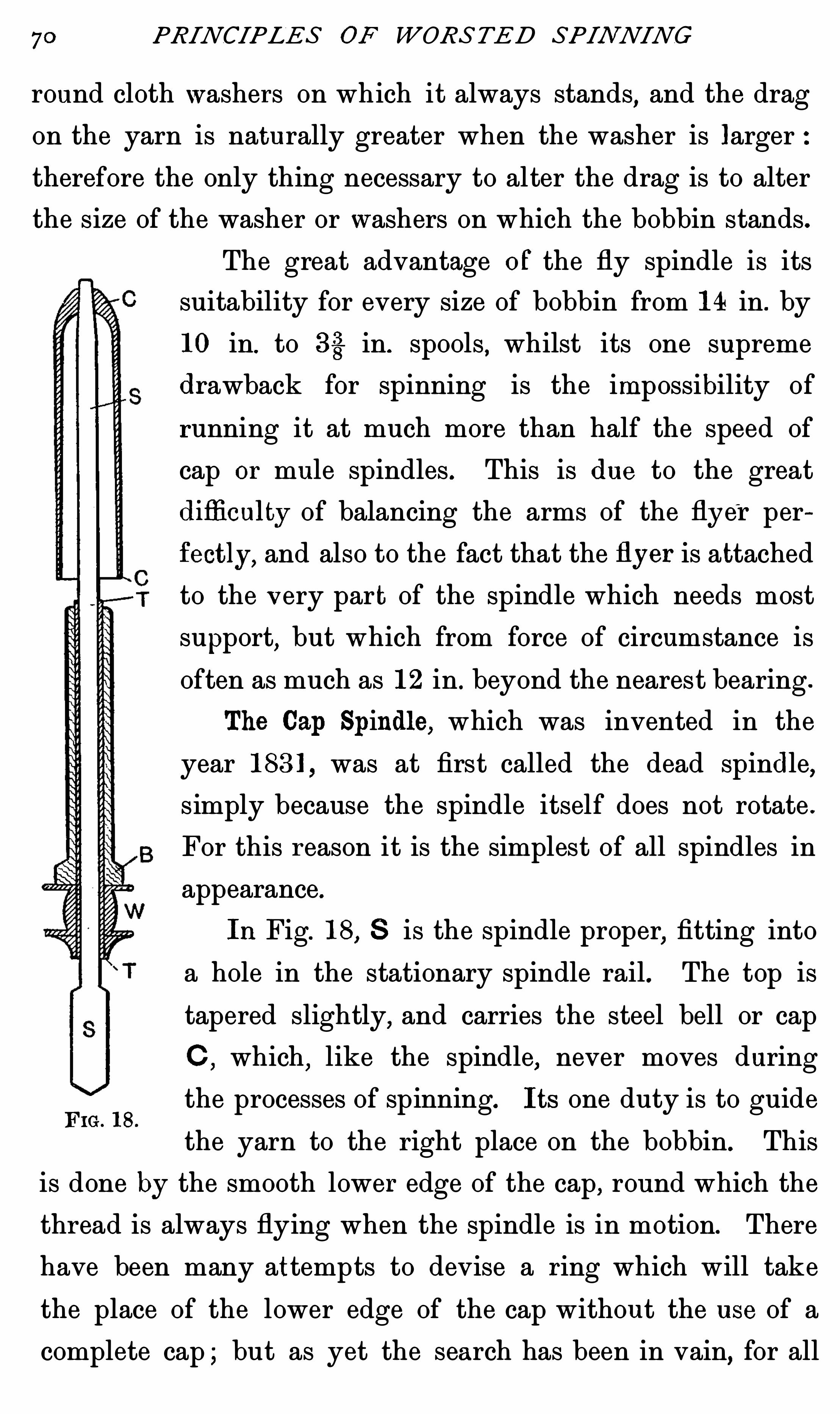
70 PRINCIPLES OF WORSTED SPINNING
round cloth washers on which it always stands,and the drag
on the yarn is naturally greater when the washer is larger
therefore the only thing necessary to alter the drag is to alter
the size of the washer or washers on which the bobbin stands.
F IG . 18 .
The great advantage o f the fly spindle is its
suitability for every size of bobbin from 14 in. by
10 in. to 33 in. spools,whilst its one supreme
drawback for spinning is the impossibility of
running it at much more than half the speed of
cap or mule spindles . This is due to the great
difliculty of balancing the arms of the flyer per
fectly, and also to the fact that the flyer is attached
to the v ery part of the spindle which needs most
support, but which from force of circumstance is
often as much as 12 in . beyond the nearest bearing .
The Cap Spindle, which was invented in the
year was at first called the dead spindle,
simply because the spindle itself does not rotate .
For this reason it is the simplest of all spindles in
appearance.
InFig. 18,S is the spindle proper
,fitting into
a hole in the stationary spindle rail. The top is
tapered slightly,and carries the steel bell or cap
C,which
,like the spindle
,never moves during
the processes of spinning. I ts one duty is to guide
the yarn to the right place on the bobbin. This
is done by the smooth lower edge of the cap, round which the
thread is always flying when the spindle is in motion. There
have been many attempts to devise a ring which will take
the place of the lower edge of the cap without the use of a
complete cap ; but as yet the search has been in vain, for all

SPINDLE THE ORI E S 7 1
rings have to be connected to something, and no connection
with the spindle has yet proved as simple as the cap, which
can be taken off at the end of each doffing , by the simplest
possible lifting movement. In Fig. 18 the bobbin B stands
on the whorle W,and is kept exactly true by the brass sleeve
or tube T . The bobbin B and the tube are therefore driven
round together on the stationary Spindle, and within the
stationary cap,by the tape which runs round the whorle W .
The twist is inserted v ery much as it is by a flyer, by the
motion of the thread round the circle of the cap , of which
circle the spindle is the centre ; not as in the mule spindle,
from the centre of the spindle itself.
The theory of the drag is the converse of that in a flyer
frame . The bobbin conveys the motive power,and pulls at the
yarn in a line d irectly tangential
to the circumference of the bob
bin. When the bobbin is full
the pull is tangential to the out
side surface of the yarn. WhenF I G. 19 . F IG. 20.
the spool is empty,as shown in
Fig. 19,this line strikes the edge Of the cap at an angle of
and the strain necessary to make the yarn slip round
the cap is therefore much greater than it is in Fig . 20,where
the line strikes the cap at a much more gentle angle,say
,
There are so many other forces involv ed that it would be
unsafe to say that the drag is in direct proportion to the
respective angles shown in these two diagrams,even if other
things were equal ; but there is no doubt that they have a
great deal to do with the excess Of drag when the bobbins or
spools are used with very small barrels .
When a spool is moved round very slowly,less than 100

72 PRINCIPLES OF WORSTED SPINNING
revolutions per minute,it is at first sight curious to notice
that no winding-ou takes place ; and this fact must be ex
plained, although there is no apparent reason why the yarn
should wind on to the spool at all. I ts natural inclination is
to slip round and round the cap j ust as fast as the bobbin
rotates, and it is not until the yarn is mov ing fast enough to
swing out into the air as it gyrates round the cap that
sufficient drag is obtained. This drag is solely due to the
resistance of the air,which at high speeds
,say 50 ft. per
second , is very considerable, and it alters with every altera
tion of the speed.
This means that the yarn acts as a kind of sail to retard
its own winding on to the bobbin,and the larger the sail area
the greater will be the tension . The sail area of the thread
is naturally increased by every inch of yarn, which, in flying
round between the eye and the cap edge, forms the apparent
balloon,and therefore the length of yarn between the eye
and the edge of the cap is a very important factor in the
setting of all cap and ring spindles. I t is very easy to
demonstrate how small is the friction of the yarn on the cap
itself in proportionto the resistance of the air, for if a spindle
be so arranged that the cap and spool rotate together at the
same Speed,the friction and the tangential strain on the yarn
between the spool and the cap ought both to be non—existentbut the yarn will be as perfectly wound on to the bobbin as
if the cap was stationary,and this proves conclusively that a
very large proportion of the drag is caused by the air . In
all cap spinning there are therefore three distinct causes of
drag
1. The relation Of the diameter of the spool to the diameter
of the cap.

74 PRINCIPLES OF WORSTED SPINNING
for this phenomenon is still to be definitely proved,it seems
probable that it is due to the motion of the lifter. I f the
lifter is working qu ickly,on the upstroke the yarn will touch
the bobbin first at a point slightly above the edge of the cap,
as shown in Fig. 21, and the angle at the edge of the cap will
be acute ; Whereas if the lifter be working very Slowly in
relation to the output of the front rollers,the yarn will move
so quickly from the cap to the bobbin that the line will
F IG. 21. F IG . 22. F IG . 23 . F I G. 24.
always be approximately level,as in Fig. 23 . On the other
hand , when the yarn is moving slowly and the lifter falling
rapidly, the point where the yarn first touches the bobbin
must be below the edge of the cap,as in Fig. 22 ; and in
extreme cases this will doubtless cause the bend of the yarn
over the edge of the cap to form an obtuse angle, and so
reduce the strain . I t is at least clear that the clinging of the
yarn to the cap as Shown in Fig. 24 has something to do w ith
the rise and fall of the lifter,and the question was only

SPINDLE THEORIES 75
mooted to Show that the speed of the lifter may therefore not
only affect the build of the spool,but that it can also affect
the spin—that is to say, the number of ends which breakdown in a given time .
I t must be clear to any one who has watched a cap spindle
running,that the cap is held in position in the only way
which is possible,because any outside connection w ith the
S ides or top of the cap would clearly prevent the yarn swing
ing completely round it, as it is bound to do, and as the spool
rotates between every part of the spindle and the cap except
the top , that is clearly the only place where connection can
be made, and the primary obj ect Of the dead spindle is there
fore to support the cap from within . This type of spindle has
four great advantages
1. The amount of weight in the moving portions is very
small .
2. The amount of bearing surface is large.
3 . The strain Of the band or tape used to drive the spool
and tube always falls within the two ends of the
long bearing surface .
4. I t can,consequently
,be run at high speed with very
little friction.
I ts drawbacks are comparatively few
1. The length of spindle necessary to support the cap
causes any v ibration of the spindle to show in an exaggerated
manner in the cap.
2. This vibration is apt to wear the top of the spindle and
make still worse vibration possible.
3 . So long as the brass tube and bobbin are perfectly true,
the vibration is very small ; but the soft nature of the brass
makes it wear on the steel spindle , and as it never wears
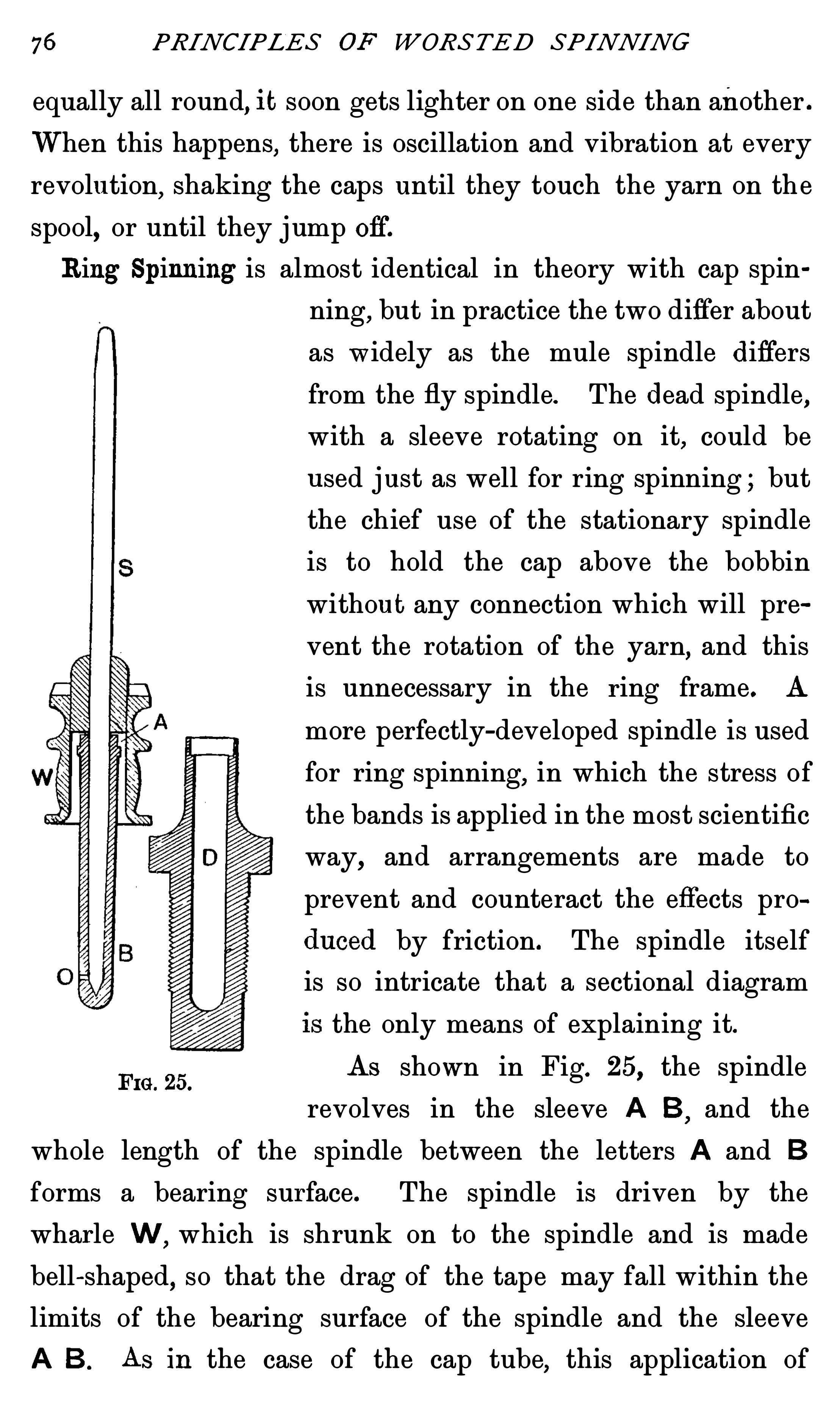
76 PRINCIPLES OF WORSTED SPINNING
equally all round,it soon gets lighter on one side than another .
When this happens,there is oscillation and vibration at every
revolution,shaking the caps until they touch the yarn on the
spool,or until they jump off.
Ring Spinning is almost identical in theory with cap spin
ning,but in practice the two differ about
as w idely as the mule spindle d iffers
from the fly spindle. The dead spindle,
with a sleeve rotating on it, could be
u sed just as well for ring spinning ; but
the chief use of the stationary spindle
is to hold the cap above the bobbin
without any connection which will pre
vent the rotation of the yarn,and this
is unnecessary in the ring frame. A
more perfectly-developed spindle is used
for ring spinning,in which the stress of
the bands is applied in the most scientific
way, and arrangements are made to
prevent and counteract the effects pro
duced by friction. The spindle itself
is so intricate that a sectional diagram
the only means of explaining it.
As shown in Fig. 25, the spindleFIG. 25.
revolves in the sleeve A B,and the
whole length of the spindle between the letters A and B
forms a bearing surface. The spindle is driven by the
wharle W , which is shrunk on to the spindle and is made
bell-shaped, so that the drag of the tape may fall within the
limits of the bearing surface of the spindle and the sleeve
A B. As in the case of the cap tube,this application of

SPINDLE THE OR I ES 77
strain within the extremities of the bearing surface causes
more uniform friction and wear than would be the case if
it were applied at a point beyond either end of the bearing
surface . The socket or well D is constructed to screw fast
into the spindle rail,and may contain Oil
,so that when the
sleeve A B in its working position is fitted closely into it,the
spindle is not only well supplied with Oil through the hole 0,
but the whole bearing may easily be lifted out for cleansing
or inspection.
Here,then
,is a spind le which strongly resembles the mule
spindle in size and often, in having a fine point. Such a
spindle is admirably adapted for put
ting twist into the thin ribbon of fibre
as it comes from the rollers,but it has
no arrangement to wind the thread on
to the bobbin,and no central stay to
which to fasten a ring which could
take the place of the lower edge of the
cap,as a guide for the yarn. Some
arrangement,therefore
,has to be de F IG. 26 .
vised,of such a nature that the yarn
can be attached to the inner edge of a ring in such a way,
that the yarn can revolve round the spindle, whilst at the
same time it will be free to wind Slowly on to the bobbin as
it was paid out by the rollers.
There are several ways of attaining this end, and many
recent patents have been taken out to improve upon the
original methods adopted. The first and simplest pattern, as
shown in Fig. 26, was a ring of such a section that a light
steel loop or trav eller of wire could be set astride its thicker
portion
.The traveller is free to run round upon the ring, but

78 PRINCIPLES OF WORS/TED SPINNING
the opening between its two ends is too narrow to allow it
to slip Off without considerable pressure . Rings have been
made of almost every conceivable size and shape, and
travellers of every kind have been used to move upon them ,
but a modification of the old type is still by far the com
monest of all those in use to-day.
When a thread is being spun, as soon as it has passed the
wire-board,it is threaded through the traveller and fastened
to the bobbin. As the spindle begins to revolve, a tension is
applied to the yarn exactly as is the case in a cap spindle,
but in this case the result is easier to understand. Looking
down on the top of the bobbin and ring in Fig. 27, it is seen
FIG. 27 . F IG. 28 . F IG. 29 .
that all the time it is under tension,the thread extends at a
tangent to the surface Of the yarn on the bobbin,until the
line cuts the ring. At that point the traveller will always be
found, and when the angle formed by the yarn and the ring
is very small, it will clearly be easy for the spool to pull the
traveller along. When the yarn is attached to the empty
bobbin,as shown in Fig. 28 , the tanggntial line cuts the ring
much m ore nearly at right angles,and as the angle between
the thread and the ring increases, the strain of pulling the
traveller round,naturally increases in proportion
,because the
traveller is being pulled harder against the sides of the ring.
I f any attempt was made to spin yarn on to the fine bare
Spindle, as is done in the mule, the yarn'
would inevitably

SPINDLE THE ORIE S 79
break, because, as shown in Fig. 29, a tangent of the spindle
surface wou ld cut the ring so nearly at right angles that the
thread would simply be d rawn through the traveller towards
the spindle,without sufficient forward pull to make the
traveller revolve round the ring and so relieve the strain.
In the foregoing paragraphs the friction of the travel ler
on the ring is treated as if it was the only source of drag in
the ring frame,although this is far from being the case . The
friction of the wire traveller, in its revolution round the ring,is naturally much greater than the friction of the thread as
it swings round the cap in a cap frame ; but the yarn between
the traveller and the eye forms a balloon,j ust as does the
yarn in a cap frame,and the size of this balloon , or, in other
words,the air resistance of the thread as it is whirled round
through the air,has also a considerable effect upon the drag.
Ina cap frame the distance from a cap edge to the eye is
always the same,becau se in order to wind the yarn uniformly
over the surface of the bobbin, the bobbin itself moves up and
down . In the ring frame it is difl'
erent. The spind les and
bobbins are absolutely stationary except for their rotation,
and in order to Obtain a traverse motion, the rings and ring
rail move up and down the whole length of the bobbin. This
has an effect which is entirely absent in cap and fly spinning.
When the ring is at the top of the traverse, it may be within
5 in. of the eye, and at the bottom of the traverse it may be
10 in. away, so that the drag caused by this continual altera
tion in the size of the balloon varies to such an extent, that
at the bottom the drag due to air resistance may be double
what it is at the top,and this quite apart from the variation
caused by the alteration in the diameter of the yarn on the
bobbin.

80 PRINCIPLES OF WORSTED SPINNING
This means that there is a very complicated and varying
series of strains present in the ordinary ring spindle,and
before perfect work in fine counts can be done,some altera
tions must be made . The variation in the length of thread
exposed to the air pressure can easily be stopped ; it is only
necessary to fix the ring rail and make the spindle rail
traverse,or to use dead spindles , with fixed Spindle and ring
rails,with a traverse motion to raise and lower the tubes and
spools exactly as in a cap frame .
The question of the drag caused by the travellers is very
much more complicated . An early patentee attempted to
overcome the diffi culty by cutting a
ring with a very deep groove,as shown
in Fig. 30,and pu tting into the groove
a light steel ring j ust larger than the
smallest diameter of the grooved ring.
Clearly the light ring could never get
out of place, but when pushed to one
side a space wou ld be v isible through
F IG. 30.
which the fyarn was carried. AS the
spindle rotated the yarn moved the
ring in such a way that the open space moved forward at
spindle speed,without causing the inner ring itself to rotate
at anything like the same number of revolutions per m inute ;
in fact, it is probable that it would rotate slowly in the
opposite direction. This absence of rapid rotation and con
sequent absence of friction on metal was intended to reduce
the drag ; but in practice other strains are involved which
more than make up for the friction caused on the ordinary
type of ring. This ring more nearly resembles the cap than
anymethod yet devised, because the inner or floating ring

CHAPTER IV
DRAFTI N G AND RArOH
Drafting .—In these days we regard the rollers and kindred
mechanism for drafting, as one of the simplest parts of a box
or frame,and it is rather curious to notice that this method
of drawing out a sliver was not introduced until 100 years
after the invention of the complicated arrangement of bobbin
and flyer winding , which had been devised for the Saxon
wheel in the early part of the seventeenth century.
With the original distaff, where the wool was simply
straightened and hung on to a rod or distaff, it stands to
reason that the fibres of various lengths were not uniformly
blended,when the spinner drew the thread ; she must have
been obliged to get first long and then short fibres quite
irregularly. This would make it very difficu lt to produce
a level thread,and the strength would be very uneven.
When combing came into regular use, a better sliver was
available ; the sliver being a ribbon of combed fibres,laid
side by side without twist,in such a way that long and short
fibres were blended equally throughout it. I f the spinner
draws from one end of the sliver, she is bound to get fibres
of all lengths, into every part of the thread, ensuring great
regularity in consequence ; that is, provided that the Sliver
is not too thick.

DRAFTIN G AND RA TCH 83
I t is necessary to call special attention to this point, for
over-drafting is one of the most serious faults which can
occur in machine drawing,and it is the modern equivalent
of drawing from a badly arranged distaff. Suppose, for
instance,that the Sliver weighs 1 oz . for 1 yd . and is to be
made into single Each sliver will have to be drawn
out 560 times its original length . I f a sliver ofl
l yd . to
the ounce were used for hand-drawing, it would be so wide
that the spinner could not possibly keep the fibres so
arranged as always to terminate in a point,from which she
could draw,and She would be attempting to produce a yarn
from a square-ended mass of fibres . She would probably
draw first long and then short fibres from the bunch, and this
again would cause uneven yarn and unequal strength . I t
would be, as nearly as handwork could be,the exact
equ ivalent of drafting the sliver too much between two
pairs of rollers.
To understand the question thoroughly,diagrams will be
necessary to illustrate the different alterations which take
place in the arrangement of fibres in the passage of sliver
between two pairs of drafting rollers. For example, if a
roving of 8 drams for 40 yds. is to be spun to 16 counts,
there will be 1280 yds. of roving in every pound, and there
are to be 6400yds . of yarn—that is to say,a draft of five will
be necessary. For the sake of illustration , it w ill be supposed
that the sliver is composed of fibres 5 in. in length, besides
equal quantities of shorter fibres. I f the sliver be level and
continuous,these 5-in. fibres must be arranged so that every
fibre is overlapped by every other with considerable regularity.
To represent a perfectly level sliver in diagram,the overlaps
must be very regular indeed,as in Fig . 31. How much

84 PRINCIPLES OF WORSTED SPINNING
each fibre overlaps is a matter of no moment,but the greater
percentage of long fibres the greater will be the overlap . I f
there are equal numbers of 5-in.,4-in.
,3-in.,
and 2-in. fibres In
the top , it is clear that these short fibres must overlap less
than those which are longer.
In a sliver of certain thickness (Fig. with its fibres
5 in . in length,there is such a number of fibres that they
overlap one another by 4 in.,but if the sliver had been more
drawn out at the previous box,it would of course have been
thinner, and it is clear that any given group of fibres would
overlap one another less (Fig. so that their friction on one
another is less, and the strength of the whole sliver less in
proportion. I f the arrangement shown in Fig. 31 is reproduced
F I GS. 31 AND 32.
w ith 4-in. fibres,it is clear that if there are the same number
in a given length, they must overlap 25 per cent. less, so that
after they have been drafted 4 to 1 the difference between
them and the 5-in. fibres is more apparent (see Figs . 34 and
I t will be better to deal with the 5-in. fibres alone
during their j ourney through the drawing rollers. The back
rollers (B R,Fig. 33) hold all the fibres so tightly that none
of them can move on one another,until their points reach the
front rollers FR,one by one, just as they become free from
the back rollers . As each in turn reaches the front roller it
is moved 4 in. forward in the same time that the back
roller pays out 1 in. The position is now greatly altered.
I nstead of an overlap Of 4: in. there is now only an overlap
of 1 in . and as the process continues, each fibre is moved

DRA FTI IVG AN D RA TCH 8 5
the same amount in regard to the one which follows it,
until the group is arranged as at Fig. 34. To under
stand the action Of the 4-in. fibres they must be dealt with
as if they existed qu ite apart from those 5 in . in length ;
and as the motion of the rollers is necessarily the same for
all,each of them will be moved j ust as much in relation to
one another as were the 5-in. fibres . This will mean that
after drafting there is no overlap (Fig. and there will
therefore be no cohesion between any of the fibres in the
group,because they have been drawn just so far that the
F IGS . 33 TO 37 .
end of one will touch the end of the other. The relations of
3-in. and 2-in. fibres after drafting are shown in Figs . 36 and 37 .
I f a set Of 5-in 4-in.,3~in.
,and 2—in. fibres is grouped as
they appear after drafting (see Fig. a result exactly
equ ivalent to the arrangement of fibres ina broken or lumpy
sliver is obtained. I t is qu ite clear how this arrangement is
caused in a gillbox ,where each faller holds all the Short fibres
until it drops. All the fibres are then se t free together ; but
where there are no fallers,it is not so easy to see why the
fibres from the front rollers arrange themselves in this
way,and it is true that as the drawing process proceeds
,the

86 PRI IVCIPLES OF WORSTED SPINNING
irregular combination of long and short fibres occurs at less
regular intervals,though each thick place is more clearly
defined when it does come.
The diagram given in Fig. 38 is, however, very u seful as
offering an explanation of the accepted fact, that a Sliver should
not be drawn twice r unning in the same direction, for it is
very easy to see that if the points of the 2-in.,3-in.,
4-in.,and
5-in. fibres all reach the front rollers together, as they would
do if they were going in the direction of the arrow,they
wou ld all go through side by side,and the sliver would be
pulled into pieces,which would be separated by distances of
four times their own length (see Fig. On the contrary,
F IGS. 38 To 40.
if the groups of fibres go to the rollers of the following box
point first,their points will reach the front roller in such
order that the 5-in. fibre will have travelled 4 in. before the
4-in. fibre has moved, so that after drafting they will be laid
end to end,and there will be short gaps between the shorter
fibres (Fig. which does not, of course, give a continuous
figure . All that can be said of it is,that when laid side by
side with other similar figures,a sliver of some regularity will
again be formed ; and as there are a number of doublings at
each box, nearly equ ivalent to the amount of draft, it is clear
that the original thickness of the sliver will not be reduced
mu ch at each operation. Moreover, only the movements of a
group of twenty-fiv e of the component fibres of the top have

DRAFTIN G AND RA TCH 8 7
been followed,and as a section of a 4—oz. sliver of 60° quality
will contain fibres,it is clear that this theory must be
largely modified in its applications,although the lesson drawn
from Figs. 39 and 40 cannot be overlooked.
The application to practice is summarized in a brief phrase
in use in many Bradford mills,to the effect that “ the draft
and the length should be the same but it has been pointed
out elsewhere that if the fibre were measured in millimetres
instead Of inches,the statement is entirely wrong, and the
relation of the draft to the inches of length in some fibres is
therefore purely accidental. For special counts, many wools
will stand much more draft than is equal to their length in
inches. Furthermore, the theory is hopelessly incorrect in
regard to cotton, which is a shorter fibre without serrations ;
but in Spite of these facts,it is well known that cotton 1 in .
in length will easily Stand a- d raft of 10. We are therefore
under the unfortunate necessity of noting another difficulty
for which no scientific solution has ever been offered, for
careful readers will notice that this reasoning is based on an
unproved axiom ; and when the amount of overlap in the
arrangement of the fibres is made d ifferent,some of the figures
in the table Of reasoning would have to be altered in propor
tion,although the general drift of the conclusions would be
unaltered . I t seems,therefore, quite impossible to sum up a
theory in regard to draft,in terms that a scientific mind would
consider accurate,bu t it is probable that no long fibre should
ever be moved at one operation more than its own length in
relation to all other fibres which lie contiguous with it,in the
Sliver as it goes through the back roller.
Batch is the distance between the nip of the back roller
and the nip of the front rollers, and if it is to bear any

88 PRINCIPLES OF WORSTED SPINNING
proportion to the length of the fibres which are being treated
it must of necessity vary with ev ery variation of length of
material which is pu t into the machine.
The subj ect may be considered under four heads,ac
cording to the methods adopted for preventing the Shorter
fibres of the top from going through the front roller in
groups.
1. By the use of fallers .
2. By the u se of porcupines .
3 . By the use of intermediate rollers or carriers.
4. By the use Of three pairs of rollers .
1. Correctly speaking, accurate ratching is not of great
importance in gillbox es, because in Botany qualities the
fallers actually hold the wool for a considerable time after it
is free from the back rollers,before it is caught by the front
ones. The presence of the fallers also makes it impossible to
set the back and front rollers within 8 in. of one another,and
therefore the only thing which is necessary is to see that the
distances from the back roller to the back faller,and from
the front faller to the front roller,are always suitable to the
length of the fibre which is being treated .
As the fallers do not hold the wool in a positive grip,
there is not the same need for accurate adjustment at these
points as there is in a roller draw ing box, and the only ru le
that can be laid down is,that however long the wool may be
,
the distance from the front roller to the back roller must be
decidedly longer. As the wool increases in length,the
distance from the back roller to the back faller must increase
in proportion. The relation of the front faller to the front
roller seldom requires alteration,and except for unusually
long wools, the front faller should always drop as near to the

90 PRINCIP LES OF WORS TE D SPINNING
two parts,provided always that the total distance from the
nip of the front rollers B to the nip of the back rollers C is
longer than any fibre in the top ; that is to say, the distance
from the back roller to the porcupine must not be so short
that there is any chance of the pins tearing the fibres,whilst
they are too closely packed together and the distance from the
porcupine to the front roller must be as short as possible,to
prevent the short fibres going through in lumps after they are
released by the pins . To meet these two requirements it is
often necessary to have the porcupine set as near as possible
to the front roller, and in that case the question of ratch
between the back and front rollers will have to be considered
very much as in an ordinary drawing box .
3 . The third class of ratch is of mu ch the greatest
importance in worsted spinning,because it is the method
used in all open drawing, and for all cap, fly,ring
,and mule
machinery,both for worsted and mohair.
I f a top cou ld be found which had all its fibres Of one
length,the ideal conditions for drafting and ratch wou ld be
secured,because the rollers could be set j ust so far apart that
as soon as a 5-in. fibre was free from the back rollers,which
are paying out 1 in . per second, it wou ld be caught by the
front rollers and moved 4 in . per second . Inother words,the
centre of the back rollers would be —in. or 53} in. from the
centre of the front rollers, without any intermediate carriers .
In such a case there would be no breakage of fibres ; there
could be no Slipping , and consequently there w ould be no
irregularity in the yarn. Unfortunately such a Simple arrange
ment can never be used in practice, because all tops contain
fibres of varying lengths and if a top containing fibres from
5 in . to 2 in. in length were put through rollers 57}in . apart,it is

DRAFTI N G AN D RA TCH 9 :
clear that the 5-in. fibres would continue to be drawn out in
an even ribbon,each ov erlapping its predecessor by 1 in but
if the 2-in. fibres are arranged in such a way that they
overlap one another by 1 in. when they reach the back roller,
it follows that four of them would be free from the back
roller before the first one reached the front roller.
Leaving the friction of the 5-in. fibres out of account, all
four of the 2-in. fibres would necessarily go through the front
rollers together, by reason of their friction upon one another,
and they would necessarily form a lump in the resulting
sliver,as it came from the front rollers. No more short fibre
wou ld then go through the front rollers until 16 in. of Sliver
had been formed .
There can be no doubt that movements of this kind
amongst the fibres of a sliver are the root cause of almost all
irregularity in spinning,although friction and other things
,
which occur in practice , may affect the fibres so that these
theoretical movements are very much modified but the greater
the difference between the longest and the shortest fibres,the
greater w ill be the danger of unevenness in the yarn.
I t is safe to say that no thread has the Short fibres
distributed evenly throughout it, but in practice they are
prevented from going through the front rollers in lumps,by
some means,in the absence of both fallers and porcupines . I f
a box were set with its front and back rollers just so far apart
that the longest fibres would not reach from one to the other,
and if in addition a pair of weighted rollers were introduced
between them,in order to deal with the short wool ; the short
wool would be held in such a way by all the rollers that it
would be made into a fairly regular sliver. This arrange
ment,however, would clearly divide the one ratch of 5 in.

92 PRINCIPLES OF WORSTED SPINNING
into two ratches of 212in. long and whether the intermediate
roller ran at the speed of the back roller or of the front
roller, or at a speed between the two, it is clear that every
fibre which was longer than 25 in. would be broken in the
process,and the spinning power of the top completely ruined .
I t is necessary to have some roller which will prevent the
Short wool slipping,but the breakage of long fibres has to be
avoided at all costs,and the method adopted is a compromise .
A pair,or more generally two pairs
,of small rollers are
introduced between the back and front rollers,as shown in
F IG. 42.
Fig. 42. These rollers, or carriers, as they are called, do not
grip the fibres tightly. They are of such small d iameter
that the back and front rollers can still be set within 5 in .
of one another if necessary. The upper carriers,or tumblers
,
are nearly always made of wood, and they are consequently
light in weight. They are just heavy enough to prevent the
short fi bres being moved forward by the friction of longer
fibres,moving near them,
but their pressure is no t suffi cient
to prevent the long fibres being drawn right under them,as
soon as the points of the fibres are clear of the back roller and
reach to the front one . In other words, the carriers have

94 PRINCIPLES OF WORS TED SPINNING
N ow comes the important point. I f the distance from C
to D is less than 2 in. there can be no slipping of the short
fibres, because the carriers hold the wool firmly enough to
prevent their moving on one another,until they are caught by
the front rollers . I f,also
,there is a draft of 4 between A and
D, every 2-in. fibre willbe moved 4 in . before the tip of the
next 2-in. fibre reaches the front roller,and the 2-in. fibres
will then be lying in a row,on the ribbon of 5-in. fibres with
j ust 2 in. between their extreme points.
I f any reader cares to work out the movements of the
3 -in. and 4-in. fibres,he will find that the tips of the 4-in. fibres
will just touch one another,and the tips of the 3 -in.
‘
fibres
will be 1 in . apart,after they have gone through the same
machine . N one of these sets of fibres,excepting the 5-in.,
will make a continuous figure,but it is clear that relatively,
each length will be distributed as regularly through the
sliver, after drawing, as it was before the operation ; and
when the fibres are again grouped together,with the other
fibres forming the sliver, there will be no preceptible irregu
larity. I t must also be remembered that every alternate box
draws from opposite ends of the sliver and fibre,and therefore
the effect described under gill box drafting will ensue in a
m odified form,each succeeding process tending to undo any
grouping of the fibres which'
has resulted from the one
before it.
The whole of the question might have been discussed
under the head of drafting, but its bearing on the question
of ratch is of even greater importance, and for that reason it
has been reserved for this place,because it must be clear to
any thinker,that if the component ratches do not bear the
right relation to the length of the Shortest fibre in a top, it

DRAFTIN G AN D RA TCH 95
is certain that the short fibre will not be evenly d istributed
in the yarn. I t may not be uneven enough to cause visible
lumps,but it cannot be so perfect as it ought to be. Take
,
for example,the case of a crossbred top w ith fibres varying
from 8 in. to 1—5 in. in length . The distance from A to D,
Fig. 42, must now necessarily be extended to 8 in. or the
long fibres will be broken ; and if two pairs of carriers are
used, it is clear that the length of each of the component
nips must be 25 in. But any two 15-in. fibres overlapping
one another by only one 1 in. extend 25 in.,and therefore
two of them will be free from A before the point of the first
arrives at B,and the two will consequently slip forward
together, leaving a long gap before the next short fibres come
through to B. To draft such a top, it is theoretically necessary
to use three carriers, SO that none of the ratches is greater in
length than the length of two fibres as they lie overlapping
one another in the sliver.
This argument is based on the supposition that they
overlap by 1 in whereas it is much more probable that they
overlap by a much greater proportion of their length,and in
that case,the component ratches would need to be shorter still.
I t needs no demonstration to show that with three pairs
of carriers or four ratches,each of them will be reduced to
2 in.,and there will be no chance of the short fibres going
through in bunches,as they were shown to be likely to do,
with only two carriers and three ratches each 25 in. long.
4. The use of the three pairs of rollers, each having a
definite grip on the fibre,and each moving the fibres forward
on one another,to a definite extent, is a subj ect which does
not properly come within the scope of this work, because it
has never been applied to worsteds, and it is a noticeable

96 PRIN CIPLES OF WORS TED SPINNING
exception to the fact that in both cotton and wool,fibres are
never drafted twice in the same direction.
Whenever three pairs of rollers are used,as shown in
Fig. 43, the central pair, which take the place of carriers,
are entirely different from carriers,because they have a
definite grip on the wool,and really form
,at one and the
same time, the front rollers of one drafting process and the
back rollers of a second. I t is noticeable that in the cotton
trade , there is an exception to the rule so universally accepted
in worsteds, and it raises the question as to whether in
worsted, the general principle at present in vogue, might at
F IG. 43 .
times be modified with advantage and with reduction in cost
of production.
Take,for instance
,a case where cotton 15 in . long goes
through the drawing with an average draft of,say
,10. By
the same rules one would expect that it wou ld be drafted to
very nearly the same extent in the mule,but it is well
known that in recent years,it has been possible greatly to
exceed these figures,and a draft of 16 is not an unheard-Of
thing. This draft of 16 would really be composed of two
consecutive drafts,of 2 and 8 respectively
,in two entirely
separate ratches,each of which would be slightly longer than
the fibres under treatment. The absence of carriers between

CHAPTER V
DRAWI N G
Drawing is a term applied to the series of processes, by means
of which a worsted sliver from the comb is reduced to such a
size that it can be drawn out in the spinning frame, at one
Operation to the desired size of yarn.
For example,a botany top will weigh about 4 oz. for 10
yds. ; it is to be made into yarn of, say, 60° counts, and it will
only stand a draft of 5 or 6 in the spinning frame To find
out how much it must be reduced,in order to be suitable
for this purpose by present methods involves a comparatively
intricate calculation.
A roving which will make GOS with a draft of 5 must
or 6720yds. per pound .
or 265yds. per dram orIf) ” drams per yard.
0
4
105
and the relation between 15 dram in 40 yds. and sliver of
dram in 40yds. ;
4 oz. in 10yds. is the amount of reduction necessary in the
drawing process.
I t is a clear proof of the conservatism of this country,that
w e are prepared to go on using such time-worn systems of

DRAWI N G 99
calculation. There are many items in the textile trades
where the calculations necessary to arrive at a desired result
are so complicated, as to mystify even competent persons, if
they are not intimately acquainted with the industry ; but it
is probable that nowhere else are denominations used, which
are so wasteful of time, as are those required to take a top
through the drawing to the spinning. In that range there
are five points where the definite relation of weight to length
must be known ; and not content with the complication
involved in the use of pounds, ounces, drams, grains, and
banks of 560 yds .,it is thought necessary to alter the
denominations,at difl
’
erent stages, from length to weight,
or vice rersci.
The sizes of tops are stated in ounces for 10 yds. At
the first and second weigh-boxes, the length of sliver on
a bobbin (which is an irregular length, such as 458 yds.) is
divided into its weight in pounds and then reduced to the
number of drams in 40 yds. Roving is weighed in lengths
of 40 yds.,the weight being stated in drams . For yarn
the weight is fixed at 125 grs. ; the number of yards in
that weight being the same as the count. I t might be
interesting to find the origin of these various figures, but
the practical man is only concerned to find a system by
which he can ' tell at sight how much draft is needed to
reduce tops to rovings, and rovings to yarn and if a decimal
system (not necessarily metric) were brought into general
use, this could be done with the utmost simplicity, and with
great saving of time and trouble .
Based as our present system of counts is, on a pound
weight and a curious multiple of yards,as a standard of
length, it goes without saying that either the standard count

I oo PRINCIPLES OF WORS TED SPINNING
must be altered,or some other weight must be substituted
for the pound,simply because neither it, nor the standard of
length can be subdivided into satisfactory decimal parts .
I f a pound is retained as the standard weight by which
to measure tops,drawing slivers, rovings and yarn ; one
thousandth part of it would become the standard for yarn
weighing.
But TOO75 of a pound is 7 grains or ”L
5or 54 ; of a 125
grain weight, and this would necessitate an alteration of the
standard count, far more revolutionary than an alteration to
the French metric system.
I f,on the other hand
,it is absolutely necessary to retain
the present standard of length, it is clear that the pound as
a standard of weight mus t be altered,and that multiples
of 125 grs. must be adopted instead. This would be very
inconvenient, as the pound would have to be replaced by1000 x 125grs. or grs. which is about 18 lb. Such
a system would need an entirely new Set of weights, of a type
not at present in existence,and it is therefore a system which
cannot be recommended because it would be quite impossible
to sell by a system not invogue in our own, or in any other
country
By adopting the Standard metric system, all such diffi
culties will be done away with. The weights can easily be
bought without trouble, and the simplest of all methods could
be adopted,if the trade would consent to have the standard
of count altered by about 12 per cent ; that is to say, a gram
(of 155 grs.) would replace our 125 grs. weight, and yarn
which we call 60° with yards to the pound,would have
in future to be called because it would contain 677
meters per gram. Roving from which to spin it with a draft

102 PRINCIPLES OF WORS TED SPINNING
the better,if novelty of method is involved. I t is certain
that it would effect a saving in spite of the necessary
alteration of figures,and if any master will trouble to work
out for himself the complete set of drafts and doublings for a
set of drawing,with the additional drafts from three different
weights of rovings, for Six different counts ; first using the
old and then the new methods,there is small doubt that he
would very soon turn reformer.
The cumbersome calculations for finding the draft from
roving to yarn, is so typical of all the other calculations in
a drawing, that there is no use wasting time in describing
a method SO involved ; and all that has to be said on this
complicated subject will therefore be stated in meters and
grams.
The metric system is now so universally used by scientists
and chemists all over the world,that no apology is needed for
its adoption. I t effects immense saving in nearly every type
of calculation for which figures are used,and for that reason it
is almost certain to be adopted sooner or later by every
civilized nation,as it already has been by France, Germany,
Austria,and many others. Measures of length
,bulk
,weight,
and fluid capacity are all related to one another in this
system,and are all based on the meter
,which is a measure
of length equal to 393 708 English inches . This length was
selected as being one-ten millionth of the earth ’ s quadrant,
measured from pole to equator, and also because it is a
length useful in itself,and very suitable for subdivision
into hundredths and thousandths. In use,the meter is
d ivided into tenths, hundredths, and thousandths, under a
name derived from the Latin, whilst multiples of the meter
are indicated by Greek prefixes.

DRAWIN G 103
Thus a kilometer is 1000meters or 1093 yards.meter 39 3708 inches.decimeter of a meter or 3 9370
centimeter nitmillimeter nits 00393
The standard of bulk both for fluids and solids is a cubic
centimeter, which is always written, and often spoken Of, as c.c .
The standard of weight is a gram , which is the weight
of one c c. of water at its greatest density (i.e. at 4° centigrade).
A cubic decimeter (being equal to 1000 is therefore
equal to 1 kilogram,and as a measure of capacity for liquids
it is known as a litre. A litre (l l—7G pint) therefore weighs 1
kilogram.
Names derived from Greek numerals are used for all
multiples of the gram,and prefixes derived from the Latin
indicate its decimals.
Thusakilogram is 1000gramsor2204 lbs. (avoir.) or35273 oz. or grs.
hectogram ,,100 0220
dekagram 10 0022 0352
gram 1 0002 0035 or l5'432grs.
decigram {3centigram nitmilligram 0015
For the conversion of English units into metric, the
following figures are useful
1 lb . 453 6 grams. 1 yd. 0914 meters.
1 oz.1 ft . 03048
1 fluid oz 283 5 1 in. 00254
1 pint 567 '93 or
1 dram1 grain
Flu id and solid measures will not concern us in this treatise,
but in calculations Of drafts, the meter will be used instead of
the yard or hank, and grams instead of grains, drams, ounces,
and pounds.

04 PRINCIPLES OF WORS TED SPINNING
Standard Bradford 60° yarn contains 60 x 560 or
yds . in a pound . This multiplied by 09 14 gives
m eters in a pound ; and again mu ltiplied by 22046 we have
meters in a kilogram,or 677 15 metres in a gram .
In other words, to reduce yards per pound, into meters
per kilogram,it is only necessary to multiply by 2014, and
the reduction from one count to another may be made in one
line of fractions thus
36x
1
1 394 453
the small difference (002 Of a count) being due to the fact
that in the fraction, only one decimal point is u sed instead of
the three used in the decimal method .
Before p roceeding to compare the relative sizes of sliver
from all the different boxes in a drawing,it is necessary to
have a list of the standard sizes of top sliver stated inmeters
per kilo. These are
Sliver Oz. in meters per kilogram9,
We are now in a position to state the size of the Sliver in
every box of the drawing process, in figures of the same
denomination ; that is, to state the number of meters o f
sliver,as it comes from each box
,which is equal to 1
kilogram in weight,and if the reader will remember that
in the final result 677 metric counts, are equal to the 60° of
the trade,he w ill have no d ifficulty in forming conclusions
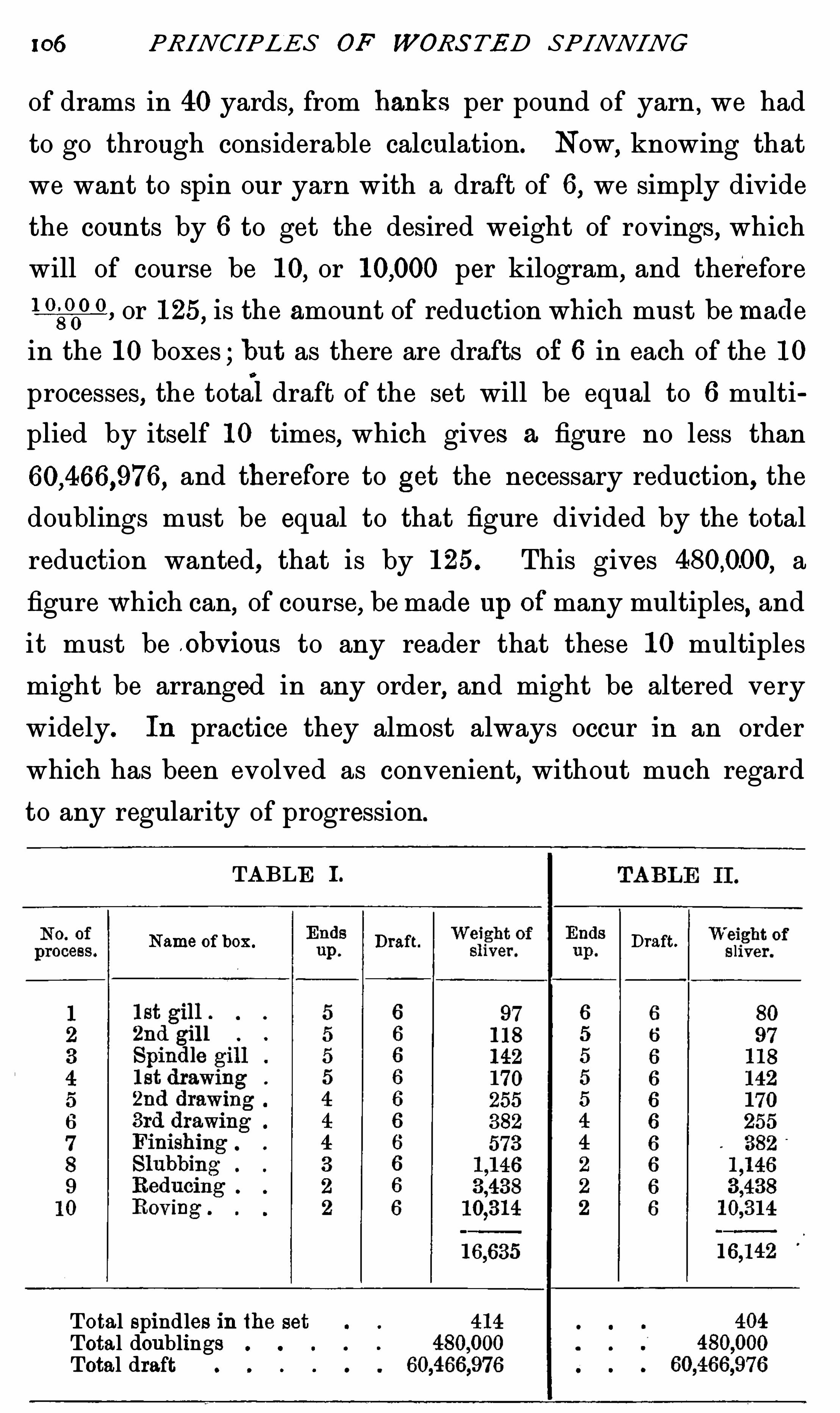
106 PRINCIPLES OF WORS TED SPINNING
of drams in 40yards,from banks per pound of yarn ,
we had
to go through considerable calculation. Now,knowing that
we want to spin our yarn with a draft of 6 , we simply divide
the counts by 6 to get the desired weight of rovings, which
will of course be 10,or per kilogram, and therefore
1 0, or 125, is the amount of reduction which must be made
in the 10 boxes ; but as there are drafts Of 6 in each of the 10
processes,the total draft of the set will be equal to 6 multi
plied by itself 10 times, which gives a figure no less than
and therefore to get the necessary reduction, the
doublings must be equal to that figure divided by the total
reduction wanted, that is by 125. This gives a
figure which can of course,be made up Ofmany multiples
,and
it must be .obV I ouS to any reader that these 10 multiples
might be arranged in any order, and might be altered very
widely. In practice they almost always occur in an order
which has been evolved as convenient,without much regard
to any regularity of progression.
TABLE I .
Name of box . Draft. Draft.
Total spindles inthe setTotal doublingsTotal draft

DRAWING 107
Tables I . and I I . show calculations for botany drawings
with the same number of doublings and the same amount of
draft,the size of sliver being stated in metres per kilo but
there is a slight difference which needs careful consideration .
In practice it is common to suppose that if the total drafts
and doublings of two drawings are equal, the result must be
equally good,but this is certainly not always the case.
To compare the advantages and d isadvantages of the two
systems,it is first necessary to notice that the output of the
front rollers of every box in a set of drawing is so nearly alike
that the result may be regarded as equal . I t may therefore
be said,that the number of spindles in each operation will be
in direct proportion to the size of the thread coming from
them,and because this is the case, the figure which is obtained
by adding together the weight of sliver from the various boxes,
will always be very nearly in proportion to the total number
of spindles in the whole drawing. For example, in Table I I . to
find the number of spindles or rollers in the first 2 sliver box
80must be divided by 40, and in like manner divided
by 40 gives 404. On this basis Table I I . would be less
expensive in first cost of machinery,in rent and in wages
,
because fewer spindles are necessary ; and the only drawback
to set against this is the fact that the sliver from the first box
is the same size as the top, because there has been no redue
tion . For these reasons, there are only two instead of three
doublings in the slubbing.
I t is not at all unusual to adopt this method of doubling at
the first box, to secure a certain desired weight at the weigh
box . Infact, it often happens that the sliver from the first
box is actually made thicker than the top,and it is not clear
that any serious harm will result from this treatment,but

108 PRINCIPLES OF WORS TED SPINNING
perfection is said to be made up of trifles, and if we adopt
Euclid’
s method of treating doubtfu l problems,by carrying
them to extremes, we see plainly enough that, not only is
Table I I . imperfect, but probably Table I . is not as good in
theory as is the system givenin Table I V .
TABLE I I I . TABLE I V .
Weight of EndsDraft .
Name of box . Draft .
sliver. up.
Total spind les inthe set
Total doublingsTotal draft
I f there is no special advantage inreducing the size of the
sliver at every operation,there seems to be no particular
reason why it should be reduced at all, until the last three
boxes of the set are reached (see Table I I I .) Such an
arrangement would clearly have the great advantage of requir
ing only two spindles in each of the first seven boxes,six
spindles in the slubbing, 36 in the reducing, and 216 in the
roving . There would be,of course, great saving in the first
cost and in wages but no manin his senses would expect to
get good work by such means,for it may be taken for granted
that after a top leaves the last combing gill box, it is nearly as

1 10 PRINCIPLES OF WORS TED SPINNING
drawing process in which there are so many doublings that
the resulting sliver is as thick,or thicker than the original.
I t is probable that most perfect evenness would result if the
percentage of reduction could be made the same in every box
of a set (see Table and as it is impossible for all to be
alike, theory advises that the later boxes, where the fibres in
each sliver are fewer, should have as many doublings as
possible.
The difficulty in the way is largely one of expense, for it
is easy to see that if the order of doublings in Table I . were
reversed, the number of rov ing boxes required in both would
be the same ; but the number of reducers , slubbing boxes, and
finishing boxes would be so enormously increased,that the
cost of machinery,rent
,and wages would be very much
raised, and would be out of all proportion to the advantage
which would be gained by any slight possible improvement in
evenness . Practical men have good reason for knowing, also,
that expense is not the only drawback which has prevented
the adoption of a uniform system of reduction throughout all
the drawing processes,for they are too well aware of the diffi
culty caused by piecings in the slubbing,reducing, and roving
processes. I f the number of ends up,in each of these pro
cesses were increased to four or five,there is no doubt that
the difficulty of keeping them free from thick j oining places
would be increased out of all proportion to the increase of ends
used ; and such careful attention would be necessary on the
part of the hands,to keep the work free from thick places, that
there would be very small chance of obtaining really perfect
work.
Present methods are a compromise between the least
expensive course,and that which would be the best in theory .

D RAWING 1 1 1
I f a spinner has the choice of increasing the number of ends
or reducing the draft,in order to get a thicker roving, he
should try as far as possible to increase the number of ends
in the later processes. I t is also well to remember that the
output of a drawing can be enormously increased by the in
crease of drafts,for there is no mechanical limit to the amount
of draft possible,as there is to the speed of a spindle,land it is
also clear that the greater the draft the fewer are the processes
necessary to reduce top to a given weight of roving, at the
same time retaining the full number of doublings. Thus,in a
crossbred with a draft of 10 throughout, only eight processes
are required to obtain doublings and a total reduction
of about 100 times.
TABLE V .
DRAFTS AND DOUBLINGS. CROSSBRED DRAWI NG .
Name. Draft.
Total spindles 138
Total doublingsTotal draft 10s
There are two discrepancies to be noted between the
tables given and the drafts which are in daily use.
1. For obvious practical reasons the draft cannot remain
exactly alike throughout the whole set. There are always at

I 12 PRINCIPLES OF WORS TED SPINNING
least three points where the weight of sliver must always be
of a size that can be stated in round figures,which are easy to
compare with others. For instance,instead of the 142 in the
first drawing-box of Table I it might be necessary to have
140 in practice ; and as this number could never be obtained
by altering the number of ends up whilst retaining a draft of
6 , the ends are allowed to remain the same, and the draft is
made 5 and a fraction instead of 6 . For the sake of sim
plicity,similiar drafts are often adopted all through a set of
drawings, and it also often happens that it is necessary to
alter these drafts very slightly at the weigh boxes, partially
because it is found impossible to make tops sufficiently regular
to avoid their showing slight differences after drafting,and
partly because they always lose a certain percentage of their
weight through evaporation in the process. The amount of
lossdiffers with different conditions of the atmosphere, and
this difference has to be made up by alterations in the draft.
2. Practical drafting differs from the theoretical examples
here taken,in that the drafts are deliberately allowed to
increase as the process continues, so that the attenuation of
the sliver at each of the smaller boxes is greater than that
shown in Table I . In other words, the drafts rise as the
number of doublings fall,and instead of making a steady
reduction from gill box to roving, as shown in Table I V ., the
increase is very slow in the early boxes, and unnecessarily
rap id in the roving and spinning.
“
Too much twist is a great mistake, for two reasons .
Firstly,the total speed at which it is possible to run the box
is generally determined by the speed of the fiyers : but an
increased amount of twist means more revolutions of the flyer
to every revolution of the front roller, and therefore the

1 14 PRINCIPLES OF WORSTED SPINNING
3 . Fallers which prevent the fibres being drawn too
rapidly by the front rollers (B,Fig.
4. Front rollers which draw out the fibres to such an
extent that the sliver is reduced to a definite extent (C ,
Fig.
5 . Calender rollers which pay the sliver into the can
(D Fig.
6 . A knocking-off motion, which stops the machine as
soon as the required amount of sliver has been paid into the
can(Fig.
1. The Creel is designed to overcome two difficulties
which cause trouble if work is attempted without it. I f t0ps
are laid on the floor,there is very seldom any diffi culty in
drawing a sliver from the centre of the ball,and fibres from
other adj acent portions of sliver do not adhere very much ;but when a sliver is drawn in this way it always contains
twist. I f the amount of twist were constant, this would not
be a very serious matter,but as the length of one lap round
the ball varies from the centre of the ball to the outside, and
as one turn of twist runs into the sliver for each wrap
round the ball,it will be found that a sliver drawn from the
centre of the ball in this way, contains varying amounts
of twist.
By making the ball rotate with a uniform surface traverse,
the creel makes it possible to take sliver from the top,without
any twist at all. Whatever may be the diameter of the
different tops on the creel,it will pay out sliver from every
one of them at a uniform speed, so that all the fibres go up
to the back rollers without having had any strain put upon
them ; consequently the slivers never break down and are
never strained . Various methods have been tried to obtain

DRAWING 1 15
this result,but none of them have been so efficient as that
shown in Fig. 44.
Any method by which a skewer, or other artificial axis is
put through the centre of the ball is bound to disarrange and
probably to damage the sliver near the centre of the top, and
it is of course impossible to apply any motion to such
spindles,which would pay out the sliver at rates varying in
d irect relation to the diameter of the ball. I t is also very
F IG . 44.
seldom that all the sliver, so skewered, would run off the
spindle, and it is quite clear that the sliver would have to
bear suffi cient strain to make the top rotate. The form in
which the rollers are arranged in the illustration is only a
matter of convenience ; it is the usual type and occupies but
little room .
In principle the machine is simplicity itself ; the rollers
are arranged in pairs, each pair being long enough to hold

PRINCIPLES OF WORS TED SPINNING
three or four balls standing on their edges, prevented from
rubbing one another,and prevented from falling over
,by
thin polished steel plates. The rollers are made to rotate by
chain or wheel gearing at the same surface speed as the back
rollers. They really form the low rollers of a nipping pair,of
which the ball itself is the deadweighted upper roller, so that
the sliver from the t0p must continue to emerge from the
nip between the ball and the rollers at a uniform speed,no
matter what may be the size of the ball itself. The sliver
will also be delivered without tw ist and without any tension
being applied to it from the back rollers.
There is only one possibility of difference in the output of
d ifferent balls running on the same creel. Any such
difference must be due to the angle at which the balls are
wound . I f a ball were built without traverse,its output
would be exactly equal to the surface traverse of the roller,
but as the wraps lie diagonally round the ball they are
necessarily rather longer than they would be if they lay
straight round its circumference, and it follows that each time
the ball completes one revolution on its axis,it pays out a
length of sliver which varies according as the
traverse has been quick or slow when the ball
was being built .
2. The Back Rollers, Fallers, and Front
Rollers are best considered in one group, be
cause they perform together the most important
function of the box,that of drafting.
F1e . 45.
The back rollers are nearly always a single
pair of tooth and pinion rollers as shown in
Fig. 45, and they usually work without a leather . Sometimes ,
for botany wool,two smooth low rollers are employed with
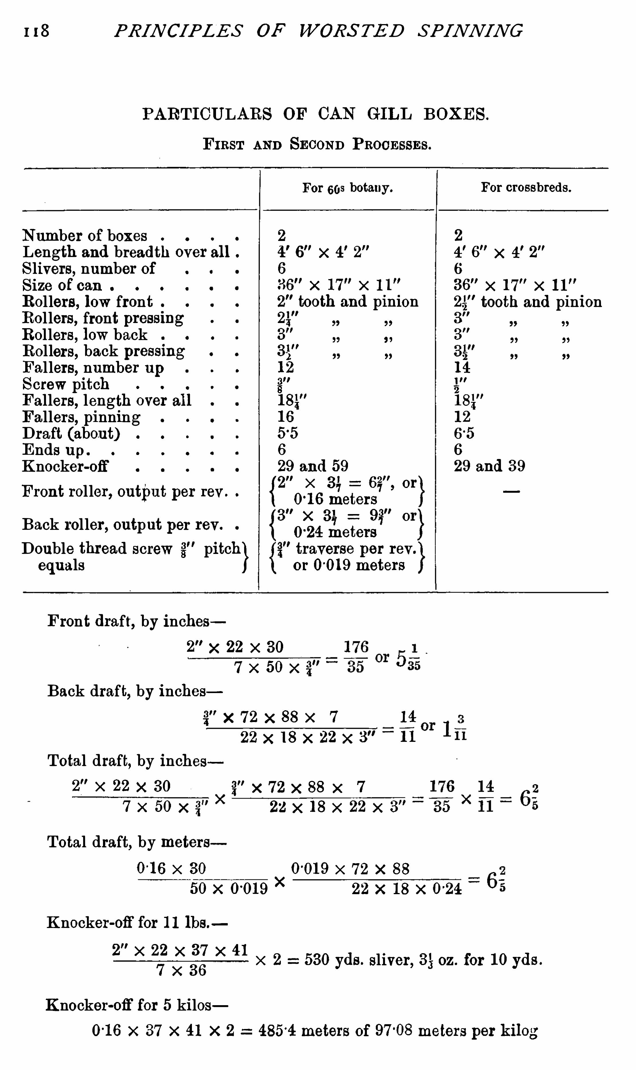
1 18 PRIN CIPLES OF WORS TED SPINNING
PARTI CULARS OF CAN GILL BOXES.
F I RST AND SECOND PROCESSES.
For 608 botany. For crossbreds.
Number of boxesLength and bread th over all .
Slivers, number ofSize of canRollers, low frontRollers, front pressmgRollers, low backRollers, back pressmgFallers, number upScrew pitchFallers, length over allFallers
,pinning
Draft (about)Ends up .
Knocker-ofi‘
Front roller, output per rev .
Back roller, output per rev .
Double thread screw 3" pitch}equals
Front draft, by inches2"x 22 >< 30
7 x 50x 3"
Back draft,by inches
141
22 x 18 x 22 x 3" “
11
Total draft, by inches§"x 72 x 88 x 7
7 x 50 x 3" 22 x 18 x 22 x 3"
Total draft,by meters0-16 x 30 0
-019 x 72 x 8 8
50x 0019x
22 x 18 x 0-24 6
Knocker-ofi'
for 11 lbs.
2"x 22 x 37 x 41
7 x 36X 2 530yds. sliver, 3 ; oz. for 10yds .
Knocker-ofi'
for 5 kilosx 37 x 41 x 2 4854 meters of meters per kilog
2 2
4!
6"x 4
!
2"
6"x 4
!
2M
6 6
36"x 17 x 11 36
”x 17
"x 11
2"tooth and pinion 25
"tooth and pinion
2p:
3"
3"
3"
35"
12 14
g"
18k"
16 12
55 65
6 6
29 and 59 29 and 39
{2" x 31, or
meters3 x 31, 92 or
024 meterstraverse per rev
or 0019 meters

DRAWING 1 19
ELEVATION.
PLAN.
ELEVAT ION.
FIG. 46 .—Cangil l box .

120 PRINCIPLES OF WORS TED SPINNIN G
screw rotates in a circle four inches in diameter,it follows
that it must travel about 300 X 4 x 371 or 3643 in. per minute,
or 5 ft. per second,and every faller will therefore be driven
down on to the low saddle at this velocity . To enable the
fallers to withstand this rough usage, it is necessary to make
them of the very best steel,and even then it is not surprising
that a very large number are broken . We are so accustomed
to many of the effects of gravitation that we are apt to ignore
some of its most logical consequences,and in the case of
fallers the consequence of the sudden stoppage has to be
guarded against,for there is always a natural inclination for
the faller to rebound from the solid s teel saddle, and the cams
must be so constructed that they not only push the faller
down, but hold it down long enough to overcome any tendency
to rise and jamb against the upper saddle.
Inaddition to falling on to the low saddle,it is
,of course,
necessary that the faller should drop accurately into the
thread of the lower screw . This is effected by careful adjust
ments of the screws and by the position of the cams and
saddles.
To reduce the number of fallers which are necessary
to complete a set,the low screw is always cut at a faster
pitch than the upper one ; that is to say, that if a faller
travels the whole length of the upper screw in14 revolutions
itmay traverse the length of the low screw in 7,so that when
both screws are rotating at the same speed,as they always
must do,there will only be 7 idle fallers in the low screw,
whilst there are 14 doing their work in the upper one.
In double thread screws,the relation of the lower and
upper screws to one another remains exactly the same,but in
each of them there are now two entirely separate threads,
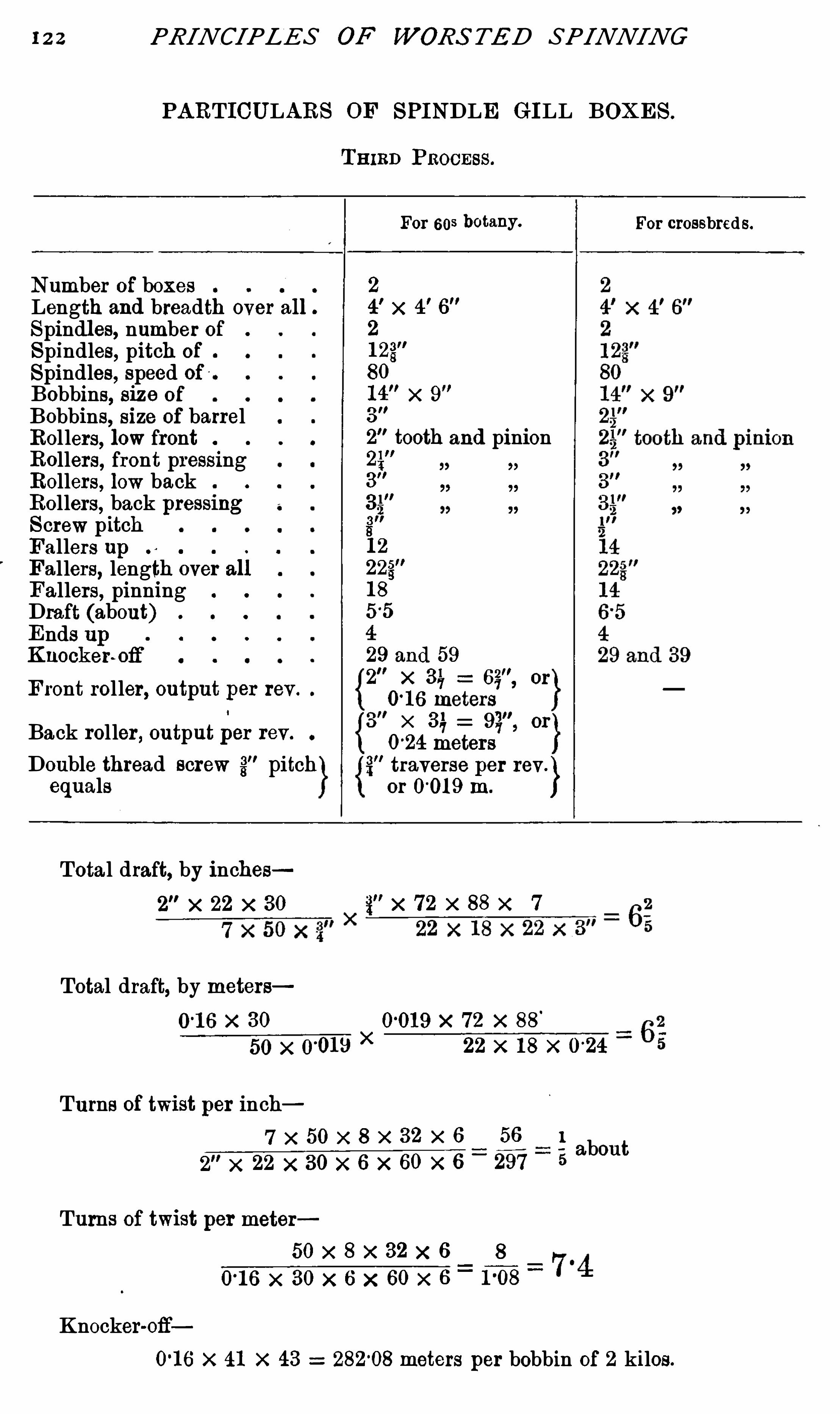
22 PRINCIPLES OF WORS TED SPINNING
PARTICULARS OF SPI NDLE GI LL BOXES.
Number of boxesLength and breadth over all .
Spindles, number ofSpindles, pitch of
Spindles, speed ofBobbins, size of
Bobbins, size of barrelRollers, low frontRollers
,front pressing
Rollers, low backRollers, back pressmgScrew pitchFallers upFallers, length over allFallers
,pinning
Draft (about)Ends upKnockenofi
’
F ront roller, output per rev .
Back roller, output per rev.
Double thread screw 3" pitchequals
T3 13 1) Pnocnss.
For 608 botany.
Total draft, by inches
Total draft, by metersx 30 0019 x 72 x 8 8
50x 0-010
X
Turns of twist per inch56
2 x 22 x 30 >< 6 x 60 x 6_297
Turns of twist per meter50x 8 >< 32 x 6 8
0'
16 x 30x 6 x 60 x 6_1°08
Knocker-ofi
22 x 18 x 024
about
For crossbred S.
01 6 x 41 x 43 28208 meters per bobbin of 2 kilos.
2
4!
x 4!6"
2
123"
80
14"x 9
3"
2"tooth and pinion
24"
3"
Si],
3"
s
12
18
29 and 592 x or
016 meters3 x 31, or
024 meterstraverse per rev .
or 0019 m.

DRAWING
F IG. 47 .—Spindle gill box .
12
ELEVAT ION .
PLAN.
ELEVAT ION .

124 PRINCIPLES OF WORS TED SPINNING
and make places where the edges of the sliver are frayed or
turned back .
Second Process—Fine botany material is almost alwaysput through a second cang ill box, which resembles the first in
every respect, but as the slivers going into the box are now
contained in cans, from which they run easily without getting
twisted, the creel is replaced by light brackets supporting
smooth guides , over which the slivers are drawn to the back
roller. Each guide should be exactly over the centre of one
division of a can,so that the sliver is therefore lifted w ithout
rubbing against the sides . This av oids all chance of the
sliver being torn by contact w ith ragged edges on old or
damaged cans . In every other respect, excepting in the size
of the sliver and possibly the draft and the number of ends
up, the first and second boxes are alike ; but in crossbred
qualities or botany drawings,which are to be used for very
thick yarns, the second process is sometimes omitted, and a
creel is then put up behind the second box, and both can gill
boxes are used for the first process.
Third Process—Spindle Gill Boxes—The practice of build inggill boxes in such a way that they can only produce two
slivers is probably due to the excessive strainthere would be
on fallers long enough to take three or four slivers side by
side .
Inthe first place,practice shows that extra length causes
many more fallers to break,as they drop on to the lower
saddle ; and in the second, the strain of drawing the three
slivers wou ld be so great, that it w ould soon pull a three
eighths faller out of shape . In spite of this drawback it is
still usual to have very long fallers in the spindle gill boxes,
simply because people prefer to make a small saving in first

126 PRINCIPLES OF WORS TED SPINNING
treated satisfactorily in gill boxes, and the suitability of a
sliver for gilling must have some relation to its size. InTable
I .,p. 106, gilling ceases where the sliver has been reduced to
142m. per kilo, whilst in crossbred qualities which~are stillmore suitable for treatment by gilling, it is discontinued when
the sliver is twice that thickness, vie. 78 m . per kgo . Ina botany
drawing, intended for very thick counts, the same rule would
apply,and if it were found by experience that square cans
were not suitable for a third process,there can be no possible
doubt that sliver of 200 111. now treated in the second drawing
box,w ith twist and withou t fallers, could be easily run from
circular coiler cans, so that it could have the extra advantage
of being treated by two extra gilling processes . At all events ,
in thick sorts, an extra gilling process could be introduced
with saving in both cost and wages .
Flu ted'
R0llers.—
,To understand what is the output of
fluted rollers under various conditions it is easiest to consider
first, what is the output of a pair of smooth rollers doing
similar work . A pair of 2 in. smooth rollers making 100
revolutions per minute would deliver 100 x 2 X 3 ; or 628
in. per minute, which is their calculation output. I f the
same pair were run with a leather over the lower roller ,
it would move just the same distance in the same time, and a
sliver drawn by smooth rollers, with or without a leather, would
be delivered at exactly the same rate. With fluted rollers the
output under these three conditions would be different in every
case, and there would also be a difference in output with thick
and with very thin slivers.
The output of fluted rollers is often said to be 3 ; times the
diameter of the mean line A, Fig. 48,halfway between the tips
and the deepest part of the flutes ; but as a matter of fact, the

D RAWING 127
length of a line drawn from point to point of the flutes all
round the roller may be taken as equal to the minimum out
put. This is very nearly equal to times the diameter over
the flutes,and as the output is always varying, this figure will
be used in following calculations, but it must be remembered
that gill box rollers often turn out a great deal more than this
amount.
I f a very thin tape were run through two bare steel-fluted
rollers (Fig. 48 ) under heavy pres
sure,the output per revolution would
nearly equal the total length of the
line B,representing the outside of
the driving roller, or five times the
diameter of the mean line A. With
a thick leather, which could not be
pressed so deep into the flutes,the
length would come much nearer to
34times the total diameter, and the
output of sliver from such a pair of
rollers,with a leather on them
,
would naturally be less than the
output of the same sliver from the Fm. 48 .
rollers working without a leather.
The draft calculations in preparing and other gill boxes
come very nearly accurate, because the sliver, coming through
the back rollers, is many times the thickness of the sliver
between the front rollers. The thick sliver keeps the back
rollers apart, and effects their output very nearly to the same
extent as the leather and sliver together affect the front
rollers.
The Knocker-ofif—I a order to ensure that the sliver as it

128 PRINCIPLES OF WORS TED SPINNING
comes from the front rollers is of the right weight per
yard, it is necessary that it should be accurately measured ,so that the length on each bobbin may be known . Each
bobbin is weighed when full,and after the nett weight
of the empty bobbin is deducted,the weight of wool
,divided
by the length of sliver,w ill show the exact weight per yard.
The piece of apparatus used
on any machine for this purpose
is known as a knocker-off,because
it stops the box when the required
length has run on to the bobbin
of the spindle gill box. On the
sp indle gill box, as well as on the
cangill boxes,the type of motion
PLAN used is that known as the candle
stick ” (see Fig .
The wheel C has usually an
indivisible number of teeth, such
as 43,and on it there is one tooth
which proj ects beyond the others .
On the wheel D there is a similar
tooth,and when the two wheels
Fm. 49 .-Knocker-off.
are in gear and the teeth start
from a point exactly between the
centres of the two wheels,each wheel must move a number
of teeth equal to the least common multiple of the number of
teeth inboth wheels,before the proj ections meet again . 1763
is the least common multiple of 41 and 43 , and hence it
happens that the wheel C will revolve just as many times
as there are teeth in D before the projecting tee th meet
again.

130 PRINCIPLES OF WORS TED SPINNING
spindle,so that all the resulting slubbing bobbins would be
exactly alike .
Fourth Process—First Drawing Box—This is the first
process in which the sliver contains twist as it enters the
back rollers,and there are two visible alterations in the
machinery for the necessarily altered treatment.
The presence of twist binds the fibres so closely to one
another,that the pins of the fallers could not move freely
through them without breaking many fibres,and consequently
fallers are no t used . Their absence makes it necessary to
have a very much shorter ratch,and the back and front
rollers are only set a fraction of an inch further apart than
the length o f the longest fibre. To prevent slipping of the
short fibres in the absence of faller pins,carriers are here
introduced for the first time . The lower carrier roller revolves
at about 15 times the surface speed of the back roller, and it
carries an upper roller of wood,which has sufficient dead
w eight in itself to prevent the short fibres being carried
forward by friction to the front roller,but not sufficient
weight to prevent long fibres being drawn under it,as soon as
they are caught in the nip . The second pair of carriers
revolve slightly slower than the fi rst,with only a very slight
lead on the back rollers. Inthe back rollers themselves there
is the greatest alteration. The pull necessary to withstand
the draft in the twisted sliver is so great,that
‘
a single pair of
smooth rollers could not possibly hold the wool, and con
sequently there are four rollers,all of equal size, arranged one
above the other in such a way that there are three nips,
through all of which the wool goes . This arrangement might
be u sed with equal advantage for spindle gill boxes where
smooth back rollers are deemed an advantage. All the rollers

DRA WING 13 1
carry wheels which have an equal number of long teeth , so
arranged that when the rollers are resting on one another, or
even when they are separated by wool, the wheels are still in
gear and every roller of the group is bound to rotate with the
Same surface velocity. This arrangement gives such a firm
grip that it is absolutely impossible for any fibres to slip
through the rollers .
Front rollers differ much less in the manner of their
arrangement than back rollers . Inevery process they consist
of a single pair,and with the one exception of gill boxes
,the
lower roller is always of smooth metal,scratch-fluted , whilst
the upper one may be of wood,paper
,cork
,or metal
,covered
with some medium such as leather,cork
,cloth and leather, or
cloth and parchment,to give elasticity and make it possible
to apply heavy pressure without cutting the fibres. Both
roller s might be elastic if d esired,but elastic materials
naturally wear much faster than iron or steel,and it is
necessary to have the size of the low (driving) roller constant ,
so that the output is always the same under all conditions .
The size of the pressing roller is a matter of no moment,
because it is pressed so tightly against the low roller that the
one cannot possibly slip on the other. The surface traverse
of both mu st be identical,and therefore when the surface of
the upper roller is worn,it can be turned down without in any
way affecting the output.
P ressing Rollers—Very early in the history of roller draft,pressing rollers were made of wood covered with leather
,and
so well have they done their work that many of the rollers
in use to—day are of this type. Whenever wood is u sed for
machinery it is unfortunately liable to warp and split,and in
spite of the extreme care taken in the preparationof the wood
132 PRINCIPLES OF WORS TED SPINNING
u sed for roller bosses,they seldom remain absolutely true for
any great length of time . The smaller ones,which were
always made from a single piece of wood,were very liable to
split in working, but larger rollers were made of segments of
wood screwed and glued together on to an iron centre . When
turned up and covered w ith one or two thickness of stout
sole-leather,turned up and polished, they make a roller most
elastic,and in many ways very suitable for its purpose
,but
badly wanting in s
permanence, so that for many years, it has
been the ambition of makers to substitute iron for wood .
Where both upper and lower rollers are of iron,it follows
that the leather covering of the former is continually being
rolled between two metal surfaces,under heavy pressure
,and
as this treatment always tends to extend the leather, it was
found very difficult to keep a leather fast to the upper roller
by means of any kind of glue or cement,and of course the
necessity for absolute uniformity of face precludes the use of
nails or stitching. The greater adhesive power of glue with
wood,made wooden rollers much easier to cover
,so that until
recently,wood has been the favourite material for roller
bosses (see Appendix C) .
Of recent years the art of stretching leather,together with
an improvement in the kind of cement or glue used,has
lengthened the life of leather on iron rollers so much,that they
do not require cov ering oftener than wood,and they remain
true under much more adverse circumstances ; for these
reasons they are rapidly coming into general use.
Leather covering is far from permanent on rollers, however
well they may be covered, but as yet nothing has been found
to supersede it,although many efforts have been made to
do so. The substitute which most nearly succeeded was a

13 1 PRINCIPLES OF WORS TED SPINNING
PARTI CULARS OF FI RST DRAWING BOX .
FOURTH PROCESS.
For fine botany, 603 andabov e .
For crossbreds.
Number of boxesLength and breadth o ver all .
N umber of spindlesPitch of spindlesSize Of bobbinSize Of bobbin barrelLow front rollersFront pressing rollersBack rollersLow carriersTumblersDraft (about)Ends upSpeed Of back ShaftType Of lifter motionType Of knocker-offSpeed Of spindlesFront rollers, output per rev .
Back rollers, output per rev .
Back shaft,re vs. per min.
Draft,by inches
4 x 22 x 100 x 84 >< 7428
7 x 33
Draft, by meters032 x 100x 84
44 x 6 3 x 020Turns Of twist per inch
7 x 154 >< 9 x 6 441 11
4 x 22 x 46 x 11 x 6 2024 5 1turns Per inch
Turns of twist per meterl54 >< 9 x 6 63
8lt t
032 x 46 x 11 x 6 7 36 5“r“ per me er
Lifter, strokes per minute03 5 x . .6 x 5
l 1
6,6"x 10
,
6,6"x 10
,
123"
123"
14"x 9 14
"x 9
3 2%I I4 scratch fluted 4
"scratch fluted
covered double cloth and leatherhard laced
Four inset Four inset
1”
1"
1 and 15"wood 1
”and 15
"wood
55
4 5
200 200
Mangle Mangle3 wheels 3 whee ls160 160
4 x 121—1, or
032meters
x 3 ; or
020meters
160

DRAWING 135

f
130 PRINCIPLES OF WORS TED SPINNING
covered,they naturally do not run quite as true as hard
covered rollers when they are on the frame,and they look
most unlikely to do good work to any person who is only
accustomed to the use Of hard rollers. Many people will
have nothing to do with them for long crossbred qualities,but
the fact remains that there are sorts for which they must be
used (Appendix C) .
The draft depends entirely on the relation of the output
of the back rollers to the output of the front rollers,and as
both pairs are now smooth, instead Of being fluted like the gill
box rollers,the actual and calculation figures may be made to
fi t with considerable accuracy. I t will also be noticed that
there are very few wheels in the train that connects these two
sets of rollers,and the calculation is therefore very much
simpler than that necessary for gill box drafts . Furthermore,
the draft always bears some definite proportion to the draft
wheel,so that any alteration is only a matter Of simple
proportion.
Where the same figures are in constant use it is,of course
,
unnecessary to work through the whole draft calculation each
time a change is made,and when an average draft has once
been worked out,it is common to notice its relation to the
draft wheel,and to say
,for instance, that a 44 wheel equals
a draft of 6 ; taking these figures as a basis for all future
calculations, and making such calculations a matter Of simple
proportion . This system Of reckoning is particularly
applicable to the method in common use,which is always
based on the actual, rather than on the calculated size of sliver.
I f the sliver is found to be too heavy or too light, on weighing
a bobbin,it is reduced or increased as desired . For instance
,
a bobbin which should weigh 5 lb . net,only weighs 4 lb. 14 oz .

138 PRINCIPLES OF WORS TED SPINNING
at a greater distance from the centre of the bobbin,and hence
the amount by which they retard rotation is increased still
more than appears at first sight. To calculate the drag would
be such a difficult matter, that it is never attempted, and in
practice the amount of strain on the sliver is always judged
by feel
In following the course of the material through the
remainder Of this drawing,we shall consider that in all
particu lars the boxes resemble those d escribed in Table I .,p .
106,and for the sake Of simplicity the wheels which effect the
draft are arranged to give a draft Of 6 with a 44 wheel on a
2é-in. front roller,and with a 1§-ih . back roller.
2; x 100 x 100Thus
63 x 44 x 15~ l_68 00
and when there are 4-in. front rollers and 2-in. back we
4 X 8 4 >< 100
44 x 63 X 2’
larger fraction,eke. 63
23 .
Thus with five ends up in the first drawing box we get
170m . sliver, and if each Of the 14 X 9 bobbins hold s 5 k g .
the front rollers must revolve 5 X 08 X 170, or 580 times
might take which gives a figure with a
before the bobbin has received the de sired quantity .
Wi th the exception of the size of the bobbins and the
number of ends up behind the back rollers, the two second
drawing boxes, the finishers, and the slubbing are so much
alike that reference will not be made to each in detail, as full
particu lars are given in the tables on pages 139 and 140.
Inthis and the following boxes the knocking-Offmotion is
u sually of a d ifferent type to that used in the gills. I t is
a simple arrangement of worms and wheels so placed that on
each revolution of the final wheel,a peg in its circumference

DRA l/V I N G I 39
PARTICULARS OF SECOND DRAWING BOX .
Fmrn PROCESS.
For 608 botany. omitted for somecrossbreds.
Number Of boxesLength and breadth over all .
N umber of spind lesPitch of spind lesSize Of bobbinSize of bobbin barrelLow front rollersFront pressing rollers. I ronBack rollersLow carrie rsTumblersDraft (about)Ends upSpeed ofback shaftSpeed of spindlesType of lifter motionType of knocker-Off
PARTICULARS OF THIRD DRAWI NG BOX .
e 'rnPROCESS.
For 608 botany. For crossbreds.
Number of boxesLength and breadth over all .
Spind les, number ofSpindles, pitch Of
Spindles, speed of .
Bobbin , size of .
Bobbin , size of barrel .
Rollers, low front .
Rollers, front pressing I ronRollers, backCarriers, low
Carriers, upper. TumblersDraft (abou t)Ends upSpeed Of back shaftLifter motionKnocker-off
For all calculations for these processes, see fourth process or first drawing
1 1
8'10 8
'10
6 6
11%N ll§l l
14'x 8 14
’
X 8ll! 25
12
"
4"
4M
7 Covered double Cloth and leatherhard laced
2L],
2éfl
l"
1"
1"and Wood 1
"and 15
"
5 5
5
200 200
180 180
Mangle Mangle3 wheels 3 wheels
1 l
9!
2 X 10! 9,
2"x 10
,
8 8
loan
200 200
14I l
x 7"
13I Ix 7
fil l
214I I
4"
4"
Covered double Cloth and leatherhard laced
212
i !2é
’ l
1"
1"
1"and I t
". Wood 1 and I t
". Wood
5 5 6 5
3 3
200
Mangle Mangle3 wheels 3 wheels

140 PRINCIPLES OF WORS TED SPINNIN G
PARTICULARS OF FIN I SHING BOXES.
SEV ENTH PROCESS.
For 608 botany. For crossbreds.
Number Of boxesLength and breadth over all .
Spindles, number ofSpindles
,pitch of
Spindles, speed ofBobbin
,size Of
Bobbin, size o f barre lRollers
,low front
Rollers, front pressing. I ronRollers
,hack
Carriers, low
Carriers, upper. TumblersDraft (about)Ends upSpeed Of back shaltLifter motionKnocker-ofi'
PARTI CULARS OF SLUBBING BOXES .
EIGHTH P ROCESS.
For 608 botany . Not required for crossbreds.
Number Of boxesLength and breadth ove1 all .
Spindles, number OfSpindles, pitch Of
Spindles, speed Of .
Bobbin , Size Of .
Bobbin , size of barrel .
Rp llel s,low front .
Rollers, front pressing. I ronRollers, backCarriers, low
Carriers, upper. TumblersDraft (about)Ends up .
Speed of back shaftLifter motionKnocker-Off
For all calculations for these processes, see fourth process or first drawingbox , making the necessary alterations insizes Of wheels.
2 2
8’6"x 10
'11
'6" X 10'
8 8
95"
931"
230 230
11 X 6 11 or 12 X 62"
2"
4"
4"
Covered double Cloth and leatherhard laced
112
"2g
:
1"
l"
1"and Wood 1
"and Wood
55
3 3
200 200
Mangle Mangle3 wheels 3 wheels
2
16’
9"x 8
’
24
711!
380
9”x 5
lg] ,
4"
Covered doublehard
2”
1"
g"and 1 Wood
6
2
MangleN one

142 PR I N CI PLES OF WORS TED SPINNING
PARTICULARS OF ROV I NG BOXES .
Number ofboxesLength and breadth over all
Spindles, number ofSpindles, pitch Of
Spindles, speed OfBobbin
,size Of
Bobbin , size Of barrelRollers, low frontRollers, fron t pressing. I ron
Rollers, backCarriers, low
Carriers, upper. TumblersDraft (about)Ends upSpeed Of back shaftL1fter motionKnocker-ofi'
Output of front roller per rev .
Output Of back roller per rev .
Draft by inches7
TENTH PROCESS.
For crossbreds.
Draft by metersX 100 X 100 5000
744 x 63 x 0~16 _ 603
Twist ininches
Twist per meter135 x 125 X 8
Lifter with back Shaft 300300 x 2 x 31 >< 22 x 5
Speed of spindles8
7 x 135 >< 125 x 8 11251
4 x 22 >< 48 x 70 x 2_704
1125
5
g plcks up and down per minute
300 X 2 1200revolutions per minute
9
or X r n r
18 4 x 3 6
32
4%I I or 5 6"
1200 1000
5"or 6
"x 3 6
”or 7 x 4
11325"
4"
4
Covered double Cloth and leatherhard laced
2"
2
i’
: ifg’
or g 2'or g
"
6
2 2
300 250
Mangle MangleNone None
metersor 4 X
01 6 meters or 2 X

DRA WING 143
I ntheory, smaller rollerswould be better inall the boxes Of a d rawing madeexpressly for short wool , because when the nips of the back rollers, carriers, andfront rollers can be set nearer together, they have more control over topscontaining a large percentage of short fibres ; but as they need more pressureto Obtain the same amount Of grip as larger rollers (see p. they have beenknown to heat if overloaded . Their output is, therefore , apt to b e less, and theycanonly b e used economically inspecial circumstances.
For all calculations, the writer alone is responsible, and in nearly all of
them, Sizes Of wheels have been used,which reduce the calculations to the
simplest possible form . Inpractice,other sizes would be used, which make the
fractions far more intricate .
F IG. 5l .—Roving box .

144 PRIN CI PLES OF WORS TED S PI IVN I N G
pushes a catch from a spring, and by so doing throws the
belt-fork over the loose pulley and stops the box .
P elee/lugs—The taking out of piecings needs too much
manual dexterity to be possible of lucid description here, or in
any book. The process must be learned at the machine,but
it is well for every student to remember,that
5in all boxes
where there are no fallers,it is a practical impossibility to
make a piecing behind a box,which will not show after
drafting ; and consequently the plan usually adopted is to
make a piecing of such a nature that it is clearly v isible after
it has come through the front rollers . The box must bestopped after each piecing has gone through the rollers
,so
that the lump which it causes in the sliver can be taken out .
I f this precaution is not taken,very serious defects are certain
to occur in the yarn . Matters of this kind are really quite
outside the range Of the theorist ; they are practice pure and
simple,and they are only mentioned here
,because however
perfectly a drawmg may be set and equipped, a manager
would have no chance of getting uniform work,unless these
points were well arranged and carefully carried out.
Reducing and roving boxes differ so much in appearance
from the drawing boxes which precede them that it is worth
while to consider in what the essential differences consist.
1. Each box contains many more spindles , because the
weight of sliver delivered by each roller is so small,being
less than one-fortieth the size of the sliver at the first gill box.
2. The spindles run a great deal faster than those Of the
earlier boxes . This is necessary because the reduced sliver
requires many more turns to make it proportionately as strong
as the thick sliver from the Spindle gill box . The word
tr ong is not used here as signifying the amount Of weight

146 PRI N CI PLE S OF WORS TE D SPINNING
In all fly spindles the size of the bobbin invariably has
soma effect on the drag,and as the roving is only capable of
bearing a strain in proportion to its size, the bobbins have to
be reduced at every“
process through the drawing ; many roving
bobbins being only 5 X 3 in . In cone drawing this is not thecase . There
,the size of the bobbin can be increased without
increasing the strain in filling it,but when the rov ing comes
to be unwound on the spinning frame, there is another strain
pu t upon the yarn which varies with the weight of the bob
bin,and when fine counts are to be spun from rovings on very
large bobbins,this extra strain affords extra opportunity
for uneven work,unless some special means is taken to
obviate it.
Spindle Drive—The belts which are used to drive the
spindles in all the drawing boxes are so muchmore powerfu lthan necessary
,that there is very little fear of the twist in the
sliver ever being less than calculated,but in the reducing and
roving boxes there are so many fast running spindles that it
would involve great waste Of power to run so many compara
tively heavy belts, and the spindles are therefore driven by
bands of twisted cotton,which are stretched tightly over a
grooved pulley on the back shaft and over the whorle. Be
cause the whorle does not rise and fall,as in a spinning frame ,
but always remains at a constant distance from the back
shaft,this system is fairly efficient. Tension pulleys on the
same principle as those used for spinning frames have been
tried with a view to saving power,but as the strain on the
band never varies very much,they are not generally thought
to be necessary. The half-round section of the whorle groo ve ,
which is the type in most general use, is not calculated to
secure the greatest amount of grip on the band, and several

DRAWING 147
arrangements have been attemp ted to increase the friction
without undue complication of parts, but a deep narrow V
shaped nick,which would grip the cord, is never used on the
spindle .
D0fitng .
—There is another point of practical importancewhich may seriously affect output
,and which becomes more
important in each succeeding process as the bobbins become
smaller and fillmore rapidly. This is the method by which
the full bobbins are removed from the spindles and the
empty ones replaced . The more rapidly this can be done, the
more work will the box turn out in a week. No bobbin can
be removed from a flyer spindle until the flyer has first been
removed. In small spindles,such as reducing
,roving
,and
Spinning, the flyer is detached from the spindle and the
bobbin lifted over the spindle top ; but in the drawing,
finishing,and slubbing boxes
,which resemble one another
,the
flyer is fixed permanently to the spindle, and both have to be
removed before the bobbincan be taken away. The Spindle
head is carried in a bearing to steady it,and the spindle
itself goes through a hole in the lifter-rail so far that its
square end fits into a square hole in the footstep,which itself
stands on a short spindle and is driven by a belt from the
main shaft.
From the position of the rollers it is always impossible to
lift a spindle straight up out of the footstep, and they are
generally so arranged that they must be disengaged from the
bearing at the top, then leaned forward and finally lifted
right out Of the footstep,the lifter-plate
,and the bobbin.
In order that the spindles may be run at the highest
possible speed without vibration, it is essential that they
should be absolutely fast in both top and bottom bearings, and

148 PRI N CIPLES OF WORS TED SPINN ING
to ensure that this is SO, several ingenious arrangements have
been devised which make it very easy to free the head of the
Spindle prior to doffing ; and to lock it quickly and tightly in
its place when the operation is complete.
The method of doffing roving and reducing boxes is
worthy Of attention , because they differ from the drawing
boxes in having the flyer separate from the’
spindle, and so
arranged that it must be lifted Off before the bobbin is
removed . The position of the spindle in regard to the front
roller makes it impossible to take off the flver and the
bobbin, until the spindle has been brought forward, and as
it is desirable to do this w ithout taking the bands off the
whorles, and without stretching them unduly, the spindle
rail is hinged at both ends,at a point exactly in a line with
the whorles, so that all the upper end of the spindles may be
tilted forward without increasing or diminishing the distance
from the whorle to the driving shaft. As soon as the
spindles are tilted the flyers and bobbins can easily be re
moved, and when empty bobbins have been replaced, the
spindle can be made vertical by a few turns of the screw
which moves the spindle rail.
Drawing Lifter Maliens—In a later chapter on spinning frames the necessity for having a trav erse which
moves with equal v elocity at all points on the up and
down strokes is explained at length,with special regard
to hearts and cams. For reasons there given, it would be
quite impossible to use a crank, and it would be most in
convenient to obtain a 14-in. traverse from any type of
heart. A motion is therefore adopted which is known as a
mangle wheel.”
In the larger boxes the lifter plate is attached to a rack

CHAPTER V I
CONE DRAWI N G
Cone Drawing—In theory, cone drawing differs from open orord inary worsted drawing, solely in the methods of winding
the sliver or roving on to the bobbin. Inpractice
1st. There is no difference between the methods of draft
ing in the two systems, though the construction of some large
cone boxes makes it necessary to use a greater number of
wh eels in order to obtain the draft calculations.
2nd . The twist, or relation Of roller speed to spindle speed,
is the same in principle,but the necessity of having a positive
relation between the spind les and the bobbins,in cone draw
ing makes it necessary to drive the spindles positively, and
involves the use of bevel wheels instead of bands to drive
them . This brings many more wheels into use,and makes
the twist calculations more complicated than with band‘driven spindles.
3 rd . In both Open and cone draw ing the relation of the
speed Of the bobbin is always altering in relation to the
constant speed of the spindles. This alteration is not uniform
at different parts of the doffing, but is relative to the number
of layers which hav e been wound on to the bobbin,or
,in
other words, to the diameter of the wool on the barrel .
4th. The essential difference between the two systems lies

CONE DRAWIN G 15:
in the fact,that in Open drawing, the yarn, after going
through the eye of the flyer, must pull the bobbin round, and
must therefore be always under tension , which may be very
slight and very nearly uniform,if all necessary adj ustments
are carefully made .
Incone drawing, the bobbin is positively driven through
out the entire process Of filling,at speeds varying in relation
to the diameter of the wool upon the bobbin,so that the
sliver may run all the time without any drag whatever. But
it must be borne in mind that if there is the slightest error in
the intricate calculations necessary to ascertain the required
speed of the bobbin , at every part of the doffing ,there may
not only be drag,but there must be an actual drafting
,or
breaking of the sliver between the roller and the flyer.
The crowning difliculty lies in the fact that the accelera
tion which the bobbin must receive from one layer to the
next,differs at different times during the fi lling. I f it is
assumed that every lap is 115 in. thick,
each layer will add126,
which is one-eighth part of the diameter of a 1-in. barrel ;
whereas the same is only one-twenty-fourth part of the
diameter of the same bobbin when it has been filled up to a
size of 3 in.,and therefore the acceleration must vary between
these two extremes.
This is a superficial summary of the differences between
theory and practice . The practical points which need atten
tion must be grouped under more numerous headings.
lst . The figures for the drafting calculations of cone boxes
are so simple,and so similar to the figures for open drawing that
they need no further explanation (see Appendixes A and B).
2nd . The twist calculations are little more complicated ,
and only differ from those of the open drawing, in having the

152 PRI N CIPLES OF WORS TED SPI N N I N G
spindle connected by a series of toothed wheels,and not by
bands or tapes with the chain of gearing from the front roller
(see Appendixes A and B) . These calculations must be
thoroughly understood,because
3rd . The speed Of the bobbin is controlled by two distinct
motions. There is one chain of wheels, which alone would
give to the bobbin exactly the same constant speed as that
of the spindle,all the wheels in the two series being equal
in size .
4th. To this speed, another variable speed is added in the
differential motion, and this is regulated by the cones and the
gearing which is attached to them.
5th. The speed Of the upper cone is constant and positive,
but the speed of the lower one is altered at each rise and fall
of the lifter, to compensate for the increasing diameter of the
bobbin. The shape of the cones is such that the alteration in
the acceleration in the lower cone ought to coincide exactly
w ith the increase in the diameter Of the bobbin at each lap .
6 th. The belt is moved along the cones, say 1 in. for every
lap that is added to the bobbin, and the cones are made insuch a way that this uniform traverse of the belt fork makes
a uniform reduction in the speed of the lower cone at all the
different portions of the traverse.
7th . The traverse of the belt fork is regulated by the gear
which is known as the “ box of tricks .” This complicated
mechanism is arranged to move the belt fork with the belt,
a uniform distance along the cones, every time that the
traverse motion has added one complete lap to the bobbin ;that is, the fork is moved as the lifter reaches the top, and is
also moved to the same ex tent, or less or more, according to
circumstances,j ust as it reaches the bottom .

154 PRI I’
VCIPLE S OF WORS TED SPIN N I N G
therefore be either added to, or subtracted from,the positive
constant spindle speed, in the differential motion.
In the appendix, for the sake of simplicity, the cal
culations of the constant and the variable speeds are made
separately from the driving shaft to the bobbin,so that if the
two he added together the speed of the bobbin may be asoer
tained when the strap is on any particular part of the cones
the sizes of the cones being the only figures which vary in
the calculation, during the filling of any given size of bobbin
with any given size of sliver (see Appendixes A and B).
The Swing Frame—I t should also be noted that inworsted boxes there are two different methods in use for
conveying the varying motion to the wheels on the lifter
which drives the bobbin. These wheels mov e up and down
on the lifter with the bobbin,and it is a strange anomaly
that the method in use in reducing and roving boxes is often
so arranged,that it does not move the bobbins equally
,at
‘
different parts of the up and down strokes of the lifter.
The action of the swing frame is fau lty in most worsted
boxes,and unless every user is acquainted with the possible
difference between theory and practice, he will be very likely
to make imperfect work from cone boxes on which it is u sed .
I t is not unusual to find the motion so far from perfect,that
if the whole machine be stopped, and the lifter lowered from
top to bottom,all the bobbins will make more than half a
revolution during the descent, and they will revolve in the
opposite direction to the same extent as they rise.
This means that if a roving frame is set correctly,without
reference to the swing frame motion, so that in theory the
bobbins are taking from the flyers exactly the same amount
as the rollers are delivering, there w ill be an extension

CONE DRAWI N G 155
between the rollers and the flyers of 6 in . each time the l ifter
falls, when the bobbins are 34 in. in diameter. As the lifter
rises, 6 in. of slack will be left between the spindles and the
roller. I t is naturally impossible to run the frame with this
amount of slack sliver resting on the spindle top,and unless
the action of the swing frame is counteracted by some other
adjustment, in the“ box of tricks
,for example
,it will be
necessary to increase the speed of the bobbins,so that on the
ascent, the uptake is equal to the roller ou tput. When this
is the case the uptake is 12 in . more than spind le output,
during the fall of the lifter,and therefore the length Of sl iver
must be extended by this amount,or be broken if it i s hard
twisted .
As a matter of fact 1t is possible to make a fine adjustment
in the “ box of tricks,which is usually regarded as sufficient
compensation for all practical purposes . By this means the
uptake can be made approximately equal to the output on
both the up and the down strokes ; but there is also a varia
tion of spindle speed,occurring during different portions of
each rise and fall of the lifter, as the three wheels of the
swing frame motion take up different positions in regard to .
one another. The amount gained or lost at various parts of
the stroke will necessarily vary in d ifferent machines, accord
ing to the position of the driving shaft in relation to the lifter
rail.
I t is possible to arrange a swing frame drive in such a
way that there is no gain on the down stroke or loss on the
up stroke. Frames with swing frame connections have been
used in the cotton trade for many years,and the theories of
the motion have been so carefully studied,that the best
position for the driving shaft with relation to the lifter is
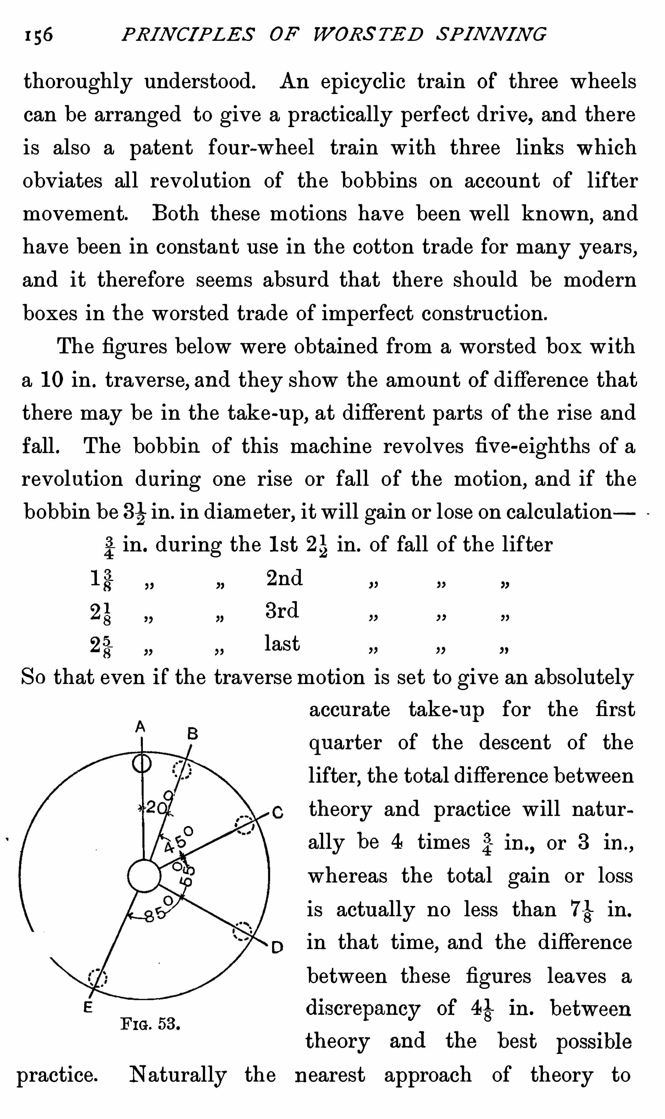
156 PRI N CI PLES OF WORS TED SPINN IN G
thoroughly understood. An epicyclic train Of three wheels
can be arranged to give a practically perfect drive, and there
is also a patent four-wheel train with three links which
obviates all revolution of the bobbins on account of lifter
movement. Both these motions have been well known,and
have been in constant use in the cotton trade for many years,
and it therefore seems absurd that there should be modern
boxes in the worsted trade of imperfect construction .
The figures below were obtained from a worsted box with
a 10 in . traverse, and they show the amount Of difference that
there may be in the take-up, at different parts of the rise and
fall . The bobbin of this machine revolves fiv e-eighths of a
revolution during one rise or fall of the motion, and if the
bobbin be 34in. in diameter, it will gain or lose on calculation
2in. during the lst 25 in. of fall of the lifter
13 2nd
3rd
25 last
SO that even if the traverse motion is set to give an absolutely
accurate take-up for the first
quarter of the descent of the
lifter,the total difference between
theory and practice will natur
ally be 4 times 2in., or 3 in.,
whereas the total gain or loss
is actually no less than in.
in that time,and the difference
between these figures leaves a
practice. Naturally the nearest approach of theory to

158 PRI N CIPLES OF WORS TED SPI N N I N G
on the lifter,and is driven by the wheel B
,which also rises
and falls with the lifter ; but B is drivenall the time by the
vertical shaft C,on which it is free to slide, having a key
fitting into a long keyway in the shaft. This simple arrange
ment involves no discrepancy between theory and practice,
and it is very difficult to see why some modification of it is
not used as a substitute for the swing frame .
P I 1. 54.—Parallel motion .
Differential Motion—In Figs. 55,56
,and 57, the driving
shaft X carries the two 72-teeth wheels A and B. Fig. 56
shows a bobbin drive,and Fig. 55 a Spindle drive,whilst Fig.
57 is another elevation of the differential motion,the sw1ng
frame links, and the bobbin and spindle drives. B is keyed
fast to the shaft X,but A is fixed to a sleeve which is con
nected to the shaft only through the differential motion 2,so
that it can gain or lose to any desie extent on the shaft X,
according as the drum of the differential motion 2 (Fig.

CON E DRAWI N G 159
is moved round by the cone gear through the shaft Y. The
intermediate wheels in the two trains of gearing have,of course
,
no bearing on the calculations ; they are different in size, but
with that one exception,every wheel in each train corresponds
,
from the wheels A and B,of 72 teeth each, on the driving
shaft X,to the bevel wheels C and D which drive the collar
F1G. 55.—Spind1e drive . F IG. 56 ,
—Bobbin drive .
and the spindle respectively . Therefore,when the drum of
the d ifferential gear 2 is stationary, the spindle and the
bobbin must rotate at the same speed.
Every time the cones cause the drum 2 to revolve once ,
the wheel W with its sleeve,and the wheel A, make two
revolutions more than the shaft X, causing the bobbins to

160 PRIN CI PLES OF WORS TED SPI N N IN G
gain Six and one-third revolutions on the spindle and flyer.
These calculations make it appear that the spindle and the
bobbin can theoretically be adjusted in exact relation to the
speed of the cone,whereas it has just been shown that in
practice the two speeds are not correctively relative, and
F IG. 57—Differentialmotion and spindle drive.
therefore the ordinary swing frame is distinctly inferior inpractice to the parallel motion which is in use in heavier boxes.
The differential gear itself is well known in many classes
of machinery,and has many various uses ; for the present
purpose it is best regarded as acting only one part. I f the
three bevel wheels U,V
,and W are of equal size
,and if all
have a simple rotary motion, U being the driver, W must

162 PR IN CIPLES OF WORS TED SPIN N I N G
equally tight on whatever part Of the cones it is working .
The very peculiar construction of the cones is necessary in
order to obtain a uniform addition to the speed of the lower
cone,from a uniform motion Of the b elt along their length .
I t is easy to see that this cannot be Obtained with recti
linear cones. I f a pair were so made, tapering one inch per
foot (see Fig. it is true that the belt would always be
equally tight,but the speed Of the lower cone would be
reduced from 180 revs. to 100 revs . that is to say, the speed
would b e reduced by 80 revs . in moving the belt over the
6 0 REVS .
REVS . 18 0
F IG. 58 .
first foot, whereas the movement over the second foot would
only give a reduction Of 40 revs , the third 24, and the last 16 .
This irregular decrease would, Of course, be no use whatever,
and consequently the form of cone adopted , has to be of such a
nature that the added diameters of the two cones are the same
at any point, but they must be so curved, that the reduction of
speed is uniform for each foot or inch which the belt traverses .
Fig . 59 shows a pair of cones which fulfil all these requ ire
ments . With the upper cone running at 60 revs the lower
one makes 180 revs. and 20 revs . respectively,with the bel t
at the extreme ends of the cones,which give a difference

CON E DRA l/VIN G 163
of 40 revs. for each stage, of 1 foot moved by the belt. In
practice the speeds would be calculated for each inch instead
of for each foot of length,but the above examples serv e to
Show the principle involved.
The same results may be obtained from cones of very
varying dimensions,but it is found that the belt traverses
better when they are long in proportion to their diameter .
The figures given do not apply to any cone in use,but are
chosenfor the sake of Simplicity . Insetting out a pair, it is
necessary to decide
6 0 REVS .
REVS .180
FIG. 59 .
1. On a suitable speed for the upper cone.
2. On the amount of reduction in the speed of the lower
cone for every foot or inch traversed by the belt, which must
be in exact proportion to the increase in the size of the
bobbin on the addition Of every successive lap.
3 . The sum Of the diameters of the two cones.
Eight inches has been taken as a convenient figure for
the sum of the diameters, 60 as the speed of the upper cone ,
and 40 revs . as the amount of reduction for every foot moved
bythe belt
,beginning with 180 and ending with 20.
Cones have beenso exhaustively discussed by other writers

164 PRIN CIPLES OF WORS TED SPIN N IN G
in books concerning both cotton and worsted machinery,that
it wou ld be out of place to go into a detailed analysis of the
formula by which their curves are designed . I t is usual to
employ algebraic formulae such as those given in Mr. Buck
ley’
s excellent little book on this subject ; but there are com
parativ ely few people who think in letters, as easily as they
think in figures. I t may,therefore
,be of interest to state the
case in the simplest possible way,leaving all algebra out of
the question .
Inthe first place, it must always be taken as an axiom,
that the diameter of the lower cone at any point along its
length must bear the same relation to the diameter of the
upper cone, that the speed of the upper cone bears to the
required speed of the lower cone. That is to say
I f the top cone is running 60 revs. per minute, and the
lower cone is required to run 180, the diameter of the two
must be in the proportion of 180 to 60, or 3 to 1.
Then,if 8 in. is the sum of the diameters of the two
cones,it is only necessary to divide that figure into two such
parts that they will bear to one another the proportion of
180 to 60. This may be done by simple arithmetic, by adding
the two numbers together (to 240) to form a common d enomi
nator,and then taking of 8 and 5
3100 of 8 .
These two fractions work out to 6 and 2 respectively.
Added together they give 8 , the sum of the diameters,and
when 60,the speed of the upper cone
,is multiplied by 6 and
divided by 2, it gives the requ ired speed of 180 for the lower
cone . D iameters at any other part of the two cones,to give
any desired speed , may be found in the same way.
I f the required reduction Of speed is to be 40 revs . for
every foot of traverse, 140, 100, 60, and 20will be the speeds

166 PR IN CI PLE S OF WORS TED SPINN I N G
in the affirmative,it is to his interest to consider how much
he will gain by having the larger size of bobbins,and reckon
whether the chance of misadjustment in the more compli
cated machinery will outweigh its advantages in regular use ,
as compared with the smaller and simpler open machines,
in which a certain amount of strain must always be present
on the rov 1ng , though the cond itions must be very far wrong
to make the yarn visibly uneven .

CHAPTER V I I
SP I N N I N G
ANY person who makes his first acquaintance with the
Spinning frame through the history of its invention,is
almost certain to regard it,not as a single process
,but as
a combination Of three processes,the invention of which was
separated by many centuries. In this respect he will regard
it more nearly in its true light than does the novice,who
simply sees a complicated series of rollers, wheels , bands,
pulleys, and spindles, fastened in bewildering compactness on
to a single framework. For the easy understanding of the
various problems at issue,it is best to divide the frame into
its three essential parts,and consider them one by one in
practical detail,in relation to one another
,rather than to the
theories of the various parts propounded in Chapter I I I .
In all throstle frames,four processes are in constant
progress .
1. Roving is unwound from the bobbin and carried to
the back rollers by means which are so simple as to be
hardly worthy of mention .
2. The roving is drafted or ex tended by the back and
front rollers,which draw the ribbon Of fibres out to several
times its previous length .
3 . Tw ist is inserted into the extended roving until it is
strong enough to be wound on to the bobbins .

168 PR IN CI PLES OF WORS TED SPI NN I N G
4. By three different means, in the three different types of
frame, the yarn is wound on to the bobbin during the whole
time the spindle is rotating. In this winding-on process it
recelv es the drag which is necessary to build a firm bobbin ,
but from the nature of things the drag is not uniform, and
there are consequent disadvantages .
In early hand-spinning,each of these three processes were
separate,and in the one-thread wheel the winding was not
continuous . In the Saxon wheel winding became automatic
and dependent on the arrangement for introducing twist, but
it was not till a hundred years after the introduction of the
Sax on wheel,that any attempt was made to make the drafting
automatic as well . For an intelligent understanding of the
practice of machine spinning,the relations Of drafting, twist
ing ,and winding on are quite as necessary as an under
standing of the theories which underlie each of these separate
movements.
Three obj ects are attained in all throstle frames .
1. By a simple arrangement of pegs on which the roving
bobbins stand in such a manner,that the d rag of the back
rollers unwinds the roving from the bobbins w ith very little
strain. The only thing that need be said of them is that
the less strain which is put upon the roving the better.
2. As in all other drawing or d rafting processes, d raft
depends entirely on the relation of the output of the back
rollers to the output of the front rollers.
3 . The twist depends on the number of turns made by the
spindle during one revolution of the front roller.
4. The winding-ou depends on the construction of the
spindle and its adjuncts,and on the movement of the lifting
motion,which continually alters the position Of the bobbin in

170 PR IN CI PLE S OF WORS TED SP I N N I N G
weight of the bobbin and reduces friction to a minimum (see
Fig.
Before the roving reaches the back roller it passes through
a gu ide which leads it to its right place in the nip. Inorder
to gu ide the roving into just the right part of the back
roller, each end is taken through a wire twizzle or through a
slit guide,which stands on a bar two or three inches behind
the back roller. I f these guides were not used,the roving
would always be running off the rollers and ceasing to be
drafted, but the duty of keeping the end between the rollers
is only a small portion of the function of the guide,for the
roving is less than one-sixth of an inch in diameter even when
it is under pressure, and it was found that the process of
drafting this narrow ribbon Of fibres caused such wear on one
portion of the leather of the front roller,that a groove was
quickly worn in its centre, whilst the leather on both sides
was untouched .
As soon as the pressure in the middle was reduced by the
thinning of the leather,the front rollers failed to draw all the
fibres which came to them,so that thicker, curly yarn resulted .
To obviate this rapid wear of one portion of the leather,the
back guide is made to traverse slowly backwards and
forwards. For example, if the face of the front roller is
in. wide,the traverse may be 52 in . just so much that
there is no fear of the end running Off the roller, although
almost all parts of the surface of the roller are u tilized in turn
for drafting. I f all parts receive an equal amount of wear,
the apparatus serves its purpose well, but u sually a piece of
mechanism which is so small,and moves so slowly, receives
but little care,and it is usually considered that an eccentric
is a good enough method of supplying the reciprocating

SPI N N I N G 17 1
motion to the traverse bar,although it is a well-known
principle of mechanics that neither a crank nor an eccentric
give a uniform speed throughout their stroke . Both systems
move a rod faster in the middle than at either end of the
stroke,and unless every j oint is in perfect condition there is
no motion at all for a perceptible time as the end reaches the
sides of the roller (see p . 200, Chapter
The parts nearest to the sides of the roller are therefore
subj ected to the strain of drafting for a longer time than anyother part of the leather
,and they naturally wear away more
in consequence. When long wool is being treated,the in
creased distance to the front roller from the guide, and also
the condition of the carriers,tend to reduce the traverse and
to increase the dwell at each end of the stroke ; and because
long wool is difficult to draw,the Sides of the roller are not
infrequently worn into very narrow grooves or nicks, which
are quite fatal to good spinning (see Chapter XL,p .
To ensure a uniform traverse speed over all portions of
the roller, a heart-shaped cam or other device is necessary,
and there is no doubt that where such a method is in use,the
risk of nicked rollers and curly yarn is decidedly reduced .
N o . 2.—The work of drafting agrees so accurately with
theory, that it is necessary to add very little to what has
already been said on this question,for spinning rollers are
never made on the tooth and pinion principle,but are always
smooth, w ith scratch flutes to give the necessary gripping
power, and their output is consequently just about 34 times
their diameter . For very fine botany yarns perfectly smooth
rollers sometimes spin even better than those which are
scratch fluted, but for the majority of qualities the ex tra grip
afforded by the scratch surface is a decided advantage,and

172 PRIN CI PLES OF WORS TED SPI NN I N G
this type of low roller is now universally used for both front
and back low rollers .
Scratch Pla ting —People often fail to notice the fact that
the scratches are irregu larly disposed . Over one-half of the
roller they become gradually wider and wider apart,getting
closer together as the revolution is completed. This m eans
that no two grooves are the same distance apart. I f they were
of equal distance,it would often happen that the diameter of
the top roller w ou ld be just so much,that every time it
rotated, the same portion of leather wou ld ex actly fit into one
of the grooves,so that in a very brief time the leather would
be pressed into a series of ridges,which would cause the yarn
to stick to it and spin badly. As things are arranged,no
portion of the top roller can ever come twice running over a
groove,unless the upper roller is exactly the same size
,or
twice the diameter of the low roller ; but any one who has
ever seen such a roller will easily understand how u seless
it is .
Milled Fla ting is.
a type Of fluting which has seldom even
been tried for cap, ring, or fly frames,although it is adopted
in the cotton trade, and for the rollers Of some worsted mules.
N ot only are the rollers usually very small in diameter, but
the flutes occur so frequently, and are relatively so deep,that
the surface of the roller almost-
resembles a series of ribs .
These ribs are very smooth, because they are cut in wrought
iron with a fine milling tool . The grip of such a roller is
relatively great,and as it 1s satisfactory for certain uses
,with
such d ifficu lt materials as cotton and dry wool, there seems to
b e no reason why it should not also have its advantages in
other departments of the trade, provided only that suitable
pressing rollers are u sed .

174 PRI N CI PLE S OF WORS TED S P I NN I N G
how they will cancel one another, and consequently a long
multiplication wou ld very likely be necessary .
But this may be stated very much more simply
24" x 34 x 100 x 100
44 x 63 x
And as the 34 in the top line Obviously cancels the same
figure in the line below ,it is just as well to leave that figure
out in both lines . So that the calculation always stands in
practice
24" x 100 x 100
44 X 63 x 14"
Carriers—The drafting arrangements of all spinning
frames are so nearly alike that there is no need to go into
further details in regard to any but the simplest and most
general method ; but it is well that the draft of each pair of
carriers should not be forgotten, and the train of wheels which
regulates each of them is given as a reminder that the first
should keep a definite lead on the back roller,whilst the
second overruns the first, but that both leads shou ld vary,
according as the draft is great or only small (see p .
Upper carriers deserve much more attention than they
usually receive ; they should always be kept free from waste
and Oil, and they should never be allowed to show signs of
wear,because if they are at all worn they are much more
liable to retard the traverse of the end to and fro across the
face of the front roller.
Ou tp u t of Rollers—I t is qu ite possible that at first sightsome students will conclude that an alteration in the size of
the top front roller will alter the output of the box,but this
is,of course, a mistake, be cause the top rollers are simply

SPINN IN G I 7S
driven by friction, and their surface traverse is exactly the
same as that of the low roller, against which they are pressed ,
and from which they receive their motion . In the drawing
boxes the amount of sliver passing between the back rollers
separates them so far that there is no friction left between
the upper and lower rollers , and when they are in work the
upper roller as well as the lower rollers have to be driven
round by wheels, lest they shou ld slip ; but in a spinning
frame the amount of fibre passing between the two front
rollers is so small, and the elasticity of the roller covering is
such,that the fibres are really squeezed into the substance of
the leather,and carried through the nip without separating
those parts of the surface where there are no fibres . Being
thus always in partial contact, the upper roller has no
inclination to slip on the lower one, and therefore the surface
traverse of its circumference must always be the same as that
Of the low roller,no matter what the size of the upper roller
may be. For example,if rollers of 3 in. diameter and 5 in .
diameter are put on to the same frame, spinning single 603
,
w ith a 4 in . low front roller, the yarn produced by all of
them will be found to be exactly alike in weight,if the
pressure on each is made to suit its altered diameter. This
makes it worthy of notice that large upper rollers will always
draw with less weight on their bearings than small ones,
because the same area of contact will be obtained with less
pressure, and it is therefore clear that if there are two frames
equally efficient, if one have large rollers and one small, the
latter will take the most d riving,because the increased
pressure necessary to get the same amount of grip,must mean
increased friction all through the machine .
Pressing Rollers—Almost every statement made in regard

176 PRIN CIPLES OF WORS TE D S P I NN IN G
to top front rollers in drawing may be applied with equal
truth to the spinning process . For very long wools and
mohair,the rollers are soft covered , whilst for botany and fine
crossbreds, hard leather, glued on to iron or wood bosses, is
almost invariably used . Probably a very large majority of
all the rollers now running are made of wood,bu t since
means have been found to stick leather so securely to iron
that no amount of rotation under pressure will wear it loose,
the majority of rollers for new frames are now being made
entirely of metal,covered w ith layers of leather
,both of
which are accurately turned up in a lathe, and the surface Of
the top layer polished . Hard,oak-tanned ox hide is stil l
considered by most people to be the most springy and durable
for the purpose ; but some brand s of the blue-grey, chrome
tanned leather are now very good,and their e lasticity is
bringing them rapidly into favour (see Appendix
In the chapter on defects and remedies, it is pointed out
that if any portion of leather gets detached from the wood
or iron boss,the loose or
,
“ bellassed portion does not draw
properly,and the roller will make uneven yarn ; but that a
soft roller , which is only a roller with the whole of its
leather b ellassed , or loose from the boss, will draw a perfect
thread when working on the same frame side by side with
a hard roller. Soft rollers are made either of iron or wood,
and to give the surface greater elasticity than hard rollers,
they should hav e a layer of thick felted cloth,over which
the leather is tightly stretched, and fastened by means of
tacks or string as the case may be. All fastenings must
naturally be done entirely on the side, and not on the surface
of the roller,because any peg or stitching would give extra
inequality Of surface,which m ight cause unev en drafting, and

178 PRIN CIPLES OF WORS TED SPI NN I N G
is repaired,but minor faults can occur which may cause
deficient,or unequal drafting
,and consequently cause trouble
later on. For example,if one bearer sinks slightly, the brass
nearest to it w ill naturally be relieved from the weight of the
roller,whilst the brasses on both sides will have their work
increased,so that they will wear away faster in proportion
,
and in a short time,the front roller will be down at that
place. The carrier stands will also be affected in a less
degree,because the greater speed and weight of the front
roller will make it wear down faster,and consequently the
whole series of the back roller,the carriers
,and the front
roller will be out of line,not only longitud inally
,but trans
v ersely as well. I f this occurs to any serious extent it will
increase the strain on the fibres,because the drafting will pull
them down on to the faces of the carriers,and therefore
,both
in the interests of economy and good work,frames should
always be kept absolutely “ in line. I t will certainly increase
their length of life,and they will tend to turn out better work .
How far it is advantageous to continue repairing Old
machinery instead of buying new of a similar type, is a
question for each practical man to settle for himself. Clearly
a firm which spends its money in mechanics’ wages to keep
machinery always efficient, will not have as much to spare‘
for new plant. There is always a tendency to squeeze new
machines into smaller compass than their predecessors,but
Space has its equ ivalent in rent, and if we suppose that the
man who spends his money in repairs can run his spindles as
fast as those in new frames, he will still be handicapped in
the matter of rent,unless by saving expenditure
,he has
accumulated capital equivalent to pay for it. Of course no
one would ever dream of leaving new machinery entirely

SPIN N IN G 179
unrepaired,until it was broken up and replaced by a more
modern type. Such a practice would be extravagant in the
extreme,unless for a part of its life the machinery was
allowed to make bad work. All machinery must be repaired
periodically ; the difficulty is, to decide when to stop repairing
and buy new machines . Probably the most economical length
of life for a machine will depend upon the improvements
which are being effected in the construction of similar types,
and for this reason every spinner must judge of the life of
each machine upon its merits .
N o . 3 . Twist—The process of putting twist into yarn isone which has received a great deal of practical attention,
because it involves a definite relation between the speed of
the front roller and the spindle,and because the speed of
every frame is limited by the speed at which it is possible to
run the spindle . This limit of speed, in ring and cap spindles
is seldom due to mechanical laws which make further increase
of speed impossible,but more frequently because the various
influences exerted by the air, upon the thread, become too
powerful when the spindles are running above a certain
speed, or else because the combined effects of air resistance
and increased vibration increase so very rapidly above 7000
revolutions per minute.
Fly spindles,on the contrary
,are so difficult to balance
that it is their great vibration at high speeds (of over
and not the effects of the air on the fibre,that limits the
speed at which it is possible to run them .
This statement may be emphasized in regard to cap yarn
by a very simple example. Suppose a sample of with
10 turns per inch, for fine dress goods, is spun on a frame
with spindles running 6000 revolutions per minute, and

180 PRIN CI PLE S OF WORS TED SPIN NI N G
makes a good piece when sold to the manufacturer. Such a
frame of 200 spindles would do about 3 33 lbs . per week .
Before the manufacturer comes to buy the further quantity
from the same lot, the spinner has found that he can runhis
spindles at 8000 rev olutions per minute, and so turn out
444 lbs . per week, reducing the cost of his yarn by perhaps
twopence per gross. I f the yarn is spun from the same
quality at the higher speed,the increase in drag will probably
make the yarn break down m ore in consequence,and the
increased speed will certainly have increased the hairiness of
the yarn, so that when it is w oven the piece will not have
the same appearance,and the yarn will be rej ected. On the
other hand, if the spindles had been run at some intermediate
speed of say 7200, the frame would have turned out 38 8 lbs.
per week, saving about lid . in wages without making any
serious alteration either in appearance or spin. In other
word s, it is necessary to find the medium speed at which cost
is not too high, whilst vibration)
and air resistance are reduced
as far as possible.
The outpu t of the frame and the consequent cost of
production vary in exact ratio to the spindle speed within
certain limits. N o one can say definitely what this limit of
speed should be,because so many facts have to be considered
but with modern machinery in good condition,7200may be
taken as over the average for fine,soft
,single yarns
,because
the twist necessary to make them stand the straininvolvedby this speed wou ld probably have to be increased from 10 to
12 turns per inch,and at 12 turns the output would be exactly
the same with 7200 revolutions as with 10 turns per inch
and 6000 revolutions,and it goes without saying that the
yarn made at the higher speed would be rougher.

18 2 PRI N CIPLE S OF WORS TED SPI N N I N G
revolutions have been made in the 56 hours, or how many
grosses the frame has turned out in the same time . A compari
son of the various frames with one another will show if any of
them has stood longer than it ought to have done ; and where
counts are fairly uniform, if the figures from every framc in
a room be added together and divided into the wages paid,
the result will give a most accurate gu ide to the total cost of
production, and will be a useful indication of the efficiency of
various overlookers to keep down the cost of wages per gross .
Owing to the fact that the speed limit of every different
class of spindle must vary with the size and quality of the
yarn being spun,it is clearly impossible to give any statistics
except of the very broadest nature, and as such figures are of
little use to anybody,nothing w ill be added to the particulars
given for each spinning frame on pages 206 and 207,where
typical cases are illustrated. These illustrations may be
taken as accurate for some class of yarn, but as different
firms prefer to work similar qualities at different speeds,
each practical man must consider at which speed he will
attain that compromise between smoothness, softness of twist
and output,which suits his purpose best.
N o . 4. Winding ou.—I t is a peculiarity of all throstle
frames that the wind ing of yarn on to the bobbin continues
slowly,all the time that the spindle is whirling round at
6000 revolutions or more per minute, and the arrangement is
such that whilst the circumference of a I ii-in. bobbin
l
moves
78 6 yds . per minute, only 11 yds . are wound on to it.
In cap spindles this is accomplished solely by the
agency of air resistance,and in ring spindles the same force
is the chief factor in the process,because the rotation of
the end is retarded just sufficiently for the bobbin to take

SPI N N IN G x83
up the amount of yarn that is paid out by the fron t
roller,however much that may be, and however fast the
spindle may rotate . This was described in detail in the
chapter on spind le theories .
There is one point of practice which deserves attention
here,because there must always be a slight difference between
calculation and actual turns inserted by this means. I t is
clear that if a front roller is paying out 11 yds . per minute
or 396 in. ,a l -in. bobbin would have to rotate 126 revolutions
in order to wind on the yarn as it came from the rollers . At
that speed 010 twist at all would be put into the thread, and
it would not gyrate round the cap, so that when the spindle
is running at full speed , say 6000 revolutions, the balloon will
only be making 6000minus'
126,or 5874 gyrations per minute,
which is a loss of rather over 2 per cent. In a yarn of ten
turns per inch this is, of course, only one-fifth of a turn,
and not worthy of consideration; but when the front rollers
are making 120 revolutions per minute,as would be the case
with 18 9 o r 2OS yarn,the loss would be 8 per cent.
,and it is
only because the d ifference is less easy to see in the thicker
yarn ,that it receives so little attention in practice.
Infly spindles the twist is determlned by the speed of the
flyer, which is constant ; whilst the speed of the bobbin is
determined by the take-up, and is variable . Hence,if a very
thick yarn were spun on both cap and fly spindles,the fly
yarn would contain 8 per cent. more twist than the cap yarn
if the calculation twist on both frames were exactly alike.
Lifter Mcalm s—Apart from the effect of the lifter motionon the drag, which is described in the chapter on the theory
of spindles,it is most essential that the speed and length of
stroke of a lifter should be made to su it the different classes

184 P RI N CI PLES OF WORS TED S P I NN I N G
of yarn w ith which the frame is to deal. For this purpose
the spinner must first decide for himself what speeds and
dimensions are best suited to his purpose,and then arrange
to make his machinery give the desired results. To under
stand this question fully,it is necessary to understand also
why spools are used in preference to straight wound bobbins,
a spool being a bobbin on to which the yarn is wound in
conical layers,as in Fig. 64
,whilst the layers on a parallel
bobbin are all wound one on to the top of another parallel
w ith the spindles .
Spools are designed for use in shuttles, so that the yarn
can unwind at any speed,without the bobbin rotating and
w ithout putting any appreciable drag on to the yarn. In
order to attain these ends it is necessary
1. That the yarn should unwind or slip over the nose of
the bobbin ; and
2. That in so doing it must not rub against the yarn
which remains on the spool,because that would cause
sufficient friction to break it, even if it were
pu lled through an eye 2 in. from the end of the
spool . In a parallel wound bobbin (see Fig. 61)
it is clear that as the yarn unwinds it will run
easily from one end A to the eye, but when
unwinding from the other end B it is equally
clear that all the thread between A and B will
have to move round the bobbin,as well as moving
forward,in contact w ith the fibres of the yarn
still on the bobbin. In fine single yarns thisF IG‘ 61‘ friction would break the thread, and therefore
some m eans had to be adopted to remove the friction . Any
one who w ill trouble to draw the yarn off a 5-in. bobbin

186 PR IN CI PLE S OF WORS TED S P I NN I N G
be a slight inclination of the whole outer face of the spool
(Fig. so that there wou ld be no actual pressure of the
mov ing thread on the layers of yarn on the spool. But a
bobbin bu ilt in this way wou ld hold very little yarn indeed,
and although the pressure of the moving thread would be
removed from the yarn near to the nose of the spool,it would
not be clear of the fibres or “ beard ” on the spool,and it
would receive considerable drag in consequence . The obvious
way to reduce the friction further was to increase the angle
at which the yarn lay,but as this could not be done over the
whole length of the spool,it doubtless occurred to hand
spinners to adopt a rough method of winding ,of which the
modern spool is the outcome (Fig.
When the yarn is built on to a bare spindle for cops,it
w ill wind easily from almost any angle, but on bobbins, the
steeper the angle,the greater will be the freedom from friction
,
and the larger amount will each bobbin hold ; but the angle
of slope which can be adopted is limited in practice by the
impossibility of building beyond and, what is still more
important,by the fact that if the slope exceeds 30° or
rings composed of two or more strands of yarn are liable to
slip off altogether from the bobbin, and go forward into the
piece,as loops and extra thick places, which will be sure to
cause serious damage to the cloth. As in many other places,
we are here confronted with two exactly opposite needs.
First,to reduce the friction, and to increase the amount
of yarn on the bobbin,it is desirable to have a very steep
slope ; but, on the contrary,
Second, to prevent the yarn slipping off unduly fast, a
slope of 20° would probably be the best ; and therefore some
compromise between the two has to be made . For various

SPI N N IN G 187
reasons different spinners use different angles and lengths of
pick,to suit the many d iflerent classes of yarn which they
prepare .
The caps used for this purpose are of two kinds .
For all double-headed bobbins the caps must have parallel
sides,so that the upper head of the bobbin can go right up
into it when the lifter is at the top of the stroke (see Fig.
A cap of the same shape, but of smaller diameter, was also
used for spools until about ten years ago (Fig.
F IG. 66 . F IG. 67 . F IG. 68 . FiG. 69 .
N ow,on the other hand
,caps for spool spinning are almost
always made bell-mouthed (see Fig .
The bell-mouthed , or, as it is better known, the bell cap,
was originally designed to reduce the friction which always
takes place between the yarn and the outer surface of the
cap . When the yarn (balloon) is not flying clear of the cap,
but is “ licking,as described in Chapter I I I it is clear that
the tendency to “ lick must be reduced by making the upper
portion of the cap only just large enough in diameter to admit

188 PR IN CI PLES OF WORS TED SPI N N I N G
the spool barrel,because the centrifugal force developed in
the balloon must tend to swing the yarn in a directionexactly
the reverse of that in which the cap slopes .
The first alteration from a cap with parallel sides was
one of conical shape (see Fig . This in itself was a slight
improvement on the original shape,but the bell cap
,which
was evolved from it,gives even more general satisfaction .
In spite of its construction,the tendency to “ lick ” is so
strong in some kinds of yarn,that the balloon appears to
adhere to the surface of a bell cap,for more than an inch
from its rim,under certain circumstances . Although this is
sometimes the case,the bell cap may be said distinctly to
reduce the surface friction, and it is now almost universally
supplied for botany spool spinning, especially for fine counts
w ith few turns of twist .
Lifter Motions—In cap and fly frames,the cap and flyer
are instrumental in guiding the yarn on to the variou s parts
of the bobbin,although they do not rise and fall. Inboth cases
the bobbin or spool is moved by the lifter motion up and down,
in such a way as to make the yarn wind on to it in layers ,
arranged as desired, either parallel or conical. In these cases,
when the bobbin is at its highest point,the yarn is being
wound on to the bottom of the bobbin, and mcc versé ; but
‘with ring frames it is quite different, the bobbin is stationary
as regards traverse,and the ring and ring rail rise and fall
so as to gu ide the yarn on to all parts of the bobbin . With
this ex ception,the lifters in all different kinds of frame may
be said to be alike,and it is now so common to spin on to
spools for two folding that nearly all frames are provided
with the necessary motion .
Hodgson’
s Motion—Some years ago a good m any frames

190 PRI N CIPLE S OF WORS TED SPI NN IN G
allow of a steady descent of the whole lifter plate,and this
is secured through the bow l,by allowing the plate to recede
slowly throughout the whole time the spool is filling. The
plate cam is free to move backwards several inches, and is
always pressed in that direction by the pressure of the bowl
against it, but the horizontal position of the plate is determined
by a cam D,shaped like half a heart
,against which it rests.
This cam might be driven by screw or other gear so as to be
adjustable in speed,but in practice it has teeth on its outer
edge,which gear into a worm on the back of the cam
,and as
the position of the heart is altered by the movements of this
F IG. 70. F IG. 71. F IG. 72.
w orm,the plate cam is allowed to move backwards
,and as
the bowl follows it,the lifter rail is lowered. The -half heart
D has about thirty teeth on its surface,and as it moves one
tooth for each revolution of the worm,it follows that if there
are four undulations on the outer ring of the lifter cam,there
must be 4 X 30, or 120 picks of the lifter in a dofflng , and
it is one of the greatest drawbacks of the Hodgson motion
that this relation cannot be altered .
By counting the number of undulations on the spiral cam,
w e find that,before the full length of pick is reached
,the
machine has made 14 shorter picks,varying in length from
SPI N N IN G 191
53 to 1g in. In order to fill a 4%spool with a 1%—in. pick,it
is clear that the lifter must fall 3 in . after the long pick is
reached ; that is to say, it will fall or316 in . for every
pick which is put on to the bobbin,including the short picks
.
But if the head of the bobbin is to be properly filled,it is
essential that the lifter should rise to the same point at every
pick until the short picks are completed (see Fig. for if
each successive short pick ended110 above its predecessor, it
is clear that the last one would be 211—3; or g in . abov e the first
(see Fig . and the bobbin would hold less than its full
quantity. Unfortunately, it is very difficult to make a motion
which would be stationary for part of the time the frame
was run, only coming into action when the long picks were
reached,and a compensating motion has therefore to be
arranged,to bring the bottom of each short pick to exactly
the same point,although the cam wheel is retiring through
out the whole time that the frame runs.Scaifc
’
s Motion—Inmodern frames the Hodgson motionand
,indeed
,all others
,have given place to Scaife
’
s lifting
motion,a piece of machinery undoubtedly w orthy of the
monopoly that it enj oys. I t really contains three distinct
mechanisms,each of which is capable of adjustment and
alteration of speed,so that any possible modification of
straight or spool—built bobbins can be turned out from thesame frame . I t consists
1. Of a heart-shaped cam motion, which gives the quick
to 2—in. stroke.
2. An adj ustment which alters this short stroke, so that
when a spool is quite empty the stroke is only about
in. in length, increasing steadily until it reaches
its full length,just at the time that the full thickness

192 PRI N CIPLE S OF WORS TED SPINN I N G
of the spool is first attained. I f preferred,this
motion may remain quite inoperative,so that the
shape of the spool may resemble that of a paper
tube (Fig.
3 . There is a screw motion which comes into operation
only when the quick stroke has reache d its full
length, and then continues quite independent of the
other movements until the spool is full.
N o . 1.—I f a frame be turning out 600 in. per minute
,with
10 turns per inch, it is clear that the 10-in. cylinder will also
be running 600 revolutions per minute, if the wharles are
1 in. in diameter. The calculation on p. 206 shows that the
heart shaft on such a frame would revolve 3g revolutions in
the same time,or once for every 171 in . turned out by the
rollers. I t is, however, one of the greatest advantages of this
motion that this and all other figures can be altered to almost
any extent by simple alterations of the wheels employed .
N o . 2.—The method of altering the length of the pick is
also adjustable ; the varying length of stroke being obtained
through a combination of two levers with their fulcrums at
opposite ends ; so arranged that the point at which they
bear upon one another is continually altered, during the
alteration from the short to the long pick. I f the heart C
(Fig. 73) has a stroke of g in., it is clear that the bowl against
which it works and the lever L will also swing backwards
and forwards the same distance (at a point opposite the centre
of the bowl) all the time the frame is running . This lever
communicates its motion to a second lever, M,by means of
another bowl,A
,fixed on a slide S
,which is moved slowly
down the lever M by the wheel W on the screw-shaft.
When the bobbin is empty and the lifter at the top, the slide

194 PRIN CI PLES OF WORS TED S P I N N I N G
and lifter rail, with the slide in various positions, he will
quickly understand the meaning of the above figures,and
will be able to adjust the motion of any frame to suit.
his
own conv enience.
No . 3 .—The slow lowering motion is driven from the
heart shaft, by means of a screw and three 40-teethed wheels,which means that the screw will make
210
‘ revolution for each
pick or revolution o f the heart shaft,so that it w ill give
exactly the same ratio of pick to traverse as in the illustra
tion given of the Hodgson motion but in this case the rela
tion of the two speeds can be altered exactly as desired,by
putting a larger or smaller wheel in place of one of the
Such an alteration w ill cause the screw shaft to move faster,
so that the wheel W will lift the rack in a shorter time,and
w ill increase the length of stroke quickly in proportion.
I f an 80-change wheel were put on Instead of a 40,the
short picks would increase their length from s to 2 in. in
just half the time requ ired with a 40,and the total amount
of lowering of the rail would beeLoinstead of 74
16for every
pick of the heart,so that the traverse would be completed in
just half the time,and the bobbins would only contain half
their proper quantity. The relation of all these various figures
can,however
,be easily altered
,either by changing the size
of the wheel W,or altering the pitch of the screw. I f a
double-thread screw is in use with a 40-change wheel, it is
clear that it will give exactly the same fall per minute, as
would a single thread,with an 80-change wheel. Whilst at
the same time the revolutions of the screw shaft and the
wheel would be qu ite different,and the alteration from a g to
a 2-in. pick can therefore be made in half the time, without
necessarily altering the total speed of the lifter and th e total

SPI NN I N G 9;
amount of yarn on the spool. All that will have been altered
will have been the angle at which the layers of yarn lie in
regard to the barrel of the bobbin, and the faster the screw
revolves the gentler will be the angle of this slope.
The reader will have observed that when the bobbin is
empty and the lifter at the top, the rack, slide, and bowl A
are also at their highest point,in gear with the wheel W
,
and that,as the screw shaft and wheel revolve
,the rack is
gradually lowered until the wheel has made one revolution,
when a large tooth which it contains, together with the screw
motion of the shaft,throw a wheel out of gear and leave the
rack stationary,so that the length of pick is constant for the
remainder of the doffing .
In this description we have discussed a combination of
two motions, the one short and quick, the other slow and
continuous, as if it were quite a simple matter, but if the
reader will try to make any arrangement which will achieve
this end , he will find that it is far from simple. In Scaife’
s
motion the screw which lowers the rail passes through a
hinged screw plate Y fixed at the top of the lever M,so that
the end of the rail can rest against the end of the screw .
When the rail is at the top,the screw protrudes say 4%in.
beyond the lever, and by its own slow rotation it retreats
3—5 in. during the doffmg, until its point is only 1 in. beyond
the lever.
This slow unscrewing through the rapidly moving lever
naturally gives a very complicated motion to the screw shaft.
I t is constantly rocking and rotating, as well as steadily
mov ing backwards, and in order to keep it in gear with the
chain ofwheels that move it round, it contains a long keyway
parallel with its axis, so that it is free to slip in and out

196 PRI N CI PLE S OF WORS TED SPINN IN G
through thewheel which drives it,whilst the key within this
wheel fits loosely into the keyway and gives the necessary
rotary motion .
In old-fashioned frames the screw shaft carried a hand
wheel on its extremity,which o f necessity projected at times
far beyond the end of the frame and moved backwards and
forwards with the screw . In the most recent patterns,the
hand wheel is attached to the toothed wheel on a long collar
which projects within the frame,in such a way that there is
no need for the screw shaft to extend beyond the frame end .
Heart-shaped Cams are devised for the special purpose of
transforming a universal rotary motion into a horizontal or
vertical reciprocating motion, in which the whole of the up
and down strokes are traversed at exactly the same speed,
and are so arranged that there is absolutely no dwell,or space
of time when the motion is stationary at the point where the
direction is reversed.
Probably the simplest way of regarding the subject is to
consider the action of a true wheel or circular cam, acting on
a bowl, as compared with the action of a crank pin, eccentric
and heart motions when used as cams, not coupled with con
necting rods. I t must be clear to every one, that if the
wheel revolves on its own centre, the position of a bowl rest
ing upon it will remain unchanged, no matter through how
many degrees the wheel rotates ; but if the wheel be so
arranged that it revolves round some point which is not its
own centre,so that it is in fact eccentric , the bowl will rise
and fall for a distance equal to the difference between the
shortest and longest radii of the eccentric. That is to say,
that if the circle ABC (Fig. 77) be caused to rotate on the
pom t E,instead of round its own centre D , its stroke would

198 PRI N CIPLES OF WORS TED SPI NN IN G
the speeds at opposite ends of the stroke are equal (a simple
harmonic motion), but a slot-headed sliding rod (Fig. 74) will
give exactly the same result at both ends,because the rod
must always m ove horizontally ; and as the crank revolves ,
parallel lines drawn through the positions of the crank pin at
equal intervals,must show the length of stroke during that
time (see Perry’ s “ Applied Mechanic
,
” p .
An eccentric and its rod may also be regarded as a crank
and connecting rod in which the length of crank is the
distance between the ax is round which the eccentric revolves,
and its true centre. This will,of course
,give exactly the
same figure as a crank proper,and if it were used for a lifting
F IG. 75.
motion it would therefore bu ild a bobbin thin in the middle ,
thick at one end,and thicker still at the other, but in the
practice of machine construction the eccentric is nearly
always used as a cam,and this involves more complicated
considerations.
The stroke of a cam w orking against a flat foot, or a bowl ,
is always equal to the distance between its longest and
shortest radii,that is the difference between AE and EB
(Fig.
To build a perfect bobbin it is necessary that the yarn
should move over every portion of the traverse, with exactly
equal speed,and to attain this end, it is necessary that for

SPINN I N G 199
every 30° which the cam revolves it shall force a bowl an
equal distance from its centre . Almost any distance may be
selected without relation to the diameter of the cam or heart.
To construct such a cam it is only necessary to draw a number
of radii at equal angles from any point,let them be say 30°
apart, and on one of them (8 ,Fig. 76) mark off a certain
length and describe a circle which will cut the point on the
cam where the periphery comes nearest to the centre . I f it is
desired that the total stroke of the cam shall be 3 in., its
periphery must be in. further from the centre on each radial
line,with radial lines 30° apart
,and if these half inches are
16 9 6
A 0 3 3-3 areatoo 133 3 16 66 200
200
F IG. 76 .
marked ofl on succeeding radii, each 5 in . further from the
centre than the last, and connected With one another, an
angular cam will be built up, which will give the desired
results . Indesigning such a cam for practical use the circle
would,of course
,be divided into many more degrees
,so that
the angles on the surface wou ld be much less acute and more
easily rounded off, to give a steady motion .
In order thoroughly to understand the movement given by
an eccentric,we must examine it as if it were a cam, and it
must,therefore
,be judged on the principle just stated . Let us
see what the result would be if the end of a radius of the
circle EB represents the point at which the periphery of the

200 PR I N CI PLE S OF WORS TED SPI N N I N G
eccentric is nearest to the centre E,and the point where
the largest circle is farthest from that centre,is exactly
opposite to it at A. I t follows that the difference between the
two radii is equal to the total stroke of the cam,and if
the circle is divided into angles of the distance between
the large circle and the small circle on each radius,shows the
distance that the eccentric will move the bowl,in each 5 sec.
I f these figures are plotted out in the line formed,it will
show that a similar amount of rotation at opposite ends of the
stroke give very different lengths of parallel motion,that no
two sections of the stroke are similar, and that a movement of
A 7 22 4 7 51 19
7 6 124
F IG. 77 .
30° from the dead centre gives only 007 in . horizontal move
ment, whereas the centre 30° give 054 in. I t is clear that
not only would the bobbin be smaller at the top than at the
bottom,but it would also be four times thicker at the top than
‘in the middle . This is,of course, such a serious drawback as
to make the eccentric quite useless for such a purpose as
lifter motions,and as the crank and crank pin do not give
much more uniform results,neither of them should ever be
used to give a traverse of any description for it was pointed
out elsewhere that unequal speed of traverse conduces very
seriously to the unequal wear and consequent nicking of
roving and spinning rollers.

202 PR IN CIPLES OF WORS TED S P I N N IN G
it is clear that its distance from the cylinder must vary
very greatly, and that w ith this variation , the length and
tension of the band must vary also. Theoretically,the axis
of the cylinder ought always to be exactly the same height
as the whorle when it is halfway up the traverse ; but the
difficulty of altering the position of the cylinder,and the
frequent necessity for altering the height of the spindle
rail,often gives them very different relative positions .
For example,if the cylinder is opposite to the whorle in
its lowest position,A (Fig. w ith a 36-in. frame and a 5-in.
lift,the centre of the cylinder w ill be 18 in . from the whorl e
F IG. 78 .
in that position . But when the lifter has reached its highest
point,the distance w ill have altered to 182in., so that there
will be 5} in . of stretch in half the length of a 48 in. band,or
3 per cent . extension and contraction at every rise and fall‘ of the lifter. I t is true that a new cotton band ought to
possess quite sufficient elasticity to maintain a fair amount
of friction under these circumstances,even when it was
least extended ; but when the same band gets old and
saturated with oil, it becomes stiffened and extended to the
length of the longest stretch,so that it has little friction on
the whorle, when the cylinder and the whorle are nearest
together.

SPI N N IN G 203
In such a case,when the lifter is at the top and the band
tight,the full calculation amount of twist will be put into
the yarn ; but as the lifter falls, the band will get steadily
slacker,and the twist will become gradually softer, until the
yarn may contain as little as 70 per cent. of the correct
amount. This would naturally make a very irregular yarn,
and in order to avoid all chance of its occurrence,tension
pulleys and tapes have been substituted for simple bands,in
almost all cap frames.
Tension p ulleys work on a principle that is simple in the
extreme. Whorles, instead of being grooved to take a round
band,are made barrel shaped, so that the tape will run
easily over them,as shown in Fig. 79. Each tape is arranged
to run , not only round the cylinder, C , and one or more
spindles,but also round the tension pulley, J, to which a
constant weight is applied. Therefore, however long the
distance between the cylinder and the whorle may be,the
tension on the tape remains exactly the same.
The simplest way of applying tension, would be to arrange
for each tape to drive two spindles, carrying it back towards
the cylinder between the two, to a third and larger pulley
in the same plane as the whorles ; this third or tension pulley
always being drawn towards the cylinder by weights or
levers,with a definite force
,equal, say, to 2 lbs .
I f mechanical difficulties could be overcome, this would
be a good system in one respect, because the tape would
tou ch each whorle for fully half its circumference . As a
matter of fact,such an arrangement would be unpractical
,
because for every 200 spindles in a frame,100 extra pulleys
would be requ ired . They would be running at 2500 rev olu
tions per minute, and it would naturally absorb a calculable

204 PRI IVCI PLES OF WORS TED SPI NN IN G
amount of additional power to drive them at any such
speed .
The system on which tapes are now generally run, needs
only one tension pulley to every four spindles ; the axis of
the pulley being almost parallel with that of the cylinder.
This pulley is carried on a hanger,with a horizontal arm so
arranged that a weight hung at its extremity will bring
additional weight to bear on the tape,by tending to draw
the tension pulley J away from the cylinder C (Fig.
See also Fig. 82 of a twist frame .
F IG. 79 .
Under this arrangement, the tape only touches each
whorle for a quarter of its circumference, but the wide
surface of the tape is found to give so much friction that
there is practically no slip with reasonable tension, and the
system has the advantage of only requiring one 4-in. tension
pulley to every four 1-in. whorles. The extra pulley‘
there
fore runs comparatively slowly and needs but little driving.
I f such a frame were driven by bands,some of them would
be slack whilst some were very tight,with consequent un
necessary friction ; but the tension pulleys maintain every
tape under exactly the amount of strain that will keep the

206 PRIN CIPLES OF WORS TE D SPI NN IN G
PARTICULARS or CAP SPI NN I NG FRAME FOR WEFT.
For 608 botany. For crossbreds.
Length and breadth over all
Spindles, number of .
pitch of .
speed of
Bobbin,size of
barrelCap
”
Rollers, low frontfront pressing (iron)low backback pressing
Cai riers, low
upper (tumblers) .
Draft (about) .
Ends upLifter motionKnocker-offFront roller (output per revo
lution)Back roller (output per revo
lution .
Draft of back carrier
}?4x 22x 35 x 7
onback roller 7 x 18 x 22x IfDraft of front carrier
}?x 22x 35 x 7
onback roller 7 x 15 x 22A liDraft offront roller on
}4 x 22x 84 x 100x 7 320
back roller 7 x 44x 63 x 22x 12} 33
Draft offront roller on}032x 84 x 100 320
back roller by metres 44 x 63 x 010 Q
7 2107T t hM F°f m° 40 22x 4 352
Twist permetre, deci-1 1x 10x 14 x 215 301
metre, or centimetre f 1x 10x 40x 03 2
Picks of lifter heart}600x 6 x 40x 1
per minute 7i x 100x 60
{26 ft. li in or 32a
}26 ft. li in. x 4 ft.
0in. x 4 ft. or 5 ft. or 5 ft.160to 200 160
3i in. 3i in.
6500 to 7000 6500
4iin. x lilgin. (spool) Ifi
n. x liin. (spool)ii in.
I f H].I i in. (hell shape) 13 in. (hell shape)4 in. or 2i in. 4 in.
{5m(covered double}
5 in. (cloth andhard) leather laced)
li in. li in.
223 in. in.
i ih ., g in. , i in. g in” g in.
, i in.
9, n J , 2“ II I ., III .,I D.
6 6 6 6 or 7
1 1
Scaife’s Scaife
’s
Spool (ifany) Spool (ifany)4 in. x 3i or 03 2
metres
li in. x 3i or 010
metres
1
1
9
9
6 .
235 permetre, or
0 3per deci
H metre.
9
29“
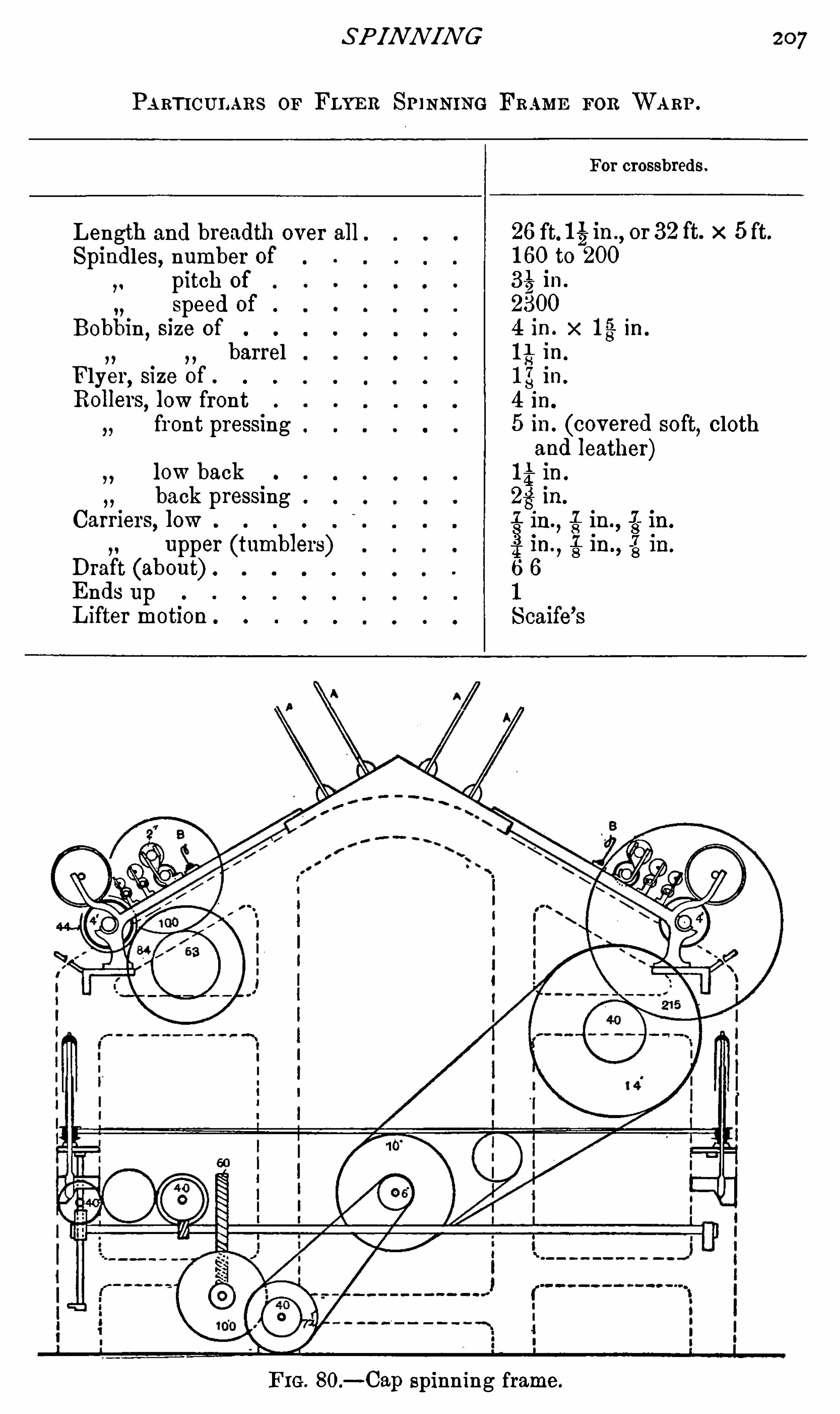
SPINN IN G
PARTICULARS or FLYRR SP INNING FRAME FOR WARP .
For crossbreds.
Length and breadth over all.
Spindles, number ofpitch of
speed of .
Bobbin,size of
barrelFlyer
,size of .
Rolleis,low frontfront pressing
low backback pressing .
Carriers, low
upper (tumblers)Draft (about) .
Ends upLifter motion
F IG. 80.—Cap spinning frame .
207
26 ft. I iin.,or 32ft. x 5 ft.
160 to 200
331
2in.
2300
4 in. x 13 in.
I i in.
in.
4 in.
5 in. (covered soft,cloth
and leather)I i in.
iin.
, iiniin.
i 1n.
, 8In -
8In.
6 6
1
Scaife’s

208 PR I N CI PLES OF WORS TED S P IN N I IVG
turns of twist per inch do not bear any constant relation
to one another .
The length of the fibres in the material which is beingspun
,and the proportion of the long to the short fibres in
that material,have also great bearing on the strength
,and
therefore on the amount of twist required in any yarn. This
may be given as the reason why the twist in a hosiery yarn,
made from short Buenos Ayres wool, does not bear any
permanent relation to finer hosiery counts,spun on the same
machine,from wool of different nationality and longer fibre .
The same argument applies to Cashmere and I talian weft
yarns ; and as different manufacturers are constantly asking
for special twist for special purposes,in twofold as well as in
single yarn,the whole subj ect would be out of place in a
book,of which the leading idea is to propound working
theories,based on practice
,which shall have some bearing
on the everyday work of practical men .

2 10 PRIN CI PLES OF WORS TED SPI NN I N G
allowed to lie until they have picked up j ust sufficient mois
ture from the air, to put them (to the very centre of the ball)in standard trade condition , all decent tops will lose the
harshness which we associate w ith dry-combed tops, and
draw out smoothly without whistling, without the fibres of
the broken end forming a brush-like tassel, but lying as they
should do,in a normal state
,parallel, side by side .
Such tops will draw and spin with little difliculty, unless
the weather is very frosty,but, so far as the writer knows,
there is no possible artificial means of securing this much
desired condition. With particularly hard fibred tops, the
time of keeping may have to extend to many weeks.
Of course, if in the washing, every particle of nature is
taken from the fibres of the top, it never will regain entirely
the suppleness and softness that it ought to have ; it will
remain both dry and harsh to the feel.
I f,on the other hand, all its exterior grease is thoroughly
removed in washing,and that put on in carding is removed in
backwashing, but if every atom that constitutes the actual
substance of the fibre, as it appears when growing on the
sheep,is left intact
,by reason of j udicious management in the
washing processes ; then, if no oil is added in or after combing,
the yolk or suint will slowly work its way from within the
fibre to the scales which form its outer coat, and thereby
largely kill all tendency to electrify, when in the processes of
drawing and of spinning, fibres are moved on one another and
on iron.
The top itself is certain to feel harsh and rough, if handled
as it comes straight from the comb, but nearly all the harsh
ness passes off from good tops when well treated . A fortnight
may be reckoned as the Shortest time for which a dry-combed

DR Y SPUN YARN S 211
top should lie,before it goes up to the drawing gill boxes . All
tops go on improving for at least three weeks, and if the very
best condition is desired, so that the waste produced in all the
processes may reach a minimum,four, five, or seven weeks is
not too much .
N o dry-combed top, if washed with proper soap, w ill take
the slightest harm if left in cool,dry cellaring for three or
four months. How long improvement goes on it is not
possible to say. The writer has seen tops which have been
left to lie for many months which have completely lost all
tendency to electrify when drawn ; and they have so com
pletely lost their harshness, that it was very diflicult’
indeed to
tell,by anything but smell, whether or not they were in oil
or dry.
A top in such condition would go right through an
ordinary worsted drawing without the slightest trouble, and
would spin well to nearly the same counts that the same top
would spin to,if combed in oil.
Unluckily, it does not follow even then, that yarn so spun
would do the work that Belgian or French yarn would do.
The reasons are not simple, on the other hand, they are
compounded from a long series of variations,which themselves
difl'
er in almost every yarn that is imported. To simplify the
case, it will be best to make a list of all the various ways in
which yarns can differ,and then endeavour to select the
various causes that make a Bradford yarn less suitable than
French or Belgian yarn for various types of dress goods.
1. For English worsted yarns, the fibres of the top should
always be uniform in length, and every one as long
as possible . French tops are often shorter,and are
composed of fibres differing in length . Hence it can

212 PRI N CIPLES OF WORS TED SPI NN IN G
often happen that for cashmere yarns , the English
man is using Australian or else Cape wool, to make
his yarn spin to the proper counts. The Frenchman
or the Belgian,on the other hand
,is using Buenos
Ayres at lower price with greater filling power.
2. In the washing there is often serious difference as
previously ex plained.
In combing there is greater difference still, for most
French “ dry-combed ” tops are not dry-combed at
all. They are first combed in oil, then backwashed,
and then finished through two or more fine gill
boxes . This makes it possible to take away less oil,
and do away with all the various troubles inherentto the combing of a very short dry carding ; the oil
being removed from the top after it has left the
comb .
4. Under the fourth head there is probably the greatest
difference of all between English and French prae
tices. In open drawing, twist is inser ted in, at
the very least,six processes
,and in them all
,there
is no attempt to separate the various fibres as they
are drafted by the rollers . In all French drawing,
on the other hand, there is no twist in any single
process, and every box has porcupines in it. The
draft is also generally greater on the Continent.
The rollers of the mule are less than half the size
of those in English worsted drawing. The draft is
always greater than in a throstle frame.
6 . The method by which drag is put upon the yarn is
wholly different in the mule from that in every
kind of throstle frame .
2 14 PRIN CI PLES OF WORS TED SPI NN I N G
or ring,up through the eye or guide, right to the nip is
seldom 15 in.,and therefore
,there is only just about a
quarter of the length for irregularities to draw upon. One
would imagine that in a throstle yarn,each length of 15 in.
must resemble every other length of 15 in. through its entire
length.
At least in theory,then
,the twist in mule yarn cannot
be very much more even than that in throstle yarn,but as
explained before (Chapter I I I .) it is quite possible that with
equal sizes made from equal sorts,the mule yarn may be
softer than all competitors,because the drag
,caused by the
cop, has no connection with the insertion of twist ; in fact
a cop may be built practically without drag. In throstle
frames the Spindle Speed, d iameter of cap, and many other
things are bound to alter the drag.
From the seven headings given in the list,the luckless
spinner is expected to find out what faults he is to avoid ,
by intuition. All he is told is,that the buyer wants a dry
spun yarn. Often enough he does not even know
What it is to be used for.How it is to be washed.
Whether to be made of BA. or P R
Whether the wool should be short or long,regular or
irregular in length .
Whether on cop or bobbin ; what the best size of each.
Whether French drawn or Open drawn.
Whether hard or soft,he is not told
,and is not over-fond
of trying to find out.

DRY SPUN YARN S 2 15
Until he knows the answer to each single head in the
complicated array,he is assuredly bound to fail in substituting
English for French yarn,at any price likely to come w ithin
the range of practical considerations .
Each point must now be studied with the utmost care
so that its bearing for or against efliciency can be ascertained .
1. Under head 1,all questions bearing on the average
length of various qualities must be considered. Of course
no hard and fast line can be laid down,but it is always
safe to say that Buenos Ayres wool is shorter and less
regular in length than is Port Philip. We always take it
as an axiom, that shorter wool will make inferior yarn .
Of this no proof is given and is seldom attempted . The
levelness of many cotton yarns, spun from fibres of equal
sectional area and a third the length of 60SJ botany wool
refute the theory altogether . I f I i in. cotton can be spun
to SOS worsted counts, why Should not 2 in. wool do likewise
The quality and levelness of French and Belgian yarns made
from such wools,make it seem possible. The simple fact is
clear. They get machinery made to suit the trade ; and we
do not. We order our machinery of such dimensions as will
suit all trades, that is to say, of such a Size that,it will do
a long wool perfectly,but cannot possibly be Set to be
efficient for very short wool. With I -in. rollers,cotton
rather more than 1 in . long w ill stand a draft of 15 or 16 ,
say full 12 times its length measured in inches . A 4 in .
botany would usually get a draft of 6 or less, and short
B.A.,reckoned at 2 in. average of length, might possibly be
drafted 3 or so. This,from
,existing instances
,is clearly
prov ed to be both waste of time and output . Both mean
waste of money.

216 PRIN CI PLE S OF WORS TED SPI NN I N G
We make our drawing rollers such a size, that they w ill
draw long wool as well as short,and because long wool laps
are hard to take from off small rollers, we make them large
enough. N ot so our oversea competitors ; they specialize and
order rollers in their mules of such a Size that they will nip
short wool in such a way as makes full use of every m illi
metre of its length. I f we would also order frames for
every type of wool we wish to spin,and let them stand
rather than put them on to work they were not built for,
then we should be upon the way to stop the import,
because we should be able to turn cheaper wool into fair
yarn .
This is not empty theory, it is being done with great
success in isolated instances here in Yorkshire.
2 and 3 . Under these heads nothing need here be said,
for every one acknowledges that if a top is spoiled in washing
or in combing,the carelessness can never be remedied .
4. Head 4 is probably the most important of them all
as regards filling power,in what we always know as mule
Spun yarn . The prime essential principle of all French
drawing lies in the separation of every fibre, for all its length,
from its near neighbours,in every single process. This is
the business of the porcupines. They do their work so well,
that any one who sees a 2-dram rov ing made on both Open
and on French drawing,can hardly bring himself to believe
that both weigh just the same amount per yard . When such
is the acknowledged fact,it is no wonder that yarn Spun
from the two will differ in the finish that they take.
In worsted drawing, not only is there no attempt to
separate the fibres,but
,on the contrary, each process puts
in twist which,in the u sual practice of running all the

218 PRI N CIPLE S OF WORS TED SPINN IN G
maker. The speed of almost every box is limited by the
Speed at which the spindles can be run . The output of the
box depends on the front roller, and therefore every extra
turn of twist reduces output and increase s cost. This is not
all. As we have seen in every case where bulk is a deside
ratum in the yarn, it does distinct harm .
I f English dry-spun yarns are to compete with those of
continental nations spun on mules, the roving must be made
to resemble that which is used by our competitors. But the
very nature of our machinery makes twist an absolute
essential,and if we really mean to attain the end in view
we must begin to rearrange our ideas.
I f drawing is to be conducted without twist, something
akin to the French system must be adopted . The fibres in
Sliver or roving, made without twist, have very little cohesion.
A sliver of that kind could never be expected to stand the
drag which must be present with any kind of flyer. A ball
built very lightly, with practically no drag, must be adopted ,and for this purpose several peculiarities will be found in all
French drawing.
In the first place,the creel is so constructed that balls
from previous boxes can be unwound without the slightest
drag or tendency to pull apart, or draft the fragile, twistless
sliver.
The balling head itself is made to work with little or no
drag,so that the ball is built up very soft, in order that the
tender sliver may not be stretched at all. '
I t is a very
natural consequence,that balls must all be handled with the
greatest care,for every box is just alike
,producing twistless
slivers rolled up,and built up into qui te large balls, which
have to be unwound with greatest care if they are to be

DR Y SPUN YARNS
unwound at all. To this end special creels are always used .
Each ball,bu ilt on a hollow barrel , Stands upright, on a
Spindle that revolves on a fine point, supported in a little
cup or pot. Friction in every case is at a minimum . In
fact,the whole arrangement works extremely well .
Once in the rollers, as there is no tw ist, fibres move far
more easily on one another. The work the rollers do is, there
fore,easier
,and porcupines—rollers with rows of pins
,that
act as combs to separate the fibres passing through them—areused instead of carriers to make the drafting regular for all
the various lengths of fibre (see Chapter At first sight
any one might easily suppose that porcupines might take the
place of carriers in cone and open drawing. But fibres going
through them must be parallel. When twist is present,
things at once reach a deadlock. The twist with which the
sliver passed the back roller,could not by any possibility get
through the porcupine without some of the fibres being
broken,knots would be formed as well. In fact
,the two
words, porcupine and twist, are incompatible .
The natural outcome of this reasoning is one that has
been reached by isolated firms and found a great success.
French drawing lends itself in many ways to treating shorter
fibres,and in it, longer drafts are possible than is the case
with the large rollers and the fast-running flyers of worsted
drawing.
Long drafts, as is well known, mean cheap production,
if other parts are set to coincide. There is no reason whyFrench drawing should not be used with either cap or ring
or flyer frames.
Just as French draw ing difl°ers from all other drawing in
theory, because the slubbing and roving contains no twist ; so

220 PRI N CI PLES OF WORS TED SPINN I N G
in practice the boxes differ from every other type in that
they have nothing of the nature of a spindle. The drawing
process usually begins with three processes of can gill boxes ;
from the last of which the sliver goes to the first drawing
box ; this box is typical of all the set that follow it, and
strongly resembles a 4-head balling gill box. The sliv er
passes through two pair of dead-weighted back rollers,AK
,
BL (Fig. between which there is little or no draft,before
it reaches the porcupine C , a roller thickly covered with
fine pins,which takes the place, and does the duty of fallers .
From the porcupine , the Sliver is drafted by the group of
F IG. 8 1.—Low rollers A, B, D, E have milled flutes. All are less than I i"
diam. Scale about 5.
front rollers,DEJ, exactly as explained in Chapter I V but
after the front rollers a contrivance is employed which has
no counter-part in other worsted processes .
The sliver as it comes from the front roller, is qu ite flat ,
and if any attempt were made to build it up into a ball, in
such a cond ition,it is true that an excellent ball could be
made,but if once wound
,it would never unwind again
,
becau se the loose fibres at the edge of these flimsy slivers
wou ld become entangled,and the slivers themselves would
tear rather than unwind . Between the front rollers EJ, and
the balling head GH,a most ingenious arrangement of leathers
is introduced . Each pair of leathers has a double movement .

222 PRI N CI PLES OF WORS TED SPI NN IN G
Most mule yarn, therefore, has a structural difference from
cap-spun yarn ; but this is simply due to what took place
before,not in the spinning
,and is as well quite unconnected
w ith different types or lengths of wool, or w ith the entire
absence of oil,in many mule-spun yarns .
W'
hy people very seldom draw a lesson from the small
size of rollers used in mules is quite another matter. I t is a
very general belief that rollers Should be as large as possible
for worsted yarn. This is an argument of pure utility ; it
simply means that 4-in. rollers are most suitable for good
long crossbred sorts,and that they also can be used to Spin
numerous other qualities of wool, not perfectly, but well . A
2i-in. roller, on the other hand, will spin a 2i-in. botany
better than will a 4-in. roller,but as it is very nearly im
possible to spin a crossbred sort on such small rollers,
largely because laps have to be cut off if they get thick,all
2i-in. rollers are discountenanced as not being sufficiently
adaptable.
Few people would deny that smaller rollers should be
used for shorter wool, and yet in practice Bradford stands
where it Stood in this respect quite thirty years ago . I t is a
simple axiom that for special trades Special machinery must
be made and used, but this need certainly not be read to‘mean that dry-spun yarn cannot be made on frames.
I t has been pointed"
out, that small-Sized rollers do not grip
as well as larger ones, if both have equal pressure. Large
Sizes should not be adopted on this account alone, for other
things than size may play their part in grip between two
rollers.
The Yorkshire worsted trade seems to consider itself
bound hand and foot to what are called scratch fluted rollers.

DR Y S P UN YARN S 223
Mule rollers are not made in that way. Their flutes are
far more frequent, deep, and regular, g ivmg a grip on fairly
soft top rollers,much more like that obtained with fluted
drawing rollers . These should at least be tried for worsted
frames.
N o one can tell how much or how little alteration would
evolve the most perfect frame for spinning quite short tops,
or tops combed without oil,but it is probable that longer
drafts would come in as a consequence . Drafting, as pointed
out in Chapter I V .,has nothing whatever to do with the
insertion of twist,and therefore if a mule with’
1-in. rollers
can give a draft of 8 to any top of Short B.A., it must be
possible to make a frame to do quite as well, or better.
All that is wanted is that brains should be applied to
every detail of the many processes through which a dry top
goes from wool to yarn.
6 . The question of the drag applied to build a cop or build
a cop-Shaped spool is treated so exhaustively in Chapter I I I .
that nothing more needs to be said about the subj ect here ,except one thing. The drag in a cap frame is altered in pro
portion to the distance from the surface on which the cop or
spool is being built and the cap edge. I f cops were to be
spun on the bare tube on which the spool rotates,the drag
would be so great as to require a great amount of twist to
stand the strain. For this cause,extremely thick
,soft
,hosiery
yarns cannot be spun with advantage on frames which have
large caps, whilst on a mule, no matter what the Size of cop ,no matter whether it be built on bare spindle or on paper
tube, the drag is not excessive . This is one of the very few
points in which a mule stands without any comparison ahead
of all throstle frames .

224 PRIN CI PLES OF WORS TED SPIN N I N G
The Sizes of flyers, caps , and rings are bound to affect the
drag in their own way ; presumably they will always do So
more or less,but if a traveller can be found for use on all
ring frames of such a nature that when the cop or spool is
empty the traveller is nearer to the Spindle than when the
spool is full, it will be possible to do more theoretically
perfect work on throstle ring frames .
7 . The difference in the weaving qualities of cops and
spools ought to be well considered by everyweaver who is
called upon to use dry yarns and when he knows the extent
towhich the properties of each affect the output of his looms,and affect the proportion of waste made, as compared with
the total weight of weft actually made into cloth, the result
Should be communicated to the spinner, who then at least has
the option of putting his yarn on to spools, parallel paper, or
conical paper tubes.
I t must not be expected from what has here been said
that spinning dry-combed tops will always be as easy as
dealing with a top of similar make and length, but combed
inoil.
The first essential, that a dry-combed top Should be
mature in age and therefore in condition (using the word
condition in its ordinary English sense), is not aneasy one
always to fulfil ; at times it is impossible, and if the luckless
spinner is driven from Sheer force of circumstances to tryand draw new dry-combed tops
,or even tops which though
they may be some days old , as yet are immature, he must
ex pect results far from desirable . Put into other words,this
means that though dry tops under favourable conditions can
be treated without unreasonable waste and cost,on ordinary
worsted machinery, there is no doubt that they canbe treated

226 PR IN CIPLES OF WORS TED S PI N N I N G
reduced,by placing machines which work them, in a warm,
damp atmosphere. An atmosphere which is warmed and
m oistened by the blowing in of free steam is very effective in
killing static electricity which makes fibres mutually repellant
when they are similarly charged. Steam,however
,is nu
pleasant to the workers,some people say unhealthy
,and
there are many efficient methods by which water can be
pulverized or turned into spray so fine that it will never fall,
but be absorbed by the atmosphere in the vicinity ‘ of the
humidifier. Any of these methods may be used ; the only
desiderata being,that all the air in the room Should be fresh
,
equally humid,and equally warm.
To obtain the desired degree of moisture some firms use
one central station from which fresh,warm
,moist air is
distributed to various rooms and various parts of every room
by large pipes . Some systems use high-pressure water to
pulverize itself, and in the process to produce a local draught
of air. In such an apparatus only the very finest water
atoms are absorbed, the coarser spray is used to wash im
purities out of the air that passes through them . All that
which is absorbed diffuses evenly throughout the room,the
heavier drops collected in the cylinder run back to a central
filler where they first part with impurities,and then are
pumped again to pulveri'
zers.
One system which is very simple to erect,and has been
made to give extreme humidity, consists of apparatus
strongly resembling the ordinary spray diffuser used for
scent. I tsdrawback is that it does not introduce fresh
air in any quantity, nor does it cleanse the air already in
the room .
Inregard to all methods of humidifying, there is one

DR Y SPUN YARN S 227
curious anomaly which is well worthy of the notice of those
who propose to practise it.
Any room where any type of artifiCIal moisture is
employed,comes under the jurisdiction of cotton factory
inspectors,and daily returns from every such room are
required from worsted factories,Showing the hygrometer
reading. These have to be sent monthly to the head oflice .

CHAPTER IX
TWI STI N G
Twisting , as understood by all Spinners, is a simple process
comprising only the one Operation of binding together two
or more threads, by wrapping them round one another a
certain number of times in every inch of their length ; or,
in more technical words,twisting two or more threads
together,by putting into them so many turns per inch .
This process must never be confused with that which a
weaver speaks of by the same term. When he orders a warp
to be twisted, or, more correctly, twisted in, he means that
every separate end of some new warp is to be twisted in a
peculiar way,which is almost as good as tying, to every other
end of some other warp,which is running out of a loom or
set of heralds, so that all the ends of the new warp can be
drawn through the mails without the necessity for each of
the several thousand ends to be separately threaded before
they can be woven.
Theoretically and practically the process is comparatively
simple,a twisting frame consisting of
1. A series of pegs A, Fig. 82, on which the Spinning
bobbins stand,so that the Single yarn may be wound from
them with uniform tension .
2. A series of twizzle guides B, through which the

230 PRIN CI PLES OF WORS TED SPI NN IN G
frame,but they carry on this roller two upper rollers, which
are supported in such a way that when an end breaks, and
the trapper rises,the stands which carry them fall forward,
away from the low roller,so that no friction with it remains,
and they come to astandstill (see Figs. 8 6 and4. The trapper
,T
,is a guide placed exactly over the
Spindle, to form a centre from which the thread can swing
freely round the cap or ring, and so arranged that if the
Strain on the yarn is removed,from any reason
,the trapper
will rise and stop the roller.
5 . The spindles 8,either cap
,ring
,or flyer,
'
are on exactly
the same principles as those described for spinning,but
they are larger dimensions in order that bobbins of larger
size, to hold as much as four ounces, may be used, and run
at high speeds.
N o . 1. The pegs A,from which the yarn runs
,are quite
simple, often of unturned iron placed nearly vertical , and of
such diameter that the bobbins can easily run round on the
conical washers at their bases. For the very large majority
of counts and qualities,this arrangement is amply good
enough,but there are exceptional qualities for which this
system will not do at all.
Hosiery qualities and other very soft yarns sometimes
contain so little twist that they cannot drag the bobbins
round,in spite of the very slight friction of the pegs, and
one or two courses must be adopted . Either a sleeve, such
as that described on p . 169 in the chapter on Spinning, must
be employed,so that the bobbin may rotate without friction ;
or a rod must be run along the whole length of the frame,
exactly over the pegs,and the yarn must be carried from the
spools over this rod,so that it may Slip over the noses of the

TWI S TI N G 23 1
bobbins without making them rotate. The former is the more
costly bu t the better plan, because there is very little likelihood
of the yarn running off too fast, whereas if new yarn is run
over the bobbin nose,it is always apt to come off too fast
and to curl up into snarls, which are certain to make bad
places in the piece . On the other hand,
V ery hard twisted yarns may require more drag than can
be obtained with pegs and cones,because in crepon and other
hard twisted kinds of yarns,the ends will run into snarls
,
unless they are kept under definite tension,and cases arise
in which some method of washer drag must be adapted to
the bobbins,so that there can never be any Slack yarn between
them and the rollers .
N o. 2. The absence of pressing rollers makes the wear and
tear of the leather covering of the vertical rollers very slight.
N icking is therefore impossible,and the regular traversing
of the end is of much less importance than in spinning, because
very little damage can result if the traverse motion gets out
of gear ; but in this, as in all other cases, some traverse motion
which gives an equal speed at all points should be used .
N o . 3 . Twist-frame rollers—The use of vertical instead ofhorizontal rollers makes it necessary to have a separate roller
for each spindle, and because every roller must stop and
start independently of the others,each of them must be
driven separately in such a way that all will move at exactly
the same speed all the time the trappers are down and the
rollers are revolving.
I t is probable that the first machine twisting was done on
spinning frames , u sing only the front rollers but it was soon
found that a great deal of unnecessary waste was made when
ever an end broke down,because there was no automatic

motion to stop the roller running ; in fact, it was impossible
to stop the rollers at all, either to save waste or to tie a
broken end,and for that reason all kinds of expedients had
to be adopted in practice which tended to inferior work and
bad knots . I t was soon discovered that it would pay w ellto have special machinery
,in which each roller and spindle
cou ld be stopped at pleasure . In the very earliest type of
twisting frame there was no Special Shaft to dri ve the upright
rollers,but each was driven by a band from a Slow moving
cylinder, placed above the cylinder which drives the spindles .
Each roller carried one or more pegs,and when an end broke
down the inner end of the trapper fell against one of the pegs
and so prevented the roller from rotating.
In a second type of twist-frame trap rollers,a shaft was
carried along each Side,directly under the row of rollers,
F IG 83 .
and the Shaft of each roller was driven
by a little pair of bevel wheels B B all
the time the frame was running (see
Fig. The roller itself R carried pegs
P,as in the first type
,but R was loose
on the Shaft,and had a square bottom
F which rested on the broad flange or
washer W,which was fastened to the
upright Shaft . N aturally the friction
betw een the flange and the heavy iron
roller drove the latter round until the
pegs were stopped by the trapper T,
on the breaking of an end . When the
roller stopped there was naturally a
great waste of power in friction, between the two surfaces
of the rotating washer W and the stationary friction plate F.

234 PRI N CIPLES OF WORSI
TE D S PIN N I N G
all the modern ones appear complex. They are,however
,
much Simpler inwork than a description w ould indicate . In
Fig. 84 the trapper consists of a lever T in two parts,hinged
at A, and so balanced that when no end is running, the twizzle
rises and the inner end falls . This inner end is also hinged,
so that the portion nearest to the roller can swing sideways
when it falls against the rotating peg D in the upright roller
Shaft. When it is thus pushed to one side,it moves the hinged
F IG. 84.
support B from under the bent lever L,and the whole roller,
w ith its frame and wheel, then swing on the pivot P , because
the centre of gravity of the roller is forward of this support,
and whilst the roller R comes half an inch forward, the lower
part of the hanger and the wheel W swing backwards, clear
of the screw-worm S,which drives it when in gear.
The small movable parts of this motion are so cleverly
arranged that all of them resume their proper positions

TWI S TIN G 235
automatically,directly the trapper goes down, and the roller
is once more in an upright position .
To Show how possible it is to attain a similar end by two
entirely different mechanical devices, the reader cannot do
better than examine the motion shown in Fig. 8 5. In its
simplicity, and in many of its arrangements, it resembles the
old-fashioned type of roller, driven as it is by a simple pair of
F IG. 85 .
bevel wheels (B B) . InFig. 8 5 the bearings are not shown ,
but an upright shaft runs up to the roller R,as in Fig. 83 .
Here the resemblance ends,for
,instead of the broad surface
of the friction plate,the only frictional contact between the
roller R and the bevel wheel B is that against the small
collar below the trigger-plate P . The friction between these
two portions is too small to cause the roller to revolve against
the slightest drag, but when the trapper-end is up, a positive

236 PRI N CI PLES OF WORS TED SP IN N IN G
drive is obtained through the trigger which falls into the
ratchet wheel F.
This bell-crank shaped trigger is pivoted on the plate P ,
in such a way that when the inner end of the trapper falls,
the rotation of the roller and the plate bring the upper end
of the trigger against the trapper,forcing the trigger back ,
and thereby lifting its catch-end out,of the teeth of the
ratchet wheel.
These two modern motions,when compared
,offer so many
points of contrast that they form an excellent illustration of
the possibility of great structural diversity in Similar
machines .
I f the various adj ustments are automatic in any type of
trap motion,its efficiency may be j udged by noting
1. The efficiency of the positive method by which the
roller is caused to rotate .
2. The amount of friction removed from the total needed
to drive the frame,on the stoppage of each separate roller on
the breaking of an end.
3 . By the simplicity or otherwise of the trap motion and
its parts.
4. By the rapidity with which the roller Stops on the
breakage of an end.
Three and Four-fold Twisters—Before going further intothe questionof folding, it is essential that the reader should
understand why a twofold end invariably breaks down, if
one of its strands gives way or runs out,whereas it does not
follow that a trapper will rise, or the end cease running on
to the bobbin,even if three ends out of a fiv e-fold yarn Should
giv e way.
Except for a few very special purposes, yarn is invariably

238 PRI N CIPLE S OF WORS TED SPINN IN G
small single knots in a four-fold yarn will cause infinitely less
damage in a piece,than one bunch knot of the same yarn in
the same piece.
3 . But if the rollers should stop automatically until a
knot is tied,whilst the spindle continued running, the yarn
F IGS. 8 6 AND 87 .
between the spindle and the roller would be twisted far too
hard,before the new end was tied in, and therefore
4.The spindle must be stopped automatically, or else
faulty yarn will go forward.
5. But if anything of the nature of a brake were used to

TWI S TI N G 239
stop the spindles,all the bands would be rubbing over the
stand ing whorles whenever the frame was running with only
a few spindles in work, and this would create a terrible
amount of friction and a waste of power in proportion to the
number of spindles standing.
6 . To save this waste of power, and the terrible wear and
tear on the bands and Whorles, it is found necessary to“ throw off
” the bands whenever a Spindle stopped ; and in
the type illustrated in Figs . 8 6 and 87, the cylinder Shaft,
the low front roller,and the lifter are practically the only
things which are running in a four-fold trap twister,which
has no yarn in it.
A type of roller often adopted for this purpose is exactly
like the low roller in a spinning frame,but instead of having
leather-covered upper rollers pressed tightly against it,each
boss on the low roller R supports two iron rollers U,round
which the yarn travels and by which it is held. So long as
all the threads are perfect, this position is maintained, but
directly one end breaks, behind the roller, a detector D drops
into such a position that it is caught by a wiper W,which
loosens a catch C , .d allows the roller-frame F to fall for
ward until both the upper rollers are out of contact with the
lower one, R (Fig. In this position they can only be
stationary, because there is nothing to drive them,so the
yarn is no longer paid out. At the same moment that they
come to rest,a lever L
,attached to the lower end of the
roller frame,moves the driving band from the fast to the
stationary pulley on the cylinder, and stops the spindle
as well.
In this type of frame,just as in a two-fold twister
,the
trapper rises, if the yarnbreaks between the rollers and the
PRI N CIPLE S OF WORS TED S P I NN IN G
bobbin ; but its action is different. When the front end of
the trapper rises,the hinged portion of its inner end falls
upon the wings of the rotating wiper W,and is thereby lifted
in such a way that it disengages the catch,and lets the upper
rollers U fall forward out of contact with the low roller R, in
exactly the same way as would be the case if a single thread
had broken behind the rollers,and allowed a detector to drop .
The rollers then stop at once,and they also stop paying out
yarn or making waste .
The whole thing takes place so instantaneously that it i s
difficult to believe that so many parts are involved ; and
when the frame is running at a normal speed, it stops so
quickly after an end has run from one of the bobbins,that
sufficient length of thread is left behind the roller to tie a
new end to it.
Spindle Brakes—In ordinary two-fold twisters with vertical rollers
,we have already seen that if one end runs out
,
the other is absolutely certain to break down, and therefore
there is much less need for automatic stopping of the spindle,
because no waste is going on, and the girl can easily stop the
spindle by hand to pick up the thread prior to tying in a new
pair of ends. I f the spind le could be allowed to run again
directly the end had been put through the eye of the trapper,
there would be no need for anything to assist the fingers in
stopping the spindle ; but if the Spindle is allowed to run
whilst the knot is being tied,before the roller begins to
deliver yarn again, it is clear that all the yarn between the
roller and the spindle would receive too much twist. For
instance,if the spindles were running 6000 revolutions
,and
the whole operation of tying a knot took only 10 seconds,
the 20in. or less of yarn between the spindle and the roller

242 PRIN CI PLE S OF WORS TED S PI NN I IVG
pulleys . N ear to each spindle a whorle,W
, Stands, free to
rotate with little or no friction on a pin which is held vertical
in a plate P,also centred on or near the spindle centre . When
the spindle is running, the whorle is behind the spindle or
within the tape (see Fig. but as soon as it moves forwa rd
by a small handle on the plate,it carries the tape clear of the
spindle whorle and at the same time presses a pad , not shown
in the figure,against the tube to stop its rotation. As the
whorle is light and easily driven,it absorbs less power than
the spindle,and can easily be applied to almost any type of
frame, but unfortunately few people thought it worth while
S P INDLES STOPPED. S PINDLES RUNNING.
F IG. 89.
to pay the price necessary for a device which required such
careful workmanship,and consequently it never cam e into
general use.
A patent of a Simpler, but very Similar kind is now made
by Prince Smith Son (see Fig . I t can be slipped over
the spindle like a washer,and when it is in place
,with the
spindle running, a curved piece of metal takes the place of
the whorle in Carnett’ s patent, and slips in between the tape
and the spindle whorle on the movement of the trigger on
the d isc D . The curved plate is so hinged that the tape
presses it like a brake against the whorle , which is instantly

I WI S TI N G 243
stopped ; the plate absorbing the whole of the friction of the
tape . I ts one d rawback is extra wear and tear on the tape,
and increased absorption of power when spindles are standing ;
but as spindles are very seldom kept Standing in frames
of the type for which it is designed,the objection is more
theoretical than real.
Probably the best brake for general purposes is one hinged
in front of the spindle:rail, or lifter rail, in such a way that
the operative can hold it to
one side with her knee .
Each lever KL controls two
spindles,hanging idly be
tween them when at rest,
and so pivoted,that when
pressed to the right it stops
the spindle on its left andrvice versci (see Fig. I t
is less effective than the last
named type because the mo
ment pressure is relaxed the
spindle w ill begin to rotate,
FIG. 90
but it w ill do very effective work, and the position of the
lever,or knee plate
,makes it very easy for the operative to
use,especially in ring or fly frames where the whorles and
brakes are always stationary.
For spindles and their theories,see Chapter I I I .
For methods of spindle drive, see the end of previous
chapter.

CHAPTER X
WI NDI N G,REELI N G,
AND WARPI N G
ALTHOUGH the structure of a yarn is completed in thetwisting process
,it often happens that it is there put on to
bobbins which are not suitable to be sent from one factory to
another and proce sses are therefore introduced after twisting,
to put the yarn into such a form that
1. I t can be packed into small space with little cost.
2. There is as little superfluous tare as possible.
3 . In a form from which the weaver can use it with the
least possible expense.
Yarns may be delivered in nine different forms.
1. Fine single yarn is usually put on to spools, or single
headed bobbins measuring I i 4i in.,whilst thicker counts
are put on to Similar Spools of larger Size (see Appendix
2. Paper tubes are used for the same classes of yarn,
which are likely to go abroad, or to any place to which
carriage is expensive .
3 . Twofold yarns may likewise be twisted direct on to
large Spools.
4. Or on to paper tubes .
5. Yarn for ex port, or for dyeing, is usually twisted on to
large double-headed bobbins,and reeled from them on to
swifts I i or 2 yds . circumference, into hanks of 560 yds.

246 PRIN CI PLES OF WORS TED SPI NN IN G
use, and this would save the cost of beaming and dressing to
the weaver. This process is therefore of mutual advantage
to the weaver and the Spinner, because the latter can put the
warp on to beam,with modern machinery
,quite as cheaply
as he can make it into balls, under the old-fashioned plan.
As none of these nine processes involves any alteration in
the relation of the fibres within a thread,either as to lateral
position or to twist,very few principles are inv olved in any
of them,and there is comparatively little opportunity for
causing damage. They may,therefore
,be dismissed w ith
briefer notice than would otherwise be necessary.
Under heads 1,2,3,and 4 no further descriptions are
necessary, because the winding on to Spools,tubes
,or ceps
takes place on the spinning and twisting frames re
spectiv ely.
N o . 5. Reeling—Both single and twofold yarns are veryoften delivered in hanks. S ingle yarns are generally made
into hanks of 1 yd . circumference,whilst twofold yarns
may be used equally well from either 1—12 or 2 yds . hanks .
For ease of calculation, the banks are nearly always reeled to
a length of 560yds .,which is the standard unit of length
,on
which all English counts are based. When a spinner accepts
an order in hank ,he is responsible for delivering correct
length as w ell as correct weight in every hank,and
means must therefore be adopted , to insure that successive
wraps of y arn are spread uniformly over the surface of the
reel and not heaped up into ridges, of which the outer
layers would be longer than the inner. For this purpose
it is necess ary that the yarn Should traverse across the face
of the reel,and two entirely d ifferent methods have been
adopted for this purpose . Clearly the narrower the hank can

WI NDI N G, REELI N G, AND WARPI N G 247
be wound on the swift,the more threads will each machine
wind at one lime,and the more weight will it turn o ut.
Therefore the pitch of the frame is u sually not more than
4 in. I f the hanks were allowed to touch one another on
the reel they would get inextricably entangled , and therefore
a space must always be left between them ; this limits the
traverse to about 3 in.,and the pitch of the frame to about
in.
Lea Reeling .—The usual method of d ividing each bank
into leas,seems to be a curious relic of hand-winding days ,
when the only method of obtaining a traverse was to lift the
thread from one guide to another . Inmodern reels the process
is,of course
,automatic
, and though it would be easier to make
a Slow and steady traverse motion,the intermittent one is
preferred , because in tying up the loose threads of the hank
it is customary to interlace the lease band,so that each lea
of 80 yds. is separated from its neighbours . The whole
hank is therefore much less likely to get entangled in the
process of dyeing . In the worsted trade this method was
at one time almost universal,but some years ago cross reeling
became much more general.
Cross Reeling—In cross-reeled hanks the guide is made to
traverse quickly to and fro,making about one traverse for
every three-quarter revolution of the reel,so that each successive
thread of yarn must cross the one laid on before it. N o two
threads lie parallel,and there is less fear of their getting
entangled . The trav erse‘
m otion is SO simple that it does not
receive the attention it deserves . The Speed at various parts
is certainly not very important,but this is not a very good
excuse for the frequent use of eccentrics for the purpose ; and
the extra thickness of the edges of a hank, as it lies on the

248 PRI N CI PLE S OF WORS TED SPIN N I N G
reel, is a clear proof of the statement made whendealing witho ther trav erse motions (see Chapter VI I I .)
In this process as in almost every other,cost is regulated
directly by Output or speed and as the speed at which a reel
can be run depends solely on the speed at which the yarn can
be unwound from the bobbins,the spindles on which the
bobbins stand are one of the most important parts of the
machine . The one object of 211 spindles from which bobbinsare unwound
,should be to keep a gentle and uniform tension
on the yarn as it leaves them for if at any time the tension
should vary for any reason, the speed of the bobbins will
become irregular,so that at times they will overrun the swift
,
turning out more yarn than is wanted, and then stopping or
moving at a very much reduced speed . AS they Slacken down,
or step, the swift overtakes them , and they then have to start
again with a violent j erk which strains the yarn much more
than‘
a considerable tension, steadily applied .
Probably the best way to obtain steadiness is to use
some well-made spindle revolving smoothly in bearings so
shaped that the bobbin will have suflcicient friction on it to
cause both bobbin and spindle to rotate together. Means
could then easily be adopted, to apply the right amount of
tension,but when stationary pegs are used, conical steel
w ashers with cloth washers on the top of them may possibly
give satisfaction.
Most reels are so constructed that when 560 yds.,or
other desired length, has been ree led, the machine will stepautomatically
,or w ill ring a bell so that the reeler may stop
it.The swift will now be covered by a certain number of
hanks,all containing the desired length, very tightly stretched
over its arms . The reeler’
s first duty is to tie -both the

250 PRI N CI PLES OF WORS TED S PI NNI N G
which strongly resembles the old-fashioned method , butwithout any need for the reeler to lift the shaft from the
bearing as in the old-fashioned type.
As many hanks as will weigh four ounces are nex t twisted
up together,in a way too well known to need description, and
forty of these are then put into a press and tied, under pres
sure,into a 10-lb . bundle which only measures 8 x 10 X 12
in. or less.
F I G. 92.
Winding—Yarn which is wanted for warping is oftenwound from twist bobbins on to warping bobbins of 5 in .
traverse by about 4 in . diameter. Five,six
,or seven twist
bobbins are put on to one warping bobbin,each being carefully
knotted to the one before it,so that when they are in
'
the
warping creel , the bobbins will run for a long time without
coming out . By this means the time of the.
warper is
economized, and the warping m ill can turn out more and
better work.
Old-fashioned winding frames consisted of two long rows
of upright spindles,one of them driven at a uniform speed
,
WI NDI N G,REE LIN G, AND WARPI N G 251
the other free to rotate ; the driven spindles carried warping
bobbins on to which the yarn was to be wound,whilst twist
bobbins stood on the other row,free to rotate . The Speed of
such a frame is limited only by the Speed at which the bobbins
can revolve steadily,becau se the d rag increases as they increase
in speed . Let us say that 2000 revolutions per minute will
be satisfactory. The d ifficulty is that the take up of the warpbobbins is very variable
,and if they run2000revolutions when
they are empty and the twist bobbins are 2 in . in diameter,
the latter will only be revolving 1000 revolutions ; but when
all the yarn is transferred to the warp bobbin,it will be 2 in.
in d iameter and the twist bobbin only 1 in and the latter
will therefore be going at 4000revolutions per minu te . When
a new bobbin is tied in,the twist bobbin and the warping
bobbin will both be one size and the speed of both will be
2000revolutions ; but before this second twist bobbin is empty
it will be about two-fifths of the diameter ‘
of the warping
bobbin and will be revolving 5000 revolutions per minute ;
and lastly,when the warp bobbin is full and the last twist
bobbin is empty, their diameters will be as four to one, and
the Speed of the twist bobbin 8000 revolutions .
I t will be safe to say that the strains on the yarn are not
in ex act proportion to the speed s, but it is pretty certain that
if the strain at 2000 revolutions is as much as the yarn will
stand,there would be at least four times too much tension
when a speed of 8000 is reached. I f,on the other hand
,w e
set the frame so that 2000 is the speed of the twist bobbin
when the warp bobbin is full,the frame will only do full work
for a very short part of each doffing ; the output would be
less than half the full amount for a large part of the time,and
at the beginning, the yarn would be travelling at less than

252 PRIN CIPLE S OF WORS TED S P IN N I N G
one-fourth the proper speed,so that the total output of the
frame would be a long way under the real maximum .
These figures are insisted on,not because of the importance
of the machine they illustrate, bu t because the same principle
is in force more or less whenever bobbins of any kind are
unwound at high Speeds .
Drum Winding—N owadays, warping bobbins are almostinvariably wound on a drum-winder, so that the amount of
yarn moved per minute is always exactly the same,and the
only alteration of drag will be caused by the acceleration
of the bobbin from which the yarn is being wound . As
the bobbin empties,the drag will also increase Slightly
,
because,although the weight of the yarn d iminishes in pro
portion to its diameter, the weight of the bobbin itself
remains constant,and has to be moved at an ever-accelerating
speed as the yarn decreases in diameter.
The machine so strongly resembles the one shown in
section on Fig . 94,as to need no description
,but for reasons
explained in Chapter VI I I .,the traverse motion must have
a constant speed,if the layers of yarn on the bobbins are all
to be parallel to the barrel.
I f the foregoing reasons have conveyed the desired mean
ing to the reader, he will understand that the strain on the
yarn which is being wound from any bobbin or ball,can only
be kept uniform if every alteration of its diameter is aecom
panied by corresponding alteration in weight.
Cross Winding—This, of course, can never happen if
bobbins are used ,
'
but the substitution of balls wound without
Side supports really solved the problem,for they may be better
described as bobbins without ends. The tubes on to which
the yarn is wound are so light that their weight has no

254 PRI N CI PLE S OF WORS TED SPI NN I N G
bobbin enters at the bottom,and
,passing close to the Shaft
emerges on the other Side of the drum at the point where
the cheese is rotating as it rests on its upper circumference.
AS is Shown in Fig. 94,the slit traverses from Side to
S ide of the drum in half a revolution,completing the double
traverse as the drum completes one turn ; and as the cheese
is driven from the drum by friction,the take-up of yarn
must continue the same as the surface traverse of the drum,
nomatter whether the diameter of the cheese is 1 in. or 4 in.
This giv es a uniform take-up and tension,together with a
traverse motion so smooth that, like the ordinary drum
winder,the speed is only limited by the rate at which the
yarn will come from the hanks or bobbins being wound . For
this reason the machine is without a competitor for strong
yarns,which can be runat high speeds, because
1. The traverse motion of the Slit across the face—of thecheese is of equal speed at every point.
2. There is no dwell at either end of the stroke.
3 . And as there is no m echanism needed to move the yarn
backwards and forwards,there is no reciprocating motion or
traverse rod to j erk and vibrate.
With drums 12 in . in diameter running at 200 revolutions
per minute, each drum would wind 630 ft. per minute, and
in that time the yarn would have moved 400 times across
the face of the cheese,laying the yarn at an angle of 15 degrees
to the circumference,and so binding the various threads
together that a compact and cohesive ball is the result. In
winding from hanks which have been at all matted in dyeing ,
this pace would probably be so high as to break the yarn ;
but, on the other hand, good warp sorts which were only
being w ound for warping could be runat a great deal higher

WINDI N G, REELI N G, AND WARP I N G 255
Speed, and it is for this purpose that the frame is pre—eminentlysuitable.
I t should,perhaps, be pointed out here that very high
speed machines do not reduce cost of production in proportion
to their speed,because it is impossible for a girl to look after
as many spindles, which are w inding 1200 ft. per minute , as
it would be if they were running at only half that speed .
In fact, if the work is to be well looked after, the cost of
wages in both cases will be about the same,but the high
Speed machine will naturally save floor space,and it may do
more work in proportion to the power absorbed .
Quick Traverse Winding Frames—I fwe take “
15 degrees
as the lowest angle which w ill bind the yarn into a ball
which will Stand packing and handling,it is clear that the
relation of output to traverse must be the same for all frames
which are building cheeses,because
,for every 38 in. of yarn
wound, the thread must be taken twice across the face of the
5-in. cheese, and this necessarily means that some traverse
motion and bar must move a series of guides,one for each
cheese, backwards and forwards once in that time. For yarn
which would wind at 1200 ft. per minute, it is obviou s that
the bar would have to move at a speed of 170 ft. per minute,
and reverse its motion instantaneously 400 times in doing
so. As yet no motion has been found which will Stand this
strain for any length of time,and most quick-traverse
machines cannot compete,where speed alone is a desideratum
,
but there are several of them which do‘
good work at more
than half that speed ; with the additional advantage that
four parallel ends may be wound together on to the same
cheese, being so arranged to run through detectors,that all
of them stop at once,if any one of them breaks down .

256 PRIN CI PLE S OF WORS TED S P I N N IN G
Where three or four-fold yarns are required with very
little twist,practical men know that it is almost impossible
for any girl to “ mind ” more than a very few twisting
spindles efficiently,if She is twisting from spinning Spools ;
thus the output of a twist frame is greatly less than calcu
lation, and money is lost ; but if the same yarns are first
wound parallel on to cheeses and sent to the twist frame in
that condition,there is no possibility of one end breaking
whilst the others run,and there is no artificial limit to the
speed at which the work may be turned out. All winding is
an illustration of the fact that the introduction of an extra
process may actually save money,and in this particular way
the development of winding has not yet reached perfection.
From what has been said, it is easy to see that the
fficiency of a quick-traverse machine depends on the speed
at which the whole series of guides can be moved, and this
in its turn depends directly on
1. The nature of the cam,or other motion
,used to obtain
a rapid stroke and instant reversal,without j erk or vibration.
2. The weight of the traverse bar and moving parts.
3 . The nature of the guides ; for it must be possible to
thread them without stopping the frames.
Inall these respects the machine made by Arundel Co .
is wonderfully efficient, and is here taken as an illustration.
In all slow-moving heart motions,cams are only used to
move a bar or bowl in one direction,the weight of the rod s
moved,or springs
,being used to give motion in the reverse
direction but when the Speed is very high,as in the present
case, a heart would literally throw any bowl from its point,
and cause vibration which no machine could possibly stand,
and therefore a double-action cam is necessary, which makes
PRIN CIPLES OF WORS TED SPI N N I N G
so that if it is desired to make a 5-in. cheese,it is only necessary
to attach the rod connecting the traverse bar to the point D,
whilst for 4-in. and 3-in. cheeses, connection must be made
nearer to the centre A. In this machine it is also possible to
alter the ratio of speed to traverse, by changing the wheels
which drive the cam and as the yarn guides pick up the
threads automatically,as soon as the cheese begins to run
,
everything is provided for doing cheap and effi cient work.
8 . Warping is a very Simple process for laying side by side
any number of ends of equal length, either on a beam ready to
be put into the loom, or in a ball or chain, from which they
can easily be run through a reed on to such a beam . In
addition to being laid side by Side, every end must be leased ,
or so separated from its next neighbour, that each end in turn
can not only be selected separately for twisting in,
” but can
be selected exactly in the order in which it came when it was
put on to the mill.
Probably the u ltimate obj ect and reason for leasing are
less understood than any process of equal simplicity in the
trade,and this may be due to the apparently complex arrange
ment of the threads on the leasing pegs of an upright warping
mill. The only way for a student to get over this idea of
complexity, is to learn to warp by hand, and to beam,to dress
,
and to twist in a warp,with his own fingers. A thorough
knowledge of all that these processes mean,if acquired in this
way, would put a practical spinner in a position to remedy
many trifling errors that may give annoyance to the weaver
of his warps,for the intricacies of manipulation are such that
no amount of explanation in print will ever make them clear.
The old -fashioned upright warp ing mill, with its huge
swift, 15 ormore yards in diameter, has been too long in, use ,

WI NDIN G, REELI N G, AN D WARP IN G 259
and is far too well known,to need description here ; but it may
be of interest to compare points in which the different types of
warping differ in theory. For instance,in the upright mill the
heck rises or falls steadily throughout the winding on of each
200 ends , so that the first 200 are arranged in a spiral which
falls about 4 in. in each revolution , so that a mill which is
10 ft. high will hold 30 circuits of 15 yds . each that is, it will
take a warp 450yds . in total length . When these first 200
threads are in place,their ends are separated in such a way that
alternate threads are taken under and over pegs placed for the
purpose . The heck is then lowered ready to begin again at
the beginning,but the threads are first divided into strands
containing 40 or other number convenient to the weaver, and
another 200 ends are thenrun on to the top of the first layer,
throughout their entire length. This process continues until
as many as 4000 threads may be laid on the mill in one long
spiral, possibly 3 in . wide and as much as li in. thick. I f this
thickness is reached,the diameter of the final wrap is increased
to 15 ft. 3 in . instead of being 15 ft.,as in the case of the first
one ; which means, in other words, that the outer layers are
1 ft. in 60 or 17 per cent. longer than the first which was put
on to the mill,so that when the threads are stretched out on
to a beam those on one Side must necessarily be Slacker than
those on the other.
Fortunately, the drag applied in dressing, in order to get
the yarn t ightly on to the beam,is so great that all the threads
are stretched more or less,and none of them appear to be slack ;
but even in this case,those which have been most stretched
will now be lightest inweight,and will lose weight exactly in
proportion to their diameter whenonthe mill , or inthis case ,to one count in60.

260 PRI N CI PLES OF WORS TED SPI NN IN G
When the desired number of ends have been run on to the
mill,the whole is taken off together, and linked into a plaited
chain, prior to being packed into a ball, from which it can be
run on to a beam,either by the Spinner or the manufacturer.
To get the yarn level on a beam it is necessary, first, to run the
threads through a coarse raddle (a kind of comb) on to a back
beam,from which it is taken, two, three, four or more ends at
a time,through each separate division of a sley, so that it
reaches the final beam uniformly divided,and equally spread
over every part of the beam surface. Heavy friction can be
applied to the back beam, so that the yarn may be wound on
to the warp beam under great tension,in order that the greatest
possible length may be put on to the beam,and a large number
of pieces woven without the necessity for twisting in another
warp.
Dressing not only ensures that the threads are all parallel
and tight on the beam,but it also gives the spinner an Oppor
tunity to take out any faulty pieces or slubs, which are very
easily seen and removed as the long stretch of threads moves
slowly forward from one beam to the other.
9 . Machines inwhich Warping and Beaming are comb ined
are now very general,wherever warps are made for use at no
great distance from the spinning factory. Unfortunately,the
great weight of beams and their flanges makes the extra cost
of carriage prohibit their use whenever the warps have to be
sent long distances by rail or sea.
There are so many d ifferent varieties of machines in use for
this purpose that it would be impossible to describe them all .
Only two types have been selected from them,and as far as
possible they will be used to make clear and to contrast points
of Special importance which occur inmany different types .

262 PRIN CI PLES OF WORS TED SPI N N IN G
In the cotton trade, if 10warps were required 56 in. wide
on beam and of the dimensions already given, a creel might
be used with 280 bobbins ; the ends running through a feed
56 in . wide,so that 5 of them would be wound on to each
m ob of breadth of the beam. When such a beam was full it
would contain 280 ends of 2500yds., weighing 50 lh .,if the
counts were 2/50i‘. Ten of these “ back beams would be
made, and then all of them would be run together straight on
to the warp beam. I f ten warps of exactly the same dimen
sions were required, each back beam having only one-tenth
the number of ends, would hold ten times the length which
it is possible to put on to one warp beam,and therefore
ten warp beams of 2800 ends by 250 yds . could be filled
from ten back beams each holding 280 threads 2500 yds.
long.
This system of mixing the ends from all the beams, over
the whole width of the warp,gives great uniformity of tension
and stretch ; but the necessity for carrying about the heavy
back beams, and the smallness of orders which often have to
be executed in the worsted trade,has kept it confined almost
entirely to cotton.
Cheese or SectionalWarp ing is a modification of this system
which has successfully been employed in the worsted trade .
With a Similar creel of 2/5OS counts
,280 ends would not be
run on to a beam 56 in . wide,but on to one specially con
structed with thin steel flanges only 5 in. apart, so that each
cheese would contain 280 ends 250yds . long, with 50 threads
in every inch of its width,and would weigh 5 lb. To com
plete a warp, 10 of these cheeses would be made from the
same yarn,and when all were complete they would be threaded
on to a strong iron Shaft, on which they could not rotate

WI NDI N G, REELI N G, AND WARP I N G 263
separately. The threads from all the cheeses would then be
collected, and would run side by side like ten broad ribands
on to the warp beam ; they would runperfectly straight, and
any desired tension cou ld be put upon them .
Machines of this type did their work very well,but like
the back-beaming method they involved the handling of very
heavy cheeses and beams,and the type which is now m ost
popular,is designed to avoid anything of the kind, and at the
same time to secure the building of a satisfactory beam,con
taining the greatest possible amount of yarn , from a compara
tively small number of bobbins.
The machine illustrated on p. 264 works on the sectional
system, but its success lies in the ingenious method by which
the sections can be built without the necessity of flanges to
support their Sides. As the 280 threads come through the reed
and the rollers,they resemble a riband 5 in . wide, with 50
threads per inch, but, of course, they have no cohesion trans
v ersely,and could not be built up into a square-sided section ,
as would be possible with a woven riband of the same width
(see Fig. I f such a formation were attempted the upper
threads would squeeze the lower ones out of place, and all
those near the sides would fall into disorder. Such confusion
has been avoided by moving the ends Slowly Sideways along
the swift as it rotates,laying them very much in the same
way that yarn lies on a paper Spinning tube ; it is, in fact,
laid exactly as yarn lies on a pirn,
” but the threads are run
on to a swift 5 ft . in diameter instead of on to a beam,because
every hundred yards that is wound on will make fewer wraps
than it would do on a beam only 5 in. in diameter. I f the
riband of yarn commenced running on to any part of a flat
swift, and was then traversed slowly sideways, it is clear tha t

264 PRIN CI PLES OF WORS TED SPI NN IN G
the successive layers would have to take the position shown
in Fig. 96 , and those parts of the top layer which rest on the
swift would be shorter and under much less tension than those
on the top of the pile of threads,so that when they went on
to the beam, they would be thick, curly, and tangled . To
avoid this confusion the ribs of the swift are made to end in
a series of checks or inclined planes,which represent the head
of the pirn, so that when the yarn traverses, every layer
of threads is maintained horizontal and at equal tension
throughout (see Fig.
When 250yds. of the first 280 threads have been run on
to the swift, a lease is taken and the ends cut off ; then the
rollers and sley are moved 5 in. to the right,so that another
F IG. 95. FIG. 96 . F IG. 97 .
wrap of 280 ends can be laid on the swift, edge to edge with
those already inplace. Only the first layer of threads actually
lies on the swift ; the remainder mounting the slope, not of the
chocks,but of the surface of the firstwrap, at exactly the same
speed, so that the two wraps continue edge to edge through
out their entire length,every portion of each being parallel
with the swift. This process is continued until ten wraps
have been laid on to the swift,and although the sections are
laid on separately the final ” effect is that of one layer of 2800
ends side by side,exactly 250yds. long with 50 ends in every
inch,all of them parallel throughout their entire length
,but
all of them moving slowly sideways and outwards,just as the
first edge traversed slowly up the s10pe of the chocks . As

266 PRIN CI PLE S OF WORS TE D SPINN I N G
no relation to the number of its own revolutions,but to the
number of yards which are wound off from the swift. This
keeps the relative positions of the beam and the yarn on the
swift always the same, so that in practice the most satisfactory
results are obtained ; variou s layers of yarn being as parallel
on the beam,as if they had undergone a proper dressing
process

CHAFTER. XI
DEFECTS AND REMEDI ES
THE exhaustive study of the defects inherent to all worsted
spinning would be far too extensive for the limits of a single
chapter,and at the same time it is a subject so essentially
practical,that it is difficult to make it entirely clear in print .
Many serious defects in finished goods are caused by fau lts
in the yarn, which are so slight as to be invisible in the yarn
itself ; and most of those which are diffi cult to remedy are
caused by misadj ustments or imperfections in machinery
which are often so subtle as to defy the ability of a practical
man,who knows exactly what to look for, and, within a
very small compass, where to look .
Photographs of faulty yarn might give some idea of the
nature of a defect,to those unacquainted with it by practical
experience, but they might convey a very erroneous idea,
and they wou ld only be useful in cases of faults which were
so glaring that they would be very easy to remedy. The
following tabulation is therefore given rather as an index of
faults, showing the place where each may originate, than as
a treatise from which the novice can learn all about their
construction. I f a student in a textile school is ever to be
equ ipped with a knowledge that can fi t him for management,
it is just as essential that he'
should know every kind of
fault, as that he should know a perfect yarn when he sees

268 PRI N CI PLE S OF WORS TED SPI N N I N G
one ; for a manager ignorant of defects and their causes
would be like a doctor trained in physiology with no know
ledge of pathology. Such a training could be given better
in a textile school than in any other place. Machinery could
be set to make every kind of imperfection,and could then
be altered by the students, at first under superv ision and
afterwards alone, until perfect work was turned out .
I nformation so obtained would never be forgotten, and the
man who knows how to make imperfections is the most
likely man to locate them , when they occur in practice.
All defects may be divided in the first place under two
great heads.
1. Those caused by wool of unsuitable length or quality
being used for any desired count or kind of cloth . With
these we have nothing to do here . They can only be avoided
by the manager who knows his business, and knows it very
thoroughly,from long experience or much experimenting.
2. Faults caused by defective or unsu itable machinery,
by accidents,or by careless work. To the manager these
will again be divided into two heads
(1) Those caused by fau lts already in existence ln the
tops as they come to him to be spun ; and
(2) Those which are produced in the drawing and spinning
machinery through which the tops go.
All of these will be dealt with according to the priority
of their causes,and descriptions of the resulting defects will
be given in each case .
I t is,of course
,the duty of every spinning manager to
see that the tops as they come to him are fit to spin to the
counts for which they are destined ; and if a given quality
has once giv en satisfaction, no trouble must be spared to

270 PRIN CI PLE S OF IVORS TE D SPI N N IN G
CLASS I . Fault 2.—B0wlp iecings caused by careless work
in the combing gill~box es are often responsible for lumps in
the sliver,which may be either large or small . They do
damage very much in proportion to their size, and by far
the best way to avoid ill effects from them,is to have them
looked for and taken out by the girls who “ mind the
drawing boxes. Their peculiar 100ped structure makes it
quite impossible to draft them,and the only result of gilling
is to break them up into smaller lumps which go forward
to the spinning as slubs. I f slubs can be said to have any
advantage at all,it is that they generally appear on the
surface o f the sliver in the drawing process . I t is seldom
that they remain quite burled,and for this reason the
drawing hands can pick out the lumps and slubs, if they
are wisely encouraged to do so.
CLASS I . Fault 23.—“ Feather edges, or slivers with ragged
sides,are very apt to cause small slubs of the same type as
the above. There is always a tendency for the fibres to
continue adhering to the leather of a gill box instead of going
to the calender rollers,and when the sliver is feather-edged,
the loose wisps of fibre will often adhere to the leather for
a short time,whilst the bulk of the sliver continues to run
forward. Whenever such a group of fibres turns back, a
small loop will be formed,which is certain to form the
nucleus of a slub of the type already described, but in this
case it will be composed of rather longer doubled fibres.
CLASS I I . Grilling : Fault 1. P iecings.
—Every sliver
which is carelessly put up to the back rollers of a gill box in
such a way that the points of the fibres do not lie perfectly
straight,but are turned backwards, will cause a small loop
to be formed, Which is likely to develop into a slub of the

DEFECTS AND REMEDI E S 27 I
type already mentioned. I t is not easy for the very best
hands to avoid this fault with certainty, and the result is
very d iffi cult to detect and to locate afterwards .
CLASS I I . Fault 2.—Feather-eolged sliver may be formed
in the drawing j ust as in the combing gill boxes, and the
result is equally bad , for whenever a fringe o f sliver turns
backward along the leather,there is likely to be a loop which
will subsequently form a slub .
CLASS I I . Fault 3 . Cu t sliver—Generally speaking, it
is true that the presence of a leather between two rollers
will prevent either of them from cutting the wool fibres, but
there are times when this is not the case . I f the pressure
on the rollers is excessive,and the material difficult to draw,
the fibres will sometimes cut. The presence of a lump in
the sliver may so greatly increase the pressure on adjacent
fibres that they w ill be bruised and broken,or cut
,
” in
passing through the rollers. I f a leather happens to come
loose at the j oint in such a way that one end can turn back,
there will be three thicknesses of leather instead of two,
and the enormous increase of pressure may then result in
cutting .
The kind of cutting which is commoner than all others is
due to the presence of foreign matter in the leather ; for
instance,a faller pin may break and drop on to the fibres .
As it is drawn through the rollers it is squeezed into the
leather,and will there remain imbedded
,after cutting in two
all the fibres which were nipped between the low roller and
the pin. Sometimes it is not fixed very securely in the
leather and falls out after punching one hole in the sliver ;
but more generally it remains in the leather, and every time
it comes round to the roller, it severs every fibre between

272 PRIN CI PLES OF WORS TED SPI NN IN G
itself and the low roller. The holes'
thus made are exactly
the length of the piece of pin,often only a quarter or half an
inch in length, but each place where the fibre is cut, will
often develop into a slub in subsequent processes,because an
ex tra amount of short wool is present at that point,and a
great many of these short fibres end on the same line .
Clearly all the fibres in front of the out will be drawn away
in succession as their tips reach the front roller, just as the
fibres on both sides are also being steadily drafted ; but the
straight row of ends behind the cut must all reach the roller
at the same time and go through together, to form a small
butt-ended slub,of a type very often seen in drawing.
CLASS I I I . Drawing : Fault 1.—Rateh which is much
longer than the longest fibres,will allow short fibres to slip
and so cause lumps and unevenness in the sliver and roving.
CLASS I I I . Fault 2.—Rateh shorter than the longest
fibres will cause breakage and consequent loss of adhesive
power,or spinning property.
CLASS I I I . Fau lt 3 .—T00 mu ch draft will cause irregu
larity in this and subsequent processes, resulting in yarn
with uneven places of considerable length.
CLASS I I I . Fault 45,—Too little draft may cause verysimilar defects.
CLASS I I I . Fault 5 .—Ezeeessive and irregular drag ,
especially in the later drawing processes,may cause slight
drafting between the front roller and the spindle,with
consequent irregularity . of size,which would cause long
thin places in the yarn and a general tendency to unevenness
and light weight. Cone drawing which is not perfectly
adjusted is particularly liable to produce this fault.
CLASS I I I . Fault 6 . Waste.—Wherever wool fibre is

74 PRI N CI PLES OF WORS TED SPI N N IN G
latter loosen and collect the fibres until they can hold no
more, and when the fibres begin to protrude behind them,
the velvet surface of the rotator picks them up,and winds
them into a lap around itself,from which they have no
inclination or opportunity to get away .
This fau lt is liable to occur in a greater or less degree in
all processes up to and includ ing spinning.
CLASS I I I . Fault 7 .—“
Bellassed rollers are those on
which a portion of the upper or ou ter leather has become
loose from the wood,iron
,or under leather of the roller. For
some reason which involves the abstruse theories of rolling
friction, the loose portion fails to draw w ith the same grip as
the firmer part. When we consider that soft-covered rollers
are loose all over,and that leathers do not even touch the
fluted rollers at all points,this failure to draw must strike us
as curious ; but the fact remains, that the fault is very serious
in later processes,especially in roving and reducing, for
though the irregularities are not very serious when they first
appear,they are extended into longer lengths in the spinning
,
and form uneven threads with faults recurring at distances
equal to the circumference of the roving top front roller,
multiplied by the d raft of the spinning frame (say 12 X 5, or
60 and when these uneven places are steadily repeated ,
as they are by the steady rotation of the front roller, they
naturally make very irregular yarn and pieces.
Unless means are taken to inspect every roller periodically
the defect is liable to go undetected for long periods,because
the inequality of the rovings is never so great as to make it
visible whilst the box is running ; nor is it likely to break
down the ends . Faulty rollers cannot be detected by
sight, but it is most important that they should at once be

DEFE CTS AND REMEDIES 275
discovered,and this can only be done by feeling each roller
as it runs ; the softness of the loose portion being easily and
immediately distinguishable to the touch of a trained hand .
This fault applies to every process including spinning.
CLASS I I I . Fault 8 . P iecings.
—The necessity for makingand taking out piecings in all d rawing boxes after the gills,
is due to the absence of fallers and their pins, which prevent
the extreme end of a sliver (which is running out) from
going undrafted through the front roller,after it has been
released from the back roller. I f one of four ends behind
a drawing box be running out, it must be clear to all readers
that it is the end of the old sliv er and not the beginning of
the new one which makes the lump after drafting ; this can
easily be demonstrated or observed,for if a pointed sliver be
run into an empty box, no excessive thickness will be visible
in the first few inches which come from the front roller .
Clearly the bulk of the sliver is fast in the back roller, and
drafting must begin the moment the point of the first fibre
touches the front roller ; bu t in running out, it is qu ite
different, for the moment all fibres are free from the back
roller the weight of the carriers is quite inadequate to hold
them ,and every one of them goes undrafted through the
front roller,as a lump .
I t is practically impossible to make a piecing behind a
box so good that this end lump will not show, and conse
qu ently the joining is usually made in such a way that the
points of the new sliver go straight to the front roller and
form many inches of reduced sliver,before the end of the old
sliver passes the back roller and slips undrafted through the
front roller on to the bobbin. This makes a well—definedlump which is quite detached from the sliver at the end

276 PRI N CI PLE S OF WORS TED SPI N N I N G
nearest to the rollers,so that if it be d rawn gently away from
the point of attachm ent,it can be removed without turning
other fibres in the wrong direction,in such a way that the
place of the piecing is very difficult to find . I f by any
accident or carelessness a piecing lump is not taken out, it is
certain to cause serious damage later on,for it is clear that a
lump which does not reach from the back to the front roller
of one drawing box is not likely to be drafted in any
subsequent processes.
CLASS I V . Roving : Fault 1. Variation in twist, due
to slack or to excessively tight bands,will seriously affect the
Spinning. I f the twist be too hard for any reason, drafting in
the spinning will be irregular,in other words , the fibres will
“ pluck ” rather than draw regularly,and if the twist is too
soft,due to slack bands
,several things may take place .
I f there is very little twist indeed,the roving may be so
soft that it will not runoff the bobbin, and it must all be made
into waste ; but a more seriou s defect, of a much more subtle
kind,may result from the same cause . We have amply proved
that the twist in a roving affects the twist in a yarn which is
made from it, and this is only natural, for the tw ist cannot be
expected to disappear without some cause . The twist which
existed in one inch of roving will be spread out inthe spinning
over 5 or 6 in. as the case may be,and if the roving for a
60 yarn contain lé turns per inch , after it has been drafted
and before receiving twist again,it would be a 60 yarn con
taining three-tenths of a turn per inch . Wherever it is necessary
to have a fine botany dress yarn as soft as it can be spun,the
addition of this three-tenths is a factor of some importance,its
absence or presence must be calculated on,and in extreme
cases this alteration may even affect the spinning.

278 PR IN CIPLES OF WORS TED SP INN I N G
a roller,in such a way that every time it comes round, a part
of it goes between the upper and lower back rollers, and
lifts one edge of the upper one. This relieves the fibres from
all pressure as they come through,and for the whole time the
roller surfaces are apart, the full size of the reducing is drawn
through the back rollers by the front rollers without any
drafting or reduction taking place. This means that 6 in .
to 1 ft. of roving runs forward on to the bobbin,six times
the thickness that it ought to be,and unduly hard in couse
quence . As the waste moves round , the back roller once
more exerts its normal pressure,drafting is resumed
,and
perfect yarn is again produced,so that with a 2-in. back
roller and a draft of 6 , the box would be turning out say
30 in . of normal roving interspaced with hard twisted lengths
of from 9 to 6 in.
,which would be Six times the normal thick
ness. Such work is, of course, useless , but the impossibility
of spinning such roving prevents it causing serious damage
to the pieces. On the contrary,when the same fault takes
place in Spinning,it cau ses v ery expensive damages
,because
it d oes not follow that the yarn will break down. The waste
may fall off the back roller, so that only one thick place is
made,and the bobbin may go forward to the loom
,or to the
twist frame,without showing any sign of the defect. I t
w ould be impossible .to take su ch yarn out of a fine piece
without leaving a v ery bad mending mark.
CLASS V . Spinning Faults, i.e . all faults caused in the
actual spinning process are naturally very serious,because in
the case of single wefts, which form such a large proportion of
the Bradford trade,they go straight from the frame to the
loom,and afford very little chance of detection . A certain
proportion of these faults may be detected, if the process of

DE FE CTS AN D REM EDI E S 279
looking over is done as carefully as it ought to be,when the
bobbins are taken from the frame but the process becomes so
much a matter of habit to the maj ority of the boys who do it,
that it is the exception rather than the rule for all defects to
be detected, and a continual inspection of frames by over
lookers and manager is necessary to prevent bad work going
to the loom. I t will also do a great deal to prevent the waste
caused by its production . On the simple ground that pre
v ention is better than cure,not only the weft
,but the frames
themselves, should be subject to the strictest inspection at
frequent,regular intervals .
Of the twelve faults tabulated under this class,those caused
by waste, rollers, left twist, and lumps on the back roller have
already appeared in regard to other processes ; but the fact
that there is now no process,following the spinning
,to
modify their results,makes them more serious and more
difficult to detect and to cure,until the damage is done.
CLASS V. Fault 1.
“
Bellassed Rollers—Rollers which
have a portion of the leather loose,are apt to cause greater
damage than almost any other single fault in a spinning
frame. Hard-covered rollers have their leather covering
secured by glue or other cement to the wood, iron, or cork of
which the roller is composed . Often two thicknesses of leather
are glued to one another to give additional springiness. This
type of roller is deservedly popular, and is extensively used
for botany and medium crossbred wool. I t is also popular
with many spinners,in preference to the soft roller
,for 40s
qualities. The necessity for absolute uniformity of surface
makes it impossible to secure the surface by nails or sewing
of any kind, and its one drawback is the tendency of the
leather to work loose,either at the j oint or at some other

280 PRI N CI PLE S OF WORS TED SPI NN I N G
point, if inferior glue has been used,if the work has been
carelessly done,or if the natural fat has no t been removed
equally from all parts of the leather (see p .
I t has already been stated,that the theories inv olved are
very complicated,and when we consider that there is no
difference between the draft of a hard roller and a soft roller
working on the same frame,and also consider that a soft roller
is really a roller “
bellassed” or loose on every part of its
surface,it is not easy to see why the yarn from a particular
bellassed roller should be so very unev en.
Fortunately,or unfortunately
,the effects of this fault are
too well known by practical men to need demonstration here,
and readers must be content to take the statement on trust,
that it is a fau lt which mu st be guarded against by every
available means . Although the leather is stretched and
fastened on to the rollers whilst wet,it is well known that a
patch where the glue has come loose soon gets slack, by reason
of the continued rolling-out process. Doubtless it is the
slackness , not the lack of adhesion,which causes the lumpy
yarn, and it is also the slackness which makes it possible to
detect fau lty rollers by touch.
CLASS V. Fault 2,
—Dry rollers, i.e . top front rollers
which have not been properly oiled,have a very curious
effect. To understand the reason it is well to look carefully
at the frictional surfaces. The leather of the upper roller
may touch the low roller for a space measuring perhaps
z} x 1 in whilst the surface of the central bearing will be
about 3g x 5 in. ; the surface of the two side bearings will
be considerably less . Owing to the relation of their diameters
the friction on the leather has eight times the power of the
friction on the bearing,and when the bearing is well oiled

282 PRI N CI PLE S OF WORS TED SPI N N I N G
and forwards,there is a time at each end of the stroke when
the traverse is stationary,and therefore at each side of the
roller there is one point which receives more wear than all
the rest of the surface ; it is at that point that nicks usually
occur. The same thing also applies to the carriers . Wooden
carriers are regarded as so essentially durable that they do
not receive much attention,and are often left to run long
periods w ithout renewal ; in course of years they also form
slight nicks,into which the end runs ev ery time it moves
across . In a bad case,if the end has once got into a nick it
will stay there until the traverse guide is nearly halfway
across the roller again, and for the whole of that time it is
drawn by exactly the same part of the front roller. Under
such circumstances a new front roller may be nicked in the
course of a very few days.
N icked rollers do great damage,because
,like dry rollers ,
they allow some fibres to go forward and some to be less
drafted . The fibres which lie in the nick are not drafted at
all,and the effect produced is very similar to that of a fancy
yarn,where two strands are paid out at irregular speeds on
to the same spindle ; the longer one being bunched up, and
wound round the shorter one at intervals, so that a nick
wide enough to miss a couple of fibres may cause great
unevenness,which will recur at each pick of the traverse .
As all rollers are liable to this fault it can only be avoided by
constant inspection,but if the carriers are also well looked
after and kept in perfect order, and if the traverse is not
allowed to dwell at the end of each pick, there will be much
less liability for the fault to occur.
CLASS V . Fault 4. Hard Twist—Whilst dealing w i th
the traverse question, it is as well to mention the possibility

DEFE CTS AND REMEDI E S 83
of the guide being tw isted or bent in such a way that the end
may not be in the centre of the front roller, so that it may
run off at one side of the roller when the traverse is at one
extremity or the other. With 4-in. rollers this fau lt is almost
certain to be detected,because the moment the yarn slips off
the roller the supply of yarn is reduced to one-sixth, and the
twist continues to run into the undrafted roving, so that it
soon becomes brittle and snaps . N o matter how the traverse
may be arranged,in the case of 4-ln. rollers it is never possible
for the yarn to ge t back again into the nip, and so down on
to the bobbin,without breaking down, but when the rollers
are only in. it may happen, under certain circumstances,
when the draft is very low. I f it ever happens that the yarn
could slip off the roller and regain its place in a few seconds,
the absence of draft wou ld cause a thick place, and the con
tinned twisting, with lessened output, would cause a whipcord
twist, which would utterly ru in any kind of cloth . I f this
intermittent action took place once for every pick of the
traverse, there would be many yards of soft twis ted fine yarn
interspaced , right through the bobbin, by a foot or two of extra
thickness containing fi ve times the normal twist. Fortunately,
this can only occur in very unusual circumstances generally
it is impossible for the yarn to get back on to the roller with
out assistance,and if it w ere put back after a few seconds
’
displacement,so much twist would run into the roving that
it would snap, instead of being drafted ,so that the end would
break down sooner or later.
All the same,the fault is a very serious one
,for it often
occurs that a yard of terrible hard thread will run on to the
bobbin be fore it breaks,and if the girl does not notice the
reason of the breakdown and fails to pull back the hard

84 PRIN CI PLE S OF WORS TE D S P I NN IN G
thread, this yard of hard twist will precede a very bad piec
ing, and there will be a serious damage in the piece ; more
over, the reason of the breakage will not be detected,and the
fault will recur until the guide on the traverse bar is put in
its right position by the overlooker. I t is really a machine
fault,but the girls should be trained to notice it, and en
couraged to report everything of the kind at once, as it will
save them labour and will obviate much imperfect work .
CLASS V . Fault 5 . Waste on the back rollers may cause
exactly the same defect as in the roving (see Class I V . ,
Fault but the unevenness in the yarn is much more
serious, because it does not follow that the yarn will break
down, and all uneven work will therefore go forward to the
weav ing.
CLASS V. Fault 6 . Lap s—There is probably no place
in the trade where the tendency of wool fibres to adhere to
one another, in preference to adhering either to leather or
iron, is so clearly marked as in spinning . When an end
breaks down, that part which continues to come from the
nip frequently adheres to the leather and forms a lap round
the upper roller,in spite of its tendency to fall and wrap
round the low one. The lap will,of course
,continue to
increase in size until an end is pieced up,or the roving runs
out,and if a new roving shou ld be put through the rollers,
the fibres from it would follow the existing lap, rather than
make a new one round the other roller. So well is it known
that loose fibres adhere to one another, that no hand would
ever try to make an end run on to the spool w ithou t first
taking the lap off the roller but,unfortunately
,a lap on the
low back roller or carrier does not necessarily break down
the end,and for this reason it is far too often allowed to

86 PRI N CI PLE S OF WORS TED SP I NN IN G
size, and more than proportionately twisted . This thick
thread will continue to run for any length of time,and as it
may take a long time to pull back the whole of it,and as the
process will also make a lot of w aste,for which the girl may
be reprimanded,there is a temptation to separate the two
threads without fully rectifying the faul t. I f this is done,
as it easily can be done, there is not much chance of the bad
work being detected until it has been woven and made a
serious fault in the piece .
CLASS V. Fault 8 . Slack bands. Where the old-fashioned
bands are still used , in preference to tapes, slackness is a fertile
source of irregular twist ; for the bands must be stretched so
tight that they are still considerably ex tended when the
wharle is nearest to the cylinder,or else there is sure to be
slack twist at that part of the lifter stroke. Because the
whorle rises and falls m a straight line, there must be two
points in that line which form the base of a right—angled
triangle with the centre of the cylinder for its apex, and
therefore the increased lengthening and shortening due to
the rise and fall of the lifter are easily calculable . With a
5-in. lift on a 36-in. fram e, that is 18 in . from the centre of
the cylinder to the whorle, the alteration in the distance of
the centres is about g in. or over 3 per cent. I t is possible
for a new band to have this elasticity,but as it gets older
and saturated with oil it naturally stretches to the length of
the longest span and stiffens, so that when the whorle is
nearest to the cylinder the band is not tight in other words,
when the lifter is down in a frame thus set, the twist would
be softer than when it was at the top (see Fig. 78,p .
For this reason many spinners have adopted tension
pulleys and tapes,so that the strain on any tape and whorle

DE FE CTS AND REMEDIES 287
may remain the same throughout the entire life of a tape,
however far the lifter may rise and fall, and however much
the tape may stretch .
I t is clear that a band which has lost its elasticity, and
has set to such a length that it is j ust tight when the whorle
is most distant from the cylinder wou ld be very loose with
the lifter at the bottom,and that the yarn would receive full
twist at one time, whilst it might be 10 per cent. or even
20 per cent. too soft at another. This difference would occur
between the extreme ends of the bobbin if the cylinder
centre is Opposite the whorle when at its lowest point,
whereas if the cylinder were raised two inches, the difference
would be less,and the contrast would be between the centre
of the bobbin and its extremities . For the sake of example,
we will assume that the first is the case : in a double
headed bobbin there will then be a change of 20 per cent.
in the twist each time the lifter rises and falls,but in a spool
build,each pick will be slightly softer at the top than the
bottom (because the lifter falls as the spool fills), and each
succeeding pick will also be softer than the one before it,
until the bobbin is full.
Since the introduction of tape and tension pulley drives,
variations of twist have been greatly reduced,but there is
one accident which sometimes happened on band-driven
frames which was much more frequent with tapes,in the
early days of their introduction . I f for any reason a tape
has run off the whorle,or has never been properly put on
to a new tube, the tube will rest upon the tape,and if it
revolves easily upon the spindle, there will be sufficient
friction to drive it at perhaps half the nominal speed . I f
the whorle be of the old type tapering to the bottom, (Fig.

88 PRIN CIPLES OF WORS TED SPIN N IN G
it is possible for the tape to mount on to that portion
which may be from to 52 of an inch in diameter,and in that
case the spindle would rotate at much greater speed than it.
would do with the tape on the proper part of a l-in. whorle .
In the newest form of spinning tube (see Fig. 99) all metal
below the lower flange of the whorle is cut away, and the
bottom is slightly recessed to take the point of a conical
washer which greatly reduces the friction . Even in this
case, if the tape were off
the whorle,and the whorle
resting on the tape as it
continued to run round the
bare spindle,there might
still be sufficient friction to
cause rotation,rapid enough
to make yarn spin . This
fault is,therefore, capable
FR, 98 .
of causing both soft and
hard twist,as well as twist
of great irregularity,and although it is now decidedly un
common,it is a fau lt to be guarded against .
The effect of such irregular twist in a piece would be
disastrous,because twist always affects the filling power of
a yarn,and the less twist there is
,the fuller the piece will
appear. In the first case,each succeeding pick in the piece
would vary slightly, and every bobbin would begin by being
hard,and would get steadily softer until it was empty. I f
the softest portion of the bobbin were not too soft to
weave,it would look fuller, and the cloth would be better
covered ; but in fine dress goods the hard beginning
of the next new bobbin would show plainly, looking

290 PRIN CI PLE S OF WORS TED SPI NN I N G
the dry and heated portion of the spindle,and therefore it
revolves more or less quickly at different portions of the
stroke .
CLASS V . Fault 10. Worn Tubes—I f good work is to
be turned out,it is easy to see that dry tubes must be
avoided ; they should also be avoided in the interests o f
economy, for a dry tube will wear away a great deal in a
few minutes . From the nature of things it always wears
away on one side,thereby throwing itself ou t of balance in
such a way that it continues to wear more quickly still .
Thus things act and react ; the rotation of a badly balanced
tube running 100 revolutions per second, naturally sets up
a vibration in the spindle and the cap,which causes wear
at the top of the spindle, where the cap fits on to it
,and
when once this is worn the vibration never again ceases .
The larger the cap and the longer the spindle, the worse will
the effect of v ibration become. Badly balanced bobbins,
bobbins with holes too large for the tube,or bobbins which
from irregularity of grain have one side heavier than the
other,will also affect the balance of the spindle and cause
vibration . They ought,therefore
,to be rigorously rej ected .
This fault may be compared to a malady which,from very
small beginnings,gets steadily worse until the final stage is
reached . When spindles are running at high speeds it does
not require much wear of parts to cause the caps to shake
until their edges touch the yarn on the bobbin, or even jump
down from their places . I f they fall on to the floor, they
may crack and be done for, or they may have their edges
bruised in such a way that no yarn will spin well upon them
in future . I f they only touch the yarn, they give the bobbin
a peculiar appearance, roughening the fibres so bad ly that

DEFE CTS A ND REMEDI E S 291
the different threads become entangled in one another, and
making the yarn look rough and unevenwhen woven into the
piece .
CLASS V. Fault 11.
—Cap-touched bobbins and jumpingcaps may also be caused by filling spools too full. I f the
lifter be run too slowly in proportion to the output of yarn,
the bobbin will get so thick,that its thicker part will not go
up inside the cap, but will touch the edge of the cap at each
rise of the lifter. When the touching is very slight, the only
result is a badly built bobbin,which will not easily unwind
,
and which will make a rough mark in the piece ; but if the
spool gets very full,it may lift the cap from the spindle and
throw it violently from its place .
CLASS V . Fault l2.
—Old bobbins which are worn in thegroove into which the driving-pegs fit are liable to jump from
their proper place when the spindle is allowed to start sud
denly,because one side of the groove gets cut away until it
forms an inclined plane up which the pegs can slide . I f an
end should happen to break down when such a bobbin is
partially filled,it is very likely that it will not fit well down
on to the pegs when the spindle is allowed to start again ; and
in that case it is certain to touch the cap, unless it is small
enough to go right inside it. The result is certain to be
inj urious ; it may also knock off the cap . The same fault
may cause slightly uneven twist,for a bobbin which has once
risen over the pegs can hardly ever fall on to them again,and
it is then possible for it to rotate less slowly than the tube,
although the friction of the wood on the tube is generallygreat enough to make this loss of twist very minute.
CLASS V. Fault 13 . Left Twist—The ability of fibres
to appear bright or dull, according to their inclination to the

292 PR IN CI PLE S OF WORS TED SPINN IN G
light,is never more clearly demonstrated than in this case ;
and it may be taken as a simple proof of the statement,that
woollens are dull because no two fibres lie in the same plane
or at the same angle ; and that w orsteds are bright because , so
far as possible in weft and warp respectively, all fibres lie
parallel to one another. I f a tape or band is put on to a
spindle in such a Way that it rotates in the reverse direction
to others in the frame it will cause serious loss, because the
yarn will spin perfectly well,and continue to spin for any
length of time. There may be some diffi culty in first piecing
the right to the left-hand twisted yarn,the ends Will natu
rally be wrapped round the spool inthe reverse direction to
others,and the girl will find that the spindle must be stopped
in another way ; but these things do not always come to the
overlooker’
s notice, and he must be a very careful man to
detect them. I f a left—hand bobbin is w oven into dress goods
amongst a lot of right-twisted weft,it will appear as a bar
,
running right across the piece,and looking either brighter or
darker than the rest,according to its relation to the light.
Many faults may give a similar effect ; the bar may simply
appear to be caused by a dirty bobbin,but left-twist weft has
this peculiarity,that in an altered position in regard to the
light,the light and shade change places , so that what appeared
as a light bar on a dark ground, w ill alter to dark bar on
light ground,or vice rversd, by simply reversing the position,
the piece (see Fig.
CLASS V. Fault 14.- Craeked sp ools must be sorted out
and destroyed at all costs,because yarn will never unwind in
the shuttle from such spools,and it will be returned to the
spinner as tare. Thus he will be compelled to make into
waste every ounce of yarn Spun on to cracked bobbins .

94 PRI N CI PLE S OF WORS TED SPIN N IN G
in the twisting process. The fibres in a properly made two
fold yarn are curiously arranged ; they are interlaced rather
than twisted, the twist of the single yarn being minimized,
if it is not entirely cancelled, by the reverse d irection of the
twist in the second process . I f the spindles of both processes
rotate in the same direction,each strand would contain
40 turns per inch, which would make it as hard as a crepon
yarn .
I f such a thread were to get into a warp by any accident,
it would show as a hard line throughout the entire length of
a piece ; and if two or three such threads occurred, near to
one another,they would shrink differently from the rest of
the piece in finishing and would cockle,or make a crinkled
mark along the whole length of the piece .
CLASS V I . Fault 7 . Left and Right Twist—For verysimilar reasons
,a left-hand thread twisted with a right-hand
thread,would cause a crinkled yarn ; one of them would
lose its tw ist in the process,the other would have the twist
added to it,and a fancy yarn would result which would do
serious damage to the piece. In the case of soft-twisted yarn
the effect would not be very plain in the yarn, unless it were
scoured,when the two strands would shrink very differently ;
but in the finishing of the piece,shrinkage would result in
any case, and the soft twist would be thrown up on to the
surface,in the form of tiny curls or loops.
CLASS V I . Fault 8 . Hard Twist. —Trappers which aretoo delicately balanced, may cause very serious faults. To
understand the reason, it mu st be borne in mind that the
speed of spindles always affects the drag. I f it is desired
that the trappers should rise on the breakage of one end of
a s/l6s thread, their adjustment need not be at all fine, the

DEFE CTS A ZVD REMEDI ES 295
difference in weight is considerable,and the trappers will
rise quickly and stop the roller immediately one end breaks ,
although it will be held tightly down so long as both ends
are intact,even if the speed of the spindle shou ld alter
considerably,on account of an imperfect drive ; but if a 2/70
SI
yarn be put into the same frame,the strain is so much
reduced that if the speed of the frame alters ever so little,
the drag becomes too light to keep the trapper down , so that
it rises and stops the roller. I f a roller is once stepped , it
may continue standing until the twist is so hard that the
yarn snaps,but as the twist increases
,the drag also increases
considerably,and it very often happens that the trapper is
again dragged down,so that the roller starts again
,and the
yarn goes forward on to the bobbin. Under cer tain con
ditions as to size,with an irregular drive
,this might be going
on,on many spindles at the same time
,each of them pro
ducing unequal lengths of yarn with a normal twist of, say,20 turns, alternating w ith shorter lengths , which might con
tain as much as 40 or 50 turns per inch. On the bobbin
these places are practically invisible,and in the warp they
may run into snarls ; but in the finished piece each hard place
in the yarn will contain so much twist,that
.it can never
swell in finishing, and will leave a mark as if an end were
missing altogether.
This is a very serious fault which is not easy to detect,and
it occurs in so many varieties that no one case can be stated
as typical. For instance,a temporary slackening in the
speed of the mill engine,for any reason
,may cause every
trapper to rise and st0p the roller for a few seconds,but the
trappers may be so balanced that they are all pulled down
again, when the engine regains its normal speed . Such an
296 PR I N CI PLE S OF WORS TED SP I N N I N G
accident would cause a piece of hard twist on every bobbin ,
and unless twist frames are thrown off the moment the engine
begins to Slacken,at stopping time, the same result w ill
happen . I t would happen every time the frame stopped or
started whilst the spindles were below the necessary speed ;b ut every frame is
,or should be
,fi tted with a contrivance
,
either automatic or otherwise,for holding the trappers down
during this period of increasing or decreasing speed .
I t is possible to have trappers so accurately balanced that
the slightest increase invibration causes them to rise and
stop the roller momentarily,until the added twist gives
increased drag,so that the trapper is again pulled down .
This may go on indefinitely,and its natural consequence is a
series of places containing a few extra turns of twist in every
inch ; they may be very regular,or very much the reverse ;
b ut in any case,the twist from the hard places will tend to
run into those which are softer,and when long lengths are
unwound at one time,as in warping
,the twist will be
averaged,and the piece w ill not appear as if the yarn were
very uneven,but as if it were all twisted more than it
should be .
CLASS V I . Fau lt 9 .
—Soft Twist is most easily caused intw isting
,by neglect on the part of the hand , to loop the two
end s round the roller, after they have been tied in . In this
case,the am ount of yarn which runs down in one minute,
depends on the amount of drag on the yarn, due to spindle
speed,and on the friction of the bobbins which contain the
single yarn,on the pegs . Som etimes yards of yarn may go
d own,w ith not more than one or two turns per inch, whilst
in other cases,the output will be j erky, and the twist irregu
lar . The fault is serious because so much yarn is made in a

298 PRIN CI PLE S OF WORS TED SPI N N IN G
careless hands are employed,it will occur more or less when
ever an end breaks down, and as it always makes a knot
show very badly in the piece,it usually proves an expensive
item for the spinner.
Considering how very difficult it is for a girl to hold the
Spindle stationary the whole time she is tying the knot, it is
curious that automatic or other devices to hold the spindle
are so uncommon . Many o f those on the market seem in
trinsically expensive, but a good automatic brake or clutch
is a great convenience to the girl,and a great safeguard
against bad work to the spinner (see Chapter IX .)CLASS V I . Fault 12. Thick Yarn—I f the ends from two
adj acent rollers happen to touch one another,they are just
as likely to run down together on to one o f the spindles, as in
the case of the equivalent spinning fault,and the results will
be very similar. A fourfold yarn is formed,say which
contains the twist which would have been right for A
fourfold yarn would not requ ire half the twist to give it
equivalent strength and bulk,and consequently it is screwed
up so hard,that it looks like whipcord . I t will run for any
length of time without breaking,bu t the excess twist makes
it so compact,that it looks very li ttle thicker than twofold
when it is stretched on the warping m ill. I t is therefore
liable to run along the whole length of a piece and cause very
serious damages in consequence.
CLASS V I . Fault 13 .
—Soft twist may,of course
,be caused
by dry tubes, as in spinning (see Class V . ,Fault
CLASS V I I—Reeling , or winding yarn from bobbins on
to hanks,is such a simple process that nearly all the possible
defects which occur in it,are due not to defects in the
machines, but to carelessness on the part of the overlooker
DE FE CTS AND REMEDIE S 299
or the minder,and they may therefore be dismissed very
briefly.
CLASS V I I . Fault 1. Overweight—I f the machine is so
set that it winds more than 560yards on to the hank before
the bell rings or the machine knocks off, or if it is allowed
to run one or two revolutions after the bell has rung,the
spinner will lose every extra yard so added to the hanks,
because all hank yarn is sold by calculation weight, and
if the calculation weight is exceeded, it will certainly not be
paid for.
In the same way, if yarn is spun too heavy, and full length
is given,each bundle will weigh more than calculation weight
,
and the overweight will also be dead loss.
CLASS V I I . Fault 2. Short w eight—On the other hand
,
if the yarn is correct in weight at standard condition,the
banks will be light if the machine gives short length for any
reason,and in this case also the spinner is responsible . In
other words,when a spinner accepts an order for yarn in
bundle, he guarantees correct weight and correct counts ; if
he gives too much length or weight he cannot charge for it,
but if there is too little length or weight he can be charged
for the difference .
CLASS V I I . Fault 3 ,
—N eglect to tie in a new end
immediately a bobbin runs out is a frequent cause of trouble,
because short hanks naturally result.
CLASS V I I . Fau lt 4.—Carelessness in tying knots is the
most general cause of complaint against this process. Knots
which slip when the yarn is being woven are the most fatal
fault of all but clumsy knots,or any kind of knot with long
ends left hanging to them,are also likely to cause trouble
,
and for this reason the reeling overlooker should be very

300 PRI N CI PLES OF WORS TED S PI N N I N G
careful to know that all his hands are competent to tie the
best knot for each different class of trade .
CLASS VI I I . Fault 1.
—Winding yarn fo r warping, from
twist bobbins on to warping bobbins,cones
,barrels
,or
cheeses, has few faults except those caused by bad knotting ;but as nothing causes more annoyance to a weaver than a
warp in which knots slip and ends break down inconsequence,
ev ery spinner should not only be sure that all his hands
know which is the best knot to tie,and how it can be tied
m ost quickly, but he should also take care that overlookers
rigorously enforce instructions in this matter .
CLASS VI I I . Fault 2,
—One of the most inexplicable
faults in the whole range of spinning is that caused by
winding a bobbin twice over,or by any other means which
causes the thread to lie on some bobbins, in the reverse
direction to that of the bulk of the yarn . I t is difficult to
find term s to ex press the relation ex actly, but if we use
the term point first ” for yarn as it runs from the spinning
frame on to the spool, it is obvious that at the twist frame,
it is heel first, and on the warp bobbin, it is point firs t again
a second winding would make it heel first. This must never
occur. I f yarn is rewound once, it mus t be rewound tw ice ,
so that all yarn on warping bobbins is arranged exactly as
it came from the spinning fram e .
I f by any ill chance a dozen bobbins should be rewound
and warped near together,a stripe would occur right down
any piece made from botany yarn which had a clear finish .
There seems to be no possible reason why this should occur,
for we know that weft lies with every alternate pick in a
reversed direction. People who have not thought the matter
out for themselves, are apt to imagine that when the direction

302 PRIN CI PLES OF WORS TED SPI NN I N G
conclusion that there is some arrangement of the fibre in the
spinning process which no one yet clearly comprehends .
N 0 reader must conclude that this list necessarily includes
all the faults likely to be met with in the trade . They are
only those with which the writer is personally acquainted
in the spinning of fine botany and crossbred yarns. Com
binations of faults from different processes will naturally
obscure their double origin, and the continual wearing out
parts of the machinery is always tending to make it
incapable of perfect work . For this reason, faults are very
seldom found to conform accurately to any rule, and the
reasons for each fault have been given as fully as possible ;
because the reason is m ore likely to suggest remedies to
a thinking mind, than is the tabulation, toclear up thedifficulties of those who wish to use this chapter as a
directory of remedies.
For ease of reference, the faults given in order of pre
cedence are here tabu lated in index form, and opposite to
each fau lt is placed the class and fault number,which
indicates the process under which it is likely to originate .
N ature of fault. Class. Faults. Class. Faults. Class. Faults.
SlubsWaste
Uneven YarnCurly YarnThick YarnHard TwistSoft TwistWeft Bars inpiecesWarp Bars inpieces


A xiaviaq .D VI IWAHCI Ell/IC C)
BEIHOVI I VI I BHHJ J OH TVIOH'
FI F0 TUCITUO
4h
mrnreq“I [ h z: 8 x an

CON E DRAW ING . A PPEND IX A
Total draft60 x if
v x ,J ("1 t
’ M 7Draft of fallers onback wflm finlrfit t gp tgm
1
Draft of front rollers on 38 , , 630 88
fallersJ ; M u
I0x
15


CON E ROV ING. APPENDIX B
REV OCUTIQNS M ‘CUM T ok fifi ffifi fi'ffi iofi nn
42 x 30 x 4852
1revs per miz n.
Ret olntinns 04 11? J fl u H'lfi ’fl
n411 per min.
7 swab
Q f'
f; fi lfi‘iffipcr ma]
ii Ilur cf
‘r calc ulat lm.

l A NN I UH rI VIU I
m J ‘ UQJ'
I We!
enoo‘
lo e'
reiemnib fenpe o‘wi no died ‘
icfislrolasbaoqg{1 i
f” 1.
(“
jgf;'( N
nioq eg rrsg s eav ig
"also i'm iti
t‘ “ m C] aleedw lev g éj

i.e. SPEED OF BOBBIN SURFAI JF
ne re volution of


YARNS FROM VARIOUS PROCESSES
1.T5 spool. 5. Twist bobbin.
2. 5 paper tube . 5A. 1; yd . hank, 560yds.
3 . 7 mu le cop . 6 . Warp bobbin 5" x4. 7 cop, two fold . 7 . Cross wound barrel .
7A. Cross wound cone


I D EX
AV ERAGE length, 44Arkwright
,13 , 23
BACK rollers, 116 , 173Bad piecings, 270, 275Ball wa1ps, 245Balancing, 129Balloon , 57 , 69Barrels, 245, 252Beaming
,245, 260, 262
Bell caps, 187Bellassed rollers
,176 , 274, 277—279
Bobbins, cap touched, 291cracked
, 292
old,291
size, 145
speed of, 66 , 182drag, 65, 137drive, 159
Botany, 36Botany coating yarn , 37Box of tricks, 152, 155Breaks, spindle , 242, 243Buenos Ayres, 42, 215
CAN gill box , 113 , 119, 124Cap spindle , 18 , 23 , 70
vibration , 75, 290shapes of
,187
touched bobbins, 291Cape wool , 50Carriers, 90, 17 4, 206
Carrier draft, 133 , 206Cashmere , 28 , 33 , 35
Calculations,draft, 118 , 122, 134, 142, 206drawing, 118 , 122, 134spinning, 206
Calculations, twist, 122, 134, 142, 206Cheeses
,245, 255. Appendix C
Coating yarn, 39Cone drawing, 150. Appendix A
drag, 153draft, 151twist, 152
speeds, 152Gone roving . Appendix B
flyer, 67
Cones, 152, 161, 165Cracked bobbins, 292Crank motions, 197 , 198Creel , 115Crompton , 16 , 23Crossbred drawing, 111Cross reeling, 247Curly yarn, 297Out sliver, 271Cut finish, 40
DEAD spindle , 18 , 23 , 70Demi, 51Dereham, Haines, 11, 23Diameter of fibres, 49Differential motion, 158 , 160Distafl
'
,7 , 23
Doffing , 147
Double draft, 96Double ends, 285Doublings, theory of, 106 , 108 , 111Draft calcu lations, 83 , 118 , 122, 134,136 , 138 , 142, 171, 173 , 206
Drafting, 11, 23 , 82, 112, 171theory of, 85, 93 , 136, 171of cotton, 96
Drag of flyers, 137of rings, 78

320
Drag of caps, 72theory of, 66, 7 1, 72, 74
Drawing calculations, 98 , 118 ,drafts, 272faults, 272twist in, 217
ratch, 272Dry rollers, 280
spun yarn, 42, 208tops, 210, 212tubes, 289
Drum winder, 252, 253
F ALLERS, 88 , 117Faults, 302Finishing box ,
140
First drawing box , 130, 134
F luted rollers, 116, 127 , 172F luting, 116 , 172Front rollers, 121, 13 1, 133
HARD-COVERED rollers, 176Hard twist, 282, 294, 297Hargreaves, 16 , 23Heart-shaped cams, 196 , 199Henrietta cloth, 28Highs
,Thos., 13 , 23
Hodgson’ s lifter, 189Hogs, hogge tts, 47Hosiery, 230Humidity, 227
I TALI AN yarn, 29, 32
JENNY, 15, 23
Knockna-ofi", 122, 128
Knots, 237 , 240, 299
LAPS, 284Lea reeling, 247Left twist, 291, 294Length of fibre , 91Levelling, 177Lifter calculations
,134, 142, 206
Lifter motions, 148, 156, 157 , 18 3,191
Licking of ends, 74Low crossbred , 47Lustre, 52
I NDEX
MANGLE whee ls, 149Merino, 35Me tric counts, 100
tables, 100, 103 , 104Milled rollers, 172. 222
Mule,16
,23 , 54, 56 , 221
rollers, 222spindles, 42spinning, 221
Nc ED rollers, 281Nip, 89, 92
position of, 62
OV ERWEIGH’
I‘
, 299
Output of frames, 180
of rollers, 127 , 175
PARALLEL motion, 157Pau l Louis, 12Piecings, 144, 270, 275Porcupines, 89, 220Port Philip, 215Positively d riven rollers, 233Pressing rollers, 131, 133 , 176
QUALI TY , 26
Quick traverse, 252, 255, 257
RAI SED finish ,40
Batch, 88
Reducing boxes, 141, 144Reeling, 246, 249, 250, 299
lea, 247
cross, 247Relative bobbin-fiyer speeds, 66 , 182Repairs
,177
Reversed yarn, 300twist, 291, 293, 294
Ring spindles, 76spinning
,23
Rings, drag of, 78patent, 80theory of, 77—8 1
Rollers,draft of
,54
drawing, 280fluted, 116 , 126 , 127outpu t of, 127 , 174pressing, 131, 133 , 176 . Appen
dix C

PRINTED BY
WILLIAM CLOWES AND SONS , LIMITEDLONDON AND BECCLES.