
PRELIM-TEXTBOOK.pdf - Noah Vendrig
380
-
Upload
khangminh22 -
Category
Documents
-
view
0 -
download
0
Transcript of PRELIM-TEXTBOOK.pdf - Noah Vendrig


First published 2011 by Parramatta Education Centre Tel: (02) 4632 7987 Fax: (02) 4632 8002 Visit our website at www.pedc.com.au Copyright © Samuel Davis 2011 All rights reserved. Copying for educational purposes The Australian Copyright Act 1968 (the Act) allows a maximum of one chapter or 10% of this book, whichever is the greater, to be copied by any educational institution for its educational purposes provided that that educational institution (or the body that administers it) has given a remuneration notice to the Copyright Agency Limited (CAL) under the Act. Copying for other purposes Except under the conditions described in the Australian Copyright Act 1968 (the Act) and subsequent amendments, no part of this publication may be reproduced, stored in a retrieval system, or transmitted in any form or by any means, electronic, mechanical, photocopying, recording or otherwise, without the prior permission of the copyright owner. National Library of Australia Cataloguing in publication data Davis, Samuel, 1964-. Software design and development: the preliminary course (second edition). Includes index. Year 11 high school students. ISBN 978 0 9808749 0 7.
1. Computer software – Development. I. Fendall, Janine, 1963- II. Title.
005.3 Cover design: Great Minds Printed in Australia by Ligare Pty. Ltd.

iii
Software Design and Development – The Preliminary Course
CONTENTS
ACKNOWLEDGEMENTS vii
TO THE TEACHER vii
TO THE STUDENT vii
CONCEPTS AND ISSUES IN THE DESIGN AND DEVELOPMENT OF SOFTWARE
1. SOCIAL AND ETHICAL ISSUES ________________________________ 3 Evolution of software applications ............................................................................... 4 Command line and graphical user interface (GUI) 4 Internet applications 6 Spreadsheets and presentation software 12 Ergonomic issues regarding software design 13 HSC style question 14 Set 1A 15 Intellectual property ...................................................................................................... 17 Software licence agreements 17 Events that have led to the need for software licence agreements 22 Sources of code and conditions that apply 23 Set 1B 24 Social context of software design ................................................................................ 25 Ergonomics 25 HSC style question 32 Set 1C 33 Inclusivity 35 Privacy 40 Required skills in software design and development 41 HSC style question 45 Chapter 1 review 46
2. HARDWARE AND SOFTWARE ________________________________ 49
Elements of a computer system .................................................................................. 50 Hardware ......................................................................................................................... 52 The function and operation of hardware within a computer system 52 Input 52 Set 2A 64 Output 65 HSC style question 78 Set 2B 79 Storage 80 – Primary storage 80 – Secondary storage 82 Processing and control 94 HSC style question 97 Set 2C 98 Software .......................................................................................................................... 99 Operating system and utilities 99 Application software 105 Set 2D 107

iv
Software Design and Development – The Preliminary Course
Programming languages .............................................................................................. 108 Generations of programming languages 108 Event driven versus sequential approach 112 The need for translation 114 HSC style question 115 Set 2E 116 The relationship between hardware and software .................................................. 118 How does the hardware process software instructions? (The fetch-execute cycle) 118 What occurs when an application is first initiated and run? 119 What are the hardware requirements for software? 120 Chapter 2 review 121
3. SOFTWARE DEVELOPMENT APPROACHES __________________ 123
Structured approach ................................................................................................... 124 Agile approach ............................................................................................................. 128 Prototyping approach .................................................................................................. 131 Set 3A 116 Rapid application development (RAD) approach .................................................. 138 End user approach ....................................................................................................... 142 HSC style question 145 Set 3B 146 Chapter 3 review 147
INTRODUCTION TO SOFTWARE DEVELOPMENT
4. DEFINING AND UNDERSTANDING THE PROBLEM, AND PLANNING AND DESIGNING SOFTWARE SOLUTIONS _______ 149
Introduction to software development ..................................................................... 149 Defining and understanding the problem ................................................................ 150 Understanding the problem 150 Identification of inputs and required outputs 151 Determining the steps that will solve a problem 152 Planning and designing software solutions .............................................................. 154 Abstraction/Refinement 154 The top-down approach to solution development 155 Systems modelling tools .............................................................................................. 158 Systems flowcharts 158 Data flow diagrams (DFDs) 161 Structure charts 164 Set 4A 168 Data types ..................................................................................................................... 169 Representing numbers in binary and hexadecimal 169 Common data types used in solutions 172 HSC style question 177 Set 4B 178 Data structures ............................................................................................................. 179 One-dimensional array 179 Record 181 Sequential files 183 Data dictionary 185 Set 4C 187
v
Software Design and Development – The Preliminary Course
Structured algorithms .................................................................................................. 188 Methods for representing algorithms 189 Control structures 190 Set 4D 199 Software structure 200 Standard algorithms 204 Checking algorithms for errors 208 Set 4E 210 HSC style question 212 Chapter 4 review 214
5. IMPLEMENTING SOFTWARE SOLUTIONS ___________________ 217
Coding in a programming language .......................................................................... 218 Metalanguages 218 - Railroad diagrams 219 - EBNF 222 HSC style question 224 Set 5A 226 Coding algorithms and data types 227 - Statements used to define and use data types 227 - Statements used to code algorithms, including the control structures 231 Set 5B 240 Error detection and correction techniques .............................................................. 241 Types of coding errors 241 Debugging techniques 244 Set 5C 248 Commonly executed sections of code ...................................................................... 249 Developing standard subroutines for reuse 249 Combining code from different sources 255 Making the same data available to different subroutines and modules 256 Set 5D 259 User interface development ....................................................................................... 261 Different perspectives of users and developers 261 Consultation with users and/or managers 261 Effective user interfaces 262 HSC style question 271 Set 5E 272 Documentation ............................................................................................................ 274 Documentation for developers 274 Documentation for users 277 HSC style question 278 Chapter 5 review 279
6. TESTING AND EVALUATING SOFTWARE SOLUTIONS _______ 281 Test data for checking algorithms and code ............................................................ 282 The selection of appropriate test data 283 Testing algorithms and coded solutions using test data 287 HSC style question 289 Set 6A 291 Evaluating the solution ............................................................................................... 293 Comparing different solutions to the same problem 293 Techniques for evaluating design 296

vi
Software Design and Development – The Preliminary Course
Evaluation of the final solution ................................................................................. 298 Checking the solution meets the original requirements 298 User feedback 299 Social and ethical perspective 299 HSC style question 300 Set 6B 302 Chapter 6 review 304
7. MAINTAINING SOFTWARE SOLUTIONS _____________________ 307
Reasons for maintaining code .................................................................................... 308 Changing user requirements 308 Upgrading the user interface 309 Changes in the data to be processed 310 Introduction of new hardware and software 311 Changing organisational focus 311 Changes in government requirements 312 Poorly implemented code 313 Inclusion of code from other sources ...................................................................... 313 HSC style question 314 Set 7A 315 Features in source code that improve its maintainability ..................................... 316 Understanding source code ........................................................................................ 319 Reading original documentation to understand code 319 Reading original algorithms 322 Creating algorithms from source code 323 HSC style question 325 Chapter 7 review 328
DEVELOPING SOFTWARE SOLUTIONS
8. DEVELOPING SOFTWARE SOLUTIONS ______________________ 331
Project management .................................................................................................... 331 Developing software solutions .................................................................................. 332 Defining and understanding the problem 333 Identification of inputs, processes and outputs 335 Identifying a suitable development approach 337 Prototype 1 ................................................................................................................... 338 Prototype 2 ................................................................................................................... 342 Prototype 3 ................................................................................................................... 347 Prototype 4 ................................................................................................................... 351 Prototype 5 ................................................................................................................... 352 Final modifications and documentation ................................................................... 352 HSC style question 353 Chapter 8 review 358
GLOSSARY 360
INDEX 369
vii
Software Design and Development – The Preliminary Course
ACKNOWLEDGEMENTS Writing a text such as this is a mammoth task. Without the assistance and support of family and friends, it would be almost impossible. It is difficult to mention names without the risk of forgetting someone. That said, there are a few individuals who simply must be mentioned. Janine Fendall has worked tirelessly during the entire writing and publishing process. Her contributions to the text and her comments have greatly improved the final manuscript. She has provided the motivation needed for me to stay on the job. Bob Frankston, who was one of the original developers of VisiCalc, provided comments in regard to many sections covered in chapter 1. Thanks to all the teachers who have made comments and suggestions. Whenever a new syllabus is released there are many different possible interpretations. I’ve tried to remain true to the intention and spirit of the syllabus. Thanks also to the many companies who willingly assisted with screen shots and other copyrighted material. Every effort has been made to contact and trace the original source of copyright material in this book. I would be pleased to hear from copyright holders to rectify any errors or omissions.
TO THE TEACHER This book is written to cover the revised NSW Software Design and Development Preliminary course first examined as part of the 2012 HSC. The text is written to closely reflect the revised syllabus, both in terms of content and intent. Within the text, we have tried to balance the theoretical aspects of the course with many varied practical examples. The Preliminary Software Design and Development course aims to provide students with a thorough grounding in the underlying concepts and knowledge required to produce quality software solutions. This is not a programming text, rather it describes the whole scope of software design and development tasks. Every effort has been made to include the most up-to-date information in this text. However, technologies are changing almost by the minute, which makes the writing task somewhat difficult. For this reason, no Internet addresses or details in regard to specific hardware technologies are used in the text.
TO THE STUDENT Software design and development is more than just writing programs. It is a profession that requires organisation and focus as well as excellent problem-solving skills. The concepts covered are many and varied. Some topics require strong communication skills whilst others require advanced logical and mathematical thought. It is important to develop skills in all these areas. This book covers the content of the revised Software Design and Development Preliminary course. You must complete all the topics covered in chapters 1-7. Chapter 8 describes the development of a sample project – projects you complete will be quite different. Try to select projects that are achievable and of personal interest to you. Best wishes with your senior high school studies and in particular with your Software Design and Development studies. The work you complete this year will provide a solid grounding for your subsequent HSC studies. Hopefully this text will provide worthwhile assistance in this regard.

2 Chapter 1
Software Design and Development –The Preliminary Course
In this chapter you will learn to: • identify significant milestones in the evolution of
software applications and design features
• analyse the issues relating to intellectual property
• appropriately acknowledge externally sourced code
• use software in an ethically and legally correct manner
• design and evaluate software interfaces in terms of inclusivity
• identify ways in which privacy can be protected
• identify the range of skills required to complete a minor software project
Which will make you more able to: • describe the effects of program language
developments on current practices
• identify the issues relating to the use of software solutions
• describe the skills involved in software development.
In this chapter you will learn about: Evolution of software applications
• significant applications and design features such as: – Command line interface – GUI interface – search engines – VisiCalc – web browsers – presentation software – email – social networking applications
Intellectual property • copyright • types of software licences • licence terminology • legal aspects • use of software covered by a licence agreement
such as: – public domain – shareware – freeware – open source (GNU licence) – site licence – creative commons
• events that have led to the need for software licence agreements, including: – ease of reproduction and copy – collaborative development history – the current open environment of the internet
• sources of code and license conditions that apply, such as: – the internet – books and magazines
Social context of software design Ergonomics
• ergonomic issues regarding software design: – effectiveness of screen design – ease of use – appropriate messages to the user – consistency of the user interface
Inclusivity • the need for software to not exclude individuals or
groups based on characteristics such as: – cultural background – economic background – gender – disability
Privacy • need to protect an individual’s data and identity
Required skills in software design and development, including:
• communication skills • ability to work in teams • creativity • design skills • technical skills • problem-solving skills • attention to detail

Social and Ethical Issues 3
Software Design and Development – The Preliminary Course
1 SOCIAL AND ETHICAL ISSUES
Human society is a social one; we all live within a community where we must interact with other people. Each community develops over time a set of rules and standards with which members are expected to abide. These are known as ethics. Some of these ethics evolve into laws. In this chapter, we examine a number of social and ethical issues pertaining to the evolution, creation and use of software solutions.
Computer solutions are so often used in today’s society. They influence the way we work, the way we communicate with others and the way we carry out our personal lives and conduct our personal finances. Computers, and in particular software, have a profound effect on our lives. We must use and create computer resources in ways that are socially and ethically responsible.
We first examine a range of significant software applications which introduced innovative design features. These design features have greatly influenced the nature of software and its influence on society.
Intellectual property is the result of mental efforts. To protect individual’s intellectual property rights, licence agreements and copyright laws have been introduced. We examine these protection methods as they apply to the intellectual property rights of software developers. The ease with which software can be copied, in particular over the Internet, has greatly increased the need for software licences. However enforcement of software licence conditions is complex and costly. As a consequence a variety of alternatives to traditional licensing have emerged, such as open source and creative commons licensing schemes.
Ergonomics is the study of how humans interact with their work environment. Therefore ergonomics includes all the hardware, software and environment issues affecting the human–computer interface. In this course we are primarily interested in software, so in relation to ergonomics, we concentrate on the user interface.
GROUP TASK Discussion Imagine a new doctor’s surgery has just opened in your area. The surgery is advertising heavily throughout your community to lure patients to their practice. Discuss the social and ethical issues this scenario presents.
Social Friendly companionship. Living together in harmony rather than in isolation.
Ethical Dealing with morals or the principles of morality. The rules or standards for appropriate conduct or practice.

4 Chapter 1
Software Design and Development –The Preliminary Course
We look at the need for software to be inclusive; that is it needs to cater for a wide and varied audience. This would include an audience from differing cultures, economic backgrounds and social groups. Gender issues also require consideration, as do users with disabilities. The actual software development process should also be inclusive; it encompasses a variety of skills. These would include communication skills, working in teams, creativity, design skills, problem-solving skills and attention to detail. Different members of the team will present with different strengths.
EVOLUTION OF SOFTWARE APPLICATIONS Before the advent of the personal computer, hardware and software were intimately linked. Software applications were written for large military or business organisations. The hardware and software were purchased together as a total solution. This is still the case with large business systems. Personal computers altered the connection between hardware and software purchases. In this section, we examine the origin of some common groups of software and the effect of their evolution on the design features present in today’s software.
We shall examine the origin of the following influential software areas whose evolution has had a profound impact on the design of software products we use today: • Command line and Graphical User Interface (GUI) • Internet Applications (Email, Web browsers, search engines and social networking
applications) • Spreadsheets and presentation software COMMAND LINE AND GRAPHICAL USER INTERFACE (GUI)
Command line interfaces (CLIs) are text based. The user is presented with a prompt where they enter commands or inputs to the system. To execute operating system commands using a CLI the user must be familiar with the required syntax. Fig 1.1 shows the command line interface to a Windows machine where the prompt is the current directory followed by a > sign, the command dir /w was entered causing the contents of the current directory to be displayed. Although graphical user interfaces (GUIs) have largely replaced CLIs for most users, CLIs remain popular when performing specialised or automated tasks. For example many servers, such as web and database servers, are administered using a CLI. In these cases the user has extensive expertise and knowledge of the available commands. For these users interaction via a CLI is more efficient compared to using a GUI and hence the additional overhead of a GUI is unnecessary in terms of usability. Using a CLI, a series of commands can be stored within a text (batch) file and replayed many times. For example all the commands required to backup the databases stored on a server could be saved in a text file. This file can then be replayed to create daily backups.
Fig 1.1 Windows command line interface.
GROUP TASK Activity Use the CLI for the operating system on your computer. Create a simple text (batch) file containing a series of commands that can be reused.

Social and Ethical Issues 5
Software Design and Development – The Preliminary Course
The ideas that form the basis of today’s GUIs, originated before the wide acceptance of personal computers. In those early days, (early 1970s) all applications used a CLI; the GUI concept was very much a theoretical possibility. Let us consider a brief history of the GUI’s development.
A team of researchers working at Xerox during the early 1970s refined many of the design concepts that form the basis of today’s GUIs. Many of them came to Xerox already armed with concepts and ideas. Essentially these researchers were academics; their intention was not to build a commercially viable product but rather investigate and brainstorm ideas for new products. During the 1970s, this research team developed an experimental machine known as the ‘Alto’. The Alto is widely recognised as the first computer to include a fully bit-mapped display, including drop down menus and icons. In 1981, Xerox produced the ‘Star’ a commercially available machine using a GUI. The Star was not a personal computer; rather it was designed for business use. It was never to be a commercial success.
During the 1970s, Apple computer’s founders Steve Jobs and Steve Wozniak had produced the Apple I and subsequently in 1976 released the highly successful Apple II, the first widely used personal computer for the masses. Apple computer soon became a huge multi-national business. Apple had employed Jef Raskin. He had previously performed work for Xerox and encouraged Steve Jobs to visit Xerox and view the experimental Alto machine. Jobs was enthusiastic about the potential of what he saw. With Apple reputably paying Xerox in the form of shares in the Apple Company, they then proceeded to modify and improve on the Xerox-developed GUI concept. This led to the development of the ‘Lisa’ and the subsequent release, in 1984 of the ‘Macintosh’. During the development of the Macintosh, Apple realised they needed applications to be developed. Apple and Microsoft reached agreement that Microsoft would develop applications for the Macintosh.
Bill Gates, Microsoft’s founder, was in awe of the Macintosh. He was quick to see the potential of the GUI. Of course, Microsoft had been given early versions of the Macintosh to allow them to develop the agreed application packages. At this stage, Microsoft was developing Windows as an integrated application package. It later developed into a shell that operated on top of Microsoft’s MS-DOS CLI based operating system. Microsoft released Windows in 1985. As we now know Microsoft’s Windows product has since become a worldwide success with Apple’s Macintosh maintaining a loyal, yet minor in comparison, slice of the market.
Fig 1.3 Screen shot from MacPaint. One of the applications that shipped with the original Macintosh in 1984.
Fig 1.2 Xerox’s Alto (left) and Star (right) computers used a GUI.

6 Chapter 1
Software Design and Development –The Preliminary Course
A legal battle between Apple and Microsoft over the GUI concept commenced in 1985. Eventually, Apple licensed Microsoft to use many of its features. This license allowed Microsoft to use many of the GUI features in all its upgrades of the Windows product. This license agreement is arguably the primary reason that Microsoft has developed into the largest software company in the world. In 1990, Windows 3.0 was released and sold 3 million copies in its first year. In April 1992, Windows 3.1 was released and sold 3 million copies in less than 2 months. The release of Windows 95 created a buying frenzy with reportedly many purchasing the product without even owning a computer! Windows 95 was the first version of Windows to be independent of MS-DOS. Further versions have continued to be released on a regular basis.
INTERNET APPLICATIONS
The network technologies behind the Internet were first developed and implemented in the early 1970s for specific military applications. The Internet as we now know it came about during the early part of the 1990s. At this time it was used to share files and documents primarily originating from universities. As the number of servers increased it became increasingly difficult to locate files and documents. Search engines appeared. To make the Internet more accessible to the wider public web browsers using GUIs were introduced in the early 1990s.
Let us consider a brief history of email, web browsers, search engines and more recently social networking applications: Email
The origins of email predate the Internet. During the early 1960s electronic mail messages were sent between terminals connected to the same mainframe. During the 1960s mainframes operated by a variety of organisations were beginning to be connected together and hence email messages could be sent between users of these systems. By the early 1970s email messages were being sent between users over ARPANET. ARPANET (Advanced Research Projects Agency Network) was the first wide area packet switched network which over time has evolved into the Internet we use today. In 1971 Ray Tomlinson is credited with introducing the @ symbol to separate
GROUP TASK Discussion Graphical user interfaces are today the most common human-computer interface. Microsoft has the largest share of this market. Much of Microsoft’s success is attributed to Bill Gates’ ability to negotiate licensing agreements that gave Microsoft certain rights in regard to the use of GUIs. Discuss how these agreements have influenced the development and success of Microsoft Corporation.
GROUP TASK Activity List, in point form, the significant events occurring during the development of today’s current GUI operating systems.
Fig 1.4 ARPANET nodes in September 1971.

Social and Ethical Issues 7
Software Design and Development – The Preliminary Course
the user’s name and the name of the computer hosting their mail. The general format and specifications of email communication have not significantly changed since the 1970s. For example, all email messages are sent as plain text. Even today images, audio and other media types are first encoded as text characters before transmission. The MIME (Multipurpose Internet Mail Extensions) standard specifies how such encoding and decoding is performed.
Email messages are sent across the Internet using SMTP (Simple Mail Transport Protocol). SMTP relays messages from one mail server to the next until the message reaches the recipients mail server. The email software running on a user’s machine uses SMTP to send messages and uses POP (Post Office Protocol) or IMAP (Internet Message Access Protocol) to retrieve messages from the users mail server. Privacy concerns with regard to email are largely a result of the requirement that SMTP servers must relay messages across the Internet without authentication. This means anybody can send email messages to anybody else without restriction. Clearly this is the cause of the enormous amount of spam email now traversing the Internet. In addition there is no guarantee that messages are not being read as they move through different mail servers.
Web Browsers
The first web browser was developed at CERN in Switzerland by Tim Berners-Lee. This occurred in 1990 and the browser ran on a NeXT computer. Actually, the concept of the Web was first developed at CERN. CERN is a physics research laboratory; the web was designed as an efficient method for researchers to share information.
During 1990 to 1992, the Internet was primarily of academic interest. Most information was text-based being distributed via FTP and Gopher servers. It was not until 1993 that web browsers (and websites) as we know them today began to emerge.
The first widely available browser was Mosaic, the forerunner to Netscape. The first version was written for UNIX machines in 1993. Other browsers were under development such as the open source code based Amaya, which is still in existence today. By the end of 1993, versions of Mosaic were available for Windows and Macintosh machines. At that time, there were some 500 web servers in existence, the first commercial site being Digital Equipment Company. In 1994, the web really took off and by the end of that year some 3 million servers were operating. Mosiac Netscape became a company with
Web browser Software for locating, accessing and displaying web pages. They are able to display graphics, text and other multimedia items.
GROUP TASK Discussion Describe strategies that are, or could be, used to deal with spam and to prevent messages from being read during transmission.
Fig 1.5 Screenshot from Tim Berners-Lee’s Worldwide Web
browser developed at CERN Switzerland.
8 Chapter 1
Software Design and Development –The Preliminary Course
more than 80 percent of the browser market. Because of Netscape’s educational roots, their browser was freely distributed to students, teachers and researchers.
In 1995, the potential of the World Wide Web was obvious and Microsoft could see this. Windows 95 was released with Microsoft Network (MSN) client software included, the aim being to establish the Microsoft Network as a parallel network to the World Wide Web. MSN as a separate network was not successful and Netscape continued their domination. The release of Netscape Navigator 2 further secured Netscape’s position. Navigator 2 included Email, frames, support for progressive JPEGs, Java support as well as support for SSL (Secure Sockets Layer) encryption. Microsoft’s Internet Explorer 2 existed with a small yet significant following.
The battle for market share between Netscape and Microsoft began in 1996. Microsoft released Internet Explorer 3 and gave it away for free! Internet Explorer 3 had similar functionality to Netscape’s product. Both Netscape and Microsoft were developing parallel technologies, each using their own standards. Web designers at that time often produced two versions of their site, one for Netscape browsers and one for Microsoft browsers. The World Wide Web Consortium (W3C) was supposedly the official standards body, however neither Netscape nor Microsoft adhered to these standards. (Incidentally Tim Berners-Lee, the originator of the Web, is currently the director of W3C). In 1996, there were some 10 million web servers in operation.
The final crunch for Netscape came in 1997 when Microsoft packaged Internet Explorer 4 with Windows 95. Microsoft integrated the web into Windows 95 using the ‘Active Desktop’ concept. Netscape filed lawsuits against Microsoft, alleging Microsoft was taking illegal advantage due to their vast share of the operating system market. Microsoft’s response was that Internet Explorer was an integral part of their operating system. No real resolution has been reached.
In 1998, Netscape had lost most of its market share as a result of Microsoft’s domination. Netscape’s browser, known as Communicator, became an ‘open source’ product. Source code for their browser was released to the open source community as the Mozilla project. In 1999 America Online (AOL) purchased Netscape and then in 2003 AOL provided the initial funds to setup the Mozilla project. The Mozilla project now develops the popular Firefox browser together with a variety of other open source software tools and applications for the web.
Search Engines
In 1990, there was no World Wide Web as we now know it. Rather there were large numbers of files spread across a vast network. The primary method of transferring files was via the File Transfer Protocol (FTP). FTP servers acted as repositories for files. To download a file you had to firstly know the file existed and secondly know its precise location. Archie, thought of as the grandfather of search engines, scoured
GROUP TASK Debate In your view were Microsoft’s actions in regard to its marketing of Internet Explorer reasonable? Debate both sides.
GROUP TASK Discussion How have web browsers altered the way in which we communicate? What makes web browsers such useful applications compared to other methods of communication? Discuss in relation to computer-based communication as well as other forms of communication.

Social and Ethical Issues 9
Software Design and Development – The Preliminary Course
FTP sites and indexed the files it found. Users could then query Archie to find the location of files. Archie was developed by Alan Emtage at McGill University in Montreal. Gopher servers contained text based documents. In 1993 Veronica, and soon after Jughead, providing similar features as that of Archie, were used for searching Gopher servers.
During 1993, Matthew Gray released the World Wide Web Wanderer. This product contained a robot that systematically examined and captured URLs from all over the web. At the time, this software caused quite a controversy as its wanderings caused a significant reduction in the performance of the Internet as a whole. Apparently, it was not real smart and would access the same page hundreds of times a day. Modifications soon reduced the problem.
Two other quite different products appeared during 1993. Archie-Like Indexing of the Web (ALIWEB) and Excite. ALIWEB was a directory of URLs. Webmasters submitted their URL to ALIWEB. These entries were then added to the ALIWEB database. Excite initially provided search software for individual websites. Excite uses a robot to gather information from websites. These robots were nicknamed spiders and the name stuck. During the later half of 1993 many spider-based search engines similar to Excite began to appear.
Spider-based search engines lacked the intelligence to understand what they were looking for; they merely scoured the web following any links that existed on individual pages. This problem led to the creation of Galaxy in early 1994. Galaxy was essentially a web directory. Each directory was split into sub-directories in a hierarchical manner. This allowed users to quickly locate information about a specific topic. Galaxy
Spider A program that automatically fetches web page data for inclusion in search engines. The spider follows links on web pages to direct its exploration.
Fig 1.6 A brief history of search engines.
1990
1993
1994
1995
1996
Archie Search of filenames of FTP servers
Veronica (and Jughead) Text documents on Gopher sites
WWW Wanderer First robot used to search & capture URLs.
ALIWEB Directory of URLs. Webmasters post sites.
Excite Initially search software for individual sites.
Galaxy Directory based. categorisation of sites.
Yahoo Included descriptions of each entry.
WebCrawler Ability to search the entire text of documents.
InfoSeek Default search engine in Netscape’s browser.
AltaVista Natural language queries. Very fast.
HotBot Very fast indexing. Ensures up-to-date links.
MetaCrawler Sends queries to other search engines.
Google Downloads and indexes the entire WWW. 1997

10 Chapter 1
Software Design and Development –The Preliminary Course
was very popular in 1994, not so much for locating websites (there were not many in 1994), but rather for locating documents on Gopher servers.
Yahoo first appeared in 1994. Yahoo, at that time was a web directory created by two Stanford University students, David Filo and Jerry Yang. Sites needed to be submitted to Yahoo for inclusion in their directory. Yahoo’s popularity grew incredibly fast due partially to the inclusion of descriptions of each entry contained in the directory. Yahoo has since grown into a massive organisation with sites maintained throughout the world. Today’s Yahoo does include spider like gathering mechanisms unlike the original.
One significantly different search engine to emerge was WebCrawler. This engine is able to index not just the URLs and titles but the entire text of each page or document. WebCrawler started out as a student project by Brian Pinkerton at the University of Washington. The demand for WebCrawler’s services soon overloaded the University’s network resources. Finally, America Online (AOL) purchased the WebCrawler system and installed it on their servers. Soon after WebCrawler was released, various competitors emerged offering similar services e.g. Lycos and Infoseek.
During 1995, businesses began to realise the enormous advertising potential of search engines. These search engines were receiving millions of hits each day. Infoseek gained a lead by becoming the default search engine for Netscape’s Navigator browser. (Microsoft’s Internet Explorer was yet to be released). Yahoo, and many of the other popular search engines, began to include advertising banners on their sites.
In December 1995, Digital Equipment Corporation (DEC) released their AltaVista search engine. AltaVista included the ability to process natural language queries e.g. ‘What time is it in Paris’. It was also one of the first search engines to implement advanced search techniques using Boolean operators e.g. AND, OR, NOT, etc. A number of other new innovative features further improved the useability of AltaVista. Webmasters could add, edit and delete their URLs and details online. The speed of AltaVista was impressive as the search engine ran on a series of Digital’s fast Alpha machines.
During 1995, Eric Selburg a masters student at the University of Washington, developed the first Meta search engine. This search engine was named MetaCrawler, after the original WebCrawler developed at the same university. MetaCrawler forwards search queries to other search engines and then formats the results on one concise page. The resources of Washington University were not sufficient to deal with the network traffic so MetaCrawler was licensed to go2net. Currently MetaCrawler forwards search queries to Google, Yahoo, Bing and others simultaneously.
Fig 1.7 Early MetaCrawler home page. MetaCrawler
submits queries to other search engines.
Metadata Data describing data. In this context Metadata describes the content of web resources. This includes text, images, video, etc.

Social and Ethical Issues 11
Software Design and Development – The Preliminary Course
Currently Google is the most popular search engine. Google began in 1996 as a research project for Stanford University students Larry Page and Sergey Brin. Their project ranked pages based on the number of backlinks. A backlink is a hyperlink on another page to the page being ranked. In addition the relevance of each backlink page in relation to the search terms was used to rank the backlinks. Other search engines used the number of times the search terms were found on a page as the basis for ranking the results. Page and Brins initial search engine was called BackRub. The domain google.com was registered in 1997 and the company Google Inc. was created on September 4, 1998.
Social Networking Applications
A person’s social network includes all their personal associations with others. This includes family, friends, work colleagues and interest groups. We all have a social network that forms a critical part of our social lives. Social networking applications enable us to communicate and extend our social network over the Internet. Many use such applications as an additional means of day to day communication which adds to our existing face to face and telephone communication. In addition social networking applications allow users to meet new people and add them to our social network, often without ever meeting face to face.
Social networking applications allow users to create a public or semi-public profile. Each user can then identify a list of other users (contacts or friends) with whom they wish to communicate. Users are then able to extend their list of contacts by examining their contact’s list of contacts or by searching for groups with common attributes. How this mechanism is implemented and the methods of communication between users differ depending on the individual social networking application. Some popular communication methods include instant messaging, comments left on a contacts profile page, tagging photos and access via mobile devices.
Although sites such as MySpace, Facebook, LinkedIn and others have become progressively more popular since 2003, there are numerous sites that have been in operation since the late 1990s. The site sixdegrees.com is often viewed as the first social networking site. Six degrees operated from 1997 to 2001 and was based on the idea that nobody is separated by more than six degrees of separation. Users specified their relationship to others and the software generated deeper links to other users in terms of the number of relationships (degrees of separation) required to reach that person.
GROUP TASK Investigation Explore the Internet for current initiatives influencing the nature of search engines. Discuss your findings.
GROUP TASK Discussion Originally search engines were created with the sole aim of allowing users to quickly locate files and other resources across the Internet. Commercial interests operate most of today’s commonly used search engines. How do these commercial organisations profit from search engines? Discuss.
GROUP TASK Discussion Social networking sites encourage users to divulge and share personal information. Outline privacy issues arising from the use of these sites.

12 Chapter 1
Software Design and Development –The Preliminary Course
SPREADSHEETS AND PRESENTATION SOFTWARE
Spreadsheets and presentation software applications were particularly influential in terms of cementing the role of the personal computer as a necessary business tool. Spreadsheets (VisiCalc)
Paper-based spreadsheets have been used by businesses to record their financial transactions for hundreds of years. With the introduction of the electronic spreadsheet, account keeping was revolutionised. Work that would take a clerk some 20 hours could be completed in around 15 minutes. Let us consider the origin of today’s spreadsheet applications.
In 1978, Dan Bricklin was completing his MBA at Harvard Business School. At that time, he envisaged a software application that could perform the repetitious and often laborious calculations that were required when using traditional paper-based accounting spreadsheets. In 1979, Dan Bricklin, together with Bob Frankston, refined these ideas and developed the first electronic spreadsheet. The spreadsheet was called VisiCalc and was first written for the Apple II computer. Versions were soon produced for various personal computers available at the time, including the IBM-PC. VisiCalc ran on affordable personal computers and hence was accessible to all. It is often stated that VisiCalc introduced and cemented the role of the personal computer in the business and financial community.
In these early days of commercial software development, the laws of copyright and patent did not cover software sufficiently. Although Dan Bricklin and Bob Frankston received royalties for the original VisiCalc product, they were unable to obtain rights for subsequent products derived from VisiCalc. Legal battles ensued during 1985. Eventually the VisiCalc product was sold to Lotus Corporation. Lotus developed Lotus 1-2-3, a spreadsheet based on VisiCalc. Lotus 1-2-3 became a worldwide bestseller. As no patent existed for VisiCalc, its design ideas have been copied and modified by most large software development companies. Microsoft’s Excel spreadsheet is now the largest selling spreadsheet in the world. Recent versions of Excel still utilise a very similar interface to the original VisiCalc product. Dan Bricklin and Bob Frankston do not receive any royalties for their monumental design ideas.
Fig 1.8 Part of a reference card for VisiCalc, the first spreadsheet.
Fig 1.9 Dan demonstrating VisiCalc at the West
Coast Computer Faire 5/12/79 (Photo courtesy of Bob Frankston)

Social and Ethical Issues 13
Software Design and Development – The Preliminary Course
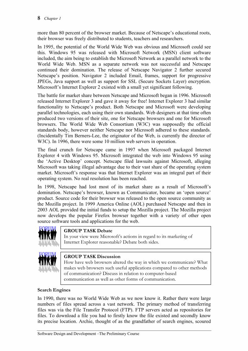
Let us consider some of the new and original ideas incorporated into VisiCalc by Dan Bricklin and Bob Frankston. These ideas are still present in most of today’s spreadsheet applications. • Input, processing and output all merged into a single interface. • Scrolling ability of the window. Left, right, up and down. • Instant recalculation of cells as contents change. • Inclusion of a status and/or formula line. • Ability to replicate a range to any other range. • Relative and absolute referencing. • Formulas could be entered using minimal keystrokes. • Cursor moves are used to select cells and ranges.
Presentation software Prior to the development of the personal computer, software was primarily used for large-scale business, government and military applications. The personal computer allowed us all to have a computer on our desk. Each personal computer could be tailored to the needs of the individual using different software applications. Presentation software, in all its many forms, helped cement the role of the personal computer as an indispensable business tool. Let us examine some of the broad categories of presentation software applications: Slideshows Slideshow applications allow a human presenter to display their notes on a large screen during lectures and seminars. Initially these applications had similar functionality to a traditional slide projector, the advantage being the speed at which the slides could be produced. Current slideshow applications include various animation, sound and interactive features to improve the experience for the audience. Multimedia In the early 1960’s, Ted Nelson came up with the idea of documents being linked together in a non-linear fashion. At that time, he also coined the terms ‘hypertext’ and ‘hypermedia’ for non-sequential writings and branching presentations of all types. In
Fig 1.10 Microsoft’s PowerPoint is a popular slideshow application.
GROUP TASK Investigation Examine a spreadsheet with which you are familiar. Can you identify each of the features listed above?
GROUP TASK Discussion Dan Bricklin and Bob Frankston did not and do not receive royalties for their work developing VisiCalc. Do you think this is socially and ethically reasonable?

14 Chapter 1
Software Design and Development –The Preliminary Course
1987, Apple released Hypercard, an authoring tool for the creation of multimedia titles. Hypercard is based on the idea of ‘stacks’ of cards. Each card contains links to other cards and multimedia content. Multimedia authoring tools are now commonly used for the creation of all types of presentations. They are particularly useful for training and educational products. The non-linear nature of most multimedia titles allows the user to explore areas of interest in a more natural sequence. Screen cameras/recorders These applications allow training and support personnel to create animations detailing the functions of their software products. Essentially the screen camera records the screen changes and is able to play them back. The trainer can superimpose messages and prompts onto the animation to further instruct the students.
Discuss the origin of the design ideas present in today’s graphical user interfaces (GUIs) together with technological advances that made GUIs possible. Suggested Solution
The initial GUI concept was developed in the early 1970s by researchers at Xerox. These ideas were expanded and used by Apple computer to produce the Lisa and then the Macintosh. Bill Gates (Microsoft) realised the potential of a GUI and began work on Windows in the early 1980s. GUI operating systems from both Microsoft and Apple introduced personal computers to the masses. GUI systems use a bitmapped display hence they require significant processing and storage to work successfully. The incredible advances in microprocessor, RAM and screen technologies during the 1980s provided the hardware that allowed GUIs to become the interface of choice for the majority of applications. Faster microprocessors (and then dedicated graphics processors) as well as larger amounts of dedicated video memory (VRAM) meant that better resolution and more colours were possible.
Fig 1.11 Lotus ScreenCam is able to record screen changes.
The result can be edited and played back.
GROUP TASK Investigation Examine a number of presentation software packages. Explain how these package’s ancestors have influenced the wide acceptance of the personal computer.
HSC style question:
GROUP TASK Discussion Creating a GUI is significantly more effort for software developers and uses more processing power compared to using a CLI. Why then do software developers go to the trouble of developing GUI applications?

Social and Ethical Issues 15
Software Design and Development – The Preliminary Course
SET 1A 1. Gopher servers contained:
(A) text based documents. (B) URLs. (C) spiders. (D) robots.
2. Software that locates, accesses and displays web pages is known as: (A) FTP software. (B) a search engine. (C) a web browser. (D) a spreadsheet.
3. The company that refined many of the design concepts that form the basis of today’s Graphical User Interface was: (A) Xerox. (B) Apple. (C) Microsoft. (D) Digital Equipment Corporation.
4. Facebook is an example of a: (A) Search engine. (B) Web browser. (C) Social networking application. (D) Presentation software application.
5. Relative and absolute referencing is a concept that is present in: (A) spreadsheet software. (B) word processor software. (C) presentation software. (D) multimedia software.
6. The first widely available browser was: (A) Amaya. (B) Internet Explorer. (C) Netscape. (D) Mosiac.
7. VisiCalc was developed by: (A) Bricklin and Frankston. (B) Bricklin and Jobs. (C) Frankston and Jobs. (D) Jobs and Wozniak.
8. The computer that is widely recognised as the first to include a fully bit-mapped display is the: (A) Lisa. (B) Alto. (C) Star. (D) Macintosh.
9. Archie was an early example of a: (A) web browser. (B) gopher server. (C) search engine. (D) robot.
10. Tim Berners-Lee developed: (A) the first personal computer. (B) the first search engine. (C) the first web browser. (D) Netscape Navigator.
11. Compare and contrast command line interfaces with graphical user interfaces.
12. List in point form, significant historical events that have influenced the development of today’s search engines.
13. List in point form, significant historical events that have influenced the development of today’s web browsers.
16 Chapter 1
Software Design and Development –The Preliminary Course
14. A screen shot of the original VisiCalc spreadsheet running on a 32kB Apple II is reproduced below. The original version allowed up to 255 rows and 255 columns of cells with a limited (by modern standards) number of built-in formulas.
Describe innovative design features first used in the VisiCalc spreadsheet.
15. Microsoft Corporation is often painted as ‘the bad guy’, yet really they have been highly effective in making the personal computer the success it has become today. Discuss this statement.

Social and Ethical Issues 17
Software Design and Development – The Preliminary Course
INTELLECTUAL PROPERTY All property is protected by law. Essentially, when you purchase any piece of property, whether it is physical goods or software, the original design is protected by law. For example, if you purchase a new desk lamp you do not have rights in regard to the design of the lamp. You own the physical desk lamp, however you do not own the design of the lamp. You therefore cannot utilise your new desk lamp to make copies and you certainly cannot market and sell these copies. Most physical devices are difficult to build and as such, the bulk of the wholesale costs of these items are manufacturing costs. This provides physical products with a built-in safeguard, protecting their designs from copying by the general population. Software together with books, music and films are easily copied and hence require extra protection.
Intellectual property is property resulting from the fruits of mental labour. Intellectual property laws cover the design of most products. Copies of software (and also books, music and film) are relatively simple and inexpensive to make. The copy is usually exactly the same as the original. Furthermore, copies can readily be made by almost anyone with computing knowledge. Laws have now been passed in most countries to protect the intellectual property rights of software developers. These laws aim to encourage the development of software by ensuring software developers are financially rewarded for their intellectual efforts.
In this section, we examine software license agreements and their relationship to intellectual property rights. We also examine historical reasons for the development of copyright laws and licence agreements. This includes the need to license commercial products as well as the need to ascertain the intellectual property rights when software is collaboratively developed. The section concludes by examining sources of code and the conditions under which the code may be used. SOFTWARE LICENCE AGREEMENTS
Software licences are intended to enforce the intellectual property rights of software developers. These licence agreements are enforceable by law. Thus, the terminology used must be legally correct if the agreement is to stand up to the scrutiny of the courts. As well as protecting the intellectual property rights of software developers, licence agreements also protect developers from legal action should their products result in hardship or financial loss to purchasers. Licence terminology
Because of the legal nature of licence agreements, they often use terminology that is difficult to understand. As licence agreements result in a legal contract between the purchaser and the seller, it is important to have an understanding of the terminology used.
• Licence – Formal permission or authority to use a product. In relation to software, licences are almost always non-exclusive; this means the product can be licensed to multiple users. The license does not give users ownership of the software, rather they are granted the right to use the software.
Intellectual Property Property resulting from the fruits of mental labour.

18 Chapter 1
Software Design and Development –The Preliminary Course
• Agreement – A mutual arrangement or contract between parties. Acceptance of a software licence agreement can be made in various ways. Products downloaded from the Internet often require clicking ‘OK’ to on-screen terms and conditions. Installing pre-packaged software indicates acceptance of the agreement. Specialised and custom solutions usually require the signatures of both parties to legalise the agreement.
• Term – The period of time the agreement is in force. In most cases, the licence agreement commences immediately the terms and conditions have been accepted. The agreement remains in force for as long as the terms and conditions are upheld. Normally either party can terminate the agreement if the other party fails to act according to the terms and conditions within the agreement.
• Warranty – An assurance of some sort - a guarantee. Software products normally contain limited warranties. They may guarantee the medium (ie. CD-ROMs) work correctly. However, most warranties will state that the product is sold ‘as is’. This means any bugs in the product, or if the product does not meet the user’s needs, are not covered by the warranty. For custom-built large-scale applications this is often not acceptable and may be replaced by statements limiting the software developer’s liability should a problem occur.
• Limited use – Software licences do not give purchasers unrestricted use of the product. Commonly usage of software products is restricted to a single machine. Copying of the product is not permitted unless for archival or backup purposes. The product cannot be altered or modified.
• Liability – An obligation or debt as a consequence of some event. Licence agreements normally restrict the liability of the software developer to replacing the product or refunding the purchase price should an error or other problem occur.
• Program – Refers to the computer software. This usually includes both executable files and included data files. The program does not include the media; it refers to the software stored on the media.
• Reverse engineer – In terms of software, this usually means the process of decompiling the product. Most agreements do not allow licensees to reverse engineer their products. This protects the intellectual property rights of the software developer.
• Backup copy – A copy of the software made for archival purposes. Backup copies should only be used in the event of the original media failing. If software is resold or the licence agreement terminated then backup copies should be destroyed.
This free trial Software is provided by Parramatta Education Centre, Australia as is, without warranties, express, implied or statutory, with respect to contents hereof, including, without limitations, any implied warranties of merchantability or fitness for any particular purpose, all of which are expressly disclaimed. Neither Parramatta Education Centre nor any of its agents, consultants, contractors, distributors or dealers shall in any event be liable for any direct, indirect, incidental or consequential damages arising from the use of this software.
Fig 1.12 A licence agreement for a free
trial software product.
GROUP TASK Discussion Examine the licence agreement in Fig 1.12. What do you think is the main purpose of this agreement? Do you think this product can be freely copied and distributed? Explain your answer.

Social and Ethical Issues 19
Software Design and Development – The Preliminary Course
Legal aspects
Intellectual property rights are protected using the laws of copyright. Software licence agreements are used to create formal contracts that allow the laws of copyright to be better enforced. There is no need to formally register software products for them to be covered by copyright laws. Coverage is automatic for all intellectual property, however selling or changing the owner of the copyrights for a product requires a written contract.
Products that do not contain licence agreements or copyright notices are still covered by copyright laws. The purpose of licence agreements is to simplify the enforcement process should a breach occur. For copyright laws not to apply, the developer must expressly state that the product is in the public domain and all copyrights have been relinquished.
In Australia, The Copyright Act 1968, together with its various amendments, is the legal document that explains the copyright law. Software licence agreements should comply with these laws if they are to be enforceable by courts. Many countries have reciprocal agreements whereby copyright laws of one country will be upheld in other countries. Use of software covered by a licence agreement
Users of software are obliged to ensure they comply with the terms and conditions of the software’s licence agreement. It is the user’s responsibility to read the licence agreement and understand its terms and conditions before using the product.
Licence agreements for different products can vary considerably, there are however, a variety of categories that encompass most current software licence agreements:
• Commercial – covered by copyright. One archival copy can be made as a backup. The product cannot be modified, distributed or reverse engineered. Source code is not distributed or available to end users.
• Shareware – covered by copyright. Copies can be made for archival or distribution purposes. The product cannot be modified or reverse engineered. Source code is not distributed.
• Freeware – covered by copyright. Copies can be made, distributed and altered. Modified products must also be freeware. Source code may or may not be distributed along with the executable code.
• Public Domain – not covered by copyright. Copies and modifications can be made without restriction. Source code may or may not be distributed along with the executable code.
• Open source licence – although covered by copyright law, open source licences, such as the GNU GPL (general purpose licence), specifically remove many traditional copyrights. The source code is developed collaboratively and is available to all to modify and redistribute. The only significant restrictions being that the author be recognised and that modified products must be released using the same unrestricted open source licence. The aim of open source licences is to ensure users can freely use and modify software without fear of legal challenge. This encourages collaboration and encourages sharing of ideas within the software development community. For most users software distributed under an open source licence can be installed and used without restriction.

20 Chapter 1
Software Design and Development –The Preliminary Course
• Site licence – covered by copyright. Site licences specify either the number of machines on which the software can be installed or they specify the specific location where the software maybe installed on any number of machines. In most cases site licences are used to extend commercial or shareware licences so the software can be used on multiple machines at reduced cost.
• Creative commons licence – alters how copyrighted material maybe used without charge. Creative commons licences are not recommended for most software products as they do not deal with the distribution of source code. Creative commons licences are commonly used for artistic works such as photographs, music, film and other media types. Although the conditions of creative commons licences can be modified to suit specific needs, most permit the work to be freely copied and distributed for non-commercial purposes as long as the original creator is acknowledged.
Consider the GNU General Purpose Licence (GPL):
Open source licences and in particular the GNU GPL are based on the premise that nobody should be restricted by the software they use. The foundation of the GNU GPL is based on the following four freedoms that every user should have:
• the freedom to use the software for any purpose, • the freedom to change the software to suit your needs, • the freedom to share the software with your friends and neighbors, and • the freedom to share the changes you make.
If a software developer releases a software product under the GNU GPL the it will be free and it stays free, regardless of any changes or how the software is distributed. This is called copyleft, instead of using the copyrights to restrict how the software can be used, copyleft removes the restrictions to implement the above four freedoms.
Consider the following: The licence agreement, reproduced on the following page (Fig 1.13), was packaged with a commercial image-processing package called ‘Super Image’.
GROUP TASK Research and discussion Open source software is great for users; however how can software developers hope to make a living if the products of their labour are freely distributed? Research and discuss how open source developers can make a living.
GROUP TASK Discussion Examine the licence agreement on the following page. Under what conditions may the Company terminate the agreement? Under what conditions may the purchaser terminate the agreement?
GROUP TASK Discussion Explain the warranty and liability provisions contained within the licence agreement.

Social and Ethical Issues 21
Software Design and Development – The Preliminary Course
Limited Use Licence Agreement You should carefully read the following terms and conditionsbefore using the Super Image CD-ROM. By using SuperImage, you are agreeing to and indicating your acceptance ofthese terms and conditions. If you do not agree with them youshould return the package to the dealer from whom youpurchased the product and your money will be refunded. If thedealer from whom you purchased this package fails to refundyour money, contact ImageWorks, Inc. immediately.ImageWorks, Inc. (hereinafter referred to as the "Company")provides the computer software (hereinafter referred to as the"Program") contained on the medium in this package andlicenses its use. You assume full responsibility for the selectionof the Program to achieve your intended results and for theinstallation, use and results obtained from the Program.
License A In consideration of the payment of the license fee, you aregranted a personal, non-transferable and non-exclusivelicense to use the Program under the terms stated in theAgreement. You own the diskette or other physical media onwhich the Program is provided under the terms of thisAgreement, but all title and ownership of the Program andenclosed related documentation (hereinafter referred to as"Documentation"), and all other rights not expressly granted toyou under this Agreement, remain with the Company. B You acknowledge that you are receiving on a LIMITEDLICENSE TO USE the Program and Documentation and thatthe Company retains title to the Program and Documentation.You acknowledge that the Company has a valuableproprietary interest in the Program and Documentation. Youmay not use, copy, modify or transfer the Program orDocumentation or any copy, modification or merged portion inwhole or in part except as expressly provided for in thisAgreement If you transfer possession of any copy modificationor merged portion of the Program or Documentation toanother party, your license is automatically terminated. C. You may not sublease, assign or otherwise transfer yourrights under this license to any other person without the priorwritten consent of the Company. D. The Program may be used by you only on a singlecomputer and at no time may it be used by two differentpeople in two different places at the same time. Site licensesfor multiple users are available. Contact ImageWorks, Inc. fordetails. E. You and your employees and agents are required toprotect the confidentiality of the Program. You may not reverseassemble, reverse engineer; decompile or otherwise translatethe Program. This limited license exists solely between youand the Company. F. You may not copy or reproduce the Program orDocumentation for any purpose, except to make one (1)archival copy of the Program, in machine readable or printedform, for back up purposes only in support of your use of theProgram on a single computer. You must reproduce andinclude Company's copyright notice on the backup copy of theProgram. G. Any portion of the Program merged into or used inconjunction with another program will continue to be theproperty of the Company and subject to the terms andconditions of this Agreement. You must reproduce and includeCompany's copyright notice on any portion merged in or usedin conjunction with another program.
H. If you have purchased a NETWORK version of thesoftware, this license agreement applies to the installation ofthe software onto a single file server. It may not be copied ontomultiple systems. Each node connected to the file server mustalso have its own node copy of the software that becomes alicense for that specific user. Term This license granted to you is effective until terminated. Youmay terminate it at any time by returning the Program andDocumentation to the Company together with all copies,modifications and merged portions in any form. The licensewill also terminate upon conditions set forth elsewhere in theAgreement, or if you fail to comply with any term or conditionof this Agreement. You agree upon such termination to returnthe Program and Documentation to the Company togetherwith all copies, modifications and merged portions in any form.Upon termination, the Company can also enforce any rightsprovided bylaw. The provision of this Agreement whichprotects the proprietary rights of the Company will continue inforce after termination. Termination of this license, eithervoluntarily or involuntarily, does not entitle you to a refund ofyour purchase cost except as provided elsewhere in thisLicense Agreement.
Limited Warranty Company warrants, as the sole warranty, that the medium onwhich the Program is furnished will be free from defects inmaterials and workmanship under normal use and conditionsfor a period of ninety (90) days from the date of delivery to youas evidenced by a copy of your receipt. No distributor, dealeror any other entity or person is authorized to expand or altereither this warranty or this Agreement. Any suchrepresentations will not bind the Company. Company doesnot warrant that the functions contained in the Program willmeet your requirements or that the operation of the Programwill be uninterrupted or error-free. Except as stated above inthis section, THE PROGRAM AND DOCUMENTATION AREPROVIDED AS-IS WITHOUT WARRANTY OF ANY KINDEITHER EXPRESSED OR IMPLIED, INCLUDING BUTNOT LIMITED TO THE IMPLIED WARRANTIES OFMERCHANTABILITY AND FITNESS FOR A PARTICULARPURPOSE. You assume entire risk as it applies to the qualityand performance of the Program and Documentation. Shouldthe Program prove defective, you (and not Company,authorized Company Distributor or dealer) assume the entirecost of all necessary servicing repair or correction.
Limitation of Remedies Company's entire liability and your sole remedy will be: A. The replacement of any medium not meeting Company's'Limited Warranty' explained above and which is returned toCompany or an authorized Company distributor or dealer witha copy or your receipt; or B. If Company is unable to deliver a replacement mediumwhich conforms to the warranty provided under thisAgreement you may terminate this Agreement by returningthe Program and Documentation to Company, distributor ordealer from whom you obtained the Program and your licensefee will be refunded.
Fig 1.13 Super Image licence agreement

22 Chapter 1
Software Design and Development –The Preliminary Course
EVENTS THAT HAVE LED TO THE NEED FOR SOFTWARE LICENCE AGREEMENTS
Initially software was developed primarily by universities where the sharing of software was commonplace and indeed encouraged. Licence agreements were not required or even considered, as the owners of machines able to execute the code were also universities. As software development became a commercial endeavour, it became necessary to consider legal methods of protecting the rights of the software developers. The problem was further exacerbated with the widespread use of personal computers and the Internet.
A number of issues particular to the software industry required attention. Ease of reproduction and copy
For most products reproducing the original is a difficult task requiring specialised equipment and skills. For example, consider making a copy of even a simple object such as a pencil. The processes and raw materials required make copying a difficult, impractical and expensive proposition. In the case of software, copying is straightforward. Copies of software products are identical to the original and can easily be made anonymously. To protect software developers licence agreements were created that prohibited the illegal reproduction of their products. Collaborative development history
Software products are commonly evolutionary in nature. Many parent products are used during the development process and many different developers may contribute to each product’s development. Each of these ‘authors’ requires recognition for their work. Licence agreements are a legal means of ensuring author’s intellectual property rights are respected and can be enforced.
Most software products are developed using tools produced by other software development companies. For example, a dynamic link library (DLL) may contain the code that allows a product to communicate using the TCP/IP protocol. The company who developed the DLL has intellectual property rights that should be reflected in the licence agreement for the final software product. Open source licences aim to reduce this complexity buy specifying that derivative products must also be open source. The current open environment of the Internet
The Internet is a worldwide network of computers. As a consequence, software can be transmitted and received across the globe. The Internet opens up worldwide markets to software development companies. This is a fantastic marketing opportunity for software developers. On the other hand, it also makes controlling illegal distribution and use of software very difficult. Licence agreements must be written with reference to international patent and copyright laws if they are to protect the intellectual property rights of the developers. Open source development allows software developers from diverse locations to contribute to a project and benefit from the efforts of all involved.
GROUP TASK Discussion Software is different to most other products. What are these differences and why have they led to the need for licence agreements? Can you think of any other products that require licence agreements before they can be used? What are the similarities between these products and software products? Discuss.

Social and Ethical Issues 23
Software Design and Development – The Preliminary Course
SOURCES OF CODE AND LICENSE CONDITIONS THAT APPLY
The source code for most commercial applications is not freely available. This has advantages for both the developers and the users. Developers can be confident that their source code cannot be stolen and users can feel secure that purchased software is in fact an original (although it may still be a pirated copy of the original). Software companies are better able to provide support for products when they have not been altered by a third party, which in turn results in reduced costs for both developers and users.
There are a number of sources of code where copyright has been relinquished and programmers are free to use the code as they please. Remember, copyright laws hold unless the author specifically and in writing relinquishes these rights. Copyright laws apply regardless of the method of distribution. Let us consider a few possible sources of code where copyright is often relinquished in a spirit of sharing and mutual cooperation. Often the only requirements are that the author be acknowledged and that the code is not to be used for financial gain. The Internet Most of the popular languages have user-groups and newsgroups dedicated to the particular language. Participants in such groups include both novice and experienced programmers. Users are encouraged to relinquish their copyrights when posting modules of code; some groups insist this is done. Remember the quality of code obtained from the Internet will be unknown so care should be exercised when using this type of code in your own projects. Apart from source code, these groups are great places to share programming experiences and to gain advice on problems you may encounter when programming. Books and magazines Source code contained in books and magazines generally form part of a tutorial. It is intended to be used and modified as part of the learning process. Text books dedicated to a particular programming language can be an excellent way of obtaining new insights into the possibilities and capabilities of a particular language. Limitations of the printed media mean that often only small modules used to illustrate some particular process are available. Some magazines and books come with CD-ROMs containing more extensive modules of source code. Remember, copyright must be expressly relinquished before the code can be used.
GROUP TASK Investigation Examine a variety of origins of source code. Take particular note of whether the author has relinquished their copyrights. Why do you think an author would choose to relinquish their copyrights? Why do these authors often not allow their code to be used in commercial products? Discuss.
GROUP TASK Discussion Examine a variety of origins of source code. Take particular note of whether the author has relinquished their copyrights. Why do you think an author would choose to relinquish their copyrights? Why do these authors often not allow their code to be used in commercial products? Discuss.

24 Chapter 1
Software Design and Development –The Preliminary Course
SET 1B 1. In terms of software licences, the term
non-exclusive means: (A) anybody can get a copy of the
product and install it. (B) the product can be licensed to
multiple users. (C) whoever purchasers the software
owns the software. (D) only one person can install and use
the software. 2. Property that results from the fruits of
mental effort is known as: (A) scholastic property. (B) speculative property. (C) academic property. (D) intellectual property.
3. A user is allowed to copy software under which of the following conditions? (A) The software is in the public
domain. (B) The software is freeware. (C) To create one archive backup. (D) All of the above.
4. Software that is NOT covered by copyright is considered to be: (A) public domain software. (B) commercial software. (C) shareware software. (D) freeware software.
5. Arthur has downloaded a software product from the Internet and has modified the product. He has made copies and is distributing these free of charge to his friends. Arthur’s modified software is most likely to be: (A) freeware. (B) shareware. (C) public domain software. (D) None of the above.
6. A software product that where the code is developed collaboratively and is freely available to all is likely to be covered by a: (A) Creative commons licence. (B) Commercial licence. (C) Site licence. (D) Open source licence.
7. A commercial software licence usually gives the user (A) ownership of the software. (B) the right to use the software. (C) the right to distribute the software. (D) the right to modify the software.
8. The process of decompiling is used when: (A) reverse engineering. (B) converse engineering. (C) backwards converting. (D) interpreting.
9. With regard to computer software licences, the term program means: (A) executable files only. (B) executable files and included data
files only. (C) executable files, included data files
and the media they are supplied on. (D) none of the above.
10. For copyright laws NOT to apply, the developer must: (A) expressly state that the product is
in the public domain. (B) not register the product with a
copyright notice. (C) not supply a licence agreement. (D) make the product downloadable
from the Internet only.
11. Describe the relationships between intellectual property, licence agreements and copyright laws.
12. Warranty and liability are terms that are often confused. Define each term and clearly state the differences.
13. Designers of all products have intellectual property rights. Why then, does software require special consideration?
14. Define the terms licence and agreement. How is a licence different from an agreement?
15. Most software can be classified as commercial, shareware, freeware, open source or public domain. Identify differences between each of these categories.

Social and Ethical Issues 25
Software Design and Development – The Preliminary Course
SOCIAL CONTEXT OF SOFTWARE DESIGN
ERGONOMICS
Ergonomics is the study of the relationship between human workers and their work environment. The study of ergonomics is far broader than the prevention of workplace injuries. Ergonomics aims to create a total environment that caters to the physical, emotional and psychological aspects of the work experience. Ergonomically sound work environments improve morale and result in productivity gains for business.
Poor ergonomics in the workplace reduces workers productivity and can cause health issues. The most common and most debilitating computer-usage health issue is Repetitive Strain Injury (RSI). Other health issues involve general muscle strain and vision problems. Ergonomics for computer users includes the design and placement of equipment together with procedures to prevent and minimise injuries.
In this course we are interested in ergonomic considerations in regard to the design and operation of user interfaces within software applications. Much research has been carried out in this area resulting in the production of ergonomically sound software products which improve work practices and the productivity of users. ERGONOMIC ISSUES REGARDING SOFTWARE DESIGN
Software design from the user’s perspective is very much about the user interface. For many users, the user interface is the system. Software developers must create products that meet the needs of users. Products that provide fantastic functionality but have poor user interfaces will not be used. The user interface is the most important aspect of most software products. The better your user interface the more people will use your product.
It is worthwhile examining other software products to evaluate the effectiveness of their user interfaces. Be critical in your evaluation. Many developers perpetuate the errors contained in other products by imitating poor design. Do not assume that large commercial packages are perfect; as we shall see in this section many applications built by global software companies include poor user interface elements.
In terms of ergonomics, the users’ experience should be an intuitive one. Effective user interfaces allow software products to be used with minimal training. The user is able to infer the underlying processing from clues inherent in the user interface. This is a clear indicator of a truly user-friendly product. How is this achieved? In this section, we examine a series of design tips that will help you to create effective and intuitive user interfaces. We also examine examples of poor design to reinforce the importance of each design tip.
Ergonomics The study of the relationship between human workers and their work environment.
User interface The screen designs and connections between screens that allow the user to communicate with the software.
User friendly Software that meets the needs of users. User-friendly software is intuitive, consistent and easily learnt.

26 Chapter 1
Software Design and Development –The Preliminary Course
Consistency, consistency, consistency
The most important aspect of user interfaces is consistency. For example, buttons should be placed in consistent places on all screens. Use the same wording in labels and messages. Use a consistent colour scheme. Consistency of design allows users to transfer skills from other applications and other areas of your application to new areas. A mental model of the software application’s operation is built up in the user’s mind; consistency reinforces this model.
Some points vital to the development of consistent user interfaces include: • Setting standards and sticking to them. Set design standards based on industry
standards and then develop extra standards specific to your application. Most operating system developers have sets of design standards; these standards will often define the majority of your needs.
• Explain the rules. Develop a simple set of rules that apply to your entire application. In this way, you will need to explain your rules only once. This makes more sense than explaining the details of how to use each individual feature of your application.
• Use interface elements correctly. Know when to use screen elements and how to use them correctly. For example, command buttons, check boxes, radio buttons, list boxes, text boxes, menus, etc. Follow recognized standards for each of these elements. Never alter the operation of standard screen elements to perform unexpected functions.
• Use colour appropriately. Colour should be used sparingly. Colour is viewed differently by each individual, what looks pleasing to you may be abhorrent to others. Don’t override a user’s system settings, they chose them and your application should not override their choices. This ensures consistency between applications. Ensure you maintain sufficient contrast between text and backgrounds.
• Use fonts appropriately. The use of fancy fonts can decrease readability considerably. Use fonts that are easy to read. Don’t override system settings for standard fonts. More than three fonts on a single screen are too much. Use fonts consistently, there should be some reason for font changes and the reason should be immediately and consistently clear. Remember you are using a different font every time you change the size, style, typeface or colour.
• Alignment of data entry elements. Text boxes should be left justified with their associated labels also left justified (see Fig 1.14). For columns of data, right justify integer, align decimals to the decimal points and left justify text.
• Provide a consistent method of reversing actions. Users like to explore software applications and are therefore likely to initiate processes that they later wish to reverse. Many software products include an undo function which reverses previous actions. Others require the user to confirm operations that will make extensive changes to data.
Fig 1.14 Alignment of labels and text boxes.

Social and Ethical Issues 27
Software Design and Development – The Preliminary Course
Consider the following:
The following screen shots are taken from commercial software packages. In each case there are consistency problems. • Font dialogue in Microsoft Word. The effects checkboxes on this dialogue in some cases behave like option or radio buttons. For example, Superscript and Subscript cannot be selected at the same time; similarly, Small-caps and All-caps, Emboss and Engrave, Strikethrough and Double strikethrough cannot be selected together. Rather than using option buttons, Microsoft has reprogrammed the checkboxes to behave as option buttons. Perhaps the designers felt the screen looked better this way. Unfortunately, this decision leads to inconsistency and may encourage other developers to do likewise.
• Cut function in Microsoft Excel In most software cut means get rid of it and store it on the clipboard. This is not the case in Microsoft Excel. In this application cut seems to mean leave it there until I decide where to move it. The cut section doesn’t get cut until you activate the paste function. It’s difficult to understand why this popular spreadsheet has been programmed in this way. It certainly makes life confusing for new users. One expects cut to mean just that, cut. The strange thing is, this has been the case since the first version of Excel was released. •
Fig 1.15 Format font dialogue from Microsoft’s Word 2000. Some check boxes behave like option or
radio buttons.
GROUP TASK Investigation Examine the screen elements used on the user interface of software installed on your computer. Compile a list of inconsistencies in regard to inappropriate or non-standard use of these elements.
GROUP TASK Activity Use the cut, copy and paste functions within and between a number of software applications. Describe any differences or issues you encounter.
Fig 1.16 Microsoft Excel’s ‘cut’ does not cut.

28 Chapter 1
Software Design and Development –The Preliminary Course
• MF Rack sound application
This application uses a real world metaphor. It attempts to create a physical audio rack using software. The problem is, it is not a real audio rack and lacks much of the functionality of its real world equivalent. It is almost impossible to intuitively find features necessary for the operation of the software. It took the author of this text around five minutes to work out how to open a file. Eventually I discovered that clicking on the musical note displays a menu that includes an open command. Altering the balance and volume is equally obscure. I soon tired and decided to exit the application. Now how do you do that? After much left and right clicking all over the screen on various controls I managed to exit the program. For the record, the button at the left of the CD section of the rack terminates the program. To use this application you need to forget virtually everything you have ever learnt about how to operate a computer program! In fact, the more software experience you have the more difficulty you will have using this product. This application is totally inconsistent with almost all other software applications. Even within the application, there is no consistency. Graphics that are just graphics, are intermingled with graphics that are in fact controls with no visual differentiation. For example, the open graphics on the cassette decks are just graphics. If you’re asking yourself ‘should I model a user interface on a real world device?’ then the short answer is ‘No’.
Appropriate messages to the user Messages to users are the primary method applications use to communicate problems to users. If these messages are poorly worded then users will perceive the product poorly. Messages should imply that the user is in control not the software. Use full words and sentences, not abbreviations and codes. Ensure messages are unambiguous and are positive. They should provide insight as to how to respond to the message. For example, which is more appealing ‘Incorrect Grade’ or ‘Grades range from A to E’? The wording of messages should be consistent across the application. For example, ‘Grades range from A to E’ and ‘Please enter a mark from 0 to 100’ are worded well when read separately. Together they are inconsistent, given the first message the second could be better written as ‘Marks range from 0 to 100’.
GROUP TASK Investigation Examine the user interface of a variety of software packages. How intuitive did you find each user interface in terms of consistency within the product and compared to other products? Explain.
Fig 1.18 Critical error messages are visually indicated
using a large white cross in a red circle.
Fig 1.17 MF Rack sound application attempts to use a
real world metaphor and fails!

Social and Ethical Issues 29
Software Design and Development – The Preliminary Course
The placement of messages should also be consistent. Generally, users expect messages to appear in the centre of the screen. Many messages are the result of an error of some sort occurring. It is usual to provide some visual clue as to the severity of the error. In MS-Windows, a series of standard icons is used to indicate the general nature of each message e.g. a large white cross in a red circle is used to indicate a critical error and an exclamation mark in a yellow triangle indicates a warning message. Many messages require a response from the user e.g. Yes, No or Cancel. Many users will inadvertently hit the Return/Enter key. It is important that the default option will not cause some potentially destructive action such as deleting or saving.
Consider the following:
The following messages have been taken from commercial software. In each case, the message confuses and confounds the user. • RealPlayer for Windows - Fig 1.19 This is a real catch 22 situation. If there is a problem contacting RealNetworks technical support, then the suggestion is to contact RealNetworks technical support! It seems incredible that such a confusing message exists in such a widely used application. • Dr Zeuss’s ABC - Fig 1.20 Messages should use language appropriate to the language of the intended audience. Some programmers may understand the message shown at right, however this game is intended for 3 to 5 year olds. • Mail Label Maker - Fig 1.21
The message at right is displayed each time data has been sent to the printer. For a start, the message interrupts the user and is unnecessary. Secondly, in this program, it is common to print a number of documents simultaneously; this message occurs for each document printed. You must respond to this silly message before the application will print the next document. Is the application looking for a pat on the back? ‘Ah, I’ve finished printing, aren’t I clever!’ Perhaps other messages should be included, ‘A file is open – OK?’, ‘The file is closed – OK?’, ‘Finished saving – OK?’ As a programmer, do not do this - it is very irritating.
Fig 1.21 This message achieves nothing but irritation.
GROUP TASK Investigation Examine messages generated by a number of applications. Comment on their appropriateness. Do you have any suggestions on how these messages could be improved?
Fig 1.19 Circular logic in RealPlayer for Windows.
Fig 1.20 Messages should suit the intended audience.

30 Chapter 1
Software Design and Development –The Preliminary Course
Ease of use
Good user interfaces are easy to use. Screen elements that are logically connected should be grouped together. Similarly, unrelated items should be separated. White space or frames can be used to accomplish this task.
Navigation between screens should follow the natural flow of the task. Applications should be flexible in this regard; the user should be able to complete tasks in the order they require. Software that forces a linear sequence for completion of tasks controls the user. The user should feel they are in control of the computer. Within each screen, information should be organised left to right and top to bottom. In western society, we expect information to be arranged in this manner.
Applications should support both novice and experienced users. The provision of shortcut keys and advanced functionality should be available. Functionality should not be hidden from the user, as this is how most users learn, by exploring the interface.
Some applications remove menu items that are currently not available; in most cases this is poor design. Rather than removing items, they should be greyed out and disabled. In this way, users can see what is both available and unavailable, helping them to build up a picture of the entire application. It is also poor practice to leave items active that are not relevant at the time. In general, if selecting a command will just result in an error message, then that command should be disabled and greyed.
Busy screens result in confusion for users. Easy to use screens will have white space on approximately 50% of the screen. Some applications go ‘icon crazy’. Icons are great if the meaning of the icon is immediately obvious. If the icon is somewhat obscure then don’t use it, use text instead. Always keep screens simple.
Consider the following:
• Tabbed dialogues Tabbed dialogues, such as the one at right, are difficult for users to navigate. Tabs in the second and third rows jump to the front when clicked. It is most difficult to maintain an understanding of the position of each tab relative to other tabs. Tabbed dialogues are useful screen elements however this example shows how a good idea can be exploited to the extent where it is almost unusable. • Inappropriate use of icons Icons are used to represent or stand for particular operations. If the icon does not easily suggest the operation then it should not be used. Often text is easier to understand. The toolbar at right contains many familiar icons. However, some are rather more obscure. What does the banana signify? Well it actually actives a compression function within the application. It’s difficult to understand why a banana was used.
Fig 1.22 Tabbed dialogues should normally be restricted to a single row.
Fig 1.23 Icons must be intuitively
recognisable to work. Many of the above icons
are not.

Social and Ethical Issues 31
Software Design and Development – The Preliminary Course
• Apple’s Quicktime Player Version 4 This product attempts to use a real world metaphor to create a movie and audio player. The problem is that many of the familiar features of all other common software products have been removed for the sake of a clean and apparently realistic look. There is no minimise or maximise button. The window cannot be resized. It is unclear how to access most of the functionality. Some of the icons do nothing whereas others are command buttons. The play and pause buttons appear to be disabled even when a file is loaded. It is a most confusing and difficult piece of software to use. The volume control is a rotary dial, similar to the volume control on real world stereos. The trouble is, how do you use such a thumb wheel using a mouse? Not an easy proposition. The favourites drawer, which slides out from the bottom of the screen, has many design flaws. The major one being that it does not display the filename just the first frame of each video. Unfortunately, most videos have a black first screen or a copyright notice. This makes the favourites drawer completely useless; it is impossible to identify any difference between video files stored in the drawer. To be fair, more recent versions of Apple’s player corrects these problems.
Acceptable response time in software
The time taken for a process to complete is known as the response time. In relation to ergonomics, response time is the time taken for software to respond to some input from the user. Users expect to see something happening because of their inputs. If a process is likely to take longer than a second to complete then some visual feedback is required. For example, in Outlook Express a progress bar is displayed to provide feedback to users as mail is sent and received (see Fig 1.25).
Response times of around 0.1 second are preferable to give users the impression of instantaneous response. If response times are closer to 1 second or greater then users will feel the computer has taken control. Response times that blow out to more than a few seconds will cause users to act and perhaps reboot or cancel operations. Often response times are linked to the power of the particular machine or the speed of the network connection on which the software is installed. Programmers should ensure users will receive adequate feedback regardless of the machine they are using.
Software accessed via communication links, and in particular the Internet, is particularly vulnerable to response-time problems. The speed of the communication
Fig 1.25 Progress bars are often used to provide feedback.
Fig 1.24 Apple’s Quicktime Player 4 ignores
traditional user interface rules.
GROUP TASK Investigation Use a software product that you have never seen before. List any issues you experienced that made the product difficult to use. Present your findings to your class.

32 Chapter 1
Software Design and Development –The Preliminary Course
link is beyond the control of the software developers. In these cases, it is vital that developers include methods to ensure their products perform satisfactorily under the most adverse conditions. For example, web-based applications should display appropriate messages in place of video and graphics whilst these items are loading. In this way users can commence reading the content of the website whilst media items continue to load. When downloading files, an indication of the approximate time the download will take provides essential feedback for users.
Input screens that contain many list and combination boxes provide excellent data validation, however the response times can often be less than desirable. Data intensive applications will often require extra data structures to negate the need to perform real time processing. For example, bank account transactions are not processed until late at night when processing resources are available; during the day, a record of the currently available balance is maintained. Often a compromise must be reached between response times and data validation.
The following messages were generated by a single software application:
Comment on the appropriateness of these messages in terms of: (a) the language and icons used (b) the options available to the user Suggested solution (a) The language in the first message is good however the second message is too
personal. Users know computers are machines, hence it is inappropriate to make it appear to be a person. If the function cannot be performed then it would be better to prevent the user to initiating the function in the first place, perhaps the control that generated the message should have been disabled. The icon used on the first message is appropriate as it indicates a minor problem, however the big cross on the second message is inappropriate; such icons are used to indicate a critical error that requires the application to close.
(b) On both messages the options available make little sense. The first message is providing information and just the OK button is needed, it is unclear what the functional difference is between the OK and the cancel buttons. The second message is similarly unclear, the text of the message indicates that the function cannot be performed so there is nothing to abort, or retry? It is similarly unclear what would occur if ignore is selected.
HSC style question:
GROUP TASK Discussion Reducing response times for applications involving large amounts of input is vital. Discuss some strategies software developers could employ to assist in the reduction of response times in their products.

Social and Ethical Issues 33
Software Design and Development – The Preliminary Course
SET 1C 1. From a user interface perspective, the
most important aspect is: (A) use of colour. (B) correct alignment of fields. (C) consistency. (D) correct use of option buttons.
2. A programmer would use progress bars as a means of: (A) validating the data. (B) screen navigation. (C) providing feedback to the user. (D) none of the above.
3. A software developer’s product must: (A) be consistent in its design. (B) meet the needs of the user. (C) be ‘user friendly.’ (D) all of the above.
4. The primary method that an application uses to communicate problems to users is: (A) messages. (B) progress bars. (C) dialogue buttons (D) applications do not communicate
with the user. 5. Users are likely to feel that the computer
has taken control when response times exceed: (A) 0.1 second. (B) 1 second. (C) 2 seconds. (D) more than a few seconds.
6. Icons are most useful when they: (A) are intuitively recognisable. (B) have different colours. (C) replace tabbed dialogues. (D) all of the above.
7. Command buttons, check boxes and radio buttons can best be described as: (A) screen elements. (B) application elements. (C) function elements. (D) design elements.
8. A programmer could use which to ensure data is validated? (A) Tabbed dialogues. (B) Progress bars. (C) Icons and shortcut keys. (D) List and combination boxes.
9. If a software application is intuitive, consistent and easy to learn then it could be considered to be: (A) functionally correct. (B) user friendly. (C) meeting the needs of the user. (D) a perfect software application.
10. The percentage of white space appearing on a well-designed screen, should be about: (A) 70% (B) 50% (C) 40% (D) 20%
11. Programs with fantastic functionality may not be commercially successful. Why could this be the case?
12. Each of the messages below are from the same software application. Comment on the appropriateness of these messages.

34 Chapter 9
Software Design and Development –The HSC Course
13. Consistent user interfaces are more user friendly. List and describe important aspects to consider when designing a consistent user interface.
14. The screen that follows is taken from a program that is used to transfer files to and from remote computers. Normally the transfer is to or from a web server.
Critically evaluate this screen.
15. Redesign the above screen to overcome the problems you identified in Question 14.

Social and Ethical Issues 35
Software Design and Development – The Preliminary Course
INCLUSIVITY Inclusive software should take into account the different users who will likely use the product; as software developers, we have a responsibility to ensure that this is the case. Furthermore, software products that do not take into account the different characteristics of users are less likely to secure a significant market share, which would result in lower sales and reduced profits. Let us now examine a number of individual and group characteristics that should be considered when designing software solutions. In most cases, these characteristics will have direct consequences for the design of the user interface. Cultural background The culture of a people can be described as the set of ways of living built up over a period of time and passed from generation to generation. It is important that the beliefs and language of different cultures be considered when designing software. Similarly, the social structure of societies is influenced by their underlying culture. How do we cater for these differences in practice? Firstly, we must understand or at least be empathetic to the needs of other cultures. It is not possible to be an expert on all cultures, however we can easily include users from a variety of cultures as part of the testing processes occurring during development. For example, in most western cultures we have a Christian name and a surname. This is not the case in many Asian cultures where a formal name and an informal name are more commonly used. Testing that includes users from the Asian culture, would quickly highlight this difference. Numbers, currency, times and dates are another common area of difference between cultures. In Australia, we express dates using day then month then year (e.g. 25/1/2012). In America, they more commonly use month then day then year (e.g. 1/25/2012). Again, those used to an alternative format, would soon encounter problems. Similarly, the format of numbers and currency is different in other countries. Sweden uses a comma as its decimal point and a period as a multiplication sign. 5.2 in Sweden would mean 5 times 2 and 3,255 would mean 3 point 255. The dominant language of a country should be used on the user interface when applications are to be sold to those cultures. Many large-scale systems manage to utilise any number of languages by storing the text used to label the interface in a text file that is loaded as the application starts. By altering this single text file the language used by the application can be customised to suit any foreign language. It may not be practical to rewrite our interfaces using a large variety of foreign languages, however we can design them using English that is clear, consistent and unambiguous. In this
Inclusive Containing, embracing or comprising everything concerned. Comprehensively includes and takes account of stated concerns.
Fig 1.26 Windows allows the format of numbers, currency, times and dates to be altered.
manjeet.kaur
Highlight
manjeet.kaur
Highlight
manjeet.kaur
Highlight
manjeet.kaur
Highlight
manjeet.kaur
Highlight
manjeet.kaur
Highlight
manjeet.kaur
Highlight
manjeet.kaur
Highlight
manjeet.kaur
Highlight
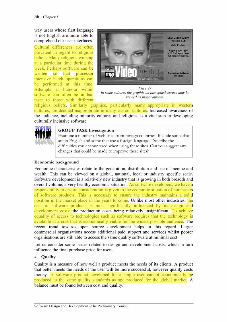
36 Chapter 1
Software Design and Development –The Preliminary Course
way users whose first language is not English are more able to comprehend our user interfaces. Cultural differences are often prevalent in regard to religious beliefs. Many religions worship at a particular time during the week. Perhaps software can be written so that processor intensive batch operations can be performed at this time. Attempts at humour within software can often be in bad taste to those with different religious beliefs. Similarly graphics, particularly many appropriate in western cultures, are deemed inappropriate in many eastern cultures. Increased awareness of the audience, including minority cultures and religions, is a vital step in developing culturally inclusive software.
Economic background Economic characteristics relate to the generation, distribution and use of income and wealth. This can be viewed on a global, national, local or industry specific scale. Software development is a relatively new industry that is growing in both breadth and overall volume; a very healthy economic situation. As software developers, we have a responsibility to ensure consideration is given to the economic situation of purchasers of software products. This is necessary to ensure the industry maintains a solid position in the market place in the years to come. Unlike most other industries, the cost of software products is most significantly influenced by its design and development costs; the production costs being relatively insignificant. To achieve equality of access to technologies such as software requires that the technology is available at a cost that is economically viable for the widest possible audience. The recent trend towards open source development helps in this regard. Larger commercial organisations access additional paid support and services whilst poorer organisations are still able to access the same quality software at minimal cost. Let us consider some issues related to design and development costs, which in turn influence the final purchase price for users. • Quality Quality is a measure of how well a product meets the needs of its clients. A product that better meets the needs of the user will be more successful, however quality costs money. A software product developed for a single user cannot economically be produced to the same quality standards as one produced for the global market. A balance must be found between cost and quality.
GROUP TASK Investigation Examine a number of web sites from foreign countries. Include some that are in English and some that use a foreign language. Describe the difficulties you encountered when using these sites. Can you suggest any changes that could be made to improve these sites?
Fig 1.27 In some cultures the graphic on this splash screen may be
viewed as inappropriate.
manjeet.kaur
Highlight
manjeet.kaur
Highlight
manjeet.kaur
Highlight
manjeet.kaur
Highlight
manjeet.kaur
Highlight
Administrator
Highlight
Administrator
Highlight
Social and Ethical Issues 37
Software Design and Development – The Preliminary Course
• Nature of the market Software developers must understand the market needs before embarking on new product development projects. It is not economically feasible to develop a product where the need it is intended to meet is of less value than the product’s cost. A feasibility study should be undertaken to determine economic feasibility of any new software project. As software developers, we should acknowledge that some market needs are better met by non-computer based solutions. • Management of the software design and development process There are various software development approaches, (see chapter 3) suited to the creation of different products. Choosing a suitable approach will result in a more economically viable product. Different work environments can also influence those involved in software development. It is often possible for developers to work flexible hours and to work from home. By creating structures that help developers work more effectively, managers will reduce costs and increase the quality of the software produced. • Influences on pricing Companies are ultimately in business to make money. This is the basis of most western capitalist economies. History shows us that companies that have a monopoly in their industry tend to produce inferior products at higher costs to consumers. As a result these companies make large profits. Competition and in some cases government regulation can assist in ensuring software products are sold at realistic prices and are within the financial grasp of a wide audience. Gender In most cases the first thing we ask when a new baby is born is whether it is a boy or a girl. In actuality, this is probably the first thing we perceive when we meet anybody for the first time. We seem to inherently know and sense the differences between the sexes. We don’t need to view a face or hear a voice; small almost imperceptible cues almost always allow us to correctly identify the gender of a person. So what are the major differences and how should these differences be included when designing and developing software? Firstly, both men and women should be included in the software design and development process. At the time of writing, men dominate the industry. Many view this as a natural consequence resulting from one of the major perceived differences between men and women. Programming is viewed as a technical, mathematical process with rigid boundaries. Research shows that rightly or wrongly, men predominate in these types of occupations. Since men are engaged in the creation of software, it follows that some bias is likely to exist towards males in the products they develop. Computers generate precise scientific-type responses; this is the nature and construction of the machines. In general, research has shown that men prefer black and white situations; they wish to reach a definite solution. On the other hand, women often see problems in a broader sense. They are interested in ensuring the method of solution is socially acceptable and are generally better at reaching and accepting more flexible solutions. Software should be designed to allow for both styles of solution. Traditionally software has been written to solve problems that do have definite answers (e.g. a set of inputs is processed into a unique set of outputs). Current
manjeet.kaur
Highlight
manjeet.kaur
Highlight
manjeet.kaur
Highlight
manjeet.kaur
Highlight

38 Chapter 1
Software Design and Development –The Preliminary Course
advances in artificial intelligence now allow computers to assist in the solution of a much broader range of problems using less structured solution techniques. Disability Software design should include functionality that allows software to be used and accessed by a wide range of users. The computer and its associated software has revolutionised the lives of many disabled people. It is estimated that one in five people have some form of disability that will affect their capacity to access and use software in the usual way. To ensure maximum accessibility to those users with a disability, software designers have a number of tools and techniques available at their disposal. Let us examine some broad categories of disability and discuss some accessibility techniques that should be considered by software designers. • Visual disabilities Simply using larger fonts and providing the facility for controls and graphics to be scaled may overcome reduced visual ability. Most operating systems provide these features and software developers should ensure they utilise the operating system’s settings within their products. Colour blindness and other related conditions make it difficult to distinguish different colours and colour combinations. For this reason, colour should not be used as the sole method of conveying information. For example, Internet links are often blue, however they should also be underlined. To accommodate users with severe to total impairment requires software to correctly interface with speech generation and Braille utilities. These utilities are able to read the text labels on the user interface and convert them into speech or Braille. In this way, the utility is able to track and describe what the user is doing. Graphics can be a problem for these readers; it is recommended that labels be used to identify all functional graphics.
• Hearing disabilities Software should not rely on sound as the sole method of communicating information. It should be used to emphasise and/or reinforce other visual clues. Utilities are available that will give some visual clue if a sound has been produced. Software developers should be aware that for many hearing-impaired users English is their second language, their first language being sign language.
Fig 1.28 The PowerBraille (top) is both an input and
display device. The BrailleBlazer (bottom) is a Braille embosser for creating Braille hardcopy.
GROUP TASK Research Search the Internet for both software and hardware to support the visually impaired. Compile a list of devices and software found, together with a brief description of the purpose of each one.
manjeet.kaur
Highlight
manjeet.kaur
Highlight
manjeet.kaur
Highlight
manjeet.kaur
Highlight
manjeet.kaur
Highlight
manjeet.kaur
Highlight

Social and Ethical Issues 39
Software Design and Development – The Preliminary Course
• Physical disabilities Some users have difficulty performing certain physical tasks. They may not be capable of using a mouse or they may find it difficult to reliably press a single key on the keyboard. Other disabilities may severely limit physical movement to the face or even just the mouth. For these people, the ability to use computer software is vital if they are to successfully communicate. Many software utilities that interface with specialised input devices for the disabled utilise the standard keyboard interface; in effect they send the same data as a standard keyboard. It is therefore vital that the user interface is able to be controlled using just the keyboard. Accessibility features found in many operating systems and applications to assist the physically disabled include: altering the time-delay before keys repeat when held down; allowing keyboard combinations to be entered one key at a time e.g. pressing Ctrl and then pressing S without the need to hold down Ctrl; changing the keyboard layout; simulating the mouse using the cursor keys; changing the mouse pointer speed and adjusting the double-click speed. Specific applications are available to perform input and output functions from and to specialised hardware devices. Many of the input devices are simple switches of varying size and sensitivity to suit the needs of the individual user. For example, users without the use of their limbs are able to use head movement detection devices to control input to an onscreen keyboard. Various other examples of switches are shown in Fig 1.29. The software interfacing with these devices commonly uses short mnemonics and word prediction to speed up data-entry. Sentences that are commonly used can be pre-defined and completed with a single input.
Fig 1.30 WiVik2 Scan provides an onscreen keyboard
that interfaces with most applications and specialised input devices.
P-Switch controlled by fine muscle movements in the eyebrow area
Sip and puff switch controlled by the users breath
Large movement rocker switch controlled by the arm or chin Tongue switch
Fig 1.29 Switches are used to provide the input to
specific accessibility applications.
GROUP TASK Research Search the Internet for both software and hardware to support the physically impaired. Compile a list of the devices and software found, together with a brief description of the purpose of each one.
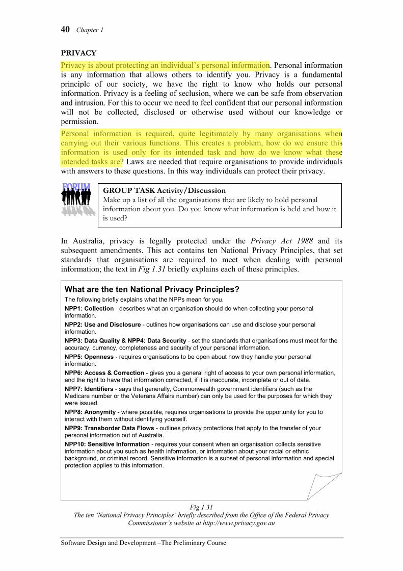
40 Chapter 1
Software Design and Development –The Preliminary Course
PRIVACY Privacy is about protecting an individual’s personal information. Personal information is any information that allows others to identify you. Privacy is a fundamental principle of our society, we have the right to know who holds our personal information. Privacy is a feeling of seclusion, where we can be safe from observation and intrusion. For this to occur we need to feel confident that our personal information will not be collected, disclosed or otherwise used without our knowledge or permission. Personal information is required, quite legitimately by many organisations when carrying out their various functions. This creates a problem, how do we ensure this information is used only for its intended task and how do we know what these intended tasks are? Laws are needed that require organisations to provide individuals with answers to these questions. In this way individuals can protect their privacy.
In Australia, privacy is legally protected under the Privacy Act 1988 and its subsequent amendments. This act contains ten National Privacy Principles, that set standards that organisations are required to meet when dealing with personal information; the text in Fig 1.31 briefly explains each of these principles.
What are the ten National Privacy Principles? The following briefly explains what the NPPs mean for you. NPP1: Collection - describes what an organisation should do when collecting your personal information. NPP2: Use and Disclosure - outlines how organisations can use and disclose your personal information. NPP3: Data Quality & NPP4: Data Security - set the standards that organisations must meet for the accuracy, currency, completeness and security of your personal information. NPP5: Openness - requires organisations to be open about how they handle your personal information. NPP6: Access & Correction - gives you a general right of access to your own personal information, and the right to have that information corrected, if it is inaccurate, incomplete or out of date. NPP7: Identifiers - says that generally, Commonwealth government identifiers (such as the Medicare number or the Veterans Affairs number) can only be used for the purposes for which they were issued. NPP8: Anonymity - where possible, requires organisations to provide the opportunity for you to interact with them without identifying yourself. NPP9: Transborder Data Flows - outlines privacy protections that apply to the transfer of your personal information out of Australia. NPP10: Sensitive Information - requires your consent when an organisation collects sensitive information about you such as health information, or information about your racial or ethnic background, or criminal record. Sensitive information is a subset of personal information and special protection applies to this information.
Fig 1.31 The ten ‘National Privacy Principles’ briefly described from the Office of the Federal Privacy
Commissioner’s website at http://www.privacy.gov.au
GROUP TASK Activity/Discussion Make up a list of all the organisations that are likely to hold personal information about you. Do you know what information is held and how it is used?
manjeet.kaur
Highlight
manjeet.kaur
Highlight
Social and Ethical Issues 41
Software Design and Development – The Preliminary Course
Consequences of the Privacy Act 1988 mean that information systems that contain personal information must legally be able to: • explain why personal information is being collected and how it will be used • provide individuals with access to their records • correct inaccurate information • divulge details of other organisations that may be provided with information from
the system • describe to individuals the purpose of holding the information • describe the information held and how it is managed
REQUIRED SKILLS IN SOFTWARE DESIGN AND DEVELOPMENT The design and development of quality software requires skilled personnel. Technical expertise although very necessary, does not on its own result in high quality products. Each member of the development team needs to communicate and work with other members to achieve a common goal. The team should comprise of those with specialised skills with regard to creativity and design. All members will need advanced problem-solving skills tuned to their particular work area. People need ongoing training to continuously develop and expand their skills. We are never too old or too experienced to learn new things. This is particularly the case with software development where new technologies and methodologies emerge constantly. Let us examine some general strengths required by those involved in the software design and development process. Communication skills Successful communication results when a message is understood precisely by the recipient; this rarely occurs. Acquiring skilled communication techniques is a learning process. Different forms of communication will require different skills; communication can be formal, informal, aggressive, passive, spoken, written, verbal and/or non-verbal. Feedback is required to confirm that the intended message was received correctly. If software is to be of high quality, then it must fulfil the needs of users. Communication skills are required to understand and refine user’s needs. Different modes of communication should be used when determining these needs. For example, a structured survey may be appropriate for determining technical requirements, however user interface design needs may be better understood using a prototype together with informal observation of the user’s work routines. The communication skills required for each of these scenarios are quite different. Internal communication within the software development team is complex; each individual comes to the team with different experiences and technical skills. Software development is a fairly structured process, therefore formal structures for communication need to be implemented and communicated to personnel. For example, particular modules of code need to be assigned to particular programmers for coding. On the other hand, informal communication should be encouraged
GROUP TASK Research Social networking sites routinely collect and store personnel information. Research the privacy policies and security mechanisms used to control access to this personnel information.
manjeet.kaur
Highlight
manjeet.kaur
Highlight
manjeet.kaur
Highlight
manjeet.kaur
Highlight

42 Chapter 1
Software Design and Development –The Preliminary Course
between team members to facilitate the flow of knowledge and expertise. For example, a problem encountered by one programmer may have already been previously encountered and solved by a colleague. Informal discussions may uncover this fact allowing the work to be accomplished more efficiently.
Ability to work in teams Software development is a collaborative process involving system analysts, graphic designers, programmers, software engineers, hardware engineers, managers, software testers, support personnel, etc. All these people must work together to achieve a common goal. Commonly, teams are created containing members with different expertise and skills; these members work together to create the software product. The ability to work in teams is therefore crucial to the creation of quality software. Some requirements and skills necessary for working successfully in teams include: • Openness and willingness to share and accept other ideas. • Support of other team members. • Commitment to the team’s performance rather than individual performance. • Team members should be treated as equals. • Interpersonal communication skills between team members. • Listening skills are vital. Individuals should not dominate. • Leadership should be shared by the group. • Self-motivation is required as teams manage themselves. • Respect for other member’s skills and knowledge.
Creativity Creativity is the ability to develop original ideas. Each software product is different and therefore requires original ideas during development. Creativity is not restricted to artistic endeavours; it encompasses any original or new thought. For example, when designing the user interface, there will be a number of different possible solutions. Some may be less functional than others and some may be more original than others. Creativity will be required to solve new problems effectively; often the most obvious solution is not the best solution. Creativity encourages new ways of looking at problems and their solutions. The design of system models and algorithms requires creativity coupled with advanced design and problem-solving skills. Each new system will involve the creation of new solution techniques; creativity is required to formulate these original ideas. There are often many ways of solving a particular problem. Creativity can be described as the ability to formulate alternative solutions.
GROUP TASK Activity Each class member is to write a one or two sentence summary of the above paragraphs on communication skills. Compare the sentences written by each student. Discuss reasons why the summaries are not the same.
GROUP TASK Discussion Work teams, when properly constructed, have been shown to consistently outperform other management structures. Why do you think this is the case? Discuss.

Social and Ethical Issues 43
Software Design and Development – The Preliminary Course
Design skills Design is the process of planning the method of solution. In terms of software design, it involves the creation of system models. These models describe the structure and processing of the software, together with screen designs for the user interface. Design skills are also required to produce algorithms. Personnel involved in the design process require a toolkit of modelling techniques from which they can draw upon. System flowcharts, dataflow diagrams, structure charts, IPO charts and data dictionaries are some of the possible tools available to software designers. These tools are used to describe the overall design of the system to other developers on the team. Similarly, flowcharts and pseudocode describe the algorithms required to code the individual modules within the solution. Technical skills Technical knowledge and skills with regard to the technologies being used are essential for all software development personnel. Within a team of developers a range of technical skills will be required. The range of technical skills should complement each other. For example when designing user interfaces the developer must possess the technical skills to position and align screen elements, whilst they must also have experience with usability issues and knowledge of the underlying functionality being implemented. Technical skills are required to transform the design into source code. Problem-solving skills Problem-solving skills are crucial to most aspects of software design and development. To solve problems efficiently requires the ability to analyse the requirements of the problem and create the most suitable method of solution. Gaining experience solving problems using different techniques, will help you develop a personal style that suits your thought processes. There are many possible techniques that can be employed to assist this process. Let us briefly examine a few common techniques: • Brainstorming - Focus on the problem. Come up with as many different possible
solutions to the problem. Brainstorming is usually performed by a group of people. The idea is to come up with as many possible solutions without critically analysing each possibility. This technique encourages the emergence of creative solutions.
• Critical path analysis - This technique is particularly useful for determining the time it will take to complete a project. The focus is on the tasks that will lead to the final solution. Some tasks may be completed in isolation whereas others must be performed in a particular sequence. This technique allows one to determine the overall flow of the solution processes.
• S.T.A.I.R. (Statement of the problem, Tools available, Algorithm, Implementation, Refinement) - The problem is first described in general terms. We then consider the tools that will be required to solve the problem. Considering the problem and the tools, we develop an initial method of solution (algorithm). We attempt to implement our algorithm. Often our first attempt will require refinement to achieve the desired result.
There are many other problem-solving techniques available. It is important that those involved in software development arm themselves with a variety of problem-solving skills and techniques. Different problems will lend themselves to different problem-solving approaches.

44 Chapter 1
Software Design and Development –The Preliminary Course
Consider the following:
Imagine you and two friends wish to go to the Gold Coast for a holiday. Let us consider each of the above problem-solving techniques using this problem: • Brainstorming - The three of you sit around and come up with as many possible
ways of organising your holiday. You could drive, catch a bus, catch a plane or go by boat. You could stay in a hotel, a motel, a caravan park or sleep on the beach. The aim of brainstorming is to come up with many different possibilities without criticising any at this stage.
• Critical path analysis - Using this technique you consider requirements and how they affect the solution For example, you can’t leave until school breaks up and you must be back before the school term resumes. This determines the possible dates for departure and return. You then consider how to get to the Gold Coast; each mode of transport considered must be available at the nominated time and be within your budget. Once transport is decided, you consider accommodation. It must be available within the constraints of the transport. This process continues until the details of your trip are formulated.
• S.T.A.I.R. – In this case the problem that needs to be solved is to organise the Gold Coast holiday. We then consider the available tools: perhaps you have car and camping gear, one of your friends may have relatives you could possibly stay with, your budget may be limited, you know your parents want you to have a phone where you stay, etc. These tools are then combined into a possible method of solution (algorithm): You can travel by car and stay with your friends relatives (this way a phone is close by). You commence implementing this solution and find that your friend’s relatives cannot accommodate all three of you. As a result, you refine your solution. Your new solution involves camping in your friend’s relatives yard.
Attention to detail Computers are rather unforgiving machines. One tiny mistake in a complete software product can result in errors that crash an entire software product. A simple oversight during the initial design stages can prove increasingly more costly to correct as development proceeds. For this reason it is necessary for developers to be particularly attentive to detail.
Consider the following:
A software development company has been contracted to create a product to automate the functions of a chain of service stations. A series of system models has been produced and the software has been coded. The product is now ready for installation at each of the service stations.
GROUP TASK Activity Imagine you wish to find the best way of travelling from home to a concert at the Entertainment Centre in Sydney. Use each of the three techniques described above to assist in reaching a solution.

Social and Ethical Issues 45
Software Design and Development – The Preliminary Course
A problem emerges. Many of the service stations purchase their fuel from different suppliers. The initial requirements determined by the system analyst did not factor in this possibility. It is found that some 50% of the service stations are affected. Consequently, these service stations are unable to order their fuel using the system and must resort to manual procedures. Although the problem can be corrected, it has tainted the system in the eyes of many of the service station owners.
Inclusive software can be used and understood by the widest possible audience. This audience includes those with various types and degrees of disability.
Discuss techniques that can be used by software developers to ensure their products can be used by those with:
(a) visual disabilities.
(b) physical disabilities. Suggested solution (a) For those with visual impairment the font and in particular the font size is often
critical. Fonts and font sizes can be specified within the operating system; software developers should use these settings and adjust their screens accordingly. The colours used, and in particular the contrast between colours, on screens should be considered. Even minor visual disabilities such as colour blindness can make many colour combinations impossible to discern. Users with no sight at all commonly rely on their hearing; they use products that read out the text on the interface, hence graphics should include invisible attached text labels that can be read by such products.
(b) Many physical disabilities mean that controlling a mouse or similar pointing device is impossible; all functionality should be accessible using the keyboard as many input devices for the physically disabled create signals that imitate those created by the keyboard. Most operating systems include settings for such things as rate of key repeat, double click speed, etc. Software applications should not override such settings, rather they should access and use them appropriately.
GROUP TASK Discussion The software development company must bear the cost of correcting this oversight. What procedures could be implemented by the software developer, to ensure this type of problem does not recur in the future?
HSC style question:

46 Chapter 1
Software Design and Development –The Preliminary Course
CHAPTER 1 REVIEW 1. Joe, Hannah and Oscar are focusing on
the particular tasks required to complete their software development project. They could be said to be using which technique in their problem-solving efforts? (A) mind-mapping. (B) S.T.A.I.R. (C) Critical path analysis. (D) Brainstorming.
2. Which of the features listed is NOT an ergonomically sound feature of a graphical user interface? (A) Consistent placement of screen
elements. (B) Exclusive use of icons to initiate all
functions. (C) Correct use of screen elements. (D) Ability to reverse or undo actions.
3. Communication between team members should be of a(n): (A) formal nature. (B) informal nature. (C) both (A) and (B). (D) fully documented.
4. Reverse engineering of software often involves: (A) compiling. (B) recompiling. (C) decompiling (D) non-compiling.
5. A program that automatically fetches web page data for inclusion in search engines is known as a: (A) spider. (B) robot. (C) both (A) and (B) (D) none of the above.
6. Prior to commencing the development of a new software product which study should be first undertaken? (A) A development approach study. (B) A marketing study. (C) A feasibility study. (D) A quality assurance study.
7. Something that comprehensively includes and takes into account the stated concerns is said to be: (A) inclusive. (B) sympathetic. (C) economic. (D) creative.
8. Quality in terms of software development can be measured by: (A) a cost benefit analysis. (B) how well the product meets the
needs of the users. (C) the amount of functionality the
product has. (D) the cost of the development.
9. Ergonomics is best described as the study of the: (A) interaction between humans and
their work environment. (B) interactions between one culture
and another culture. (C) interactions between hardware and
software. (D) user interface.
10. Screens and the connections between the screens that allow the user to communicate with the software is called the: (A) system model. (B) screen elements. (C) screen design. (D) user interface.
11. Outline the processes performed by a social networking application with which you are familiar. Explain how the privacy of user’s personnel information is addressed within this application.
12. Outline the range of skills required for a software development team to complete a software project.

Social and Ethical Issues 47
Software Design and Development – The Preliminary Course
13. The above screen is from Intel’s Video Wave 1.0 product for Windows machines. Evaluate this screen design in terms of your knowledge of ergonomics. Comment on both positive and negative aspects of the design.
14. What is intellectual property? Why are intellectual property rights of particular concern in regard to software compared to other physical products?
15. Software should be inclusive. What does this mean? Describe areas that should be addressed when evaluating inclusivity.

48 Chapter 2
Software Design and Development –The Preliminary Course
In this chapter you will learn to: • identify the elements of a computer system and
their role in that system • describe the significance of and interaction
between the elements comprising computer systems
• describe how data is captured, stored, manipulated or displayed on a variety of hardware devices. Select ONE device from each: – Input: keyboard, mouse, scanner, radio
frequency identification (RFID), barcode reader, graphics tablet, microphone
– Output: laser printer, inkjet printer, cathode ray tube (CRT), LCD display, plasma display, CD writer/burner, DVD writer/burner, data projector, speakers
– Storage: CD, DVD, flash drive, hard drive • competently use computer hardware, selecting
appropriate hardware for specific tasks • identify the impact of using particular devices on
the development and use of software • identify typical tasks performed by operating
systems: – batch job scheduling – emulation
• competently use a range of software • describe the development of the generations of
programming languages • identify the effect of the generations of
programming languages on software development practices
• distinguish between methods of translation • identify typical tasks performed by operating
systems • describe what happens during each of the steps of
the fetch-execute cycle • identify the role of specific hardware used during
each step of the fetch-execute cycle
Which will make you more able to: • describe the functions of hardware and software • describe the interactions between the elements of
a computer system • describe developments in the levels of
programming languages • describe the effects of program language
developments on current practices • identify the issues relating to the use of software
solutions • describe the skills involved in software
development.
In this chapter you will learn about: Elements of a computer system • hardware • software • data • procedures • personnel
Hardware • the function of hardware within a computer
system, namely: – input – output – process – storage – control
• how a variety of input devices, output devices, storage devices and CPU components achieve their purpose
• the current trends and developments in computer hardware
Software • operating systems and utilities, such as:
– file compression – defragging – virus checking – embedded licence installation counts
• off-the-shelf applications packages and custom-designed software
• generations of programming languages, namely: – machine code: 1st generation – assembly language: 2nd generation – higher-level languages (imperative/procedural):
3rd generation – declarative (non-procedural) languages: 4th
generation • the need for translation
– compilation – interpretation
• functions of operating systems – provide interface to hardware – provide interface to user – provide interface to software applications – control the concurrent running of software
applications – manage system resources: time (multitasking),
memory, data, hardware devices • current trends in the development of software and
operating systems
The relationship between hardware and software • processing of software instructions by hardware
– the fetch-execute cycle • the initiation and running of an application by the
operating system – locate and load application – hand control to application – start fetch-execute cycle for application
• the existence of minimum hardware requirements to run some software

Hardware and Software 49
Software Design and Development – The Preliminary Course
2 HARDWARE AND SOFTWARE
Computer systems are comprised of various elements. Commonly these elements are grouped into hardware, software, data, personnel and procedures. All computer systems operate using a combination of each of these components. Elements from each of these groups are required for the successful operation of the system. Hardware is the physical components of the system; the things you can touch. For example, the keyboard, mouse, hard drive, microprocessor, monitor and printer. Software is the instructions and programs that control the hardware causing it to perform some function. For example, a word processor, operating system, web browser, spreadsheet or even a programming language environment. Data is the raw information; the inputs into the system. The data is input into the system, processed by the system and then output as information. Personnel are the people involved in using the system. This includes users, network administrators, support teams, maintenance technicians and engineers. Procedures are modes of action that personnel perform to initiate and complete tasks. For example, backup procedures, how to load paper into the printer, or how to load a file. In this chapter we focus on the hardware and software elements of computer systems. We first examine how hardware functions to capture, store, manipulate and display data. The operation of some common hardware devices is then explained in some detail. Then we examine software in its many forms, focusing on programming languages. The translation of source code to machine-executable code is also discussed. Finally the relationship between hardware and software is considered. How does computer hardware execute software instructions? We answer this question by examining the fetch-execute cycle and the sequence of events occurring when an application is first run.
Hardware
Software
Data Personnel
Procedures Computer
System
Fig 2.1 Elements of computer systems.
GROUP TASK Activity Consider either your home or classroom computer as a system. Identify each component. Group these component elements as either hardware, software, data, personnel or procedures.

50 Chapter 2
Software Design and Development –The Preliminary Course
ELEMENTS OF A COMPUTER SYSTEM The five elements present in all computer-based systems are hardware, software, data, procedures and personnel. Each of these elements plays a role in the operation of the system and should be considered during the design and development of software products. Hardware is made up of the physical elements of the system. Software is the instructions controlling the hardware. Data is the raw inputs used during processing that are transformed by the system into information. Personnel include all people involved or influenced by the system and procedures are actions performed by these personnel to operate the system or support the operation of the system.
Each system is composed of a series of sub-systems. Each sub-system being a system in its own right. For example, a personal computer contains a video sub-system, a keyboard sub-system, a secondary storage sub-system. etc. Each of these sub-systems can be considered as a separate system, however they all work together to perform the functions of the larger parent system.
Consider a typical video arcade game machine:
• Hardware – items include the chair, monitor, steering wheel, brake and accelerator pedals, gear shift, CPU, hard disk, power supply, sound system, coin input system.
• Software – operating system, software drivers for each hardware device and of course the game itself.
• Data – inputs from the coin slot, steering wheel, peddles and gear shift. Scenery and vehicle data stored on the hard disk.
• Personnel – players, arcade workers, technicians, software developers, support team.
• Procedures – how to start and play the game. How to empty the coin tray. How to replace components.
System
Sub-system A
Sub-system B
Fig 2.3 Systems are composed of
sub-systems.
Proce-dures
Pers-onnel
Data
Hard-ware
Soft-ware
Fig 2.2 Computer systems contain five
basic elements.
Fig 2.4 A typical video arcade
game console.
GROUP TASK Discussion The above video arcade game system can be viewed as a series of sub-systems. List and describe a series of sub-systems contained within a typical video arcade game machine.

Hardware and Software 51
Software Design and Development – The Preliminary Course
Consider the computer-based systems used within a newsagency:
• Hardware – cash register, barcode scanner, computer linked to lottery office,
EFTPOS machine, communication connections and modems to lottery office and bank.
• Software – controlling software in cash register, lottery computer and EFTPOS machine, communication software to communicate with lottery office and bank.
• Data – cash tendered and change amount, items in stock, lottery data including lotto numbers and lottery ticket numbers, withdrawal amounts and authorisations to and from the bank.
• Personnel – sales staff, manager, customers, lottery representatives and technical staff, bank representatives and technical staff.
• Procedures – sequence of operations carried out by sales personnel to affect a sale, security procedures, how to balance the cash register each day, backup procedures, stocktaking procedures, manual procedures to be used in the event of a power or communication failure.
Consider the following scenarios:
1. An author writing a book using a home computer.
2. An automatic teller machine in a shopping centre.
3. The engine management system in a car.
4. A customer support officer working for an Internet Service Provider (ISP).
5. A typical self-serve petrol station.
GROUP TASK Discussion In the above system, the cash register, lottery computer and EFTPOS systems are not electronically linked. Procedures performed by the sales staff provide this link. Describe the likely steps performed by a sales assistant when a customer purchases a lottery ticket using EFTPOS.
GROUP TASK Discussion For each of the above scenarios list and describe elements of the system in terms of hardware, software, data, personnel and procedures.
GROUP TASK Discussion Software developers need to consider more than just the hardware on which their systems will run. Why is this necessary? Discuss using examples from the above scenarios to justify your answers.

52 Chapter 2
Software Design and Development –The Preliminary Course
Function An activity or sequence of activities carried out by a device or person. Their purpose being to carry out this function. (Different to the programming language meaning).
HARDWARE All hardware must perform some function if it is to be of use to the system. Commonly, hardware devices are categorised according to their main function. Keyboards are primarily input devices as they provide a human-machine interface allowing people to input data into the computer system. Similarly, the monitor provides a human-machine interface by converting digital signals from the processor into light in the form of text and graphics that can be understood by the human brain. THE FUNCTION AND OPERATION OF HARDWARE WITHIN A COMPUTER SYSTEM There are essentially five functions performed by hardware devices: input, output, processing, storage and control. These five basic hardware functions combine to perform all the actions of all computer systems. In brief, input is received from outside the system and processed into output. This processing may involve reading and/or writing to storage. Control is the function that coordinates the sequencing and timing of the other functions. Fig 2.5 illustrates the flow of data between each of these functions. Notice that control is positioned within the processing function. Control is a form of processing that directs every other function. Data is not moved or processed by control functions, rather other functions are instructed to commence their actions. Let us now consider each of these five basic hardware functions, included the operation of typical devices used to perform each function. INPUT Input is the function that obtains data from outside the system. This usually involves the user pressing a key, moving the mouse or initiating some other action. Their action (input) is converted into a binary electronic signal by the input device. This signal is sent to a buffer where it is accessed by the processor. The buffer is a circuit that is part of Random Access Memory (RAM) that allows devices operating at different speeds to communicate correctly. The input may come from a variety of sources including: • users entering data via a keyboard, mouse, barcode reader or other input device • communication links such as a local area network or the Internet • sensors such as microphones, cameras, temperature sensors, pressure sensors, optical
sensors, motion sensors. Note that storage devices also perform input functions however their main function is one of storage and as such are classified separately. It is not possible to study the operation of all the various types of input device; therefore we restrict our discussion to the keyboard, mouse, scanners (including barcode scanners), RFID and microphones (and sound cars).
Hardware The physical components of the system. The things you can see and touch. Hardware includes input, processing, storage and output devices.
Inpu
t
Output
Storage
Processing
Control
Fig 2.5 Hardware functions and their interactions.

Hardware and Software 53
Software Design and Development – The Preliminary Course
Keyboard
In essence a keyboard is a collection or matrix of switches; each switch completes a circuit to indicate a particular key, or combination of keys, has been pressed. A digital code representing the key is then sent as an electrical signal to the computer. Sounds relatively simple, however in reality the keyboard is an amazing mix of ergonomic and technological design.
To structure our discussion let us work through the operations occurring as a single character is collected. That is, from the time the user presses a key until the computer receives the information.
First the user decides which key to press and locates that key. This may seem obvious but there are many aspects of keyboard design that facilitate this process. Consider the standard design of the keys; in most cases a QWERTY layout is used, the layout of the keys needs to be familiar if the user is to efficiently locate the correct key. Consider the physical size and shape of each key and the way each row is staggered relative to other rows (see Fig 2.6); these attributes are common to almost all keyboards, they allow users to transfer their keyboard skills from one keyboard to another. At first glance most keys appear to be cubes; actually they are tapered, with the top surface of each pad slightly concave; these design elements assist the fingers to positively locate the required keypad without touching adjoining keys.
So the user now presses the key; during this process the keyboard provides feedback to the user. Finger pressure moves the key down then upon release the key springs back to its original position, at the same time an audible ‘click’ is often produced. This feedback is a major factor in determining the general feel of a keyboard and is perhaps the most significant reason conventional keyboards are considered superior to most notebook keyboards; notebooks minimise the downward throw of each key to reduce their thickness.
Contained under each keypad is a switch which completes a circuit indicating precisely which key has been pressed. There are various designs of key switch used for this process; older designs use a matrix of mechanical switches, each switch being similar to those used for other applications such as door bells. At the time of writing, the most common designs utilise flexible rubber or silicone domes. Some use a separate dome with carbon button for each key (see Fig 2.7). When a key is pressed the dome flexes, causing the carbon button to complete a circuit on the underlying circuit board, when released the dome springs back to its original shape. Other designs utilise two printed circuit boards separated by a thin film containing a hole for each key (see Fig 2.8); the domes are contained within a single silicone membrane. When a dome is depressed the contacts touch through the hole in the film to complete the circuit. All these designs are far simpler, and cheaper to produce, than traditional switches; furthermore the domes protect the actual switch contacts from dust and liquid spills.
Fig 2.6 Section of a QWERTY keyboard.
Note the staggered rows and standard size and shape of each key.
Keycap
Carbon button
Circuit board
Plastic dome
Fig 2.7 Detail of a typical flexible dome key switch similar to those used
on many keyboards.

54 Chapter 2
Software Design and Development –The Preliminary Course
The circuit board is really a matrix of wires; the intersection of a row and a column identifying a specific key. Each row and column is connected to the keyboard’s internal controller which is a microchip contained within the keyboard case. The controller’s job is to make sense of these signals and convert them into binary data for transmission to the computer. In actuality the controller detects changes in voltage; as a key is pressed the voltage in that circuit goes from low to high, and similarly when a key is released the voltage returns from high back to low. Every key is associated with a pair of scan codes; the ‘make code’ is generated as the key is pressed and the second, known as the ‘break code’, is generated when the key is released. The controller produces these scan codes, stores them in its own internal memory and sends them to the computer usually via a USB (Universal Serial Bus) interface cable.
The USB cable contains four wires; two are used to power the keyboard, and the remaining two are used for transmission of the scan codes and other control data. The cable connects to the motherboard via a USB port.
When a series of scan codes arrive at the motherboard they are stored in memory and the operating system is notified using an interrupt request. The operating system, with assistance from the keyboard driver software, then examines the scan codes and responds accordingly. In most cases the scan codes are converted into a representation that includes the key’s ASCII code together with information in regard to any modifier keys that may have been used. This data is passed to the currently active application. In other words the operating system transforms the scan code data into information that is meaningful to the application. This means different keyboard layouts are specified at the operating system level rather than at the keyboard itself; Fig 2.10 shows a screen used to implement this facility within Microsoft’s Windows XP; obviously the labels on each key would require alteration to reflect the changes made to such settings. The operating system also intercepts keystrokes that are intended for
Fig 2.10 Changing the keyboard layout to Dvorak using the control panel in Microsoft’s Windows XP.
Silicon dome membrane
Upper printed circuit board
Thin separation film with holes
Lower printed circuit board
Fig 2.8 Detail of a keyboard design utilising a silicon membrane of domes and two
circuit boards separated by a thin film.
Fig 2.9 Detail of the keyboard controller
within Microsoft’s ‘Natural’ Keyboard.
Board connecting key matrix to controller
Keyboard internal controller
Interface cable to computer
Row and column matrix

Hardware and Software 55
Software Design and Development – The Preliminary Course
system level tasks, such as switching between applications, starting new applications or even rebooting the system.
So far we have only considered the transfer of data from the keyboard to the computer, however some data also travels in the other direction. For example when the caps lock is pressed the operating system responds to these scan codes by sending the keyboard a message to turn on or off the caps lock light. There is also data returned to the keyboard each time an error occurs in the transmission of a scan code; each error signals the keyboard’s internal controller to resend the last scan code.
Consider the following:
All keyboards contain groups of keys that perform related actions. Consider the following groupings: • Alphanumeric and punctuation keys (e.g. A-Z) • Modifier keys (e.g. Shift) • Numeric keypad (e.g. 0-9) • Function keys (e.g. F1) • Cursor control and navigation keys (e.g. Page Up) • Other specialised keys (e.g. keys for Internet access)
Mouse The basic design of the mouse were first conceived by Douglas Englebart in 1964; it was some 20 years later, when Apple released the Macintosh, that the mouse became the input device of choice. Today it is hard to imagine using a computer without a mouse. The mouse is primarily used to collect movement data in two dimensions; usually this data is used by the computer to control the position of the cursor on the monitor. In addition mice include a number of buttons and many also include a scroll wheel that doubles as an extra button.
So what happens when we move a mouse; that is, how does the mouse detect this movement and transform it into digital data for use by the computer? Currently optical designs dominate the market as they do not have any moving parts. Older designs included a rolling rubber ball, however they required regular cleaning to remove accumulated dust that would foul the internal mechanism. We restrict our discussion to the operation of an optical mouse.
GROUP TASK Activity Most standard keyboards contain at least 104 keys. Examine the keyboard you use and classify each of the keys using the above bulleted list.
GROUP TASK Research Research a variety of different keyboard layouts, including those used for specific purposes such as point of sale machines and for disabled persons.
GROUP TASK Activity There are many other input devices that collect movement data similar to that collected by a mouse. Create a list of such devices.
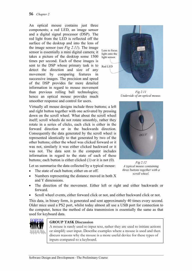
56 Chapter 2
Software Design and Development –The Preliminary Course
An optical mouse contains just three components; a red LED, an image sensor and a digital signal processor (DSP). The red light from the LED is reflected off the surface of the desktop and into the lens of the image sensor (see Fig 2.11). The image sensor is essentially a mini digital camera; it takes a picture of the desktop some 1500 times per second. Each of these images is sent to the DSP whose primary task is to detect the direction and size of any movement by comparing features in successive images. The precision and speed of the DSP provides far more detailed information in regard to mouse movement than previous rolling ball technologies; hence an optical mouse provides much smoother response and control for users. Virtually all mouse designs include three buttons; a left and right button together with one activated by pressing down on the scroll wheel. What about the scroll wheel itself; scroll wheels do not rotate smoothly, rather they rotate in a series of clicks, each click is either in the forward direction or in the backwards direction. Consequently the data generated by the scroll wheel is represented identically to that generated by two of the other buttons; either the wheel was clicked forward or it was not, similarly it was either clicked backward or it was not. The data sent to the computer includes information in regard to the state of each of these buttons; each button is either clicked (1) or it is not (0). Let us summarise the data collected by a typical mouse: • The state of each button; either on or off. • Numbers representing the distance moved in both X
and Y dimensions. • The direction of the movement. Either left or right and either backwards or
forward. • Scroll wheel events, either forward click or not, and either backward click or not. This data, in binary form, is generated and sent approximately 40 times every second. Older mice used a PS2 port, whilst today almost all use a USB port for connection to the computer, hence the method of data transmission is essentially the same as that used for keyboard data.
Fig 2.11 Underside of an optical mouse.
Lens to focus light onto the light sensor.
Red LED
Fig 2.12 A typical mouse containing
three buttons together with a scroll wheel.
GROUP TASK Discussion A mouse is rarely used to input text, rather they are used to initiate actions or simplify user input. Describe examples where a mouse is used and then discuss reasons why the mouse is a more useful device for these types of inputs compared to a keyboard.
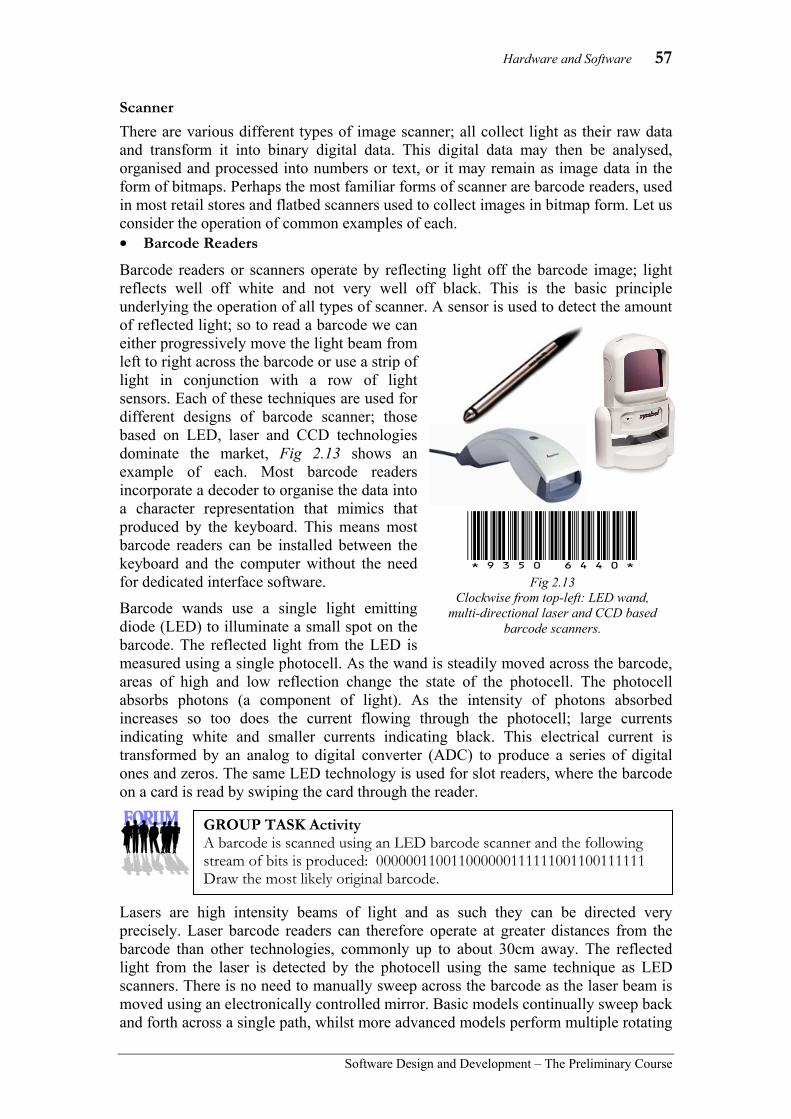
Hardware and Software 57
Software Design and Development – The Preliminary Course
Scanner There are various different types of image scanner; all collect light as their raw data and transform it into binary digital data. This digital data may then be analysed, organised and processed into numbers or text, or it may remain as image data in the form of bitmaps. Perhaps the most familiar forms of scanner are barcode readers, used in most retail stores and flatbed scanners used to collect images in bitmap form. Let us consider the operation of common examples of each. • Barcode Readers
Barcode readers or scanners operate by reflecting light off the barcode image; light reflects well off white and not very well off black. This is the basic principle underlying the operation of all types of scanner. A sensor is used to detect the amount of reflected light; so to read a barcode we can either progressively move the light beam from left to right across the barcode or use a strip of light in conjunction with a row of light sensors. Each of these techniques are used for different designs of barcode scanner; those based on LED, laser and CCD technologies dominate the market, Fig 2.13 shows an example of each. Most barcode readers incorporate a decoder to organise the data into a character representation that mimics that produced by the keyboard. This means most barcode readers can be installed between the keyboard and the computer without the need for dedicated interface software.
Barcode wands use a single light emitting diode (LED) to illuminate a small spot on the barcode. The reflected light from the LED is measured using a single photocell. As the wand is steadily moved across the barcode, areas of high and low reflection change the state of the photocell. The photocell absorbs photons (a component of light). As the intensity of photons absorbed increases so too does the current flowing through the photocell; large currents indicating white and smaller currents indicating black. This electrical current is transformed by an analog to digital converter (ADC) to produce a series of digital ones and zeros. The same LED technology is used for slot readers, where the barcode on a card is read by swiping the card through the reader.
Lasers are high intensity beams of light and as such they can be directed very precisely. Laser barcode readers can therefore operate at greater distances from the barcode than other technologies, commonly up to about 30cm away. The reflected light from the laser is detected by the photocell using the same technique as LED scanners. There is no need to manually sweep across the barcode as the laser beam is moved using an electronically controlled mirror. Basic models continually sweep back and forth across a single path, whilst more advanced models perform multiple rotating
*9350(6440! Fig 2.13
Clockwise from top-left: LED wand, multi-directional laser and CCD based
barcode scanners.
GROUP TASK Activity A barcode is scanned using an LED barcode scanner and the following stream of bits is produced: 000000110011000000111111001100111111 Draw the most likely original barcode.

58 Chapter 2
Software Design and Development –The Preliminary Course
sweeps that trace out a ‘star like’ pattern. These advanced models are much more effective as the user need not hold the scanner parallel to the barcode; rather the scanner rotates the scan line until a positive read is collected. Supermarkets often use this type of barcode scanner mounted within the counter top.
Charge coupled devices (CCDs) contain one or more rows of photocells built into a single microchip. CCD technology is used by many image collection devices including CCD barcode scanners, digital still and video cameras, handheld image scanners, and also flatbed scanners. For both barcode and image scanners a single row CCD is used (refer Fig 2.14). The light source for these scanners is typically a single row of LEDs with the light being reflected off the image back to a mirror. The mirror reflects the light onto a lens that focuses the image at the CCD. Each photocell in the CCD transforms the light into different levels of electrical current. These levels are converted into bits using a similar technique to that used in LED and laser barcode scanners.
• Flatbed Scanners
Let us now consider flatbed scanners based on CCDs in detail. This type of flatbed scanner is by the far the most common; scanners based on other technologies are available, but currently they fall into the higher quality and price ranges. CCDs in flatbed scanners differ slightly from those used in barcode readers. Within flatbed scanners the CCD converts the electrical current from each photocell into a binary number, normally between 0 and 255, using a more complex analog to digital converter (ADC). 0 to 255 is the range of different numbers that can be represented using 8 bits (1 byte). If white light is used then these numbers will represent shades of grey, ranging from black (0) to white (255). So how do flatbed scanners collect colour images? Quite simply, they reflect red light off the original image to collect the red component, green to collect the green component and blue for the blue component. Some early scanners performed this action by doing three passes over the entire image using a different coloured filter for each pass; this technique is seldom used today. Today most scanners use an LED light source that cycles through each of the colours red, green, blue; hence only a single pass is needed.
Mirror Lamp (or row of LEDs)
Original image
Lens
CCD Digital output
Fig 2.14 The components and light path typical
of most CCD scanner designs.
ADC
GROUP TASK Investigation Barcode scanners are used in most retail stores and libraries. Over the next 24 hours observe closely each barcode scanner you encounter. Classify each as using either LED, laser or CCD technology. Justify your choices.
GROUP TASK Discussion The pixels (picture elements) in many images use 24 bits per pixel. 8 bits are used to represent red, 8 bits for green and 8 bits for blue. How many different colours are possible and how much memory is required to represent an image with a resolution of 1680 by 1050 pixels?
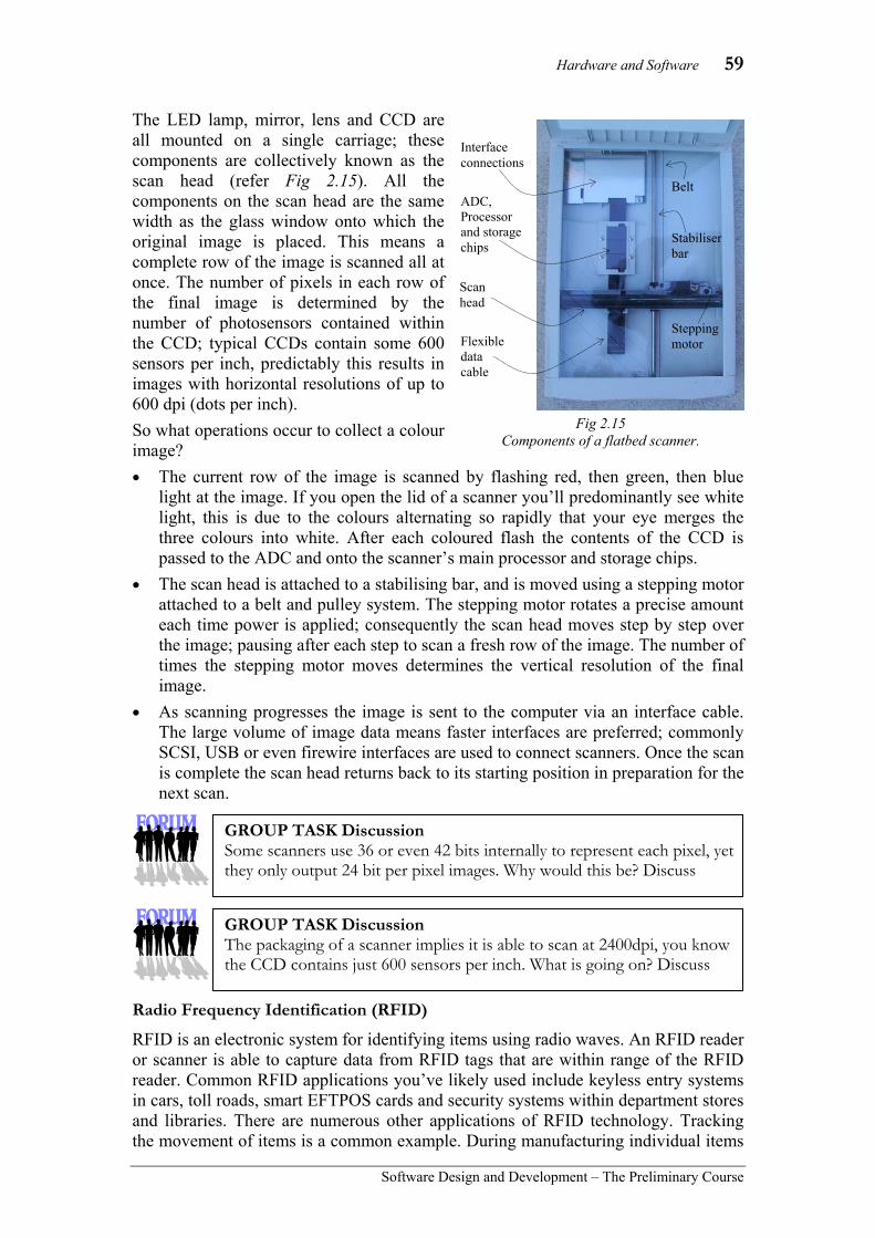
Hardware and Software 59
Software Design and Development – The Preliminary Course
The LED lamp, mirror, lens and CCD are all mounted on a single carriage; these components are collectively known as the scan head (refer Fig 2.15). All the components on the scan head are the same width as the glass window onto which the original image is placed. This means a complete row of the image is scanned all at once. The number of pixels in each row of the final image is determined by the number of photosensors contained within the CCD; typical CCDs contain some 600 sensors per inch, predictably this results in images with horizontal resolutions of up to 600 dpi (dots per inch). So what operations occur to collect a colour image? • The current row of the image is scanned by flashing red, then green, then blue
light at the image. If you open the lid of a scanner you’ll predominantly see white light, this is due to the colours alternating so rapidly that your eye merges the three colours into white. After each coloured flash the contents of the CCD is passed to the ADC and onto the scanner’s main processor and storage chips.
• The scan head is attached to a stabilising bar, and is moved using a stepping motor attached to a belt and pulley system. The stepping motor rotates a precise amount each time power is applied; consequently the scan head moves step by step over the image; pausing after each step to scan a fresh row of the image. The number of times the stepping motor moves determines the vertical resolution of the final image.
• As scanning progresses the image is sent to the computer via an interface cable. The large volume of image data means faster interfaces are preferred; commonly SCSI, USB or even firewire interfaces are used to connect scanners. Once the scan is complete the scan head returns back to its starting position in preparation for the next scan.
Radio Frequency Identification (RFID)
RFID is an electronic system for identifying items using radio waves. An RFID reader or scanner is able to capture data from RFID tags that are within range of the RFID reader. Common RFID applications you’ve likely used include keyless entry systems in cars, toll roads, smart EFTPOS cards and security systems within department stores and libraries. There are numerous other applications of RFID technology. Tracking the movement of items is a common example. During manufacturing individual items
Scan head
Stepping motor
Interface connections
ADC, Processor and storage chips
Belt
Stabiliser bar
Flexibledata cable
Fig 2.15 Components of a flatbed scanner.
GROUP TASK Discussion The packaging of a scanner implies it is able to scan at 2400dpi, you know the CCD contains just 600 sensors per inch. What is going on? Discuss
GROUP TASK Discussion Some scanners use 36 or even 42 bits internally to represent each pixel, yet they only output 24 bit per pixel images. Why would this be? Discuss
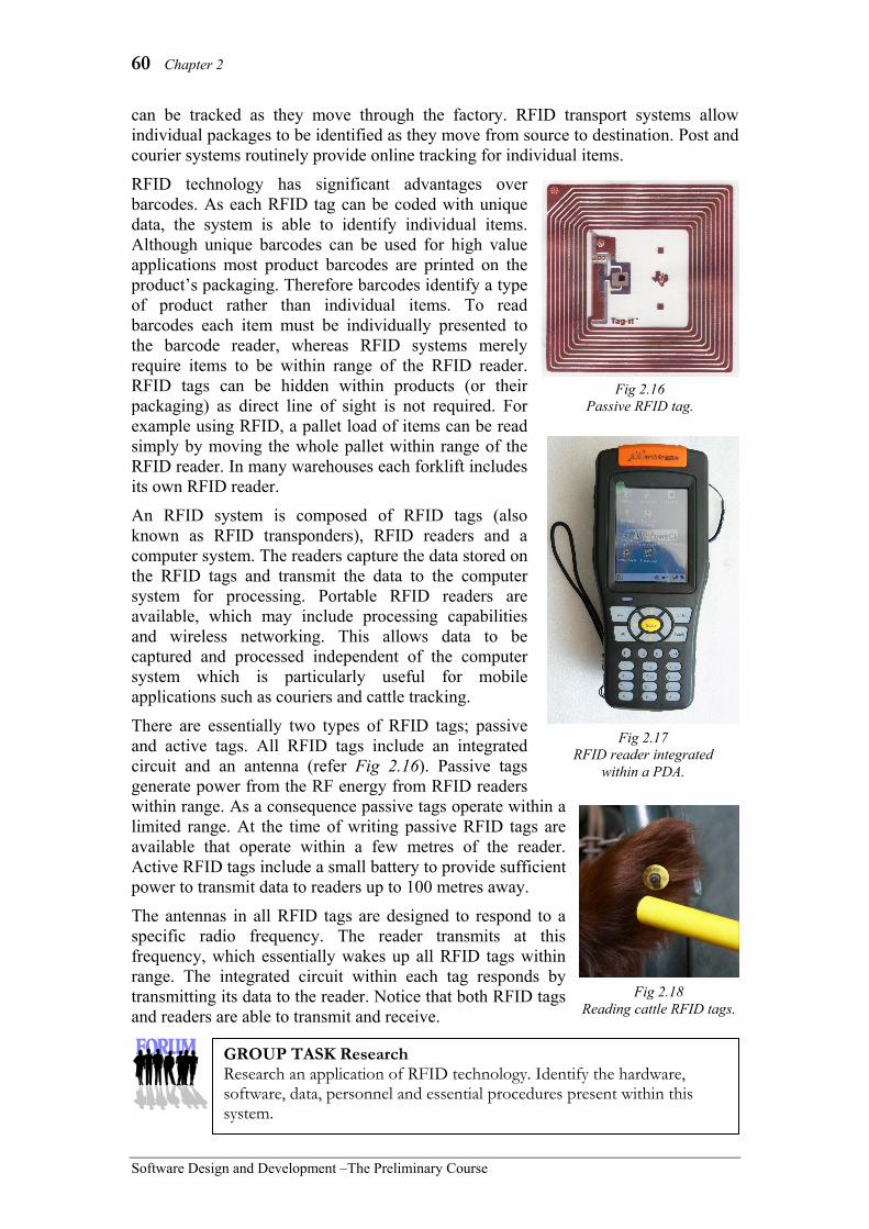
60 Chapter 2
Software Design and Development –The Preliminary Course
can be tracked as they move through the factory. RFID transport systems allow individual packages to be identified as they move from source to destination. Post and courier systems routinely provide online tracking for individual items.
RFID technology has significant advantages over barcodes. As each RFID tag can be coded with unique data, the system is able to identify individual items. Although unique barcodes can be used for high value applications most product barcodes are printed on the product’s packaging. Therefore barcodes identify a type of product rather than individual items. To read barcodes each item must be individually presented to the barcode reader, whereas RFID systems merely require items to be within range of the RFID reader. RFID tags can be hidden within products (or their packaging) as direct line of sight is not required. For example using RFID, a pallet load of items can be read simply by moving the whole pallet within range of the RFID reader. In many warehouses each forklift includes its own RFID reader.
An RFID system is composed of RFID tags (also known as RFID transponders), RFID readers and a computer system. The readers capture the data stored on the RFID tags and transmit the data to the computer system for processing. Portable RFID readers are available, which may include processing capabilities and wireless networking. This allows data to be captured and processed independent of the computer system which is particularly useful for mobile applications such as couriers and cattle tracking.
There are essentially two types of RFID tags; passive and active tags. All RFID tags include an integrated circuit and an antenna (refer Fig 2.16). Passive tags generate power from the RF energy from RFID readers within range. As a consequence passive tags operate within a limited range. At the time of writing passive RFID tags are available that operate within a few metres of the reader. Active RFID tags include a small battery to provide sufficient power to transmit data to readers up to 100 metres away.
The antennas in all RFID tags are designed to respond to a specific radio frequency. The reader transmits at this frequency, which essentially wakes up all RFID tags within range. The integrated circuit within each tag responds by transmitting its data to the reader. Notice that both RFID tags and readers are able to transmit and receive.
Fig 2.18 Reading cattle RFID tags.
Fig 2.16 Passive RFID tag.
Fig 2.17 RFID reader integrated
within a PDA.
GROUP TASK Research Research an application of RFID technology. Identify the hardware, software, data, personnel and essential procedures present within this system.

Hardware and Software 61
Software Design and Development – The Preliminary Course
Microphone (and sound card) Microphones are, predictably, used to collect data in the form of sound waves. They convert these compression waves into electrical energy. In digital systems, this analog electrical energy is converted, using an analog to digital converter (ADC) into a series of digital sound samples. In this section we examine the operation of microphones and then consider the operations performed by a typical sound card to process the resulting analog electrical energy into a sequence of digital sound samples. There are a variety of different microphone designs, the most popular being dynamic microphones and condenser microphones. All these designs contain a diaphragm which vibrates in response to incoming sound waves. If you hold your hand close to your mouth whilst talking you can feel the effect of the sound waves; the skin on your hand vibrates in response to the sound waves in exactly the same way as the diaphragm in a microphone vibrates. A dynamic microphone has its diaphragm attached to a coil of wire; as the diaphragm vibrates so too does the coil of wire (see Fig 2.20). The coil of wire surrounds, or is surrounded by, a stationary magnet. As the coil moves in and out the interaction of the coil with the magnetic field causes current to flow through the coil of wire. This electrical current varies according to the movement of the wire coil, hence it represents the changes in the original sound wave. Condenser microphones alter the distance between two plates (see Fig 2.21). The diaphragm is the front plate; it vibrates in response to the incoming soundwaves, whereas the backplate remains stationary. Therefore the distance between the diaphragm and the stationary backplate varies; when the two plates are close together electrical current flows more freely and as they move further apart the current decreases, hence the level of current flowing represents the changes in the original sound waves. Condenser microphones require a source of power to operate; this can be provided from an external source via the microphone’s lead or by using a permanent magnetically charged diaphragm.
Sound waves
Magnet
Wire coil
Diaphragm
Electric current
Fig 2.20 Detail of a dynamic microphone.
Sound waves
Diaphragm
Backplate
Electric current
Power source
Fig 2.21 Detail of a condenser microphone.
Fig 2.19 A dynamic microphone element.
This one has the magnet mounted within the wire coil.
Wire coil
Magnet
GROUP TASK Investigation Make a list of all the microphones you see each day. Can you determine whether these microphones are dynamic, condenser or some other design?

62 Chapter 2
Software Design and Development –The Preliminary Course
Consider the following:
The varying electrical current produced by a microphone is essentially the same as the raw analog signal output from all types of audio devices. Therefore it is possible to connect any of these different audio sources to one of the analog input ports on a computer’s sound card; just be careful to connect to a port designed for the level of signal produced by the device. There are usually a number of input ports on most sound cards suited to different levels of analog input signal.
Let us now consider the processes taking place once the analog signal from the microphone reaches the computer’s sound card. The signal is fed through an analog to digital converter (ADC), which predictably converts the signal to a sequence of binary ones and zeros. The output from the ADC is then fed into the digital signal processor (DSP), whose task is to clean up any abnormalities in the samples. The final sound samples are then placed on the computer’s data bus. The data bus feeds the samples to the main CPU, where they are generally sent to a storage device. The major components involved in processing the audio data are the analog to digital converter (ADC) and the digital signal processor (DSP). Let us consider each of these components in more detail. Analog to digital converters (ADCs) repeatedly sample the magnitude of the incoming electrical current and convert these samples to binary digital numbers; for audio data the size of the incoming current directly mirrors the shape of the original sound wave, hence the digital samples also represent the original wave. The ADCs used in many other devices, including scanners and digital cameras, are essentially the same as those found on sound cards; the CCDs in image collection devices produce varying levels of electrical current that represent the intensity of light detected at each photosite. The electrical signal is much the same as that produced by audio collection devices.
GROUP TASK Investigation Examine the ports, and accompanying documentation, for either your school or home computer’s sound card. Describe the difference between each of the input ports and list suitable audio sources that could be connected to each port.
Fig 2.22 Creative’s Audigy sound card.
GROUP TASK Activity Brainstorm a list of hardware devices that would likely include an analog to digital converter. Indicate the type of data collected by each device and how different levels of electrical current could be used to represent the identified type of data.

Hardware and Software 63
Software Design and Development – The Preliminary Course
Most analog to digital converters contain a digital to analog converter (DAC). On the surface this seems somewhat strange; however the digital to analog conversion process is significantly simpler than the corresponding analog to digital conversion process. The components and data connections within a typical ADC are shown in Fig 2.23; this ADC performs its conversion using the following steps: • At precise intervals the incoming analog signal is fed
into a capacitor; a capacitor is a device that is able to hold a particular electrical current for a set period of time, this allows the ADC to examine the same current repeatedly over time.
• An integrated circuit, called a successive approximation register (SAR), repeatedly produces digital numbers in descending order. For 8-bit samples it would start at 255 (11111111 in binary) and progressively count down to 0.
• The DAC receives the digital numbers from the SAR and repeatedly produces the corresponding analog signal. The analog signals will therefore be produced with decreasing levels of electrical current.
• The electrical current output from the DAC is compared to the electrical current held in the capacitor using a device called a comparator. The comparator signals the SAR as soon as it detects that the current from the DAC is less than the current in the capacitor.
• The SAR responds to the signal from the comparator by storing its current binary number. This number is one of the digital sound samples and hence is output to the DSP. The SAR then resets its counter and the whole process is repeated.
So what happens to these sound samples once they reach the DSP? The DSP’s task, in regard to collected audio data, is to filter and compress the sound samples in an attempt to better represent the original sound waves in a more efficient form. The DSP is itself a powerful processing chip; most have numerous settings that can be altered using software. Most DSPs perform wave shaping, a process that smooths the transitions between sound samples. Music has different characteristics to speech, so the DSP is able to filter music samples to improve the musical qualities of the recording whilst removing noise. The DSP uses the sound samples surrounding a particular sample to estimate its likely value, if these estimates do not agree then the sample can be adjusted accordingly. Once the sound samples have been filtered the DSP compresses the samples to reduce their size. Some less expensive sound cards do not contain a dedicated DSP, these cards use the computer’s main processor to perform the functions of the DSP.
Capacitor
DAC Comparator
SAR
Analog Digital
Fig 2.23 Components and data
connections for a typical ADC.
GROUP TASK Discussion CD quality sound uses 16-bit samples recorded at a frequency of 44.1kHz. Assuming 2 channels (stereo) calculate the raw storage required for a particular song. Examine the actual size of the song file and determine the compression ratio.

64 Chapter 2
Software Design and Development –The Preliminary Course
SET 2A 1. Elements of computer systems include:
(A) hardware, software, input and output.
(B) hardware, software, data, personnel and procedures.
(C) input, output, process, storage and control.
(D) input, data, output and information. 2. Which list contains only input devices?
(A) monitor, printer, microphone. (B) CD, DVD, hard disk. (C) keyboard, mouse, microphone. (D) printer, scanner, screen.
3. The keyboard and mouse are most likely to be connected to a computer using which of the following? (A) serial port. (B) Bluetooth. (C) PS2 port. (D) USB.
4. Which function maintains data even when the system is off? (A) input. (B) output. (C) storage. (D) control.
5. Which of the following is True with regard to microphones? (A) Sound waves are converted into
digital samples. (B) Sound waves are converted into
analog electrical signals. (C) Analog electrical signals are
converted into digital. (D) Digital data is converted into sound
waves.
6. To capture analog data for processing within a computer requires which of the following? (A) ADC (B) DAC (C) CCD (D) LCD
7. Which of the following allows identification data to be captured from distances in excess of 50m? (A) active RFID. (B) passive RFID. (C) barcodes. (D) microphones.
8. CCDs are commonly found in devices which capture which type of data? (A) Sound. (B) Text. (C) Numbers. (D) Images.
9. Which type of device often sends data to the computer in a format that mimics the data sent by a keyboard? (A) flatbed scanner. (B) mouse. (C) RFID reader. (D) barcode reader.
10. Which answer best describes the data produced by a keyboard when a key is pressed and released? (A) ASCII code for the key. (B) UNICODE for the key. (C) Make and break code for the key. (D) Analog representation of the key.
11. Make up a list of as many input devices as you can think of. Try to have more items on your list than anyone else!
12. Consider your mobile phone as a computer system. List elements of this system under the headings of hardware, software, data, personnel and procedures.
13. Describe the operation of a keyboard as a key is pressed and released.
14. Describe the operation of a flatbed scanner as a colour image is scanned.
15. Contrast RFID systems for identifying items with barcode systems.

Hardware and Software 65
Software Design and Development – The Preliminary Course
OUTPUT
Output is the function that sends data outside the system, essentially the reverse of the input function. Normally, data is transmitted via a port to the output device. The processor sends the data to a buffer area where it is progressively sent out through the port. The data is received by the output device and converted to a suitable form. In the case of the monitor, the final form is light of varying intensities and shades; for a printer it is a collection of dots on paper. Many output devices can be viewed as systems in their own right; the output from the computer is input for the device. The device processes the data and outputs the information. An output device’s primary function is to provide output from a computer system to another system.
Output may be sent to a number of destinations including: • video cards and monitors • hardcopy devices such as laser printers, inkjet printers, dot matrix printers and
plotters. • communication links such as a local area network or the Internet • actuators that perform some mechanical operation. e.g. moving a robot arm,
opening a door, setting off an alarm or activating the anti-lock brakes on a car. Many storage devices also perform output functions however their main function is one of storage and as such are classified separately. It is not possible to study the operation of all the various types of output device; therefore we restrict our discussion to screens (or monitors), data projectors, printers and speakers (and sound cards). Screens
Information destined for the screen is received by the video system via the system bus. In most applications the video system retrieves this data directly from main memory without direct processing by the CPU. The video system is primarily composed of a video card (or display adapter) and the screen itself. The video card translates the data into a form that can be understood and displayed on the screen.
• Video cards (display adapters)
A typical video card contains a powerful processor chip known as a GPU (Graphics Processing Unit), random access memory chips (often called Video RAM or VRAM) and various interfaces. Currently (2010) most video cards use at least 128MB of VRAM and some contain up to 4GB. When the video card is embedded as part of the motherboard it is common for some of the systems RAM to be used as VRAM. On most computers the functionality of a standard video card is embedded on the motherboard, whilst more powerful video cards, such as the one in Fig 2.24, are installed for intensive graphics applications such as video editing and high resolution gaming. The video card in Fig 2.24 communicates with the motherboard via a PCIe (PCI Express) port and transmits digital video data via its DVI (Digital Visual Interface) and HDMI (High Definition Multimedia Interconnect) interfaces. This particular video card also includes a TV tuner so it can be used to both collect and display video data. The PCIe interface has recently (2007) replaced
Fig 2.24 ATI All-in-Wonder includes plugs into a PCIe slot and includes DVI and HDMI interfaces.

66 Chapter 2
Software Design and Development –The Preliminary Course
the older AGP (Advanced Graphics Port); PCIe supports the high data transfer speeds required to move and process high definition and high frame rate video data. Digital computer monitors have largely replaced older analog screens. Currently most digital computer monitors use a DVI interface and most widescreen televisions include HDMI connections. HDMI interfaces can send and receive video and audio and also include the ability to control connected devices. For example, turning devices on and off, and altering contrast, brightness and volume settings. Older analog monitors were connected using VGA cables which included separate analog channels for red, green and blue, together with connections for vertical and horizontal synchronisation.
• LCD (liquid crystal display) based monitors Flat panel displays, such as LCD based monitors, have largely replaced CRT based monitors. This has occurred for both computer monitors and television monitors. At the time of writing the most common flat panel technology for computers and television applications is based on liquid crystals. Gas plasma technologies are still used for larger televisions but popularity is declining. In this section we consider the operation of LCD based monitors. Liquid crystals have been used within display devices since the early 1970s. We see them used within digital watches, microwave ovens, telephones, printers, CD players and many other devices. Clearly the technology used to create the LCD panels within these devices is relatively simple compared to that contained within a full colour LCD monitor, however the basic principles are the same. Hence we first consider the operation of a simple single colour LCD panel and then extrapolate these principles to a full colour computer monitor. So what are liquid crystals? They are substances in a state between liquid and solid, as a consequence they possess some of the properties of a liquid and some of the properties of a solid (or crystal). Each molecule within a liquid crystal is free to move like a liquid, however they remain in alignment to one another just like a solid (see Fig 2.25). In fact the liquid crystals used within liquid crystal displays (LCDs) arrange themselves in a regular and predictable manner in response to electrical currents. LCD based panels and monitors make use of the properties of liquid crystals to alter the polarity of light as it passes through the molecules. The liquid crystal substance is sandwiched between two polarizing panels. A polarizing panel only allows light to enter at a particular angle (or polarity). The two polarizing panels are positioned so their polarities are at right angles to each other. For light to pass through the entire sandwich requires the liquid crystals to alter the polarity of the light 90 degrees so it
GROUP TASK Discussion Many video cards contain large amounts of VRAM, whilst others utilise part of main memory (RAM). Discuss advantages and disadvantages of each of these approaches.
GROUP TASK Discussion Many users of intensive graphics applications install more powerful video cards containing large amounts of VRAM. Identify applications where the purchase of such high performance video cards is justified.
Solid Liquid Liquid Crystal Fig 2.25
The molecules within liquid crystals are in a state between
liquids and solids.

Hardware and Software 67
Software Design and Development – The Preliminary Course
matches the polarity of the second polarizing panel. Each layer of liquid crystal molecules alters the polarizing angle slightly and uniformly, hence if the correct number of liquid crystal molecule layers are present then the light will pass through unheeded. This is the resting state of LCDs. To display an image requires that light be blocked at certain points. This is achieved by applying an electrical current that causes the liquid crystal molecules to adjust the polarity of the light so it does not match that of the second polarizing panel. Furthermore different electrical currents result in different alignments of the molecules and thus varying intensities of light pass through. In Fig 2.26 the first sequence of molecules has no electrical current applied and hence most of the light passes through. A medium electrical current has been applied to the second sequence of molecules hence some light passes through. A larger current has been applied to the third molecule sequence and hence virtually no light passes through to the final display causing that pixel to appear dark. In a CRT monitor, light is produced by glowing phosphors, therefore no separate light source is required. Within an LCD no light is produced, thus LCD based panels and monitors require a separate light source. For small LCD panels, such as those within microwave ovens and watches, the light within the environment is used. A mirror is installed behind the second polarizing panel, this mirror reflects light from the room back through the panel to your eye. LCD based computer monitors include fluorescent lights or a series of LEDs (Light Emitting Diodes) mounted behind the LCD, the light passes through the LCD to your eye. Such monitors are often called ‘backlit LCDs’. So how are liquid crystals used to create full colour monitors? Each pixel is composed of a red, green and blue part. A filter containing columns of red, green and blue is contained between the polarizing panels (see Fig 2.27). A separate transistor controls the light allowed to pass through each of the three component colours in every pixel. In current LCD screens transistors known as ‘Thin Film Transistors’ or TFTs are used, so for that reason LCD monitors were once known as TFT monitors. A two dimensional grid of connections supplies electrical current to the transistor located at the intersection of a particular column and row. The transistor activates a transparent electrode, which in turn causes electrical current to pass through the liquid crystals (see Fig 2.28). However, as each transistor is
Light
Some light
No light
Liquid crystal molecules
Polarizing panel
Polarizing panel
Light
Fig 2.26 The primary components within a LCD.
Red column
Green column
Blue column
Approx. 0.25mm
Fig 2.27 Section of the filter within a colour LCD based monitor.
Thin Film Transistor (TFT)
Storage capacitor
Transparent electrode
Row connection
Column connection
Fig 2.28 Components within each colour of each
pixel in a TFT display.

68 Chapter 2
Software Design and Development –The Preliminary Course
sent electrical current in turn, usually rows then columns, there is a delay between each transistor receiving current. To counteract this delay storage capacitors are used; each capacitor ensures the electrical current to its transparent electrode is maintained between each pixel refresh.
• CRT (cathode ray tube) based monitors Let us consider the components and operation of a typical cathode ray tube based monitor. The cathode is a device within the CRT that emits rays of electrons. Cathode is another name for a negatively charged terminal. The cathode in a CRT is a heated filament that is similar to the filament in a light globe. The anode is a positive terminal; as a result electrons rush from the negative cathode to the positive anode. In reality, a series of anodes are used to focus the electron beam accurately and to accelerate the beam towards the screen at the opposite end of the glass vacuum tube. The flat screen at the end of the tube is coated with phosphor. When electrons hit the phosphors they glow for a small amount of time. The glowing phosphors are what we see as the screen image. To accurately draw an image on the screen requires very precise control of the electron beams. Most CRTs use magnetic steering coils wrapped around the outside of the vacuum tube. By varying the current to these coils the electron beams can be accurately aimed at specific phosphors on the screen. To further increase accuracy a shadow mask is used. This mask has a series of holes through which the electron beam penetrates and strikes the phosphors. There are various types of phosphors that give off different coloured light for different durations. In colour monitors there are groups of phosphors. Each group contains red, green and blue phosphors. When a red dot is required on the screen the red electron gun fires electrons at the red phosphors. To create a white dot all three guns fire. Firing the electrons at different intensities allows most monitors to display some 16.8 million different colours. The entire screen is drawn at least 60 times each second (Fig 2.30); this is known as the refresh rate or frequency and is expressed in Hertz. Each refresh of the screen involves firing the red, green
Cathode
Anode
Steering coils
Electron beams
Phosphor coating
Shadow mask
Fig 2.29 Detail of a Cathode Ray Tube (CRT).
GROUP TASK Investigation Resolutions less than the physical resolution of an LCD monitor mean part of the screen is not used. Is this true? Investigate and explain.
GROUP TASK Discussion LCD based computer monitors have almost completely replaced CRT based monitors. Why do you think this has occurred? Discuss.
Fig 2.30 The screen is refreshed at least 60 times
per second using a raster scan.

Hardware and Software 69
Software Design and Development – The Preliminary Course
and blue electron beams at each picture element (pixel) on the screen. A screen with a resolution of 1280 by 1024 has approximately 1.3 million pixels to redraw 60 or more times every second. The electron guns fire in a raster pattern commencing with the top row of pixels and moving down one row at a time. Most CRT monitors are multisync, meaning that they can automatically detect and respond to signals with various refresh, resolution and colour-depth settings. The software driver for the video card allows changes to be made to the refresh rate, resolution and colour-depth. Faster refresh rates, increases in resolution or increases in colour-depth require more memory and processing power. Often compromises need to be made between refresh rate, resolution and colour depth to maintain performance at a satisfactory level.
Consider the following:
The controllers within most monitors (including LCD, plasma and CRT based monitors) are able to generate 256 different levels of electrical current corresponding to each 8-bit binary colour value received from the video card. Consequently 256 levels of light intensity are possible for each colour within each pixel. As there are three colours within each pixel there are 256 × 256 × 256 or 16777216 different possible colours. Current TFT based LCD monitors have a physical resolution that is at least 1024 × 768 = 786432 pixels. As there are 3 transistors required for each pixel then these screens contain some 786432 × 3 ≈ 2.3 million transistors. Each of these transistors is refreshed approximately 70 times per second, this means 2.3 million × 70 or approximately 161 million transistors are being refreshed each and every second!
GROUP TASK Investigation Examine the different settings available for the video card and monitor on either your school or home computer. Observe the effect of altering these settings. Which settings were the most satisfactory?
GROUP TASK Discussion TFT based monitors include capacitors that maintain the electrical current in each pixel between screen refreshes. How is the screen image maintained between refreshes within CRT based monitors? Discuss.
GROUP TASK Activity Dots per inch (dpi) and also dot pitch (width of each pixel in mm) are common measures of screen definition or crispness. If a screen is 12 inches (305mm) wide and has a resolution of 1024 × 768 pixels, calculate its dpi and dot pitch.
Colour Depth (Bits per pixel) Number of colours
1 2 (monochrome) 2 4 (CGA) 4 16 (EGA) 8 256 (VGA)
16 65,536 (High colour) 24 16,777,216 (True colour)
Fig 2.31 Colour depth table showing number
of bits required per pixel.

70 Chapter 2
Software Design and Development –The Preliminary Course
• Plasma Screens Plasma screens are common within large televisions. Plasma screens, like LCD screens can also be used as computer monitors and also for large advertising displays. In general, LCD screens dominate the computer monitor market, whilst LCD and plasma screens compete in the large wide-screen television market. A plasma is a state of matter known as an ionised gas. It possesses many of the characteristics of a gas, however technically plasma is a separate state of matter. When a solid is heated sufficiently it turns to a liquid, similarly liquids when heated turn into a gas. Now, when gases are heated sufficiently they form plasma; a fourth state of matter. Plasma is formed as atoms within the gas become excited by the extra heat energy and start to lose electrons. In gases, liquids and solids each atom has a neutral charge, but in plasma some atoms have lost negatively charged electrons, hence these atoms are positively charged. Therefore plasma contains free-floating electrons, positively charged atoms (ions) and also neutral atoms that haven’t lost any electrons. The sun is essentially an enormous ball of plasma and lightning is an enormous electrical discharge that creates a jagged line of plasma – in both cases light (photons) is released. Photons are released as all the negative electrons and positive ions charge around bumping into the neural atoms – each collision causes a photon to be released. In summary, when an electrical charge is applied to a plasma substance it gives off light. Within a plasma screen the gas is a mix of neon and xenon. When an electrical charge is applied this gas forms plasma that gives off ultraviolet (UV) light. We can’t see ultraviolet light, however phosphors (much like the ones in CRT screens) glow when excited by UV light. This is the underlying science, but how is this science implemented within plasma screens?
A plasma screen is composed of a two dimensional grid of cells sandwiched between sheets of glass. The grid includes alternating rows of red, green and blue cells – much like a colour LCD screen. Each set of red, green and blue cells forms a pixel. Each cell contains a small amount of neon/xenon gas and is coated in red, green or blue phosphors (refer Fig 2.32). Fine address wires run horizontally across the front of the grid of cells and vertically behind the grid. When a circuit is created between a cell’s horizontal and vertical address wires electricity flows through the neon/xenon gas and plasma forms within the cell. The plasma emits ultraviolet light, which in turn causes the phosphors to glow and emit visible light. By altering the current passing through the cell the amount of visible light emitted can be altered to create different intensities of light. As with other technologies, the different intensities of red, green and blue light are merged by the human eye to create different colours.
Rear glass
Front glass
Plasma
Phosphor emits visible light
Plasma emits ultraviolet light
Red, green or blue phosphor Horizontal address wire
Fig 2.32 Detail of a cell within a plasma screen.
Vertical address wire

Hardware and Software 71
Software Design and Development – The Preliminary Course
Data Projectors Projectors use a strong light source, usually a high power halogen globe, to project images onto a screen. In this section we consider the operation and technology used within such projectors. There are two basic projection systems; those that use transmissive projection and those that use reflective transmission. Transmissive projectors direct light through a smaller transparent image, whereas reflective projectors reflect light off a smaller image (see Fig 2.33). In both cases the final light is then directed through a focusing lens and then onto a large screen. Older projector designs are primarily transmissive, the oldest operate similarly to CRTs. CRT based projectors have being largely phased out, and transmissive LCD projectors are marketed to low-end applications such as home theatre and other personal use systems. For high-end applications, such as conference rooms, board rooms and even cinemas, reflective technologies are predominant. Let us briefly consider three technologies used to generate the small reflective images within reflective projectors, namely liquid crystal on silicon (LCOS), digital micromirror devices (DMDs) and grating light valves (GLVs). • LCOS (Liquid Crystal on Silicon) Liquid crystal on silicon is essentially a traditional LCD where the transistors controlling each pixel are embedded within a silicon chip underneath the LCD. A mirror is included between the silicon chip and the LCD, hence light travels through the LCD and is reflected off the mirror and back through the LCD to the focusing lens. LCOS chips, such as the one shown in Fig 2.34, are also used in devices such as mobile phones and other devices where a small screen is required. For these applications the two polarizing panels are included as an integrated part of the LCOS chip. When used within projectors the polarizing panels are usually independent of the LCOS chips (see Fig 2.35). This means the light must only pass through each polarizing panel once on its journey to the screen. At the time of writing LCOS is a new technology and it appears likely to gain a large part of the projector market. Projectors for high quality digital cinema applications are under development that use a separate LCOS chip to generate each of the component colours.
Reflective small image
Transparent small image Light
source
Focusing lens
Projected image
Fig 2.33 Transmissive (left) and reflective (right)
projector systems.
Fig 2.34 LCOS chip suitable for use in a mobile phone or PDA.
Fig 2.35 Most LCOS based projectors use two
independent polarizing panels.
Polarizing panels
LCOSchip
GROUP TASK Discussion Brainstorm a list of possible applications where LCOS chips would be suitable.
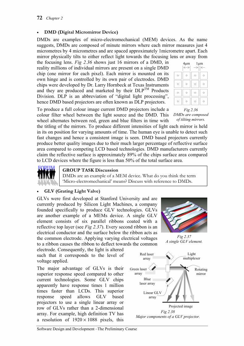
72 Chapter 2
Software Design and Development –The Preliminary Course
• DMD (Digital Micromirror Device) DMDs are examples of micro-electromechanical (MEM) devices. As the name suggests, DMDs are composed of minute mirrors where each mirror measures just 4 micrometres by 4 micrometres and are spaced approximately 1micrometre apart. Each mirror physically tilts to either reflect light towards the focusing lens or away from the focusing lens. Fig 2.36 shows just 16 mirrors of a DMD, in reality millions of individual mirrors are present on a single DMD chip (one mirror for each pixel). Each mirror is mounted on its own hinge and is controlled by its own pair of electrodes. DMD chips were developed by Dr. Larry Hornbeck at Texas Instruments and they are produced and marketed by their DLPTM Products Division. DLP is an abbreviation of “digital light processing”, hence DMD based projectors are often known as DLP projectors. To produce a full colour image current DMD projectors include a colour filter wheel between the light source and the DMD. This wheel alternates between red, green and blue filters in time with the titling of the mirrors. To produce different intensities of light each mirror is held in its on position for varying amounts of time. The human eye is unable to detect such fast changes and hence a consistent image is seen. DMD based projectors currently produce better quality images due to their much larger percentage of reflective surface area compared to competing LCD based technologies. DMD manufacturers currently claim the reflective surface is approximately 89% of the chips surface area compared to LCD devices where the figure is less than 50% of the total surface area.
• GLV (Grating Light Valve) GLVs were first developed at Stanford University and are currently produced by Silicon Light Machines, a company founded specifically to produce GLV technologies. GLVs are another example of a MEMs device. A single GLV element consists of six parallel ribbons coated with a reflective top layer (see Fig 2.37). Every second ribbon is an electrical conductor and the surface below the ribbon acts as the common electrode. Applying varying electrical voltages to a ribbon causes the ribbon to deflect towards the common electrode. Consequently, the light is altered such that it corresponds to the level of voltage applied. The major advantage of GLVs is their superior response speed compared to other current technologies. Some GLV chips apparently have response times 1 million times faster than LCDs. This superior response speed allows GLV based projectors to use a single linear array or row of GLVs rather than a 2-dimensional array. For example, high definition TV has a resolution of 1920 × 1088 pixels, this
Fig 2.37 A single GLV element.
Fig 2.38 Major components of a GLV projector.
Red laser array
Rotating mirror
Green laser array
Blue laser array
Linear GLV array
Light multiplexer
Projected image
4µm 1µm
Fig 2.36 DMDs are composed
of tilting mirrors.
GROUP TASK Discussion DMDs are an example of a MEM device. What do you think the term ‘Micro-electromechanical’ means? Discuss with reference to DMDs.

Hardware and Software 73
Software Design and Development – The Preliminary Course
resolution can be achieved using a single linear array of 1088 GLV elements, compare this to other technologies that require in excess of 2 million pixel elements. In reality current GLV projectors utilise a separate linear array of GLVs for the red, green and blue components of the image (see Fig 2.38). The light source for each GLV linear array being a similar linear array of lasers generating red, green and blue light respectively. The red, green and blue strips of light are combined using a light multiplexer. Finally a rotating mirror directs each strip of light to its precise location on the screen.
Printers Currently most printers receive their data via USB connections, however network printers often use Ethernet or wireless to connect directly to a LAN. Most current printers on the market are classified as either laser printers or inkjet printers. Specialised printers that use thermal technologies and impact dot matrix technologies are available. For example, most small receipt printers use thermal technology and many businesses use impact dot matrix printers to print documents in triplicate onto carbonised paper (examples of each are reproduced in Fig 2.39). In this section, we restrict our discussion to the operation of laser and inkjet printers.
• Laser printers Laser printers use static electricity to form images on paper. Static electricity is a charge built up on insulated materials in such a way that materials with opposing charges attract one another. Laser printers use static electricity to temporarily attract toner and then transfer it to paper. As no physical contact is used to form images laser printers are an example of non-impact printers. Software applications send their output to the printer’s software driver. The printer driver translates this data into a form that can be sent to the printer. The data is usually sent to the printer via a USB cable and is received by the printer controller within the laser printer. The printer controller is itself a dedicated computer containing significant amounts of RAM. Its job is to communicate with the host computer, format and prepare each page ready for printing and finally to create a rasterised image and send it progressively to the print engine.
GROUP TASK Discussion Discuss similarities and differences between computer monitors and projectors. Consider the signal received from the computer together with the operation of the device as part of your discussion.
Fig 2.39 Epson’s TM-T88 thermal receipt printer and FX-880 Impact dot matrix printer.
GROUP TASK Research Use the Internet to research different types of printer technologies (not including laser and inkjet technologies). Print specific examples of printers that use each technology you find and describe where they are used.

74 Chapter 2
Software Design and Development –The Preliminary Course
So how does the print engine transform the information from the printer controller into hardcopy? The main component of the print engine is the photoreceptor. This is normally a rotating drum coated in a photo-sensitive material that is able to hold a static electrical charge. First the drum is given a positive charge by the charge corona wire. The drum then rotates past the laser-scanning unit. This unit traces out the image using a laser which discharges the static electricity on portions of the drum. The drum now holds the image as discharged areas (areas to be black) and positive charged areas (areas to be white). The drum now rotates past the developer roller. The developer roller is coated in fine positively charged magnetic particles. As the developer roller passes through the toner hopper, these particles act like a brush, collecting a coating of positively charged toner. The toner is attracted to the discharged areas of the drum and repelled by the positively charged areas. As a consequence the image areas on the drum are coated with toner. The paper now approaches the drum, travelling at precisely the same speed as the drum. The transfer corona wire first negatively charges the paper, as a result the paper attracts the toner off the drum and onto the paper. The detac corona wire then discharges the negative charge held in the paper. This is necessary to stop it sticking to the photoreceptor or other sheets of paper. The fuser then fixes the toner to the paper. The fuser is essentially a pair of hot rollers, which melt the fine plastic toner particles into the fibres of the paper. The drum finally revolves past the discharge lamp, which removes all traces of the previous image.
• Inkjet printers Inkjet printers form images by depositing minute drops of ink onto the page. Within most current inkjet printers the diameter of each dot is approximately 20 to 60 micrometres. Full colour images are formed using the CMYK or four colour process system. This system requires dots of cyan, magenta, yellow and black to be deposited on the paper, hence most inkjet printers include cartridges containing ink in each of these colours. The Epson printer shown in Fig 2.41 includes a black ink cartridge and a cartridge containing cyan, magenta and yellow inks. The dots produced are too small for the human eye to detect, thus adjoining dots merge and we perceive a full colour image.
Photo- receptor Drum
Discharge Lamp
Laser Scanning
Unit
Fuser
Developer Roller
Toner Hopper
Toner
Paper
Charge Corona Wire
Transfer Corona Wire
Detac Corona Wire
Fig 2.40 The main components of a laser printer.
GROUP TASK Investigation Most laser printers contain replaceable toner and drum cartridges. Examine these cartridges and identify components from Fig 2.40.
Fig 2.41 An inkjet printer showing the black ink
cartridge alongside the cyan, magenta and yellow ink cartridge.
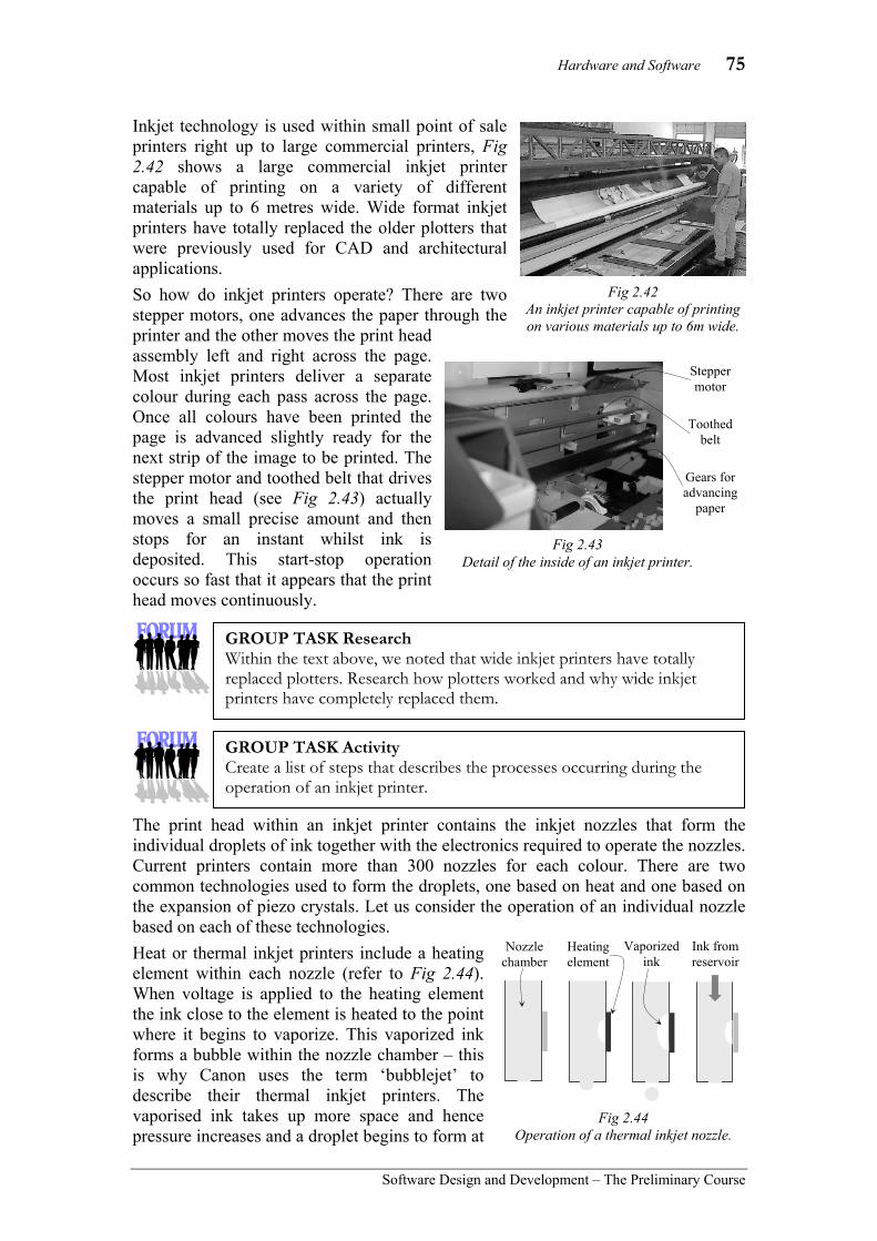
Hardware and Software 75
Software Design and Development – The Preliminary Course
Inkjet technology is used within small point of sale printers right up to large commercial printers, Fig 2.42 shows a large commercial inkjet printer capable of printing on a variety of different materials up to 6 metres wide. Wide format inkjet printers have totally replaced the older plotters that were previously used for CAD and architectural applications. So how do inkjet printers operate? There are two stepper motors, one advances the paper through the printer and the other moves the print head assembly left and right across the page. Most inkjet printers deliver a separate colour during each pass across the page. Once all colours have been printed the page is advanced slightly ready for the next strip of the image to be printed. The stepper motor and toothed belt that drives the print head (see Fig 2.43) actually moves a small precise amount and then stops for an instant whilst ink is deposited. This start-stop operation occurs so fast that it appears that the print head moves continuously.
The print head within an inkjet printer contains the inkjet nozzles that form the individual droplets of ink together with the electronics required to operate the nozzles. Current printers contain more than 300 nozzles for each colour. There are two common technologies used to form the droplets, one based on heat and one based on the expansion of piezo crystals. Let us consider the operation of an individual nozzle based on each of these technologies. Heat or thermal inkjet printers include a heating element within each nozzle (refer to Fig 2.44). When voltage is applied to the heating element the ink close to the element is heated to the point where it begins to vaporize. This vaporized ink forms a bubble within the nozzle chamber – this is why Canon uses the term ‘bubblejet’ to describe their thermal inkjet printers. The vaporised ink takes up more space and hence pressure increases and a droplet begins to form at
GROUP TASK Research Within the text above, we noted that wide inkjet printers have totally replaced plotters. Research how plotters worked and why wide inkjet printers have completely replaced them.
GROUP TASK Activity Create a list of steps that describes the processes occurring during the operation of an inkjet printer.
Heating element
Nozzle chamber
Vaporized ink
Ink from reservoir
Fig 2.44 Operation of a thermal inkjet nozzle.
Stepper motor
Toothed belt
Gears for advancing
paper
Fig 2.43 Detail of the inside of an inkjet printer.
Fig 2.42 An inkjet printer capable of printing on various materials up to 6m wide.

76 Chapter 2
Software Design and Development –The Preliminary Course
the nozzle opening. A drop of ink is released once the pressure within the nozzle chamber is sufficient to overcome the surface tension at the nozzle opening. As the drop is released the heating element is switched off, this causes a pressure drop as the vaporized ink returns to its liquid state. The pressure drop causes ink from the adjoining reservoir to refill the nozzle chamber. This process is occurring thousands of times per second at each nozzle. Piezo crystals expand and contract predictably as electrical current is increased or decreased. Essentially piezo crystals are able to transform electrical energy into mechanical energy due to vibration within the crystals. In the case of inkjet printers the mechanical energy is used to push ink out the nozzle chamber as microscopic droplets. When the electrical current is reduced or removed the piezo crystals contract. This contraction lowers the pressure within the nozzle chamber and causes ink from the adjoining reservoir to refill the nozzle chamber. Piezo based inkjet printers are able to produce a wide range of different sized droplets in response to different levels of electrical current. This is much more difficult to achieve with thermal systems. Also thermal systems must heat ink to high temperatures (thousands of degrees) and then quickly cool it down, for this reason, special inks are required that can withstand such extreme conditions. Piezo systems do not have such limitations and are therefore suited to a wider range of inks. Currently Epson’s inkjet printers are based on piezo technology.
Speakers (and sound card) Earlier in this chapter we discussed the operation of microphones and sound cards as input devices. The components within speakers are similar to those found within microphones. In fact the processes occurring to display audio are essentially the reverse of the processes occurring during audio input. Many older sound cards used many of their components for both input and output. This meant that sound could either be input or output but not at the same time. Modern sound cards can usually be used for sound input and output simultaneously.
Fig 2.45 Operation of a piezoelectric inkjet nozzle.
Piezo crystal
Ink from reservoir
Piezo crystal vibrates causing expansion
GROUP TASK Investigation Take note of the inkjet printers around your home, school and local area. Research whether each of these printers uses thermal or piezo nozzles.
GROUP TASK Discussion Some inkjet cartridges include the entire print head as part of the cartridge whilst others merely contain the ink reservoir. Compare and contrast these two approaches.
GROUP TASK Discussion Identify applications where it is useful for sound to be both input and output simultaneously.

Hardware and Software 77
Software Design and Development – The Preliminary Course
• Sound card Most computers today include the functionality of a sound card embedded on the motherboard, however it is common to add more powerful capabilities through the addition of a separate sound card that attaches to the PCI bus via a PCI expansion slot. In either case similar components are used to perform the actual processing. In regard to displaying the purpose of a sound card is to convert binary digital audio samples from the CPU into signals suitable for use by speakers and various other audio devices. Although many of today’s audio devices include digital inputs ultimately an analog signal is required to generate sound through the system’s speakers. Hence we restrict our discussion to the generation of analog audio signals. Analog audio signals are electromagnetic waves composed of alternating electrical currents of varying frequency and amplitude. The frequency determines the pitch and the amplitude determines the volume. An alternating current is needed to drive the speakers, as we shall see later. The sound card receives binary digital audio samples from the CPU via the PCI bus and transforms them into an analog audio signal suitable for driving a speaker. The context diagram in Fig 2.46 models this process. On the surface it would seem a simple digital to analog converter (DAC) could perform this conversion. In reality audio data is time sensitive, meaning it must be displayed in real time, the DFD in Fig 2.47 describes this process. To achieve real time display sound cards contain their own RAM which is essentially a buffer between the received data and the card’s digital signal processor (DSP). The DSP performs a variety of tasks including decompressing and smoothing the sound samples. The DSP then feeds the final individual samples in real time to a DAC. The DAC performs the final conversion of each sample into a continuous analog signal. The analog signal produced by the sound card’s DAC has insufficient power (both voltage and current) to drive speakers directly. This low power signal is usually output directly through a line out connector and a higher-powered or amplified signal is output via a speaker connector. Obviously the line out connector is used to connect display devices that include their own amplifiers, such as stereo and surround sound systems.
GROUP TASK Research Many sound cards also contain a MIDI port, that often doubles as a joystick port. Research different types of audio display devices that connect to MIDI ports.
Fig 2.47 A sound card’s output processes
modelled using a dataflow diagram.
Digital audio samples
Analog audio signal Store
samples
Digital signal
processing
Digital to analog
conversion
Storage Buffer
Digital audio samples
Digital audio samples
Real time digital
samples
Digital audio samples Speaker
Analog audio signal
Sound card
CPU
Fig 2.46 Context diagram for a sound card.

78 Chapter 2
Software Design and Development –The Preliminary Course
• Speakers Most speakers include similar components as dynamic microphones (refer p61). This includes an electromagnet, which is essentially a coil of wire surrounded by a magnet. As current is applied to the coil it moves in and out in response to the changing magnetic fields. As an alternating current is used to drive the speaker the coil vibrates in time with the fluctuations present within the alternating current. The coil is attached to a paper diaphragm, it is the diaphragm that compresses and decompresses the air forming the final sound waves. The coil and diaphragm are held in the correct position within the magnet using a paper support known as a ‘suspension spider’. The size of the diaphragm in combination with the coils range of movement determines the accuracy with which different frequencies can be reproduced. Large diameter diaphragms coupled with coils that are able to move in and out over a larger range are suited to low frequencies (0Hz to about 500Hz). Such speakers are commonly used within woofers. Smaller diameter diaphragms are tighter and hence respond more accurately to higher frequencies. Speakers with very small diameter diaphragms respond to just the higher frequencies and are known as tweeters. Commonly speaker systems include a separate low frequency woofer or sub-woofer, combined with a number of speakers capable of producing all but the lowest frequencies. Just a single large woofer is sufficient as low frequency sound waves are omnidirectional, that is they can be heard in all directions. Conversely, high frequency sounds from say 6000Hz up to 20000Hz are very directional, hence tweeters need to be arranged to produce sound in the direction of the listener.
Explain how CRT monitors operate. Suggested solution CRTs contain an electron gun with three beams (for Red, Green and Blue). The beam is deflected by a magnetic coil to reach the required pixel through a spot in the screen mask. This screen mask is used to prevent neighbouring pixels from being lit up. When the beams hit the required pixel, the 3 phosphors (Red, Green and Blue) comprising the pixel glow for a short amount of time based on the intensity of each beam. Each pixel on the screen is refreshed in a raster scan from top to bottom, left to right. Commonly the entire screen is refreshed 60 times per second.
Magnet Paper
diaphragm Suspension
spider
Fig 2.48 Underside of a typical speaker.
GROUP TASK Practical Activity Listen to the various sounds around you to determine their source. Is it easier to determine the direction of the source of higher or lower frequency sounds? How can you explain your results?
HSC style question:

Hardware and Software 79
Software Design and Development – The Preliminary Course
SET 2B 1. A sound card is used for:
(A) input only. (B) output only. (C) input and output. (D) voice recognition.
2. What output device uses the CMYK system? (A) Screens (B) Colour printers (C) Speakers (D) Data projectors
3. Piezo crystals are used in which type of device? (A) Laser printers (B) Plasma screens (C) Inkjet printers (D) Data projectors
4. Substances in a state between liquid and solid are known as: (A) plasmas (B) liquid crystals (C) toner (D) transistors
5. Within an LCD screen, what ensures light can only exit at right angles to the light entering the screen? (A) LEDs (B) Piezo crystals (C) coil and diaphragm (D) polarizing panels
6. Within plasma screens visible light is generated by: (A) plasma (B) phosphors (C) backlights (D) reflection
7. A refresh rate of 50Hertz means: (A) the screen is redrawn 50 times each
second. (B) new image data is received from
the computer 50 times per second. (C) data is received at a rate of 50
bytes per second. (D) the screen includes 50 rows of
pixels. 8. Which interface is able to transmit
video, audio and control data? (A) DVI (B) VGA (C) HDMI (D) All of the above
9. Plasma emits: (A) red light (B) green light (C) blue light (D) UV light
10. Within a laser printer, which component makes the image permanent? (A) Laser (B) Fuser (C) Photoreceptor (D) Detac corona wire
11. For each of the following components, identify the output device that includes the component and briefly outline the purpose of the component. (a) VRAM (f) polarizing panel (b) cathode (g) neon and xenon gas (c) detac corona wire (h) suspension spider (d) liquid crystals (i) TFT (e) shadow mask (j) light multiplexor
12. Make up a list of as many output devices as you can think of. Try to have more items on your list than anyone else!
13. Describe the operation of a plasma screen.
14. Describe the operation of an LCD screen.
15. Describe the operation of a laser printer.

80 Chapter 2
Software Design and Development –The Preliminary Course
STORAGE Storage is the function that reads, writes and retains data. The ability to store and retrieve data is the major reason why computers are able to perform multiple tasks. Other technologies invented by man are dedicated to performing one particular task; e.g. an oven cannot be easily modified to perform as a refrigerator. Computers can in a matter of seconds change from being a word-processor to managing businesses finance. In this section we examine different types of storage used by computers and how they work together to efficiently carry out storage functions. There are a variety of different storage devices used in a typical computer system. These devices are commonly classified as primary storage and secondary storage or temporary and permanent storage. Primary storage works closely with the processor; it is generally very fast and apart from Read Only Memory (ROM), requires power to retain its contents. Secondary storage generally has a far greater storage capacity and does not require power to retain data. Both these storage types work together to carry out the storage functions.
Let us consider the different types of memory used by a typical computer system to help explain the flow of data between storage areas (see Fig 2.49). There are many different types of storage used by computer systems; each has its particular strengths and weaknesses. Primary Storage
Primary storage is often referred to as main memory or just memory. It includes the registers within the CPU, cache, physical RAM, ROM and virtual memory. Apart from ROM primary memory is volatile, meaning it only temporarily holds data whilst the power is on. Read Only Memory (ROM) chips are used within the computer to store permanent instructions required to start-up or boot the computer. Many peripheral devices contain their own ROM chips containing instructions to control the operation of the device.
The closer the storage is to the CPU, the faster its storage functions need to perform. Registers are contained within the CPU and are used as temporary stores for data during processing. As a consequence, registers must be able to store and deliver data from and to the CPU at the same speed as the CPU. Any delay would result in major performance problems.
Physical Random Access Memory (RAM) is significantly slower than the CPU. Data and applications currently being used are stored in RAM. To alleviate the speed difference between RAM and the CPU’s operations, two levels of cache are used by most systems. In the current context, cache is a small area of very fast RAM. Instructions that are used repeatedly are maintained in cache. This drastically reduces the time it takes for the CPU to load most instructions. Around 95% of most program’s instructions are contained within loops; as a consequence they need only be loaded into cache once, yet they may be executed by the CPU many hundreds of
CPU Registers
Level 1 Cache
Level 2 Cache
Hard Drive
Physical RAM
Virtual Memory
ROMBIOS
Removable Drives
Network / Internet Storage
Spee
d, C
ost i
ncre
ase
Size
incr
ease
Prim
ary
Stor
age
Seco
ndar
y St
orag
e
Fig 2.49 Levels of storage used by a typical computer system.

Hardware and Software 81
Software Design and Development – The Preliminary Course
times. Modern CPU designs have two levels of cache. Level 1 cache operates at the same speed as the CPU and is contained within the microprocessor; it is commonly between 4 kilobytes and 16 kilobytes in size. Level 2 cache operates at about twice the speed of physical RAM and is usually between 128 kilobytes and 1 megabyte in size. Without cache storage the CPU would spend most of its time waiting for the next instruction to arrive from RAM. Virtual memory is a way of extending the amount of RAM available to the system. Part of the hard drive is used when the amount of physical RAM has been exhausted. If your computer is continually accessing the hard drive it is likely that it has insufficient physical RAM and is resorting to virtual memory. The use of virtual memory allows the system to remain operational with greatly reduced performance.
• Random Access Memory (RAM)
Random access means that the system can read or write directly to any location. Each RAM chip contains a grid of memory cells where each cell is able to store a single binary digit (bit). Together with the memory cells, is a complex arrangement of circuits, whose purpose is to coordinate the operation of and access to each cell. RAM chips are integrated circuits made up of many millions of transistors and capacitors. There are two major types of RAM chips; dynamic (DRAM) and static (SRAM).
Dynamic RAM is commonly used in the production of physical RAM modules. A series of DRAM chips are combined on a circuit board that plugs into the system’s motherboard. Each memory cell within a DRAM chip is composed of a transistor and a capacitor. The transistor provides the mechanism for reading or writing to the capacitor. The capacitor is able to store electrons. A binary 1 is represented when the capacitor is full and a 0 when it is empty. The problem with capacitors is that the electrons soon escape so they must be continually recharged if they are to maintain their state. This continual recharging of each memory cell takes time and as a consequence their performance is decreased.
Static RAM (SRAM) is able to hold a particular binary state without need for recharging. As a consequence SRAM can perform its storage functions much faster than DRAM. SRAM does not use capacitors to store data rather it uses flip-flops. Flip-flops are circuits that include feedback to enable them to maintain a particular state. If you
GROUP TASK Discussion If Level 1 Cache is so fast then why not make primary memory just one huge Level 1 Cache? Discuss with regard to cost, speed and communication with other devices.
Fig 2.51 Examples of DRAM modules.
From top: Single Inline Memory Module (SIMM), Dual Inline Memory Module
(DIMM) and Small Outline Dual Inline Memory Module (SODIMM).
Fig 2.50 Each RAM chip contains a two
dimensional grid of memory cells. In the above diagram the shaded cells
represent 1s and the unshaded cells 0s.

82 Chapter 2
Software Design and Development –The Preliminary Course
study the HSC course option on The Software Developer’s View of the Hardware, you will learn more about the operation of flip-flops. SRAM is far more expensive to produce and takes up more space because of the complexities of the circuitry. Consequently, SRAM is used primarily for Level 1 and Level 2 Cache memory.
Secondary Storage Secondary storage is permanent or non-volatile storage. The contents of secondary storage remains when the power is turned off. Most common secondary storage devices can be classified as either magnetic, optical or solid state. Examples of magnetic devices include: hard disks and magnetic tapes. CD-ROMs and DVDs use optical methods for reading and, where possible, for writing. Network connections, including the Internet, provide further secondary storage on remote computers. In this section we consider magnetic storage and hard disk drives, optical storage and CD/DVD reading and writing, and finally flash drives which use solid state storage. Magnetic Storage To understand the underlying operation of magnetic storage devices requires a basic knowledge of certain magnetic principles: 1. Magnets exert forces on each other known as magnetic
fields. Such forces move from the north to the south pole of the magnet.
2. Magnetic fields are greatest at the poles. 3. Electrical currents produce magnetic fields. 4. There are only a few elements, primarily iron, cobalt
and nickel, which can be magnetised. Materials that include these elements and that can be magnetised are known as ferromagnetic materials.
5. Different ferromagnetic materials behave differently when placed in a magnetic field. A. Some materials are easily magnetised by weak magnetic fields but when the
field is turned off they quickly demagnetise; these materials are known as soft magnetic materials and are used during the process of storing or writing data.
B. Some soft magnetic materials conduct electricity well when in the presence of a magnetic field but are poor electrical conductors when not. This phenomenon is called the magneto-resistance (MR) effect. MR materials are used during the process of retrieving or reading data.
C. Some materials require a strong magnetic field to become magnetised however they retain their magnetisation when the magnetic field is turned off. These materials are known as hard magnetic materials and are used to produce permanent magnets. Such materials are the basis of magnetic storage media.
To further assist our discussion let us first examine a microscopic detail of a typical piece of magnetic storage medium that already contains stored data (refer Fig 2.53). This detail could be a hard disk platter or even a piece of magnetic tape; in each case hard magnetic material is used and the storage principles are the same.
GROUP TASK Discussion Why do you think the D in DRAM stands for dynamic and the S in SRAM stands for static? Discuss.
N
S
Fig 2.52 Magnetic forces move from north to south poles and are
greatest at the poles.

Hardware and Software 83
Software Design and Development – The Preliminary Course
Digital data is composed of a sequence of binary digits, zeros and ones. These zeros and ones are equally spaced along the surface of the magnetic medium. High magnetic forces are present where the direction of the magnetic field changes; these points are really magnetic poles. It is the strength of the magnetic force that determines a one or a zero, not the direction of the magnetic force. Low magnetic forces occur between two poles and represent zeros. High magnetic forces are present at the poles and represent ones.
Consider the following:
At the time of writing (2010) the number of bits stored per inch (BPI) on the surface of a hard disk ranges up to around 1,000,000 BPI at the centre of each disk platter; this measure is commonly called linear density. This means a track on a hard disk can store some 40000 bits per millimetre. If Fig 2.53 is the surface of a hard disk platter then the real width of the medium depicted would be approximately 1.5 ten thousandths of a millimetre; rather too small to print! Currently magnetic tape is available with a linear density of around 100,000 BPI resulting in some 4000 bits per millimetre.
• Storing or writing magnetic data Magnetic data is written on to hard magnetic material using tiny electromagnets. These electromagnets form the write heads for all types of magnetic storage devices. Essentially an electromagnet is comprised of a copper coil of wire wrapped around soft magnetic material (see Fig 2.54). The soft magnetic material is in the shape of a loop that is not quite joined; this tiny gap in the loop is where the magnetic field is produced and the writing takes place. When an electrical current is present in the coil the enclosed soft magnetic material becomes magnetised, one end of the material becoming a north pole and the other a south pole. Hence a magnetic field is produced flowing from the north to the south. If the direction of the current through the coil is reversed then the direction of the magnetic field produced is also reversed. The magnetic field is strong enough for the hard magnetic material on the medium to be magnetised. A binary one is represented each time the direction of the magnetic field changes as a consequence of reversing the current into the coil. Zeros are represented when the direction of the current flow is constant and hence the direction of the magnetic field remains constant.
GROUP TASK Research Investigate the linear density of various hard disks and magnetic tapes. During your research determine the relationship between linear density and areal density.
Fig 2.54 Detail of magnetic write head.
Magnetic media passes under write head
Copper wire coil
Soft magnetic material
Reversible electrical current
Magnetic field produced in gap between poles.
S S N N S S N N Surface of magnetic media
High
Low Strength of magnetic field
1 0 1 0 1 1 Stored bits
Fig 2.53 Microscopic detail of magnetic storage medium.
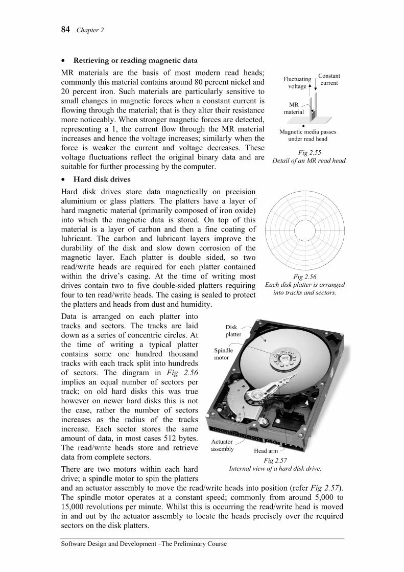
84 Chapter 2
Software Design and Development –The Preliminary Course
• Retrieving or reading magnetic data MR materials are the basis of most modern read heads; commonly this material contains around 80 percent nickel and 20 percent iron. Such materials are particularly sensitive to small changes in magnetic forces when a constant current is flowing through the material; that is they alter their resistance more noticeably. When stronger magnetic forces are detected, representing a 1, the current flow through the MR material increases and hence the voltage increases; similarly when the force is weaker the current and voltage decreases. These voltage fluctuations reflect the original binary data and are suitable for further processing by the computer. • Hard disk drives Hard disk drives store data magnetically on precision aluminium or glass platters. The platters have a layer of hard magnetic material (primarily composed of iron oxide) into which the magnetic data is stored. On top of this material is a layer of carbon and then a fine coating of lubricant. The carbon and lubricant layers improve the durability of the disk and slow down corrosion of the magnetic layer. Each platter is double sided, so two read/write heads are required for each platter contained within the drive’s casing. At the time of writing most drives contain two to five double-sided platters requiring four to ten read/write heads. The casing is sealed to protect the platters and heads from dust and humidity. Data is arranged on each platter into tracks and sectors. The tracks are laid down as a series of concentric circles. At the time of writing a typical platter contains some one hundred thousand tracks with each track split into hundreds of sectors. The diagram in Fig 2.56 implies an equal number of sectors per track; on old hard disks this was true however on newer hard disks this is not the case, rather the number of sectors increases as the radius of the tracks increase. Each sector stores the same amount of data, in most cases 512 bytes. The read/write heads store and retrieve data from complete sectors. There are two motors within each hard drive; a spindle motor to spin the platters and an actuator assembly to move the read/write heads into position (refer Fig 2.57). The spindle motor operates at a constant speed; commonly from around 5,000 to 15,000 revolutions per minute. Whilst this is occurring the read/write head is moved in and out by the actuator assembly to locate the heads precisely over the required sectors on the disk platters.
Fig 2.55 Detail of an MR read head.
Magnetic media passes under read head
MR material
Constant current Fluctuating
voltage
Fig 2.56 Each disk platter is arranged
into tracks and sectors.
Actuator assembly
Disk platter
Spindle motor
Head arm Fig 2.57
Internal view of a hard disk drive.

Hardware and Software 85
Software Design and Development – The Preliminary Course
Each read/write head is attached to a head arm with all the head arms attached to a single pivot point, consequently all the read/write heads move together. This means just a single read/write head on a single platter is actually operational at any instant. Each read/write head is extremely small, so small it is difficult to see with the naked eye. What is usually seen is the slider that houses the head. The air pressure created by the spinning platters causes the sliders to float a few nanometers (billionths of a metre) above the surface of the disk. Sophisticated circuits are required to control the accurate performance of the drive; in fact the processing power contained within a modern hard disk drive far exceeds the power of computers produced during the 1980s, furthermore they contain similar amounts of RAM in the form of cache. Hard drive circuits control the operation of the motors, communication with the CPU as well as checking on the accuracy of each read or write operation. Most hard disks contain their own built-in cache to significantly speed up access times. Data on sectors near the requested data is read into cache; commonly such data is subsequently required, consequently it can be accessed much faster from cache. Because the operation of a hard drive involves mechanical operations they will never reach the speeds possible with chip based storage technologies. Hard disks provide an economical means of permanently storing vast quantities of data. At the time of writing 500GB hard drives were common and drives exceeding 1TB were readily available. Currently, with the assistance of cache, hard drives are able to store and retrieve data at speeds exceeding 100MB per second.
Consider the following:
Older hard disk drives used the track (or cylinder) number, head number and sector number to determine the address of each sector (or block) of data. These addresses, known as CHS addresses, were translated via the computers BIOS (Basic Input Output System). Unfortunately such a system limited the size of hard disks to 1024 cylinders, 255 heads and 63 sectors per track equating to a capacity of 8.4GB. As newer higher capacity hard drives became available and variable sectors were present on each track a new addressing system known as LBA (Logical Block Addressing) was introduced; this system essentially bypasses the computers BIOS altogether. LBA assigns each block (or sector) of data a unique sequential number; for example a drive with a total of 490,350,672 sectors would use LBA addresses from 0
Fig 2.59 Underside of a hard disk drive showing the circuit board containing processing
and cache chips.
Head arm Slider
Read/write head (Too small to see)
Actuator pivot
Fig 2.58 Expanded view of a head arm assembly.

86 Chapter 2
Software Design and Development –The Preliminary Course
to 490,350,671. The circuits within the hard drive translate the LBA address into the required physical address on the disks.
Optical Storage Optical storage processes are based on reflection of light; either the light reflects well or it reflects poorly. It is the transition from good reflection to poor reflection or vice versa, that is used to represent a binary one (1); when reflection is constant a zero (0) is represented. This is similar to magnetic retrieval where a change in direction of the magnetic force represents a binary one and no change represents a zero. To illustrate optical storage imagine shining a torch across a busy highway at night, you would see the light reflected back as each vehicle passed through the beam of light; ones being represented each time a vehicle enters the beam and again as it leaves the beam (see Fig 2.60). If this data were recorded at precise intervals, say every hundredth of a second, the result would be a sequence of binary digits. As the data is so tightly packed on both compact disks (CDs) and digital versatile disks (DVDs) it is essential that the light used for optical storage processes be as consistent as is possible; lasers provide such light. The word laser is really an acronym for “light amplification by stimulated emission of radiation”. Different types of atoms, when excited, give off radiation in the form of different types of light; under normal conditions the light is emitted in all directions, for example neon advertising signs. A laser controls this process by using particular atoms within a precisely controlled environment. Essentially a laser produces an intense parallel beam of light composed of electromagnetic waves that are all identical; accurately focussing this light produces just what is needed for optical storage and retrieval processes. Relatively weak lasers are used during the retrieval of data and much higher-powered lasers when storing data. Higher-powered lasers produce the heat necessary to alter the material used during the CD or DVD burning process; in fact similar lasers are used during the initial stages when manufacturing commercial CDs and DVDs. Before we consider the detail of the optical storing and retrieving processes let us consider the nature of both CD and DVD media. CDs contain a single spiral track (Fig 2.61) that commences at the inner portion of the disk and spirals outward toward the
1 0 1 0 1 0 0 0 1 1 0 1
Fig 2.60 The transition between good and poor reflection is read as a binary one (1).
Fig 2.61 CDs and DVDs contain spiral tracks.
GROUP TASK Activity Explain how 1024 cylinders, 255 heads and 63 sectors per track equates to a storage capacity of 8.4Gb?
GROUP TASK Research Research specifications with regard to currently available hard disk drives. Determine the storage capacity, claimed data transfer rate, number of platters, total number of sectors and the storage size of each sector.

Hardware and Software 87
Software Design and Development – The Preliminary Course
edge of the disk. This single track is able to store up to 680 megabytes of data. DVDs contain similar but much more densely packed tracks, each track can store up to 4.7 gigabytes of data. Furthermore, DVDs may be double sided and they may also be dual layered. Therefore a double sided, dual layer DVD would contain a total of four spiral tracks; in total up to 17 gigabytes of data can be stored. Each spiral track, whether on a CD or a DVD, is composed of a sequence of pits and lands. On commercially produced disks the pits really are physical indentations within the upper side of the disk. Fig 2.62 depicts the underside of a disk, this is the side read by the laser, and hence the pits appear as raised bumps above the surrounding surface. On writeable media the pits are in fact not pits at all; rather they are areas that reflect light poorly; more on this when we discuss optical storing. The essential point is that pits reflect light poorly and lands reflect light well regardless of their physical structure. The dimensions shown in Fig 2.62 indicate an approximate 50 percent reduction in both track pitch and pit length for DVDs compared to CDs; these physical size differences account for about a four-fold increase in the storage capacity of DVDs compared to CDs. In reality, an almost seven-fold increase in capacity has occurred; the remaining increase is largely due to improvements in error correction techniques. In Fig 2.62 the measurements are expressed in microns, one micron is one millionth of a metre or one thousandth of a millimetre. As a consequence of these incredibly small distances the length of pits that would be needed when ones appear together or close together is so small that it is likely to cause read errors. Also tracking problems can occur when the pits or lands are too long, this would occur when a large number of zeros are in sequence. The solution is to avoid such bit patterns occurring in the first place. The eight to fourteen modulation (EFM) coding system is used; EFM converts each eight-bit byte into fourteen bits such that all the bit patterns include at least two but less than ten consecutive zeros. This avoids such problems occurring within a byte of data, but what about between bytes? For example, the two bytes 10001010 and 11011000 convert using the EFM coding system to 1001001000001 and 01001000010001. When placed together the transition between the two coded bytes is …0101…; our rule of having at least two zeros is broken. To correct this problem two merge bits are placed between each coded byte; the value of these merge bits is chosen to maintain our at least two zeros but less than ten rule. Obviously once the data has been read the merge bits are ignored. Both CDs and DVDs are approximately 1.2mm thick and are primarily clear polycarbonate plastic. On commercially produced disks the pits are stamped into the top surface of the plastic, which is then covered by a fine layer of reflective metal (commonly aluminium), followed by a protective acrylic lacquer and finally some sort of printed label. On recordable and rewriteable media a further layer is added between the polycarbonate and the reflective layer; this is the layer whose reflective properties can be altered. It is actually quite difficult to damage a disk by scratching its underside, in contrast the
Fig 2.62 Magnified view of the underside of an optical disk.
Min 0.834 microns (CD) Min 0.4 micron (DVD)
1.6 microns (CD) 0.74 microns (DVD)
Pits Lands
Label
Acrylic lacquer Reflective metal (Aluminium)
Clear polycarbonate plastic
Fig 2.63 Cross section of a typical commercially
produced CD or single sided single layer DVD.
1.2 mm

88 Chapter 2
Software Design and Development –The Preliminary Course
label side of a disk is easily damaged; try scratching both sides of an old CD-R with a pen, you’ll see what I mean. Double-sided DVDs are essentially two single-sided disks back to back. Double layer DVDs contain two data layers where the outside layer is semi reflective; this allows light to pass through to the lower layer. The laser is accurately focussed onto the layer currently being read. • Retrieving or reading optical data Retrieving data from an optical disk can be split into two processes; spinning the disk as the read head assembly is moved in or out to the required data and actually reading the reflected light and translating it into an electrical signal representing the original sequence of bits. To structure our discussion we consider each of these processes separately, although in reality both occur at the same time. 1. Spinning the disk and moving the read head assembly To read data off an optical disk requires two motors, a spindle motor to spin the disk and another to move the laser in or out so that the required data passes above the laser. The spindle assembly contains the spindle motor together with a clamping system that ensures the disk rotates with minimal wobble. The read head assembly is mounted on a carriage, which moves in and out on a pair of rails. In modern optical drives the motor that moves the carriage responds to tracking information returned by the read head. This feedback allows the carriage to move relative to the actual location of the data track. At a constant number of revolutions per minute (rpm) the outside of a disk rotates much faster than the inside. Older CD drives, and in particular audio CD drives, reduce the speed of the spindle motor as the read head moves outwards and increase speed as the read head moves inwards. For example, a quad speed drive spins at 2120 rpm when reading the inner part of the track and at only 800 rpm when reading the outer part. The aim being to ensure approximately the same amount of data passes under the read head every second; drives based on this technology are known as CLV (constant linear velocity) drives. Most CD and DVD drives manufactured since 1998 use a constant angular velocity (CAV) system, which simply means the spindle motor rotates at a steady speed. CLV technology is still used within most audio drives, which makes sense, as there really is no point retrieving such data at faster speeds. However for computer applications, such as installing software applications, faster retrieval is definitely an advantage. As a consequence of CAV, such drives have variable rates of data transfer. For example, a 24-speed CAV CD drive can retrieve some 1.8 megabytes per second at the centre and 3.6 megabytes per second at the outside. Quoted retrieval speeds for CAV drives are often misleading; for example a CAV drive designated as 48-speed can only retrieve data from the outside of a disk at 48 times that required for normal CD audio. These maximum speeds are rarely achieved as few CDs have data stored on their outer edges. Current CAV drives have spindle speeds in excess of 12000 rpm; faster than most hard disk drives. Such high speeds produce air turbulence resulting in vibration. When most drives are operating the noise produced by this turbulence can be clearly heard.
Fig 2.64 Detail of a CD/DVD drive from a
laptop computer.
Spindle assembly
Carriage and motor
Read head assembly

Hardware and Software 89
Software Design and Development – The Preliminary Course
Furthermore, the vibration is worst at the outside of the disk, just where the data passes under the read head at the fastest speed, hence read errors do occur. Such problems must be resolved if the ever increasing speed of optical data retrieval is to continue.
Consider the following:
How does CLV work? Essentially the speed of the spindle motor is controlled by the amount of data within the drive’s temporary storage or buffer. When the amount of data in the buffer exceeds a certain threshold the motor is slowed and hence the buffer begins to empty. Similarly if the data in the buffer is less than a certain threshold then the motor speeds up. Unfortunately it takes time to speed up and slow down the spindle; this time becomes significant once rates of data transfer approach 16 times that required to read an audio CD (about 16 times 150 kilobytes per second or roughly 2 megabytes per second). This is the primary reason for the development and production of CAV drives.
2. Reading and translating reflected light into electrical signals There are various different techniques used to create, focus and then collect and convert the reflected light into electrical signals. Our discussion concentrates on the most commonly used techniques. Let us follow the path taken by the light as it leaves the laser, reflects off the pits and lands, and finally arrives at the opto-electrical cell (refer to Fig 2.65). Firstly, remember that lasers generate a single parallel beam. This beam passes through a diffraction grating whose purpose is to create two extra side beams; these side or tracking beams are used to ensure the main beam tracks accurately over the pits and lands. Unfortunately the diffraction grating causes dispersion of the beams. To correct this dispersion the three beams pass through a collimator lens; whose job is to make the beams parallel to each other. A final lens is used to precisely focus the beams on the reflective surface of the disk. As the disk spins both tracking beams should return a constant amount of light - they are reflecting off the smooth surface between tracks (see Fig 2.66). If this is not the case then the carriage containing the read assembly is moved ever so slightly until constant reflection is achieved. In essence the tracking beams are provide the feedback controlling the operation of the motor that moves the read head in and out.
GROUP TASK Discussion Buffers are used primarily to assist the movement of data between hardware devices operating at different speeds. CAV optical drives also contain a buffer; discuss how such a buffer would operate during data retrieval from a complete track.
Fig 2.65 Detail of a typical optical
storage read head.
Focusing lens
Collimator lens
Beam splitter prism
Diffraction grating Laser
Opto- electrical cell
Underside of CD or DVD
Main beam
Tracking beams
Fig 2.66 Magnified view of main and
tracking laser beams.
Tracking beams
Main beam
Pit
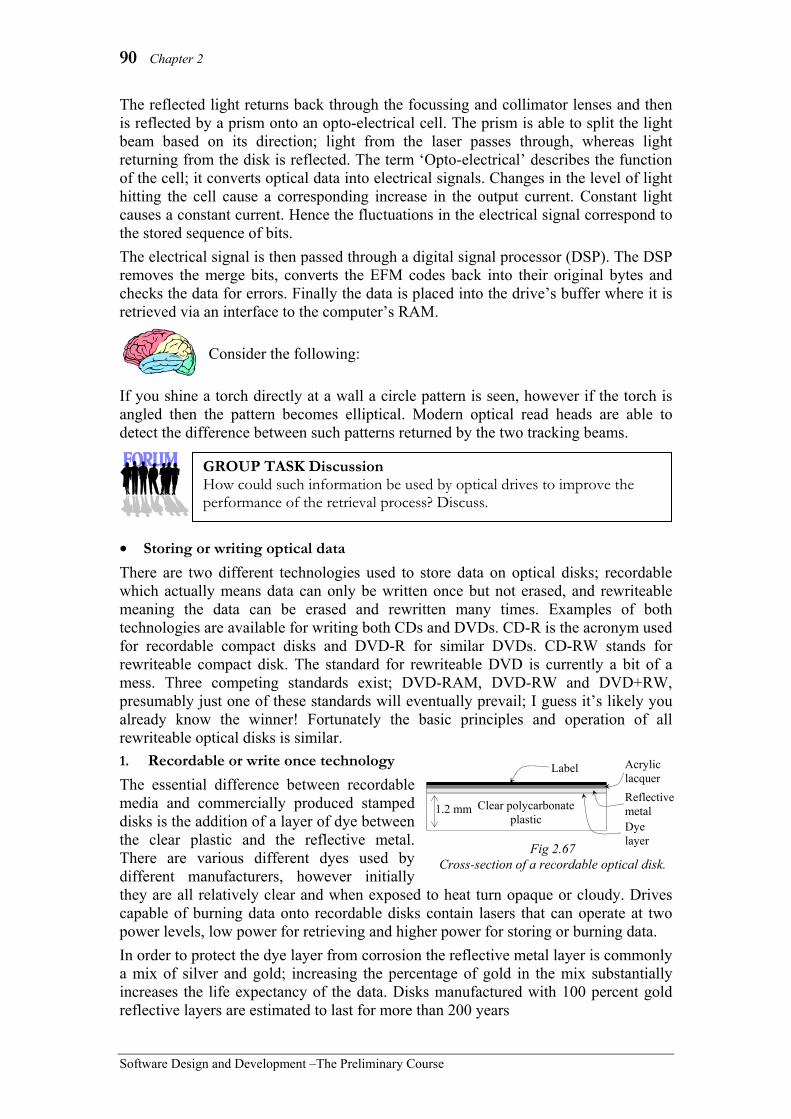
90 Chapter 2
Software Design and Development –The Preliminary Course
The reflected light returns back through the focussing and collimator lenses and then is reflected by a prism onto an opto-electrical cell. The prism is able to split the light beam based on its direction; light from the laser passes through, whereas light returning from the disk is reflected. The term ‘Opto-electrical’ describes the function of the cell; it converts optical data into electrical signals. Changes in the level of light hitting the cell cause a corresponding increase in the output current. Constant light causes a constant current. Hence the fluctuations in the electrical signal correspond to the stored sequence of bits. The electrical signal is then passed through a digital signal processor (DSP). The DSP removes the merge bits, converts the EFM codes back into their original bytes and checks the data for errors. Finally the data is placed into the drive’s buffer where it is retrieved via an interface to the computer’s RAM.
Consider the following:
If you shine a torch directly at a wall a circle pattern is seen, however if the torch is angled then the pattern becomes elliptical. Modern optical read heads are able to detect the difference between such patterns returned by the two tracking beams.
• Storing or writing optical data There are two different technologies used to store data on optical disks; recordable which actually means data can only be written once but not erased, and rewriteable meaning the data can be erased and rewritten many times. Examples of both technologies are available for writing both CDs and DVDs. CD-R is the acronym used for recordable compact disks and DVD-R for similar DVDs. CD-RW stands for rewriteable compact disk. The standard for rewriteable DVD is currently a bit of a mess. Three competing standards exist; DVD-RAM, DVD-RW and DVD+RW, presumably just one of these standards will eventually prevail; I guess it’s likely you already know the winner! Fortunately the basic principles and operation of all rewriteable optical disks is similar. 1. Recordable or write once technology The essential difference between recordable media and commercially produced stamped disks is the addition of a layer of dye between the clear plastic and the reflective metal. There are various different dyes used by different manufacturers, however initially they are all relatively clear and when exposed to heat turn opaque or cloudy. Drives capable of burning data onto recordable disks contain lasers that can operate at two power levels, low power for retrieving and higher power for storing or burning data. In order to protect the dye layer from corrosion the reflective metal layer is commonly a mix of silver and gold; increasing the percentage of gold in the mix substantially increases the life expectancy of the data. Disks manufactured with 100 percent gold reflective layers are estimated to last for more than 200 years
GROUP TASK Discussion How could such information be used by optical drives to improve the performance of the retrieval process? Discuss.
Label Acrylic lacquer Reflective metal Clear polycarbonate
plastic
Fig 2.67 Cross-section of a recordable optical disk.
1.2 mm Dye layer
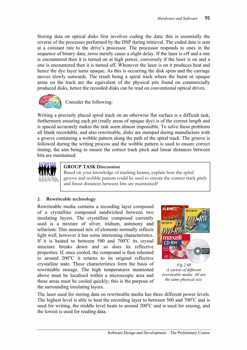
Hardware and Software 91
Software Design and Development – The Preliminary Course
Storing data on optical disks first involves coding the data; this is essentially the reverse of the processes performed by the DSP during retrieval. The coded data is sent at a constant rate to the drive’s processor. The processor responds to ones in the sequence of binary data; zeros merely cause a slight delay. If the laser is off and a one is encountered then it is turned on at high power, conversely if the laser is on and a one is encountered then it is turned off. Whenever the laser is on it produces heat and hence the dye layer turns opaque. As this is occurring the disk spins and the carriage moves slowly outwards. The result being a spiral track where the burnt or opaque areas on the track are the equivalent of the physical pits found on commercially produced disks, hence the recorded disks can be read on conventional optical drives.
Consider the following:
Writing a precisely placed spiral track on an otherwise flat surface is a difficult task, furthermore ensuring each pit (really areas of opaque dye) is of the correct length and is spaced accurately makes the task seem almost impossible. To solve these problems all blank recordable, and also rewriteable, disks are stamped during manufacture with a groove containing a wobble pattern along the path of the spiral track. The groove is followed during the writing process and the wobble pattern is used to ensure correct timing; the aim being to ensure the correct track pitch and linear distances between bits are maintained.
2. Rewriteable technology Rewriteable media contains a recording layer composed of a crystalline compound sandwiched between two insulating layers. The crystalline compound currently used is a mixture of silver, iridium, antimony and tellurium. This unusual mix of elements normally reflects light well, however it has some interesting characteristics. If it is heated to between 500 and 700oC its crystal structure breaks down and so does its reflective properties. If, once cooled, the compound is then reheated to around 200oC it returns to its original reflective crystalline state. These characteristics form the basis of rewriteable storage. The high temperatures mentioned above must be localised within a microscopic area and these areas must be cooled quickly; this is the purpose of the surrounding insulating layers. The laser used for storing data on rewriteable media has three different power levels. The highest level is able to heat the recording layer to between 500 and 700oC and is used for writing, the middle level heats to around 200oC and is used for erasing, and the lowest is used for reading data.
GROUP TASK Discussion Based on your knowledge of tracking beams, explain how the spiral groove and wobble pattern could be used to ensure the correct track pitch and linear distances between bits are maintained?
Fig 2.68 A variety of different
rewriteable media. All are the same physical size.

92 Chapter 2
Software Design and Development –The Preliminary Course
The process of storing data on new rewriteable media is essentially the same as that used for recordable media. The only significant difference being the much hotter temperatures needed to break down the crystalline compound. Rewriting data is slightly different; there are two techniques commonly used. One involves first erasing all the data, that is the laser is set at a constant erase power level whilst the entire data track is rotated above the laser. The disk can then be written as if it were new. A second technique allows new data to be directly written over existing data. This technique involves alternating the power of the laser between write power and erase power each time a one is encountered within the data.
Consider the following:
Currently CD-RW disks cost approximately four times that of a CD-R, however CD-RW disks can be reused more than 1000 times. Unfortunately the reflective properties of CD-RW disks are such that they cannot be read by many older CD-ROM drives, including most CD audio drives.
Flash Memory Flash memory is commonly seen in the form of memory cards that are often called flash drives; these cards provide removable storage for various electrical devices, for example digital cameras, MP3 players, PDAs, video game consoles, laptop computers and even mobile phones. Fig 2.69 shows a variety of different types of flash drives. Flash memory is not just used for removable storage; it is now becoming available as an alternative to magnetic hard disk drives (HDDs) in the form of flash solid state drives (SSDs). Flash memory is also included as an integral part of many devices. For example, BIOS chips, mobile phones, cable modems, DVD players, network routers, motor vehicles and even kitchen appliances. So what is flash memory? Flash memory is electronic, solid-state and non-volatile; now what does that mean? Electronic devices use electricity; that is they manipulate electrons. Flash memory is a type of electronic storage that represents data by trapping or storing electrons. The essential difference between flash memory and other types of electronic storage, such as RAM, is the ability to trap electrons even when no power is present. This makes flash memory non-volatile. Solid state means there are no moving parts. Mechanical parts take time to do their job, generate noise and are prone to wear and failure. In contrast, flash memory is fast, silent and reliable. Furthermore, flash memory operates reliably within a much wider temperature range than magnetic or optical storage devices. For example, flash memory developed for motor vehicles is certified to operate from -40oC to +125oC.
GROUP TASK Identify and justify CD-R and CD-RW are suited to different applications. Identify applications where CD-R is more suitable and applications where CD-RW is more suitable. Justify your answers.
Fig 2.69 A variety of removable flash
memory devices.

Hardware and Software 93
Software Design and Development – The Preliminary Course
Flash memory cards can be used in a variety of different devices. For example, Fig 2.70 shows a variety of devices that include a Sony memory stick slot. Using a single flash drive you can take photos, edit them on your computer, view them on your TV and then send them to Grandma using your PDA! If flash memory is so wonderful then why hasn’t it replaced magnetic and optical storage? The answer is cost; compared to magnetic and optical storage flash memory is expensive. For example, presently (2009) a 250GB flash solid state drive (SSD) retails for about $1,000, yet a 1TB (1000GB) hard disk drive retails for around $100. Currently it’s not economically feasible to include large capacity flash SSDs in most computers, however this is likely to change over the coming years. All the large microchip manufacturers are continually investigating a variety of high capacity solid-state non-volatile secondary storage technologies, flash technology being just one of the technologies under consideration.
Consider the following:
(Extract of an article on www.storagesearch.com)
GROUP TASK Research Using the Internet, or otherwise, research current developments in non-volatile solid-state storage solutions. Are any of these new developments seen as a real alternative to current secondary storage devices?
What's a Solid State Disk (SSD) A solid state disk/drive (SSD) - is electrically, mechanically and software compatible with a conventional (magnetic) hard disk. The difference is that the storage medium is not magnetic (like a hard disk) or optical (like a CD) but solid state semiconductor such as battery backed RAM, EPROM or other electrically erasable RAM-like chip such as flash. This provides faster access time than a hard disk, because the SSD data can be randomly accessed in the same time whatever the storage location. The SSD access time does not depend on a read/write interface head synchronising with a data sector on a rotating disk. The SSD also provides greater physical resilience to physical vibration, shock and extreme temperature fluctuations. SSDs are also immune to strong magnetic fields which could sanitise a hard drive. The only downside to SSDs is a higher cost per megabyte of storage - although in some applications the higher reliability of SSDs makes them cheaper to own than replacing multiple failing hard disks. When the storage capacity needed by the application is small (as in some embedded systems) the SSD can actually be cheaper to buy because hard disk oems no longer make low capacity drives. Also in enterprise server acceleration applications - the benefit of the SSD is that it reduces the number of servers needed compared to using hard disk based RAID on its own. Historically RAM based SSDs were faster than flash based products - but in recent years the performance of the fastest flash SSDs has been more than fast enough to replace RAM based systems in many server acceleration applications.
Fig 2.70 Just some of the devices utilising Sony’s memory stick technology.

94 Chapter 2
Software Design and Development –The Preliminary Course
PROCESSING AND CONTROL Processing is the function that transforms the inputs into outputs. Control is the function that directs the other components within the processor to perform their functions at the correct time and in the correct order. Both these functions are integrated within the central processing unit (CPU). Both processing and control functions are performed by transistors, millions of transistors. A Pentium 4 microprocessor contains some 42 million transistors and current Core i7 processors include in excess of 1 billion transistors. Each transistor can be thought of as a switch, just like a light switch. Either electrons flow through the switch or they do not. By connecting these switches in complex ways microprocessors are able to perform complex and varied tasks. They do this at an ever-increasing speed. Gordon Moore, one of the founders of Intel, theorised in 1965 that the speed of processors would double every 18 months, he is yet to be proven wrong, in fact his theory has become known as ‘Moore’s Law’. The underlying basic design or architecture of most CPUs has not changed significantly since John von Neumann’s designs were implemented on the ENIAC during the early 1940s. Computers contain four basic parts; the arithmetic logic unit (ALU), the control unit (CU), memory and input/output devices. The CPU contains the ALU, the control unit and registers. The registers are memory areas used to store instructions, addresses and data currently being used by the CPU. The control unit makes sense of each instruction it receives and directs the ALU to perform the appropriate process. The data and the result from the ALU’s processing are stored in the CPU’s internal registers. The control unit, ALU and the registers are hardwired into the CPU, each design of CPU having its own unique instruction set. Modern CPU’s also contain one or more cache areas to speed up the interface between the CPU and RAM. Most also have an integrated floating point unit (FPU) to perform real number computations. Later in this chapter we examine how the software instructions sent to the CPU are understood and executed by the CPU’s hardware. During the early 1990s there were two significantly different implementations of the von Neumann architecture; CISC and RISC. A CISC (Complex Instruction Set Computer) uses some 200 plus hardwired instructions. The theory being that hardwiring complex instructions into the CPU would result in improved performance. However chip designs were becoming incredibly complex and expensive to produce. This led to the development of RISC (Reduced Instruction Set Computers) based on a far smaller instruction set. RISC based CPUs are able to operate at faster speeds and can be produced at lower cost. However they place a larger burden on the software which must emulate those instructions not hardwired into the chip. RISC chips introduced pipelining where multiple instructions are at different stages of execution at the same time. Today’s modern CPUs use pipelining together with other aspects of both RISC and CISC to optimise their performance. There is no longer a clear distinction between RISC and CISC processors.
Fig 2.71 View of a Pentium 4 processor which contains some 42 million transistors.

Hardware and Software 95
Software Design and Development – The Preliminary Course
Microprocessor chips are manufactured in highly controlled environments; the smallest dust or smoke particle is able to render a chip useless. Silicon is the primary raw material as it is an excellent semi-conductor. Semi-conductors can be made to either conduct or not conduct electricity under different conditions. The microscopic circuits are lines of conductive silicon surrounded by non-conductive silicon. Each chip undergoes thorough testing before it leaves the factory. Following successful testing, the chips are packaged into square pin-grids. The wires bonding the silicon microprocessor to the pins are much finer than a human hair. The packaged microprocessor is then ready for installation onto the motherboard.
Consider the design of a typical CPU.
A simplified view of a CPU is shown in Fig 2.73. Remember, that in reality the components shown are closely integrated on a single silicon chip.
Let us consider the function of each component shown on this diagram. Remember each of these components are hardware components. They are hardwired to perform their functions. • Bus interface – provides a communication
channel between the CPU and primary storage (RAM). Both instructions and data are received and sent via this interface. Information moves faster within the CPU than into and out of the CPU, the bus interface must sort out this inconsistency.
• Code cache – a storage area for instructions that are likely to be needed in the near future. Most programs involve repeating the same instructions, these instructions are retained in the code cache where they can be accessed quickly.
• Branch predictor – attempts to guess the most likely next instruction and determine its reliance on previous instructions. This is particularly useful when there is a jump within the code to a set of new instructions. The Branch Predictor assists the Decode/Prefetch Unit to get instructions ready in advance.
• Decode/Prefetch Unit – performs most of the control functions and handles the execution of some instructions. This unit makes sense of instructions and directs the other components to perform their functions. A number of instructions are being fetched and decoded at the same time in a modern CPU.
GROUP TASK Research Research the speed and number of transistors contained in CPUs from the mid 1970s to the present. Does your research substantiate ‘Moore’s Law’?
Fig 2.72 A packaged microprocessor with the cover removed to
expose the silicon chip.
Decode/Prefetch Unit
Branch Predictor
Floa
ting
Poi
nt U
nit
ALU ALU
Registers
RAM
Bus
Inte
rfac
e
Code Cache
Data Cache
Fig 2.73 Simplified view of a typical CPU.

96 Chapter 2
Software Design and Development –The Preliminary Course
• ALU – modern CPUs have more than one arithmetic logic unit, so more than one instruction can be executing at the same time. The ALUs perform the bulk of the actual processing functions. Essentially the ALU can add binary numbers, shift them left or right, and compare them. Combinations of these tasks allow ALUs to subtract, multiply, divide and perform logical comparisons such as greater than, less than, and equal to.
• Registers – temporary storage areas used by the ALUs during execution. Registers hold the operands required to execute instructions and also the results obtained after execution.
• Data Cache – very fast memory area for storage of data that may soon be needed or is needed repeatedly.
• Floating Point Unit (FPU) – performs all non-integer calculations. The FPU is a processing unit dedicated to performing computations involving floating point numbers.
Consider the operation of a transistor.
Transistors are the basic building blocks for all CPU operations. Millions of transistors are contained on a single tiny silicon microprocessor. So what is a transistor and how do they operate within a silicon microchip? Transistors are essentially switches, just like a light switch. They either allow current in the form of electrons to flow or not flow. The difference between a light switch and a transistor is that a transistor is switched on and off by an electrical current. So the input to a transistor is an electrical current (or lack of) and the output is also an electrical current (or lack of). There are two different types of silicon used in the construction of a typical transistor; n-type silicon which contains phosphorous and has a negative charge indicating an abundance of electrons (-ve particles) and p-type silicon which contains boron and is positive or lacking electrons. Each transistor contains three terminals commonly called the source, the gate and the drain. When the transistor is off current cannot flow from the source to the drain. This occurs when no voltage is applied to the gate.
Floating point number A number with no fixed number of digits before or after the decimal point. Computations with these numbers are complex and require much computing power.
Integer A whole number. e.g. 5, 768, -234, 0. Most data is represented by computers as a sequence of binary integers.
GROUP TASK Discussion Classify each of the components of the CPU discussed above in terms of its functionality. Is the component performing a processing, control or storage function or some combination of these functions?
p-type silicon
n-type silicon
+++
+ + + ++
+ ++ +
+
+ + _ _ _ __
_ _ _
_ _
_
___ _ _ _ _
_ _ __ __ __ _ _
Source Gate Drain
n-type silicon
Fig 2.74 Detail of a silicon transistor in
the off state. Current cannot flow from source to drain.

Hardware and Software 97
Software Design and Development – The Preliminary Course
When positive voltage is applied to the gate the electrons in the p-type silicon are attracted to the positive voltage at the gate. This forms an electron channel between the source and the drain allowing current to flow. In this state the transistor is on.
By connecting or combining the drain to the gate or source of further transistors creates the circuits that form the CPU. Current flowing represents a logical 1 and not flowing represents a logical 0. Simple configurations of transistors are used to form logic gates that are able to perform AND, OR and NOT decisions. These logic gates are further combined to create circuits able to store data, add numbers, control other components and every other function performed by computers. The HSC option topic The Software Developer’s View of the Hardware, examines the operation of logic gates and how they can be combined to perform complex tasks.
Name a storage device and explain how binary data is physically stored on this device. Suggested Solution
CD-ROM (or DVD) – The disk contains a continuous spiral track containing pits and lands. The binary data is evenly spaced along this track. Binary ones are represented as transitions between pit and land (when reading the reflection changes). Binary zeros occur where no change from pit to land or land to pit is detected, in other words a pit continues or a land continues. The binary data is encoded using a system that ensures very short or very long lands or pits cannot occur.
p-type silicon
n-type silicon
+++
+ + + ++
+ ++ +
+ +
+ _ _ _ __
_ _
_ _ _ _
___ _ _ _ _
_ _ __ __ __ _ _
Source Gate Drain
n-type silicon
Fig 2.75 Detail of a silicon transistor in the on state. Current can flow
from source to drain.
Positive Voltage
GROUP TASK Discussion How could multiple transistors be connected to perform a logical AND operation and a logical OR operation? Draw diagrams to describe your answers.
GROUP TASK Research Using the Internet or library research the history of the transistor. How has the discovery and subsequent development of the transistor influenced the nature of computer technologies?
HSC style question:

98 Chapter 2
Software Design and Development –The Preliminary Course
SET 2C 1. An integer is best described as:
(A) a fraction of a number. (B) a whole number. (C) a negative number. (D) a positive number.
2. Another term for main memory is: (A) primary storage. (B) secondary storage. (C) processing storage. (D) cache.
3. Printers, plotters and monitors are examples of: (A) input devices. (B) control devices. (C) output devices. (D) secondary storage devices.
4. Processing and control functions are performed by: (A) transistors. (B) Random Access Memory. (C) ferrous-oxide platters. (D) an input device.
5. The component that provides communication between the CPU and RAM is the: (A) code cache. (B) bus interface. (C) data cache. (D) branch predictor.
6. The chip that is able to hold a binary state without the need for recharging is called a: (A) Dynamic RAM chip. (B) Static RAM chip. (C) ROM chip. (D) None of the above.
7. The function that transforms inputs into outputs is called: (A) processing. (B) control. (C) transformation. (D) storage.
8. The storage that remains when the power is turned off is known as: (A) secondary storage. (B) permanent storage. (C) non-volatile storage. (D) All of the above.
9. Memory areas that are used to store instructions currently being used by the CPU are called: (A) registers. (B) control units. (C) instruction sets. (D) None of the above.
10. The component that performs all non-integer numeric calculations is called the: (A) Register. (B) Arithmetic Logic Unit. (C) Data Cache. (D) Floating Point Unit.
11. Make up lists of as many storage devices as you can think of. Try to have more items in your list than anyone else!
12. What is a transistor and why are there so many of them in the CPU?
13. Explain how data is written onto a magnetic hard disk drive.
14. Explain how data is read from a CD-ROM.
15. Distinguish between integers and floating point numbers. Research why CPUs include a separate processor for floating point number calculations.

Hardware and Software 99
Software Design and Development – The Preliminary Course
SOFTWARE Software is the set of instructions used to direct the operation of the hardware causing it to solve some problem. Software provides the communication link between hardware and users. In this section we commence by examining the different types of software used within computer systems. There are two main types of software present in all computer systems namely the operating system and application software. The operating system provides an interface between the hardware and the application software (Fig 2.76). Application software operates between users and the operating system. There are also a variety of utilities which are used to maintain and protect the system. File compression, virus checking are both examples of utilities. Application software can be categorised as off-the-shelf or custom designed. Off-the-shelf software includes word processor, spreadsheet and database applications. Custom designed software is developed to meet a specific purpose. As an introduction to programming we examine the different generations of programming languages from machine languages to declarative languages. All programming languages must be translated into machine code before they can be executed; we discuss this process. Knowledge and familiarity with software is important if the software we develop is to be consistent with other available products. When using various software products it is worthwhile considering their strengths and weaknesses, this should ensure the projects we complete do not reproduce faults found in other products. We should try to learn good programming techniques from our critical observations, this is particularly important in regard to the user interface.
OPERATING SYSTEM AND UTILITIES The operating system is the first software we see once the computer has booted and the last software seen when we shutdown. It organises and controls the hardware and other software used by the system. Operating systems provide a stable and consistent way for applications to use hardware without them having to know the precise nature of the hardware. Operating systems are used to manage and control the resources of the system. The operating system is what brings life to the hardware and in many cases determines the look and feel of the computer for its users. Operating systems come packaged with various utilities to assist in the management of various system functions e.g. creating directory structures, copying and deleting files, defragmenting hard drives, performing backups, altering system settings, etc. Other utilities are available to perform functions not supplied with the operating system e.g. scanning for viruses, restoring corrupted files, networking and file sharing, etc.
Hardware
Operating System
Application Software
Users
Fig 2.76 Conceptual diagram
showing how software links hardware to users.
GROUP TASK Investigation Examine your own or one of the school’s computers. Make a list of all the software installed on this machine then classify each as either system or application software.

100 Chapter 2
Software Design and Development –The Preliminary Course
Operating systems come in various flavours suited to particular computers and their uses. Some dedicated computers don’t have an operating system at all e.g. pocket calculators, microwave ovens, etc. These devices have well defined functions that cannot change, similarly their hardware is always the same. Most computers are more complex and are able to accommodate different hardware and software functionality. Let us examine some of the more common types of operating systems that manage the resources of computers we see and use every day: • Real-time operating systems (RTOS) are primarily used to
control machinery and scientific instruments. These systems specialise in performing tasks immediately and in the same amount of time every time.
• Single-user, single-task operating systems manage the computer so that one user can complete a single task. The Symbian operating system used on many mobile phones is an example of this type of operating system.
• Single-user, multi-tasking operating systems allow multiple programs to execute on a single computer. These are the operating systems used on most personal computers, the most common being the MS-Windows and Apple Macintosh families of operating systems. The operating system allocates CPU time to each program. This gives the appearance of multiple programs executing at the same time. For example, typing a letter while also downloading a file from the Internet.
• Multi-user operating systems allow access to the system’s resources by many users. The operating system must ensure each user has sufficient resources to complete their task. Also it must separate these resources so errors encountered by one user do not affect other users. Multi-user operating systems are used on mini and mainframe computers. Examples include VMS (Virtual Memory System) which is used on Digital Equipment Corporation (DEC) mini-computers and servers. Unix which is available for many computers from PCs up to mainframes. MVS (Multiple Virtual Storage) which is used on many of IBM’s mainframe computers.
Multi-tasking The ability to execute more than one program concurrently. The operating system allocates resources to each program in turn.
GROUP TASK Investigation Make a list of the utilities included with the operating system or installed on your or the school’s computer. Briefly describe the task performed by each of these utilities.
GROUP TASK Investigation Examine a number of different computer-based devices. Determine the type of operating system used by each of these devices.
Fig 2.77 Pocket calculators do not require a separate
operating system.

Hardware and Software 101
Software Design and Development – The Preliminary Course
The functions performed by most operating systems can be split into five general categories: processor management, memory and storage management, device management, application interface and user interface. Apart from the user interface these tasks remain hidden from the user. Software developers utilise the services of the application interface and user interface whilst relying on the operating system to manage each of the other tasks. • Processor management
The operating system ensures that each process receives enough of the processor’s time to function correctly. Even when running a single application it is common for various other background processes to be initiated. The operating system must allocate each of these tasks an appropriate amount of processing time. When a number of applications are running the situation becomes even more complex. Multi-user systems further add to this complexity as do computers containing multiple CPUs. The operating system must be able to allocate resources appropriately to maximise the performance of all processes.
Often a process will involve interrupting execution to wait for an input or an output device. Operating systems respond to interrupt requests by swapping to another process while waiting for a response from the device, the aim being to use as many processor cycles for real work. • Memory and storage management
Each process must be allocated sufficient memory in which to execute. This memory must be reserved for the exclusive use of that process. Problems would occur if processes were to infringe on each other’s memory areas. If insufficient memory is available for a new process then the operating system will remove portions of existing processes and store them elsewhere e.g. in virtual memory on a hard drive. The operating system balances the demands of each process and allocates memory appropriately. • Device management
Most devices communicate through a driver. Drivers are programs that translate messages into those that can be understood by the device. Drivers are separate from the operating system and are usually supplied with each new hardware device. The operating system controls when a driver can send or receive data. Most devices contain a buffer, which holds data until the operating system directs the device to commence sending or receiving. • Application interface
The application interface provides a method by which application software can communicate with the operating system. Applications are then able to utilise many of the computer system’s functions without worrying about the details of how the process is accomplished. For example, if a program wishes to create a new file it sends a message to the application interface. The application interface section of the operating system knows how to create files and directs the appropriate storage device to carry out the task. The application programmer need not consider the type or model of storage device present on particular systems; rather they let the operating system handle the details. As a consequence, application software is written for particular operating systems rather than particular hardware devices.
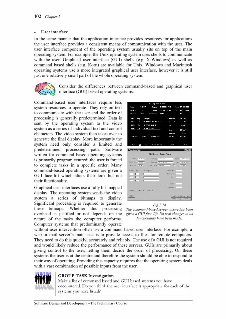
102 Chapter 2
Software Design and Development –The Preliminary Course
• User interface In the same manner that the application interface provides resources for applications the user interface provides a consistent means of communication with the user. The user interface component of the operating system usually sits on top of the main operating system. For example, the Unix operating system uses shells to communicate with the user. Graphical user interface (GUI) shells (e.g. X-Windows) as well as command based shells (e.g. Korn) are available for Unix. Windows and Macintosh operating systems use a more integrated graphical user interface, however it is still just one relatively small part of the whole operating system.
Consider the differences between command-based and graphical user interface (GUI) based operating systems.
Command-based user interfaces require less system resources to operate. They rely on text to communicate with the user and the order of processing is generally predetermined. Data is sent by the operating system to the video system as a series of individual text and control characters. The video system then takes over to generate the final display. More importantly the system need only consider a limited and predetermined processing path. Software written for command based operating systems is primarily program centred; the user is forced to complete tasks in a specific order. Many command-based operating systems are given a GUI face-lift which alters their look but not their functionality. Graphical user interfaces use a fully bit-mapped display. The operating system sends the video system a series of bitmaps to display. Significant processing is required to generate these bitmaps. Whether this processing overhead is justified or not depends on the nature of the tasks the computer performs. Computer systems that predominantly operate without user intervention often use a command based user interface. For example, a web or mail server’s main task is to provide access to files for remote computers. They need to do this quickly, accurately and reliably. The use of a GUI is not required and would likely reduce the performance of these servers. GUIs are primarily about giving control to the user, letting them decide the order of processing. On these systems the user is at the centre and therefore the system should be able to respond to their way of operating. Providing this capacity requires that the operating system deals with a vast combination of possible inputs from the user.
Fig 2.78 The command-based screen above has been given a GUI face-lift. No real changes to its
functionality have been made.
GROUP TASK Investigation Make a list of command based and GUI based systems you have encountered. Do you think the user interface is appropriate for each of the systems you have listed?

Hardware and Software 103
Software Design and Development – The Preliminary Course
Utilities Many utilities are provided with the operating system whilst others are installed to provide additional functionality. All utilities are used to manage, maintain or secure the resources of the system. • File compression The ability to compress files is a common task to save storage space or to reduce file size prior to transmission across the Internet. Many operating systems now include utilities to compress files and other utilities are available to add this functionality if it is not present. In Windows XP users can specify that all files on the hard drive should be compressed. Although this will free up space on the hard drive, it is not recommended as the extra time taken to decompress each file results in poor system performance. Right clicking on one or more files allow just those files to be compressed using ZIP compression. This is useful when emailing large files. The compression provided by operating systems is lossless, which means no data is lost during compression and decompression. Lossy compression, which forms part of many audio, image and video formats, achieves higher compression ratios by removing data that will not be obvious to users. • Defragmentation Over time the file system on all hard disk drives becomes fragmented. When a hard drive is first used each file is saved on a new portion of the disk using complete sectors that are close to each other. Later when files are deleted these sectors are freed for later use. However each new file stored is a different size hence many sectors are not used. Over time more and more unused or partially used sectors appear and many files are stored on sectors that are physically separated on the disk. Such fragmentation causes poor read and write performance. Defragmentation (or defrag) utilities are used to correct this problem. Defragging rewrites the entire drive so that each file is stored on adjoining sectors and few empty sectors remain within the stored data. Most operating systems include a defrag utility. Commonly the utility includes the ability to analyse the disk prior to beginning the defragmentation process. The analysis advises the user if defrag is required and also provides an indication of likely improvements once the defrag process is complete. • Virus checking Anti-virus software is perhaps the most well known utility in use today. A large variety of commercial and free anti-virus packages are available and most operating systems encourage the user to install at least one such package. All virus checking utilities aim to prevent viruses and other malware before they are executed by the system. They scan all executable files entering the system looking for known virus signatures or potential patterns in the code that may cause unwanted processing. If a
Fig 2.79 Disk defragmenter within Windows XP.
Virus A type of malware that is able to copy itself either within a single system or to other systems.

104 Chapter 2
Software Design and Development –The Preliminary Course
potential virus is identified then the virus utility advises the user and then either deletes the file or quarantines the file so it cannot be executed by the system. As new viruses are detected the signature files are updated by the anti-virus developer and distributed to all users. It is therefore critical that anti-virus software is regularly updated so that new viruses are detected. Many anti-virus packages include an automatic update facility such that virus signatures are updated on a daily basis. Many anti-virus packages include a variety of other features. Most are able to scan the entire file system in search of potential viruses and other malware. If a virus is found in a required system file then the software is able to clean the file so it is restored to its original state. Many also provide real time checks of Internet sites and files. The company distributing the anti-virus package visits each website in search of potential viruses and other malware. The results of these searches are then used to warn users of potential threats within the websites they visit. • Embedded licence installation count Within large commercial and government organisations software applications are routinely installed over a local area network from installation files stored on a server. Utilities are available to monitor the number of computers where each software application has been installed. In some cases the software licence agreement will specify the number of machines on which the application can be installed. Other licences allow unlimited installation but require the organisation to report on an annual or bi-annual basis the number of times the application has been installed. These utilities ensure compliance with the licence terms and conditions. • Batch job scheduling There are numerous processes that should be executed on a regular basis. For example a complete scan of the hard drive for viruses, backing up data files and defragmenting drives. These tasks are often best accomplished when nobody is using the computer. Batch jobs allow a number of processes to be performed sequentially and then a task scheduling utility can be used to execute the batch job at specific times. Windows XP includes a utility called “Windows Task Scheduler” that operates in the background so that batch jobs can be started at scheduled times. Fig 2.80 shows when the AppleSoftwareUpdate process is scheduled to run on a Windows XP machine. • Emulation Many current operating systems include the ability to emulate previous versions of the operating system. This enables existing software applications to continue to operate on newer versions of the operating system. Emulators are also available which allow applications written for another operating system to execute. For example there are Mac OS emulators for MS Windows and MS Windows emulators for Mac OS. All emulators must provide an application interface which complies with the application interface of the original operating system being emulated.
Malware Malicious software that deliberately causes some undesired result. Malware includes viruses, adware, spyware, Trojans and worms.
Fig 2.80 Windows Task Scheduler.

Hardware and Software 105
Software Design and Development – The Preliminary Course
APPLICATION SOFTWARE
Software designed to perform some specific task for users is known as application software. The software is being applied to the solution of a problem. It can transform a personal computer into a word processor, a spreadsheet, a games machine, a database system, an Internet browser, a digital video studio or virtually any other type of data processor. Applications for large computer systems can run hotels, communication networks, banking systems, government departments, warehouses and a myriad of other tasks. Application software is what makes computers such versatile machines.
Application software sits between the operating system and the users. Most software developers are engaged in the task of designing and developing application software. They need not concern themselves with the detailed operations and functions of the hardware; the operating system performs these tasks for them. As a consequence applications are developed to execute on machines running a particular operating system rather than a particular hardware configuration. The software application communicates with the application interface section of the operating system.
Application software can be categorised into two areas; off-the-shelf packages and custom designed packages. Let us now consider each of these in turn: Off-the-shelf packages
Applications that are distributed as pre-packaged products are known as off-the-shelf packages. They may be distributed through retail stores or the Internet. Most software used on personal computers is of this type. For example, word processors, spreadsheets, games, graphic editors, etc. The software developer distributes the product ‘as is’, it is up to the purchaser to decide if the functionality of the application suits their requirements.
Development of large commercial off-the-shelf software products is very expensive yet the cost to the end-user is relatively inexpensive. Why is this so? Off-the-shelf packages are economical to purchase as development costs are shared between all users. Also the product is the same for all users, it is therefore more economical to provide quality support. Generally the wider the audience for a product the cheaper the product should be for its end users.
Some off-the-shelf products can be customised by users to suit varying requirements. The resulting products are known as customised off-the-shelf (COTS) packages. For example, creating a database system to store a school’s timetable using Microsoft Access. In this case, Microsoft Access (an off-the-shelf product) is being used to create a new customised product (the timetable database system). The off-the-shelf package is being used as a software development tool to create a new application. The new custom application, in most cases, requires the services of the parent off-the-shelf application to operate.
GROUP TASK Investigation Make a list of all the off-the-shelf applications installed on your home or class computer. Briefly describe the purpose of each of these applications.

106 Chapter 2
Software Design and Development –The Preliminary Course
Custom designed packages
Unique problems where no existing solution is available require the development of a custom designed package. These custom applications are designed to meet the precise needs of a particular client. Systems for large business and government organizations are often custom designed. The performance requirements combined with the unique needs of these organizations make developing a custom solution necessary. COTS based products can be used for developing smaller applications with limited numbers of users. However performance tends to deteriorate as the number of users increases. Applications that must interface with unusual or custom hardware will require custom software solutions.
Consider the following:
There are many situations where an off-the-shelf solution is not available. Some examples where a custom designed package is likely to be required include: • A new dam requires a software package to control the operation of its floodgates. • The water board wishes to computerise its meter reading activities. • A small business that has a unique distribution and invoicing system. • A school wishing to implement their own unique reporting system. • A large chain of restaurants computerising their operations. • A mail order company developing a web site allowing customers to order and pay
online. • A security company developing a computer controlled alarm system. In each case it is likely that a specialist software development company would be contracted to develop a custom designed application. There are software development companies that specialise in designing and developing applications for use within most industries
GROUP TASK Discussion Why do you think a custom designed solution may be required for each of the examples above? Discuss.
GROUP TASK Discussion Why would it be preferable to use a specialist software developer rather than attempt to develop applications in-house? Use the example scenarios above to assist with your discussion.
Fig 2.81 Microsoft Office is a popular off-the-shelf product that allows developers
to produce customised solutions.

Hardware and Software 107
Software Design and Development – The Preliminary Course
SET 2D 1. The ability to execute more than one
program at the same time is known as: (A) processor-tasking. (B) memory management. (C) processor management. (D) multi-tasking.
2. The software that organises and controls hardware and other software is called: (A) the application software. (B) the operating system. (C) the memory device. (D) the application interface.
3. Generally, COTS based packages are used to: (A) develop smaller applications with a
limited amount of users. (B) develop large applications with a
limited amount of users. (C) develop smaller applications with
an unlimited amount of users. (D) develop large applications with an
unlimited amount of users. 4. Spreadsheet software and database
software can best be described as: (A) system software. (B) custom-made software. (C) application software. (D) interface software.
5. Application interfaces provide the means by which: (A) application software communicates
with the operating system. (B) the operating system communicates
with the hardware. (C) application software communicates
with the hardware. (D) application software communicates
with itself.
6. Most devices communicate with the operating system using: (A) a user (B) a GUI. (C) a driver (D) application software.
7. The two main types of software present on all computer systems are: (A) spreadsheet software and the
operating system. (B) operating system and application
software. (C) web browser software and
operating system. (D) word processor software and
application software.
8. Application software that is pre-packaged is often called: (A) customised software. (B) user software. (C) off-the-shelf software. (D) operating system software.
9. Graphical user interfaces use: (A) a command-based system. (B) a program-centred system. (C) text to communicate with the user. (D) a fully bit-mapped display.
10. Peter has a PC at home, which he uses to complete a number of different tasks such as using the Internet, doing his finances and writing letters. The operating system on Peter’s PC is most likely to be: (A) single-user, multi-tasking. (B) single-user, single-tasking. (C) multi-user, multi-tasking. (D) RTOS.
11. What are the essential differences between operating system software and application software?
12. Describe the essential functions performed by most operating systems.
13. Describe the essential differences between command-based and GUI operating systems.
14. What is the difference between a multi-user operating system and a multi-tasking operating system? Include examples where each would be used.
15. List and describe all the software applications used within your school environment.

108 Chapter 2
Software Design and Development –The Preliminary Course
PROGRAMMING LANGUAGES To create software requires a method of instructing the computer. Programming languages provide a more human way of instructing computers. There are a large number of programming languages available for use by programmers. Each has their strengths and weaknesses. Professional software developers require knowledge and expertise in the use of a range of programming languages. In this way they are able to select and use a language suited to the current project under development.
In this section we examine the different generations of programming languages, from machine language, then assembler, higher-level languages and finally declarative languages. We then examine the current trend towards the use of event driven languages compared to the more traditional sequential languages. Finally the process of translating higher-level languages into a form that can be executed by the computer is discussed. GENERATIONS OF PROGRAMMING LANGUAGES
Programming languages have traditionally been grouped into levels and generations. Each subsequent generation being closely related to hardware developments occurring at the time. Low-level languages include the first generation machine languages and the second-generation assembler languages. High-level languages are termed third generation. Declarative languages are included as part of the fourth and subsequent generations.
First and second generation languages are known as low-level languages as their instructions relate directly to the hardwired instruction set of the CPU. These languages are difficult for humans to understand but easy for machines to understand. Different CPUs require different low-level languages. As a consequence code written in a low-level language cannot be used on computers using a different CPU. Low-level languages are said to be machine dependent, they can only be used on a machine with the same CPU instruction set.
Third and subsequent generations of languages are said to be machine independent. These languages are translated into machine instructions. By using different translators the same code can be used by a variety of CPU designs. Higher-level languages are more like English making them easier for humans to use and understand. They include commands to simplify common tasks. These built-in commands greatly reduce the size and complexity of the code. However they also limit the programmer, as they can only use the commands included in the language’s syntax.
Machine
Assembler
High-level
Declarative
Mor
e En
glish
Lik
e
Mor
e M
achi
ne In
depe
nden
t
Mor
e Lin
es o
f Cod
e
Fig 2.82 Generations of programming languages.
GROUP TASK Research Machine language emerged in the late 1940s, assembler the mid 1950s, and soon after the first high-level languages appeared. What hardware developments were occurring at the time to allow programming languages to evolve so rapidly? Discuss.

Hardware and Software 109
Software Design and Development – The Preliminary Course
Machine Languages
The CPU is able to execute a limited number of inbuilt commands. These commands are called the instruction set for the processor. A machine language program is a collection of these commands. Each machine language instruction is represented by the computer as a series of binary digits e.g. 10011101010011010011. To the casual human observer it is impossible to make any sense of machine language in its native form. Nevertheless every program ever written is ultimately converted into a series of machine language instructions. They have to be; these instructions are all the computer can actually understand.
Prior to the development of the keyboard machine language instructions were entered using a series of cables that effectively opened and closed particular circuits. Later punched cards were introduced. These cards provided a storage medium allowing programs to be reloaded more easily. Once the keyboard arrived machine language was entered in hexadecimal, this reduced the volume of data entry significantly. In hexadecimal every 4 bits (binary digits) can be represented using a single character.
Each machine language instruction contains two parts, an operation code (opcode) and one or more operands. The majority of instructions require a single operand. The opcode identifies to the control unit what process is to be performed and the operand provides the data on which the process is to be performed. For example, on a Pentium machine the instruction 10100001 00000000 00000010 adds the decimal number 2 to the value currently in the accumulator. 10100001 is the opcode letting the control unit know to carry out an add to the accumulator and 00000000 00000010 is the decimal value 2 using 16 bit binary. For many operations the operand will be a memory address rather than the data itself.
Assembler Languages
Assembler languages were the first attempt to make programming languages more human like. These languages use mnemonics to represent different commands available in the assembler language. A mnemonic is simply an aid to assist in remembering, For example, add ax means add to accumulator and is far easier to remember than 10100001. Programs written in an assembler language cannot be understood by the CPU. An assembler is required to translate the assembler code into machine language. The translation process is straightforward as the majority of the commands translate directly into single machine language instructions.
Fig 2.83 Cables were used to enter machine
language programs into ENIAC, the first electronic computer.
GROUP TASK Research Use the Internet to find a list of opcodes for a number of modern CPUs. Using these opcodes, write a few machine language instructions.
Accumulator A register within the CPU that holds the result of the last operation performed by the ALU.
110 Chapter 2
Software Design and Development –The Preliminary Course
Programs written in assembler can be optimised for particular processors. As a consequence assembler language programs are often written for routines where speed is crucial e.g. graphics intensive operations. The resulting machine language is then combined with the code generated from other higher-level languages.
Consider the following
Suppose we wish to read a single key press from the keyboard. The resulting character is to be displayed on the screen and then stored in memory. In assembler (and in machine language) this process involves a number of operations. In high-level languages a single statement is required.
Let us examine the steps involved. The example assembler statements are from an x86 assembler used on the Intel range of processors (which includes the Pentiums). • Clear the accumulator by moving in a 0 value. e.g. mov ax,0 • Initiate a keyboard interrupt request. This causes the scan code and ASCII value
of the next key pressed on the keyboard to be placed in the accumulator. e.g. int 16,0
• Display this value on the screen so the user gets feedback that they have entered a value. e.g. int 10,a this statement tells the video system to write the character with the ASCII value held in the accumulator to the screen at the current cursor position.
• Store the value held in the accumulator into some memory location for later use. e.g. stos address
In the above example we have simplified the process. When using assembler, you must perform all validation and error checking yourself. You must also be extremely careful to not overwrite memory used by the operating system or other applications.
High-Level Languages
High-level languages are designed to simplify the programming process. They allow programmers to concentrate on solving problems rather than dealing with the mundane details of the hardware systems. There are many hundreds of different high-level languages available today, each with it’s own particular strengths and weaknesses. For example, Fortran is used for scientific applications, Cobol for business applications, Prolog for artificial intelligence applications and Pascal for teaching applications.
All high-level languages must be translated into machine code using a translator. Different translators are available for different models of CPU. This allows high-level code (source code) to be translated into the machine language (object code) appropriate to a particular CPU. We examine different methods of translation later in this chapter. The high-level code is said to be machine independent. Program code could now be reused on different machines with little modification.
GROUP TASK Discussion When first introduced assemblers revolutionised the way programs were written. Why do you think assemblers made such an impact? Discuss.

Hardware and Software 111
Software Design and Development – The Preliminary Course
High-level languages use commands that are more readily understood by humans. They are designed for the use of human programmers. For example, the command Write “Hello” has a clear English meaning compared to the equivalent set of machine language instructions that are actually executed by the CPU. This makes the task of programming more intuitive and greatly assists the maintenance of existing code.
The majority of high-level languages in common use today require the programmer to unambiguously describe how a problem is to be solved, these languages are known as third generation languages. In the next section we consider declarative languages where the emphasis is on what needs to be done rather than how it is to be accomplished.
Consider the following timeline:
Many high-level languages have maintained a steady following since their initial creation e.g. Cobol. Others have been influential in the evolution of new programming techniques, e.g. Lisp, whilst themselves being specialised and not widely known. Fig 2.84 describes the historical development of most of the commonly used languages; there are hundreds of other languages not included on the above timeline.
Fortran
1950 1960 1970 1980 1990 2000
Fortran 95
Cobol Object Oriented
Cobol
Algol
Pascal
Modula
Ada
C BCPL
C++
Java
Basic Visual Basic
Lisp
Logo
Simula
Smalltalk
Prolog
Delphi
Fig 2.84 The development and evolution of high-level languages.
The dotted arrows indicate where languages evolved from previous languages.
GROUP TASK Investigation Each member of the class is to research one or more of the languages shown on the timeline above. Find a sample code segment and describe each language’s main areas of application.
GROUP TASK Discussion Share your results from the above group task with your class. Compile a class summary of everyone’s research.

112 Chapter 2
Software Design and Development –The Preliminary Course
Declarative Languages
Traditional or imperative languages have developed as a consequence of the design of the hardware. They require programmers to describe the sequence of processes leading to the solution of the problem. You must know precisely how to solve the problem before you can hope to write a program. Declarative languages are very different, instead programs are more a formal description or specification of a problem. In most cases the order of statements is of little or no significance. Code written in a declarative language describes what the problem is rather than how it can be solved. The program works out a method of solution as it executes.
Declarative languages can be likened to spreadsheets and database queries. On a spreadsheet all the specifications for the solution are clearly described as formulas and values entered into cells. The spreadsheet application determines the best method for evaluating these formulas. From the users point of view the order of processing is of little significance. Querying a database is a similar process. The query is a specification describing the conditions that must be met or the rules that must be followed. The data itself is the facts onto which the rules are applied. The database management system determines the method and sequence of events required to extract the facts (data) that work with the rules (query).
The Software Design and Development HSC option topic Evolution of Programming Languages, examines declarative language types in detail. Examples of declarative languages include Prolog, Lisp, APL, and Haskell. Most declarative languages are used for specialised tasks involving artificial intelligence. For example, the spelling and grammar checker contained in your word processor was most likely developed using a declarative language. Historically applications written using declarative languages have executed substantially slower than their imperative equivalents. This situation is becoming progressively less significant as the processing power of modern CPUs increase.
EVENT DRIVEN VERSUS SEQUENTIAL APPROACH
Sequential programs have a distinct start and end. The user is led through the program in a pre-determined sequence. Instructions are executed one after the other. The user is unable to deviate from the sequence determined by the program. This approach does not take account of the different ways in which people work. Event driven programs listen for and then respond to certain occurrences or events. Once an event has occurred the program executes a particular section of the code. Each section is executed in a similar manner to a sequential program. The event driven approach results in more flexible and user-friendly software.
GROUP TASK Discussion Programs written using declarative languages require more processing power than their imperative equivalents. Why then would one choose to program in a declarative language? Discuss.
Fig 2.85 Available events for a command button in VB.NET.

Hardware and Software 113
Software Design and Development – The Preliminary Course
GROUP TASK Investigation Consider the open dialogue window from a typical GUI application. Assume this application was written using an event driven approach. List all the controls found on this dialogue. What events are active for each of these controls?
Event driven programs can be viewed as a collection of inter-related modules. The execution of an event driven program involves the computer continually scanning each control to check if an event has occurred. Once it detects an event then the code attached to that event is executed sequentially. The computer continues scanning controls for events even whilst an event procedure is executing. In this way multiple events can be executing concurrently. For example, the user may click on a command button that executes a certain event routine and at the same time an automatic save of the current document may occur as a consequence of a timer event occurring. This does not occur in a sequential program.
Most event driven programming languages use controls as their basic building blocks. Each control has properties which affect the way the control looks and behaves e.g. a command button control would have properties to control its colour, alter its caption, change its size and define its position within its window. Controls also have events to which they can respond. A command button would have a click event, got focus event, drag over event, etc. Event procedures are written for each event where some processing is required. Controls and events used in event driven languages are often confused with objects used in object oriented languages. These two concepts are quite different and should not be confused.
Different problems will suit different approaches. In general, user-centred programs are easier to implement in event driven languages. Programs where a distinct sequence is required are often suited to implementation in a sequential language. Software developers should have an understanding of a variety of languages and approaches. This allows them to choose the most appropriate language for each given problem.
Consider the following problems:
• Creating the daily weather forecast based on vast quantities of data. • A graphics utility that automatically converts different formats into jpeg files. • Software to control the engine management system in a car. • An ordering and invoicing system for a small business.
GROUP TASK Discussion Consider each of the problems above. Do you think a sequential or event driven language is the most appropriate? Discuss.
Fig 2.86 The properties window for a command button in VB.NET

114 Chapter 2
Software Design and Development –The Preliminary Course
THE NEED FOR TRANSLATION Source code is a collection of statements written in a high-level language. These statements make no sense to the CPU; they must be translated into machine language. A translator is used to carry out this translation process. Translators are themselves software applications whose purpose is to convert the source code of a particular high-level language into the machine language instructions understood by a particular CPU. Different CPUs require different translators. The translation process includes three main steps: lexical analysis, syntactical analysis and code generation. Lexical analysis examines each element of the source code to ensure it is a legitimate part of the high-level language. This is similar to checking the spelling in a written document. Syntactical analysis checks the grammar or syntax of the source code is correct. This is similar to checking a written document has correct grammar and punctuation. Finally the machine code is generated. There are two main methods of translation; compilation and interpretation. During the development of a software product it is common to use both these methods. Interpreters are used during development to test code as it is being produced. Once the source code is complete compilation is usually used to generate the final executable files for distribution.
Compilation The process of compilation involves translating the entire source code into object code. The object code is then combined with other linked files to create the final executable files. These executable files can then be executed repeatedly at a later time without the services of the compiler. Compiled code executes fast as there is no translation required at run time. Most applications we use on computers have been compiled. When using a compiled application it is difficult to determine the original high-level language used for its development. The compiled code is a series of machine language instructions. This provides protection for the software developer as it is very difficult to alter the code. Similarly, determining the nature of the original source code is very difficult to achieve from executable machine code.
Interpretation Interpreters translate source code statement by statement. After each statement has been translated into machine code it is immediately executed. This process of translation then execution continues until either an error in a line of source code is encountered or the application ends. The process of translating code at run time is a significant processing overhead resulting in poor performance. Apart from code that generates many web sites few applications are executed using interpreters; rather interpreters are used by programmers to test their code as it is being developed.
GROUP TASK Activity How many people in your class can speak and/or write in a foreign language? Each of these people is to translate the first two sentences on this page into that language. Discuss this process and describe any similarities to the translation process described above.
GROUP TASK Discussion Apparently most applications we use have been translated using a compiler. Make up a list of reasons why this is the case.
manjeet.kaur
Highlight
manjeet.kaur
Highlight
manjeet.kaur
Highlight
manjeet.kaur
Highlight
manjeet.kaur
Highlight
manjeet.kaur
Highlight
manjeet.kaur
Highlight
manjeet.kaur
Highlight
manjeet.kaur
Highlight
manjeet.kaur
Highlight
manjeet.kaur
Highlight
manjeet.kaur
Highlight
manjeet.kaur
Highlight
manjeet.kaur
Highlight
manjeet.kaur
Highlight

Hardware and Software 115
Software Design and Development – The Preliminary Course
When running programs using an interpreter you must have a copy of the interpreter installed together with the original source code. To distribute a program in this way makes copying and alteration of the source code simple. For commercial software this is a definite problem. The code behind many websites is interpreted. For example the popular PHP language is always interpreted. PHP code runs on a web server to create dynamic web sites. In this case the output from the execution of the code is transmitted to the user’s browser. The source code remains on the web server where it is not accessible to users. Some declarative languages do not use compilers, rather they must be interpreted. In these cases, the interpreter is one part of the programming environment. The environment provides much of the processing support for the application.
(a) Outline the major functions performed by an operating system. (b) Most commercial software is distributed as executable files.
(i) Identify the method of translation used to create commercially distributed executable files.
(ii) Explain why commercial software is distributed as executable files. Suggested solution
(a) Operating system functions include: • Scheduling and running of tasks • Accessing hardware • Managing allocation of memory to the various tasks running • Provides an interface to the user • Provides an interface between applications and peripherals. • Provides an interface between applications and the file system
(b) (i) Compilation is used to create an executable file.
(ii) Why distribute executable files: • Protects copyright. There is no need to provide those using the software
access to the source code. This makes it much harder for people to change the code and redistribute the files as their own slightly different product.
• Code executes much faster. There is no need to re-check each line and then translate it to its equivalent machine code as would have to be done if the source code were distributed and an interpreter used.
GROUP TASK Discussion There are many problems and issues that can arise when distributing interpreted software products. List and discuss some possible problems.
GROUP TASK Activity Make up a table to summarise the advantages and disadvantages of the two forms of translation discussed above.
HSC style question:
manjeet.kaur
Highlight
manjeet.kaur
Highlight

116 Chapter 2
Software Design and Development –The Preliminary Course
SET 2E 1. Low-level languages are also known as:
(A) first generation languages. (B) second generation languages. (C) first and second generation
languages. (D) second and third generation
languages. 2. C++ and Pascal are examples of:
(A) high-level languages. (B) machine languages. (C) first generation languages. (D) assembler languages.
3. Which type of language developed as a consequence of the hardware design? (A) Event-driven. (B) Imperative. (C) Declarative. (D) None of the above.
4. A register within the CPU, which holds the result of the last operation performed by the ALU is called: (A) the control unit. (B) the operand. (C) the arithmetic logic unit. (D) the accumulator.
5. The process that examines whether the syntax of the source code is correct is known as: (A) lexical analysis. (B) syntactical analysis. (C) incremental compilation. (D) compilation.
6. Languages that use mnemonics to represent different commands are called: (A) assembler languages. (B) machine languages. (C) high-level languages. (D) declarative languages.
7. The two main methods of translation are: (A) compilation and interpretation. (B) compilation and source translation. (C) lexical and syntactical analysis. (D) assembly and translation.
8. Lisp, APL and Haskell are examples of: (A) traditional languages. (B) imperative languages. (C) declarative languages. (D) machine languages.
9. Which languages are said to be machine dependent? (A) High-level languages. (B) Low-level languages. (C) Declarative languages. (D) All computer languages.
10. The process that examines each element of the source code to ensure that it is a legitimate part of the language is known as: (A) compilation. (B) translation. (C) lexical analysis. (D) syntactical analysis.
11. Describe the essential features of machine languages, assembler languages, high-level languages and declarative languages.
12. Machine and assembler languages are said to be machine dependent. What does this mean?
13. List as many high-level languages as you can. See if you can come up with the longest list in the class.

Hardware and Software 117
Software Design and Development – The Preliminary Course
14. Examine the above screen shot from taken from The HSC Assistant: SDD CD-ROM. This product was written using an event driven programming language. List the events that are likely to activate code for each control on this screen. Include a brief description of the processing that would likely occur for each event identified.
15. Compare and contrast the two methods of translation; namely compilation and interpretation.

118 Chapter 2
Software Design and Development –The Preliminary Course
THE RELATIONSHIP BETWEEN HARDWARE AND SOFTWARE In this section we examine the interactions that take place between the hardware and software components of the system. We address the following questions:
• How does the hardware process software instructions?
• What occurs when an application is first initiated and run?
• What are the hardware requirements for software?
We then consider the complete computer system including hardware, software, data, procedures and personnel. Each of these elements has a significant role to play in all computer systems. We consider these roles, particularly in regard to the process of software design and development.
HOW DOES THE HARDWARE PROCESS SOFTWARE INSTRUCTIONS? (THE FETCH-EXECUTE CYCLE)
Software instructions processed by the CPU are always in machine language. This is all the CPU, or more precisely the control unit, can understand. The method of executing each machine language statement is hardwired within the CPU. Each machine language instruction corresponds to a precise series of CPU operations. These CPU operations are known as microcode.
The fetch-execute cycle is used to carry out each and every machine language instruction. This cycle can be split into instruction time (I-time) and execution time (E-time). Instruction time involves fetching the instruction from memory and then decoding it. Execution time involves executing the instruction and storing the result. The fetch-execute cycle occurs at a constant pace. The system clock determines this pace. At each tick of the clock a part of the fetch-execute cycle occurs.
A register is a temporary but very fast storage area within the CPU. There are a number of registers crucial to the operation of the fetch-execute cycle. The program counter holds the address of the next instruction to be executed. It is a counter because in most cases, instructions are held sequentially, thus the program counter is incremented to point to the address of the next instruction. The instruction register holds the machine language instruction waiting to be executed. The accumulator together with other general-purpose registers, are used to store data and any results during and after processing.
Let us examine each step in the fetch-execute cycle: • Fetch - the instruction at the address in memory indicated by the program counter,
is read into the instruction register. The program counter is then incremented to point to the next instruction.
• Decode – the control unit makes sense of the instruction. It then directs other components to load any required operands into the appropriate registers.
• Execute – the instruction is actually carried out. For most instructions, the services of the ALU are used.
• Store – the results are stored in one or more of the general-purpose registers. A further instruction is needed to move the results to RAM.
Fig 2.87 The fetch-execute cycle.
I-TIME
E-T
IME

Hardware and Software 119
Software Design and Development – The Preliminary Course
Modern CPU's are able to process multiple instructions concurrently. While one instruction is being fetched, another is being decoded and another is being executed. This is called pipelining. Most CPUs have more than one ALU, which means instructions that do not affect one another can be executed at the same time. These and other techniques significantly improve the performance of modern CPUs.
WHAT OCCURS WHEN AN APPLICATION IS FIRST INITIATED AND RUN?
The operating system controls the initiation and allocation of resources to all applications. Once the user selects or enters a command to start an application, the operating system takes over. Let us consider the steps taking place from this moment until the application is executing.
• The application is located on secondary storage. The operating system firstly needs to ensure the application exists and how much space it requires in RAM.
• The operating system allocates a certain area of RAM to the application. Areas for the actual executable file are allocated, as well as storage areas for use by the application.
• The application begins to be loaded into its allocated section of RAM. At this stage, instructions relating to the execution of the application are loaded.
• The operating system allocates CPU time to the application. The application has control of the CPU during its allocated CPU time. In most circumstances, the application is sharing CPU time with other software, including the operating system. The operating system switches between applications to ensure they can each perform effectively.
• The fetch-execute cycle begins processing the instructions that form the application.
• The start screen for the application is displayed and the application waits for user input. The application is now running and will continue to be allocated CPU time by the operating system.
GROUP TASK Discussion Repetition of sections of code occurs by altering the contents of the program counter. Explain how this would occur using the fetch-execute cycle.
GROUP TASK Discussion Describe the steps of the fetch-execute cycle for a typical instruction that adds the contents of two registers.
GROUP TASK Discussion Why do you think it is appropriate for the operating system to allocate RAM and other resources rather than the application doing this itself?

120 Chapter 2
Software Design and Development –The Preliminary Course
WHAT ARE THE HARDWARE REQUIREMENTS FOR SOFTWARE?
All software requires hardware on which to operate. Most software will have a set of minimum requirements necessary for the product to install and execute. Further resources are needed for optimal performance. Many products also specify a set of recommended requirements if optimal performance is to be realised.
Let us consider the different hardware areas often specified in these requirements:
• Processor – The type of processor and speed of the processor. Applications are really sets of machine language instructions. The processor on which the software is to be run must be able to understand each of the instructions contained within the program. Different processors utilise different instruction sets. Newer versions of a particular family of processors often include new instructions not available in previous versions. If a program includes some of these instructions then it will not execute on earlier processors. Obviously the speed of the processor will greatly affect the speed at which the application can execute.
• RAM – The amount of random access memory available is often more crucial to the performance of software than the speed of the processor. Insufficient RAM causes the processor to create virtual RAM on a hard drive resulting in poor performance. Minimum RAM requirements usually assume the software is running exclusively on the computer, this is seldom the case. Extra RAM beyond the minimum requirements is always advisable.
• Hard disk space – Applications require physical secondary storage. Without the required space it is impossible to install the application. The more crowded a hard disk becomes, the longer it takes to locate information. Often hard disk storage requirements specify space required for a minimum installation and again for a full installation with extra features, tutorials and data files installed.
• Peripheral Devices – Items such as printers, video cards, sound cards, monitors, pointing devices, etc… are specified. Often these can be of any type as the application communicates with the peripherals via the operating system. Generic requirements are often stated such as ‘requires VGA or higher resolution monitor’ or ‘Microsoft compatible pointing device required.’ Specialised applications may require particular hardware products. For example, an application that communicates with a company’s telephone system may do so directly rather than through the operating system. In this case, the application will include the instructions needed to communicate with a limited selection of telephone systems.
GROUP TASK Research Examine the packaging for a number of commercial software applications. Make a list of the minimum hardware requirements of each package.
GROUP TASK Discussion Imagine a user purchases a software product and whilst attempting to install the product finds their computer does not meet the minimum requirements. Should they have the right to return the package for a full refund? Debate each side of the argument.

Hardware and Software 121
Software Design and Development – The Preliminary Course
CHAPTER 2 REVIEW 1. The five elements of all computer-based
systems are: (A) Hardware, hard disk, peripheral
devices, software, personnel. (B) Operating system, application
software, peripheral devices, personnel and data.
(C) Hardware, software, data, personnel and procedures.
(D) Operating system, application software, input devices, output devices and personnel.
2. The pace that the fetch-execute cycle occurs is determined by: (A) the system clock. (B) the arithmetic logic unit. (C) the accumulator. (D) the user.
3. The term ‘pixel’ is an abbreviation meaning: (A) picture resolution. (B) photo element. (C) picture element. (D) pattern element.
4. The function that sends data outside the system is known as: (A) output (B) input. (C) throughput. (D) processing.
5. The basic building blocks of all Central Processing Unit components are: (A) arithmetic logic units. (B) registers. (C) processor chips. (D) transistors.
6. The term known as ‘pipelining’ means: (A) CPU’s are able to process multiple
transactions concurrently. (B) CPU’s are able to process only one
transaction from start to finish at any one time.
(C) CPU’s are not able to process any transactions.
(D) CPU’s can send and receive data simultaneously.
7. The function that obtains data from outside the system is known as: (A) output. (B) input. (C) throughput. (D) processing.
8. Software instructions that are processed by the CPU are always in: (A) low-level languages. (B) machine language. (C) source code. (D) high-level languages.
9. An area used for storing instructions that are likely to be needed in the future is called the: (A) microprocessor. (B) branch predictor. (C) bus interface. (D) code cache.
10. The theory that says the speed of processors would double every 18 months has come to be known as: (A) Gordon’s Law. (B) Moore’s Law. (C) Gate’s Law. (D) Intel’s Law.
11. Describe the sequence of events occurring within the CPU during execution of a single microcode instruction.
12. A digital watch can be thought of as a computer system. List elements of this system under the headings hardware, software, data, personnel and procedures. Would such a watch have an operating system? Assuming it did, what would be the essential features of its operating system?
13. What are the differences between the way data is physically stored on a hard disk compared to the way it is stored on a CD-ROM?
14. Describe the interaction that occurs between users, application software, system software and hardware when a computer system is in operation.
15. Most software is written in high-level programming languages. This seems a bit odd when low-level languages execute faster and declarative languages don’t require knowledge of how to solve the problem. Can you explain this situation? Discuss.

122 Chapter 3
Software Design and Development –The Preliminary Course
In this chapter you will learn to: • identify each of these stages in practical
programming exercises • design and develop a limited prototype as a
proposed solution, or part of a solution, to a problem
• analyse the effectiveness of the prototyping approach in developing a software solution
• use an existing software package to develop a solution using a RAD approach
• discuss the advantages and disadvantages of end user developed software
• compare and contrast structured and agile approaches
• recognise reasons for the failure of solutions • select appropriate software development
approaches for specific purposes • identify characteristics of projects that lend
themselves to a specific development approach • recognise that a single solution may involve a
combination of approaches • identify characteristics of projects that require a
combination of approaches
Which will make you more able to: • describe the effects of program language
developments on current practices
• identify the issues relating to the use of software solutions
• analyse a given problem in order to generate a computer-based solution
• investigate a structured approach in the design and implementation of a software solution
• use a variety of development approaches to generate software solutions and distinguish between these approaches
• describe the skills involved in software development.
In this chapter you will learn about: Structured approach to software solutions • stages in program development
– defining and understanding the problem – planning and designing – implementing – testing and evaluating – maintaining
• characteristics of the structured approach, including: – distinct formal stages – long time periods – large-scale projects – large budgets – involvement of a development team consisting
of: - analysts - designers - programmers - clients (users and management)
Agile approach • speed of getting solution to market • interactive approach with selective refinement • working version delivered after each iteration • responds well to changing specifications • close collaboration between development team and
client throughout the development process Prototyping • modelling of a proposed solution or part of a
solution • progressive refinement of the model in response to
feedback Rapid applications development approach (RAD) • characteristics of the rapid approach, including:
– lack of formal stages – use of existing routines – use of appropriate applications to develop the
RAD solution - drag and drop programming environments - common application packages such as
spreadsheets, databases – communication between developer and client – short time period – small-scale projects – small budgets
End user approach • characteristics of the end user approach, including:
– end user as the developer and maintainer – typically uses RAD and/or prototyping – the developer is the client, therefore there are
no communication issues – small budget and/or short time period for
development Selecting an appropriate development approach • software solutions that have been developed using
a single approach • software solutions that have been developed using
a combination of approaches

Software Development Approaches 123
Software Design and Development – The Preliminary Course
3 SOFTWARE DEVELOPMENT
APPROACHES Software development is the process of creating new software solutions. In this chapter we examine five commonly used approaches to software development. These approaches provide a general framework under which the development of software products can progress. It is important to choose an approach that will yield the best result for the given problem. For many problems a combination of approaches is used.
The approaches examined range from the formal structured approach, through the agile, prototyping and rapid application development (RAD) approaches to the informal end user approach. The structured approach is used for developing large-scale complex, high budget software products and requires extensive expertise and long development times. At the other end of the scale is the end user approach. This approach is used for small-scale projects where the user with a limited budget quickly develops the product.
Historically, software development has been accomplished in stages, where each stage must be completed before the next is commenced. Altering requirements during development being difficult and costly. Unfortunately due to the long development times, many requirements had substantially changed before the product had been released for use. Software developers had to acknowledge this problem and respond by altering their approach to software development. Faster, more reactive approaches were required. The creation of software tools to assist in speeding up and reducing the formality of the task began to emerge. These issues and tools led to the prototyping, RAD and agile approaches becoming recognised and valuable techniques.
GROUP TASK Discussion Hardware technologies have advanced at an astounding rate yet in many ways software has lagged behind. Suggest reasons why this may be the case. Discuss.
GROUP TASK Discussion ‘Software development is a compromise between cost and quality’ Do you agree with this statement? Discuss with reference to the information above and in Fig 3.1.
Fig 3.1 A general view of the five software
development approaches.
Agile
Prototyping RAD
End User
form
al
cost
time
expe
rtise
size
com
plex
ity
qual
ity
High
Low
Structured

124 Chapter 3
Software Design and Development –The Preliminary Course
STRUCTURED APPROACH The structured approach to software development is characterised by distinct formal stages. Each stage is completed before the next is commenced. This is necessary as teams of developers with varying skills and responsibilities are involved in the development process. For example, the coding of the solution cannot commence until the solution has been thoroughly planned in its entirety. The personnel coding the solution are often different to those who plan the solution.
This approach is generally used for large-scale projects where performance and reliability are vital requirements. A large audience will use the final product so even relatively minor errors will prove costly. It is worth spending extra time and money to ensure the final product is of the highest quality.
Let us examine the processes and personnel involved at each stage in the structured development of a typical software product. Defining and understanding the problem
The requirements of the problem must be understood precisely. Omissions at this stage will prove the most expensive to correct during later stages. System analysts are experts in determining and defining requirements. The set of requirements should clearly and precisely define each aspect of the problem. These requirements will later be used to test the success of the solution.
System analysts often commence by compiling a list of outputs. These outputs are then examined to determine the required inputs. The system analyst is then able to create models showing the flow of data through the system from inputs through the various processes to the final outputs.
Defining the problem involves consideration of all aspects that can affect the operation of the final system. Existing systems should be studied to ensure the new system will accomplish all existing requirements. New requirements will then be added. All elements of the system should be considered. There is no point designing a product that cannot operate on the available hardware. The potential users of the system should be consulted to determine their needs and requirements. Software products that solve problems in a manner that cannot be easily understood and used are of little value. Defining and understanding the problem includes catering to the needs of users. This may involve the creation of screen designs to document user requirements.
Finally a development plan is constructed. This plan provides an overview of the steps required to develop the solution and the relative timing allocated to each step.
GROUP TASK Discussion Defining the problem precisely is particularly vital when using the structured approach. Why do you think this is the case? Why might it be difficult to accomplish this task? Discuss.
Fig 3.2 The software development cycle
for the structured software development approach.
Testing and
evaluating
Maintaining
Defining and understanding the problem
Implementing
Planning and
designing

Software Development Approaches 125
Software Design and Development – The Preliminary Course
Planning and designing
At the planning stage the structures that will hold the data to be used during processing are designed. The nature of processing that will occur should be considered at this time. Well-designed data structures can greatly reduce the processing required. These data structures are carefully documented, as the programmers will require them as the solution is built in code.
The project is broken down into modules; each module solving a particular aspect of the problem. Methods of solving each problem are described using an algorithm description language such as pseudocode or flowcharts. These algorithms form the templates for the programmers who will code the solution in a programming language. Implementing
This stage is where the solution is coded in a programming language. Programmers are allocated specific modules to code. They are given system models, the nature and names of relevant data structures together with algorithms. This documentation ensures each programmer adheres to the planned solution and assists in ensuring each module will operate correctly with other modules. The programmer tests their allocated modules to ensure they perform the required task correctly and efficiently.
Once all modules are complete they are combined to form the final solution. Testing of the connections between modules occurs. In theory the software should now be ready for use; unfortunately this is seldom the case. Thorough testing to ensure the solution meets the requirements determined when defining the problem is required. Testing and evaluating
Before the solution can be used it must be thoroughly tested. Large software development companies have teams of testers whose sole function is to check products against the original requirements. This stage involves testing for errors in the code as well as testing the performance of the product under real conditions. For example, the program may be free of errors yet it may perform poorly when subjected to large amounts of data.
Selections of potential users are often used to evaluate the solution and ensure it meets the user’s requirements. This is particularly important in regard to the user interface. These users are asked to note any problems encountered and also to make suggestions in regard to possible improvements.
Once any problems encountered have been corrected the software is ready for distribution and installation. Maintaining
Almost all software products have a life span. They are upgraded to include new functionality and to improve existing functionality. In fact many large-scale applications have been in use for thirty years or more when they were originally intended to have a life of around ten years. These applications have been continually upgraded. Maintenance programmers are employed to perform these upgrades.
When using the structured approach each modification is performed using the steps of the program development cycle. The problem is defined, the solution planned and designed, implemented and then tested. Finally the modified product is released.

126 Chapter 3
Software Design and Development –The Preliminary Course
Consider the following:
Slapper Wackers is a popular chain of fast food restaurants. The directors of Slapper Wackers make a decision to update the company’s computer system. They contract Winston Soft, a software development company, to design and develop the new system.
A feasibility study has been completed and the directors of Slapper Wackers have accepted a general plan as to how the project should proceed. As there are some 400 restaurants in the chain it is decided that the structured approach to development should be used. Let us examine the steps carried out by Winston Soft: Defining and understanding the problem
• A team of system analysts first collect data from a sample of employees. Employees at various levels within the organization are included in the sample. Interviews, questionnaires and informal observations are carried out. Aspects of the existing system as well as perceived needs in relation to the new system are addressed.
• The analysts meet with management to determine the workflow and organisational structure of the company. The needs expressed by the employees are presented, discussed and prioritised.
• Given the needs expressed by management and the employees the analysts can now examine the existing system in detail. An analysis of the data and how it flows through the system is undertaken. A graphical model of the system is created.
• Detailed recommendations are compiled. These recommendations are presented to the directors of Slapper Wackers for approval.
• The objectives of the new system need to be determined. The recommendations together with the analysis of the existing system provide the basis for the creation of these objectives.
• The system analysts prepare a plan for the development of the software. A timeline is included together with a description of each step in the development process.
GROUP TASK Activity Imagine your class are the system analysts working for Winston Soft. Create a series of questionnaires that could be used to collect relevant data from a sample of the waiters, the kitchen staff, the managers and the head office staff working at Slapper Wackers.
GROUP TASK Discussion Why do you think the system analysts chose to survey the employees before surveying management? Discuss.

Software Development Approaches 127
Software Design and Development – The Preliminary Course
Planning and designing
• The project is progressively broken down into smaller more manageable modules by the system designers. This process is known as top-down design. Many of these designers were part of the initial system analysis team and others are specialist software designers. These modules will become the sub-programs of the final software product.
• Data structures are designed. The details of the processing to be performed by each module are created. Algorithms are created for the more difficult modules.
• Design standards are discussed and created. Standards in regard to the look and consistency of the user interface together with naming standards for variables to be used throughout the program.
Implementing
• Programmers are assigned modules to code in the chosen high-level language.
• Modules are coded from the lowest level of the top-down design, progressively working upwards to higher-level modules.
• As modules are completed they are tested and then added to the main project.
• As higher-level modules are completed their connections with lower level modules are tested.
• Once all modules have been written the entire product is tested to ensure it operates according to the design specifications.
GROUP TASK Discussion As the structured approach is being used planning does not commence until all requirements and objectives have been determined. In reality can all the requirements and objectives be known at this stage? Discuss.
GROUP TASK Discussion When using a structured approach to software development it is vital that programmers adhere to the design of each module formulated during the planning stage. Why is this necessary? Discuss.
Slapper Wackers
Menu system
Special items
EFTPOS interface
Enter orders
Process payment
Head office interface
Account keeping
Sales reports
Food delivery
Fig 3.3 A possible initial top-down design for
the Slapper Wackers project.
GROUP TASK Discussion Programs can be built from the top-down or from the bottom-up. In this example the product is to be coded from the bottom-up. Discuss advantages and disadvantages of each of these coding methods.

128 Chapter 3
Software Design and Development –The Preliminary Course
Agile Quick thinking, co-ordinated, active and lean. Adapts well to changing situations.
Testing and evaluating
• Specialist software testers perform testing of the final product. Their aim is to ensure the product achieves the objectives determined when defining the problem.
• The product interfaces with the EFTPOS network as well as communicating sales and profit data back to head office. A software load testing application is used to simulate the demands of the system when all 400 restaurants are operational.
• Installing the product in a sample of 10 restaurants performs useability testing. Feedback is sought from all personnel involved in this beta test.
• The software testers prepare a report outlining and prioritising any problems encountered during testing. The report may also include recommendations for improving the product before final release.
• Winston Soft decides which problems and recommendations should be acted upon prior to release and makes the necessary changes.
• Finally the software is ready for implementation.
AGILE APPROACH Agile development methods have emerged in response to the “adhoc” reality of many software development projects. They place emphasis on the team developing the system rather than following predefined structured development processes. Agile methods remove the need for detailed requirements and complex design documentation. Rather they encourage cooperation and team work. Agile methods are particularly well suited to web-based software development and other software applications that are modified regularly such that they evolve and are updated over time. Typically quite small teams of developers are used. It would be unusual for an agile team to have more than about half a dozen members. It is preferable for one team member to be a knowledgeable and experienced user. Small teams are better able to share ideas and work on solutions together. Larger teams tend to break into smaller groups – for agile methods to be a success everyone must be an equal member with a clear shared purpose. Often the team members are multi-skilled so all are actively contributing to all development activities.
GROUP TASK Discussion How does the testing undertaken by programmers differ from that undertaken by the specialist software testers? Discuss.
GROUP TASK Discussion The structured approach is particularly suited to the development of large scale, large budget software products. These products can often take a number of years to develop. Using the development of the Slapper Wacker system as an example, explain why the above statements are true.

Software Development Approaches 129
Software Design and Development – The Preliminary Course
Typical characteristics of an agile software development approach include:
• Speed of getting a working solution to market or to users. Basic functionality is included initially so operational software can be released as soon as possible.
• Interaction within the team and users which allows the solution to be selective refinemed throughout the development process.
• Working versions of the software are regularly delivered. Each version adds the next most important functions.
• Responds well to changing specifications. Specifications are encouraged to change and evolve.
• Development team and clients collaborate closely througout development. Often a cleint representative or user is part of the team. The needs and ongoing feedback of the client and users drives the direction of the development.
Let us work through the typical sequence of activities occuring during agile development (refer Fig 3.4). Initially the general nature of the problem is determined and the development team is formed. The team first meet to create a basic plan and a general design for the software – only minimal detail at this stage, just enough to get started. The basic idea is to only plan, design and document details as they’re actually needed. Often a simple whiteboard is used to sketch out the general design. The team then gets straight to the task of creating an initial solution. As this occurs they informally consult and negotiate with each other. The user team member is always present to answer questions, make suggestions and generally ensure the solution will be workable in practice.
Once an initial, yet simplified, solution is implemented it is immediately tested, evaluated and then released for use. This means a working version of the software is actually being used by real users – usually the client but it could be a sample of users or even globally to all users via the web. The users see exactly what has been achieved, can provide feedback and make suggestions about further additions. In effect we have entered a new mini “defining and understanding the problem” phase. The team again meets informally to discuss the next part of the design. The design incorporates feedback from users together with their own ideas. They then go straight to work coding this next part of the design. The solution is again thoroughly tested and evaluated before being released. This process repeats many times with each iteration implementing further functionality and detail. Typically a single iteration takes weeks or even just days. Each design meeting is short, maybe just an hour or so, whilst coding and testing consumes the majority of the development time.
When developing software it’s all the miniscule details that combine to form the total solution. Agile methods are a response to the reality that intricate details are difficult to specify accurately in advance. Each part of a software solution relies heavily on many other related parts. Until the related parts exist, it is wasteful to continue designing. Much of the design will prove unworkable and will need to be redesigned
Fig 3.4 The software development cycle
for the agile approach.
Defining and understanding initial problem
Plan, design and
implement
Test and evaluate current
solution
Define and understand new
requirements
Release working
version to users

130 Chapter 3
Software Design and Development –The Preliminary Course
or significantly altered. Compare this to the traditional approach where specific and intricate detail is created well in advance.
One significant issue with agile methods is how to construct agreements when outsourcing the development. Traditionally a strict set of detailed requirements, together with the total cost and time for completion is negotiated. When using agile methods no detailed specifications exist – they emerge and change during development. A common solution to this dilemma is to fix the budget and time and allow the specifications to change. Once the budget and time is exhausted then the current solution becomes the final solution. To enter into such agreements requires significant trust to be established between the client and developer. The client stands to gain, as they are heavily involved throughout the development process and hence are more likely to receive a final product that better meets their actual and current requirements.
Consider the following situations:
• Google, Yahoo and other search engine companies continually update their systems. This includes both the software and also the data and its underlying organisation.
• Currently most operating systems, and in particular Microsoft Windows, are regularly updated via automatic download to add new functionality and also to overcome security flaws.
• Large businesses commonly employ their own teams of information system developers. These teams are continually working to fulfil new and changing user requirements.
• Websites often change. For instance, discussion forums are added, links to social networks are included, RSS feeds are implemented, etc.
• Small businesses and even individuals regularly modify their websites. Once the new site has been uploaded to their web server it is immediately operational for all end-users.
• A large company has decided to develop a new software application for internal use. They already have a team of developers, however the existing team is comprised of members with different specific skills and no agile development experience.
GROUP TASK Discussion Critically analyse each of the above situations in terms of its suitability for development using agile methods. Identify any issues that should be addressed if agile development is to be a success.
GROUP TASK Research There are a variety of different versions of the agile approach. For example, Scrum, Extreme Programming, Crystal, and Lean software development. Research a variety of agile methods and summarise their major features.

Software Development Approaches 131
Software Design and Development – The Preliminary Course
PROTOTYPING APPROACH The prototyping approach was created to assist the gathering of specifications from users. Users are more able to express their needs when they see a realistic model of the final system. Feedback based on prototypes of the final system uncovers many issues that would be difficult to determine using traditional meetings and text based documents.
Software prototypes can be used purely to assist in the formulation of requirements or they can be evolutionary. Concept prototypes are produced to assist in the determination of requirements, they are then discarded. This type of prototype is often used to assist in the design and development of all sorts of products. They can be used as system analysis tools regardless of the software development approach being used. Evolutionary prototypes develop over time and finally become the final operational product. Each prototype is created using a simplified software development cycle similar to that used in the structured approach. After each cycle a new prototype emerges. This process continues repeatedly until a product suitable for implementation is created. These evolutionary prototypes are the basis of the prototyping approach to software development.
Let us examine the prototyping approach to software development in more detail. We will consider the use of evolutionary prototypes as they provide a comprehensive method resulting in a final operational solution. First the initial problem is defined and a prototype created. This prototype is a first attempt at a solution. Its development involves using the steps of the program development cycle in a less formal manner to how they are used in the structured approach. Once complete this prototype is used as a tool to redefine the problem. As a consequence of the redefined requirements a new prototype is developed using the previous prototype as a starting point. This second prototype is then used to redefine the requirements and a further prototype is developed. This process continues until an acceptable solution is reached. This solution, which is itself a refined prototype, becomes the operational product. The prototyping approach works well for medium sized projects involving extensive user
Prototype An enactable model or mock-up of a software system that enables evaluation of features and functions in an operational scenario.
GROUP TASK Discussion How do evolutionary prototypes used in software development differ from prototypes used in most other industries? Why don’t other industries use evolutionary prototypes? Discuss.
Fig 3.5 The program development cycle for the prototyping approach.
Defining and understanding initial problem
Plan and design the prototype
Implement the
prototype
Implement operational
solution
Redefine the
problem
Test and evaluate the prototype
Testing and
evaluating

132 Chapter 3
Software Design and Development –The Preliminary Course
interactions. These projects are normally designed for a particular client who has unique needs and a small budget. Absolute reliability and performance are not vital to the success of the project. More important is a useable product that includes the required functionality required by users. For the prototyping approach to be a success the team of developers should include a variety of skills and is usually of a small size. Often those performing the system analysis tasks will also perform other tasks such as designing screens or coding the solution. Because of the continual interaction with users each developer should possess strong teamwork and communication skills. Defining and understanding initial problem The general requirements of the solution are required. Often observing and examining the current system can obtain these requirements. The reason for a new system being considered are often enough to describe any new or changed requirements. The general requirements for the user interface are needed, however the finer details are not required at this stage. It is vital for the success of the project that communication channels are opened and encouraged between the development team and the client. This includes management and end-users. The success of the prototyping approach is largely dependant on the quality of the communication occurring.
Planning and designing the prototype For each prototype a new plan is devised. Initially this plan will be similar in form to that used in the structured approach. New and altered requirements resulting from evaluation of the current prototype will require modification of the initial plan. New data structures, modules and algorithms will be added and existing ones changed. Because of the changing nature of each successive prototype it is important that all documentation is kept current. It is also vital to retain documentation relating to previous versions of the prototype. Often changes made will be rejected with the older version being preferred. Computer aided software engineering (CASE) tools are available to assist in this process. Implementing the prototype The prototype is coded in a high-level language. Initially the prototype may be no more than a collection of screens with little or no real processing occurring. As the project develops more detailed coding is added. For example, command buttons will become active and data entry screens will actually store data. It is necessary to retain the code from previous prototypes when developing new prototypes. Often new ideas will be incorporated into the new prototype that will later be rejected in favour of a past attempt. Documentation must be accurately maintained to ensure the integrity of the code. Test and evaluate the prototype As each prototype is built it is necessary to check the correctness of the code as well as the useability of the product. Informal testing is used to test each successive prototype with more thorough testing occurring once a final product has been developed. The programmer, using test data where the expected results are known,
GROUP TASK Discussion Little attention to the fine details of the user interface is required when initially defining the problem. Why do you think this is the case? Discuss.

Software Development Approaches 133
Software Design and Development – The Preliminary Course
should test any code that has been added or altered. The users of the product will also test each prototype. Users are likely to uncover problems with the user interface as well as logic errors contained within the code. Redefine the problem New and changing requirements will occur as each prototype is trialed by the users. Users should write down any problems they encounter or suggestions they may have as a result of the trial. These form the basis for creating the requirements for the next prototype. The developer or developers should spend time on-site observing and discussing the prototype with the users. Observation often highlights details of the user interface that can significantly improve the useability of the final product. As these developers are usually also the programmers, they are able to immediately determine if requests from users are technically possible. In this way new requirements emerge that are understood by both parties and are actually achievable. When a prototype is found to meet sufficient requirements to be implemented it undergoes thorough testing with live data. This testing ensures the product will perform satisfactorily under real conditions. For example, large file sizes, multiple transactions, different hardware configurations and network settings.
Implement operational solution
The product is translated into its final form and installed on the user’s machines. The old system is removed and the new application becomes operational. Often, only minor training is required as the users should already be familiar with the product’s functionality.
Consider the following:
Swishy Fishy is an aquarium that sells a large variety of both fresh water and salt-water tropical fish. They also sell various tanks and other accessories required by fish owners. Although the aquarium operates out of a shop the majority of their sales are to country clients via mail order. They wish to develop a website where clients can order fish and supplies online. The owners of Swishy Fishy contract Whoa Websites to develop the software product. Whoa Websites is a small company with three employees. All three have strong HTML experience. One is also a graphic designer and another has strong Java and database experience. A combination of the agile and prototyping approaches is particularly well suited to the development of many websites. Websites are themselves dynamic products that are expected to change as requirements change. Swishy Fishy, in conjunction with Whoa Websites, decide to progressively create and implement different aspects of their website. In other words, each prototype developed will actually be the Swishy
GROUP TASK Discussion Testing is more informal when using the prototyping approach. Surely this must lower the quality of the final product. Do you agree? Discuss.
FOR EVERYTHING FISHY

134 Chapter 3
Software Design and Development –The Preliminary Course
Fishy website. The users of the product will be both the employees of Swishy Fishy and more importantly their customers. Initial prototype • The three developers meet with the owners and employees of Swishy Fishy. The
aim being to create a set of broad goals for the project. At this meeting it is envisaged the site will contain four sections; fish information, accessories, orders and general information.
• Samples of current paper-based advertising and information are obtained by the graphic designer. These are to be used as a starting point to develop the look and feel of the website.
• A timeline for completion of the project is discussed. In general a new prototype will be ready every 2 months. Each prototype will become the operational website. The total project should require around 5 prototypes to complete.
• The initial prototype is primarily used to demonstrate the look and feel of the website. It includes cartoon-type stylised fish, which will be used as clickable icons. Links are included to the yet to be created pages.
• Two versions of the home page are created using different graphics, colour schemes and font sizes. One is formal whilst the other has a more fun, colourful feel. The fun colourful one is selected. The prototype developed includes contact details for Swishy Fishy as well as a form for feedback from customers on what they would like to see included on the final website.
Second iteration
• After the initial prototype has been operating for 6 weeks a second meeting is scheduled. At this meeting feedback from customers and employees of Swishy Fishy is discussed.
• The use of fish as clickable icons has proved difficult for many users so it is decided to reduce their size and use more conventional text in conjunction with the icons. In addition, the icons should alter their appearances as the cursor passes over them or as they are clicked.
• A plan is developed for the second prototype. It is to include the database of different fish. The data on each fish is to include common name, scientific name, water details, compatibility with other species, feeding requirements, a colour photo, availability and some general information.
• The fish data will be held in a database residing on the Web server. It will be produced using a commercial database management system and will require a data entry screen so that Swishy Fishy employees can edit the data.
• The second prototype is developed and installed on the Web server with a small amount of fish data. The data entry screen system for the fish data is installed in the office at Swishy Fishy. The second prototype (or version) is now operational.
Fig 3.7 Data entry screen for the Swishy Fishy database.
Fish
Information
Fish Details
Information
Fig 3.6 Examples of the icons used in the initial
and second prototypes.

Software Development Approaches 135
Software Design and Development – The Preliminary Course
Third iteration
• The second prototype (or version) is evaluated. Comments from customers and employees indicate the need to split the fish information database into two distinct areas; one for fresh water fish and one for salt-water fish. Also the data entry screen used by employees should contain a find option to simplify the editing process.
• Customers also indicate that the current method of searching for a particular species is causing problems. Currently, a thumbnail version of each picture is displayed. This is causing two problems. Firstly, customers with modem connections are experiencing significant delays waiting for the page to download. Secondly, most customers know the general category of fish they are interested in and do not need to view pictures of all fish.
• It is decided that the third prototype should include the tanks and other accessories available for purchase. These are to be grouped as tanks, feed, filters/heaters, plants and other accessories.
• The third prototype is planned, built, checked and installed on the web server. Fourth iteration • The third operational prototype is evaluated. It is found that many customers wish
to obtain information about complete aquarium packages. A section is added to the tanks and accessories items called packages. This section includes set-ups of various sizes combined with some possible combinations and species of fish suitable for each set-up.
• A number of customer’s comments indicate the need for a whole site search facility. This feature should be available on the home page with a link to the feature on all other pages. The idea being that customers need not have an understanding of the sites layout to be able to locate specific information.
• The fourth prototype is to include implementation of the ordering system. At this stage online credit card transactions will not be included, however the developers will investigate the technical and security details with Swishy Fishy’s bank for implementation as part of the fifth prototype.
• The structure of the information section is discussed. This section will be in a frequently asked questions (FAQs) format. The answer to each question being able to contain text, graphics and links to other sections on the website or other websites. The structure is to be included as part of the fourth prototype.
• The fourth prototype is planned, built and implemented on the web server. Fifth and subsequent iterations • The fourth prototype (or version) is examined and evaluated. At this stage the
design of the site has been established and accepted by customers. The employees of Swishy Fishy wish to include more generic information than can be provided using the FAQ format. In conjunction with the developers, they decide to split the information section into generic items and FAQs.
GROUP TASK Activity Create a possible screen design that could have been used as the home page for the second Swishy Fishy prototype. Explain your design.

136 Chapter 3
Software Design and Development –The Preliminary Course
• The fifth prototype is supposed to implement the credit card transaction function. Unfortunately the bank has strict requirements that credit card details must not be stored on computers used for other purposes. Furthermore, the security on these machines must be extremely secure and include software to create an audit trail should a breach occur. As a consequence, the developers recommend to Swishy Fishy that this function should be outsourced to a company specialising in the provision of such services. Customers would be redirected to this site to complete any credit card transactions. This is implemented as part of the fifth prototype.
• Minor changes are made to the data entry screens and a provision is added to allow PDF files to be displayed in the generic information section of the website.
• The fifth prototype is planned, built, checked and installed on the web server. Subsequent prototypes (or versions) will be created as needs change.
GROUP TASK Discussion Create a data entry screen that could be used to enter information into the database about each tank and accessory item. This screen should incorporate the data entry of packages as well as individual items. Justify the inclusion of each screen element you use. Compare your design with those of other students. Design a screen that incorporates the best features of each student’s design.
GROUP TASK Discussion The software development approach selected for each project can include a combination of approaches. Discuss aspects of the Swishy Fishy software development indicative of the agile approach and aspects indicative of the prototyping approach.
GROUP TASK Discussion The functionality to process credit card payments online was outsourced. Which software development approach would be most suited to the development of payment processing software? Justify your answer.

Software Development Approaches 137
Software Design and Development – The Preliminary Course
SET 3A 1. An enactable model of a software
system is best known as: (A) an operational solution. (B) a prototype. (C) a system model. (D) an operational model.
2. Implementing the solution is the stage where: (A) testing of the solution takes place. (B) determining the requirements takes
place. (C) coding in a programming language
takes place. (D) modification of the solution takes
place. 3. A software solution that is high in
complexity, requiring absolute reliability coupled with extensive development timeframes would most likely be developed using which approach? (A) The structured approach. (B) The prototyping approach. (C) The RAD approach. (D) The end user approach.
4. For the prototyping approach to be successful, which element may be considered to be the most important? (A) Precisely known requirements prior
to commencement of the project. (B) Expert programming skills. (C) Strong communication between the
developers and the users. (D) A detailed system analysis prior to
commencement of the project. 5. Keeping accurate documentation with
regards to the development of a software project is especially important in the case of which approach(s)? (A) The structured approach. (B) The prototyping approach. (C) Both the structured and the
prototyping approach. (D) No documentation is required.
6. The software development approach that is characterised by distinct stages is the: (A) structured approach. (B) rapid application development
approach. (C) prototyping approach. (D) end user approach.
7. Pseudocode is an example of a(n): (A) data structure. (B) algorithm description language. (C) flowchart. (D) programming language.
8. With regards to the structured approach, the relative timing allocated to each step of the project would form part of which stage of development? (A) Planning and designing. (B) Implementing. (C) Testing and evaluating. (D) Defining and understanding the
problem.
9. Which approach produces a series of operational versions of the product: (A) RAD approach. (B) structured approach. (C) agile approach. (D) prototyping approach.
10. Hilda and Jack are employed by a software company that has gained the contract to develop a highly-complex, large-budget software development project. Their particular tasks are to compile a list of outputs, examine these and then create various models detailing the flow of data through the proposed system. Hilda and Jack could be described as: (A) system programmers. (B) system analysts. (C) end users. (D) system testers.
11. Historically, the structured approach was the recommended method for developing software. Describe reasons why this is no longer the case.
12. List and describe each stage of development when the structured approach is used.
13. Why is the quality of products developed using the prototyping approach likely to be lower than similar products developed using the structured approach?
14. Compare and contrast the agile approach with the prototyping approach.
15. Personnel with specific skills are used when large products are developed using the structured approach. Describe the tasks performed by: system analysts, programmers, software testers.

138 Chapter 3
Software Design and Development –The Preliminary Course
RAPID APPLICATION DEVELOPMENT (RAD) APPROACH The main aim of the rapid application development (RAD) approach is to create a usable software solution in the shortest possible time at the lowest possible cost to the client. When using a RAD approach maximum use is made of existing code and software solutions. These resources are customised to suit the requirements of the current project. Computer aided software engineering (CASE) tools are used to further streamline the design and development process. Software produced using the RAD approach is limited to the capabilities of the software used during development. Many of the products used for RAD do not allow programmers to access lower level processes available in more traditional high-level languages. However, the functionality provided by these tools has usually been extensively tried and tested. In most cases RAD tools provide far more functionality than is actually needed in the final product. This results in added processing and size overheads. Generally, products produced using RAD, are larger in size and less efficient in terms of performance and reliability than similar products produced using a structured approach.
Characteristics of the RAD approach include: Lack of formal stages Design and development of products progress informally. The needs of individual clients and the individual product determine the manner in which the product is developed. A free flow of information and ideas is crucial to success. As the software is produced by combining and customising other products the necessity for formal models, data structures and algorithms is greatly reduced. This unstructured approach works well when a small number of developers and end users collaborate closely during development. As the scope of the project is limited each team member is able to have an intimate knowledge of the entire system. Use of existing routines Wherever possible existing code routines are used to reduce the development effort. Extensive use is made of the application program interface (API) included as part of most operating systems. For example, API calls could be used to access standard dialogue windows for opening files, printing and searching. The final application may utilise the services of various applications and existing code modules to complete its task.
Fig 3.8 Microsoft Access is a popular environment for developing database applications using RAD.
GROUP TASK Discussion Why use RAD if the resulting product is likely to be less efficient? Surely it would be better to use the structured approach? Discuss.

Software Development Approaches 139
Software Design and Development – The Preliminary Course
Appropriate applications to develop RAD solutions Many RAD applications are developed using the scripting language built into larger software packages. For instance Microsoft Office includes Visual Basic for Applications (VBA) which is used by programmers to build custom applications. VBA uses almost identical syntax as Visual Basic Version 6.0 therefore code and routines developed and tested in Visual Basic can be used to customise Office applications. A graphical integrated development environment (IDE) greatly improves the productivity of most RAD programmers. The ability to graphically draw screens and screen elements using drag and drop simplifies the process. Many IDEs also include wizards which automate the coding of screens. Often the default behaviour of screen elements built using a wizard requires minimal or no coding. Communication between developer and client The developer(s) and client(s) should work together as a team. Often a single developer will use RAD to create an application for use by a specific client. Continual communication between developers and end users to determine and refine requirements during development is vital. The software tools used for development allow the programmers to alter the product in a short time period. Consequently, responding to new and changing requirements occurs quickly and with the full knowledge of all involved. Short time period
The main aim of using the RAD approach is to shorten development times. Often requirements will be compromised in the interests of expediency. Research has shown that requirements often change significantly whilst projects are being developed. The RAD approach addresses this issue through the use of existing solutions and modules together with integrated development environments. Small-scale project
RAD is particularly suited to small-scale projects. Often, the client will be a small business and the developer an individual. This does not mean the applications developed using RAD are unsuited to wide distribution; rather they focus on achieving a limited set of requirements. For example, the software behind many multimedia CD-ROM and DVD titles is produced using RAD tools and techniques. These products are designed to execute on standalone machines and utilise the resources of various multimedia players. A single developer creates the software for the multimedia company who creates the graphics, video and other data. The product is then distributed through appropriate retail outlets. Low budget
Many software products developed today using a RAD approach would not have been feasible prior to the existence of modern 4GLs and customisable applications. It was just not economically viable. RAD allows quality applications to be developed at low cost. The widespread reuse of components is common in most industries but is relatively new to software development. For example, tyres for cars can be used on various vehicle models, steel is used in the manufacture of bridges, nails, fencing, etc. The RAD approach to software development encourages the reuse of software components or modules resulting in subsequent cost savings. Low budget software applications are particularly suited to development using RAD techniques.

140 Chapter 3
Software Design and Development –The Preliminary Course
Consider the following:
Parramatta Education Centre develops, publishes and distributes educational software and resources to schools and students within NSW. This text is one such product. They wish to computerise their invoicing functions. As the business has software development expertise they decide to develop this product themselves using a RAD approach.
The final software product is to be used on a day-to-day basis by up to three users across a local area network. Clearly this application would be best developed using a database management system that allows easy networking of the database. As the business already has a licence for Microsoft Office Developer Edition they decide to develop the product using Microsoft Access as the main development tool.
Let us examine the manner in which this product is developed:
• Initial consultation with those involved in the invoicing procedures uncovers a number of needs that it is hoped the new system can overcome. As the business sells primarily to schools and bookstores a database is required to maintain address, phone and fax details. The business sells a limited number of products, which are all produced in-house. It is important to be able to analyse sales trends for each of these products. GST is chargeable on the majority of sales however there are some overseas schools which are GST exempt.
• The format of the invoice is to remain similar to the existing format (see Fig 3.9). Currently invoices are generated within a word processor document personalised using the mail merge facility. This is cumbersome and the details of each invoice are not maintained centrally.
• The developer produces the initial database structure to store the school details, product details and invoices themselves. They also create data entry screens for each of these data elements using the form creation wizard included in Microsoft Access. The database is installed so that some initial data can be entered and the design evaluated.
GROUP TASK Discussion Communication between developer and end users together with the reuse of existing code are central to the RAD approach. Describe how these two ideas allow software to be rapidly and cost effectively developed.
Fig 3.9 Example of the existing invoice.

Software Development Approaches 141
Software Design and Development – The Preliminary Course
• Discussions with the staff who have been using the system uncover some concerns. Firstly no allowance has been made for postage charges to be entered and secondly it is common for schools to fax their order and then post the order. The first problem is overcome by entering each postage charge as a product. The second problem involves writing Visual Basic code that queries the database for any invoices from the current school and displays a list of invoice numbers and dates. This allows the data entry staff to immediately see if an order for the school has recently been processed.
• The final invoice report is created and a command button added to the invoice entry screen. Also a screen that summarises the purchases made between a range of dates. The new database is installed and now becomes operational. This process has taken less than a week to complete.
• Minor problems emerge over subsequent weeks. The Parramatta Education Centre logo on the invoice considerably slows printing to the office’s laser printer. It takes about 60 seconds with the logo and about 10 seconds without it. The logo is redesigned using fonts within Microsoft Access and the original bitmap is discarded.
• After a month of use, those with the task of entering payments received into the system report problems locating invoices where a single cheque has been used to pay multiple invoices. Code is written that allows users to click on one of the displayed previous invoice numbers for a school; this invoice is then retrieved and displayed on the screen.
GROUP TASK Activity Design a series of screens that could be used to enter the school details, product details and invoices. Ensure fields are included that cover all the data on the sample invoice above. Justify the inclusion of each element of your design.
Fig 3.10 The invoice entry screen for the PEC product.
GROUP TASK Discussion Although development using a RAD approach is unstructured and informal each of the steps used in the structured approach is still completed. They are just not completed sequentially. Categorise tasks from the above example according to the steps of the program development cycle described for the structured approach.
GROUP TASK Discussion RAD aims to reduce development time and cost. What aspects of the development of the above product contributed to time and cost reductions? Discuss.
142 Chapter 3
Software Design and Development –The Preliminary Course
END USER APPROACH The end user approach to software development, as the name suggests, is when the end user develops their own software solution. The end user is the developer. Normally the product developed is for the exclusive use of the user-developer. The end user usually has little or no software development or programming experience, rather they utilise functions within the application to automate most programming tasks.
Standard software packages are customised to suit the specific needs of the user. Examples of commonly used packages include spreadsheets, database management systems and word processors. Many of these packages behave somewhat like declarative languages where the user tells the software what they would like done and the software works out how to do it. Typically the developer/user makes extensive use of wizards and existing solutions. The programmer, in this case also the user, is very much removed from the details of how the processing is accomplished.
Characteristics of the end user approach include: Use of standard software packages
Most end user developed products are produced using packages already owned by the user. The experience as a user of the package gives them sufficient knowledge to customise the product to suit their particular needs. In this regard end-user development typically uses the RAD like or prototyping like approach. For specific development problems the developer/user will often refer to online resources such as, news and user groups devoted to customising the base software package. End user as the developer and maintainer
The end user has a need or idea for a specific software solution. They develop the software using tools with which they are familiar. The solution focuses on solving the problem with little regard to testing or usability issues. As the developer is the user then clearly they will understand how the software operates without the need for training material or help systems. Clearly there are no communication issues when the developer is the user. Small budget and/or short time period for development
Often the development costs are nil. The end user’s time and perhaps the cost of the parent application being the only significant costs. The low cost is an incentive for many users to develop their own software solutions.
Development is often completed within hours, at the very most a few days. The size and complexity of these projects is such that they can be accomplished within a small amount of time. Often the software is not central to the user’s job, rather it is used as a tool to streamline or improve the efficiency of some aspect of their job. Lack of formal stages
Development is unstructured, informal and is often undertaken with little initial planning. The user-developer is often learning the package as they develop their
GROUP TASK Discussion Often RAD uses techniques from the agile approach and prototyping approach. Describe aspects of the above scenario with similarities to the agile approach and prototyping approach. Discuss.

Software Development Approaches 143
Software Design and Development – The Preliminary Course
product. No formal attempt is made to document the solution. As the software is normally for the exclusive use of the user-developer the need for documentation is negligible.
Consider the following: Fred is the Head of Mathematics at a high school. He wishes to store marks for each Mathematics course under his control. After examining a number of commercially available packages he decides to develop a system himself using a spreadsheet. As the Mathematics faculty already owns a licence for Microsoft Excel it seems logical to develop the system using this application. Let us examine how Fred develops his mark book application. He first creates a rough sketch of how he would like his final mark book to appear. The sketch shows the placement of labels, data and formulas. As Fred has some experience using spreadsheets he feels he’ll be able to develop the formulas as he enters them into Excel. Fred now enters his layout into Excel. He also enters some sample data to allow him to check the correctness of each of the formulas as he works. The development process is informal. Fred enters formulas using trial and error. He progressively modifies his solution until it reaches a useable stage. As a problem is encountered, Fred alters the spreadsheet, with the assistance of manuals and help screens, until a satisfactory solution is found. He is interested in correct calculations rather than creating a robust user-friendly product. For example, Fred finds that errors occur in many places when one or more students do not have marks entered for particular tasks. He could enter zeros for all these marks, however this would mean the averages and standard deviations would be incorrect. Eventually he discovers the ISERROR function. This allows his formulas to identify these errors and deal with them using decision functions. As the mark book is for Fred’s exclusive use, he doesn’t document his solution. This will make it more difficult should he wish to alter the product in the future, however from Fred’s point of view the time taken to document the solution outweighs any future maintenance concerns. There is no need for Fred to consider copyright or piracy concerns as the mark book is for his exclusive use.
GROUP TASK Discussion If the development time and costs are minimal then why not develop all products using the end user approach? Discuss.
Fig 3.11 Rough plan for Fred’s mark book spreadsheet.

144 Chapter 3
Software Design and Development –The Preliminary Course
The final mark book product performs the processes Fred requires in a way that suits his individual requirements. As Fred is both the user and the developer, he can modify the product precisely to suit his needs.
Initially, Fred built the weightings for each task into the formulas within the Total W column (see Fig 3.12). Fred finds that this is inconvenient as each course has different weightings for each task. He adds a new row under the Standard Deviation row where the weighting for each task can be entered. He then alters the Total W formulas to refer to these percentages. This modified spreadsheet is saved as a template that will be used in the future for all new mark books. Unfortunately, he needs to copy and paste this row and the associated formulas into each existing mark book.
The initial development of the mark book has taken Fred some 8 hours to complete and has cost him nothing. He uses and modifies the template for a number of years. Although his product is not as efficient and robust as it could be, it successfully fulfils Fred’s needs.
GROUP TASK Discussion Imagine Fred leaves the school and is subsequently replaced by another Head of Mathematics. What difficulties may this new Head of Mathematics experience in regard to Fred’s mark book application? Discuss.
Fig 3.12 Fred’s completed mark book application.
GROUP TASK Discussion Fred deliberately chose the end user approach for the development of the mark book. Do you think this was a wise decision? Discuss advantages and disadvantages.
GROUP TASK Discussion A number of other department heads within the school are impressed with Fred’s mark book. They wish to implement his system within their own faculties. Discuss any problems that may arise if this were to occur.
GROUP TASK Discussion The Head of History gives a copy of Fred’s template to a teacher at another school. Without Fred’s knowledge, the teacher posts the template on the Internet where other teachers download and use the product. What are the possible implications in terms of Fred’s intellectual property rights? Discuss.

Software Development Approaches 145
Software Design and Development – The Preliminary Course
Recommend and justify a suitable software development approach or combination of approaches for each of the following situations.
(a) Developing the software required to run a new model of mobile phone.
(b) Developing an application to automate the allocation of deliveries to drivers within a small home delivery business that employs five truck drivers.
(c) Developing software for use by a company’s sales manager that produces various graphs and charts from existing data to monitor the performance of the sales team.
Suggested solutions
(a) The structured approach would be most suitable as the specific hardware components are known in advance and requirements will not change over time. Detailed requirements can be specified prior to development commencing. As thousands of phones will be produced it is critical that the software perform as efficiently and error free as is possible – these are characteristics of software produced using the structured approach. Software modules are produced specifically to suit the needs of the phone system and thorough testing of each module (as well as the final solution) ensures a stable and high quality result.
(b) The RAD approach would be most suitable. This is a small business with just 5 truck drivers; hence the efficiency of the processing is not critical as there are relatively small amounts of data. Furthermore given that this is a home based business the structured approach would involve unwarranted extra cost and development time. Using a RAD approach the user interface can be created quickly using existing controls (this could be presented to the client as an initial prototype). Using RAD the most significant programming task will be the creation of the code to allocate and schedule each delivery – other tasks, such as recording delivery details, can be accomplished by modifying existing modules.
(c) The charts and graphs could be produced within a spreadsheet application. This would require the data to be imported into the spreadsheet and then charted. If the sales manager has sufficient spreadsheet skills then they could create macros within a spreadsheet to automate the processing – that is, the end user approach would be used. Using the end user approach means that the sales manager can alter the format and detail of the graphs and charts as required. If the sales manager is not sufficiently skilled then a RAD prototyping approach would be appropriate. The developer can then code the automation of the functions to import the existing data and produce sample graphs – the sample graphs forming the prototypes which are used to determine the sales manager’s requirements. Each prototype being refined until they evolve into the final solution.
HSC style question:

146 Chapter 3
Software Design and Development –The Preliminary Course
SET 3B 1. Unstructured, informal development
with no documentation is often the hallmark of which approach? (A) The structured approach. (B) The end user approach. (C) The RAD approach. (D) The agile approach.
2. Max is a programmer working for a software development company. He is given the task of developing a software solution for a client. The client has a limited budget and wishes to have the product operational in the shortest possible timeframe. Which approach would Max most likely consider? (A) The RAD approach. (B) The end user approach. (C) The structured approach. (D) The prototyping approach.
3. The approach that is known as Rapid Prototyping is the combination of which other two approaches? (A) End user and Prototyping. (B) RAD and end user. (C) Prototyping and structured. (D) RAD and prototyping.
4. The style of development undertaken by the end user approach may be considered to be: (A) formal. (B) informal. (C) very structured. (D) strict.
5. The RAD approach aims to: (A) reduce both development time and
development cost. (B) teach programmers how to work
more efficiently. (C) produce highly complex, large-
scale software products. (D) None of the above.
6. Small scale projects are often particularly suited to which approach? (A) The RAD approach. (B) The structured approach. (C) The end user approach. (D) The prototyping approach.
7. Which approach delivers working versions of the software after each iteration? (A) RAD. (B) Agile. (C) Prototyping. (D) Structured.
8. Barbara has decided that she would like to develop a program that stores all the details currently contained in her old address book. She already has brought the software to enable her to do this and commences to develop the program at home. This is an example of the: (A) structured approach. (B) end user approach. (C) prototyping approach. (D) RAD approach.
9. The approach that encourages the use of existing code and already developed modules is the: (A) RAD approach. (B) Structured approach. (C) Prototyping approach. (D) Agile approach.
10. The use of CASE tools is unlikely when using: (A) the structured approach. (B) the end user approach. (C) the RAD approach. (D) the prototyping approach.
11. RAD has become recognised as an acceptable software development approach for a number of reasons. Discuss some of these reasons.
12. RAD is not suitable for the development of all software projects. Describe aspects of potential products that would make them unsuitable for development using RAD.
13. Do you think the end user approach is really software development? No real programming of any significance need take place, so to call it software development is overstating its significance. Discuss.
14. Strong communication is required between developers and users when the RAD approach is used. Why is this so vital to the development process?
15. Both RAD and end user developed products often require code and in many cases complete applications from other sources to execute. Discuss advantages and disadvantages that may result.

Software Development Approaches 147
Software Design and Development – The Preliminary Course
CHAPTER 3 REVIEW 1. A prototype that is developed to assist in
determining the requirements and then is discarded is best described as a(n): (A) evolutionary prototype. (B) concept prototype. (C) progressional prototype. (D) theory prototype.
2. With regards to the structured approach, the process of breaking down the solution into smaller, more manageable modules is known as: (A) ‘bottom-up’ design. (B) ‘modular’ design. (C) ‘top-down’ design. (D) ‘structural’ design.
3. Herman is a programmer and for the development of his product, he intends to use various existing applications and their associated tools. The approach(s) that Herman is most likely to use is(are): (A) The RAD or end user approach. (B) The structured approach. (C) The prototyping approach. (D) The agile approach.
4. Jim is an end user and is part of the development team formed by his company to develop a new software application for their workplace. After using each successive version of the new system, Jim and the team collaborate to determine any new or changing specifications. The development team is most likely using which approach? (A) Structured approach. (B) End user approach. (C) Prototyping approach. (D) Agile approach.
5. Which approach is generally thought of to be highest in terms of cost? (A) The structured approach. (B) The end user approach. (C) The prototyping approach. (D) The agile approach.
6. The designing of the structures that will hold the data generally takes place at which stage of development? (A) Planning the solution. (B) Defining the problem. (C) Building the solution. (D) Checking the solution.
7. Generally speaking, a product developed using the RAD approach will be what, compared to a similar product developed using the structured approach? (A) Smaller in size and more efficient. (B) Larger in size and less efficient. (C) Smaller in size and less efficient. (D) Larger in size and more efficient.
8. The RAD approach differs to that of the structured approach because: (A) the RAD approach does not include
or complete any of the steps that characterises the structured approach .
(B) the RAD approach completes the same steps as the structured approach but not in the sequential order of the structured approach.
(C) the RAD approach is more costly and takes a great deal more time.
(D) the RAD approach does not differ at all from the structured approach.
9. Which approach(s) produce multiple operational versions of the software during its development? (A) Agile approach (B) Prototyping approach (C) End user approach. (D) RAD and end user approach.
10. The historical approach to software development has been which approach? (A) The structured approach. (B) The agile approach. (C) The RAD approach. (D) The prototyping approach.
11. Describe in point form, the essential features of the structured approach to software development.
12. Describe in point form, the essential features of the agile approach to software development.
13. Describe in point form, the essential features of the prototyping approach to software development.
14. Describe in point form, the essential features of the rapid application development approach to software development
15. Often software is developed using a combination of development approaches. Identify characteristics of a number of projects that are suited to a combination of approaches.

148 Chapter 4
Software Design and Development –The Preliminary Course
In this chapter you will learn to: • determine the inputs and outputs required for a
particular problem • produce an IPO diagram from a set of
specifications • develop a systematic approach to the
development of software solutions • document a proposed non-complex software
solution – represent the flow of data through a system
using a context diagram – represent a system using a data flow diagram
(DFD) to show its components and the data transferred between them
– represent a system using a structure chart to show the interrelationship between the component modules
– represent a system using a systems flowchart to show its component modules, files and media
• interpret and use an ASCII table • identify the maximum decimal value that can be
stored in a given number of bits • recognise the impact of the use of an
inappropriate data type • select the most appropriate data type for the
solution to a particular problem and discuss the merit of the chosen type
• create a data dictionary which defines the data appropriately
• identify control structures in an algorithm • interpret and create algorithms represented in
both pseudocode and flowcharts that use standard control structures
• detect logic errors in an algorithm by performing a desk check
• gather solutions from a number of sources and modify them to form an appropriate solution to a specified problem
• represent code from different sources as an algorithm to assist in understanding its purpose and to assess its relevance in a proposed solution
• incorporate a stub for modules for which the detail has not yet been developed
Which will make you more able to: • describe and use appropriate data types • describe the interactions between the elements of
a computer system • describe the effects of program language
developments on current practices • identify the issues relating to the use of software
solutions • investigate a structured approach in the design
and implementation of a software solution • use a variety of development approaches to
generate software solutions and distinguish between these approaches
• use and develop documentation to communicate software solutions to others.
In this chapter you will learn about: Understanding the problem • clarification of the specifications • performance requirements • identification of inputs and required outputs • determining the steps that, when carried out, will
solve the problem • Input Process Output (IPO) diagrams
Abstraction/refinement • the top-down approach to solution development
– a system comprises all the programs in the suite – a program comprises all of the modules
required to perform the required task – a module is a group of subroutines that together
achieve a subtask – a subroutine is a set of statements that performs
a single logical task
Data types • data types used in solutions, including:
– integer – string – floating point/real – Boolean
• integer representation in binary, decimal and hexadecimal
• characters represented as numbers in binary, decimal and hexadecimal
• limitations of particular data types • data structures, including:
– one-dimensional array – record
• use of records in sequential files
Structured algorithms • control structures which form the basic building
blocks of all algorithms: – sequence – selection (binary, multiway) – repetition (pre-test, post-test), including for
…next loops – use of subroutines
• methods for representing algorithms: – pseudocode – flowcharts incorporating standard control
structures • software structure
– use of a clear uncluttered mainline and subroutines
– use of a modular approach – use of stubs to represent incomplete modules
• use of standard algorithms, including: – load an array and print its contents – add the contents of an array of numbers
• checking the algorithm for errors • benefits of using structured algorithms
– ease of development – ease of understanding – ease of modification

Defining and Understanding the Problem, and Planning and Designing Software Solutions 149
Software Design and Development – The Preliminary Course
4 DEFINING AND UNDERSTANDING THE
PROBLEM, AND PLANNING AND DESIGNING SOFTWARE SOLUTIONS
INTRODUCTION TO SOFTWARE DEVELOPMENT In the previous chapter, we examined various approaches to software development. We now examine the process of developing software solutions in more detail. Although in a text such as this, it is convenient to examine each stage separately, it is important to remember that this need not be the case when developing actual software products. Software development is often a cyclical process. The requirements of the problem will change over time. During development new ideas surface; the processes and techniques used during development should cater to these needs.
The remainder of this text examines each stage of the software development cycle. This chapter examines defining and understanding the problem, and planning and designing software solutions. Chapter 5 discusses the implementing phase, chapter 6 methods for testing and evaluating software solutions and chapter 7 deals with maintaining existing solutions. The final chapter follows the development of a typical project through each phase of its development.
Fig 4.1 describes the basic processes occurring during each phase of the software development cycle. From defining and understanding the problem, planning and designing the solution, then coding or implementing the solution. Following implementation the solution is tested and evaluated for correctness and to ensure that it meets the original requirements. Software products are seldom static; rather they are continually modified and upgraded to meet new or varied requirements. The maintenance of software is simplified when the solution is well documented.
GROUP TASK Discussion The phases of the software development cycle are really the logical steps used to solve most problems. Describe how you would build a dog kennel in terms of the phases outlined in Fig 4.1. Fig 4.1
Phases of the software development cycle.
Defining and understanding the problem• Clarifying specifications • Identifying inputs and outputs • Determine steps to solve problem
Planning and designing • Abstraction/refinement • Data types and data structures • Structured algorithms
Implementing • Coding the solution in a
programming language • Error detection and correction • User interface development • Documentation
Testing and evaluating • Selecting and using test data • Evaluation of the solution
Maintaining • To meet new or changing
requirements • Importance of documentation

150 Chapter 4
Software Design and Development –The Preliminary Course
DEFINING AND UNDERSTANDING THE PROBLEM Defining the problem precisely is vital to the successful development of any product. An intimate understanding of the nature and requirements of the problem must be realised. Once an understanding of the problem is reached it is possible to consider the inputs into and outputs from the system. The nature of the processing required to transform these inputs into the outputs can then be developed.
There are many other questions and issues that should be addressed during this initial phase. Some common questions follow: • What needs does the solution hope to meet? • Is it feasible to develop such a solution? • What constraints exist? • What resources are available? • Does the development team possess the required skills? • Are there other similar existing solutions?
In the HSC course, we examine many of these questions in more detail.
UNDERSTANDING THE PROBLEM
To thoroughly understand the problem involves time and research. It is appropriate to examine similar software solutions as well as non-computer based solutions. Time spent with potential users and existing systems will greatly assist this process. Often users will assume many aspects of a solution are understood because of their familiarity with an existing system. It is the job of software developers to ensure both formal and informal communication with users is maintained. In most cases these communication channels will provide developers with a means of best understanding the problem. Remember, the main advantage of the user-based approach to software development is that the user is the developer and as such, the problem is thoroughly understood. We must try to reach a similar understanding when developing products using other software development approaches. A list of requirements should be formulated. Such a list can be used to ensure your understanding of the problem will meet the needs of your potential users. These requirements can then be transformed into a more specific set of specifications under which the final product can be evaluated. Often users will communicate their needs in general and non-specific terms e.g. ‘I’d like to be able to print a daily sales summary’. To meet this need requires a deep understanding of what they mean by a sales summary. We must know what data they require, how it should be arranged and summarised, the format of the report and where the source data is stored. Questions in regard to the user interface must be considered. How will the command to print the report be commenced? Is there already a suitable screen that could incorporate the command? Users are often not concerned with such issues until the product is operational. As developers these are important details essential to a complete understanding of the problem.
GROUP TASK Discussion The job of a system analyst is largely about answering many of the above questions. Imagine you are a system analyst. What techniques could you use to assist you in answering questions such as those listed above? Discuss.

Defining and Understanding the Problem, and Planning and Designing Software Solutions 151
Software Design and Development – The Preliminary Course
Consider the following:
You have been asked by a group of your friends to create a website where you can all share your class notes and summaries. Many of you are in the same class for some courses whilst others are in different classes with different teachers. It would be nice if you could have access to the notes from other classes without duplicating those from your own class.
IDENTIFICATION OF INPUTS AND REQUIRED OUTPUTS
Understanding the problem will enable a list of required outputs to be created. Outputs are the result of processed input. For example, if a program outputs the number of items purchased in a single week then this implies the required inputs into the process. Each sale during the week is needed, also a range of dates and some input to identify the item to be totalled.
Often inputs will be used by a number of processes resulting in a number of outputs. Some outputs will themselves become the input into other processes. An understanding of the inputs and outputs together with their relationships to each other are vital to the accurate definition of the problem and provide a solid basis for commencing the solution.
The input into a process is known as data and the output as information. The processing occurring transforms the raw data into useful information. There are various modelling techniques available that can be used to describe the data moving through systems. Each technique aims to describe the system in a logical and understandable manner. System flowcharts and data flow diagrams are two such techniques that will be examined in some detail as part of the HSC course.
Context diagrams are level 0 data flow diagrams used to show all the external inputs and outputs to and from a system. Each data item is represented as an arrow or data flow and is labelled with the name of the data item. External entities from which data is obtained (source) or sent (sink) are represented as boxes.
GROUP TASK Discussion In small groups brainstorm a list of needs that could be fulfilled by such a system. Develop these needs into a list of requirements that precisely describe the problem to be solved. Compare and discuss your results with those from other groups.
Input (Data) Output
(Information)
Process
Fig 4.2 A context diagram is used to show the external
inputs and outputs into and out of a system.
External Entity
External Entity
GROUP TASK Activity Develop a context diagram to describe the inputs and outputs from an EFTPOS machine. The processing performed by the EFTPOS machine should be considered as the single central process.

152 Chapter 4
Software Design and Development –The Preliminary Course
DETERMINING THE STEPS THAT WILL SOLVE A PROBLEM
Once the inputs and outputs have been determined, the nature of the processing required can be considered. Processing transforms the inputs into outputs. The steps required to solve the problem are essentially a description of the processing that when implemented, will fulfil the requirements. For example, making a cup of coffee involves boiling the kettle, putting coffee in the cup, pouring in the boiling water, stirring, then if required adding milk and/or sugar and finally stirring again. The inputs are the boiling water, coffee, milk and sugar and the output is the cup of coffee. The processing transforms the ingredient inputs into the output cup of coffee.
IPO diagrams or charts are useful tools for describing the steps that when carried out will transform inputs into outputs. There are various methods for constructing IPO diagrams. For our present purpose the table format is particularly useful. This format allows a step-by-step description of the processing to be described. The inputs into the process are written beside the step where they are used. Similarly, as outputs are produced by a step they are written to the right. Fig 4.3 shows an IPO Diagram describing our coffee example. Tabular IPO diagrams are commonly used as documentation for programmers. The programmer uses this information to develop detailed algorithms and to then code the problem in a programming language.
Determining the steps needed to make a cup of coffee is a relatively simple process. For many problems the steps involved will be far from obvious. Even tasks that we are able to perform efficiently and somewhat mechanically can prove difficult to express as a series of unambiguous steps. At this stage, we are interested in determining the general nature of the processing rather than the precise details. Later in this chapter, we examine structured algorithms. Structured algorithms provide a method of describing processing in a detailed and unambiguous manner in preparation for coding in a programming language.
Some techniques that may be useful when determining the steps that will solve a problem include:
• Consider a smaller version of the problem.
• Examine solutions to similar or related problems.
• Work through an example by hand using pen and paper.
• Break down the problem into smaller more manageable pieces.
• Brainstorm possibilities with others.
Input Process Output Water Boil water in kettle Coffee Add coffee to cup Pour boiling water in cup Stir Milk If required add milk to cup Sugar If required add sugar to cup Stir Cup of coffee
IPO Diagram Making a cup of coffee
Fig 4.3 IPO Diagram describing the inputs, processing and
outputs required to make a cup of coffee.

Defining and Understanding the Problem, and Planning and Designing Software Solutions 153
Software Design and Development – The Preliminary Course
Consider the following:
We all know how to add a list of numbers, however can we describe the steps involved in a way that could be understood by someone who had no knowledge of addition? Let us attempt this task.
For this scenario the inputs and output are obvious. The numbers are the inputs and the sum is the output. There are also various other things we need to know. We must know the basic addition number facts e.g. 4+5=9, 6+7=13, etc… We need an understanding of place value; in decimal we have a units column, then to the left a tens column, hundreds, thousands, etc… For our solution let us assume this knowledge is understood.
To commence we could consider adding two 3-digit numbers. Say 456 + 789. As we perform the addition on paper we write down each step.
1. Add units column. 2. Write unit part of answer below units column. 3. If result has a tens column component write this above the
tens column. 4. Add up the tens column including the carry. 5. Write units part of answer below the tens column. 6. If result has a tens component write it above the hundreds
column. 7. Add up the hundreds column including the carry. 8. Write answer below hundreds column.
We notice that much of what we do is repeated. If our steps are to work for very large numbers, then it would be better if we could write a more general description where a block of steps is repeated until we reach the left hand column containing digits. What about lists of more than two numbers? How can we alter the steps to account for this possibility?
GROUP TASK Activity Rewrite the above steps in such a way that they will work for two numbers of any length. Will your steps work if there are more than two numbers? Alter your steps to ensure this is the case.
GROUP TASK Activity Draw up an IPO diagram like the one in Fig 4.3 for your addition problem. Swap IPO diagrams with other class members and try to perform an addition using only the steps on their chart. Discuss your results and refine your IPO diagram accordingly.
Fig 4.4 Consider a smaller
example.
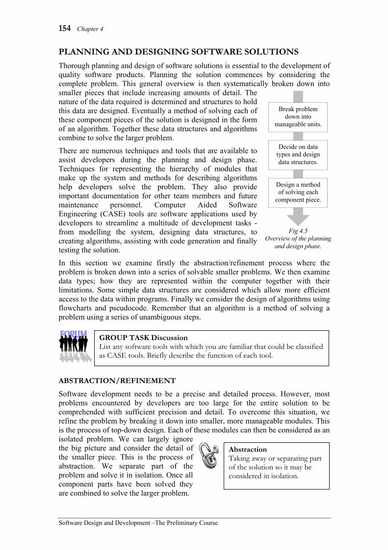
154 Chapter 4
Software Design and Development –The Preliminary Course
PLANNING AND DESIGNING SOFTWARE SOLUTIONS Thorough planning and design of software solutions is essential to the development of quality software products. Planning the solution commences by considering the complete problem. This general overview is then systematically broken down into smaller pieces that include increasing amounts of detail. The nature of the data required is determined and structures to hold this data are designed. Eventually a method of solving each of these component pieces of the solution is designed in the form of an algorithm. Together these data structures and algorithms combine to solve the larger problem.
There are numerous techniques and tools that are available to assist developers during the planning and design phase. Techniques for representing the hierarchy of modules that make up the system and methods for describing algorithms help developers solve the problem. They also provide important documentation for other team members and future maintenance personnel. Computer Aided Software Engineering (CASE) tools are software applications used by developers to streamline a multitude of development tasks - from modelling the system, designing data structures, to creating algorithms, assisting with code generation and finally testing the solution.
In this section we examine firstly the abstraction/refinement process where the problem is broken down into a series of solvable smaller problems. We then examine data types; how they are represented within the computer together with their limitations. Some simple data structures are considered which allow more efficient access to the data within programs. Finally we consider the design of algorithms using flowcharts and pseudocode. Remember that an algorithm is a method of solving a problem using a series of unambiguous steps.
ABSTRACTION/REFINEMENT
Software development needs to be a precise and detailed process. However, most problems encountered by developers are too large for the entire solution to be comprehended with sufficient precision and detail. To overcome this situation, we refine the problem by breaking it down into smaller, more manageable modules. This is the process of top-down design. Each of these modules can then be considered as an isolated problem. We can largely ignore the big picture and consider the detail of the smaller piece. This is the process of abstraction. We separate part of the problem and solve it in isolation. Once all component parts have been solved they are combined to solve the larger problem.
Abstraction Taking away or separating part of the solution so it may be considered in isolation.
GROUP TASK Discussion List any software tools with which you are familiar that could be classified as CASE tools. Briefly describe the function of each tool.
Break problem down into
manageable units.
Decide on data types and design data structures.
Design a method of solving each
component piece.
Fig 4.5 Overview of the planning
and design phase.

Defining and Understanding the Problem, and Planning and Designing Software Solutions 155
Software Design and Development – The Preliminary Course
There are many advantages of the abstraction process. It encourages developers to create reusable modules of code. For example, a module that sorts a list of data can be used in the future as part of the solution to a variety of different problems. Testing is greatly simplified. As each module is small and self-contained it can be thoroughly tested before being included in the total solution. As a consequence, checking the final total solution is greatly simplified. Teams of developers are able to work on individual modules in the knowledge that the work completed by others will not affect their own. The top-down approach to solution development
Top-down design is the most common method of breaking a problem into smaller units. The problem is progressively refined until each unit can be successfully implemented as a subroutine of programming code. In many cases, the design will be strictly hierarchical; each higher-level subroutine accessing or calling one or more lower-level subroutines. The process of developing this hierarchy of subroutines is known as stepwise refinement. Each level or step is refined into a series of lower- level subroutines.
Systems are also composed of a hierarchy of software elements (refer Fig 4.6). The system includes a number of programs. Each program is implemented as a number of modules. And each module is a group of related subroutines which together perform related tasks. Subroutines are at the lowest level. Each subroutine implements a single logical task. By combining related subroutines into modules, modules into programs and programs into systems promotes reusability. Particular modules or even programs can be reused as part of many software solutions.
Most programming languages include or provide access to a variety of different libraries; these libraries are modules which perform common tasks. For example, a module (or library of code) for drawing graphics contains subroutines for drawing different shapes including different colours, line weights and fill styles. There is no need for software developers to “reinvent the wheel”, rather they include and utilise these existing modules within their own programs.
Top-down design Progressively breaking a larger problem into a series of smaller easier to solve problems.
System
Program
Module
Subroutine Subroutine
Subroutine
Module
SubroutineSubroutine
Subroutine
Program
Module
SubroutineSubroutine
Subroutine
Module
SubroutineSubroutine
Subroutine Fig 4.6
Software systems are composed of programs, which are composed of modules, which are composed of subroutines.

156 Chapter 4
Software Design and Development –The Preliminary Course
Hierarchy charts are a simple method used to represent the top-down design of a particular problem. Subroutines are often numbered to indicate their placement in the hierarchy (refer Fig 4.7). Structure diagrams are similar to hierarchy charts but enable the inclusion of more detailed information in regard to the order and nature of processing. Data flow diagrams (DFDs) also model the top-down design but focus on the movement of data rather than the detail of the processing performed.
Be aware that top-down design does not necessarily lead to the development of reusable modules of code. Often the design of subroutines reflects the particular needs of the current problem. In the past software was often developed in isolation and hence modules and subroutines where specific to the current problem. Today there is an emphasis on developing more general and therefore reusable solutions. There has also been a shift in thinking towards the use of externally developed modules or libraries of code. The use of these generic modules is similar to the way most other products are developed. For example, the majority of components used in a new model of car are derived from generic components. The motor, air conditioning, tyres, brakes and instruments are sourced from outside. These same components are often used with minor alterations on a variety of vehicles.
Top-down design focuses on the processing required to solve a problem. We commence with a set of inputs and move through a series of predetermined steps that process these inputs into outputs. For many problems this should certainly be the focus. For other problems the flow of data, the links between data, the maintainability of the code or response times are of a higher priority. Be aware that there are other different approaches to that of top-down design.
Consider the following:
Imagine you’ve decided to cook a special meal for your family. Let us develop a top-down design to describe the processes involved in this venture.
Firstly, you must decide on the time and the date of the meal. You must then work out the menu and obtain the ingredients. On the allocated day you must cook and serve the meal. Fig 4.8 describes our solution so far.
Fig 4.7 Hierarchy charts describe top-down designs.
Main Program
Subroutine 1
Subroutine2
Subroutine3
Sub 1.1
Sub 1.2
Sub 2.1
Sub 2.2
Sub 3.1
Sub 3.2
Sub 3.3
Sub 1.1.1
Sub 1.1.2
Sub 2.1.1
Sub 2.2.1
Sub 2.2.2
Sub 3.2.1
Sub 3.2.2
Sub 3.3.1
Sub 1.1.1.1
Sub 1.1.1.2
Sub 1.1.2.1
Sub 2.2.1.1
Sub 2.2.1.2
Sub 2.2.1.3
Sub 3.2.2.1
Sub 3.2.2.2
Sub 3.3.1.1
Sub 3.3.1.2

Defining and Understanding the Problem, and Planning and Designing Software Solutions 157
Software Design and Development – The Preliminary Course
We can now consider in isolation each subroutine on level 1 of our hierarchy chart. As we consider each subroutine we ignore the larger problem – this is the process of abstraction. Deciding on the time and date involves questioning each family member and then picking the most appropriate time and date. We are refining the problem using stepwise refinement. Working out the menu includes considering the tastes of those who’ll attend and then examining recipe books. Obtaining the ingredients may include working out the quantities required, checking the pantry and then visiting various shops. Cooking and serving the meal includes preparing the ingredients, cooking them and finally serving to each family member.
Let us expand the preparation of the ingredients branch of our hierarchy chart. This may include rinsing the vegetables, chopping the ingredients, measuring quantities and mixing ingredients. Chopping may further involve first peeling vegetables and perhaps grating and dicing.
Consider the following:
• A large multi-national software company specialises in the development and marketing of software to the retail industry. One of their largest selling software products is able to interface with various types of cash register and EFTPOS terminals. Currently there is no standard in place for these communication links. As a consequence, the company must develop a new software interface each time new models of cash register or EFTPOS terminal become available.
• A web site developer works from home. He charges an hourly rate to design and develop web sites for various clients. At present he has been in business for about 2 years and is finding that past clients are increasingly requesting modifications to their original sites. Implementing these modifications is proving difficult and time consuming.
• The Year 2000 bug was due to programs only considering and storing the last two digits of the year e.g. 1931 was stored as just 31. The time spent examining software products to ensure Year 2000 compliance was considerable. Perhaps the most annoying aspect of the problem was that most products were found to be compliant without the need for any modification.
Family meal
Decide on time and date
Work out menu
Obtain ingredients
Cook and serve meal
Fig 4.8 Initial top-down design for preparing our family meal.
Fig 4.9 Preparing the ingredients refined and expanded.
Cook and serve meal
Prepare the ingredients
Cook ingredients
Serve food to family
Peel vegetables
Grate and dice
Rinse vegetables
Chop the ingredients
Measure quantities
Mix ingredients
GROUP TASK Activity Expand each branch of the initial hierarchy chart shown in Fig 4.8. Add a numbering system to your completed chart.

158 Chapter 4
Software Design and Development –The Preliminary Course
SYSTEMS MODELLING TOOLS
A model of a system is a representation of that system designed to show the structure and functionality of the system. Diagrams are particularly useful methods of modelling because they are able to give a broad view whilst at the same time conveying necessary detail. Accomplishing the same task in words is difficult. In terms of software development, a model can be thought of as a plan which specifies the design of the software. The model gives direction and specifications to the builders of the product, in the same way as the plan for a house gives builders of the house direction and specification in regard to the house’s design and erection.
Different types of modelling are applicable to different aspects of the system. System flowcharts are used to represent the logic and movement of data between the system’s components, including hardware, software and manual components. Dataflow diagrams describe the flow of data to and from processes and storage elements. Structure diagrams describe the top-down design and sequence of processing. IPO diagrams explain how inputs are transformed into outputs by processing. Data dictionaries describe the nature and type of the data used in a program. Screen designs and concept prototypes are used to determine user requirements by simulating the final product from the user’s perspective. Most projects will use a combination of modelling techniques. We considered IPO diagrams in the previous section, in this section we examine systems flowcharts, data flow diagrams (and context diagrams) and structure charts. Systems Flowcharts
Systems flowcharts are used to describe the logic and flow of data through a system. They describe the interactions that occur between input, processing, output and storage, as well as the nature of each of these components. Even manual processes can be included on systems flowcharts. Generally, systems flowcharts are used at a higher level than the other modelling techniques to show an overall view of the entire system.
Although some of the symbols used on system flowcharts are the same as in algorithm flowcharts, the design of system flowcharts is quite different. Flowcharts for algorithms are designed to precisely show the logic of an algorithm, whereas system flowcharts are not describing an algorithm but a system. Logic is only shown where necessary to sensibly describe the flow between components.
Systems flowcharts have been in common use since the 1960s, hence some of the symbols, such as the punched card symbol, are now outdated. Fig 4.10 details the systems flowchart symbols specified for Software Design and Development. There are many other symbols that can be used for specialised processes such as sorting and merging data. In this course we use the process rectangle for all processing.
GROUP TASK Discussion For each scenario above, discuss how top-down design, abstraction and reusable modules simplify the process of modifying the software.
GROUP TASK Discussion In many cases it is just simpler to throw out the old product and develop a new one from scratch. Do you agree with this statement? Explain and discuss your answer using the above scenarios as examples.

Defining and Understanding the Problem, and Planning and Designing Software Solutions 159
Software Design and Development – The Preliminary Course
Consider the following:
The systems flowchart at right describes the logic and flow of data for results from an assessment task.
Firstly, the teacher marks the test, which is a manual operation. These marks are entered by hand into the teacher’s mark book. The marks are entered into the computer, which is an online input, and stored in the school database. At the same time, the student names are being retrieved from the school database. Once all the marks have been entered they are scaled and stored in the school database. Finally, a printout of the results is generated and students are given their results.
This systems flowchart describes the path taken by the marks through the system, from their generation, when the teacher marks the papers, through to the final scaled marks being delivered to the students. The logic is also described to make sense of the flow of the data. Notice that the logic is from an overall system viewpoint rather than just the logic required to code the software part of the solution. This systems flowchart is not significantly different to one that would be used to describe a completely manual system. That is, the software is just one item within the total system.
Input or Output
Paper Document
Multi Paper Document
Online Display
Online Input
Disk Drive
Process
Decision
Manual Operation
Punched Card
MagneticTape
TelecommunicationsLink
Fig 4.10 Components of System Flowcharts.
Teacher marks task
Teacher’s mark book
Marks entered School
database
Are all marks
in?
Scale marks
Teacher printout
Students given results
No Yes
Fig 4.11 System flowchart for results
from an assessment task.

160 Chapter 4
Software Design and Development –The Preliminary Course
Consider the following:
The systems flowchart below describes a hotel’s information system. This model is designed to describe the logic and flow of data through the hotel system for an individual guest.
GROUP TASK Describe The above system flowchart uses a number of symbols as part of its construction. Describe in words what is occurring at each symbol on the diagram.
Fig 4.12 System flowchart describing the flow of data for an individual guest in a hotel.
Reservation entered
Arrival list and registration
cards
Guest details entered
Hotel database
Create room key card
Phone system
Internet system
Room service
Calculate charge
Movie system
Generate final bill
Guest bill
Payment entered
Yes
Hotel database
Guest leaves
Guest completes registration card
Key servicesdatabase
System selects clean room
Is payment by credit card?
Bank system
Guest selects service?
Phone exchange
Internet service provider

Defining and Understanding the Problem, and Planning and Designing Software Solutions 161
Software Design and Development – The Preliminary Course
The above systems flowchart describes the information transfers occurring during a guest’s stay in a hotel. A reservation is entered, and then at the start of each day an arrival list and registration cards are printed. When the guest arrives, he or she completes their registration card and the details are entered into the system. A room and a key are allocated to the guest. If payment is to be made by credit card then the bank’s system is contacted to ensure there are sufficient available funds. The guest then is able to use a number of services whilst staying, namely the phone, movie or Internet systems or room service. Charges for these services are recorded in the hotel’s database. The phone and Internet systems involve telecommunication links to outside systems. At checkout time, the final bill is generated from data stored in the hotel’s database and presented to the guest. Finally, the bill is paid and the guest leaves.
Data Flow Diagrams (DFDs)
Data flow diagrams describe the path data takes through a system. No attempt is made to indicate the timing of events. Think of a DFD as a railroad map: it shows where the train tracks are laid, but it does not give the timetables.
Let us now consider the syntax of DFDs: Data flows or vectors are used to join the entities and processes within the model. They can be thought of as pipelines or interfaces for data to flow between the other components of the DFD. A label is placed on the vector or arrow to indicate the nature of the data. The label used should be unique within a given DFD. The origin of data input into the system is known as a source. A destination for data output from the system is known as a sink. Both sources and sinks are external entities and are designated using a square or rectangle symbol. In some references, external entities are also known as terminators as they describe starting and ending points for the DFD. External entities are often groups of people or other systems. Processes are the actions that take place on the data within the system to transform inputs into outputs. Processes are represented on data flow diagrams as circles. All processes in a data flow diagram will have one or more data flows coming in (inputs) and one or more data flows going out (outputs). Data stores are repositories for data. They usually represent databases or files, however manual storage such as filing cabinets or paper files may also be included. Data stores are represented using open rectangles.
External entity Process
Data flow Data store
Fig 4.13 Symbols used on data flow diagrams.
GROUP TASK Discussion Name any items on the above systems flowchart that could or should have links to the hotel database but do not. Explain your answer.
GROUP TASK Discussion Systems flowcharts are designed to display an overall view of a system. Specific detail about each process is not required, also the logic need not be as precise as that required for an algorithm. How useful is the above hotel’s system flowchart for a software developer working on an upgrade to the hotel’s database? Describe any information of use to the software developer provided by this model.

162 Chapter 4
Software Design and Development –The Preliminary Course
Data flow diagrams are used both as a tool for system analysis and as a tool for system design. Modelling an existing system using a data flow diagram assists in understanding the flow of information through a system and also helps the analyst to separate processing into distinct units resulting in a better understanding of the problem. Data flow diagrams are particularly useful modelling tools during system design. Computer aided software engineering (CASE) tools are available to assist in the creation of data flow diagrams. Many of these tools include data dictionary functions that link to the data flows on the diagrams.
Usually, a context diagram is drawn first. A context diagram shows the entire system as a single process with all the external inputs and outputs to and from any external entities. Context diagrams are also called Level 0 data flow diagrams. Data stores should not be shown on context diagrams. A series of data flow diagrams are produced from the context diagram that progressively break the problem down into lower-level modules. This top-down design technique is continued until the lower-level processes are sufficiently detailed for them to be easily coded.
Consider the following:
The data flow diagram in Fig 4.14 describes the student administration system at a local college.
The college receives enrolment forms from students. The data on these forms is used to create class lists, which are sent to the staff. Courses taken by students are recorded in the student file. Staff set test papers, which are used to generate results. The results are stored in the student file. Academic records are retrieved from the student file and processed. Graduating students receive a transcript of their degree.
Each of the processes on the level 1 DFD in Fig 4.14 can be further refined into a series of level 2 DFDs. In Fig 4.15 the Examine 2 process has been expanded to form a level 2 DFD. Notice the numbering system for the processes; 2.1, 2.2, etc. The processes on the level 3 DFD for the Print exams 2.1 process would be numbered 2.1.1, 2.1.2, 2.1.3, etc. The inputs and outputs to and from a process must be identical at all times. In this Examine 2 level 2 DFD example, Test paper is the input and Results is the output, just as they were on the original level 1 DFD in Fig 4.14.
Examine 2
Graduate 3
Student file
Student
Staff
Enrol 1
Enrolment form
Class lists
Course taken
Test paper
Results
Academic record
Degree transcript
Fig 4.14 Level 1 data flow diagram describing student
administration at a college.
Print exams
2.1
Student file
Exams occur 2.3
Timetable exams
2.2
Grade exams
2.4
Course numbers
Courses clashing
Test paper Exam
papers
Exam timetable
Completed exams
Results
Fig 4.15 Level 2 DFD for the Examine 2 process.

Defining and Understanding the Problem, and Planning and Designing Software Solutions 163
Software Design and Development – The Preliminary Course
Consider the following:
A book reseller, who sells by mail order, is looking to computerise the functions involved in filling orders. After analysing the current system, a series of data flow diagrams are produced.
Firstly, a context diagram or level 0 DFD is created. The context diagram in Fig 4.16 above includes a single process with all the external entities to this process.
Further refinement results in a more detailed Level 1 data flow diagram (Fig 4.17). Notice that the external inputs and outputs are still the same as on the original context diagram above.
GROUP TASK Create For the student administration data flow diagram shown above in Fig 4.14 create a context diagram. Remember context diagrams contain only one process together with any external entities.
GROUP TASK Explanation Explain, in words, the processing and flow of data occurring in the Examine 2 DFD shown in Fig 4.15 above.
GROUP TASK Create Develop a possible DFD for the Enrol 1 process shown above in Fig 4.14. Include at least 3 processes on your diagram.
Fig 4.16 Context diagram for the book reseller problem.
Customer Fulfil orders Invoice
Supplier Delivery docket
Purchase order Order
Fig 4.17 Level 1 data flow diagram for the book reseller problem.
Enter order
1
Check stock level
2
Compile order
3 Stock file
Item details file
Invoice
Order
Item details
Stock request
Stock response
Purchase order
Delivery docket
Item details, Quantity
Item details, Quantity
Delivered item details,
Quantity
Reduced quantity
GROUP TASK Explanation Explain, in words, the processing and flow of data occurring in the context diagram shown in Fig 4.16 above.

164 Chapter 4
Software Design and Development –The Preliminary Course
Structure Charts
Structure charts (or diagrams) are used to model the hierarchy of subroutines (processes) within a system, together with the sequence in which these subroutines take place. Data movements between subroutines are included to improve the reader’s understanding of the relationships between them. In terms of software development, structure charts describe the top-down design of the program together with the order in which subroutines are called. Because subroutines can be conditionally called or repeatedly called from a higher-level subroutine, decisions and repetitions are also indicated on structure charts.
The primary function of a structure chart is to create a template in preparation for the creation of the actual source code. Each subroutine shown on the structure chart will be coded within the final program. For large software projects, structure charts may be used to allocate tasks to individual programmers on the development team. Structure charts are also useful tools for maintaining and upgrading software. Identifying subroutines and modules that could potentially contain an error or that need upgrading is made easier if a structure chart is available.
There are many recognised techniques for drawing structure chart type models and many different names are used for these diagrams. Some common names include structure diagram, function chart, call graph, call tree and hierarchy diagram. The important common theme for all these modelling techniques is that they attempt to describe the top-down, hierarchical design of a system. Some include an indication of the sequence of execution and methods for indicating decisions and repetitions.
Let us now consider the symbols used in structure charts as they are to be drawn in this course. Processes, which are usually subroutines and sometimes modules, are drawn as rectangles. Lines drawn between processes are known as call lines or control lines. They show the connections between processes. Each line represents a call to a subroutine from the subroutine above. Decisions about whether a call should be made are indicated using a small diamond. If a sub-task is to be called multiple times, then a circular arrow to indicate this repetition, is placed around the call line. Data items passed between tasks are known as parameters and are shown using a small open circle with an arrow attached to indicate the direction of the data movement along the call line. A filled in circle with
Call Causing the execution of a subroutine (process) from within another subroutine.
Control The influence that causes tasks to execute in their correct sequence.
GROUP TASK Create Create a table listing all the external entities, processes, data stores and data flows for the above two data flow diagrams. For each item write a brief description of its purpose and how it links to other items.
Module or subroutine (process) Repetition Decision
Parameter (data movement)
Control parameter
(flag)
Call line
Fig 4.18 Symbols used in structure charts.

Defining and Understanding the Problem, and Planning and Designing Software Solutions 165
Software Design and Development – The Preliminary Course
attached arrow is used to show a control parameter. Control parameters have an effect on the order in which tasks are executed. Usually, a control parameter will be a flag. Flags are data items used to indicate that a certain criterion has been met.
Structure charts can be read from top to bottom. Lower-levels represent subroutines that are called from the subroutine above. Reading from left to right on a particular level describes the order of execution of tasks. Sometimes a subroutine may be called by more than one higher-level subroutine, because order of execution is from left to right. It is necessary to include this subroutine each time it is called by a different higher-level task.
Consider the following:
A business is invoiced for supplies from its vendors. The structure chart below models the tasks involved in processing and paying these invoices.
There are two ways of interpreting the above structure diagram: left to right or top to bottom. Reading from left to right on a particular level describes the sequence of processing. Reading from top to bottom describes the top-down design of the system.
Reading along the first level from left to right, invoices are verified and then paid. Moving down a level, the sequence of processes would be entering details, comparing with purchase order, determining payment to make and generating a cheque. Reading across the lowest level gives entering details, comparing with purchase order, check date due, check available funds, convert amount to words and print cheque. Each of these sequences makes sense; the lower the level the more detail is included.
Reading from the top indicates that the main program, called Process Invoices, includes a repeated call to the Verify Invoice subroutine. The Verify Invoice subroutine contains a call to the Enter Details subroutine and also to the Compare with Purchase Order subroutine.
Process Invoices
Pay Invoice
Verify Invoice
Compare with Purchase
Order
Determine payment to
make
Generate cheque
Convert amount to
words
Print cheque
Enter Details
Invoice details
OK invoice Invoice
details
Vendor, amount, date due
Payment details
Check date due
Check available
funds
Date OK
Invoice date Funds
OK
Invoice amount
Payment details OK
to pay
Payment details
Amount Amount in words
Cheque details
Fig 4.19 Structure chart for processing invoices.

166 Chapter 4
Software Design and Development –The Preliminary Course
Let us now consider the parameters included on the above structure chart. These parameters give an indication of the data movements between processes. The initial input into this system is the Invoice details, which are presumably obtained from the paper invoices received by the company. The final output is the Cheque details, which are sent out of the system as printed cheques. Presumably, the cheques are posted to the vendors. Notice that the external source and destinations are not indicated on structure charts - remember they were included on DFDs.
Now we examine the Determine payments to make subroutine in detail. This routine receives the payment details as input. Then the invoice date is sent with the call to the Check date due subroutine. A control parameter is returned indicating if the date is okay. The Check date due subroutine checks if the invoice is due for payment. If it is, the Date OK flag is set to true; if not then the Date OK flag is set to false. A decision is then made as to whether the Check available funds subroutine is called. If the Date OK flag is false, the Check available funds routine is not called. The Check available funds routine is called with the invoice amount sent as a parameter. A control parameter is returned. If funds are available to pay the invoice, then the Funds OK flag is set to true; if not then it is set to false. Control returns to the Determine payments to make subroutine. This process checks the value of both the Date OK and Funds OK control parameters or flags and sets the OK to pay flag appropriately. As you can see, explaining this in words is difficult compared to the simplicity of design of the structure chart. The structure chart also allows you to gain an overall view of the program at a glance. This is not possible with written explanations.
Consider the following:
A software solution is required to simulate the card game Patience, which is also known as Solitaire. To assist in understanding the game and designing a software solution the structure chart in Fig 4.20 has been produced.
The general sequence of processing that occurs when playing a game of patience is as follows. First the cards are dealt, then cards are played repeatedly and finally the result of the game is displayed. These are the three processes (or subroutines) on the first level of the Fig 4.20 structure chart.
GROUP TASK Discussion Describe in words the processing and movement of data for the Generate Cheque process.
GROUP TASK Discussion Explain the difference between a parameter and a control parameter. Use examples from the Process Invoices structure diagram above to illustrate your response.
GROUP TASK Discussion Expand the Compare with Purchase Order process into another level on the structure diagram. This process checks that the items ordered are the same as those on the invoice and confirms that prices on both purchase order and invoice are the same. Finally the totals are compared.

Defining and Understanding the Problem, and Planning and Designing Software Solutions 167
Software Design and Development – The Preliminary Course
Further detail is specified in regard to playing a card; a card is either generated or actioned. A card is generated from the remaining pack of cards. The program must monitor which cards remain within the pack and then randomly choose one of these cards. The details of the generated card are returned to the Play Card subroutine. Actioning a card involves getting the details of the move from the user, checking if it is a legal move and then if the move is OK the move is actually performed by the software.
Notice that many subroutines on this structure chart do not require any inputs. For example, at the start of the game the cards are dealt unconditionally. There are some tasks that have input parameters but no data is returned to the calling task. For example, the Perform Move task gets the move details but does not return any data to the Action Card task.
Fig 4.20 Structure chart for the card game ‘Patience’.
Patience
Play Card
Display Result
Generate Card
Action Card
Show Win Animation
Show Lose Animation
Get user input
Check if legal
Perform move
Result
Result
Card Details
Move Details Move
Details Move OK
Move Details
Deal Cards
GROUP TASK Discussion Describe in words the processing and movement of data for the Action Card process.
GROUP TASK Discussion Why do you think the Result parameter is a control parameter? What do you think is the purpose of this Result control parameter in the context of the game?
GROUP TASK Discussion Choose one of the low-level tasks on the above structure diagram and expand this task into a lower level. Explain your diagram in words.

168 Chapter 4
Software Design and Development –The Preliminary Course
SET 4A 1. Context diagrams are used to show:
(A) the external inputs and outputs into and out of a system.
(B) the data structures used in the design of the system.
(C) the algorithms that have been designed for the system.
(D) the top-down design of the system. 2. Inputs and outputs are also known as:
(A) data and processing. (B) data and information. (C) information and processing. (D) none of the above.
3. The advantage(s) of the abstraction process is (are): (A) it encourages the development of
reusable modules of code. (B) it simplifies the testing process. (C) developers are assured that the
work of other members of the team will not affect their own module development.
(D) all of the above. 4. A useful tool used for describing the
steps that will transform the inputs into outputs is: (A) a context diagram. (B) an IPO diagram. (C) a hierarchy chart. (D) the abstraction process.
5. A system modelling tool that describes the sequence and top-down design of a problem is known as: (A) an IPO diagram. (B) a DFD. (C) a context diagram. (D) a structure chart.
6. Considering a part of the solution by separating or isolating it, is known as: (A) modular design. (B) top-down design. (C) abstraction. (D) hierarchy charting.
7. Ben is a system analyst, who after spending time researching just what is required of a proposed new system, presents his recommendation to management. Which phase of the software development cycle has Ben been involved with? (A) Testing and evaluating. (B) Defining and understanding the
problem. (C) Implementing. (D) Planning and designing.
8. In a DFD, the external entities from which data is obtained are also known as: (A) sources. (B) inputs. (C) sinks. (D) outputs.
9. Another name for a level 0 data flow diagram is: (A) an IPO diagram. (B) a context diagram. (C) an algorithm. (D) a structure chart
10. Which system model shows the movement of data between subroutines with no specific detail of the order in which subroutines execute? (A) Structure chart (B) IPO diagram (C) DFD (D) Context diagram
11. List and briefly describe each stage of the software development cycle.
12. Create an IPO diagram to describe the steps required to drive a car from point A to point B.
13. What is abstraction and stepwise refinement? Why is it so useful when developing software products?
14. Create a structure chart to describe the general processes and decisions that are required to make somebody a cup of coffee. Assume you are the computer and you do not know in advance if the person has milk or sugar in their coffee.
15. Examine the functions within a typical mobile phone that are related to making and answering phone calls. Create a series of data flow diagrams (DFDs) to describe this functionality.

Defining and Understanding the Problem, and Planning and Designing Software Solutions 169
Software Design and Development – The Preliminary Course
DATA TYPES
Data items are the raw materials on which computer programs operate. These data items must be stored in binary if they are to be manipulated by the instructions that form the software programs. Each data item must be assigned a data type. The data type determines how each of the data items will be represented in binary and what kind of processing the software will be able to perform on them.
There are a number of data types that are used so frequently that most programming languages include them as predefined parts of the language. These data types are those that are used in everyday life. For example, we use whole numbers (integers) for counting and performing arithmetic, numbers with decimal points or real numbers (floating point) for fractional and large number computations and words and sentences (strings) for all forms of writing. We use yes/no or true/false (Boolean) data to answer questions and make decisions. Dates and times are used to schedule our lives and currency is used for purchasing. All these data types are predefined in most programming languages.
All data and instructions are stored in binary. We will firstly examine the representation of numbers using the binary, decimal and hexadecimal systems. Then we will examine many of the data types in Fig 4.21. We investigate how they are represented in binary together with any of their limitations. Following our examination of data types we consider a number of data structures. Data structures are ways of combining multiple data items into some logical form, the aim being to enable the program code to more efficiently access and hence manipulate the data.
Representing numbers in binary and hexadecimal
The number system we use every day is based on the number ten and is known as the decimal system. This system has evolved as a consequence of us having ten fingers. Computers are based on transistors. Like switches, they can either allow electrical currents to flow or not flow. These two states are best represented using a number system based on two - the binary system. Current flowing or present is represented as a binary 1 and not flowing or not present as a binary 0. Similarly, storage devices require only two different states to represent binary data.
Binary numbers are difficult for humans to comprehend. The hexadecimal system assists us in this regard. The hexadecimal system is based on 16. As 16 is a power of two the hexadecimal system provides a shorter method for representing binary with minimal effort. For example, 8 binary digits (1 byte) can be represented using just 2 hexadecimal digits.
Data type Example data items
Integer -5, 0, 34, -9245, 89 Floating point -5.045, 2.3×10⁸, 6.874 String Fred, Yu3fk, Eggplant Boolean Yes, No, True, False Date 16/1/02, 25 Jan 2002 Currency $5.65, $19.05, -$3.70
Fig 4.21 Common data types that are predefined in
most programming languages.
GROUP TASK Discussion Digital data is stored in binary. This includes text, numbers, graphics, video, audio and instructions. How has this assisted the development of devices that can utilise digital data from a variety of sources? Discuss.

170 Chapter 4
Software Design and Development –The Preliminary Course
• Binary
In decimal each digit has a place value. The number 4305 can be written in expanded form as (4 × 10³) + (3 × 10²) +(0 × 101) +(5 × 100). The 4 has a place value of 1000, the 3 a place value of 100, 0 a place value of 10 and 5 a place value of 1. This system is based on powers of 10 so we require 10 digits, namely 0, 1, 2, 3, 4, 5, 6, 7, 8 and 9.
The binary system is based on the number 2, so we require only 2 digits; 0 and 1. Each binary digit is known as a bit. The place values are powers of 2. Moving from the right hand side to the left, the place values increase by a factor of 2. For example, the binary number 110101 could be written in expanded form as (1 × 25) + (1 × 24) + (0 × 23) + (1 × 22) + (0 × 21) + (1 × 20). This is the decimal equivalent of 32 + 16 + 0 + 4 + 0 + 1 which is 53.
Most microprocessors operate on multiples of 8 bits. 8 bits make up a byte. It is common to include leading zeros at the start of binary numbers to make up the remaining bits in each byte. For example, 00110101 is the same as 110101 in the same way as 0053 is the same as 53 in decimal. The place value for each of the 8 bits in a byte is 27=128, 26=64, 25=32, 24=16, 23=8, 22=4, 21=2 and 20=1. Each byte is able to store 256 unique combinations of 1s and 0s representing the decimal numbers 0 through to 255.
A single combination of bits will have a different meaning dependant on its context. 10101110 could represent a number, a character, a pixel within a graphic, a controlling character to assist with communication or even an instruction for the CPU. All data used by computers is ultimately a combination of bits. Software is the set of instructions that describes how to make sense and process these bits.
Decimal Binary 1 1 2 10 3 11 4 100 5 101 6 110 7 111 8 1000 9 1001
10 1010 11 1011 12 1100 13 1101 14 1110 15 1111
… …
250 11111010 251 11111011 252 11111100 253 11111101 254 11111110 255 11111111
Fig 4.22 Decimal and binary
equivalents.
GROUP TASK Activity Choose 10 binary numbers containing no more than 8 bits. Convert each of these numbers to their decimal equivalent.
GROUP TASK Activity Most microprocessors process 16, 32 or 64 bits at a single time. This is known as the processor’s word size. How many different bit combinations are available using 16 bits, 32 bits and 64 bits?
GROUP TASK Activity Counting in binary does not come naturally to us. We could all count from 1 to 255 in decimal but can you do it in binary? Try counting around the class from 1 to 255 in binary.

Defining and Understanding the Problem, and Planning and Designing Software Solutions 171
Software Design and Development – The Preliminary Course
• Hexadecimal Hexadecimal is based on the number 16. Hex means 6 and dec means 10. In hexadecimal, each 8 bit byte is represented using exactly 2 hexadecimal digits. This greatly improves the readability of binary data for humans. As hexadecimal uses 16 as it’s base, we require 16 digits. Rather than invent 6 new symbols, the capital letters A through to F are used to represent the numbers 10 to 15 respectively. Fig 4.23 shows these hexadecimal digits alongside their decimal and binary equivalents. Each place value is a power of 16. For example, 38C in hexadecimal can be written as (3 × 162) + (8 × 161) + (12 × 160); notice that the hexadecimal digit C is equivalent to the decimal number 12. The result in decimal is (3 × 256) + (8 × 16) + (12 × 1) = 908.
Converting between binary and hexadecimal we consider groups of 4 bits at a time. Often 4 bits are referred to as half a byte or a nibble. Each nibble corresponds to a single hexadecimal digit. For example, converting the binary number 10110101 we first split the number into nibbles. Each nibble is then converted to its corresponding hexadecimal digit (refer Fig 4.23). In our example 1011 converts to the hexadecimal digit B and 0101 to the digit 5. The result in hexadecimal is therefore B5. Converting from hexadecimal back to binary involves the reverse operation.
In mathematics, numbers in different bases are indicated using subscripts e.g. 5E816 or 11001012. On computers it is difficult to write subscripts. A variety of different notations are used to specify hexadecimal numbers. One common notation uses a leading ampersand (&H) to indicate base 16. For example, &H7A means 7A is a hexadecimal number. Within URLs for accessing web pages the percent (%) sign is often used. For example, often URLs will include %20 to replace space characters. In the ASCII system the space character has a decimal code of 32, which in hexadecimal is 20. Some programming languages use a leading hash (#) and others add a small h after the number to indicate hexadecimal numbers. There are many other hexadecimal notations.
Decimal Binary Hexadecimal 1 1 1 2 10 2 3 11 3 4 100 4 5 101 5 6 110 6 7 111 7 8 1000 8 9 1001 9
10 1010 A 11 1011 B 12 1100 C 13 1101 D 14 1110 E 15 1111 F
Fig 4.23 Decimal, binary and
hexadecimal equivalents.
GROUP TASK Activity Choose 10 binary numbers containing no more than 8 bits. Convert each of these numbers to their hexadecimal equivalent.
GROUP TASK Activity Choose 10 hexadecimal numbers containing no more than 2 digits. Convert each of these numbers to their binary equivalent.
GROUP TASK Discussion Why do you think hexadecimal is commonly used on computers but rarely used for other purposes? Discuss.

172 Chapter 4
Software Design and Development –The Preliminary Course
COMMON DATA TYPES USED IN SOLUTIONS
In this section we examine a number of data types that are commonly used as part of most software solutions. Each type has its own strengths and limitations. As a consequence, it is important to select the most appropriate type for the circumstances present in the particular problem. Computers are finite binary machines; there is a limit to their storage and processing abilities. As software developers we must be aware of these limitations.
Variables are containers for data items. Each variable used within a program must be assigned a data type. In some languages the translator will determine and assign a data type to a variable based on its context within the code. It is often preferable and more efficient to manually assign each variable a data type rather than allow this to occur.
The data types described below are predefined in most programming languages. Integer
Integers are whole numbers both negative and positive. For example, -3456, -1, 0, 903. If an integer data type is chosen then you must be absolutely certain that fractional values will never be required or even stored as part of a computation. Attempting to assign a fractional value to a variable of integer type will at best result in the loss of the fractional part and at worst will cause a type mismatch error; either occurrence is unsatisfactory.
Integers are stored using sequences of binary digits. Most languages contain a number of integer data types which each use a different number of bytes. A 2 byte or 16 bit integer is able to store whole numbers in the range -32768 to 32767. 4 bytes or 32 bits can store integers within the range -2147483648 to 2147483647 and 8 byte (64 bit) integers range from -9,223,372,036,854,775,808 up to 9,223,372,036,854,775,807. Many languages also include a byte data type that predictably uses a single byte (8 bits) to store integers in the range -128 to 127. Attempting to assign a value outside the allowable range will result in a type mismatch error. As developers we must be careful to ensure this situation never occurs.
In most programming languages, the two’s complement system is used so both negative and positive integers can be stored. The two’s complement system integrates the sign (‘-‘ve or ‘+’ve) within the coding system. Essentially the highest order (LHS) bit is given a negative value. So using 8 bit twos complement the decimal integer -102 is represented as 10011010 as -128 + 16 + 8 + 2 = -102. This system allows the computer to perform each of the four basic arithmetic operations without regard for the sign of the number. Other coding systems require consideration of the sign of each integer during computation.
Compared to floating point calculations, integer calculations are fast and perfectly accurate. For these reasons it is preferable to use integer data types wherever possible. Just be aware of their range and ensure that fractional values will never be required.
1000000000000000 (-3276810)
to 0111111111111111
(3276710)
16 b
it In
tege
rs
10000000000000000000000000000000 (-214748364810)
to 01111111111111111111111111111111
(214748364710)
32 b
it In
tege
rs
Fig 4.24 Range of 16 bit and 32 bit integer data types.

Defining and Understanding the Problem, and Planning and Designing Software Solutions 173
Software Design and Development – The Preliminary Course
Floating point (real)
Floating point data types are used to store fractional and very large numbers. In mathematics the real number system includes all such numbers. With computers, as in mathematics, we cannot represent all numbers exactly. For example, in mathematics we cannot write √2, ⅓ or π as precise decimal fractions. However, we can write them as accurately as we wish e.g. ⅓ can be approximated as 0.3 or 0.333 or 0.3333333333. Using computers and binary, similar problems occur. As a consequence the binary representation used is not perfectly accurate. The more decimal places we use the better the accuracy, however this involves larger and larger amounts of storage and faster and faster processors. A compromise between accuracy and storage/speed must be achieved.
The Institute of Electrical and Electronics Engineers (IEEE) has produced the 754 standard for representing binary floating point numbers. Most processors and programming languages adhere to these standards. The single precision format uses 32 bits for each number and the double precision format uses 64 bits per number. The IEEE 754 standard uses a system similar to scientific or standard notation; the mantissa, exponent and sign of the number being encoded within each representation. The single precision format uses 23 bits for the mantissa, 8 bits for the exponent and 1 for the sign with a decimal range from approximately -3.4 × 1038 to 3.4 × 1038. Double precision uses 52 bits for the mantissa, 11 for the exponent and 1 for the sign, the decimal range being approximately -10308 to 10308.
Performing arithmetic with floating point numbers is difficult and processor intensive. As a consequence, most microprocessors contain a floating point unit (FPU) that is dedicated to performing these operations. Early Intel 386 and 486 based machines used a separate chip known as a maths coprocessor; these days the FPU is integrated within the main processor’s circuitry. Software applications involving repeated mathematical calculations are greatly improved using the services of the FPU, e.g. games involving complex animation.
Most programming languages include a predefined single and double data type. These types correspond to the IEEE 754 standard described above. Floating point data types should only be used when the requirements give no other choice. When they are used, be aware of their processing demands. Also carefully consider the consequences of inaccuracies due to the approximate nature of floating point representations. Such inaccuracies can easily become significant for repeated calculations on a single variable and when very small numbers are added to large numbers.
GROUP TASK Activity Examine the integer data types available within a common database application. Create fields with each of these types. What is the range of these data types? Discover the effect of entering a fractional value or a value outside the allowable range.
-5.9402 × 1026
mantissa sign exponent
Fig 4.25 Floating point representations
use a system similar to scientific or standard notation.
Sign Exponent Mantissa 1 110…0101 11011…0010011 Single 1 bit 8 bits 23 bits Double 1 bit 11 bits 52 bits
Fig 4.26 The IEEE 754 Single and Double Precision standards use 32 and 64 bits respectively.

174 Chapter 4
Software Design and Development –The Preliminary Course
String
String data types are used to store text data. For example, ‘cat’, ‘123abc’, ‘y<%2g’ or ‘Once upon a time’. Most programming languages provide predefined string data types. Often a fixed length string and a dynamic length string are provided. The fixed length string can hold up to a set number of characters whereas dynamic strings grow in size as required. Other languages require programmers to define strings themselves using sequences of characters; the character data type being predefined.
Regardless of the available data types, strings are ultimately stored as separate characters. Each character is coded using a standard system. ASCII, EBCDIC, ANSI and Unicode are some common examples. Many of these coding systems use a single byte or less, to represent each character. The Unicode system uses up to 32 bits and is designed to include all the possible characters and marks used in all the languages of the world. The Unicode system incorporates the more widely understood ASCII system. Regardless of the coding system used, each character is stored separately as a unique pattern of bits.
Let us consider the ASCII system in some detail. ASCII is an acronym for American Standard Code for Information Interchange. Each character is represented using 7 bits. In binary, 7 bits provides 128 different combinations hence there are 128 characters in the standard ASCII character set (see Fig 4.27 below).
The ASCII characters are grouped and ordered to facilitate the sorting and searching process for programmers. The 10 digits are in order and come before the uppercase alphabet, which comes before the lowercase alphabet. There are relationships between upper and lower case characters. For example, uppercase ‘A’ has an ASCII code of 65, which in binary is 1000001. Lowercase ‘a’ occupies ASCII 97 which is 1100001 in binary. In fact all the lowercase characters are exactly 32 more than their uppercase partner. Sorting without regard to case and converting between cases is simplified.
GROUP TASK Activity Scientific calculators are dedicated computers. What is the range of values that can be represented in scientific notation on your scientific calculator? What is the smallest positive number possible? Write down some calculations beyond the accuracy or range of your calculator.
GROUP TASK Activity Examine the character based data types available in a database program with which you are familiar. What are the size limitations for each of these data types? What happens if an entry exceeds these limits?
ASCII American Standard Code for Information Interchange. A coding system for characters using 7 bits. Most other coding systems incorporate ASCII.
GROUP TASK Activity Investigate the data type used to represent numbers within a spreadsheet application. Create various formulas to help determine the accuracy and other limitations of the data type used. Determine the number of significant figures that can be relied upon.
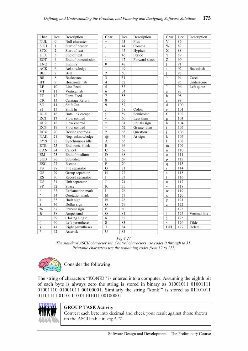
Defining and Understanding the Problem, and Planning and Designing Software Solutions 175
Software Design and Development – The Preliminary Course
Consider the following:
The string of characters “KONK!” is entered into a computer. Assuming the eighth bit of each byte is always zero the string is stored in binary as 01001011 01001111 01001110 01001011 00100001. Similarly the string “konk!” is stored as 01101011 01101111 01101110 01101011 00100001.
Char Dec Description Char Dec Description Char Dec Description NUL 0 Null character + 43 Plus V 86 SOH 1 Start of header , 44 Comma W 87 STX 2 Start of text - 45 Hyphen X 88 ETX 3 End of text . 46 Period Y 89 EOT 4 End of transmission / 47 Forward slash Z 90 ENQ 5 Enquiry 0 48 [ 91 ACK 6 Acknowledge 1 49 \ 92 Backslash BEL 7 Bell 2 50 ] 93 BS 8 Backspace 3 51 ^ 94 Caret HT 9 Horizontal tab 4 52 _ 95 Underscore LF 10 Line Feed 5 53 ` 96 Left quote VT 11 Vertical tab 6 54 a 97 FF 12 Form Feed 7 55 b 98 CR 13 Carriage Return 8 56 c 99 SO 14 Shift Out 9 57 d 100 SI 15 Shift In : 58 Colon e 101 DLE 16 Data link escape ; 59 Semicolon f 102 DC1 17 Flow control < 60 Less than g 103 DC2 18 Flow control = 61 Equals sign h 104 DC3 19 Flow control > 62 Greater than i 105 DC4 20 Device control 4 ? 63 Question j 106 NAK 21 Neg. acknowledge @ 64 At-sign k 107 SYN 22 Synchronous idle A 65 l 108 ETB 23 End trans. block B 66 m 109 CAN 24 Cancel C 67 n 110 EM 25 End of medium D 68 o 111 SUB 26 Substitute E 69 p 112 ESC 27 Escape F 70 q 113 FS 28 File separator G 71 r 114 GS 29 Group separator H 72 s 115 RS 30 Record separator I 73 t 116 US 31 Unit separator J 74 u 117 SP 32 Space K 75 v 118 ! 33 Exclamation mark L 76 w 119 " 34 Quotation mark M 77 x 120 # 35 Hash sign N 78 y 121 $ 36 Dollar sign O 79 z 122 % 37 Percent sign P 80 { 123 & 38 Ampersand Q 81 | 124 Vertical line ' 39 Closing single R 82 } 125 ( 40 Left parentheses S 83 ~ 126 Tilde ) 41 Right parentheses T 84 DEL 127 Delete * 42 Asterisk U 85
Fig 4.27 The standard ASCII character set. Control characters use codes 0 through to 31.
Printable characters use the remaining codes from 32 to 127.
GROUP TASK Activity Convert each byte into decimal and check your result against those shown on the ASCII table in Fig 4.27.

176 Chapter 4
Software Design and Development –The Preliminary Course
Boolean
The Boolean data type is used to store logical data; the only possible data items being either true or false (or yes or no). The term Boolean is derived from Boolean algebra which was developed by mathematician George Boole. Boolean algebra is used to describe logical propositions where the result must always be either true or false. Other common names used by programming languages rather than Boolean include logical, bit or simply Yes/No. In all cases, only two possible states are possible.
Each Boolean data item requires a single bit of storage, either a binary 1 or 0. It is standard practice to use 0 to mean false and 1 to mean true. In reality, many programming languages allow you to assign Boolean variables any value, however any non-zeros are treated as 1s and hence represent the Boolean value true.
The Boolean data type is commonly used to store any data that can only have two possible states. Examples include, Male or female, eligible or ineligible and on or off. Checkboxes are screen elements used to gather and display Boolean data. Boolean flags are variables often used within programs to signal that a section of code has or has not been executed.
Consider the following:
The following data are often used and stored by software solutions: • Phone numbers • Email addresses • Gender • Total number of items • Postcodes • Cost of products • Date of birth • X, Y coordinates on a screen • Time of day • Average of many integers
GROUP TASK Discussion The processes occurring within the CPU are all based on logical decisions. These decisions result in the output of sequences of 1s and 0s, therefore all data is ultimately Boolean data. Do you agree? Discuss.
GROUP TASK Discussion Although Boolean data is often thought of as true or false it can be used to represent other data that has just two states. Make a list of at least 10 instances where the Boolean data type would be appropriate.
GROUP TASK Discussion Examine the above two sets of binary numbers. How could ASCII assist programmers to convert between upper and lowercase? Discuss using KONK! as an example.
GROUP TASK Discussion Recommend the most suitable data type for each of the above data elements. Justify your answers.

Defining and Understanding the Problem, and Planning and Designing Software Solutions 177
Software Design and Development – The Preliminary Course
(a) Convert the binary number 11001010 into hexadecimal and decimal.
(b) Compare and contrast the binary representation of string data with the binary representation of integer data.
(c) In regard to examinations: • They are written by teachers and printed • Students sit the exams to answer questions • Teachers mark the exams and the results are given to students
Draw a dataflow diagram to describe the above system using each of the above dot points as individual processes.
Suggested solutions
(a) 11002 = 8 + 4 = 12 = C. 10102 = 8 + 2 = 10 = A. Therefore, 110010102 = CA16. 110010102 = 128 + 64 + 8 + 2 = 20210. Or, CA16.= (12 * 16) + 10 = 20210.
(b) String data is represented as a sequence of individual characters. A particular character is represented using the same binary code each time it occurs within the text. Integer data, on the other hand, represents complete numbers using a single representation. For example each digit in the numeric value 123 is NOT represented individually, rather the entire number is represented as a binary number using the twos complement system. Integer data is represented this way so it can be used to perform mathematical operations.
(c)
Write and print
exams
Students sit
exams
Teachers mark
exams
Exam questions
Exam papers
Completed exams
Results Marks
Answers
Students
Teachers
HSC style question:

178 Chapter 4
Software Design and Development –The Preliminary Course
SET 4B 1. Boolean, Date, Integer and Floating
Point are examples of: (A) data items. (B) data types. (C) strings. (D) instructions.
2. If a stored result may be of a fractional value, then which data type should be assigned to the applicable variable? (A) Floating point. (B) Integer. (C) Boolean. (D) String.
3. Today, all computer data and instructions are ultimately stored in: (A) ASCII. (B) hexadecimal. (C) binary (D) decimal.
4. The decimal equivalent of the binary number 10001 is: (A) 9. (B) 17. (C) 24. (D) 65.
5. Which is the most accurate data type for storing real numbers? (A) double precision floating point (B) single precision floating point (C) Boolean (D) 64 bit integers
6. Which data type is most commonly used to store data that can only have two possible states? (A) Integer. (B) Floating point. (C) String. (D) Boolean.
7. A value that is assigned outside of the allowable range will most likely result in: (A) a type mismatch error. (B) a null value. (C) the correct result but represented as
a negative value. (D) no error occurring.
8. The number 27B is probably an example of: (A) a hexadecimal number. (B) a binary number. (C) an octal number. (D) a decimal number.
9. The most common coding system for characters that uses 7 bits is known as: (A) ANSI. (B) EBCDIC. (C) ASCII. (D) Unicode.
10. Whole numbers are also known as: (A) real numbers. (B) floating point numbers. (C) integers. (D) none of the above.
11. Convert each of the following binary numbers into their decimal and hexadecimal equivalents.
(a) 01010101 (b) 11110111 (c) 10111010 (d) 01111110
12. Choose the best data type for each of the following. Justify your answers.
(a) The gender of clients in a database. (c) The number of items remaining on the shelf. (b) The average of a set of exam results. (d) A doctor’s notes on patients.
13. Convert the word “Gouldian” into binary ASCII. (set the first bit of each byte to 0)
14. The following hexadecimal numbers represent ASCII characters.
49 20 6C 6F 76 65 20 41 53 43 49 49
What does it say?
15. Calculations involving money must be precise. Research how this is achieved when money is often a fractional quantity.
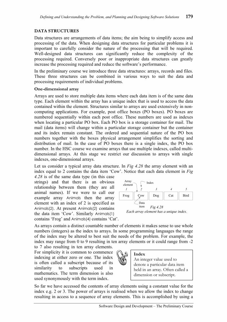
Defining and Understanding the Problem, and Planning and Designing Software Solutions 179
Software Design and Development – The Preliminary Course
DATA STRUCTURES Data structures are arrangements of data items; the aim being to simplify access and processing of the data. When designing data structures for particular problems it is important to carefully consider the nature of the processing that will be required. Well-designed data structures can significantly reduce the complexity of the processing required. Conversely poor or inappropriate data structures can greatly increase the processing required and reduce the software’s performance. In the preliminary course we introduce three data structures: arrays, records and files. These three structures can be combined in various ways to suit the data and processing requirements of individual problems. One-dimensional array Arrays are used to store multiple data items where each data item is of the same data type. Each element within the array has a unique index that is used to access the data contained within the element. Structures similar to arrays are used extensively in non-computing applications. For example, post office boxes (PO boxes). PO boxes are numbered sequentially within each post office. These numbers are used as indexes when locating a particular PO box. Each PO box is a storage container for mail. The mail (data items) will change within a particular storage container but the container and its index remain constant. The ordered and sequential nature of the PO box numbers together with the boxes physical arrangement simplifies the sorting and distribution of mail. In the case of PO boxes there is a single index, the PO box number. In the HSC course we examine arrays that use multiple indexes, called multi-dimensional arrays. At this stage we restrict our discussion to arrays with single indexes, one-dimensional arrays. Let us consider a typical array data structure. In Fig 4.28 the array element with an index equal to 2 contains the data item ‘Cow’. Notice that each data element in Fig 4.28 is of the same data type (in this case strings) and that there is an obvious relationship between them (they are all animal names). If we were to call our example array Animals then the array element with an index of 2 is specified as Animals(2). At present Animals(2) contains the data item ‘Cow’. Similarly Animals(1) contains ‘Frog’ and Animals(4) contains ‘Cat’. As arrays contain a distinct countable number of elements it makes sense to use whole numbers (integers) as the index to arrays. In some programming languages the range of the index may be altered to best suit the needs of the problem. For example, the index may range from 0 to 9 resulting in ten array elements or it could range from -2 to 7 also resulting in ten array elements. For simplicity it is common to commence indexing at either zero or one. The index is often called a subscript because of its similarity to subscripts used in mathematics. The term dimension is also used synonymously with the term index.
So far we have accessed the contents of array elements using a constant value for the index e.g. 2 or 3. The power of arrays is realised when we allow the index to change resulting in access to a sequence of array elements. This is accomplished by using a
Frog
1
Cow
2
Dog
3
Cat
4
Bird
5
Fig 4.28 Each array element has a unique index.
Index Array element
Data item
Index An integer value used to denote a particular data item held in an array. Often called a dimension or subscript.

180 Chapter 4
Software Design and Development –The Preliminary Course
variable in place of the constant index value. For example, consider again the Animals array in Fig 4.28. If the variable Count ranges in value from 1 to 5 during processing then Animals(Count) would access each of the five animal names in sequence as shown in Fig 4.29. Our code is generalised to process each element in the array.
Consider the following:
A modification is required to the airline check-in system to increase security as a consequence of the September 11, 2001 attacks on the USA. Currently passengers show identification to obtain their seat allocation and boarding pass. No identification is required as they board the aircraft. This makes it possible for passengers to exchange boarding passes and sit in different seats and even on different aircraft to those for which they hold a ticket. The modification to the system involves flight personnel at the boarding gate entering the seat number into a computer terminal. The terminal responds by displaying the passenger’s name. The staff member must then check the name against that on the passenger’s passport and ensure the passport photo is actually the passenger. The software developer assigned this task decides to use an array which is declared with the identifier Seating. The index for each element of the Seating array will be the seat number and the data items stored in the array will be the passenger names. At the check-in desk, passengers are assigned seats. This process sets the array element corresponding to the required seat to the passenger’s name. For example, Seating(23)=”Nerk Fred” means that Fred Nerk will be sitting in seat number 23 on the aircraft. At the boarding gate the flight personnel enter the seat number from the boarding pass. The system responds by displaying the passenger’s name. If the seat is empty then no name is returned. The passenger name displayed is compared to the passenger’s passport and the passport photo compared to the person to confirm their identity.
Seating(1) = “Broermann Kim” Seating(2) = “” Seating(3) = “Bradley Marlene” Seating(4) = “Bradley John” Seating(5) = “” Seating(6) = “” Seating(7) = “Eagle Nicholas” Seating(8) = “Carrucan Lindsay” Seating(9) = “Fendall Janine” Seating(10) = “” Seating(11) = “Davis Matthew” Seating(12) = “Davis Kareena” Seating(13) = “” Seating(14) = “Fendall Brent” Seating(15) = “Fendall Richard”
Fig 4.30 The Seating array for a 15 seat aircraft after most passengers have checked in.
GROUP TASK Discussion How does the above modification assist in improving security? Use possible examples to assist in your explanation.
GROUP TASK Discussion The index for the Seating array is itself meaningful data. Often this is not the case. What attributes make the seat numbers appropriate for use as the array’s index? Discuss.
Fig 4.29 Allowing the index to change
allows efficient access to multiple array elements.
Animals(Count)
Count is 1, then 2, then 3, then 4, then 5.

Defining and Understanding the Problem, and Planning and Designing Software Solutions 181
Software Design and Development – The Preliminary Course
Consider the following:
1. 10,000 names need to be searched to find any duplicates. 2. Calculating the average of a set of test results. 3. Storing the personal details for an individual employee. 4. Storing the daily rainfall occurring over a number of years. 5. Inputting a list of numbers and outputting them in reverse order. 6. Preparing a family tree.
Record
A data structure containing data items that are related but not necessarily of the same data type is called a record. Records are used extensively for database applications. Generally individual records contain all the information about a particular entity (or individual) within the database. For example, an address book contains details of individual people. Each person is an entity within the address book and has their own record. The record may contain the person’s surname, Christian name, date of birth, gender, street address, suburb, postcode, phone number, mobile number and email address. Each of the data items within each record is known as a field.
Each record of the same data type is made up of the same fields. The data items held within these fields will most likely be different but the data type of like fields must be the same. For example, the surname field always holds strings whereas the gender field always holds Boolean data.
GROUP TASK Discussion In which of the above scenarios would an array be of assistance? In each case explain your reasons. If an array is appropriate describe its structure.
Fig 4.31 Microsoft Outlook includes an address book where
an individual’s details are stored as a record.
GROUP TASK Discussion Records are different in many ways to arrays. Describe these differences. Use examples to reinforce your response.
GROUP TASK Discussion Records are used extensively as integral parts of many software applications. List and describe some applications that use records.
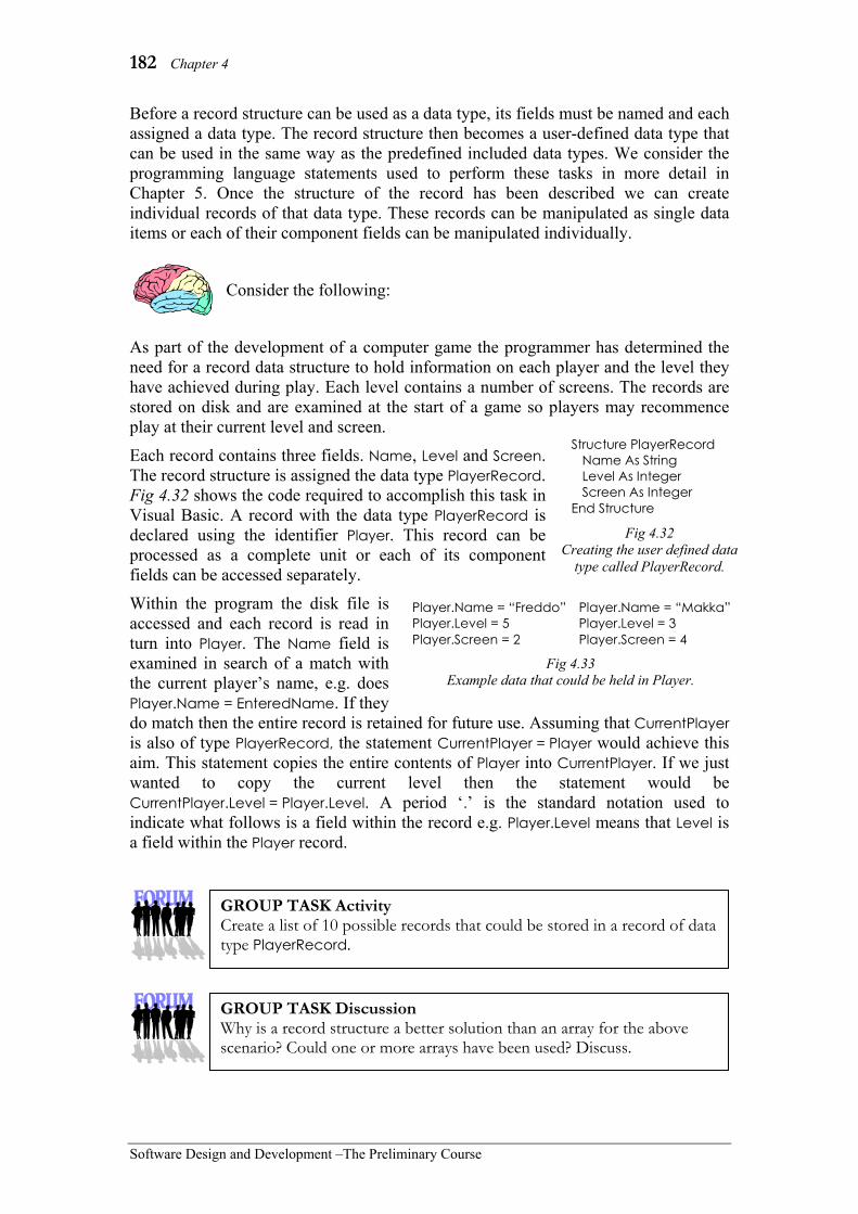
182 Chapter 4
Software Design and Development –The Preliminary Course
Before a record structure can be used as a data type, its fields must be named and each assigned a data type. The record structure then becomes a user-defined data type that can be used in the same way as the predefined included data types. We consider the programming language statements used to perform these tasks in more detail in Chapter 5. Once the structure of the record has been described we can create individual records of that data type. These records can be manipulated as single data items or each of their component fields can be manipulated individually.
Consider the following:
As part of the development of a computer game the programmer has determined the need for a record data structure to hold information on each player and the level they have achieved during play. Each level contains a number of screens. The records are stored on disk and are examined at the start of a game so players may recommence play at their current level and screen.
Each record contains three fields. Name, Level and Screen. The record structure is assigned the data type PlayerRecord. Fig 4.32 shows the code required to accomplish this task in Visual Basic. A record with the data type PlayerRecord is declared using the identifier Player. This record can be processed as a complete unit or each of its component fields can be accessed separately.
Within the program the disk file is accessed and each record is read in turn into Player. The Name field is examined in search of a match with the current player’s name, e.g. does Player.Name = EnteredName. If they do match then the entire record is retained for future use. Assuming that CurrentPlayer is also of type PlayerRecord, the statement CurrentPlayer = Player would achieve this aim. This statement copies the entire contents of Player into CurrentPlayer. If we just wanted to copy the current level then the statement would be CurrentPlayer.Level = Player.Level. A period ‘.’ is the standard notation used to indicate what follows is a field within the record e.g. Player.Level means that Level is a field within the Player record.
Structure PlayerRecord Name As String Level As Integer Screen As Integer End Structure
Fig 4.32 Creating the user defined data
type called PlayerRecord.
GROUP TASK Discussion Why is a record structure a better solution than an array for the above scenario? Could one or more arrays have been used? Discuss.
GROUP TASK Activity Create a list of 10 possible records that could be stored in a record of data type PlayerRecord.
Fig 4.33 Example data that could be held in Player.
Player.Name = “Freddo” Player.Level = 5 Player.Screen = 2
Player.Name = “Makka” Player.Level = 3 Player.Screen = 4

Defining and Understanding the Problem, and Planning and Designing Software Solutions 183
Software Design and Development – The Preliminary Course
Sequential files Files are used to permanently store data on secondary storage devices. Data can be written to a file or read from a file. Different types of access to files suit different requirements. Sequential files can only be accessed from start to finish. That is, to read or write to the middle of a sequential file requires accessing all the data prior to that position in the file. It is not possible to jump directly to a particular data item. The operating system controls access to files. As a consequence, software applications must work via the operating system when working with files. To commence using a file the operating system needs to know the location and name of the file together with information in regard to the method of access. Once work on the file is completed the application notifies the operating system and the operating system closes the file. A sequential file can be likened to an audio- cassette. To play the fifth song on the cassette requires fast forwarding through the first four songs. You cannot record a song between the fourth and fifth songs without overwriting existing music. If you wish to record over the fifth song you must be sure the new one is of identical size to the old. If it is not then you risk either overwriting part of song six or having the end of the old song five left on the tape. However you can easily add (or append) a new song to the end of the tape without affecting the existing songs. Sequential files operate in a similar manner. Sequential files are continuous streams of data (usually characters). The structure of the data is not coded as part of the file. If the data within the file has some structure then the software must understand this structure; the file itself does not contain this information. Many languages contain statements that allow data to be written and read a single character at a time, a data item at a time, record at a time or a line at a time. Separators are inserted by the programming language to separate data items e.g. commas or tabs. Carriage returns and/or line feed characters are added after each line. Most programming languages include an end of file (EOF) function, which returns the Boolean value True when the end of a file has been reached. This function can be used to ensure errors do not occur due to programs attempting to read past the last character. Programmers often add sentinel values within files to indicate the end of a sequence of data items e.g. “ZZZ” or 9999999.
Consider the following:
It is possible to open most files sequentially. Most word processors allow you to do this by stipulating that the file is a text file. Unfortunately the result often appears to be gibberish. Fig 4.35 shows part of a jpeg image file opened as a text file in Microsoft Word.
Song 1, Song 2, Song 3, Song 4…
Fig 4.34 Data on audio-cassettes are stored
sequentially.
Fig 4.35 Part of a jpeg file opened as a text file.
GROUP TASK Discussion Using your knowledge of sequential files and ASCII text, explain why the file in Fig 4.24 appears as gibberish. Discuss.

184 Chapter 4
Software Design and Development –The Preliminary Course
Consider the following:
As part of a program a sequential file is used. The requirements of a particular module mean that new data needs to be inserted at the start of the file. To perform this process the program performs the following steps: 1. Create a new file. 2. Add the new data to this new file. 3. Open the existing file. 4. Read a character from the existing file. 5. Write this character to the new file. 6. Repeat the above two steps until the end of the existing file is reached. 7. Close both files. 8. Delete the original existing file. 9. Rename the new file to the name of the old file.
Consider the following:
An existing sequential file contains the text for a Shakespeare essay you are working on in English. A friend notices that you have incorrectly spelt Shakespeare as Shakespear throughout the essay. Being a keen Software Design and Development student, you decide to correct the problem using your knowledge of sequential file techniques.
GROUP TASK Discussion From the user’s point of view it would seem that data could be added to the front of the sequential file. Explain why the user may think this is the case.
GROUP TASK Activity Work through the above steps on paper using some sample data. In your own words explain how these steps achieve their purpose.
GROUP TASK Discussion Develop a series of steps that could be used to accomplish the above task. Remember you can only add or append data to the end of a sequential file.
GROUP TASK Activity Create, on paper, a sample file containing the misspelt word a number of times. Work through your steps developed above to ensure each of the errors has been corrected.

Defining and Understanding the Problem, and Planning and Designing Software Solutions 185
Software Design and Development – The Preliminary Course
DATA DICTIONARY
When developing a software solution to a problem, it is vital that all variable names or identifiers are carefully documented. This ensures that all members of the development team are aware of identifiers that have been used, their data type and the scope of usage. A data dictionary is the repository where this information is held. Data dictionary functions are available with most software development CASE tools. If the data dictionary is an integral part of the development environment then confusion due to duplicate identifiers can be eliminated. For smaller development projects, the data dictionary is often maintained on paper with the assistance of a database or word processor.
A data dictionary should include a thorough description of each variable used by the program and each field in each database and file used or accessed by the program. A separate data dictionary is created for each module, database and file used by the program. Commonly a data dictionary will be a table containing columns for: • Identifier name (or field name) • Data type (including the data
structure if applicable) • Length (Number of characters
or decimal places if applicable) • Scope of the variable • Purpose or description
The exact columns used will be determined by the nature of the data used in the application. The example data dictionary at right (Fig 4.36), displays a sub-form to allow entry of information specific to the particular data type of the current field. This data dictionary describes a table in a relational database. It includes an icon of a key to indicate the primary key field in the table.
The screen shown in Fig 4.37 is part of a data flow diagram CASE tool. This screen allows the modification of the attributes of each data item used in the data flow diagram. As data flows are added to the diagrams the data items are automatically added to the data dictionary. Clicking on the ‘Edit Data Item’ button opens a screen allowing entry of details describing specific data items, such as data type, range, and a description of the data item’s purpose.
Scope The extent to which a variable is available for use. Global variables are available for use by all subroutines. Local variables are available to an individual subroutine.
Fig 4.36 A data dictionary from MS-Access, a popular
relational database system.
Fig 4.37 Data dictionary screen from the
Axiomsys CASE tool.

186 Chapter 4
Software Design and Development –The Preliminary Course
Consider the following:
The data dictionary below describes all the identifiers used in the Convert Amount to Words module from the Invoicing System structure diagram shown in Fig 4.19.
The programmer created this data dictionary whilst developing the source code. Data dictionaries are stored, along with other documentation, to assist in future maintenance and upgrading of the software product.
Name Data Type Length Scope Purpose
AmountInWords String 255 char Function Name Global
Returns the currency amount in words.
Amount Numeric Real (2 dec. pl.) Local Input parameter.
TempDigit Numeric Integer Local Stores each digit as it is extracted from Amount.
DigitWord(19) Array of strings 10 char Local The word associated with each digit, e.g. DigitWord(5)=”five”.
TenPowerWord(9) Array of strings 10 char Local Word for each power of ten, e.g. TenPowerWord(3)=”thirty”
Ten3Word(4) Array of strings 10 char Local Word for each 3rd power of ten, e.g. Ten3Word(2)=”million”
PlaceCounter Numeric Integer Local Counter incremented for each digit in Amount.
TempResult String 255 char Local Stores the amount in words during processing.
Fig 4.38 Data dictionary for the ‘Convert Amount to Words’ module.
GROUP TASK Discussion How could a data dictionary, such as the one above, be of assistance to future maintenance personnel?
GROUP TASK Discussion Explain the relationship between structure diagrams, IPO charts and data dictionaries. Use the above data dictionary as an example to illustrate your answer.

Defining and Understanding the Problem, and Planning and Designing Software Solutions 187
Software Design and Development – The Preliminary Course
SET 4C 1. A record can best be described as:
(A) a data structure containing unrelated data items.
(B) a data structure containing related data items all of the same data type.
(C) a data structure containing related data items but not necessarily of the same data type.
(D) a data structure containing unrelated data items but all of the same data type.
2. A dimension or subscript is another name for: (A) an index. (B) a data item. (C) an array. (D) a record.
3. What is often added within a file to indicate the end of a sequence of data items? (A) EOF function. (B) Sentinel values. (C) Boolean values. (D) A carriage return.
4. A one-dimensional array has how many indexes? (A) One. (B) Two. (C) Multiple. (D) None.
5. Each data item within a record is individually known as: (A) an array. (B) a file. (C) an element. (D) a field.
6. Arrays, records and files are examples of: (A) data indexes. (B) data types. (C) data items. (D) data structures.
7. Adam is developing a product and has decided to use a record structure in one of the modules. What must Adam do first to ensure it can be used as a user defined data type? (A) He must name every field and
assign each a data type. (B) He does not need to name them,
just assign each field a data type. (C) He must name them but he does
not need to assign each a data type.
(D) He cannot create a user defined data type.
8. A file that can only be accessed from start to finish is a: (A) serial file. (B) sequential file. (C) random access file. (D) direct access file.
9. Arrays are used to: (A) store multiple items of the same
data type. (B) store multiple items of differing
data types. (C) store a single data item. (D) none of the above.
10. File access is controlled by: (A) the browser. (B) the application software. (C) the operating system. (D) the FP Unit.
11. Select a data structure for each of the following. Justify your responses.
(a) Gathering the responses to a questionnaire. (c) A set of exam marks. (b) Storing the output from a word processor. (d) Details of products sold in a shop.
12. Describe the essential differences between an array and a record.
13. Arrays can greatly simplify access to multiple data items. Do you agree? Explain your response.
14. Sequential files can be used to store records and arrays, however there are access restrictions. Describe these restrictions.
15. Create an IPO diagram to describe how a data item can be inserted into the middle of a sequential file.

188 Chapter 4
Software Design and Development –The Preliminary Course
STRUCTURED ALGORITHMS An algorithm is a method of solving a problem. The algorithm describes the processing steps necessary to transform the inputs into the outputs. This occurs within a finite amount of time. Algorithms are used to assist in the solution of all types of problems not just computer-based problems. For example, a recipe is an algorithm describing the preparation and cooking steps required to create a meal. In most cases, recipe books call this the ‘method’. The method is a sequence of steps that transform the ingredients (input) into the meal (output).
We use algorithms subconsciously. For example, each morning you go through a sequence of decisions and steps to prepare and travel to school. When searching for a lost article we try various techniques; we may try retracing our steps, looking in obvious places, asking other family members, etc… These are all valid methods of solving the problem; in essence you are using algorithms. The algorithm is not the solution but the method used to arrive at the solution. This chapter is about bringing algorithms out of the subconscious and presenting them in such a way that others can understand them. To do this requires us to be able to clearly and logically describe algorithms we devise. There are various methods of algorithm description, in this course we consider two, pseudocode and flowcharts.
Consider the following:
Each morning most high school students need to make decisions about their day. The steps taking place may include the following:
1. Wake up 2. If you are sick then stay in bed. 3. If it is a school day then continue otherwise stay in bed. 4. Get out of bed. 5. Have a shower. 6. Get dressed in school uniform. 7. Eat breakfast. 8. Pack school bag. 9. If mum is home then scab a lift otherwise catch bus to school.
There are problems with the above steps if we work through them in the precise order indicated. If you are sick, then step 2 directs you to stay in bed. We then reach step three, which indicates that on school days we must complete the steps that follow. This seems to contradict step 2’s direction. This algorithm has three exit points, at steps 2, 3 and 9. It would be better if we could restructure our algorithm to have a single exit. Structured algorithms require a single exit point and, as we shall see, this is always possible.
GROUP TASK Activity Can you rewrite the steps 1 to 9 from above in such a way that there is only one exit point from the algorithm? Ensure that your new algorithm performs the tasks in the manner intended in the original.

Defining and Understanding the Problem, and Planning and Designing Software Solutions 189
Software Design and Development – The Preliminary Course
METHODS FOR REPRESENTING ALGORITHMS
There are many standard methods for representing algorithms. Using standard methods of algorithm description assists in the process of developing algorithms and allows others to understand the algorithms created. In this course, we examine two methods; pseudocode and flowcharts. By adhering to the rules of pseudocode and flowcharts the process of coding is simplified.
Pseudocode is an English-like algorithm description language. Keywords are used in pairs to indicate the start and finish of each control structure. These keywords are written in capitals to make them stand out. Between each pair of keywords, statements are indented to further emphasise each control structure. Flowcharts use rectangles for processes, parallelograms for input and output and diamonds for decisions. These components are connected with flow lines. Although it is possible to draw flow lines in any direction there are standard constructs for each of the standard control structures used for structured algorithms. When using flowcharts we must be careful to use only recognised control structures. It is possible to draw flowcharts that cannot be implemented in programming code.
Pseudocode and flowcharts are used to represent exactly the same thing. For example, Fig 4.39 and Fig 4.40 represent exactly the same algorithms. Which one is used, is purely personal preference. Some would argue that pseudocode is easier as it is closer to programming code. Others feel flowcharts are more visual and hence easier to construct and understand. In this course, it is necessary to be comfortable writing and reading both pseudocode and flowcharts.
The wording of each process used is not part of the algorithm description method. For some algorithms, maths symbols may be appropriate, for others English phrases are more suitable. For example, Count = 1 or Set Count to 1. It is common practice to be consistent within each algorithm. The aim is to write algorithms that can be easily understood and are logically correct.
BEGIN
Set Count to 1
Set Product to Number × Count
Yes
No Is Number > Count
?
Get Number
Display Product
Increment Count
END
Fig 4.40 Sample algorithm expressed
using a flowchart.
BEGIN MAINPROGRAM Get Number Set Count to 1 WHILE Number > Count Set Product to Number × Count Display Product Increment Count ENDWHILE END MAINPROGRAM
Fig 4.39 Sample algorithm using pseudocode.
GROUP TASK Discussion Compare the pseudocode and flowchart shown in Fig 4.39 and Fig 4.40. Can you see how both algorithms are describing the same method of solution? Discuss.
GROUP TASK Discussion What problem do you think is being solved by the algorithms in Fig 4.39 and Fig 4.40? Describe, in words, the operation of the algorithms that lead to the solution of this problem.

190 Chapter 4
Software Design and Development –The Preliminary Course
CONTROL STRUCTURES
Structured algorithms are built using control structures. This process is known as structured programming. Control structures determine the direction or order in which statements within an algorithm are executed. Control is the influence that directs the flow of execution. Control structures are standard constructs used when creating structured algorithms. The theory behind structured programming is that all problems can be solved using just three different control structures; sequence, selection and iteration. This theory has never been definitively proven however no problem has ever been found that cannot be solved using structured techniques. All imperative and procedural programming languages include statements allowing the implementation of each of these control structures as part of software solutions. Structured programming techniques are used to create the majority of software developed in the world today. Although only the three control structures; sequence, selection and iteration are required, a fourth, the use of subroutines or subprograms, is desirable when using top-down design development techniques. Let us examine each of these control structures in detail: Sequence
In structured programming the order of processing is important. Each process must be performed in the correct order for the solution to be realised. Sequence is the control structure that ensures each process occurs in the correct order. For example, when getting dressed you must put your socks on before your shoes. There are programming languages where the sequence of processing is not significant. Consider a spreadsheet; formulas are entered into cells with little need to consider the order in which these formulas will be evaluated. In Prolog a set of facts and rules are interrogated to reach conclusions. The order of events is not a significant consideration. When using pseudocode each process is written one under the other. Similarly on flowcharts the order of processing moves from top to bottom. Each process is completed before the next is commenced. A single process that is out of order will most likely effect the operation of the entire algorithm.
Consider the following:
To back a car out of a garage requires the following steps: start the car, open the garage door, get in the car, release the hand brake, engage reverse gear, press accelerator, check review mirror, unlock car and place foot on brake.
Process 1
Process 1
Process 1
Process 1
Process 1 Process 2 Process 3 Process 4
Fig 4.41 Sequence expressed in
pseudocode and as a flowchart.
GROUP TASK Activity The steps above are obviously not in the correct sequence. Rewrite these steps in the correct sequence first as a flowchart and then in pseudocode. Is there only one possible sequence? Discuss.

Defining and Understanding the Problem, and Planning and Designing Software Solutions 191
Software Design and Development – The Preliminary Course
Consider the following:
Many software solutions require that the contents of two variables need to be swapped. A precise sequence of events must be adhered to if this process is to occur correctly. The four flowchart segments below are attempting to swap the data item in Num1 with the data item in Num2.
Selection Selection is the control structure that allows decisions to be made between different alternative paths. Different paths are executed in response to the outcome of some condition. Once the processes along this path are complete processing continues with the statement following the selection control structure. • Binary selection In binary selection there are two alternatives, one being selected if the condition is true and the other if the condition is false. The condition results in a Boolean value, either true or false. Often one branch will not involve any additional processes, rather its purpose is to avoid execution of the processes present on the alternate branch. Fig 4.43 shows the syntax used to represent binary selection using pseudocode and flowcharts.
GROUP TASK Discussion Some of the algorithms above correctly perform the swap while others do not. Identify the correct and incorrect algorithms. Explain your response for each algorithm.
GROUP TASK Discussion The sequence of steps is vital to the success of the swap algorithm. Describe situations where sequence is not so vital to an algorithm’s success. Discuss.
Yes No Condition?
Process 1
IF Condition THEN Process 1 ENDIF
Yes No Condition ?
Process 1 Process 2
IF Condition THEN Process 1 ELSE Process 2 ENDIF
Fig 4.43 Binary selection using flowcharts and pseudocode.
Num1 = Num2
Num2 = Num1
Num1 = Num2
Temp = Num1
Num2 = Temp
Num1 = Num2
Temp = Num2
Num2 = Temp
Num2 = Num1
Temp = Num2
Num1 = Temp
Num2 = Num1
Num1 = Temp
Temp = Num1
Algorithm A Algorithm B Algorithm C Algorithm D Algorithm E Fig 4.42
Possible swap algorithms.

192 Chapter 4
Software Design and Development –The Preliminary Course
Yes No Height > 135?
You can’t ride
Get Weight, Height
Weight < 40 ?
You can ride You can’t ride
No Yes
When using binary selection, the condition can be expressed as a statement e.g. Number > 2 in which case the result is either True or False. It can also be expressed as a question e.g. Is Number > 2? in which case the answer is either Yes or No. In either case, it is important on flowcharts to label each branch appropriately using Yes/No or True/False. In this text we prefer to use questions combined with Yes and No.
Consider the following:
Under current Australian law you must be 18 years of age to vote. An algorithm to determine if someone can vote is described in Fig 4.44 as a flowchart and in pseudocode.
Consider the following:
To ride on the roller coaster at an amusement park you must weigh at least 40 kilograms and be taller than 135cm. Fig 4.45 describes two different algorithms. The first uses pseudocode and the second, a flowchart.
Get Age IF Age ≥ 18 THEN You can vote ELSE You can’t vote ENDIF
Fig 4.44 Algorithm to decide if someone can vote.
Yes No Age ≥ 18 ?
You can voteYou can’t vote
Get Age
GROUP TASK Activity There are many different ways of writing the above algorithm so it correctly achieves its purpose. Describe using both pseudocode and a flowchart some alternative algorithms.
GROUP TASK Discussion The flowchart shown in Fig 4.44 uses the three symbols. Describe the purpose of each symbol in terms of making flowcharts more understandable. Discuss.
Get Weight, Height IF Weight ≥ 40 THEN IF Height > 135 THEN You can ride ELSE You can’t ride ENDIF ELSE You can’t ride ENDIF
Fig 4.45 Two different algorithms for the roller coaster problem.
GROUP TASK Activity Rewrite the first algorithm as an equivalent flowchart. Rewrite the second algorithm in its equivalent pseudocode. Which solution do you think is the best? Discuss your answer.

Defining and Understanding the Problem, and Planning and Designing Software Solutions 193
Software Design and Development – The Preliminary Course
• Multiway selection
Multiway selection caters for situations where more than two alternative paths are required. The first choice encountered that makes the expression true causes control to branch to that respective path. Multiway or multiple selection statements can be implemented using multiple binary selection statements. Multiway selection statements are not a necessary part of structured algorithms however in many instances they greatly reduce the length and complexity of the solution.
The Otherwise choice is a default should none of the available choices make the expression true. It can be likened to the No or Else part of the binary selection structure. It is not necessary to include the Otherwise choice in all algorithms.
Consider the following:
A triathlon is being organised. As part of the administration of the event, a software application is developed to sort the entrants into their respective levels. Competitors who are 12 years old or younger are juniors, 15 years or under are intermediate, younger than 18 are seniors. Competitors who are 35 years or older compete in the veteran level and the remaining competitors are placed in the open level. An algorithm for this aspect of the software product has been developed:
CASEWHERE Expression is Choice A : Process 1 Choice B : Process 2 Choice C : Process 3 Choice D : Process 4 ⋅ ⋅ ⋅ ⋅ ⋅ ⋅ Otherwise : Process n ENDCASE
Fig 4.46 Multiway selection expressed using pseudocode and as a flowchart.
Expression
Process 4 Process 3 Process 1 Process 2 Process n
Choice A Choice B Choice C Choice D Otherwise
CASEWHERE Age is ≤ 12 : Junior ≤ 15 : Intermediate < 18 : Senior ≥ 35 : Veteran Otherwise : Open ENDCASE
Fig 4.47 Algorithm segment to sort triathlon entrants into levels.
Age is
Veteran Senior Junior Intermediate Open
≤ 12 ≤ 15 < 18 ≥ 35 Otherwise
GROUP TASK Activity The algorithm above has been created using multiway selection. Rewrite the algorithm using only binary selection structures. Do this as a flowchart and then in pseudocode.

194 Chapter 4
Software Design and Development –The Preliminary Course
Iteration (or Repetition)
Iteration is the repetition of a sequence of steps. A termination condition is used either at the start or at the end of the sequence to stop the repetition. Iteration is often called looping as control passes from the last statement in the sequence back to the first forming a loop. The processes within the loop structure are known as the body of the loop.
Program runtime errors are often a consequence of poor iteration structures where the termination condition is never met. This results in the appearance, to the user that the computer has frozen. In actuality it is processing at full speed but is stuck in an infinite loop.
Iteration is what makes computers such powerful calculating machines. Their ability to repeat instructions continually at incredible speeds makes the software applications we use each day possible. For example, the animation sequences in computer games, the screen redrawing millions of colours some 70 times per second, and weather forecasting applications processing vast amounts of data.
There are two main types of iteration; pre-test where the termination condition is at the start of the loop and post-test where the termination condition follows the body of the loop. A third structure known as a counting loop or for…next loop is a special case of the pre-test loop that is used so often that it is included in most programming languages. • Pre-test iteration
Pre-test iteration is the most commonly used form of repetition. Because the termination condition comes before the body of the loop it is possible that the processes within the loop will not be executed at all. For this reason, pre-test loops are also known as guarded loops, the condition guards the entrance to the loop. Most algorithms require the possibility of not entering the loop if all possibilities are to be taken into account.
With pre-test loops the repetition continues whilst the condition remains true. It is when the condition becomes false that the repetition terminates. As a consequence, it is essential that the processing occurring within the loop alters the contents of variables that form the condition. If this does not occur the loop will continue infinitely.
The pseudocode implementation of pre-test iteration uses the keyword pair WHILE and ENDWHILE. The initial WHILE is followed by a condition, which must remain true for the repetition to continue. ENDWHILE signifies the end of the loop and that control should return to the WHILE statement. On flowcharts, the ENDWHILE keyword is replaced by a flow line connecting back to above the condition. This flow line requires an arrow as it directs control in an upward direction rather than the normal downwards direction.
Yes
No Condition ?
Process
Fig 4.49 Pre-test iteration using
pseudocode and as a flowchart.
WHILE Condition Process ENDWHILE
Process
Process
Process
Fig 4.48 Iteration is the control structure that repeats
sequences of code.

Defining and Understanding the Problem, and Planning and Designing Software Solutions 195
Software Design and Development – The Preliminary Course
Consider the following:
To sharpen a pencil you continue turning the sharpener whilst the pencil is not sharp. Fig 4.50 shows this algorithm expressed in pseudocode and as a flowchart. The use of pre-test iteration means that if the pencil is already sharp we don’t ever turn the sharpener.
• Post-test iteration
Post-test iteration is where the termination condition follows the body of the loop. This means that the processes within the body of the loop are always executed at least once. For this reason post-test loops are also called unguarded loops. When using a post-test loop you must be absolutely certain that under all circumstances the processes within the loop should occur at least once.
Checking user input is a common situation where a post-test loop is appropriate. The body of the loop gets input from the user. The termination condition checks that the input is reasonable. If it is not then further input is requested. If the input is successfully validated then the loop is terminated.
Consider the representations shown in Fig 4.51. On the flowchart control enters the body of the loop from above. The processes within the loop are executed then the condition is checked. If the condition is true the loop terminates, if not then control returns to the top of the loop. In pseudocode the keyword REPEAT is synonymous with the arrow on the flowchart leading back up to the top of the loop. Effectively the word REPEAT is merely a marker indicating the top of the loop. Similarly, UNTIL indicates the end of the iteration and has the same meaning as the decision diamond on the flowchart. Remember, both the pseudocode and the flowchart are representing exactly the same control structure.
Yes
No Pencil blunt ?
Turn the sharpener
Fig 4.50 Sharpening a pencil using pre-test iteration.
WHILE Pencil is blunt Turn the sharpener ENDWHILE
GROUP TASK Discussion Pre-test iteration continues whilst the condition is true. The condition is contained within a decision diamond. What makes this decision different to that used for binary selection? Discuss.
Yes
No Condition
?
Process
Fig 4.51 Post-test iteration using
pseudocode and as a flowchart.
REPEAT Process UNTIL Condition

196 Chapter 4
Software Design and Development –The Preliminary Course
GROUP TASK Discussion Describe, in words, how the algorithm in Fig 4.53 effectively validates the number of copies input.
Consider the following:
User input is a common cause of errors. It is difficult to completely control the actions of users. As a consequence it is necessary to validate their input to ensure it is acceptable. Consider the text box on a print dialogue (Fig 4.52) that is used to obtain the number of copies the user wishes to print. Obviously a positive integer is required, however what happens if a letter, word or fractional value is entered? As developers we must deal with such situations if we are to produce quality software products. We could stop users entering numbers directly into the text box and insist they use the up or down arrows to select a value. This would work, however it is rather inconvenient if you wish to print say 10 or 20 copies. A preferable solution is to validate the data after it has been input. Fig 4.53 shows a possible algorithm to achieve this validation.
Consider the following:
The above validation example could have been implemented using a pre-test loop. Fig 4.54 describes a possible algorithm that accomplishes this task.
Fig 4.52 Print dialogue from Microsoft Word.
Fig 4.53 Post-test iteration used to validate input.
REPEAT Get Copies UNTIL Copies is a positive integer
Yes
No Is
Copies a positive integer
?
Get Copies
GROUP TASK Discussion The condition used to validate the input does not really include sufficient detail. Which type of tests are required to check that the input is indeed a positive integer? Discuss.
Fig 4.54 Pre-test iteration used
to validate input.
Yes
No Is Copies NOT a positive
integer ?
Get Copies
Get Copies GROUP TASK Discussion Two input statements are used in the pre-test algorithm. Why is this necessary? Is there a way of rewriting the algorithm using a single input? Discuss.

Defining and Understanding the Problem, and Planning and Designing Software Solutions 197
Software Design and Development – The Preliminary Course
• Counting or FOR…NEXT loops. Counting loops are a special case of pre-test iteration. These loops are used when we wish to repeat a sequence of processes a set number of times or we wish repetition to occur whilst a value is incrementing within the limits of two values. For example, if we require a variable to take the values 1, 2, 3, 4, 5… 100 then a counting or FOR…NEXT loop is the most convenient structure to use. In most programming languages it is possible to alter the magnitude of each increment (or step) to produce sequences such as 10, 9, 8, 7, … 0 or even -1, -0.5, 0, 0.5, 1, 1.5… 10. The incrementing value, called the loop counter, changes by a set amount (the step) each time the body of the loop has been executed. Counting loops are so often required that most programming languages include them as a standard construct. Strictly speaking, we do not require a specific method for representing counting loops using our two methods of algorithm description, as the pre-test iteration control structure can be used to more accurately describe the logic. However for convenience, the FOR…NEXT keywords can be used in pseudocode. If a flowchart is being used then the explicit logic of the loop should be shown.
The pseudocode in Fig 4.55 represents a counting iteration structure. During the first iteration, the loop counter holds the initial value. During the second iteration the loop counter is equal to the initial value plus the step value. Subsequent iteration increment the loop counter by the step value. The loop terminates once the loop counter reaches a value greater than the final value if the step value is positive. If the step value is negative, then the loop terminates once the loop counter is less than the final value. Be careful when using fractional step values, as the approximate nature of floating point representations can cause the loop to terminate earlier or later than expected.
Consider the following:
Develop an algorithm that displays the first 10 multiples of a number entered. For example, if the user enters 3 then the algorithm should display 3, 6, 9, 12, 15, 18, 21, 24, 27 and 30. A possible solution is described in Fig 4.56. Notice that the STEP part of the pseudocode is not required when the step value is 1.
GROUP TASK Practical activity We have stated that FOR…NEXT loops are special cases of pre-test iteration. Perhaps this is not really the case. Using a programming language with which you are familiar, write statements to ensure that it’s FOR…NEXT structure does in fact implement pre-test iteration. Discuss your findings.
FOR LoopCounter = InitialValue TO FinalValue STEP StepValue Process NEXT LoopCounter
Fig 4.55 Suggested syntax for representing counting loops in pseudocode.
Get Number FOR Count = 1 TO 10 Multiple = Count × Number Display Multiple NEXT Count
Fig 4.56 Algorithm to display the first 10
multiples of a number.

198 Chapter 4
Software Design and Development –The Preliminary Course
Consider the following:
The logic is clearer if we write algorithms that include counting loops using pre-test iteration structures rather than the FOR…NEXT pseudocode keyword pairs, however this does require a little more effort.
Suppose a problem requires a loop that outputs the even numbers from 2 to 100. Let us develop this algorithm using pseudocode and a counting loop, pre-test pseudocode and finally as a flowchart. Each of these algorithms is logically identically, it is the method used to describe them that is different.
The FOR statement in the FOR…NEXT version includes setting the initial value of the loop together with the decision. This corresponds to the first two lines of the pre-test pseudocode version. The NEXT Count statement corresponds to the last two lines of the second version. The flowchart is a precise copy of the second pseudocode with minor changes to the wording of some statements.
There is a difference in the way counting loops are implemented in some programming languages that is not immediately obvious. When the loops within the second and third algorithms above terminate, Count will have a value of 101. In most programming languages, this is also the case when the first algorithm is implemented. Unfortunately it is not always the case. Sometimes Count will be undefined, and sometimes it will be the final value given in the FOR statement. It is important to understand the intricacies of the FOR…NEXT implementation in the programming language you are using.
FOR Count = 2 TO 100 STEP 2 Display Count NEXT Count
Count = 2 WHILE Count ≤ 100 Display Count Count = Count + 2 ENDWHILE
Fig 4.57 Identical algorithms describing a method of displaying the even numbers from 2 to 100.
Yes
No Is Count ≤ 100
?
Display Count
Set Count to 2
Add 2 to Count
GROUP TASK Discussion Study each of the algorithms in Fig 4.57. Describe how each of these algorithms operates to perform the stated task.
GROUP TASK Activity Describe how each of the above algorithms could be changed to display the following sets of numbers: 1, 2, 3, 4, 5,…50. 100, 95, 90, 85,… 0. -45, -35, -25,… 45. 0.1, 0.3, 0.5, 0.7,… 5.1
Defining and Understanding the Problem, and Planning and Designing Software Solutions 199
Software Design and Development – The Preliminary Course
SET 4D
1. What is the control structure that allows decisions to be made between alternative paths? (A) Sequence. (B) Iteration. (C) Selection. (D) Subroutines.
2. The most commonly used form of repetition is: (A) pre-test iteration. (B) post-test iteration. (C) iteration. (D) none of the above.
3. Keywords used in pairs, are a characteristic of which method of representing an algorithm? (A) Flowcharts. (B) Context diagrams. (C) Pseudocode. (D) None of the above.
4. Which shape is used on flowcharts to represent input and output? (A) Rectangles. (B) Diamonds. (C) Squares. (D) Parallelograms
5. When using binary selection, how many alternatives are there? (A) One. (B) Two. (C) Eight. (D) Sixteen.
6. What determines the direction or order in which statements within an algorithm are executed? (A) Subroutines. (B) Control structures. (C) Parameters (D) Variables.
7. Kate is a SDD student who has been given the task of representing the same algorithm using two different methods. Which two common methods for doing this, are examined in this course? (A) NS diagrams and structured
English. (B) Pascal and Cobol. (C) Context diagrams and decision
trees. (D) Pseudocode and flowcharts.
8. Post-test loops are also known as: (A) counting loops. (B) guarded loops. (C) unguarded loops. (D) none of the above.
9. Which shape is used on flowcharts to represent decisions? (A) Diamonds. (B) Squares. (C) Rectangles. (D) Circles.
10. What is the control structure that ensures that each process is executed in the correct order? (A) Iteration. (B) Sequence. (C) Selection. (D) Pre-test iteration.
11. What is an algorithm and why are they so important when designing software solutions?
12. What is structured programming? Discuss.
13. Explain the operation of each of the three fundamental control structures. Use examples of each as part of your explanation.
14. Create an algorithm that calculates the average of a series of numbers.
15. Create an algorithm that describes the operation of a light that can be turned on or off using either of two switches.

200 Chapter 4
Software Design and Development –The Preliminary Course
SOFTWARE STRUCTURE Earlier in this chapter we examined the concepts of abstraction and refinement. These concepts are implemented using top-down design. The top-down design, in turn, determines the structure of the software. We can model this structure using structure charts or dataflow diagrams. In this section we examine how algorithms are influenced by and represented when using top-down design. How do we indicate the position of a module or subroutine within the top-down design? Furthermore, how do we specify the parameters required by these modules to allow them to be reusable self-contained units? Subroutines Software developed using top-down design is comprised of a series of subroutines. Subroutines are also called subprograms or procedures. The terms subroutine and subprogram imply a lower level process whereas the term procedure refers to its sequence of statements. The highest level routine is known as the main program. The main program contains calls to lower level subroutines. In turn these subroutines call lower level subroutines and so on. When using pseudocode, a call to a subroutine is indicated by underlining the process (see Fig 4.58). The underline tells the reader that there is more detail in regard to this process elsewhere. Furthermore, the subroutine found elsewhere will have the same name as the underlined words. The keywords BEGIN…END together with the underlined name of the routine are used to enclose the processing of the subroutine. When representing algorithms using pseudocode the main program is enclosed within the keywords BEGIN MAINPROGRAM… END MAINPROGRAM.
When representing algorithms using flowcharts a call to a subroutine is indicated using additional vertical bars on either side of the process box (see Fig 4.59). The start of the main program commences with the word BEGIN in a box with rounded sides and ends with a similar box containing the word END. Some references use the words start and stop in preference to begin and end. The commencement and termination of a subroutine is similarly indicated with the addition of the subroutine’s name within each symbol.
BEGIN MAINPROGRAM Process 1 Process 2 Process 3 END MAINPROGRAM
BEGIN Process 1 Do something Do something else END Process 1
BEGIN Process 3 Do whatever Do whatever else END Process 3
Fig 4.58 Subroutine names are underlined
when using pseudocode.
Process 2
Process 1
Process 3
BEGIN
END
BEGIN Process 1
Do something else
Do something
END Process 1
BEGIN Process 3
Do whatever else
Do whatever
END Process 3
Fig 4.59 Calls to subroutines are indicated using
additional vertical lines. Rounded boxes are used at the start and end of every routine.
GROUP TASK Discussion Fig 4.58 and Fig 4.59 describe the same algorithm. They also describe the top-down design of software. Discuss how these methods of indicating subroutines assist developers during the top-down design process.

Defining and Understanding the Problem, and Planning and Designing Software Solutions 201
Software Design and Development – The Preliminary Course
Modularity Modularity refers to the ability to reuse modules as a result of their independent nature. A module, in the broader sense of the word, refers to a self-contained unit. For example, the anti-lock brake system used on cars can be thought of as a module. It can be used on a variety of different makes and models of car. The car company need not understand the details of the operation of the anti-lock brake module. The module can be treated by the car company as a black box where only the required inputs and resulting outputs need to be known. In terms of software development, modules are groups or libraries of related subroutines designed so they can be reused both within the same application and in other applications. Testing software products developed using self-contained modules is simplified. The operation of each module can be thoroughly tested in isolation to the total application. When the module is added to the project we can be reasonably sure that the module will not cause any problems. It is considered good practice to develop all subroutines using modularity principles regardless of whether they are ever likely to be reused. Earlier in this chapter we discussed abstraction, modularity is closely related to abstraction. Abstraction involves taking away part of the problem for consideration in isolation. Modularity principles ensure this part remains a self-contained unit. Because modules are designed to be reused as part of the solution to different problems the source of their inputs and the destination of their outputs will change. We must have a way of communicating the inputs to and outputs from subroutines in such a way that these channels can easily be reused. We use parameters to provide this interface. • Parameters Parameters provide the interface between different subroutines within a software product. These are the same parameters specified on structure charts and used as data flows on dataflow diagrams. They allow subroutines to access and alter the data items held in variables. These variables may be simple data types or they may be complex data structures. Higher level subroutines call lower level subroutines using actual parameters. Actual parameters are real variables that contain data. Formal parameters are used within subroutines. Formal parameters are effectively replaced by actual parameters whilst the subprogram is executing. Let us consider how parameters are represented when using pseudocode and flowcharts. In both cases, the list of parameters to be sent and returned from the subroutine is included within a bracketed list. The order in which the parameters are listed is significant; it determines their destination when they arrive at the subroutine. In Fig 4.61 the actual parameter First in the call to the subroutine Biggest corresponds to the formal parameter Item1 within the subprogram. Similarly, the actual parameter Second corresponds to the formal parameter Item2 in the subprogram.
INPUTS BLACK BOX
OUTPUTS
Fig 4.60 Modularity allows modules to be reused as black boxes.
Fig 4.61 Using parameters in pseudocode.
BEGIN MAINPROGRAM Get First Get Second Biggest (First, Second, Result) Display Result END MAINPROGRAM
BEGIN Biggest(Item1,Item2, Big) IF Item1 > Item2 THEN Big = Item1 ELSE Big = Item2 ENDIF END Biggest

202 Chapter 4
Software Design and Development –The Preliminary Course
The process of communicating via parameters is known as passing. In our Biggest example (Fig 4.61 and 4.62) the actual parameter First is passed to the formal parameter Item1 in the Biggest subprogram. In reality, the variable First is an identifier pointing to a specific address in memory. First can be passed to Item1 in one of two ways, either “by reference” or “by value”: 1. When passing “by reference” a
pointer to the address in memory of First is sent to the formal parameter Item1. In this case no new memory location is created rather Item1 will point to the memory location received from the actual parameter First. Whilst the Biggest subroutine is executing, each reference to Item1 causes the memory location associated with the formal parameter First to be accessed. It is often helpful to think of each occurrence of the identifier Item1 being replaced by the identifier First whilst the subroutine is active. If the Biggest subroutine altered the value of Item1 during processing then the value of First in the main program will also change. This makes sense as both Item1 and First are merely different names for exactly the same memory location. In summary, passing by reference passes data in both directions – both to and from subroutines. In the Biggest subroutine the variable Big must be passed by reference as this is the variable that returns the output back to the calling routine.
2. When passing “by value” a copy of the value held in the variable First is sent rather than the memory address. This means there is no connection between corresponding parameters, such as First and Item1, during the processing of the Biggest subroutine. The Biggest subroutine must create memory locations for each of its parameters and store the received values in these locations. More significantly the value of the original formal parameter is not altered during execution of the called subroutine. In summary, passing by value only passes data into subroutines. In many current programming languages passing by value is the default behaviour. This prevents changes to variables in calling subroutines from being changed unintentionally.
To further confuse the issue, in most programming languages the identifier associated with many data structures (such as arrays) store pointers to the memory address of the data structure. Therefore regardless of whether an array is passed “by reference” or “by value” to a subroutine it is the address of the location of the array in memory that is passed. This means the values within the actual array elements can be altered by the subroutine. Many program languages, such as Java for example, pass all parameters by value. To return a value from a subroutine requires use of the RETURN keyword. In this case each subroutine is a function. And all subroutine calls are function calls. Fig 4.63 shows how such calls are specified in pseudocode and flowcharts. Functions receive one or more inputs and return a single output. Each unique set of inputs will always return the same output. However, different sets of inputs may well produce the same outputs. This behaviour is the same as functions in maths. For example, in Fig 4.63 inputs of 3,4 always return 4, however inputs of 4,2 will also always return 4.
Fig 4.62 Using parameters in flowcharts.
Get First
Biggest (First, Second, Result)
BEGIN
END
Get Second
Display Result
BEGIN Biggest (Item1, Item2, Big)
END Biggest
Big = Item1
Is Item1>Item2
?
Big = Item2
Yes No

Defining and Understanding the Problem, and Planning and Designing Software Solutions 203
Software Design and Development – The Preliminary Course
Consider the following:
Imagine you work part time at the local library. Often you have the task of locating books for the librarian. The librarian gives you a list containing the call numbers of each required book. You then go to the shelves and retrieve these books. This is similar to the way a call where parameters are passed by reference works. You are playing the part of the subprogram and the librarian is the main program. The shelves are memory areas containing the data (the books). The call numbers represent the actual locations of the books; the actual parameters. There is only a single book with a unique call number. You receive the list of call numbers and use them as formal parameters. Whether you or the librarian find a particular book it remains the same book. Now imagine the librarian wishes you to comment on a newspaper article. She makes a photocopy of the original article and hands it to you. You then take the photocopy to your desk and as you read you highlight significant words and ideas. You then write down your comments on a piece of paper, hand them to the librarian and toss the photocopy of the article in the bin. This is like passing by value. Again the librarian is playing the part of the main program and you are playing the subroutine role. The article is passed by value meaning a copy of the data is passed rather than a link to the original. Clearly your highlighting will not appear on the original newspaper article as it is merely a copy of the original. Also, tossing the photocopy in the bin has no effect on the original. The return value is your comments which you (the subroutine) hand back to the librarian (the main program).
Fig 4.63 Using RETURN to pass values back in pseudocode and flowcharts.
BEGIN MAINPROGRAM Get First Get Second Result = Biggest (First, Second) Display Result END MAINPROGRAM
BEGIN Biggest(Item1,Item2) IF Item1 > Item2 THEN Big = Item1 ELSE Big = Item2 ENDIF RETURN Big END Biggest
Get First
Result = Biggest (First, Second)
BEGIN
END
Get Second
Display Result
BEGIN Biggest (Item1, Item2)
END Biggest
Big = Item1
Is Item1>Item2
?
Big = Item2
Yes No
RETURN Big
GROUP TASK Activity Act out the above library scenario. Pause as the drama unfolds to discuss how each component and process compares and assists your understanding of calling subroutines with parameters.
GROUP TASK Discussion The use of parameters is central to the programming process. Most commands, functions and even operators included within programming languages use parameters. Discuss using examples.

204 Chapter 4
Software Design and Development –The Preliminary Course
STANDARD ALGORITHMS Often similar problems are encountered as part of the solution to many problems. Rather than continually reinvent the wheel, there are many standard algorithms that are used in these circumstances. In life we commonly use standard algorithms. For example, in primary school you learnt how to perform long multiplication using a specific method or algorithm. Imagine if your primary school teacher insisted that you discover and create an algorithm for multiplication on your own. Perhaps eventually you would work it out, however it is unlikely your algorithm would be as easy to use as the one you now use. No doubt you have added modifications to the originally taught multiplication algorithm. Perhaps you just add a zero when multiplying by ten or you halve and add a zero when multiplying by five. Standard algorithms can be altered to suit the requirements of the current problem. We shall examine standard algorithms for loading and printing arrays, adding the contents of an array of numbers, and processing records from sequential files. In the HSC course, we examine further algorithms that assist us to search and sort data. Loading and printing arrays Loading an array means storing data items in each element of the array. Printing an array is the process of displaying each data item stored in the array. Both these processes are similar, as each and every element of the array must be accessed. Loading an array (see Fig 4.64) could be done using an assignment statement for each element. This may be acceptable when the array contains a small number of elements, however it becomes tedious once the number of elements exceeds ten or so and becomes extremely cumbersome when hundreds or even thousands of elements are involved. A more general solution is required. As each element in the array is normally filled one after the other we can use a variable that increments as the index. An iteration control structure surrounding this statement causes each element of the array to be accessed sequentially. Various possibilities exist for the termination condition for the loop. If the number of data items is known precisely then a counting loop could be used. If not then a sentinel value (say “ZZZ” or 999) could be used as an indicator that there is no more data to be loaded (see Fig 4.65). Let us consider the algorithm in Fig 4.65 more closely. We first set the index for the array to its starting value. In most cases arrays are indexed from 0, as is the case in our pseudocode. We then get the first data item from the user and temporarily store it in the variable DataItem. We then check the loop’s termination condition before entering the body of the loop. If the initial data item was the sentinel value, we would never enter or execute the body of the loop. If we had chosen a post-test iteration structure we would be forced to process the first data item, in other words the sentinel value would always be stored in the array. This may or may not be desirable depending on the problem. The body of the loop stores the data item in the array element Item(Index). Index is then incremented, meaning 1 is added to the
BEGIN LoadArray Set Index to 0 Get DataItem WHILE DataItem is not the sentinel Store DataItem in Item(Index) Increment Index Get DataItem ENDWHILE END LoadArray
Fig 4.65 Algorithm to load data into an array.
BEGIN LoadArray Get Item(0) Get Item(1) Get Item(2) Get Item(3) Get Item(4) Get Item(5) Get Item(6) Get Item(7) Get Item(8) Get Item(9) END LoadArray
Fig 4.64 Tedious algorithm to
load data into an array.

Defining and Understanding the Problem, and Planning and Designing Software Solutions 205
Software Design and Development – The Preliminary Course
existing value of Index. So if we have just loaded ‘sausage’ into Item(5) then Index contains the value 5 and Item(5) contains the string ‘sausage’. When Index is incremented its value now becomes 6 in preparation for the next data item to be loaded. This process continues until the sentinel value is encountered. Note that the value of Index is incremented after each array element is loaded. As a consequence, the algorithm ends with Index equal to the next vacant array element. It may seem appropriate to reduce this value by 1. However as the array is indexed from 0, this value actually reflects the precise number of elements loaded into the array, which is often useful. It is also quite common to append further elements to the end of an array in which case, the value of Index is best left as is.
Printing or displaying the contents of an array is a similar process to loading an array. Rather than reading or getting data, we are printing or displaying the data. If we know the precise number of items in the array then the process is further simplified (see Fig 4.66). If a sentinel value is stored in the array to indicate the end of the data items then we must be careful not to print or display the sentinel (see Fig 4.67).
GROUP TASK Discussion The algorithm described in Fig 4.65 uses two get statements. Can you rewrite the algorithm using a single get? The result of the processing must be identical to the original in all circumstances.
GROUP TASK Activity Rewrite the algorithm in Fig 4.65 using a post-test iteration control structure. Ensure that the sentinel value is read into the last array element.
BEGIN PrintArray Set Index to 0 WHILE Index < NumItems Display Item(Index) Increment Index ENDWHILE END PrintArray
Fig 4.66 Algorithm to print or display the
data in an array when the number of items is known.
BEGIN PrintArray Set Index to 0 WHILE Item(Index) is not the sentinel Display Item(Index) Increment Index ENDWHILE END PrintArray
Fig 4.67 Algorithm to print or display the data in an array when the last item is a sentinel.
GROUP TASK Discussion In the above algorithms we displayed the array elements directly whereas when loading the array we read each data item into a temporary variable first and later stored it in the array. Why did we do this? Is it always necessary to use a temporary variable when loading an array? Discuss.
GROUP TASK Activity Rewrite the above algorithms as equivalent flowcharts. Now redraw your flowcharts using post-test loops.
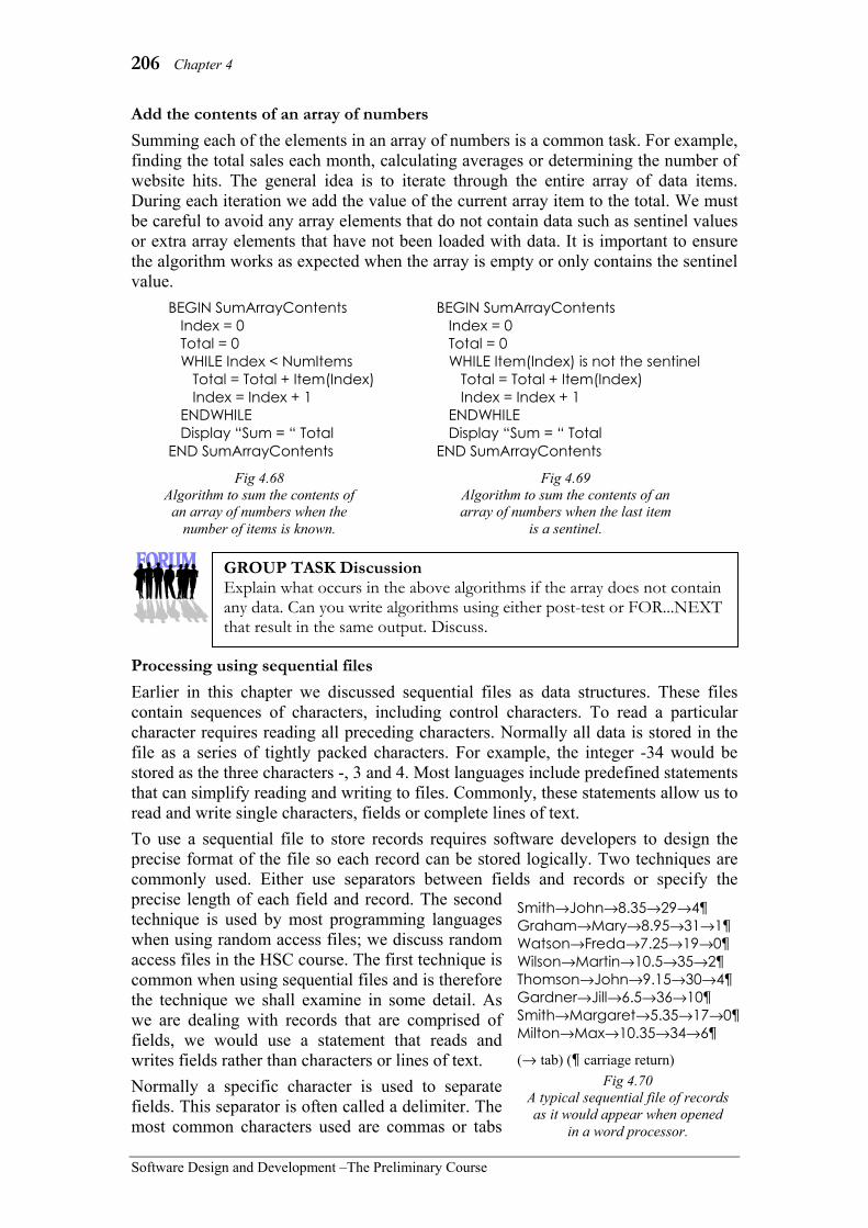
206 Chapter 4
Software Design and Development –The Preliminary Course
Add the contents of an array of numbers Summing each of the elements in an array of numbers is a common task. For example, finding the total sales each month, calculating averages or determining the number of website hits. The general idea is to iterate through the entire array of data items. During each iteration we add the value of the current array item to the total. We must be careful to avoid any array elements that do not contain data such as sentinel values or extra array elements that have not been loaded with data. It is important to ensure the algorithm works as expected when the array is empty or only contains the sentinel value.
Processing using sequential files Earlier in this chapter we discussed sequential files as data structures. These files contain sequences of characters, including control characters. To read a particular character requires reading all preceding characters. Normally all data is stored in the file as a series of tightly packed characters. For example, the integer -34 would be stored as the three characters -, 3 and 4. Most languages include predefined statements that can simplify reading and writing to files. Commonly, these statements allow us to read and write single characters, fields or complete lines of text. To use a sequential file to store records requires software developers to design the precise format of the file so each record can be stored logically. Two techniques are commonly used. Either use separators between fields and records or specify the precise length of each field and record. The second technique is used by most programming languages when using random access files; we discuss random access files in the HSC course. The first technique is common when using sequential files and is therefore the technique we shall examine in some detail. As we are dealing with records that are comprised of fields, we would use a statement that reads and writes fields rather than characters or lines of text. Normally a specific character is used to separate fields. This separator is often called a delimiter. The most common characters used are commas or tabs
Smith→John→8.35→29→4¶ Graham→Mary→8.95→31→1¶ Watson→Freda→7.25→19→0¶ Wilson→Martin→10.5→35→2¶ Thomson→John→9.15→30→4¶ Gardner→Jill→6.5→36→10¶ Smith→Margaret→5.35→17→0¶ Milton→Max→10.35→34→6
(→ tab) (¶ carriage return) Fig 4.70
A typical sequential file of records as it would appear when opened
in a word processor.
BEGIN SumArrayContents Index = 0 Total = 0 WHILE Index < NumItems Total = Total + Item(Index) Index = Index + 1 ENDWHILE Display “Sum = “ Total END SumArrayContents
Fig 4.68 Algorithm to sum the contents of
an array of numbers when the number of items is known.
BEGIN SumArrayContents Index = 0 Total = 0 WHILE Item(Index) is not the sentinel Total = Total + Item(Index) Index = Index + 1 ENDWHILE Display “Sum = “ Total END SumArrayContents
Fig 4.69 Algorithm to sum the contents of an array of numbers when the last item
is a sentinel.
GROUP TASK Discussion Explain what occurs in the above algorithms if the array does not contain any data. Can you write algorithms using either post-test or FOR...NEXT that result in the same output. Discuss.
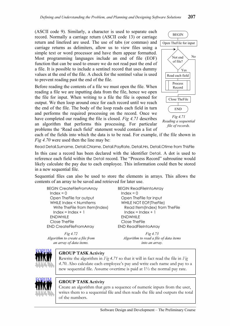
Defining and Understanding the Problem, and Planning and Designing Software Solutions 207
Software Design and Development – The Preliminary Course
(ASCII code 9). Similarly, a character is used to separate each record. Normally a carriage return (ASCII code 13) or carriage return and linefeed are used. The use of tabs (or commas) and carriage returns as delimiters, allow us to view files using a simple text or word processor and have them appear formatted. Most programming languages include an end of file (EOF) function that can be used to ensure we do not read past the end of a file. It is possible to include a sentinel record that uses dummy values at the end of the file. A check for the sentinel value is used to prevent reading past the end of the file. Before reading the contents of a file we must open the file. When reading a file we are inputting data from the file, hence we open the file for input. When writing to a file the file is opened for output. We then loop around once for each record until we reach the end of the file. The body of the loop reads each field in turn and performs the required processing on the record. Once we have completed our reading the file is closed. Fig 4.71 describes an algorithm that performs this processing. For particular problems the ‘Read each field’ statement would contain a list of each of the fields into which the data is to be read. For example, if the file shown in Fig 4.70 were used then the line may be: Read Detail.Surname, Detail.CName, Detail.PayRate, Detail.Hrs, Detail.Otime from ThisFile
In this case a record has been declared with the identifier Detail. A dot is used to reference each field within the Detail record. The “Process Record” subroutine would likely calculate the pay due to each employee. This information could then be stored in a new sequential file. Sequential files can also be used to store the elements in arrays. This allows the contents of an array to be saved and retrieved for later use.
No
Fig 4.71 Reading a sequential
file of records.
BEGIN
Read each field Yes
Process Record
END
Open TheFile for input
Close TheFile
Not end of file?
GROUP TASK Activity Rewrite the algorithm in Fig 4.71 so that it will in fact read the file in Fig 4.70. Also calculate each employee’s pay and write each name and pay to a new sequential file. Assume overtime is paid at 1½ the normal pay rate.
GROUP TASK Activity Create an algorithm that gets a sequence of numeric inputs from the user, writes them to a sequential file and then reads the file and outputs the total of the numbers.
BEGIN CreateFileFromArray Index = 0 Open TheFile for output WHILE Index < NumItems Write TheFile from Item(Index) Index = Index + 1 ENDWHILE Close TheFile END CreateFileFromArray
Fig 4.72 Algorithm to create a file from
an array of data items.
BEGIN ReadFileIntoArray Index = 0 Open TheFile for input WHILE NOT EOF(TheFile) Read Item(Index) from TheFile Index = Index + 1 ENDWHILE Close TheFile END ReadFileIntoArray
Fig 4.73 Algorithm to read a file of data items
into an array.

208 Chapter 4
Software Design and Development –The Preliminary Course
CHECKING ALGORITHMS FOR ERRORS The main purpose of creating algorithms is to explain the logic of the solution. Therefore checking algorithms is primarily about checking the correctness of the logic. Checking doesn’t just take place once an algorithm has been completed, rather it is an ongoing process occurring during the algorithm’s development. The primary technique for checking algorithms is known as desk checking. As the name implies, a desk check is the process of working through an algorithm using pencil and paper. Test data where the expected outputs are known, provide the inputs for the desk check. In Chapter 6 we examine the creation of test data and desk checking in detail. To be sure an algorithm performs correctly for all expected inputs requires that all paths through the algorithm be tested. Test data should be designed to accomplish this aim. This can often be a laborious task when there are many selection statements and loops. For example, an algorithm with 4 binary selections will have a total of 16 unique possible paths requiring up to 16 sets of test data and 16 desk checks. Many algorithms have far more unique paths than this. Iterations can also greatly increase the time required to desk check an algorithm. Most errors occur either as an iteration commences or as it terminates; be careful as loops start and end. Another common source of logic errors is within decisions themselves. The use of incorrect logical operators being the most common e.g. using > instead of ≥. Be sure to test these boundary conditions carefully by including test data items that equal the boundary value. Algorithms need not include detail in regard to validation of unexpected inputs, this is primarily a task undertaken when building the solution in code. It is not necessary to check algorithms respond correctly to unexpected inputs. For example, if you expect a particular input into an algorithm to be an integer then it is not necessary to check the algorithm works when strings or fractions are input.
Consider the following:
To illustrate the creation of test data and the desk checking process consider the algorithm in Fig 4.75. This algorithm is designed to find the average of a set of numbers. The process terminates when a negative number is entered. We require at least two sets of test data; one to test the normal situation where the body of the loop is executed and another to test when the loop’s termination condition is immediately false. We should also test using the boundary value zero; this could be included within the first set of test data. Say we use the test data set 34, 0, 65, 40, 85, -1 and the test data set containing just -1.
Fig 4.74 One of sixteen unique
paths through this algorithm.
BEGIN MAINPROGRAM Input Number Sum = 0 Tally = 0 WHILE Number ≥ 0 Sum = Sum + Number Tally = Tally + 1 Input Number ENDWHILE Average = Sum/Tally Print Average ENDMAINPROGRAM
Fig 4.75 Algorithm to calculate the
average of a set of numbers.
GROUP TASK Discussion Do you think the two test data sets are sufficient to ensure the correct operation of this algorithm? Discuss.

Defining and Understanding the Problem, and Planning and Designing Software Solutions 209
Software Design and Development – The Preliminary Course
Before commencing the desk check we calculate the expected output from each test data set. Our first set should output the average of 34, 0, 65, 40 and 85. As 34 + 0 + 65 + 40 = 224, the average should be 224 ÷ 5 = 44.8. The second data set contains just a negative value so a sensible result would be an output of 0 or no output at all. We now commence the desk check. A table is drawn by hand with a column for each variable used within the algorithm and an additional column for output (see Fig 4.76). The current contents of each variable are written under the appropriate identifier. As the contents of a variable changes the new data is written under the previous item. It is common practice to horizontally align data items assigned within each iteration. Essentially, the desk check is completed by stepping statement by statement through the algorithm. When an input is required the next test data item is used. The first test data set results in the same output as was expected. The second causes a division by zero error. We need to adjust our algorithm to overcome this problem. Once the algorithm has been edited both desk checks need to be completed again as it is possible that the alterations may solve one problem but cause other problems.
Consider the following:
Earlier in this chapter, we considered an algorithm to determine if people are able to ride on a roller coaster. The algorithm is reproduced at right. We wish to thoroughly check the operation of this algorithm using sufficient sets of test data together with a series of desk checks.
Fig 4.76 Desk check for the average algorithm.
GROUP TASK Activity Alter the algorithm to overcome the division by zero problem. Now perform the desk checks again using your altered algorithm.
GROUP TASK Activity Design appropriate pairs of test data and state the expected output for each. Give reasons why each test data pair is included.
GROUP TASK Activity Perform a desk check of the algorithm using each of your test data pairs.
Fig 4.77 Algorithm to determine if a person
can ride the roller coaster.
Yes No Height > 135?
You can’t ride
Get Weight, Height
Weight < 40 ?
You can ride You can’t ride
Begin
End
No Yes

210 Chapter 4
Software Design and Development –The Preliminary Course
SET 4E 1. In terms of software structure, what
provides the interface between different subroutines? (A) Indexes. (B) Parameters. (C) Subroutines. (D) algorithms.
2. A primary technique for checking algorithms is known as: (A) desk checking. (B) peer checking. (C) black box checking. (D) white box checking.
3. The process of communicating via parameters is known as: (A) parsing. (B) swapping. (C) passing. (D) none of the above.
4. The ability to reuse modules is best described as: (A) black boxing. (B) modularity. (C) abstraction. (D) top-down design.
5. In regards to a sequential file, what is the term given to the character that is used to separate fields? (A) Delimiter. (B) Sentinel value. (C) Comma. (D) Tab.
6. In pseudocode, how is a call to a subroutine indicated? (A) The process is in capital letters. (B) The process is italicised. (C) The process is underlined. (D) The process is preceded by a #
symbol.
7. In most programming languages, what is used to ensure reading does not continue past the end of the file? (A) A delimiter. (B) Sentinel value. (C) EOF function. (D) Carriage return.
8. Subprogram has a similar meaning to: (A) lower level process. (B) module. (C) subroutine. (D) all of the above.
9. In both pseudocode and flowcharts, parameters are represented by: (A) a bracketed list. (B) an underlined list. (C) an italicised list. (D) capital letters.
10. An algorithm with 5 binary selections could have as many as _____ unique possible paths? (A) 5. (B) 16. (C) 54. (D) 32.
11. Problems can be solved without using subroutines. So, why do we use them? Discuss.
12. Discuss aspects of designs that increase the reusability of code modules.
13. Parameters provide the interface between different modules. What is a parameter and how do they enable data to be shared?

Defining and Understanding the Problem, and Planning and Designing Software Solutions 211
Software Design and Development – The Preliminary Course
Consider the following flowchart when answering questions 14 and 15.
14. Design a set of test data for the above flowchart.
15. Perform a desk check of the flowchart using your test data.
Yes
No Count ≤ NumResults
?
Get Mark
Get NumResults
Set Count to 1
DetermineGrade(Mark,Grade)
Set Result(Count) to Grade
Increment Count
BEGIN
END
Number is
≤ 40 ≤ 50 < 65 ≥ 80 Otherwise
BEGIN DetermineGrade(Number,Letter
END DetermineGrade
Letter = “B”Letter = “C”Letter = “E” Letter = “D” Letter = “A”

212 Chapter 4
Software Design and Development –The Preliminary Course
RSA security is a company that produces encryption and decryption software products. RSA’s encryption is based on pairs of prime numbers. A prime number is an integer that only has 1 and itself as factors, for example 7 is a prime number as its only pair of factors is 1 and 7. However 8 is not a prime, as 2 and 4 are factors in addition to 1 and 8.
To monitor the security of RSA’s encryption techniques they run a number of competitions. The data reproduced below is from their RSA-640 factoring competition. The aim is to determine the two prime numbers whose product is the competition number shown below. This competition number contains 193 decimal digits and the sum of these digits is 806. Furthermore if this number were converted to binary it would contain 640 binary digits, hence the competition name RSA-640. There are numerous competitions, the largest being RSA-2048 where the prize money is $200,000.
Name: RSA-640 Prize: $20,000 Digits: 193 Digit Sum: 806 Competition number: 3107418240490043721350750035888567930037346022842727545720161948823206440518081504556346829671723286782437916272838033415471073108501919548529007337724822783525742386454014691736602477652346609
The following algorithm is an attempt to solve the above problem:
BEGIN RSA_Solution Get CompNum CheckNumDigits CheckDigitSum PossibleFactor = 2 REPEAT IsPrime = CheckIfPrime(PossibleFactor) IF IsPrime THEN OtherFactor = CompNum/PossibleFactor IF OtherFactor is an Integer THEN IsPrime = CheckIfPrime(OtherFactor) IF IsPrime THEN Display PossibleFactor, OtherFactor ENDIF ENDIF ENDIF Increment PossibleFactor UNTIL IsPrime END RSA_Solution
HSC style question:

Defining and Understanding the Problem, and Planning and Designing Software Solutions 213
Software Design and Development – The Preliminary Course
(a) The above algorithm checks if OtherFactor is an integer, however there is no check to ensure PossibleFactor is an integer. Why is this? Discuss.
(b) When building this solution a problem will emerge in regard to representing some of the variables using standard data types. Identify and describe the problem.
(c) Perform a desk check of the algorithm using 18 as the input. You may assume all calls to subroutines are performed correctly.
(d) There is a logic error within the algorithm. Identify the error and describe its effect on the operation of the algorithm.
(e) Design an algorithm for the CheckIfPrime routine. You may assume that the variables PossibleFactor and OtherFactor are integers.
Suggested solutions
(a) PossibleFactor must be an integer. It starts with a value of 2 and is incremented each time through the loop, hence it remains an integer. OtherFactor is the result of a division and hence will rarely be an integer, hence a check is needed.
(b) The competition number is well outside the range of any standard data type. If CompNum was a long integer it could not hold the competition number, in fact a 640 bit integer type is needed not a 32 bit integer type. A floating point type is not appropriate as the representation must be exact and so too must calculations based on this representation. Similar problems would occur with PossibleFactor and OtherFactor.
(c)
(d) The use of IsPrime for the PossibleFactor and OtherFactor prime checks, as well as for the loop termination condition cause problems. This means that if PossibleFactor is a prime and OtherFactor is not an integer then the loop will exit. Using the RSA-640 competition number the loop would end after a single iteration as PossibleFactor is a prime (2) and OtherFactor will end in .5. (2 marks)
(e) BEGIN CheckIfPrime (Num) Check = True Count = 2 WHILE Count <= square root of Num AND Check IF Num/Count is an integer THEN Check = False ENDIF Increment Count ENDWHILE RETURN Check
END
CompNum PossibleFactor IsPrime OtherFactor 18 2
3 4 5 6
T F T F F T
9 6
3.6

214 Chapter 4
Software Design and Development –The Preliminary Course
CHAPTER 4 REVIEW 1. Selecting data types and data structures
generally falls under which phase of the software development cycle? (A) Defining the problem. (B) Planning the solution. (C) Building the solution. (D) Checking the solution.
2. Floating point data types are used to store which type of data? (A) Strings. (B) Whole numbers. (C) Fractional and very large numbers. (D) Integers.
3. In flowcharts, rectangles are used for representing: (A) processes. (B) decisions. (C) input and output. (D) subroutines.
4. A step-by-step list of the processing that will take place is usually represented with what? (A) A structure chart. (B) An IPO chart. (C) A context diagram. (D) A data flow diagram.
5. A structured algorithm can BEST be described as: (A) a method that provides a solution
to a problem. (B) a method detailing a series of
unambiguous steps that provides a solution to a problem.
(C) a sequence of steps that transforms inputs into outputs.
(D) any method that gives the correct result.
6. A Boolean data type is used to store which type of data? (A) Dates and Times. (B) Currency. (C) Logical. (D) Integer.
7. The control structure that repeats sequences of code is known as what? (A) Iteration. (B) Sequence. (C) Selection. (D) Subroutines.
8. Two modelling techniques that are used to describe the flow of data moving through the system are: (A) Context diagrams and algorithms. (B) Data flow diagrams and system
flowcharts. (C) Hierarchy charts and IPO charts. (D) Abstraction and refinement.
9. Coding in a programming language occurs during which phase of the software development cycle? (A) Testing and evaluating (B) Maintaining (C) Implementing (D) Planning and designing
10. Which control structure caters for situations where more than two alternative paths are required? (A) Repetition (B) Binary selection (C) Multiway selection (D) Sequence
11. Different data types have different limitations. Describe limitations that exist when using integer, floating point and string data types.
12. In this chapter, we discussed three data structures, namely arrays, records and sequential files. Briefly, describe the nature of each of these structures together with an example of where each would be used.

Defining and Understanding the Problem, and Planning and Designing Software Solutions 215
Software Design and Development – The Preliminary Course
BEGIN ChangeArray (Item( ), NumItems) Get DateItem Get Command CASEWHERE Command is Add : AppendItem (Item( ), NumItems, DateItem) Delete : RemoveItem (Item( ), NumItems, DataItem) Change : AlterItem (Item ( ), NumItems, DataItem) ENDCASE
END ChangeArray
BEGIN AppendItem (Array( ), Count, Item) Add 1 to Count Set Array(Count) to Item END AppendItem
BEGIN RemoveItem (Array( ), NumItems, DelItem) FindIndex (Array( ), NumItems, DelItem, Index) IF Index ≥ 0 THEN Set Array(Index) to Array(NumItems) Decrement NumItems ELSE Display “Can’t delete as item does not exist” ENDIF END Remove Item
Consider the algorithm that follows, when answering questions 13, 14 and 15.
BEGIN AlterItem (Array( ), Count, Original)
FindIndex (Array( ), Count, Original, Index) IF Index ≥ 0 THEN Get ChangeItem Set Array(Index) to ChangeItem ELSE Display “Can’t change as item does not exist”
ENDIF END AlterItem
13. Construct a structure chart to describe the top-down design of the ChangeArray sub-program.
14. There is no algorithm for the FindIndex subroutine. Create this algorithm in pseudocode.
15. Perform a desk check of the algorithm using the following sets of test data:
Desk, Delete Table, Change, Door Goose, Add
Duck, Delete Goose, Change, Bird
(Assume the initial array is indexed from 0 and contains the items Desk, Table, Chair, Plate and Cutlery). Describe any problems you encounter.

216 Chapter 5
Software Design and Development –The Preliminary Course
In this chapter you will learn to: • verify the syntax of a command using metalanguage
statements • specify syntax using meta-language statements • use meta-language statements to develop syntactically correct
code • generate appropriate source code by:
– using appropriate data types and data structures – using a programming environment to generate and execute
code – coding an algorithm into the chosen programming language
• trace the output of a given code fragment and modify it appropriately
• systematically eliminate syntax errors so that a program can be executed
• run, correct and extend existing code • test a program with boundary values to detect possible runtime
errors • detect and correct logic errors in program code by using a
systematic error detection and correction process • develop standard modules or subroutines for reuse • create solutions to problems using existing code with minimal
change or additions • develop code that makes use of common modules or subroutines • differentiate between the scope of local and global variables • develop code that makes appropriate use of global and local
variables • develop code that calls common modules and passes
parameters appropriately • incorporate functions into modules or subroutines • make use of procedures • develop solutions that include appropriate user interfaces • evaluate the effectiveness of interfaces used in commercially
available software • develop an appropriate storyboard for a specified problem • design screens incorporating good design and ergonomic features • incorporate current relevant interface elements into software
solutions • produce documentation for different audiences • produce source code which is well documented and therefore
easy to read, understand and maintain • fully document a solution that has been developed in the
classroom • create a data dictionary to define the data (including variables,
arrays and records) used in a developed solution • use a range of application packages to develop the various
types of documentation to fully document a solution • interpret code and documentation prepared by others • assess the effectiveness of online help available in software
packages
Which will make you more able to: • describe and use appropriate data types • describe the interactions between the elements of a computer
system • identify the issues relating to the use of software solutions • investigate a structured approach in the design and
implementation of a software solution • use a variety of development approaches to generate software
solutions and distinguish between these approaches • use and develop documentation to communicate software
solutions to others • describe the skills involved in software development • communicate with appropriate personnel throughout the
software development process • design and construct software solutions with appropriate
interfaces.
In this chapter you will learn about: Coding in an approved programming language • meta-languages, including EBNF and Railroad diagrams • language syntax specified through meta-languages in manuals
and help documentation • the syntax used to represent the control structures, including:
– sequence, selection (binary, multiway), repetition (pre-test, post-test, for…next loops), and use of subroutines or procedures
– combinations of these • the syntax used to define and use a range of data types and data
structures, including integer, string, floating point/real, Boolean, one-dimensional array and records
Developing source code • converting algorithms into source code using syntactically
correct statements Error detection and correction techniques • types of coding errors, including syntax errors, runtime errors
and logic errors • stubs used to check the flow of execution or used to replace
subroutines/modules during testing to check if that section of the code is the cause of an error
• flags used to check if a section of code has been executed or can be used as part of the logic of a solution or as an error detection process
• debugging output statements – additional print statements in the code for use in the
debugging process – used to identify which sections of the code have been
executed and used to interrogate variable contents at a particular point in the execution of a program
Commonly executed sections of code • reusable code
– standard logic, such as a login process, data validation, conversion between date formats or to replace multiple occurrences of the same code
• combining code from different sources, copying and pasting into code and calling modules or subroutines
• making the same data available to different modules using global variables and parameter passing
• use of functions and procedures User interface development • the need for consultation with users and/ or managers • use of storyboard to show the general design of each interface
and show navigation between interfaces • effective user interfaces, including:
– factors affecting readability – use of white space – effective prompts – judicious use of colour and graphics – grouping of information – unambiguous and non-threatening error messages – legibility of text, including justification, font type (serif vs
sans serif), font size, font style and text colour – navigation – recognition of relevant social and ethical issues – consistency – appropriate language for the intended audience
Documentation • types of documentation
– documentation for developers and documentation for users • internal documentation including meaningful variable names
(intrinsic), readability of code, comments, white space and indentation
• online help, such as context sensitive help and help files

Implementing Software Solutions 217
Software Design and Development – The Preliminary Course
5 IMPLEMENTING
SOFTWARE SOLUTIONS
Implementing the software solution refers to coding in a programming language. During this stage the planning and design undertaken in the previous stage is put into practice. This includes producing the source code and creating the user interface. A variety of integrated development environments (IDEs) are available to assist. Fig 5.1 shows the popular open source Netbeans IDE commonly used by Java and PHP programmers and Microsoft’s Visual Studio IDE used to develop code using Microsoft’s “.NET” family of programming languages.
We commence the chapter by examining the syntax of programming languages. The syntax of a language is the way the language is formed and the rules governing its formation. Metalanguages are languages used to describe the syntax of other languages. We use metalanguages to describe the syntax used for each of the standard control structures and each of the data types and data structures introduced in the previous chapter.
A coded solution in a high-level language is known as source code. The creation of source code involves continuous testing to minimise and eliminate errors. There are various error detection and correction techniques. We examine many of the more commonly used of these techniques. Thankfully, modern integrated development environments (IDEs) provide many tools to automate this debugging process.
Often reusable modules of code are included as part of new software products. We examine the process of combining code and modules from different sources. We also discuss considerations when creating code that will or may be reused as part of future solutions. In particular, we consider the sharing or passing of data between different subroutines.
The user interface is often the most important part of a new software product. No matter how perfect and efficient the processing, products with poor user interfaces seldom survive in the market place. We examine aspects of successful user interfaces together with methods for evaluating their effectiveness.
Fig 5.1 Netbeans and Microsoft Visual Studio integrated development environments.

218 Chapter 5
Software Design and Development –The Preliminary Course
Finally, we consider types of documentation that should be produced as part of the implementing phase. This includes documentation to assist the potential users of the completed application as well as documentation to describe the source code to developers.
CODING IN A PROGRAMMING LANGUAGE The process of coding data types, data structures and algorithms in a programming language requires knowledge and understanding of the way in which the language implements each of these components. METALANGUAGES
Metalanguages are used to describe the syntax of programming languages. In the previous chapter we examined the three control structures used to solve problems; namely sequence, selection and iteration. These same three control structures are required to describe the syntax of programming languages. For example, an identifier, in many languages, must commence with a letter and is then followed optionally by a sequence of letters and digits. This example includes all three control structures. Sequence – a letter is followed by other characters. Selection – the second (and subsequent) character is either a letter or a digit. Repetition – multiple characters follow the first letter. When studying algorithms we also examined techniques for representing subroutines or lower-level processes; similar structures are included within metalanguages. For example, a digit is further specified as one of the characters 0, 1, 2, 3, 4, 5, 6, 7, 8 or 9.
We shall examine two metalanguages - EBNF (Extended Backus-Naur Form) and railroad diagrams. Fig 5.2 shows an identifier and a digit described using railroad diagrams and using EBNF. Each technique is describing exactly the same thing; it is the method of description used that is different.
EBNF is an extension of the original BNF developed by John Backus in the 1950s to describe the syntax of ALGOL. At this time it was known as Backus Normal Form. Later, Peter Naur when describing a subsequent version of ALGOL, modified BNF and hence the word normal was replaced with Naur, resulting in the current BNF meaning - Backus-Naur Form. EBNF or Extended Backus-Naur Form, as the name implies, adds further extensions to BNF, in particular, the addition of symbols for repetition and grouping of elements. EBNF is a text-based metalanguage. It can be readily produced using standard characters. Railroad diagrams, on the other hand, are graphical. Elements are connected using flowlines in a similar manner to algorithmic flowcharts. In many references, railroad diagrams are known as syntax diagrams or syntax structure diagrams.
Letter
Letter
Digit
Identifier
Identifier = <Letter>{<Letter>|<Digit>}
Digit = 0|1|2|3|4|5|6|7|8|9
0
1
2
3
4
5
6
7
8
9
Digit
Fig 5.2 Identifier and Digit described using railroad diagrams and using EBNF.
GROUP TASK Discussion Examine the railroad diagrams and EBNF productions shown in Fig 5.2. Can you identify each of the three control structures? Can you create a different railroad diagram for an identifier? Discuss.

Implementing Software Solutions 219
Software Design and Development – The Preliminary Course
Railroad diagrams
Railroad diagrams are so named because the flowlines can be thought of as railroad tracks and the symbols as stations. When interpreting a railroad diagram we commence by moving from left to right, we then follow only those tracks that could be used by a train. As we pass through a station, its contents are used as the characters to form the syntax of the programming language. Each railroad diagram should have a single entry point and a single exit point.
Rectangles are used for elements that will be further defined elsewhere. These are known as non-terminal symbols and can be likened to subroutines used during top-down design. Circles or rounded rectangles are used for terminal elements. Terminal elements are often called literals as they are used exactly as they appear.
Let us consider how sequence, selection and iteration are represented using railroad diagrams. The order in which elements are placed determines the sequence. Be aware that diagrams that use more than one line or contain loops will have flowlines from right to left. In these cases, elements must also be sequenced from right to left rather than left to right. In Fig 5.5 the second line has elements arranged from right to left. Assuming Cat is an Animal, sat is a Verb and mat is an Object, ‘The cat sat on the mat’ is correct whereas ‘The cat sat mat the on’ is not.
Selection is represented using a series of branches. Normally branches are drawn horizontally and parallel to each other. Branches should leave the main line at a single point and rejoin the main line at a single point. The railroad diagram describing a Digit in Fig 5.2 is an example of this. Notice the main flow continues in a straight line through the selection structure.
Iterations or repetition is represented using flowlines that loop back to a prior point on the diagram. Repetitions that are optional, that is zero or more iterations, should have no elements on the main flowline. Conversely, repetitions requiring one or more iterations should have their elements on the main flowline. Fig 5.6 shows the description of a list where elements appear on both the mainline and the loop flowline. Unlike flowcharts used to describe algorithms this is allowable on railroad diagrams.
The above description of railroad diagrams should be used for this course. However many references use different rules for the construction of railroad diagrams. Some use arrows on flowlines, some use capitals for terminating elements and lower case for non-terminating elements. There are many other permutations in common usage. The techniques used in this course are just one such construction method.
Fig 5.3 Flowlines on railroad
diagrams are like railway tracks.
Digit
PRINT ;
Fig 5.4 Digit is defined
elsewhere. PRINT and ; are used as is.
The Animal
on the
Verb
Object
Fig 5.5 Elements on railroad diagrams are not
always sequenced from left to right.
Item List
#
Fig 5.6 A list is comprised of items separated by
hash symbols.

220 Chapter 5
Software Design and Development –The Preliminary Course
Consider the following:
Winston is a fictitious programming language. Fig 5.7 describes some of the statements and elements of Winston. Winston is a simple language that only operates on integers; this is the only data type available.
Fig 5.7 Railroad diagrams describing some of the syntax of the fictitious language Winston.
UCase
LCase
Digit
Identifier
0
1
2
3
4
5
6
7
8
9
Digit
A
B
C
D
E
F
G
H
I
J
UCase
a
b
c
d
LCase
+
-
*
/
Operator
Digit Constant -
Set Identifier
Assignment
to Constant
Identifier
Operator
Start Program
Statement Stop
!
Statement
Input
Output
Assignment
When
Pretest
Posttest
Identifier Condition
=
<
>
<=
>=
<>
Identifier
Constant
and
or
GROUP TASK Discussion Describe the railroad diagrams above in terms of their top-down design. Construct a hierarchy chart to assist your description.
GROUP TASK Activity Create five legitimate assignment statements in the programming language called Winston. Check the statements created by your peers.
GROUP TASK Discussion Are the following legitimate conditions in the Winston language? Abcd = +99 BAD >= bad A < B and B < C Eb1 < Eb2 or Eb2 = 1 Bad = -45 56 = A3 and A2 < 0.5

Implementing Software Solutions 221
Software Design and Development – The Preliminary Course
Winston implements each of the three control structures required for structured programming. Selection is implemented using statements commencing with the keyword When. The When statement is used for both binary and multiple selection. Consider the example Winston selection statements that follow: When (F=4, Set A3 to F) Set A3 to 0
When (Jab>20, Set Bb4 to Bb4 + 1) (Jab>0, Set Bb4 to 0)
When (H1>2, Set H1 to 0) (H1=1, Set Fab to 1) (H1=2, Set Fab to 0) Set Fab to 2 The first statement means if F is 4 then A3 is assigned the value held in F, else A3 is set to 0. The second and third examples implement multiple selection. Brackets are used to contain each case. Each case includes the condition and the statement to be executed. The statement after the final bracket, if used, is executed if none of the conditions are found to be true. For binary selection, this is equivalent to the pseudocode Else clause and for multiple selection it is equivalent to the Otherwise clause.
Implementing program statements based on algorithms involves careful attention to the detail of the chosen programming language. One minor syntactical error results in a program that will not execute at all. Metalanguage descriptions, such as railroad diagrams, provide the required detail. Consider the following algorithm written in pseudocode. Many of the identifiers, keywords and statements used in pseudocode are different to those used in Winston. However, the logic of this algorithm can be precisely implemented in Winston as well as in almost any real programming language.
The following algorithm gets two numbers. If the first number is smaller then it displays the sum. If not then it displays the difference.
BEGINMAINPROGRAM Get First, Second IF First < Second THEN Result = First + Second ELSE Result = First – Second ENDIF Display Result END MAINPROGRAM
GROUP TASK Activity Construct a possible railroad diagram for the Winston When statement. Ensure each of the examples above work with your diagram.
GROUP TASK Activity The Winston Input and Output statements are simple. The keyword, either Input or Output is followed by an identifier. Construct a Winston program to correctly implement the above pseudocode.

222 Chapter 5
Software Design and Development –The Preliminary Course
EBNF (Extended Backus-Naur Form) As is the case with railroad diagrams, EBNF has terminal and non-terminal elements. The non-terminal elements are further defined elsewhere. Terminal elements are written as they should appear in the programming language whereas non-terminal elements are enclosed between less than and greater than signs. For example, <Digit> is non-terminal whereas Cat is a terminal or literal element. When we examined railroad diagrams we wrote the name of the element being defined at the start of the diagram. In EBNF we use a single equals sign to mean ‘is defined as’. For example, Thing = <This> <That> in EBNF is read as ‘a Thing is defined as a This followed by a That. Selection in EBNF is indicated using a vertical line. For example, A|B|C means either A or B or C. In Fig 5.8 a Widget is either a <Woogle> or the literal characters GOO or the literal characters MOO. Optional elements in EBNF are enclosed within square brackets. For example, let’s say a Molly is a Cat followed optionally by a Dog. In EBNF we write Molly = <Cat> [<Dog>]. Repetition is indicated in EBNF using parentheses {}. Elements contained within parentheses are repeated zero or more times. If an item is to be repeated one or more times then this must be stipulated by writing the item prior to the repetition. For example, if a Critty is a sequence of one or more A’s then in EBNF this would be specified as Critty = A {A}. The first A ensures a Critty has at least one A. EBNF allows the use of brackets to group elements and avoid possible ambiguity. For example, Wobit = <Floop> | <Gloop> <Bloop> is not clear. Is the final Bloop always required or is it part of the selection and only follows a Gloop? The use of brackets removes this ambiguity. Assuming a Bloop must always be at the end of a Wobit the EBNF definition would be written Wobit = (<Floop> | <Gloop>) <Bloop>.
Consider the following:
Earlier we examined the fictitious programming language called Winston. We used railroad diagrams to describe aspects of Winston’s syntax (see Fig 5.7). Let us now consider the equivalent descriptions using EBNF. The use of spaces are purely to make the descriptions more readable. EBNF Digit = 0|1|2|3|4|5|6|7|8|9 LCase = a|b|c|d UCase = A|B|C|D|E|F|G|H|I|J Operator = +|-|*|/ Logical =|<|>|<=|>=|<> Constant = [-] <Digit>{<Digit>} Identifier = <UCase>{<LCase>|<Digit>} Assignment = Set <Identifier> to <Constant>|<Identifier> {<Operator>(<Constant>|<Identifier>)} Condition = <Identifier> <Logical> (<Identifier>|<Constant>) {(and|or) <Identifier> <Logical> (<Identifier>|<Constant>)} Statement = <Input>|<Output>|<Assignment>|<When>|<Pretest>|<Posttest> Program = Start <Statement> {! <Statement>} Stop
Widget = <Woogle>|GOO|MOO Woogle = WOO|ZOO|KOO
Fig 5.8 In EBNF a Widget is defined as either a Woogle, GOO or MOO. A Woogle
could be WOO, ZOO or KOO.

Implementing Software Solutions 223
Software Design and Development – The Preliminary Course
The following program has been written in Winston. It uses the Input, Output and When statements we considered earlier. Start Input J1 Input J2 When (J1 = J2, Set A3 to 0), (J1<J2, Set A3 to –1), Set A3 to 1 Output A3 Stop
Consider the following:
Winston contains two iteration statements; Pretest and Posttest. Following are EBNF descriptions for each of these statements together with an example of each. Note that spaces and new lines are not significant in Winston, they are used to make the code more readable. Pretest = Whilst <Condition> is True <Statement> {! <Statement>} Cease
Posttest = Do <Statement> {! <Statement>} Awaiting <Condition>
Examples: Whilst Abc=2 is True Input B1 Cease
Do Set C to C + 1 ! Input A Awaiting C=10
GROUP TASK Activity Create a number of Condition and Assignment statements using the EBNF descriptions above. Check the correctness of your creations using the railroad diagrams in Fig 5.7.
GROUP TASK Discussion The program does not execute. Use the EBNF descriptions to identify the errors. Alter the code so it should execute correctly.
GROUP TASK Activity Create EBNF descriptions for the Input, Output and When statements. Test your descriptions using the Winston program above.
GROUP TASK Activity Write an algorithm that outputs the first 20 positive integers. Code your algorithm into a Winston program.
GROUP TASK Activity Convert the Winston Pretest and Postest EBNF descriptions into their equivalent railroad diagrams. Check your diagrams using the two examples given above.

224 Chapter 5
Software Design and Development –The Preliminary Course
The following metalanguage definitions describe part of a particular programming language.
Digit = 0|1|2|3|4|5|6|7|8|9
Letter = a|b|c|d|e|f|g|h|i|j|k|l|m|n|o|p|q|r|s|t|u|v|w|x|y|z
Operator = <|>|+|-|*|/
(a) Write down THREE significantly different examples of a valid expression in this language.
(b) Construct EBNF definitions equivalent to the Constant, Identifier and Expression railroad diagrams above.
(c) Following are two examples of valid procedures in the above programming language.
(i) Write a procedure in this programming language that adds up the first ten positive integers.
(ii) Construct a series of metalanguage definitions to extent the initial metalanguage definitions to include the syntax used in the above examples. You may use EBNF and/or railroad diagrams.
HSC style question:
Letter
Digit
Letter Identifier
Digit Constant
Constant
Operator
Expression
Identifier
PROC aa cd = 0; START ab AT 4 ADD 1 cd = ab * cd; cd = cd + 1 END ab AT 12; SHOW cd
PROC pd3s cd = 0; km = 10; fg = 3; START ab AT 20 SUBTRACT 3 cd = cd - fg; SHOW cd; km = km - fg END ab AT 12; SHOW km

Implementing Software Solutions 225
Software Design and Development – The Preliminary Course
Suggested solutions
(a) aa ab2c – 5 < sd 123 * ff5f5 / 234
(b) Constant = <Digit> {<Digit>} Identifier = <Letter> <Letter> {<Digit> <Letter>} ConIdent = <Constant>|<Identifier> Expression = <ConIdent> {<Operator> <ConIdent>}
(c) (i) PROC xx sm = 0; START ct AT 1 ADD 1 sm = sm + ct END ct AT 10
(ii) Using EBNF: Assignment = <Identifier> = <Expression> Output = SHOW <Identifier> Loop = START <Identifier> AT <Constant> ADD|SUBTRACT <Constant> <Statements> END <Identifier> AT <Constant> Statement = <Assignment>|<Output>|<Loop> Statements = <Statement> {; <Statement>} Procedure = PROC <Identifier> <Statements>
Or using railroad diagrams:
IdentifierOutput
SHOW
IdentifierAssignment
Expression =
ConstantLoop
START Identifier AT SUBTRACT
ADD
Constant
Identifier Statements END AT Constant
Statement Output
Loop
Assignment
Statements Statement
;
IdentifierProcedure
PROC Statements

226 Chapter 5
Software Design and Development –The Preliminary Course
SET 5A 1. The iteration structure where the
statements in the body of the loop are always executed is called: (A) pre-test. (B) recursion. (C) post-test. (D) looping.
2. Railroad diagrams are an example of: (A) Extended Backus-Naur Form (B) Backus-Naur Form. (C) a metalanguage. (D) a system flow chart.
3. Name two text-based metalanguages that are referred to in this text. (A) EBNF and railroad diagrams. (B) BNF and railroad diagrams. (C) BNF and EBNF. (D) Syntax diagrams and syntax
structure diagrams. 4. With regard to railroad diagrams, what
is another term given to terminal elements? (A) Literals. (B) Facts. (C) Truths. (D) Symbols.
5. How is the selection control structure indicated in EBNF? (A) A horizontal line. (B) A vertical line. (C) A square bracket. (D) A curly bracket.
6. The syntax of a programming language is described using: (A) a metalanguage. (B) a data structure. (C) an algorithm. (D) a data type.
7. High-level language code is referred to as: (A) syntactical code. (B) source code. (C) compiled code. (D) lexical code.
8. With regard to railroad diagram construction for this course, which shape is used for elements that are further defined in another place? (A) Rectangles. (B) Squares. (C) Circles. (D) Rounded rectangles.
9. With regard to the EBNF metalanguage, the symbol = means: (A) ‘is not defined’ (B) ‘is defined as’ (C) ‘is defined elsewhere’ (D) ‘is equal to’
10. A Drull is defined in EBNF as follows: Drull = (A | B) {[C] D}
Which of the following is an example of a Drull? (A) ABCD (B) BCCD (C) ADDC (D) BCDD
11. What is a metalanguage and how can metalanguages be of assistance to programmers?
12. In Australia, an address is made up of a number followed by a street name, then a street type (e.g. St, Ave, Cres, Rd, Pl), then a suburb or town and finally a 4 digit postcode. Describe an address using a railroad diagram.
13. Write an EBNF description for the pseudocode pre-test iteration structure. Assume that identifier, digit and statement have been previously defined with the usual meaning.
14. Are each of the following, valid Winston statements? Explain any errors. (a) Do Set A to A+2! Awaiting A = 20
(b) When (X=10,A=1) A = 0 (c) Whilst A1<10 Set A1toA1+1! Output A1 Cease
15. Write a Winston program that displays all the multiples of a number that are less than 100.

Implementing Software Solutions 227
Software Design and Development – The Preliminary Course
CODING ALGORITHMS AND DATA TYPES
Source code is built using algorithms and data types. The source code created, implements the solution in a language so that it can be translated into machine executable form. In this section we examine the creation of source code using Visual Basic, Java and Pascal. Visual Basic is an event driven language where subroutines are executed in response to a certain event occurring. For example, clicking on a command button causes execution of the subroutine attached to the command button’s click event. Although there are event driven versions of Pascal, such as Delphi, in this text we shall concentrate on standard sequential Pascal. Statements used to define and use data types
Before a variable can be used within program code it must be defined and declared. This process involves giving the variable a name, or identifier, and describing its data type and/or data structure. The identifier is then used to refer to the data item throughout the source code. Identifiers are also used for subroutine and function names. To make source code more readable, we use meaningful identifiers e.g. Average rather than A. In most languages identifiers must commence with a letter followed by a series of letters, digits and underscore characters. Keywords or reserved words that are used as part of the syntax of the language cannot be used as identifiers. There may be other requirements unique to individual programming languages.
There are two steps to consider when defining and declaring variables for use within programs: 1. Data structures are defined, these are known as user defined data types. This is
unnecessary for simple data types that are included in the language. The standard data types available will differ from language to language. Visual Basic uses the keyword Structure and Pascal uses the keyword TYPE to commence this process. This step does not create any variables rather it provides a pattern or description of the data structure in preparation for its creation.
2. Variables of the required type or structure are declared. An instant of the particular data type or structure is created and assigned an identifier. Variables can be declared using predefined data types or user defined data types. In Visual Basic the Dim (short for dimension) statement is generally used to declare variables. These variables are local to the subroutine in which they are declared and only exist whilst the subroutine executes. Identifiers (including the name of subroutines) can also be declared using either the Public or Private keyword. Identifiers declared as Public can be accessed by outside subroutines, whilst Private (which is equivalent to Dim) restricts access to the routine in which the variable is declared. The extent to which a variable can be access within a program is known as the scope of the variable. In Pascal a section commencing
Identifier The name given to a variable, subroutine or function. In most languages identifiers are comprised of letters, digits and the underscore character. They must commence with a letter.
GROUP TASK Activity Create a railroad diagram to describe the rules governing a typical identifier. Assume that letter and digit have been previously defined.

228 Chapter 5
Software Design and Development –The Preliminary Course
with VAR is used to declare variables. The location of the VAR block is used to determine the scope of the declared variables. Constants are declared. These are data items that are required in various places throughout the code. Once declared, their value never changes. It is more efficient to create constants for commonly used values e.g. a constant called GST may be declared with a value of 0.1. If GST changes from 10% then only the initial declaration needs to be altered. The keyword CONST is used in both Visual Basic and Pascal to declare constants.
Consider the following:
The data storage requirements for a program are described using a data dictionary. A small sample of a typical data dictionary is shown in Fig 5.9. This data dictionary forms part of the documentation for a teacher’s mark book program that is currently under development. At this point, we are not interested in the detail of the processing that will occur, rather we wish to define and declare each identifier. Let us examine the statements required to define and declare each identifier in firstly Visual Basic .NET and then in Pascal. • Visual Basic .NET The Visual Basic online reference uses its own metalanguage to describe each component of the language. Following is a simplified EBNF description for the syntax of the Visual Basic .NET Structure and Dim statements used in this text. AccessModifier = Dim | Public | Private
Identifier = <Letter> { <Letter>|<Digit>|_ }
DimStatement = <AccessModifier> <Identifier> [ “(“<PositiveInteger>”)” ] As <Type>
StructureStatement = <AccessModifier> Structure <Identifier> <DimStatement> { <DimStatement> }
End Structure
The Type non-terminal element above can be any of the available types included within Visual Basic (String, Integer, Double, Boolean, etc.) or it can be a user defined type that has been declared using a Structure statement.
The description of the DimStatement above indicates that arrays can be declared directly without using the StructureStatement. To declare an array the identifier is followed by the upper bound in brackets, such as Private MyArray(4) As String to declare a string array called MyArray with 5 elements (subscript 0 to 4). However, record data structures require definition using a StructureStatement and then declaration using a DimStatement.
Identifier Data Type Purpose
Count Integer Loop counter
Mark Array of Integers
Stores up to 500 marks. Each Mark is from 0 to 100.
Finished Boolean Indicates the end of processing.
Student Record Contains Surname, FirstName and Mark fields
MaxStud Record Same as Student
Surname String Field in Student record
FirstName String Field in Student record
Mark Integer Field in Student record
Fig 5.9 Sample data dictionary.

Implementing Software Solutions 229
Software Design and Development – The Preliminary Course
Let us now define and declare each of the identifiers in the data dictionary in Fig 5.9. Public Structure StudRecord Public Surname As String Public FirstName As String Public Mark As Integer End Structure
Dim Count As Integer Dim Mark(500) As Integer Dim Finished As Boolean Dim Student As StudRecord Dim MaxStud As StudRecord
The Structure statement has been used to define a new user-defined data type called StudRecord. StudRecord can now be used to declare particular variables of that type. For example, Student is of type StudRecord, hence it contains the fields Student.Surname, Student.FirstName and Student.Mark.
• Pascal
In Pascal, programs commence with the declaration of any constants, followed by the definitions of any user-defined data types and then the declaration of the actual variables used by the program. The code that performs the actual processing follows the variable declaration section.
GROUP TASK Discussion Imagine our program required 30 student records rather than a single record. Given that StudRecord is now a data type, how could the declaration of 30 such records best be accomplished?
GROUP TASK Discussion Fig 5.10 above shows typical syntax diagrams for the TYPE and VAR sections in the Pascal language. Discuss the differences and similarities between the metalanguage used above and the railroad diagrams specified for use in this course.
TYPE identifier = type ;
VAR identifier : type ; ,
Fig 5.10 Simplified syntax diagrams for the TYPE and VAR sections within Pascal programs.
Notice the similarity to the railroad diagrams examined in this course.
field list identifier : type
;
,
range .. integer integer
type simple type
user defined type
ARRAY [ ]range type OF,
RECORD field list END
PACKED

230 Chapter 5
Software Design and Development –The Preliminary Course
Let us now define and declare the identifiers described in Fig 5.9 using the Pascal language. In standard Pascal, no predefined string data type exists, rather strings must be defined as arrays of characters. The keyword PACKED tells the computer to put as many components as possible into each place in memory. When used to define strings the resulting array variables can be accessed as a single data item. Say we assume that surnames and first names have a maximum of 20 characters, we must therefore define an array capable of holding up to 20 characters. We then utilise this user-defined type to declare the Surname and FirstName fields of our record data type. The technique used to declare each of the other identifiers is similar to that used in Visual Basic. TYPE NameString = PACKED ARRAY[1..20] OF Char; MarkArray = ARRAY[1..500] OF Integer; StudRecord = RECORD Surname : NameString; FirstName : NameString; Mark : Integer END;
VAR Count : Integer; Mark : MarkArray; Finished : Boolean; Student : StudRecord; MaxStud : StudRecord; In Pascal, arrays should be created as user-defined data types. The identifiers associated with these definitions can then be used to define further user-defined data types or they can be used to declare variables. Once a user-defined type has been defined, it is used in the VAR section in exactly the same manner as the simple pre-defined data types.
The syntax or railroad diagrams in Fig 5.10 have been simplified. There are other options available in standard Pascal and many more available in different implementations of Pascal. For example, a text file can be defined in the TYPE section. Say we wished to have a file containing multiple student records. At the end of the TYPE section we could write StudFileType = FILE OF StudRecord; To declare a file of type StudFileType we add the line StudentFile : StudFileType; to the VAR section. We now have a structure that can store multiple student records sequentially.
In Pascal, spaces and carriage returns have no effect on the source code, rather semi-colons are used to separate statements. The translator, usually a compiler, ignores all spaces and carriage returns. The TYPE and VAR sections above could have been written as follows: TYPE NameString = PACKED ARRAY[1..20] OF Char; MarkArray = ARRAY[1..500] OF Integer; StudRecord = RECORD Surname : NameString; FirstName : NameString; Mark : Integer END; VAR Count : Integer; Mark : MarkArray; Finished : Boolean; Student : StudRecord; MaxStud : StudRecord;
GROUP TASK Discussion Why do you think spaces and carriage returns are used if they have no effect on the performance of the source code?

Implementing Software Solutions 231
Software Design and Development – The Preliminary Course
Statements used to code algorithms, including the control structures
Algorithms are written in such a way that they could be implemented in a range of programming languages. Different programming languages will include many varied and unique features. However all programming languages will include input, output and assignment statements together with statements for implementing each of the control structures. In this section we again consider examples using Visual Basic .NET and standard Pascal statements. • Input
Input statements are used to obtain data and store it in some variable. The source of the data may be the keyboard, a file or some other peripheral device. For our current explanation let us first consider input originating from the keyboard.
In standard Pascal the read or readln statement is used. Actually, these are not really statements, rather they are procedures or subroutines that are so often used that they are included within the language. Following the read or readln keywords is a list of one or more identifiers enclosed within brackets. For example, read(Mark) or readln(Surname,FirstName). The read version takes only the next data item input whereas the readln version takes a complete line of input.
In Visual Basic, there is a Read and ReadLine statement that uses a similar syntax to the above Pascal read and readln statements. Specifically VB uses Console.ReadLine to obtain a string of characters from the user via the console or command line interface. For example the code MyVar = Console.ReadLine will store the data entered by the user into the variable MyVar. Commonly in VB a graphical user interface and an event driven approach is used. When coding event driven programs it is more likely that controls on the user interface will be used to obtain input. The data entered can then be accessed by examining the value stored in the appropriate property. For example, the Text property of a text box contains the data entered into that control. Similarly the Checked property of a check box will be either True or False to indicate the current state of the check box. Later in this chapter we examine elements of the user interface in more detail.
Input from sequential files is accomplished using the read statement in Pascal and the Input statement in Visual Basic. An additional parameter is required to identify the file to be accessed. In Pascal, the file or files to be used must be specified in the program’s header section. To obtain input from the file the Reset statement is used prior to any read statements. In Visual Basic the FileOpen command is used to associate a particular file with a unique file number and prepare the file for access. This file number is then used as the first parameter of the input statement. The following extract of Visual Basic code reads the first line of data from the file c:\text.txt into the variable TempData.
Fig 5.11 In Visual Basic, user input into text boxes is accessed via
the text property. Similarly the state of option or radio buttons can be accessed using their checked property.

232 Chapter 5
Software Design and Development –The Preliminary Course
FileOpen (123, “C:\Test.txt”, OpenMode.Input) Input (123, TempData) FileClose(123)
The above code shows the three essential steps required when either reading or writing to files. We first open the file which includes indicating its name and location together with how the file will be accessed. We then read or write the data from or to the file. Finally we close the file so the system can perform clean up tasks and release the file for use by other processes. • Output
Output statements are used to send data to devices. This could be the monitor, a printer, a file or almost any other output device. In most languages the syntax of output statements is similar to that used for input, only the keyword being different.
In Pascal the write and writeln statements, or more correctly procedures, are used. These statements are followed by one or more variables and/or constants. Each item is separated by commas and the list is enclosed within brackets. For example, writeln(‘The average score is ‘,Average) results in the screen output The average score is 61, assuming Average currently holds the value 61. If the first parameter used indicates a file, then the file receives the data rather than the screen. When outputting to a file the Rewrite statement is used rather than the Reset statement used for input.
In Visual Basic .NET, properties of controls are altered in code using assignment statements. We’ll see how this is done when we consider assignment statements below. In this case the programming language updates the screen to reflect the change to the control’s content.
The command Console.WriteLine is used to send output to the console (command line interface). For example Console.WriteLine(“Your name is “ & UserName) will cause Your name is Fred to be displayed on the command line (assuming the variable UserName contains Fred). Console.WriteLine causes the cursor to move to the next line whilst Console.Write leaves the cursor at the end of the current line. Console.Write is often used to provide a prompt prior to obtaining input from the user. The following Visual Basic code uses the command line to request the user’s name and then outputs “Hello “ followed by the name entered. Dim UserName as string Console.Write(“Enter your name: ”) UserName = Console.ReadLine Console.WriteLine(“Hello “ & UserName)
To output to a sequential file, we use the WriteLine statement in a similar fashion to our use of the Input statement used for reading from sequential files. The following code fragment writes the contents of the variable TempData into the file c:\Test.txt. FileOpen (123, “C:\Test.txt”, OpenMode.Output) WriteLine (123, TempData) FileClose(123)
When opening a sequential file for output any existing file is overwritten with the new data. It is often advisable to first check if the file already exists. In Visual Basic .NET the command System.IO.File.Exists(FilePath) returns true if the file specified by FilePath exists and false if it does not exist.
In most languages, including Pascal and Visual Basic, it is not possible to read (input) and write to a file concurrently. Rather the file must be prepared for either input, output or append. Append is used to add data to the end of an existing file.

Implementing Software Solutions 233
Software Design and Development – The Preliminary Course
Fig 5.12 Railroad diagram for the Visual Basic
assignment statement.
Identifier Expression = Assignment
• Assignment
Assignment statements are used to set the value of variables (and properties). In most languages the variable on the left is set to the result of the expression on the right of the assignment symbol. In Pascal, a colon and equal sign are used as the assignment symbol. In Visual Basic .NET an equal sign is used. Equal signs can be misleading; assignment is not the same as equivalence. Consider the statement Count = Count + 1. Mathematically this is not possible, in other words it is always logically false. There is no possible value for Count that makes this statement true. However, as a Visual Basic assignment statement, it works! We should read the statement as Count is set to Count plus 1. The contents of Count, is obtained, one is added and the result is stored in Count.
The expression on the right side of assignment statements must always evaluate to a value of a compatible data type as the identifier on the left. For example, an expression that evaluates to an integer can be assigned to a floating point variable. However, a string cannot be assigned to a variable of integer type.
• Sequence Sequence is the control structure that ensures each process is executed in the correct order. In most programming languages sequence is implemented by writing statements in their correct order; each statement being separated by some character. In Visual Basic a carriage return (new line) is used as the separator and in Pascal a semicolon is used. In sequential languages the order in which statements are written determines a unique order of processing. As programmers we know all the possible paths of execution. Event-driven languages require special consideration. There will most likely be a large number of possible sequences in which processing could occur. • Selection Most programming languages implement binary selection using statements similar to that used in pseudocode. In Pascal the ENDIF used in pseudocode is unnecessary as the semicolon at the end of the statement is sufficient. In Visual Basic End If is used to complete the binary selection statement. Most languages also include an optional ElseIf clause. The use of ElseIf is logically the same as nesting If statements within each other.
Assignment The process of storing the value of an expression in a variable.
GROUP TASK Activity Create a program that gets two numbers and outputs their product and sum. Perform this task in at least two different programming languages.
Sequence Statement
;
Fig 5.13 In Pascal statements are separated by semicolons.
If <Condition> THEN <Statements> {ElseIf <Condition> THEN <Statements>} {Else <Statements>} End If Fig 5.14
Visual Basic’s If statement includes optional ElseIf clauses.

234 Chapter 5
Software Design and Development –The Preliminary Course
Multiple selection in Visual Basic is implemented using the Select Case statement. The expression at the beginning of the statement is evaluated. Each case is then examined in turn until a match is found. If no match is found then the statements following the Case Else clause are evaluated. Multiple selection statements perform slightly differently to If statements containing multiple ElseIf clauses. A different condition is evaluated for each ElseIf clause whereas a single expression is evaluated for a complete Select Case statement. In Pascal the CASE statement implements multiple selection. The syntax is almost identical to the pseudocode CASEWHERE structure. Fig 5.15 shows an example of multiple selection implemented in Pascal and also in Visual Basic. In both cases the otherwise clause is optional. In most situations it is advisable to use an otherwise clause to deal with any unexpected possibilities.
• Repetition There are two types of repetition - pre-test and post-test. We considered each of these in chapter 4 when developing algorithms. A third structure, counting loops, are so often used that they are also implemented in most languages. Care should be taken when using loops within event-driven programs. Quite often a procedure needs to execute after each input from the user. In a sequential environment a loop may be used to repeatedly obtain these inputs. In an event-driven environment no such loop is required as the user initiates each individual input that triggers an event resulting in execution of the required processing. Pre-test repetition is implemented in Visual Basic and Pascal using the WHILE statement. The condition following the keyword WHILE must be true for an iteration to occur. In Pascal, the condition is followed by the word DO and like most other Pascal statements a semi-colon is used to signify the end of the iteration structure. If multiple statements form the body of the loop then in Pascal they are enclosed within the keywords BEGIN and END. In Visual Basic the keywords End While are used at the end of the loop much like in Pseudocode. Post-test repetition is implemented in Pascal using an almost identical syntax to that used in Pseudocode. The keyword REPEAT commences the iteration structure. The loop concludes using the keyword UNTIL followed by a condition. The body of the loop always executes once and continues to execute until the condition is true.
CASE Grade OF ‘A’, ‘B’ : Write(‘Great Work’); ‘C’ : Write(‘Satisfactory’); ‘D’, ‘E’ : Write(‘Poor’); OTHERWISE : Write(‘Fail’) END Select Case Grade Case “A”, “B” txtResult.Text = “Great Work” Case “C” txtResult.Text = “Satisfactory” Case “D”, “E” txtResult.Text = “Poor” Case Else txtResult.Text = “Fail” End Select
Fig 5.15 Multiple selection example in firstly,
Pascal and then in Visual Basic.
GROUP TASK Discussion Surely multiple selection statements are really unnecessary. Why do you think most languages include such statements?
GROUP TASK Activity Write and execute a program to implement the code in Fig 5.15. Do this using firstly multiple selection and then using nested IF statements.
While <Condition> {<Statement>} End While Do {<Statement>} Loop Until <Condition>
Fig 5.16 Visual Basic’s implementation of pre-test and post-test iteration.

Implementing Software Solutions 235
Software Design and Development – The Preliminary Course
In Visual Basic there are a number of alternative iteration structures. The one that most closely reflects the post-test iteration used in our algorithms is the Do…Loop Until Condition structure. Essentially the word repeat has been replaced by the keyword Do and Loop Until replaces the word UNTIL used in Pseudocode. Counting loops, which are really pre-test structures, are implemented in both Visual Basic and Pascal using the keyword FOR followed by the loop counter and its limits. In Visual Basic NEXT followed optionally by the loop counter is used at the end of the loop.
Consider the following:
A program is required to display a brief animation sequence. Visual Basic .NET is being used to develop this program and a digital camera will be used to take the pictures used by the program. Essentially each picture is loaded into a picture box. After a period of time it is replaced by the next picture in the sequence. An algorithm describing this process is shown in Fig 5.17. picName is the path to the photos including the first part of each file’s name. picCount is the number of the photo currently being displayed. For example, the photos may be stored in c:\photos\ and have the names DCP_001, DCP_002, DCP003, DCP_004,… DCP_0052. In this case, picName would be c:\photos\DCP_00, NumPics would be 52 and picCount would range from 1 to 52.
A user interface, which in this case is a single form, is created in Visual Basic (refer Fig 5.18). The form contains two text boxes for the inputs, a picture box to hold the photos as they are displayed and a command button to activate the animation. Labels are used to prompt and instruct the user. In Visual Basic, these are all called controls and are drawn on the form using the mouse.
Examining the Visual Basic online help indicates we need to set the ImageLocation of the picture box, then call the picture boxes Load method to display each photo. As most digital cameras store photos as .jpg files we code our program using this extension.
Fig 5.19 shows the Visual Basic code that is activated when the command button is clicked. Notice that we first declare each identifier to be used within our cmdOK_Click procedure. picCount and numPics are Integer data types and picName is a string. We then get the picName and numPics by reading the text property of the
Fig 5.17 Algorithm for the
Animator application.
Yes
No picCount <= numPics?
Load picture number picCount
Get numPics
Get picName
picCount = 1
Add 1 to picCount
Begin
End
Pause for 150 milliseconds
Fig 5.18 Possible screen design for Animator.

236 Chapter 5
Software Design and Development –The Preliminary Course
appropriate text boxes. As numPics must be a number we use the Val (short for value) function to convert the text within the text box into a number. The pre-test while loop repeats once for each photo. The body of the loop displays the picture and then increments picCount. During initial testing it was found that the photo did not update correctly, hence the need to Refresh the picture box after loading each new image.
Private Sub cmdOK_Click(ByVal sender As System.Object, ByVal e As System.EventArgs) Handles cmdOK.Click
Dim picCount As Integer Dim numPics As Integer Dim picName As String
picName = txtPicName.Text numPics = Val(txtNumPics.Text) picCount = 1
While picCount <= numPics
'load and display the next image picMain.ImageLocation = picName & picCount & ".jpg" picMain.Load() picMain.Refresh()
'pause for 150 milliseconds System.Threading.Thread.Sleep(150)
picCount = picCount + 1
End While
End Sub Fig 5.19
Visual Basic .NET code for the Animator application.
GROUP TASK Discussion There are four significant controls on the user interface in Fig 5.18. With reference to the code above identify the name and describe the purpose of each of these controls.
GROUP TASK Discussion The code in Fig 5.19 is far from perfect. There are many situations that could or will cause errors. Describe some of these error situations? How could these errors be corrected or avoided? Discuss.
GROUP TASK Discussion The first line of code in Fig 5.19 includes a variety of keywords and other features that we have not discussed within the text. This additional code was automatically generated by the Visual Basic IDE (Integrated Development Environment). Research and describe the purposed (in simple terms) of the parameters and handles keyword within the first line of the code.
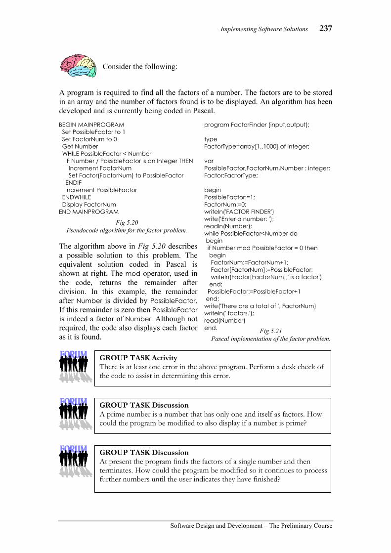
Implementing Software Solutions 237
Software Design and Development – The Preliminary Course
Consider the following:
A program is required to find all the factors of a number. The factors are to be stored in an array and the number of factors found is to be displayed. An algorithm has been developed and is currently being coded in Pascal.
The algorithm above in Fig 5.20 describes a possible solution to this problem. The equivalent solution coded in Pascal is shown at right. The mod operator, used in the code, returns the remainder after division. In this example, the remainder after Number is divided by PossibleFactor. If this remainder is zero then PossibleFactor is indeed a factor of Number. Although not required, the code also displays each factor as it is found.
BEGIN MAINPROGRAM Set PossibleFactor to 1 Set FactorNum to 0 Get Number WHILE PossibleFactor < Number IF Number / PossibleFactor is an Integer THEN Increment FactorNum Set Factor(FactorNum) to PossibleFactor ENDIF Increment PossibleFactor ENDWHILE Display FactorNum END MAINPROGRAM
Fig 5.20 Pseudocode algorithm for the factor problem.
program FactorFinder (input,output); type FactorType=array[1..1000] of integer; var PossibleFactor,FactorNum,Number : integer; Factor:FactorType; begin PossibleFactor:=1; FactorNum:=0; writeln('FACTOR FINDER') write('Enter a number: '); readln(Number); while PossibleFactor<Number do begin if Number mod PossibleFactor = 0 then begin FactorNum:=FactorNum+1; Factor[FactorNum]:=PossibleFactor; writeln(Factor[FactorNum],' is a factor') end; PossibleFactor:=PossibleFactor+1 end; write('There are a total of ', FactorNum) writeln(' factors.'); read(Number) end. Fig 5.21
Pascal implementation of the factor problem.
GROUP TASK Activity There is at least one error in the above program. Perform a desk check of the code to assist in determining this error.
GROUP TASK Discussion A prime number is a number that has only one and itself as factors. How could the program be modified to also display if a number is prime?
GROUP TASK Discussion At present the program finds the factors of a single number and then terminates. How could the program be modified so it continues to process further numbers until the user indicates they have finished?
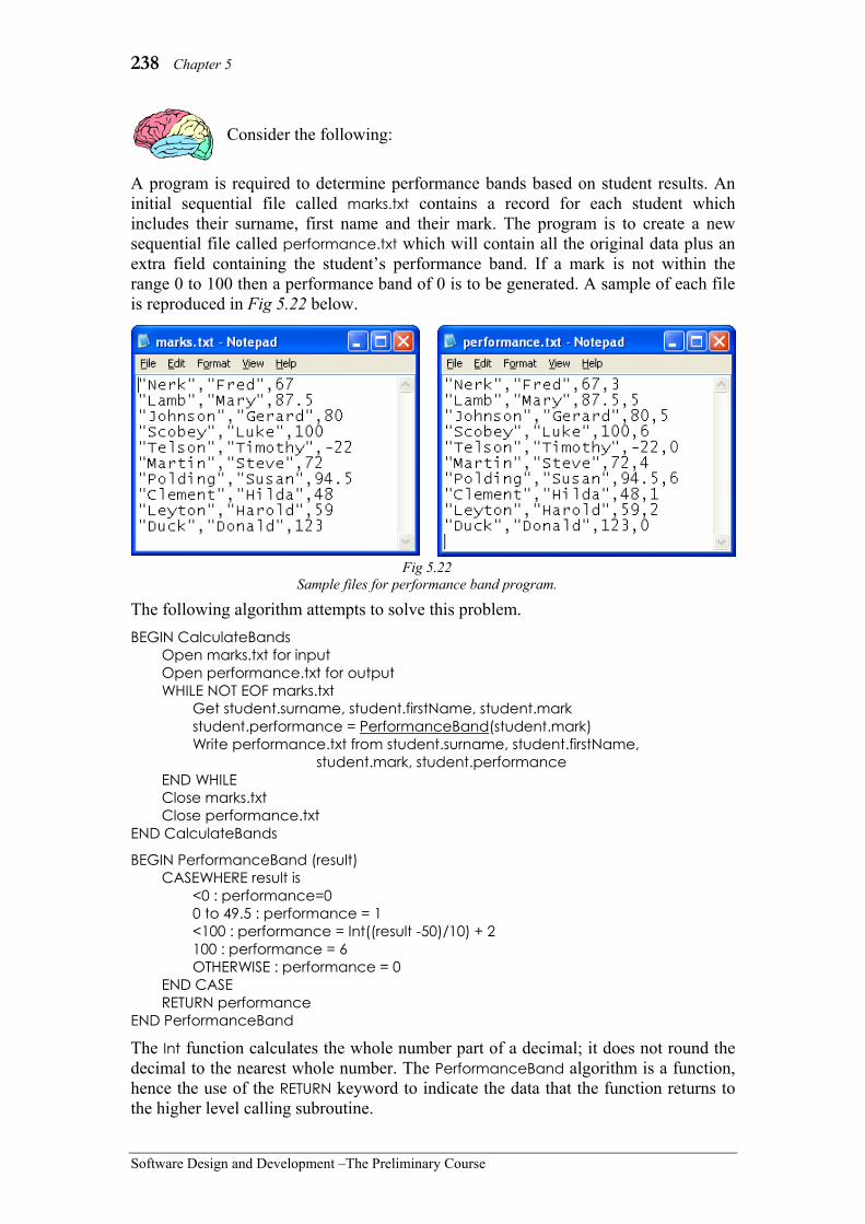
238 Chapter 5
Software Design and Development –The Preliminary Course
Consider the following:
A program is required to determine performance bands based on student results. An initial sequential file called marks.txt contains a record for each student which includes their surname, first name and their mark. The program is to create a new sequential file called performance.txt which will contain all the original data plus an extra field containing the student’s performance band. If a mark is not within the range 0 to 100 then a performance band of 0 is to be generated. A sample of each file is reproduced in Fig 5.22 below.
The following algorithm attempts to solve this problem. BEGIN CalculateBands Open marks.txt for input Open performance.txt for output WHILE NOT EOF marks.txt Get student.surname, student.firstName, student.mark student.performance = PerformanceBand(student.mark) Write performance.txt from student.surname, student.firstName, student.mark, student.performance END WHILE Close marks.txt Close performance.txt END CalculateBands
BEGIN PerformanceBand (result) CASEWHERE result is <0 : performance=0 0 to 49.5 : performance = 1 <100 : performance = Int((result -50)/10) + 2 100 : performance = 6 OTHERWISE : performance = 0 END CASE RETURN performance END PerformanceBand
The Int function calculates the whole number part of a decimal; it does not round the decimal to the nearest whole number. The PerformanceBand algorithm is a function, hence the use of the RETURN keyword to indicate the data that the function returns to the higher level calling subroutine.
Fig 5.22 Sample files for performance band program.

Implementing Software Solutions 239
Software Design and Development – The Preliminary Course
The above algorithms have been coded in Visual Basic .NET. Module Performance
Public Structure StudentRecord Public surname As String Public firstName As String Public mark As Double Public performance As Integer End Structure
Sub Main() Dim student As StudentRecord FileOpen(1, "c:\marks.txt", OpenMode.Input) FileOpen(2, "c:\performance.txt", OpenMode.Output) While Not EOF(1) Input(1, student.surname) Input(1, student.firstName) Input(1, student.mark)
student.performance = PerformanceBand(student.mark)
WriteLine(2, student.surname, student.firstName, student.mark, student.performance) End While FileClose(1, 2) End Sub
Function PerformanceBand(ByVal result As Double) As Integer Dim performance As Integer Select Case result Case Is < 0 performance = 0 Case 0 To 49.5 performance = 1 Case Is < 100 performance = Int((result - 50) / 10) + 2 Case Is = 100 performance = 6 Case Else performance = 0 End Select Return performance End Function End Module
GROUP TASK Discussion Perform a desk check of the PerformanceBand algorithm using the data shown in the above marks.txt file.
GROUP TASK Discussion Compare the above Visual Basic code with the algorithms on the previous page. Note and explain any differences. Code the algorithms in your choice of programming language.

240 Chapter 5
Software Design and Development –The Preliminary Course
SET 5B 1. The process of storing the value of an
expression in a variable is known as: (A) assignment. (B) declaration. (C) identification. (D) iteration.
2. Output statements are used for achieving what? (A) Obtaining data. (B) Sending data. (C) Setting variables. (D) Implementing control structures.
3. The name given to a variable, process or function is known as a(n): (A) identifier. (B) assignment. (C) declaration. (D) definition.
4. A constant can best be described as: (A) a data item that is required in more
than one place throughout the code and once declared, never changes its value.
(B) a data item, that never changes its value but is only required in one place in the code.
(C) a data item that is required in more than one place throughout the code and once declared, can have multiple values.
(D) None of the above. 5. Is it always necessary to define data
structures as user-defined data types? (A) Only if it uses a constant. (B) No, only for those data types that
are not included in the language. (C) Yes, even for those data types that
are included in the language. (D) Only if it uses a constant and that
constant changes value.
6. Input statements are used for achieving what? (A) Implementing control structures. (B) Obtaining data. (C) Sending data. (D) Setting variables.
7. Before a variable can be used within program code, it must first be: (A) defined and declared. (B) translated into machine code. (C) defined as a control structure. (D) identified by a keyword of the
language that is being used.
8. In most programming languages, an identifier must begin with: (A) a $ (dollar) symbol. (B) a # (hash) symbol (C) a letter. (D) an _ (underscore) character.
9. Variables can be declared: (A) using only predefined data
types. (B) using only user-defined data
types. (C) using both predefined or user-
defined data types. (D) Variables are not generally
declared.
10. In most languages, is it possible to concurrently read and write to a file? (A) Yes. (B) No. (C) Only if the input/output statements
have been written using the ReadIn/Write statement
(D) Only if the file is stored on a read/write storage device.
11. Some variables can be declared directly whereas others must have their structure defined first. Why is this the case? Explain using examples.
12. What is a data dictionary and what is its purpose?
13. Research a programming language you have never used. Give an example of an assignment, selection and iteration statement in this language.
14. The value of declared constants cannot be changed. What then, is the point of using declared constants?
15. Code the factor algorithm (see Fig 5.20) in a language with which you are familiar. Print out a copy of the source code.

Implementing Software Solutions 241
Software Design and Development – The Preliminary Course
ERROR DETECTION AND CORRECTION TECHNIQUES Errors can occur at all stages of software development. In most cases the earlier the error occurred in the development cycle the more difficult it will be to correct. For example, if a misunderstanding or oversight happens when defining and understanding the problem and it is not detected until the implementing stage, this will be more time consuming and costly to correct than a problem that first occurs during the implementing stage. It is vital to foster and maintain communication with all parties involved in the software’s development, including the end-users. Regardless of the time spent planning and documenting solutions, errors will occur and must be corrected. In this section we examine errors that occur when implementing or coding software in programming languages.
There are essentially three types of errors that can occur at the coding stage: syntax errors, runtime errors and logic errors. Syntax errors are simple to detect and correct. Runtime and logic errors can be more difficult to detect and correct. The next chapter on testing and evaluating software solutions examines techniques for detecting possible errors throughout the development cycle. In this section we concentrate on detecting and correcting errors during coding. In reality, the actual correction of the error is often a straightforward process. The more difficult task is to isolate the source of the error. In the Preliminary course, we examine three commonly used techniques: stubs, flags and debugging output statements. There are many other techniques available, some of which we shall consider in the HSC course.
TYPES OF CODING ERRORS
Before we commence examining techniques for correcting coding errors, we need to understand the different types of errors that commonly occur. Remember we are discussing coding errors. There are other sources of errors, which are not caused by faulty code. Syntax Errors
Syntax errors, as the name suggests, result when source code statements do not adhere to the rules of the programming language. All syntax errors will be detected as the source code is translated into object code. The translator, normally an interpreter or a compiler, is unable to understand code that contains one or more syntax errors.
In chapter 2, we discussed the translation process as being comprised of three main steps: lexical analysis, syntactical analysis and code generation. Lexical analysis ensures each element of the source code is a legitimate part of the language. Syntactical analysis ensures these elements are combined to form correct statements. The metalanguages examined earlier in this chapter define the rules used
GROUP TASK Discussion Errors occurring earlier in the software development cycle are usually more costly to correct as time goes on. Why is this so? Discuss.
Fig 5.23 Visual Basic checks the syntax of statements as they are entered.

242 Chapter 5
Software Design and Development –The Preliminary Course
during lexical and syntactical analysis. Errors encountered during lexical and syntactical analysis are collectively called syntax errors.
The editors that form part of most modern programming environments perform an analysis of the syntax of each statement as it is entered. Often different coloured text is used to visually differentiate between keywords, identifiers, operators and comments. This greatly reduces the number of syntax errors encountered during translation. However, these editors cannot find all such errors. It is not possible for them to know in advance the code that is yet to be entered. This is particularly the case with many of the control structures. For example, a missing ENDIF cannot be determined by an editor as it cannot determine where the ENDIF should be placed. During translation, the entire code is available and consequently the error can be determined.
Consider the following:
Earlier in the chapter we created a fictitious language called Winston. Fig 5.24 is the source code for a program written in Winston. This code contains a number of syntax errors.
Runtime Errors
Runtime errors occur when for some reason the computer is unable to continue executing instructions. We have all encountered runtime errors at some stage. For example, in Windows the all too familiar blue screen of death is the result of a runtime error causing the operating system to crash. Runtime errors can be caused by either hardware or software faults. The complexity of modern computer systems makes it almost inevitable that runtime errors will occur. To counteract this reality most systems, and programming languages, provide methods of dealing with errors when they occur. Visual Basic .NET, C++, Java and many other languages generate “exceptions” to allow programmers to catch and deal gracefully with many runtime errors. An exception is essentially a type of runtime error; disk overflows, invalid input, poor path name, and so on, are examples of common exceptions which should be handled. Essentially the programmer writes subroutines called “exception handlers” which are executed when an exception of a particular type occurs. The exception handler attempts to resolve the issue and resume execution. If the error means execution cannot continue then the exception handler can at least save any data and exit the program gracefully with a meaningful message.
It is possible to predict the nature of likely runtime errors and deal with them within the code itself. We have already seen some examples of this. For instance, when using files we should check the file exists before we begin reading and we can check inputs to ensure they are within the expected range before we begin processing. For example, the PerformanceBand function (page 239) dealt with negative and greater than 100 marks by generating a 0.
Start Input Dad Input Mum Set A to Dad + Mum Set A to A/2 When (A<Mum, Set B to Dad), Set B to Mum Output A Output B ‘ is an older age’ Stop
Fig 5.24 Source code for a short program written
using the fictitious language Winston.
GROUP TASK Activity Find and correct each syntax error in Fig 5.24.

Implementing Software Solutions 243
Software Design and Development – The Preliminary Course
Let us consider common runtime errors within the programs we write. Runtime errors cannot easily be anticipated or detected until the code is executing. Runtime and logic errors are not mutually exclusive; many logic errors will result in a runtime error. Possible causes of runtime errors include:
• Mathematical calculations that cannot be evaluated. For example, division by zero, attempting to find the square root of negative numbers and finding the tan ratio of 90 degrees. These problems often occur when unexpected data is entered.
• Inaccuracies due to non-exact floating point representations. For example, in single precision floating point 0.9999999 multiplied by 2 gives the result 2 rather than 1.9999998. In double precision floating point, we need to go to 14 decimal places before such errors occur. If a selection or iteration statement was based on such results, it is likely that incorrect sections of code would execute.
• Data that is out of the range of the identifier’s data type. For example, 16 bit integers have a range from -32768 to 32767. Calculations with results outside this range will result in a runtime error. Attempts to assign values to array elements outside the range of the index will also cause a runtime error.
• Infinite calls to subroutines. Often the result of unintentional recursive calls. Functions and procedures that include calls to themselves can easily result in an attempt to make infinite calls resulting in stack overflow runtime errors.
Logic Errors
Logic errors occur when programs do not correctly work as anticipated. The program may continue to execute, albeit incorrectly. For example, a loop may repeat fewer times than required, resulting in some data not being processed. The program contains a logic error yet the program still executes, it just doesn’t achieve its purpose correctly. Often a logic error is the cause of a runtime error that halts execution. For example, a program that calculates averages may cause a division by zero error if no data is input. The logic within the code is incorrect which results in a runtime error.
Logic errors are the most difficult errors to correct. A mistake in a single line of code can manifest itself in often unexpected ways. Identifying the precise source of the error can prove to be a laborious task. Often logic errors result from poor planning and design. Time spent ensuring the correctness of algorithms and system models will greatly reduce the number of logic errors encountered. Isolating the cause of a logic error can be accomplished using similar techniques to those used to check algorithms. Remember, algorithms are descriptions of the logic of the solution. Mistakes made when developing algorithms manifest themselves as logic errors in the final source code.
GROUP TASK Activity Deliberately write code that will cause a runtime error. Use exception handling or some other technique to catch and recover from this error.
GROUP TASK Discussion There are mathematical methods that can be used to prove the correctness of many algorithms, however the time required to create such proofs means it is an unreasonable task for even a small algorithm. For large applications mathematical proofs are impractical. Research and discuss practical strategies used to determine the correctness of large applications.

244 Chapter 5
Software Design and Development –The Preliminary Course
Consider the following:
A Visual Basic procedure has been written to tally up the number of A, B, C, D and Es stored in an array. The procedure does not work correctly yet no runtime errors occur. The results are almost correct the first time the procedure is called, however strange things seem to occur if subsequent calls are made from the same routine.
The input data for the procedure is the Grades array that is passed as a parameter to the procedure. This array contains up to 50 grades and is indexed from 0 to 49. The Total array is used to pass the results back to the calling routine. Total(0) holds the number of As, Total(1) the number of Bs, and so on.
DEBUGGING TECHNIQUES
Errors or defects that cause software to malfunction in some way are called bugs. Debugging is the process of identifying and correcting bugs. In this section we consider some commonly used techniques used to assist in the debugging process. The use of stubs, flags and debugging output statements are techniques allowing programmers to isolate the source of errors within source code. There are many other techniques, as well as many software tools, available to programmers. In the HSC course we examine many more of these techniques and tools. Stubs
As each higher-level subroutine is coded, it requires testing and debugging. Routines that call lower-level routines are difficult to test until these lower-level routines are coded. Stubs are used to alleviate this problem. A stub is a small routine that takes the place of a yet to be written subroutine or is substituted for an existing subroutine when attempting to locate the cause of an error.
Stubs allow the flow of execution to be checked before lower level subroutines are coded. They can also be used to temporarily replace subroutines when attempting to locate the source of an error. It is difficult to isolate the precise subroutine which is causing an error. It is often helpful to systematically replace each called subroutine with a simple stub which is known to return valid output.
Often a stub will set the value of appropriate variables or simply return valid output and then end. Sometimes an output statement may be included within a stub to indicate that a call has taken place. No real processing takes place within the stub, its purpose is to allow testing of the calling routine or to assist the debugging process.
GROUP TASK Discussion Examine the code in Fig 5.25. There are a number of logic errors. Find these errors and suggest methods for correcting each error.
Bug An error or defect in software or hardware that causes a program to malfunction.
Public Sub TallyGrades( ByVal Grades() As String, ByVal Total() As Integer) Dim Count As Integer For Count = 1 To 49 Select Case Grades(Count) Case "A": Total(0) = Total(0) + 1 Case "B": Total(1) = Total(1) + 1 Case "C": Total(2) = Total(1) + 1 Case "D": Total(3) = Total(3) + 1 Case Else: Total(4) = Total(4) + 1 End Select Next Count End Sub
Fig 5.25 Visual Basic procedure to tally grades.
(Including errors)

Implementing Software Solutions 245
Software Design and Development – The Preliminary Course
Consider the following:
The simple structure chart in Fig 5.26 describes the top-down design for a new software application. The main program will be coded first followed by the DoThis and DoThat routines. In other words the higher- level modules are coded first followed by the lower-level modules. This makes it difficult to test each module as it is coded.
When the main program is being coded, two stubs are written to take the place of the DoThis and DoThat subroutines. Similarly when the DoThis routine is being written, stubs are created to take the place of the GetIt and SortIt subroutines.
Flags
A flag is a Boolean variable used to check if a section of code has been executed. Normally the flag is initialised to false and then set to true if the section of code is executed. By examining the value of the flag, the programmer can determine the execution path through the code. Knowing the execution path is of great assistance when diagnosing the source of bugs. For example, when attempting to find the source of an error the statement setting the flag to true can be systematically moved through the code. If the flag is false then we are not following the execution path correctly, conversely if it is true then we are.
Often a flag will be used to confirm that a particular condition has been met. When debugging the programmer may suspect that say, a value becomes negative when it should not. A statement can be added to the code that sets a flag variable should this occur. For example, the Pascal statement TestFlag:= Average < 0 sets TestFlag to True if Average is negative. If Average is not negative then TestFlag is set to False.
Flags are not only used for debugging, they can form part of the logic of the solution. Often execution of particular sections of code depends on whether a certain condition has been met. Flag variables provide a mechanism for communicating this information to other parts of the program. For example, in the HSC course we examine a number of algorithms for sorting data. A flag is used to signal that the data is now sorted. As a consequence, the sort can end and execution can continue to other sections of code.
Fig 5.26 The top-down design for a fictitious program.
Main Program
DoThis1
DoThat 2
GetIt 1.1
SortIt1.2
FindIt 2.1
MixIt 2.2
GrabIt1.1.1
CheckIt1.1.2
GetInput 2.1.1
Shuffle 2.2.1
ReHash2.2.2
GROUP TASK Discussion It is normal to code software from the top down. Why do you think this is a more common method than coding from the bottom up? Discuss.
GROUP TASK Discussion Why bother creating stubs? Surely it would be better to code the entire project and then test and debug the total solution. Do you agree? Discuss.

246 Chapter 5
Software Design and Development –The Preliminary Course
Debugging Output Statements Output statements can be strategically placed within the code to indicate execution has passed through that point. They can also be used to display the contents of variables at particular points in the code. These statements are removed once the source code has been tested and the bugs removed. Often errors originating much earlier in the execution path do not surface until later in the code. By strategically displaying the contents of variables at crucial points, the source of many bugs can be determined. Debugging output statements are particularly useful to display the result of processes that are normally hidden from the user. For example, when reading data from a disk file it is helpful during development to include an output statement to display each data item obtained from the file immediately after it has been read. This allows the programmer to view the raw data prior to processing. Output statements are often used as part of a stub. A simple output statement confirming that a call to a subroutine has occurred in many cases is the stub. Output statements can also be used in conjunction with flags to alert the programmer that some condition has been met.
Consider the following:
Fig 5.27 shows a simple screen and Visual Basic procedure used to test and debug the TallyGrades procedure described in Fig 5.25. This code essentially opens a file and loads the grades into an array. The TallyGrades procedure is called and then the results are output. This code is known as a driver, its purpose is to test a lower- level routine.
GROUP TASK Discussion Slips of paper are used as bookmarks to flag certain pages. Flags are used by ships to communicate simple messages. White flags are carried as a sign of peaceful intentions. Discuss the similarities between these types of flags and the Boolean flags described above.
Fig 5.27 Example of a driver used for debugging.
Private Sub cmdOK_Click(ByVal sender As System.Object, ByVal e As System.EventArgs) Handles cmdOK.Click
Dim Grade(50) As String Dim Total(4) As Integer Dim c As Integer
FileOpen(1, "c:\grades.txt", OpenMode.Input)
c = 0 While Not EOF(1) And c <= 50 Input(1, Grade(c)) txtInput.Text = txtInput.Text & Grade(c) c = c + 1 End While
TallyGrades(Grade, Total)
For c = 0 To 4 txtOutput.Text = txtOutput.Text & " " & Total(c) Next
FileClose(1)
End Sub

Implementing Software Solutions 247
Software Design and Development – The Preliminary Course
Automated debugging tools
Most modern programming environments provide a variety of automated debugging tools to assist programmers locate and correct errors in their code. Common tools include breakpoints, single line stepping and setting watch expressions.
Breakpoints halt execution and allow the contents of variables at that point to be interrogated and even changed. Single line stepping causes execution to halt after each line of code is executed. A single key press causes the next line to execute. Watch expressions can be used to display the contents of variables during execution. They can also cause execution to halt when a certain condition becomes true.
Automated debugging tools can often be used instead of flags and debugging output statements. They can also provide a means for performing an automated desk check of the source code.
GROUP TASK Activity Examine the automated debugging tools available in a programming environment with which you are familiar. List and describe each of the available tools.
GROUP TASK Discussion How does the code in Fig 5.27 help to simplify the testing and debugging of the TallyGrades procedure? Discuss.
GROUP TASK Discussion There are three essential controls on the form shown in Fig 5.27. Can you work out the name and purpose of each of these controls?
Fig 5.28 Debugging in Visual Basic .NET
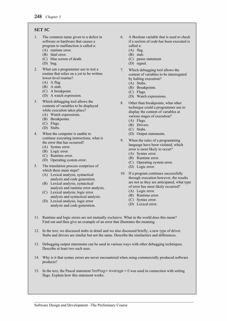
248 Chapter 5
Software Design and Development –The Preliminary Course
SET 5C 1. The common name given to a defect in
software or hardware that causes a program to malfunction is called a: (A) runtime error. (B) fatal error. (C) blue screen of death. (D) bug.
2. What can a programmer use to test a routine that relies on a yet to be written lower-level routine? (A) A flag. (B) A stub. (C) A breakpoint. (D) A watch expression.
3. Which debugging tool allows the contents of variables to be displayed while execution takes place? (A) Watch expressions. (B) Breakpoints. (C) Flags. (D) Stubs.
4. When the computer is unable to continue executing instructions, what is the error that has occurred? (A) Syntax error. (B) Logic error. (C) Runtime error. (D) Operating system error.
5. The translation process comprises of which three main steps? (A) Lexical analysis, syntactical
analysis and code generation. (B) Lexical analysis, syntactical
analysis and runtime error analysis. (C) Lexical analysis, logic error
analysis and syntactical analysis. (D) Lexical analysis, logic error
analysis and code generation.
6. A Boolean variable that is used to check if a section of code has been executed is called a: (A) flag. (B) stub. (C) pause statement. (D) signal.
7. Which debugging tool allows the content of variables to be interrogated by halting execution? (A) Stubs. (B) Breakpoints. (C) Flags. (D) Watch expressions.
8. Other than breakpoints, what other technique could a programmer use to display the content of variables at various stages of execution? (A) Flags. (B) Drivers. (C) Stubs. (D) Output statements.
9. When the rules of a programming language have been violated, which error is most likely to occur? (A) Syntax error. (B) Runtime error. (C) Operating system error. (D) Logic error.
10. If a program continues successfully through execution however, the results are not as they are anticipated, what type of error has most likely occurred? (A) Logic error. (B) Runtime error. (C) Syntax error. (D) Lexical error.
11. Runtime and logic errors are not mutually exclusive. What in the world does this mean? Find out and then give an example of an error that illustrates the meaning.
12. In the text, we discussed stubs in detail and we also discussed briefly, a new type of driver. Stubs and drivers are similar but not the same. Describe the similarities and differences.
13. Debugging output statements can be used in various ways with other debugging techniques. Describe at least two such uses.
14. Why is it that syntax errors are never encountered when using commercially produced software products?
15. In the text, the Pascal statement TestFlag:= Average < 0 was used in connection with setting flags. Explain how this statement works.

Implementing Software Solutions 249
Software Design and Development – The Preliminary Course
COMMONLY EXECUTED SECTIONS OF CODE Most programmers create and maintain their own library of source code. When new projects are being developed much of this code can be reused. In chapter 4, we discussed modularity as a method used to enhance the reusability of code. If modules are developed as self-contained units, then little or no modification will be required to reuse them in new projects.
There are also commercial, open source and public domain libraries where modules can be obtained. For example, many languages are able to use Active X controls and other .COM components. These components are available as compiled units (often dynamic linked libraries or DLLs) that provide enhanced capabilities to a variety of programming languages. Many programmers maintain a library of such components and controls for future use. There are currently many companies who specialise in the development and distribution of such components.
In this section, we consider the development of some standard routines suitable for inclusion in a library of code. We also consider methods of including and using code and modules from different sources within new projects. This includes adding the code to the project, calling the code and also sharing and passing data to and from different modules. DEVELOPING STANDARD SUBROUTINES FOR REUSE
When developing code for reuse, it is important to consider a more generic case than the one presented for the current project. Standard routines will be more useful if they solve a more generic case of the problem rather than the precise current problem. For example, a routine written to sort the data in an array would be more useful if it could sort both numerical and string data in either ascending or descending order.
If a routine can be written that requires no modification then we can thoroughly test the module when first developed and then use it with confidence in future software projects. More generic solutions are likely to require minimal changes to work within new projects.
Consider data validation:
Data validation is a process used by most software. Without a robust data validation routine, user input will often be the cause of runtime errors. It makes sense to develop standard routines to perform this process.
It is common practice to obtain user input as string data. The string is then analysed according to the validation rules appropriate to the particular variable and context. If the data is appropriate then no visible action takes place. On the other hand, if the data is out of the required range or is of the wrong type some corrective action is required.
Fig 5.29 Extra controls and other components can be added
and used within Visual Basic .NET.

250 Chapter 5
Software Design and Development –The Preliminary Course
Let us develop a Visual Basic routine for validating non-negative integers. The following general requirements have been formulated: • User input is to be in string form presumably via a text box control. This string
forms the input to the validation routine. • If the user enters any digits these will become the input. For example, a3&9.4
should be returned by the routine as 394. • The routine should also ensure the integer is within a specified range. For
example, if the input was a mark out of 100 then the range would be from 0 to 100.
• Any input that is inappropriate should result in a message box being displayed with an appropriate message. In this case the routine should return a default value.
An algorithm is first developed using pseudocode. This algorithm is reproduced below in Fig 5.30.
This algorithm is then coded as a Visual Basic function (see Fig 5.32). The function uses four parameters: the input string, the minimum value, the maximum value and the default value. Functions are used where a single value is returned, in this case the validated integer.
The Visual Basic code in Fig 5.32 on the next page uses a number of features and built-in methods (or functions). The lines commencing with three single quotes are used to document the function using XML code. Within the Visual Basic IDE typing three single quotes on the line before a subroutine causes an XML template to be automatically generated. This template can then be completed to summarise the purpose of the subroutine and each of its parameters. When calling the subroutine these comments appear as part of Visual Basic’s intellisense system (refer Fig 5.31). Many languages include similar features, such as Java’s JavaDoc system. These
GROUP TASK Activity Examine the input screens from a number of applications. Try entering inappropriate data on these screens and observe the feedback, if any, generated by the software’s validation routines.
BEGIN ValidateInteger(InputString,Min,Max,Default) WHILE more characters in InputString IF current character is a digit THEN Add the character to StringInteger ENDIF Move to next character in InputString ENDWHILE Set ValidInt to value of StringInteger IF StringInteger is empty OR ValidInt is not within Min to Max THEN Set ValidInt to Default Display message box prompt ENDIF RETURN ValidInt
END ValidateInteger Fig 5.30 Pseudocode for the integer validation problem.
GROUP TASK Discussion Examine the algorithm above. Describe in words the generic nature of the processing taking place to meet the stated requirements.

Implementing Software Solutions 251
Software Design and Development – The Preliminary Course
systems greatly improve the ability of code to be reused. In most cases it is unnecessary to examine the original source code as the comments provide sufficient information.
The Length function is a method which returns the number of characters in a string. The Substring method is used to extract part of a string. The first parameter in this function is the index of the first character to be extracted and the second is the length of the string to be extracted. Predictably, the IsDigit method returns true if the character is a valid digit and false if it is not and CInt converts the final string into an integer data type. ''' <summary> ''' Converts a string to a non-negative integer using all digits present within the string. If the result is not within the range Min to Max the default value is returned. ''' </summary> ''' <param name="InputString">The string to convert</param> ''' <param name="Min">The smallest acceptable integer</param> ''' <param name="Max">The largest acceptable integer</param> ''' <param name="DefaultValue">Return value if the integer is not in the range Min to Max</param> ''' <returns>Returns an integer</returns> ''' <remarks>Written By Sam Davis 3/2/2011</remarks>
Public Function ValidateInteger(ByVal InputString As String, ByVal Min As Integer, ByVal Max As Integer, ByVal DefaultValue As Integer) As Integer
Dim StringInteger As String = "" Dim TempChar As Char Dim Counter As Integer Dim ValidInt As Integer
'Consider each character in turn looking for digits For Counter = 0 To InputString.Length - 1 TempChar = InputString.Substring(Counter, 1) If Char.IsDigit(TempChar) Then StringInteger = StringInteger & TempChar End If Next Counter
'Convert string to integer ValidInt = CInt(StringInteger)
'Check for digits and that number is within the required range If StringInteger = "" Or ValidInt < Min Or ValidInt > Max Then ValidInt = DefaultValue MsgBox("A number from " & Min & " to " & Max & " is required.") End If
Return ValidInt
End Function Fig 5.32
Visual Basic code for the integer validation problem.
Fig 5.31 Visual Basic’s intellisense shows XML comments as you enter code.

252 Chapter 5
Software Design and Development –The Preliminary Course
The ValidateInteger function requires extensive testing before being included in a library of code. To perform this testing, a program is required that calls the new function. This driver program would then be used to test the function with various test data sets.
Consider login processes
Login processes are used to authenticate users. Authentication is the process of identifying a user using known information. For most software applications a username and password is used. The password is a secret string of characters that only the system and of course the user should know. Therefore the password can be used to authenticate that the user is who they claim to be during the login process.
Let us create a login subroutine in Visual Basic that is suitable for reuse and meets the following requirements.
1. Displays a form to get the username and password from the user. 2. Accesses usernames and encrypted passwords from a text file. 3. Stored passwords are encrypted using a one way hash algorithm such as SHA
(Secure Hash Algorithm) so access to the text file does not reveal passwords. 4. Is a function which returns a Boolean value – true if the user has been successfully
authenticated and false if they have not.
First we design the login screen using two textboxes and two buttons. For the password textbox we don’t wish the characters typed to be echoed on the screen. In Visual Basic textboxes have a PasswordChar property, which we set to * so that a * appears for each character typed. Form properties are set so that the OK button is the AcceptButton and the CancelButton is (predictably) the cancel button. Further properties are adjusted to produce the screen in Fig 5.33.
GROUP TASK Discussion A number of minor changes have been made to implement the ValidateInteger algorithm in Visual Basic. Describe these changes.
GROUP TASK Activity Design a suitable screen that could form the basis of a suitable testing program. Describe the nature of the test data sets required to ensure the correct operation of the function.
Fig 5.33 Screen design for VB login form.
GROUP TASK Activity Produce the form in Fig 5.33 using the IDE of a programming language such as Visual Basic .NET.

Implementing Software Solutions 253
Software Design and Development – The Preliminary Course
Visual Basic code for the OK and Cancel button click events follows. Public Class Login Public UserOK As Boolean = False
Private Sub OK_Click(ByVal sender As System.Object, ByVal e As System.EventArgs) Handles OK.Click
Dim UserName As String = "", Password As String = "" Dim SHAPassword As String Dim fullPath As String = Application.CommonAppDataPath & "\users.txt"
'Assume login will fail UserOK = False
If System.IO.File.Exists(fullPath) Then
'Authenticate the user SHAPassword = getSHA(PasswordTextBox.Text) FileOpen(1, fullPath, OpenMode.Input) While Not (EOF(1) Or UserOK) Input(1, UserName) Input(1, Password) UserOK = (UserName = UsernameTextBox.Text) And (Password = SHAPassword) End While FileClose(1)
'close the form if user is authenticated If UserOK Then Me.Close() Else MsgBox("Incorrect User name / Password combination") End If
Else MsgBox("Users.txt does NOT exist. Unable to login.") Me.Close() End If
End Sub
Private Sub Cancel_Click(ByVal sender As System.Object, ByVal e As System.EventArgs) Handles Cancel.Click UserOK = False Me.Close() End Sub End Class
GROUP TASK Activity Based on the above Visual Basic source code, produce a simplified pseudocode algorithm for the OK button’s click event.
GROUP TASK Discussion The system never stores the raw user passwords. How is this achieved and how does this help to secure the login process? Discuss.
GROUP TASK Discussion Explain the operation of the following line of code UserOK = (UserName = UsernameTextBox.Text) And (Password = SHAPassword)
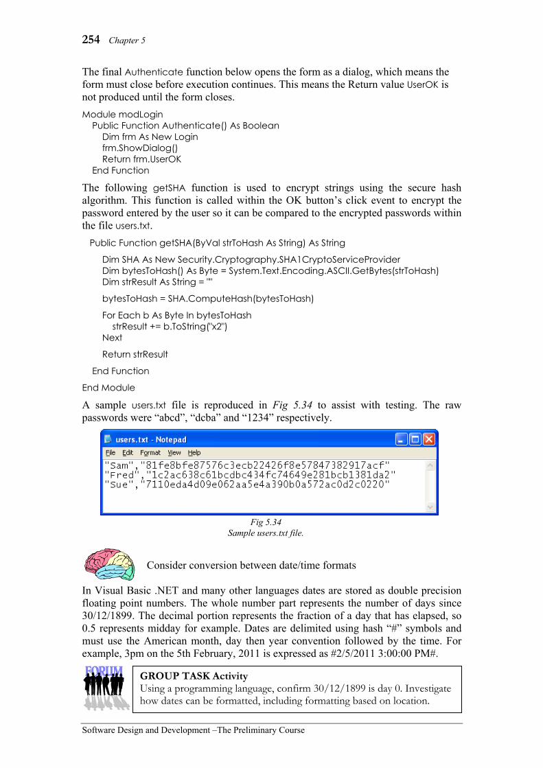
254 Chapter 5
Software Design and Development –The Preliminary Course
The final Authenticate function below opens the form as a dialog, which means the form must close before execution continues. This means the Return value UserOK is not produced until the form closes. Module modLogin Public Function Authenticate() As Boolean Dim frm As New Login frm.ShowDialog() Return frm.UserOK End Function
The following getSHA function is used to encrypt strings using the secure hash algorithm. This function is called within the OK button’s click event to encrypt the password entered by the user so it can be compared to the encrypted passwords within the file users.txt. Public Function getSHA(ByVal strToHash As String) As String
Dim SHA As New Security.Cryptography.SHA1CryptoServiceProvider Dim bytesToHash() As Byte = System.Text.Encoding.ASCII.GetBytes(strToHash) Dim strResult As String = ""
bytesToHash = SHA.ComputeHash(bytesToHash)
For Each b As Byte In bytesToHash strResult += b.ToString("x2") Next
Return strResult
End Function
End Module
A sample users.txt file is reproduced in Fig 5.34 to assist with testing. The raw passwords were “abcd”, “dcba” and “1234” respectively.
Consider conversion between date/time formats
In Visual Basic .NET and many other languages dates are stored as double precision floating point numbers. The whole number part represents the number of days since 30/12/1899. The decimal portion represents the fraction of a day that has elapsed, so 0.5 represents midday for example. Dates are delimited using hash “#” symbols and must use the American month, day then year convention followed by the time. For example, 3pm on the 5th February, 2011 is expressed as #2/5/2011 3:00:00 PM#.
Fig 5.34 Sample users.txt file.
GROUP TASK Activity Using a programming language, confirm 30/12/1899 is day 0. Investigate how dates can be formatted, including formatting based on location.

Implementing Software Solutions 255
Software Design and Development – The Preliminary Course
COMBINING CODE FROM DIFFERENT SOURCES
The simplest method of combining code from an outside source is to use the operating system’s clipboard to copy and paste the code. This technique works well for source code that is written in the same version of the same language. Changes are likely to be required if the code originates from a different version of the language. Remember, whenever changes are made, the code will require thorough testing to ensure its correctness is maintained.
Before a module of code can be called or used within a software project, it must be known to the programming environment. Different techniques are used depending on the nature of the code or module to be used. Once the code has been added to the project, its functions and procedures can be called in a similar way to subroutines written from scratch.
If source code has been copied and pasted then it becomes part of the source code for the total project and can be used as if it had just been written. Many modern programming environments allow modules of source code to be stored in single library files. These files can be imported into the current project. The functions and procedures within these modules are then available to the programmer. During translation these subroutines are compiled and included within the project’s executable files.
Most modern programming environments allow the inclusion of external modules of code. These modules can be in the form of compiled files such as dynamic link libraries, objects or new controls. Or the modules can be files containing source code. They extend the capabilities of the programming language. For example, Visual Basic controls can be written and compiled into separate files. These files can then be referenced and used in any Visual Basic application. Any external compiled modules used within the new application will need to be distributed with the new application unless you are sure each user’s machine will already have the required files.
Different programming environments will use different commands for using compiled modules. In all cases, the location, name of the component and the details of its parameters will need to be communicated to the programming environment. The format of these files includes all the properties, methods and events relevant to the component. Often this declaration occurs at the start of the project’s main program. Once the components have been added they can then be called and used within the source code.
When using code from other sources, the intellectual property rights of the author should be considered. Often code and modules are sold together with a licence permitting distribution and use within new applications. In most cases, a copyright notice acknowledging the source of the code or module must accompany the new application. In any case, it is unethical to use code created by others without first ensuring their intellectual property rights are upheld and any licensing requirements are fulfilled.
GROUP TASK Investigation For at least two different programming languages, investigate how external modules of code can be added so their subroutines can be called from your source code.

256 Chapter 5
Software Design and Development –The Preliminary Course
Calling modules or subroutines
Modules added to software projects will contain one or more subroutines. These subroutines can be either procedures or functions. In most languages the syntax used to call or execute subroutines written from scratch, and subroutines included from outside sources, is similar or in most cases identical. However, there are differences in the way a procedure call and a function call are implemented within the source code of all languages. • Procedure calls
The name given to a procedure is a special kind of identifier. This identifier does not have a data type, rather it is used by the programming language to locate the subprogram within the source code. In most languages, the use of a procedure’s identifier causes control to execute the associated procedure. In essence, the procedure’s name, together with any parameters, is the statement used to execute the procedure. For example, if a Visual Basic procedure has been written called DoThis it can be called using the statement Call DoThis or more simply by the statement DoThis. • Function calls
Functions are similar in most respects to procedures. However, the identifier used to name a function also has a data type. This data type defines the type of data that will be returned by the function. Functions should be designed to return a single data item via this return vale. This is why they are called functions. In mathematics, a function is defined to be a relationship where each set of inputs returns a single unique output. Subroutines written as functions should adhere to this definition. Unfortunately many programming languages do not enforce this rule. Function calls form part of expressions. For example, 5 + Cos(34) is an expression that calls the Cosine function using the value 34 as its parameter. The result is returned via the Cos identifier.
MAKING THE SAME DATA AVAILABLE TO DIFFERENT SUBROUTINES AND MODULES
There are two methods of sharing the data held in variables between subroutines in a software project. Firstly, the variable can be made available for access by the subroutine or module. This involves altering the scope of the variable so it is shared directly by the subroutines. Global variables are an extreme example where the variable can be accessed directly by all parts of the program. Secondly, the data can be passed to the subroutine via parameters. In chapter 4, we discussed the concept of parameters. Parameters are not variables, rather they are identifiers used to communicate data between subroutines within software. Wherever possible it is preferable to use parameters. Use of global variables makes it difficult to debug code and even more difficult to develop subroutines suitable for reuse.
GROUP TASK Activity Many commands included within programming languages are themselves subroutines. Consider some of the commands included in a language with which you are familiar. Describe each as either a procedure or a function. Compare your descriptions with other students.
Call To invoke a routine in a programming language. Calling a routine consists of specifying the routine name and, optionally, parameters.

Implementing Software Solutions 257
Software Design and Development – The Preliminary Course
• Sharing variables by altering their scope
The scope of an identifier is all the places within the program from which the identifier can be accessed. The idea of scope relates to all identifiers not just those associated with variables. For our current purposes let us restrict our discussion to variables.
Local variables can only be accessed by the subroutines in which they are declared. In this case other subroutines are unable to directly access these variables. To these other modules the variables simply do not exist. An instance of the local variable is created as the subroutine begins execution and is destroyed once the subroutine ends. If a subroutine is being called numerous times then its local variables will be created and destroyed numerous times.
Global variables, on the other hand, are available to other modules within the project. They are created as the program starts and are only destroyed when the program finally ends. It is normally considered bad practice to use global variables, however there are some exceptional circumstances where the use of global variables is convenient. When global variables are used extensively in larger projects, it becomes difficult to track how and where they are altered. Also, the use of global variables within projects makes it difficult to reuse subroutines and modules in other projects. They do however provide a simple mechanism for sharing variables between subroutines and modules.
Consider the following:
Different programming languages have different ways for determining the scope of variables. In Visual Basic you must explicitly declare variables as Public if you wish to use them globally. The scope rules for Pascal are more implicit. Let us consider Pascal’s scope rules in more detail.
Pascal programs are made up of blocks of code, each block generally being a procedure or function. Other blocks can also nest within these. The scope of a Pascal identifier includes all the statements that are within the block following its declaration. This includes any nested blocks within the block where the identifier was declared. Consequently, identifiers declared higher in the programs nested hierarchy will have a larger scope than those declared lower in the nested hierarchy. The only global variables are those declared in the main program’s block.
So what happens if the same name is used for multiple identifiers within the same block? In Pascal, the most local identifier declaration using that name is used. Higher-level identifiers of the same name are not available to that block of code.
Scope The extent or range of operation of an identifier. Where in a program, a given identifier may be accessed.
PROGRAM Sample… var This:Integer; . . . PROCEDURE Level1Sub1… var That: Integer; . . . PROCEDURE Level2Sub1… var Thing: Integer; . . . PROCEDURE Level3Sub1… var That:Integer; . . . PROCEDURE Level1Sub2… var That: Integer; . . .
Fig 5.35 In Pascal the scope of a variable is determined by the procedure
in which it is declared.

258 Chapter 5
Software Design and Development –The Preliminary Course
• Parameter passing The term ‘parameter passing’ can be misleading. In most cases the variable used as a parameter is not passed, rather a copy of the data held in the variable or the address in memory of the variable is passed. This is known as passing “by value” or passing “by reference” respectively. We discussed “by value” and “by reference” in Chapter 4 (page 202). This is a difficult concept, so it would be worthwhile reviewing this material. The most common and best way to share data between different subroutines is through the use of parameters. The use of parameters, rather than global variables, greatly assists in the development of reusable self-contained modules. In fact, global variables should not be used in modules that will be included in libraries of code, particularly if these modules are to be distributed and used by others. Consider the use of compiled modules of code. In these circumstances, there is no simple way of knowing the memory address of variables used by a particular subroutine. We have no alternative but to use parameters to communicate data to the subroutine. In fact, we do not even know or require the names of the identifiers used in the original source code, we just need to know their order and data type. For example, a square root function is available as a built-in function in most languages. There is no need for us to know the name of the identifier used as the parameter, rather we just need to know that it is a number and that the function will return a number.
Consider the following:
In most cases data is passed to subroutines “by value”. This requires a new local variable to be created by the called subroutine to store this data for the life of the call. For strings, integers and other standard data types the called subroutine is unable to alter the original data. However, when data structures (including arrays) are passed “by value”, the value passed is commonly a pointer to the original data structure in memory. Therefore the called subroutine creates a pointer variable which enables access to the original data structure and the data items it contains. Therefore the called subroutine is able to alter the original data items.
GROUP TASK Discussion Examine the diagrammatic representation of a typical Pascal program shown in Fig 5.35. Describe the scope of each variable used within this diagram. Pay particular attention to the three declarations that use the identifier That.
GROUP TASK Discussion In the above section, the use of global variables was fairly strongly discouraged in favour of using parameters. Make up a list of reasons why this is the case. Discuss your answers.
GROUP TASK Discussion Problems can occur when it is unclear whether a called subroutine will alter the original values held in actual parameter variables. Discuss likely issues that could occur.

Implementing Software Solutions 259
Software Design and Development – The Preliminary Course
SET 5D 1. What is generally considered to be the
most common and best way to pass variables between modules? (A) The use of parameters. (B) The use of sharing variables. (C) The use of function calls. (D) The use of procedure calls.
2. Variables that are available to all other modules within the software project are referred to as: (A) actual parameters. (B) global parameters. (C) function variables. (D) global variables.
3. What is the name given to a subroutine when its identifier has a data type and a value of this type is returned to the calling subroutine? (A) A procedure. (B) A function. (C) A call. (D) A variable.
4. With regards to variables, what is meant by the term ‘Scope’? (A) The extent or range of operation. (B) A call that specifies the routine to
be executed. (C) Where in a program, a given
identifier may be accessed. (D) Both A and C.
5. When developing code for reuse, it is important to develop generic code because: (A) It will then be suitable for inclusion
in a library of code. (B) It will have been thoroughly tested
at time of creation and therefore should only need minimal, if any modification for use in a new project.
(C) Programming time is saved. (D) All of the above.
6. To invoke a subroutine in a programming language is known by what term? (A) Process. (B) Parse. (C) Pass. (D) Call.
7. A subroutine can either be a: (A) procedure or function. (B) procedure or parameter. (C) function or variable. (D) parameter or variable.
8. Routines suitable for inclusion in a library of code should: (A) use global variables. (B) use parameters. (C) call other modules. (D) always be compiled.
9. What is normally used to communicate data to subroutines? (A) Local variables. (B) Global variables. (C) All variables. (D) Parameters.
10. Which of the following statements is correct? (A) A global variable is available to
other subroutines and is destroyed only when the program ends.
(B) A global variable is available to other subroutines and is created and destroyed each time a subroutine calls it.
(C) A global variable is available only to a single subroutine but is destroyed only when the program ends.
(D) A global variable is available to other subroutines and is never destroyed to ensure its availability.
11. Dynamic Link Libraries, Active X controls and the Windows API are all compiled modules of code. What advantages and disadvantages does this have for software developers?
12. How can altering the scope of a variable, be used to allow other modules access to required data items. Discuss.
13. Procedures and functions are different types of subroutines. What is the difference between the two in terms of how they are called by higher-level routines? Discuss.

260 Chapter 5
Software Design and Development –The Preliminary Course
14. Express the following Visual Basic code as an algorithm using a flowchart.
15. What do you think is the purpose of the above code? Is the code suitable for inclusion in a library of code? Justify your response.
Public Sub RandomLines(ByVal frm As Form, ByVal Numlines As Integer) Dim blackPen As Pen = Pens.Black Dim firstPoint As New Point(0, 0) Dim secondPoint As New Point(0, 0) Dim frmGraphics As System.Drawing.Graphics = frm.CreateGraphics() Dim currentLine As Integer = 0 Randomize() While currentLine < Numlines secondPoint.X = Int(frm.Width * Rnd()) secondPoint.Y = Int((frm.Height) * Rnd()) frmGraphics.DrawLine(blackPen, firstPoint, secondPoint) firstPoint = secondPoint currentLine = currentLine + 1 End While End Sub

Implementing Software Solutions 261
Software Design and Development – The Preliminary Course
USER INTERFACE DEVELOPMENT The user interface is all the screens, elements and actions that allow users to communicate with software. User interfaces should be intuitive, forgiving and consistent in their design. Processes that take some time to complete should provide feedback to the user. The design of the user interface to most users is the most significant consideration when purchasing and continuing to use a software product. Software developers must recognise this when developing new products.
DIFFERENT PERSPECTIVES OF USERS AND DEVELOPERS
Users often evaluate software primarily on the merits of its user interface. This is natural and to be expected. After all, the user interface is their method of communicating with the program. Users do not need to understand the processing going on behind the scenes. For example, when we print a document from a word processor we don’t consider the vast amounts of processing occurring. The word processor must convert the document to a form that can be understood by the printer’s driver. The driver must then turn this data into a form the printer understands and progressively send it to the printer. From the user’s perspective the document just prints, with perhaps some feedback displayed on the screen.
Developers view software from a different perspective. They must be aware of the underlying processes occurring. Most of the work involved in developing software concerns the correct planning, design and implementation of these processes. It is natural and right that developers concentrate on such matters. However, the user interface cannot be ignored if software products are to be a success for their users. The development team must include users as integral and important resources when developing software. This is particularly crucial when designing and creating the user interface.
CONSULTATION WITH USERS AND/OR MANAGERS
The user interface is for the use of users. Therefore, users must have input into its design and development. In chapter 3, we examined a number of software development approaches; the more recent approaches aim to ensure user consultation is ongoing and integral to the development process. Regardless of the software development approach being used, consultation with users in regard to the design and functionality of the user interface is crucial. Consider a developer creating an interface for a new peripheral device. The developer must know every detail of the commands and processes available within this device. The software has to interface as flawlessly as is possible with the peripheral. The same applies to the user interface, only we can’t just pick up a technical manual! Software developers must have a detailed understanding of user’s requirements if the software is to operate as flawlessly as possible. Consultation with users aims to achieve this detailed understanding.
User
Developer
Fig 5.36 Users and developers view software
from different perspectives.

262 Chapter 5
Software Design and Development –The Preliminary Course
A number of tools and techniques are available to ensure consultation with users results in user interfaces that meet the needs of users. Some tools and techniques include: • Observation – observing users onsite is perhaps the most useful technique for
obtaining accurate information in regard to user’s needs. This is particularly so in regard to determining work routines and flows.
• Storyboards – Shows the general design of each form within the interface together with how users navigate between forms within the interface.
• Prototypes – User needs are better expressed when they have a concrete model on which to comment. Prototypes of the user interface are invaluable in this regard.
• Questionnaires or surveys – questionnaires and surveys should include both structured and unstructured questions. Often more honest answers are obtained if the survey is anonymous.
• Meetings – meetings are generally fairly structured. Therefore they are particularly useful for resolving issues in a short time. Often decisions must be made about directions in which to proceed, meetings are great for this purpose.
EFFECTIVE USER INTERFACES Effective user interfaces meet the needs of users. Many of these needs will be specific to the current project being developed, others relate to more general aspects of good effective user interface design. In this section we examine a number of general points that should be considered when developing effective user interfaces. For convenience these points have been grouped under subheadings. Be aware that each aspect of the user interface will affect other aspects of the interface. For example, poor grouping of information will likely lead to more error messages. These error messages must be legible and make appropriate use of white space. • Factors affecting readability
use of white space judicious use of colour and graphics grouping of information legibility of text
• Prompts and messages effective prompts unambiguous and non-threatening error messages provision of feedback
• Consistency of design (see chapter 1, pages 25-32) • Social and ethical issues (see chapter 1, in particular pages 35-39)
GROUP TASK Discussion Observation, prototypes, questionnaires/surveys and meetings are useful in different ways. Their usefulness is dependant largely on the nature of the software project and the number of potential users. Think up scenarios where each tool/technique would be particularly suitable. Discuss.
GROUP TASK Discussion Surely the primary task of the user interface is to gather data and display information. If the user interface does this then it will be effective. Do you agree or disagree? Debate both sides.

Implementing Software Solutions 263
Software Design and Development – The Preliminary Course
Factors affecting readability
Readability is the ease with which a user can read and understand the written word. There are many scientific measures commonly used by authors, editors and publishers to assess the readability of documents. Most of these measures are based on the length of words, sentences and paragraphs. In terms of user interface design these measures are of limited assistance. It is rare to use full sentences, let alone paragraphs on a user interface. However, they do indicate that shorter more common words increase the readability of text.
Factors that are relatively minor, yet vital considerations for traditional paper-based documents, can have major effects on the readability of user interfaces. The user interface’s aim is to achieve intuitive understanding in an instant. Users should be able to take in the entire screen and intuitively deduce the purpose of each screen element and its relationship to those elements around it.
Let us consider some factors affecting the user’s ability to achieve this intuitive understanding: • Use of white space
We see white space all the time, yet often we are unaware of it. It is the portion of the user interface that isn’t there! White space is the area on the screen that is not used by screen elements. However, white space is a vital component on all user interfaces. White space need not be white. In the case of graphical user interfaces it is often grey and on command-based interfaces it is commonly black White space should be a neutral colour that does not attract or draw the user’s attention.
White space breaks up the screen into sections. It draws the user’s eye to important elements and highlights these elements. Consider the two magazine advertisements in Fig 5.38. Clearly the one on the right, uses large areas of white space to focus the reader’s eyes on the shirt box and hence the Cold Power logo. In comparison, the advertisement on the left does not clearly direct the reader to one particular element of the design. Although these are extreme examples, they do clearly illustrate the importance of white space.
Readability The ease with which the written word can be read and understood.
Fig 5.37 Microsoft Word provides readability
statistics. These measures are of little use when assessing the
effectiveness of user interfaces.
Fig 5.38 The use of white space in advertising. Example Magazine advertisements from the March 2002
Australian Women’s Weekly.
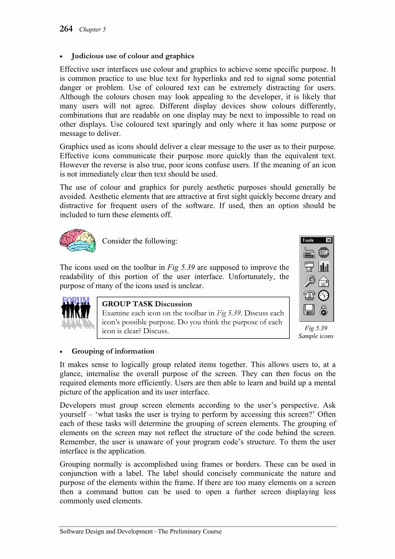
264 Chapter 5
Software Design and Development –The Preliminary Course
• Judicious use of colour and graphics
Effective user interfaces use colour and graphics to achieve some specific purpose. It is common practice to use blue text for hyperlinks and red to signal some potential danger or problem. Use of coloured text can be extremely distracting for users. Although the colours chosen may look appealing to the developer, it is likely that many users will not agree. Different display devices show colours differently, combinations that are readable on one display may be next to impossible to read on other displays. Use coloured text sparingly and only where it has some purpose or message to deliver.
Graphics used as icons should deliver a clear message to the user as to their purpose. Effective icons communicate their purpose more quickly than the equivalent text. However the reverse is also true, poor icons confuse users. If the meaning of an icon is not immediately clear then text should be used.
The use of colour and graphics for purely aesthetic purposes should generally be avoided. Aesthetic elements that are attractive at first sight quickly become dreary and distractive for frequent users of the software. If used, then an option should be included to turn these elements off.
Consider the following:
The icons used on the toolbar in Fig 5.39 are supposed to improve the readability of this portion of the user interface. Unfortunately, the purpose of many of the icons used is unclear.
• Grouping of information
It makes sense to logically group related items together. This allows users to, at a glance, internalise the overall purpose of the screen. They can then focus on the required elements more efficiently. Users are then able to learn and build up a mental picture of the application and its user interface.
Developers must group screen elements according to the user’s perspective. Ask yourself – ‘what tasks the user is trying to perform by accessing this screen?’ Often each of these tasks will determine the grouping of screen elements. The grouping of elements on the screen may not reflect the structure of the code behind the screen. Remember, the user is unaware of your program code’s structure. To them the user interface is the application.
Grouping normally is accomplished using frames or borders. These can be used in conjunction with a label. The label should concisely communicate the nature and purpose of the elements within the frame. If there are too many elements on a screen then a command button can be used to open a further screen displaying less commonly used elements.
Fig 5.39 Sample icons
GROUP TASK Discussion Examine each icon on the toolbar in Fig 5.39. Discuss each icon’s possible purpose. Do you think the purpose of each icon is clear? Discuss.

Implementing Software Solutions 265
Software Design and Development – The Preliminary Course
It is a good idea to show all possible elements that are on the screen; any inactive elements should be dimmed rather than hidden from view. Elements that seem to appear from nowhere surprise users, rather than enhancing the screen’s readability. Showing all screen elements gives the user an overall picture of all the available possibilities, further enhancing their mental picture of the application as a whole.
Readability is improved when an accurate mental picture of a program’s structure is efficiently and accurately created within the user’s mind. The logical grouping of screen elements is crucial if this is to occur.
Consider the following:
Parramatta Education Centre, the publisher of this text, also writes software to computerise various processes that are necessary to successfully operate a school. Fig 5.40 shows a screen from one of their reporting packages.
This screen is used to set-up each course prior to reports being written by teachers. Various methods of grouping elements are used. For example, frames are used around groups of radio buttons and groups of check boxes. Lines are used to group each major task on the screen.
• Legibility of text
Legibility of text refers to the user’s ability to make out each word and or character on the user interface. Primarily, the font used and how it is justified or aligned on the screen, influences legibility. Different fonts and methods of justification are suited to different uses. We need to understand how legibility is affected by our choice and use of fonts and justification.
A font is a complete set of characters that are of the same design. Each font is a particular example of a typeface. For example, Arial is a typeface and 10 point bold Arial is a font. 12 point italic Arial is another font that uses the Arial typeface. Therefore, each font possesses a series of properties; it uses a typeface e.g. Arial, a typestyle e.g. italic or bold and a size e.g. 10 point or 12 point.
Fig 5.40 Add/Edit Courses screen from a school’s reporting application. This application was developed using
MS-Access and Visual Basic using a RAD approach.
GROUP TASK Discussion Can you quickly understand the purpose of the screen in Fig 5.40 and each of its elements? Discuss how grouping of the screen’s elements assists in improving the readability of this screen.
10 point Bold Arial 12 point Italic Arial 14 point normal Arial
Fig 5.41 Three different fonts that all
use the Arial typeface.

266 Chapter 5
Software Design and Development –The Preliminary Course
Fonts can also be classified as either serif or sans serif fonts. Serifs are the little ticks or blobs attached to each end of the curves and lines that make up each character. Sans serif means, in French, no serifs. Hence sans serif fonts have no serifs and serif fonts do. Before the advent of the printing press, scribes used quills. It was very difficult to start and end a stroke neatly and squarely consequently serifs came into being. When the printing press was invented each character in a font was cast in lead. This casting occurred in a foundry. The word foundry is the source of the word fount, which was later shortened to font. It was now possible to create fonts of any design, including sans serif fonts.
So how do fonts affect legibility and as a consequence the readability of text? It depends on where the font is to be used. Written documents generally use serif fonts for the main body of the document and sans serif fonts for headings. Research has shown that serifs help the reader to more efficiently make out the shape of each character. They also assist in keeping the eye tracking across each line. The smaller the font then the more significant this becomes. Printed documentation and user manuals should reflect this research.
What about user interfaces? The resolution of a printed document is quite different to that of a computer monitor. Most books are printed using a resolution of at least 1200 dots per inch; monitors have a resolution of around 70 dots per inch. Command based systems often have a far lower resolution than this. Unfortunately this low resolution can often blur the serifs resulting in lowered legibility. Simple sans serif fonts are not affected to the same degree. Fig 5.43 shows an enlarged view of the letter ‘d’ as viewed on a typical monitor. The simpler shape of the sans serif version on the right makes it more legible. Remember, it is the simpler curves and lines that make the font more readable. A fancy sans serif font may be less legible than a basic serif font.
Modern GUI operating systems include settings where fonts can be specified for particular components of the user interface. This allows individual users the ability to customise fonts to suit their own personal needs. This is particularly important for those users with sight problems. Software developers should use these settings within their applications rather than forcing particular fonts on users.
The number of different fonts used on a single screen should be kept to a minimum. Remember even altering size or style results in a different font. Different fonts should only be used to convey meaning. Perhaps hints or informational items could be in italics whereas the rest of the screen uses a normal font. The extensive use of fancy fonts is generally unwise. The use of fancy fonts should be limited to headings where they are really performing an advertising function.
d serifs d no serifs
Fig 5.42 A serif font on the left and a sans serif font on the right.
Fig 5.43 Serifs are blurred on computer monitors.
GROUP TASK Activity Change the operating system settings to alter the fonts used by the system. Assess the effect of different fonts in terms of their affect on the legibility of the user interface.

Implementing Software Solutions 267
Software Design and Development – The Preliminary Course
Justification is how text is aligned to the margins. Left justified text is tight against the left margin. Similarly right justified text is tight against the right margin. Full justification means the text is spread evenly between both margins. Centred means the text is equidistant from both margins. Many word processors use the term alignment in preference to the term justification.
Most documents, including this book, are fully justified. Fully justified documents look more symmetrical and more importantly assist the reader to maintain their current position. As all text begins and ends at the same point it is easier for the brain to scan each line.
User interfaces rarely use multiple lines of text. However, they often contain lists of labels and other screen elements. In general all lists should be left justified. It is easier to absorb a list of items when each commences at the same point. Centred text should only be used for headings or for specialised elements such as command buttons. Right justification is used for numbers. This ensures the decimal points line up directly underneath each other.
Consider the following:
An input screen is required to gather and display client information. The fields to be included on this screen include: surname, first name, sex, street address, suburb, postcode, phone number, fax number, mobile number and email address. Two screen designs that formed part of the first and second prototypes have been created and are shown in Fig 5.45.
This text is left justified. This text is left justified. This text is left justified. This text is left justified.
This text is right justified. This text is right justified. This text is right
justified. This text is right justified.
This text is full justified. This text is full justified. This text is full justified. This text is full justified.
This text is centred. This text is centred. This text is centred. This
text is centred. This text is centred.
Fig 5.44 Justification is how text is
aligned to the margins.
Fig 5.45 Two screen designs for gathering and displaying client information.
GROUP TASK Activity Both the screen designs above have good and bad points. Discuss the merits of each design. Create a new screen design that incorporates the good features of each of the above designs.

268 Chapter 5
Software Design and Development –The Preliminary Course
Prompts and messages
The words used in both prompts and messages must be understandable from the point of view of the user. Prompts and messages aim to communicate their message in the most efficient and effective manner. Users are generally quite intolerant of computers, they expect to be in charge of the machine rather than have the machine control them. This is a reasonable situation; after all, the computer is just a machine. The text used in prompts and messages should take this into account. The use of threatening or condescending messages is certainly not appropriate. It is also poor form to attempt to humanise the computer by using pleases and thankyous. Keep prompts and messages straightforward and to the point. • Effective prompts
A prompt is a reminder or a cue as to what is required. For example, most stage productions have prompters standing in the wings. Their job is to prompt the actors using cues should any of them forget their lines. Prompts on user interfaces perform a similar task for users rather than actors. They must be concise yet they should accurately communicate their message.
A prompt is not the place to teach users about the details of the program. Neither is it necessary or desirable to embellish the wording of prompts. Consider the two prompts in Fig 5.46. The top one sounds nice and fuzzy and friendly when first read. What if you had to read it many times during each day? Suddenly the fuzzy and friendly becomes irritating and annoying. Obviously you need to enter a guess, if you didn’t then why is there a text box containing a flashing cursor. The bottom prompt in Fig 5.46 communicates the same message and is far less likely to irritate anyone.
Prompts are the main method of communicating with users. Most screen elements contain or are linked to prompts. Without them it would be impossible for users to understand and use software. It is well worth spending time considering the words used to ensure they correctly communicate the desired message.
Some general guidelines for developing prompts are: • Use verbs or doing words if choosing that screen element activates some process
or action. Often verbs are used on menus e.g. file, edit, print or format. The implication being that choosing one of these items will lead to some action being performed.
• If the prompt is merely used to gather data of some sort then the prompt should be a noun that describes the data e.g. Surname rather than Enter surname.
• It is common practice to use an ellipsis (…) after prompts that open new windows. The ellipsis also signifies that the item does not directly activate a process.
Fig 5.46 Prompts should accurately and concisely
communicate a single simple message.
GROUP TASK Activity Open a new document in a word processor. Examine each of the menus and dialogues available in this word processor paying close attention to the prompts used. Type up a list of all the prompts, together with a short description of their purpose.

Implementing Software Solutions 269
Software Design and Development – The Preliminary Course
• Unambiguous and non-threatening error messages
Messages are used to provide further information. Error messages are used to inform the user of some problem that has occurred. There are different types of errors that can occur and this should be reflected in the error message displayed. For example, a data validation error requires quite a different message to a runtime error that halts execution. In all cases the language used in error messages should clearly communicate the nature of the error in a concise and non-threatening way.
Error messages should identify the error and also provide some solution in a non-threatening way. Fig 5.47 is an error message from a school’s reporting system. The error has been identified i.e. the comment number was not in the database, and two possible solutions are suggested. The user is given the option to add the new comment directly or return and use a different comment. Notice that no blame is assigned to the user. The message states the problem without laying blame. If the message had read You entered comment number 1234 which does not exist… then the user could feel threatened, the implication being that they have stuffed up.
If the error is one that cannot be resolved, then this should be stated. For example, A fatal error has occurred and the application will be shut down. The error has been identified as a fatal one and the only solution is for the application to be terminated.
Often icons are used to indicate the severity of the error. Using these icons inappropriately is a common problem found in many applications. For example, Microsoft Photo Editor displays the error message shown in Fig 5.48 if the user enters a width that is out of range. This is not a critical error, rather it is a minor validation error. The use of the critical warning icon leads the user to expect the application to halt. In fact, no runtime error is generated and the application continues to operate flawlessly. An information icon, such as the one used in Fig 5.47 would have been more appropriate. The error message as it stands is ambiguous, the user is unsure of its meaning. • Provision of feedback
Feedback to users is crucial and should appear to be instantaneous. Feedback is required after the user initiates any action. The user should never be left wondering whether their actions have been successful.
In most cases, feedback is provided intuitively as the processing results in some obvious change to the interface or data. Some examples include, clicking on a check box resulting in a visual change, when a command button is clicked it appears to depress and entering data into a field causing the focus to move to the next field. Other processes occur in the background and take some time to complete. If a process takes longer than a second (0.1 second is preferable), then additional feedback is needed. Most users will tolerate waiting if they are confident that processing is occurring. If they are unsure, then they are likely to abort the application in the belief that an error has occurred.
Fig 5.47 Error messages should identify the error and
suggest some possible solution.
Fig 5.48 Inappropriate use of warning symbols leads to ambiguity.
270 Chapter 5
Software Design and Development –The Preliminary Course
The type of feedback required depends on the nature of the processing occurring. If the user can continue working whilst the process continues then the feedback can be subtler. For example, in most word processors a document can be printed in the background. In this case the feedback (Fig 5.49) does not interrupt the user.
Processes that require the user to wait require more obvious feedback. This feedback should provide an indication of the total time the process is likely to take and the time remaining. Often a window is used displaying a progress bar. Most installation or set-up programs provide this type of feedback. GUI operating systems use different icons for the mouse pointer as feedback. An hourglass is commonly used to inform the user that processing is occurring.
Consistency of design
The most important aspect of user interface design is consistency. Consistency within the application’s screens and consistency between applications. In chapter 1, (see pages 26) we considered consistency of the user interface in regard to ergonomics. Consistent user interfaces are easier to learn and are therefore easier to use. Skills learnt using other applications can be reused. The result being a more ergonomically sound application.
Each of the items examined in this section should be used consistently. Readability is greatly increased when user interfaces make consistent use of white space, colour, graphics, grouping and text. Prompts and messages should be consistent. Users should be able to predict the result of their actions. Consistency of user interface design promotes this ability in users.
Social and ethical issues
In chapter 1, we examined social and ethical issues in detail. From the user’s perspective, the user interface is the most vital component of most new software products. Thus, many of the issues in chapter 1 relate to user interface design. Developers have a responsibility to ensure social and ethical issues are considered and dealt with during the design and development of the user interface.
Fig 5.49 Subtle feedback
in MS-Word.
Fig 5.50 Progress bars provide feedback
for processes that take some time to complete.
GROUP TASK Activity Examine the different types of feedback provided by a number of applications. Make a list of all the different techniques you discover.
GROUP TASK Activity Revise chapter 1, pages 25-39. These pages deal with social and ethical issues relevant to the design of the user interface. Create a summary or outline of the important points from these pages.
GROUP TASK Activity Examine a number of applications in regard to the consistency of their user interface. List any items of inconsistency that you find.

Implementing Software Solutions 271
Software Design and Development – The Preliminary Course
A page setup screen for a graphics application is required to gather the following information:
• The size of the left, right, top and bottom margins. • Page orientation – either landscape or portrait. • The printer to which the document will be sent. • The final printed size of the graphic.
(a) Design a user interface for this page setup screen.
(b) Explain how the software could ensure that the data entered is appropriate. Suggested Solutions (a) (b) The paper size can be determined directly from the printer driver. If the user
enters margin or graphic sizes that will not fit then these values are automatically adjusted to fit the page size. The value just entered is retained wherever possible and the other values are altered and reflected within the preview frame. Inputs such as negative numbers or alphabetic characters simply cannot be entered. These techniques mean that it should never be necessary to generate error messages.
HSC style question:
272 Chapter 5
Software Design and Development –The Preliminary Course
SET 5E 1. When a complete set of characters are
said to be of the same design, together they are referred to as what? (A) A serifed font. (B) A typeface. (C) A typestyle. (D) A font.
2. The most important aspect of the design of a user interface is: (A) readability. (B) white space. (C) consistency.. (D) legibility.
3. The little ticks or blobs attached to the ends of the curves or lines that make up a character are called: (A) serifs. (B) sans serifs. (C) founts. (D) stylisers.
4. A reminder or cue of what is required of the user is known as a: (A) ellipsis. (B) message. (C) trigger. (D) prompt.
5. Lists of screen elements should generally be: (A) left justified. (B) right justified. (C) centred. (D) fully justified.
6. Of the four terms listed below, which refers to the way text is aligned to margins? (A) Equidistant. (B) Justification. (C) Centred. (D) Readability.
7. The ease with which the written word can be understood is referred to as: (A) readability. (B) interpretation. (C) legibility. (D) unambiguousness.
8. The ease with which the user can identify each character is referred to as: (A) readability. (B) legibility. (C) typefacing. (D) typestyling.
9. Which justification looks the most symmetrical? (A) Left justification. (B) Right justification. (C) Centred justification. (D) Full justification.
10. For a user interface to be effective it must: (A) show the user all the processing
going on in the background. (B) meet the needs of the user. (C) have lots of icons because users
prefer pictures to words. (D) have lots of colour so it will not be
so boring to use.
11. Users and developers view software quite differently. Discuss the implications of this, in terms of user interface development.
12. The Internet is now used to make voice calls. A new product is under development that will allow users to enter an Internet address (IP address) to talk to people. This causes a tune to play on the receiving person’s computer. Once they respond to this tune, the voice conversation can commence. Initial investigations have shown that a single screen is preferred for the products user interface. Create a screen design for this product.
13. Various factors affect the readability of the user interface. List and describe at least 4 such factors.

Implementing Software Solutions 273
Software Design and Development – The HSC Course
Use the following screen designs when answering questions 14 and 15.
14. Evaluate each of the above screens in terms of their effectiveness.
15. Redesign the screens to rectify any problems that you identified in question 14.

274 Chapter 5
Software Design and Development –The Preliminary Course
DOCUMENTATION There are essentially two unique audiences who will use documentation: developers and users. In this section, we first consider the documentation needs of each of these groups. We then examine internal documentation. Internal documentation is contained within the source code and is for the use of programmers and other developers who may wish to later understand the code. Online help is an important form of documentation for users. It forms part of the source code and is thus part of building a software solution. We examine different methods for including online help within software products.
DOCUMENTATION FOR DEVELOPERS
Documentation of software solutions should be ongoing throughout the software development cycle. Each stage of development produces various forms of documentation for developers. Each should be retained and updated to reflect changes made during development. This documentation will prove invaluable when modifications to the original product are required.
In the preliminary course, we have already touched on a number of different types of documentation used by developers. In the defining and understanding stage, we considered the development of a list of specifications and requirements for the project. We used techniques to create models of the system such as systems flowcharts, dataflow diagrams, IPO charts and structure charts. In the design stage data dictionaries and algorithms were created. The source code itself is perhaps the most vital form of documentation. It must be as readable as possible. Other items of documentation include test data and the associated results. The test data created to ensure the correct operation of algorithms will be reused to test that the source code performs as intended. Future maintenance programmers will also reuse test data to confirm the correctness of their modifications. In the HSC course we further expand and formalise many of these techniques and tools. Each forms an important part of the documentation for both current and future developers.
Documentation developed in one stage of the software development cycle provides information for the next stage. For example, the requirements are developed into a top-down design for the project. This top-down design is then used as the framework for developing algorithms. These algorithms describe the logic required when coding the solution in a programming language. Each form of documentation should be retained even after the project has been completed and implemented. Future maintenance and modifications to the product to either correct errors or to add new functionality are greatly simplified when the original documentation is available and accurate.
GROUP TASK Activity Make a list of all the types of documentation examined so far in this course. Write a brief description describing the purpose of each.
Fig 5.51 Documentation from one
stage provides information for the subsequent stages.
Defining and understanding the
problem
Planning and designing software solutions
Implementing software
solutions
Testing and evaluating
software solutions
Maintaining software
solutions

Implementing Software Solutions 275
Software Design and Development – The Preliminary Course
Let us examine documentation of the source code itself. This is known as internal documentation and is vital if our code is to be read and understood. Internal Documentation
Internal documentation is for the use of developers. It is designed to make the programming code readable. Understanding source code written by others is often a difficult and time-consuming task. After a period of time it is even difficult to quickly understand your own code. Internal documentation aims to alleviate this situation. The use of internal documentation has no effect on the translation process; it is purely for the benefit of programmers.
Although we have not formally discussed source code documentation, we have nevertheless been using it throughout this chapter. The use of meaningful identifiers was first introduced when writing algorithms. We continued this practice when writing programming code. For example, using the identifier Average rather than A or txtSurname rather than S. Similarly, when writing pseudocode we indented within each control structure. The practice was continued when coding solutions.
The use of identifier names that describe their purpose is often called intrinsic documentation. Intrinsic means ‘belonging to or part of’, meaningful identifiers are functional parts of the code, hence the term intrinsic documentation.
Other internal documentation we’ve used includes comments and white space within the source code. Comments are used to describe the purpose of the code or to explain the logic of unusual or difficult to understand processes. Comments can also be used to record details in regard to the programmers name and when the code was written. If the code is later modified then further comments would be added to update this information. Blank lines are used to provide white space between logical blocks of code. White space visually separates the code making it more readable.
Consider the following:
Earlier in this chapter, we developed a function for validating integers. The Visual Basic code is reproduced below – first without internal documentation and then with internal documentation. Both these implementations perform exactly the same task, in fact, once compiled they would be identical in all respects.
Fig 5.52 Visual Basic code for the integer validation problem shown without documentation.
Public Function ValidateInteger(ByVal I As String, ByVal M1 As Integer, ByVal M2 As Integer, ByVal D As Integer) As Integer Dim S As String = "", T As Char, C As Integer, V As Integer For C = 0 To I.Length - 1 T = I.Substring(C, 1) If Char.IsDigit(T) Then S = S & T Next V = CInt(S) If S = "" Or V < M1 Or V > M2 Then V = D MsgBox("A number from " & M1 & " to " & M2 & " is required.") End If Return V End Function

276 Chapter 5
Software Design and Development –The Preliminary Course
''' <summary> ''' Converts a string to a non-negative integer using all digits present within the string. If the result is not within the range Min to Max the default value is returned. ''' </summary> ''' <param name="InputString">The string to convert</param> ''' <param name="Min">The smallest acceptable integer</param> ''' <param name="Max">The largest acceptable integer</param> ''' <param name="DefaultValue">Return value if the integer is not in the range Min to Max</param> ''' <returns>Returns an integer</returns> ''' <remarks>Written By Sam Davis 3/2/2011</remarks>
Public Function ValidateInteger(ByVal InputString As String, ByVal Min As Integer, ByVal Max As Integer, ByVal DefaultValue As Integer) As Integer
Dim StringInteger As String = "" Dim TempChar As Char Dim Counter As Integer Dim ValidInt As Integer
'Consider each character in turn looking for digits For Counter = 0 To InputString.Length - 1 TempChar = InputString.Substring(Counter, 1) If Char.IsDigit(TempChar) Then StringInteger = StringInteger & TempChar End If Next Counter
'Convert string to integer ValidInt = CInt(StringInteger)
'Check for digits and that number is within the required range If StringInteger = "" Or ValidInt < Min Or ValidInt > Max Then ValidInt = DefaultValue MsgBox("A number from " & Min & " to " & Max & " is required.") End If
Return ValidInt
End Function Fig 5.53
Visual Basic code for the integer validation problem shown with documentation.
GROUP TASK Discussion How can it be that the code in Fig 5.52 performs identically to the code in Fig 5.53? Discuss.
GROUP TASK Activity Identify each type of internal documentation included in Fig 5.53. How does each of these affect the readability of the code?
GROUP TASK Activity Create a data dictionary to define the data used in the Fig 5.53 version of the above ValidateInteger function.

Implementing Software Solutions 277
Software Design and Development – The Preliminary Course
DOCUMENTATION FOR USERS
Most forms of user documentation are designed to teach users about the operation of some aspect of the software product. Possible user documentation includes installation guides, user manuals, reference manuals and tutorials. Traditionally these have been provided in printed form. It is now more common for these to be stored and accessed electronically. In many cases, they are linked to the application’s online help system. This allows users to quickly access help information relevant to the area in which they are currently working.
The provision of online help is part of building a software solution in a programming language. Many languages provide various facilities to assist programmers with this task. Let us consider types of online help and how it can be included within the source code of projects.
Online help Most commercial applications provide online help. Online help is provided as an integral part of these applications. The major advantage of online help compared to printed documentation is that it can be context sensitive. The user is presented with help associated with the task currently being completed. Online help can be provided in a number of ways. Most GUI operating systems provide applications that automate the display of help topics. They also specify standards for help systems to encourage consistency between applications and the operating system. Utilising such facilities means that users are likely to be familiar with the format and functionality available within the help system. The major help system for most applications is like an online reference and user manual combined into one. Reference manuals contain items in alphabetical order whereas user manuals generally are arranged in a logical sequence of topics. Online systems allow these manuals to be combined into one. The contents view displaying like a user manual and the index being used like a reference manual. Many applications also include online tutorials and wizards to lead and teach users new or unfamiliar tasks. Another common type of help is the use of tool tips and what’s this or balloon help. Tool tips are small windows containing a brief description of the current screen element. These windows popup when the user holds the mouse pointer over a screen element for longer than a second. Once the user moves the mouse pointer off the element the window closes. Balloon and What’s this help requires the user to actively select the option. Once selected, the user can click on elements and a short description of the function of the element is displayed.
GROUP TASK Activity Examine a number of applications installed on your school or home computer. What forms of printed and electronic documentation is provided with these products?
Fig 5.55 Tool tips provide brief descriptions of screen
elements.
Fig 5.54 A help screen from Winfax Pro
showing contents and index options.

278 Chapter 5
Software Design and Development –The Preliminary Course
Consider the flowchart algorithm for a subroutine:
(a) (i) What is the purpose of the algorithm?
(ii) Suggest more meaningful names for each of the identifiers A, B, C, D and E.
(b) The use of meaningful variable names is one feature that improves the maintainability of source code. Identify and describe THREE other features that improve the maintainability of source code.
Suggested Solutions
(a) (i) The algorithm calculates and displays the average of all elements indexed from 1 to 1000 within the array D.
(ii) A – CalcAverage, B – Count, C – Sum, D – arrNumbers, E – Average.
(b) Use of white space to visually split different logical blocks of code. This greatly improves readability for future programmers.
Comments in code to explain what the code does. This makes understanding the code simpler for future maintenance programmers. Comments should also be added to indicate when and who made changes.
Indent statements within control structures to visually separate them from the control structure statements. This greatly simplifies understanding of the source code as programmers can see the overall logic at a glance.
Always using standard sequence, selection and iteration control structures. This makes the code much easier to follow and understand. If unconditional jumps and other non-standard structures are used then following the logic becomes difficult. Standard control structures allow maintenance programmers to more easily comprehend the logic.
Each subroutine should solve a single well defined problem within the larger problem. When modifying and testing a program it is much easier to comprehend the processing when a single well defined task is accomplished within each subroutine.
GROUP TASK Activity Examine the tools available to assist in the provision of online help within a programming environment with which you are familiar. Try them out!
HSC style question:
BEGIN A
END A
B = 0 C = 0
B = B + 1
C = C + D(B)
E = C/B
Display E
Yes
No B < 1000

Implementing Software Solutions 279
Software Design and Development – The Preliminary Course
CHAPTER 5 REVIEW 1. Which debugging tool causes execution
to halt after each line of code has been executed? (A) Watch expressions. (B) Breakpoints. (C) Single line stepping. (D) Stubs.
2. Of the four forms of documentation listed below, which is considered to be internal documentation? (A) Tutorial. (B) Installation guide. (C) Online help. (D) Comments within the source code.
3. Of the metalanguages referred to in this text, which one requires an element to be included twice if it is required one or more times? (A) Both EBNF and railroad diagrams. (B) EBNF. (C) Railroad diagrams. (D) None of the above.
4. A mathematical calculation that cannot be evaluated, will most likely result in which kind of error(s)? (A) Runtime error. (B) Lexical error. (C) Syntax error. (D) All of the above.
5. Dataflow diagrams, IPO charts and structure charts are all forms of documentation for whom? (A) The developers. (B) The users. (C) Future maintenance programmers. (D) Both (A) and (C).
6. Identifier names that describe their purpose are often referred to as what type of documentation? (A) Source code documentation. (B) Internal documentation. (C) Intrinsic documentation. (D) Reference manual documentation.
7. With regards to the EBNF metalanguage, what is used to indicate the selection control structure? (A) A vertical line. (B) A horizontal line. (C) A double quote. (D) Square brackets.
8. Which form of user documentation is usually arranged in alphabetical order? (A) User manual. (B) Tutorial. (C) Reference guide. (D) Installation manual.
9. With regards to railroad diagram construction for this course, the selection control structure is represented how? (A) Using a series of branches. (B) Using flowlines. (C) Using rectangles. (D) Using circles.
10. An online wizard is what form of documentation? (A) User documentation. (B) Internal documentation (C) Intrinsic documentation. (D) Source code documentation.
11. Create an EBNF production and also a railroad diagram to describe the syntax of the pseudocode CASEWHERE structure.
12. Explain the steps required to use a record data structure within a program.
13. Explain how stubs, flags and debugging output statements, can assist with correcting errors in code.
14. What qualities are necessary in a code module if it is to be included within a library of code?
15. List and briefly describe as many types of documentation as you can. Indicate items designed for users and items designed for developers.

280 Chapter 6
Software Design and Development –The Preliminary Course
In this chapter you will learn to: • determine the expected result given test data
• compare the actual output from a piece of code with the expected output from test data to detect logic errors
• create a set of appropriate test data and use it to verify the logic in a solution
• perform a desk check by producing a table showing the changes to the content of variables as the algorithm or code is stepped through manually
• critically evaluate their work and that of their peers
• share good aspects of their solutions and the solutions of others
Which will make you more able to: • identify the issues relating to the use of software
solutions
• investigate a structured approach in the design and implementation of a software solution
• use and justify the need for appropriate project management techniques
• use and develop documentation to communicate software solutions to others
• describe the skills involved in software development
• communicate with appropriate personnel throughout the software development process
• design and construct software solutions with appropriate interfaces
In this chapter you will learn about: Testing the solution
• the selection of appropriate test data, including: – data that test all the pathways through the algorithm – data that test boundary conditions ‘at’, ‘above’ and
‘below’ values upon which decisions are based – data where the required answer is known – data which is outside the expected values
• the need for thorough test data
• testing both algorithms and coded solutions with test data such as: – desk checking an algorithm – stepping through a coded solution line by line
• peer checking
• structured walk through
Evaluating the solution
• comparing different solutions to the same problem – different interpretations of the design specifications – the advantages and disadvantages of different approaches
to a solution
• checking the solution to see if it meets the original design specifications
• the importance and use of user feedback
• the importance of checking that social and ethical perspectives have been appropriately addressed
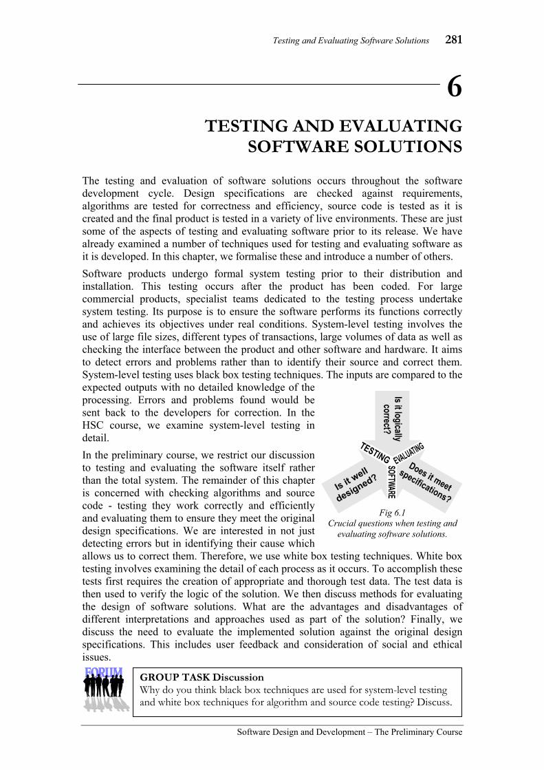
Testing and Evaluating Software Solutions 281
Software Design and Development – The Preliminary Course
6 TESTING AND EVALUATING
SOFTWARE SOLUTIONS The testing and evaluation of software solutions occurs throughout the software development cycle. Design specifications are checked against requirements, algorithms are tested for correctness and efficiency, source code is tested as it is created and the final product is tested in a variety of live environments. These are just some of the aspects of testing and evaluating software prior to its release. We have already examined a number of techniques used for testing and evaluating software as it is developed. In this chapter, we formalise these and introduce a number of others. Software products undergo formal system testing prior to their distribution and installation. This testing occurs after the product has been coded. For large commercial products, specialist teams dedicated to the testing process undertake system testing. Its purpose is to ensure the software performs its functions correctly and achieves its objectives under real conditions. System-level testing involves the use of large file sizes, different types of transactions, large volumes of data as well as checking the interface between the product and other software and hardware. It aims to detect errors and problems rather than to identify their source and correct them. System-level testing uses black box testing techniques. The inputs are compared to the expected outputs with no detailed knowledge of the processing. Errors and problems found would be sent back to the developers for correction. In the HSC course, we examine system-level testing in detail. In the preliminary course, we restrict our discussion to testing and evaluating the software itself rather than the total system. The remainder of this chapter is concerned with checking algorithms and source code - testing they work correctly and efficiently and evaluating them to ensure they meet the original design specifications. We are interested in not just detecting errors but in identifying their cause which allows us to correct them. Therefore, we use white box testing techniques. White box testing involves examining the detail of each process as it occurs. To accomplish these tests first requires the creation of appropriate and thorough test data. The test data is then used to verify the logic of the solution. We then discuss methods for evaluating the design of software solutions. What are the advantages and disadvantages of different interpretations and approaches used as part of the solution? Finally, we discuss the need to evaluate the implemented solution against the original design specifications. This includes user feedback and consideration of social and ethical issues.
GROUP TASK Discussion Why do you think black box techniques are used for system-level testing and white box techniques for algorithm and source code testing? Discuss.
Fig 6.1 Crucial questions when testing and
evaluating software solutions.

282 Chapter 6
Software Design and Development –The Preliminary Course
TEST DATA FOR CHECKING ALGORITHMS AND CODE Test data is made up of sets of inputs. Each test data set is input into either the algorithm or the coded solution and the processing and outputs are observed. Remember in this chapter we are concerned with checking algorithms and code rather than system-level issues. Therefore the creation of test data sets, aims to ensure that all processes are thoroughly checked and verified. To do this efficiently requires an intimate knowledge of the underlying logic within the algorithm or code. The test data should be thorough but it should also be efficient. There is little point including multiple test data sets that check identical scenarios. Similarly, it is more efficient to choose test data where the expected outputs are available or can be readily calculated. As we are interested in checking the logic of algorithms and source code, each set of test data will be designed to check some particular processing scenario. To do this effectively requires that we know the expected outputs for each test data set. Also there should be a reason for the inclusion of each test data set; each set should have a purpose. The results of our tests can then be compared with the expected results. Inconsistencies between the actual and expected outputs highlighting errors for further examination. As the purpose of the test data causing the error is known then identifying the source of the error is simplified.
Consider the following:
Parramatta Education Centre develops and distributes a software product for estimating ATARs. The ATAR Estimator uses statistics from the previous five HSC examinations to calculate these estimates. If a set of courses and HSC marks is entered then the software calculates the ATAR a student who achieved those results would have attained in each of the five preceding years. The theory being that if there is little difference between each of these five results it is unlikely the ATAR would change significantly for the current year. To verify the correctness of the product a large number of test data sets are required. These data sets are provided voluntarily to Parramatta Education Centre anonymously by a number of schools. Unfortunately schools are not informed of the ATARs their students achieve. However many schools contact students to obtain their ATAR.
GROUP TASK Discussion Describe the nature of the test data sets and expected outcomes used to test this product. The expected outcomes for each set of data are not always accurate particularly for lower UAIs. Explain why this may be the case? What effects could this have on the testing process? How could these effects be minimised?
Fig 6.2 Screen from the UAI/ATAR Estimator Version 13.0
developed by Parramatta Education Centre.

Testing and Evaluating Software Solutions 283
Software Design and Development – The Preliminary Course
THE SELECTION OF APPROPRIATE TEST DATA Test data sets should be selected to test different processing scenarios. These different scenarios are designed to ensure every statement is executed (statement coverage testing) and every boundary condition is tested (decision coverage testing). Furthermore, the order in which statements are executed will affect the processing therefore every path through the algorithm or code must be executed by our test data if we are to be sure of its correctness; this is known as path coverage testing. Of course we must also know the expected output for each set of test data if we are to accurately assess the results of our analysis. Statement, decision and path coverage tests are not mutually exclusive, in fact path coverage testing always includes statement coverage testing. For this reason we need not consider statement coverage testing in detail. Be aware that it is used to significantly reduce the number of test cases; albeit with reduced effectiveness. Actually statement coverage tests are more often used to find code that can never be executed rather than to test the code’s correctness. Many large software products that have been revised over numerous years can contain large amounts of redundant code. Let us now consider path and decision coverage testing in more detail:
Testing all pathways through the algorithm or code To be confident about the correctness of our code requires testing each and every possible execution path. This process is known as path coverage testing. It requires a unique set of test data for each possible path; Fig 6.3 shows a single path through a typical algorithm. Each binary selection statement creates two possible paths; if our code contains two binary selection statements we would have a maximum of four possible paths. A module of code containing five binary selections would have a maximum of thirty two paths. The number of test data sets required increases exponentially for each extra condition within the code. At first glance we would say it doubles for each extra condition; however nested control structures reduce this situation somewhat. For example a binary selection containing one other nested binary selection actually has three possible paths rather than four. Even in small software products the number of paths can soon run into the hundreds or even thousands. Large products can often require millions of sets of test data. Repetition structures often have an unknown number of paths so in reality the number would be far greater than even this! Fortunately, there are testing CASE tools available to assist when creating test data and checking code. When checking algorithms the situation is more difficult. Compromises are often made to reduce the number of test data sets required. The best way to reduce the total number of pathways is to test each subroutine independently. If subroutines have been written as self contained units then each can be tested in the knowledge that it does not effect the processing within other subroutines. The top-down design of the program can be used as a template when designing testing procedures. Bottom-up testing involves testing the lowest level subroutines first and progressively working upwards to the main program. A small driver routine is created to call the subroutine currently being tested. Top-down testing commences with the
Fig 6.3 The grey line indicates a
single execution path through this algorithm.
284 Chapter 6
Software Design and Development –The Preliminary Course
main program and works down through the hierarchy to the lowest level modules. A stub is required to take the place of each lower level subroutine. It is normal practice to check post-test iterations using data that causes the body to execute once and more than once. For pre-test repetition, data should be included to cause the body of the loop to execute zero and more than zero times.
Testing boundary conditions Selection and repetition control structures use the results of conditions to determine their actions. These conditions, if incorrect, are likely to result in major errors. For this reason all conditions require close examination during testing. We should ensure each condition is checked using test data above, below and equal to any values upon which decisions are based. This is known as decision coverage testing. For example, the condition Counter < 2 should be tested using a value greater than 2, less than 2 and equal to two. The situation becomes more complicated as the complexity of the condition increases. Many conditions contain logical or and and operators and others are based on values that are calculated by previous processes. In these cases, it is often appropriate to test the condition in isolation from the rest of the algorithm or code. Once its correctness has been established it can be included in the code with confidence. Fortunately, the sets of test data designed to check each pathway through the algorithm will also check the upper and lower values of each condition. This leaves the task of testing the precise values on which decisions rest. Additional test data sets should be added to the path coverage data sets to ensure this occurs.
Consider the following:
In chapter 5, we developed a function for validating integers; the algorithm is reproduced below in Fig 6.4. Let us develop a set of test data that performs both path and decision coverage testing of this algorithm. Remember we are testing the algorithm for correctness, this does not ensure it meets the original design specifications nor does it ensure it operates efficiently. Later in this chapter, we examine methods for evaluating these issues. There are four inputs into this function; InputString, Min, Max and Default and a single output; ValidateInteger. Each test data set therefore requires four values together with a single expected output. The documentation detailing our test data sets should also include a reason for each set’s inclusion. The algorithm contains a single repetition and two binary selection statements. Three conditions in all, so there will be a maximum of eight (23) possible execution paths to test. Because of the repetition, it is possible for a single set of test data to check more than one path so it is likely that less than eight sets of test data will be needed to perform our path coverage tests.
GROUP TASK Discussion The flowchart above in Fig 6.3 contains three binary selections and two repetition control structures. Identify each of these control structures. Determine the number of execution paths through this algorithm.

Testing and Evaluating Software Solutions 285
Software Design and Development – The Preliminary Course
Let us examine each of the eight paths and determine which should be possible and which should not be possible:
Loop condition (initially)
First selection condition
Second selection condition
Should this path be possible?
1 True True True Yes. Should occur when InputString contains sets of digits that are outside the Min to Max range.
2 True True False Yes. This is the most common occurrence. The InputString contains digits within the range.
3 True False True Yes. Should occur when InputString contains no valid digits.
4 True False False No. If no valid digits are within the input string then StringInteger should be empty.
5 False True True Yes. However, the first selection is irrelevant as the body of the loop is not executed at all (this is also the case for the remaining paths). This occurs when InputString is Null.
6 False True False No. If InputString is Null then StringInteger should be empty. Errors in this regard would be picked up by case 5 above.
7 False False True Logically the same as path 5.
8 False False False Logically the same as path 6.
Examining the above table reveals that we have six possible paths, namely paths 1, 2, 3, 4, 5 and 6. However, only four of these six paths should ever be executed if our algorithm operates correctly. Paths 3 and 4 both require similar inputs containing no valid digits and paths 5 and 6 both require InputString to be Null. We therefore require four sets of test data to perform our path coverage test.
Possible test data to cover these paths could be:
Test data Expected output
Reason for inclusion InputString Min Max Default ValidInt
9a3 0 10 -1 -1 Digits are outside the Min to Max range. (Path 1)
9a3 0 100 -1 93 Digits are within the Min to Max range. (Path 2)
abc 0 10 -1 -1 No valid digits in InputString. (Paths 3 and 4).
Null 0 10 -1 -1 No loop iterations. (Paths 5 to 8)
Fig 6.4 Pseudocode for the integer validation problem.
BEGIN ValidateInteger(InputString,Min,Max,Default) WHILE more characters in InputString IF current character is a digit THEN Add the character to StringInteger ENDIF Move to next character in InputString ENDWHILE Set ValidInt to value of StringInteger IF StringInteger is empty OR ValidInt is not within Min to Max THEN Set ValidInt to Default Display message box prompt ENDIF RETURN ValidInt
END ValidateInteger
Loop condition
First selection condition
Second selection condition
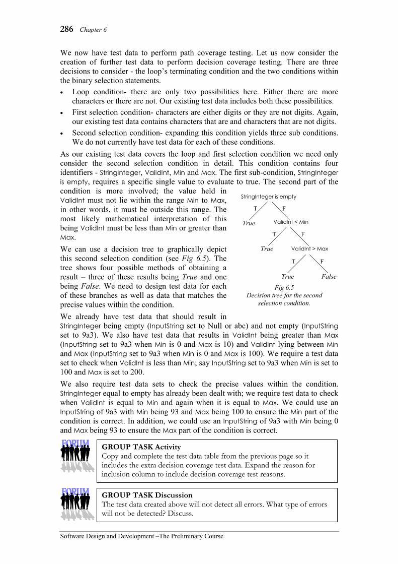
286 Chapter 6
Software Design and Development –The Preliminary Course
We now have test data to perform path coverage testing. Let us now consider the creation of further test data to perform decision coverage testing. There are three decisions to consider - the loop’s terminating condition and the two conditions within the binary selection statements. • Loop condition- there are only two possibilities here. Either there are more
characters or there are not. Our existing test data includes both these possibilities. • First selection condition- characters are either digits or they are not digits. Again,
our existing test data contains characters that are and characters that are not digits. • Second selection condition- expanding this condition yields three sub conditions.
We do not currently have test data for each of these conditions. As our existing test data covers the loop and first selection condition we need only consider the second selection condition in detail. This condition contains four identifiers - StringInteger, ValidInt, Min and Max. The first sub-condition, StringInteger is empty, requires a specific single value to evaluate to true. The second part of the condition is more involved; the value held in ValidInt must not lie within the range Min to Max, in other words, it must be outside this range. The most likely mathematical interpretation of this being ValidInt must be less than Min or greater than Max. We can use a decision tree to graphically depict this second selection condition (see Fig 6.5). The tree shows four possible methods of obtaining a result – three of these results being True and one being False. We need to design test data for each of these branches as well as data that matches the precise values within the condition. We already have test data that should result in StringInteger being empty (InputString set to Null or abc) and not empty (InputString set to 9a3). We also have test data that results in ValidInt being greater than Max (InputString set to 9a3 when Min is 0 and Max is 10) and ValidInt lying between Min and Max (InputString set to 9a3 when Min is 0 and Max is 100). We require a test data set to check when ValidInt is less than Min; say InputString set to 9a3 when Min is set to 100 and Max is set to 200. We also require test data sets to check the precise values within the condition. StringInteger equal to empty has already been dealt with; we require test data to check when ValidInt is equal to Min and again when it is equal to Max. We could use an InputString of 9a3 with Min being 93 and Max being 100 to ensure the Min part of the condition is correct. In addition, we could use an InputString of 9a3 with Min being 0 and Max being 93 to ensure the Max part of the condition is correct.
StringInteger is empty
ValidInt > Max
ValidInt < Min True
T F
T F
T F
True
True False
Fig 6.5 Decision tree for the second
selection condition.
GROUP TASK Activity Copy and complete the test data table from the previous page so it includes the extra decision coverage test data. Expand the reason for inclusion column to include decision coverage test reasons.
GROUP TASK Discussion The test data created above will not detect all errors. What type of errors will not be detected? Discuss.

Testing and Evaluating Software Solutions 287
Software Design and Development – The Preliminary Course
TESTING ALGORITHMS AND CODED SOLUTIONS USING TEST DATA Once a thorough series of test data has been created it needs to be used to check the correctness of the algorithm or code. Each test data set is used as the inputs into the code. The results from the tests are then compared to the expected results. Any inconsistencies arising indicate errors that require further investigation. In many cases, errors are highlighted during the testing process. These errors can be corrected immediately and the full set of tests recommenced. For large projects where testing is undertaken by specialists, a test report would be returned to the developers who in turn make the corrections. This process cycle continues until the test results confirm the code’s correctness. If we are checking an algorithm then a manual desk check is performed. For coded solutions, most programming environments allow developers to step through each line of code as it is executed. This is essentially an automated desk check. Let us consider each of these techniques.
Desk checking an algorithm
Desk checking is a manual process. As the name suggests it is carried out using pen and paper sitting, presumably, at a desk. Each statement in the algorithm is evaluated by hand and the results written on a table. The table contains a column for each identifier used within the algorithm. As the value in an identifier changes the new value is written beneath the previous value. In this way, a full record of all the changes that have occurred is maintained.
Usually values altered within a single iteration are written on a single row. This assists reading back through the table should an error occur. Often a repetition will contain a large number of iterations, this can become tedious. It is acceptable to detail the first few iterations and then skip forward to consider the last few iterations as in the large majority of cases errors will occur at the start or end of loops. A horizontal line is drawn once the end of the algorithm is reached and prior to the next set of test data being applied to a new desk check.
Data types such as arrays and records require special consideration. The elements of an array can be given their own column if this is practical. It is also possible to have a column for the array index beside the array’s identifier column. This technique makes it possible to determine which element of the array is being accessed, however it is difficult to see the changes occurring to particular elements.
Each record requires a separate column for each of its fields. This can become tedious when a number of records with a number of fields are being used. It is acceptable to just detail the values held in the fields relevant to the processing occurring. For example, the desk check of an algorithm that calculates statistics based on employees sick days need not detail the employee’s name, phone number or other details, rather it can just detail the field containing each employee’s number of sick days.
GROUP TASK Activity The testing process is cyclical. The code is checked using the test data then any errors are corrected. The code is again tested and further corrected. The cycle continues until no errors are detected. Create a flowchart that describes this cycle.

288 Chapter 6
Software Design and Development –The Preliminary Course
Consider the following:
Let us complete a desk check of the ValidateInteger algorithm (see Fig 6.4) using the path coverage test data created in the previous section. There are six identifiers used explicitly in the algorithm, however the current character being examined is implicit within the logic so we have seven in total. In this case, the output is via the ValidateInteger function call – ValidInt is returned by the function call. A message box is displayed when an error is detected. Therefore, our desk check table requires seven columns for identifiers and an output column for the message box. Remember, we are desk checking an algorithm so it is the correctness of the logic that is being examined rather than the fine details required within the source code. Fig 6.6 shows the result of the desk check performed using the four test data sets created to perform the path coverage tests.
Stepping through a coded solution Most programming environments (IDEs) provide a method of stepping line-by-line through code. This allows programmers to examine the contents of identifiers and follow the execution path precisely. Stepping through a coded solution is essentially an automated desk check of the code. Most IDEs provide a window where the current contents of each identifier is shown and updated as execution progresses. It is usually possible to alter the value of identifiers and even make corrections to the code before execution is recommenced.
Fig 6.6 Sample desk check of the ValidateInteger algorithm.
GROUP TASK Discussion A problem occurs when InputString is Null. Identify the cause of the problem and suggest a solution.
GROUP TASK Activity The table in Fig 6.6 uses the path coverage test data. Complete the desk check using the decision coverage test data.
GROUP TASK Activity Examine the stepping tools available in a programming environment with which you are familiar. Use these tools to step through a coded solution.
Fig 6.7 Stepping through the ValidateInteger function in
Visual Basic .NET. The ‘Locals’ window shows the current value of each identifier.

Testing and Evaluating Software Solutions 289
Software Design and Development – The Preliminary Course
The following algorithm rotates the names within an array of 5 names so that each name moves up one place and the first name becomes the new last name.
BEGIN RotateArray Index = 0 First = Name(0) WHILE Index < 4 Name(Index) = Name(Index+1) Increment Index ENDWHILE Name(4) = First END RotateArray
(a) Complete a desk check of the above RotateArray algorithm assuming the data shown in the first row of the table below has already been loaded into the array.
Index First Name(0) Name(1) Name(2) Name(3) Name(4) Fred Mary John Amy Ann
(b) Modify the RotateArray algorithm so that it operates with any size array and is also able to rotate elements by a variable number of places.
Your modified algorithm is to use two parameters - Size and Rotation. For example, the call RotateArray(100, 6) means the array contains 100 elements that will be rotated such that all elements move up 6 places. Assume the Name array has been declared globally and is indexed from 0 to Size - 1.
Suggested Solutions
(a) Index First Name(0) Name(1) Name(2) Name(3) Name(4)
Fred Mary John Amy Ann 0 Fred Mary 1 John 2 Amy 3 Ann 4 Fred
HSC style question:

290 Chapter 6
Software Design and Development –The Preliminary Course
(b) It is anticipated that each of the following solutions would be awarded full marks. The following solution improves the efficiency of the processing as it moves items directly into their final location in the array, however it does not deal with negative Rotation values or Rotation values greater than the size of the array.
BEGIN RotateArray(Size, Rotation) Declare TempArray(0 to Rotation): String FOR index = 0 to Rotation – 1 TempArray(index) = Name(index) NEXT index FOR index = 0 to (Size – Rotation – 1) Name(index) = Name(index + Rotation) NEXT index Count = 0 FOR index = (Size – Rotation) to (Size – 1) Name(index) = TempArray(count) Increment count NEXT index END RotateArray
OR…
The following solution deals with negative Rotation values and Rotation values greater than the Size of the array. For example, the call RotateArray(10,-16) first converts –16 into the equivalent Rotation value of 4, as 10 + -16 MOD 10 = 10 – 6 = 4. The actual rotation processing is less efficient (compared to the previous solution) as it moves items up one place at a time using the same strategy as the original algorithm - essentially a loop has been placed around the original algorithm.
BEGIN RotateArray(Size, Rotation) IF Rotation < 0 THEN Rotation = Size + Rotation MOD Size ELSE Rotation = Rotation MOD Size ENDIF FOR Count = 1 TO Rotation Index = 0 First = Name(0) WHILE Index < Size - 1 Name(Index) = Name(Index+1) Increment Index ENDWHILE Name(Size - 1) = First NEXT Count END RotateArray
OR…
An even better solution could combine the features of both the above solutions and might also include initial checks to ensure/convert the inputs into integers.
Note: Rotation MOD Size is equivalent to Rotation – (INT(Rotation/Size)*Size)
GROUP TASK Activity Perform desk checks of the above solutions to part (b) to confirm that they correctly perform the required processing.

Testing and Evaluating Software Solutions 291
Software Design and Development – The Preliminary Course
SET 6A 1. Test data is comprised of:
(A) a set of outputs. (B) a set of inputs. (C) a set of both inputs and outputs. (D) different algorithms.
2. When each statement in an algorithm is evaluated by hand and results written into a table, this is known as what? (A) Peer checking. (B) Stepping through. (C) Desk checking. (D) Structured walk through.
3. Which type of testing primarily uses white box techniques? (A) System-level testing. (B) Source code testing. (C) Algorithm testing. (D) Both (B) and (C).
4. The type of testing which tests the order in which statements are executed is known as: (A) Statement coverage testing. (B) Path coverage testing. (C) Decision coverage testing. (D) Black box testing.
5. When performing a desk check on an algorithm, what is commonly used to indicate that the end of the algorithm has been reached? (A) A horizontal line. (B) The tester’s signature. (C) A special identifier. (D) Whatever the tester feels like.
6. What is the name of the testing that tests every boundary condition? (A) Statement coverage testing. (B) Decision coverage testing. (C) Path coverage testing. (D) Control structure testing.
7. Which type of testing primarily uses black box techniques? (A) System-level testing. (B) Algorithm testing. (C) Source code testing. (D) All types of testing.
8. The testing that ensures that every statement is executed is known as: (A) Statement coverage testing. (B) Path coverage testing. (C) Decision coverage testing. (D) System-level testing.
9. A graphical depiction of the possible outcomes of a condition is known as: (A) an execution path. (B) a boundary tree. (C) a desk check. (D) a decision tree.
10. The examination of the detail of each process as it occurs is characteristic of: (A) Black box testing. (B) White box testing. (C) System-level testing. (D) Statement coverage testing.
11. Describe the purpose of statement coverage, path coverage and decision coverage testing. Why are these described as white box testing techniques?
12. Draw a decision tree for the condition: A<0 AND (B=5 OR C>2) Design test data for this condition.

292 Chapter 6
Software Design and Development –The Preliminary Course
The following algorithm has been written to control the temperature of an oven. Use this algorithm to answer questions 13, 14, and 15.
13. How many unique paths are there through this algorithm?
14. Design a set of test data to perform path and decision coverage testing.
15. Perform desk checks of the algorithm using your test data.
BEGIN ControlTemp Get Temp REPEAT Get CurrentTemp from Sensor IF CurrentTemp ≥ Temp THEN Turnoff heat element ELSE IF CurrentTemp < Temp –5 THEN Turnon heat element ENDIF ENDIF Wait 1 minute UNTIL Power is turned off
END ControlTemp

Testing and Evaluating Software Solutions 293
Software Design and Development – The Preliminary Course
EVALUATING THE SOLUTION There are many different ways of interpreting and approaching the design of software solutions. Most problems can be solved in various ways using different strategies; some approaches are better than others. We need to compare these differences and evaluate their advantages and disadvantages. We then examine a number of techniques available to assist in this evaluation process.
COMPARING DIFFERENT SOLUTIONS TO THE SAME PROBLEM
In this section, we concentrate on comparing different algorithms and source code solutions that aim to solve the same problem. Design specifications can be interpreted in a variety of ways by different developers. Algorithms and source code created to solve the same problem will differ according to the approach used by the particular developer. We need to examine the advantages and disadvantages of different solutions.
Different interpretations of the design specifications
Design specifications aim to formalise the requirements that must be fulfilled. However, different developers will interpret these specifications in different ways. For example, consider the design of a bridge: different structural engineers are likely to create quite different bridge designs. Each design may equally fulfil the design specifications; it is the manner in which these specifications have been interpreted and implemented that is different. The Sydney Harbour and Golden Gate bridges both fulfil similar design specifications yet these specifications have been interpreted in quite different ways.
Software development involves many creative aspects. This is particularly obvious in regard to the design of the user interface, however it is also true for algorithm and source code development. It is natural for different people to interpret the same specifications in different ways. For example, the design specifications for a module may require the input of a date by the user. The date could be collected as a complete string or it could be collected in pieces as year, month and day. In the first case, the entire string must be validated and in the second case, each component would be validated once entered. Both interpretations fulfil the design specifications in different ways.
Fig 6.8 The Sydney Harbour and Golden
Gate bridges are examples of different interpretations of design
specifications.
GROUP TASK Activity Examine a number of different word processors. Make a list of functions that appear to fulfil the same design specifications but have been interpreted differently. Indicate which interpretation you preferred and state why you preferred this interpretation.
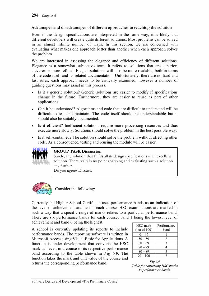
294 Chapter 6
Software Design and Development –The Preliminary Course
Advantages and disadvantages of different approaches to reaching the solution
Even if the design specifications are interpreted in the same way, it is likely that different developers will create quite different solutions. Most problems can be solved in an almost infinite number of ways. In this section, we are concerned with evaluating what makes one approach better than another when each approach solves the problem.
We are interested in assessing the elegance and efficiency of different solutions. Elegance is a somewhat subjective term. It refers to solutions that are superior, cleverer or more refined. Elegant solutions will also be more readable, both in terms of the code itself and its related documentation. Unfortunately, there are no hard and fast rules; each approach needs to be critically examined, however a number of guiding questions may assist in this process:
• Is it a generic solution? Generic solutions are easier to modify if specifications change in the future. Furthermore, they are easier to reuse as part of other applications.
• Can it be understood? Algorithms and code that are difficult to understand will be difficult to test and maintain. The code itself should be understandable but it should also be suitably documented.
• Is it efficient? Inefficient solutions require more processing resources and thus execute more slowly. Solutions should solve the problem in the best possible way.
• Is it self-contained? The solution should solve the problem without affecting other code. As a consequence, testing and reusing the module will be easier.
Consider the following:
Currently the Higher School Certificate uses performance bands as an indication of the level of achievement attained in each course. HSC examinations are marked in such a way that a specific range of marks relates to a particular performance band. There are six performance bands for each course; band 1 being the lowest level of achievement and band 6 being the highest.
A school is currently updating its reports to include performance bands. The reporting software is written in Microsoft Access using Visual Basic for Applications. A function is under development that converts the HSC mark achieved in a course to its respective performance band according to the table shown in Fig 6.9. The function takes the mark and unit value of the course and returns the corresponding performance band.
HSC mark (out of 100)
Performance band
0 – 49 1 50 – 59 2 60 – 69 3 70 – 79 4 80 – 89 5
90 – 100 6
Fig 6.9 Table for converting HSC marks
to performance bands.
GROUP TASK Discussion Surely, any solution that fulfils all its design specifications is an excellent solution. There really is no point analysing and evaluating such a solution any further. Do you agree? Discuss.
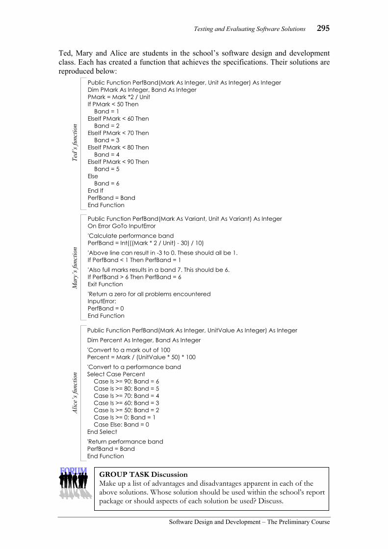
Testing and Evaluating Software Solutions 295
Software Design and Development – The Preliminary Course
Ted, Mary and Alice are students in the school’s software design and development class. Each has created a function that achieves the specifications. Their solutions are reproduced below:
Public Function PerfBand(Mark As Integer, Unit As Integer) As Integer Dim PMark As Integer, Band As Integer PMark = Mark *2 / Unit If PMark < 50 Then Band = 1 ElseIf PMark < 60 Then Band = 2 ElseIf PMark < 70 Then Band = 3 ElseIf PMark < 80 Then Band = 4 ElseIf PMark < 90 Then Band = 5 Else Band = 6 End If PerfBand = Band End Function
Public Function PerfBand(Mark As Integer, UnitValue As Integer) As Integer Dim Percent As Integer, Band As Integer 'Convert to a mark out of 100 Percent = Mark / (UnitValue * 50) * 100 'Convert to a performance band Select Case Percent Case Is >= 90: Band = 6 Case Is >= 80: Band = 5 Case Is >= 70: Band = 4 Case Is >= 60: Band = 3 Case Is >= 50: Band = 2 Case Is >= 0: Band = 1 Case Else: Band = 0 End Select 'Return performance band PerfBand = Band End Function
Public Function PerfBand(Mark As Variant, Unit As Variant) As Integer On Error GoTo InputError 'Calculate performance band PerfBand = Int(((Mark * 2 / Unit) - 30) / 10) 'Above line can result in -3 to 0. These should all be 1. If PerfBand < 1 Then PerfBand = 1 'Also full marks results in a band 7. This should be 6. If PerfBand > 6 Then PerfBand = 6 Exit Function 'Return a zero for all problems encountered InputError: PerfBand = 0 End Function
Ted’
s fun
ctio
n M
ary’
s fun
ctio
n Al
ice’
s fun
ctio
n
GROUP TASK Discussion Make up a list of advantages and disadvantages apparent in each of the above solutions. Whose solution should be used within the school’s report package or should aspects of each solution be used? Discuss.

296 Chapter 6
Software Design and Development –The Preliminary Course
TECHNIQUES FOR EVALUATING DESIGN
How do we go about evaluating the design of a software solution? There are a number of techniques available to assist in this process including peer checking, structured walk throughs and desk checks. Although each of these techniques can be used to test the correctness of algorithms and code, in this section we are concerned with ensuring the code is well designed. These techniques include other interested parties in the evaluation process. Often personnel who are somewhat removed from the detail of the development process are better able to assess the design of a solution from an unbiased perspective. Peer checking
Peer checking is normally an informal process. Colleagues at the same level within the company examine and comment on the work of their peers. A strong team atmosphere is required if peer checking is to be successful. Colleagues should feel able to make constructive criticisms without fear of their comments being seen as negative. On the other hand, the developer should feel able to refute any criticisms and to logically debate the merits of their work. This is the primary advantage of peer checking; it enables and encourages the natural flow of ideas between members of the development team. Structures where a superior performs the checking do not encourage this transfer of ideas; the superior often dominates the process.
There are a number of ways in which peer checking can be implemented. Some software development companies have formal systems in place whereby developers must check and formally endorse the work of their peers. Most companies encourage peer checking through the creation of teams. The responsibility for the completion of a module of code rests with the team rather than with an individual. In this way, each team member has a responsibility to ensure the quality of the team’s efforts. Consequently, peer checking evolves as a natural consequence of team formation rather than as a structure imposed from above.
Structured walk through
Structured walk throughs, as the name suggests, are more formal than peer checks. The developer or team of developers present their work to a group of interested parties. This group may include representatives from management, marketing and potential users, with the aim being to present the software and formally work through its functionality. The developers walk the group step-by-step through each aspect of the program. As the walk through continues, comments are written down for future consideration. No attempt is made to correct or justify aspects of the product; the aim being to receive feedback on the product as it stands.
Fig 6.10 Peer checking is more successful when
developers work together as a team.
GROUP TASK Discussion Some companies insist that peers check and endorse each other’s work whilst others prefer to allow peer checking to be a more informal process. What are the advantages and disadvantages of each approach? Discuss.

Testing and Evaluating Software Solutions 297
Software Design and Development – The Preliminary Course
Structured walk throughs are normally undertaken as formal meetings. Each person in attendance at a structured walk through should be given all relevant documentation prior to the meeting. This allows them to have an overall view and feel for the product and its design. The walk through itself should be a demonstration of the product and its design. Comments can either be made verbally or may be restricted to written comments. In either case, a response to comments should not occur during the walk through, rather at a later time when they can be considered carefully.
Structured walk throughs can be used to evaluate the design at different levels. Their aim is to explain in a structured manner the operation of some part of the design and development process and to obtain feedback from interested parties. They may be used to walk through an algorithm created for a specific module within a product or they may be used to evaluate the final product once it has been implemented in code. In fact, most aspects of the software design and development process can be evaluated using structured walk throughs.
Desk checking
Previously in this chapter, we examined desk checking as a technique for checking the correctness of software solutions using test data. Desk checking is also a useful technique for evaluating the design of algorithms and code. The process of manually working through a solution one statement at a time is a sure way of realising the efficiency and elegance of the solution. As a consequence, recommendations and constructive criticisms can be made in regard to the products design.
Personnel, other than the code’s developer, would be the best people to perform desk checks that aim to evaluate the design rather than the correctness of the solution. These personnel require expertise in algorithm or code design if their evaluation is to be relevant; the most likely candidates being other developers who possess the technical skills but are not intimately involved in the products design. Because of the intensive and detailed nature of desk checking they are best performed in isolation by individuals.
Fig 6.11 Structured walk throughs are normally
undertaken as formal meetings.
Fig 6.12 Desk checks are generally completed
by individuals.
GROUP TASK Discussion Why do you think comments and suggestions should be collected but not responded to until after the walk through is complete? Surely it would be better to discuss any issues during the walk through. Discuss.
GROUP TASK Discussion Desk checks are normally undertaken by individuals whereas peer checks and structured walk throughs often involve a number of personnel. Why do you think this is the case? Discuss.

298 Chapter 6
Software Design and Development –The Preliminary Course
EVALUATION OF THE FINAL SOLUTION The final solution in this context refers to the total software product once it has been coded in some programming language. We are concerned with evaluating the software against its original design specifications. Although the processes within the product may operate correctly and be well designed, they may not achieve the requirements or meet all the design specifications. It is also important to obtain user feedback in regard to the operation of the software as a whole. User feedback should be obtained and acted upon throughout the development process, however it is particularly vital once the source code has been completed. We also need to consider various social and ethical issues. For example, can users alter the screen fonts and colours, can the product be used with or without a pointing device, and is the language used consistent and appropriate for the intended audience. Remember, we are evaluating the software rather than the total system. We are interesting in addressing issues within the source code that require modification prior to the commencement of system-level testing. CHECKING THE SOLUTION MEETS THE ORIGINAL REQUIREMENTS The main aim of any new software solution is to meet its original requirements and design specifications. Evaluating software against these specifications should be integral to all aspects of the design and development process. However, it is an essential task once the software has been implemented or built in a programming language. The original design specifications include requirements for the particular application together with specifications in regard to documentation required, screen design and code design. In essence, these specifications describe what the software should do together with how it should be done. Evaluation of the design specifications will therefore ensure the product realises its requirements and that those involved in the design process have maintained standards in regard to how the requirements have been achieved. When defining and understanding the problem, a set of requirements was formulated. These requirements should have been written in such a way that they could easily be evaluated. For example, a requirement such as ‘overdue accounts are to be generated every 7 days’ can easily be evaluated as being achieved or not achieved whereas ‘follow up is required for unpaid accounts’ is not specific and is therefore difficult to evaluate. Each requirement should be checked against the software to ensure it has been included and achieved. Design specifications in regard to the development process need to be evaluated to ensure those involved have complied. Evaluation of documentation and checks that it accurately reflects the product are needed. Similar analysis of the user interface and the source code is required to make sure the developers have adhered to the stated specifications. This should be a reflective process rather than a disciplinary one, where the formation of recommendations for future projects is the main focus.
GROUP TASK Discussion Evaluation of the implemented solution is from two different perspectives. One examines the success of the actual project and the other considers the success of the design and development process. Explain each of these perspectives and describe how they differ.

Testing and Evaluating Software Solutions 299
Software Design and Development – The Preliminary Course
USER FEEDBACK
Software is written for users, if it does not meet their needs then it will not be a success. Therefore, user feedback should always be valued and considered. Many software products meet their requirements and design specifications, however they are not well accepted by users. For example, consider the number of different photo editing software products available; only a few are widely used. What makes one product a commercial success and other similar products commercial failures is largely to do with their acceptance by users. We discussed the development of user interfaces in chapter 5; user feedback aims to evaluate the success of our decisions.
User feedback can be obtained using pre-release versions of the product. The users selected should possess various levels of expertise dependant on the nature of the product. Users should be encouraged to complete tasks using the new product and evaluate its effectiveness in terms of their own needs.
The feedback from users can take a number of forms. Written questionnaires are appropriate where specific items require evaluation, however they can restrict the process unnecessarily to those items within the questionnaire. Informal observation is often useful in determining the useability of the product. For example, evaluating a user’s ability to intuitively activate and complete functions is clear during observation. In chapter 5, we discussed a number of other techniques available to obtain user feedback.
SOCIAL AND ETHICAL PERSPECTIVE
We are interested in evaluating the success of the software product from a social and ethical perspective. Some of these issues involve legal responsibility whereas others should be considered to ensure the integrity of the product.
Some questions relevant to this social and ethical perspective include:
• Does the design of the software exclude some users?
• Is the product ergonomically sound?
• Does the product use code from other sources?
• Have the intellectual property rights of all involved been considered and upheld?
Questions such as these require attention and must be addressed during the evaluation process. Software developers have a responsibility to ensure the answers to such questions are addressed.
GROUP TASK Activity In chapter 5, we examined the development of user interfaces. Revise this section of chapter 5. With this information in mind, describe methods that could be appropriately used to evaluate the success of the implemented user interface.
GROUP TASK Activity/Discussion Chapter 1 of this text dealt with social and ethical issues related to software design and development. Expand on the four questions above using information from chapter 1. Discuss your responses.

300 Chapter 6
Software Design and Development –The Preliminary Course
A wholesaler charges customers for their products based on a percentage increase on the product’s cost price. Different customers are charged a different percentage increase based on a variety of different factors. For example, large account customers are charged a 20% increase whilst a retail customer who walks in off the street is charged a 50% increase.
A subroutine is being developed to calculate the price charged to customers for each type of product purchased. The routine has three inputs; the cost price for one of the products, the number of units purchased and the percentage increase. The cost price is always in cents, so a cost price of $2.35 is sent to the function as 235. The percentage increase is also an integer, so a 20% increase is sent to the function as 20. The subroutine returns the sell price in cents rounded down to the nearest cent. However, -1 is to be returned if the sell price is not greater than the total cost price.
Jack and Jill have both written algorithms for this subroutine.
BEGIN CalcSellPrice(CostPrice, Units, PIncrease, SellPrice) IF CostPrice>0 AND Units>0 AND PIncrease>0 THEN SellPrice = INT(CostPrice * Units * (100 + PIncrease) / 100) ELSE SellPrice = -1 ENDIF END CalcSellPrice
BEGIN CalcSellPrice(CostPrice, Units, PIncrease, SellPrice) UnitIncrease = INT(CostPrice * PIncrease / 100) SellPrice = (CostPrice + UnitIncrease) * Units IF SellPrice <= CostPrice * Units THEN SellPrice = -1 ENDIF END CalcSellPrice
Note: The INT function rounds a number down to the nearest whole number. For example, INT(3.7) returns 3 and INT(-3.7) returns -4
(a) Calculate the SellPrice returned by both algorithms from the call CalcSellPrice(15, 100, 20, SellPrice)
(b) Calculate the SellPrice returned by both algorithms from the call CalcSellPrice(8, 100, 20, SellPrice)
(c) The CalcSellPrice subroutine will be called many times from many routines within the final program. Marg, who is Jack and Jill’s team leader, performs a peer check of both algorithms. She prefers one algorithm over the other, however she is uneasy with the value -1 being returned.
(i) Compare Jack and Jill’s algorithms and recommend one of the algorithms.
(ii) Explain why Marg is uneasy with the value -1 being returned by the subroutine. Propose an alternative strategy to resolve Marg’s uneasiness.
Jack’s algorithm
Jill’s algorithm
HSC style question:

Testing and Evaluating Software Solutions 301
Software Design and Development – The Preliminary Course
Suggested Solutions
(a) Jack’s algorithm: SellPrice = INT(15 * 100* 120) / 100 = 1800
Jill’s algorithm: UnitIncrease = INT(15 * 20 / 100) = 3 SellPrice = (15 + 3) * 100 = 1800
(b) Jack’s algorithm: SellPrice = INT(8 * 100* 120) / 100 = 960
Jill’s algorithm: UnitIncrease = INT( 8 * 20 / 100) = INT(1.6) = 1 SellPrice = (8 + 1) * 100 = 900
(c) (i) The two algorithms clearly take a different approach, and can produce different values for the Selling Price even though they both appear to meet the requirements given in the question.
There are a variety of valid differences, some of which include:
Jack’s algorithm checks for any zero (or lower) value before doing any processing and exits immediately, whereas Jill’s approach performs the calculations before checking for an unreasonable value. This wastes processing time unnecessarily.
Jack’s algorithm takes the integer value of the result of the cost price by the number of units by the percentage increase giving a higher value of the selling price, whereas Jill’s algorithm takes the integer value of the percentage increase times the cost price first (for one unit only), and then applies this increase to the number of units. Hence, in Jill’s algorithm the rounding down to the nearest cent occurs for each unit sold, whilst Jack rounds the final total for all units down to the nearest cent. Jill’s algorithm can therefore produce a lower resultant selling price. From the perspective of the company, it is in their interest to have a higher selling price so they make more profit.
Jack’s algorithm is therefore preferred over Jill’s algorithm.
(c) (ii) The value -1 is used to signify an error condition (or inappropriate value) due to a negative value for the cost price, number of units or percentage increase. This would give rise to a selling price lower than the cost price, clearly an inappropriate result.
If this is signalled by setting the selling price to -1, there is the possibility of confusion if this selling price is inadvertently printed or used in further processes (particularly by subsequent maintenance programmers). Potentially customers would be charged -1 cents for such products!
A much better approach would be to generate an error (exception) or use a separate variable, say ErrorFlag, which is passed back to the calling routine. The purpose is much clearer to those reading the source code and there is no possibility of an inappropriate value in the SellPrice variable.

302 Chapter 6
Software Design and Development –The Preliminary Course
SET 6B 1. Of the techniques listed below, which is
considered to be the most informal method of evaluation? (A) Desk checking. (B) Peer checking. (C) Structured walk through. (D) User feedback.
2. A team of developers present their work and formally demonstrate the functionality to a group. This is known as what type of evaluation technique? (A) Peer checking. (B) Desk checking. (C) User feedback. (D) Structured walk through.
3. Victor is a programmer and has completed a software development project that includes some modules of code that were written by someone else. He has advertised himself as the sole author of the product. What has Victor violated with regard to the other programmer? (A) The other programmer’s
intellectual property rights. (B) The other programmer’s civil
liberties. (C) The other programmer’s human
rights. (D) He is not in violation of anything.
4. Pre-release versions of a software product can be used to obtain what? (A) Peer feedback. (B) Colleague feedback. (C) User feedback. (D) Marketplace domination.
5. Which requirement listed below, cannot be easily evaluated? (A) Backup of the data must be
performed every 4 hours. (B) Any account that is past 30 days
old must be marked as being Overdue and the client contacted.
(C) All clients in the database must be contacted by email at least once every three months.
(D) All new clients that have been entered in the database in the last two months must by followed up to ensure they are receiving satisfactory service.
6. What is the primary purpose of design specifications? (A) They ensure that the written code
will be easy to understand. (B) They ensure that the solution will
be generic in nature. (C) They ensure that the solution is
developed in the most efficient manner.
(D) They formalise the requirements that need to be fulfilled.
7. When a solution is superior, cleverer and more refined, it is referred to as being what type of solution? (A) An elegant solution. (B) A stylish solution. (C) A chic solution. (D) A neat solution.
8. The difference between peer checking and desk checking is: (A) Desk checking is the process of
working through the code by hand. Peer checking is the process of analysing and checking code that has been written by another team member.
(B) Peer checking is the process of working through the code by hand. Desk checking is the process of analysing and checking code that has been written by another team member.
(C) Peer checking is only performed by large software development companies, whereas desk checking is performed by all software development companies.
(D) There is no difference.
9. When developing a solution, by using language appropriate to the intended audience of a software product, the developer is being mindful of: (A) the social and ethical perspective. (B) the design specification
perspective. (C) the interface from the user
perspective (D) All of the above.
10. Informal observation is a form of: (A) user feedback. (B) peer checking. (C) desk checking. (D) structured walk through.

Testing and Evaluating Software Solutions 303
Software Design and Development – The Preliminary Course
11. Obtaining feedback from users and other interested parties is vital when evaluating the design of software. Describe techniques that can be used to obtain this feedback.
12. Evaluation of software includes checking that the documentation is correct. Describe different types of documentation that should be evaluated.
13. The intellectual property rights of all involved in the design and development of a software product, require consideration. Make up a list of possible people or companies who need to be considered as part of the process.
14. If two functions both successfully solve the same problem, then how can one be reasonably selected in preference to the other? Discuss.
15. Different makes and models of cars have different characteristics, yet they all essentially perform the same function. What criteria would you use to assess the elegance of one car against another?
No doubt, your criterion is different to the criteria of your classmates. Discuss problems this situation presents to those involved in the evaluation of different designs.

304 Chapter 6
Software Design and Development –The Preliminary Course
CHAPTER 6 REVIEW 1. The type of testing whereby the inputs
and expected outputs are known, but the processes that are occurring are not known, is called what type of testing? (A) White box testing. (B) System-level testing. (C) Black box testing. (D) Structural testing.
2. Harry is involved in the testing of a software product and intends to utilise large files, different types of transactions as well as a large volume of test data. What type of testing is Harry most likely to be doing? (A) Open box testing. (B) White box testing. (C) System-level testing. (D) Structural testing.
3. The aim of a structured walk through can best be described as: (A) an explanation given in a structured
manner, of the operation of parts of the design and development process to gain useful feedback.
(B) showing management how far the development team has got with the new software project.
(C) an evaluation of the overall design of the project.
(D) a chance for various levels of people in the organization to have their say about the new project.
4. Path coverage testing always includes what other type of testing? (A) Boundary condition testing. (B) Decision coverage testing. (C) Statement coverage testing. (D) No other testing type.
5. A test data set is used to test: (A) the coded solution only. (B) the algorithms only. (C) both the code and the algorithms. (D) either the code or the algorithm.
6. Some techniques that could be employed to gain user feedback include: (A) formal meetings, questionnaires
and peer checks. (B) prototypes, informal meetings and
desk checks. (C) questionnaires, meetings and
prototypes. (D) meetings, prototypes and alpha
testing.
7. What is the maximum number of paths that a subroutine containing five binary selections could have? (A) 32 (B) 5 (C) 16 (D) 8
8. Testing of software solutions occurs: (A) at the end of the software
development process. (B) throughout the software
development process. (C) only when the source code has
been written. (D) when end users get to look at the
finished product.
9. Barbara has been given the task of checking an algorithm. Which technique would Barbara most likely use? (A) Desk check. (B) Peer check. (C) Open box testing. (D) Structural testing.
10. Desk checking an algorithm is primarily checking for what? (A) The naming conventions used. (B) The syntax of the source code. (C) The correctness of the logic. (D) All of the above.
11. Describe considerations when designing test data to ensure the logic of an algorithm is correct.
12. Desk checking can be a laborious task. Describe tools available to assist when desk checking source code.
Testing and Evaluating Software Solutions 305
Software Design and Development – The Preliminary Course
13. Devise a set of suitable questions that should be considered when comparing two solutions to the same problem.
14. What is a structured walk through? How could a software developer who works alone from home, use a structured walk through? Discuss.
15. This chapter is about testing and evaluating software solutions, however we have not covered checks for all possible problems that could arise.
Make up a list of problems or errors that we have tested for and make up a second list of problems or errors that we have not discussed.
(Hopefully in the HSC course, we will cover your second list satisfactorily)

306 Chapter 7
Software Design and Development –The Preliminary Course
In this chapter you will learn to: • identify and describe features in code that allow it to
be easily maintained
• create solutions that are easy to maintain
• convert a fragment of source code into its equivalent algorithm
• define the purpose of the code to be maintained
• modify code to meet changed requirements
• provide appropriate acknowledgement of the code of other programmers that has been incorporated as part of the maintenance process
• assess the compatibility of code to be included in the source code of an existing solution
Which will make you more able to: • describe and use appropriate data types
• describe the effects of program language developments on current practices
• identify the issues relating to the use of software solutions
• analyse a given problem in order to generate a computer-based solution
• investigate a structured approach in the design and implementation of a software solution
• use a variety of development approaches to generate software solutions and distinguish between these approaches
• use and justify the need for appropriate project management techniques
• use and develop documentation to communicate software solutions to others
• describe the skills involved in software development
• communicate with appropriate personnel throughout the software development process
• design and construct software solutions with appropriate interfaces.
In this chapter you will learn about: Reasons for maintaining code
• changing user requirements
• upgrading the user interface
• changes in the data to be processed
• introduction of new hardware or software
• changing organisational focus
• changes in government requirements
• poorly implemented code
Features in source code that improve its maintainability, including:
• use of variables instead of literal constants
• use of meaningful variable names
• explanatory comments in the code
• use of standard control structures with appropriate indentation
• appropriate use of white space to improve legibility of the source code
• a clear and uncluttered mainline
• one logical task per subroutine
• meaningful names for subroutines and modules
Understanding source code
• reading original documentation in order to understand code – documentation for the user (including user manuals) – documentation for developers
• reading original algorithms to identify: – inputs – the type and purpose of variables used – processes – outputs
• creating algorithms for source code when they are not available to aid in understanding – identify the control structures that have been used – understand how variables have been used
Inclusion of code from other sources
• copyright issues
• compatibility of code

Maintaining Software Solutions 307
Software Design and Development – The Preliminary Course
7 MAINTAINING
SOFTWARE SOLUTIONS The majority of software solutions are regularly upgraded as requirements change and as errors are found that require correction. In fact, most software developers are engaged to maintain existing software products. This maintenance involves continuous modification of the code. Modifications should be completed using similar techniques to those used to design and develop new software. Each stage should be carefully documented and testing should be ongoing. The difference between developing a software product from scratch and modifying an existing product is largely about understanding the operation of the existing product. This chapter aims to examine how this understanding can best be achieved and facilitated. It is vital that source code and its accompanying documentation is written in such a way as to facilitate the job of modifying the code. Maintainability is a measure of how easily code can be understood and modified by future developers. The task of maintenance programmers is greatly simplified when the code is well structured and well documented. In this chapter, we first consider various reasons for maintenance coding. A number of social and ethical issues are discussed. We then examine features within the source code and its accompanying documentation that improve its maintainability. Finally, we consider the task of understanding existing solutions to enable their effective modification.
Consider the following:
Imagine your company has purchased the intellectual property rights for an existing software product. The source code is now owned by your company and can be modified as you require. Unfortunately, there is no documentation accompanying the code and the code is written in a language that is not familiar to you or any of your current employees. The product has a customer base of some 1000 users. An urgent upgrade of the product is required to meet the changing needs of these users. In addition, the upgrade is likely to make a significant amount of money so it will be a worthwhile exercise!
GROUP TASK Discussion Discuss problems this scenario suggests. How could each of these problems be solved so the product can be upgraded now as well as in the future?
Maintainability A measure of the ease with which source code can be understood and modified.

308 Chapter 7
Software Design and Development –The Preliminary Course
REASONS FOR MAINTAINING CODE Maintenance of software solutions is required for a variety of reasons. Many are to do with adding new functionality, others are to take advantage of evolving technologies and some are to improve poor aspects of the existing solution. Personnel involved in the maintenance of software must respond if their products are to remain viable in the market place. Possible reasons for maintenance coding include: • changing user requirements. • upgrading the user interface. • changes in the data to be processed. • introduction of new hardware or software. • changing organisational focus. • changes in government requirements. • poorly implemented code. There is, of course, some overlap between each of the items listed above. For example, a change in government requirements will most likely change the user’s requirements. Similarly a new operating system (software) may introduce new user interface standards resulting in a likely upgrade of the user interface. Let us consider each of these reasons together with an example scenario where each could apply:
CHANGING USER REQUIREMENTS Perhaps the most common reason for modifying code is to include new functionality due to changes in users’ requirements. As users are the final clients for all software solutions it makes sense that they are the most likely source of changed requirements. These changes range from minor modifications to enhancement of existing functionality, to the addition of completely new functions.
Consider the following:
Each year a software company develops an upgrade for their dentist surgery administration package. Prior to the development of the upgrade, a questionnaire, requesting suggestions for inclusion, is distributed to all dental practices using the package. Each of these suggestions are prioritised and finally a list of changes to be included in the upgrade is formulated. The table in Fig 7.1 lists the most common suggestions for the current upgrade. The software company must now prioritise these items and decide which should be included.
Request Freq-uency Notes
Ability to bill more than one person for a single service.
15
Occurs when separated parents are sharing the cost of treatment.
Need to be able to assign two patients the same appointment.
20
Often family groups come in for checkups. Reasonable work around is currently being used.
Appointment reminders need to be generated at any time.
12 Currently they are generated either 7 or 14 days in advance.
Ability to assign an appointment prior to obtaining patient details.
34 Often new patients make appointments by phone.
Wish to maintain a list of standard items ordered.
13 Currently each order must be entered from scratch.
Fig 7.1
Table of user requests for the dental administration software upgrade.
GROUP TASK Discussion Prioritise the list of requests in Fig 7.1. Compare and discuss your reasoning with the class.

Maintaining Software Solutions 309
Software Design and Development – The Preliminary Course
UPGRADING THE USER INTERFACE The user interface is the communication medium between software and users. As a consequence, the user interface is often the most significant influence on the ongoing success of a software product. Even small inconsistencies and minor omissions can prove irritating for users who must interact with the software on a regular basis. Changes to the user interface can cause problems for users skilled in the use of the existing product. Care must be taken to maintain consistency between subsequent versions of software products. It is generally preferable for user interfaces to evolve without significantly altering their structure. Today most user interfaces are a reflection of the GUI-based platform on which they run. This is great in terms of consistency between software products and the operating system, however it does mean that user interfaces often require upgrading once a new version of the operating system is released. Products that do not conform with new operating system standards for user interface design will quickly lose market share to their competitors.
Consider the following:
Ulead is a software development company that writes and distributes a photo-editing product called iPhoto Plus. Fig 7.2 shows a screen shot from version 4.0 of this product. The product was originally written to run under MS-Windows 95.
The user interface for iPhoto Plus, although incorporating a number of Windows features, has its own look and feel. For example, the toolbar on the left hand side of the screen alters the toolbar displayed at the top of the screen. Clicking on a toolbar at the top of the screen either activates that function or opens a popup menu containing further items for selection. Some items on the graphical toolbars are repeated as menu items whereas other are not.
The software company wishes to develop a new version of the product. There is some disagreement in regard to the retention or removal of the toolbars.
Fig 7.2 Ulead’s Iphoto Plus Version 4.0 photo editing
software uses non-standard toolbars.
GROUP TASK Discussion Why do you think there may be disagreement in regard to retaining or removing the toolbars as they appear on the current user interface? What do you think? Discuss.
GROUP TASK Discussion The developer’s of popular GUI operating systems have too much control over the design of user interfaces for other products. Do you agree with this statement? Debate both sides.

310 Chapter 7
Software Design and Development –The Preliminary Course
CHANGES IN THE DATA TO BE PROCESSED
Modifications to software are often required when the structure or format of the input data changes. Perhaps new fields within records are needed or maybe the range of acceptable values for a variable have changed. For example, the widespread use of mobile phones means that most applications that store peoples details now require a field for storing mobile phone numbers. All NSW postcodes used to commence with a two, this is no longer the case, many NSW postcodes now begin with a one. Validation routines for postcodes required alteration to accept this change.
Changes to the data often occurs when software uses the output from other applications as its input. If the output from the other product changes then modifications will be required to ensure this data can still be accessed or imported. For example, a website extracts information from a Microsoft Access database. If Microsoft alters the format or structure of their Access files then the website will require modification to allow it to continue to extract data from the updated Access files.
Consider the following:
During the late 1990s telephone numbers throughout Australia where modified so that each local number now has eight digits and each area code has two digits. Previously, local numbers had six or seven digits and area codes had two or three digits. Furthermore, the area code, in the majority of cases, now indicates the state. The conversion process took a number of years to implement. Fortunately the Australian Communications Authority released a strict timetable so other interested parties could alter their records accordingly as the conversion took place. Fig 7.3 shows an extract from this timetable; notice that it also includes detail in regard to the digits to be added and their placement within the existing numbers.
Software applications that import and/or store telephone numbers required modification to accommodate these changes. Firstly, a function was needed to progressively convert old numbers as the conversion took place. Secondly, the validation of phone numbers as they are entered required changes.
GROUP TASK Discussion The above scenario presented unique problems for software developers. Describe some of these problems and suggest methods that could have been used to ensure the correct and timely conversion of the data within their software products.
Fig 7.3 Extract from the Australian
Communication Authority’s timetable for the conversion of telephone numbers.

Maintaining Software Solutions 311
Software Design and Development – The Preliminary Course
INTRODUCTION OF NEW HARDWARE OR SOFTWARE
Hardware and software are intimately linked. New CPUs, storage devices and peripherals alter the way in which software operates. Similarly, many software applications rely on the services of other software; the most obvious example being the operating system. Fortunately, it is in the interest of both hardware and software developers to create products that are backwards compatible. For example, most early MS-DOS applications will execute successfully on todays modern CPUs.
Although older applications may work successfully they will not take advantage of any new features available. Software developers must therefore modify their products if they wish them to utilise these features. For example, many modern CPUs have larger instruction sets and multiple processors compared to their predecessors; therefore applications wishing to take advantage of these features must be modified.
New versions of operating systems will have an impact on applications. The most obvious impact, from the user’s point of view, will be possible changes to the graphical user interface. Other changes that influence applications include alterations in the way memory is allocated to loaded applications, methods for accessing and communicating with peripherals and the modification of the application programmers interface. Developers have a responsibility to test their products with new versions of operating systems to ensure they continue to execute successfully.
Consider the following:
A particular application has been in use for 10 years. During this time it has been upgraded regularly and currently version 7 is being distributed. The product runs on Apple Macintosh machines, however for the past few years a growing demand has emerged to use the product on Windows based machines.
CHANGING ORGANISATIONAL FOCUS
Organisations change and evolve over time, some grow, others change their way of operating and many diversify into other related industries. Software applications often require modification to cater to these changes. For example, most small businesses commence operations as either a single person or perhaps as a partnership. At this time many operations are performed manually. As the business grows it is natural for its functions to be progressively automated.
Custom-designed solutions often require continual modification. This is particularly true of software used by large companies, banks and government departments. Most of these large organisations have a staff of software developers who spend much of their time maintaining the application to reflect changes in the organisation’s focus.
GROUP TASK Discussion This is a common problem encountered by many software developers. Why is it not possible to easily create a version for another operating system? Discuss the nature of the changes required to modify the application so it will execute on Window’s machines.

312 Chapter 7
Software Design and Development –The Preliminary Course
Consider the following:
A small family-owned furniture manufacturer currently has a single retail showroom at the front of their factory. The company specialises in the manufacture of custom-designed furniture for the higher end of the market. Business is progressing so well that they intend opening two new showrooms and extending the production at their factory.
The business uses a custom-designed software package that has served them well for a number of years. This package allows the entry of specifications and concept diagrams for each piece of furniture together with the usual ordering and invoicing functions. It also schedules the manufacture and delivery of pieces whilst customers are ordering. The company prides itself on being able to deliver its products on time, every time.
CHANGES IN GOVERNMENT REQUIREMENTS
Government legislation covers many areas that can affect software applications. As legislation and laws are changed by government these software applications must be modified to comply. Different legislation and laws will apply to different software products, however common areas affecting many software products include those dealing with taxation, privacy and security. A common requirement is that all transactions should leave an audit trail. This allows the source and path taken by data to be retraced should a problem be detected.
Consider the following:
The ability to use credit cards to pay for goods online has now become common place. As a consequence, a number of security and privacy issues have arisen. Most governments around the world have laws governing the use and secure transmission of credit card numbers. Banks have responded by implementing various systems to safeguard these numbers. For example, in Australia credit card numbers cannot be stored on a merchant’s computer system that has access to the Internet without a thorough audit of the computer system being completed by the bank. Software that stores or manipulates credit card numbers online must therefore comply with the bank’s requirements.
GROUP TASK Discussion There are various challenges involved in modifying the software application discussed above. List and describe some of the modifications to the software that will be required.
GROUP TASK Discussion Many smaller retail websites outsource their credit card transactions to specialists rather than modify their sites to include this facility. Why do you think this occurs? Discuss the advantages and disadvantages of this approach.

Maintaining Software Solutions 313
Software Design and Development – The Preliminary Course
POORLY IMPLEMENTED CODE
Testing and evaluating software solutions aims to ensure that software applications are bug free and perform their tasks efficiently. Unfortunately this is not a perfect process and problems can and do occur once products have been distributed. Even large scale, widely distributed products are seldom, if ever free, of problems. Maintenance of the code is required to correct these problems as they are discovered.
In the past, software products were developed with an expected life span of only a few years. Many of these products have remained in use for periods far exceeding this expectation. Modern techniques now used may not have applied when these products were first developed. For example, the use of modularisation and encapsulation. By modern standards these products are poorly implemented. Although modification to improve the code is desirable; often the process is hampered by the difficulties involved in understanding the code.
INCLUSION OF CODE FROM OTHER SOURCES Perhaps the most significant ethical issue to be considered when modifying software concerns intellectual property and copyrights. Modifications to software can somewhat blur the ownership of these rights. Modifying a product should only be undertaken with the consent of the owner of the product’s intellectual property rights. Remember, source code is covered by copyright unless the author has specifically in writing given up these rights.
Plagiarism is the act of copying or imitating the work of another and claiming it to be your own. Just because you have modified a piece of software, this does not give you the right to claim the entire product as your own work. Even products where copyright does not apply should include recognition of all those whose work it includes. For example, the music of many classical composers is now in the public domain and copyright does not apply. If I were to make modifications to say, one of Mozart’s operas and then claim the entire opera as my own original work I would be ostracized. This would be a blatant case of plagiarism.
New code added to an existing solution must be compatible with the existing code. It should conform to the design specifications of the original code. Items such as code comments, identifer naming conventions, resusability and testing protocols are some areas that should be considered. All new code, whether written from scratch or obtained from outside sources should be thoroughly tested before inclusion in the final product.
GROUP TASK Discussion Why do you think many software applications have lasted longer than expected? Surely it would be better to dispose of them and produce new applications from scratch. Discuss.
Plagiarism Copying or imitating the work of another and claiming it to be your own.
GROUP TASK Activity Revisit chapter 1 of the text. Make a list of any social and ethical issues you consider require particular attention when maintaining software.

314 Chapter 7
Software Design and Development –The Preliminary Course
(a) Designing a solution using one logical task per subroutine eases the job of future
maintenance programmers.
Discuss the various reasons why the maintenance effort will be reduced using this approach.
(b) As a new programmer on a programming team developing software for a large organisation, you have been advised not to use literal constants in your code.
Using a relevant example, demonstrate your understanding of a literal constant, and explain why it is not appropriate in terms of future maintenance of your code.
Suggested Solutions
(a) This approach makes it easier for a person other than the original programmer to be able to read and follow the source code. It is broken into easily understandable ‘chunks’ where routines that do not need to be understood in detail can be ignored by the maintenance programmer.
This approach also makes it easier to locate a specific logical task. The job of maintenance requires that the maintenance programmer identify which part of the code needs to be changed, and this makes it easier to locate that part of the code.
It also means that testing the changed code should be easier. A driver could be written to test just the changed routine, or a dummy stub could be used to test that the remaining code still works after the changes have been made.
(b) A literal constant is the use of an actual value embedded in the source code. Thus, a program calculating how many days there are in a term could say Days = 10 * 5, assuming that there are 10 weeks in the term and 5 school days a week. Both 10 and 5 are considered here as literal constants.
The problem arises when later on, we wish to change this value, perhaps when the government legislates that all schools will have 9 week terms, or that the school week will consist of only 4 days. The maintenance programmer would have to read through the source code in detail, locating every occurrence of the value 10 as it refers to the number of weeks in a term, and changing it to 9 (and similarly for the days in the week from 5 to 4).
The alternative is to include assignment or constant statements at the start of the routine or module, saying WeeksInTerm = 10 DaysInWeek = 5 In this way, the maintenance programmer only has to change this one line to WeeksInTerm = 9 and every statement such as Days = WeeksInTerm * DaysInWeek will automatically reflect the new value. When meaningful identifiers, such as WeeksInTerm are used it also easier for the maintenance programmer to follow the logic of the code compared to the use of literal constants.
HSC style question:

Maintaining Software Solutions 315
Software Design and Development – The Preliminary Course
SET 7A 1. A measure of the ease with which source
code can be modified and understood is referred to as: (A) maintenance. (B) modularity. (C) maintainability. (D) standardisation.
2. Claiming that a piece of work is your own when it is in fact the creation of someone else is called: (A) plagiarism. (B) larceny. (C) embezzlement. (D) appropriation.
3. When the user interface is modified, care must be taken to ensure what? (A) The original documentation must
not be changed. (B) The structure of the interface is
changed completely from the original, so users are aware that the product has been modified.
(C) None of the original functionality should be included, because this will only confuse users.
(D) Consistency is maintained across various versions of the product.
4. Intellectual property can best be described as: (A) the fruits of mental labour. (B) a software application. (C) material goods. (D) a thought or an idea.
5. The term backward compatible means: (A) the ability of a new system to
operate in harmony with an older system.
(B) the ability of an older system to operate in harmony with a new system.
(C) the ability of a system to operate under different operating systems.
(D) the ability of users to operate both old and new systems concurrently.
6. Software solutions may be required to be modified for which reason(s) listed? (A) user’s have new and different
requirements. (B) changes have been made in the
organisation that need to be reflected in the software solution.
(C) changes have been made to government legislation that need reflecting in the software.
(D) All of the above are valid reasons.
7. The medium that enables users to communicate with the software is referred to by what name? (A) The user interface. (B) The user protocol. (C) The operating system. (D) The platform.
8. Changes made to the structure or format of input data will most likely result in: (A) the software not requiring any
modification. (B) the need for the software to be
modified accordingly. (C) modification of the user interface
only. (D) modification of the operating
system.
9. The operation of software may be altered by the introduction of: (A) new CPU’s. (B) different storage devices. (C) different peripherals. (D) All of the above.
10. Maintenance of software solutions is necessary to: (A) correct known bugs. (B) add additional requested
functionality. (C) keep up with new technologies. (D) All of the above.
11. New versions of software products should not include major changes to the user interface. Do you agree? Justify your answer.
12. New hardware products should retain all the functionality of their predecessors. Why is this the case? What implications does this have for software developers?
13. Changes in governmental requirements can mean changes are needed in software products. Who should bear the cost of these changes? Justify your response.
14. Many software products have outlasted their life expectancy by 10, 20, even 30 years. Suggest reasons why this has occurred. What are the consequences for those involved in the maintenance of these products?
15. There are a variety of reasons for maintaining software. List and describe at least 5 of these.

316 Chapter 7
Software Design and Development –The Preliminary Course
FEATURES IN SOURCE CODE THAT IMPROVE ITS MAINTAINABILITY Maintainable code will be easier to understand and as a result will be easier to modify. In chapter 5, we considered internal documentation of source code; this documentation is essential to understanding existing code. Furthermore, in chapter 4, we discussed software structure and in particular modularity and top-down design; software that embodies these ideas is easier to understand, modify and test. In this section, we revisit many of these ideas in the context of maintaining software solutions. USE OF VARIABLES OR CONSTANTS INSTEAD OF LITERAL CONSTANTS
Constants, as the name suggests, are values that do not change and more importantly, we do not want them to change. For example, in mathematics pi (π) is the ratio of the circumference of a circle to its diameter; the result is always the same regardless of the size of the circle. We cannot alter the value of pi; it remains constant.
Literal constants are particular values, such as 45 or ‘abcd’. If a literal constant is used many times throughout a program, each usage is independent. This means that if the value of the literal constant requires modification then all occurrences will need to be manually changed. For example, currently the GST rate in Australia is 10%, however this is likely to change in the future. If the literal value 10 has been used throughout the source code then a change to a GST rate of 12% would require modifying each and every occurrence. We cannot just blindly do a search and replace, as we can never be certain that each and every occurrence of the literal constant 10 refers to the GST rate. We must manually examine each 10 we find.
Programmers overcame this problem by assigning literal constants to variables. In our GST example, we could create a variable using the identifier GST_RATE and assign it the value 10 at the start of our code. When the GST rate changes we need only modify this initial assignment statement. One problem remains; what if our code inadvertently alters the value held in the variable? For this reason, most modern languages include the facility to declare constants. Constants are given a value when they are declared and this value cannot be altered within the code.
The use of meaningful identifiers for constants greatly enhances the readability of code. Many programming languages include a large number of predefined constants that are used as parameters within the language’s functions. For example, in Microsoft Access the OpenReport method includes a parameter called acView that determines whether the report should be opened in design view, printed immediately or previewed on the screen. These three options correspond to the values 0, 1 and 2 respectively, however it is more intuitive to use the intrinsic constants acViewDesign, acViewNormal and acViewPreview.
DoCmd.OpenReport “Invoice”, 2 DoCmd.OpenReport “Invoice”, acViewPreview
Fig 7.4 In Microsoft Access these statements
are functionally identical.
GROUP TASK Activity Examine a number of programming languages to determine the statements used to declare constants. Do these languages include predefined or intrinsic constants similar to the Microsoft Access example mentioned above?
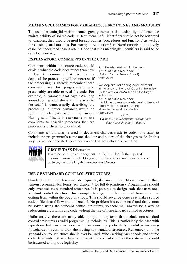
Maintaining Software Solutions 317
Software Design and Development – The Preliminary Course
MEANINGFUL NAMES FOR VARIABLES, SUBROUTINES AND MODULES
The use of meaningful variable names greatly increases the readability and hence the maintainability of source code. In fact, meaningful identifiers should not be restricted to variables; they should be used for subroutines (procedures and functions) as well as for constants and modules. For example, Average:= Sum/NumElements is intuitively easier to understand than A:=B/C. Code that uses meaningful identifiers is said to be self-documenting. EXPLANATORY COMMENTS IN THE CODE
Comments within the source code should explain what the code does rather than how it does it. Comments that describe the detail of the processing will be incorrect if the processing is altered; remember these comments are for programmers who presumably are able to read the code. For example, a comment that says ‘We loop around adding each element in the array to the total’ is unnecessarily describing the processing; a better comment would be ‘Sum the elements within the array’. Having said this, it is reasonable to use comments to describe processes that are particularly difficult to understand.
Comments should also be used to document changes made to code. It is usual to include the programmer’s name and the date and nature of the changes made. In this way, the source code itself becomes a record of the software’s evolution.
USE OF STANDARD CONTROL STRUCTURES
Standard control structures include sequence, decision and repetition in each of their various recommended forms (see chapter 4 for full descriptions). Programmers should only ever use these standard structures. It is possible to design code that uses non-standard control structures; for example, having more than one exit from a loop or exiting from within the body of a loop. This should never be done as it makes source code difficult to follow and understand. No problem has ever been found that cannot be solved using the standard control structures, so there will always be a way of redesigning algorithms and code without the use of non-standard control structures.
Unfortunately, there are many older programming texts that include non-standard control structures as valid programming techniques. This is particularly the case with repetitions but can also occur with decisions. Be particularly careful when using flowcharts; it is easy to draw them using non-standard structures. Remember, only the standard control structures should ever be used. When writing pseudocode and source code statements within a decision or repetition control structure the statements should be indented to improve legibility.
‘Sum the elements within the array For Count = 0 to MaxIndex Total = Total + Results(Count) Next Count
‘We loop around adding each element ‘in the array to the total. Count is the index ’for the array and MaxIndex is the largest ’index used. For Count = 0 to MaxIndex ‘Add the current array element to the total Total = Total + Results(Count) ‘Move to the next array index Next Count Fig 7.5
Comments should explain what the code does rather than how it does it.
GROUP TASK Discussion Examine both the code segments in Fig 7.5. Identify the types of documentation in each. Do you agree that the comments in the second code segment are largely unnecessary? Discuss.

318 Chapter 7
Software Design and Development –The Preliminary Course
Consider the following:
Non-standard control structures have been used to write many software applications in the past. It is possible to draw flowcharts that do not use standard control structures, however the resulting source code will be difficult to follow and consequently difficult to maintain.
Fig 7.6 shows three examples of flowcharts that use non-standard control structures. Don’t ever do this!
APPROPRIATE USE OF WHITE SPACE WITHIN SOURCE CODE
Legibility of source code is critical for maintenance programmers. Including blank lines between subroutines and between significant processing within subroutines greatly improves legibility.
Many languages allow multiple source code statements to be aggregated onto a single line. This is poor programming practice as it unnecessarily clutters the code and hence reduces legibility. Some programmers try to be clever by writing complex lines of code, such as including multiple function calls within a single statement (refer Fig 7.7) for example. It is far better to expand the code over multiple lines to improve legibility.
Yes
No Condition ?
Process 2
Process 1
Sample 1
Yes No Condition 1 ?
Process 2
Process 1 Condition 2
?
No
Yes
Sample 2
Fig 7.6 Sample flowcharts that use non-standard control
structures. Don’t ever do this!
Expression
Process 4 Process 3 Process 1 Process 2
Choice A Choice B Choice C Otherwise
Sample 3
GROUP TASK DiscussionExamine each of the flowcharts at right and explain why the control structure used is incorrect.
GROUP TASK Activity Redraw each of the flowcharts using only standard control structures.
‘Single apparently “clever” line FinalBand = CalcPerfBand(CalcScaleMark(CalcRawMark(StudentID,ClassID),CourseID)) ‘Multiple “legible” lines that perform identical processing RawMark = CalcRawMark(StudentID, ClassID) ScaleMark = (RawMark, CourseID) FinalBand = CalcPerfBand(ScaleMark)
Fig 7.7 Sample “clever” line of code and more legible multiple lines of code.

Maintaining Software Solutions 319
Software Design and Development – The Preliminary Course
A CLEAR AND UNCLUTTERED MAINLINE
The mainline or mainprogram of a software solution should include minimal actual processing. The mainline of many programs will essentially be a series of calls to subroutines. In terms of maintaining software solutions the mainline can be of great assistance in determining the top-down design of the program. For this reason, a clear and uncluttered mainline is preferred. ONE LOGICAL TASK PER SUBROUTINE
Subroutines that accomplish a single logical task increase the maintainability of the product. The longer the subroutine is, the more difficult it will be to understand, test and subsequently maintain. In addition, single task subroutines will prove to be more useful when developing other software product. Short routines that accomplish single well-defined tasks are generally easier to understand, test, reuse and consequently maintain.
UNDERSTANDING SOURCE CODE The major difference between developing software from scratch and maintaining existing solutions is the need to understand the existing solution. This is perhaps the most difficult aspect of maintaining software. We have already discussed reasons why code may need modification and we have examined features that improve the maintainability of code; we now consider the difficult task of actually making sense and understanding the code. Original documentation is the only source of information that is available to assist developers with the task of interpretation. We have already examined documentation within the source code, we now consider the use of other types of documentation. Algorithms are perhaps the most useful means for gaining an understanding of the logic of a solution; and as such, we shall consider them separately to the other forms of documentation. READING ORIGINAL DOCUMENTATION TO UNDERSTAND CODE
Documentation falls within two broad categories: documentation written for users and documentation written for software developers. Each can assist maintenance developers with their task of interpreting existing software solutions. Documentation for the user Before modifying a software product, it is important that the developers understand the operation of the existing product from the user’s perspective. Maintenance developers should be familiar with using the product. User documentation can be of great assistance in this regard. The modifications to be made must work seamlessly with all the existing functionality. Types of user documentation includes: • installation guides • user manuals
GROUP TASK Discussion Clear and uncluttered mainlines as well as subroutines that accomplish single tasks are a consequence of abstraction, refinement and top-down design. Do you agree? How do abstraction, refinement and top-down design assist maintenance programmers? Discuss.

320 Chapter 7
Software Design and Development –The Preliminary Course
Fig 7.8 Screen shots of the existing and updated
save dialogues.
• reference manuals • online help • tutorials Apart from assisting developers understand the product, the user documentation itself will require modification to reflect the changes made to the product. Documentation for software developers The source code itself is the most crucial piece of documentation when modifying software solutions; we have examined source code documentation in detail in the previous section. Other forms of technical documentation, that were produced during the product’s design and development, will also be of assistance when attempting to understand and interpret code in preparation for modification. Types of technical documentation in addition to the source code include: • requirements • design specifications • system models eg. system flowcharts, data flow diagrams, structure charts • IPO charts • data dictionaries • algorithms • screen designs and storyboards As all these forms of technical documentation were crucial to the original development of the product, it makes sense that the information they contain will be of assistance to those wishing to modify the product. For example, structure charts provide an overview of the top down design of the software. Data dictionaries explain the data type and size of each identifier used in the code. This information is crucial when attempting to interpret and understand source code.
During the maintenance process, all original documentation should be updated to reflect the changes. Future developers will need to interpret the code that implements the modifications.
Consider the following:
Imagine you have been assigned the task of modifying an existing software product to enable it to open, save and close files more effectively. Currently the program uses it’s own dialogue to perform this process. The modification aims to use a standard Windows dialogue for both the open and save functions.
Fig 7.8 shows the existing save dialogue together with the expected look of the updated dialogue. The open dialogues are similar apart from the word save being replaced by open.
The documentation available from the original product includes a structure chart (without parameters), data dictionary, the source code, an online user manual and, of course, the existing final product. The source code is written in Visual Basic.

Maintaining Software Solutions 321
Software Design and Development – The Preliminary Course
Examining the functionality of the existing product reveals a number of problems associated with the open and save functions: • If the close cross is used to exit the program, the user is not prompted to save any
changes they may have made. • Exiting the program using the normal file exit command, prompts the user to save
even if no changes have been made to the file. • Choosing the open command, when a file is already open, closes the open file
without prompting the user to save. The online user manual is context sensitive; it explains that only a single file can be open at a time. None of the documentation refers to the three problems mentioned above.
Your next task is to interpret the existing code to determine where the modifications are required. Examining the structure chart should assist in identifying the procedures and functions that will require modification. A copy of the original structure chart without parameters is reproduced in Fig 7.9. It seems clear that the Get file name and also the Confirm operation subroutines are highly likely candidates for modification to include the use of the standard dialogue.
The data dictionary can then be examined to understand how each variable has been used. Data dictionaries describe each identifier, its data type and a description of its purpose; a great help when interpreting code. Fig 7.10 shows a portion of the data dictionary. The ChangeFlag identifier appears to determine whether the file has been changed. The problems we identified when using the product, indicate that it is not being used or perhaps set correctly.
The source code itself can now be read with some knowledge of the program’s structure and variables. Finally, the code to be altered can be identified and then the modifications can be implemented and tested.
GROUP TASK Activity Examine an application with which you are familiar. How many different ways are there to access each of the save and open dialogues? Do any of the above situations arise in the application you examined?
Identifier Data type Description
Word() Array of strings Holds the file data
FileName String Path and filename
TempChar Character Character to be inserted or deleted
ChangeFlag Boolean True after insert or remove operations.
WordCt Integer Number of words
CharCt Integer Number of characters
ParaCt Integer Number of paragraphs
Fig 7.10 Portion of the data dictionary.
Fig 7.9 Structure charts and other models can assist
developers interpret existing software solutions.
Main program
File operation
Edit operation
Calculate statistics
Get file name
Confirm operation
Insert character
Remove character
Delete control characters
Character count
Word count
Paragraph count
Load word array

322 Chapter 7
Software Design and Development –The Preliminary Course
READING ORIGINAL ALGORITHMS
Algorithms describe the logic of solutions, thus they provide an invaluable tool when attempting to understand existing software solutions. The inputs, types of variables used, processes used and also the outputs can all be determined by analysing existing algorithms.
Many modifications to software involve altering the logic of code. As algorithms are the prime method of documenting the logic, it makes sense to make the modifications to the algorithms themselves. The modified algorithm is then implemented within the source code.
Consider the following:
An existing program is used to determine the type of triangle formed when the length of all three sides is known. A problem with this program is encountered; it is possible for three lengths to be entered that cannot form a triangle. The existing program does not deal with this possibility.
The original algorithm is shown in Fig 7.11. Let us analyse this algorithm and then attempt modifications to correct the problem identified.
The inputs into the algorithm are clearly the lengths of the three sides, namely SideA, SideB and SideC. Presumably, these are numeric values. The output is via the variable called Result. As the assignment statements assign words to this variable, it must be of data type string. The processing involves the use of nested binary selection control
GROUP TASK Discussion Examine the structure chart and data dictionary in Fig 7.9 and Fig 7.10. Using these two pieces of documentation, attempt to explain the purpose of this application. As part of your explanation, discuss the processing likely to be taking place in each subroutine on the structure chart.
GROUP TASK Discussion The new open and save dialogues use screens and functions from a dynamic link library. What consequences for users may result from the use of such a library file? What are the social and ethical issues that should be considered in relation to the use of this DLL? Discuss.
GROUP TASK Discussion How could the ChangeFlag identifier be used to correct the three problems identified in relation to the use of the open and save dialogues?
BEGIN Get SideA, SideB, SideC IF SideA=SideB and SideB=SideC THEN Set Result to Equilateral ELSE IF SideA=SideB or SideB=SideC or SideC=SideA THEN Set Result to Isosceles ELSE Set Result to Scalene ENDIF ENDIF Display Result END Fig 7.11
Pseudocode to determine types of triangles.

Maintaining Software Solutions 323
Software Design and Development – The Preliminary Course
structures. These selection statements are used to determine firstly, if the triangle is equilateral, meaning all sides are the same length. Secondly, to determine if it is an isosceles, meaning two sides are of equal length. Lastly, any triangles that are neither equilateral nor isosceles must be scalene, meaning all the sides differ in length.
However, this is not correct; sets of lengths that are not all equal may not form a triangle at all. For example, lengths of 5, 5, and 12 may at first appear to form an isosceles triangle. In fact, no such triangle is possible, as the third length of 12, exceeds the sum of the other two lengths.
CREATING ALGORITHMS FROM SOURCE CODE In many instances, the original algorithms will not be available for use. It is often beneficial to create an algorithm based on the processing within the source code. This can be done so the program can be better understood or it may be required to facilitate coding the program in a different programming language. In any case, the act of creating the algorithm is a worthwhile method of understanding the logic of the source code. There are two main steps involved in the process of interpreting source code into algorithms: identifying each of the control structures and understanding how the variables have been used. Other forms of documentation can assist in this process. For example, system models give an overall view of the processing and data dictionaries provide information about data structures and data types. Identifying control structures If the original code has been written using structured programming techniques then identifying each control structure should be a relatively straightforward process. Code that does not use standard control structures will be more difficult to interpret. Often it is useful to draw a flowchart rather than pseudocode when non-standard control structures are used. It is not possible to represent non-standard structures in pseudocode, whereas it is possible when using flowcharts. Once the logic of the existing solution is understood, the flowchart can be modified to include only standard control structures. Understanding the variables that have been used When we first commenced designing software solutions, we learnt that programs are a combination of data structures and algorithms. Fortunately, the nature of data structures, and therefore variables, can be determined from the source code. In most languages it is necessary to define and declare all identifiers prior to their use in code. And we need to understand the structure and data type of each variable if we are to correctly represent the processing in our algorithms. We also require an understanding of the purpose of each variable and how the processing achieves this purpose, if we are to accurately translate the source code back into an algorithm. Often the name of each identifier will provide a clue and the logic determined when identifying the control structures will also assist.
GROUP TASK Activity Modify the algorithm in Fig 7.11 so that it corrects the problem discussed above. Code the algorithm in a language of your choice and test it to ensure its correctness.

324 Chapter 7
Software Design and Development –The Preliminary Course
Consider the following:
The code shown in Fig 7.12 is written in an old version of BASIC. In this version of BASIC, line numbers are used to determine the order of processing. The code does correctly find all the prime numbers from 1 up to 1000, with one minor error; it doesn’t find the prime number 2. The prime numbers are stored in the array called PrimeArray. This code is actually a subroutine; the return command in line 90 sends control back to the statement following the subroutine call. By modern structured programming standards, the code is a nightmare. There are goto statements everywhere and thus the flow of control is very difficult to follow. Nevertheless, let us try and create a flowchart to represent this mess.
To create the flowchart, we first sequence each statement and place it within an appropriate symbol: rectangles for processes, diamonds for decisions and parallelograms for inputs and outputs. The flow of control goes from top to bottom through each of these symbols reflecting the order of the line numbers within the original source code. Finally, we add flow lines from each decision to the appropriate place on the flowchart. Fig 7.13 shows the completed flowchart.
The completed flowchart more clearly shows the flow of control through the program. If we are to modify this algorithm so it adheres to the rules of structured programming, we need to alter its structure. Notice that their appears to be two loops, both of which seem to be close to post-test repetitions. Actually the outside one is perfectly fine. The inside loop however, has two exit points occuring when Result = Int(Result) and when Counter < Prime is false. This requires correction. It appears that the decision Result = Int(Result) actually behaves like a binary selection structure as well as the termination condition for the inside loop. This situation requires modification.
The variables used in the program have not had their data type explicitly declared. In many older versions of BASIC, it was not necessary to declare variables, rather variables were implicitly declared dependant on the last character of
5 Rem Finding primes 10 Dim PrimeArray(500) 20 Prime = 1 25 Index = 0 30 Counter = 2 40 Result = Prime / Counter 45 If Result = Int(Result) Then GoTo 80 50 Counter = Counter + 1 60 If Counter < Prime Then GoTo 40 70 Print Prime & " is a prime" 75 PrimeArray(Index) = Prime 77 Index = Index + 1 80 Prime = Prime + 1 90 If Prime > 1000 Then Return 100 GoTo 30
Fig 7.12 Old BASIC code for finding primes.
Yes
No
Prime=1
Index=0
Counter=2
Result=Prime/Counter
Result = Int(Result)
?
Counter = Counter+1
Counter < Prime
?
Display Prime
PrimeArray(Index) = Prime
Index = Index + 1
Prime = Prime + 1
Prime > 1000
?
BEGIN
END
No
Yes
Yes
No
Fig 7.13 The code from Fig 7.12
represented as a flowchart.
GROUP TASK Activity Perform a desk check of the code in Fig 7.12. Comment on the difficulties encountered following the flow of control through the program.

Maintaining Software Solutions 325
Software Design and Development – The Preliminary Course
the identifier. For example, % signs meant integer, $ sign meant string and all others meant floating point. The variables in this program are therefore, unnecessarily, of floating point data type. We can surmise from the code and algorithm that Prime, Index and Counter would be better as integers, that Result needs to be of type real or floating point, and that PrimeArray should be an array of integers.
Refer to the following algorithms when answering the questions that follow.
1 BEGIN CreateRandomArray(HighIndex) 2 Count = 0 3 WHILE Count < HighIndex 4 Count = Count + 1 5 MyArr(Count) = Count 6 ENDWHILE 7 RandomiseArray(HighIndex, MyArr) 8 END CreateRandomArray 9 BEGIN RandomiseArray(High, MyArr) 10 Count = High 11 WHILE Count >= 1 12 RandomIndex = INT(High * RND) + 1 13 Temp = MyArr(RandomIndex) 14 MyArr(RandomIndex) = MyArr(Count) 15 MyArr(Count) = Temp 16 Count = Count - 1 17 ENDWHILE 18 END RandomiseArray
Note:
• The INT function returns the whole number or integer part of a number, for example INT(3.66) = 3.
• The RND function generates a different random number from 0 to 0.999999 each time it is encountered.
GROUP TASK Activity Redraw the flowchart in Fig 7.13 using only standard control structures. Ensure your algorithm correctly identifies 2 as a prime number. You may use either pseudocode or a flowchart.
GROUP TASK Activity Code your correctly structured algorithm as a procedure or function in some programming language. Your code should use parameters to interface with its calling routine.
HSC style question:

326 Chapter 7
Software Design and Development –The Preliminary Course
(a) Describe the purpose of each of the following lines in the algorithms.
(i) Lines 2 to 6
(ii) Lines 13 to 15
(b) Complete a desk check of the algorithms using the call CreateRandomArray(5) as follows.
(i) Complete a desk check of the CreateRandomArray algorithm using a table with columns as follows:
HighIndex Count MyArr(1) MyArr(2) MyArr(3) MyArr(4) MyArr(5)
(ii) Complete a desk check of the RandomiseArray algorithm using the following table headings and assuming the RND function produces the numbers 0.2, 0.9, 0.7, 0.6 and 0.5 in turn.
High Count RandomIndex Temp MyArr(1) MyArr(2) MyArr(3) MyArr(4) MyArr(5)
(c) An alternative CreateRandomArray algorithm that achieves the same purpose as the previous version is reproduced below.
1 BEGIN CreateRandomArray(HighIndex) 2 Count = 1 3 WHILE Count <= HighIndex 4 Exists = False 5 REPEAT 6 Temp = INT(HighIndex * RND) + 1 7 Index = 1 8 WHILE Index < Count 9 IF MyArr(Index) = Temp THEN 10 Exists = True 11 ENDIF 12 Index = Index + 1 13 ENDWHILE 14 UNTIL Exists = False 15 MyArr(Count) = Temp 16 Count = Count + 1 17 ENDWHILE 18 END CreateRandomArray
Compare and contrast the logic and likely performance of these two different CreateRandomArray algorithms.
Suggested Solutions
(a) (i) Sets the contents of each array element equal to its index. For example, MyArr(1) is set to 1, MyArr(2) is set to 2 and so on.
(ii) Swaps the contents of the array element MyArr(RandomIndex) with the contents of MyArr(Count).

Maintaining Software Solutions 327
Software Design and Development – The Preliminary Course
(ii) High Count Random
Index Temp MyArr(1) MyArr(2) MyArr(3) MyArr(4) MyArr(5)
5 5 2 2 5 2 4 5 2 2 4 3 4 2 2 3 2 4 3 3 5 1 3 2 2 1 0
(c) The original version is much more efficient as it iterates through the array just
twice – once in the CreateRandomArray subroutine and once again in the call to the RandomArray subroutine. The second version contains three nested loops, furthermore the inner loop contains a selection. The inner loop checks if the random number already exists in the array, if it does then the whole iteration process continues after a new random has been generated. For large arrays it will take many iterations to generate the last element. The worst case being to generate the last element as all other elements already exist. For example, consider generating the last element of an array with 1000 elements. Only one number will not exist, say 567. This requires the middle loop to spin around until it randomly generates 567. Each time it doesn’t generate 567 the inner loop will spin around 999 times looking for an existing match – very inefficient.
(b) (i) HighIndex Count MyArr(1) MyArr(2) MyArr(3) MyArr(4) MyArr(5) 5 0 1 1 2 2 3 3 4 4 5 5
GROUP TASK Activity Code the above two algorithms in a programming language. Test each coded routine using larger and larger values for HighIndex. Comment on your results.
GROUP TASK Research Big-O notation is a mathematical system for approximating the time complexity of algorithms. In the above question the first algorithm is of order n (often written O(n)) and the second algorithm is of order n3 (written O(n3). Research Big-O notation to confirm that the algorithms are O(n) and O(n3) respectively.
GROUP TASK Activity Describe the logic underpinning the processing performed by each of the above algorithms. Demonstrate the general strategy of each approach using slips of paper and a list of random values.

328 Chapter 7
Software Design and Development –The Preliminary Course
CHAPTER 7 REVIEW 1. A constant can best be described as:
(A) a value that changes its contents. (B) a meaningful identifier. (C) a value that does not change. (D) something that has been predefined
in a programming language. 2. Non-standard control structures should:
(A) only be used when creating flowcharts.
(B) only be used when creating pseudocode.
(C) be used when creating both flowcharts and pseudocode.
(D) never be used at all. 3. What is the name of the documentation
that describes identifiers, the data type given to the identifier together with a description of its purpose? (A) IPO chart. (B) Data dictionary. (C) Structure chart. (D) Data flow diagram.
4. What is the principal method for documenting the logic of a software program? (A) Data dictionaries. (B) Context diagrams. (C) Data flow diagrams. (D) Algorithms.
5. Jasmine is a programmer working for a large software development company. She has been given the task of identifying the procedures and functions of a particular program that her company has undertaken to modify for its client base. Which form of technical documentation would be the most useful for Jasmine to examine, to assist her in identifying those procedures and functions that need to undergo modification? (A) IPO chart. (B) Context diagram. (C) Structure chart. (D) Algorithms.
6. Comments within the source code should generally perform what function? (A) They should explain what the code
does rather than how it does it. (B) They should explain how the code
does it rather than what it does. (C) They should explain what the code
does as well as how it does it. (D) They shouldn’t explain anything –
they are only quick notes for the programmer so he/she doesn’t forget where they are up to.
7. Data dictionaries, IPO charts and data flow diagrams are examples of: (A) technical documentation. (B) user documentation. (C) reference manuals. (D) internal documentation.
8. The two main steps involved in the process of interpreting source code into algorithms are: (A) identifying each of the control
structures and then understanding how the parameters have been used.
(B) identifying each of the control structures and then understanding how the variables have been used.
(C) identifying each of the standard control structures and then identifying each of the non-standard control structures.
(D) identifying and then representing both the standard and non-standard control structures into pseudocode.
9. What is the name given to the technical documentation that gives an overall view of a system? (A) System model. (B) Data dictionary. (C) IPO chart. (D) Decision tree.
10. User documentation often consists of: (A) installation guides. (B) online help. (C) tutorials. (D) All of the above.

Maintaining Software Solutions 329
Software Design and Development – The Preliminary Course
11. Describe features within the source code that enhance its maintainability.
12. Documentation of all kinds can greatly assist the job of maintenance programmers. This is obviously true for technical documentation. Is it also true of user manual, online help and other forms of user documentation? Justify your response.
13. In most languages, constants can be declared whose value cannot be changed within the code. Why would this be useful? Explain in terms of modifying the code.
Consider the following Visual Basic .NET code when answering questions 14 and 15.
14. Comment on the documentation within the above code. Can you determine the purpose of the RunAway function?
15. Convert the above Visual Basic function into an algorithm. (Use either a flowchart or pseudocode)
Public Sub RunAway(ByVal X As Single, ByVal Y As Single, ByVal Distance As Integer)
'Me being the current form and cmdMove a button on this form If Y > Me.cmdMove.Top - 100 And Y < Me.cmdMove.Top + Distance + Me.cmdMove.Height Then
'Horizontally in line Me.cmdMove.Top = (Me.Height - Me.cmdMove.Height - 400) * Rnd
If X > Me.cmdMove.Left - 100 And X < Me.cmdMove.Left + Distance + Me.cmdMove.Width Then
'also vertically in line Me.cmdMove.Left = (Me.Width - Me.cmdMove.Width) * Rnd
End If
End If
End Sub

330 Chapter 8
Software Design and Development –The Preliminary Course
In this chapter you will learn to: • use appropriate project management techniques • create and use Gantt charts and logbooks • devise, document and implement an appropriate
backup strategy that incorporates relevant version numbers
• prepare suitable documentation to accompany software solutions
• use appropriate application packages in creating documentation to support a software solution
• create appropriate systems documentation for a variety of programming tasks
• apply the steps in the software development cycle when developing solutions
• produce a working solution from an algorithm derived from a set of specifications
• effectively test a solution • update a solution incorporating new requirements • address relevant social and ethical issues in your
software solutions
Which will make you more able to: • describe and use appropriate data types • describe the interactions between the elements of a
computer system • identify the issues relating to the use of software
solutions • analyse a given problem in order to generate a
computer-based solution • investigate a structured approach in the design and
implementation of a software solution • use a variety of development approaches to generate
software solutions and distinguish between these approaches
• use and justify the need for appropriate project management techniques
• use and develop documentation to communicate software solutions to others
• communicate with appropriate personnel throughout the software development process
• design and construct software solutions with appropriate interfaces.
In this chapter you will learn about: Project management • identifying tasks • identifying required programs, modules and subroutines • Gantt charts • logbooks
– regular record of progress – record of major milestones and stumbling blocks
• allocating resources • regular backup with version numbers • responding to difficulties
– reference to documentation such as manuals – discussion with peers and experts – reporting problems to management
• evaluating the solution – throughout the process – on completion
Documenting software solutions • IPO diagrams • context diagrams • data flow diagrams (DFDs) • storyboards • structure charts • system flowcharts • data dictionaries • Gantt charts • logbooks • algorithms • user documentation including manuals and online help Developing software solutions • defining and understanding the problem
– preparation of initial documentation • planning and designing
– identification of a suitable development approach – design of appropriate algorithms – identification and incorporation of appropriate existing
algorithms – determination of appropriate data structures – identification of relevant subroutines – design of test data and expected output – desk check of algorithms – identification of existing code that can be used
• implementing – coding the solution in an appropriate language – testing using test data – documenting the solution, including:
- algorithms - test data and expected output - data dictionary - user documentation
• testing and evaluating – testing of the solution using test data – evaluating the implemented solution
• maintaining – modifying the solution to meet original or changed
specifications Social and ethical issues related to software solutions • intellectual property • ergonomics issues • inclusivity and accessibility • privacy

Developing Software Solutions 331
Software Design and Development – The Preliminary Course
8 DEVELOPING
SOFTWARE SOLUTIONS Learning to design and develop software solutions is the aim of this course. In this chapter, we work through this process using a sample project. Remember, there are many possible development approaches and many different techniques that could be used as part of the creation of a software product. We will be using just some of these throughout this chapter. Projects you develop may lend themselves to different approaches and techniques. One area we have not yet examined in detail is the overall project management of the design and development process. This is a vital aspect if tasks are to be completed on time and resources are to be available when required. Project management tasks to consider include: • Identification of tasks – what needs to be done to complete the project? • Allocation of resources – do we have the personnel, hardware, software, etc…
available to complete the tasks when required? • Documentation – what documentation will be kept, including project management
documents such as Gantt charts and log books? • Regular backup – what techniques and strategies are required to ensure the safety
and security of work in progress? How will different versions of the software be retained during development?
• Response to difficulties – it is almost inevitable that problems will occur. Programming language manuals and access to peers and other experts are invaluable resources. How will we deal with and overcome difficulties we will inevitably encounter?
• Regular reporting – who needs to be kept informed of the project’s progress and how will this be achieved?
• Evaluation – how will the success of the project and the development process be evaluated both during development and after completion?
Project management is about ensuring projects are completed on time and that they achieve their objectives. Commercial software development teams would be assigned a project manager whose task is to coordinate the overall design and development process. These managers require high-level communication and time-management skills. They must be able to adapt to change, motivate people and resolve conflicts. Their job is to focus all personnel and resources on the accomplishment of the project’s goals.
GROUP TASK Discussion Examine each of the above bulleted points. Create a list of items that should be considered when answering each of these questions. Share and discuss your responses with the class.

332 Chapter 8
Software Design and Development –The Preliminary Course
DEVELOPING SOFTWARE SOLUTIONS In the real world, software developers are presented with problems to solve. In our case, we must first decide on the type and nature of the project we wish to produce. It is important to select a project that will be useful and that can be realistically achieved. Often this is not an easy task and it may be necessary to examine a number of possibilities in detail before making the final decision. During the creation of your software project, it is worthwhile maintaining a process diary or logbook. Use this as you would a normal diary; write down details of the design and development process as it unfolds. This logbook will prove invaluable when it comes time to evaluate the project after completion. SAMPLE PROJECT For the purpose of this chapter, we shall develop a software application to automate the operation of various household devices. There are hardware modules available that transmit and receive messages using the power cabling within the walls of the house using the X10 protocol. The aim of this project is to control these modules enabling different devices to be switched on and off in various sequences and at various times. The most useful devices to control are those that would normally have their own individual timers and those devices where switching them manually is inconvenient because of the location of the switch. Examples include pool filters, garden lights, watering systems and perhaps inside lamps for when children wake in the night. The system includes motion sensors that can be used to activate home security systems or just to switch other devices on or off. For example, for deaf people, a motion sensor could be used to detect someone entering the property and cause the lights in the house to flash on and off. In the USA and across many other countries, there are various implementations of this ‘smart home’ concept; a number of these are available in Australia. Some applications include: automated video surveillance, the ability to control devices in the home using a mobile phone or the internet, and multifunction remotes that control music and video systems as well as lights and other household appliances. Each of these systems can be integrated to further enhance the system’s functionality. For example, if you are away from home and an intruder is detected by the video surveillance system you could have your house dial your mobile phone and then email you video footage of the intrusion. Furthermore, you could then call the house and turn on the sprinklers, turn the stereo on at full volume and flash all the lights in the house on and off.
Fig 8.1 View of a backyard showing various devices
that could be controlled using our project and X10 hardware modules.
GROUP TASK Activity Research the ‘smart home’ concept using the Internet. Make a list of all the devices and applications you find. Which do you think are the most useful? Discuss your findings with the class.

Developing Software Solutions 333
Software Design and Development – The Preliminary Course
DEFINING AND UNDERSTANDING THE PROBLEM Before the design of our project can commence, we need to define and understand the problem precisely. What exactly is it that we hope to achieve, in other words what are our requirements? We also need to be confident that these requirements are achievable. To do this requires some detailed research in regard to the X10 protocol and its related hardware. Firstly let us reconstruct our problem as a set of requirements: • The software will be able to switch devices attached to the mains power on and off
using the X10 protocol. • Devices can be manually turned on or off using the application’s main screen. • The software can automatically turn devices on and off at preset times each day. • Messages received from motion sensors can be used to turn on or off other
devices. Different devices can be switched depending on the preset times. • Timing and other settings are to be stored in a file. Different files can be used for
different sequences. • The software is to run on a Windows platform. • All devices that are on should be highlighted on the main screen. A brief overview of X10 is in order. Firstly, each hardware module is either a receiver or a transmitter or both. Receivers detect X10 commands on the power lines and transmitters place X10 commands on the power lines. The power lines within the house being the communication medium for the transfer of instructions. There is no need for special wiring, X10 uses the existing power cables, this is the main advantage of X10 over other systems. Each X10 hardware module has its own two character address comprising; a house code from A to P, and a unit code, from 1 to 16. This gives a total of 16 times 16 or 256 possible unique addresses. These addresses are set manually on each device using a small screwdriver during installation (see Fig 8.2). For example, the garden lights may be A1 and the pool filter A2. To turn on the pool filter requires the transmission of a message to turn A2 on. The module attached to the filter’s power point responds by switching on the power. Let us now examine some X10 hardware modules and consider some of the detail of their operation. The most vital module is the computer interface module (CM11), this module recieves instructions via the computer’s serial port and converts them to X10 messages, which in turn are transmitted down the existing power cables within the house. This interface also detects X10 messages on the power cable and transmits them back to the computer’s serial port. Without this hardware module our project would be impossible to implement. The unit also has its own memory, battery backup and clock, we will not use these features in our project. Rather our application will need to be running at all times and will use the computer’s clock to determine the timing of events.
Fig 8.3 The CM11 computer
interface module attaches to one of the
computer’s serial ports.
Fig 8.2 An X10 module set
to house code A and unit code 8.

334 Chapter 8
Software Design and Development –The Preliminary Course
Each device to be controlled requires either an X10 appliance module, X10 lamp module or an X10 universal module. Appliance modules are designed for higher power consumption applications where as lamp modules contain a built-in dimmer function. For our project we will not utilise the dimmer function. The universal module is used to switch low voltage devices on and off. Each of these modules are receivers only, they are able to turn on devices or turn off devices in response to X10 messages containing their address.
Both lamp and appliance modules are available as plug-in units or units that are hardwired. The plug-in units simply plug into an existing power point and then the appliance or lamp to be controlled is plugged into the X10 module. Hardwired units can take the place of a power point or can be installed behind an existing power point. Hardwired modules should only be installed by qualified electricians. Universal modules plug into an existing power point and incorporate low voltage input and output connections.
There are various sensors available that transmit X10 messages. For our purposes, let us consider a wireless motion sensor and its related receiver. Motion sensors also have an X10 address, when motion is detected they transmit a radio frequency (RF) message containing their address together with an on signal. This message is received by an RF transceiver module. The transceiver then transmits the message over the power line. After a motion sensor sends an on message it waits a preset period of time. If no motion has been detected during this time, an off message is sent. Multiple motion sensors can transmit to a single transceiver, in fact the transceiver can receive RF signals from a variety of different types of wireless devices. The transceiver is both a receiver and also a transmitter; it receives RF messages from wireless devices and it transmits these RF messages onto the power lines.
A typical scenario where a motion sensor may be used in conjunction with our project could be: as you walk out the back door of your house, the motion sensor with address B1 detects your movement. It sends an on message to the transceiver which in turn transmits a B1 on message over the power lines. This message is received by the CM11 computer interface and sent to the serial port of the computer. The software responds by say, sending messages to turn on A1 and A4, which may be the garden and pool lights. These messages reach the CM11 unit via the serial port where they are transmitted across the powerlines. The X10 module wired to the garden light responds to the A1 on message and the garden light turns on, similarly the A4 on message causes the pool light to turn on. If no motion is detected for a period of time, the motion sensor would transmit a B1 off message resulting in units A1 and A4 being turned off.
Fig 8.4 An X10 plug-in lamp module.
Fig 8.5 Lamp and appliance modules can be hardwired by an electrician.
Fig 8.6 An X10 motion sensor and associated RF transceiver.

Developing Software Solutions 335
Software Design and Development – The Preliminary Course
IDENTIFICATION OF INPUTS, PROCESSES AND OUTPUTS
Let us first create a list of inputs into our software, together with a list of outputs. These lists should give us an indication of the processing required to transform the inputs into the outputs. We can then construct a high-level model of our software describing the general nature of the processing.
Inputs include: • X10 commands from the serial port. • Current time from the computer’s clock. • Timer settings from stored files. • User input of manual on and off commands. • User input to create or edit timer setting files.
Outputs include: • X10 commands sent to the serial port. • Timer setting files saved to disk. • Display of the status of each device.
Examining and considering the above inputs and outputs a number of relatively independent high-level processes emerge: • Creation, editing and saving of timer setting files. • Display of current status of all devices. • Manually turning devices on or off. • Implementing timer setting files.
Creation,
editing and saving of
timer setting files
Display of current
status of all devices.
Imple-menting
timer setting files. Manually
turning devices on
or off.
User
Serial port
Disk files
Computer clock
settings
timer settings file
timer settings file
timer settings file
time
on/off details
X10 commands
X10 commands
X10 commands
on/off details
on/off inputs
Fig 8.7 Dataflow diagram (DFD) for the X10 device control project.
GROUP TASK Discussion Examine the above dataflow diagram. Describe the flow of data and the general nature of the processing described on this diagram.

336 Chapter 8
Software Design and Development –The Preliminary Course
Let us now develop a series of IPO diagrams to further assist our understanding of the problem. At this stage, we need not concern ourselves too much with the detail of how the processing will occur rather our purpose is to understand what processing will be required. We create an IPO diagram for each process identified on the DFD.
Analysis of the processing during the creation of the above IPO diagrams raises a number of issues: • a number of the IPO diagrams contain similar or identical processes. Perhaps at
the implementation stage these should be implemented as single subroutines. • We need to carefully consider the design of suitable data structures to make
accessing the timer and other settings as efficient as possible. This includes the structure of the saved files.
• In regard to the ‘Implementing timer settings’ files IPO diagram, it seems there are two relatively independent processes occurring; implementing settings based on the current time and implementing X10 commands originating from sensors. Perhaps, it would be better to separate these two processes.
Input Process Output On or off command
Send command to serial port
X10 command
Change status of device
Refresh device status display on main screen Status details
IPO DIAGRAM Manually turning devices on or off
IPO DIAGRAM Display of current status of all devices
Input Process Output
List of devices
Format and display each address and description..
List of devices on main screen
Status of each device
Refresh status of each device on main screen.
Status of each device on main screen
IPO DIAGRAM Implementing timer setting files
Input Process Output Current time from computer’s clock
Update time every minute.
Check timer settings for each device
X10 command from serial port
Receive X10 commands as they are detected
Check sensor exists and is active
Refresh status of each device on main screen.
Status of each device on main screen
Send appropriate X10 commands(s)
X10 commands to serial port
IPO DIAGRAM Creation, editing and saving of timer setting files
Input Process Output file name and location from user
Create new file or open existing file.
Various settings from user
Add new devices or edit existing devices and settings
Save edited file Timer settings file
Fig 8.8 Preliminary IPO diagrams (or charts) for the X10 device control project.
GROUP TASK Discussion Examine the above IPO diagrams in conjunction with the above comments. Discuss the issues above and brainstorm possible solutions.
Developing Software Solutions 337
Software Design and Development – The Preliminary Course
IDENTIFYING A SUITABLE DEVELOPMENT APPROACH
We need to decide on a software development approach. Do we use a structured, prototyping, rapid application development (RAD) or end user approach? After some thought we decide on a cross between the prototyping and RAD approaches. The plan is to create a prototype of the user interface based on our understanding of the problem. This prototype will initially contain no real processing, that is, it will not actually receive or transmit X10 commands. The aim being to first design and develop a user interface that can be evaluated by potential users. As the development progresses each subsequent prototype will have added functionality. As we have experience using Visual Basic we will build our solution using this language. Visual Basic is particularly suited to RAD as it allows various components to be integrated into a single software solution.
Before continuing with the actual planning of the project let us briefly consider the stages and timing of our design and development process. We create a general overview of the projected nature of each of our prototypes: • Prototype 1. – Initial storyboard of screen designs and creation of user interface.
The only processing being the ability to open screens and close them from the appropriate places.
• Protoype 2. – Inclusion of file creation, editing and save functionality. Also modifications to the user interface to reflect evaluation of prototype 1.
• Prototype 3. – Add ability to manually turn devices on and off. Also modifications due to evaluation of prototype 2.
• Prototype 4. – Acting on timer settings. Sending messages to turn devices on and off once the computer clock reaches the required time. Also modifications due to the evaluation of prototype 3.
• Prototype 5. – Acting on X10 commands from sensors. This prototype includes all the functionality of the final product. Also modifications due to the evaluation of prototype 4.
• Final modifications. – Modifications are made in response to the evaluation of prototype 5. We also need to thoroughly test the final solution and create setup files for distribution.
• Documentation – Create user documentation and ensure all development documentation is correct.
We need to ensure that our project is completed within the available timeframe; let’s just assume we have three months or about fourteen weeks to complete the project. To facilitate this process we create a Gantt chart (see Fig 8.9). Gantt charts are graphs designed to ensure each task that forms part of a project is sequenced correctly and is allocated an appropriate amount of time. Before finalising the Gantt chart, we should also ensure required resources will be available when needed.
GROUP TASK Discussion Do you think the use of a rapid prototyping software development approach is suitable for this project? Justify your response.

338 Chapter 8
Software Design and Development –The Preliminary Course
Fig 8.10 Initial design for the main screen.
PROTOTYPE 1 Initial storyboard of screen designs and creation of user interface. The only processing being the ability to open screens and close them from the appropriate places.
We first develop a series of screen designs on paper. After much thought, and many trashed designs, we decide on a series of designs. The first prototype requires three screens: the main screen, the edit devices screen and the edit sensor commands screen.
Time (weeks)
Prototype 1
Prototype 2
Prototype 3
Prototype 4
Final modifications
Documentation
0 3 2 4 5 6 7 8 9 10 11 12 13 14 15 1
Task
Development
Evaluation
Fig 8.9 Gantt chart for the X10 device control project’s development.
GROUP TASK Discussion Examine the above Gantt chart. How will this chart assist during the development process? Why do you think so much time is spent on evaluation? How can the next prototype be commenced before the previous one has finished being evaluated? Discuss.

Developing Software Solutions 339
Software Design and Development – The Preliminary Course
The screens accessed from the file menu will use standard MS-Windows dialogs, similarly for the help screens. These screens will be added in subseqsequent prototypes as the need arises. Let us consider the operation of each of the three screens included in this prototype.
The main screen (see Fig 8.10) contains drop down menus to access functions. All devices are listed on the screen together with their current status. Clicking once on a description selects that device. If you then choose the Edit option on the Device menu the Edit Device screen opens with the details of the selected device displayed. Double clicking a description also opens the Edit Device screen for that device. Clicking on the status of a device toggles the device on and off. On will be displayed in green and Off in red as a further visual indicator. Sensor devices can have a status of Active or Inactive based on their timer settings. At the bottom of the screen, the last X10 command sent or received is displayed together with the time it occurred. The current time is displayed in the right hand bottom corner.
The edit device screen is used to set the details for each device (see Fig 8.11). It is essentially a data input screen. If the sensor check box is selected then the Edit Commands command button becomes active and the timing labels change to Active from and Active to. Clicking on the Edit Commands button will then open the Edit Sensor Commands screen. The timing settings for recievers cause them to turn on or off at the specified times. The timing settings for transmitters (sensors) cause the commands specified on the Edit Sensor Commands screen to become active between the specified times. Often users will wish different commands to take place at different times in response to sensors. For example, at night time we may wish the garden lights and fountain to switch on whereas during the day only the fountain should turn on. The user would create two devices using the same sensor to implement such a scenario.
The Edit Device screen, and also the Edit Sensor Commands screen, should be modal. This, in effect, means they must be closed before the user can return to the parent screen.
Fig 8.11 Initial design for the edit device screen.

340 Chapter 8
Software Design and Development –The Preliminary Course
The Edit Sensor Commands screen lists all devices that are not sensors. It is used to specify the commands to be sent when a sensor message is received. For example, the data on the screen in Fig 8.12 means: when the backyard sensor with address B1 transmits an on command the fountain will turn on and the lawn sprinklers will turn off, when the sensor tranmits an off command the fountain will turn off. Note that this will only occur between the times specified on the Edit Device screen.
We now need to build our user interface in Visual Basic. The device lists on both the main screen and the edit sensor commands screen are best implemented using a grid control. Other controls used include forms, menus, text boxes, labels, command buttons and a status bar for the bottom of the main screen. Each control’s name commences with a three character mnemonic to indicate its type.
Fig 8.12 Initial design for the edit sensor command screen.
GROUP TASK Discussion Examine the above screen designs. Can you suggest any modifications that may improve their useability? Discuss.
Fig 8.13 The main screen implemented in Visual Basic. Each control’s name commences
with a three character mnemonic eg. the screen is called frmMainScreen
grdStatusGrid
mnuAddNew
mnuEdit
stbCommandTime
frmMainScreen

Developing Software Solutions 341
Software Design and Development – The Preliminary Course
The screen shots in Fig 8.14 show the completed user interface and in particular they show the changes resulting when the value of the sensor check box is altered. This is really the only significant piece of processing that requires some thought. Fig 8.15 shows the Visual Basic .NET procedure created for this purpose. When reading this code, be aware that when a check box is checked it’s Checked property is true and when it is not checked this property is false. Other code is written to open and close forms from the appropriate places. Both the Edit Device and Edit Commands screens are opened as dialogs using the ShowDialog method – this ensures users must complete editing before returning to the main screen. The main screen also requires properties to be set appropriately to alter the size of the grid should the user resize the window. These settings maintain the status column at a constant width whilst the device column grows and shrinks to fit. The completed prototype is compiled into an executable file and distributed via email to a number of friends for evaluation. At this stage, we are primarily interested in their ability to intuitively understand the operation of the user interface, however they are asked to comment on any errors they encounter.
Private Sub SensorInput() cmdEditCommands.Enabled = chkSensor.Checked If chkSensor.Checked Then lblOn.Text = "Active from:" lblOff.Text = "Active to:" Else lblOn.Text = "On at:" lblOff.Text = "Off at:" End If End Sub Fig 8.15
Procedure to alter aspects of the Edit Device screen when the value of the sensor check box is altered.
Fig 8.14 EditDevice and EditCommands screens for the X10 controller project.
Note the changes dependent on the sensor check box.
Clicking on Edit Commands button opens the Edit Commands screen

342 Chapter 8
Software Design and Development –The Preliminary Course
PROTOTYPE 2 Inclusion of file creation, editing and save functionality. Also modifications to the user interface to reflect evaluation of prototype 1.
Before we can create, edit or save a settings file we must determine the data structures to use within the code. We can then work out a method for arranging and then storing this data to a disk file.
Let us list the data items required for each device to be controlled by our project: • Description – a text description of the device eg. Pool light. • X10 Address – two or three characters, the house code being a letter from A-P, the
remainder being characters representing the unit number from 1 to 16 eg. A14. • Sensor – Boolean, either the device is a sensor or it is not eg. True or False. • Time On 1 – four digits representing time in 24 hour format eg. 1430. • Time Off 1 – same as Time On 1. • Time On 2 – same as Time On 1. • Time Off 2 – same as Time On 1.
For each sensor, we also require data in regard to which devices should be turned on or off when the sensor turns on and similarly for when the sensor turns off: • Sensor identifier – so we know which sensor this data applies to. • Sensor message – Boolean value indicating whether this data applies when the
sensor turns on or when the sensor turns off. • Device identifier – some method of identifying the device to be turned on or off. • Device command – Boolean value indicating whether to turn the device on or turn
the device off.
There is no data item that uniquely identifies a particular device, however we need one to use as the sensor and device identifier in the above structure. The simplest solution is to add an extra field specifically for this purpose. We can use an integer that is incremented for each new device.
Let us examine some sample data to assist our understanding. We then create a type declaration to define each data structure in Visual Basic .NET.
Consider sample data on each device: Description X10
Address Sensor Time
On 1 Time Off 1
Time On 2
Time Off 2
Device Identifier
Garden Lights A1 False 1800 2200 0500 0630 1 Pool Filter A2 False 2300 0400 2 Fountain A3 False 3 Pool Light A4 False 4 Backyard Sensor Day B1 True 0700 1730 5 Backyard Sensor Night B1 True 1730 2300 0400 0700 6
GROUP TASK Activity Identify and suggest names for each of the controls used on the Edit Devices and Edit Sensor Commands screens.
GROUP TASK Discussion To make the screens open and close in the appropriate places requires statements to be executed in response to particular events. Identify the events and controls where these statements must be located.

Developing Software Solutions 343
Software Design and Development – The Preliminary Course
This data could be implemented as an array of records. To reflect the sample data above each record would require eight fields. However it may be more efficient to combine the time on and off fields into an array containing four elements. Splitting the X10 address into House and Unit code will likely assist data entry and validation. In addition we will require a field to store the current status of each device (either On or off) whilst the program runs. Each record would therefore have seven fields, one of them being the time array which will contain four elements. Note that devices need not have any timer settings entered, however all other fields must contain data.
In Visual Basic .NET, these user defined type definitions are best placed within a module so they can be used throughout the application. If we use the Public keyword then we can use our data structures to declare instances of these data types anywhere within our code. Fig 8.16 is the code used to define the DeviceRecord data structure in Visual Basic .NET. We will later use this definition to create an array of these records for storing each device. We now consider the structure to store the commands resulting from a sensor command (refer Fig 8.17). A separate record is used for each command that will be transmitted when a sensor’s message is received. Again, we will require an array of these records. Some sample data is reproduced in the table below:
We now need to consider the processing required to build the solution in Visual Basic using the above data structures. Some issues that need to be considered. 1. Data entered on the Edit Device screen needs to be stored in the appropriate
position within the device data structure. To do this, we need to track the number of devices currently stored.
2. Data held in the device data structure should be reflected on the main screen. The grdStatusGrid on the main screen (refer Fig 8.13) is a DataGridView .NET component. This component can be bound to a data source (such as our device data structure) to manage updating of the display to reflect the current data.
GROUP TASK Discussion Examine the Visual Basic code in Fig 8.16 and 8.17 in conjunction with the sample data in the tables. What are the links between data held in these two structures? Discuss using examples from the sample data.
Sensor Identifier
Sensor Message
Device Identifier
Device Command
6 On 1 On 6 On 3 On 6 On 4 On 6 Off 1 Off 6 Off 3 Off 5 On 3 On 5 Off 3 Off
'Structure for storing sensor commands Public Structure SensorRecord Public SensorID As Integer 'matches the sensor’s ID Public SensorMessage As Boolean 'On or Off Public DeviceID As Integer 'not the ID of a sensor Public DeviceCommand As Boolean 'On or Off End Structure
Fig 8.17 Visual Basic .NET definition for the
SensorRecord data structure.
'Structure for storing each X10 device Public Structure DeviceRecord Public Description As String 'Name of device Public House As String 'A-P Public Unit As String '1-16 Public Sensor As Boolean 'True if it is a sensor Public ID As Integer 'must be unique Public Time() As String '24 hour time 0001 to 2400 Public Status as String ‘On or Off End Structure
Fig 8.16 Definition of the DeviceRecord data structure.

344 Chapter 8
Software Design and Development –The Preliminary Course
3. File operations should use MS-Windows dialogs. .NET components called the OpenFileDialog and SaveFileDialog are available to simplify this process.
4. Save function must write the entire contents of both device and sensor command data structures to a file.
5. Open command needs to first remove data in memory before reading the data from the file into the device and sensor command data structures.
6. Need to determine if data in memory has been saved. We don’t want to open an existing file whilst unsaved data is loaded, similarly when exiting the program and creating new files.
Let us create an algorithm for the first item in our list (see Fig 8.18). This algorithm includes the identifier DeviceCount, this variable is used to store the number of records that are currently held in the Device array. This identifier would be used in many places throughout the project, so we declare it as a global variable. Similarly for the IDCount identifier. This variable is used to uniquely identify each record in the Device array.
Two processes in Fig 8.18 require further detail; the ValidInputs function and refreshing the main screen to reflect data changes. Refreshing the main screen will be required whenever data is changed and fulfils the second item on our list above. Initially we code the ValidInputs function as a simple stub which always returns true.
Consider the second item on our list, namely, refreshing the main screen. Essentially we need to load the grid on the main screen with the current device data held in the Device array. After testing we find the .NET DataGridView component includes a DataSource property which when set to the Device data structure causes the grid to be refreshed with the current data. In our application, the statement grdStatusGrid.DataSource = Device effectively causes the grid to display the current data. Edits to the DeviceRecord structure were also needed to change the fields we wish to display to properties, for example, Public Property Description As String rather than Public Description As String. Similar edits are made to the House, Unit and Status fields within the DeviceRecord structure defined in Fig 8.16.
GROUP TASK Discussion We have not considered the format of the data files. Discuss the data items that need to be saved and possible formats for this data.
BEGIN StoreDevice IF ValidInputs THEN IF New device THEN Add 1 to DeviceCount Resize Device array to add one more record Index = DeviceCount Increment IDCount Device(Index).ID = IDCount Device(Index).Status = “Off” ELSE Index = current record index on main screen ENDIF Device(Index).Description = description on form Device(Index).House = House on form Device(Index).Unit = Unit on form Device(Index).Sensor = sensor check box Device(Index).Time(0) = On1 on form Device(Index).Time(1) = Off1 on form Device(Index).Time(2) = On2 on form Device(Index).Time(3) = Off2 on form Refresh the main screen Close edit device screen END IF END StoreDevice
Fig 8.18 Algorithm to store data from the edit device
screen in the Device data structure.
GROUP TASK Discussion Examine the pseudocode in Fig 8.18. Discuss how this algorithm operates to achieve its purpose.

Developing Software Solutions 345
Software Design and Development – The Preliminary Course
The StoreDevice subroutine will be executed each time the user clicks on the OK button on the EditDevice screen (refer Fig 8.14). In summary the StoreDevice routine updates the Device array with edits to existing records and creates a new record for any new devices entered by the user.
We now create algorithms and code to save the data to a file and open files previously created. Source code to open an existing file is reproduced in Fig 8.19 and Fig 8.20.
Public Sub OpenFile() Dim FileName As String Dim FileNum As Integer Dim Count As Integer, C As Integer
'first check for existing data and see if it is wanted If CheckExisting Then 'data exists Exit Sub End If
OpenFileDialog1.Filter = "X10 Settings (*.x10)|*.X10" OpenFileDialog1.FileName = "" OpenFileDialog1.ShowDialog() FileName = OpenFileDialog1.FileName If FileName = "" Then Exit Sub
'adjust the main screen caption to include the file name Me.Text = "X10 Controller (" & FileName & ")"
'open the file for reading FileNum = FreeFile FileOpen(FileNum, FileName, OpenMode.Input)
'read the data for each device Input(FileNum, DeviceCount) Input(FileNum, IDCount) ReDim Device(DeviceCount) For Count = 0 To DeviceCount - 1 Input(FileNum, Device(Count).Description) Input(FileNum, Device(Count).House) Input(FileNum, Device(Count).Unit) Input(FileNum, Device(Count).Sensor) Input(FileNum, Device(Count).ID) ReDim Device(Count).Time(3) For C = 0 To 3 Input(FileNum, Device(Count).Time(C)) Next Device(Count).Status = "Off" Next
'read the data for each sensor command Input(FileNum, SensorCommandCount) ReDim SensorCommand(SensorCommandCount) For Count = 0 To SensorCommandCount - 1 Input(FileNum, SensorCommand(Count).SensorID) Input(FileNum, SensorCommand(Count).SensorMessage) Input(FileNum, SensorCommand(Count).DeviceID) Input(FileNum, SensorCommand(Count).DeviceCommand) Next
‘close the file FileClose(FileNum)
'resetting datasource causes refresh of grid grdStatusGrid.DataSource = Device
End Sub Fig 8.19 Source code for OpenFile subroutine in Visual Basic .NET

346 Chapter 8
Software Design and Development –The Preliminary Course
Assume we have completed the requirements for prototype 2 (essentially the 6 steps on pages 343-344). We now need to consider changes in response to our evaluation of prototype 1. Most of the comments were in regard to validating data entry on the EditDevice screen. These issues are corrected as part of the ValidInputs function we previously wrote as a simple stub. This function is called before the data on the EditDevice screen is stored in the Device data structure (refer StoreDevice algorithm in Fig 8.18).
Examining the input areas on the EditDevice screen (Fig 8.14), a number of possible user input errors need to be checked by the ValidInputs function: 1. Description – a blank description is not appropriate. 2. House code – must be a single upper case letter from A through to P. 3. Unit code – must be an integer from 1 to 16. 4. Timing – 24 hour time so must be in the range 0001 to 2400. The third digit
represents the ten’s column for minutes and therefore cannot be greater than 5.
GROUP TASK Discussion Examine the OpenFile source code in Fig 8.19. Describe the structure of the files that are opened (and saved) by the program.
Public Function CheckExisting() As Boolean Dim msgResult As Integer Dim Check As Boolean = False
If DeviceCount > 0 Then 'data exists msgResult = MsgBox("Only one file can be open at a time." & vbCrLf & "Unsaved changes will be lost." & vbCrLf & "Do you want to continue?", vbOKCancel + vbExclamation, "Open File") If msgResult = vbOK Then NewFile() Else Check = True End If End If
Return Check
End Function
Public Sub NewFile() ReDim Device(0) ReDim SensorCommand(0) DeviceCount = 0 SensorCommandCount = 0 grdStatusGrid.DataSource = Device Me.Text = "X10 Controller" End Sub Fig 8.20
Source code for CheckExisting and NewFile subroutines.
GROUP TASK Discussion Why do you think the CheckExisting and NewFile subroutines in Fig 8.20 are written as separate subroutines rather than their statements being included directly within the OpenFile subroutine? Discuss.
GROUP TASK Activity Create a structure chart for the OpenFile, CheckExisting and NewFile subroutines shown in Fig 8.19 and Fig 8.20.
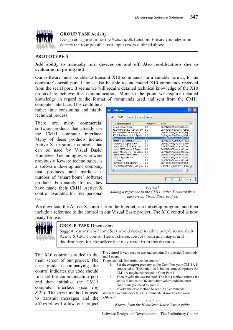
Developing Software Solutions 347
Software Design and Development – The Preliminary Course
PROTOTYPE 3 Add ability to manually turn devices on and off. Also modifications due to evaluation of prototype 2.
Our software must be able to transmit X10 commands, in a suitable format, to the computer’s serial port. It must also be able to understand X10 commands received from the serial port. It seems we will require detailed technical knowledge of the X10 protocol to achieve this communication. More to the point we require detailed knowledge in regard to the format of commands used and sent from the CM11 computer interface. This could be a rather time consuming and highly technical process.
There are many commercial software products that already use the CM11 computer interface. Many of these products include Active X, or similar controls, that can be used by Visual Basic. HomeSeer Technologies, who were previously Keware technologies, is a software development company that produces and markets a number of ‘smart home’ software products. Fortunately, for us, they have made their CM11 Active X control available for free personal use.
We download the Active X control from the Internet, run the setup program, and then include a reference to the control in our Visual Basic project. The X10 control is now ready for use.
The X10 control is added to the main screen of our project. The user guide accompanying the control indicates our code should first set the communication port and then initialise the CM11 computer interface (see Fig 8.22). The exec method is used to transmit messages and the x10event will allow our project
GROUP TASK Discussion Suggest reasons why HomeSeer would decide to allow people to use their Active X CM11 control free of charge. Discuss both advantages and disadvantages for HomeSeer that may result from this decision.
GROUP TASK Activity Design an algorithm for the ValidInputs function. Ensure your algorithm detects the four possible user input errors outlined above.
Fig 8.21 Adding a reference to the CM11 Active X control from
the current Visual Basic project.
The control is very easy to use and contains 3 properties 5 methods and 1 event. To get started, first initialize the control.
1. Set the comport property to the Com Port your CM11A is connected to. The default is 2, but on some computers the CM11A maybe connected to Com Port 1.
2. Then invoke the init method. The init() method returns the status. 0 indicates OK and other values indicate error conditions you need to handle.
3. Invoke the exec method to send X10 commands. When the module detects X10 commands, it invokes the event x10event.
Fig 8.22 Extract from the HomeSeer Active X user guide.

348 Chapter 8
Software Design and Development –The Preliminary Course
to receive messages. For prototype 3 we need to just transmit messages to receiving X10 devices, so for the time being we need only concern ourselves with the exec method. Examining the documentation for the X10 control reveals the format of the exec method: controlname.Exec (housecode as String, devicecode as String, command as Integer)
The housecode is from A to P, devicecode from 1 to 16 and command from 0 to 15. The only commands relevant to our project are the on and off commands which correspond to values of 2 and 3 respectively. For example, the statement exec(“A”,”1”,2) would cause the device with address A2 to turn on. Let us now consider the processing required to allow us to manually turn devices on and off. Remember this will occur when the user double clicks on the status of a device on the main screen. 1. We need to determine the serial port (comport property of the X10 Active X
control) where the CM11 computer interface is connected. We then initialise this port as the program loads.
2. When the user double clicks on the status of a device: • the status message changes from off to on, and the colour of the text changes
from red to green, and vice versa. • the Status field for the device is changed in the Device array. • a message is displayed in the status bar at the bottom of the screen • the appropriate exec command is sent to the X10 Active X control.
Let us consider the first item on our list. It would be nice if the user had the option to connect or not connect to the CM11 unit. This would allow the program to simulate operation where a CM11 unit was not available. Furthermore it would be good if the program could search the serial ports to find the location of the CM11 unit automatically. We decide to implement this initialisation of the CM11 unit using a separate form which opens over the top of the main screen when the program is first launched. Assume the form and its opening functionality have already been implemented in Visual Basic. If the user selects OK the code attempts to initialise the CM11 interface from serial port 1 through to port 4. Fig 8.23 shows an initial view of the project, including this form, and Fig 8.24 shows the form after the user clicks OK and initialisation of the CM11 fails and then again after a successful initialisation. The code controlling this processing is reproduced in Fig 8.25. As indicated in the code, the form is called frmInitialise and contains three labels named lblQuestion, lblMessage and lblSuccess, together with two buttons named cmdOK and cmdCancel.
Fig 8.23 The initial view when the X10 project is first executed.
Fig 8.24 CM11 connection failure and
success screens.

Developing Software Solutions 349
Software Design and Development – The Preliminary Course
Public Class frmInitialise
Public CM11Linked As Boolean = False
Private Sub cmdOK_Click(ByVal sender As System.Object, ByVal e As System.EventArgs) Handles cmdOK.Click If CM11Linked Then 'OK button closes the form Me.Close() Else 'Try to connect to CM11 InitialiseCM11() End If End Sub
Public Sub InitialiseCM11() Dim TempComPort As Integer = 1 Dim msg As String = ""
Me.lblQuestion.Text = "Attempting to connect to the CM11 computer interface..." Me.cmdOK.Enabled = False Me.cmdCancel.Enabled = False Me.lblMessage.Text = "" Me.lblSuccess.Text = ""
'Attempt to initialise the CM11 interface 'try comports 1 to 4 While TempComPort < 5 And Not CM11Linked msg = msg & "Trying to connect to COM" & TempComPort Me.lblMessage.Text = msg frmMainScreen.Axcontrolcm1.comport = TempComPort If frmMainScreen.Axcontrolcm1.Init = 0 Then msg = msg & "...Success" & vbCrLf frmMainScreen.tsslX10Message.Text = "CM11 computer interface initialised on COM" & TempComPort CM11Linked = True Else msg = msg & "...Fail" & vbCrLf End If Me.lblMessage.Text = msg TempComPort = TempComPort + 1 End While
'Deal with success or failure If CM11Linked Then 'Success Me.lblSuccess.ForeColor = Color.Green Me.lblSuccess.Text = "Success" Else 'Fail Me.lblSuccess.ForeColor = Color.Red Me.lblSuccess.Text = "Fail" Me.lblQuestion.Text = "Try to connect again?" frmMainScreen.tsslX10Message.Text = "CM11 computer interface not initialised" Me.cmdCancel.Enabled = True End If
Me.cmdOK.Enabled = True
End Sub End Class
GROUP TASK Discussion Analyse the above Fig 8.25 source code to determine how the two screens shown in Fig 8.24 were produced.
Fig 8.25 Visual Basic .NET code to initialise the CM11 interface.

350 Chapter 8
Software Design and Development –The Preliminary Course
The second item on the above list involves actually responding to manual inputs from the user and sending the appropriate X10 message. We write an algorithm, as a flowchart, to describe the logic that should occur in response to the user double clicking on a device’s status within the main screen’s grid. This algorithm is then built as a procedure in Visual Basic.
The above procedure is executed when the double click event for the grid on the main screen occurs. When the program is executed we find it would be more intuitive if the RespondToManual subroutine only executed when the status for a device is double clicked. For the description, house and unit columns it would be more user friendly to open the Edit Device screen for that device. We alter the code appropriately. Another problem emerges: double clicks cannot be initiated using the keyboard. Using the keyboard there is no way to manually turn devices on or off.
Fig 8.27 Typical screen shot of Prototype 3 in action.
Public Sub RespondToManual()
Dim Command As Short Dim msg As String Dim Index As Integer = grdStatusGrid.CurrentRow.Index
'if device is on then turn it off and vice versa If Device(Index).Status = "On" Then Device(Index).Status = "Off" grdStatusGrid.CurrentCell.Style.ForeColor = Color.Red Command = 2 Else Device(Index).Status = "On" grdStatusGrid.CurrentCell.Style.ForeColor = Color.Green Command = 3 End If
'place message in status bar msg = Device(Index).Description & " turned " & Device(Index).Status & " at " & Format(TimeOfDay, "HHmm") tsslX10Message.Text = msg
'send command to CM11 interface Axcontrolcm1.Exec(Device(Index).House, Device(Index).Unit, Command) End Sub
BEGIN RespondToManual
Set Index to current row of grid
Set Device(Index) .Status to “Off”
Set Device(Index) .Status to “On”
Change colour on grid to red “Off”
Change colour on grid to green “On”
Set Command to 3 Set Command to 2
Place message in status bar
Send Command to address
Device(Index).House, Device(Index).Unit
END RespondToManual
Is Device(Index) .Status = “On”
?
Yes No
Fig 8.26 Algorithm and Visual Basic procedure to respond to manual user inputs.
GROUP TASK Activity Analyse the flowchart and Visual Basic code above. Explain how each element of the flowchart has been built in Visual Basic .NET.

Developing Software Solutions 351
Software Design and Development – The Preliminary Course
The requirements for prototype 3 have largely been completed. However, before we commence work on prototype 4 we must first consider the results from the evaluation of prototype 2. A number of issues have arisen, the most significant being problems relating to the lack of warnings when data is to be lost. For example, if the program is exited using the close button in the top right hand corner, there is no warning given under any circumstance; the program just ends. Although these problems are crucial, our time constraints mean that we must leave their solution to a later prototype.
PROTOTYPE 4
Prototype 4 sends X10 commands to devices as a result of the timer settings for each non-sensor device. A timer control is used to implement this process in Visual Basic.
Timer controls generate a timer event at preset intervals of time. In our project we need to check our time settings every minute so we set the timer control’s interval property to 60000; meaning the timer event will fire repeatedly each time 1 minute or 60000 milliseconds has elapsed.
The code to actually turn the devices on or off is executed each time this timer event occurs. Our code needs to scan through each time setting in the Device array looking for times that are equal to the computer clock’s current time. In most cases, no such time will be found, however, when a match is found the code must respond by sending the appropriate exec command to the CM11 interface.
However, if the device is a sensor then no command should be sent, rather its Status field should be altered accordingly. Inactive sensor devices should have a Status field equal to “Off” and active one’s equal to “On”.
GROUP TASK Discussion Suggest modifications that could be made to the project to allow use of the keyboard to manually turn devices on or off. Discuss your suggestions.
GROUP TASK Discussion Do you understand the difference between sensor devices and other devices? Why do we talk about sensor devices being active and inactive where as other devices are on or off? Discuss.
GROUP TASK Activity Create an algorithm to be implemented when each timer event occurs. Remember to alter the status of each device and to display a message in the status bar when an X10 command is sent.
Fig 8.28 The interval property for the timer control determines the
period of time in milliseconds between timer events.

352 Chapter 8
Software Design and Development –The Preliminary Course
PROTOTYPE 5 This is the final prototype, it adds the ability of the project to respond to X10 messages transmitted by sensors. The Active X control, we added to the project as part of prototype 3, has an event called X10event, this event fires each time an X10 command is detected on the power line by the CM11 computer interface. The parameters included as part of this event include the sensor’s X10 address as well as the command detected. The code required for prototype 5 will execute in response to each X10event. The pseudocode shown in Fig 8.29 describes much of the logic required to respond to each X10event. The identifier called DeviceCount is a global variable that tracks the number of records held in the zero indexed Device array.
FINAL MODIFICATIONS AND DOCUMENTATION The bulk of the effort spent on final modifications does not really involve modifying the project at all! Most of the time is spent checking the solution. This is carried out by a number of friends who have purchased X10 equipment as well as other friends who use the project as a simulation. Most of the problems encountered are hardware issues; many people found that interference on the powerlines at times blocked or scrambled the X10 signals. Unfortunately, X10 devices do not send feedback so it is impossible to confirm that a device actually received and responded to a command. One possible solution is to send each command multiple times with a delay between each. Fortunately the motion sensors already do this; they continue to send “On” commands at preset intervals whilst movement is being detected. The user documentation is largely in the form of online help screens. We intend distributing the product free of charge using the Internet so printed documentation is not produced. Some users experienced difficulty understanding the difference between sensors and other devices. Perhaps there is a more natural way of implementing this concept, however, for the time being we ensure our online help is quite detailed in this regard.
BEGIN RespondToSensor (Address, Command) Index = 0 WHILE Index < DeviceCount IF Address of Device(Index) = Address THEN IF Device(Index).Status = “On” THEN DeviceID = Device(Index).ID TransmitSensorCommands(DeviceID, Command) ENDIF ENDIF Add 1 to Index ENDWHILE END RespondToSensor
Fig 8.29 Algorithm for responding to X10 events
originating from sensors.
GROUP TASK Discussion Describe the processing occurring in the RespondToSensor algorithm in Fig 8.29. The X10event returns the address as a single parameter. What problem does this create and is this problem dealt with in the above algorithm? Discuss.
GROUP TASK Discussion The set-up program and executables are compressed into a single installation file as we intend distributing the product freely over the Internet. What social and ethical issues should we consider before we commence distribution of our product? Discuss.
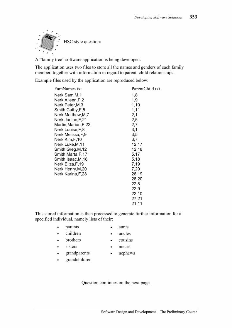
Developing Software Solutions 353
Software Design and Development – The Preliminary Course
A “family tree” software application is being developed.
The application uses two files to store all the names and genders of each family member, together with information in regard to parent–child relationships.
Example files used by the application are reproduced below:
This stored information is then processed to generate further information for a specified individual, namely lists of their:
• parents • children • brothers • sisters • grandparents • grandchildren
Question continues on the next page.
HSC style question:
• aunts • uncles • cousins • nieces • nephews
FamNames.txt Nerk,Sam,M,1 Nerk,Aileen,F,2 Nerk,Peter,M,3 Smith,Cathy,F,5 Nerk,Matthew,M,7 Nerk,Janine,F,21 Martin,Marion,F,22 Nerk,Louise,F,8 Nerk,Melissa,F,9 Nerk,Kim,F,10 Nerk,Luke,M,11 Smith,Greg,M,12 Smith,Marta,F,17 Smith,Isaac,M,18 Nerk,Eliza,F,19 Nerk,Henry,M,20 Nerk,Karina,F,28
ParentChild.txt 1,8 1,9 1,10 1,11 2,1 2,5 2,7 3,1 3,5 3,7 12,17 12,18 5,17 5,18 7,19 7,20 28,19 28,20 22,8 22,9 22,10 27,21 21,11

354 Chapter 8
Software Design and Development –The Preliminary Course
(a) The user interface has been designed and is reproduced below:
Analyse the above user interface in terms of the appropriateness of the screen elements used and the apparent relationships between them.
(b) Algorithms have been written to load each of the two files: BEGIN LoadFamNames Open file FamNames.txt for Input Index=0 WHILE NOT end of file FamNames.txt Read FamNames(Index).Surname Read FamNames(Index).CName Read FamNames(Index).Gender Read FamNames(Index).ID Add 1 to Index ENDWHILE NumNames= Index - 1 Close file FamNames.txt END LoadFamNames BEGIN LoadParentChild Open file ParentChild.txt for Input Index=0 WHILE NOT end of file ParentChild.txt Read ParentChild(0,Index) Read ParentChild(1,Index) Add 1 to Index ENDWHILE NumParentChild= Index - 1 Close file ParentChild.txt END LoadParentChild
(i) Describe the data structure FamNames and the data structure ParentChild.
(ii) Construct an algorithm for a subroutine called PersonName to which a person’s ID is passed and their name is returned. For example, using the sample file data an ID of 8 would return Nerk, Louise.
(You may assume the FamNames data structure has already been loaded with data using the LoadFamNames subroutine above).

Developing Software Solutions 355
Software Design and Development – The Preliminary Course
(iii) Identify where the subroutine PersonName would be useful within the context of the whole application.
(c) Construct an algorithm for a subroutine called Children.
A call to the Children subroutine includes a person’s ID as a parameter. The subroutine returns an array (arrChildren) containing the ID of each of the person’s children.
For example, Karina Nerk’s ID is 28, hence calling the Children subroutine with an ID of 28 returns an array with arrChildren(0)=19 and arrChildren(1)=20.
(You may assume the ParentChild data structure has already been loaded with data using the LoadParentChild subroutine from part (b)).
(d) The following series of algorithms relate to finding an individual’s brothers and make use of the Children subroutine you have just designed in part (c).
A call to the Brothers subroutine includes a person’s ID. The subroutine returns an array (arrBrothers) containing the ID of each of the person’s brothers.
BEGIN Brothers(ID) arrSiblings = Siblings(ID) Count=0 FOR Index = 0 TO last index in arrSiblings IF IsMale(arrSiblings(Index)) THEN arrBrothers(Count)=arrSiblings(Index) Increment Count ENDIF NEXT Index RETURN arrBrothers END Brothers
BEGIN Siblings(ID) arrParents = Parents(ID) Count = 0 FOR Index = 0 TO last index in arrParents arrChildren = Children(arrParents(Index)) FOR Index2 = 0 TO last index in arrChildren IF arrChildren(Index2) ≠ ID AND NotInArray(arrChildren(Index2),arrSiblings)) THEN arrSiblings(Count) = arrChildren(Index2) Increment Count ENDIF NEXT Index2 NEXT Index RETURN arrSiblings END Siblings
(i) Outline, in words, the logic occurring in the above algorithms to determine a person’s brothers.

356 Chapter 8
Software Design and Development –The Preliminary Course
(ii) Copy and complete the following structure diagram to reflect the algorithms on the previous page.
Suggested solutions (a) The Name drop down combo box is an appropriate choice as it enables all the
names present in the FamNames file to be available using a minimum of screen space. In addition it is self-validating as only names present in the file can be selected, and it requires minimum keying, which is ergonomically better for the user. The use of radio buttons for the available Relationships restricts users to selecting just one relationship yet all available relationships can be seen. A list box would also have been a reasonable control, would require less space and would simplify the adding extra relationships in the future. The results text box, that includes scroll bars, is suitable for the output. It is of sufficient size to include most names yet the scroll bars allow longer names (or a large number of results) to be viewed. Each time the content of the Name box is altered the Results of the currently selected Relationship would be used to determine the Results. Similarly when a different Relationship is selected the current Name would be used to determine the Results. In essence changes to either the Name or Relationship data are reflected immediately in the Results.
(b) (i) FamNames is an array of records. Each record contains a field for the person’s surname, Christian name and ID. The Surname and CName fields would be strings and the ID field would be an Integer data type. ParentChild is a two dimensional array of integers. The first index has just two values – either 0 or 1. The 0’th element is used to store the parent’s ID and the 1’st element is used for storing the child’s ID. The two elements are used to define the relationship between each parent and one of their their children
Note: In the preliminary course one dimensional arrays and records are specified within the syllabus, however in the HSC course arrays of records and multi-dimensional arrays are included. (ii) BEGIN PersonName(ID)
PName = "" Index = 0 WHILE Index <= NumNames IF FamNames(Index).ID = ID THEN PName = FamNames(Index).Surname & ", " & FamNames(Index).CName Index = NumNames ENDIF Index = Index + 1 ENDWHILE RETURN PName END PersonName
Brothers
ID arrBrothers

Developing Software Solutions 357
Software Design and Development – The Preliminary Course
(iii) The subroutine would be used to display the final results in the results list box. All subroutines return an array of IDs and each of these IDs needs to be converted to the person’s actual name prior to display.
(c) BEGIN Children(ParentID) Count = 0 Index = 0 WHILE Index <= NumParentChild IF ParentChild(0, Index) = ParentID THEN arrChildren(Count) = ParentChild(1, Index) Increment Count ENDIF Increment Index ENDWHILE RETURN arrChildren END Children
(d) (i) First all siblings of the person are determined. This involves finding the person’s parents and then determining all the children of each parent in turn. Whenever a child has been found the algorithm ensures the original person is excluded and also that no entry is included more than once. All siblings are returned to the Brothers routine. The siblings are then examined in turn to determine if they are male – only the males being retained in the array arrBrother.
(ii)
Note: The above HSC style question would form a complete 20 mark question within a typical HSC or Trial HSC examination. Although this is a Preliminary course textbook, it is worthwhile becoming familiar with the depth of questions and answers that will be required during your HSC year.
ID arrBrothers
Brothers
Siblings IsMale
Parents Children NotInArray
ID
arrParents
ParentID arrChildren
ChildrenID
arrSiblings
NotInArray
SiblingID IsMale ID
arrSiblings
358 Chapter 8
Software Design and Development –The Preliminary Course
CHAPTER 8 REVIEW 1. Project management tasks include all of
the following EXCEPT: (A) Identifying tasks. (B) Creating system models. (C) Backup strategies. (D) Allocation of resources.
2. A diagram that describes the source and movement of data through the system is called a: (A) IPO diagram. (B) flowchart. (C) dataflow diagram. (D) screen design.
3. Products that are progressively developed in response to feedback, are using which approach to software development? (A) Structured approach. (B) Prototyping approach. (C) RAD approach. (D) End user approach.
4. A graphical technique that is useful when sequencing and allocating times to development tasks is called: (A) a log book. (B) a decision tree. (C) a dataflow diagram. (D) a Gantt chart.
5. The screen designs should primarily reflect: (A) the standards prescribed by the
operating system developers. (B) the users view of the processing. (C) the developers view of the
processing. (D) the underlying data structures.
6. Programming languages that execute routines only when some occurrence is detected are known as: (A) object oriented languages. (B) sequential languages. (C) event driven languages. (D) declarative languages.
7. Validation is the process of ensuring data entered is: (A) precise and accurate. (B) of the correct type. (C) within an expected range. (D) Both (B) and (C).
8. Initialisation is used to: (A) set the value of variables prior to
processing. (B) ensure the value of variables
cannot be changed. (C) make sure variables cannot be
assigned incorrect values. (D) validate the contents of variables.
9. CASE tools are used to: (A) enter source code. (B) ensure the correctness of
requirements. (C) automate many software
development tasks. (D) encourage teamwork in
development teams.
10. When code is used from outside sources, intellectual property rights: (A) need not be considered if the
product is freeware. (B) can be ignored when the code is in
the public domain. (C) should always be considered and at
least acknowledged. (D) only needs to be respected when
the product is sold commercially.

Social and Ethical Issues 359
Software Design and Development – The Preliminary Course
For each item within each of the following questions, create a ‘plan of attack’ that you can follow during the completion of your project. This plan can be used as an outline for the creation of your project. Your project need not address all the items listed below; however you should consider each during the development of your project’s plan.
11. Project management • identifying tasks • identifying required programs, modules and subroutines • Gantt charts • logbooks
– regular record of progress – record of major milestones and stumbling blocks
• allocating resources • regular backup with version numbers • responding to difficulties
– reference to documentation such as manuals – discussion with peers and experts – reporting problems to management
• evaluating the solution – throughout the process – on completion
12. Documenting software solutions • IPO diagrams • context diagrams • data flow diagrams (DFDs) • storyboards • structure charts • system flowcharts
13. Developing software solutions - Defining and Understanding, and Planning and Designing • defining and understanding the problem
– preparation of initial documentation • planning and designing
– identification of a suitable development approach – design of appropriate algorithms – identification and incorporation of appropriate existing algorithms – determination of appropriate data structures – identification of relevant subroutines – design of test data and expected output – desk check of algorithms – identification of existing code that can be used
14. Developing software solutions - Implementing, Testing and Evaluating and Maintaining • implementing
– coding the solution in an appropriate language – testing using test data – documenting the solution, including: - algorithms - test data and expected output - data dictionary - user documentation
• testing and evaluating – testing of the solution using test data – evaluating the implemented solution
• maintaining – modifying the solution to meet original or changed specifications
15. Social and ethical issues related to software solutions • intellectual property • ergonomics issues • inclusivity and accessibility • privacy
• data dictionaries • Gantt charts • logbooks • algorithms • user documentation including manuals and online help

360 Glossary
Software Design and Development –The Preliminary Course
GLOSSARY
absolute address
This is the number given to identify a particular storage location in the computer's memory. The name given to an address in which the location is a unique number.
abstraction The hiding of detail by the presentation of a more general instance. In the programming environment, an example of this is the use of a subroutine, rather than the inclusion of detailed code.
agile Quick thinking, co-ordinated, active and lean. Adapts well to changing situations.
algorithm A series of unambiguous instructions or procedural steps that will result in the solution to a specific problem within a finite time.
ALU Arithmetic and logic unit. The part of the central processing unit capable of mathematical and logical operations.
analog computer A computer that uses data in analog rather than digital form.
application software
Software that performs a specialised task. Software applied to the solution of a problem.
array A data structure in which a collection of data items of the same type can be treated as a single entity. Individual data items are identified by an index or subscript.
ASCII Acronym for American Standard Code for Information Interchange. The standard ASCII character set uses 128 characters represented by 7 bits.
assembler A piece of software that changes a program written in assembly language into machine language.
assignment The process of storing the value of an expression in a variable.
backup A copy, on disk or tape, of software or data that is made by the user to guard against accidental loss.
Backus-Naur form
A metalanguage used to define the syntax of a programming language. Named after its two authors. Abbreviated to BNF. Can also be abbreviated to EBNF
bias Having an inclination towards one view rather than another.
binary digit A digit in the binary number system. Commonly called a "bit".
binary number system The number system in which the base is two. It uses the digits 0 and 1.
binary selection
A control structure in which a choice between two alternatives is made based upon the truth or falsity of a condition. Usually implemented as an IF-THEN-ELSE structure.
bit A contraction of binary digit. It is either a zero or a one.
BNF Abbreviation for Backus-Naur form.
Boolean algebra
A set of rules, laws and theorems by which logical operations can be expressed and solved.
Boolean operator
An operator that acts upon Boolean variables and values. The list of these operators includes AND, OR and NOT.
Boolean variable
A variable that can only have two possible states – either 0 or 1. Usually thought of as either False or True.
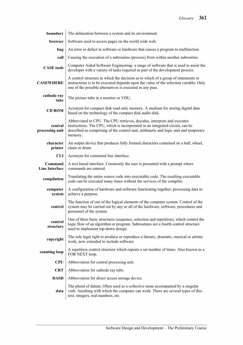
Glossary 361
Software Design and Development – The Preliminary Course
boundary The delineation between a system and its environment.
browser Software used to access pages on the world wide web.
bug An error or defect in software or hardware that causes a program to malfunction.
call Causing the execution of a subroutine (process) from within another subroutine.
CASE tools Computer Aided Software Engineering- a range of software that is used to assist the developer with a variety of tasks required as part of the development process.
CASEWHERE A control structure in which the decision as to which of a group of statements or instructions is to be executed depends upon the value of the selection variable. Only one of the possible alternatives is executed in any pass.
cathode ray tube The picture tube in a monitor or VDU.
CD ROM Acronym for compact disk read only memory. A medium for storing digital data based on the technology of the compact disk audio disk.
central processing unit
Abbreviated to CPU. The CPU retrieves, decodes, interprets and executes instructions. The CPU, which is incorporated in an integrated circuit, can be described as comprising of the control unit, arithmetic and logic unit and temporary memory.
character printer
An output device that produces fully formed characters contained on a ball, wheel, chain or drum.
CLI Acronym for command line interface.
Command Line Interface
A text based interface. Commonly the user is presented with a prompt where commands are entered.
compilation Translating the entire source code into executable code. The resulting executable code can be executed many times without the services of the compiler.
computer system
A configuration of hardware and software functioning together, processing data to achieve a purpose.
control The function of one of the logical elements of the computer system. Control of the system may be carried out by any or all of the hardware, software, procedures and personnel of the system.
control structure
One of three basic structures (sequence, selection and repetition), which control the logic flow of an algorithm or program. Subroutines are a fourth control structure used to implement top-down design.
copyright The sole legal right to produce or reproduce a literary, dramatic, musical or artistic work, now extended to include software.
counting loop A repetition control structure which repeats a set number of times. Also known as a FOR NEXT loop.
CPU Abbreviation for central processing unit.
CRT Abbreviation for cathode ray tube.
DASD Abbreviation for direct access storage device.
data The plural of datum. Often used as a collective noun accompanied by a singular verb. Anything with which the computer can work. There are several types of this: text, integers, real numbers, etc.

362 Glossary
Software Design and Development –The Preliminary Course
data dictionary A comprehensive description of each identifier used in a program. This commonly includes: name, number of characters (size), data type, number of decimal places (if applicable) and a description of the purpose of each variable.
data flow diagram
(DFD) A modelling tool describing the data and the path data takes through a system.
data type The data type of an identifier determines how data items will be represented within the computer.
debugging The process of finding and eliminating logic and syntax errors in a program or algorithm.
debugging output
statement An output statement used to assist in the location and isolation of an error.
decimal A number expressed using the base 10 system.
declarative language
A classification of programming languages in which the language constructs represent relations and the emphasis is on what will be the output of a program rather than on how the output is achieved. A classification within the non-procedural languages.
design
The third phase of the system development cycle in which decisions are made on how the new system will be organised. The plan of the new system includes the overall organisation envisaged together with the detailed requirements of input, processing and output.
desk checking Checking the validity of an algorithm by working through the written version of the algorithm using test data. Usually performed by hand.
developers Persons who takes part in the production of a computer-based system. Examples include analysts, project leaders, programmers, technical writers etc.
direct access storage device Any secondary storage device on which the data may be accessed in any order.
disk drive A device that writes data to, or reads data from, a magnetic disk. It contains a mechanism for spinning the disk and for moving read/write heads over the surface of the disk.
disk platter A circular piece of metal or glass, coated with a thin layer of magnetic material on which electronically transmitted data may be stored. Used within hard disk drives.
diskette A disk made of flexible plastic and covered with iron oxide particles. Generally used with a microcomputer. The common sizes of disks are 9 cm (3.5 inches) or 13 cm (5.25 inches) diameter.
documentation Descriptions of source code, a software package, the hardware configuration, the tasks it can perform and/or the way in which it is used.
dumb terminal A terminal that carries out no local processing of the software. It transmits characters typed at the keyboard and displays information received on the screen.
Dvorak A keyboard layout named after its designer. It was designed to enhance the speed and ease of typing by placing the most frequently used keys on the home row under the stronger fingers.
EBCDIC Acronym for extended binary coded decimal interchange code.
EBNF Abbreviation for extended Backus-Naur form.

Glossary 363
Software Design and Development – The Preliminary Course
end user approach
A process in which an application is developed by users who have knowledge of a relevant software package and can customize it to meet their needs.
end users People who use the computer system. They are usually employees and customers.
EOF Acronym for end of file. Many programming languages include an EOF function, which returns true when the end of the file has been reached.
ergonomics The study of the relationship between people and their working environment.
ethical A set of moral principles accepted by society as a standard against which individual behaviour can be judged.
extended Backus-Naur
form
An extended and modified form of the BNF metalanguage for the definition of the syntax of a programming language. Abbreviated to EBNF.
fetch-execute cycle
The cycle of events, which a computer carries out to process an instruction. During the fetch part of the cycle, the address of the next instruction is used to access the memory and the contents of that location are placed into a register. During the execution part of the cycle , the instruction in the register is decoded and carried out.
file A block of data comprising a related set of records that may be written to a storage device.
file server A computer dedicated to the function of storing and retrieving files on a network.
flag A variable used in a program (usually in the development or debugging stages) to indicate the result of a process, or that the process was executed.
floating point representation
The internal representation of numbers in which each number is stored as two sets of digits, one holding the mantissa and the other holding the exponent. The value of the exponent causes the decimal (binary) point to float until it rests in the final, correct place. Compared with fixed point representation, this method allows a much wider range of numbers that the computer can manipulate, but the operation is relatively slower.
floating point unit
Part of the CPU dedicated to the processing of floating point numbers. Often abbreviated to FPU. Older CPU designs had separate FPUs known as maths coprocessors.
floppy disk "Also known as a diskette. A disk made of flexible plastic and covered with iron oxide particles. Generally used with a microcomputer. The common sizes are 9 cm (3.5"") or 13 cm (5.25"") diameter."
flowchart A pictorial method of describing a system in which the various steps are represented by symbols.
font In typography, the word is used to describe all the characters in a tray of type that possess the same type face, type size, type style and stroke weight.
freeware Software that is covered by copyright, however, copies can be made, distributed and altered. Modified products must also be freeware.
Gantt chart A chart showing timelines for different stages of a systems development project.
global variable A variable declared so that it can be accessed from all parts of the program. Global variables exist for the life of the program.
graphical user interface
A method of presentation employed by a developer presenting the information (usually the screen design) in a graphical format.
GUI An acronym for Graphical User Interface
hard disk A type of disk in which the platters are made from metal and the mechanism is sealed inside a container.

364 Glossary
Software Design and Development –The Preliminary Course
hardware The physical units that make up a computer or any device working with the computer.
hexadecimal A number system that uses sixteen as its base. Because it requires sixteen symbols, the letters A to F are used as digits to represent the decimal numbers 10 to 15.
hierarchy chart A graphical representation of the top-down design of a software product.
high-level language
A computer programming language in which each instruction or statement corresponds to several machine code instructions. It allows users to write in a notation with which they are relatively familiar.
identifier The name given to a variable, process or function. In most languages, identifiers are comprised of letters, digits and the underscore character. They must commence with a letter.
IF-THEN-ELSE
A control structure in which the decision as to which of a pair of statements or instructions is to be executed depends upon the truth or falsity of a condition. Only one of the possible alternatives is executed in any pass.
inclusivity A recognition of equal access.
index An integer value, used to denote a particular data item held in an array. Often called a dimension or subscript.
input The process of transferring data or program instructions from the environment into the computer’s memory using some peripheral device. Sometimes used to denote the data itself, sometimes to denote the signal applied to a circuit or device.
integer One of the (infinite) set of the positive and negative whole numbers including zero. In any computer application, the range of allowable values is determined by the number of bytes used and the way in which the hardware represents integers.
intellectual property Property resulting from the fruits of mental labour.
interpretation Translates source code one line at a time. After each line has been translated it is immediately executed.
IPO diagram IPO diagrams (or charts) describe the data entering a process, the nature of the processing performed and the resulting information leaving the process. Also known as IPO charts.
iteration A single repetition of a sequence of steps.
laser Acronym for light amplification by stimulated emission of light.
Licence Agreement
A signed agreement between the manufacturer and the purchaser of software that gives the purchaser the right to use the software.
local variable A variable that can only be accessed by the subroutine in which it was declared. Local variables only exist whilst the subroutine executes.
logic error
An error in the logic of the program that causes incorrect actions to be taken. Can normally only be detected by the programmer during the testing and debugging of the program when carefully selected test data is used as input to see that the program generates the known result.
logical process A process involving the use of Boolean algebra in which the results can be represented in a truth table.

Glossary 365
Software Design and Development – The Preliminary Course
macro
A term generally used to denote a routine, which is a set of instructions or a list of keyboard commands, stored in a file that can be executed by entering a few keys from the keyboard. They are used to save time and reduce the chance of keyboard errors
maintainability A measure of ease with which source code can be understood and modified.
maintenance Part of the operation and evaluation phase of the system development cycle. The process where all required adjustments or corrections are carried out as a result of the continuing evaluation of the system.
malware Malicious software that deliberately causes some undesired result. Malware includes viruses, adware, spyware, Trojans and worms.
metadata Data describing data.
metalanguage A means of specifying the syntax of each of the valid commands in a given language.
module Performs a complete portion of a larger task and consists of one or more subroutines.
mouse A mechanical or optical input device used to move a pointer on a screen.
multi-way selection
A control structure in which a choice between two or more alternatives is made based upon the value of an expression. Usually implemented as a CASEWHERE structure.
network A system that allows a number of computers and their peripheral devices to be connected over a distance.
octal A number system in which the base is eight, and which uses the eight digits 0-7.
open source Source code is developed collaboratively and is available to all to modify and redistribute. Modified products must also be released as open source.
output The process of transferring data or information from the computer’s memory to the environment using some peripheral device.
passing (parameters)
"Communicating data to and from subroutines using parameters. Parameters can be passed ""by reference"" or ""by value""."
peer checking A process whereby programmers not involved with the original design, are asked to check the logic of an algorithm.
peripheral device Any I/O device connected to the CPU of a computer.
personnel One of the components of a computer-based system. The people employed to work with that system.
plagiarism Copying or imitating the work of another and claiming it to be your own. A violation of copyright.
post-test iteration
A repetition control structure where the terminating condition is checked after the body of the loop executes. Aslo known as an unguarded loop.
pre-test iteration
A repetition control structure where the terminating condition is checked prior to entering the body of the loop. Also known as a guarded loop.
primary storage
Primary storage is often referred to as main memory or more simple memory. Includes the registers within the CPU, cache, physical RAM, ROM and virtual memory.
print server A computer dedicated to the function of printing on a network.

366 Glossary
Software Design and Development –The Preliminary Course
processing The function that transforms inputs into outputs. Executing an instruction or series of instructions.
programming language
A language used to create, store, recall and edit instructions used to control the operation of a computer.
prototype An enactable model or mock-up of a software system that enables evaluation of features and functions in an operational scenario.
pseudocode One method of algorithm description involving the use of English. Although similar to many high-level languages, it does not observe the same very strict syntax rules.
public domain Software that is available for use, due to the copyright holder relinquishing all rights to the software.
railroad diagram
A graphical metalanguage used to describe the syntax of another language. Comprised of flowlines connecting terminal and non-terminal symbols.
RAM Abbreviation for random access memory
random access memory
Abbreviated to RAM. It is the primary memory, and is used to contain both data and instructions (programs) generated by the user. Data may be read from or written to this type of memory. Most technologies used for this memory make it a volatile memory.
rapid application
development (RAD)
A process in which a programmer makes use of software packages to quickly build applications to meet the users' needs. Abbreviated to RAD.
record A collection of facts about an entity in a database. A record comprises one or more related fields.
register A group of fast access memory cells within the CPU. They are used by the CPU for the temporary storage of data or instructions.
repetition Another word for iterations. A control structure causing statements to execute multiple times.
response time (speed)
The amount of time elapsing between the transmission of a command and the receipt of some response from the computer.
reverse engineering
The process of analysing an existing system to identify its components and their interrelationships, to allow the creation of a similar system.
RSI An acronym for Repetitive Strain Injury - its cause being identified by excessive use of a computer keyboard.
runtime error
An error, which occurs when the object code is executed. It may be the result of a logic error, an undefined arithmetic operation such as division by zero, or an overflow error which occurs when a result is computed which cannot be correctly stored in the
scope The extent or range of operation of an identifier. Where in a program, a given identifier may be accessed.
search engine A program designed to locate files, documents and more specifically web pages on the Internet.
secondary storage
Permanent or non-volatile storage. Examples include hard disks, CD-ROMs, tapes and floppy disks.
selection Selection is the control structure that allows decisions to be made between different alternative execution paths.
sentinel value A dummy value inserted to indicate the end of a sequence of data items.

Glossary 367
Software Design and Development – The Preliminary Course
sequence Sequence is the control structure that ensures each process occurs in the correct order.
sequential file Files that can only be accessed from start to finish. Data within a sequential file is stored as a continuous stream.
shareware Shareware is software that is covered by copyright but is distributed freely. A licence must be purchased to continue using the software beyond a trial period. Distributing software as shareware is largely a marketing decision.
social Friendly companionship. Living together in harmony rather than isolation.
software A sequence of detailed instructions used to direct the operation of a computer. Generally categorised as either application or system (which includes utility).
source code The original high-level language program written by the computer programmer.
Spider A program that automatically fetches web page data for inclusion in search engines. The spider follows links on web pages to direct its exploration.
statement In programming, an expression or generalised instruction written in the language of the source program.
storage The function that reads, writes and retains data.
string A term often used to describe a sequence of characters treated as a single entity.
structure chart A model of the top-down design of a program. Includes the sequence in which subroutines execute together with the data movements between subroutines.
structured programming
A programming technique characterised by the whole being broken down into small, independent modules, each of which has a single entry and exit point.
stub
An incomplete procedure or function, which has the same name and interface as the final form but is much simpler. Usually only contains an output statement to indicate that the procedure or function was called, together with any essential statements to ensure that related procedures and functions can work correctly. Used in testing the implementation of a program.
subprogram Synonym for subroutine.
subroutine
A self-contained section of programming code, which can be incorporated into a complete program. Can becalled from any point in the program and usually returns to the instruction immediately following the call to the subroutine. Has only one entry and exit point. Functions and procedures are subroutines.
syntax The rules governing the way in which elements of a programming language may be combined to form legal statements.
syntax error An error resulting from an illegal statement in a program's source code. The translator cannot continue once an error of this type is encountered.
system software
System software is used to manage and control the resources of the system. Operating systems are the most common form of system software.
temporary storage
Storage that is used to hold data for a relatively short time. It often uses a volatile storage medium.
terminal A device at which data may be input to or output from a system. VDUs, together with their keyboards, are often known as terminals.
testing The process in which data identified during the design of a program is provided as input to the program in order to test all possible decisions, ensure that all statements are executed, and that the solution provided is correct in all cases tested.

368 Glossary
Software Design and Development –The Preliminary Course
top-down design
In programming, this implements stepwise refinement. An approach to program design that progressively breaks a large problem into a series of smaller, easier to solve problems. This leads to the creation of modules and subroutines, thus reducing the programming complexity.
user friendly Software that meets the needs of users. User friendly software is intuitive, consistent and easily learnt.
user interface The screens and connections between screens that allow the user to communicate with software.
validation A check carried out by the computer to ensure that only data conforming to certain rules is accepted for input to the program.
value One of the data types used in a spreadsheet. They can be in the form of number, currency, date, percentage etc.
variable The symbolic name of an addressed, stored entity in a program that is referred to for later processing.
virus A type of malware that is able to copy itself either within a single system or to other systems.
walk through The presentation of the software project by the developer or team of developers, to interested parties with the aim being to work through the software and its functionality. More formal than peer checking.
web browser Software for locating, accessing and displaying web pages. They are able to display graphics, text and other multimedia items.

Index 369
Software Design and Development – The Preliminary Course
INDEX abstraction, 154 accessibility, 39 ADC (analog to digital converter), 58, 62, 63 agile approach, 128 agile, 128 algorithm, 188, 189, 221, 227, 250, 322, 324, 344 Alto, 5 ALU, 94, 118 Apple computer, 5 application software, 105 ARPANET, 6 array, 179, 204, 205, 206, 230 ASCII, 174, 175 assembler, 108, 109 assignment, 233 authenticate, 254 backup, 18 balloon help, 277 barcode, 57 batch job scheduling, 104 binary digit, 170 binary number system, 170 binary selection, 191, 233 BNF, 218 Boolean variable, 176, 245 brainstorming, 43 breakpoint, 247 browser, 7 bug, 244 cache, 81, 85, 96 call, 164, 200, 256 capacitor, 81 CASE tools, 138, 185, 283 cathode ray tube, 67, 68 CAV (constant angular velocity), 88 CCD (charge coupled device), 58, 62 CD (compact disk), 86 CD ROM, 86 central processing unit, 77, 80, 120 CERN, 7 CLI, 4, 102 CLV (constant linear velocity), 88, 89 CM11, 333, 347 collimator lens, 89, 90 Command Line Interface, 4, 102 comments (source code), 317
communication skills, 41 compilation, 114 condenser microphone, 61 consistency, 26, 262, 270 constant, 316 context diagram, 151, 163 control structure, 190, 231, 317, 323 control unit, 94, 118 control, 94, 164 copyright, 19, 313 COTS (customised off-the-shelf) package, 105 counting loop, 197 CPU, 77, 94, 95, 118, 120 creative commons licence, 20 creativity, 42 critical path analysis, 43 CRT, 67, 68 cultural background, 35 DAC (digital to analog converter), 63, 77 data dictionary, 185 data flow diagram (DFD), 161, 162, 163, 335 data projector, 71 data structure, 179, 227, 228 data type, 169, 227 data validation, 249 data, 310 debugging output statement, 246 debugging, 244 decision coverage testing, 283 decision tree, 286 declarative language, 108, 112 defining and understanding the problem, 150 defragmentation, 103 desk checking, 208, 239, 287, 297 developers, 331 developing software solutions, 331 diffraction grating, 89 Digital Equipment Company, 7 disability, 38 disk platter, 84 display adapter, 65 DLP projector, 72 DMD (digital micromirror device), 72 documentation, 250, 274, 307, 319, 352 dot pitch, 69 dpi (dots per inch), 69

370 Index
Software Design and Development –The Preliminary Course
DRAM (dynamic RAM), 81 DSP (digital signal processor), 62, 77 DVD (digital versatile disk), 86 DVI (digital visual interface), 65 Dvorak, 54 dynamic microphone, 61 EBNF, 218, 222 economic background, 36 EFTPOS (electronic funds transfer point of sale), 59 electron beam, 68 email, 6 embedded licence installation count, 104 emulation, 104 end user approach, 142 ENIAC, 94 EOF, 183 ergonomics, 3, 25 error messages, 269 ethical, 3, 270, 299 evaluation, 281, 298 event driven, 112 expected outputs, 282 Facebook, 11 feedback, 269 fetch-execute cycle, 118, 119 file compression, 103 flag, 245 flash memory, 92 flatbed scanner, 58 floating point representation, 173, 254 floating point unit, 96 flowchart, 189, 200 font, 265 freeware, 19 FTP, 8 function, 52, 239, 250, 256 Gantt chart, 338 gender, 37 global variable, 256, 257 GLV (grating light valve), 72 GNU general purpose licence (GPL), 20 Google, 9, 130 Gopher, 9 graphical user interface, 4, 102, 266, 309 GUI, 4, 102, 266, 309 hard disk, 84, 120 hard magnetic material, 83 hardware, 49, 52, 311 HDMI (high definition multimedia interface), 65
hexadecimal, 171 hierarchy chart, 156 high-level language, 108, 110 identifier, 227, 228, 316 implementing, 217 inclusivity, 35 index, 179 inkjet printer, 74 input, 52, 231 integer, 172 intellectual property, 3, 17, 255, 307, 313 internal documentation, 275 internet, 6, 23 interpretation, 114 IPO diagram, 152, 336 iteration, 194 keyboard, 53 land, 87, 89 laser printer, 73 laser, 57, 86, 89, 91 LCD monitor, 66 LCOS (liquid crystal on silicon), 71 legibility, 265 liability, 18 Licence Agreement, 17, 22 LinkedIn, 11 liquid crystal, 66 literal constant, 316 loading arrays, 204 local variable, 257 logbook, 332 logic error, 243, 322 login, 252 Lotus 1-2-3, 12 machine language, 108, 109, 118 Macintosh, 5 magnetic storage, 82 mainline, 319 maintainability, 307 malware, 104 MEM (micro-electromechanical), 72 metadata, 10 metalanguage, 218 micron, 87 microphone, 61 Microsoft, 5, 130 module, 155, 217, 255, 256, 258 Moore's Law, 94 Mosaic, 7

Index 371
Software Design and Development – The Preliminary Course
mouse, 55 MR (magneto-resistance), 82, 84 multimedia, 13 multi-way selection, 193, 234 MySpace, 11 national privacy principles, 40 neon, 70 Netbeans, 217 Netscape, 8 off-the-shelf package, 105 online help, 277 open source, 19 operating system, 99 optical storage, 86 output, 65, 232 parameter, 161, 164, 201, 258 Pascal, 229 passing (parameters), 202, 258 path coverage testing, 283 PCIe, 65 peer checking, 296 peripheral device, 120 PHP, 115 piezo crystal, 75, 76 pit, 87, 89 plagiarism, 313 planning and designing software solutions, 154 plasma, 70 polarizing, 66 post-test iteration, 195, 235 presentation software, 13 pre-test iteration, 194, 234 primary storage, 80 printer, 73 printing arrays, 204 privacy, 40 problem solving, 43 procedure, 256 processing, 94 program, 155 programming language, 108 project management, 331 prompt, 268 prototype, 131, 337 prototyping approach, 131` pseudocode, 189, 200 public domain, 19 quality, 36 railroad diagram, 218, 219, 229
RAM, 118 random access memory, 80, 81, 85, 118, 119, 120 rapid application development (RAD), 138, 337 read/write heads, 84 readability, 262, 263 record, 181, 205, 206, 230, 343, 354 recordable optical disk, 90 refinement, 154 refresh rate, 68 register, 95, 118 repetition, 194, 234 requirements, 150, 293, 298, 308, 312, 333 response time (speed), 31 reusable, 217, 249, 258 reverse engineering, 18 rewriteable optical disk, 90, 91 RFID (radio frequency identification), 59 ROM (read only memory), 80, runtime error, 242 S.T.A.I.R., 43 sans serif, 266 scan code, 54 scanner, 57 scope, 185, 257 screen camera, 14 screen resolution, 69 screen, 65 search engine, 8 secondary storage, 82 sector (HDD), 84 selection, 191, 233 sensor, 334 sentinel value, 183 sequence, 190, 233 sequential file, 183, 206, 207, 231, 232, 238, 342, 345, 354 sequential, 112 serif, 266 shareware, 19 single line stepping, 247, 288 site licence, 20 slideshow, 13 social networking applications, 11 social, 3, 270, 299 soft magnetic material, 83 software development cycle, 149 software, 99, 311 sound card, 61, 76, 77 source code, 114, 217, 307, 323 speaker, 76, 78

372 Index
Software Design and Development –The Preliminary Course
Spider, 9 spindle motor, 84 spreadsheet, 12 SRAM (static RAM), 81 SSD (solid state drive), 93 standard algorithms, 204 statement coverage testing, 283 stepper motor, 75 storage, 80 storyboard, 338 string, 174 structure chart, 156, 164, 165, 245, 321 structured approach, 124 structured programming, 188, 190 structured walk through, 296 stub, 244 subprogram, 155 subroutine, 155, 200, 249, 256, 350 syntax error, 241 syntax, 217 system analyst, 124 system, 155 systems flowchart, 158, 159, 160 team, 42 test data, 208, 282, 287 testing, 208, 281 TFT (thin film transistor), 67 thermal inkjet printer, 75 tool tip, 277 top-down design, 127, 154, 155, 156 track, 84, 86 tracking beam, 89 transistor, 81, 96 translation, 114 understanding the problem, 150 UNIX, 7 user friendly, 25 user interface, 25, 102, 217, 261, 262, 309, 338, 340 utilities, 99 validation, 284, 310 variable, 227, 316 video card, 65 virus, 103 VisiCalc, 12 Visual Studio, 217 von Neumann, 94 VRAM (video random access memory), 65 warranty, 18 watch expression, 247
web browser, 7 white space, 263, 318 X10, 332 xenon, 70 Xerox, 5 XML, 250 Yahoo, 9, 130

Student notes 373
Software Design and Development – The Preliminary Course
STUDENT NOTES

374 Student notes
Software Design and Development –The Preliminary Course


![Download Full Proceedings [~20M] - prelim pages.pmd - Tata ...](https://static.fdokumen.com/doc/165x107/631773d871e3f2062906ca05/download-full-proceedings-20m-prelim-pagespmd-tata-.jpg)

