Preferred cell alignment along concave microgrooves - City ...
7
Preferred cell alignment along concave microgrooves Baoce Sun, ab Kai Xie, a Ting-Hsuan Chen ac and Raymond H. W. Lam * abc Geometrical cues in the extracellular environment are essential for guiding the direction of cells and tissue architectures. For example, nano/micro-scale topography such as grooves and fibrous scaffolds induces cell alignment and migration through contact guidance. However, previous research has focused on patterns with scales ranging from nanometers to several microns. It remains unclear how cell behavior is affected by geometric cues at larger scales, such as the cylindrical curvature in the interior surface of blood vessels. Here, using microfabricated concave microgrooves to culture vascular endothelial cells, we examine how the radius of curvature affects cell body characteristics including shape, spreading area, and preferred alignment along the microgroove direction. Furthermore, analysis of subcellular actin filaments reveals that subcellular stress fibers play an essential role in such morphological response. Together, our findings not only broaden the knowledge basis of surface curvature as a biophysical factor but also offer cell characterization and contact guidance strategies for future cell and tissue engineering applications. I. Introduction Interactions between cells and their surrounding extracellular matrix (ECM) 34,35 play important roles in cell and tissue behav- iors. 1–3 ECM physical factors such as stiffness, 4–8 geometrical cues, 9–16 and force stimulation 17–21 can regulate cell migration, proliferation, differentiation, and so on. In particular, it has been reported that the topology of ECM 22–24 can also direct the alignment and migration of cells through contact guidance. 25 On the other hand, cell morphology including cell spreading and alignment has been proven to be crucial to cell growth and tissue formation and functioning. Taking the endothelial cells as an example, the morphology of endothelial cells correlates to the nucleus shape and alignment, and even the gene expressions, 11,26–28 which govern cell fate. As the major compo- nent of vessel interiors, the alignment of endothelial cells also determines endothelial conformity and formation of new blood capillaries. 29,30 Notably, the abnormal cell behaviors may lead to endothelial dysfunctions and vascular diseases such as atherosclerosis. 20,31,32 However, most previous studies focused on cell behaviors in response to ECM topography in the range of nanometers to several microns. 23,33 The ECM topology with larger feature sizes, i.e. tens of microns, which is equally important and prominent in the human body, were rarely addressed. Considering the endothelial cells growing on vessel interiors, the ECM of tunica media connes the biophysical conditions including the cylin- drical curvatures of vessels, which should affect the cell behaviors. As such, investigations on how cells behave on the micro-scale topology could provide new insights on the roles of environmental cues from ECM. Microfabrication techniques have been widely applied to engineer cell environment for investigating cell behaviors and physiological mechanisms. Micro-contact printing was employed to pattern different micro-adhesion islands conning cell shape and demonstrated that cell shape can inuence individual cell viability and morphological behaviors. 10 Subcel- lular actin laments, focal adhesions and nucleus can also be affected by micro-topographical features including the shape 34 and aspect ratio 35,36 of adhesion islands. Nevertheless, most of these techniques focus on controlling topographical factors of planar substrates. As cells in three-dimensional matrices can behave distinctly compared to those on planar substrates, 37 how the non-planar topographical cues affect cell behaviors is worth to be investigated quantitatively but remains elusive. Researchers have employed several methods to fabricate non-planar microstructures for cell studies. Nikkhah et al. fabricated microchambers by reactive ion etching (RIE) 38 to examine the cytoskeletal properties. However, the rough edges le aer fabrication caused the radii of curvature undened. Park et al. applied suction pressure to fabricate silicone micro- chambers, yet the research focus remained on comparison of a Department of Mechanical and Biomedical Engineering, City University of Hong Kong, Hong Kong, China. E-mail: [email protected]; Fax: +852-3442-0172; Tel: +852- 3442-8577 b Centre for Biosystems, Neuroscience and Nanotechnology, City University of Hong Kong, Hong Kong, China c City University of Hong Kong Shenzhen Research Institute, Shenzhen, China Cite this: RSC Adv. , 2017, 7, 6788 Received 9th November 2016 Accepted 12th January 2017 DOI: 10.1039/c6ra26545f www.rsc.org/advances 6788 | RSC Adv. , 2017, 7, 6788–6794 This journal is © The Royal Society of Chemistry 2017 RSC Advances COMMUNICATION
-
Upload
khangminh22 -
Category
Documents
-
view
4 -
download
0
Transcript of Preferred cell alignment along concave microgrooves - City ...
RSC Advances
COMMUNICATION
Preferred cell ali
aDepartment of Mechanical and Biomedical E
Hong Kong, China. E-mail: rhwlam@cityu.
3442-8577bCentre for Biosystems, Neuroscience and N
Kong, Hong Kong, ChinacCity University of Hong Kong Shenzhen Res
Cite this: RSC Adv., 2017, 7, 6788
Received 9th November 2016Accepted 12th January 2017
DOI: 10.1039/c6ra26545f
www.rsc.org/advances
6788 | RSC Adv., 2017, 7, 6788–6794
gnment along concavemicrogrooves
Baoce Sun,ab Kai Xie,a Ting-Hsuan Chenac and Raymond H. W. Lam*abc
Geometrical cues in the extracellular environment are essential for
guiding the direction of cells and tissue architectures. For example,
nano/micro-scale topography such as grooves and fibrous scaffolds
induces cell alignment and migration through contact guidance.
However, previous research has focused on patterns with scales
ranging from nanometers to several microns. It remains unclear how
cell behavior is affected by geometric cues at larger scales, such as the
cylindrical curvature in the interior surface of blood vessels. Here,
using microfabricated concave microgrooves to culture vascular
endothelial cells, we examine how the radius of curvature affects cell
body characteristics including shape, spreading area, and preferred
alignment along the microgroove direction. Furthermore, analysis of
subcellular actin filaments reveals that subcellular stress fibers play an
essential role in such morphological response. Together, our findings
not only broaden the knowledge basis of surface curvature as
a biophysical factor but also offer cell characterization and contact
guidance strategies for future cell and tissue engineering applications.
I. Introduction
Interactions between cells and their surrounding extracellularmatrix (ECM)34,35 play important roles in cell and tissue behav-iors.1–3 ECM physical factors such as stiffness,4–8 geometricalcues,9–16 and force stimulation17–21 can regulate cell migration,proliferation, differentiation, and so on. In particular, it hasbeen reported that the topology of ECM22–24 can also direct thealignment and migration of cells through contact guidance.25
On the other hand, cell morphology including cell spreadingand alignment has been proven to be crucial to cell growth andtissue formation and functioning. Taking the endothelial cellsas an example, the morphology of endothelial cells correlates tothe nucleus shape and alignment, and even the gene
ngineering, City University of Hong Kong,
edu.hk; Fax: +852-3442-0172; Tel: +852-
anotechnology, City University of Hong
earch Institute, Shenzhen, China
expressions,11,26–28 which govern cell fate. As the major compo-nent of vessel interiors, the alignment of endothelial cells alsodetermines endothelial conformity and formation of new bloodcapillaries.29,30 Notably, the abnormal cell behaviors may lead toendothelial dysfunctions and vascular diseases such asatherosclerosis.20,31,32
However, most previous studies focused on cell behaviors inresponse to ECM topography in the range of nanometers toseveral microns.23,33 The ECM topology with larger feature sizes,i.e. tens of microns, which is equally important and prominentin the human body, were rarely addressed. Considering theendothelial cells growing on vessel interiors, the ECM of tunicamedia connes the biophysical conditions including the cylin-drical curvatures of vessels, which should affect the cellbehaviors. As such, investigations on how cells behave on themicro-scale topology could provide new insights on the roles ofenvironmental cues from ECM.
Microfabrication techniques have been widely applied toengineer cell environment for investigating cell behaviors andphysiological mechanisms. Micro-contact printing wasemployed to pattern different micro-adhesion islands conningcell shape and demonstrated that cell shape can inuenceindividual cell viability and morphological behaviors.10 Subcel-lular actin laments, focal adhesions and nucleus can also beaffected by micro-topographical features including the shape34
and aspect ratio35,36 of adhesion islands. Nevertheless, most ofthese techniques focus on controlling topographical factors ofplanar substrates. As cells in three-dimensional matrices canbehave distinctly compared to those on planar substrates,37 howthe non-planar topographical cues affect cell behaviors is worthto be investigated quantitatively but remains elusive.
Researchers have employed several methods to fabricatenon-planar microstructures for cell studies. Nikkhah et al.fabricated microchambers by reactive ion etching (RIE)38 toexamine the cytoskeletal properties. However, the rough edgesle aer fabrication caused the radii of curvature undened.Park et al. applied suction pressure to fabricate silicone micro-chambers, yet the research focus remained on comparison of
This journal is © The Royal Society of Chemistry 2017
Fig. 1 Structure characterization of the microgrooves. (a) Top viewand side view SEM images of a series of microgrooves with differentradii of curvature captured. Scale bar: 100 mm. (b) Surface profile ofa microgroove region (top view size: 40 mm � 40 mm). (c) Surfaceroot-mean-square roughness (sRMS) measured by AFM over an area of10 mm � 10 mm.
Communication RSC Advances
convex and concave surfaces for their effects to cell adhesionand proliferation.39 Lee et al.manufactured scaffolds embeddedwith micro-pores with a controlled concave curvature,40 but theaccessibility and detailed cell analysis were challenging becausethe micro-pores were located inside the scaffold material.
In this study, we characterize the vascular endothelial cellsgrowing on an array of concave microgrooves with differentmicro-scale curvatures. Owing to the geometric similaritybetween the microgrooves and vessel interiors, these resultscould exhibit key cell properties in the vascular endothelium.We examine the effect of microgroove dimensions on cellmorphology and alignment. As cell morphology reects theintracellular properties41,42 including the architecture of cyto-skeletal stress,36,43 we also investigate the roles of stress bers insuch alignment processes through analysis of subcellular actinlaments. Overall, our study of surface curvature in deter-mining cell alignment and morphology will provide newinsights for tissue formation and the related mechanisticprocesses.
II. ResultsMicrogroove curvature mediates cell morphology andorientation
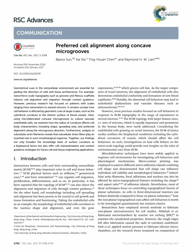
We manufactured arrays of concave microgrooves (Fig. 1) withdifferent radii of curvature (50 mm, 75 mm and innity (atsurface)) using replica molding of polydimethylsiloxane(PDMS).44,45 Notably, the surface roughness of all the substratesurfaces is negligible (<5 nm) as indicated in Fig. 1c, whichindicates that the radius of curvature is the only variable in ourexperiments. Aer seeding human vascular endothelial cells(hVECs) on the substrates and culturing them for 4 h, we xedthe cells and conducted immunouorescence staining oncytoskeletal actin and nuclei (Fig. 2a) to visualize spreadingareas, orientations and body aspect ratios of the cell bodies.Using low density for visualizing single cells and high densityfor a cell layer, we found that cell alignment is apparent inmicrogrooves with 50 mm radius of curvature regardless of celldensities. Moreover, through quantitative analysis, the cellspreading areas increased with the radii of curvature, while thebody aspect ratios decreased with the radii (Fig. 2b). Of note,hVECs in the microgrooves with a 50 mm radius of curvatureexhibited a halved average spreading area and a two-foldaverage body aspect ratio compared to those on the planarsurface.
To test whether cell alignment was also effected, we analyzedthe orientation of each single cell by applying a best-ttingellipse to the cell body boundary in the uorescence micro-graphs (Fig. 2c). The cell orientation in microgrooves wasdened by a cell-groove angle q as the intersection anglebetween the major axis of the ellipse and the groove direction toquantify the cell alignment tendency. For the at substrates, thecell orientation was dened as an intersection angle betweenthe major axis and the vertical direction of the micrograph. Wecan observe that cell orientations tended to align with thegroove direction, i.e. q / 0�, when cultured in microgrooveswith 50 mm radius of curvature (Fig. 2d), suggesting a preferred
This journal is © The Royal Society of Chemistry 2017
cell body alignment along the microgroove direction. Incontrast, there was not obvious alignment when cultured inmicrogrooves with radius of curvature 75 mm or on planarsubstrate. Moreover, as q can be viewed as the ‘misalignmenterror’ betweenmajor axes of the cell body and groove directions,the level of alignment can be further quantied based on thestandard deviation of such ‘misalignment error’ using the root-mean-squares of q (qRMS). Our results showed that qRMS were19.3� � 2.1�, 30.1� � 1.9� and 48.57� � 0.17� for 50 mm micro-grooves, 75 mm microgrooves and planar surfaces, respectively.A smaller ‘misalignment error’ reveals that substrates witha smaller radius of curvature would induce the more coherentcell-groove alignment.
Alignment of actin laments with cell body is independent ofmicrogroove curvatures
Intracellular stress bers can modulate ranges of cell behaviorsincluding cell shape and orientation.36,43,46,47 Here, we investi-gated the intersection angle between the dominant direction of
RSC Adv., 2017, 7, 6788–6794 | 6789

Fig. 2 Cell morphology and orientation in microgrooves. (a) Repre-sentative fluorescence microscopy images of hVECs at low and highdensities on a planar surface (left) and in a microgroove with a radius ofcurvature of 50 mm (right). Scale bar: 20 mm. (b) The average cellspreading area and body aspect ratio for cells in microgrooves and theplanar surface. Each data point is calculated based on at least 40 cells.(c) The schematic showing q defined by an intersection angle betweenthemajor axis of cells and themicrogroove direction. (d) q of hVECs onmicrogrooves with 50 mm and 75 mm radii of curvature (n50 ¼ 96, n75 ¼87) and cell orientation on the planar surface exhibited as in micro-graphs (n ¼ 53).
Fig. 3 The cell-actin intersection angle f between the major axis ofcells and average stress fiber direction inside a cell. (a) The schematicshowing f defined by an intersection angle between the averageorientation of stress fibers and the major axis of cells. (b) f of hVECs inmicrogrooves with a radius of curvature as 50 (n ¼ 96) and 75 mm (n ¼87) and on a planar surface (n ¼ 53).
RSC Advances Communication
stress bers (represented by actin laments) and the major axisof cell body, f (Fig. 3a). Results showed that stress bers tendedto align with the cell body when cultured either in microgroovesor on planar surfaces (f/ 0�, Fig. 3b). Similar with the analysesin the previous section, we quantied the standard deviations of
6790 | RSC Adv., 2017, 7, 6788–6794
the ‘misalignment error’ between the major axis of cell bodyand dominant actin directions using the root-mean-squares off (fRMS). We found that the fRMS values were comparable for allthe chosen cases: 28.57� � 2.5� on 50 mmmicrogrooves, fRMS ¼23.43� � 3.5� on 75 mmmicrogrooves, and fRMS ¼ 24.31� � 3.2�
on planar surfaces. It suggests that stress bers are alwaysaligned with cell body and may underlie the cell's directionality.
Stress bers are involved in cell alignment to microgrooves
To further investigate the roles of stress bers, we employed thestress-ber-targeting reagent, blebbistatin, to inhibit formationof stress bers.48,49 In the experiments, we chose microgrooveswith a radius of 50 mm because of the signicant alignmentbetween cell body and groove directions. As shown in Fig. 4aand b, cells treated with blebbistatin in microgrooves havelower total contents and reduced lengths of stress bers ascompared to the control group. We also observed increasedspreading area and the reduced body aspect ratio aer theblebbistatin treatment (Fig. 4b). Collectively, as the drug-treatedcell morphology was analogous to that on planar substrates, it isinteresting to further examine whether the suppressed stressber content may abrogate the inuence of concave micro-grooves, resulting in the more randomly distributed cell-grooveangles q.
We then investigated the cell orientation on concavemicrogrooves in response to the blebbistatin treatment. Itshould be noted that the stress bers were still aligned with thecell body for those cells treated with blebbistatin (f / 0�,Fig. 4c), which is consistent with previous report on the
This journal is © The Royal Society of Chemistry 2017

Fig. 4 Blebbistatin inhibition revealing the role of stress fibers in cellmorphology and preferred alignment along microgroove directions.(a) In a microgroove with a radius of curvature as 50 mm, fluorescencemicroscopy images showing that the reduced actin filament afterblebbistatin inhibition. Scale bar: 10 mm. Insets show the disruptedactin filaments by blebbistatin. Scale bar: 2 mm. (b) The change of cellmorphology and actin filament in microgrooves with the presence ofblebbistatin. Left to right: actin coverage; average stress fiber length;cell spreading area; cell body aspect ratio; (n ¼ 60 for the controlgroup and n ¼ 57 for the group treated with blebbistatin). (c) Cell-groove angle q (n¼ 57) and (d) cell-actin angle f of hVECs treated withblebbistatin in the microgrooves with a radius of curvature as 50 mm(n ¼ 57).
Communication RSC Advances
maintained cell-actin alignment for cells with inhibited actincontents.11,50More importantly, the drug-treated cell orientationrelative to the direction of microgrooves showed a randomdistribution from 0 to 90� (Fig. 4d), suggesting the importantrole of stress bers in the preferred cell alignment tomicrogrooves.
III. Discussions
In this work, we employed the photolithography with reow ofphotoresist microstructures and the replica molding of PDMSto obtain microgroove substrates. Notably, the surface rough-ness of the microgroove substrate is the same as the unstruc-tured PDMS material. As the roughness is less than 5 nm
This journal is © The Royal Society of Chemistry 2017
(Fig. 1), which is far less than the range known capable forinuencing cell behaviors (dozens to hundreds of nanome-ters),16 the effect of surface roughness can be disregarded.Therefore, the fabricated microgroove should reduce to onlyone dened environmental factor – the surface radius ofcurvature.
In a microgroove, cells encounter an environment withanisotropic geometries. That is, the radius of curvature isminimum when orthogonal to the microgroove direction andbecomes innity when parallel to it. On such substrates, ourresults showed that cells in microgrooves with smaller nominalradius of curvature exhibited less spreading (Fig. 2b). Given theanisotropic geometries of microgrooves, the preferred align-ment of cells along the microgrooves (Fig. 2d) and increasedbody aspect ratios (Fig. 2b) may be all due to the intention ofspreading along the direction with larger even or innite radiusof curvature – the microgroove direction. This may explain whythe alignment preferences of cell body and intracellular actinreduce as the radius of curvature increases (Fig. 2d).
Cells can respond to their environment via the force inter-actions between the cells and the biophysical cues ofsubstrates.43 Among different intracellular components, stressbers play a key role in such force interaction and associatedwith cell morphology.46,47 Prior to this study, cell characteristicsincluding morphology, migration and cytoskeletal architecturehave been reported sensitive to many other directional physicalcues. For instance, vascular endothelial cells tended to alignwith the direction of shear stress under a liquid ow.51,52 Witha unidirectional cyclic stretching, broblasts reoriented to thestretch direction.53–55 Of note, the alignment of cell behaviors todirectional physical cues correlated with the cytoskeletal activ-ities. When stress bers were inhibited by related reagents,endothelial cells no longer displayed the shear-stress-inducedalignment.51 Likewise, aer blebbistatin treatment, thephenomenon of stretch-induced reorientation in broblastsdisappeared.54 Here, through the quantitative analysis (Fig. 3),we found that the stress bers' average direction is consistentwith the cell body orientation, for both the cells on a planarsurface or in a microgroove. Moreover, on the blebbistatin-treated hVECs with a suppressed cell-groove alignment (Fig. 4)suggest good agreements with those previous ndings for theother physical cues. In such processes, stress bers were provento play an essential role in sensing and responding to thosestimulations.
As stress bers are the main source of cell contractility andresponsible for cell-ECM force interaction,43 it is very likely thatthe cell alignment along microgrooves is due to the forcebalance between cell contractility and the force from the ECM.On a at surface (roughness: <5 nm), there is no dominatinganisotropic cues; arrange isotopically; and the cells exhibita random orientation distributed accordingly. Differently, inmicrogrooves contains micro-curvatures orthogonal to thegroove direction, which might lead to the biased distribution ofcell contractility represented by stress bers and cells alignmentalong microgrooves analogous to the effect of shear stress51 andstretching.55 When being treated with the blebbistatin (stressbers inhibitor), cell contractility is inhibited and its role in cell
RSC Adv., 2017, 7, 6788–6794 | 6791
RSC Advances Communication
alignment along microgrooves is reduced. Thus, the effect cellalignment along microgrooves becomes insignicant comparedwith cells without any treatment.
In a nutshell, the underlying mechanism behind theseresults may lie in the role of stress bers in the force interactionbetween cells and such concave micro-curvature. Consideringthe micro-curvature is a biophysical factor affecting cell align-ment and morphology, it should be worthwhile to furtherinvestigate its effect together with the other well-studiedbiophysical factors (e.g. substrate stiffness,4,7,8 shear stress21,55
and external stretch53,54) on the integrative effects to a broadrange of cell behaviors in the future. It will be interesting todiscover possible roles of the substrates stiffness in cell align-ment along microgrooves by regulating rigidity of PDMSsubstrates using different ratios of PDMS monomer and curingagent as the substrate materials. The shear stress along themicrogroove direction can be produced by driving culturemedia along the desired direction, mimicking the blood ow.Additionally, stretching the substrates carrying the adherentcells along one direction can generate the tensile stress/strain,which might be induced from blood pressure or muscularmovements in the human body. Collectively, the results re-ported here provide insightful information about morpholog-ical characteristics of cells growing on micro-curved surfacespresent in scaffolds as well as other tissue engineeringapplications.
IV. MethodsFabrication of microgrooves
Substrates containing an array of microgrooves were fabricatedby replica molding of polydimethylsiloxane (PDMS). To fabri-cate the molds, photolithography was used to pattern positivephotoresist (AZ 50XT, AZ electronics) containing rectangularstripes on a silicon wafer. The photoresist with 60 mm thicknesswas rst spin-coated on a silicon wafer, followed by so-bakingat 95 �C for 2 min. Aer UV exposure, the photoresist wasdeveloped using diluted AZ400K (1 : 2 dilution by deionizedwater) and dried by air ow. For the planar substrates, neitherUV exposure nor development was performed. In order toobtain the quasi-semi-cylindrical structures in the microgroovegeometries, the developed photoresist was baked at 120 �C for1 min to allow photoresist reowing. Due to the surface tensionof photoresist, the cross-section of photoresist patterns turnsround, which is the targeted microgrooves. The mold was thensilanized with trichloro(1H,1H,2H,2H-peruorooctyl)silane(Sigma-Aldrich) to reduce the adhesion of PDMS to the mold tofacilitate the demolding processes.
To perform replica molding, the PDMS pre-polymer wasprepared by mixing the PDMS base with a curing agent (Sylgard184, Dow Corning Corporation) at a weight ratio of 10 : 1. Aerthe PDMS pre-polymer was poured onto the molds and fullydegassed, we baked the PDMS at 70 �C for 24 h. The PDMS wasthen peeled off and the pattern regions were cut out. Forphysical supports, the PDMS substrate was bonded onto glassslides (microgroove structures facing outward) using air plasma(energy 1 kJ; Harrick Plasma, Ithaca, NY). Before plating cells,
6792 | RSC Adv., 2017, 7, 6788–6794
a 50 mg ml�1 human bronectin solution (cat#33016-015, LifeTechnologies) was applied onto these PDMS substrates for cellculture. Then, the substrates were rinsed with phosphate-buffered saline (PBS) and submerged in fresh cell culturemedia.
Characterization of substrate surface
Aer fabricating the substrates, we applied light reection andinterference between interfaces to visualize and examinesurface curvatures using the optical surface proler (NT9300,Veeco). Then, we quantied roughness of the groove surfacesusing an atomic force microscope (DMI, Bruker) with thetapping mode (Fig. 1c). To facilitate SEM imaging, we coateda 20 nm thick layer of Aurum on the surface of microstructureswith a sputter-coating machine (Q150T, Quorum). The coatedmicrogrooves were then observed in the high vacuum mode ofSEM machine (FEI 250, Quanta). We took SEM for the top viewand side view of the microgrooves.
Cell preparation
Primary human vascular endothelial cells (hVECs; C2517A,Lonza, Walkersvilla, MD) were cultured in supplementedendothelial cell growth medium (CC-3162, Lonza). The cellswere cultured in standard 5% CO2, 37 �C humidied incubator(Forma Steri-Cycle CO2 incubator, Thermo Scientic). Once thecells reached 80% conuence, they were washed with hydrox-yethyl piperazineethanesulfonic acid-buffered saline solution(CC-5022, Lonza), trypsinized (CC-5012, Lonza), and neutralizedwith a trypsin neutralization solution (CC-5002, Lonza). Theresuspended cells were reseeded at two cell densities (3000 cellper cm2 and 10 000 cell per cm2) in fresh media for subculture.Only cells within 5 passages were used in all experiments in thisresearch.56
Drug treatment
Aer seeding hVECs in the microgrooves, we randomly selectedsamples to treat with reagents. The cells were treated at thefourth hour aer cell seeding and incubation for 30 min.Aerwards, the reagents were removed by replacing with PBS forfollow-up experiments. For control groups, cells were addedwith equal amount of corresponding reagents solvent (PBS ordimethyl sulfoxide) to cell media for 30 min.
Fluorescence staining
For all cell samples, actin laments and nuclei were stainedwith Alexa Fluor 555 conjugated phalloidin (A34055, Thermo-Fisher) and 40,6-diamidino-2-phenylindole (DAPI; D1306,ThermoFisher) respectively for 1 h. The samples were washed toremove unbounded staining agents with PBS. Finally, weapplied a mounting solution (17984-25, Electron MicroscopySciences) to the stained cells for microscopic imaging.
Image characterization
For determining the cell body aspect ratio, we used theprojection images (along the direction normal to substrates' at
This journal is © The Royal Society of Chemistry 2017
Communication RSC Advances
surface, same below) of image stacks of actin laments. Thebody aspect ratio was dened based on the ratio of the majoraxis and minor axis for each cell's most tted ellipse calculatedbased on ImageJ soware (NIH, US). With those projectionimages of actin laments, we used ImageJ soware withFibrilTool plugin57 to quantify the overall average orientation ofactin laments (stress bers) in a cell. The stress bers coveragewas calculated by dividing the projection area of actin lamentswith the cell's projection area.
Statistics
All values in this paper are each expressed as mean � standarderror of the mean (S.E.M) unless otherwise specied. Samplesfor quantication were from three independent, repeatedexperiments. Each cell group in this study contains >50 cells forpromising comparison. To calculate the signicance of thedifference between two groups of data, we conducteda student's t-test with a two-tailed distribution and a two-sampleunequal variance for these two data sets. An asterisk in chartsrepresents the signicant difference with the p-value < 0.05.
V. Conclusion
In this work, we applied concave microgrooves to characterizethe morphology and alignment of vascular endothelial cells inresponse to the direction and radius of curvature. Importantly,the results demonstrate that the substrate curvature causessignicant inuence on cell spreading areas, body aspect ratiosand preferred alignment along the microgroove direction.Furthermore, the weakened stress bers mediated by blebbis-tatin underlie the reduced spreading area, enhanced bodyaspect ratio, and indifferent cell orientation along micro-grooves, suggesting the essential role of stress ber in suchpreferred directionality. Altogether, our results about the effectsof the surface curvature of ECM on cells offer further insightsabout cell behaviors on ECM topology at the micro-scale, e.g.morphology, alignment and cytoskeletal structures, andenlighten relative application on engineering tissue formation/regeneration processes in the future.
Acknowledgements
We thank the nancial supports from City University of HongKong (project# 9678100 and 7004540), Croucher FoundationStartup Grant (CityU project# 9500017), National NaturalScience Foundation of China (NSFC 31500758), GeneralResearch Fund (project# RGC11206014), and CollaborativeResearch Fund (project# C1013-15GF) of Hong Kong ResearchGrant Council.
References
1 T. Rozario and D. W. DeSimone, Dev. Biol., 2010, 341, 126–140.
2 C. Frantz, K. M. Stewart and V. M. Weaver, J. Cell Sci., 2010,123, 4195–4200.
This journal is © The Royal Society of Chemistry 2017
3 A. D. Theocharis, S. S. Skandalis, C. Gialeli andN. K. Karamanos, Adv. Drug Delivery Rev., 2016, 97, 4–27.
4 A. Zemel, F. Rehfeldt, A. E. X. Brown, D. E. Discher andS. A. Safran, Nat. Phys., 2010, 6, 468–473.
5 J. R. Garcia and A. J. Garcia, Nat. Mater., 2014, 13, 539–540.6 S. V. Plotnikov, A. M. Pasapera, B. Sabass andC. M. Waterman, Cell, 2012, 151, 1513–1527.
7 A. J. Engler, S. Sen, H. L. Sweeney and D. E. Discher, Cell,2006, 126, 677–689.
8 T. Yeung, P. C. Georges, L. A. Flanagan, B. Marg, M. Ortiz,M. Funaki, N. Zahir, W. Ming, V. Weaver and P. A. Janmey,Cell Motil. Cytoskeleton, 2005, 60, 24–34.
9 M. J. Dalby, N. Gadegaard, P. Herzyk, H. Agheli,D. S. Sutherland and C. D. Wilkinson, Biomaterials, 2007,28, 1761–1769.
10 C. S. Chen, M. Mrksich, S. Huang, G. M. Whitesides andD. E. Ingber, Science, 1997, 276, 1425–1428.
11 M. Versaevel, T. Grevesse and S. Gabriele, Nat. Commun.,2012, 3, 671.
12 K. Mandal, I. Wang, E. Vitiello, L. A. C. Orellana andM. Balland, Nat. Commun., 2014, 5, 5749.
13 M. Thery, J. Cell Sci., 2010, 123, 4201–4213.14 B. Geiger, J. P. Spatz and A. D. Bershadsky, Nat. Rev. Mol. Cell
Biol., 2009, 10, 21–33.15 W. Chen, L. G. Villa-Diaz, Y. Sun, S. Weng, J. K. Kim,
R. H. Lam, L. Han, R. Fan, P. H. Krebsbach and J. Fu, ACSNano, 2012, 6, 4094–4103.
16 Y. Shao and J. Fu, Adv. Mater., 2014, 26, 1494–1533.17 K. Kurpinski, J. Chu, C. Hashi and S. Li, Proc. Natl. Acad. Sci.
U. S. A., 2006, 103, 16095–16100.18 N. Ziegler, A. Alonso, T. Steinberg, D. Woodnutt, A. Kohl,
E. Mussig, S. Schulz and P. Tomakidi, BMC Cell Biol., 2010,11, 1.
19 J. H.-C. Wang and B. P. Thampatty, Biomech. Model.Mechanobiol., 2006, 5, 1–16.
20 C. Hahn and M. A. Schwartz, Nat. Rev. Mol. Cell Biol., 2009,10, 53–62.
21 J. Ando and K. Yamamoto, Circ. J., 2009, 73, 1983–1992.22 A. D. Doyle, F. W. Wang, K. Matsumoto and K. M. Yamada, J.
Cell Biol., 2009, 184, 481–490.23 Y. Li, G. Huang, X. Zhang, L. Wang, Y. Du, T. J. Lu and F. Xu,
Biotechnol. Adv., 2014, 32, 347–365.24 M. K. Driscoll, X. Sun, C. Guven, J. T. Fourkas and W. Losert,
ACS Nano, 2014, 8, 3546–3555.25 P. Weiss, J. Exp. Zool., 1945, 100, 353–386.26 C. H. Thomas, J. H. Collier, C. S. Sfeir and K. E. Healy, Proc.
Natl. Acad. Sci. U. S. A., 2002, 99, 1972–1977.27 R. P. Jean, D. S. Gray, A. A. Spector and C. S. Chen, J. Biomech.
Eng., 2004, 126, 552–558.28 C. Lanctot, T. Cheutin, M. Cremer, G. Cavalli and T. Cremer,
Nat. Rev. Genet., 2007, 8, 104–115.29 R. M. Merks, S. V. Brodsky, M. S. Goligorksy, S. A. Newman
and J. A. Glazier, Dev. Biol., 2006, 289, 44–54.30 H. Parsa, R. Upadhyay and S. K. Sia, Proc. Natl. Acad. Sci. U. S.
A., 2011, 108, 5133–5138.
RSC Adv., 2017, 7, 6788–6794 | 6793
RSC Advances Communication
31 D. B. Cines, E. S. Pollak, C. A. Buck, J. Loscalzo,G. A. Zimmerman, R. P. McEver, J. S. Pober, T. M. Wick,B. A. Konkle and B. S. Schwartz, Blood, 1998, 91, 3527–3561.
32 A. Lerman and A. M. Zeiher, Circulation, 2005, 111, 363–368.33 A. I. Teixeira, G. A. Abrams, P. J. Bertics, C. J. Murphy and
P. F. Nealey, J. Cell Sci., 2003, 116, 1881–1892.34 K. A. Kilian, B. Bugarija, B. T. Lahn and M. Mrksich, Proc.
Natl. Acad. Sci. U. S. A., 2010, 107, 4872–4877.35 M. Thery, A. Pepin, E. Dressaire, Y. Chen and M. Bornens,
Cell Motil. Cytoskeleton, 2006, 63, 341–355.36 J. James, E. D. Goluch, H. Hu, C. Liu and M. Mrksich, Cell
Motil. Cytoskeleton, 2008, 65, 841–852.37 M. A. Schwartz and C. S. Chen, Science, 2013, 339, 402–404.38 M. Nikkhah, J. S. Strobl, R. De Vita and M. Agah,
Biomaterials, 2010, 31, 4552–4561.39 J. Y. Park, D. H. Lee, E. J. Lee and S.-H. Lee, Lab Chip, 2009, 9,
2043–2049.40 Y.-h. Lee, J.-r. Huang, Y.-k. Wang and K.-h. Lin, Integr. Biol.,
2013, 5, 1447–1455.41 V. Vogel andM. Sheetz, Nat. Rev. Mol. Cell Biol., 2006, 7, 265–
275.42 F. Pampaloni, E. G. Reynaud and E. H. Stelzer, Nat. Rev. Mol.
Cell Biol., 2007, 8, 839–845.43 M. Murrell, P. W. Oakes, M. Lenz and M. L. Gardel, Nat. Rev.
Mol. Cell Biol., 2015, 16, 486–498.44 Y. Xia and G. M. Whitesides, Annu. Rev. Mater. Sci., 1998, 28,
153–184.
6794 | RSC Adv., 2017, 7, 6788–6794
45 F. T. O'Neill and J. T. Sheridan, Optik, 2002, 113, 391–404.46 D. E. Ingber, J. Cell Sci., 2003, 116, 1397–1408.47 S. Kumar, I. Z. Maxwell, A. Heisterkamp, T. R. Polte,
T. P. Lele, M. Salanga, E. Mazur and D. E. Ingber, Biophys.J., 2006, 90, 3762–3773.
48 M. Kovacs, J. Toth, C. Hetenyi, A. Malnasi-Csizmadia andJ. R. Sellers, J. Biol. Chem., 2004, 279, 35557–35563.
49 S. Shu, X. Liu and E. D. Korn, Proc. Natl. Acad. Sci. U. S. A.,2005, 102, 1472–1477.
50 N. Gadhari, M. Charnley, M. Marelli, J. Brugger andM. Chiquet, Biochim. Biophys. Acta, 2013, 1833, 3415–3425.
51 B. Wojciak-Stothard and A. J. Ridley, J. Cell Biol., 2003, 161,429–439.
52 J. T. Butcher, A. M. Penrod, A. J. Garcıa and R. M. Nerem,Arterioscler., Thromb., Vasc. Biol., 2004, 24, 1429–1434.
53 D. Wang, W. Zheng, Y. Xie, P. Gong, F. Zhao, B. Yuan, W. Ma,Y. Cui, W. Liu, Y. Sun, M. Piel, W. Zhang and X. Jiang, Sci.Rep., 2014, 4, 6160.
54 A. M. Greiner, H. Chen, J. P. Spatz and R. Kemkemer, PLoSOne, 2013, 8, e77328.
55 A. Livne, E. Bouchbinder and B. Geiger, Nat. Commun., 2014,5, 3938.
56 R. H. Lam, S. Weng, W. Lu and J. Fu, Integr. Biol., 2012, 4,1289–1298.
57 A. Boudaoud, A. Burian, D. Borowska-Wykret, M. Uyttewaal,R. Wrzalik, D. Kwiatkowska and O. Hamant, Nat. Protoc.,2014, 9, 457–463.
This journal is © The Royal Society of Chemistry 2017