PRACTICAL GUIDE - SALTEK sro
40
PRACTICAL GUIDE Low-voltage power systems Surge protection
-
Upload
khangminh22 -
Category
Documents
-
view
4 -
download
0
Transcript of PRACTICAL GUIDE - SALTEK sro

PRACTICAL GUIDELow-voltage power systems Surge protection

2
a) b)a) b)
a) b)
Overvoltage caused by lightning
Switching overvoltage
Transient overvoltage
Temporary overvoltage
Overvoltage
230 V, 50 Hz
230 V, 50 Hz
Introduction
Since the 1960s, the purely technical term EMC (elec-tromagnetic compatibility) has become a term compris-ing not only safety for appliances and components, but in particular, for their users. Apart from others, it refers to the resistance of devices and equipment to all forms of electromagnetic disturbance, including impulse over-voltage and high frequency disturbance. It is thus the suppliers who must increase the resistance of systems today. A correctly designed and installed system of surge protective devices and SALTEK® filters can satisfy even the most demanding requirements for the safety of equipment in terms of electromagnetic compatibility.
The current standard of technology offers good protec-tion for electronic and electrical equipment against the effects of dangerous impulse overvoltage, i.e., surge ar-resters. Equipment can be protected not only against the effects of a destructive impulse that features great energy, but also against the effects of high frequency disturbances. Unprotected electrical wiring, computer and data networks always pose a huge risk for their users. Installing overvoltage protection devices there-fore prevents possible damage. The price of surge arresters is onIy a tiny part of the cost expended on protected equipment and a negligible amount com-pared to the potential damage resulting from a failure or destruction of the technological equipment followed by financial losses.
SALTEK surge arresters comply to Czech and interna-tional standards.
Electronic components damaged by overvoltage
Overvoltage
Overvoltage typesBasically, overvoltage can be classed according to its dura-tion.
Transient overvoltage – short-term changes in voltage: overvoltage that lasts a short time not exceeding several thousandths of a second, oscillating or non-oscillating, usually highly damped, in hundreds of microseconds (see Fig. 1a) – such overvoltage can be successfully eliminated using an SPD (Surge Protective Device).
Temporary overvoltage – long-term changes in voltage:overvoltage with industrial frequency of oscillation and a relatively long duration in milliseconds or less (see Fig. 1b) such overvoltage cannot be eliminated by means of an
SPD.
Fig. 1a
Fig. 1b

Practical Guide - Low-voltage power systems
3
L
N
L
N
L
N
L
N
L
N
L
N
Short-term changes in voltage, i.e. transient overvoltage can be classed in several groups according to the origin: differential mode of overvoltage: overvoltage between
live conductors (L1-L2, L-N with LV supply, a-b with tele-communications…), such overvoltage occurs as a result of technological events – e.g. switching of non-linear loads (motors, refrigerators,...). These are particularly dangerous for electronic equipment, sensitive hardware-like control systems, computers and their software utilities, etc. (see Fig. 2)
common-mode of overvoltage: overvoltage between the neutral conductor and earthing conductor (L-PE, N-PE in LV, a/b-PE in telecommunications…) that results from at-mospheric events – a lightning strike. Such overvoltages are particularly dangerous for technological equipment, the frame of which is earthed (insulation breakdown). (see Fig. 3)
An SPD in the supply network will be selected according to the type of respective overvoltage.
Parameters of (current) impulse
Differential mode (switching) of overvoltage
Common-mode (lightning) of overvoltage
The front time
Test impulse 10/350 µs simulates a lightning strike and SPD Type 1 and SPD Type 1+2 are tested according to it
i (kA)
508/20 μs 10/350 μs
t (μs)
25
50
25
20 10 3508t (μs)
i (kA)
The time to half-value
Fig. 2
Fig. 3
Fig. 4

4
Protection of technological equipment against overvoltage
Supply networks – SPD connection principles on how to connect SPDs
8/20 μs current impulse simulates surge from switching overvoltage or inductive coupling. This impulse is used for the classification of the SPD for class II test (SPD Type 2)
Fig. 5
Comparison of the energy of 10/350 μs and 8/20 μs testing impulses
The principle of surge protective devices is based on equipotential bonding. This is conditioned by the effective equalising potential in the whole building. It is only possible if the whole building is thoroughly provided with equipo-tential bonding and it should be connected to the earthing electrode.
If a building features external lightning protection (LPS), both the down conductor as well as the protective con-ductor of the supply network should be connected to the earthing conductor. This is shown in the following chapter.
An SPD in power supply networks should be connected in two connection modes – mode x+0 (CT1) and mode x+1 (CT2).
The x+0 (CT1) connection mode is designated 3+0 (TN-C) or 4+0 (TN-S) for three-phase power supply and 1+0 (TN-C) or 2+0 (TN-S) for single-phase power supply. Such mode is beneficial in eliminating common mode of overvoltage.
The x+1 (CT2) connection mode is designated 3+1 for three-phase power supply and 1+1 for single-phase power supply. It cannot be used in the TN-C supply network. It is advantageous to use it to eliminate the differential mode of overvoltage.
Zkušební proudové vlny 10/350 μs a 8/20 μs
•
•
10/350 μs
8/20 μs
Isn
(kA)
Lightning arresters SPD Type 1
Surge arresters SPD Type 2
i (kA)
508/20 μs 10/350 μs
t (μs)
25
50
25
20 10 3508t (μs)
i (kA)
Fig. 5
Fig. 6

Practical Guide - Low-voltage power systems
5
*F3
Podružný rozváděč (1)
SPD typ 2
SPD typ 2
Vstupní část instalace
L1
L2
L3
N
PE
F1RC
D
Hlavní zemní přípojnice
Exte
rní o
chra
na p
roti
bles
ku
Hlavní rozváděč
SPD typ 1 nebo 1+2
Podružný rozváděč (2)
SPD typ 2
Jemná ochrana
SPD typ 3
63 A
16 A
16 A
LPZ 0 LPZ 2LPZ 1 LPZ 2
Lokální zemní přípojnice Lokální zemní přípojnice
*F4*F2
LPZ 2
Vstupní část instalace
L1
L2
L3
N
PE
F1
RCD
Hlavní zemní přípojnice
Exte
rní o
chra
na p
roti
bles
ku
Hlavní rozváděč
SPD typ 1 nebo 1+2
Podružný rozváděč
SPD typ 2
Jemná ochrana
SPD typ 3
63 A
16 A
16 A
LPZ 0 LPZ 1 LPZ 2
Lokální zemní přípojnice
*F3
L1
L2
L3
N
PEN PE
F1
*F2
Vstupní část instalace
L1
L2
L3
PEN
F1
Hlavní zemní přípojnice
Exte
rní o
chra
na p
roti
bles
ku
Hlavní rozváděč
SPD typ 1 nebo 1+2LPZ 0
*F2
RCD
SPD typ 3LPZ 1
*F3
*F3
Podružný rozváděč
Lokální zemní přípojnice
*F4
*F2
63 A
16 A
16 A
Jemná ochrana
63 A
16 A
16 A
An SPD Type 3 is always mounted close to the equipment to be protected.
TN-C-S systemIn a TN-C-S supply network, the SPD located before the point from which the PEN conductor separates to the N and PE conductors should always be connected in the x+0 mode. Behind the point of separation, the SPD Type 2 can be connected in both the x+1 mode or x+0, with the same principle to be followed as in a TN-S network, i.e., such type of connection should be chosen to better suit the re-spective situation.
*F3
L1
L2
L3
N
PE
F1
RCD
63 A
16 A
16 A
*F4*F2
L1
L2
L3
N
PE
F1
RCD
63 A
16 A
16 A
*F3
L1
L2
L3
N
EPNEP
F1
*F2
L1
L2
L3
PEN
F1
*F2
RCD
*F3
*F3
*F4
*F2
63 A
16 A
16 A
63 A
16 A
16 A
* Additional protection of SPD – see page 7
SPD Type 1 or 1+2Main distribution board
SPD Type 2Subsidiary distribution board (1)
SPD Type 2Subsidiary distribution board (2)
SPD Type 3Fine protectionOrigin of the
installation
Exte
rnal
ligh
tnin
g pr
otec
tion
Main earthing bonding bar
Local earthing bonding bar Local earthing bonding bar
Origin of the installation
TN-S systemAn SPD Type 1 or SPD Type 1 and 2 should be located at the incoming supply side to the building (mostly in the main distri-bution board). These SPDs are mainly intended to restrict light-ning electromagnetic impulses (lightning strikes) and therefore are connected in the x+0 pattern, i.e. with all (L1, L2, L3 and N) conductors in live condition against the ground (PE).
An SPD Type 2 should be located in a subsidiary distribution board. In such supply networks, the SPD Type 2 can either be connected in the x + 0 mode (to eliminate longitudinal – light-ning electromagnetic impulse) or in the x + 1 mode (to restrict overvoltage in the equipment).
In a TN-S supply network, connection of a Type 2 SPD must follow the type of overvoltage that will prevail in the supply network. Consequently, in industrial operations, where a great number of switching overvoltage occurs, it is more advanta-geous to connect the SPD Type 2 in the x+1 (CT2) mode, while in administrative and residential buildings it is better to connect the SPD Type 2 in the x+0 (CT1) mode.
TN-S system
TN-C-S system
Equi
pmen
t (te
chno
logy
)Eq
uipm
ent (
tech
nolo
gy)
* Additional protection of SPD – see page 7Main earthing
bonding barLocal earthing bonding bar Local earthing bonding bar
Exte
rnal
ligh
tnin
g pr
otec
tion
SPD Type 1 or 1+2Main distribution board
SPD Type 2Subsidiary distribution board (1)
SPD Type 2Subsidiary distribution board (2)
SPD Type 3Fine protection
Fig. 7
Fig. 8

6
*F3
L1
L2
L3
N
PE
F1
RCD
63 A
16 A
16 A
*F4*F2
L1
L2
L3
N
PE
F1
RCD
63 A
16 A
16 A
*F3
L1
L2
L3
N
EPNEP
F1
*F2
L1
L2
L3
PEN
F1
*F2
RCD
*F3
*F3
*F4
*F2
63 A
16 A
16 A
63 A
16 A
16 A
* předjišťování SPD – viz str. 7
*F3
L1
L2
L3
N
PE
F1
RCD
63 A
16 A
16 A
*F4*F2
L1
L2
L3
N
PE
F1
RCD
63 A
16 A
16 A
*F3
L1
L2
L3
N
EPNEP
F1
*F2
L1
L2
L3
PEN
F1
*F2
RCD
*F3
*F3
*F4
*F2
63 A
16 A
16 A
63 A
16 A
16 A
TN-C systemIn a TN-C supply network, an SPD can only be connected in the x+0 (CT1) mode. Concerning the SPD Type 3, wired in the x+1 (CT2) connection mode, the N conductor (blue) as well as the PE conductor (yellow-green) should always be connected to the PEN conductor.
TT systemFor a TT supply network, in which only neutral conductors L1, L2, L3 are routed from the power source, all levels of SPD should always be connected in the x+1 (CT2) mode.
* Additional protection of SPD – see page 7
SPD Type 1 or 1+2Main distribution board
SPD Type 2Subsidiary distribution board
SPD Type 3Fine protectionOrigin of the
installation
Exte
rnal
ligh
tnin
g pr
otec
tion
Main earthing bonding bar
Local earthing bonding bar
Equi
pmen
t
Origin of the installation
TN-C system
TT system
SPD Type 1 or 1+2Main distribution board
SPD Type 2Subsidiary distribution board
SPD Type 3Fine protection
* Additional protection of SPD – see page 7
Exte
rnal
ligh
tnin
g pr
otec
tion
Main earthing bonding bar
Local earthing bonding bar
Equi
pmen
t
Fig. 9
Fig. 10

Practical Guide - Low-voltage power systems
7
Principle of overcurrent protection using SPD
In case of the protection priority principle the SPD is pre-protection only if the line protection value (fuse F1) is higher than of SPD in the catalogue (fuse F2), and the overcur-rent protection of SPD has always the value specified in the manufacturer’s catalogue (parameter – maximum overcur-rent protection)
For overcurrent protection using SPD it is important to con-sider whether we should follow the protection priority princi-ple, which is used in most installations, or the power supply priority principle.
An example of back-up fuse for SPD – FLP-B+C MAXI V – in different supply networks.The catalogue value of maximum back-up fuse for FLP-B+C MAXI V is 250 A, and 125 A for the “V” connection.
TT
TN-C and also TN-C-S
TN-S
Parallel connection “V” (series) connection
1
2
3
FLP-B+C MAXI VSPD T1 T2
červená – porucha red – defect
250 A
Uc: 260 V~Iimp: 25 kAIn: 30 kAImax: 60 kAUp: < 1,5 kV
FLP-B+C MAXI VSPD T1 T2
červená – porucha red – defect
250 A
Uc: 260 V~Iimp: 25 kAIn: 30 kAImax: 60 kAUp: < 1,5 kV
FLP-B+C MAXI VSPD T1 T2
červená – porucha red – defect
250 A
Uc: 260 V~Iimp: 25 kAIn: 30 kAImax: 60 kAUp: < 1,5 kV
PE
N
F1 ≤ 125 A
FLP-B+C MAXI VSPD T1 T2
červená – porucha red – defect
250 A
Uc: 260 V~Iimp: 25 kAIn: 30 kAImax: 60 kAUp: < 1,5 kV
FLP-B+C MAXI VSPD T1 T2
červená – porucha red – defect
250 A
Uc: 260 V~Iimp: 25 kAIn: 30 kAImax: 60 kAUp: < 1,5 kV
FLP-B+C MAXI VSPD T1 T2
červená – porucha red – defect
250 A
Uc: 260 V~Iimp: 25 kAIn: 30 kAImax: 60 kAUp: < 1,5 kV
PE
N
F1 > 250 A → F2F1 ≤ 250 A → F2F1 > 125 AF1 ≤ 125 A
F1 > 250 A → F2F1 ≤ 250 A → F2F1 > 125 AF1 ≤ 125 A
FLP-B+C MAXI VSPD T1 T2
červená – porucha red – defect
250 A
Uc: 260 V~Iimp: 25 kAIn: 30 kAImax: 60 kAUp: < 1,5 kV
FLP-B+C MAXI VSPD T1 T2
červená – porucha red – defect
250 A
Uc: 260 V~Iimp: 25 kAIn: 30 kAImax: 60 kAUp: < 1,5 kV
FLP-B+C MAXI VSPD T1 T2
červená – porucha red – defect
250 A
Uc: 260 V~Iimp: 25 kAIn: 30 kAImax: 60 kAUp: < 1,5 kV
FLP-B+C MAXI VSPD T1 T2
červená – porucha red – defect
250 A
Uc: 260 V~Iimp: 25 kAIn: 30 kAImax: 60 kAUp: < 1,5 kV
F1 ≤ 125 A
FLP-B+C MAXI VSPD T1 T2
červená – porucha red – defect
250 A
Uc: 260 V~Iimp: 25 kAIn: 30 kAImax: 60 kAUp: < 1,5 kV
FLP-B+C MAXI VSPD T1 T2
červená – porucha red – defect
250 A
Uc: 260 V~Iimp: 25 kAIn: 30 kAImax: 60 kAUp: < 1,5 kV
FLP-B+C MAXI VSPD T1 T2
červená – porucha red – defect
250 A
Uc: 260 V~Iimp: 25 kAIn: 30 kAImax: 60 kAUp: < 1,5 kV
FLP-B+C MAXI VSPD T1 T2
červená – porucha red – defect
250 A
Uc: 260 V~Iimp: 25 kAIn: 30 kAImax: 60 kAUp: < 1,5 kV
F1 > 250 A → F2F1 ≤ 250 A → F2F1 > 125 AF1 ≤ 125 A
SPD T1 T2
Uc: 255 V~Iimp: 100 kAIn: Imax: Up: < 1,5 kV
FLP-B+C MAXI VSPD T1 T2
červená – porucha red – defect
250 A
Uc: 260 V~Iimp: 25 kAIn: 30 kAImax: 60 kAUp: < 1,5 kV
FLP-B+C MAXI VSPD T1 T2
červená – porucha red – defect
250 A
Uc: 260 V~Iimp: 25 kAIn: 30 kAImax: 60 kAUp: < 1,5 kV
FLP-B+C MAXI VSPD T1 T2
červená – porucha red – defect
250 A
Uc: 260 V~Iimp: 25 kAIn: 30 kAImax: 60 kAUp: < 1,5 kV
FLP-A100N V
100 kA100 kA
SPD T1 T2
Uc: 255 V~Iimp: 100 kAIn: Imax: Up: < 1,5 kV
FLP-A100N V
100 kA100 kA
FLP-B+C MAXI VSPD T1 T2
červená – porucha red – defect
250 A
Uc: 260 V~Iimp: 25 kAIn: 30 kAImax: 60 kAUp: < 1,5 kV
FLP-B+C MAXI VSPD T1 T2
červená – porucha red – defect
250 A
Uc: 260 V~Iimp: 25 kAIn: 30 kAImax: 60 kAUp: < 1,5 kV
FLP-B+C MAXI VSPD T1 T2
červená – porucha red – defect
250 A
Uc: 260 V~Iimp: 25 kAIn: 30 kAImax: 60 kAUp: < 1,5 kV
8
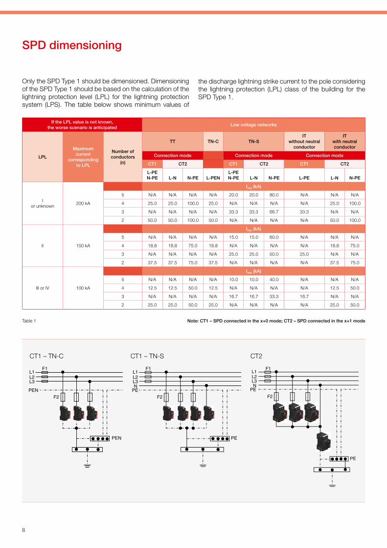
SPD dimensioning
Only the SPD Type 1 should be dimensioned. Dimensioning of the SPD Type 1 should be based on the calculation of the lightning protection level (LPL) for the lightning protection system (LPS). The table below shows minimum values of
Table 1 Note: CT1 – SPD connected in the x+0 mode; CT2 – SPD connected in the x+1 mode
CT1 – TN-C CT1 – TN-S CT2
the discharge lightning strike current to the pole considering the lightning protection (LPL) class of the building for the SPD Type 1.
If the LPL value is not known, the worse scenario is anticipated
Low voltage networks
LPL
Maximum current
corresponding to LPL
Number of conductors
(n)
TT TN-C TN-SIT
without neutral conductor
ITwith neutral conductor
Connection mode Connection mode Connection mode
CT1 CT2 CT1 CT2 CT1 CT2
L-PEN-PE L-N N-PE L-PEN
L-PEN-PE L-N N-PE L-PE L-N N-PE
I or unknown
200 kA
Iimp (kA)
5 N/A N/A N/A N/A 20.0 20.0 80.0 N/A N/A N/A
4 25.0 25.0 100.0 25.0 N/A N/A N/A N/A 25.0 100.0
3 N/A N/A N/A N/A 33.3 33.3 66.7 33.3 N/A N/A
2 50.0 50.0 100.0 50.0 N/A N/A N/A N/A 50.0 100.0
II 150 kA
Iimp (kA)
5 N/A N/A N/A N/A 15.0 15.0 60.0 N/A N/A N/A
4 18.8 18.8 75.0 18.8 N/A N/A N/A N/A 18.8 75.0
3 N/A N/A N/A N/A 25.0 25.0 50.0 25.0 N/A N/A
2 37.5 37.5 75.0 37.5 N/A N/A N/A N/A 37.5 75.0
III or IV 100 kA
Iimp (kA)
5 N/A N/A N/A N/A 10.0 10.0 40.0 N/A N/A N/A
4 12.5 12.5 50.0 12.5 N/A N/A N/A N/A 12.5 50.0
3 N/A N/A N/A N/A 16.7 16.7 33.3 16.7 N/A N/A
2 25.0 25.0 50.0 25.0 N/A N/A N/A N/A 25.0 50.0

Practical Guide - Low-voltage power systems
9
For selection of the SPD Type 1 at the incoming supply to the building we use the table for SPD Type 1 dimensioning (see table 1). At the same time, it is necessary to consider the specific situation. Even if the calculation made according to the previous table shows that the Impulse current of SPD
Type 1 may be, for example, 12.5 kA in a 10/350 μs wave and the building is fed by external cabling, then the prob-ability of a lightning strike into the outdoor line is high and the SPD Type 1 would be under-dimensioned.
Variants of SPD applications are shown in the following examples:
Selection of SPD at the incoming supply side to the building
Situation at the entrance of structure Solution
A house with LPS, earthed antenna, or metallic roof, etc. SPD Type 1 SPD Type 2
A house with an overhead line SPD Type 1 SPD Type 2
A house with earthed metallic parts or LPS nearby SPD Type 1 SPD Type 2
1
TN-C: SLP-275 V/3TN-C-S: SLP-275 V/3TN-S: SLP-275 V/3+1or SLP-275 V/4TT-SLP: 275 V/3+1
DA-275-A TN-C: SLP-275 V/3TN-C-S: SLP-275 V/3TN-S: SLP-275 V/3+1or SLP-275 V/4TT-SLP: 275 V/3+1
DA-275-A
T1 T2T1 T2T1 T2
T2T3T3 T2
A family house in a built-up area or a detached structure with or without LPS and overhead line
TN-C: FLP-B+C MAXI V(S)/3TN-C-S: FLP-B+C MAXI V(S)/3TN-S: FLP-B+C MAXI V(S)/4TT: FLP-B+C MAXI V(S)/3+1
TN-C: FLP-12,5 V/3TN-C-S: FLP-12,5 V/3TN-S: FLP-12,5 V/4TT: FLP-12,5 V/3+1
TN-C: FLP-B+C MAXI V(S)/3TN-C-S: FLP-B+C MAXI V(S)/3TN-S: FLP-B+C MAXI V(S)/4TT: FLP-B+C MAXI V(S)/3+1

10
TN-C: FLP-12,5 V/3TN-C-S: FLP-12,5 V/3TN-S: FLP-12,5 V/4TT: FLP-12,5 V/3+1
TN-C: SLP-275 V/3TN-C-S: SLP-275 V/3TN-S: SLP-275 V/3+1 or SLP-275 V/4TT: SLP-275 V/3+1
DA-275-A
TN-C: FLP-B+C MAXI V(S)/3TN-C-S: FLP-B+C MAXI V(S)/3TN-S: FLP-B+C MAXI V(S)/4TT: FLP-B+C MAXI V(S)/3+1
TN-C: SLP-275 V/3TN-C-S: SLP-275 V/3TN-S: SLP-275 V/3+1 or SLP-275 V/4TT: SLP-275 V/3+1
DA-275-A
TN-C: FLP-12,5 V/3TN-C-S: FLP-12,5 V/3TN-S: FLP-12,5 V/4TT: FLP-12,5 V/3+1
TN-C: FLP-12,5 V/3TN-C-S: FLP-12,5 V/3TN-S: FLP-12,5 V/4TT: FLP-12,5 V/3+1
3
T1 T2T1 T2
T2T3T2T3
T2T1T2T1
T2T1
2
TN-C: FLP-B+C MAXI V(S)/3TN-C-S: FLP-B+C MAXI V(S)/3TN-S: FLP-B+C MAXI V(S)/4TT: FLP-B+C MAXI V(S)/3+1
A family house in a built-up area without LPS and with an underground cable connection
A detached family house with or without LPS, with an underground cable connection
T2T3T2T3
TN-C: SLP-275 V/3TN-C-S: SLP-275 V/3TN-S: SLP-275 V/3+1or SLP-275 V/4TT: SLP-275 V/3+1
DA-275-ATN-C: SLP-275 V/3TN-C-S: SLP-275 V/3TN-S: SLP-275 V/3+1 or SLP-275 V/4TT: SLP-275 V/3+1
DA-275-A

Practical Guide - Low-voltage power systems
11
5 Terrace houses with a common LPS and an underground cable connection
Terrace houses with a common LPS and overhead line
TN-C: SLP-275 V/3TN-C-S: SLP-275 V/3TN-S: SLP-275 V/3+1or SLP-275 V/4TT: SLP-275 V/3+1
DA-275-A
TN-C: FLP-B+C MAXI V(S)/3TN-C-S: FLP-B+C MAXI V(S)/3TN-S: FLP-B+C MAXI V(S)/4TT: FLP-B+C MAXI V(S)/3+1
TN-C: FLP-12,5 V/3TN-C-S: FLP-12,5 V/3TN-S: FLP-12,5 V/4TT: FLP-12,5 V/3+1
T1 T2
T1 T2
T3
T2
4
TN-C: SLP-275 V/3TN-C-S: SLP-275 V/3TN-S: SLP-275 V/3+1or SLP-275 V/4TT: SLP-275 V/3+1
DA-275-A
T3T2

12
Blocks of flats with an underground cable connection with the possibility to install an SPD Type 1 upstream of power meter
TN-C: FLP-12,5 V/3TN-C-S: FLP-12,5 V/3TN-S: FLP-12,5 V/4TT: FLP-12,5 V/3+1
DA-275-A
TN-C: FLP-B+C MAXI V(S)/3TN-C-S: FLP-B+C MAXI V(S)/3TN-S: FLP-B+C MAXI V(S)/4TT: FLP-B+C MAXI V(S)/3+1
TN-C: SLP-275 V/3TN-C-S: SLP-275 V/3TN-S: SLP-275 V/3+1or SLP-275 V/4TT: SLP-275 V/3+1
DA-275-A
TN-C: FLP-B+C MAXI V(S)/3TN-C-S: FLP-B+C MAXI V(S)/3TN-S: FLP-B+C MAXI V(S)/4TT: FLP-B+C MAXI V(S)/3+1
TN-C: FLP-12,5 V/1TN-C-S: FLP-12,5 V/1TN-S: FLP-12,5 V/2TT: FLP-12,5 V/1+1
TN-C: SLP-275 V/1TN-C-S: SLP-275 V/1TN-S: SLP-275 V/1+1or SLP-275 V/2TT: SLP-275 V/1+1
T1 T2
7
T3
T2
T2
T3
6
T1 T2
T1 T2
T1 T2
Blocks of flats with an underground cable connection without the possibility to install an SPD Type 1 upstream of power meter

Practical Guide - Low-voltage power systems
13
DA-275-A
TN-C: SLP-275 V/3TN-C-S: SLP-275 V/3TN-S: SLP-275 V/3+1or SLP-275 V/4TT: SLP-275 V/3+1
LED ADVERTISINGSP-T2+T3-320/Y-CLT-LED
LED LIGHTING DA-320-LED
TN-C: SLP-275 V/3TN-C-S: SLP-275 V/3TN-S: SLP-275 V/3+1or SLP-275 V/4TT: SLP-275 V/3+1
TN-C: FLP-B+C MAXI V(S)/3TN-C-S: FLP-B+C MAXI V(S)/3TN-S: FLP-B+C MAXI V(S)/4TT: FLP-B+C MAXI V(S)/3+1
Administration building
T1T2
T3
8
T2 T2 T3
T2
T3

14
TN-C: FLP-B+C MAXI V(S)/3TN-C-S: FLP-B+C MAXI V(S)/3TN-S: FLP-B+C MAXI V(S)/4TT: FLP-B+C MAXI V(S)/3+1
TN-C: SLP-275 V/3TN-C-S: SLP-275 V/3TN-S: SLP-275 V/4TT: SLP-275 V/3+1
DA-275-A
TN-S: DA-275 V/3+1TT: DA-275 V/3+1
TN-S: DA-275-DF16TT: DA-275-DF16
RACK-PROTECTOR-F6-1URACK-PROTECTOR-VF5-1URACK-PROTECTOR-VX7-1URACK-PROTECTOR-X8-1URACK-PROTECTOR-EURO-X12-1U
TN-S: SLP-275 V/3+1TT: SLP-275 V/3+1
TN-C: SLP-275 V/3TN-C-S: SLP-275 V/3TN-S: SLP-275 V/4TT: SLP-275 V/3+1
T2
T3
T3
T3
T2
T3
T2
T1 T2
9 Administrative and commercial premises

Practical Guide - Low-voltage power systems
15
TN-C: 3 pcs. FLP-SG50 V(S)/1TN-C-S: 3 pcs. FLP-SG50 V(S)/1TN-S: 4 pcs. FLP-SG50 V(S)/1TT: 3 pcs. FLP-SG50 V(S)/1
+ 1 piece FLP-A100N VS/NPE
TN-S: SLP-275 V/3+1TT: SLP-275 V/3+1
TN-S: DA-275 V/3+1 TT: DA-275 V/3+1
TN-S: DA-275-DF16TT: DA-275-DF16
TN-S: DA-275-DF16TT: DA-275-DF16
TN-S: SLP-275 V/3+1TT: SLP-275 V/3+1
T3
T1
T3
T2T3
T2
TN-S: FLP-12,5 V/3+1TT: FLP-12,5 V/3+1
T1 T2

16
TN-C: FLP-B+C MAXI V(S)/3TN-C-S: FLP-B+C MAXI V(S)/3TN-S: FLP-B+C MAXI V(S)/4TT: FLP-B+C MAXI V(S)/3+1
or or
and
TN-C: 3 pcs. FLP-SG50 V(S)/1TN-C-S: 3 pcs. FLP-SG50 V(S)/1TN-S: 4 pcs. FLP-SG50 V(S)/1TT: 3 pcs. FLP-SG50 V(S)/1 + 1 piece FLP-A100N VS/NPE
11
T1
TN-C: SLP-275 V/3TN-C-S: SLP-275 V/3TN-S: SLP-275 V/4TT: SLP-275 V/3+1
T2
TN-C: FLP-25-T1-V(S)/3TN-C-S: FLP-25-T1-V(S)/3TN-S: FLP-25-T1-V(S)/4TT: FLP-25-T1-V(S)/3+1
T1
TN-C: 3 pcs. FLP-SG50 V(S)/1TN-C-S: 3 pcs. FLP-SG50 V(S)/1TN-S: 4 pcs. FLP-SG50 V(S)/1TT: 3 pcs. FLP-SG50 V(S)/1
+ 1 piece FLP-A100N VS/NPE
T1
T1 T2
10 Commercial building
Commercial building of special importance

Practical Guide - Low-voltage power systems
17
T1
12 Building with LPS and air conditioner or heating cables in gutters
TN-C: 1 piece FLP-SG50 V(S)/1TN-C-S: 1 piece FLP-SG50 V(S)/1
TN-S: 2 pcs. FLP-SG50 V(S)/1TT: 1 piece FLP-SG50 V(S)/1
+ 1 piece FLP-A100N VS/NPE
TN-C: FLP-B+C MAXI V(S)/3TN-C-S: FLP-B+C MAXI V(S)/3TN-S: FLP-B+C MAXI V(S)/4TT: FLP-B+C MAXI V(S)/3+1
DA-275-A
TN-C: FLP-12,5 V/1TN-C-S: FLP-12,5 V/1TN-S: FLP-12,5 V/2TT: FLP-12,5 V/1+1
House with a single-phase power supply and LPS (LPL I)
T1
T3
T1 T2
T1 T2
1 2
13
Two- -conductor supply
Three- -conductor supply
18
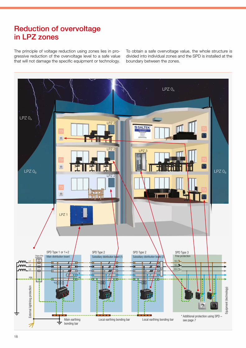
The principle of voltage reduction using zones lies in pro-gressive reduction of the overvoltage level to a safe value that will not damage the specific equipment or technology.
Reduction of overvoltage in LPZ zones
To obtain a safe overvoltage value, the whole structure is divided into individual zones and the SPD is installed at the boundary between the zones.
LPZ 0A
LPZ 0BLPZ 0B
LPZ 0A
LPZ 2
LPZ 2
LPZ 2
LPZ 1
LPZ 3
*F3
L1
L2
L3
N
PE
F1
RCD
63 A
16 A
16 A
*F4*F2
L1
L2
L3
N
PE
F1
RCD
63 A
16 A
16 A
*F3
L1
L2
L3
N
EPNEP
F1
*F2
L1
L2
L3
PEN
F1
*F2
RCD
*F3
*F3
*F4
*F2
63 A
16 A
16 A
63 A
16 A
16 A
Origin of the installation
* Additional protection using SPD – see page 7
SPD Type 1 or 1+2Main distribution board
SPD Type 2Subsidiary distribution board (1)
SPD Type 2Subsidiary distribution board (2)
SPD Type 3Fine protection
Exte
rnal
ligh
tnin
g pr
otec
tion
Main earthing bonding bar
Local earthing bonding bar Local earthing bonding bar
Equi
pmen
t (te
chno
logy
)
T3T3
T3T3
T3T3

Practical Guide - Low-voltage power systems
19
a
b c
a + b ≤ 0.5 m c ≤ 0.5 m
b
a
UW
U1
Up
U2
OCP
SPD
SPD mounting – principles
Principle 1 – length of connecting conductors If you want to protect equipment, there are several things to remember when installing an SPD, i.e., apart from its diverting ability, it is the maximum value of voltage protec-tive level to be withheld by the equipment at its terminals considering the installation method. Protection level Up and the drop in voltage at the supply conductors DU must not exceed the withstand voltage at the terminals of the equip-ment.
Fig. 11 clearly shows that the aggregate protection level is given by adding partial reductions in voltage, while such a sum must not exceed 80% of the withstand voltage Uw at the terminals of the equipment.
where Uw … withstand voltage Up … voltage protection level DU1, DU2 … reduction in voltage at the
supply conductor.
The impedance of supply conductors for high frequency currents is approximately 1 μH per 1 m of conductor length.
The voltage drop in this conductor is given by the formula:
So with a steepness of the pulse rise time of 1 kA/μs, there is a reduction of 1,000 V per 1 m of length, which is added to the protection voltage level of the SPD itself. With the total length of supply conductors being 0.5 m, 500 V will be added to the protection voltage level U. Consequently, the length of the supply conductors must be as short as possi-ble and should not exceed an aggregate length of 0.5 m, as shown in the following figures (Fig. 12 and Fig. 13), depicting the connection options.
DU = L × di/dt
Uw > Up + DU1 + DU2
Fig. 11
Fig. 12 Fig. 13

20
The two pictures below illustrate how the stipulated con-ductor length of ≤ 0.5 m to connect the SPD can be met in practice.
Before the intervention: The SPD installation fails to meet the condition as regards the length of supply conductors for the SPD
After the intervention: By relocating the SPD the condition above will be satisfied.
Before the intervention: The SPD installation fails to meet the condition as regards the length of supply conductors
After the intervention: By relocating the SPD the condition will be satisfied

Practical Guide - Low-voltage power systems
21
Principle 2 – Locating the SPD in the distribution board An SPD in the distribution board is located at the entry of the customer´s structure, to eliminate as early as possible any surges entering the supply line, and to prevent their effects on appliances installed in the distribution board. It makes
The next figure shows the practical implementation of the c) option displayed in Fig. 14.
sure the unprotected conductors (affected by overvoltage) are kept as short as possible and the overvoltage that could be induced in conductors protected by the SPD is minimi-zed. Basic options are shown in Fig.14.
EBB
a) b) c) d)
Before the intervention: The SPD installation fails to meet the condition as regards the length of supply conductors for the SPD
After the intervention: By adding a terminal block and connecting a PEN conduc-tor, these conditions will be satisfied
Fig. 14

22
Principle 3 – loopsTo minimize the overvoltage induced in a loop and to consid-erably reduce the effects of such overvoltages on other equip-ment connected in the distribution board, the surface of the
Before the intervention: The SPD installation fails to meet the condition as regards the length of supply conductors for the SPD and also the SPD connection for the TN-S system
Before the intervention After the intervention: By turning the SPD, the hardwiring in the distribution board will be better arranged and, at the same time, the condition from IEC 61643-12/2008 (CLC/TS 61643-12/2009) concerning loops will be satisfied
After the intervention: By relocating the circuit breaker and the SPD, the condi-tions will be satisfied; and by adding one more SPD the N conductor will also be protected.
loop consisting of the L, N and PE conductors must be kept as small as possible. The principle of minimizing the loop is shown in Fig. 14 and the following examples.
+1

Practical Guide - Low-voltage power systems
23
Principle 4 – conductor routing in the distribution boardWhen routing the conductors in the distribution board it is always necessary to separate protected („clean“) from un-protected („dirty“) conductors. To minimise the bonding be-tween the different types of conductors („clean“ and „dirty“), it is essential to keep the distance between them as great as possible (over 30 cm). If such a distance is impossible
< 30 cm < 30 cm
Protected cable
Unprotected cable
Divider
Unprotected cable
Protected cable
90°
> 30 cm
Protected cable
Unprotected cable
to observe, a protective partition should be placed between them, see Fig. 15. If you cannot avoid crossing of protected and unprotected conductors, the crossing should be made at a right angle to prevent induction of interference pulses in the protected conductors, as shown in Fig. 16.
Protected cable
Unprotected cable
Protected cable
Unprotected cable
Before the intervention After the intervention: By relocating the SPD, the hardwiring in the distribution board will be better arranged, the condition concerning loops specified in IEC 61643-12/2008 (CLC/TS 61643-12/2009) will be satisfied and, at the same time, the condition stipulating the length of supply conductors for the SPD will be met as well
Fig. 15
Fig. 16
24
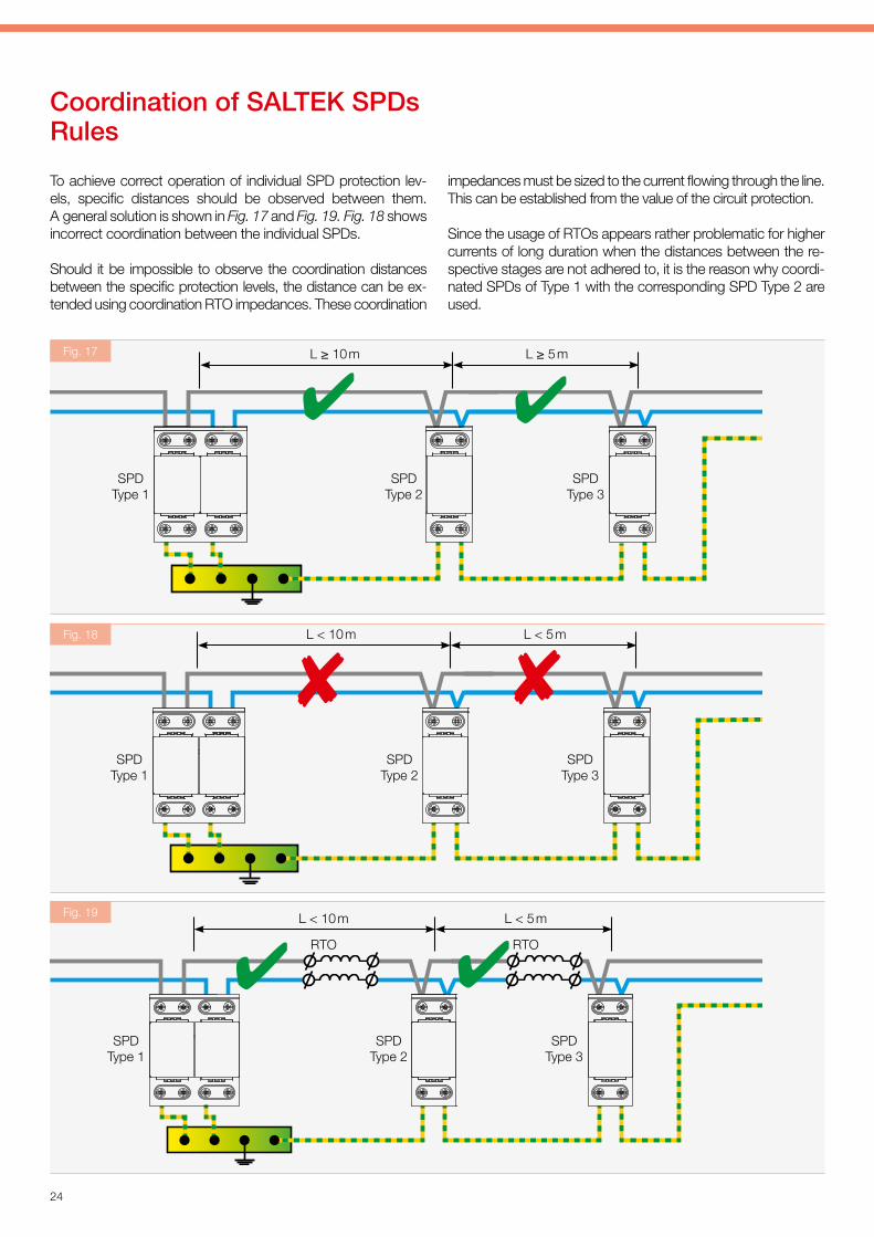
impedances must be sized to the current flowing through the line. This can be established from the value of the circuit protection.
Since the usage of RTOs appears rather problematic for higher currents of long duration when the distances between the re-spective stages are not adhered to, it is the reason why coordi-nated SPDs of Type 1 with the corresponding SPD Type 2 are used.
To achieve correct operation of individual SPD protection lev-els, specific distances should be observed between them. A general solution is shown in Fig. 17 and Fig. 19. Fig. 18 shows incorrect coordination between the individual SPDs.
Should it be impossible to observe the coordination distances between the specific protection levels, the distance can be ex-tended using coordination RTO impedances. These coordination
Coordination of SALTEK SPDs Rules
L ≥ 10 m L ≥ 5 m
SPD Type 1
SPD Type 2
SPD Type 3
RTO RTO
L < 10 m L < 5 m
L < 10 m L < 5 m
Fig. 17
Fig. 18
Fig. 19
SPD Type 1
SPD Type 1
SPD Type 2
SPD Type 2
SPD Type 3
SPD Type 3

Practical Guide - Low-voltage power systems
25
0 m < L < 10 m L ≥ 5 m
FLP-SG50 V /1 SLP-275 V*
* Depending of the type of connection
L ≥ 10 m L ≥ 5 m
L ≥ 5 m
FLP-B+C MAXI V* SLP-275 V*
* Depending of the type of connection
L ≥ 10 m L ≥ 5 m
SLP-275 V*
* Depending of the type of connection
SLP-275 V*
Type 2Type 2 Type 3
the distance between this SPD and the next one exceeds 10 m, an SPD Type 2 should be located behind the SPD Type 1+2, e.g., SLP-275 V (see Fig. 21).
If the distance between this SPD and the next one is less than 10 m, you will not need to install an SPD Type 2 down-stream of the SPD Type 1+2.
The same applies onIy if an SPD Type 2 is used instead of an SPD Type 1+2 (see Fig. 22).
See following figures for coordination of specific SPD Type 1 and SPD Type 2 by Saltek. If lightning arrester FLP-SG50 V/1 is used as an SPD Type 1 and SLP-275 V is used as an SPD Type 2, it will not be necessary to keep the distance between them in excess of 10 m since they are mutually coordinated and can be mounted next to each other (see Fig. 20).
If, for example, FLP-B+C MAXI V is installed as an SPD Type 1, which is an SPD Type 1+2 with Up < 1.5 kV and
Type 2Type 1 Type 3
Type 2Type 1 + 2 Type 3
FLP-SG50 V /1
Fig. 20
Fig. 21
Fig. 22
L ≥ 5 m
26
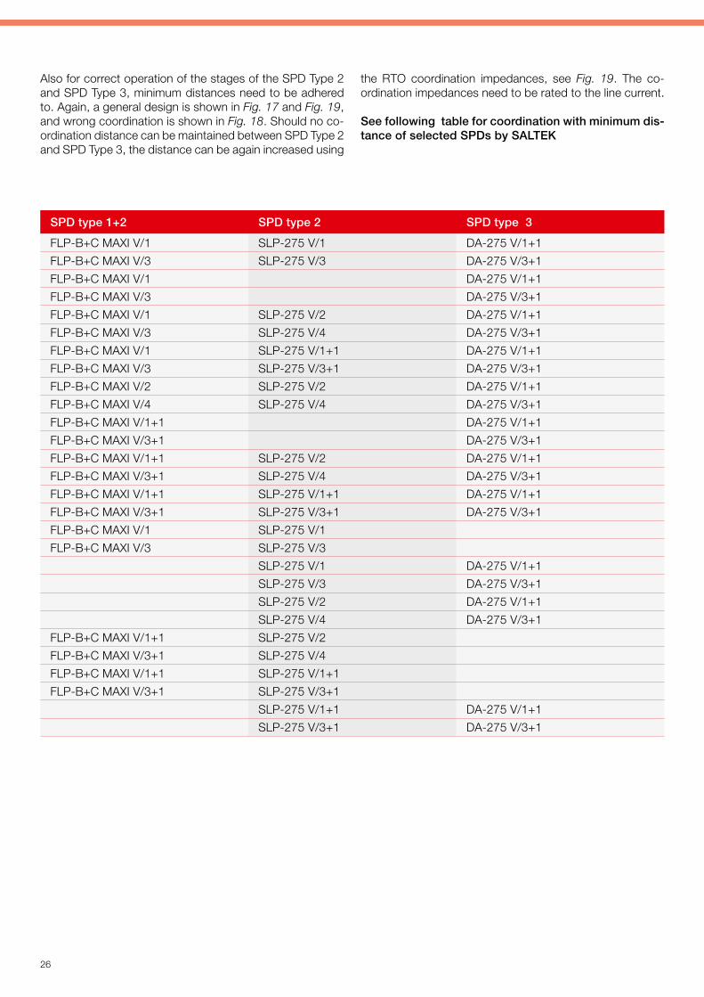
Also for correct operation of the stages of the SPD Type 2 and SPD Type 3, minimum distances need to be adhered to. Again, a general design is shown in Fig. 17 and Fig. 19, and wrong coordination is shown in Fig. 18. Should no co-ordination distance can be maintained between SPD Type 2 and SPD Type 3, the distance can be again increased using
the RTO coordination impedances, see Fig. 19. The co-ordination impedances need to be rated to the line current.
See following table for coordination with minimum dis-tance of selected SPDs by SALTEK
SPD type 1+2 SPD type 2 SPD type 3
FLP-B+C MAXI V/1 SLP-275 V/1 DA-275 V/1+1
FLP-B+C MAXI V/3 SLP-275 V/3 DA-275 V/3+1
FLP-B+C MAXI V/1 DA-275 V/1+1
FLP-B+C MAXI V/3 DA-275 V/3+1
FLP-B+C MAXI V/1 SLP-275 V/2 DA-275 V/1+1
FLP-B+C MAXI V/3 SLP-275 V/4 DA-275 V/3+1
FLP-B+C MAXI V/1 SLP-275 V/1+1 DA-275 V/1+1
FLP-B+C MAXI V/3 SLP-275 V/3+1 DA-275 V/3+1
FLP-B+C MAXI V/2 SLP-275 V/2 DA-275 V/1+1
FLP-B+C MAXI V/4 SLP-275 V/4 DA-275 V/3+1
FLP-B+C MAXI V/1+1 DA-275 V/1+1
FLP-B+C MAXI V/3+1 DA-275 V/3+1
FLP-B+C MAXI V/1+1 SLP-275 V/2 DA-275 V/1+1
FLP-B+C MAXI V/3+1 SLP-275 V/4 DA-275 V/3+1
FLP-B+C MAXI V/1+1 SLP-275 V/1+1 DA-275 V/1+1
FLP-B+C MAXI V/3+1 SLP-275 V/3+1 DA-275 V/3+1
FLP-B+C MAXI V/1 SLP-275 V/1
FLP-B+C MAXI V/3 SLP-275 V/3
SLP-275 V/1 DA-275 V/1+1
SLP-275 V/3 DA-275 V/3+1
SLP-275 V/2 DA-275 V/1+1
SLP-275 V/4 DA-275 V/3+1
FLP-B+C MAXI V/1+1 SLP-275 V/2
FLP-B+C MAXI V/3+1 SLP-275 V/4
FLP-B+C MAXI V/1+1 SLP-275 V/1+1
FLP-B+C MAXI V/3+1 SLP-275 V/3+1
SLP-275 V/1+1 DA-275 V/1+1
SLP-275 V/3+1 DA-275 V/3+1

Practical Guide - Low-voltage power systems
27
Fig. 27 Fig. 28
L > 50 m
FLP-SG50 V /1
SLP-275 V/1+1
Type 1 Type 2
L > 50 m
L > 100 m
FLP-SG50 V /1
FLP-12,5 V/1+1
FLP-B+C MAXI V/2
Type 1
Type 1
Type 1+2
Type 1+2
L > 100 m
FLP-SG50 V /1
SLP-275 V/1+1
Type 1 Type 2
FLP-SG50 V /1
Fig. 23
Fig. 25
Fig. 24
Fig. 26
Since there are situations in practice where the equipment to be protected is connected directly from the main distribution board and the technology distribution board finds itself usu-ally at a distance of tens of meters, it is advisable to install an SPD in the technology distribution board to cope with over-voltage as well as different earth potentials that might occur there, particularly if the earthing (equipotential bonding) is
In series connection of SPDs with different level, attention should be valid both to their mutual distance (reflection fac-tor effect, see below) and their Up (protection voltage level).
Relation between distance and selection of SPD
Ranging the SPDs with reference to Up
not completely all the way through. Consequently, an SPD Type 1+2, featuring a diverting ability of In = 30 kA (8/20 μs), should be installed in the position of the SPD Type 2, whose diverting ability is In = 20 kA (8/20 μs), to work In this case as a strong SPD Type 2 (see Fig. 23–24 and Fig. 25–26). For more information see the table “SALTEK SPD applications in LV distribution systems”, pages 32–33.
The series connection of SPD is shown in the following figures (Fig. 27–28 and Fig. 29–30).
Type 1+2
Up (L-N) ≤ 1.5 kV
Type 3
Up (L-N) ≤ 1.0 kVType 2
Up (L-N) ≤ 1.2 kV
Type 3
Up (L-N) ≤ 1.0 kV
28
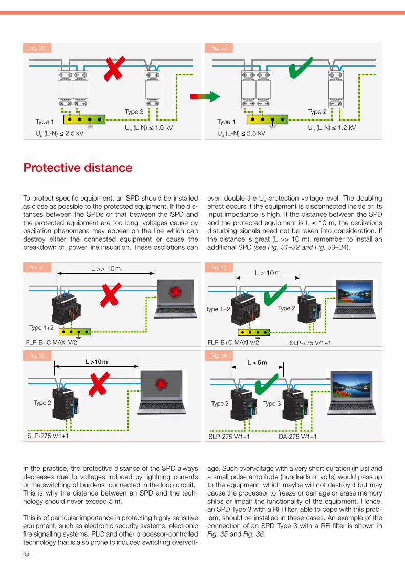
In the practice, the protective distance of the SPD always decreases due to voltages induced by lightning currents or the switching of burdens connected in the loop circuit. This is why the distance between an SPD and the tech-nology should never exceed 5 m.
This is of particular importance in protecting highly sensitive equipment, such as electronic security systems, electronic fire signalling systems, PLC and other processor-controlled technology that is also prone to induced switching overvolt-
age. Such overvoltage with a very short duration (in μs) and a small pulse amplitude (hundreds of volts) would pass up to the equipment, which maybe will not destroy it but may cause the processor to freeze or damage or erase memory chips or impair the functionality of the equipment. Hence, an SPD Type 3 with a RFi filter, able to cope with this prob-lem, should be installed in these cases. An example of the connection of an SPD Type 3 with a RFi filter is shown in Fig. 35 and Fig. 36.
even double the Up protection voltage level. The doubling effect occurs if the equipment is disconnected inside or its input impedance is high. If the distance between the SPD and the protected equipment is L ≤ 10 m, the oscilations disturbing signals need not be taken into consideration. If the distance is great (L >> 10 m), remember to install an additional SPD (see Fig. 31–32 and Fig. 33–34).
Protective distance
To protect specific equipment, an SPD should be installed as close as possible to the protected equipment. If the dis-tances between the SPDs or that between the SPD and the protected equipment are too long, voltages cause by oscilation phenomena may appear on the line which can destroy either the connected equipment or cause the breakdown of power line insulation. These oscilations can
FLP-B+C MAXI V/2 FLP-B+C MAXI V/2
Type 1+2
Type 1+2 Type 2
SLP-275 V/1+1
L >> 10 mL > 10 m
L > 10 m L > 5 m
Type 2 Type 2 Type 3
SLP-275 V/1+1 SLP-275 V/1+1 DA-275 V/1+1
Fig. 31
Fig. 33
Fig. 32
Fig. 34
Fig. 29 Fig. 30
Type 1
Up (L-N) ≤ 2.5 kV
Type 1
Up (L-N) ≤ 2.5 kV
Type 3
Up (L-N) ≤ 1.0 kV
Type 2
Up (L-N) ≤ 1.2 kV

Practical Guide - Low-voltage power systems
29
A socket with integrated SPD Type 3
DA-275-A DA-275-A DA-275-A DA-275-A DA-275-A
SPD Type 3 for additional installation
T3T3T3T3T3
Fig. 37
Socket circuitry featuring all sockets either with integrated SPD Type 3 protection or available with SPD Type 3 protec-tion for additional installation (see Fig. 37), is always used in heavily disturbed environments, or places with a larger number of electrical appliances installed. Laboratories are a typical example of such environment.
Socket circuits with SPD Type 3
Consideration should be taken regarding socket circuits, which are usually very long and are used in different situations. The protective distance of an SPD Type 3 in cabled socket circuits amounts to 5 m, at maximum, as shown in Fig. 38.
To ensure correct functioning of an SPD Type 3, both pro-tection levels – SPD Type 1 and SPD Type 2 – should be mounted upstream.
Fig. 35
Fig. 36
FLP-B+C MAXI V/2
Type 1+2 Type 3
DA-275-DF16
L > 5 m L < 5 m
SLP-275 V/1+1
Type 2Type 3
DA-275-DF16
L > 5 m L < 5 m

30
If this principle is not observed, the problem located at the LV line bar will manifest itself in the socket circuit and will damage the equipment connected to the specific socket. Administrative buildings feature a great number of socket circuits with many sockets. To reduce the number of SPDs in such cases, not only the protective distance for the SPD
Type 3 is used, but also so-called installations in groups, as shown in the following examples. If distances between individual groups exceed 5 m, as shown in Fig. 42, the pas-sage socket group must be provided with an SPD Type 3 at the first and last socket.
DA-275-A DA-275-ADA-275-A DA-275-A
< 5 m < 5 m < 5 m < 5 m
for example a down conductor
T3T3T3T3
Fig. 40
In order to reduce the number of SPD Type 3 in the socket circuitry, protective distances between the SPDs Type 3 of less than 5 m are used as standard. In these cases it is not necessary to equip all sockets with SPD Type 3 protection. The basic principle to follow in this method of installing an SPD Type 3 is that the SPD must always be installed at the first socket in the socket circuit; the protective distance prin ciple for SPD Type 3, as shown in Fig. 38, can be ap-
plied only after that. Fig. 39 shows an example of incorrect application of the protective distance. The principle of pro-tective distance cannot be applied to situations where one side of the wall features a socket circuit with, for example, a down conductor bar or an unprotected ascending LV line situated on the other side of the wall. All sockets installed at this place should be provided with an SPD Type 3, as shown in Fig. 40 and Fig. 41.
DA-275-A DA-275-A DA-275-A
< 5 m < 5 m < 5 m < 5 m
T3T3T3
DA-275-A DA-275-A
< 5 m < 5 m < 5 m < 5 m
T3T3
Fig. 38
Fig. 39

Practical Guide - Low-voltage power systems
31
If the group is not a through-way group, an SPD Type 3 should always be installed at the first socket. Should the distance between individual socket groups be less than 5 m, then the property of the SPD protective distance can be used and the no an SPD Type 3 will be mounted on the through-way group - see Fig. 43. The principle of pro-
tective distance cannot be applied in situations where the distance between two groups is less than 5 m, and, for example, a down lead or an unprotected LV line is located on the other side of the wall. It is necessary in this case that the last socket of the through-way group be provided with an SPD Type 3. This option is shown in Fig. 44.
through-way last group
T3
< 5 m
DA-275-A DA-275-A
through-way last group
for example, the down conductor
< 5 m
DA-275-A DA-275-A
T3
T3T3
Fig. 43
Fig. 44
DA-275-A DA-275-A DA-275-A
< 5 m < 5 m < 5 m < 5 m
for example a down conductorT3T3T3
through-way last group
T3
> 5 m
DA-275-A DA-275-A
T3
Fig. 41
Fig. 42

32
SALTEK® SPD applications in LV distribution systems
Type of structure system main distribution board (in the structure) sub-distribution board (in the same structure) end consumer
Family houses, administrativebuildings, technological units, industrial structures
3-ph. TN-C FLP-B+C MAXI V(S)/3FLP-25-T1-V(S)/3
distance > 10 mSLP-275 V/3 (S)
distance > 5 m
surge protection to DIN rail:DA-275 V/1(S)+1 (up to 63 A)DA-275 V/3(S)+1 (up to 63 A)DA-275-DJ25-(S) (25 A)
surge protection to a DIN rail with a RFi filter:DA-275-DFx-(S) (x = 2, 6, 10, 16 A)DA-275 DF25 for 25 ADA-275-DFix (x = 6, 10, 16 A)
RACK-PROTECTORmultiple sockets to 19" enclosures
CZ-275-A, DA-275 CZSDA-275-A, DA-275-S for additional assembly to the sockets and appliances
distance < 5 mplace before the surge protectionRTO-xx (xx – rated current 16, 35 or 63 A)
number acording to connection
1-phase TN-C1x RTO-xx1-phase TN-S2x RTO-xx3-phase TN-C3x RTO-xx3-phase TN-S4x RTO-xx
distance > 50 mFLP-12,5 V/3 (S)
distance > 100 mFLP-B+C MAXI V(S)/3
FLP-25-T1-V(S)/3 distance < 10 mSLP-275 V/3 (S)
FLP-B+C MAXI V(S)/3FLP-25-T1-V(S)/3 + SLP-275 V/3 (S)(also with terminals to the equipment)
distance > 10 mSLP-275 V/3 (S)
distance > 50 mFLP-12,5 V/3 (S)
distance > 100 mFLP-B+C MAXI V(S)/3
3-ph. TN-S FLP-B+C MAXI V(S)/4FLP-25-T1-V(S)/4
distance > 10 mSLP-275 V/4 (S)
distance > 50 mFLP-12,5 V/4 (S)
distance > 100 mFLP-B+C MAXI V(S)/4
FLP-25-T1-V(S)/4 distance < 10 mSLP-275 V/4 (S)
FLP-B+C MAXI V(S)/4FLP-25-T1-V(S)/4 + SLP-275 V/4 (S)(also with terminals to the equipment)
distance > 10 mSLP-275 V/4 (S)
distance > 50 mFLP-12,5 V/4 (S)
distance > 100 mFLP-B+C MAXI V(S)/4
3-ph. TN-C-S FLP-B+C MAXI V(S)/3FLP-25-T1-V(S)/3
distance > 10 mSLP-275 V/4 (S)
distance > 50 mFLP-12,5 V/4 (S)
distance > 100 mFLP-B+C MAXI V(S)/4
FLP-25-T1-V(S)/3 distance < 10 mSLP-275 V/4 (S)
FLP-B+C MAXI V(S)/3FLP-25-T1-V(S)/3 + SLP-275 V/3 (S)(also with terminals to the equipment)
distance > 10 mSLP-275 V/4 (S)
distance > 50 mFLP-12,5 V/4 (S)
distance > 100 mFLP-B+C MAXI V(S)/4
Blocks of flats with 12 or more apartments (SPD located in the apart. distr. boards)
3-ph. TN-C FLP-12,5 V/3 (S)
3-ph. TN-S FLP-12,5 V/4 (S)
3-ph. TN-C-S division in the apartment distr. board FLP-12,5 V/3 (S)
1-ph. TN-C FLP-B+C MAXI V(S)/1
1-ph. TN-S FLP-12,5 V/2 (S)
Demanding applications (structures – operations classified at the risk of explosion, chemical plants…, structures of a very high importance)
3-ph. TN-C 3× FLP-SG50 V(S)/1
with terminals to the equipment3× FLP-SG50 V(S)/1 + 1× SLP-275 V/3 (S)
distance < 10 m1× SLP-275 V/3 (S)distance > 10 mSLP-275 V/3 (S)distance > 50 mFLP-12,5 V/3 (S)distance > 100 mFLP-B+C MAXI V(S)/3
3-ph. TN-S 4× FLP-SG50 V(S)/1
with terminals to the equipment4× FLP-SG50 V(S)/1 + 1× SLP-275 V/4(S)
distance < 10 m1× SLP-275 V/4 (S)distance > 10 mSLP-275 V/4 (S)distance > 50 mFLP-12,5 V/4 (S)distance > 100 mFLP-B+C MAXI V(S)/4
3-ph. TN-C-S division in the main distribution board3× FLP-SG50 V(S)/1
with terminals to the equipment3× FLP-SG50 V(S)/1 + 1× SLP-275 V/4(S)
distance < 10 m1× SLP-275 V/4 (S)distance > 10 mSLP-275 V/4 (S)distance > 50 mFLP-12,5 V/4 (S)distance > 100 mFLP-B+C MAXI V(S)/4
Practical Guide - Low-voltage power systems
33
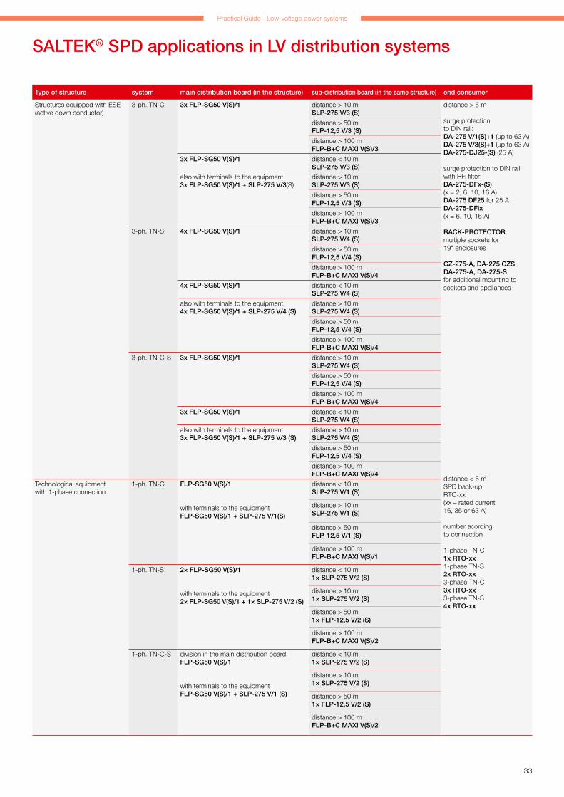
SALTEK® SPD applications in LV distribution systems
Type of structure system main distribution board (in the structure) sub-distribution board (in the same structure) end consumer
Structures equipped with ESE (active down conductor)
3-ph. TN-C 3x FLP-SG50 V(S)/1 distance > 10 mSLP-275 V/3 (S)
distance > 5 m
surge protection to DIN rail:DA-275 V/1(S)+1 (up to 63 A)DA-275 V/3(S)+1 (up to 63 A)DA-275-DJ25-(S) (25 A)
surge protection to DIN rail with RFi filter:DA-275-DFx-(S) (x = 2, 6, 10, 16 A)DA-275 DF25 for 25 ADA-275-DFix (x = 6, 10, 16 A)
RACK-PROTECTORmultiple sockets for 19" enclosures
CZ-275-A, DA-275 CZSDA-275-A, DA-275-S for additional mounting to sockets and appliances
distance < 5 mSPD back-upRTO-xx (xx – rated current 16, 35 or 63 A)
number acording to connection
1-phase TN-C1x RTO-xx1-phase TN-S2x RTO-xx3-phase TN-C3x RTO-xx3-phase TN-S4x RTO-xx
distance > 50 mFLP-12,5 V/3 (S)
distance > 100 mFLP-B+C MAXI V(S)/3
3x FLP-SG50 V(S)/1 distance < 10 mSLP-275 V/3 (S)
also with terminals to the equipment3x FLP-SG50 V(S)/1 + SLP-275 V/3(S)
distance > 10 mSLP-275 V/3 (S)
distance > 50 mFLP-12,5 V/3 (S)
distance > 100 mFLP-B+C MAXI V(S)/3
3-ph. TN-S 4x FLP-SG50 V(S)/1 distance > 10 mSLP-275 V/4 (S)
distance > 50 mFLP-12,5 V/4 (S)
distance > 100 mFLP-B+C MAXI V(S)/4
4x FLP-SG50 V(S)/1 distance < 10 mSLP-275 V/4 (S)
also with terminals to the equipment4x FLP-SG50 V(S)/1 + SLP-275 V/4 (S)
distance > 10 mSLP-275 V/4 (S)
distance > 50 mFLP-12,5 V/4 (S)
distance > 100 mFLP-B+C MAXI V(S)/4
3-ph. TN-C-S 3x FLP-SG50 V(S)/1 distance > 10 mSLP-275 V/4 (S)
distance > 50 mFLP-12,5 V/4 (S)
distance > 100 mFLP-B+C MAXI V(S)/4
3x FLP-SG50 V(S)/1 distance < 10 mSLP-275 V/4 (S)
also with terminals to the equipment3x FLP-SG50 V(S)/1 + SLP-275 V/3 (S)
distance > 10 mSLP-275 V/4 (S)
distance > 50 mFLP-12,5 V/4 (S)
distance > 100 mFLP-B+C MAXI V(S)/4
Technological equipment with 1-phase connection
1-ph. TN-C FLP-SG50 V(S)/1
with terminals to the equipmentFLP-SG50 V(S)/1 + SLP-275 V/1(S)
distance < 10 mSLP-275 V/1 (S)
distance > 10 mSLP-275 V/1 (S)
distance > 50 mFLP-12,5 V/1 (S)
distance > 100 mFLP-B+C MAXI V(S)/1
1-ph. TN-S 2× FLP-SG50 V(S)/1
with terminals to the equipment2× FLP-SG50 V(S)/1 + 1× SLP-275 V/2 (S)
distance < 10 m1× SLP-275 V/2 (S)
distance > 10 m1× SLP-275 V/2 (S)
distance > 50 m1× FLP-12,5 V/2 (S)
distance > 100 mFLP-B+C MAXI V(S)/2
1-ph. TN-C-S division in the main distribution boardFLP-SG50 V(S)/1
with terminals to the equipmentFLP-SG50 V(S)/1 + SLP-275 V/1 (S)
distance < 10 m1× SLP-275 V/2 (S)
distance > 10 m1× SLP-275 V/2 (S)
distance > 50 m1× FLP-12,5 V/2 (S)
distance > 100 mFLP-B+C MAXI V(S)/2

34
SPDs connected to LV power supply systems up to 1 000 V
Lightning current arresters (SPD Type 1), spark-gap basedA high-performance spark gap specified for using in LV installations at the boundary of the LPZ 0 and LPZ 1 zones. Surge protection indirect as well as indirect lightning strikes in the hardest application in heavy, chemical and energy industry. Coordination with SPD Type 2 (SLP-275 V) without coupling impedances.
FLP-SG50 V(S)/1 Pluggable module Visual fault signalling Module locking Optional remote fault signalling (S) Up ≤ 2.5 kV
Type ConnectionSuitable
networksUc
Iimp
(10/350 µs)Ifi
Remote signalling
Ordering number
FLP-SG50 V/1 1+0 TN, TT 255 V AC 50 kA 50 kA No A04054
FLP-SG50 VS/1 1+0 TN, TT 255 V AC 50 kA 50 kA Yes A04053
Lightning current arresters (SPD Type 1), serial combination MOV+GDTVery high-performance lightning current arresters for LV installations at the boundary of the LPZ 0 and LPZ 1 zones or higher. For protec-tion in direct as well as indirect lightning strikes. For using in a variety of installations, for family houses, office and industrial buildings, or in sub-distribution boards of large buildings. Coordination with SPD Type 2 (SLP-275 V) without coupling impedances. No leakage current. No follow current.
FLP-25-T1-V(S)/…
Pluggable module Visual fault signalling Module locking Optional remote fault signalling (S) Up ≤ 1.5 kV
Type ConnectionSuitable
networksUc
Iimp
(10/350 µs)Remote signalling Ordering number
FLP-25-T1-V/1 1+0 TN-C 260 V AC 25 kA No A06263
FLP-25-T1-VS/1 1+0 TN-C 260 V AC 25 kA Yes A06264
FLP-25-T1-V/1+1 1+1 TT 260 V AC 25 kA No A06257
FLP-25-T1-VS/1+1 1+1 TT 260 V AC 25 kA Yes A06258
FLP-25-T1-V/2 2+0 TN-S 260 V AC 25 kA No A06259
FLP-25-T1-VS/2 2+0 TN-S 260 V AC 25 kA Yes A06260
FLP-25-T1-V/3 3+0 TN-C 260 V AC 25 kA No A05300
FLP-25-T1-VS/3 3+0 TN-C 260 V AC 25 kA Yes A05301
FLP-25-T1-V/3+1 3+1 TT 260 V AC 25 kA No A05304
FLP-25-T1-VS/3+1 3+1 TT 260 V AC 25 kA Yes A05305
FLP-25-T1-V/4 4+0 TN-S 260 V AC 25 kA No A05302
FLP-25-T1-VS/4 4+0 TN-S 260 V AC 25 kA Yes A05303
Lightning current arresters (SPD Type 1), spark-gap for N-PEA spark gap for N-PE with a replaceable module for using in LV installations, at the boundary of the LPZ 0 and LPZ 1 zones. Surge protec-tion in direct as well as indirect lightning strikes. ATTENTION! Only for wiring between N and PE!
Type ConnectionSuitable
networksUc
Iimp
(10/350 µs)In
(8/20 µs)Imax
(8/20 µs)Remote
signallingOrdering number
FLP-A50N VS/NPE 1+1 TT 255 V AC 50 kA 50 kA 100 kA Yes A03573
FLP-A100N VS/NPE 3+1 TT 255 V AC 100 kA 100 kA 100 kA Yes A03574
FLP-A…N VS/NPE Pluggable module Module locking Remote signalling of module presence (S) Up ≤ 1.5 kV

Practical Guide - Low-voltage power systems
35
SPDs connected to LV power supply systems up to 1 000 V
Lightning current arresters and surge arresters (SPD Type 1 and 2), serial combination MOV+GDTVery high-performance lightning current arresters for LV installations at the boundary of the LPZ 0 and LPZ 1 zones or higher. For protec-tion in direct as well as indirect lightning strikes. For using in a variety of installations, for family houses, office and industrial buildings, or in sub-distribution boards of large builings. No leakage current. No follow current.
FLP-B+C MAXI V(S)/...
Type ConnectionSuitable
networksUc
Iimp
(10/350 µs)In
(8/20 µs)Imax
(8/20 µs)Remote
signallingOrdering number
FLP-B+C MAXI V/1 1+0 TN 260 V AC 25 kA 30 kA 60 kA No A05091
FLP-B+C MAXI VS/1 1+0 TN 260 V AC 25 kA 30 kA 60 kA Yes A03533
FLP-B+C MAXI V/1+1 1+1 TT 260 V AC 25 kA 30 kA 60 kA No A05095
FLP-B+C MAXI VS/1+1 1+1 TT 260 V AC 25 kA 30 kA 60 kA Yes A03783
FLP-B+C MAXI V/2 2+0 TN-S 260 V AC 25 kA 30 kA 60 kA No A05092
FLP-B+C MAXI VS/2 2+0 TN-S 260 V AC 25 kA 30 kA 60 kA Yes A03784
FLP-B+C MAXI V/3 3+0 TN-C 260 V AC 25 kA 30 kA 60 kA No A05093
FLP-B+C MAXI VS/3 3+0 TN-C 260 V AC 25 kA 30 kA 60 kA Yes A03570
FLP-B+C MAXI V/3+1 3+1 TT 260 V AC 25 kA 30 kA 60 kA No A05096
FLP-B+C MAXI VS/3+1 3+1 TT 260 V AC 25 kA 30 kA 60 kA Yes A03572
FLP-B+C MAXI V/4 4+0 TN-S 260 V AC 25 kA 30 kA 60 kA No A05094
FLP-B+C MAXI VS/4 4+0 TN-S 260 V AC 25 kA 30 kA 60 kA Yes A03571
FLP-B+C MAXI150 V/1 1+0 TN 150 V AC 25 kA 30 kA 60 kA No A05834
FLP-B+C MAXI150 VS/1 1+0 TN 150 V AC 25 kA 30 kA 60 kA Yes A05835
Lightning current arresters and surge arresters (SPD Type 1 and 2), MOV basedFor LV installations at the boundary of the LPZ 0 and LPZ 1 or higher. Protection against the effects of partial lightning strike currents, induced overvoltage in lightning strikes and against switching overvoltage. It is suitable for lightning protection levels III and IV of buildings, in sub-distribution boards of large buildings or the protection of air conditioners or heating cables.
Type ConnectionSuitable
networksUc
Iimp
(10/350 µs)In
(8/20 µs)Imax
(8/20 µs)Remote
signallingOrdering number
FLP-12,5 V/1 1+0 TN 275 V AC 12.5 kA 30 kA 60 kA No A03421
FLP-12,5 V/1 S 1+0 TN 275 V AC 12.5 kA 30 kA 60 kA Yes A03422
FLP-12,5 V/1+1 1+1 TT 275 V AC 12.5 kA 30 kA 60 kA No A03423
FLP-12,5 V/1S+1 1+1 TT 275 V AC 12.5 kA 30 kA 60 kA Yes A03424
FLP-12,5 V/2 2+0 TN-S 275 V AC 12.5 kA 30 kA 60 kA No A03809
FLP-12,5 V/2 S 2+0 TN-S 275 V AC 12.5 kA 30 kA 60 kA Yes A05182
FLP-12,5 V/3 3+0 TN-C 275 V AC 12.5 kA 30 kA 60 kA No A03425
FLP-12,5 V/3 S 3+0 TN-C 275 V AC 12.5 kA 30 kA 60 kA Yes A03426
FLP-12,5 V/3+1 3+1 TT 275 V AC 12.5 kA 30 kA 60 kA No A03427
FLP-12,5 V/3S+1 3+1 TT 275 V AC 12.5 kA 30 kA 60 kA Yes A03428
FLP-12,5 V/4 4+0 TN-S 275 V AC 12.5 kA 30 kA 60 kA No A03429
FLP-12,5 V/4 S 4+0 TN-S 275 V AC 12.5 kA 30 kA 60 kA Yes A03430
Pluggable module Visual fault signalling Module locking Optional remote fault signalling (S) Up ≤ 1.5 kV
FLP-12,5 V/…
Pluggable module Visual fault signalling Module locking Optional remote fault signalling (S) Up ≤ 1.5 kV

36
Surge arresters (SPD Type 2), MOV basedFor LV installations, especially to sub-distribution boards. Protection of installation and devices against effects of induced surge during a lightning strike or switching surges.
Pluggable module Visual fault signalling Module locking Optional remote fault signalling (S)
SLP-… V/… (S)
Type ConnectionSuitable
networksUc
In
(8/20 µs)Imax
(8/20 µs)Remote
signallingOrdering number
SLP-275 V/1 1+0 TN 275 V AC 20 kA 40 kA No A01617
SLP-275 V/1 S 1+0 TN 275 V AC 20 kA 40 kA Yes A01618
SLP-275 V/1+1 1+1 TT 275 V AC 20 kA 40 kA No A01948
SLP-275 V/1S+1 1+1 TT 275 V AC 20 kA 40 kA Yes A02491
SLP-275 V/2 2+0 TN-S 275 V AC 20 kA 40 kA No A01619
SLP-275 V/2 S 2+0 TN-S 275 V AC 20 kA 40 kA Yes A05183
SLP-275 V/3 3+0 TN-C 275 V AC 20 kA 40 kA No A01760
SLP-275 V/3 S 3+0 TN-C 275 V AC 20 kA 40 kA Yes A01761
SLP-275 V/3+1 3+1 TT 275 V AC 20 kA 40 kA No A01946
SLP-275 V/3S+1 3+1 TT 275 V AC 20 kA 40 kA Yes A02002
SLP-275 V/4 4+0 TN-S 275 V AC 20 kA 40 kA No A01722
SLP-275 V/4 S 4+0 TN-S 275 V AC 20 kA 40 kA Yes A01763
SLP-075 V/1 1+0 TN 75 V AC 15 kA 40 kA No A01815
SLP-075 V/1 S 1+0 TN 75 V AC 15 kA 40 kA Yes A01823
SLP-150 V/1 1+0 TN 150 V AC 15 kA 40 kA No A05185
SLP-150 V/1 S 1+0 TN 150 V AC 15 kA 40 kA Yes A05186
SLP-385 V/1 1+0 TN 385 V AC 20 kA 40 kA No A01955
SLP-385 V/1 S 1+0 TN 385 V AC 20 kA 40 kA Yes A02771
SLP-440 V/1 1+0 TN 440 V AC 20 kA 40 kA No A01817
SLP-440 V/1 S 1+0 TN 440 V AC 20 kA 40 kA Yes A01825
SLP-600 V/1 1+0 TN 760 V AC 15 kA 40 kA No A03301
SLP-600 V/1 S 1+0 TN 760 V AC 15 kA 40 kA Yes A03302
SLP-600 V/3 3+0 TN 760 V AC 15 kA 40 kA No A06076
SLP-600 V/3 S 3+0 TN 760 V AC 15 kA 40 kA Yes A06305
Surge arresters (SPD Type 2), serial combination MOV+GDTFor protection of installations and devices against the effects of induced overvoltage in lightning strikes in areas with more frequent storms and against switching overvoltage. Suitable for supply by diesel-generator and networks with fluctuating voltages. For protection of measurement circuits as the first level of protection. It is also suitable for Instrumentation and control (I&C) circuits at the boundary of the LPZ 0 and LPZ 1. No leakage current. No follow current.
SLP-… VB/… (S)
Type ConnectionSuitable
networksUc
In
(8/20 µs)Imax
(8/20 µs)Remote
signallingOrdering number
SLP-075 VB/1 1+0 TN 75 V AC 15 kA 25 kA No A02155
SLP-075 VB/1 S 1+0 TN 75 V AC 15 kA 25 kA Yes A02156
SLP-130 VB/1 1+0 TN 135 V AC 20 kA 25 kA No A02182
SLP-130 VB/1 S 1+0 TN 135 V AC 20 kA 25 kA Yes A02996
SLP-275 VB/1 1+0 TN 275 V AC 20 kA 25 kA No A01944
SLP-275 VB/1 S 1+0 TN 275 V AC 20 kA 25 kA Yes A01945
SLP-275 VB/3+1 3+1 TN-S, TT 275 V AC 20 kA 25 kA No A03310
SLP-275 VB/3S+1 3+1 TN-S, TT 275 V AC 20 kA 25 kA Yes A03311
Pluggable module Visual fault signalling Module locking Optional remote fault signalling (S)
SPDs connected to LV power supply systems up to 1 000 V

Practical Guide - Low-voltage power systems
37
SPDs connected to LV power supply systems up to 1 000 V
Surge protections (SPD Type 3) on the DIN rail, for parallel connectionA combination of varistor surge protection and an encapsulated spark gap connected in the 1+1 (3+1) mode. For LV installations at the boundary of the LPZ 2 and LPZ 3 zones. For protection installations and devices against the effects of induced overvoltage in lightning strikes and against switching overvoltage. Location as close as possible to the protected device.
DA-275 V/… (S)
Pluggable module Visual fault signalling Module locking Optional remote fault signalling (S) Up ≤ 1.5 kV
Type ConnectionSuitable
networksUc
In
(8/20 µs)Uoc
Remote signalling
Ordering number
DA-275 V/1+1 1+1 TN-S, TT 275 V AC 5 kA 10 kV No A01872
DA-275 V/1S+1 1+1 TN-S, TT 275 V AC 5 kA 10 kV Yes A01975
DA-275 V/3+1 3+1 TN-S, TT 275 V AC 5 kA 10 kV No A01848
DA-275 V/3S+1 3+1 TN-S, TT 275 V AC 5 kA 10 kV Yes A01849
Surge protections (SPD Type 3) on the DIN rail, for serial connectionA surge protection for universal use to protect all types of LV electrical and electronic devices against transient overvoltage. Location as close as possible to the protected device.
DA-275-DJ25 (S), DA-… DJ
Symmetrical internal connection Visual fault signalling Optional remote fault signalling (S) Up ≤ 1.5 kV
Type ConnectionSuitable
networksUC IL
In (L+N-PE)(8/20 µs)
Uoc(L+N-PE)
Remote signalling
Ordering number
DA-275-DJ25 Symmetric TN-S, TT 275 V AC 25 A 5 kA 10 kV No A05770
DA-275-DJ25-S Symmetric TN-S, TT 275 V AC 25 A 5 kA 10 kV Yes A05771
DA-075-DJ25 Symmetric TN-S, TT 75 V AC 25 A 4 kA 8 kV No A06094
DA-150-DJ25 Symmetric TN-S, TT 150 V AC 25 A 5 kA 10 kV No A06095
Surge protections (SPD Type 3) for additional mountingSurge protection for additional mounting to devices, machines, equipment, etc. For protection of all types LV electrical and electronic devices against transient overvoltage. Location as close as possible to the protected device.
CZ-275-A, DA-275-…
Acoustic or remote status signalling Up ≤ 1.5 kV
Type ConnectionSuitable
networksUc
In (L+N-PE)(8/20 µs)
Uoc(L+N-PE)
Remote signalling
Ordering number
CZ-275-A 1+1 TN, TT 275 V AC 3 kA 6 kV Acoustic A05957
DA-275 CZS 1+1 TN, TT 275 V AC 3 kA 6 kV Remote A01916
DA-275-A Symmetrical TN, TT 275 V AC 2 kA 4 kV Acoustic A05958
DA-275-S Symmetrical TN, TT 275 V AC 2 kA 4 kV Remote A05959

38
SPDs connected to LV power supply systems up to 1 000 V
Surge protections (SPD Type 3) on the DIN rail, with RFi filterA surge protection with an integrated RFi filter to protect the supply of control systems such as I&C, electronic security and fire alarm systems, etc., against transient overvoltage and RF disturbance. Variants "i" with remote fault signalling by interruption of power supply. Location as close as possible to the protected device.
DA-275-DF…(-S), DA-… DF … (S)
Type ConnectionSuitable
networksUC IL
In (L+N-PE)(8/20 µs)
Uoc (L+N-PE)
Remote signalling
Ordering number
DA-275-DF2 Symmetric TN, TT 275 V AC 2 A 5 kA 10 kV No A05715
DA-275-DF2-S Symmetric TN, TT 275 V AC 2 A 5 kA 10 kV Yes A05716
DA-275-DF6 Symmetric TN, TT 275 V AC 6 A 5 kA 10 kV No A05717
DA-275-DF6-S Symmetric TN, TT 275 V AC 6 A 5 kA 10 kV Yes A05718
DA-275-DF10 Symmetric TN, TT 275 V AC 10 A 5 kA 10 kV No A05719
DA-275-DF10-S Symmetric TN, TT 275 V AC 10 A 5 kA 10 kV Yes A05720
DA-275-DF16 Symmetric TN, TT 275 V AC 16 A 5 kA 10 kV No A05721
DA-275-DF16-S Symmetric TN, TT 275 V AC 16 A 5 kA 10 kV Yes A05722
DA-275 DF 25 Symmetric TN, TT 275 V AC 25 A 5 kA 10 kV No A03732
DA-275 DFI 1 Symmetric TN, TT 275 V AC 1 A 1.5 kA 3 kV Interruption A01205
DA-275-DFi6 Symmetric TN, TT 275 V AC 6 A 5 kA 10 kV Interruption A05723
DA-275-DFi10 Symmetric TN, TT 275 V AC 10 A 5 kA 10 kV Interruption A05724
DA-275-DFi16 Symmetric TN, TT 275 V AC 16 A 5 kA 10 kV Interruption A05725
DA-275 BFG Symmetric TN, TT 275 V AC 16 A 5 kA 10 kV No A00629
DA-275-BFi2 Symmetric TN, TT 275 V AC 2 A 5 kA 10 kV Interruption A06262
Visual fault signalling Optional remote fault signalling (S) Filter attenuation range ca. 150 kHz ÷ 30 MHz Up ≤ 1.5 kV
Multiple sockets with surge protection (SPD Type 3) into 19" RACKSurge protection SPD Type 3 for protection of information technology in 19" RACKs with visual fault signalling. Variants with switch or RFi filter. Earth pin socket version. Location as close as possible to the protected device.
RACK-PROTECTOR-…-1U
Type Sockets Switch RFi filterIn
(8/20 µs)Uoc Up Ordering number
RACK-PROTECTOR-F6-1U 6 No Yes 5 kA 10 kV 1.5 kV A05874
RACK-PROTECTOR-VF5-1U 5 Yes Yes 5 kA 10 kV 1.5 kV A05875
RACK-PROTECTOR-VX7-1U 7 Yes No 5 kA 10 kV 1.5 kV A05873
RACK-PROTECTOR-X8-1U 8 No No 5 kA 10 kV 1.5 kV A05872
RACK-PROTECTOR-EURO-X12-1U 12 EURO No No 3 kA 6 kV 1.6 kV A05961
Mounting height 1U Power supply cord 3 m, CEE 7/7 plug Visual fault signalling Un = 230 V AC, IL = 16 A

Practical Guide - Low-voltage power systems
39
SPDs connected to LV power supply systems up to 1 000 V
Coordination impedance RTO-…Coupling impedance to secure proper coordination of a SPD if the minimum distance between a SPD Type 1 and SPD Type 2, which exceeds 10 m, is not maintained, or a Type 2 and Type 3 SPD, which exceeds 5 m.
Surge separating inductors
Type UC IL Resistance Inductance Power loss at IL Ordering number
RTO-16 500 V AC 16 A 5 mΩ 10 µH 1.28 W A01432
RTO-35 500 V AC 35 A 2.5 mΩ 10 µH 3 W A01433
RTO-63 500 V AC 63 A 2 mΩ 10 µH 8 W A01434
Surge protection (SPD Type 3 and Type 2 and 3) for LED lightsSPDs mainly for drivers of LED lights. Instalation close to protected equipment into LV power circuits. Also for equipments in external part of structure with low or high exposure level (according IEEE C62.41.2). Fault signalling by supply interruption.
DA-320-LED SP-T2+T3-320/Y-CLT-LED
For equipment in external part of building with low exposure level Up ≤ 1.5 kV
For equipment in external part of building with high exposure level Up ≤ 1.5 kV
Type SPD Type Location UC ILIn
(8/20 µs)Uoc
(L+N-PE)Fault
signallingOrdering number
DA-320-LED 3 C low 320 V AC 5 A 3 kA 6 kV Interruption A05876
SP-T2+T3-320/Y-CLT-LED 2 a 3 C high 320 V AC 10 A 5 kA 10 kV Interruption A06044

Distributor:
03/2
019
Sales and technical support:
SALTEK TRADE s.r.o.Vodňanská 1419/226198 00 Praha 9 - KyjeCzech RepublicPhone: +420 272 942 470E-mail: [email protected]/en
Manufacture and headquarter:
SALTEK s.r.o.Drážďanská 85400 07 Ústí nad LabemCzech RepublicPhone: +420 475 655 511Fax: +420 475 622 213E-mail: [email protected] www.saltek.eu