
Power transmission parts - HPC
356
2016 / Power transmission parts Mechanical components by mail order Tel: +33 (0)4 37 496 496 www.hpceurope.com PDF files
-
Upload
khangminh22 -
Category
Documents
-
view
32 -
download
0
Transcript of Power transmission parts - HPC
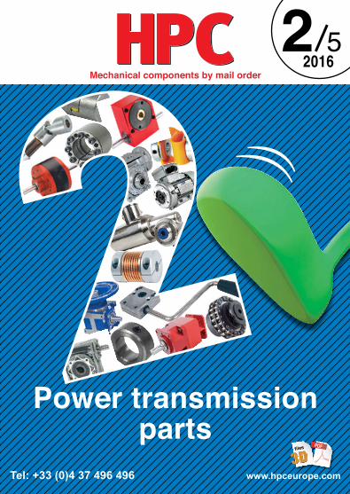
2016/
Power transmissionparts
Mechanical components by mail order
Tel: +33 (0)4 37 496 496 www.hpceurope.com
PDFfiles

p.26Panamech Multi-Beam p.32Single-disc flexible coupling p.34
Oldham®coupling
Gerwah® couplingp.38
Gerwah® coupling
Gerwah® couplingp.36
Rotex® GS backlash free jaw coupling p.42p.40
Gerwah® coupling Flexible bellows couplingp.44 p.46
p.52 p.58p.50P-FLEX®coupling
Miniature bellows coupling
Miniature bellows coupling
BoWex® curved tooth gear couping p.60
p.64BoWex® curved tooth coupling
Elastic coupling,ECONOMY RANGEp.62
couplingECONOMY RANGE
Shaft clamp with keyway
PERIFLEX® elastic coupling p.76
MasterFlex®flexible shaft p.70 p.82 p.84
Single univeraljoint
p.68p.66Rotex®coupling
images index 1 /4
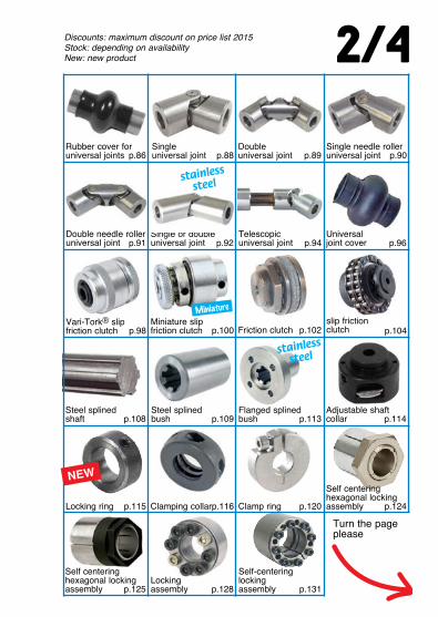
2/4
p.91Single or double universal joint p.94
Telescopic universal joint p.96
Universal joint cover
Double needle rolleruniversal joint p.92
p.104p.102Friction clutchslip friction clutchp.98
Vari-Tork® slip friction clutch
Miniature slip friction clutch p.100
p.113Steel splinedshaft p.109
Steel splined bush
Flanged splined bushp.108 p.114
Adjustable shaftcollar
p.89Single universal joint
Double universal jointp.86
Rubber cover foruniversal joints
Single needle roller universal jointp.88 p.90
Miniature
Locking ring p.116 p.124Clamping collar Clamp ringp.115 p.120
p.128Locking assemblyp.125
Self centering hexagonal lockingassembly
Self-centeringlocking assembly p.131
NEW
Discounts: maximum discount on price list 2015 Stock: depending on availabilityNew: new product
Turn the page please
stainless
steel
stainless
steel
Self centering hexagonal lockingassembly

p.204 p.208p.198Internal epicyclic servo-reducers
Right angled gearboxSingle or dual output gearboxes p.232 p.242
p.225Miniature right angled gear reducer Manual bevel gearboxp.217
Spur gear coaxial gearbox p.226
p.228
p.138p.132Mechanical locking assembly
Hydraulic lockingassembly p.142Worm and wheel gear reducer
Offset spur gear reducer
Internal epicyclic servo-reducers
Inline spur gear reducer p.211
Manual worm/ wheel gearbox
stainless
steel
stainless
steel
stainless
steel
Right angled gearbox, dual output shafts p.174
made tomeasure
Contact-us
Optional shaft for E-typegear reducersp.163
Worm gear reducers
Right angle helical reducersp.162 p.173p.166
Optional output shaft
Mini
Mini
Increasedstock
images index 3/4
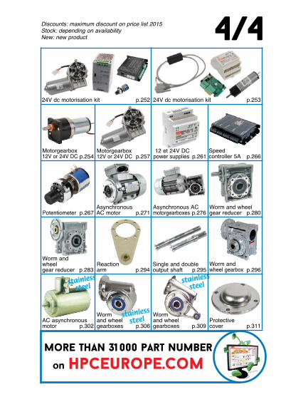
more than 31 000 part number
on hpceurope.com
p.254Motorgearbox 12V or 24V DC p.261
12 et 24V DCpower supplies p.266
Speed controller 5A
Motorgearbox 12V or 24V DC p.257
p.280p.276Asynchronous AC motorgearboxes
Worm and wheelgear reducerp.267Potentiometer
Asynchronous AC motor p.271
p.295
Worm and wheelgear reducer p.294
Reaction arm
Single and double output shaftp.283 p.296
Worm and wheel gearbox
24V dc motorisation kit24V dc motorisation kit p.252 p.253
stainless
steel
stainless
steelstainless
steel
p.309 p.311
Worm and wheel gearboxes
Worm and wheel gearboxes
Protectivecoverp.302
AC asynchronous motor p.306
4/4Discounts: maximum discount on price list 2015 Stock: depending on availabilityNew: new product
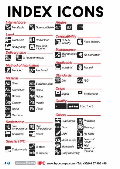
4 www.hpceurope.com - Tel: +33(0)4 37 496 496Volume 2 2016
1T
Internal bore Angles
Load Compatibility
Delivery timeMaintenance
Method of fabricationApplicable
MaterialStandards
Origin
Quality
Resistant to
Special HPC
Others
Modifiable Non-modifiable
Axial load Radial load
Moulded Machined
Steel
Cast iron
Aluminium
Stainless steel
Bronze
Brass
Copper
Nylon
Delrin
Plastic
Corrosion Shock
In stockCustom-made
In imperial
Peek
Robotic industry Food industry
Maintenance free No lubrication
Industrial Manual
DIN ISO
Japan Switzerland
Bi-directional
Miniature size
Precision
Easy assembly
Modulable
Light
Bearings
No fixing
Duo
Low cost rangeHigh speed of rotation
from 1 to 8
Heavy duty Max load1 tonne
In hours or weeks
High temperatures
Low temperatures
index icons
5 Fax: +33(0)4 37 490 055 - [email protected] Volume 2 2016
table ofcontents
Image index ..........................................................................................................................................p.0 ➞ 3Index icons .......................................................................................................................................................p.4Services availables from HPC ....................................................................................................p.6 ➞ 7Buyers guide .......................................................................................................................................p.8 ➞ 23Products ......................................................................................................................................... p.24 ➞ 327 Couplings for servo-motors ..................................................................................p.24 ➞ 58 Transmission couplings ...........................................................................................p.59 ➞ 79 Universal joints and rigid couplings .............................................................p.80 ➞ 105 Assembly elements ..............................................................................................p.106 ➞ 139 Gearboxes ...................................................................................................................p.140 ➞ 223 Other gearboxes .................................................................................................... p.224 ➞ 249 Motor-gearboxes .................................................................................................... p.250 ➞ 327General terms and conditions of sale .......................................................................p.328 ➞ 331Index by part numbers .......................................................................................................p.332 ➞ 338 Index by reference to international standards ....................................................p.339 ➞ 340Index by names ........................................................................................................................p.341 ➞ 350HPC in Europe ...........................................................................................................................................p.351Catalogue request .................................................................................................................................. p.352

6 www.hpceurope.com - Tel: +33(0)4 37 496 496Volume 2 2016
EASY ORDENING
• Personalised advice from our technical and sales• teams is available by telephone from Monday to• Friday from 08.00 to 12.20 and 13.40 to 18.00,• just call +33 (0) 4 37 496 496• We can also be contacted by fax, email or post.
PERSONALISED SOLUTIONS
• 190 000 standard parts available from stock• Custom parts can be machined to order from• samples or drawings• Items not listed in catalogue can also be supplied• Medium and large production runs available on• request
• www.hpceurope.com references 31,000 parts• Instant online quote generation• Datasheets in PDF format and 3D models can be
downloaded free of charge from the site• Package tracking
ONLINE ORDERING AVAILABLE 24/24
services available from

7 Fax: +33(0)4 37 490 055 - [email protected] Volume 2 2016
SAFE PAYMENT
FAST DELIVERY
GENERAL INFORMATION
Our bank details:BNP PARIBAS18 Chemin de Gargantua69570 DardillyN° de compte: 00010041122
Engrenages HPC SARL, share capital 76 224EN°382 911 907 RCS LyonFrench SIC code : APE 4669BTVA FR 41 382 911 907 58, Chemin de la Bruyère69570 Dardilly – Lyon – FranceEmail: [email protected]: www.hpceurope.comTel: +33(0)4 37 496 496Fax: +33(0)4 37 490 055
BankTransfer
Cheque
*Some restrictions apply. For deliveries to French mainland only.
Creditcard
Bankdraft
• Any order for articles in stock received before• 14.00 will be delivered before 18.00 the
following day*• Free delivery for all orders over 50€*
8 www.hpceurope.com - Tel: +33(0)4 37 496 496Volume 2 2016
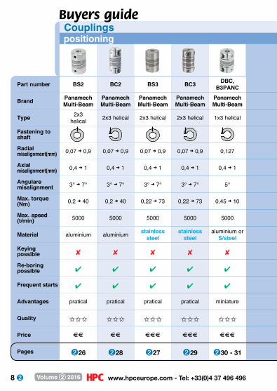
Part number BS2 BC2 BS3 BC3 DBC, B3PANC
Brand Panamech Multi-Beam
Panamech Multi-Beam
Panamech Multi-Beam
Panamech Multi-Beam
Panamech Multi-Beam
Type 2x3helical 2x3 helical 2x3 helical 2x3 helical 1x3 helical
Fastening to shaft Radial misalignment(mm) 0,07 ➜ 0,9 0,07 ➜ 0,9 0,07 ➜ 0,9 0,07 ➜ 0,9 0,127
Axial misalignment(mm) 0,4 ➜ 1 0,4 ➜ 1 0,4 ➜ 1 0,4 ➜ 1 0,4 ➜ 1
Angulare misalignment 3° ➜ 7° 3° ➜ 7° 3° ➜ 7° 3° ➜ 7° 5°
Max. torque (Nm) 0,2 ➜ 40 0,2 ➜ 40 0,22 ➜ 73 0,22 ➜ 73 0,45 ➜ 10
Max. speed (t/min) 5000 5000 5000 5000 5000
Material aluminium aluminium stainless steel
stainless steel
aluminium orS/steel
Keying possible 8 8 8 8 8
Re-boring possible 4 4 4 4 4
Frequent starts 4 4 4 4 4
Advantages pratical pratical pratical pratical miniature
Quality III III III III III
Price DD DD DDD DDD DDD
Pages ➋26 ➋28 ➋27 ➋29 ➋30 ➜ 31
Couplings positioning
Buyers guide

9 Fax: +33(0)4 37 490 055 - [email protected] Volume 2 2016
MHS MHW PFL BG, BGC
- - P-FLEX Oldham
simple disc double disc double elastomerring -
0 0,15 ➜ 0,3 2,6 ➜ 3,2 0,2 ➜ 0,25
0,2 0,4 ➜ 0,8 4,5 ➜ 11 0,05 ➜ 0,2
1° 2° 10° ➜ 15° 0,5°
2,8 ➜ 38 2,8 ➜ 38 0,5 ➜ 10 0,06 ➜ 44
2400 ➜ 4800 2400 ➜ 4800 3000 3000
aluminium + S/steel
aluminium + S/steel steel + Hytrel brass or
aluminium + acetal
8 8 8 8
8 8 8 4
4 4 4 4
precise precise economical pratical
III III II III
DDD DDD D DD
➋32 ➋33 ➋58 ➋34 ➜ 35
: locking jaw : set screw : locking assembly

10 www.hpceurope.com - Tel: +33(0)4 37 496 496Volume 2 2016
Part number RGS DKGSBKGS EKGS ADSR
Brand Rotex® GS Gerwah® Gerwah® Gerwah®
Type spacer mounted,pre-stressed
spacer mounted,pre-stressed
spacer mounted,pre-stressed
spacer mounted,pre-stressed
Fastening to shaft
Radial misalignment(mm) 0,06 ➜ 0,15 0,06 ➜ 0,14 0,06 ➜ 0,14 0,06 ➜ 0,16
Axial misalignment(mm) 0,4 ➜ 1,5 0,2 ➜ 2 0,2 ➜ 1,4 0,5 ➜ 2,1
Angulare misalignment 1° 0,5 ➜ 1° 1° 0,9°
Max. torque (Nm) 0,08 ➜ 190 0,5 ➜ 450 0,5 ➜ 35 12,5 ➜ 525
Max. speed (t/min) 8500 ➜ 56000 4000 ➜ 3800 8500 ➜ 47500 3600 ➜ 13000
Material aluminium + polyurethane
aluminium + polyurethane
aluminium + polyurethane
aluminium + polyurethane
Keying possible 4 4 4 4
Re-boring possible 8 4 4 4
Frequent starts 4 4 4 4
Advantages powerful, precise
powerful, precise
powerful, precise
powerful, precise
Quality III III III III
Price AAA AAA AAA AAA
Pages ➋36 ➜ 37 ➋40 ➜ 43 ➋38 ➜ 39 ➋44 ➜ 45
Couplings positioning
Buyers guide

11 Fax: +33(0)4 37 490 055 - [email protected] Volume 2 2016
MFBMFB-C
MFBSMFBS-C
EKNDKN
AKDAKN AK
- - Gerwah® Gerwah® Gerwah®
bellows bellows bellows bellows bellows
0,1 ➜ 0,2 0,1 ➜ 0,2 0,1 ➜ 0,25 0,1 ➜ 0,2 0,1 ➜ 0,2
-2,5 ➜ +0,8 -2,5 ➜ +0,8 0,2 ➜ 0,5 0,4 ➜ 1 0,4 ➜ 1
1,5° ➜ 2° 1,5° ➜ 2° 1,2° ➜ 2° 1° ➜ 1,5° 1° ➜ 1,5°
0,3 ➜ 4 0,5 ➜ 6 0,1 ➜ 10 18 ➜ 500 30 ➜ 500
4800 ➜ 32000 4800 ➜ 32000 - 4900 ➜ 12700 4600 ➜ 11000
aluminium + bronze
stainless steel + stainless steel
aluminium + stainless steel
steel or aluminium + stainless steel
steel + stainless steel
8 8 4 4 8
4 4 8 8 8
4 4 4 4 4
precise precise miniature powerful, precise
powerful, precise
III III III III III
A AA AA AAAA AAAA
➋46, 48 ➋47, 49 ➋50 ➜ 53 ➋54 ➜ 56 ➋57
: locking jaw : set screw : locking assembly
12 www.hpceurope.com - Tel: +33(0)4 37 496 496Volume 2 2016
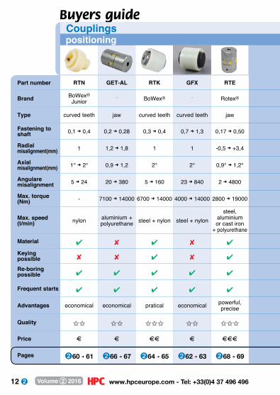
Part number RTN GET-AL RTK GFX RTE
Brand BoWex® Junior
- BoWex® - Rotex®
Type curved teeth jaw curved teeth curved teeth jaw
Fastening to shaft 0,1 ➜ 0,4 0,2 ➜ 0,28 0,3 ➜ 0,4 0,7 ➜ 1,3 0,17 ➜ 0,50
Radial misalignment(mm) 1 1,2 ➜ 1,8 1 1 -0,5 ➜ +3,4
Axial misalignment(mm) 1° ➜ 2° 0,9 ➜ 1,2 2° 2° 0,9° ➜ 1,2°
Angulare misalignment 5 ➜ 24 20 ➜ 380 5 ➜ 160 23 ➜ 840 2 ➜ 4800
Max. torque (Nm) - 7100 ➜ 14000 6700 ➜ 14000 4000 ➜ 14000 2800 ➜ 19000
Max. speed (t/min) nylon aluminium +
polyurethane steel + nylon steel + nylonsteel,
aluminium or cast iron
+ polyurethane
Material 4 8 4 8 4
Keying possible 8 8 4 8 4
Re-boring possible 4 4 4 4 4
Frequent starts 4 4 4 4 4
Advantages economical economical pratical economical powerful, precise
Quality II II III II III
Price A A AA A AAA
Pages ➋60 ➜ 61 ➋66 ➜ 67 ➋64 ➜ 65 ➋62 ➜ 63 ➋68 ➜ 69
Buyers guide Couplings positioning
13 Fax: +33(0)4 37 490 055 - [email protected] Volume 2 2016
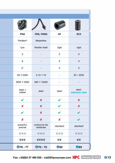
PNA FDS, FDSQ AF SC2
Periflex® Masterflex
tyre flexible shaft rigid rigid
5 - 0 0
6 - 0 0
2° - 0 0
50 ➜ 2400 0,15 ➜ 75 - 25 ➜ 2250
3000 ➜ 5000 200 ➜ 12000 - -
steel + rubber steel steel steel,
stainless steel
4 8 4 8
8 8 4 8
4 8 4 4
8 8 8 4
powerful, precise
contourne les obstacles standard standard
III III III III
AAA AAAA AA AA
➋76 ➜ 77 ➋70 ➜ 73 ➋82 ➋83
14 www.hpceurope.com - Tel: +33(0)4 37 496 496Volume 2 2016
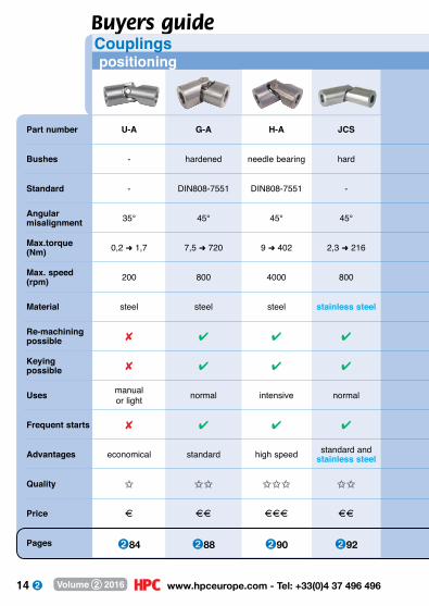
Part number U-A G-A H-A JCS
Bushes - hardened needle bearing hard
Standard - DIN808-7551 DIN808-7551 -
Angular misalignment 35° 45° 45° 45°
Max.torque (Nm) 0,2 ➜ 1,7 7,5 ➜ 720 9 ➜ 402 2,3 ➜ 216
Max. speed (rpm) 200 800 4000 800
Material steel steel steel stainless steel
Re-machining possible 8 4 4 4
Keying possible 8 4 4 4
Uses manual or light normal intensive normal
Frequent starts 8 4 4 4
Advantages economical standard high speed standard andstainless steel
Quality I II III II
Price A AA AAA AA
Pages ➋84 ➋88 ➋90 ➋92
Buyers guideCouplings positioning
15 Fax: +33(0)4 37 490 055 - [email protected] Volume 2 2016
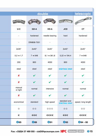
U-C GD-A HD-A JCD CT
- hardened needle bearing hard hardened
- DIN808-7551 - - -
2x35° 2x45° 2x45° 2x45° 2x45°
0,2 ➜ 1,7 7 ➜ 648 8,1 ➜ 361,8 5,22 ➜ 194,4 7 ➜ 648
200 800 4000 800 4000
steel steel steel stainless steel steel
8 4 4 4 4
8 4 4 4 4
manual or light normal intensive normal normal
8 4 4 4 4
economical standard high speed standard and stainless steel speed, long length
I II III II II
A AAA AAAA AAA AAAA
➋85 ➋89 ➋91 ➋93 ➋94 ➜ 95
double telescopic
16 www.hpceurope.com - Tel: +33(0)4 37 496 496Volume 2 2016
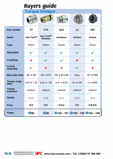
Part number VT VTA SAS LC DSF
Name Vari-Tork® Vari-Tork® /Oldham miniature friction chaine
Type friction friction friction friction friction
Adjustable 4 4 4 4 4
Couplings 8 4 4 8 4
In-hurb assembly 4 8 8 4 8
Bore size (mm) Ø6 ➜ Ø8 Ø6 ➜ Ø10 Ø6 ➜ Ø15,88 Plein Ø7 ➜ Ø68
Torque range (Nm) 0,53 ➜ 1,32 0,53 ➜ 1,32 0,01 ➜ 8,64 30 ➜ 240 4 ➜ 2600
Torque precision medium medium medium medium medium
Quality II II II II II
Price AA AA AAA AA AAAA
Pages ➋98 ➋99 ➋100 ➜ 101 ➋102 ➜ 103 ➋104 ➜ 105
Buyers guideTorque limiters
17 Fax: +33(0)4 37 490 055 - [email protected] Volume 2 2016
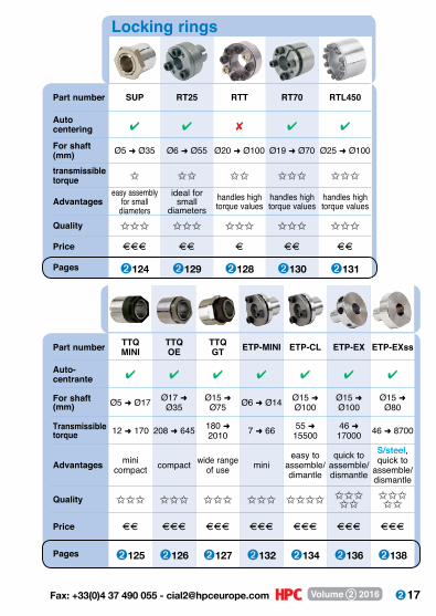
Part number SUP RT25 RTT RT70 RTL450
Auto centering 4 4 8 4 4
For shaft (mm) Ø5 ➜ Ø35 Ø6 ➜ Ø55 Ø20 ➜ Ø100 Ø19 ➜ Ø70 Ø25 ➜ Ø100
transmissible torque I II II III III
Advantageseasy assembly
for smalldiameters
ideal for small
diametershandles high torque values
handles high torque values
handles high torque values
Quality III III III III III
Price AAA AA A AA AA
Pages ➋124 ➋129 ➋128 ➋130 ➋131
Locking rings
Part number TTQ MINI
TTQ OE
TTQGT ETP-MINI ETP-CL ETP-EX ETP-EXss
Auto-centrante 4 4 4 4 4 4 4
For shaft (mm) Ø5 ➜ Ø17 Ø17 ➜
Ø35Ø15 ➜ Ø75 Ø6 ➜ Ø14 Ø15 ➜
Ø100Ø15 ➜ Ø100
Ø15 ➜ Ø80
Transmissible torque 12 ➜ 170 208 ➜ 645 180 ➜
2010 7 ➜ 66 55 ➜ 15500
46 ➜ 17000 46 ➜ 8700
Advantages minicompact compact wide range
of use minieasy to
assemble/dimantle
quick to assemble/dismantle
S/steel,quick to
assemble/dismantle
Quality III III III III IIII IIIII
IIIII
Price AA AAA AAA AAA AAA AAA AAA
Pages ➋125 ➋126 ➋127 ➋132 ➋134 ➋136 ➋138

18 www.hpceurope.com - Tel: +33(0)4 37 496 496Volume 2 2016
Part number DER RFV LINK64
Gearboxe type worm and wheel stainless steel spur
Voltage 230/400 V AC 230V AC 1 phase
Nominal current (A) 0,58 ➜ 3,3 0,051
Max.torque (Nm) 11 ➜ 141 1,2 ➜ 6
Max. speed (rpm) 14 ➜ 186 0,5 ➜ 31
Quality III III
Price AAA AA
Pages ➋302 ➜ 311 ➋270
Part number MAX22 MAX26 BUH77
Gearboxe type spur spur spur
Voltage 12V DC and 24V DC
12V DC and 24V DC
12V DC and 24V DC
Nominal current (A) 0,05 ➜ 0,30 0,05 ➜ 0,63 0,275 ➜ 1,4
Max.torque (Nm) 0,07 ➜ 0,20 0,08 ➜ 0,6 0,1 ➜ 2
Max. speed (rpm) 27 ➜ 435 8 ➜ 459 14 ➜ 900
Quality III III III
Price AA AA AA
Pages ➋254 ➋255 ➋256
Motorgearboxesdirect current
Buyers guide
AC synchrone

19 Fax: +33(0)4 37 490 055 - [email protected] Volume 2 2016
CHM30-MOT CHM40-MOT CHM50-MOT CHM63-MOT
worm and wheel worm and wheel worm and wheel worm and wheel
400V AC phase 400V AC phase 400V AC phase 400V AC phase
- - - -
9 ➜ 22 22 ➜ 52 33 ➜ 87 67 ➜ 165
17 ➜ 186 14 ➜ 186 14 ➜ 186 14 ➜ 186
II II II II
AA AA AA AA
➋276 ➋277 ➋278 ➋279
DOG316 DOG111 DOG319 DOG258
worm and wheel worm and wheel worm and wheel worm and wheel
12V DC and 24V DC
12V DC and 24V DC
12V DC and 24V DC
12V DC and 24V DC
2 ➜ 4 2 ➜ 5 3 ➜ 10 5 ➜ 12
1,5 ➜ 2 1,5 ➜ 6 6 ➜ 10 12 ➜ 15
27,5 ➜ 65 10 ➜ 240 10 ➜ 80 25 ➜ 40
II II II II
A AA AA AAA
➋257 ➋258 ➋259 ➋260

20 www.hpceurope.com - Tel: +33(0)4 37 496 496Volume 2 2016
Part number B332 RVM RAM CHTRP / CHTRB BL
Type bevel gear worm and wheel bevel gear bevel gear bevel gear
Reduction ratio 1:1 1:1 ➜ 30:1 1:1 ➜ 2:1 1:1 ➜ 3:1 1:1 ➜ 4:1Transmissible torque (Nm) 0,11 ➜ 0,68 2 ➜ 17 4 ➜ 6 1,4 ➜ 87,3 0,4 ➜ 6
Input shaft
Output shaftAxle orientation or Self locking output 8 4* 8 8 8
Multiplier 8 8 8 4 8
Quality I I I II II
Price A A A AA AA
Pages ➋225 ➋228 ➜ 229➋226 ➜ 227➋232 ➜ 241 ➋174
Buyers guideGearboxes
Part number CHMR CHM CHML RFV P PF
Type worm and wheel
worm and wheel
integrated torque limiter
worm and wheel
worm and wheel
worm and wheel
Reduction ratio 7,5:1 ➜ 100:1
7,5:1 ➜ 100:1
7,5:1 ➜ 100:1 7,5 ➜ 100 5:1 ➜ 120:1 5:1 ➜ 120:1
Transmissible torque (Nm) 11 ➜ 980 11 ➜ 980 11 ➜ 980 11 ➜ 141 0,94 ➜ 164 1,25 ➜ 164
Input shaft
Output shaft
Axle orientationSelf locking output 4* 4* 4* 4* 4* 4*Multiplier 8 8 8 8 8 8
Quality III III III III III III
Price AA AA AA AAA AAA AAA
Pages ➋280 ➋283 ➋296 ➋306 ➋148 ➋149

21 Fax: +33(0)4 37 490 055 - [email protected] Volume 2 2016
FF EHD XJ-J NT NH HLA, HLC
spur planetary spur spur spur spiral bevel gears
2:1 ➜ 7:1 36:1 1:1 ➜ 625:1 1:1 ➜ 120:1 1:1 ➜ 120:1 1:1 ➜ 120:1
0,78 ➜ 425 3,4 ➜ 380 0,16 ➜ 2,80 5 ➜ 85 5 ➜ 85 35 ➜ 128
8 8 8 8 8 8
8 8 8 8 8 8
III III II II II III
AAA AAA AA AAA AAA AA
➋198 ➜ 203 ➋204 ➜ 209 ➋211 ➜ 216 ➋217 ➜ 223 ➋217 ➜ 223 ➋242 ➜ 249
PP E BLHB / BLHI / BLHO BLHM BLH, BLHT
worm and wheel bevel gear bevel gear bevel gear
25:1 ➜ 900:1 1:1 ➜ 40:1 1:1 ➜ 2:1 1:1 ➜ 2:1 1:1 ➜ 2:1
2,2 ➜ 34 0,4 ➜ 62 0,53 ➜ 70 0,53 ➜ 128 0,53 ➜ 128
or
or
4* 8 8 8 8
8 8 8 8 8
III III III III III
AAA AAA AAA AAAA AAA
➋163 ➜ 164 ➋166 ➜ 172 ➋178 ➜ 194 ➋179 ➜ 195 ➋176 ➜ 197
arbre plein arbre creux * sous conditions
22 www.hpceurope.com - Tel: +33(0)4 37 496 496Volume 2 2016
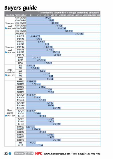
Buyers guide Transmissible torque (Nm) changes depending on speed Gearbox Part number 0-1 >1-5 >5-20 >20-100 >100-300 >300-600 >600-900 >900-1200 >1200-1512 CHM-CHMR30 10-28 CHM-CHMR40 22-57 CHM-CHMR50 39-107 CHM-CHMR63 73-198 CHM-CHMR75 118-298 CHM-CHMR90 198-540 CHM-CHMR110 350-980 P-PF15 0.94-3.75 P-PF20 1.25-5 P-PF30 2.5-8.8 P-PF40 5-18 P-PF45 10.3-40 P-PF55 13.4-57 P-PF60 27-118 P-PF70 38-164 PP35 2.2-4.1 PP50 6.5-12.8 PP60 17.8-34 E15 0.4-1.32 E20 0.6-3.84 E30 1.5-9 E40 2.3-20 E50 3-41 E60 4.5-62 BLHB20 0.53-1.77 BLHB30 1.32-4.4 BLHB40 3-10.3 BLHB50 7.7-30 BLHB60 19-70 BLHM20 0.53-1.77 BLHM30 1.32-4.4 BLHM40 3-10.3 BLHM50 7.7-30 BLHM60 19-70 BLHM70 26-128 BLH20 0.53-1.77 BLH30 1.32-4.4 BLH40 3-10.3 BLH50 7.7-30 BLH60 19-70 BLH70 26-128 BLHT20 0.53-1.77 BLHT30 1.32-4.4 BLHT40 3-10.3 BLHT50 7.7-30 BLHT60 19-70 BLHT70 26-128 BL8 0.2-2 BL15 1.1-6
Worm and weel
➋142 ➜ 165
Angle transmission➋166 ➜ 172
Bevelgearing
➋174 ➜ 197
Worm and weel
➋280 ➜ 293
23 Fax: +33(0)4 37 490 055 - [email protected] Volume 2 2016
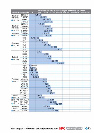
Transmissible torque (Nm) changes depending on speed Gearbox Part number 0-1 >1-5 >5-20 >20-100 >100-300 >300-600 >600-900 >900-1200 >1200-1512 CHTRB8 1.4-4.7 CHTRB15 5.2-16.5 CHTRB20 15.3-53.1 CHTRB25 29.6-87.3 CHTRP8 3.2-9.1 CHTRP14 9.9-34.5 CHTRP19 22.8-87.3 CHTRP24 22.8-87.3 CHTRP14 9.9-28.8 CHTRP19 22.8-75.7 FF10 0.78-3.70 FF15 2.2-10 FF20 5.8-23 FF30 21.5-83 FF40 59-210 FF50 111-425 EHD04 3.4-7 EHD06 8-19 EHD08 20-50 EHD08 35-50 EHD12 60-140 EHD16 210-380 J-XJ51 0.13-0.49 J-XJ52 0.27-0.9 J-XJ53 0.43-1.15 J-XJ64 0.57-2.25 J-XJ65 0.8-2.95 J-XJ66 0.9-2.8 NT-NH61 5-14 NT-NH62 6-18 NT-NH63 8-20 NT-NH91 10-35 NT-NH92 15-40 NT-NH121 20-68 NT-NH122 32-85
Single or dual output➋232 ➜ 235
Single or dual output➋236 ➜ 241
Dual output ➋238 ➜ 239
Spur gear➋198 ➜ 203
Epicyclic➋204 ➜ 209
Planetary➋210➜ 223
RAMRVM
HLA-HLC19HLA-HLC24HLA-HLC28
RFV40RFV50RFV63
Manual➋226➜ 229Spiral bevel
gear➋242➜ 249
Worm and wheel
➋306➜ 311
35 à 4322 à 78
126 à 142➜ 47Nm
➜ 80Nm➜152Nm
4 à 65 à 17

24 www.hpceurope.com - Tel: +33(0)4 37 496 496Volume 2 2016
panamechmulti-beam®
p.26
Flexible coupling
p.32
oldham® coupling
p.34
p.36
rotex gs® coupling
25 Fax: +33(0)4 37 490 055 - [email protected] Volume 2 2016
couplings for servo-motors
p.26 - 58
gerwah® coupling
p.52
gerwah® coupling
p.38
flexible bellows
coupling
p.46
p.58
p-flex® coupling
26 www.hpceurope.com - Tel: +33(0)4 37 496 496Volume 2 2016
Part number ØD L CSet
screwRadial(mm)
AngularTorsional
rigidity(Nm/Rad)
shockand
reversingnon
reversingpeak
torque
Misalignment Max. torque (Nm)
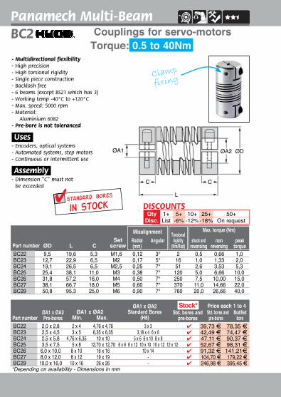
- Multidirectional flexibility- High precision- High torsional rigidity- Single piece construction- Backlash free- 6 beams (except BS21 which has 3)- Working temp -40°C to +120°C- Max. speed: 5000 rpm- M aterial:
Aluminium 6082- Pre-bore is not toleranced
.Uses.- Encoders, optical systems- Automated systems, step motors- Continuous or intermittent use
.Assembly.- Dimension “C”
must not be exceeded
ØA2ØA1 ØD
L
C C
Set screw
fixing
BS2Torque: 0.2 to 40Nm
Panamech Multi-BeamCouplings for servo-motors
*Depending on availability - Dimensions in mm
BS21 6,4 12,7 3,2 M2 0,07 3° - 0,20 0,26 0,4BS22 9,5 19,6 5,3 M2,5 0,12 3° 2 0,50 0,66 1,0BS23 12,7 22,9 6,5 M3 0,17 5° 16 1,00 1,33 2,0BS24 19,1 26,5 6,5 M4 0,25 7° 51 2,65 3,53 5,3BS25 25,4 38,1 11,0 M5 0,38 7° 120 5,00 6,66 10,0BS266 31,8 57,2 16,0 M6 0,50 7° 250 7,50 10,00 15,0BS27 38,1 66,7 18,0 M6 0,60 7° 370 11,00 14,66 22,0BS29 50,8 95,3 25,0 M8 0,90 7° 760 20,00 26,66 40,0
Part number
Price each 1 to 4 Std bores and Modified pre-bores bore
Std bores and pre-bores
ØA1 x ØA2Pre-bores
ØA1 x ØA2Min. Max.
ØA1 x ØA2Standard Bores
(H8)
Stock*
BS21 1,5 x 2,0 1 x 2 3 x 3 1 x 2 4 24,60 F 41,19 FBS22 2,0 x 2,8 2 x 4 4,76 x 4,76 3, 18 x 4 - 27,12 F 45,49 FBS23 2,5 x 4,5 3 x 5 6,35 x 6,35 6 x 6 4 29,60 F 61,76 FBS24 2,5 x 5,8 4,76 x 6,35 10 x 10 5 x 6 6 x 6 10 x 10 4 36,87 F 68,11FBS25 3,5 x 7,5 5 x 8 12,70 x 12,70 6 x 6 4 41,02 F 79,29 FBS266 6,0 x 10,0 8 x 10 16 x 16 - 4 53,78 F 107,04 FBS27 8,0 x 12,0 8 x 12 22 x 22 - 4 68,92 F 131,84 FBS29 10,0 x 16,0 10 x 16 28 x 28 - - 177,04 F 272,90 F
in stockboresstandard
1+List
5+-6%
10+-12%
25+-18%
50+On request
QtyDisc.
DISCOUNTS

27 Fax: +33(0)4 37 490 055 - [email protected] Volume 2 2016
Part number ØD L CSet
screwRadial(mm)
AngularTorsional
rigidity(Nm/Rad)
shock andreversing
nonreversing
peaktorque
Misalignment
Part number
Price each 1 to 4 Std bores and Modified pre-bores bore
ØA1 x ØA2Pre-bores
ØA1 x ØA2Min. Max.
ØA1 x ØA2Standard Bores
(H8)Std bores and
pre-bores
ØA2ØA1 ØD
L
C C
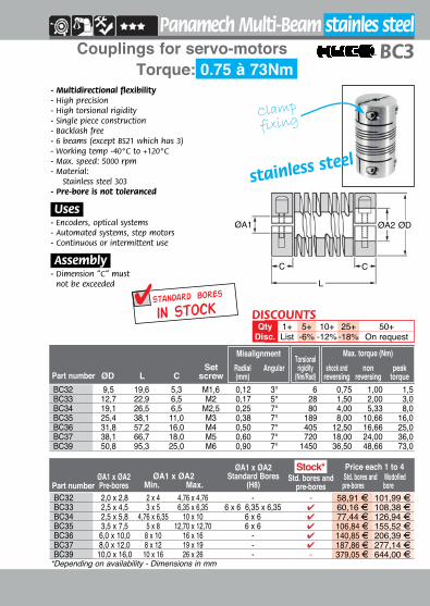
- Multidirectional flexibility- High precision- High torsional rigidity- Single piece construction - Backlash free- 6 beams (except BS21 which has 3)- Working temp -40°C to +120°C- Max. speed: 5000 rpm- M aterial:
Stainless steel 303- Pre-bore is not toleranced
.Uses.- Encoders, optical systems- Automated systems, step motors- Continuous or intermittent use
.Assembly.- Dimension “C”
must not be exceeded
Set screw
fixing
stainless steel
BS3Torque: 0.22 to 73Nm
Panamech Multi-Beam stainless steelCouplings for servo-motors
*Depending on availability - Dimensions in mm
BS31 6,4 12,7 3,2 M2 0,07 3° - 0,22 0,30 0,45BS32 9,5 19,6 5,3 M2,5 0,12 3° 6 0,75 1,00 1,50BS33 12,7 25,4 6,5 M3 0,17 5° 28 1,50 2,00 3,00BS34 19,1 28,0 6,5 M4 0,25 7° 80 4,00 5,33 8,00BS35 25,4 38,1 11,0 M5 0,38 7° 189 8,00 10,66 16,00BS36 31,8 57,2 16,0 M6 0,50 7° 405 12,50 16,66 25,00BS37 38,1 66,7 18,0 M6 0,60 7° 720 18,00 22,50 36,00BS39 50,8 95,3 25,0 M8 0,90 7° 1450 36,50 48,66 73,00
Stock*
BS31 1,5 x 2,0 1 x 2 3 x 3 - 4 42,73 F 111,86 FBS32 2,0 x 2,8 2 x 4 4,76 x 4,76 4 x 4 6,35 x 6,35 4 35,85 F 76,56FBS33 2,5 x 4,5 3 x 5 6,35 x 6,35 5 x 9,52 10 x 10 4 46,62 F 81,90FBS34 2,5 x 5,8 4,76 x 6,35 10 x 10 8 x 8 4 50,51 F 50,51 FBS35 3,5 x 7,5 5 x 8 12,70 x 12,70 - 4 79,81 F 118,91FBS36 6,0 x 10,0 8 x 10 19 x 19 - 4 117,13 F 165,03FBS37 8,0 x 12,0 8 x 12 22 x 22 - 4 150,30 F 204,74FBS39 10,0 x 16,0 10 x 16 28 x 28 - - 278,48 F 507,10F
in stockboresstandard
1+List
5+-6%
10+-12%
25+-18%
50+On request
QtyDisc.
DISCOUNTS
28 www.hpceurope.com - Tel: +33(0)4 37 496 496Volume 2 2016
Part number ØD L CSet
screwRadial(mm)
AngularTorsional
rigidity(Nm/Rad)
shock andreversing
nonreversing
peaktorque
Misalignment Max. torque (Nm)
Part number
Price each 1 to 4Std. bores and Modified
pre-bores boreØA1 x ØA2Pre-bores
ØA1 x ØA2Min. Max.
ØA1 x ØA2Standard Bores
(H8)Std. bores and
pre-bores
- Multidirectional flexibility- High precision- High torsional rigidity- Single piece construction - Backlash free- 6 beams (except BS21 which has 3)- Working temp -40°C to +120°C- Max. speed: 5000 rpm- M aterial:
Aluminium 6082- Pre-bore is not toleranced
.Uses.- Encoders, optical systems- Automated systems, step motors- Continuous or intermittent use
.Assembly.- Dimension “C” must not
be exceeded
ØA2ØA1 ØD
L
C C
Clamp
fixing
Torque: 0.5 to 40NmBC2Panamech Multi-Beam
Couplings for servo-motors
*Depending on availability - Dimensions in mm
BC22 9,5 19,6 5,3 M1,6 0,12 3° 2 0,5 0,66 1,0BC23 12,7 22,9 6,5 M2 0,17 5° 16 1,0 1,33 2,0BC24 19,1 26,5 6,5 M2,5 0,25 7° 51 2,6 3,53 5,3BC25 25,4 38,1 11,0 M3 0,38 7° 120 5,0 6,66 10,0BC26 31,8 57,2 16,0 M4 0,50 7° 250 7,5 10,00 15,0BC27 38,1 66,7 18,0 M5 0,60 7° 370 11,0 14,66 22,0BC29 50,8 95,3 25,0 M6 0,90 7° 760 20,0 26,66 40,0
BC22 2,0 x 2,8 2 x 4 4,76 x 4,76 3 x 3 4 39,73 F 78,35 FBC23 2,5 x 4,5 3 x 5 6,35 x 6,35 3,18 x 4 6 x 6 4 42,49 F 74,47 FBC24 2,5 x 5,8 4,76 x 6,35 10 x 10 5 x 6 6 x 10 8 x 8 4 47,11 F 90,37 FBC25 3,5 x 7,5 5 x 8 12,70 x 12,70 6 x 6 8 x 12 10 x 10 10 x 12 12 x 12 4 52,67 F 98,31 FBC26 6,0 x 10,0 8 x 10 16 x 16 10 x 14 4 91,32 F 141,21FBC27 8,0 x 12,0 8 x 12 19 x 19 - 4 104,70 F 179,22 FBC29 10,0 x 16,0 10 x 16 26 x 26 - 4 246,98 F 395,45 F
Stock*
in stockboresstandard
1+List
5+-6%
10+-12%
25+-18%
50+On request
QtyDisc.
DISCOUNTS
29 Fax: +33(0)4 37 490 055 - [email protected] Volume 2 2016
Part number ØD L CSet
screwRadial(mm)
AngularTorsional
rigidity(Nm/Rad)
shock andreversing
nonreversing
peaktorque
Misalignment Max. torque (Nm)
Clamp
fixing
- Multidirectional flexibility- High precision- High torsional rigidity- Single piece construction - Backlash free- 6 beams (except BS21 which has 3)- Working temp -40°C to +120°C- Max. speed: 5000 rpm- M aterial:
Stainless steel 303- Pre-bore is not toleranced
.Uses.- Encoders, optical systems- Automated systems, step motors- Continuous or intermittent use
.Assembly.- Dimension “C” must
not be exceeded
ØA2ØA1 ØD
L
C C
Panamech Multi-Beam stainles steel
Torque: 0.75 à 73NmBC3Couplings for servo-motors
*Depending on availability - Dimensions in mm
BC32 9,5 19,6 5,3 M1,6 0,12 3° 6 0,75 1,00 1,5BC33 12,7 22,9 6,5 M2 0,17 5° 28 1,50 2,00 3,0BC34 19,1 26,5 6,5 M2,5 0,25 7° 80 4,00 5,33 8,0BC35 25,4 38,1 11,0 M3 0,38 7° 189 8,00 10,66 16,0BC36 31,8 57,2 16,0 M4 0,50 7° 405 12,50 16,66 25,0BC37 38,1 66,7 18,0 M5 0,60 7° 720 18,00 24,00 36,0BC39 50,8 95,3 25,0 M6 0,90 7° 1450 36,50 48,66 73,0
Part number
Price each 1 to 4Std. bores and Modofied
pre-bores boreØA1 x ØA2Pre-bores
ØA1 x ØA2Min. Max.
ØA1 x ØA2Standard Bores
(H8)Std. bores and
pre-bores
Stock*
BC32 2,0 x 2,8 2 x 4 4,76 x 4,76 - - 58,91 F 101,99 FBC33 2,5 x 4,5 3 x 5 6,35 x 6,35 6 x 6 6,35 x 6,35 4 60,16 F 108,38 FBC34 2,5 x 5,8 4,76 x 6,35 10 x 10 6 x 6 4 77,44 F 126,94 FBC35 3,5 x 7,5 5 x 8 12,70 x 12,70 6 x 6 4 106,84 F 155,52 FBC36 6,0 x 10,0 8 x 10 16 x 16 - 4 140,85 F 206,39 FBC37 8,0 x 12,0 8 x 12 19 x 19 - 4 187,86 F 277,14 FBC39 10,0 x 16,0 10 x 16 26 x 26 - - 379,05 F 644,00 F
stainless steel
in stockboresstandard
1+List
5+-6%
10+-12%
25+-18%
50+On request
QtyDisc.
DISCOUNTS

30 www.hpceurope.com - Tel: +33(0)4 37 496 496Volume 2 2016
*Depending on availability - Dimensions in mm
Torque: 0.45 to 6NmCouplings for servo-motorsDBC
- Multidirectional flexibility- High precision- Space saving- Good torsional ridigity- Single piece construction - Backlash free- For use in restricted spaces- 3 beams- Working temperature: -40°C to +120°C- Max. speed: 5000 rpm- M aterial:
Aluminium 6082- Pre-bore is not toleranced
.Uses.- Encoders, optical systems- Automated systems, step motors
.Assembly.- Dimension “C” must not be exceeded
ØA2ØA1 ØD
L
C C
Clamp
fixing
Panamech Multi-beam
Part number ØD L CSet
screwRadial(mm)
Angular shock andreversing
nonreversing
peaktorque
Misalignment Max torque (Nm)
DBC3 12,7 19,1 6,0 M2 0,127 5° 0,45 0,60 0,9DBC3.5 15,9 20,3 6,5 M2,5 0,127 5° 0,75 1,00 1,5DBC4 19,1 22,9 6,5 M2,5 0,127 5° 1,25 1,66 2,5DBC5 25,4 31,8 9,0 M3 0,127 5° 2,00 2,66 4,0DBC6 31,8 44,5 12,0 M4 0,127 5° 3,00 4,00 6,0
DBC3 2,5 x 3,95 3 x 4 5 x 5 - 4 44,10 F 74,76 FDBC3.5 2,5 x 3,95 3 x 4 6,35 x 6,35 5 x 5 - 44,10 F 82,17 FDBC4 2,5 x 5,8 4 x 4,76 8 x 8 6 x 6 4 46,93 F 86,41 FDBC5 3,8 x 5,95 5 x 6 10 x 10 10 x 10 4 53,14 F 100,26 FDBC6 5,1 x 9,2 6 x 8 14 x 14 - 4 79,96 F 143,28 F
Part number
Price each 1 to 4Std. bores and Modified
pre-bores boreØA1 x ØA2Pre-bores
ØA1 x ØA2Min. Max.
ØA1 x ØA2Standard Bores
(H8)Std. bores and
pre-bores
Stock*
in stockboresstandard
1+List
5+-6%
10+-12%
25+-18%
50+On request
QtyDisc.
DISCOUNTS

31 Fax: +33(0)4 37 490 055 - [email protected] Volume 2 2016
Part number ØD L CSet
screwRadial(mm)
Angular shock andreversing
nonreversing
peaktorque
Misalignment Max. torque (Nm)
*Depending on availability - Dimensions in mm
Coupling for servo-motors
clamp
fixing
B3PAN
- Multidirectional flexibility- High precision- Space saving- Good torsional ridigity- Single piece construction - Backlash free- For use in restricted spaces- 3 beams- Working temperature: -40°C to +140°C- Max. speed: 5000 rpm- M aterial:
Stainless steel 303- Pre-bore is not toleranced
.Uses.- Encoders, optical systems- Automated systems, step motors
.Assembly.- Dimension “C” must not be exceeded
ØA2ØA1 ØD
L
C C
stainless steel
Panamech Multi-Beam stainless steelCouplings for servo-motors
Torque: 0,5 to 10NmB3PAN
B3PAN4C 12,7 19,1 6,0 M2 0,127 5° 0,50 0,66 1,0B3PAN5C 15,9 20,3 6,5 M2,5 0,127 5° 0,90 1,20 1,8B3PAN6C 19,1 22,9 6,5 M2,5 0,127 5° 1,35 1,80 2,7B3PAN7C 25,4 31,8 9,0 M3 0,127 5° 3,00 4,00 6,0B3PAN8C 31,8 44,5 12,0 M4 0,127 5° 5,00 6,66 10,0
B3PAN4C 1,6 x 4,5 3 x 4 5 x 5 4 x 4 4 63,70 F 101,44 FB3PAN5C 2,5 x 4,8 3 x 4 6,35 x 6,35 5 x 5 4 66,02 F 115,01 FB3PAN6C 2,5 x 4,75 4 x 4,76 8 x 8 6 x 6 4 69,96 F 127,11 FB3PAN7C 3,5 x 5,95 5 x 6 10 x 10 8 x 8 4 90,05 F 159,44 FB3PAN8C 5,1 x 9,2 6 x 8 14 x 14 10 x 10 4 140,86 F 218,94 F
Part number
Price each 1 to 4Std. bores and Modified
pre-bores boreØA1 x ØA2Pre-bores
ØA1 x ØA2Standard Bores
(H8)ØA1 x ØA2
Min. Max.Std. bores and
pre-bores
Stock*
in stockstandard bores
DISCOUNTSQty 1+ 5+ 10+ 25+ 50+
Disc. List -6% -12% -18% On request
32 www.hpceurope.com - Tel: +33(0)4 37 496 496Volume 2 2016
Part number
Max. speed of rotation
(rpm)Weight
(g)
Moment of inertia(kg•m2)
Static torsionalstiffness(Nm/Rad)
Radial(mm)
Angular Axial(mm)
Nominal torque(Nm)
Max. torque(Nm)
Misalignment
Part number
Price each1 to 4
StandardboreØA
Max.boreØA ØD F L W ØC S1 M G
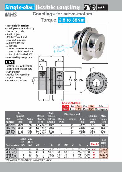
- Very rigid in torsion- Misalignment absorbed by
stainless steel disc- Backlash free- Resistant to oil and
chemical products- Maintenance free- M aterials:
Hubs: Aluminium A-U4G Disc: Stainless steel 301 Pin: Stainless steel 303
- Max. working temp.: +100°C
.Uses.- Ideal for use with stepper
motors that cannot detect start position
- Applications requiring high accuracy
- Automated systems
Clamp
fixing
Couplings for servo-motorsSingle-disc flexible coupling
Torque: 2.8 to 38NmMHS
*Depending on availability - Dimensions in mm
M
G
MHS-32C 4800 38 4,5 x 10⁻⁶ 1300 - 1° ±0,20 2,8 5,6MHS-40C 3800 66 1,2 x 10⁻⁵ 2800 - 1° ±0,20 6,0 12,0MHS-50C 3100 120 3,7 x 10⁻⁵ 3700 - 1° ±0,20 12,0 24,0MHS-63C 2400 190 8,4 x 10⁻⁵ 5000 - 1° ±0,20 19,0 38,0
Stock*MHS-32C 6 10 32 4 13,70 32 22 9 M3 8,00 44 139,10 FMHS-40C 8 14 40 6 16,50 38 28 12 M4 10,50 4 151,04 FMHS-50C 12 20 50 7 19,40 44 39 15 M5 14,75 4 182,63 FMHS-63C 16 25 63 8 22,30 50 45 18 M6 19,00 4 255,10 F
W
L L
S1 S1
F
ØA ØC ØDØA
DISCOUNTSQty 1+ 5+ 10+ 15+ 20+
Disc. List -10% -15% -25% On request
33 Fax: +33(0)4 37 490 055 - [email protected] Volume 2 2016
Part number
StandardboreØA
Max.boreØA ØD ØE F L W ØC S1 M G
Price each1 to 4
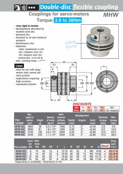
- Very rigid in torsion- Misalignment absorbed by
stainless steel disc- Backlash free- Resistant to oil and chemical
products- Maintenance free- M aterials:
Hubs: Aluminium A-U4G Disc: Stainless steel 301 Pin: Stainless steel 303 Central disc: A-U5 Pb Bi
- Max. working temp.: +100°C
.Uses.- Ideal for use with stepper
motors that cannot detect start position
- Applications requiring high accuracy
- Automated systems
Clamp
fixing
Couplings for servo-motorsDouble-disc flexible coupling
Torque: 2.8 to 38NmMHW
*Depending on availability - Dimensions in mm
G
M
Part number
Max. speed of rotation
(rpm)Weight
(g)
Moment of inertia(kg•m2)
Static torsionalstiffness(Nm/Rad)
Radial(mm)
Angular Axial(mm)
Nominal torque(Nm)
Max. torque(Nm)
Misalignment
MHW-32C 4800 48 6,2 x 10⁻⁶ 1000 0,15 2° ±0,40 2,8 5,6MHW-40C 3800 81 1,6 x 10⁻⁵ 1500 0,20 2° ±0,50 6,0 12,0MHW-50C 3100 150 4,6 x 10⁻⁵ 2000 0,20 2° ±0,60 12,0 24,0MHW-63C 2400 230 1,1 x 10⁻⁴ 2500 0,30 2° ±0,80 19,0 38,0
Stock*MHW-32C 6 10 32 15 4 13,70 40 22 9 M3 8,00 4 165,47 FMHW-40C 8 14 40 25 6 16,50 46 28 12 M4 10,50 4 185,58 FMHW-50C 12 20 50 25 7 19,40 52 39 15 M5 14,75 4 223,16 FMHW-63C 16 25 63 32 8 22,30 58 45 18 M6 17,00 4 316,15 F
DISCOUNTSQty 1+ 5+ 10+ 15+ 20+
Disc. List -10% -15% -25% On request
W
L L
S1 S1
F
ØA ØC ØDØAØE

34 www.hpceurope.com - Tel: +33(0)4 37 496 496Volume 2 2016
Part number ØD L C VisWeight
(g)Standard
boresOptional bores
(mm)
Standard bores (mm)
Price each1 to 4
Standardbores
ØD
CC
Torsion disc
ØA
Hub
L
+0,03-0,00
Set screw
fixing
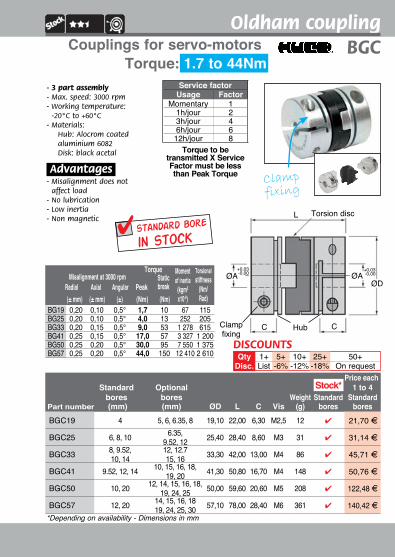
- 3 part assembly- Max. speed: 3000 rpm- Working temp: -20°C to +60°C - Materials:
BG6-BG13 Hubs: brass CZ121 BG19-57 Hubs: Alocrom coated aluminium 6082Disk: black acetal Torque to be
transmitted X Service Factor must be less than Peak Torque
Service factorUsage
Momentary1hr/day3h/day6h/day12h/day
Factor12468
Oldham coupling
Torque: 0.06 to 44NmBG Couplings for servo-motors
*Depending on availability - Dimensions in mm
(± mm) (± mm) (±) (Nm) (Nm)Radial Axial Angular
Static breakPeak
Misalignment at 3000 rpm Torque Moment of inertia
(kgm2 x10-8)
Torsional stiffness
(Nm/Rad)
BG6 0,10 0,05 0,5° 0,06 0,7 6 10BG9 0,10 0,05 0,5° 0,21 2,0 18 30BG13 0,10 0,05 0,5° 0,5 4,0 26 65BG19 0,20 0,10 0,5° 1,7 10,0 67 115BG25 0,20 0,10 0,5° 4,0 13,0 252 205BG33 0,20 0,15 0,5° 9,0 53,0 1 278 615BG41 0,25 0,15 0,5° 17,0 57,0 3 327 1 200BG50 0,25 0,20 0,5° 30,0 95,0 7 550 1 375BG57 0,25 0,20 0,5° 44,0 150,0 12 410 2 610
BG6 2 3, 3.18 6,40 12,70 3,80 M3 2,5 4 19,76 FBG9 3, 4, 5 - 9,50 12,70 3,80 M3 4 4 16,67 FBG13 3 4, 5, 6, 6.35 12,70 15,90 4,30 M3 11 4 18,76 FBG19 4, 6, 8 5, 6.35 19,10 22,00 6,30 M3 12 4 21,12 FBG25 6, 8, 10 6.35, 9.52, 12 25,40 28,40 8,60 M4 31 4 28,47 F
BG33 8, 12 9.52, 10, 14, 15, 16 33,30 48,00 13,00 M4 86 4 42,75 F
BG41 9.52, 10 12, 14, 15,16, 18, 19, 20 41,30 50,80 16,70 M5 148 4 50,75 F
BG50 10, 20 12, 14, 15,16, 18, 19, 24, 25 50,00 59,60 20,60 M8 208 4 116,93 F
BG57 12, 20 14, 15, 16,18, 19, 24, 25, 30 57,10 78,00 28,40 M8 361 4 162,20 F
Stock*
ØA+0,03-0,00
DISCOUNTSQty 1+ 5+ 10+ 25+ 50+
Disc. List -6% -12% -18% On request
35 Fax: +33(0)4 37 490 055 - [email protected] Volume 2 2016
ØD
CC
Torsion disc
Clampfixing
ØAØA
Hub
L
+0,03-0,00
+0,03-0,00
Clamp fixing
- 3 part assembly- Max. speed: 3000 rpm- Working temperature:
-20°C to +60°C - Materials:
Hub: Alocrom coated aluminium 6082Disk: black acetal
.Advantages.- Misalignment does not
affect load- No lubrication- Low inertia- Non magnetic
Torque to be transmitted X Service Factor must be less than Peak Torque
Oldham coupling
Torque: 1.7 to 44NmBGCCouplings for servo-motors
*Depending on availability - Dimensions in mm
Moment of inertia
(kgm2 x10-8)
Torsional stiffness
(Nm/Rad) (± mm) (± mm) (±) (Nm) (Nm)
Radial Axial AngularStatic breakPeak
Misalignment at 3000 rpmTorque
BG19 0,20 0,10 0,5° 1,7 10 67 115BG25 0,20 0,10 0,5° 4,0 13 252 205BG33 0,20 0,15 0,5° 9,0 53 1 278 615BG41 0,25 0,15 0,5° 17,0 57 3 327 1 200BG50 0,25 0,20 0,5° 30,0 95 7 550 1 375BG57 0,25 0,20 0,5° 44,0 150 12 410 2 610
in stockstandard bore
Service factorUsage Factor
Momentary 11h/jour 23h/jour 46h/jour 612h/jour 8
1+List
5+-6%
10+-12%
25+-18%
50+On request
QtyDisc.
DISCOUNTS
Price eachStandard Optional 1 to 4
bores bores Weight Standard Standard Part number (mm) (mm) ØD L C Vis (g) bores boresBGC19 4 5, 6, 6.35, 8 19,10 22,00 6,30 M2,5 12 4 21,70 F
BGC25 6, 8, 10 6.35, 9.52, 12 25,40 28,40 8,60 M3 31 4 31,14 F
BGC33 8, 9.52, 10, 14
12, 12.715, 16 33,30 42,00 13,00 M4 86 4 45,71 F
BGC41 9.52, 12, 14 10, 15, 16, 18, 19, 20 41,30 50,80 16,70 M4 148 4 50,76 F
BGC50 10, 20 12, 14, 15, 16, 18,19, 24, 25 50,00 59,60 20,60 M5 208 4 122,48 F
BGC57 12, 20 14, 15, 16, 1819, 24, 25, 30 57,10 78,00 28,40 M6 361 4 140,42 F
Stock*

36 www.hpceurope.com - Tel: +33(0)4 37 496 496Volume 2 2016
Part number
Max. speed(rpm)
static(Nm/rad)
dynamic(Nm/rad)
Radial stiffness(N/mm) Tksp Tkn Tkmax
axial(mm)
radial(mm)
angularTorque (Nm)Misalignment
Part number Ø3 Ø4 Ø5 Ø6 Ø7 Ø8 Ø10 Ø12 Ø14 Ø15 Ø16 Ø19 Ø20 Ø24 Ø28 Ø30 Ø32Transmissible torque (Nm) by friction for split hub
Rotex® GS backlash free jaw couplingRGS
Torque: 0.5 to 190NmCouplings for servo-motors
- No-wear elastic couplings- No maintenance- Low inertia and reduced size- Easy blind assembly using standard screws- Dampens vibration- Electrically insulated
.Definition.- TKN Nominal torque (Nm)- TKMAX Max. torque (Nm)- TKSP Torque transmitted without wear (Nm)
when used with encoders and resolvers
RGS-AL-5 - -RGS-AL-7 0,65 0,70 0,74 0,79RGS-AL-9 1,48 - 1,43 - 1,79 1,94RGS-AL-14 3,32 3,43 - 3,67 3,91 4,14 4,38RGS-AL-19 18,90 - 20,80 21,3 21,7 - 23,6RGS-AL-24 27,5 28 29,0 31RGS-AL-28 62,0 66 69 71 73
RGS-AL-5 56 000 5,16 16 154 0,08 0,50 1,00 0,40 0,06 1°RGS-AL-7 40 000 14,30 45 219 0,20 1,20 2,40 0,60 0,10 1°RGS-AL-9 28 000 31,50 95 262 0,45 3,00 6,00 0,80 0,13 1°RGS-AL-14 19 000 114,60 344 336 1,00 7,50 15,00 1,00 0,15 1°RGS-AL-19 14 000 573,00 1720 1120 2,50 10,00 20,00 1,20 0,10 1°RGS-AL-24 10 600 1432,00 4296 1480 - 35,00 70,00 1,40 0,14 1°RGS-AL-28 18 500 2292,00 6876 1780 - 95,00 190,00 1,50 0,15 1°
Dimensions in mm
Torsional stiffness
in stockstandard bore
Clamp
fixing
DISCOUNTSQty 1+ 5+ 10+ 25+
Disc. List -6% -12% On request
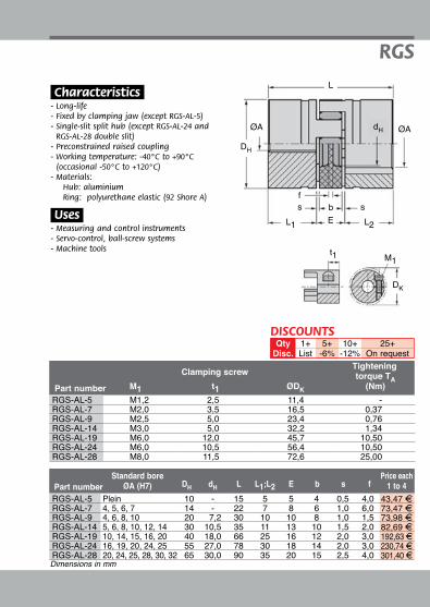
37 Fax: +33(0)4 37 490 055 - [email protected] Volume 2 2016
Part number Dh dh L L1;L2 E b s fStandard bore
ØA (H7)Price each
1 to 4
Dk
t1 M1
L
ØA dh ØA
fs sb
Dh
L1 L2E
.Characteristics.- Long-life- Fixed by clamping jaw (except RGS-AL-5)- Single-slit split hub (except RGS-AL-24 and
RGS-AL-28 double slit)- Preconstrained raised coupling- Working temperature: -40°C to +90°C
(occasional -50°C to +120°C)- Materials:
Hub: aluminiumRing: polyurethane elastic (92 Shore A)
.Uses.- Measuring and control instruments- Servo-control, ball-screw systems- Machine tools
RGS
Dimensions in mm
Part number M1 t1 ØDk
torque Ta(Nm)
Clamping screw Tightening
RGS-AL-5 M1,2 2,5 11,4 -RGS-AL-7 M2,0 3,5 16,5 0,37RGS-AL-9 M2,5 5,0 23,4 0,76RGS-AL-14 M3,0 5,0 32,2 1,34RGS-AL-19 M6,0 12,0 45,7 10,50RGS-AL-24 M6,0 10,5 56,4 10,50RGS-AL-28 M8,0 11,5 72,6 25,00
RGS-AL-5 Plein 10 - 15 5 5 4 0,5 4,0 43,47 FRGS-AL-7 4, 5, 6, 7 14 - 22 7 8 6 1,0 6,0 73,47 FRGS-AL-9 4, 6, 8, 10 20 17,2 30 10 10 8 1,0 1,5 73,98 FRGS-AL-14 5, 6, 8, 10, 12, 14 30 10,5 35 11 13 10 1,5 2,0 82,69 FRGS-AL-19 10, 14, 15, 16, 20 40 18,0 66 25 16 12 2,0 3,0 192,63 FRGS-AL-24 16, 19, 20, 24, 25 55 27,0 78 30 18 14 2,0 3,0 230,74 FRGS-AL-28 20, 24, 25, 28, 30, 32 65 30,0 90 35 20 15 2,5 4,0 301,40 F
DISCOUNTSQty 1+ 5+ 10+ 25+
Disc. List -6% -12% On request
38 www.hpceurope.com - Tel: +33(0)4 37 496 496Volume 2 2016
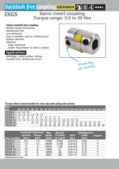
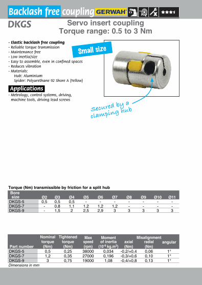
Backlash free couplingServo insert coupling
Torque range: 0.5 to 35 Nm
Transmissiblenominal
(Nm)
Tightenedtorque(Nm)
Max speed (rpm)
Moment of inertia
(10-6 kgm2)
Misalignmentaxial(Nm)
radial(Nm)
angularPart numberEKGS-5 0,5 1,3 47500 0,034 -0,2/+0,4 0,06 1°EKGS-7 1,2 1,3 34000 0,196 -0,3/+0,6 0,10 1°EKGS-9 3 3 24000 1,08 -0,4/+0,8 0,13 1°EKGS-14 7,5 6 16000 5,7 -0,5/+1,0 0,15 1°EKGS-19 10 6 12000 36 -0,5/+1,2 0,10 1°EKGS-24 35 6 8500 162 -0,5/+1,4 0,14 1°
EKGS
- Elastic backlash free coupling- Reliable torque transmission- Maintenance free- Low inertia/size- Easy to assembly, even in confined spaces- Reduces vibration- M aterials:
Body: Aluminium Spider: Polyurethane 92 Shore A (Yellow)
.Applications.- Metrology, control systems, driving,
machine tools, driving lead screws
Dimensions in mm
Bore size Ø3 Ø4 Ø5 Ø6 Ø7 Ø8 Ø9 Ø10 Ø11 Ø12 Ø13 Ø14 Ø15 Ø16 Ø17 Ø18 Ø20 Ø22 Ø24 Ø28EKGS-5 0,5 0,5 0,5EKGS-7 1,2 1,2 1,2 1,2 1,2 1,2EKGS-9 3 3 3 3 3 3 3 3 3 3EKGS-14 7,5 7,5 7,5 7,5 7,5 7,5 7,5 7,5 7,5 7,5 7,5 7,5 7,5 7,5EKGS-19 10 10 10 10 10 10 10 10 10 10 10 10 10 10 10 10EKGS-24 20 22 24 26 29 31 34 35 35 35 35 35 35 35 35
Torque (Nm) transmissible for hub secured using set screws
Fixed by
set screws
39 Fax: +33(0)4 37 490 055 - [email protected] Volume 2 2016
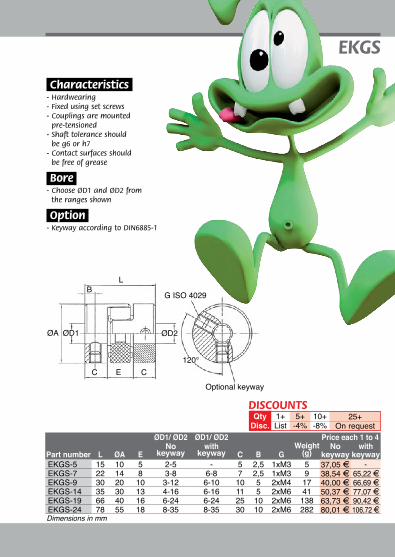
ØD1/ ØD2 ØD1/ ØD2 Price each 1 to 4No with Weight No with
Part number L ØA E keyway keyway C B G (g) keyway keywayEKGS-5 15 10 5 2-5 - 5 2,5 1xM3 5 37,05 F -EKGS-7 22 14 8 3-8 6-8 7 2,5 1xM3 9 38,54 F 65,22 FEKGS-9 30 20 10 3-12 6-10 10 5 2xM4 17 40,00 F 66,69 FEKGS-14 35 30 13 4-16 6-16 11 5 2xM6 41 50,37 F 77,07 FEKGS-19 66 40 16 6-24 6-24 25 10 2xM6 138 63,73 F 90,42 FEKGS-24 78 55 18 8-35 8-35 30 10 2xM6 282 80,01 F 106,72 F
EKGS
Dimensions in mm
5+-4%
25+On request
10+-8%
1+List
QtyDisc.
DISCOUNTS
ØA ØD1 ØD2
120°
G ISO 4029
LB
C E C
Optional keyway
.Characteristics.- Hardwearing- Fixed using set screws- Couplings are mounted
pre-tensioned- Shaft tolerance should
be g6 or h7- Contact surfaces should
be free of grease
.Bore.- Choose ØD1 and ØD2 from
the ranges shown
.Option.- Keyway according to DIN6885-1
40 www.hpceurope.com - Tel: +33(0)4 37 496 496Volume 2 2016
Backlash free couplingServo insert coupling
Torque range: 0.5 to 3 Nm
Nominaltorque(Nm)
Tightenedtorque(Nm)
Max speed (rpm)
Moment of inertia
(10-6 kg.m2)
Misalignmentaxial(Nm)
radial(Nm)
angularPart numberDKGS-5 0,5 0,25 38000 0,034 -0,2/+0,4 0,06 1°DKGS-7 1,2 0,35 27000 0,196 -0,3/+0,6 0,10 1°DKGS-9 3 0,75 19000 1,08 -0,4/+0,8 0,13 1°
DKGS
- Elastic backlash free coupling- Reliable torque transmission- Maintenance free- Low inertia/size- Easy to assemble, even in confined spaces- Reduces vibration- M aterials:
Hub: Aluminium Spider: Polyurethane 92 Shore A (Yellow)
.Applications.- Metrology, control systems, driving,
machine tools, driving lead screws
Dimensions in mm
Boresize Ø2 Ø3 Ø4 Ø5 Ø6 Ø7 Ø8 Ø9 Ø10 Ø11
DKGS-5 0,5 0,5 0,5 - - - - - - -DKGS-7 - 0,8 1,1 1,2 1,2 1,2 - - - -DKGS-9 - 1,5 2 2,5 2,9 3 3 3 3 3
Torque (Nm) transmissible by friction for a split hub
Small size
Secured by a
clamping hub
41 Fax: +33(0)4 37 490 055 - [email protected] Volume 2 2016
ØD1/ ØD2 ØD1/ ØD2 Price each 1 to 4Part number L ØA K ØH E No with C B G Weight No with
keyway keyway (g) keyway keywayDKGS-5 15 10 3,2 11,5 5 2-4 - 5 2,5 M1,6 5 41,50 F -DKGS-7 22 14 5 16,5 8 3-7 6 -7 7 3,5 M2 9 42,96 F 69,65 FDKGS-9 30 20 7,3 23,5 10 3-11 6 -11 10 5 M2,5 15 44,45 F 71,15 F
DKGS
Dimensions in mm
5+-4%
25+On request
10+-8%
1+List
QtyDisc.
DISCOUNTS
Optional keyway
ØAØD1 H7
C E C
ØD2 H7ØH
LB
I
KG ISO 4762
Hub
Elastic spider
.Characteristics.- Hardwearing- Secured by a clamping hub- Couplings are mounted
pre-tensioned- Shaft tolerance should be g6 or h7- Contact surfaces should be
grease free
.Bore.- Choose ØD1 and ØD2 from
the ranges shown
.Option.- Keyway according to DIN6885-1
42 www.hpceurope.com - Tel: +33(0)4 37 496 496Volume 2 2016
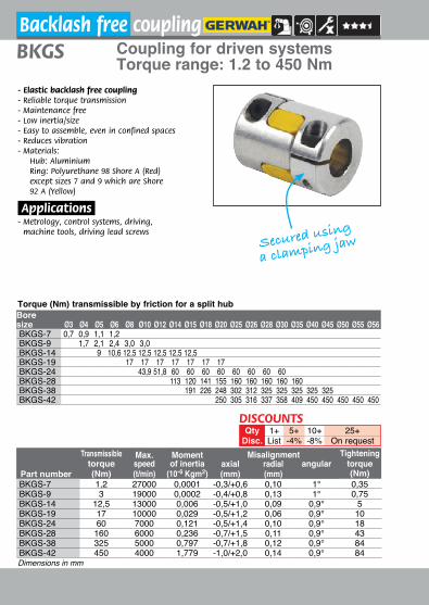
Coupling for driven systems Torque range: 1.2 to 450 Nm
BKGS
- Elastic backlash free coupling- Reliable torque transmission- Maintenance free- Low inertia/size- Easy to assemble, even in confined spaces- Reduces vibration- M aterials:
Hub: Aluminium Ring: Polyurethane 98 Shore A (Red) except sizes 7 and 9 which are Shore 92 A (Yellow)
.Applications.- Metrology, control systems, driving,
machine tools, driving lead screws
Dimensions in mm
5+-4%
25+On request
10+-8%
1+List
QtyDisc.
DISCOUNTS
Bore size Ø3 Ø4 Ø5 Ø6 Ø8 Ø10 Ø12 Ø14 Ø15 Ø18 Ø20 Ø25 Ø26 Ø28 Ø30 Ø35 Ø40 Ø45 Ø50 Ø55 Ø56BKGS-7 0,7 0,9 1,1 1,2BKGS-9 1,7 2,1 2,4 3,0 3,0BKGS-14 9 10,6 12,5 12,5 12,5 12,5 12,5BKGS-19 17 17 17 17 17 17 17BKGS-24 43,9 51,8 60 60 60 60 60 60 60 60BKGS-28 113 120 141 155 160 160 160 160 160BKGS-38 191 226 248 302 312 325 325 325 325 325BKGS-42 250 305 316 337 358 409 450 450 450 450 450
Torque (Nm) transmissible by friction for a split hub
Secured using
a clamping jaw
Backlash free coupling
Transmissibletorque(Nm)
Max.speed(t/min)
Moment of inertia
(10-6 Kgm2)
Misalignment Tighteningaxial(mm)
radial(mm)
angular torquePart number (Nm)BKGS-7 1,2 27000 0,0001 -0,3/+0,6 0,10 1° 0,35BKGS-9 3 19000 0,0002 -0,4/+0,8 0,13 1° 0,75BKGS-14 12,5 13000 0,006 -0,5/+1,0 0,09 0,9° 5BKGS-19 17 10000 0,029 -0,5/+1,2 0,06 0,9° 10BKGS-24 60 7000 0,121 -0,5/+1,4 0,10 0,9° 18BKGS-28 160 6000 0,236 -0,7/+1,5 0,11 0,9° 43BKGS-38 325 5000 0,797 -0,7/+1,8 0,12 0,9° 84BKGS-42 450 4000 1,779 -1,0/+2,0 0,14 0,9° 84
43 Fax: +33(0)4 37 490 055 - [email protected] Volume 2 2016
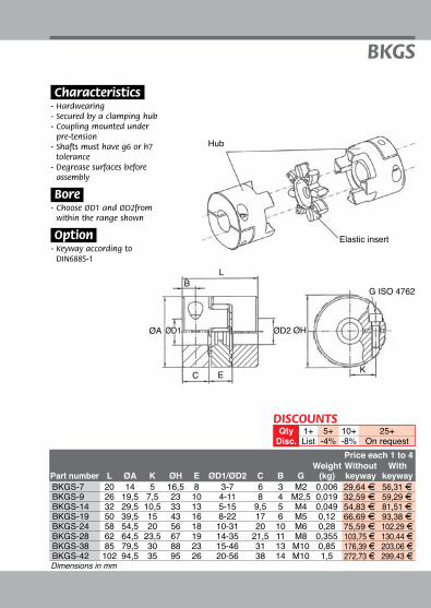
Hub
Elastic insert
BKGS
Dimensions in mm
.Characteristics.- Hardwearing- Secured by a clamping hub- Coupling mounted under
pre-tension- Shafts must have g6 or h7
tolerance- Degrease surfaces before
assembly
.Bore.- Choose ØD1 and ØD2from
within the range shown
.Option.- Keyway according to
DIN6885-1
L
G ISO 4762B
ØA ØD1 ØD2 ØH
EC K
5+-4%
25+On request
10+-8%
1+List
QtyDisc.
DISCOUNTS
Price each 1 to 4Weight Without With
Part number L ØA K ØH E ØD1/ØD2 C B G (kg) keyway keywayBKGS-7 20 14 5 16,5 8 3-7 6 3 M2 0,006 29,64 F 56,31 FBKGS-9 26 19,5 7,5 23 10 4-11 8 4 M2,5 0,019 32,59 F 59,29 FBKGS-14 32 29,5 10,5 33 13 5-15 9,5 5 M4 0,049 54,83 F 81,51 FBKGS-19 50 39,5 15 43 16 8-22 17 6 M5 0,12 66,69 F 93,38 FBKGS-24 58 54,5 20 56 18 10-31 20 10 M6 0,28 75,59 F 102,29 FBKGS-28 62 64,5 23,5 67 19 14-35 21,5 11 M8 0,355 103,75 F 130,44 FBKGS-38 85 79,5 30 88 23 15-46 31 13 M10 0,85 176,39 F 203,06 FBKGS-42 102 94,5 35 95 26 20-56 38 14 M10 1,5 272,73 F 299,43 F

44 www.hpceurope.com - Tel: +33(0)4 37 496 496Volume 2 2016
Backlash free couplingServo insert coupling
Torque range: 12.5 to 525 Nm
transmissible Tightened Max Moment Misalignmenttorque torque speed of inertia axial radial angular
Part number (Nm) (Nm) (t/min) 10-3 kg.m2 (mm) (mm)ADSR-14 12,5 2 13000 0,006 -0,5/+1,0 0,09 0,9°ADSR-19 17 11 10000 0,036 -0,5/+1,2 0,06 0,9°ADSR-24 60 15 7000 0,15 -0,5/+1,4 0,10 0,9°ADSR-28 160 32 6000 0,33 -0,7/+1,5 0,11 0,9°ADSR-38 325 38 5000 0,96 -0,7/+1,8 0,12 0,9°ADSR-42 450 84 4000 4,92 -1,0/+2,0 0,14 0,9°ADSR-48 525 145 3600 8,26 -1,0/+2,1 0,16 0,9°
ADSR
- Elastic backlash free coupling- Reliable torque transmission - Maintenance free- Low inertia/size- Easy to assemble, even in confined spaces- Reduces vibration- M aterials:
Hub- Aluminium Ring- Polyurethane 98 Shore A (Red)
.Applications.- Metrology, control systems, driving,
machine tools, driving lead screws
Dimensions in mm
Part number Ø5 Ø6 Ø8 Ø10 Ø12 Ø14 Ø16 Ø20 Ø25 Ø30 Ø35 Ø40 Ø45 Ø50 Ø55ADSR-14 4,8 6,0 7,7 9,4 11 12,5 12,5ADSR-19 16 17 17 17 17 17 17ADSR-24 37 43 50 56 60 60 60ADSR-28 61 72 83 94 114 138 160 160ADSR-38 87 100 113 138 168 197 225 251 277ADSR-42 174 197 242 296 348 398 450 450ADSR-48 276 343 424 502 525 525 525 525 525
Torque (Nm) transmissible by friction for a split hub
Secured by a
clamping hub
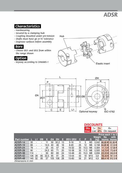
45 Fax: +33(0)4 37 490 055 - [email protected] Volume 2 2016
Price each 1 to 2Weight No with
Part number L L1 ØB K ØA ØH E ØD1/ ØD2 C P G (kg) keyway keywayADSR-14 35 - - 11 30 32,2 13 5-16 11 5 M3 0,042 66,69 F 93,38 FADSR-19 66 - - 14,5 40 46 16 6-20 25 12 M6 0,158 94,85 F 121,53 FADSR-24 78 - - 20 55 57 18 10-32 30 10,5 M6 0,304 111,15 F 137,86 FADSR-28 90 - - 24,5 65 71 20 10-38 35 11,5 M8 0,505 143,76 F 170,46 FADSR-38 114 - - 30 80 83 24 12-48 45 15,5 M8 0,934 222,35 F 249,03 FADSR-42 126 28 85 32,5 95 91 26 14-54 50 18 M10 3,8 760,46 F 787,14 FADSR-48 140 32 95 37 105 106 28 15-60 56 21 M12 4,9 889,41 F 916,10 F
ADSR
Dimensions in mm
3+-8%
6+On request
1+List
QtyDisc.
DISCOUNTS
Hub
Elastic insert
Optional keyway
ØAØD1
C E L1
ØD2 ØB
L
PØH
K
GISO 4762
.Characteristics.- Hardwearing- Secured by a clamping hub- Coupling mounted under pre-tension- Shafts must have g6 or h7 tolerance- Degrease surfaces before assembly
.Bore.- Choose ØD1 and ØD2 from within
the range shown
.Option.- Keyway according to DIN6885-1

46 www.hpceurope.com - Tel: +33(0)4 37 496 496Volume 2 2016
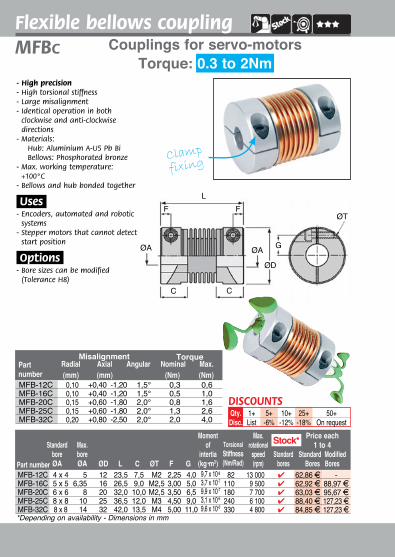
Part number
Standard bore ØA
Max. boreØA
Moment of
inertia(kg•m2)
Torsional stiffness(Nm/Rad)
Weight (g)
Max. rotational speed(rpm)
Price each 1 to 4
Standard Modified Bores BoresØD L C ØT F
- High precision- High torsional stiffness- Large misalignment- Identical operation in both
clockwise and anti-clockwise directions
- M aterials: Hub: Aluminium A-U5 Pb Bi Bellows: Phosphorated bronze
- Max. working temperature: +100°C
- Bellows and hub bonded together
.Uses.- Encoders, automated and robotic
systems- Stepper motors that cannot detect
start position
.Options.- Bore sizes can be modified
(Tolerance H8)
LØT
CC
ØA ØA
ØD
F F
Part number (mm) (mm) (Nm) (Nm)
Radial Axial Angular Nominal Max.Misalignment Torque
Set screw
fixing
1+List
5+-6%
10+-12%
25+-18%
50+On request
Qty.Disc.
DISCOUNTS
Flexible bellows coupling
Torque: 0.3 to 2NmMFB Couplings for servo-motors
MFB-12 0,10 +0,40 / -1,20 1,5° 0,3 0,6MFB-16 0,10 +0,40 / -1,20 1,5° 0,5 1,0MFB-20 0,10 +0,60 / -1,80 2,0° 0,8 1,6MFB-25 0,15 +0,60 / -1,80 2,0° 1,3 2,6MFB-32 0,20 +0,80 / -2,50 2,0° 2,0 4,0
MFB-12 3 x 3 6,35 12 23,5 7,5 M2,5 2,5 9,0 x 10⁻⁸ 82 4,1 32000 47,72 F 62,71 FMFB-16 4 x 4 8 16 26,5 9,0 M3 3,0 3,5 x 10⁻⁷ 110 9,0 24000 49,41 F 69,30 FMFB-20 5 x 5 10 20 32,0 10,0 M3 3,5 9,9 x 10⁻⁷ 180 16,0 19000 48,97 F 71,59 FMFB-25 6 x 6 12 25 36,5 12,0 M4 4,5 3,1 x 10⁻⁶ 240 32,0 15000 62,95 F 90,57 FMFB-32 8 x 8 16 32 42,0 13,5 M4 5,5 9,2 x 10⁻⁶ 330 57,0 12000 72,40 F 106,63 FDimensions in mm
in stockstandard bore

47 Fax: +33(0)4 37 490 055 - [email protected] Volume 2 2016
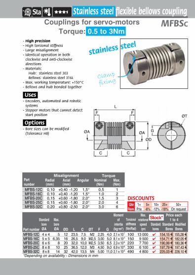
Part number
Standardbore ØA
Max.boreØA
Momentof
inertia(kg•m2)
Torsionalstiffness(Nm/Rad)
Weight(g)
Max.rotational
speed(rpm)
Price each 1 to 4
Standard Modified Bores BoresØD L C ØT F
- High precision- High torsional stiffness- Large misalignment- Identical operation in both
clockwise and anti-clockwise directions
- Materials: Hub: stainless steel 303 Bellows: stainless steel 316L
- Max. working temperature: +150°C
- Bellows and hub bonded together
.Uses.- Encoders, automated and robotic
systems- Stepper motors that cannot detect
start position
.Options.- Bore sizes can be modified
(Tolerance H8)
LØT
CC
ØA ØA
ØD
F F
Partnumber (mm) (mm) (Nm) (Nm)
Radial Axial Angular Nominal Max.Misalignment Torque
set screw
fixing
1+List
5+-6%
10+-12%
25+-18%
50+On request
Qty.Disc.
DISCOUNTS
stainless steel
Stainless steel bellows flexible coupling
Torque: 0.5 to 3NmMFBSCouplings for servo-motors
MFBS-12 0,10 +0,40 / -1,20 1,5° 0,5 1MFBS-16 0,10 +0,40 / -1,20 1,5° 1,0 2MFBS-20 0,15 +0,60 / -1,80 2,0° 1,5 3MFBS-25 0,15 +0,60 / -1,80 2,0° 2,0 4MFBS-32 0,20 +0,80 / -2,50 2,0° 3,0 6
MFBS-12 3 x 3 6,35 12 23,5 7,5 M2,5 2,5 2,1 x 10⁻⁷ 100 9,1 32000 79,67 F 96,00 FMFBS-16 4 x 4 8 16 26,5 9,0 M3 3,0 8,0 x 10⁻⁷ 150 20,0 24000 102,60 F 104,35 FMFBS-20 5 x 5 10 20 32,0 10,0 M3 3,5 2,3 x 10⁻⁶ 220 37,0 19000 118,74 F 118,74 FMFBS-25 6 x 6 12 25 36,5 12,0 M4 4,5 7,0 x 10⁻⁶ 240 330 15000 115,75 F 144,18 FMFBS-32 8 x 8 16 32 42,0 13,5 M4 5,5 2,1 x 10⁻⁵ 330 490 12000 151,30 F 150,48 FDimensions in mm
in stockstandard bore
48 www.hpceurope.com - Tel: +33(0)4 37 496 496Volume 2 2016
Part number
Standard bore ØA
Max. boreØA
Moment of
intertia(kg•m2)
TorsionalStiffness (Nm/Rad)
Max. rotational
speed (rpm)
Standard bores
Price each1 to 4
Standard ModifiedBores BoresØD L C ØT F G
*Depending on availability - Dimensions in mm
L
ØT
CC
ØA ØA
ØD
G
F F
- High precision- High torsional stiffness- Large misalignment- Identical operation in both
clockwise and anti-clockwise directions
- Materials:Hub: Aluminium A-U5 Pb Bi Bellows: Phosphorated bronze
- Max. working temperature: +100°C
- Bellows and hub bonded together
.Uses.- Encoders, automated and robotic
systems- Stepper motors that cannot detect
start position
.Options.- Bore sizes can be modified
(Tolerance H8)
Clamp
fixing
1+List
5+-6%
10+-12%
25+-18%
50+On request
Qty.Disc.
DISCOUNTS
Flexible bellows coupling
Torque: 0.3 to 2NmMFBc Couplings for servo-motors
Part number (mm) (mm) (Nm) (Nm)
Radial Axial Angular Nominal Max.Misalignment Torque
MFB-12C 0,10 +0,40 -1,20 1,5° 0,3 0,6MFB-16C 0,10 +0,40 -1,20 1,5° 0,5 1,0MFB-20C 0,15 +0,60 -1,80 2,0° 0,8 1,6MFB-25C 0,15 +0,60 -1,80 2,0° 1,3 2,6MFB-32C 0,20 +0,80 -2,50 2,0° 2,0 4,0
MFB-12C 4 x 4 5 12 23,5 7,5 M2 2,25 4,0 9,7 x 10⁻⁸ 82 13 000 4 62,86 F -MFB-16C 5 x 5 6,35 16 26,5 9,0 M2,5 3,00 5,0 3,7 x 10⁻⁷ 110 9 500 4 62,92 F 88,97 FMFB-20C 6 x 6 8 20 32,0 10,0 M2,5 3,50 6,5 9,9 x 10⁻⁷ 180 7 700 4 63,03 F 95,67 FMFB-25C 8 x 8 10 25 36,5 12,0 M3 4,50 9,0 3,1 x 10⁻⁶ 240 6 100 4 88,40 F 127,23 FMFB-32C 8 x 8 14 32 42,0 13,5 M4 5,00 11,0 9,6 x 10⁻⁶ 330 4 800 4 84,85 F 127,23 F
Stock*
49 Fax: +33(0)4 37 490 055 - [email protected] Volume 2 2016
Part number
Standard bore ØA
Max. boreØA
Moment of
intertia(kg•m2)
Torsionalstiffness (Nm/Rad)
Max. rotational
speed (rpm)
Standard bores
Price each1 to 4
Standard ModifiedBores BoresØD L C ØT F G
*Depending on availability - Dimensions in mm
Part number (mm) (mm) (Nm) (Nm)
Radial Axial Angular Nominal Max.Misalignment Torque
L
ØT
CC
ØA ØAØD
G
F F
- High precision- High torsional stiffness- Large misalignment- Identical operation in both
clockwise and anti-clockwise directions
- Materials:Hub: stainless steel 303 Bellows: stainless steel 316L
- Max. working temperature: +150°C- Bellows and hub bonded together
.Uses.- Encoders, automated and robotic
systems- Stepper motors that cannot detect
start position
.Options.- Bore sizes can be modified
(Tolerance H8)
Clamp
fixing
stainless steel
1+Prix
5+-6%
10+-12%
25+-18%
50+On request
QtéRem.
DISCOUNTS
Stainless steel flexible bellows coupling
Torque: 0.5 to 3NmMFBScCouplings for servo-motors
MFBS-12C 0,10 +0,40 -1,20 1,5° 0,5 1MFBS-16C 0,10 +0,40 -1,20 1,5° 1,0 2MFBS-20C 0,15 +0,60 -1,80 2,0° 1,5 3MFBS-25C 0,15 +0,60 -1,80 2,0° 2,0 4MFBS-32C 0,20 +0,80 -2,50 2,0° 3,0 6
Stock*
MFBS-12C 4 x 4 5 12 23,5 7,5 M2 2,25 4,0 2,1 x 10⁻⁷ 100 13 000 4 154,15 F 155,28 FMFBS-16C 5 x 5 6,35 16 26,5 9,0 M2,5 3,00 5,0 8,1 x 10⁻⁷ 150 9 500 4 154,71 F 182,05 FMFBS-20C 6 x 6 8 20 32,0 10,0 M2,5 3,50 6,5 2,3 x 10⁻⁶ 220 7 700 4 190,99 F 180,36 FMFBS-25C 8 x 8 10 25 36,5 12,0 M3 4,50 9,0 6,9 x 10⁻⁶ 330 6 100 4 197,79 F 197,43 FMFBS-32C 8 x 8 14 32 42,0 13,5 M4 5,00 11,0 2,1 x 10⁻⁵ 490 4 800 4 225,03 F 228,10 F
50 www.hpceurope.com - Tel: +33(0)4 37 496 496Volume 2 2016
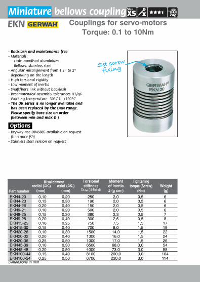
Miniature bellows couplingEKN Couplings for servo-motors
Torque: 0.1 to 10Nm
- Backlash and maintenance free- Materials:
Hub: anodised aluminium Bellows: stainless steel
- Angular misalignment from 1.2º to 2º depending on the length
- High torsional rigidity- Low moment of inertia- Shaft/bore link without backlash- Recommended assembly tolerances H7/g6- Working temperature -30°C to +100°C- The DK series is no longer available and
has been replaced by the DKN range. Please specify bore size on order (between min and max Ø )
.Options.- Keyway acc DIN6885 available on request
(tolerance JS9)- Stainless steel version on request
Set screw
fixing
radial (∆Kr)(mm)
axial (∆Ka)(mm)
Torsional stiffness
CT dyn (103 Nm/rad)
Moment of inertia J (g cm2)
Tightening torque (Screw)
(Nm)Weight
(g) Part number
Misalignment
EKN4-20 0,10 0,20 250 2,0 0,5 6EKN4-23 0,15 0,30 190 2,0 0,5 6EKN4-26 0,20 0,40 150 2,0 0,5 6EKN9-21 0,10 0,20 500 2,0 0,5 6EKN9-25 0,15 0,30 380 2,3 0,5 7EKN9-28 0,20 0,40 300 2,6 0,5 8EKN15-25 0,10 0,25 750 7,5 1,5 17EKN15-30 0,15 0,40 700 8,0 1,5 19EKN20-26 0,10 0,30 1500 14,0 1,5 22EKN20-32 0,20 0,40 1300 16,0 1,5 24EKN20-36 0,25 0,50 1000 17,0 1,5 26EKN45-39 0,10 0,30 6500 68,0 3,0 54EKN45-48 0,20 0,50 4000 73,0 3,0 58EKN100-44 0,15 0,40 8100 200,0 3,0 104EKN100-54 0,25 0,50 6700 220,0 3,0 114
Dimensions in mm

51 Fax: +33(0)4 37 490 055 - [email protected] Volume 2 2016
EKN
øD1/øD2(H7) øA C L
G(DIN 916)
E(mm)
Nominal torque(Nm)
Part number
L ±2
C
ØAØD1 H7 ØD2 H7
EG ISO 4029(DIN 916)
Keyway acc DIN6885 available on request
120°
High Precision
Price each 1 to 4 No With keyway keyway
EKN4-20 3-8 16 6 20 M3 2,0 0,4 47,76 F 91,69 FEKN4-23 3-8 16 6 23 M3 2,0 0,4 47,76 F 91,69 FEKN4-26 3-8 16 6 26 M3 2,0 0,4 47,76 F 91,69 FEKN9-21 3-8 16 6 21 M3 2,0 0,9 47,76 F 91,69 FEKN9-25 3-8 16 6 25 M3 2,0 0,9 47,76 F 91,69 FEKN9-28 3-8 16 6 28 M3 2,0 0,9 47,76 F 91,69 FEKN15-25 3-10 20 10 25 2 x M4 3,0 1,5 47,76 F 91,69 FEKN15-30 3-10 20 10 30 2 x M4 3,0 1,5 47,76 F 91,69 FEKN20-26 3-12 25 11 26 2 x M3 2,0 2,0 47,76 F 91,69 FEKN20-32 3-12 25 11 32 2 x M3 2,0 2,0 47,76 F 91,69 FEKN20-36 3-12 25 11 36 2 x M3 2,0 2,0 47,76 F 91,69 FEKN45-39 6-16 33 16 39 2 x M6 4,0 4,5 67,30 F 101,28 FEKN45-48 6-16 33 16 48 2 x M6 4,0 4,5 67,30 F 101,28 FEKN100-44 6-19 40 20 44 2 x M6 4,0 10,0 95,57 F 129,48 FEKN100-54 6-19 40 20 54 2 x M6 4,0 10,0 95,57 F 129,48 F
Dimensions in mm
DISCOUNTSQty 1+ 5+ 10+ 25+
Disc. List -4% -8% On request
52 www.hpceurope.com - Tel: +33(0)4 37 496 496Volume 2 2016
- Backlash and maintenance free- Materials:
Hub: anodised aluminium Bellows: stainless steel
- Angular misalignment from 1.2º to 2º depending on the length
- High torsional rigidity- Low moment of inertia- Shaft/bore link without backlash- Recommended assembly tolerances H7/g6- Working temperature -30°C to +100°C- Please specify bore size on order (between
min and max Ø )
.Options.- Keyway acc DIN6885 available on request
.Info..- The DK series is no longer available and has
been replaced by the DKN range
Part number
Nominal torque(Nm)
Torsional stiffness
CT dyn (Nm/rad)
Moment of inertiaJ (g cm2)
Tightening torque (Nm)
Weight(g)
Angulaire(°)
radial (∆Kr)(mm)
axial (∆Ka)(mm)
Misalignment
Clamp fixing
Miniature bellows couplingDKN
Torque: 0.4 to 10NmCouplings for servo-motors
DKN4/21 0,4 0,10 0,20 1,2 250 2,6 0,3 9DKN4/24 0,4 0,15 0,30 2,0 190 2,6 0,3 9DKN4/28 0,4 0,20 0,40 2,0 150 2,6 0,3 9DKN9/23 0,9 0,10 0,20 1,2 500 2,6 0,3 9DKN9/26 0,9 0,15 0,30 2,0 380 2,9 0,3 10DKN9/30 0,9 0,20 0,40 2,0 300 3,2 0,3 11DKN15/26 1,5 0,10 0,25 1,2 750 11,0 0,8 22DKN15/30 1,5 0,15 0,40 2,0 700 12,0 0,8 24DKN20/32 2,0 0,10 0,30 1,2 1500 25,0 1,0 36DKN20/38 2,0 0,20 0,40 2,0 1300 27,0 1,0 38DKN20/42 2,0 0,25 0,50 2,0 1000 28,0 1,0 40DKN45/41 4,5 0,10 0,30 1,2 6500 98,0 3,0 74DKN45/50 4,5 0,20 0,50 2,0 4000 103,0 3,0 78DKN100/47 10,0 0,15 0,40 1,2 8100 231,0 3,0 120DKN100/57 10,0 0,25 0,50 2,0 6700 250,0 3,0 130
Dimensions in mm

53 Fax: +33(0)4 37 490 055 - [email protected] Volume 2 2016
Part numberD1/D2
(H7) ØA C L FøH
undercutG
(DIN 912) K
L ±2
C
KFG ISO 4762(DIN 912)
ØA ØHØD1 ØD2
Price each 1 to 4 No With keyway keyway
DKN
DKN4/21 3-6,5 16 7 21 2 18 M2 5 62,96 F 96,93 FDKN4/24 3-6,5 16 7 24 2 18 M2 5 62,96 F 96,93 FDKN4/28 3-6,5 16 7 28 2 18 M2 5 62,96 F 96,93 FDKN9/23 3-6,5 16 7 23 2 18 M2 5 62,96 F 96,93 FDKN9/26 3-6,5 16 7 26 2 18 M2 5 62,96 F 96,93 FDKN9/30 3-6,5 16 7 30 2 18 M2 5 62,96 F 96,93 FDKN15/26 3-10 20 9 26 3 21 M2,5 7 62,96 F 96,93 FDKN15/30 3-10 20 9 30 3 21 M2,5 7 62,96 F 96,93 FDKN20/32 3-12 25 11 32 4 27 M3 9 67,32 F 101,28 FDKN20/38 3-12 25 11 38 4 27 M3 9 67,32 F 101,28 FDKN20/42 3-12 25 11 42 4 27 M3 9 67,32 F 101,28 FDKN45/41 6-16 33 13 41 5 34 M4 12 99,91 F 133,87 FDKN45/50 6-16 33 13 50 5 34 M4 12 99,91 F 133,87 FDKN100/47 6-19 40 14 47 5 42 M4 16 125,98 F 159,92 FDKN100/57 6-19 40 14 57 5 42 M4 16 125,98 F 159,92 F
Dimensions in mm
DISOUNTSQty 1+ 5+ 10+ 25+
Disc. List -4% -8% On request
High Precision

54 www.hpceurope.com - Tel: +33(0)4 37 496 496Volume 2 2016
Nominal torque(Nm)
Torsional stiffness
(103Nm/rad)
Radial stiffness (N/mm)
Axial stiffness (N/mm)
Moment of inertia
(10-3kgm2)
Tightening torque(Nm) Part number
- Backlash and maintenance free- Materials:
Hub: aluminium for sizes 18-60 steel for sizes 80-500
- High torsional stiffness- Low moment of inertia- Shaft/bore link without backlash- Recommended assembly tolerances H7/g6- Working temperature: -30°C to +100°C- Please specify bore size on order (between
min and max Ø )
.Options.- Keyway acc DIN6885 available on request
Clamp
fixing
radial(mm)
axial(mm)
angular
Max. speed(rpm)
Weight(approx)(ca.kg) Part number
Misalignment
Bellows couplingCouplings for servo-motors
Torque: 18 to 500NmAKD
AKD18 0,2 0,5 1,5° 12700 0,17AKD30 0,2 0,5 1,5° 10200 0,27AKD60 0,2 0,5 1,5° 8600 0,47AKD80 0,2 0,5 1,5° 6800 1,00AKD150 0,2 0,5 1,5° 6800 1,00AKD200 0,2 0,5 1,5° 6300 1,20AKD300 0,2 0,5 1,5° 5900 1,40AKD500 0,2 1,0 1,5° 4900 1,80
AKD18 18 6 85 40 0,06 6AKD30 30 25 220 30 0,10 12AKD60 60 50 330 55 0,30 30AKD80 80 75 400 55 0,90 60AKD150 150 100 600 85 0,90 85AKD200 200 120 450 85 1,50 100AKD300 300 280 1500 150 3,20 120AKD500 500 310 1000 85 4,90 190
Dimensions in mm

55 Fax: +33(0)4 37 490 055 - [email protected] Volume 2 2016
High Precision
L ±2
C
KF
G ISO 4762(DIN 912)
ØA ØHØD1 H7 ØD2 H7
AKD
Dimensions in mm
Price each 1 to 2
(H7) C L øA F G K HPart number
AKD18 10-25 20 71 45 6 M5 18 47 224,44 FAKD30 10-25 25 73 55 8 M6 20 56 278,84 FAKD60 14-32 29 89 64 10 M8 24 67 315,12 FAKD80 20-40 34 103 80 12 M10 28 84 358,17 FAKD150 20-40 34 103 80 12 M10 28 84 428,49 FAKD200 25-44 38 113 90 13 M12 31 93 516,92 FAKD300 32-50 38 115 109 13 M12 39 110 564,54 FAKD500 40-60 41 122 119 15 M14 43 122 723,26 F
BoreøD1/D2
DISCOUNTSQty 1+ 3+ 6+
Disc. List -8% On request
56 www.hpceurope.com - Tel: +33(0)4 37 496 496Volume 2 2016
Part numberØA
mini.ØA
maxi. L ØD C F G K ØH
Pric each 1 to 2 No With keyway keyway
Part number
Max. speed(rpm)
radial(mm)
Misalignmentaxial(mm)
angularNominal torque(Nm)
Torsionalstiffness
(103 Nm/Rad)
Momentof inertia(10-3kgm2)
Tightening torque (Nm)
Weight(kg)
L ±2
C
K
F
G ISO 4762(DIN 912)
ØH
ØDØA1 H7 ØA2 H7
*Undercut diameter
High Precision
- Backlash and maintenance free- High torsional stiffness- Low moment of inertia- Shaft/bore link without backlash- Recommended assembly tolerances
H7/g6- Working temperature -30°C to +100°C - Materials:
Hub: aluminium for sizes 18-60 steel for sizes 80-500
Bellows: stainless steel- Please specify bore size on order
(between min and max Ø )
.Torque calculation.- Use the formulaTKN > K x TAS x Jmach/(Jmot+Jmach) in NmWith following safety coefficient:K = 1.5 for regular motionK = 2 for irregular motionK = 2.5 - 4 for jerky motionJx = moment of inertia (machine + motor)TAS Required torque
Couplings for servo-motorsBacklash-free bellow
Clamp
fixing
Torque: 18 to 150NmAKN
AKN18-63 12 700 0,2 0,5 1,5° 18 8 0,05 6 0,16AKN30-65 10 200 0,1 0,4 1,0° 30 35 0,11 12 0,26AKN60-78 8 600 0,1 0,4 1,0° 60 75 0,29 30 0,44AKN80-91 6 800 0,2 0,4 1,0° 80 130 0,87 60 0,98AKN150-91 6 800 0,2 0,4 1,0° 150 150 0,87 85 0,98
AKN18-63 10 25 63 45 20 6 M5 18 47 214,12 F 247,93 FAKN30-65 10 25 65 55 25 8 M6 20 56 266,05 F 299,87 FAKN60-78 14 32 78 64 29 10 M8 24 67 300,66 F 334,47 FAKN80-91 20 40 91 80 34 12 M10 28 84 341,77 F 375,58 FAKN150-91 20 40 91 80 34 12 M10 28 84 408,44 F 442,66 F
Dimensions in mm
DISCOUNTSQty 1+ 3+ 6+
Disc. List -8% On request
57 Fax: +33(0)4 37 490 055 - [email protected] Volume 2 2016
ØT
J
EG (DIN 933)
ØD
2H7
H
ØA
L±21
ØB
ØD
1H7
High Precision
Torque: 30 to 500Nm
Part number
- Backlash and maintenance free- High torsional stiffness- Low moment of inertia- Shaft/bore link without backlash- Recommended assembly tolerances H7/g6- Working temperature -30°C to +100°C - Materials:
Hub: steelBellows: stainless steel
- Please specify bore size on order (between min and max Ø )
.Torque calculation.- Use the formula
TKN > K x TAS x Jmach/(Jmot+Jmach) in NmWith following safety coefficient:K = 1.5 for regular motionK = 2 for irregular motionK = 2.5 - 4 for jerky motionJx = moment of inertia (machine + motor)Tas Required torque
radial(mm)
axial(mm)
Nominal torque(Nm)
torsional(103 Nm/Rad)
radial(N/mm)
axial(N/mm)
Momentof inertia(10-3kgm2)
Weight(kg)
Tightening torque(Nm)
angular(°)
Max. speed(t/min)
Stiffness Misalignement
Clamp fixing
Part numberØA
(mm)ØB
(mm) LD1H7/D2H7
min. D1H7/D2H7
max. E J ØT GPrice each
1 to 2
Couplings for servo-motorsBacklash-free bellow
AK
AK30-60 30 25 220 30 0,15 3,0 0,4 0,2 0,5 1,5 11 000AK60-73 60 50 330 55 0,24 8,5 0,8 0,2 0,5 1,5 9 100AK80-91 80 75 400 55 0,65 10,0 1,3 0,2 0,5 1,5 7 000AK150-92 150 100 600 85 0,65 14,0 1,3 0,2 0,5 1,5 7 000AK200-93 200 120 450 85 0,87 14,0 1,6 0,2 0,5 1,5 6 700AK300-104 300 280 1500 150 2,33 18,0 3,4 0,2 0,5 1,5 5 200AK500-113 500 310 1000 85 3,61 26,0 4,7 0,2 1,0 1,5 4 600
AK30-60 56 55 60 12 20 53 38 31 6 x M4 262,89 FAK60-73 66 64 73 15 25 65 46 37 6 x M6 286,76 FAK80-91 82 80 91 20 35 83 61 51 6 x M6 315,02 FAK150-92 82 80 92 20 35 84 61 51 6 x M6 367,16 FAK200-93 90 90 93 20 40 85 63 56 6 x M6 430,04 FAK300-104 110 109 104 25 50 93 67 75 6 x M8 497,55 FAK500-113 122 120 113 35 55 105 72 80 6 x M8 647,49 F
Dimensions in mm
DISCOUNTSQty 1+ 3+ 6+
Disc. List -8% On request

58 www.hpceurope.com - Tel: +33(0)4 37 496 496Volume 2 2016
Part number
Price each1 to 5Standard Max. D L H ØE
Max. torque(Nm) Vis
Weight(g)
ØA Bores(mm)
*Depending on availability - Dimensions in mm
ØE
L
D ØA
H
- Tolerates extreme misalignment- Compact- Corrosion-resistant- High resistance to acids, solvents,
alkaline solutions, fats, oils and ozone- High torsional rigidity- High resistance to tearing- Retains its flexibility even at low
temperatures
.Characteristics.- High angular, radial, and axial
flexibility- Dampens vibrations- Absorbs shocks- Max. working temp.: -40°C to +100°C- Max. speed: 3000 rpm- Materials:
Ring: Hytrel® resistant elastomerHub: galvanised steel
P-FLEX CouplingCouplings for servo-motors PFL
Torque: 0.5 to 10Nm
Set screw
fixing
Misalignmentaxial angulaire radial
Part number (mm) (°) (mm)PFL28 4,5 10° 2,6PFL48 7,5 15° 3,2PFL58 8,5 15° 3,2PFL61 11,0 15° 3,2
Stock*PFL28-6 6 x 6 8 26 28 7,9 18 0,5 M3 25 4 36,34 FPFL28-8 8 x 8 8 26 28 7,9 18 0,5 M3 25 4 36,34 FPFL48-10 10 x 10 12 48 48 12,7 25 1,8 M4 92 4 42,43 FPFL48-12 12 x 12 12 48 48 12,7 25 1,8 M4 92 4 42,43 FPFL58-12 12 x 12 16 54 58 15,9 28 5,0 M5 124 4 48,11 FPFL58-14 14 x 14 16 54 58 15,9 28 5,0 M5 124 4 48,11 FPFL61-14 14 x 14 16 54 61 15,9 28 10,0 M6 136 4 55,03 FPFL61-16 16 x 16 16 54 61 15,9 28 10,0 M6 136 4 55,03 F
DISOUNTSQty 1+ 6+ 20+ 40+
Disc. List -15% -20% On request

59 Fax: +33(0)4 37 490 055 - [email protected] Volume 2 2016
transmissioncouplings
p.60 - 78
elastic coupling,
economy range
p.66
p.62
bowex® coupling
p.64
curved tooth coupling
ECO. range
ECO. range
masterflex® shaft
p.70
periflex® elastic
coupling
p.76
60 www.hpceurope.com - Tel: +33(0)4 37 496 496Volume 2 2016
BoWex® curved tooth gear coupling
M
ØA
2
M5
L
KK
ØB
P
Standardkeyway
ØDØG ØH
F
- Anti-corrosion materials- Very low wear- BoWex® Junior- Maintenance free- 2 part construction- Curved teeth- M aterial:
Nylon- Working temp.: -25°C to +100°C- Bore and keyway acc DIN6885/1-JS9,
fixing screw supplied- Max. speed: 6000 rpm- Low weight and low inertia- Axial plug-in assembly
.Info..- ØD is a non-operational surface
and is not truly circular
ØA
RCN±0,08
+0,05-0,10
RTN Torque: 5 to 24Nm
Dimensions in mm
IN stockMANY DIFFERENT B
ORES
2 parts
hub
Socket
Plug-in design !
COUPLE NmPart number K L P F M ØH ØD
HubØA
SocketØB ØG
Axial(mm)
Radial(mm)
Angular Tkn Tknmax.
Price each1 to 4
Torque (Nm)MisalignmentBores
RTN-J-14 23 48 40 23 8 25252526
6,8,910,1112,14
8,10,1110,1112,14
40 ±1 ±0,1 ±1° 5 10 19,60 F
RTN-J-19 25 52 42 23 10 30292935
12,141619
14,1614,15
1948 ±1 ±0,1 ±1° 8 16 29,71 F
RTN-J-24 26 54 45 25 9 36
32323640
10,11,1214,15,1618,19,20
24
14,1614,1619,20
24
52 ±1 ±0,1 ±1° 12 24 35,82 F
DISOUNTSQty 1+ 5+ 10+ 25+
Disc. List -6% -12% On request

61 Fax: +33(0)4 37 490 055 - [email protected] Volume 2 2016
Torque: 5 to 24Nm RTNBoWex® curved tooth gear coupling
- Anti-corrosion material- Very low wear- BoWex® Junior- Maintenance free- 3 part construction- Curved teeth- M aterial:
Nylon- Working temp.: -25°C to +100°C- Bore and keyway acc DIN6885/1-JS9,
fixing screw supplied- Tolerances: Bore +0.05 / -0.1 Keyway ±0.08 - Axial plug-in means easy assembly
.Info..- ØD is a non-operational surface and
is not truly circular
M
ØA
K
L
4
P
Standardkeyway
ØGØD
M5
ØA
RCN±0,08
+0,05-0,10
Dimensions in mm
IN stockMANY DIFFERENT B
ORES
3 parts
Plug-in design !
Part number K L P M ØD ØA ØGAxial(mm)
Radial(mm)
Angular Tkn Tkn
max.
Torque (Nm)Price each1 to 4
Misalignment
RTN-JM-14 23 50 37 6,50222526
6,7,8,910,1112,14
40 ±1 ±0,3 ±2° 5 10 27,00 F
RTN-JM-19 23 54 37 8,50273032
12,141619
48 ±1 ±0,3 ±2° 8 16 42,08 F
RTN-JM-24 26 56 41 7,50
26323638
10,11,1214,15,1618,19,20
24
52 ±1 ±0,4 ±2° 12 24 50,69 F
DISOUNTSQty 1+ 5+ 10+ 25+
Disc. List -6% -12% On request
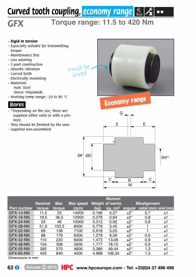
62 www.hpceurope.com - Tel: +33(0)4 37 496 496Volume 2 2016
C C
E E
G
ØF ØD
MB
Ød(1)
Curved tooth coupling, economy rangeTorque range: 11.5 to 420 Nm
MomentNominal Max Max speed Weight of inertia Misalignment
Part number torque torque (rpm) (kg) kg. cm2 angular radial (mm) axial (mm)GFX-14-NN 11,5 23 14000 0,166 0,27 ±2° 0,7 ±1GFX-19-NN 18,5 36,5 12000 0,276 0,64 ±2° 0,8 ±1GFX-24-NN 23 46 10000 0,312 0,92 ±2° 0,8 ±1GFX-28-NN 51,5 103,5 8000 0,779 3,45 ±2° 1 ±1GFX-32-NN 69 138 7100 0,918 5,03 ±2° 1 ±1GFX-38-NN 88 176 6300 1,278 9,59 ±2° 0,9 ±1GFX-42-NN 110 220 6000 1,473 13,06 ±2° 0,9 ±1GFX-48-NN 154 308 5600 1,777 18,15 ±2° 0,9 ±1GFX-55-NN 285 570 4800 3,380 49,44 ±2° 1,2 ±1GFX-65-NN 420 840 4000 4,988 106,34 ±2° 1,3 ±1
GFX
- Rigid in torsion- Especially suitable for transmitting
torque- Maintenance free- Low wearing- 3 part construction- Absorbs vibration- Curved teeth- Electrically insulating- M aterials:
Hub: Steel Sleeve: Polyamide
- Working temp range: -20 to 80 °C
.Bores.- (1) Depending on the size, these are
supplied either solid or with a pre-bore.
- They should be finished by the user.- Supplied non-assembled
Dimensions in mm
Economy range
Must be
bored
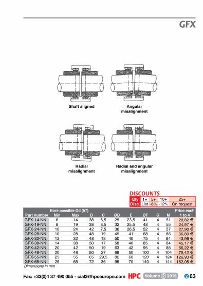
63 Fax: +33(0)4 37 490 055 - [email protected] Volume 2 2016
Bore possible Ød (h7) Price eachPart number Min Max B C ØD E ØF G M 1 to 4GFX-14-NN 6 14 38 6,5 25 23,5 41 4 51 20,82 FGFX-19-NN 8 19 38 8,5 32 25,5 48 4 55 24,97 FGFX-24-NN 10 24 42 7,5 36 26,5 52 4 57 27,90 FGFX-28-NN 10 28 48 19 45 41 68 4 86 36,80 FGFX-32-NN 12 32 48 18 50 40 75 4 84 43,96 FGFX-38-NN 14 38 50 17 58 40 85 4 84 45,17 FGFX-42-NN 20 42 50 19 63 42 95 4 88 66,22 FGFX-48-NN 20 48 50 27 68 50 100 4 104 79,42 FGFX-55-NN 25 55 65 29,5 82 60 120 4 124 126,93 FGFX-65-NN 25 65 72 36 95 70 140 4 144 182,05 F
GFX
Dimensions in mm
5+-6%
25+On request
10+-12%
1+List
QtyDisc.
DISCOUNTS
Radial misalignment
Radial and angular misalignment
Shaft aligned Angular misalignment
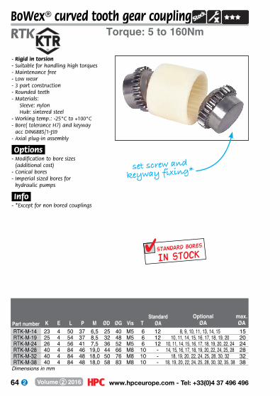
64 www.hpceurope.com - Tel: +33(0)4 37 496 496Volume 2 2016
Dimensions in mm
BoWex® curved tooth gear couplingTorque: 5 to 160NmRTK
Part number K E L P M ØD ØG Vis TOptional
ØAmax.ØA
StandardØA
RTK
In stockSTANDARD BORES
RTK-M-14 23 4 50 37 6,5 25 40 M5 6 12 8, 9, 10, 11, 13, 14, 15 15RTK-M-19 25 4 54 37 8,5 32 48 M5 6 12 10, 11, 14, 15, 16, 17, 18, 19, 20 20RTK-M-24 26 4 56 41 7,5 36 52 M5 6 12 10, 11, 14, 15, 16, 17, 18, 19, 20, 22, 24 24RTK-M-28 40 4 84 46 19,0 44 66 M8 10 - 14, 15, 16, 17, 18, 19, 20, 22, 24, 25, 28 28RTK-M-32 40 4 84 48 18,0 50 76 M8 10 - 18, 19, 20, 22, 24, 25, 28, 30, 32 32RTK-M-38 40 4 84 48 18,0 58 83 M8 10 - 18, 19, 20, 22, 24, 25, 28, 30, 32, 35, 38 38
- Rigid in torsion- Suitable for handling high torques- Maintenance free- Low wear- 3 part construction- Rounded teeth- Materials:
Sleeve: nylonHub: sintered steel
- Working temp.: -25°C to +100°C- Bore( tolerance H7) and keyway
acc DIN6885/1-JS9- Axial plug-in assembly
.Options.- Modification to bore sizes
(additional cost)- Conical bores- Imperial sized bores for
hydraulic pumps
.Info.- *Except for non bored couplings
set screw and
keyway fixing*
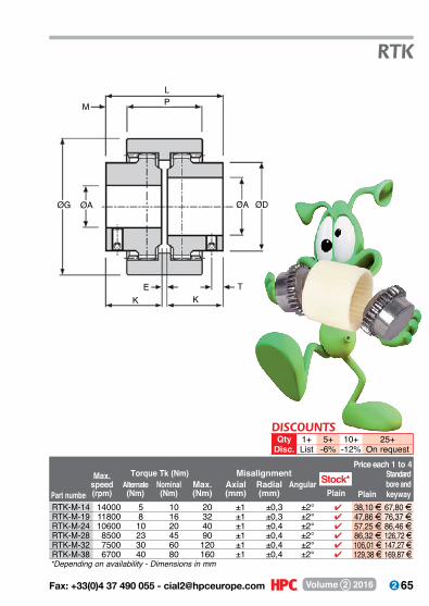
65 Fax: +33(0)4 37 490 055 - [email protected] Volume 2 2016
RTK
Part number
Max. speed(rpm)
Alternate(Nm)
Nominal(Nm)
Max.(Nm)
Axial(mm)
Radial(mm)
AngularPlain
Price each 1 to 4Torque Tk (Nm) Misalignment
Plain
Standardbore and keyway
*Depending on availability - Dimensions in mm
P
E T
ØG ØDØA ØA
K K
M
L
Stock*
RTK-M-14 14000 5 10 20 ±1 ±0,3 ±2° 4 38,10 F 67,80 FRTK-M-19 11800 8 16 32 ±1 ±0,3 ±2° 4 47,86 F 76,37 FRTK-M-24 10600 10 20 40 ±1 ±0,4 ±2° 4 57,25 F 86,46 FRTK-M-28 8500 23 45 90 ±1 ±0,4 ±2° 4 86,32 F 126,72 FRTK-M-32 7500 30 60 120 ±1 ±0,4 ±2° 4 106,01 F 147,27 FRTK-M-38 6700 40 80 160 ±1 ±0,4 ±2° 4 129,38 F 169,87 F
DISCOUNTSQty 1+ 5+ 10+ 25+
Disc. List -6% -12% On request
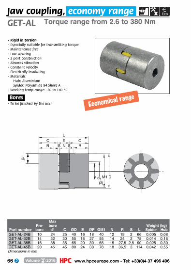
66 www.hpceurope.com - Tel: +33(0)4 37 496 496Volume 2 2016
Jaw coupling, economy rangeTorque range from 2.6 to 380 Nm
MaxPre- bore Weight (kg)
Part number bore d1 C ØD E ØF ØM1 N R S L Spider HubGET-AL-24B 10 24 25 40 16 18 40 12 19 2 66 0,005 0,08GET-AL-32B 14 32 30 55 18 27 55 14 24 2 78 0,014 0,18GET-AL-38B 16 38 35 65 20 30 65 15 27,5 2,5 90 0,025 0,30GET-AL-45B 20 45 45 80 24 38 78 18 36,5 3 114 0,042 0,55
GET-AL
- Rigid in torsion- Especially suitable for transmitting torque- Maintenance free- Low wearing- 3 part construction- Absorbs vibration- Constant velocity- Electrically insulating- M aterials:
Hub: Aluminium Spider: Polyamide 94 Shore A
- Working temp range: -30 to 140 °C
.Bores.- To be finished by the user
Dimensions in mm
Economical range
LE
S N SCR R
C
d1
d1M1 D(3)
F
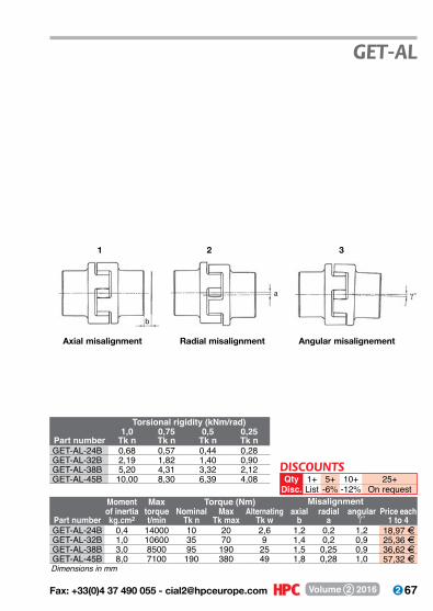
67 Fax: +33(0)4 37 490 055 - [email protected] Volume 2 2016
Moment Max Torque (Nm)of inertia torque Nominal Max Alternating axial radial angular Price each
Part number kg.cm2 t/min Tk n Tk max Tk w b a γ° 1 to 4GET-AL-24B 0,4 14000 10 20 2,6 1,2 0,2 1,2 18,97 FGET-AL-32B 1,0 10600 35 70 9 1,4 0,2 0,9 25,36 FGET-AL-38B 3,0 8500 95 190 25 1,5 0,25 0,9 36,62 FGET-AL-45B 8,0 7100 190 380 49 1,8 0,28 1,0 57,32 F
Torsional rigidity (kNm/rad)1,0 0,75 0,5 0,25
Part number Tk n Tk n Tk n Tk nGET-AL-24B 0,68 0,57 0,44 0,28GET-AL-32B 2,19 1,82 1,40 0,90GET-AL-38B 5,20 4,31 3,32 2,12GET-AL-45B 10,00 8,30 6,39 4,08
GET-AL
Dimensions in mm
5+-6%
25+On request
10+-12%
1+List
QtyDisc.
DISCOUNTS
Misalignment
b
Axial misalignment
1
a
Radial misalignment
2
Angular misalignement
γ°
3
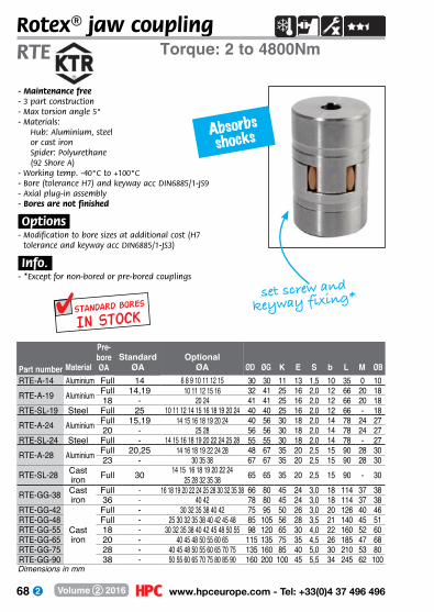
68 www.hpceurope.com - Tel: +33(0)4 37 496 496Volume 2 2016
Absorbs shocks
Rotex® jaw couplingTorque: 2 to 4800NmRTE
- Maintenance free- 3 part construction- Max torsion angle 5°- Materials:
Hub: Aluminium, steel or cast ironSpider: Polyurethane (92 Shore A)
- Working temp. -40°C to +100°C- Bore (tolerance H7) and keyway acc DIN6885/1-JS9- Axial plug-in assembly- Bores are not finished
.Options.- Modification to bore sizes at additional cost (H7
tolerance and keyway acc DIN6885/1-JS3)
.Info..- *Except for non-bored or pre-bored couplings
Part number ØD ØG K E S b L M ØBOptional
ØAMaterialStandard
ØA
Pre-boreØA
set screw and
keyway fixing*
In stockSTANDARD BORES
RTE-A-14 Aluminium Full 14 6 8 9 10 11 12 15 30 30 11 13 1,5 10 35 0 10RTE-A-19 Aluminium Full 14,19 10 11 12 15 16 32 41 25 16 2,0 12 66 20 18
18 - 20 24 41 41 25 16 2,0 12 66 20 18RTE-SL-19 Steel Full 25 10 11 12 14 15 16 18 19 20 24 40 40 25 16 2,0 12 66 - 18RTE-A-24 Aluminium Full 15,19 14 15 16 18 19 20 24 40 56 30 18 2,0 14 78 24 27
20 - 25 28 56 56 30 18 2,0 14 78 24 27RTE-SL-24 Steel Full - 14 15 16 18 19 20 22 24 25 28 55 55 30 18 2,0 14 78 - 27RTE-A-28 Aluminium Full 20,25 14 16 18 19 22 24 28 48 67 35 20 2,5 15 90 28 30
23 - 30 35 38 67 67 35 20 2,5 15 90 28 30RTE-SL-28 Cast
iron Full 30 14 15 16 18 19 20 22 2425 28 32 35 38 65 65 35 20 2,5 15 90 - 30
RTE-GG-38 Cast iron
Full - 16 18 19 20 22 24 25 28 30 32 35 38 66 80 45 24 3,0 18 114 37 3836 - 40 42 78 80 45 24 3,0 18 114 37 38
RTE-GG-42
Cast iron
Full - 30 32 35 38 40 42 75 95 50 26 3,0 20 126 40 46RTE-GG-48 Full - 25 30 32 35 38 40 42 45 48 85 105 56 28 3,5 21 140 45 51RTE-GG-55 18 - 30 32 35 38 40 42 45 48 50 55 98 120 65 30 4,0 22 160 52 60RTE-GG-65 20 - 40 45 48 50 55 60 65 115 135 75 35 4,5 26 185 47 68RTE-GG-75 28 - 40 45 48 50 55 60 65 70 75 135 160 85 40 5,0 30 210 53 80RTE-GG-90 38 - 50 55 60 65 70 75 80 85 90 160 200 100 45 5,5 34 245 62 100Dimensions in mm

69 Fax: +33(0)4 37 490 055 - [email protected] Volume 2 2016
Axial(mm)
Radial(mm)
AngularMax.
speed(rpm) Alternate Nominal max.
Tk j
Tk max.j
RTE
Plain or pre-bored
Standard bore and keyway
Angle of torsionMisalignment at 1500 (rpm)Torque Tk (Nm)
Plug-in design !
L
ØBØD
K KMb S
ØAH7
ØG ØDØAH7
SE
M
Price each 1 to 4
-0,5/1,0 0,17 1,2° 19 000 2,0 7,5 15 6,4° 10° 36,57 F 51,39 F-0,5/1,2 0,20 1,2° 14 000 2,6 10 20 3,2° 5° 29,51 F 62,77 F-0,5/1,2 0,20 1,2° 14 000 2,6 10 20 3,2° 5° 35,23 F --0,5/1,2 0,20 1,2° 14 000 2,6 10 20 3,2° 5° 41,59 F 78,34 F-0,5/1,4 0,22 0,9° 10 600 9,0 35 70 3,2° 5° 38,89 F 79,74 F-0,5/1,4 0,22 0,9° 10 600 9,0 35 70 3,2° 5° 45,12 F --0,5/1,4 0,22 0,9° 10 600 9,0 35 70 3,2° 5° 59,13 F 103,75 F-0,7/1,5 0,25 0,9° 8 500 25,0 95 190 3,2° 5° 53,41 F 104,13 F-0,7/1,5 0,25 0,9° 8 500 25,0 95 190 3,2° 5° 56,05 F --0,7/1,5 0,25 0,9° 8 500 25,0 95 190 3,2° 5° 76,29 F 130,27 F-0,7/1,8 0,28 1,0° 7 100 49,0 190 380 3,2° 5° 141,56 F 203,05 F-0,7/1,8 0,28 1,0° 7 100 49,0 190 380 3,2° 5° - --1,0/2,0 0,32 1,0° 6 000 69,0 265 530 3,2° 5° 214,96 F 295,37 F-1,0/2,1 0,36 1,1° 5 600 81,0 310 620 3,2° 5° 252,87 F 340,55 F-1,0/2,2 0,38 1,1° 4 750 105,0 410 820 3,2° 5° 351,29 F 440,07 F-1,0/2,6 0,42 1,2° 4 250 163,0 625 1 250 3,2° 5° 475,27 F 595,48 F-1,5/3,0 0,48 1,2° 3 550 254,0 975 1 950 3,2° 5° 743,53 F 895,23 F-1,5/3,4 0,50 1,2° 2 800 624,0 2400 4 800 3,2° 5° 1 111,64 F 1 307,00 FDimensions in mm
5+-6%
25+On request
10+-12%
1+List
QtyDisc.
DISCOUNTS
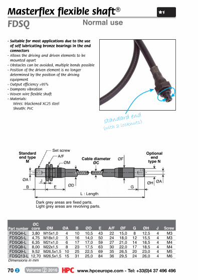
70 www.hpceurope.com - Tel: +33(0)4 37 496 496Volume 2 2016
Part numberØC
core ØM ØA B ØD E A/F ØF G ØH J Screw
Masterflex flexible shaft®
- Suitable for most applications due to the use of self lubricating bronze bearings in the end connectors
- Allows the driving and driven elements to be mounted apart
- Obstacles can be avoided, multiple bends possible- Position of the driven element is no longer
determined by the position of the driving equipment
- Output efficiency >95%- Dampens vibration- Woven wire flexible shaft- Materials:
Wires: blackened XC25 steelSheath: PVC
standard end
(with 2 locknuts)
Normal useFDSQ
Standard end type
MA/F
Set screw
ØM
EL : Length
G
ØAØH
ØFCable diameterØC
ØDØA
BJ
Optional end
type N
Dark grey areas are fixed parts. Light grey areas are revolving parts.
FDSQ4-L 3,80 M15x1,0 4 10 10,5 43 22 15,0 8 12,5 4 M3FDSQ5-L 4,75 M18x1,0 5 16 14,0 50 24 18,0 12 15,5 4 M3FDSQ6-L 6,35 M21x1,0 6 17 17,0 59 27 21,0 14 18,5 4 M4FDSQ8-L 8,00 M22x1,5 8 23 17,5 63 30 22,0 17 18,5 4 M4FDSQ9-L 9,52 M26,5x1,5 10 25 22,5 69 35 26,5 20 23,0 4 M5FDSQ13-L 12,70 M26,5x1,5 15 31 25,0 84 36 29,5 24 26,0 4 M6
Dimensions in mm

71 Fax: +33(0)4 37 490 055 - [email protected] Volume 2 2016
FDSQ
Price for 500 mm
Price for 1000 mm
Price for 1500 mm
Price for2000 mm
Price for2500 mm
Price for 3000 mmanti-clockwise bidirectional clockwise
Part number
.Info..- Replace the “L” in the part number by the
length required and add the desired end (R: standard; S: optional) E.g. FDSQ4A-500RR
- Steel core lubricated with oil- For continuous use, the shaft should be
lubricated every 3 months- Flexible shaft can be removed by unscrewing
the knurled part. Check the sealing before re-use
- Delivered pre-bored
NOTE: For assembly, the end must be drilled and pinned to the connected shaft. The set screw is only there for positioning. It does not allow a torque to be transmitted.
“L” in part number refers to length, see info.
R
Ra
b
Radius = a2 + b2 (mm) 4b
BEND RADIUS
Depending on the sense of shaft rotation, the braiding may be different.
Rotation seen from the motor
motor
A: anti-clockwise rotation
B: bi-directional rotation
C: clockwise rotation
FDSQ4A-L FDSQ4B-L FDSQ4C-LFDSQ5A-L FDSQ5B-L FDSQ5C-LFDSQ6A-L FDSQ6B-L FDSQ6C-LFDSQ8A-L FDSQ8B-L FDSQ8C-LFDSQ9A-L FDSQ9B-L FDSQ9C-LFDSQ13A-L FDSQ13B-L FDSQ13C-L O
n re
ques
t
On
requ
est
On
requ
est
On
requ
est
On
requ
est
On
requ
est
Dimensions in mm

72 www.hpceurope.com - Tel: +33(0)4 37 496 496Volume 2 2016
Part numberØC
core ØM ØA B ØD E A/F ØF G ØH J Screw
Masterflex flexible shaft®Heavier duty applicationsFDS
- Ball bearings in the end connectors allow for a higher speed of rotation and more intensive use.
- Allows the driving and driven elements to be mounted apart
- Obstacles can be avoided, multiple bends possible
- Position of the driven element is no longer determined by the position of the driving equipment
- Output efficiency >95% - Dampens vibration- Woven wire flexible shaft- Materials:
Wires: blackened XC25 steelSheath: PVC
.Info..- FDS19 is only available for bi-directional
rotation
standard end
(with 2 locknuts)
Standart M end type
A/FSet screw
ØM
E
L : Length
G
ØAØH
ØFCable diameterØC
ØD ØAB
J
Optionalend type N
Dark grey areas are fixed parts. Light grey areas are revolving parts.
FDS4-L 3,80 M18 x 1,0 4 11,0 10,5 48,0 24 18 8 10,75 4 M3FDS5-L 4,75 M21 x 1,0 5 14,5 14,0 59,0 27 21 12 14,00 4 M3FDS6-L 6,35 M27 x 1,0 6 19,5 17,0 66,5 35 27 14 18,00 4 M4FDS8-L 8,00 M30 x 1,5 8 24,0 17,5 68,5 36 30 17 20,00 4 M4FDS9-L 9,52 M34 x 1,5 10 25,0 22,5 78,5 41 34 20 24,50 4 M5FDS13-L 12,70 M38 x 1,5 15 26,5 25,0 85,5 46 38 24 28,00 4 M6FDS16-L 16,00 M44 x 1,5 16 30,0 32,0 108,5 55 44 25 31,00 4 M6FDS19-L 19,05 M50 x 1,5 20 31,0 31,0 114,0 60 50 25 36,50 4 M6
Dimensions in mm
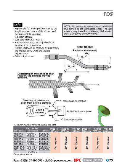
73 Fax: +33(0)4 37 490 055 - [email protected] Volume 2 2016
FDS
Price for 500 mm
Price for 1000 mm
Price for 1500 mm
Price for2000 mm
Price for2500 mm
Price for 3000 mmanti-clockwise bidirectional clockwise
Part number
.Info..- Replace the “L” in the part number by the
length required and add the desired end (M: standard; N: optional) E.g. FDS4-500MM
- Steel core lubricated with oil- For continuous use, the shaft should be
lubricated every 3 months- Flexible shaft can be removed by unscrewing the knurled part. Check the sealing before re-use- Delivered pre-bored
NOTE: For assembly, the end must be drilled and pinned to the connected shaft. The set screw is only there for positioning. It does not allow a torque to be transmitted.
R
Ra
b
Radius = a2 + b2 (mm) 4b
BEND RADIUS
Depending on the sense of shaft rotation, the braiding may be different.
Direction of rotation as seen from driving element
Driving element
A: anti-clockwise rotation
B: bi-directional rotation
C: clockwise rotation
“L” in part number refers to length, see info.
Dimensions in mm
FDS4A-L FDS4B-L FDS4C-LFDS5A-L FDS5B-L FDS5C-LFDS6A-L FDS6B-L FDS6C-LFDS8A-L FDS8B-L FDS8C-LFDS9A-L FDS9B-L FDS9C-LFDS13A-L FDS13B-L FDS13C-LFDS16A-L FDS16B-L FDS16C-L
- FDS19B-L -
On
requ
est
On
requ
est
On
requ
est
On
requ
est
On
requ
est
On
requ
est
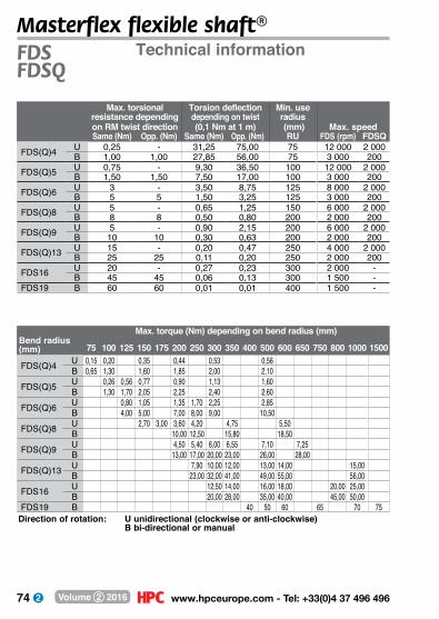
74 www.hpceurope.com - Tel: +33(0)4 37 496 496Volume 2 2016
Masterflex flexible shaft®Technical informationFDS
FDSQ
Direction of rotation: U unidirectional (clockwise or anti-clockwise) B bi-directional or manual
Max. torsional Torsion deflection Min. useresistance depending depending on twist radiuson RM twist direction (0,1 Nm at 1 m) (mm) Max. speedSame (Nm) Opp. (Nm) Same (Nm) Opp. (Nm) RU FDS (rpm) FDSQ
FDS(Q)4 U 0,25 - 31,25 75,00 75 12 000 2 000B 1,00 1,00 27,85 56,00 75 3 000 200
FDS(Q)5 U 0,75 - 9,30 36,50 100 12 000 2 000B 1,50 1,50 7,50 17,00 100 3 000 200
FDS(Q)6 U 3 - 3,50 8,75 125 8 000 2 000B 5 5 1,50 3,25 125 3 000 200
FDS(Q)8 U 5 - 0,65 1,25 150 6 000 2 000B 8 8 0,50 0,80 200 2 000 200
FDS(Q)9 U 5 - 0,90 2,15 200 6 000 2 000B 10 10 0,30 0,63 200 2 000 200
FDS(Q)13 U 15 - 0,20 0,47 250 4 000 2 000B 25 25 0,11 0,20 250 2 000 200
FDS16 U 20 - 0,27 0,23 300 2 000 -B 45 45 0,06 0,13 300 1 500 -
FDS19 B 60 60 0,01 0,01 400 1 500 -
Max. torque (Nm) depending on bend radius (mm)Bend radius (mm) 75 100 125 150 175 200 250 300 350 400 500 600 650 750 800 1000 1500
FDS(Q)4 U 0,15 0,20 0,35 0,44 0,53 0,56B 0,65 1,30 1,60 1,85 2,00 2,10
FDS(Q)5 U 150 0,26 0,56 0,77 0,90 1,13 1,60B 175 1,30 1,70 2,05 2,25 2,40 2,60
FDS(Q)6 U 200 0,80 1,05 1,35 1,70 2,25 2,85B 250 4,00 5,00 7,00 8,00 9,00 10,50
FDS(Q)8 U 300 2,70 3,00 3,60 4,20 4,75 5,50B 350 10,00 12,50 15,80 18,50
FDS(Q)9 U 400 4,50 5,40 6,00 6,55 7,10 7,25B 500 13,00 17,00 20,00 23,00 26,00 28,00
FDS(Q)13 U 600 7,90 10,00 12,00 13,00 14,00 15,00B 650 23,00 32,00 41,00 49,00 55,00 56,00
FDS16 U 750 12,50 14,00 16,00 18,00 20,00 25,00B 20,00 28,00 35,00 40,00 45,00 50,00
FDS19 B 40 50 60 65 70 75
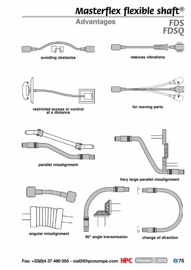
75 Fax: +33(0)4 37 490 055 - [email protected] Volume 2 2016
Masterflex flexible shaft®Advantages FDS
FDSQ
avoiding obstacles reduces vibrations
restricted access or control at a distance
for moving parts
parallel misalignment
Very large parallel misalignment
angular misalignment90° angle transmission change of direction
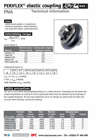
76 www.hpceurope.com - Tel: +33(0)4 37 496 496Volume 2 2016
Technical informationPNAPERIFLEX® elastic coupling
Part number
Nominal torque
TCN (Nm)
Max. torque
TCmaxi. (Nm)
Max. speed(rpm)
Momentof inertia
(kgm2)Axial(Nm)
Radial(Nm)
Angular
Dimensions in mm
Misalignment
Tmn = NkW x 9550
= (Nm) nrpm
Service factor K :
.Uses.- Motor driven pumps or compressors- Electrical generators, textile machines- Iron and steel plants, cement factories.
.Determining torque.
.Safety precautions.The tyre is cut to allow mounting/dismounting in a radial direction. Depending on the speed and torque transmitted, an axial force will be generated which must be absorbed by the bearings in the coupled machines. The tyre may expand by up to 5% during use which must be taken into account when choosing a protective housing.
Temperature factor St:
Tmn x K x St < Tcn coupling
n inst. < nmax coupling
shaft diameter < dmax coupling
PNA2-203R 50 150 5000 0,001 1,0 0,75 2°PNA6-206R 100 300 5000 0,003 1,5 1,00 2°PNA16-210R 200 600 4000 0,013 2,0 1,30 2°PNA40-214R 400 1200 4000 0,035 2,5 1,60 2°PNA63-218R 800 2400 3000 0,105 3,0 2,10 2°
Electric motor Combustion engineService steam turbine hydraulic turbineUniform S1 1,0 1,5Light S2 1,5 2,0medium S3 2,0 2,5Heavy S4 2,5 3,0Very heavy S5 3,0 3,2
St-20°C
1,00°C1,0
+20°C1,0
+40°C1,0
+60°C1,2
+70°C1,4
+80°C1,6

77 Fax: +33(0)4 37 490 055 - [email protected] Volume 2 2016
Part number solid coupling ØA ØB ØC L M
Ødmax.
Ødpre-bore
Part numbersolid coupling N O P
Number of
screws Screw
Locking torque(Nm)
Weight(kg)
Price each 1 to 4 full or boredprebored keyway
*Depending on availability - Dimensions in mm
ØdStandard bores
(H7)
PERIFLEX® elastic couplingTorque: 50 to 2400Nm PNA
C
M
L
Ød ØC ØB ØAN
OP
- Easy installation, machines to be coupled will not require to be moved
- Backlash free- Can transmit shocks up to
3 times the value of nominal torque- Quickly damps vibrations- Maintenance free
.Characteristics.- Large axial misalignment up to 6mm radial up to 5mm angular up to 2°- Keyway in accordance with NF E22-175/P9 (JS9)- Working temp.: -20°C to +80°C - Materials:
Hub: SteelLocking assembly: SteelTyre: Natural rubber with rubber inserts
.Options.- Alternative tyre materials
((2)inserts mounted in X pattern)
PNA2-203R 104 54 40 70 30 28 Full 10, 15, 19, 20, 25, 28PNA6-206R 136 68 55 110 45 38 Full 10, 15, 20, 25, 30, 35, 38PNA16-210R 178 88 70 130 50 48 15 20, 25, 30, 35, 38, 48PNA40-214R (1) 210 116 92 160 65 65 15 20, 25, 30, 35, 40, 45, 50, 55, 60, 65PNA63-218R (1) 263 140 107 190 75 75 25 30, 35, 40, 45, 50, 55, 60, 65, 70, 75
Stock*prebored
PNA2-203R 8 16 66 12 M6 4(2) 1,15 4 309,64 F 524,33 FPNA6-206R 8 18 74 16 M6 6(2) 2,50 4 410,79 F 648,20 FPNA16-210R 19 35 100 16 M8 15(2) 5,40 4 520,21 F 759,67 FPNA40-214R (1) 20 38 99 24 M8 20 9,50 - 757,62 F 1 011,54 FPNA63-218R (1) 24 44 121 16 M12 25 17,50 - 1 034,24 F 1 350,10 F
DISCOUNTSQty 1+ 5+ 10+
Disc. List -3% On request
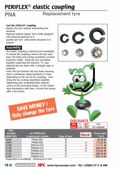
78 www.hpceurope.com - Tel: +33(0)4 37 496 496Volume 2 2016
Replacement tyrePNA
Part number
spare tyrefor PERIFLEX®
coupling part number Type of tyrePrice each
1 to 4
*Depending on availability - Dimensions in mm
- Tyre for PERIFLEX® coupling- Replace the tyre without dismantling the machine
- Material natural rubber Tyre R (NR) equipped with disposed material in R
- Quality tyre X(1) with inserts mounted in X pattern
.Assembly.- The elastic coupling is delivered pre-assembled. To mount the coupling, remove the tyre and place the hubs and locking assemblies on their respective shafts. Bring the two assemblies together respecting the distance “O” and aligning the two hubs with a straight edge or template.
- Place the tyre between the two hubs ensuring there is minimum radial backlash (2-15mm depending on the size of the coupling). Then bring the two locking assemblies together, tightening pairs of diametrically opposite screws to the prescribed torque. As the rubber may decompress with time, re-check the torque after a few hours.
SAVE MONEY !
Only change the tyre
PERIFLEX® elastic coupling
Stock*203R PNA2-203 R - 92,88 F206R PNA6-206 R 4 113,52 F210R PNA16-210 R 4 171,31 F214R PNA40-214 R 4 266,28 F218R PNA63-218 R 4 276,60 F414X PNA40-214 X - 268,36 F418X PNA63-218 X - 295,18 F
DISCOUNTSQty 1+ 5+ 10+
Disc. List -3% On request
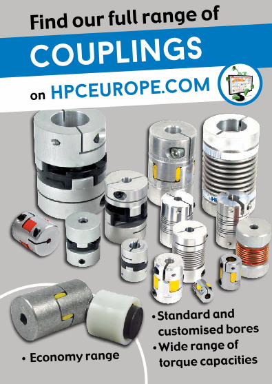
79 Fax: +33(0)4 37 490 055 - [email protected] Volume 2 2016
Find our full range of
Standard and customised bores
Wide range of torque capacities
couplingson hpceurope.com
Economy range

80 www.hpceurope.com - Tel: +33(0)4 37 496 496Volume 2 2016
single universal
joint
p.84
single universal
joint
p.88
p.92p.90
single universal
joint
Shaft clamp with keyway
p.82ECO. range
needle roller universal joint
stainless steel

81 Fax: +33(0)4 37 490 055 - [email protected] Volume 2 2016
universal joints and rigid couplings
p.82 - 105
telescopic universal joint
p.94
universal joint cover
p.96 p.98
varitork® slip friction clutch
friction clutch slip friction clutch
p.104p.102
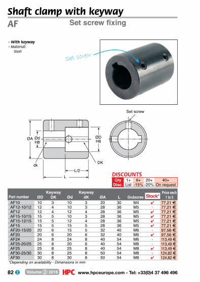
82 www.hpceurope.com - Tel: +33(0)4 37 496 496Volume 2 2016
*Depending on availability - Dimensions in mm
Shaft clamp with keywaySet screw fixing
- With keyway- M aterial:
Steel
AF
ØA ØdH8
dk
LL/2
ØDH8
Set screw
DK
Part number ØDKeyway
DK ØdKeyway
dK ØA L GrubscrewPrice each
1 to 5Stock*AF10 10 3 10 3 20 30 M4 4 77,21 FAF12-10/12 12 4 10 3 28 36 M5 - 77,21 FAF12 12 4 12 4 28 36 M5 4 77,21 FAF15-10/15 15 5 10 3 28 36 M5 4 77,21 FAF15-12/15 15 5 12 4 28 36 M5 4 77,21 FAF15 15 5 15 5 28 36 M5 4 77,21 FAF20-15/20 20 6 15 5 32 40 M6 - 97,56 FAF20 20 6 20 6 32 40 M6 4 97,56 FAF24 24 8 24 8 40 54 M6 - 113,49 FAF25-20/25 25 8 20 6 40 54 M8 - 113,49 FAF25 25 8 25 8 40 54 M8 4 113,49 FAF30-25/30 30 8 25 8 50 54 M8 - 124,82 FAF30 30 8 30 8 50 54 M8 4 124,82 F
DISCOUNTSQty 1+ 6+ 20+ 40+
Disc. List -15% -20% On request
Set screw
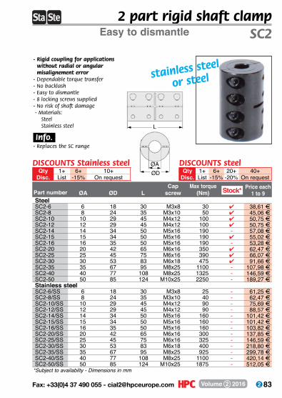
83 Fax: +33(0)4 37 490 055 - [email protected] Volume 2 2016
*Subject to availabilty - Dimensions in mm
2 part rigid shaft clampEasy to dismantle
- Rigid coupling for applications without radial or angular misalignement error
- Dependable torque transfer- No backlash- Easy to dismantle- 8 locking screws supplied- No risk of shaft damage - Materials:
SteelStainless steel
.Info..- Replaces the SC range
SC2
stainless steel
or steel
SteelSC2-6 6 18 30 M3x8 30 4 38,61 FSC2-8 8 24 35 M3x10 50 4 45,06 FSC2-10 10 29 45 M4x12 100 4 50,75 FSC2-12 12 29 45 M4x12 100 4 50,75 FSC2-14 14 34 50 M5x16 190 - 57,08 FSC2-15 15 34 50 M5x16 190 4 55,02 FSC2-16 16 35 50 M5x16 190 - 53,28 FSC2-20 20 42 65 M6x16 350 4 62,47 FSC2-25 25 45 75 M6x16 390 4 66,07 FSC2-30 30 53 83 M6x18 475 4 91,66 FSC2-35 35 67 95 M8x25 1100 - 107,98 FSC2-40 40 77 108 M8x25 1325 - 146,59 FSC2-50 50 85 124 M10x25 2250 - 189,27 FStainless steelSC2-6/SS 6 18 30 M3x8 25 - 61,25 FSC2-8/SS 8 24 35 M3x10 40 - 62,47 FSC2-10/SS 10 29 45 M4x12 90 - 75,69 FSC2-12/SS 12 29 45 M4x12 90 - 88,57 FSC2-14/SS 14 34 50 M5x16 160 - 101,42 FSC2-15/SS 15 34 50 M5x16 160 - 101,42 FSC2-16/SS 16 35 50 M5x16 160 - 103,82 FSC2-20/SS 20 42 65 M6x16 300 - 137,85 FSC2-25/SS 25 45 75 M6x16 325 - 146,59 FSC2-30/SS 30 53 83 M6x18 400 - 218,80 FSC2-35/SS 35 67 95 M8x25 925 - 299,78 FSC2-40/SS 40 77 108 M8x25 1100 - 420,14 FSC2-50/SS 50 85 124 M10x25 1875 - 512,05 F
ØA ØD LCap
screw Max torque
(Nm)Part numberPrice each
1 to 9Stock*
ØAØD
DISCOUNTS Stainless steelQty 1+ 6+ 10+
Disc. List -15% On request
DISCOUNTS steelQty 1+ 6+ 20+ 40+
Disc. List -15% -20% On request
L

84 www.hpceurope.com - Tel: +33(0)4 37 496 496Volume 2 2016
*Depending on availability - Dimensions in mm
Single universal jointFor hand operationUA
- Conforms to DIN 7551-E (size 13) or DIN 808-E (sizes 16 to 32)
- Light duty applications- Manual operation or infrequent use- Misalignment angle 35°- M aterial:
Untreated steel 9SMnPb28
.Uses.- Stress valve- Valve drive- Blinds
MMC
ØD
L
ØAH8
Economy range
DISCOUNTSQty 1+ 5+ 10+ 25+ 50+
Disc. List -6% -12% -18% On request
For manual application
Bore Max. speed Backlash Price each Part number ØD ØA C M L (rpm) Nm (min) 1 to 4U813A 13 8,0 11,0 21,0 42 200 - - 4 11,39 FU816A 16 10,0 15,0 26,0 52 200 0,2 45’ 4 15,65 FU820A 20 12,0 18,0 31,0 62 200 0,4 40’ 4 17,95 FU825A 25 16,0 22,0 37,0 74 200 1,0 32’ 4 24,07 FU832A 32 20,0 25,0 43,0 86 200 1,7 28’ 4 42,27 F
Stock*
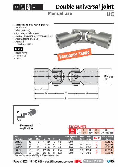
85 Fax: +33(0)4 37 490 055 - [email protected] Volume 2 2016
*Depending on availability - Dimensions in mm
Double universal jointManual use UC
- Conforms to DIN 7551-E (size 13) or DIN 808-E (sizes 16 to 40)
- Light duty applications- Manual operation or infrequent use- Misalignment angle 70°- M aterial:
Steel 9SMnPb28
.Uses.- Stress valve- Valve drive- Blinds
MMC
ØD
L
T
ØAH8
Economy range
DISCOUNTSQty 1+ 5+ 10+ 25+ 50+
Disc. List -6% -12% -18% On request
For manual application
Part Bore Max speed Backlash Price eachnumber ØD ØA C M T L (rpm) Nm (min) 1 to 4U813C 13 08 11 21 18 60 200 - - 4 26,40 FU816C 16 10 15 26 22 74 200 0,2 1°30’ 4 25,32 FU820C 20 12 18 31 26 88 200 0,4 1°20’ 4 30,73 FU825C 25 16 22 37 30 104 200 1,0 1°04’ 4 62,03 FU832C 32 20 25 43 37 123 200 1,7 0°56’ 4 63,36 F
Stock*

86 www.hpceurope.com - Tel: +33(0)4 37 496 496Volume 2 2016
Part number For joint d L DPrice each
1 to 4
*Depending on availability - Dimensions in mm
Rubber cover for universal jointsFor use with U816 - U832U8R
- Increases length of life of universal joints
- M aterial: Synthetic rubber
- PVC Shore A 1,18g/cm2
- Electrical resistance 8 x 10⁹ Ωcm- Working temperature:
Continuous -27°C to +70°C Occasional -32°C to +120°C
.Advantages.- Oil-resistant- Good elasticity
For single joint For double joint
d
L
Dd
L
D
Stock*For single jointU8R-02 U816A 16 32 35 - 11,64 FU8R-04 U820A 20 40 36 4 16,99 FU8R-1 U825A 24 45 44 4 12,73 FU8R-3 U832A 32 55 62 4 15,48 FFor double jointU8R-19 U816C 16 55 35 - 20,52 FU8R-20 U820C 20 65 36 4 22,46 FU8R-21 U825C 24 70 44 4 26,01 FU8R-23 U832C 32 90 62 - 31,10 F
DISCOUNTSQty 1+ 5+ 10+ 25+ 50+
Disc. List -6% -12% -18% On request

87 Fax: +33(0)4 37 490 055 - [email protected] Volume 2 2016
Straight to your door!
in 24/48H*fast delivery
*Onl
y fo
r ite
ms
in s
tock
T+Cs apply , call us for
details on :
+33 (0)4 37 496 496
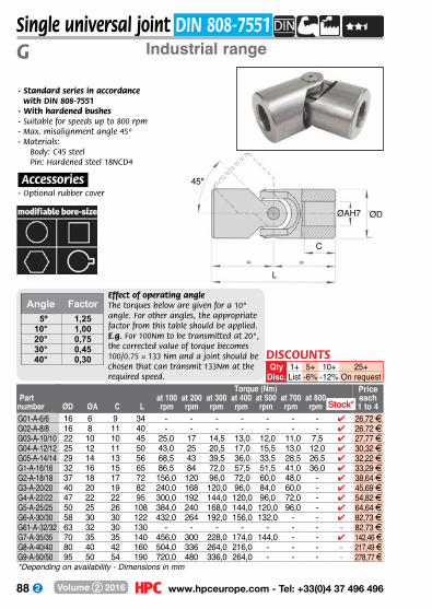
88 www.hpceurope.com - Tel: +33(0)4 37 496 496Volume 2 2016
Price each1 to 4ØD
ØA C Lat 100rpm
at 200rpm
at 300rpm
at 400rpm
at 500rpm
at 700rpm
at 800rpm
Part number
Torque (Nm)
*Depending on availability - Dimensions in mm
Single universal joint DIN 808-7551Industrial rangeG
45º
ØAH7 ØD
C
L
- Standard series in accordance with DIN 808-7551 - With hardened bushes- Suitable for speeds up to 800 rpm- Max. misalignment angle 45º- Materials:
Body: C45 steelPin: Hardened steel 18NCD4
.Accessories.- Optional rubber cover
Effect of operating angleThe torques below are given for a 10° angle. For other angles, the appropriate factor from this table should be applied. E.g. For 100Nm to be transmitted at 20°, the corrected value of torque becomes 100/0.75 = 133 Nm and a joint should be chosen that can transmit 133Nm at the required speed.
Angle Factor 5º10°20°30°40°
1,251,000,750,450,30
G01-A-6/6 16 6 9 34 - - - - - - - 4 26,72 FG02-A-8/8 16 8 11 40 - - - - - - - 4 26,72 FG03-A-10/10 22 10 10 45 25,0 17 14,5 13,0 12,0 11,0 7,5 4 27,77 FG04-A-12/12 25 12 11 50 43,0 25 20,5 17,0 15,5 13,0 12,0 4 30,32 FG05-A-14/14 29 14 13 56 68,5 43 39,5 36,0 33,5 28,5 26,5 4 32,22 FG1-A-16/16 32 16 15 65 86,5 84 72,0 57,5 51,5 41,0 36,0 4 33,29 FG2-A-18/18 37 18 17 72 156,0 120 96,0 72,0 60,0 48,0 - 4 38,64 FG3-A-20/20 40 20 19 82 240,0 168 120,0 96,0 84,0 60,0 - 4 45,69 FG4-A-22/22 47 22 22 95 300,0 192 144,0 120,0 96,0 72,0 - 4 54,82 FG5-A-25/25 50 25 26 108 384,0 240 168,0 144,0 120,0 96,0 - 4 64,64 FG6-A-30/30 58 30 30 122 432,0 264 192,0 156,0 132,0 - - 4 82,73 FG61-A-32/32 63 32 30 130 - - - - - - - - 82,73 FG7-A-35/35 70 35 35 140 456,0 300 228,0 174,0 144,0 - - 4 142,46 FG8-A-40/40 80 40 42 160 504,0 336 264,0 216,0 - - - - 217,49 FG9-A-50/50 95 50 54 190 720,0 480 336,0 264,0 - - - - 278,77 F
Stock*
DISCOUNTSQty 1+ 5+ 10+ 25+
Disc. List -6% -12% On request
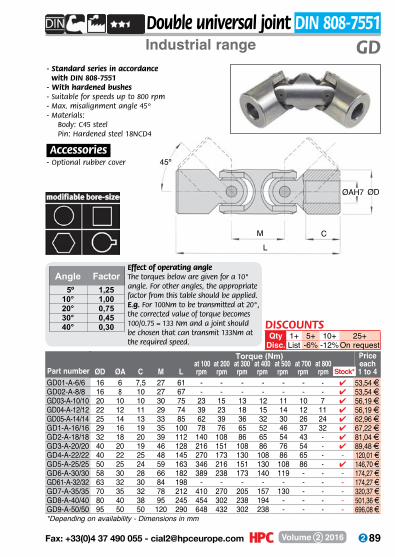
89 Fax: +33(0)4 37 490 055 - [email protected] Volume 2 2016
*Depending on availability - Dimensions in mm
Double universal joint DIN 808-7551Industrial range GD
- Standard series in accordance with DIN 808-7551 - With hardened bushes- Suitable for speeds up to 800 rpm- Max. misalignment angle 45º- Materials:
Body: C45 steelPin: Hardened steel 18NCD4
.Accessories.- Optional rubber cover
Effect of operating angleThe torques below are given for a 10° angle. For other angles, the appropriate factor from this table should be applied. E.g. For 100Nm to be transmitted at 20°, the corrected value of torque becomes 100/0.75 = 133 Nm and a joint should be chosen that can transmit 133Nm at the required speed.
Angle Factor 5º10°20°30°40°
1,251,000,750,450,30
ØAH7 ØD
CL
M
45º
Price each1 to 4
ØD
ØA C M L at 100
rpmat 200rpm
at 300rpm
at 400rpm
at 500rpm
at 700rpm
at 800rpmPart number
Torque (Nm)
GD01-A-6/6 16 6 7,5 27 61 - - - - - - - 4 53,54 FGD02-A-8/8 16 8 10 27 67 - - - - - - - 4 53,54 FGD03-A-10/10 20 10 10 30 75 23 15 13 12 11 10 7 4 56,19 FGD04-A-12/12 22 12 11 29 74 39 23 18 15 14 12 11 4 56,19 FGD05-A-14/14 25 14 13 33 85 62 39 36 32 30 26 24 4 62,96 FGD1-A-16/16 29 16 19 35 100 78 76 65 52 46 37 32 4 67,22 FGD2-A-18/18 32 18 20 39 112 140 108 86 65 54 43 - 4 81,04 FGD3-A-20/20 40 20 19 46 128 216 151 108 86 76 54 - 4 89,48 FGD4-A-22/22 40 22 25 48 145 270 173 130 108 86 65 - - 120,01 FGD5-A-25/25 50 25 24 59 163 346 216 151 130 108 86 - 4 146,70 FGD6-A-30/30 58 30 28 66 182 389 238 173 140 119 - - - 174,27 FGD61-A-32/32 63 32 30 84 198 - - - - - - - - 174,27 FGD7-A-35/35 70 35 32 78 212 410 270 205 157 130 - - - 320,37 FGD8-A-40/40 80 40 38 95 245 454 302 238 194 - - - - 501,36 FGD9-A-50/50 95 50 50 120 290 648 432 302 238 - - - - 696,08 F
Stock*
DISCOUNTSQty 1+ 5+ 10+ 25+
Disc. List -6% -12%On request
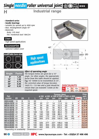
90 www.hpceurope.com - Tel: +33(0)4 37 496 496Volume 2 2016
ØD
ØA C Lat 250rpm
at 500rpm
at 1000rpm
at 2000rpm
at 3000rpm
at 4000rpm
Price each1 to 4
45º
ØAH7 ØD
C
L
Part number
Torque (Nm)
*Depending on availability - Dimensions in mm
Single needle roller universal jointIndustrial rangeH
- Standard series - Needle bearings- Suitable for speeds up to 4000 rpm- Max. misalignment angle 45º- Materials:
Body: C45 steelPin: Hardened steel 18NCD4
.Uses.- High speed applications
.Accessories.- Optional rubber cover
Effect of operating angleThe torques below are given for a 10° angle. For other angles, the appropriate factor from this table should be applied. E.g. For 100Nm to be transmitted at 20°, the corrected value of torque becomes 100/0.75 = 133 Nm and a joint should be chosen that can transmit 133Nm at the required speed.
Angle Factor 5º10°20°30°40°
1,251,000,750,450,30
1+List
5+-6%
10+-12%
25+On request
Qty.Disc.
DISCOUNTS
H02-A-8/8 16 8 15 52 - - - 5,8 - - 4 50,77 FH03-A-10/10 20 10 18 62 22 17 14 11,0 10 9 4 45,69 FH05-A-14/14 25 14 20 74 34 29 24 22,0 20 18 4 45,69 FH1-A-16/16 32 16 24 86 65 55 45 40,0 37 32 4 50,77 FH2-A-18/18 37 18 17 72 75 61 50 45,0 40 36 4 53,43 FH3-A-20/20 40 20 30 108 140 120 100 80,0 70 65 4 60,94 FH4-A-22/22 47 22 22 95 162 132 108 88,0 77 71 - 70,91 FH5-A-25/25 50 25 38 132 200 170 130 110,0 90 85 4 78,69 FH6-A-30/30 63 30 45 166 300 270 230 190,0 160 140 - 101,34 FH61-A-32/32 63 32 45 166 - - - - - - - 101,34 FH7-A-35/35 70 35 35 140 326 277 237 198,0 168 - - 183,39 FH8-A-40/40 80 40 50 180 365 303 255 205,0 186 - - 252,50 FH9-A-50/50 95 50 54 190 402 335 275 225,0 198 - - 353,84 F
Stock*
High speed applications
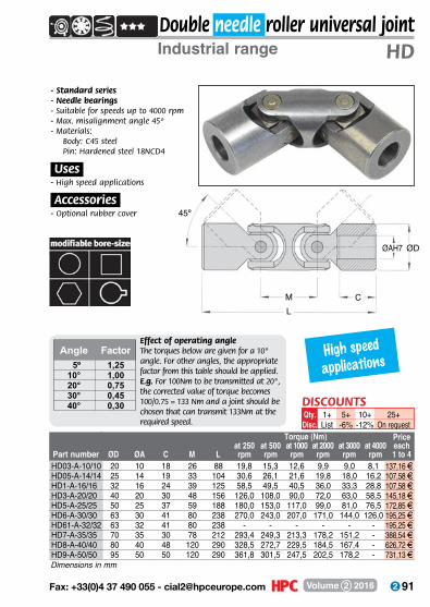
91 Fax: +33(0)4 37 490 055 - [email protected] Volume 2 2016
ØD ØA C M Lat 250rpm
at 500rpm
at 1000rpm
at 2000rpm
at 3000rpm
at 4000rpm
Price each1 to 4Part number
Torque (Nm)
Dimensions in mm
Double needle roller universal jointIndustrial range HD
- Standard series - Needle bearings- Suitable for speeds up to 4000 rpm- Max. misalignment angle 45º- Materials:
Body: C45 steelPin: Hardened steel 18NCD4
.Uses.- High speed applications
.Accessories.- Optional rubber cover
Effect of operating angleThe torques below are given for a 10° angle. For other angles, the appropriate factor from this table should be applied. E.g. For 100Nm to be transmitted at 20°, the corrected value of torque becomes 100/0.75 = 133 Nm and a joint should be chosen that can transmit 133Nm at the required speed.
Angle Factor 5º10°20°30°40°
1,251,000,750,450,30
1+List
5+-6%
10+-12%
25+On request
Qty.Disc.
DISCOUNTS
45º
ØAH7 ØD
CLM
HD03-A-10/10 20 10 18 26 88 19,8 15,3 12,6 9,9 9,0 8,1 137,16 FHD05-A-14/14 25 14 19 33 104 30,6 26,1 21,6 19,8 18,0 16,2 107,58 FHD1-A-16/16 32 16 24 39 125 58,5 49,5 40,5 36,0 33,3 28,8 107,58 FHD3-A-20/20 40 20 30 48 156 126,0 108,0 90,0 72,0 63,0 58,5 145,18 FHD5-A-25/25 50 25 37 59 188 180,0 153,0 117,0 99,0 81,0 76,5 172,85 FHD6-A-30/30 63 30 41 80 238 270,0 243,0 207,0 171,0 144,0 126,0 195,25 FHD61-A-32/32 63 32 41 80 238 - - - - - - 195,25 FHD7-A-35/35 70 35 30 78 212 293,4 249,3 213,3 178,2 151,2 - 388,54 FHD8-A-40/40 80 40 48 120 290 328,5 272,7 229,5 184,5 167,4 - 626,72 FHD9-A-50/50 95 50 50 120 290 361,8 301,5 247,5 202,5 178,2 - 731,13 F
High speed applications

92 www.hpceurope.com - Tel: +33(0)4 37 496 496Volume 2 2016
ØD
ØA C Lat 100rpm
at 200rpm
at 300rpm
at 400rpm
at 500rpm
at 700rpm
at 800rpm
Price each1 to 4Part number
Torque (Nm)
*Depending on availability - Dimensions in mm
Single stainless steel universal jointIndustrial rangeJCSss
- Stainless steel range- Plain pins and bushes- Suitable for speeds up to 800 rpm- Max. angle of misalignment 45º- M aterial:
Stainless steel X5CrNi1810
.Uses.- Food and pharmaceutical industries
.Accessories.- Optional rubber cover 45º
ØAH7 ØD
C
L
Effect of operating angleThe torques below are given for a 10° angle. For other angles, the appropriate factor from this table should be applied. E.g. For 10Nm to be transmitted at 20°, the corrected value of torque becomes 10/0.75 = 13.3 Nm and a joint should be chosen that can transmit 13.3Nm at the required speed.
Angle Factor
5º10°20°30°40°
1,251,000,750,450,30
stainless steel
1+List
5+-6%
10+-12%
25+-18%
50+On request
Qty.Disc.
DISCOUNTS
Stock*JCS00/SS 10 5 15 44 3,6 3,3 2,8 2,5 2,3 - - 4 42,55 FJCS01/SS 13 6 18 50 4,4 4,4 3,5 3,2 2,9 - - 4 38,98 FJCS02/SS 16 8 19 58 8,6 6,0 5,3 4,6 4,0 3,4 3,1 4 38,98 FJCS03/SS 22 10 25 76 12,3 8,3 7,0 6,4 5,8 5,2 3,5 4 38,98 FJCS04/SS 25 12 29 86 21,0 12,6 10,0 8,0 7,3 6,3 5,8 4 44,29 FJCS05/SS 29 14 30 90 33,0 21,3 19,3 17,6 16,3 13,3 12,6 4 46,08 FJCS06/SS 32 16 30 95 45,0 42,0 35,3 28,0 25,3 20,0 17,3 4 47,85 FJCS07/SS 37 18 35 108 76,0 60,0 46,6 35,3 29,3 23,3 - - 56,73 FJCS08/SS 40 20 32 108 117,0 84,0 58,6 46,6 41,3 29,3 - 4 62,05 FJCS09/SS 47 22 38 127 146,0 96,0 70,0 58,6 46,6 35,3 - - 78,02 FJCS10/SS 50 25 44 140 192,0 120,0 84,0 72,0 60,0 48,0 - 4 92,25 FJCS11/SS 58 30 58 178 216,0 132,0 96,0 78,0 66,0 - - 4 120,64 F

93 Fax: +33(0)4 37 490 055 - [email protected] Volume 2 2016
Stainless steel double universal joint
Price each1 to 4
*Depending on availability - Dimensions in mm
ØD
ØA C M Lat 100rpm
at 200rpm
at 300rpm
at 400rpm
at 500rpm
at 700rpm
at 800rpmPart number
Torque (Nm)
Industrial range JCDss
- Stainless steel range- Plain pins and bushes- Suitable for speeds up to 800 rpm- Max. angle of misalignment 90º- M aterial:
Stainless steel X5CrNi1810
.Uses.- Food and pharmaceutical
industries
.Accessories.- Optional rubber cover
Effect of operating angleThe torques below are given for a 10° angle. For other angles, the appropriate factor from this table should be applied. E.g. For 10Nm to be transmitted at 20°, the corrected value of torque becomes 10/0.75 = 13.3 Nm and a joint should be chosen that can transmit 13.3Nm at the required speed.
Angle Factor
5º10°20°30°40°
1,251,000,750,450,30
1+List
5+-6%
10+-12%
25+-18%
50+On request
Qty.Disc.
DISCOUNTS
stainless steel
ØAH7 ØD
CLM
45º
Stock*JCD04/SS 22 12 25 29 105 18,9 11,34 9,00 7,20 6,57 5,67 5,22 4 88,68 FJCD05/SS 25 14 29 33 119 29,7 19,17 17,37 15,84 14,67 11,97 11,34 - 92,25 FJCD06/SS 29 16 30 35 125 40,5 37,80 31,77 25,20 22,77 18,00 15,57 4 95,76 FJCD07/SS 32 18 30 39 134 68,4 54,00 41,94 31,77 26,37 20,97 - - 113,51 FJCD08/SS 40 20 32 46 154 105,3 75,60 52,74 41,94 37,17 26,37 - 4 124,15 FJCD09/SS 40 22 38 46 173 131,4 86,40 63,00 52,74 41,94 31,77 - - 156,11 FJCD10/SS 50 25 44 59 199 172,8 108,00 75,60 64,80 54,00 43,20 - - 184,53 FJCD11/SS 58 30 58 66 244 194,4 118,80 86,40 70,20 59,40 - - - 241,30 F

94 www.hpceurope.com - Tel: +33(0)4 37 496 496Volume 2 2016
Lmin/max
ØA H7 ØD L1 L2 B Stroke E FPart number
*Depending on availability - Dimensions in mm
Telescopic universal jointIndustrial range
ØAH
7
ØAH
7Ø
D
Length L
L2 L2L1 L1Stroke B
- Standard series - With hardened bushes- Suitable for speeds up to 800 rpm- Max. angle of misalignment 45º- Materials:
Body: C45 steelPin: Hardened steel 18NCD4
- For transmissible torques, refer to GD range
.Accessories.- Optional rubber cover
.Options.- Stainless steel version on request
CT
Price each1 to 4Stock*
CT10-130/150 130/150 10 22 45 10 40 20 11 14 4 154,64 FCT10-140/170 140/170 10 22 45 10 40 30 11 14 4 154,64 FCT10-160/200 160/200 10 22 45 10 40 40 11 14 4 154,64 FCT10-170/230 170/230 10 22 45 10 40 60 11 14 - 154,64 FCT10-180/240 180/240 10 22 45 10 40 60 11 14 - 154,64 FCT10-230/330 230/330 10 22 45 10 40 100 11 14 4 154,64 FCT12-140/170 140/170 12 25 50 11 45 30 13 16 - 163,37 FCT12-160/200 160/200 12 25 50 11 45 40 13 16 - 163,37 FCT12-180/225 180/225 12 25 50 11 45 45 13 16 - 163,37 FCT12-200/270 200/270 12 25 50 11 45 70 13 16 4 163,37 FCT12-220/300 220/300 12 25 50 11 45 80 13 16 4 163,37 FCT12-250/355 250/355 12 25 50 11 45 105 13 16 - 163,37 FCT12-280/420 280/420 12 25 50 11 45 140 13 16 4 163,37 FCT12-300/450 300/450 12 25 50 11 45 150 13 16 4 163,37 FCT14-160/190 160/190 14 29 56 13 45 30 13 16 - 168,60 FCT14-170/200 170/200 14 29 56 13 45 30 13 16 - 168,60 FCT14-180/220 180/220 14 29 56 13 45 40 13 16 - 168,60 FCT14-210/280 210/280 14 29 56 13 45 70 13 16 - 168,60 FCT14-220/300 220/300 14 29 56 13 45 80 13 16 - 168,60 FCT14-250/350 250/350 14 29 56 13 45 100 13 16 4 168,60 FCT14-280/420 280/420 14 29 56 13 45 140 13 16 - 168,60 FCT14-300/450 300/450 14 29 56 13 45 150 13 16 - 168,60 FCT14-350/550 350/550 14 29 56 13 45 200 13 16 - 173,43 FCT14-400/650 400/650 14 29 56 13 45 250 13 16 4 173,43 F
DISCOUNTSQty 1+ 5+ 10+ 25+
Disc. List -6% -12% On request

95 Fax: +33(0)4 37 490 055 - [email protected] Volume 2 2016
CT
*Depending on availability - Dimensions in mm
Lmin/max
ØA H7 ØD L1 L2 B Stroke E FPart number
Price each1 to 4Stock*
CT16-180/210 180/210 16 32 65 15 45 30 16 20 - 173,70 FCT16-190/220 190/220 16 32 65 15 45 30 16 20 - 173,70 FCT16-210/250 210/250 16 32 65 15 45 40 16 20 - 173,70 FCT16-240/320 240/320 16 32 65 15 45 80 16 20 - 173,70 FCT16-250/350 250/350 16 32 65 15 45 100 16 20 4 173,70 FCT16-275/390 275/390 16 32 65 15 45 115 16 20 - 173,70 FCT16-300/430 300/430 16 32 65 15 45 130 16 20 - 173,70 FCT16-380/590 380/590 16 32 65 15 45 210 16 20 - 178,56 FCT16-400/630 400/630 16 32 65 15 45 230 16 20 4 183,39 FCT18-195/225 195/225 18 37 72 17 45 30 16 20 - 195,15 FCT18-230/280 230/280 18 37 72 17 45 50 16 20 - 195,15 FCT18-250/320 250/320 18 37 72 17 45 70 16 20 - 195,15 FCT18-270/370 270/370 18 37 72 17 45 100 16 20 - 195,15 FCT18-290/400 290/400 18 37 72 17 45 110 16 20 - 195,15 FCT18-300/415 300/415 18 37 72 17 45 115 16 20 - 195,15 FCT18-400/620 400/620 18 37 72 17 45 220 16 20 - 204,84 FCT18-500/820 500/820 18 37 72 17 45 320 16 20 - 214,51 FCT20-220/250 220/250 20 40 82 19 45 30 18 22 4 199,40 FCT20-250/300 250/300 20 40 82 19 45 50 18 22 - 199,40 FCT20-270/340 270/340 20 40 82 19 45 70 18 22 - 199,40 FCT20-290/380 290/380 20 40 82 19 45 90 18 22 - 199,40 FCT20-320/440 320/440 20 40 82 19 45 120 18 22 - 199,40 FCT20-380/560 380/560 20 40 82 19 45 180 18 22 4 204,27 FCT20-420/640 420/640 20 40 82 19 45 220 18 22 - 209,10 FCT20-500/800 500/800 20 40 82 19 45 300 18 22 4 213,95 FCT22-250/280 250/280 22 47 95 22 48 30 21 25 - 253,10 FCT22-270/320 270/320 22 47 95 22 48 50 21 25 - 253,10 FCT22-290/350 290/350 22 47 95 22 48 60 21 25 - 253,10 FCT22-330/430 330/430 22 47 95 22 48 100 21 25 - 253,10 FCT22-350/470 350/470 22 47 95 22 48 120 21 25 - 253,10 FCT22-470/710 470/710 22 47 95 22 48 240 21 25 - 267,61 FCT25-270/320 270/320 25 50 108 26 48 50 23 28 - 285,95 FCT25-295/350 295/350 25 50 108 26 48 55 23 28 - 285,95 FCT25-310/375 310/375 25 50 108 26 48 65 23 28 - 285,95 FCT25-350/450 350/450 25 50 108 26 48 100 23 28 - 285,95 FCT25-380/500 380/500 25 50 108 26 48 120 23 28 - 285,95 FCT25-420/590 420/590 25 50 108 26 48 170 23 28 - 285,95 FCT25-460/660 460/660 25 50 108 26 48 200 23 28 - 285,95 FCT25-500/745 500/745 25 50 108 26 48 245 23 28 4 285,95 FCT30-320/390 320/390 30 58 122 30 50 70 26 32 - 389,14 FCT30-350/420 350/420 30 58 122 30 50 70 26 32 - 389,14 FCT30-370/455 370/455 30 58 122 30 50 85 26 32 - 389,14 FCT30-400/510 400/510 30 58 122 30 50 110 26 32 - 389,14 FCT30-450/620 450/620 30 58 122 30 50 170 26 32 - 389,14 FCT30-500/720 500/720 30 58 122 30 50 220 26 32 - 389,14 FCT30-540/795 540/795 30 58 122 30 50 255 26 32 - 389,14 F
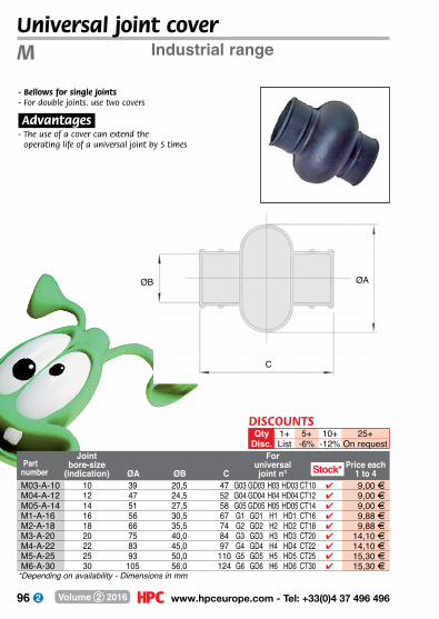
96 www.hpceurope.com - Tel: +33(0)4 37 496 496Volume 2 2016
Joint bore-size
(indication) ØA ØB C
For universal joint n°
Price each1 to 4
*Depending on availability - Dimensions in mm
Part number
Universal joint coverIndustrial rangeM
ØAØB
C
- Bellows for single joints- For double joints. use two covers
.Advantages.- The use of a cover can extend the
operating life of a universal joint by 5 times
M03-A-10 10 39 20,5 47 G03 GD03 H03 HD03 CT10 4 9,00 FM04-A-12 12 47 24,5 52 G04 GD04 H04 HD04 CT12 4 9,00 FM05-A-14 14 51 27,5 58 G05 GD05 H05 HD05 CT14 4 9,00 FM1-A-16 16 56 30,5 67 G1 GD1 H1 HD1 CT16 4 9,88 FM2-A-18 18 66 35,5 74 G2 GD2 H2 HD2 CT18 4 9,88 FM3-A-20 20 75 40,0 84 G3 GD3 H3 HD3 CT20 4 14,10 FM4-A-22 22 83 45,0 97 G4 GD4 H4 HD4 CT22 4 14,10 FM5-A-25 25 93 50,0 110 G5 GD5 H5 HD5 CT25 4 15,30 FM6-A-30 30 105 56,0 124 G6 GD6 H6 HD6 CT30 4 15,30 F
Stock*
DISCOUNTSQty 1+ 5+ 10+ 25+
Disc. List -6% -12% On request

97 Fax: +33(0)4 37 490 055 - [email protected] Volume 2 2016
Use and maintenance of universal jointsUse and maintenance of universal joints
The yokes should be positioned as shown in the diagram in order to obtain an uniform movement.
Several rules should be followed for a universal joint to work correctly:• It is rare for a single joint to be used alone. They are normally only used in manually operated systems.• Assembly of two single joints (a double joint) allows speed irregularities of a single joint to be corrected by another joint exhibiting the same irregularities in the opposite direction. The transmission is said to be homocinetic.
Maintenance of universal joints is limited to regular lubrification at least once a day. In a dusty environment, using grease-filled joint covers is recommended.
Correct assemblyYokes well-positioned
Incorrect assemblyYokes badly-positioned
2 single joints
for constant velocity movement, the two angles should be equal and in the same plane
double joint
correct: a angles equal Entry and exit shafts
should be parallel
incorrect: a and β angles unequal
a
a
b
a
a
A
A1
A
A1
b
correct: A parallel to A1
incorrect: A not parallel to A1
correct: a symetrical to a
incorrect: a not symetrical to β
a
a
Shafts should be guided by bearings as close to joint as possible to reduce radial loads.
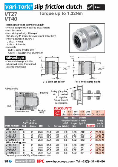
98 www.hpceurope.com - Tel: +33(0)4 37 496 496Volume 2 2016
Vari-Tork® slip friction clutchTorque up to 1.32NmVT27
VT40
VT4 With clamp fixing
Ø22-0,03-0,05
5
ØA
ØDL
Part number
Price each1 to 4
ØAStd.
N° of friction discs ØD L Screw
Heat dissipation
at 20°C(Watts)
Max. frictional
torque (Nm)
Moment of inertia (kgm2x 10-8)
+0,03-0,00
*Depending on availability - Dimensions in mm
BearingAdjuster ring
Hub
Friction discWaved washers
- Basic clutch to be insert into a hub- Protects equipment in case of excess torque- Max. backlash 2°- Max. sliding velocity: 1000 rpm- The housing t° should be maintained below 80°C- Power dissipation at 20°C :
2 discs : 7 watts 6 discs : 8.6 watts
- Materials:Hubs + discs: treated steelCasing + adjuster ring: aluminium
.Advantages.- Clutches interrupt rotation
when load being transmitted exceeds preset limit.
Ø22-0,03-0,05
5
ØA
ØD L
Pulley (Or gear, etc...) bonded
to register. Press fits not permissible.
Stock*With set screwVT2712-6 6 2 25,8 26,4 M3 7,0 0,53 242 4 70,62 FVT2712-8 8 2 25,8 26,4 M3 7,0 0,53 242 4 70,62 FVT2796-6 6 6 25,8 32,4 M3 8,6 1,32 312 4 83,72 FVT2796-8 8 6 25,8 32,4 M3 8,6 1,32 312 4 83,72 FWith locking jawVT4012-6 6 2 25,8 34,4 M3 7,0 0,53 317 4 79,64 FVT4012-8 8 2 25,8 34,4 M3 7,0 0,53 317 - 79,64 FVT4096-6 6 6 25,8 40,7 M3 8,6 1,32 381 4 91,56 FVT4096-8 8 6 25,8 40,7 M3 8,6 1,32 381 4 91,56 F
VT2 With set screw
DISCOUNTSQty 1+ 5+ 10+ 15+ 20+ 25+
Disc. List -15% -20% -25% -30% On request
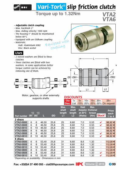
99 Fax: +33(0)4 37 490 055 - [email protected] Volume 2 2016
Vari-Tork® slip friction clutchTorque up to 1.32Nm VTA2
VTA6
Part number ØB1 ØB2 L ØD
Max. shaft
lengthL1
Max. shaft
lengthL2
Heat dissipation at 20°C(Watts)
Max. frictional
torque (Nm)
Price each1 to 4
*Depending on availability - Dimensions in mm
Screw M4
ScrewM3
- Adjustable clutch coupling- Max. backlash 2°- Max. sliding velocity: 1000 rpm- The housing t° should be maintained
below 80°C- Equipped with an Oldham coupling- M aterials:
Hub: Aluminium 6082 Disc: Black acetal
.Uses.- 2 waved washers are fitted to these
clutches- These clutches are fitted with two
washers. In some applications better torque control can be achieved by removing one of them.
L
L1 L2
ØB2ØB1
Motor, gearbox, or other externally supports shafts
Stock*2 discsVTA2-0606 6 6 46,50 25,8 25 8,60 7,0 0,53 4 98,92 FVTA2-0608 6 8 46,50 25,8 25 8,60 7,0 0,53 4 98,92 FVTA2-0610 6 10 46,50 25,8 25 8,60 7,0 0,53 - 98,92 FVTA2-0806 8 6 46,50 25,8 25 8,60 7,0 0,53 - 98,92 FVTA2-0808 8 8 46,50 25,8 25 8,60 7,0 0,53 4 98,92 FVTA2-0810 8 10 46,50 25,8 25 8,60 7,0 0,53 4 98,92 F6 discsVTA6-0606 6 6 53,40 25,8 31 8,60 8,6 1,32 - 112,09 FVTA6-0608 6 8 53,40 25,8 31 8,60 8,6 1,32 - 112,09 FVTA6-0610 6 10 53,40 25,8 31 8,60 8,6 1,32 - 112,09 FVTA6-0806 8 6 53,40 25,8 31 8,60 8,6 1,32 - 112,09 FVTA6-0808 8 8 53,40 25,8 31 8,60 8,6 1,32 4 112,09 FVTA6-0810 8 10 53,40 25,8 31 8,60 8,6 1,32 4 112,09 F
DISCOUNTSQty 1+ 5+ 10+ 15+ 20+ 25+
Disc. List -15% -20% -25% -30% On request
Equipped with
coupling
ØD
+0,03-0,00
+0,03-0,00
100 www.hpceurope.com - Tel: +33(0)4 37 496 496Volume 2 2016
Miniature slip friction clutchSAS
- Adjustable clutch coupling- Rotation will stop if a preset torque
is exceeded and will restart when the torque is reduced, thus protecting equipment and personnel
- Protects in case of overload- Backlash 6°- Brass friction discs
.Principle.- Springs maintain contact between the
clutch plates and friction rings, this contact is broken in case of excessive torque
Torque up to 8.64Nm
Tolerances(0/+0,005)
Part number B ØA Std. ØA max. C ØD E EE F G HSAS16-6 25,40 6 9,53 33,27 19,30 6,35 - - - -SAS20-6 31,75 6 9,53 38,10 19,30 6,35 12,70 25,40 26,98 2,39SAS24-10 38,10 10 12,70 63,50 25,65 9,40 19,05 44,45 33,33 3,18SAS32-12 50,80 12 15,88 72,90 35,05 12,70 25,40 47,75 42,47 4,78SAS44-14 69,85 14 15,88 72,90 41,40 12,70 25,40 47,75 60,33 4,78
Dimensions in mm
+ - 0,254
Miniature
101 Fax: +33(0)4 37 490 055 - [email protected] Volume 2 2016
*Depending on availability - Dimensions in mm
SAS
Protection
Adjustment nut
EC
ØBØD
ØAProtected clutch - SAS16
Protection
Adjustment nut
E
EE F
C
ØBØD
H
G
ØA
Open clutch - SAS20-44
Capacity at Capacity at Friction Price each Part number 50 rpm (Nm) 50 rpm (Watts) surfaces 1 to 4SAS16-6 0,010 - 1,28 5,8 8 4 146,66 FSAS20-6 0,010 - 1,35 6,0 8 - 401,67 FSAS24-10 0,055 - 3,22 14,5 12 4 433,79 FSAS32-12 0,090 - 5,64 29,0 12 - 558,35 FSAS44-14 0,110 - 8,64 43,0 12 - 807,57 F
Stock*
DISCOUNTSQty 1+ 5+ 10+ 25+ 50+
Disc. List -6% -12% -18% On request
102 www.hpceurope.com - Tel: +33(0)4 37 496 496Volume 2 2016
Friction clutchMax torque 30Nm to 240NmLC
- Adjustable clutch- Place the wheel (gear, pulley, chain sprocket)
between the two friction disks and tighten/loosen the thread to achieve the torque setting required.
- Supplied pre-boredM aterial:
Steel Friction disks do not contain asbestos
.Option.- Bore and keyway to your specifications
(Mini quantity order: 30 pieces)
.Info..- Friction disks should never come into contact
with oil as this could cause damage or affect the performance of the clutch
- Gear/sprocket not supplied
LC 40-50
*Depending on availability - Dimensions in mm
Part G Ø torque N° Recommended sprocket Price each number ØE ØBh8 Ød F max H ØD L max (Nm) springs Pas N of teeth 1 to 4LC40-1-7 40 26 7 10 6 3 22 30,0 15 1 3/8”
1/2”18-21
15- 24,31 F
LC40-2-7 40 26 7 10 6 3 22 30,0 28 2 - 27,06 FLC50-1-7 45 35 7 11 6 3 32 35,5 30 1 3/8”
1/2”19-23
184 30,06 F
LC50-2-7 45 35 7 11 6 3 32 35,5 55 2 4 30,06 F
DISCOUNTSQty 1+ 5+ 10+ 25+ 50+
Disc. List -6% -12% -18% On request
Stock*
L
F G H
ØE ØB Ød ØD
103 Fax: +33(0)4 37 490 055 - [email protected] Volume 2 2016
- Adjustable clutch- Place the wheel (gear, pulley, chain sprocket)
between the two friction disks and tighten/loosen the thread to achieve the torque setting required.
- Supplied pre-bored- M aterial:
Steel- Friction disks do not contain asbestos
.Option.- Bore and keyway to your specifications
(Mini quantity order: 30 pieces)
.Info..- Friction disks should never come into contact
with oil as this could cause damage or affect the performance of the clutch
- Gear/sprocket not supplied
Friction clutchMax torque 190Nm to 1.800Nm LC
*Depending on availability - Dimensions in mm
LC 65-85-95-120-140-170
LC65-1-10 65 45 10 16 9 4 36 50,5 70 1 3/8”1/2”5/8”
272119
4 39,68 FLC65-2-10 65 45 10 16 9 4 36 50,5 120 2 4 43,52 FLC85-1-15 85 52 15 17,0 11,0 4,0 45 55,5 130 1 3/8”
1/2”5/8”3/4
38252118
4 49,60 FLC85-2-15 85 52 15 17,0 11,0 4,0 45 55,5 240 2 4 54,67 FLC95-1-15 95 60 15 18,0 11,0 4,0 52 67,0 190 1 1/2”
5/8”3/4”
302519
4 76,19 FLC95-2-15 95 60 15 18,0 11,0 4,0 52 67,0 340 2 - 81,63 FLC120-1-20 120 73 20 20,0 16,0 4,0 64 78,0 350 1 1/2”
5/8”3/41”
38322521
- 84,83 FLC120-2-20 120 73 20 20,0 16,0 4,0 64 78,0 650 2 4 96,85 FLC140-1-20 140 90 20 23,0 17,0 4,0 85 86,5 650 1 3/4
1”3021
- 141,68 FLC140-2-20 140 90 20 23,0 17,0 4,0 85 86,5 1200 2 - 160,49 FLC170-1-28 170 100 28 27,5 18,5 4,5 90 95,0 1000 1 3/4
1”1”1/4
352522
- 164,08 FLC170-2-28 170 100 28 27,5 18,5 4,5 90 95,0 1800 2 - 190,89 F
Part number G Ø torque Nb ØE ØBh8 Ød F max H ØD L max (Nm) springs Pitch Nb of teeth
Price each 1 to 4
Recommended sprocketStock*
LG H
ØE
ØB
ØDØd
F
DISCOUNTSQty 1+ 5+ 10+ 25+ 50+
Disc. List -6% -12% -18% On request
LC 65-85-95-120-140-170

104 www.hpceurope.com - Tel: +33(0)4 37 496 496Volume 2 2016
Part number ØA ØB ØE ØF G H J L M ØP Q
Torque up to 2.600NmDSFSlip friction clutch
- Adjustable clutch coupling- Chain coupling- Clutch with slip friction disc- Can be supplied pre-bored or solid- Max. speed: 100 rpm- Materials: Steel EN10083-2
.Options.- Bore-size and keyway
Q
Threaded holeØP
ØDØE ØFØC
H
ØB
ØA
J LM
G
Dimensions in mm
DSF025-4-20 41 23 22 25 13 5,5 9,0 26 36,0 M3 3DSF038-5-35 58 37 32 38 28 8,0 20,0 33 56,0 M3 3DSF050-12-60 75 50 44 50 28 8,0 19,0 35 59,0 M4 4DSF170-26-100 101 70 63 70 40 10,0 29,0 55 87,0 M4 4DSF290-70-300 126 90 82 90 60 15,0 48,0 60 112,5 M6 6DSF311-240-580 157 110 105 115 70 17,0 57,5 70 131,0 M6 6DSF414-400-1200 198 130 139 140 70 21,0 59,5 80 152,0 M6 6DSF517-450-2600 223 130 160 170 100 25,0 90,5 95 192,0 M8 8
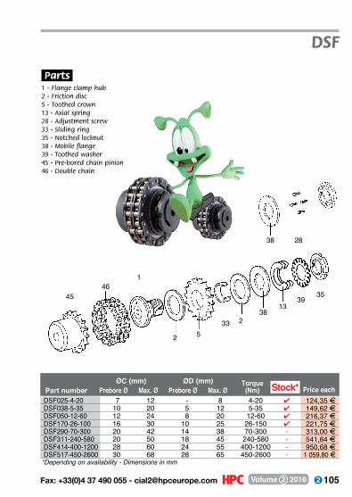
105 Fax: +33(0)4 37 490 055 - [email protected] Volume 2 2016
Part number Prebore Ø Max. Ø Prebore Ø Max. ØTorque
(Nm) Price eachØC (mm) ØD (mm)
DSF
.Parts.1 - Flange clamp hub2 - Friction disc5 - Toothed crown13 - Axial spring28 - Adjustment screw33 - Sliding ring35 - Notched locknut38 - Mobile flange39 - Toothed washer45 - Pre-bored chain pinion46 - Double chain
2838
4546
1
2 533 2
3813
3935
*Depending on availability - Dimensions in mm
Stock*DSF025-4-20 7 12 - 8 4-20 4 124,35 FDSF038-5-35 10 20 5 12 5-35 4 149,62 FDSF050-12-60 12 24 8 20 12-60 4 216,37 FDSF170-26-100 16 30 10 25 26-150 4 221,75 FDSF290-70-300 20 42 14 38 70-300 - 313,00 FDSF311-240-580 20 50 18 45 240-580 - 541,64 FDSF414-400-1200 28 60 24 55 400-1200 - 950,68 FDSF517-450-2600 30 68 28 65 450-2600 - 1 059,80 F
106 www.hpceurope.com - Tel: +33(0)4 37 496 496Volume 2 2016
Adjustable shaft
collar
locking rings
p.115
p.124
self-centering locking assembly
stainless
steel
p.113
flanged splined
bush
p.114
NEW
clamping collar
p.116
p.120
clamping ring
107 Fax: +33(0)4 37 490 055 - [email protected] Volume 2 2016
assembly elements
p.108 - 139
self-centering locking assembly
p.125
mechanical locking
assemblyhydraulic locking
assembly
p.136p.132
locking assemby
p.128
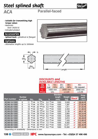
108 www.hpceurope.com - Tel: +33(0)4 37 496 496Volume 2 2016
Part number Number
of splines Ød1 Ød2 b
Standard length(mm)
Weight(kg)
Price each1 to 9
*Depending on availability - Dimensions in mm
Steel splined shaftParallel-facedACA
b
Ød1
Ød2
Length
- Suitable for transmitting high torque values
- M aterials: Steel C40/XC42
- Extruded product
.Accessories.- Splined bush: cylindrical or flanged
.Options.- Alternative lengths up to 3000mm
Stock* ACA6-14-1000 6 11 +0 /-0,08 14 -0,07/-0,2 3,0 +0 /-0,08 1000 0,949 4 28,84 FACA6-16-1000 6 13 +0 /-0,08 16 -0,07/-0,2 3,5 +0 /-0,08 1000 1,287 4 27,62 FACA6-20-1000 6 16 +0 /-0,08 20 -0,07/-0,25 4,0 +0 /-0,08 1000 1,911 4 37,05 FACA6-22-1000 6 18 +0 /-0,08 22 +0/-0,10 5,0 +0 /-0,08 1000 2,453 4 41,99 FACA6-25-1000 6 21 +0 /-0,08 25 -0,07/-0,27 5,0 +0 /-0,08 1000 3,139 4 48,01 FACA6-28-1000 6 23 +0 /-0,08 28 -0,07/-0,25 6,0 +0 /-0,08 1000 3,964 4 64,54 FACA6-32-1000 6 26 +0 /-0,08 32 -0,07/-0,27 6,0 +0 /-0,08 1000 5,008 4 79,05 FACA6-34-1000 6 28 +0 /-0,08 34 -0,07/-0,27 7,0 +0 /-0,08 1000 5,816 4 93,28 FACA8-38-1000 8 32 +0 /-0,08 38 -0,07/-0,27 6,0 +0 /-0,08 1000 7,433 4 115,68 FACA8-42-1000 8 36 +0 /-0,08 42 -0,07/-0,27 7,0 +0 /-0,08 1000 9,302 4 150,14 FACA8-48-1000 8 42 +0 /-0,08 48 -0,07/-0,27 8,0 +0 /-0,08 1000 12,371 4 190,46 FACA8-54-1000 8 46 +0 /-0,08 54 -0,07/-0,27 9,0 +0 /-0,08 1000 15,300 4 277,15 F
DISCOUNTS andAVAILABLE LENGTHS
Qty 1+ 10+ 20+ 30+ 40+dISC List -15% -20% -30% On request
L. 1000 mm 2000 mm 3000 mmPrice Uni. x 2,23 x 3,35

109 Fax: +33(0)4 37 490 055 - [email protected] Volume 2 2016
*Depending on availability - Dimensions in mm
Steel splined bushParallel-faced BCA
- Suitable for transmitting high torque values- M aterial:
Steel C45
.Accessories.- Steel or stainless steel splined shaft
Ød3
L
b
Ød1
DISCOUNTSQty 1+ 10+ 20+ 30+ 40+
Disc. List -15% -20% -30% On requestNumber L
Part of total splined Price eachnumber splines Ød1 Ød2 b length length Ød3 1 to 9BCA6-14 6 11,00 14,00 3,00 40 30 25 4 11,80 FBCA6-16 6 13,00 16,00 3,50 40 40 28 4 11,10 FBCA6-20 6 16,00 20,00 4,00 50 50 30 4 11,10 FBCA6-22 6 18,00 22,00 5,00 50 50 32 4 11,10 FBCA6-25/40 6 21,00 25,00 5,00 40 40 38 4 13,08 FBCA6-25 6 21,00 25,00 5,00 60 60 38 4 13,08 FBCA6-28 6 23,00 28,00 6,00 60 60 38 4 13,59 FBCA6-32 6 26,00 32,00 6,00 60 60 42 4 13,59 FBCA6-34 6 28,00 34,00 7,00 60 60 45 4 15,25 FBCA8-38 8 32,00 38,00 6,00 60 60 55 4 22,28 FBCA8-42 8 36,00 42,00 7,00 70 70 60 4 26,07 FBCA8-48 8 42,00 48,00 8,00 70 70 65 4 32,39 FBCA8-54 8 46,00 54,00 9,00 80 80 70 4 43,20 F
Stock*
Ød2

110 www.hpceurope.com - Tel: +33(0)4 37 496 496Volume 2 2016
Stock*
*Depending on availability - Dimensions in mm
+0 -0,08
-0,07 -0,27
+0 -0,08 Part number
Number of
splines Ød1 Ød2 b
Standard length(mm)
Price each1 to 9 for 1000mm
Stainless steel 303 splined shaftISO 14-BBUC
b
Ød1
Ød2
Length
- Suitable for transmitting high torque values
- Conforming to DIN ISO 14-B- Material:
Steel 303- Extruded product
.Accessories.- Splined bush:
cylindrical or flanged
.Options.- Alternative lengths up to 3000mm
stainless steel
For hostile environments
BUC30-001SS 6 11,00 14,00 3,00 1000 4 115,75 FBUC30-002SS 6 13,00 16,00 3,50 1000 4 124,82 FBUC30-003SS 6 16,00 20,00 4,00 1000 4 220,74 FBUC30-004SS 6 21,00 25,00 5,00 1000 4 344,24 FBUC30-005SS 6 26,00 32,00 6,00 1000 - 461,99 FBUC30-006SS 8 32,00 38,00 6,00 1000 - 732,50 FBUC30-007SS 8 42,00 48,00 8,00 1000 - 1 213,38 F
Stock*
DISCOUNTSQty 1+ 10+ 20+
Disc. List -7% On request
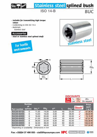
111 Fax: +33(0)4 37 490 055 - [email protected] Volume 2 2016
Part number
Price each1 to 9
*Depending on availability - Dimensions in mm
ISO 14-B BUC
Ød3
L
b
Ød1
Ød2
- Suitable for transmitting high torque values
- Conforming to DIN ISO 14-A- M aterials:
Stainless steel 303
.Accessories.- Steel or stainless steel splined shaft
Number of
splines Ød1H7 Ød2 bD9 L Ød3h11
stainless steel
Stainless steel splined bush
For hostileenvironments
Stock*BUC00-001SS 6 11,00 14,00 3,00 40 20,00 4 67,96 FBUC00-002SS 6 13,00 16,00 3,50 45 28,00 4 69,93 FBUC00-003SS 6 16,00 20,00 4,00 45 32,00 4 72,76 FBUC00-004SS 6 21,00 25,00 5,00 55 40,00 4 87,97 FBUC00-005SS 6 26,00 32,00 6,00 60 52,00 - 100,08 FBUC00-006SS 8 32,00 38,00 6,00 60 60,00 - 106,94 FBUC00-007SS 8 42,00 48,00 8,00 70 65,00 - 157,55 F
DISCOUNTSQty 1+ 10+ 20+
Disc. List -7% On request
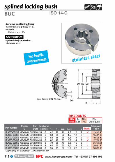
112 www.hpceurope.com - Tel: +33(0)4 37 496 496Volume 2 2016
Stock*
*Depending on availability - Dimensions in mm
Part numberPrice each
1 to 9Profile
GFor
shaft D1 D2 D3h6 D4H13 L KNumber of
splines
Splined locking bushISO 14-GBUC
- For axial positioning/fixing- Conforming to DIN ISO 14-G- M aterial:
Stainless steel 304
.Accessories.- Splined shaft in steel or
stainless steel
D3
D4Spot facing DIN 74-Km
D2D1
LK
For hostileenvironments stainless steel
BUC00-031SS G6x11x14 BUC30-001SS 6 42 28 20 4,5 12 2 4 134,42 FBUC00-032SS G6x13x16 BUC30-002SS 6 50 36 22 4,5 12 2 - 154,01 FBUC00-033SS G6x16x20 BUC30-003SS 6 52 38 25 5,5 14 2 4 165,25 FBUC00-034SS G6x21x25 BUC30-004SS 6 62 48 35 6,6 14 3 4 177,58 FBUC00-035SS G6x26x32 BUC30-005SS 6 70 56 40 6,6 15 3 - On requestBUC00-036SS G6x32x38 BUC30-006SS 8 82 65 50 9,0 18 3 - 259,51 FBUC00-037SS G6x42x48 BUC30-007SS 8 95 75 60 11,0 22 3 - 303,99 F
Stock*
DISCOUNTSQty 1+ 10+ 20+
Disc. List -7% On request

113 Fax: +33(0)4 37 490 055 - [email protected] Volume 2 2016
Part number Price each1 to 9
ProfileG
For shaft
Number of splines
*Depending on availability - Dimensions in mm
Stainless steel flanged splined bushISO 14-F BUC
- Suitable for transmitting high torque values- Flange is toleranced- Conforming to DIN ISO 14-F- M aterial:
Stainless steel 304
.Accessories.- Splined shaft in steel or stainless steel
D1 D2 D3H7 D4h8 D5H13 E H L
D3D4
D5
D2 D1
LE
H
For hostileenvironments stainless steel
Stock*BUC00-017SS F6x11x14 BUC30-001SS 6 42 28 20 20 4,5 8 3,0 35 4 122,76 FBUC00-018SS F6x13x16 BUC30-002SS 6 50 36 22 25 4,5 8 3,0 40 4 125,40 FBUC00-019SS F6x16x20 BUC30-003SS 6 52 38 25 28 5,5 10 3,0 40 4 134,88 FBUC00-020SS F6x21x25 BUC30-004SS 6 62 48 35 34 6,6 10 3,5 50 4 171,85 FBUC00-021SS F6x26x32 BUC30-005SS 6 70 56 40 42 6,6 10 3,5 60 - 209,99 FBUC00-022SS F6x32x38 BUC30-006SS 8 82 65 50 50 9,0 12 3,5 60 - 230,45 FBUC00-023SS F6x42x48 BUC30-007SS 8 95 75 60 60 11,0 16 4,0 80 - 318,53 F
DISCOUNTSQty 1+ 10+ 20+
Disc. List -7% On request
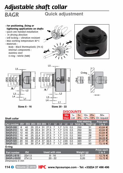
114 www.hpceurope.com - Tel: +33(0)4 37 496 496Volume 2 2016
Adjustable shaft collarQuick adjustmentBAGR
- For positioning, fixing or tightening applications on shafts
- Quick one handed installation- In driving direction- Self locking – vibration resistant- Max working temperature 80°C- M aterials :
Body : Black thermoplastic (PA 6) Internal components : stainless steel O-ring : Nitrile (NBR)
BAGR-008 8 40 25 22,4 31 27,5 7 1,7 3,15 0,5 250 31 43,84 FBAGR-010 10 40 25 22,4 31 27,5 7 1,7 3,15 0,5 250 30 43,84 FBAGR-012 12 40 25 22,4 31 27,5 7 1,7 3,15 0,5 350 30 43,84 FBAGR-015 15 40 25 22,4 31 27,5 7 1,7 3,15 0,5 350 28 54,81 FBAGR-016 16 40 25 22,4 31 27,5 7 1,7 3,15 0,5 380 27 59,03 FBAGR-020 20 55 30 27,4 37 32,5 7 1,7 2,65 0,5 320 51 61,97 FBAGR-022 22 55 30 27,4 37 32,5 7 1,7 2,65 0,5 320 50 73,19 F
Part number Axial retaining ØD1 ØD2 ØD3 ØD4 ØD5 L1 L2 L3 L4 force (N) Weight (g)
Price each1 to 4
BAGR-J-8/16 22x1,5 8 - 16 0,17 12,78 FBAGR-J-20/22 27x1,5 20 - 22 0,20 15,72 F
Part number Ød Used with size Weight (g)Price each
1 to 4
O-ring
Shaft collar
ØD1
ØD4
ØD3
ØD5 ØD5
ØD3 ØD4
ØD1ØD2
ØD2
L5
L2L3
L4L1
L5
L2L3L4
L1
O-ringØ
h9
Sizes 8 - 16 Sizes 20 - 22
Dimensions in mm
L5
DISCOUNTSQty 1+ 5+ 10+ 25+ 50+
Disc. List -6% -12% -18% On request
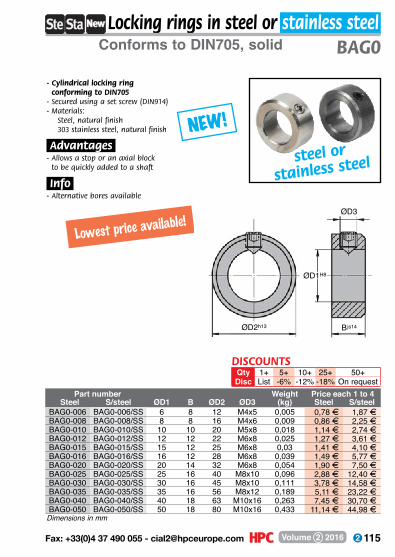
115 Fax: +33(0)4 37 490 055 - [email protected] Volume 2 2016
Locking rings in steel or stainless steelConforms to DIN705, solid BAG0
- Cylindrical locking ring conforming to DIN705
- Secured using a set screw (DIN914)- M aterials:
Steel, natural finish 303 stainless steel, natural finish
.Advantages.- Allows a stop or an axial block
to be quickly added to a shaft
.Info.- Alternative bores available
Dimensions in mm
Part number Weight Price each 1 to 4Steel S/steel ØD1 B ØD2 ØD3 (kg) Steel S/steel
BAG0-006 BAG0-006/SS 6 8 12 M4x5 0,005 0,78 F 1,87 FBAG0-008 BAG0-008/SS 8 8 16 M4x6 0,009 0,86 F 2,25 FBAG0-010 BAG0-010/SS 10 10 20 M5x8 0,018 1,14 F 2,74 FBAG0-012 BAG0-012/SS 12 12 22 M6x8 0,025 1,27 F 3,61 FBAG0-015 BAG0-015/SS 15 12 25 M6x8 0,03 1,41 F 4,10 FBAG0-016 BAG0-016/SS 16 12 28 M6x8 0,039 1,49 F 5,77 FBAG0-020 BAG0-020/SS 20 14 32 M6x8 0,054 1,90 F 7,50 FBAG0-025 BAG0-025/SS 25 16 40 M8x10 0,096 2,88 F 12,40 FBAG0-030 BAG0-030/SS 30 16 45 M8x10 0,111 3,78 F 14,58 FBAG0-035 BAG0-035/SS 35 16 56 M8x12 0,189 5,11 F 23,22 FBAG0-040 BAG0-040/SS 40 18 63 M10x16 0,263 7,45 F 30,70 FBAG0-050 BAG0-050/SS 50 18 80 M10x16 0,433 11,14 F 44,98 F
NEW!
steel or
stainless steel
DISCOUNTSQty 1+ 5+ 10+ 25+ 50+Disc List -6% -12% -18% On request
Lowest price available!ØD3
ØD1H8
ØD2h13 B js14
116 www.hpceurope.com - Tel: +33(0)4 37 496 496Volume 2 2016
Ø10 to Ø20BAPClamping collar
*Depending on availability - Dimensions in mm
ØDe
W
ØDp
ØD
- 2 part clamping collar- Materials:
Body: reinforced polyamideScrews: stainless steel 304
Weight Price each Part number ØD ØDe ØDp W (kg) 1 to 39BAP-10 10 30 20 12 0,01 4 3,15 FBAP-12 12 30 20 12 0,01 4 3,15 FBAP-14 14 30 20 12 0,01 4 3,15 FBAP-15 15 39 27 14 0,02 4 3,15 FBAP-16 16 39 27 14 0,02 4 3,15 FBAP-18 18 39 27 14 0,02 4 3,15 FBAP-20 20 40 29 14 0,02 4 3,15 F
Stock*
DISCOUNTSQty 1+ 40+ 100+ 200+ 300+
Disc. List -5% -10% -15% On request
117 Fax: +33(0)4 37 490 055 - [email protected] Volume 2 2016
Ø25 to Ø40 BAPClamping collar
- 2 part locking collar- Smooth or grooved bore- Materials:
Body: reinforced polyamideScrews: stainless steel 304
Price each. 1 à 39
smooth grooved
*Subject to available stocks - Dimensions in mm
Part numbersmooth grooved
ØD
ØDe
ØDp
A1
K
W
BAP-25 BAP-25K 25 8 45 35 14 28,3 0,02 4 3,15 F 5,28 FBAP-30 BAP-30K 30 8 55 45 16 33,3 0,03 4 3,74 F 5,80 FBAP-35 BAP-35K 35 10 60 47 16 38,3 0,03 4 4,04 F 6,10 FBAP-40 BAP-40K 40 12 64 51 18 43,3 0,04 4 4,04 F 6,10 F
Stock*ØD A1 ØDe ØDp W KWeight(kg)
DISCOUNTSQty 1+ 40+ 100+ 200+ 300+
Disc. List -5% -10% -15% On request

118 www.hpceurope.com - Tel: +33(0)4 37 496 496Volume 2 2016
*Depending on availability - Dimensions in mm
Steel clampSingle or two part assemblyBAG1
BAG2- Solid fixing onto any type of shaft- Do not separate the two pieces- Materials:
Clamp: blackened steel (natural, blackened or chromed steel depending of arrivage)Screw: steel alloy
- 2-part clamps offer a 20% stronger fixing- Dimensions ØD and L are given as an indication only
and are subject to change.
ØD ØA
L
Screw
BAG1
Screw
BAG2
Typical applicationDISCOUNTS
Qty 1+ 5+ 10+ 25+ 50+Disc List -6% -12% -18% On request
Part number Price each 1 to 41 2 1 2 1 2
part parts ØA ØD L Screw part parts part partsBAG1-004 BAG2-004 4 16 9 M3 x 8 - - 3,89 F 6,67 FBAG1-005 BAG2-005 5 16 9 M3 x 8 4 4 3,89 F 6,67 FBAG1-006 BAG2-006 6 16 9 M3 x 8 4 4 3,89 F 6,67 FBAG1-008 BAG2-008 8 18 9 M3 x 8 4 4 3,89 F 6,67 FBAG1-010 BAG2-010 10 24 9 M3 x 10 4 4 4,41 F 7,40 FBAG1-012 BAG2-012 12 28 11 M4 x 12 4 4 4,89 F 7,75 FBAG1-015 BAG2-015 15 34 13 M5 x 16 4 4 5,83 F 9,17 FBAG1-016 BAG2-016 16 34 13 M5 x 16 4 4 5,83 F 9,17 FBAG1-018 BAG2-018 18 36 13 M5 x 16 - 4 6,51 F 9,88 FBAG1-020 BAG2-020 20 40 15 M6 x 16 4 4 7,40 F 10,59 FBAG1-025 BAG2-025 25 45 15 M6 x 16 4 4 8,00 F 11,64 FBAG1-030 BAG2-030 30 54 15 M6 x 18 4 4 10,12 F 13,22 FBAG1-035 BAG2-035 35 57 15 M6 x 18 4 4 10,96 F 14,62 FBAG1-040 BAG2-040 40 60 15 M6 x 18 4 4 11,64 F 15,61 FBAG1-050 BAG2-050 50 78 19 M8 x 25 4 4 24,67 F 27,96 FBAG1-055 BAG2-055 55 90 16 M8 x 20 - - 18,07 F 21,43 FBAG1-060 BAG2-060 60 100 16 M8 x 20 - 4 21,38 F 24,59 FBAG1-070 BAG2-070 70 110 20 M10 x 25 - - 24,41 F 28,21 FBAG1-075 BAG2-075 75 125 20 M10 x 25 - - 30,67 F 34,60 FBAG1-080 BAG2-080 80 125 20 M10 x 25 - - 30,12 F 33,91 F
Stock* Stock*
119 Fax: +33(0)4 37 490 055 - [email protected] Volume 2 2016
*Depending on availability - Dimensions in mm
Stainless steel clampSingle or two part assembly BAG1ss
BAG2ss
ØD ØA
L
Screw Screw
BAG1/SS BAG2/SS
stainless steel
Typical application
- Solid fixing onto any type of shaft- Do not separate the two pieces- Materials:
Clamp + screw: stainless steelScrew: steel alloy
- 2-part clamps offer a 20% stronger fixing- Dimensions ØD and L are given as an
indication only and are subject to change
DISCOUNTSQty 1+ 5+ 10+ 25+ 50+Disc List -6% -12% -18% On request
Part number Price each 1 to 41 2 1 2 1 2
part parts ØA ØD L Screw part parts part partsBAG1-004/SS BAG2-004/SS 4 16 9 M3 x 8 4 4 8,19 F 10,47 FBAG1-005/SS BAG2-005/SS 5 16 9 M3 x 8 4 4 8,19 F 10,47 FBAG1-006/SS BAG2-006/SS 6 16 9 M3 x 8 4 4 8,19 F 10,47 FBAG1-008/SS BAG2-008/SS 8 18 9 M3 x 8 4 4 9,11 F 10,67 FBAG1-010/SS BAG2-010/SS 10 24 9 M3 x 10 4 4 11,27 F 13,31 FBAG1-012/SS BAG2-012/SS 12 28 11 M4 x 12 4 4 11,64 F 13,81 FBAG1-015/SS BAG2-015/SS 15 34 13 M5 x 16 4 4 13,93 F 16,92 FBAG1-016/SS BAG2-016/SS 16 34 13 M5 x 16 4 4 13,93 F 16,92 FBAG1-018/SS BAG2-018/SS 18 36 13 M5 x 16 4 4 15,92 F 19,01 FBAG1-020/SS BAG2-020/SS 20 40 15 M6 x 16 4 4 19,40 F 20,24 FBAG1-025/SS BAG2-025/SS 25 45 15 M6 x 16 4 4 21,44 F 23,01 FBAG1-030/SS BAG2-030/SS 30 54 15 M6 x 18 4 4 24,76 F 27,59 FBAG1-040/SS BAG2-040/SS 40 60 15 M6 x 18 4 4 30,93 F 38,38 FBAG1-050/SS BAG2-050/SS 50 78 19 M8 x 25 4 4 58,29 F 84,96 FBAG1-055/SS BAG2-055/SS 55 90 16 M8 x 20 - - 84,02 F 88,99 FBAG1-060/SS BAG2-060/SS 60 100 16 M8 x 20 - 4 96,82 F 101,91 FBAG1-070/SS BAG2-070/SS 70 110 20 M10 x 25 - - 107,85 F 113,61 FBAG1-075/SS BAG2-075/SS 75 125 20 M10 x 25 - - 138,32 F 144,27 FBAG1-080/SS BAG2-080/SS 80 125 20 M10 x 25 - - 131,65 F 137,52 F
Stock* Stock*
120 www.hpceurope.com - Tel: +33(0)4 37 496 496Volume 2 2016
*Depending on availability - Dimensions in mm
Part number ØA L Screw MaterialsBore-size
ØDPrice each
1 to 5
Stainless steel or steel clamp ringSingle piece assemblyCC
L
ØDØA
Vis- Shaft end stop clamp
Wide range of bores
Screw
CC3-3 16 5 M3 Stainless steel 303 3 - 52,04 FCC3-4 16 5 M3 Stainless steel 303 4 - 52,04 FCC3-5 16 5 M3 Stainless steel 303 5 - 52,04 FCC3-6 16 5 M3 Stainless steel 303 6 4 52,04 FCC5-5 22 5 M3 Stainless steel 303 5 - 59,78 FCC5-6 22 5 M3 Stainless steel 303 6 - 59,78 FCC5-7 22 5 M3 Stainless steel 303 7 - 59,78 FCC5-8 22 5 M3 Stainless steel 303 8 4 59,78 FCC8-8 25 8 M4 Stainless steel 303 8 - 66,00 FCC8-9 25 8 M4 Stainless steel 303 9 - 66,00 FCC8-10 25 8 M4 Stainless steel 303 10 4 66,00 FCC10-10 30 8 M4 Stainless steel 303 10 - 66,00 FCC10-11 30 8 M4 Stainless steel 303 11 - 66,00 FCC10-12 30 8 M4 Stainless steel 303 12 4 66,00 FCC10-13 30 8 M4 Stainless steel 303 13 - 66,00 FCC12-12 32 10 M5 Stainless steel 303 12 4 74,22 FCC12-13 32 10 M5 Stainless steel 303 13 - 74,22 FCC12-14 32 10 M5 Stainless steel 303 14 - 74,22 FCC12-15 32 10 M5 Stainless steel 303 15 4 74,22 FCC15-15 35 10 M5 Stainless steel 303 15 - 78,97 FCC15-16 35 10 M5 Stainless steel 303 16 - 78,97 FCC15-17 35 10 M5 Stainless steel 303 17 - 78,97 FCC15-18 35 10 M5 Stainless steel 303 18 - On requestCC20-19 38 10 M5 Stainless steel 303 19 - 85,93 FCC20-20 38 10 M5 Stainless steel 303 20 4 85,93 FCC20-22 38 10 M5 Stainless steel 303 22 - 85,93 FCC20-23 38 10 M5 Stainless steel 303 23 - 85,93 FCC25 48 15 M6 Steel 25 - 105,76 FCC30 55 15 M6 Steel 30 - 123,24 FCC35 60 15 M6 Steel 35 - 150,63 FCC40 65 15 M6 Steel 40 - 174,33 F
Stock*
DISCOUNTSQty 1+ 6+ 20+ 40+
Disc. List -15% -20% On request

121 Fax: +33(0)4 37 490 055 - [email protected] Volume 2 2016
Part number ØA L Screw MaterialsBore-size
ØDPrice each
1 to 5
*Depending on availability - Dimensions in mm
Stainless steel or steel clamp ringSingle or two part assembly CT
- Shaft clamp ring for applications access is restricted
Wide range of bores L
ØDØA
VisScrew
Stock*CT3-3 16 5 M3 Stainless steel 303 3 - 52,83 FCT3-4 16 5 M3 Stainless steel 303 4 - 26,54 FCT3-5 16 5 M3 Stainless steel 303 5 - 26,54 FCT3-6 16 5 M3 Stainless steel 303 6 - 26,22 FCT5-5 22 5 M3 Stainless steel 303 5 - 30,47 FCT5-6 22 5 M3 Stainless steel 303 6 - 30,47 FCT5-7 22 5 M3 Stainless steel 303 7 - 30,47 FCT5-8 22 5 M3 Stainless steel 303 8 - 30,09 FCT8-8 25 8 M4 Stainless steel 303 8 - 33,69 FCT8-9 25 8 M4 Stainless steel 303 9 - 33,69 FCT8-10 25 8 M4 Stainless steel 303 10 4 33,69 FCT10-10 30 8 M4 Stainless steel 303 10 - 33,69 FCT10-11 30 8 M4 Stainless steel 303 11 - 33,69 FCT10-12 30 8 M4 Stainless steel 303 12 4 33,69 FCT10-13 30 8 M4 Stainless steel 303 13 - 33,69 FCT12-12 32 10 M5 Stainless steel 303 12 - 37,87 FCT12-13 32 10 M5 Stainless steel 303 13 - 37,87 FCT12-14 32 10 M5 Stainless steel 303 14 4 37,87 FCT12-15 32 10 M5 Stainless steel 303 15 - 37,87 FCT15-15 38 10 M5 Stainless steel 303 15 - 40,32 FCT15-16 38 10 M5 Stainless steel 303 16 - 40,32 FCT15-17 38 10 M5 Stainless steel 303 17 - 40,32 FCT15-18 38 10 M5 Stainless steel 303 18 - 40,32 FCT17-17 40 10 M5 Stainless steel 303 17 - 43,87 FCT17-18 40 10 M5 Stainless steel 303 18 - 43,87 FCT17-19 40 10 M5 Stainless steel 303 19 - 43,87 FCT17-20 40 10 M5 Stainless steel 303 20 - 43,87 FCT20-19 43 10 M5 Stainless steel 303 19 - 48,74 FCT20-20 43 10 M5 Stainless steel 303 20 4 48,74 FCT20-22 43 10 M5 Stainless steel 303 22 - 48,74 FCT20-23 43 10 M5 Stainless steel 303 23 - 48,74 FCT25-25 48 15 M6 Steel 25 - 62,13 FCT30-30 55 15 M6 Steel 30 - 75,38 FCT35-35 60 15 M6 Steel 35 - 88,21 FCT40-40 65 15 M6 Steel 40 -- 101,44 F
DISCOUNTSQty 1+ 6+ 20+ 40+
Disc. List -15% -20% On request
steel or
stainless steel
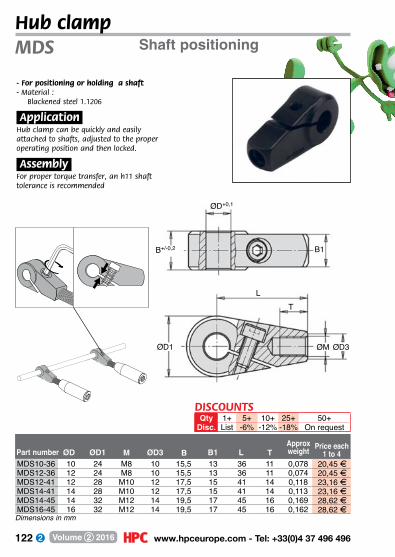
122 www.hpceurope.com - Tel: +33(0)4 37 496 496Volume 2 2016
Shaft positioningMDS
- For positioning or holding a shaft- M aterial :
Blackened steel 1.1206
.Application.Hub clamp can be quickly and easily attached to shafts, adjusted to the proper operating position and then locked.
.Assembly.For proper torque transfer, an h11 shaft tolerance is recommended
MDS10-36 10 24 M8 10 15,5 13 36 11 0,078 20,45 FMDS12-36 12 24 M8 10 15,5 13 36 11 0,074 20,45 FMDS12-41 12 28 M10 12 17,5 15 41 14 0,118 23,16 FMDS14-41 14 28 M10 12 17,5 15 41 14 0,113 23,16 FMDS14-45 14 32 M12 14 19,5 17 45 16 0,169 28,62 FMDS16-45 16 32 M12 14 19,5 17 45 16 0,162 28,62 F
Price each1 to 4Part number MØD1ØD B B1ØD3 L T
Approx weight
L
ØD+0,1
B1B+/-0,2
ØD1
T
ØM ØD3
Dimensions in mm
Hub clamp
DISCOUNTSQty 1+ 5+ 10+ 25+ 50+
Disc. List -6% -12% -18% On request

123 Fax: +33(0)4 37 490 055 - [email protected] Volume 2 2016
Technical information
Counterbore H9
RTT
Shaft h9
RT25
Bore H8
Shaft h8
Locking elements
.Principle of operation.These parts operate on the basis of an interference fit between two conical rings crewed together. The outer ring expands and exerts a pressure on the part being held whilst the inner ring exerts a pressure on a shaft.
.Assembly.Carefully clean all the components parts and then apply a light coating of oil to the contact surfaces. Place one part in the hub and insert the shaft, then tighten the screws in a uniform fashion until the prescribed torque is reached. The Torque (T )and Axial Force (F ax) figures in the tables have been calculated for an oiled assembly.
Note:Do not use Molybdenum Bisulphate based oils or greases as these can significantly reduce the frictional torque.
.Dismantling.Unscrew the screws, inserting them in the extraction holes and increasing the pressure in a gradual and uniform manner until the cones are freed. When re-using the pieces, ensure that the screws and threaded holes are oiled.
.Tolerance.A good machine-finish is sufficient.
.Roughness.Maximum admissible roughness: Rt max 16µm
.Recommended assembly tolerances.

124 www.hpceurope.com - Tel: +33(0)4 37 496 496Volume 2 2016
*Depending on availability - Dimensions in mm
Self-centering hexagonal locking assemblyFor small diametersSUP
- Backlash free, self centring shaft-gear hub.- Single part to insert- Corrosion resistant- M aterials:
Internal ring: blackened steel External ring: zinc plated steel Nut: nickel plated steel
.Info..- Ta: tightening torque of nut- M: transmissible rotational movement- Fa: transmissible axial load- Pw: shaft surface pressure- Pn: hub surface pressure
Ød1H9D2h9
Ød2
L1L2 SW
Ød1
Reduces
assembly time
Ta M Fa Pw Pn Price
Part max. max. max. max. max. each
number Ød1 Ød2 L1 L2 SW (Nm) (Nm) (kN) (N/mm2) (N/mm2) 1 to 5
SUP-005 5 14 19 15 14 9,9 10,1 4,0 264 96 4 35,50 FSUP-006 6 14 19 15 14 9,9 12,1 4,0 220 96 4 35,50 FSUP-008 8 16 22 17 16 16,9 23,4 5,8 179 91 4 37,15 FSUP-010 10 20 24 19 22 34,9 48,6 9,7 221 115 4 39,29 FSUP-012 12 22 24 19 22 43,8 65,3 10,9 206 117 4 42,83 FSUP-014 14 26 28 22 27 65,0 93,0 13,3 178 99 4 46,47 FSUP-015 15 26 28 22 27 65,0 99,0 13,3 166 99 4 46,47 FSUP-016 16 26 28 22 27 65,0 106,0 13,3 156 99 4 46,47 FSUP-018 18 35 36 27 36 161,0 223,0 24,8 224 125 - 50,99 FSUP-020 20 35 36 27 36 161,0 248,0 24,8 201 125 4 50,99 FSUP-022 22 42 41 30 46 250,0 349,0 31,8 197 110 4 55,91 FSUP-024 24 42 41 30 46 250,0 381,0 31,8 180 110 4 55,91 FSUP-025 25 42 41 30 46 250,0 397,0 31,8 173 110 4 55,91 FSUP-030 30 47 44 33 50 355,0 605,0 40,4 162 110 4 65,55 FSUP-032 32 55 51 38 55 490,0 764,0 47,8 166 102 - 78,36 FSUP-035 35 55 51 38 55 490,0 836,0 47,8 151 102 4 78,36 F
Stock*
DISCOUNTSQty 1+ 6+ 20+
Disc. List -5% On request
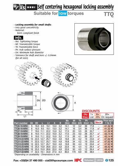
125 Fax: +33(0)4 37 490 055 - [email protected] Volume 2 2016
Self centering hexagonal locking assemblySuitable for low torques TTQ
- Locking assembly for small shafts- Very good concentricity- M aterial:
RoHS compliant finish
.Info..- Ma: Tightening torque- Mt: Transmissible torque- Th: Transmissible force- Ph: Hub surface pressure- Dn: Minimum hub diameter- Tolerance for shaft and bore +/- 0.04mm
(for all sizes)
AØd ØD
BL
L1
DISCOUNTSQty 1+ 6+ 20+
Disc. List -5% On request
TTQ5-16-MINI 5 16,0 9,5 19,1 13,0 3,2 14,1 12 3,2 36 17,8 - 41,32 FTTQ6-16-MINI 6 16,0 9,5 19,1 13,0 3,2 14,1 16 3,4 36 17,8 4 41,32 FTTQ7-19-MINI 7 19,0 11,1 22,2 15,9 3,2 17,0 20 3,5 26 20,7 - 41,32 FTTQ8-19-MINI 8 19,0 11,1 22,2 15,9 3,2 17,0 23 4,0 26 20,7 4 43,14 FTTQ9-19-MINI 9 19,0 11,1 22,2 15,9 3,2 17,0 26 4,1 26 20,7 4 43,14 FTTQ10-22-MINI 10 22,5 12,7 25,7 19,0 4,8 19,8 30 4,2 19 23,6 4 47,62 FTTQ11-22-MINI 11 22,5 12,7 25,7 19,0 4,8 19,8 34 4,2 19 23,6 4 47,62 FTTQ12-22-MINI 12 22,5 12,7 25,7 19,0 4,8 19,8 39 4,3 19 23,6 4 47,62 FTTQ15-25-MINI 15 25,5 15,9 28,6 22,0 4,8 22,6 45 4,4 12 26,4 4 49,42 FTTQ16-25-MINI 16 25,5 15,9 28,6 22,0 4,8 22,6 50 4,5 12 26,4 4 49,42 FTTQ17-32-MINI 17 32,0 19,1 34,9 27,0 6,4 80,0 170 8,9 55 38,0 - 49,42 F
Part number Ma Mt Th Ph Ød ØD L L1 A B (Nm) (Nm) (kN) (N/mm2) Dn
Price each1 to 5Stock*
*Depending on availability - Dimensions in mm

126 www.hpceurope.com - Tel: +33(0)4 37 496 496Volume 2 2016
Self centering hexagonal locking assemblySuitable for medium torque applicationsTTQ
- Compact locking assembly- Very good concentricity
.Info..- Ma: Tightening torque- Mt: Transmissible torque- Th: Transmissible force- Ph: Hub surface pressure- Dn: Minimum hub diameter- Tolerance for shaft and bore +/- 0.08mm
(for all sizes)
Part number Ma Mt Th Ph Ød ØD L L1 A B (Nm) (Nm) (kN) (N/mm2) Dn
Price each 1 to 5
A
BL
Ød ØD
L1
TTQ17-32-OE 17 32 22 30 30 6 110 208 25 92 43,5 4 33,16 FTTQ18-32-OE 18 32 22 30 30 6 110 221 25 92 43,5 4 38,46 FTTQ19-32-OE 19 32 22 30 30 4 110 233 25 92 43,5 4 38,46 FTTQ20-35-OE 20 35 24 33 32 7 150 298 30 94 47,9 4 45,97 FTTQ22-35-OE 22 35 24 33 32 7 150 328 30 94 47,9 4 45,97 FTTQ24-38-OE 24 38 25 35 36 8 185 398 33 93 51,7 4 45,97 FTTQ25-38-OE 25 38 25 35 36 8 185 415 33 93 51,7 4 45,97 FTTQ28-45-OE 28 45 29 41 46 11 240 505 36 73 57,3 - 59,54 FTTQ30-45-OE 30 45 29 41 46 11 240 541 36 73 57,3 4 59,54 FTTQ32-50-OE 32 50 30 44 50 12 265 590 37 65 61,9 - 59,54 FTTQ35-50-OE 35 50 30 44 50 12 265 645 37 65 61,9 4 59,54 F
Stock*
DISCOUNTSQty 1+ 6+ 20+
Disc. List -5% On request
*Depending on availability - Dimensions in mm
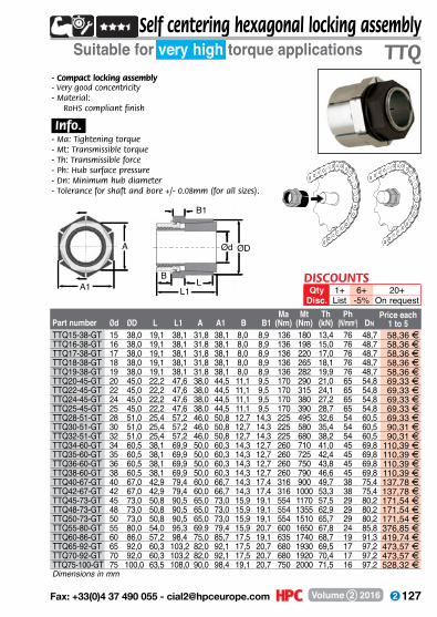
127 Fax: +33(0)4 37 490 055 - [email protected] Volume 2 2016
Self centering hexagonal locking assemblySuitable for very high torque applications TTQ
- Compact locking assembly- Very good concentricity- M aterial:
RoHS compliant finish
.Info..- Ma: Tightening torque- Mt: Transmissible torque- Th: Transmissible force- Ph: Hub surface pressure- Dn: Minimum hub diameter- Tolerance for shaft and bore +/- 0.08mm (for all sizes).
Part number Ma Mt Th Ph Ød ØD L L1 A A1 B B1 (Nm) (Nm) (kN) (N/mm2) Dn
Price each 1 to 5
L
Ød ØDA
A1B
L1
B1
TTQ15-38-GT 15 38,0 19,1 38,1 31,8 38,1 8,0 8,9 136 180 13,4 76 48,7 58,36 FTTQ16-38-GT 16 38,0 19,1 38,1 31,8 38,1 8,0 8,9 136 198 15,0 76 48,7 58,36 FTTQ17-38-GT 17 38,0 19,1 38,1 31,8 38,1 8,0 8,9 136 220 17,0 76 48,7 58,36 FTTQ18-38-GT 18 38,0 19,1 38,1 31,8 38,1 8,0 8,9 136 265 18,1 76 48,7 58,36 FTTQ19-38-GT 19 38,0 19,1 38,1 31,8 38,1 8,0 8,9 136 282 19,9 76 48,7 58,36 FTTQ20-45-GT 20 45,0 22,2 47,6 38,0 44,5 11,1 9,5 170 290 21,0 65 54,8 69,33 FTTQ22-45-GT 22 45,0 22,2 47,6 38,0 44,5 11,1 9,5 170 315 24,1 65 54,8 69,33 FTTQ24-45-GT 24 45,0 22,2 47,6 38,0 44,5 11,1 9,5 170 380 27,2 65 54,8 69,33 FTTQ25-45-GT 25 45,0 22,2 47,6 38,0 44,5 11,1 9,5 170 390 28,7 65 54,8 69,33 FTTQ28-51-GT 28 51,0 25,4 57,2 46,0 50,8 12,7 14,3 225 495 32,6 54 60,5 69,33 FTTQ30-51-GT 30 51,0 25,4 57,2 46,0 50,8 12,7 14,3 225 580 35,4 54 60,5 90,31 FTTQ32-51-GT 32 51,0 25,4 57,2 46,0 50,8 12,7 14,3 225 680 38,2 54 60,5 90,31 FTTQ34-60-GT 34 60,5 38,1 69,9 50,0 60,3 14,3 12,7 260 710 41,0 45 69,8 110,39 FTTQ35-60-GT 35 60,5 38,1 69,9 50,0 60,3 14,3 12,7 260 725 42,4 45 69,8 110,39 FTTQ36-60-GT 36 60,5 38,1 69,9 50,0 60,3 14,3 12,7 260 750 43,8 45 69,8 110,39 FTTQ38-60-GT 38 60,5 38,1 69,9 50,0 60,3 14,3 12,7 260 790 46,6 45 69,8 110,39 FTTQ40-67-GT 40 67,0 42,9 79,4 60,0 66,7 14,3 17,4 316 900 49,7 38 75,4 137,78 FTTQ42-67-GT 42 67,0 42,9 79,4 60,0 66,7 14,3 17,4 316 1000 53,3 38 75,4 137,78 FTTQ45-73-GT 45 73,0 50,8 90,5 65,0 73,0 15,9 19,1 554 1170 57,5 29 80,2 171,54 FTTQ48-73-GT 48 73,0 50,8 90,5 65,0 73,0 15,9 19,1 554 1355 62,9 29 80,2 171,54 FTTQ50-73-GT 50 73,0 50,8 90,5 65,0 73,0 15,9 19,1 554 1510 65,7 29 80,2 171,54 FTTQ55-80-GT 55 80,0 54,0 95,3 69,9 79,4 15,9 20,7 600 1650 67,8 24 85,8 376,85 FTTQ60-86-GT 60 86,0 57,2 98,4 75,0 85,7 17,5 19,1 635 1740 68,7 19 91,3 419,74 FTTQ65-92-GT 65 92,0 60,3 103,2 82,0 92,1 17,5 20,7 680 1930 69,5 17 97,2 473,57 FTTQ70-92-GT 70 92,0 60,3 103,2 82,0 92,1 17,5 20,7 680 1920 70,4 17 97,2 473,57 FTTQ75-100-GT 75 100,0 63,5 108,0 90,0 98,4 19,1 20,7 750 2000 71,5 16 97,2 528,32 F
DISCOUNTSQty 1+ 6+ 20+
Disc. List -5% On request
Dimensions in mm

128 www.hpceurope.com - Tel: +33(0)4 37 496 496Volume 2 2016
*Depending on availability - Dimensions in mm
Medium/high torque, not self-centeringRTT
- Inserts between the shaft and the bore- High transmissible torque- Contact pressure spread evenly- Easy to assembly and dismantle- Reduced width- Backlash free- No constraints due to keyway- Increases the resistant part of the shaft- Suitable for alternating rotational movements- Up to 4 units can be used together- Materials:
Body: steelScrews: steel DIN 912 12.9
.Options.- Other diameters available
(up to 220mm bore)- Stainless steel version
.Info.- **PN: hub surface pressure- **PW: shaft surface pressure
Locking assembly
ØDØA
L
Part number ØA ØD L HScrew
M
Tighteningtorque TA(Nm)
Transmissible torqueT (Nm)
**PW (N/
mm2)
**PN
(N/mm2) Price each1 to 5Stock*
RTT-20-47 20 47 20 28 8xM6x18 14 270 210 90 4 15,25 FRTT-22-47 22 47 20 28 8xM6x18 14 300 195 90 4 15,25 FRTT-24-50 24 50 20 28 9xM6x18 14 360 195 95 4 15,64 FRTT-25-50 25 50 20 28 9xM6x18 14 380 190 85 4 15,64 FRTT-28-55 28 55 20 28 10xM6x18 14 500 187 96 - 17,46 FRTT-30-55 30 55 20 28 10xM6x18 14 530 176 96 4 17,46 FRTT-32-60 32 60 20 28 12xM6x18 14 630 192 105 4 19,17 FRTT-35-60 35 60 20 28 12xM6x18 14 700 180 105 4 19,17 FRTT-38-65 38 65 20 28 14xM6x18 14 860 183 107 - 21,11 FRTT-40-65 40 65 20 28 14xM6x18 14 910 180 110 4 21,11 FRTT-42-75 42 75 24 34 12xM8x22 35 1500 226 125 - 26,41 FRTT-45-75 45 75 24 34 12xM8x22 35 1610 210 125 - 26,41 FRTT-48-80 48 80 24 34 12xM8x22 35 1700 196 115 - 28,00 FRTT-50-80 50 80 24 34 12xM8x22 35 1770 190 115 4 28,00 FRTT-55-85 55 85 24 34 14xM8x22 35 2270 200 130 - 30,74 FRTT-60-90 60 90 24 34 14xM8x22 35 2470 180 120 4 32,51 FRTT-65-95 65 95 24 34 16xM8x22 35 3040 190 130 4 35,39 FRTT-70-110 70 110 28 40 14xM10x25 70 4600 210 130 - 46,85 FRTT-75-115 75 115 28 40 14xM10x25 70 4900 195 125 - 50,99 FRTT-80-120 80 120 28 40 14xM10x25 70 5200 180 120 - 53,61 FRTT-85-125 85 125 28 40 16xM10x25 70 6300 195 130 - 57,04 FRTT-90-130 90 130 28 40 16xM10x25 70 6600 180 125 - 57,26 FRTT-95-135 95 135 28 40 18xM10x25 70 7900 195 135 - 62,99 FRTT-100-145 100 145 33 47 14xM12x30 125 9600 195 135 - 75,16 F
DISCOUNTSQty 1+ 6+ 20+ 40+ 60+ 100+
Disc. List -10% -15% -20% -25% On request
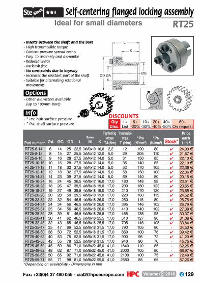
129 Fax: +33(0)4 37 490 055 - [email protected] Volume 2 2016
DISCOUNTSQty 1+ 6+ 10+ 20+ 40+ 60+
Disc. List -20% -30% -40% -50% On request
Part number ØA ØG ØD LScrewM K
Tightening torque
TA(Nm)
Transmissibletorque
T (Nm)*Pw
(N/mm2)*Pn
(N/mm2)
Price each1 to 5
*Depending on availabiliity - Dimensions in mm
Self-centering flanged locking assemblyRT25
- Inserts between the shaft and the bore- High transmissible torque- Contact pressure spread evenly- Easy to assembly and dismantle- Reduced width- Backlash free- No constraints due to keyway- Increases the resistant part of the shaft- Suitable for alternating rotational
movements
.Options.- Other diameters available
(up to 100mm bore)
.Info.- * PN: hub surface pressure- * Pw: shaft surface pressure
Ideal for small diameters
ØD
K
L
ØGØA
Stock*RT25-6-14 6 14 25 22,5 3xM3x10 10,0 2,2 12 190 80 4 24,90 FRT25-8-15 8 15 27 25,5 3xM4x12 12,0 5,0 29 205 110 4 21,87 FRT25-9-16 9 16 28 27,5 3xM4x12 14,0 5,0 31 150 85 4 22,10 FRT25-10-16 10 16 28 27,5 3xM4x12 14,0 5,0 35 140 85 4 22,10 FRT25-11-18 11 18 32 27,5 4xM4x12 14,0 5,0 52 170 105 4 22,36 FRT25-12-18 12 18 32 27,5 4xM4x12 14,0 5,0 58 150 100 4 22,36 FRT25-14-23 14 23 39 27,5 4xM4x12 14,0 5,0 69 140 80 4 20,15 FRT25-16-24 16 24 45 36,5 4xM6x12 16,0 17,0 180 148 98 4 23,51 FRT25-18-26 18 26 47 39,5 4xM6x18 19,0 17,0 200 180 125 4 23,65 FRT25-19-27 19 27 49 39,5 4xM6x18 19,0 17,0 210 170 120 4 23,65 FRT25-20-28 20 28 50 39,5 4xM6x18 19,0 17,0 220 160 115 4 24,52 FRT25-22-32 22 32 54 46,5 4xM6x18 26,0 17,0 250 115 80 4 26,75 FRT25-24-34 24 34 56 46,5 6xM6x18 26,0 17,0 395 146 102 - 26,79 FRT25-25-34 25 34 56 46,5 6xM6x18 26,0 17,0 410 140 102 4 27,38 FRT25-28-39 28 39 61 46,5 6xM6x18 25,5 17,0 465 135 98 4 30,37 FRT25-30-41 30 41 62 46,5 6xM6x18 25,5 17,0 510 127 90 4 31,08 FRT25-32-43 32 43 65 46,5 8xM6x18 25,5 17,0 705 146 108 4 33,84 FRT25-35-47 35 47 69 52,5 8xM6x18 31,5 17,0 790 105 80 - 34,50 FRT25-38-50 38 50 72 52,5 8xM6x18 31,5 17,0 860 100 76 4 39,42 FRT25-40-53 40 53 75 52,5 8xM6x18 31,5 17,0 900 96 72 4 41,20 FRT25-42-55 42 55 78 52,5 8xM6x18 31,5 17,0 940 90 70 - 45,75 FRT25-45-59 45 59 86 71,0 8xM8x22 45,0 41,0 1840 110 85 - 62,25 FRT25-48-62 48 62 87 71,0 8xM8x22 45,0 41,0 2000 105 80 - 66,97 FRT25-50-65 50 65 92 71,0 8xM8x22 45,0 41,0 2100 100 75 4 72,49 FRT25-55-71 55 71 98 81,0 9xM8x22 55,0 41,0 2580 85 65 - 87,26 F
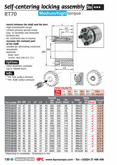
130 www.hpceurope.com - Tel: +33(0)4 37 496 496Volume 2 2016
Part number ØA ØD L1 L2 L3 LTransmissible
torque(Nm)
Pw(N/mm2)
Tightening torque(Nm)
Screws No. Type
Pn(N/mm2)
Price each 1 to 5
LL2L1
L3
Self-centering locking assembly Medium/high torqueRT70
- Inserts between the shaft and the bore- High transmissible torque- Contact pressure spread evenly- Easy to assembly and dismantle- Backlash free- No constraints due to keyway- Increases the resistant part
of the shaft- Suitable for alternating rotational
movements- Materials:
Body: steelScrews: steel DIN 912 12.9
.Options.- Other diameters available
(up to 180mm bore)
.Info..- * PN: hub surface pressure- * PW: shaft surface pressure
ØDØA
RT70-19-47 19 47 26 31 39 45 350 228 98 4 M6x25 17 4 13,43 FRT70-20-47 20 47 26 31 39 45 390 231 100 4 M6x25 17 4 13,43 FRT70-22-47 22 47 26 31 39 45 440 220 95 4 M6x25 17 4 13,43 FRT70-24-50 24 50 26 31 39 45 519 215 102 6 M6x25 17 - 14,02 FRT70-25-50 25 50 26 31 39 45 590 230 105 6 M6x25 17 4 14,02 FRT70-28-55 28 55 26 31 39 45 700 220 110 6 M6x25 17 4 15,92 FRT70-30-55 30 55 26 31 39 45 760 200 120 6 M6x25 17 4 15,92 FRT70-32-60 32 60 26 31 39 45 930 230 114 8 M6x25 17 4 17,27 FRT70-35-60 35 60 26 31 39 45 1030 200 119 8 M6x25 17 4 17,27 FRT70-38-65 38 65 26 31 39 45 1240 210 124 8 M6x25 17 4 19,62 FRT70-40-65 40 65 26 31 39 45 1350 200 125 8 M6x25 17 4 19,62 FRT70-42-75 42 75 30 36 47 55 2170 236 140 6 M8x30 41 - 26,27 FRT70-45-75 45 75 30 36 47 55 2350 236 140 6 M8x30 41 4 26,27 FRT70-48-80 48 80 30 36 47 55 2510 218 135 6 M8x30 41 4 29,36 FRT70-50-80 50 80 30 36 47 55 2580 218 135 6 M8x30 41 4 29,36 FRT70-55-85 55 85 30 36 47 55 3200 223 145 8 M8x30 41 4 33,52 FRT70-60-90 60 90 30 36 47 55 3380 198 157 8 M8x30 41 4 35,97 FRT70-65-95 65 95 30 36 47 55 4160 213 140 8 M8x30 41 - 38,70 FRT70-70-110 70 110 40 46 57 67 6840 225 143 8 M10x35 83 4 59,06 F
Stock*
DISCOUNTSQty 1+ 6+ 20+ 40+ 60+ 100+
Disc. List -10% -15% -20% -25% On request
*Depending on availability - Dimensions in mm

131 Fax: +33(0)4 37 490 055 - [email protected] Volume 2 2016
DISCOUNTSQty 1+ 6+ 20+ 40+ 60+ 100+
Disc. List -10% -15% -20% -25% On request
Part number ØA ØD B L CScrew
M
Tightening torque
TA (Nm) T (Nm)*Pw
(N/mm2)*Pn
(N/mm2)
Price each 1
to 5
Transmissible torque
+ axial load
High torque RTL450Self-centering locking assembly
ØDØA
B
CL
- Inserts between the shaft and the bore
- High transmissible torque- Contact pressure spread evenly- Easy to assembly and dismantle- Reduced width- Backlash free- No constraints due to keyway- Increases the resistant part
of the shaft- Suitable for alternating rotational
movements- Up to 3 units can be used together- Material: Steel
.Options.- Other diameters available
(up to 300mm bore)
.Info..- *PN: hub surface pressure- *PW: shaft surface pressure
RTL450-25-55 25 55 32 40 46 6xM6x35 17 295 295 134 4 26,97 FRTL450-30-55 30 55 32 40 46 6xM6x35 17 246 246 134 4 27,72 FRTL450-35-60 35 60 44 54 60 7xM6x45 17 174 174 101 4 33,72 FRTL450-38-75 38 75 44 54 62 7xM8x50 41 296 296 150 - 42,08 FRTL450-40-75 40 75 44 54 62 7xM8x50 41 281 281 150 4 42,08 FRTL450-42-75 42 75 44 54 62 7xM8x50 41 268 268 150 - 45,51 FRTL450-45-75 45 75 44 54 62 7xM8x50 41 250 250 150 - 45,51 FRTL450-48-80 48 80 44 54 62 8xM8x50 41 207 207 124 4 52,48 FRTL450-50-80 50 80 56 64 72 8xM8x50 41 200 200 98 4 52,48 FRTL450-55-85 55 85 56 64 72 9xM8x50 41 205 205 104 4 59,44 FRTL450-60-90 60 90 56 64 72 10xM8x50 41 202 202 106 4 63,93 FRTL450-65-95 65 95 56 64 72 10xM8x50 41 187 187 100 4 70,17 FRTL450-70-110 70 110 70 78 88 10xM10x60 83 223 223 114 4 95,72 FRTL450-75-115 75 115 70 78 88 10xM10x60 83 223 223 114 4 103,71 FRTL450-80-120 80 120 70 78 88 11xM10x60 83 215 215 115 4 110,42 FRTL450-85-125 85 125 70 78 88 12xM10x60 83 215 215 115 - 118,38 FRTL450-90-130 90 130 70 78 88 12xM10x60 83 208 208 115 - 122,02 FRTL450-95-135 95 135 70 78 88 12xM10x60 83 208 208 115 - 138,00 FRTL450-100-145 100 145 90 100 112 11xM12x80 145 200 200 107 - 185,35 F
Stock*
*Depending on availability - Dimensions in mm
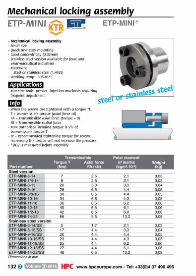
132 www.hpceurope.com - Tel: +33(0)4 37 496 496Volume 2 2016
ETP-MINI®
Transmissible Polar momentTorque T Axial force of inertia Weight
Part number (Nm) FA (kN) (kgm2.10-3) (kg)Steel versionETP-MINI-6-14 7 2,5 2,1 0,03ETP-MINI-1/4-14 8 2,5 2,1 0,03ETP-MINI-8-15 20 5,0 3,3 0,04ETP-MINI-9-16 28 6,5 4,4 0,05ETP-MINI-3/8-16 30 6,5 4,4 0,05ETP-MINI-10-16 34 6,5 4,3 0,05ETP-MINI-11-18 36 6,5 6,2 0,06ETP-MINI-12-18 40 6,5 6,1 0,06ETP-MINI-1/2-18 42 6,5 6,0 0,06ETP-MINI-14-22 66 9,5 13,2 0,08Stainless steel versionETP-MINI-6-14/SS 5 1,7 2,1 0,03ETP-MINI-8-15/SS 17 4,4 3,3 0,04ETP-MINI-9-16/SS 20 4,4 4,4 0,05ETP-MINI-10-16/SS 23 4,4 4,3 0,05ETP-MINI-11-18/SS 25 4,4 6,2 0,06ETP-MINI-12-18/SS 27 4,4 6,1 0,06ETP-MINI-14-22/SS 48 6,5 13,2 0,08
ETP-MINI
- Mechanical locking assembly- Small size- Quick and easy mounting- Good concentricity (0.02mm)- Stainless steel version available for food and
pharmaceutical industries- M aterials:
Steel or stainless steel (1.4565)- Working temp: -30/+85°C
.Applications.- Machine tools, presses, injection machines requiring
frequent adjustment
.Info.- When the screws are tightened with a torque Tt:
T = transmissible torque (axial force =0) FA = Transmissible axial force (torque = 0) FR = Transmissible radial force
- Max authorised bending torque is 5% of transmissible torque T
- Tt = Recommended tightening torque for screws. Increasing the torque will not increase the pressure
- *ØD2 is measured before assembly
Dimensions in mm
Mechanical locking assembly
steel or stainless steel
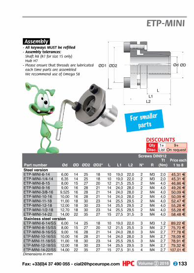
133 Fax: +33(0)4 37 490 055 - [email protected] Volume 2 2016
Screws DIN912Tt Price each
Part number Ød ØD ØD2 ØD2* L L1 L2 N° R (Nm) 1 to 8Steel versionETP-MINI-6-14 6,00 14 25 18 10 19,0 22,0 2 M3 2,0 45,31 AETP-MINI-1/4-14 6,35 14 25 18 10 19,0 22,0 2 M3 2,0 45,31 AETP-MINI-8-15 8,00 15 27 20 12 21,5 25,5 2 M4 4,0 46,86 AETP-MINI-9-16 9,00 16 28 21 14 24,0 28,0 2 M4 4,0 49,26 AETP-MINI-3/8-16 9,525 16 28 21 14 24,0 28,0 2 M4 4,0 50,09 AETP-MINI-10-16 10,00 16 28 21 14 24,0 28,0 2 M4 4,0 50,09 AETP-MINI-11-18 11,00 18 30 23 14 25,5 29,5 2 M4 4,0 52,47 AETP-MINI-12-18 12,00 18 30 23 14 25,5 29,5 2 M4 4,0 55,28 AETP-MINI-1/2-18 12,70 18 30 23 14 25,5 29,5 2 M4 4,0 55,28 AETP-MINI-14-22 14,00 22 35 27 15 27,5 31,5 3 M4 4,0 58,48 AStainless steel versionETP-MINI-6-14/SS 6,00 14 25 18 10 19,0 22,0 3 M3 1,2 89,22 AETP-MINI-8-15/SS 8,00 15 27 20 12 21,5 25,5 3 M4 2,7 75,70 AETP-MINI-9-16/SS 9,00 16 28 21 14 24,0 28,0 3 M4 2,7 77,78 AETP-MINI-10-16/SS 10,00 16 28 21 14 24,0 28,0 3 M4 2,7 78,09 AETP-MINI-11-18/SS 11,00 18 30 23 14 25,5 29,5 3 M4 2,7 78,91 AETP-MINI-12-18/SS 12,00 18 30 23 14 25,5 29,5 3 M4 2,7 79,32 AETP-MINI-14-22/SS 14,00 22 35 27 15 27,5 31,5 4 M4 2,7 107,01 A
ETP-MINI
.Assembly.- All keyways MUST be refilled- Assembly tolerances: Shaft h8 (h7 for size 15 only)
Hub H7- Please ensure that threads are lubricated
each time parts are assembled We recommend use of Omega 58
Dimensions in mm
9+On request
1+List
QtyDisc.
DISCOUNTS
ØD1
L
Ød ØD
L1L2
ØD2
For smaller parts
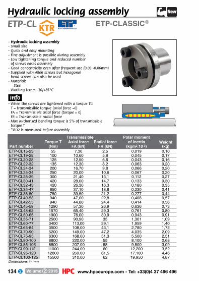
134 www.hpceurope.com - Tel: +33(0)4 37 496 496Volume 2 2016
ETP-CLASSIC®ETP-CLHydraulic locking assembly
- Hydraulic locking assembly- Small size- Quick and easy mounting- Fine adjustment is possible during assembly- Low tightening torque and reduced number
of screws eases assembly- Good concentricity even after frequent use (0.03 -0.06mm)- Supplied with Allen screws but hexagonal
head screws can also be used- M aterial:
Steel- Working temp: -30/+85°C
.Info.- When the screws are tightened with a torque Tt:
T = transmissible torque (axial force =0) FA = Transmissible axial force (torque = 0) FR = Transmissible radial force
- Max authorised bending torque is 5% of transmissible torque T
- *ØD2 is measured before assembly.
Transmissible Polar momentTorque T Axial force Radial force of inertia Weight
Part number (Nm) FA (kN) FR (kN) (kgm2.10-3) (kg)ETP-CL15-23 55 7,30 2,5 0,019 0,10ETP-CL19-28 100 10,60 5,8 0,045 0,17ETP-CL20-28 125 12,50 6,6 0,043 0,16ETP-CL22-32 135 12,30 8,2 0,063 0,20ETP-CL24-34 200 16,70 9,8 0,066 0,20ETP-CL25-34 250 20,00 10,6 0,067 0,20ETP-CL28-39 300 21,40 13,1 0,112 0,27ETP-CL30-41 420 28,00 14,7 0,133 0,30ETP-CL32-43 420 26,30 16,3 0,180 0,35ETP-CL35-47 650 37,10 18,8 0,230 0,41ETP-CL38-50 750 39,50 21,2 0,277 0,44ETP-CL40-53 940 47,00 22,8 0,408 0,57ETP-CL42-55 940 44,80 24,4 0,414 0,56ETP-CL45-59 1290 57,30 26,9 0,636 0,73ETP-CL48-62 1570 65,40 29,3 0,761 0,80ETP-CL50-65 1900 76,00 30,9 0,943 0,91ETP-CL55-71 2500 90,90 35 1,301 1,09ETP-CL60-77 3400 113,00 39,1 1,959 1,40ETP-CL65-84 3500 108,00 43,1 2,780 1,72ETP-CL70-90 5200 149,00 47,2 4,035 2,09ETP-CL75-95 6300 168,00 51,3 5,500 2,51ETP-CL80-100 8800 220,00 55 8,100 2,68ETP-CL85-106 8800 207,00 58 9,500 3,09ETP-CL90-112 11000 244,00 60 12,200 3,52ETP-CL95-120 12800 269,00 61,5 17,100 4,46ETP-CL100-125 15500 310,00 62 19,950 4,87Dimensions in mm

135 Fax: +33(0)4 37 490 055 - [email protected] Volume 2 2016
ETP-CL
Screws DIN915Tt Price each
Part number Ød ØD ØD2 ØD2* L L1 L2 Nb R (Nm) 1 to 8ETP-CL15-23 15 23 38 28,5 17 30 35 3 M5 6 145,50 AETP-CL19-28 19 28 45 35,0 21 37 42 3 M5 8 146,64 AETP-CL20-28 20 28 45 35,0 22 37 42 3 M5 8 149,85 AETP-CL22-32 22 32 49 40,0 22 37 42 4 M5 8 151,08 AETP-CL24-34 24 34 49 40,0 25 40 45 4 M5 8 152,65 AETP-CL25-34 25 34 49 40,0 27 43 48 4 M5 8 157,10 AETP-CL28-39 28 39 55 46,0 29 45 50 4 M5 8 165,09 AETP-CL30-41 30 41 57 47,5 32 47 52 4 M5 8 177,85 AETP-CL32-43 32 43 60 50,5 34 52 57 4 M5 8 179,51 AETP-CL35-47 35 47 63 53,5 37 55 60 6 M5 8 199,53 AETP-CL38-50 38 50 65 56,0 41 59 64 6 M5 8 211,56 AETP-CL40-53 40 53 70 60,5 43 63 68 6 M5 8 221,60 AETP-CL42-55 42 55 70 60,5 45 65 70 6 M5 8 230,03 AETP-CL45-59 45 59 77 66,5 49 69 75 6 M6 13 250,02 AETP-CL48-62 48 62 80 69,5 52 73 79 6 M6 13 265,29 AETP-CL50-65 50 65 83 72,5 53 76 82 6 M6 13 276,48 AETP-CL55-71 55 71 88 78,0 58 82 88 8 M6 13 303,76 AETP-CL60-77 60 77 95 84,5 64 90 96 8 M6 13 329,78 AETP-CL65-84 65 84 102 91,0 68 96 102 8 M6 13 371,06 AETP-CL70-90 70 90 113 99,0 72 99 107 6 M8 32 435,99 AETP-CL75-95 75 95 118 104,0 85 114 122 6 M8 32 720,05 AETP-CL80-100 80 100 123 109,0 90 120 128 6 M8 32 758,10 AETP-CL85-106 85 106 129 115,0 95 125 133 6 M8 32 1194,51 AETP-CL90-112 90 112 135 121,0 100 133 141 8 M8 32 1007,32 AETP-CL95-120 95 120 143 129,0 105 139 147 8 M8 32 1443,30 AETP-CL100-125 100 125 148 134,0 110 145 153 8 M8 32 1156,02 ADimensions in mm
9+On request
1+List
QtyDisc.
DISCOUNTSØD1
ØdØD
LL1 L2
ØD2
.Applications.- Machine tools, presses, injection machines requiring frequent
adjustment
.Assembly.- All keyways MUST be refilled.- Assembly tolerances: Shaft h8 – k6 (h7 for size 15 only)- When using a k6 shaft, transmissible torque (+20%)- When using a h9 shaft, transmissible torque (-25%) Hub H7
.Torque.- The transmissible torque T is for a static load.- If the load is an alternating or pulsating torque, reduce the
transmissible torque T by the following factor ( factor x T): Alternating : 0.6 x T for sizes 15-30mm.
0.5 x T for sizes 32-100mm.Pulsating : 0.7 x T for sizes 15-30mm.
0.6 x T for sizes 32-100mm.
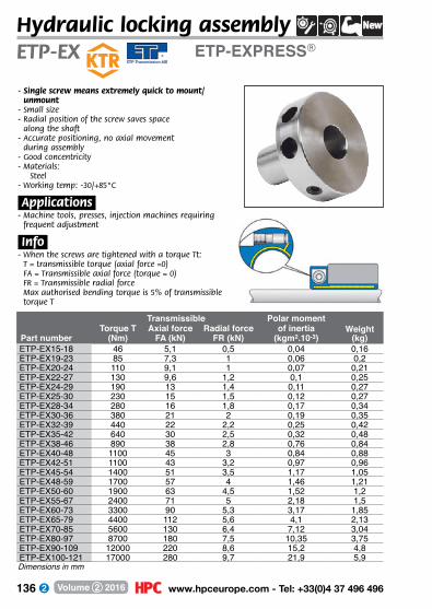
136 www.hpceurope.com - Tel: +33(0)4 37 496 496Volume 2 2016
ETP-EXPRESS®ETP-EXHydraulic locking assembly
Transmissible Polar momentTorque T Axial force Radial force of inertia Weight
Part number (Nm) FA (kN) FR (kN) (kgm2.10-3) (kg)ETP-EX15-18 46 5,1 0,5 0,04 0,16ETP-EX19-23 85 7,3 1 0,06 0,2ETP-EX20-24 110 9,1 1 0,07 0,21ETP-EX22-27 130 9,6 1,2 0,1 0,25ETP-EX24-29 190 13 1,4 0,11 0,27ETP-EX25-30 230 15 1,5 0,12 0,27ETP-EX28-34 280 16 1,8 0,17 0,34ETP-EX30-36 380 21 2 0,19 0,35ETP-EX32-39 440 22 2,2 0,25 0,42ETP-EX35-42 640 30 2,5 0,32 0,48ETP-EX38-46 890 38 2,8 0,76 0,84ETP-EX40-48 1100 45 3 0,84 0,88ETP-EX42-51 1100 43 3,2 0,97 0,96ETP-EX45-54 1400 51 3,5 1,17 1,05ETP-EX48-59 1700 57 4 1,46 1,21ETP-EX50-60 1900 63 4,5 1,52 1,2ETP-EX55-67 2400 71 5 2,18 1,5ETP-EX60-73 3300 90 5,3 3,17 1,85ETP-EX65-79 4400 112 5,6 4,1 2,13ETP-EX70-85 5600 130 6,4 7,12 3,04ETP-EX80-97 8700 180 7,5 10,35 3,75ETP-EX90-109 12000 220 8,6 15,2 4,8ETP-EX100-121 17000 280 9,7 21,9 5,9Dimensions in mm
- Single screw means extremely quick to mount/unmount
- Small size- Radial position of the screw saves space
along the shaft- Accurate positioning, no axial movement
during assembly- Good concentricity- M aterials:
Steel- Working temp: -30/+85°C
.Applications.- Machine tools, presses, injection machines requiring
frequent adjustment
.Info.- When the screws are tightened with a torque Tt:
T = transmissible torque (axial force =0) FA = Transmissible axial force (torque = 0) FR = Transmissible radial force Max authorised bending torque is 5% of transmissible torque T
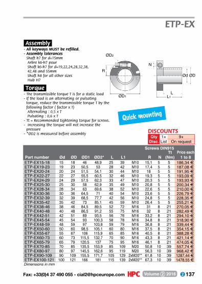
137 Fax: +33(0)4 37 490 055 - [email protected] Volume 2 2016
ØD2
R
ØD1 L1L
Ød ØD
N
ETP-EX
Dimensions in mm
Screws DIN915Tt Price each
Part number Ød ØD ØD1 ØD2* L L1 R N (Nm) 1 to 8ETP-EX15-18 15 18 46 48,9 25 39 M10 15,1 5 5 186,34 AETP-EX19-23 19 23 50,5 53 28 42 M10 17,4 5 5 187,08 AETP-EX20-24 20 24 51,5 54,1 30 44 M10 18 5 5 191,95 AETP-EX22-27 22 27 55,5 60,5 32 46 M10 19,3 5 5 193,09 AETP-EX24-29 24 29 57,5 62,3 33 47 M10 20,3 5 5 193,93 AETP-EX25-30 25 30 58 62,9 35 49 M10 20,8 5 5 200,34 AETP-EX28-34 28 34 63 69,6 38 52 M10 22,6 5 5 210,00 AETP-EX30-36 30 36 64,5 71 40 54 M10 23,6 5 5 226,79 AETP-EX32-39 32 39 68,5 77,7 42 56 M10 24,8 5 5 228,35 AETP-EX35-42 35 42 73 85,1 45 59 M10 26,4 5 5 255,21 AETP-EX38-46 38 46 84,5 89,5 52 72 M16 31 8 21 270,05 AETP-EX40-48 40 48 86,5 91,2 55 75 M16 32 8 21 282,49 AETP-EX42-51 42 51 89 93,5 56 76 M16 33,2 8 21 294,10 AETP-EX45-54 45 54 93 100,3 58 78 M16 34,8 8 21 318,90 AETP-EX48-59 48 59 97 103,8 59 79 M16 36,8 8 21 339,44 AETP-EX50-60 50 60 98,5 105,1 60 80 M16 37,5 8 21 354,15 AETP-EX55-67 55 67 106 115,9 65 85 M16 40,5 8 21 388,28 AETP-EX60-73 60 73 115,5 132,7 70 90 M16 43,3 8 21 421,14 AETP-EX65-79 65 79 120,5 137 75 95 M16 46,1 8 21 474,05 AETP-EX70-85 70 85 135,5 153,9 85 109 M20 50,8 10 39 557,74 AETP-EX80-97 80 97 145,5 162,6 95 119 M20 56,3 10 39 968,42 AETP-EX90-109 90 109 155,5 171,7 105 129 2xM20** 61,8 10 39 1287,44 AETP-EX100-121 100 121 166 181 115 139 2xM20** 67,3 10 39 1478,55 A
.Assembly.- All keyways MUST be refilled.- Assembly tolerances
Shaft h7 for d=15mm Arbre k6-h7 pour Shaft k6-h7 for d=19,22,24,28,32,38,
42,48 and 55mm Shaft h8 for all other sizes Hub H7
.Torque.- The transmissible torque T is for a static load- If the load is an alternating or pulsating
torque, reduce the transmissible torque T by the following factor ( factor x T)
Alternating : 0,5 x T Pulsating : 0,6 x T - Tt = Recommended tightening torque for screws.- Increasing the torque will not increase the
pressure- *ØD2 is measured before assembly
9+On request
1+List
QtyDisc.
DISCOUNTS
Quick mounting
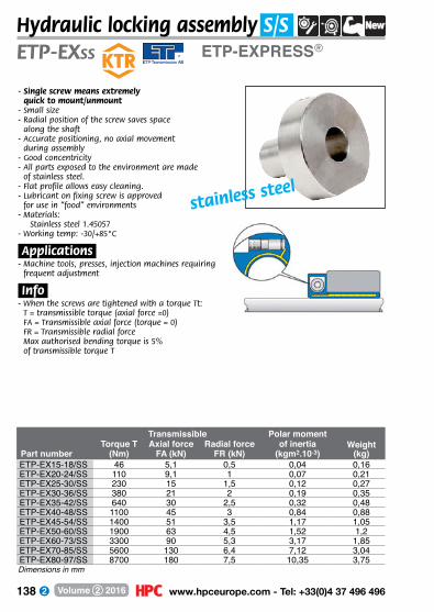
138 www.hpceurope.com - Tel: +33(0)4 37 496 496Volume 2 2016
ETP-EXPRESS®ETP-EXSS
Hydraulic locking assembly S/S
Transmissible Polar momentTorque T Axial force Radial force of inertia Weight
Part number (Nm) FA (kN) FR (kN) (kgm2.10-3) (kg)ETP-EX15-18/SS 46 5,1 0,5 0,04 0,16ETP-EX20-24/SS 110 9,1 1 0,07 0,21ETP-EX25-30/SS 230 15 1,5 0,12 0,27ETP-EX30-36/SS 380 21 2 0,19 0,35ETP-EX35-42/SS 640 30 2,5 0,32 0,48ETP-EX40-48/SS 1100 45 3 0,84 0,88ETP-EX45-54/SS 1400 51 3,5 1,17 1,05ETP-EX50-60/SS 1900 63 4,5 1,52 1,2ETP-EX60-73/SS 3300 90 5,3 3,17 1,85ETP-EX70-85/SS 5600 130 6,4 7,12 3,04ETP-EX80-97/SS 8700 180 7,5 10,35 3,75
stainless steel
- Single screw means extremely quick to mount/unmount
- Small size- Radial position of the screw saves space
along the shaft- Accurate positioning, no axial movement
during assembly- Good concentricity- All parts exposed to the environment are made
of stainless steel.- Flat profile allows easy cleaning.- Lubricant on fixing screw is approved
for use in “food” environments- M aterials:
Stainless steel 1.45057- Working temp: -30/+85°C
.Applications.- Machine tools, presses, injection machines requiring
frequent adjustment
.Info.- When the screws are tightened with a torque Tt:
T = transmissible torque (axial force =0) FA = Transmissible axial force (torque = 0) FR = Transmissible radial force Max authorised bending torque is 5% of transmissible torque T
Dimensions in mm
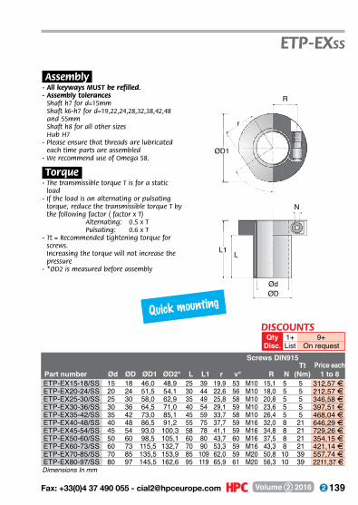
139 Fax: +33(0)4 37 490 055 - [email protected] Volume 2 2016
ETP-EXSS
Screws DIN915Tt Price each
Part number Ød ØD ØD1 ØD2* L L1 r v° R N (Nm) 1 to 8ETP-EX15-18/SS 15 18 46,0 48,9 25 39 19,9 53 M10 15,1 5 5 312,57 AETP-EX20-24/SS 20 24 51,5 54,1 30 44 22,6 56 M10 18,0 5 5 212,57 AETP-EX25-30/SS 25 30 58,0 62,9 35 49 25,8 58 M10 20,8 5 5 346,58 AETP-EX30-36/SS 30 36 64,5 71,0 40 54 29,1 59 M10 23,6 5 5 397,51 AETP-EX35-42/SS 35 42 73,0 85,1 45 59 33,7 58 M10 26,4 5 5 468,04 AETP-EX40-48/SS 40 48 86,5 91,2 55 75 37,7 59 M16 32,0 8 21 646,29 AETP-EX45-54/SS 45 54 93,0 100,3 58 78 41,1 59 M16 34,8 8 21 729,26 AETP-EX50-60/SS 50 60 98,5 105,1 60 80 43,7 60 M16 37,5 8 21 354,15 AETP-EX60-73/SS 60 73 115,5 132,7 70 90 53,3 59 M16 43,3 8 21 421,14 AETP-EX70-85/SS 70 85 135,5 153,9 85 109 62,0 59 M20 50,8 10 39 557,74 AETP-EX80-97/SS 80 97 145,5 162,6 95 119 65,9 61 M20 56,3 10 39 2211,37 A
.Assembly.- All keyways MUST be refilled.- Assembly tolerances
Shaft h7 for d=15mm Shaft k6-h7 for d=19,22,24,28,32,38,42,48 and 55mm Shaft h8 for all other sizes Hub H7
- Please ensure that threads are lubricated each time parts are assembled
- We recommend use of Omega 58.
.Torque.- The transmissible torque T is for a static
load- If the load is an alternating or pulsating
torque, reduce the transmissible torque T by the following factor ( factor x T)
Alternating: 0.5 x T Pulsating: 0.6 x T- Tt = Recommended tightening torque for
screws. Increasing the torque will not increase the pressure
- *ØD2 is measured before assembly
9+On request
1+List
QtyDisc.
DISCOUNTS
Dimensions In mm
R
ØD1
r
L1 L
Ød
NØD
Quick mounting
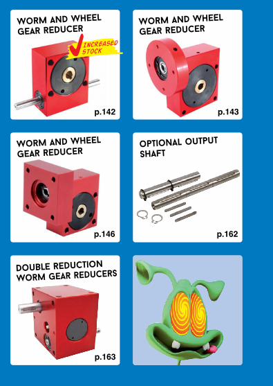
140 www.hpceurope.com - Tel: +33(0)4 37 496 496Volume 2 2016
worm and wheel
gear reducer
worm and wheel
gear reducer
worm and wheel
gear reducer
optional output
shaft
p.162
p.163
double reduction
worm gear reducers
p.142 p.143
p.146
Increasedstock
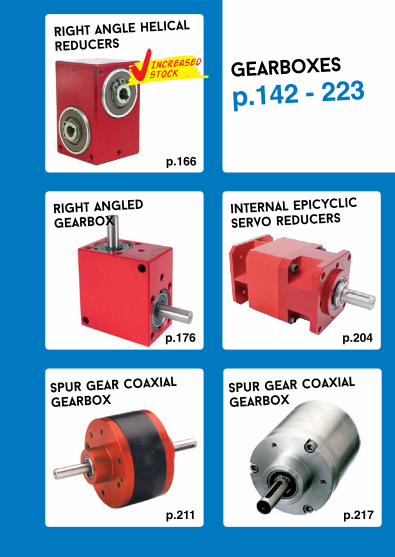
141 Fax: +33(0)4 37 490 055 - [email protected] Volume 2 2016
gearboxes
p.142 - 223
right angle helical
reducers
p.166
internal epicyclic
servo reducers
p.204p.176
right angled gearbox
p.217p.211
spur gear coaxial
gearboxspur gear coaxial
gearbox
Increasedstock

142 www.hpceurope.com - Tel: +33(0)4 37 496 496Volume 2 2016
Worm and wheel gear reducer
22
Ø5
40
40
Ø6
High reduction ratios
P15 Torque up to 3,75Nm
- Ratios from 5:1 to 120:1- Output backlash –~0°30’- Max. input speed: 3000 rpm- Materials:
Casing: anodised aluminium Input: high carbon steel Output: Bronze
- Weight: 0,15 kg
.Options.- Can be modified to your
specifications
.Accessories.- Output shafts
P20-X and P20-DX
22
4 32
5
Ø5h7
20 40 20
16
15
9
Ø6H7keyway2JS9
(4) Ø3,30
15
OUTPUT TORQUE (Nm values given as a guide only)Ratios 6,66:1 8:1 10:1 13,33:1 20:1 40:1 80:1
3000 1,05 1,13 1,20 1,28 1,43 1,58 0,942000 1,28 1,28 1,35 1,35 1,58 1,80 1,071000 1,58 1,73 1,73 1,88 2,03 2,18 1,28
INPUT 500 2,03 2,03 2,10 2,18 2,40 2,63 1,46SPEED 200 2,55 2,63 2,63 2,78 2,93 3,08 1,70(rpm) 100 2,93 2,93 3,08 3,15 3,23 3,38 1,91
50 3,30 3,38 3,38 3,45 3,53 3,60 2,0410 3,60 3,60 3,68 3,68 3,75 3,75 2,04
Dimensions in mm
DISCOUNTSQty 1+ 3+ 6+ 10+Disc. List -10%-15%On request
Increasedstock
Part Efficiency at Reflected inertia Anti-back Price eachnumber Ratios 1000 rpm at input (kg.m2) drive 1 to 2P15-6 6,66:1 86% 1,79x10⁻⁷ NO 4 244,99 FP15-8 8:1 85% 1,73x10⁻⁷ NO 4 244,99 FP15-10 10:1 84% 1,68x10⁻⁷ NO 4 244,99 FP15-13 13,33:1 78% 1,65x10⁻⁷ NO - 244,99 FP15-20 20:1 71% 1,62x10⁻⁷ NO - 244,99 FP15-40 40:1 60% 1,61x10⁻⁷ NO 4 244,99 FP15-80 80:1 32% 1,60x10⁻⁷ NO - 244,99 FP15-A Reduced output backlash ~ 0°8’ On requestP15-AR Reduced output backlash ~ 0°4’ On request
Stock*

143 Fax: +33(0)4 37 490 055 - [email protected] Volume 2 2016
22
Worm and wheel gear reducer
High reduction ratios
- Ratios from 6:1 to 80:1- Output backlash –~0°30’- Max input speed: 3000 rpm- Materials:
Casing: Anodised aluminium Input: High carbon steel Output: Bronze
- The angle of the input flange is not aligned- Verify it is suitable for use with your motor- Weight: 0,21 kg
22
40
40Ø6
Ø5
Ø45
Torque up to 5Nm PF15
3,4
3 Ø5H7 Ø1615
2mm wide5 deep. slot to suit Ø2x8 long pin 12 Ø45
15
16
4 324
40
9
Ø6H8keyway2JS9
(4) Ø3,305
15
Input arrangement
OUTPUT TORQUE (Nm values given as a guide only)
Efficiency at at input Anti-back Part number Ratios 1000 rpm (kg.m2) drive
Reflected inertia Price each1 to 2
Dimensions in mm
Ratios 6,66:1 8:1 10:1 13,33:1 20:1 40:1 80:13000 1,05 1,13 1,20 1,28 1,43 1,58 0,942000 1,28 1,28 1,35 1,35 1,58 1,80 1,071000 1,58 1,73 1,73 1,88 2,03 2,18 1,28
INPUT 500 2,03 2,03 2,10 2,18 2,40 2,63 1,46SPEED 200 2,55 2,63 2,63 2,78 2,93 3,08 1,70(rpm) 100 2,93 2,93 3,08 3,15 3,23 3,38 1,91
50 3,30 3,38 3,38 3,45 3,53 3,60 2,0410 3,60 3,60 3,68 3,68 3,75 3,75 2,04
PF15-6 6,66:1 86% 1,79x10⁻⁷ NO 314,91 FPF15-8 8:1 85% 1,73x10⁻⁷ NO 314,91 FPF15-10 10:1 84% 1,68x10⁻⁷ NO 314,91 FPF15-13 13,33:1 78% 1,65x10⁻⁷ NO 314,91 FPF15-20 20:1 71% 1,62x10⁻⁷ NO 314,91 FPF15-40 40:1 60% 1,61x10⁻⁷ NO 314,91 FPF15-80 80:1 32% 1,60x10⁻⁷ NO 314,91 FPF15-A Reduced output backlash ~ 0°8’ On requestPF15-AR Reduced output backlash ~ 0°4’ On request
DISCOUNTSQty 1+ 3+ 6+ 10+Disc. List -10%-15%On request
144 www.hpceurope.com - Tel: +33(0)4 37 496 496Volume 2 2016
22
Worm and wheel gear reducer
22
Ø5
47
40
Ø6
- Ratios from 5:1 to 120:1- Output backlash –~0°30’- Max. input speed: 3000 rpm- Materials:
Casing: anodised aluminium Input: high carbon steel Output: Bronze
- Weight: 0,18 kg
.Options.- Can be modified to your specifications
.Accessories.- Output shafts P-X and P-DX
*Depending on availability - Dimensions in mm
P20 Torque up to 5Nm
4 32
Ø5h7
20 40 20
18
20
9
Ø6H7keyway2JS9
(4) Ø4,20
24
5
OUTPUT TORQUE (Nm values given as a guide only)
Efficiency at Reflected inertia Price each Part number Ratios 1000 rpm at input (kg.m2) Anti-back drive 1 to 2
Ratios 10:1 12:1 15:1 20:1 30:1 60:1 120:13000 1,40 1,50 1,60 1,70 1,90 2,10 1,252000 1,70 1,70 1,80 1,80 2,10 2,40 1,421000 2,10 2,30 2,30 2,50 2,70 2,90 1,70
INPUT 500 2,70 2,70 2,80 2,90 3,20 3,50 1,94SPEED 200 3,40 3,50 3,50 3,70 3,90 4,10 2,27(rpm) 100 3,90 3,90 4,10 4,20 4,30 4,50 2,55
50 4,40 4,50 4,50 4,60 4,70 4,80 2,7210 4,80 4,80 4,90 4,90 5,00 5,00 2,72
Stock*P20-10 10:1 86% 2,03 x 10⁻⁷ NO 4 273,87 FP20-12 12:1 85% 1,93 x 10⁻⁷ NO 4 273,87 FP20-15 15:1 84% 1,85 x 10⁻⁷ NO 4 273,87 FP20-20 20:1 78% 1,78 x 10⁻⁷ NO 4 273,87 FP20-30 30:1 71% 1,74 x 10⁻⁷ NO 4 273,87 FP20-60 60:1 60% 1,71 x 10⁻⁷ YES 4 273,87 FP20-120 120:1 32% 1,50 x 10⁻⁷ YES 4 273,87 FP20-SP 5:1-120:1 Ratios from 5:1 to 120:1 or left handed - On requestP20-A Reduced output backlash ~ 0°8’ - On requestP20-AR Reduced output backlash ~ 0°4’ - On request
DISCOUNTSQty 1+ 3+ 6+ 10+Disc. List -10%-15%On request
High reduction ratios

145 Fax: +33(0)4 37 490 055 - [email protected] Volume 2 2016
Ø45
(4)M3 on Ø36 PCD
Worm and wheel gear reducer
- Ratios from 5:1 to 120:1- Output backlash –~0°30’- Max input speed: 3000 rpm- Materials:
Casing: Anodised aluminium Input: High carbon steel Output: Bronze
- The angle of the input flange is not aligned
- Verify it is suitable for use with your motor- Weight: 0,23 kg
Efficiency at Reflected inertia Price each Part number Ratios 1000 rpm at input (kg.m2) Anti-back drive 1 to 2
Torque up to 5Nm PF20
9
18
1222
20
324
40
Ø6H7keyway 2JS9
(4) Ø3,305
24
3,4
3 Ø5H7 Ø1615
2mm wide5 deep. slot to suit Ø2x8 long pin
22
47
40Ø6
Ø5
Ø45
Input arrangement
Ratios 10:1 12:1 15:1 20:1 30:1 60:1 120:13000 1,40 1,50 1,60 1,70 1,90 2,10 1,252000 1,70 1,70 1,80 1,80 2,10 2,40 1,421000 2,10 2,30 2,30 2,50 2,70 2,90 1,70
INPUT 500 2,70 2,70 2,80 2,90 3,20 3,50 1,94SPEED 200 3,40 3,50 3,50 3,70 3,90 4,10 2,27(rpm) 100 3,90 3,90 4,10 4,20 4,30 4,50 2,55
50 4,40 4,50 4,50 4,60 4,70 4,80 2,7210 4,80 4,80 4,90 4,90 5,00 5,00 2,72
OUTPUT TORQUE (Nm values given as a guide only)
PF20-10 10:1 86% 2,53 x 10⁻⁷ NO 349,20 FPF20-12 12:1 85% 2,43 x 10⁻⁷ NO 349,20 FPF20-15 15:1 84% 2,35 x 10⁻⁷ NO 349,20 FPF20-20 20:1 78% 2,28 x 10⁻⁷ NO 349,20 FPF20-30 30:1 71% 2,24 x 10⁻⁷ NO 349,20 FPF20-60 60:1 60% 2,21 x 10⁻⁷ YES 349,20 FPF20-120 120:1 32% 2,00 x 10⁻⁷ YES 349,20 FPF20-SP 5:1 - 120:1 Ratios from 5:1 to 120:1 or left handed On requestPF20-A Reduced output backlash ~ 0°8’ On requestPF20-AR Reduced output backlash ~ 0°4’ On request
Dimensions in mm
High reduction ratios
DISCOUNTSQty 1+ 3+ 6+ 10+Disc. List -10%-15%On request

146 www.hpceurope.com - Tel: +33(0)4 37 496 496Volume 2 2016
40 17 42SQ
22
20
931SQ
18Ø6H7keyway 2JS9
(4) Ø4,20
(4) Ø3.5 with Ø6 x 3mm
32
Worm and wheel gear reducer
NEMA 17
square flange
- Ratios from 5:1 to 120:1- Output backlash –~0°30’- Max. input speed: 3000 rpm- Materials:
Casing: anodised aluminiumInput: high carbon steelOutput: Bronze
- Weight: 0,23 kg
Torque up to 5NmPF20NM
4
5
24
2,56,5
Ø5H7 x 19 deep
Ø22,15
2mm wide5 deep. slot to suit Ø2x8 long pin
Input arrangement
Reflected Inertia Efficiency at Input at Anti back Price each Part number Ratio (kg.m2) 1000 rpm drive 1 to 2
OUTPUT TORQUE (Nm values given as a guide only)Ratios 10:1 12:1 15:1 20:1 30:1 60:1 120:1
3000 1,40 1,50 1,60 1,70 1,90 2,10 1,252000 1,70 1,70 1,80 1,80 2,10 2,40 1,421000 2,10 2,30 2,30 2,50 2,70 2,90 1,70
INPUT 500 2,70 2,70 2,80 2,90 3,20 3,50 1,94SPEED 200 3,40 3,50 3,50 3,70 3,90 4,10 2,27(rpm) 100 3,90 3,90 4,10 4,20 4,30 4,50 2,55
50 4,40 4,50 4,50 4,60 4,70 4,80 2,7210 4,80 4,80 4,90 4,90 5,00 5,00 2,72
PF20-10NM 10:1 2,53 x 10⁻⁷ 86% NO 349,20 FPF20-12NM 12:1 2,43 x 10⁻⁷ 85% NO 349,20 FPF20-15NM 15:1 2,35 x 10⁻⁷ 84% NO 349,20 FPF20-20NM 20:1 2,28 x 10⁻⁷ 78% NO 349,20 FPF20-30NM 30:1 2,24 x 10⁻⁷ 71% NO 349,20 FPF20-60NM 60:1 2,21 x 10⁻⁷ 60% YES 349,20 FPF20-120NM 120:1 2,00 x 10⁻⁷ 32% YES 349,20 FPF20-SPNM 5:1 - 120:1 Special ratios from 5:1 to 120:1 or left handed On requestPF20-ANM Reduced output backlash ~ 0°8’ On request
Dimensions in mm
DISCOUNTSQty 1+ 3+ 6+ 10+
Disc. List -10% -15% On request

147 Fax: +33(0)4 37 490 055 - [email protected] Volume 2 2016
Questions ? Need a quote ?
our technical team
is here to help
With made to measure items Help choosing the right component For any other questions
Tel. +33 (0)4 37 496 496Fax. +33 (0)4 37 490 055

148 www.hpceurope.com - Tel: +33(0)4 37 496 496Volume 2 2016
Worm and wheel gear reducerP30
- Ratios from 5:1 to 120:1- Output backlash –~0°30’- Max. input speed: 3000 rpm- Materials:
Casing: anodised aluminium Input: high carbon steel Output: Bronze
- Weight: 0,48 kg
.Options.- Can be modified to your
specifications
.Accessories.- Output shafts
P-X and P-DX
*Depending on availability - Dimensions in mm
Efficiency at Reflected inertia Price each Part number Ratios 1000 rpm at input (kg.m2) Anti-back drive 1 to 2
Torque up to 8.8Nm
5 50
Ø6h7
25 60 25
30
30
10
28
Ø8H7keyway2JS9
(4) Ø5,205
43
28
70
60
Ø8
Ø6
OUTPUT TORQUE (Nm values given as a guide only)Ratios 10:1 12:1 15:1 20:1 30:1 60:1 120:1
3000 2,50 2,50 2,60 2,70 3,00 3,50 3,402000 2,80 2,90 3,00 3,20 3,60 4,10 3,701000 3,50 3,70 4,00 4,20 4,50 5,00 4,60
INPUT 500 4,60 4,70 4,90 5,10 5,30 5,80 5,40SPEED 200 5,40 5,60 5,70 5,90 6,20 6,60 6,40(rpm) 100 6,00 6,00 6,50 6,50 7,00 7,50 6,70
50 7,50 7,80 8,00 8,30 8,30 8,60 6,7010 8,00 8,00 8,30 8,50 8,50 8,80 6,70
P30-10 10:1 90% 8,43 x 10⁻⁷ NO 4 338,73 FP30-12 12:1 88% 7,55 x 10⁻⁷ NO - 338,73 FP30-15 15:1 86% 6,92 x 10⁻⁷ NO - 338,73 FP30-20 20:1 84% 6,43 x 10⁻⁷ NO - 338,73 FP30-30 30:1 78% 6,08 x 10⁻⁷ NO 4 338,73 FP30-60 60:1 70% 5,87 x 10⁻⁷ YES 4 338,73 FP30-120 120:1 40% 5,72 x 10⁻⁷ YES 4 338,73 FP30-SP 5:1-120:1 Ratios from 5:1 to 120:1 or left handed - On requestP30-A Reduced output backlash ~ 0°8’ - On requestP30-AR Reduced output backlash ~ 0°4’ - On request
Stock*
High reduction ratios
DISCOUNTSQty 1+ 3+ 6+ 10+Disc. List -10%-15%On request
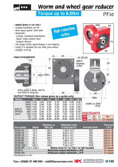
149 Fax: +33(0)4 37 490 055 - [email protected] Volume 2 2016
- Ratios from 5:1 to 120:1- Output backlash –~0°30’- Max input speed: 3000 rpm- Materials:
Casing: Anodised aluminium Input: High carbon steel Output: Bronze
- The angle of the input flange is not aligned- Verify it is suitable for use with your motor- Weight: 0,59 kg
(4)M4 on Ø46 PCD
28
10
30
14
Ø60
30
505
60
Ø8H7keyway2JS9
(4) Ø5,205
43
Worm and wheel gear reducerPF30Torque up to 8.8Nm
2,2
5 Ø6H7 Ø2620
2mm wide 5 deep. slot to suit Ø2x14 long pin
28
70
60Ø8
Ø6
Ø60
Input arrangement
Efficiency at Reflected inertia Price each Part number Ratios 1000 rpm at input (kg.m2) Anti-back drive 1 to 2
OUTPUT TORQUE (Nm values given as a guide only)Ratios 10:1 12:1 15:1 20:1 30:1 60:1 120:1
3000 2,50 2,50 2,60 2,70 3,00 3,50 3,402000 2,80 2,90 3,00 3,20 3,60 4,10 3,701000 3,50 3,70 4,00 4,20 4,50 5,00 4,60
INPUT 500 4,60 4,70 4,90 5,10 5,30 5,80 5,40SPEED 200 5,40 5,60 5,70 5,90 6,20 6,60 6,40(rpm) 100 6,00 6,00 6,50 6,50 7,00 7,50 6,70
50 7,50 7,80 8,00 8,30 8,30 8,60 6,7010 8,00 8,00 8,30 8,50 8,50 8,80 6,70
PF30-10 10:1 90% 1,00 x 10⁻⁶ NO 420,01 FPF30-12 12:1 88% 9,25 x 10⁻⁷ NO 420,01 FPF30-15 15:1 86% 8,62 x 10⁻⁷ NO 420,01 FPF30-20 20:1 84% 8,13 x 10⁻⁷ NO 420,01 FPF30-30 30:1 78% 7,88 x 10⁻⁷ NO 420,01 FPF30-60 60:1 70% 7,67 x 10⁻⁷ YES 420,01 FPF30-120 120:1 40% 7,42 x 10⁻⁷ YES 420,01 FPF30-SP 5:1-120:1 Ratios from 5:1 to 120:1 or left handed On requestPF30-A Reduced output backlash ~ 0°8’ On requestPF30-AR Reduced output backlash ~ 0°4’ On request
Dimensions in mm
High reduction ratios
DISCOUNTSQty 1+ 3+ 6+ 10+Disc. List -10%-15%On request

150 www.hpceurope.com - Tel: +33(0)4 37 496 496Volume 2 2016
NEMA 23
square flange
60 16 57,14SQ
30
1047,14SQ
30Ø8H7keyway 2JS9
(4) Ø5,2050 28
Worm and wheel gear reducer
OUTPUT TORQUE (Nm values given as a guide only)
- Ratios from 5:1 to 120:1- Output backlash –~0°30’- Max. input speed: 3000 rpm- Materials:
Casing: anodised aluminiumInput: high carbon steelOutput: Bronze
- Weight: 0,59 kg
Reflected Inertia Efficiency at Input at Anti back Price each Part number Ratio (kg.m2) 1000 rpm drive 1 to 2
Torque up to 8.8NmPF30NM
5
Ø6,35H7
Input arrangement
3Ø38,15
20
2mm wide 5 deep. slot to suit Ø2x10 long pin
2,3 5
43
(4) M4Ratios 10:1 12:1 15:1 20:1 30:1 60:1 120:13000 2,50 2,50 2,60 2,70 3,00 3,50 3,402000 2,80 2,90 3,00 3,20 3,60 4,10 3,701000 3,50 3,70 4,00 4,20 4,50 5,00 4,60
INPUT 500 4,60 4,70 4,90 5,10 5,30 5,80 5,40SPEED 200 5,40 5,60 5,70 5,90 6,20 6,60 6,40(rpm) 100 6,00 6,00 6,50 6,50 7,00 7,50 6,70
50 7,50 7,80 8,00 8,30 8,30 8,60 6,7010 8,00 8,00 8,30 8,50 8,50 8,80 6,70
PF30-10NM 10:1 1,00 x 10⁻⁶ 90% NO 420,01 FPF30-12NM 12:1 9,25 x 10⁻⁷ 88% NO 420,01 FPF30-15NM 15:1 8,62 x 10⁻⁷ 86% NO 420,01 FPF30-20NM 20:1 8,13 x 10⁻⁷ 84% NO 420,01 FPF30-30NM 30:1 7,88 x 10⁻⁷ 78% NO 420,01 FPF30-60NM 60:1 7,67 x 10⁻⁷ 70% YES 420,01 FPF30-120NM 120:1 7,42 x 10⁻⁷ 40% YES 420,01 FPF30-SPNM 5:1 - 120:1 Special ratios from 5:1 to 120:1 or left handed On requestPF30-ANM Reduced output backlash ~ 0°8’ On request
Dimensions in mm
DISCOUNTSQty 1+ 3+ 6+ 10+
Disc. List -10% -15% On request

151 Fax: +33(0)4 37 490 055 - [email protected] Volume 2 2016
32
15
37,5
16 58,20SQ
37,5
636
75
Ø10H7keyway 3JS9
(4) Ø5,806
50
- Ratios from 5:1 to 120:1- Output backlash –~0°30’- Max. input speed: 3000 rpm- Materials:
Casing: anodised aluminiumInput: high carbon steelOutput: Bronze
- Weight: 1,15 kg
Worm and wheel gear reducer
Reflected Inertia Efficiency at Input at Anti back Price each Part number Ratio (kg.m2) 1000 rpm drive 1 to 2
PF40NMTorque up to 18Nm
2,3
5 Ø6,35H7Ø38,15
20
Undercut 2mm x 5mm for Ø2 x 14mm dowel
Input arrangement
NEMA 23 square
flange
(4) M4OUTPUT TORQUE (Nm values given as a guide only)
Ratios 10:1 12:1 15:1 20:1 30:1 60:1 120:13000 5,00 5,20 5,40 5,60 6,40 7,20 6,502000 5,50 5,80 6,20 6,60 7,30 8,00 7,201000 7,10 7,50 8,00 8,20 9,00 10,00 8,70
INPUT 500 8,90 9,10 9,60 10,00 10,50 11,40 10,20SPEED 200 11,60 11,90 12,30 12,50 13,50 14,20 11,70(rpm) 100 13,40 13,60 14,10 14,60 15,30 16,00 12,30
50 15,10 15,50 16,20 16,40 17,30 17,60 12,3010 17,60 17,60 17,60 17,70 17,80 18,00 12,30
PF40-10NM 10:1 3,78 x 10⁻⁶ 89% NO 570,26 FPF40-12NM 12:1 3,62 x 10⁻⁶ 87% NO 570,26 FPF40-15NM 15:1 3,49 x 10⁻⁶ 85% NO 570,26 FPF40-20NM 20:1 3,39 x 10⁻⁶ 83% NO 570,26 FPF40-30NM 30:1 3,32 x 10⁻⁶ 76% NO 570,26 FPF40-60NM 60:1 3,27 x 10⁻⁶ 65% YES 570,26 FPF40-120NM 120:1 3,26 x 10⁻⁶ 41% YES 570,26 FPF40-SPNM 5:1 - 120:1 Special ratios from 5:1 to 120:1 or left handed On requestPF40-ANM Reduced output backlash ~ 0°8’ On request
Dimensions in mm
DISCOUNTSQty 1+ 3+ 6+ 10+
Disc. List -10% -15% On request

152 www.hpceurope.com - Tel: +33(0)4 37 496 496Volume 2 2016
- Ratios from 5:1 to 120:1- Output backlash –~0°30’- Max. input speed: 3000 rpm- Materials:
Casing: anodised aluminium Input: high carbon steel Output: Bronze
- Weight: 0,92 kg
.Options.- Can be modified to your
specifications
.Accessories.- Output shafts
P-X and P-DX
Worm and wheel gear reducerP40
*Depending on availability - Dimensions in mm
Efficiency at Reflected inertia Price each Part number Ratios 1000 rpm at input (kg.m2) Anti-back drive 1 to 2
32
Ø8
90
75
Ø10
Torque up to 18Nm
6 63
Ø8h7
40 75 40
37,5
37,5
15
32
Ø10H7keyway3JS9
(4) Ø5,80
50
6
OUTPUT TORQUE (Nm values given as a guide only)Ratios 10:1 12:1 15:1 20:1 30:1 60:1 120:1
3000 5,00 5,20 5,40 5,60 6,40 7,20 6,502000 5,50 5,80 6,20 6,60 7,30 8,00 7,201000 7,10 7,50 8,00 8,20 9,00 10,00 8,70
INPUT 500 8,90 9,10 9,60 10,00 10,50 11,40 10,20SPEED 200 11,60 11,90 12,30 12,50 13,50 14,20 11,70(rpm) 100 13,40 13,60 14,10 14,60 15,30 16,00 12,30
50 15,10 15,50 16,20 16,40 17,30 17,60 12,3010 17,60 17,60 17,60 17,70 17,80 18,00 12,30
Stock*P40-10 10:1 89% 2,94 x 10⁻⁶ NO 4 459,13 FP40-12 12:1 87% 2,69 x 10⁻⁶ NO - 459,13 FP40-15 15:1 85% 2,49 x 10⁻⁶ NO - 459,13 FP40-20 20:1 83% 2,33 x 10⁻⁶ NO 4 459,13 FP40-30 30:1 76% 2,22 x 10⁻⁶ NO - 459,13 FP40-60 60:1 65% 2,15 x 10⁻⁶ YES 4 459,13 FP40-120 120:1 41% 2,10 x 10⁻⁶ YES - 459,13 FP40-SP 5:1-120:1 Ratios from 5:1 to 120:1 or left handed - On requestP40-A Reduced output backlash ~ 0°8’ - On requestP40-AR Reduced output backlash ~ 0°4’ - On request
High reduction ratios
DISCOUNTSQty 1+ 3+ 6+ 10+Disc. List -10%-15%On request

153 Fax: +33(0)4 37 490 055 - [email protected] Volume 2 2016
(4) M5 on Ø60 PCD
32
15
37,5
16Ø80
37,5
636
75
Ø10H7keyway3JS9
(4) Ø5,806
50
- Ratios from 5:1 to 120:1- Output backlash –~0°30’- Max input speed: 3000 rpm- Materials:
Casing: Anodised aluminium Input: High carbon steel Output: Bronze
- The angle of the input flange is not aligned- Verify it is suitable for use with your motor- Weight: 1,15 kg
Worm and wheel gear reducer
Dimensions in mm
PF40Torque up to 18Nm
2,7
4 Ø8H7Ø3224
2mm wide 5 deep. slot to suit Ø2x14 long pin
32
90
75Ø10
Ø8
Ø80
Input arrangement
Efficiency at Reflected inertia Price each Part number Ratios 1000 rpm at input (kg.m2) Anti-back drive 1 to 2
Ratios 10:1 12:1 15:1 20:1 30:1 60:1 120:13000 5,00 5,20 5,40 5,60 6,40 7,20 6,502000 5,50 5,80 6,20 6,60 7,30 8,00 7,201000 7,10 7,50 8,00 8,20 9,00 10,00 8,70
INPUT 500 8,90 9,10 9,60 10,00 10,50 11,40 10,20SPEED 200 11,60 11,90 12,30 12,50 13,50 14,20 11,70(rpm) 100 13,40 13,60 14,10 14,60 15,30 16,00 12,30
50 15,10 15,50 16,20 16,40 17,30 17,60 12,3010 17,60 17,60 17,60 17,70 17,80 18,00 12,30
OUTPUT TORQUE (Nm values given as a guide only)
PF40-10 10:1 89% 3,78 x 10⁻⁶ NO 570,26 FPF40-12 12:1 87% 3,62 x 10⁻⁶ NO 570,26 FPF40-15 15:1 85% 3,49 x 10⁻⁶ NO 570,26 FPF40-20 20:1 83% 3,39 x 10⁻⁶ NO 570,26 FPF40-30 30:1 76% 3,32 x 10⁻⁶ NO 570,26 FPF40-60 60:1 65% 3,27 x 10⁻⁶ YES 570,26 FPF40-120 120:1 41% 3,26 x 10⁻⁶ YES 570,26 FPF40-SP 5:1-120:1 Ratios from 5:1 to 120:1 or left handed On requestPF40-A Reduced output backlash ~ 0°8’ On requestPF40-AR Reduced output backlash ~ 0°4’ On request
High reduction ratios
DISCOUNTSQty 1+ 3+ 6+ 10+Disc. List -10%-15%On request
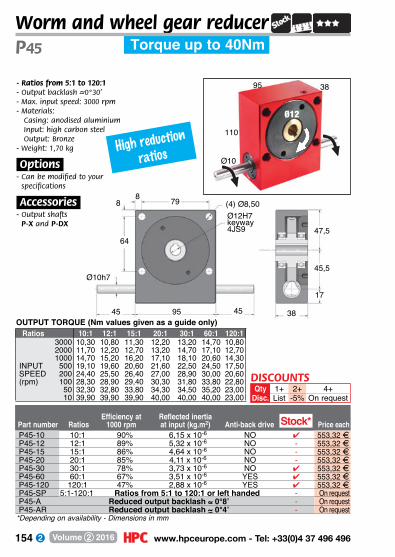
154 www.hpceurope.com - Tel: +33(0)4 37 496 496Volume 2 2016
Worm and wheel gear reducerP45
Efficiency at Reflected inertia Part number Ratios 1000 rpm at input (kg.m2) Anti-back drive Price each
Torque up to 40Nm
- Ratios from 5:1 to 120:1- Output backlash –~0°30’- Max. input speed: 3000 rpm- Materials:
Casing: anodised aluminium Input: high carbon steel Output: Bronze
- Weight: 1,70 kg
.Options.- Can be modified to your
specifications
.Accessories.- Output shafts
P-X and P-DX
79
Ø10h7
45 95 45
47,5
45,5
17
38
Ø12H7keyway4JS9
(4) Ø8,508
64
8
38
Ø10
110
Ø12
95
OUTPUT TORQUE (Nm values given as a guide only)Ratios 10:1 12:1 15:1 20:1 30:1 60:1 120:1
3000 10,30 10,80 11,30 12,20 13,20 14,70 10,802000 11,70 12,20 12,70 13,20 14,70 17,10 12,701000 14,70 15,20 16,20 17,10 18,10 20,60 14,30
INPUT 500 19,10 19,60 20,60 21,60 22,50 24,50 17,50SPEED 200 24,40 25,50 26,40 27,00 28,90 30,00 20,60(rpm) 100 28,30 28,90 29,40 30,30 31,80 33,80 22,80
50 32,30 32,80 33,80 34,30 34,50 35,20 23,0010 39,90 39,90 39,90 40,00 40,00 40,00 23,00
Stock*P45-10 10:1 90% 6,15 x 10⁻⁶ NO 4 553,32 FP45-12 12:1 89% 5,32 x 10⁻⁶ NO - 553,32 FP45-15 15:1 86% 4,64 x 10⁻⁶ NO - 553,32 FP45-20 20:1 85% 4,11 x 10⁻⁶ NO - 553,32 FP45-30 30:1 78% 3,73 x 10⁻⁶ NO 4 553,32 FP45-60 60:1 67% 3,51 x 10⁻⁶ YES 4 553,32 FP45-120 120:1 47% 2,88 x 10⁻⁶ YES 4 553,32 FP45-SP 5:1-120:1 Ratios from 5:1 to 120:1 or left handed - On requestP45-A Reduced output backlash ~ 0°8’ - On requestP45-AR Reduced output backlash ~ 0°4’ - On request
*Depending on availability - Dimensions in mm
High reduction ratios
DISCOUNTSQty 1+ 2+ 4+
Disc. List -5% On request
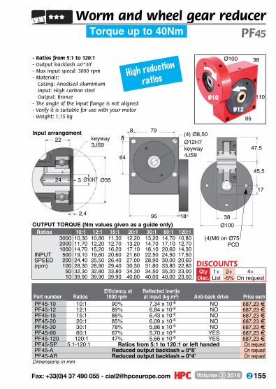
155 Fax: +33(0)4 37 490 055 - [email protected] Volume 2 2016
22
3 Ø10H7 Ø3524
2,4
Worm and wheel gear reducer
- Ratios from 5:1 to 120:1- Output backlash –~0°30’- Max input speed: 3000 rpm- Materials:
Casing: Anodised aluminium Input: High carbon steel Output: Bronze
- The angle of the input flange is not aligned- Verify it is suitable for use with your motor- Weight: 1,15 kg
PF45Torque up to 40Nm
(4)M6 on Ø75 PCD
38
17
47,5
18Ø100
45,5
798
95
Ø12H7keyway4JS9
(4) Ø8,508
64
38
110
95Ø12
Ø10
Ø100
keyway3JS9
Input arrangement
Efficiency at Reflected inertia Part number Ratios 1000 rpm at input (kg.m2) Anti-back drive Price each
OUTPUT TORQUE (Nm values given as a guide only)
Dimensions in mm
Ratios 10:1 12:1 15:1 20:1 30:1 60:1 120:13000 10,30 10,80 11,30 12,20 13,20 14,70 10,802000 11,70 12,20 12,70 13,20 14,70 17,10 12,701000 14,70 15,20 16,20 17,10 18,10 20,60 14,30
INPUT 500 19,10 19,60 20,60 21,60 22,50 24,50 17,50SPEED 200 24,40 25,50 26,40 27,00 28,90 30,00 20,60(rpm) 100 28,30 28,90 29,40 30,30 31,80 33,80 22,80
50 32,30 32,80 33,80 34,30 34,50 35,20 23,0010 39,90 39,90 39,90 40,00 40,00 40,00 23,00
PF45-10 10:1 90% 7,34 x 10⁻⁶ NO 687,23 FPF45-12 12:1 89% 6,84 x 10⁻⁶ NO 687,23 FPF45-15 15:1 86% 6,43 x 10⁻⁶ NO 687,23 FPF45-20 20:1 85% 6,09 x 10⁻⁶ NO 687,23 FPF45-30 30:1 78% 5,86 x 10⁻⁶ NO 687,23 FPF45-60 60:1 67% 5,70 x 10⁻⁶ YES 687,23 FPF45-120 120:1 47% 5,66 x 10⁻⁶ YES 687,23 FPF45-SP 5:1-120:1 Ratios from 5:1 to 120:1 or left handed On requestPF45-A Reduced output backlash ~ 0°8’ On requestPF45-AR Reduced output backlash ~ 0°4’ On request
High reduction ratios
DISCOUNTSQty 1+ 2+ 4+
Disc. List -5% On request

156 www.hpceurope.com - Tel: +33(0)4 37 496 496Volume 2 2016
Worm and wheel gear reducer
- Ratios from 5:1 to 120:1- Output backlash –~0°30’- Max. input speed: 3000 rpm- Materials:
Casing: anodised aluminium Input: high carbon steel Output: Bronze
- Weight: 2,40 kg
.Options.- Can be modified to your
specifications
.Accessories.- Output shafts
P-X and P-DX
*Depending on availability - Dimensions in mm
Efficiency at Reflected inertia Part number Ratios 1000 rpm at input (kg.m2) Anti-back drive Price each
46
Ø10
130
110
Ø15
Torque up to 57Nm
8 94
Ø10h7
50 110 50
55
55
20
46
Ø15H7keyway5JS9
(4) Ø8,508
80
OUTPUT TORQUE (Nm values given as a guide only)
P55
Ratios 10:1 12:1 15:1 20:1 30:1 60:1 120:13000 13,40 14,00 14,80 16,20 17,60 20,40 18,002000 16,20 16,90 18,30 19,10 20,40 23,90 20,001000 21,10 22,50 23,20 24,60 25,30 28,80 25,00
INPUT 500 27,40 28,10 28,80 30,20 31,60 35,10 30,00SPEED 200 34,40 35,10 36,50 37,90 39,30 42,10 36,00(rpm) 100 40,00 41,40 42,10 42,80 44,90 46,30 38,00
50 45,60 46,30 47,70 48,40 49,80 50,50 38,0010 56,80 56,80 56,80 57,00 57,00 57,00 38,00
P55-10 10:1 89% 1,35 x 10⁻⁵ NO 4 655,71 FP55-12 12:1 88% 1,13 x 10⁻⁵ NO 4 655,71 FP55-15 15:1 86% 9,81 x 10⁻⁶ NO 4 655,71 FP55-20 20:1 84% 8,63 x 10⁻⁶ NO 4 655,71 FP55-30 30:1 78% 7,79 x 10⁻⁶ NO 4 655,71 FP55-60 60:1 69% 7,23 x 10⁻⁶ YES 4 655,76 FP55-120 120:1 47% 7,04 x 10⁻⁶ YES - 655,71 FP55-SP 5:1-120:1 Ratios from 5:1 to 120:1 or left handed - On requestP55-A Reduced output backlash ~ 0°8’ - On requestP55-AR Reduced output backlash ~ 0°4’ - On request
Stock*
High reduction ratios
DISCOUNTSQty 1+ 2+ 4+
Disc. List -5% On request
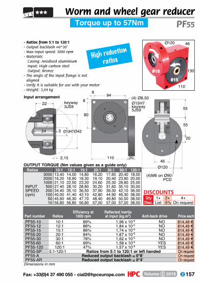
157 Fax: +33(0)4 37 490 055 - [email protected] Volume 2 2016
Worm and wheel gear reducer
- Ratios from 5:1 to 120:1- Output backlash –~0°30’- Max input speed: 3000 rpm- Materials:
Casing: Anodised aluminium Input: High carbon steel Output: Bronze
- The angle of the input flange is not aligned
- Verify it is suitable for use with your motor- Weight: 3,04 kg
Dimensions in mm
Efficiency at Reflected inertia Part number Ratios 1000 rpm at input (kg.m2) Anti-back drive Price each
PF55Torque up to 57Nm
46
20
55
20
Ø120
55
948
110
Ø15H7keyway5JS9
(4) Ø8,508
80
22
3 Ø10H7Ø4224
2,15
keyway3JS9
46
130
110Ø15
Ø10
Ø120
Input arrangement
(4)M6 on Ø90 PCD
OUTPUT TORQUE (Nm values given as a guide only)Ratios 10:1 12:1 15:1 20:1 30:1 60:1 120:1
3000 13,40 14,00 14,80 16,20 17,60 20,40 18,002000 16,20 16,90 18,30 19,10 20,40 23,90 20,001000 21,10 22,50 23,20 24,60 25,30 28,80 25,00
INPUT 500 27,40 28,10 28,80 30,20 31,60 35,10 30,00SPEED 200 34,40 35,10 36,50 37,90 39,30 42,10 36,00(rpm) 100 40,00 41,40 42,10 42,80 44,90 46,30 38,00
50 45,60 46,30 47,70 48,40 49,80 50,50 38,0010 56,80 56,80 56,80 57,00 57,00 57,00 38,00
PF55-10 10:1 89% 1,96 x 10⁻⁵ NO 814,49 FPF55-12 12:1 88% 1,84 x 10⁻⁵ NO 814,49 FPF55-15 15:1 86% 1,74 x 10⁻⁵ NO 814,49 FPF55-20 20:1 84% 1,67 x 10⁻⁵ NO 814,49 FPF55-30 30:1 78% 1,62 x 10⁻⁵ NO 814,49 FPF55-60 60:1 69% 1,58 x 10⁻⁵ YES 814,49 FPF55-120 120:1 47% 1,57 x 10⁻⁵ YES 814,49 FPF55-SP 5:1-120:1 Ratios from 5:1 to 120:1 or left handed On requestPF55-A Reduced output backlash ~ 0°8’ On requestPF55-AR Reduced output backlash ~ 0°4’ On request
High reduction ratios
DISCOUNTSQty 1+ 2+ 4+
Disc. List -5% On request
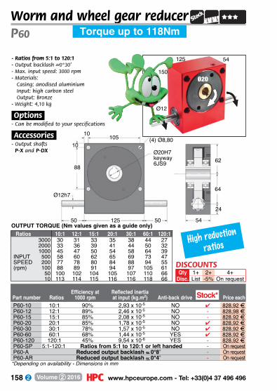
158 www.hpceurope.com - Tel: +33(0)4 37 496 496Volume 2 2016
Worm and wheel gear reducerP60
- Ratios from 5:1 to 120:1- Output backlash –~0°30’- Max. input speed: 3000 rpm- Materials:
Casing: anodised aluminium Input: high carbon steel Output: Bronze
- Weight: 4,10 kg
.Options.- Can be modified to your specifications
.Accessories.- Output shafts
P-X and P-DX
*Depending on availability - Dimensions in mm
Efficiency at Reflected inertia Part number Ratios 1000 rpm at input (kg.m2) Anti-back drive Price each
54
Ø12
150
125
Ø20
Torque up to 118Nm
105
Ø12h7
50 125 50
62
64
24
54
Ø20H7keyway6JS9
(4) Ø8,80
88
10
10
OUTPUT TORQUE (Nm values given as a guide only)Ratios 10:1 12:1 15:1 20:1 30:1 60:1 120:1
3000 30 31 33 35 38 44 272000 33 36 39 41 44 50 321000 45 47 50 54 58 64 39
INPUT 500 58 60 62 65 69 73 47SPEED 200 77 78 80 84 88 94 55(rpm) 100 88 89 91 94 97 105 61
50 100 102 104 105 107 110 6610 113 114 115 116 116 118 66
Stock*P60-10 10:1 90% 2,93 x 10⁻⁵ NO 4 828,92 FP60-12 12:1 89% 2,46 x 10⁻⁵ NO - 828,98 FP60-15 15:1 85% 2,08 x 10⁻⁵ NO - 828,92 FP60-20 20:1 85% 1,78 x 10⁻⁵ NO 4 828,92 FP60-30 30:1 78% 1,57 x 10⁻⁵ NO 4 828,92 FP60-60 60:1 68% 1,44 x 10⁻⁵ YES 4 828,92 FP60-120 120:1 45% 9,54 x 10⁻⁶ YES - 828,92 FP60-SP 5:1-120:1 Ratios from 5:1 to 120:1 or left handed - On requestP60-A Reduced output backlash ~ 0°8’ - On requestP60-AR Reduced output backlash ~ 0°4’ - On request
High reduction ratios
DISCOUNTSQty 1+ 2+ 4+
Disc. List -5% On request
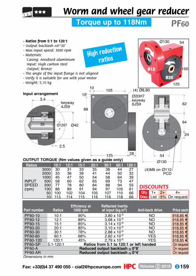
159 Fax: +33(0)4 37 490 055 - [email protected] Volume 2 2016
54
Worm and wheel gear reducer
- Ratios from 5:1 to 120:1- Output backlash –~0°30’- Max input speed: 3000 rpm- Materials:
Casing: Anodised aluminium Input: High carbon steel Output: Bronze
- The angle of the input flange is not aligned- Verify it is suitable for use with your motor- Weight: 5,10 kg
Dimensions in mm
PF60Torque up to 118Nm
24
6288
28
Ø130
64
10 105
125
Ø20H7keyway6JS9
10(4) Ø8,80
3,4
Ø12H7 Ø4235
2,5
keyway 4JS9
54
150
125Ø20
Ø12
Ø130
Input arrangement
OUTPUT TORQUE (Nm values given as a guide only)
(4)M8 on Ø110 PCD
Efficiency at Reflected inertia Part number Ratios 1000 rpm at input (kg.m2) Anti-back drive Price each
Ratios 10:1 12:1 15:1 20:1 30:1 60:1 120:13000 30 31 33 35 38 44 272000 33 36 39 41 44 50 321000 45 47 50 54 58 64 39
INPUT 500 58 60 62 65 69 73 47SPEED 200 77 78 80 84 88 94 55(rpm) 100 88 89 91 94 97 105 61
50 100 102 104 105 107 110 6610 113 114 115 116 116 118 66
PF60-10 10:1 90% 3,80 x 10⁻⁵ NO 918,85 FPF60-12 12:1 89% 3,68 x 10⁻⁵ NO 918,85 FPF60-15 15:1 85% 3,14 x 10⁻⁵ NO 918,85 FPF60-20 20:1 85% 3,10 x 10⁻⁵ NO 918,85 FPF60-30 30:1 78% 2,88 x 10⁻⁵ NO 918,85 FPF60-60 60:1 68% 2,82 x 10⁻⁵ YES 918,85 FPF60-120 120:1 45% 2,79 x 10⁻⁵ YES 918,85 FPF60-SP 5:1-120:1 Ratios from 5:1 to 120:1 or left handed On requestPF60-A Reduced output backlash ~ 0°8’ On requestPF60-AR Reduced output backlash ~ 0°4’ On request
High reduction ratios
DISCOUNTSQty 1+ 2+ 4+
Disc. List -5% On request

160 www.hpceurope.com - Tel: +33(0)4 37 496 496Volume 2 2016
Worm and wheel gear reducerP70
*Depending on availability - Dimensions in mm
Efficiency at Reflected inertia Part number Ratios 1000 rpm at input (kg.m2) Anti-back drive Price each
60
170
145
Ø25
55 145
72,5
25
Torque up to 164Nm
Ø15
- Ratios from 5:1 to 120:1- Output backlash –~0°30’- Max. input speed: 3000 rpm- Materials:
Casing: anodised aluminium Input: high carbon steel Output: Bronze
- Weight: 6,40 kg
.Options.- Can be modified to
your specifications
.Accessories.- Output shafts
P-X and P-DX
Ø15h7
55
72,5
60
Ø25H7keyway8JS9
(4) Ø8,80
100
10
10125
OUTPUT TORQUE (Nm values given as a guide only)Ratios 10:1 12:1 15:1 20:1 30:1 60:1 120:1
3000 38 40 42 45 50 56 382000 47 49 53 55 61 69 461000 61 65 67 71 73 83 55
INPUT 500 77 81 83 87 91 100 66SPEED 200 99 101 105 107 113 121 77(rpm) 100 115 119 121 123 129 133 86
50 129 133 137 139 144 146 9010 160 160 160 164 164 164 90
P70-10 10:1 90% 6,04 x 10⁻⁵ NO 4 920,48 FP70-12 12:1 89% 5,03 x 10⁻⁵ NO - 920,48 FP70-15 15:1 86% 4,21 x 10⁻⁵ NO 4 920,55 FP70-20 20:1 85% 3,57 x 10⁻⁵ NO - 920,55 FP70-30 30:1 78% 3,11 x 10⁻⁵ NO 4 920,48 FP70-60 60:1 67% 2,84 x 10⁻⁵ YES 4 920,48 FP70-120 120:1 50% 2,48 x 10⁻⁵ YES - 920,48 FP70-SP 5:1-120:1 Ratios from 5:1 to 120:1 or left handed - On requestP70-A Reduced output backlash ~ 0°8’ - On requestP70-AR Reduced output backlash ~ 0°4’ - On request
Stock*
High reduction ratios
DISCOUNTSQty 1+ 2+ 4+
Disc. List -5% On request
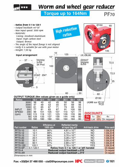
161 Fax: +33(0)4 37 490 055 - [email protected] Volume 2 2016
Worm and wheel gear reducer
- Ratios from 5:1 to 120:1- Output backlash –~0°30’- Max input speed: 3000 rpm- Materials:
Casing: Anodised aluminium Input: High carbon steel Output: Bronze
- The angle of the input flange is not aligned- Verify it is suitable for use with your motor- Weight: 7,90 kg
Dimensions in mm
Torque up to 164Nm PF70
30 60
72,5
25
Ø150
72,5
12510
60
Ø25H7keyway8JS9
(4) Ø8,80 10
100
37
Ø15H7 Ø4740
3
keyway5JS934 Prof.
60
170
145Ø25
Ø15
Ø150
Input arrangement
(4)M8 sur Ø110 PCD
OUTPUT TORQUE (Nm values given as a guide only)Ratios 10:1 12:1 15:1 20:1 30:1 60:1 120:1
3000 38 40 42 45 50 56 382000 47 49 53 55 61 69 461000 61 65 67 71 73 83 55
INPUT 500 77 81 83 87 91 100 66SPEED 200 99 101 105 107 113 121 77(rpm) 100 115 119 121 123 129 133 86
50 129 133 137 139 144 146 9010 160 160 160 164 164 164 90
PF70-10 10:1 90% 4,81 x 10⁻⁵ NO 1 036,20 FPF70-12 12:1 89% 4,19 x 10⁻⁵ NO 1 036,20 FPF70-15 15:1 86% 3,70 x 10⁻⁵ NO 1 036,20 FPF70-20 20:1 85% 3,28 x 10⁻⁵ NO 1 036,20 FPF70-30 30:1 78% 3,00 x 10⁻⁵ NO 1 036,20 FPF70-60 60:1 67% 2,89 x 10⁻⁵ YES 1 036,20 FPF70-120 120:1 50% 2,76 x 10⁻⁵ YES 1 036,20 FPF70-SP 5:1-120:1 Ratios from 5:1 to 120:1 or left handed On requestPF70-A Reduced output backlash ~ 0°8’ On requestPF70-AR Reduced output backlash ~ 0°4’ On request
High reduction ratios
DISCOUNTSQty 1+ 2+ 4+
Disc. List -5% On request
Efficiency at Reflected inertia Part number Ratios 1000 rpm at input (kg.m2) Anti-back drive Price each

162 www.hpceurope.com - Tel: +33(0)4 37 496 496Volume 2 2016
For P and PF gear reducersPxPdx
Optional output shaft stainless steel
- Optional accessory for adding outputs shafts to P and PF gear reducers
.Composition.- Single shaft kit P-x: Stainless steel 303 shaft, 2
steel keys and 2 steel circlips- Double shaft kit P-dx: Stainless steel 303 shaft, 3
steel keys and 2 steel circlips
Single DoubleTypical applications 1
2
3
Dimensions in mm
For Price each Part number gearbox ØD O/L M P X L K 1 to 5 SingleP20-X P20-PF20 6 50,80 22 23,60 3,00 25 K2 x 22 4 34,29 FP30-X P30-PF30 8 63,90 28 29,80 3,00 32 K2 x 22 4 40,28 FP40-X P40-PF40 10 76,60 32 34,20 3,50 40 K3 x 20 4 45,26 FP45-X P45-PF45 12 88,10 38 40,20 4,00 45 K4 x 25 - 48,62 FP55-X P55-PF55 15 101,10 46 48,20 4,00 50 K5 x 30 - 53,85 FP60-X P60-PF60 20 119,80 54 56,60 4,50 60 K6 x 32 - 63,30 FP70-X P70-PF70 25 135,80 60 62,60 4,50 70 K8 x 40 - 72,74 F
DoubleP20-DX P20-PF20 6 73,60 22 23,60 1,50 25 K2 x 22 4 45,13 FP30-DX P30-PF30 8 93,80 28 29,80 5,45 32 K2 x 22 4 49,04 FP40-DX P40-PF40 10 114,20 32 34,20 9,90 40 K3 x 20 - 56,18 FP45-DX P45-PF45 12 130,20 38 40,20 4,00 45 K4 x 25 - 61,37 FP55-DX P55-PF55 15 148,20 46 48,20 9,90 50 K5 x 30 - 66,87 FP60-DX P60-PF60 20 176,60 54 56,60 4,50 60 K6 x 32 - 77,75 FP70-DX P70-PF70 25 202,50 60 62,60 4,50 70 K8 x 40 - 88,64 F
Stock*
stainless
steel
ØD h8
XL
O/L
MPL
K
X PM
K ØD h8
Single shaft P-X Double shaft P-DX
XL
O/L
DISCOUNTSQty 1+ 6+ 20+ 40+
Disc. List -15% -20% Sur demande
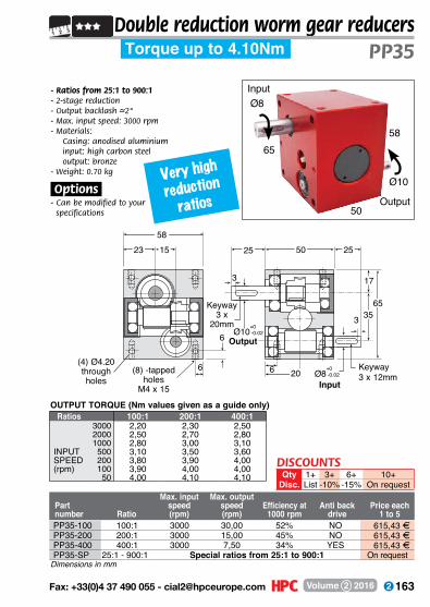
163 Fax: +33(0)4 37 490 055 - [email protected] Volume 2 2016
Torque up to 4.10Nm PP35Double reduction worm gear reducers
Input
Output
Very high
reduction
ratios
Part number Ratio
Max. input speed(rpm)
Max. output speed(rpm)
Efficiency at 1000 rpm
Anti back drive
Price each1 to 5
- Ratios from 25:1 to 900:1- 2-stage reduction- Output backlash –~2°- Max. input speed: 3000 rpm- M aterials:
Casing: anodised aluminium input: high carbon steel output: bronze
- Weight: 0.70 kg
.Options.- Can be modified to your specifications
OUTPUT TORQUE (Nm values given as a guide only)
(8) -tapped holes
M4 x 15
581523
6
6 6(4) Ø4.20 through holes
20
5025
17
3565
3
25
Keyway3 x
20mm
OutputØ10
+0,00-0.02
InputØ8
+0,00-0.02
3
Ratios 100:1 200:1 400:13000 2,20 2,30 2,502000 2,50 2,70 2,801000 2,80 3,00 3,10
INPUT 500 3,10 3,50 3,60SPEED 200 3,80 3,90 4,00(rpm) 100 3,90 4,00 4,00
50 4,00 4,10 4,10
PP35-100 100:1 3000 30,00 52% NO 615,43 FPP35-200 200:1 3000 15,00 45% NO 615,43 FPP35-400 400:1 3000 7,50 34% YES 615,43 FPP35-SP 25:1 - 900:1 Special ratios from 25:1 to 900:1 On request
Dimensions in mm
5865
50
Ø8
Ø10
DISCOUNTSQty 1+ 3+ 6+ 10+
Disc. List -10% -15% On request
Keyway 3 x 12mm
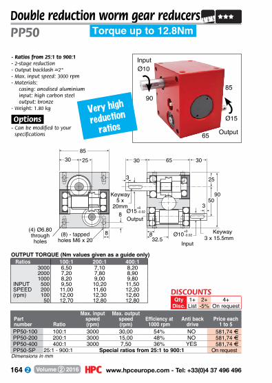
164 www.hpceurope.com - Tel: +33(0)4 37 496 496Volume 2 2016
8590
65
Ø10
Ø15
Double reduction worm gear reducers
Input
Output
Part number Ratio
Max. input speed(rpm)
Max. output speed(rpm)
Efficiency at 1000 rpm
Anti back drive
Price each1 to 5
- Ratios from 25:1 to 900:1- 2-stage reduction- Output backlash –~2°- Max. input speed: 3000 rpm- M aterials:
casing: anodised aluminium input: high carbon steel output: bronze
- Weight: 1.80 kg
.Options.- Can be modified to your specifications
OUTPUT TORQUE (Nm values given as a guide only)
8(8) - tapped holes M6 x 20
852530
8
8(4) Ø6.80 through holes 32.5
6530
25
5090
3
30
Keyway5 x
20mm
OutputØ15+0,00
-0.02
Keyway 3 x 15.5mm
InputØ10+0,00
-0.02
3
PP50 Torque up to 12.8Nm
Ratios 100:1 200:1 400:13000 6,50 7,10 8,202000 7,20 7,80 8,901000 8,20 9,00 9,80
INPUT 500 9,50 10,20 11,50SPEED 200 11,00 11,60 12,20(rpm) 100 12,00 12,30 12,60
50 12,70 12,80 12,80
PP50-100 100:1 3000 30,00 54% NO 581,74 FPP50-200 200:1 3000 15,00 48% NO 581,74 FPP50-400 400:1 3000 7,50 36% YES 581,74 FPP50-SP 25:1 - 900:1 Special ratios from 25:1 to 900:1 On request
Dimensions in mm
DISCOUNTSQty 1+ 2+ 4+
Disc. List -5% On request
Very high
reduction
ratios
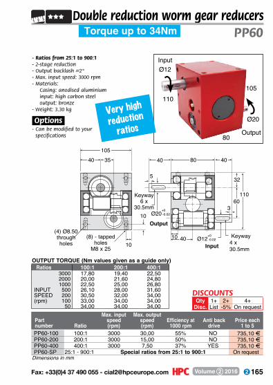
165 Fax: +33(0)4 37 490 055 - [email protected] Volume 2 2016
105110
80
Ø12
Ø20
Double reduction worm gear reducersTorque up to 34Nm PP60
Very high
reduction
ratios
Input
Output
Part number Ratio
Max. input speed(rpm)
Max. output speed(rpm)
Efficiency at 1000 rpm
Anti back drive
Price each1 to 5
- Ratios from 25:1 to 900:1- 2-stage reduction- Output backlash –~2°- Max. input speed: 3000 rpm- M aterials:
Casing: anodised aluminium input: high carbon steel output: bronze
- Weight: 3.30 kg
.Options.- Can be modified to your
specifications
OUTPUT TORQUE (Nm values given as a guide only)
(8) - tapped holes
M8 x 25
1053540
10
1010
(4) Ø8.50 through holes
40
8040
32
60110
5
40
Keyway6 x
30.5mm
Output
Ø20+0,00-0.02
Keyway 4 x 30.5mmInput
Ø12+0,00-0.02
3
Ratios 100:1 200:1 400:13000 17,80 19,40 22,502000 20,00 21,60 24,801000 22,50 25,00 26,80
INPUT 500 26,10 28,00 31,60SPEED 200 30,50 32,00 34,00(rpm) 100 33,00 34,00 34,00
50 34,00 34,00 34,00
PP60-100 100:1 3000 30,00 55% NO 735,10 FPP60-200 200:1 3000 15,00 50% NO 735,10 FPP60-400 400:1 3000 7,50 37% YES 735,10 FPP60-SP 25:1 - 900:1 Special ratios from 25:1 to 900:1 On request
Dimensions in mm
DISCOUNTSQty 1+ 2+ 4+
Disc. List -5% On request
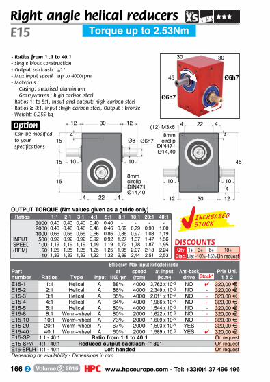
166 www.hpceurope.com - Tel: +33(0)4 37 496 496Volume 2 2016
- Ratios from 1 :1 to 40:1- Single block construction- Output backlash : ±1°- Max input speed : up to 4000rpm - Materials :
Casing: anodised aluminiumGears/worms : high carbon steel
- Ratios 1: to 5:1, Input and output: high carbon steel- Ratios ≥ 8:1, Input :high carbon steel, Output : bronze- Weight: 0.255 kg
.Option.- Can be modified
to your specifications
Right angle helical reducers
15
15
15
12
4 22 4
Ø8
8mm circlip DIN471Ø14,40
8mm circlip
DIN471Ø14,40
Ø6h7
12 4
10 10
12 30 12
4
(12) M3x6 4
4
45
2230
4
10 10
Ø6h7
45 Ø6h7
30 30
Torque up to 2.53NmE15
OUTPUT TORQUE (Nm values given as a guide only)Ratios 1:1 2:1 3:1 4:1 5:1 8:1 10:1 20:1 40:1
3000 0,40 0,40 0,40 0,40 0,40 - - - -2000 0,46 0,46 0,46 0,46 0,46 0,69 0,79 0,90 1,001000 0,66 0,66 0,66 0,66 0,86 0,86 0,97 1,08 1,19
INPUT 500 0,92 0,92 0,92 0,92 0,92 1,27 1,37 1,47 1,56SPEED 100 1,19 1,19 1,19 1,19 1,19 1,72 1,78 1,87 1,95(RPM) 50 1,25 1,25 1,25 1,25 1,25 1,95 2,07 2,18 2,24
10 1,32 1,32 1,32 1,32 1,32 2,39 2,44 2,51 2,53
Depending on availability - Dimensions in mm
DISCOUNTSQty 1+ 3+ 6+ 10+
Disc. List -10% -15% On request
Increasedstock
Efficiency Max input Reflected inertiaPart at speed at input Anti-back Prix Uni.number Ratios Type Input 1000 rpm (rpm) (kg.m2) drive 1 à 2E15-1 1:1 Helical A 88% 4000 3,762 x 10-6 NO 4 320,00 FE15-2 2:1 Helical A 86% 4000 2,349 x 10-6 NO - 320,00 FE15-3 3:1 Helical A 85% 4000 2,011 x 10-6 NO - 320,00 FE15-4 4:1 Helical A 84% 4000 1,986 x 10-6 NO - 320,00 FE15-5 5:1 Helical A 80% 4000 1,544 x 10-6 NO - 320,00 FE15-8 8:1 Worm+wheel A 80% 2000 1,622 x 10-6 NO - 320,00 FE15-10 10:1 Worm+wheel A 73% 2000 1,609 x 10-6 NO - 320,00 FE15-20 20:1 Worm+wheel A 67% 2000 1,593 x 10-6 YES - 320,00 FE15-40 40:1 Worm+wheel A 60% 2000 1,589 x 10-6 YES 4 320,00 FE15-SP 1:1 - 40:1 Ratio from 1:1 to 40:1 On requestE15-SPA 1:1 - 40:1 Reduced output backlash –~ 30’ On requestE15-SPLH 1:1 - 40:1 Left handed On request
Stock*

167 Fax: +33(0)4 37 490 055 - [email protected] Volume 2 2016
Effeciency Max. input Reflected inertia at speed at input Part number Ratio Type Input 1000 rpm (rpm) (kg.m2) Anti-back drive
Right angle helical reducers
*Depending on availability - Dimensions in mm
E20Torque up to 3.84Nm
Ø6
52 Ø6
34 34
2JS94034
2JS9
16
16
20
4 426
3 3
4
A
B
Bearing protrude Ø26x1
Bearing protrude Ø26x1
Ø6H7
Ø6H7
(12) M3x64 426
3 33440
4
4
52
Price each1 to 2
COUPLE DE SORTIE (Nm : VALEURS INDICATIVES)Ratios 1:1 2:1 3:1 4:1 5:1 8:1 10:1 20:1 40:1
3000 0,60 0,60 0,60 0,60 0,60 - - - -2000 0,70 0,70 0,70 0,70 0,70 1,05 1,20 1,36 1,521000 1,00 1,00 1,00 1,00 1,00 1,31 1,47 1,63 1,80
INPUT 500 1,40 1,40 1,40 1,40 1,40 1,93 2,08 2,22 2,37SPEED 100 1,80 1,80 1,80 1,80 1,80 2,60 2,70 2,83 2,95(RPM) 50 1,90 1,90 1,90 1,90 1,90 2,95 3,13 3,31 3,40
10 2,00 2,00 2,00 2,00 2,00 3,62 3,70 3,80 3,84
E20-1 1:1 Helical A 88% 4000 3,762 x 10-6 NO 4 354,66 FE20-2 2:1 Helical A 86% 4000 2,349 x 10-6 NO - 354,66 FE20-3 3:1 Helical A 85% 4000 2,011 x 10-6 NO - 354,66 FE20-4 4:1 Helical A 84% 4000 1,986 x 10-6 NO 4 354,66 FE20-5 5:1 Helical A 80% 4000 1,544 x 10-6 NO - 354,66 FE20-8 8:1 Worm+wheel A 80% 2000 1,622 x 10-6 NO 4 354,66 FE20-10 10:1 Worm+wheel A 73% 2000 1,609 x 10-6 NO - 354,66 FE20-20 20:1 Worm+wheel A 67% 2000 1,593 x 10-6 YES 4 354,66 FE20-40 40:1 Worm+wheel A 60% 2000 1,589 x 10-6 YES - 354,66 FE20-SP 1:1 - 40:1 Ratio from 1:1 to 40:1 - On requestE20-SPA 1:1 - 40:1 Reduced output backlash ~ 30’ On requestE20-SPLH 1:1 - 40:1 Left handed On request
Stock*
DISCOUNTSQty 1+ 3+ 6+ 10+
Disc. List -10% -15% On request
- Ratios from 1:1 to 40:1- Single piece construction- Output backlash –~1°- Max. input speed up to 4000 rpm- M aterials:
Casing: anodised aluminium gears and worms: case-hardened steel
- Ratios 1:1 to 5:1, input and output: case-hardened steel- Ratios ≥ 8:1,
input: case-hardened steel output: bronze
- Weight: 0.255 kg
.Options.- Can be modified
to your specifications
.Accessories.- Input or output
shafts E-X and E-DX

168 www.hpceurope.com - Tel: +33(0)4 37 496 496Volume 2 2016
Right angle helical reducers
- Ratios from 1:1 to 40:1- Single piece construction- Output backlash –~1°- Max. input speed up to 4000 rpm- M aterials:
Casing: anodised aluminium gears and worms: case-hardened steel
- Ratios 1:1 to 5:1, input and output: case-hardened steel- Ratios ≥ 8:1,
input: case-hardened steel output: bronze
- Weight: 0.72 kg
.Options.- Can be modified to
your specifications
.Accessories.- Input or output
shafts E-X and E-DX
*Depending on availability - Dimensions in mm
Effeciency Max. input Reflected inertia at speed at input Part number Ratio Type Input 1000 rpm (rpm) (kg.m2) Anti-back drive
Ø10
78 Ø10
48 48
E30 Torque up to 9Nm
5448
3JS9
24
24
30
6 636
3 36
A
B
Bearing protrudeØ40x0,5
Bearing protrudeØ35x0,5
Ø10H7
Ø10H7
(12) M4x106 636
3 34854
6
6
78
3JS9
Price each1 to 2
Ratios 1:1 2:1 3:1 4:1 5:1 8:1 10:1 20:1 40:13000 1,5 1,5 1,5 1,5 1,5 - - - -2000 2,0 2,0 2,0 2,0 2,0 - - - -1000 2,5 2,5 2,5 2,5 2,5 3,6 4,2 4,7 5,0
INPUT 500 3,0 3,0 3,0 3,0 3,0 4,9 5,3 5,6 6,0SPEED 100 4,0 4,0 4,0 4,0 4,0 6,5 7,0 7,1 7,3(RPM) 50 4,5 4,5 4,5 4,5 4,5 7,9 8,4 8,5 8,6
10 5,0 5,0 5,0 5,0 5,0 8,5 8,7 8,9 9,0
Stock*
OUTPUT TORQUE (Nm values given as a guide only)
E30-1 1:1 Helical B 90% 4000 2,867 x 10-6 NO 4 407,11 FE30-2 2:1 Helical A 88% 4000 1,362 x 10-6 NO 4 407,11 FE30-3 3:1 Helical A 87% 4000 1,071 x 10-6 NO 4 407,11 FE30-4 4:1 Helical A 86% 4000 1,032 x 10-6 NO 4 407,11 FE30-5 5:1 Helical A 80% 4000 9,372 x 10-6 NO 4 407,11 FE30-8 8:1 Worm+wheel A 80% 1500 1,115 x 10-6 NO 4 407,11 FE30-10 10:1 Worm+wheel A 73% 1500 1,106 x 10-6 NO 4 407,11 FE30-20 20:1 Worm+wheel A 67% 1500 1,094 x 10-6 YES 4 407,11 FE30-40 40:1 Worm+wheel A 60% 1500 1,091 x 10-6 YES - 407,11 FE30-SP 1:1 - 40:1 Ratio from 1:1 to 40:1 On requestE30-SPA 1:1 - 40:1 Reduced output backlash ~ 30’ On requestE30-SPLH 1:1 - 40:1 Left handed On request
DISCOUNTSQty 1+ 3+ 6+ 10+
Disc. List -10% -15% On request
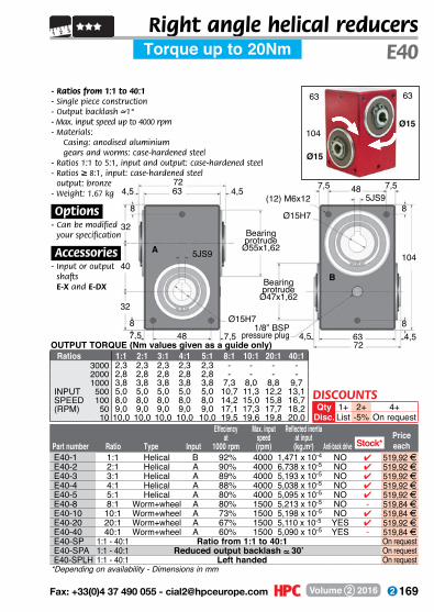
169 Fax: +33(0)4 37 490 055 - [email protected] Volume 2 2016
Effeciency Max. input Reflected inertia at speed at input Part number Ratio Type Input 1000 rpm (rpm) (kg.m2) Anti-back drive
Right angle helical reducersE40
- Ratios from 1:1 to 40:1- Single piece construction- Output backlash –~1°- Max. input speed up to 4000 rpm- M aterials:
Casing: anodised aluminium gears and worms: case-hardened steel
- Ratios 1:1 to 5:1, input and output: case-hardened steel- Ratios ≥ 8:1, input: case-hardened steel
output: bronze- Weight: 1.67 kg
.Options.- Can be modified to
your specifications
.Accessories.- Input or output
shafts E-X and E-DX
*Depending on availability - Dimensions in mm
Torque up to 20Nm
Ø15
104Ø15
63 63
7263
5JS9
5JS9
32
32
40
87,5487,5
4,5 4,5
8
A
B
Bearing protrude
Ø55x1,62
Bearing protrude
Ø47x1,62
1/8” BSPpressure plug
Ø15H7
Ø15H7
(12) M6x127,5 7,548
4,5 4,56372
8
8
104
Price eachStock*
E40-1 1:1 Helical B 92% 4000 1,471 x 10-4 NO 4 519,92 FE40-2 2:1 Helical A 90% 4000 6,738 x 10-5 NO 4 519,92 FE40-3 3:1 Helical A 89% 4000 5,193 x 10-5 NO 4 519,92 FE40-4 4:1 Helical A 88% 4000 5,038 x 10-5 NO 4 519,92 FE40-5 5:1 Helical A 80% 4000 5,095 x 10-5 NO 4 519,92 FE40-8 8:1 Worm+wheel A 80% 1500 5,213 x 10-5 NO - 519,84 FE40-10 10:1 Worm+wheel A 73% 1500 5,198 x 10-5 NO 4 519,84 FE40-20 20:1 Worm+wheel A 67% 1500 5,110 x 10-5 YES 4 519,92 FE40-40 40:1 Worm+wheel A 60% 1500 5,090 x 10-5 YES - 519,84 FE40-SP 1:1 - 40:1 Ratio from 1:1 to 40:1 On requestE40-SPA 1:1 - 40:1 Reduced output backlash ~ 30’ On requestE40-SPLH 1:1 - 40:1 Left handed On request
Ratios 1:1 2:1 3:1 4:1 5:1 8:1 10:1 20:1 40:13000 2,3 2,3 2,3 2,3 2,3 - - - -2000 2,8 2,8 2,8 2,8 2,8 - - - -1000 3,8 3,8 3,8 3,8 3,8 7,3 8,0 8,8 9,7
INPUT 500 5,0 5,0 5,0 5,0 5,0 10,7 11,3 12,2 13,1SPEED 100 8,0 8,0 8,0 8,0 8,0 14,2 15,0 15,8 16,7(RPM) 50 9,0 9,0 9,0 9,0 9,0 17,1 17,3 17,7 18,2
10 10,0 10,0 10,0 10,0 10,0 19,5 19,6 19,8 20,0
OUTPUT TORQUE (Nm values given as a guide only)
DISCOUNTSQty 1+ 2+ 4+
Disc. List -5% On request

170 www.hpceurope.com - Tel: +33(0)4 37 496 496Volume 2 2016
Right angle helical reducers
OUTPUT TORQUE (Nm values given as a guide only)
*Depending on availability - Dimensions in mm
Effeciency Max. input Reflected inertia at speed at input Part number Ratio Type Input 1000 rpm (rpm) (kg.m2) Anti-back drive
E50 Torque up to 41Nm
8880
6JS9
40
40
50
106010 10
4410
A
B
Bearing protrude
Ø68x1,12
Bearing protrude
Ø62x1,12
Ø20H7
Ø20H7
(12) M8x15 10 1060
4 480
10
10
130
6JS9
Price each
- Ratios from 1:1 to 40:1- Single piece construction- Output backlash –~1°- Max. input speed up to 4000 rpm- M aterials:
Casing: anodised aluminium gears and worms: case-hardened steel
- Ratios 1:1 to 5:1, input and output: case-hardened steel- Ratios ≥ 8:1, input: case-hardened steel, output: bronze- Weight: 3.18 kg
.Options.- Can be modified
to your specifications
.Accessories.- Input or output
shafts E-X and E-DX
Stock*
Ratios 1:1 2:1 3:1 4:1 5:1 8:1 10:1 20:1 40:13000 3,0 3,0 3,0 3,0 3,0 - - - -2000 4,0 4,0 4,0 4,0 4,0 - - - -1000 6,0 6,0 6,0 6,0 6,0 11,3 13,0 15,0 17,0
INPUT 500 8,0 8,0 8,0 8,0 8,0 18,0 20,0 21,0 23,0SPEED 100 12,0 12,0 12,0 12,0 12,0 25,0 26,0 28,0 30,0(RPM) 50 14,0 14,0 14,0 14,0 14,0 31,0 31,0 32,0 33,0
10 16,0 16,0 16,0 16,0 16,0 40,0 40,0 41,0 41,0
Ø20
130Ø20
80 80
E50-1 1:1 Helical B 93% 3000 4,585 x 10-4 NO 4 661,22 FE50-2 2:1 Helical A 91% 3000 2,240 x 10-4 NO 4 661,22 FE50-3 3:1 Helical A 90% 3000 1,759 x 10-4 NO - 661,22 FE50-4 4:1 Helical A 89% 3000 1,924 x 10-4 NO 4 661,22 FE50-5 5:1 Helical A 80% 3000 1,920 x 10-4 NO - 661,24 FE50-8 8:1 Worm+wheel A 80% 1500 1,489 x 10-4 NO - 661,22 FE50-10 10:1 Worm+wheel A 73% 1500 1,496 x 10-4 NO - 661,22 FE50-20 20:1 Worm+wheel A 67% 1500 1,463 x 10-4 YES 4 661,22 FE50-40 40:1 Worm+wheel A 60% 1500 1,455 x 10-4 YES 4 661,22 FE50-SP 1:1 - 40:1 Ratio from 1:1 to 40:1 On requestE50-SPA 1:1 - 40:1 Reduced output backlash ~ 30’ On requestE50-SPLH 1:1 - 40:1 Left handed On request
DISCOUNTSQty 1+ 2+ 4+
Disc. List -5% On request

171 Fax: +33(0)4 37 490 055 - [email protected] Volume 2 2016
Right angle helical reducersE60
OUTPUT TORQUE (Nm values given as a guide only)
Effeciency Max. input Reflected inertia at speed at input Part number Ratio Type Input 1000 rpm (rpm) (kg.m2) Anti-back drive
1+List
4+On request
Qty.Disc.
DISCOUNTS2+
-5%
Torque up to 62Nm
10696
8JS9
8JS9
45
45
60
121212 72
55
12
A
B
Bearing protrude
Ø80x1,18
Bearing protrude
Ø75x1,18
Ø25H7
Ø25H7
(12) M10x1812 1272
55 96
12
12
150
Ø25
150Ø25
96 96
Price each
- Ratios from 1:1 to 40:1- Single piece construction- Output backlash –~1°- Max. input speed up to 4000 rpm- Materials:
casing: anodised aluminium gears and worms: case-hardened steel
- Ratios 1:1 to 5:1, input and output: case-hardened steel- Ratios ≥ 8:1, input: case-hardened steel, output: bronze- Weight: 5.50 kg
.Options.- Can be modified
to your specifications
.Accessories.- Input and output
shafts E-X and E-DX
Ratios 1:1 2:1 3:1 4:1 5:1 8:1 10:1 20:1 40:13000 4,5 4,5 4,5 4,5 4,5 - - - -2000 5,5 5,5 5,5 5,5 5,5 - - - -1000 8,0 8,0 8,0 8,0 8,0 17,8 21,3 22,0 24,0
INPUT 500 10,0 10,0 10,0 10,0 10,0 27,0 29,0 31,0 34,0SPEED 100 16,0 16,0 16,0 16,0 16,0 37,0 40,2 42,0 44,0(RPM) 50 20,0 20,0 20,0 20,0 20,0 48,0 49,0 50,0 51,0
10 24,0 24,0 24,0 24,0 24,0 60,0 60,0 61,0 62,0
*Depending on availability - Dimensions in mm
Stock*E60-1 1:1 Helical B 94% 3000 1,319 x 10-3 NO 4 797,13 FE60-2 2:1 Helical A 92% 3000 6,507 x 10-4 NO 4 797,13 FE60-3 3:1 Helical A 91% 3000 5,111 x 10-4 NO 4 797,13 FE60-4 4:1 Helical A 90% 3000 5,543 x 10-4 NO 4 797,13 FE60-5 5:1 Helical A 80% 3000 5,489 x 10-4 NO - 797,13 FE60-8 8:1 Worm+wheel A 80% 1500 4,951 x 10-4 NO 4 797,13 FE60-10 10:1 Worm+wheel A 73% 1500 4,911 x 10-4 NO - 797,13 FE60-20 20:1 Worm+wheel A 67% 1500 4,859 x 10-4 YES 4 797,13 FE60-40 40:1 Worm+wheel A 60% 1500 4,846 x 10-4 YES - 797,13 FE60-SP 1:1 - 40:1 Ratio from 1:1 to 40:1 On requestE60-SPA 1:1 - 40:1 Reduced output backlash ~ 30’ On requestE60-SPLH 1:1 - 40:1 Left handed On request

172 www.hpceurope.com - Tel: +33(0)4 37 496 496Volume 2 2016
Right angle helical reducers
OUTPUT TORQUE (Nm values given as a guide only)
*Depending on availability - Dimensions in mm
Effeciency Max. input Reflected inertia at speed at input Part number Ratio Type Input 1000 rpm (rpm) (kg.m2) Anti-back drive
10696
8JS9
8JS9
45
45
60
121212 72
5512
A
B
Bearing protrudes Ø80 x1.18
Bearing protrudes
Ø75 x 1.1Sheet 18
Ø30H7
Ø30H7
(12) M10x1812 1272
5596
12
12
150
Ø30
150Ø30
96 96Large bore
Price each
E60b Torque up to 24Nm
Ratios 1:1 2:1 3:13000 4,5 4,5 4,52000 5,5 5,5 5,51000 8,0 8,0 8,0
INPUT 500 10,0 10,0 10,0SPEED 200 16,0 16,0 16,0(RPM) 100 20,0 20,0 20,0
50 24,0 24,0 24,0
E60B-1 1:1 Helical B 94% 3000 1,237 x 10-3 NO - 797,13 F E60B-2 2:1 Helical A 92% 3000 6,023 x 10-4 NO - 797,13 F E60B-3 3:1 Helical A 91% 3000 4,651 x 10-4 NO - 797,13 F E60B-4 4:1 Helical A 90% 3000 5,026 x 10-4 NO - 797,13 F E60B-SP 1:1 - 40:1 Ratio from 1:1 to 40:1 - On request E60B-SPA 1:1 - 40:1 Reduced output backlash ~ 30’ - On request E60B-SPLH 1:1 - 40:1 Left handed - On request
Stock*
DISCOUNTSQty 1+ 2+ 4+
Disc. List -5% On request
- Ratios from 1 :1 to 4:1- Large bores- Single block construction- Output backlash : ±1°- Max input speed : up to 3000rpm - Materials :
Casing: anodised aluminiumGears : high carbon steelRatios 1: to 4:1, Input and output: high carbon steel
- Weight: 5.5 kg
.Option.- Can be modified
to your specifications
.Accessoires.- E-X and E-DX
input/output shafts
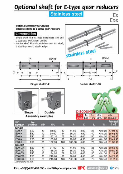
173 Fax: +33(0)4 37 490 055 - [email protected] Volume 2 2016
Optional shaft for E-type gear reducersStainless steel Ex
Edx
Single shaft E-X Double shaft E-DX
ØD h8
X
LO/L
MPL
K
XPM
K ØD h8
XL
O/L
- Optional accessory for adding outputs shafts to E series gear reducers
.Composition.- Single shaft kit E-x: shaft in stainless steel 303,
2 steelkeys and 2 steel circlips- Double shaft kit E-dx: stainless steel 303 shaft,
3 steel keys and 2 steel circlips
Single DoubleAssembly examples
Part Price each number 1 to 5For
gearbox ØD O/L M P X L K
stainless steel
SingleE20-X E20 6 68,80 40 41,60 3,00 25 K2 x 22 47,01 FE30-X E30 10 98,60 54 56,20 3,50 40 K3 x 20 55,68 FE40-X E40 15 127,10 72 74,20 4,00 50 K5 x 30 67,62 FE50-X E50 20 153,80 88 90,60 4,50 60 K6 x 32 75,49 FE60-X E60 25 182,30 106 108,60 5,00 70 K8 x 40 81,38 F
DoubleE20-DX E20 6 91,60 40 41,60 3,00 25 K2 x 22 60,58 FE30-DX E30 10 136,20 54 56,20 3,50 40 K3 x 20 69,80 FE40-DX E40 15 174,20 72 74,20 4,00 50 K5 x 30 81,21 FE50-DX E50 20 210,60 88 90,60 4,50 60 K6 x 32 94,27 FE60-DX E60 25 248,60 106 108,60 5,00 70 K8 x 40 110,01 F
Dimensions in mm
DISCOUNTSQty 1+ 6+ 20+ 40+
Disc. List -15% -20% On request
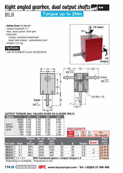
174 www.hpceurope.com - Tel: +33(0)4 37 496 496Volume 2 2016
*Depending on availability - Dimensions in mm
Ratio
Efficiency at
1000 rpm
Max. input speed
(rpm)
Max. output speed
(rpm) A B Module
Price each1 to 2Part number
Right angled gearbox, dual output shafts
- Ratios from 1:1 to 4:1- Output backlash –~1°- Max. input speed: 2000 rpm- M aterials:
Casing: anodised aluminium input and output : unhardened steel
- Weight: 0.55 kg
.Options.- Can be modified to your specifications
OUTPUT TORQUE (Nm: VALUES GIVEN AS A GUIDE ONLY)
BL8 Torque up to 2Nm
Ø8 Output
Ø8 Input
B
50
A
Ratios 1:1 2:1 3:1 4:12000 0,40 0,20 0,50 0,801000 0,50 0,30 0,50 0,90
INPUT 500 0,50 0,30 0,60 1,10SPEED 200 0,60 0,40 0,70 1,30(rpm) 100 0,70 0,40 0,80 1,40
50 0,80 0,40 0,90 1,6010 1,00 0,60 1,20 2,00
Stock*BL8-1 1:1 88% 2000 2000 50 65 0,8 - 232,45 FBL8-2 2:1 88% 2000 1000 50 65 0,8 4 232,45 FBL8-3 3:1 88% 2000 666 50 75 0,8 4 232,45 FBL8-4 4:1 88% 2000 500 60 80 0,8 - 232,45 FBL8-XH 1:1 - 4:1 With hardened gears = output torque x 2 - On request
B
50
1530
Ø8+0,00-0,02
= =A
7
30
22
15
30
50 30Ø8+0,00
-0,02
Ø8+0,00-0,02
(4) M4 x 12
Output
Input 30
DISCOUNTSQty 1+ 3+ 6+ 10+
Disc. List -15% -20% On request
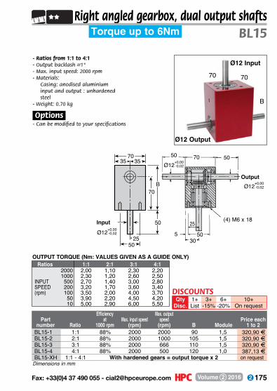
175 Fax: +33(0)4 37 490 055 - [email protected] Volume 2 2016
Dimensions in mm
Partnumber Ratio
Efficiencyat
1000 rpmMax. input speed
(rpm)
Max. output speed
(rpm) B ModulePrice each
1 to 2
Right angled gearbox, dual output shafts
- Ratios from 1:1 to 4:1- Output backlash –~1°- Max. input speed: 2000 rpm- M aterials:
Casing: anodised aluminium input and output : unhardened steel
- Weight: 0.70 kg
.Options.- Can be modified to your specifications
OUTPUT TORQUE (Nm: VALUES GIVEN AS A GUIDE ONLY)
BL15Torque up to 6Nm
B
Ø12 Output
Ø12 Input
70 70
Ratios 1:1 2:1 3:1 4:12000 2,00 1,10 2,30 2,201000 2,30 1,20 2,60 2,50
INPUT 500 2,70 1,40 3,00 2,80SPEED 200 3,20 1,70 3,60 3,40(rpm) 100 3,50 2,00 4,00 3,70
50 3,90 2,20 4,50 4,2010 5,00 2,90 6,00 5,50
BL15-1 1:1 88% 2000 2000 90 1,5 320,90 FBL15-2 2:1 88% 2000 1000 105 1,5 320,90 FBL15-3 3:1 88% 2000 666 110 1,5 320,90 FBL15-4 4:1 88% 2000 500 120 1,0 387,13 FBL15-XH 1:1 - 4:1 With hardened gears = output torque x 2 on request
DISCOUNTSQty 1+ 3+ 6+ 10+
Disc. List -15% -20% On request
B70
70
2550
35 35
Input
Ø12+0,00-0,02 5
50
30
25
50
70 50Ø12+0,00
-0,02
Ø12+0,00-0,02
(4) M6 x 18
Output
50

176 www.hpceurope.com - Tel: +33(0)4 37 496 496Volume 2 2016
Right angled gearbox
9
27,5
2
Torque up to 1.77NmBLH20
- Input and output rotate in opposite directions
- Ratios from 1:1 to 2:1- Output backlash –~1°- Max. speed: 4000 rpm- Materials:
casing: anodised aluminium input and output: hardened steel
- Keyway conforming to DIN 6885- Greased for life: Shell Gadus S2 V220AD 2- Weight: 0.11 kg
.Options.- Can be modified to your specifications
9
40
(2) Ø4,20
12,5
11
(8) M3 x 6
deep.
16
9
9
12,5
2540 44
16
Ø5h7
Ø5h7
Keyway 2mm
Keyway 2mm
*Depending on availability - Dimensions in mm
Part number Ratio
Efficiencyat
1000 rpm
Max. input speed(rpm)
Max. output speed(rpm)
Reflected inertiaat input(kg.m2)
Price each1 to 2
4025
40
Ø5
Ø5
OUTPUT TORQUE (Nm values given as a guide only)Ratios 1:1 2:1
3000 0,66 0,532000 0,72 0,58
INPUT 1000 0,88 0,70SPEED 500 1,00 0,80(rpm) 100 1,35 1,08
50 1,48 1,1810 1,77 1,41
Stock*BLH20-1 1:1 88% 4000 4000 4,34 x 10⁻⁷ 4 288,83 FBLH20-2 2:1 88% 4000 2000 8,41 x 10⁻⁸ 4 288,83 F
DISCOUNTSQty 1+ 3+ 6+ 10+
Disc. List -15% -20% On request

177 Fax: +33(0)4 37 490 055 - [email protected] Volume 2 2016
Torque up to 1.77Nm BLHT20
- Input and output rotate in opposite directions
- Ratios from 1:1 to 2:1- Output backlash –~1°- Max. speed: 4000 rpm- Materials:
casing: anodised aluminium input: hardened steel output: unhardened steel
- Keyway conforming to DIN 6885- Greased for life: Shell Gadus S2 V220AD 2- Weight: 0.12 kg
.Options.- Can be modified to your specifications
25
Ø5
40
40
Ø5
*Depending on availability - Dimensions in mm
Part number Ratio
Efficiencyat
1000 rpm
Max. input speed(rpm)
Max. output speed(rpm)
Reflected inertiaat input(kg.m2)
Price each1 to 2
Ø5
Right angled gearbox
9
12,5
Keyway 2mm
9
4016 16 259
16
12,5
(8) M3 x 6
deep.
44
(2) Ø4,20
Keyway 2mm
Ø5h8
Ø5h7
40
9
11
2
27,5
OUTPUT TORQUE (Nm values given as a guide only)
Stock*
Ratios 1:1 2:13000 0,66 0,532000 0,72 0,58
INPUT 1000 0,88 0,70SPEED 500 1,00 0,80(rpm) 100 1,35 1,08
50 1,48 1,1810 1,77 1,41
BLHT20-1 1:1 88% 4000 4000 4,34 x 10⁻⁷ 4 317,71 FBLHT20-2 2:1 88% 4000 2000 8,41 x 10⁻⁸ - 317,71 F
DISCOUNTSQty 1+ 3+ 6+ 10+
Disc. List -15% -20% On request

178 www.hpceurope.com - Tel: +33(0)4 37 496 496Volume 2 2016
BLHB20BLHI20BLHO20
Right angled gearbox, bored shafts
- Input and output rotate in opposite directions
- Ratio from 1:1 to 2:1- Output backlash – ~1º- Max. speed: 4000 rpm- Greased for life- Materials:
casing: anodised aluminium 6082gears: case hardened steel
- Allowable loads, please refer to the technical pages
2540
40
Shaft Ø5
Circlip CX5Ø5
+0-0,02
40
(2) Ø4,2Circlip CX8
440
4
44
Bore size 5H8, depth 12mm
211
2
16
Ø8
Efficiency Max. input Max. output Input Output at 1000 speed speed Part number Ratios shaft shaft (rpm) (rpm) (rpm) Price each
Torque up to 1.77Nm
Bore 5H8
25
40
40
Bore 5H8
Bore 5H8
BLHI/BLHOBLHB
(2) Ø4,2
Slot width 2mm, depth 5mm
3,5
9
40
(8)M3x6
25
Output torque (Nm values given as a guide only)Ratios 1:1 2:1
3000 0,66 0,532000 0,72 0,58
INPUT 1000 0,88 0,70SPEED 500 1,00 0,80(rpm) 100 1,35 1,08
50 1,48 1,1810 1,77 1,41
BLHB20-1 1:1 Hollow Hollow 88% 4000 4000 353,55 FBLHB20-2 2:1 Hollow Hollow 88% 4000 2000 353,55 FBLHI20-1 1:1 Hollow Solid 88% 4000 4000 322,93 FBLHI20-2 2:1 Hollow Solid 88% 4000 2000 322,93 FBLHO20-2 2:1 Solid Hollow 88% 4000 2000 322,93 F
Dimensions in mm
DISCOUNTSQty 1+ 2+ 4+ 6+
Disc. List -15% -20% On request

179 Fax: +33(0)4 37 490 055 - [email protected] Volume 2 2016
Right angled gearbox, double output shafts
- The two outputs rotate in opposite directions
- Ratios of 1:1 to 2:1- Output backlash –~1˚- Max. speed: 4000 rpm- Materials: casing: anodised aluminium
input: hardened steel, output: hardened steel
- Weight: 0.16 kg
.Options.- Can be modified to your specifications
25
40
55Ø5
Part number Ratio
Efficiencyat
1000 rpm
Max. input speed(rpm)
Max. output speed(rpm) Module Price each
Ø5
55==16 16
16
18
25
2
12.5
3.53.5
11 40
9
9
4
4
4
(3) Ø4.20
2mmkeyway
Ø5.00
Ø5.0012.5
Hardened
Input shaftHardened
(12) M3 x 6(4 per face)
+0,00-0.02
+0,00-0.02
Ø5
BLHM20Torque up to 1.77Nm
Innovative !
Outputs rotate in
different directions
Output torque Nm (Nm values given as a guide only)Ratios 1:1 2:1
3000 0,66 0,532000 0,72 0,58
INPUT 1000 0,88 0,70SPEED 500 1,00 0,80(rpm) 100 1,35 1,08
50 1,48 1,1810 1,77 1,41
BLHM20-1 1:1 88% 4000 4000 0,6 433,28 FBLHM20-2 2:1 88% 4000 2000 0,6 433,28 F
Dimensions in mm
DISCOUNTSQty 1+ 2+ 4+ 6+
Disc. List -15% -20% On request
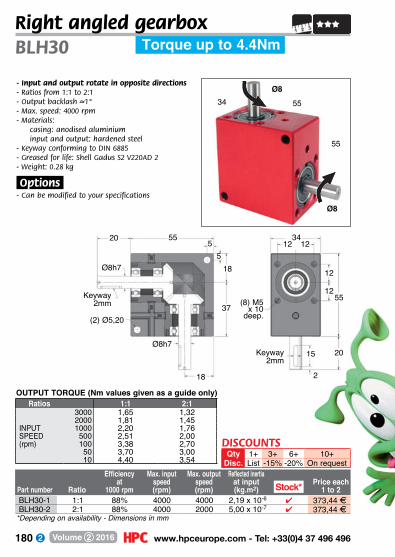
180 www.hpceurope.com - Tel: +33(0)4 37 496 496Volume 2 2016
Torque up to 4.4NmBLH30
- Input and output rotate in opposite directions- Ratios from 1:1 to 2:1- Output backlash –~1°- Max. speed: 4000 rpm- M aterials:
casing: anodised aluminium input and output: hardened steel
- Keyway conforming to DIN 6885- Greased for life: Shell Gadus S2 V220AD 2- Weight: 0.28 kg
.Options.- Can be modified to your specifications
OUTPUT TORQUE (Nm values given as a guide only)
Part number Ratio
Efficiencyat
1000 rpm
Max. input speed(rpm)
Max. output speed(rpm)
Reflected inertiaat input(kg.m2)
Price each1 to 2
5534
55
Ø8
Ø8
Right angled gearbox
37
2
12
55
(2) Ø5,20
18
15
(8) M5 x 10
deep.
20
12
12
18
34555
5
20
Ø8h7
Ø8h7
Keyway 2mm
Keyway 2mm
Ratios 1:1 2:13000 1,65 1,322000 1,81 1,45
INPUT 1000 2,20 1,76SPEED 500 2,51 2,00(rpm) 100 3,38 2,70
50 3,70 3,0010 4,40 3,54
*Depending on availability - Dimensions in mm
BLH30-1 1:1 88% 4000 4000 2,19 x 10⁻⁶ 4 373,44 FBLH30-2 2:1 88% 4000 2000 5,00 x 10⁻⁷ 4 373,44 F
Stock*
DISCOUNTSQty 1+ 3+ 6+ 10+
Disc. List -15% -20% On request
12
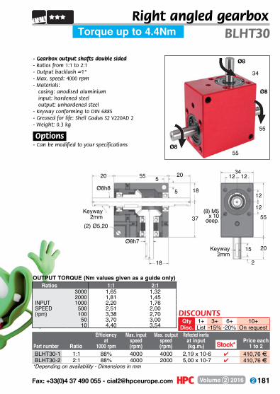
181 Fax: +33(0)4 37 490 055 - [email protected] Volume 2 2016
Torque up to 4.4Nm BLHT30
- Gearbox output shafts double sided- Ratios from 1:1 to 2:1- Output backlash –~1°- Max. speed: 4000 rpm- Materials:
casing: anodised aluminium input: hardened steel output: unhardened steel
- Keyway conforming to DIN 6885- Greased for life: Shell Gadus S2 V220AD 2- Weight: 0.3 kg
.Options.- Can be modified to your specifications
OUTPUT TORQUE (Nm values given as a guide only)
Part number Ratio
Efficiencyat
1000 rpm
Max. input speed(rpm)
Max. output speed(rpm)
Reflected inertiaat input(kg.m2)
Price each1 to 2
34
Ø8
55
55Ø8
Ø8
Right angled gearbox
18
Keyway 2mm
5520 20 3412
20
18
(8) M5 x 10
deep.
5
5
(2) Ø5,20
Keyway 2mm
Ø8h8
Ø8h7
12
15
2
5537
*Depending on availability - Dimensions in mm
Stock*
Ratios 1:1 2:13000 1,65 1,322000 1,81 1,45
INPUT 1000 2,20 1,76SPEED 500 2,51 2,00(rpm) 100 3,38 2,70
50 3,70 3,0010 4,40 3,54
BLHT30-1 1:1 88% 4000 4000 2,19 x 10⁻⁶ 4 410,76 FBLHT30-2 2:1 88% 4000 2000 5,00 x 10⁻⁷ 4 410,76 F
DISCOUNTSQty 1+ 3+ 6+ 10+
Disc. List -15% -20% On request
12
12

182 www.hpceurope.com - Tel: +33(0)4 37 496 496Volume 2 2016
Right angled gearbox, bored shafts
- Input and output rotate in opposite directions
- Ratio from 1:1 to 2:1- Output backlash – ~1º- Max. speed: 4000 rpm- Greased for life- Materials:
casing: anodised aluminium 6082gears: case hardened steel
- Allowable loads, please refer to the technical pages
34
55
55
Bore 8H8
Circlip CX8Ø8+0
-0,02
55
(2) Ø5,2Circlip CX12
555
55
5
Bore size 8H8, depth 16mm
315
2
20
Torque up to 4.4Nm
Bore 8H8
BLHI/BLHOBLHB
(2) Ø4,2
Slot width 2mm, depth 5mm
5
12
55
(8)M5x10
34
BLHB30BLHI30BLHO30
Ø12
3455
55
Arbre Ø8
Bore 8H8
Output torque (Nm values given as a guide only)Ratios 1:1 2:1
3000 1,65 1,322000 1,81 1,45
INPUT 1000 2,20 1,76SPEED 500 2,51 2,00(rpm) 100 3,38 2,70
50 3,70 3,0010 4,40 3,54
Dimensions in mm
DISCOUNTSQty 1+ 2+ 4+ 6+
Disc. List -15% -20% On requestEfficiency Max. input
Input Output at 1000 speed speed PricePart number Ratios shaft shaft (rpm) (rpm) (rpm) eachBLHB30-1 1:1 Hollow Hollow 88% 4000 4000 4 457,19 FBLHB30-2 2:1 Hollow Hollow 88% 4000 2000 - 457,19 FBLHI30-1 1:1 Hollow Solid 88% 4000 4000 4 417,59 FBLHI30-2 2:1 Hollow Solid 88% 4000 2000 - 417,59 FBLHO30-2 2:1 Solid Hollow 88% 4000 2000 - 417,59 F
Stock*
Increasedstock
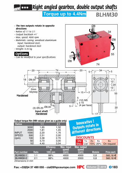
183 Fax: +33(0)4 37 490 055 - [email protected] Volume 2 2016
Right angled gearbox, double output shafts
- The two outputs rotate in opposite directions
- Ratios of 1:1 to 2:1- Output backlash –~1˚- Max. speed: 4000 rpm- Materials: casing: anodised aluminium
input: hardened steel, output: hardened steel
- Weight: 0.35 kg
.Options.- Can be modified to your specifications
34
55
74Ø8
Part number Ratio
Efficiencyat
1000 rpm
Max. input speed(rpm)
Max. output speed(rpm) Module Price each
Ø8
74 ==20 20
20
24
34
2
17
55
15 55
12
12
5
5
5
(3) Ø5.20
2mmkeyway
Ø8.00
Ø8.0018
Hardened
Input shaftHardened
(12) M5 x 10(4 per face)
+0,00-0.02
+0,00-0.02
BLHM30
Ø8
Torque up to 4.4Nm
Innovative !
Outputs rotate in
different directions
Output torque Nm (NM values given as a guide only)Ratios 1:1 2:1
3000 1,65 1,322000 1,81 1,45
INPUT 1000 2,20 1,76SPEED 500 2,51 2,00(rpm) 100 3,38 2,70
50 3,70 3,0010 4,40 3,54
BLHM30-1 1:1 88% 4000 4000 0,8 560,18 FBLHM30-2 2:1 88% 4000 2000 0,8 560,18 F
Dimensions in mm
DISCOUNTSQty 1+ 2+ 4+ 6+
Disc. List -15% -20% On request

184 www.hpceurope.com - Tel: +33(0)4 37 496 496Volume 2 2016
BLH40
- Input and output rotate in opposite directions- Ratios from 1:1 to 2:1- Output backlash –~1°- Max. speed: 4000 rpm- Materials:
casing: anodised aluminium input and output: hardened steel
- Keyway conforming to DIN 6885- Greased for life: Shell Gadus S2 V220AD 2- Weight: 0.90 kg
.Options.- Can be modified to your specifications
Part number Ratio
Efficiencyat
1000 rpm
Max. input speed(rpm)
Max. output speed(rpm)
Reflected inertiaat input(kg.m2)
Price each1 to 2
7544
75
Ø10
Ø10
Right angled gearboxTorque up to 10.3Nm
16
50
3
16
75
(2) Ø6,50
25
20
(8) M6 x 10
deep.
25
16
16
25
44756
6
25
Ø10h7
Ø10h7
Keyway 3mm
1/8’’ BSPpressure Plug
Protube Ø10x5 Approx.
Keyway 3mm
Output torque (Nm values given as a guide only)Ratios 1:1 2:1
3000 4,00 3,002000 4,40 3,40
INPUT 1000 5,10 4,00SPEED 500 5,80 4,60(rpm) 100 7,60 6,00
50 8,50 6,3010 10,30 8,00
*Depending on availability - Dimensions in mm
Stock*BLH40-1 1:1 88% 4000 4000 6,42 x 10⁻⁶ 4 476,41 FBLH40-2 2:1 88% 4000 2000 1,40 x 10⁻⁶ 4 476,41 F
DISCOUNTSQty 1+ 3+ 6+ 10+
Disc. List -15% -20% On request

185 Fax: +33(0)4 37 490 055 - [email protected] Volume 2 2016
Torque up to 10.3Nm BLHT40
- Gearbox output shafts double sided- Ratios from 1:1 to 2:1- Output backlash –~1°- Max. speed: 4000 rpm- Materials:
casing: anodised aluminium input: hardened steel output: unhardened steel
- Keyway conforming to DIN 6885- Greased for life: Shell Gadus S2 V220AD 2- Weight: 1 kg
.Options.- Can be modified to your specifications
Output torque (Nm values given as a guide only)
Part number Ratio
Efficiencyat
1000 rpm
Max. input speed(rpm)
Max. output speed(rpm)
Reflected inertiaat input(kg.m2)
Price each1 to 2
44
Ø10
75
75Ø10
Ø10
Right angled gearbox
16
25
50
Keyway 3mm
16
7525 2544
16
25
25
(8) M6 x 10
deep.
66
(2) Ø6,50
Keyway 3mm
Ø10h8
Ø10h7
75
16
20
3
1/8’’ BSPpressure Plug
Protube Ø10x5 Approx.
*Depending on availability - Dimensions in mm
Stock*
Ratios 1:1 2:13000 4,00 3,002000 4,40 3,40
INPUT 1000 5,10 4,00SPEED 500 5,80 4,60(rpm) 100 7,60 6,00
50 8,50 6,3010 10,30 8,00
BLHT40-1 1:1 88% 4000 4000 6,42 x 10⁻⁶ 4 524,08 FBLHT40-2 2:1 88% 4000 2000 1,40 x 10⁻⁶ 4 524,08 F
DISCOUNTSQty 1+ 3+ 6+ 10+
Disc. List -15% -20% On request
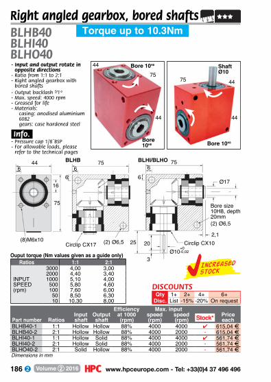
186 www.hpceurope.com - Tel: +33(0)4 37 496 496Volume 2 2016
BLHB40BLHI40BLHO40
Right angled gearbox, bored shafts
- Input and output rotate in opposite directions
- Ratio from 1:1 to 2:1- Right angled gearbox with
bored shafts- Output backlash – ~1º- Max. speed: 4000 rpm- Greased for life- Materials:
casing: anodised aluminium 6082gears: case hardened steel
.Info..- Pressure cap 1/8¨BSP- For allowable loads, please
refer to the technical pages
44
75
44
Bore 10H8
Circlip CX10Ø10
+0-0,02
75
(2) Ø6,5Circlip CX17
675
66
6
Bore size 10H8, depth 20mm
2,120
3
25
Torque up to 10.3Nm
Bore 10H8
BLHI/BLHOBLHB
(2) Ø6,5
6
16
75
(8)M6x10
44
Ø17
4475
44
Shaft Ø10
Bore 10H8
Ouput torque (Nm values given as a guide only)Ratios 1:1 2:1
3000 4,00 3,002000 4,40 3,40
INPUT 1000 5,10 4,00SPEED 500 5,80 4,60(rpm) 100 7,60 6,00
50 8,50 6,3010 10,30 8,00
Dimensions in mm
DISCOUNTSQty 1+ 2+ 4+ 6+
Disc. List -15% -20% On requestEfficiency Max. input
Input Output at 1000 speed speed PricePart number Ratios shaft shaft (rpm) (rpm) (rpm) eachBLHB40-1 1:1 Hollow Hollow 88% 4000 4000 4 615,04 FBLHB40-2 2:1 Hollow Hollow 88% 4000 2000 - 615,04 FBLHI40-1 1:1 Hollow Solid 88% 4000 4000 4 561,74 FBLHI40-2 2:1 Hollow Solid 88% 4000 2000 - 561,74 FBLHO40-2 2:1 Solid Hollow 88% 4000 2000 - 561,74 F
Stock*
Increasedstock
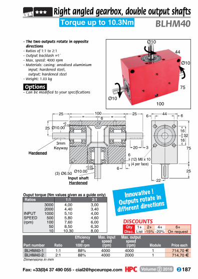
187 Fax: +33(0)4 37 490 055 - [email protected] Volume 2 2016
Right angled gearbox, double output shafts
- The two outputs rotate in opposite directions
- Ratios of 1:1 to 2:1- Output backlash –~1˚- Max. speed: 4000 rpm- Materials: casing: anodised aluminium
input: hardened steel, output: hardened steel
- Weight: 1.03 kg
.Options.- Can be modified to your specifications
44
75
100Ø10
Part number Ratio
Efficiencyat
1000 rpm
Max. input speed(rpm)
Max. output speed(rpm) Module Price each
Ø10
100==25 25
25
32
44
3
22
66
20 75
16
16
6
6
6
(3) Ø6.50
3mmKeyway
Ø10.00
Ø10.0025
Hardened
Input shaftHardened
(12) M6 x 10(4 per face)
+0,00-0.02
+0,00-0.02
Ø10
BLHM40Torque up to 10.3Nm
Ratios 1:1 2:13000 4,00 3,002000 4,40 3,40
INPUT 1000 5,10 4,00SPEED 500 5,80 4,60(rpm) 100 7,60 6,00
50 8,50 6,3010 10,30 8,00
Ouput torque (Nm values given as a guide only)
BLHM40-1 1:1 88% 4000 4000 1 714,70 FBLHM40-2 2:1 88% 4000 2000 1 714,70 F
Dimensions in mm
Innovative !
Outputs rotate in
different directions
DISCOUNTSQty 1+ 2+ 4+ 6+
Disc. List -15% -20% On request
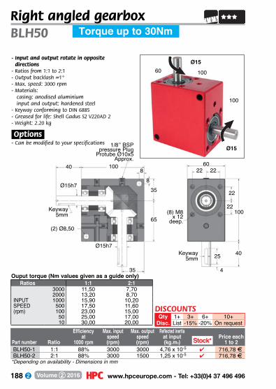
188 www.hpceurope.com - Tel: +33(0)4 37 496 496Volume 2 2016
Torque up to 30NmBLH50
- Input and output rotate in opposite directions
- Ratios from 1:1 to 2:1- Output backlash –~1°- Max. speed: 3000 rpm- Materials:
casing: anodised aluminium input and output: hardened steel
- Keyway conforming to DIN 6885- Greased for life: Shell Gadus S2 V220AD 2- Weight: 2.20 kg
.Options.- Can be modified to your specifications
Part number Ratio
Efficiencyat
1000 rpm
Max. input speed(rpm)
Max. output speed(rpm)
Reflected inertiaat input(kg.m2)
Price each1 to 2
10060
100
Ø15
Ø15
Right angled gearbox
Ouput torque (Nm values given as a guide only)
22
65
4
22
22
100
(2) Ø8,50
35
25
(8) M8 x 12
deep.
40
22
35
601008
8
40
Ø15h7
Ø15h7
Keyway 5mm
Keyway 5mm
1/8’’ BSPpressure Plug
Protube Ø10x5 Approx.
Ratios 1:1 2:13000 11,50 7,702000 13,20 8,70
INPUT 1000 15,90 10,20SPEED 500 17,50 11,60(rpm) 100 23,00 15,00
50 25,00 17,0010 30,00 20,00
Stock*BLH50-1 1:1 88% 3000 3000 4,76 x 10⁻⁵ 4 716,78 FBLH50-2 2:1 88% 3000 1500 1,25 x 10⁻⁵ 4 716,78 F
*Depending on availability - Dimensions in mm
DISCOUNTSQty 1+ 3+ 6+ 10+
Disc. List -15% -20% On request
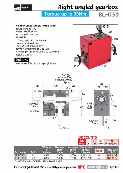
189 Fax: +33(0)4 37 490 055 - [email protected] Volume 2 2016
Torque up to 30Nm BLHT50
- Gearbox output shafts double sided- Ratios from 1:1 to 2:1- Output backlash –~1°- Max. speed: 3000 rpm- Materials:
casing: anodised aluminium input: hardened steel output: unhardened steel
- Keyway conforming to DIN 6885- Greased for life: Shell Gadus S2 V220AD 2- Weight: 2.31 kg
.Options.- Can be modified to your specifications
Part number Ratio
Efficiencyat
1000 rpm
Max. input speed(rpm)
Max. output speed(rpm)
Reflected inertiaat input(kg.m2)
Price each1 to 2
60
Ø15
100
100Ø15
Ø15
Right angled gearbox
22
35
Keyway 5mm
10040 4060
22
40
35
(8) M8 x 12
deep.
88
(2) Ø8,50
Keyway 5mm
Ø15h8
Ø15h7
22
25
4
100
1/8’’ BSPpressure Plug
Protube Ø10x5 Approx.
*Depending on availability - Dimensions in mm
BLHT50-1 1:1 88% 3000 3000 4,76 x 10⁻⁵ 4 786,91 FBLHT50-2 2:1 88% 3000 1500 1,25 x 10⁻⁵ 4 786,91 F
Stock*
DISCOUNTSQty 1+ 3+ 6+ 10+
Disc. List -15% -20% On request
65
22

190 www.hpceurope.com - Tel: +33(0)4 37 496 496Volume 2 2016
Right angled gearbox, bored shafts
- Input and output rotate in opposite directions
- Ratio from 1:1 to 2:1- Right angled gearbox with
bored shafts- Output backlash – ~1º- Max. speed: 4000 rpm- Greased for life- Materials:
casing: anodised aluminium 6082gears: case hardened steel
.Info..- Pressure cap 1/8¨BSP- For allowable loads, please
refer to the technical pages
60
100
100
Bore 15H8
(2) Ø8,5Circlip CX25
8100
8
Torque up to 30Nm
Bore 15H8
BLHB
8
22
100
(8)M8x12
60
BLHB50BLHI50BLHO50
Circlip CX15
Ø15+0-0,02
1008
8
Bore size 15H8 depth.20mm
2,525
4
40
BLHI/BLHO
(2) Ø8,5
Ø25
60100
100
Shaft Ø15
Bore 15H8
Ouput torque (Nm values given as a guide only)Ratios 1:1 2:1
3000 11,50 7,702000 13,20 8,70
INPUT 1000 15,90 10,20SPEED 500 17,50 11,60(rpm) 100 23,00 15,00
50 25,00 17,0010 30,00 20,00
DISCOUNTSQty 1+ 2+ 4+ 6+
Disc. List -15% -20% On requestEfficiency Max. input
Input Output at 1000 speed speed PricePart number Ratios shaft shaft (rpm) (rpm) (rpm) eachBLHB50-1 1:1 Hollow Hollow 88% 3000 3000 4 925,34 FBLHB50-2 2:1 Hollow Hollow 88% 3000 1500 - 925,34 FBLHI50-1 1:1 Hollow Solid 88% 3000 3000 4 845,21 FBLHI50-2 2:1 Hollow Solid 88% 3000 1500 - 845,21 FBLHO50-2 2:1 Solid Hollow 88% 3000 1500 - 845,21 F
Stock*
*Depending on availability - Dimensions in mm
Increasedstock

191 Fax: +33(0)4 37 490 055 - [email protected] Volume 2 2016
Right angled gearbox, double output shafts
- The two outputs rotate in opposite directions
- Ratios of 1:1 to 2:1- Output backlash –~1˚- Max. speed: 4000 rpm- Materials: casing: anodised aluminium
input: hardened steel, output: hardened steel
- Weight: 2.53 kg
.Options.- Can be modified to your specifications
60
100
135Ø15
Part number Ratio
Efficiencyat
1000 rpm
Max. input speed(rpm)
Max. output speed(rpm) Module Price each
Ø15
135==40 40
40
44
60
4
30
88
25 100
22
22
8
8
8
(3) Ø8.50
5mmkeyway
Ø15.00
Ø15.0035
Hardened
Input shaftHardened
(12) M8 x 12(4 per face)
+0,00-0.02
+0,00-0.02
BLHM50
Ø15
Torque up to 30Nm
Ouput torque (Nm values given as a guide only)Ratios 1:1 2:1
3000 11,50 7,702000 13,20 8,70
INPUT 1000 15,90 10,20SPEED 500 17,50 11,60(rpm) 100 23,00 15,00
50 25,00 17,0010 30,00 20,00
BLHM50-1 1:1 88% 3000 3000 1,5 1 075,27 FBLHM50-2 2:1 88% 3000 1500 1,5 1 075,27 F
Dimensions in mm
Innovative !
Outputs rotate in
different directions
DISCOUNTSQty 1+ 2+ 4+ 6+
Disc. List -15% -20% On request
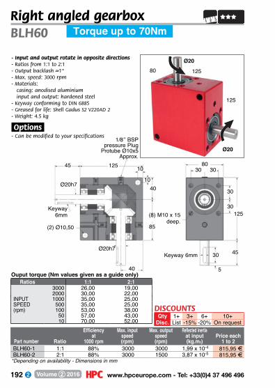
192 www.hpceurope.com - Tel: +33(0)4 37 496 496Volume 2 2016
Torque up to 70NmBLH60
- Input and output rotate in opposite directions- Ratios from 1:1 to 2:1- Output backlash –~1°- Max. speed: 3000 rpm- Materials:
casing: anodised aluminium input and output: hardened steel
- Keyway conforming to DIN 6885- Greased for life: Shell Gadus S2 V220AD 2- Weight: 4.5 kg
.Options.- Can be modified to your specifications
Part number Ratio
Efficiencyat
1000 rpm
Max. input speed(rpm)
Max. output speed(rpm)
Reflected inertiaat input(kg.m2)
Price each1 to 2
12580
125
Ø20
Ø20
Right angled gearbox
85
5
30
Keyway 6mm
30
(2) Ø10,50
40
30
(8) M10 x 15deep.
45
30
40
80125 10
10
45
Ø20h7
Ø20h7
Keyway 6mm 125
1/8’’ BSPpressure Plug
Protube Ø10x5 Approx.
Ratios 1:1 2:13000 26,00 19,002000 30,00 22,00
INPUT 1000 35,00 25,00SPEED 500 35,00 25,00(rpm) 100 53,00 38,00
50 57,00 43,0010 70,00 52,00
Ouput torque (Nm values given as a guide only)
BLH60-1 1:1 88% 3000 3000 1,99 x 10⁻⁴ 815,95 FBLH60-2 2:1 88% 3000 1500 3,87 x 10⁻⁵ 815,95 F
*Depending on availability - Dimensions in mm
DISCOUNTSQty 1+ 3+ 6+ 10+
Disc. List -15% -20% On request
30

193 Fax: +33(0)4 37 490 055 - [email protected] Volume 2 2016
Torque up to 70Nm BLHT60
- Gearbox output shafts double sided- Ratios from 1:1 to 2:1- Output backlash –~1°- Max. speed: 3000 rpm- Materials:
casing: anodised aluminium input: hardened steel output: unhardened steel
- Keyway conforming to DIN 6885- Greased for life: Shell Gadus S2 V220AD 2- Weight: 4.75 kg
.Options.- Can be modified to your
specifications
Ouput torque (Nm values given as a guide only)
Part number Ratio
Efficiencyat
1000 rpm
Max. input speed(rpm)
Max. output speed(rpm)
Reflected inertiaat input(kg.m2)
Price each1 to 2
80
Ø20
125
125Ø20
Ø20
Right angled gearbox
30
40
85
Keyway 6mm
30
12545 4580
30
45
40
(8) M10 x 15
deep.
1010
(2) Ø10,50
Keyway 6mm
Ø20h8
Ø20h7
125
30
30
5
1/8’’ BSPpressure Plug Protube
Ø10x5 Approx.
*Depending on availability - Dimensions in mm
Ratios 1:1 2:13000 26,00 19,002000 30,00 22,00
INPUT 1000 35,00 25,00SPEED 500 35,00 25,00(rpm) 100 53,00 38,00
50 57,00 43,0010 70,00 52,00
BLHT60-1 1:1 88% 3000 3000 1,99 x 10⁻⁴ 897,54 FBLHT60-2 2:1 88% 3000 1500 3,87 x 10⁻⁵ 897,54 F
DISCOUNTSQty 1+ 3+ 6+ 10+
Disc. List -15% -20% On request

194 www.hpceurope.com - Tel: +33(0)4 37 496 496Volume 2 2016
Right angled gearbox, bored shafts
- Input and output rotate in opposite directions
- Ratio from 1:1 to 2:1- Right angled gearbox with
bored shafts- Output backlash – ~1º- Max. speed: 3000 rpm- Greased for life- Materials:
casing: anodised aluminium 6082gears: case hardened steel
.Info..- Pressure cap 1/8¨BSP- For allowable loads, please refer
to the technical pages
80
125
125
Bore 20H8
Circlip CX20Ø20+0
-0,02
125
(2)Ø10,5Circlip CX40
10125
1010
10
Bore size 20H8, depth 36mm
430
5
45
Torque up to 70Nm
Bore 20H8
BLHI/BLHOBLHB
(2)Ø10,5
10
30
125
(8)M10x15
80
BLHB60BLHI60BLHO60
Ø40
80125
125
Shaft Ø20
Bore 20H8
Ouput torque (Nm values given as a guide only)Ratios 1:1 2:1
3000 26,00 19,002000 30,00 22,00
INPUT 1000 35,00 25,00SPEED 500 40,00 29,00(rpm) 100 53,00 38,00
50 57,00 43,0010 70,00 52,00
Dimensions in mm
DISCOUNTSQty 1+ 2+ 4+ 6+
Disc. List -15% -20% On requestEfficiency Max. input
Input Output at 1000 speed speed PricePart number Ratios shaft shaft (rpm) (rpm) (rpm) eachBLHB60-1 1:1 Hollow Hollow 88% 3000 3000 4 1 053,31 FBLHB60-2 2:1 Hollow Hollow 88% 3000 1500 - 1 053,31 FBLHI60-1 1:1 Hollow Solid 88% 3000 3000 4 962,13 FBLHI60-2 2:1 Hollow Solid 88% 3000 1500 - 962,13 FBLHO60-2 2:1 Solid Hollow 88% 3000 1500 - 962,13 F
Stock*
Increasedstock
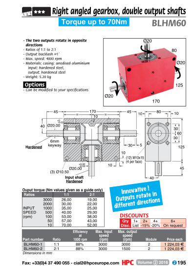
195 Fax: +33(0)4 37 490 055 - [email protected] Volume 2 2016
Right angled gearbox, double output shafts
- The two outputs rotate in opposite directions
- Ratios of 1:1 to 2:1- Output backlash –~1˚- Max. speed: 4000 rpm- Materials: casing: anodised aluminium
input: hardened steel, output: hardened steel
- Weight: 5.20 kg
.Options.- Can be modified to your specifications
80
125
170Ø20
Part number Ratio
Efficiencyat
1000 rpm
Max. input speed(rpm)
Max. output speed(rpm) Module Price each
Ø20
170==45 45
45
60
80
5
40
1010
30 125
30
30
10
10
10
(3) Ø10.50
6mmkeyway
Ø20.00
Ø20.0040
Hardened
Input shaftHardened
(12) M10x15(4 per face)
+0,00-0.02
+0,00-0.02
Ø20
BLHM60Torque up to 70Nm
Ratios 1:1 2:13000 26,00 19,002000 30,00 22,00
INPUT 1000 35,00 25,00SPEED 500 40,00 29,00(rpm) 100 53,00 38,00
50 57,00 43,0010 70,00 52,00
Ouput torque (Nm values given as a guide only)
BLHM60-1 1:1 88% 3000 3000 2 1 224,03 FBLHM60-2 2:1 88% 3000 1500 2 1 224,03 F
Dimensions in mm
DISCOUNTSQty 1+ 2+ 4+ 6+
Disc. List -15% -20% On request
Innovative !
Outputs rotate in
different directions

196 www.hpceurope.com - Tel: +33(0)4 37 496 496Volume 2 2016
Torque up to 128NmBLH70
- Input and output rotate in opposite directions- Ratios from 1:1 to 2:1- Output backlash –~1°- Max. speed: 3000 rpm- Materials:
casing: anodised aluminium input and output: hardened steel
- Keyway conforming to DIN 6885- Greased for life: Shell Gadus S2 V220AD 2- Weight: 7.05 kg
.Options.- Can be modified to your specifications
Part number Ratio
Efficiencyat
1000 rpm
Max. input speed(rpm)
Max. output speed(rpm)
Reflected inertiaat input(kg.m2)
Price each1 to 2
14098
140
Ø25
Ø25
Right angled gearbox
90
5
35
35
140(2) Ø12,50
50
50
(8) M12 x 20
deep.
60
35
50
98140 16
16
60
Ø25h7
Ø25h7
Keyway 8mm
Keyway 8mm
OUTPUT TORQUE (Nm values given as a guide only)
1/8’’ BSPpressure Plug Protube
Ø10x5 Approx.
Ratios 1:1 2:13000 43 262000 47 30
INPUT 1000 51 34SPEED 500 64 38(rpm) 100 85 51
50 94 6010 128 77
BLH70-1 1:1 88% 3000 3000 4,15 x 10⁻⁴ 1 637,71 FBLH70-2 2:1 88% 3000 1500 1,12 x 10⁻⁴ 1 637,71 F
Dimensions in mm
DISCOUNTSQty 1+ 3+ 6+ 10+
Disc. List -15% -20% On request
35
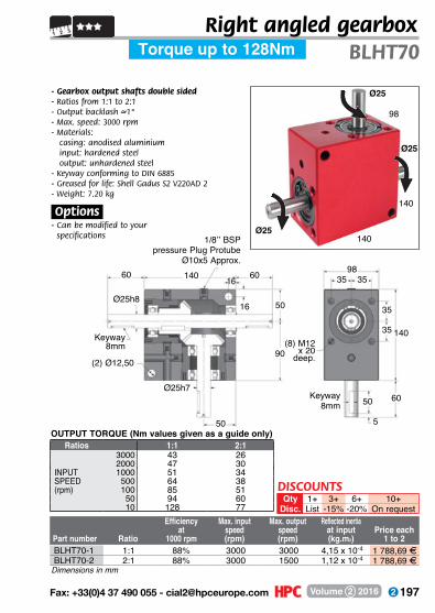
197 Fax: +33(0)4 37 490 055 - [email protected] Volume 2 2016
Torque up to 128Nm BLHT70
- Gearbox output shafts double sided- Ratios from 1:1 to 2:1- Output backlash –~1°- Max. speed: 3000 rpm- Materials:
casing: anodised aluminium input: hardened steel output: unhardened steel
- Keyway conforming to DIN 6885- Greased for life: Shell Gadus S2 V220AD 2- Weight: 7.20 kg
.Options.- Can be modified to your
specifications
Part number Ratio
Efficiencyat
1000 rpm
Max. input speed(rpm)
Max. output speed(rpm)
Reflected inertiaat input(kg.m2)
Price each1 to 2
98
Ø25
140
140Ø25
Ø25
Right angled gearbox
OUTPUT TORQUE (Nm values given as a guide only)
Keyway 8mm
35
14060 60 9835
60
50
(8) M12 x 20
deep.
16
16
(2) Ø12,50
Keyway 8mm
Ø25h8
Ø25h7
35
50
5
1/8’’ BSPpressure Plug Protube
Ø10x5 Approx.
Ratios 1:1 2:13000 43 262000 47 30
INPUT 1000 51 34SPEED 500 64 38(rpm) 100 85 51
50 94 6010 128 77
BLHT70-1 1:1 88% 3000 3000 4,15 x 10⁻⁴ 1 788,69 FBLHT70-2 2:1 88% 3000 1500 1,12 x 10⁻⁴ 1 788,69 F
Dimensions in mm
DISCOUNTSQty 1+ 3+ 6+ 10+
Disc. List -15% -20% On request
35
90
50
140

198 www.hpceurope.com - Tel: +33(0)4 37 496 496Volume 2 2016
Offset spur gear reducer
*Depending on availability - Dimensions in mm
Part number Ratio
Max. input speed(rpm)
Max. output speed(rpm)
Efficiencyat
1000 rpmPrice each
1 to 2
FF10 Torque up to 3.7Nm
58
Ø5
Ø8
2446
Ø15
2
5826
38
13,40
21,60
23
24
2011
4
2
46
10
(4) Ø4,50through drilled
Ø8H7Keyway2 Js9 (Output) Ø5h7 Keyway 2 N9
- High efficiency- Ratios from 2:1 to 7:1- Output backlash –~1°- Max. speed: 2000 rpm- Materials: casing: anodised aluminium input and output: unhardened steel- Weight: 0.226 kg
.Options.- Can be modified to your specifications
OUTPUT TORQUE (Nm values given as a guide only)Ratios 2:1 3:1 4:1 5:1 6:1 7:1
2000 1,34 1,29 1,15 1,10 0,94 0,781000 1,55 1,49 1,33 1,27 1,08 0,90
INPUT 500 1,85 1,78 1,58 1,51 1,30 1,07SPEED 200 2,08 2,00 1,78 1,71 1,46 1,21(rpm) 100 2,44 2,35 2,09 2,00 1,71 1,42
50 2,74 2,63 2,36 2,25 1,92 1,6010 3,70 3,57 3,16 3,03 2,60 2,16
28
Stock*FF10-2 2:1 2000 1000 93% 4 290,57 FFF10-3 3:1 2000 666 93% - 290,57 FFF10-4 4:1 2000 500 93% - 290,57 FFF10-5 5:1 2000 400 93% 4 290,57 FFF10-6 6:1 2000 333 93% - 290,57 FFF10-7 7:1 2000 285 93% - 290,57 FFF10-XH 2:1 - 7:1 (With hardened gears = torque x 2) - 513,61 F
DISCOUNTSQty 1+ 3+ 6+ 10+
Disc. List -15%-20% On request

199 Fax: +33(0)4 37 490 055 - [email protected] Volume 2 2016
80
Ø8
Ø12
32
64
Offset spur gear reducer
*Depending on availability - Dimensions in mm
Part number Ratio
Max. input speed(rpm)
Max. output speed(rpm)
Efficiencyat
1000 rpmPrice each
1 to 2
Torque up to 10Nm FF15
30,50
32
40
Ø20
2
8036
52
17,50
32
2915
6
2
64
14
(4) Ø5,50through drilled
Ø12H7Keyway4 Js9 (Output)
Ø8h7 Keyway 2 N9
- High efficiency- Ratios from 2:1 to 7:1- Output backlash –~1°- Max. speed: 2000 rpm- Materials: casing: anodised aluminium input and output: unhardened steel- Weight: 0.55 kg
.Options.- Can be modified to your specifications
Stock*
OUTPUT TORQUE (Nm values given as a guide only)Ratios 2:1 3:1 4:1 5:1 6:1 7:1
2000 3,70 3,50 3,20 2,90 2,60 2,201000 4,30 4,00 3,70 3,40 3,10 2,60
INPUT 500 5,00 4,80 4,40 4,00 3,60 3,00SPEED 200 5,70 5,50 5,00 4,40 3,90 3,20(rpm) 100 6,70 6,50 5,90 5,10 4,50 3,70
50 7,50 7,20 6,50 5,70 5,00 4,0010 10,00 9,80 9,00 8,00 7,30 6,10
FF15-2 2:1 2000 1000 93% 4 355,31 FFF15-3 3:1 2000 666 93% 4 355,31 FFF15-4 4:1 2000 500 93% - 355,31 FFF15-5 5:1 2000 400 93% 4 355,31 FFF15-6 6:1 2000 333 93% - 355,31 FFF15-7 7:1 2000 285 93% - 355,31 FFF15-XH 2:1 - 7:1 (With hardened gears = torque x 2) - 639,30 F
DISCOUNTSQty 1+ 3+ 6+ 10+
Disc. List -15%-20% On request
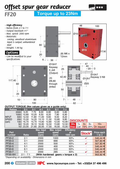
200 www.hpceurope.com - Tel: +33(0)4 37 496 496Volume 2 2016
Offset spur gear reducer
*Depending on availability - Dimensions in mm
Part number Ratio
Max. input speed(rpm)
Max. output speed(rpm)
Efficiencyat
1000 rpmPrice each
1 to 2
FF20 Torque up to 23Nm
117,40
Ø10
Ø15
48 100
20
3647
627
40
Ø25117,40
60
80
25
42,40
50
48
20
10
3
100
20
(4) Ø6,80through drilled
Ø15H7Keyway5 Js9 (Output)
Ø12h7
- High efficiency- Ratios from 2:1 to 7:1- Output backlash –~1°- Max. speed: 2000 rpm- Materials: casing: anodised aluminium input & output: unhardened
steel- Weight: 1.90 kg
.Options.- Can be modified to your
specifications 6
(8) M6 x 12mm
60
OUTPUT TORQUE (Nm values given as a guide only)Ratios 2:1 3:1 4:1 5:1 6:1 7:1
2000 9,20 7,70 8,00 6,90 6,60 5,801000 10,80 10,20 9,50 8,20 7,80 6,90
INPUT 500 12,50 11,80 11,00 9,60 9,00 8,20SPEED 200 15,00 14,20 13,10 11,50 10,80 9,80(rpm) 100 16,70 15,70 14,60 12,80 12,00 10,90
50 19,20 18,10 16,80 14,50 13,80 12,5010 23,00 21,60 20,00 17,50 16,50 15,00
Stock*FF20-2 2:1 2000 1000 93% 4 540,44 FFF20-3 3:1 2000 666 93% - 507,83 FFF20-4 4:1 2000 500 93% 4 507,83 FFF20-5 5:1 2000 400 93% - 540,44 FFF20-6 6:1 2000 333 93% - 540,44 FFF20-7 7:1 2000 285 93% 4 540,44 FFF20-XH 2:1 - 7:1 (With hardened gears = torque x 2) - 902,82 F
DISCOUNTSQty 1+ 3+ 6+ 10+
Disc. List -15%-20% On request
Ø10h7 Keyway 3 N9
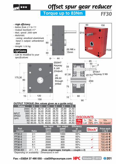
201 Fax: +33(0)4 37 490 055 - [email protected] Volume 2 2016
Offset spur gear reducer
*Depending on availability - Dimensions in mm
Part number Ratio
Max. input speed(rpm)
Max. output speed(rpm)
Efficiencyat
1000 rpmPrice each
1 to 2
FF30Torque up to 83Nm
175,30
Ø15
Ø20
60 150
9015
90
44
31
175,3090
120
33
67,30
75
60
6550
15
3
150
30
(4) Ø8,50through drilled
Ø20H7Keyway6 Js9 (Output) Ø15h7
Keyway 5 N9Ø17h7
- High efficiency- Ratios from 2:1 to 7:1- Output backlash –~1°- Max. speed: 2000 rpm- Materials: casing: anodised aluminium input & output: unhardened
steel- Weight: 5.50 kg
.Options.
- Can be modified to your specifications
(8) M8 x 15mm30
8
Ø30
Stock*
OUTPUT TORQUE (Nm values given as a guide only)Ratios 2:1 3:1 4:1 5:1 6:1 7:1
2000 33,20 29,10 25,20 24,30 23,90 21,501000 39,10 34,40 29,80 28,70 27,30 25,10
INPUT 500 45,20 39,70 34,40 33,10 31,60 28,80SPEED 200 54,30 47,60 41,30 39,70 38,20 34,00(rpm) 100 60,40 52,90 45,90 44,20 43,40 39,10
50 69,00 60,08 43,00 50,80 49,30 45,2010 83,00 72,70 63,00 60,70 59,20 54,40
FF30-2 2:1 2000 1000 93% - 722,49 FFF30-3 3:1 2000 666 93% - 722,49 FFF30-4 4:1 2000 500 93% 4 722,49 FFF30-5 5:1 2000 400 93% - 722,49 FFF30-6 6:1 2000 333 93% - 722,49 FFF30-7 7:1 2000 285 93% 4 722,49 FFF30-XH 2:1 - 7:1 (Avec engrenages trempés = couple x 2) - 1 125,75 F
DISCOUNTSQty 1+ 3+ 6+ 10+
Disc. List -15%-20% On request
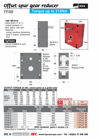
202 www.hpceurope.com - Tel: +33(0)4 37 496 496Volume 2 2016
Offset spur gear reducer
Part number Ratio
Max. input speed(rpm)
Max. output speed(rpm)
Efficiencyat
1000 t/minPrice each
1 to 2
FF40 Torque up to 210Nm
128
38
66
236128
160
53
88
95
90
5045
15
2,50
190
38
(4) Ø12,5through drilled
Ø25H7Keyway8 Js9 (Output)
Ø20h7 Keyway 6 N9
- High efficiency- Ratios from 2:1 to 7:1- Output backlash –~1°- Max. speed: 1500 rpm- Materials: casing: anodised aluminium input & output: unhardened
steel
.Options.- Can be modified to your
specifications
236
Ø20
Ø25
90 190
12
(8) M10 x 20mm
OUTPUT TORQUE (In Nm, values given as a guide only)Ratios 2:1 3:1 4:1 5:1 6:1 7:1
2000 83 83 76 70 61 591000 90 90 82 76 66 64
INPUT 500 103 102 95 87 76 73SPEED 200 120 120 110 102 89 86(rpm) 100 138 135 126 116 101 98
50 156 155 146 136 117 11310 210 210 196 180 158 152
FF40-2 2:1 1500 750 93% 1 270,61 FFF40-3 3:1 1500 500 93% 1 270,61 FFF40-4 4:1 1500 395 93% 1 270,61 FFF40-5 5:1 1500 300 93% 1 270,61 FFF40-6 6:1 1500 250 93% 1 270,61 FFF40-7 7:1 1500 214,29 93% 1 270,61 FFF40-XH 2:1 - 7:1 (With hardened gears = torque x 2) 1 661,60 F
*Depending on availability - Dimensions in mm
DISCOUNTSQty 1+ 3+ 6+ 10+
Disc. List -15%-20% On request
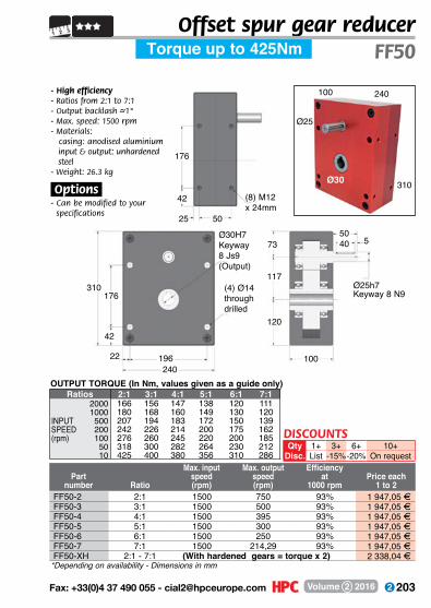
203 Fax: +33(0)4 37 490 055 - [email protected] Volume 2 2016
Offset spur gear reducer
Part number Ratio
Max. input speed(rpm)
Max. output speed(rpm)
Efficiencyat
1000 rpmPrice each
1 to 2
Torque up to 425Nm FF50
310
Ø25
Ø30
100 240
176
42
50
310176
196
73
117
120
100
5040
22
5
240
42
(4) Ø14through drilled
Ø30H7Keyway8 Js9 (Output)
Ø25h7 Keyway 8 N9
- High efficiency- Ratios from 2:1 to 7:1- Output backlash –~1°- Max. speed: 1500 rpm- Materials: casing: anodised aluminium input & output: unhardened
steel- Weight: 26.3 kg
.Options.- Can be modified to your
specifications 25
(8) M12 x 24mm
OUTPUT TORQUE (In Nm, values given as a guide only)Ratios 2:1 3:1 4:1 5:1 6:1 7:1
2000 166 156 147 138 120 1111000 180 168 160 149 130 120
INPUT 500 207 194 183 172 150 139SPEED 200 242 226 214 200 175 162(rpm) 100 276 260 245 220 200 185
50 318 300 282 264 230 21210 425 400 380 356 310 286
FF50-2 2:1 1500 750 93% 1 947,05 FFF50-3 3:1 1500 500 93% 1 947,05 FFF50-4 4:1 1500 395 93% 1 947,05 FFF50-5 5:1 1500 300 93% 1 947,05 FFF50-6 6:1 1500 250 93% 1 947,05 FFF50-7 7:1 1500 214,29 93% 1 947,05 FFF50-XH 2:1 - 7:1 (With hardened gears = torque x 2) 2 338,04 F
*Depending on availability - Dimensions in mm
DISCOUNTSQty 1+ 3+ 6+ 10+
Disc. List -15%-20% On request
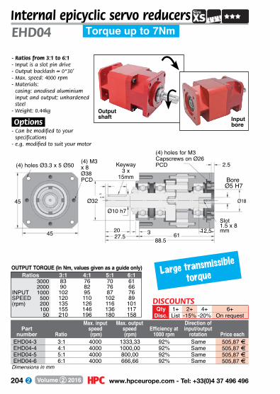
204 www.hpceurope.com - Tel: +33(0)4 37 496 496Volume 2 2016
45
345
Ø32 Ø18
Ø10 h7
12,520
88.561
+0,00-0,05
27.5
2.5
Torque up to 7NmEHD04Internal epicyclic servo reducers
Part number Ratio
Max. input speed (rpm)
Max. output speed (rpm)
Efficiency at 1000 rpm
Direction of input/output
rotation Price each
- Ratios from 3:1 to 6:1- Input is a slot pin drive- Output backlash –~ 0°30’- Max. speed: 4000 rpm- Materials:
casing: anodised aluminium input and output: unhardened steel
- Weight: 0.44kg
.Options.- Can be modified to your
specifications- e.g. modified to suit your motor
(4) M3 x 8Ø38 PCD
(4) holes for M3 Capscrews on Ø26 PCD(4) holes Ø3.3 x 5 Ø50 Keyway
3 x 15mm Bore
Ø5 H7
Slot1.5 x 8 mm
Large transmissible
torqueOUTPUT TORQUE (In Nm, values given as a guide only)
Ratios 3:1 4:1 5:1 6:13000 83 76 70 612000 90 82 76 66
INPUT 1000 102 95 87 76SPEED 500 120 110 102 89(rpm) 200 135 126 116 101
100 155 146 136 11750 210 196 180 158
EHD04-3 3:1 4000 1333,33 92% Same 505,87 FEHD04-4 4:1 4000 1000,00 92% Same 505,87 FEHD04-5 5:1 4000 800,00 92% Same 505,87 FEHD04-6 6:1 4000 666,66 92% Same 505,87 F
Dimensions in mm
DISCOUNTSQty 1+ 2+ 4+ 6+
Disc. List -15% -20% On request
Output shaft Input
bore

205 Fax: +33(0)4 37 490 055 - [email protected] Volume 2 2016
Torque up to 19NmInternal epicyclic servo reducers
EHD06
Part number Ratio
Max. input speed (rpm)
Max. output speed (rpm)
Efficiency at 1000 rpm
Direction of input/output
rotation Price each
- Ratios from 3:1 to 6:1- Input is a slot pin drive- Output backlash –~ 0°30’- Max. speed: 4000 rpm- Materials: casing: anodised aluminium gears: heat-treated steel
.Options.- Can be modified to your
specifications- e.g. modified to suit your motor
(4) M5 x 10 Ø50 PCD
(4) holes for M4 Capscrews Ø39 PCD(4) holes Ø4.3
Ø68 PCD
60
4.4Keyway
4 x 25mm
5
3
60
Ø40
Bore Ø7 H7
Ø26
Ø12 h7
37 2428115 78
Slot2.5 x 12 mm
+0.00-0.05
Large transmissible
torque
Dimensions in mm
OUTPUT TORQUE (In Nm, values given as a guide only)Ratios 3:1 4:1 5:1 6:1
3000 10 10 10 82000 12 12 12 10
INPUT 1000 15 15 15 12SPEED 500 16 16 16 13(rpm) 200 18 18 18 14
100 19 19 19 1550 19 19 19 15
EHD06-3 3:1 4000 1333,33 92% Same 563,65 FEHD06-4 4:1 4000 1000,00 92% Same 563,65 FEHD06-5 5:1 4000 800,00 92% Same 563,65 FEHD06-6 6:1 4000 666,66 92% Same 563,65 F
DISCOUNTSQty 1+ 2+ 4+ 6+
Disc. List -15% -20% On request
Output shaft Input
bore

206 www.hpceurope.com - Tel: +33(0)4 37 496 496Volume 2 2016
- Ratios from 3:1 to 6:1- Output backlash –~0°30’- Max. speed: 4000 rpm- Materials: casing: anodised aluminium gears: heat-treated steel- Weight: 1.4kg
.Options.- Can be modified to your
specifications- e.g. modified to suit your motor
Output shaft
Keyway5 x 25mm
Keyway3mm
(4) holes Ø5.3 x Ø84
Bore Ø9 H7
(4) holes Ø5.3 x 6 Ø65
EHD08Internal epicyclic servo reducers
Part number Ratio
Max. input speed (rpm)
Max. output speed (rpm)
Efficiency at 1000 rpm
Direction of input/output
rotation Price each
Torque up to 50Nm
(4) M6 x 12 x Ø60
75
375
+0-0,02
Ø50+0-0,05
302340
35 80120
Ø50
8 26,5 30 6
3
OUTPUT TORQUE (In Nm, values given as a guide only)Ratios 3:1 4:1 5:1 6:1
3000 25 25 25 202000 30 30 30 23
INPUT 1000 35 35 35 28SPEED 500 42 42 42 35(rpm) 200 45 45 45 40
100 48 48 48 4250 50 50 50 45
EHD08-3 3:1 4000 1333,33 92% Same 696,88 FEHD08-4 4:1 4000 1000,00 92% Same 696,88 FEHD08-5 5:1 4000 800,00 92% Same 696,88 FEHD08-6 6:1 4000 666,66 92% Same 696,88 F
Dimensions in mm
Input bore
Large transmissible
torque
Ø15
DISCOUNTSQty 1+ 2+ 4+ 6+
Disc. List -15% -20% On request

207 Fax: +33(0)4 37 490 055 - [email protected] Volume 2 2016
- Ratios from 9:1 to 36:1- Output backlash –~ 1°30’- Max. speed: 4000 rpm- Materials: casing: anodised
aluminium gears: heat-treated steel- Weight: 2.1 kg
.Options.- Can be modified to your specifications- e.g. modified to suit
your motor
Output shaft
(4) holes Ø5.3 x Ø84 (4) M6 x 12 x Ø60
Ø50Ø15 +0
-0.02
Ø50 +0-0.05
15540
75
75 23
8 6
3
(4) holes Ø5.3 x 6 Ø65
11530
Keyway5 x 25mm
Keyway 3mm
Bore Ø9 H7
Internal epicyclic servo reducers
Part number Ratio
Max. input speed (rpm)
Max. output speed (rpm)
Efficiency at 1000 rpm
Direction of input/output
rotation Price each
Torque up to 50Nm EHD08
Input shaft
Dimensions in mm
OUTPUT TORQUE (In Nm, values given as a guide only)Ratios 9:1 12:1 15:1 16:1 18:1 20:1 24:1 25:1 30:1 36:1
3000 35 35 35 38 42 42 42 42 42 36INPUT 1000 43 43 43 45 46 46 46 46 46 41SPEED 500 45 45 45 48 48 48 48 48 48 42(rpm) 100 50 50 50 50 50 50 50 50 50 45
50 50 50 50 50 50 50 50 50 50 45
EHD08-9 9:1 4000 444,44 86% Same 1 046,13 FEHD08-12 12:1 4000 333,33 86% Same 1 046,13 FEHD08-15 15:1 4000 266,66 86% Same 1 046,13 FEHD08-16 16:1 4000 250,00 86% Same 1 046,13 FEHD08-18 18:1 4000 222,22 86% Same 1 046,13 FEHD08-20 20:1 4000 200,00 86% Same 1 046,13 FEHD08-24 24:1 4000 166,66 86% Same 1 046,13 FEHD08-25 25:1 4000 160,00 86% Same 1 046,13 FEHD08-30 30:1 4000 133,33 86% Same 1 046,13 FEHD08-36 36:1 4000 111,11 86% Same 1 046,13 F
Large
transmissible
torqueDISCOUNTS
Qty 1+ 2+ 4+ 6+Disc. List -15% -20% On request
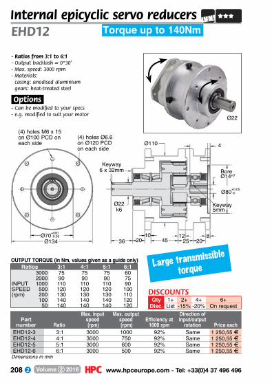
208 www.hpceurope.com - Tel: +33(0)4 37 496 496Volume 2 2016
- Ratios from 3:1 to 6:1- Output backlash –~ 0°30’- Max. speed: 3000 rpm- Materials: casing: anodised aluminium gears: heat-treated steel
.Options.- Can be modified to your specs- e.g. modified to suit your motor
Ø70+000
Ø134
(4) holes M6 x 15 on Ø100 PCD on each side Ø110 4
BoreØ14H7
Ø22 k6
36 452012
202510
Keyway6 x 32mm
(4) holes Ø6.6 on Ø120 PCD on each side
8
Torque up to 140NmEHD12Internal epicyclic servo reducers
Part number Ratio
Max. input speed (rpm)
Max. output speed (rpm)
Efficiency at 1000 rpm
Direction of input/output
rotation Price each
Keyway 5mm
OUTPUT TORQUE (In Nm, values given as a guide only)Ratios 3:1 4:1 5:1 6:1
3000 75 75 75 602000 90 90 90 75
INPUT 1000 110 110 110 90SPEED 500 120 120 120 100(rpm) 200 130 130 130 110
100 140 140 140 12050 140 140 140 120
EHD12-3 3:1 3000 1000 92% Same 1 250,55 FEHD12-4 4:1 3000 750 92% Same 1 250,55 FEHD12-5 5:1 3000 600 92% Same 1 250,55 FEHD12-6 6:1 3000 500 92% Same 1 250,55 F
Dimensions in mm
Ø22
Large transmissible
torque
Ø80+0.05-0
-0.05
DISCOUNTSQty 1+ 2+ 4+ 6+
Disc. List -15% -20% On request
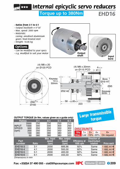
209 Fax: +33(0)4 37 490 055 - [email protected] Volume 2 2016
- Ratios from 3:1 to 6:1- Output backlash –~ 0°30’- Max. speed: 2000 rpm- Materials: casing: anodised aluminium gears: heat-treated steel- Weight: 18.86 kg
.Options.- Can be modified to your specs- e.g. modified to suit your motor
Input bore
Output shaft
(4) M8 x 20on Ø120 PCD
Ø95
Ø32 k6
Ø90+0,00-0.04 30
Ø160
41
223135
4(4) M8 x 20mmon Ø115 PCD
58
Keyway10 x
50mm
Keyway6mm
Bore Ø19 H7
Torque up to 380NmInternal epicyclic servo reducers
EHD16
Part number Ratio
Max. input speed (rpm)
Max. output speed (rpm)
Efficiency at 1000 rpm
Direction of input/output
rotation Price each
Dimensions in mm
OUTPUT TORQUE (In Nm, values given as a guide only)Ratios 3:1 4:1 5:1 6:1
2000 250 250 250 210INPUT 1000 300 300 300 250SPEED 500 350 350 350 300(rpm) 200 350 350 350 300
100 380 380 380 32050 380 380 380 320
EHD16-3 3:1 2000 666,66 92% Same 1 682,44 FEHD16-4 4:1 2000 500,00 92% Same 1 682,44 FEHD16-5 5:1 2000 400,00 92% Same 1 682,44 FEHD16-6 6:1 2000 333,33 92% Same 1 682,44 F
Large transmissible
torque
DISCOUNTSQty 1+ 2+ 4+ 6+
Disc. List -15% -20% On request

210 www.hpceurope.com - Tel: +33(0)4 37 496 496Volume 2 2016
Motor
XJ, NH
Adaptor plate Please specify the number and
dimensions for all holes
Inline spur gear reducerTechnical information
Input face of the XJ reducers Output face of the XJ reducers
XJ + NH Reducers: Please supply us with the dimensions of the face plate of your motori

211 Fax: +33(0)4 37 490 055 - [email protected] Volume 2 2016
Spur gear coaxial gearbox
Ratios
Max. input speed (rpm)
Max. output speed(rpm)
Efficiency at
1000 rpm
Direction of input/output
rotationPart number
- Ratios from 1:1 to 20:1 (Other ratios available on request)
- Output backlash: N/A- Max. input speed: 4000 rpm- Materials:
casing: anodised aluminium and black delrininput & output: unhardened steel
- Weight: 0.14 kg- Keyway conforms to DIN 6885
XJ Gearbox;- Please send us the dimensions of the front
face of your motor - The overall length depends on the adaptor plate
Large choice
of reduction
ratios !
Up to 625:1
J51XJ51
Torque up to 0.49Nm
Ø6
Ø50
J51-2 XJ51-2 2:1 4000 2000 92% Same 338,94 FJ51-3 XJ51-3 3:1 4000 1333 92% Same 338,94 FJ51-4 XJ51-4 4:1 4000 1000 92% Same 338,94 FJ51-5 XJ51-5 5:1 4000 800 92% Same 338,94 FJ51-10 XJ51-10 10:1 4000 400 92% Same 338,96 FJ51-15 XJ51-15 15:1 4000 266 92% Same 338,96 FJ51-20 XJ51-20 20:1 4000 200 92% Same 338,96 FJ51-SP XJ51-SP 1:1 - 20:1 Special ratios from 1:1 to 20:1 476,40 F
On
requ
est
OUTPUT TORQUE (In Nm, values given as a guide only)Ratios 2:1 3:1 4:1 5:1 10:1 15:1 20:1
4000 0,16 0,15 0,14 0,13 0,15 0,17 0,182000 0,19 0,18 0,17 0,15 0,18 0,20 0,211000 0,22 0,22 0,20 0,18 0,21 0,22 0,23
INPUT 500 0,27 0,25 0,23 0,21 0,24 0,25 0,27SPEED 200 0,32 0,30 0,27 0,25 0,28 0,30 0,32(rpm) 100 0,36 0,33 0,30 0,28 0,32 0,34 0,36
50 0,40 0,38 0,35 0,32 0,36 0,37 0,4220 0,48 0,45 0,41 0,38 0,43 0,44 0,49
15
9030
20
2mm keyway
J51
10
Ø6h7
30
2
10 2030
Ø6h7
152 15
Ø6h7
2mm keyway
2030
10VariableXJ51
Face
to b
e m
odifie
d to
suit
ap
plica
tion
Variable
(2x3) M4 x 5mm deep on 38mm PCD
Ø20Ø50
+0,00-0,05
2mm keyway
Dimensions in mm
DISCOUNTSQty 1+ 2+ 4+ 6+
Disc. List -15% -20% On request
2
Price eachJ XJ

212 www.hpceurope.com - Tel: +33(0)4 37 496 496Volume 2 2016
J52-30 XJ52-30 30:1 4000 133 88% Opposite 468,12 FJ52-40 XJ52-40 40:1 4000 100 88% Opposite 468,12 FJ52-50 XJ52-50 50:1 4000 80 88% Opposite 468,12 FJ52-60 XJ52-60 60:1 4000 66 88% Opposite 468,12 FJ52-75 XJ52-75 75:1 4000 53 88% Opposite 468,12 FJ52-100 XJ52-100 100:1 4000 40 88% Opposite 468,12 FJ52-125 XJ52-125 125:1 4000 32 88% Opposite 468,12 FJ52-SP XJ52-SP 1:1 - 130:1 Special ratios from 1:1 to 130:1 551,67 F
Spur gear coaxial gearbox
Ratios
Max. input speed (rpm)
Max. output speed(rpm)
Efficiency at
1000 rpm
Direction of input/output
rotationPart number
Ø6
Ø50
J52XJ52
Torque up to 0.9Nm
- Ratios from 1:1 to 130:1 (Other ratios available on request)
- Output backlash: N/A- Max. input speed: 4000 rpm- Materials:
casing: anodised aluminiumand black delrininput & output: unhardened steel
- Weight: 0.16 kg- Keyway conforms to DIN 6885
XJ Gearbox;- Please send us the dimensions of the front face of your motor - The overall length depends on the adaptor plate
On
requ
est
2 15
Ø6h7
RCN2
2030
10
VariableXJ52
Variable
15
10030
20
2
2mm keyway
J52
10
Ø6h7
40
2
10 2030
Ø6h7
15
Ø20+0,00-0,05
Ø50Face
to b
e m
odifie
d to
suit
ap
plica
tion
2mm keyway
(2x3) M4 x 5mm deep on 38mm PCD
Large choice
of reduction
ratios !
Up to 625:1
OUTPUT TORQUE (In Nm, values given as a guide only)Ratios 30:1 40:1 50:1 60:1 75:1 100:1 125:1
4000 0,27 0,28 0,29 0,30 0,31 0,33 0,342000 0,30 0,32 0,33 0,34 0,35 0,38 0,401000 0,34 0,36 0,38 0,40 0,41 0,42 0,43
INPUT 500 0,40 0,41 0,42 0,43 0,46 0,49 0,49SPEED 200 0,46 0,48 0,49 0,52 0,54 0,57 0,59(rpm) 100 0,52 0,55 0,57 0,59 0,61 0,65 0,69
50 0,57 0,62 0,65 0,69 0,73 0,74 0,7520 0,69 0,73 0,75 0,75 0,75 0,90 0,90
Dimensions in mm
DISCOUNTSQty 1+ 2+ 4+ 6+
Disc. List -15% -20% On request
Price eachJ XJ
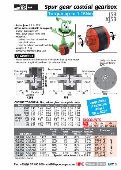
213 Fax: +33(0)4 37 490 055 - [email protected] Volume 2 2016
Spur gear coaxial gearbox
Ratios
Max. input speed (rpm)
Max. output speed(rpm)
Efficiency at1000 rpm
Direction of input/output
rotationPart number
Ø6
Ø50
J53XJ53
Torque up to 1.15Nm
- Ratios from 1:1 to 625:1 (Other ratios available on request)- Output backlash: N/A- Max. input speed: 4000 rpm- Materials:
casing: anodised aluminiumand black delrininput & output: unhardened steel
- Weight: 0.17 kg- Keyway conforms to DIN 6885
XJ Gearbox;- Please send us the dimensions of the front face of your motor - The overall length depends on the adaptor plate
Large choice
of reduction
ratios !
Up to 625:1
2 15
Ø6h7
2mm keyway
2030
10VariableXJ53
Variable
15
11030
20
2
2mm keyway
J53
10
Ø6h7
50
2
10 2030
Ø6h7
15
(2x3) M4 x 5mm deep on 38mm PCD
Ø20+0,00-0,05
Ø50Face
to b
e m
odifi
ed to
sui
t ap
plic
atio
n
2mm keyway
OUTPUT TORQUE (In Nm, values given as a guide only)Ratios 140:1 160:1 200:1 300:1 400:1 500:1 625:1
4000 0,43 0,45 0,46 0,51 0,53 0,55 0,582000 0,50 0,52 0,53 0,58 0,59 0,61 0,631000 0,56 0,57 0,58 0,63 0,65 0,67 0,69
INPUT 500 0,63 0,67 0,69 0,69 0,79 0,84 0,96SPEED 200 0,76 0,79 0,79 0,79 0,91 0,99 1,15(rpm) 100 0,86 0,91 0,91 0,91 1,15 1,15 1,15
50 0,95 0,95 0,95 0,95 1,15 1,15 1,1520 1,15 1,15 1,15 1,15 1,15 1,15 1,15
J53-140 XJ53-140 140:1 4000 29 85% Same 625,81 FJ53-160 XJ53-160 160:1 4000 25 85% Same 625,81 FJ53-200 XJ53-200 200:1 4000 20 85% Same 625,81 FJ53-300 XJ53-300 300:1 4000 13 85% Same 625,81 FJ53-400 XJ53-400 400:1 4000 10 85% Same 625,81 FJ53-500 XJ53-500 500:1 4000 8 85% Same 625,81 FJ53-625 XJ53-625 625:1 4000 6,40 85% Same 625,81 FJ53-SP XJ53-SP 1:1 - 625:1 Special ratios from 1:1 to 625:1 715,35 F
On
requ
est
Dimensions in mm
DISCOUNTSQty 1+ 2+ 4+ 6+
Disc. List -15% -20% On request
Price eachJ XJ
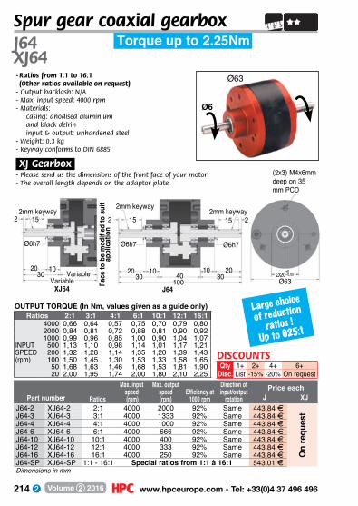
214 www.hpceurope.com - Tel: +33(0)4 37 496 496Volume 2 2016
J64-2 XJ64-2 2:1 4000 2000 92% Same 443,84 FJ64-3 XJ64-3 3:1 4000 1333 92% Same 443,84 FJ64-4 XJ64-4 4:1 4000 1000 92% Same 443,84 FJ64-6 XJ64-6 6:1 4000 666 92% Same 443,84 FJ64-10 XJ64-10 10:1 4000 400 92% Same 443,84 FJ64-12 XJ64-12 12:1 4000 333 92% Same 443,84 FJ64-16 XJ64-16 16:1 4000 250 92% Same 443,84 FJ64-SP XJ64-SP 1:1 - 16:1 Special ratios from 1:1 à 16:1 543,01 F
Ratios
Max. input speed (rpm)
Max. output speed(rpm)
Efficiency at1000 rpm
Direction of input/output
rotationPart number
- Ratios from 1:1 to 16:1 (Other ratios available on request)
- Output backlash: N/A- Max. input speed: 4000 rpm- Materials:
casing: anodised aluminiumand black delrininput & output: unhardened steel
- Weight: 0.3 kg- Keyway conforms to DIN 6885
XJ Gearbox;- Please send us the dimensions of the front face of your motor - The overall length depends on the adaptor plate
Ø63
J64XJ64
Torque up to 2.25Nm
On
requ
est
Large choice
of reduction
ratios !
Up to 625:1
OUTPUT TORQUE (In Nm, values given as a guide only)Ratios 2:1 3:1 4:1 6:1 10:1 12:1 16:1
4000 0,66 0,64 0,57 0,75 0,70 0,79 0,802000 0,84 0,81 0,72 0,88 0,81 0,90 0,921000 0,99 0,96 0,85 1,00 0,90 1,04 1,07
INPUT 500 1,13 1,10 0,98 1,14 1,01 1,17 1,21SPEED 200 1,32 1,28 1,14 1,35 1,20 1,39 1,43(rpm) 100 1,50 1,45 1,30 1,53 1,33 1,58 1,65
50 1,68 1,63 1,46 1,68 1,53 1,81 1,9020 2,00 1,95 1,74 2,00 1,80 2,10 2,25
2 15
Ø6h7
2mm keyway
2030
10Variable
XJ64
Variable
15
10030
20
2
2mm keyway
J64
10
Ø6h7
40
2
10 2030
Ø6h7
15
Ø20+0,00-0,05
Ø63
(2x3) M4x6mm deep on 35 mm PCD
Face
to b
e m
odifi
ed to
sui
t ap
plic
atio
n
Dimensions in mm
2mm keyway
DISCOUNTSQty 1+ 2+ 4+ 6+
Disc. List -15% -20% On request
Spur gear coaxial gearbox
Ø6
Price eachJ XJ
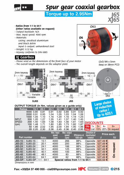
215 Fax: +33(0)4 37 490 055 - [email protected] Volume 2 2016
Ratios
Max. input speed (rpm)
Max. output speed(rpm)
Efficiency at1000 rpm
Direction of input/output
rotationPart number
- Ratios from 1:1 to 64:1 (Other ratios available on request)
- Output backlash: N/A- Max. input speed: 4000 rpm- Materials:
casing: anodised aluminiumand black delrininput & output: unhardened steel
- Weight: 0.32 kg- Keyway conforms to DIN 6885
XJ Gearbox;- Please send us the dimensions of the front face of your motor - The overall length depends on the adaptor plate
J65XJ65
Torque up to 2.95Nm
Ø63
Large choice
of reduction
ratios !
Up to 625:1
OUTPUT TORQUE (In Nm, values given as a guide only)Ratios 15:1 20:1 24:1 32:1 40:1 48:1 64:1
4000 0,80 0,81 0,91 0,92 0,89 0,91 0,922000 0,91 0,93 1,04 1,05 1,03 1,04 1,061000 1,05 1,10 1,16 1,20 1,16 1,19 1,23
INPUT 500 1,20 1,27 1,35 1,41 1,37 1,40 1,45SPEED 200 1,40 1,63 1,58 1,63 1,56 1,61 1,63(rpm) 100 1,48 1,71 1,80 1,85 1,73 1,82 1,87
50 1,86 2,02 1,95 2,00 1,94 1,95 1,9620 2,20 2,30 2,36 2,45 2,36 2,40 2,95
J65-15 XJ65-15 15:1 4000 266 88% Opposite 527,49 FJ65-20 XJ65-20 20:1 4000 200 88% Opposite 527,49 FJ65-24 XJ65-24 24:1 4000 166 88% Opposite 527,49 FJ65-32 XJ65-32 32:1 4000 125 88% Opposite 527,49 FJ65-40 XJ65-40 40:1 4000 100 88% Opposite 527,49 FJ65-48 XJ65-48 48:1 4000 83 88% Opposite 527,49 FJ65-64 XJ65-64 64:1 4000 62 88% Opposite 527,49 FJ65-SP XJ65-SP 1:1 - 64:1 Special ratios from 1:1 to 64:1 620,59 F
On
requ
est
2 15
Ø6h7
2mm keyway
2030
10Variable
XJ65
Variable
15
11030
20
22mm keyway
J65
10
Ø6h7
50
2
10 2030
Ø6h7
15
Ø20+0,00-0,05
Ø63Face
to b
e m
odifi
ed to
sui
t ap
plic
atio
n
2mm keyway
(2x3) M4 x 5mm deep on 38mm PCD
Dimensions in mm
DISCOUNTSQty 1+ 2+ 4+ 6+
Disc. List -15% -20% On request
Spur gear coaxial gearbox
Price eachJ XJ
Ø6

216 www.hpceurope.com - Tel: +33(0)4 37 496 496Volume 2 2016
Ratios
Max. input speed (rpm)
Max. output speed(rpm)
Efficiency at1000 rpm
Direction of input/output
rotationPart number
- Ratios from 1:1 to 256:1 (Other ratios available on request)
- Output backlash: N/A- Max. input speed: 4000 rpm- Materials:
casing: anodised aluminiumand black delrininput & output: unhardened steel
- Weight: 0.34 kg- Keyway conforms to DIN 6885
XJ Gearbox;- Please send us the dimensions of the front face of your motor - The overall length depends on the adaptor plate
Ø63
J66XJ66
Torque up to 2.8Nm
Large choice
of reduction
ratios !
Up to 625:1
OUTPUT TORQUE (In Nm, values given as a guide only)Ratios 50:1 80:1 96:1 128:1 160:1 192:1 256:1
4000 0,90 1,01 1,05 1,09 1,13 1,25 1,402000 1,04 1,13 1,18 1,24 1,30 1,40 1,551000 1,18 1,30 1,33 1,39 1,44 1,60 1,85
INPUT 500 1,40 1,44 1,50 1,58 1,64 1,78 2,00SPEED 200 1,60 1,73 1,80 1,87 1,96 2,18 2,42(rpm) 100 1,82 1,96 2,10 2,17 2,28 2,47 2,80
50 2,02 2,28 2,45 2,61 2,80 2,80 2,8020 2,50 2,80 2,80 2,80 2,80 2,80 2,80
J66-50 XJ66-50 50:1 4000 80 85% Same 625,34 FJ66-80 XJ66-80 80:1 4000 50 85% Same 625,34 FJ66-96 XJ66-96 96:1 4000 41 85% Same 625,34 FJ66-128 XJ66-128 128:1 4000 31 85% Same 625,34 FJ66-160 XJ66-160 160:1 4000 25 85% Same 625,34 FJ66-192 XJ66-192 192:1 4000 21 85% Same 625,34 FJ66-256 XJ66-256 256:1 4000 15 85% Same 625,34 FJ66-SP XJ66-SP 1:1 - 256:1 Special ratios from 1:1 to 256:1 719,97 F
On
requ
est
2 15
Ø6h7
2mm keyway
2030
10Variable
XJ66
Variable
15
12030
20
22mm keyway
J66
10
Ø6h7
60
2
10 2030
Ø6h7
152mm keyway
Ø20+0,00-0,05
Ø63
(2x3) M4x6mm deep on 35 mm PCD
Dimensions in mm
Face
to b
e m
odifi
ed
to s
uit a
pplic
atio
n
DISCOUNTSQty 1+ 2+ 4+ 6+
Disc. List -15% -20% On request
Spur gear coaxial gearbox
Price eachJ XJ
Ø6
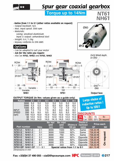
217 Fax: +33(0)4 37 490 055 - [email protected] Volume 2 2016
DISCOUNTSQty 1+ 2+ 4+ 6+
Disc. List -15% -20% On request
Spur gear coaxial gearbox
- Ratios from 1:1 to 9:1 (other ratios available on request)- Output backlash: N/A- Max. input speed: 3000 rpm- Materials: casing: anodised aluminium input & output: unhardened steel- Weight: 0.6 / 1.2kg- keyway conforms to DIN 6885
.Options.- Can be adapted to suit your motor- Ask for the ratio you require- Also see NT62, NH62 and NT63, NH63
Ø12
Ø60
Large choice of
reduction ratios !
Up to 120:1
Torque up to 14Nm NT61NH61
Output face
(2x3) M4x8 depth.on Ø52
Ø60Ø40
+0,00-0,05
NT61
5 25
Ø12h7
RCN4
35 18 1853
3556 53162
25 5
Ø12h7
RCN4
NH61
Varia
ble
5 25RCN4
Ø12h7
35 1853 Variable
Variable
OUTPUT TORQUE (In Nm: values given as a guide only)Ratios 2:1 3:1 4:1 5:1 6:1 8:1 9:1
3000 5,0 5,0 5,0 5,0 5,0 5,0 5,02000 5,5 5,5 5,5 6,0 6,0 6,0 6,01000 6,5 6,5 6,5 7,0 7,0 7,0 7,0
INPUT 500 7,5 7,5 7,5 8,0 8,0 8,0 8,0SPEED 200 9,0 9,0 9,0 9,0 9,0 9,0 9,0(rpm) 100 10,0 10,0 10,0 10,0 10,0 10,0 10,0
50 12,0 12,0 12,0 12,0 12,0 12,0 12,020 14,0 14,0 14,0 14, 0 14,0 14,0 14,0
NT61-2 NH61-2 2:1 3000 1500 92% Same 726,93 FNT61-3 NH61-3 3:1 3000 1000 92% Same 726,93 FNT61-4 NH61-4 4:1 3000 750 92% Same 726,93 FNT61-5 NH61-5 5:1 3000 600 92% Opposite 726,93 FNT61-6 NH61-6 6:1 3000 500 92% Opposite 726,93 FNT61-8 NH61-8 8:1 3000 375 92% Opposite 726,93 FNT61-9 NH61-9 9:1 3000 333 92% Opposite 726,93 FNT61-SP NH61-SP 1:1 - 9:1 Special ratios from 1:1 to 9:1 851,75 F
On
requ
est
Ratios
Max. input speed (rpm)
Max. output speed(rpm)
Efficiency at1000 rpm
Direction of input/output
rotationPart number
Dimensions in mm
Price eachNT NH
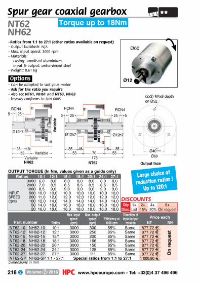
218 www.hpceurope.com - Tel: +33(0)4 37 496 496Volume 2 2016
- Ratios from 1:1 to 27:1 (other ratios available on request)- Output backlash: N/A- Max. input speed: 3000 rpm- Materials: casing: anodised aluminium input & output: unhardened steel- Weight: 0.61 kg
.Options.- Can be adapted to suit your motor- Ask for the ratio you require- Also see NT61, NH61 and NT63, NH63- keyway conforms to DIN 6885
NT62NH62
Spur gear coaxial gearbox
Ø12
Ø60
Ratios
Max. input speed (rpm)
Max. output speed(rpm)
Efficiency at1000 rpm
Direction of input/output
rotationPart number
Torque up to 18Nm
Large choice of
reduction ratios !
Up to 120:1
Output face
(2x3) M4x8 depthon Ø52
Ø60Ø40
+0,00-0,05
NT62
5 25
Ø12h7
RCN4
35 18 1853
3570 53176
25 5
Ø12h7
RCN4
NH62
Varia
ble
5 25RCN4
Ø12h7
35 1853 Variable
Variable
OUTPUT TORQUE (In Nm, values given as a guide only)Ratios 10:1 12:1 15:1 18:1 20:1 24:1 27:1
3000 6,0 8,0 8,0 8,0 8,0 8,0 8,02000 7,0 8,5 8,5 8,5 8,5 8,5 8,51000 8,5 9,0 9,0 9,0 9,0 9,0 9,0
INPUT 500 10,0 10,0 10,0 10,0 10,0 10,0 10,0SPEED 200 11,0 12,0 12,0 12,0 12,0 12,0 12,0(rpm) 100 12,0 14,0 14,0 14,0 14,0 14,0 14,0
50 14,0 16,0 16,0 16,0 16,0 16,0 16,020 16,0 18,0 18,0 18,0 18,0 18,0 18,0
NT62-10 NH62-10 10:1 3000 300 85% Same 877,72 FNT62-12 NH62-12 12:1 3000 250 85% Same 877,72 FNT62-15 NH62-15 15/1 3000 200 85% Same 877,72 FNT62-18 NH62-18 18:1 3000 166 85% Same 877,72 FNT62-20 NH62-20 20:1 3000 150 85% Same 877,72 FNT62-24 NH62-24 24:1 3000 125 85% Same 877,72 FNT62-27 NH62-27 27:1 3000 111 85% Same 877,72 FNT62-SP NH62-SP 1:1 - 27:1 Special ratios from 1:1 to 27:1 1 000,80 F
On
requ
est
Dimensions in mm
Price eachNT NH
DISCOUNTSQty 1+ 2+ 4+ 6+
Disc. List -15% -20% On request

219 Fax: +33(0)4 37 490 055 - [email protected] Volume 2 2016
NT63-30 NH63-30 30:1 3000 100 80% Opposite 968,82 FNT63-36 NH63-36 36:1 3000 83 80% Opposite 968,82 FNT63-40 NH63-40 40:1 3000 75 80% Opposite 968,82 FNT63-48 NH63-48 48:1 3000 62 80% Opposite 968,82 FNT63-54 NH63-54 54:1 3000 55 80% Opposite 968,82 FNT63-81 NH63-81 81:1 3000 37 80% Opposite 968,82 FNT63-120 NH63-120 120:1 3000 25 80% Same 968,82 FNT63-SP NH63-SP 1:1 - 120:1 Special ratios from 1:1 to 120:1 1 080,84 F
Spur gear coaxial gearbox
- Ratios from 1:1 to 120:1 (other ratios available on request)- Output backlash: N/A- Max. input speed: 3000 rpm- Materials: casing: anodised aluminium input & output: unhardened steel- Weight: 0.64 kg
.Options.- Can be adapted to suit your motor- Ask for the ratio you require- Also seeNT61, NH61 and NT62, NH62- keyway conforms to DIN 6885
Ø12
Ø60
Ratios
Max. input speed (rpm)
Max. output speed(rpm)
Efficiency at1000 rpm
Direction of input/output
rotationPart number
NT63NH63
Torque up to 20Nm
Large choice of
reduction ratios !
Up to 120:1
OUTPUT TORQUE (In Nm, values given as a guide only)
On
requ
est
Output face
(2x3) M4x8 depthon Ø52
Ø60Ø40
+0,00-0,05
NT63
5 25
Ø12h7
RCN4
35 18 1853
3584 53190
25 5
Ø12h7
RCN4
NH63
Varia
ble
5 254 RCN
Ø12h7
35 1853 Variable
Variable
Ratios 30:1 36:1 40:1 48:1 54:1 81:1 120:13000 8,0 9,0 9,0 9,0 9,0 10,0 10,02000 8,5 9,0 9,0 9,0 9,0 10,0 10,01000 9,0 10,0 10,0 10,0 10,0 10,0 10,0
INPUT 500 10,0 11,0 11,0 11,0 11,0 11,0 11,0SPEED 200 12,0 12,0 12,0 12,0 12,0 12,0 12,0(rpm) 100 14,0 14,0 14,0 14,0 14,0 14,0 14,0
50 16,0 17,0 17,0 17,0 17,0 17,0 17,020 19,0 20,0 20,0 20,0 20,0 20,0 20,0
Dimensions in mm
Price eachNT NH
DISCOUNTSQty 1+ 2+ 4+ 6+
Disc. List -15% -20% On request
220 www.hpceurope.com - Tel: +33(0)4 37 496 496Volume 2 2016
- Ratios from 1:1 to 9:1 (other ratios available on request)- Output backlash: N/A- Max. input speed: 3000 rpm- Materials: casing: anodised aluminium input & output: unhardened steel- Weight: 1.6 kg
.Options.
- Can be adapted to suit your motor- Ask for the ratio you require- Also seeNT92, NH92 - keyway conforms to DIN 6885
NT91NH91
Spur gear coaxial gearbox
Ø15
Ø90
Ratios
Max. input speed (rpm)
Max. output speed(rpm)
Efficiency at1000 rpm
Direction of input/output
rotationPart number
Torque up to 35Nm
Large choice of
reduction ratios !
Up to 36:1
NT91
5 35
Ø15h7
RCN5
45 20 2065
4574 65204
35 5
Ø15h7
5RCN
NH91
Varia
ble
5 35RCN5
Ø15h7
45 2065 Variable
VariableOutput face
(2x3) M5x10 depthon Ø70
Ø90Ø44
+0,00-0,05
Ratios 2:1 3:1 4:1 5:1 6:1 8:1 9:13000 10 11 12 12 14 14 152000 12 13 14 15 16 16 171000 15 16 17 18 19 19 20
INPUT 500 18 18 19 21 22 22 23SPEED 200 21 22 22 24 25 25 26(rpm) 100 24 25 26 26 27 28 29
50 27 27 28 30 31 32 3220 30 30 30 33 33 35 35
OUTPUT TORQUE (In Nm, values given as a guide only)
NT91-2 NH91-2 2:1 3000 1500 90% Same 840,41 FNT91-3 NH91-3 3:1 3000 1000 90% Same 840,41 FNT91-4 NH91-4 4:1 3000 750 90% Same 840,41 FNT91-5 NH91-5 5:1 3000 600 90% Opposite 840,41 FNT91-6 NH91-6 6:1 3000 500 90% Opposite 840,41 FNT91-8 NH91-8 8:1 3000 375 90% Opposite 840,41 FNT91-9 NH91-9 9:1 3000 333 90% Opposite 840,41 FNT91-SP NH91-SP 1:1 - 9:1 Special ratios from 1:1 to 9:1 968,40 F
On
requ
est
Dimensions in mm
Price eachNT NH
DISCOUNTSQty 1+ 2+ 4+ 6+
Disc. List -15% -20% On request

221 Fax: +33(0)4 37 490 055 - [email protected] Volume 2 2016
NT92-10 NH92-10 10:1 3000 300 84% Same 899,05 FNT92-12 NH92-12 12:1 3000 250 84% Same 899,05 FNT92-15 NH92-15 15:1 3000 200 84% Same 899,05 FNT92-18 NH92-18 18:1 3000 166 84% Same 899,05 FNT92-20 NH92-20 20:1 3000 150 84% Same 899,05 FNT92-27 NH92-27 27:1 3000 125 84% Same 899,05 FNT92-36 NH92-36 36:1 3000 83 84% Same 898,93 FNT92-SP NH92-SP 1:1 - 36:1 Special ratios from 1:1 to 36:1 1 022,64 F
Spur gear coaxial gearbox
- Ratios from 1:1 to 36:1 (other ratios available on request)- Output backlash: N/A- Max. input speed: 3000 rpm- Materials: casing: anodised aluminium input & output: unhardened steel- Weight: 2 kg
.Options.- Can be adapted to suit your motor- Ask for the ratio you require- Also seeNT91, NH91- keyway conforms to DIN 6885
Ø15
Ø90
Ratios
Max. input speed (rpm)
Max. output speed(rpm)
Efficiency at1000 rpm
Direction of input/output
rotationPart number
NT92NH92
Torque up to 40Nm
Large choice of
reduction ratios !
Up to 36:1
OUTPUT TORQUE (In Nm, values given as a guide only)
On
requ
est
NT92
5 35
Ø15h7
RCN5
45 20 2065
4594 65224
35 5
Ø15h7
RCN5
NH92
Varia
ble
5 35RCN5
Ø15h7
45 2065 Variable
VariableOutput face
(2x3) M5x10 depthon Ø70
Ø90Ø44
+0,00-0,05
Ratios 10:1 12:1 15:1 18:1 20:1 27:1 36:13000 15 15 17 17 17 18 182000 18 18 20 20 20 21 211000 21 21 23 23 23 24 24
INPUT 500 24 24 26 26 26 27 27SPEED 200 27 27 29 29 29 30 30(rpm) 100 30 30 31 31 32 33 33
50 32 33 34 34 35 36 3620 35 36 38 38 40 40 40
Dimensions in mm
Price eachNT NH
DISCOUNTSQty 1+ 2+ 4+ 6+
Disc. List -15% -20% On request
222 www.hpceurope.com - Tel: +33(0)4 37 496 496Volume 2 2016
- Ratios from 1:1 to 9:1 (other ratios available on request)- Output backlash: N/A- Max. input speed: 3000 rpm- Materials: casing: anodised aluminium input & output: unhardened steel- Weight: 2.3 kg
.Options.- Can be adapted to suit your motor- Ask for the ratio you require- Also see NT122, NH122- keyway conforms to DIN 6885
NT121NH121
Spur gear coaxial gearbox
Ø17
Ø114
Ratios
Max. input speed (rpm)
Max. output speed(rpm)
Efficiency at1000 rpm
Direction of input/output
rotationPart number
OUTPUT TORQUE (In Nm, values given as a guide only)
Torque up to 68Nm
Large choice of
reduction ratios !
Up to 27:1
Ratios 2:1 3:1 4:1 5:1 6:1 8:1 9:13000 20,0 20,0 21,1 22,2 23,5 29,7 26,02000 23,0 23,6 24,7 26,0 27,4 28,6 30,01000 27,1 27,5 28,6 29,7 31,0 32,5 34,0
INPUT 500 31,5 32,0 33,3 34,8 36,4 38,0 40,0SPEED 200 35,0 35,5 37,2 38,0 40,8 42,8 45,0(rpm) 100 40,0 41,0 41,8 42,7 43,6 47,0 51,0
50 47,2 48,0 50,2 52,5 55,0 58,0 61,120 53,0 55,0 57,0 60,0 62,0 65,0 68,0
5 40
Ø17h7
RCN5
50 20 2070
5090 70230
40 5
Ø17h7
RCN5
Varia
ble
5 40RCN5
Ø17h7
50 2070 Variable
Variable
(2x3) M6x12 depthon Ø104
Ø114Ø50
+0,00-0,05
NT121-2 NH121-2 2:1 3000 1500 92% Same 1 046,03 FNT121-3 NH121-3 3:1 3000 1000 92% Same 1 046,03 FNT121-4 NH121-4 4:1 3000 750 92% Same 1 046,03 FNT121-5 NH121-5 5:1 3000 600 92% Same 1 046,03 FNT121-6 NH121-6 6:1 3000 500 92% Same 1 046,03 FNT121-8 NH121-8 8:1 3000 375 92% Same 1 046,03 FNT121-9 NH121-9 9:1 3000 333 92% Same 1 046,03 FNT121-SP NH121-SP 1:1 - 9:1 Special ratios from 1:1 to 9:1 1 164,75 F
On
requ
est
Dimensions in mm
NT121NH121 Output face
Price eachNT NH
DISCOUNTSQty 1+ 2+ 4+ 6+
Disc. List -15% -20% On request

223 Fax: +33(0)4 37 490 055 - [email protected] Volume 2 2016
NT122-10 NH122-10 10:1 3000 300 88% Opposite 1 251,96 FNT122-12 NH122-12 12:1 3000 250 88% Opposite 1 251,96 FNT122-15 NH122-15 15:1 3000 200 88% Opposite 1 251,96 FNT122-18 NH122-18 18:1 3000 166 88% Opposite 1 251,96 FNT122-24 NH122-24 24:1 3000 125 88% Opposite 1 251,96 FNT122-27 NH122-27 27:1 3000 111 88% Opposite 1 251,96 FNT122-SP NH122-SP 1:1 - 27:1 Special ratios from 1:1 to 27:1 1 329,31 F
Spur gear coaxial gearbox
- Ratios from 1:1 to 27:1 (other ratios available on request)- Output backlash: N/A- Max. input speed: 3000 rpm- Materials: casing: anodised aluminium input & output: unhardened steel- Weight: 2.6 kg
.Options.- Can be adapted to suit your motor- Ask for the ratio you require- Also see NT121, NH121- keyway conforms to DIN 6885
Ø17
Ø120
Ratios
Max. input speed (rpm)
Max. output speed(rpm)
Efficiency at1000 rpm
Direction of input/output
rotationPart number
OUTPUT TORQUE (In Nm, values given as a guide only)
NT122NH122
Torque up to 85Nm
Large choice of
reduction ratios !
Up to 27:1O
n re
ques
tRatios 10:1 12:1 15:1 18:1 24:1 8:1
3000 32 32 32 32 32 322000 36 36 36 36 36 361000 42 42 42 42 42 42
INPUT 500 49 49 49 49 49 49SPEED 200 54 54 54 54 54 54(rpm) 100 61 61 61 61 61 61
50 73 73 73 73 73 7320 85 85 85 85 85 85
Output face
(2x3) M6x12 depthon Ø104
Ø114Ø50
+0,00-0,05
NT122
5 40
Ø17h7
RCN5
50 20 2070
5070
260
40 5
Ø17h7
RCN5
NH122
Varia
ble
5 40RCN5
Ø17h7
50 2070 Variable
Variable
Dimensions in mm
120
Price eachNT NH
DISCOUNTSQty 1+ 2+ 4+ 6+
Disc. List -15% -20% On request
224 www.hpceurope.com - Tel: +33(0)4 37 496 496Volume 2 2016
others gearboxes
p.225 - 249
right angle gearbox
manual worm/wheel
gearbox
p.228p.226
manual bevel gearbox
p.244
miniature right
angled gear reducers
p.225
single or dual output gearboxes
p.232
Increasedstock
225 Fax: +33(0)4 37 490 055 - [email protected] Volume 2 2016
- Ratio 1:1- Lightweight construction- Output backlash 1°- Max. input speed: 3000 rpm- Materials:
casing: plastic gears: Type 1 = steel
Type 2 = plastic- Weight: 37 to 41g
30,530,5
18,7
Ø4
Ø4
*Depending on availability - Dimensions in mm
Part number Type RatioEfficiency at
1500 rpm
Max. input speed(rpm)
Price each1 to 4
Torque up to 0.68Nm B332
Economy range
Miniature right angled gear reducer
OUTPUT TORQUE (Nm)Ratios 1:1 1:1Inputspeed
Type 1Steel
Type 2 Plastic
1500 rpm 0,68 0,11
B332.31.2 1 1:1 94% 3000 4 67,87 FB332.31.3 2 1:1 94% 1500 4 39,43 F
Stock*
Shafts Ø4+0,000-0,012
Fixing holesØ smooth holes 3.7Ø countersunk 7.4 x 5
30,5
20,7
8,7
17,630,5
17,6Ø13
Ø3,4
Max panel thickness, with M3 x 8mm screw
12
4
Panel mounting arrangement Ø12,7
Tapped holes
M3
18,7= =
12 20,7
19,85,38,7
+0,00 -0,01
DISCOUNTSQty 1+ 5+ 10+ 25+ 50+
Disc. List -6% -12% -18% On request
226 www.hpceurope.com - Tel: +33(0)4 37 496 496Volume 2 2016
RAM30
Max torque Price eachPart number Ratio Input Output (Nm) 1 to 9RAM30-1 1:1 hex 6mm hex 6mm 4 39,10 F
30
30
hex 6Ø14,5
4414,4
1924
7,6 (4) Ø4,1
hex 624
(2) Ø4,6x7 deep12
8
Dimensions in mm
For manual applications
Manual torque up to 4 NmManual bevel gearbox
- Manually operated bevel gearbox- Ratios from 1:1- M aterials:
Housing: Glass fibre reinforced PA6 Bevel gears: Case hardened steel
.Accessories.- MBEX handle- AHEX hexagonal shaft
.Info.- Not suitable for motorised applications
10+-5%
50+On request
25+-15%
1+List
QtyDisc.
DISCOUNTS
227 Fax: +33(0)4 37 490 055 - [email protected] Volume 2 2016
35,8 55
hex 7(2) Ø5x7 deep27
25,6
16 7 (2) Ø4,1
35,8
17
hex 7 22
6 6
Ø42
Manual torque up to 6 Nm RAM35
- Manually operated bevel gearbox- Ratios from 1:1 to 2:1- M aterials:
Housing: Glass fibre reinforced PA6 Bevel gears: Case hardened steel
.Accessories.- MBEX handle- AHEX hexagonal shaft
.Info.- Not suitable for motorised applications
Max torque Price eachPart number Ratio Input Output (Nm) 1 to 9RAM35-1 1:1 hex 7mm hex 7mm 6 50,60 FRAM35-2 2:1 hex 7mm hex 7mm 6 50,60 F
10+-5%
50+On request
25+-15%
1+List
QtyDisc.
DISCOUNTS
Dimensions in mm
For manual applications
Manual bevel gearbox

228 www.hpceurope.com - Tel: +33(0)4 37 496 496Volume 2 2016
Manual worm/wheel gearboxManual torque up to 5 NmRVM14
- Manually operated bevel gearbox- Ratios from 1:1 to 23:1- M aterials:
Housing: die cast zinc Worm/wheel: Case hardened steel
.Accessories.- MBEX handle- AHEX hexagonal shaft
.Info.- Not suitable for motorised applications
MaxInput/ torque Price each
Part number Ratio Output (Nm) Self locking 1 to 9RVM14-1 1:1 hex 6mm 2,0 No 78,14 FRVM14-2 2:1 hex 6mm 2,0 No 78,14 FRVM14-2.8 2,8:1 hex 6mm 2,5 No 78,14 FRVM14-4.33 4,33:1 hex 6mm 2,0 Yes 78,14 FRVM14-10 10:1 hex 6mm 4,0 Yes 78,14 FRVM14-14 14:1 hex 6mm 5,0 Yes 78,14 FRVM14-15 15:1 hex 6mm 4,0 Yes 78,14 FRVM14-23 23:1 hex 6mm 3,0 Yes 78,14 F
Dimensions in mm
10+-5%
50+On request
25+-15%
1+List
QtyDisc.
DISCOUNTSFor manual applications
3517
hex 6mm
Output
Input
(4) Ø4,342
4,2 26,5
15
29
R2 R2
13,8
229 Fax: +33(0)4 37 490 055 - [email protected] Volume 2 2016
Manually operated gearboxManual torque up to 17 Nm RVM25
- Compact manually operated gearbox- Ratios from 1:1 to 30:1- M aterial:
Housing: die cast zinc
.Accessories.- MBEX handle- AHEX hexagonal shaft
.Info.- Not suitable for motorised applications
Maxtorque Price each
Part number Ratio Input Output (Nm) Self locking 1 to 9RVM25-1 1:1 hex 6mm hex 9mm 2,0 No 115,00 FRVM25-2 2:1 hex 6mm hex 9mm 3,0 No 115,00 FRVM25-3.25 3,25:1 hex 6mm hex 9mm 4,0 Yes 115,00 FRVM25-4.33 4,33:1 hex 6mm hex 9mm 5,0 Yes 115,00 FRVM25-7 7:1 hex 6mm hex 9mm 7,0 Yes 115,00 FRVM25-8.5 8,5:1 hex 6mm hex 9mm 9,0 Yes 115,00 FRVM25-17 17:1 hex 6mm hex 9mm 12,0 Yes 115,00 FRVM25-20 20:1 hex 6mm hex 9mm 15,0 Yes 115,00 FRVM25-30 30:1 hex 6mm hex 9mm 17,0 Yes 115,00 F
Dimensions in mm
For manual applications
Ø26(6) M4
(4) M4
30
OutputInput
70 60
40
49
40
24
10+-5%
50+On request
25+-15%
1+List
QtyDisc.
DISCOUNTS

230 www.hpceurope.com - Tel: +33(0)4 37 496 496Volume 2 2016
For manually operated bevel gearboxAHEX
- Hexagonal shaft for use with the RAM and RVM bevel gearbox ranges
- Cut to required length- M aterial:
Steel
Length Price eachPart number Profil (mm) 1 to 9AHEX6-1000 hex 6mm 1000 24,64 FAHEX7-1000 hex 7mm 1000 29,36 FAHEX9-1000 hex 9mm 1000 29,36 F
10+-5%
50+On request
25+-15%
1+List
QtyDisc.
DISCOUNTS
Dimensions in mm
Hexagonal shaft DIN176
1000hex
Typical application
RVM bevel gearbox
MBEXhandle
AHEX shaft
231 Fax: +33(0)4 37 490 055 - [email protected] Volume 2 2016
Hexagonal ended handleFor use with manually
operated bevel gearboxMBEX
- Handle for operating RAM and RVM manual bevel gearboxes
- M aterial Shaft: stainless steel Rotating handle: plastic
Price eachPart number A H ØD E B 1 to 9MBEX6-90 90 hex 6mm 7 60 20 57,50 FMBEX7-90 90 hex 7mm 8 62 15 46,00 F
10+-5%
50+On request
25+-15%
1+List
QtyDisc.
DISCOUNTS
1x45°
1x45°
ER5
R5
A
44
ØD
B
H
Dimensions in mm
Used with a RVM14 gearbox
232 www.hpceurope.com - Tel: +33(0)4 37 496 496Volume 2 2016
Single or dual output gearboxesSuitable for torques up to 4.7NmCHTRB8
15
60
1515
16
16
1115 1568
34 341616
32(X3)
2,5(X3)1133
4 Ø4.2 holes on 3 flanges 3 Ø5.2 holes
40(x3)
Ø22H7(X3)
5(X3)
Ø8f7(X3)
Ø8 shafts
- Gearbox with one or two outputs- Ratios from 1:1 to 2:1- Maximum speed 3000 rpm- Lubrication: Synthetic oil- Material :
Box: Cast aluminiumGears: Steel 16CrN4
- Operating temperature -20° to +80°C
.Info..- For the maximum loads and service factor, please
see technical pages- If used as a multiplier, the maximum input speed
is 750 rpm for gearboxes with a 2:1 ratio.
OUTPUT TORQUE (Nm: VALUES GIVEN AS A GUIDE ONLY)Ratios 1:1 2:1
3000 1,7 1,42000 1,8 1,61400 2,0 1,7
INPUT 800 2,3 2,0SPEED 400 2,8 2,4(rpm) 200 3,3 2,8
100 3,9 3,450 4,7 4,0
Depending of availability - Dimensions in mm
DISCOUNTSQty 1+ 6+ 20+ 40+
Disc. List -15% -20% On requestMax. input Max. output Price
speed speed Weight eachPart number Type Ratio Input Output (rpm) (rpm) (kg) 1 to 5CHTRB8-1-1 1 1:1 A B 3000 3000 0,3 4 143,37 FCHTRB8-2-1 2 1:1 A C 3000 3000 0,3 4 143,37 FCHTRB8-3-2 3 2:1 A B 3000 1500 0,3 4 143,37 FCHTRB8-4-2 4 2:1 A C 3000 1500 0,3 - 143,37 FCHTRB8-5-1 5 1:1 A B-C 3000 3000 0,3 4 150,67 FCHTRB8-6-2 6 2:1 A B-C 3000 1500 0,3 - 150,67 F
Stock*
Increasedstock
233 Fax: +33(0)4 37 490 055 - [email protected] Volume 2 2016
35 104 35 Ø35H
7(X3
)Ø1
5f7(
X3)
35
3,5(x3)90
28(x3)7(x3)
2626
66(x3) 2424
5218 18 5252
24 244(x3)
50(x3) 5(X3)
4 Ø6.2 holes on 3 flanges
3 holes Ø8,3
Grease nipple12(x3)
Single or dual output gearboxesSuitable for torques up to 16.5Nm CHTRB15
- Gearbox with one or two outputs- Ratios from 1:1 to 2:1- Maximum speed 3000 rpm- Lubrication: Synthetic oil- Material :
Box: Cast aluminiumGears: Steel 16CrN4
- Operating temperature -20° to +80°C
.Info..- For the maximum loads and service factor,
please see technical pages- If used as a multiplier,
the maximum input speed is 750 rpm for gearboxes with a 2:1 ratio.
OUTPUT TORQUE (Nm: VALUES GIVEN AS A GUIDE ONLY)Ratios 1:1 2:1
3000 5,9 5,22000 6,6 5,81400 7,2 6,3
INPUT 800 8,2 7,3SPEED 400 9,8 8,7(rpm) 200 11,7 10,3
100 13,9 12,350 16,5 14,6
Ø15 shafts
DISCOUNTSQty 1+ 6+ 20+ 40+
Disc. List -15% -20% On requestMax. input Max. output Price
speed speed Weight eachPart number Type Ratio Input Output (rpm) (rpm) (kg) 1 to 5CHTRB15-1-1 1 1:1 A B 3000 3000 1,1 4 186,62 FCHTRB15-2-1 2 1:1 A C 3000 3000 1,1 4 186,62 FCHTRB15-3-2 3 2:1 A B 3000 1500 1,1 4 186,62 FCHTRB15-4-2 4 2:1 A C 3000 1500 1,1 4 186,62 FCHTRB15-5-1 5 1:1 A B-C 3000 3000 1,2 4 194,62 FCHTRB15-6-2 6 2:1 A B-C 3000 1500 1,2 4 194,62 F
Stock*
Depending of availability - Dimensions in mm
Increasedstock
234 www.hpceurope.com - Tel: +33(0)4 37 496 496Volume 2 2016
Single or dual output gearboxesSuitable for torques up to 53.1NmCHTRB20
Ø20f7(X3)
Ø52H
7(X3
)Ø5
5H7(
X3)
3,5(
x3)
140
50
4(x3)
40(x3)
5(x3)
16,5(x3)
38
3896(x3) 38
38
7627 27
50 150 507575
38 38
74(x3) 6(X3)
4 Ø8.3 holes on 3 flanges
3 holes Ø8,3
Grease nipple
10(x3)
Ø20 shafts
- Gearbox with one or two outputs- Ratios from 1:1 to 2:1- Maximum speed 3000 rpm- Lubrication: Synthetic oil- Material :
Box: Cast aluminiumGears: Steel 16CrN4
- Operating temperature -20° to +80°C
.Info..- For the maximum loads and service factor,
please see technical pages- If used as a multiplier, the maximum input speed
is 750 rpm for gearboxes with a 2:1 ratio.
OUTPUT TORQUE (Nm: VALUES GIVEN AS A GUIDE ONLY)Ratios 1:1 2:1
3000 19,1 15,32000 21,1 16,91400 23,1 18,5
INPUT 800 26,5 21,3SPEED 400 31,6 25,3(rpm) 200 37,5 30,1
100 44,6 35,750 53,1 42,5
DISCOUNTSQty 1+ 6+ 20+ 40+
Disc. List -15% -20% On requestMax. input Max. output Price
speed speed Weight eachPart number Type Ratio Input Output (rpm) (rpm) (kg) 1 to 5CHTRB20-1-1 1 1:1 A B 3000 3000 3,4 4 265,17 FCHTRB20-2-1 2 1:1 A C 3000 3000 3,4 - 265,17 FCHTRB20-3-2 3 2:1 A B 3000 1500 3,4 - 265,17 FCHTRB20-4-2 4 2:1 A C 3000 1500 3,4 4 265,17 FCHTRB20-5-1 5 1:1 A B-C 3000 3000 3,5 4 269,40 FCHTRB20-6-2 6 2:1 A B-C 3000 1500 3,5 4 269,40 F
Stock*
Depending of availability - Dimensions in mm
Increasedstock
235 Fax: +33(0)4 37 490 055 - [email protected] Volume 2 2016
Ø65H
7(X3
)Ø2
5f7(X
3)
10(x3)
150
70 50(x3)
21(x3)
70
453838
10038 38
70 160 708080
45 45
8(X3)
3,5(X3)
4 Ø10.3 holes on 3 flanges
3 holes Ø10,5Grease nipple
13(x3)
98(x3)
Single or dual output gearboxesSuitable for torques up to 87.3Nm CHTRB25
- Gearbox with one or two outputs- Ratios from 1:1 to 2:1- Maximum speed 3000 rpm- Lubrication: Synthetic oil- Material :
Box: Cast aluminiumGears: Steel 16CrN4
- Operating temperature -20° to +80°C
.Info..- For the maximum loads and service factor,
please see technical pages- If used as a multiplier, the maximum input
speed is 750 rpm for gearboxes with a 2:1 ratio.
Ø25 shafts
OUTPUT TORQUE (Nm: VALUES GIVEN AS A GUIDE ONLY)Ratios 1:1 2:1
3000 31,4 29,62000 34,7 32,71400 38,0 35,8
INPUT 800 43,7 41,1SPEED 400 51,9 48,9(rpm) 200 61,8 58,2
100 73,4 69,250 87,3 82,3
Part number
Price each 1 to 5
Max. input Max. output speed speed Weight Type Ratio Input Output (rpm) (rpm) (kg)
CHTRB25-1-1 1 1:1 A B 3000 3000 5,5 328,92 FCHTRB25-2-1 2 1:1 A C 3000 3000 5,5 328,92 FCHTRB25-3-2 3 2:1 A B 3000 1500 5,5 328,92 FCHTRB25-4-2 4 2:1 A C 3000 1500 5,5 328,92 FCHTRB25-5-1 5 1:1 A B-C 3000 3000 5,8 340,78 FCHTRB25-6-2 6 2:1 A B-C 3000 1500 5,8 340,78 FDimensions in mm
DISCOUNTSQty 1+ 6+ 20+ 40+
Disc. List -15% -20% On request
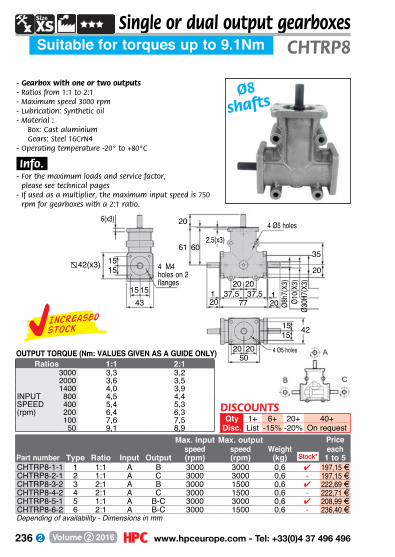
236 www.hpceurope.com - Tel: +33(0)4 37 496 496Volume 2 2016
Ø8h7
(X3)
Ø10(
X3)
Ø30H
7(X3
)
6(x3)
2,5(x3)
35
1515 42
20
61 60
20
1515
431515
20 77 2037,5
20 2050
11 37,520 20
4 M4 holes on 2 flanges
4 Ø5 holes
4 Ø5 holes
42(x3)
Single or dual output gearboxesSuitable for torques up to 9.1Nm CHTRP8
Ø8 shafts
- Gearbox with one or two outputs- Ratios from 1:1 to 2:1- Maximum speed 3000 rpm- Lubrication: Synthetic oil- Material :
Box: Cast aluminiumGears: Steel 16CrN4
- Operating temperature -20° to +80°C
.Info..- For the maximum loads and service factor,
please see technical pages- If used as a multiplier, the maximum input speed is 750
rpm for gearboxes with a 2:1 ratio.
OUTPUT TORQUE (Nm: VALUES GIVEN AS A GUIDE ONLY)Ratios 1:1 2:1
3000 3,3 3,22000 3,6 3,51400 4,0 3,9
INPUT 800 4,5 4,4SPEED 400 5,4 5,3(rpm) 200 6,4 6,3
100 7,6 7,550 9,1 8,9
DISCOUNTSQty 1+ 6+ 20+ 40+
Disc. List -15% -20% On requestMax. input Max. output Price
speed speed Weight eachPart number Type Ratio Input Output (rpm) (rpm) (kg) 1 to 5CHTRP8-1-1 1 1:1 A B 3000 3000 0,6 4 197,15 FCHTRP8-2-1 2 1:1 A C 3000 3000 0,6 - 197,15 FCHTRP8-3-2 3 2:1 A B 3000 1500 0,6 4 222,69 FCHTRP8-4-2 4 2:1 A C 3000 1500 0,6 - 222,71 FCHTRP8-5-1 5 1:1 A B-C 3000 3000 0,6 4 208,99 FCHTRP8-6-2 6 2:1 A B-C 3000 1500 0,6 - 236,40 F
Stock*
Depending of availability - Dimensions in mm
Increasedstock

237 Fax: +33(0)4 37 490 055 - [email protected] Volume 2 2016
CHTRP14Single or dual output gearboxes
Suitable for torques up to 34.5Nm
- Gearbox with one or two outputs- Ratios from 1:1 to 3:1- Maximum speed 3000 rpm- Lubrication: Synthetic oil- Material :
Box: Cast aluminiumGears: Steel 16CrN4
- Operating temperature -20° to +80°C
.Info..- For the maximum loads and service factor,
please see technical pages- If used as a multiplier, the maximum input speed is 750
rpm for gearboxes with a 2:1 ratio and 500 rpm for a 3:1 ratio.
Ø14h
7(X3
)Ø1
7(X3
)Ø4
7H7(
X3)
11(x3)
91
30
3(x3)11(x3)
63
32
90
1
70
30 112 3055 11 55
30 30
Ø65(X3) 5(X3)
5(X3)
22(X3)
4 M8 holes on 3 flanges
4 Ø8.5 holes
Grease nipple
65(x3)
OUTPUT TORQUE (Nm: VALUES GIVEN AS A GUIDE ONLY)Ratios 1:1 2:1 3:1
3000 12,4 12,2 9,92000 13,7 13,5 10,91400 15,0 14,7 12,0
INPUT 800 17,2 16,9 13,7SPEED 400 20,5 20,1 16,3(rpm) 200 24,4 23,9 19,4
100 29,0 28,5 23,150 34,5 33,8 27,5
Ø14 shafts
DISCOUNTSQty 1+ 6+ 20+ 40+
Disc. List -15% -20% On requestMax. input Max. output Price
speed speed Weight eachPart number Type Ratio Input Output (rpm) (rpm) (kg) 1 to 5CHTRP14-1-1 1 1:1 A B 3000 3000 2 4 238,88 FCHTRP14-2-1 2 1:1 A C 3000 3000 2 4 238,88 FCHTRP14-3-2 3 2:1 A B 3000 1500 2 4 256,22 FCHTRP14-4-2 4 2:1 A C 3000 1500 2 - 256,22 FCHTRP14-5-3 5 3:1 A B 3000 1000 2 - 262,11 FCHTRP14-6-3 6 3:1 A C 3000 1000 2 - 262,11 FCHTRP14-7-1 7 1:1 A B-C 3000 3000 2 4 262,11 FCHTRP14-8-2 8 2:1 A B-C 3000 1500 2 - 274,38 FCHTRP14-9-3 9 3:1 A B-C 3000 1000 2 4 294,85 F
Stock*
Depending of availability - Dimensions in mm
Increasedstock
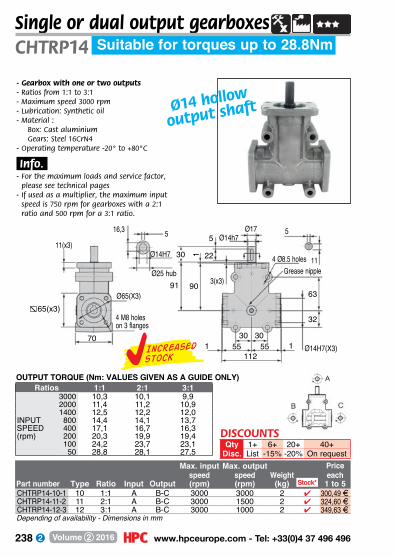
238 www.hpceurope.com - Tel: +33(0)4 37 496 496Volume 2 2016
Single or dual output gearboxesSuitable for torques up to 28.8NmCHTRP14
- Gearbox with one or two outputs- Ratios from 1:1 to 3:1- Maximum speed 3000 rpm- Lubrication: Synthetic oil- Material :
Box: Cast aluminiumGears: Steel 16CrN4
- Operating temperature -20° to +80°C
.Info..- For the maximum loads and service factor,
please see technical pages- If used as a multiplier, the maximum input
speed is 750 rpm for gearboxes with a 2:1 ratio and 500 rpm for a 3:1 ratio.
Ø14 hollow
output shaft
Ø14H7(X3)
11(x3)
16,3
91
30
3(x3)
11
63
32
90
1 22
5
70
11255 11 55
30 30
Ø65(X3)
Ø175 Ø14h7
Ø14H7
Ø25 hub
5
4 M8 holes on 3 flanges
4 Ø8.5 holesGrease nipple
65(x3)
OUTPUT TORQUE (Nm: VALUES GIVEN AS A GUIDE ONLY)Ratios 1:1 2:1 3:1
3000 10,3 10,1 9,92000 11,4 11,2 10,91400 12,5 12,2 12,0
INPUT 800 14,4 14,1 13,7SPEED 400 17,1 16,7 16,3(rpm) 200 20,3 19,9 19,4
100 24,2 23,7 23,150 28,8 28,1 27,5
DISCOUNTSQty 1+ 6+ 20+ 40+
Disc. List -15% -20% On request
Depending of availability - Dimensions in mm
Max. input Max. output Pricespeed speed Weight each
Part number Type Ratio Input Output (rpm) (rpm) (kg) 1 to 5CHTRP14-10-1 10 1:1 A B-C 3000 3000 2 4 300,49 FCHTRP14-11-2 11 2:1 A B-C 3000 1500 2 4 324,60 FCHTRP14-12-3 12 3:1 A B-C 3000 1000 2 4 349,63 F
Stock*
Increasedstock

239 Fax: +33(0)4 37 490 055 - [email protected] Volume 2 2016
Single or dual output gearboxesSuitable for torques up to 87.3Nm CHTRP19
- Gearbox with one or two outputs- Ratios from 1:1 to 3:1- Maximum speed 3000 rpm- Lubrication: Synthetic oil- Material :
Box: Cast aluminiumGears: Steel 16CrN4
- Operating temperature -20° to +80°C
.Info..- For the maximum loads and service factor,
please see technical pages- If used as a multiplier, the maximum input speed is 750
rpm for gearboxes with a 2:1 ratio and 500 rpm for a 3:1 ratio.
30(X
3)
5(X3)3(
X3)
13(x3)15,5(x3)
3030
3030
43
40
141 140
1
4384
1 175 75152 4040
43 43303086
40 40105
Ø25(X3) Ø62H7(X3)Ø19h7(X3)
4 M10 holes on 2 flanges
4 Ø11 holes
4 Ø10.5 holes
Grease nipple
6(x3)
84(x2)
Ø19 shafts
OUTPUT TORQUE (Nm: VALUES GIVEN AS A GUIDE ONLY)Ratios 1:1 2:1 3:1
3000 31,4 29,6 22,82000 34,7 32,7 25,21400 38,0 35,8 27,6
INPUT 800 43,7 41,1 31,7SPEED 400 51,9 48,9 37,7(rpm) 200 61,8 58,2 44,9
100 73,4 69,2 53,350 87,3 82,3 63,4
DISCOUNTSQty 1+ 6+ 20+ 40+
Disc. List -15% -20% On requestMax. input Max. output Price
speed speed Weight eachPart number Type Ratio Input Output (rpm) (rpm) (kg) 1 to 5CHTRP19-1-1 1 1:1 A B 3000 3000 4,5 4 349,52 FCHTRP19-2-1 2 1:1 A C 3000 3000 4,5 4 349,52 FCHTRP19-3-2 3 2:1 A B 3000 1500 4,5 - 366,00 FCHTRP19-4-2 4 2:1 A C 3000 1500 4,5 - 365,98 FCHTRP19-5-3 5 3:1 A B 3000 1000 4,5 4 382,56 FCHTRP19-6-3 6 3:1 A C 3000 1000 4,5 - 382,60 FCHTRP19-7-1 7 1:1 A B-C 3000 3000 4,5 4 349,41 FCHTRP19-8-2 8 2:1 A B-C 3000 1500 4,5 - 371,20 FCHTRP19-9-3 9 3:1 A B-C 3000 1000 4,5 - 398,06 F
Stock*
Depending of availability - Dimensions in mm
Increasedstock

240 www.hpceurope.com - Tel: +33(0)4 37 496 496Volume 2 2016
CHTRP19Single or dual output gearboxes
Suitable for torques up to 75.7Nm
Ø19 hollow
output
shafts- Gearbox with one or two outputs- Ratios from 1:1 to 3:1- Maximum speed 3000 rpm- Lubrication: Synthetic oil- Material :
Box: Cast aluminiumGears: Steel 16CrN4
- Operating temperature -20° to +80°C
.Info..- For the maximum loads and service factor,
please see technical pages- If used as a multiplier, the maximum input speed is 750
rpm for gearboxes with a 2:1 ratio and 500 rpm for a 3:1 ratio.
305
3(X3)
13(x3)
Ø30
hub
15,5
3030
3030
43
40
141 140
1
4384
1 175 75152
43 43303086
40 40105
Ø25 Ø62H7(X3)Ø19h7
Ø19H76
621,8
4 M10 holes on 2 flanges
4 Ø11 holes
4 Ø10.5 holes
Grease nipple
84(x2)
OUTPUT TORQUE (Nm: VALUES GIVEN AS A GUIDE ONLY)Ratios 1:1 2:1 3:1
3000 27,2 26,6 22,82000 30,1 28,3 25,21400 32,9 31,0 27,6
INPUT 800 37,9 35,6 31,7SPEED 400 45,0 42,4 37,7(rpm) 200 53,5 50,4 44,9
100 63,7 59,9 53,350 75,7 71,3 63,4
DISCOUNTSQty 1+ 6+ 20+ 40+
Disc. List -15% -20% On request
Depending of availability - Dimensions in mm
Max. input Max. output Pricespeed speed Weight each
Part number Type Ratio Input Output (rpm) (rpm) (kg) 1 to 5CHTRP19-10-1 10 1:1 A B-C 3000 3000 4,5 4 451,74 FCHTRP19-11-2 11 2:1 A B-C 3000 1500 4,5 4 533,85 FCHTRP19-12-3 12 3:1 A B-C 3000 1000 4,5 - 615,19 F
Stock*
Increasedstock

241 Fax: +33(0)4 37 490 055 - [email protected] Volume 2 2016
Single or dual output gearboxesSuitable for torques up to 87.3Nm CHTRP24
Part number
Price each 1 to 5
Max. input Max. output speed speed Weight Type Ratio Input Output (rpm) (rpm) (kg)
- Gearbox with one or two outputs- Ratios from 1:1 to 3:1- Maximum speed 3000 rpm- Lubrication: Synthetic oil- Material :
Box: Cast aluminiumGears: Steel 16CrN4
- Operating temperature -20° to +80°C
.Info..- For the maximum loads and service factor,
please refer to the technical pages of the catalogue- If used as a multiplier, the maximum input speed is 750
rpm for gearboxes with a 2:1 ratio and 500 rpm for a 3:1 ratio.
Ø24 shafts
3(X3
)40
(X3)
5(X3)
13(x3) 20(x3)
3030
3030
43
50
141 140
1
4384
1 175 7515250 50
43 43303086
40 40105
Ø25(x3) Ø62H7(X3)Ø24h7(x3)
8(x3)
4 M10 holes on 2 flanges
4 Ø11 holes
4 Ø10.5 holes
Grease nipple
84(x2)
OUTPUT TORQUE (Nm: VALUES GIVEN AS A GUIDE ONLY)Ratios 1:1 2:1 3:1
3000 31,4 29,6 22,82000 34,7 32,7 25,21400 38,0 35,8 27,6
INPUT 800 43,7 41,1 31,7SPEED 400 51,9 48,9 37,7(rpm) 200 61,8 58,2 44,9
100 73,4 69,2 53,350 87,3 82,3 63,4
CHTRP24-1-1 1 1:1 A B 3000 3000 4,5 358,40 FCHTRP24-2-1 2 1:1 A C 3000 3000 4,5 615,19 FCHTRP24-3-2 3 2:1 A B 3000 1500 4,5 403,29 FCHTRP24-4-2 4 2:1 A C 3000 1500 4,5 403,29 FCHTRP24-5-3 5 3:1 A B 3000 1000 4,5 434,04 FCHTRP24-6-3 6 3:1 A C 3000 1000 4,5 434,06 FCHTRP24-7-1 7 1:1 A B-C 3000 3000 4,5 394,54 FCHTRP24-8-2 8 2:1 A B-C 3000 1500 4,5 427,43 FCHTRP24-9-3 9 3:1 A B-C 3000 1000 4,5 470,69 FDimensions in mm
DISCOUNTSQty 1+ 6+ 20+ 40+
Disc. List -15% -20% On request
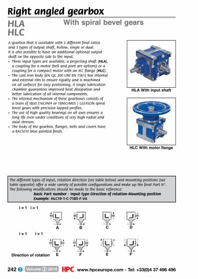
242 www.hpceurope.com - Tel: +33(0)4 37 496 496Volume 2 2016
With spiral bevel gearsHLAHLCA gearbox that is available with 3 different final ratios and 3 types of output shaft, hollow, single or dual. It is also possible to have an additional optional output shaft on the opposite side to the input.• Three input types are available; a projecting shaft (HLA),
a coupling for a motor (bell and joint are options) or a coupling for a compact motor with an IEC flange (HLC).
• The cast iron body (EN GJL 200 UNI EN 1561) has internal and external ribs to ensure rigidity and is machined on all surfaces for easy positioning. A single lubrication chamber guarantees improved heat dissipation and better lubrication of all internal components.
• The internal mechanism of these gearboxes consists of a train of steel (16CrNi4 or 18NiCrM05 ) GLEASON spiral bevel gears with precision lapped profiles.
• The use of high quality bearings on all axes ensures a long life even under conditions of very high radial and axial stresses.
• The body of the gearbox, flanges, bells and covers have a RAL5010 blue painted finish.
HLA With input shaft
HLC With motor flange
The different types of input, rotation direction (see table below) and mounting positions (see table opposite) offer a wide variety of possible configurations and make up the final Part N°.The following modifications should be made to the basic reference: Basic Part number - Input type-Direction of rotation-Mounting position Example: HLC19-1-C-71B5-F-VA
Right angled gearbox
i = 1 i > 1
i = 1A
E
B
F
C
E
D
FDirection of rotation
i > 1
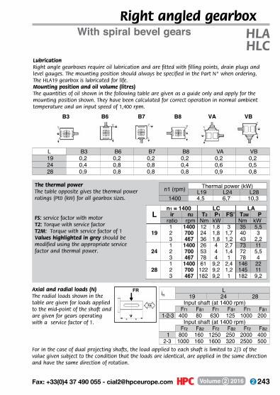
243 Fax: +33(0)4 37 490 055 - [email protected] Volume 2 2016
The thermal power The table opposite gives the thermal power ratings (Pt0 (kW) for all gearbox sizes.
FS: service factor with motorT2: Torque with service factorT2M: Torque with service factor of 1Values highlighted in grey should be modified using the appropriate service factor and thermal power.
With spiral bevel gears HLAHLC
LubricationRight angle gearboxes require oil lubrication and are fitted with filling points, drain plugs and level gauges. The mounting position should always be specified in the Part N° when ordering. The HLA19 gearbox is lubricated for life.Mounting position and oil volume (litres)The quantities of oil shown in the following table are given as a guide only and apply for the mounting position shown. They have been calculated for correct operation in normal ambient temperature and an input speed of 1,400 rpm.
Right angled gearbox
Axial and radial loads (N)The radial loads shown in the table are given for loads applied to the mid-point of the shaft and are given for gears operating with a service factor of 1.
For In the case of dual projecting shafts, the load applied to each shaft is limited to 2/3 of the value given subject to the condition that the loads are identical, are applied in the same direction and have the same direction of rotation.
FR
v
in L19 24 28
Input shaft (at 1400 rpm)Fr1 Fa1 Fr1 Fa1 Fr1 Fa1
1-2-3 400 80 630 125 1000 200Input shaft (at 1400 rpm)
Fr2 Fa2 Fr2 Fa2 Fr2 Fa21 800 160 1250 250 2000 400
2-3 1000 160 1600 320 2500 500
L B3 B6 B7 B8 VA VB19 0,2 0,2 0,2 0,2 0,2 0,224 0,4 0,8 0,8 0,4 0,6 0,528 0,9 0,8 0,8 0,8 0,9 0,8
n1 (rpm) Thermal power (kW)L19 L24 L28
1400 4,5 6,7 10,3
Ln1 = 1400 LC LA
ir n2 T2 P1 FS’ T2M Pratio rpm Nm kW Nm kW
191 1400 12 1,8 3 35 5,52 700 24 1,8 1,7 40 33 467 36 1,8 1,2 43 2,2
241 1400 26 4 2,7 73 112 700 53 4 1,4 72 5,53 467 78 4 1 78 4
281 1400 61 9,2 2,4 146 222 700 122 9,2 1,2 145 113 467 182 9,2 1 182 9,2
B3 B6 B7 B8 VA VB

244 www.hpceurope.com - Tel: +33(0)4 37 496 496Volume 2 2016
Torque up to 43 NmHLA19
- Right angle bevel gearbox- Max speed 1,400 rpm- Output backlash: 12’ to 20’- M aterials:
Components: steel Case: cast iron
- Thermal power: 4.5 kW (Heat dissipation capability)
.Part number.- When ordering, specify the rotation direction
and mounting position by replacing E and B3 in the Part number (see presentation page)
Right angle gearbox
Ø input Max output Mechanicalshaft Output speed ouput Weight Price
Part number Ratio (h6) shaft (rpm) torque (Nm) (kg) eachHLA19-1-C-E-B3 1:1 19 hollow 1400 35 8,5 384,17 FHLA19-2-C-E-B3 2:1 14 hollow 700 40 8,5 384,17 FHLA19-3-C-E-B3 3:1 14 hollow 467 43 8,5 384,17 FHLA19-1-S-E-B3 1:1 19 single 1400 35 8,5 382,92 FHLA19-2-S-E-B3 2:1 14 single 700 40 8,5 382,92 FHLA19-3-S-E-B3 3:1 14 single 467 43 8,5 382,92 FHLA19-1-B-E-B3 1:1 19 dual 1400 35 8,5 395,43 FHLA19-2-B-E-B3 2:1 14 dual 700 40 8,5 395,43 FHLA19-3-B-E-B3 3:1 14 dual 467 43 8,5 395,43 F
30
90
8056
801127
80112
101
With input shaft
130128110
40
M86
21,5
40
7Single output shaft S or dual shafts B
Ø19h6
130128110
6
7
Hollow output shaft C
22,8
Ø20H7
Ratio 1:1
6
21,5M8
Ø19h6
Ratio 2:1Ratio 3:1
5
16M6
Ø14h6
*For maximum torque and a service factor applied, see presentation page - Dimensions en mm
2+-5%
4+On request
1+List
QtyDisc.
DISCOUNTS
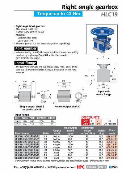
245 Fax: +33(0)4 37 490 055 - [email protected] Volume 2 2016
Torque up to 43 Nm HLC19
- Right angle bevel gearbox- Max speed 1,400 rpm- Output backlash: 12’ to 20’- M aterials:
Components: steel Case: cast iron
- Thermal power: 4.5 kW (Heat dissipation capability)
.Part number.- When ordering, specify the rotation direction and mounting
position by replacing E and B3 in the Part number (see presentation page)
.Input flange.- The following flanges are available: 63B5, 71B5, 80B5, 90B5
and 80B14 and the reference should be added to the Part number
Right angle gearbox
Max output MechanicalOutput speed output Weight Price
Part number Ratio shaft (rpm) torque* (Nm) (kg) eachHLC19-1-C-63B5-E-B3 1:1 hollow 1400 35 11,5 458,01 FHLC19-2-C-63B5-E-B3 2:1 hollow 700 40 11,5 458,01 FHLC19-3-C-63B5-E-B3 3:1 hollow 467 43 11,5 458,01 FHLC19-1-S-63B5-E-B3 1:1 single 1400 35 11,5 456,75 FHLC19-2-S-63B5-E-B3 2:1 single 700 40 11,5 456,75 FHLC19-3-S-63B5-E-B3 3:1 single 467 43 11,5 456,75 FHLC19-1-B-63B5-E-B3 1:1 dual 1400 35 11,5 469,26 FHLC19-2-B-63B5-E-B3 2:1 dual 700 40 11,5 469,26 FHLC19-3-B-63B5-E-B3 3:1 dual 467 43 11,5 469,26 F
130128110
40
M86
21,5
40
7Single output shaft S
or dual shafts B
Ø19h6
*For maximum torque and a service factor applied, see presentation page - Dimensions in mm
Input with motor flange
Y
7
80112
P
56
11280
80
Hollow output shaft C
130128110
6
7Ø20H7
22,8
Input flangeIEC 63B5 71B5 80/90B5 80B14
Y 140 160 200 120P 104 111 131 131
2+-5%
4+On request
1+List
QtyDisc.
DISCOUNTS
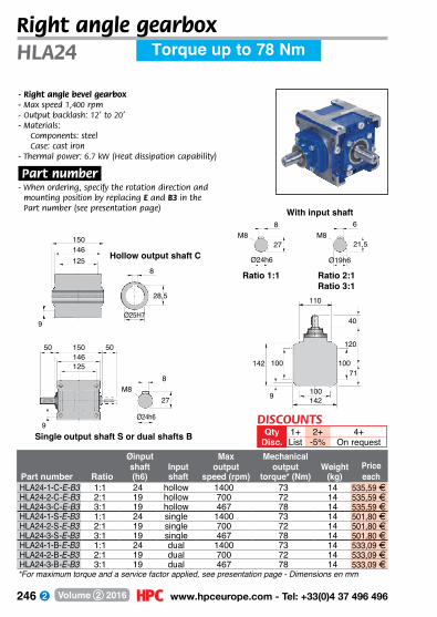
246 www.hpceurope.com - Tel: +33(0)4 37 496 496Volume 2 2016
Torque up to 78 NmHLA24
- Right angle bevel gearbox- Max speed 1,400 rpm- Output backlash: 12’ to 20’- M aterials:
Components: steel Case: cast iron
- Thermal power: 6.7 kW (Heat dissipation capability)
.Part number.- When ordering, specify the rotation direction and
mounting position by replacing E and B3 in the Part number (see presentation page)
Right angle gearbox
Øinput Max Mechanicalshaft Input output output Weight Price
Part number Ratio (h6) shaft speed (rpm) torque* (Nm) (kg) eachHLA24-1-C-E-B3 1:1 24 hollow 1400 73 14 535,59 FHLA24-2-C-E-B3 2:1 19 hollow 700 72 14 535,59 FHLA24-3-C-E-B3 3:1 19 hollow 467 78 14 535,59 FHLA24-1-S-E-B3 1:1 24 single 1400 73 14 501,80 FHLA24-2-S-E-B3 2:1 19 single 700 72 14 501,80 FHLA24-3-S-E-B3 3:1 19 single 467 78 14 501,80 FHLA24-1-B-E-B3 1:1 24 dual 1400 73 14 533,09 FHLA24-2-B-E-B3 2:1 19 dual 700 72 14 533,09 FHLA24-3-B-E-B3 3:1 19 dual 467 78 14 533,09 F
40
110
10071
1001429
100142
120
With input shaft
150146125
50
M88
27
50
9Single output shaft S or dual shafts B
Ø24h6
150146125
8
9
Hollow output shaft C
28,5
Ø25H7
Ratio 1:1
8
27M8
Ø24h6
Ratio 2:1Ratio 3:1
6
21,5M8
Ø19h6
*For maximum torque and a service factor applied, see presentation page - Dimensions en mm
2+-5%
4+On request
1+List
QtyDisc.
DISCOUNTS

247 Fax: +33(0)4 37 490 055 - [email protected] Volume 2 2016
Torque up to 78 Nm HLC24
- Right angle bevel gearbox- Max speed 1,400 rpm- Output backlash: 12’ to 20’- M aterials:
Components: steel Case: cast iron
- Thermal power: 6.7 kW (Heat dissipation capability)
.Part number.- When ordering, specify the rotation direction and mounting
position by replacing E and B3 in the Part number (see presentation page)
.Input flange.- The following flanges are available: 63B5, 71B5, 80B5, 90B5
and 80B14 and the reference should be added to the Part number
Right angle gearbox
Max output MechanicalOutput speed output Weight Price
Part number Ratio shaft (rpm) torque* (Nm) (kg) eachHLC24-1-C-71B5-E-B3 1:1 hollow 1400 73 19 633,21 FHLC24-2-C-71B5-E-B3 2:1 hollow 700 72 19 633,21 FHLC24-3-C-71B5-E-B3 3:1 hollow 467 78 19 633,21 FHLC24-1-S-71B5-E-B3 1:1 single 1400 73 19 599,42 FHLC24-2-S-71B5-E-B3 2:1 single 700 72 19 599,42 FHLC24-3-S-71B5-E-B3 3:1 single 467 78 19 599,42 FHLC24-1-B-71B5-E-B3 1:1 dual 1400 73 19 649,47 FHLC24-2-B-71B5-E-B3 2:1 dual 700 72 19 649,47 FHLC24-3-B-71B5-E-B3 3:1 dual 467 78 19 649,47 F
Input with motor flange
*For maximum torque and a service factor applied, see presentation page - Dimensions in mm
Input flangeIEC 71B5 80B5 90B5 100/112B5
Y 160 200 200 250P 128 148 148 158
Y
9
100142
P
71
142100
100
150146125
50
M88
27
50
9Single output shaft S
or dual shafts B
Ø24h6
Hollow output shaft C
150146125
8
9Ø25H7
28,5
2+-5%
4+On request
1+List
QtyDisc.
DISCOUNTS

248 www.hpceurope.com - Tel: +33(0)4 37 496 496Volume 2 2016
Torque up to 182 NmHLA28
- Right angle bevel gearbox- Max speed 1,400 rpm- Output backlash: 12’ to 20’- M aterials:
Components: steel Case: cast iron
- Thermal power: 10.3 kW (Heat dissipation capability)
.Part number.- When ordering, specify the rotation direction and
mounting position by replacing E and B3 in the Part number (see presentation page)
Right angle gearbox
ØInput Max output Mechanicalshaft output speed output Weight Price
Part number Ratio (h6) shaft (rpm) torque* (Nm) (kg) eachHLA28-1-C-E-B3 1:1 28 hollow 1400 146 23 795,88 FHLA28-2-C-E-B3 2:1 24 hollow 700 145 23 795,88 FHLA28-3-C-E-B3 3:1 24 hollow 467 182 23 795,88 FHLA28-1-S-E-B3 1:1 28 single 1400 146 23 713,29 FHLA28-2-S-E-B3 2:1 24 single 700 145 23 713,29 FHLA28-3-S-E-B3 3:1 24 single 467 182 23 713,29 FHLA28-1-B-E-B3 1:1 28 dual 1400 146 23 757,09 FHLA28-2-B-E-B3 2:1 24 dual 700 145 23 757,09 FHLA28-3-B-E-B3 3:1 24 dual 467 182 23 757,09 F
50
130
13090
13018010
130180
147
With input shaft
180175145
60
M88
31
60
11Single output shaft S or dual shafts B
Ø28h6
180175145
8
11
Hollow output shaft C
33,3
Ø30H7
Ratio 1:1
8
31M8
Ø28h6
Ratio 2:1Ratio 3:1
8
27M8
Ø24h6
2+-5%
4+On request
1+List
QtyDisc.
DISCOUNTS
*For maximum torque and a service factor applied, see presentation page - Dimensions en mm

249 Fax: +33(0)4 37 490 055 - [email protected] Volume 2 2016
Torque up to 182 Nm HLC28
- Right angle bevel gearbox- Max speed 1,400 rpm- Output backlash: 12’ to 20’- M aterials:
Components: steel Case: cast iron
- Thermal power: 10.3 kW (Heat dissipation capability)
.Part number.- When ordering, specify the rotation direction and mounting
position by replacing E and B3 in the Part number (see presentation page)
.Input flange.- The following flanges are available: 63B5, 71B5, 80B5, 90B5
and 80B14 and the reference should be added to the Part number
Right angle gearbox
Max output MechanicalOutput speed output Weight Price
Part number Ratio shaft (rpm) torque* (Nm) (kg) eachHLC28-1-C-80B5-E-B3 1:1 hollow 1400 146 33 919,77 FHLC28-2-C-80B5-E-B3 2:1 hollow 700 145 33 919,77 FHLC28-3-C-80B5-E-B3 3:1 hollow 467 182 33 919,77 FHLC28-1-S-80B5-E-B3 1:1 single 1400 146 33 837,18 FHLC28-2-S-80B5-E-B3 2:1 single 700 145 33 837,18 FHLC28-3-S-80B5-E-B3 3:1 single 467 182 33 837,18 FHLC28-1-B-80B5-E-B3 1:1 dual 1400 146 33 1 451,19 FHLC28-2-B-80B5-E-B3 2:1 dual 700 145 33 1 451,19 FHLC28-3-B-80B5-E-B3 3:1 dual 467 182 33 1 451,19 F
Input with motor flange
180175145
60
M88
31
60
11Single output shaft S
or dual shafts B
Ø28h6
*For maximum torque and a service factor applied, see presentation page - Dimensions in mm
Input flangeIEC 80/90B5 100/112B5 132B5
Y 200 250 300P 171 181 203
Y
10
130180
P
90
180130
130
Hollow output shaft C
180175145
8
11Ø30H7
33,3
2+-5%
4+On request
1+List
QtyDisc.
DISCOUNTS

250 www.hpceurope.com - Tel: +33(0)4 37 496 496Volume 2 2016
motor gearboxes
motor gearboxes
motor gearboxes
power supply
p.266 p.267
speed controller potentiometer
p.257
p.256p.254
p.262

251 Fax: +33(0)4 37 490 055 - [email protected] Volume 2 2016
motor- gearboxes
p.252 - 327
asynchronous ac motor
ac asynchronous
motorworm and wheel
gearbox
p.302
worm and wheel
gearbox
p.296p.276
p.306
p.271
asynchronous ac
motorgearboxes
stainless
steel stainless
steel

252 www.hpceurope.com - Tel: +33(0)4 37 496 496Volume 2 2016
24V dc motorisation kitWorm and wheelKITdog
- The kit comprises: 1 motorised gearbox DOG319 1 servoamplifier FIRSTDC-1Q 1 potentiometer MDPOT-10T/10K 1 power supply ALIDR120-2 (please refer to product pages for full
technical details)- Reduced size- Low noise- Solid design- Powerfull
.Application.- Industrial drives
.Advantages.- Complete set- Easy to set up
Part number Max speed Max torque Motor used (rpm) (Nm)
Price each 1 to 9
KIT-DOG-30 DOG319-24-30 30 9 537,41 FKIT-DOG-45 DOG319-24-45 45 9 537,41 FKIT-DOG-85 DOG319-24-85 85 4 537,41 F
Dimensions in mm
DISCOUNTSQty 1+ 6+ 10+
Disc. List -7% On request

253 Fax: +33(0)4 37 490 055 - [email protected] Volume 2 2016
24V dc motorisation kit2 Planetary gears KITbuh
- T he kit comprises : 1 motorised gearbox BUH77 1 servoamplifier NANO DC-1Q-30/3 1 cable NANO DC-RS232 1 power supply 24V 2.1A 1 cable NANODC-RS232 1 power supply 24V 2,1A (please refer to product pages for full technical details)
- Reduced diameter- Works in Start/Stop mode or in
reverse direction
.Application.- Industrial drives
.Advantages.- Complete set of components- Easy to install
KIT-BUH-900 BUH77-24-004 900 0,10 352,89 FKIT-BUH-260 BUH77-24-012 260 0,30 352,89 FKIT-BUH-140 BUH77-24-022 140 0,55 352,89 FKIT-BUH-075 BUH77-24-040 75 1,00 352,89 FKIT-BUH-023 BUH77-24-135 23 1,80 352,89 FKIT-BUH-014 BUH77-24-250 14 2,00 352,89 F
Part number Max speed Max torque Motor used (rpm) (Nm)
Price each 1 to 9
Dimensions in mm
DISCOUNTSQty 1+ 6+ 10+
Disc. List -7% On request

254 www.hpceurope.com - Tel: +33(0)4 37 496 496Volume 2 2016
Torque from 0.07 to 0.2 NmMAX22Motor-gearbox,12 and 24 V DC
6+-7%
1+List
10+On request
QtyDisc.
DISCOUNTS
- Type of gearbox: spur gear- Bearings: self lubricating bushes- Avg angular backlash: 2° to 3 °- Max axial load: 15N- Max radial load at 5 mm from
fixing surface: 35 N- Working temperature: -5 to 65 °C- Weight: 104g min
.Accessories.- ESCON-4Q-50/5 (servo-amplifier) NANODC-1Q-30/3 (speed controller)
- Power supplies: ALIDR30-12 and ALIDR30-24
No-load Speed Nominal NominalN° of L1 speed under load torque current Price each
Part number Ratio stages Efficiency (mm) (rpm) (rpm) (Nm) (A) 1 to 512 V versionMAX22-12-015 15:1 3 73% 54,9 356 176 0,07 0,30 161,00 FMAX22-12-100 100:1 4 66% 57,4 53 47 0,10 0,08 186,09 FMAX22-12-200 200:1 5 59% 62,4 27 23 0,20 0,09 192,36 F24 V versionMAX22-24-015 15:1 3 73% 54,9 435 252 0,07 0,18 161,00 FMAX22-24-100 100:1 4 66% 57,4 65 58 0,10 0,05 164,26 FMAX22-24-200 200:1 5 59% 62,4 33 29 0,20 0,05 192,36 FDimensions in mm
Ø16
22°8
+0,40
3,40 31,9 max.
L1 160-1
2,500-0,200
-0,505,9516,10
-0,8
Ø30 Ø220-0,20
0-0,13
B 3024,2
4,9Ø2
Ø5
4,50 Ø10 Ø
8
Ø2,2
± 0,10
0-0,1
-0,0
05-0
,010
-0 -0,0
15
± 0,0
5
-0 -0,1 -0,0
2-0
,05
Wire length: 150 mm ±5Stripped and tinned ends: 4 mm ±1
Ø0,2 B
2xM1,6x4,6Cs (L=4,2 max) 3,5 Ncm max
Replaces the MAX30

255 Fax: +33(0)4 37 490 055 - [email protected] Volume 2 2016
Ø6
Ø12
5,50
±0,0
5
22 -0,80 44,70 max
6,85 -0,05 4,40L1
2,20 -0,20
Ø8Ø3
Ø38
-0,20
Ø26
-0,1
5
16
12 +0,100
-0,1
00 -0,0
50 -0
,010
-0,0
05
-0,0
50-0
,020
-10
00
0 0
0
Motor-gearboxes 12 and 24 V DC Torque from 0.075 to 0.6 Nm MAX26
- Gearbox type : spur gear - Bearing :self lubricating- Max axial load : 30N- Min axial backlash : 0.03mm- Max axial backlash : 0.2mm- Max radial load : 50N at 5mm
from flange- Press fit force : 500N- Angular backlash (no load) : 2°- Angular backlash (under load) : 3°- Working temp : from -5° to 65°C- Input stage : Tufnol- Output stage : Steel- Weight : 181g
.Accessories.Servoamplifier : FIRSTDC-1Q-60/10- NANODC-1A-30/3(speed controller)-Power supply ALIDR30-24
Ø2,60
30,5
0
7
B
112°60°±0,15°
~38,40
16
Spade terminal2,8x0,4+
M1,6x4,6Cs (L=4,2min)3,5Ncm max.
ø 0,2 B
No-load Speed nominal nominal N° of Max L1 speed under load torque current Reduction stages efficiency (mm) (rpm) (rpm) (Nm) (A)
Price each1 to 5Part number
12V VersionMAX26-12-006 6 2 0,81 62,4 740 457 0,08 0,63 208,67 FMAX26-12-010 10 2 0,81 62,4 444 311 0,10 0,50 208,67 FMAX26-12-018 18 3 0,73 67,9 247 155 0,20 0,61 217,46 FMAX26-12-030 30 3 0,73 67,9 148 115 0,20 0,37 217,46 FMAX26-12-060 60 4 0,66 70,4 74 47 0,60 0,61 227,35 FMAX26-12-100 100 4 0,66 70,4 44 35 0,60 0,37 227,35 FMAX26-12-200 200 5 0,59 72,3 22 19 0,60 0,22 232,84 FMAX26-12-500 500 6 0,53 75,3 9 8 0,60 0,11 239,44 F24V VersionMAX26-24-006 6 2 0,81 62,4 752 459 0,08 0,25 208,67 FMAX26-24-010 10 2 0,81 62,4 451 310 0,10 0,25 208,67 FMAX26-24-018 18 3 0,73 67,3 251 154 0,20 0,31 217,46 FMAX26-24-030 30 3 0,73 67,3 150 116 0,20 0,19 217,46 FMAX26-24-060 60 4 0,66 70,4 75 46 0,60 0,31 227,35 FMAX26-24-100 100 4 0,66 70,4 45 35 0,60 0,19 227,35 FMAX26-24-200 200 5 0,59 72,3 22 20 0,60 0,11 232,84 FMAX26-24-500 500 6 0,53 75,9 9 8 0,60 0,053 239,44 F
c 38
Dimensions in mm
DISCOUNTSQty 1+ 6+ 10+
Disc. List -7% On request
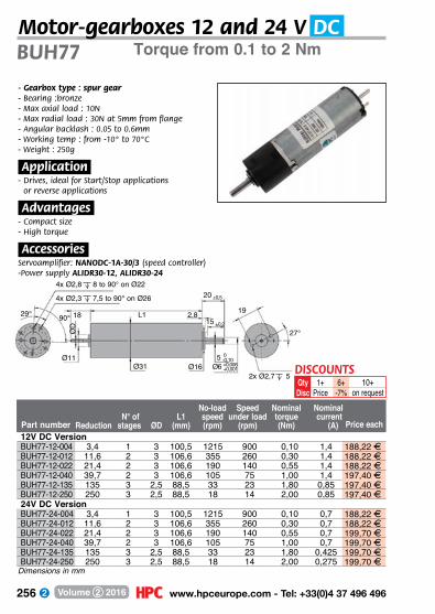
256 www.hpceurope.com - Tel: +33(0)4 37 496 496Volume 2 2016
Torque from 0.1 to 2 NmBUH77
- Gearbox type : spur gear- Bearing :bronze- Max axial load : 10N- Max radial load : 30N at 5mm from flange- Angular backlash : 0.05 to 0.6mm- Working temp : from -10° to 70°C- Weight : 250g
.Application.- Drives, ideal for Start/Stop applications
or reverse applications
.Advantages.- Compact size- High torque
.Accessories.Servoamplifier: NANODC-1A-30/3 (speed controller)-Power supply ALIDR30-12, ALIDR30-24
6+-7%
1+Price
QtyDisc
DISCOUNTS10+
on request
4x Ø2,8 8 to 90° on Ø22
4x Ø2,3 7,5 to 90° on Ø26
L1 2,818
ØD
Ø11Ø31 Ø16
20 ±0,5
15 ±0,2
5 -0,100
Ø6 +0,001+0,006
2x Ø2,7 5
19
27°
29° 90°
12V DC VersionBUH77-12-004 3,4 1 3 100,5 1215 900 0,10 1,4 188,22 FBUH77-12-012 11,6 2 3 106,6 355 260 0,30 1,4 188,22 FBUH77-12-022 21,4 2 3 106,6 190 140 0,55 1,4 188,22 FBUH77-12-040 39,7 2 3 106,6 105 75 1,00 1,4 197,40 FBUH77-12-135 135 3 2,5 88,5 33 23 1,80 0,85 197,40 FBUH77-12-250 250 3 2,5 88,5 18 14 2,00 0,85 197,40 F24V DC VersionBUH77-24-004 3,4 1 3 100,5 1215 900 0,10 0,7 188,22 FBUH77-24-012 11,6 2 3 106,6 355 260 0,30 0,7 188,22 FBUH77-24-022 21,4 2 3 106,6 190 140 0,55 0,7 199,70 FBUH77-24-040 39,7 2 3 106,6 105 75 1,00 0,7 199,70 FBUH77-24-135 135 3 2,5 88,5 33 23 1,80 0,425 199,70 FBUH77-24-250 250 3 2,5 88,5 18 14 2,00 0,275 199,70 F
Part number
No-load Speed Nominal Nominal N° of L1 speed under load torque current Reduction stages ØD (mm) (rpm) (rpm) (Nm) (A) Price each
Dimensions in mm
Motor-gearboxes 12 and 24 V DC
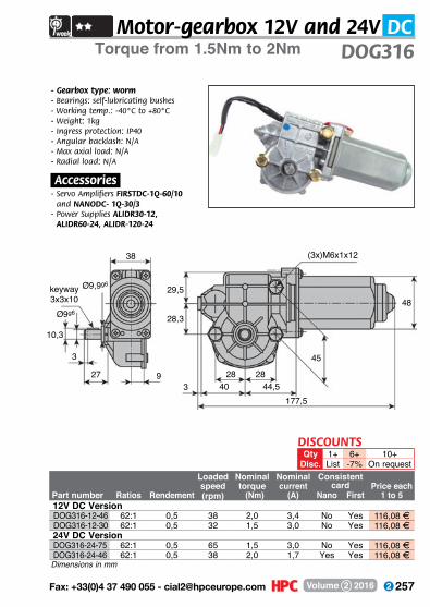
257 Fax: +33(0)4 37 490 055 - [email protected] Volume 2 2016
Dimensions in mm
Torque from 1.5Nm to 2Nm DOG316
- Gearbox type: worm- Bearings: self-lubricating bushes- Working temp.: -40°C to +80°C- Weight: 1kg- Ingress protection: IP40- Angular backlash: N/A- Max axial load: N/A- Radial load: N/A
.Accessories.- Servo Amplifiers FIRSTDC-1Q-60/10
and NANODC- 1Q-30/3- Power Supplies ALIDR30-12,
ALIDR60-24, ALIDR-120-24
38
29,5
28,3
27 93
28 2840 44,5
177,5
45
48
(3x)M6x1x12
keyway 3x3x10
Ø9g6
10,3
3
Ø9,9g6
DISCOUNTSQty 1+ 6+ 10+
Disc. List -7% On request
Motor-gearbox 12V and 24V DC
Loaded Nominal Nominal Consistentspeed torque current card Price each
Part number Ratios Rendement (rpm) (Nm) (A) Nano First 1 to 5 12V DC VersionDOG316-12-46 62:1 0,5 38 2,0 3,4 No Yes 116,08 FDOG316-12-30 62:1 0,5 32 1,5 3,0 No Yes 116,08 F
24V DC VersionDOG316-24-75 62:1 0,5 65 1,5 3,0 No Yes 116,08 FDOG316-24-46 62:1 0,5 38 2,0 1,7 Yes Yes 116,08 F
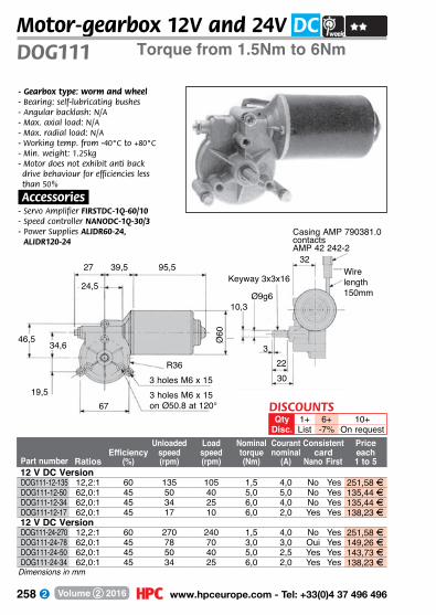
258 www.hpceurope.com - Tel: +33(0)4 37 496 496Volume 2 2016
3 holes M6 x 153 holes M6 x 15on Ø50.8 at 120°
R36
Ø60
95,539,527
24,5
6719,5
34,646,5
Torque from 1.5Nm to 6NmDOG111Motor-gearbox 12V and 24V DC
- Gearbox type: worm and wheel- Bearing: self-lubricating bushes- Angular backlash: N/A- Max. axial load: N/A- Max. radial load: N/A- Working temp. from -40°C to +80°C- Min. weight: 1.25kg- Motor does not exhibit anti back drive behaviour for efficiencies less than 50%
.Accessories.- Servo Amplifier FIRSTDC-1Q-60/10- Speed controller NANODC-1Q-30/3- Power Supplies ALIDR60-24,
ALIDR120-24Casing AMP 790381.0contactsAMP 42 242-2
30
Ø9g610,3
Wire length 150mm
Keyway 3x3x16
223
32
Dimensions in mm
DISCOUNTSQty 1+ 6+ 10+
Disc. List -7% On requestUnloaded Load Nominal Courant Consistent Price
Efficiency speed speed torque nominal card each Part number Ratios (%) (rpm) (rpm) (Nm) (A) Nano First 1 to 5 12 V DC VersionDOG111-12-135 12,2:1 60 135 105 1,5 4,0 No Yes 251,58 FDOG111-12-50 62,0:1 45 50 40 5,0 5,0 No Yes 135,44 FDOG111-12-34 62,0:1 45 34 25 6,0 4,0 No Yes 135,44 FDOG111-12-17 62,0:1 45 17 10 6,0 2,0 Yes Yes 138,23 F
12 V DC VersionDOG111-24-270 12,2:1 60 270 240 1,5 4,0 No Yes 251,58 FDOG111-24-78 62,0:1 45 78 70 3,0 3,0 Oui Yes 149,26 FDOG111-24-50 62,0:1 45 50 40 5,0 2,5 Yes Yes 143,73 FDOG111-24-34 62,0:1 45 34 25 6,0 2,0 Yes Yes 138,23 F

259 Fax: +33(0)4 37 490 055 - [email protected] Volume 2 2016
Torque from 4Nm to 9Nm DOG319
65
13,5 -0,006Ø12g6 -0,017
45°
3xM6 à 120° depth 20 Ø72Ø50,8
M4 depth12
27,8 46,6 113,8
Ø6044,12
4
Keyway 4x4x14
25,5
65
3xM6 à 120° depth 20Ø92 wire length
190mm
28,5
14
30
Dimensions in mm
- Gearbox type: worm- Bearings: self-lubricating bushes- Angular backlash: N/A- Max. axial load: N/A- Max. radial load: N/A- Working temperature: -40°C to +80°C- Weight 1.7kg- Materials:
Screws: steel- Wheel: POM
.Accessories.- Servo Amplifier FIRSTDC-1Q-60/10- Speed controller NANODC-1Q-30/3- Power Supplies ALIDR120-24,
ALIDR240-24
DISCOUNTSQty 1+ 6+ 10+
Disc. List -7% On request
Motor-gearbox 12V and 24V DC
No-load Loaded Nominal Nominal Consistentspeed speed torque current carde Price each
Part number Ratios (rpm) (rpm) (Nm) (A) Nano First 1 to 5 12 V DC VersionDOG319-12-15 81:1 18 15 9 3 No Yes 214,91 FDOG319-12-30 81:1 35 30 9 7 No Yes 215,52 FDOG319-12-45 81:1 50 45 8 6 No Yes 214,91 FDOG319-12-85 39:1 95 85 4 7 No Yes 263,16 F
12 V DC VersionDOG319-24-30 81:1 30 30 9 3 No Yes 227,63 FDOG319-24-45 81:1 45 45 9 3 No Yes 203,94 FDOG319-24-85 39:1 95 85 4 3,5 No Yes 271,93 F
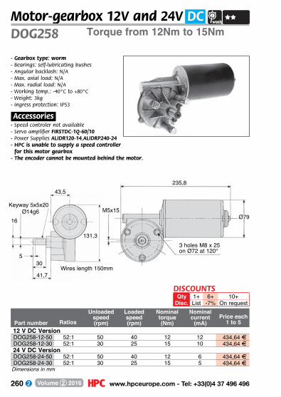
260 www.hpceurope.com - Tel: +33(0)4 37 496 496Volume 2 2016
Torque from 12Nm to 15NmDOG258Motor-gearbox 12V and 24V DC
- Gearbox type: worm- Bearings: self-lubricating bushes- Angular backlash: N/A- Max. axial load: N/A- Max. radial load: N/A- Working temp.: -40°C to +80°C- Weight: 3kg- Ingress protection: IP53
.Accessories.- Speed controler not available- Servo amplifier FIRSTDC-1Q-60/10- Power Supplies ALIDR120-14,ALIDRP240-24- HPC is unable to supply a speed controller
for this motor gearbox- The encoder cannot be mounted behind the motor.
235,8
Ø79
3 holes M8 x 25on Ø72 at 120°
M5x15Keyway 5x5x20
16
530
43,5
41,7
Ø14g6
131,3
Wires length 150mm
Part number Ratios
Unloaded speed(rpm)
Loaded speed(rpm)
Nominal torque(Nm)
Nominal current
(mA)Price each
1 to 5 12 V DC VersionDOG258-12-50 52:1 50 40 12 12 434,64 FDOG258-12-30 52:1 30 25 15 10 434,64 F
24 V DC VersionDOG258-24-50 52:1 50 40 12 6 434,64 FDOG258-24-30 52:1 30 25 15 5 434,64 F
Dimensions in mm
DISCOUNTSQty 1+ 6+ 10+
Disc. List -7% On request

261 Fax: +33(0)4 37 490 055 - [email protected] Volume 2 2016
12 and 24V DC power suppliesMax current 1.5A or 2A ALIDR
30.Advantages.- Universal mains input- Din rail mounting, DINTS35/7.5 or 15- Protected against short circuits, overloads and
over-voltage.- Insulation class II- LED supply indication- Air-cooled- 100% Burn-in
.Charateristics.- Output voltage can be varied by +/- 10%- Max ripple on output +/- 1%
.Protections.- Max overload on output limited to 105/160%- Output is short circuit protected- Max overvoltage on output 115 to 135% of
nominal output voltage
.Environment.- EMC: Conforms to EN55022 class B, EN61000-
3-2,3, EN61000-6-2, EN61000-4-2,3,4,5,6,8,11, ENV50204, EN61204-3
- Max working temperature -20° to +50°C at 100% rated load (+60°C at 80% rated load)
.Connection.- Supply: 2 screw clamp terminals (0.2 to 2.5mm2)- Output: 4 screw clamp terminals (0.2 to 2.5mm2)
.Dimensions/Material.- Enclosure: painted plastic- Dimensions 93 x 78 x 56 (L x W x H)
Part number
Supply Output Output voltage voltage current Weight (V AC) (V DC) (A) (kg)
Price each 1 to 5
6845
46,5
93
12,2
555
6543 7
8
12
5
46,5
27,4
7837,75
4756
ALIDR30-12 85-264 / 120-370 12 2 0,27 51,39 FALIDR30-24 85-264 / 120-370 24 1,5 0,27 62,21 F
Dimensions in mm
Terminal n° Connection Terminal n° Connection1 AC/N 5,6 V-2 AC/L 7 LED
3,4 V+ 8 +VADJ DISCOUNTSQty 1+ 6+ 10+
Disc. List -7% On request

262 www.hpceurope.com - Tel: +33(0)4 37 496 496Volume 2 2016
24V DC power supplyMax current 5AALIDR
120.Advantages.- Mains input voltage switch-selectable- UL508 listed- Din rail mounting, DINTS35/7.5 or 15- Protected against short circuits, overloads and
over-voltage.- Insulation class II- LED supply indication- Air-cooled- 100% Burn-in
.Characteristics.- Output voltage can be varied from 24 to 48V DC- Max ripple on output +/- 1%
.Protections.- Max overload on output limited to 105/160%- Output is short circuit protected- Max overvoltage on output 120 to 140% of
nominal voltage
.Environment.- Environmental- EMC: Conforms to EN55022 class B, EN61000-
3-2,3, EN61000-6-2, EN61000-4-2,3,4,5,6,8,11, ENV50204, EN61204-3
- Personnel safety: Conforms to UL508, UL60950-1, TUV60950-1
- Max working temperature -20° to +60°C (natural convection)
.Connections.- Supply: 3 screw clamp terminals DIN- Output: 4 screw clamp terminals DIN
.Dimensions/Material.- Enclosure: painted plastic- Dimensions 65.5 x 125.2 x 100 (L x W x H)
100
125,2
65,5
Part number
Supply Output Output voltage voltage current Weight (V AC) (V DC) (A) (kg)
Price each1 to 5
ALIDR120-24 88-132 / 176-264commutable
24 5 0,79 154,22 FDimensions in mm
DISCOUNTSQty 1+ 6+ 10+
Disc. List -7% On request
Contact n° Affectation1 FG2 AC/N3 AC/L
Contact n° Affectation1,2 DC OUTPUT +V3,4 DC OUTPUT -V
Terminal assignment (TB1) Terminal assignment (TB2)

263 Fax: +33(0)4 37 490 055 - [email protected] Volume 2 2016
24V DC power supplyMax current 10A ALIDRP
240
125,5100
125,2
Part number
Supply Output Output voltage voltage current Weight (V AC) (V DC) (A) (kg)
Price each 1 to 5
.Advantages.- Universal Mains supply.
PF>0.98@115Vac, PF>0.95@230Vac- Protected against short circuits, overloads and
over-voltage- Switching frequency : 100KHz- UL508 listed- Din rail mounting, DINTS35/7.5 or 15.- LED supply indication- Air-cooled- 100% Burn-in
.Characteristics.- Output voltage can be varied from 24 to 48V DC- Max ripple on output +/- 1%
.Protections.- Max overload on output limited to 105 to150%- Output is short circuit protected- Max overvoltage on output 30 to 36 V DC
.Environment.- EMC: Conforms to EN55022 class B, EN61000-
3-2,3, EN61000-6-2, EN61000-4-2,3,4,5,6,8,11, ENV50204, EN61204-3
- Personnel safety: Conforms to UL508, UL60950-1, TUV60950-1
- Max working temperature -10° to +50°C @100% load, +70°C @60% load (natural convection)
.Connection.- Supply: 3 screw clamp terminals DIN- Output: 4 screw clamp terminals DIN
.Dimensions/Material.- Enclosure: painted plastic- Dimensions 125.5 x 125.2 x 100 (L x W x H)
Dimensions in mmALIDRP240-24 85-264 / 120-370 24 10 1,2 227,29 F
DISCOUNTSQty 1+ 6+ 10+
Disc. List -7% On request

264 www.hpceurope.com - Tel: +33(0)4 37 496 496Volume 2 2016
3A Servo amplifier
- Max Power 90W- Power Supply 10 to 30 Vdc- Max permanent output current 3A- Operating mode PWM, 1 quadrantInputs- Speed control External voltage 0/10V- Enable Voltage free contact (earthed)- Direction Voltage free contact (earthed)- Limit switches 2 Voltage free contacts (earthed)Outputs- Ready Open collector, 30Vdc 20mAControls- Max speed Analogue voltage- Max current Analogue voltageProtection- Reverse polarity Resettable fuse- Over voltage Yes
- Under voltage Yes- Over-current Adjustable- Motor short circuit Yes- Short circuit on inputs YesEnvironment- Working temperature 0 to 40°C- Storage temperature -40 to +85°C- Relative humidity 20 t0 80 %non-condensingConnections- Connectors Spring loaded terminals, pitch 2.54mm. Wire size : 0.14 to 1.5mm2- Connectors (motor + supply) Screw clamp terminals, pitch 3.81mm . Wire size : 0.14 to 1.5mm2Mechanical characteristics - Dimensions 50x100x32mm- Weight 105g- Mounting: Uses M4 screws
Technical specifications 30V/3A
Part number Mounting Screw spacing cableWeight
(g)Price each 1 to 5
- Digital motor servo amplifier for driving motors (>90W)- Accepts limit switch inputs- Small size- Easily configured using a PC, RS232 cable required
(not supplied)
.Accessories.- MDPOT-10T/10K Control potentiometer- Power supplies
NANO For motor control systems
NANODC-1Q-30/3 M4 screw 34x54 0,11 134,86 FNANODC-RS232 Cable NANO DC - RS232 101,52 F
Dimensions in mm
DISCOUNTSQty 1+ 6+ 10+
Disc. List -7% On request

265 Fax: +33(0)4 37 490 055 - [email protected] Volume 2 2016
5A servo amplifierElectronic card 1 quadrant FIRSTDC-1Q
- Digital servo amplifier operating in “R x I” mode
- Allows direction of rotation to be reversed- Analogue output signal
.Accessories.- MDPOT-10T/10K Control potentiometer- Power supply
- Max. power 250W- Feed voltage 12 to 50 VDC- Max. permanent output current 5 A- Workings PWM (20kHz) - 1 quadrant- Control method RxlInputs :- Setting Potentiometer ext. 10KW Voltage ext.0/10V- Enable Voltage free contact (earthed)- Direction Voltage free contact (earthed)Outputs : - Current image 1 V/A- Ready Open collector 30 VDC/20 mA- Auxiliary voltage 10 V / 20 mA max.Adjustments : - Compensation RI Via pushbutton- Offset Via pushbutton- Max. speed Via pushbutton- Max. current Via pushbutton
Protection :- Polarity reversal Fuse 10A- Overvoltage Yes- Undervoltage Yes- Current overload Can be limited by adjustment- Short-circuit motor Yes- Input/output short-circuit Yes- Auxiliary feed short-circuit YesEnvironment :- Operating Temperature -10 to +35°C- Storage Temperature -40 to +85°C - Relative humidity 20 to 80% non-condensingConnections :- Connectors Detachable terminal block for wire 0.14 to 1.52 mm2
Mechanics :- Eurocard format 3U Yes
Technical specifications 50V/5A
Push button switch
DISCOUNTSQty 1+ 6+ 10+
Disc. List -7% On requestEuro card weight Price each
Part number Mounting format 3U (g) 1 to 5FIRSTDC-1Q-60/10 M4 screw 100 x 100 x 32 220 322,03 F
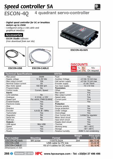
266 www.hpceurope.com - Tel: +33(0)4 37 496 496Volume 2 2016
Speed controller 5A4 quadrant servo-controllerESCON-4Q
Weight Price each Part number Mounting Format (g) 1 to 5ESCON-4Q-50/5 M4 screw 115X75,5x24 204 384,73 FESCON-USB USB cable for PC link 23,00 FESCON-CABLE Kit of 4 cables for DC motor 50,18 F
Dimensions in mm
Technical Specifications 50V/5A- Max power 250W - Fault Yes- Supply voltage 10 to 50 Vdc - Auxiliary Voltage +5 Vdc 10 mA max- Max output current 15A - Hall sensor supply +5 Vdc 10 mA max- Nominal Output current 5A - Encoder supply +5 vdc 70mA- Max motor speed 150 000 rpm - Aux input supply -10 /+10 Vdc- Programmable No Parameters- Control mode Current, Speed - Offset Yes Inputs: - Max speed Yes- Limit switches No - Max output current 5 A- Analogue 2,12 bit, +/-10V - Speed ramp Yes- Speed limit Pot. ext/int, PWM 53.6KHZ - Current point 15 A- Enable/Disable Yes - Gain Yes- Electronic brake Yes Protection- Stop No - Reverse polarity No- Direction Yes - Surge protection Yes- Encoder A,A/,B, B/ -1MHz - Under voltage Yes- Tachometer Yes - Overvoltage Yes- Regulation Rxl - Over Current limit Limited by regulator- Serial link No - Motor short circuit Yes- CAN bus No - Input short circuit Yes Outputs : - Supply short circuit Yes- USB signal Mini USB - Thermal Yes- Speed Yes - Working temp -30°/ +45°C- Current Yes - Storage -40°/ +85°C- Ready Yes - Relative humidity 20/80 % non condensing
ESCON-4Q-50/5
ESCON-USB ESCON-CABLE
- Digital speed controller for DC or brushless motors up to 250W
- Configured using a USB cable and graphical interface
.Accessories.- ESCON Studio software
(Free download from our site)
6+-7%
10+On request
1+List
QtyDisc.
DISCOUNTS
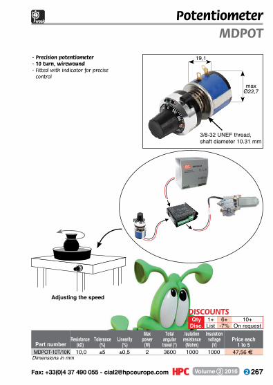
267 Fax: +33(0)4 37 490 055 - [email protected] Volume 2 2016
PotentiometerMDPOT
- Precision potentiometer- 10 turn, wirewound- Fitted with indicator for precise
control
Resistance(kΩ)
Tolerance(%)
Linearity(%)
Maxpower
(W)
Total angular travel (°)
Isulation resistance
(Mohm)
Insulationvoltage
(V)Part numberPrice each
1 to 5MDPOT-10T/10K 10,0 ±5 ±0,5 2 3600 1000 1000 47,56 F
Dimensions in mm
Adjusting the speed
DISCOUNTSQty 1+ 6+ 10+
Disc. List -7% On request
19,1
3/8-32 UNEF thread,shaft diameter 10.31 mm
maxØ22,7

268 www.hpceurope.com - Tel: +33(0)4 37 496 496Volume 2 2016
AC motorsTechnical information
A wide range of AC motors with both synchronous permanent magnet versions and asynchronous single-phase or three -phase versions.Synchronous motors rotate at a fixed and precise speed, independent of variations in load and supply voltage.Asynchronous motors are characterised by a speed of rotation that is dependent on the load applied to the shaft. The unloaded speed is proportional to the frequency of the single or three phase supply (230/400V-50Hz).AC motors are often used for applications where the speed and operating torque are fixed and are directly powered by mains voltage. They are designed to have a long working life, necessary for many applications.
The following information is given as a guide to choosing an AC motor:
.Type.Permanent magnet synchronous motor - double wound stator- multi-polar magnet and radial magnetisation rotor- bi-directional rotation via the use of an internal de-phasing capacitor
Squirrel cage asynchronous motor- multi-recessed triple-wound stator- squirrel cage rotor- single-phase or three-phase versions
.Life expectancy.- Depends on usage, principally limited by life expectancy of the bearings.
.Overheating.Synchronous motors - convection cooling, motor can block rotor without risk of deterioration- isolation quality class B.
Squirrel cage asynchronous motors- incorporated ventilator cooling- isolation quality class E.

269 Fax: +33(0)4 37 490 055 - [email protected] Volume 2 2016
AC motorsTechnical information
Synchronous motor
M = f
(U)n = f(M) n = f(M)
M
M 0,8 0,9 1 11 12 U
n = speedM = torqueU = applied
voltagee
Asynchronous single-phased motor
n
0 MMnAsynchronous
three-phase motor
n
0 MMn
Diagram 3400 V3-ph wiring
V1400V
U1
W1
Diagram 1230V 1-ph wiring
White(H)
Blue
Red(AH)
Diagram 5230 V3-ph wiring
W1
U1
V1
230V
.Caracteristics.The performance of AC motors is shown by the graphs given below which are given as a guide only as actual performance will depend on temperature, stability of the supply voltage and frequency and of the circuit capacitance.
.Electronics.These speed controllers operate by varying the frequency of the power supply to an asynchronous three-phase motor. In order to maintain a constant torque, the ratio of the supply voltage and frequency ration is kept constant. As output voltage remains constant above 50Hz, the torque will drop as the speed rises. To avoid reducing the efficiency, motors should not be run at a frequency higher than 150Hz.When connected to a motor with internal ventilation, it is also recommended to avoid working permanently at supply frequencies lower than 20 Hz. This is because as the fan is not turning as fast, the motor may overheat and be damaged or destroyed.Variable frequency drives can produce electrical interference. To protect sensitive equipment nearby these units conform to applicable EMC standards.
.Wiring diagram.
Diagram 2
230V 1-ph wiring
Purple(Noir)
Orange(Vert)
Red(Gris)
Red(Gris) Diagram 4
230V 1-ph wiring
V1
U1
W1
230V
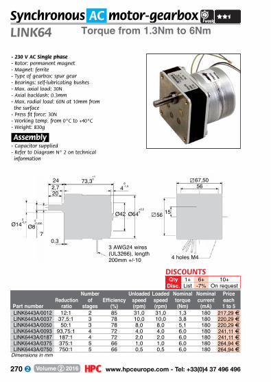
270 www.hpceurope.com - Tel: +33(0)4 37 496 496Volume 2 2016
- 230 V AC Single phase- Rotor: permanent magnet- Magnet: ferrite- Type of gearbox: spur gear- Bearings: self-lubricating bushes- Max. axial load: 30N- Axial backlash: 0.3mm- Max. radial load: 60N at 10mm from the surface
- Press fit force: 30N- Working temp. from 0°C to +40°C- Weight: 830g
.Assembly.- Capacitor supplied- Refer to Diagram N° 2 on technical information
3 AWG24 wires (UL3266), length 200mm +/-10
LINK64Synchronous AC motor-gearbox
Torque from 1.3Nm to 6Nm
Dimensions in mm
DISCOUNTSQty 1+ 6+ 10+
Disc. List -7% On request
24 73,34
Ø42 Ø64 56
56
15
4 holes M4
2,720
7Ø8Ø14
0,3
67,50
0-0,1 0
-0,036
+10
0-1,5
+0,50
Number Unloaded Loaded Nominal Nominal PriceReduction of Efficiency speed speed torque current each
Part number ratio stages (%) (rpm) (rpm) (Nm) (mA) 1 to 5LINK6443A/0012 12:1 2 85 31,0 31,0 1,3 180 217,29 FLINK6443A/0037 37,5:1 3 78 10,0 10,0 3,8 180 220,29 FLINK6443A/0050 50:1 3 78 8,0 8,0 5,1 180 220,29 FLINK6443A/0093 93,75:1 4 72 4,0 4,0 6,0 180 241,11 FLINK6443A/0187 187:1 4 72 2,0 2,0 6,0 180 241,11 FLINK6443A/0375 375:1 5 66 1,0 1,0 6,0 180 264,94 FLINK6443A/0750 750:1 5 66 0,5 0,5 6,0 180 264,94 F

271 Fax: +33(0)4 37 490 055 - [email protected] Volume 2 2016
Torque up to 0.64Nm CHT56Asynchronous AC motor 0.09kW
Part numberPower(kW)
Powersupply
(V)
Current at 400V
(A)Torque(Nm) Efficiency
Power factor
cosWeight
(kg)Price each
1 to 5
Ø80 Ø120
100M5
65
195
20
02,5
Ø50
3
Ø9
10,2
- 3 phase AC asynchronous motor- 4 pole motor- Supply frequency 50 Hz- B14 mounting flange - Insulation class F- Protection IP55- Bearings: ball bearings- Can rotate in both directions- Rotor: Squirrel cage
.Accessories.- Servo amplifier TEL-ATV11/180- Gearbox CHM
.Option.- Motor with B5 mounting flange
CHT56B4-B14 0,09 230/400 0,43 0,64 50% 0,61 3,2 92,55 FDimensions in mm
DISCOUNTSQty 1+ 6+ 10+
Disc. List -7% On request

272 www.hpceurope.com - Tel: +33(0)4 37 496 496Volume 2 2016
Torque up to 1.77NmCHT63Asynchronous AC motor 0.12 to 0.22kW
Part numberPower(kW)
Powersupply
(V)
Current at 400V
(A)Torque(Nm) Efficiency
Power factor
cosWeight
(kg)Price each
1 to 5
Ø90 Ø130
110M5
75
215
23
02,5
Ø60
4
Ø11
12,5
- 3 phase AC asynchronous motor- 4 pole motor- Supply frequency 50 Hz- B14 mounting flange - Insulation class F- Ingress protection: IP55- Bearings: ball bearings- Can rotate in both directions- Rotor: Squirrel cage
.Accessories.- Servo amplifier TEL-ATV11/180, TEL-ATV11/370- Gearbox CHM
.Option.- Motor with B5 mounting flange
CHT63A4-B14 0,12 230/400 0,47 0,86 57% 0,64 3,9 95,81 FCHT63B4-B14 0,18 230/400 0,70 1,27 57% 0,65 4,5 100,44 FCHT63C4-B14 0,22 230/400 0,92 1,77 59% 0,67 4,8 105,50 F
Dimensions in mm
DISCOUNTSQty 1+ 6+ 10+
Disc. List -7% On request

273 Fax: +33(0)4 37 490 055 - [email protected] Volume 2 2016
Torque up to 3.81Nm CHT71Asynchronous AC Motor 0.18 to 0.55kW
Part numberPower(kW)
Powersupply
(V)
Current at 400V
(A)Torque(Nm) Efficiency
Power factor
cosWeight
(kg)Price each
1 to 5
Ø105 Ø145
117M6
85
255
30
02,5
Ø70
5
Ø14
16
- 3 phase AC asynchronous motor- 4 pole motor- Supply frequency 50 Hz- B14 mounting flange - Insulation class F- Ingress protection: IP55- Bearings: ball bearings- Can rotate in both directions- Rotor: Squirrel cage
.Accessories.- Servo amplifier TEL-ATV11/370- Gearbox CHM
.Option.- Motor with B5 mounting flange
CHT71A4-B14 0,25 230/400 0,84 1,77 60% 0,72 5,6 108,61 FCHT71B4-B14 0,37 230/400 1,12 2,58 65% 0,74 6,2 121,00 FCHT71C4-B14 0,55 230/400 1,61 3,81 66% 0,75 7,0 137,19 F
Dimensions in mm
DISCOUNTSQty 1+ 6+ 10+
Disc. List -7% On request

274 www.hpceurope.com - Tel: +33(0)4 37 496 496Volume 2 2016
Torque up to 7.6NmCHT80Asynchronous AC Motor 0.55 to 1.1kW
Part numberPower(kW)
Powersupply
(V)
Current at 400V
(A)Torque(Nm) Efficiency
Power factor
cosWeight
(kg)Price each
1 to 5
Ø120 Ø165
137M6
100
290
40
03
Ø80
6
Ø19
21,5
- 3 phase AC asynchronous motor- 4 pole motor- Supply frequency 50 Hz- B14 mounting flange- Insulation class F- Ingress protection: IP55- Bearings: ball bearings- Can rotate in both directions- Rotor: Squirrel cage
.Accessories.- Gearbox CHM
.Option.- Motor with B5 mounting flange
CHT80A4-B14 0,55 230/400 1,59 3,81 67% 0,75 8,9 143,73 FCHT80B4-B14 0,75 230/400 1,94 5,20 72% 0,78 10,0 212,90 FCHT80C4-B14 1,10 230/400 2,64 7,58 78% 0,77 11,0 245,84 F
Dimensions in mm
DISCOUNTSQty 1+ 6+ 10+
Disc. List -7% On request

275 Fax: +33(0)4 37 490 055 - [email protected] Volume 2 2016
Torque up to 9.24Nm CHT90Asynchronous AC Motor 1.1 to 1.85kW
Part numberPower(kW)
L(mm)
Powersupply
(V)
Current at 400V
(A)Torque(Nm) Efficiency
Power factor
cosWeight
(kg)Price each
1 to 5
Ø140 Ø185
145M8
115
255
50
03
Ø95
8
Ø24
27
- 3 phase AC asynchronous motor- 4 pole motor- Supply frequency 50 Hz- B14 mounting flange - Insulation class F- Ingress protection: IP55- Bearings: ball bearings- Can rotate in both directions- Rotor: Squirrel cage
.Accessories.- Gearbox CHM
.Option.- Motor with B5 mounting flange
CHT90S4-B14 310 1,10 230/400 2,64 5,19 76,2% 0,79 12,1 254,71 FCHT90L4-B14 335 1,50 230/400 3,46 7,51 78,5% 0,80 14,3 295,26 FCHT90LL4-B14 365 1,85 230/400 4,30 9,24 79% 0,78 16,0 On request
Dimensions in mm
DISCOUNTSQty 1+ 6+ 10+
Disc. List -7% On request

276 www.hpceurope.com - Tel: +33(0)4 37 496 496Volume 2 2016
Part number
Motor Loaded Nominal Reduction power speed Torque Service ratio Motor (kW) (rpm) (Nm) factor
Price each1 to 5
Torque up to 22NmCHM30 -MOT
Asynchronous AC motorgearboxes 0.09 to 0.22kW
4027
44 30
63
4456
6,5
5797
14H7
65(4)M6x55
54
8055
0°
- Three phase electric motor gearbox assembly- Comprises 1 CHM30 gearbox and 1 CHT motor
(see motor section)- 4 pole motor- B14 mounting flange- Motor speed 1400 rpm- Material:
Gearbox casing: aluminium
.Accessories.- Servo amplifier TEL-ATV11/180, TEL-ATV11/370- Output shaft CHM30-X, CHM30-DX- Reaction arm CHM30-BR
.Wiring.- See wiring diagrams
N°3 and N°5 on technical information pages
CHM30-7-63C4 7,5:1 63C4 0,22 186,7 9 2,1 216,41 FCHM30-10-63C4 10:1 63C4 0,22 140,0 11 1,6 216,41 FCHM30-15-63C4 15:1 63C4 0,22 93,3 16 1,0 215,92 FCHM30-20-63C4 20:1 63C4 0,22 70,0 20 0,9 215,92 FCHM30-25-63B4 25:1 63B4 0,18 56,0 20 1,0 211,33 FCHM30-30-63B4 30:1 63B4 0,18 46,7 22 0,9 211,33 FCHM30-40-63B4 40:1 63B4 0,18 35,0 21 0,8 211,33 FCHM30-50-63B4 50:1 63B4 0,18 28,0 19 0,8 211,33 FCHM30-60-56B4 60:1 56B4 0,09 23,3 18 0,9 203,44 FCHM30-80-56B4 80:1 56B4 0,09 17,5 13 0,9 203,44 FDimensions in mm
DISCOUNTSQty 1+ 6+ 10+
Disc. List -7% On request

277 Fax: +33(0)4 37 490 055 - [email protected] Volume 2 2016
5035
55 40
78
6071
6,5
71,5
121,5
18H7
75(4)M6x8
70
10063
45°
DISCOUNTSQty 1+ 6+ 10+
Disc. List -7% On request
Asynchronous AC motorgearboxes 0.18 to 0.55kWTorque up to 52Nm CHM40
-MOT
Dimensions in mm
- Three phase electric motor gearbox assembly- Comprises 1 CHM40 gearbox and 1 CHT motor
(see motor section)- 4 pole motor- B14 mounting flange- Motor speed 1400 rpm- Material:
Gearbox casing: aluminium
.Accessories.- Servo amplifier TEL-ATV11/370- Output shaft CHM40-X, CHM40-DX- Reaction arm CHM40-BR
.Cabling.- See wiring diagrams
N°3 and N°5 on technical information pages
CHM40-7-71C4 7,5:1 71C4 0,55 186,7 22 1,6 271,03 FCHM40-10-71C4 10:1 71C4 0,55 140,0 30 1,4 271,03 FCHM40-15-71C4 15:1 71C4 0,55 93,3 44 0,9 271,03 FCHM40-20-71C4 20:1 71C4 0,55 70,0 38 1,0 271,03 FCHM40-25-71B4 25:1 71B4 0,37 56,0 45 0,9 254,81 FCHM40-30-71B4 30:1 71B4 0,37 46,7 52 0,8 254,81 FCHM40-40-71A4 40:1 71A4 0,25 35,0 43 0,9 242,45 FCHM40-50-63C4 50:1 63C4 0,22 28,0 44 0,9 239,32 FCHM40-60-63B4 60:1 63B4 0,18 23,3 42 0,8 234,27 FCHM40-80-63B4 80:1 63B4 0,18 17,5 36 0,8 234,27 FCHM40-100-63B4 100:1 63B4 0,18 14,0 35 0,8 234,27 F
Part number
Motor Loaded Nominal Reduction power speed Torque Service ratio Motor (kW) (rpm) (Nm) factor
Price each1 to 5

278 www.hpceurope.com - Tel: +33(0)4 37 496 496Volume 2 2016
Part number
Motor Loaded Nominal Reduction power speed Torque Service ratio Motor (kW) (rpm) (Nm) factor
Price each1 to 5
Asynchronous AC motorgearboxes 0.18 to 0.75kWTorque up to 87NmCHM50
-MOT
6040
64 50
92
7085
8,5
84
144
25H7
85
(4)M8x10
80
12080
45°
* without CHM50-100-63B4 mounting flange B5
- Three phase electric motor gearbox assembly- Comprises 1 CHM50 gearbox and 1 CHT motor
(see motor section)- 4 pole motor- B14 mounting flange- Motor speed: 1400 rpm- Material:
Gearbox casing: aluminium
.Accessories.- Servo amplifier TEL-ATV11/370- Output shaft CHM50-X, CHM50-DX- Reaction arm CHM50-BR
.Cabling.- See wiring diagrams
N°3 and N°5 on technical information pages
CHM50-7-80B4 7,5:1 80B4 0,75 186,7 33,3 2,0 330,73 FCHM50-10-80B4 10:1 80B4 0,75 140,0 43,9 1,6 330,73 FCHM50-15-80B4 15:1 80B4 0,75 93,3 62,6 1,2 330,73 FCHM50-20-80B4 20:1 80B4 0,75 70,0 80,0 0,9 330,73 FCHM50-25-80A4 25:1 80A4 0,55 56,0 70,0 1,0 316,26 FCHM50-30-80A4 30:1 80A4 0,55 46,7 80,0 1,0 316,26 FCHM50-40-71B4 40:1 71B4 0,37 35,0 67,0 1,1 293,51 FCHM50-50-71B4 50:1 71B4 0,37 28,0 78,0 0,9 293,51 FCHM50-60-71B4 60:1 71B4 0,37 23,3 87,0 0,8 293,51 FCHM50-80-71A4 80:1 71A4 0,25 17,5 70,0 0,9 281,13 FCHM50-100-63B4* 100:1 63B4 0,18 14,0 59,0 0,9 272,97 FDimensions in mm
DISCOUNTSQty 1+ 6+ 10+
Disc. List -7% On request

279 Fax: +33(0)4 37 490 055 - [email protected] Volume 2 2016
72 50
80 63
112
85103
8,5
102
174
25H7
95
(4)M8X14
100
14495
45°
Part number
Motor Loaded Nominal Reduction power speed Torque Service ratio Motor (kW) (rpm) (Nm) factor
Price each1 to 5
Asynchronous AC motorgearboxes 0.37 to 1.5kW
- Three phase electric motor gearbox assembly- Comprises 1 CHM63 gearbox and 1 CHT motor
(see motor section)- 4 pole motor- B14 mounting flange- Motor speed 1400 rpm- Material:
Gearbox casing: aluminium
.Accessories.- Servo amplifier TEL-ATV11/370- Output shaft CHM63-X, CHM63-DX- Reaction arm CHM63-BR
.Cabling.- See wiring diagrams
N°3 and N°5 on technical information pages
Torque up to 165Nm CHM63-MOT
Dimensions in mm
CHM63-7-90L4 7,5:1 90L4 1,50 186,7 67,4 1,8 457,37 FCHM63-10-90L4 10:1 90L4 1,50 140,0 88,6 1,4 457,37 FCHM63-15-90L4 15:1 90L4 1,50 93,3 126,0 1,1 457,37 FCHM63-20-90L4 20:1 90L4 1,50 70,0 164,0 0,8 457,37 FCHM63-25-90S4 25:1 90S4 1,10 56,0 145,0 0,9 432,22 FCHM63-30-90S4 30:1 90S4 1,10 46,7 165,0 1,0 432,22 FCHM63-40-80B4 40:1 80B4 0,75 35,0 143,0 1,0 402,60 FCHM63-50-80A4 50:1 80A4 0,55 28,0 122,0 1,1 388,15 FCHM63-60-80A4 60:1 80A4 0,55 23,3 138,0 0,9 388,15 FCHM63-80-71B4 80:1 71B4 0,37 17,5 114,0 1,1 365,40 FCHM63-100-71B4 100:1 71B4 0,37 14,0 127,0 0,9 365,40 F
DISCOUNTSQty 1+ 6+ 10+
Disc. List -7% On request
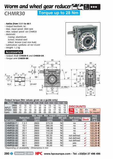
280 www.hpceurope.com - Tel: +33(0)4 37 496 496Volume 2 2016
Torque up to 28 NmCHMR30Worm and wheel gear reducer
Part numberReduction
ratio
Max. input speed(rpm)
Max. output speed(rpm)
Efficiency at 900 rpm
(%)Self locking
output
Price each1 to 5
- Ratios from 7.5:1 to 80:1- Output backlash: NC- Max. input speed: 2800 rpm- Max. output speed: see CHMR30- Materials:
Casing: aluminiumScrews: treated steelWheel: bronze (cast iron hub)
- Lubrication: synthetic oil ISO VG320- Weight: 1.2 kg
.Accessories.- Output shaft CHM30-X and CHM30-DX- Torque arm CHM30-BR
Ø14H7
51
9j6
63
21
3
0°10,2
16,3
65
5
5,5
20 54
8040
75
21
(4) M6x11
6329 29
97
57
40
44
27
30
Ø6324456
55 h8
Output torque (Nm values given as a guide only)Ratios 7,5:1 10:1 15:1 20:1 25:1 30:1 40:1 50:1 60:1 80:1
2800 12 12 12 11 15 14 13 12 11 10INPUT 1400 17 17 17 17 20 19 17 16 15 12SPEED 900 19 19 19 19 22 20 19 17 16 14(rpm) 500 23 23 23 22 28 25 22 20 18 16
CHMR30-7 7,5:1 2800 373,33 NC no 4 122,29 FCHMR30-10 10:1 2800 280,00 NC no 4 122,29 FCHMR30-15 15:1 2800 186,66 NC no 4 122,29 FCHMR30-20 20:1 2800 140,00 NC no - 122,29 FCHMR30-25 25:1 2800 112,00 NC no 4 122,29 FCHMR30-30 30:1 2800 93,33 NC not defined - 122,29 FCHMR30-40 40:1 2800 70,00 NC not defined 4 122,29 FCHMR30-50 50:1 2800 56,00 NC not defined 4 122,29 FCHMR30-60 60:1 2800 46,66 NC yes 4 122,29 FCHMR30-80 80:1 2800 35,00 NC yes 4 122,29 F*Depending on availability - Dimensions in mm
Stock*
DISCOUNTSQty 1+ 6+ 20+ 40+
Disc. List -15% -20% On request
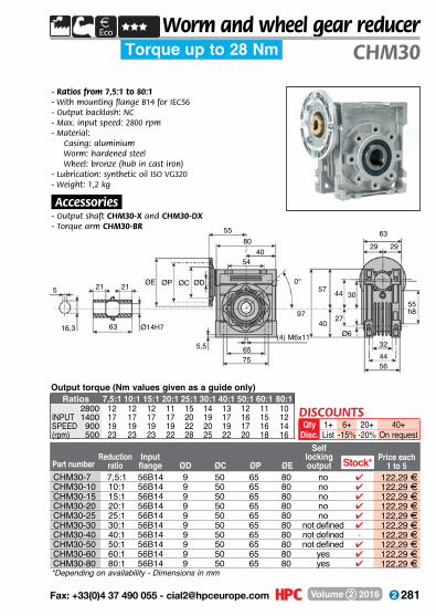
281 Fax: +33(0)4 37 490 055 - [email protected] Volume 2 2016
Torque up to 28 Nm CHM30Worm and wheel gear reducer
- Ratios from 7,5:1 to 80:1- With mounting flange B14 for IEC56- Output backlash: NC- Max. input speed: 2800 rpm- Material:
Casing: aluminium Worm: hardened steel Wheel: bronze (hub in cast iron)
- Lubrication: synthetic oil ISO VG320- Weight: 1,2 kg
.Accessories.- Output shaft CHM30-X and CHM30-DX- Torque arm CHM30-BR
Price each1 to 5
Ø14H7
55
21 0°
16,3
65(4) M6x11
ØD
5,5
54
8040
75
21 ØCØPØE
63
5
97
57
40
44
27
30
Ø6
6329 29
55 h8
324456
Part numberReduction
ratioInputflange ØD ØC ØP ØE
Self locking output
*Depending on availability - Dimensions in mm
Stock*
Output torque (Nm values given as a guide only)Ratios 7,5:1 10:1 15:1 20:1 25:1 30:1 40:1 50:1 60:1 80:1
2800 12 12 12 11 15 14 13 12 11 10INPUT 1400 17 17 17 17 20 19 17 16 15 12SPEED 900 19 19 19 19 22 20 19 17 16 14(rpm) 500 23 23 23 22 28 25 22 20 18 16
CHM30-7 7,5:1 56B14 9 50 65 80 no 4 122,29 FCHM30-10 10:1 56B14 9 50 65 80 no 4 122,29 FCHM30-15 15:1 56B14 9 50 65 80 no 4 122,29 FCHM30-20 20:1 56B14 9 50 65 80 no 4 122,29 FCHM30-25 25:1 56B14 9 50 65 80 no 4 122,29 FCHM30-30 30:1 56B14 9 50 65 80 not defined 4 122,29 FCHM30-40 40:1 56B14 9 50 65 80 not defined - 122,29 FCHM30-50 50:1 56B14 9 50 65 80 not defined 4 122,29 FCHM30-60 60:1 56B14 9 50 65 80 yes 4 122,29 FCHM30-80 80:1 56B14 9 50 65 80 yes 4 122,29 F
DISCOUNTSQty 1+ 6+ 20+ 40+
Disc. List -15% -20% On request
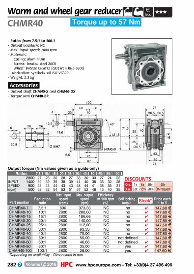
282 www.hpceurope.com - Tel: +33(0)4 37 496 496Volume 2 2016
Torque up to 57 NmCHMR40Worm and wheel gear reducer
Part numberReduction
ratio
Max. input speed(rpm)
Max. output speed(rpm)
Efficiency at 900 rpm
(%)Self locking
outputPrice each
1 to 5
6+-15%
40+On request
1+List.
Qty.Disc.
DISCOUNTS20+
-20%
- Ratios from 7.5:1 to 100:1- Output backlash: NC- Max. input speed: 2800 rpm- Materials:
Casing: aluminiumScrews: treated steel 20CRWheel: bronze CuSn12 (cast iron hub 6500)
- Lubrication: synthetic oil ISO VG320- Weight: 2.3 kg
.Accessories.- Output shaft CHM40-X and CHM40-DX- Torque arm CHM40-BR
Ø18H7
60
11j6
78
26
4
45°12,5
20,8
75
6
6,5
23 70
10050
87
26
(4)M6x8
7836,5 36,5
121,5
71,5
50
55
35
40
Ø6,5
43
6071
60 h8
Output torque (Nm values given as a guide only)Ratios 7,5:1 10:1 15:1 20:1 25:1 30:1 40:1 50:1 60:1 80:1 100:1
2800 27 26 30 28 27 33 30 30 27 24 22INPUT 1400 39 39 39 38 39 44 40 38 35 32 28SPEED 900 43 43 44 43 43 48 44 41 38 35 31(rpm) 500 52 52 54 53 51 57 52 48 45 40 35
CHMR40-7 7,5:1 800 373,33 NC no 4 147,60 FCHMR40-10 10:1 2800 280,00 NC no 4 147,60 FCHMR40-15 15:1 2800 186,66 NC no 4 147,60 FCHMR40-20 20:1 2800 140,00 NC no 4 147,60 FCHMR40-25 25:1 2800 112,00 NC no 4 147,60 FCHMR40-30 30:1 2800 93,33 NC no 4 147,60 FCHMR40-40 40:1 2800 70,00 NC no 4 147,60 FCHMR40-50 50:1 2800 56,00 NC not defined - 147,60 FCHMR40-60 60:1 2800 46,66 NC not defined 4 147,60 FCHMR40-80 80:1 2800 35,00 NC yes 4 147,60 FCHMR40-100 100:1 2800 28,00 NC yes 4 147,60 F
Stock*
*Depending on availability - Dimensions in mm
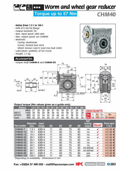
283 Fax: +33(0)4 37 490 055 - [email protected] Volume 2 2016
Torque up to 57 Nm CHM40Worm and wheel gear reducer
Price each1 to 5
6+-15%
40+On request
1+List.
Qty.Disc.
DISCOUNTS20+
-20%
- Ratios from 7.5:1 to 100:1- With B14 (IEC56) flange - Output backlash: NC- Max. input speed: 2800 rpm- Max. output speed: see CHMR40- Materials:
Casing: aluminiumScrews: treated steel 20CRWheel: bronze CuSn12 (cast iron hub G500)
- Lubrication: synthetic oil ISO VG320- Weight: 2.3 kg
.Accessories.- Output shaft CHM40-X and CHM40-DX- Torque arm CHM40-BR
Ø18H7
70
26 45°
20,8
75(4) M6x8
ØD
6,5
70
10050
87
26 ØCØPØE
78
6
121,5
71,5
50
55
35
40
Ø6,5
7836,5 36,5
60 h8
436071
Part numberReduction
ratioInputflange ØD ØC ØP ØE
Self locking output
*Depending on availability - Dimensions in mm
Output torque (Nm values given as a guide only)Ratios 7,5:1 10:1 15:1 20:1 25:1 30:1 40:1 50:1 60:1 80:1 100:1
2800 27 26 30 28 27 33 30 30 27 24 22INPUT 1400 39 39 39 38 39 44 40 38 35 32 28SPEED 900 43 43 44 43 43 48 44 41 38 35 31(rpm) 500 52 52 54 53 51 57 52 48 45 40 35
CHM40-7 7,5:1 63B14 11 60 75 90 no 4 147,60 FCHM40-10 10:1 63B14 11 60 75 90 no 4 147,60 FCHM40-15 15:1 63B14 11 60 75 90 no 4 147,60 FCHM40-20 20:1 63B14 11 60 75 90 no 4 147,60 FCHM40-25 25:1 63B14 11 60 75 90 no - 147,60 FCHM40-30 30:1 63B14 11 60 75 90 no 4 147,60 FCHM40-40 40:1 63B14 11 60 75 90 no 4 147,60 FCHM40-50 50:1 63B14 11 60 75 90 not defined 4 147,60 FCHM40-60 60:1 63B14 11 60 75 90 not defined 4 147,60 FCHM40-80 80:1 63B14 11 60 75 90 yes 4 147,60 FCHM40-100 100:1 63B14 11 60 75 90 yes 4 147,60 F
Stock*

284 www.hpceurope.com - Tel: +33(0)4 37 496 496Volume 2 2016
Worm and wheel gear reducer
Part numberReduction
ratio
Max. input speed(rpm)
Max. output speed(rpm)
Efficiency at 900 rpm
(%)Self locking
outputPrice each
1 to 5
6+-15%
40+On request
1+List.
Qty.Disc.
DISCOUNTS20+
-20%
- Ratios from 7.5:1 to 100:1- Output backlash: NC- Max. input speed: 2800 rpm- Materials:
Casing: aluminiumScrews: treated steel 20CRWheel: bronze CuSn12 (cast iron hub 6500)
- Lubrication: synthetic oil ISO VG320- Weight: 3.5 kg
.Accessories.- Output shaft CHM50-X and CHM50-DX- Torque arm CHM50-BR
M6
Ø25H7
74
14j6
92
30
5
45°16
28,3
85(4) M8x10
8
7
30 80
12060
100
30
144
84
60
64
40
50
Ø8,5
9243,5 43,5
70 h8
49
7085
CHMR50 Torque up to 107 Nm
Output torque (Nm values given as a guide only)Ratios 7,5:1 10:1 15:1 20:1 25:1 30:1 40:1 50:1 60:1 80:1 100:1
2800 51 53 56 52 51 63 58 52 49 44 39INPUT 1400 70 71 73 72 69 83 75 72 67 64 54SPEED 900 83 83 83 76 74 89 81 76 71 67 55(rpm) 500 102 102 102 92 90 107 97 90 82 74 64
CHMR50-7 7,5:1 2800 373,33 NC no 4 190,29 FCHMR50-10 10:1 2800 280,00 NC no 4 190,29 FCHMR50-15 15:1 2800 186,66 NC no 4 190,29 FCHMR50-20 20:1 2800 140,00 NC no 4 190,29 FCHMR50-25 25:1 2800 112,00 NC no - 190,29 FCHMR50-30 30:1 2800 93,33 NC no 4 190,29 FCHMR50-40 40:1 2800 70,00 NC no 4 190,29 FCHMR50-50 50:1 2800 56,00 NC not defined 4 190,29 FCHMR50-60 60:1 2800 46,66 NC not defined 4 190,29 FCHMR50-80 80:1 2800 35,00 NC yes 4 190,29 FCHMR50-100 100:1 2800 28,00 NC yes 4 190,29 F*Depending on availability - Dimensions in mm
Stock*
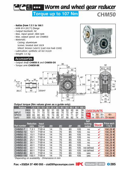
285 Fax: +33(0)4 37 490 055 - [email protected] Volume 2 2016
Torque up to 107 Nm CHM50Worm and wheel gear reducer
Price each1 to 5
6+-15%
40+On request
1+List.
Qty.Disc.
DISCOUNTS20+
-20%
- Ratios from 7.5:1 to 100:1- With B14 (IEC71) flange - Output backlash: NC- Max. input speed: 2800 rpm- Max. output speed: see CHMR50- Materials:
Casing: aluminiumScrews: treated steel 20CRWheel: bronze CuSn12 (cast iron hub G500)
- Lubrication: synthetic oil ISO VG320- Weight: 3.5 kg
.Accessories.- Output shaft CHM50-X and CHM50-DX- Torque arm CHM50-BR
Ø25H7
80
3045°
28,3
85(4) M8x10
ØD
7
80
12060
100
30 ØCØPØE
92
8
144
84
60
64
40
50
Ø8,5
9243,5 43,5
70 h8
49
7085
Part numberReduction
ratioInputflange ØD ØC ØP ØE
Self locking output
*Depending on availability - Dimensions in mm
Output torque (Nm values given as a guide only)Ratios 7,5:1 10:1 15:1 20:1 25:1 30:1 40:1 50:1 60:1 80:1 100:1
2800 51 53 56 52 51 63 58 52 49 44 39IMPUT 1400 70 71 73 72 69 83 75 72 67 64 54SPEED 900 83 83 83 76 74 89 81 76 71 67 55(rpm) 500 102 102 102 92 90 107 97 90 82 74 64
CHM50-7 7,5:1 71B14 14 70 85 105 no 4 190,29 FCHM50-10 10:1 71B14 14 70 85 105 no 4 190,29 FCHM50-15 15:1 71B14 14 70 85 105 no 4 190,29 FCHM50-20 20:1 71B14 14 70 85 105 no 4 190,29 FCHM50-25 25:1 71B14 14 70 85 105 no - 190,29 FCHM50-30 30:1 71B14 14 70 85 105 no 4 190,29 FCHM50-40 40:1 71B14 14 70 85 105 no 4 190,29 FCHM50-50 50:1 71B14 14 70 85 105 not defined 4 190,29 FCHM50-60 60:1 71B14 14 70 85 105 not defined 4 190,29 FCHM50-80 80:1 71B14 14 70 85 105 yes 4 190,29 FCHM50-100 100:1 71B14 14 70 85 105 yes 4 190,29 F
Stock*
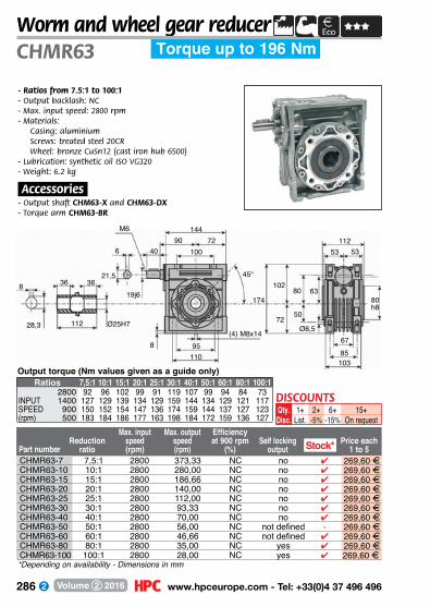
286 www.hpceurope.com - Tel: +33(0)4 37 496 496Volume 2 2016
Torque up to 196 NmCHMR63Worm and wheel gear reducer
Part numberReduction
ratio
Max. input speed(rpm)
Max. output speed(rpm)
Efficiency at 900 rpm
(%)Self locking
outputPrice each
1 to 5
2+-5%
15+On request
1+List.
Qty.Disc.
DISCOUNTS6+
-15%
- Ratios from 7.5:1 to 100:1- Output backlash: NC- Max. input speed: 2800 rpm- Materials:
Casing: aluminiumScrews: treated steel 20CRWheel: bronze CuSn12 (cast iron hub 6500)
- Lubrication: synthetic oil ISO VG320- Weight: 6.2 kg
.Accessories.- Output shaft CHM63-X and CHM63-DX- Torque arm CHM63-BR
M6
Ø25H7
90
19j6
112
36
6
45°21,5
28,3
95(4) M8x14
8
8
40 100
14472
110
36
174
102
72
80
50
63
Ø8,5
11253 53
80 h8
6785
103Output torque (Nm values given as a guide only)
Ratios 7,5:1 10:1 15:1 20:1 25:1 30:1 40:1 50:1 60:1 80:1 100:12800 92 96 102 99 91 119 107 99 94 84 73
INPUT 1400 127 129 139 134 129 159 144 134 129 121 117SPEED 900 150 152 154 147 136 174 159 144 137 127 123(rpm) 500 183 184 186 177 163 198 184 172 159 136 127
CHMR63-7 7,5:1 2800 373,33 NC no 4 269,60 FCHMR63-10 10:1 2800 280,00 NC no 4 269,60 FCHMR63-15 15:1 2800 186,66 NC no 4 269,60 FCHMR63-20 20:1 2800 140,00 NC no 4 269,60 FCHMR63-25 25:1 2800 112,00 NC no 4 269,60 FCHMR63-30 30:1 2800 93,33 NC no 4 269,60 FCHMR63-40 40:1 2800 70,00 NC no 4 269,60 FCHMR63-50 50:1 2800 56,00 NC not defined - 269,60 FCHMR63-60 60:1 2800 46,66 NC not defined 4 269,60 FCHMR63-80 80:1 2800 35,00 NC yes 4 269,60 FCHMR63-100 100:1 2800 28,00 NC yes 4 269,60 F*Depending on availability - Dimensions in mm
Stock*

287 Fax: +33(0)4 37 490 055 - [email protected] Volume 2 2016
Torque up to 196 Nm CHM63Worm and wheel gear reducer
Price each1 to 5
Ø25H7
95
36 45°
28,3
95(4) M8x14
ØD
8
100
14472
110
36 ØCØPØE
112
8
174
102
72
80
50
63
Ø8,5
11253 53
80 h8
6785103
Part numberReduction
ratioInputflange ØD ØC ØP ØE
Self locking output
*Depending on availability - Dimensions in mm
CHM63-7 7,5:1 80B14 19 80 100 120 no - 269,60 FCHM63-10 10:1 80B14 19 80 100 120 no - 269,60 FCHM63-15 15:1 80B14 19 80 100 120 no 4 269,60 FCHM63-20 20:1 80B14 19 80 100 120 no 4 269,60 FCHM63-25 25:1 80B14 19 80 100 120 no - 269,60 FCHM63-30 30:1 80B14 19 80 100 120 no 4 269,60 FCHM63-40 40:1 71B14 14 70 85 105 no 4 269,60 FCHM63-50 50:1 71B14 14 70 85 105 not defined 4 269,60 FCHM63-60 60:1 71B14 14 70 85 105 not defined 4 269,60 FCHM63-80 80:1 71B14 14 70 85 105 yes 4 269,60 FCHM63-100 100:1 71B14 14 70 85 105 yes 4 269,60 F
Stock*
Output torque (Nm values given as a guide only)Ratios 7,5:1 10:1 15:1 20:1 25:1 30:1 40:1 50:1 60:1 80:1 100:1
2800 92 96 102 99 91 119 107 99 94 84 73INPUT 1400 127 129 139 134 129 159 144 134 129 121 117SPEED 900 150 152 154 147 136 174 159 144 137 127 123(rpm) 500 183 184 186 177 163 198 184 172 159 136 127
2+-5%
15+On request
1+List.
Qty.Disc.
DISCOUNTS6+
-15%
- Ratios from 7.5:1 to 100:1- With B14 flange acc IEC80 for ratios 7.5:1 to 30:1- With B14 mounting flange acc IEC71 for ratios
7.5:1 to 30:1- Output backlash: NC- Max. input speed: 2800 rpm- Max. output speed: see CHMR63- Materials:
Casing: aluminiumScrews: treated steel 20CRWheel: bronze CuSn12 (cast iron hub G500)
- Lubrication: synthetic oil ISO VG320- Weight: 3.5 kg
.Accessories.- Output shaft CHM63-X and CHM63-DX- Torque arm CHM63-BR

288 www.hpceurope.com - Tel: +33(0)4 37 496 496Volume 2 2016
M8
Ø28H7
105
24j6
120
40
8
45°27
31,3
115(4) M8x14
8
10
50 120
17286
140
40
205
119
86
93
60
75
Ø11
12057 57
95 h8
7290
112
Torque up to 298 NmCHMR75Worm and wheel gear reducer
- Ratios from 7.5:1 to 100:1- Output backlash: NC- Max. input speed: 2800 rpm- Materials:
Casing: aluminiumScrews: treated steel 20CRWheel: bronze CuSn12 (cast iron hub 6500)
- Lubrication: synthetic oil ISO VG320- Weight: 8.5 kg
.Accessories.- Output shaft CHM75-X and CHM75-DX- Torque arm CHM75-BR
Max. input Max output EfficiencyReduction speed speed at 900 rpm Self locking
Part number ratio (rpm) (rpm) (%) output Price eachCHMR75-7 7,5:1 2800 373,33 NC no 4 360,09 FCHMR75-10 10:1 2800 280,00 NC no 4 360,09 FCHMR75-15 15:1 2800 186,66 NC no - 360,09 FCHMR75-20 20:1 2800 140,00 NC no 4 360,09 FCHMR75-25 25:1 2800 112,00 NC no 4 360,09 FCHMR75-30 30:1 2800 93,33 NC no 4 360,09 FCHMR75-40 40:1 2800 70,00 NC no 4 360,09 FCHMR75-50 50:1 2800 56,00 NC not defined 4 360,09 FCHMR75-60 60:1 2800 46,66 NC not defined 4 360,09 FCHMR75-80 80:1 2800 35,00 NC not defined 4 360,09 FCHMR75-100 100:1 2800 28,00 NC yes 4 360,09 F
Stock*
*Depending on availability - Dimensions in mm
Ratio 7,5:1 10:1 15:1 20:1 25:1 30:1 40:1 50:1 60:1 80:1 100:12800 129 144 148 158 148 119 168 146 144 129 118
INPUT 1400 184 194 198 209 198 159 228 209 198 188 178SPEED 900 214 228 234 234 214 174 258 218 209 198 186(rpm) 500 258 268 278 284 254 198 298 248 238 214 208
Output torque (Nm values given as a guide only)
DISCOUNTSQty 1+ 2+ 6+ 15+
Disc. List -5% -15% On request

289 Fax: +33(0)4 37 490 055 - [email protected] Volume 2 2016
Torque up to 298 Nm CHM75Worm and wheel gear reducer
Ø28H7
112,5
4045°
31,3
115(4)
M8x14
ØD
10
120
17286
140
40 ØCØPØE
120
8
205
119
86
93
60
75
Ø11
120
57 57
95 h8
7290
112
- Ratios from 7.5:1 to 100:1- With B14 flange acc IEC80 for ratios 7.5:1 to 15:1- With B14 mounting flange acc IEC71 for ratios
20:1 to 30:1- Output backlash: NC- Max. input speed: 2800 rpm- Max. output speed: see CHMR75- Materials:
Casing: aluminiumScrews: treated steel 20CRWheel: bronze CuSn12 (cast iron hub G500)
- Lubrication: synthetic oil ISO VG320- Weight: 8.5 kg
.Accessories.- Output shaft CHM75-X and CHM75-DX- Torque arm CHM75-BR
Part Reduction Input Irrever- Pricenumber ratio flange ØD ØC ØP ØE -sibility eachCHM75-7 7,5:1 90B14 24 95 115 140 no 4 360,09 FCHM75-10 10:1 90B14 24 95 115 140 no 4 360,09 FCHM75-15 15:1 90B14 24 95 115 140 no - 360,09 FCHM75-20 20:1 80B14 19 80 100 120 no - 360,09 FCHM75-25 25:1 80B14 19 80 100 120 no 4 360,09 FCHM75-30 30:1 80B14 19 80 100 120 no - 360,09 FCHM75-40 40:1 80B14 19 80 100 120 no 4 360,09 FCHM75-50 50:1 80B14 19 80 100 120 not defined 4 360,09 FCHM75-60 60:1 80B14 19 80 100 120 not defined 4 360,09 FCHM75-80 80:1 80B14 19 80 100 120 not defined 4 360,09 FCHM75-100 100:1 80B14 19 80 100 120 yes 4 360,09 F
Stock*
*Depending on availability - Dimensions in mm
Ratio 7,5:1 10:1 15:1 20:1 25:1 30:1 40:1 50:1 60:1 80:1 100:12800 129 144 148 158 148 119 168 146 144 129 118
INPUT 1400 184 194 198 209 198 159 228 209 198 188 178SPEED 900 214 228 234 234 214 174 258 218 209 198 186(rpm) 500 258 268 278 284 254 198 298 248 238 214 208
Output torque (Nm values given as a guide only)
DISCOUNTSQty 1+ 2+ 6+ 15+
Disc. List -5% -15% On request

290 www.hpceurope.com - Tel: +33(0)4 37 496 496Volume 2 2016
Worm and wheel gear reducer
- Ratios from 7.5:1 to 100:1- Output backlash: NC- Max. input speed: 2800 rpm- Materials:
Casing: aluminiumScrews: treated steel 20CRWheel: bronze CuSn12 (cast iron hub 6500)
- Lubrication: synthetic oil ISO VG320- Weight: 12 kg
.Accessories.- Output shaft CHM90-X and CHM90-DX- Torque arm CHM90-BR
M8
Ø35H7
125
24j6
140
45
8
45°27
38,3
130(4) M10x18
10
11
50 140
208103
160
45
238
135
103
102
70
90
Ø13
14067 67
110 h8
74100130
CHMR90 Torque up to 540 Nm
Max. input Max output Efficiency SelfReduction speed speed at 900 rpm locking
Part number ratio (rpm) (rpm) (%) output Price eachCHMR90-7 7,5:1 2800 373,33 NC No 4 469,97 FCHMR90-10 10:1 2800 280,00 NC No 4 469,97 FCHMR90-15 15:1 2800 186,66 NC No 4 469,97 FCHMR90-20 20:1 2800 140,00 NC No 4 469,97 FCHMR90-25 25:1 2800 112,00 NC No - 469,97 FCHMR90-30 30:1 2800 93,33 NC No 4 469,97 FCHMR90-40 40:1 2800 70,00 NC No 4 469,97 FCHMR90-50 50:1 2800 56,00 NC No 4 469,97 FCHMR90-60 60:1 2800 46,66 NC not defined 4 469,97 FCHMR90-80 80:1 2800 35,00 NC not defined 4 469,97 FCHMR90-100 100:1 2800 28,00 NC Yes 4 469,97 F
Stock*
*Depending on availability - Dimensions in mm
Output torque (Nm values given as a guide only)Ratio 7,5:1 10:1 15:1 20:1 25:1 30:1 40:1 50:1 60:1 80:1 100:1
2800 208 234 258 258 248 308 274 264 244 224 198INPUT 1400 288 308 358 354 338 408 358 338 318 284 268SPEED 900 338 368 418 388 368 458 408 388 346 314 278(rpm) 500 408 434 438 468 438 540 478 448 398 364 328
DISCOUNTSQty 1+ 2+ 6+ 15+
Disc. List -5% -15% On request
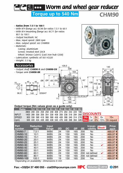
291 Fax: +33(0)4 37 490 055 - [email protected] Volume 2 2016
Ø35H7
129,5
4545°
38,3
130(4) M10x18
ØD
11
140
208103
160
45 ØCØPØE
140
10
238
135
103
102
70
90
Ø13
14067 67
110 h8
74100130
Torque up to 540 Nm CHM90Worm and wheel gear reducer
- Ratios from 7.5:1 to 100:1- With B14 flange acc IEC90 for ratios 7.5:1 to 60:1- With B14 mounting flange acc IEC71 for ratios
80:1 to 100:1- Output backlash: NC- Max. input speed: 2800 rpm- Max. output speed: see CHMR90- Materials:
Casing: aluminiumScrews: treated steel 20CRWheel: bronze CuSn12 (cast iron hub G500)
- Lubrication: synthetic oil ISO VG320- Weight: 3.5 kg
.Accessories.- Output shaft CHM90-X and CHM90-DX- Torque arm CHM90-BR
Part Reduction Input Irrever- Pricenumber ratio flange ØD ØC ØP ØE -sibility eachCHM90-7 7,5:1 90B5 24 130 165 200 No - 469,97 FCHM90-10 10:1 90B5 24 130 165 200 No - 469,97 FCHM90-15 15:1 90B5 24 130 165 200 No - 469,97 FCHM90-20 20:1 90B5 24 130 165 200 No - 469,97 FCHM90-25 25:1 90B5 24 130 165 200 No - 469,97 FCHM90-30 30:1 90B5 24 130 165 200 No 4 469,97 FCHM90-40 40:1 90B5 24 130 165 200 No - 469,97 FCHM90-50 50:1 90B5 24 130 165 200 No - 469,97 FCHM90-60 60:1 90B5 24 130 165 200 not defined 4 469,97 FCHM90-80 80:1 80B5 19 130 165 200 not defined - 469,97 FCHM90-100 100:1 80B5 19 130 165 200 Yes - 469,97 F
Stock*
*Depending on availability - Dimensions in mm
Output torque (Nm values given as a guide only)Ratio 7,5:1 10:1 15:1 20:1 25:1 30:1 40:1 50:1 60:1 80:1 100:1
2800 208 234 258 258 248 308 274 264 244 224 198INPUT 1400 288 308 358 354 338 408 358 338 318 284 268SPEED 900 338 368 418 388 368 458 408 388 346 314 278(rpm) 500 408 434 438 468 438 540 478 448 398 364 328
DISCOUNTSQty 1+ 2+ 6+ 15+
Disc. List -5% -15% On request
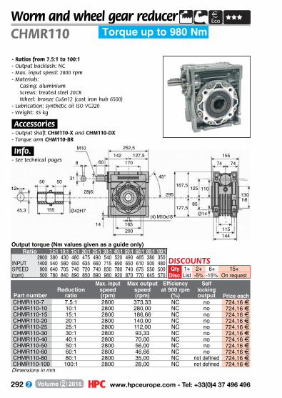
292 www.hpceurope.com - Tel: +33(0)4 37 496 496Volume 2 2016
M10
Ø42H7
142
28j6
155
50
8
45°31
45,3
165(4) M10x18
14
60 170
252,5127,5
200
50
295
167,5
127,5
125
85
110
Ø14
15574 74
130 h8
-115144
Torque up to 980 NmCHMR110Worm and wheel gear reducer
12
- Ratios from 7.5:1 to 100:1- Output backlash: NC- Max. input speed: 2800 rpm- Materials:
Casing: aluminiumScrews: treated steel 20CRWheel: bronze CuSn12 (cast iron hub 6500)
- Lubrication: synthetic oil ISO VG320- Weight: 35 kg
.Accessories.- Output shaft CHM110-X and CHM110-DX- Torque arm CHM110-BR
.Info..- �See technical pages
Max. input Max output Efficiency SelfReduction speed speed at 900 rpm locking
Part number ratio (rpm) (rpm) (%) output Price eachCHMR110-7 7,5:1 2800 373,33 NC no 724,16 FCHMR110-10 10:1 2800 280,00 NC no 724,16 FCHMR110-15 15:1 2800 186,66 NC no 724,16 FCHMR110-20 20:1 2800 140,00 NC no 724,16 FCHMR110-25 25:1 2800 112,00 NC no 724,16 FCHMR110-30 30:1 2800 93,33 NC no 724,16 FCHMR110-40 40:1 2800 70,00 NC no 724,16 FCHMR110-50 50:1 2800 56,00 NC no 724,16 FCHMR110-60 60:1 2800 46,66 NC no 724,16 FCHMR110-80 80:1 2800 35,00 NC not defined 724,16 FCHMR110-100 100:1 2800 28,00 NC not defined 724,16 FDimensions in mm
Output torque (Nm values given as a guide only)Ratio 7,5:1 10:1 15:1 20:1 25:1 30:1 40:1 50:1 60:1 80:1 100:1
2800 380 430 480 475 490 540 520 490 465 380 350INPUT 1400 540 580 650 635 660 715 690 650 610 505 480SPEED 900 640 705 740 720 740 830 780 740 675 550 500(rpm) 500 780 840 890 850 890 980 920 870 770 645 570
DISCOUNTSQty 1+ 2+ 6+ 15+
Disc. List -5% -15% On request

293 Fax: +33(0)4 37 490 055 - [email protected] Volume 2 2016
Torque up to 980 Nm CHM110Worm and wheel gear reducer
160
45°
165(4) M10x18
ØD
14
170
252,5127,5
200
ØCØPØE
Ø42H7
50
45,3
50
155
12
295
167,5
127,5
125
85
110
Ø14
155
74 74
130 h8
-115144
Part Reduction Input Irrever-number ratio flange ØD ØC ØP ØE -sibility Price eachCHM110-7 7,5:1 100/112B5 28 180 215 250 no 724,16 FCHM110-10 10:1 100/112B5 28 180 215 250 no 724,16 FCHM110-15 15:1 100/112B5 28 180 215 250 no 724,16 FCHM110-20 20:1 100/112B5 28 180 215 250 no 724,16 FCHM110-25 25:1 100/112B5 28 180 215 250 no 724,16 FCHM110-30 30:1 100/112B5 28 180 215 250 no 724,16 FCHM110-40 40:1 100/112B5 28 180 215 250 no 724,16 FCHM110-50 50:1 100/112B5 28 180 215 250 no 724,16 FCHM110-60 60:1 100/112B5 28 180 215 250 no 724,16 FCHM110-80 80:1 90B5 24 130 165 200 not defined 724,16 FCHM110-100 100:1 90B5 24 130 165 200 not defined 724,16 F
- Ratios from 7.5:1 to 100:1- With B14 flange acc IEC100/112 for ratios 7.5:1 to 60:1- With B14 mounting flange acc IEC90 for ratios 80:1 to 100:1- Output backlash: NC- Max. input speed: 2800 rpm- Max. output speed: see CHMR110- Materials:
Casing: aluminiumScrews: treated steel 20CRWheel: bronze CuSn12 (cast iron hub G500)
- Lubrication: synthetic oil ISO VG320- Weight: 35 kg
.Accessories.- Output shaft CHM63-X and CHM63-DX- Torque arm CHM63-BR
.Info..- �See technical pages
Dimensions in mm
Output torque (Nm values given as a guide only)Ratio 7,5:1 10:1 15:1 20:1 25:1 30:1 40:1 50:1 60:1 80:1 100:1
2800 380 430 480 475 490 540 520 490 465 380 350INPUT 1400 540 580 650 635 660 715 690 650 610 505 480SPEED 900 640 705 740 720 740 830 780 740 675 550 500(rpm) 500 780 840 890 850 890 980 920 870 770 645 570
DISCOUNTSQty 1+ 2+ 6+ 15+
Disc. List -5% -15% On request

294 www.hpceurope.com - Tel: +33(0)4 37 496 496Volume 2 2016
For CHM and CHMR gear gearboxesCHMbr
Reaction arm
- Mounts directly on the output side of the CHM and CHMR gear gearboxes
- The mounting point of the reaction arm is equipped with an anti-vibration bearing
*Depending on availability - Dimensions in mm
R
ØP
B L
ØC
A
Ød
F
ØE
H
Weight Price each Part number L R F H ØE A B ØC ØD ØP (kg) 1 to 5CHM30-BR 85 15 24,0 14 8 38 138 65 7 55 0,18 4 9,00 FCHM40-BR 100 18 31,5 14 10 44 162 75 7 60 0,24 4 9,56 FCHM50-BR 100 18 38,5 14 10 50 168 85 9 70 0,27 4 10,45 FCHM63-BR 150 18 49,0 14 10 55 223 95 9 80 0,57 4 13,35 FCHM75-BR 200 30 47,5 25 20 70 300 115 9 95 1,10 4 20,03 FCHM90-BR 200 30 57,5 25 20 80 310 130 11 110 1,26 4 28,49 FCHM110-BR 250 35 62,0 30 25 100 385 165 11 130 1,92 - 37,90 F
DISCOUNTS BQty 1+ 2+ 6+ 15+
Disc. List -5% -15% On request
DISCOUNTS A
Qty 1+ 6+ 20+ 40+Disc. List -15% -20% On request
Stock*AAAABBB
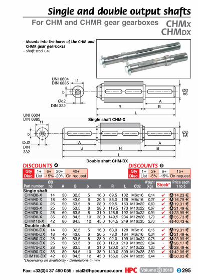
295 Fax: +33(0)4 37 490 055 - [email protected] Volume 2 2016
Part numberØDh6 A B b t1 R L Ød2
Weight(kg)
Price each1 to 5
For CHM and CHMR gear gearboxes CHMxCHMdx
Single and double output shafts
b
Ød2DIN 332 R B
t1
ØD h6
A
L
- Mounts into the bores of the CHM and CHMR gear gearboxes
- Shaft steel C40
Single shaft CHM-X
UNI 6604DIN 6885
b
UNI 6604DIN 6885
Double shaft CHM-DX
Ød2DIN 332
t1
ØD h6
A AB BR
L
*Depending on availability - Dimensions in mm
Stock*Single shaftCHM30-X 14 30 32,5 5 16,0 69,5 102 M6x16 0,14 4 14,23 FCHM40-X 18 40 43,0 6 20,5 85,0 128 M6x16 0,27 4 16,79 FCHM50-X 25 50 53,5 8 28,0 99,5 153 M10x22 0,60 4 19,31 FCHM63-X 25 50 53,5 8 28,0 119,5 173 M10x22 0,67 4 21,49 FCHM75-X 28 60 63,5 8 31,0 128,5 192 M10x22 0,94 4 23,99 FCHM90-X 35 80 84,5 10 38,0 149,5 234 M12x28 1,79 4 35,73 FCHM110-X 42 80 84,5 12 45,0 164,5 249 M16x35 2,70 - 40,43 FDouble shaftCHM30-DX 14 30 32,5 5 16,0 63,0 128 M6x16 0,16 4 19,31 FCHM40-DX 18 40 43,0 6 20,5 78,0 164 M6x16 0,34 4 21,49 FCHM50-DX 25 50 53,5 8 28,0 92,0 199 M10x22 0,75 4 23,99 FCHM63-DX 25 50 53,5 8 28,0 112,0 219 M10x22 0,84 - 26,17 FCHM75-DX 28 60 63,5 8 31,0 120,0 247 M10x22 1,20 4 28,49 FCHM90-DX 35 80 84,5 10 38,0 140,0 309 M12x28 2,50 4 42,06 FCHM110-DX 42 80 84,5 12 45,0 155,0 324 M16x35 3,44 - 50,03 F
AAAABBB
AAAABBB
DISCOUNTS BQty 1+ 2+ 6+ 15+
Disc. List -5% -15% On request
DISCOUNTS A
Qty 1+ 6+ 20+ 40+Disc. List -15% -20% On request
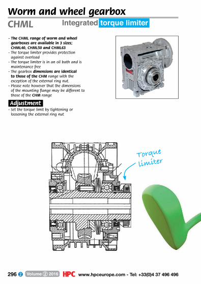
296 www.hpceurope.com - Tel: +33(0)4 37 496 496Volume 2 2016
Integrated torque limiterCHML- The CHML range of worm and wheel
gearboxes are available in 3 sizes; CHML40, CHML50 and CHML63
- The torque limiter provides protection against overload
- The torque limiter is in an oil bath and is maintenance free
- The gearbox dimensions are identical to those of the CHM range with the exception of the external ring nut.
- Please note however that the dimensions of the mounting flange may be different to those of the CHM range
.Adjustment.- Set the torque limit by tightening or
loosening the external ring nut
Worm and wheel gearbox
Torque
limiter
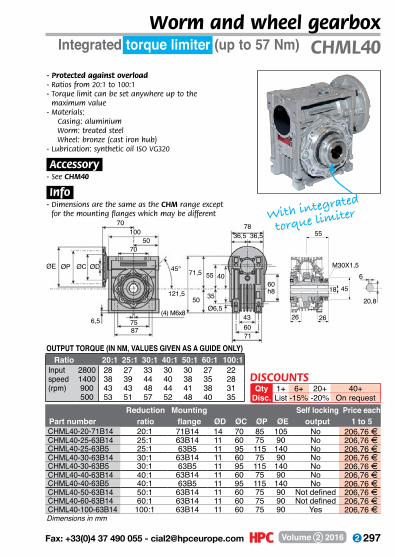
297 Fax: +33(0)4 37 490 055 - [email protected] Volume 2 2016
45°
(4) M6x86,5 75
87
ØDØCØPØE
70
70
100
121,5
36,578
36,5
71,5
50 35
55 40
50
Ø6,5
60h8
436071
Integrated torque limiter (up to 57 Nm)
Reduction Mounting Self locking Price eachPart number ratio flange ØD ØC ØP ØE output 1 to 5CHML40-20-71B14 20:1 71B14 14 70 85 105 No 206,76 FCHML40-25-63B14 25:1 63B14 11 60 75 90 No 206,76 FCHML40-25-63B5 25:1 63B5 11 95 115 140 No 206,76 FCHML40-30-63B14 30:1 63B14 11 60 75 90 No 206,76 FCHML40-30-63B5 30:1 63B5 11 95 115 140 No 206,76 FCHML40-40-63B14 40:1 63B14 11 60 75 90 No 206,76 FCHML40-40-63B5 40:1 63B5 11 95 115 140 No 206,76 FCHML40-50-63B14 50:1 63B14 11 60 75 90 Not defined 206,76 FCHML40-60-63B14 60:1 63B14 11 60 75 90 Not defined 206,76 FCHML40-100-63B14 100:1 63B14 11 60 75 90 Yes 206,76 F
OUTPUT TORQUE (IN NM, VALUES GIVEN AS A GUIDE ONLY) Ratio 20:1 25:1 30:1 40:1 50:1 60:1 100:1Input 2800 28 27 33 30 30 27 22speed 1400 38 39 44 40 38 35 28(rpm) 900 43 43 48 44 41 38 31
500 53 51 57 52 48 40 35
CHML40
Dimensions in mm
- Protected against overload- Ratios from 20:1 to 100:1- Torque limit can be set anywhere up to the
maximum value- M aterials:
Casing: aluminium Worm: treated steel Wheel: bronze (cast iron hub)
- Lubrication: synthetic oil ISO VG320
.Accessory.- See CHM40
.Info.- Dimensions are the same as the CHM range except
for the mounting flanges which may be different With integrated
torque limiter
6+-15%
20+-20%
40+On request
1+List
DISCOUNTSQty
Disc.
Worm and wheel gearbox
55
18 45
2626
M30X1,56
20,8
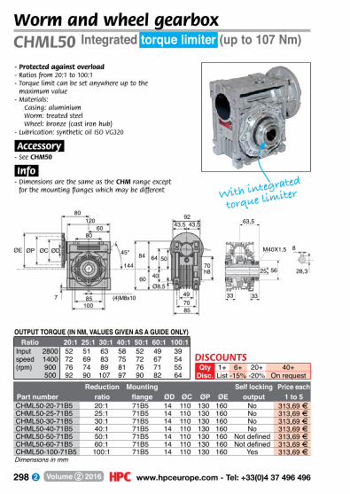
298 www.hpceurope.com - Tel: +33(0)4 37 496 496Volume 2 2016
Integrated torque limiter (up to 107 Nm)
Reduction Mounting Self locking Price eachPart number ratio flange ØD ØC ØP ØE output 1 to 5CHML50-20-71B5 20:1 71B5 14 110 130 160 No 313,69 FCHML50-25-71B5 25:1 71B5 14 110 130 160 No 313,69 FCHML50-30-71B5 30:1 71B5 14 110 130 160 No 313,69 FCHML50-40-71B5 40:1 71B5 14 110 130 160 No 313,69 FCHML50-50-71B5 50:1 71B5 14 110 130 160 Not defined 313,69 FCHML50-60-71B5 60:1 71B5 14 110 130 160 Not defined 313,69 FCHML50-100-71B5 100:1 71B5 14 110 130 160 Yes 313,69 F
OUTPUT TORQUE (IN NM, VALUES GIVEN AS A GUIDE ONLY) Ratio 20:1 25:1 30:1 40:1 50:1 60:1 100:1Input 2800 52 51 63 58 52 49 39speed 1400 72 69 83 75 72 67 54(rpm) 900 76 74 89 81 76 71 55
500 92 90 107 97 90 82 64
CHML50
Dimensions in mm
- Protected against overload- Ratios from 20:1 to 100:1- Torque limit can be set anywhere up to the
maximum value- M aterials:
Casing: aluminium Worm: treated steel Wheel: bronze (cast iron hub)
- Lubrication: synthetic oil ISO VG320
.Accessory.- See CHM50
.Info.- Dimensions are the same as the CHM range except
for the mounting flanges which may be different
Worm and wheel gearbox
With integrated
torque limiter
45°
(4)M8x107 85100
ØDØCØPØE
80120
144
43,5 43,592
84
60 40
64 50
6080
Ø8,5
70h8
497085
8
28,3
63,5
25 56
3333
M40X1,5
6+-15%
20+-20%
40+On request
1+List
DISCOUNTSQty
Disc.
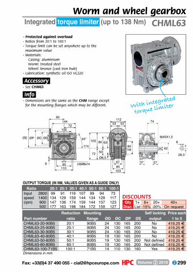
299 Fax: +33(0)4 37 490 055 - [email protected] Volume 2 2016
Integrated torque limiter (up to 138 Nm)
Reduction Mounting Self locking Price eachPart number ratio flange ØD ØC ØP ØE output 1 to 5CHML63-20-90B5 20:1 90B5 24 130 165 200 No 419,25 FCHML63-25-90B5 25:1 90B5 24 130 165 200 No 419,25 FCHML63-30-90B5 30:1 90B5 24 130 165 200 No 419,25 FCHML63-40-80B5 40:1 80B5 19 130 165 200 No 419,25 FCHML63-50-80B5 50:1 80B5 19 130 165 200 Not defined 419,25 FCHML63-60-80B5 60:1 80B5 19 130 165 200 Not defined 419,25 FCHML63-100-71B5 100:1 71B5 14 110 130 160 Yes 419,25 F
OUTPUT TORQUE (IN NM, VALUES GIVEN AS A GUIDE ONLY) Ratio 20:1 25:1 30:1 40:1 50:1 60:1 100:1Input 2800 99 91 119 107 99 94 73speed 1400 134 129 159 144 134 129 117(rpm) 900 147 136 174 159 144 137 123
500 177 163 198 184 172 159 127
CHML63
Dimensions in mm
- Protected against overload- Ratios from 20:1 to 100:1- Torque limit can be set anywhere up to the
maximum value- M aterials:
Casing: aluminium Worm: treated steel Wheel: bronze (cast iron hub)
- Lubrication: synthetic oil ISO VG320
.Accessory.- See CHM63
.Info.- Dimensions are the same as the CHM range except
for the mounting flanges which may be different.
Worm and wheel gearbox
With integrated
torque limiter
45°
(4)M8x148 95110
ØDØCØPØE
95144
174
53112
53
102
72 50
80 63
72100
Ø8,5
80h8
6785103
74
25 62
3737
M45X1,58
28,3
6+-15%
20+-20%
40+On request
1+List
DISCOUNTSQty
Disc.
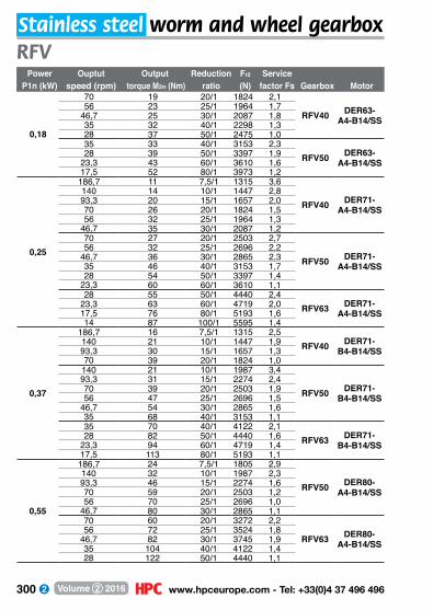
300 www.hpceurope.com - Tel: +33(0)4 37 496 496Volume 2 2016
Power Ouptut Output Reduction Fr2 ServiceP1n (kW) speed (rpm) torque M2n (Nm) ratio (N) factor Fs Gearbox Motor
0,18
70 19 20/1 1824 2,1
RFV40 DER63-A4-B14/SS
56 23 25/1 1964 1,746,7 25 30/1 2087 1,835 32 40/1 2298 1,328 37 50/1 2475 1,035 33 40/1 3153 2,3
RFV50 DER63-A4-B14/SS
28 39 50/1 3397 1,923,3 43 60/1 3610 1,617,5 52 80/1 3973 1,2
0,25
186,7 11 7,5/1 1315 3,6
RFV40 DER71-A4-B14/SS
140 14 10/1 1447 2,893,3 20 15/1 1657 2,070 26 20/1 1824 1,556 32 25/1 1964 1,3
46,7 35 30/1 2087 1,270 27 20/1 2503 2,7
RFV50 DER71-A4-B14/SS
56 32 25/1 2696 2,246,7 36 30/1 2865 2,335 46 40/1 3153 1,728 54 50/1 3397 1,4
23,3 60 60/1 3610 1,128 55 50/1 4440 2,4
RFV63 DER71-A4-B14/SS
23,3 63 60/1 4719 2,017,5 76 80/1 5193 1,614 87 100/1 5595 1,4
0,37
186,7 16 7,5/1 1315 2,5RFV40 DER71-
B4-B14/SS140 21 10/1 1447 1,993,3 30 15/1 1657 1,370 39 20/1 1824 1,0
140 21 10/1 1987 3,4
RFV50 DER71-B4-B14/SS
93,3 31 15/1 2274 2,470 39 20/1 2503 1,956 47 25/1 2696 1,5
46,7 54 30/1 2865 1,635 68 40/1 3153 1,135 70 40/1 4122 2,1
RFV63 DER71-B4-B14/SS
28 82 50/1 4440 1,623,3 94 60/1 4719 1,417,5 113 80/1 5193 1,1
0,55
186,7 24 7,5/1 1805 2,9
RFV50 DER80-A4-B14/SS
140 32 10/1 1987 2,393,3 46 15/1 2274 1,670 59 20/1 2503 1,256 70 25/1 2696 1,0
46,7 80 30/1 2865 1,170 60 20/1 3272 2,2
RFV63 DER80-A4-B14/SS
56 72 25/1 3524 1,846,7 82 30/1 3745 1,935 104 40/1 4122 1,428 122 50/1 4440 1,1
RFVStainless steel worm and wheel gearbox

301 Fax: +33(0)4 37 490 055 - [email protected] Volume 2 2016
Motor and gearbox selection table
Radial load
Power Output Output torque Reduction Fr2 ServiceP1n (kW) speed (rpm) M2n (Nm) Ratio (N) factor Fs Gearbox Motor
0,75
186,7 33 7,5/1 1805 2,1RFV50 DER80-
B4-B14/SS140 43 10/1 1987 1,793,3 62 15/1 2274 1,293,3 63 15/1 2973 2,2
RFV63 DER80-B4-B14/SS
70 82 20/1 3272 1,656 98 25/1 3524 1,3
46,7 112 30/1 3745 1,435 141 40/1 4122 1,0
1,1186,7 50 7,5/1 2359 2,6
RFV63 DER90-S4-B14/SS
140 65 10/1 2597 2,093,3 92 15/1 2973 1,570 120 20/1 3272 1,1
1,5186,7 68 7,5/1 2359 1,9
RFV63 DER90-L4-B14/SS140 88 10/1 2597 1,5
93,3 126 15/1 2973 1,1
RFV
RFVUse the following formula to calculate the radial load:Where: Fr radial load (N) M Shaft torque (Nm) do Diameter of the transmission element (mm) Fz Transmission factor (see table)
Use the following formula to calculate the maximum permissible radial load on the shaft:Where: Fr2 Allowable radial load (x=L/2), see table (N) a, b are constant, see table x distance at which load is applied (mm)
Transmission Factor Factorelement Fz M2n (Nm)Gear 1,00 >=17 teeth
1,15 <17 teethChain sprocket
1,00 >=20 teeth1,25 <20 teeth1,40 <13 teeth
Belt pulley 1,75 Depends on tensionSynchronous pulley 2,50 Depends on tension
RFV40 RFV50 RFV63a 84 101 120b 64 76 95Fr2 max (N) 3490 4840 6270
Fr2
Fxl
LL/2
X
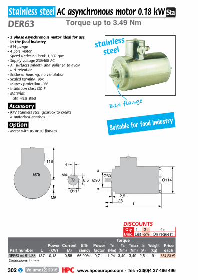
302 www.hpceurope.com - Tel: +33(0)4 37 496 496Volume 2 2016
Torque up to 3.49 Nm
TorquePower Current Effi- Power Tn Ts Tmax Is Weight Price
Part number L (kW) (A) ciency factor (Nm) (Nm) (Nm) (A) (kg) eachDER63-A4-B14/SS 137 0,18 0,58 66,90% 0,71 1,24 3,49 3,49 2,5 9 554,23 F
DER63
2+-5%
4+On request
1+List
QtyDisc.
DISCOUNTS
Stainless steel AC asynchronous motor 0.18 kW
- 3 phase asynchronous motor ideal for use in the food industry
- B14 flange- 4 pole motor- Speed under no load: 1,500 rpm- Supply voltage 230/400 AC- All surfaces smooth and polished to avoid
dirt retention- Enclosed housing, no ventilation- Sealed terminal box- Ingress protection IP66- Insulation class ISO F- M aterial:
Stainless steel
.Accessory.- RFV Stainless steel gearbox to create
a motorised gearbox
.Option.- Motor with B5 or B3 flanges
Dimensions in mm
B14 flange
stainless
steel
Suitable for food industry
Ø75
118
M5
M4
4
8,5
Ø11
Ø90Ø60
232,5
L
Ø114
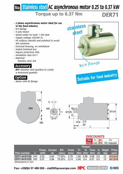
303 Fax: +33(0)4 37 490 055 - [email protected] Volume 2 2016
Torque up to 6.37 Nm
TorquePower Current Effi- Power Tn Ts Tmax Is Weight Price
Part number L (kW) (A) ciency factor (Nm) (Nm) (Nm) (A) (kg) eachDER71-A4-B14/SS 243 0,25 0,64 77,50% 0,76 1,65 3,58 3,58 3,0 12 610,55 FDER71-B4-B14/SS 253 0,37 0,96 79,20% 0,74 2,46 6,4 6,37 5,0 13 647,09 F
DER71Stainless steel AC asynchronous motor 0.25 to 0.37 kW
- 3 phase asynchronous motor ideal for use in the food industry
- B14 flange- 4 pole motor- Speed under no load: 1,500 rpm- Supply voltage 230/400 AC- All surfaces smooth and polished to avoid
dirt retention- Enclosed housing, no ventilation- Sealed terminal box- Ingress protection IP66- Insulation class ISO F- M aterial:
Stainless steel 304
.Accessory.- RFV Stainless steel gearbox to create
a motorised gearbox
.Option.- Motor with B5 flange
Dimensions in mm
B14 flange
2+-5%
4+On request
1+List
QtyDisc.
DISCOUNTS
stainless
steel
Suitable for food industry
Ø85
129
M6
M5
5
11
Ø14
Ø105Ø70
302,5
L
Ø134

304 www.hpceurope.com - Tel: +33(0)4 37 496 496Volume 2 2016
Torque up to 17.46 Nm
TorquePower Current Effi- Power Tn Ts Tmax Is Weight Price
Part number L (kW) (A) ciency factor (Nm) (Nm) (Nm) (A) (kg) eachDER80-A4-B14/SS 308 0,55 1,33 84,20% 0,75 3,62 10,50 10,50 8,10 18,9 756,76 FDER80-B4-B14/SS 348 0,75 1,81 85,20% 0,74 4,91 17,46 17,46 12,59 21,0 849,64 F
DER80Stainless steel AC asynchronous motor 0.55 to 0.75 kW
- 3 phase asynchronous motor ideal for use in the food industry
- B14 flange- 4 pole motor- Speed under no load: 1,500 rpm- Supply voltage 230/400 AC- All surfaces smooth and polished to
avoid dirt retention- Enclosed housing, no ventilation- Sealed terminal box- Ingress protection IP66- Insulation class ISO F- M aterial:
Stainless steel
.Accessory.- RFV Stainless steel gearbox to create
a motorised gearbox
.Option.- Motor with B5 flange
Dimensions in mm
2+-5%
4+On request
1+List
QtyDisc.
DISCOUNTS
B14 flange
stainless
steel
Suitable for food industry
Ø100
135
M6
M6
6
15,5
Ø19
Ø120Ø80
403
L
Ø144

305 Fax: +33(0)4 37 490 055 - [email protected] Volume 2 2016
Ø140 Ø95
503
L
Ø176Ø115
148
M8
M8
8
20
Ø24
Torque up to 33 Nm
TorquePower Current Effi- Power Tn Ts Tmax Is Weight Price
Part number L (kW) (A) ciency factor (Nm) (Nm) (Nm) (A) (kg) eachDER90-S4-B14/SS 351 1,1 2,45 84,30% 0,81 7,35 20,08 20,08 15,20 23,9 1 203,32 FDER90-L4-B14/SS 367 1,5 3,3 85,10% 0,81 9,93 33,00 33,00 23,50 28,9 1 274,45 F
DER90Stainless steel AC asynchronous motor 1.1 to 1.5 kW
- 3 phase asynchronous motor ideal for use in the food industry
- B14 flange- 4 pole motor- Speed under no load: 1,500 rpm- Supply voltage 230/400 AC- All surfaces smooth and polished to
avoid dirt retention- Enclosed housing, no ventilation- Sealed terminal box- Ingress protection IP66- Insulation class ISO F- M aterial:
Stainless steel
.Accessory.- RFV Stainless steel gearbox to create
a motorised gearbox
.Option.- Motor with B5 flange
Dimensions in mm
2+-5%
4+On request
1+List
QtyDisc.
DISCOUNTS
B14 flange
stainless
steel
Suitable for food industry

306 www.hpceurope.com - Tel: +33(0)4 37 496 496Volume 2 2016
Torque up to 47 Nm
Part number Reduction Self locking Price63B14 flange 71B14 flange ratio output each
RFV40-7.5-63B14/SS RFV40-7,5-71B14/SS 7,5 No 575,96 FRFV40-10-63B14/SS RFV40-10-71B14/SS 10 No 575,96 FRFV40-15-63B14/SS RFV40-15-71B14/SS 15 No 575,96 FRFV40-20-63B14/SS RFV40-20-71B14/SS 20 Not defined 575,96 FRFV40-25-63B14/SS RFV40-25-71B14/SS 25 Not defined 575,96 FRFV40-30-63B14/SS RFV40-30-71B14/SS 30 Yes 575,96 FRFV40-40-63B14/SS RFV40-40-71B14/SS 40 Yes 575,96 FRFV40-50-63B14/SS - 50 Yes 575,96 FRFV40-60-63B14/SS - 60 Yes 575,96 FRFV40-80-63B14/SS - 80 Yes 575,96 FRFV40-100-63B14/SS - 100 Yes 575,96 F
RFV40Stainless steel worm and wheel gearbox
- Gearbox especially suitable for use in the food industry
- Ratios from 7.5:1 to 100:1- B14 flange- All surfaces smooth and polished to avoid dirt retention- Lubricated using food quality grease- Working temperature: -20° to +40 °C- M aterial:
316 stainless steel housing
.Accessories.- Use with a DER 4 pole motor to create a motorised gearbox- Torque arm, mounting feet and protective covers
.Info.- All information is engraved directly on to gearbox
rather than being on a tag plate to avoid accumulating dirt etc
Dimensions in mm
FLANGE DIMENSIONSØD ØP ØM ØN
63B14 flange 11 90 75 6071B14 flange 14 105 85 70
2+-5%
4+On request
1+List
QtyDisc.
DISCOUNTS
78
Ø18
53,5
6
20,87360
52
40
70
ØP ØM ØN
ØD
75
123
(4)M6x8
9078
stainless
steel
Suitable for the food industry

307 Fax: +33(0)4 37 490 055 - [email protected] Volume 2 2016
Torque up to 80 Nm
Part number Reduction Self locking Price63B14 flange 71B14 flange 80B14 flange ratio output each
- RFV50-7,5-71B14/SS RFV50-7,5-80B14/SS 7,5 No 615,49 F- RFV50-10-71B14/SS RFV50-10-80B14/SS 10 No 615,49 F- RFV50-15-71B14/SS RFV50-15-80B14/SS 15 No 615,49 F- RFV50-20-71B14/SS RFV50-20-80B14/SS 20 Not defined 615,49 F- RFV50-25-71B14/SS RFV50-25-80B14/SS 25 Not defined 615,49 F- RFV50-30-71B14/SS RFV50-30-80B14/SS 30 Yes 615,49 F- RFV50-40-71B14/SS - 40 Yes 615,49 F
RFV50-50-63B14/SS RFV50-50-71B14/SS - 50 Yes 615,49 FRFV50-60-63B14/SS RFV50-60-71B14/SS - 60 Yes 615,49 FRFV50-80-63B14/SS RFV50-80-71B14/SS - 80 Yes 615,49 FRFV50-100-63B14/SS - - 100 Yes 615,49 F
RFV50- Gearbox especially suitable for use in the food industry- Ratios from 7.5:1 to 100:1- B14 flange- All surfaces smooth and polished to avoid dirt retention- Lubricated using food quality grease- Working temperature: -20° to +40 °C- M aterial:
316 stainless steel housing
.Accessories.- Use with a DER 4 pole motor to create a motorised gearbox- Torque arm, mounting feet and protective covers
.Info.- All information is engraved directly on to gearbox
rather than being on a tag plate to avoid accumulating dirt etc
Dimensions in mm
FLANGE DIMENSIONSØD ØP ØM ØN
63B14 flange 11 90 75 6071B14 flange 14 105 85 7080B14 flange 19 120 100 80
2+-5%
4+On request
1+List
QtyDisc.
DISCOUNTS
Stainless steel worm and wheel gearbox
stainless
steel
92
Ø25
62
8
28,38770
64
50
83
ØP ØM ØN
ØD
85
143
(4)M8x10
10092
Suitable for the food industry
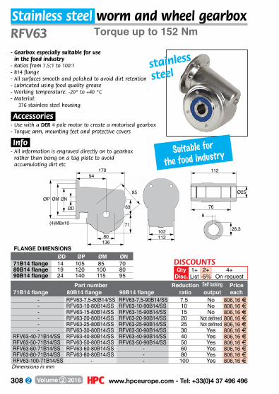
308 www.hpceurope.com - Tel: +33(0)4 37 496 496Volume 2 2016
Part number Reduction Self locking Price71B14 flange 80B14 flange 90B14 flange ratio output each
- RFV63-7,5-80B14/SS RFV63-7,5-90B14/SS 7,5 No 806,16 F- RFV63-10-80B14/SS RFV63-10-90B14/SS 10 No 806,16 F- RFV63-15-80B14/SS RFV63-15-90B14/SS 15 No 806,16 F- RFV63-20-80B14/SS RFV63-20-90B14/SS 20 Not defined 806,16 F- RFV63-25-80B14/SS RFV63-25-90B14/SS 25 Not defined 806,16 F- RFV63-30-80B14/SS RFV63-30-90B14/SS 30 Yes 806,16 F
RFV63-40-71B14/SS RFV63-40-80B14/SS RFV63-40-90B14/SS 40 Yes 806,16 FRFV63-50-71B14/SS RFV63-50-80B14/SS RFV63-50-90B14/SS 50 Yes 806,16 FRFV63-60-71B14/SS RFV63-60-80B14/SS - 60 Yes 806,16 FRFV63-80-71B14/SS RFV63-80-80B14/SS - 80 Yes 806,16 FRFV63-100-71B14/SS - - 100 Yes 806,16 F
RFV63
Dimensions in mm
FLANGE DIMENSIONSØD ØP ØM ØN
71B14 flange 14 105 85 7080B14 flange 19 120 100 8090B14 flange 24 140 115 95
2+-5%
4+On request
1+List
QtyDisc.
DISCOUNTS
Stainless steel worm and wheel gearboxTorque up to 152 Nm
- Gearbox especially suitable for use in the food industry
- Ratios from 7.5:1 to 100:1- B14 flange- All surfaces smooth and polished to avoid dirt retention- Lubricated using food quality grease- Working temperature: -20° to +40 °C- M aterial:
316 stainless steel housing
.Accessories.- Use with a DER 4 pole motor to create a motorised gearbox- Torque arm, mounting feet and protective covers
.Info.- All information is engraved directly on to gearbox
rather than being on a tag plate to avoid accumulating dirt etc
112
Ø25
76
8
28,310280
71
63
94
ØP ØM ØN
ØD
95
170
(4)M8x10
136112
stainless
steel
Suitable for the food industry
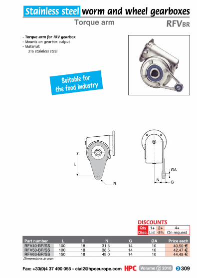
309 Fax: +33(0)4 37 490 055 - [email protected] Volume 2 2016
Torque arm
Part number L R N G ØA Price eachRFV40-BR/SS 100 18 31,5 14 10 40,50 FRFV50-BR/SS 100 18 38,5 14 10 42,47 FRFV63-BR/SS 150 18 49,0 14 10 44,45 F
RFVBR
- Torque arm for FRV gearbox- Mounts on gearbox output- M aterial:
316 stainless steel
Dimensions in mm
2+-5%
4+On request
1+List
QtyDisc.
DISCOUNTS
Stainless steel worm and wheel gearboxes
Suitable for the food industry
L
RN G
ØA

310 www.hpceurope.com - Tel: +33(0)4 37 496 496Volume 2 2016
Mounting bracket
PricePart number H H1 V V1 X X1 V2 V3 each
RFV40-FP/SS 50 90 111 83 35 70 95 60 75,08 FRFV50-FP/SS 60 110 131 97 40 80 114 70 81,99 FRFV63-FP/SS 72 135 156 116 45 100 137 85 99,77 F
RFVFP
2+-5%
4+On request
1+List
QtyDisc.
DISCOUNTS
Stainless steel worm and wheel gearboxes
- Supports FRV gearbox- Inward or outward facing- Sold in pairs- M aterial:
316 stainless steel
Dimensions in mm
V3 V2
X1X1
X X
H
H1 H1
VV1Brackets facing
inwardsBrackets facing
outwards
Suitable for the food industry
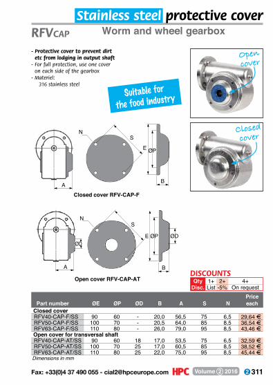
311 Fax: +33(0)4 37 490 055 - [email protected] Volume 2 2016
Worm and wheel gearbox
PricePart number ØE ØP ØD B A S N each
Closed coverRFV40-CAP-F/SS 90 60 - 20,0 56,5 75 6,5 29,64 FRFV50-CAP-F/SS 100 70 - 20,5 64,0 85 8,5 36,54 FRFV63-CAP-F/SS 110 80 - 26,0 79,0 95 8,5 43,46 F
Open cover for transversal shaftRFV40-CAP-AT/SS 90 60 18 17,0 53,5 75 6,5 32,59 FRFV50-CAP-AT/SS 100 70 25 17,0 60,5 85 8,5 38,52 FRFV63-CAP-AT/SS 110 80 25 22,0 75,0 95 8,5 45,44 F
RFVCAP
Stainless steel protective cover
- Protective cover to prevent dirt etc from lodging in output shaft
- For full protection, use one cover on each side of the gearbox
- M ateriel: 316 stainless steel
Dimensions in mm
Closed cover RFV-CAP-FA
NS
ØP
B
E
Open cover RFV-CAP-AT 2+-5%
4+On request
1+List
QtyDisc.
DISCOUNTSA
NS
ØP
B
E ØDØD
Open cover
Closed
cover
Suitable for the food industry
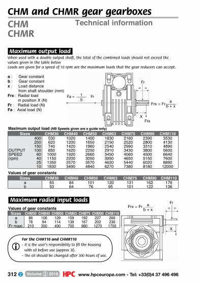
312 www.hpceurope.com - Tel: +33(0)4 37 496 496Volume 2 2016
Technical informationCHM and CHMR gear gearboxes
.Maximum output load.When used with a double output shaft, the total of the combined loads should not exceed the values given in the table belowLoads are given for a speed of 10 rpm are the maximum loads that the gear reducers can accept.
a : Gear constantb : Gear constantx : Load distance
from shaft shoulder (mm)Frx : Radial load
in position X (N)Fr : Radial load (N)Fa : Axial load (N)
.Maximum radial input loads.
1 5
Fa = Fra
b + x Frx = Fr
FrxX
Fr= =
X
Fr= =
a b + x Frx = Fr
Maximum output load (NB Speeds given are a guide only)Sizes CHM30 CHM40 CHM50 CHM63 CHM75 CHM90 CHM110
400 530 1020 1400 1830 2160 2390 3530250 620 1200 1650 2150 2520 2800 4130150 740 1420 1960 2540 2990 3310 4890
OUTPUT 100 850 1620 2250 2910 3430 3800 5600SPEED 60 1000 1920 2660 3450 4060 4500 6640(rpm) 40 1150 2200 3050 3950 4650 5150 7600
25 1350 2570 3570 4620 5440 6020 889010 1830 3490 4840 6270 7380 8180 12000
Values of gear constantsSizes CHM30 CHM40 CHM50 CHM63 CHM75 CHM90 CHM110
a 65 84 101 120 131 162 176b 50 64 76 95 101 122 136
Values of gear constantsSizes CHM30 CHM40 CHM50 CHM63 CHM75 CHM90 CHM110
a 86 106 129 159 192 227 266b 76 94 114 139 167 202 236
Fr maxi. 210 350 490 700 980 1270 1700
CHMCHMR
For the CHM110 and CHMR110- It is the user’s responsibility to fill the housing with oil before use (approx 3l).- �The oil should be changed after 300 hours of use.
i
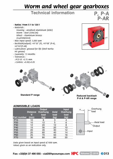
313 Fax: +33(0)4 37 490 055 - [email protected] Volume 2 2016
Worm and wheel gear gearboxes
Data given based on input speed of 1000 rpm. Values given as an indication only.
Standard P range Reduced backlashP-A & P-AR range
ADMISSIBLE LOADSOverhung load
Axial load
x
Output
Input
Output InputDistance Overhung Axial Overhung
‘X’ load load loadPart number (mm) (kg) (kg) (kg)P15 10 8 3 4P20 10 12 5 6P30 12 20 12 8P40 15 30 20 10P45 20 45 30 12P55 20 60 40 14P60 25 70 50 16P70 30 80 60 20
Technical information P, P-AP-AR
- Ratios: From 5:1 to 120:1- M aterials :
Housing - anodised aluminium (6082) Worm - Steel (35NCD6) Wheel - Aluminium bronze (CuAl10Ni5Fe4)
- Max input speed: 3,000 rpm- Backlash(output): –~0º30’ (P), –~0º08’ (P-A),
–~0º04’(P-AR)- Lubrication: greased for life (Shell Nerita
HV grease)- Guaranty: 13 months- Tolerances :
• PCD Ø: -0.15 mm • Centres: +0.00/+0.05
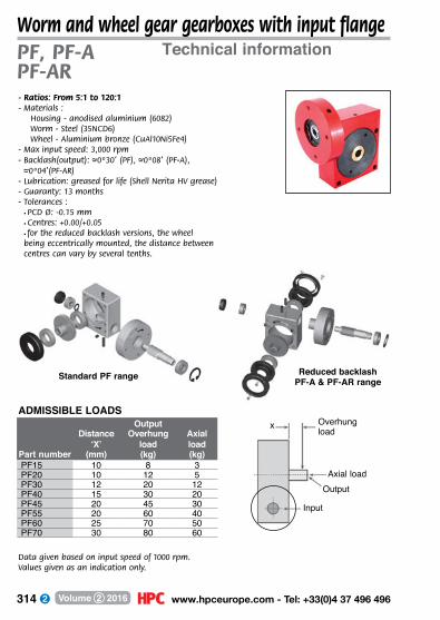
314 www.hpceurope.com - Tel: +33(0)4 37 496 496Volume 2 2016
Worm and wheel gear gearboxes with input flange
Data given based on input speed of 1000 rpm. Values given as an indication only.
Standard PF range Reduced backlash PF-A & PF-AR range
Overhung load
Axial loadOutput
Input
x
- Ratios: From 5:1 to 120:1- M aterials :
Housing - anodised aluminium (6082) Worm - Steel (35NCD6) Wheel - Aluminium bronze (CuAl10Ni5Fe4)
- Max input speed: 3,000 rpm- Backlash(output): –~0º30’ (PF), –~0º08’ (PF-A),
–~0º04’(PF-AR)- Lubrication: greased for life (Shell Nerita HV grease)- Guaranty: 13 months- Tolerances :
• PCD Ø: -0.15 mm • Centres: +0.00/+0.05 • for the reduced backlash versions, the wheel being eccentrically mounted, the distance between centres can vary by several tenths.
ADMISSIBLE LOADSOutput
Distance Overhung Axial‘X’ load load
Part number (mm) (kg) (kg)PF15 10 8 3PF20 10 12 5PF30 12 20 12PF40 15 30 20PF45 20 45 30PF55 20 60 40PF60 25 70 50PF70 30 80 60
Technical informationPF, PF-APF-AR
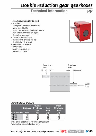
315 Fax: +33(0)4 37 490 055 - [email protected] Volume 2 2016
Double reduction gear gearboxes
- Speed ratio: from 25:1 to 900:1- Materials :
casing 6082 anodised aluminium worm steel 35NCD6 wheel CuAl10Ni5Fe4 aluminium bronze
- Max. speed: 3000 rpm on input depending on model
- Backlash: –~2º on output- Lubrification: greased for life (Shell Nerita HV grease)- Guarantee: 13 months- Tolerances :
• Centres: +0.00/+0.05 • PCD Ø: -0.15 mm
Data given based on input speed of 1000 rpm. Values given as an indication only.
Overhung load
Overhung load
xx
Axial load
ADMISSIBLE LOADSOutput Input
Distance Overhung Axial Overhung‘X’ load load load
Part number (mm) (kg) (kg) (kg)PP35 12 12 10 6PP50 20 30 20 10PP60 25 45 35 15
Technical information PP

316 www.hpceurope.com - Tel: +33(0)4 37 496 496Volume 2 2016
Overhung load
Axial load
xx
Crossed axis gear gearboxes
ADMISSIBLE LOADS
Data given based on input speed of 1000 rpm. Values given as an indication only.
Left handed teeth (LH)
Right handed teeth (RH)
Typical application
Distance Overhung Axial‘X’ load load
Part number (mm) (kg) (kg)E15 6 15 10E20 6 15 10E30 10 20 15E40 12 40 30E50 20 60 40E60 25 80 50E60B 25 80 50
- Speed ratio: from 1:1 to 40:1- Materials :
casing 6082 anodised aluminium gears in 20NCD2 case hardened (ratio >8 : output CuAl10Ni5Fe4
aluminium bronze)- Max. speed: 3000 to 4000 rpm at input
depending on model- Backlash(output): –~1° (0º30’ optional)- Lubrification: greased for life (Shell Alvania HDX2 grease)- Guarantee: 13 months- Tolerances :
• PCD Ø: -0.15 mm • Centres: +0.00/+0.05
- Steel bearing with single ball race 2RS
Technical informationE

317 Fax: +33(0)4 37 490 055 - [email protected] Volume 2 2016
Double output bevel gearbox
Overhung load
Axialload
x
x
Axial load
Axial load
x
BLHM series
- Speed ratio: from 1:1 to 2:1- Materials :
casing 6082 anodised aluminium gears in heat treated steel (20NCD2)
- ax. speed: 2000 to 4000 rpm on input depending on model
- Backlash: –~1ºon output- Lubrification: greased for life (Shell Alvania HDX2 grease)- Guarantee: 13 months- Tolerances:
• PCD Ø: -0.15 mm • ground shafts h7, Ra 0.8
Distance Overhung Axial‘X’ load load
Part number (mm) (kg) (kg)BLHM20 6 4 3BLHM30 10 8 6BLHM40 12 12 10BLHM50 20 20 15BLHM60 25 30 25BLHM70 30 40 35
Data given based on input speed of 1000 rpm. Values given as an indication only.
Technical information BLHM
ADMISSIBLE LOADS

318 www.hpceurope.com - Tel: +33(0)4 37 496 496Volume 2 2016
T and L right angle drive gearbox
Data given based on input speed of 1000 rpm. Values given as an indication only.
BLHT angle transmission
BLH range BLHT range
Overhung load
Axial load
x
x
x
Axial load
Axial load
BLH angle transmission
- Speed ratio: from 1:1 to 4:1- Materials :
casing 6082 anodised aluminium gears in heat treated steel (20NCD2)
- Max. speed: 2000 to 4000 rpm on input depending on model
- Backlash: –~1ºon output- Lubrification: greased for life (Shell Alvania HDX2 grease)- Guarantee: 13 months- Tolerances :
• PCD Ø: -0.15 mm • ground shafts h7, Ra 0.8
Distance Overhung Axial‘X’ load load
Part number (mm) (kg) (kg)BLH20 BLHT20 6 4 3BLH30 BLHT30 10 8 6BLH40 BLHT40 12 12 10BLH50 BLHT50 20 20 15BLH60 BLHT60 25 30 25BLH70 BLHT70 30 40 35
Technical informationBLH, BLHT, BL, BLHB
ADMISSIBLE LOADS
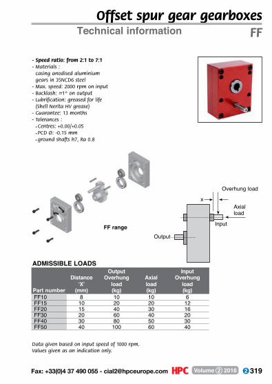
319 Fax: +33(0)4 37 490 055 - [email protected] Volume 2 2016
Offset spur gear gearboxes
- Speed ratio: from 2:1 to 7:1- Materials :
casing anodised aluminium gears in 35NCD6 steel
- Max. speed: 2000 rpm on input- Backlash: –~1º on output- Lubrification: greased for life (Shell Nerita HV grease)- Guarantee: 13 months- Tolerances :
• Centres: +0.00/+0.05 • PCD Ø: -0.15 mm • ground shafts h7, Ra 0.8
Data given based on input speed of 1000 rpm. Values given as an indication only.
FF range
Overhung load
Axial load
x
Input
Output
Output InputDistance Overhung Axial Overhung
‘X’ load load loadPart number (mm) (kg) (kg) (kg)FF10 8 10 10 6FF15 10 20 20 12FF20 15 40 30 16FF30 20 60 40 20FF40 30 80 50 30FF50 40 100 60 40
Technical information FF
ADMISSIBLE LOADS
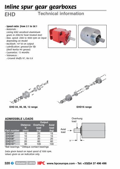
320 www.hpceurope.com - Tel: +33(0)4 37 496 496Volume 2 2016
Inline spur gear gearboxes
Data given based on input speed of 1000 rpm. Values given as an indication only.
EHD 04, 06, 08, 12 range EHD16 range
Overhung load
x
Axial load
- Speed ratio: from 3:1 to 36:1- Materials :
casing 6082 anodised aluminium gears in 20NCD2 heat treated steel
- Max. speed: 2000 to 4000 rpm on input depending on model
- Backlash: –~0º30 on output- Lubrification: greased for life (Shell Nerita HV grease)- Guarantee: 13 months- Tolerances :
• Ground shafts h7, Ra 0.8
OutputDistance Overhung Axial
‘X’ load loadPart number (mm) (kg) (kg)EHD04* 10 20 15EHD06* 10 25 15EHD08* 12 30 20EHD12** 20 60 60EHD16** 30 100 100
Technical informationEHD
ADMISSIBLE LOADS
*Ball bearings **Oblique contact bearings
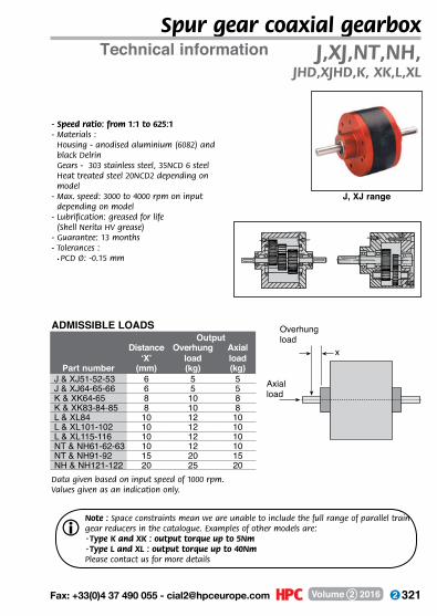
321 Fax: +33(0)4 37 490 055 - [email protected] Volume 2 2016
Spur gear coaxial gearbox
- Speed ratio: from 1:1 to 625:1- Materials :
Housing - anodised aluminium (6082) and black Delrin Gears - 303 stainless steel, 35NCD 6 steel Heat treated steel 20NCD2 depending on model
- Max. speed: 3000 to 4000 rpm on input depending on model- Lubrification: greased for life (Shell Nerita HV grease)- Guarantee: 13 months- Tolerances :
• PCD Ø: -0.15 mm
Data given based on input speed of 1000 rpm. Values given as an indication only.
Overhung load
Axial load
x
Note : Space constraints mean we are unable to include the full range of parallel train gear reducers in the catalogue. Examples of other models are:·Type K and XK : output torque up to 5Nm ·Type L and XL : output torque up to 40NmPlease contact us for more details
i
OutputDistance Overhung Axial
‘X’ load loadPart number (mm) (kg) (kg)
J & XJ51-52-53 6 5 5J & XJ64-65-66 6 5 5K & XK64-65 8 10 8K & XK83-84-85 8 10 8L & XL84 10 12 10L & XL101-102 10 12 10L & XL115-116 10 12 10NT & NH61-62-63 10 12 10NT & NH91-92 15 20 15NH & NH121-122 20 25 20
Technical information J,XJ,NT,NH, JHD,XJHD,K, XK,L,XL
ADMISSIBLE LOADS
J, XJ range
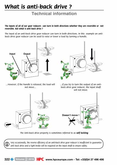
322 www.hpceurope.com - Tel: +33(0)4 37 496 496Volume 2 2016
What is anti-back drive ?Technical information
The inputs of all of our gear reducers can turn in both directions whether they are reversible or not reversible. But what is anti back drive ?
Input
The input of an anti-back drive gear reducer can turn in both directions. In this example an anti-back drive gear reducer can be used to raise or lower a load by turning a handle.
...However, if the handle is released, the load will not move...
...If you try to turn the output of an anti-back drive gear reducer, the input shaft
will not move.
The Anti-back drive property is sometimes referred to as self locking
Doesn’t move !
Ouput
Very occasionally, the reverse efficiency of an anti-back drive gear reducer is insufficient to guarantee anti back drive and a light brake will be required on the input shaft to ensure safety.i

323 Fax: +33(0)4 37 490 055 - [email protected] Volume 2 2016
Clamp coupling
Clamp coupling avoids damage to shaft and absorbs
misalignments.
The addition of a bearing at the end of the shaft acts as a counter-weights to the
overhung load thus avoiding damage to the shaft.
Please contact us about any modifications you may require to be made to a shaft. In that way they can be done before assembly, thus
avoiding any possible damage to the gear reducer due to later re-machining.
Gears mounted at the outer extremity of the input shaft can cause bending and eventual
failure of the shaft.
Mounting a gear as near to the casing as possible allows the torque produced by the overhung load to be reduced, and protects the shaft from premature wear.
Assembly adviceAll types of gear gearboxes
Note: Gear reducers can be mounted in any position. Any modifications made by the customer will void the guarantee.i
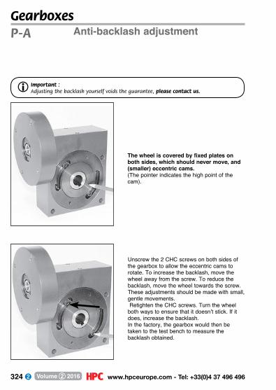
324 www.hpceurope.com - Tel: +33(0)4 37 496 496Volume 2 2016
Gearboxes
The wheel is covered by fixed plates on both sides, which should never move, and (smaller) eccentric cams. (The pointer indicates the high point of the cam).
Unscrew the 2 CHC screws on both sides of the gearbox to allow the eccentric cams to rotate. To increase the backlash, move the wheel away from the screw. To reduce the backlash, move the wheel towards the screw.These adjustments should be made with small, gentle movements. Retighten the CHC screws. Turn the wheel both ways to ensure that it doesn’t stick. If it does, increase the backlash.In the factory, the gearbox would then be taken to the test bench to measure the backlash obtained.
Anti-backlash adjustmentP-A
Important : Adjusting the backlash yourself voids the guarantee, please contact us.i

325 Fax: +33(0)4 37 490 055 - [email protected] Volume 2 2016
Gearboxes
A pair of compasses will be required when adjusting the backlash
Do not unscrew any of the other screws to avoid damaging the gear reducer. The main plates should never be moved, irreparable damage could be caused.
Anti-backlash adjustment P-A

326 www.hpceurope.com - Tel: +33(0)4 37 496 496Volume 2 2016
Gearboxes
Greased for life! Do not
re-grease
Re-greasing is only necessary in certain
special conditions. Please contact us for advice
beforehand.
X
Technical information
.Torque.- Torque figures have been calculated on the basis of a 12,000 hour working life and being 12
hours per day. For 24/24 use, multiply the original figure by 0.75.
.Working temperature.- Normal working temperature range is 0°C to +70°C.
Alternative greases for use between -55°C and +155°C are available, as are bearings with sealed joints (2RS) for use up to +120°C, steel bearings without joints for use up to +150°C or stainless steel bearings for use up to +288°C when used with special high temperature grease.
- Standard grease allows use of up to +80°C in most applications. However if the speed or torque rises, the gear reducer temperature will also rise, which could cause damage.
.Modifications.- We can modify gear reducer, adding keyways or circlip groove or modifying the shaft... Please
contact us with your requirements. Any modifications that you carry out to a gear reducer modification will void the guarantee.
.Usage.- The use of flexible coupling is recommended to connect the gearbox to the rest of the system.- Gear reducers are designed to reduce speed, not multiply it. Because of this, we cannot
guarantee the correct operation of a gear reducer when used backwards.- The user must always test a gear reducer in his own application to ensure that it is suitable and
produces the desired results.
.Oiling.- Gear reducers are greased for life and do not require maintenance. If re-greasing, do not over-fill
as this could cause gears to get stuck and over-heat the gear reducer.
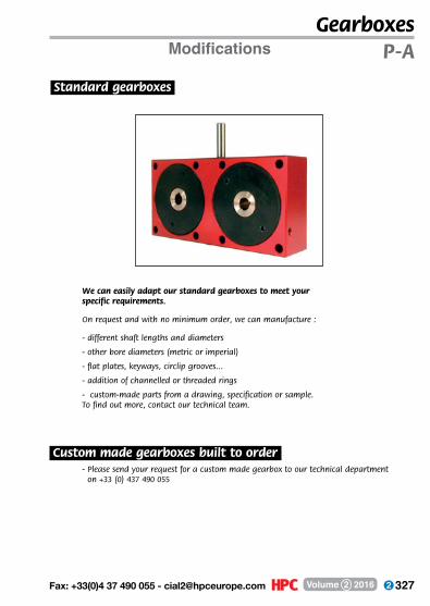
327 Fax: +33(0)4 37 490 055 - [email protected] Volume 2 2016
Gearboxes
We can easily adapt our standard gearboxes to meet your specific requirements.
On request and with no minimum order, we can manufacture :
- different shaft lengths and diameters
- other bore diameters (metric or imperial)
- flat plates, keyways, circlip grooves...
- addition of channelled or threaded rings
- custom-made parts from a drawing, specification or sample. To find out more, contact our technical team.
- Please send your request for a custom made gearbox to our technical department on +33 (0) 437 490 055
Modifications P-A
.Standard gearboxes.
.Custom made gearboxes built to order.

328 www.hpceurope.com - Tel: +33(0)4 37 496 496Volume 2 2016
Note. This translation of the original Engrenages HPC French Terms and Conditions is offered as a guide only. In the case of any dispute, the terms and conditions in the original French document will apply.
1 - APPLICATION AND ENFORCEMENT OF THESE TERMS AND CONDITIONS OF SALE.
The act of a professional Client ( “The client” ) placing an order with Engrenages HPC ( “HPC” ) implies the complete and unreserved agreement by the Client to these general terms and conditions of sale, to the exclusion of any other documents such as catalogues produced by HPC, which are provided for information only and are merely intended as an indication, and regardless of any other information that may be included on the Client’s order documents, the Client’s terms and conditions of purchase or in any other document transmitted by the Client to HPC.
Any conditions applied by the Client will therefore by default be not accepted by HPC, regardless of when they may be brought to their attention unless they have been explicitly confirmed in writing by HPC.
Only specifications relating to custom-made parts can modify these general terms and conditions but should there be a conflict between these T+Cs and the specifications of the pieces to be manufactured, these T+Cs shall take precedence
The fact that HPC does not immediately apply any of the clauses in these terms and conditions should not be interpreted as meaning that they may not do so at a later date.
2 - ORDERS.
Orders must be placed in writing to HPC by the Client. Any order placed by telephone must be confirmed in writing by the Client within 24 hours. Without such confirmation the order will be cancelled. An order will only become definitive and the sales contract confirmed when it is accepted by HPC, this acceptance taking the form of an order confirmation sent to the Client or the delivery of the products ordered.
In case of any modification HPC may deem necessary to be made to the Client’s order and confirmed in the order acknowledgment sent to the Client, the latter is assumed to have accepted the modification unless HPC is advised in writing within 24 hours of receipt.
No order with a value lower than 20 Euros (before tax) will be accepted, this includes orders passed at the trade counter at HPC’s offices.
No order with a value lower than 150 Euros (before tax) will be accepted from customers outside of France (EU countries included)
3 - ORDER MODIFICATIONS
Any modification to, or cancellation of an order requested by the Client will not be taken into consideration unless it is received in writing before the goods (for standard products) are despatched or manufacture is started (of custom-made products) and acceptance of the modification has been expressly confirmed by HPC in a fax addressed to the Client within 24 hours of the request. If either of these conditions is not fulfilled, the products ordered initially will be sent and full payment will become due.
General terms and conditions of saleFor professional Clients

329 Fax: +33(0)4 37 490 055 - [email protected] Volume 2 2016
General terms and conditions of saleFor professional Clients
4 - PRICES
All prices mentioned in the catalogue are given excluding any taxes. Value Added Tax (VAT) at the current rate, delivery and packing charges as marked in the catalogue and any insurance to which the Client wishes to subscribe, will be added to these prices. Choice of packaging material will be made by HPC unless the Client has made a prior request.
Unless stated to the contrary, products are sold at the price applicable the day the order is placed. Prices quoted in the catalogue are those applicable on the date of publication marked on the cover of said catalogue. HPC reserves the right to modify these prices at any time.
5 - DELIVERY METHODS AND TIMES.
A - DESPATCH DATES
Items in stock on the date an order is accepted can be made available for collection or despatched within a maximum of 72 hours. For catalogue items not in stock at the time the order is accepted or for special items, an estimated despatch time will given when the order is accepted.
Should the estimated delivery date given by HPC be exceeded by more than thirty (30 ) working days and except in the case of force majeure, the Client has the right to cancel the order within thirty (30) working days from the estimated delivery date by sending a registered letter.
For the purposes of the Terms and Conditions, force majeure is consider to cover, but not limited to such events as: war, riot, fire, industrial disputes, natural disasters or failure of their suppliers to deliver.
B - DELIVERY
Unless stated otherwise, delivery is carried out by the collection of the goods by Client from HPC’s premises in Dardilly 69570 (France) or by delivery a means of transport chosen by HPC or the Client. Products are sold from Dardilly 69570 France (HPC premises) and are transported at the risk of the Client, the goods remaining the property of HPC until full payment is received as explained in Clause 10.
Unless otherwise agreed, goods are sold “ex-works” and transport is carried out at the Client’s cost by a transport method chosen by HPC unless one has been specified by the Client.
In case of loss or damage during transit, it is the Client’s responsibility to make any claims or remarks to the transporter in writing by recommended letter or other legally accepted means within 3 days of reception of the products (article L133-3 of the French Commercial Code)
HPC reserves the right to make partial deliveries from an order where necessary.
C - RECEPTION
Without prejudice to any claims for damaged goods made direct to the transport company concerned, any complaints regarding differences between the products delivered and those products ordered or identified on the delivery document, should be sent in writing to HPC within 30 days of receipt of the goods. Claims received outside of this period will not be accepted
It is the Client’s responsibility to provide full proof of the existence of problems or faults with the goods supplied. He must give HPC access and means to evaluate and rectify any problems. He will not however attempt to repair any faults either directly or by intervention of a third party.
HPC’s guarantee is limited to the free replacement or repair of products or components that they have agreed are faulty.
330 www.hpceurope.com - Tel: +33(0)4 37 496 496Volume 2 2016
General terms and conditions of saleFor professional Clients
Any product for which the Client required repair or replacement under guarantee must be returned to HPC’s service department whose authorisation is required before any replacement can be made. Transport costs will be charged to the Client if a claim for replacement under guarantee is found not to be applicable.
6 - METHODS OF PAYMENT.
Invoices which will be sent at the same time as goods are despatched, are payable as follows:
• On receipt
• 30 days from the end of the month of the date of the invoice or summary invoice. This method of payment is subject to acceptance by HPC and may be withdrawn at any moment without the Client’s approval.
• in Euros
• by cheque, credit card, bank transfer, or promissory note, the choice of method of payment cannot c hange the payment due date. No discounts are made for advance payments.
7 - LATE OR NON PAYMENT
If payment is not made within the period quoted above and after receipt of a formal notice of non payment with payment not being received within 8 days, the Client will be liable for charges equivalent to an interest rate of one and a half times the prevailing legal interest rate on the sum owed as well as any costs associated with the final collection of the unpaid sum. Any claims by the Client do not exempt him from paying an invoice on or before the due date. Non or partial payments will lead to the immediate requirement for the Client to pay all sums outstanding to HPC, even if they are not yet due and whatever the intended method of payment might be.
8 - GARANTEE.
HPC guarantees the Client against faults or hidden defects that appear in the products sold under the conditions stipulated in article 1641 of the French Civil Code.
For products made to a Client’s specification, HPC’s responsibility is limited to manufacturing items that conform to the specifications supplied but does not guarantee their functionality or suitability for any application the Client may use them for. The Client is solely responsible for the information transmitted to HPC.
For standard products, HPC guarantees their conformity to the specifications quoted in the catalogue except where the original manufacturer has changed the technical specification. Any action to invoke HPC’s responsibility and/or the implementation of the guarantee offered by HPC must be made within 30 days of receipt of the goods by the Client. Any claim under the guarantee will be limited to an amount equal to the price paid for the product. In no case can damage caused by a product marketed by HPC be a reason to any claim for damages or repair.
In the event that a product manufactured to a Client’s specification infringes the rights of a third party, the Client accepts responsibility for refunding all the costs (procedure, claims, damages, lawyers’ expenses, other advisors...) suffered by HPC and will actively cooperate at his own expense in the defence of the latter.
The guarantee will be considered void if products have been modified or interfered with in any way by the Client without prior written agreement from HPC or if the products have been used in any abnormal way or under unsuitable conditions taking into account their characteristics and normal
331 Fax: +33(0)4 37 490 055 - [email protected] Volume 2 2016
General terms and conditions of saleFor professional Clients
applicable uses and standards (in particular in the event of use or installation in any aerial or space going craft for which the products are completely unsuited)
9 - RETURNED MATERIAL.
Every returned product must be the subject of a formal written agreement between the HPC and the Client by fax, email or letter.
The choice of transport method will be made by HPC. Any product returned without this prior
agreement will be stored on behalf of the Client but will not oblige HPC to provide a refund or replacement.
In any event, no product returned more than 30 days after receipt of the product by the Client will be accepted. The cost of returning a product is always the responsibility of the purchaser and the risk in the product remains with him. Any returned product must be addressed to HPC’s registered office.
Once the material has been accepted by HPC for return, a Credit Note for the value of the products, valid for duration of six months will be issued. The condition and quantity of all products returned will be subject to inspection.
In the case of an obvious problem or the non-conformity of the product has been confirmed by HPC, the Client will either receive at the discretion of HPC, either replacement products or a refund, no other charges or penalties will be accepted.
10 - RENTENTION OF PROPERTY
The transfer of property in any standard or custom-made part is subject to the full payment of the invoice, payment is understood to take place the day funds reach HPC’s bank account.
The above prevision does not stop the risk in the product passing to the Client (in particular risk of loss, deterioration, and damage caused by the shipped parts) once the parts have been handed over or dispatched by HPC.
If a Client supplies a product for modification, repair or to be used as a sample, the Client remains the owner of the original product and is responsible for the cost of their transport to and from HPC. The Client also accepts all risks related to their transport, any possible modification by HPC, and any damage that might be caused.
11 - APPLICABLE LAW - COURT OF JURISDICTION.
Sales concluded with HPC are subject to French law.
Any dispute which may arise between the two parties relating to the interpretation and/or execution and/or termination of the contract will be brought before the competent commercial courts of the jurisdiction for the registered office of HPC, even in the event of case of appeal or plurality of defendants.
Photos are non-contractual
All product information is subject to technical modifications where necessary

332 www.hpceurope.com - Tel: +33(0)4 37 496 496Volume 2 2016
Part number Volume 1 2 3 4 5 Page203R PERIFLEX® 2 78712 handle 1 92 ➔ 94 1 105,113
AAAG, ABG toothed bar 4 38, 212 AB anti-backlash wormwheel 4 185ABL antistatic brush 5 184 ➔ 187ABM anti-backlash gear 4 176 ➔ 177ABS anti-backlash wormwheel 4 184AC hook 1 124 ➔ 125ACA splined shaft 2 108ACL angle bracket 5 329 ➔ 355ACLfpa panel mounting block 5 346ACM bonnet fastener 1 155 ➔ 157ADG, ASG toothed bar 4 39, 213ADL eye bolt 1 330 ➔ 331ADSR backlash free coupling 2 44 ➔ 45AF rigid coupling 2 82AFM, ASM Iglidur cylindrical polymer bush 3 28 ➔ 33AHEX hexagonal shaft 2 230AK, AKD, AKN coupling Gerwah 2 54 ➔ 57ALI power supply DC 2 261 ➔ 263APB, APB BOU adjusting rod 5 107 ➔ 109APBC circular rod 3 117ARL Plastic flexible rack 4 199ARTE NEW 1 268 ➔ 269AT timing pulley 4 64 ➔ 83AT toothed bar 4 62 ➔ 63AT timing belt 4 84 ➔ 86AT-M timing belt per metre 4 86AT-P connecting plate 4 87AT-ZY elasto mount 1 248 ➔ 249AWMP aluminium shaft 3 229AXTR axle for tensioner pulley 4 129A-ZY(ss) cylindrical mount 1 252 ➔ 255
BB, B/Eco Bevel gear 4 132 ➔ 133, 138 ➔ 139B332 reducer 2 225B3PAN Panamech Multi-Beam 2 31BAB clamping pin 1 24 ➔ 39, 41BABa lifting pin 1 332 ➔ 333BAD NEW brush ring 5 182 ➔ 183BAG locking assembly 2 118 ➔ 119BAG0 NEW locking ring 2 115BAG1-TR leadscrew locking ring 3 309
Part number Volume 1 2 3 4 5 PageBAGR adjustable shaft collar 2 114BAP clamping collar 2 116 ➔ 117 5 74 ➔ 75BAN angular clamp 5 22BC Panamech Multi-Beam 2 28 ➔ 29BCA splined bush 2 109BCH mushroom knob 1 111BCM cylindrical brushes 5 167 ➔ 171BDP holding arm 5 23 ➔ 25BEF, BEK miniature leadscrew 3 316 ➔ 317BETA spring pin 1 373BFA shaft locking washer 1 360BFM flanged nut 3 305, 308BG(C) OLDHAM coupling 2 34 ➔ 35 BH single housed bearing assembly 3 64 ➔ 67BHC socket head button screw 1 428BISF ball transfer unit 5 47BKGS backlash free coupling 2 42 ➔ 43BL, BLH, BLHT right bevel gearbox 2 174 ➔ 197BLHB, BLHO, BLHI right bevel gearbox 2 178 ➔ 194BLHM right bevel gearbox 2 179 ➔ 195BLM spring loaded plunger 1 62BLOC doorstop 5 280BOX-BETA NEW dowel pin 1 348BOX-DH, BOX-DHX dowel pin 1 349 ➔ 350BOX-INS self tapping insert 1 408 ➔ 409BOX-KK, BOX-KU key 1 353 ➔ 354BOX-SAP spring pin 1 352BPM spring plunger 1 63 ➔ 65BPMc slotted spring plunger 1 66BPTRW,BTCW cap for tube 5 138 ➔ 139BPOM ball transfer unit 5 48BPF, BPFL, BPP flanged bearing 3 48 ➔ 50BPTRm end cap 5 140 ➔ 141BRI panel holder 5 282BS Panamech Multi-Beam 2 26 ➔ 27BSB ballscrew bearing unit 3 324BSM spring plunger 1 60 ➔ 61BSP compact precision slide 3 162 ➔ 163BSPM miniature leadscrew 3 314 ➔ 315BSPT single rod clip 5 106BTC end cap 5 142 ➔ 144, 272BTE, BTE(ss) universal tension arm 4 120 ➔ 121BTEU ball transfer unit 5 49BTEU, BTHD ball transfer unit 5 45 ➔ 46 BUC shaft and bush splined 2 111 ➔ 113

333 Fax: +33(0)4 37 490 055 - [email protected] Volume 2 2016
Part number Volume 1 2 3 4 5 PageBUH motor gearboxes 2 256BUT panel 5 top 5 281BWU compact precision shaft 3 164 ➔ 169B-ZY(ss) cylindrical mount 1 256 ➔ 259
CCAB cable 1 296 ➔ 297CAP plate chain 5 60 ➔ 63CAR NEW articulated coupling 3 400 ➔ 403CC, CT collar clamp 2 120 ➔ 121CCL(ss) wire thimble 1 298 ➔ 299CD compression spring 1 180 ➔ 191CDR cable for clamping pin 1 40CGLc NEW tubular structure 5 263CGT NEW tubular structure 5 250 ➔ 258CGR NEW tubular structure 5 259 ➔ 261CF(S), CFES cam follower 3 283 ➔ 284CFC spring loaded 1 57CFCL cam follower 3 285CFF(ss) rod end 3 131, 133CFU cam follower 3 280 ➔ 281CHA hinge 5 196 ➔ 199, 205CHAE decorative hinge 5 201 ➔ 204CHAFR adjustable friction hinge 5 222CHAK indent hinge 5 223CHAL long hinge 5 200CHAM marine hinge 5 206CHA-R hinge 5 214 ➔ 221CHC socket head screw 1 420 ➔ 425CHM, CHMR wormwheel 2 280 ➔ 293CHM-BR, CHM-X arm and shaft 2 294 ➔ 295 CHML worm and wheel gearbox 2 296 ➔ 299CHM-MOT motor-reducers AC 2 276 ➔ 279 5 88 ➔ 90CHN(ss) straight long link chain 1 320 ➔ 321CHT asynchronous AC motor 2 271 ➔ 275CHTRB right bevel gearbox 2 232 ➔ 235CHTRP right bevel gearbox 2 236 ➔ 241CLA, CLB indexing handle 1 72 ➔ 75CLS-R/CLL-R clevis components 1 230CLG moulded spur gear 4 248 ➔ 290CLM(ss) clevis components 3 144CLS, CLP clevis components 3 142CLL, CLLP clevis components 3 143, 1 231CLQ NEW feeler strip on roll 3 114 ➔ 115CLR/CLRss NEWstraight clevis 1 227, 3 137CLS(ss), CLP(ss) clevis components 3 145
Part number Volume 1 2 3 4 5 PageCMA(ss) eye screw 1 328 ➔ 329CMM(ss) rod end 3 130, 132CNA/CNG NEW mounting plate 1 228, 3 138COA/COG NEW mounting plate 1 229, 3 139CPAS stay with safety catch 5 224CR/CPE NEW accessories for tubular structure 5 266 ➔ 269CRG adjustment column 5 86 ➔ 87, 3 362 ➔ 363CRM imperial section rack 4 200CRR NEW rack fot tubular structure 5 262CSS(ss) spherical bearing 3 122 ➔ 123CT, CTH telescopic universal joint 2 94 ➔ 95CT-ZY diabolo mount 1 250 ➔ 251CX, CY circlip 1 358 ➔ 359CYT NEW Graphit® connector 5 265
DD springs in metre 1 192DB, DB/Eco bevel gear 4 134, 140DBC Panamech Multi-Beam 2 30DBL idler 5 72 ➔ 73DCA, DCG, DFG suction cup 5 15 ➔ 17DER AC asynchronous motor 2 302 ➔ 305DG double spur gear 4 180 ➔ 183DGS rod end 3 126 ➔ 129DH dowel pin 1 368 ➔ 369DHX extandable dowel pin 1 372 DIL, DIA, DIV locking bolt 1 44 ➔ 47DKGS coupling 2 40 ➔ 41DKN coupling GERWAH® 2 52 ➔ 53D-KON, D-PAR(ss) elasto buffer 1 266 ➔ 267DOG motor-reducer DC 2 257 ➔ 260DOMI adjustable slide 3 374 ➔ 391DP dowel pin 1 370 ➔ 371DR flexible rack 4 198DSF clutche 2 104 ➔ 105DST, DT pinion shaft 4 186 ➔ 189DTR chain idler sprocket 4 117D-ZY(ss) elasto buffer 1 260 ➔ 263
EE right angle reducer 2 166 ➔ 173EAR NEW lock nut bearing 3 105EBM u bolt 1 392ECF well nut 1 247ECL adjusting nut 1 291ECPR high helix leadscrew 3 293EDS support bracket 5 111
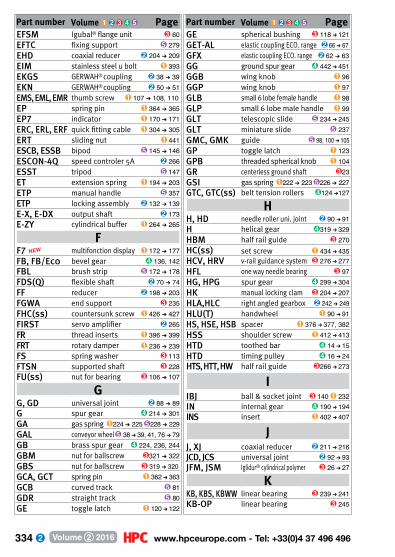
334 www.hpceurope.com - Tel: +33(0)4 37 496 496Volume 2 2016
Part number Volume 1 2 3 4 5 PageEFSM Igubal® flange unit 3 60EFTC fixing support 5 279EHD coaxial reducer 2 204 ➔ 209EIM stainless steel u bolt 1 393EKGS GERWAH® coupling 2 38 ➔ 39EKN GERWAH® coupling 2 50 ➔ 51EMS, EML, EMR thumb screw 1 107 ➔ 108, 110EP spring pin 1 364 ➔ 365EP7 indicator 1 170 ➔ 171ERC, ERL, ERF quick fitting cable 1 304 ➔ 305ERT sliding nut 1 441ESCB, ESSB bipod 5 145 ➔ 146ESCON-4Q speed controler 5A 2 266ESST tripod 5 147ET extension spring 1 194 ➔ 203ETP manual handle 5 357ETP locking assembly 2 132 ➔ 139E-X, E-DX output shaft 2 173E-ZY cylindrical buffer 1 264 ➔ 265
FF7 NEW multifonction display 1 172 ➔ 177FB, FB/Eco bevel gear 4 136, 142FBL brush strip 5 172 ➔ 178FDS(Q) flexible shaft 2 70 ➔ 74FF reducer 2 198 ➔ 203FGWA end support 3 235FHC(ss) countersunk screw 1 426 ➔ 427FIRST servo amplifier 2 265FR thread inserts 1 396 ➔ 399FRT rotary damper 1 236 ➔ 239 FS spring washer 3 113FTSN supported shaft 3 228FU(ss) nut for bearing 3 106 ➔ 107
GG, GD universal joint 2 88 ➔ 89G spur gear 4 214 ➔ 301GA gas spring 1 224 ➔ 225 5 228 ➔ 229GAL conveyor wheel 5 38 ➔ 39, 41, 76 ➔ 79 GB brass spur gear 4 224, 236, 244GBM nut for ballscrew 3 321 ➔ 322GBS nut for ballscrew 3 319 ➔ 320GCA, GCT spring pin 1 362 ➔ 363GCB curved track 5 81GDR straight track 5 80GE toggle latch 1 120 ➔ 122
Part number Volume 1 2 3 4 5 PageGE spherical bushing 3 118 ➔ 121GET-AL elastic coupling ECO. range 2 66 ➔ 67GFX elastic coupling ECO. range 2 62 ➔ 63GG ground spur gear 4 442 ➔ 451GGB wing knob 1 96GGP wing knob 1 97GLB small 6 lobe female handle 1 98GLP small 6 lobe male handle 1 99GLT telescopic slide 5 234 ➔ 245GLT miniature slide 5 237GMC, GMK guide 5 98, 100 ➔ 105GP toggle latch 1 123GPB threaded spherical knob 1 104GR centerless ground shaft 3 23GSI gas spring 1 222 ➔ 223 5 226 ➔ 227GTC, GTC(ss) belt tension rollers 4 124 ➔127
HH, HD needle roller uni. joint 2 90 ➔ 91H helical gear 4 319 ➔ 329HBM half rail guide 3 270HC(ss) set screw 1 434 ➔ 435HCV, HRV v-rail guidance system 3 276 ➔ 277HFL one way needle bearing 3 97HG, HPG spur gear 4 299 ➔ 304HK manual locking clam 3 204 ➔ 207HLA,HLC right angled gearbox 2 242 ➔ 249HLU(T) handwheel 1 90 ➔ 91HS, HSE, HSB spacer 1 376 ➔ 377, 382HSS shoulder screw 1 412 ➔ 413HTD toothed bar 4 14 ➔ 15HTD timing pulley 4 16 ➔ 24HTS, HTT, HW half rail guide 3 266 ➔ 273
IIBJ ball & socket joint 3 140 1 232IN internal gear 4 190 ➔ 194INS insert 1 402 ➔ 407
JJ, XJ coaxial reducer 2 211 ➔ 216JCD, JCS universal joint 2 92 ➔ 93JFM, JSM Iglidur® cylindrical polymer 3 26 ➔ 27
KKB, KBS, KBWW linear bearing 3 239 ➔ 241KB-OP linear bearing 3 245

335 Fax: +33(0)4 37 490 055 - [email protected] Volume 2 2016
Part number Volume 1 2 3 4 5 PageMEB bevel gear 4 146MEP cylindrical handle 1 76MET(C) Metafram® cylindrical bush 3 34 ➔ 41MF shock absorber flange 1 245MFB(S) bellows coupling 2 46 ➔ 49MFB, MHB bevel gear 4 148MGS support brush 5 42 ➔ 43,164 ➔165MH, MHQ arm with handle 1 78 ➔ 80MHS, MHW coupling 2 32 ➔ 33MHX sleeves 1 384 ➔ 385MLY(ss) bow shackle 1 308 ➔ 309MPB, MPE, MPS spacer 1 378 ➔ 381, 383MR(S), MMR rack 4 204 ➔ 205MRA(ss)-Eco quick link 1 322 ➔ 323MRA(ss) quick link 1 324 ➔ 325MURP mini-profile 3 359 ➔ 361
NNANO servo amplifier 2 264NAST cam follower 3 278NCT connector 5 275 ➔ 278NDS adjustable clamp 5 20 ➔ 21NINA, NIN self locking nut 1 439NJM adjustable clamp 5 134NK, NW Drylin N®guiding system 3 208 ➔ 211NKX, NKXR combined bearing 3 90 ➔ 91NPCR, NPR, NSA adjustable clamp 5 130 ➔ 132NPTF, NPTR adjustable clamp 5 125 ➔ 129NSB, NSO linear bearing housing 3 248, 250NSD straight support clamp 5 123NSKB Miniature guidance 3 212NSR adjustable clamp 5 133NT, NH coaxial reducer 2 217 ➔ 223NTM set screw 1 429 ➔ 433NRR adjustable support clamp 5 122NRV orthogonal support clamp 5 121NSP universal 90° support clamp 5 119 NSU universal 90° support clamp 5 120
OOP indicators 1 162 ➔169
PP wormwheel reducer 2 148 ➔ 162PAL self locking counter nut 1 361PAM(ss) articulated foot 1 285PAP handle for alu. profile 5 356
Part number Volume 1 2 3 4 5 PageKGS ballscrew 3 318KH linear bearing 3 236KIT motorisation kit 2 252 ➔ 253KK(ss) keysteel 1 356 ➔ 357KM bearing locknut 3 102KS(ss) keysteel 1 355KSM cylindrical nut 3 302KSTM Igubal® block bearing 3 62 ➔ 63
LLAC came lever 1 116 ➔ 117LAT linear actuator 3 328 ➔ 332LB(E) miniature linear bearing 3 238LC clutche 2 102 ➔ 103LDS security strap 1 442LF bearing accessories 3 110 ➔ 111LFM leadscrew 3 294 ➔ 295, 306LINK motor-reducer AC 2 270LPR high helix leadscrew 3 292LOQ manual lock 5 285LQT mechanical catch 5 194LR precision locknut 3 108 ➔ 109LRH leadscrew 3 298LRM trapezoidal nut 3 304, 307LRR spring loaded latch 5 192 ➔ 193LRX linear roller slide 3 194 ➔ 201LSAG linear ball spline 3 154 ➔ 157LSM leadscrew 3 296 ➔ 297LVT motorised actuator 3 334 ➔ 341LWL, LWH linear ball slide 3 170 ➔ 193LWL25 linear ball LWL 3 182 ➔ 183
MM cover for uni. joint 2 96M, PM worm and wheel set 4 157 ➔ 175MAC(ss) carabiner 1 310 ➔ 311MAT(ss) NEW round bar 3 20, 22, 24MAX moto-reducer DC 2 254 ➔ 255MB stop washer 3 103MBEX hexagonal ended handle 2 231MBF threaded blocking clamp 5 118MC shock absorber 1 243MCL sleeves 1 410MDB, MTB bevel gear 4 147MDPOT potentiometre 2 267MDR(ss) dee shackle 1 306 ➔ 307MDS hub clamp 2 122
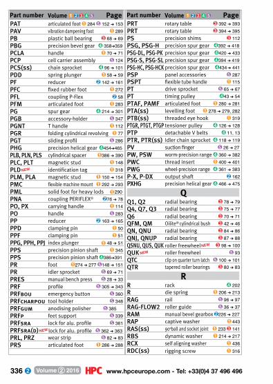
336 www.hpceurope.com - Tel: +33(0)4 37 496 496Volume 2 2016
Part number Volume 1 2 3 4 5 PagePRT rotary table 3 392 ➔ 393PRT rotary table 3 394 ➔ 395PS precision shims 3 112PSG, PSG-H precision spur gear 4 392 ➔ 418PSG-DL, PSG-PK precision spur gear 4 420 ➔ 433PSG-S, PSG-SL precision spur gear 4 394 ➔ 419PSG-HC, PSG-HCK precision spur gear 4 434 ➔ 441PSP panel accessories 5 287PSPT flexible tube handle 1 115PT drive sprocket 5 65 ➔ 67PT timing pulley 4 43 ➔ 54PTAF, PAMF articulated foot 1 280 ➔ 281PTA(ss) levelling foot 1 278 ➔ 279, 282PTB(ss) threaded eye hook 1 319PTGR, PTGT, PTGP tensioner pulley 4 126 ➔ 128PTP detachable V belts 4 11, 13PTR, PTR(ss) Idler chain sprocket 4 118 ➔ 119PV suction finger 5 26 ➔ 27PW, PSW worm-precision range 4 360 ➔ 382PWC thread insert 1 400 ➔ 401PWG wheel-precision range 4 361 ➔ 383P-X, P-DX output shaft 2 162PXHG precision helical gear 4 466 ➔ 475
QQ1, Q2 radial bearing 3 78 ➔ 79Q4, Q7, Q3 radial bearing 3 75 ➔ 77Q6 radial bearing 3 70 ➔ 71QFM, QM Oilite® cylindrical bush 3 42 ➔ 46QN, QNU radial bearing 3 84 ➔ 86QNJ, QNUP radial bearing 3 87 ➔ 88QSNU, QUS, QUK roller freewheel NEW 3 98 ➔ 100QUK NEW roller freewheel 5 93QTC clip on quarter turn latch 5 100 ➔ 101QTR tapered roller bearings 3 80 ➔ 83
RR rack 4 202R die spring 1 206 ➔ 213RAG rail 5 96 ➔ 97RAG-FLOW2 roller guide 5 36 ➔ 37RAM manual bevel gearbox 2 226 ➔ 227RAP captive washer 1 443RAS(ss) 90°ball and socket joint 1 233 3 141RBS dynamic washer 1 214 ➔ 217RCX self aligning washer 1 436RDC(ss) rigging screw 1 316
NEWPart number Volume 1 2 3 4 5 PagePAT articulated foot 1 284 5 152 ➔ 153PAV vibration dampening foot 1 289PB plastic ball bearing 3 68 ➔ 69PBG precision bevel gear 4 358➔359PCLA handle 1 70 ➔ 71PCP cell carrier assembly 5 124PCS(ss) chain sprocket 4 96 ➔ 101PDD spring plunger 1 58 ➔ 59PF reducer 2 142 ➔ 161PFC fixed rubber foot 1 272PFL coupling P-Flex 2 58PFM articulated foot 1 283PG spur gear 4 214 ➔ 301PGB accessory-holder 5 347PGNT T handle 1 112PGR folding cylindrical revolving 1 77PGT sliding profil 5 286PHG precision helical gear 4 454➔465PLB, PLN, PLS cylindrical spacer 1 386 ➔ 390PLC, PLT magnetic stud 1 148PLD NEW identification tag 1 318PLM, PLA magnetic stud 1 150 ➔ 154PMC flexible machine mount 1 292 ➔ 293PML solid foot for heavy lods 1 290PNA coupling PERIFLEX® 2 76 ➔ 78PO, PX carrying handle 1 114PO handle 5 283PP reducer 2 163 ➔ 165PPD clamping pin 1 50PPF clamping pin 1 51PPG, PPH, PPJ index plunger 1 48 ➔ 51PPS precision pinion shaft 1 345PPS precision pinion shaft 4 386➔391PR foot 1 274 ➔ 277 5 148 ➔ 151PR idler sprocket 5 69 ➔ 71PRES manual bench press 5 28 ➔ 33PRF profile 5 305 ➔ 343PRFbou emergency button 5 360PRFcharpou tool holder 5 348PRFgum anodising polisher 5 385PRFp feet support 5 339PRFsra lock for alu. profile 5 361PRFsra(d) NEW lock for alu. profile 5 362 ➔ 363PRL, PRZ wear strip 5 82 ➔ 83PRS articulated foot 1 286 ➔ 288

337 Fax: +33(0)4 37 490 055 - [email protected] Volume 2 2016
Part number Volume 1 2 3 4 5 PageRDER NEW rigging screw 1 317REGA-REGP aluminium ruler 1 160 ➔ 161RFV worm and wheel gearbox 2 306 ➔ 311RGG drip feeder 5 85RGS coupling ROTEX® GS 2 36 ➔ 37RJA sealing strip 5 230 ➔ 233RJZM, RJUM Drylin® bearing 3 243, 254RLR Rollring® chain tensioner 4 114 ➔ 115RLX free running conveyor roller 5 40RMSA shock absorber 1 244RNAST cam follower 3 279ROB, ROS caster 5 50 ➔ 51ROCPL, ROCTR caster 5 52 ➔ 53ROE, RES, RES(ss) caster 5 54 ➔ 56RPB ballscrew bearing unit 3 325RPP timing belt 4 25 ➔ 33RPP-P connecting plate 4 34RSH centerless ground shaft 3 21 RT(T), RTL locking assembly 2 128 ➔ 131RTE coupling ROTEX® 2 68 ➔ 69RTK, RTN coupling BoWex® 2 60 ➔ 65RVM manual worm and wheel 2 228 ➔ 229
SS chain sprocket 4 92 ➔ 95S, SF ball bearing 3 72 ➔ 74S2B, S2O linear bearing housing 3 249, 251SA(KH) linear bearing housing 3 237SAS clutche 4 100 ➔ 101SBR, SUA chain per metre 4 102 ➔ 103SBS chain per metre 4 104 ➔ 105SC2 rigid coupling 2 83SCA, SCE(ss) cable clamp 1 300 ➔ 303SCH toggle clamp 1 139SCR suction cup threaded insert 5 19SDA, SDB locating bolt support bracket 1 42 ➔ 43SDG(ss) support bracket 5 112 ➔ 113SEH, SEV toggle clamp 1 137 ➔ 138SER magnetic doorstop 5 284SERB came latch 5 195SFE, SME rod end Unibal® 3 134 ➔ 135SFWR end support 3 234SGV, SRG adjustable latch 1 126 ➔ 133SH helical gear 4 308 ➔ 318SHA handwheel 1 82 ➔ 84SHN, SHNA nut 1 438
Part number Volume 1 2 3 4 5 PageSHS, SHSS shoulder screw 1 414 ➔ 417SHTC, SHTP Drylin® linear table 3 354 ➔ 357SHW washer 1 437SKM/SKF star knob 1 95SKM hexagonal nut 3 303SLB(ss), SLBS clamping pin 1 52 ➔ 53, 56SLBW(ss) index bolt 1 54 ➔ 55SLH, SLV toggle latch 1 134 ➔ 136SLHH, SLHV toggle latch 1 142 ➔ 143SLS trapezoidal rolled leadscrew 3 310SLVH, SLVV toggle clamp 1 143 ➔ 145SMLS linear table 3 255SMS spiral bevel gear 4 152 ➔ 153SPIT levelling support 5 154SR rack 4 203SRP slotted spring pin 1 366 ➔ 367SSB stainless steel bevel gear 4 144SSDB, SSTB, SSFB stainless steel bevel gear 4 145SSE Unibal® spherical bearing 3 124SSG spur gear 4 225 ➔ 272STC elasto buffer 1 246STL guidance brush 5 99STL detachable V belt 4 10, 12STRIP sealing brush strip 5 179 ➔ 181STU stroke rotary bush 3 47SUA chain by metre 4 102 ➔ 103SUP locking assembly 2 124SVG, SRG adjustable latch 1 126 ➔ 133SVT, SVR screwjack 3 342 ➔ 353 SW(H) worm shaft 4 156 ➔ 174
TT toothed bar 4 40 ➔ 42T timing belt 4 55 ➔ 60T timing pulley 4 43 ➔ 54T spring in metre 1 193T-M timing belt per metre 4 60T-P connecting plate 4 61T0 torsion spring 1 204 ➔ 205TAC(ss) rigging screw 1 312 ➔ 313TAD plastic foot 1 273TB(ss) axial thrust bearing 3 92 ➔ 94TB8 roller thrust bearings 3 95TB, TB/Eco bevel gear 4 135, 141TBD leadscrew table 3 366 ➔ 369TBL mini table, metric thread 3 364 ➔ 365

338 www.hpceurope.com - Tel: +33(0)4 37 496 496Volume 2 2016
Part number Volume 1 2 3 4 5 PageW
W(H) worm and wheel 4 156 ➔ 174WBG hoist ring 1 344WFRM flanged ring 3 301WING wing nut 1 440WJRM Drylin®W modular guidance 3 226 ➔ 227SHW plain washer 1 437WSRM cylindrical nut 3 300WS, WW, WJUM Drylin® W rail 3 214 ➔ 225 WSS(ss) symmetrical S shaped hook 1 326 ➔ 327
XXG spur gear 4 234 ➔ 295XJ/J coaxial reducer 2 211 ➔ 216
YYG spur gear 4 234 ➔ 295
ZZA, ZB shaft for linear guide 3 230 ➔ 231ZB bevel gear 4 149 ➔ 150ZDB, ZTB, ZFB bevel gear 4 151ZG, ZPG spur gear 4 220 ➔ 297ZH helical gear 4 320 ➔ 328ZHG, ZHPG spur gear 4 300 ➔ 305ZIN internal gear 4 190 ➔ 194ZM, ZPM worm and wheel 4 157 ➔ 175ZR rack 4 201ZSH helical gear 4 309 ➔ 317ZSW, ZW worm and wheel 4 156 ➔ 174
Part number Volume 1 2 3 4 5 PageTBV manual lifting table 3 370 ➔ 373TC1rp, TCRX chain tensioner 4 110 ➔ 111TCC(ss) rigging screw 1 314 ➔ 315TCL support rod for heavy loads 1 291TCLar, TCSH chain tensioner 4 112 ➔ 113TFR tensioner plate 4 123TIF threaded bar 1 411TK linear bearing 3 242TK-OP linear bearing 3 246TM suction cup threaded insert 5 18TMR tensioner plate 4 122TOC swivel head 5 110TR(M), TRM(ss) rack 4 207 ➔ 208TS, TW Drylin® linear slide 3 202 ➔ 203TTQ locking assembly 2 125 ➔ 127TUBE square tube 5 273
UU universal joint 2 84 ➔ 86UCF flange bearing 3 52, 55, 58 5 157, 160UCFL flange bearing 3 53, 56, 59 5 158, 161UCP block bearing 3 51, 54, 57 5 156, 159UGAC, UGET actuator guide kit 3 399UGCG actuator guide kit 3 398UGH H type guide unit 3 404 ➔ 410UGPC, UGPL actuator guide kit 3 396 ➔ 397UTK UtiliTrack® linear guide 3 256 ➔ 265
VV3RA handwheel 1 85 ➔ 89VAP magnetic stud 1 149VKM square nut 3 299VLBG, VRBG hoist ring 1 342 ➔ 343 VLBS, VRBS hoist ring 1 340 ➔ 341VML set screw 1 109VMS set screw 1 106VP(ss) small threaded handle 1 102 ➔ 103VB, VBFP small threaded handle 1 100 ➔ 101VPRAM handwheel 1 81VRC retaining clamp 1 146 ➔ 147VRM hoist ring 1 339 VRS(ss) hoist ring 1 336 ➔ 338VT(A) clutche 2 98 ➔ 99VTH hexagonal headed bolts 1 418 ➔ 419
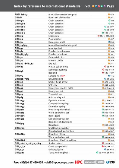
339 Fax: +33(0)4 37 490 055 - [email protected] Volume 2 2016
ANSI B18-17 Manually operated wing nut 1 440DIN 1B Boxes set of threaded 1 351DIN 04-1 Chain sprocket 4 93DIN 05B-1 Chain sprocket 4 94DIN 06B-1 Chain sprocket 4 96 ➔ 97DIN 08B-1 Chain sprocket 4 98 ➔ 99DIN 10B-1 Chain sprocket 4 100 ➔ 101DIN 103 Leadscrew 3 294 ➔ 295, 306DIN 125 Plain washer 1 437 DIN 176 Hexagonal shaft 2 230DIN 314/315 Manually operated wing nut 1 440DIN 444 Male eye bolt 1 329DIN 464 Knurled thumb screw 1 106DIN 466/467 Knurled thumb nut 1 107DIN 471 External circlip 1 358DIN 472 Internal circlip 1 359DIN 580 - DIN 582 Eye bolt 1 331DIN 625 Plastic ball bearing 3 68 ➔ 69
DIN 648Spherical bushing 3 118 ➔ 119 Rod end 3 126 ➔ 127
DIN 705 Locking ring NEW 2 115DIN 808/7551 Universal joint 2 84 ➔ 85DIN 912 Socket-head screw 1 420 ➔ 425DIN 916 Set scrw 1 434 ➔ 435DIN 933 Hexagonal headed bolts 1 418 ➔ 419DIN 934 Hexagonal nut 1 438 DIN 975 Threaded bar 1 411DIN 985 Auto locking nut 1 439DIN 2093 Dynamic washer 1 214 ➔ 217DIN 2095 Compression spring 1 180 ➔ 191DIN 2097 Extension spring 1 194 ➔ 203DIN 3961 Precision pinion shaft 4 387 ➔ 475
DIN 3974 Worm and wheel set 4 362 ➔ 383DIN 3985 Bevel gears 4 358 ➔ 359DIN 6319 Self aligning washer 1 436
DIN 6325Boxed set of dowel pins 1 349Dowel pin 1 368 ➔ 369
DIN 6799 Shaft locking washer 1 360
DIN 6885Rounded end feather key 1 356 ➔ 357Boxed set of key 1 353Worm and wheel set 4 361 ➔ 383
DIN 6888 Boxed set of half round key 1 354DIN 71802 - 71803 - 71805 Socket joints 3 140 ➔ 141DIN 71752 Clevis components 3 142 ➔ 147DIN 7551 Universal joint 2 84 ➔ 85DIN 7721 T and AT timing belt 4 55 ➔ 60, 84 ➔ 86
Index by reference to international standards Vol. 1 2 3 4 5 Page
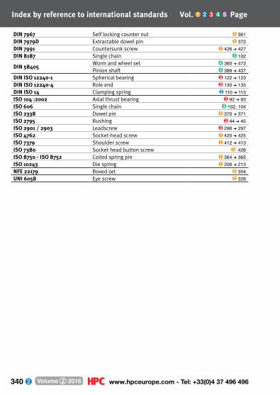
340 www.hpceurope.com - Tel: +33(0)4 37 496 496Volume 2 2016
DIN 7967 Self locking counter nut 1 361DIN 7979D Extractable dowel pin 1 372DIN 7991 Countersunk screw 1 426 ➔ 427DIN 8187 Single chain 4 102
DIN 58405Worm and wheel set 4 360 ➔ 473Pinion shaft 4 386 ➔ 437
DIN ISO 12240-1 Spherical bearing 3 122 ➔ 123DIN ISO 12240-4 Role end 3 130 ➔ 133DIN ISO 14 Clamping spring 2 110 ➔ 113ISO 104 :2002 Axial thrust bearing 3 92 ➔ 93ISO 606 Single chain 4 102, 104ISO 2338 Dowel pin 1 370 ➔ 371ISO 2795 Bushing 3 44 ➔ 45ISO 2901 / 2903 Leadscrew 3 296 ➔ 297ISO 4762 Socket-head screw 1 420 ➔ 425ISO 7379 Shoulder screw 1 412 ➔ 413ISO 7380 Socket head button screw 1 428ISO 8750 - ISO 8752 Coiled spring pin 1 364 ➔ 365ISO 10243 Die spring 1 206 ➔ 213NFE 22179 Boxed set 1 354UNI 6058 Eye screw 1 328
Index by reference to international standards Vol. 1 2 3 4 5 Page
341 Fax: +33(0)4 37 490 055 - [email protected] Volume 2 2016
Index by name Chapter ➊➋➌➍➎ Page
Accessory Holder accessory holder for aluminium profile ➎ 347Actuator motorised actuator ➌ 328 ➜ 341Adjustment Unit mini adjustment unit on profile ➌ 359 ➜ 361Anchor bracket for aluminium profile ➎ 340 ➜ 341Angle Gearbox manual gearbox ➋ 226 ➜ 227, 229
miniature right angle gearbox ➋ 225right angle gearbox ➋ 166 ➜ 197right angle or T gearbox ➋ 174 ➜ 197, 232 ➜ 249
Arms holding arm ➎ 23 ➜ 25tension arm for belt/chain ➍ 120 ➜ 121adjustable holding arm ➎ 24 ➜ 25
Assembly sensor carrier assembly ➎ 116 ➜ 134, 373Backlash anti-backlash gear ➍ 184 ➜ 185
anti-backlash spur gear ➍ 184 ➜ 185anti-backlash wheel for worm ➍ 176 ➜ 177
Ball catch ➎ 194Ball Joint ➌ 118 ➜ 125Ballscrew ➌ 314 ➜ 315, 318Bar feather key rod ➊ 355 ➜ 357
timing pulley bar stock ➍14 ➜ 15, 38 ➜ 42, 62 ➜ 63, 212 ➜ 213Bar Stock round steel bar NEW➌ 20 ➜ 24Bearing ball bearing ➌ 68 ➜ 77
combined bearing ➌ 90 ➜ 91cylindrical roller bearing ➌ 84 ➜ 88spherical bearing ➌ 118 ➜ 147tapered roller bearing ➌ 80 ➜ 83thrust bearing ➌ 92 ➜ 95linear bearing ➌ 326, 238 ➜ 246linear bearing housing ➌ 237, 248 ➜ 251, 254Drylin® W hybrid bearing ➌ 226 ➜ 227flanged bearing ➌ 48 ➜ 63pillow block ➌ 51 ➜ 63, ➎ 156 ➜ 161
Bearing Block ball screw bearing housing ➌ 316 ➜ 317, 323 ➜ 325for leadscrew ➌ 310screw block for aluminium profile ➎ 383
Bipod bipod support base ➎ 145 ➜ 146Block bearing adjustment shim ➌ 112Bolt indexing bolt ➊ 56Bracket aluminium profile bracket ➎ 332 ➜ 335, 338 ➜ 352Brush anti-static brush ➎ 184 ➜ 187
clip-on support brush ➎ 42 ➜ 43, 164 ➜ 165cylindrical brush ➎ 166 ➜ 171guidance brush ➎ 98 ➜ 99
A
B
342 www.hpceurope.com - Tel: +33(0)4 37 496 496Volume 2 2016
Brush ring brush ➎ 182 ➜ 183profile mounting strip brush ➎ 384sealing brush strip ➎ 172 ➜ 181
Bush clamping ring ➋ 116 ➜ 121flexible bush NEW➊ 268 ➜ 269locking ring ➋ 115splined bush ➋ 109, 111 ➜ 113
Bushing linear and rotary bushing ➌ 47Button emergency release button ➎ 360
mushroom button ➊ 111Cable aviation cable ➊ 296 ➜ 297
retaining cable for ballpin ➊ 40cable clamp ➊ 300 ➜ 303cable clip ➎ 376 ➜ 377
Carabiner ➊ 310 ➜ 311Casters ➎ 51 ➜ 56
furniture caster for aluminium profile ➎ 350 ➜ 351Cam follower ➌ 278 ➜ 285Catchplate ➎ 193Chain cable-carrier chain ➌ 288, ➎ 318
plate chain ➎ 60 ➜ 73straight long-link chain ➊ 320 ➜ 321transmission chain per metre ➍ 102 ➜ 104
Circlip ➊ 358 ➜ 359Clamp angular clamp ➎ 22
cross clamp ➎ 20, 125 ➜ 127for aluminium profile ➎ 336rod clamp ➎ 132 ➜ 134support clamp ➎ 119 ➜ 123clamping locking rings ➋ 114 ➜ 121locking clamp ➎ 118square tube connector ➎ 274 ➜ 278
Clevis NEW➌ 142 ➜ 146, ➊ 230 ➜ 231straight clevis NEW➌ 137, ➊ 227
Clip spring clip ➌ 142 ➜ 143, 145Clamping lever ➊ 70 ➜ 75Collar adjustable shaft collar ➋ 124
clamping collar ➎ 74 ➜ 75Conical bevel gear ➍ 132 ➜ 151
precision bevel gear ➍ 358 ➜ 359Connector connector for aluminium profile NEW➎ 330
angular connector ➎ 21Graphit® round tube connector NEW➎ 250 ➜ 261square tube connector ➎ 274 ➜ 278
BIndex by name Chapter ➊➋➌➍➎ Page
C

343 Fax: +33(0)4 37 490 055 - [email protected] Volume 2 2016
Connector belt connecting plate ➍ 34, 61, 87chain link ➍ 103, 105
Conveyor conveyor components ➎ 136 ➜ 161Conveyor roller ➎ 40, 77Conveyor roller spacer ➎ 78Conveyor wheel ➎ 38 ➜ 39, 76Coupling articulated coupling for actuator rod ➌ 400 ➜ 403
bellows coupling ➋ 46 ➜ 57BoWex® toothed driven coupling ➋ 60 ➜ 65ECO series toothed driven coupling ➋ 62 ➜ 63ECO series spider coupling ➋ 66 ➜ 67flexible coupling ➋ 32 ➜ 33GERWAH® coupling ➋ 38 ➜ 45miniature coupling ➋ 50 ➜ 53OLDHAM coupling ➋ 34 ➜ 35P-FLEX coupling ➋ 58PANAMECH - MULTIBEAM coupling ➋ 26 ➜ 31PERIFLEX® coupling ➋ 76 ➜ 78rigid coupling ➋ 82 ➜ 83ROTEX® coupling ➋ 68 ➜ 69ROTEX® GS coupling ➋ 36 ➜ 37servo system coupling ➋ 26 ➜ 58torque limiter ➋ 98 ➜ 105transmission coupling ➋ 60 ➜ 78universal joint ➋ 84 ➜ 97
Corner reinforcement ➎ 337Crank rotating handle crank ➊ 78 ➜ 80Cylindrical Bushing ➌ 26 ➜ 46Damper rotary damper ➊ 236 ➜ 239Display multifunction display NEW➊ 172 ➜ 177Door Stop ➎ 280, 284End Fitting ball and socket joint ➊ 232 ➜ 233, 140 ➜ 141
quick-fit cable terminal ➊ 304 ➜ 305Eye bolt ➊ 330 ➜ 331Fasteners aluminium profile fastener ➎ 319 ➜ 325
manual bonnet fastener ➊ 155 ➜ 157Feeder drip feeder ➎ 85Flange flange withbearing ➌ 64 ➜ 67Feeler strip NEW➌ 114 ➜ 115Foot adjustable foot ➊ 273
aluminium profile foot NEW➎ 349, 371,339anti-vibration mount ➊ 289articulated foot ➊ 274 ➜ 288bipod or tripod foot ➎ 145 ➜ 147
CIndex by name Chapter ➊➋➌➍➎ Page
DE
F
344 www.hpceurope.com - Tel: +33(0)4 37 496 496Volume 2 2016
Foot fixed rubber foot ➊ 272heavy load foot ➊ 290support foot ➎ 148 ➜ 154
Freewheel Bearing freewheel bearing NEW➎ 93, ➌ 96 ➜ 100Freewheel Roller freewheel roller for gravity conveyor ➎ 40Gear anti-backlash spur gear ➍ 184 ➜ 185
bevel gear ➍ 132 ➜ 151, 358 ➜ 359class 6 precision spur gear ➍ 434 ➜ 441class 7 precision crossed helical gear ➍ 466 ➜ 479class 7 precision parallel helical gear ➍ 454 ➜ 465class 7 precision spur gear ➍ 392 ➜ 419crossed helical gear ➍ 319 ➜ 329delrin class 8 precision spur gear ➍ 420 ➜ 433double spur gear ➍ 180 ➜ 183ground spur gear ➍ 442 ➜ 451internal gear ➍ 190 ➜ 194parallel helical gear ➍ 308 ➜ 318pinion shaft ➍ 186 ➜ 189spiral bevel gear ➍ 152 ➜ 153Spur gear ➍ 212 ➜ 305
Motor gearboxes AC gearbox motor ➋ 270 ➜ 279, ➎ 88 ➜ 89DC motor-gearbox ➋ 254 ➜ 260stainless steel gear motor ➋ 300 ➜ 311
Gearbox epicyclic servo gearbox ➋ 204 ➜ 209manual bevel gearbox ➋ 226 ➜ 227manually operated gearbox ➋ 229manual wormwheel gearbox ➋ 228miniature gearbox ➋ 225spur gear coaxial gearbox ➋ 210 ➜ 223right angle gearbox ➋ 166 ➜ 197, 244 ➜ 249right angle or T gearbox ➋ 174 ➜ 197, 232 ➜ 249spur gear reducer ➋ 198 ➜ 203stainless steel wormwheel gearbox ➋ 306 ➜ 311wormwheel gearbox ➋ 142 ➜ 165, 280 ➜ 293wormwheel gearbox with torque limiter ➋ 296 ➜ 299
General Terms And Conditions Of Sale ➊ 456, ➋ 328, ➌ 424, ➍ 488, ➎ 392Guide ➎ 100 ➜ 102
actuator guide kit ➌ 396 ➜ 399for plate chain guide ➎ 80 ➜ 81Drylin W systems ➌ 214 ➜ 227Drylin® N miniature systems ➌ 208 ➜ 213half-rail motion ➌ 266 ➜ 273linear guide ➌ 150 ➜ 189linear rotary ball spline ➌ 152 ➜ 157
GIndex by name Chapter ➊➋➌➍➎ Page

345 Fax: +33(0)4 37 490 055 - [email protected] Volume 2 2016
Guide rotary motion ➌ 20 ➜ 115Utilitrack® linear motion ➌ 256 ➜ 265V-slot rail motion ➌ 274 ➜ 277
Guide Unit H-type guide unit ➌ 404 ➜ 410Handle carrying handle ➊ 114
cylindrical revolving handle ➊ 76 ➜ 77door handle for aluminium profile ➎ 356 ➜ 358hexagonal ended handle ➋ 231handle ➎ 283flexible handle tube ➊ 115T-form thermoplastic handle ➊ 112small 6 lobe handle ➊ 98 ➜ 103
Handling ➎ 34 ➜ 57Handwheel rotating handwheel ➊ 81 ➜ 91Head swivel head ➎ 110Heat Treatment technical information ➍ 332 ➜ 333Hinge hinge NEW➎ 288 ➜ 290, 196 ➜ 223, 354 ➜ 355
clevis joint and clip hinge ➌ 142 ➜ 146hinge for aluminium profile ➎ 354 ➜ 355
Hook threaded eye hook ➊ 319Hub Clamp ➋ 122Idler idler for plate chain ➎ 72 ➜ 73Identification tag NEW➊ 318Indexing And Positioning ➊ 24 ➜ 67Insert self-tapping insert ➊ 402 ➜ 410
suction cup insert ➎ 18 ➜ 19Joining Bar for aluminium profile ➎ 325Joint Cover universal joint cover ➋ 86, 96Key ➊ 353 ➜ 357
universal latch key ➎ 195Kit motor kit ➋ 252 ➜ 253Knob knurled knob ➊ 92 ➜ 93
mushroom knob ➊ 113revolving knob ➊ 113spherical knob ➊ 104 ➜ 105star knob ➊ 95wing knob ➊ 96 ➜ 97
Latch latch ➎ 192, 194, 285, 365cam latch ➎ 195latch for aluminium profile ➎ 365quarterturn latch ➎ 190 ➜ 191
Linear table ➌ 255, 354 ➜ 357Leadscrew table with opposing threads ➌ 366 ➜ 369
mini leadscrew table ➌ 364 ➜ 365Lifting pin ➊ 332 ➜ 333
HG
Index by name Chapter ➊➋➌➍➎ Page
IJ
K

346 www.hpceurope.com - Tel: +33(0)4 37 496 496Volume 2 2016
Lifting Table manual lifting table ➌ 370 ➜ 373Lifting Ring ➊ 334 ➜ 345Linear Drive And Adjustment ➌ 328 ➜ 410Link chain link ➍ 103, 105
quick link ➊ 322 ➜ 325Locking assembly hydraulic locking assembly ➋ 134 ➜ 139
mechanical locking assembly ➋ 132 ➜ 133Locking assembly self-centring locking assembly ➋ 124 ➜ 131Locking clamp manual locking clamp ➌ 204 ➜ 207Locking ring NEW ➋115
locking for leadscrew ➌ 309Locking pin ➊ 24 ➜ 41Locking System aluminium profile locking system ➎ 366 ➜ 367, 369Machine mount flexible ➊ 292 ➜ 293Machine tools parts ➎ 12 ➜ 33Magnet ➊ 148 ➜ 154, ➎ 284, 367Magnetic Stud magnetic stop ➎ 284, 367,➊ 148 ➜ 154Manual workbench press ➎ 28 ➜ 33Modular Aluminium Structure ➎ 292 ➜ 391Motor AC motor ➋ 271 ➜ 275
stainless steel AC motor ➋ 300 ➜ 305Motorised Linear Actuator ➌ 328 ➜ 333Mount elasto mount ➊ 248 ➜ 259Nut auto-locking nut ➊ 439
ball screw ➌ 319 ➜ 322bearing locknut ➌ 102 ➜ 110hexagonal nut DIN 934 ➊ 438knurled nut ➊ 108leadscrew ➌ 293sliding nut ➊ 441self locking counter nut ➊ 361thumb nut ➊ 107, 110trapezoidal nut ➌ 299 ➜ 308wing nut (fastener) ➊ 440well nut ➊ 247
Panel holder ➎ 282mounting block ➎ 346support ➎ 286 ➜ 287
Peek® Peek® precision spur gear ➍ 420 ➜ 433Peek® precision worm and wheel ➍ 372 ➜ 383
Pin extractable dowel pin ➊ 372hitch pin ➊ 372linch pin ➊ 362 ➜ 363
ML
Index by name Chapter ➊➋➌➍➎ Page
PN
347 Fax: +33(0)4 37 490 055 - [email protected] Volume 2 2016
Pin solid dowel pin ➊ 349 ➜ 350, ➊ 368 ➜ 371spring pin NEW➊ 348, ➊ 364 ➜ 367, 352taper pin ➊ 351
Pinion anti-backlash spur gear ➍ 184 ➜ 185bevel gear ➍ 132 ➜ 151, 358 ➜ 359chain sprocket ➍ 92 ➜ 101, 117 ➜ 119double spur gear ➍ 180 ➜ 183drive sprocket ➎ 65 ➜ 67helical gear ➍ 308 ➜ 329internal gear ➍ 190 ➜ 194pinion shaft ➍ 186 ➜ 189precision helical gear ➍ 454 ➜ 457precision pinion shaft ➍ 386 ➜ 391precision spur gear ➍ 386 ➜ 452spur gear ➍ 212 ➜ 305
Plate mounting plate NEW➌ 138 ➜ 139, ➊ 228 ➜ 229belt connecting plate per metre ➍ 34, 61, 87plate for aluminium profile ➎ 326 ➜ 328, 342 ➜ 343
Plunger spring plunger ➊ 60 ➜ 66spring operated plunger ➊ 58 ➜ 59
Position Indicator electronic position indicator ➊ 170 ➜ 171mechanical position indicator ➊ 162 ➜ 167
Positioner linear positioner ➌ 362 ➜ 363, ➎ 86 ➜ 87Potentiometer ➋ 267Power power supplies ➋ 261 ➜ 263Profile accessory holder ➎ 347, 348
adjustable joint ➎ 329aluminium profile ➎ 294 ➜ 316coupling bar ➎ 331floor anchor ➎ 340 ➜ 341guiding profile clamp ➎ 103 ➜ 105internal hinge pin ➎ 353open channel alu. profile ➎ 316 ➜ 317polishing block ➎ 385vertical bearing support ➎ 372support profile for plate chain ➎ 82 ➜ 83screw block ➎ 385cover profile ➎ 382
Pulley timing pulley ➍16 ➜ 24, 43 ➜ 54, 64 ➜ 83Quick-Release Pin ➊ 24 ➜ 41Rack standard rack ➍ 198 ➜ 209Rail guide rail ➌ 150 ➜ 289
PIndex by name Chapter ➊➋➌➍➎ Page

348 www.hpceurope.com - Tel: +33(0)4 37 496 496Volume 2 2016
Rail Utilitrack® V-slot rail ➌ 259, 261, 263, 265Reaction arm ➋ 294Retaining catch ➊ 146 ➜ 147Rigging Screw manual rigging screw ➊ 317
rigging screw with 2 jaws ➊ 316with hook/eye ➊ 312 ➜ 313with hook/hook ➊ 314 ➜ 315
Rod ➎ 117rod clip ➎ 106rod for clamp ➎ 107 ➜ 108
Rod protecture cap ➎ 109Rod end ➌ 126 ➜ 135Roller aluminium profile roller ➌ 287, ➎ 379, 381
freewheel NEW➌ 98 ➜ 100omni-directional roller ➎ 41
Roller Track rolle guide ➎ 36 ➜ 37, 96 ➜ 97Rotary Table ➌ 390 ➜ 395Ruler aluminium ruler ➊ 160 ➜ 161S Hook symmetrical s hook ➊ 326 ➜ 327Screws ballscrew ➌ 311 ➜ 315, 318Screws counter sunk screw ➊ 426 ➜ 427
driving screw ➌ 292 ➜ 325eye screw ➊ 328 ➜ 329hexagonal head screw DIN 933 ➊ 418 ➜ 419leadscrew ➌ 292 ➜ 298precision worm screw ➍ 360 ➜ 383screw ➊ 106, 109screw for aluminium profile ➎ 324set screw ➊ 429 ➜ 435shoulder screw ➊ 412 ➜ 417socket-head screw ➊ 420 ➜ 428wingknob ➊ 97worm ➍ 156 ➜ 177
Screwjack ➌ 342 ➜ 353Sealing Strip lip seal ➎ 386 ➜ 389
sealing strip for profile ➎ 390Shackle bow shackle ➊ 308 ➜ 309
dee shackle ➊ 306 ➜ 307Shaft drawn and calibrated shaft ➌ 20 ➜ 21
drawn shaft NEW➎ 107 ➜ 108end support ➌ 234 ➜ 235flexible shaft ➌ 70 ➜ 73ground precision shaft ➌ 23ground shaft NEW➌ 22, 24
S
Index by name Chapter ➊➋➌➍➎ Page
R
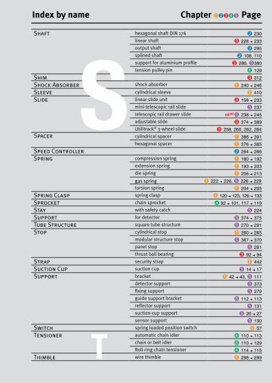
349 Fax: +33(0)4 37 490 055 - [email protected] Volume 2 2016
Shaft hexagonal shaft DIN 176 ➋ 230linear shaft ➌ 228 ➜ 233output shaft ➋ 295splined shaft ➋ 108, 110support for aluminium profile ➌ 286, ➎380 tension pulley pin ➍ 129
Shim ➌ 312Shock Absorber shock absorber ➊ 240 ➜ 246Sleeve cylindrical sleeve ➊ 410Slide linear slide unit ➌ 158 ➜ 203
mini-telescopic rail slide ➎ 237telescopic rail drawer slide NEW➎ 238 ➜ 245adjustable slide ➌ 374 ➜ 389Utilitrack® 3-wheel slide ➌ 258, 260, 262, 264
Spacer cylindrical spacer ➊ 386 ➜ 391hexagonal spacer ➊ 376 ➜ 385
Speed Controller ➋ 264 ➜ 266Spring compression spring ➊ 180 ➜ 192
extension spring ➊ 193 ➜ 203die spring ➊ 206 ➜ 213gas spring ➊ 222 ➜ 226, ➎ 226 ➜ 229torsion spring ➊ 204 ➜ 205
Spring Clasp spring clasp ➊ 120 ➜ 123, 126 ➜ 133Sprocket chain sprocket ➍ 92 ➜ 101, 117 ➜ 119Stay with safety catch ➎ 224Support for detector ➎ 374 ➜ 375Tube Structure square tube structure ➎ 270 ➜ 291Stop cylindrical stop ➊ 260 ➜ 265
modular structure stop ➎ 367 ➜ 370panel stop ➎ 281thrust ball bearing ➌ 92 ➜ 94
Strap security strap ➊ 442Suction Cup suction cup ➎ 14 ➜ 17Support bracket ➊ 42 ➜ 43, ➎ 111
detector support ➎ 373 fixing support ➎ 279
guide support bracket ➎ 112 ➜ 113reflector support ➎ 131suction-cup support ➎ 26 ➜ 27sensor support ➎ 130
Switch spring loaded position switch ➊ 57Tensioner automatic chain idler ➍ 110 ➜ 113
chain or belt idler ➍ 110 ➜ 129Roll-ring chain tensioner ➍ 114 ➜ 115
Thimble wire thimble ➊ 298 ➜ 299
S
T
Index by name Chapter ➊➋➌➍➎ Page

350 www.hpceurope.com - Tel: +33(0)4 37 496 496Volume 2 2016
Thread threaded inserts ➊ 396 ➜ 401Threaded bar ➊ 411Tools ➎ 12 ➜ 33, 315Toggle latch ➊ 120 ➜ 133
clamp ➊ 134 ➜ 145Tooth Size gear tooth size ➍ 209
rack tooth size ➍ 195Toothed Belt timing belt ➍ 25 ➜ 33, 55 ➜ 60, 80 ➜ 86Torque Limiter ➋ 98 ➜ 105Transfer unit ball transfer unit ➎ 44 ➜ 49Trapezoid Rod ➌ 294 ➜ 298Tripod tripod support base ➎ 147Tube end cap for tube ➎ 138 ➜ 144, 272
round tube for clamp ➎ 117, 264square tube structure ➎ 273tube carrier ➎ 128 ➜ 129
Tube structure round tube structure NEW➎ 248 ➜ 269U-Bolt ➊ 392 ➜ 393Universal Joint ➋ 84 ➜ 97Valve wheel ➊ 94V Belt detachable V belt ➍ 10 ➜ 13Washer stop washer ➌103
captive washer ➊ 443dynamic washer ➊ 214 ➜ 217self aligning washer ➊ 436shaft locking washer ➊ 360spring washer ➌ 113plain washer ➊ 437
Wheel idler sprocket ➎ 69 ➜ 71for aluminium profile ➎ 378rubber wheel for conveyor system ➎ 79rubber tyred wheel ➎ 50
Worm And Wheel set precision worm and wheel ➍ 360 ➜ 383standard worm and wheel ➍ 156 ➜ 177
VU
W
Index by name Chapter ➊➋➌➍➎ Page
T

351 Fax: +33(0)4 37 490 055 - [email protected] Volume 2 2016
united Kingdom
Tel: +44 (0)1246 455 500 Email: [email protected]
www.ondrives.com
hpc in europe
Italia
Torino - ItaliaTel: +(39) 011 760 95 05
Email: [email protected]
Tél: Service 0,15 A / min + prix appel
Fax: Service 0,15 A / min + prix appel
France
58, Chemin de la Bruyère69570 Dardilly (Lyon) - France
Tél : +33 (0)4 37 496 496Fax : +33 (0)4 37 490 055
Email : [email protected]

5 Volumes for 2016
+ +Made to measure Catalogue + CAD files
free catalogues
Compagny: ..........................................................................................................Address: ..............................................................................................................Postcode: ............ Town: ...................................................................................Surname/First name: .......................................................................................... Tel: ............................................ Position: ............................................................
Click on the catalogue tab on hpceurope.comor complete this form and send it to:
+33 (0)4 37 490 055
th
rough the poste
instantly
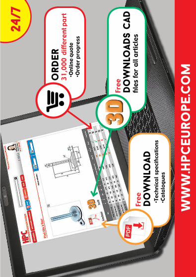
Free
do
wn
load
s cad
files
for
all a
rtic
les
ww
w.h
pceu
rope
.co
m
Free do
wn
load
Te
chni
cal s
peci
ficat
ions
Ca
talo
gues
24/7
ord
er31
,000
diff
eren
t par
t
Onlin
e qu
ote
Or
der p
rogr
ess
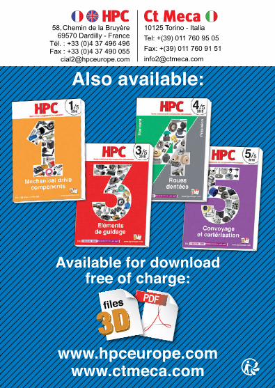
Also available:
www.hpceurope.comwww.ctmeca.com
58, Chemin de la Bruyère 69570 Dardilly - France
Tél. : +33 (0)4 37 496 496Fax : +33 (0)4 37 490 055
10125 Torino - Italia Tel: +(39) 011 760 95 05Fax: +(39) 011 760 91 [email protected]
Available for download free of charge:
PDFfiles