POTOMAC ANNEX BUILDING 2 - GSA
821
POTOMAC ANNEX BUILDING 2 HISTORIC STRUCTURES REPORT CORRECTED FINAL SUBMISSION Prepared for the U.S. General Services Administration by Swanke Hayden Connell Architects February 16, 2000
-
Upload
khangminh22 -
Category
Documents
-
view
1 -
download
0
Transcript of POTOMAC ANNEX BUILDING 2 - GSA

POTOMAC ANNEX BUILDING 2
HISTORIC STRUCTURES REPORT CORRECTED FINAL SUBMISSION
Prepared for the U.S. General Services Administration
by
Swanke Hayden Connell Architects
February 16, 2000

POTOMAC ANNEX BUILDING 2 TABLE OF CONTENTS
i
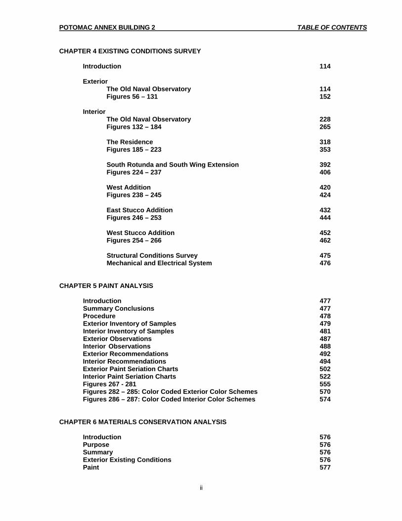
TABLE OF CONTENTS CHAPTER 1 EXECUTIVE SUMMARY 1 CHAPTER 2 BUILDING HISTORY Introduction 5 The Site 6 The Quest for a National Observatory 6 The Establishment of a Depot of Charts and Instruments 8 James Melville Gilliss and the Genesis of the Observatory 9 Mathew Fontaine Maury 13 The Civil War and the Return of James Gilliss 15 The Transit Circle Observatory 17 The Transit Circle 17 The Transit of Venus Expeditions 18 Time Keeping at the Observatory 19 The Great Equatorial Telescope 19 Asaph Hall’s Discovery of the Moons of Mars 20 Decline of the Observatory’s Role in Foggy Bottom 21 The United States Naval Museum of Hygiene 22 Founding the Museum 23 Research at the Museum 25 Establishment of the Medical School 26 The Naval Hospital Moves to Observatory Hill 30 Hospital Design of the Early 20th Century 31 The Hospital Building 33 The Hospital Complex 36 World War One 37 Plans for a New Facility 39 A New Naval Medical Center 41 The Bureau of Medicine and Surgery 42 Chronology of Important Events 44 Statement of Significance 45 Figures 1 - 26 48 CHAPTER 3 DESCRIPTION OF BUILDING AS ORIGINALLY BUILT IN 1844 Introduction 74 The Old Naval Observatory 74 The Magnetic Observatory 77 The Residence and Connecting Hyphen 77 The Transit Circle Observatory 78 West Wing Alterations and Additions 78 The Great Equatorial Observatory 79 Naval Hygiene Museum 80 Naval Medical School 81 Naval Medical School and Hospital 81 Site and Surroundings 82 Figures 27 - 55 85
POTOMAC ANNEX BUILDING 2 TABLE OF CONTENTS
ii
CHAPTER 4 EXISTING CONDITIONS SURVEY Introduction 114
Exterior The Old Naval Observatory 114 Figures 56 – 131 152 Interior
The Old Naval Observatory 228 Figures 132 – 184 265 The Residence 318 Figures 185 – 223 353
South Rotunda and South Wing Extension 392 Figures 224 – 237 406
West Addition 420 Figures 238 – 245 424 East Stucco Addition 432 Figures 246 – 253 444 West Stucco Addition 452 Figures 254 – 266 462 Structural Conditions Survey 475 Mechanical and Electrical System 476 CHAPTER 5 PAINT ANALYSIS Introduction 477 Summary Conclusions 477 Procedure 478 Exterior Inventory of Samples 479 Interior Inventory of Samples 481 Exterior Observations 487 Interior Observations 488 Exterior Recommendations 492 Interior Recommendations 494 Exterior Paint Seriation Charts 502 Interior Paint Seriation Charts 522
Figures 267 - 281 555 Figures 282 – 285: Color Coded Exterior Color Schemes 570 Figures 286 – 287: Color Coded Interior Color Schemes 574
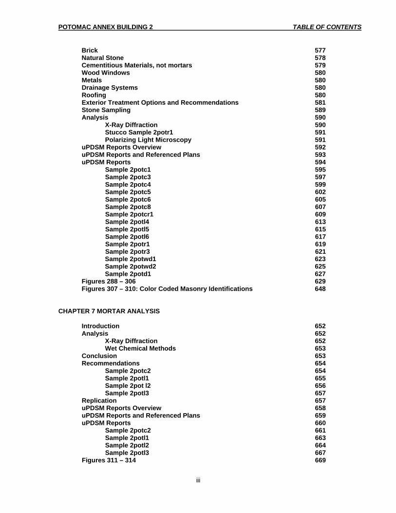
CHAPTER 6 MATERIALS CONSERVATION ANALYSIS Introduction 576 Purpose 576 Summary 576 Exterior Existing Conditions 576 Paint 577
POTOMAC ANNEX BUILDING 2 TABLE OF CONTENTS
iii
Brick 577 Natural Stone 578 Cementitious Materials, not mortars 579 Wood Windows 580 Metals 580 Drainage Systems 580 Roofing 580 Exterior Treatment Options and Recommendations 581 Stone Sampling 589 Analysis 590 X-Ray Diffraction 590 Stucco Sample 2potr1 591 Polarizing Light Microscopy 591 uPDSM Reports Overview 592 uPDSM Reports and Referenced Plans 593 uPDSM Reports 594 Sample 2potc1 595 Sample 2potc3 597 Sample 2potc4 599 Sample 2potc5 602 Sample 2potc6 605 Sample 2potc8 607 Sample 2potcr1 609 Sample 2potl4 613 Sample 2potl5 615 Sample 2potl6 617 Sample 2potr1 619 Sample 2potr3 621 Sample 2potwd1 623 Sample 2potwd2 625 Sample 2potd1 627 Figures 288 – 306 629 Figures 307 – 310: Color Coded Masonry Identifications 648 CHAPTER 7 MORTAR ANALYSIS Introduction 652 Analysis 652 X-Ray Diffraction 652 Wet Chemical Methods 653 Conclusion 653 Recommendations 654 Sample 2potc2 654 Sample 2potl1 655 Sample 2pot l2 656 Sample 2potl3 657 Replication 657 uPDSM Reports Overview 658 uPDSM Reports and Referenced Plans 659 uPDSM Reports 660 Sample 2potc2 661 Sample 2potl1 663 Sample 2potl2 664 Sample 2potl3 667 Figures 311 – 314 669

POTOMAC ANNEX BUILDING 2 TABLE OF CONTENTS
iv
CHAPTER 8 MATERIALS CLEANING ANALYSIS Introduction 673 Purpose of Cleaning 673 Test Procedure and Materials 673 Material Cleaning Analysis 674 Figures 315 – 316 678 CHAPTER 9 DESIGN GUIDELINES/REHABILITATION ACTIONS Introduction 680 Inventory of Significant Exterior Spaces and Details 681 Inventory of Significant Interior Spaces and Details 683 Maintenance Guild lines for Building Management 686 Recommendations for Maintenance, Restoration and Alterations 686 Gutters, Leaders and Storm Drainage 686 Window and Door Sealant 686
Exterior Walks and Paving 687 Floor Tiles 687 Wood Maintenance 687 Windows 687 Brass Hardware 688 Painting 688
Recommendations for Maintenance, Restoration and Alterations 688 Exterior 688 Interior 690 Addition Recommended Areas or Elements That Require Restoration, Renovation and Rehabilitation 693 Recommendations for Conformance with the American’s with Disabilities Act (ADA) of 1990 697 Criteria for the Installation of HVAC, Computer Cabling, Security Systems and Other Building Systems 698 Prioritized Summary of Repairs 700 Figures 317 – 319: Color Coded Preservation Plans 703 CHAPTER 10 GUIDELINES SPECIFICATIONS 706 Concrete Paving 707 Door and Window Hardware Refinishing 712 Flashing and Sheet Metal 715 Joint Sealers 719
Masonry Re-pointing and Repairs 727 Modified Bitumen Sheet Roofing 737 Painting 746 Paint Removal 760 Patching Portland Cement Plaster (Stucco) 765 Rough Carpentry 773 Wood Refinishing 777 Wood Window Rehabilitation 782
POTOMAC ANNEX BUILDING 2 TABLE OF CONTENTS
v
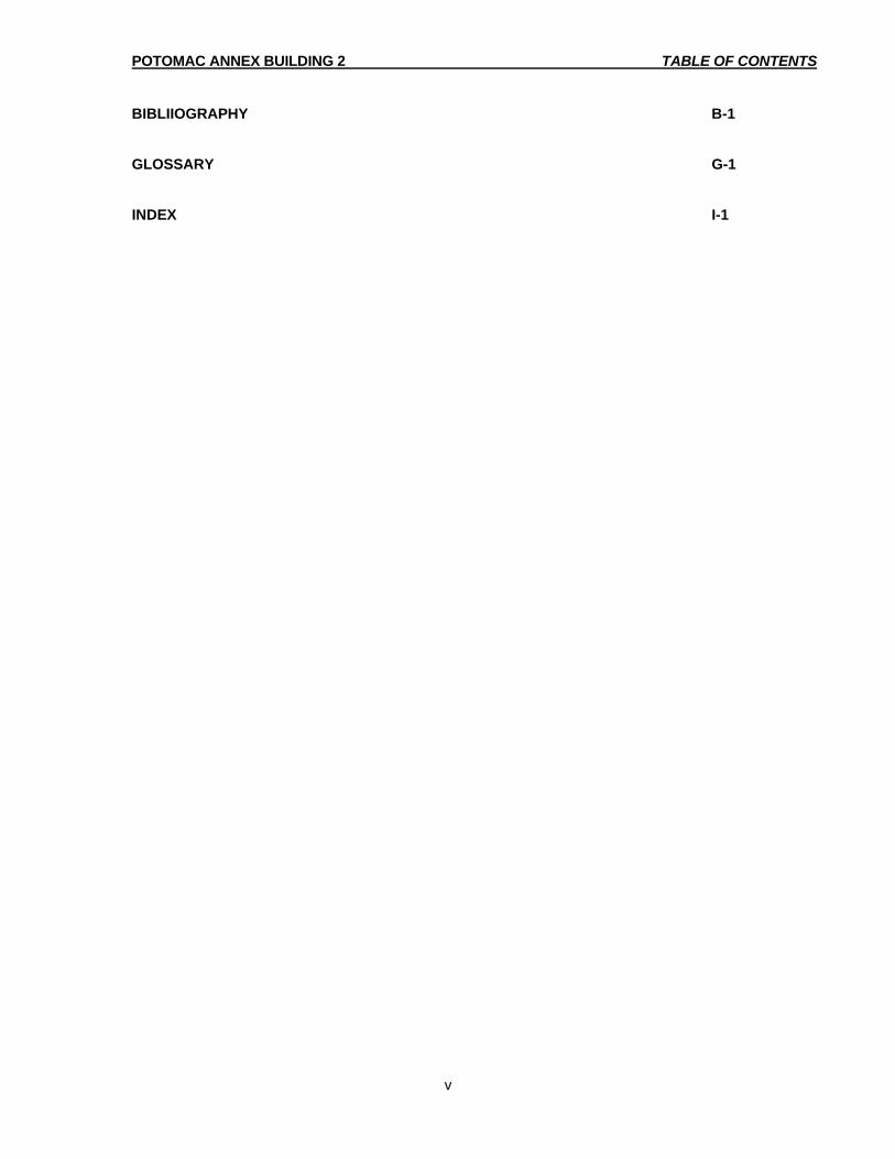
BIBLIIOGRAPHY B-1 GLOSSARY G-1 INDEX I-1
POTOMAC ANNEX BUILDING 2 PREFACE
v
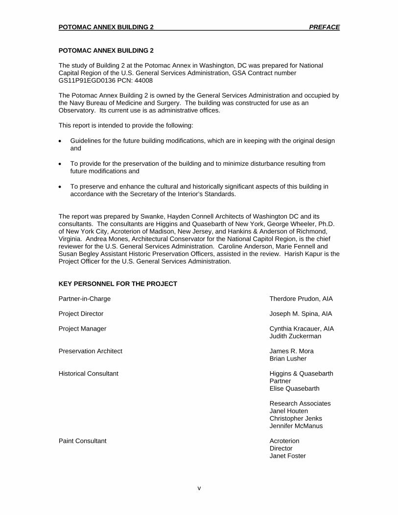
POTOMAC ANNEX BUILDING 2 The study of Building 2 at the Potomac Annex in Washington, DC was prepared for National Capital Region of the U.S. General Services Administration, GSA Contract number GS11P91EGD0136 PCN: 44008 The Potomac Annex Building 2 is owned by the General Services Administration and occupied by the Navy Bureau of Medicine and Surgery. The building was constructed for use as an Observatory. Its current use is as administrative offices. This report is intended to provide the following: • Guidelines for the future building modifications, which are in keeping with the original design
and • To provide for the preservation of the building and to minimize disturbance resulting from
future modifications and • To preserve and enhance the cultural and historically significant aspects of this building in
accordance with the Secretary of the Interior’s Standards. The report was prepared by Swanke, Hayden Connell Architects of Washington DC and its consultants. The consultants are Higgins and Quasebarth of New York, George Wheeler, Ph.D. of New York City, Acroterion of Madison, New Jersey, and Hankins & Anderson of Richmond, Virginia. Andrea Mones, Architectural Conservator for the National Capitol Region, is the chief reviewer for the U.S. General Services Administration. Caroline Anderson, Marie Fennell and Susan Begley Assistant Historic Preservation Officers, assisted in the review. Harish Kapur is the Project Officer for the U.S. General Services Administration. KEY PERSONNEL FOR THE PROJECT Partner-in-Charge Therdore Prudon, AIA Project Director Joseph M. Spina, AIA Project Manager Cynthia Kracauer, AIA Judith Zuckerman Preservation Architect James R. Mora Brian Lusher Historical Consultant Higgins & Quasebarth Partner Elise Quasebarth
Research Associates Janel Houten Christopher Jenks Jennifer McManus Paint Consultant Acroterion Director Janet Foster
POTOMAC ANNEX BUILDING 2 PREFACE
vi
Conservation Consultant George Wheeler, PH.D Structural Consultant Hankins and Anderson Director Larry Willis Word Processing Luba Ivanchuk Sherrise M. Smith Judy Wang ACKNOWLEDGEMENTS Research Assistance Jan K. Herman, Editor and Historian of the Naval Bureau of Medicine and Surgery Dave Klubes, Associate Editor Site Maintenance Procedures Assistance Ike Brown, Potomac Annex Facilities Manager

POTOMAC ANNEX BUILDING 2 CHAPTER 1 EXECUTIVE SUMMARY
GLOSSARY LOCATED AT END OF DOCUMENT 1
Introduction The Old Naval Observatory, is located in the Northwest quadrant of Washington DC, on a ten acre site overlooking the Potomac River. The Old National Observatory site is bordered by 23rd Street to the east, 25th Street to the west, E Street to the north and the Potomac River to the south. Construction began in 1842 and the building was completed in 1844. The original name of the Old Naval Observatory, which included a 9.6-inch refracting telescope, was the Depot of Charts and Instruments. The Old Naval Observatories primary importance lies with the extraordinary work that was conducted there, as well as its historic and architectural merit. The Old Naval Observatory operated on this site from 1844 through 1893. Under the Navy’s management, significant discoveries, functions and events associated with the Old Naval Observatory included navigational, oceanographic and astronomical activities. Significant discoveries, functions and events associated with the Old Naval Observatory included publications such as “Abstract Log for the Use of American Navigators” (1848), volumes of sailing instructions and a whaling chart (1851). Other contributions included the first textbook of oceanography and the rating of maritime chronometers for accuracy, which was of paramount importance to the Navy. There were international forays to observe total eclipses of the sun and the Transit of Venus across the sun were undertaken during the 1870’s. These foray’s helped established the Old Naval Observatory in the international scientific community. In 1877, Asaph Hall, one of the Old Naval Observatories most illustrious astronomers, discovered the inner and outer moons of Mars. This was without parallel the most dramatic event in the history of the Old Naval Observatory. However, in 1893, the Old Naval Observatory was moved to Massachusetts Avenue, where the name was changed to the National Observatory. After this move, there was a long period of transitions and different tenants that would occupy the Old Naval Observatory. This period lasted until the last tenant, the Naval Medical School, moved its operations to Bethesda, MD in 1942. Chapter 2 – Building and History Chapter Two, Building History, describes the building, site, designer and the significant people and events that were associated with the Old Naval Observatory. Construction of the Old Naval Observatory began in 1842 and was completed in 1844. The U.S. Navy was the agency who was in charge of the construction and staffing. The original name of the Old Naval Observatory was the Depot of Charts and Instruments. Due to Lt. Gilliss’ political efforts, the Depot of Charts and Instruments took the appearance and practicality of an observatory. The material in Chapter two presents a continuum of the land’s pre-Revolutionary ownership, through the development of the site as a naval military facility, a period of disuse and finally to the historic significance of the site today. Using the site as a backdrop, Chapter Two then focuses on the Old Naval Observatories evolution from its beginnings as the Depot of Charts and Instruments, through it’s additions and tenants that occupied the Old Naval Observatory. It is the result of the tenants that created much of the changes that the Old Naval Observatory experienced. The changes that occurred at the Old Naval Observatory were the addition of the Superintendents Residence in 1847. This was added to provide a space for the director of the Observatory and his family. The next addition was the Connecting Hyphen in 1848. This was added to connect the residence and the east wing of the Old Naval Observatory. In 1864-65 the west wing was altered and expanded to accommodate the addition of more instruments. The next addition was the South wing and the South Rotunda. The South wing was extended in 1865 and culminated in the South Rotunda in 1873. At the turn of the century, from 1902 to 1903 the east, west and south wings had a second story added to them. These additions were directly related to the new tenant that now occupied the Old Naval Observatory. That new tenant was the
POTOMAC ANNEX BUILDING 2 CHAPTER 1 EXECUTIVE SUMMARY
GLOSSARY LOCATED AT END OF DOCUMENT 2
Museum of Hygiene. The last addition was the east and west stucco additions. The Naval Medical School and Hospital made these additions in response to their needs and requirements. Chapter 3 – Description of the Building as Originally Built in 1844 Chapter Three, Description of the Building as Originally Built in 1844, describes the Old Naval Observatory with more attention to the physical treatments of its exterior and interior than was provided by the preceding historical narrative. This chapter documents the Old Naval Observatories site planning, construction, spatial organization, uses, finishes and other elements original to the building. The information that is provided in this chapter refers to the Old Naval Observatories original built conditions in 1844. To simplify the analysis and avoid any redundancy, Chapter 3 is divided into the following sections. The Observatory (1844-1865), this section details those who were responsible for the creation, design, and funding of the Old Naval Observatory. This section also covers the initial architectural and construction details, including those that cover the dome, telescope and its workings. The Magnetic Observatory, this discussion focuses on the construction intentions of the Magnetic Observatory. The Residence (1847) and Connecting Hyphen (1848), this part discusses the reasoning for the residence and those involved in its creation and the basic architecture that was involved. The Transit Circle Observatory, West Wing Alterations (1864-1865) and addition (1869), this discussion focuses on the construction, structural, and interior changes that were made to the west wing. The Great Equatorial Observatory (1873), this section covers the changes that were needed to house a new refracting 26-inch telescope. This new Observatory was located just south of the original Observatory. This section covers the location, construction, and interior details that were included in this new Observatory. The next section begins the transformation of the Depot of Charts and Instruments to the Naval Hygiene Museum (1894-1902). The discussion focuses on the interior changes that were needed to accommodate this new tenant. The next part introduces the addition of the Naval Medical School (1902-1904). The discussion covers the construction of an additional floor in the wings as well as interior changes made to the basement and rotunda spaces. The next section covers Naval Medical School and Hospital (1904-1942). The discussion focuses on the east, west and south wings and their subsequent additions, construction, fenestration, and interior space changes that the building campaign of 1904-1910 produced. The last part covers the Site and Surroundings. This section discusses the architect that did the initial excavation and landscaping on the site, the later changes that were made to accommodate each tenant that occupied the Old Naval Observatory. Chapter 4 – Existing Conditions Survey Chapter 4, Existing Conditions Survey, represents a physical description of the Old Naval Observatories exterior and interior. The chapter focuses on the Old Naval Observatories present condition. The description is based on a site examination that was conducted during the fall of 1994. Fields notes and photographs were taken of the existing conditions and then compared to the historic documentation. This was done in order to assess the integrity of the structure, space and features. A description of the general conditions is made in this chapter. The purpose of the Existing Conditions Survey is, 1) to identify architecturally significant feature, finishes, and concepts, 2) to differentiate them from other existing features, finishes, and concepts and 3) to assess the physical condition of existing features and finishes as the basis for developing a comprehensive program for the repair and maintenance of the Old Naval Observatory. The information on the Old Naval Observatories features and materials assumes the reader’s familiarity with the data presented in Chapter 3, which illustrates the “As Built” conditions of the Old Naval Observatory. Chapter 4 assesses the extent to which the original features and materials have survived. Chapter 4 also addresses those features, which have been added to the building since the time of construction.

POTOMAC ANNEX BUILDING 2 CHAPTER 1 EXECUTIVE SUMMARY
GLOSSARY LOCATED AT END OF DOCUMENT 3
Chapter 5 – Paint Analysis Chapter 5, Paint Analysis, contains a scientific paint analysis based upon the removal of small samples of the accumulated paint layers on the original architectural elements of the Old Naval Observatory and all its related additions. This analysis is done in order to determine the early colors of such elements, the sequence of finishes and an appropriate color match for any restoration work that needs to be done. A second purpose of the paint analysis is to determine the relative dates for the alterations, using the historic paint sequences as a common point of reference. Since the original Old Naval Observatory was built in 1844, there have been a number of alterations and additions that has occurred to the original structure. From the addition of the Residence in 1847, to the east and west stucco additions in 1918, the Old Naval Observatory building has change dramatically from its original 1844 construction. Not only has the exterior been altered, but also the interior spaces have undergone modification to integrate the alterations and additions. The paint analysis addresses these continuing changes of the building throughout its history and the tenants that occupied the Old Naval Observatory. Chapter 6 – Materials Conservation Analysis Chapter 6, Materials Conservation Analysis, discusses the exterior of the Old Naval Observatory. These exteriors are in generally good condition. While deterioration to the brick is noted in areas where there are drainage problems, other masonry elements are well preserved. The most important condition to be addressed on the exterior is the multiple paint layers covering all masonry elements. The paint coating on the masonry represents a risk to the substrates due to the poor vapor transmission of both new and old paint coatings. Clear evidence of failure of the paint can be seen throughout the exterior due to the inability of water vapor to escape. The opposing effect is the retention of water by the respective masonry materials (brick, natural stone, etc.). Serious consideration must be given to removing most of the paint from all elevations. This chapter also discusses a serious complication to any consideration of paint removal. This complication is the identification of lead paint found on most of the exterior walls and architectural elements. A program of tightly controlled containment must be carried out during paint removal. Even though there is less of a health hazard to adults, for children the hazard is much more serious. If children are present in the Old Naval Observatory they are especially at risk. Especially, if there are any daycare facilities located in the Potomac Annex compound. Chapter 7 – Mortar Analysis Chapter 7, Mortar Analysis, discusses the compositions of existing mortars used in the Old Naval Observatory. Pointing ensures that there is a watertight "skin" on the building facade. In contemplating any new pointing campaign, it is important to attempt to reproduce the color, texture, and profile of the pointing which exists. The color, texture, and profiles may be reproduced with mortars, which are identical in composition, or with mortars whose compositions are different from the original mortars. The Old Naval Observatory exhibits no obvious signs of a re-pointing campaign. There is no evidence such as differences in color, texture, profile or discontinuity with setting mortars. Therefore, it can be concluded that original mortar compositions were determined prior to the commencement of work.

POTOMAC ANNEX BUILDING 2 CHAPTER 1 EXECUTIVE SUMMARY
GLOSSARY LOCATED AT END OF DOCUMENT 4
Chapter 8 – Materials Cleaning Analysis Chapter 8, Materials Cleaning Analysis, discusses the cleaning strategies to preserve the Old Naval Observatories aesthetic character. Different methodologies are introduced to provide an analysis for the best possible solutions to remove a build-up of dirt, soiling and rust stains left on painted, as well as on exposed brick, granite and limestone. Chapter 9 – Design Guidelines/Rehabilitation Actions Chapter 9, Design Guidelines/Rehabilitation Actions, introduces guidelines for the preservation of the Old Naval Observatory. The recommended treatments outlined in this chapter address the aging, weathering, soiling and deterioration of the Old Naval Observatories features and finishes by atmospheric and human agents. The guidelines also present criteria for preserving significant architectural concepts, reproducing important finishes and adapting the Old Naval Observatory in the future. These design guidelines and rehabilitation actions are intended as a curator’s tool to manage change at the Old Naval Observatory. The Old Naval Observatory possesses much of its original spatial configuration and many of the original materials, finishes and features. Chapter 10 – Guideline Specifications Chapter 10, Guide Specifications, includes the following outline specifications. Concrete Paving, Door and Window Hardware Refinishing, Flashing and Sheet Metal, Joint Sealers, Masonry Re-pointing & Repairs, Modified Bitumen Sheet Roofing, Painting, Paint Removal, Portland Cement Plaster, Rough Carpentry, Wood Refinishing, Wood Window Rehabilitation and Stucco Repair and Replacement. These guideline specifications are intended as a curator’s tool to manage change at the Old Naval Observatory. They are also for the individual and staff responsible for the care and maintenance of the Old Naval Observatory.

POTOMAC ANNEX BUILDING 2 CHAPTER 10 GUILDLINE SPECIFICATIONS
GLOSSARY LOCATED AT END OF DOCUMENT
706
SPECIFICATIONS TABLE OF CONTENTS CONCRETE PAVING DOOR & WINDOW HARDWARE REFINISHING FLASHING & SHEET METAL JOINT SEALERS MASONRY REPOINTING & REPAIRS MODIFIED BITUMEN SHEET ROOFING PAINTING PAINT REMOVAL PORTLAND CEMENT PLASTER ROUGH CARPENTRY WOOD REFINISHING WOOD WINDOW REHABILITATION CONCRETE PAVING

POTOMAC ANNEX BUILDING 2 CHAPTER 10 GUILDLINE SPECIFICATIONS
GLOSSARY LOCATED AT END OF DOCUMENT
707
PART 1 - GENERAL 1.1 USE OF DOCUMENTS: These specification sections have been written for deficiencies described in Chapter 9.
An extensive existing condition survey of the Old Naval Observatory and the corresponding historical/architectural research, undertaken in 1994, was the basis for determining the scope of work. No contract or construction work should incorporate these documents without further project specific editing to account for changing conditions and technical advances in conservation practice.
1.2 WORK INCLUDES: A. Replacement of existing paving. B. Related work specified elsewhere. 1. Joint Sealers 2. Rough Carpentry 1.3 SUBMITTALS A. Product Data: Submit selected manufacturer's technical data for each product
indicated, including published recommendations for their application and use. B. Sample: Submit for verification purposes, samples of all materials required for
the work of this section, whether specified or not. Size of samples shall be 250 ml. (1 cup) of each or a 12 inch section of sheet material.
1.4 QUALITY ASSURANCE A. Work must be performed by a firm having not less than 5 continuous years’
experience in concrete work. Provide documentation for at least one project similar in scope and size to this project, and on a building with historic designation.
B. Codes and Standards: Comply with the most stringent codes, for strength,
testing and concrete placement, of all applicable agencies having jurisdiction. 1.5 DELIVERY STORAGE HANDLING A. Delivery: Deliver materials to site in manufacturer's original and unopened
containers and packaging, bearing legible labels as to type and names of products and manufacturers. There shall be no broken bags.
B. Storage: Store in accordance with manufacturer's recommendations.

POTOMAC ANNEX BUILDING 2 CHAPTER 10 GUILDLINE SPECIFICATIONS
GLOSSARY LOCATED AT END OF DOCUMENT
708
C. Protection: Protect materials during storage and construction from wetting by rain, snow or ground water and from staining or intermixture with earth or other types of materials. Store in a dry location or in waterproof containers on raised platforms. Keep containers tightly closed and away from open flames. Protect liquid components from freezing. Comply with manufacturer's recommendations for minimum and maximum temperature requirements for storage.
1.6 EQUIPMENT
A. Spade B. Mechanical vibrating equipment C. Polyethylene moisture barrier D. Moisture retaining core such as waterproof paper, polyethylene film or
polyethylene-coated burlap.
1.7 PROJECT CONDITIONS A. Protection of building elements: Protect adjacent paving, landscaping, walls,
ironwork, ledges and window frames from droppings and spillage. B. Temperature should be above 45 degrees F for at least 48 hours prior to
placing concrete. C. Protection of surroundings: Protect persons, motor vehicles, building or
construction site and surrounding buildings from damage or injury which could result from the performance of the work.
E. Cleanup: Site shall be left broom clean at the end of each work day.
PART 2 - PRODUCTS 2.1 CONCRETE MATERIALS A. Welded wire mesh: Welded plain cold-drawn steel wire fabric conforming to
ASTM A 185: 6" x 6"; W1.4 x W1.4 1. Furnish in flat sheets, not rolls. B. Raw materials for mixing of concrete: 1. Portland Cement: ASTM C 150, Type I. 2. Sand: Clean, sharp, sand free of loam, silt, soluble salts and organic
matter conforming to ASTM C 33. 3. Coarse aggregate: Clean, hard, sharp and durable particles of broken
stone ranging in size up to ¾" and free of any chemicals, dirt, silt, clay, mica, salts and organic matter conforming to ASTM C 33.
4. Water: Potable and free of deleterious amounts of oils, alkalis and
organic matter.
POTOMAC ANNEX BUILDING 2 CHAPTER 10 GUILDLINE SPECIFICATIONS
GLOSSARY LOCATED AT END OF DOCUMENT
709
5. Admixtures: Use of admixtures is not permitted. C. Design Mix: Provide a concrete mix that will yield 4000 PSI at 28 days. It shall
have as low a water/cement ratio and be as watertight as possible, yet be workable.
2.2 MISCELLANEOUS MATERIALS A. Joint Fillers and Sealant: See Joint Sealers. B. Form-work: Rough lumber sized as required. 2.3 CONCRETE MIXING A. Ready-mixed concrete to comply with ASTM C 94. 1. All concrete mixed in transit mixer shall be mixed continuously until
discharged. Mix ready-mixed concrete for a period of not less than ten (10) minutes. At least three (3) minutes of mixing shall be done immediately prior to discharging at the job site. Introduction of additional water into transit type mixers after leaving the plant will not be permitted. Load truck mixers at only that capacity which will insure a uniform batch at the slump specified. In the event that mixing in any truck mixer is not uniform in the opinion of the Architect, the truck may either be rejected or not used on the project, or, if warranted, allowed to mix only batches, which will assure delivery of uniform concrete.
2. If a mixer truck has been used for other projects prior to use on this
project, thoroughly clean drum of the previous mix. B. Job mixed concrete: Mix materials for concrete in appropriate drum type batch
machine mixer. Mixing shall be for a minimum of 1 minute for mixers up to 1 cu. yd. capacity, with an increase of 15 seconds mixing for each ½ cu. yd., or fraction thereof. The mixing period should be measured from the time all solid materials are in the mixer drum. Add all of the water before ¼ of the mixing time has elapsed. For mixers of one cu. yd. or smaller capacity, continue mixing at least 1 minute, but not more than 5 minutes after ingredients are in mixer, before any part of batch is released. For mixers of capacity larger than one cu. yd., increase minimum 1½ minutes of mixing time by 15 seconds for each additional cu. yd., or fraction thereof.
C. Test concrete for compressive strength following ASTM C 31. Cure samples
in the laboratory. PART 3 - EXECUTION 3.1 SURFACE PREPARATION A. Remove existing concrete and sub-base.
POTOMAC ANNEX BUILDING 2 CHAPTER 10 GUILDLINE SPECIFICATIONS
GLOSSARY LOCATED AT END OF DOCUMENT
710
B. Install granular base, 6" minimum depth, compacted in two layers. Check for
unstable areas and any need for additional compaction. Do not begin concrete work until such conditions have been corrected and surfaces are ready to receive concrete.
C. Provide a polyethylene moisture barrier that is cut and fit for the concrete area. 3.2 CONCRETE PLACEMENT A. Comply with ACI 304, "Recommended Practice for Measuring, Mixing,
Transporting, and Placing Concrete." B. Do not place concrete until sub base has been checked for line and grade. C. Place concrete using methods which prevent segregation of mix. Consolidate
concrete along face of walls and adjacent to transverse joints with internal vibrator. Keep vibrator away from joint assemblies, or reinforcement. Use only square-faced shovels for hand spreading and consolidation. Consolidate with care to prevent dislocation of reinforcing, dowels and joint devices.
D. Deposit and spread concrete in a continuous operation between transverse
joints. 3.3 JOINTS A. General: Construct expansion, weakened-plane contraction and construction
joints true-to-line with face perpendicular to surface of concrete. Construct transverse joints at right angles to the centerline, unless otherwise indicated.
B. Provide ½" asphalt impregnated expansion joint filler at walls set ½" below
surface of concrete. Fill recess with polyurethane sealant. 3.4 CONCRETE FINISHING A. After striking-off and consolidating concrete, smooth surface by screed and
floating. Use hand methods only where mechanical floating is not possible. Adjust float to produce a uniform texture.
B. After floating, test surface for true with a straightedge. Distribute concrete as
required to remove surface irregularities, tool marks and re-float repaired areas to provide a continuous smooth finish, sloped to drain.
C. After concrete is floated, troweled and when excess moisture or surface sheen
has disappeared, finish concrete with a slip resistant finish that matches adjacent.
3.5 CURING A. General: Protect freshly placed concrete or patching compound from
premature drying and excessive cold or hot temperatures. B. Start: Begin curing process one day after installation of concrete or when the
concrete has reached 1450 PSI or a minimum of seven days.

POTOMAC ANNEX BUILDING 2 CHAPTER 10 GUILDLINE SPECIFICATIONS
GLOSSARY LOCATED AT END OF DOCUMENT
711
C. Protect and cure finished concrete paving. Use water-based acrylic
membrane curing and sealing compound complying with ASTM C309, Type I, Class B.
END OF SECTION

POTOMAC ANNEX BUILDING 2 CHAPTER 10 GUILDLINE SPECIFICATIONS
GLOSSARY LOCATED AT END OF DOCUMENT
712
DOOR & WINDOW HARDWARE REFINISHING PART 1 - GENERAL 1.1 USE OF DOCUMENTS: These specification sections have been written for deficiencies described in Chapter 9.
An extensive existing condition survey of the Old Naval Observatory and the corresponding historical/architectural research, undertaken in 1994, was the basis for determining the scope of work. No contract or construction work should incorporate these documents without further project specific editing to account for changing conditions and technical advances in conservation practice.
1.2 WORK INCLUDES: A. Door and Window Hardware includes, but is not limited to, historic door and
window hardware, such as cast knobs, handles, push bars, push plates, kick plates, hinges, lock sets and so forth.
B. Related work specified elsewhere. 1. Painting 2. Wood Refinishing 3. Wood Window Rehabilitation 1.3 SUBMITTALS: A. Product Data: Submit manufacturers technical product data for each product
used. Include whatever information may be necessary to show compliance with requirements.
B. Samples: Prior to submittal of the final hardware schedule and prior to final
finishing of hardware, submit one sample of each type of exposed hardware unit, refinished as required, and tagged with full description for coordination with schedule. Sample will be reviewed for color and texture only.
C. Qualification data for firm and technicians, as specified in 00900 Competency
of Restoration Specialist, demonstrating the firm's capability to perform work specified in this section.
1.4 QUALITY ASSURANCE: A. Qualification of workmen: Use adequate numbers of skilled workmen who are
thoroughly trained and experienced in the necessary crafts. Engage an experienced specialist who has successfully completed work similar in material, complexity and extent to that specified for this project.
B. Volatile Organic Compound: Content of materials is limited to the percentages
prescribed for factory or for field application by the authorities having jurisdiction.
1.5 PRODUCT HANDLING:

POTOMAC ANNEX BUILDING 2 CHAPTER 10 GUILDLINE SPECIFICATIONS
GLOSSARY LOCATED AT END OF DOCUMENT
713
A. Handle, store, distribute, protect and install in accordance with manufacturer's instructions. Deliver packaged materials in original containers with seals unbroken and labels intact.
1.6 JOB CONDITIONS: A. Coordination: Coordinate hardware with other work. Tag each item or
package separately, with identification related to the final hardware schedule and include basic installation fasteners in the package. Deliver individually packaged hardware items at the proper locations (shop or project site) for installation.
PART 2 - PRODUCTS 2.1 MATERIALS: A. Abrasive Polishing Material: Fine grade Scotch-Brite pads and Bronze Wool. B. Non-abrasive polishing compound: Flitz Polish. C. Lacquer: Agateen #8A manufactured by Agate Lacquer Co., Long Island City. D. Corrosion-Inhibiting Lacquer: Incralac manufactured by Stan Chem, Inc. East
Berlin, Ct. 06023. E. Solvent stripper: Methylene Chloride based stripper. For use outdoors or
offsite stripping only. F. Solvent: Ethyl Alcohol or Toluene. G. Detergent: Non-ionic type such as Orvus or Triton X 100. H. Solvents – non-corrosive to brass metal. 2.2 FABRICATION: A. Fasteners: Provide new bronze machine screws and other fasteners where
missing, broken or defective. New fasteners shall match original in color, texture, size and shape.
B. Field Checks: Make periodic checks during installation of refinished hardware
to ascertain the correctness of the installation. After completion of the work, certify in writing that all items of finish hardware have been installed, adjusted and are functioning in accordance with requirements specified herein.
C. Tools and Maintenance Instructions for Maintenance: Furnish a complete set
of specialized tools and maintenance instructions as needed for Owner's continued adjustment, maintenance, removal and replacement of hardware.
2.3 FINISHES: A. All hardware shall have a brightly polished finish.
POTOMAC ANNEX BUILDING 2 CHAPTER 10 GUILDLINE SPECIFICATIONS
GLOSSARY LOCATED AT END OF DOCUMENT
714
PART 3 - EXECUTION 3.1 REFINISHING A. Scrub and wash all items with non-ionic detergent using a stiff bristle brush. B. Remove all existing coatings with Methylene Chloride based paint stripper. C. Polish using a non-abrasive polish such as Flitz Polish. Avoid using abrasive
polishing unless required by local conditions of corrosion or surface damage non-responsive to Flitz Polish.
D. Degrease using a solvent such as Ethyl Alcohol or Toluene to remove polish
residue. E. Apply a protective coating of clear lacquer using a spray gun. Use Incralac at
all locations that may be exposed to weather (e.g. windows). Use Agateen 8A in protected interior locations.
3.2 INSTALLATION: A. Re-mount all hardware units at original heights and locations. 3.3 ADJUST AND CLEAN: A. Adjust and check each operating item of hardware, door and window to
ensure proper operation of all units. B. Wherever hardware installation is made more than one (1) month prior to
acceptance, return to the work during the week prior to acceptance and make a final check and adjustment to all hardware items in such areas. Adjust door control devices and compensate for final operation of heating and ventilating equipment.
END OF SECTION

POTOMAC ANNEX BUILDING 2 CHAPTER 10 GUILDLINE SPECIFICATIONS
GLOSSARY LOCATED AT END OF DOCUMENT
715
FLASHING & SHEET METAL PART 1 - GENERAL 1.1 USE OF DOCUMENTS: A. These specification sections have been written for deficiencies described in
Chapter 9. An extensive existing condition survey of the Old Naval Observatory and the corresponding historical/architectural research, undertaken in 1994, was the basis for determining the Scope of Work. No contract or construction work should incorporate these documents without further project specific editing to account for changing conditions and technical advances in conservation practice.
1.2 SUMMARY OF WORK A. This section includes all labor and materials, equipment and services
necessary to complete the following: 1. New metal flashing at window and door openings on the West and East
Stucco Additions. 2. New metal lining for wood gutters. 3. New metal flashing at cornice of the octagonal bays on the West Wing
and wood hoods over the windows on the Old Naval Observatory. B. Related work specified elsewhere: 1. Rough Carpentry. 2. Modified Bitumen Sheet Roofing. 3. Joint Sealers. 1.3 SUBMITTALS A. Product data for each type of product specified. B. Samples: Submit for verification purposes, samples of all materials used in
the work of this section whether specified or not. 1. 12-inch square samples of each sheet material to be exposed as finished
surfaces. 2. 12-inch long samples of linear products factory fabricated and exposed
as finished work. Provide complete with factory finish. C. Qualification data for firm and technicians as specified in 00900, Competency
of Restoration Specialist, demonstrating the firm's capability to perform work specified in this section.
1.4 QUALITY ASSURANCE

POTOMAC ANNEX BUILDING 2 CHAPTER 10 GUILDLINE SPECIFICATIONS
GLOSSARY LOCATED AT END OF DOCUMENT
716
A. Qualification of workmen: Use adequate numbers of skilled workmen who are thoroughly trained and experienced in the necessary crafts. Engage an experienced specialist who has successfully completed work similar in material, complexity and extent to that specified for this project. This specialist firm and all technicians who will be performing work in this project must submit project documentation and other qualification data as required under Section 00900, Competency of Restoration Specialist, demonstrating all required skills and a record of successful in-service performance.
1.5 PROJECT CONDITIONS A. Coordination: Coordinate work of this section with interfacing and adjoining
work for proper sequencing of each installation. Ensure best possible weather resistance and durability of work and protection of materials and finishes.
B. Delivery: Deliver sheet metal fabrications to site with protective covering and
crating. C. Storage: Store on elevated platforms in dry locations. D. Protection: Protect all exposed surfaces. E. Damage: Do not install damaged metal fabrications. PART 2 - PRODUCTS 2.1 SHEET METAL MATERIALS A. Metal for lining of wood gutters to be lead coated copper on both sides
conforming to ASTM B101, Type I, Class A; 16 oz. B. Metal used for flashing at window and door openings, wood cornice and
hoods to be 24 gauge galvanized sheet metal. C. For metal cleats to hold metal gutter liner use 16 oz copper conforming to
ASTM B 370. 2.2 MISCELLANEOUS MATERIALS AND ACCESSORIES A. Solder: Use with sheet metal and lead coated copper. Provide a 60-40
tin/lead solder (ASTM B32) with rosin flux. For use with copper only, provide 50-50 tin/lead solder with ruby flux.
B. Fasteners: Use the same metal as flashing/sheet metal or other non-corrosive
metal as recommended by sheet manufacturer. Match finish of exposed heads with material fastened. Use neoprene washers between fasteners and sheet metal to hinder any corrosion and to maintain watertight qualities. Use brass fasteners with all copper work.
C. Mastic Sealant: As recommended by sealant manufacturer and flashing sheet
manufacturer for each type of metal to metal joints. Do not use acrylic, neoprene and nitrite based sealant with copper.

POTOMAC ANNEX BUILDING 2 CHAPTER 10 GUILDLINE SPECIFICATIONS
GLOSSARY LOCATED AT END OF DOCUMENT
717
D. Bituminous Coating: SSPC - Paint 12, solvent-type bituminous mastic, nominally free of sulfur, compounded for 15 mil dry film thickness per coat.
E. Elastomeric Sealant: See Joint Sealers. F. Adhesives: Type recommended by flashing sheet manufacturer for
waterproof/weather-resistant seaming and adhesive application of flashing sheet.
G. Paper Slip-Sheet: 6-lb. rosin sized building paper. H. Metal Accessories: Provide sheet metal clips, straps, anchoring devices and
similar accessory units as required for installation of work, matching or compatible with material being installed, non corrosive, size and gage required for performance.
I. Water Proofing: Use # 30 felt, for use with lead coated copper gutter linen. 2.3 FABRICATED UNITS A. General Metal Fabrication: 1. Shop-fabricate as much work as possible to minimize field bending and
assembly. Disassemble units only as necessary for shipping and handling limitations. Clearly mark units for reassembling and coordinated installation.
2. Comply with details shown and with requirements of SMACNA
"Architectural Sheet Metal Manual" and other recognized industry practices.
3. Fabricate for waterproof and weather-resistant performance, with
expansion provisions for running work sufficient to permanently prevent leakage, damage or deterioration of the work. All expansion to be accommodated by concealed splice plates or lapping.
4. Form to fit substrates and profiles indicated in maximum lengths to
minimize joints and without exposed cut edges. Fold back exposed ends of unsupported sheet metal to form a ½ inch wide hem on the concealed side or ease exposed edges with backing to a radius of approximately 1/32 inch. Produce flat flush surfaces without cracking and grain separation at bends.
5. Build-in straps, plates and brackets as required for support and
anchorage of fabricated items to adjoining construction. Reinforce sheet metal units as required for attachment and support of other construction.
B. Cross Seams: Fabricate non-moving seams in sheet metal with flat-lock
seams. Copper seams shall be ¾" lock seams that are also soldered. C. Expansion provision: Use type of expansion provision that produces a
water/weatherproof joint. Follow guidelines of the Copper Development Association, Inc. for expansion joints in copper.
D. Sealant Joints: Form metal to provide for a proper installation of elastomeric
sealant in compliance with SMACNA standards.

POTOMAC ANNEX BUILDING 2 CHAPTER 10 GUILDLINE SPECIFICATIONS
GLOSSARY LOCATED AT END OF DOCUMENT
718
E. Separations: Provide for separation of metal from corrosive substrates by
coating or separating concealed surfaces at locations of contact. 2.4 FINISHES, GENERAL A. Comply with NAAMM "Metal Finishes Manual" for recommendations relative
to application and designations of finishes. B. Complete mechanical finishes of flat sheet metal surfaces before fabrication,
wherever possible. After fabrication, touch up all joints, bends, abrasions and other surface blemishes to match sheet finish.
PART 3 - EXECUTION 3.1 INSTALLATION OF NEW SHEET METAL A. Locate and place sheet metal fabrications plumb, level and in alignment with
adjacent construction. Coordinate installation with installation of other work. B. Use concealed anchors where possible. Provide neoprene washers fitted to
screws where required to protect sheet metal surfaces and to make a weather-tight connection.
C. Install metal for gutter liner in as long runs as possible. Maximum length of
lead coated copper to be 10'-0". D. Provide required concealed gaskets, flashing, sealant, fillers and insulation
necessary to achieve a water/weather-tight installation. E. Protect surfaces of all metal during fabrication and installation. F. Underlayment: Where copper is to be installed directly over wood, install a
slip-sheet of red rosin paper.
END OF SECTION

POTOMAC ANNEX BUILDING 2 CHAPTER 10 GUILDLINE SPECIFICATIONS
GLOSSARY LOCATED AT END OF DOCUMENT
719
JOINT SEALERS PART 1 - GENERAL 1.1 USE OF DOCUMENTS: A. These specification sections have been written for deficiencies identified in
Chapter 9. An extensive existing condition survey of the Old Naval Observatory and the corresponding historical/architectural research, undertaken in 1994, was the basis for determining the Scope of Work. No contract or construction work should incorporate these documents without further project specific editing to account for changing conditions and technical advances in conservation practice.
1.2 WORK INCLUDES: A. Application of joint sealers to the joints connecting the following materials: 1. Concrete to concrete 2. Wood to brick 3. Sandstone to sandstone 4. Wood to plaster 5. Wood to stone 6. Metal to metal 7. Sandstone to wood 8. Wood to wood B. Related work specified elsewhere 1. Flashing & sheet metal 2. Concrete paving 3. Painting 4. Masonry, Re-pointing & Repairs 1.3 SUBMITTALS A. Product Data: Submit manufacturer's technical data for each joint sealer
product required, including instructions for joint preparation and joint sealer application.
B. Samples for Initial Selection Purposes: Submit manufacturer's standard bead
samples consisting of strips of actual products showing full range of colors available for each product exposed.
C. Samples for Verification Purposes: Submit samples of each type and color of
joint sealer required. Install joint sealer samples in 1/2" wide joints formed between two (2) 6" long strips of material matching the appearance of exposed surfaces adjacent to joint sealer in the work.
D. Test Reports: 1. Submit certified test reports for elastomeric sealant indicating that
material forming each joint substrate and joint backing has been tested for compatibility, adhesion and staining with proposed joint sealant.

POTOMAC ANNEX BUILDING 2 CHAPTER 10 GUILDLINE SPECIFICATIONS
GLOSSARY LOCATED AT END OF DOCUMENT
720
2. Include sealant manufacturer's interpretation of test results relative to sealant performance and recommendations for primers and substrate preparation needed to obtain adhesion.
1.4 QUALITY ASSURANCE A. Compatibility with substrate: Applicator shall be responsible for verifying that
sealant used are compatible with joint substrates. B. Joint tolerance: Comply with the manufacturer's limitations for joint width and
depth ratios. C. Sample Installations and Mock-ups 1. Prior to pre-installation conference and commencing work, provide
sealant, joint fillers and other joint materials in conjunction with sample installations and mock-ups.
2. Mock-ups shall include primary types of materials, substrates, surfaces,
joint size, exposure and other conditions to be encountered in the work. 3. Preparation, priming, application and curing shall comply with
manufacturer's recommendations and actual proposed methods. 4. Schedule mock-ups, with allowance for sufficient curing time, so that
samples may be examined and necessary adjustments made at least one (1) week prior to date scheduled for commencing installation of the work.
5. Architect shall visually examine mock-ups for staining, dirt pickup,
shrinkage, color, general workmanship and appearance. 6. Conduct a pull test according to ASTM D 3359-87. Examine each joint
sample for internal bubbles or voids, adhesion, and general compatibility with substrate.
1.5 JOB CONDITIONS A. Weather Conditions: Do not proceed with installation of sealant under
unfavorable weather conditions. Install elastomeric sealant when temperature is in lower third of temperature range recommended by manufacturer for installation.
B. Joint Width Condition: Do not proceed with installation of joint sealers when
joint widths are less than allowed by joint sealer manufacturer for application indicated.
1.6 SYSTEM PERFORMANCES A. General Material Requirements:

POTOMAC ANNEX BUILDING 2 CHAPTER 10 GUILDLINE SPECIFICATIONS
GLOSSARY LOCATED AT END OF DOCUMENT
721
1. Where more than one of manufacturer's product complies with specified requirements, provide specific as product recommended by manufacturer for that particular application or condition of use in each case.
2. Where joint fillers, sealant or other required joint materials are not
specifically shown or specified, provide materials as recommended by manufacturer for proper conditions of application and use as required to fulfill system requirements.
3. Elastomeric sealant: a. Hardness or consistency: Determine proper hardness or
consistency in consultation with manufacturer considering joint movement and exposure for joint size indicated.
b. Modulus of elasticity: In general, provide sealant having lowest
modulus of elasticity, which is consistent with the degree of exposure in wear, abrasion and vandalism. Sealant exposed to traffic must have strength and modulus of elasticity sufficiently high to resist damage by traffic, including indentation by stiletto heels.
4. Maintain width to depth ratios and minimum sizes as per manufacturer. 5. Joint fillers: Determine proper size, shape, hardness and compressibility
of joint fillers in consultation with manufacturer considering joint conditions, movement and proposed sealant.
B. Performance Requirements: 1. General: Design, manufacture and install joint materials to establish and
maintain air and watertight continuous joint systems. 2. Compatibility and Adhesion: Provide only sealant, joint fillers, primers and
other compounds which are compatible with each other and with joint surfaces and which will adhere to joint surfaces.
1. Ranges of hardness: In general, provide sealant within the following
ranges that are fully cured at 75 degrees F: a. For joints subject to maximum movement and nominal exposure to
weather and abrasion, such as vertical wall joints not subject to vandalism: 15 to 25 Shore A durometer hardness.
b. For joints subject to moderate movements and severe weather
exposure or moderate abrasion, such as horizontal joints exposed to light traffic or vertical joints exposed to vandalism: 25 to 40 Shore A durometer hardness.
c. For joints subject to minimum movement and severe abrasion, such
as sidewalk joints: 35 to 60 Shore A durometer hardness. C. Color Requirements: 1. Fully concealed joints: Provide manufacturer's standard color, which has
best overall performance characteristics for required application.

POTOMAC ANNEX BUILDING 2 CHAPTER 10 GUILDLINE SPECIFICATIONS
GLOSSARY LOCATED AT END OF DOCUMENT
722
2. Exposed joints: Match adjacent materials with standard colors. Provide two custom colors to match Architect's sample if there is no acceptable match from standard colors.
1.7 DELIVERY STORAGE HANDLING A. Deliver, store, handle and protect products in accordance with manufacturer's
instructions. B. Store in protected and dry area in manufacturer's unopened protective
shipping packaging. PART 2 - PRODUCTS 2.1 MANUFACTURERS A. Sika B. Sonneborn 2.2 MATERIALS A. General: Provide colors indicated or, if not otherwise indicated, as selected by
Architect from manufacturer's standard colors. Select sealant, filler and other related materials for compatibility with each other, joint substrates and other indicated exposures, as well as select modulus of elasticity and hardness or grade recommended by manufacturer for each application indicated and as indicated by testing.
B. Elastomeric Sealant: Provide manufacturer's standard chemically curing
elastomeric sealant of base polymer indicated, which complies with ASTM C 920 requirements, including those for Type, Grade, Class and Uses.
1. Type I: One-part, self-leveling polyurethane sealant complying with the
following: a. Federal Specification TT-S00230, Type I, Class A; ASTM C-920, Type S, Grade P, Class 25, Use T, M. b. Color gray. c. Use: concrete pavement expansion and contraction joints. 2. Type II: One part non-sag urethane sealant complying with the following: a. Federal specification TT-S-00230C, Type II, Class A; ASTM C-920, Type S Grade NS, Class 25, use NT, M and A. b. Manufacturer's standard colors to match adjacent materials. c. Use: Brick to wood, sandstone to sandstone, sandstone to wood
and metal to metal.

POTOMAC ANNEX BUILDING 2 CHAPTER 10 GUILDLINE SPECIFICATIONS
GLOSSARY LOCATED AT END OF DOCUMENT
723
3. Acrylic latex caulk suitable for interior use only with the following characteristics:
a. Use for wood to plaster/plasterboard joints. b. Capable of being painted with latex or oil-base paints. c. Quick drying with in 30 minutes. d. Colorfast, non-staining; non-bleeding. C. Pavement Type Joint Fillers: 1. Bituminous and Fiber Joint Filler (BF-JF): Provide resilient and non-
extruding type pre-molded bituminous impregnated fiberboard units complying with ASTM D1751, FS HH-F-341, Type I and AASHTO M 213.
D. Cellular and Foam Joint Fillers: 1. General: Provide sealant backings of material and type which are non-
staining and are compatible with joint substrates, sealant, primers and other joint fillers and are accepted for applications indicated by sealant manufacturer based on field experience and laboratory testing.
2. Plastic Foam Joint Fillers: Preformed, compressible, resilient, non-
waxing, non-extruding strips of plastic foam of material indicated below, and of size, shape and density to control sealant depth and otherwise contribute to producing optimum sealant performance.
a. Either flexible, open cell polyurethane foam or non-gassing, closed-
cell polyethylene foam, unless otherwise indicated, subject to approval of sealant manufacturer.
3. Bond-Breaker Tape: Polyethylene tape or other plastic tape as
recommended by sealant manufacturer for preventing bond between sealant and joint filler or other materials at back 1/3 surface of joint. Provide self-adhesive tape where applicable.
E. Miscellaneous Materials: 1. Primer: Provide type recommended by joint sealer manufacturer where
required for adhesion of sealant to joint substrates as indicated and as determined from pre-construction joint sealer substrate and field tests.
2. Cleaners for Nonporous Surfaces: Provide non-staining chemical cleaner
or type acceptable to manufacturer of sealant and sealant backing materials which are not harmful to substrate and adjacent nonporous materials.
3. Masking Tape: Provide non-staining, non-absorbent type compatible with
joint sealant and to surfaces adjacent to joints. PART 3 - EXECUTION
POTOMAC ANNEX BUILDING 2 CHAPTER 10 GUILDLINE SPECIFICATIONS
GLOSSARY LOCATED AT END OF DOCUMENT
724
3.1 JOINT PREPARATION AND INSPECTION A. Inspect joints indicated to receive joint sealant for compliance with
requirements for joint configuration, installation tolerances and other conditions affecting joint sealant performance. Provide written report listing any conditions detrimental to performance of joint sealer work. Do not allow joint sealant work to proceed until unsatisfactory conditions have been corrected.
B. Verify that concrete is twenty-eight (28) days old. C. Surface Cleaning of Joints: Clean out joints immediately before installing joint
sealant to comply with recommendations of joint sealant manufacturer and the following requirements:
1. Remove all foreign material from joint substrates which could interfere
with adhesion of joint sealant, including paints, dust, oil, grease, waterproofing, water repellents, water, surface dirt and frost except for permanent, protective coatings tested and accepted for sealant adhesion and compatibility by sealant manufacturer.
2. Clean concrete, masonry, unglazed surfaces of ceramic tile and similar
porous joint substrate surfaces, by brushing, grinding, blast cleaning, mechanical abrading, acid washing or a combination of these methods to produce a clean, sound substrate capable of developing optimum bond with joint sealers. Remove loose particles remaining from above cleaning operations by vacuuming or blowing out joints with oil-free compressed air.
3. Remove laitance and form release agents from concrete. 4. Clean metal, glass, porcelain enamel, glazed surfaces of ceramic tile and
other non-porous surfaces by chemical cleaners or other means which are not harmful to substrates or leave residues capable of interfering with adhesion of joint sealers.
D. Joint Priming: Prime joint substrates where indicated or where recommended
by joint sealant manufacturer based on pre-construction joint sealant-substrate test or prior experience. Apply primer to comply with joint sealant manufacturer's recommendations. Confine primers to areas of joint sealant bond. Do not allow spillage or migration onto adjoining surfaces.
E. Masking Tape: Use masking tape where required to prevent contract of
sealant with adjoining surfaces which otherwise would be permanently stained or damaged by such contact or by cleaning methods required to remove sealant smears. Remove tape immediately after tooling without disturbing joint seal.
3.2 INSTALLATION A. Comply with manufacturer's printed instructions except where more stringent
requirements are shown or specified.
POTOMAC ANNEX BUILDING 2 CHAPTER 10 GUILDLINE SPECIFICATIONS
GLOSSARY LOCATED AT END OF DOCUMENT
725
B. Set joint filler units at proper depth or position in joint to coordinate with other work, including installation of bond breakers, backer rods and sealant. Comply with joint sealer manufacturer's printed installation instructions applicable to products and applications indicated, except where more stringent requirements are shown or specified.
C. Install sealant backer rod or joint filler for liquid elastomeric sealant, except
where shown to be omitted or recommended to be omitted by sealant manufacturer for application indicated.
D. Install joint-fillers of type indicated to provide support of sealant during
application and at position required to produce the cross-sectional shapes and depths of installed sealant relative to joint width, which allow optimum sealant movement capability.
1. Do not leave gaps between ends of joint-fillers. 2. Do not stretch, twist, puncture or tear joint-fillers. 3. Remove absorbent joint-filler, which may have become wet prior to
sealant application and replace with dry material. E. Install bond breaker tape between sealant and joint-fillers, compression seals
or back of joints where required to prevent third-side adhesion to sealant to back of joint.
F. Employ only proven installation techniques, which will ensure that sealant is
deposited in uniform, continuous ribbons without gaps or air pockets, forcing the complete "wetting" of joint bond surfaces equally on opposite sides. Comply with ASTM C 962 and manufacturer's instructions as applicable to materials, applications conditions indicated.
G. Installation of Sealant: Install sealant by proven techniques that result in
sealant directly contacting and fully wetting joint substrates, completely filling recesses provided for each joint configuration and providing uniform, cross-sectional shapes and depths relative to joint width, which allow optimum sealant movement capability. Tool joints to configuration within manufacturer's recommended setting time. Confine sealant to joint areas by the use of masking tape or other precautions to prevent spillage or migration.
1. For normal moving joints sealed with elastomeric sealant but not subject
to traffic, fill joints to a depth equal to 50% of joint width, but neither more than 1/2" deep nor less than 1/4" deep.
2. For joints sealed with non-elastomeric sealant and caulking compounds, fill joints to a depth in range of 75% to 125% of joint width.
3. If masking material used, remove immediately after tooling. H. Spillage: Do not allow sealant or compounds to overflow or spill onto
adjoining surfaces or to migrate into voids of adjoining surfaces. I. Recess exposed edges of gasket and exposed joint fillers slightly behind
adjoining surfaces, unless otherwise shown, so that compressed unit will not protrude from joints.
J. Tool exposed surfaces of joints to compress sealant to form smooth, uniform
beads with slightly concave surfaces and slightly below adjoining surfaces,

POTOMAC ANNEX BUILDING 2 CHAPTER 10 GUILDLINE SPECIFICATIONS
GLOSSARY LOCATED AT END OF DOCUMENT
726
except from slight cove with sealant at inverted corner. Use tooling agents only if recommended by sealant manufacturer.
K. Pour self-leveling grade sealant in horizontal joints to level indicated or if not
indicated to a level 1/16" below adjoining surfaces. L. Against rough surfaces or in joints of uneven width, avoid appearance of
excess sealant by locating compound well back into joint wherever possible. 3.3 CURE PROTECTION AND CLEANING A. Cure sealant and caulking compounds in compliance with manufacturer's
instructions and recommendations to obtain high early bond strength, internal cohesive strength and surface durability.
B. Protect joint sealers during and after curing period from contact with
contaminating substances or from damage resulting from construction operations or other causes so that they are without deterioration or damaged. Cut out and remove damaged or deteriorated joint sealers immediately. Reseal joints with new materials to produce repaired areas that are indistinguishable from the original work.
C. Clean off excess sealant or sealant smears adjacent to joints as work
progresses by methods and with cleaning materials approved by manufacturer of joint sealers and of products in which joints occur.
END OF SECTION
POTOMAC ANNEX BUILDING 2 CHAPTER 10 GUILDLINE SPECIFICATIONS
GLOSSARY LOCATED AT END OF DOCUMENT
727
MASONRY REPOINTING & REPAIRS PART 1 - GENERAL 1.1 USE OF DOCUMENTS: These specification sections have been written for deficiencies described in Chapters 6,
7 and 9. An extensive existing condition survey of the Old Naval Observatory and the corresponding historical/ architectural research, undertaken in 1994, was the basis for determining the Scope of Work. No contract or construction work should incorporate these documents without further project specific editing to account for changing conditions and technical advances in conservation practice.
1.2 WORK INCLUDES: A. Re-pointing, brick replacement and resetting of out of plane brick B. Related Work Specified Elsewhere 1. Paint 2. Paint Removal 1.3 SUBMITTALS A. Product Data: Submit selected manufacturer's product data for each raw
material used in mixing the mortar and for each type of accessory and other manufactured products. Include published recommendations for their application and use.
B. Substitutions: If alternative methods and materials to those indicated in this
section are proposed for any phase of masonry restoration work, provide written description. Include evidence of successful use on other comparable projects and a program of testing to demonstrate effectiveness for use on this project.
C. Samples: Submit samples for verification purposes of all materials used in the
work of this section whether specified or not. 1. Samples of raw materials used in mixing mortar and of each mortar mix
used in the work of this section: submit 250 ml (1 cup) of all raw materials and ½" x 2" sample of cured mortar mix.
2. Samples of all mortars required for the work of this section: Contractor
shall be responsible for keeping a log of each mortar mix during the process of establishing an acceptable sample, noting date, location and proportioning of color for contracting officer.
3. Samples of new brick units to match existing shall include entire range of
color, not less than 4 units.

POTOMAC ANNEX BUILDING 2 CHAPTER 10 GUILDLINE SPECIFICATIONS
GLOSSARY LOCATED AT END OF DOCUMENT
728
1.4 QUALITY ASSURANCE A. Source of Materials: Except as otherwise specified, obtain masonry materials
from a single source for each type material required to ensure match of quality, color, pattern and texture.
B. Qualifications of workmen: Use adequate numbers of skilled workmen who
are thoroughly trained and experienced in the necessary crafts. Engage an experienced specialist who has successfully completed similar work in material, complexity and extent to that specified for this project.
C. Field Samples: Furnish sample of raking and re-pointing of clean brick totaling
approximately 5 linear feet in the presence of the Contracting Officer or his Representative. Provide a panel 4' long by 3' high and demonstrate ability to match original mortar and workmanship. Allow panel to dry 3 days to accurately reflect mortar color.
4. Do not begin re-pointing work until samples have been accepted.
Contractor shall reformulate mortar and re-point as directed until test area is approved.
5. Power assisted raking of horizontal joints may be accomplished using a
rotary grinder or pneumatic carving tool as described in 3.4.B.2 Re-pointing. The decision to remove mortar from horizontal joints either manually or by power tools for the duration of the project is at the discretion of the Contracting Officer or his Representative based on the Contractor's performance executing field samples. Removal of mortar from vertical (head) joints must be done manually.
6. Protect approved samples for the remainder of the work. They shall
become the standard against which all re-pointed work shall be evaluated. Failure to successfully execute raking and re-pointing samples or to maintain raking and re-pointing quality established in the samples is grounds for technician's dismissal from the project.
D. Furnish sample of resetting, including re-pointing of the brick: Construct a field
panel approximately 3' long by 2' high from selected brick and matching original mortar in the presence of the Contracting Officer or his representative. Allow panel to dry 3 days to accurately reflect mortar color.
1. Do not commence resetting of brickwork until sample has been
accepted. 2. Approved sample panel shall be used as standard by which all resetting
of brick shall be evaluated. Failure to successfully execute resetting of brick sample or to maintain quality of work established in the samples is grounds for technician's dismissal from the project.
1.5 DELIVERY STORAGE AND HANDLING A. All materials shall be delivered to the site and stored in accordance with
manufacturer's recommendations and by methods that will prevent damage, deterioration and loss, including theft.

POTOMAC ANNEX BUILDING 2 CHAPTER 10 GUILDLINE SPECIFICATIONS
GLOSSARY LOCATED AT END OF DOCUMENT
729
B. Raw materials for mortar mixing shall be delivered, handled and stored in the following manner:
1. Timing: Deliver raw materials in ample time to facilitate inspection and preparation of samples and test areas.
2. Packaging: Materials shall be delivered in unbroken bags, barrels,
packages or in other approved and suitable containers that are plainly marked and labeled with the name of the manufacturer and brand.
3. Method: Deliver and handle all materials to prevent inclusion of any
foreign matter and to prevent damage by water or breakage. 4. Storage: Properly protect and store all perishable materials in weather-
tight structures with floor raised not less than one foot above grade. For short intervals of time not exceeding seven days, cement may be stored on suitable raised platforms and covered with waterproof tarpaulins.
a. Remove cement that has hardened or partially set from the site and
do not use in work. b. Store sand in clean bins or on platforms having hard, clean surfaces
and cover to prevent accumulation of water or freezing. C. Carefully pack, handle and ship masonry units and accessories strapped
together in suitable packs or pallets or in heavy cartons. Unload and handle to prevent chipping and breakage.
D. Remove materials, which are damaged or otherwise not suitable for
installation from the job site and replace with acceptable materials at no additional cost to the Owner.
1.6 PROJECT CONDITIONS A. Protection of Adjoining Surfaces: Protect sills, ledges and projections from
droppings or mortar. Care must also be taken to adequately protect existing masonry during the work of this section.
1. Power tools for mortar removal may only be used by skilled workmen so
that the existing brickwork is not damaged. Demonstrate skill with rotary grinder and pneumatic carrying tool.
B. Protection of Work: During erection, cover walls with heavy waterproof
sheeting at the end of each day's work. C. Staining: Prevent grout, mortar or soil from staining the face of masonry to be
left exposed. Immediately remove grout or mortar in contact with such masonry. Protect base of walls from rain splashed mud and mortar splatter by using a cover that is spread on flat and over wall surfaces.
D. Cold Weather Limitations on the Work: Remove any ice or snow formed on
masonry bed by carefully applying heat until top surface is dry to the touch. Remove all masonry that is determined damaged by freezing conditions.
1. Do not mix mortar or perform repairs when air or masonry temperatures
are below 40 degrees F when it is expected to drop below 40 degrees F
POTOMAC ANNEX BUILDING 2 CHAPTER 10 GUILDLINE SPECIFICATIONS
GLOSSARY LOCATED AT END OF DOCUMENT
730
within 48 hours of the application of the mortar. Do not mix mortar at temperatures above 80 degrees F.
a. Use insulating blankets or heated enclosures for at least 24 hours if
the temperature drops below 32 degrees F. 2. Raw materials for mortar mixing: Do not use frozen materials or materials
mixed or coated with ice or frost. Do not use salt to thaw ice for any purpose. Do not lower the freezing point of mortar by use of admixtures or anti-freeze agents and do not use any chlorides in mortar or grout.
E. Protection from Rain: Protect completed masonry and masonry work-in
progress with a water-resistive membrane. PART 2 - PRODUCTS 2.1 MATERIALS FOR MORTARS A. Cements: 1. Portland cement shall conform to ASTM C 150, Types I or II, white and
gray. White cement shall be non-staining with no sulfates or other impurities.
2. The use of masonry cement mortars will not be permitted. B. Lime: 1. Hydrated masons lime shall be in accordance with ASTM C 207, Type S. C. Sand: 1. Sand shall be clean, hard, sharp, durable particles and contain a total of
no more than 5% by volume of loam, mica, clay or other deleterious substances and free from organic matter.
2. Sand shall be graded from fine to coarse in accordance with ASTM C-
144, except when the joints are less than ¼" then use an aggregate graded with 100% passing through No. 16 sieve.
3. Sand for re-pointing mortar shall have the following color and gradation: Sand in Mortar C2 should have a slightly gray-to-white color and contain
the following gradation: Mesh Size Weight Percent 10 -- 20 3 40 24 60 38 100 22 140 6 180 1 200 2

POTOMAC ANNEX BUILDING 2 CHAPTER 10 GUILDLINE SPECIFICATIONS
GLOSSARY LOCATED AT END OF DOCUMENT
731
Pan 4 Sand in Mortar L1 should have a light gray-to-white color and contain the
following gradation: Mesh Size Weight Percent 10 -- 40 35 60 30 100 13 140 6 180 1 200 5 Pan 10 Sand in Mortar L2 should have a light gray-to-white color and contain the
following gradation: Mesh Size Weight Percent 10 -- 20 3 40 24 60 38 100 22 140 6 180 1 200 2 Pan 4 Sand in Mortar L3 should have a nearly white color and contain the
following gradation: Mesh Size Weight Percent 10 -- 40 38 60 27 100 12 140 7 180 1 200 6 Pan 9 D. Pigments: 1. Use inorganic pigments that are insoluble in water and are free from
acids and soluble salts. Submit samples of all pigments proposed for use in the work to the Architect. The maximum permissible quantity of most metallic oxide pigments is 10% of the cement content by weight.

POTOMAC ANNEX BUILDING 2 CHAPTER 10 GUILDLINE SPECIFICATIONS
GLOSSARY LOCATED AT END OF DOCUMENT
732
E. Water: 1. Use clean, potable water free of deleterious amounts of oils, acids,
alkalis and organic matter. 2.2 MORTAR MIXES A. All construction mortar shall comply with ASTM C 270, proportion specification
for types of mortar required, unless otherwise indicated. 1. Use Type N mortar for laying up of new face brick and repair work.
Mortar proportions by volume: 1:1:6. B. The use of admixtures will not be permitted. C. The intent is to match existing clean mortar. The Contracting Officer or his
designated Representative must approve new mortar mixes. D. Four re-pointing mortars have been identified. Use as follows and for all
similar mortar joints. Refer to Chapter 7 for exact details. 1. For the walls of the Old Naval Observatory, mix mortar similar to C2 in
the following proportions: 1:1, lime/sand. Sand should match sieve analysis found under 2.1.C.3 above. Some mica and mineral pigments may be added, to achieve an exact color match of nearly white.
2. For the walls of the Residences East, West and South Elevations, and
the East and West Wings of Old Naval Observatory on the North and South Elevations, mix mortar similar to L1 in the following proportions: 1.5:1, lime/sand. Sand should match sieve analysis found under C2 above. Color of mortar should be a fine textured light tan with a few dark particles. Mineral oxide pigments may be added to attain proper color.
3. For all foundation walls made of schist, mix mortar similar to L2 in the
following proportions: 1:1:6 cement/lime/sand. Use Type II Portland cement. Sand should match sieve analysis found under C2 above. Color of mortar should be gray to white with fine aggregate.
4. For the north elevation of Residence, mix mortar similar to L3 in the
following proportions: 1.5:1 lime to sand. Sand should match sieve analysis found under C2 above. Color of mortar should be nearly white with fine aggregate. Pigments may be added to attain proper color.
2.3 MASONRY UNITS A. Replacement brick should match original adjacent brick in color, texture and
size, conform to ASTM C 216 for face brick and be graded SW, severe weathering.
2.4 TOOLS
POTOMAC ANNEX BUILDING 2 CHAPTER 10 GUILDLINE SPECIFICATIONS
GLOSSARY LOCATED AT END OF DOCUMENT
733
A. All chisels and blades for power grinders shall have a diamond circular blade
and be narrower than the joints in which they are used. B. Tools for cutting of horizontal joints are as follows: 1. The Barre Short Stroke Pneumatic carving tool, type Sor D with splitter or
cape chisel, as manufactured by Trow and Holden Col, 45 South Main Street, Barie, Vermont 05641. Telephone (800) 476-7121.
2. A 4" maximum wheeled angle grinder such as Type 100 Black and Decker industrial heavy-duty slow speed grinder. Maximum size of circular blade is 4".
C. Brushes shall be stiff natural bristle brushes. D. Trowels used for pointing shall be long, thin and narrower than the joints being
pointed. PART 3 - EXECUTION 3.1 MORTAR MIXING IN GENERAL A. Measure by volume or equivalent weight. Do not measure by shovel. Use
known measure. B. Mix ingredients in clean mechanical mixer for 5 minutes. Dry ingredients
should be mixed for 2 minutes before adding water. C. Let mortar set for 20 minutes prior to use to allow for initial shrinkage. Place
mortar within 2 hours of mixing. Do not temper again or use partially hardened material.
D. Completely empty drum before the succeeding batch is placed therein. E. Where hydrated lime is used for mortars requiring lime content, Contractor to
have option of using the dry mix method or first converting the hydrated lime into a putty.
3.2 MORTAR MIXING FOR REPOINTING & CONSTRUCTION MORTARS A. Follow below for pre-hydrate mortar as follows: 1. Pre-hydrate mortar by adding sufficient water to make a damp, stiff
mortar. 2. After 1-2 hours, re-mix mortar with additional water to give desire
consistency. Use the least amount of water to produce a workable mortar. Do not make mixture too wet. Avoid bleeding of water and segregation of constituents. A mortar is workable if its consistency allows it to be spread with little effort and if it will readily adhere to vertical masonry surfaces.
3.3 BRICK REPLACEMENT AND RESETTING
POTOMAC ANNEX BUILDING 2 CHAPTER 10 GUILDLINE SPECIFICATIONS
GLOSSARY LOCATED AT END OF DOCUMENT
734
A. Remove all defective brick and brick that is out of plane with facade. Do not damage adjacent surrounding brick. Support and protect remaining masonry. Cut out brick units from joint to joint and in manner to permit their use as replacement brick. Remove all mortar left on brick.
1. Sound all brick with a wooden mallet. Investigate all hollow sounding
brick. Remove brick that has lost more than 25% of its wearing surface. If the depth of the allowable defective surface (25%) exhibits spall to a depth greater than 1/4", then the brick shall be replaced. Where brick is cracked, remove brick when the surface crack is 1/16" wide or wider.
2. Intent of brick repairs is to conserve as much original material as
possible, removing only those units necessary to ensure the continued performance of the building envelope.
B. Reinstall bricks in full bed of mortar to be flush with the existing finish. Butter
ends with sufficient mortar to fill head joints and shove into place. Fit units into bonding and coursing pattern of existing brick. Wet new bricks so that units are nearly saturated but surface dry when laid. Maintain joint width for replacement units to match existing.
C. Allow to cure. D. Rout out ½" of new construction mortar. Point mortar joints in repaired areas
with approved re-pointing mortar. Tool to match existing original joint profile. Match existing mortar joints in color, texture and profile.
3.4 REPOINTING A. Examine areas designated for re-pointing work. Rake or cut as required. B. Inspection and Preparation: 1. Cut out and rake all joints that are open, cracked, where mortar has
shrunk from the sides of the brick joints and if mortar has no cohesion to a minimum depth of ¾" or back to sound, solid mortar.
2. Remove mortar using a masonry chisel, pneumatic carving tool or
grinder with a diamond blade narrower than the joint. Do not widen joint. Clean all mortar from surfaces within the joint or crack so that the new pointing mortar bonds to the masonry, not the old mortar. Do not spall or chip brick. If work is found to be unacceptable, all raking will cease without additional cost to the Owner until deficiencies in tools, workmanship or method have been corrected to the Contracting Officer or his Representative's satisfaction.
3. For horizontal joints thicker than 1/8", cut the center of the joint using an
angle grinder or the pneumatic carving tool. Hand rake out the mortar after a single pass has been made with the angle grinder.
4. For hand cut joints, vertical and those 1/8" wide or less, use chisels with
1½ inch maximum heads. Sharpen chisels hourly to minimize chipping. One quarter inch chip per linear yard of cutting is the minimum standard of acceptable skill. Additional damage may be grounds for removal of a technician from his job.

POTOMAC ANNEX BUILDING 2 CHAPTER 10 GUILDLINE SPECIFICATIONS
GLOSSARY LOCATED AT END OF DOCUMENT
735
a. Width of the chisel must not exceed ¾ of the width of the mortar
joint. b. The pneumatic carving tool is preferable for raking narrow joints. A
hand-held hacksaw blade may be an alternate for joints narrower than 1/8".
5. Brush off all carbonates or sulfates with a stiff natural fiber brush. 6. Brush, vacuum, blow out or flush joints and cracks to remove all dirt,
loose debris or sealant. C. Application of Mortar: 1. Wet the entire brick surface. Allow it to surface dry, prior to pointing.
Contractor shall maintain a five (5) gallon pressure sprayer filled and on the scaffold at all times that the masonry work is in progress.
2. Point all joints and cracks more than 1" in depth by back pointing with
mortar. Apply in layers not greater than ½" until a uniform depth of ¾" is formed. Continue placing mortar in layers no larger than ½" thick until flush with outer surface of the masonry. Pack entire joint leaving no voids.
3. For joints 1" in depth or less, push mortar into the joint with a long, thin
pointing trowel having a blade that is narrower than the width of the joint, in layers so that the depth of each layer does not exceed ½". After one layer of mortar has set, apply another layer as necessary to completely fill the joint. Compact each layer tightly. Do not let the previous layer dry out before applying succeeding layer.
4. When stopping work at the end of each day or for other reasons, stagger
the layers of mortar so that there will be no through joints in the pointing. Stagger the joints in the layers so that they are at least three inches (3") from each other. When new work joins that of the previous day, dampen the previous work so that a good bond will be formed.
D. Joint Tooling: 1. Tool joint to match existing joint profile. Do not allow mortar to extend
over the edges of the joint or feather edging. Stipple surface of the mortar with a soft bristle brush to match texture of surrounding joints.
E. Curing: 1. Keep joints damp (80%-90% RH) for 72 hours or until set. This will be
accomplished by thoroughly wetting the pointed and patched areas at the beginning and end of each working day until 72 hours are passed.
F. Cleaning: 1. Clean up all mortar droppings the day they are dropped. G. Corrective Measures:

POTOMAC ANNEX BUILDING 2 CHAPTER 10 GUILDLINE SPECIFICATIONS
GLOSSARY LOCATED AT END OF DOCUMENT
736
1. Should shrinkage or tiny cracks occur in the surface of the joint, cut out the mortar and re-point following the requirements of these specifications to the satisfaction of the Contracting Officer or his Representative.
END OF SECTION

POTOMAC ANNEX BUILDING 2 CHAPTER 10 GUILDLINE SPECIFICATIONS
GLOSSARY LOCATED AT END OF DOCUMENT
737
MODIFIED BITUMEN SHEET ROOFING PART 1 - GENERAL 1.1 USE OF DOCUMENTS These specification sections have been written for deficiencies identified in Chapters 9.
An extensive existing condition survey of the Old Naval Observatory and the corresponding historical/ architectural research, undertaken in 1994, was the basis for determining the Scope of Work. No contract or construction work should incorporate these documents without further project specific editing to account for changing conditions and technical advances in conservation practice.
1.2 SUMMARY OF WORK A. This section includes all labor and materials, equipment and services
necessary to complete the following: 1. New insulated modified Bitumen Roofing System. 2. All associated flashing, and metal accessories. 3. Testing of all existing roofing for asbestos containing materials. 4. Removal and disposal of existing roofing. If tests are positive, then all
removal and disposal operations shall follow most stringent regulations of the EPA.
B. Related work specified elsewhere: 1. Rough Carpentry 2. Flashing & Sheet Metal 3. Joint Sealers 1.3 SYSTEM DESCRIPTION A. The intent of this Section is to provide for a complete watertight installation. All
work required to achieve such installation is to be included whether or not it is specifically shown or identified on the drawings or described in the Specifications. No additional payment will be made, or change orders processed, for any conditions that can be observed on the surface of the roof and its projections and appurtenances. No additional payment will be made for any conditions that can reasonably be assumed to exist below the surface from observations of the surface and its projections and appurtenances on the day on which the bids are due. No additional payment will be made for any work required by the manufacturer of the roofing membrane as a condition for issuing required warranties.
B. Roofing system shall be installed under a manufacturer's warranty for a
minimum of 10 years. In addition there shall be a 2 year installer guarantee that the work of this section and related sections shall not cause the roof to leak.
POTOMAC ANNEX BUILDING 2 CHAPTER 10 GUILDLINE SPECIFICATIONS
GLOSSARY LOCATED AT END OF DOCUMENT
738
1.4 SUBMITTALS A. Product data shall include installation instructions, storage recommendations,
material safety data sheets and other general recommendations from the manufacturer of the modified bitumen sheet roofing system. Include data substantiating that all materials are compatible with each other and comply with all other requirements.
B. Samples: Submit samples of insulation, vapor barrier, the membrane, base
sheet and flashing all in 12" square pieces. Samples of termination bars and any other linear products should be in 12" lengths. Mark all samples with name of manufacturer.
C. Shop Drawings: Submit shop drawings for all details installed under this
section. The manufacturer will supply all shop drawings for any required insulation that needs to be installed. Written approval of the layout must be obtained from the roofing manufacturer. Written approval must also be obtained for the fastener.
D. The Contractor must submit written evidence from the manufacturer that he or
his installer is an authorized applicator. E. The Contractor shall verify that the drawings and specifications for the
proposed roofing project are in accordance with the recommendations of the manufacturer of the roofing membrane.
F. Contractor shall submit 2 fully executed copies of both warranties to the
Contracting Officer in order to close out the job. 1.5 QUALITY ASSURANCE A. There shall be no deviation made from the modified bitumen sheet
manufacturer's specifications, requirements for the Warranty or the approved shop drawings without prior written approval of the roofing manufacturer.
B. Obtain modified bitumen sheet roofing membranes, base flashing, insulation, if
any and secondary materials from the manufacturer of the roofing membrane as per policies of roofing manufacturer for length of desired warranty.
C. The installer must have no less than 5 years of experience in the installation of
modified bitumen system and must be on the approved installer list of the manufacturer.
1.6 PROJECT DELIVERY STORAGE HANDLING A. Deliver all materials in original unopened containers or packaging. B. Containers shall be labeled with manufacturer's name, product name and
such identifying numbers as are appropriate.

POTOMAC ANNEX BUILDING 2 CHAPTER 10 GUILDLINE SPECIFICATIONS
GLOSSARY LOCATED AT END OF DOCUMENT
739
C. Storage of materials: Store materials, except membrane, in a dry area and protect from water and direct sunlight. Follow manufacturer's recommendations.
D. Protect materials from damage. Obtain manufacturer's written authorization to
use damaged materials. Replace damaged materials that cannot be used at no expense to the Owner.
E. Storage of membrane: Follow manufacturer's requirements for storage and
temperature. In general membrane shall be stored indoors if temperature dips to below 40 degrees Fahrenheit.
F. Storage of combustible materials: Store separately in cool dry place away
from sparks or open flame. Precautions outlined on containers or provided by manufacturer must be followed.
1.7 JOB CONDITIONS A. Isolate waste products, such as petroleum, grease, oil, mineral, vegetable and
animal fat from modified bitumen membrane and flashing. If such products come in contact with roofing system, contact manufacturer for protection or repair requirements.
B. Do not allow membrane to come in direct contact with steam, steam source or
expose components to temperatures in excess of 140 degrees F, except during initial installation.
C. Weather: Proceed with roofing work only when existing and forecasted
weather conditions will permit work to be performed in accordance with manufacturer's recommendations and warranty requirements. Do not apply membrane during adverse weather or below 30 degrees F without taking precautionary measures recommended by manufacturer.
D. At the end of the working day temporary closures to prevent water from getting
beneath membrane must be made according to the manufacturer's recommendations and warranty requirements.
E. Roof shall be protected at all times. Contractor is responsible to keep roof
watertight during all phases of construction. Any water damage due to improper protection is the Contractor's responsibility.
F. Each day work shall be completed in accordance with manufacturer's
specifications including flashing, terminations and surfacing. G. Only that amount of existing roofing and insulation as can be replaced and
made watertight the same day shall be removed. H. It is the Contractor's responsibility to protect membrane from potential damage
and take precautions to avoid such damage during construction. If there is a separate installer from the General Contractor, then the installer must advise the Contractor concerning potential damage.
I. If materials must be stored temporarily on the roof before application, they
should be kept elevated from roof surface on pallets or plywood, distributed across the roof surface to reduce point loading. Do not overload structure.
POTOMAC ANNEX BUILDING 2 CHAPTER 10 GUILDLINE SPECIFICATIONS
GLOSSARY LOCATED AT END OF DOCUMENT
740
1.8 SEQUENCING A. All related work cleaning of drain lines, relining the gutter, paint removal and
repainting and any masonry work shall occur before any re-roofing work begins.
1.9 SAFETY A. Storage of flammable items shall be in accordance with the GSA. B. Take all necessary precautions to avoid fire, health and other safety risks
when using cements, bonding adhesives, primers, Heptone, unleaded or white gasoline and any other products required for the work of this section. Follow all precautions and recommendations of manufacturer for product handling and use.
C. Follow manufacturers general safety precautions when re-roofing. D. All personnel operating a torch must be certified to operate a torch and follow
the roofing manufacturer's list of safety precautions. 1.10 REMOVALS A. Asbestos containing materials, if present, are to be removed under a separate
section. B. Non-asbestos removals under this section shall include but are not be limited
to the following: 1. Temporary waterproofing, if required. 2. Existing roofing materials. C. Demolition and removal of the non-asbestos portions of the existing roofing
system shall be executed by experienced workmen, in an orderly manner and with due consideration of the existing structure and the occupied spaces below.
D. The sequence and method of removal is at the discretion of the Contractor but
subject to the approval by the Contracting Officer or his Representative. Contractor shall submit an overall schedule.
E. Removal and Carting: Non-asbestos debris resulting from the re-roofing work
shall be removed from the roof daily. All containers of discarded materials shall be carted off the site as soon as they are full. No debris shall be left on the roof overnight.
F. In the event of delays to the roof replacement operations beyond the
Contractor's control, any exposed roof area shall be temporarily weatherproofed until permanent replacement is made at no additional cost to the Owner.

POTOMAC ANNEX BUILDING 2 CHAPTER 10 GUILDLINE SPECIFICATIONS
GLOSSARY LOCATED AT END OF DOCUMENT
741
PART 2 - PRODUCTS 2.1 GENERAL A. All components of the roofing system shall be manufactured, supplied or
accepted by manufacturer of the roofing membranes that issues the Warranty. B. Compatibility: Provide products which are recommended by manufacturer to
be fully compatible with indicated substrata or provide separation materials as required to eliminate contact between incompatible materials.
C. Performance: Provide roofing materials recognized to be of generic type
indicated and tested to show compliance with indicated performances or provide other similar materials certified in writing by manufacturer to be equal to, or better than, materials specified in every significant respect and acceptable to the Architect.
D. Type of System: Fully adhered, torch applied 2-ply system with insulation on
Old Naval Observatory and Residence roofs. New roof must be classified as a Class A and I90 assembly.
1. Manufacturer: U.S. Intec., Firestone or equal. 2. Architect must approve all substitutions. 2.2 MEMBRANE A. Roofing membrane shall be an APP product with mineral surface for the top
ply as manufactured by U.S. Intec. 2.3 RELATED MATERIALS A. Insulation: Polyisocyanurate rigid roof insulation with organic facer supplied or
approved by roofing manufacturer. Minimum thickness of rigid insulation to be 2.5 inches and an R value of the entire roof structure shall average R20.
B. Fastener: Corrosion resistant anchor as recommended by roofing
manufacturer for a wood deck. C. Vapor barrier: Use product supplied or approved by roofing manufacturer. D. Base sheet: 28 lb. per square or heavier fiberglass base sheet that is either
asphalt saturated or polymer modified made or supplied by roofing manufacturer.
E. Primer: Asphalt adhesive primer that is UL approved, compatible with all
materials and approved for use by the roofing manufacturer. F. Base flashing: Product manufactured by the roofing manufacturer. G. Filler for penetration pans: Non-shrink grout.

POTOMAC ANNEX BUILDING 2 CHAPTER 10 GUILDLINE SPECIFICATIONS
GLOSSARY LOCATED AT END OF DOCUMENT
742
H. Pour sealant: Compatible with materials used and as recommended by the roofing manufacturer.
I. Penetration pans or pitch pockets: Supplied by roofing manufacturer. J. Termination bars, draw bands and hoods: Made of non-corrosive materials or
stainless steel and approved for use by the roofing manufacturer. Brass should be used with copper. Other metals will be allowed with proper isolation from the copper.
K. Asphalt: Use steep roofing asphalt conforming to ASTM D-312, Type III.
Provide label on each container indicating flash point, finished blowing temperature, softening point and equally viscous temperature.
L. Pipe sleeve: 24 gauge galvanized with soldered joints, supplied or approved
by roofing manufacturer. PART 3 - EXECUTION 3.1 RE-ROOFING, GENERAL A. Under no circumstances shall any stage of the insulation and roofing
operations be performed during rain or snow or when the deck material is wet or covered with frost or snow.
B. Watertight enclosures, special metal flashing and pipe sleeves at projections
through roof surfaces shall have been properly positioned before roofing work begins.
C. The Contractor is responsible for maintaining the watertight integrity of the
building envelope at the roof during the entire course of the work, including asbestos abatement and installation of temporary waterproofing, if required.
3.2 TEMPORARY WATERPROOFING, IF REQUIRED A. The installation of a temporary membrane shall be according to the
manufacturer's specifications. B. The temporary membrane and any residues shall be removed sufficiently to
properly install the vapor barrier or other materials specified. The manufacturer of the permanent roofing system will decide whether to accept the substrate or roof deck.
3.3 ROOF DECK PREPARATION A. Contractor shall inspect the substrate to receive the fully adhered roofing
system. It shall be smooth, solid, dry, clean and free of sharp projections and depressions. Any defects must be corrected before installation of membrane. The roofing manufacturer shall verify that the substrate is acceptable for the installation of the vapor barrier. If any defects are present that would interfere with the warranty, the Contracting Officer or his Representative must be notified immediately.
B. Roof surfaces shall be free of standing water, ice, snow or any other signs of
moisture so as not to promote future condensation or blistering problems.

POTOMAC ANNEX BUILDING 2 CHAPTER 10 GUILDLINE SPECIFICATIONS
GLOSSARY LOCATED AT END OF DOCUMENT
743
C. New and existing metal, masonry walls and wood surfaces, including wood fiber cant strips, shall be primed with an approved asphalt primer as required by roofing manufacturer. The primer shall be allowed to totally dry before installation of the roofing and flashing membranes.
D. Work shall begin at the low point of the roofing project area such that the
direction of water flow is not against the laps. The direction of the overlap shall be changed as the direction of the water flow changes.
E. The roof deck must meet the specifications for substrate preparation of the
roofing manufacturer prior to membrane application. 3.4 INSULATION A. Insulation shall not be stored on ground or allowed to become damp. B. Insulation shall be installed as per approved plan and roofing manufacturer's
instructions. It shall be applied in parallel courses so adjacent boards are butted together with no joints greater than 3/16 of an inch. Fit insulation tightly around roof protrusions and terminations.
C. Insulation shall be mechanically fastened to wood deck. D. No more insulation shall be applied than can be covered with the roof
membrane by the end of the of the day or the onset of inclement weather. 3.5 FASTENERS A. Fasteners to secure insulation shall be as accepted by roofing manufacturer
with a pull out strength set by the roofing manufacturer. Test shall be conducted in the presence of the Architect and roofing manufacturer.
B. Fasteners shall be driven perpendicular to the work surface. C. Follow the fastener manufacturer's recommendations for the following: 1. Fastener suitability for specific application. 2. Proper drill bit for drilling correct hole size into wood deck. 3. A minimum depth of penetration is required into the deck to achieve the
proper pull out resistance. 4. Fastener length to provide proper fastening into deck. D. Fasteners that are improperly installed shall be removed or corrected. 3.6 BASE SHEET INSTALLATION A. Install base sheet together with the insulation and attach with fasteners
according to manufacturer's recommendations, see 3.4 above. 3.7 FIRST AND SECOND PLY MEMBRANE
POTOMAC ANNEX BUILDING 2 CHAPTER 10 GUILDLINE SPECIFICATIONS
GLOSSARY LOCATED AT END OF DOCUMENT
744
A. Where required, the substrate shall be primed with primer recommended by
the roofing manufacturer. Primer shall be dry and tack free before the membrane applied.
B. Install first ply of membrane over the base sheet, perpendicular to the
insulation and parallel to the roof slope. C. Install second ply perpendicular to the first ply and the slope and parallel to the
insulation. D. The membrane shall be cut to fit neatly around penetrations and any roof
projections. E. Minimum side and end lap widths shall be in accordance with the roofing
manufacturer's requirements. All field seams shall be perpendicular or parallel to the direction of the water flow. End laps shall be staggered a minimum of six inches.
F. Attachment: 1. Applied membranes are to be torch as per manufacturer's requirements. 2. The membranes shall be unrolled and positioned to allow proper overlap.
The roll shall then be re-rolled, except for the starter end. The sheet shall be torch-heated to achieve bitumen flow so that adhesion to the substrate and at the seams is obtained. The hot fluid bitumen shall flow in front of the roll and out from under the laps. The membrane shall have pressure applied to obtain contact and bonding. Caution must be taken not to overheat the sheet as defined for the specific membrane by the manufacturer.
G. All side and end laps shall be inspected for evidence of complete and
continuous closure. 3.8 FLASHING APPLICATION A. General: The roofing manufacturer's specifications and details shall be
followed in all flashing applications. B. Edge flashing: Any metal flanges which are incorporated into the roof
assembly shall be set according to the installation detail accepted by the roofing manufacturer.
C. Base flashing at chimneys: Membrane flashing shall be installed at all vertical
projections. A cant strip may be provided to break the sharp angle between the wall and the roof deck. The flashing shall be lapped at the corners in the manner specified by the roofing manufacturer.
D. Vertical terminations: The top portion of vertical membrane flashing shall be
fastened to the wall or curb in accordance with the roofing manufacturer's requirements. The horizontal top termination point shall be either fastened by
POTOMAC ANNEX BUILDING 2 CHAPTER 10 GUILDLINE SPECIFICATIONS
GLOSSARY LOCATED AT END OF DOCUMENT
745
a metal termination bar or protected by the metal counter flashing . All counter flashing other than the through wall type shall be sealed to the walls or projection in accordance with installation detail accepted by the roofing manufacturer.
E. Penetrations: 1. All penetrations of pipes, supports, soil stacks and cold vents passing
through the membrane shall be flashed with metal or membrane flashing in accordance with installation detail accepted by the roofing manufacturer.
2. When bonding or sealing directly to metal, the roofing manufacturer's
details when using a metal primer shall be consulted. 3. Penetration pans or pitch pockets: Pipes and other penetrations, which
cannot be sealed with membrane flashing, shall be sealed by surrounding them with a pour type sealer contained within a penetration pan. Filler material shall create a base for the sealer. All metal surfaces must be primed with approved primer so that the sealant will adhere to the surface. Flash all penetration pans in accordance with the installation details that are accepted by the roofing manufacturer.
3.9 TEMPORARY CLOSURE AND WATER CUT OFF A. Measures shall be taken to ensure that water does not flow beneath the
completed sections of the membrane system. A water cut-off shall be provided on a daily basis or at the onset of inclement weather. A water cut-off shall be removed prior to the resumption of work. The integrity of the water cut-off is the sole responsibility of the roofing Contractor.
END OF SECTION PAINTING PART 1 - GENERAL 1.1 USE OF DOCUMENTS: These specification sections have been written for deficiencies identified in Chapters 9.
An extensive existing condition survey of the Old Naval Observatory and the corresponding historical/architectural research, undertaken in 1994, was the basis for determining this Scope of Work. No contract or construction work should incorporate these documents without further project specific editing to account for changing conditions and technical advances in conservation practice.
1.2 WORK INCLUDES: A. Surface preparation, priming and painting of elements listed in Prioritized
Summary of Recommended Repairs in Chapter 9, Design Guidelines,

POTOMAC ANNEX BUILDING 2 CHAPTER 10 GUILDLINE SPECIFICATIONS
GLOSSARY LOCATED AT END OF DOCUMENT
746
Rehabilitation Actions, according to the colors selected in the Paint Color Palette portion of Chapter 5, Paint Analysis.
B. Wood repairs to original wood trim at cornice and windows. C. "Paint" as used herein shall mean all coating systems materials, including
fillers, primers, emulsions, enamels, varnishes, glazes, sealers and other applied materials whether used as prime, intermediate, finish or protective coats.
D. Disposal of lead dust, paint chips and wastes materials in compliance with
hazardous waste regulations of authorities having jurisdiction. E. The following categories of work are not included as part of field-applied finish
work. Pre-Finished Items: Unless otherwise indicated, they do not include painting
when factory-finishing or installer-finishing is specified for such items as, but not limited to, finished mechanical equipment, including registers.
Concealed Surfaces: Unless otherwise indicated, painting is not required on
surfaces such as walls or ceilings in concealed areas and generally inaccessible areas like ducts elevator shafts.
Finished Metal Surfaces: Unless otherwise indicated, metal surfaces of
anodized aluminum, stainless steel, chromium plate, copper, bronze and similar finished materials will not require finish painting.
Operating Parts: Unless otherwise indicated, moving parts of operating units,
mechanical and electrical parts, such as valve and damper operators, linkages, sinkages, sensing devices, motor and fan shafts will not require finish painting.
F. Do not paint over any code-required labels, such as Underwriters'
Laboratories and Factory Mutual or any equipment identification, performance rating, name or nomenclature plates.
G. Related Work Specified Elsewhere 1. Joint Sealers 2. Wood Refinishing 3. Paint Removal 1.3 SUBMITTALS A. Product Data: Submit manufacturer's technical information for all materials
including manufacturer's Safety Data Sheets (MSDS). In addition to actual material data, submit manufacturer's printed directions and recommendations for environmental conditions, surface preparation, priming, mixing, reduction, spreading rate, application and storage for each material proposed for use.
B. Samples for verification purposes: Prior to beginning work, submit two paint
samples of each color with texture to simulate actual conditions on representative samples of the substrate. Define each separate coat, including fillers and primers. Provide a listing of material and application for each coat
POTOMAC ANNEX BUILDING 2 CHAPTER 10 GUILDLINE SPECIFICATIONS
GLOSSARY LOCATED AT END OF DOCUMENT
747
of each finish sample. Resubmit samples as requested until an acceptable sheen, color and texture of the paint is achieved.
C. Written verification of having had coded color chips computer matched to
paints must be submitted to the Contracting Officer or his designated Representative 48 hours prior to painting. These verifications must be written on paint manufacturer's stationery and hand signed by the individual conducting the computer color matching. No substitution for coded colors will be accepted.
1.4 QUALITY ASSURANCE: A. Single Source Responsibility: Provide primers and other undercoat paint
produced by same manufacturer as finish coats. Use only thinners approved by paint manufacturer and use only within recommended limits.
B. Qualifications: Engage an experienced specialist who has successfully
completed work similar in material, complexity and extent to that specified for this project. The specialist firm and all technicians who will be performing work on this project must submit project documentation and other qualification data as required under Section 00900, Competency of Restoration Specialist, demonstrating all required skills and a record of successful in-service performance.
C. Coordination of work: Review other sections in which primers are provided to
ensure compatibility of the total systems for various substrates. On request, furnish information on characteristics of finish materials to ensure use of compatible primers.
1. Notify the Contracting Officer or his Representative of problems
anticipated using the materials specified. D. Computer Color Matching: All paint will be custom tinted by computer
matching. Color selection must follow the codes indicated in the Paint Color Palette portion of Chapter 5, Paint Analysis. Accurate color reproduction is accomplished by matching modern paints to the sample color chips corresponding to each code. There are two coding systems for describing color. They are the Munsell and Plochere color systems. The Contractor must obtain the coded color chips for each color indicated in the finish schedule. Chips can be purchased directly from the one of following firm(s):
Munsell Color System 2441 N. Calvert Street Baltimore, MD 21218 (301) 243-2171 Plochere Color System 1818 Hyperion Avenue Los Angeles, CA 90002 (213) 661-0070 Frank Welsh P. O. Box 767 Bryn Mawr, PA 19010 (215) 525-3564
POTOMAC ANNEX BUILDING 2 CHAPTER 10 GUILDLINE SPECIFICATIONS
GLOSSARY LOCATED AT END OF DOCUMENT
748
(215) 525-1333 (Fax) Coded color chips must be computer matched. Major paint manufacturers
known to be capable of computer color matching include Sherman Williams, Benjamin Moore, and Glidden. Visual matching is not acceptable.
E. Field Samples: On actual wall surfaces and other exterior and interior building
components, duplicate painted finishes of approved samples. Simulate final lighting conditions for review of in-place work.
1. Final acceptance of colors will be from samples applied on the job. F. Material Quality: Provide the manufacturer's best quality trade sale paint
material of the various coating types specified. Paint material containers not displaying manufacturer's product identification will not be acceptable.
G. Volatile Organic Compound: Content of coatings and other materials is limited
to the percentages prescribed for factory or for field application by the authorities having jurisdiction.
H. Federal Specifications establish a minimum quality level for paint materials,
except where other product identification is used. Provide written certification from the manufacturer that materials provided meet or exceed these criteria.
I. Test for lead-based paints where there is sanding, welding or scraping of
painted surfaces scheduled. Follow the latest GSA and OSHA standards and regulations for removal of lead paint.
J. Comply with the most stringent Municipal and Federal regulations governing
protection, disposal and access. The same regulations apply to scaffolding, at the site, on adjacent property, including cars in the street and for the workmen.
1.5 DELIVERY STORAGE HANDLING A. Deliver materials to job site in original, new and unopened packages and
containers bearing manufacturer's name and label and the following information:
Product name or title of material. Federal. Specification. number, if applicable. Manufacturer's stock number and date of manufacture. Manufacturer's name. Contents by volume for major pigment and vehicle constituents Application instructions. Color name and number. Manufacturer's recommended primer. Thinning instructions. All original containers shall be removed from the job site after the contents
have been used. In no case shall such containers be refilled. B. Store materials not in actual use in tightly covered containers in a well
ventilated area at a minimum ambient temperature of 45 degrees F (7 degrees C). Maintain containers used in storage of paint in a clean condition and free of foreign materials and residue.

POTOMAC ANNEX BUILDING 2 CHAPTER 10 GUILDLINE SPECIFICATIONS
GLOSSARY LOCATED AT END OF DOCUMENT
749
1. Protect from freezing where necessary. Keep storage area neat and orderly. Take all precautions to ensure that workmen and work areas are adequately protected from fire and health hazards resulting from handling, mixing and application of paints.
C. Storage space for all material used on the job shall be designated by the
Contracting Officer or his designated Representative. The Contractor shall provide a lock and key and shall secure local Fire Department permit if needed for the storage and use of paint materials. Paint and other flammable products shall not be stored in the building. Keep storage space neat and clean. Soiled or used rags, waste and trash shall be removed from the job site daily at the end of each day's work. Every precaution shall be taken to avoid the danger of fire.
1.6 JOB CONDITIONS A. Apply water-base paints only when temperature of surfaces to be painted and
surrounding air temperatures are between 50 degrees F (10 degrees C) and 90 degrees F (32 degrees C), unless otherwise permitted by paint manufacturer's printed instructions.
B. Apply solvent-thinned paints only when temperature of surfaces to be painted
and surrounding air temperatures are between 45 degrees F (7 degrees C) and 95 degrees F (35 degrees C), unless otherwise permitted by paint manufacturer's printed instructions.
C. Do not apply paint in snow, rain, fog, mist, when relative humidity exceeds
85% and to damp or wet surfaces unless otherwise permitted by paint manufacturer's printed instructions.
1. Painting may be continued during inclement weather if areas and surfaces to be painted are enclosed and heated within temperature limits specified by paint manufacturer during application and drying periods.
D. Do not apply paint in areas where dust is being generated or will be generated
while the material is drying. E. Lead Paint Hazard: Follow latest regulations published by OSHA. In general,
provide polyethylene sheet masking attached securely to building to contain lead dust and paint residue. Extend 4 feet minimum from the building, covering the ground and any immovable objects and vegetation. Workmen shall be equipped with respirators for use during exposure to lead paint dust, complying with the requirements of ANSI Z88.2. Dispose of residue and waste materials in compliance with regulations of authorities having jurisdiction.
PART 2 - PRODUCTS 2.1 PAINT MANUFACTURERS Benjamin Moore and Co. (Moore). Glidden Coatings and Resins (Glidden) Conservare Breathable Masonry Coating (ProSoCo)

POTOMAC ANNEX BUILDING 2 CHAPTER 10 GUILDLINE SPECIFICATIONS
GLOSSARY LOCATED AT END OF DOCUMENT
750
2.2 MATERIALS A. General: 1. Paint shall be well ground, shall not settle badly, cake or thicken in the
container, shall be readily broken with a paddle to a smooth consistency and shall have easy brushing properties.
2. Paint shall arrive on the job ready-mixed except for tinting of undercoats
and possible thinning. 3. All thinning and tinting materials, solvents and other materials used with
paint shall be the best quality and recommended by the paint manufacturer.
4. Application equipment is not required to be new, but shall be adequate
and commensurate for the work and workmanship required herein. 5. Color Pigments: Pure, non-fading, applicable types to suit
substrates and service indicated. 6. Gloss Ratings: Spectral gloss of finished surface shall be within the
following ranges when measured at 60 * in accordance with ASTM D523: Degree of Gloss Gloss Units Flat Below 5 Eggshell 5 - 15 Semi-Gloss 50 - 60 Gloss Above - 90 2.3 PRIMERS A. Interior Flat Latex-Based Paint: Flat latex paint used as a primer over concrete
and masonry under alkyd flat and semi-gloss enamel: Glidden: 5300 Ultra-Hide Flat Wall Paint Moore: Moore's Latex Quick-Dry Prime Seal. B. Interior Flat Latex-Based Paint: Flat latex paint used as a primer on plaster
under flat, semi-gloss, and full-gloss alkyd finishes: Glidden: 5019 PVA Primer Sealer Moore: Moore's Latex Quick-Dry Prime Seal. C. Galvanized Metal Primer: Primer used to prime interior and exterior zinc-
coated (galvanized) metal surfaces: Glidden: 5229 Glidden-Guard All Purpose Metal Primer Moore: Ironclad Galvanized Metal Latex Primer #155
POTOMAC ANNEX BUILDING 2 CHAPTER 10 GUILDLINE SPECIFICATIONS
GLOSSARY LOCATED AT END OF DOCUMENT
751
2.4 UNDERCOAT ENAMELS A. Interior Enamel Undercoat: Ready-mixed enamel for use as an undercoat over
a primer on plaster under full gloss or odorless semi-gloss enamels. Also for use as a deep color primer on the exteriors:
Glidden: 4500 Glidden-Guard Enamel Moore: Moore's Alkyd Enamel Underbody #217 B. Interior Enamel Undercoat: Ready-mixed enamel for use as an undercoat over
wood and hardboard under an odorless alkyd semi-gloss enamel or full gloss alkyd enamel:
Glidden: 310 Glidden Wood Undercoat Moore: Moore's Alkyd Enamel Underbody 2.5 EXTERIOR FINISH PAINT MATERIAL A. Medium Shade and Deep Color Alkyd Resin Exterior Trim Paint: Medium
deep color, ready-mixed high gloss paint for use on the exterior over prime-coated wood trim, doors and shutters:
Glidden: 1901 Spread Luster Dura-Gloss Oil House Paint Moore: Moore's House Paint B. Alkyd Gloss Enamel: Weather-resistant high-gloss enamel for use over primed
ferrous metal surfaces: Glidden: 4500 Glidden-Guard Alkyd Industrial Enamel Moore: Impervo Enamel C. Alkyd Gloss Enamel: Weather-resistant high-gloss enamel for use over
primed, zinc-coated and galvanized metal surfaces and aluminum: Glidden: 4500-Line Glidden-Guard Alkyd Industrial Enamel Moore: Impervo Enamel D. Silicone based: For use on exterior masonry surfaces ProSoCo: Breathable Masonry Coating 2.6 INTERIOR FINISH PAINT MATERIAL A. Latex-Based Interior Flat Paint: Ready-mixed, latex-based paint for use as a
flat finish over concrete and masonry surfaces, including filled concrete masonry block, mineral-fiber-reinforced cement panels and plaster and over prime-coated gypsum drywall, ferrous metal and zinc-coated and galvanized metal surfaces:
Glidden: 3400 Spread Satin Latex Wall Paint. Moore: Regal Wall Satin. B. Interior Odorless Alkyd Paint: Ready-mixed, low-odor interior semi-gloss finish
for use over concrete, masonry, and plaster:
POTOMAC ANNEX BUILDING 2 CHAPTER 10 GUILDLINE SPECIFICATIONS
GLOSSARY LOCATED AT END OF DOCUMENT
752
Glidden: Spread Luster Alkyd Semi-Gloss Enamel. Moore: Moore's Dulamel Eggshell C. Interior Semi-gloss Odorless Alkyd Enamel: Low-odor, semi-gloss, alkyd
enamel for use over a primer, undercoat on concrete, masonry including concrete masonry block, plaster, wood, hardboard, both ferrous and zinc-coated and galvanized metal surfaces and over a primer on gypsum drywall:
Glidden: 4200 Spread Luster Alkyd Semi-Gloss Enamel. Moore: Moore's Satin Impervo Enamel. D. Interior Alkyd high-gloss enamel for use over a primer, undercoat on interior
plaster surfaces, wood, hardboard, ferrous, zinc-coated and galvanized metal surfaces:
Glidden: 4500 Glidden-Guard Alkard Industrial Enamel. Moore: Impervo Enamel. 2.7 MISCELLANEOUS PRODUCTS A. Consolidated Wood and Epoxy Wood Filler: Abatron, Inc. or Conservation
Services. PART 3 - EXECUTION 3.1 EXAMINATION A. Examine substrate and conditions under which removal, surface penetration,
and painting will be performed for compliance with requirements for application of paint. Do not proceed with work until satisfactory conditions have been corrected in a manner acceptable to Applicator.
1. Start of painting work will be construed as Applicator's acceptance of surfaces and conditions within any particular area.
3.2 PREPARATION A. General: 1. Remove hardware, hardware accessories, and machined surfaces,
lighting fixtures and similar items in place and not to be finish-painted or provide surface-applied protection prior to surface preparation and painting operations. Remove, if necessary, for complete painting of items and adjacent surfaces. Following completion of painting of each space or area, reinstall removed items.
2. Clean surfaces to be painted before applying paint or surface treatments. 3. Program cleaning and painting so that contaminants from cleaning will do
not fall onto wet, new painted surfaces. B. Surface Preparation: Clean and prepare surfaces to be painted in accordance
with manufacturer's instructions for each particular substrate condition and as specified.
POTOMAC ANNEX BUILDING 2 CHAPTER 10 GUILDLINE SPECIFICATIONS
GLOSSARY LOCATED AT END OF DOCUMENT
753
1. Provide barrier coats over incompatible primers or remove and re-prime. Notify Architect in writing of problems anticipated with using the specified finish-coat materials with substances primed by others.
a. Old paint layers contain lead. Follow latest recommendations for
encapsulation of these paint layers. Where it is required to scrape and thoroughly remove loose paint, follow proper disposal methods. Workmen shall use protective clothing and use an air filtering system equipped with a HEPA filter.
2. Cementitious Materials: Prepare concrete, concrete masonry block,
cement plaster and mineral-fiber-reinforced cement panel surfaces to be painted. Remove efflorescence, chalk, dust, dirt, grease, oils and release agents. Roughen as required to remove glaze. If hardeners or sealers have been used to improve curing, use mechanical methods of surface preparation.
a. Do not use abrasive blast cleaning on exterior masonry. b. Determine alkalinity and moisture content of surfaces by performing
appropriate tests. If surfaces are sufficiently alkaline to cause blistering and burning of finish paint, correct this condition before application. Do not paint surfaces where moisture content exceeds that permitted in manufacturer's printed directions.
c. Clean concrete floors to be painted with a 5 percent (5%) solution of
Muriatic acid or other etching cleaner. Flush the floor with clean water to remove acid, neutralize with ammonia and rinse. Allow floor to dry and vacuum before painting.
3. Wood: Clean surfaces of dirt, oil, and other foreign substances with
scrapers, mineral spirits and sandpaper as required. Sand surfaces smooth and dust off.
4. Ferrous Metals: Clean non-galvanized ferrous-metal surfaces that have
not been shop coated; remove oil, grease, dirt, loose mill scale and other foreign substances. Use solvent or mechanical cleaning methods that comply with recommendations of the Steel Structures Painting Council.
a. Apply primer immediately after cleaning. 5. Galvanized Surfaces: Clean galvanized surfaces with non-petroleum-
based solvents so that the surface is free of oil and surface contaminants.
C. Materials Preparation: Carefully mix and prepare paint materials with
manufacturer's directions. 1. Maintain containers used in mixing and application of paint in a clean
condition, free of foreign materials and residue. 2. Stir material before application to produce a mixture of uniform density.
Stir as required during application. Do not stir surface film into material. Remove film, if necessary, straining material before using.
3. Use only thinners approved by paint manufacturer and only within
recommended limits.
POTOMAC ANNEX BUILDING 2 CHAPTER 10 GUILDLINE SPECIFICATIONS
GLOSSARY LOCATED AT END OF DOCUMENT
754
D. Tinting: Tint each undercoat with a lighter shade to facilitate identification of each coat where multiple coats of the same material is applied. Tint undercoats to match the color of the finish coat, but provide sufficient differences in shade of undercoats to distinguish each separate coat.
3.3 APPLICATION A. Apply paint in accordance with manufacturer's directions. Use applicators and
techniques best suited for substrate and type of material being applied. B. Do not paint over dirt, rust, scale, grease, moisture, scuffed surfaces or
conditions detrimental to formation of a durable paint film. 1. Paint colors, surface treatments and finishes are indicated in Chapter 5,
Paint Analysis. 2. Provide finish coats that are compatible with primers used. 3. The number of coats and film thickness required is the same regardless
of the application method. Do not apply succeeding coats until the previous coat has been cured as recommended by the manufacturer. Sand between applications where sanding is required to produce an even, smooth surface in accordance with the manufacturer's directions.
4. Apply additional coats when undercoats, stains or other conditions show
through final coat of paint or until paint film is of uniform finish, color and appearance. Give special attention to ensure that surfaces, including edges, corners, crevices, welds and exposed fasteners receive a dry film thickness equivalent to that of a flat surface.
5. The term "exposed surfaces" includes areas visible when permanent or
built-in fixtures, convector covers, covers for finned tube radiation, grilles and similar components are in place. Extend coatings in these areas as required to maintain the system integrity and provide desired protection.
6. Paint surfaces behind movable equipment and furniture the same as
similar exposed surfaces. Paint surfaces behind permanently fixed equipment or furniture with prime coat only before final installation of equipment.
7. Finish exterior doors on tops, bottoms and side edges the same as
principal surfaces. 8. Sand lightly between each succeeding enamel or varnish coat. C. Scheduled Painting: Apply first coat to surfaces that have been cleaned,
pretreated or otherwise prepared for painting as soon as practical after preparation and before subsequent surface deterioration.
1. Allow sufficient time between successive coats to permit proper drying.
Do not re-coat until paint has dried to where it feels firm and does not deform or feel sticky under moderate thumb pressure and where application of another coat of paint does not cause lifting or loss of adhesion of the undercoat.
D. Minimum Coating Thickness: Apply materials at not less than the
manufacturer's recommended spreading rate. Provide a total dry film thickness of the entire system as recommended by the manufacturer.
POTOMAC ANNEX BUILDING 2 CHAPTER 10 GUILDLINE SPECIFICATIONS
GLOSSARY LOCATED AT END OF DOCUMENT
755
E. Prime Coats: Before application of finish coats, apply a prime coat of material
as recommended by the manufacturer to material that is required to be painted or finished and has not been prime coated by others. Re-coat primed and sealed surfaces where evidence of suction spots or unsealed areas in first coat appears. This is to insure that the finish coat will not burn through or suffer other defects due to insufficient sealing.
F. Stipple Enamel Finish: Roll and redistribute paint to an even and fine texture.
Leave no evidence of rolling such as laps, irregularity in texture, skid marks or other surface imperfections.
G. Pigmented (Opaque) Finishes: Completely cover to provide an opaque,
smooth surface of uniform finish, color, appearance and coverage. Cloudiness, spotting, holidays, laps, brush marks, runs, sags, ropy appearances or other surface imperfections will not be acceptable.
H. Completed Work: Match approved samples for color, texture and coverage.
Remove, refinish or repaint work not in compliance with specified requirements.
3.4 CLEANING A. Cleanup: At the end of each workday, remove empty cans, rags, rubbish and
other discarded paint materials from the site. B. Upon completion of painting, clean glass and paint-spattered surfaces.
Remove spattered paint by washing, scraping and using care not to scratch or damage adjacent finished surfaces.
3.5 PROTECTION A. Protect work of other trades, whether to be painted or not, against damage by
painting. Correct damage by cleaning, repairing, replacing and repainting as acceptable to Architect. Provide "wet paint" signs to protect newly painted finishes. Remove temporary protective wrappings provided by others for protection of their work after completion of painting operations.
1. At completion of construction activities of other trades, touch up and
restore damaged or defaced painted surfaces. 3.6 EXTERIOR PAINT SCHEDULE A. General: Provide the following paint systems for the various substrates
indicated. All restoration zones to be repainted in colors recommended in the Paint Color Palette, in Chapter 5, Paint Analysis.
B. Wood: 1. Alkyd Gloss Finish: Two (2) finish coats over primer with total dry film
thickness not less than 3.5 mils. Primer: Exterior Primer Coating (FS TT-P-25).

POTOMAC ANNEX BUILDING 2 CHAPTER 10 GUILDLINE SPECIFICATIONS
GLOSSARY LOCATED AT END OF DOCUMENT
756
First Coat: Alkyd Gloss Enamel (TT-E-489). Second Coat: Alkyd Gloss Enamel (TT-E-489). 2. Low-Luster Finish: 2 (two) finish coats over primer. Primer: Exterior Primer Coating (FS TT-P-25). First Coat: Exterior Acrylic Emulsion (FS TT-P-19). Second Coat: Exterior Acrylic Emulsion (FS TT-P-19). C. Wood Trim: 1. Deep Color, High-Gloss Alkyd Finish: Two (2) finish coats over primer. Primer: Exterior Primer Coating (FS TT-P-25). First Coat: Deep Color Alkyd Resin Exterior Trim Paint FS TT-P-37). Second Coat: Deep Color Alkyd Resin Exterior Trim Paint (FSTT-P-37). 2. Medium-Shade, High-Gloss Alkyd Finish: Two (2) finish coats over
primer. Primer: Exterior Primer Coating (FS TT-P-25). First Coat: Medium-Shade, Ready-Mixed Exterior Oil Paint (FS
TT-P-81). Second Coat: Medium-Shade, Ready-Mixed Exterior Oil Paint (FS
TT-P-81). D. Ferrous Metal: Primer is not required on shop-primed items. 1. Full-Gloss Alkyd Enamel: Two (2) finish coats over primer. Primer: Synthetic Rust-Inhibiting Primer (FS TT-P-664). First Coat: Alkyd Gloss Enamel (FS TT-E-489). Second Coat: Alkyd Gloss Enamel (FS TT-E-489). 2. Lusterless Alkyd Enamel: Two (2) finish coats over primer. Primer: Synthetic Rust-Inhibiting Primer (FS TT-P-664). First Coat: Lusterless Alkyd Enamel (FS TT-E-527). Second Coat: Lusterless Alkyd Enamel (FS TT-E-527). E. Zinc-Coated Metal: 1. High-Gloss Alkyd Enamel: Two (2) finish coats over primer. Primer: Galvanized Metal Primer (FS TT-P-641). First Coat: Alkyd Gloss Enamel (FS TT-E-489). Second Coat: Alkyd Gloss Enamel (FS TT-E-489). F. Exterior Masonry: 1. Silicone Masonry Paint. Primer: None First Coat: Silicone Emulsion Second Coat: Silicone Emulsion
POTOMAC ANNEX BUILDING 2 CHAPTER 10 GUILDLINE SPECIFICATIONS
GLOSSARY LOCATED AT END OF DOCUMENT
757
3.7 INTERIOR PAINT SCHEDULE A. General: Provide the following paint systems for the various substrates as
indicated. All restoration zones to be repainted in colors recommended in Paint Color Palette, in Chapter 5, Paint Analysis.
B. Gypsum Drywall Systems: 1. Lusterless (Flat) Emulsion Finish: Two (2) coats. Primer: Latex-Based Interior White Primer (FS TT-P-650). Finish Coat: Latex-Based Interior Flat Paint (FS TT-P-29). 2. Semi-gloss Alkyd Enamel Finish: Three (3) coats with total dry film
thickness not less than 2.5 mils. Primer: Interior Latex-Based White Primer (FS TT-P-650). First Coat: Interior Semi-gloss Odorless Alkyd Enamel(FS TT-E-509).
Second Coat: Interior Semi-gloss Odorless Alkyd Enamel (FS TT-E-509). C. Plaster: 1. Lusterless (Flat) Latex Finish: Two (2) coats. Primer: Latex-Based Interior Flat Paint (FS TT-P-29). Finish Coat: Interior Flat Odorless Alkyd Paint (FS TT-P-30). 2. Semi-gloss Enamel Finish: Three (3) coats with total dry film thickness
not less than 2.5 mils. Primer: Latex-Based Interior Flat Paint (FS TT-P-29). Undercoat: Interior Enamel Undercoat (FS TT-E-543). Finish Coat: Interior Semi-gloss Odorless Alkyd Enamel (FS
TT-E-509). D. Woodwork and Hardboard: 1. Semi-gloss Enamel Finish: Three (3) coats. Undercoat: Interior Enamel Undercoat (FS TT-E-543). First Coat: Interior Semi-gloss Odorless Alkyd Enamel (FS
TT-E-509). Second Coat: Interior Semi-gloss Odorless Alkyd Enamel (FS TT-E-509).
E. Ferrous Metal: 1. Semi-gloss Enamel Finish: Two (2) coats over primer with total dry film
thickness not less than 2.5 mils. Primer: Synthetic Rust-Inhibiting Primer (FS TT-P-664). Undercoat: Interior Enamel Undercoat (FS TT-E-543). Finish Coat: Interior Semi-gloss Odorless Alkyd Enamel (FS
TT-E-509). 3.8 APPLICATION OF EXTERIOR MASONRY COATING A. Surface Preparation:

POTOMAC ANNEX BUILDING 2 CHAPTER 10 GUILDLINE SPECIFICATIONS
GLOSSARY LOCATED AT END OF DOCUMENT
758
1. Remove old paint and other surface coatings. 2. Allow surface to dry thoroughly. 3. Thinning: Coating can be thinned depending on surface and drying
conditions. Follow manufacturer's recommendations for thinning. B. Application: 1. Material can be applied with either a 4"-6" nylon brush. A 9" wide roller
with a 3/4" to 1¼" nap or conventional airless spray. a. If spray is used, back roll to assure adhesion to masonry. 2. Allow first coat to dry 24 hours. 3. Apply second coat. Let dry 48 hours for complete curing. 3.9 WOOD REPAIRS A. Consolidation: 1. Remove paint build-up. 2. Surface cracks shall be clean and dust free. 3. Cover wood with plastic in order to dry out any cracks to their widest
point. This process will take from one week to one month. 4. Prime cracks with epoxy. Apply directly into each crack with narrow
spouted bottle. Let it soak into dry wood. Cure. 5. Fill cracks completely with epoxy paste filler. Force into cracks as
required, expelling all voids. Let mound slightly higher than adjacent surface and cure.
6. Remove excess once epoxy has set and before it hardens. 7. Sand as required. The results should be alternating stripes of epoxy-
filled cracks and bare untreated wood. 8. Apply primer and paint. B. Other Repairs: 1. General: Replace all missing, damaged, rotted or otherwise defective
wood. Patch holes, indentations, gouges, etc. using epoxy wood filler for holes less than 1"x1"x½" deep and wood dutchman for holes larger than 1"x1"x½" deep.
a. Remove all dirt, paint and debris from wood. 2. Dutchman Repairs: Where practicable, repair deteriorated, split or
missing wood with dutchman repairs. a. Neatly cut out defective materials and enough sound wood to bond
dutchman to sound substrate. Form a prismatic void in existing

POTOMAC ANNEX BUILDING 2 CHAPTER 10 GUILDLINE SPECIFICATIONS
GLOSSARY LOCATED AT END OF DOCUMENT
759
wood with square corners and edges. Cut dutchman to exactly fit void with exposed portion matching original profile of woodwork and grain of dutchman inserted parallel to original wood grain direction.
b. Secure dutchman with waterproof adhesive and clamp in place until
glue is set. c. Where necessary to cut off an end of a component and install
dutchman, use a diagonal scarf for end-to-end joints.
END OF SECTION

POTOMAC ANNEX BUILDING 2 CHAPTER 10 GUILDLINE SPECIFICATIONS
GLOSSARY LOCATED AT END OF DOCUMENT
760
PAINT REMOVAL PART 1 - GENERAL 1.1 USE OF DOCUMENTS: These specification sections have been written for deficiencies identified in Chapters 9.
An extensive existing condition survey of the Old Naval Observatory and the corresponding historical/ architectural research, undertaken in 1994, was the basis for determining the Scope of Work. No contract or construction work should incorporate these documents without further project specific editing to account for changing conditions and technical advances in conservation practice.
1.2 WORK INCLUDES: A. Removal of paint layers from the following materials:
1. Exterior Brick 2. Interior Wood
B. Related Work Specified Elsewhere
1. Painting 2. Wood Refinishing
1.3 SYSTEM DESCRIPTION: A. Performance Requirement: The fundamental consideration for selection of
appropriate paint removal materials and procedures shall be that the materials and techniques used do minimal or no damage to the masonry substrates and the interior wood, as well as all other finishes in building while achieving the desired results. The presence of lead is suspected in the existing paint layers. Further testing is recommended. If lead is conclusively found, follow safety procedures for the removal of lead based paint.
1. Removal systems specified will effectively remove paint coating from
brick. Selection of specific products shall be dependent on the nature and thickness of surface coating, condition of the substrate and the results of mock-ups conducted at the job site.
2. Removal systems specified will effectively remove paint from designated
wood elements in preparation for new finish installation. Select specific paint removal products and apply them so that the wood can be refinished.
1.4 SUBMITTALS A. Product data: Submit manufacturer's technical information for all materials
including MSDS sheets. In addition, submit manufacturer's recommendation for environmental protection, surface preparation and application.
B. Qualification data for firms and technicians as specified in 00900, Competency
of Restoration Specialist, demonstrating the company’s capability to perform work specified in this section.

POTOMAC ANNEX BUILDING 2 CHAPTER 10 GUILDLINE SPECIFICATIONS
GLOSSARY LOCATED AT END OF DOCUMENT
761
C. Material List: Submit for approval a list of materials for use in paint removal procedures.
D. Paint Removal Program: Submit for approval a written program for each
phase of paint removal, including protection of surrounding materials on building and site during operations and coordination with work of other trades and Contracts. Describe in detail materials, methods and equipment to be used for each phase of removal work. Program shall incorporate results of mock-ups. Provide documentation of the procedures used in the preparation of the mock-ups. Include the following:
1. Materials used including concentration, number of applications, method
and order of applications. 2. Equipment 3. Water and application pressures. 4. Accessory materials E. If alternative methods and materials to those indicated are proposed for any
phase of paint removal work, provide a written description. Include evidence of successful use on other, comparable projects and program of testing to demonstrate effectiveness for use on this project.
F. Test Reports: When directed by the Contracting Officer or his Representative,
submit laboratory test reports confirming physical and chemical characteristics of materials used in Work of this Section.
1.5 QUALITY ASSURANCE A. Restoration Specialist: Work must be performed by an experienced specialist
who has successfully completed work similar in material, complexity and extent to that specified for this project. The specialist firm and all technicians who will be performing work on this project must submit project documentation and other qualification data as required under Section 00900, Competency of Restoration Specialist, demonstrating all required skills and a record of successful in-service performance.
B. Regulatory Requirements: Work shall be in compliance with applicable
federal, state and local codes and regulations. C. Field Constructed Mock-Ups: Prior to start of paint removal work prepare
sample panels on building where directed by Contracting Officer or his Representative. Obtain Contracting Officer's written acceptance before proceeding with general cleaning. Retain acceptable mock-up panels in undisturbed condition, suitably marked, during construction as a standard for judging completed work.
1. Demonstrate materials and methods to be used for removing paint from
each substrate on sample panels of approximately 3' x 4' in area. Conduct mock-ups with materials and products specified under "Products" and "Execution". Document products, procedures and results.
2. Test and evaluate proposed materials and techniques for protection of
surrounding and adjacent surfaces.
POTOMAC ANNEX BUILDING 2 CHAPTER 10 GUILDLINE SPECIFICATIONS
GLOSSARY LOCATED AT END OF DOCUMENT
762
3. Allow the indicated waiting period, but this period should not be less than seven calendar days, after completion of sample cleaning to permit drying and subsequent study of sample panels for negative reactions.
D. Source of Materials: Obtain materials for masonry cleaning from a single
source for each type of material required that would insure compatibility. Use of materials other than those specified shall require the advance written approval of the Contracting Officer or his Representative.
1. Materials shall be supplied by a manufacturer having not less than ten
(10) years regular successful experience in formulation, manufacturer and distribution of restoration cleaning treatments.
E. Test all paint coatings that are to be removed for lead content. Follow latest
GSA, EPA and OSHA standards and regulations for lead paint removal procedures and disposition.
1.6 DELIVERY, STORAGE AND HANDLING A. Deliver materials to site in manufacturer's original and unopened containers
and packaging, bearing labels as to type and names of products and manufacturers.
B. Protect materials during storage and construction from wetting by rain, snow,
ground water and from staining or intermixture with earth or other types of materials.
C. Store materials at job site in a secure storage area approved by Contracting
Office. Comply with additional storage and handling requirements of manufacturer.
1.7 PROJECT CONDITIONS A. Environmental Requirements: Remove paint on exterior masonry surfaces
only when surface and air temperatures are above 50 F or be low 90 deg F and will remain so until masonry has dried out, but for not less than seven days after completion of cleaning. Do not remove paint on windy days.
B. Provide adequate ventilation during paint removal activities on interior
surfaces. C. If lead is present, Contractor shall be responsible for compliance with all
OSHA, EPA and District of Columbia regulations. 1.8 SEQUENCING AND SCHEDULING: A. Coordinate work of this section with Painting and Wood Re-finishing work. PART 2 - PRODUCTS 2.1 GENERAL A. Do not use Methylene Chloride based products on the interior of the building. B. Field test for exterior paint removal should follow procedures in Chapter 7,
Materials Cleaning Analysis.
POTOMAC ANNEX BUILDING 2 CHAPTER 10 GUILDLINE SPECIFICATIONS
GLOSSARY LOCATED AT END OF DOCUMENT
763
2.2 PRODUCTS A. ProSoCo: Use Enviro Strip 2. B. Peel-Away: Use Peel-Away 1. 2.3 MISCELLANEOUS MATERIALS A. Spray equipment for controlled application of water at rates indicated for
pressure, measured at spray tip and by volume. B. Wet vacuum for removing water. Vacuums used for removal of lead based
paint shall be equipped with HEPA filters. C. Water: Clean, potable, free of oils, acids, alkalis, salts, rust and organic matter. D. Sandpaper, steel wool, brushes, cloths, cheesecloth, picks, stainless steel
dental type tools and rounded corner scrapers. E. Denatured alcohol. F. Liquid Strippable Masking Agents: Manufacturer's standard liquid, film-
forming, strippable masking material for protecting glass, metal and polished stone surfaces.
PART 3 EXECUTION 3.1 PREPARATION A. Remove hardware, accessories, carpet and other in-place items. Provide
surface-applied protection prior to paint removal activities on all adjacent decorative surfaces.
B. Provide protection for all other adjacent building elements, including cars on
street, trees, shrubs and brick paving at walks. 3.2 GENERAL A. Dwell time will vary according to number of paint layers and paint medium.
Contractor shall perform tests to determine the optimum product and technique for each material, wood and brick under the field mock-ups.
B. Collect all gel and paint residues in solvent waste containers and dispose of
according to EPA regulations. C. Repeat application as described in Paint Removal Program and developed in
field mock-ups. The goal is not to completely remove paint on the brick. Paint shall be allowed to remain on brick in places where the surface of the brick is fragile.
3.3 PAINT REMOVAL FROM BRICK A. Follow 3-2 A-C above plus the following:
POTOMAC ANNEX BUILDING 2 CHAPTER 10 GUILDLINE SPECIFICATIONS
GLOSSARY LOCATED AT END OF DOCUMENT
764
1. Apply with natural bristle brush and cover with plastic. 2. Dwell time should be about 8 hours. 3. Scrape and remove as much material as possible. 4. Reapply gel and cover for another 8 hours. 5. Remove and peel off as much material as possible. Scrape. 3.4 PAINT REMOVAL FROM WOOD A. Apply gel remover thickly and evenly to wood. Allow dwell time as in mock-up
procedures. Cover with aluminum foil or "Saran Wrap" to get increase effect. Do not allow solvent to dry.
B. Remove paint sludge with putty-type knife that has rounded edges. C. Remove paint from grain of the wood as the wood is scheduled for clear
finishing. D. Wipe down with denatured alcohol and cotton cheesecloth for removal of final
paint residue. D. Let surface dry for 3-5 days before refinishing.
END OF SECTION PATCHING PORTLAND CEMENT PLASTER ( STUCCO) PART 1 - GENERAL 1.1 USE OF DOCUMENTS: These specification sections have been written for deficiencies identified in Chapter 6.
An extensive existing condition survey of the Old Naval Observatory and the corresponding historical/ architectural research, undertaken in 1994, was the basis for determining the Scope of Work. No contract or construction work should incorporate these documents without further project specific editing to account for changing conditions and technical advances in conservation practice.
POTOMAC ANNEX BUILDING 2 CHAPTER 10 GUILDLINE SPECIFICATIONS
GLOSSARY LOCATED AT END OF DOCUMENT
765
1.2 WORK INCLUDES: A. Remove existing stucco and lath on the West Stucco Addition. B. Metal lath and furring. C. Exterior Portland Cement plaster. D. Related work specified elsewhere 1. Flashing and Sheet Metal. 1.3 SUBMITTALS A. Product Data consisting of manufacturer's product specifications and
installation instructions for each product, including data showing compliance with the requirements.
B. Samples for verification purposes in units at least 12" square of each type of
finish indicated, in sets for each texture and pattern specified, showing full range of variations expected in these characteristics.
C. Samples for verification purposes of all linear materials shall be in 12" long
units. 1. Metal Lath: 12" square each type 2. Metal clips, fastenings and miscellaneous accessories: For each kind. D. Material Certificates: Submit producer's certificate for each kind of aggregate
indicated evidence that the materials comply with the requirements. E. Qualification data for firms and technicians as in 00900, Competency of
Restoration Specialists, demonstrating the company’s capability to perform work specified in this section.
1.4 QUALITY ASSURANCE A. Qualifications of workmen: Engage an experienced specialist who has
successfully completed work similar in material, complexity and extent to that specified for this project.
B. Single-Source Responsibility: Prior to the installation of plaster work, fabricate panels for each type of finish and application required to verify selections made under sample submittals and to demonstrate aesthetic effects of application as well as qualities of materials and erection.
C. Build mock-ups for new stucco work to comply with the following
requirements, using materials indicated for final unit of work. 1. Locate mock-up on site in location and size indicated or, if not indicated,
as directed by the Contracting Officer or his Representative. 2. Erect a 4' x 4' full thickness mock-up in presence of Contracting Officer or
his Representative using materials, including lath and support system indicated for final work.
3. Demonstrate the proposed range of aesthetic effects, including texture
and workmanship to be expected in completed work.
POTOMAC ANNEX BUILDING 2 CHAPTER 10 GUILDLINE SPECIFICATIONS
GLOSSARY LOCATED AT END OF DOCUMENT
766
4. Obtain Contracting Officer's acceptance of mock-up before start of
stucco work. 5. Retain and maintain mock-up during construction in undisturbed
condition as a standard for judging completed stucco work. 1.5 DELIVERY STORAGE AND HANDLING A. Deliver materials in original packages, containers or bundles bearing brand
name and identification of manufacturer. B. Protect materials during storage and construction from wetting by rain, snow,
ground water, from staining, intermixture with earth or other types of materials. Neatly stack metal lath flat to prevent deformation.
C. Store materials at job site in a secure storage area approved by Contracting
Officer. Comply with any additional storage and handling requirements of manufacturer.
D. Handle metal lath to prevent damage to edges, ends or surfaces. Protect
metal corner beads and trim from being bent or damaged. 1.6 PROJECT CONDITIONS A. Environmental Requirements: Comply with the requirements of Portland
Cement plaster application standards and recommendations of manufacturer for environmental conditions before, during and after application of Portland Cement plaster.
B. Cold Weather Requirements: Provide heat and protection, temporary or
permanent, as required to protect each coat of plaster from freezing for at least 24 hours after application. Distribute heat uniformly to prevent concentration of heat in plaster near heat sources. Provide deflection or protection screens.
C. Warm Weather Requirements: Protect plaster against uneven and excessive
evaporation and from strong flows of dry air, both natural and artificial. Apply and cure plaster as required by climatic and job conditions to prevent dry out during cure period. Provide suitable coverings, moist curing, barriers to deflect sunlight and wind or any combinations of the above as required.
D. Exterior Plaster Work: Do not apply plaster when ambient temperature is below 40 degrees Fahrenheit.
E. Determine that surfaces to which finishes are to be applied are sound and free
from defects affecting proper application. F. Dispose of all waste in accordance with all applicable regulations and as
directed by the Contracting Officer. G. Work areas shall be curtained off from other trades and occupants.
POTOMAC ANNEX BUILDING 2 CHAPTER 10 GUILDLINE SPECIFICATIONS
GLOSSARY LOCATED AT END OF DOCUMENT
767
PART 2 - PRODUCTS 2.1 ACCEPTABLE MANUFACTURERS A. General: Subject to compliance with requirements, manufacturers offering
products, which may be incorporated in the work include, but are not limited to, the following:
B. Manufacturers of Expanded Metal Lath and Accessories: National Gypsum Co. Western Metal Lath Co. United States Gypsum Co. C. Manufacturers of Stucco: California Stucco Products Corp. Highland Stucco United States Gypsum Co. D. Manufacturers of Metal Accessories: Fry Reglet Corporation MM Systems Corp. National Gypsum Co. 2.2 LATH A. Expanded Metal Lath: Provide lath complying with ASTM C847 for type,
configuration and other characteristics indicated below, which is painted after fabrication.
1. Material: Fabricate expanded-metal lath from sheet metal conforming to
the following. a. Galvanized Steel: Structural quality, zinc coated galvanized steel
sheet complying with ASTM A653, G60 minimum coating designation, unless otherwise indicated.
2. Diamond Mesh Lath: Comply with the following requirements: a. Configuration: Flat with large diamond-shaped openings ½" x 1". b. Weight: 3.4 lbs. per square yard minimum. 3. Paper Backing: Where paper-backed lath is indicated, provide the
following material bonded to back of lath. Comply with FS UU-B-790 Type I, grade and style as indicated below:
4. Vapor-Retardant Paper: Grade B, Style 1A. 2.3 ACCESSORIES A. General: Comply with material provisions of ASTM C 1063 and the
requirements indicated below. Coordinate depth of accessories with thickness of plaster.
POTOMAC ANNEX BUILDING 2 CHAPTER 10 GUILDLINE SPECIFICATIONS
GLOSSARY LOCATED AT END OF DOCUMENT
768
1. Galvanized Steel Components: Fabricated from zinc-coated galvanized steel sheet complying with ASTM A 653, G40 minimum coating designation.
B. Metal Corner Reinforcement: Expanded large-mesh and diamond-metal lath
fabricated from zinc-alloy or welded-wire mesh fabricated from 0.0475 inch diameter, zinc-coated galvanized wire and specially formed to reinforce external corners of Portland Cement plaster on exterior exposures while allowing full plaster encasement.
C. Casing Beads: Square-edged style with short or expanded flanges to suit
different kinds of plaster bases indicated, like Zinc-coated galvanized steel. D. Control Joints: Prefabricated of material and type indicated below: 1. Material: a. Zinc-alloy: Minimum 0.0207 inch thick. b. Galvanized Steel: Minimum 0.0172 inch thick. 2. Two-Piece Type: Pair of casing beads with back flanges formed to
provide slip-joint action, adjustable for joint widths from 1/8 inch to 5/8 inch. Provide removable protective tape on face of control joints.
E. Foundation Sill (Weep) Screed: Manufacturer's standard profile designed for
use at sill plate line to form plaster stop and prevent plaster from contacting damp earth, fabricated from zinc-coated galvanized steel.
F. Lath Attachment Devices: Stainless steel and of type required by ASTM C
1063 for installations over wood sheathing. 2.4 PLASTER MATERIALS A. Base Coat Cements: ASTM C 150, Type I, Portland Cement, white. B. Stucco Finish Coat: Manufacturer's standard factory-packaged stucco,
including Portland Cement, aggregate, coloring agent,and other proprietary ingredients.
C. Sand aggregate for Base Coats: ASTM C 897. 2.5 MISCELLANEOUS MATERIALS A. Water for Mixing and Finishing Plaster: Drinkable and free of substances
capable of affecting plaster set or of damaging plaster, lath or accessories. B. Bonding Agent: ASTM C 932. 2.6 PLASTER MIXES AND COMPOSITIONS A. Base Coat Mixes and Compositions: Comply with ASTM C 926. Proportion
materials to comply with the following: a. Scratch Coat: 1 part Portland Cement, ¾ to 1½ parts lime and 2½ to 4
parts aggregate.

POTOMAC ANNEX BUILDING 2 CHAPTER 10 GUILDLINE SPECIFICATIONS
GLOSSARY LOCATED AT END OF DOCUMENT
769
b. Brown Coat: 1 part Portland Cement, ¾ to 1½ parts lime and 3-5 parts aggregate.
B. Stucco Finish Coat: Add water only and comply with stucco manufacturer's
written instructions. 2.7 MIXING A. Mechanically mix cementitious and aggregate materials for plasters to comply
with applicable referenced application standard and with the recommendations of the plaster manufacturer.
PART 3 - EXECUTION 3.1 PREPARATION AND REMOVALS A. Completely remove existing stucco, lath and all fasteners. Remove existing
wood casting at window and door openings. B. Examine substrate and replace rolled or otherwise unstable wood sheathing.
Close up all openings greater than 3 inches. C. Install new metal flashing at heads and sills of all window and door openings. 3.2 INSTALLATION OF LATHING AND FURRING, GENERAL A. Standards: Comply with Ml/SFA 920, "Guide Specifications for Metal Lath and
Furring", with ASTM C 1063. B. Isolation: Where lath and metal support system abuts horizontal building
structure, sufficiently isolate from structural movement to prevent transfer of loads from building. Install slip-type joints to absorb deflections but maintain lateral support.
1. Frame both sides of control joints independently and do not bridge joints
with furring, lath or accessories. 3.3 LATH INSTALLATION A. Install metal lath with the long dimension across supports along short
dimension every 16". Attach metal lath to supports at 6" O.C. Wire tie metal lath at side laps not to exceed 9" O.C. Comply with the requirements of ASTM C 1063-86 and ANSI A 42.3.
B. Lap diamond mesh and flat rib metal laths at sides at least 1/2". Lap 3/8" rib
lath by either nesting edge ribs of lapping sides 1/2". Lap ends of lath at least 1" and nest major ribs at ends of sheets. Lap ends over supports.
C. Attach lath with stainless steel anchors. Install anchors with stainless steel
washer in front and in back of lath, spaced 16" O.C. in 6" rows. Securely wire tie side laps or lace between the cross rows.
D. Where unrestrained construction is desired, install casing bead or control joint
along plaster edge. Lath shall not bridge control or expansion joints.

POTOMAC ANNEX BUILDING 2 CHAPTER 10 GUILDLINE SPECIFICATIONS
GLOSSARY LOCATED AT END OF DOCUMENT
770
E. Install metal plaster accessories to plaster line, use shims if necessary and attach accessory, to metal lath, concrete, masonry, etc., by wire-tying, nailing, stapling through expanded wings or through holes provided in accessory. Attachments should be strong enough to hold accessory in place during plastering.
F. Install strip lath diagonally at the corners of openings. 3.4 INSTALLATION OF PLASTERING ACCESSORIES A. General: Comply with referenced lath and furring installation standards for
provision and location of plaster accessories of type indicated. Miter or cope accessories at corners. Install with tight joints and in alignment. Attach accessories securely to plaster bases to hold accessories in place and in alignment during plastering. Install accessories of type indicated at following locations:
B. External Corners: Bend lath around external angles without using corner
beads or reinforcement. C. Control Joints: Install at locations indicated or, if not indicated, at locations
complying with the following criteria and approved by Contracting Officer: 1. Where an expansion or contraction joints occurs in surface of
construction directly behind plaster membrane. 2. Distance between Control Joints: Not to exceed 18 feet (5.4 m) in either
direction or a length-to-width ratio of 2½ to 1. 3. Wall Areas: Not more than 144 sq. ft. (13 sq. m).
Horizontal Surfaces: Not more than 100 sq. ft. (9 sq. m) in any area. 4. Where plaster panel sizes or dimensions change, extend joints full width
or height of plaster membrane. 5. Align joints with window openings where possible. 3.5 PLASTER APPLICATION, GENERAL A. Plaster Application Standard: Apply plaster materials, composition and mixes
to comply with ASTM C 926. B. Do not use materials that are frozen, caked, lumpy, dirty or contaminated by
foreign materials. C. Flat Surface Tolerances: Do not deviate more than plus or minus 1/16inch in
10 feet (3 mm in 3 m) from a true plane in finished plaster surfaces, as measured by a 10-foot (3-m) straightedge placed at any location on surface.
D. Plaster will be flush with metal frames and other built-in metal items or
accessories that act as a plaster ground, unless otherwise indicated. Where interior plaster is not terminated at metal frame by casing beads, cut base coat free from metal frame before plaster sets and groove finish coat at junctures with metal.
E. Corners: Make internal corners and angles square. Finish external corners
flush with corner beads on interior work. Square and true with plaster faces on exterior work.
POTOMAC ANNEX BUILDING 2 CHAPTER 10 GUILDLINE SPECIFICATIONS
GLOSSARY LOCATED AT END OF DOCUMENT
771
F. Number of Coats: Apply plaster of composition indicated to comply with the following requirements:
1. Two Coats: Over a metal lath. G. Finish Coats: Apply finish coats to comply with the following requirements: 1. Prepared Finish: Apply stucco finish coats, acrylic-based finish coats and
other factory-prepared finish coats according to manufacturer's written instructions.
3.6 PLASTER APPLICATION A. Apply each stucco coat to the entire area to be patched without interruption to
avoid cold joints and abrupt changes in the uniform appearance of succeeding coats.
B. Apply first coat with sufficient material and pressure to form full keys through
lath. Thoroughly embed the lath so that there is sufficient thickness of material over the lath to allow for scoring of the surface.
C. Apply the second coat with sufficient material and pressure to ensure tight
contact with the first coat and to bring the combined thickness of the base coat to a thickness of ¾ inch.
D. Bring the surface of the second coat to a true even plane with a rod or straightedge, filling surface defects in plane with stucco. Dry rotting the surface of the brown coat shall be permitted.
E. Apply the third finish coat with sufficient material and pressure to ensure tight
contact with and complete coverage of the base coat and to a thickness of an inch, where total stucco thickness should be 1 1/8”. Where the total thickness is too great, reduce the thickness of the brown coat. Where the thickness is too small, increase the thickness of the scratch coat.
3.7 CURING A. Protect stucco from direct rain and direct sunlight to prevent premature drying
for a minimum of seven days. B. Moist cure the plaster base and finish coats to comply with ASTM C 926
including written instructions for time between coats and curing in "Annex A2 Design Considerations".
3.8 CUTTING, PATCHING AND RESTORATION OF PLASTER A. Cut, patch, point up and repair plaster as necessary to accommodate other
work and to restore defects and where bond to the substrate has failed. Repair or replace work to eliminate blisters, buckles, cracking, dry outs, efflorescence, excessive pinholes and similar defects. Repair or replace work as necessary to comply with required visual effect.
3.9 CLEANING AND PROTECTION A. Remove temporary protection and enclosure of other work. Promptly remove
plaster from doorframes, windows and other surfaces not plastered. Repair

POTOMAC ANNEX BUILDING 2 CHAPTER 10 GUILDLINE SPECIFICATIONS
GLOSSARY LOCATED AT END OF DOCUMENT
772
surfaces that were stained, marred or otherwise damaged during plastering work. When plastering work is completed, remove unused materials, containers and equipment and plaster debris.
B. Provide final protection and maintain conditions in a manner suitable to
manufacturer and installer. This will insure that the plaster work is without damage or deterioration during Substantial Completion.
END OF SECTION

POTOMAC ANNEX BUILDING 2 CHAPTER 10 GUILDLINE SPECIFICATIONS
GLOSSARY LOCATED AT END OF DOCUMENT
773
ROUGH CARPENTRY PART 1 - GENERAL 1.1 USE OF DOCUMENTS A. These specification sections have been written for deficiencies identified in
Chapter 9. An extensive existing condition survey of the Old Naval Observatory and the corresponding historical/architectural research, undertaken in 1994, was the basis for determining the Scope of Work. No contract or construction work should incorporate these documents without further project specific editing to account for changing conditions and technical advances in conservation practice.
1.2 SUMMARY OF WORK A. Rough Carpentry includes work installed as part of other sections but specified
here and which is generally not exposed except as otherwise indicated. 1. Blocking. 2. Nailers. 3. Hardwood lumber for replacement of rotted wood elements to be painted. B. Related work specified elsewhere: 1. Modified Bitumen Sheet Roofing 2. Painting 1.3 SUBMITTALS A. Wood Treatment Data: Submit chemical treatment manufacturer's instructions
for handling, storing, installation and finishing of treated material. 1. Preservative Treatment: For each type specified, include certification by
treating plant stating type of preservative solution, pressure process used, net amount of preservative retained and conformance with applicable standards.
2. Fire Retardant Treatment: Include certification by treating plant that
treated material complies with applicable standards and other requirements.
1.4 PRODUCT HANDLING A. Delivery and Storage: Keep materials under cover and dry. Protect against
exposure to weather and contact with damp or wet surfaces. Stack lumber as well as plywood. Provide for air circulation within and around stacks and under temporary coverings including polyethylene and similar materials.
PART 2 - PRODUCTS 2.1 LUMBER, GENERAL

POTOMAC ANNEX BUILDING 2 CHAPTER 10 GUILDLINE SPECIFICATIONS
GLOSSARY LOCATED AT END OF DOCUMENT
774
A. Lumber Standards: Manufactured lumber to comply with PS 20 "American
Softwood Lumber Standard" and with applicable grading rules of inspection agencies certified by American Lumber Standards committee's (ALSC) Board of Review.
B. Inspection Agencies: Inspection agencies and the abbreviations used to
reference with lumber grades and species include the following: NLGA National Lumber Grades Authority (Canadian) SPIB Southern Pine Inspection Bureau WCLIB West Coat Lumber Inspection Bureau WWPA Western Wood Products Association C. Grade Stamps: Factory-mark each piece of lumber with grade stamp of
inspection agency evidencing compliance with grading rule requirements and identified grading agency, grade, species, moisture content at time of surfacing and mill.
D. Nominal sizes are indicated except as shown by detail dimensions. Provide
actual sizes as required by PS 20 for moisture content specified for each use. 1. Provide seasoned lumber with 19 percent maximum moisture content at
time of dressing prior to treatment and shipment for lumber 2" or less in nominal thickness.
E. Use appropriate species for fire retardant treatment. 2.2 MISCELLANEOUS LUMBER A. Provide pressure treated wood for support or attachment of other work
including rooftop support bases, cant strips, bucks, nailers, blocking, furring, and similar members. Provide lumber sizes as indicated, worked into shapes shown and as follows:
1. Moisture content: See Section 2.05 below. 2. Grade: Standard Grade light framing size lumber of any species or
board size lumber as required. No. 2 Common or Standard grade board per WCLIB or WWPA rules or No. 2 board per SPIB rules.
B. Provide fire-retardant treated wood that comes in contact with healed roofing
membrane. 2.3 CONSTRUCTION PANELS A. Construction Panel Standards: Comply with PS 1 "U.S. Product Standard for
Construction and Industrial Plywood" for plywood panels. For products not manufactured under PS 1 provisions with American Plywood Association (APA) "Performance Standard and Policies for Structural-Use Panels", Form No. E445.
B. Trademark: Factory mark each construction panel with APA trademark evidencing compliance with grade requirement.
C. Concealed APA Performance-Rated Panels: Where construction panels will
be used for the following concealed types of applications, provide APA

POTOMAC ANNEX BUILDING 2 CHAPTER 10 GUILDLINE SPECIFICATIONS
GLOSSARY LOCATED AT END OF DOCUMENT
775
Performance-Related Panels complying with requirements indicated for grade designation and exposure durability classification.
D. Use fire-retardant treated panels where panels will live in contact with heat
roofing membrane or will be coated with asphalt primer to receive heated membrane.
E. Plywood Sheathing: ¾" thick, CDX rated, pressure treated, APA rated;
Exterior, Exposure 1. Span rating as required to suit support spacing indicated. Provide plywood of other thickness’ as required.
2.4 MISCELLANEOUS MATERIALS A. Fasteners and Anchors: Provide size, type, material and finish as indicated
and as recommended by applicable standards. These standards must comply with applicable Federal Specifications for nails, staples, screws, bolts, nuts, washers and anchoring devices.
1. Use nails or staples with hot-dip zinc coating (ASTM A153). 2. For anchoring devices, screws, bolts, nuts and washers use stainless
steel. 2.5 WOOD TREATMENT BY PRESSURE PROCESS A. Preservative Treatment: Where lumber or plywood is indicated as "TRT, WD"
or "Treated" or as specified herein to be treated, this limber must comply with the applicable requirements of AWPA Standards C2 for lumber and C9 for plywood and of AWPB Standards listed below. Mark each treated item with the AWPB Quality Mark Requirements.
1. Pressure treated above ground items with water-borne preservatives to
comply with AWPB LP-2. Use salt based preservatives that are non-asphaltic and creosote. After treatment, kiln-dry lumber and plywood to a maximum moisture content between 15 and 19 percent. Treat indicated items the following:
a. Plywood sheathing, nailers, curb blocking and similar members in
connection with roofing, flashing, vapor barriers and waterproofing. b. Wood sills, sleepers, blocking, furring and similar concealed
members in contact with masonry or concrete. 2. If items are cut after treatment, coat cut surfaces with heavy brush coat
of same chemical used for treatment that complies with AWPA M4. PART 3 - EXECUTION 3.1 INSTALLATION, GENERAL A. Discard units of material with defects, which might impair quality of work and
units which are too small to use in fabricating work with minimum joints or optimum joint arrangement.

POTOMAC ANNEX BUILDING 2 CHAPTER 10 GUILDLINE SPECIFICATIONS
GLOSSARY LOCATED AT END OF DOCUMENT
776
B. Set carpentry work accurately to required levels, lines, and with members plumb, true and accurately cut and fitted.
C. Use fasteners and anchors as indicated. Make tight connections between
members. Install fasteners without splitting of wood. Pre-drill as required. 3.2 WOOD NAILERS, BLOCKING, AND OTHER CONCEALED LUMBER AND PLYWOOD A. Provide wherever shown and where required for attachment of other work.
Form lumber to shapes as shown and cut as required for true line and level of work to be attached. Coordinate location with other work involved.
END OF SECTION

POTOMAC ANNEX BUILDING 2 CHAPTER 10 GUILDLINE SPECIFICATIONS
GLOSSARY LOCATED AT END OF DOCUMENT
777
WOOD REFINISHING PART 1 - GENERAL 1.1 USE OF DOCUMENTS: These specification sections have been written for deficiencies identified in Chapter 9.
An extensive existing condition survey of the Old Naval Observatory and the corresponding historical/architectural research, undertaken in 1994, was the basis for determining this Scope of Work. No contract or construction work should incorporate these documents without further project specific editing to account for changing conditions and technical advances in conservation practice.
1.2 WORK INCLUDES: A. Refinishing the oak and other wood at staircase. B. Minor repair of wood. C. Related Work Specified Elsewhere: 1. Paint Removal 1.3 SUBMITTALS A. Product Data: Submit for approval manufacturers' technical data, including
Material Safety Data Sheets (MSDS) for each product proposed for use, including recommendations for their application and use. Include test reports and certifications substantiating that products comply with requirements.
B. Samples of finishes for verification purposes: Provide samples of all finishes
on wood base for Contracting Officer's approval. 1. Size of samples: 12" in length C. Refinishing Program: Submit for approval a written program for each phase of
wood refinishing or each type of wood. Include protection of surrounding materials. Incorporate results of mock-ups. Provide documentation of all procedures and materials used in preparation of the mock-ups.
1. If alternate methods and materials to those indicated are proposed for
any phase of wood refinishing work, provide written description, including evidence of successful use on other comparable projects and program of testing to demonstrate effectiveness for use on this project.
D. Submit sample of wood insert work (dutchmen). E. Submit samples of each species and/or type of new wood to be used for
repairs. 1.4 QUALITY ASSURANCE

POTOMAC ANNEX BUILDING 2 CHAPTER 10 GUILDLINE SPECIFICATIONS
GLOSSARY LOCATED AT END OF DOCUMENT
779
A. Qualifications of Workmen: The use of an experienced specialist who has successfully completed work similar in material, complexity and extent to that specified for this project.
B. Field Samples: Prior to start of restoration work, prepare sample panels of each finish and stain on appropriate wood where directed by Architect. Obtain Architect's acceptance of visual qualities before proceeding with the work. Retain acceptable panels in undisturbed condition, suitably masked, as a standard for judging completed work:
1. Coordinate with Decorative Painting technician and prepare a sample of
grained wood finish over pine with final walnut and oak clear finish sample.
1.5 PROTECTION A. Take all necessary precautions to protect all persons, whether engaged in the
work of this Section or not from all hazards of any kind associated with the work.
B. Take all necessary precautions to protect all property and materials, whether
subject to the work in this Section or not from any harm or damage associated with the work.
C. Perform all work in accordance with all Federal, State and local regulations
regarding the transportation, storing, handling, application, removal and disposal of the products involved.
D. Take all necessary precautions to prevent fire and spread of fire. PART 2 - PRODUCTS 2.1 FINISH MATERIALS & MANUFACTURERS A. Cut Shellac: Quick-drying, resin-free, clear and general purpose shellac
varnish for use on the interior over stained and natural-finished woodwork for a clear finish:
Glidden: 5035 Ultra-Hide Sanding Sealer Moore: 413 Moore's Interior Wood Finishes Quick-Dry Sanding Sealer. B. Oil-Type Interior Wood Stain: Slow-penetrating oil-type wood stain for general
use on interior wood surfaces under varnish. 2.2 FINISH CARPENTRY REPAIR MATERIALS A. Quality Standards: The Quality Standards of the Architectural Woodwork
Industry (AWI) shall apply and by reference are made a part of this specification.
B. Quality Grade: Material and workmanship of all woodwork shall conform to the
Premium Grade requirements of the AWI Quality Standards. C. New wood for finish millwork shall match the existing wood species, Class 1.
POTOMAC ANNEX BUILDING 2 CHAPTER 10 GUILDLINE SPECIFICATIONS
GLOSSARY LOCATED AT END OF DOCUMENT
780
D. Joinery of panels, stiles, cross-rails, running and standing moldings, crown moldings, brackets and other ornamental elements shall be fabricated to match existing or AWI Premium Grade, whichever is more stringent.
2.3 MISCELLANEOUS MATERIALS A. Felt pads, steel wool (000), sand paper, cottonstone, boiled linseed oil and
brushes. B. Clean lint free cotton rags and cheesecloth. C. Water: Clean, potable water, free of deleterious amounts of acids, alkalis,
sediment, rust, salts and organic matter. D. Detergent: Dirtex or approved equal. E. Strippers: Lacquer Thinner, Mineral Spirits and Denatured Alcohol. F. Miscellaneous finishing materials. 2.4 EPOXIES, ADHESIVES, FASTENERS A. Epoxy adhesives shall be products of Sika Corporation, Lyndhurst, New
Jersey, (201) 933-8800; Abatron, Inc., Gilberts, IL, (312) 426-2200: Philadelphia Resins, Inc., Montgomeryville, PA; or approved equal.
B. Wood filler shall be Woodepox #1, as made by Abatron, Inc. Gilberts, IL, (312)
426-2200, or low modulus epoxy resin mixed with microballoons. C. Adhesives for repair shall be non-staining, waterproof, aliphatic resin type
glue, as made by Borden Company or approved equal. D. Provide new nails and brads to match original. 2.5 FABRICATION OF WOODWORK REPAIRS A. All work shall comply with AWI Section 1000, Premium Grade for new
millwork. Repair existing millwork exactly matching existing joinery, profiles and dimensions.
2.6 PROTECTION MATERIALS A. Ethafoam boards, ¼" to 2" thick boards, 4' by 8'. B. Gaffers' Tape C. Plywood, ¼" to ¾" thick. D. Screws, nails and miscellaneous fasteners. E. 2 x 4 blocking. PART 3 - EXECUTION 3.1 WOODWORK REFINISHING - GENERAL
POTOMAC ANNEX BUILDING 2 CHAPTER 10 GUILDLINE SPECIFICATIONS
GLOSSARY LOCATED AT END OF DOCUMENT
781
A. General: Repair woodwork as required using methods specified in this
section. Repair work includes all work necessary and is not limited to specific items.
B. Wood Components, General: Replace all missing, damaged, rotted or otherwise defective wood. Finished woodwork shall be fully intact and structurally sound. Patch holes, indentations and gouges using epoxy wood filler for holes less than 1" x 1" x ½" deep and wood dutchmen for holes larger than 1" x 1" x ½" deep.
C. Remove all dirt and debris from woodwork. Remove existing runner on stair
treads. D. Fill grain where necessary and thoroughly sand. E. Remove and label existing hardware and fixtures. F. Repair Procedure: 1. Remove all extraneous nails, staple, bolts and hooks from woodwork.
For transparent finish work, fill resulting small holes, gouges, indentations and sand smooth with approved filler material. Use new wood dutchmen for large holes and imperfections.
2. For severe damage and deterioration: Inspect all components. Where
severely deteriorated, disassemble and remove deteriorated components and replace with replicated components.
3. Dutchman Repairs: Where practicable, repair deteriorated, split or
missing wood with dutchman repairs. a. Neatly cut out defective materials and enough wood to bond
dutchman to sound substrate. Form a prismatic void in existing wood with square corners and edges. Cut dutchman to fit the void exactly with the exposed portion matching the profile and grain of the original woodwork.
b. Secure dutchman with waterproof adhesive and clamp in place until
glue is set. c. Where it is necessary, cut off an end of a component and install a
dutchman. Use a diagonal scarf for end-to-end joints. 4. Tighten loose and open joints using waterproof glue and finishing nails
properly countersunk. Fill all joints, which cannot be closed without dismantling the component. Fill all other holes with non-shrinking epoxy wood filler.
5. Sand to smooth surface. 3.2 FINISHING A. Stains: 1. Apply stain to non-matching wood to tone wood to oak where required. 2. Apply stain to existing oak elements at staircase to even out color where
required.
POTOMAC ANNEX BUILDING 2 CHAPTER 10 GUILDLINE SPECIFICATIONS
GLOSSARY LOCATED AT END OF DOCUMENT
782
B. Shellac-Rubbed Finish: 1. Apply in three (3) coats and rub between each coat with fine sandpaper. a. Apply a thin 1 pound cut, 1lb. flakes per gallon of denatured alcohol
for the first coat. Rub down with fine sandpaper. b. Increase to a 2 and then a 3-pound cut for second and third coats
respectively. Rub down well between coats. c. Do not rub down between coats to reduce gloss. Sand out brush
strokes and drips. 2. Final rub: Use 000 or finer steel wool and boiled linseed oil, or paraffin.
Rub to desired sheen. 3.3 CLEAN-UP A. Reinstall stair treads covering.
END OF SECTION WOOD WINDOW REHABILITATION 1.1 SUMMARY
A. This procedure includes guidance on stabilizing decayed wood window members with epoxy and filler.
B. Deterioration and decay in wood results from moisture infiltration, which is
accompanied with fungal growth and insect infestation. Paint, caulk and sealant failures are also major cause of wood deterioration.

POTOMAC ANNEX BUILDING 2 CHAPTER 10 GUILDLINE SPECIFICATIONS
GLOSSARY LOCATED AT END OF DOCUMENT
783
C. Some sources of moisture may include the original moisture in green wood, rainwater, condensation, ground water, piped water and water released by water-conducting fungus through the decay process itself.
D. Epoxy repair may be appropriate if:
1. The piece to be repaired is historically significant. Epoxy repair makes
it possible to retain most of an original component by selectively repairing only the damaged area.
2. If the piece is decorative and replacement would be too expensive or
impossible.
E. Epoxy repair may NOT be appropriate if:
1. The piece is a structural member. Epoxy has adequate compression strength, but is not the best choice to repair a member in tension. In this case, replacement is usually a better option.
2. The wood to be repaired is to remain unpainted, as the epoxy is quite
different in appearance than wood. In this case, the wood should be selectively replaced.
3. If the area to be repaired is large an epoxy repair can be expensive.
2.1 MANUFACTURERS
A. Conservation Services 8 Lakeside Trail Kinnelon, NJ 07405 201/838-6412
B. Abatron, Inc. 5501 95th Ave. Kenosha, WI 53144 800/445-1754 or 414/653-2000
C. Roux Laboratories 5344 Overmyer Dr. Jacksonville, FL 32205 904/693-1200
2.2 MATERIALS
A. Epoxy is a multiple part compound. Purchase by the gallon unless a large amount of work needs to be done. Use one of the following or approved equal:
1. "Con Serv (T) Flexible Consolidant 100"
(Conservation Services): Cures slowly with a 5 to 7 hour application time to allow deep penetration. Complete hardness is achieved in 3 to 6 days.
2. "Con Serv (T) Flexible Patch 200" (Conservation

POTOMAC ANNEX BUILDING 2 CHAPTER 10 GUILDLINE SPECIFICATIONS
GLOSSARY LOCATED AT END OF DOCUMENT
784
Services): A four part putty-like filler; Is not easy to mix in small amounts; Consistency and hardness are easily controlled with this material.
NOTE: The products of Conservation Services are recommended for treatment of thicker wood such as window sills. Because of its slower curing time, it allows for deeper penetration into members.
3. "Liquidwood-1" Consolidant (Abatron): Solidifies
in a short period of time.
4. "Woodepox-2" Adhesive Paste (Abatron): A two-part paste mix; final hardness is determined by varying the ratio of the two parts. The LiquidWood can be used as a thinner, but this reduces the flexibility of the filler.
NOTE: These Abatron products are recommended for use on smaller members such as window sashes where deep penetration of consolidant is not required. The quick drying feature is an advantage for small, but repetitive, jobs. Abatron carries twenty different types of wood consolidants with varying degrees of penetration.
B. Oil clay that can be purchased from a hobby store and can be used to keep
consolidant from leaking through the cracks. C. Nitril Rubber Gloves (Abatron) D. Disposable vinyl gloves: Available from drug store or pharmaceutical supply
distributor in 50 count or larger boxes. 2.3 EQUIPMENT
A. Plastic bottles, like those used for hair dye can be used to apply the consolidant. It is recommended to have many on available. Cleaning of the bottles for reuse is possible.
B. Applicator bottles: Available from drug store and sold for hair dye
application usually in 8 fl. oz. Size. Also available in bulk from Roux Laboratories. Roux Color Applicators lend themselves more easily to cleaning and reuse.
C. Rags of different sizes to wipe up spills before epoxy has a chance to
harden. Small rags are recommended for quick one time uses such as wiping off spouts and caps.
D. Thin wooden sticks, approximately 8" long for scooping out paste and
mixing consolidant. E. Goggles and a respirator for protection from fumes F. Putty knives for application of filler G. Channel lock pliers for opening stuck caps H. Allen wrench to clean out cap holes
POTOMAC ANNEX BUILDING 2 CHAPTER 10 GUILDLINE SPECIFICATIONS
GLOSSARY LOCATED AT END OF DOCUMENT
785
I. Needle nose pliers to pull out hardened epoxy J. 1/8"x8"x12" Masonite boards for mixing paste filler K. Carbon dioxide fire extinguisher: Curing epoxy creates
heat that may cause fire L. Rotary saw M. Air compressor N. Drill O. Stiff bristle brushes P. Permanent ink marker Q. Sand paper that is between 120 and 150 grit R. Forced hot air heat gun S. Rubber mallet
PART 3 EXECUTION 3-1 General Repair
A. Remove stop bead, being careful to retain it intact. Number the section on its backside with a permanent ink marker as to its window of original and specific location. Inspect for damage or deterioration and set aside for consolidation or patching with dutchmen as appropriate.
B. Remove sash and apply unique number with a permanent ink marker.
Inspect the glass and apply a unique number with a marker to every salvageable piece. Remove glass and store in a secure location for later reinstallation.
C. Inspect sash for damage or deterioration and set aside for consolidation or
patching with dutchmen as appropriate. D. Remove weather stripping being careful not to damage the surrounding
wood surfaces. Inspect for possible reinstallation if salvageable. Apply a unique number and store in a secure place for reinstallation.
E. Remove caulking using putty knives and dental tools with heat gun if
necessary. F. Remove paint from window sill, jamb, head, reveal, moldings, stud and
parting beads. Remove only enough paint to reach a sound paint surface or to fully expose area of deterioration. Use only heat guns with putty knives and dental tools or hand sanding to remove paint. If sanding, use a 120-150 grit paper with a block on flat surfaces and grit paper with no block on curved surfaces. Before undertaking any paint removal actions, an assessment of lead based paint hazards should be done.

POTOMAC ANNEX BUILDING 2 CHAPTER 10 GUILDLINE SPECIFICATIONS
GLOSSARY LOCATED AT END OF DOCUMENT
786
G. Inspect the fasteners. If there are any missing or badly deteriorated fasteners replace as approved by architect.
H. If trim joints are open on applied pieces, remove them carefully to keep the
pieces intact and then re-align. I. Inspect all wood surfaces for rot, cracks, splits, insect damage or other
forms of deterioration. J. Check bottom ends of jambs, moldings and parting beads at sills for rot.
For minor deterioration, rot of 1/3” to ¼” depth, consolidate with high strength epoxy resin. For deep deterioration, 1/4” or deeper, either immerse the disassembled element in epoxy resin or drill 1/8” diameter holes in the element to allow saturation by the epoxy resin. If sections are missing, replace with dutchmen after surrounding rot is removed.
K. All holes and cracks deeper than 3/16” shall be consolidated with epoxy
resin then filled with an epoxy filler. Scrape and sand to be level with adjoining surfaces. Do not feather the edges. Check all horizontal surfaces, especially the sill, due to their susceptibility to rot.
L. When consolidation with epoxy resin and repairs with dutchmen and epoxy
filler have been completed, hand sand all wood surfaces lightly with 120-150 grit paper to remove paint chips, grit, oil and glaze. Dust using a dry cloth or paint brush. Lastly, wipe down all wood surfaces with a damp cloth of paint thinner.
M. For dry, weathered wood with very minor surface deterioration, less than
1/8,” brush apply kyan oil and pure alkyd resin at full strength. Repeat application until oil remains on the surface then wipe away the excess. The intent is to load the wood fibers but not create a surface coating. Allow to dry and sand lightly prior to painting.
N. Brush apply alkyd exterior primer at full strength to all wood surfaces. Allow
first primer coat to dry completely. O. Apply exterior spackle with small putty knife, 1” or 2” wide, to all minor
surface cracks, valleys and indentations. Allow to dry to a hard condition. P. Remove excess spackle by hand sanding with a 150 grit paper to make
level with surrounding surface. Avoid sanding through primer coat. Q. Dust all surfaces with dry cloth or paintbrush. Brush apply second coat of
alkyd exterior primer at full strength to all wood surfaces. Allow second primer coat to dry completely.
R. Repeat process of hand sanding and dusting between applications of two
finish coats of alkyd paint.
3-2 General Sash Repair – Problem Areas
A. Channels that are cut into stile from long use. B. Cracks or splits in thin edges of rope dadoes. C. Soft rotting or partially eroded muntin profiles.
POTOMAC ANNEX BUILDING 2 CHAPTER 10 GUILDLINE SPECIFICATIONS
GLOSSARY LOCATED AT END OF DOCUMENT
787
D. Shallow rot and minor cracks and splints at the joint intersection. E. Severely rotted or missing wood at bottom of lower sash on both the stile
and rail. Open splits in the sash. F. Loose and separated mortise and tenon, as well as missing tenons G. Bottom surface of rails are soft and the edges are rotted or partially missing.
3-3 Remedial Actions
A. Problem Area A: Plane the worn area with a rabbet plane to make channel smooth and straight with square edges. Cut a strip of similarly grained, same species wood to fit in the channel as a dutchman. Glue the dutchman in place with epoxy glue. When dry, plane, scrape and sand to make dutchmen level with the face of the stile.
B. Problem Area B: Remove debris from crack. Brush, pour or inject epoxy
resin glue. Clamp until dry. For larger poorly fitting cracks, glue can be thickened with cabosil to lessen run out.
C. Problem Area C: For minor surface deterioration in wood, which is to be
repainted, first brush apply kyan oil to the wood and let dry to harden the deteriorated areas. If the wood is very soft or loose, use a brush on application of epoxy resin. Dilute slightly if necessary. When fully saturated, wipe off excess and allow to dry completely. Avoid a glassy or syrupy coating on the surface. Partially exposed surfaces can be in-filled, after consolidation with epoxy resin, with epoxy paste filler and shaped after drying. Large missing areas of the muntin profile or the glass edge are to be repaired using wood dutchmen as described in the remedy for condition A.
D. Problem Area D: After the paint is removed from the woodwork, test areas
that feel soft or appear unsound to determine the extent of the deterioration using a sharp small-bladed knife, ice pick or awl. It is not important to determine the depth of the rot. Probe but do not pry or splinter the wood. If the wood rot is shallow or the cracks and splits are minor, these areas can be consolidated with a brush applied epoxy resin.
E. Problem Areas E, F, & G: Epoxy that is not enhanced on the surface application of consolidant is not sufficient to correct these problems. After removal of the pins, carefully tap using a rubber mallet to disassemble severely damaged stiles, rails and muntins. Stand the rotted ends of the disassembled pieces in a container of epoxy consolidant. There should be enough resin in the container to cover at least ½ - ¾ of the rotted area. Allow epoxy to saturate the rotted wood and rise upwards by capillary action until the entire damaged area is loaded with epoxy. For some woods, it may be necessary to drill 1/8” diameter holes approximately ½” on center in alternating staggered rows to promote saturation by exposing the end grain of the wood. Apply epoxy consolidant by brushing or pouring. Repeatedly filling the holes until absorption stops. For either technique, wipe off epoxy and allow wood to dry, once the wood itself is fully saturated.
POTOMAC ANNEX BUILDING 2 CHAPTER 10 GUILDLINE SPECIFICATIONS
GLOSSARY LOCATED AT END OF DOCUMENT
788
3-4 Remove Paint and Putty with Heat Gun
A. Use a forced air heat gun and a selection of putty knives, scrapers, picks, dental instruments and wood chisels. For large painted areas, more than one foot wide, a flat plate heating element is also useful.
B. Stripping paint with heat does not mean charring the wood. Although
occasionally surface darkening may occur due to the heated oil residue remaining in the wood.
C. On vertical surfaces start paint removal at the bottom and work up. If one
starts from the top and works down, the rising heat may char the bare wood above. If one starts from the bottom the rising heat will pre-soften the paint above, making the paint removal proceed more quickly.
D. When using the 1 ½” – 2” putty knife, hold the gun so that the hot air is
directed partially on the blade and the area of paint several inches in front. Push the knife at a slight diagonal and upwards across the grain direction of the wood.
E. Remove paint in the recesses first. The remaining paint on the broader areas will protect them from burning. When removing paint, heat an area evenly, through all layers of paint and remove all paint simultaneously. Insufficient heat will allow only the upper layers to come off and re-heating will be required. After three or more heat treatments, the paint will lose its elasticity and must be removed by scraping and sanding.
3-5 Procedures for Paint and Putty Removal From Window Sash
A. Heat a section of glazing putty until soft. B. Move the heating element along to another section. C. Using a ½” wood chisel or the blade of a putty knife, slide it along between
the putty and the wood edge and gently along the surface of the glass separating the putty from these surfaces.
D. Pull the glazing points with needle nose pliers. E. Run the tip of a sharp knife or a veneer saw along the embedded glazing
and putty at the edge of the glass, until the glass is no longer bound. F. Gently tap the inside surface of the glass upwards until it comes free. It
may be necessary to slide the knife tip along the intersection of the glass and the muntin on the inside.
G. Continue until all glass and putty are removed. H. Remove paint from muntins, rails and stiles. I. Repair sash once paint has been removed from all necessary components

POTOMAC ANNEX BUILDING 2 CHAPTER 10 GUILDLINE SPECIFICATIONS
GLOSSARY LOCATED AT END OF DOCUMENT
789
J. After completing repairs, lightly sand interior and exterior, dust off and apply a coat of kyan oil or primer to all surfaces. Allow to dry. Lightly sand all surfaces, except the glass rabbets, to remove bumps and raised grain. The sash is now ready for re-glazing.
K. When the sash is glazed, with all putty lines clean, straight and true, set
aside to cure. When putty has set, apply first prime coat of paint to the exterior. Do not try to cut into the paint along the edge where the putty meets the glass. Allow the paint to flow onto the surface of the glass at least 1/8”. Continue with other coats of paint in the same manner.
L. Do not remove paint from the glass by scraping with a razor blade against
the putty. Rather, remove the paint using a wide, approx. 5,” spackle knife as a guide that provides protection for the putty.
3-6 Consolidation of Flat Wood Surfaces
A. Always probe the deteriorated area with a small knife blade, ice pick or awl to map the area to be consolidated and to determine the best consolidation technique.
B. For very minor surface deterioration, less than 1/8” depth, use epoxy
consolidant. C. For minor surface rot, 1/8” to ¼” in depth, use a brush to apply the epoxy
consolidant. D. For deep rot, ¼” or greater in depth, immerse disassembled sash units in
container of epoxy resin or drill 1/8” diameter holes in staggered rows and allow epoxy to fully saturate the sash.
3-7 Procedures Concerning Epoxy Paste Filler
A. Follow manufacturer’s directions for mixing. B. Use this product for filling holes, gouges, cracks and for rebuilding missing
surface details or ornament carvings like muntin profiles. Do not use to recreate missing decorative elements or missing sections of structural elements such as the ends of joists or studs.
C. Sand or scrape to remove excess filler until outline of crack or split is visible.
Avoid leaving thin layers of filler on the surface around or along the area of repair. Avoid feathering the edges.
D. If the area to be filled is soft or rotted, do not scrape out materials. Instead,
apply by brush a thoroughly mixed epoxy liquid to the weakened area. The mixture can be thin if necessary, no more than 10%. Repeat the applications until the fibers are saturated. Wipe or blot off excess. Filler can be applied at this time or after the epoxy consolidant cures. Epoxy paste filler applied to soft or deteriorated wood will not hold.

POTOMAC ANNEX BUILDING 2 CHAPTER 10 GUILDLINE SPECIFICATIONS
GLOSSARY LOCATED AT END OF DOCUMENT
790
E. For very minor surface deterioration or slightly soft conditions, kyan oil,
alkyd resin may be brush applied as a consolidant. E. Exterior grade spackle fill may be applied for minor surface unevenness. It
should be applied with a putty knife and sanded smooth.
END OF SECTION

POTOMAC ANNEX BUILDING 2 CHAPTER 2 BUILDING HISTORY
GLOSSARY LOCATED AT END OF DOCUMENT 5
Introduction The Potomac Annex is located on a 16.84-acre site overlooking the Potomac River. Ten primary buildings occupy the hilltop and range in date from 1843 to 1911. The Potomac Annex site is nationally significant both for the astronomical, map making and time-keeping contributions made here during the years 1844 through 1893 and for the medical contributions made during the years 1902 through 1942. The primary importance of the Potomac Annex site is symbolized by the extraordinary observatory building, which is noted for both its historic and architectural merit. The Old Naval Observatory operated on this site from 1844 through 1893. Significant discoveries, functions, astronomers and events associated with the Old Naval Observatory include navigational as well as astronomical pursuits. The Old Naval Observatory was responsible for keeping detailed catalogues siting the locations of stars and planets. It was also assigned to calibrate and rate maritime chronometers for accuracy. The accuracy of keeping time was essential to naval navigation. Under the Navy’s management of the Old Naval Observatory, many contributions were made in the fields of navigation and oceanography. Some of the publications that came out of the Old Naval Observatory include, “Abstract Log” for the Use of American Navigators” (1848), volumes of sailing instructions, a whaling chart (1851) and the first textbook on oceanography. International forays to observe total eclipses of the sun and the passage of the planet Venus across the sun known as the Transit of Venus, were undertaken during the 1870’s. Asaph Hall, one of the Old Naval Observatories most illustrious astronomers discovered the outer and inner moons of Mars, without parallel the most dramatic event that occurred at the Old Naval Observatory. These events firmly established the Old Naval Observatory in the international scientific community. After the Old Naval Observatory was moved to its present location on Massachusetts Avenue, the Old Naval Observatory and its anchor buildings were occupied by the Naval Museum of Hygiene and the Naval Medical School and Hospital. These new tenants enhance the significance of the site, both through the important role that the School and Hospital played as the Navy’s medical headquarters in the Nation’s Capital, and through the architectural quality of the buildings. The Navy Bureau of Medicine and Surgery has occupied the site since 1942. The Old Naval Observatory was a prominent national institution associated with major political and scientific figures of the 19th-century. As such, it appeared in both scientific and popular contemporary literature. The quality of documentation on the Old Naval Observatory is exceptional. Much of the primary source material is to be found in the body of files of Record Group 78, Records of the Old Naval Observatory, at the National Archives in Washington, DC. This includes the majority of early (1840’s) Old Naval Observatory correspondence. A 1981 Catholic University paper outlining the Record Group 78 files at the National Archives proved to be useful tool in accessing this material. Additional correspondence from the 1840’s was found in Navy Department records, specifically letters to and from the Secretary of the Navy.
1 Other
records are at the Library of Congress, under Record Group 78, including correspondence, general records, building specifications and contracts. Scientific publications exist, as do publications issued by the Old Naval Observatory and memoirs of Old Naval Observatory staff. Congressional Records are found at the Library of Congress. The Annual Report of the Surgeon General, published by the Bureau of Medicine and Surgery, provided important information about the Museum of Hygiene and the Medical School and Hospital. Jan K. Herman, Historian at the Navy Bureau of Medicine and Surgery, wrote a major work on the history of the Old Naval Observatory, A Hilltop in Foggy Bottom, in 1991.
2 Mr. Herman’s work reference’s an abundance
of primary resources concerning the site. Mr. Herman was an essential resource both in his knowledge of the site, and in his generous allowance of access to his files and library at the Bureau of Medicine and Surgery headquarters.
1 Unfortunately, these are organized by military position, not by date. 2 Jan K. Herman, A Hilltop in Foggy Bottom, (Washington, DC GPO, 1991)

POTOMAC ANNEX BUILDING 2 CHAPTER 2 BUILDING HISTORY
GLOSSARY LOCATED AT END OF DOCUMENT 6
The Site The Potomac Annex is located in the northwest quadrant of Washington, D.C., on a 16.84-acre site overlooking the Potomac River. It lies between 23rd and 25th Streets, E Street and the river. The hilltop rises out of the area known as “Foggy Bottom”, so named for its low-lying topography, marshes and humidity.
3 The many names associated with the hill illustrate the numerous roles it has played throughout history. Among them and the most significant are University Square, Observatory Hill, the Depot of Charts and Instruments, the Naval Observatory, the Naval Museum of Hygiene, the Naval Medical School and Hospital and the Navy Bureau of Medicine and Surgery. The earliest evidence of land ownership appeared in a grant of six hundred acres by King Charles II to John Longworth in 1664. The plot called “Widow’s Mite” was later merged with another tract called “the Vineyard,” together they were renamed “Mexico”. Its owner, Jacob Funk, had planned a town called Hamburg in 1768 for part of the land. On the other part of the land there was to be a town called Funkstown, but it never materialized. The hill had also been used as an encampment by the British General Edward Braddock and his troops in 1755 on their way to Fort Dusquesne during the French and Indian War. Robert Peter, a Georgetown merchant and holder of extensive property owned the site in 1790. “Peter’s Hill” figured in Pierre L’Enfant’s plans for the new Federal City. Peter deeded part of his holdings for use by the Federal Government “forever”. The Federal City Commissioners designated the site “Reservation Number 4.”
4
Several Possible uses were put forward for Reservation Number 4. Secretary of State Thomas Jefferson thought the high ground would be ideal for the site of the Capitol Building. But L’Enfant preferred Jenkins’ Hill (now known as Capitol Hill), and President George Washington concurred. In 1795, the commissioners of the Federal City told President Washington that Reservation 4 had been chosen for the location of a National University. Although those plans were never realized, the name, “University Square” stuck for many years. Because it was positioned overlooking the Potomac, the hill was considered an ideal site for military defense. Plans were drawn up for the placement of a fort on the hill, but these plans were never executed. Marines from Philadelphia in the early 19th-century used Reservation 4 temporarily as “camp hill.” They suffered with the accompanying mosquitoes, poor sanitation and disease that plagued the site throughout much of its history. Following the departure of the soldiers, the site remained an overgrown meadow for the next three decades.
5
The Quest for National Observatory (1800-1830) The Old Naval Observatory which was completed 1844, symbolizes progress in America’s early struggle for intellectual, scientific and technological independence from Europe. However, it took decades following the Revolutionary War to establish a national scientific agenda because the time was marked by political controversy, international strife and economic priorities. Science was considered an “internal improvement,” a public work similar to roads, canals and banks, for which federal financing was a major political issue. Support for science was limited to the fortune of internal improvements at large, which were considered outside the federal government domain. Thus, funding for science began as a constitutional issue as Congress questioned its relationship to politics and its potential limitations and purpose in the new republic.
3 Herman. A Hilltop in Foggy Bottom, p. 2 4 Herman, A Hilltop in Foggy Bottom, pp. 3-4 5 Herman, A Hilltop in Foggy Bottom, pp.3-4 6 The prime meridian is the meridian designated 0degrees longitude , from which all other longitudes are measured. By international convention Greenwich was agreed upon as the location for the prime meridian.

POTOMAC ANNEX BUILDING 2 CHAPTER 2 BUILDING HISTORY
GLOSSARY LOCATED AT END OF DOCUMENT 7
It was not until the government recognized the practical commercial needs and not simply the academic need for sciences that support began to grow. In addition, America’s dependence on Europe for scientific data had been problematic both financially and politically. Accurate mariner’s charts, produced from astronomical data were necessary for oceanic travel and naval expeditions at the turn of the 19th-century. The majority of this scientific information (including accurate time) came from Europe. The prime meridian, as well, was established at the Royal Observatory at Greenwich, England.
6 Advocates for America’s independence from Europe
argued for the establishment of institutions allowing for American self-reliance in the sciences. One such person, pension office clerk William Lambert, aggressively petitioned for the establishment of a prime meridian through Washington beginning in 1809, so that America might extricate itself “from a sort of degrading and unnecessary dependence on a foreign nation.”
7
Some early American leaders, who were also amateur scientists, including Thomas Jefferson and Benjamin Franklin, recognized the importance of establishing the country’s credentials in all areas of science. An early government effort occurred in 1805, when the first Surveyor-General of the United States, Colonel Jared Mansfield, acquired astronomical instruments from London. Because there had been no legislative appropriation for such expenses, President Thomas Jefferson paid for them from his own contingency fund.
8 This was followed two years later by the
first concrete effort to establish an astronomical observatory when President Jefferson appointed Ferdinand Rudolph Hassler, a renowned scientist and Swiss émigré, to undertake the Coast Survey for military and commercial navigation. In organizing the survey he called for the establishment of two observations for the purpose of continuous astronomical observations to aid in determining accurate longitude and latitude. Hassler suggested that one be placed in Washington, since in Europe observations were placed in the principal capitals, “as a national object, a scientific ornament and a means of nourishing an interest for science in general”.
9 Hassler identified a hill north of the Capitol Building as an appropriate site. Unfortunately, the Survey was interrupted by the War of 1812 and was left unfinished. Hassler’s Observatory was not constructed. Amateur astronomer and pension clerk William Lambert, who wished to establish a prime meridian through Washington, made the next request for an observatory. Lambert used astronomical instruments borrowed from the War Department that had been obtained by Hassler for Coast Survey and created a temporary observatory in the south wing of the Capitol Building in 1821. This enabled him to carry out the necessary observations to determine longitude. Submitting his findings in a report to President John Quincy Adams, he recommended the
7 Original source the American State Papers, Misc.II, p. 403 as reprinted in Hunter Dupree, Science in the Federal Government, (Cambridge, MA: The Belknap Press of Harvard University Press, 1957), pp.33-34. In 1850 the meridian of the Observatory at Washington was adopted as the American meridian for astronomical and that of Greenwich for all nautical purposes. B. de Keim, Keims Illustrated Handbook: Washington and its Environs. (Washington City, 1884), p.166. 8 J.E. Nourse, “Observatories in the United States, “Harper’s New Monthly Magazine, No. CCLXXXVI, Vol. XLVIII, March 1874, p. 527. 9 Charles Oscar Paulin, “Early Movements in the United States for a National Observatory”, Popular Science Monthly 71, no. 4 (October 1907), p. 326, as quoted in Marianne M. Withers, “Arrangement and Description in the National Archives, RG 78: Records of the Naval Observatory,” Research Seminar in the Use of Archival Resources, Washington D.C.: Catholic University, December 1981, p.4.

POTOMAC ANNEX BUILDING 2 CHAPTER 2 BUILDING HISTORY
GLOSSARY LOCATED AT END OF DOCUMENT 8
establishment of a permanent observatory that would allow the United States to publish a nautical almanac to replace the one published by the British.
10
As sixth President of the United States, John Quincy Adams championed government financed support for scientific endeavors and geographic explorations. He stunned Congress in his first annual address in December 1825, by proposing a national university, a naval academy, exploring expeditions, and a national observatory. In his speech he cited that Europe already had a hundred and thirty “light-houses of the skies’, and that the federal government had both the constitutional right and obligation to provide these facilities for the American public.
11 He aimed to make Washington “the cultural capital radiating enlightenment to the entire nation.”
12
Members of Congress, however, did not support what they considered extravagant and inappropriate requests. Adams suffered politically for his interest in astronomy at the hands of a hostile and partisan Congress during both his presidential administration (1825-29), and later as member of the House of Representatives.
13 However, working against these forces he continued to promote the goals of a national observatory throughout his political career. Meanwhile, American astronomers initiated personal travel abroad to gather data on the scientific advances in Europe. In 1815, William Cranach Bond, future director of the Harvard College Observatory, traveled to Greenwich to note construction of the Observatory there, its instruments, and the mechanics of its dome.
14 President of the University of the North Carolina, Joseph
Caldwell, went to Europe in 1824 to buy books and instruments for that University’s small observatory. In 1836, Elias Loomis traveled to Europe and purchased instruments for the observatory at Western Reserve College in Hudson, Ohio, and in 1840 William H.C. Bartlett of the U.S. Military Academy toured Britain and the continent for four months, recording carefully observatory construction and instrumentation.
15 Professor Ornsby Cincinnati Astronomical
Society, and later head of the Cincinnati Observatory, also called to Europe for the purchase of a telescope.
16
The Establishment of a Depot of Charts and Instruments (1830-1844) Despite all the difficulties in reconciling science with the American agenda, both politicians and the public regarded the sub-fields of exploration and surveying quite favorably at large. The Coast Survey was revived in 1832, and was to provide the impetus in assembling and training scientific personnel by the government. The government in the 1840’s recognized the demand 10 This became a function of the Observatory beginning in 1849. Paulin, pp. 327-329 and Dupree, pp. 34-35, as quoted in Withers, p. 5. 11 John Quincy Adams, ‘Message to the 19th Congress,” 6 Dec 1825, as quoted in Herman, A Hilltop in Foggy Bottom, p.5. 12 Dupree, p. 40 as quoted in Withers, p. 3. 13 Adams was elected to the House of Representatives from Massachusetts in 1831, serving for eight successive terms. 14 William C. Bond (1789-1859) was a watchmaker who had erected a private observatory at Dorchester, Massachusetts. Harvard opened its observatory in 1847, where Bond worked and was succeeded by his son, George P. Bond (1825-1865). As very good observers outstanding for their development of instrument techniques, the Bonds placed the Harvard Observatory in the first rank with their discoveries. See Nathan Reingold, Science in 19th Century America: A Documentary History. (New York: Hill and Wang, 1964) p, 135. 15 Jan K. Herman, “The Establishment of the U.S. Naval Observatory,” Vistas in Astronomy, Vol. 28, (Great Britain: Pergamon Press Ltd.., 1985), p. 397. 16 The telescope arrived in Cincinnati in 1845. See Nourse, Harper’s, p. 528.

POTOMAC ANNEX BUILDING 2 CHAPTER 2 BUILDING HISTORY
GLOSSARY LOCATED AT END OF DOCUMENT 9
for geographical information in the broadest sense. Yet for some time, the Navy admittedly had no organized policy for conducting coast surveys.
17 The important field of navigation sorely
demonstrated a lack of such progress in America. The maritime charts created by Benjamin Franklin still remained one of the primary resources for navigators, supplemented by charts published in Britain.18 The Navy and commercial navigators also needed accurate instruments to enable ships to calculate their position at sea. One of those instruments was the chronometer, a delicate timepiece that measured port time. Longitude and position could be determined when the chronometer’s data was used in conjunction with sextant readings of the sun, moon and stars. However, since the smallest inaccuracies could throw ships hundreds of miles off course, chronometers had to be rated periodically to adjust their speeds.
19
In 1830, the Department of the Navy established the Depot of Charts and Instruments to rate chronometers and to provide for the storage of charts and instruments. Scientific undertakings were delegated to the military because of its organizational abilities and experience with technical equipment.
20 The responsibility of the Depot of Charts and Instruments consequently fell to the Navy, since its function was related to Naval Operations. It was a natural progression that the Depot of Charts and Instruments would undertake astronomical research as an adjunct to its navigational and time-keeping roles. The Depot of Charts and Instruments was first located in a rented house on G Street in Washington between 17th and 18th Streets. Navy Lieutenant Louis M. Goldsborough, who had advocated the creation of the facility, managed it. Lt. Goldsborough obtained a small Transit instrument, and in this humble way, began the first real government support of astronomical studies.
21 Lt. Goldsbourough left his position in February 1833 and was
replaced by Lieutenant Charles Wilkes, a controversial figure, recognized for both his dedication and his arrogance. With the grudging permission of the Navy Department, and at his own initiative and personal expense, Lt. Wilkes moved the Depot to a location near his own residence close to the Capitol Building.
22 Lt. Wilkes erected a small structure located on the land originally recommended for an observatory by F.R. Hassler. As Director, Lt. Wilkes conducted geographical coast surveys and regular astronomical observations. Lt. Wilkes also purchased new instruments. Despite his contributions to the development of the Depot of Charts and Instruments, Lt. Wilkes received orders in 1838 to command the important U.S. Exploring Expedition from the Pacific to Antarctica, which kept him away until 1842.
23
James Melville Gilliss and the Genesis of the Observatory Lieutenant James Melville Gilliss had been Lt. Wilkes’ assistant at the Depot of Charts and Instruments and became his successor as Director. Lt. Gilliss was an astronomer with a limited formal education in the field. However, he was highly regarded for his accuracy, dedication and attention to detail. Concurrent with Lt. Gilliss’ appointment, the government expanded the functions of the Depot of Charts and Instruments. Lt. Gilliss recognized the need for a facility that was capable of making observations and providing more storage space for the growing collection
17 Dupree, p. 51. 18 Robert Greehalgh Albion, Square Riggers on Schedule, (Princeton NJ : Princeton University Press, 1938,) p. 6, as quoted in Withers, p. 4. 19 Withers, p.5. 20 Dupree, p.43. 21 Withers, p. 5. 22 David Jaffe, The Stormy Petrel and the Whale. (Baltimore, MD.: Port City Press, 1976)p. 22, as quoted in Withers, p.6. 23 Dupree, p.62.

POTOMAC ANNEX BUILDING 2 CHAPTER 2 BUILDING HISTORY
GLOSSARY LOCATED AT END OF DOCUMENT 10
of valuable equipment. He petitioned Congress for a better structure in 1841. Due to Lt. Gilliss’ political efforts and the favorable publicity he received following his observation of Encke’s comet,
24 Congress appropriated $25,000 for the construction of a Depot of Charts and Instruments in Washington the following year.
25 Charged with the task of designing, building and equipping the new Depot of Charts and Instruments, which immediately took on the appearance and practicality of an observatory, Lt. Gilliss went to great lengths to ensure that it would meet the standards of observatories previously established in America and abroad.
26 He was not alone in these pursuits, as observatories appeared in the 1830’s, at Williams College, Yale, West Point in 1840 (the first Federal observatory)
27, Cincinnati and Harvard in 1843.
28 While these early observatory aimed to rival European models, they were actually quite modest compared with those abroad. The American observatories served a dual role, acting as the physical embodiment of great achievements of Newtonian science, and as laboratories of geophysics.
29
Lt. Gilliss first envisioned the Depot of Charts and Instruments as one central structure for offices and residence and two detached buildings housing the observatories. He first described his plans and intentions for the two observatories and an underground magnetic observatory in a letter to Secretary of the Navy A.P. Upshur, on June 15, 1842.
30 After visiting several American
observatories, and consulting with other astronomers, Lt. Gilliss altered the scheme. A cruciform plan was deemed most appropriate by consensus,
31 while a completely separate underground
area was designated for a magnetic observatory. In November of 1842, the government entered a contract with William Bird to build the Depot of Charts and Instruments.
32 At the request of
Secretary of the Navy Abel Upshur, the drawings were taken to Europe and presented to several of the most distinguished among the English and continental astronomers…”for final
24 J.F Encke (1791-1865) was a German astronomer best known for his discovery of the comet bearing his name, which has the shortest known period of any comet. 25 Withers, p. 6. 26 Herman, “The Establishment of the U.S. Naval Observatory”, p. 392. 27Nourse, Harper’s, pp. 528, 539,541. In 1843, observatories existed at Yale (1828) Williams College (1836) Hudson, Ohio (1838) Philadelphia High School (1838), West Point (1839). From file “Ante-Bellum Observatories”, library of the Bureau of Medicine and Surgery. The Army Engineers were considered the scientific elite of the War Department. See Reingold, p. 135. 28 In 1768 David Rittenhouse (1732-1796), built a private observatory of a temporary nature at Norristown, Pa., in order to view the transit of Venus the next year. The observatory at Yale University is the earliest permanent astronomical institution to be constructed in the United Sates still extant. In 1831, an observatory was also constructed at the University of North Carolina in Chapel Hill, but was subsequently destroyed. In 1838, the Hopkins Observatory at Williams College in Williamstown, Mass. Was established and is the oldest observatory whose buildings remain substantially unaltered. 29 Reingold, p. 134. 30 See “Letters received by the Secretary of the Navy from Officers below the rank of Commander, 1802-1884,” M148, Roll 144, June 1842, p.104, National Archives. 31 The scientists were Professors Bache, Bartlett, Bond, Hassler, Paine, Patterson and Walker, along with the consultation of G.F. Dela Roche, Esq. See James Melville Gilliss, “A Report of the Secretary of the Navy, 28th Congress, 2nd Session, 1845. 32 “…a contract for executing was entered into with Mr. William Bird, in November of the same year. “Gilliss, p.2. Another letter from Secretary of the Navy J.Y. Mason to Gilliss indicates that other contractors were involved; Messr. I (or) J. Coburn and W.T. Dove, Contractors”, See RG 45, E3, M209, Navy Department General Letter Book, 1844-1845, August 6, 1844, p.99, National Archives.

POTOMAC ANNEX BUILDING 2 CHAPTER 2 BUILDING HISTORY
GLOSSARY LOCATED AT END OF DOCUMENT 11
adaptation.”33 Lt. Gilliss left for Europe early in December 1842, beginning his trip in Liverpool,
and continuing with visits to the leading observatories of the day in London, Oxford, Cambridge, Dublin, Hamburg, Berlin, Leipzig and Munich.
34 Lt. Gilliss conferred with their directors about the
most appropriate dimensions suitable for the instruments of a working observatory and hired a draftsman in London to draw the revised plans.
35 Lt. Gilliss’ trip to Europe also allowed him the
opportunity to procure new astronomical and general scientific books for the Depot of Charts and Instruments library.
36 Lt. Gilliss met with prominent astronomers in Britain and Germany. The
astronomers were George Airy, Edward Sabine, Francis Baily, Johann Encke, Johann von Lamont, and others. With them, he reviewed his plans for the Depot of Charts and Instruments. Most of these astronomers found the plans acceptable with a few suggestions for alterations.
37
Lt. Gilliss also prepared a procurement list of the necessary and affordable instruments. The list included an Achromatic Refractor, Median Transit, Prime Vertical, Mural Circle, Comet Seeker, more general magnetic instruments, meteorological instruments and books. Also purchased for exploring expeditions were two portable transit instruments and clocks. Lt. Gilliss ordered a 9.6 inch Equatorial Refracting Telescope and a Comet Seeker from Nerz and Mahler of Munich.
38 A 4-inch Prime Vertical Transit was purchased from Pistor and Martins in Berlin. After debating between the British and German models of Mural and Transit Circles, Lt. Gilliss decided to purchase a 5.44-inch Meridian Transit from Munich’s Ertel and Son, and a Mural Circle from London’s Troughton and Simms. Meteorological instruments were purchased from John Newman in London and Boston, “The Observing Chair” for the Equatorial Refracting Telescope was designed by T. W. and R.C. Smith of Alexandria, Virginia. Its construction was, “entirely original.”
39 Lt. Gilliss described the chair as “A specimen of American ingenuity.”40 There were
also general astronomy texts acquired from Europe.41
Construction began in 1842, and was completed in autumn of 1844.
42 In its original appearance,
the Observatory was a two-story brick structure, ornamented by a wood cornice and balustrade
33 Gilliss, p.2. 34 Gilliss, p. 2. Gilliss kept a diary and complete record of his trip to Europe, including copies of letters sent abroad, which he sent to Secretary of the Navy A.P. Upshur. Drawings are mentioned in the letter, as having accompanied it. See “Letters Received by the Secretary of the Navy from Officers below the rank of Commander 1802-1884”, M148, Roll 151, March 1843, p. 177. 35 See Letter March 23, 1843, “Letters Received by the Secretary of the Navy from Officers below the rank of Commander 1802-1884,” M148, Roll 151, March 1843, p. 177. 36 Most of the information in this paragraph was taken from Herman, “The Establishment of the U.S. Naval Observatory,” p. 392. 37 Most of the information in this paragraph was taken from Herman, “The Establishment of the U.S. Naval Observatory,” p. 396-397. 38 The firm was capable of constructing much larger telescopes, but a restricted budget dictated size. 39 Most of the information in this paragraph was taken from Gilliss, pp. 9-43. 40 Letter to Elias Loomis, October 18, 1844, as reprinted in Reingold, p 139. 41 Most of the information in this paragraph was taken from Herman, “The Establishment of the U.S. Naval Observatory,” p. 397. 42 A letter from Gilliss to Secretary of the Navy David Henshaw November 23, 1843 updated progress made in the building of the Observatory, including details about modifications from the original plan, materials, instruments, etc. See “Letters received by the Secretary of the Navy from

POTOMAC ANNEX BUILDING 2 CHAPTER 2 BUILDING HISTORY
GLOSSARY LOCATED AT END OF DOCUMENT 12
and surmounted by an observation dome. The building faced north, was square in plan and had radiating wings to the east, west and south. Its overall appearance was of a solid classical structure with Greek Revival overtones. The most impressive and important feature of the Observatory was the revolving dome, which housed the 9.6-inch Equatorial Refracting Telescope. Because the dome rotated a full 360 degrees, its aperture could be aligned with any directional coordinate.
43
Philadelphia architect William Strickland was commissioned to design a site plan for the grading and enclosure of the Observatory grounds. William Strickland illustrated his scheme and provided suggestions for adaptations to the building in a pair of drawings done in 1844.
44
Merz and Mahler, of Munich made the 9.6-inch Equatorial Refracting Telescope. It was supported on a pier of Maryland Granite stone and cement with a foundation extending 9 feet below ground, with a diameter of 15 feet.
45 The tube, made of pine, paper, mahogany and metal,
was 15 feet 3 inches long with an object glass 9.62 inches in diameter. It was provided with a finder, hour and declination circles, micrometer, position-circle and a driving-clock. It was placed in its own circular observing room that was 20.1 feet in diameter with walls 7 feet high.
46
The west wing housed the Meridian Transit Instrument and Mural Circle. The east wing was intended for a Meridian Circle and portable Transit Instrument. In both cases, masonry piers rose up from the basement level to support the instruments.
47 The Transit Instrument in the Prime Vertical was housed in the south wing. A Magnetic Observatory was constructed as a subterranean cruciform structure with a tunnel corridor connecting it to the Observatory. Magnetometers sat on stone piers at the extremities of the cross, with a horizontal force magnetometer at the east-end, vertical force magnetometer at the east-end and vertical force
Officers below the rank of Commander, 1802-1884”, M148, Roll 158, November 1843, p. 197, National Archives. 43 In September 1843, Gilliss had written to Secretary of the Navy J.Y. Mason for permission to visit and obtain drawings of the similarity-revolving dome at the Observatory at West Point. See letter to J.Y. Mason from J.M. Gilliss, 12 Sept 1843. “Letters received by the Secretary of the Navy from Officers below the rank of Commander 1802-1884,” M148, Roll 156, p. 129, National Archives. Maury had corresponded with Professor Bartlett of West Point in 1842 about the design of the Observatory there, and requested his recommendations for the construction of one; seems to indicate that he may have been involving himself in the job charged to Gilliss. See letter, 12 Sept. 1842, RG 78, Records of the Naval Observatory, “Letters Received,” Box 1. January 1838-July 1843, Entry 7, File January-December 1842, National Archives. 44 Letters confirm Strickland’s role in planning for the grading of the Observatory grounds. Strickland also recommended the “alteration of the base of the dome of the Depot by surrounding it with a Circular Colonnade,” illustrated in one of his drawings, but no alterations were ever made. See Navy Department “Miscellaneous letters”, RG 45, E21, M124/085-01, August 1844, pp. 24,29, and 83. Also see two drawings at National Archives, College Park, Maryland. 45 From “The instruments of the Observatory,” p. 20, collection of the U.S. Naval Observatory, 1876. 46 Gilliss, p. 14, “The Instruments of the Observatory”, p. 20. 47 A letter from Gilliss to the Secretary of the Navy indicates that the piers’ granite may have come from Woodstock, Maryland. “I have been requested by the contractors for building the new Depot & c, and the Granit cutter, to visit the Quarries near Woodstock Md. for the purpose of examining the Piers for the Great Telescope and Transit in the prime vertical….” See letter, M148, Letters Received by the Secretary of the Navy from Officers below the rank of Commander 1802 –1884, Roll 153, May 23, 1843, p. 228.
POTOMAC ANNEX BUILDING 2 CHAPTER 2 BUILDING HISTORY
GLOSSARY LOCATED AT END OF DOCUMENT 13
magnetometer at the west-end. A declination magnetometer was located at the cross’ southern foot and the piers in the center of the cross carried scales and reading telescopes allowing the magnetometers to be read remotely.
48 Lt. Gilliss’ Report to the Senate dated February 18, 1845 reflected the precision and balance of his astronomical work. It emphasized that optical instrument of the highest quality and most sophisticated technology had been procured. While legislation had provided for a Depot of Charts and Instruments, architecturally, the design had every indication of being an observatory. Lt. Gilliss’ personal mission was clearly the establishment of an observatory, not a warehouse for naval tools. He noted in a letter to Elias Loomis that, “my head would be brought with sorrow to the grave if I thought I had labored to found a mere Depot of Charts and Instruments.”
49
Congressman John Quincy Adams openly recognized it as an astronomical achievement in 1846 in stating his “delight…that an astronomical observatory—not perhaps so great as it should have been—had been smuggled …under the mask of a small depot for charts.”
50 From its inception,
the Depot of Charts and Instruments was also referred to as the National or Naval Observatory51
but, it was not until 1854 that the title of U.S. Naval Observatory and Hydrographic Office was officially conferred.
52 Undoubtedly, the establishment of the Depot of Charts and Instruments as the Naval Observatory could not have happened so early without the perseverance of Lt. James Melville Gilliss. Matthew Fontaine Maury (1844-1861) On October 8, 1844, Lieutenant Matthew Fontaine Maury (1806-73), a Southerner with an impressive background in navigation, as well as an adroit promoter and lobbyist, replaced Lt. Gilliss as Director of the Depot of Charts and Instruments. Lt. Gilliss’ replacement by Lt. Maury came to many as a shock, particularly to Lt. Gilliss, himself. Lt. Gilliss communicated to his associates the feeling that Lt. Maury was an inappropriate choice for the position.
53 Lt. Maury,
not known as an astronomer, was recognized for his work in other fields including navigation, hydrography,
54 geography and meteorology. Lt. Maury had served three extended tours at sea, and taught himself navigation and astronomy before writing the acclaimed A New Theoretical and Practical Treatise on Navigation in 1836.
55
48 Most of the information in this paragraph was taken from Gilliss, pp. 9-43. 49 Letter to Elias Loomis, October 18, 1844, as quoted in Reingold, p. 138. 50 Paulin, p. 336 as quoted in Withers, p. 7. 51 The following is a list of names by which the institution was known: “Depot of Charts and Instruments, 1830-1844”; (popular name) “National Observatory” ca. 1845; “United States Naval Observatory and Hydrographic Office,” 1853-1866; “United States Naval Observatory”, 1866-1893. 52In 1866 the Hydrographic services were separated. At this time the Hydrographic Office lost most of Maury’s wide-ranging interest in oceanography and concentrated on making charts specific areas outside the continental United States. Reingold, p. 187. 53 Reingold, p. 138, as quoted in Herman, A Hilltop in Foggy Bottom, p. 8. 54 The study of oceans for navigational purposes. 55 Maury issued six series of charts: Wind and Current charts—Track Charts, Trade Wind Charts, Pilot Charts, Whale Charts, Thermal Charts, and Storm and Rain Charts. Accompanying these he published Sailing directions, which translated the new information into practical guides allowing mariners to choose the most favorable routes.
POTOMAC ANNEX BUILDING 2 CHAPTER 2 BUILDING HISTORY
GLOSSARY LOCATED AT END OF DOCUMENT 14
While Lt. Maury’s Directorship was marked by significant achievements in navigation, it suffered from the neglect of astronomical pursuits. The astronomy conducted at Harvard eclipsed the observatory’s status.
56 Some of Lt. Maury’s contemporaries saw him as an impressive scientific
figure (particularly among the commercial nations of the world), but to a large and important segment of the American scientific community, Lt. Maury’s integrity as a scientist was continuously questioned. His critics accused him of theorizing in the absence of facts and infusing his science with extremist politics for the Southern cause.
57 In addition, with the rise of
scientific professionalism, Lt. Maury became a target of scorn since his reputation was as an amateur scientist. At the beginning of his tenure as Director/Superintendent, Lt. Maury professed to broaden his scientific interests to include astronomy. Upon taking the job as Director, Lt. Maury’s initially impressed his critics by learning to use the instruments of the Observatory.
58 He furthered his
position initially when he proposed to the Secretary of the Navy to catalogue “every star”, cluster, nebula or object that should pass through the field of view.”
59 While this ambitious goal was
never realized, some of the observations that occurred later enabled Sears Walker, a staff astronomer, to determine the orbit of Neptune.
60 Aside from James Ferguson’s discovery of
three asteroids with the 9.6-inch telescope, little astronomical progress was made during Lt. Maury’s directorship. In fact, Lt. Maury’s tenure as Director was characterized by his focus on navigation. He was known as a skilled commercial technician, with an impressive ability to collect and organize information. Lt. Maury’s creation of the “abstract log”, a blank log where navigational information, weather conditions and other observations that could be noted by ships at sea, was presented to the National Institute for the Advancement of Science in July 1843. It served as the model for the construction of his Wind and Current Charts.
61 In a letter from Lt. Maury to Commodore Crane,
written in 1844, Lt. Maury lamented the dilemma of America’s dependence on England for navigational charts.
“Up to this time our public ships not only depend upon other nations for their charts of distant seas, but also of our own waters we are dependent upon foreigners for the information by which we determine latitude and longitude at sea. We cannot shape a time course nor steer from one port to another without realizing our entire dependence upon other nations for all the elements of calculation by which it is done. The Charts used by an American man of war when she enters the Chesapeake Bay on her way to this city are English. We are dependent upon the English Admiralty for them. The only charts we have that are our own are of the Lakes and inland waters procured by this office from that English board. However, if it was not for the nautical Almanac of England or some other Nation, absent ships could not find their way home, nor those in our
56 Reingold, p. 146. 57 Reingold, p. 146. 58 Herman, A Hilltop in Foggy Bottom, p. 8. 59 Williams, Frances Leigh, Matthew Fontaine Maury: Scientist of the Sea, (New Brunswick, NJ : Rutgers University Press, 1963), p. 162, as quoted in Herman, A Hilltop in Foggy Bottom, pp. 8-9. 60 Sears C. Walker (1805-53) and Benjamin Peirce began studying Neptune after its independent discovery in 1846 by both Frenchman Urbain Jean Joseph Leverrier (1811-1877) and Englishman John Couch Adams (1819-92). Walker realized that Neptune’s actual orbit was markedly different from that determined by its discoveries. Tensions naturally resulted between those initial discoveries and the revisionists. See Reingold, p. 136. 61 Matthew Fontaine Maury, “Blank Charts on Board Public Cruisers,” Southern Literary Messenger (August 1843): 458-461, as quoted in Withers, p. 7.
POTOMAC ANNEX BUILDING 2 CHAPTER 2 BUILDING HISTORY
GLOSSARY LOCATED AT END OF DOCUMENT 15
ports lift their anchors and grope to sea with any certainty of finding their way back again.”
62 Lt. Maury developed the Depot of Charts and Instruments mission to include the creation of wind and current charts of the Atlantic, Pacific and Indian oceans. The new charts were first issued in 1847. His Abstract Log for the Use of American Navigators was published in 1848, followed by eight more volumes of sailing instructions. Lt. Maury helped issue a whaling chart in 1851, an important venture because of the governments strong commercial interest in whaling at the time.
63
In 1853 Lt. Maury attended an international congress in Brussels, which had adopted his system of recording oceanic data. Upon his return to Washington, most of his time was occupied in writing and overseeing the processing of new data. Two years later, he published the first textbook of oceanography, The Physical Geography of the Sea and received professional acclaim for his work. While Lt. Maury’s contributions to navigation and oceanography were significant between 1850 and 1861, the Observatory did not produce any publications on astronomy. In addition, Lt Maury had undertaken more projects than he could manage. This caused an increase in tension between him and his employees. The astronomers later complained of a lack of support for their work.
64
There were other factors adding to the demands on Lt. Maury’s attention. One was poor health of the Observatory’s personnel due to malaria. The Foggy Bottom site provided an excellent breeding ground for mosquitoes, which had yet to be identified as the transmitters of malaria. Lt. Maury, his family and Depot of Charts and Instruments employees suffered frequent bouts of fever and chills. By 1855, Lt. Maury’s disenchantment with the site and frustrations from night fogs hampering observations appeared in official communications.
65 He realized the connection
between the fevers and the marshes. He proposed that either the wetlands are filled, or the Observatory is relocated. Lt. Maury’s stress was further aggravated by professional tensions within the elite American scientific community.
66 Finally, the increasing political tensions between North and South in the years preceding the Civil War took a toll on Lt. Maury. A radical advocate for the Confederacy, his resignation in April 1861 to serve the Confederate government was something of a relief to the Navy.
67
One of Lt. Maury’s lasting contributions to the Observatory was in providing for the construction of the residence. When Lt. Maury became Superintendent of the Depot of Charts and Instruments in 1844, he and his family lived in rented quarters near the White House. For his own convenience and for ease in entertaining the many guests of the Observatory, Lt. Maury desired quarters on the Observatory grounds. When Congressman John Quincy Adams visited on April 1, 1845, he remarked on the absence of suitable quarters and garden for the 62 RG 78, “Letters Sent”, Entry 1, Volume 1 page 297. November 7, 1844. 63 One of the primary functions of the U.S. Exploring Expedition had been to identify and learn more about Pacific whaling grounds. David Henderson, The Hidden Coasts (West Port), CT: Greenwood Press Publishers, 1953), p. 76, as quoted in Withers, p. 8. 64 Herman, A Hilltop in Foggy Bottom, p. 12. 65 Herman, A Hilltop in Foggy Bottom, p.12. This same year the Navy faced the problem of weighing scales of promotion in terms of scientific rank. Maury’s rank of Lieutenant was frozen and he was placed “on leave of absence pay”. After public outcry Maury was not only restored to the active list, but also promoted to commander. Reingold, p. 108. 66 Maury came into direct conflict with scientist Joseph Henry about meteorology, resulting in professional problems and roadblocks for Maury. There was also bitterness in the scientific community because of Maury’s replacement if Gilliss as director. See Reinhold, p. 106. 67 Dupree, pp. 106-107, as quoted in Withers, p. 8.

POTOMAC ANNEX BUILDING 2 CHAPTER 2 BUILDING HISTORY
GLOSSARY LOCATED AT END OF DOCUMENT 16
Superintendent.68
Adams’ influence with the Secretary of the Navy reinforced Lt. Maury’s pleas and Lt. Maury received approval to seek bids for the construction of a two-story, slate roofed house with a back building and wash house with a cost limited to $5,000.
69 By the end of 1847,
the house was ready and the family moved in. A year later, the Observatory’s east wing was extended 24 feet to connect with the house. The Civil War and the Return of James Gilliss During the civil war Washington became a garrison town, always just a few miles from the war front. Homes and government buildings were used as barracks and hospitals and the city’s population swelled with wartime personnel. The war had significant impact on the operation of the Observatory as staff officers were reassigned to active duty in the Navy. After Maury’s resignation, James Gilliss was asked to return to supervise the Observatory he had so conscientiously built more than fifteen years before. He had a small staff of fourteen people. They were one lieutenant, an assistant observer, four professors, an “acting master”, a clerk, instrument maker, two watchmen, a groundskeeper and a porters messenger. Besides having an inadequate staff, the political circumstances left little time for astronomy. President Abraham Lincoln’s blockade of the South called for the printing and dissemination of hundreds of hundreds of current navigation charts of southern shorelines by the Observatory. Nevertheless, James Gilliss launched an ambitious new program for observations. He hired several new employees to help with the work.
70 Among his new staff was a young astronomer from Connecticut, Asaph
Hall, who would later make a major scientific contribution to the Observatory. However, Asaph Hall found the environment of his new place of employment difficult, speaking contemptuously of the loose discipline and low regard for astronomical work. Simon Newcomb, one of the great American scientists of the time,
71 was appointed as a new Professor of Mathematics. He too
noted that the quality of astronomy was outdated, and that clocks and instruments were unfit for use.
72
In 1862, Civil War fighting advanced to within seven miles of the Observatory, putting employees within earshot of cannon fire. Although Asaph Hall received time off from work to search the hospitals for wounded friends and family, he still managed to do credible work in his observations with the 9.6-inch refractor. When an opening presented itself in 1863, James Gilliss promoted Asaph Hall to the position of Professor of Mathematics.
73 Asaph Hall played host to a
distinguished visitor in August of that year when President Lincoln and his Secretary, John Hay viewed the Earth’s moon and Arcturus through the 9.6-inch refractor. In July 1864, Washington was at its most fearful since the beginning of the War. Confederate General Jubal Early’s troops were at the northern approaches to the city. All capable people 68 Herman, A Hilltop in Foggy Bottom, p.12. 69 Contract May 5, 1845, Administrative Records Building Contracts and Specifications, RG 78, Library of Congress Manuscript Division. 70 Most of the information in the last two paragraphs was taken from Herman, A Hilltop in Foggy Bottom. p. 20. 71 Newcomb was offered the directorship of the Harvard Observatory by Harvard president C.W. Elliot, but declined. Newcomb chose to pursue a governmental career instead. See Reingold, p.185. 72 Simon Newcomb, The Reminiscences of an Astronomer, (Boston, MA: Houghton Mifflin & Co., 1903), p. 102, as quoted in Herman, A Hilltop in Foggy Bottom, p. 23. 73 Hall Angeline, An Astronomers Wife, The Biography of Angeline Hall, Baltimore, Md. :Nunn & Co., 1908), p. 90,as quoted in Herman, A Hilltop in Foggy Bottom, p.24.

POTOMAC ANNEX BUILDING 2 CHAPTER 2 BUILDING HISTORY
GLOSSARY LOCATED AT END OF DOCUMENT 17
were organized and sent to the northern suburbs, including Simon Newcomb and Asaph Hall, who were assigned to a naval brigade. Hall and Newcomb never saw active combat. Following the withdrawal of General Jubal Early’s troops, Observatory staff was relieved by regular troops. By the winter of 1864-1865 the Civil War was coming to a close. However, the Observatory suffered a great loss when one day after welcoming his son home from a Confederate prison, James Gilliss died of a stroke at the age of fifty-four. When James Gilliss returned to the Observatory in 1861, he had found a disorganized and floundering institution. Despite the serious hindrances posed by the war, James Gilliss managed to increase staff, guide the Observatory back to a professional role in astronomy and to organize the work left undone by Lt. Maury. He updated the backlog of stellar observations and had them published. Also in early February 1865, James Gilliss’ scientific report to the Secretary of the Navy was published in the Daily National Intelligencer, This report detailed a study of solar parallax he had begun years before while heading an expedition to Chile.
74 Thanks to James Gilliss, the Observatory was well situated to move into its golden age. The Transit Circle Observatory (1865-1873) Rear Admiral Charles H. Davis, Chief of the Bureau of Navigation, was James Gilliss’ supervisor at the time of his death. Foremost a scientist, Davis appointed himself Superintendent of the Observatory in May 1865. While Davis was not an astronomer, he had published articles concerning the relationship between geology, tides and currents. He also had served as superintendent of the American Ephemeris and the Nautical Almanac, two important publications for navigators. Throughout Davis’ tenure and that of his successor, Benjamin Franklin Sands, the Observatory would enjoy worldwide renown. Many of its astronomers would become members of the National Academy of Sciences, an organization Davis helped found in 1863.
75
The Observatory gained international prestige at this time, with the world’s scientific community forming a body of correspondents, project co-sponsors and visitors. Some of these people included Joseph Henry, Secretary of the Smithsonian Institution and President of the National Academy of Sciences, Henry Draper, an innovator in celestial photography, U.J.J. Leverrier, discoverer of Neptune and Samuel Langley, solar investigator and pioneer in manned flight. Other included Louis Agassiz, Swiss born naturalist and Harvard Professor and John Wesley Powell, a Colorado River explorer and first director of the U.S. Geological Survey.
76 By 1862, the Bureau of Navigation was already consolidating hydrography, astronomy, navigation and surveying functions into the Hydrographic Office. The Hydrographic Office was formally separated from the Observatory in 1866. This separation changed the role of the Observatory dramatically. While naval chronometers were still rated and meteorological observations continued at the Observatory, other functions that were a distraction from astronomy were no longer employed. Davis initiated new assignments for Observatory staff. James Ferguson was primarily responsible for the 9.6-inch refracting telescope, but shared observing with Asaph Hall and John R. Eastman. Professor Mordechai Yarnall worked with the east-wing Transit and Mural Circle. In the adjacent room, Lieutenant Commander Andrew W. Johnson wound and rated chronometers, maintained histories of all Observatory instruments and
74 The solar parallax is an angle important for determining the mean distance of the earth to the sun, which is the unit of measurement of the solar system. 75 Most of the information in this paragraph was taken from Herman, A Hilltop in Foggy Bottom. p. 29. 76Most of the information in this paragraph was taken from Herman, A Hilltop in Foggy Bottom. p. 29.

POTOMAC ANNEX BUILDING 2 CHAPTER 2 BUILDING HISTORY
GLOSSARY LOCATED AT END OF DOCUMENT 18
insured the accuracy of the mean-time standard clock (based on celestial observations). LtCmdr. Johnson also managed the Observatory’s timekeeping responsibilities and activated the time ball each day at noon. Professor Eastman made observations on the 9.6-inch telescope and as meteorologist observed the mercury barometers. The barometers were the dry, wet-bulb, sun thermometers, the wind vane and rain gauge.
77
The Transit Circle In 1863, James Gilliss had recognized the need for updating and replacing the Observatory’s Astronomical instruments. He contacted the German optical firm, Pistor and Martins, for a Transit or Meridian Circle, a versatile instrument with the ability to accurately determine the fundamental positions of the stars and planets. Upon its arrival in 1865, workmen removed the old Meridian Transit from the west wing, and enlarged the structure by two octagonal bays on the north and south sides. The installment and mounting began on October 23,1865 and took sixteen days to complete. Professor Simon Newcomb saw the arrival of the Transit Circle as the most monumental event in the Observatory’s history, as it marked American astronomers’ freedom from European data on fundamental star positions. By 1866, the Observatory’s prestige was equal to those of the observatories in Greenwich and Paris.
78
When Superintendent Davis was recalled to sea duty in May 1867, Commodore Benjamin Franklin Sands was inducted as his replacement. Commodore Sands was a fifty-five-year-old Navy veteran who had served previously under Matthew Maury for three years at the Observatory. Commodore Sands had an active Civil War career and like his predecessor was not an astronomer. However Commodore Sands had a sincere interest in oceanography that led him to invent a deep-sea sounding instrument. Commodore Sands was known for gladly giving credit to his scientists when it was due, supporting both his military and civilian colleagues equally.
79 Commodore Sands continued the ambitious publication program that had been initiated by James Gilliss and promoted by Rear Admiral Davis. By 1876, the Observatory had published more than sixty volumes of astronomical and meteorological observations, in addition to sailing directions, fundamental star positions, expedition reports and longitude determinations.
80
The Naval Observatory began to develop an international profile during Rear Admiral Davis’ directorship earning scientific credibility as an institution. A rare phenomenon, a total solar eclipse was predicted for August 7, 1869. Commodore Sands insured that special appropriation was made to equip and dispatch two skilled teams of astronomers to observe the event. Asaph Hall and an assistant arrived in Siberia on July 30, 1869, but because of cloudy weather, they could only glimpse the eclipse. The other team including Professors Simon Newcomb, William Harkness and John Eastman traveled to Des Moines, Iowa and found a clear view . One other Observatory aide viewed the eclipse from Bristol, Tennessee.
81 Viewing the eclipse provided the
opportunity to observe and record the structure of the Sun’s corona and to help determine the path of the Sun’s shadow across the Earth. Upon their return to Washington, the scientists began to prepare for the next eclipse, which was to occur the following year in December. Professor Newcomb traveled to Gibraltar, while Professors Hall, Harkness, Eastman and Pierce went to Syracuse, Sicily. Unfortunately, viewing again suffered from the bad weather. However, 77 Most of the information in this paragraph was taken from Herman, A Hilltop in Foggy Bottom, p. 31. 78 Herman, A Hilltop in Foggy Bottom, pp. 31-33. 79 One distinguished Observatory staff member during this time was E.S. Holden from West Point, who worked as an assistant at the Observatory from 1873-1881. Reinhold, pp. 184-185. 80 Post, R., 1876: A Centennial Exposition (Washington D.C.: Smithsonian Institution Press, 1976), p.93, as quoted in Herman, A Hilltop in Foggy Bottom, p. 34. 81 Herman, A Hilltop in Foggy Bottom, p. 34.

POTOMAC ANNEX BUILDING 2 CHAPTER 2 BUILDING HISTORY
GLOSSARY LOCATED AT END OF DOCUMENT 19
these international forays laid the groundwork for an U.S. expedition to track the Transit of Venus in 1874.
82
The Transit of Venus Expeditions The passage of the planet Venus across the Sun is observable from the Earth approximately twice in a century. Usually, the transit of Venus, as the phenomenon is known, occurs in pairs with only a few years between observations. By timing Venus’ passage across the solar disk from several locations around the world, scientists expected to be able to accurately determine the Earth’s distance from the Sun. The previous transit had occurred more than a century earlier and the next was expected for December 8, 1874. Eight nations planned to participate in an international multi-team expedition to observe the phenomenon. The U.S. Commission was organized for the transit. The Commission consisted of Rear Admiral Sands, Joseph Henry, Professor Benjamin Pierce, Superintendent of the Coast Survey and Observatory Professors Newcomb and Harkness. Eight teams were trained in skills for measuring and photographing the transit. By the spring of 1874, eight portable stations were designed, with the teams familiarizing themselves with their use at the Observatory. In June, the expeditions embarked to five Southern Hemisphere destinations. The Southern destinations were the Kerguelen Island in the South Indian Ocean, Campbell Town and Hobart Town in Tasmania, Queenstown, New Zealand and Chatham Island to the east of New Zealand. Northern Hemisphere destinations included Nagasaki, Peking and Vladivostok. Like earlier eclipse expeditions, viewing and photography suffered from the poor weather. A year later, the expeditions ended because of financial constraints, which unfortunately prevented the publication of the results.
83
Time Keeping at the Observatory Because the Navy for efficient and safe navigation required precise chronometers, setting accurate time was one of the Observatory’s tasks from its inception, as the Depot of Charts and Instruments.
84 In 1845, a local time service was added at the request of the Secretary of the
Navy. Time was communicated from a flag staff mounted on the dome of the Observatory. A black canvas ball was hoisted every day at ten minutes before noon. Exactly at noon an officer in the chronometer room released the ball by means of an electric telegraph key. The time ball was visible to ships on the river and to area residents.
85
Following the Civil War, the Observatory’s role in time keeping increased. Before standard time was adopted in 1883, local times fluctuated from minutes to hours, allowing the possibility for minor scheduling delays and major railroad disasters.
86 Local time was relative, as mid-day
varied from location to location. For example New York’s noon differed twelve minutes from
82 Herman, A Hilltop in Foggy Bottom, pp. 34-35. 83 The information in the last three paragraphs was taken from Herman, A Hilltop in Foggy Bottom, p. 38. 84 Herman, A Hilltop in Foggy Bottom, p. 29. 85 Herman, A Hilltop in Foggy Bottom, p. 9. 86 Uniform time was adapted in the United States on November 18, 1883, called the day of “two noon’s”. The next year in Washington D.C. at the Prime Meridian Conference, Greenwich was established as the zero meridian, as the exact length of the day was agreed upon, and the earth was divided into twenty-four time zones each an hour apart, and the universal day began. Stephen Kern, The Culture of Time and Space: 1880-1918. Cambridge: Harvard University Press, 1983), p. 12.
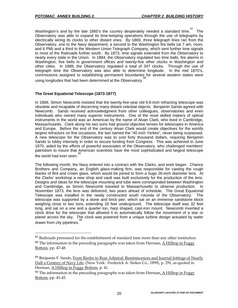
POTOMAC ANNEX BUILDING 2 CHAPTER 2 BUILDING HISTORY
GLOSSARY LOCATED AT END OF DOCUMENT 20
Washington’s and by the late 1860’s the country desperately needed a standard time.87
The Observatory was able to expand its time-keeping operations through the use of telegraphs by electrically wiring its clocks to other distant ones. By 1869, three telegraph lines ran from the Observatory, one to the Navy department, a second to the Washington fire bells (at 7 am, noon, and 6 PM) and a third to the Western Union Telegraph Company, which sent further time signals to most of the Railroads further south. By 1873, time signals extended from the Observatory to nearly every state in the Union. In 1884, the Observatory regulated two time balls, fire alarms in Washington, five bells in government offices and twenty-five other clocks in Washington and other cities. In 1888, the Observatory regulated a total of 347 clocks. Through the use of telegraph time the Observatory was also able to determine longitude. In the mid 1870’s, commissions assigned to establishing permanent boundaries for several western states were using longitudes that had been determined at the Observatory.
88
The Great Equatorial Telescope (1873-1877) In 1868, Simon Newcomb insisted that the twenty-five-year old 9.6-inch refracting telescope was obsolete and incapable of discerning many distant celestial objects. Benjamin Sands agreed with Newcomb. Sands received acknowledgment from other colleagues, observatories and even individuals who owned many superior instruments. One of the most skilled makers of optical instruments in the world was an American by the name of Alvan Clark, who lived in Cambridge, Massachusetts. Clark along his two sons had ground objective lenses for telescopes in America and Europe. Before the end of the century Alvan Clark would create objectives for the worlds largest refractors on five occasions, the last named the “40 inch Yerkes”, never being surpassed. A new telescope for the Observatory was to cost forty thousand dollars, requiring Benjamin Sands to lobby intensely in order to secure funding from Congress. This was achieved in June 1870, aided by the efforts of powerful associates of the Observatory, who challenged members’ patriotism to insure that American scientists have the most sophisticated and largest telescope the world had ever seen.
89
The following month, the Navy entered into a contract with the Clarks, and work began. Chance Brothers and Company, an English glass-making firm, was responsible for casting the rough blanks of flint and crown glass, which would be joined to form a huge 26-inch diameter lens. At the Clarks’ workshop a new shop and vault was built exclusively for the production of the lens. Designs and ideas for the telescope mounting and tube were corresponded between Washington and Cambridge, as Simon Newcomb traveled to Massachusetts to observe production. In November 1873, the lens was delivered, two years ahead of schedule. The Great Equatorial Telescope was installed in the newly constructed south rotunda of the Observatory. The telescope was supported by a stone and brick pier, which sat on an immense sandstone block weighing close to two tons, extending 18 feet underground. The telescope itself was 32 feet long, and sat on a one and a quarter ton, harp shaped, cast-iron mount. Newcomb invented a clock drive for the telescope that allowed it to automatically follow the movement of a star or planet across the sky. The clock was powered from a unique turbine design actuated by water drawn from city pipelines.
90
87 Railroads pressured for the establishment of standard time more than any other institution. 88 The information in the preceding paragraphs was taken from Herman, A Hilltop in Foggy Bottom, pp. 47-48. 89 Benjamin F. Sands, From Reefer to Rear Admiral: Reminiscences and Journal Jottings of Nearly Half a Century of Navy Life, (New York: Frederick A. Stokes Co., 1899), p. 291, as quoted in Herman, A Hilltop in Foggy Bottom, p. 41. 90 The information in the preceding paragraphs was taken from Herman, A Hilltop in Foggy Bottom, pp. 41-45.

POTOMAC ANNEX BUILDING 2 CHAPTER 2 BUILDING HISTORY
GLOSSARY LOCATED AT END OF DOCUMENT 21
The Observatory’s reputation was firmly established by the Great Equatorial. The new telescope, mesmerized both the scientific community and the public with the letters arriving from the curious, hoping for a chance to peer at the skies. This type of patronage was discouraged. However, there were the exceptions of government officials and visiting dignitaries. Evening visits were not allowed since they disrupted observations. In 1876, the Observatory participated in the Centennial Exposition in Philadelphia, proudly displaying evidence of its scientific achievements.
91 Brazilian Emperor Don Pedro came to participate in the opening of the
Exposition with President Ulysses S. Grant. Upon his arrival in Washington, the Emperor scheduled the Observatory as one of the first places visit. Asaph Hall’s Discovery of the Moons around Mars Asaph Hall’s discovery of the outer and inner moons of Mars, Deimos and Phobos, was without parallel the most dramatic event in the Observatory’s history. On August 11, 1877, Hall observed a faint object resembling a star close to Mars, but could not make any conclusions as a fog rolled in before he could establish its position. On the 16th, he saw the object again, concluding in its movement with Mars that it could not be a star. The following day, with the help of his assistant George Anderson, the positioning of the inner moon, Phobos, was established. On August 18th, Hall telegraphed his discovery to the Clarks in Cambridge, who confirmed the sightings with a 26.25-inch telescope they were constructing for the University of Virginia. Shortly after their confirmation, the Smithsonian Institution announced the discoveries to observatories around the world.
92
Decline of the Observatory’s Role in Foggy Bottom (1877-1893) Despite the elation over Asaph Hall’s discovery, 1877 marked a beginning of crisis for the Observatory. Six months before the Observatory’s proudest moment, Superintendent Charles Davis had died of heart failure, having long been weakened by frequent bouts of malaria. Rear Admiral John Rogers arrived as Superintendent to an Observatory once again plagued with problems. A controversy concerning the governance of the Observatory weakened its administration. The future of the Observatory was in question, as advocates for civilian control pitted themselves against advocates for continued naval administration. In addition, the environment surrounding the Observatory had steadily declined as riverfront businesses continued to impede the flow of the Potomac River, and the marsh steadily expanded. Nearby on “B” Street (now Constitution Avenue) there was an open sewer, which deposited waste into Tiber Creek and the mud flats. Additionally, the long-standing problem of malaria continued to plague Observatory staff. While the link between malaria and mosquitoes had yet to be established, the river with its insects and fogs was generally felt to be the source of the problem. The fog also created a major obstacle hampering work and suspending observations. Furthermore, the condition of the physical plant of the Observatory itself was severely deteriorated.
93 The Transit
Circle room in the west wing was dangerously run down, the instruments were dilapidated and in need of repair. The 9.6-inch refractor needed a new drive clock, and the 26-inch Great Equatorial dome had warped and was difficult to operate.
94
91 Herman, A Hilltop in Foggy Bottom, p. 29. 92 Herman, A Hilltop in Foggy Bottom, p. 50. 93 Information in the preceding paragraphs was taken from Herman, A Hilltop in Foggy Bottom, p. 50. 94 S.C. Rowan, Letter to Secretary of the Navy W.C. Chandler, July 6, 1882, as quoted in Herman, A Hilltop in Foggy Bottom, p. 53.
POTOMAC ANNEX BUILDING 2 CHAPTER 2 BUILDING HISTORY
GLOSSARY LOCATED AT END OF DOCUMENT 22
Rear Admiral Rodgers showed great ability in administering the scientific institution. He aggressively fought for appropriations and the Observatory’s publication of its astronomical observations. He was known as a fair and sensible man, who earned the respect and trust of his employees. Rear Admiral Rodgers and many others saw relocation as the only answer to the problems faced by the Observatory. In September 1877, he initiated efforts to relocate the Observatory. After consulting the Secretary of the Navy, he successfully lobbied Congress to pass a bill the following June to appoint a three-person commission to the task of finding a new Observatory site. Seventy-eight proposals were received after Washington landowners were invited to send in their offers. However, finding a new location for the Observatory was a low priority for Congress. A year and half-passed before money was finally appropriated to purchase the Barber Estate located north of Georgetown. As plans remained indefinite for the Observatory’s move, no money was provided for the construction of a new building and very little money was set aside for maintenance of the original property. Despite obstacles, programs continue and astronomers updated star catalogues. Professor Mordechai Yarnall was finishing his catalogue after twenty-five years of work. Asaph Hall still operated the 26-inch Great Equatorial observing satellites, double stars, nebulae and comets. Other astronomers still used the 9.6-inch telescope in observing comets and minor planets. The time-keeping functions at the Observatory were still expanding. Expeditions were also launched for the observation of Mercury transiting the Sun on May 6, 1878, in Washington and Austin, Texas. A solar eclipse occurred a few months later on July 29, with eight teams venturing through Wyoming, Colorado and Texas. Due to good weather, excellent photographs were taken. This allowed for the detailing of the sun corona, the mysterious band of flight around the edge of the sun. Four years later Venus again transited the sun and Observatory staff witnessed the event from Washington, the Cape of Good Hope, two South American stations, New Zealand, Texas, New Mexico, and one from the Florida Keys. When Rear Admiral Rodgers died in May 1882, the new Superintendent, George E. Belknap, continued the crusade to relocate the Observatory and to fight for appropriations for a new building.
95 Congress finally acted in 1886. A New York architect named Richard Morris Hunt
was contracted to prepare the plans. When construction began in 1888, it was delayed by contract, labor, material and weather problems. Finally on May 15, 1893, the Foggy Bottom site was abandoned as the new Observatory on Massachusetts Avenue was officially occupied. The old building was left without instruments, with broken windows and sprouting weeds.
96
The United States Naval Museum of Hygiene (1894-1905) “There is a Naval Museum of Hygiene in Washington, established on the most historic spot in the city, containing objects of new and unique interest which have never yet come under the tourist’s eye, and which are seldom inspected by the ‘Washington public’. It is a white building, fashioned after the colonial style, with white wings on both sides, cut by arched windows and columnar doors—that simple, majestic order of house framed long ago by aristocracy of the South, but few examples of which remain around Washington today. It stands high on a northwest hill skirting the river near Georgetown, and a dome arising from its center above the silver poplars maples marks it for miles in the distance as the old Naval Observatory.”
97
95 Rogers died May 5, 1882. 96 Information from the preceding paragraphs from Herman, A Hilltop in Foggy Bottom, pp.57-59. 97F.W. Smith, “Designs, Plans, and Suggestions for the Aggrandizement of Washington”, U.S. Congress Senate, 56th Congress, 1st Session, S. Doc. 209, (Washington, D.C., GPO, 1900), P.33, as quoted in Herman, A Hilltop in Foggy Bottom, p. 62.

POTOMAC ANNEX BUILDING 2 CHAPTER 2 BUILDING HISTORY
GLOSSARY LOCATED AT END OF DOCUMENT 23
Thirteen months after the Observatory’s move to Massachusetts Avenue, Observatory Hill had a new tenant, the United States Naval Museum of Hygiene. The museum was twelve years old by the time of the move. Having originated from a $7,500 congressional grant “for rent of quarters necessary for the preservation of objects already collected, transportation of contributions intended for exhibition, preparation of models and drawings to be used in the illustration of sanitary science and its progress…”
98
German bacteriologist Robert Koch’s (1843-1910) discovery of germs as the cause of infectious disease marked a pivotal point in medicine, helping to establish the relationship of hygiene and sanitation to disease.99 In keeping with the spirit of faith invested in science at the time, optimists hoped that Koch’s discoveries proved a major step towards the eradication of disease through better hygiene and sanitation. The founders and promoters of the Museum of Hygiene saw in their Museum the future of medicine “The rapid progress that we are making in sanitary science is manifested in all parts of the country and in every department of life, within the last few years, shows the importance of the subject. Its truths are now recognized and accepted by the people.... This is evident on every hand by the increases in the number of hygienic and sanitary journals, in the rapid organization of State boards of health. The making of laws in the various States to suppress and limit disease, in the study of school hygiene and the care shown in every stage of the child’s growth, in securing the lives and property of our citizens. The alleviation of the working classes in mines, factories and the application of the science in every conceivable way, not only to the human race but also to the animal kingdom. Our colleges and school see the need of developing this important science: special teachers now devote their energies to this most important branch of medicine.”
100
Founding of the Museum In 1879, the Naval Bureau of Medicine and Surgery
101 established a laboratory for the study of
“naval hygiene”. They began to acquire a collection of objects related to this study. Collected items included foods, plumbing fixtures, waterclosets, cleaning materials, burial accoutrements, clothing and models of buildings. In December 1880, at the Eighth Annual meeting of the American Public Health Association in New Orleans, the advisability of a national museum of hygiene was discussed, and the following year a favorable endorsement of the idea was made.
102
In 1882, the Navy’s collection, along with a dispensary and lab was established in a building 98 Bureau of Medicine and Surgery, Annual Report of the Surgeon General (Washington, D.C.: GPO, 1897), p. 217. 99 Koch devised a method of staining bacteria with aniline dyes, and developed bacteriological culture techniques that are still used. He established the bacterial cause of many infectious diseases, including anthrax (1876), tuberculosis (1882), conjunctivitis (1883) and Asiatic cholera (1884), and studied sleeping sickness, malaria, bubonic plague, rinderpest, and other diseases. 100 P.S. Wales, “Report on Museum of Hygiene, Washington, D.C.,” Annual Report of the Surgeon General (Washington, D.C.: Bureau of Medicine and Surgery, GPO, 1890) p. 53. 101 The Bureau of Medicine and Surgery was established in the Navy Department by an Act of Congress on August 31, 1842. BUMED acted and continues to acts as the central administrative organization of the Medical Department, with its headquarters in Washington D.C. Its is responsible for the health of the Navy and Marine Corps, directing control over naval hospitals, medical centers, dental clinics, preventive medicine units, and technical schools for Medical Department personnel. 102 N.L. Bates, “Fifteenth Annual Report of the United States Naval Museum of Hygiene,” Annual Report of the Surgeon General, Washington, D.C. :Bureau of Medicine and Surgery, GPO, 1897), p.217.

POTOMAC ANNEX BUILDING 2 CHAPTER 2 BUILDING HISTORY
GLOSSARY LOCATED AT END OF DOCUMENT 24
rented at 1744 G Street, NW. In October of that year, Medical Director John Mills Browne was placed in charge of the Museum.
103 In that same year the Museum also acquired the library of
the Bureau of Medicine and Surgery, about 3,400 volumes. Interest in the museum was sought out from “medical men, architects, builders, plumbers, inventors and students of hygiene throughout the country.“ An unusual assortment of artifacts was accumulated.
104 On July 1,
1887, the Museum moved to 1707 New York Avenue, near Navy Department headquarters and the White House. As the Museum expanded and activity increased in laboratory research, the Bureau lobbied for larger quarters.
105
“The need of a new building for the purpose of the institution is most urgent, not only on account of the defective adaptability of the one in present use for the grouping and display of the exhibit, but by reason of the limited space. Many important and interesting articles are necessary relegated to the cellar and yard”.
106
However, in 1892, the Museum appears to have been fighting for credibility as a valuable scientific institution, like similar ones “located respectively in London and Berlin.”
107 Seeking
appropriations, they complained that “the foreign museums are supported by both national and private contributions, while this one since its first appropriation in 1882 has had no governmental aid in its success.”
108 Discussions regarding use of the Old Naval Observatory as a new location
for the Museum had begun the previous year, although, at the time it seemed an unlikely development. Therefore, the Museum asked that Congress appropriate $100,000 “for the erection of a suitable building on some portion of the public grounds near the Army Medical Museum.”
109 However, the Secretary of the Navy granted approval and transfer of the property
of the former Naval Observatory to the Museum on January 20, 1894.110
The Museum occupied the site officially on July 1, 1894, as Surgeon General James R. Tryon and Medical Director Albert C. Gorgas oversaw the institution’s move.
111
103 “Prior to that date the officers connected with the duties of the laboratory and museum had been ordered to special duty in Washington and their names do not appear in the registers as connected with the museum.” N.L. Bates, “Fifteenth Annual Report of the United States Naval Museum of Hygiene,” Annual Report of the Surgeon General, ( Washington, D.C.: Bureau of Medicine and Surgery, GPO, 1897), p. 217 104 Bureau of Medicine and Surgery, Annual Report of the Surgeon General, (Washington D.C.:G.P.O., 1888), P. 7. 105 Herman, A Hilltop in Foggy Bottom, p.61. 106 Bureau of Medicine and Surgery, “Museum of Hygiene”, Annual Report of the Surgeon General, (Washington, D.C.: GPO, 1892), p. 11. 107 Bureau of Medicine and Surgery, “Museum of Hygiene”, Annual Report of the Surgeon General, (Washington, D.C.:G.P.O., 1892) P.12. 108 Bureau of Medicine and Surgery, “Museum of Hygiene,” Annual Report of the Surgeon General, (Washington, D.C.: GPO, 1892), p. 12. 109 “The official application for the vacant buildings of the Naval Observatory having failed of success and as there is at present no available public building to be obtained for the purposes of the institution…” Bureau of Medicine and Surgery, “Museum of Hygiene, “Annual Report of the Surgeon General, (Washington, D.C.: GPO, 1892), p. 12. 110 “Recommendations are made for acquiring a portion of the grounds soon to be vacated by the Naval Observatory for the permanent establishment of the Museum, in view of the fact that at no very distant day the question of new and permanent quarters will demand consideration, “Museum of Hygiene,” Bureau of Medicine and Surgery, Annual Report of the Surgeon General, (Washington, D.C. :GPO, 1891), p.8. 111 Herman, A Hilltop in Foggy Bottom, pp. 61-62.
POTOMAC ANNEX BUILDING 2 CHAPTER 2 BUILDING HISTORY
GLOSSARY LOCATED AT END OF DOCUMENT 25
Extensive repairs and alterations to the Old Naval Observatory building were made to accommodate the new use during the first few years of the Museum’s occupation, including interior alterations and the rebuilding of the west and south wings. Three of the Old Naval Observatory’s second-story offices were transformed into chemistry, bacteriology and photography laboratories. A chemist occupied the fourth room. The former residence wing was to house exhibits on modern water filters and plumbing, while the west Transit Circle annex would serve as a lecture hall. The interior of the Great Equatorial dome room was to now function as a library-lecture hall.
112
By August 1894, much work remained to be done at the new location. Director Gorgas indicated that it would be settled, as the massive masonry piers had to be removed, laboratories created, and exhibits arranged. Overall he expressed satisfaction with the new site. “The removal of these quarters is a vast step in the direction of improvement, and I feel gratified that this part of the recommendations made last year has been conceded.”
113 Albert Gorgas believed that the
museum’s facilities would increase at the new location and that a new bridge proposed to cross the Potomac River would turn adjacent avenues into major thoroughfares, helping to increase transit and visitors. He expressed pleasure in “the grounds surrounding the museum possessing natural advantages,” which he provided suggestions on the landscaping that would be quite attractive.
114
The first week of September 1894, Gorgas was sent as a delegate of the Medical Department of the Navy to the Eighth International Congress of Hygiene and Demography in Budapest. While in Europe, he inspected the Museums of Hygiene in London and Berlin. Unfortunately, Gorgas fell ill, and never sufficiently recovered. He retired in the spring of 1895, and died a few weeks later on May 25, 1895.
115 Three days later, a new Medical Director, N.L. Bates, was appointed to
replace Gorgas. Alterations to the buildings continued as the Museum settled into its new location. In a reaffirmation of its purpose, and perhaps in an effort toward further appropriations, Bates contended in the Annual Report that
“this museum in Washington should not be inferior to those in London and Berlin. In no country in the world has greater progress in providing good water and drainage and healthy buildings for private and public uses been made than in the United States. The most desperate and dangerous conditions successfully overcome and the danger from epidemics of preventable disease has been greatly lessened.”
116
Work on the Museum grounds began but was ruined by a hurricane in late September 1896. The storm was strong enough to uproot some trees. There was also minor damage to the
112 Bureau of Medicine and Surgery, Annual Report of the Surgeon General, (Washington, D.C.:G.P.O., 1896), p.199. 113 A.C. Gorgas, “Twelfth Annual Report of the Museum of Hygiene”, Annual Report of the Surgeon General, (Washington, D.C.:G.P.O., 1894), p. 82. 114 A.C. Gorgas, “Twelfth Annual Report of the Museum of Hygiene”, Annual Report of the Surgeon General, (Washington, D.C.; Bureau of Medicine and Surgery, GPO, 1894), p.82. 115 Bureau of Medicine and Surgery, ‘United States Naval Museum of Hygiene”, Annual Report of the Surgeon General, (Washington, D.C. :GPO , 1895) p. 112 N.L. Bates, “Thirteenth Annual Report on the United States Naval Museum of Hygiene, “Annual Report of the Surgeon General, (Washington, D.C. : Bur. of Medicine and Surgery, GPO, 1895), p. 148. 116 N.L. Bates, “Thirteenth Annual Report on the United States Naval Museum of Hygiene,” Annual Report of the Surgeon General, (Washington, D.C.: Bureau of Medicine and Surgery, GPO, 1895), p. 148.
POTOMAC ANNEX BUILDING 2 CHAPTER 2 BUILDING HISTORY
GLOSSARY LOCATED AT END OF DOCUMENT 26
buildings.117
Regardless of the hurricane, by the end of 1897, most of the renovations at the Museum were completed.
118
Research at the Museum Varied specimens were analyzed at the Museum, water from different locations, samples of building materials, medicines and foods were just some of the things evaluated. The Museum rapidly became and innovator in environmental and occupational medicine. Water systems on naval vessels and shore installations were studied, including the Old Naval Observatory’s water.
119 Water filtration was investigated and manufactured water filters were tested for
efficiency. Microscopic and bacterial examinations were made frequently. An inspection of workspaces in government buildings found a sub-basement area unfit due to excessive temperatures and dangerous levels of carbonic acid and ammonia.
120 By 1898, the laboratories
were conducting tests of disinfectants, vaccine viruses and pathological specimens. Two years later, five hundred thirty-seven chemical, bacteriological and microscopic examinations were performed for the purpose of clinical diagnosis. The labs were considered to be among the best in the country. At the turn of the century as research and testing increased, the collection acted as the focus for many lectures and symposia held at the Museum. The collection had acquired a bizarre and miscellaneous character, with objects including Belgian and Chinese shoes, Korean hats, Mexican sandals, foods, shells, cots, hospital ships, camps, crematories and water pipes. Also included in the collection were architectural plans and models of schools, asylums, alms houses, reformatories, factories, laboratories, hospitals and ships displayed with their respective systems of ventilation, drainage and illumination.
121 Unique
exhibits displayed vaults, morgues, mortuaries, crematoria and all methods and customs for burial of the dead, including a reproduction of a miniature “Tower of Silence,” located outside of Bombay where vultures flocked to feast on the dead. “A model of the picturesque crematory at Mount Olivet Cemetery, Williamsburg, [Brooklyn], N.Y., is also on exhibition and that hideous engine, “Sieman’s furance,” as well as burglarproof vaults, metallic burial caskets, Alaskan Indian caskets and old Roman cinerary urns.”
122
By General Order No. 89 of May 27, 1902, the name of the Naval Museum of Hygiene was changed to the “ United States Naval Museum of Hygiene and Medical School.”
123 The
117 “The storm of September 29, 1896, uprooted and broke down many of the old trees and damaged roofs, gutters, etc. The grounds in front and at the sides of the main building were cleared, trees trimmed, and rubbish removed and the ground plowed, graded,, and put in grass. The roads were also put in order, some extensions made, and the damage to buildings repaired.” N.L. Bates , “Fifteenth Annual Report of the United States Naval Museum of Hygiene,” Annual Report of the Surgeon General, (Washington D.C.: Bureau of Medicine and Surgery, GPO, 1897)p. 218. 118 Bureau of Medicine and Surgery, “United States Naval Museum of Hygiene” Annual Report of the Surgeon General, (Washington, D.C.:G.P.O., 1897), p. 218. 119 J. Mills Browne, “Ninth Annual Report of the Museum of Hygiene,” Annual Report of the Surgeon General, (Washington, D.C.: Bureau of Medicine and Surgery, GPO, 1891), P.101 120 S.H. Griffith, Letter to James R. Tyron, Surgeon General of the Navy, April 5, 1895, as quoted in Herman, A Hilltop in Foggy Bottom, p. 63. 121 Smith, pp. 33-35. 122 Smith, pp. 33-35. 123 Bureau of Medicine and Surgery, “United States Naval Museum of Hygiene and Medical School” Annual Report of the Surgeon General, (Washington, D.C.: GPO, 1902), p. 44.
POTOMAC ANNEX BUILDING 2 CHAPTER 2 BUILDING HISTORY
GLOSSARY LOCATED AT END OF DOCUMENT 27
Museum’s future however was short-lived. Although it was considered an important part of the Medical School during the next few years, it was officially disestablished in 1905. Its collections were probably transferred to the Smithsonian Institution.
124 The year 1903 was a pivotal one for
the site as appropriations were made to erect a new hospital building. That construction marked a building campaign, which significantly changed the landscape and appearance of “Observatory Hill”, which would soon have a new life as the Naval Hospital and Medical School. Establishment of the Medical School - 1902 Surgeon William Paul Crillan Barton had proposed the concept of formal Naval Medical training as early as 1809.
125 But it was not until 1829 that Congress established Medical Examining
Boards for the purpose of reviewing physicians who wanted to work in the Navy. Surgeon General of the Navy, Joseph Beale, considered the idea of a medical school in 1873, but it was his successor William Grier who was the first to institute formal instruction at the Naval Hospital in Brooklyn, New York. William Grier started a two-year program focusing on Naval Hygiene
126 and
Military Surgery in 1893.127
Surgeon General James R. Tryon inaugurated the initial three-month term at the United States Naval Laboratory and Department of Instruction in Brooklyn. Course work included chemistry, hygiene, microbiology, microscopy, military and operative surgery, clinical medicine and hospital work, the construction and ventilation of modern warships, examination of recruits, lifesaving methods, naval regulations, naval rations and administration.
128
Upon completion of the program, graduates were either sent to sea or general duty. The instruction program operated continuously until its transfer to Washington, with the exception of a four-month hiatus during the Spanish-American War in 1898. Meanwhile, Surgeon General Presley M. Rixey envisioned a plan for the relocation of the Brooklyn Program and a consolidation of it with the Museum of Hygiene in Washington. The Museum seemed to be an appropriate setting for the school, with its ample facilities for lab work, classrooms and library. The staff of the Museum would form a core faculty, while the city itself offered extensive resources of military and civilian medical specialists as lecturers.
129 On 27 May
124 Herman, A Hilltop in Foggy Bottom, p.65. 125 Barton was to be the first Chief of the Bureau of Medicine and Surgery named in 1842. 126 James Chambers Pryor, A. M., M. D., head of the Department of Hygiene at the Naval Medical School in his book, Naval Hygiene of 1918, defined "hygiene" as "that branch of medical science which concerns itself with the preservation of the health of individuals and communities." With "Naval Hygiene" concerned with "men aboard ship...men in camp or barracks ashore." James Chambers Pryor, Naval Hygiene, (Philadelphia: P. Blakiston's Son and Co., 1918), p. 1. 127 Jan K. Herman, A Hilltop in Foggy Bottom, (Washington D.C.: Bureau of Medicine and Surgery, Department of the Navy, 1991), p. 67. 128 H.G. Danilson, "The United States Naval Medical School,” Military Surgery, Jan.1937, p. 54, as quoted in Herman, A Hilltop in Foggy Bottom, p. 67. 129 "...the following thirteen gentlemen, prominent in professional, scientific, and educational circles...accepted the invitation to deliver lectures and give demonstrations before the class: Col. W.C. Gorgas, Maj. L. A. La Garde, Maj. W. C. Borden, First Lieut. James Carroll, and Dr. W. M. Gray, of the Army; Medical Director A. F. Price, of the Navy; Passed Asst. Surg. M. J. Rosenau and Dr. C. W. Stiles, of the Public Health and Marine-Hospital Service. Dr. L. O. Howard, of the Department of Agriculture; and Drs. S. S. Adams, G. M. Kober, C. W. Richardson, and A. B. Richardson. The members of the naval examining board, consisting of Medical Director R. A. Marimon, Medical Director J. W. Ross, Medical Inspector J. B. Boyd, and Surg. A. C. H. Russell, have been utilized as a faculty. The school was fortunate in having added Mr. E. P. Hanna, solicitor of the Navy Department, for the course in naval law. Lt. D. L. Wilson, U.S. Navy,

POTOMAC ANNEX BUILDING 2 CHAPTER 2 BUILDING HISTORY
GLOSSARY LOCATED AT END OF DOCUMENT 28
1902, the United States Naval Medical School130
was formally established in Washington "for the instruction and training of newly appointed medical officers in professional branches peculiar to naval requirements."
131 Supervising the establishment of the school was Surgeon General Rixey,
a friend and the personal physician of President Theodore Roosevelt. Also joining the move from New York was the Naval Medical Examining Board, the group responsible for screening incoming naval physicians. With the role of the Museum enhanced to include the Naval Medical School, additional changes were required to the Old Naval Observatory building, including another "story constructed on the two connecting wings to provide laboratory facilities...."
132 A second story was added to the south
wing in 1903, to accommodate student officers for lockers and sitting rooms.133
The school building, originally occupied by the Naval Observatory and later by the Museum of Hygiene, has with slight remodeling and some additions, proved peculiarly adapted to its present purpose.
134
The east wing, home of the Museum's medical officer and the former Residence of the Old Naval Observatory Superintendent, would now become an office for the Medical Examining Board. New laboratories were fitted for work in pathology, clinical microscopy, bacteriology and medical zoology with space and fixtures for twenty-six people. The lab was also equipped with a large incubator and ovens. The chemical lab contained thirty-two working spaces. The basement provided room for photography and photomicrography and a room for cold storage. The Library consolidated with the Museum's collection continued to grow in the south rotunda. This included important foreign and domestic medical journals in addition to standard works on medicine and surgery. Medical Director Robert A. Marmion served as the school's commanding officer over the first class of twelve medical students. The first course of instruction lasted five months with studies in microscopy, naval hygiene, ophthalmology, psychiatry, military surgery, military medicine, the duties of naval medical officers and military law. The program also included physical exercise and military drills. A major topic of study was tropical disease. The medical school was the first major center for its study in the United States. Doctors with clinical experience in tropical disease
retired, in the department of signals, tactics, etc., and Passed Asst. Surg. T. D. Myers, U. S. Navy, retired, for the course in ophthalmology. Surg. E. R. Stitt, U.S. Navy, planned and superintended the construction and equipment of the laboratories, and has charge of the department of which they are a part. He is assisted by Hospital Steward E. R. Noyes, U. S. Navy, chemist of the Museum of Hygiene, who also conducts the course in general chemistry." Bureau of Medicine and Surgery, "Naval Medical School," Annual Report of the Surgeon General, (Washington, D.C.: GPO, 1903), p 7. 130 Official titles of the school included "Naval Museum and Medical School," 1902-1905; and "Naval Medical School," 1902-1906. 131 Bureau of Medicine and Surgery, "Prospectus of the United States Naval Medical School," United States Naval Medical School Bulletin, (Washington, D.C.: GPO, 1910), p. 585. 132 Bureau of Medicine and Surgery, Annual Report of the Surgeon General, (Washington, D.C.: GPO, 1902), p. 44. 133 Bureau of Medicine and Surgery, Annual Report of the Surgeon General, (Washington, D.C.: GPO, 1904), p. 222. 134 Bureau of Medicine and Surgery, "Prospectus of the United States Naval Medical School," United States Naval Medical School Bulletin, (Washington, D.C.: GPO, 1910), p. 587.
POTOMAC ANNEX BUILDING 2 CHAPTER 2 BUILDING HISTORY
GLOSSARY LOCATED AT END OF DOCUMENT 29
visited as guest lecturers. Colonel William C. Gorgas, who frequently visited the school, was a renowned expert on yellow fever and later became Surgeon General of the Army.
135
The first class graduated 4 April 1903, and Medical Director Marmion deemed the program in a special report of the first year's progress.
136
The officers graduating from this school can go forth confidently to meet the new and strange duties, which they are called upon to perform with little or no inconvenience or discomfort. They will have received not merely a much broader education from a medical standpoint than it is practicable for them to obtain in the medical colleges of our country. However, they will have, in addition to that, a knowledge of matters purely naval which is sure to enhance their value to the service in fields other than those in which the medical officer of a few years ago was ever called upon to labor.
137
The course of instruction...[is] primarily intended to prepare an already well-educated medical man for grappling with the problems presented by a rapidly growing naval medical service, and to enable him from the very beginning of his career in the service to assist in solving some of these problems.
138
When the Hospital opened in 1906, it was expected to be "of the greatest assistance in practical instruction,”
139 and the Bureau of Medicine and Surgery anticipated growth in the school's
enrollment.140
In the annual report for 1906, Medical Director, J.C. Wise, reiterated the school's role in stating that
...The fact that military medicine has greatly progressed in late years, from the scientific standpoint, and that members of the service have done much to create the branch known as 'colonial medicine. In reality medicine considered in its relation to commerce, is still the principal object of a school such as this is to fit the entrant into the Medical Corps of the Navy for practical duties on board ship. The greater will be its success the more constantly this end is kept in view; thus the courses on hygiene, surgery, medicine, pathology, bacteriology, chemistry and hospital-corps work are based on this conception.
141
135 William Crawford Gorgas (1854-1920) was appointed Surgeon General of the Army in 1914. 136 R. A. Marmion, "Report on the United States Naval Medical School, Washington, D.C.," Annual Report of the Surgeon General, (Washington, D.C.: Bureau of Medicine and Surgery, GPO, 1904), p. 217. 137 R. A. Marmion, "Report on the United States Naval Medical School, Washington, D.C.," Annual Report of the Surgeon General, (Washington, D.C.: Bureau of Medicine and Surgery, GPO, 1904), p. 224. 138 Bureau of Medicine and Surgery, "Prospectus of the United States Naval Medical School," United States Naval Medical School Bulletin, (Washington, D.C.: GPO, 1910), p. 585. 139 J. C. Wise, "Report on the United States Naval Medical School", Annual Report of the Surgeon General, (Washington, D.C.: Bureau of Medicine and Surgery, GPO, 1906), p. 166. 140 "The Bureau anticipates that during the next six years it will be possible to assemble a class from 35 to 40 members at each session. The outlook is most promising for furnishing the service with well-trained and equipped medical officers...." from J. C. Wise," Report on the United States Naval Medical School," Annual Report of the Surgeon General, (Washington, D.C.: Bureau of Medicine and Surgery, GPO, 1903), p. 7. 141 J. C. Wise, "Report on the United States Naval Medical School", Annual Report of the Surgeon General, (Washington, D.C.: Bureau of Medicine and Surgery, GPO, 1906), p. 166.

POTOMAC ANNEX BUILDING 2 CHAPTER 2 BUILDING HISTORY
GLOSSARY LOCATED AT END OF DOCUMENT 30
In 1906, the School claimed to have "taken its place among the best postgraduate schools not only of the country, but of the world."
142 New course work included instruction in meat inspection,
pharmaceuticals, climate and dental emergencies. The study of tropical disease was an increasingly important component of study and the specialty of naval surgery, characterized primarily by the treatment of burns and scalds, occupied another prominent place in course work. The school was receiving many applications for entry.
143
1910 occupied the majority of school instructors, at least partially, with hospital duty. The school's training program was expanded as classes were instituted for hospital corpsmen, stewards and nurses. However, external events were affecting the school's enrollment. In 1914, the school was emptied of its students after President Woodrow Wilson sent Marines into Veracruz following an incident involving an arrest of U.S. sailors.
144 Then with the beginning of
U.S. involvement in World War One in 1917, instruction was reduced from six to four months, and then to two months.
145 The problem of maintaining a regular faculty became critical since there
was little time to devote to teaching, and the Surgeon General lamented that ...unlike the usual college instructors, [they] can give but a portion of their time to this work. They are on duty at the Naval Hospital, at the Naval Dispensary, at St. Elizabeth's Hospital, and in the laboratory of the school. They serve as members of examining boards and are constantly burdened with varied additional duties.
146
Only a small number of students were trained during the school's early years. The total number of graduates from September 1906 to the end of 1916 was only two hundred thirty-five.
147 Yet
despite international conflict and a preoccupied faculty, 1917 stood as a banner year for the school as one hundred seventy five student officers received instruction, a number nearly equal to the entire cumulative amount previously graduated. The Naval Hospital Moves to Observatory Hill - 1903 The Washington Naval Hospital on Pennsylvania Avenue at 10th Street SE, which had been established in 1866, had long complained of insufficient space and outdated facilities.
148
For many years a need has been felt for a naval hospital in Washington commensurate with the importance and dignity of the station. The present building is antiquated and insufficient and conforms in no respect to the conditions of modern hospital requirements. Its quarters are cramped, the
142 J. C. Wise, "Report on the United States Naval Medical School," Annual Report of the Surgeon General, (Washington, D.C.: Bureau of Medicine and Surgery, GPO, 1907), p.12. 143 J. C. Wise, "Report on the United States Naval Medical School", Annual Report of the Surgeon General, (Washington, D.C.: Bureau of Medicine and Surgery, GPO, 1907), pp. 12-13. 144 144 "Mexico-U.S. Relations," Eric Foner and John A. Garraty, editors, The Reader's Companion to American History, (Boston, MA: Houghton Mifflin Company, 1991), p. 725. 145 Bureau of Medicine and Surgery, "Schools," Annual Report of the Surgeon General, (Washington, D.C.: GPO, 1917), p. 25. 146 Bureau of Medicine and Surgery, "Schools,” Annual Report of the Surgeon General, (Washington, D.C.: GPO, 1917), p. 26. 147 Bureau of Medicine and Surgery, "Schools," Annual Report of the Surgeon General, (Washington, D.C.: GPO, 1917), p. 25. 148 The hospital was decommissioned 26 May 1911. File, "U.S. Naval Hospital, Washington, D.C.," "Hospital" file, BUMED library.

POTOMAC ANNEX BUILDING 2 CHAPTER 2 BUILDING HISTORY
GLOSSARY LOCATED AT END OF DOCUMENT 31
operating room small and of a makeshift character and the only provision made for sick officers is one small room originally intended for a restraining room for insane patients. There is no proper provision made for the isolation of contagious diseases....
149
Following the turn of the century, the Navy recognized the need for enlarging, rehabilitating and replacing most of their hospitals throughout the country. The first decades of the century marked a time of great expansion for the Navy. The Navy and Marine Corps grew from 10,500 in 1893, to over 61,000 by 1912.
150 The consequences of the Spanish American War instigated the need
for new naval bases in the Philippines, Hawaii, Cuba, locations in Guam, Samoa and Puerto Rico. Older hospitals had provided for the needs of a small Navy, but they proved insufficient for a rapidly expanding Navy. And many felt it was the duty of the Navy to provide "the benefit of treatment in modern and well-appointed hospitals" to those "personnel of the service who risk limb and life."
151
After considering a number of locations for a new hospital in Washington, Congress appropriated $125,000 for a facility on Observatory Hill on 3 March 1903.
152
An estimate for a new building, planned on modern lines of hospital construction, is submitted, and a site offering ideal advantages for the location of a hospital has been selected on the grounds of the Museum of Hygiene and Medical School, under control of the Bureau.
153
The renowned New York architect, Ernest Flagg, was commissioned to design the new Washington Naval Hospital.
154 Flagg's relationship with the Navy had been established at the end
of the previous century. In 1895, he had won the commission to design the new campus for the Naval Academy in Annapolis, Maryland, the largest commission of his career. The Naval
149 Bureau of Medicine and Surgery, "Naval Hospital, Washington D.C.,” Annual Report of the Surgeon General, (Washington, D.C.: GPO, 1902), p 31. 150 A. W. Dunbar, "A Description of Recent Hospital Construction in the United States Navy," U.S. Naval Medical Bulletin, No. 4 (Washington, D.C., Bureau of Medicine and Surgery, G.P.O., Oct., 1912), p. 473. 151 Bureau of Medicine and Surgery, "Hospitals", Annual Report of the Surgeon General, (Washington, D.C.: GPO, 1905), p. 15. 152 "The Fifty-seventh Congress appropriated $125,000 for a new hospital structure, to be erected on the grounds of the Museum of Hygiene and Medical School, a site admirably adapted to the purpose, and providing many features peculiarly appropriate. The plans for this new institution have been prepared with much care and study, and it is believed that a model hospital and a building of architectural beauty will be added in the near future to the public buildings of Washington." Bureau of Medicine and Surgery, "Naval Hospital, Washington, D.C.," Annual Report of the Surgeon General, (Washington, D.C.: GPO, 1903), p. 12. 153 Bureau of Medicine and Surgery, "Naval Hospital, Washington D.C.," Annual Report of the Surgeon General, (Washington, D.C.: GPO, 1902), p. 31. 154 "Wards A and B, and the operating pavilion were constructed in 1903 from plans and specifications prepared by Ernest Flagg, Architect. Wards C and D were constructed in 1907 from plans and specifications prepared by Wood, Donn and Deming, Architects." On 6 March 1935 Memorandum to Mr. Southworth from Ben Moreell and B.W. Fink, Jr., File NH6/N9 Washington Hospital, Box 1469, Volume 3, General Correspondence 1925-1942, RG71, The Bureau of Yards and Docks, National Archives. The hospital was formally known by several names including "Washington Naval Hospital" 1906-1934, "Naval Medical Center" or "National Naval Medical Center" 1934-42.

POTOMAC ANNEX BUILDING 2 CHAPTER 2 BUILDING HISTORY
GLOSSARY LOCATED AT END OF DOCUMENT 32
Academy project was fraught with problems, particularly relating to budgets and the use of materials. Although he was frequently at odds with government officials, the Navy clearly had respect for the architect's work since it commissioned at least three additional projects from Flagg including the Washington Hospital on Observatory Hill, officers' housing at the Brooklyn Navy Yard (1903) and the Naval Hospital in Annapolis (1904-1907).
155 The employment of a civilian
architect for naval hospitals was unusual, and with the exception of Flagg's hospital at Annapolis, a civilian architect designed only one other contemporary naval hospital.
156
Hospital Design of the early 20th century Historically, the function of caring for the sick was fitted into architectural forms originally designed for other purposes; hospital plans were borrowed figuratively and literally from other types of buildings: monasteries, palaces, estates, prisons and barracks.
157 The ward plan,
specifically the cross-shaped ward plan, was introduced during the Renaissance.158
Eventually, the trend toward separation of patients produced detached wards, which eventually developed into the popular pavilion plan hospital.
159 By the 18th century, the pavilion plan was the most
common and accepted design for hospitals, virtually extinguishing the cross-shaped ward and its derivatives.
160 The pavilion plan,
161 a style derived from French court architecture, acted in a
hospital essentially as a "sanitary code embodied in a building."162
Pavilions were open wards of limited size, which had individual service rooms, were ventilated by windows and doors and were connected by corridors serving similar pavilions. The pavilion plan dominated hospital design in France, England and America into the 20th century.
163
In his 1912 essay "A Few General Principles of Hospital Construction," F. W. Southworth, architect and leading draftsman for the Bureau of Yards and Docks, explained exemplary modern hospital design.
164 Southworth noted that most contemporary naval hospitals were designed as
155 Andrew S. Dolkart, "Historic Overview of the U.S. Naval Academy Chapel: Historic Building Conditions Report," (New York: Beyer, Blinder, Belle, Architects, 1994). 156 "With the exception of the naval hospitals at Washington, Annapolis, and Great Lakes...the designing of the plans and the inspection of the work for new construction has been done by the Bureau of Yards and Docks. This was based upon the general plans recommended by the Bureau of Medicine and Surgery." Jarvis Hunt designed the hospital at Great Lakes. Bureau of Medicine and Surgery, A. W. Dunbar, "A Description of Recent Hospital Construction in the United States Navy," U.S. Naval Medical Bulletin, No. 4 (Washington, D.C.: Bureau of Medicine and Surgery, G.P.O., Oct., 1912), pp. 493, 522. 157 John D. Thompson and Grace Goldin, The Hospital: a Social and Architectural History, (New Haven: Yale University Press, 1975), p. XXVII. 158 The cross-shaped ward was known to be the usual form of hospitals in many Roman Catholic countries in the eighteenth century. See Thompson and Goldin, p. 128. 159 Thompson and Goldin, p. 159. 160 Thompson and Goldin, p. 79. 161 The-pavilion hospital was derived in its form from the most infamous and dangerous hospital in eighteenth-century Paris, the Hotel-Dieu. Thompson and Goldin, p. 126 162 Thompson and Goldin, p. 118 163 Thompson and Goldin, p. 118 164 The Bureau of Yards and Docks was the department of the Navy responsible for construction of new buildings. As leading draftsman for the Bureau of Yards and Docks, Southworth's name appears on drawings as project manager and supervisor for the later complex buildings constructed in 1908, and for the additions and alterations to the old Observatory building. These
POTOMAC ANNEX BUILDING 2 CHAPTER 2 BUILDING HISTORY
GLOSSARY LOCATED AT END OF DOCUMENT 33
one of the "blocks," "corridor," or "pavilion" hospital plans.165
Southworth identified two major elements as crucial components for hospital design, "administration and construction". Administrative needs called for the central location of executive features and convenient placing of utility rooms and supplies, while construction was obligated to create ample natural and artificial light for ventilation and heat. Southworth described in great detail his recommendations for hospital design and construction, and many of his suggestions were harmonious with Flagg's design for the main hospital building.
166 Southworth recommended that wards have at least two
outside walls with windows, and for the use of sunlit and properly placed solaria.167
He also advised that administrative offices were "most advantageously placed along the front of the main or administration building, on the first floor, near the first story wards...providing easy supervision over the main hospital life," as at the Washington Hospital. Southworth opined that in lighting for operating rooms "southern light [was]...obviously the worst."
168 Flagg's operating room did face
south and was noted for its glare (the sun's reflection on the tiles) and sweltering temperature in summer.
169 Many of the materials that Southworth recommended were used, including linoleum,
white wooden trim, terrazzo and tile flooring and "Tennessee marble." Southworth included recommendations for ventilating and heating systems, hardware, radiators, plumbing, fixtures, etc. Ernest Flagg was one of America's premier hospital architects in the late 19th and early 20th centuries. Flagg's first design commission had been for St. Luke's Hospital in New York City (1892-97). This project earned him considerable reputation as a hospital designer and led to three other hospital commissions for him. All were derived from the pavilion plan type.
170 Flagg's
pavilion plan at St. Luke's in New York was no more than a perfection of that long-established type, still generally regarded in the 1890s as the safest and most hygienic arrangement.
171 Dr.
John S. Billings has had loosely modeled the design for St. Luke after the celebrated design for included the Contagious Disease Hospital, the Female Nurses' Quarters, the Quarters for Hospital Corpsmen, Sick Officers' Quarters, and three houses for Junior and Senior Medical Officers. F.W. Southworth, "A Few General Principles of Hospital Construction" U.S. Naval Medical Bulletin, (Washington, D.C.: Bureau of Medicine and Surgery, GPO, Oct. 1912), pp. 523-524. Indexes at the National Archives indicate that the Thompson-Starrett Company was responsible for the contract of the additional buildings at the Hospital Complex built by the Bureau of Yards and Docks. See RG 52, Records of the Bureau of Medicine and Surgery, "Headquarters Records Correspondence," Index to General Correspondence, 1896-1925, "Washington D.C. Hospital (New) - Whirlpool Manufacturing." 165 "...The hospitals at Boston and Washington may be said to have been constructed on no recognized plan whatever," A. W. Dunbar. " A Description of Recent Hospital Construction in the United States Navy," U.S. Naval Medical Bulletin, No. 4, (Washington, D.C.: Bureau of Medicine and Surgery, GPO, Oct. 1912), p. 474. 166 Southworth included recommendations as detailed as the appropriateness of decorative trim, the use of materials, etc. 167 F.W. Southworth, "A Few General Principles of Hospital Construction," U.S. Naval Medical Bulletin, (Washington, D.C.: Bureau of Medicine and Surgery, GPO, Oct. 1912), pp. 523-524. 168 F.W. Southworth, "A Few General Principles of Hospital Construction," U.S. Naval Medical Bulletin, (Washington, D.C.: Bureau of Medicine and Surgery, GPO, Oct. 1912), p. 524. 169 Herman, A Hilltop in Foggy Bottom, p. 72. 170 After St. Luke's, Flagg designed St. Margaret Memorial Hospital in Pittsburgh (1894-98), the Washington Naval Hospital, and the Annapolis Naval Hospital (1904-07). See Mardges Bacon, Ernest Flagg: beaux-arts Architect and Urban Reformer, (Cambridge, MA: The MIT Press, 1986), p. 98. 171 Mardges Bacon, Ernest Flagg: beaux-arts Architect and Urban Reformer, (New York and Cambridge: The Architectural History Foundation and The MIT Press, 1986), p. 94.

POTOMAC ANNEX BUILDING 2 CHAPTER 2 BUILDING HISTORY
GLOSSARY LOCATED AT END OF DOCUMENT 34
Johns Hopkins Hospital (1876), where wards were housed in separate pavilions and maximum use was made of natural sunlight and ventilation. Flagg's plan made each pavilion even more autonomous than those did in Billings' hospital in a centralized and bilaterally symmetrical plan, which strongly adhered to beaux-arts principles.
172 Flagg took inspiration from French pavilion
hospitals because he saw in them a successful combination of the art and science of hospital planning, with equal importance placed on aesthetic and practical elements.
173 Flagg generalized
his design of St. Luke's into principles in his article "The Planning of Hospitals" which appeared in the trade periodical, Brickbuilder, in 1903.
174
The Hospital Building The concept of the pavilion plan and many fundamental components of Flagg's designs for St. Luke's, and St. Margaret's Memorial Hospital (Pittsburgh 1894-98) were brought together in his designs for the hospitals at Washington and at the Naval Academy in Annapolis (1904-7). Following the pavilion plan, Flagg accommodated the architectural styles of both buildings to "Tidewater regionalism."175 The buildings relate to Tidewater colonial domestic architecture through plan, composition, scale, materials, ornament and functional details.
176 The building
ornament is similar to those found in illustrations from Pierre Chabat's French publication of 1881, La Brique et la Terre Cuite.
177 Flagg demonstrates in these buildings his concern to rationalize
and beautify utilitarian buildings in plan and materials.178
Flagg described his design for the Washington Hospital in a letter accompanying his drawings sent to the Navy in September 1902. The building plan originated from two main cores, one for administration (north) and one for the operating room and related facilities (south). Radiating from the cores were to be three one-story pavilion wards connected by glass-enclosed solaria. A fourth ward was outlined in a drawing. However, there is no concrete evidence suggested that this was meant to be implemented in the future.
179 As in his other hospital plans, Flagg designed
the wards and solaria for the Naval Hospital specifically for maximum sunlight and ventilation. The main hospital entrance was from the north through the administration building. The basement was to contain the kitchen and its dependencies, two serving rooms. In the basement in the north section of the floor would be a "smoking or lounging room," a storeroom and drug store room.
180 The first floor was to contain offices, an examining room, a reception room,
172 Bacon, p. 95. 173 Bacon, p. 97. 174 Brickbuilder XII (June 1903), p. 111. 175 Bacon, p. 101. 176 Bacon suggested that the buildings relate particularly to mid-eighteenth century houses by William Buckland. Bacon, pp. 101-102. 177 Bacon, p. 102. 178 Bacon, p. 102. 179 Flagg's first floor plan illustrates a ghost outline where a fourth ward to the southwest could have been. It can only be speculated that Flagg was working with the intent that the hospital would grow, since then only limited funding was available. In fact, only two of the three wards designed by Flagg were built before money ran out; construction (and design) for the third and fourth wards were instead done by the firm of Wood Donn and Deming. Flagg had also designed St. Luke's with the intent that additional pavilions would be built in the future. 180 From page 2, "Architect's Description of Proposed Naval Hospital at Washington, D.C.," RG 52, Records of the Bureau of Medicine and Surgery, Headquarters Records Correspondence, 1896-1925, 12 Sep 02, Description and plans, letter 73736, National Archives.
POTOMAC ANNEX BUILDING 2 CHAPTER 2 BUILDING HISTORY
GLOSSARY LOCATED AT END OF DOCUMENT 35
dispensary, two dining rooms and a doctor's "living room."181
On the second floor were to be eight rooms for sick officers, a room for use as a parlor or dining room, a kitchen, nurse and store rooms. The third floor was to contain eleven nurses' rooms. In the south pavilion, the operating room was to be "oblong, of ample size" and one wall entirely built of glass.
182 Connecting to the
operating room was a doctor’s room, instrument room, nurses' and sterilizing room and etherizing room. Flagg described the outlying three wards as "all alike," containing twelve beds each, with windows on "both sides (north and south) and fireplaces. The southeastward was to be an isolation ward. Dependencies within the wards contained a quiet and toilet room. Connecting the wards would be three solaria "from which there will be a magnificent view."
183 Flagg intended
the building to be made of "brick...with simple stone trimmings and slate roofs. The construction to be substantial, but plain." Interiors were to be of an "aseptic character, such as is used in the most approved modern hospitals."
184 Heating would be "direct-indirect steam." For lighting, Flagg
suggested that it could "be by electricity, but I recommend the use of acetylene gas."185
Construction of the Washington Hospital began 22 May 1904.
186 In 1905, only part of the hospital
was completed before money ran out and another appropriation of $20,000 was deemed necessary to build the southeastward.
187 At this time the Washington firm of Wood, Donn and
Deming were awarded the contract for Flagg's third ward and a new fourth one, replacing him as architect, after having won in competition plans for the Naval Hospital at Norfolk, Virginia.
188 And
it was not until 1 October 1906 that the first patients were admitted to the hospital. Even after patients were being admitted, construction was not complete.
189 Officially named "the Naval
181 Flagg, p. 3. 182 Flagg, p. 3. 183 Flagg, p. 3. Flagg's description does not match his plans in orientation for the interiors of the wards, or the direction of the operating room (north vs. south). This could have simply been an error in the description. 184 Flagg, p. 4. 185 Flagg, p. 5. 186 Herman, A Hilltop in Foggy Bottom, p. 71. 187 "As originally planned, the new hospital was of sufficient capacity, but it could not be so completed under the appropriations made. The original appropriation proving insufficient, an additional sum was requested to complete the hospital, but of this sum only one-third was appropriated at the last session of Congress. The omission from the plans of one pavilion and of an isolation ward was consequently made necessary" Bureau of Medicine and Surgery, "Naval hospital, Washington, D.C.," Annual Report of the S1urgeon General, (Washington, D.C.: GPO, 1905), p. 22. 188 "Wards A and B, and the operating pavilion were constructed in 1903 from plans and specifications prepared by Ernest Flagg, Architect. Wards C and D were constructed in 1907 from plans and specifications prepared by Wood, Donn and Deming, Architects." On 6 March 1935 Memorandum to Mr. Southworth from Ben Moreell and B.W. Fink, Jr., File NH6/N9, Washington Hospital, Box 1469, Volume 3, General Correspondence 1925-1942, RG71, Bureau of Yards and Docks. Indexes at the National Archives indicate that the Brennan Construction Company was responsible for the contract of the two additional wards by Wood, Donn and Deming. See RG 52, Records of the Bureau of Medicine and Surgery, "Headquarters Records Correspondence," Index to General Correspondence, 1896-1925, "Washington D.C. Hospital (New) - Whirlpool Manufacturing." 189 "The new hospital structure appropriated for by the Fifty-seventh Congress and erected on an admirable site in the grounds of the Naval Medical School has been completed and will be opened for the reception of patients on October 1, 1906. " Bureau of Medicine and Surgery, "The

POTOMAC ANNEX BUILDING 2 CHAPTER 2 BUILDING HISTORY
GLOSSARY LOCATED AT END OF DOCUMENT 36
Medical School Hospital,"190
its purpose at the time was described as "...to receive and care for the sick among those of the Navy stationed in and about Washington, both officers and enlisted personnel...."
191
With increasing knowledge regarding the transmittance of contagious diseases, the proper control, isolation and care for such patients became a priority for hospitals.
192 The Navy found it
"desirable to have buildings in which these cases can be properly cared for, as well as isolation wards to control those cases having doubtful or undetermined diagnosis."
193 Contagious
hospitals were planned according to the belief that those contagious diseases, ...are transmitted by contact and are not air-borne, as was formerly supposed. The contact may be direct or indirect. Direct when there is actual contact with the patient and indirect when there is contact with a contaminated carrier. Anything that comes in contact with a patient, directly or indirectly, is contaminated and should be considered dangerous. In order that time and labor may be saved when caring for these patients, it is necessary to divide them into units. A unit is an area, which represents a separate and distinct infection. It may comprise a single bed or an entire room. In caring for these different units it is necessary to use aseptic technique,
194 the object being to confine the infection
to one unit.195
The Main Hospital Building and the later Contagious Disease Building were equipped with unique ventilation and heating systems. The Hospital gauze filters purified incoming air, while water air washing, cleansed the air of the Contagious Building.
196
The Hospital Complex
Naval Medical School Hospital, Washington, D.C.," Annual Report of the Surgeon General, (Washington, D.C.: G.P.O., 1906), p. 45. 190 Bureau of Medicine and Surgery, "The Naval Medical School hospital, Washington, D.C.," Annual Report of the Surgeon General, (Washington, D.C.: G.P.O., 1906), p. 45. "In February 1911 the old Naval Hospital was "discontinued for the care of the sick." Office of Naval Records and Library, Subject File U.S. Navy 1775-1910, "History of all Naval Hospitals in the city including the Navy yard and Marine barracks," RG 45, Box 554, Folder 8, p. 4. 191 Bureau of Medicine and Surgery, "Washington, D.C.,” Annual Report of the Surgeon General, (Washington, D.C.: GPO, 1907), p. 85. 192 "Nineteenth-century scientific advances, real breakthroughs to understanding the causes of disease, were not fully understood in their time and only in the twentieth century were they translated into changes in hospital design." See Thompson and Goldin, p. 187 193 R.K. Joslin, "Contagious Hospitals", U.S. Naval Medical Bulletin, (Washington, D.C.: Bureau of Medicine and Surgery, GPO, 1918), p. 21. 194 "Lord Lister's taught surgeons that clean operative wounds were possible by employing "antisepsis." The asepsis of to day is Lister's "antisepsis," without the antiseptic spray to sterilize the air. Asepsis will do for the medical care of patients suffering from infectious disease what it has done for surgery." R.K. Joslin, "Contagious Hospitals,” U.S. Naval Medical Bulletin, (Washington, D.C.: Bureau of Medicine and Surgery, GPO, 1918), p. 21. 195 Lucile A. Butler and Virginia Rau, "The Hospital Care of Contagious Diseases," U.S. Naval Medical Bulletin, (Washington, D.C.: Bureau of Medicine and Surgery, GPO, 1918), p. 27. 196 Herman, A Hilltop in Foggy Bottom, p. 71.

POTOMAC ANNEX BUILDING 2 CHAPTER 2 BUILDING HISTORY
GLOSSARY LOCATED AT END OF DOCUMENT 37
By the end of 1908, new construction approached completion. To the southwest of the Main Hospital Building, a steam laundry, stable and greenhouses were built beside the power plant.
197
Concrete walks crossed the compound.198
That same year, the Bureau of Yards and Docks proceeded with plans and specifications for "sick officers' quarters, quarters for female nurses, quarters for male nurses and quarters for medical staff."
199 The foundations were laid for the
buildings at the end of 1908 and construction progressed.200
In 1910, the Contagious Disease Building and the Hospital Corps Buildings were completed. The Quarters for Medical Officers, the Sick Officers' Quarters
201 and the Female Nurses' Quarters were also approaching
completion.202
By 1911, all buildings were ready for occupancy including the Quarters for Sick Officers, the Corpsmen's Quarters, Nurses' Quarters, the Contagious Disease Hospital and housing for the Commanding Officer and other assigned medical officers.
203
Stylistically, the naval architects for the new buildings followed Flagg's lead. The buildings are a rather conservative Georgian Revival, domestic in scale, classical in composition, materials and ornamentation. The complex is characterized by two-and-one-half story, buff-yellow colored brick buildings with hipped or gabled roofs. Windows are multi-pane double-hung sashes. Ornamental features include classical porte-cocheres, entrance porticos, cupolas, roof cornices, dormers, balustrades, keystones, quoins and columns. Most of the buildings were equipped with two-story porches opening to the south. The Female Nurses' Quarters (Building #1) is a two-and-one-half story brick building with a hipped roof and a classical balustrade portico supported by Tuscan columns. An addition, which more than doubled the size of the building, was constructed on the south end in 1926. The addition continues the architectural detail and materials without the sense of balance and symmetry. The other buildings share the same characteristics of height, materials, composition and roof shape. The Sick Officers' Quarters (Building #5) is T-shaped. Its most impressive feature is the colossal portico on the north facade. Double porticos characterize the Contagious Diseases Hospital (Building #6) with Tuscan columns on both the north and south facades. The Hospital Corps' Quarters (Building # 7) has a semi-elliptical arch framing the main entry into the portico and an arched entry onto the portico roof. The total patient treatment capacity for the hospital was one hundred thirty beds. Seventy-eight beds were in the Main Hospital, twenty-two beds in the Sick Officers' Quarters and thirty beds in
197 These were designed by the Bureau of Medicine and Surgery and are no longer extant. Bureau of Medicine and Surgery, "Naval Medical School Hospital, Washington, D.C.," Annual Report of the Surgeon General, (Washington, D.C.: GPO, 1908), pp. 59-60. 198 Herman, A Hilltop in Foggy Bottom, p. 73 199 "These plans are in course of preparation, and it is designed to provide for these buildings out of the hospital fund." Bureau of Medicine and Surgery, "Naval Medical School Hospital, Washington, D.C.," Annual Report of the Surgeon General, (Washington, D.C.: GPO, 1908), p. 60. 200 Bureau of Medicine and Surgery, "Naval Medical School Hospital, Washington, D.C.," Annual Report of the Surgeon General, (Washington, D.C.: GPO, 1909), p. 80. 201 "The tunnel connecting the Sick Officers' Quarters with the hospital has been completed and makes it possible to transfer patients for operation without exposing them to the weather." Bureau of Medicine and Surgery, "Naval Hospital, Washington, D.C.," Annual Report of the Surgeon General, (Washington, D.C.: GPO, 1912), p. 21 202 Bureau of Medicine and Surgery, "Hospitals," Annual Report of the Surgeon General, (Washington, D.C.: GPO, 1910), p. 98. 203 Bureau of Medicine and Surgery, "Naval hospital, Washington, D.C.," Annual Report of the Surgeon General, (Washington, D.C.: GPO, 1911), p. 32.
POTOMAC ANNEX BUILDING 2 CHAPTER 2 BUILDING HISTORY
GLOSSARY LOCATED AT END OF DOCUMENT 38
the Contagious Disease Hospital. Expansion to one hundred seventy-five total beds was possible by reconfiguring the Corpsmen's Quarters capacity.
204
A 1910 report on the Hospital described the status of its use:
The accommodations for enlisted patients is ample for this station and apparently there will be no expansion of the hospital necessary so long as the enlisted force is not increased much beyond its present strength. The number admitted is indeed higher than ordinary demand....a large proportion of [officers] have been received from ships commissioned at sea.
205
A 1915 report on the status of naval hospitals reviewed the Washington Naval Hospital's activity. The receipt of a significant number of patients with mental disorders was noted, particularly those suffering from paralytic dementia, many cases of which were thought to be the result of syphilis.
206 Sexually transmitted diseases were historically a problem for the military, particularly
for the Navy. For the year 1916, six hundred seventy-nine patients in total were treated at the hospital.
207
World War One The Naval Hospital was unprepared for the consequences of American entry into World War One on 6 April 1917. As large numbers of wounded men returned from the battlefields of France, the Hospital was forced to construct emergency facilities, including a tent storage building, an addition to the mess hall and kitchen and eight temporary wooden structures.
208 The war years
saw a tremendous increase in casualties at the hospital. While in 1912, there had been only five hundred and eight admissions, in 1918, at the height of American involvement in the War, two thousand patients were admitted. The Armistice did not stem the flow. The admission of war veterans and great influenza epidemics starting in 1918 strained its resources to the limit.
This hospital received its first case of influenza on September 1, 1918, and pandemic proportions were assumed very rapidly. The admission rate soon arose to twenty-five and thirty cases daily....From its first appearance in this hospital the disease was of an unusually severe type.
209
The Medical School was also effected by the War. It became necessary to add laboratory technician courses and other new forms of instruction dealing with the treatment of victims of gas warfare, electrocardiograph and analytic chemistry. Plans for two additions to the Medical School building (the Old Naval Observatory) for additional instruction space was approved in
204 Herman, A Hilltop in Foggy Bottom, p. 73. 205 Bureau of Medicine and Surgery, "Hospitals," Annual Report of the Surgeon General, (Washington, D.C.: G.P.O., 1910), p. 103. 206 Bureau of Medicine and Surgery, "Washington, D.C.," Annual Report of the Surgeon General, (Washington, D.C.: GPO, 1915), p. 26. 207 Bureau of Medicine and Surgery, "Washington, D.C.," Annual Report of the Surgeon General, (Washington, D.C.: GPO, 1917), p. 57. 208 Herman, A Hilltop in Foggy Bottom, p. 76 209 Washington, D.C. File, "Sanitary and Other Reports Annual Sanitary Reports for 1907-1916, 1919 and 1927", Box 4, p. 10, RG 52, Records of the Bureau of Medicine And Surgery, Headquarters Records, National Archives
POTOMAC ANNEX BUILDING 2 CHAPTER 2 BUILDING HISTORY
GLOSSARY LOCATED AT END OF DOCUMENT 39
1918.210
Five mobile laboratory units were also equipped to prepare for potential emergencies at various naval stations or camps, with five to thirteen men trained to accompany them.
211 The
school became the headquarters for training epidemiological and sanitary units that were deployed to the Western Front.
212
The War ended in 1918, and the hospital buildings, which had been designed near the turn of the century, were beginning to show their age and the strain of excessive use.
213 In 1920, the Annual
Report of the Surgeon General noted that the accommodations for the sick officers was inadequate, since the patient load was double what the building was designed to handle.
214 The
staff at the hospital for that year consisted of sixteen medical officers, three pharmacists, twenty-six female nurses, thirty-three-hospital corpsmen and ninety civilian employees. There were 2,044 admissions with 1,916 for disease, 128 for injuries and 309 "psychopathic" patients with no war wounded remaining.
215
By 1920, course work at the Medical School was increasingly adapted toward specialization. Cooperative programs in surgery were sponsored with the Mayo Clinic. The Phipps Institute, Pepper Laboratory and the University of Pennsylvania sponsored internal medicine. Ophthalmology and otology was sponsored at the New York Eye and Ear Infirmary, Washington University and St. Louis. General medicine was sponsored at Harvard Medical School.
216 In
1923, course work covered
...surgery, tropical and preventive medicine, medical diagnosis, cardiovascular diseases, naval hygiene and sanitation, field sanitation and hygiene, epidemiology, ophthalmology, laryngology, otology, genitourinary diseases, psychiatry, neurology and aviation medicine. Course work also included medical department duties, administration, defense in chemical warfare, pathology, medical zoology, bacteriology, serology, hematology, endocrinology, chemistry, operative dentistry, oral hygiene, dental anesthesia, minor oral surgery, dental radiology, dental prosthesis and metallurgy.
217
210 Plans for additions were approved 28 January 1918 (west) and 8 November 1918 (east). (See drawings "Emergency Hospital Buildings, Laboratory Building" (east) and "Addition to Medical School", Bureau of Yards and Docks, 531-31-21 and 531-31-1, illustrated in the HSR for Building 2). 211 Bureau of Medicine and Surgery, "The United States Naval Medical School," Annual Report of the Surgeon General, (Washington, D.C.: GPO, 1918), p. 36. 212 Herman, A Hilltop in Foggy Bottom, p. 76. 213 Herman, A Hilltop in Foggy Bottom, p. 76. 214 "The present building is entirely too small for the accommodation of sick officers at this hospital. It is recommended that it be extended to the south. During the past year it has been frequently necessary to put two officers in a room." Bureau of Medicine and Surgery, " Washington, D.C.,” Annual Report of the Surgeon General, (Washington, D.C.: GPO, 1920), p. 132. 215 Bureau of Medicine and Surgery, "Washington, D.C.," Annual Report of the Surgeon General, (Washington, D.C.: G.P.O., 1921), pp. 46-47. 216 Herman, A Hilltop in Foggy Bottom, p. 76. 217 Bureau of Medicine and Surgery, "Instruction at the United States Naval Medical School, Washington, D.C.," Annual Report of the Surgeon General, (Washington, D.C.: GPO, 1923), p. 8.

POTOMAC ANNEX BUILDING 2 CHAPTER 2 BUILDING HISTORY
GLOSSARY LOCATED AT END OF DOCUMENT 40
During the same year a portion of the west addition (1918) to the Medical School was remodeled and equipped for instruction in aviation medicine.
218 A dental school was established as a
department of the Naval Medical School on 3 February 1923, providing several postgraduate specialties and serving as the Hospital's dental department. In 1927, aviation medicine expanded to include training for "flight surgeons."
219 The next year a special course in chemical
warfare was given and the aviation program was expanded further.220
In 1932, the Medical School redefined its mission as being:
...to give instruction to Medical Department personnel in subjects of a medico-military character that are not taught in civilian institutions. These subjects include aviation medicine, naval hygiene and sanitation, field sanitation and hygiene, the medical aspects of deep-sea diving, submarine service and chemical warfare.
221
Plans for a New Facility By 1929, the Navy recognized the need for a new and modern medical center. Planners were contemplating replacing the existing Hospital and Medical School complex with a single facility. In January 1930, the Surgeon General of the Navy, the Chief of the Bureau of Yards and Docks and a representative of the Veteran's Bureau inspected the existing site. They found conditions deplorable and recommended that everything be razed including the original Old Naval Observatory building.
222 Problems were widespread. The compound's layout was judged
inefficient. Food prepared in the Main Hospital Building had to be carried to patients in the temporary wards at the bottom of the hill. Patients had to be transported back and forth between temporary buildings and the main hospital. More than half of the four hundred thirty five beds in the entire hospital complex was located in the temporary buildings. Melvin J. Maas of the Veterans' Bureau was shocked by their poor condition.
...[I think it] a disgrace to house our men in shacks that would be condemned and discontinued by any municipality in this country. Those temporary buildings...are the worst set of firetraps imaginable....
223
Basement spaces that had been originally intended for storage, with little ventilation or light, had been converted into spaces for special treatment, exams and the eye, ear and throat department.
218 In 1924, an aviation department was established to prepare naval medical officers "as to the physical examination necessary preliminary to flying.” Bureau of Medicine and Surgery, "Instruction at the United States Naval Medical School, Washington, D.C.," Annual Report of the Surgeon General, (Washington, D.C.: GPO, 1923), p. 9, and Bureau of Medicine and Surgery. "Instruction at the United States Naval Medical School, Washington, D.C.," Annual Report of the Surgeon General, (Washington, D.C.: GPO, 1924), p. 8. 219 Bureau of Medicine and Surgery, "United States Naval Medical School, Washington, D.C.," Annual Report of the Surgeon General, (Washington, D.C.: GPO, 1927), pp. 9-10. 220 Bureau of Medicine and Surgery, "United States Naval Medical School, Washington, D.C.," Annual Report of the Surgeon General, (Washington, D.C.: GPO, 1928), pp. 11-12. 221 Bureau of Medicine and Surgery, "United States Naval Medical School, Washington, D.C.," Annual Report of the Surgeon General, (Washington, D.C.: GPO, 1932.) 222 Herman, A Hilltop in Foggy Bottom, p. 78. 223 U.S. Congress, House, "Public Works at United States Naval Hospital, Washington, D.C.," HR 741, (Washington, D.C.: GPO, 24 Feb 1930), p. 3, as quoted in Herman, A Hilltop in Foggy Bottom, p. 78.

POTOMAC ANNEX BUILDING 2 CHAPTER 2 BUILDING HISTORY
GLOSSARY LOCATED AT END OF DOCUMENT 41
More importantly, the Main Hospital only had room for ninety-six beds, while the Sick Officers' Quarters was constantly overcrowded. Based on recommendations made by the inspectors, a bill was introduced in the House of Representatives to authorize the Secretary of the Navy "to replace, remodel, extend existing structures and to construct additional buildings at the United States Naval Hospital and Naval Medical School, Washington, D.C., at a cost not to exceed $3,200,000."
224 A plan was designed
for a hospital center atop Observatory Hill's high grounds, with a five hundred twenty-four-bed capacity, expandable to seven hundred twenty-four beds in an emergency.
225
The proposal for a new hospital was introduced as the nation was entering the Depression, and broad government cuts were being implemented. On 1 March 1930, the Bureau of the Budget advised the Navy that the original $3,200,000 would have to be more than halved in order to conform with President Hoover's austerity program. In a modified version of the original bill, only $1.5 million would be available, of which $250,000 would have to come from the Naval Hospital Fund, a reserve needed for other hospital projects.
226 The Navy knew that it could not build an
adequate new facility with such limited funds and recommended against passage of the legislation, hoping that adequate funding would be appropriated in a future budget. Despite the setback, the development of Observatory Hill appeared inevitable, and it was thought that a new medical center would make an impressive addition to the Washington skyline. How that complex would fit in became a controversial issue. A new building would have to satisfy the National Capital Park and Planning Commission (NCPPC) and the Commission of Fine Arts.
227
Plans were also subject to the approval of the Public Building Commission.228
A 1929 plan calling for a seven or eight-story tower was eliminated since it would overshadow the Lincoln Memorial. The next year the Bureau of Yards and Docks submitted a new plan for a five-story building, which was also rejected.
229
In November 1931, the Navy selected the Allied Architects
230 of Washington, D.C. to draw up
new plans for the site, but even as the blueprints were completed, it became increasingly obvious that Observatory Hill would be too small to accommodate a complete medical complex. A letter from the Commission of Fine Arts detailed some of the problems with the design. This was in relation to the area.
The Commission are unanimous in advising you that the buildings as planned would prove to be a serious detriment to the integrity and dominance of the dignity, power and feeling for beauty of this Nation....No other people known to history have ever achieved a more comprehensive, impressive and beautiful scheme for a National Capital....This magnificent composition now approaching completion would be ruined in appearance by the towering mass of a brick building. Hospital construction carried out on modern hospital lines is not a thing of beauty and should not be given a dominating place in the landscape. The very attempt to provide this hospital group with a monumental entrance brings
224 U.S. Congress, House, HR 8866, 71st Congress, (Washington, D.C.: GPO, 8 Feb 1930), as quoted in Herman, A Hilltop in Foggy Bottom, p. 79. 225 Herman, A Hilltop in Foggy Bottom, p. 79. 226 Herman, A Hilltop in Foggy Bottom, p. 79. 227 The NCPPC reviewed the utilitarian and economic consequences of projects as they affected the city, while the Commission of Fine Arts made recommendations as to the harmony of design. 228 Most of the information in this paragraph was taken from Herman, A Hilltop in Foggy Bottom, p. 80. 229 Herman, A Hilltop in Foggy Bottom, p. 80. 230 The Allied Architects had firms in New York, Los Angeles and Washington D.C. at the time.
POTOMAC ANNEX BUILDING 2 CHAPTER 2 BUILDING HISTORY
GLOSSARY LOCATED AT END OF DOCUMENT 42
the hospital in sharp competition with the Lincoln Memorial to the detriment of both. The two buildings are mutually antagonistic in design as well as in purpose.
231
Frederic Delano, the Chairman of the NCPPC, suggested that a new site in the Washington suburbs might serve as a solution. In the meantime, new buildings constructed at Observatory Hill were advised to be readily convertible into office space, for the future needs of the executive departments of the government.
232
A New Naval Medical Center The 1931 Naval Act, which commissioned the Allied Architects to build a Naval Medical Center on Observatory Hill, was amended in 1937, to authorize the Secretary of the Navy
...to construct in the District of Columbia, or in the immediate vicinity thereof, on land already acquired or hereby authorized to be acquired...buildings to replace the present Naval Hospital and Naval Medical School...including facilities for the Naval Medical Center and Naval Dental School: Provided, that the total cost of the land and of construction hereby authorized shall not exceed $4,850,000.
233
The same year Surgeon General of the Navy Percival S. Rossiter supported a transfer of the Hospital and Medical School. An evaluation of the complex described its current occupations.
The Naval Medical Center embracing the Naval Hospital, Naval Medical School and Naval Dental School is designed to make available to the Navy the modern development of "group medicine"....Washington offers many advantages in accessible form for the postgraduate education of Medical and Dental Officers, and to the Medical Center are referred many delicate and difficult questions of diagnosis and treatment: for example, all of the insane of the Navy are brought to the Naval Medical Center for final diagnosis and many obscure cases are referred to this institution for study and determination. In addition to the above, the Naval Hospital cares regularly for the sick and disabled of all Navy and Marine Corps activities in Washington and nearby Maryland and Virginia, and for the retired personnel residing in this vicinity.
234
The House Committee on Naval Affairs agreed that
231 Letter from Charles Moor, Chairman of the Commission of Fine Arts to Rear Admiral A.E. Parsons, Chief, Navy Dept, December 22, 1931, "Structures: New Hospital Washington," Volume 1,Bureau of Yards and Docks General Correspondence, 1925-1942, RG 71, NH6 (1)/N9, National Archives. 232 Most of the information in this paragraph was taken from Herman, A Hilltop in Foggy Bottom, pp. 80-81. 233 Department of the Navy General Order 70, of 20 June 1935, established the Naval Medical Center under the Bureau of Medicine and Surgery. On 1 August 1936, the Naval Dental School was established as an independent command under the center. U.S. Congress, House, 75th Congress, HR 6547, (Washington, D.C.: GPO, 16 August 1937), as quoted in Herman, A Hilltop in Foggy Bottom, p. 81. 234 Document dated 14 May 1937, RG52, Records of the Bureau of Medicine and Surgery, General Correspondence, "Headquarters Records Correspondence 1842-1951," Box 112, File NH6/A1-1, 1929-1937, National Archives.

POTOMAC ANNEX BUILDING 2 CHAPTER 2 BUILDING HISTORY
GLOSSARY LOCATED AT END OF DOCUMENT 43
...the facilities at the present naval hospital are entirely inadequate to fully and completely provide for the [necessary] activities and, too, the space for expansion is so limited that there is no room for the additional requirements that would be necessary in time of an emergency.
235
Consequently, a 247-acre tract was acquired in Bethesda, Maryland, and the construction of the Naval Medical Center became President Franklin D. Roosevelt's personal crusade.
236
This left open the question of the fate of the Observatory Hill site. The NCPPC suggested turning the Naval Hospital grounds into a park and converting the old Observatory into a planetarium, but with the arrival of World War Two, the plans were put aside.
237
The buildings at Bethesda were completed in 1942, and President Roosevelt dedicated the new Naval Medical Center on 31 August. In the meantime, the fate of the old complex at Observatory Hill was secured. The old complex had been selected for the new administrative headquarters of the Bureau of Medicine and Surgery. The former medical center was soon transformed, in a rapid overhauling of the complex into offices.
238
The Bureau of Medicine and Surgery (1942-1994) In 1942, the Bureau of Medicine and Surgery (BUMED) transformed the former medical complex into its national administrative headquarters. BUMED had been established in the Navy Department by an Act of Congress on 31 August 1842, as part of a major reorganization of the Navy.
239 Five bureaus were created at the time. The bureaus were the Yards, Docks,
235 U. S. Congress, "Construction of Certain Public Works in or in the Vicinity of the District of Columbia”, 75th Congress, Report No. 1039, p. 3, as quoted in Herman, A Hilltop in Foggy Bottom, p. 81. 236 Most of the information in this paragraph was taken from Herman, A Hilltop in Foggy Bottom, p. 81. Paul Cret was consulting architect for this project. See letter from Gilmore D. Clarke, Chairman of the Commission of Fine Arts 12 Aug. 1938, RG 52 Bureau of Medicine and Surgery Headquarters Records Correspondence, General Correspondence, File 1938-1939, National Archives. 237 Herman, A Hilltop in Foggy Bottom, p. 81. 238 Herman, A Hilltop in Foggy Bottom, p. 82. 239 Bureau of Medicine and Surgery, Bureau of Medicine and Surgery: Guardian of Health, Souvenir Booklet, (Washington D.C., 16 October 1965), pp. 85-86. 240 See unpublished paper, "History of BUMED" from BUMED history file, Files of Jan Herman, and "Evolution of the Medical Department (An Overview)" by Jan Herman. The following is a chronology of Surgeon Generals/Chief of BUMED. : William P.C. Barton (1842-1844); Thomas Harris (1844-1853); William Whelan (1853-1865); Phineas J. Horwitz (186-1869) [Title of Surgeon General Added in 1871] William Maxwell Wood (1869-1871); Jonathan M. Foltz (1871-1872); James C. Palmer (1872-1873); Joseph Beale (1873-1877); William Grier (1877-1878); J. Winthrop Taylor (1878-1879); Philip S. Wales ( 1879-1884); Francis M. Ginnell (1884-1888); John Mills Brown (1888-1893); James Rufus Tryon (1893-1897); Newton L. Bates (1897-1897); William J. Van Reypen (1897-1902); Presley M. Rixey (1902-1910); Charles F. Stokes (1910-1914); William C. Braisted (1914-1920); Edward R. Stitt (1920-1928); Charles E. Riggs (1928-1933); Percival S. Rossiter (1933-1938); Ross T. McIntire (1938-1946); Clifford A. Swanson (1946-1951); H. Lamont Pugh (1951-1955); Bartholomew W. Hogan (1955-1961); Edward C. Kenney (1961-1965); Robert B. Brown (1965-1969); George M. Davis (1969-1973); Donald L. Custis (1973-1976); Willard P. Arentzen (1976-1980) [BUMED becomes Naval Medical Command 1 Oct 1982. Surgeon General gets
POTOMAC ANNEX BUILDING 2 CHAPTER 2 BUILDING HISTORY
GLOSSARY LOCATED AT END OF DOCUMENT 44
Construction, Equipment, Repair, Provisions, Clothing, Ordnance and Hydrography. The first Chief of the Bureau was William Paul Crillan Barton, appointed by President John Tyler.
240 Dr.
William Maxwell Wood was the first Chief of the Bureau to bear the additional title of "Surgeon General" in 1871.
241
During its first 140 years, BUMED was exclusively responsible for exercising direct control over naval hospitals, medical and dental clinics, preventative medicine units, disease vector environment and control units, medical units at non-naval activities and technical schools serving Medical Department personnel.
242 BUMED retained its basic structure over time, with the
exception of minor administrative changes taking place during the World Wars.243
By the 1960s, BUMED defined its responsibilities as
...safeguarding the health of the Navy by providing for the sick and injured, the prevention of disease, conducting the professional education and training of Medical Department personnel, the upkeep and operation of designated naval medical facilities, research in the sciences of medicine and dentistry, inspection of naval facilities with respect to sanitary conditions and for the custody and preservation of records, accounts and properties under its cognizance.244
BUMED continues to act as the central administrative organization of the Medical Department responsible for the health of the Navy and Marine Corps.
245
additional title of Director of Naval Medicine]; J. William Cox (1980-1983); Lewis H. Seaton (1983-1987); James A. Zimble (1987-). 240 Bureau of Medicine and Surgery, Bureau of Medicine and Surgery: Guardian of Health, Souvenir Booklet, (Washington D.C., 16 October 1965), pp. 85-86. 241See Jan Herman paper, "Evolution of the Medical Department," BUMED library BUMED history file. 241 Bureau of Medicine and Surgery, Bureau of Medicine and Surgery: Guardian of Health, Souvenir Booklet, (Washington D.C., 16 October 1965), pp. 85-86. 242 See Jan Herman paper, "Evolution of the Medical Department," BUMED library BUMED history file. 243 Bureau of Medicine and Surgery, Bureau of Medicine and Surgery: Guardian of Health, Souvenir Booklet, (Washington D.C., 16 October 1965), BUMED: Guardian of Health, p. 86. 244 Carolyn E. Wheat, "Potomac Annex Historic District National Register Nomination Form," August 1993. 245 Bacon, p. 102
POTOMAC ANNEX BUILDING 2 CHAPTER 2 BUILDING HISTORY
GLOSSARY LOCATED AT END OF DOCUMENT 45
CHRONOLOGY OF IMPORTANT EVENTS 1830 Establishment of the Depot of Charts and Instruments (predecessor to the Naval
Observatory 1938-1844 Lt. James Melville Gillis served as director of Depot of Charts and Instruments 1842-1844 Construction of the Naval Observatory building 1844-1861 Lt. Matthew Fontaine Maury served as director. Observatory’s function largely to serve navigational interests 1845 Local time-keeping service provided at the Observatory 1847 Construction of Naval Observatory’s Residence 1861-1865 Capt. James Melville Gillis served as director for a second term. Observatory’s
function turn’s toward astronomical observations and discoveries 1865-1866 Rear Admiral Charles H. Davis served as director. 1865 Installation of Transit Circle. The accuracy with which this equipment could
Establish the position of the stars freed US ships from reliance on information from European observatories
1867-1874 Commodore Benjamin Franklin Sands served as director. 1865 Observatory personnel participated .in international study of total solar eclipse 1865 Construction of South Rotunda and installation of Equatorial Telescope 1874 Observatory personnel participated in international study of the transit of Venus across the sun 1874-1877 Rear Admiral Charles H. Davis served as director for a second term 1877 Asaph Hall’s discovery of the moons of Mars 1877-1882 Rear Admiral John Rogers served as director 1893 The Naval Observatory functions moved to the Barber Estate north of
Georgetown on Massachusetts Avenue. The Naval Museum of Hygiene moves its operations to "Observatory Hill. "The Museum altered the original Old Naval Observatory building (Building 2) to accommodate the new use The Navy established its first formal medical instruction at the Naval Hospital in Brooklyn, New York.
1894-1895 Naval Museum of Hygiene installed at Old Naval Observatory site 1902 The Navy established it's Medical School in Washington at "Observatory Hill."
Further alterations and additions were made to the Old Naval Observatory building to accommodate the Medical School.

POTOMAC ANNEX BUILDING 2 CHAPTER 2 BUILDING HISTORY
GLOSSARY LOCATED AT END OF DOCUMENT 46
1903 Congress appropriated funds for a new Washington Naval Hospital on "Observatory Hill" to replace the outmoded facility located on Pennsylvania Avenue at 10th Street, SE
The Navy commissioned New York architect, Ernest Flagg to design the new hospital building in Washington
1904 Construction began on the new hospital building (Buildings 3-4) 1906 Construction of the hospital building was completed. 1911 The remaining permanent buildings in the hospital complex were completed. 1917 The United States entered World War I, which caused a great influx at the
hospital of war-wounded and sick patients. Patient admissions quadrupled from 1912 to 1918.
1918 World War I ended. The influenza epidemic began, which caused an additional burden on the
hospital complex, with admissions of 25 to 30 cases per day. 1931 The Navy commissioned Allied Architects to design a Naval Medical Center on
"Observatory Hill." That plan was never materialized. 1937 The Naval Act of 1931 was amended to allow construction of a new facility
elsewhere in the vicinity. 1942 President Franklin D. Roosevelt dedicated the Naval Medical Center in
Bethesda, Md. 1942-present Navy Bureau of Medicine and Surgery has occupied the site since 1942 1945 The Naval Bureau of Medicine and Surgery transformed "Observatory Hill" into
an administrative center, turning the old buildings into offices. Statement of Significance The Potomac Annex’s site is significant under National Register criterion A, because the Old Naval Observatory, during the site’s first period of significance (1844-1893), is identified with developments in astronomy, which helped the United States establish its credentials in the international scientific community. The Old Naval Observatory is also associated with navigational charting which established American maritime independence from European observatories. During the second period of significance (1902-1942) the site was occupied by the Naval Medical School and Hospital where doctors were trained in specialties of wartime medicine. The site is also significant under criterion C, because the Old Naval Observatory’s aperture dome and vestiges of apertures in the wings, etc., are still extant. The Old Naval Observatory building also is rendered in the Greek Revival style. This style was a very popular architectural expression at the time it was constructed. During both the first and second periods of significance, the Old Naval Observatory building was enlarged with additions that, for the most part, respected the original form and fashion of the building. The new buildings constructed on the site during the second period of significance, particularly the Hospital Building (Buildings 3 and 4), designed by Ernest Flagg, contribute to the historic and architectural significance of the site.
POTOMAC ANNEX BUILDING 2 CHAPTER 2 BUILDING HISTORY
GLOSSARY LOCATED AT END OF DOCUMENT 47
The Potomac Annex site is nationally significant both for the astronomical, map-making and timekeeping contributions made here during the years 1844 through 1893 and for the medical contributions made here during the years 1902 through 1942. The primary importance of the Potomac Annex site is symbolized by the extraordinary Old Naval Observatory building, which is noted for both its historic and architectural merit. The Old Naval Observatory operated on the site from 1844 through 1893. The Potomac Annex, overlooking the Potomac River, is located in the northwest quadrant of Washington, D.C. on a 16.84-acre site. Ten primary buildings, ranging in date from 1844 through 1911, occupy the hilltop. The site is the former home of the United States Naval Observatory, the Naval Museum of Hygiene and the Naval Hospital and Medical School. Its significance is established by the fact that the Old Naval Observatory Building (now known as building #2) is listed separately in the National Register of Historic Places (1966) and is a National Historic Landmark.
246
The site’s primary importance rests with the extraordinary Old Naval Observatory Building, noted for both its historic and architectural merit. The Old Naval Observatory was a symbol of success in America’s early struggle for intellectual, scientific and technological independence from Europe. As an institution, it represented the young nation’s aspirations to take its place in the world scientific community. It also allowed America to generate its own astronomical data without reliance on Europe. This was an important step in developing independence in navigation and whaling, two endeavors, which were critical to the commercial success of 19th century America. Its middle history, between years 1893 and 1942, allowed Observatory Hill and its anchor buildings to mature into new uses with new occupants including the Naval Museum of Hygiene and later, the Naval Medical School and Hospital. These later developments enhance the significance of the site both through the quality of the architecture and the important role the School and Hospital played as the Navy’s medical headquarters in the Nation’s Capital. Potomac Annex currently functions both as the administrative offices for the Naval Bureau of Medicine and Surgery and as the headquarters of the Surgeon General of the Navy. The pursuit of creating a national observatory enjoyed the support and sustained the attention of America’s leaders from the beginning. Early in Thomas Jefferson’s presidency, there were advocates for the institution of a national observatory. John Quincy Adams, as sixth President and later as Congressman from Massachusetts, championed governmental financial support for the establishment of such a facility. In an 1825 speech to Congress he cited the fact that Europe already had one hundred and thirty “light houses of the skies,” The federal government had both the constitutional right and obligation to provide these facilities for the American public.
247 His
aim was to make Washington “the cultural capital radiating enlightenment to the entire nation”.248
Lieutenant James Melville Gilliss (Director of the Depot of Charts and Instruments 1838-1844, and the Observatory from 1861-1865) was the man largely responsible for the Old Naval Observatory rising out of the Depot of Charts and Instruments, which had been established in 1830. The Depot of Chart and Instruments had been located in insufficient quarters on Pennsylvania Avenue and in 1841, Lt. Gilliss petitioned Congress for a better structure. Congress appropriated $25,000 for the construction of a new building the following year, on the site now occupied by the Potomac Annex. Construction began in 1842, and was completed in autumn of 1844, a year and a half after it had begun. Significant discoveries, functions and events associated with the Old Naval Observatory include astronomical pursuits, navigation, chronometers, time keeping and publications. The Old Naval 246 Carolyn E. Wheat, “Potomac Annex Historic District National Register Nomination Form,” August 1993. 247 John Quincy Adams, “Message to the 19th Congress”, 6 Dec 1825, as quoted in Jan K. Herman, A Hilltop in Foggy Bottom, p. 5. 248 Dupree, p. 40 as quoted in Withers, p.3.
POTOMAC ANNEX BUILDING 2 CHAPTER 2 BUILDING HISTORY
GLOSSARY LOCATED AT END OF DOCUMENT 48
Observatory was responsible for keeping detailed catalogues, siting the locations of stars and planets. It was also assigned to rate maritime chronometers, one of the Old Naval Observatory’s tasks from the beginning. In 1845, a local time service was communicated from a flag staff mounted on the dome of the Old Naval Observatory. With the assistance of telegraphic communication during the late 1860’s and 1870’s, the Old Naval Observatory functioned as the regional and later, national timekeeper, standardizing the measurement of time throughout much of the country. Lt. Matthew Fontaine Maury (Director from 1844-1861) made contributions in the fields of navigation and oceanography, which were well recognized, particularly his publication of the “Abstract Log for the Use of American Navigators” (1848). There were eight more volumes of sailing instructions, as well as a whaling chart (1851). There was also the first textbook of oceanography, The Physical Geography of the Sea (1855). The 1865 installation of the Transit Meridian Circle finally enabled the United States to accurately determine the fundamental position of stars, freeing the country from dependence on European information. International forays to observe total eclipses of the sun during 1869 helped establish the Old Naval Observatory in the international scientific community, and set the stage for later international endeavors including the Transit of Venus expeditions during the 1870’s. In 1877, Asaph hall, one of the Old Naval Observatory’s staff astronomers, discovered the outer and inner moons of Mars, named the moons Deimos and Phobos, was without parallel, the most dramatic event in the Old Naval Observatory’s history. Although changed by many alterations and additions, much of the original structure exists as the central core of the building. In its original appearance (1844), the Old Naval Observatory was a two-story brick structure, ornamented by a wood cornice and balustrade and surmounted by an observation dome. The building faced north, was square in plan with radiating wings to the east, west and south. Its overall appearance was of a solid, classical structure with Greek Revival overtones. The most impressive and important feature of the Old Naval Observatory was the revolving dome, which housed the 9.6-inch Equatorial Refracting Telescope. Because the dome rotated a full 360 degrees, the aperture could be aligned with any directional coordinate. A Magnetic Observatory was constructed as a subterranean, cruciform structure with a tunnel corridor connecting it to the Old Naval Observatory. Later significant additions include the 1847 Superintendent’s residence to the east, the 1895 lecture hall (which replaced the 1869 Transit Circle Room) and the 1895 South Rotunda (built on the foundations of the 1873 Great Equatorial Telescope Rotunda). Other significant additions include the second-story additions (1902,1903) to the original one-story wings and two stucco additions (1918) to the south. While these additions to the original building greatly altered its appearance, they represent significant developments in the history of the site and for the most part are sympathetic to the original design. The late-Greek Revival style of the original core of the Old Naval Observatory reflects the architectural taste of the 1840’s, when the building was constructed. It was an appropriate institutional style and symbolized the democratic aspirations of the young country. That style was reflected, and sometimes simply replicated in detail as new additions were made to the building. The quality of design and construction, as well as the unusual technological requirements of the original Old Naval Observatory building, render it a significant contribution to American architecture. The attention and respect paid to the original design intent during subsequent construction, creates a cohesive and pleasing architectural composition. Please refer to the Historic Structures Report for Buildings 1,3,4,5,6, and 7 for a discussion of the second period of significance for the Potomac Annex site (1902-1942) during which it was occupied by the Naval Medical School and Hospital.
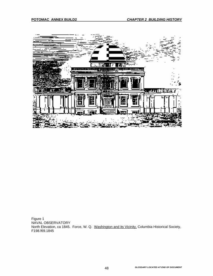
POTOMAC ANNEX BUILD2 CHAPTER 2 BUILDING HISTORY
GLOSSARY LOCATED AT END OF DOCUMENT 48
Figure 1 NAVAL OBSERVATORY North Elevation, ca 1845. Force, W. Q. Washington and its Vicinity, Columbia Historical Society, F198.f69.1845

POTOMAC ANNEX BUILD2 CHAPTER 2 BUILDING HISTORY
GLOSSARY LOCATED AT END OF DOCUMENT 49
Figure 2 NAVAL OBSERVATORY View for the Northeast, ca 1845. Naval Observatory Library.

POTOMAC ANNEX BUILD2 CHAPTER 2 BUILDING HISTORY
GLOSSARY LOCATED AT END OF DOCUMENT 50
Figure 3 NAVAL OBSERVATORY View from Northwest, ca. 1850. Lithograph by Sackse (Baltimore), from photocopy in files of Jan Herman, BUMED.

POTOMAC ANNEX BUILD2 CHAPTER 2 BUILDING HISTORY
GLOSSARY LOCATED AT END OF DOCUMENT 51
Figure 4 NAVAL OBSERVATORY Interior View of Central Dome, Before 1864. Naval Observatory Library.
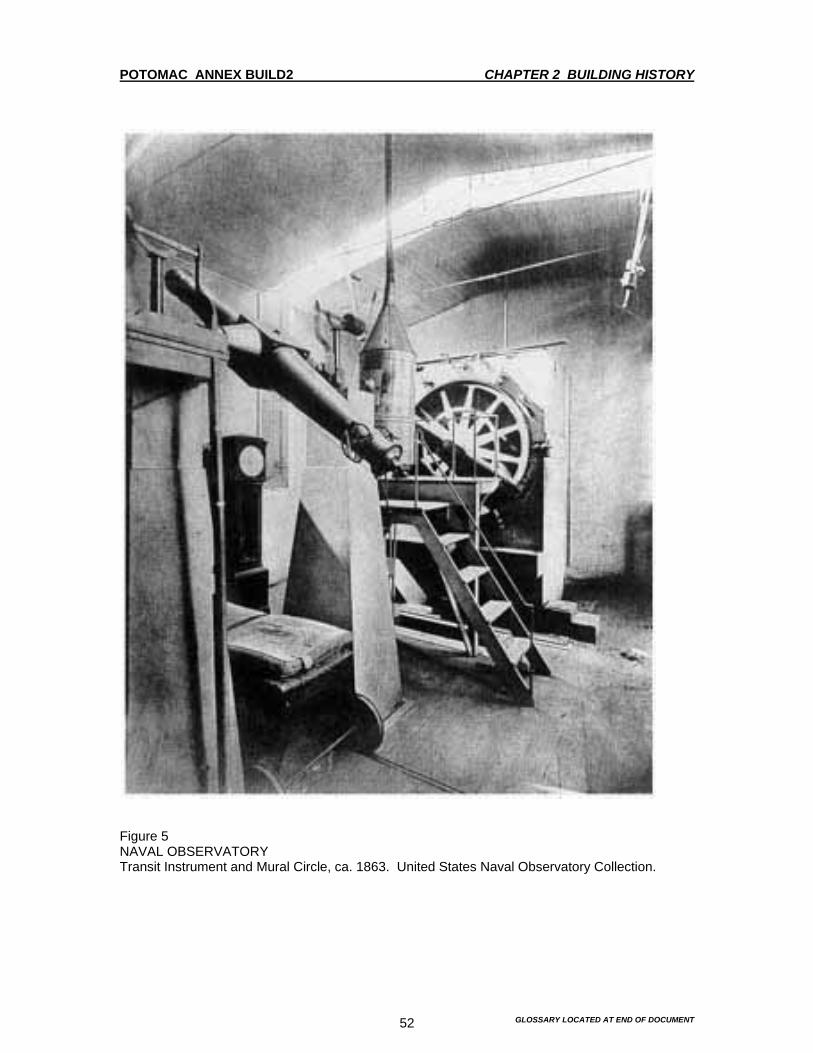
POTOMAC ANNEX BUILD2 CHAPTER 2 BUILDING HISTORY
GLOSSARY LOCATED AT END OF DOCUMENT 52
Figure 5 NAVAL OBSERVATORY Transit Instrument and Mural Circle, ca. 1863. United States Naval Observatory Collection.

POTOMAC ANNEX BUILD2 CHAPTER 2 BUILDING HISTORY
GLOSSARY LOCATED AT END OF DOCUMENT 53
Figure 6 NAVAL OBSERVATORY Transit Circle United States Naval Observatory Collection.
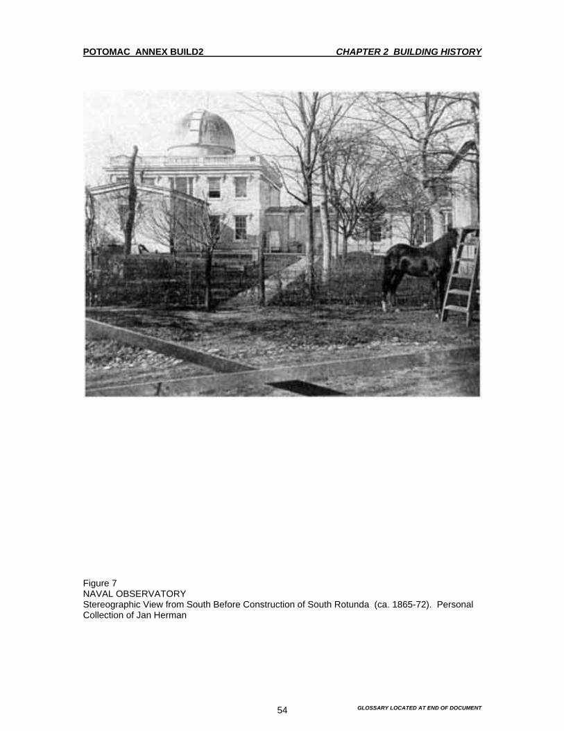
POTOMAC ANNEX BUILD2 CHAPTER 2 BUILDING HISTORY
GLOSSARY LOCATED AT END OF DOCUMENT 54
Figure 7 NAVAL OBSERVATORY Stereographic View from South Before Construction of South Rotunda (ca. 1865-72). Personal Collection of Jan Herman
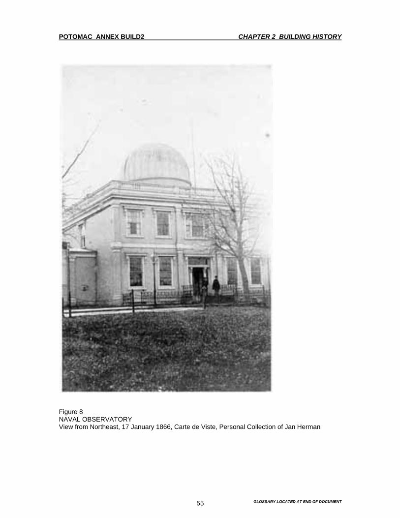
POTOMAC ANNEX BUILD2 CHAPTER 2 BUILDING HISTORY
GLOSSARY LOCATED AT END OF DOCUMENT 55
Figure 8 NAVAL OBSERVATORY View from Northeast, 17 January 1866, Carte de Viste, Personal Collection of Jan Herman

POTOMAC ANNEX BUILD2 CHAPTER 2 BUILDING HISTORY
GLOSSARY LOCATED AT END OF DOCUMENT 56
Figure 9 NAVAL OBSERVATORY Stereographic View from Northeast, ca. 1873. Naval Observatory Library & Smithsonian Institution Physical Science Collection
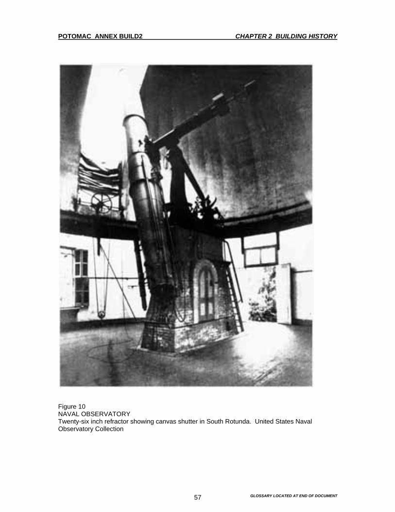
POTOMAC ANNEX BUILD2 CHAPTER 2 BUILDING HISTORY
GLOSSARY LOCATED AT END OF DOCUMENT 57
Figure 10 NAVAL OBSERVATORY Twenty-six inch refractor showing canvas shutter in South Rotunda. United States Naval Observatory Collection

POTOMAC ANNEX BUILD2 CHAPTER 2 BUILDING HISTORY
GLOSSARY LOCATED AT END OF DOCUMENT 58
Figure 11 NAVAL OBSERVATORY Interior View of South Rotunda, ca. 1873. Seated Figures: Simon Newcomb, Commodore Benjamin Franklion Sands (r). Naval Observatory Library
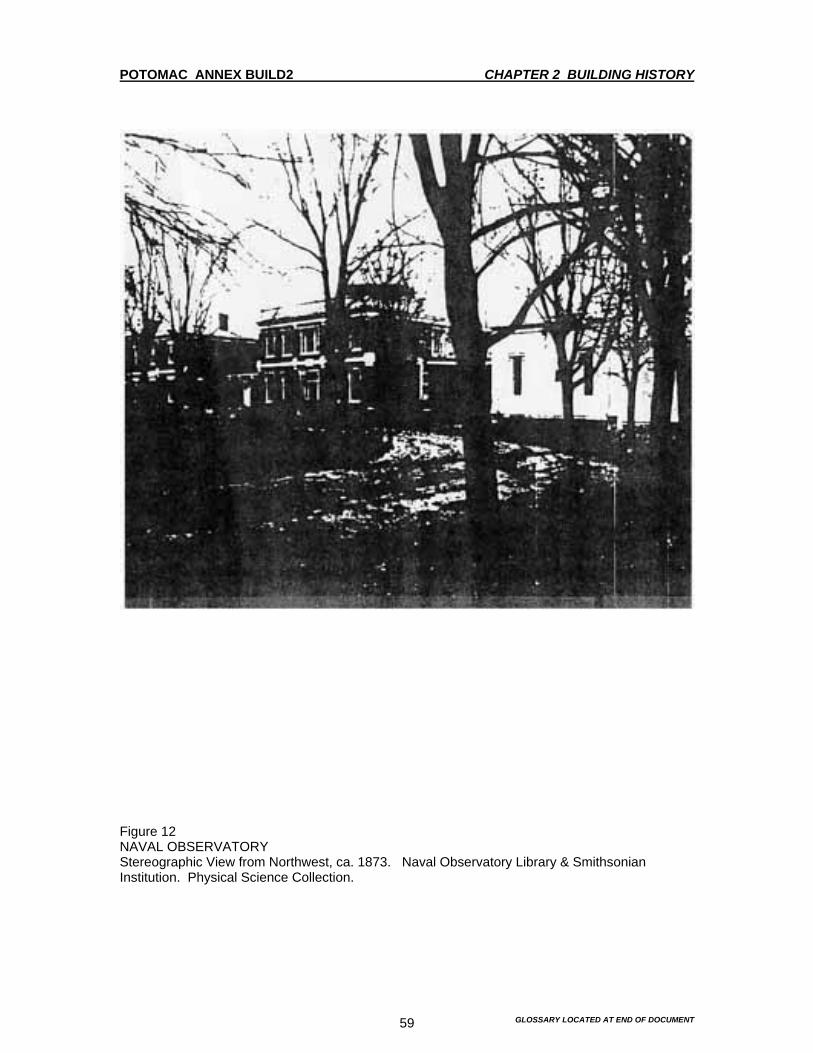
POTOMAC ANNEX BUILD2 CHAPTER 2 BUILDING HISTORY
GLOSSARY LOCATED AT END OF DOCUMENT 59
Figure 12 NAVAL OBSERVATORY Stereographic View from Northwest, ca. 1873. Naval Observatory Library & Smithsonian Institution. Physical Science Collection.

POTOMAC ANNEX BUILD2 CHAPTER 2 BUILDING HISTORY
GLOSSARY LOCATED AT END OF DOCUMENT 60
Figure 13 NAVAL OBSERVATORY North front walk, ca. 1874. United States Naval Observatory Collection.
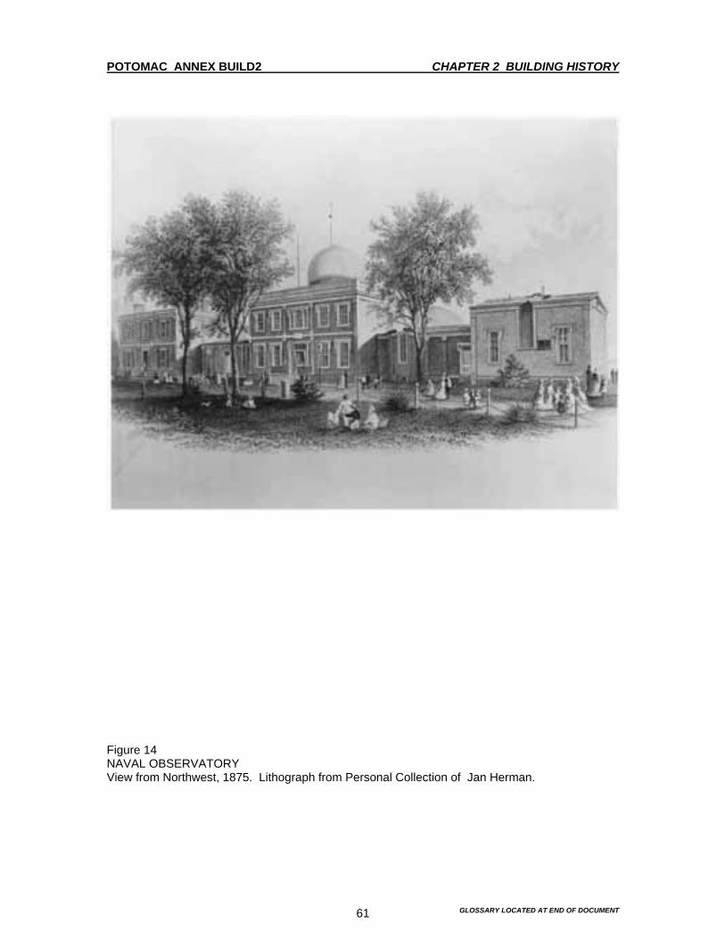
POTOMAC ANNEX BUILD2 CHAPTER 2 BUILDING HISTORY
GLOSSARY LOCATED AT END OF DOCUMENT 61
Figure 14 NAVAL OBSERVATORY View from Northwest, 1875. Lithograph from Personal Collection of Jan Herman.

POTOMAC ANNEX BUILD2 CHAPTER 2 BUILDING HISTORY
GLOSSARY LOCATED AT END OF DOCUMENT 62
Figure 15 NAVAL OBSERVATORY Detail of Transit Circle Room from Northeast, ca. 1885. Naval Observatory Library.

POTOMAC ANNEX BUILD2 CHAPTER 2 BUILDING HISTORY
GLOSSARY LOCATED AT END OF DOCUMENT 63
Figure 16 NAVAL OBSERVATORY Detail of Transit Circle Room from South, ca. 1885. Naval Observatory Library.
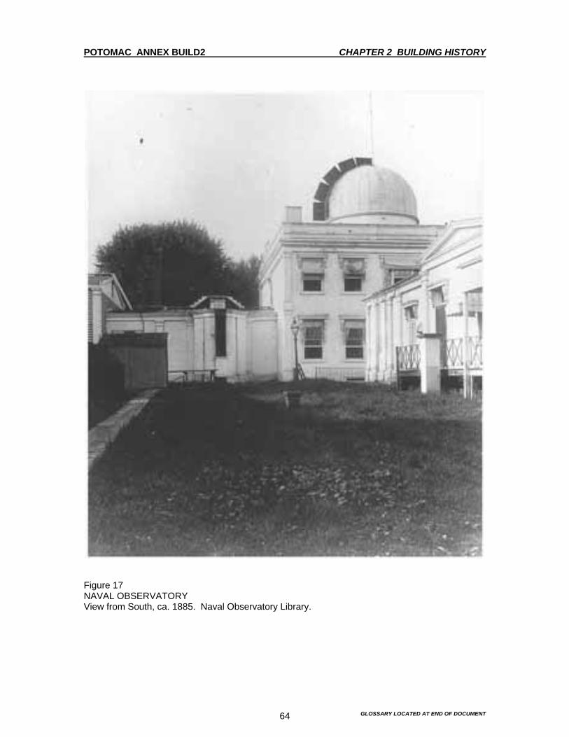
POTOMAC ANNEX BUILD2 CHAPTER 2 BUILDING HISTORY
GLOSSARY LOCATED AT END OF DOCUMENT 64
Figure 17 NAVAL OBSERVATORY View from South, ca. 1885. Naval Observatory Library.
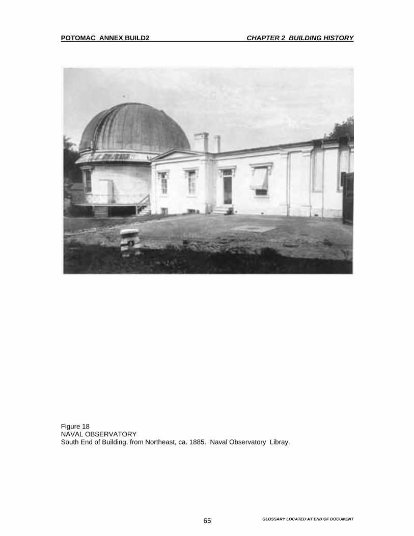
POTOMAC ANNEX BUILD2 CHAPTER 2 BUILDING HISTORY
GLOSSARY LOCATED AT END OF DOCUMENT 65
Figure 18 NAVAL OBSERVATORY South End of Building, from Northeast, ca. 1885. Naval Observatory Libray.

POTOMAC ANNEX BUILD2 CHAPTER 2 BUILDING HISTORY
GLOSSARY LOCATED AT END OF DOCUMENT 66
Figure 19 NAVAL OBSERVATORY View to West from Washington Monument 1885. Naval Observatory Library.
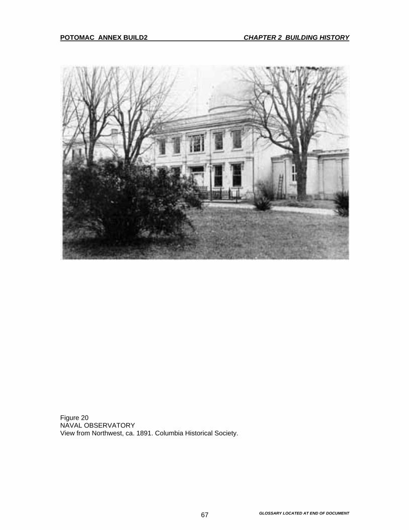
POTOMAC ANNEX BUILD2 CHAPTER 2 BUILDING HISTORY
GLOSSARY LOCATED AT END OF DOCUMENT 67
Figure 20 NAVAL OBSERVATORY View from Northwest, ca. 1891. Columbia Historical Society.
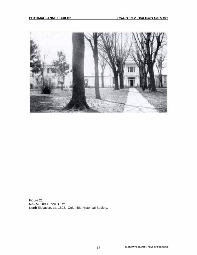
POTOMAC ANNEX BUILD2 CHAPTER 2 BUILDING HISTORY
GLOSSARY LOCATED AT END OF DOCUMENT 68
Figure 21 NAVAL OBSERVATORY North Elevation, ca. 1893. Columbia Historical Society.

POTOMAC ANNEX BUILD2 CHAPTER 2 BUILDING HISTORY
GLOSSARY LOCATED AT END OF DOCUMENT 69
Figure 22 NAVAL MEDICAL SCHOOL View from North, ca. 1902. Naval Observatory Library.

POTOMAC ANNEX BUILD2 CHAPTER 2 BUILDING HISTORY
GLOSSARY LOCATED AT END OF DOCUMENT 70
Figure 23 NAVAL MEDICAL SCHOOL View from Northeast, ca. 1908. Waldon Fawcett Collection, Library of Congress.

POTOMAC ANNEX BUILD2 CHAPTER 2 BUILDING HISTORY
GLOSSARY LOCATED AT END OF DOCUMENT 71
Figure 24 NAVAL MEDICAL SCHOOL View from Northeast, ca. 1908. Waldon Fawcett Collection, Library of Congress.

POTOMAC ANNEX BUILD2 CHAPTER 2 BUILDING HISTORY
GLOSSARY LOCATED AT END OF DOCUMENT 72
Figure 25 HOSPITAL COMPLEX Birds eye view, ca. 1930. BUMED Archives

POTOMAC ANNEX BUILD2 CHAPTER 2 BUILDING HISTORY
GLOSSARY LOCATED AT END OF DOCUMENT 73
Figure 26 NAVAL HOSPITAL AND MEDICAL SCHOOL Aerial view from the South, ca 1935. From Photography in Files of Jan Herman, BUMED Archives.
POTOMAC ANNEX BUILDING 2 CHAPTER 3 DESCRIPTION OF BUILDING AS ORIGINALLY BUILT IN 1844
GLOSSARY LOCATED AT END OF DOCUMENT 74
Introduction The Old Naval Observatory, which was built in 1844, was the beginning of a complex of buildings that would eventually be built on the site know as Reservation 4. The evolution of the Old Naval Observatory didn’t take long after the initial building was completed. Soon after completion of the Old Naval Observatory, the Residence for the superintendent was completed in 1847. The connecting hyphen that connected the Observatory to the Residence was completed in 1848. The Transit Circle Observatory was completed in 1864-65. The West Wing Alterations were completed in 1869. The South Wing Extension was completed in 1873. The Second Floor Additions to the east, west and south wings were completed in 1902-03. And finally the East and West Stucco Additions were completed in 1918. The Museum of Hygiene made many of the alteration and additions as a result of the museums need to alter the Old Naval Observatory. After the Museum of Hygiene, another tenant, the Naval Medical School, which was established in 1902, occupied the Old Naval Observatory. Just before America’s entrance into World War One, the Naval Hospital was also established on this site in 1918. All three of these tenants contributed much to the Old Naval Observatory. The Medical School constructed the second floor additions in 1902-03. The Naval Hospital constructed the east and west stucco additions in 1918. The Naval Medical School and Naval Hospital were the last tenants of any consequence in the Old Naval Observatory. Both the Naval Medical School and Naval Hospital moved to Bethesda, Maryland after World War Two. The Old Naval Observatory (1844-1865) This description is based on historic documentation, which includes Lt. James M. Gilliss’ report to the U. S. Senate on February 18, 1845, and construction specification presumably issued by Lt. Gilliss in October 1842. Other documentation includes other construction contracts dated 1847,1848 and 1864, an article written in 1873 by J.E. Nourse, USN by order of Rear Admiral B. F. Sands, then Superintendent of the Observatory, Annual Reports and inventories dating from 1861, 1867 and 1877. Copies of those sources all are provided in the appendix. The description is also based on a review of historic photographs, drawings and engravings, which appear as figures in the text, as well as a visual inspection of the building as it exists today. Construction of the Depot of Charts and Instruments, as the Old Naval Observatory was first known, began in 1842 and was completed in 1844. Although changed by many alterations and additions, much of the original structure exists as the central core of what is now known as Building #2. In its original appearance, the Old Naval Observatory was a two-story plus basement brick structure, ornamented by a wood cornice and balustrade and surmounted by an observation dome. The Old Naval Observatory faced north and was square in plan with radiating one-story wings to the east, west and south. Its overall appearance was of a solid, classical structure with Greek Revival overtones. As constructed, the center section was basically a symmetrical cube five window bays wide by two-high and the door was the central feature of the facade. Brick pilasters divided the central bay from the two flanking bays and terminated the ends of the central block. Grey sandstone was used for the bases and the capitals of the pilasters. Granite was used for the sills and the basement window lintels. Lt. Gilliss called for the “Blue rock” to be used for the foundations. However, materials analysis shows it to be of schist and gneiss, (See Chapter 6: Materials Conservation Analysis). A wooden parapet surmounted the main block and balustrade with turned balusters. According to Lt. Gilliss’ report, the flat roof was covered with copper and fitted with a metal grating to create a walking surface for observation activities. The entrance was centered on the façade and fitted with double-leaf paneled wood doors with a glass transom and side lights. Lt. Gilliss specified that the door be 8 feet wide from outside to outside and 11 feet 1 inch in height from sill to top of woodwork. He further specified that the door be made of the best-seasoned oak and varnished. Granite was specified for the front steps
POTOMAC ANNEX BUILDING 2 CHAPTER 3 DESCRIPTION OF BUILDING AS ORIGINALLY BUILT IN 1844
GLOSSARY LOCATED AT END OF DOCUMENT 75
and the landing was to be 11 feet 6 inches by 5 feet with 6 steps from grade. “The sides are to be fitted with granite side pieces eleven feet long and six inches wide.” Lt. Gilliss specified two outside doors to the basement, each 6 feet 6 inches and 7 feet tall with sidelights. The windows were 6-over-6 double-hung wood sash, except on the second floor where a 6-over-6 window was flanked by 2-over-2 windows. Lt. Gilliss indicated that all the widows in the Old Naval Observatory were to be fitted with close inside shutters and that the shutters were to be painted white. He also indicated that each wing had to have a window in its gabled end. These windows were removed when later additions to the building were made. The molded wood window and door lintels were decorated with foliated brackets of gray sandstone. The most impressive and important feature of the Old Naval Observatory was the revolving dome, which housed the 9.6-inch Equatorial Refracting Telescope built by the Munich optical firm of Merz and Mahler. The dome, which was centered on the main core of the Old Naval Observatory, was 23 feet in diameter resting on a 7-foot high circular wall, or drum. Lt. Gilliss’ specification calls for weather-boarded studs for the drum, so it is likely that a change order was made during construction. Like the roof, the dome was sheathed with copper. It was fitted with three windows and a door in the drum and an observation aperture or slit, fitted with a shutter with five doors, which could be opened separately. Because the dome rotated a full 360 degrees, the aperture could be aligned with any directional coordinate. The rotation of the dome was accomplished by fitting an iron rail on top of the drum into which, were set six 32-pound cannon balls. The dome’s curb was fitted with a similar iron rail, which rested on the balls in the track. A “cornice” below the coping protected the mechanism from the weather. Below the rollers was the rack wheel, which required only ten pounds of pressure to move the dome from a standing position. In 1845, a flagstaff was mounted to the Observatory’s dome to accommodate the local time service requested by the Secretary of the Navy, Figure 92. To the east and west sides of the central core of the Old Naval Observatory were the wings, which one entered from the interior passages. Each wing was 26 feet 6 inches long, 21 feet wide and 18 feet high. The west wing housed the Meridian Transit Instrument and the Mural Circle. The east wing was intended for a Meridian Circle and portable Transit Instrument. In both cases, masonry piers rose up from the basement level to support the instruments. The sides of the walls of the wings were 18 inches thick with pilasters on either side of each door to strengthen them. There was also a 21-foot wing to the south separated from the central core by a 10-foot passage. The Transit Instrument in the Prime Vertical was housed here. A clock was to be placed in each wing. Like the dome, each wing had two 20-inch openings on each side, in the meridian or prime vertical. The openings had doors, “with grooves on each side to lead off any water that may drive in”. The roofs had a rise of 3 feet, and like the roof of the central core and dome, they were sheathed in copper. Vertical doors to the apertures opened inwardly and operated separately. The original color scheme for the Old Naval Observatory is not certain. This is due to conflicting information in the paint analysis, historic photographs and historic documentation. What is certain however, is that at least the woodwork and stonework were painted. Lt. James Gilliss clearly specified in 1842 that the stone trim be given three coats of white paint, see appendix. The analysis of paint samples supports that the stone elements of the façade were painted early, since the samples taken from the, belt course, foundation and sandstone features, except the brackets, all have similar numbers of paint layers described as yellowish. The brackets have similar finishes to the wood elements. It is uncertain when the Old Naval Observatory’s brickwork was first painted. However, it is known that Lt. Matthew Maury, on November 1,1844, issued a great request for proposals that read. “I wish to have the outside (the brickwork) of this building painted and should be glad to receive as early as convenient your estimates for doing the same in the best manner. The necessary
POTOMAC ANNEX BUILDING 2 CHAPTER 3 DESCRIPTION OF BUILDING AS ORIGINALLY BUILT IN 1844
GLOSSARY LOCATED AT END OF DOCUMENT 76
particulars will be given to you when ever you can make it convenient to call”.1 Some paint samples taken from the brickwork have similar numbers of paint layers to the stonework and others have fewer layers. But whites, yellows and a pale yellow orange appear with some consistency. If the brick had been left unpainted, this would have created a sharp visual contrast between the body of the Old Naval Observatory and the painted trim. The stereographic views from 1873 appear to show a high degree of contrast between the body of the Old Naval Observatory and the trim. However, earlier images show less contrast. The Carte de visit taken on January 17, 1866, which is the first photographic image of the Old Naval Observatory known to exist, shows a very low level of contrast. This low contrast between the body of the Old Naval Observatory and its trim suggests that both the brickwork and the stone were indeed painted. This also appears to be the case in the photographs dated ca. 1865-1872. After the 1880s, the photographs and paint analysis do seem to support a light color scheme. The interior of the central core was divided into two stories. Each story had four rooms separated by passages crossing each other at right angles. The center of the Old Naval Observatory was quite different in its original configuration from what exists today. At the center, there was great masonry pier, designed to support the 9.6-inch Merz and Mahler Equatorial Telescope that rose through the floors. In the basement, the diameter of the pier’s stone base was 15 feet. From there, it rose to a height of 10 feet 6 inches diminishing to a twelve-inch diameter. On top there was a conical brick pier capped by flagstone, Figure 29. The pedestal of the Equatorial Telescope rested at the apex. The inside of the dome and shutters were lined with painted canvas. The room was furnished with an observing chair, which could be moved around the pier on casters. Where the dome wall crossed each passage, a brick arch carried the load. A stair, no longer extant, situated to the south of the rotunda, led from the basement to the second story. In the second story, a wrought and cast iron stair, also gone, spiraled around a pier structure to a landing at the circumference of the dome. The stair structure was completely independent of the pier to protect the pier from vibrations. The warm air furnace occupied one room in the basement. There were other rooms in the basement. One was for fuel storage and two others were for workshops of the instrument maker and lithographer. The library, computing room, director and assistants’ offices and the chronometer room were located on the first floor. Drafting rooms were located on the second floor as were storage rooms for instruments and charts. There was a discharging flue from the furnace in every room and two in the passages of the second story. Lt. Gilliss insured that the all the details of the construction were taken care of during the construction contract of 1842. He specified that the interior doors were to be made of white pine, two inches thick with moldings and paneling of the most approved modern patterns. The interior doors were to be fitted with hinges at least four inches by four and a half inches and with mortised door locks. The exterior doors were to have wrought iron hinges. A section through the building shows the doors in elevation, Figure 29. The windows were to be finished with splayed jambs and the doors with open jams. Both had 8” double Architrave’s. The doors shown in the section have single panels. Those that exist have four panels. The existing Architrave’s match the specified dimensions. Carolina yellow pine was specified for the floors. With the exception of the basement, all interior walls were primed and painted with three coats of the best white lead paint. Analysis of the paint samples taken, shows that the plaster walls were tan and the woodwork was white throughout the building.
1 Maury, M.F., Lt., USN, letter dated November 1, 1844. National Archives, RG 78, outgoing letters Entry 1, Volume1, page 293. Jan Herman indicates in his notes that the contract was awarded to a Mr. Purdy.
POTOMAC ANNEX BUILDING 2 CHAPTER 3 DESCRIPTION OF BUILDING AS ORIGINALLY BUILT IN 1844
GLOSSARY LOCATED AT END OF DOCUMENT 77
The Magnetic Observatory As part of the original building campaign, Lt. Gilliss directed the excavation for a subterranean structure to house Magnetometers to read the Earth’s magnetism, an important factor in navigation. The Magnetic Observatory was built underground to the southwest of the Old Naval Observatory. A 95-foot corridor connected the two structures. Four 72-foot arms radiated from the octagonal core of the Magnetic Observatory. The central intersection contained an 8-foot diameter skylight. At a depth of 16 feet, Lt. Gilliss asserted that the temperature of the structure would be uniform because the floor was below grade. The structure was framed out in yellow pine and roofed by an octagonal dome light at the center of the cross. Four marble pillars to support the manometers were located in the extremities of the cross. With Five feet of earth on top of the structure, Lt. Gilliss planned for the structure to be rainproof. However, this proved not to be the case. When Congressman John Quincy Adams visited in 1845, Lt. Gillis had already suspended observations.2 Subsequently, the subterranean structure was back-filled. The only remaining evidence today is the entry to the corridor. The Residence (1847) and Connecting Hyphen (1848) At the urging of the former President John Quincy Adams, then serving as congressman from Massachusetts, Congress allocated funding in 1845 for the construction of a residence for the superintendent and his family on the Old Naval Observatory grounds. It was to be a two-story plus basement house with a slate roof, back building and wash house.3 At least three bids for the new construction were received in May 1845. The descriptions of the bid documents are not consistent with the existing conditions. Based on the existing conditions, the brick house was constructed to be as compatible as possible with the Old Naval Observatory building. By the end of 1847, the house was ready and Lt. Maury and his family moved in. The house was built to the east of the Old Naval Observatory. The east wing was extended 24 feet to connect with the house. It is an extremely simple building, three window bays wide on the front elevation with a center entry. The center bay is flanked by brick pilasters, which are similar to the terminated corners on the Old Naval Observatory. Materials analysis shows that the basement window lintels and sills were constructed of a coarse red-orange sandstone and a finer red sandstone was used for the upper window lintels and sills, as well as the pilaster bases and capitals. Schist and gneiss were utilized for the foundation. (See Chapter 6: Materials Conservation Analysis.) The 1873 stenographic view, Figure 9 and the lithograph, Figure 14, of 1875, show that a balustrade similar to that of the Old Naval Observatory terminated the house roof. The pictures also show the entry steps and a cast-iron railing. There were simple window frames and chimneys on both the east and west sides of the house. The windows were six-over-six sashes. The historic photographs show louvered shutters, the pointless are still extant. Most of the features noted in the historic images are extant, with the exception of the balustrade and the east chimney, which was probably removed when the second story addition was added the wing. The historic images noted above seem to indicate that the color scheme of the Residence was similar to that of the Old Naval Observatory. While little historic documentation exists for the construction of the rear of the house, the existing conditions do appear to be original. The rear of the house is connected on the first and second floors to a back building bay on an elevated passage. The basement areaway passes under this connector, which is supported by granite beams. Ghosts in the brickwork indicate that there were porches on the eastside of the south elevation with access from the southeast and southwest rooms by doors, which were later converted to windows. The existence of the west porch is substantiated by historic documentation. The 1848 specifications for the hyphen extension called 2 Adams, C.F., Memoirs of John Quincy Adams 1795-1848, as cited in Herman, A Hilltop in Foggy Bottom, p.18. 3 Herman, p.12, makes reference to specifications dated 12 February 1847.

POTOMAC ANNEX BUILDING 2 CHAPTER 3 DESCRIPTION OF BUILDING AS ORIGINALLY BUILT IN 1844
GLOSSARY LOCATED AT END OF DOCUMENT 78
for the parlor porch to be glazed. This is supported by a photograph ca. 1865-1872, Figure 7 of the south side of the Old Naval Observatory, which indicates a glimpse of glazing not in conformance with the fenestration pattern of the house. Look directly above the horses back in Figure 7. Unfortunately, little documentation was located for the interior layout except for the floor plan in Keim’s Illustrated Hand Book: Washington and its Environs, 1884, Figure 30 and inventories dated 1861,1867 and 1877. Keim’s floor Plan must be viewed, as somewhat schematic since the proportions for the residence is highly inaccurate. The inventories support the general floor plan scheme of four rooms per floor separated by a central stair hall, which is reflected in the existing conditions as they have been modified. However, they offer some conflicting information for the upper floor. The “library” or “hall room” indicated is most likely the small room on the north side of the second floor and there are listings for chambers in each major corner. A small southwest room, that contained and entry and closets, between the major rooms, no longer exists. No concrete historic documentation was located for physical alterations made to residence during the Museum and Medical School periods. However, it is certain that the floor plans on the west side of the Residence on both the first and second floors have been altered more than once to accommodate the changing uses of the Residence. (See Chapter 4 for a discussion of the existing conditions). The interior finishes for the Residence is specified in the inventories. Wallpaper was found throughout the Residence, although patterns, colors and types were not specified. Small fragments of paper were found in the northeast parlor as part of the paint study. Unfortunately, not enough was found anywhere to determine a pattern or color. It appears that the paper was stripped during the 1894-1902 alterations. Grain-painted surfaces on the doors were called out for repair in the 1877 inventory, which supports grain-painted finishes found on original features in the paint analysis. In 1848, a hyphen was constructed connecting the east wing of the Old Naval Observatory to the Residence. The existing windows were converted to doors. The specifications called for the extension to be finished in the same manner as the existing wing except that rather than observation slits it would have an entry door on the north facade and windows on the south. The door was to have a transom and stone steps like the dwelling. The Transit Circle Observatory West Wing Alterations (1864-65) and Addition (1869) When Capt. Gilliss ordered a new Transit or Meridian Circle in 1863 from the Berlin optical firm of Pistor and Martins, alterations to the Old Naval Observatory were required. In 1864, specifications were written for the addition of semi-octagonal brick bays to the west wing, which would accommodate the new equipment. These bays still exist with some alterations. The central portions of the north and south walls of the west wing and its piers and floors were removed and the existing transits were moved into the east wing. Observation apertures, thirty inches wide and seven feet six inches above the ground were specified, as were shutters to match existing. The cornices were to be finished in the same manner as the existing and the openings were to be flanked by brick pilasters matching the existing pilasters. New masonry piers and a turntable were to be installed. The interior finishes included heart pine floors, which were to be two feet six inches below the existing level. A ceiling of thin boards and plaster walls were painted the same color as the old section.4
4 Specifications of alterations and additions to the Observatory buildings, prior to 1864, US Naval OBS, MN Div of LC, Box 13—need to check reference.

POTOMAC ANNEX BUILDING 2 CHAPTER 3 DESCRIPTION OF BUILDING AS ORIGINALLY BUILT IN 1844
GLOSSARY LOCATED AT END OF DOCUMENT 79
The brick Transit Circle room described above was not adequate. In the summer of 1869 a larger structure to house the Transit Circle was added to the west wing. This room was occupied on February 12, 1870, and the Old Naval Observatory library was moved into the west wing.5 The new Transit Circle addition was 40 feet by 28 feet 3 inches. It was 22 feet high at the ridge and 19 feet 6 inches at the eaves. The ridge of the roof extended east and west. The aperture was 3 feet 8 inches wide and extended downward within 7 feet 4 inches of the floor and was closed by four sliding shutters. The walls of the frame were covered with tin and shaded from the direct rays of the sun on the east, south and west sides by light wooden louvers. The construction was adopted in order to equalize the temperature between the external and internal air.6 Contemporary illustrations, Figures 5 and 6 illustrate the rather temporary appearance of this Transit Circle room. In fact by 1882, Herman notes that. “The west wing Transit Circle room was in terrible shape and required nothing short of an entire remodeling of the roof and shutters to make it safe.”7 Indeed, the structure was replaced in 1897 by the brick lecture hall constructed by the Naval Museum of Hygiene. The alterations are still extent. The existing structure, Figure 71 was composed of brick and contained a two-story space on the interior that was used as a lecture hall. The main entrance was centered on the north façade and was characterized by a one-story projecting porch with an open wood balustrade. The corners of this structure are ornamented with superimposed pilasters on other sections of the building. These were constructed of brick. Unlike the pilasters on the other sections, the bases and capitals here were also constructed of brick. There were belt courses installed on the north and west elevations. In 1918, a stucco addition was constructed on the south side of the building obscuring the south elevation entirely. (See Chapter 4 for a discussion of existing conditions.) The Great Equatorial Observatory (1873) In 1870, Congress appropriated funds for the purchase of a 26-inch refracting telescope. Alvan Clark & Sons, of Cambridge, Massachusetts were contracted to manufacture the telescope. This new, large Equatorial Telescope required more spacious quarters than the obsolete 9.6-inch telescope. Therefore, a new observation dome was constructed to the south of the old Observatory. A rubble-stone foundation was laid, which rose as a water table above grade. On this structure, an oak sill was laid in 8-foot sections, which supported the oak vertical framework of the cylindrical portion of the dome. Diagonal bracing strengthened the verticals. On top of the verticals rested a flanged iron plate. This plate served as the rail, which rested the rollers used to rotate the dome. The dome was moved on the rollers by means of a cast iron pinion. The wood framed dome was covered on the exterior by galvanized iron plates. The interior was covered with a canvas that was soaked with several coats of soluble glass for fireproofing. The dome was fitted with an observation slit 6 feet 6 inches wide and 39 feet 6 inches long and shuttered by a canvas shade operated on a pulley system. The dome was lit by eight gas burners arranged around the drum about 6 feet from the floor level.8 A photograph taken in November 1873, shortly after installation, shows that the interior surface treatments were quite simple. The floor appears to be wood with a simple base, perhaps one foot in height. The wall covering appears to be either unpainted vertical wood boards or a faux wood-grained fabric. The observing chair and step ladder did not move on a track, but rather on casters to allow flexibility in it's positions.9 The telescope rested on a brick pier fitted with a closet for support of the driving clock.
5 Nourse, J.E., “Memoir of the Founding and Progress of the United States Naval Observatory,” Washington Observations for 1871—Appendix IV, Government Printing Office, Washington, D.C., 1873, p. 43. Nourse also notes that a description of this wing exists in the Volume for Observations for 1870. 6 Yarnall, Mordechai, “Instruments of the Observatory,” Monograph, 1876, p. 25. 7 Rowan, SC: Letter to Secretary of the Navy, W.C. Chandler, 6 July 1882, as noted in Herman, p.53. 8 Yarnall, “Instruments of the Observatory”, pp. 26-31. 9 Yarnall, “Instruments of the Observatory,” pp. 26-31.

POTOMAC ANNEX BUILDING 2 CHAPTER 3 DESCRIPTION OF BUILDING AS ORIGINALLY BUILT IN 1844
GLOSSARY LOCATED AT END OF DOCUMENT 80
Without doubt, the existing foundation is all that is left of the 1873 structure. The existing structure of the rotunda is brick on a stone foundation of schist and gneiss. A contemporary photograph, Figures 93 and 94 shows metal cladding as the exterior treatment and the window surrounds are certainly not the same as the existing structure. An iron balcony or walkway, approximately 4 feet in height was constructed around the exterior circumference of the drum. In 1894-1895, when the Naval Museum of Hygiene moved onto the site, the frame structure was taken down and the current brick structure built. The current brick structure was probably built on the original foundations. The dome was removed and replaced with semi-conical roof and cupola. (See Chapter 4 for a discussion of existing conditions.) When the rotunda was constructed, a one-story brick addition was made to connect it to the old Observatory building. Figure 1, shows this addition with a gabled roof and facing east. The specifications called for the Interior of this space to be fitted for residential use with a parlor and a coal grate in one room. The smaller room was “…to be supplied with a bath tub and a standing marble wash basin…” The Keim floor plan indicates that the room on the east side of this section was a bedroom, but it is not known for whom. Naval Museum of Hygiene (1894-1902) In 1894 the Old Naval Observatory’s presence at the site in Foggy Bottom ended.10 By 1 July 1894, the Old Naval Observatory had a new tenant. This tenant was Naval Museum of Hygiene. The Naval Museum of Hygiene undertook a campaign of major repairs and alterations to the Old Naval Observatory to get it ready for exhibition, lecture and laboratory spaces. The supporting piers for the 9.6-inch telescope, the Mural Circle and the equal altitude were removed, as was the obstructing hallway and the light from the dome. Plumbing and heating were upgraded.11 The rooms in the Old Naval Observatory and Residence would be used for exhibition space, with the exception of the second floor of the Old Naval Observatory, which would accommodate laboratories. The west wing and the Transit Circle room would be fitted with shelves for library and exhibition purposes. While the south equatorial room appealed to A.C. Gorgas, Medical Director of the Navy, he noted that it was “…an admirable apartment for museum purposes, but needed extensive repairs.” Those repairs were undertaken in 1895. “ In the last fiscal year, the library building has been almost entirely rebuilt. It is circular in form, 40 feet in diameter, with side and lantern lighting, stamped steel ceiling, oak parquetry floor, oak shelving, library tables and furniture. On the south wall is a handsome fireplace and over the mantel the tablet contributed by the medical officers of the Navy in memory of Surgeon. James Markham Ambler has been appropriately and permanently set.” 12 The main stair connecting the first and second floors in the Old Naval Observatory was replaced. This is the stairs, which exists today. Connecting archways were constructed throughout the Old Naval Observatory. The Old Naval Observatory’s exterior and gateways were all painted. The interior finishes were changed as well. Oak parquetry flooring and new Georgia pine floors were installed. Carpets, rugs and matting were supplied for the reception room, offices and corridors. In 1896, a new steam heating system was being installed. “A new smokestack has been installed for new boilers, steam pipes, and radiators…”13 There are minor references to “repairs” that were made to the west wing in the Surgeon General’s Annual Report of 1897. There was a view of enlarging the usefulness of the Naval Museum of Hygiene. The Bureau of Medicine and Surgery had plans and specifications prepared for repairing the west wing of the Old Naval Observatory. “Work on which has commenced and will 10 Bureau of Medicine and Surgery, Annual Report of Surgeon General, Wash., DC, GPO, 1894), p.9. 11 Bureau of Medicine and Surgery, Annual Report of Surgeon General, (Wash., DC, GPO, 1894),p.9. While the report mentions “the obstructing hallway,” floor plans do not clarify its nature or location. 12 Bureau of Medicine and Surgery, Annual Report of Surgeon General, (Wash.,DC, GPO, 1896) p. 199. 13 Bureau of Medicine and Surgery, Annual Report of Surgeon General, (Wash. DC, GPO, 1896) p. 199.

POTOMAC ANNEX BUILDING 2 CHAPTER 3 DESCRIPTION OF BUILDING AS ORIGINALLY BUILT IN 1844
GLOSSARY LOCATED AT END OF DOCUMENT 81
soon be completed.”14 “Plans and specifications for extensive repairs to the west wing or annex have been prepared and a requisition for the work has been approved.”15 The “repairs” should be regarded as a major reconstruction of the west wing. As noted above, the west wing constructed in 1869 was a frame structure on the south, east and west elevations. Historic images show this configuration quite clearly. While no specifications or drawings were located for the 1897 “repairs,” there is no doubt that the brick lecture hall, which exists today, was constructed at that time. It appears that the original structure was taken down and that the new brick structure was built on the original stone foundations. (See Chapter 4 for a discussion of existing conditions.) Naval Medical School (1902-1904) When the role of the Naval Museum of Hygiene was enhanced in 1902 to include the Naval Medical School, additional changes were made to the physical plant. Those changes included “An additional story constructed on the two connecting wings of the main buildings to provide laboratory facilities…”16 A second story was added to the south wing in 1903 to accommodate student officers for lockers and sitting rooms.17 The construction of these second-story wings significantly altered the appearance of the Old Naval Observatory. Their installation necessitated removing the pitched roofs over the original wings and altering, or simply removing, the obsolete observation apertures. The additions were constructed of brick and were fenestrated by 2-over-1 wood sash windows with arched transoms. The windows on the south wing lacked the arched transoms. The interiors of the front wings were open spaces fitted out with laboratory equipment for pathology, clinical microscopy, bacteriology and medical zoology with space and fixtures for 26 people. The lab was also equipped with a large incubator and ovens. The chemical lab contained 32 working spaces. The basement was utilized for photography and photomicrography, as well as a room for cold storage. The Naval Medical School Library, consolidated with the Naval Museum of Hygiene’s collection, continued to grow in the south rotunda. The east wing, which was the home of a Naval Museum of Hygiene officer and formerly of the Old Naval Observatory Superintendent, was transformed into an office for the Medical Examining Board. Naval Medical School and Hospital (1904-1942) The Naval Hospital undertook a major building campaign between 1904 and 1910. The major building campaign included the Hospital, Buildings 3 & 4, designed by Ernest Flagg, the Female Nurses’ Quarters, Building 7, the Contagious Building, Building 6, the Sick Officers Quarters, Building 5 and three residences. These improvements to the Hospital complex served the Navy well until 1917, when the United States entered World War One. To accommodate the large numbers of wounded men returning from battle, the Hospital was forced to construct emergency facilities including tent storage buildings, additions to the mess hall and eight temporary wooden structures.18 Plans for two additions to the Old Naval Observatory were approved in 1918. These were two, two-story plus basement stucco additions still extant on the south side of the Old Naval Observatory. The west wing was approved in January 1918 and was constructed for additional classroom space. The east wing, approved in November 1918, was intended for additional laboratory space. Both masonry wings were clad in stucco. The east and west walls of the west addition were aligned with the lecture hall, with a minor entrance to the basement level on the 14 Bureau of Medicine and Surgery, Annual Report of Surgeon General, (Wash. DC, GPO, 1897) p. 199. 15 Bureau of Medicine and Surgery, Annual Report of Surgeon General, (Wash. DC, GPO, 1897) p. 218. 16 Bureau of Medicine and Surgery, Annual Report of Surgeon General, (Wash, DC, GPO, 1902) p. 44. 17 Bureau of Medicine and Surgery, Annual Report of Surgeon General, (Wash, DC, GPO, 1904) p. 222. 18 Herman, A Hilltop in Foggy Bottom, p. 76.

POTOMAC ANNEX BUILDING 2 CHAPTER 3 DESCRIPTION OF BUILDING AS ORIGINALLY BUILT IN 1844
GLOSSARY LOCATED AT END OF DOCUMENT 82
east-side. The south elevation was simply fenestrated with 6-over-6 wood sash windows. The east addition abuts the rear building of the residence, and therefore, reads more as a freestanding structure. Like the west addition, it was designed with 6-over-6 wood sash windows. However, on the south side it was furnished with a Colonial Revival entry, giving direct access to the first floor. The floor plans for both additions were mostly open and simply finished, with minor partitions for discrete offices. A handsome, simply designed wood staircase served each addition. Thus, it was not until 1918-1919 that the Old Naval Observatory took on the appearance that it still retains today. Only minor exterior alterations have been made since 1918, except for painting, repair and introduction of new entries and porches. However, when the administrative offices of the Naval Bureau of Medicine and Surgery moved to the Old Naval Observatory in 1942, the building was retrofitted for office use. Chapter 4 discusses the existing conditions including alterations made during BUMED occupation. Site and Surroundings William Strickland, the Philadelphia architect, was contracted by the Navy to undertake the excavation and landscaping of the site. Strickland had been doing a great deal of work for the Navy during the 1840’s, so his choice was a natural one. There are two watercolor renderings done by Strickland in 1844, as a landscaping proposal to the Navy, Figures 46,47 and 48. The drawings also include proposed pavilion buildings and architectural alterations to the Old Naval Observatory, none of which was executed. Figure 46, the first drawing, is a site plan. The north end of the site was rectilinear and fit into the Washington street grid. The south end boundary ran from northeast to a southwest direction. The landscaping scheme included a perimeter wall with a gate in the east wall on axis with D Street. The north gate, flanked by two “lodges,” opened to a circular drive leading directly to the Old Naval Observatory entry. The east gate opened to a circular drive leading to the “yard” of one of the proposed pavilions. In the scheme, two concentric terraces circled the Old Naval Observatory. Figure 47, consists of two drawing sections through the site showing how much earth would need to be moved in order to create the terracing Strickland proposed. While separately stored today, these drawings were accompanied by a letter from Strickland to J. Y. Mason, Secretary of the Navy, dated August 10, 1844, recommending grading the grounds prior to the construction of the walls. A letter from Mason to Strickland dated September 18, 1844, states, “that he had received the report with the plans and that they were approved with the exception of that part relating to the dome, which is reserved further consideration.” (Records of the Department of the Navy. Navy Department, General Letter Book #34, 1844-1845, RG 45 E3 M209). It is not clear from the correspondence when, or if decisions were made to eliminate the pavilions from the construction scheme. However, the grading and terracing work was continued through the autumn of 1845. Sessford’s Annals noted in 1845, that, “The Observatory is now well furnished with instruments, the grounds enclosed, and in a sate of preparation for laying them out in walks. This site, which will soon afford a delightful place for recreation, being on an eminence and affording a splendid view of this city, Georgetown, Alexandria, and the District.” While no mention was noted of the materials to be used for building the perimeter walls in 1844, it is clear from later documentation that they were red brick. Thomas Lewis of Washington and the Navy Department in 1853, entered into a contract to raise the perimeter walls on the east, south and west sides. “The bricks, including the coping bricks used in raising the said wall are to be the best red brick and they are to be laid and filled in with mortar…” (Records of the Naval Observatory, Box 13) A watercolor site plan, Figure 48, dating after the construction of the south rotunda observation in 1873, shows that at least some of the Strickland’s concepts were undertaken. It also shows
POTOMAC ANNEX BUILDING 2 CHAPTER 3 DESCRIPTION OF BUILDING AS ORIGINALLY BUILT IN 1844
GLOSSARY LOCATED AT END OF DOCUMENT 83
plantings, garden designs and many buildings. The plan shows the Old Naval Observatory fully developed with a footprint that is substantially consistent with the existing condition. The buildings grouped to the southwest of the Old Naval Observatory were used for a number of astronomy related purposes. Those to the southeast were utilitarian stables and cowsheds. None of these buildings survive. The drawing indicates terracing at the south end of the site in a much more rectilinear fashion than Strickland’s concentric circles. The most notable feature is the circular drive, which is more oval than Strickland’s drawing indicated. Unlike Strickland’s drawings, the main gate is shown at the corner of 23rd and E Streets. A tree-lined walkway from what appears to be an opening in the north wall bisects the circular drive leading directly to the north entry of the Old Naval Observatory. A secondary drive intersects the northwest quadrant of the circular drive. This secondary drive leads west, then turns in a gentle curve to the south ending at the stable and barnyard behind the south observatory. A walkway leads from the corner gate to the northeast corner of the residence. Curvilinear paths and low plantings characterize the residence garden to the east. Larger garden patches, presumably kitchen gardens were located behind the barnyards. Hedges outline a number of the drives, pathways and gardens. Early images of the Old Naval Observatory also give clues to historic landscape features and plantings. The 1850 engraving shows the path leading to the Old Naval Observatory’s front door flanked by grassy lawns and planted with young trees. A post and chain fence bounding the lawns is evident in this and later images. Beginning in the 1860’s, gas lamps began to appear in the landscape. Ornamental iron gates and wires fences appear in some of the late 19th century images. Historic images also show brick paving and stone swales and two boot scrapers on either side of the Residence stoop. In 1894, the new Observatory on Massachusetts Avenue was ready for occupation. The Naval Museum of Hygiene occupied the Old Naval Observatory, which had fallen into disrepair as noted in the photographs and documents of that period. A storm in 1896 caused even more damage. “It uprooted and broke down many of the old trees.” The grounds in front and at the sides of the Old Naval Observatory were cleared of debris. Trees were trimmed and rubbish removed. The grounds were plowed, graded and put in grass.” (Fifteenth Annual Report of the Museum of Hygiene, Medical Director, US. Navy, 1897. P.218) It wasn’t until the first decade of the twentieth century, when the Naval Hospital began its construction campaigns that extensive and irreversible alterations were undertaken to the site. In 1901, a land transfer reduced the to site five acres on the west side. (Publication “Federal Owned Real Estate, Navy Department” p. 78. Attached to Building Evaluation Report, Potomac Annex Buildings, June 22, 1960). This decade also saw the construction of the major hospital buildings, which contribute to the campus like setting of the site today. In 1905, a granite approach was constructed at the entrance to the grounds. This granite approach is no longer standing. However, a macadam roadway leading to the hospital building was installed. (Report of the Surgeon General, US Navy, 1905, p. 13) In 1908-1909 new concrete paths, roadways, grading and retaining walls were completed. A site plan dated June 1911 done by the Bureau of Yards and Docks Figure 49, shows the site after the construction of the major hospital buildings. This plan shows the five-acre lot to the west separated from the Hospital Grounds. It is noted with “Property of United States Marine Hospital Service.” This plan shows no plantings, gardens or trees. However, it is clear that the new hospital buildings stand in the places of the old gardens, barns and outbuildings. Aside from the extant hospital buildings, others include the stable, conservatory, power plant and laundry were constructed in the southwest quadrant. All but the power plant has been demolished. In the 1911 plan, the circular and the connecting drives entering from the southeast gate are still intact. However, the southwest drive has been eliminated since most of it was located in the five acres that were separated in 1901. A new drive on the east side of the site was installed. It traveled roughly parallel to 23rd Street, curving to the west between the Sick Officers’ Quarters

POTOMAC ANNEX BUILDING 2 CHAPTER 3 DESCRIPTION OF BUILDING AS ORIGINALLY BUILT IN 1844
GLOSSARY LOCATED AT END OF DOCUMENT 84
and the Hospital Corps Quarters. One fork terminated behind the Hospital Building and the other fork curved behind the Contagious Building toward the laundry and stable. On the north side, a grand stair entered the site from E Street. The stair led to the walkway bisecting the circular drive. Two circular structures were located in the center of the walk. While they are not indicated on the plan, the structures must be the statue of Benjamin Rush and the flagpole. There are additional walkways throughout the site connecting the buildings to each other and to the drives. It does appear that a retaining wall exists along the east side of the site. However, it is not clear that there is any wall along the north side. The sculpture of Dr. Benjamin Rush was installed on the site in 1904. Benjamin Rush, 1745-1813, a signer of the Declaration of Independence, was a physician practicing in Philadelphia. He held several high medical posts in the Army and was known for his heroic treatments of Yellow Fever in 1793. Dr. Benjamin Rush was widely published in the fields of medicine, mental health and was a distinguished philanthropist, (DAB, p. 75). The choice of the Naval Hospital on Observatory Hill as the location for the sculpture of Rush was probably due to the influence of Surgeon General of the Navy, Presley M. Rixey, who headed the site selection committee. Commodore Albert L. Gihon, Medical Director, and United States Navy created the Rush Monument Committee in 1896. The Committee commissioned sculptor Roland Hinton Perry. The statue was cast in the foundry of the Henry-Bonnard Bronze Company of New York. Architect Louis R. Metcalf designed the limestone pedestal. The statue was dedicated in 1904 and until the late 1960’s, stood closer to E Street. At that time, the locations of the flagpole and the sculpture were switched. (Herman p. 75). A typographic site plan, Figure 50, is undated. However, it clearly post-dates the construction of the stucco additions in 1918. The site plan is substantially the same as in the 1911 plan. However, it also shows trees, planting beds and grade changes. Material notes include the cement curbs and brick gutters. The notes also show that the sculpture of Benjamin Rush and the flagpole are located on axis with the entrance to the Old Naval Observatory, now the Medical School. The plan also shows that the double row of trees lining the walk, shown in the 1873 plan, is gone and a more random planting of trees has taken its place. Also, by 1918, vehicle parking made its first encroachments at the west of the Old Naval Observatory. Topographic maps from 1925 and 1946, show electric lights, fire hydrants and fire call boxes. Some of those features that exist today may date to this period. The fire call boxes and the iron light poles in front of the Old Naval Observatory are some of those features that are still extant. The 1946 plan shows a parking area south of the southern boundary of the site. The plan shows further parking on the southwest side of the Old Naval Observatory adjacent to the drive between the Sick Officer’s Quarters and the Hospital Building. Fences are indicated adjacent to parking areas and at the curve in the drive behind the Sick Officer’s Quarters. This parking area is designated as parking for Naval Officers, and continues in that use today. A site plan attached to the National Register Nomination Form, ca. 1964 and shows that E Street had been widened by that date. The gate to this site, which had historically been situated at the corner of 23rd and E Streets, had been removed and a new one constructed to the east. This gate is oriented to face directly onto 23rd Street, rather than the corner. The circular drive was straightened on the north side, taking up roughly one third of the landscaped center. The circular drive was also widened somewhat on the south side of the nearest building, presumably to accommodate additional front-door parking, as is shown in the photographs dating to the time of the National Register nomination. The walk on axis with the Old Naval Observatory entry was shortened and the locations of the Benjamin Rush sculpture and the flagstaff were reversed so that Benjamin Rush was closer to and facing the Old Naval Observatory. The photographs also show parking abutting the west side of the west addition. This condition still exists today.

POTOMAC ANNEX BUILDING 2 CHAPTER 3 DESCRIPTION OF BUILDING AS ORIGINALLY BUILT
GLOSSARY LOCATED AT END OF DOCUMENT 112
Figure 54 BUILDING MORPHOLOGY

POTOMAC ANNEX BUILDING 2 CHAPTER 3 DESCRIPTION OF BUILDING AS ORIGINALLY BUILT
GLOSSARY LOCATED AT END OF DOCUMENT 113
Figure 55 BUILDING MORPHOLOGY

POTOMAC ANNEX BUILDING 2 CHAPTER 3 DESCRIPTION OF BUILDING AS ORIGINALLY BUILT IN 1844
GLOSSARY LOCATED AT END OF DOCUMENT 85
Figure 27 DEPOT OF CHARTS AND INSTRUMENTS, North Elevation Drawing,1845 Lt. James M. Gilliss, Report to U.S. Senate, 1845

POTOMAC ANNEX BUILDING 2 CHAPTER 3 DESCRIPTION OF BUILDING AS ORIGINALLY BUILT IN 1844
GLOSSARY LOCATED AT END OF DOCUMENT 86
Figure 28 NAVAL OBSERVATORY Plan, Gillis Report to the Senate, 1845.
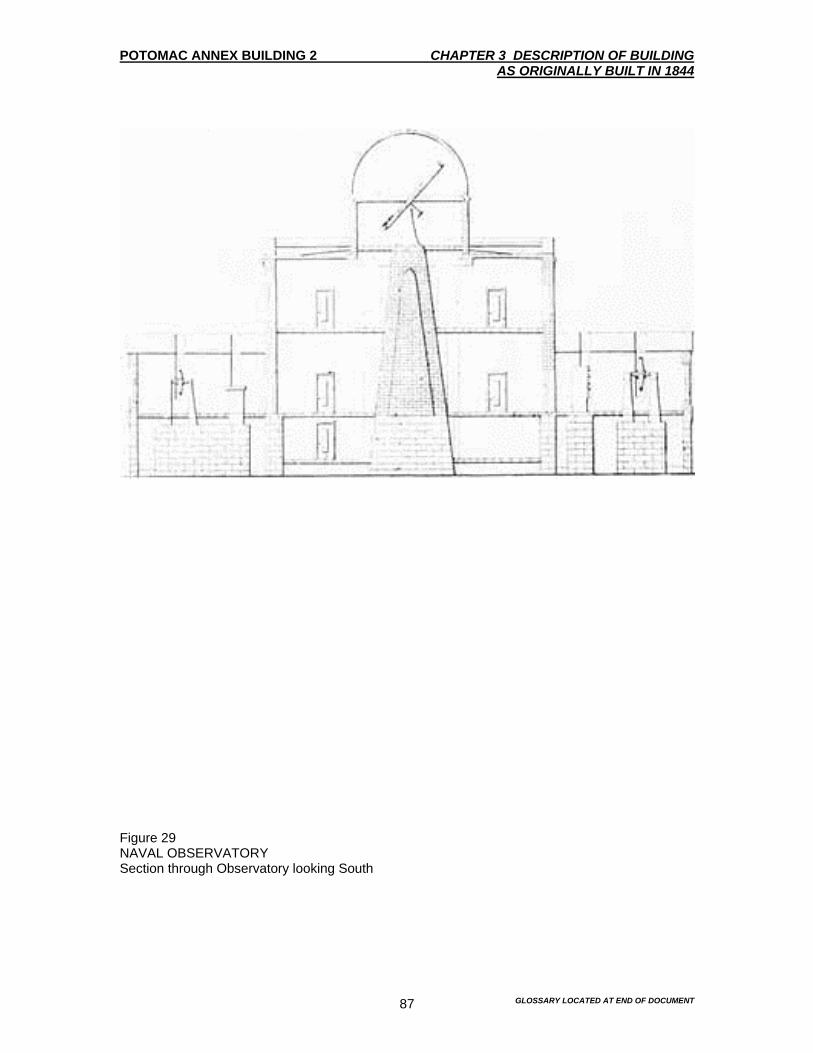
POTOMAC ANNEX BUILDING 2 CHAPTER 3 DESCRIPTION OF BUILDING AS ORIGINALLY BUILT IN 1844
GLOSSARY LOCATED AT END OF DOCUMENT 87
Figure 29 NAVAL OBSERVATORY Section through Observatory looking South
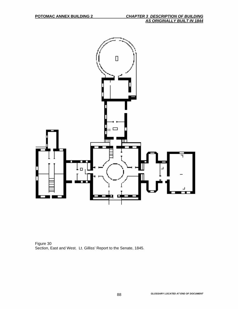
POTOMAC ANNEX BUILDING 2 CHAPTER 3 DESCRIPTION OF BUILDING AS ORIGINALLY BUILT IN 1844
GLOSSARY LOCATED AT END OF DOCUMENT 88
Figure 30 Section, East and West. Lt. Gilliss’ Report to the Senate, 1845.

POTOMAC ANNEX BUILDING 2 CHAPTER 3 DESCRIPTION OF BUILDING AS ORIGINALLY BUILT IN 1844
GLOSSARY LOCATED AT END OF DOCUMENT 89
Figure 31 SECOND STORY ADDITION, WEST WING A View of Bacteriology Laboratory, West Wing, ca 1902.

POTOMAC ANNEX BUILDING 2 CHAPTER 3 DESCRIPTION OF BUILDING AS ORIGINALLY BUILT IN 1844
GLOSSARY LOCATED AT END OF DOCUMENT 90
Figure 32 SECOND STORY ADDITIONS, EAST WING A View of the Chemical Laboratory, ca. 1902.

POTOMAC ANNEX BUILDING 2 CHAPTER 3 DESCRIPTION OF BUILDING AS ORIGINALLY BUILT IN 1844
GLOSSARY LOCATED AT END OF DOCUMENT 91
Figure 33 WEST WING Interior View of the West Wing After 1895.

POTOMAC ANNEX BUILDING 2 CHAPTER 3 DESCRIPTION OF BUILDING AS ORIGINALLY BUILT IN 1844
GLOSSARY LOCATED AT END OF DOCUMENT 92
Figure 34 SOUTH ROTUNDA Interior View of South Rotunda Library After 1895.

POTOMAC ANNEX BUILDING 2 CHAPTER 3 DESCRIPTION OF BUILDING AS ORIGINALLY BUILT IN 1844
GLOSSARY LOCATED AT END OF DOCUMENT 93
Figure 35 BUILDING NO. 2 View of Observatory Building, ca. 1902.
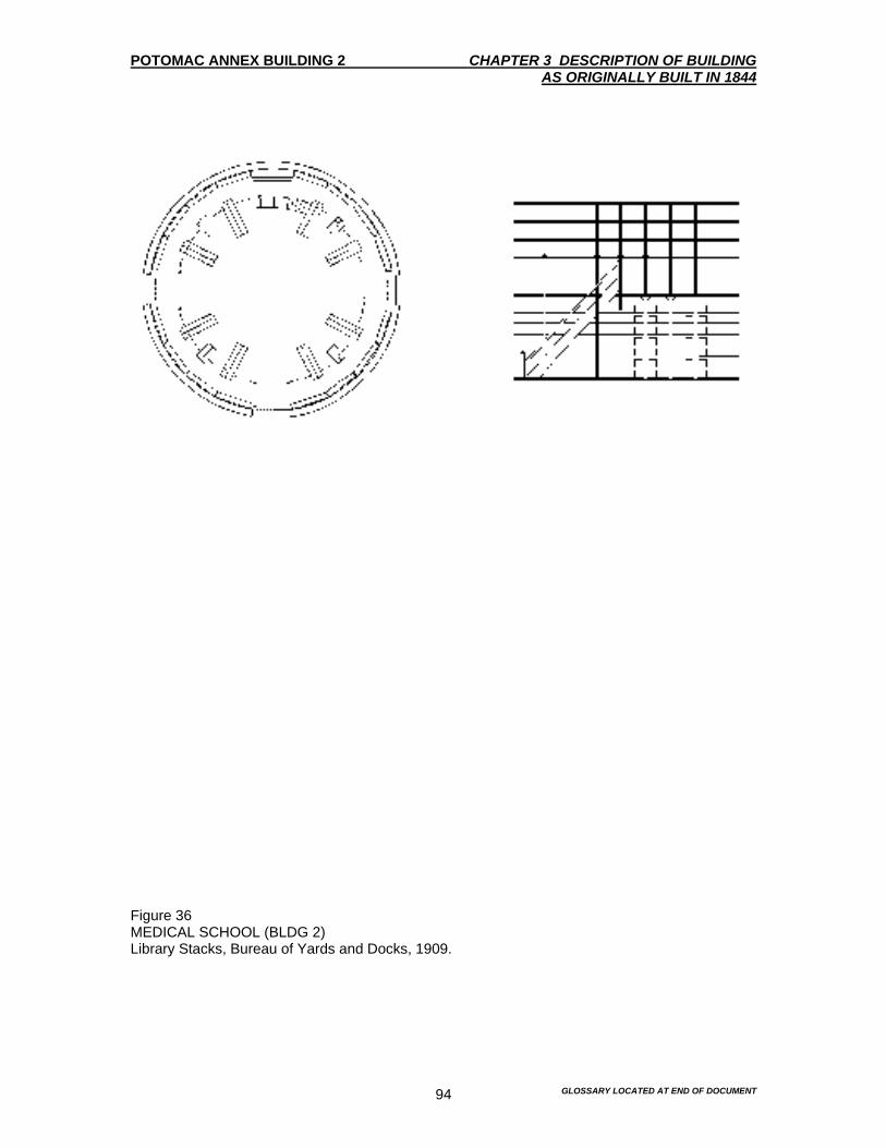
POTOMAC ANNEX BUILDING 2 CHAPTER 3 DESCRIPTION OF BUILDING AS ORIGINALLY BUILT IN 1844
GLOSSARY LOCATED AT END OF DOCUMENT 94
Figure 36 MEDICAL SCHOOL (BLDG 2) Library Stacks, Bureau of Yards and Docks, 1909.
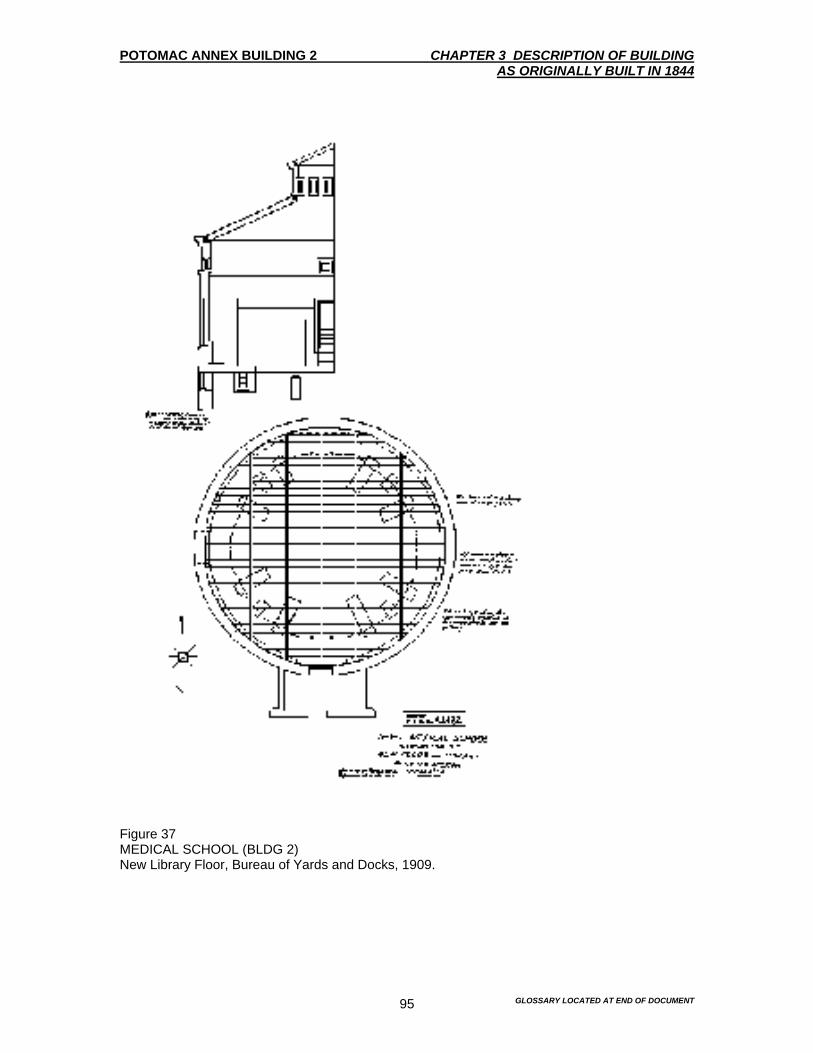
POTOMAC ANNEX BUILDING 2 CHAPTER 3 DESCRIPTION OF BUILDING AS ORIGINALLY BUILT IN 1844
GLOSSARY LOCATED AT END OF DOCUMENT 95
Figure 37 MEDICAL SCHOOL (BLDG 2) New Library Floor, Bureau of Yards and Docks, 1909.

POTOMAC ANNEX BUILDING 2 CHAPTER 3 DESCRIPTION OF BUILDING AS ORIGINALLY BUILT IN 1844
GLOSSARY LOCATED AT END OF DOCUMENT 96
Figure 38 MEDICAL SCHOOL (BLDG 2) Basement Plan, Bureau of Yards and Docks, 1927.
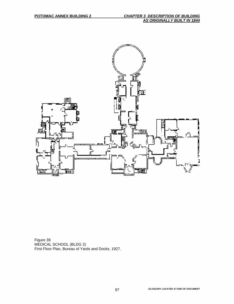
POTOMAC ANNEX BUILDING 2 CHAPTER 3 DESCRIPTION OF BUILDING AS ORIGINALLY BUILT IN 1844
GLOSSARY LOCATED AT END OF DOCUMENT 97
Figure 39 MEDICAL SCHOOL (BLDG 2) First Floor Plan, Bureau of Yards and Docks, 1927.

POTOMAC ANNEX BUILDING 2 CHAPTER 3 DESCRIPTION OF BUILDING AS ORIGINALLY BUILT IN 1844
GLOSSARY LOCATED AT END OF DOCUMENT 98
Figure 40 MEDICAL SCHOOL (BLDG 2) Second Floor Plan, Bureau of Yards and Docks, 1927.

POTOMAC ANNEX BUILDING 2 CHAPTER 3 DESCRIPTION OF BUILDING AS ORIGINALLY BUILT IN 1844
GLOSSARY LOCATED AT END OF DOCUMENT 99
Figure 41 MEDICAL SCHOOL (BLDG 2) Roof Plan, Bureau of Yards and Docks, 1927.
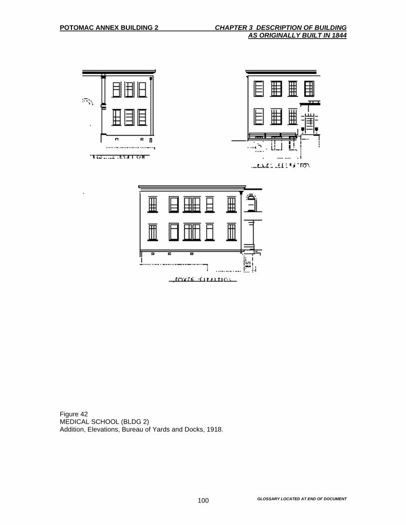
POTOMAC ANNEX BUILDING 2 CHAPTER 3 DESCRIPTION OF BUILDING AS ORIGINALLY BUILT IN 1844
GLOSSARY LOCATED AT END OF DOCUMENT 100
Figure 42 MEDICAL SCHOOL (BLDG 2) Addition, Elevations, Bureau of Yards and Docks, 1918.

POTOMAC ANNEX BUILDING 2 CHAPTER 3 DESCRIPTION OF BUILDING AS ORIGINALLY BUILT IN 1844
GLOSSARY LOCATED AT END OF DOCUMENT 101
Figure 43 MEDICAL SCHOOL (BLDG 2) Addition, Floor Plans, Bureau of Yards and Docks, 1918.

POTOMAC ANNEX BUILDING 2 CHAPTER 3 DESCRIPTION OF BUILDING AS ORIGINALLY BUILT IN 1844
GLOSSARY LOCATED AT END OF DOCUMENT 102
Figure 44 MEDICAL SCHOOL (BLDG 2)Laboratory Building, Bureau of Yards and Docks, 1918.
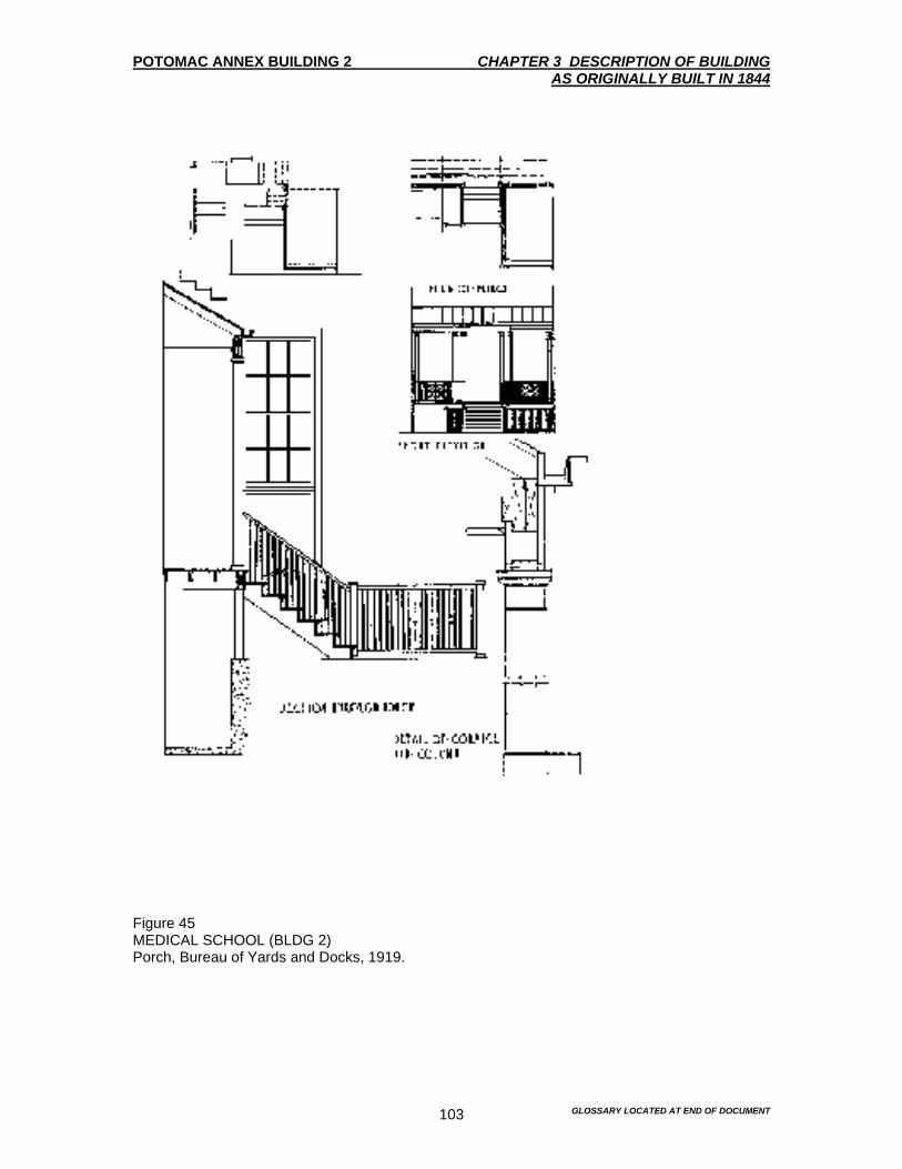
POTOMAC ANNEX BUILDING 2 CHAPTER 3 DESCRIPTION OF BUILDING AS ORIGINALLY BUILT IN 1844
GLOSSARY LOCATED AT END OF DOCUMENT 103
Figure 45 MEDICAL SCHOOL (BLDG 2) Porch, Bureau of Yards and Docks, 1919.

POTOMAC ANNEX BUILDING 2 CHAPTER 3 DESCRIPTION OF BUILDING AS ORIGINALLY BUILT IN 1844
GLOSSARY LOCATED AT END OF DOCUMENT 104
Figure 46 SITE PLAN (1844) Landscape Plan, William Strickland, National Archives

POTOMAC ANNEX BUILDING 2 CHAPTER 3 DESCRIPTION OF BUILDING AS ORIGINALLY BUILT IN 1844
GLOSSARY LOCATED AT END OF DOCUMENT 105
Figure 47 SITE SECTION (1844) Landscape Plan, William Strickland, National Archives.

POTOMAC ANNEX BUILDING 2 CHAPTER 3 DESCRIPTION OF BUILDING AS ORIGINALLY BUILT IN 1844
GLOSSARY LOCATED AT END OF DOCUMENT 106
Figure 48 SITE PLAN (After 1873) “Map of the U.S. Naval Observatory Grounds at Washington D.C., BUMED Archive.

POTOMAC ANNEX BUILDING 2 CHAPTER 3 DESCRIPTION OF BUILDING AS ORIGINALLY BUILT IN 1844
GLOSSARY LOCATED AT END OF DOCUMENT 107
Figure 49 SITE PLAN (1911) “U.S. Naval Hospital Reservation”, National Archives.

POTOMAC ANNEX BUILDING 2 CHAPTER 3 DESCRIPTION OF BUILDING AS ORIGINALLY BUILT IN 1844
GLOSSARY LOCATED AT END OF DOCUMENT 108
Figure 50 SITE PLAN (After 1918) Detail of Topographical Map, National Archives.

POTOMAC ANNEX BUILDING 2 CHAPTER 3 DESCRIPTION OF BUILDING AS ORIGINALLY BUILT IN 1844
GLOSSARY LOCATED AT END OF DOCUMENT 109
Figure 51 SITE PLAN (1927) Site plan showing proposed extension of New York Avenue, National Archives.
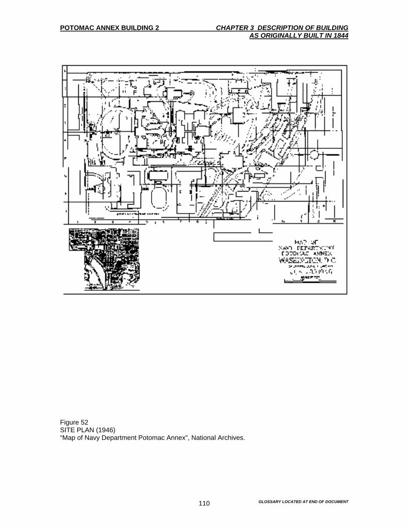
POTOMAC ANNEX BUILDING 2 CHAPTER 3 DESCRIPTION OF BUILDING AS ORIGINALLY BUILT IN 1844
GLOSSARY LOCATED AT END OF DOCUMENT 110
Figure 52 SITE PLAN (1946) “Map of Navy Department Potomac Annex”, National Archives.

POTOMAC ANNEX BUILDING 2 CHAPTER 3 DESCRIPTION OF BUILDING AS ORIGINALLY BUILT IN 1844
GLOSSARY LOCATED AT END OF DOCUMENT 111
Figure 53 SITE PLAN (ca. 1964) “Potomac Annex”, National Register of Historic Places Inventory- Nomination Form for Old Naval Observatory.

POTOMAC ANNEX BUILDING 2 CHAPTER 4 EXISTING CONDITION SURVEY
GLOSSARY LOCATED AT END OF DOCUMENT 114
Introduction The existing condition survey was undertaken during the fall 1994. Swanke Hayden Connell Architects, Higgins and Quasebarth, and Hankins and Anderson conducted this survey. The building was visually inspected and there were no problems or tests that were done. The only thing that was done was to analyze the paint. Field notes and photographs of the existing conditions were taken and compared to the historic documentation. This was done to assess the integrity of the structure, spaces and features. Evaluation of the general conditions is made in this chapter. A more detailed explanation will be made in subsequent chapters that deal with materials conservation. The Old Naval Observatory building is complex in plan due to the many construction campaigns that were undertaken by the varied occupants in its long history. Despite the alterations, the Old Naval Observatory retains a remarkable sense of integrity. The exterior of the Old Naval Observatory was surveyed first and then the interior of the building was done. The methodology of the survey was to follow the chronological events of the Old Naval Observatory. This enabled the survey to consolidate building features and conditions common to a particular construction period. An example that illustrates this is the exterior of the original 1844 Old Naval Observatory that was surveyed first and then the 1847 residence. Where minor additions and alteration were encountered, they were surveyed as part of the larger section in which they were encountered. An example of this methodology is the west wing of the 1844 Old Naval Observatory, which includes the 1864 octagonal projections. Although the octagonal projections have an architectural and historical significance, their size and scale do not warrant a separate survey effort. Although the entire façade is in good condition, there are a few areas and conditions that need to be addressed. There are some areas of the brick that need to be re-pointed. There are also a few areas where the brick is deteriorating. This is due to a lack of maintenance of the drainage system. All Old Naval Observatory features, including the windows, are to be considered original to the 1844-construction date unless other wise noted. Much of the window glazing dates back to the 19th century. EXTERIOR 1844 Old Naval Observatory Exterior Includes the 1864 Octagonal bay on the west wing Summary Description This is the original section of the Old Naval Observatory. This Old Naval Observatory was constructed in 1844 as the Depot of Charts and Instruments. It is a two-story plus a basement brick structure. It is ornamented by a wood cornice and surmounted by an observation done. The Old Naval Observatory faces north and is square in plan with radiating wings to the east, west and south. Its overall appearance is of a solid classical structure with Greek Revival overtones. The main block of this section is basically a symmetrical cube. The main block is five bays wide architecturally. It is also two bays high. The door is the central feature of the façade. The brick pilasters divide the central bay from the two flanking bays and terminate the ends of the central block. Gray sandstone was used for the bases, the capitals of the pilasters and the belt courses. Granite was used for the basement window lintels and all the sills. The entrance is centered on the façade and is fitted with wood and glass doors, which include a glass transom and sidelights. The entry stoop is composed of a short flight of granite steps and a porch fitted with a wrought

POTOMAC ANNEX BUILDING 2 CHAPTER 4 EXISTING CONDITION SURVEY
GLOSSARY LOCATED AT END OF DOCUMENT 115
iron railing with cast elements. The windows are 6-over-6 and double hung wood sash, except on the second floor. On the second floor the windows are the same, except that there are 2-over-2 windows on the flanks. Molded wood hoods supported by sandstone acanthus leaf brackets distinguish the masonry openings. The most impressive and important feature of the Old Naval Observatory is the dome, Figures 63, 64 and 79-81. The dome originally revolved so that the telescope could be pointed in any direction. The dome, which is centered on the main core of the Old Naval Observatory, is 23 feet in diameter. It rests on a seven-foot circular wall or drum. The drum is fitted with four windows. One of these four windows was originally a door. The remains of the aperture are still evident today. To the east and west sides of the central core are the wings, which can be entered from the interior passages. Each wing was originally 26-feet 6-inches long, 21-feet long and 18-feet high. Both one-story wings were extended during the 19th century. The octagonal bays on the west wing were added in 1864 to accommodate new observational equipment. The exterior of the wings were changed substantially in 1902 when the second-story additions were constructed and observation apertures and entrances were bricked over or converted to windows. The south elevation is similar to the north. The north elevation is two and one-half stories over a raised basement, with a view of the dome above. The materials and detailing are the same on the south elevations of the east and west wings. There is also a 21-foot south wing that is separated from the central core by a 10’ foot passage. Like the east and west wings, the south wing was altered in 1903 with the addition of a second story. The observation apertures were also altered on the east and west wings of the second story addition. The entire Old Naval Observatory is painted a cream color with white trim. The earliest paint finishes are impossible to accurately reconstruct. Historic specifications, see Chapter 2, indicate that the Old Naval Observatory may have been painted at an early date. Paint analysis, see Chapter 5, indicates, that there is a heavy soiling on the brick substrate. However, the data is not conclusive because there may be other factors that may have caused the soiling. These factors may be pollution related. Over the years, an accumulation of smoke, dust and pollen may have also contributed to the soiling. North Facade Figures 63-74 General Description The 1844 north façade, which is the front elevation of the Old Naval Observatory, is comprised of the exterior walls of the two-story Old Naval Observatory’s main block and the adjoining one-story wings to the east and west. A copper-clad dome on a cylindrical drum rises through the hip roof of the main block. The east and west wings were originally one-story and were capped with a gabled roof. However, these wings had a two-story addition constructed in 1902. A one-story octagonal bay was added to the north façade of the west wing in 1864. These octagonal bays were added to accommodate observatory instruments. These originally bays also had an observational slit and a hatched opening. The Old Naval Observatory’s main block maintains much of its original appearance. However, the east and west wings have been extended and modified over time. Foundation and Areaways The areaways, stoop and stairs were replaced in 1991 with materials that replicate the original materials that were used. An areaway fronts the Old Naval Observatory’s main block at the basement level. The areaway is reached by a symmetrical placed stairway occupying the east and west ends. The areaway floor is concrete and sloped to drain water. The drain has a steel

POTOMAC ANNEX BUILDING 2 CHAPTER 4 EXISTING CONDITION SURVEY
GLOSSARY LOCATED AT END OF DOCUMENT 116
cover inset in the center of the concrete floor. There is evidence of some moss growing around the drain. But overall, the areaway is in good condition. The retaining wall facing the basement level foundation wall is unpainted ashlar schist and gneiss. The wall is capped with an 8” light-gray granite copping stone. The mortar joints appear to have been re-pointed recently. The joints appear to be in good condition. An original cast iron fence is set into the granite coping. The coping runs along the front of the areaway and up to the front door see Figures 65 and 66. The railing is painted and is in good condition. However, there are rust stains that are visible on the granite adjacent to the railing stanchions. The basement wall is made of schist and gneiss. The wall is approximately 6’ in height and composed of common bond brick. The stone and brick are painted and in good condition. However, the paint needs some remedial work. The two identical stairways are of recent construction. The structure is concrete with light-gray granite slabs forming the treads and risers. The granite is identical to that used for the coping. A simple painted iron railing is mounted to the treads along the south side of the stairways. The joints on the stairs are in good condition and well sealed. Walls and Trim The walls above the 6’ stone foundation are common bond brick masonry. The wall is painted over with a cream colored paint. The red brick units are approximately 2 ½” x 4 ½” x 8 ½” in size. The vertical mortar joints typically vary from 1/8” to ¼”. The horizontal joints vary typically from 3/16” to ¼”. A water table runs along the floor of the first floor. The water table is in good condition. However, there are a few places where the bricks are slightly chipped. The main block of the Old Naval Observatory façade, Figure 64, is divided into three bays by Tuscan pilasters. These pilasters run on both the first and second floors. The pilasters are also separated by a stone belt course. The pilasters have painted sandstone caps and bases. The brick shafts and pedestals are also painted. Molded wood hoods supported by sandstone acanthus leaf brackets, Figures 69 and 70, distinguish the window and door openings on the first and second floors of the main block. A plaque, Figures 65 and 67, with the building name inscribed in painted concrete is centered on the belt course just above the main entrance door. Such a plaque, although not this one, is visible in the earliest illustrations of the Old Naval Observatory. A national Historic Landmark plaque, Figures 73, is attached to the pilaster just west of the main entry. The original wood balustrade at the roofline of the Old Naval Observatory main block no longer exists. The wings, Figures 63,64 and 91, to the east and west of the Old Naval Observatory main block were originally one-story structures with gabled roofs. The wings were extended during the 19th century and a second story was added in 1902, Figures 64 and 72. The walls were originally ordered with Tuscan pilasters that were identical to those on the Old Naval Observatory’s main block façade. Only the west wing pilasters remain today. Observation slits, which were located between the pilasters, are now bricked over today. The walls appear to be in good condition. However, they are concealed by a thick build-up of peeling paint. There is an area that exhibits a severe condition of brick deterioration. This deterioration appears on the east corner of the Old Naval Observatory’s main block façade. This deterioration includes spalled and exfoliated brick units. The mortar also missing and crumbling, Figure 68. The problem appears to be related to water leaking down from the gutter and downspout. This water over time, especially over the winter, has frozen and thawed. This action appears to have caused the deterioration of the bricks in this area.

POTOMAC ANNEX BUILDING 2 CHAPTER 4 EXISTING CONDITION SURVEY
GLOSSARY LOCATED AT END OF DOCUMENT 117
Entrance Stoop A granite stoop, Figures 65 and 66, which was replaced in 1991, spans the areaway in front of the Old Naval Observatory’s main block. This stoop allows access through a door that is centered in the façade of the main block. The granite is light gray and matches the stone work that was used for the areaway stairways and coping. Three granite steps lead up to a flat granite slab, which spans the areaway. These stairs are flanked by a granite slab curb wall and with painted cast iron railings mounted to the granite slabs. The granite treads are chipped at the edges. These chips are most likely due to a mechanical impact. There is also some soiling on the granite. Doors There are two doors are located on the north façade of the main block. The main entrance door at the center and a basement door directly under the main door. The main door, Figure 67, is divided into four panels. The two upper panels have been replaced with wire glass. A six-part clear glass transom surmounts the door. A narrow horizontal blind panel between the transom bar and the door probably relates to a change in the door size. The door is also flanked on either side by a clear glass sidelight, just above a blind lower panel. A hood comprised of sandstone brackets and a decorative wood lintel shelters the door opening. A brass knob and a stainless steel lock set constitute the door hardware. A brass doorbell is mounted to the doorframe. There is also a painted metal building sign that is nailed above the door. The door is not original. However, the door is in good condition. There is some soiling and scuffing on the main door. The basement is accessed through a pair of wood doors, which are divided into four panels. The two upper panels contain one leaf. An upper panel of the other leaf is covered with wood louvered units. Plywood sheets have been nailed to the doors on the inside to prevent any air infiltration through the louvers. A brass knob and a stainless steel lock set constitute the hardware. Windows Figures 64,69 and 70 The two side bays of the Old Naval Observatory’s main block has two windows on each floor. This arrangement is the same in the basement level. These windows are stacked vertically above each other. The basement window sash is 3-over-3, double hung. The windows on the first and second floors are 6-over-6 and double hung. These windows are all counter balanced. The windows in the central bay above the main entrance door are 6-over-6, double hung and flanked by 2-over-2 double hung windows on either side. Hoods comprised of sandstone acanthus-leaf brackets and molded wood hoods shelter the window openings on the first and second floors. All the window lintels, on the basement level, as well as on the first and second floors are painted granite. The east basement window is in-filled with stone and brick to match the structure of the adjoining walls. There are window mounted air conditioning units visible in the first and second floor windows. There are a few windows that have visually obtrusive metal angles installed to carry the load of the air conditioners. The east wing of the north façade has two 6-over-6 double hung windows. The windowsills and lintels are painted blue stone. The observation aperture on the 1864 semi-octagonal bay, Figures 71 and 74, was probably converted to a window opening with a transom at the same time. However, the 4-over-4 wood sash windows are set into metal tracks. This suggests that a late 20th century alteration occurred. A small basement-level single pane is located immediately under the first floor window. This basement window has a rotting window frame. The brick lintel spanning the opening is displaced. The windows in the east and west wings probably date to the alterations that were made during the 1890’s and 1902. This is when the observation aperture

POTOMAC ANNEX BUILDING 2 CHAPTER 4 EXISTING CONDITION SURVEY
GLOSSARY LOCATED AT END OF DOCUMENT 118
and doors were changed and the second story was added. Overall, the windows are in good condition. There are a few windows that need to be restored. Also the amount of paint that exists on the windows needs to be removed in order to insure that the windows function as they did when they were originally installed. The four windows in the dome drum are double hung with six translucent glass panes. The dome windows have painted stone sills, Figure 80. The dome windows are probably not original because the dome was heavily altered during the 19th century. The windows on the north façade do not work. This is due in part to the amount of paint that has built-up around the mechanisms. However, it does appear that once this built-up of paint has been removed, the windows will function as they originally were meant to function. Cornice A painted wood cornice surmounts the brick masonry wall of the Old Naval Observatory’s main block. The wash surface of the cornice contains a built-in gutter. A painted wood cornice caps the one-story east and west facades. This cornice cap serves to delineate the first from the second floor. The cornice was installed as part of the 1902 second- story addition. Roofs and Drainage Figures 79-82 The 1844 main block has a shallow pitched hip roof with a flat seam roof covered with modified bitumen elastomeric sheets that have an aluminized face. This was installed in 1983-84. The Cooper-Lecky Partnership drawings indicated this work. The 1993 Water Leakage Study indicates through core analysis, that the modified bitumen sheets were KMM Self-Adhering 60-mil membranes with a foil face. The dome is surfaced with a painted standing seam copper roof. A plain wood fascia runs around the base. There is a painted ladder that is mounted to the roof to allow access to the top of the dome. The bay addition on the west wing has a flat seam metal roof. This roof was repaired with asphaltic coating and an aluminizer in 1983-84. The aluminized roof face of the Old Naval Observatory’s main block has random tears throughout. The integral gutter has been covered with a roofing material. The gutter is concealed in the wood cornice and drains through metal downspouts that are located on the east and west facades. Runoff from the octagonal bays on the west wing is collected through scuppers on the east and west sides of the roof then down to the metal downspouts. South Façade Figures 75-78 General Description The 1844 south façade is composed of the exterior walls of the two-story Old Naval Observatory’s main block and the adjoining one-story wings to the east and west. A cooper-clad dome on a cylindrical brick drum rises through the hip roof of the main block. The east and west wings were originally one-story and capped with gabled roofs. However, the east and west wings had a two-story addition added in 1902. A one-story octagonal bay, identical to the one on the north façade, was added to the south façade on the west wing in 1864. This bay was added to accommodate Old Naval Observatory instruments. The bay had originally an observation slit with a hatched opening. An 1844 wing abuts the south façade and two wood-framed structures flank the Old Naval Observatory’s main block on either side. Currently in the west wing there is storage shed. In the east wing there is currently a bathroom addition.
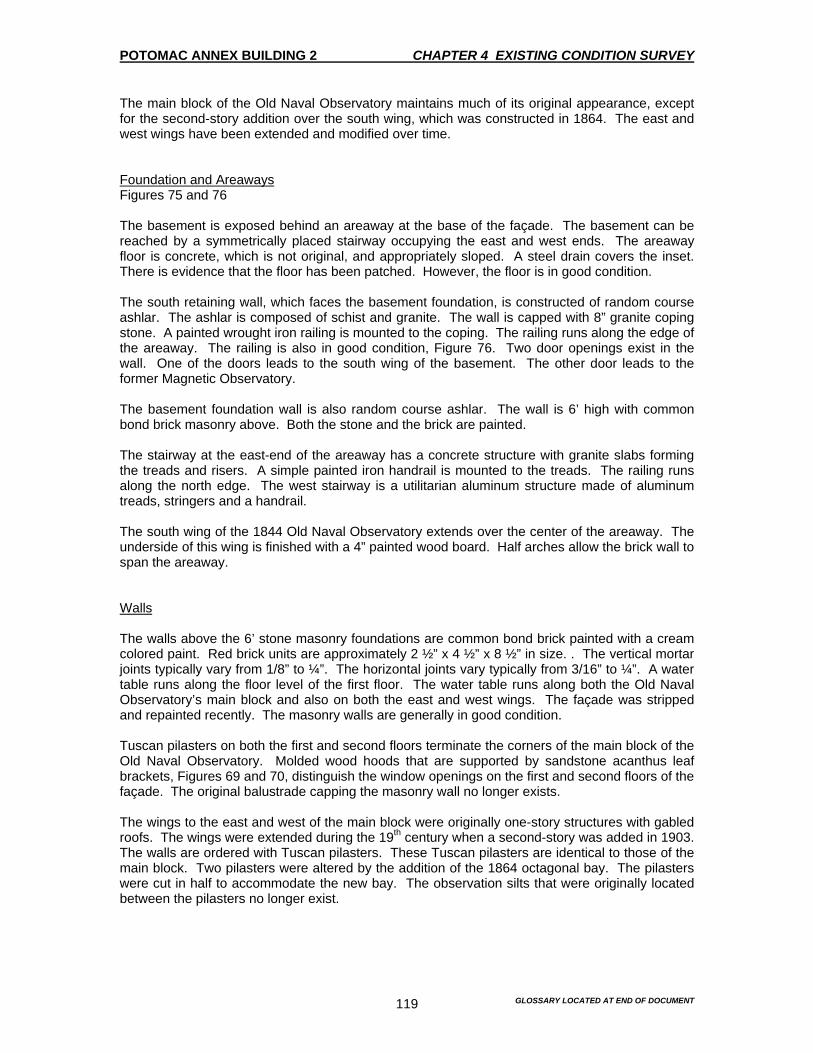
POTOMAC ANNEX BUILDING 2 CHAPTER 4 EXISTING CONDITION SURVEY
GLOSSARY LOCATED AT END OF DOCUMENT 119
The main block of the Old Naval Observatory maintains much of its original appearance, except for the second-story addition over the south wing, which was constructed in 1864. The east and west wings have been extended and modified over time. Foundation and Areaways Figures 75 and 76 The basement is exposed behind an areaway at the base of the façade. The basement can be reached by a symmetrically placed stairway occupying the east and west ends. The areaway floor is concrete, which is not original, and appropriately sloped. A steel drain covers the inset. There is evidence that the floor has been patched. However, the floor is in good condition. The south retaining wall, which faces the basement foundation, is constructed of random course ashlar. The ashlar is composed of schist and granite. The wall is capped with 8” granite coping stone. A painted wrought iron railing is mounted to the coping. The railing runs along the edge of the areaway. The railing is also in good condition, Figure 76. Two door openings exist in the wall. One of the doors leads to the south wing of the basement. The other door leads to the former Magnetic Observatory. The basement foundation wall is also random course ashlar. The wall is 6’ high with common bond brick masonry above. Both the stone and the brick are painted. The stairway at the east-end of the areaway has a concrete structure with granite slabs forming the treads and risers. A simple painted iron handrail is mounted to the treads. The railing runs along the north edge. The west stairway is a utilitarian aluminum structure made of aluminum treads, stringers and a handrail. The south wing of the 1844 Old Naval Observatory extends over the center of the areaway. The underside of this wing is finished with a 4” painted wood board. Half arches allow the brick wall to span the areaway. Walls The walls above the 6’ stone masonry foundations are common bond brick painted with a cream colored paint. Red brick units are approximately 2 ½” x 4 ½” x 8 ½” in size. . The vertical mortar joints typically vary from 1/8” to ¼”. The horizontal joints vary typically from 3/16” to ¼”. A water table runs along the floor level of the first floor. The water table runs along both the Old Naval Observatory’s main block and also on both the east and west wings. The façade was stripped and repainted recently. The masonry walls are generally in good condition. Tuscan pilasters on both the first and second floors terminate the corners of the main block of the Old Naval Observatory. Molded wood hoods that are supported by sandstone acanthus leaf brackets, Figures 69 and 70, distinguish the window openings on the first and second floors of the façade. The original balustrade capping the masonry wall no longer exists. The wings to the east and west of the main block were originally one-story structures with gabled roofs. The wings were extended during the 19th century when a second-story was added in 1903. The walls are ordered with Tuscan pilasters. These Tuscan pilasters are identical to those of the main block. Two pilasters were altered by the addition of the 1864 octagonal bay. The pilasters were cut in half to accommodate the new bay. The observation silts that were originally located between the pilasters no longer exist.
POTOMAC ANNEX BUILDING 2 CHAPTER 4 EXISTING CONDITION SURVEY
GLOSSARY LOCATED AT END OF DOCUMENT 120
Doors In the areaway a door, which is not original, opens to the basement of the Old Naval Observatory. The door is centered directly below the overhead of the south wing. The door is divided into four panels. The upper two panels are fitted with wood louvered units. A four part glazed sidelight lies to the east of the door. A brass knob and a stainless steel lock set constitute the hardware. The installation of piping and conduits pass over the door and through the opening. This installation of pipes and conduit has resulted in damage to the frame. This installation has also cause damage to the sidelight pane. Windows Figures 63,70,75 and 78 The Old Naval Observatory’s main block has four windows on each floor. This includes the basement area. These windows are stacked vertically. The basement window sash is 3-over-3 and double hung. The windows on the first and second floors are 6-over-6 and double hung. All the windows are counter balanced. There are masonry openings that are distinguished by molded wood hoods that are supported by sandstone acanthus leaf brackets. This element occurs on both the first and second floors. The basement window lintels, as well as all other windows are painted granite. The east wing of the south façade has a double window made of 2-over-2 double hung sash with a plain painted stone sill and lintel at the location of a converted observation slit, Figure 75. These windows probably date to the time when the alterations were done, between 1890 and 1902. The observation slit on the 1864 octagonal bay on the west wing was changed to a window with a transom at the same time. However, the 4-over-4 wood sash windows are set into metal tracks. This suggests that these windows are 20th century additions. This treatment is similar to the one that was used on the north façade. There are window mounted air conditioning units located in the first and second floor windows. The windows on the south side are not functioning due to the amount of pant that has built-up over the years. If this built-up is removed, it appears that the windows will function as they were originally intended to function when they were installed. Additions A shed, Figure 78, (behind the truck), is located in the corner where the west wing meets the Old Naval Observatory’s main block. This shed is faced with painted Masonite. The Masonite has buckled and is wrapped and torn in certain areas. The roof is made of an asphalt shingles. The shed post dates the 1927 floor plans and detracts from the symmetry and quality of the south façade. The bathroom addition, Figure 77, located at the junction of the east wing and the main block pre-dates 1927. The bathroom is surfaced with painted wood board siding that is above a painted brick base. This siding extends to the bathroom floor level. There is some minor wood rotting visible at the base that was caused by the black splash. A 2-over-2 double-hung wood window is installed in the east façade with a painted wood sill and trim. A painted wood denticulate cornice surmounts the wall. The bathroom addition has a flat seam metal roof that was repaired with asphaltic coating with aluminizer in 1983-84. While the bathroom addition is a late feature, it functions well within the space where it is located. There doesn’t appear to be any detriment to the architectural quality of the building.
POTOMAC ANNEX BUILDING 2 CHAPTER 4 EXISTING CONDITION SURVEY
GLOSSARY LOCATED AT END OF DOCUMENT 121
Cornice A painted wood cornice surmounts the brick masonry wall of the main block. The integral gutter, which has been covered with roof material, is concealed in the wood cornice and drains through the metal downspouts that are located on the east and west ends. Painted molded wood cornices cap the one-story east and west facades. These cornices serve to delineate the first and the second floors levels. The cornices were installed when the second story was added in 1902. Roof The roof has been address in the north façade section. East Façade Figures 68, 75, 77 and 97 General Description The east façade of the 1844 Old Naval Observatory is composed of a blank wall of the two-story main block and the lower story of the façade of the south wing. This wing was originally a one-story with a gabled roof. The second-story addition was constructed in 1903. The east wing of the 1844 Old Naval Observatory abuts the east façade. A one-story wood framed bathroom addition also abuts the south façade and is included in the description of the south façade. The south wing has been extended and modified over time. Foundation and Areaways The stone foundation walls are below ground level and are not visible on the east façade. A brick window well surrounds the basement window opening in the south wing façade. The well has a concrete floor with a drain. Walls The walls of the east façade are common brick that is painted over with cream colored paint. The red bricks are approximately 2 ½” x 4 ½” x 8 ½” in size. . The vertical mortar joints typically vary from 1/8” to ¼”. The horizontal joints vary typically from 3/16” to ¼”. A water table runs along the floor level of the first floor. A water table also runs along the floor level of the first floor. This feature occurs on both the Old Naval Observatory’s main block and the south wing. This feature is also articulated by recessing the façade walls above the water table, approximately 4.” The façade was stripped and repainted recently. Tuscan pilasters on both the first and second floors terminate the corners of the main block. The original balustrade capping the masonry no longer exists. The south wing was originally a one-story structure with a gabled roof. The wing has been extended to the south in phases through out the 19th century. A second story was added in 1903. Tuscan pilasters order the walls. These pilasters are identical to the ones on the main block façade. The original observation aperture was filled to accommodate a window opening. This was done during the alterations of the 1890’s and 1903. A painted stone belt course delineates the second floor level. A molded wood hood that is supported by a sandstone acanthus leaf bracket distinguishes the door opening on the south wing. This was a typical treatment for the 1844 Old Naval Observatory structure.
POTOMAC ANNEX BUILDING 2 CHAPTER 4 EXISTING CONDITION SURVEY
GLOSSARY LOCATED AT END OF DOCUMENT 122
Entrances Three granite slab steps lead up to the door on the south wing. A painted iron railing is mounted to the treads. The steps are in good condition. The six panel wood door is surmounted by a three part glazed transom. The two upper door panels are glazed. A brass knob and stainless steel locks constitutes the hardware. The door appears to be in good condition. While the masonry opening probably dates to the time of construction, the door is not an original item. Windows A two-light wood casement window is located at the basement level of the south wing. The window is placed within a square opening with a painted stone sill. A brick window well fronts the window. The well has a concrete floor with a surface drain. Simple painted wood trim surrounds the opening. The masonry is probably an original item, but the window is not original. The south wing of the east façade has a double window comprised of 2-over-2 double hung sash with plain painted stone sills and lintels. The opening and windows probably date to the alterations that were made during the 1890’s and in 1903. An air conditioning unit is mounted in the window opening. The windows on the north façade do not function because of the amount of paint built-up on the sash’s and frames. However, if all the paint built-up is removed, the window will function as they were intended to function. Cornice A painted wood cornice surmounts the brick wall of the Old Naval Observatory’s main block. The integral gutter has been covered with the roofing material. The integral gutter in concealed in the wood cornice and drains through metal downspouts that are located on either side of the façade. Roof The roof has been included in the discussion of the north façade. A rectangular brick chimney rises through the roof. The chimney is centered on the façade of the main block. A painted metal ventilator unit is mounted to the roof. West Façade Figures 78 and 96 General Description The west façade of the 1844 building is composed of a blank wall of the two-story Old Naval Observatory’s main block and the lower story of the façade of the south wing. The south wing was originally a one-story with a gabled roof. A second-story was added in 1903. The west wing building abuts the west façade of the main block. A one-story wood framed storage shed also abuts the façade at the south end and this shed is covered with like material the cover the south façade. The south wing has been extended and modified over time.
POTOMAC ANNEX BUILDING 2 CHAPTER 4 EXISTING CONDITION SURVEY
GLOSSARY LOCATED AT END OF DOCUMENT 123
Foundation and Areaways The stone masonry foundation walls are below ground level. The foundation wall is not visible from the east façade. A brick window well surrounds the basement window in the south wing façade. The window well has a concrete floor surface with a drain. Walls The walls of the west façade are common bond masonry. The wall is painted over with a cream-colored paint. Red brick units are approximately 2 ½” x 4 ½” x 8 ½” in size. . The vertical mortar joints typically vary from 1/8” to ¼”. The horizontal joints vary typically from 3/16” to ¼”. A water table runs along the floor level of the first floor. This water table is also present in the main block and the south wing. The façade was stripped and repainted recently. Tuscan pilasters terminate the corners of the main block. These pilasters appear on both the first and second floors. The original balustrade capping the masonry wall no longer exists. The south wing was originally a one-story structure with a gabled roof. The wing has been extended to the south in phases throughout the 19th century. A second story was added in 1903. There are Tuscan ordered pilasters on the walls. These pilasters are identical to those of the main block. The original observation aperture was filled to accommodate a window opening. This was probably done during the alterations of the 1890’s and in 1903. A painted stone belt course delineates the second floor level. Molded wood hoods that are supported by sandstone acanthus leaf brackets distinguish the door opening on the south wing. This was typical to the 1844 Old Naval Observatory structure. Entrances The door opening is located in the south wing façade. Three granite slab steps lead up to the door. The granite is soiled and the joints require re-pointing. A painted iron railing is mounted to the treads. The iron railing is starting to rust in the areas where the paint has come off. There is no other damage that is occurring on or near the iron railing. The six panel wood door, which is not original is surmounted by a three part glazed transom. The two upper door panels are glazed. A brass knob and stainless steel lock set constitutes the hardware. The door appears to be in good condition. The masonry opening probably dates to the original construction. However, the door does not appear to be original. Windows A two-light wood casement window is located at the basement level of the south wing. The window is placed within a square opening with a painted stone sill. A brick masonry window well fronts the window with a concrete surfaced floor and a drain. Simple painted wood trim surrounds the opening of the window. The masonry opening is probably original. However, the window does not appear to be original. The south wing of the east façade has a double window comprised of 2-over-2 double hung sash with plain painted stone sills and lintels. The opening and windows probably date to the alterations that were made to the building during the 1890’s and in 1903. An air conditioning unit is mounted in the window opening.

POTOMAC ANNEX BUILDING 2 CHAPTER 4 EXISTING CONDITION SURVEY
GLOSSARY LOCATED AT END OF DOCUMENT 124
Windows on the north façade do not function. The reason they do not function is because of the amount of paint that has built-up over the years. Overall, the windows appear to be in good condition. If the paint were removed the windows would function as they were intended. Cornice A painted wood cornice surmounts the brick masonry wall of the main block. The integral gutter, which has been covered with roof material, is concealed in the wood cornice and drains through metal down spouts that are located on either side of the façade. Roof The roof has been included in the discussion of the north façade. A rectangular brick chimney rises through the roof. The chimney is centered on the façade of the main block. A painted metal ventilator unit is mounted to the roof. 1847 Superintendent’s Residence and 1848 connecting hyphen Summary Description The brick Superintendent’s Residence was constructed in 1847. The Residence is compatible in design and construction with the Old Naval Observatory. It is an extremely simple building with two stories on a raised basement and three window bays wide. The Residence faces north. This is the main elevation. The center bay is flanked by a set of brick pilasters. The corners are also terminated by a set of brick pilasters. These pilasters are similar to those that are on the Old Naval Observatory’s main block. The central entry is served by a red sandstone stoop with a short flight of steps and finished with a cast iron railing. The door opening is surmounted by a glazed transom and flanked with brownstone lintels and sills. Pintles from original louvered blinds still exist on the windows of the first and second floors. The foundation walls are stone and an areaway gives access to the basement level. During the first year, the Residence stood unattached. In 1848, the east wing of the Old Naval Observatory was extended to connect the Residence to the Old Naval Observatory. The connection had two window bays. Subsequent changes were made in 1902 when a second story was added to the wings. A door in the eastern most bay of the east wing was converted to a window. The east elevation is centered by two 6-over-6 windows on each floor. The basement windows are off center. On the south elevation, the Residence is connected on the first and second floors to a back building by an elevated passage. The basement areaway passes under this passage, which is supported by granite beams. Ghosts in the brickwork on the south elevation indicate that there were porches on the east and west sides of the south elevation with, access from the southeast and southwest rooms by doors. These doors were later converted to windows. The low-pitched hip roof of the Residence is covered with flat seam metal roof. There are two brick chimneys that rise through the roof on the east side. The entire roof is finished with a simple wood cornice. The Residence is currently painted a cream color with white trim. The earliest paint finished is impossible to accurately determine. However, historic documentation and paint analysis indicated that the Residence, like the Old Naval Observatory was painted using a light palette through most of its history.

POTOMAC ANNEX BUILDING 2 CHAPTER 4 EXISTING CONDITION SURVEY
GLOSSARY LOCATED AT END OF DOCUMENT 125
North Façade Figures 83-87 General Description The north façade of the Residence is composed of a symmetrical two-story façade with a one-story hyphen connecting to the east wing of the Old Naval Observatory. A second story was added to the hyphen, as well as to the south wing of the Old Naval Observatory in 1902. The north façade of the Residence maintains much of its original appearance. The main changes being the removal of the window shutters and the original wood balustrade capping the masonry wall. A door in the connecting hyphen, which appears in historical images, was later converted to a window. This was probably done during the alteration of the 1890’s and in 1902. Historical pictures indicate that a chimney on the west façade. This chimney no longer exists. The façade appears to be in good condition. Settlement cracks are visible in the brick masonry wall. Although there are cracks in the wall, they appear to be stable and no longer a problem. Foundation and Areaways Figures 85 and 86 The areaways, stoop and stairs were replaced in 1991. The materials replicate the original. The basement is exposed behind an areaway at the base of the façade. The basement can be reached by a symmetrically placed stairways occupying the east and west ends. The areaway is similar in design and dimension to that of the1844 Old Naval Observatory. The areaway floor is made of concrete, properly drained and has a steel drain cover inset in the concrete. There is some moss growth and minor soiling that is visible on the concrete floor. Overall, the foundation and areaways are in good condition. The north retaining wall, which faces the basement foundation wall, is constructed of ashlar masonry. The wall is capped with an 8” band of red sandstone coping. The unpainted wall appears to have been re-pointed and is in good condition. The original painted iron railing, which is set into the coping, runs along the edge of the areaway. The railing is also in good condition. The basement foundation wall is random course ashlar. The wall is approximately 5’-6” in height with common bond brick above. Both the stone and brick are painted. The stairways at the east and west ends of the areaway have concrete structures and landings, slate treads and brick risers. The stairways appear to have been re-pointed and grouted recently. The stairways are in good condition. A utilitarian painted iron hand rail is mounted to the treads and runs along the south edge of the stairs. Walls The wall above the 5’-6” stone foundation is common bond brick, painted with cream colored paint. A water table runs along the floor level of the first floor. This water table appears on the Residence, the Old Naval Observatory and the connecting hyphen. The Residence’s façade echo’s the Old Naval Observatory. The façade is divided into three bays by Tuscan pilasters on both the first and second floors. A stone belt course separates the second floor from the first. The pilasters have painted brownstone caps and bases and painted brick shafts and pedestals. The connecting hyphen to the Old Naval Observatory east wing was originally a one-story structure with a gabled roof. The second story was added in 1902. The walls were originally

POTOMAC ANNEX BUILDING 2 CHAPTER 4 EXISTING CONDITION SURVEY
GLOSSARY LOCATED AT END OF DOCUMENT 126
ordered with Tuscan pilasters. The pilasters were removed during the alterations of the 1890’s and 1902. This was also when the observation apertures were replaced with windows. The connecting hyphen originally had a door, but that door was later replaced with a window. The general condition of the walls appears to be good. However, the masonry is concealed by a thick built-up of peeling paint. A pronounced settlement crack runs from the first floor window to the basement window on the east wall. This settlement crack appears to be stable. Entrances A red sandstone stoop, which was installed in 1991, spans the areaway in front of the Residence. This stoop allows access to a door that is centered in the façade. Five sandstone steps lead up to the stoop. Stepped sandstone slab curb walls flank these steps. There is a painted cast iron railing. The joints are well sealed. Doors Two doors are located on the north façade. One door is the main entrance door is centered on the façade. The other door is the basement door. Neither door is original. The main door is set within paneled jambs and is divided into four panels. The upper two panels have been replaced with clear glass panes. Two wood Tuscan pilasters supporting a wood entablature flank the opening of the door. The cornice to the entablature has peeling paint and deteriorating wood members. This is a clear indication that there are moisture penetration problems. This problem may be associated with an air conditioning unit that is installed above the cornice. A brass knob and a stainless steel lock set constitute the hardware. A brass doorbell is mounted to the wood pilaster at the side of the door. The door is in good condition. A four-panel door, which is located in the basement, is sealed closed. This opening was probably converted from an original window to a door. However, an original door at the basement level, below the main entrance door has been filled with a piece of plywood. Along with the plywood, there is an air conditioning unit mounted to the plywood. Windows Figures 83 and 87 Two windows flank the entrance door on the first floor. The three windows on the second floor are located directly above the window and door openings of the first floor. All sash’s are wood, 6-over-6 double hung and have clear glass panes. There is an inscription in the north center window on the second floor. This inscription probably dates to the middle 19th century. The inscription included the names of “Nanny F. Maury,” the daughter of Superintendent Lt. Matthew Fountain Maury, “M.F. Maury,” “Ellen Hamilton” and “Carter Branton.” The inscription is located in the lower right pane on the bottom sash. The basement has three window openings. Two of the openings are in the east bay and the other in the west. One of the original basement window openings in the west bay appears to have been converted to a door. The basement window sashes are 3-over-3 double hung units. The brownstone windowsills and lintels protrude slightly from the façade. These sills and lintels have been painted. Window mounted air conditioning units are installed in the basement, first and second floor window openings. Pintles, originally used to mount wood louvered shutters, exist on the window frames on the first and second floors. The façade of the connecting hyphen leading to the Old Naval Observatory has two 6-over-6 double hung windows with painted stone sills and lintels. Modifying an original door opening

POTOMAC ANNEX BUILDING 2 CHAPTER 4 EXISTING CONDITION SURVEY
GLOSSARY LOCATED AT END OF DOCUMENT 127
created one window opening. Both windows were installed during the alterations of the 1890’s and 1902. The windows are identical in the east wing of the Old Naval Observatory. The east windows were also altered at the same time. Cornice A painted wood cornice surmounts the brick wall of the Residence. This cornice matches the Old Naval Observatory cornice in profile. Roofing material has covered the integral gutter. The concealed gutter is in the wood cornice and drains through metal downspouts. These downspouts are located at the east and west ends of the Residence. Peeling paint and some deterioration of the wood is visible at the east end of the cornice. This indicates that there are moisture problems. A painted wood cornice caps the one-story hyphen. This cornice is continuous with the adjoining cornice of the east wing of the Old Naval Observatory. Roof Figure 92 The Residence has a shallow hip roof. The roof is made of a flat seam metal. This metal is covered with modified bitumen sheets that have an aluminized face. This roof covering was installed in 1983-84. This is indicated in the drawings of Cooper-Lecky Partnership. The 1993 Water Leakage Study determined through core analysis, that the modified bitumen sheets were KMM Self-Adhering 60-mil membranes, with a foil face. A wood frame scuttle is located on the north section of the roof. This scuttle allows access to the Residence attic. Water proofing was observed along the edges of the roof. A metal-framed skylight is located on the south section of the roof. This skylight lies directly above the oval-shaped skylight in the second floor ceiling. Each of the slopped sides is composed of two translucent glass panes. The metal members of the skylight are painted with aluminum paint. South Façade Figures 88-91 General Description The south façade of the Residence is composed of the two-story façade and a one-story hyphen extension. This hyphen connects the east wing to the Old Naval Observatory’s main block. The back of the Residence abuts to the hyphen, as well as part of a 1918-stucco addition. A second-story was added to the hyphen in 1902. The main change to the appearance of the south façade occurred when two porches, one on either side of the Residence’s back building were removed. The doors that opened onto the porches were subsequently converted to windows. Traces of the porch rooflines are still evident on the façade. Other changes include the removal of window shutters and the original wood balustrade capping the masonry wall. The façade appears to be in good condition. Settlement cracks are visible in the brick wall at the basement. However, the cracks appear to have stabilized. Foundation and Areaways The basement is exposed behind a U-shaped areaway at the base of the façade. The areaway floor is painted concrete. The floor is sloped and there are drain covers insets in the concrete. Minor surface cracks are visible in the floor and the paint is generally worn and soiled. The
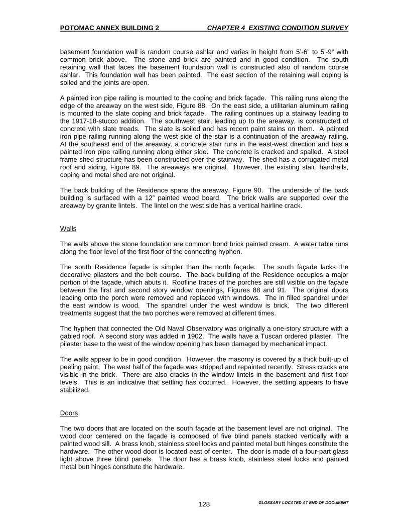
POTOMAC ANNEX BUILDING 2 CHAPTER 4 EXISTING CONDITION SURVEY
GLOSSARY LOCATED AT END OF DOCUMENT 128
basement foundation wall is random course ashlar and varies in height from 5’-6” to 5’-9” with common brick above. The stone and brick are painted and in good condition. The south retaining wall that faces the basement foundation wall is constructed also of random course ashlar. This foundation wall has been painted. The east section of the retaining wall coping is soiled and the joints are open. A painted iron pipe railing is mounted to the coping and brick façade. This railing runs along the edge of the areaway on the west side, Figure 88. On the east side, a utilitarian aluminum railing is mounted to the slate coping and brick façade. The railing continues up a stairway leading to the 1917-18-stucco addition. The southwest stair, leading up to the areaway, is constructed of concrete with slate treads. The slate is soiled and has recent paint stains on them. A painted iron pipe railing running along the west side of the stair is a continuation of the areaway railing. At the southeast end of the areaway, a concrete stair runs in the east-west direction and has a painted iron pipe railing running along either side. The concrete is cracked and spalled. A steel frame shed structure has been constructed over the stairway. The shed has a corrugated metal roof and siding, Figure 89. The areaways are original. However, the existing stair, handrails, coping and metal shed are not original. The back building of the Residence spans the areaway, Figure 90. The underside of the back building is surfaced with a 12” painted wood board. The brick walls are supported over the areaway by granite lintels. The lintel on the west side has a vertical hairline crack. Walls The walls above the stone foundation are common bond brick painted cream. A water table runs along the floor level of the first floor of the connecting hyphen. The south Residence façade is simpler than the north façade. The south façade lacks the decorative pilasters and the belt course. The back building of the Residence occupies a major portion of the façade, which abuts it. Roofline traces of the porches are still visible on the façade between the first and second story window openings, Figures 88 and 91. The original doors leading onto the porch were removed and replaced with windows. The in filled spandrel under the east window is wood. The spandrel under the west window is brick. The two different treatments suggest that the two porches were removed at different times. The hyphen that connected the Old Naval Observatory was originally a one-story structure with a gabled roof. A second story was added in 1902. The walls have a Tuscan ordered pilaster. The pilaster base to the west of the window opening has been damaged by mechanical impact. The walls appear to be in good condition. However, the masonry is covered by a thick built-up of peeling paint. The west half of the façade was stripped and repainted recently. Stress cracks are visible in the brick. There are also cracks in the window lintels in the basement and first floor levels. This is an indicative that settling has occurred. However, the settling appears to have stabilized. Doors The two doors that are located on the south façade at the basement level are not original. The wood door centered on the façade is composed of five blind panels stacked vertically with a painted wood sill. A brass knob, stainless steel locks and painted metal butt hinges constitute the hardware. The other wood door is located east of center. The door is made of a four-part glass light above three blind panels. The door has a brass knob, stainless steel locks and painted metal butt hinges constitute the hardware.

POTOMAC ANNEX BUILDING 2 CHAPTER 4 EXISTING CONDITION SURVEY
GLOSSARY LOCATED AT END OF DOCUMENT 129
Windows Two windows flank the Residence back building on the first and second floors. All sashes are wood 6-over-6 double hung with clear panes. The two windows on the first floor are installed in original door openings. The basement has three window openings. There are two windows west of center and two windows to the east. The basement window sashes are 3-over-3 double hung units. The brownstone windowsills and lintels are painted and protrude slightly from the brick façade. Window mounted air conditioning units and vent fans are installed in some basement, first and second floor windows. Pintles, originally used to mount wood louvered shutters still exist on the window frames. The façade of the connecting hyphen leading to the main block has a 6-over-6 double hung window sash. A molded wood hood that is supported by sandstone acanthus leaf brackets distinguishes this treatment. This is typical of the 1844 Old Naval Observatory openings. However, the connecting hyphen was constructed in 1848, one year after the construction of the Residence, which has unarticulated stone lintels. Historic images and photos show that the door on the north façade of the hyphen also had an ornamental hood. It is possible that the connecting hyphen was designed to appear more a part of the Old Naval Observatory than the Residence. It seems likely that the ornamental window hood is an original treatment to the 1848 construction date. The windows on the north façade do not operate due to excessive paint that has built-up. However, they will function if the excessive paint is removed. Cornice A painted wood cornice surrounds the brick wall of the Residence and matches the Old Naval Observatory’s main block cornice in profile. The integral gutter, which has been covered with roofing material, is concealed in the wood cornice and drains through metal downspouts. The cornice has been repainted recently and appears in good condition. A painted wood cornice caps the one-story hyphen and is continuous with the adjoining cornice of the east wing of the Old Naval Observatory. Roof The roof has been included in the north façade description. East Façade Figures 89 and 91 General Description The east façade is comprised of the two-story main Residence façade along with its adjoining back building façade. The back building rises only halfway up the second floor of the main Residence structure. The first floor of the back building is obscured by a 1918-stucco addition, relegating a formerly exterior window to the interior. Originally, a porch occupied the corner between the main residence and the back building. However, the porch no longer exists. Foundation and Areaways The foundation of the main Residence structure, above the planting bed, is random course masonry. The foundation is made of common bond brick with a painted finish.

POTOMAC ANNEX BUILDING 2 CHAPTER 4 EXISTING CONDITION SURVEY
GLOSSARY LOCATED AT END OF DOCUMENT 130
Walls The walls above the stone foundation of the main Residence structure are common bond brick painted with cream colored paint. The back building façade is painted common bond brick. The east façade of the Residence is relatively simple. The only decorative elements are the Tuscan pilasters at the north end of the wall on the first and second floors. The pilasters are made of brick shafts and brownstone caps and bases. A painted granite lintel carries the masonry walls of the back building over the areaway. The general condition of the walls appears to be good. However, the masonry is concealed by a thick built-up of peeling paint. Stress cracks run vertically and diagonally through the masonry mortar joints. A cracked north window lintel unit at the basement indicates that the foundation had settling problems. However, the settling has stabilized. Doors There are no doors located on this façade. Windows The first and second floors of the main Residence has two windows placed symmetrically on the façade closer to the center than the building corners. The sashes are wood 6-over-6 double hung with clear glass panes. The basement has two asymmetrically placed window openings. Each window is fitted with 3-over-3 double hung units. The brownstone windowsills and lintels are painted and protrude slightly from the brick façade. Window mounted air conditioning units are installed in some basement, first and second floor window openings. Pintles, originally used to mount wood louvered shutters are still extent on the window frames on the first and second floor levels. The back building of the Residence has only one 6-over-6 double hung window on the first and second floors. The first floor window was obscured from the exterior by the construction of the stucco addition. However, it remains exposed on the interior. A 3-over-3 double hung window is located at the basement level. The back building window openings are square and have painted stone sills protruding slightly from the façade. An air conditioning unit is mounted to the basement window opening and a vent fan at the second floor. Windows do not operate due to the amount of paint built-up. However, if the paint is removed, the window will function as intended. Cornice A painted wood cornice surrounds the brick wall of the Residence and matches the main block cornice in profile. The integral gutter, which has been covered with roofing material, is concealed and drains through metal downspouts located at the east and west ends of the Residence. The back building brick walls terminate in a modest corbel brick cornice with a metal gutter mounted to it. Roof The roof of the residence has been included in the description of the north façade.
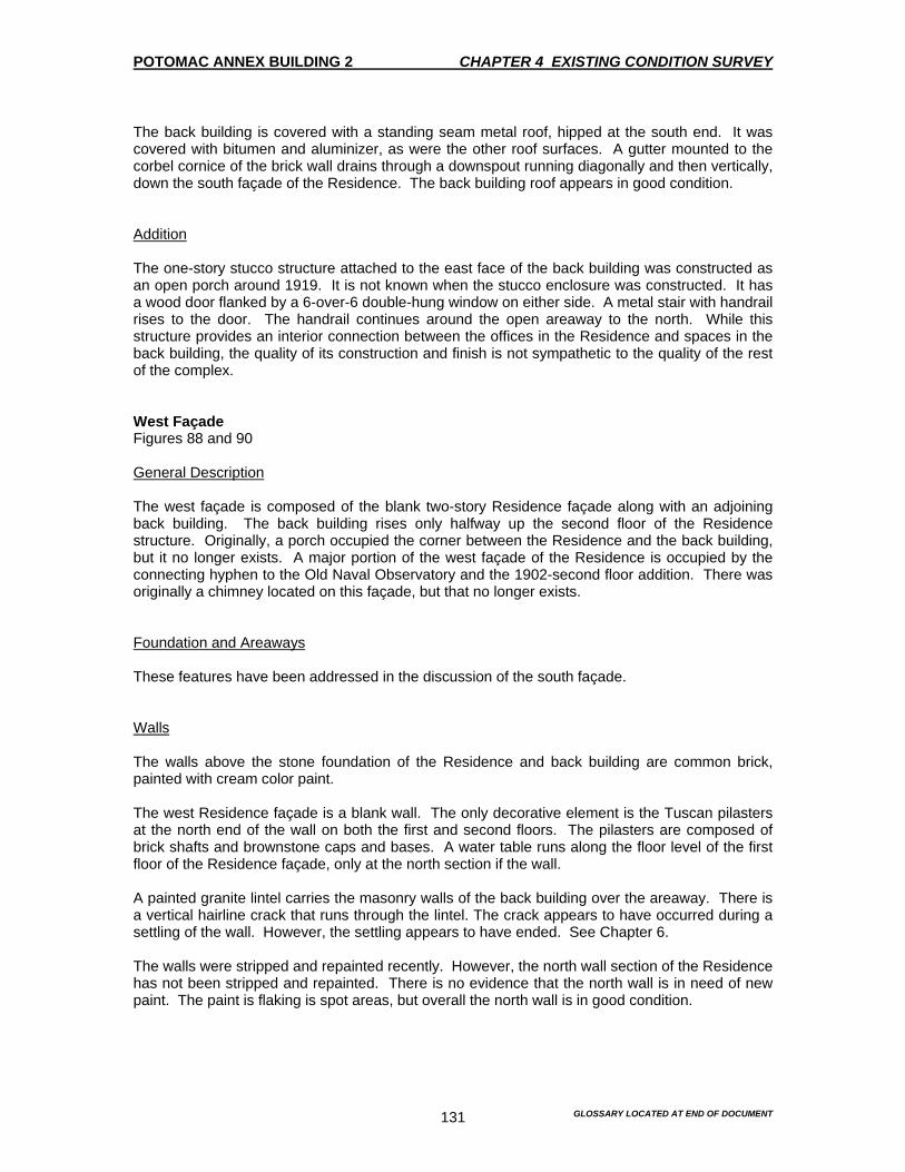
POTOMAC ANNEX BUILDING 2 CHAPTER 4 EXISTING CONDITION SURVEY
GLOSSARY LOCATED AT END OF DOCUMENT 131
The back building is covered with a standing seam metal roof, hipped at the south end. It was covered with bitumen and aluminizer, as were the other roof surfaces. A gutter mounted to the corbel cornice of the brick wall drains through a downspout running diagonally and then vertically, down the south façade of the Residence. The back building roof appears in good condition. Addition The one-story stucco structure attached to the east face of the back building was constructed as an open porch around 1919. It is not known when the stucco enclosure was constructed. It has a wood door flanked by a 6-over-6 double-hung window on either side. A metal stair with handrail rises to the door. The handrail continues around the open areaway to the north. While this structure provides an interior connection between the offices in the Residence and spaces in the back building, the quality of its construction and finish is not sympathetic to the quality of the rest of the complex. West Façade Figures 88 and 90 General Description The west façade is composed of the blank two-story Residence façade along with an adjoining back building. The back building rises only halfway up the second floor of the Residence structure. Originally, a porch occupied the corner between the Residence and the back building, but it no longer exists. A major portion of the west façade of the Residence is occupied by the connecting hyphen to the Old Naval Observatory and the 1902-second floor addition. There was originally a chimney located on this façade, but that no longer exists. Foundation and Areaways These features have been addressed in the discussion of the south façade. Walls The walls above the stone foundation of the Residence and back building are common brick, painted with cream color paint. The west Residence façade is a blank wall. The only decorative element is the Tuscan pilasters at the north end of the wall on both the first and second floors. The pilasters are composed of brick shafts and brownstone caps and bases. A water table runs along the floor level of the first floor of the Residence façade, only at the north section if the wall. A painted granite lintel carries the masonry walls of the back building over the areaway. There is a vertical hairline crack that runs through the lintel. The crack appears to have occurred during a settling of the wall. However, the settling appears to have ended. See Chapter 6. The walls were stripped and repainted recently. However, the north wall section of the Residence has not been stripped and repainted. There is no evidence that the north wall is in need of new paint. The paint is flaking is spot areas, but overall the north wall is in good condition.

POTOMAC ANNEX BUILDING 2 CHAPTER 4 EXISTING CONDITION SURVEY
GLOSSARY LOCATED AT END OF DOCUMENT 132
Door There are no doors located on this façade. Windows There are no windows located on the west façade of the two-story Residence However, the back building does have some windows. The back building of the Residence has two 6-over-6 double-hung window sashes on the second floor, as well as one on the first floor, toward the south end. These window openings are square and have painted stone sills that protrude slightly from the façade. Three non-original fixed windows are located on this façade. These window openings have painted wood sills. There are air conditioning units mounted in the windows on both the first and second floors. Cornice A painted wood cornice surmounts the brick wall of the Residence and matches the Old Naval Observatory’s main block in profile. There is paint that is peeling on the cornice. The back buildings brick wall terminates in a modest corbel brick cornice with a copper gutter mounted to it. Roof The roof has been included in the description of the north and east facades 1865-73 South Wing Extension and South Rotunda Rebuilt in 1895 Summary Description The 1893 South Extension was originally constructed as an addition to the south wing of the 1844 Old Naval Observatory. Historic photographs indicate that the addition was extended in two phases. These two phases culminated in a rotunda at the south end. Rotunda The photographs indicate that the Rotunda that was built in 1873 is not the one that currently exists. The Rotunda specifications from 1865 indicate that there is a frame construction on a stone foundation. The original rotunda structure was taken down to the foundation and rebuilt in 1895, during the building campaign that was undertaken by the Museum of Hygiene. The existing South Rotunda is a brick cylindrical structure set on a stone foundation. The metal door is conical and capped with a glazed cupola. 2-over-2 double-hung wood windows punctuate the brick drum of the Rotunda at the first floor level. The attic story windows are aligned above. The stone lintels and sills are painted. There is a basement entrance to the Rotunda on the west side.

POTOMAC ANNEX BUILDING 2 CHAPTER 4 EXISTING CONDITION SURVEY
GLOSSARY LOCATED AT END OF DOCUMENT 133
South Wing Extension While the wing connecting the Rotunda to the original Old Naval Observatory was historically one story. A second story addition was constructed in 1903. This additional story was part of the Naval Medical School building campaign. At that time, some windows and doors on the first floor were reconfigured. A water table runs along the first floor level of the north section of the 1873 South Wing Extension. Two Tuscan pilasters flank the middle section of the 1873 South Wing Extension, which lies just north of the Rotunda and protrudes slightly from the adjoining façade plan. The pilasters are composed of brick shafts and stone bases. The first floor capitals on the west side are wood. Those on the east side show up in historical photographs, but are currently missing. A simple painted wood pediment surmounting the middle section, also seen in historical photographs, was probably removed in 1903 when the second story was constructed. A painted stone belt course serves to distinguish the first floor level of the 1873 South Wing Extension from the 1903-second floor addition. Molded hoods supported by sandstone acanthus leaf brackets distinguish the masonry openings. A rectangular brick structure links the Rotunda and the south section of the 1873 South Wing Extension. A rectangular brick chimney rises up from the concrete curb that is located on the east side of the Rotunda. The chimney is corbel at the top. East Façade Figures 94, 97 and 98 General Description The 1873 South Wing Extension was originally construction as an addition to the south wing of the 1844 Old Naval Observatory. Historical photographs indicate that the addition was extended in two phases, culminating in a Rotunda at the south end. A second floor was added in 1902-03 and the Rotunda walls and dome were taken down and completely rebuilt with brick and filled with a conical roof and topped with a cupola in 1895. The wall of the east façade has been recently stripped and repainted. There is spot damage to the mortar that was caused by the stripping of paint. Foundations and Areaways The stone masonry foundation walls of the South Wing Extension are concealed below grade. The painted ashlar foundation wall of the Rotunda is capped with a 9” belt of course of painted blue stone. Walls The walls above the stone foundation of the 1873 South Wing Extension, are common bond brick that is painted with a cream colored paint. During the 1994 repainting campaign, the walls were stripped and repainted. A water table runs along the first floor level of the north section of the 1873 South Wing Extension. Two Tuscan pilasters flank the middle section of the 1873 South Wing Extension, which lies just north of the Rotunda and protrudes slightly from the adjoining façade plane. The pilasters are composed of brick shafts and stone bases. The pilaster capitals, which are visible in historical pictures, are no longer present. A wood pediment surmounting the middle section, also visible in historical pictures, was duplicated on the second floor in 1903, when the second story
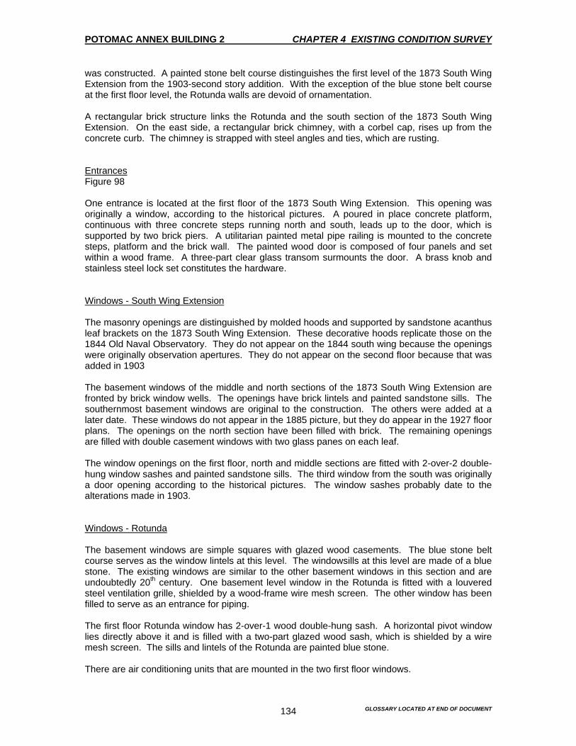
POTOMAC ANNEX BUILDING 2 CHAPTER 4 EXISTING CONDITION SURVEY
GLOSSARY LOCATED AT END OF DOCUMENT 134
was constructed. A painted stone belt course distinguishes the first level of the 1873 South Wing Extension from the 1903-second story addition. With the exception of the blue stone belt course at the first floor level, the Rotunda walls are devoid of ornamentation. A rectangular brick structure links the Rotunda and the south section of the 1873 South Wing Extension. On the east side, a rectangular brick chimney, with a corbel cap, rises up from the concrete curb. The chimney is strapped with steel angles and ties, which are rusting. Entrances Figure 98 One entrance is located at the first floor of the 1873 South Wing Extension. This opening was originally a window, according to the historical pictures. A poured in place concrete platform, continuous with three concrete steps running north and south, leads up to the door, which is supported by two brick piers. A utilitarian painted metal pipe railing is mounted to the concrete steps, platform and the brick wall. The painted wood door is composed of four panels and set within a wood frame. A three-part clear glass transom surmounts the door. A brass knob and stainless steel lock set constitutes the hardware. Windows - South Wing Extension The masonry openings are distinguished by molded hoods and supported by sandstone acanthus leaf brackets on the 1873 South Wing Extension. These decorative hoods replicate those on the 1844 Old Naval Observatory. They do not appear on the 1844 south wing because the openings were originally observation apertures. They do not appear on the second floor because that was added in 1903 The basement windows of the middle and north sections of the 1873 South Wing Extension are fronted by brick window wells. The openings have brick lintels and painted sandstone sills. The southernmost basement windows are original to the construction. The others were added at a later date. These windows do not appear in the 1885 picture, but they do appear in the 1927 floor plans. The openings on the north section have been filled with brick. The remaining openings are filled with double casement windows with two glass panes on each leaf. The window openings on the first floor, north and middle sections are fitted with 2-over-2 double-hung window sashes and painted sandstone sills. The third window from the south was originally a door opening according to the historical pictures. The window sashes probably date to the alterations made in 1903. Windows - Rotunda The basement windows are simple squares with glazed wood casements. The blue stone belt course serves as the window lintels at this level. The windowsills at this level are made of a blue stone. The existing windows are similar to the other basement windows in this section and are undoubtedly 20th century. One basement level window in the Rotunda is fitted with a louvered steel ventilation grille, shielded by a wood-frame wire mesh screen. The other window has been filled to serve as an entrance for piping. The first floor Rotunda window has 2-over-1 wood double-hung sash. A horizontal pivot window lies directly above it and is filled with a two-part glazed wood sash, which is shielded by a wire mesh screen. The sills and lintels of the Rotunda are painted blue stone. There are air conditioning units that are mounted in the two first floor windows.

POTOMAC ANNEX BUILDING 2 CHAPTER 4 EXISTING CONDITION SURVEY
GLOSSARY LOCATED AT END OF DOCUMENT 135
Cornice A painted sheet metal cornice surmounts the conical Rotunda wall. The wash surface of the cornice has a built-in terne-coated stainless steel gutter. The cupola at the apex of the roof had as identical cornice, in similar scale. Roof The Rotunda is capped with a painted conical standing seam terne-coated stainless steel roof. This roof is a replacement roof that replaced an older metal roof as part of the general roof repairs that were carried out in 1983-84. A wood frame cupola is located at the apex of the roof and is also covered with a cylindrical standing seam terne-coated stainless steel roof. Sixteen windows, each divided into two glazed parts are filled within the cupola frame. The stainless steel terne-coated gutter, which receives runoff from the Rotunda, is covered within the metal cornice and drains through a stainless steel terne-coated downspout located on the west façade of the Rotunda. Water is drained from the cupola from the downspouts, which are mounted, to the wood frame of the cupola, releasing water onto the main rotunda roof. West façade Figures 93, 95 and 96 General Description The 1873 South Wing Extension was originally constructed as an addition to the south wing of the 1844 Old Naval Observatory. Historical pictures indicate that the addition was extended in two phases, culminating in a Rotunda at the south end. A second floor was added in 1902-03 and the Rotunda walls and dome were taken down and completely rebuilt with brick and fitted with a conical roof and topped with a cupola in 1895. The walls of the east façade have recently been stripped and painted with minor spot damage to the mortar. Foundations and Areaways The stone foundation walls of the South Wing Extension are concealed below grade. The painted ashlar foundation walls of the South Wing Extension are common bond brick painted with a cream colored paint. During the 1994 repainting campaign, the walls were stripped and repainted There is a water table along the first floor level of the north section of the 1873 South Wing Extension. Two Tuscan pilasters flank the middle section of the 1873 South Wing Extension, which lies just north of the Rotunda and protrudes slightly from the adjoining façade plane. The pilasters are composed of brick shafts and stone bases. The pilaster capitals, which were visible in the historical pictures, were duplicated on the second floor in 1903, when the second story was built. A painted stone belt course distinguishes the first floor level of the 1873 South Wing Extension from the 1903-second floor addition. With the exception of the blue stone belt course at the first floor level, the Rotunda walls are devoid of ornamentation. A rectangular brick structure links the Rotunda and the south section of the 1873 South Wing Extension. On the east side, a rectangular brick chimney, with a corbel cap, rises up from the concrete curb. The chimney is strapped with steel angles and ties, which are rusting.
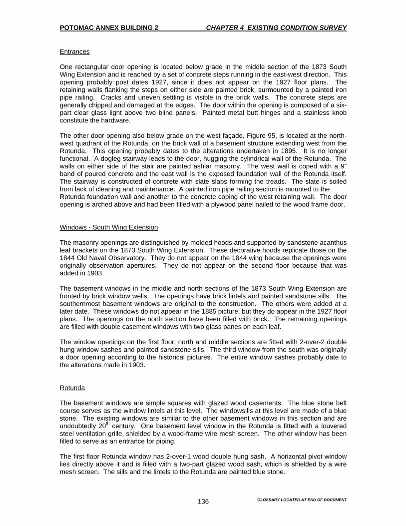
POTOMAC ANNEX BUILDING 2 CHAPTER 4 EXISTING CONDITION SURVEY
GLOSSARY LOCATED AT END OF DOCUMENT 136
Entrances One rectangular door opening is located below grade in the middle section of the 1873 South Wing Extension and is reached by a set of concrete steps running in the east-west direction. This opening probably post dates 1927, since it does not appear on the 1927 floor plans. The retaining walls flanking the steps on either side are painted brick, surmounted by a painted iron pipe railing. Cracks and uneven settling is visible in the brick walls. The concrete steps are generally chipped and damaged at the edges. The door within the opening is composed of a six-part clear glass light above two blind panels. Painted metal butt hinges and a stainless knob constitute the hardware. The other door opening also below grade on the west façade, Figure 95, is located at the north-west quadrant of the Rotunda, on the brick wall of a basement structure extending west from the Rotunda. This opening probably dates to the alterations undertaken in 1895. It is no longer functional. A dogleg stairway leads to the door, hugging the cylindrical wall of the Rotunda. The walls on either side of the stair are painted ashlar masonry. The west wall is coped with a 9” band of poured concrete and the east wall is the exposed foundation wall of the Rotunda itself. The stairway is constructed of concrete with slate slabs forming the treads. The slate is soiled from lack of cleaning and maintenance. A painted iron pipe railing section is mounted to the Rotunda foundation wall and another to the concrete coping of the west retaining wall. The door opening is arched above and had been filled with a plywood panel nailed to the wood frame door. Windows - South Wing Extension The masonry openings are distinguished by molded hoods and supported by sandstone acanthus leaf brackets on the 1873 South Wing Extension. These decorative hoods replicate those on the 1844 Old Naval Observatory. They do not appear on the 1844 wing because the openings were originally observation apertures. They do not appear on the second floor because that was added in 1903 The basement windows in the middle and north sections of the 1873 South Wing Extension are fronted by brick window wells. The openings have brick lintels and painted sandstone sills. The southernmost basement windows are original to the construction. The others were added at a later date. These windows do not appear in the 1885 picture, but they do appear in the 1927 floor plans. The openings on the north section have been filled with brick. The remaining openings are filled with double casement windows with two glass panes on each leaf. The window openings on the first floor, north and middle sections are fitted with 2-over-2 double hung window sashes and painted sandstone sills. The third window from the south was originally a door opening according to the historical pictures. The entire window sashes probably date to the alterations made in 1903. Rotunda The basement windows are simple squares with glazed wood casements. The blue stone belt course serves as the window lintels at this level. The windowsills at this level are made of a blue stone. The existing windows are similar to the other basement windows in this section and are undoubtedly 20th century. One basement level window in the Rotunda is fitted with a louvered steel ventilation grille, shielded by a wood-frame wire mesh screen. The other window has been filled to serve as an entrance for piping. The first floor Rotunda window has 2-over-1 wood double hung sash. A horizontal pivot window lies directly above it and is filled with a two-part glazed wood sash, which is shielded by a wire mesh screen. The sills and the lintels to the Rotunda are painted blue stone.
POTOMAC ANNEX BUILDING 2 CHAPTER 4 EXISTING CONDITION SURVEY
GLOSSARY LOCATED AT END OF DOCUMENT 137
There are air conditioning units that are mounted in the two first floor windows. In addition, there is a pair of single pane non-operable windows located in the tower that separates the middle section of the 1873 South Wing Extension addition and the Rotunda, at the first floor level. The openings have brick lintels and painted wood sills. Cornice The cornice has been included in the east façade description. Roof The roof has been included in the east façade description. South Façade General Description The south façade is comprised of the south section of the Rotunda. Foundation and Areaways The painted ashlar foundation wall of the Rotunda is capped with a 9” belt course of painted blue stone. Walls The walls above the stone foundation are common bond brick painted over with a cream colored paint. The walls have recently been stripped and repainted. With the exception of the blue stone belt course at the first floor level, the Rotunda walls are devoid of ornamentation. Entrances There are no entrances located on the south façade of the 1873 South Wing Extension. Windows The basement level windows in the Rotunda have been included in the east and west descriptions. The first floor window opening of the south façade is fitted with a 2-over-1 double hung window sash. A horizontal pivot window lies directly above the first floor window of the Rotunda and is fitted with a wood sash with two part light. One of the glass panes has been replaced with masonite. The sills and lintels of the Rotunda windows are painted blue stone. There is an air conditioning unit mounted in the first floor window opening.

POTOMAC ANNEX BUILDING 2 CHAPTER 4 EXISTING CONDITION SURVEY
GLOSSARY LOCATED AT END OF DOCUMENT 138
Cornice The cornice has been included in the east façade description. Roof The roof has been included in the east façade description. 1869 West Addition Rebuilt in 1897 Summary Description The West Addition on the west end of the Old Naval Observatory was constructed in 1897. It replaced the west transit house, which had been constructed in 1869. The new brick structure was built on the old foundation. It is a one-story structure that is characterized by large arched window openings reflecting the double-height space within. The windows are 2-over-2 double hung windows whose top sash arches to fit the masonry opening. Brick pilasters, similar to those on the 1844 Old Naval Observatory defines the corners of the West Addition. An entry is centered on the north elevation. The entry is has an octagonal projecting vestibule with a parapet wall. This structure replaced an open porch. The door is wood paneled and glazed. The east elevation abuts the West Addition of the Old Naval Observatory and is otherwise unadorned. The west elevation has four windows that are identical to those on the north elevation. A water table runs along the floor level of the first floor. Tuscan pilasters with brick shaft, caps and bases terminate the corners. The pilasters are separated horizontally by a brick belt course, which follow the line of the round arches of the window openings. North Façade Figures 99-101 General Description This façade is symmetrical and of the same height as the two-story 1844 Old Naval Observatory. This description includes the one-story connecting passageway of the West Addition, which was constructed in 1869. Foundation and Areaway The stone foundation walls are concealed below grade. Walls The walls above the stone foundations are common bond brick painted a cream colored paint. A water table runs along the floor level of the first floor. The corners of this façade end with Tuscan pilasters with brick shafts, caps and bases. The pilasters are separated horizontally by a brick belt course, which follow the line of the arches of the window openings. A brick portico structure is centered on the West Addition façade and is described in greater detail below. The walls appear to be in good condition. However, the walls are concealed with a heavy build-up of paint.

POTOMAC ANNEX BUILDING 2 CHAPTER 4 EXISTING CONDITION SURVEY
GLOSSARY LOCATED AT END OF DOCUMENT 139
Entrances Figure 100 The West Addition is entered through an octagonal brick portico, which is one story in height and centered on the façade. Historical pictures indicate the original entry was through an open porch. The open porch appears in 1902 pictures of the West Addition, but the historical record is not clear about the construction date of the enclosed vestibule. The door opening is filled with a cement panel to accommodate a wood and glass door. A concrete slab functions as the portico ceiling and appears as a belt course on the exterior. A brick parapet wall, which rises above the concrete slab, is ornamental with a painted wood cornice halfway between the door opening and the parapet coping. A round opening is located at the center of the parapet, above the cornice. The opening is fitted with a cast iron grille. There are three painted concrete steps that lead up to the door. The wood door is composed of a four-part clear glass light above three blind panels. A brass knob, stainless steel lock and painted metal hinge constitute the door hardware. Windows The portico structure is flanked on either side by a round arched window openings. The openings are fitted with a 2-over-2 double hung window sash and painted blue stone sills. The upper sash unit is arched to fit the masonry opening. The grand scale of the window reflects the full height of the interior space. The masonry opening of the West Addition passageway to the 1844 Old Naval Observatory is distinguished by a molded wood hood supported by sandstone acanthus leaf brackets. Historic pictures show that this opening was originally a door. The window is a 6-over-6 double hung sash, which was probably installed in 1902, when the second story addition was installed. The opening is also fitted with an air conditioning unit and an HVAC exhaust duct. Cornice A painted cornice surmounts the masonry wall matching the cornice of the 1844 Old Naval Observatory in profile. The cornice over the one-story connecting passageway matches that of the adjoining 1844 Old Naval Observatory’s West Addition. A painted wood cornice is mounted to the parapet walls of the portico and is flashed with sheet metal. The flashing is rusting and staining the cornice. The paint is also peeling. Roof The roof of the West Addition is a built-up bituminous surface with gravel topping. This was replaced as part of the 1983-84 roof repairs. The portico roof is a flat seam metal that has been repaired with an asphaltic coating with aluminizer. The main section of the roof drains through a scupper. The scupper leads to a copper downspout located on the west façade. Water from the portico roof drains through the copper downspouts that are mounted to the east and west walls of the West Addition.

POTOMAC ANNEX BUILDING 2 CHAPTER 4 EXISTING CONDITION SURVEY
GLOSSARY LOCATED AT END OF DOCUMENT 140
West Façade Foundation and Areaways The stone masonry foundation walls of the West Addition are concealed below grade Walls The walls above the stone masonry foundations are common bond brick painted a cream colored paint. The bottom 2’-6” of the masonry wall is coated with a cement plaster, which is scored to resemble ashlar. A water table runs along the floor level of the first floor. The corner of the West Addition façade ends in Tuscan pilasters with brick shafts, caps and bases. The pilasters are separated horizontally by a brick belt course, which follow the line of the round arched window opening. A painted metal parking sign is nailed to the wall. The walls appear to be in good condition. However, there is a heavy amount of paint on the walls. Entrances There are no entrances located on the West Addition façade. Windows Four round arched window openings are located on the West Addition façade. The openings are fitted with 2-over-2 double hung window sash and painted blue stone sills. The upper sash unit is arched to fit the window opening. Cornice A painted wood cornice surmounts the masonry walls and matches the cornice of the 1844 Old Naval Observatory profile. Roof The roof is included in the north façade description. 1902-03 Second Floor Additions East, West, and South Wings Summary Description The Second Floor Additions were constructed as part of the building campaign that was done by the Naval Medical School. The east and west wings were constructed in 1902. The east wing accommodated the bacteriological laboratory. The chemical laboratory was housed in the west wing. The south wing, built the following year in 1893, housed the student lounges and locker rooms. All of these wings are characterized by round arched window openings. They present a radical alteration to the physical appearance of the 1844 Old Naval Observatory. However, they were well designed and executed. These additions should be considered as significant parts of the fabric of the entire Old Naval Observatory.
POTOMAC ANNEX BUILDING 2 CHAPTER 4 EXISTING CONDITION SURVEY
GLOSSARY LOCATED AT END OF DOCUMENT 141
North Façade Figures 63-65, 71 and 72 General Description The north façade is divided into two sections. A One section over the east wing and the other section over the west wing of the Old Naval Observatory. Walls The walls are common bond brick painted with a cream colored paint. Double-sunk round arched window openings are on the façade and give the visual impression of a colonnade. A sill course runs through the length of each section of the north façade. A brick belt course runs through at the height of the arches of the window openings, following the curve of the arch at each opening. Painted cast iron ventilation grilles are located between the window openings, immediately below the cornice. The walls appear to be in good condition. However, there is a heavy amount of paint on the walls. Entrances There are no entrances on the Second Floor Additions Windows Seven window openings are located on the east section of the Second Floor Addition façade and five on the west section. The arched parts of the openings are fitted with glazed transoms. The sashes are 4-over-1 double hung wood units. There are air conditioning units mounted in some of the window openings. Cornice A painted wood cornice surmounts the masonry wall of both sections of the Second Floor Additions north façade and matches the cornice of the 1844 Old Naval Observatory in profile. Peeling paint is visible on the cornice. The wash surface of the cornice contains a built-in gutter, which is obscured by the roofing material. Roof The Second Floor Additions have hipped roofs. The standing seam of the metal roof was flattened and covered with modified bitumen sheets with an aluminized facer as part of the 1983-84 general roof repairs. The aluminized facer has random blistering throughout. Painted metal ventilator units are mounted on the roof edges. The gutters that receive runoff from the roof are concealed in the wood cornice. These gutters drain through copper downspouts located on adjoining facades.

POTOMAC ANNEX BUILDING 2 CHAPTER 4 EXISTING CONDITION SURVEY
GLOSSARY LOCATED AT END OF DOCUMENT 142
South Façade Figures 77, 78 and 103 General Description The south façade of the Second Floor Additions are divided into two identically designed single storied sections. One story is over the east wing and the other over the west wing of the 1844 Old Naval Observatory. A 1917-18-stucco addition abuts the west-end of the west section of the façade. This stucco addition conceals two original window openings, which are visible on the interior. Walls The walls are common bond brick painted with a cream colored paint. Double-sunk round arched window openings are on the façade and give the visual impression of a colonnade. A sill course runs through the length of each section of the north façade. A brick belt course runs through at the height of the arches of the window openings, following the curve of the arch at each opening. Painted cast iron ventilation grilles are located between the window openings, immediately below the cornice. The walls appear to be in good condition. However, there is a heavy amount of paint of the walls. Entrances There are no entrances on the Second Floor Additions Windows Seven window openings are located on the east façade and three on the west of the Second Floor Additions. The arched parts of the openings are fitted with glazed transoms. The sashes are 4-over-1 double hung wood units. There are air conditioning units mounted in some of the window openings. There are two original window openings on the west section that were obscured by the 1918-stucco addition. However, these windows are still visible from the interior. One of the obscured window openings was converted to a doorway and the other was filled in with brick, somewhere around 1918. Cornice A painted wood cornice surmounts the masonry wall of both sections of the south façade of the Second Floor Additions. This matches the cornice of the 1844 Old Naval Observatory in profile. Peeling paint is visible on the cornice. The wash of the cornice contains a built-in gutter. Roof The roof is included in the north façade description.

POTOMAC ANNEX BUILDING 2 CHAPTER 4 EXISTING CONDITION SURVEY
GLOSSARY LOCATED AT END OF DOCUMENT 143
East Façade Figure 97 General Description This constitutes the east façade of the Second Floor Addition constructed over the south wing of the 1844 Old Naval Observatory and adjoining structures. Walls The walls of the east façade rise above a painted stone belt course, capping the older first floor walls. The wall is constructed of common course brick. The corners of the addition end with a Tuscan pilasters that divide the façade into sections and are comprised of brick shafts, woods caps and stone bases. The framing around the two pilasters, above the 1873 middle section, are surmounted by a simple painted wood pediment. Three first floor pilasters, located on the south wing of the 1844 Old Naval Observatory, have been extended with tapered stone tops to appear almost as buttresses reinforcing the wall. The walls have recently been stripped and repainted. Entrances One window opening on the façade has been converted to a doorway, opening onto a utilitarian painted steel fire escape that leads to the ground. The fire escape is supported at the top by two tapered steel brackets, bolted to the façade and at the landing by a brick pier. The bottom landing is a concrete slab that rests on grade. A simple painted steel railing runs along either side of the glazed transom. A stainless steel lever, lock set and stainless steel butt hinges constitute the hardware. This fire escape is a recent addition replacing an earlier fire escape. Windows The window openings are fitted with 2-over-2 double hung wood sash and painted stone sills. The northernmost opening is a double window, fitted with a pair of 2-over-2 double hung sashes. There are air conditioning units in two of the windows. Cornice The wood cornice that surmounts the masonry walls has a different profile than that of the adjoining 1844 Old Naval Observatory. A painted sheet metal gutter surmounts the wash surface of the cornice. Although the cornice has been recently repainted, large sections of rotted wood are present along the bottom. Further investigation is needed to determine the cause. See Chapter 6. Roof The roof is divided into two sections. The first is a simple gabled roof that is set between two masonry walls, located over the northernmost section of the Second Floor Additions and the second larger section, is a gabled roof with a cross-gabled roof at the southern end. The gabled ends terminate in simple wood pediments. Both sections are standing seam terne coated stainless steel roof. These roofs are replacement roofs that were added as part of the 1987 roof repairs. Painted metal ventilator units are mounted to the roof ridge.
POTOMAC ANNEX BUILDING 2 CHAPTER 4 EXISTING CONDITION SURVEY
GLOSSARY LOCATED AT END OF DOCUMENT 144
Painted terne coated stainless steel gutters, receiving runoff from the roof, surmount the wood cornice and drain through downspouts located on the east façade. West Façade Figure 96 General Description This constitutes the west façade of the Second Floor Addition constructed over the south wing of the 1844 Old Naval Observatory. Walls The walls of the west façade rise above a painted stone belt course, capping the older first floor walls. The wall is constructed of common course brick. The corners of the Second Floor Addition end with a Tuscan pilasters that divide the façade into sections and are comprised of brick shafts, woods caps and stone bases. The framing around the two pilasters, above the 1873 middle section, are surmounted by a simple painted wood pediment. Three first floor pilasters, located on the south wing of the 1844 Old Naval Observatory, have been extended with tapered stone tops to appear almost as buttresses reinforcing the wall. The walls have recently been stripped and repainted. Entrances There are no entrances located in the Second Floor Additions. Windows The window openings are fitted with 2-over-2 double hung sash and painted stone sills. The northernmost opening is a double window, fitted with a pair of 2-over-2 double hung sashes. Air conditioning units are mounted in two of the window openings. Cornice The wood cornice that surmounts the masonry walls has a different profile than that of the adjoining 1844 Old Naval Observatory. A painted sheet metal gutter surmounts the wash surface of the cornice. Although the cornice has been recently repainted, large sections of rotted wood are present along the bottom. Further investigation is needed to determine the cause. See Chapter 6. Roof The roof is addressed in the east façade description.
POTOMAC ANNEX BUILDING 2 CHAPTER 4 EXISTING CONDITION SURVEY
GLOSSARY LOCATED AT END OF DOCUMENT 145
1918 East and West Stucco Additions Summary Description The East and West Stucco Additions, located on the south side of the Old Naval Observatory were constructed in 1918. Both masonry wings are clad with a cream colored stucco. The east and west walls of the West Stucco Addition were aligned with the brick on the West Addition, with a minor entrance to the basement level on the east side. The south elevation was simply fenestrated with 6-over-6 wood sash windows. The East Stucco Addition abuts the rear of the Residence, and therefore, reads more as a freestanding structure. Like its mate, it was designed with 6-over-6 wood sash windows. However, on the south side, it was furnished with a Colonial-Revival entry, giving direct access to the first floor, Figures 102-108. North Façade General Description The north façade description pertains only to the East Stucco Addition. The West Stucco Addition abuts the 1869 West Addition along its north face. The two story south wing of the 1848 Residence takes up a large portion of the north façade. Foundation and Areaways The concrete foundation wall that rises above grade up to the floor level of the first floor is surfaced with painted stucco and is in good condition. The areaway that exposes the east corner of the façade is included in the description of the south façade of the 1848 Residence. Walls The two story walls, above the concrete foundation, are surfaced with painted stucco over metal lath. The walls are slightly recessed from the plane of the foundation stucco surface. The stucco appears to be in fair condition with surface crack throughout. Entrances One entrance is located at the east end of the basement level of the north façade, and is reached by an areaway that was surveyed as part of the south façade of the 1848 Residence. The opening is fitted with a contemporary glazed aluminum frame with aluminum hardware. Windows Two window openings are located at the basement level. Both are surmounted by painted concrete window wells. The sashes are wood 6-over-6 double hung units. There are air conditioning units mounted in the openings. The wells are protected by a steel framed sloped wire mesh screens Two window openings are located on the first floor, west of the south wing of the 1848 Residence and two are located on the second floor, one on either side of the south wing of the Residence. The openings are fitted with 6-over-6 double hung sash and painted wood sill and frames. There are air conditioning units mounted in some of the window openings.
POTOMAC ANNEX BUILDING 2 CHAPTER 4 EXISTING CONDITION SURVEY
GLOSSARY LOCATED AT END OF DOCUMENT 146
Windows on the north façade are generally no longer functional. There is an excessive amount of paint built up and weathering has resulted in general paint failure on the wood frames. Cornice A painted wood cornice surmounts the stucco walls and matches that of the 1844 Old Naval Observatory in profile. The wash surface of the cornice has a built-in gutter coated with modified bitumen roofing material. Roof The hipped batten seam metal roof was repaired with modified bituminous sheets with an aluminized facer as part of the 1983-84 general roof repairs to the East Stucco Addition. Two painted metal ventilators are mounted along the ridge of the roof. A brick chimney, which is engaged with the south wall of the south wing of the 1838 Residence, abuts the roof and is covered by a rusting sheet metal cover. This sheet metal cover is causing ferrous stains on the chimney structure. The gutter that receives runoff from the roof is concealed in the wood cornice and drains through a copper downspout. The downspout is located at the east end of the façade. South Façade Figures 103-108 General Description The south façades of both the East and West Stucco Additions are unobstructed and appear unchanged from their original configuration. Foundations and Areaways The concrete foundation wall rises above grade up to the floor level of the first floor. The foundation wall is surfaced with painted stucco and is in good condition. The poured in place concrete wall is exposed at the west end of the West Stucco Addition and is painted with cream colored paint. Cast iron ventilation grilles are inset in the openings of the foundation wall of the west stucco addition. There are no areaways the front the south façade of either East or West Stucco Addition. Walls The two story walls above the concrete foundation are surfaced with painted stucco on metal lath. The walls are slightly recessed from the plane of the foundations stucco surface on the East Stucco Addition. On the West Stucco Addition, a wood trim member flashed with sheet metal delineated the bottom edge of the stucco from the concrete foundation wall below. The stucco appears in fair condition with surface cracks throughout. Limited areas of buckling and spalling have also occurred.

POTOMAC ANNEX BUILDING 2 CHAPTER 4 EXISTING CONDITION SURVEY
GLOSSARY LOCATED AT END OF DOCUMENT 147
Entrances Figures 107 and 108 One entrance is located at the first floor level of the south façade of the East Stucco Addition. A set of seven granite steps leads up to the doorway. The steps are flanked on either side by stucco sloped curb walls. Light gray granite slabs cope the walls and a painted wrought iron railing is bolted to the coping. The stucco is cracking and crumbling at the base due to moisture penetration. The granite has ferrous stains from the railing and an ashtray that was placed on the coping. The joints in the granite steps also require a re-sealing. The door is set within painted surrounds comprised of Doric Order pilasters, surmounted by a Doric entablature. Recessed panels ornament the pilaster shafts. A narrow band of painted wood fretwork, in a running pattern, highlights the frieze. Peeling paint and rotting wood elements are visible on the cornice. The eight panel wood door is surmounted by an eight part glazed transom. The panels are raised and have raised and chamfered edges. A clear glass light has replaced one panel. A brass pull handle and painted metal butt hinges constitute the hardware. This hardware is probably not original. The door is scuffed from normal use and the hinges are rusting. Windows Basement level windows are located only on the East Stucco Addition. The two openings are filled with plywood. One of the openings is also fitted with an air conditioning unit and the other is fitted with a ventilation grille. The window openings on the first and second floor levels are fitted with 6-over-6 double hung painted wood sash, sills and frames. The center windows on the first and second floor of both the East and West Stucco Additions are paired windows. Painted sheet metal flashing has been added to the sills of the West Stucco Addition. There are air conditioning units mounted in some of the window openings. The windows are generally no longer operable. Excessive paint build-up and weathering has resulted in general paint failure on the wood frames. Cornice Painted wood cornices, matching the cornice of the 1844 Old Naval Observatory in profile, surmount the stucco walls of both the East and West Stucco Additions. The wash surface of the East Stucco Addition cornice has a built-in gutter. This gutter has been covered with roofing material. Roof A hipped batten seam metal roof, repaired with modified bituminous sheets with an aluminized facer as part of the 1983-84 general roof repairs caps the East Stucco Addition. Two painted metal ventilators are mounted along the ridge of the roof. The metal gutter receiving the runoff from the roof is concealed in the wood cornice and drains through metal downspouts on adjacent facades. The roof of the West Stucco Addition has a built-up bituminous roof topped with gravel and concealed behind the stucco parapet. The roof was replaced as part of the general roof repairs carried out in 1983-84. Two painted metal ventilators are mounted to the roof. Water runoff from

POTOMAC ANNEX BUILDING 2 CHAPTER 4 EXISTING CONDITION SURVEY
GLOSSARY LOCATED AT END OF DOCUMENT 148
the roof drains through metal downspouts that are located on the east-end of the south façade and on the adjoining west façade. East Façade Figure 106 General Description The east façade of the West Stucco Addition retains its original appearance. The West Stucco Addition was extended at the first floor level to create a corridor that wraps around the back building of the 1847 Residence. This structure replaces a porch that was constructed in 1918 Foundation and Areaways The basement wall of the West Stucco Addition is exposed behind an areaway that runs along the entire length of the façade. The areaway floor is concrete and sloped to drain water with a steel drain cover inset in the center of the floor. The walls on either side of the areaway are painted poured in place concrete. A concrete ramp for barrier-free access runs along the east retaining wall, spanning the areaway at the north end to reach a door on the first level of the façade. Painted pipe railing sections run along either side of the ramp and are mounted to the ramp floor and adjoining stucco and brick walls. The areaway is reached by a concrete stairway located at the south end. A painted iron pipe mounted along the east areaway wall servers as a railing. The concrete stairs are chipped at the edges and soiled. The concrete foundation wall of the east façade of the East Stucco Addition rises above grade up to the floor level of the first floor. The wall is surfaced with painted stucco and is in good condition. Walls The two story walls, above the concrete foundation are surfaced with painted stucco on metal lath. The walls are slightly recessed from the plane of the foundation stucco surface on the East Stucco Addition. On the West Stucco Addition, a wood trim member flashed with sheet metal delineates the bottom edge of the stucco from the concrete foundation wall below. The stucco appears to be in fair condition with surface cracks throughout. Entrances Entrances are located on the basement and first floor level of the West Stucco Addition and on the first floor corridor extension of the East Stucco Addition. The basement level door is located at the north end of the west wing areaway and is set within a painted wood frame. The painted wood door has a four-part glass light above two blind panels. Painted metal butt hinges, a brass knob and stainless steel locks constitute the door hardware. The first floor door of the West Stucco Addition is located at the center of a tripartite painted wood frame. Each of the two-side sections is fitted with an eight-part clear glass sidelight above a blind panel. A two-part clear glass transom surmounts the two side sections. The door that occupies the center section is composed of a nine part clear glass light above two blind panels. A four-part clear glass transom surmounts the door. Painted steel butt hinges, a brass knob and stainless

POTOMAC ANNEX BUILDING 2 CHAPTER 4 EXISTING CONDITION SURVEY
GLOSSARY LOCATED AT END OF DOCUMENT 149
steel locks constitute the door hardware. A handicapped accessible door opening control button is mounted on the frame along with a painted metal sign. The door at the first floor level of the East Stucco Addition is located in the corridor extension wrapping around the south wing of the Residence. Aluminum framed and surfaced landing structure abuts the façade at the doorway and is reached by an industrial quality stairway with non-skid aluminum treads and stringers. A simple utilitarian aluminum railing runs along the landing and the sides of the stairway. The door itself is a painted four panel wood door set within a painted wood frame with a wood threshold. A painted metal butt hinged, a brass knob and stainless steel locks constitute the door hardware Windows Three windows are located at the basement level of the West Stucco Addition. The southernmost horizontal opening is fitted with a painted wood three-light sash and a painted wood frame. The outer two openings are fitted with 6-over-6 double hung sash. The sills are painted concrete. An air conditioning unit is mounted in one of the window openings. Three window openings are located at the basement level of the East Stucco Addition. The painted wood 6 light sashes pivot along a horizontal axis and are set within painted wood frames. The sills are painted concrete. An air conditioning unit is mounted in one of the south window openings. Most of the window openings on the first and second floor level of both Stucco Additions are fitted with 6-over-6 double hung painted wood sashes, sills and frames. Two windows located south of the center on the east façade of the West Stucco Addition are fitted with 8-over-8 double hung sash units. Air conditioning units is mounted in some of the window openings. Windows on the façade are generally no longer functional. This is due to the amount of paint build-up that has occurred over the years. The paint and the weathering are failing on the wood frames. Cornice The cornice is included in the south façade description Roof The roof is included in the south façade description. West façade Figure 102 General Description The west façades of both the East and West Stucco Additions is unobstructed and appears unchanged from their original configuration.

POTOMAC ANNEX BUILDING 2 CHAPTER 4 EXISTING CONDITION SURVEY
GLOSSARY LOCATED AT END OF DOCUMENT 150
Foundation and Areaways The concrete foundation wall of the East Stucco Addition rises above grade to the floor level of the first floor. The wall is surfaced with painted stucco and is in good condition. The poured in place concrete foundation wall is exposed at the West Stucco Addition and is painted with a cream colored paint. Cast iron ventilation grilles are inset in the openings of the foundation wall of the West Stucco Addition at the basement level. There are no areaways on the front of the west façade of East or West Stucco Additions. Walls The two story walls, above the concrete foundation are surfaced with painted stucco on metal lath. The walls are slightly recessed from the plane of the foundation stucco surface on the East Stucco Addition. On the West Stucco Addition, a wood trim member flashed with sheet metal delineates the bottom edge of the stucco from the concrete foundation wall below. The stucco appears to be in fair condition with surface cracks throughout. Limited areas of buckling and spalling are also evident. Entrances There are no entrances located on the west façade of the East or West Stucco Additions. Windows Basement level windows are located only on the East Stucco Addition. A painted concrete window sash surmounts the two openings. The sashes are wood 6-over-6 double hung units. There are air conditioning units mounted in the window openings. The wells are shielded by steel-framed sloped wire mesh screen. The window openings on the first and second floor levels of the East and West Stucco Additions are fitted with 6-over-6 double hung painted wood sashes, sills and frames. The only exception is a window that is located at the south end of the East Stucco Addition. This window pertains to an interior stairwell, which is located between the first and second floor levels. This window is fitted with 6/12 double hung sash units. This window opening spans the basement and first floor levels. There are air conditioning units mounted in some of the window openings. The windows in general are no longer functional. Excessive paint built-up and weathering has resulted in general paint failure on the wood frames Cornice The cornice is included in the south façade description Roof The roof is included in the south façade description.

POTOMAC ANNEX BUILDING 2 CHAPTER 4 EXISTING CONDITION SURVEY
GLOSSARY LOCATED AT END OF DOCUMENT 151
Exterior Lighting Figure 65, 67, 71,75, 83-85, 91, 98,106 and 107 There are no historic lighting fixtures attached to the Old Naval Observatory. Like other structures on this site, exterior lighting is comprised of cornice mounted flood lights and surface mounted entry lights. Most of this type of lighting has a clear glass globe Site and Landscaping The landscaping of Potomac Annex is characterized by a hill top setting, with the Old Naval Observatory located on its summit. The land slopes away in all directions. There are stone retaining walls surmounted by a chain-linked fence. This feature marks the perimeter where the site meets the public roadways on the north, east and west behind the Old Naval Observatory. The land is terraced down toward the southern parking lots, which were installed during the mid-20th century. Two vehicular gates open onto the site. One is at the corner of 23rd and E Streets. The other is located on 23rd Street across from C Street. Both entries are served by a brick guardhouse. The appearance of the site is most reflective of the early 20th century alterations that were made when the Naval Hospital and Medical School developed the site. The site retains only ghost like memory of the 19th century landscape design, which is overlaid by the obtrusive alterations made a century later. The historic landscape of the Old Naval Observatory has been compromised by these alterations. The major changes include the reduction of the site by the transfer of part of the property to the west in 1901 and the construction of the hospital buildings during the 20th century and the attendant drives. The reduction of the site to the north is due to the widening of the E Street and the incremental encroachment of asphalt parking and drives throughout the 20th century. Most of the retaining walls, concrete paths, asphalt roads, parking areas, fencing and plantings date to the middle 1900’s As discussed in Chapter 3, the roughly circular drive existing to the north of the Old Naval Observatory reflects the original circular drive. However, it was reduced significantly upon the widening of E Street. At that time, it appears that the northernmost section of the drive was moved southward. This created an oval rather than a circle. The concrete walkway on axis with the entry of the Old Naval Observatory does not replicate the condition noted in the historic pictures. The flagstaff and the sculpture of Benjamin Rush, which are on axis with the walkway, are significant features that date to the early 1900’s. The remaining planted areas should be considered significant to the site. These include any planted areas adjacent to the buildings, as well as the entire area to the north of the Old Naval Observatory. The gardens adjoining the residences and the terraced areas to the south and east are also significant. Other features located throughout the site date to the early 1900’s. These include fragments of brick swales, as noted in the pictures and in the site description of the Hospital Historic Structures Report, Project number RDC-44007, an emergency call box, Figure 74, and a couple of cast iron light posts. The parking areas surrounding the Old Naval Observatory on all sides should be considered inappropriate intrusions to the landscape. These intrusions detract from the historic and architectural significance of the site and the Old Naval Observatory. This is particularly true on the north side, which most reflects the remaining image of the 19th century landscape. In addition, the parking, which abuts the Old Naval Observatory on the west and south sides, presents a constant danger of damage by physical impact.

POTOMAC ANNEX BUILDING 2 CHAPTER 4 EXISTING CONDITIONS SURVEY
GLOSSARY LOCATED AT END OF DOCUMENT 152
Figure 56 Existing North Elevation

POTOMAC ANNEX BUILDING 2 CHAPTER 4 EXISTING CONDITIONS SURVEY
GLOSSARY LOCATED AT END OF DOCUMENT 153
Figure 57 Existing South Elevation

POTOMAC ANNEX BUILDING 2 CHAPTER 4 EXISTING CONDITIONS SURVEY
GLOSSARY LOCATED AT END OF DOCUMENT 154
Figure 58 Existing East Elevation
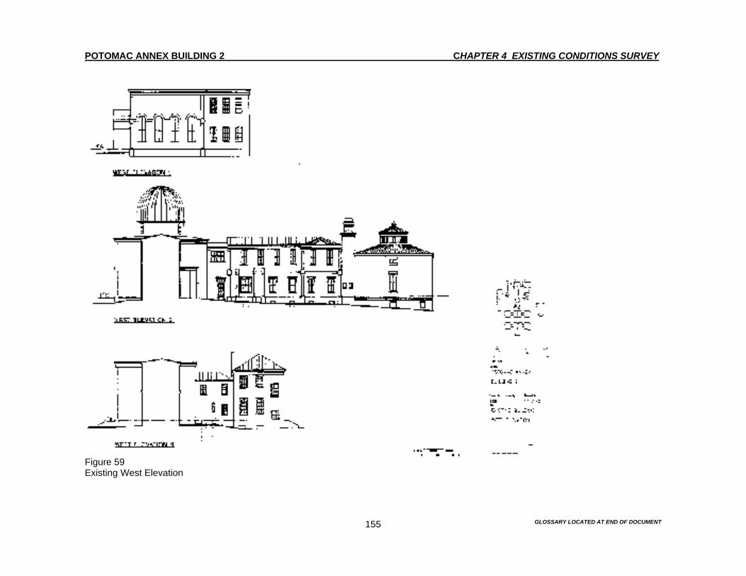
POTOMAC ANNEX BUILDING 2 CHAPTER 4 EXISTING CONDITIONS SURVEY
GLOSSARY LOCATED AT END OF DOCUMENT 155
Figure 59 Existing West Elevation
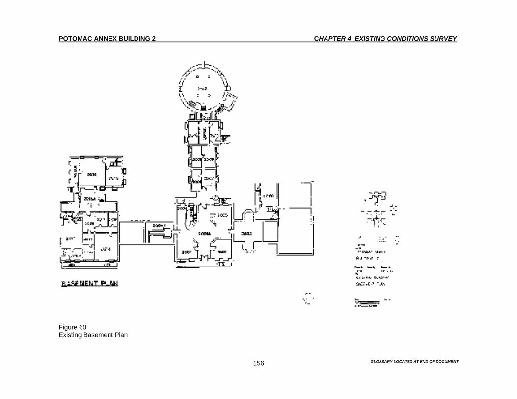
POTOMAC ANNEX BUILDING 2 CHAPTER 4 EXISTING CONDITIONS SURVEY
GLOSSARY LOCATED AT END OF DOCUMENT 156
Figure 60 Existing Basement Plan

POTOMAC ANNEX BUILDING 2 CHAPTER 4 EXISTING CONDITIONS SURVEY
GLOSSARY LOCATED AT END OF DOCUMENT 157
Figure 61 Existing First Floor Plan
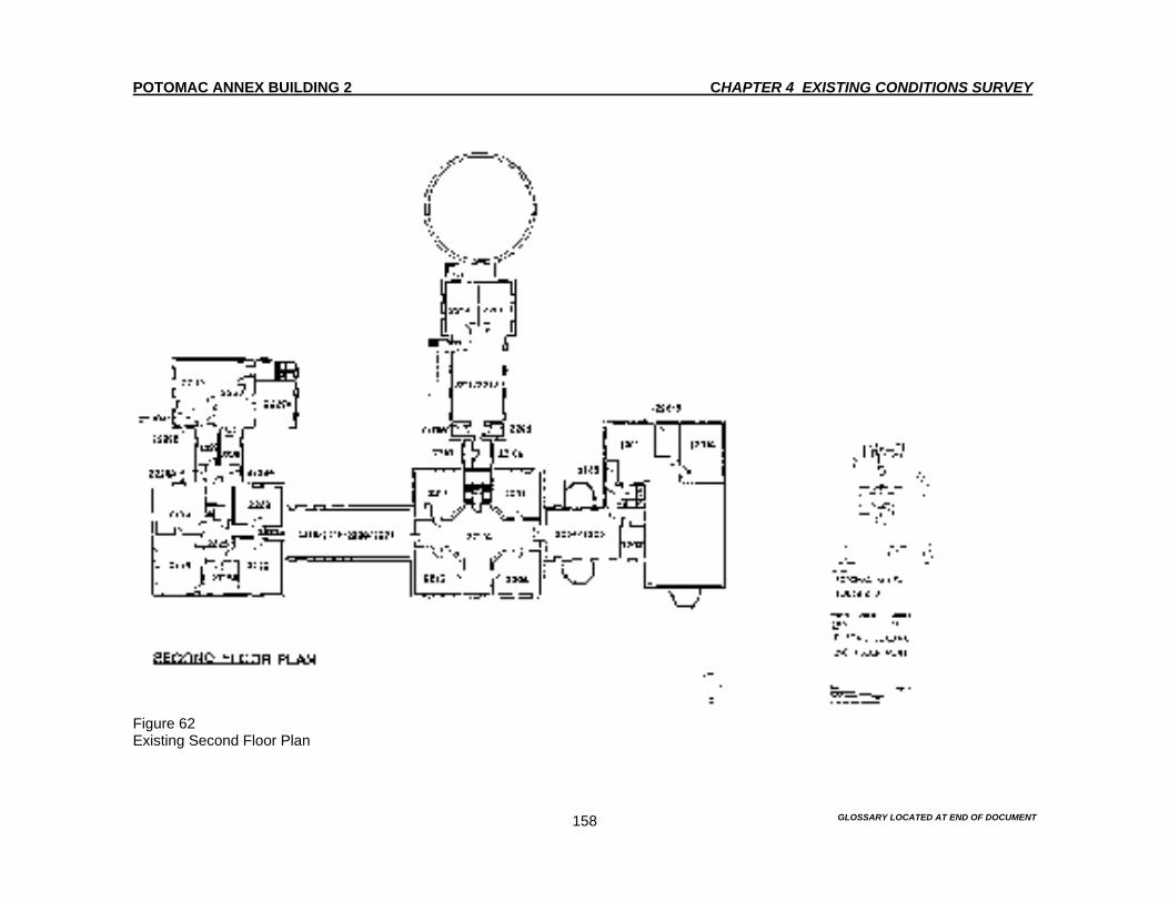
POTOMAC ANNEX BUILDING 2 CHAPTER 4 EXISTING CONDITIONS SURVEY
GLOSSARY LOCATED AT END OF DOCUMENT 158
Figure 62 Existing Second Floor Plan

POTOMAC ANNEX BUILDING 2 CHAPTER 4 EXISTING CONDITIONS SURVEY
GLOSSARY LOCATED AT END OF DOCUMENT 159
Figure 63 Old Naval Observatory (1844) North Elevation, including view of the Old Naval Observatory and its west wing.
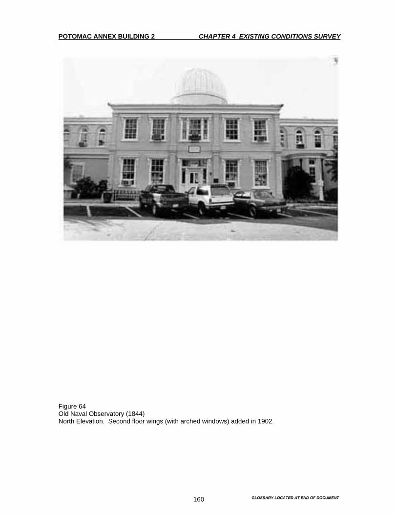
POTOMAC ANNEX BUILDING 2 CHAPTER 4 EXISTING CONDITIONS SURVEY
GLOSSARY LOCATED AT END OF DOCUMENT 160
Figure 64 Old Naval Observatory (1844) North Elevation. Second floor wings (with arched windows) added in 1902.
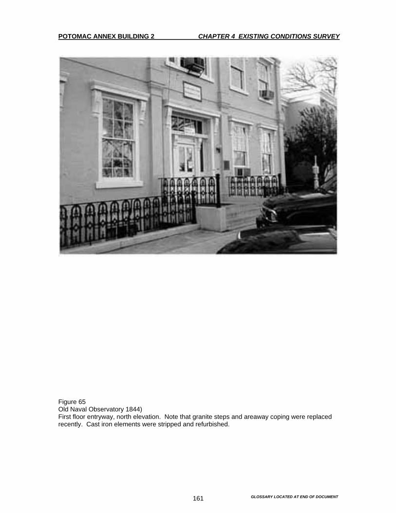
POTOMAC ANNEX BUILDING 2 CHAPTER 4 EXISTING CONDITIONS SURVEY
GLOSSARY LOCATED AT END OF DOCUMENT 161
Figure 65 Old Naval Observatory 1844) First floor entryway, north elevation. Note that granite steps and areaway coping were replaced recently. Cast iron elements were stripped and refurbished.

POTOMAC ANNEX BUILDING 2 CHAPTER 4 EXISTING CONDITIONS SURVEY
GLOSSARY LOCATED AT END OF DOCUMENT 162
Figure 66 Old Naval Observatory (1844) North Elevation. Detail of cast iron fence and areaway.
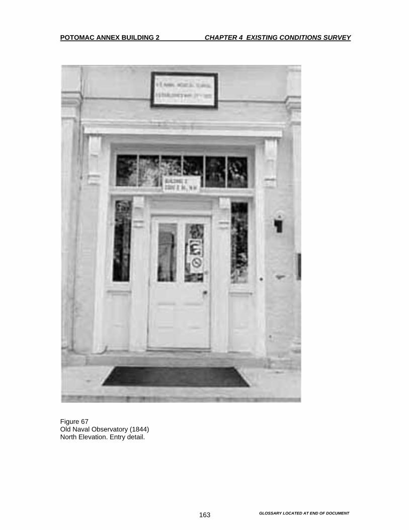
POTOMAC ANNEX BUILDING 2 CHAPTER 4 EXISTING CONDITIONS SURVEY
GLOSSARY LOCATED AT END OF DOCUMENT 163
Figure 67 Old Naval Observatory (1844) North Elevation. Entry detail.

POTOMAC ANNEX BUILDING 2 CHAPTER 4 EXISTING CONDITIONS SURVEY
GLOSSARY LOCATED AT END OF DOCUMENT 164
Figure 68 Old Naval Observatory (1844) Severe masonry deterioration on brick pier at northeast corner.
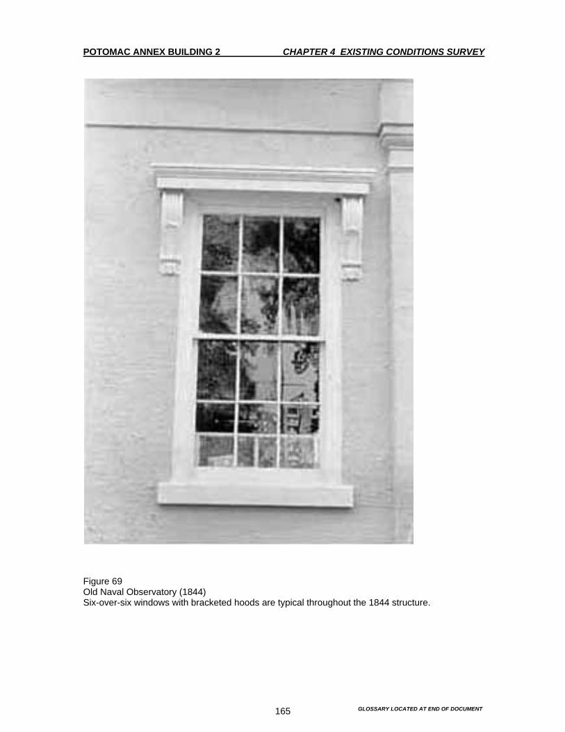
POTOMAC ANNEX BUILDING 2 CHAPTER 4 EXISTING CONDITIONS SURVEY
GLOSSARY LOCATED AT END OF DOCUMENT 165
Figure 69 Old Naval Observatory (1844) Six-over-six windows with bracketed hoods are typical throughout the 1844 structure.

POTOMAC ANNEX BUILDING 2 CHAPTER 4 EXISTING CONDITIONS SURVEY
GLOSSARY LOCATED AT END OF DOCUMENT 166
Figure 70 Old Naval Observatory (1844) Detail of bracketed window hood. This decorative detail was repeated in later additions.

POTOMAC ANNEX BUILDING 2 CHAPTER 4 EXISTING CONDITIONS SURVEY
GLOSSARY LOCATED AT END OF DOCUMENT 167
Figure 71 Old Naval Observatory (1844) West transit wing with 1864 semi-octagonal bay. Second story added in 1902.
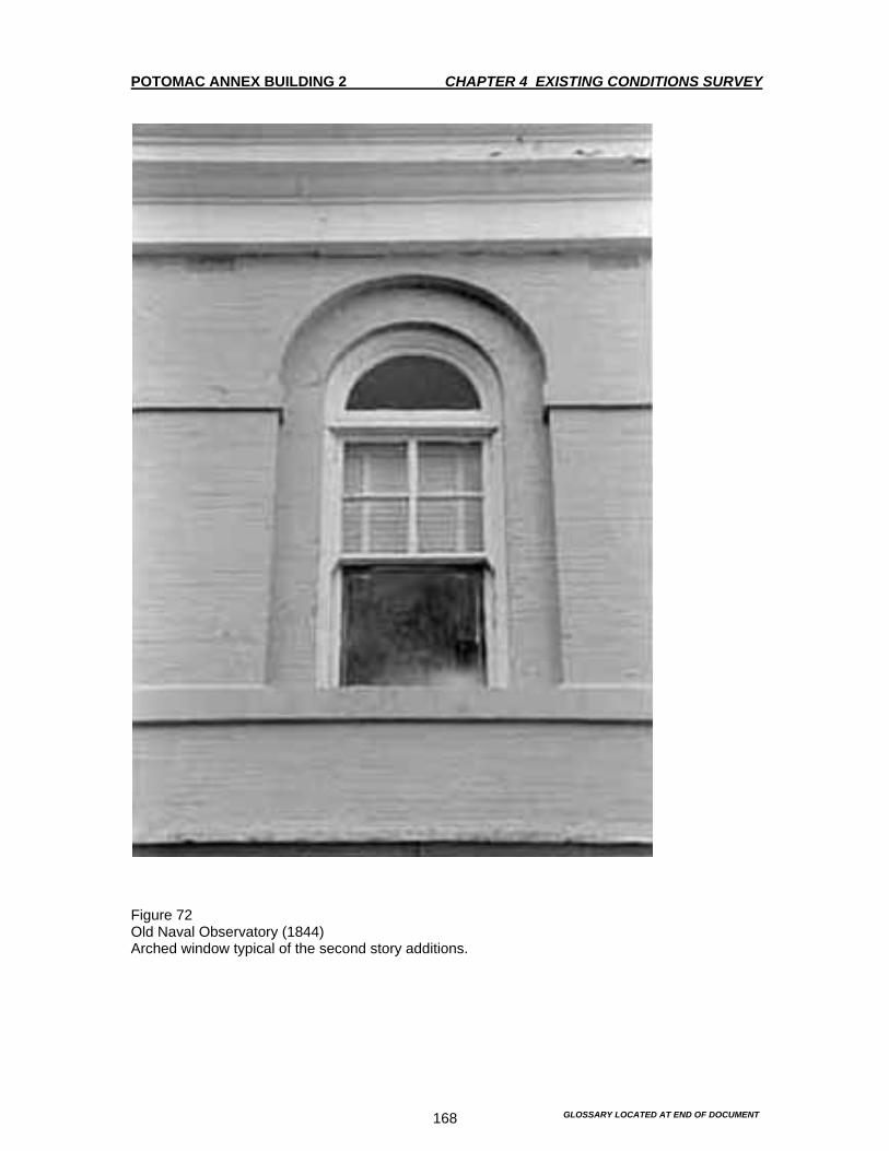
POTOMAC ANNEX BUILDING 2 CHAPTER 4 EXISTING CONDITIONS SURVEY
GLOSSARY LOCATED AT END OF DOCUMENT 168
Figure 72 Old Naval Observatory (1844) Arched window typical of the second story additions.

POTOMAC ANNEX BUILDING 2 CHAPTER 4 EXISTING CONDITIONS SURVEY
GLOSSARY LOCATED AT END OF DOCUMENT 169
Figure 73 Old Naval Observatory 1844) National Historic Landmark Plaque, located to the right of the main entrance.

POTOMAC ANNEX BUILDING 2 CHAPTER 4 EXISTING CONDITIONS SURVEY
GLOSSARY LOCATED AT END OF DOCUMENT 170
Figure 74 Old Naval Observatory (1844) West transit wing detail showing 1864 semi-octagonal bay.
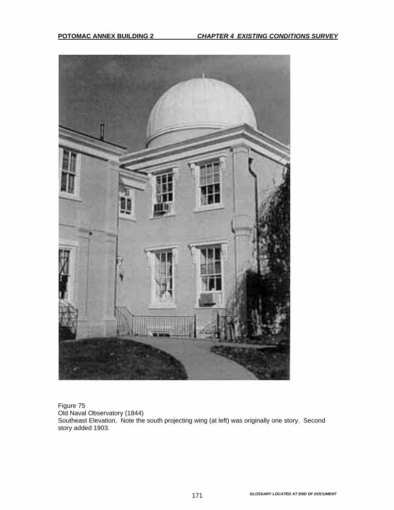
POTOMAC ANNEX BUILDING 2 CHAPTER 4 EXISTING CONDITIONS SURVEY
GLOSSARY LOCATED AT END OF DOCUMENT 171
Figure 75 Old Naval Observatory (1844) Southeast Elevation. Note the south projecting wing (at left) was originally one story. Second story added 1903.
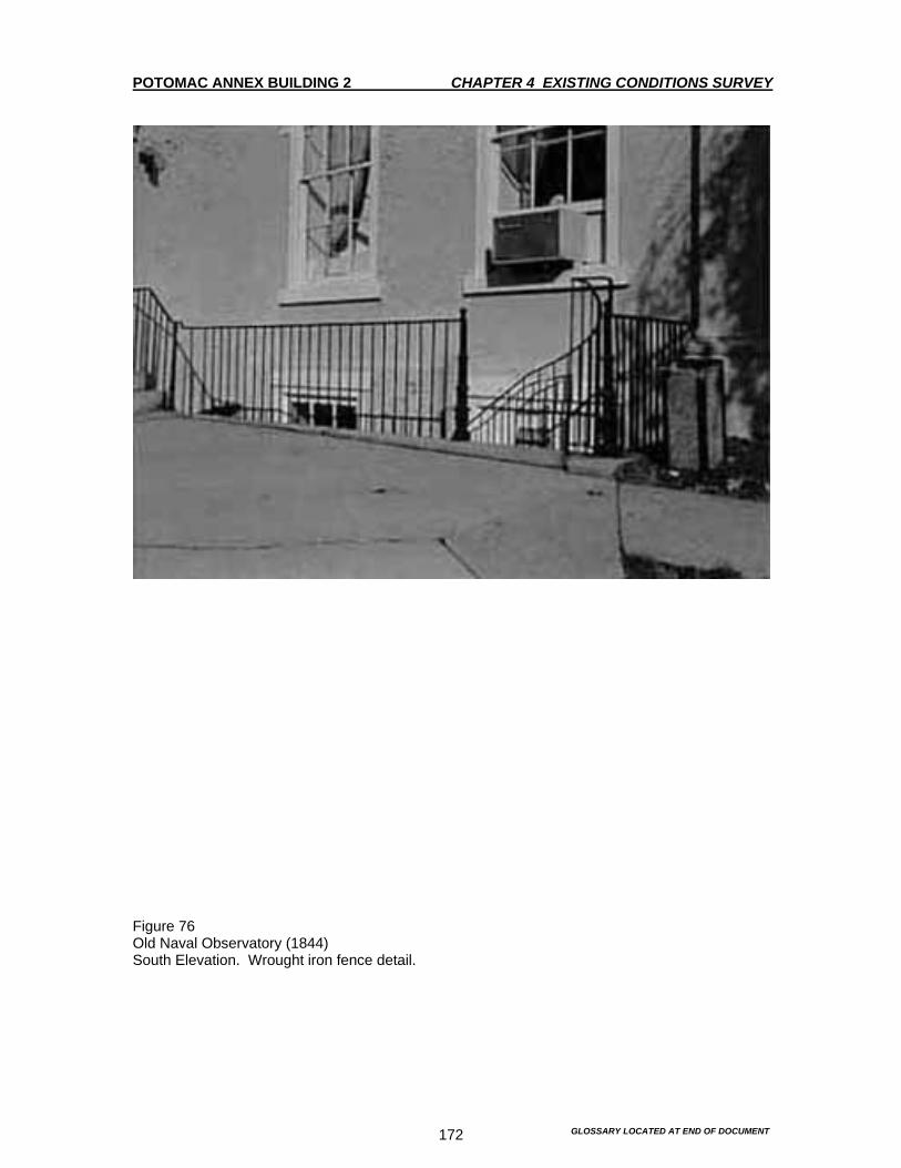
POTOMAC ANNEX BUILDING 2 CHAPTER 4 EXISTING CONDITIONS SURVEY
GLOSSARY LOCATED AT END OF DOCUMENT 172
Figure 76 Old Naval Observatory (1844) South Elevation. Wrought iron fence detail.

POTOMAC ANNEX BUILDING 2 CHAPTER 4 EXISTING CONDITIONS SURVEY
GLOSSARY LOCATED AT END OF DOCUMENT 173
Figure 77 Old Naval Observatory (1844) South Elevation. Wood toilet addition ca. 1920.

POTOMAC ANNEX BUILDING 2 CHAPTER 4 EXISTING CONDITIONS SURVEY
GLOSSARY LOCATED AT END OF DOCUMENT 174
Figure 78 Old Naval Observatory (1844) Southwest Elevation. West wing semi-octagonal bay constructed in 1864. Original south wing ended at southernmost pilaster. Note the paint was being stripped during survey work in August of 1994.

POTOMAC ANNEX BUILDING 2 CHAPTER 4 EXISTING CONDITIONS SURVEY
GLOSSARY LOCATED AT END OF DOCUMENT 175
Figure 79 Old Naval Observatory (1844) View of dome and drum from the north. Dome cladding is painted copper.
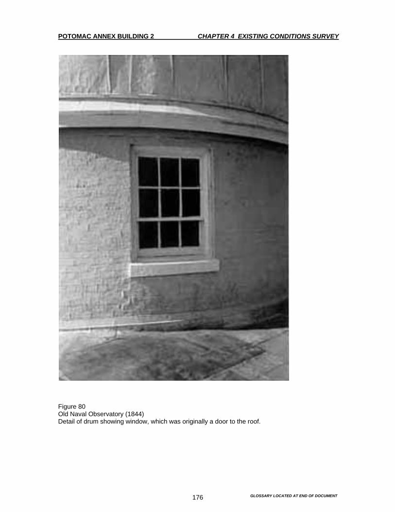
POTOMAC ANNEX BUILDING 2 CHAPTER 4 EXISTING CONDITIONS SURVEY
GLOSSARY LOCATED AT END OF DOCUMENT 176
Figure 80 Old Naval Observatory (1844) Detail of drum showing window, which was originally a door to the roof.

POTOMAC ANNEX BUILDING 2 CHAPTER 4 EXISTING CONDITIONS SURVEY
GLOSSARY LOCATED AT END OF DOCUMENT 177
Figure 81 Old Naval Observatory (1844) View of dome and drum from southwest corner of roof.

POTOMAC ANNEX BUILDING 2 CHAPTER 4 EXISTING CONDITIONS SURVEY
GLOSSARY LOCATED AT END OF DOCUMENT 178
Figure 82 Old Naval Observatory (1844) Water accumulation on roof, northwest corner. Standing water on roof is a problem typical throughout the site and may be caused by clogged drains, gutter, downspouts, etc. due to lack of maintenance.
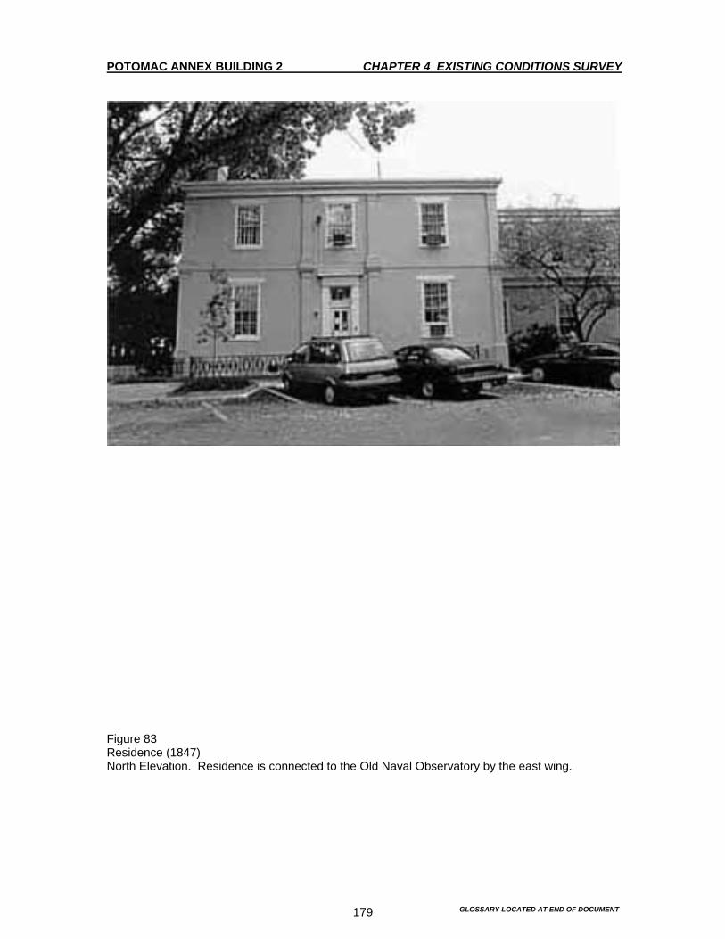
POTOMAC ANNEX BUILDING 2 CHAPTER 4 EXISTING CONDITIONS SURVEY
GLOSSARY LOCATED AT END OF DOCUMENT 179
Figure 83 Residence (1847) North Elevation. Residence is connected to the Old Naval Observatory by the east wing.

POTOMAC ANNEX BUILDING 2 CHAPTER 4 EXISTING CONDITIONS SURVEY
GLOSSARY LOCATED AT END OF DOCUMENT 180
Figure 84 Residence (1847) North Elevation entry.

POTOMAC ANNEX BUILDING 2 CHAPTER 4 EXISTING CONDITIONS SURVEY
GLOSSARY LOCATED AT END OF DOCUMENT 181
Figure 85 Residence (1847) North Elevation entry. Red sandstone steps and coping were recently replaced in kind. Wrought and cast iron elements were stripped, painted, and refurbished.

POTOMAC ANNEX BUILDING 2 CHAPTER 4 EXISTING CONDITIONS SURVEY
GLOSSARY LOCATED AT END OF DOCUMENT 182
Figure 86 Residence (1847) North Elevation. View of areaway.

POTOMAC ANNEX BUILDING 2 CHAPTER 4 EXISTING CONDITIONS SURVEY
GLOSSARY LOCATED AT END OF DOCUMENT 183
Figure 87 Residence (1847) Six-over-six windows with sandstone lintels and sills typical throughout the residence.
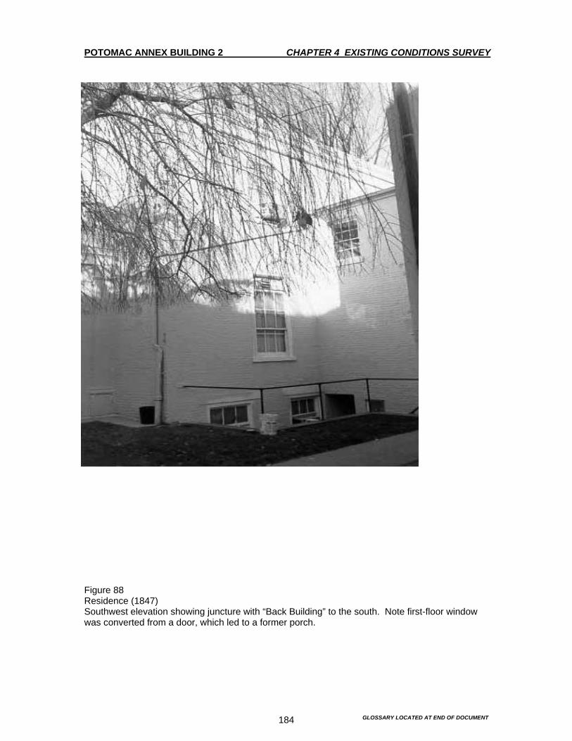
POTOMAC ANNEX BUILDING 2 CHAPTER 4 EXISTING CONDITIONS SURVEY
GLOSSARY LOCATED AT END OF DOCUMENT 184
Figure 88 Residence (1847) Southwest elevation showing juncture with “Back Building” to the south. Note first-floor window was converted from a door, which led to a former porch.
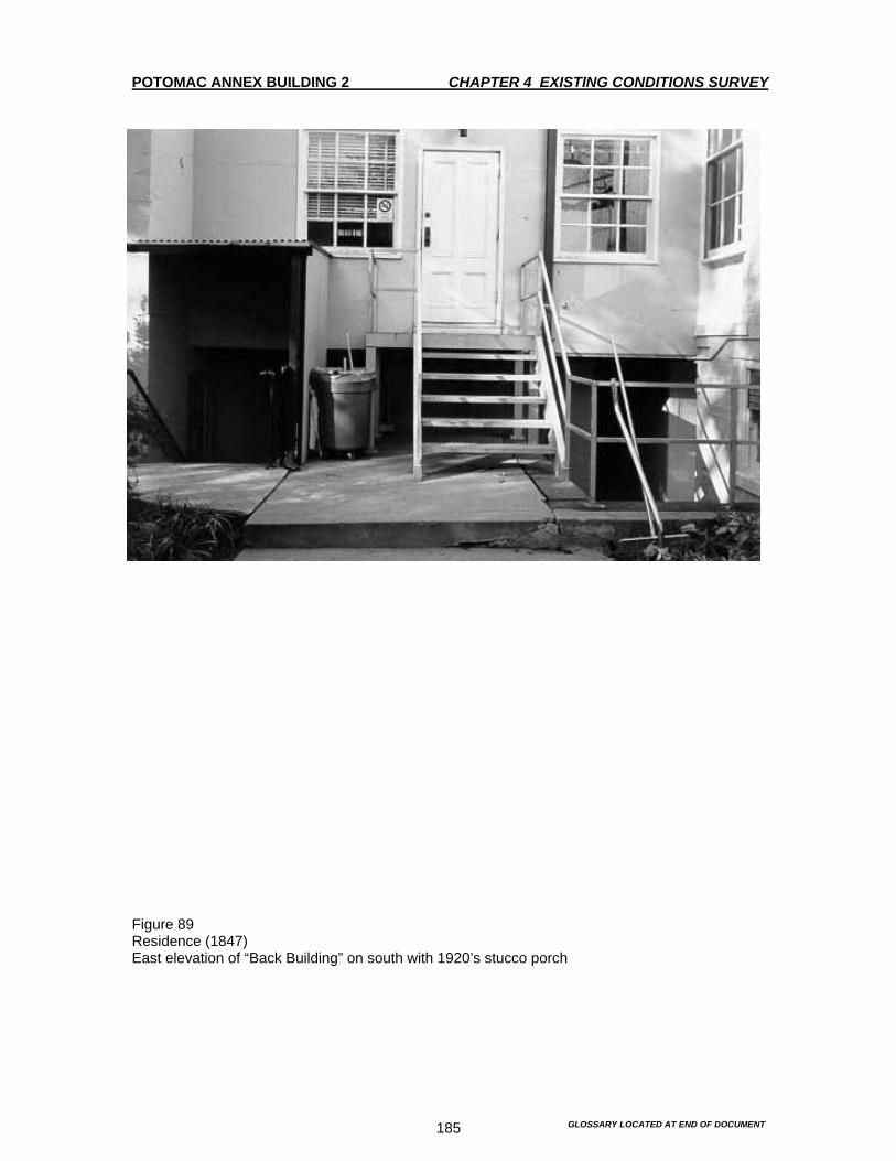
POTOMAC ANNEX BUILDING 2 CHAPTER 4 EXISTING CONDITIONS SURVEY
GLOSSARY LOCATED AT END OF DOCUMENT 185
Figure 89 Residence (1847) East elevation of “Back Building” on south with 1920’s stucco porch

POTOMAC ANNEX BUILDING 2 CHAPTER 4 EXISTING CONDITIONS SURVEY
GLOSSARY LOCATED AT END OF DOCUMENT 186
Figure 90 Residence (1847) View through passageway under “Back Building”. Granite lintel, which supports structure above, is cracked.

POTOMAC ANNEX BUILDING 2 CHAPTER 4 EXISTING CONDITIONS SURVEY
GLOSSARY LOCATED AT END OF DOCUMENT 187
Figure 91 Residence (1847) Residence Southeast Elevation. Window was converted from a door, which led to a former porch. Note ghosts in brick above window lintel.

POTOMAC ANNEX BUILDING 2 CHAPTER 4 EXISTING CONDITIONS SURVEY
GLOSSARY LOCATED AT END OF DOCUMENT 188
Figure 92 Residence (1847) Skylight on roof.
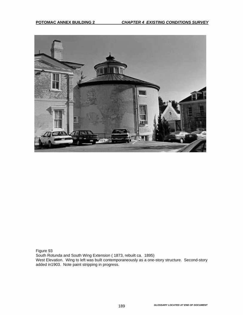
POTOMAC ANNEX BUILDING 2 CHAPTER 4 EXISTING CONDITIONS SURVEY
GLOSSARY LOCATED AT END OF DOCUMENT 189
Figure 93 South Rotunda and South Wing Extension ( 1873, rebuilt ca. 1895) West Elevation. Wing to left was built contemporaneously as a one-story structure. Second-story added in1903. Note paint stripping in progress.
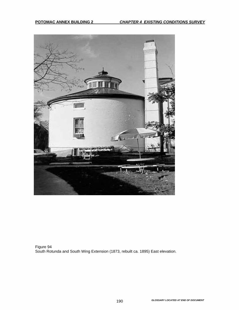
POTOMAC ANNEX BUILDING 2 CHAPTER 4 EXISTING CONDITIONS SURVEY
GLOSSARY LOCATED AT END OF DOCUMENT 190
Figure 94 South Rotunda and South Wing Extension (1873, rebuilt ca. 1895) East elevation.

POTOMAC ANNEX BUILDING 2 CHAPTER 4 EXISTING CONDITIONS SURVEY
GLOSSARY LOCATED AT END OF DOCUMENT 191
Figure 95 South Rotunda (1873, rebuilt ca. 1895) Entry to vault. No longer in use.
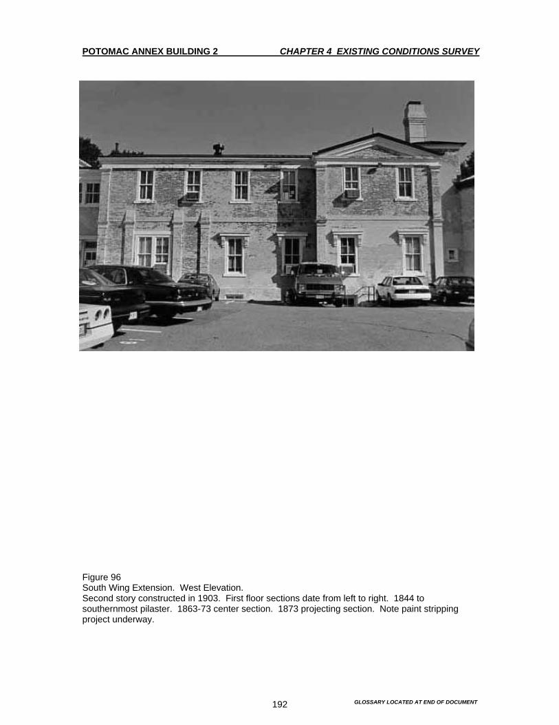
POTOMAC ANNEX BUILDING 2 CHAPTER 4 EXISTING CONDITIONS SURVEY
GLOSSARY LOCATED AT END OF DOCUMENT 192
Figure 96 South Wing Extension. West Elevation. Second story constructed in 1903. First floor sections date from left to right. 1844 to southernmost pilaster. 1863-73 center section. 1873 projecting section. Note paint stripping project underway.

POTOMAC ANNEX BUILDING 2 CHAPTER 4 EXISTING CONDITIONS SURVEY
GLOSSARY LOCATED AT END OF DOCUMENT 193
Figure 97 South Wing Extension Second story constructed in 1903. Sections date from right to left. 1844 to southernmost pilaster. 1863-73 center section. 1873 projecting section. Note the entry and window openings in 1873 section are original.
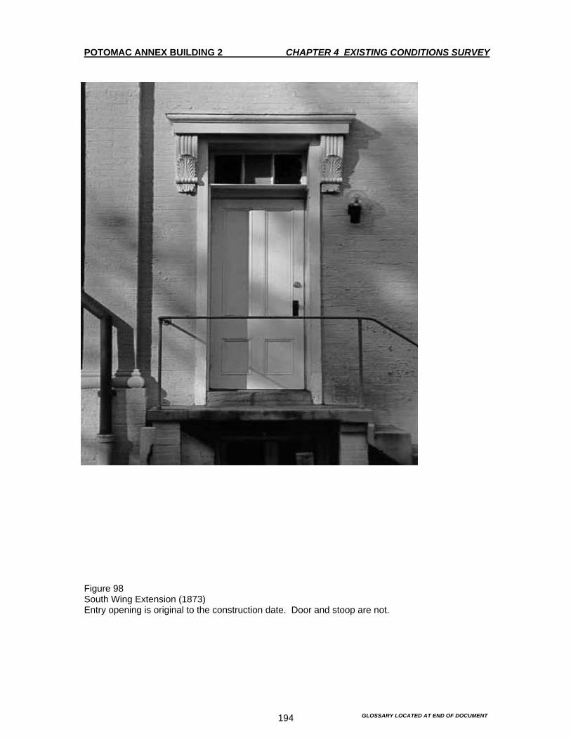
POTOMAC ANNEX BUILDING 2 CHAPTER 4 EXISTING CONDITIONS SURVEY
GLOSSARY LOCATED AT END OF DOCUMENT 194
Figure 98 South Wing Extension (1873) Entry opening is original to the construction date. Door and stoop are not.

POTOMAC ANNEX BUILDING 2 CHAPTER 4 EXISTING CONDITIONS SURVEY
GLOSSARY LOCATED AT END OF DOCUMENT 195
Figure 99 West Wing Addition (1869, rebuilt ca. 1895) North Elevation. Detail of projecting vestibule, which was converted from an open portico (date unknown).
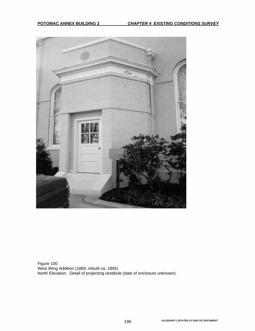
POTOMAC ANNEX BUILDING 2 CHAPTER 4 EXISTING CONDITIONS SURVEY
GLOSSARY LOCATED AT END OF DOCUMENT 196
Figure 100 West Wing Addition (1869, rebuilt ca. 1895) North Elevation. Detail of projecting vestibule (date of enclosure unknown).
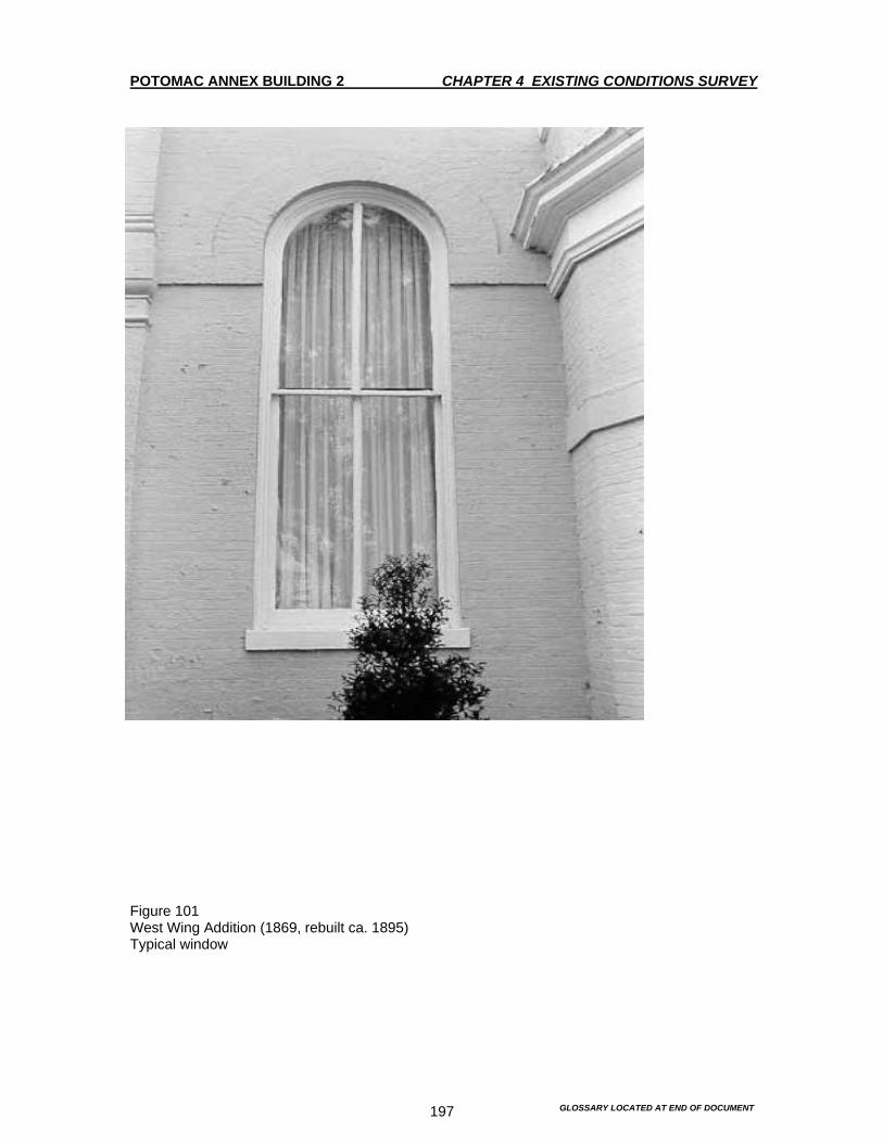
POTOMAC ANNEX BUILDING 2 CHAPTER 4 EXISTING CONDITIONS SURVEY
GLOSSARY LOCATED AT END OF DOCUMENT 197
Figure 101 West Wing Addition (1869, rebuilt ca. 1895) Typical window

POTOMAC ANNEX BUILDING 2 CHAPTER 4 EXISTING CONDITIONS SURVEY
GLOSSARY LOCATED AT END OF DOCUMENT 198
Figure 102 West Wing Addition (1869, rebuilt ca. 1895) West Elevation. Structure to right is the west stucco addition (1918).
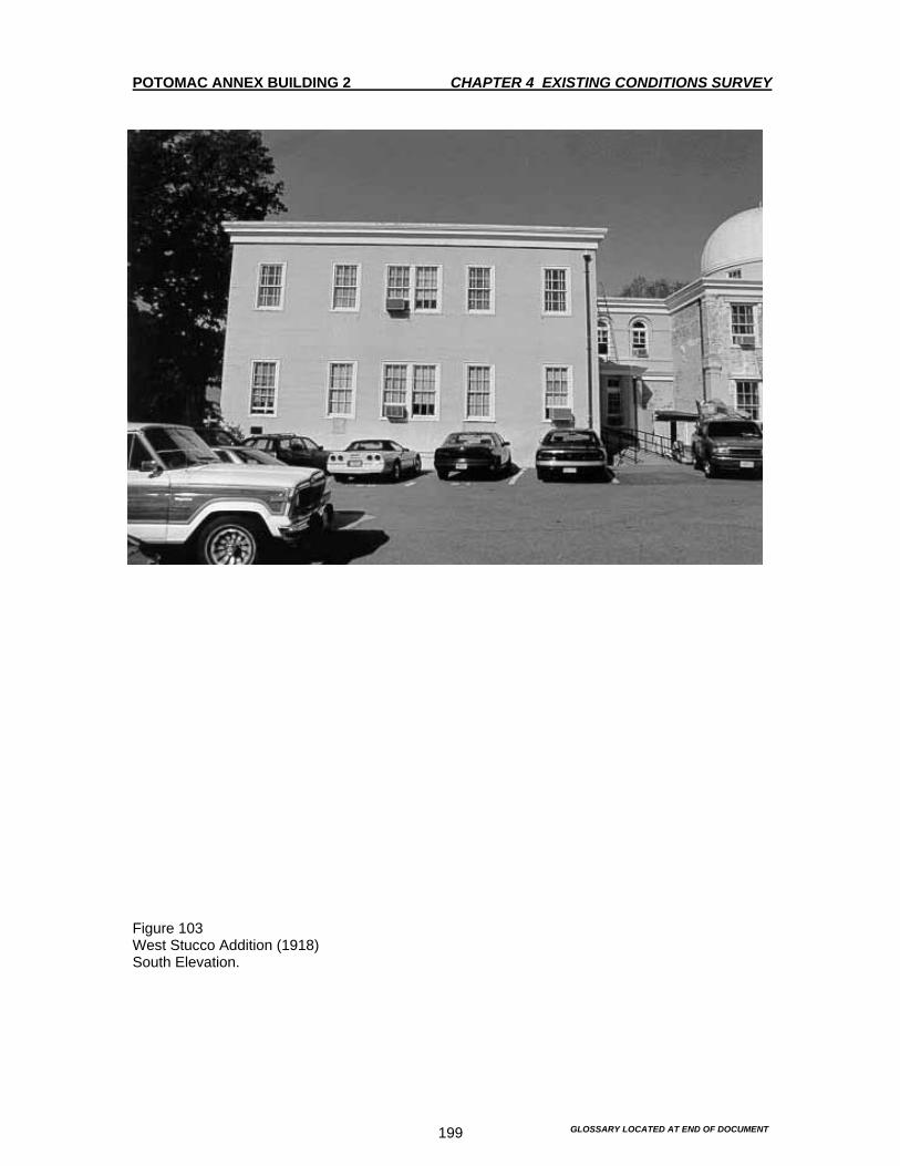
POTOMAC ANNEX BUILDING 2 CHAPTER 4 EXISTING CONDITIONS SURVEY
GLOSSARY LOCATED AT END OF DOCUMENT 199
Figure 103 West Stucco Addition (1918) South Elevation.
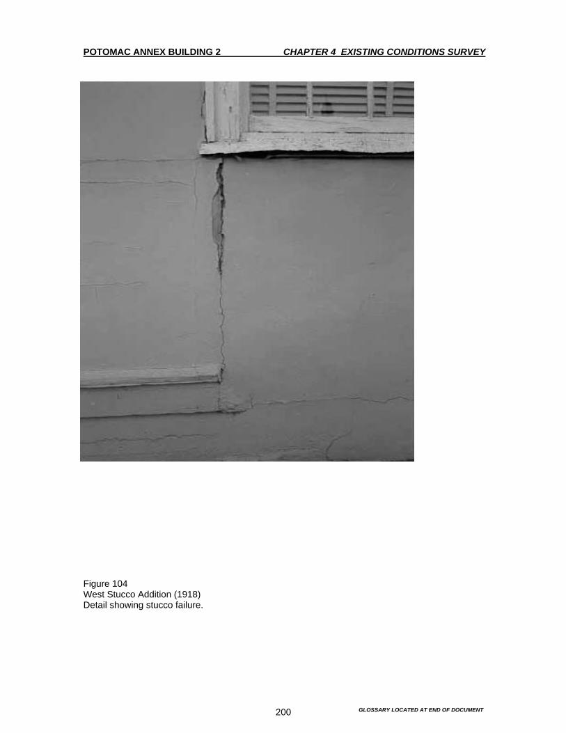
POTOMAC ANNEX BUILDING 2 CHAPTER 4 EXISTING CONDITIONS SURVEY
GLOSSARY LOCATED AT END OF DOCUMENT 200
Figure 104 West Stucco Addition (1918) Detail showing stucco failure.

POTOMAC ANNEX BUILDING 2 CHAPTER 4 EXISTING CONDITIONS SURVEY
GLOSSARY LOCATED AT END OF DOCUMENT 201
Figure 105 West Stucco Addition (1918) Window AC installation. Wall – mounted brackets and Plexiglas panels are typical of such installations throughout the building.

POTOMAC ANNEX BUILDING 2 CHAPTER 4 EXISTING CONDITIONS SURVEY
GLOSSARY LOCATED AT END OF DOCUMENT 202
Figure 106 East Stucco Addition (1918) South elevation.

POTOMAC ANNEX BUILDING 2 CHAPTER 4 EXISTING CONDITIONS SURVEY
GLOSSARY LOCATED AT END OF DOCUMENT 203
Figure 107 East Stucco Addition (1918) Entry detail.

POTOMAC ANNEX BUILDING 2 CHAPTER 4 EXISTING CONDITIONS SURVEY
GLOSSARY LOCATED AT END OF DOCUMENT 204
Figure 108 East Stucco Addition (1918) Entry stoop showing masonry failure

POTOMAC ANNEX BUILDING 2 CHAPTER 4 EXISTING CONDITIONS SURVEY
GLOSSARY LOCATED AT END OF DOCUMENT 205
Figure 109 Views to the northeast taken from roof of Building 2, showing extended parking area in front of the buliding. Also shown are mature trees and sculpture of Benjamin Rush.

POTOMAC ANNEX BUILDING 2 CHAPTER 4 EXISTING CONDITIONS SURVEY
GLOSSARY LOCATED AT END OF DOCUMENT 206
Figure 110 View to the northwest taken from the roof of Building 2 showing extensive parking area in front of the building. Also shown are mature trees and sculpture of Benjamin Rush.

POTOMAC ANNEX BUILDING 2 CHAPTER 4 EXISTING CONDITIONS SURVEY
GLOSSARY LOCATED AT END OF DOCUMENT 207
Figure 111 View to the southeast from roof showing small lawn area with concrete patch next to Building 2. Intrusive stockade fence cordons off the garden associated with one of the residences (not subject of the HSR). Note the driveway at upper right corner, which is part of extensive drive and parking area at the rear of the site.
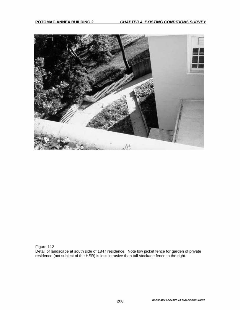
POTOMAC ANNEX BUILDING 2 CHAPTER 4 EXISTING CONDITIONS SURVEY
GLOSSARY LOCATED AT END OF DOCUMENT 208
Figure 112 Detail of landscape at south side of 1847 residence. Note low picket fence for garden of private residence (not subject of the HSR) is less intrusive than tall stockade fence to the right.
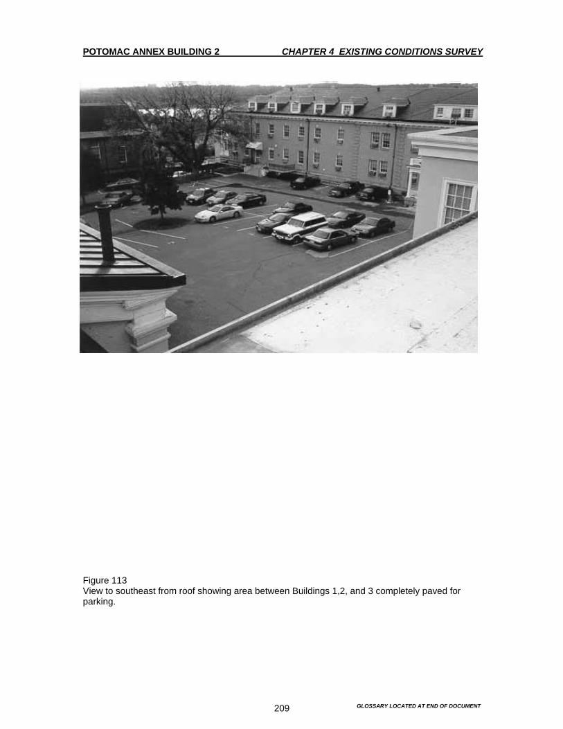
POTOMAC ANNEX BUILDING 2 CHAPTER 4 EXISTING CONDITIONS SURVEY
GLOSSARY LOCATED AT END OF DOCUMENT 209
Figure 113 View to southeast from roof showing area between Buildings 1,2, and 3 completely paved for parking.

POTOMAC ANNEX BUILDING 2 CHAPTER 4 EXISTING CONDITIONS SURVEY
GLOSSARY LOCATED AT END OF DOCUMENT 210
Figure 114 View to the east showing residence Building A at east-end of site (not subject of this HSR).

POTOMAC ANNEX BUILDING 2 CHAPTER 4 EXISTING CONDITIONS SURVEY
GLOSSARY LOCATED AT END OF DOCUMENT 211
Figure 115 View to the west showing residence Building C (not subject of this HSR)

POTOMAC ANNEX BUILDING 2 CHAPTER 4 EXISTING CONDITIONS SURVEY
GLOSSARY LOCATED AT END OF DOCUMENT 212
Figure 116 View to north. Sculpture of Benjamin Rush in foreground, flagstaff behind.

POTOMAC ANNEX BUILDING 2 CHAPTER 4 EXISTING CONDITIONS SURVEY
GLOSSARY LOCATED AT END OF DOCUMENT 213
Figure 117 View to southeast showing residence building B (not part of this HSR). Note picket fence separating this garden from the rest of the site. Note Cast-iron light pole left of center.

POTOMAC ANNEX BUILDING 2 CHAPTER 4 EXISTING CONDITIONS SURVEY
GLOSSARY LOCATED AT END OF DOCUMENT 214
Figure 118 Cast iron light post (date unknown) located on the site of Residence C (not part of this HSR).

POTOMAC ANNEX BUILDING 2 CHAPTER 4 EXISTING CONDITIONS SURVEY
GLOSSARY LOCATED AT END OF DOCUMENT 215
Figure 119 Typical stone retaining wall.

POTOMAC ANNEX BUILDING 2 CHAPTER 4 EXISTING CONDITIONS SURVEY
GLOSSARY LOCATED AT END OF DOCUMENT 216
Figure 120 Typical concrete retaining wall.

POTOMAC ANNEX BUILDING 2 CHAPTER 4 EXISTING CONDITIONS SURVEY
GLOSSARY LOCATED AT END OF DOCUMENT 217
Figure 121 View looking northwest showing retaining wall overlooking E Street.

POTOMAC ANNEX BUILDING 2 CHAPTER 4 EXISTING CONDITIONS SURVEY
GLOSSARY LOCATED AT END OF DOCUMENT 218
Figure 122 View of the site from the northeast showing retaining wall over E Street.

POTOMAC ANNEX BUILDING 2 CHAPTER 4 EXISTING CONDITIONS SURVEY
GLOSSARY LOCATED AT END OF DOCUMENT 219
Figure 123 View into the site from the southeast. Building 6 is in the right foreground. Note obtrusive paving areas and chain link fences.

POTOMAC ANNEX BUILDING 2 CHAPTER 4 EXISTING CONDITIONS SURVEY
GLOSSARY LOCATED AT END OF DOCUMENT 220
Figure 124 View into the site from the northeast. Note concrete retaining wall and chain link fence along 23rd
Street.
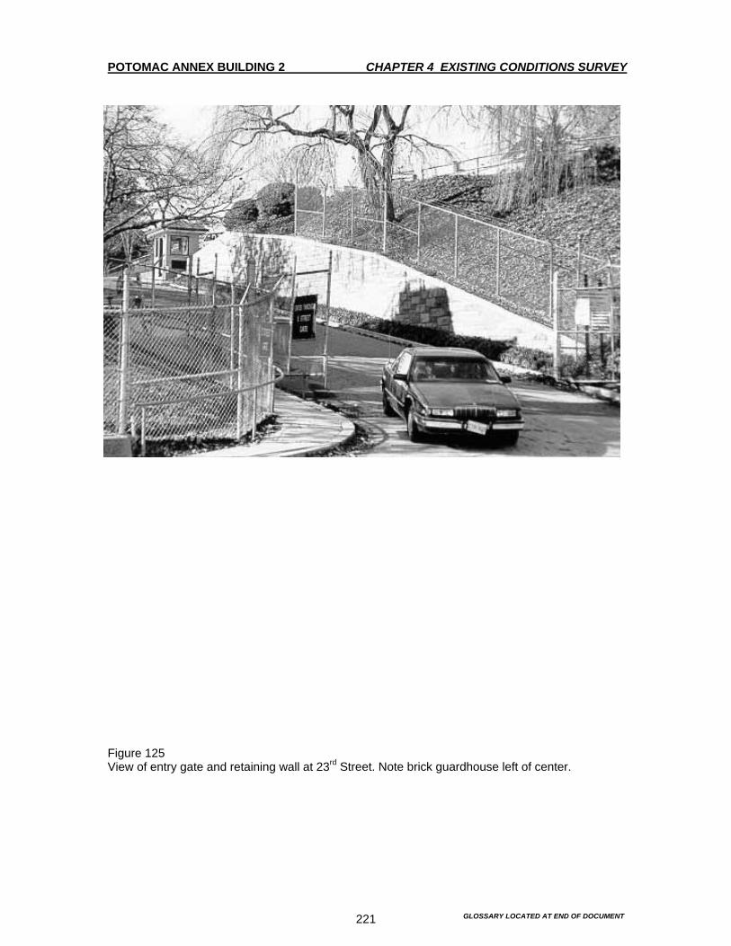
POTOMAC ANNEX BUILDING 2 CHAPTER 4 EXISTING CONDITIONS SURVEY
GLOSSARY LOCATED AT END OF DOCUMENT 221
Figure 125 View of entry gate and retaining wall at 23rd Street. Note brick guardhouse left of center.

POTOMAC ANNEX BUILDING 2 CHAPTER 4 EXISTING CONDITIONS SURVEY
GLOSSARY LOCATED AT END OF DOCUMENT 222
Figure 126 View to west showing building on adjacent CIA property.
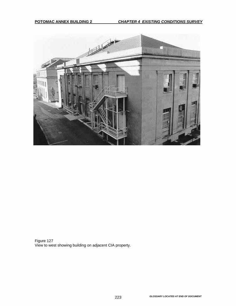
POTOMAC ANNEX BUILDING 2 CHAPTER 4 EXISTING CONDITIONS SURVEY
GLOSSARY LOCATED AT END OF DOCUMENT 223
Figure 127 View to west showing building on adjacent CIA property.

POTOMAC ANNEX BUILDING 2 CHAPTER 4 EXISTING CONDITIONS SURVEY
GLOSSARY LOCATED AT END OF DOCUMENT 224
Figure 128 First Floor Plan – Photo Locations
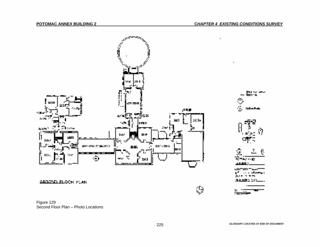
POTOMAC ANNEX BUILDING 2 CHAPTER 4 EXISTING CONDITIONS SURVEY
GLOSSARY LOCATED AT END OF DOCUMENT 225
Figure 129 Second Floor Plan – Photo Locations

POTOMAC ANNEX BUILDING 2 CHAPTER 4 EXISTING CONDITIONS SURVEY
GLOSSARY LOCATED AT END OF DOCUMENT 226
Figure 130 Roof Plan – Photo Locations

POTOMAC ANNEX BUILDING 2 CHAPTER 4 EXISTING CONDITIONS SURVEY
GLOSSARY LOCATED AT END OF DOCUMENT 227
Figure 131 Site Plan – Photo Locations
POTOMAC ANNEX BUILDING 2 CHAPTER 4 EXISTING CONDITION SURVEY
GLOSSARY LOCATED AT END OF DOCUMENT 228
INTERIOR 1844 Old Naval Observatory General Notes For detailed descriptions of the doors, please see the door survey that was conducted by Peck, Peck and Architrave in 1993, GSA Report RDC 28168. For the windows, please refer to the Water Leakage Study conducted by Peck, Peck and Architrave completed in December 7, 1993, GSA Report RDC 24102 Doors are generally treated as features of the corridors, not of the interior of the rooms. Doorframes in the interior of the rooms are identical to the window frames, unless otherwise notes. The sprinkler system was installed in 1988. Most of the sprinklers were installed in such a manner that they did not impact or cut through the decorative pressed metal ceilings. Throughout the survey, the follow abbreviations are employed. WC Water Closet F&LS Fire and Life Safety HVAC Heating Ventilation and Air Conditioning First Floor The square plan of the first floor is divided symmetrically into four quadrants by a cross-shaped corridor, which is flanked by wings on the east, west and south. Each quadrant represents a single room in its original configuration. Arched openings lead from the central core to the radiating wings on the east, west and south side. Historic documentation suggests that the arches date to 1895. However all the arched openings have been partially filled by intrusive partition walls and doorways, which compromise the architectural integrity of the arches and spaces, Figures 138, 146 and 147. The metal ceilings throughout this section of the building probable date to the alterations made by the Naval Museum of Hygiene and the Naval Medical School. The following discussion is presented in the order of Central Core, West Wing, East Wing, and South Wing. Room 2108 - Main Lobby Figures 132-139 The stone supporting pier for the 9.6 inch Equatorial Telescope, which rose up from the basement through to the second floor originally occupied this roughly circular room. The pier was removed and flooring installed during the Museum of Hygiene period, 1894. Currently, the space is used as the main lobby and circulation corridor.

POTOMAC ANNEX BUILDING 2 CHAPTER 4 EXISTING CONDITION SURVEY
GLOSSARY LOCATED AT END OF DOCUMENT 229
Staircase Figures 132-135 The central feature of the lobby is a double return stair at the south half of the space. It leads from the first to the second floor. It was constructed as part of the Naval Museum of Hygiene alterations in 1894. The stairs, run from the first floor to the first floor landing and follows the curve of the central wall. From the first landing to the second, the run is straight. A straight run, which is integral with the 1896 stair, originates from the second landing, switches back to the north and leads to the second floor of the central core. The ornamentation of the stair is classical utilizing composite ordered columns to support the landings and egg and dart motifs in the newel posts. The oak newel post handrails and landing pendills are stained and varnished. The turned balustrades are oak, but have been painted white. The open sides of the stringers are painted white and have flat decorative brackets under the treads. The stringers along the wall are grain painted to match the baseboards on the first floor. All grain painted and varnished surfaces were done in 1984. The stairs and risers are covered with blue carpeting. Another straight run originates at the second landing leading to the second story of the south wing. The second story of the south wing was constructed in 1903, so it is likely that this stair run is contemporary with the second story addition. The landing is surfaced with blue wall to wall carpeting. There are three varnished wood steps leading to the south wing. The treads are covered with vinyl. The opening to the south wing has molded trim, which matches the window frames throughout the building. This was probably the original south window for the Old Naval Observatory. Floor The floors are covered with blue wall to wall carpeting. This is a typical treatment throughout the building. The carpets are generally in good condition. However, it is not known what kind of flooring exists under the carpets. It is known that the masonry base for the telescope originally occupied this space. Therefore, the flooring cannot date to the 1843-construction date. Additionally, historic documentation indicates that the flooring throughout the Old Naval Observatory building was replaced with oak parquetry and Georgia pine floors. Baseboards Figure 149 Baseboards are 9” high with simple cyma recta molding. The grain painted finish dates to the past decade. Walls The walls are plaster and some are painted and some are surfaced with a painted canvas. The canvas was probably installed around 1902, since the paint sequences are similar to areas of the building of that date. A simple picture molding runs along the wall approximately 18” from the ceiling. The beaded plaster edges of the arched openings are obscured by paint build-up. Other wise, the walls are in good condition. Ceiling Figures 132-139 The ceiling is painted press metal with a ribbon and egg pattern and dart cornice. It appears to be in good condition.

POTOMAC ANNEX BUILDING 2 CHAPTER 4 EXISTING CONDITION SURVEY
GLOSSARY LOCATED AT END OF DOCUMENT 230
Windows – N/A Doors Figures 136 and 137 The office doors are set within 8” molded wood frames with painted jambs. The only historic door in the space is the one entering room 2108. It is a four-panel wood door with steel hinges and an enameled doorknob and metal locks, which has been painted. This type of door is found on the second floor of the Old Naval Observatory and in the Residence. It is likely that most of these doors date to the 1890 alterations. A recent lock and closer have been installed on this door. Lighting Three wall mounted metal box up lights have been installed over the office doors. There is one 1x4 fluorescent light fixture mounted to the stair landing ceiling Built-in features There is a floor standing water fountain outside room 2107. There are typical metal framed wall mounted room numbering signs. A gypsum board vertical riser is located at the southeast corner of the space with stainless steel corner guards. HVAC There are three floor-standing cast-iron radiators with decorative cast iron covers. F&LS Sprinkler heads are mounted on the wall below the ceiling fire alarm pull station and the bell are mounted near the south exit doors. There are two wall-mounted fire extinguishers. Located on the stair landing are wall mounted fire alarm pull station, strobe light and bell and emergency lighting. Entry Vestibule Floor The floors are covered with blue wall to wall carpeting. This is a typical treatment throughout the building. The carpets are generally in good condition. Baseboards The baseboards are 9” high with simple cyma recta molding. The grain painted finish dates to the past decade.

POTOMAC ANNEX BUILDING 2 CHAPTER 4 EXISTING CONDITION SURVEY
GLOSSARY LOCATED AT END OF DOCUMENT 231
Walls The walls are plaster and some are painted and some are surfaced with a painted canvas. A simple picture molding runs along the wall approximately 18” from the ceiling. The wood and glass partition probably dates from the 1890’s. Windows – N/A Lighting – N/A Built-in features – N/A HVAC – N/A F&LS – N/A Room 2107 The southwest quadrant was historically used as the Superintendent’s office. It is currently used as office space. Floor The floors are covered with blue wall to wall carpeting. This is a typical treatment throughout the building. The carpets are in good condition. Baseboards The baseboards along the northwest corner, near the curved wall section, are painted wood 7” high with cyma recta molding. The baseboards along the other walls are 12” steel electrical raceways, Figure 150. Walls The walls are painted plaster. Ceiling The ceiling is painted pressed metal with grid diaper pattern and egg and dart cornice. A section of metal ceiling and cornice in the northwest corner has been cut and poorly re-patched. Windows The window frame is a typical 8” molded frame with a simple wood sill. The wood shutters have been painted shut. There is a window mounted air conditioning unit with Plexiglas panels.

POTOMAC ANNEX BUILDING 2 CHAPTER 4 EXISTING CONDITION SURVEY
GLOSSARY LOCATED AT END OF DOCUMENT 232
Lighting Two metal box up lights are mounted above the doors. Built-in features – N/A HVAC – N/A F&LS Sprinkler piping is mounted to walls. Room 2108 The northwest quadrant was historically used as an office and continues in that use. Floor The floors are covered with blue wall to wall carpeting. This is a typical treatment throughout the building. The carpets are generally in good condition. Baseboards The baseboards along the southeast corner are 9” high with cyma recta molding. The baseboards along the other walls are 12” steel electrical raceways. Walls The walls are painted plaster with a non-original rectangular wood chair rail on the west wall. Ceiling The ceiling is painted pressed metal with coffer pattern and a cove floral cornice. Water damage has caused yellow rust stains at the north wall. Paint is flaking throughout Windows The window frame is a typical 8” molded frame with a simple wood sill. The wood shutters have been painted shut. There is a window mounted air conditioning unit with Plexiglas panels. Lighting Two metal box up lights are mounted above the doors. Built-in features – N/A
POTOMAC ANNEX BUILDING 2 CHAPTER 4 EXISTING CONDITION SURVEY
GLOSSARY LOCATED AT END OF DOCUMENT 233
HVAC There is a painted floor standing cast iron radiator with a cast iron cover. FL&S Sprinkler piping is mounted to the plaster walls Room 2116 The northeast quadrant was historically used as an office and continues in that use. Floor The floors are covered with blue wall to wall carpeting. This is a typical treatment throughout the building. The carpets are generally in good condition. Baseboards The baseboards along the SE corner, near the curved wall section, are painted wood 9” high with cyma recta molding. The baseboards along the other walls are 12” steel electrical raceways. Walls The walls are painted plaster with a picture molding set approximately 18” from the ceiling. Ceiling The ceiling in this room is painted plaster. It is the only room in this quadrant on the first floor without a pressed ceiling. Windows The window frame is a typical 8” molded frame with a simple wood sill. The wood shutters have been painted shut. There is a window mounted air conditioning unit with Plexiglas panels. Lighting Two metal box-up lights are mounted on the walls. Built-in features – N/A HVAC There is a painted floor standing cast-iron radiator between the windows.
POTOMAC ANNEX BUILDING 2 CHAPTER 4 EXISTING CONDITION SURVEY
GLOSSARY LOCATED AT END OF DOCUMENT 234
FL&S Sprinkler piping is mounted to the plaster walls. Room 2117 The southeast quadrant was historically used as a packing room. It is currently used as an office. The original volume has been reduced by the installation of the basement stair, which was probably installed in 1902. A toilet, Room 2117A was added in the middle 1900’s. Floor The floors are covered with blue wall to wall carpeting. This is a typical treatment throughout the building. The carpets are generally in good condition. Baseboards The baseboards along the southeast corner, near the curved wall section, are painted wood 9” high with cyma recta molding. The baseboards along the other walls are 12” steel electrical raceways. Walls The walls are painted plaster. Ceiling The ceiling painted pressed metal with geometrical diaper pattern and egg and dart cornice. Windows The window frame is a typical 8” molded frame with a simple wood sill. The wood shutters have been painted shut. There is a window mounted air conditioning unit with Plexiglas panels. Doors The doors to the bathroom and closet are four-panel wood doors, dating to the middle 1900’s when the features were installed. The bathroom door has a 7” molded casing and the closet casing is 4” wide with no molded trim. Lighting Two metal box-up lights are mounted above the doors.

POTOMAC ANNEX BUILDING 2 CHAPTER 4 EXISTING CONDITION SURVEY
GLOSSARY LOCATED AT END OF DOCUMENT 235
Built-in features There is an intrusive gypsum board telecommunications closet recently installed in the northeast corner with a four-panel wood door with stainless steel hardware. Another closet was created on the west wall ca. 1902. HVAC One floor-standing cast-iron radiator with a wood cover. F&LS Sprinkler piping is mounted to the plaster walls. Sprinkler head is mounted on the gypsum board west wall. Room 2117A This toilet addition next to Room 2117 was constructed during the middle 1900’s. Floor The floor is covered with a cream-colored 12” square vinyl tile. The tile is in good condition. Baseboards Baseboards are 4” vinyl. Walls The walls are painted plaster. Moisture penetration has caused some peeling and bubbling on the east wall. Ceiling The ceiling is painted plaster. A hole and peeling paint on the ceiling in the northwest corner indicate that there is moisture penetration from the pipes located in the ceiling. Further investigation is required. Windows Plain painted wood trim. Lighting A single-tube fluorescent fixture is surface mounted to the ceiling.

POTOMAC ANNEX BUILDING 2 CHAPTER 4 EXISTING CONDITION SURVEY
GLOSSARY LOCATED AT END OF DOCUMENT 236
Built-in features There is one WC and one wall mounted lavatory. HVAC One cast-iron radiator located below the window. F&LS Sprinkler piping is mounted to the north wall. Room 2104A, 2105 and 2106 Figure 141 This is the original west wing of the Old Naval Observatory. It was a single space that was occupied by the Meridian Transit Instrument and the Mural Circle. Originally square in plan the octagonal projection on the north and south sides date to 1864. Remnants of the observation apertures still remain. Ca. 1894, the Naval Museum of Hygiene removed the supporting piers for the astronomical instruments and installed a new wood floor. The space is currently bisected by a gypsum board partition leading to room 2104 was constructed in conjunction with the west transit house in 1869. Rooms 2105 and 2106 are really one space used as an office. Room 2104 is a corridor. Interior finishes represent several periods of construction. Floor The floors are covered with blue wall to wall carpeting. The carpets are generally in good condition. The octagonal projections on the north and south feature raised platforms. Baseboards Most of the baseboards are painted wood 9” high with cyma recta molding. The baseboards date from different periods and vary in height from 7” to 9” high. The molding profile is the same. There are sections of 12” steel electrical raceways in the office spaces. Walls The perimeter walls are painted plaster. Arched openings with beaded edges open to Rooms 2104 and 2108A. Non original partition walls detract from the size and volume of the original space. The painted plaster walls are ornamented with a cornice molding and a simple picture molding.

POTOMAC ANNEX BUILDING 2 CHAPTER 4 EXISTING CONDITION SURVEY
GLOSSARY LOCATED AT END OF DOCUMENT 237
Ceiling The painted wood beaded board ceiling probably dates to 1902. At the time, the pitched roof was altered to accommodate the second story addition. The ceiling of the octagonal projections on both the north and south side, are tongue and groove boards. It is likely that these pieces of ceiling date to 1864. Historic pictures of the east wing show tongue and groove board ceiling in place on that side. Remnants of the observation apertures located in the octagonal bays are filled with a window on the lower section and plain painted wood boards above. The aperture was probably closed in during the 1864-1902 alterations. The windows on both sides have metal tracks and probably date to the middle 1900’s. Windows The window frames are 4” wide with a small molded trim. Lighting Metal box up-lights are mounted to the walls. Built-in features – N/A HVAC Painted cast-iron radiators with patterned grille covers are located beneath the windows. F&LS Sprinkler piping is mounted to plaster walls. An emergency light and fire extinguisher is mounted to the wall. Rooms 2119 and 2119A This is the original east wing of the Old Naval Observatory. A single space occupied by the Meridian Circle and portable Transit Instrument. In 1895, the Naval Museum of Hygiene removed the supporting piers and installed a wood floor. The space is currently bisected by a gypsum board partition leading east from Room 2108A to Room 2121. An extension to the wing was constructed in 1848 to connect the Director’s Residence to the Old Naval Observatory. Room 2119 is used as an office. Room 2119A is a corridor. This discussion includes only the 1843 section of corridor. There is a decided drop in the floor and a reduction in the north wall width at the juncture of the two sections. Floor The floors are covered with a blue wall to wall carpeting. The floor is in good condition.

POTOMAC ANNEX BUILDING 2 CHAPTER 4 EXISTING CONDITION SURVEY
GLOSSARY LOCATED AT END OF DOCUMENT 238
Baseboards The baseboards on the perimeter walls in the corridor area are grain painted wood 9” high with cyma recta molding. Those on the partition wall are 8” high and are non-original varnished wood without moldings. There are sections of 12” steel raceways in the office space. Walls The perimeter walls are painted plaster. The bisecting corridor wall is gypsum board, which has negative impact on the original size and volume of the space and on the architectural expression of the masonry arches leading to the central core and the Residence wing. Beaded edges of arched openings are impacted by paint build up. Ceiling The painted wood beaded board ceiling probably dates to 1902. At that time the pitched roof was altered to make room for the second story addition. Wood crown molding exists on the perimeter walls. Windows The south window in Room 2119 is in the location of the 1843 observation aperture. The aperture was converted to a window at the time of the 1894-1902 alterations. The window sashes are similar in detail to those on the 1902 addition. One window sash is raised to make room for an air conditioning unit. The north windows in the corridor were installed at the same time and their frames are identical in detail to the 8” historic window frames, but they are only 7” in diameter. Lighting Metal box up-lights units are mounted to the walls. Built-in features – N/A HVAC – N/A F&LS Sprinkler piping is mounted to plaster walls. A fire extinguisher is mounted to the window frame in the corridor.
POTOMAC ANNEX BUILDING 2 CHAPTER 4 EXISTING CONDITION SURVEY
GLOSSARY LOCATED AT END OF DOCUMENT 239
Room 2109 and 2110 and the connecting passage from the central core Figures 146-148 This is the original south wing of the Old Naval Observatory. A single space occupied by the Transit Instrument in the Prime Vertical. In 1895, the Museum of Hygiene removed the supporting piers for the astronomical instruments and installed a new wood floor. The space is currently bisected by a gypsum partition, which compromises the architectural integrity of the arched opening and the spatial character of the space. Room 2109 is used as the historian’s library. Room 2110 is actually a corridor to the South Rotunda. This room is also used as a copy room. The passage space is original and connects Rooms 2108A to the south wing. Two non-original exterior doors occupy openings in the east and west walls. Floor The floors are covered with blue wall to wall carpeting. The carpeting is in good condition. Baseboards The baseboards in the passage between Room 2108A and the south wing are gain painted wood 9” high with cyma recta molding. Baseboards in Rooms 2109 and 2110 are 12” steel electrical raceways. The partition wall has a 4” vinyl baseboard. Walls The perimeter walls are painted plaster. The partition wall is painted gypsum board. Efflorescence and powdering of the plaster is noted below the window on the east wall and is mostly due to moisture penetration. Bulging and cracking plaster is also evident at the northeast corner. This is probably a result of water penetration from piping that is concealed in the ceiling from the second floor bathroom that is located just above. Ceiling The painted wood beaded board ceiling probably dates to 1903. At this time the pitched roof was altered to make room for the second story addition. Wood crown molding is located on the perimeter walls. Peeling paint and rotting wood indicated that there is moisture penetration. Windows The windows on the east and west are similar to the south window in Room 2119. They are in the location of the 1843 observation apertures. The apertures were converted to windows at the time of the 1894-1902 alterations. The window sashes are similar in detail to those on the 1903 addition. Lighting Metal box up-lights are mounted to the walls. Built-in features – N/A

POTOMAC ANNEX BUILDING 2 CHAPTER 4 EXISTING CONDITION SURVEY
GLOSSARY LOCATED AT END OF DOCUMENT 240
HVAC – N/A F&LS Sprinkler heads are mounted to the walls. A lighted exit sign and a smoke detector are mounted to the north wall. Second Floor The central feature of this floor is the Old Naval Observatory dome at the center of the building. The square plan of this floor, similar to the first floor is divided symmetrically into four quadrants by a cross-shaped corridor, which combines the central rotunda space and corridors separating the quadrants. Like the first floor, the center of this floor was originally open to make room for the masonry piers that supported the 9.6-inch Equatorial Telescope. Major alterations were made in 1895 by the Naval Museum of Hygiene when the telescope and the pier were removed and a floor was installed. Originally, there was also a third level, just under the dome. This third level gave access to the telescope itself. This third floor was also removed in 1895. A door on this level, which appears in historic pictures, was also closed in. Each quadrant represents a single room in the original 1844 spatial configuration. These rooms were used for storage and drafting. When the Old Naval Observatory was constructed, there were no second story wings. The Naval Medical School added the second floors in 1902-03. Although the second-floor additions were constructed after the Old Naval Observatory period, they are discussed in this section because they are part of the function of the Old Naval Observatory. Room 2217A Figures 151-158 The space dominated by the Old Naval Observatory dome is the central rotunda. Corridor spaces radiate to the north, east and west, giving access to the office spaces. The stair to the first floor, which was installed in 1895, occupies the south part of the corridor. The space is currently used for circulation and furniture storage. Floor The floors are covered by 12” square grayish-white vinyl tile with simulated stone finish. The tile is scuffed, rust stained and has holes exposing the wood board floor. Blue wall to wall carpeting covers the floor in the north corridor. Baseboards The baseboards are 9” high with simple cyma recta molding. The baseboards are painted a dark brown color.

POTOMAC ANNEX BUILDING 2 CHAPTER 4 EXISTING CONDITION SURVEY
GLOSSARY LOCATED AT END OF DOCUMENT 241
Walls The walls are painted plaster. Four rectangular openings in the two-story cylindrical rotunda wall lead to adjoining north, southeast and west corridors. Vertical edges of the openings are beaded 8” high. The beads are obscured by paint build-up. The south opening is filled by an intrusive gypsum board stairway enclosure. The plaster is scuffed and damaged due to impact. A wood cornice molding runs around the dome drum, which may indicate the location of the third floor. A simpler molding marks the junction between the drum and the dome. There is also a chair rail molding present. None of these molding appear to be original. Ceiling The ribbed copper dome is the dominating feature of this space. The original observation aperture is visible, but has been filled in. The dome has been painted. According to Jan Herman, BUMED historian, the dome was taken off its original track and now sits on wood blocks and is probably not attached to the drum. The ceiling in the north, east and west corridors are painted plaster. Windows Windows in the dome drum have painted wood molded trim and sills. Window openings in the east and west corridors are converted to doorways. The window in the adjoining north space has a 7” molded wood casing, wood sill and jambs. The sill has been impacted by the construction of a built-in wood-shelving unit in the window. Doors The office doors are set within 8” molded wood frames with panel jambs. The historic wood doors are four-paneled, steel hinged and enameled doorknobs and metal locks sets, which have been painted. `This type of door is found in the first floor of the Old Naval Observatory and in the Residence. It is likely that most of these doors date to the 1890’s alterations. Most of the doors on this floor have been heavily altered by the installation of glazed panels and recent locks. The wood and glass double-leaf door with transom, leading to the 1902 Second Floor West Addition, appears to be original to that construction campaign. The single-leaf wood and glaze door leading to the 1902 Second Floor East Addition is probably not original to the 1902 campaign. Lighting Brass wall scones of recent vintage are mounted in the rotunda and above the office door in adjoining areas. Built-in Features Typical metal frame room signage is mounted to the walls. There is a floor standing steel water fountain in the west corridor. There is a wood frame notice board in the north area. Built-in wood utilitarian shelves under the north window are intrusive. These shelves are damaging the window and the walls.

POTOMAC ANNEX BUILDING 2 CHAPTER 4 EXISTING CONDITION SURVEY
GLOSSARY LOCATED AT END OF DOCUMENT 242
HVAC One cast iron standing radiator is located under the north window. F&LS Sprinkler heads and piping are mounted at the top of the rotunda wall. They are fairly well concealed, although the pipe cuts through the drum wall. The sprinkler heads are also mounted to the ceiling in the east and west corridors. Two lighted exit signs are mounted to the ceiling above the east and west exit doors. One fire alarm bell is mounted to the south entryway. There is one wall-mounted fire extinguisher. Room 2207 The southwest quadrant is currently used for office space, Figures 159 and 160. Floor The floors are covered with blue wall to wall carpeting. The carpet is in good condition. Baseboards The baseboards along the northeast corner of the curved wall section are painted wood 9” high with cyma recta molding. The baseboards along the other walls are 12” steel electrical raceways. Walls The walls are painted plaster. The walls are fitted with a flat non-original wood chair molding on the east, west and north walls. Ceiling The ceiling is painted gypsum board. There is minor bubbling of paint. This is indicative that there may be a moisture or water penetration problem. Windows The window frame is a typical 8” molded frame with a single wood sill. The wood shutters have been painted shut. There is a window mounted air conditioning unit with Plexiglas side panel. Lighting Two metal box up-lights are mounted to the walls.

POTOMAC ANNEX BUILDING 2 CHAPTER 4 EXISTING CONDITION SURVEY
GLOSSARY LOCATED AT END OF DOCUMENT 243
Built-in features A wood mantel with columns and mirror is centered on a curved wall in the northeast corner. It probably dates to the 1895 alterations and is the only mantel that exists in the Old Naval Observatory. Its earliest paint layer is varnish. HVAC There is one cast iron radiator with a decorative cover that is located between the windows. F&LS Sprinkler heads are mounted to the ceiling. Room 2208 The northwest quadrant is currently used for office space, Figures 161 and 162. Floor The floors are covered with brown wall to wall carpeting. The carpeting is in good condition. Baseboards The baseboards along the southeast corner near the curved section of wall are painted wood 9” high with cyma recta molding. The baseboards along the other walls are 12” electrical raceways. Walls The walls are painted plaster. Ceiling The ceilings are painted gypsum board and are in good condition. Windows The window frame is a typical 8” molded frame with a simple wood sill. The wood shutters are painted shut. There is a window-mounted air conditioning with Plexiglas panels. Doors Aside from the main corridor door, whose frame matches the window, there is another door in the west wall. The doorframe is flat with no moldings. The doorframe on the reverse is eight inches wide with a molding typical of those found throughout the Old Naval Observatory. The opening may be original, the door and frame were altered.
POTOMAC ANNEX BUILDING 2 CHAPTER 4 EXISTING CONDITION SURVEY
GLOSSARY LOCATED AT END OF DOCUMENT 244
Lighting Two metal box up-lights are mounted to the walls. Built-in features – N/A HVAC A cast-iron radiator is located between the windows. F&LS Sprinkler heads are mounted to the ceiling. Room 2216 The northeast quadrant is used as office space, Figure 163. Floor The floors are covered with blue wall to wall carpeting. The carpeting is in good condition. Baseboards The baseboards along the southeast corner near the curved section of wall are painted wood 9” high with cyma recta molding. The baseboards along the other walls are 12” electrical raceways. Walls The walls are painted plaster Ceiling The ceiling is painted plaster. Some of the paint is peeling and blistering. This condition indicates that there is moisture penetration. Windows The window frame is a typical 8” molded frame with a simple wood sill. The wood shutters are painted shut. There is a window-mounted air conditioning with Plexiglas panels. Doors Aside from the main corridor door, whose frame matches the window, there is another door in the west wall. The doorframe is eight inches wide with a molding typical of those found throughout the Old Naval Observatory. The opening may be original, but the door and frame were altered.
POTOMAC ANNEX BUILDING 2 CHAPTER 4 EXISTING CONDITION SURVEY
GLOSSARY LOCATED AT END OF DOCUMENT 245
Lighting Two metal box up-lights are mounted to the walls. Built-in features – N/A HVAC A cast-iron radiator is located between the windows. F&LS Sprinkler heads are mounted to the ceiling. Room 2217 The southeast quadrant is used as office space, Figures 164 and 165. Floor The floors are covered with blue wall to wall carpeting. The carpeting is in good condition. Baseboards The baseboards along the southeast corner near the curved section of wall are painted wood 9” high with cyma recta molding. The baseboards along the other walls are 12” steel electrical raceways. Walls The walls are painted plaster Ceiling The ceiling is painted gypsum board. The ceiling is in good condition. Windows The window frame is a typical 8” molded frame with a simple wood sill. The wood shutters are painted shut. There is a window-mounted air conditioning with Plexiglas panels. Doors – N/A
POTOMAC ANNEX BUILDING 2 CHAPTER 4 EXISTING CONDITION SURVEY
GLOSSARY LOCATED AT END OF DOCUMENT 246
Lighting Two metal box up-lights are mounted to the walls. Built-in features A recent telecommunications closet is located in the northeast corner with a 7” wood baseboard. There is a four-panel door with stainless steel hardware. HVAC A cast-iron radiator is mounted to a wooden platform. F&LS Sprinkler heads are mounted to the ceiling. Room 2202, 2204 and 2205 While this room is given three numbers, it is really one open space with one small partitioned room at the west end. The space was created as the 1902 addition over the 1843 west wing and 1869 connecting hyphen to the west lecture hall. The Naval Medical School installed it for laboratory space. It is currently used as office space, Figures 166-169. Floor The floors are covered with a blue wall to wall carpeting. The carpeting is in good condition. Baseboards The baseboards are 6” or 12” steel electrical raceway, except on the partition which has a 7” wood baseboard. Walls The walls are painted plaster. Gypsum partitions at the west end create room 2002. Ceiling The ceiling is painted pressed metal in grid diaper pattern with egg and dart cornice. Moisture penetration is visible along the west wall resulting in peeling paint, rust stains and some bulging of the ceiling.
POTOMAC ANNEX BUILDING 2 CHAPTER 4 EXISTING CONDITION SURVEY
GLOSSARY LOCATED AT END OF DOCUMENT 247
Windows The arched window openings are finished with 6” molded window frames. Some windows have air conditioning units with Plexiglas side panels. The east wall was originally the exterior wall of the 1843 Old Naval Observatory and that the door opening was converted from an original window. The original bracketed lintel remains in place. Lighting Nine 1x4 fluorescent fixtures are surface mounted to the ceiling. There is also a 1x4 fixture in room 2002. Built-in features Wood framed notice boards are mounted to the walls. HVAC There are four cast-iron radiator units located under the windows. F&LS Sprinkler heads are mounted to the ceiling. A lighted exit sign is mounted to the wall above the east door opening. Room 2218, 2219, 2220 and 2221 Although this space has several room numbers, it is only one open space. The space was created as the 1902 addition over the 1843 east wing and connecting hyphen to the Residence. The Naval Medical School installed it for laboratory space. It is currently used as office space, Figures 170-173. Floor The floors are covered with a blue wall to wall carpeting. The carpeting is in good condition. Baseboards The baseboards are 6” steel electrical raceway. Walls The walls are painted plaster.
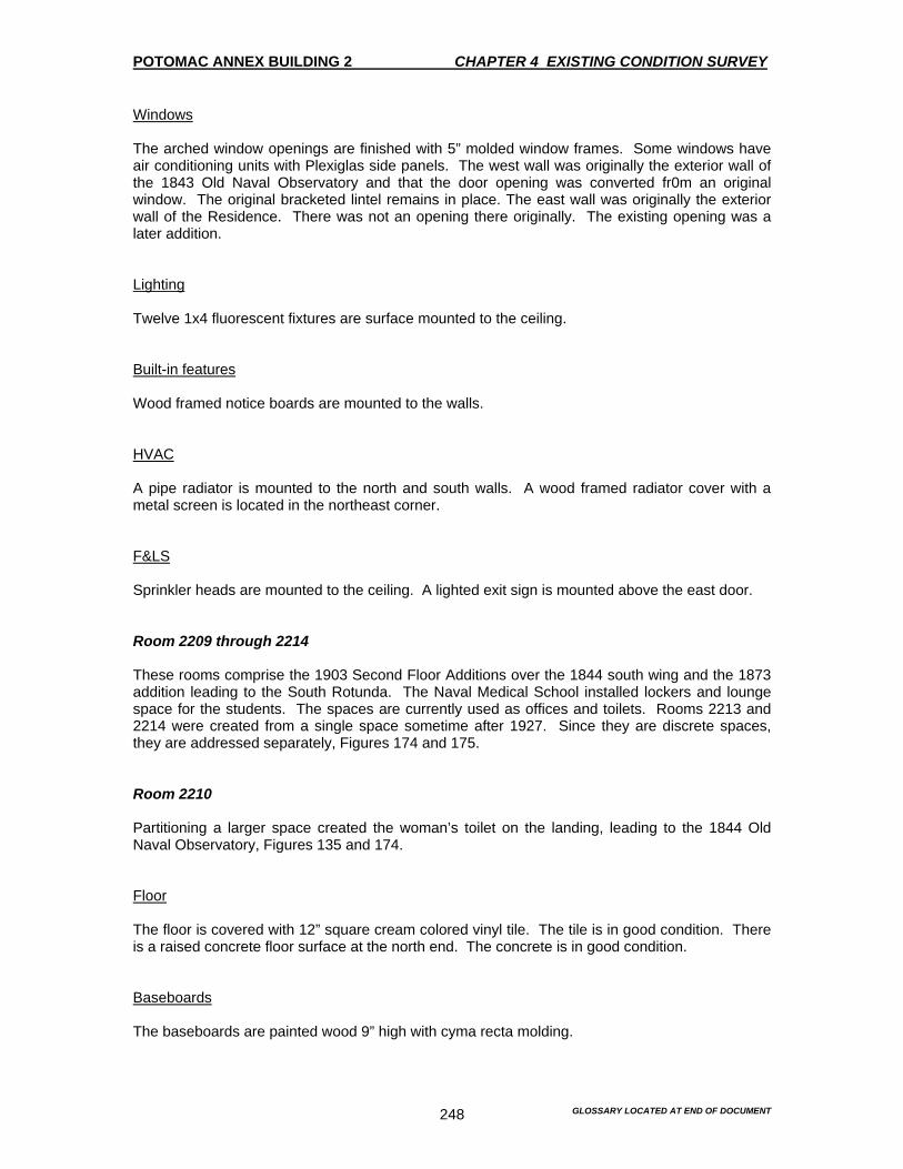
POTOMAC ANNEX BUILDING 2 CHAPTER 4 EXISTING CONDITION SURVEY
GLOSSARY LOCATED AT END OF DOCUMENT 248
Windows The arched window openings are finished with 5” molded window frames. Some windows have air conditioning units with Plexiglas side panels. The west wall was originally the exterior wall of the 1843 Old Naval Observatory and that the door opening was converted fr0m an original window. The original bracketed lintel remains in place. The east wall was originally the exterior wall of the Residence. There was not an opening there originally. The existing opening was a later addition. Lighting Twelve 1x4 fluorescent fixtures are surface mounted to the ceiling. Built-in features Wood framed notice boards are mounted to the walls. HVAC A pipe radiator is mounted to the north and south walls. A wood framed radiator cover with a metal screen is located in the northeast corner. F&LS Sprinkler heads are mounted to the ceiling. A lighted exit sign is mounted above the east door. Room 2209 through 2214 These rooms comprise the 1903 Second Floor Additions over the 1844 south wing and the 1873 addition leading to the South Rotunda. The Naval Medical School installed lockers and lounge space for the students. The spaces are currently used as offices and toilets. Rooms 2213 and 2214 were created from a single space sometime after 1927. Since they are discrete spaces, they are addressed separately, Figures 174 and 175. Room 2210 Partitioning a larger space created the woman’s toilet on the landing, leading to the 1844 Old Naval Observatory, Figures 135 and 174. Floor The floor is covered with 12” square cream colored vinyl tile. The tile is in good condition. There is a raised concrete floor surface at the north end. The concrete is in good condition. Baseboards The baseboards are painted wood 9” high with cyma recta molding.
POTOMAC ANNEX BUILDING 2 CHAPTER 4 EXISTING CONDITION SURVEY
GLOSSARY LOCATED AT END OF DOCUMENT 249
Walls The east and south walls are painted plaster. The north and west partitions are gypsum board. Ceiling The ceiling is painted plaster. Windows The windows have a painted wood frame, a wood sill and 4” molded wood trim. There is a section of trim that was removed to make room for a lavatory. Lighting A 1x4 fluorescent fixture is surface mounted to the ceiling. Built-in features There is one toilet and one wall-mounted lavatory. HVAC There is one cast-iron radiator with a cover. F&LS A sprinkler head is mounted to the ceiling. Room 2210B The landing to the second story of the 1844 Old Naval Observatory, Figure 135, was part of a larger space, which was partitioned for Room 2210 (toilet). Floor The floor is covered with 12” square blue vinyl tile that is in good condition. Baseboards The baseboards are varnished wood 9” in height with cyma recta molding. Walls The south and west walls are painted plaster. The north end of the space opens to the 1844 Old Naval Observatory.

POTOMAC ANNEX BUILDING 2 CHAPTER 4 EXISTING CONDITION SURVEY
GLOSSARY LOCATED AT END OF DOCUMENT 250
Ceiling The ceiling is painted gypsum board that is in good condition. Windows The windows have a painted wood frame, wood sill and 4” molded wood trim. Lighting A 1x4 fluorescent fixture is surface mounted to the ceiling. HVAC There is one cast iron radiator with a decorative cover. F&LS A sprinkler head is mounted to the ceiling. Room 2209 This space is used as a toilet, which reflects its original use. Floor The floor is covered with 12” square cream colored vinyl tiles that are in good condition. Baseboards – N/A Walls The walls are painted plaster that is in good condition. Ceiling The ceiling is painted plaster that is in good condition. Windows The windows have a painted 4” molded wood trim and wood sill. An exhaust fan is mounted to a plywood panel in the window opening. The windowpanes are painted for privacy.
POTOMAC ANNEX BUILDING 2 CHAPTER 4 EXISTING CONDITION SURVEY
GLOSSARY LOCATED AT END OF DOCUMENT 251
Lighting A 1x4 fluorescent fixture is mounted to the ceiling. Built-in fixtures There is one toilet and a wall-mounted lavatory with wall-mounted steel-framed mirror. HVAC There is one cast iron radiator. F&LS A sprinkler head is mounted to the ceiling. Room 2210A This room is used as a toilet. This reflects its original use. Floor The floor is covered with 12” square cream colored vinyl tiles that are in good condition. Baseboards – N/A Walls The walls are painted plaster and are in good condition. Ceiling The ceiling is painted plaster and is in good condition. Windows Painted wood frame, 4” molded wood trim and wood sill. An exhaust fan is mounted to a plywood panel in the window opening. The windowpanes are painted for privacy. Lighting A 1x4 fluorescent fixture is mounted to the ceiling.
POTOMAC ANNEX BUILDING 2 CHAPTER 4 EXISTING CONDITION SURVEY
GLOSSARY LOCATED AT END OF DOCUMENT 252
Built-in fixtures There is one toilet and a wall-mounted lavatory with wall-mounted steel-framed mirror. HVAC There is one cast-iron radiator. F&LS A sprinkler head is mounted to the ceiling. Rooms 2211 and 2212 These rooms comprise one space that is currently used for offices. Floors The floors are covered with blue wall to wall carpeting, which is in good condition. The floor between 2209 and 2210A is covered with 12” square blue colored vinyl tile. Baseboards A 12” electrical raceway is used throughout. Walls The walls are painted plaster and are in good condition. The arched opening on the south wall may be original to the space or may be an alteration, which created rooms 2213 and 2214. Ceiling The ceiling is painted gypsum board with a hatch to the attic. The ceiling is in good condition. Windows The windows have a painted wood frame, wood sill and 4” molded wood trim. Two window-mounted air conditioning units that have Plexiglas side panels. Lighting Eight 1x4 fluorescent fixtures are surface mounted to the ceiling.

POTOMAC ANNEX BUILDING 2 CHAPTER 4 EXISTING CONDITION SURVEY
GLOSSARY LOCATED AT END OF DOCUMENT 253
Built-in features There is a recent telecommunication closet at the southeast corner of the space with a 7” wood baseboard, 4-panel wood door with stainless steel hardware and butt hinges. Metal framed room signage is mounted on the walls outside Rooms 2209 and 2210A. HVAC There are four cast-iron metal radiators with decorative cast iron covers. F&LS Sprinkler heads are suspended from the ceiling. A lighted exit sign is suspended from the ceiling above the east door. Room 2213 Office space at the southwest corner. Floors The floors are covered with blue wall to wall carpeting, which is in good condition. Baseboards The baseboards are 12” electrical raceways. There are remnants of a painted wood baseboard 9” high with cyma recta molding next to the door. Walls The walls are painted plaster and are in good condition. Ceiling The ceiling is painted gypsum board, which is in good condition. Windows The windows have a painted wood frame and wood sill. The jambs have breaded edges. Lighting Two 1x4 fluorescent fixtures are surface mounted to the ceiling. Built-in features – N/A

POTOMAC ANNEX BUILDING 2 CHAPTER 4 EXISTING CONDITION SURVEY
GLOSSARY LOCATED AT END OF DOCUMENT 254
HVAC There are two cast-iron metal radiators located under the window. F&LS Sprinkler heads are suspended from the ceiling. Room 2214 Office space at the southeast corner of the addition. Floors The floors are covered with blue wall to wall carpeting, which is in good condition. Baseboards The baseboards are 12” steel electrical raceways. There are remnants of a painted wood baseboard 9” high with cyma recta molding next to the door. Walls The walls are painted plaster that is in good condition Ceiling The ceiling is painted gypsum board, which is in good condition. Windows The windows have a painted wood frame and wood sill. The jambs have breaded edges. Lighting Two 1x4 fluorescent fixtures are surface mounted to the ceiling. Built-in features – N/A HVAC There are two cast-iron metal radiators located under the window.
POTOMAC ANNEX BUILDING 2 CHAPTER 4 EXISTING CONDITION SURVEY
GLOSSARY LOCATED AT END OF DOCUMENT 255
F&LS Sprinkler heads are suspended from the ceiling. Basement The square plan of the basement is divided symmetrically into four quadrants by a cross-shaped corridor, flanked by wings on the east, west and south. Each quadrant represents a single room in its original configuration. The exception to this is the southeast quadrant, which was altered to include a toilet and stair. Radiating wings on the east, west and south side of the basement are part of the original Old Naval Observatory. There are general problems in the basement. These include extensive piping and conduits running along the ceiling. Their installation typically damages ceiling and walls finishes, resulting in deteriorating conditions. Inappropriate storage of items throughout the basement has caused damage to walls and floors and may present a fire hazard, Figures 176-181. The room numbering does not follow a logical spatial sequence. Therefore, the description uses the following order: central core, west wing, east wing, and south wing. Room 2001A Central Corridor In its original configuration, the stone support pier occupied the center section of the basement for the 9.6-inch Equatorial Telescope. The pier was removed by the Naval Museum of Hygiene in 1895-96. This space is currently used for storage of file cabinets, a Coke machine, a boiler and a telecommunications panel. Floor The floor is a smooth concrete scored in a grid pattern and painted. It is in generally good condition. Baseboards There are few sections of wood baseboards and simple rectangular baseboard along the walls adjoining Room 2001. Walls The walls adjoining Rooms 2003 and 2004A are rubble stone masonry up to a height of 6’, with common bond brick above. Other walls are brick. Walls are surfaced and painted plaster, which are in fair to poor condition. Ceilings The ceilings consist of painted gypsum board with wood battens at the joints. They are in fair to poor condition.
POTOMAC ANNEX BUILDING 2 CHAPTER 4 EXISTING CONDITION SURVEY
GLOSSARY LOCATED AT END OF DOCUMENT 256
Windows – N/A Lighting Five 1x4 fluorescent fixtures are surface mounted to the ceiling. Some of the fixtures are missing lenses. Built-in features There is one metal slop sink against the west wall. There is also a standing water heater and a plywood board with telecommunications switches mounted to the north wall. HVAC – N/A F&LS Sprinkler piping is suspended from the ceiling. There are two lighted exit signs that are suspended from the ceiling. There is a wall-mounted emergency light, strobe alarm and fire extinguisher are also mounted to the ceiling. There is also a wall mounted alarm pull station. Room 2001 This room is located in the northwest quadrant. The room is used for storage. There was no access to this room because it was locked. Room 2002 Floor The floor is smooth concrete scored in a grid pattern and painted. It is in generally good condition. Baseboards – N/A Walls The masonry walls are surfaced with painted, beaded board paneling probably dating to the early Hospital period of 1902. The same material as the masonry walls blocks the eastern window. The paneling is scuffed with peeling paint. There are missing paneled sections along the east wall. Ceiling The ceiling is surfaced with the same beaded paneling as the walls. It is in poor condition due to the installation of plumbing pipes.

POTOMAC ANNEX BUILDING 2 CHAPTER 4 EXISTING CONDITION SURVEY
GLOSSARY LOCATED AT END OF DOCUMENT 257
Windows Only one of the two windows on the north wall is visible. The 4” frame of the visible window is original with a simple wood plank sill and stool. The paint is in poor condition. Lighting Four 1x4 fluorescent fixtures are surface mounted to the ceiling. Built-in features – N/A HVAC – N/A F&LS Sprinkler piping is suspended from the ceiling. Room 2005 This is the southwest quadrant in the main section of the basement. It is currently used for storage of computer equipment. None of the finishes are original. Floor Brown wall to wall carpeting was installed over foam insulation panels. It is heavily soiled with open seams. Baseboards The baseboards are 3” and painted wood. Walls Masonry walls are surfaced with painted plasterboard. Some damage is evident due to the installation of the sprinkler piping. Ceiling The ceiling has 12”x12” acoustical tiles are mounted to an unknown surface. Windows Two windows on the south wall have the standard painted wood architrave with molding and a flat sill and stool. The bottom sash of one double-hung window was removed for the installation of an air conditioning unit with glass side panels. The molding is damaged and missing sections in both windows are a result of careless piping and conduit installation.
POTOMAC ANNEX BUILDING 2 CHAPTER 4 EXISTING CONDITION SURVEY
GLOSSARY LOCATED AT END OF DOCUMENT 258
Lighting 1x4 box fluorescent fixtures that are surfaced mounted to the ceiling. Built-in features A wood-framed notice board is mounted to the west wall. The board has been painted over. HVAC – N/A F&LS Sprinkler piping is suspended from the ceiling. There is one wall-mounted fire extinguisher. Rooms 2004 and 2004B The room is somewhat confusing. Room 2004A is the basement of the original east wing. Rooms 2004 and 2004B, a toilet and stair hall respectively, which is a later sub-addition to the southeast quadrant of the main basement. For ease of discussion 2004 and 2004B are discussed together first. Later 2004A is addressed following the description of Room 2003. Room 2004 - Toilet Floor The floor is covered with 12” square cream colored vinyl tile that is in good condition. Baseboards- N/A Walls The north and south walls are painted plaster. The east wall is surfaced with painted plywood. The west wall is a gypsum board partition, which has been used to subdivide the original 8” space. Ceiling The ceiling is painted gypsum board. Windows The window is a painted wood frame, wood sill and 3” molded wood trim. The top sash of the double-hung window was removed to make room for an exhaust fan that is mounted to a plywood panel.

POTOMAC ANNEX BUILDING 2 CHAPTER 4 EXISTING CONDITION SURVEY
GLOSSARY LOCATED AT END OF DOCUMENT 259
Lighting One 1x4 fluorescent fixture and one naked halogen bulb fixture are surface mounted to the ceiling. Built-in feature There are two lavatories, two urinals and two toilets. The six-foot high stall partitions consist of painted wood frames and panels with no doors. Four-foot high-painted wood-backed panels are also located in the stalls. These panels are showing signs of rotting. HVAC One cast-iron radiator is mounted to the west wall. F&LS Sprinkler piping is suspended from the ceiling. 2004B This room serves as a vestibule to the toilet Room 2004 and the stair landing. Floor The floor is covered with 12” square vinyl tile that is in good condition. It appears to have been installed recently. Baseboards There is an 8” wood painted baseboard on the east wall only. Walls The south and west walls are painted plaster. The east and north partition walls are made from gypsum board. The walls are in good condition. Ceiling The ceiling is painted gypsum board. The installation of electrical conduits has punctured the ceiling. Windows The window is a painted wood-frame, wood sill and 3” molded wood trim.

POTOMAC ANNEX BUILDING 2 CHAPTER 4 EXISTING CONDITION SURVEY
GLOSSARY LOCATED AT END OF DOCUMENT 260
Lighting One 1x4 fluorescent fixture and one naked halogen bulb fixture are surface mounted to the ceiling. Built-in feature – N/A HVAC – N/A F&LS Sprinkler piping is suspended from the ceiling. Stair An enclosed dogleg stair to the first floor abuts the west wall. The stair dates to the 1902-03 Second Floor Addition alterations. This is based on the use of painted wood beaded board that was identical to other part of the building that used this feature. The stringers, treads and risers are painted wood with wood posts supporting the stair structure on the open side. A non-original round wood handrail is mounted to the beaded board paneling with brass brackets. The stair is in good condition. Floor Carpeting covers the first floor landing. A blue vinyl tile covers the basement landing. The wood stair treads and risers are painted with aluminum non-skid plates. The paint on the tread and rises is scuffed and chipped due to foot traffic. Baseboards The baseboards at the first floor landing are simple painted wood 7” high. Walls The walls are painted plaster. A wood beaded board from the floor to the basement ceiling covers the east wall. Ceiling The painted plaster ceiling goes approximately halfway up the stairs, then the painted pressed metal ceiling of Room 2117 is visible. Some mechanical damage to the plaster ceiling soffit is due to impact. Windows – N/A
POTOMAC ANNEX BUILDING 2 CHAPTER 4 EXISTING CONDITION SURVEY
GLOSSARY LOCATED AT END OF DOCUMENT 261
Lighting One naked incandescent bulb light fixture is mounted to gypsum board wall surface. Built-in feature – N/A HVAC – N/A F&LS Sprinkler piping is mounted to the walls. Room 2003 This room is the original west wing of the Old Naval Observatory. Two stone piers that were used to support the Meridian Transit Instrument and the Mural Circle originally occupied this room. The piers are no longer there. The room is square in plan with octagonal projections on the north and south sides dating to 1864. It is currently used for storage and houses the fire standpipe system valves and generator. Floor The floor is smooth concrete scored in grid pattern and painted. It is in good condition. Baseboards – N/A Walls The east wall is exposed brick laid up in common bond. It is separate from the stone wall of the main block of the building. The north, south and west walls are rubble masonry to varying heights of 5’ to 6’ with common bond brick above. Traces of plaster exist on some of the walls. Ceiling The joist and flooring are exposed. Joists rest on wood post and beam structure. Three beams run east and west. Additional posts are incorporated into the brick walls and rest on the stone base structure. The additional structure is of uncertain date. However, it may be associated with the installation of the Old Naval Observatory library to carry the additional load. Windows A small window in the north-projecting bay has a simple utilitarian wood frame with no molding. Lighting A fluorescent fixture is surface mounted to the ceiling.
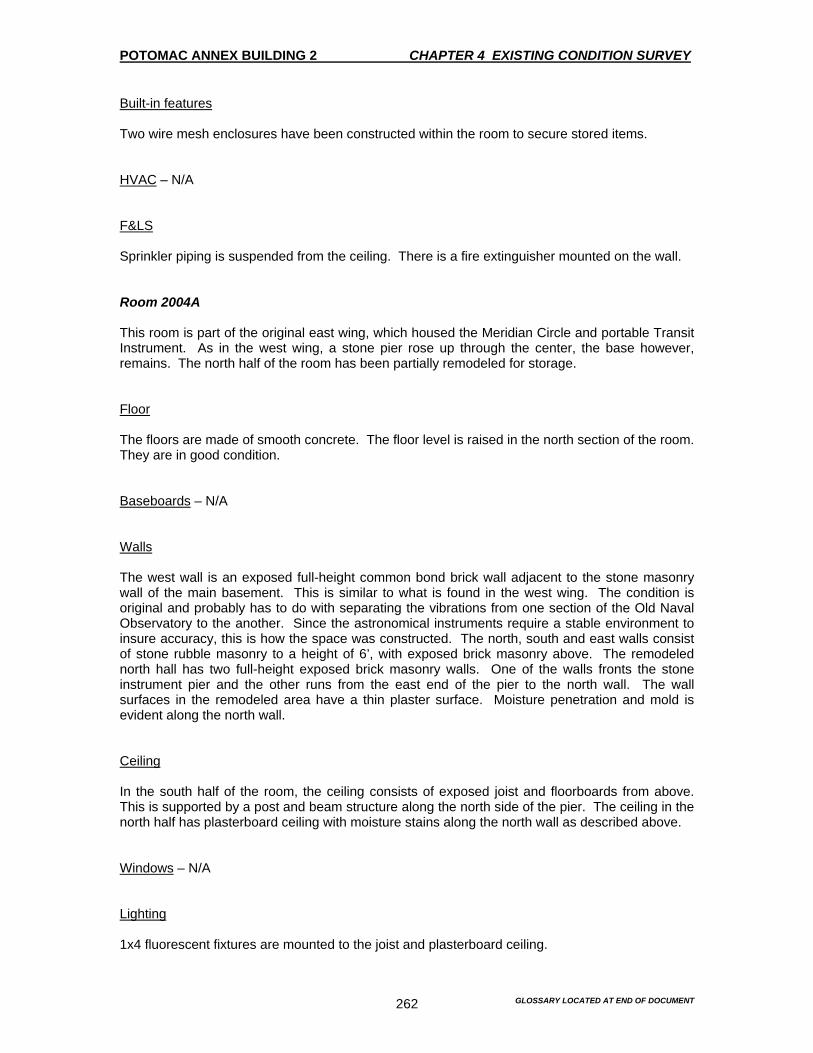
POTOMAC ANNEX BUILDING 2 CHAPTER 4 EXISTING CONDITION SURVEY
GLOSSARY LOCATED AT END OF DOCUMENT 262
Built-in features Two wire mesh enclosures have been constructed within the room to secure stored items. HVAC – N/A F&LS Sprinkler piping is suspended from the ceiling. There is a fire extinguisher mounted on the wall. Room 2004A This room is part of the original east wing, which housed the Meridian Circle and portable Transit Instrument. As in the west wing, a stone pier rose up through the center, the base however, remains. The north half of the room has been partially remodeled for storage. Floor The floors are made of smooth concrete. The floor level is raised in the north section of the room. They are in good condition. Baseboards – N/A Walls The west wall is an exposed full-height common bond brick wall adjacent to the stone masonry wall of the main basement. This is similar to what is found in the west wing. The condition is original and probably has to do with separating the vibrations from one section of the Old Naval Observatory to the another. Since the astronomical instruments require a stable environment to insure accuracy, this is how the space was constructed. The north, south and east walls consist of stone rubble masonry to a height of 6’, with exposed brick masonry above. The remodeled north hall has two full-height exposed brick masonry walls. One of the walls fronts the stone instrument pier and the other runs from the east end of the pier to the north wall. The wall surfaces in the remodeled area have a thin plaster surface. Moisture penetration and mold is evident along the north wall. Ceiling In the south half of the room, the ceiling consists of exposed joist and floorboards from above. This is supported by a post and beam structure along the north side of the pier. The ceiling in the north half has plasterboard ceiling with moisture stains along the north wall as described above. Windows – N/A Lighting 1x4 fluorescent fixtures are mounted to the joist and plasterboard ceiling.

POTOMAC ANNEX BUILDING 2 CHAPTER 4 EXISTING CONDITION SURVEY
GLOSSARY LOCATED AT END OF DOCUMENT 263
Built-in features A rubble stone and brick pier occupies most of the space in this room. It is the base of the supporting pier for the Meridian Circle and the Transit Instrument. HVAC – N/A F&LS Sprinkler piping is suspended from the ceiling in remodeled areas. Room 2006 and 2007 A partition wall bisects the south wing to create these two rooms. They are separated from the central core of the 1844 basement by an open passage connected to the areaway. This is the original configuration. In the basement of the south wing, as in the east and west wings, there was originally a stone pier to support the Transit Instrument in the Prime Vertical. Nothing of the pier remains. The rooms are currently used for the men’s locker room next to the gym that was set up in the basement. Floor The flooring consists of 12” square cream-colored vinyl tile. Some rust stains from a steel locker are present. Baseboards A simple 3” painted wood baseboard on gypsum board partition lies between the two rooms. Walls A gypsum board partition separates the two rooms. Exterior walls have coursed stone rubble masonry up to a varying height of 5’ to 6’ with common bond brick masonry above. The surfaces of the walls are finished with a thin coat of plaster. Rounded concrete curbs exist on parts of the exterior walls. Efflorescence powdering plaster and black mold is typical on east and west exterior walls at ground level. Ceiling The ceilings are a painted plaster board. The ceiling is in extremely poor condition with holes and entire sections missing due to the installation of piping and conduits Windows The window has a painted wood frame with no casing

POTOMAC ANNEX BUILDING 2 CHAPTER 4 EXISTING CONDITION SURVEY
GLOSSARY LOCATED AT END OF DOCUMENT 264
Lighting One 1x4 fluorescent fixture is suspended from the ceiling in each room. Built-in features A built-in electrical closet of gypsum board construction occupies the north part of Room 2007. HVAC A coiled pipe radiator is suspended from the ceiling in Room 2006. F&LS Sprinkler pipe is suspended from the ceiling in both rooms. In Room 2007, there is one emergency light, a fire alarm pull station, a bell and fire control panel mounted to the closet at the exit door.
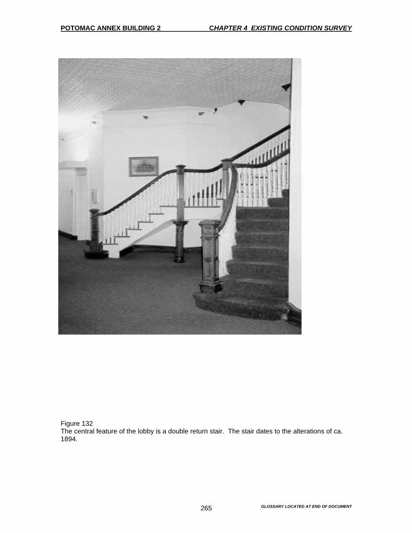
POTOMAC ANNEX BUILDING 2 CHAPTER 4 EXISTING CONDITION SURVEY
GLOSSARY LOCATED AT END OF DOCUMENT 265
Figure 132 The central feature of the lobby is a double return stair. The stair dates to the alterations of ca. 1894.
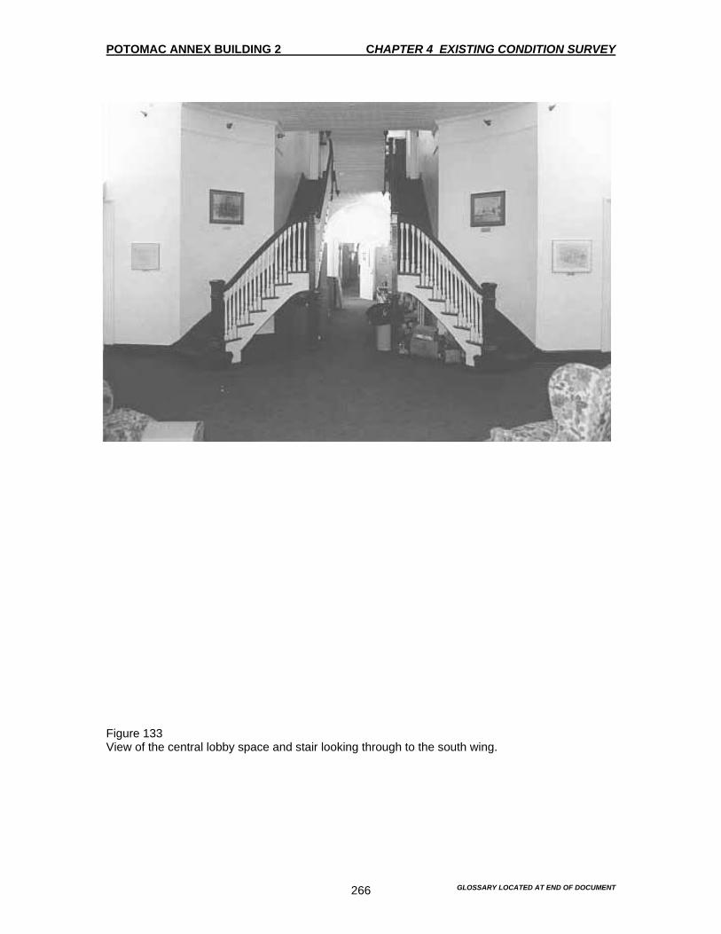
POTOMAC ANNEX BUILDING 2 CHAPTER 4 EXISTING CONDITION SURVEY
GLOSSARY LOCATED AT END OF DOCUMENT 266
Figure 133 View of the central lobby space and stair looking through to the south wing.
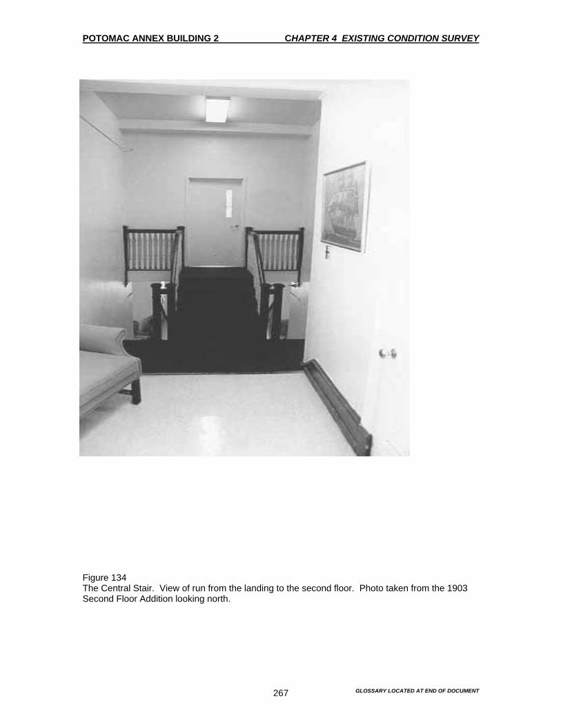
POTOMAC ANNEX BUILDING 2 CHAPTER 4 EXISTING CONDITION SURVEY
GLOSSARY LOCATED AT END OF DOCUMENT 267
Figure 134 The Central Stair. View of run from the landing to the second floor. Photo taken from the 1903 Second Floor Addition looking north.

POTOMAC ANNEX BUILDING 2 CHAPTER 4 EXISTING CONDITION SURVEY
GLOSSARY LOCATED AT END OF DOCUMENT 268
Figure 135 View from the second floor of the Old Naval Observatory looking towards the1903 Second Floor Addition to the south. The wide opening with molded casing was probably originally the south window of the Old Naval Observatory.

POTOMAC ANNEX BUILDING 2 CHAPTER 4 EXISTING CONDITION SURVEY
GLOSSARY LOCATED AT END OF DOCUMENT 269
Figure 136 Door to Room 2108. Typical historic door found in the Old Naval Observatory and Residence.

POTOMAC ANNEX BUILDING 2 CHAPTER 4 EXISTING CONDITION SURVEY
GLOSSARY LOCATED AT END OF DOCUMENT 270
Figure 137 Detail of typical historic door hardware found in the Old Naval Observatory and Residence.
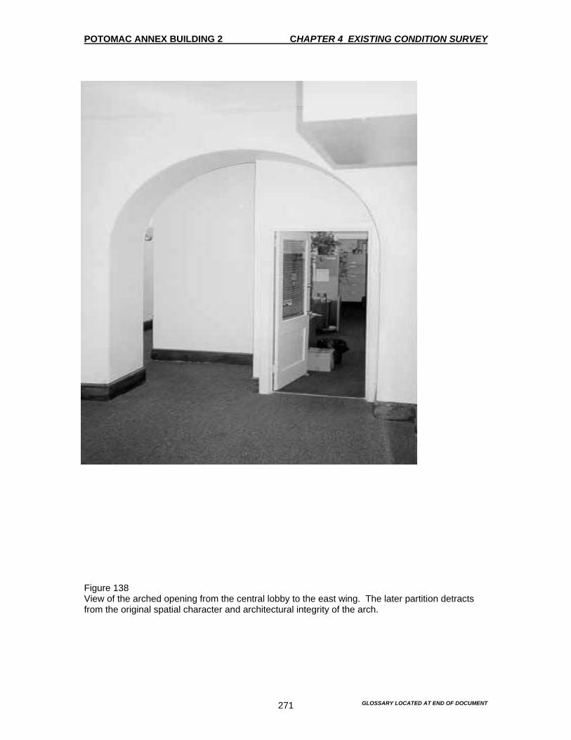
POTOMAC ANNEX BUILDING 2 CHAPTER 4 EXISTING CONDITION SURVEY
GLOSSARY LOCATED AT END OF DOCUMENT 271
Figure 138 View of the arched opening from the central lobby to the east wing. The later partition detracts from the original spatial character and architectural integrity of the arch.
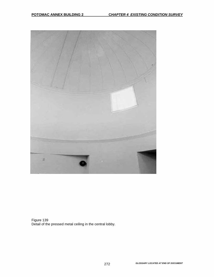
POTOMAC ANNEX BUILDING 2 CHAPTER 4 EXISTING CONDITION SURVEY
GLOSSARY LOCATED AT END OF DOCUMENT 272
Figure 139 Detail of the pressed metal ceiling in the central lobby.
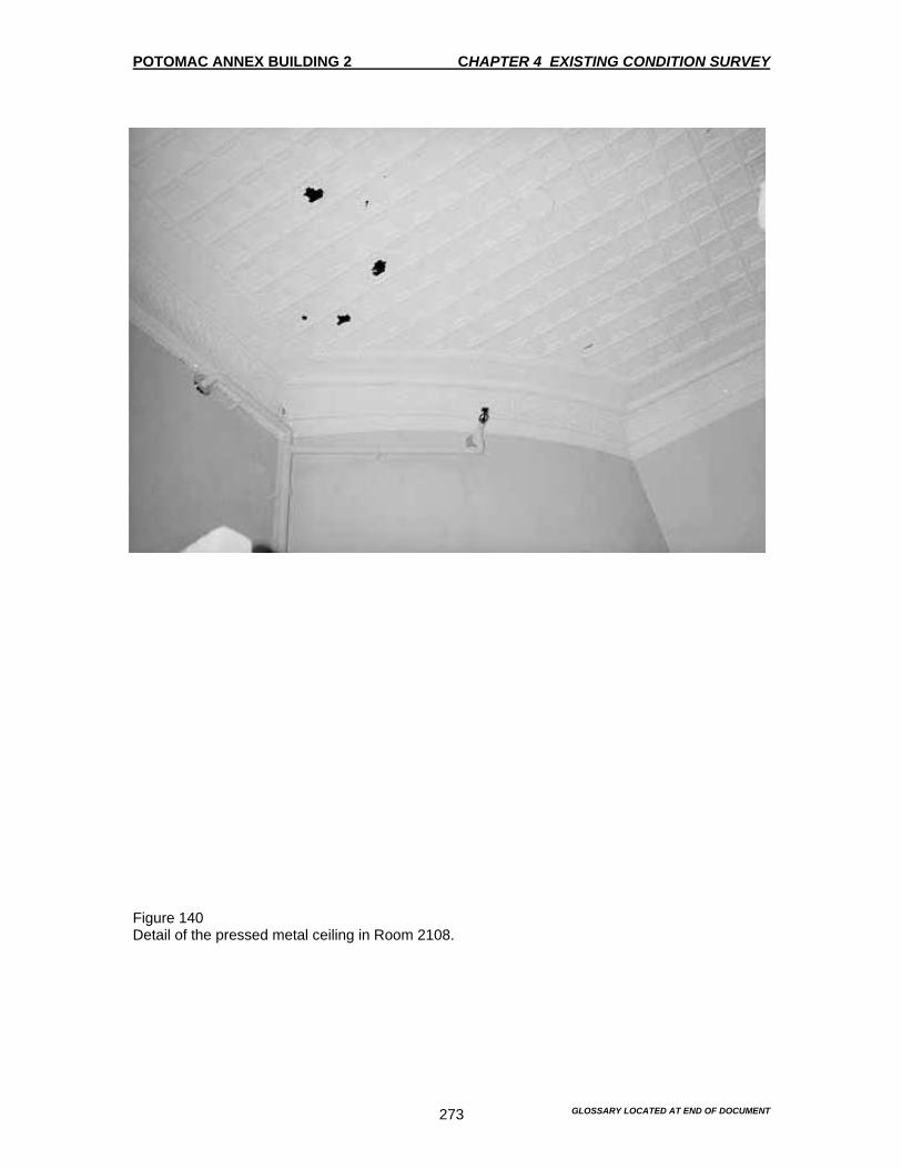
POTOMAC ANNEX BUILDING 2 CHAPTER 4 EXISTING CONDITION SURVEY
GLOSSARY LOCATED AT END OF DOCUMENT 273
Figure 140 Detail of the pressed metal ceiling in Room 2108.
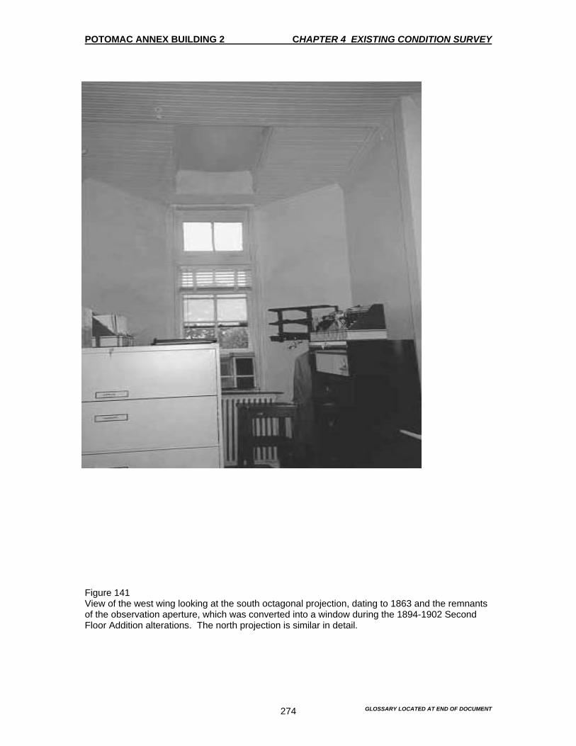
POTOMAC ANNEX BUILDING 2 CHAPTER 4 EXISTING CONDITION SURVEY
GLOSSARY LOCATED AT END OF DOCUMENT 274
Figure 141 View of the west wing looking at the south octagonal projection, dating to 1863 and the remnants of the observation aperture, which was converted into a window during the 1894-1902 Second Floor Addition alterations. The north projection is similar in detail.
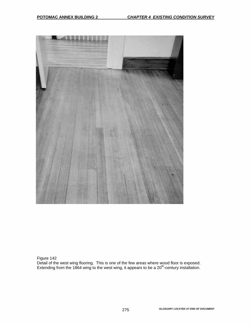
POTOMAC ANNEX BUILDING 2 CHAPTER 4 EXISTING CONDITION SURVEY
GLOSSARY LOCATED AT END OF DOCUMENT 275
Figure 142 Detail of the west wing flooring. This is one of the few areas where wood floor is exposed. Extending from the 1864 wing to the west wing, it appears to be a 20th-century installation.

POTOMAC ANNEX BUILDING 2 CHAPTER 4 EXISTING CONDITION SURVEY
GLOSSARY LOCATED AT END OF DOCUMENT 276
Figure 143 View of Room 2119 located in the 1844 east wing.

POTOMAC ANNEX BUILDING 2 CHAPTER 4 EXISTING CONDITION SURVEY
GLOSSARY LOCATED AT END OF DOCUMENT 277
Figure 144 Room 2119. The south window is in the location of the 1844 observation aperture. The aperture was converted to a window at the time of the 1894-1902 Second Floor Addition alterations. The window sashes are similar in detail to those on the 1902 Second Floor Addition.
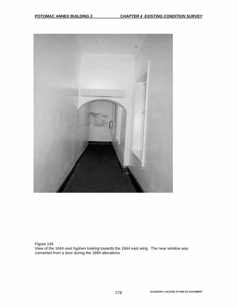
POTOMAC ANNEX BUILDING 2 CHAPTER 4 EXISTING CONDITION SURVEY
GLOSSARY LOCATED AT END OF DOCUMENT 278
Figure 145 View of the 1844 east hyphen looking towards the 1844 east wing. The near window was converted from a door during the 1894 alterations.
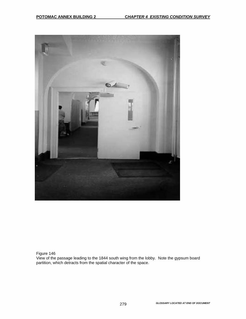
POTOMAC ANNEX BUILDING 2 CHAPTER 4 EXISTING CONDITION SURVEY
GLOSSARY LOCATED AT END OF DOCUMENT 279
Figure 146 View of the passage leading to the 1844 south wing from the lobby. Note the gypsum board partition, which detracts from the spatial character of the space.

POTOMAC ANNEX BUILDING 2 CHAPTER 4 EXISTING CONDITION SURVEY
GLOSSARY LOCATED AT END OF DOCUMENT 280
Figure 147 View of the 1844 south wing with the 1873 addition beyond. The partition in the foreground is from the spatial character of the room.
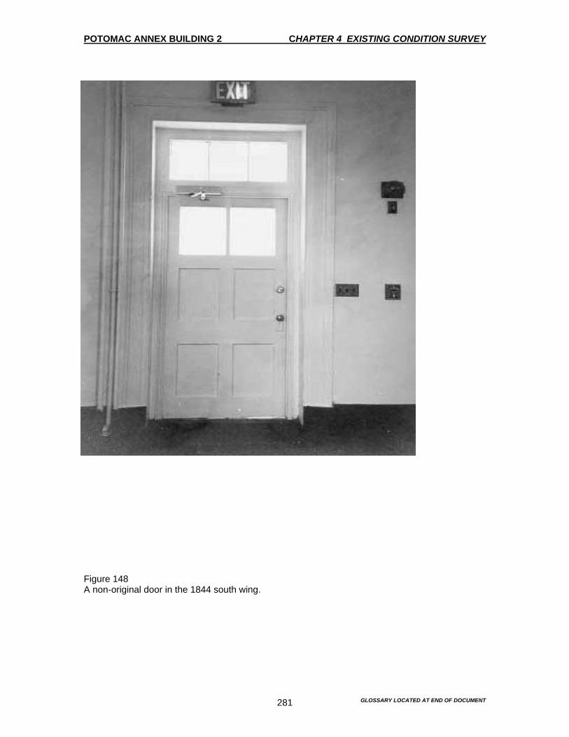
POTOMAC ANNEX BUILDING 2 CHAPTER 4 EXISTING CONDITION SURVEY
GLOSSARY LOCATED AT END OF DOCUMENT 281
Figure 148 A non-original door in the 1844 south wing.

POTOMAC ANNEX BUILDING 2 CHAPTER 4 EXISTING CONDITION SURVEY
GLOSSARY LOCATED AT END OF DOCUMENT 282
Figure 149 A typical baseboard found throughout the building. They range in height from 6 inches to 9 inches. The 9-inch perimeter baseboards may date to the 1840’s. The 8-inch baseboards probably date to 1894, when new flooring was installed by the Naval Museum of Hygiene. Differing baseboard sizes are undoubtedly due to later attempts to match in the historic fabric. The grain painting was all undertaken during the last decade.

POTOMAC ANNEX BUILDING 2 CHAPTER 4 EXISTING CONDITION SURVEY
GLOSSARY LOCATED AT END OF DOCUMENT 283
Figure 150 An example of the hollow metal raceways typically found throughout the building. In some instances the molding was installed to approximate the appearance of the historic baseboards. Frequently, the molding was omitted.
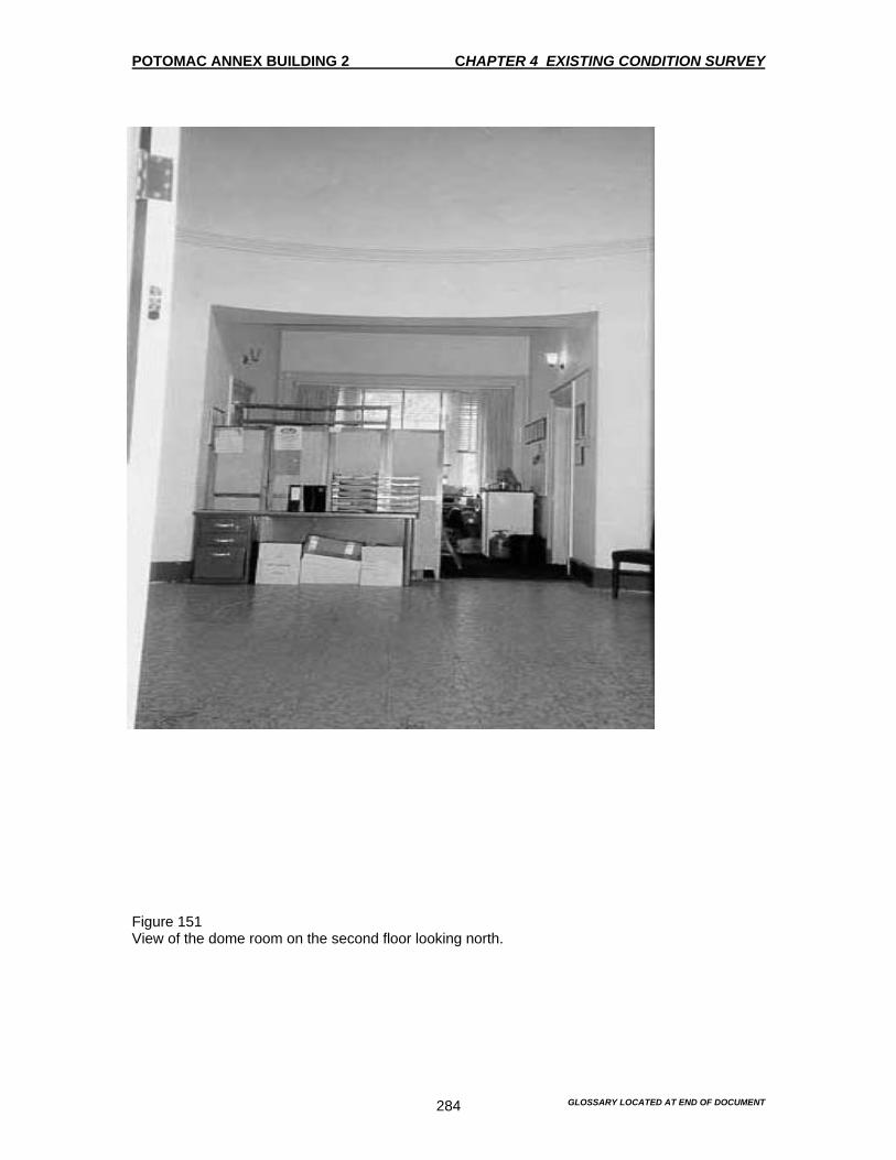
POTOMAC ANNEX BUILDING 2 CHAPTER 4 EXISTING CONDITION SURVEY
GLOSSARY LOCATED AT END OF DOCUMENT 284
Figure 151 View of the dome room on the second floor looking north.

POTOMAC ANNEX BUILDING 2 CHAPTER 4 EXISTING CONDITION SURVEY
GLOSSARY LOCATED AT END OF DOCUMENT 285
Figure 152 View of the dome room on the second floor looking south. Note the gypsum-board fill and the door separating the rotunda from the south stair.

POTOMAC ANNEX BUILDING 2 CHAPTER 4 EXISTING CONDITION SURVEY
GLOSSARY LOCATED AT END OF DOCUMENT 286
Figure 153 View of the dome room on the second floor looking west. Note that the door leading to the 1902 Second Floor Addition was converted from an 1844 window. The cornice molding along the perimeter wall marks the approximate location of the third level originally used for access to the telescope. This third level was removed during the 1894 alteration.

POTOMAC ANNEX BUILDING 2 CHAPTER 4 EXISTING CONDITION SURVEY
GLOSSARY LOCATED AT END OF DOCUMENT 287
Figure 154 View of the dome on the second floor looking east. Note that the door leading to the 1902 Second Floor Addition was converted from an 1844 window.
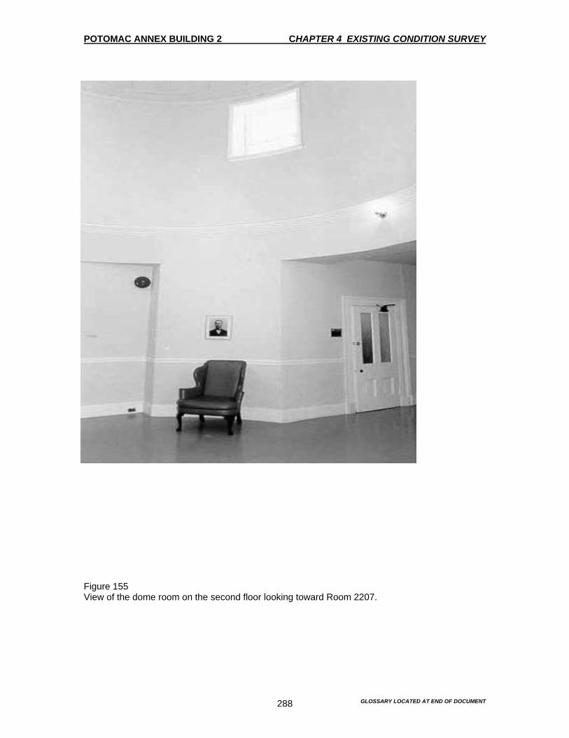
POTOMAC ANNEX BUILDING 2 CHAPTER 4 EXISTING CONDITION SURVEY
GLOSSARY LOCATED AT END OF DOCUMENT 288
Figure 155 View of the dome room on the second floor looking toward Room 2207.
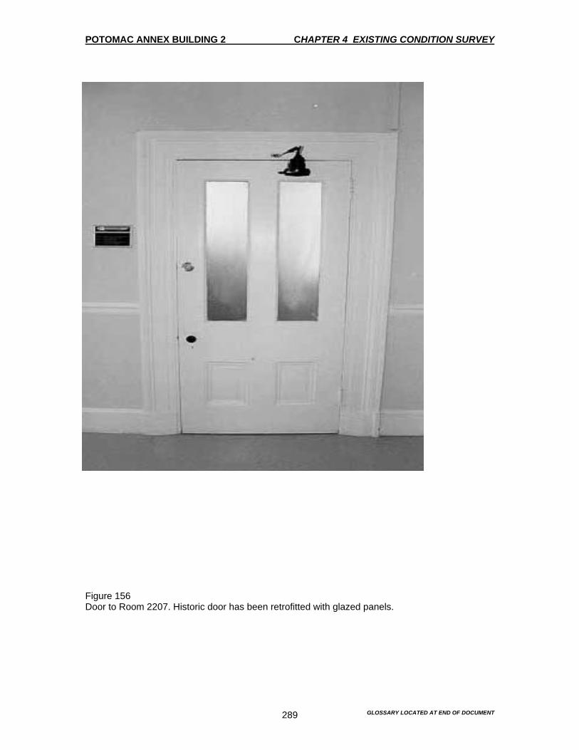
POTOMAC ANNEX BUILDING 2 CHAPTER 4 EXISTING CONDITION SURVEY
GLOSSARY LOCATED AT END OF DOCUMENT 289
Figure 156 Door to Room 2207. Historic door has been retrofitted with glazed panels.
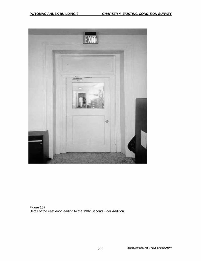
POTOMAC ANNEX BUILDING 2 CHAPTER 4 EXISTING CONDITION SURVEY
GLOSSARY LOCATED AT END OF DOCUMENT 290
Figure 157 Detail of the east door leading to the 1902 Second Floor Addition.

POTOMAC ANNEX BUILDING 2 CHAPTER 4 EXISTING CONDITION SURVEY
GLOSSARY LOCATED AT END OF DOCUMENT 291
Figure 158 View of the 1844 dome. Note original observation aperture is still visible although it has been roofed over on the exterior.
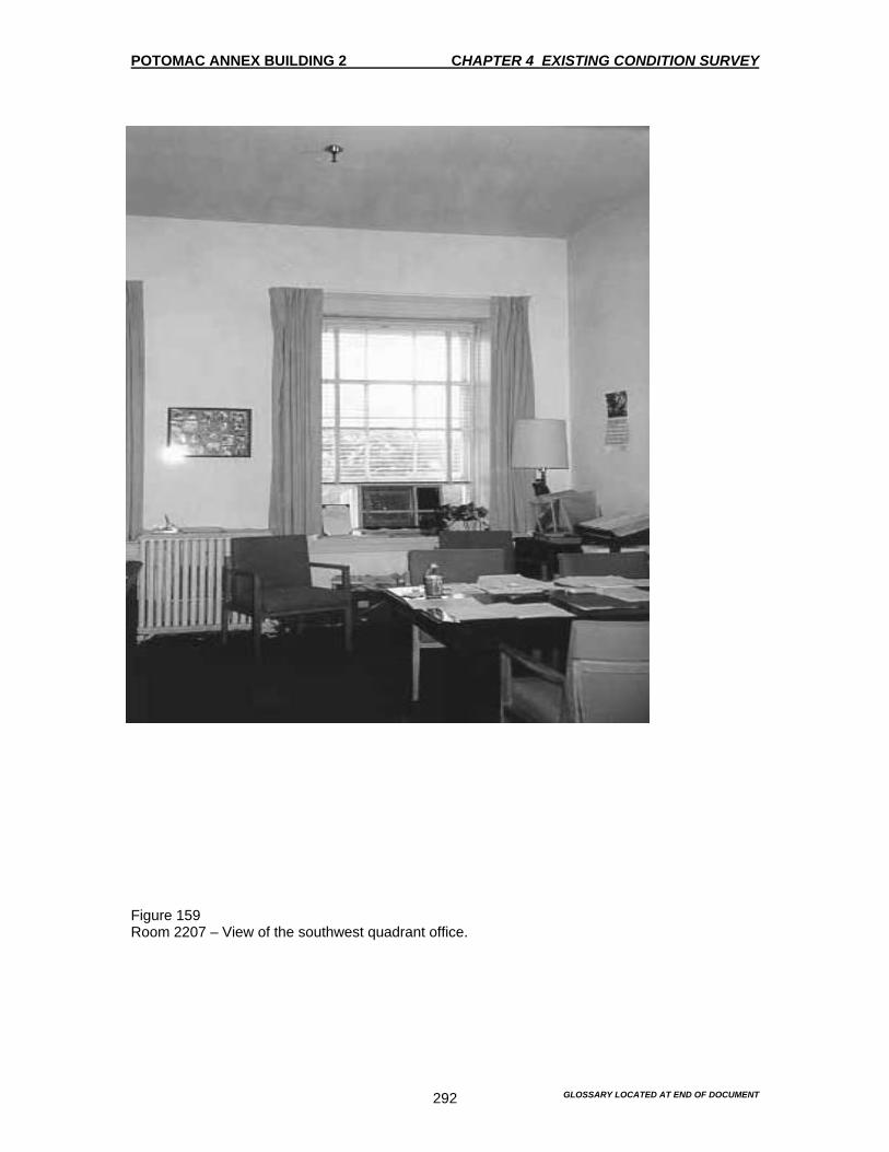
POTOMAC ANNEX BUILDING 2 CHAPTER 4 EXISTING CONDITION SURVEY
GLOSSARY LOCATED AT END OF DOCUMENT 292
Figure 159 Room 2207 – View of the southwest quadrant office.

POTOMAC ANNEX BUILDING 2 CHAPTER 4 EXISTING CONDITION SURVEY
GLOSSARY LOCATED AT END OF DOCUMENT 293
Figure 160 Mantle in Room 2207 dates to the late 19th century. It is probably associated with the 1894 alterations, and is the only extant mantle in the Old Naval Observatory.

POTOMAC ANNEX BUILDING 2 CHAPTER 4 EXISTING CONDITION SURVEY
GLOSSARY LOCATED AT END OF DOCUMENT 294
Figure 161 View of the northwest quadrant office, Room 2208.

POTOMAC ANNEX BUILDING 2 CHAPTER 4 EXISTING CONDITION SURVEY
GLOSSARY LOCATED AT END OF DOCUMENT 295
Figure 162 Room 2208. The door enters the north space between Rooms 2208 and 2216. The doorframe here is flat, with no moldings. The doorframe on the reverse side is eight inches wide with moldings typical of those found in the 1844 Old Naval Observatory. It appears that the opening is original, but that the door and frame were altered.

POTOMAC ANNEX BUILDING 2 CHAPTER 4 EXISTING CONDITION SURVEY
GLOSSARY LOCATED AT END OF DOCUMENT 296
Figure 163 A view of the northeast quadrant space. Room 2216.

POTOMAC ANNEX BUILDING 2 CHAPTER 4 EXISTING CONDITION SURVEY
GLOSSARY LOCATED AT END OF DOCUMENT 297
Figure 164 A view of the southeast quadrant space. Room 2217.

POTOMAC ANNEX BUILDING 2 CHAPTER 4 EXISTING CONDITION SURVEY
GLOSSARY LOCATED AT END OF DOCUMENT 298
Figure 165 A view of the radiator in Room 2217, which on a raised platform. This appears to be a recent alteration.
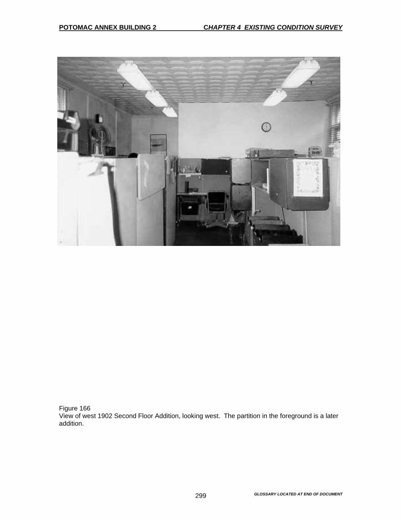
POTOMAC ANNEX BUILDING 2 CHAPTER 4 EXISTING CONDITION SURVEY
GLOSSARY LOCATED AT END OF DOCUMENT 299
Figure 166 View of west 1902 Second Floor Addition, looking west. The partition in the foreground is a later addition.

POTOMAC ANNEX BUILDING 2 CHAPTER 4 EXISTING CONDITION SURVEY
GLOSSARY LOCATED AT END OF DOCUMENT 300
Figure 167 Typical window detail in the west 1902 Second Floor Addition.

POTOMAC ANNEX BUILDING 2 CHAPTER 4 EXISTING CONDITION SURVEY
GLOSSARY LOCATED AT END OF DOCUMENT 301
Figure 168 West 1902 Second Floor Addition looking east. This bracketed lintel indicates that this was originally an exterior wall of the 1844 Old Naval Observatory. The window was converted to a door in the new interior space.

POTOMAC ANNEX BUILDING 2 CHAPTER 4 EXISTING CONDITION SURVEY
GLOSSARY LOCATED AT END OF DOCUMENT 302
Figure 169 West 1902 Second Floor Addition. Note the intrusive partition wall and the water damage in the west wall and ceiling.
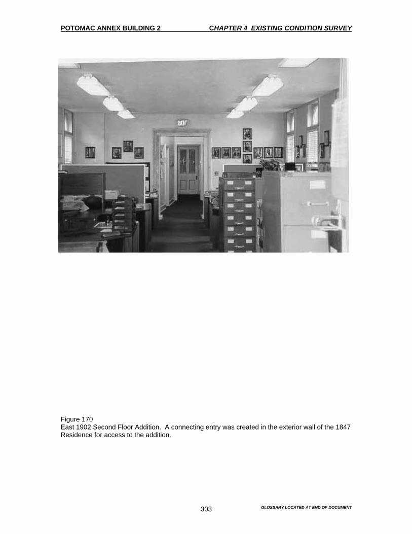
POTOMAC ANNEX BUILDING 2 CHAPTER 4 EXISTING CONDITION SURVEY
GLOSSARY LOCATED AT END OF DOCUMENT 303
Figure 170 East 1902 Second Floor Addition. A connecting entry was created in the exterior wall of the 1847 Residence for access to the addition.
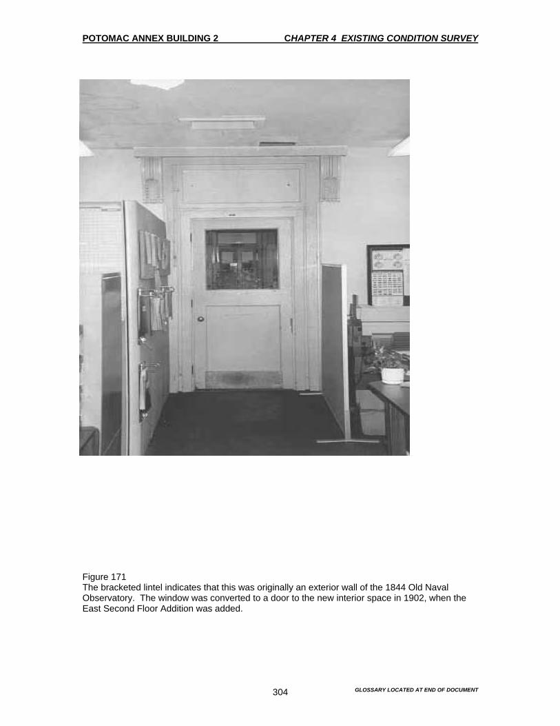
POTOMAC ANNEX BUILDING 2 CHAPTER 4 EXISTING CONDITION SURVEY
GLOSSARY LOCATED AT END OF DOCUMENT 304
Figure 171 The bracketed lintel indicates that this was originally an exterior wall of the 1844 Old Naval Observatory. The window was converted to a door to the new interior space in 1902, when the East Second Floor Addition was added.
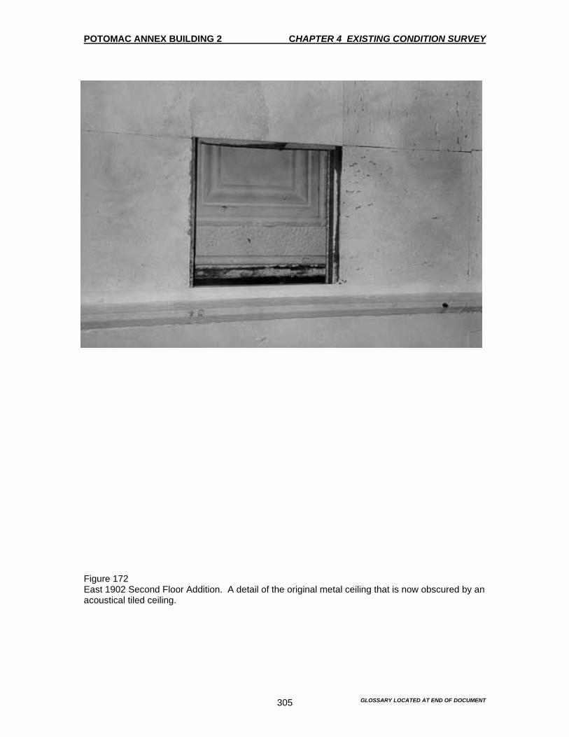
POTOMAC ANNEX BUILDING 2 CHAPTER 4 EXISTING CONDITION SURVEY
GLOSSARY LOCATED AT END OF DOCUMENT 305
Figure 172 East 1902 Second Floor Addition. A detail of the original metal ceiling that is now obscured by an acoustical tiled ceiling.
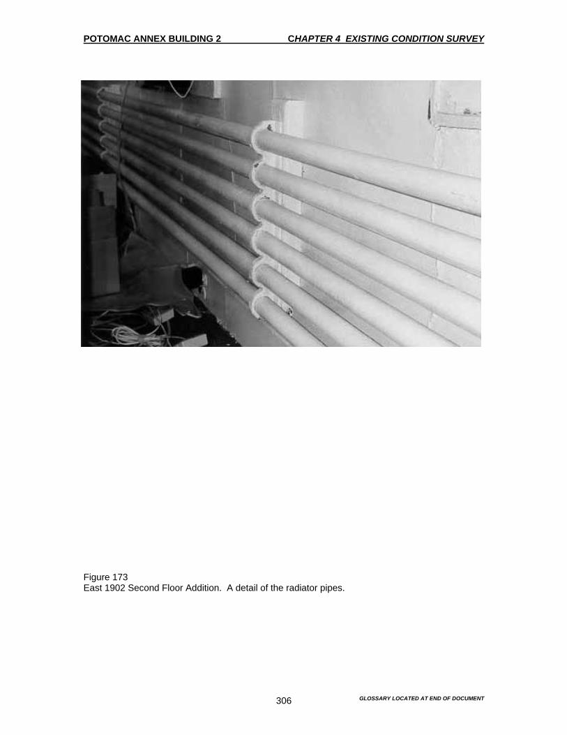
POTOMAC ANNEX BUILDING 2 CHAPTER 4 EXISTING CONDITION SURVEY
GLOSSARY LOCATED AT END OF DOCUMENT 306
Figure 173 East 1902 Second Floor Addition. A detail of the radiator pipes.

POTOMAC ANNEX BUILDING 2 CHAPTER 4 EXISTING CONDITION SURVEY
GLOSSARY LOCATED AT END OF DOCUMENT 307
Figure 174 The 1903 Second Floor Addition. View of the toilet on the landing.
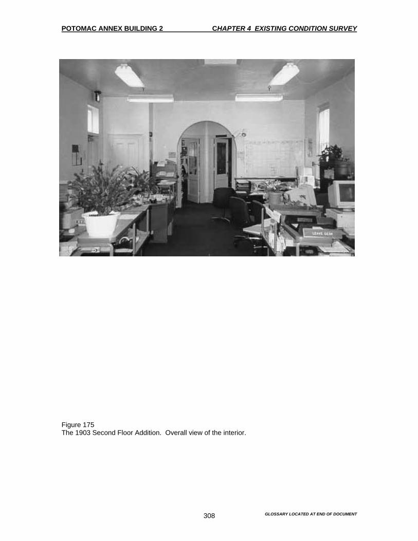
POTOMAC ANNEX BUILDING 2 CHAPTER 4 EXISTING CONDITION SURVEY
GLOSSARY LOCATED AT END OF DOCUMENT 308
Figure 175 The 1903 Second Floor Addition. Overall view of the interior.
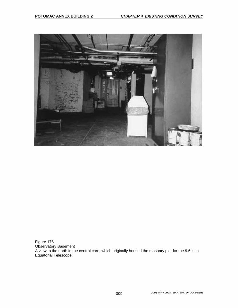
POTOMAC ANNEX BUILDING 2 CHAPTER 4 EXISTING CONDITION SURVEY
GLOSSARY LOCATED AT END OF DOCUMENT 309
Figure 176 Observatory Basement A view to the north in the central core, which originally housed the masonry pier for the 9.6 inch Equatorial Telescope.

POTOMAC ANNEX BUILDING 2 CHAPTER 4 EXISTING CONDITION SURVEY
GLOSSARY LOCATED AT END OF DOCUMENT 310
Figure 177 Observatory Basement A view looking west from the central core.

POTOMAC ANNEX BUILDING 2 CHAPTER 4 EXISTING CONDITION SURVEY
GLOSSARY LOCATED AT END OF DOCUMENT 311
Figure 178 Observatory Basement View of the southeast quadrant space, Room 2004B. The staircase was installed in 1902.
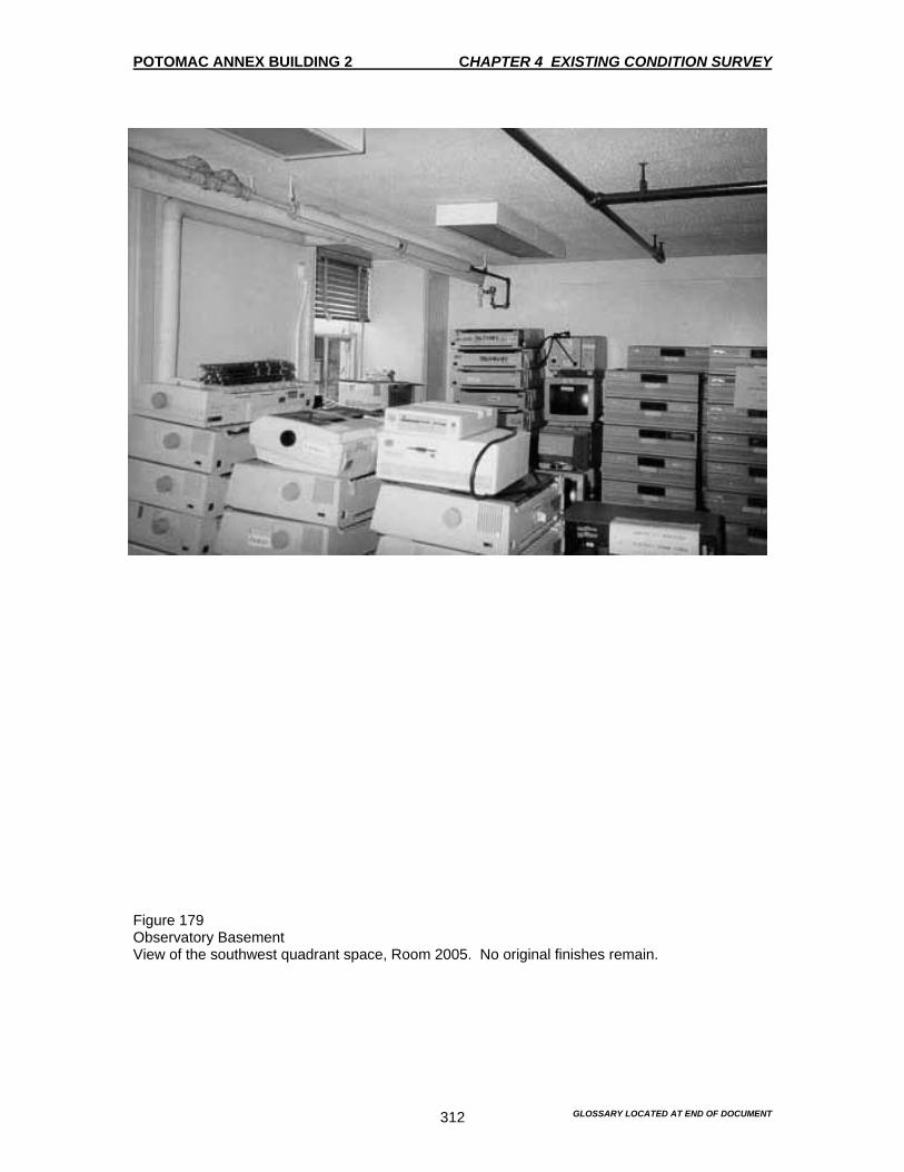
POTOMAC ANNEX BUILDING 2 CHAPTER 4 EXISTING CONDITION SURVEY
GLOSSARY LOCATED AT END OF DOCUMENT 312
Figure 179 Observatory Basement View of the southwest quadrant space, Room 2005. No original finishes remain.
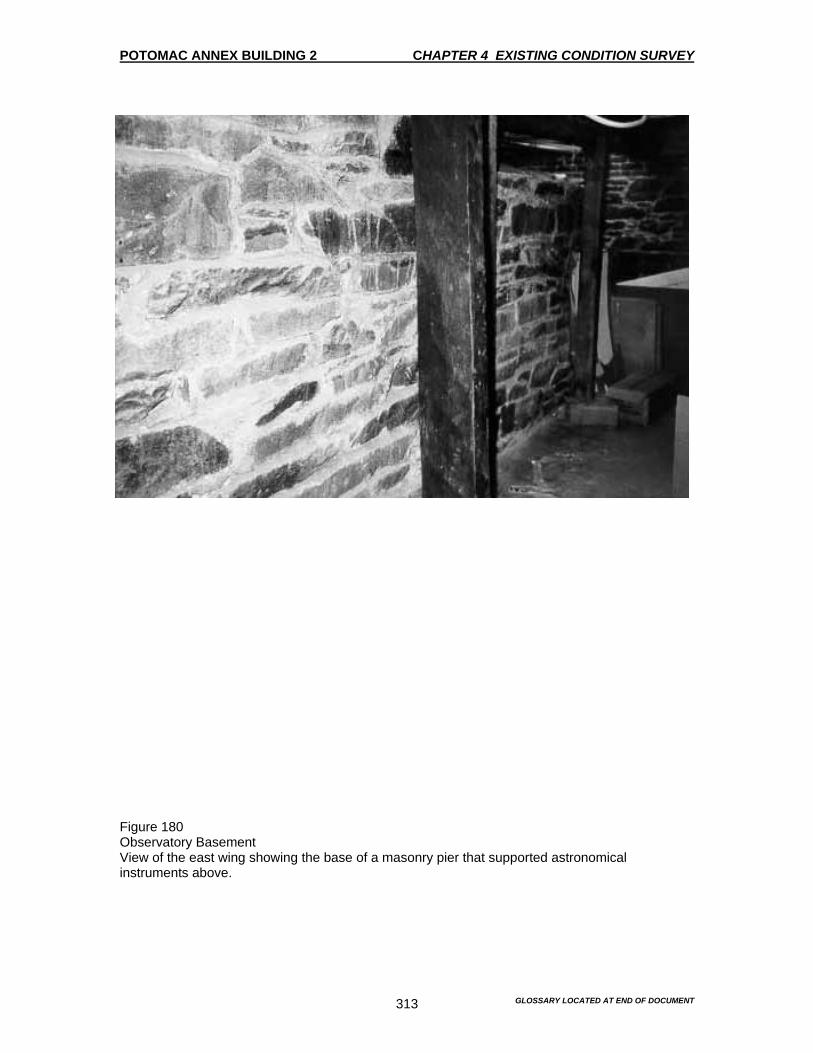
POTOMAC ANNEX BUILDING 2 CHAPTER 4 EXISTING CONDITION SURVEY
GLOSSARY LOCATED AT END OF DOCUMENT 313
Figure 180 Observatory Basement View of the east wing showing the base of a masonry pier that supported astronomical instruments above.
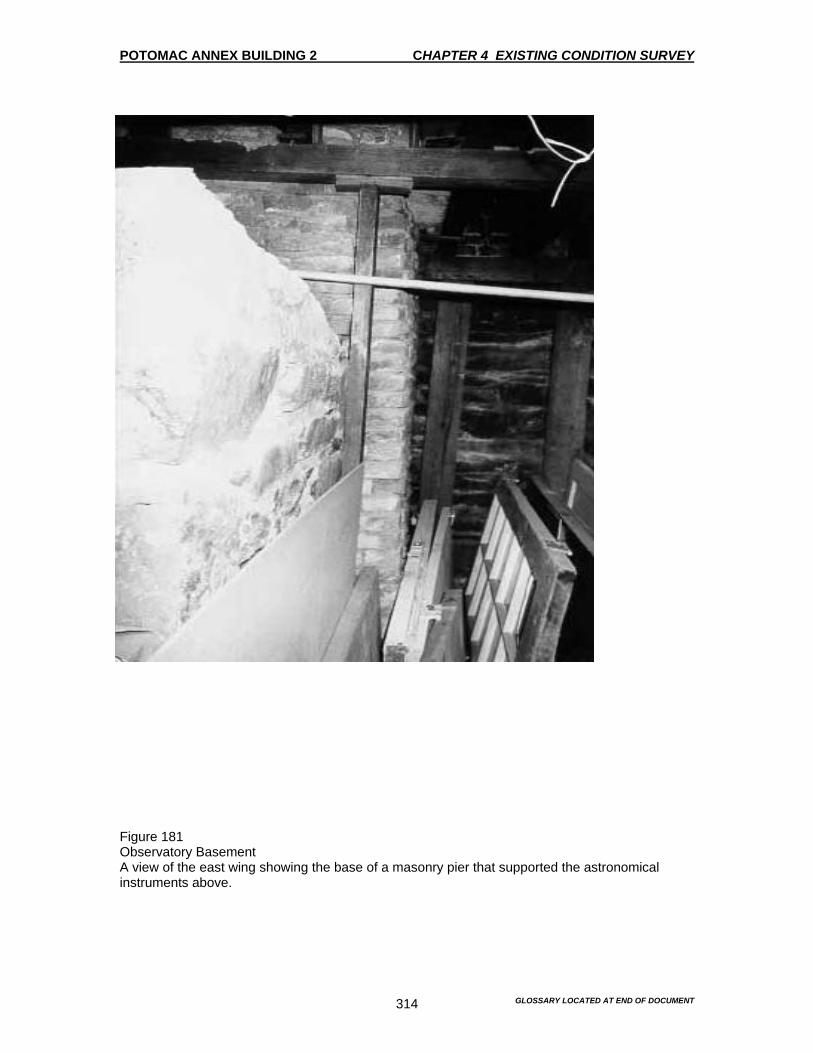
POTOMAC ANNEX BUILDING 2 CHAPTER 4 EXISTING CONDITION SURVEY
GLOSSARY LOCATED AT END OF DOCUMENT 314
Figure 181 Observatory Basement A view of the east wing showing the base of a masonry pier that supported the astronomical instruments above.
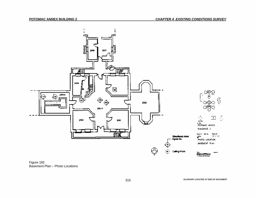
POTOMAC ANNEX BUILDING 2 CHAPTER 4 EXISTING CONDITIONS SURVEY
GLOSSARY LOCATED AT END OF DOCUMENT 315
Figure 182 Basement Plan – Photo Locations
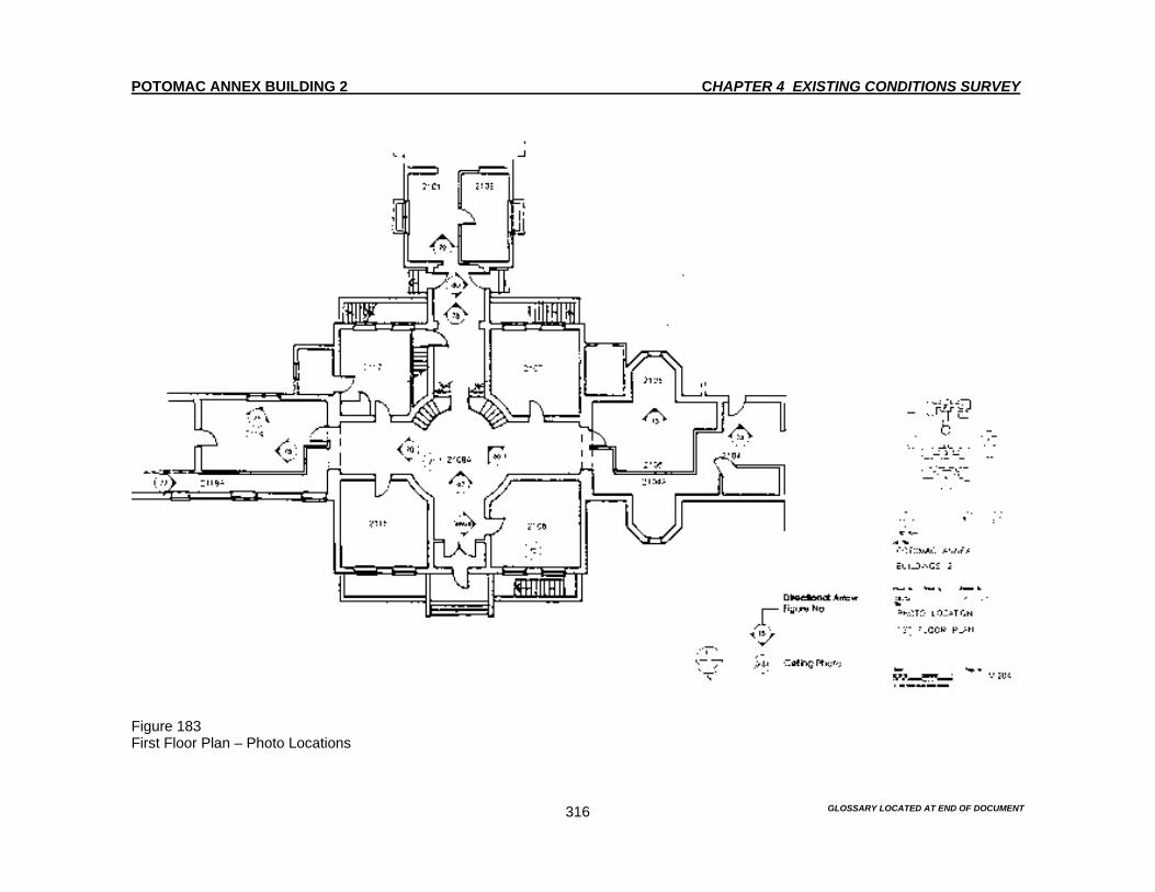
POTOMAC ANNEX BUILDING 2 CHAPTER 4 EXISTING CONDITIONS SURVEY
GLOSSARY LOCATED AT END OF DOCUMENT 316
Figure 183 First Floor Plan – Photo Locations
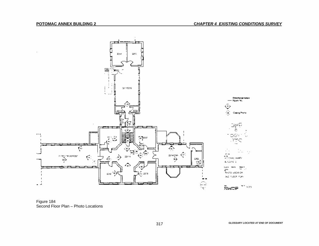
POTOMAC ANNEX BUILDING 2 CHAPTER 4 EXISTING CONDITIONS SURVEY
GLOSSARY LOCATED AT END OF DOCUMENT 317
Figure 184 Second Floor Plan – Photo Locations

POTOMAC ANNEX BUILDING 2 CHAPTER 4 EXISTING CONDITION SURVEY
GLOSSARY LOCATED AT END OF DOCUMENT 318
INTERIOR 1847 Superintendent’s Residence The Superintendent’s Residence was constructed to the east of the Old Naval Observatory in 1847. The floor plan, defined by a central hall flanked by two rooms on each side is typical of residential construction during the mid-19th century. While the plan and finishes on both the first and second floors have been altered, the Residence retains much of its historic character. Although it has been fitted out as office space, and has been used as such since the 1980’s, it still reads as 19th-century home. The survey here includes the back building structure, which was built at the same time as a kitchen, wash house and servants’ quarters. The one-story hyphen connecting the Residence to the east wing of the Old Naval Observatory was constructed in 1848. It is discussed here because its construction and function is so closely related to that of the Residence. First Floor The floor plan in Keim’s Illustrated Handbook: Washington and its Environs, (1884) shows the floor plan to be a center hall configuration with two flanking rooms. This is supported by the inventories of 1861, 1867 and 1877. However, currently, the west side of the first floor is separated into three spaces. While Keim’s plan is of limited use, it does support a theory that the room configuration on the west side of the house was altered at the turn of the 20th century as part of the Naval Museum of Hygiene and/or Naval Medical School building campaigns. The 1927 floor plans reflect the existing conditions, so first floor plan alterations were undertaken previously. The room numbering utilized by BUMED does not follow a logical architectural sequence. Therefore, the rooms are not described in numerical order. Rather, they are described as one might actually experience the building, in the following order. Central hall and subsidiary spaces, primary rooms and subsidiary spaces on the east side, primary rooms on the west side, the 1848 connecting hyphen and the 1847 back building. Room 2124A The central hall bisects the house and runs north and south. The focusing feature of the hall is the stair, Figures 185-194. Stair Figures 185-193 The main feature of the hall is an open wood stair against the east wall, which connects the first and second floors. The treads and risers is grain-painted wood with aluminum non-skid pads on the treads. The stringer along the wall matches the grain-painted wood baseboards throughout the first floor of the Old Naval Observatory. This grain painting was undertaken during the 1980’s. The paneled wood side stringer is painted white. The wood clear-finished handrail is supported by painted turned balusters. The square newel post on the first floor is ornamented with recessed panels, bead and reel molding and wood beads along vertical edges. Newel posts at the top of the stairs are simpler with wood beads along vertical edges. The clear finish on all the newels was undertaken during the 1980’s. The floor is covered with blue wall to wall carpeting. The walls are painted plaster with typical 9” grained painted and varnished baseboard. The ceiling is painted pressed metal with a geometric
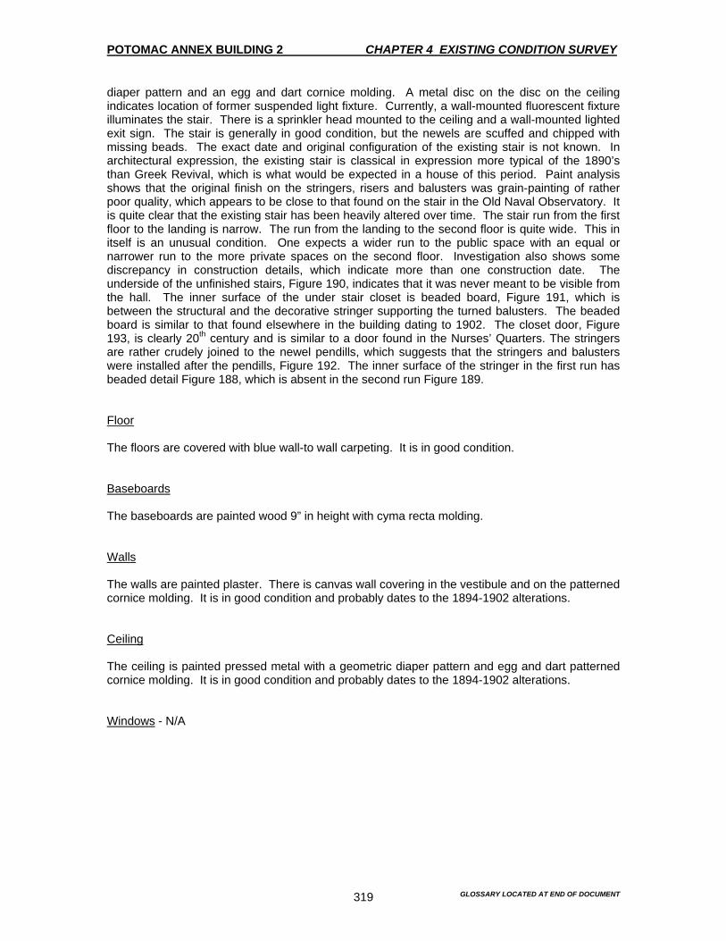
POTOMAC ANNEX BUILDING 2 CHAPTER 4 EXISTING CONDITION SURVEY
GLOSSARY LOCATED AT END OF DOCUMENT 319
diaper pattern and an egg and dart cornice molding. A metal disc on the disc on the ceiling indicates location of former suspended light fixture. Currently, a wall-mounted fluorescent fixture illuminates the stair. There is a sprinkler head mounted to the ceiling and a wall-mounted lighted exit sign. The stair is generally in good condition, but the newels are scuffed and chipped with missing beads. The exact date and original configuration of the existing stair is not known. In architectural expression, the existing stair is classical in expression more typical of the 1890’s than Greek Revival, which is what would be expected in a house of this period. Paint analysis shows that the original finish on the stringers, risers and balusters was grain-painting of rather poor quality, which appears to be close to that found on the stair in the Old Naval Observatory. It is quite clear that the existing stair has been heavily altered over time. The stair run from the first floor to the landing is narrow. The run from the landing to the second floor is quite wide. This in itself is an unusual condition. One expects a wider run to the public space with an equal or narrower run to the more private spaces on the second floor. Investigation also shows some discrepancy in construction details, which indicate more than one construction date. The underside of the unfinished stairs, Figure 190, indicates that it was never meant to be visible from the hall. The inner surface of the under stair closet is beaded board, Figure 191, which is between the structural and the decorative stringer supporting the turned balusters. The beaded board is similar to that found elsewhere in the building dating to 1902. The closet door, Figure 193, is clearly 20th century and is similar to a door found in the Nurses’ Quarters. The stringers are rather crudely joined to the newel pendills, which suggests that the stringers and balusters were installed after the pendills, Figure 192. The inner surface of the stringer in the first run has beaded detail Figure 188, which is absent in the second run Figure 189. Floor The floors are covered with blue wall-to wall carpeting. It is in good condition. Baseboards The baseboards are painted wood 9” in height with cyma recta molding. Walls The walls are painted plaster. There is canvas wall covering in the vestibule and on the patterned cornice molding. It is in good condition and probably dates to the 1894-1902 alterations. Ceiling The ceiling is painted pressed metal with a geometric diaper pattern and egg and dart patterned cornice molding. It is in good condition and probably dates to the 1894-1902 alterations. Windows - N/A

POTOMAC ANNEX BUILDING 2 CHAPTER 4 EXISTING CONDITION SURVEY
GLOSSARY LOCATED AT END OF DOCUMENT 320
Doors The inner vestibule door is set into a paneled wood frame with transom, console brackets and sidelights. The door is a double-leaf wood and glass door on swing hinges. The door leading to the northeast parlor, Room 2124, is a 4-panel wood door, Figure 196. It is an historic door, which has been heavily altered by the installation of glazed upper panels, new hardware and closures. This door is similar to others found in the Residence and in the Old Naval Observatory, which are presumed to date to the 1890’s alterations. Of the doors tested, this door is the only one that had a grain-painted finish. The finish appears to be of a much higher quality than that found on the stairs, which may indicate different dates of installation for the two features. The doorframe is the typical 8” with molding found throughout the Old Naval Observatory and Residence. The first finished layer was white. The door entering the northwest parlor, Room 2122, is a panel wood door, Figure 201. It is an historic door, which has been heavily altered by the installation of glazed upper panels, new hardware and closures. The doorframe casing on the hall side is missing. This is probably due to the installation of the plaster and metal lath furring mentioned above. The doorframe casing on the interior does not match other historic frames. This clearly indicates an alteration over time, but possibly indicating that the opening is not original. There is an opening leading from the hall to Room 2122A and another leading from the hall to 2124B, which do not appear to have ever had doors. The casing detail is similar to that found on the door and window frames in the back building, which appears to be of a late 19th-century style. This may mean that these openings and the finishes in the back building are contemporaneous, and represent alterations to the 1847 structure. Lighting A metal box up light is mounted to the wall. Built-in features There is the typical wall-mounted metal frame room signage. There is a floor-standing steel water fountain and wood framed wall-mounted notice board. HVAC There is a cast-iron radiator with decorative cover located against the west wall. F&LS Sprinkler heads are mounted to the east and west walls. The pipes are concealed. Other elements include a wall mounted emergency light until, fire extinguisher, wall mounted fire alarm pull station near main entry door and a metal exit sign on the frame of main the entry. Front Entry Vestibule The exterior front door and the interior door leading to the central hallway define the front entry vestibule.

POTOMAC ANNEX BUILDING 2 CHAPTER 4 EXISTING CONDITION SURVEY
GLOSSARY LOCATED AT END OF DOCUMENT 321
Floor The floors are covered with blue wall-to-wall carpeting. It is in good condition. Baseboards The baseboards are painted wood 9” in height with cyma recta molding. Walls The walls are covered with canvas, which has been painted. Ceiling The ceiling is pressed metal with a geometric diaper pattern with egg and dart cornice molding. There is some minor damage due to the installation of conduit. Windows - N/A Doors The inner vestibule door is set into a paneled wood frame with a transom, console brackets and sidelights. The door is a non-original double leaf wood and glass door on swing hinges. Lighting - N/A Built-in features - N/A HVAC – N/A F&LS Sprinkler heads are mounted to the east and west walls. There is a wall-mounted lighted exit sign. Room 2124B There is a small vestibule at the south end of the central hall under the stair landing. The east and west ends are enclosed as closets. This space is defined on the south by the rear brick wall of the Residence and on the north by a wall with detailing suggesting a late 19th-century construction. Based on the evidence, it seems unlikely that this space represents an original configuration.
POTOMAC ANNEX BUILDING 2 CHAPTER 4 EXISTING CONDITION SURVEY
GLOSSARY LOCATED AT END OF DOCUMENT 322
Floor The floors are covered with blue wall-to-wall carpeting. It is in good condition. Baseboards There is a section of 9” baseboard along the north wall. Walls The walls are painted plaster on the north and south. Above the east closet door, the wall is gypsum board. Above the west closet door is painted wood board. Ceiling The ceiling is pressed metal with egg and dart cornice molding, which is interrupted by the east closet partition. The soffit under the stair is beaded board. Windows - NA Doors The door entering the closet from Room 2126, Figure 198, appears to be an historic 4-panel wood door. Its frame on the closet side is a typical 8” frame found throughout the Residence and the Old Naval Observatory. The closet doors are not historic. Lighting There is one halogen light mounted to the ceiling. Built-in features - N/A HVAC - N/A F&LS Sprinkler pipes are mounted to the wall. Room 2124 The northeast room was designated in inventories of 1861, 1867 and 1877 as a parlor. It is currently used as an office, Figures 195-197.

POTOMAC ANNEX BUILDING 2 CHAPTER 4 EXISTING CONDITION SURVEY
GLOSSARY LOCATED AT END OF DOCUMENT 323
Floor The floors are covered with blue wall-to-wall carpeting. It is in good condition. Baseboards The baseboards are 12” steel electrical raceway. Walls The walls are painted plaster with a molded wood chair rail. The walls are in good condition. The south wall that has an adjoining built in closets appears to be original. Inventories also refer to closets between the rooms. Ceiling The ceiling is pressed metal with a geometric diaper pattern and an egg and dart cornice molding. The ceiling is in good condition and probably dates to the 1894-1902 alterations. Windows The windows are painted molded wood casing, 6” on east wall window and 8” on north wall window. There is a difference in the casing dimensions between the closet wall and the fireplace. The wood shutters are painted shut. The paint is in poor condition on east window wood surrounds. There are possible moisture problems. One A/C unit is installed in an east window with Plexiglas side panels. Doors The corridor door was described above. There is a door opening with historic 8” frame opening from this room to the closet space to the south. There is no door in this location now, but based on the hinge ghosts and remaining lock mortise, the original door had an inward swing. Lighting Two metal box up-lights are mounted to the walls. Built-in features There is a wood mantel with floral swag motif supported by a paired colonnade with a beveled mirror over the mantel. The mantel has a green ceramic tiled firebox surround. The firebox is located on the east wall. Stylistically this fireplace is typical of the late 19th-century and probably dates to the 1894-1902 alterations. It appears to have been refinished recently. HVAC There is cast-iron radiator with a wood-framed with a `metal screen.
POTOMAC ANNEX BUILDING 2 CHAPTER 4 EXISTING CONDITION SURVEY
GLOSSARY LOCATED AT END OF DOCUMENT 324
F&LS Sprinkler pipes are mounted to the walls. Additional sprinkler heads are located on the south wall. Closets located between Rooms 2124 and 2126 The 1861 Inventory mentions floor covering in the entry between the northeast and southeast rooms. This suggests more than a door in the partition wall. The same inventory documents items in an east closet between the northeast and southeast rooms on the second floor. While there is no certainty, there is some reason to believe that the east closet, at least, may be an original feature. However, the trim finishes indicate alteration during the 20th century. Both closets appear on the 1927 floor plans. West Closet Floor The floor is covered with 12” square black vinyl tile. Baseboards The baseboards are painted wood 9” in height with cyma recta molding. Walls The walls are painted plaster. Ceiling The ceiling is painted plaster. Windows - N/A Doors The door is a 4-panel wood door with a brass knob, a metal painted lockset and steel hinges. Lighting There is one halogen fixture mounted to the north and west walls. HVAC - N/A

POTOMAC ANNEX BUILDING 2 CHAPTER 4 EXISTING CONDITION SURVEY
GLOSSARY LOCATED AT END OF DOCUMENT 325
F&LS Sprinkler pipes are mounted to the ceiling. East Closet This space is now used as a toilet. Floor The floors are covered with wall-to-wall carpeting. It is in good condition. Baseboards The baseboards are painted 6” flat wood. Walls The walls are painted plaster. Ceiling The ceiling is painted plaster. Windows - N/A Doors The door is a 4-panel wood door with brass knob, a metal painted lock-set and steel hinges. On the closet side of the door the panel surface is flush with the rails and stiles. This is an anomalous condition, which may indicate a later installation date. Lighting One incandescent fixture is mounted on the ceiling. Built-in features There is one wall-mounted lavatory and one toilet. HVAC - N/A F&LS Sprinkler pipes are mounted to the ceiling.

POTOMAC ANNEX BUILDING 2 CHAPTER 4 EXISTING CONDITION SURVEY
GLOSSARY LOCATED AT END OF DOCUMENT 326
Room 2126 This southeast room was designated in inventories of 1861, 1867 and 1877 as the dining room. It is currently used as an office, Figure 198. Floor The floors are covered with blue wall-to-wall carpeting. It is in good condition. Baseboards The baseboards are 12” steel electrical raceway. Walls The walls are painted plaster. The fireplace on the east wall is blocked and filled with gypsum board. The north wall and adjoining built-in closets appear to have been resurfaced with gypsum board. Ceiling The ceiling is painted pressed metal ceiling with geometric a diaper pattern and an egg and dart cornice molding. The ceiling is in good condition and probably dates to the 1894-1902 alterations. Windows The windows have a painted molded wood casing, 5” on east wall window and 8” on south wall window and a wood frame and sill. The difference in the casing dimensions between the south and east windows is probably due to the window fitting tightly between the closet wall and the fireplace. The exterior condition shows that the south window was converted from a door, which gave access to a former porch. The wood shutters are painted shut. There is one window mounted A/C unit with plywood side panels. Doors The corridor door is discussed above in the discussion of Room 2124A. The door leading from Room 2126 to the closet, in the southwest corner, was mentioned in the discussion of the closet. This appears to be an early, if not original, opening. However, the door casing on this side of the wall was removed. The door leading to Room 2124 is a two-panel wood and glass door with no frame casing. This is clearly a 20th-century door. Lighting Two metal box up-lights are mounted to the walls. Built-in features - N/A
POTOMAC ANNEX BUILDING 2 CHAPTER 4 EXISTING CONDITION SURVEY
GLOSSARY LOCATED AT END OF DOCUMENT 327
HVAC There is a cast-iron radiator against the north wall with a wood-framed cover with a metal screen. F&LS Sprinkler heads are mounted to north wall. Sprinkler pipes are mounted to south wall. Room 2122 This northwest room was designated in inventories dated 1861, 1867 and 1877 as a parlor. Historic photographs of the exterior show a chimney on the west wall of this room. However, there is no evidence of a mantel, a fireplace or stove on the interior. The space is currently used as an office, Figures, 200 and 201. Floor The floors are covered with blue wall-to-wall carpeting. It is in good condition. Baseboards The baseboards are 12” steel electrical raceway. Walls The walls are painted plaster. The walls are in good condition. The south wall has a transom opening near the top. It is likely that the transoms were added to the wall sometime later after 1902. It seems likely that the pressed metal ceilings were installed in 1902. However, the bundled sheaf cornice molding on either side of the transoms does not match the other detail in the ceiling. It is not fitted very well at the edges indicating a later installation. The 1927 drawings indicate that this room was used as a print shop, which may indicate a need for more ventilation than was provided by one window. Ceiling The ceiling is pressed metal with grid diaper pattern. Cornice molding has egg and dart motif on the east, west and north and a bundled sheaf on south. The ceiling is in good condition and was probably installed during the 1894-1902 alterations. Windows The windows have a painted wood frame, wood sill and 9” molded wood trim. Wood shutters are painted shut. Window mounted A/C unit with Plexiglas side panels.
POTOMAC ANNEX BUILDING 2 CHAPTER 4 EXISTING CONDITION SURVEY
GLOSSARY LOCATED AT END OF DOCUMENT 328
Doors The corridor door was described in the discussion of Room 2124A. The frame does not match the historic frames found elsewhere in the building. The door leading to 2122A is described in the discussion of that room. The frame does match other historic frames in the Residence. Lighting Two metal box up-lights are mounted to the east and west walls. Built-in features - N/A HVAC There is a painted cast-iron radiator with a cover located under the north window. F&LS Sprinkler pipes are mounted to the wall. Room 2122A Corridor leading from the central hall to the 1848 hyphen, Figures 202-204. The date of this space is unknown. However, it is likely to be associated with alterations made by the Naval Museum of Hygiene or Naval Medical School. In addition to the notes on historic documentation, there is an interruption of the cornice molding detail from the egg and dart to the bundled sheaf along the partition wall. This is between this room and Room 2122, which is repeated in the other room. This may indicate that the metal ceiling was installed in one period and a new cornice molding was installed at a later date, or simply that the transoms are later installations. Floor The floors are covered with blue wall-to-wall carpeting. It is in good condition. Baseboards The baseboards are painted wood 9” in height with cyma recta molding. Walls The walls are painted plaster. The wood-framed transom in the north wall is divided into five sections. Two openings have fixed painted panels and three are operable, although painted shut. There is an arched opening on the west, leading to the hyphen. Its architectural integrity is compromised by the gypsum board partition subdividing the office space in that area, Figure 204.

POTOMAC ANNEX BUILDING 2 CHAPTER 4 EXISTING CONDITION SURVEY
GLOSSARY LOCATED AT END OF DOCUMENT 329
Ceiling The ceiling is pressed metal with geometric diaper pattern. The cornice has an egg and dart motif on the east and west walls. There is a bundled sheaf motif on the north. The ceiling is in good condition. Windows - N/A Doors The door leading into Room 2122 is a 4-panel wood door. It has been heavily altered by the installation of glazing panels. The doorknob is glass. Lighting One metal box up-lights are mounted above east door. Built-in features - N/A HVAC - N/A F&LS Sprinkler heads are mounted to the south wall. There is one wall-mounted fire extinguisher. Room 2123 Women’s toilet room at southwest corner. Non-original finishes and use impact original appearance, Figures 202-205. In the 1927 floor plans, this room is designated as a print shop. Floor The floor is covered with 1”square ceramic tiles. The floor surface is uneven and there is some damage to tile near entrance door. Baseboards - N/A Walls The walls are covered with 4” ceramic tiles. Some damage and missing tiles are noted on the east wall due to the installation of the lavatory.

POTOMAC ANNEX BUILDING 2 CHAPTER 4 EXISTING CONDITION SURVEY
GLOSSARY LOCATED AT END OF DOCUMENT 330
Ceiling The suspended 2x4 lay-in acoustical tile ceiling is in good condition. It obscures the historic metal ceiling above. Windows The windows have a painted wood frame, wood sill and 7” molded wood trim. The wood shutters are painted shut. Lighting Two 2x4 fluorescent fixtures are integral with the suspended ceiling. Built-in features There are three toilets situated along the west wall. One stainless steel lavatory and mirror unit is mounted to the east wall. There is one plastic slop sink against the east wall. There is one wall-mounted metal trash container and two wall-mounted wood framed mirrors and baked enameled toilet partitions at the west end. The partitions are mounted to the floors and walls with stainless steel hardware. HVAC There is one cast-iron radiator located beneath the window. F&LS Sprinkler heads are located in the acoustical tile ceiling. Room 2121 This space was constructed in 1848 to connect the residence to the Old Naval Observatory to the west. It has been bisected by an intrusive gypsum board partition, which detracts from the original size and volume of the space and the architectural expression of the arched opening to the east, Figure 204. The rooms are used for offices and a corridor leading to the west wing of the Old Naval Observatory. Floor The floors are covered with blue wall-to-wall carpeting. It is in good condition. Baseboards The baseboards in the office space are 12” steel electrical raceway. The baseboards in the corridor are painted wood 9” in height with cyma recta molding.
POTOMAC ANNEX BUILDING 2 CHAPTER 4 EXISTING CONDITION SURVEY
GLOSSARY LOCATED AT END OF DOCUMENT 331
Walls The walls are painted plaster on the perimeter walls. The bisecting partition is gypsum board. There is a simple wood chair rail along the north and south walls. There is a simple wood crown molding at the juncture of the wall and ceiling except at the partition. Ceiling The ceiling is painted wood beaded board, which was probably installed in 1902 when the Naval Medical School removed the pitched roof to accommodate the second-story addition. Windows The windows in the office and in the corridor have painted wood frames and sills and a 7” casing with trim typical of that found throughout the Residence. The south window in the office probably dates to 1848. The north windows in the corridor probably date to the 1894-1902 alterations. Lighting Metal box up-lights are mounted to the walls. Built-in features - N/A HVAC A cast iron radiator is located beneath the window on the south wall. F&LS Sprinkler pipes are mounted to the north and south walls. Room 2125A This is the corridor separating Room 2125 and the Residence. Floor The floors are covered with blue wall-to-wall carpeting. It is in good condition. Baseboards The baseboards are painted wood 4”-5” in height with cyma recta molding.
POTOMAC ANNEX BUILDING 2 CHAPTER 4 EXISTING CONDITION SURVEY
GLOSSARY LOCATED AT END OF DOCUMENT 332
Walls The north, east and south walls are painted plaster. The west wall is a gypsum board partition with a flat 5” wood baseboard. This is a closet with access from Room 2125. It appears from the 1927 drawings that this closet housed a stair at that time. Since there is no other documentation that shows the stair, its date of construction is not known. Ceiling The ceiling is pressed metal with geometric diaper pattern and an egg and dart cornice molding. Windows - N/A Lighting A 1x4 fluorescent fixture is surface-mounted to the ceiling. Built-in features Typical metal framed door signage. HVAC - N/A F&LS A sprinkler head is mounted to the west wall. A lighted exit sign mounted to the east wall. Room 2125B This is the corridor separating constructed around Room 2125 in 1918 Floor The floors are covered with blue wall-to-wall carpeting. It is in good condition. Baseboards A 9” wood baseboard is located along the east wall. Walls The west and north walls are of exposed painted brick. The east wall is painted plaster. A simple crown molding is located on the west wall. There is a section of crown molding missing.

POTOMAC ANNEX BUILDING 2 CHAPTER 4 EXISTING CONDITION SURVEY
GLOSSARY LOCATED AT END OF DOCUMENT 333
Ceiling The ceiling is composed of beaded board, whose details differ slightly from that found in areas dating to 1902. Windows The windows have painted wood frames, wood sills and 4” wood trim. Lighting A 1x4 fluorescent fixture is surface-mounted to the ceiling. Built-in features - N/A HVAC There is one cast iron radiator beneath the windows. F&LS Sprinkler pipes are hung from the ceiling. Other equipment includes a wall-mounted fire alarm pull station, an alarm bell and a lighted exit sign. Second Floor As noted above, the second floor of the Residence retains some integrity from its historic period. However, the results of the visual inspection compared to the historic documentation do indicate some inconsistencies. The inventories dated 1861, 1867, and 1877, support the general floor plan scheme of four rooms per floor separated by a central stair hall, which is reflected in the existing conditions as they have been modified. However, they offer some conflicting information for the upper floor and there are listings for chambers in each major corner. A small southwest room, entries and closets between the major rooms no longer exist. However, it is certain that the floor plans on the west side have been altered more than once to accommodate the changing uses of the building, particularly noting the corridor leading west to the 1902 Second Floor Addition to the Old Naval Observatory. The 1927 floor plan shows that the west half of the second floor is entirely open, suggesting that all the original partition walls had been removed prior to that time to accommodate a bacteriological laboratory. The existing corridor partition walls may have been installed as part of the 1940’s renovations, which converted the building to office use. While the spaces were originally used as “chamber” or bedrooms and other private family functions, the spaces were appropriated for offices as early as the Naval Museum of Hygiene period. They continue in that use today. Note: Despite the room numbering sequence, the central hall is discussed first, then the major rooms.
POTOMAC ANNEX BUILDING 2 CHAPTER 4 EXISTING CONDITION SURVEY
GLOSSARY LOCATED AT END OF DOCUMENT 334
Room 2225 – Central Hall Floor The floors are covered with blue wall-to-wall carpeting. It is in good condition. Baseboards The baseboards are painted wood 9” in height with cyma recta molding. There are no baseboards on the south wall. Walls The north, east and west walls are painted plaster. The south wall is a gypsum board stair enclosure. There is an intrusive partition, which compromises the original integrity. Ceiling The ceiling is painted pressed metal with geometric diaper pattern and an egg and dart cornice molding. There is an oval wood-framed skylight in the ceiling with wire glass, Figure 209. The 19th-century inventories indicate that there was a skylight in the ceiling. However, there is no documentation for its appearance. The pressed metal ceiling probably dates to the 1894-1902 alterations. The casing of the skylight is placed over the surface of the ceiling suggesting that this casing, at least, date to the time of ceiling installation. Windows - N/A Doors Some of the door openings leading from the central hall to the flanking offices are probably original. Rooms 2224, 2226 and 2223A are illustrated on the 1927 floor plans. These all have 8” frame casings similar to those throughout the building. The opening leading to Room 2222 does not appear on the 1927 plan, and while the corridor side casing matches the others, the inside is a 3.5” frame similar to those found on the post 1927 walls. The door leading to Room 2224 is a 5-panel wood door similar to those found throughout the hospital buildings on the site, indicating an early 20th-century date. The doors leading to Rooms 2226 and 2225A are 4-panel wood doors, which have been altered. There is no door in the opening between the hall and 2223A. The door in the gypsum board partition is a fire door and not original. Lighting One metal box up light is mounted to the north wall. Built-in features There is a floor-standing steel water fountain and typical wood and metal-framed door signage.

POTOMAC ANNEX BUILDING 2 CHAPTER 4 EXISTING CONDITION SURVEY
GLOSSARY LOCATED AT END OF DOCUMENT 335
HVAC - N/A F&LS Sprinkler heads are mounted on the ceiling. There is one lighted exit sign, one fire alarm pull station, one alarm bell mounted on the south wall, a wall-mounted emergency light and a fire extinguisher. There is also a sprinkler standpipe system control valve. Room 2225A Room at north end of hall, Figure 210. Historic inventories identify this room as the library. It is currently used as office space. The west wall of this room is out of alignment with the remainder of the original partition wall indicating that part of the original partition was replaced with the existing, which makes this room larger than its original size. This condition is illustrated in the 1927 plan, suggesting an earlier alteration or an unlikely original condition. Floor The floors are covered with blue wall-to-wall carpeting. It is in condition. Baseboards The baseboards along the south, east and west wall are 12” steel electrical raceway. On the north wall the baseboard is painted wood 6” in height with cyma recta molding. Walls The walls are painted plaster. Ceiling The ceiling is painted gypsum board. It is in good condition. Windows The window frames are 5’-6” flat painted wood. This is typical of the windows on this floor and probably an original condition. The wood shutters are painted shut. This is the window with the historic inscription. Please refer to the exterior survey for more information. Lighting One metal box up light is mounted to the south wall. Built-in features - N/A

POTOMAC ANNEX BUILDING 2 CHAPTER 4 EXISTING CONDITION SURVEY
GLOSSARY LOCATED AT END OF DOCUMENT 336
HVAC A floor-standing cast iron radiator is located beneath the window. F&LS A sprinkler head is mounted to the ceiling. Room 2222 Historic inventories identity this room as the northeast chamber. It is currently used as office space, Figure 211. Floor The floors are covered with blue wall-to-wall carpeting. It is in good condition. Baseboards The baseboards are 12” steel electrical raceways, with the exception of a small section of painted wood baseboard 6” in height with cyma recta molding. Walls Most of the walls appear to be surfaced with gypsum board, which may be attached to the original plaster. The south section of the east wall is painted plaster, which is probably the original partition wall. The north section is a partition wall relating to the enlargement of the small room to the east. There is a flat wood chair rail on this wall as well. The south wall is a gypsum board partition relating to the construction of the angled corridor leading to the 1902 addition to the west. Ceiling The ceiling is suspended 2x4 lay-in acoustical tile with some minor soiling. Windows The window frames are 5’-6” flat painted wood. This is typical of the windows on this floor, which is probably an original condition. The wood shutters are painted shut. One window mounted A/C unit with Plexiglas side panels. Moisture from A/C has resulted in deterioration of windowsill. Lighting Two metal box up-lights are mounted to the east and west walls. Built-in features - N/A
POTOMAC ANNEX BUILDING 2 CHAPTER 4 EXISTING CONDITION SURVEY
GLOSSARY LOCATED AT END OF DOCUMENT 337
HVAC There is one cast-iron radiator located beneath the window. F&LS Sprinkler heads are cut into the suspended ceiling system. Room 2223 Historic inventories identify this room as the southwest chamber. They also refer to a small southwest chamber and closets, which are not extant. It is probable that these spaces were removed in conjunction with the construction of the biological laboratory represented in the 1927 floor plans. The space is currently used as an office, Figure 213. Floor The floors are covered with blue wall-to-wall carpeting. It is in good condition. Baseboards The baseboards are 12” steel electrical raceways. Walls The south, east and west walls appear to have been resurfaced with gypsum board, which may be attached to the original plaster. The north wall is a gypsum board partition associated with the installation of the angled corridor. Ceiling The ceiling is covered with painted fiberboard sheets nailed to the ceiling. The surface is in good condition. Windows The window frames are 5’-6” flat painted wood. This is typical of the windows on this floor, which is probably an original condition. The wood shutters are painted shut. Lighting Two metal box up-lights are mounted to the walls.

POTOMAC ANNEX BUILDING 2 CHAPTER 4 EXISTING CONDITION SURVEY
GLOSSARY LOCATED AT END OF DOCUMENT 338
Built-in features There is a gypsum board telecommunications closet in the southeast corner with 7” molded wood baseboard, a four panel wood door with stainless steel lever and butt hinges and a molded wood door trim. There is a vertical riser in the southwest corner. HVAC There is one cast-iron radiator with a decorative cast-iron cover. F&LS Sprinkler heads are mounted to the ceiling. Room 2223A Corridor space between the second floor central hallway of house and the 1902-03 Second Floor Additions between the Residence and the Old Naval Observatory, Figure 212. Floor The floors are covered with blue wall-to-wall carpeting. It is in good condition. Baseboards The baseboards are 6” painted wood with a quarter round shoe molding. Walls The north and south walls are painted gypsum board. Ceiling The ceiling is painted gypsum board in good condition. Windows - N/A Lighting One metal box up light is mounted to the west wall. Built-in features Typical metal-framed room signage
POTOMAC ANNEX BUILDING 2 CHAPTER 4 EXISTING CONDITION SURVEY
GLOSSARY LOCATED AT END OF DOCUMENT 339
HVAC - N/A F&LS Sprinkler head mounted to the ceiling. Room 2224 Historic inventories identify this as the northeast chamber. It is currently used for office and conference space, Figure 214. Floor The floors are covered with blue wall-to-wall carpeting. It is in good condition. Baseboards The baseboards along the other walls are 12” steel electrical raceways. Walls The north, south and west walls are painted plaster. The west wall has a flat painted wood chair rail. The east wall is covered with veneered plywood. This is an intrusive wall finish, which probably covers the fireplace. Ceiling The ceiling is painted gypsum board. It is in good condition. Windows The window frames are 5’-6” flat painted wood. This is typical of the windows on this floor, which is probably an original condition. The wood shutters are painted shut. Some damage to south wall window trim due to installation of conduits. There is one A/C unit with Plexiglas side panels on south window opening. Lighting Two metal box up-lights are mounted to the walls. Built-in features - N/A HVAC There is a cast-iron radiator under the east window.
POTOMAC ANNEX BUILDING 2 CHAPTER 4 EXISTING CONDITION SURVEY
GLOSSARY LOCATED AT END OF DOCUMENT 340
F&LS Sprinkler heads mounted to the ceiling. The following rooms are part of the 1847 Residence Back Building structure. The historic inventories refer to servant’s rooms, which may have been located in this area. The current spatial arrangement is reflected in the 1927 floor plans. As mentioned in the discussion of the first floor, the stair indicated in the 1927 plan, is no longer extant. The spaces are currently used as offices and a toilet. Room 2228 – Men’s Toilet Floor The floors are covered with 12” square, cream colored vinyl tile. It is in good condition. Baseboards The baseboards are painted wood 4” in height with cyma recta molding. Walls The walls are painted plaster. Ceiling The ceiling is painted gypsum board ceiling. It is in good condition. Windows The window has a painted wood frame, wood sill and 3” molded wood trim. The upper part of the opening is filled with a plywood panel and it is mounted to an exhaust fan. Lighting There is one 1x4 fluorescent fixture surface mounted to the ceiling. Built-in features There are two toilets against the west wall. Two lavatories are mounted to the east wall, one wall-mounted steel trashcans, two wall-mounted steel-framed mirrors and painted wood-framed toilet partitions mounted to the floors. The west wall has wood paneled doors with steel hardware.
POTOMAC ANNEX BUILDING 2 CHAPTER 4 EXISTING CONDITION SURVEY
GLOSSARY LOCATED AT END OF DOCUMENT 341
HVAC There is one cast-iron radiator located below the window. F&LS Sprinkler pipes are suspended from the ceiling. There is one smoke detector. Room 2228A Small locked closet. There was no need to identify this space as a room. Room 2229 Corridor to 1918 Additions to the south is also used for storage. A stair leads up to the 1918 Additions second-floor level. Floor The floors are covered with blue wall-to-wall carpeting. It is in good condition. Baseboards The baseboards are painted wood 4” in height with cyma recta molding. Walls The walls are painted plaster. Ceiling The ceiling is painted plaster. Some peeling paint and efflorescence is note at the southeast corner indicating moisture penetration. There is a hatch opening in the ceiling. Windows The window has a painted wood frame, wood sill and 3” molded trim. There is one window mounted A/C unit with plywood side panels. Lighting There is one 1x4 fluorescent fixture suspended from ceiling.
POTOMAC ANNEX BUILDING 2 CHAPTER 4 EXISTING CONDITION SURVEY
GLOSSARY LOCATED AT END OF DOCUMENT 342
Built-in features There is a varnished wood enclosure for plumbing and conduits in the southeast corner. A wood stair leads up to the 1918 addition. The treads and risers are surfaced with carpeting. Utilitarian wood handrails are mounted to the wall and treads. HVAC - N/A F&LS Sprinkler heads are mounted to the ceiling. Room 2229A This is a vestibule between Room 2229 and the Residence stairway. Used as photocopy room. Floor The floors are covered with blue wall-to-wall carpeting. It is in good condition. Baseboards The baseboards on the north, south and east walls are painted wood 9” in height with cyma recta Molding. The west wall has a flat painted wood baseboard. Walls The walls are painted plaster. Ceiling The ceiling is painted pressed metal with geometric diaper pattern and egg and dart cornice molding. It is in good condition. Windows The window has a painted wood frame, wood sill and 5” mounted wood trim. Lighting A 1X4 fluorescent fixture is surface mounted to ceiling. Built-in features There is typical metal-framed room signage on the walls.

POTOMAC ANNEX BUILDING 2 CHAPTER 4 EXISTING CONDITION SURVEY
GLOSSARY LOCATED AT END OF DOCUMENT 343
HVAC - N/A F&LS A sprinkler head is mounted to east wall above closet door. Basement The 19th-century inventories indicate that the kitchen was in the basement. However, the floor plans and finishes are so heavily altered that there is no visible evidence of the original configuration. The basement of the connecting hyphen between the Residence and the Old Naval Observatory is not excavated. The basement is currently used for custodial offices and locker rooms and for file storage. The basement areas are generally worn, soiled and poorly maintained, Figures 217-220. Room 2013 Custodial staff locker room at northwest corner of basement space. Floor The floor is covered with 9” square gray vinyl tile. There is some patching and soiling. Baseboards The baseboards are a flat painted wood 5” in height. Walls The plaster walls are mostly painted. The west section of the north wall is surfaced with gypsum board. General scuffing of the surfaces and large holes are due to mechanical damage. The door to exterior has been in-filled with plywood and there is some mechanical damage to the plaster on the adjoining wall surfaces. Ceiling There are 12” square acoustical tiles surface mounted to ceiling. There are some missing and loose tiles in northwest corner. Windows The window has a simple molded wood trim. There is one window mounted A/C unit with Plexiglas side panels. Lighting Five 1x4 fluorescent box fixtures are surface-mounted to the ceiling.

POTOMAC ANNEX BUILDING 2 CHAPTER 4 EXISTING CONDITION SURVEY
GLOSSARY LOCATED AT END OF DOCUMENT 344
Built-in features Steel locker units, located against east and south walls, are mounted on a wood base with a gypsum board panel between the lockers and ceiling. One lavatory is mounted on the east wall. One wood framed notice board is mounted on the west wall. HVAC The steel fin-tube radiator unit on west wall appears not to function. One cast iron radiator is hung from ceiling. F&LS Sprinkler pipes are hung from ceiling. Room 2014 Office located in center of basement area. Floor The floor is covered with blue wall-to-wall carpeting. It is in good condition. Baseboards The baseboards are flat painted wood 3” in height. Walls The east and west walls are painted plaster. The north and south walls are gypsum board partitions. Ceiling The ceiling is painted gypsum board with holes due to installation of conduits. Windows - N/A Lighting A 1x4 fluorescent fixture is surface-mounted to the ceiling. Built-in features There is a wall-mounted wood-framed notice board.
POTOMAC ANNEX BUILDING 2 CHAPTER 4 EXISTING CONDITION SURVEY
GLOSSARY LOCATED AT END OF DOCUMENT 345
HVAC - N/A F&LS Sprinkler heads are suspended from ceiling. Room 2014A Office at north end of basement space. Floor The floors are covered with blue wall-to-wall carpeting. It is in good condition. Baseboards The baseboard is a flat painted wood 5” in height. Walls The walls are painted gypsum board. A hole in the drywall adjacent to entrance doorway was probably caused by mechanical impact. A filled doorway to the exterior areaway on north wall appears to be drywall. There is an air conditioning unit in the door opening. The frame is wood with a simple molded trim. Ceiling The ceiling is painted gypsum board. There is a hole due to the installation of radiator pipes. Windows - N/A Lighting Two 1x4 fluorescent fixtures are surface-mounted to ceiling. Built-in features There is one floor-standing lavatory against the south wall. Steel locker units against west wall are mounted on a wood base with drywall in-fill panel between the lockers and ceiling. HVAC A cast-iron radiator unit is hung from the ceiling.
POTOMAC ANNEX BUILDING 2 CHAPTER 4 EXISTING CONDITION SURVEY
GLOSSARY LOCATED AT END OF DOCUMENT 346
F&LS Sprinkler pipes are suspended from the ceiling. Room 2015 Toilet located at southwest corner of basement area. Floor The floor is surfaced with smooth concrete with worn paint. There is a concrete curb at the urinal. Baseboards The baseboards are 7” vinyl. Walls The walls are painted plaster with a 4’ high painted hollow metal wainscot panel at the southwest corner. Moisture penetration on the south wall has resulted in peeling paint, efflorescence and powdering plaster. Ceiling The ceiling is painted gypsum board. The paint above the window is peeling. Windows The window has a simple wood frame and both surrounds are plaster. The lower half of the double-hung window sash has been removed and filled with an exhaust fan mounted to a metal panel. Lighting 1x4 fluorescent light surface-mounted to ceiling. Built-in features One lavatory and one urinal are mounted to the west wall. The built in shower stall at the southeast corner includes a concrete base and curb with gray marble sides held together with metal angles and a tie rod. The toilet is enclosed with a floor and wall-mounted wood partition with a two-paneled wood door. HVAC - N/A

POTOMAC ANNEX BUILDING 2 CHAPTER 4 EXISTING CONDITION SURVEY
GLOSSARY LOCATED AT END OF DOCUMENT 347
F&LS Sprinkler pipes are suspended from the ceiling. Room 2016 File room on the east side of the basement area. Floor The raised floor is surfaced with unfinished plywood. Baseboards Vinyl cove baseboard has been impacted by a raised floor and delaminating. Walls The walls are painted gypsum board. Ceiling The ceiling is 2x4 lay-in acoustical tile concealing a pressed metal ceiling surface above. Tiles are sagging and missing in areas. Pressed metal ceiling is damaged by installation of conduits. Windows The window has a wood frame typical to the basement with plaster surrounds. The window in the north wall separating Room 2106A has a simple wood frame. Lighting 2x4 fluorescent fixtures are inset in the lay-in acoustical tile ceiling. Built-in features - N/A. HVAC - N/A F&LS Sprinkler heads in the lay-in acoustical tile ceiling. Room 2016A File room functionally connected to Room 2016 at the northeast corner of the basement area.

POTOMAC ANNEX BUILDING 2 CHAPTER 4 EXISTING CONDITION SURVEY
GLOSSARY LOCATED AT END OF DOCUMENT 348
Floor The floor is covered with wall to wall carpeting, which is heavily soiled. Baseboards The baseboards are vinyl. Walls The walls are painted gypsum board. Ceiling There is lay-in acoustical ceiling tile. Windows The window is a typical basement window with a wood frame and plaster surrounds. The east window opening on south wall has been filled with plywood and has an A/C unit. The window in the south wall separating this room from Room 2016 has a simple wood frame. Lighting 2x4 fluorescent lights are part of the lay-in acoustical ceiling tiles. Built-in features There is a gypsum board closet in the northeast corner with a flush wood door and brass hardware. HVAC - N/A F&LS Sprinkler heads are installed through the lay-in acoustical tile ceiling. Room 2016B File room is functionally related to Room 2016 at the southeast corner of the basement area. Floor The raised floor is surfaced with unfinished plywood.
POTOMAC ANNEX BUILDING 2 CHAPTER 4 EXISTING CONDITION SURVEY
GLOSSARY LOCATED AT END OF DOCUMENT 349
Baseboards The vinyl baseboards are impacted by the raised floor surface. Walls The walls are painted gypsum board. Ceiling There are 2x4 lay-in acoustical ceiling tiles. Windows The window has a simple wood window frame typical to basement windows with plaster surrounds. There is one exhaust fan mounted to the replacement Plexiglas window panel on the south wall. Lighting 2x4 fluorescent fixtures are inset in lay-in acoustical ceiling tiles. Built-in features - N/A HVAC - N/A F&LS Sprinkler heads are installed through the lay-in acoustical ceiling tiles. Room 2016C Entry vestibule connecting basement areas to the south areaway Floor Painted smooth concrete floor surface. Baseboards - N/A Walls The walls are painted plaster.
POTOMAC ANNEX BUILDING 2 CHAPTER 4 EXISTING CONDITION SURVEY
GLOSSARY LOCATED AT END OF DOCUMENT 350
Ceiling The ceiling is pressed metal with geometric diaper pattern and egg and dart cornice molding. Installation of conduits has damaged the ceiling. Windows - N/A Lighting 1x4 fluorescent fixture is surface mounted to the ceiling. Built-in features There is one floor-standing steel water fountain. HVAC - N/A F&LS Sprinkler pipe is suspended from the ceiling. Room 2017 There was no access to this room because it was locked and could not be surveyed. Room 2017A and 2017B L-shaped corridor in the custodial services part of the basement area. Floor The floor is surfaced with a painted scored concrete floor. It is in good condition. Baseboards The baseboards are 4” vinyl connected to a metal paneled wall surface. Some of the baseboards are coming off and missing in sections. Walls The walls are painted plaster except where there is a gypsum board partition separating Room 2014. Walls are surfaced with utilitarian 4’ high hollow metal panel painted wainscoting, which is scuffed and dented. There is some mechanical damage to the plaster at the corners. The paint is blistering on the south perimeter wall indicating possible problems with moisture leakage from piping.
POTOMAC ANNEX BUILDING 2 CHAPTER 4 EXISTING CONDITION SURVEY
GLOSSARY LOCATED AT END OF DOCUMENT 351
Ceiling The ceiling is painted plaster. A large volume of mounted pipes and conduits impacts the ceiling. Windows - N/A Lighting Four 1X4 fluorescent fixtures are surface mounted to the ceiling. One naked incandescent light is mounted to the ceiling. One single tube fluorescent fixture is mounted to the wall. Built-in features - N/A HVAC - N/A F&LS Sprinkler piping is suspended from the ceiling. There is a lighted exit sign at the south exit doorway. There is a fire alarm pull-station and bell mounted to the wall near the south exit door. Room 2018A This is the basement of the Residence Back Building. It is separated from the other 1847 basement rooms by the areaway, which is now connected to 1918 addition. It is currently used as office space. Floor The floor is covered with blue wall-to-wall carpeting. It is in good condition. Baseboards - N/A Walls The walls are covered with painted beaded board with a 4’ fiberboard wainscot. There is evidence of a door opening on the north wall that has been filled. The trim remains. Ceiling The ceiling is covered with a painted wood beaded board. Post and beam, made of wood run north and south through the center of the room. There is some fiberboard patching along the south wall.
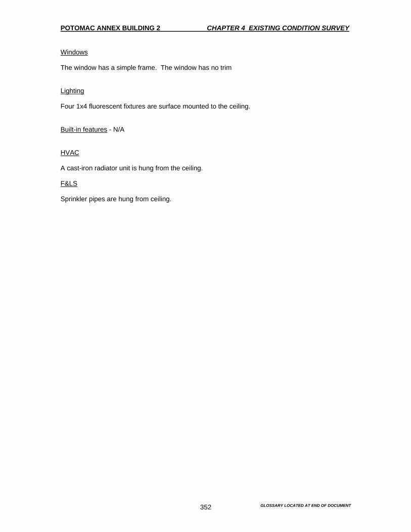
POTOMAC ANNEX BUILDING 2 CHAPTER 4 EXISTING CONDITION SURVEY
GLOSSARY LOCATED AT END OF DOCUMENT 352
Windows The window has a simple frame. The window has no trim Lighting Four 1x4 fluorescent fixtures are surface mounted to the ceiling. Built-in features - N/A HVAC A cast-iron radiator unit is hung from the ceiling. F&LS Sprinkler pipes are hung from ceiling.
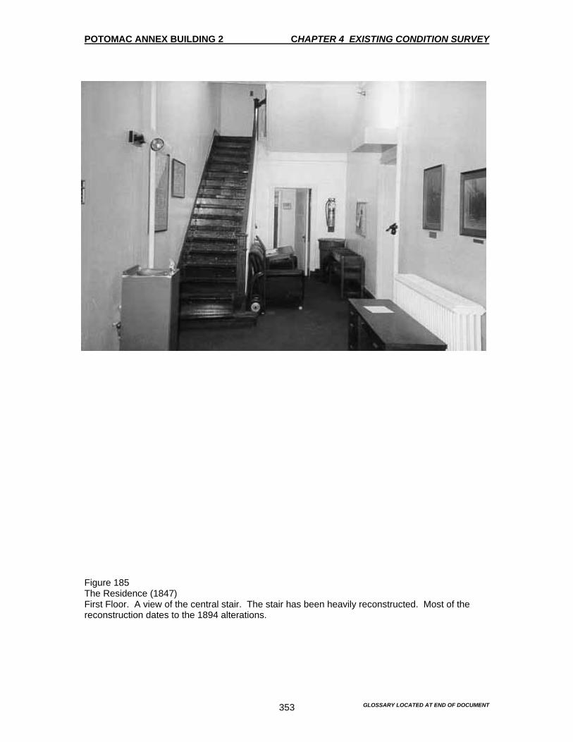
POTOMAC ANNEX BUILDING 2 CHAPTER 4 EXISTING CONDITION SURVEY
GLOSSARY LOCATED AT END OF DOCUMENT 353
Figure 185 The Residence (1847) First Floor. A view of the central stair. The stair has been heavily reconstructed. Most of the reconstruction dates to the 1894 alterations.
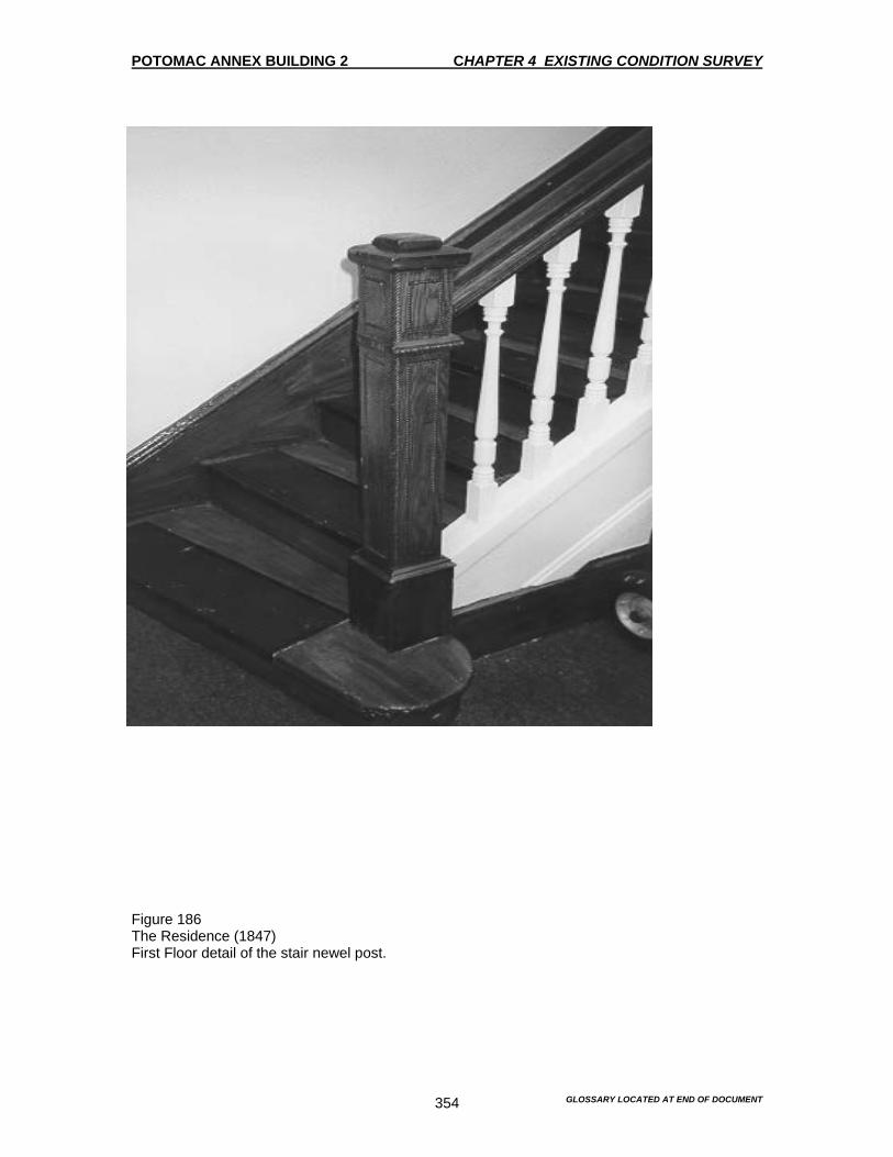
POTOMAC ANNEX BUILDING 2 CHAPTER 4 EXISTING CONDITION SURVEY
GLOSSARY LOCATED AT END OF DOCUMENT 354
Figure 186 The Residence (1847) First Floor detail of the stair newel post.
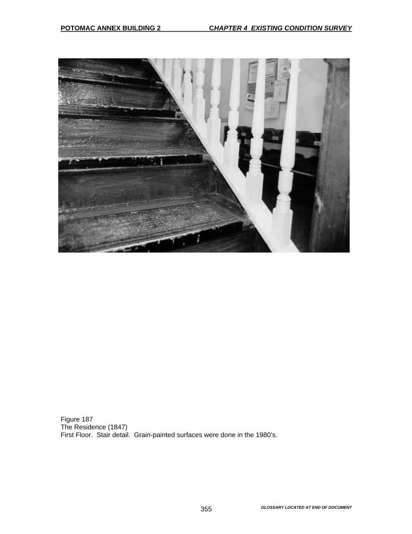
POTOMAC ANNEX BUILDING 2 CHAPTER 4 EXISTING CONDITION SURVEY
GLOSSARY LOCATED AT END OF DOCUMENT 355
Figure 187 The Residence (1847) First Floor. Stair detail. Grain-painted surfaces were done in the 1980’s.
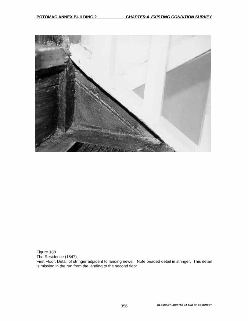
POTOMAC ANNEX BUILDING 2 CHAPTER 4 EXISTING CONDITION SURVEY
GLOSSARY LOCATED AT END OF DOCUMENT 356
Figure 188 The Residence (1847), First Floor. Detail of stringer adjacent to landing newel. Note beaded detail in stringer. This detail is missing in the run from the landing to the second floor.
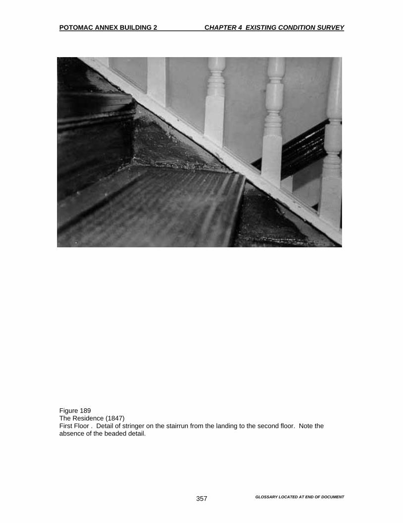
POTOMAC ANNEX BUILDING 2 CHAPTER 4 EXISTING CONDITION SURVEY
GLOSSARY LOCATED AT END OF DOCUMENT 357
Figure 189 The Residence (1847) First Floor . Detail of stringer on the stairrun from the landing to the second floor. Note the absence of the beaded detail.
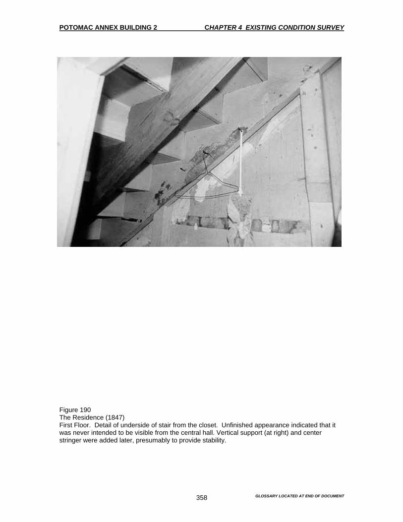
POTOMAC ANNEX BUILDING 2 CHAPTER 4 EXISTING CONDITION SURVEY
GLOSSARY LOCATED AT END OF DOCUMENT 358
Figure 190 The Residence (1847) First Floor. Detail of underside of stair from the closet. Unfinished appearance indicated that it was never intended to be visible from the central hall. Vertical support (at right) and center stringer were added later, presumably to provide stability.

POTOMAC ANNEX BUILDING 2 CHAPTER 4 EXISTING CONDITION SURVEY
GLOSSARY LOCATED AT END OF DOCUMENT 359
Figure 191 The Residence (1847) First Floor. Detail of underside of stair from the closet. Beaded board closet indicates a late – 19th or 20th century date.

POTOMAC ANNEX BUILDING 2 CHAPTER 4 EXISTING CONDITION SURVEY
GLOSSARY LOCATED AT END OF DOCUMENT 360
Figure 192 The Residence (1847) First Floor. Detail of stair pendills. The difference in detail suggests different dates. The crude number in which the stringers join the pendills also support that the stairs were heavily reconstructed.

POTOMAC ANNEX BUILDING 2 CHAPTER 4 EXISTING CONDITION SURVEY
GLOSSARY LOCATED AT END OF DOCUMENT 361
Figure 193 The Residence (1847) First Floor. Detail of closet door under stair (beaded board wall on reverse). The door, with its chamfered rails and stiles, is similar to that found in the Nurses’ Residence.
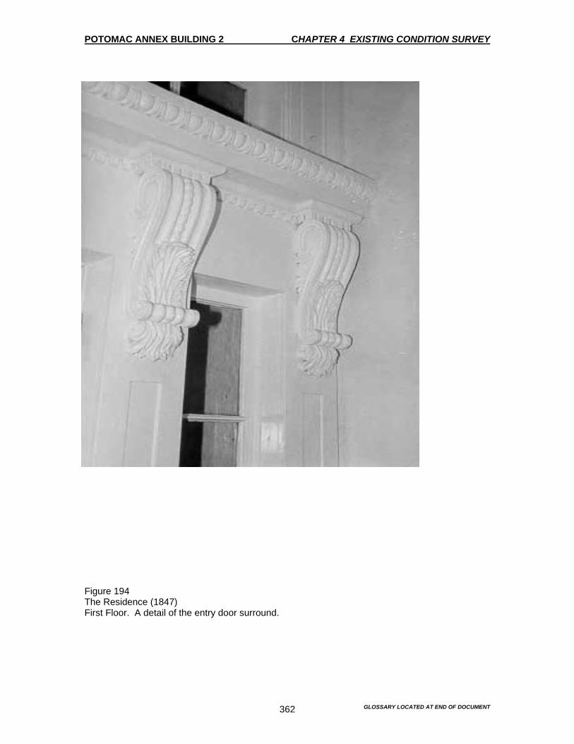
POTOMAC ANNEX BUILDING 2 CHAPTER 4 EXISTING CONDITION SURVEY
GLOSSARY LOCATED AT END OF DOCUMENT 362
Figure 194 The Residence (1847) First Floor. A detail of the entry door surround.
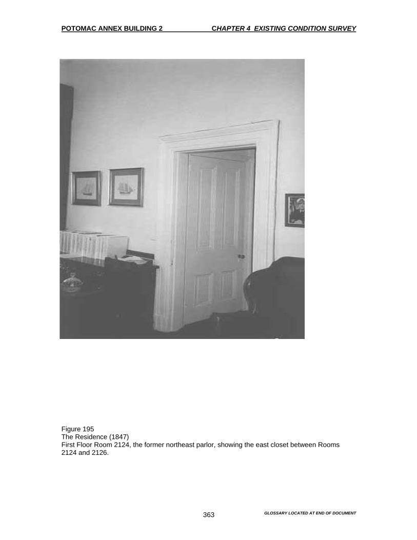
POTOMAC ANNEX BUILDING 2 CHAPTER 4 EXISTING CONDITION SURVEY
GLOSSARY LOCATED AT END OF DOCUMENT 363
Figure 195 The Residence (1847) First Floor Room 2124, the former northeast parlor, showing the east closet between Rooms 2124 and 2126.

POTOMAC ANNEX BUILDING 2 CHAPTER 4 EXISTING CONDITION SURVEY
GLOSSARY LOCATED AT END OF DOCUMENT 364
Figure 196 The Residence (1847) First floor room 2124, the former northeast parlor, showing the door leading to the central hall. This door may be original to the construction of the residence but it has been heavily altered by the insertion of glazed panels and new hardware.

POTOMAC ANNEX BUILDING 2 CHAPTER 4 EXISTING CONDITION SURVEY
GLOSSARY LOCATED AT END OF DOCUMENT 365
Figure 197 The Residence (1847) First Floor. A detail of the mantel (ca. 1894-96) in Room 2124.

POTOMAC ANNEX BUILDING 2 CHAPTER 4 EXISTING CONDITION SURVEY
GLOSSARY LOCATED AT END OF DOCUMENT 366
Figure 198 The Residence (1847) First Floor. Room 2126 (the former dining room) looking southeast. The door frame casing was removed from this side, but the typical 8” molded casing exists on the reverse side.

POTOMAC ANNEX BUILDING 2 CHAPTER 4 EXISTING CONDITION SURVEY
GLOSSARY LOCATED AT END OF DOCUMENT 367
Figure 199 The Residence (1847) First floor room 2122, in the former northwest parlor.

POTOMAC ANNEX BUILDING 2 CHAPTER 4 EXISTING CONDITION SURVEY
GLOSSARY LOCATED AT END OF DOCUMENT 368
Figure 200 The Residence (1847) First Floor. A detail of the metal ceiling in Room 2122, the northeast parlor. Note that the Egg-and-dart cornice continues past the south wall. The south wall terminates with a bundled sheaf cornice that matches that on the other side of the wall (in Room 2122A).
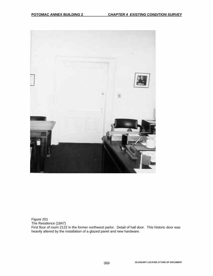
POTOMAC ANNEX BUILDING 2 CHAPTER 4 EXISTING CONDITION SURVEY
GLOSSARY LOCATED AT END OF DOCUMENT 369
Figure 201 The Residence (1847) First floor of room 2122 in the former northwest parlor. Detail of hall door. This historic door was heavily altered by the installation of a glazed panel and new hardware.
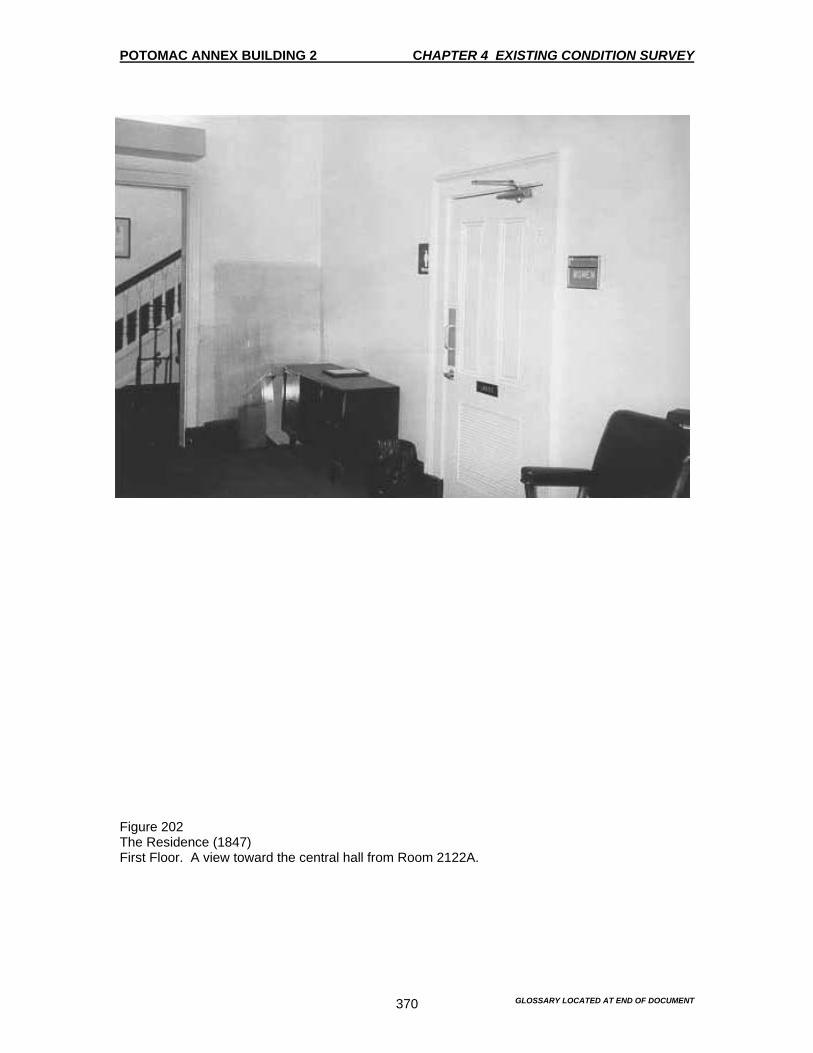
POTOMAC ANNEX BUILDING 2 CHAPTER 4 EXISTING CONDITION SURVEY
GLOSSARY LOCATED AT END OF DOCUMENT 370
Figure 202 The Residence (1847) First Floor. A view toward the central hall from Room 2122A.

POTOMAC ANNEX BUILDING 2 CHAPTER 4 EXISTING CONDITION SURVEY
GLOSSARY LOCATED AT END OF DOCUMENT 371
Figure 203 The Residence (1847) First Floor. A detail of the metal ceiling in Room 2122A, showing the bundled sheaf Cornice adjacent to the transom (see figures 118-119).

POTOMAC ANNEX BUILDING 2 CHAPTER 4 EXISTING CONDITION SURVEY
GLOSSARY LOCATED AT END OF DOCUMENT 372
Figure 204 The Hyphen (1848) Connects the Residence to the Old Naval Observatory. A view into the office space (Room 2121). Note the non-original partition, which detracts from the architectural integrity of the arch and the original spatial quality.
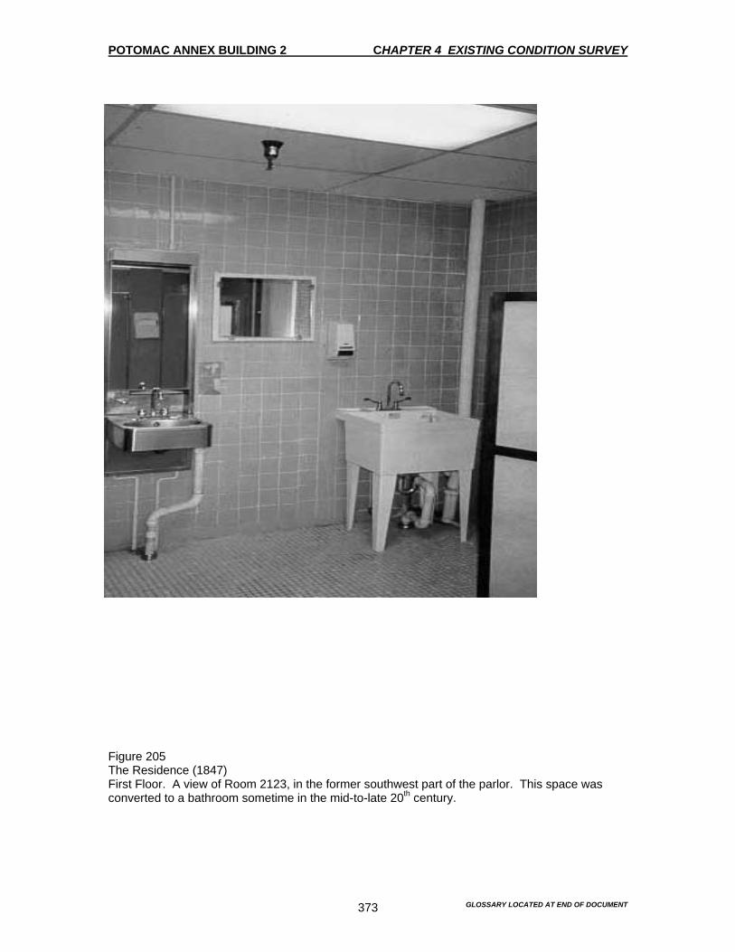
POTOMAC ANNEX BUILDING 2 CHAPTER 4 EXISTING CONDITION SURVEY
GLOSSARY LOCATED AT END OF DOCUMENT 373
Figure 205 The Residence (1847) First Floor. A view of Room 2123, in the former southwest part of the parlor. This space was converted to a bathroom sometime in the mid-to-late 20th century.

POTOMAC ANNEX BUILDING 2 CHAPTER 4 EXISTING CONDITION SURVEY
GLOSSARY LOCATED AT END OF DOCUMENT 374
Figure 206 The Residence Back Building First Floor. The back building was constructed with the Residence for utility purposes, probably including the kitchen.

POTOMAC ANNEX BUILDING 2 CHAPTER 4 EXISTING CONDITION SURVEY
GLOSSARY LOCATED AT END OF DOCUMENT 375
Figure 207 The Residence Back Building First Floor. View to the south showing the blocked in fireplace.

POTOMAC ANNEX BUILDING 2 CHAPTER 4 EXISTING CONDITION SURVEY
GLOSSARY LOCATED AT END OF DOCUMENT 376
Figure 208 The Residence Back Building First Floor. View of the corridor (Room 2125A) connecting the Residence to the back building. The window is part of the east corridor constructed in 1918.

POTOMAC ANNEX BUILDING 2 CHAPTER 4 EXISTING CONDITION SURVEY
GLOSSARY LOCATED AT END OF DOCUMENT 377
Figure 209 The Residence (1847) Second Floor. A detail of the skylight in the central hall.
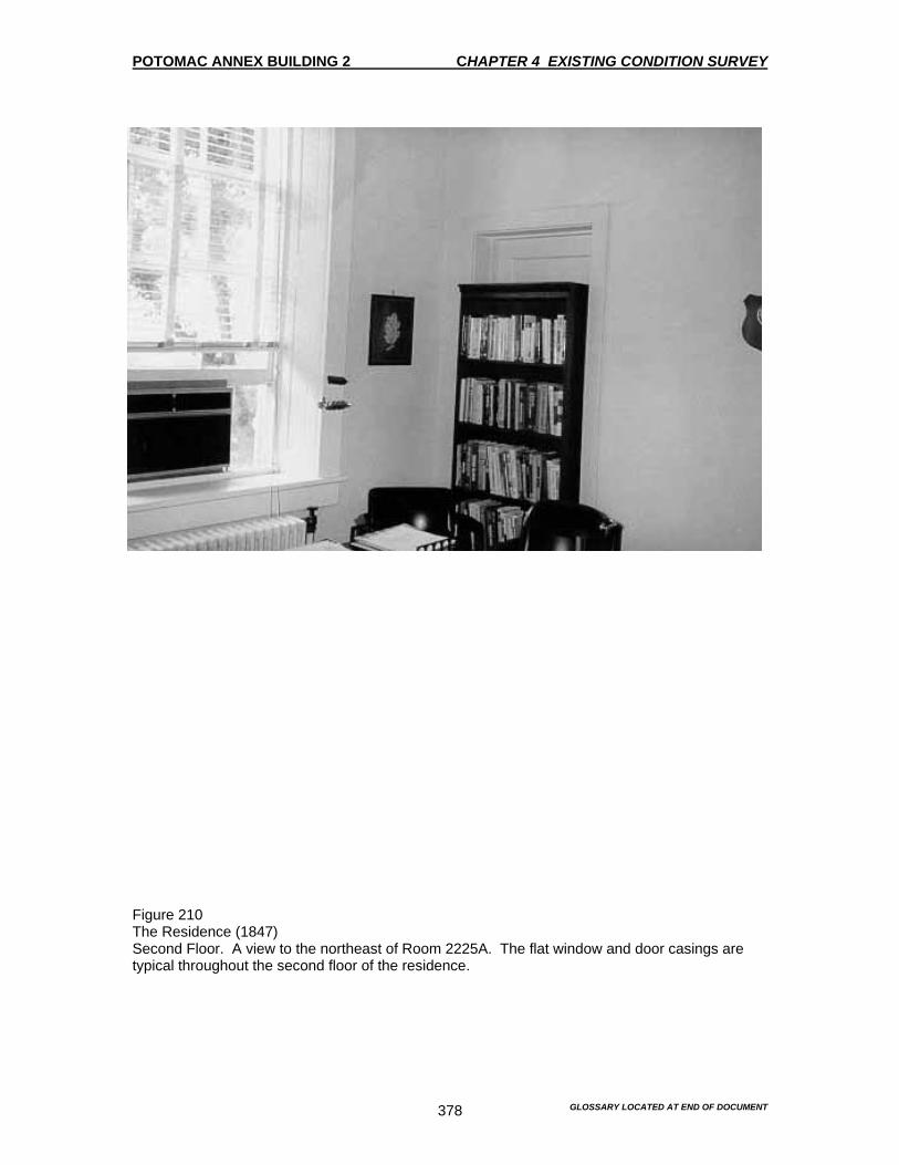
POTOMAC ANNEX BUILDING 2 CHAPTER 4 EXISTING CONDITION SURVEY
GLOSSARY LOCATED AT END OF DOCUMENT 378
Figure 210 The Residence (1847) Second Floor. A view to the northeast of Room 2225A. The flat window and door casings are typical throughout the second floor of the residence.

POTOMAC ANNEX BUILDING 2 CHAPTER 4 EXISTING CONDITION SURVEY
GLOSSARY LOCATED AT END OF DOCUMENT 379
Figure 211 The Residence (1847) Second Floor. A view of Room 2222 looking northwest.
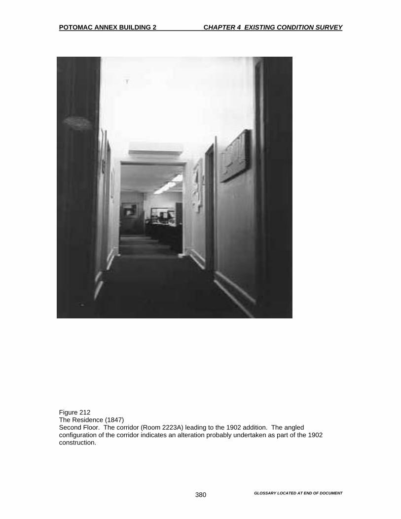
POTOMAC ANNEX BUILDING 2 CHAPTER 4 EXISTING CONDITION SURVEY
GLOSSARY LOCATED AT END OF DOCUMENT 380
Figure 212 The Residence (1847) Second Floor. The corridor (Room 2223A) leading to the 1902 addition. The angled configuration of the corridor indicates an alteration probably undertaken as part of the 1902 construction.
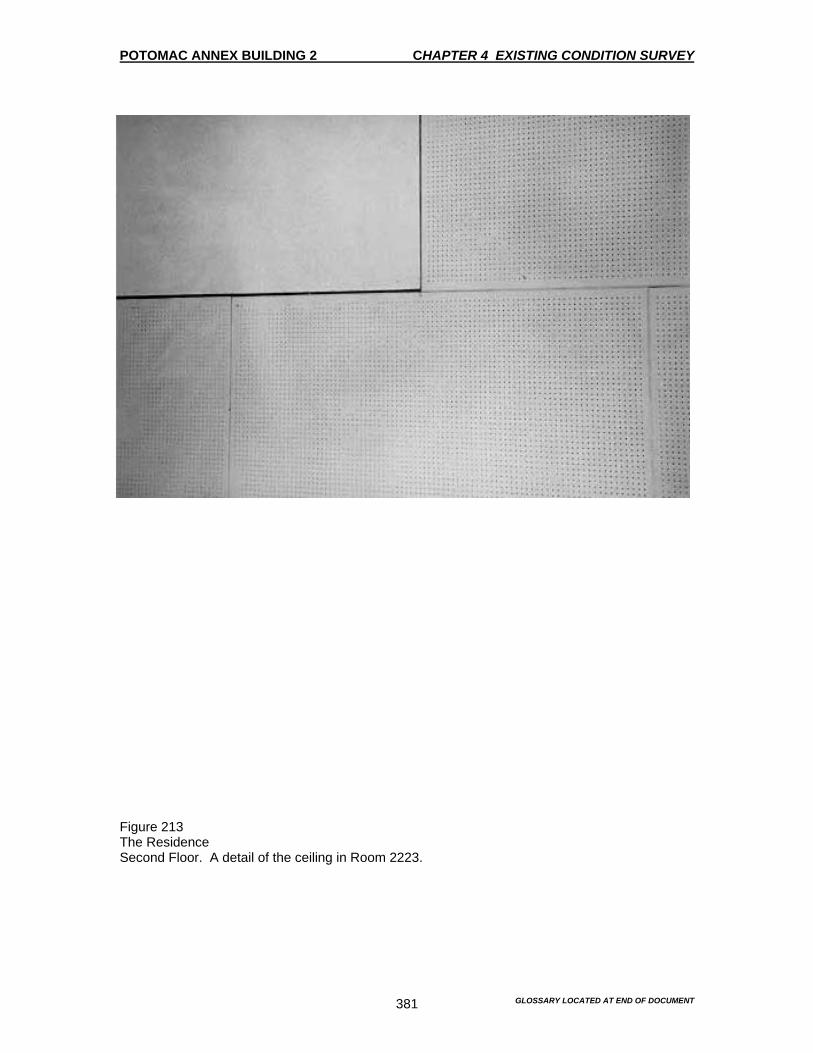
POTOMAC ANNEX BUILDING 2 CHAPTER 4 EXISTING CONDITION SURVEY
GLOSSARY LOCATED AT END OF DOCUMENT 381
Figure 213 The Residence Second Floor. A detail of the ceiling in Room 2223.
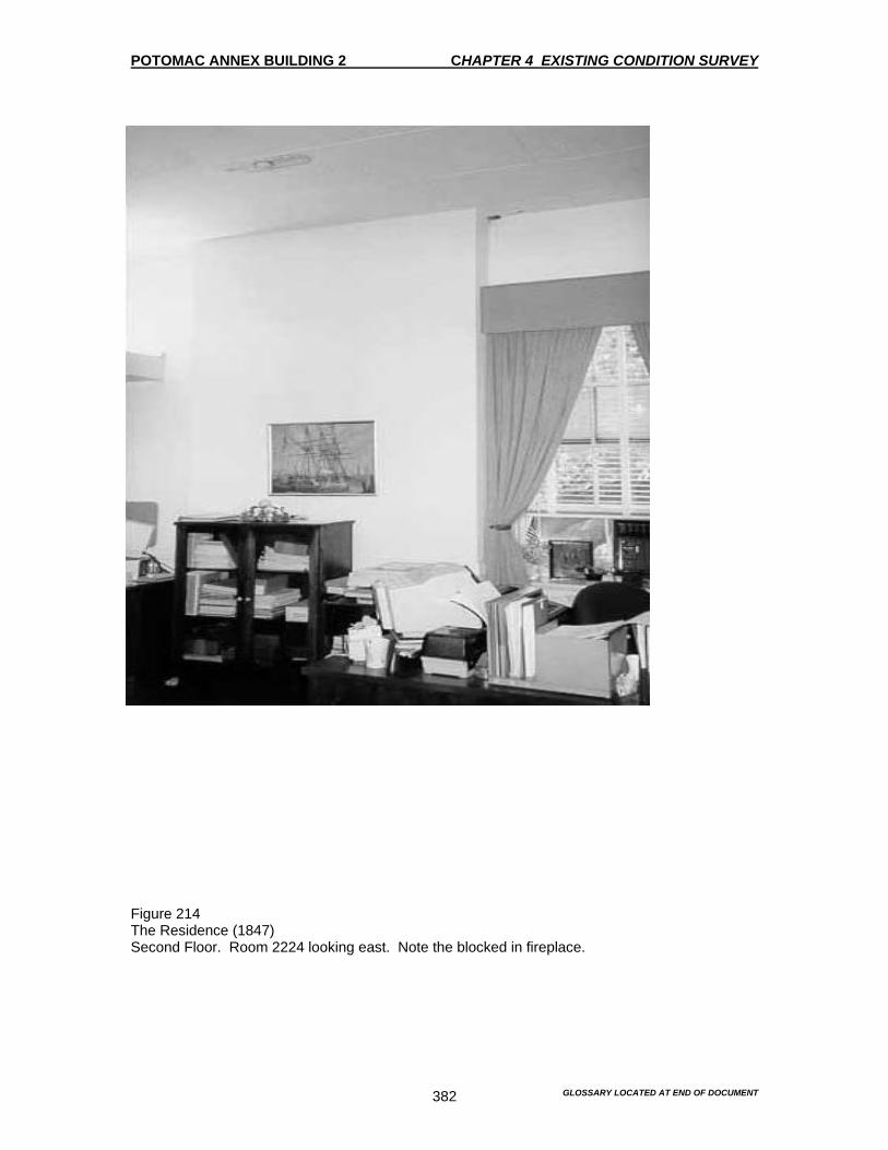
POTOMAC ANNEX BUILDING 2 CHAPTER 4 EXISTING CONDITION SURVEY
GLOSSARY LOCATED AT END OF DOCUMENT 382
Figure 214 The Residence (1847) Second Floor. Room 2224 looking east. Note the blocked in fireplace.
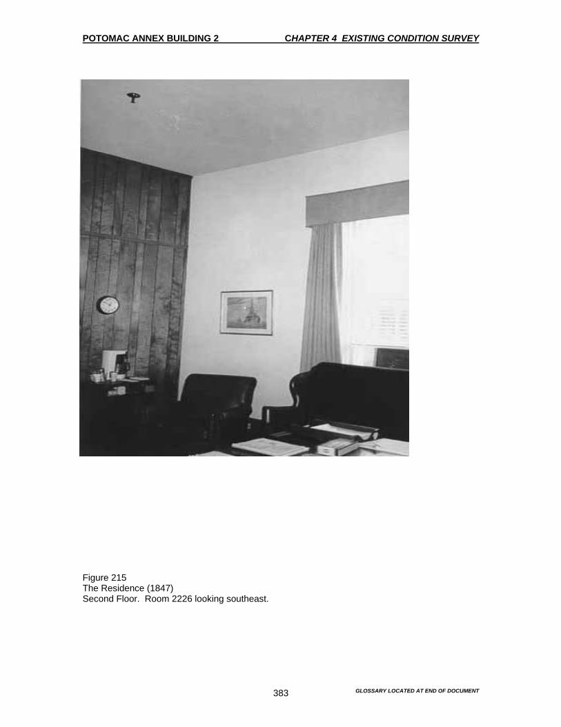
POTOMAC ANNEX BUILDING 2 CHAPTER 4 EXISTING CONDITION SURVEY
GLOSSARY LOCATED AT END OF DOCUMENT 383
Figure 215 The Residence (1847) Second Floor. Room 2226 looking southeast.

POTOMAC ANNEX BUILDING 2 CHAPTER 4 EXISTING CONDITION SURVEY
GLOSSARY LOCATED AT END OF DOCUMENT 384
Figure 216 The Residence (1847) Second Floor A view to the 1918 addition

POTOMAC ANNEX BUILDING 2 CHAPTER 4 EXISTING CONDITION SURVEY
GLOSSARY LOCATED AT END OF DOCUMENT 385
Figure 217 The Residence (1847) The basement Room 2013

POTOMAC ANNEX BUILDING 2 CHAPTER 4 EXISTING CONDITION SURVEY
GLOSSARY LOCATED AT END OF DOCUMENT 386
Figure 218 The Residence (1847) The Basement Room 2014 looking into Room 2014A
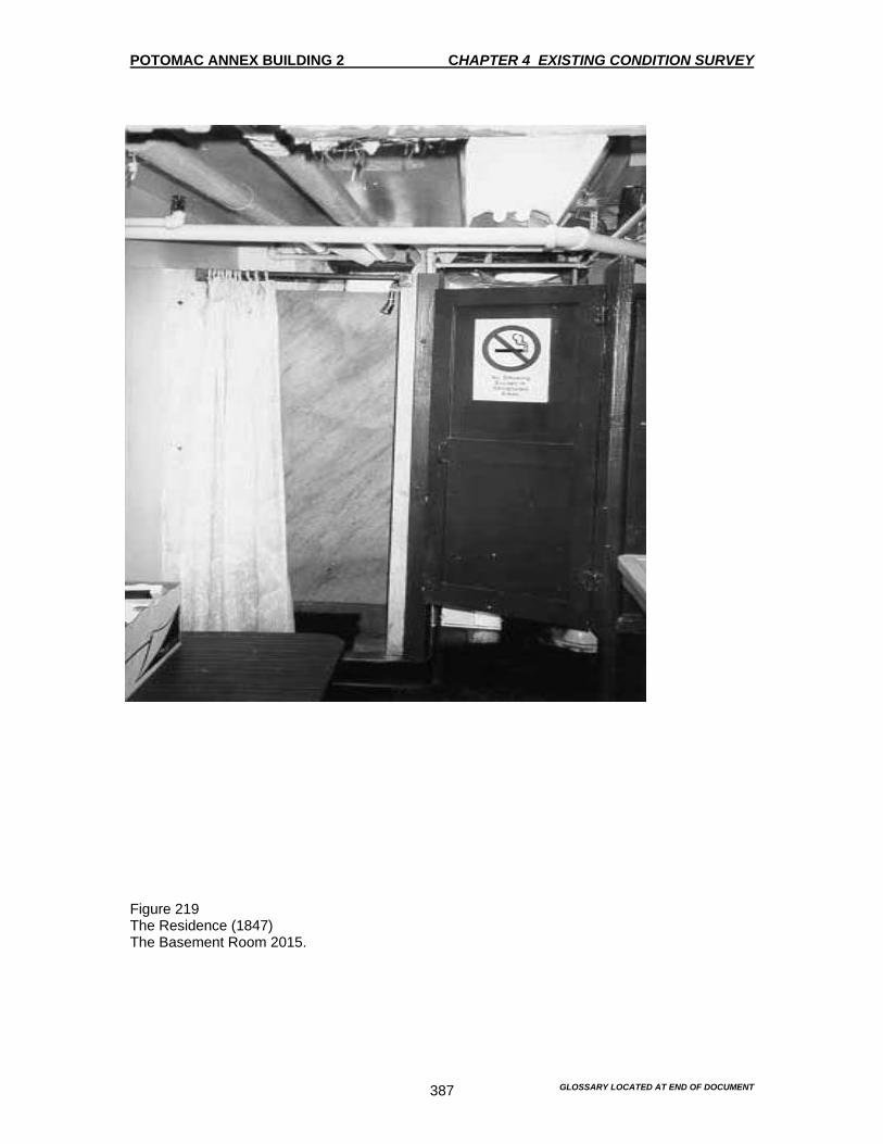
POTOMAC ANNEX BUILDING 2 CHAPTER 4 EXISTING CONDITION SURVEY
GLOSSARY LOCATED AT END OF DOCUMENT 387
Figure 219 The Residence (1847) The Basement Room 2015.
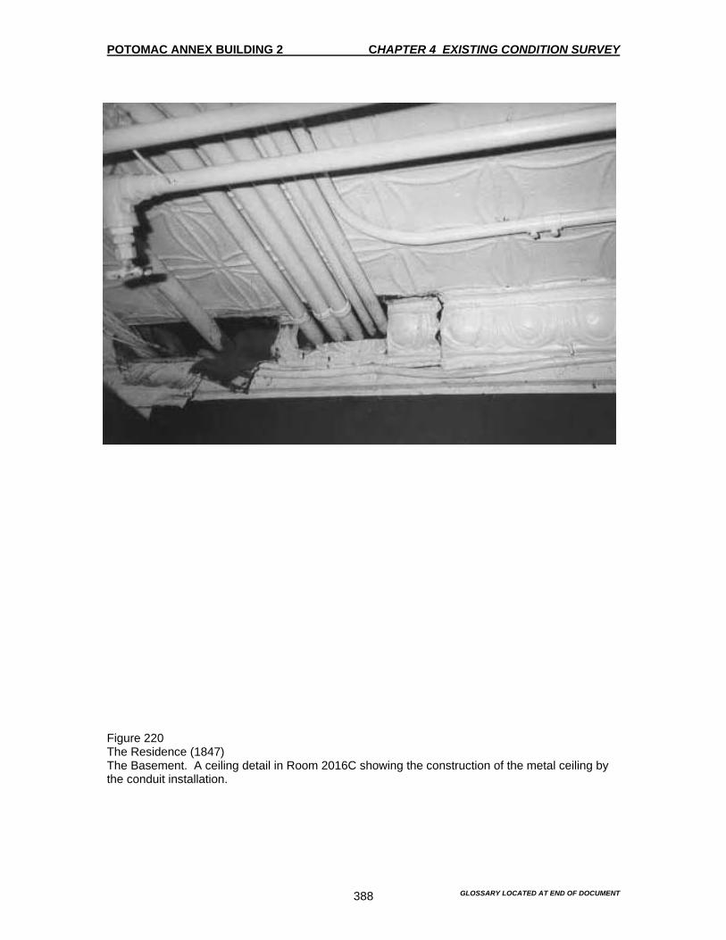
POTOMAC ANNEX BUILDING 2 CHAPTER 4 EXISTING CONDITION SURVEY
GLOSSARY LOCATED AT END OF DOCUMENT 388
Figure 220 The Residence (1847) The Basement. A ceiling detail in Room 2016C showing the construction of the metal ceiling by the conduit installation.
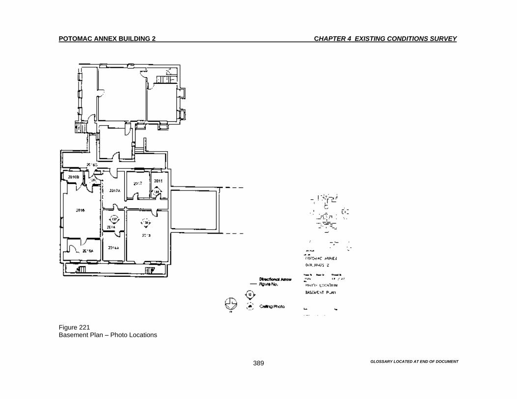
POTOMAC ANNEX BUILDING 2 CHAPTER 4 EXISTING CONDITIONS SURVEY
GLOSSARY LOCATED AT END OF DOCUMENT 389
Figure 221 Basement Plan – Photo Locations

POTOMAC ANNEX BUILDING 2 CHAPTER 4 EXISTING CONDITIONS SURVEY
GLOSSARY LOCATED AT END OF DOCUMENT 390
Figure 222 First Floor Plan – Photo Locations

POTOMAC ANNEX BUILDING 2 CHAPTER 4 EXISTING CONDITIONS SURVEY
GLOSSARY LOCATED AT END OF DOCUMENT 391
Figure 223 Second Floor Plan – Photo Locations

POTOMAC ANNEX BUILDING 2 CHAPTER 4 EXISTING CONDITION SURVEY
GLOSSARY LOCATED AT END OF DOCUMENT 392
INTERIOR 1873 South Rotunda & South Wing Extension Rebuilt in 1895 First Floor Figures 146-148 and 224-233 Room 2111 and 2112 This section of the building was constructed in 1869. Historically, it was used as a machine shop. It is currently used for office space divided by partial-height partitions. Floor The floor is covered with typical blue wall to wall carpeting. The carpeting is in good condition. Baseboard The baseboard is composed of a 12” steel electrical raceway. There are remnants of a 9” painted wood baseboard that are visible at the arched openings and on a section of the west wall. Walls The walls are surfaced with painted plaster with arched openings on the north and south walls. The beaded bases of the arches have a considerable amount of paint build up. A simple crown molding finish is on the walls. Some mechanical damage and scuffing is evident to the arched openings. There is some evidence that there was once an exterior pilaster wall from the 1844 Old Naval Observatory, that is visible at the northeast and northwest corners of the room. Ceiling The ceiling is surfaced with 4” painted beaded board. This dates to the 1903 Second Floor Additions alteration. The ceiling is in good condition. Windows The window has a painted wood frame, a wood sill and a simple 6” molded wood casing. There are two windows mounted air conditioning unit with Plexiglas side panels. Lighting Two wall-mounted box up lighting units are located on the north and south walls.
POTOMAC ANNEX BUILDING 2 CHAPTER 4 EXISTING CONDITION SURVEY
GLOSSARY LOCATED AT END OF DOCUMENT 393
Built-in features There is a gypsum board telecommunications closet with a 7” wood baseboard is located at the south east corner of the room. The closet door is a four panel wood door with molded wood trim, stainless steel butt hinges and level hardware. HVAC One cast iron radiator with a decorative cast-iron cover is located under the window on the west wall. F&LS Sprinkler pipes are mounted to the east and west walls. A sprinkler duct is located in the southeast corner. The closet door is a four panel wood door with molded trim, stainless steel butt hinges and level hardware. Room 2113 Figure 233 This space created by Rooms 2113, 2114, and 2114A are part of the 1873 construction. Historically the person in command of the great equatorial telescope used Room 2113, which was located in the1873 South Rotunda. Floor The floor is covered with typical blue wall to wall carpeting. The carpeting is in good condition. Baseboard The baseboard is composed of a 12” electrical raceway. Walls The north, south and west walls are painted plaster. The east wall is a gypsum board partition. There is simple crown molding finish on the north, south and west walls. Ceiling The ceiling is surfaced with 4” painted beaded board, which dates to the 1903 Second Floor Addition alterations. Windows The window has a painted wood frame, a wood sill and a simple 6” molded wood casing. There is one window mounted air conditioning unit with Plexiglas side panels.

POTOMAC ANNEX BUILDING 2 CHAPTER 4 EXISTING CONDITION SURVEY
GLOSSARY LOCATED AT END OF DOCUMENT 394
Lighting Wall mounted box-up lighting units are mounted to the north and south walls. Built-in features – N/A HVAC – N/A F&LS Sprinkler heads are mounted to the east gypsum board partition. Room 2114 This space was originally designated as a bedroom. Although it is not known who occupied the room, it is currently used as an office. Floor The floor is covered with typical blue wall to wall carpeting. The carpeting is in good condition. Baseboard The baseboards on the south section of the east wall are composed of 9” beaded painted wood. The remained of the baseboards are composed of 12” steel electrical raceway. Walls The north, south and east walls are painted plaster. The west and south wall have gypsum board partitions. Ceiling The ceiling is surfaced with painted pressed metal ceiling with a coffer pattern and cove borders with floral patterns. The ceilings molded borders have been damaged due to the installation of conduits and piping. A beaded wood board ceiling with typical simple crown molding trim is visible through the damaged sections. Windows The window has a painted wood frame, a wood sill and a simple 6” molded wood casing. Lighting There is one box up lighting unit that is mounted to the south wall.
POTOMAC ANNEX BUILDING 2 CHAPTER 4 EXISTING CONDITION SURVEY
GLOSSARY LOCATED AT END OF DOCUMENT 395
Built-in features A gypsum board enclosed sprinkler duct runs along the ceiling from Room 2115 to Room 2112 in a north-south direction. HVAC One cast-iron radiator is located under the window. F&LS Sprinkler heads are mounted to a gypsum board sprinkler duct the runs along the west wall at ceiling level. Room 2114A This is an L shaped corridor space created by partitioning off the larger original volume. Floor The floor is covered with typical blue wall to wall carpeting. The carpeting is in good condition. Baseboard The original walls have 9” painted wood baseboards. The gypsum board partitions have 4” vinyl baseboards. Walls The walls are painted plaster with gypsum board partition enclosures to Room 2114 and Room 2113. There are arched openings at the north and south end of the space. A simple crown molding finishes the plaster walls. Ceiling The rectangular north-south section is surfaced with a 4” beaded board ceiling. A pressed metal ceiling in a grid diaper pattern is used in the section adjoining the exit door. Windows – N/A Lighting One box up lighting unit is mounted to gypsum board partition. Two plastic wall mounted incandescent fixtures are located near the exit door.

POTOMAC ANNEX BUILDING 2 CHAPTER 4 EXISTING CONDITION SURVEY
GLOSSARY LOCATED AT END OF DOCUMENT 396
Built-in features There are wood shelves located on the south wall. HVAC – N/A F&LS An emergency light and a bell and strobe fire alarm are mounted on the gypsum board partition. There is also one lighted exit sign, a pull station alarm and a fire extinguisher located near the exit door. Room 2115 Figures 224-228 This circular two-story rotunda occupies the space where the 1873 Old Naval Observatory housed the Great Equatorial Telescope. In 1895, the Naval Museum of Hygiene replaced the earlier structure with the one that currently exists. It was used as a library and had been fitted with shelves, tables and a fireplace on the south wall. The flooring was described as oak parquetry. However, it is not know whether or not if this flooring still exists, since the floors are covered with carpet. In 1909 a new supporting structure was built in the basement, presumably to carry the load of the books. The 1909 drawings indicate that a gallery or mezzanine was located along the perimeter. A gallery still existed during WW I, but was later removed. Today, the space is used for meetings and as an exercise room. Floor The floor is covered with reddish brown wall to wall carpeting. The carpeting is in good condition. Baseboard The baseboard is an 11” painted wood baseboard. There is some scuffing and chipping of the baseboard present. Walls The walls are painted plaster. Ghosts of the former gallery are visible. There is an arched opening at the north end. Some mechanical scuffing, chipping and crude repair work is present. There is also paint build up on the beaded edges. Molded trim runs around at the level of the second floor horizontal windows. Intrusive electrical conduit and outlet boxes are mounted to the walls just above the baseboard. Ceiling The ceiling is surfaced with pressed metal in a grid diaper pattern, an egg and dart pattern on the molded border and a radial rope molding to the lantern. The ceiling was installed during the 1980’s and matches the previous existing ceiling. A pressed metal 4’ square medallion is centered in the lantern roof. All ceiling elements are in good condition.
POTOMAC ANNEX BUILDING 2 CHAPTER 4 EXISTING CONDITION SURVEY
GLOSSARY LOCATED AT END OF DOCUMENT 397
Windows Three first floor windows have wood frames, wood sills and 6” molded wood trim. Some openings contain a window mounted air conditioning unit with Plexiglas side panels. Four horizontal windows with molded wood trim are located at the upper level. The north window has been filled with plywood and serves as the entrance for sprinkler piping. Lighting Eight box up units are mounted to the walls. Built-in features – N/A HVAC Two cast-iron radiators with decorative cast iron screws are located under the east and west windows. F&LS Sprinkler heads protrude through the walls just under the pressed metal ceiling. Room 2115A This room serves as a vestibule to Room 2115. It is used for storage of chairs and for a coat rack. Floor The floor is covered with typical blue wall to wall carpeting. The carpeting is in good condition. Baseboard The room contains an 11” wood baseboard, which matches that of Room 2115. The baseboard is scuffed with a damaged section on the north wall. Walls The walls are painted plaster. Ceiling The ceiling is surfaced with painted plaster with a hatch opening to the crawl space above.

POTOMAC ANNEX BUILDING 2 CHAPTER 4 EXISTING CONDITION SURVEY
GLOSSARY LOCATED AT END OF DOCUMENT 398
Windows The window has a painted wood frame and a 3” molded wood trim, which has been damaged. Lighting – N/A Built-in features – N/A HVAC – N/A F&LS A sprinkler head is mounted to the ceiling. Basement The basement is in poor condition. The round space below the South Rotunda is used as a weight training room. The adjoining areas serve as locker and shower rooms and toilets. Part of the basement is currently being remodeled for a woman’s locker and shower room. Entrance is through the west side to Room 2011. There is an additional fire exit at the north end. A new doorway is visible between Room 2011 and 2009. A doorway between Room 2010A and 2009 has been blocked in with brick masonry. Room 2008 This serves as a man’s shower room and toilet. Floor The floors are covered with 2” square ceramic mosaic tiles. The tile is in good condition. Baseboard – N/A Walls The west wall is a gypsum board partition with a 4’ ceramic tile wainscot. The east wall and a section of the south wall are painted plaster. The north wall has a 4” square ceramic tile above the built in shower stalls. Ceiling The ceiling is made of 2x4 lay-in acoustical tiles.
POTOMAC ANNEX BUILDING 2 CHAPTER 4 EXISTING CONDITION SURVEY
GLOSSARY LOCATED AT END OF DOCUMENT 399
Windows The window openings have been blocked in with brick masonry. One has a smaller opening mounted exhaust fan. Lighting Two 1x4 fluorescent fixtures are surface mounted to the ceiling. Built-in features The room has a built in closet, which is accessible from Room 2009. It is painted concrete masonry unit walls with a ceramic tile wainscot. Three prefabricated plastic shower stalls, with frosted glass doors in metal frames, are mounted at the north end of the room. The stalls have gypsum board fill surfaced with 4” ceramic tile. The room has one toilet and one urinal on the east wall. A lavatory is mounted to the west wall. HVAC – N/A F&LS Sprinkler heads are mounted in the ceiling with exposed pipes. Room 2009 This room serves as a men’s locker room. Floor The floor is composed of 12” square cream colored vinyl tile. Rust stains are evident from steel locker units. The tiles have warped slightly due to moisture. Baseboard – N/A Walls The east wall is a gypsum board partition separating this room from Room 2008. The south wall is common brick with a thin plaster surface. An older door opening, to Room 2010A, has been filled and a new one, to Room 2011, has been added to the side. The north wall has coursed stone rubble to a height of approximately 5’ high. Above this height, the wall is made of common brick with a thin plaster coat. An arched opening to Room 2007 has been damaged by the installation of conduit. The west wall is concrete to a height of 4’. Above this height the wall is made of common brick with a thin coat of plaster.

POTOMAC ANNEX BUILDING 2 CHAPTER 4 EXISTING CONDITION SURVEY
GLOSSARY LOCATED AT END OF DOCUMENT 400
Ceiling The ceiling is made of painted plasterboard. There are large holes that were caused by the installation of conduits. The ceiling is in poor condition. Windows The window frames are wood with no casing. Lighting Two 1x4 fluorescent fixtures are surface-mounted to the ceiling. Built-in features Note that the closet that opens into Room 2009 occupies Room 2008. The room has a closet made of concrete block. The door is a flush painted wood door with steel bucks, brass knob and stainless steel butt hinges. HVAC – N/A F&LS Sprinkler heads are mounted to the ceiling. There is also a wall-mounted emergency light. Room 2010 This room is currently under construction to convert the room into a woman’s shower room and toilet. Floor The floor is exposed concrete. This will probably be surfaced with ceramic tile. Baseboard – N/A Walls The walls are of recently installed painted gypsum board with a 3’-6” ceramic tile wainscot. Ceiling The ceiling is made of 2x4 lay in acoustical tiles. The ceiling is in good condition.

POTOMAC ANNEX BUILDING 2 CHAPTER 4 EXISTING CONDITION SURVEY
GLOSSARY LOCATED AT END OF DOCUMENT 401
Windows The window frames are wood with no casing. Lighting Fluorescent fixtures are mounted in the acoustical ceiling. Built-in features Three new prefabricated shower stalls are being mounted to the west wall. HVAC There is a coiled pipe that is mounted to the ceiling. F&LS Sprinkler pipes are mounted to the ceiling. Room 2010A This room is currently under construction Floor The floor is covered with 12” square cream colored vinyl tile. Baseboard – N/A Walls The walls are composed of common bond brick with a thin coat of plaster. The plaster is in poor condition. The doorway to Room 2009 has been blocked in. There is damage at the door opening to Room 2010. This damage is due to the removal of the frame. Ceiling The ceiling is made of painted gypsum board. The ceiling is in poor condition due to the installation of conduits. Windows The window frames are wood with no casing.
POTOMAC ANNEX BUILDING 2 CHAPTER 4 EXISTING CONDITION SURVEY
GLOSSARY LOCATED AT END OF DOCUMENT 402
Lighting One 1x4 fluorescent fixture is suspended from the ceiling. Built-in features There is a floor standing water heater. HVAC – N/A F&LS Sprinkler pipes are mounted in the ceiling. There is also a wall mounted lighted exit sign, a fire alarm pull station and a strobe alarm and bell. Room 2011 This room currently serves as the entry vestibule to the basement and has a set of locker. Floor The floor is composed of 12” square cream colored vinyl tile. The floor is discolored with rust stains that were caused by the steel lockers. The area near the entry door has missing tiles. Baseboard – N/A Walls The walls are made of common bond brick with a layer of plaster applied over the brick. The perimeter walls exhibit efflorescence and peeling paint. A wood timber with pegs measuring 2x12 is mounted to the west wall below the ceiling. A new opening has been cut in the north wall. The mortar in this area has been re-pointed. Ceiling The ceiling is painted metal veneer made of 2x8 sheets nailed to the floor joists above. The ceiling has also been damaged by holes due to the installation of conduits. Windows The window frame is wood with no casing. Some rot is present. Lighting One 1x4 fluorescent fixture is surfaced mounted to the ceiling. One halogen fixture is surface mounted to the ceiling.

POTOMAC ANNEX BUILDING 2 CHAPTER 4 EXISTING CONDITION SURVEY
GLOSSARY LOCATED AT END OF DOCUMENT 403
Built-in features There is one steel floor standing water fountain. There is also HVAC cooling equipment that is located on the floor. HVAC One cast iron radiator is located against the north wall. F&LS A sprinkler head is mounted to the ceiling. Room 2012 This room is circular in plan and serves as a weight training room. Floor The floor is painted concrete with an inscribed grid pattern. The paint is worn. Baseboard – N/A Walls The wall surface is painted plaster with a textured finish. The wall is in poor condition with peeling paint efflorescence and powdering plaster. This condition is also present on the south and west sections where water penetration has occurred. In addition, the plaster in the south section has been damaged by the installation of conduit. Ceiling The ceiling is made of a painted corrugated metal. There are some holes due to the installation of conduit. Windows The window frames are wood with no casing. The openings are filled with steel vent grilles, plywood and one air conditioning unit with Plexiglas side panels. Lighting Four 2x4 fluorescent fixtures are suspended from the ceiling.

POTOMAC ANNEX BUILDING 2 CHAPTER 4 EXISTING CONDITION SURVEY
GLOSSARY LOCATED AT END OF DOCUMENT 404
Built-in features A painted concrete stair occupies the north end of the room. There is a plaster finish on the sides and a utilitarian painted metal pipe railing mounted to the floors and doorframe. A vertical duct, at the top of the stairs is wood framed and covered with plywood. HVAC Two cast iron radiators are located on the west side of the room. F&LS Sprinkler pipes are mounted to the ceiling Room 2012A The former locker and shower room adjoining Room 2012 is gutted and in very poor condition. Floor The floor is made of 2” square ceramic mosaic tile. The tile is soiled, cracked and chipped. Baseboard – N/A Walls The wall is plaster with a 7” ceramic tile wainscot. Sections of tile are missing and the ceramic surface exhibit general soiling, cracking and chipping. Ceiling The ceiling is made of painted plaster. The plaster is stained, soiled and in poor condition. Windows – N/A Lighting – N/A Built-in features – N/A HVAC - N/A F&LS A sprinkler head is mounted to the ceiling.
POTOMAC ANNEX BUILDING 2 CHAPTER 4 EXISTING CONDITION SURVEY
GLOSSARY LOCATED AT END OF DOCUMENT 405
Room 2012B This room serves as a vestibule between Room 2012 and 2010A. This room also is used as a locker room. Floor The floor is made of 12” square cream colored vinyl tile. Baseboard – N/A Walls The curved south wall is coursed rubble masonry that is covered with a thin plaster coat. This thin plaster coat is crumbling. The north wall is common brick masonry. The west wall is coursed stone rubble masonry with brick above. The east wall is has a closet. Ceiling The ceiling is made of painted sheet metal that is nailed to the wood joists above. Windows – N/A Lighting One 1x4 fluorescent fixture is mounted to the ceiling. Built-in features There is a gypsum board closet at the east end of the room with a flush painted door, a wood frame, simple 4” wood trim, brass knob and hinges. HVAC – N/A F&LS There is a wall-mounted fire extinguisher.

POTOMAC ANNEX BUILDING 2 CHAPTER 4 EXISTING CONDITION SURVEY
GLOSSARY LOCATED AT END OF DOCUMENT 406
Figure 224 South Rotunda (1873, rebuilt 1896). View to the north through the 1873 additions. The Rotunda was constructed in 1873 to house a new telescope; however, the historic photographs and documentation show that the existing structure dates to 1894.
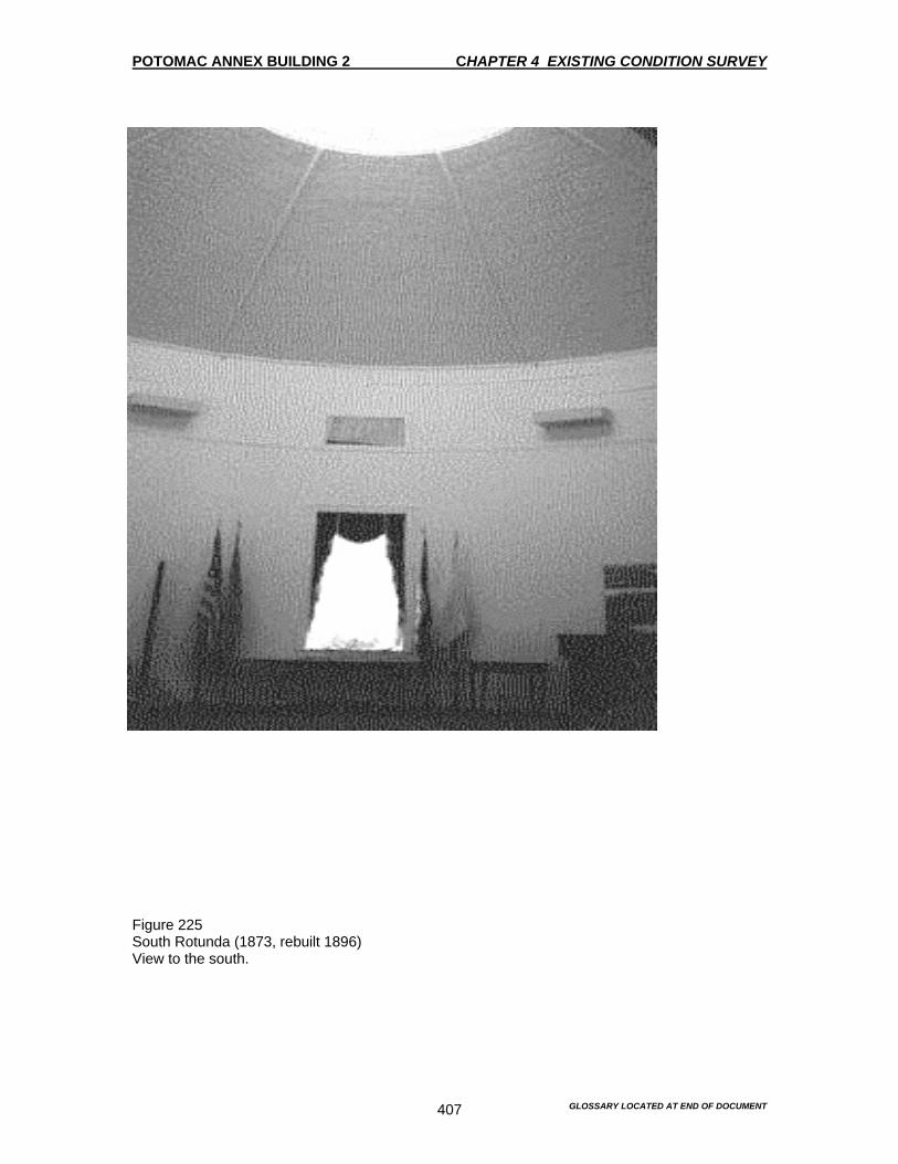
POTOMAC ANNEX BUILDING 2 CHAPTER 4 EXISTING CONDITION SURVEY
GLOSSARY LOCATED AT END OF DOCUMENT 407
Figure 225 South Rotunda (1873, rebuilt 1896) View to the south.

POTOMAC ANNEX BUILDING 2 CHAPTER 4 EXISTING CONDITION SURVEY
GLOSSARY LOCATED AT END OF DOCUMENT 408
Figure 226 South Rotunda (1873, rebuilt 1896) Detail of window frame.
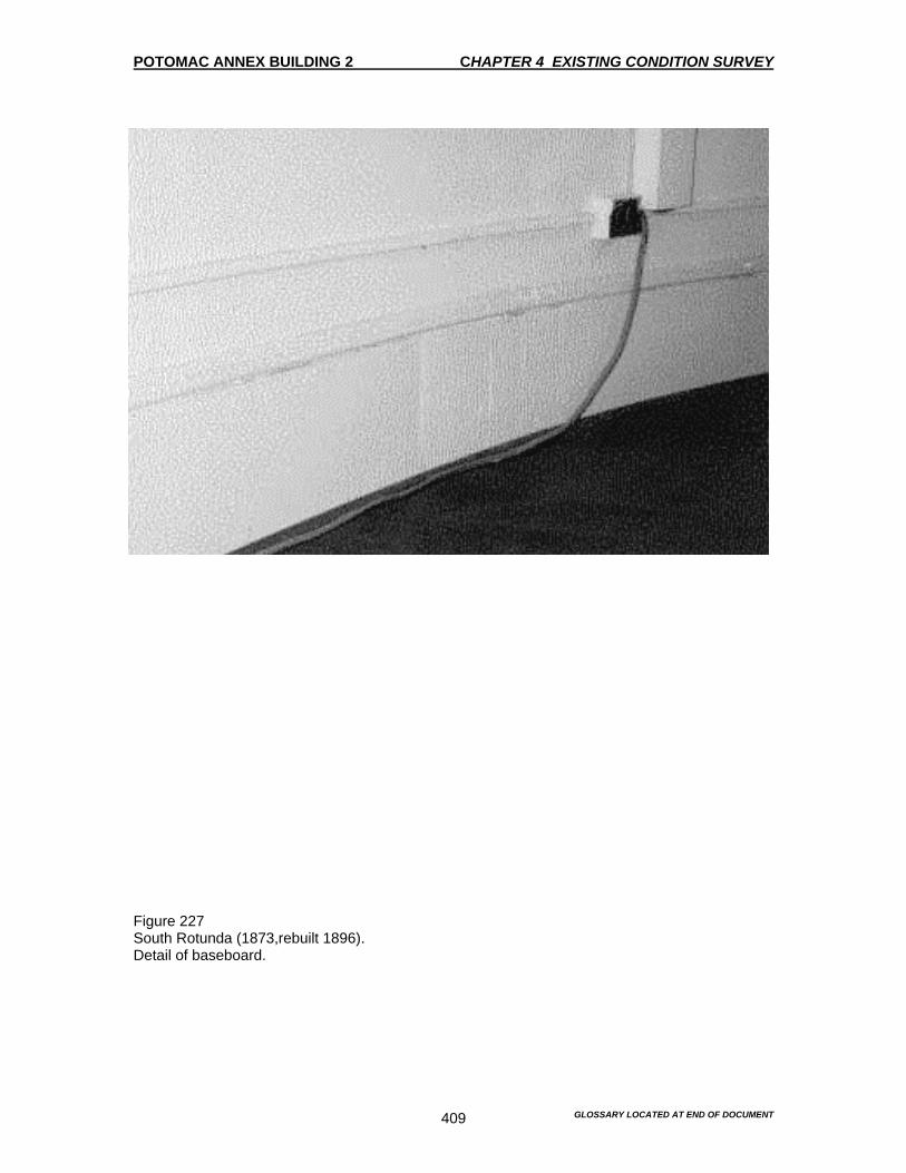
POTOMAC ANNEX BUILDING 2 CHAPTER 4 EXISTING CONDITION SURVEY
GLOSSARY LOCATED AT END OF DOCUMENT 409
Figure 227 South Rotunda (1873,rebuilt 1896). Detail of baseboard.

POTOMAC ANNEX BUILDING 2 CHAPTER 4 EXISTING CONDITION SURVEY
GLOSSARY LOCATED AT END OF DOCUMENT 410
Figure 228 South Rotunda (1873, rebuilt 1896). View of dome and lantern. The pressed metal ceiling was installed in the 1980’s. It replaces the one that had existed previously.
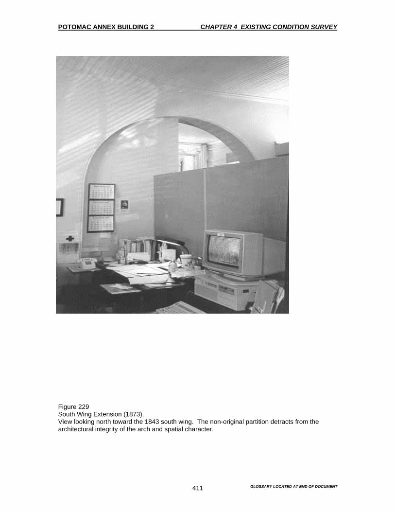
POTOMAC ANNEX BUILDING 2 CHAPTER 4 EXISTING CONDITION SURVEY
GLOSSARY LOCATED AT END OF DOCUMENT 411
Figure 229 South Wing Extension (1873). View looking north toward the 1843 south wing. The non-original partition detracts from the architectural integrity of the arch and spatial character.

POTOMAC ANNEX BUILDING 2 CHAPTER 4 EXISTING CONDITION SURVEY
GLOSSARY LOCATED AT END OF DOCUMENT 412
Figure 230 South Wing Extension (1873). This door was originally a window; it was probably converted during the 1894-1902 alterations.
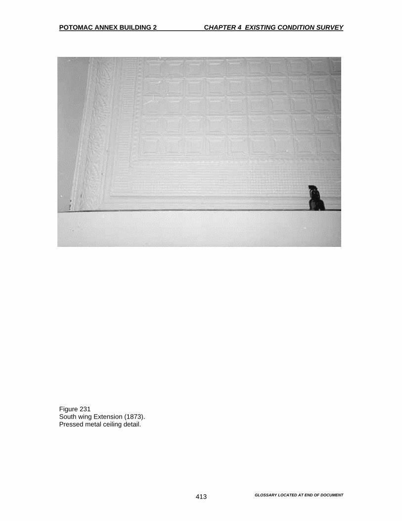
POTOMAC ANNEX BUILDING 2 CHAPTER 4 EXISTING CONDITION SURVEY
GLOSSARY LOCATED AT END OF DOCUMENT 413
Figure 231 South wing Extension (1873). Pressed metal ceiling detail.

POTOMAC ANNEX BUILDING 2 CHAPTER 4 EXISTING CONDITION SURVEY
GLOSSARY LOCATED AT END OF DOCUMENT 414
Figure 232 South Wing Extension (1873). Door to Room 2114. This partition was probably added during the 1894-1902 alterations.

POTOMAC ANNEX BUILDING 2 CHAPTER 4 EXISTING CONDITION SURVEY
GLOSSARY LOCATED AT END OF DOCUMENT 415
Figure 233 South Wing Extension (1873). Window frame detail in Room 2114.

POTOMAC ANNEX BUILDING 2 CHAPTER 4 EXISTING CONDITION SURVEY
GLOSSARY LOCATED AT END OF DOCUMENT 416
Figure 234 South Rotunda (1873,rebuilt 1896) Basement view looking south. The brick piers and steel beams were Installed ca. 1909 when the space above was used as a library.

POTOMAC ANNEX BUILDING 2 CHAPTER 4 EXISTING CONDITION SURVEY
GLOSSARY LOCATED AT END OF DOCUMENT 417
Figure 235 South Rotunda (1873, rebuilt 1896) Basement view looking north.

POTOMAC ANNEX BUILDING 2 CHAPTER 4 EXISTING CONDITIONS SURVEY
GLOSSARY LOCATED AT END OF DOCUMENT 418
Figure 236 Basement Plan – Photo Locations

POTOMAC ANNEX BUILDING 2 CHAPTER 4 EXISTING CONDITIONS SURVEY
GLOSSARY LOCATED AT END OF DOCUMENT 419
Figure 237 First Floor Plan – Photo Locations

POTOMAC ANNEX BUILDING 2 CHAPTER 4 EXISTING CONDITION SURVEY
GLOSSARY LOCATED AT END OF DOCUMENT 420
INTERIOR 1869 West Addition Rebuilt in 1897 Room 2102 Figures 238-241 This square two-story room occupies the space where the 1869 Transit Circle Observatory was located. In 1897, the Naval Museum of Hygiene replaced the earlier structure with the one that is currently there. It was used as a lecture room and had been fitted with theater seating. The arched opening with doors from the east were filled in by the existing entry system. This space continues to be used as a lecture room. However, the interior finishes have been compromised by the installation of wood veneer paneling and suspended acoustic tile ceiling. Floor The floor is covered with the typical blue wall to wall carpeting. The carpeting is in good condition. Baseboard All wood baseboards are 3” high. Walls The walls are painted plaster with wood veneer paneling. The south wall has an opening to make room for a projection screen and chalkboard. The recessed opening surface is finished with a vinyl wall covering. Ceiling The ceiling is 2x4 lay in acoustical tile. Some sagging and minor moisture stains are evident. Windows The windows have painted wood frames and 5” molded wood trim. The wood sills are recent replacement, but the casing appears to date to the 1897 alteration. Lighting There are eight 2x4 fluorescent fixtures in the lay in acoustical ceiling tiles. There are four incandescent spotlights in the lay in ceiling above the stage area. Built-in features A projection screen and chalkboard are mounted on aluminum tracks and are located in the opening on the south wall.

POTOMAC ANNEX BUILDING 2 CHAPTER 4 EXISTING CONDITION SURVEY
GLOSSARY LOCATED AT END OF DOCUMENT 421
HVAC Eight ventilation grilles are integrated into the acoustical ceiling. One metal grille on the east wall corresponds to the closet in Room 2104, which houses HVAC equipment. There is a one-finned tube radiator unit that runs along the west wall. There are four ceiling hung fans. F&LS Sprinkler heads are mounted to the ceiling. One emergency light is mounted on the east wall. Portico An enclosed portico at the north end, which was originally open, is currently used for the storage of chairs Floor The floor is painted concrete. The paint is worn. Baseboards – N/A Walls The walls are painted brick masonry. Minor scuffing is evident due to the storage of items in the space. Ceiling The room contains painted concrete ceiling with a hatched opening. Windows – N/A Lighting – N/A Built-in features A painted steel ladder is mounted to the floor and ceiling. This ladder leads to the hatched opening in the ceiling. HVAC – N/A F&LS – N/A

POTOMAC ANNEX BUILDING 2 CHAPTER 4 EXISTING CONDITION SURVEY
GLOSSARY LOCATED AT END OF DOCUMENT 422
Room 2104 This space was constructed in 1869 to connect the Transit Circle Observatory to the Old Naval Observatory. It currently serves as a vestibule for Room 2102 Floor The floor is composed of oak boards with a clear finish. This is probably a 20th century installation. Baseboards The baseboard is composed of 9” varnished wood. Walls The walls are made of painted plaster with a canvas wall covering. A beaded arched opening on the east wall leads to the 1844 Old Naval Observatory. Some scuffing and damage of the edges is present. A gypsum board partition on the north wall separates the closet housing the HVAC equipment from Room 2102 to 2104. Ceiling The ceiling is made of 2x4 lay in acoustical tiles. Minor moisture staining is evident in several areas. Windows The window in the closet has a painted wood frame, wood sill and 5” molded trim. A window-mounted air conditioning unit and a vent for HVAC equipment is located in the closet. Lighting One 2x4 fluorescent fixture is mounted in the acoustical tile. Built-in features One wood coat rack is mounted to the walls in the southwest corner. A gypsum board closet with a 9” wood baseboard occupies the north end of the space and houses the HVAC equipment. The door is a 6-panel wood door with brass lever hardware and hinges. The closet compromises the original spatial layout. HVAC Cooling equipment is located in the closet

POTOMAC ANNEX BUILDING 2 CHAPTER 4 EXISTING CONDITION SURVEY
GLOSSARY LOCATED AT END OF DOCUMENT 423
F&LS Sprinkler heads are mounted to the ceiling. Basement This room is used for storage. It houses three stone masonry piers. These piers were once used to mount the instruments. Floor The floor is made up of 12”unfinished wood boards. There are missing sections along the east wall. Baseboards – N/A Walls The perimeter walls are of coursed rubble stone masonry to a height of approximately 5’. The walls are common bond brick above. Windows – N/A Lighting The lighting consists of six 1x4 fluorescent fixtures mounted to the joists. Built-in features There are three stone masonry piers. These piers were once used to mount the instruments. A built in shelving system is mounted to the walls. HVAC F&LS Sprinkler heads are mounted to the ceiling with exposed pipes.

POTOMAC ANNEX BUILDING 2 CHAPTER 4 EXISTING CONDITION SURVEY
GLOSSARY LOCATED AT END OF DOCUMENT 424
Figure 238 West Addition (1869, rebuilt 1895). The west transit house was constructed in 1869. However, historic photographs and documentation indicate that the structure was replaced by the existing in 1895. An historic photograph shows an arched opening to this room similar to those seen throughout the Observatory. The partition and these doors are of more recent installation.

POTOMAC ANNEX BUILDING 2 CHAPTER 4 EXISTING CONDITION SURVEY
GLOSSARY LOCATED AT END OF DOCUMENT 425
Figure 239 West Addition (1869,rebuilt 1895). This space has always been used as a lecture room. However, with the exception of the window frames, the interior finishes have been compromised by the installation of the wood veneer paneling and the acoustic tile ceiling.

POTOMAC ANNEX BUILDING 2 CHAPTER 4 EXISTING CONDITION SURVEY
GLOSSARY LOCATED AT END OF DOCUMENT 426
Figure 240 West Addition (1869, rebuilt 1895). View looking north.

POTOMAC ANNEX BUILDING 2 CHAPTER 4 EXISTING CONDITION SURVEY
GLOSSARY LOCATED AT END OF DOCUMENT 427
Figure 241 West Addition (1869, rebuilt 1895). View looking north through double doors to covered porch Space. The porch space was originally an open portico. (See historic photographs of the exterior).
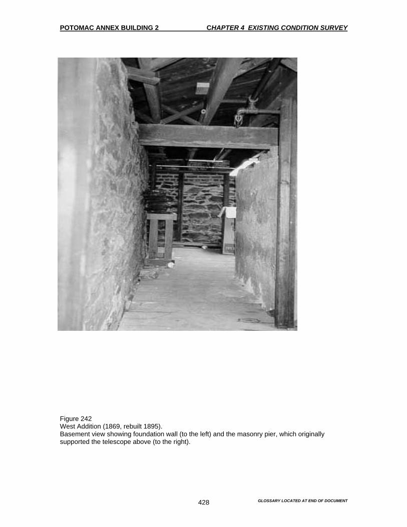
POTOMAC ANNEX BUILDING 2 CHAPTER 4 EXISTING CONDITION SURVEY
GLOSSARY LOCATED AT END OF DOCUMENT 428
Figure 242 West Addition (1869, rebuilt 1895). Basement view showing foundation wall (to the left) and the masonry pier, which originally supported the telescope above (to the right).
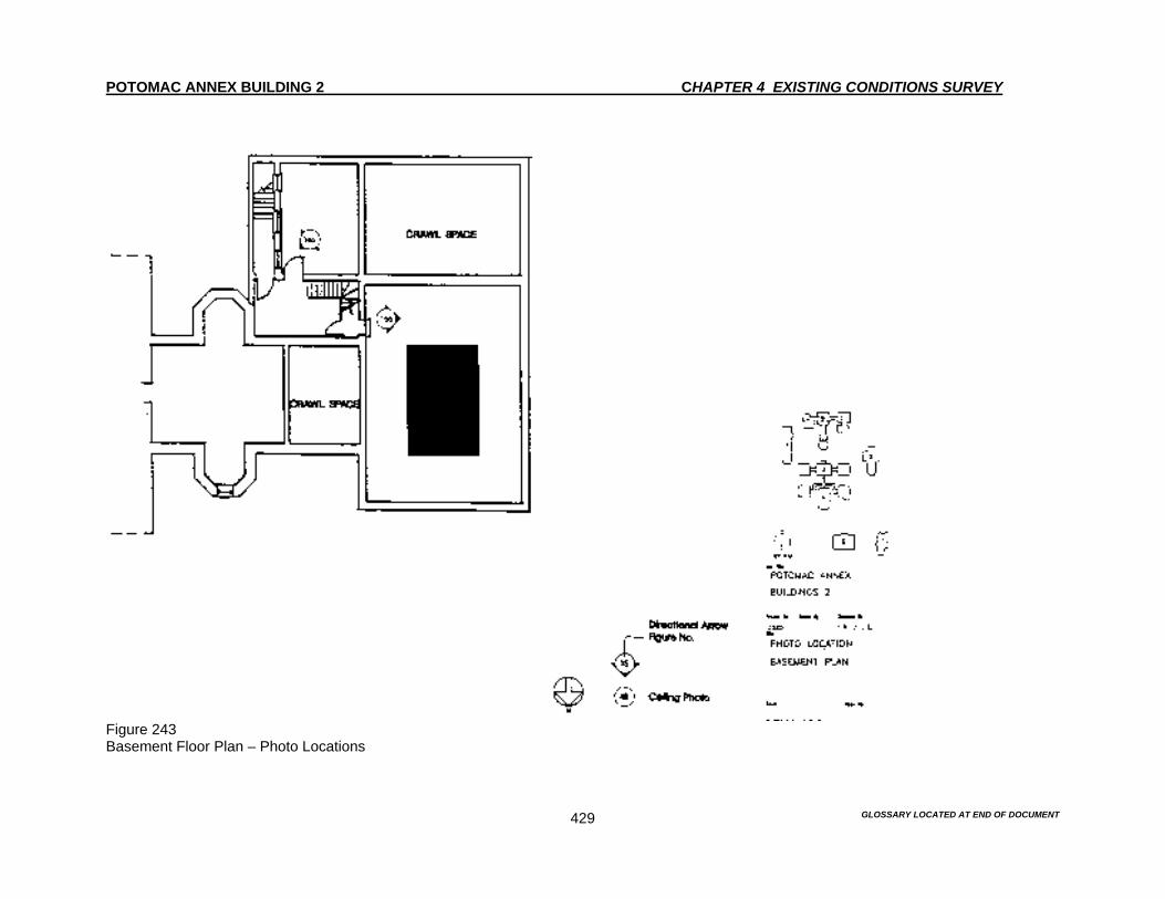
POTOMAC ANNEX BUILDING 2 CHAPTER 4 EXISTING CONDITIONS SURVEY
GLOSSARY LOCATED AT END OF DOCUMENT 429
Figure 243 Basement Floor Plan – Photo Locations
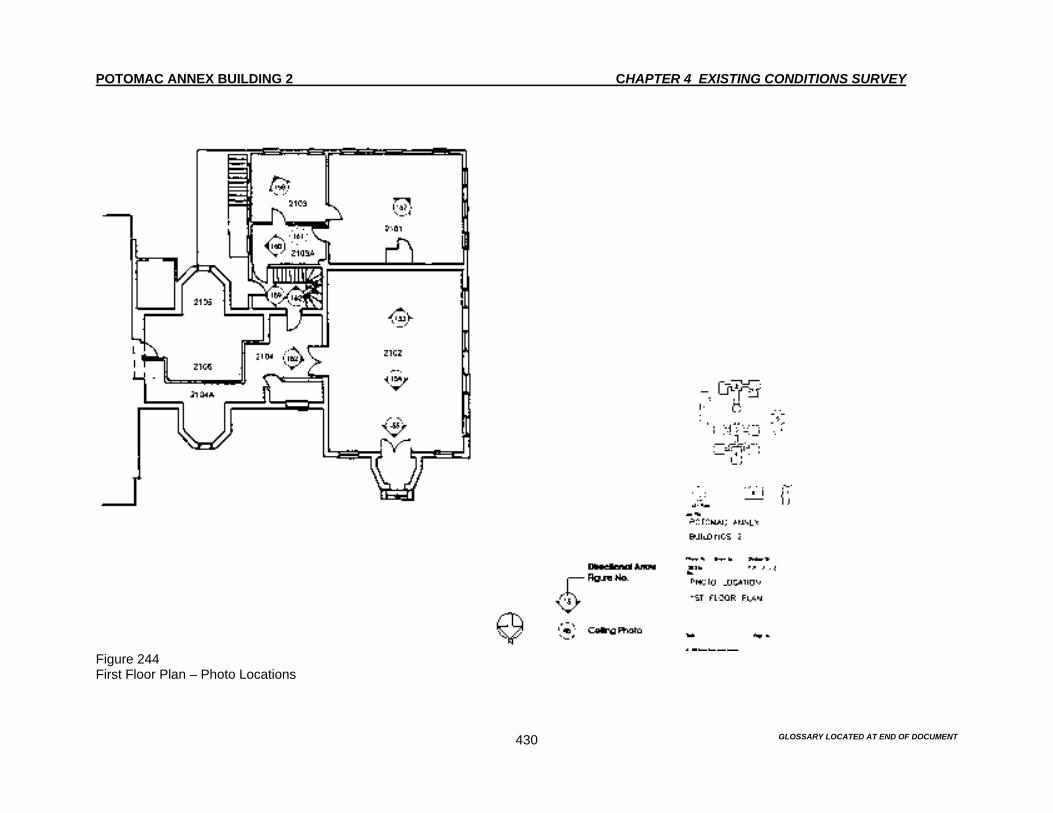
POTOMAC ANNEX BUILDING 2 CHAPTER 4 EXISTING CONDITIONS SURVEY
GLOSSARY LOCATED AT END OF DOCUMENT 430
Figure 244 First Floor Plan – Photo Locations

POTOMAC ANNEX BUILDING 2 CHAPTER 4 EXISTING CONDITIONS SURVEY
GLOSSARY LOCATED AT END OF DOCUMENT 431
Figure 245 Second Floor Plan – Photo Locations
POTOMAC ANNEX BUILDING 2 CHAPTER 4 EXISTING CONDITION SURVEY
GLOSSARY LOCATED AT END OF DOCUMENT 432
INTERIOR 1918 East Stucco Addition The East and West Stucco Additions were constructed in 1918 to make room for new facilities. This was in response to the efforts that were made during WW I. Both were constructed to house laboratory and office spaces and are very similar in their interior finishes. First Floor The first floor was originally an open laboratory space. It is currently divided into two spaces. Room 2127 This room is used for office space. Floor The floor is covered with typical blue wall to wall carpeting. The carpeting is in good condition. Baseboard The baseboard is composed of a 12” electrical raceway. Walls The north, south and west walls are painted plaster. The east wall is a gypsum board partition. There are sections of molded picture rail on the north, south and west walls. Ceiling The ceiling is made of 2x4 lay in acoustical tiles. The ceiling is in good condition. Windows The window has a painted wood frame, a wood sill and a simple 5” molded wood trim. There is one window mounted air conditioning unit with Plexiglas side panels. Lighting Four fluorescent fixtures are mounted in the acoustical ceiling. Built-in features – N/A

POTOMAC ANNEX BUILDING 2 CHAPTER 4 EXISTING CONDITION SURVEY
GLOSSARY LOCATED AT END OF DOCUMENT 433
HVAC One cast-iron radiator is located in the room. F&LS Sprinkler heads are mounted in the acoustical tiles. Room 2128 This room is used as an office space. Floor The floor is covered with typical blue wall to wall carpeting. The carpeting is in good condition. Baseboard The baseboard is composed of a 12” steel electrical raceway. However on the south wall there is a section of 7” wood baseboard. Walls A gypsum board partition separates Rooms 2128 and 2127. The perimeter walls are painted plaster. Two posts are located in the space and an additional post is incorporated into the gypsum board partition. There are sections of molded picture rail on the north, south and west walls. Ceiling The ceiling is made of 2x4 lay-in acoustical tiles. The ceiling is in good condition. Windows The window has a painted wood frame, a wood sill and a simple 5” molded wood casing. There is one window mounted air conditioning unit with Plexiglas side panels. Lighting Eight fluorescent fixtures are mounted to the lay in acoustical ceiling. Built-in features A gypsum board closet is located against the west wall. The closet enclosure includes a 7” wood baseboard and a four panel wood door with stainless steel hardware.

POTOMAC ANNEX BUILDING 2 CHAPTER 4 EXISTING CONDITION SURVEY
GLOSSARY LOCATED AT END OF DOCUMENT 434
HVAC Three cast-iron radiators are located under the windows. F&LS Sprinkler heads are mounted in the acoustical tiles. Other equipment includes a wall mounted fire alarm pull station, a strobe and alarm bell and a lighted exit sign. Room 2128A The room is used as a men’s toilet, reflecting its original purpose. Floor The floor is composed of 1” square ceramic mosaic tiles. The floor surface is uneven, but otherwise the floor is in good condition. Baseboard The room has an 8” painted wood baseboard. Walls The walls are painted plaster. There is some hairline cracks that are visible on the south wall. Ceiling The ceiling is painted plaster. Windows The window has a painted wood frame; wood sill and a simple 5” molded wood casing Lighting The lighting consist of one 1x4 fluorescent fixture suspended from the ceiling. Built-in features There are wood toilet partitions mounted to the floors and walls against the south wall with two-panel wood doors with brass handles and swing hardware. There are also two toilets and one lavatory. The toilet partitions appear to be original.

POTOMAC ANNEX BUILDING 2 CHAPTER 4 EXISTING CONDITION SURVEY
GLOSSARY LOCATED AT END OF DOCUMENT 435
Second Floor Room 2227 This room is used as office space. The original door and window openings on the east and west walls have been blocked Floor The floor is covered with typical blue wall to wall carpeting. The carpeting is in good condition. Baseboard The baseboard is composed of a 12” electrical raceway. There are also sections of 7” wood baseboards on the south and east walls. Walls The walls are painted plaster. Three interior window openings have been filled in on the east wall and the door opening to Room 2230 has been converted from a double door to a single door. On the west wall, two windows originally flanked the door to Room 2227A. Of those two windows, only one remains. A gypsum board closet has blocked the other in. Ceiling The ceiling is painted plaster. The ceiling is in good condition. Windows The window has a painted wood frame, a wood sill and a simple 5” molded wood casing. Lighting Two 1x4 fluorescent fixtures are suspended from the ceiling. Built-in features There is a gypsum board closet against the west wall with a 7” wood baseboard. There is also a four panel wood door and stainless hardware. HVAC One cast-iron radiator is located under the window.
POTOMAC ANNEX BUILDING 2 CHAPTER 4 EXISTING CONDITION SURVEY
GLOSSARY LOCATED AT END OF DOCUMENT 436
F&LS Sprinkler heads are mounted to the ceiling. Other equipment includes a wall mounted pull station and a strobe and bell mounted to the gypsum board closet adjoining the stairway door. Room 2227A This room is used as office space. Floor The floor is covered with typical blue wall to wall carpeting. The carpeting is in good condition. Baseboard The baseboard is composed of a 12” electrical raceway. There is also a section of 7” wood baseboards on the west wall. Walls The walls are painted plaster with a painted a molded picture rail. The walls are in good condition. Ceiling The ceiling is painted plaster. The ceiling is in good condition. Windows The window has a painted wood frame, a wood sill and a simple 5” molded wood casing. Lighting Two fluorescent fixtures are suspended from the ceiling. Built-in features A gypsum board notice board is mounted on the wall. HVAC One cast-iron radiator is located under the window. F&LS Sprinkler heads are mounted to the ceiling.
POTOMAC ANNEX BUILDING 2 CHAPTER 4 EXISTING CONDITION SURVEY
GLOSSARY LOCATED AT END OF DOCUMENT 437
Room 2229B This room is used as a toilet, reflecting its original use. Floor The floor has 12” square cream-colored vinyl tiles. Some patching is visible. Baseboard There are 7” wood baseboards. There is peeling paint and minor rotting of the baseboards. Walls The walls are painted plaster. Ceiling The ceiling is painted plaster. The ceiling is in good condition. Windows The window has a painted wood frame, a wood sill and a simple 5” molded wood casing. The window has a plywood panel with a mounted exhaust fan. Lighting A 1x4 fluorescent fixture is suspended from the ceiling. Built-in features There is a toilet, a lavatory and a metal framed mirror. HVAC One cast-iron radiator is located under the window. F&LS Sprinkler heads are mounted to the ceiling. Room 2230 This room is used as a conference room.

POTOMAC ANNEX BUILDING 2 CHAPTER 4 EXISTING CONDITION SURVEY
GLOSSARY LOCATED AT END OF DOCUMENT 438
Floor The floor is covered with typical blue wall to wall carpeting. The carpeting is in good condition. Baseboard The baseboard is composed of a 12” electrical raceway. There are also section of 7” wood baseboards on the south and east walls. Walls The walls are painted plaster. Ceiling The ceiling is painted plaster. There is a hatched opening that leads to the attic space. The ceiling is in good condition. Windows The window has a painted wood frame, a wood sill and a simple 5” molded wood casing. There is a window-mounted air conditioner with Plexiglas side panels. Lighting Two 1x4 fluorescent fixtures are suspended from the ceiling. Built-in features – N/A HVAC There are two cast-iron radiators with wood framed radiator covers and metal screens. F&LS Sprinkler heads are mounted to the ceiling. Room 2230A This room is used as a toilet, reflecting its original use. Floor The floor is covered with typical blue wall to wall carpeting. The carpeting is in good condition.

POTOMAC ANNEX BUILDING 2 CHAPTER 4 EXISTING CONDITION SURVEY
GLOSSARY LOCATED AT END OF DOCUMENT 439
Baseboard There is a 7” wood baseboard. Walls The walls are painted plaster. They are in good condition. Ceiling The ceiling is painted plaster. The ceiling is in good condition. Windows The window has a painted wood frame, a wood sill and a simple 5” molded wood casing. Lighting The room has one non original wall mounted incandescent light fixture. Built-in features The room has one toilet, one lavatory and a metal framed mirror. HVAC – N/A F&LS A sprinkler head is mounted to the ceiling. Basement The floor plan reflects the original intentions in that it is divided into three spaces. However it appears that the partitions have been moved. Room 2018 This room is used as an office. Floor The floor is covered with typical blue wall to wall carpeting. The carpeting is in good condition.
POTOMAC ANNEX BUILDING 2 CHAPTER 4 EXISTING CONDITION SURVEY
GLOSSARY LOCATED AT END OF DOCUMENT 440
Baseboard A 4” vinyl base is used in the room instead of the baseboard. Walls The north, south and west walls are painted plaster. The east wall is a gypsum partition. Two piers covered with gypsum board are in the space Ceiling The ceiling is 2x4 acoustical tile. Windows – N/A Lighting 2x4 fluorescent fixtures are suspended from the acoustical ceiling tiles. Built-in features A wood framed notice board is mounted on the wall. HVAC – N/A F&LS Sprinkler heads are mounted to the ceiling. Other equipment includes a wall mounted pull station, a bell, a lighted exit sign and a fire extinguisher. Room 2018B This room is used as a storage room and pantry. Floor The floor is covered with typical blue wall to wall carpeting. The carpeting is in good condition. Baseboard A section of 6” wood baseboard is located on the west wall. A 4” vinyl base is used in the remainder of the room.
POTOMAC ANNEX BUILDING 2 CHAPTER 4 EXISTING CONDITION SURVEY
GLOSSARY LOCATED AT END OF DOCUMENT 441
Walls The are perimeter walls are painted plaster. The west wall is gypsum board partition. Ceiling The ceiling is 2x4 lay in acoustical tiles. Some moisture staining and sagging is present in several areas. Windows There is one window with an air conditioner mounted in the window. There is no window trim. Lighting Three 2x4 fluorescent fixtures are suspended from the acoustical ceiling. Built-in features – N/A HVAC – N/A F&LS Sprinkler heads are mounted to the ceiling. Room 2019 This room is used as office space. Floor The floor is covered with typical blue wall to wall carpeting. The carpeting is in good condition. Baseboard A 4” vinyl base is used in the room instead of a baseboard. Walls The walls are painted plaster. They are in good condition. Ceiling The ceiling is 2x4 lay in acoustical tile. The ceiling is in good condition.

POTOMAC ANNEX BUILDING 2 CHAPTER 4 EXISTING CONDITION SURVEY
GLOSSARY LOCATED AT END OF DOCUMENT 442
Windows There is one window with an air conditioner mounted in the window. There is no window trim. Lighting Four 2x4 fluorescent fixtures are mounted to the acoustical ceiling. Built-in features – N/A HVAC – N/A F&LS Sprinkler heads are mounted to the ceiling. Stair Hall A wood structure is located within the space. The stair treads, risers and stringers are varnished. Aluminum non-skid is mounted to the treads. The staircase has simple rectangular newel posts and a wood handrail. Newel posts and railings are varnished. The simple rectangular spindles are painted white. Floor The floor is covered with a brown carpeting on the second floor landing. It is heavily soiled. The other landings have 12” square cream-colored vinyl tile. Some of the tiles are chipped throughout. Baseboard There is a 6” varnished wood baseboard. Walls The walls are painted plaster. Ceiling The ceiling is painted plaster, as are the stair soffits. There is damage to the second floor ceiling due to the removal of some of the sprinkler heads. Windows The windows have painted wood frames, wood sills with a simple 5” wood casing.
POTOMAC ANNEX BUILDING 2 CHAPTER 4 EXISTING CONDITION SURVEY
GLOSSARY LOCATED AT END OF DOCUMENT 443
Lighting Three 1x4 fluorescent fixtures are surface mounted to the landing ceiling. Built-in features There is metal framed room signage present. HVAC – N/A F&LS Sprinkler heads are mounted on the east wall on the first floor landing, on the ceiling of the second floor landing and to the piping hung from ceiling at the basement level. A lighted exit sign is mounted above the first floor exit door. There are three wall mounted emergency light units.

POTOMAC ANNEX BUILDING 2 CHAPTER 4 EXISTING CONDITION SURVEY
GLOSSARY LOCATED AT END OF DOCUMENT 444
Figure 246 East Stucco Addition (1918) First floor. Room 2128.

POTOMAC ANNEX BUILDING 2 CHAPTER 4 EXISTING CONDITION SURVEY
GLOSSARY LOCATED AT END OF DOCUMENT 445
Figure 247 East Stucco Addition (1918) First floor. Room 2128.

POTOMAC ANNEX BUILDING 2 CHAPTER 4 EXISTING CONDITION SURVEY
GLOSSARY LOCATED AT END OF DOCUMENT 446
Figure 248 East Stucco Addition (1918) First floor. Stair detail.

POTOMAC ANNEX BUILDING 2 CHAPTER 4 EXISTING CONDITION SURVEY
GLOSSARY LOCATED AT END OF DOCUMENT 447
Figure 249 East Stucco Addition (1918) Second floor.
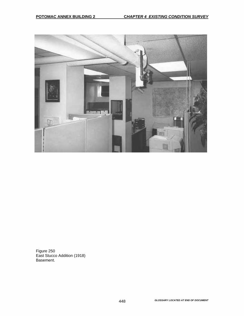
POTOMAC ANNEX BUILDING 2 CHAPTER 4 EXISTING CONDITION SURVEY
GLOSSARY LOCATED AT END OF DOCUMENT 448
Figure 250 East Stucco Addition (1918) Basement.
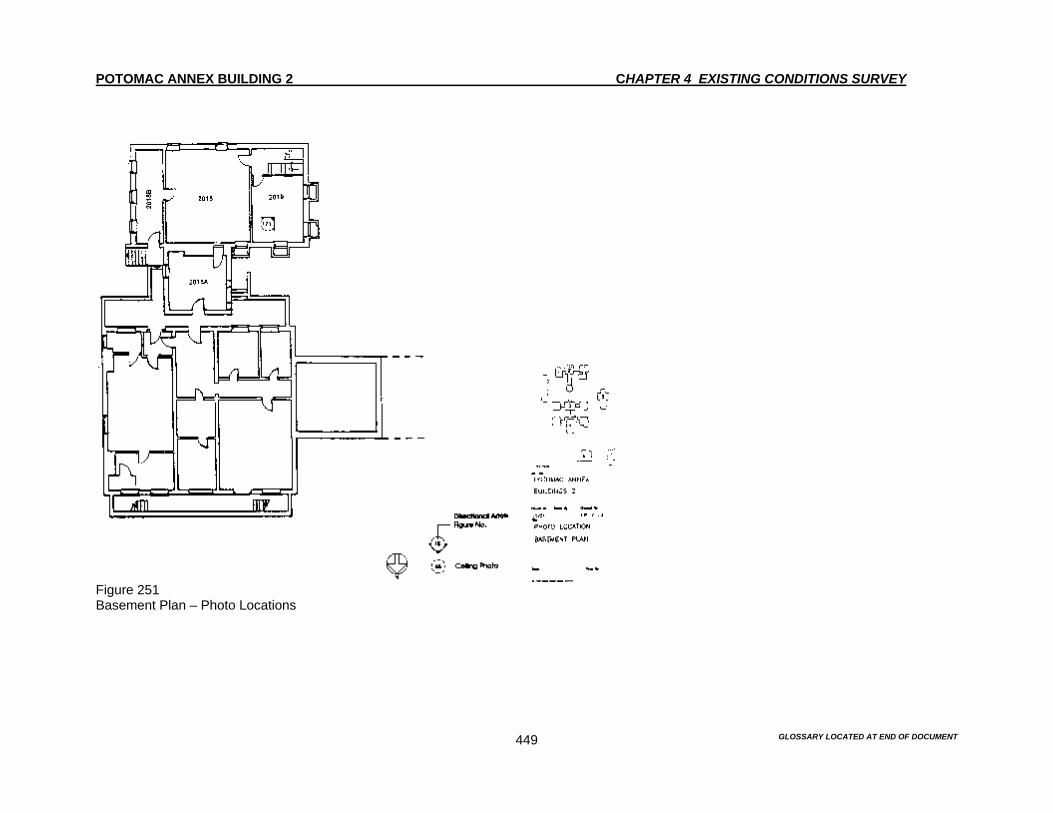
POTOMAC ANNEX BUILDING 2 CHAPTER 4 EXISTING CONDITIONS SURVEY
GLOSSARY LOCATED AT END OF DOCUMENT 449
Figure 251 Basement Plan – Photo Locations

POTOMAC ANNEX BUILDING 2 CHAPTER 4 EXISTING CONDITIONS SURVEY
GLOSSARY LOCATED AT END OF DOCUMENT 450
Figure 252 First Floor Plan – Photo Locations

POTOMAC ANNEX BUILDING 2 CHAPTER 4 EXISTING CONDITIONS SURVEY
GLOSSARY LOCATED AT END OF DOCUMENT 451
Figure 253 Second Floor Plan – Photo Locations
POTOMAC ANNEX BUILDING 2 CHAPTER 4 EXISTING CONDITION SURVEY
GLOSSARY LOCATED AT END OF DOCUMENT 452
INTERIOR 1918 West Stucco Addition The East and West Stucco Additions were constructed in 1918 to make room for new facilities. This was in response to the efforts that were made during WW I. Both were constructed to house laboratory and offices spaces and are very similar in their interior finishes. First Floor The existing first floor reflects the original layout. The floor is in good condition. Room 2101 This room is used for office space. Floor The floor is covered with typical blue wall to wall carpeting. The carpeting is in good condition. Baseboard Some sections of 8” wood baseboard remain. There is also a 12” steel electrical raceway used elsewhere. Walls The walls are painted plaster. There are moisture stains visible at the southwest corner near the ceiling. A post is located along the west wall supporting a beam running in an east-west direction. A glazed window opens into Room 2103 in the east wall. Ceiling The ceiling is painted plaster. The ceiling is in good condition. Windows The window has a painted wood frame, a wood sill and a simple 5” molded wood casing. There is one window-mounted air conditioner with Plexiglas side panels. Lighting Six fluorescent fixtures are suspended from the ceiling.
POTOMAC ANNEX BUILDING 2 CHAPTER 4 EXISTING CONDITION SURVEY
GLOSSARY LOCATED AT END OF DOCUMENT 453
Built-in features There is a gypsum board telecommunications closet with a 7” wood baseboard. There is also a four-paneled wood door with stainless steel hardware, which is located against the north wall. HVAC One cast iron radiator is located in the room. F&LS Sprinkler pipes are mounted to the north and south walls. Room 2103 This room is used as office space. Floor The floor is covered with typical blue wall to wall carpeting. The carpeting is in good condition. Baseboard Some sections of 8” wood baseboard remain. There is also a 12” electrical raceway used elsewhere. Walls The walls are painted plaster. They are in good condition. Ceiling The ceiling is painted plaster. The ceiling is in good condition. Windows The window has a painted wood frame, a wood sill and a simple 5” molded wood casing. There is one window mounted air conditioning unit with Plexiglas side panels. Lighting Four fluorescent fixtures are suspended from the ceiling. Built-in features – N/A
POTOMAC ANNEX BUILDING 2 CHAPTER 4 EXISTING CONDITION SURVEY
GLOSSARY LOCATED AT END OF DOCUMENT 454
HVAC – N/A F&LS Sprinkler pipes are mounted to the south walls. A sprinkler head is mounted to the north wall. Room 2103A This room is used as a corridor and for storage. Floor The floor is a creamed colored linoleum floor surface. The floor is in good condition. Baseboard The room has an 8” wood baseboard. Walls The walls are painted plaster. There are moisture stains visible at the southeast corner related to the ceiling problem, see ceilings below. Ceiling The ceiling is painted plaster. Moisture staining and peeling paint is evident in the southeast corner. This is probably due to the pipes from the bathroom on the second floor. Windows The window has a painted wood frame, a wood sill and a simple 5” molded wood casing. Lighting There is one incandescent fixture suspended from the ceiling. This fixture may date from 1918. Built in features There is a wood framed notice board. There is also the typical metal-framed room signage. HVAC – N/A
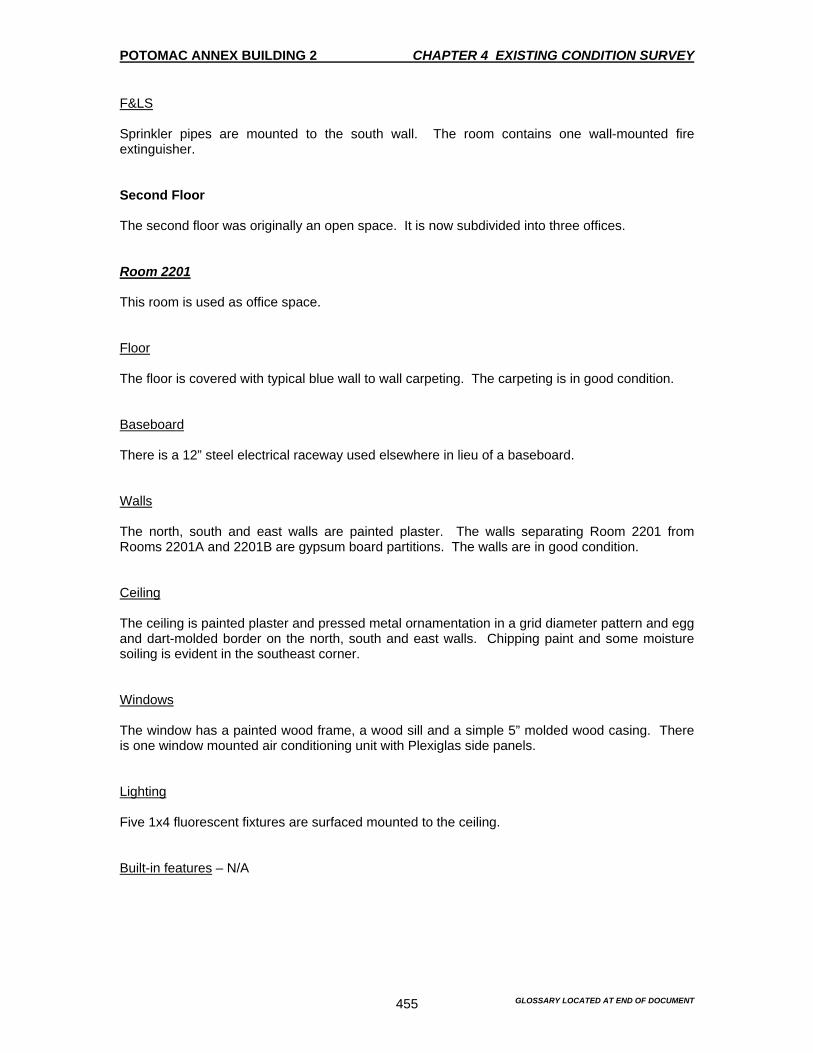
POTOMAC ANNEX BUILDING 2 CHAPTER 4 EXISTING CONDITION SURVEY
GLOSSARY LOCATED AT END OF DOCUMENT 455
F&LS Sprinkler pipes are mounted to the south wall. The room contains one wall-mounted fire extinguisher. Second Floor The second floor was originally an open space. It is now subdivided into three offices. Room 2201 This room is used as office space. Floor The floor is covered with typical blue wall to wall carpeting. The carpeting is in good condition. Baseboard There is a 12” steel electrical raceway used elsewhere in lieu of a baseboard. Walls The north, south and east walls are painted plaster. The walls separating Room 2201 from Rooms 2201A and 2201B are gypsum board partitions. The walls are in good condition. Ceiling The ceiling is painted plaster and pressed metal ornamentation in a grid diameter pattern and egg and dart-molded border on the north, south and east walls. Chipping paint and some moisture soiling is evident in the southeast corner. Windows The window has a painted wood frame, a wood sill and a simple 5” molded wood casing. There is one window mounted air conditioning unit with Plexiglas side panels. Lighting Five 1x4 fluorescent fixtures are surfaced mounted to the ceiling. Built-in features – N/A
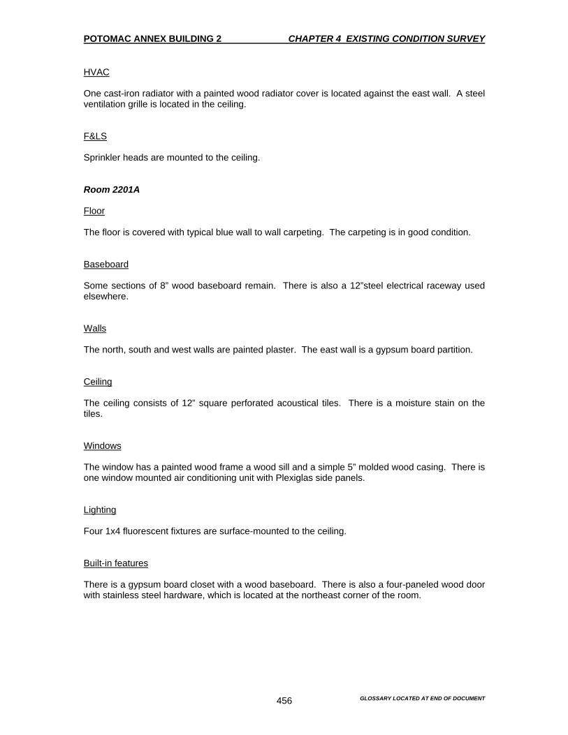
POTOMAC ANNEX BUILDING 2 CHAPTER 4 EXISTING CONDITION SURVEY
GLOSSARY LOCATED AT END OF DOCUMENT 456
HVAC One cast-iron radiator with a painted wood radiator cover is located against the east wall. A steel ventilation grille is located in the ceiling. F&LS Sprinkler heads are mounted to the ceiling. Room 2201A Floor The floor is covered with typical blue wall to wall carpeting. The carpeting is in good condition. Baseboard Some sections of 8” wood baseboard remain. There is also a 12”steel electrical raceway used elsewhere. Walls The north, south and west walls are painted plaster. The east wall is a gypsum board partition. Ceiling The ceiling consists of 12” square perforated acoustical tiles. There is a moisture stain on the tiles. Windows The window has a painted wood frame a wood sill and a simple 5” molded wood casing. There is one window mounted air conditioning unit with Plexiglas side panels. Lighting Four 1x4 fluorescent fixtures are surface-mounted to the ceiling. Built-in features There is a gypsum board closet with a wood baseboard. There is also a four-paneled wood door with stainless steel hardware, which is located at the northeast corner of the room.

POTOMAC ANNEX BUILDING 2 CHAPTER 4 EXISTING CONDITION SURVEY
GLOSSARY LOCATED AT END OF DOCUMENT 457
HVAC One cast iron radiator with a painted wood cover is located below the window on the west wall. F&LS – N/A Room 2201B This room is used as office space. Floor The floor is covered with typical blue wall to wall carpeting. The carpeting is in good condition. Baseboard There is a 12”steel electrical raceway instead of a baseboard. Walls The north, east and west walls are gypsum board partitions. The south wall is painted plaster. Ceiling The ceiling is painted plaster and pressed metal ornamentation in a grid diameter pattern and egg and dart-molded border on the north, south and east walls. Chipping paint and some moisture soiling is evident in the southeast corner. Windows The window has a painted wood frame; a wood sill and a simple 5” molded wood casing. There is one window mounted air conditioning unit with Plexiglas side panels. Lighting Two 1x4 fluorescent fixtures are surface mounted to the ceiling. Built -in features – N/A HVAC One cast-iron radiator with a wood framed cover is located below the window.
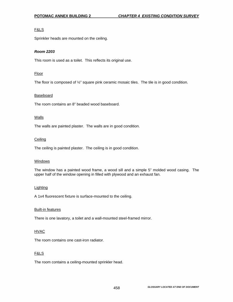
POTOMAC ANNEX BUILDING 2 CHAPTER 4 EXISTING CONDITION SURVEY
GLOSSARY LOCATED AT END OF DOCUMENT 458
F&LS Sprinkler heads are mounted on the ceiling. Room 2203 This room is used as a toilet. This reflects its original use. Floor The floor is composed of ½” square pink ceramic mosaic tiles. The tile is in good condition. Baseboard The room contains an 8” beaded wood baseboard. Walls The walls are painted plaster. The walls are in good condition. Ceiling The ceiling is painted plaster. The ceiling is in good condition. Windows The window has a painted wood frame, a wood sill and a simple 5” molded wood casing. The upper half of the window opening in filled with plywood and an exhaust fan. Lighting A 1x4 fluorescent fixture is surface-mounted to the ceiling. Built-in features There is one lavatory, a toilet and a wall-mounted steel-framed mirror. HVAC The room contains one cast-iron radiator. F&LS The room contains a ceiling-mounted sprinkler head.
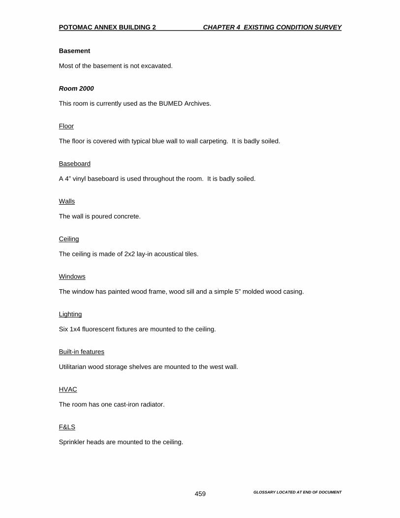
POTOMAC ANNEX BUILDING 2 CHAPTER 4 EXISTING CONDITION SURVEY
GLOSSARY LOCATED AT END OF DOCUMENT 459
Basement Most of the basement is not excavated. Room 2000 This room is currently used as the BUMED Archives. Floor The floor is covered with typical blue wall to wall carpeting. It is badly soiled. Baseboard A 4” vinyl baseboard is used throughout the room. It is badly soiled. Walls The wall is poured concrete. Ceiling The ceiling is made of 2x2 lay-in acoustical tiles. Windows The window has painted wood frame, wood sill and a simple 5” molded wood casing. Lighting Six 1x4 fluorescent fixtures are mounted to the ceiling. Built-in features Utilitarian wood storage shelves are mounted to the west wall. HVAC The room has one cast-iron radiator. F&LS Sprinkler heads are mounted to the ceiling.
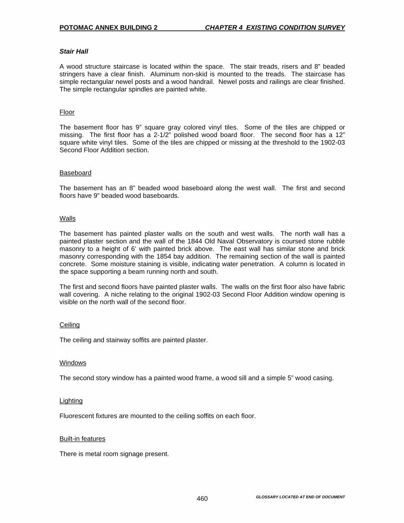
POTOMAC ANNEX BUILDING 2 CHAPTER 4 EXISTING CONDITION SURVEY
GLOSSARY LOCATED AT END OF DOCUMENT 460
Stair Hall A wood structure staircase is located within the space. The stair treads, risers and 8” beaded stringers have a clear finish. Aluminum non-skid is mounted to the treads. The staircase has simple rectangular newel posts and a wood handrail. Newel posts and railings are clear finished. The simple rectangular spindles are painted white. Floor The basement floor has 9” square gray colored vinyl tiles. Some of the tiles are chipped or missing. The first floor has a 2-1/2” polished wood board floor. The second floor has a 12” square white vinyl tiles. Some of the tiles are chipped or missing at the threshold to the 1902-03 Second Floor Addition section. Baseboard The basement has an 8” beaded wood baseboard along the west wall. The first and second floors have 9” beaded wood baseboards. Walls The basement has painted plaster walls on the south and west walls. The north wall has a painted plaster section and the wall of the 1844 Old Naval Observatory is coursed stone rubble masonry to a height of 6’ with painted brick above. The east wall has similar stone and brick masonry corresponding with the 1854 bay addition. The remaining section of the wall is painted concrete. Some moisture staining is visible, indicating water penetration. A column is located in the space supporting a beam running north and south. The first and second floors have painted plaster walls. The walls on the first floor also have fabric wall covering. A niche relating to the original 1902-03 Second Floor Addition window opening is visible on the north wall of the second floor. Ceiling The ceiling and stairway soffits are painted plaster. Windows The second story window has a painted wood frame, a wood sill and a simple 5” wood casing. Lighting Fluorescent fixtures are mounted to the ceiling soffits on each floor. Built-in features There is metal room signage present.
POTOMAC ANNEX BUILDING 2 CHAPTER 4 EXISTING CONDITION SURVEY
GLOSSARY LOCATED AT END OF DOCUMENT 461
HVAC One cast iron radiator is located on the first floor against the north wall. F&LS The basement has ceiling sprinkler pipes, a wall mounted emergency light, a fire alarm pull station, a bell and strobe, a fire extinguisher, and a lighted exit sign. The first floor has sprinkler pipes mounted to the north wall, a wall mounted pull station, a strobe and bell, an emergency light and a lighted exit sign. The second floor has a ceiling-mounted sprinkler head, a wall mounted pull station, a bell and strobe alarm, a fire extinguisher and an emergency light.
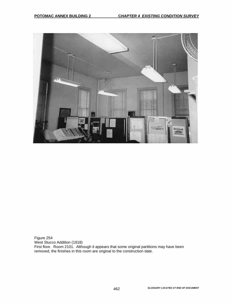
POTOMAC ANNEX BUILDING 2 CHAPTER 4 EXISTING CONDITION SURVEY
GLOSSARY LOCATED AT END OF DOCUMENT 462
Figure 254 West Stucco Addition (1918) First floor. Room 2101. Although it appears that some original partitions may have been removed, the finishes in this room are original to the construction date.

POTOMAC ANNEX BUILDING 2 CHAPTER 4 EXISTING CONDITION SURVEY
GLOSSARY LOCATED AT END OF DOCUMENT 463
Figure 255 West Stucco Addition (1918) First floor. Room 2103.

POTOMAC ANNEX BUILDING 2 CHAPTER 4 EXISTING CONDITION SURVEY
GLOSSARY LOCATED AT END OF DOCUMENT 464
Figure 256 West Stucco Addition (1918) First floor. Stair hall entry. This entry and door appear to be original to the 1918 construction site.

POTOMAC ANNEX BUILDING 2 CHAPTER 4 EXISTING CONDITION SURVEY
GLOSSARY LOCATED AT END OF DOCUMENT 465
Figure 257 West Stucco Addition (1918) First floor. Room 2103A. This room serves as a passageway from the entry vestibule to Room 2101.

POTOMAC ANNEX BUILDING 2 CHAPTER 4 EXISTING CONDITION SURVEY
GLOSSARY LOCATED AT END OF DOCUMENT 466
Figure 258 West Stucco Addition (1918) First floor. Detail of light fixture in Room 2103A.

POTOMAC ANNEX BUILDING 2 CHAPTER 4 EXISTING CONDITION SURVEY
GLOSSARY LOCATED AT END OF DOCUMENT 467
Figure 259 West Stucco Addition (1918) Stair detail.
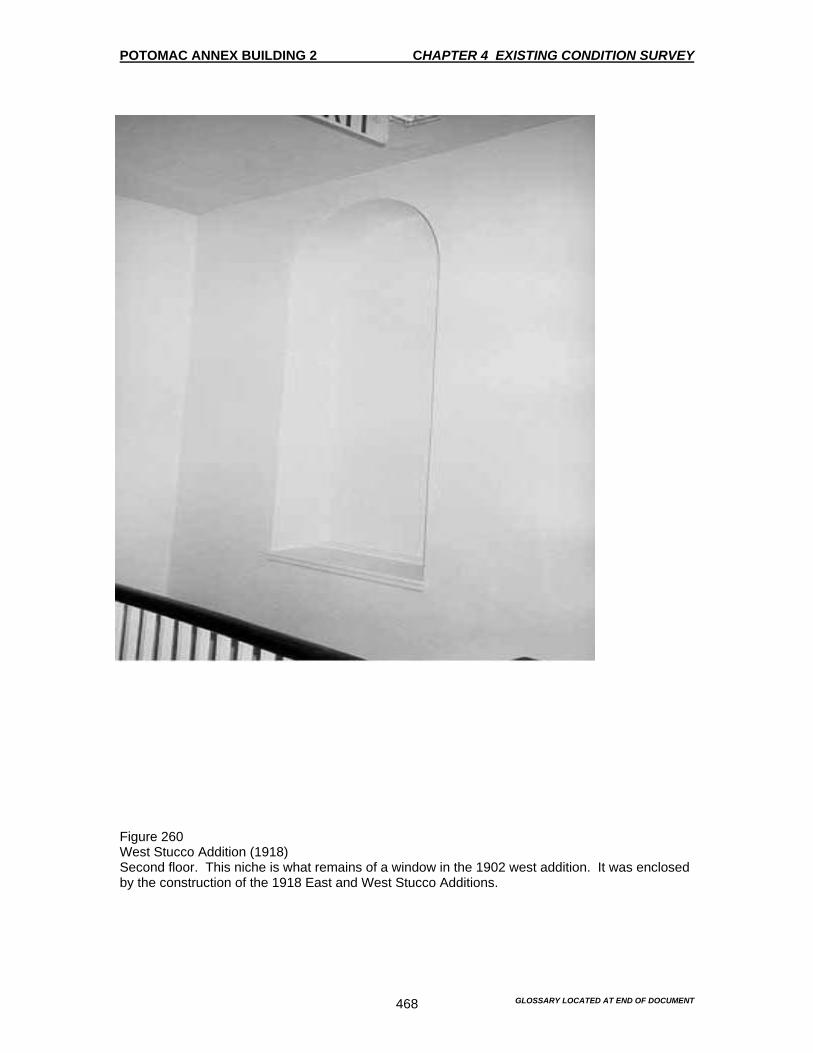
POTOMAC ANNEX BUILDING 2 CHAPTER 4 EXISTING CONDITION SURVEY
GLOSSARY LOCATED AT END OF DOCUMENT 468
Figure 260 West Stucco Addition (1918) Second floor. This niche is what remains of a window in the 1902 west addition. It was enclosed by the construction of the 1918 East and West Stucco Additions.
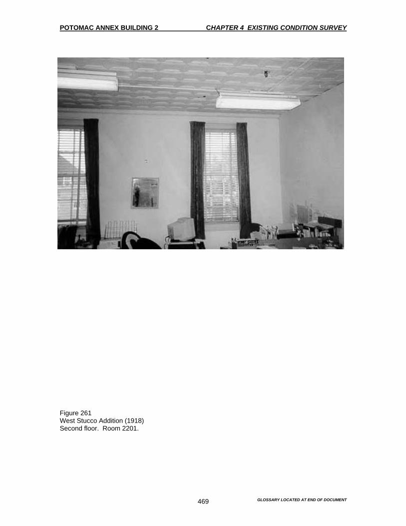
POTOMAC ANNEX BUILDING 2 CHAPTER 4 EXISTING CONDITION SURVEY
GLOSSARY LOCATED AT END OF DOCUMENT 469
Figure 261 West Stucco Addition (1918) Second floor. Room 2201.

POTOMAC ANNEX BUILDING 2 CHAPTER 4 EXISTING CONDITION SURVEY
GLOSSARY LOCATED AT END OF DOCUMENT 470
Figure 262 West Stucco Addition (1918) Second floor. Room 2201A

POTOMAC ANNEX BUILDING 2 CHAPTER 4 EXISTING CONDITION SURVEY
GLOSSARY LOCATED AT END OF DOCUMENT 471
Figure 263 West Stucco Addition (1918) Basement. Room 2000.
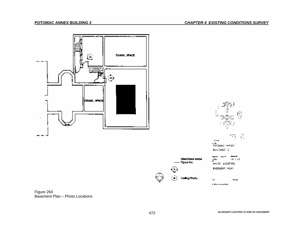
POTOMAC ANNEX BUILDING 2 CHAPTER 4 EXISTING CONDITIONS SURVEY
GLOSSARY LOCATED AT END OF DOCUMENT 472
Figure 264 Basement Plan – Photo Locations
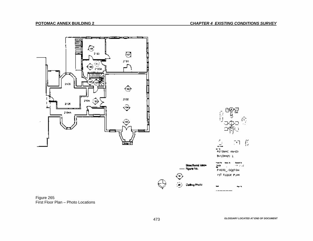
POTOMAC ANNEX BUILDING 2 CHAPTER 4 EXISTING CONDITIONS SURVEY
GLOSSARY LOCATED AT END OF DOCUMENT 473
Figure 265 First Floor Plan – Photo Locations
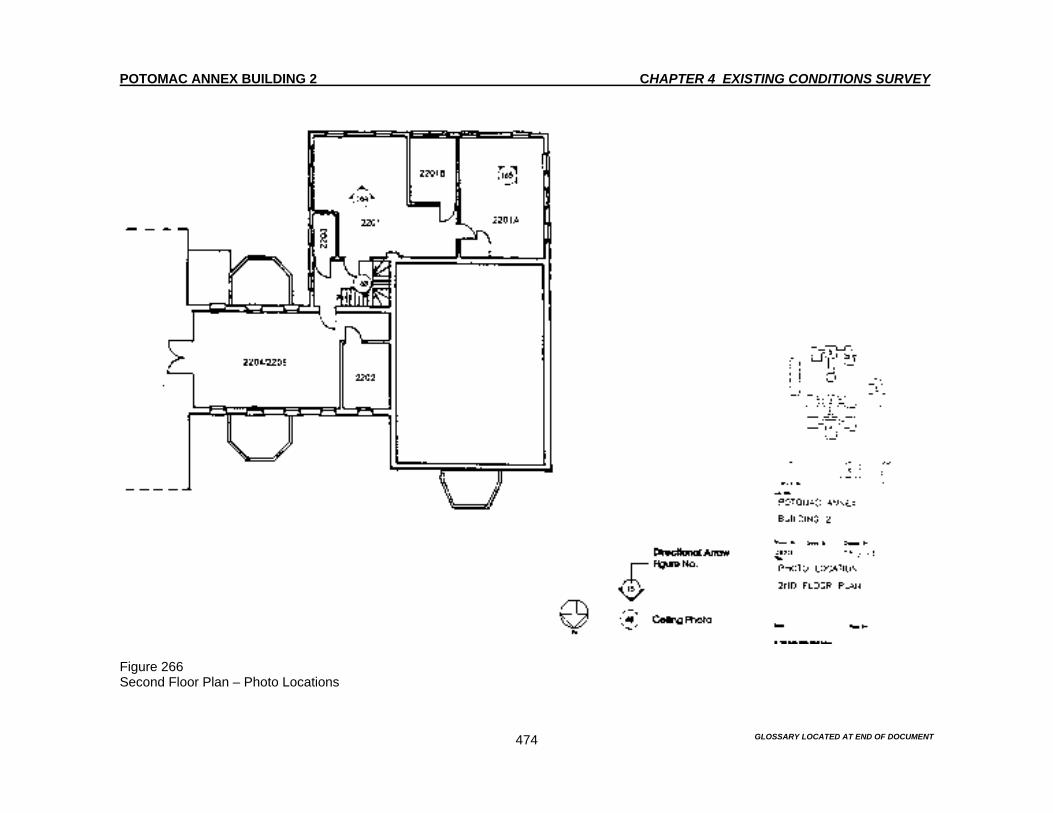
POTOMAC ANNEX BUILDING 2 CHAPTER 4 EXISTING CONDITIONS SURVEY
GLOSSARY LOCATED AT END OF DOCUMENT 474
Figure 266 Second Floor Plan – Photo Locations
POTOMAC ANNEX BUILDING 2 CHAPTER 4 EXISTING CONDITION SURVEY
GLOSSARY LOCATED AT END OF DOCUMENT 475
STRUCTURAL CONDITIONS SURVEY Introduction Description of Structure The only known documentation providing information about the Old Naval Observatory’s structural elements are the references contained in the construction contract and specifications. These references came from the 1845 and 1873 time periods. Destructive inspections to remove finishes and verify the structural systems are not permitted. Therefore, the specifications along with observations, in the few areas where the structure is exposed, are the only available means to identify the existing elements. Original Observatory Building The Old Naval Observatory was completed in 1844. The Old Naval Observatory has a stone foundation of “bluerock,” which is two feet thick. The floor framing systems are made of wood joists that span between the bearing walls. The joists have a wood floor decking. Some exposed first floor framing is visible in the basement of the original west wing. This exposed framing consists of 2-3/4” to 3” wide by 11-1/2” deep joists. The floor decking is 5-1/2” wide. The joists appear to be from various time periods. Most are swan members. However, some are hand worked. This is evident by the scalloped texture from the hand tools that is present on the vertical faces on the joists. The hand work joists should be considered original framing members. Many of the joist connections are mortised together. There are others that are nailed. The nails that are visible in the basement area are cut nails that probably date to the 1800’s. Superintendents Residence Roof framing appears to be original can be viewed in an attic space of the Residence. This framing is accessible though a hatch on the roof. Typical rafters are 3” by 6”. The spacing varies from 24” to 32”. The roof decking boards are 7/8” thick and 14” wide. The hip beams are 3-1/2” by 6”. The hip beams are also mitered and toe nailed at the joints’ South Rotunda In 1873, a new wing to was created to house the 26-inch Equatorial Telescope. This new structure was constructed south of the original Old Naval Observatory. The South Rotunda was cylindrical in shape with a diameter of approximately 41 feet. This diameter enclosed the basement and the first floor. The rotunda was topped with an observation dome. The foundation is a two-foot thick rubble stone wall, which supports the first floor joists and serves as the basement wall. In the original structure, the exterior cylindrical wall was constructed of oak studs with diagonal bracing above the first floor. Around 1895, the rotunda wall was rebuilt above the existing foundations with brick exterior walls. The first floor framing was reconstructed. The first floor was then used as a floor for the library in the early 1900’s. The reconstructed floor has not changes since it was rebuilt in 1895. The floor consists of two central steel beams that are about 11 feet apart. The steel beams span north and south across the circular floor plan. The beams are 12” deep and bear on full height brick piers. Wood 2” by 12” floor joists span east and west. These wood beams bear on either the basement wall or the interior steel beams. Wood floor decking consists of nominal 5” wide planks that are oriented diagonally to the floor joists. The steel beams are exposed in the basement, while a corrugated metal ceiling, that is painted white, hides the floor joists.
POTOMAC ANNEX BUILDING 2 CHAPTER 4 EXISTING CONDITION SURVEY
GLOSSARY LOCATED AT END OF DOCUMENT 476
MECHANICAL AND ELECTRICAL SYSTEMS Mechanical and Electrical The electrical equipment for the Old Naval Observatory 2 has been upgraded as part of an upgrade for the entire complex. The interior upgrade involved replacing the service equipment. The Old Naval Observatory’s lighting system has been updated to modern standards. Energy saving devices such as occupancy sensors have been installed. Also, fluorescent lights replaced incandescent lamps. The capacity of the Old Naval Observatory’s main service equipment has been increased to take care of the larger electrical loads. Additional receptacle circuits from new distribution panel boards were also installed in the Old Naval Observatory’s to serve offices and other space.1 HVAC GSA currently provides steam via an underground distribution system to all of the Potomac Annex Complex buildings, including the Old Naval Observatory. This system is not a historically significant feature of the site, since the Old Naval Observatory originally had its own boiler. Cast iron radiators provided steam heat to the Old Naval Observatory and most of these original radiators still provide heat to the building.2 The most significant HVAC alteration to the Old Naval Observatory has been the addition of window air conditioning units. Only a larger packaged commercial air conditioning unit is used in the auditorium/conference room. The air conditioning units are not original and represent a myriad of installation dates. Generally, the environmental condition of the Old Naval Observatory is poor since the radiator heat output is difficult to control and many of the window air conditioning units provide inadequate service. The window units are generally less efficient than the commercial packaged air conditioning unit.3 Plumbing There are nine public and private restrooms that service the Old Naval Observatory. The basement also contains a shower and wash room. Each floor has an electric water cooler. However the water heater is located in the basement. The domestic hot and cold water pipes are original. These pipes are badly deteriorated. The interior water pipe system needs to be replaced.4
1 “Building Evaluation Report for Potomac Annex Buildings 1-7.” GSA-NCR Repair and Alterations Division. Washington, D.C., December 1991. P.IV-8. 2 Ibid. p. IV-8. 3 Ibid. 4 Ibid.

POTOMAC ANNEX BUILDING 2 CHAPTER 5 PAINT ANALYSIS
GLOSSARY LOCATED AT END OF DOCUMENT 477
Introduction A scientific paint analysis is based upon the removal of small samples of the accumulated paint layers on the original architectural elements of a building in order to determine the early colors of such elements, the sequence of finishes and an appropriate color match for restoration. A second purpose of this paint analysis is to determine relative dates for alterations, using the historic paint sequences as a common point of reference. Paint analysis was requested for Potomac Annex Building 2 as part of Historic Structures Report of this building, which served as the original United States Naval Observatory. The Old Naval Observatory is a rambling, roughly "E" shaped building which includes the original Naval Observatory building of 1843-44, the Superintendent's Residence, built 1847, and later 19th century additions. After it ceased to be used as the Naval Observatory in 1895, it became for a time the Naval Museum of Hygiene, and still later, part of the Navy Medical School and the Washington Naval Hospital, which operated on this site from 1902-1941. It is now used as office space by the Navy Department's Bureau of Medicine. The Old Naval Observatory is in generally good condition, with much of its historic fabric intact throughout. The surviving historic architectural features in the restoration zones of the exterior and interior of the Old Naval Observatory were sampled for paint stratigraphies, which might yield clues about the original and subsequent finishes of the building. In order to do this, samples were taken from all accessible surviving historic architectural elements at the Old Naval Observatory during a site visit and sampling, which was carried out on August 2 - 5, 1994. Small samples were removed, individually packaged and labeled and brought to the laboratory of Acroterion, Historic Preservation Consultants in Madison, New Jersey, for visual inspection from August 8 - 22, 1994. The relative dating of paint layers within the samples was greatly aided by the discovery of a painting of the Old Naval Observatory, which was done in the 1940s. An officer based at the Naval Hospital during World War II painted this large portrait of the building. It hangs in the Old Naval Observatory in Room 2126, which was the original dining room of the Old Naval Observatory Superintendent's home. This portrait shows on example of the Old Naval Observatory with light-green trim on the walls. Because light green does appear as window and door trim consistently throughout the painting of the Old Naval Observatory, the painting may be relied upon as an accurate document of the finishes at the Potomac Annex Complex in the 1940s. It also provides a relative date for the architectural elements, which contain this paint layer. Definite conclusions can be drawn on the early finishes of the buildings. This was the period of significance for the complex, which was the period prior to the Naval Hospital moving from the site in 1941. Summary Conclusions The Old Naval Observatory, constructed in 1844, and enlarged and altered over a half century of use, is the most significant building on the property, having been designated a National Historic Landmark. Except for a brief interlude in the "brown decades", immediately after the Civil War, the Old Naval Observatory has been painted white, with dark green sash and shutters. This color scheme reflects the exterior appearance of the building for much of its period of significance. This color scheme should be incorporated in any present or future repainting campaigns of the Old Naval Observatory. The period of significance for the Old Naval Observatory covers the period from 1844 through 1900. The original paint colors are recommended for restoring the buildings to their historic appearance. This means retaining the unpainted yellow brick walls, accented with white cornices, porticoes,

POTOMAC ANNEX BUILDING 2 CHAPTER 5 PAINT ANALYSIS
GLOSSARY LOCATED AT END OF DOCUMENT 478
balustrades and dormers. Where sun porches exist, they are also to be painted all white. A dark green color was originally used on the window sash and frames of all the buildings. Repainting the windows dark green will give a definite "historic" appearance to the buildings, as dark colored sash in particular was a very common paint treatment in the 19th and early 20th centuries, which has generally fallen out of fashion since World War I. Most of the doors in the Old Naval Observatory have been replaced. If the metal and glass replacements are removed, and wooden doors replicating the originals are reinstalled, the same dark green paint found on the windows should be used. An original varnish finish was identified at the Old Naval Observatory and it is unknown if it is typical. Varnish should be returned to the wooden doors of the Old Naval Observatory. However, on any wooden replacement doors, green paint should be used as is documented on a few service entries for this building. This green paint has the advantage of being a more practical finish. During World War II, all the buildings, including the Old Naval Observatory, were painted in the same way. The Old Naval Observatory was painted a light yellow to match the naturally yellow brick used on other buildings of the Potomac Annex complex. All the buildings had light green windows and doors in this era. The color scheme for the World War II era is well documented. This is also true for the paint samples that were removed for paint study in the Old Naval Observatory and in the original Superintendent's Residence. However, the World War II period is not of the greatest historic and architectural significance for Potomac Annex and so it should not be recreated with those finishes. Procedure Eighty-two (82) exterior samples were removed from the Old Naval Observatory for microscopic investigation. Included in the study were elements from each of the major building components of the structure, including the original Old Naval Observatory (1843-44), the Superintendent's Residence (1847), the "new" transit building (1868-69), the enlarged telescope building (1873), and the 1890's West Addition. Fragments from the window frames and sash, door and doorframes, walls, cornice and other trim represent these parts of the building. In addition, one hundred forty-eight (148) samples were taken throughout the interior of the Old Naval Observatory documenting finishes from the various sections of the structure. The samples were removed with a x-acto knife and contained portions of the substrate as well as surviving paint layers. Samples were taken to the laboratory and examined in cross-section using a stereo-binocular microscope at twenty to forty power magnifications. Information derived from laboratory work includes: - color chronology of each cross-section, - identification of paint composition, - color matching of appropriate finishes. - relative dating of features by comparison of paints stratigraphies Color matching was done under a fiber-optic halogen light, with a 3200 degree Kelvin light source. The first significant color layer of each element was matched to the Munsell Book of Color (1976 edition). The Munsell color number follows the recommended color for restoration in the color chronology listings for each feature. Color chronologies begin with the earliest finish found in the sequence and end with the color presently visible. The color name chart devised by the National Bureau of Standards, NBS, has been used as a guide to color names for significant paint layers in this report. The initials NBS following the color name reference these colors. All paint finishes are semi-gloss unless otherwise noted in color seriation charts. All finishes on the charts are paints unless otherwise noted.
POTOMAC ANNEX BUILDING 2 CHAPTER 5 PAINT ANALYSIS
GLOSSARY LOCATED AT END OF DOCUMENT 479
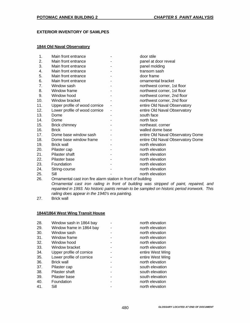
POTOMAC ANNEX BUILDING 2 CHAPTER 5 PAINT ANALYSIS
GLOSSARY LOCATED AT END OF DOCUMENT 480
EXTERIOR INVENTORY OF SAMLPES 1844 Old Naval Observatory 1. Main front entrance - door stile 2. Main front entrance - panel at door reveal 3. Main front entrance - panel molding 4. Main front entrance - transom sash 5. Main front entrance - door frame 6. Main front entrance - ornamental bracket 7. Window sash - northwest corner, 1st floor 8. Window frame - northwest corner, 1st floor 9. Window hood - northwest corner, 2nd floor 10. Window bracket - northwest corner, 2nd floor 11. Upper profile of wood cornice - entire Old Naval Observatory 12. Lower profile of wood cornice - entire Old Naval Observatory 13. Dome - south face 14. Dome - north face 15. Brick chimney - northeast. corner 16. Brick - walled dome base 17. Dome base window sash - entire Old Naval Observatory Dome 18. Dome base window frame - entire Old Naval Observatory Dome 19. Brick wall - north elevation 20. Pilaster cap - north elevation 21. Pilaster shaft - north elevation 22. Pilaster base - north elevation 23. Foundation - north elevation 24. String-course - north elevation 25. Sill - north elevation 26. Ornamental cast iron fire alarm station in front of building
Ornamental cast iron railing in front of building was stripped of paint, repaired, and repainted in 1993. No historic paints remain to be sampled on historic period ironwork. This railing does appear in the 1940’s era painting.
27. Brick wall 1844/1864 West Wing Transit House 28. Window sash in 1864 bay - north elevation 29. Window frame in 1864 bay - north elevation 30. Window sash - north elevation 31. Window frame - north elevation 32. Window hood - north elevation 33. Window bracket - north elevation 34. Upper profile of cornice - entire West Wing 35. Lower profile of cornice - entire West Wing 36. Brick wall - north elevation 37. Pilaster cap - south elevation 38. Pilaster shaft - south elevation 39. Pilaster base - south elevation 40. Foundation - north elevation 41. Sill - north elevation
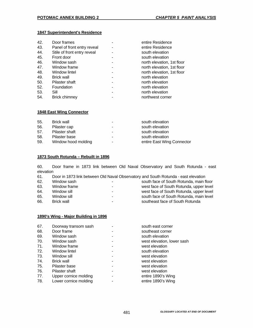
POTOMAC ANNEX BUILDING 2 CHAPTER 5 PAINT ANALYSIS
GLOSSARY LOCATED AT END OF DOCUMENT 481
1847 Superintendent's Residence 42. Door frames - entire Residence 43. Panel of front entry reveal - entire Residence 44. Stile of front entry reveal - south elevation 45. Front door - south elevation 46. Window sash - north elevation, 1st floor 47. Window frame - north elevation, 1st floor 48. Window lintel - north elevation, 1st floor 49. Brick wall - north elevation 50. Pilaster shaft - north elevation 52. Foundation - north elevation 53. Sill - north elevation 54. Brick chimney - northwest corner 1848 East Wing Connector 55. Brick wall - south elevation 56. Pilaster cap - south elevation 57. Pilaster shaft - south elevation 58. Pilaster base - south elevation 59. Window hood molding - entire East Wing Connector 1873 South Rotunda – Rebuilt in 1896 60. Door frame in 1873 link between Old Naval Observatory and South Rotunda - east elevation 61. Door in 1873 link between Old Naval Observatory and South Rotunda - east elevation 62. Window sash - south face of South Rotunda, main floor 63. Window frame - west face of South Rotunda, upper level 64. Window sill - west face of South Rotunda, upper level 65. Window sill - south face of South Rotunda, main level 66. Brick wall - southeast face of South Rotunda 1890's Wing - Major Building in 1896 67. Doorway transom sash - south east corner 68. Door frame - southeast corner 69. Window sash - south elevation 70. Window sash - west elevation, lower sash 71. Window frame - west elevation 72. Window lintel - south elevation 73. Window sill - west elevation 74. Brick wall - west elevation 75. Pilaster base - west elevation 76. Pilaster shaft - west elevation 77. Upper cornice molding - entire 1890’s Wing 78. Lower cornice molding - entire 1890’s Wing

POTOMAC ANNEX BUILDING 2 CHAPTER 5 PAINT ANALYSIS
GLOSSARY LOCATED AT END OF DOCUMENT 482
1902 Second Story Addition (over transit house wings) 79. Brick wall - north elevation 80. Brick window niche - north elevation 81. Upper cornice molding - entire second story addition 82. Lower cornice molding - entire second story addition INTERIOR INVENTORY OF SAMPLES 1844 Old Naval Observatory Basement A. Rotunda basement and stair corridor 1. Masonry wall 2. Wood door, door to original furnace room (east) a. door b. frame 3. Wood window a. sash b. frame First Floor A. Entrance vestibule 1. Plaster wall 2. Pressed metal ceiling 3. Wood door a. panel b. frame c. sidelight panel d. transom B. Main entrance/stair lobby 1. Plaster wall 2. Pressed metal ceiling 3. Wood door a. door b. frame 4. Wood stair a. tread end projecting past balusters b. stringer c. riser d. baluster 5. Baseboard C. Office adjoining main entrance/stair lobby - Type A: Room 2108 1. Plaster wall 2. Wood door a. door
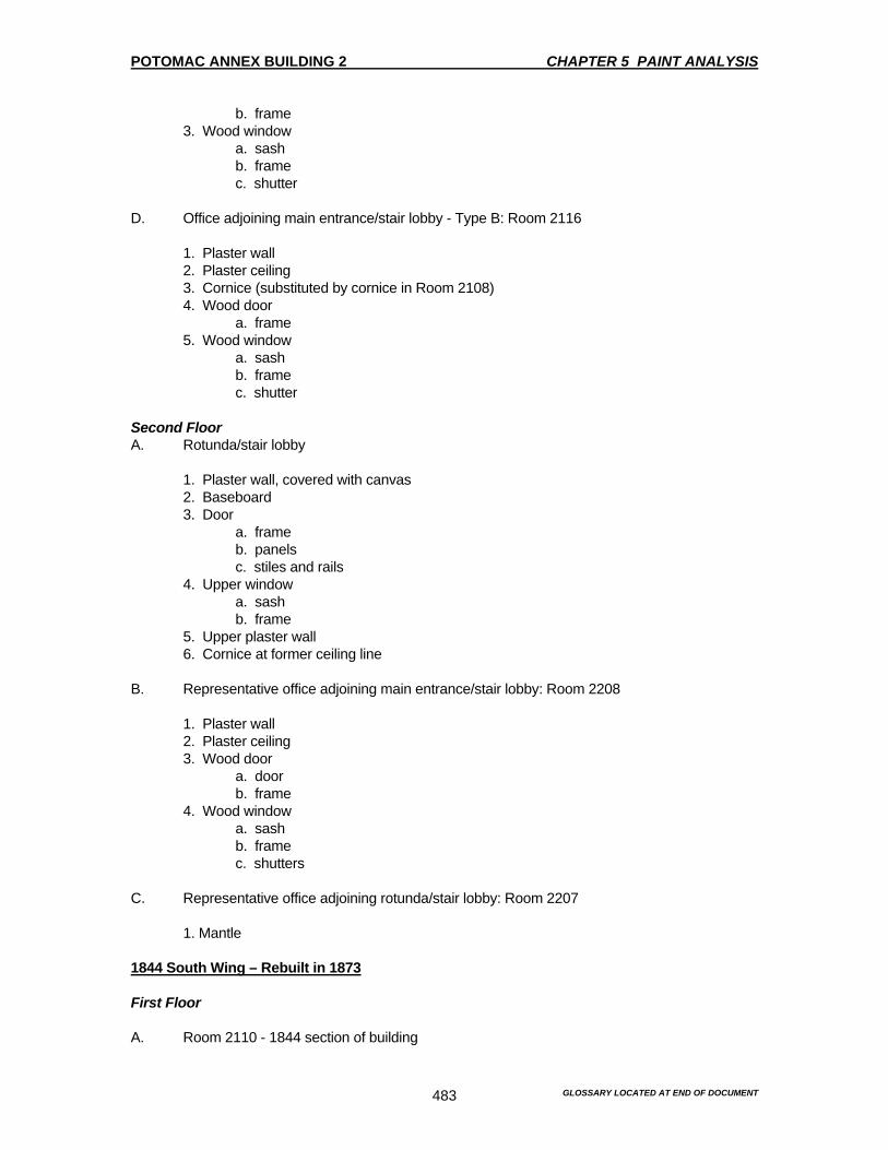
POTOMAC ANNEX BUILDING 2 CHAPTER 5 PAINT ANALYSIS
GLOSSARY LOCATED AT END OF DOCUMENT 483
b. frame 3. Wood window a. sash b. frame c. shutter D. Office adjoining main entrance/stair lobby - Type B: Room 2116
1. Plaster wall 2. Plaster ceiling 3. Cornice (substituted by cornice in Room 2108) 4. Wood door a. frame 5. Wood window a. sash b. frame c. shutter Second Floor A. Rotunda/stair lobby 1. Plaster wall, covered with canvas 2. Baseboard 3. Door a. frame b. panels c. stiles and rails 4. Upper window a. sash b. frame 5. Upper plaster wall 6. Cornice at former ceiling line B. Representative office adjoining main entrance/stair lobby: Room 2208 1. Plaster wall 2. Plaster ceiling 3. Wood door a. door b. frame 4. Wood window a. sash b. frame c. shutters C. Representative office adjoining rotunda/stair lobby: Room 2207
1. Mantle 1844 South Wing – Rebuilt in 1873 First Floor A. Room 2110 - 1844 section of building
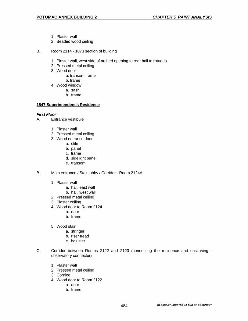
POTOMAC ANNEX BUILDING 2 CHAPTER 5 PAINT ANALYSIS
GLOSSARY LOCATED AT END OF DOCUMENT 484
1. Plaster wall 2. Beaded wood ceiling B. Room 2114 - 1873 section of building 1. Plaster wall, west side of arched opening to rear hall to rotunda 2. Pressed metal ceiling 3. Wood door a. transom frame b. frame 4. Wood window a. sash b. frame 1847 Superintendent's Residence First Floor A. Entrance vestibule 1. Plaster wall 2. Pressed metal ceiling 3. Wood entrance door a. stile b. panel c. frame d. sidelight panel e. transom B. Main entrance / Stair lobby / Corridor - Room 2124A 1. Plaster wall a. hall, east wall b. hall, west wall 2. Pressed metal ceiling 3. Plaster ceiling 4. Wood door to Room 2124 a. door b. frame 5. Wood stair a. stringer b. riser tread c. baluster C. Corridor between Rooms 2122 and 2123 (connecting the residence and east wing -
observatory connector) 1. Plaster wall 2. Pressed metal ceiling 3. Cornice 4. Wood door to Room 2122 a. door b. frame

POTOMAC ANNEX BUILDING 2 CHAPTER 5 PAINT ANALYSIS
GLOSSARY LOCATED AT END OF DOCUMENT 485
D. Space (now office) adjoining main corridor - Room 2122
1. Plaster wall 2. Pressed metal ceiling
3. Pressed metal cornice 4. Wood door, door to central hall (Room 2124A) a. bottom panel b. frame 5. Wood window a. sash b. frame E. Space (now office) adjoining main corridor - Room 2124
1. Plaster wall 2. Plaster wall behind mantle 3. Pressed metal ceiling 4. Metal cornice 5. Wood door, to closet between Rooms 2124 and 2126 a. door 6. Wood door, for main door a. frame
6. Wood window a. sash b. frame F. Space (now office) adjoining main corridor - Room 2126
1. Plaster wall 2. Wood door, to closet in SW corner a. door 3. Wood window a. sash b. frame c. shutter, painted into window reveal 4. Baseboard Second Floor A. Central corridor - Room 2225 1. Plaster wall 2. Pressed metal ceiling 3. Wood door to Room 2224 a. door b. frame 4. Skylight a. frame B. Secondary corridor connecting Room 2223A and Room 2218
1. Plaster wall 2. Paneled doorway reveal, leading from central hall to secondary corridor

POTOMAC ANNEX BUILDING 2 CHAPTER 5 PAINT ANALYSIS
GLOSSARY LOCATED AT END OF DOCUMENT 486
3. Wood door a. door b. frame C. Upper landing of stairway
1. Plaster wall 2. Wood door a. frame 3. Baseboard / stringer D. Representative bedroom (now office): Room 2226
1. Plaster wall 2. Plaster ceiling 3. Wood door a. door b. frame 4. Window a. sash b. frame 5. Chair rail 1848 East Wing Connector First Floor A. Room 2119
1. Plaster wall 2. Wood door a. frame 3. Wood window a. sash b. frame Second Floor A. Room 2218
1. Plaster wall 2. Ceiling 3. Wood door a. door b. frame 4. Wood window a. sash b. frame

POTOMAC ANNEX BUILDING 2 CHAPTER 5 PAINT ANALYSIS
GLOSSARY LOCATED AT END OF DOCUMENT 487
1845 West Wing Transit Building – Addition in 1868 and Second Story in 1902 First Floor A. Room 2106
1. Plaster wall 2. Wood ceiling a. original ceiling, not beaded b. beaded wood ceiling 3. Bead on arched opening 4. Wood window a. sash b. frame 5. Wood instrument hatch 6. Wood cornice B. Room 2104A, north side
1. original wood ceiling 2. triple beaded wood ceiling 3. coved cornice in bay extension Second Floor A. Room 2204 1. Plaster wall 2. Pressed metal ceiling 3. Wood door a. door panel b. frame 4. Wood window a. sash b. frame 5. Wood window hood at opening to main building 1873 Large Rotunda - Reconstructed in 1893) First Floor A. Room 2115
1. Plaster wall 2. Upper window a. sash b. frame 3. Lower large window
a. frame

POTOMAC ANNEX BUILDING 2 CHAPTER 5 PAINT ANALYSIS
GLOSSARY LOCATED AT END OF DOCUMENT 488
EXTERIOR Observations The first observations of the paint sample under a microscope reveal distinct dirt layers in nearly all the samples. The atmosphere was historically very dirty and the remedy to clean the dirty surfaces has clearly been to apply a new layer of paint. The dirt layers are helpful indicators in counting layers on much of the trim of this brick building because only white had been used. The whites sometimes variable in their tone, one layer might be grayer, another creamier, but these differences can reflect the response of individual areas of the Old Naval Observatory to sunlight, shadow and weathering as easily as they can reflect subtle differences in tone of the paint when applied. Although the color seriation may indicate "yellowish white" or "bright white," this term is relative to the surrounding layers and no attempt has been made at this time to cross-match internal layers of the white paints. It reflects the fact that traditional lead-based white paint in drying oil was subject to yellowing from the aging of the oil and to the graying of the lead component by the infiltration of sulfur, through polluted rain water. These subtle color distinctions were helpful in distinguishing individual layers in the color sequence, but they would be individually matched to an ordinary white paint. The very visible and accessible areas of the building, like the main doorway frontispiece, have the most accumulated paint. This element seems to have been freshened with a new coat of paint up to sixteen times. The new paint is invariably a single-coat application over the heavy dirt layer. Dirt layers should be assumed between each layer of paint noted in the color seriation. However, extraordinarily thick layers of dirt are noted on some of the brick substrates of the building, suggesting that the brick was unpainted for a time. Historical documentation includes the information that very early in the Old Naval Observatory’s life, it was painted "three coats of good lead white". The visible dirt on the brick may be a result of the severe cracking and pulling away of the paint film from the building. Dirt may be deposited along with the water that seeps behind the paint, as noted in the Existing Condition Survey. This lifting and pulling away of the thick build-up of paint results in the need for scraping away the accumulated layers prior to repainting. As a result, maintenance and repainting over the years has in fact resulted in the removal of many paint layers and accounts for the differences in numbers of layers for elements known to be of the same age or from the same part of the structure. Prior to the turn-of-the-century, the paint history of the Old Naval Observatory is less than clear based solely on paint samples removed for study. Scraping of earlier paint in the process of repainting has destroyed a full chromo-chronology on most elements tested. Although there is clearly a great build-up of paint on the exterior of the building, much of it is attributable to this century. Photographic documentation of the Old Naval Observatory indicates that it was painted a light color, probably white, from the 1840s to the 1860s. In the 1870s, the photographs suggest that the brick walls were painted a dark color, while the trim remained picked out in white or another very light color. Photographs from the mid-1880s and later show the brickwork again painted a light color, with matching light-color trim. Only a few samples taken from the Old Naval Observatory confirm this photographic evidence. Those samples are from the East Wing Connector, built in 1848 and from the Superintendent's Residence. A layer of strong brown, NBS, paint follows the original yellowish white, NBS, paint in these sequences. Subsequent layers are white and then a pale yellow, which
POTOMAC ANNEX BUILDING 2 CHAPTER 5 PAINT ANALYSIS
GLOSSARY LOCATED AT END OF DOCUMENT 489
is the finish for the first half of the twentieth century (see below). A painting of the Old Naval Observatory, which was completed in 1940, is currently located in Room 2126. This room was the original dining room. This painting shows the Old Naval Observatory painted a pale yellow with light green trim. Light green does appear as window and door trim consistently throughout the Old Naval Observatory and the brickwork has several layers of light yellow paint. These layers precede whites and creams which have a spongy appearance under the microscope, typical of latex paints. Thus, the painting may be relied upon as an accurate document of the finishes of the Potomac Annex Complex in the 1940s and earlier and can provide a relative date for the architectural elements that contain this paint layer. The brick walls of the Old Naval Observatory were probably painted yellow at the same time the complex of the Naval Hospital Buildings were erected around the Old Naval Observatory in the first decade of the twentieth century. The hospital buildings were constructed with a light-yellow and tan-colored brick. The six layers of yellow paint typically present on a masonry sample from the Old Naval Observatory indicates that the yellowish body may have existed for some time. In the 1940's the windows and doors of the Old Naval Observatory were trimmed in light green, according to the picture in the dining room. Prior to that, the sashes were dark green, as found on the other buildings of the complex and the window frames and doorways were apparently painted white. The painting of the Old Naval Observatory served the practical purpose of unifying a building that was continually enlarged through the nineteenth century with additions and wings. The brick does not match perfectly throughout the complex. Painting insured that the building was seen as a consistent whole rather than an additive sprawl. Painting the exterior was established as standard practice by the time of the first addition to the original Old Naval Observatory. The Old Naval Observatory has been white or off-white for much of its history. INTERIOR Observations The additive nature of the Old Naval Observatory is much more apparent with the interior than on the exterior. The floor plan is confusing to a visitor. There is a warren of rooms throughout the Old Naval Observatory. The reconfiguration of the original spaces in some areas of the Old Naval Observatory make the perception of "original" and "later" difficult, if not impossible. Because what are now different wings of the same building were constructed for very different uses in different times, the historic finishes for each part were also distinctive. The additive building is divided into a number of spaces, each unseen from the other. Thus, it is not only possible, but desirable to restore "original" finishes to each part of the Old Naval Observatory, thereby graphically identifying the succession of individual additions and wings which today comprise the entire Old Naval Observatory. Just as the paints on the exterior can be roughly dated by correlating the appearance of yellow walls and green trim with a World War II era painting. The interior finishes have a nearly universal coating of light green, which seems to correspond to the first decade of the 20th century. The light green appears as the earliest finish of those sections added about 1902 and appears consistently in the color sequence for the architectural elements predating this period. Light green, which may best be described as "hospital green," is consistent with the building's use as a hospital and was probably applied throughout the Old Naval Observatory in a series of re-paintings during the years from 1902 to 1908. Nineteenth century finishes do survive in many areas of the Old Naval Observatory and repainting

POTOMAC ANNEX BUILDING 2 CHAPTER 5 PAINT ANALYSIS
GLOSSARY LOCATED AT END OF DOCUMENT 490
did not apparently take place as frequently as on the exterior. Less dirt, and better cleaning of the interior may account for this distinction, as well as the fact that the erection of an addition at one end of the Old Naval Observatory did not necessarily require repainting the existing fabric, as it did on the exterior. However, the plaster walls of the Old Naval Observatory and the Superintendent's Residence did not survive over a half-century of hard use without some damage. Several samples were taken from the walls included sections of canvas, which were applied before the application of a light green paint. This light green paint is from the early twentieth-century hospital era of the Old Naval Observatory. The evidence suggests that the canvas was applied to repair the old plaster walls where needed and then repainted. Application of canvas to the walls to repair them is a traditional repair technique. On some samples, intact paint layers prior to the repair could be recovered to document the nineteenth century finishes. Each main section of the interior of the Old Naval Observatory is individually discussed in the following sections. Old Naval Observatory The interior of the Old Naval Observatory, finished in 1844, was utilitarian by definition. Although the conical stone base for the telescope is gone from the Old Naval Observatory, the original room configuration remains intact. There is consistent evidence of the original paints to allow recommendations to approximate the original appearance of the Old Naval Observatory’s finishes. The plaster walls throughout the first floor were originally painted a tan color, accented with a white painted trim. The ceiling, many of which are now covered with pressed metal from the early 20th century, would have been a white plaster. The metal ceilings were also originally white. The visual effect of the room approximates the historic appearance in spite of the intrusion of more modern materials. The staircase that dominates the entry hall of the Old Naval Observatory is an addition of the 1890s. Currently, it is finished with crude graining, which was done in 1993. The handrail was recently stripped and refinished with a clear coating of polyurethane. It is unclear whether the decision to strip the handrail and grain the rest of the staircase was made with the intent of recreating any known historic finish. Paint analysis indicates that the balusters of the staircase are oak and originally finished with a clear varnish. The handrail was likely to have been intended to be a clear-finished as well. The stringers, risers and treads of the staircase are not oak, but were originally finished with a dark-toned tinted varnish. This was a common way of finishing woodwork at the turn of the century. This would have blended the functional parts of the staircase with the ornamental and more expensive oak turned balusters. None of the stair's finishes or details suggests that the workmanship was anything other than basic and utilitarian. The upper wall of the Old Naval Observatory space itself does not retain nineteenth century finishes. This indicates an extensive wall repair and reconstruction when the Old Naval Observatory equipment was removed and the space reconfigured for office use. The mantle, which remains in one second-floor office, Room 2207, has a clear varnish as its first finish. This was a popular turn-of-the-century treatment, which supports the stylistic observation that the mantle is part of the 1890s renovation of the Old Naval Observatory and not original fabric. The basement of the Old Naval Observatory, the most utilitarian space of all, does have painted walls and wooden trim around the doors and windows. The finish was consistently white on all the elements. Residence The Greek Revival-style Residence was constructed and finished far more finely than its utilitarian counterpart, the Old Naval Observatory. The Residence was a large comfortable home with many

POTOMAC ANNEX BUILDING 2 CHAPTER 5 PAINT ANALYSIS
GLOSSARY LOCATED AT END OF DOCUMENT 491
stylish features and finishes. There is physical evidence that the walls of the principal rooms of the first floor were wallpapered. There is documentary evidence that the walls of the second floor were papered as well. Unfortunately, no fragments of paper have been recovered which give any indication of the patterns or colors used in the Residence. It is logical to assume that, like the architecture, the papers would have been "standard" for their time and place. It is not the cheapest, but not custom-made avant-garde designs with high style pretensions. The papers were removed and painting of the walls was started about the time of the 1890s renovations to the Residence. Woodwork throughout the Residence appears to have been originally and subsequently painted white for most of the nineteenth century. There is some evidence of graining or a faux-bois treatment of the paneled door to the front parlor on the hall face. Decoratively grained doors or clear-finished doors in exotic woods were often paired with white door frames and other white-painted woodwork in Greek Revival style dwellings.1 However, the absence of other original doors facing the hallway and the modification of this parlor door to incorporate windows makes the extent of any original grained door decoration hard to verify throughout the first floor. Even if graining existed, it was subsequently repainted white in the nineteenth century. The staircase in the center hall of the Residence dates to the 1890s and so was constructed as the Residence was converted from residential to office use. The first finish on the stair was crude graining, not unlike that found on presently on the main staircase of the Old Naval Observatory. There may have been the intent to match this stair with the Old Naval Observatory stair. However, the Residence stair does not incorporate any oak, so the wood-like appearance had to be entirely derived from paint and varnish. The 1890s also introduced a large wooden mantle into the front parlor. The mantle contained a mirrored overmantle. The entire mantle was originally clear-finished, as was popular in the 1890s. The pressed metal ceilings throughout the Residence's first floor are part of the 1890s alterations as well. Their original white finish carried on the convention of white finishes established on the earlier plaster ceilings in the Residence. South Rotunda The existing South Rotunda dates to 1893. It was originally painted a dark red with white trim. It may have had stencil designs or other decorative painted details, but in the scope of this paint analysis, they were not discovered. In the twentieth century, shelving was attached to the walls, which has been subsequently removed. In the removal, a great deal of patching and repair took place, which may make recovery of the full decorative design of the South Rotunda impossible. As in other areas of the South Rotunda, the woodwork was consistently painted white. South Wing Constructed in 1873 to link the Old Naval Observatory with the first rotunda, which was later replaced by the South Rotunda. The South Wing is a short hall with flanking offices. The walls were originally painted a gray-blue and as is typical throughout the South Wing. All wooden trim work was painted white.
1 This treatment has been identified by Janet W. Foster in carrying our paint analysis at the 1839 Greek Revival style Barrow Mansion in Jersey City, New Jersey; and in the vernacular Greek Revival-decorated parlors of the Vail Mansion, part of the Speedwell Village National Historic Site in Morristown, New Jersey. It is also documented in several folk paintings of the 1840s and '50s.

POTOMAC ANNEX BUILDING 2 CHAPTER 5 PAINT ANALYSIS
GLOSSARY LOCATED AT END OF DOCUMENT 492
West Wing Transit Building Different types of beaded tongue and groove ceiling mark the location of the original 1868 transit slit. The in-fill was added in the 1902 renovations. Because of the great physical changes to the room at the turn of this century, there is little remaining of the original transit room. Samples from the old beaded tongue and groove board indicate that it was originally painted a gray-blue. That may have been a practical choice rather than an aesthetic one. This was probably done to avoid reflected light in a room where serious stargazing was done. However, most of the features of that early period are gone. They were replaced by the 1902 woodwork, which had walls that were originally painted white. Second Floor Additions - East, West and South Wings At the turn-of-the-twentieth century, the one-story connectors between the Old Naval Observatory and its extensions were enlarged to two stories. The second floor rooms created in this process were long narrow spaces, brightly lit by banks of windows on both sides. They were logical locations for the laboratories needed by the newly created Naval Hospital. All were originally painted the light green associated with the Naval Hospital period of the Old Naval Observatory. The light green walls were also continued onto the window and doorframes. However, the window sash was originally white.

POTOMAC ANNEX BUILDING 2 CHAPTER 5 PAINT ANALYSIS
GLOSSARY LOCATED AT END OF DOCUMENT 493
RECOMMENDATIONS EXTERIOR The Old Naval Observatory should be repainted creamy white on the brick body and bright white on the trim. This is the original treatment of the Old Naval Observatory, which is the most significant part of the Potomac Annex complex. It is also the finish that the Old Naval Observatory had at the turn of the twentieth century, when the structure had achieved its present architectural configuration. Painting the various parts of the sprawling Old Naval Observatory the colors they had when they were new would create a multi-hued building, which would detract from its architectural dignity and offer a view of a "building that never was". Although it is interesting to understand the morphology of the Old Naval Observatory, presenting this information with a "color-coded" exterior would be overly-didactic at best and confusing to the uninformed visitor of the Potomac Annex complex. The guidelines of the Secretary of the Interior's, Standards for Historic Rehabilitation, which should be observed as the baseline of preservation practice in this country, point to finishing the Old Naval Observatory to the period of its present configuration. That configuration was completed around 1902. At that time the entire Old Naval Observatory was uniformly finished with cream-colored brick walls, bright white trim, dark green sash and dark green iron railings. This color scheme is recommended for repainting the Old Naval Observatory. The brick walls, including the pilaster shafts, should be repainted to match Munsell 5 Y 9/1. This is a good match to Plochere color 128. The bricks should be painted with high-quality semi-gloss paint to match. Plochere color chip 128 is attached below. Cream-Light Mustard-White Brick Walls Munsell 5 Y 9/1 Pilaster Shafts Plochere 128

POTOMAC ANNEX BUILDING 2 CHAPTER 5 PAINT ANALYSIS
GLOSSARY LOCATED AT END OF DOCUMENT 494
The window sash should be repainted to match Munsell 5 G 3/4. This is a good match to Plochere color 1073. The sash should be painted with high-quality gloss paint to match. The Plochere color chip is attached below. Dark Green-Yellow Window Sash Munsell 5 G 3/4 Plochere 1073
The trim on the wood, stone, cornice, door and window enframements, doors, pilaster caps and bases should be repainted a high-quality bright white paint. The doors are all replacements of originals and should be painted white to harmonize with other trim work. No Munsell match or commercial brand is recommended.
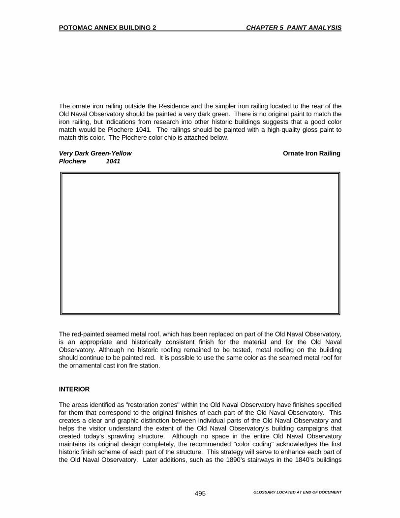
POTOMAC ANNEX BUILDING 2 CHAPTER 5 PAINT ANALYSIS
GLOSSARY LOCATED AT END OF DOCUMENT 495
The ornate iron railing outside the Residence and the simpler iron railing located to the rear of the Old Naval Observatory should be painted a very dark green. There is no original paint to match the iron railing, but indications from research into other historic buildings suggests that a good color match would be Plochere 1041. The railings should be painted with a high-quality gloss paint to match this color. The Plochere color chip is attached below. Very Dark Green-Yellow Ornate Iron Railing Plochere 1041
The red-painted seamed metal roof, which has been replaced on part of the Old Naval Observatory, is an appropriate and historically consistent finish for the material and for the Old Naval Observatory. Although no historic roofing remained to be tested, metal roofing on the building should continue to be painted red. It is possible to use the same color as the seamed metal roof for the ornamental cast iron fire station. INTERIOR The areas identified as "restoration zones" within the Old Naval Observatory have finishes specified for them that correspond to the original finishes of each part of the Old Naval Observatory. This creates a clear and graphic distinction between individual parts of the Old Naval Observatory and helps the visitor understand the extent of the Old Naval Observatory’s building campaigns that created today's sprawling structure. Although no space in the entire Old Naval Observatory maintains its original design completely, the recommended "color coding" acknowledges the first historic finish scheme of each part of the structure. This strategy will serve to enhance each part of the Old Naval Observatory. Later additions, such as the 1890’s stairways in the 1840’s buildings

POTOMAC ANNEX BUILDING 2 CHAPTER 5 PAINT ANALYSIS
GLOSSARY LOCATED AT END OF DOCUMENT 496
are to be restored to their original appearance. Although this creates a discrepancy in a strict interpretive sense, it is one that allows the later elements to be seen at their best as a clearly additive element in an otherwise earlier structure. This is dissimilar to the exterior, which is being interpreted to the 1902 period, when construction of the Old Naval Observatory was largely complete to the way we now see it. An interior interpretation of the Old Naval Observatory to one period would create an undesirable, uniform appearance, which would negate the historic significance of the 1840’s Old Naval Observatory and its subsequent additions. Areas of the interior which are non-restoration zones should be repainted a simple monochromatic color scheme of flat-finished white walls with semi-gloss finished white trim. This should be appropriate for the modern uses of the Old Naval Observatory and will not compete with the "color-coded" restoration zones of the Old Naval Observatory. Old Naval Observatory Walls throughout the original Old Naval Observatory on the first and second floors, including the original south wing which now contains Rooms 2109 and 2110, should be painted an eggshell finish light yellowish brown, NBS, to match Munsell 10 YR 7/4. This is a good match for Plochere color 181. The Plochere chip is attached below. Eggshell Yellowish-Brown Old Naval Observatory Interior Walls Munsell 10 YR 7/4 Plochere 181
All trim work, including window frames, sash, doorframes, doors and baseboards should be painted a high-gloss white. Pressed metal ceilings should be painted a semi-gloss white and plaster ceilings a flat white. No Munsell color chip or Plochere color chip is attached. The staircase in the center hall of the Old Naval Observatory should be stripped of accumulated paint. The treads, stringers and riser should be finished with a brown tinted varnish to match the balusters. The oak balusters should be finished with a clear varnish finish. The tinted varnish

POTOMAC ANNEX BUILDING 2 CHAPTER 5 PAINT ANALYSIS
GLOSSARY LOCATED AT END OF DOCUMENT 497
should correspond to Minwax "Oak" or equivalent. Stripping the existing paint should be carried out under the direction of a qualified conservator so as not to damage the historic wood. South Wing First floor The first floor extension of the original South Wing, connecting it to the South Rotunda comprises Rooms 2111, 2112, 2113, 2114 and 2114A. The walls of all these rooms should be painted a pale blue, NBS, to match Munsell 7.5B 7/2. This is a good match to Plochere color 767. The Plochere is attached below. Cream Pale Blue South Wing First Floor Interior Walls Munsell 7.5 B 7/2 Plochere 767
The woodwork in this portion of the South Wing should be painted a glossy white paint. No color chip is attached.

POTOMAC ANNEX BUILDING 2 CHAPTER 5 PAINT ANALYSIS
GLOSSARY LOCATED AT END OF DOCUMENT 498
South Wing: Second floor The second floor of the South Wing is part of the construction of the 1902-3 Second Floor Addition renovations that transformed the Old Naval Observatory into a hospital. The South Wing, Second Floor original finish was a very pale green, NBS, on the walls, doors and door and window frames. The South Wing should be repainted this color to match Munsell 5 G 8/2. This is a good match to Plochere color 1039. The Plochere color chip attached below. Cream Pale Green South Wing Second Floor Interior Walls Munsell 5 G 8/2 Plochere 1039
The window sash of the South Wing second-floor space should be painted glossy white. The ceiling of the space should be painted a flat-finish white. No color samples are provided for the white paints recommended. Residence The restoration zones of the Residence, including the vestibule, center hall and the three intact rooms on the first floor, should be finished with white-painted woodwork and papered walls.

POTOMAC ANNEX BUILDING 2 CHAPTER 5 PAINT ANALYSIS
GLOSSARY LOCATED AT END OF DOCUMENT 499
Wallpaper reproductions from the Greek Revival period are available commercially through several companies. Although no specific patterns are recommended here, historical precedent does suggest that the hall walls were very likely to have been covered with a faux-ashlar look paper in the Greek Revival period. This should continue up the stairs to the second floor hallway. The parlors of the Residence, which are now the three principal offices, should be finished with papers documented as having been used in parlors, dining rooms or other "public" rooms. These would undoubtedly have a larger-pattern and bolder-colored design than those papers documented for use in the bedrooms or "private" rooms. Catherine Lynn's book Wallpaper in America (Van Nostrand, 1975) is an invaluable source of information about appropriate wallpaper types for the Greek Revival period. This reference should be consulted before the wallpaper is selected. In addition, the book, Wallpapers for Historic Buildings, by Richard Nylander (Preservation Press, 1983) should also be consulted for historically appropriate patterns available in reproduction. The stairway in the center hall is like the one in the Old Naval Observatory, a product of remodeling in the 1890s. Likewise, on the first floor, the original plaster ceiling is covered with pressed metal. The metal ceiling throughout the Residence should be finished in a semi-gloss, bright white paint. The plaster ceilings should be painted a flat-finished white paint. The staircase should be refinished so that the balusters are also grained to match the graining already extant on the stringers and risers. The newel post, which is clear finished, should remain a clear-finish. No color samples are attached or recommended for the Residence. East Wing: First floor The western section of the first floor of the present East Wing connector was part of the original Old Naval Observatory, but was reconfigured at the turn of the twentieth century to house office spaces. The on-site historian for Potomac Annex 2 has already graphically delineated the location of the slits, which accommodated the transit. The current use of paint to recall the historic use of the area is very appropriate and should be maintained. The office space that remains is not a restoration zone and so should be painted all white. The extension of the East Wing to connect the Old Naval Observatory with the Residence occurred in 1848, after both the Residence and the Old Naval Observatory were constructed as freestanding buildings. It is not an important interior space and was not tested as part of the paint analysis. However, using paint to match the exterior color of the East Wing, see recommendations for the exterior, the original exterior wall of the Residence and of the Old Naval Observatory's East Wing could be highlighted against the white walls and woodwork of this non-restoration zone. The use of creamy-white walls at the east and west ends of Room 2121 would effectively communicate that this space linked two earlier structures which once had exposed exterior walls in this location. No color samples are attached or recommended for the East Wing.
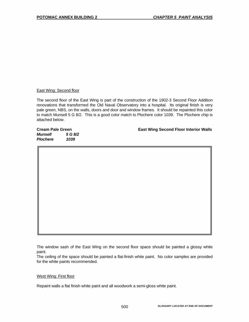
POTOMAC ANNEX BUILDING 2 CHAPTER 5 PAINT ANALYSIS
GLOSSARY LOCATED AT END OF DOCUMENT 500
East Wing: Second floor The second floor of the East Wing is part of the construction of the 1902-3 Second Floor Addition renovations that transformed the Old Naval Observatory into a hospital. Its original finish is very pale green, NBS, on the walls, doors and door and window frames. It should be repainted this color to match Munsell 5 G 8/2. This is a good color match to Plochere color 1039. The Plochere chip is attached below. Cream Pale Green East Wing Second Floor Interior Walls Munsell 5 G 8/2 Plochere 1039
The window sash of the East Wing on the second floor space should be painted a glossy white paint. The ceiling of the space should be painted a flat-finish white paint. No color samples are provided for the white paints recommended. West Wing: First floor Repaint walls a flat finish white paint and all woodwork a semi-gloss white paint.
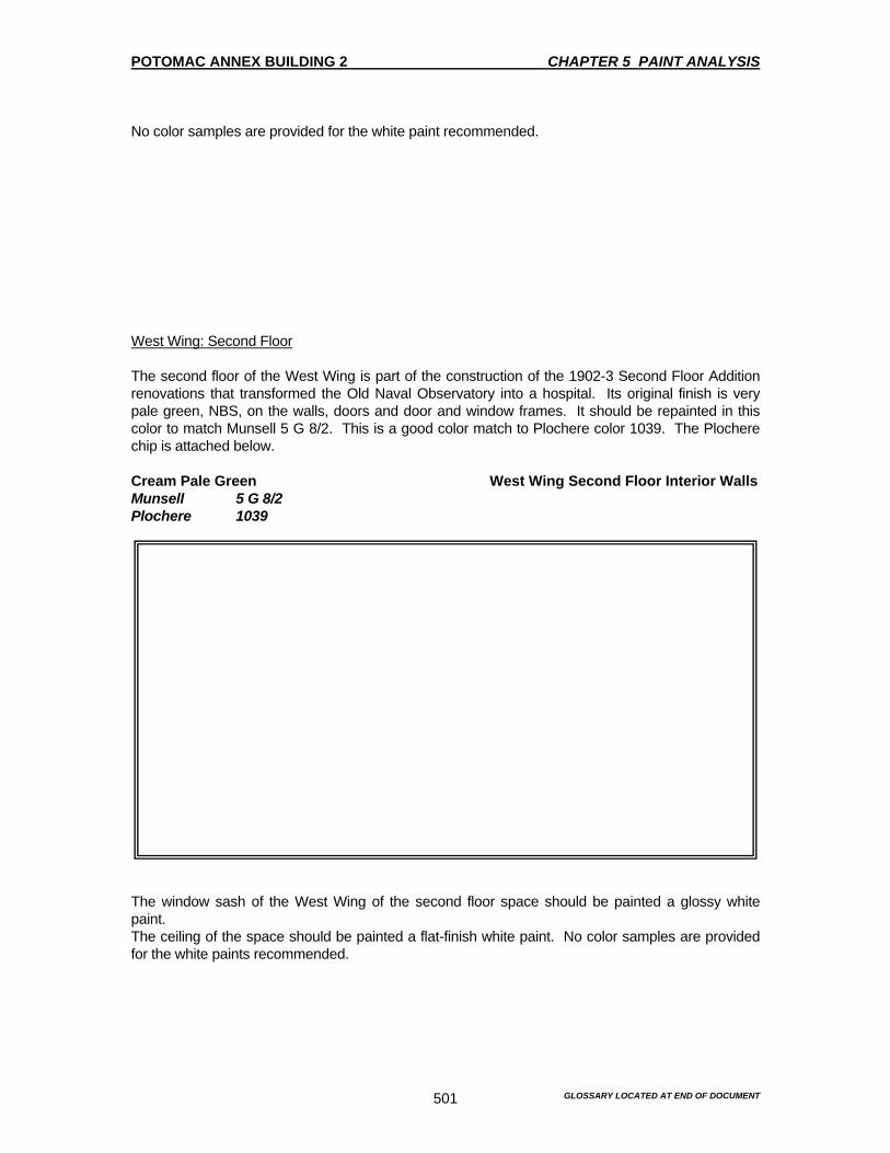
POTOMAC ANNEX BUILDING 2 CHAPTER 5 PAINT ANALYSIS
GLOSSARY LOCATED AT END OF DOCUMENT 501
No color samples are provided for the white paint recommended. West Wing: Second Floor The second floor of the West Wing is part of the construction of the 1902-3 Second Floor Addition renovations that transformed the Old Naval Observatory into a hospital. Its original finish is very pale green, NBS, on the walls, doors and door and window frames. It should be repainted in this color to match Munsell 5 G 8/2. This is a good color match to Plochere color 1039. The Plochere chip is attached below. Cream Pale Green West Wing Second Floor Interior Walls Munsell 5 G 8/2 Plochere 1039
The window sash of the West Wing of the second floor space should be painted a glossy white paint. The ceiling of the space should be painted a flat-finish white paint. No color samples are provided for the white paints recommended.
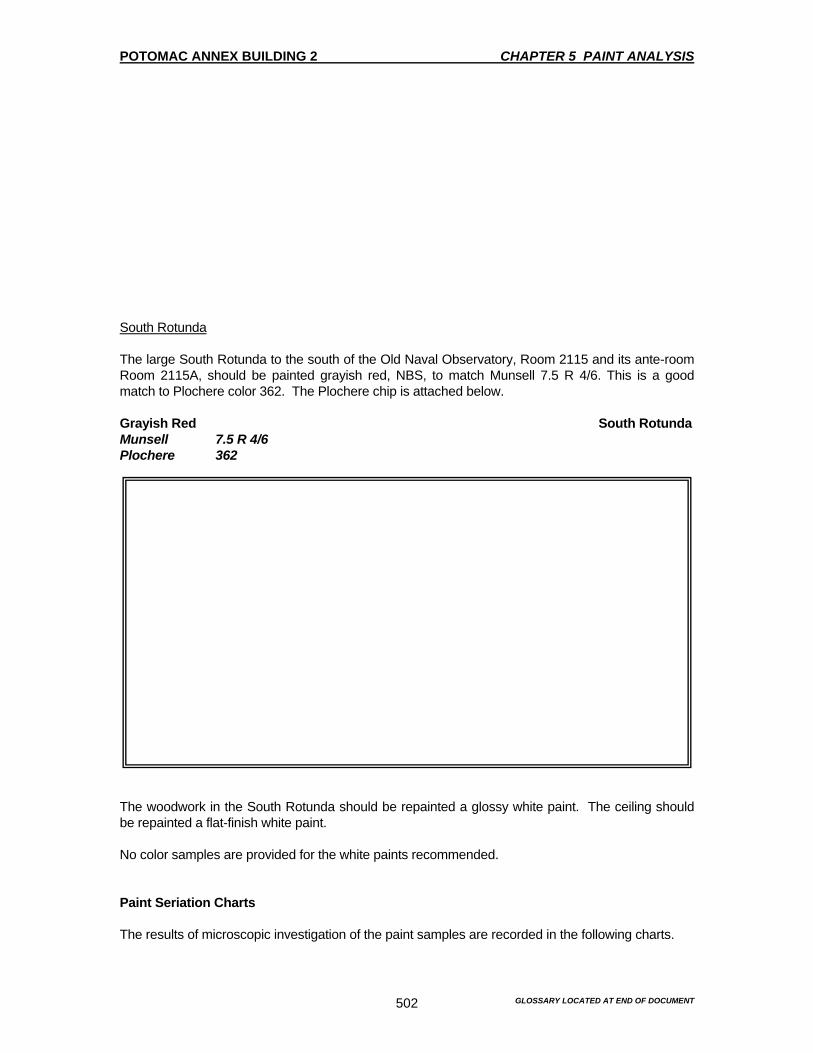
POTOMAC ANNEX BUILDING 2 CHAPTER 5 PAINT ANALYSIS
GLOSSARY LOCATED AT END OF DOCUMENT 502
South Rotunda The large South Rotunda to the south of the Old Naval Observatory, Room 2115 and its ante-room Room 2115A, should be painted grayish red, NBS, to match Munsell 7.5 R 4/6. This is a good match to Plochere color 362. The Plochere chip is attached below. Grayish Red South Rotunda Munsell 7.5 R 4/6 Plochere 362
The woodwork in the South Rotunda should be repainted a glossy white paint. The ceiling should be repainted a flat-finish white paint. No color samples are provided for the white paints recommended. Paint Seriation Charts The results of microscopic investigation of the paint samples are recorded in the following charts.
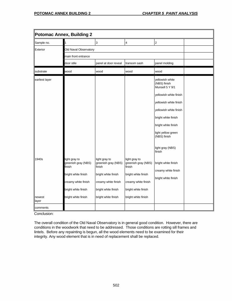
POTOMAC ANNEX BUILDING 2 CHAPTER 5 PAINT ANALYSIS
502
Potomac Annex, Building 2
Sample no. 1 3 4 2
Exterior Old Naval Observatory
main front entrance
door stile panel at door reveal transom sash panel molding
substrate wood wood wood wood
earliest layer 1940s newest layer
light gray to greenish gray (NBS) finish bright white finish creamy white finish bright white finish bright white finish
light gray to greenish gray (NBS) finish bright white finish creamy white finish bright white finish bright white finish
light gray to greenish gray (NBS) finish bright white finish creamy white finish bright white finish bright white finish
yellowish white (NBS) finish Munsell 5 Y 9/1 yellowish white finish yellowish white finish yellowish white finish bright white finish bright white finish light yellow green (NBS) finish light gray (NBS) finish bright white finish creamy white finish bright white finish
comments
Conclusion: The overall condition of the Old Naval Observatory is in general good condition. However, there are conditions in the woodwork that need to be addressed. Those conditions are rotting sill frames and lintels. Before any repainting is begun, all the wood elements need to be examined for their integrity. Any wood element that is in need of replacement shall be replaced.

POTOMAC ANNEX BUILDING 2 CHAPTER 5 PAINT ANALYSIS
503
Potomac Annex, Building 2 Sample no. 5 6 7 8 9
Exterior Old Naval Observatory
main front entrance NW corner, first floor NW corner, second floor
door frame ornamental bracket window sash window frame window hood
substrate wood wood wood wood wood
earliest layer 1940s newest layer
white primer yellowish white (NBS) finish Munsell 5 Y 9/1 yellowish white finish yellowish white finish yellowish white finish yellowish white finish yellowish white finish yellowish white finish yellowish white finish bright white finish bright white finish light yellow green (NBS) finish light gray (NBS) finish bright white finish creamy white finish bright white finish bright white finish
white primer yellowish white (NBS) finish Munsell 5 Y 9/1 yellowish white finish yellowish white finish yellowish white finish yellowish white finish yellowish white finish yellowish white finish yellowish white finish bright white finish bright white finish light yellow green (NBS) finish light gray (NBS) finish bright white finish creamy white finish bright white finish bright white finish
yellowish white (NBS) finish Munsell 5 Y 9/1 dark yellowish green (NBS) finish Munsell 2.5 G 4/4* dark green (NBS) finish Munsell 2.5 G 3/4 very dark yellowish green (NBS) finish Munsell 10 GY 2/2 dark green (NBS) finish Munsell 5 G 3/4 light yellow green (NBS) finish light gray (NBS) finish bright white finish creamy white finish bright white finish bright white finish
yellowish white (NBS) finish Munsell 5 Y 9/1 yellowish white finish yellowish white finish yellowish white finish yellowish white finish yellowish white finish yellowish white finish yellowish white finish yellowish white finish bright white finish bright white finish light yellow green (NBS) finish light gray (NBS) finish bright white finish creamy white finish bright white finish bright white finish
yellowish white (NBS) finish Munsell 5 Y 9/1 yellowish white finish yellowish white finish yellowish white finish yellowish white finish yellowish white finish yellowish white finish yellowish white finish bright white finish bright white finish white finish white finish white finish white finish white finish white finish
comments * very heavy dirt layer

POTOMAC ANNEX BUILDING 2 CHAPTER 5 PAINT ANALYSIS
504
Potomac Annex, Building 2 Sample no. 10 11 12 13 14
Exterior Old Naval Observatory
NW corner, first floor upper profile of cornice
lower profile of cornice
south face north face
window bracket dome dome
substrate sandstone wood wood* copper copper*
earliest layer 1870s 1940s newest layer
yellowish white (NBS) finish Munsell 5 Y 9/1 strong brown (NBS) finish Munsell 2.5 YR 4/6 yellowish white finish yellowish white finish yellowish white finish yellowish white finish yellowish white finish yellowish white finish yellowish white finish yellowish white finish yellowish white finish yellowish white finish yellowish white finish yellowish white finish creamy white finish creamy white finish bright white finish
yellowish white (NBS) finish Munsell 5 Y 9/1 yellowish white finish yellowish white finish yellowish white finish yellowish white finish yellowish white finish yellowish white finish yellowish white finish yellowish white finish yellowish white finish yellowish white finish yellowish white finish yellowish white finish yellowish white finish creamy white finish bright white finish bright white finish
black residue - from burning off early paint layers? creamy white finish bright white finish bright white finish
thin layer of verdigris patina on the copper silver-colored, shiny metallic finish thick black tar-like layer (patch? drip from other roof work??) white-gold, shiny metallic finish silver-gray, dull metallic finish white finish
thick black tar-like layer (patch? drip from other roof work??) white-gold, shiny metallic finish silver-gray, dull metallic finish white finish
comments * substrate scorched * no visible verdigris patina on this sample
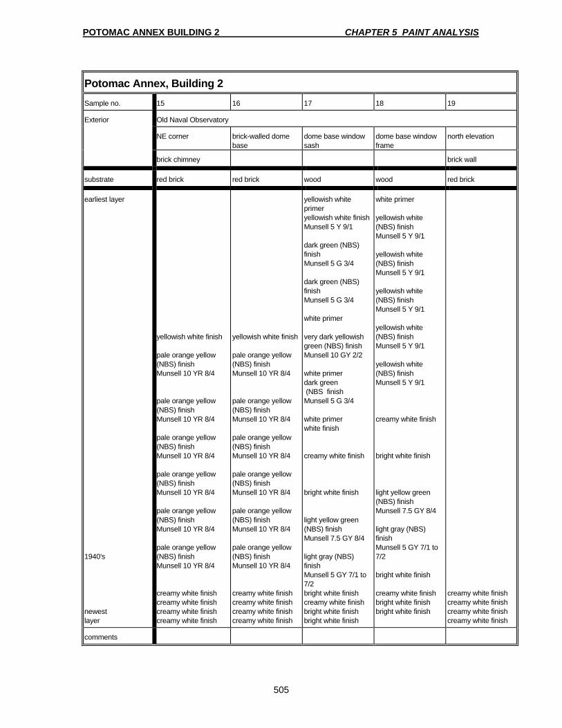
POTOMAC ANNEX BUILDING 2 CHAPTER 5 PAINT ANALYSIS
505
Potomac Annex, Building 2 Sample no. 15 16 17 18 19
Exterior Old Naval Observatory
NE corner brick-walled dome base
dome base window sash
dome base window frame
north elevation
brick chimney brick wall
substrate red brick red brick wood wood red brick
earliest layer 1940's newest layer
yellowish white finish pale orange yellow (NBS) finish Munsell 10 YR 8/4 pale orange yellow (NBS) finish Munsell 10 YR 8/4 pale orange yellow (NBS) finish Munsell 10 YR 8/4 pale orange yellow (NBS) finish Munsell 10 YR 8/4 pale orange yellow (NBS) finish Munsell 10 YR 8/4 pale orange yellow (NBS) finish Munsell 10 YR 8/4 creamy white finish creamy white finish creamy white finish creamy white finish
yellowish white finish pale orange yellow (NBS) finish Munsell 10 YR 8/4 pale orange yellow (NBS) finish Munsell 10 YR 8/4 pale orange yellow (NBS) finish Munsell 10 YR 8/4 pale orange yellow (NBS) finish Munsell 10 YR 8/4 pale orange yellow (NBS) finish Munsell 10 YR 8/4 pale orange yellow (NBS) finish Munsell 10 YR 8/4 creamy white finish creamy white finish creamy white finish creamy white finish
yellowish white primer yellowish white finish Munsell 5 Y 9/1 dark green (NBS) finish Munsell 5 G 3/4 dark green (NBS) finish Munsell 5 G 3/4 white primer very dark yellowish green (NBS) finish Munsell 10 GY 2/2 white primer dark green (NBS finish Munsell 5 G 3/4 white primer white finish creamy white finish bright white finish light yellow green (NBS) finish Munsell 7.5 GY 8/4 light gray (NBS) finish Munsell 5 GY 7/1 to 7/2 bright white finish creamy white finish bright white finish bright white finish
white primer yellowish white (NBS) finish Munsell 5 Y 9/1 yellowish white (NBS) finish Munsell 5 Y 9/1 yellowish white (NBS) finish Munsell 5 Y 9/1 yellowish white (NBS) finish Munsell 5 Y 9/1 yellowish white (NBS) finish Munsell 5 Y 9/1 creamy white finish bright white finish light yellow green (NBS) finish Munsell 7.5 GY 8/4 light gray (NBS) finish Munsell 5 GY 7/1 to 7/2 bright white finish creamy white finish bright white finish bright white finish
creamy white finish creamy white finish creamy white finish creamy white finish
comments
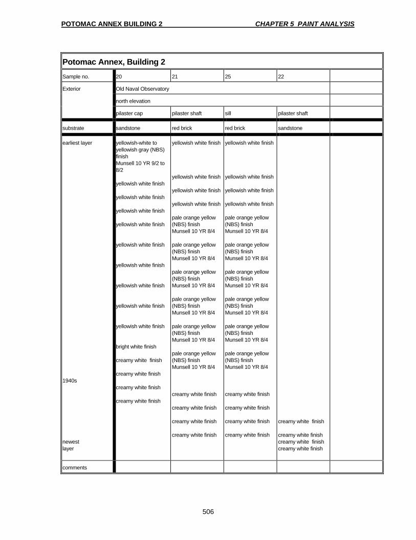
POTOMAC ANNEX BUILDING 2 CHAPTER 5 PAINT ANALYSIS
506
Potomac Annex, Building 2 Sample no. 20 21 25 22
Exterior Old Naval Observatory
north elevation
pilaster cap pilaster shaft sill pilaster shaft
substrate sandstone red brick red brick sandstone
earliest layer 1940s newest layer
yellowish-white to yellowish gray (NBS) finish Munsell 10 YR 9/2 to 8/2 yellowish white finish yellowish white finish yellowish white finish yellowish white finish yellowish white finish yellowish white finish yellowish white finish yellowish white finish yellowish white finish bright white finish creamy white finish creamy white finish creamy white finish creamy white finish
yellowish white finish yellowish white finish yellowish white finish yellowish white finish pale orange yellow (NBS) finish Munsell 10 YR 8/4 pale orange yellow (NBS) finish Munsell 10 YR 8/4 pale orange yellow (NBS) finish Munsell 10 YR 8/4 pale orange yellow (NBS) finish Munsell 10 YR 8/4 pale orange yellow (NBS) finish Munsell 10 YR 8/4 pale orange yellow (NBS) finish Munsell 10 YR 8/4 creamy white finish creamy white finish creamy white finish creamy white finish
yellowish white finish yellowish white finish yellowish white finish yellowish white finish pale orange yellow (NBS) finish Munsell 10 YR 8/4 pale orange yellow (NBS) finish Munsell 10 YR 8/4 pale orange yellow (NBS) finish Munsell 10 YR 8/4 pale orange yellow (NBS) finish Munsell 10 YR 8/4 pale orange yellow (NBS) finish Munsell 10 YR 8/4 pale orange yellow (NBS) finish Munsell 10 YR 8/4 creamy white finish creamy white finish creamy white finish creamy white finish
creamy white finish creamy white finish creamy white finish creamy white finish
comments
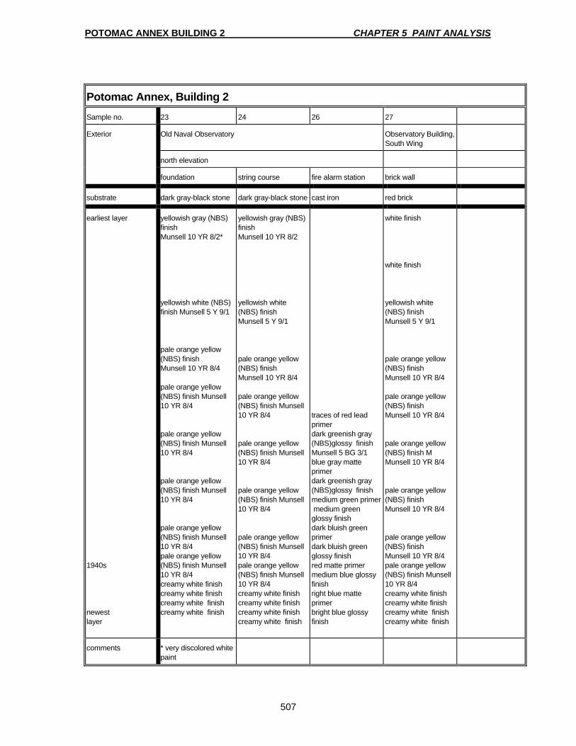
POTOMAC ANNEX BUILDING 2 CHAPTER 5 PAINT ANALYSIS
507
Potomac Annex, Building 2 Sample no. 23 24 26 27
Exterior Old Naval Observatory Observatory Building, South Wing
north elevation
foundation string course fire alarm station brick wall
substrate dark gray-black stone dark gray-black stone cast iron red brick
earliest layer 1940s newest layer
yellowish gray (NBS) finish Munsell 10 YR 8/2* yellowish white (NBS) finish Munsell 5 Y 9/1 pale orange yellow (NBS) finish Munsell 10 YR 8/4 pale orange yellow (NBS) finish Munsell 10 YR 8/4 pale orange yellow (NBS) finish Munsell 10 YR 8/4 pale orange yellow (NBS) finish Munsell 10 YR 8/4 pale orange yellow (NBS) finish Munsell 10 YR 8/4 pale orange yellow (NBS) finish Munsell 10 YR 8/4 creamy white finish creamy white finish creamy white finish creamy white finish
yellowish gray (NBS) finish Munsell 10 YR 8/2 yellowish white (NBS) finish Munsell 5 Y 9/1 pale orange yellow (NBS) finish Munsell 10 YR 8/4 pale orange yellow (NBS) finish Munsell 10 YR 8/4 pale orange yellow (NBS) finish Munsell 10 YR 8/4 pale orange yellow (NBS) finish Munsell 10 YR 8/4 pale orange yellow (NBS) finish Munsell 10 YR 8/4 pale orange yellow (NBS) finish Munsell 10 YR 8/4 creamy white finish creamy white finish creamy white finish creamy white finish
traces of red lead primer dark greenish gray (NBS)glossy finish Munsell 5 BG 3/1 blue gray matte primer dark greenish gray (NBS)glossy finish medium green primer medium green glossy finish dark bluish green primer dark bluish green glossy finish red matte primer medium blue glossy finish right blue matte primer bright blue glossy finish
white finish white finish yellowish white (NBS) finish Munsell 5 Y 9/1 pale orange yellow (NBS) finish Munsell 10 YR 8/4 pale orange yellow (NBS) finish Munsell 10 YR 8/4 pale orange yellow (NBS) finish M Munsell 10 YR 8/4 pale orange yellow (NBS) finish Munsell 10 YR 8/4 pale orange yellow (NBS) finish Munsell 10 YR 8/4 pale orange yellow (NBS) finish Munsell 10 YR 8/4 creamy white finish creamy white finish creamy white finish creamy white finish
comments * very discolored white paint
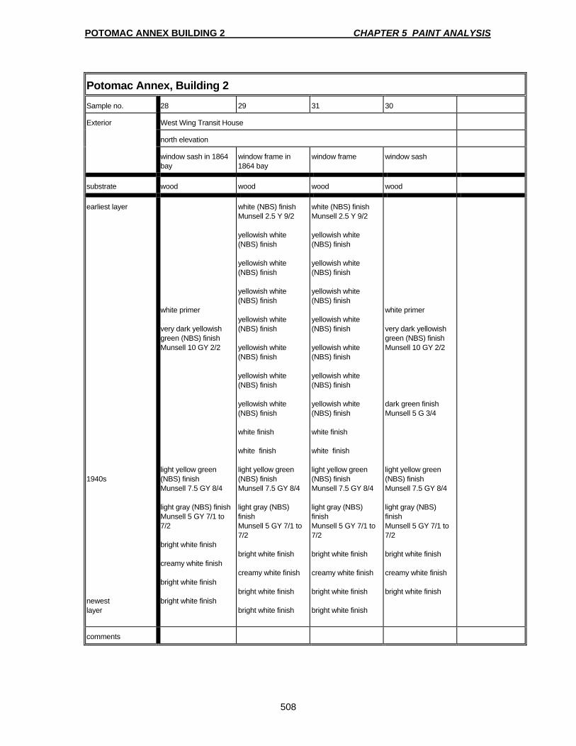
POTOMAC ANNEX BUILDING 2 CHAPTER 5 PAINT ANALYSIS
508
Potomac Annex, Building 2 Sample no. 28 29 31 30
Exterior West Wing Transit House
north elevation
window sash in 1864 bay
window frame in 1864 bay
window frame window sash
substrate wood wood wood wood
earliest layer 1940s newest layer
white primer very dark yellowish green (NBS) finish Munsell 10 GY 2/2 light yellow green (NBS) finish Munsell 7.5 GY 8/4 light gray (NBS) finish Munsell 5 GY 7/1 to 7/2 bright white finish creamy white finish bright white finish bright white finish
white (NBS) finish Munsell 2.5 Y 9/2 yellowish white (NBS) finish yellowish white (NBS) finish yellowish white (NBS) finish yellowish white (NBS) finish yellowish white (NBS) finish yellowish white (NBS) finish yellowish white (NBS) finish white finish white finish light yellow green (NBS) finish Munsell 7.5 GY 8/4 light gray (NBS) finish Munsell 5 GY 7/1 to 7/2 bright white finish creamy white finish bright white finish bright white finish
white (NBS) finish Munsell 2.5 Y 9/2 yellowish white (NBS) finish yellowish white (NBS) finish yellowish white (NBS) finish yellowish white (NBS) finish yellowish white (NBS) finish yellowish white (NBS) finish yellowish white (NBS) finish white finish white finish light yellow green (NBS) finish Munsell 7.5 GY 8/4 light gray (NBS) finish Munsell 5 GY 7/1 to 7/2 bright white finish creamy white finish bright white finish bright white finish
white primer very dark yellowish green (NBS) finish Munsell 10 GY 2/2 dark green finish Munsell 5 G 3/4 light yellow green (NBS) finish Munsell 7.5 GY 8/4 light gray (NBS) finish Munsell 5 GY 7/1 to 7/2 bright white finish creamy white finish bright white finish
comments
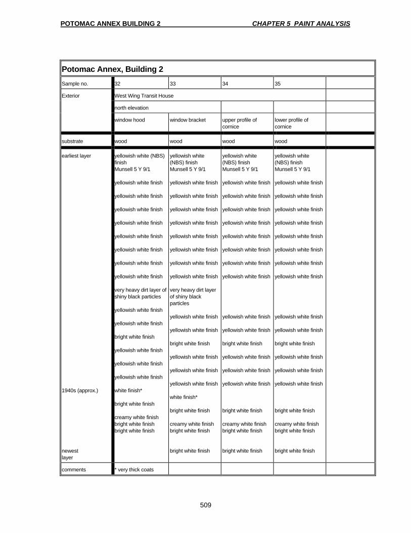
POTOMAC ANNEX BUILDING 2 CHAPTER 5 PAINT ANALYSIS
509
Potomac Annex, Building 2 Sample no. 32 33 34 35
Exterior West Wing Transit House
north elevation
window hood window bracket upper profile of cornice
lower profile of cornice
substrate wood wood wood wood
earliest layer 1940s (approx.) newest layer
yellowish white (NBS) finish Munsell 5 Y 9/1 yellowish white finish yellowish white finish yellowish white finish yellowish white finish yellowish white finish yellowish white finish yellowish white finish yellowish white finish very heavy dirt layer of shiny black particles yellowish white finish yellowish white finish bright white finish yellowish white finish yellowish white finish yellowish white finish white finish* bright white finish creamy white finish bright white finish bright white finish
yellowish white (NBS) finish Munsell 5 Y 9/1 yellowish white finish yellowish white finish yellowish white finish yellowish white finish yellowish white finish yellowish white finish yellowish white finish yellowish white finish very heavy dirt layer of shiny black particles yellowish white finish yellowish white finish bright white finish yellowish white finish yellowish white finish yellowish white finish white finish* bright white finish creamy white finish bright white finish bright white finish
yellowish white (NBS) finish Munsell 5 Y 9/1 yellowish white finish yellowish white finish yellowish white finish yellowish white finish yellowish white finish yellowish white finish yellowish white finish yellowish white finish yellowish white finish yellowish white finish bright white finish yellowish white finish yellowish white finish yellowish white finish bright white finish creamy white finish bright white finish bright white finish
yellowish white (NBS) finish Munsell 5 Y 9/1 yellowish white finish yellowish white finish yellowish white finish yellowish white finish yellowish white finish yellowish white finish yellowish white finish yellowish white finish yellowish white finish yellowish white finish bright white finish yellowish white finish yellowish white finish yellowish white finish bright white finish creamy white finish bright white finish bright white finish
comments * very thick coats

POTOMAC ANNEX BUILDING 2 CHAPTER 5 PAINT ANALYSIS
510
Potomac Annex, Building 2 Sample no. 36 38 37 39
Exterior West Wing Transit House
north elevation south elevation
brick wall pilaster shaft pilaster cap pilaster shaft
substrate red brick red brick sandstone sandstone
earliest layer 1940s newest layer
pinkish-white primer intermixed with brick white primer white finish light grayish yellowish brown (NBS) finish Munsell 10 YR 6/2 white finish pale orange yellow (NBS) finish Munsell 10 YR 8/4 pale orange yellow (NBS) finish Munsell 10 YR 8/4 pale orange yellow (NBS) finish Munsell 10 YR 8/4 pale orange yellow (NBS) finish Munsell 10 YR 8/4 pale orange yellow (NBS) finish Munsell 10 YR 8/4 pale orange yellow (NBS) finish Munsell 10 YR 8/4 creamy white finish water-based creamy white finish water-based creamy white finish water-based creamy-white finish water-based
pinkish-white primer intermixed with brick white primer white finish light grayish yellowish brown (NBS) finish Munsell 10 YR 6/2 white finish pale orange yellow (NBS) finish Munsell 10 YR 8/4 pale orange yellow (NBS) finish Munsell 10 YR 8/4 pale orange yellow (NBS) finish Munsell 10 YR 8/4 pale orange yellow (NBS) finish Munsell 10 YR 8/4 pale orange yellow (NBS) finish Munsell 10 YR 8/4 pale orange yellow (NBS) finish Munsell 10 YR 8/4 creamy white finish water-based creamy white finish water-based creamy white finish water-based creamy-white finish water-based
pinkish-white primer intermixed w/brick white primer white finish white finish pale orange yellow (NBS) finish Munsell 10 YR 8/4 pale orange yellow (NBS) finish Munsell 10 YR 8/4 pale orange yellow (NBS) finish Munsell 10 YR 8/4 pale orange yellow (NBS) finish Munsell 10 YR 8/4 pale orange yellow (NBS) finish Munsell 10 YR 8/4 pale orange yellow (NBS) finish Munsell 10 YR 8/4 creamy-white finish water-based creamy-white finish water-based creamy-white finish water-based creamy-white finish water-based
pale orange yellow (NBS) finish Munsell 10 YR 8/4 creamy-white finish water-based creamy-white finish water-based creamy-white finish water-based creamy-white finish water-based
comments
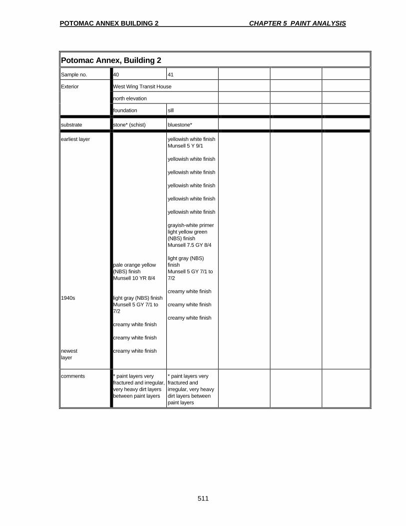
POTOMAC ANNEX BUILDING 2 CHAPTER 5 PAINT ANALYSIS
511
Potomac Annex, Building 2 Sample no. 40 41
Exterior West Wing Transit House
north elevation
foundation sill
substrate stone* (schist) bluestone*
earliest layer 1940s newest layer
pale orange yellow (NBS) finish Munsell 10 YR 8/4 light gray (NBS) finish Munsell 5 GY 7/1 to 7/2 creamy white finish creamy white finish creamy white finish
yellowish white finish Munsell 5 Y 9/1 yellowish white finish yellowish white finish yellowish white finish yellowish white finish yellowish white finish grayish-white primer light yellow green (NBS) finish Munsell 7.5 GY 8/4 light gray (NBS) finish Munsell 5 GY 7/1 to 7/2 creamy white finish creamy white finish creamy white finish
comments * paint layers very fractured and irregular, very heavy dirt layers between paint layers
* paint layers very fractured and irregular, very heavy dirt layers between paint layers
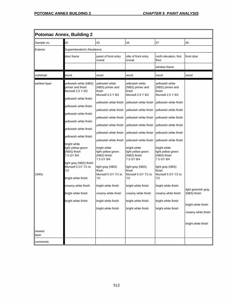
POTOMAC ANNEX BUILDING 2 CHAPTER 5 PAINT ANALYSIS
512
Potomac Annex, Building 2
Sample no. 42 43 44 47 45
Exterior Superintendent's Residence
door frame panel of front entry reveal
stile of front entry reveal
north elevation, first floor
front door
window frame
substrate wood wood wood wood wood
earliest layer 1940s newest layer
yellowish white (NBS) primer and finish Munsell 2.5 Y 9/2 yellowish white finish yellowish white finish yellowish white finish yellowish white finish yellowish white finish yellowish white finish bright white light yellow green (NBS) finish 7.5 GY 8/4 light gray (NBS) finish Munsell 5 GY 7/1 to 7/2 bright white finish creamy white finish bright white finish bright white finish
yellowish white (NBS) primer and finish Munsell 2.5 Y 9/2 yellowish white finish yellowish white finish yellowish white finish yellowish white finish yellowish white finish yellowish white finish bright white light yellow green (NBS) finish 7.5 GY 8/4 light gray (NBS) finish Munsell 5 GY 7/1 to 7/2 bright white finish creamy white finish bright white finish bright white finish
yellowish white (NBS) primer and finish Munsell 2.5 Y 9/2 yellowish white finish yellowish white finish yellowish white finish yellowish white finish yellowish white finish yellowish white finish bright white light yellow green (NBS) finish 7.5 GY 8/4 light gray (NBS) finish Munsell 5 GY 7/1 to 7/2 bright white finish creamy white finish bright white finish bright white finish
yellowish white (NBS) primer and finish Munsell 2.5 Y 9/2 yellowish white finish yellowish white finish yellowish white finish yellowish white finish yellowish white finish yellowish white finish bright white light yellow green (NBS) finish 7.5 GY 8/4 light gray (NBS) finish Munsell 5 GY 7/1 to 7/2 bright white finish creamy white finish bright white finish bright white finish
light greenish gray (NBS) finish bright white finish creamy white finish bright white finish
comments
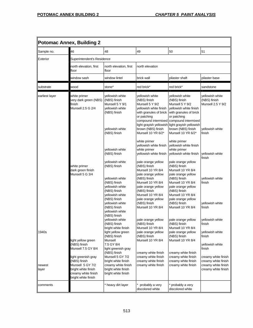
POTOMAC ANNEX BUILDING 2 CHAPTER 5 PAINT ANALYSIS
513
Potomac Annex, Building 2
Sample no. 46 48 49 50 51
Exterior Superintendent's Residence
north elevation, first floor
north elevation, first floor
north elevation
window sash window lintel brick wall pilaster shaft pilaster base
substrate wood stone* red brick* red brick* sandstone
earliest layer 1940s newest layer
white primer very dark green (NBS) finish Munsell 2.5 G 2/4 white primer dark green finish Munsell 5 G 3/4 light yellow green (NBS) finish Munsell 7.5 GY 8/4 light greenish gray (NBS) finish Munsell 5 GY 7/2 bright white finish creamy white finish bright white finish
yellowish white (NBS) finish Munsell 5 Y 9/1 yellowish white (NBS) finish yellowish white (NBS) finish yellowish white (NBS) finish yellowish white (NBS) finish yellowish white (NBS) finish yellowish white (NBS) finish yellowish white (NBS) finish yellowish white (NBS) finish yellowish white (NBS) finish yellowish white (NBS) finish bright white finish light yellow green (NBS) finish Munsell 7.5 GY 8/4 light greenish gray (NBS) finish Munsell 5 GY 7/2 bright white finish creamy white finish bright white finish bright white finish
yellowish white (NBS) finish Munsell 5 Y 9/2 yellowish white finish with granules of brick or patching compound intermixed light grayish yellowish brown (NBS) finish Munsell 10 YR 6/2* white primer yellowish white finish white primer yellowish white finish pale orange yellow (NBS) finish Munsell 10 YR 8/4 pale orange yellow (NBS) finish Munsell 10 YR 8/4 pale orange yellow (NBS) finish Munsell 10 YR 8/4 pale orange yellow (NBS) finish Munsell 10 YR 8/4 pale orange yellow (NBS) finish Munsell 10 YR 8/4 pale orange yellow (NBS) finish Munsell 10 YR 8/4 creamy white finish creamy white finish creamy white finish creamy white finish
yellowish white (NBS) finish Munsell 5 Y 9/2 yellowish white finish with granules of brick or patching compound intermixed light grayish yellowish brown (NBS) finish Munsell 10 YR 6/2* white primer yellowish white finish white primer yellowish white finish pale orange yellow (NBS) finish Munsell 10 YR 8/4 pale orange yellow (NBS) finish Munsell 10 YR 8/4 pale orange yellow (NBS) finish Munsell 10 YR 8/4 pale orange yellow (NBS) finish Munsell 10 YR 8/4 pale orange yellow (NBS) finish Munsell 10 YR 8/4 pale orange yellow (NBS) finish Munsell 10 YR 8/4 creamy white finish creamy white finish creamy white finish creamy white finish
yellowish white (NBS) finish Munsell 2.5 Y 9/2 yellowish white finish yellowish white finish yellowish white finish yellowish white finish yellowish white finish yellowish white finish yellowish white finish creamy white finish creamy white finish creamy white finish creamy white finish
comments * heavy dirt layer * probably a very discolored white
* probably a very discolored white

POTOMAC ANNEX BUILDING 2 CHAPTER 5 PAINT ANALYSIS
514
Potomac Annex, Building 2
Sample no. 52 53 54
Exterior Superintendent's Residence
north elevation NW corner
pilaster base foundation sill
Substrate stone sandstone* red brick*
Earliest layer 1940s Newest Layer
multiple fractured layers of whitewash creamy white finish creamy white finish creamy white finish creamy white finish
yellowish white (NBS) finish Munsell 5 Y 9/2 moderate brown (NBS) finish Munsell 2.5 YR 3/4 white finish pale orange yellow (NBS) finish Munsell 10 YR 8/4 pale orange yellow (NBS) finish Munsell 10 YR 8/4 pale orange yellow (NBS) finish Munsell 10 YR 8/4 pale orange yellow (NBS) finish Munsell 10 YR 8/4 pale orange yellow (NBS) finish Munsell 10 YR 8/4 pale orange yellow (NBS) finish Munsell 10 YR 8/4 creamy white finish creamy white finish creamy white finish creamy white finish
yellowish white (NBS) finish Munsell 5 Y 9/2 moderate brown (NBS) finish Munsell 2.5 YR 3/4 white finish white finish pale orange yellow (NBS) finish Munsell 10 YR 8/4 pale orange yellow (NBS) finish Munsell 10 YR 8/4 pale orange yellow (NBS) finish Munsell 10 YR 8/4 pale orange yellow (NBS) finish Munsell 10 YR 8/4 creamy white finish creamy white finish creamy white finish creamy white finish
Comments * heavy dirt layer * heavy dirt layer

POTOMAC ANNEX BUILDING 2 CHAPTER 5 PAINT ANALYSIS
515
Potomac Annex, Building 2 Sample no. 55 57 56 58 59
Exterior East Wing Connector
south elevation window hood molding
brick wall pilaster cap pilaster shaft pilaster base
Substrate red brick* red brick stone very fractured sample wood
Earliest layer 1940s Newest Layer
yellowish white (NBS) finish Munsell 5 Y 9/2 moderate brown (NBS) finish Munsell 2.5 YR 3/4 white finish white finish pale orange yellow (NBS) finish Munsell 10 YR 8/4 pale orange yellow (NBS) finish Munsell 10 YR 8/4 pale orange yellow (NBS) finish Munsell 10 YR 8/4 pale orange yellow (NBS) finish Munsell 10 YR 8/4 creamy white finish creamy white finish creamy white finish creamy white finish
yellowish white (NBS) finish Munsell 5 Y 9/2 moderate brown (NBS) finish Munsell 2.5 YR 3/4 white finish white finish pale orange yellow (NBS) finish Munsell 10 YR 8/4 pale orange yellow (NBS) finish Munsell 10 YR 8/4 pale orange yellow (NBS) finish Munsell 10 YR 8/4 pale orange yellow (NBS) finish Munsell 10 YR 8/4 creamy white finish creamy white finish creamy white finish creamy white finish
yellowish white (NBS) finish Munsell 5 Y 9/1 strong brown (NBS) finish Munsell 2.5 YR 4/6 yellowish white (NBS) finish yellowish white (NBS) finish yellowish white (NBS) finish yellowish white (NBS) finish yellowish white (NBS) finish creamy white finish creamy white finish bright white finish
yellowish white (NBS) finish Munsell 5 Y 9/1 yellowish white (NBS) finish yellowish white (NBS) finish yellowish white (NBS) finish yellowish white (NBS) finish yellowish white (NBS) finish creamy white finish creamy white finish creamy white finish
yellowish white (NBS) finish Munsell 5 Y 9/1 yellowish white (NBS) finish Munsell 5 Y 9/1 yellowish white (NBS) finish Munsell 5 Y 9/1 yellowish white (NBS) finish Munsell 5 Y 9/1 yellowish white (NBS) finish Munsell 5 Y 9/1 yellowish white (NBS) finish Munsell 5 Y 9/1 yellowish white (NBS) finish Munsell 5 Y 9/1 white finish white finish white finish white finish
Comments * heavy dirt layer
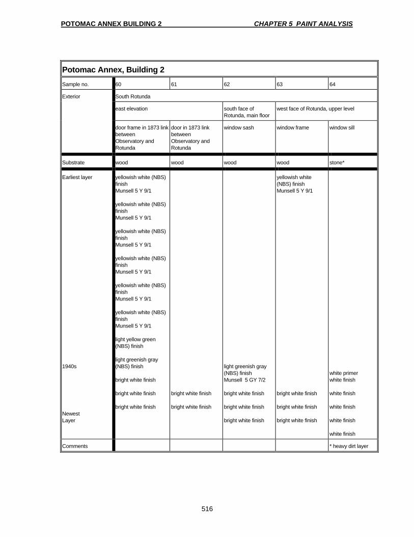
POTOMAC ANNEX BUILDING 2 CHAPTER 5 PAINT ANALYSIS
516
Potomac Annex, Building 2 Sample no. 60 61 62 63 64
Exterior South Rotunda
east elevation south face of Rotunda, main floor
west face of Rotunda, upper level
door frame in 1873 link between Observatory and Rotunda
door in 1873 link between Observatory and Rotunda
window sash window frame window sill
Substrate wood wood wood wood stone*
Earliest layer 1940s Newest Layer
yellowish white (NBS) finish Munsell 5 Y 9/1 yellowish white (NBS) finish Munsell 5 Y 9/1 yellowish white (NBS) finish Munsell 5 Y 9/1 yellowish white (NBS) finish Munsell 5 Y 9/1 yellowish white (NBS) finish Munsell 5 Y 9/1 yellowish white (NBS) finish Munsell 5 Y 9/1 light yellow green (NBS) finish light greenish gray (NBS) finish bright white finish bright white finish bright white finish
bright white finish bright white finish
light greenish gray (NBS) finish Munsell 5 GY 7/2 bright white finish bright white finish bright white finish
yellowish white (NBS) finish Munsell 5 Y 9/1 bright white finish bright white finish bright white finish
white primer white finish white finish white finish white finish white finish
Comments * heavy dirt layer

POTOMAC ANNEX BUILDING 2 CHAPTER 5 PAINT ANALYSIS
517
Potomac Annex, Building 2 Sample no. 65 66
Exterior South Rotunda
south face of Rotunda, main level
south east face of Rotunda
window sill brick wall
Substrate stone red brick*
Earliest layer 1940s Newest Layer
white finish white finish white finish creamy white finish creamy white finish
white primer white finish pale orange yellow (NBS) finish Munsell 10 YR 8/4 pale orange yellow (NBS) finish Munsell 10 YR 8/4 pale orange yellow (NBS) finish Munsell 10 YR 8/4 pale orange yellow (NBS) finish Munsell 10 YR 8/4 pale orange yellow (NBS) finish Munsell 10 YR 8/4 pale orange yellow (NBS) finish Munsell 10 YR 8/4 creamy white finish creamy white finish creamy white finish creamy white finish
Comments * heavy dirt layer

POTOMAC ANNEX BUILDING 2 CHAPTER 5 PAINT ANALYSIS
518
Potomac Annex, Building 2 Sample no. 67 69 68 70 71
Exterior West Wing
south east corner South elevation SE Corner West elevation South elevation
Doorway/transom
Sash
Window sash Door frame Lower window sash Window frame
substrate wood wood wood wood wood
earliest layer 1940s newest layer
White primer yellowish white
(NBS) finish Dark green (NBS) finish Munsell 5 G 3/4 Light yellow green (NBS) finish Munsell 7.5 GY 8/4 Light gray NBS) finish Munsell 5 GY 7/1 to 7/2 white finish white finish white finish white finish
White primer yellowish white
finish Dark green (NBS) finish Munsell 5 G 3/4 Light yellow green (NBS) finish Munsell 7.5 GY 8/4 Light gray NBS) finish Munsell 5 GY 7/1 to 7/2 white finish white finish white finish white finish
White primer yellowish white finish yellowish white (NBS) finish yellowish white (NBS) finish bright white primer Light yelloe green (NBS) finish Munsell 7.5 GY 8/4 Light gray NBS) finish Munsell 5 GY 7/1 to 7/2 white finish white finish white finish white finish
White primer yellowish white
Finish Munsell 5 Y 9/1 Dark gray primer Dark green (NBS) finish Munsell 5 G 3/4 Light yelloe green (NBS) finish Munsell 7.5 GY 8/4 Light gray NBS) finish Munsell 5 GY 7/1 to 7/2 white finish white finish silver gray colored metallic finish – aluminum paint white finish white finish
yellowish white (NBS) finish white finish white finish white finish yellowish white finish yellowish white finish yellowish white finish Light yellow green (NBS) finish Munsell 7.5 GY 8/4 Light gray NBS) finish Munsell 5 GY 7/1 to 7/2 white finish white finish white finish white finish white finish
comments
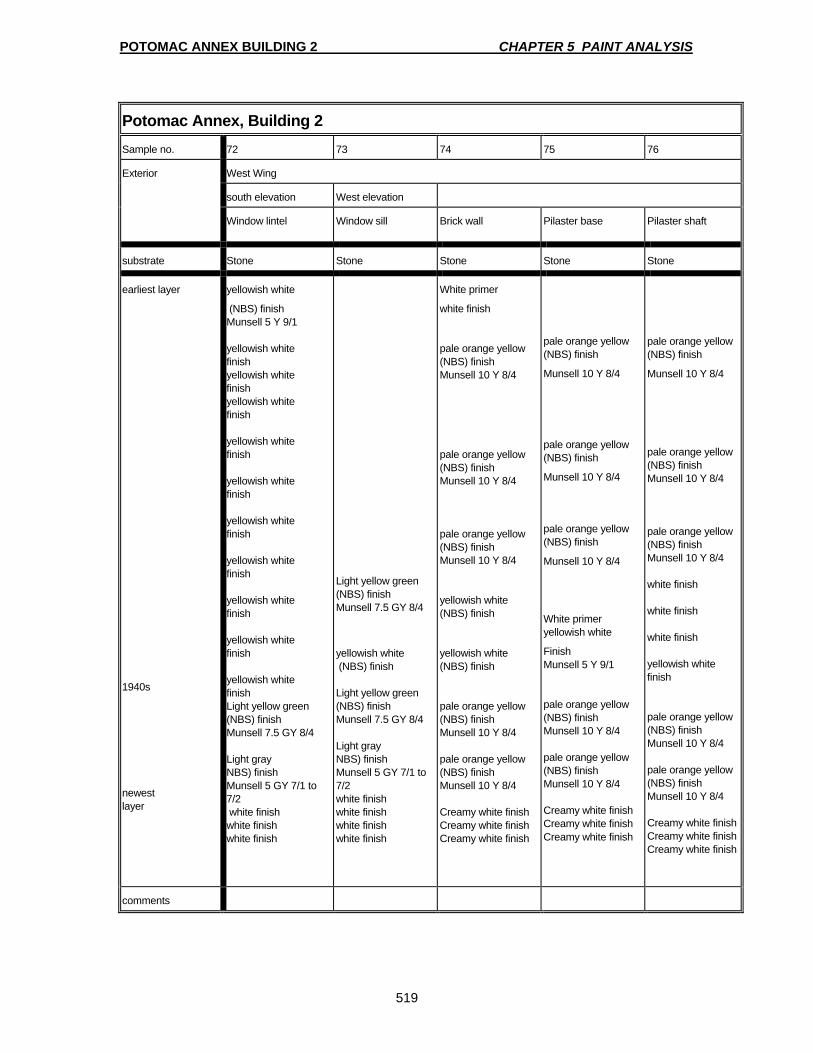
POTOMAC ANNEX BUILDING 2 CHAPTER 5 PAINT ANALYSIS
519
Potomac Annex, Building 2 Sample no. 72 73 74 75 76
Exterior West Wing
south elevation West elevation
Window lintel Window sill Brick wall Pilaster base Pilaster shaft
substrate Stone Stone Stone Stone Stone
earliest layer 1940s newest layer
yellowish white
(NBS) finish Munsell 5 Y 9/1 yellowish white finish yellowish white finish yellowish white finish yellowish white finish yellowish white finish yellowish white finish yellowish white finish yellowish white finish yellowish white finish yellowish white finish Light yellow green (NBS) finish Munsell 7.5 GY 8/4 Light gray NBS) finish Munsell 5 GY 7/1 to 7/2 white finish white finish white finish
Light yellow green (NBS) finish Munsell 7.5 GY 8/4
yellowish white (NBS) finish Light yellow green (NBS) finish Munsell 7.5 GY 8/4 Light gray NBS) finish Munsell 5 GY 7/1 to 7/2 white finish white finish white finish white finish
White primer
white finish pale orange yellow (NBS) finish Munsell 10 Y 8/4 pale orange yellow (NBS) finish Munsell 10 Y 8/4 pale orange yellow (NBS) finish Munsell 10 Y 8/4 yellowish white (NBS) finish yellowish white (NBS) finish pale orange yellow (NBS) finish Munsell 10 Y 8/4 pale orange yellow (NBS) finish Munsell 10 Y 8/4 Creamy white finish Creamy white finish Creamy white finish
pale orange yellow (NBS) finish
Munsell 10 Y 8/4
pale orange yellow (NBS) finish
Munsell 10 Y 8/4
pale orange yellow (NBS) finish
Munsell 10 Y 8/4
White primer yellowish white
Finish Munsell 5 Y 9/1 pale orange yellow (NBS) finish Munsell 10 Y 8/4 pale orange yellow (NBS) finish Munsell 10 Y 8/4 Creamy white finish Creamy white finish Creamy white finish
pale orange yellow (NBS) finish
Munsell 10 Y 8/4
pale orange yellow (NBS) finish Munsell 10 Y 8/4 pale orange yellow (NBS) finish Munsell 10 Y 8/4 white finish white finish white finish yellowish white finish pale orange yellow (NBS) finish Munsell 10 Y 8/4 pale orange yellow (NBS) finish Munsell 10 Y 8/4 Creamy white finish Creamy white finish Creamy white finish
comments

POTOMAC ANNEX BUILDING 2 CHAPTER 5 PAINT ANALYSIS
520
Potomac Annex, Building 2 Sample no. 77 78
Exterior West Wing
Upper cornice molding Lower cornice molding
substrate wood wood
earliest layer 1940s newest layer
yellowish white
Finish
Munsell 5 Y 9/1
yellowish white
Finish
Munsell 5 Y 9/1
yellowish white
Finish
Munsell 5 Y 9/1
yellowish white
Finish
Munsell 5 Y 9/1
yellowish white
Finish
Munsell 5 Y 9/1
yellowish white
Finish
Munsell 5 Y 9/1
bright white finish bright white finish bright white finish bright white finish
Reddish brown primer
yellowish white
Finish
Munsell 5 Y 9/1
yellowish white
Finish
Munsell 5 Y 9/1
yellowish white
Finish
Munsell 5 Y 9/1
yellowish white
Finish Munsell 5 Y 9/1 bright white finish bright white finish bright white finish bright white finish
comments
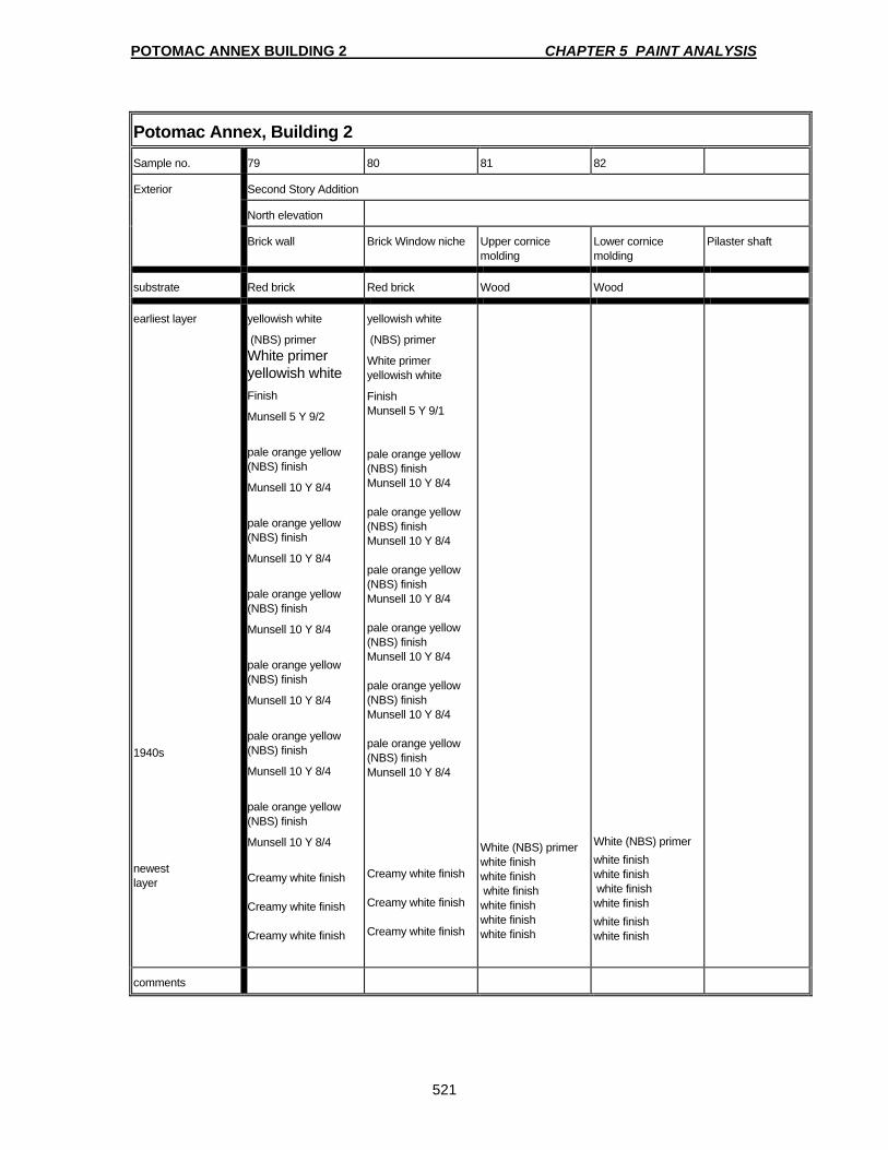
POTOMAC ANNEX BUILDING 2 CHAPTER 5 PAINT ANALYSIS
521
Potomac Annex, Building 2 Sample no. 79 80 81 82
Exterior Second Story Addition
North elevation
Brick wall Brick Window niche Upper cornice molding
Lower cornice molding
Pilaster shaft
substrate Red brick Red brick Wood Wood
earliest layer 1940s newest layer
yellowish white
(NBS) primer White primer yellowish white Finish
Munsell 5 Y 9/2
pale orange yellow (NBS) finish
Munsell 10 Y 8/4
pale orange yellow (NBS) finish
Munsell 10 Y 8/4
pale orange yellow (NBS) finish
Munsell 10 Y 8/4
pale orange yellow (NBS) finish
Munsell 10 Y 8/4
pale orange yellow (NBS) finish
Munsell 10 Y 8/4
pale orange yellow (NBS) finish
Munsell 10 Y 8/4
Creamy white finish Creamy white finish Creamy white finish
yellowish white
(NBS) primer
White primer yellowish white
Finish Munsell 5 Y 9/1 pale orange yellow (NBS) finish Munsell 10 Y 8/4 pale orange yellow (NBS) finish Munsell 10 Y 8/4 pale orange yellow (NBS) finish Munsell 10 Y 8/4 pale orange yellow (NBS) finish Munsell 10 Y 8/4 pale orange yellow (NBS) finish Munsell 10 Y 8/4 pale orange yellow (NBS) finish Munsell 10 Y 8/4 Creamy white finish Creamy white finish Creamy white finish
White (NBS) primer white finish white finish white finish white finish white finish white finish
White (NBS) primer white finish white finish white finish white finish white finish white finish
comments

POTOMAC ANNEX BUILDING 2 CHAPTER 5 PAINT ANALYSIS
522
Potomac Annex, Building 2: 1843 Observatory Building sample no. I1a1 I1a2a I1a2b I1a3a I1a3b
Interior BASEMENT
Rotunda basement and stair corridor
masonry wall wood door wood door, frame wood window, sash wood window, frame
substrate plaster wood wood wood wood
earliest layer newest layer
white finish white finish white finish
creamy white white heavy dirt layer light gray finish white finish light blue gray finish dark gray finish blue gray finish blue green finish creamy white finish
creamy white white heavy dirt layer light gray finish white finish light blue gray finish dark gray finish blue gray finish blue green finish white finish blue green finish creamy white finish
creamy white finish light gray finish white finish gray finish white finish light blue gray finish dark gray finish blue gray finish blue green finish dark green finish blue green finish creamy white finish
creamy white finish white finish blue gray finish dark gray finish dark green finish blue green finish creamy white finish
comments

POTOMAC ANNEX BUILDING 2 CHAPTER 5 PAINT ANALYSIS
523
Potomac Annex, Building 2: 1843 Observatory Building sample no. I1b1 I1b2 I1c1 I1c2
Interior FIRST FLOOR
Entrance vestibule Stair hall
plaster wall pressed metal ceiling plaster wall pressed metal ceiling
substrate plaster metal plaster metal
earliest layer newest layer
tan finish - Munsell 10 YR 7/4 tan finish tan finish tan finish light bluish gray finish yellow orange finish blue green finish light green finish dark green finish creamy white finish creamy white finish white finish blue green finish creamy white finish off-white finish off-white finish
creamy white finish creamy white finish creamy white finish white finish creamy white finish blue green finish creamy white finish gray primer white finish gray primer creamy white finish green finish gray primer white finish
canvas repair creamy white finish off-white finish
creamy white finish creamy white finish blue green finish creamy white finish white finish white finish
comments

POTOMAC ANNEX BUILDING 2 CHAPTER 5 PAINT ANALYSIS
524
Potomac Annex, Building 2: 1843 Observatory Building sample no. I1b3a I1b3b I1b3c I1b3d
Interior FIRST FLOOR
Entrance vestibule
wood door, panel wood door, frame wood door, sidelight panel
wood door, transom
substrate wood wood wood wood
earliest layer newest layer
creamy white primer creamy white finish blue green finish blue green white finish creamy white finish white finish
creamy white finish creamy white finish blue green finish light grayish green finish light grayish green finish green finish white finish white finish creamy white finish white finish
varnish with gilding (specks of gold colored material embedded in varnish layer) - probably remnant of a painted sign green finish white finish white finish creamy white finish white finish
creamy white creamy white finish blue green finish light grayish green finish light grayish green finish green finish white finish creamy white finish white finish
comments

POTOMAC ANNEX BUILDING 2 CHAPTER 5 PAINT ANALYSIS
525
Potomac Annex, Building 2: 1843 Observatory Building sample no. I1c3a I1c3b I1c4a I1c4b I1c4c
Interior FIRST FLOOR
Main entrance / Stair lobby
wood door wood door, frame wood stair, tread end wood stair, stringer wood stair, riser
substrate wood wood wood wood wood
earliest layer newest layer
white finish creamy white finish creamy white finish creamy white finish white finish creamy white finish creamy white finish white finish creamy white finish light green finish light green finish light green finish medium green finish light green finish medium green finish white finish white finish creamy white finish white finish
white finish creamy white finish creamy white finish white finish light green finish light green finish light green finish medium green finish light green finish medium green finish white finish white finish creamy white finish white finish
dark brown tinted varnish medium brown finish modern, crude "oak" graining: tan paint & brown varnish
dark brown tinted varnish light green finish white finish graining: medium brown finish and dark brown varnish light green finish black primer black finish reddish brown finish creamy white finish black finish creamy white finish yellow orange finish modern, crude "oak" graining: tan paint & brown varnish
dark brown tinted varnish light green finish light green finish medium green finish white finish
comments handrail recently stripped and stained oak, tread end substituted
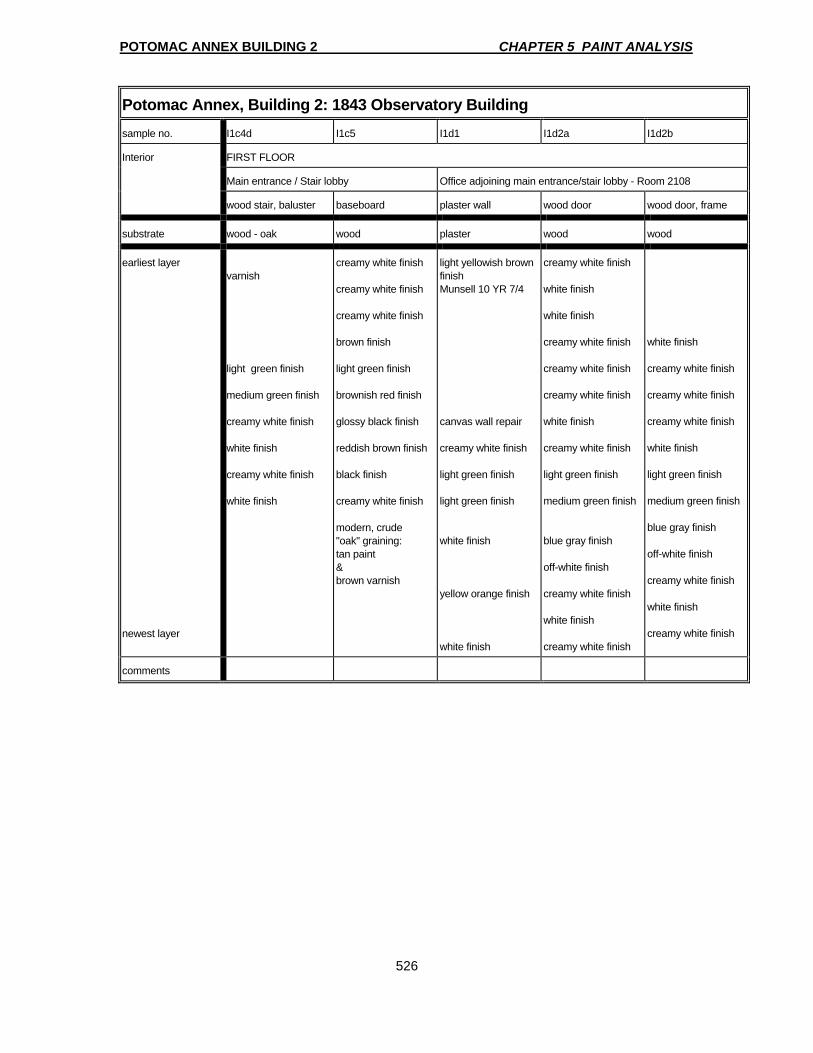
POTOMAC ANNEX BUILDING 2 CHAPTER 5 PAINT ANALYSIS
526
Potomac Annex, Building 2: 1843 Observatory Building sample no. I1c4d I1c5 I1d1 I1d2a I1d2b
Interior FIRST FLOOR
Main entrance / Stair lobby Office adjoining main entrance/stair lobby - Room 2108
wood stair, baluster baseboard plaster wall wood door wood door, frame
substrate wood - oak wood plaster wood wood
earliest layer newest layer
varnish light green finish medium green finish creamy white finish white finish creamy white finish white finish
creamy white finish creamy white finish creamy white finish brown finish light green finish brownish red finish glossy black finish reddish brown finish black finish creamy white finish modern, crude "oak" graining: tan paint & brown varnish
light yellowish brown finish Munsell 10 YR 7/4 canvas wall repair creamy white finish light green finish light green finish white finish yellow orange finish white finish
creamy white finish white finish white finish creamy white finish creamy white finish creamy white finish white finish creamy white finish light green finish medium green finish blue gray finish off-white finish creamy white finish white finish creamy white finish
white finish creamy white finish creamy white finish creamy white finish white finish light green finish medium green finish blue gray finish off-white finish creamy white finish white finish creamy white finish
comments

POTOMAC ANNEX BUILDING 2 CHAPTER 5 PAINT ANALYSIS
527
Potomac Annex, Building 2: 1843 Observatory Building sample no. I1d3a I1d3b I1d3c I1e1 I1e2
Interior FIRST FLOOR
Office adjoining main entrance/stair lobby - Room 2108 Office adjoining main entrance/stair lobby - Room 2116
wood window, sash wood window, frame wood window, shutter plaster wall plaster ceiling, metal ceiling in 2108 substituted
substrate wood wood wood plaster metal
earliest layer newest layer
white finish creamy white finish off-white finish white finish whitish green finish medium green finish blue gray finish off-white finish off-white finish white finish creamy white finish white finish creamy white finish
yellowed white finish (heavy dirt layer) white finish creamy white finish creamy white finish whitish green finish medium green finish whitish blue gray finish white finish white finish
creamy white finish off-white finish white finish creamy white finish creamy white finish creamy white finish creamy white finish creamy white finish white finish creamy white finish whitish green finish whitish blue gray finish white finish
tan finish remnant of wall paper white finish dark green finish medium green finish creamy white finish creamy white finish creamy white finish creamy white finish creamy white finish creamy white finish medium green finish light green finish medium green finish light olive green finish blue gray finish whitish blue finish blue gray finish creamy white finish white finish
creamy white finish creamy white finish white finish creamy white finish medium green finish creamy white finish creamy white finish white finish creamy white finish
comments
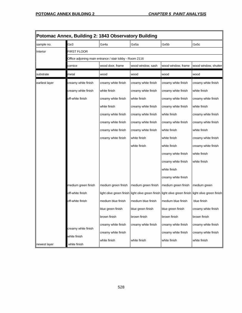
POTOMAC ANNEX BUILDING 2 CHAPTER 5 PAINT ANALYSIS
528
Potomac Annex, Building 2: 1843 Observatory Building
sample no. I1e3 I1e4a I1e5a I1e5b I1e5c
Interior FIRST FLOOR
Office adjoining main entrance / stair lobby - Room 2116
cornice wood door, frame wood window, sash wood window, frame wood window, shutter
substrate metal wood wood wood wood
earliest layer newest layer
creamy white finish creamy white finish off-white finish medium green finish off-white finish off-white finish creamy white finish white finish white finish
creamy white finish white finish creamy white finish white finish creamy white finish creamy white finish creamy white finish creamy white finish medium green finish light olive green finish medium blue finish blue green finish brown finish creamy white finish creamy white finish white finish
creamy white finish creamy white finish white finish creamy white finish creamy white finish creamy white finish creamy white finish white finish white finish medium green finish light olive green finish medium blue finish blue green finish brown finish creamy white finish white finish
creamy white finish creamy white finish creamy white finish creamy white finish white finish creamy white finish white finish white finish white finish creamy white finish creamy white finish white finish creamy white finish medium green finish light olive green finish medium blue finish blue green finish brown finish creamy white finish creamy white finish white finish
creamy white finish white finish creamy white finish white finish creamy white finish creamy white finish white finish creamy white finish creamy white finish white finish white finish medium green light olive green finish blue finish creamy white finish brown finish creamy white finish creamy white finish white finish
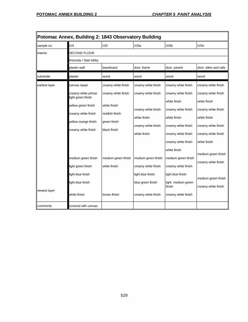
POTOMAC ANNEX BUILDING 2 CHAPTER 5 PAINT ANALYSIS
529
Potomac Annex, Building 2: 1843 Observatory Building sample no. I1f1 I1f2 I1f3a I1f3b I1f3c
Interior SECOND FLOOR
Rotunda / Stair lobby
plaster wall baseboard door, frame door, panels door, stiles and rails
substrate plaster wood wood wood wood
earliest layer newest layer
canvas repair creamy white primer light green finish yellow green finish creamy white finish yellow orange finish creamy white finish medium green finish light green finish light blue finish light blue finish white finish
creamy white finish creamy white finish white finish reddish finish green finish black finish medium green finish white finish brown finish
creamy white finish creamy white finish creamy white finish white finish creamy white finish white finish medium green finish creamy white finish light blue finish blue green finish creamy white finish
creamy white finish creamy white finish white finish creamy white finish white finish creamy white finish creamy white finish creamy white finish white finish medium green finish creamy white finish light blue finish light medium green finish creamy white finish
creamy white finish creamy white finish white finish creamy white finish white finish creamy white finish creamy white finish white finish medium green finish creamy white finish medium green finish creamy white finish
comments covered with canvas
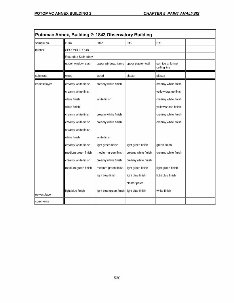
POTOMAC ANNEX BUILDING 2 CHAPTER 5 PAINT ANALYSIS
530
Potomac Annex, Building 2: 1843 Observatory Building sample no. I1f4a I1f4b I1f5 I1f6
Interior SECOND FLOOR
Rotunda / Stair lobby
upper window, sash upper window, frame upper plaster wall cornice at former ceiling line
substrate wood wood plaster plaster
earliest layer newest layer
creamy white finish creamy white finish white finish white finish creamy white finish creamy white finish creamy white finish white finish creamy white finish medium green finish creamy white finish medium green finish light blue finish
creamy white finish white finish creamy white finish creamy white finish white finish light green finish medium green finish creamy white finish medium green finish light blue finish light blue green finish
light green finish creamy white finish creamy white finish light green finish light blue finish plaster patch light blue finish
creamy white finish yellow orange finish creamy white finish yellowish tan finish creamy white finish creamy white finish green finish creamy white finish light green finish light blue finish white finish
comments

POTOMAC ANNEX BUILDING 2 CHAPTER 5 PAINT ANALYSIS
531
Potomac Annex, Building 2: 1843 Observatory Building sample no. I1g1 I1g2 I1g3a I1g3b
Interior SECOND FLOOR
Room 2208
plaster wall plaster ceiling wood door wood door, frame
substrate plaster plaster wood wood
earliest layer newest layer
creamy white finish creamy white finish whitish blue green finish white finish whitish blue green finish white finish whitish blue green finish bright whitish blue finish white finish
creamy white finish creamy white finish creamy white finish creamy white finish white finish creamy white finish yellowish tan finish off-white finish reddish brown finish creamy white finish creamy white finish creamy white finish white finish off-white finish light blue green finish creamy white finish white finish creamy white finish white finish white finish
white primer whitish blue finish white finish off-white finish off-white finish light green finish white finish whitish blue gray finish whitish blue green finish off-white finish brown finish blue green finish white finish light brown finish creamy white finish creamy white finish
creamy white finish white finish creamy white finish white finish off-white finish creamy white finish creamy white finish off-white finish off- white finish light green finish white finish whitish blue gray finish whitish blue green finish off-white finish brown finish blue green finish white finish light brown finish creamy white finish creamy white finish
comments

POTOMAC ANNEX BUILDING 2 CHAPTER 5 PAINT ANALYSIS
532
Potomac Annex, Building 2: 1843 Observatory Building sample no. I1g4a I1g4b I1g4c I1h1
Interior SECOND FLOOR
Room 2208 Room 2207
wood window, sash wood window, frame wood window, shutters
mantle
substrate wood wood wood wood
earliest layer newest layer
creamy white finish white finish creamy white finish creamy white finish white finish off-white finish off-white finish off-white finish creamy white finish white finish white finish medium green finish white finish medium green finish whitish blue gray finish whitish blue green finish brown finish medium green finish white finish tan finish creamy white finish
white finish white finish creamy white finish creamy white finish off-white finish off-white finish off-white finish off-white finish white finish medium green finish black finish white finish medium green finish whitish blue gray finish whitish blue green finish brown finish medium green finish white finish tan finish creamy white finish
creamy white finish white finish creamy white finish creamy white finish white finish creamy white finish creamy white finish creamy white finish creamy white finish white finish creamy white finish medium green finish creamy white finish whitish blue gray finish whitish blue green finish brown finish medium green finish white finish tan finish creamy white finish
yellowed varnish light green finish creamy white finish light blue finish creamy white finish off-white finish bright white finish

POTOMAC ANNEX BUILDING 2 CHAPTER 5 PAINT ANALYSIS
533
Potomac Annex, Building 2: 1873 South Wing - Instrument Building sample no. I2a1 I2a2 I2b1 I2b2
Interior FIRST FLOOR
Room 2110 Room 2114
plaster wall beaded wood ceiling plaster wall pressed metal ceiling
substrate wood wood plaster metal
earliest layer newest layer
remnant of wall paper off-white finish whitish green finish yellow green finish yellow orange finish dark yellow orange finish creamy white finish creamy white finish creamy white finish green finish whitish green finish whitish blue finish white finish white finish
creamy white finish creamy white finish creamy white finish creamy white finish creamy white finish green finish creamy white finish white finish creamy white finish
blue gray finish blue gray finish blue gray finish bright medium green finish yellow orange finish whitish yellow orange finish creamy white finish yellow finish creamy white finish whitish green finish white finish creamy white finish whitish light green finish whitish blue finish whitish light blue finish white finish white finish
creamy white finish creamy white finish creamy white finish creamy white finish medium green finish creamy white finish white finish creamy white finish

POTOMAC ANNEX BUILDING 2 CHAPTER 5 PAINT ANALYSIS
534
Potomac Annex, Building 2: 1873 South Wing - Instrument Building sample no. I2b3a I2b3b I2b4a I2b4b
Interior FIRST FLOOR
Room 2114
wood door, transom frame
wood door, frame wood window, sash wood window, frame
substrate wood wood wood wood
earliest layer newest layer
off-white finish off-white finish off-white finish off-white finish white finish creamy white finish medium green finish whitish green finish whitish light green finish medium green finish white finish creamy white finish
creamy white finish creamy white finish creamy white finish creamy white finish creamy white finish creamy white finish creamy white finish white finish creamy white finish medium green finish whitish green finish light olive green finish whitish green finish light olive green finish whitish green finish light blue green finish white finish whitish blue finish white finish creamy white finish
creamy white finish creamy white finish white finish creamy white finish whitish medium green finish medium green finish creamy white finish white finish
off-white finish off-white finish white finish off-white finish off-white finish off-white finish white finish creamy white finish whitish medium green finish medium green finish white finish creamy white finish white finish
comments

POTOMAC ANNEX BUILDING 2 CHAPTER 5 PAINT ANALYSIS
535
Potomac Annex, Building 2: 1847 Residence Building sample no. I3a1 I3a2 I3a3a I3a3b I3a3c
Interior FIRST FLOOR
Entrance vestibule
plaster wall pressed metal ceiling wood entrance door, stile
wood entrance door, panel
wood entrance door, frame
substrate plaster metal wood wood wood
earliest layer newest layer
canvas repair light green finish light green finish medium green finish creamy white finish
white finish creamy white finish
creamy white finish creamy white finish bright white finish white finish
creamy white finish creamy white finish white finish creamy white finish orange yellow finish white finish
brown varnish creamy white finish light green finish light green finish green finish white finish orange yellow finish white finish
comments
POTOMAC ANNEX BUILDING 2 CHAPTER 5 PAINT ANALYSIS
536
Potomac Annex, Building 2: 1847 Residence Building sample no. I3a3d I3a3e I3b1a I3b1b I3b2
Interior FIRST FLOOR
Entrance vestibule Main entrance / Stair lobby / Corridor
wood entrance door, sidelight panel
wood entrance door, transom
east wall of hall west wall of hall pressed metal ceiling
substrate wood wood plaster plaster metal
earliest layer newest layer
brown varnish creamy white finish light green finish light green finish white finish creamy white finish white finish
white finish white finish white finish creamy white finish brown varnish creamy white finish light green finish light green finish green finish white finish creamy white finish white finish
remnant of wall paper yellow green finish creamy white finish creamy white finish yellow finish creamy white finish creamy white finish orange yellow finish reddish brown finish orange yellow finish green finish light green finish light blue green finish light blue finish light blue green finish white finish
white finish white finish
creamy white finish light green finish creamy white finish creamy white finish white finish creamy white finish light green finish white finish white finish white finish
comments earlier finishes removed

POTOMAC ANNEX BUILDING 2 CHAPTER 5 PAINT ANALYSIS
537
Potomac Annex, Building 2: 1847 Residence Building sample no. I3b3 I3b4a I3b4b I3b5a I3b5b
Interior FIRST FLOOR
Main entrance / Stair lobby / Corridor
plaster ceiling wood door to Room 2124, door
wood door to Room 2124, frame
wood stair, stringer wood stair, riser
substrate plaster wood wood wood wood
earliest layer newest layer
canvas repair creamy white finish creamy white finish creamy white finish white finish medium green finish white finish light green finish light blue finish light blue green finish white finish
yellowed varnish graining: orange yellow & dark brown varnish creamy white finish creamy white finish white finish medium green finish white finish medium green finish medium green finish tan finish medium green finish white finish yellowish tan finish off-white finish
creamy white finish creamy white finish off-white finish white finish creamy white finish creamy white finish white finish creamy white finish creamy white finish white finish creamy white finish green finish light green finish medium green finish creamy white finish white finish creamy white finish white finish
light green finish black finish graining: ochre finish & brown finish white primer modern graining: orange yellow finish & brown finish clear varnish
glossy black finish green finish green finish black finish graining: ochre finish & brown finish modern graining: ochre finish & brown finish clear varnish
comments

POTOMAC ANNEX BUILDING 2 CHAPTER 5 PAINT ANALYSIS
538
Potomac Annex, Building 2: 1847 Residence Building sample no. I3b5c I3c1 I3c2 I3c3
Interior FIRST FLOOR
Main entrance / Stair lobby / Corridor
Corridor between Rooms 2122 and 2123
wood stair, baluster plaster wall pressed metal ceiling cornice
substrate wood plaster metal metal
earliest layer newest layer
simple graining: ochre paint & dark brown varnish medium green finish light green finish white finish white finish
canvas repair white finish light green finish creamy white finish light orange yellow finish yellow orange finish creamy white finish creamy white finish creamy white finish medium green finish green finish light blue finish creamy white finish white finish yellow finish white finish white finish
gray primer green finish red finish creamy white finish white finish creamy white finish medium green finish creamy white finish
white finish creamy white finish medium green finish creamy white finish
comments
POTOMAC ANNEX BUILDING 2 CHAPTER 5 PAINT ANALYSIS
539
Potomac Annex, Building 2: 1847 Residence Building sample no. I3c4a I3c4b I3d1 I3d2 I3d3
Interior FIRST FLOOR
Corridor between Rooms 2122 and 2123 Room 2122
wood door wood door, frame plaster wall pressed metal ceiling pressed metal cornice
substrate wood wood plaster metal metal
earliest layer newest layer
white finish creamy white finish white finish medium green finish medium green finish medium green finish medium green finish medium green finish creamy white finish white finish
white finish creamy white finish white finish medium green finish medium green finish medium green finish medium green finish medium green finish creamy white finish white finish
remnant of wall paper blue gray finish blue gray finish yellow green finish white finish creamy white finish orange yellow finish creamy white finish yellow finish creamy white finish creamy white finish creamy white finish medium green finish light green finish light green finish light blue finish light blue green finish creamy white finish white finish
creamy white finish white finish creamy white finish light green finish creamy white finish white finish
creamy white finish white finish creamy white finish light green finish creamy white finish white finish
comments

POTOMAC ANNEX BUILDING 2 CHAPTER 5 PAINT ANALYSIS
540
Potomac Annex, Building 2: 1847 Residence Building sample no. I3d4a I3d4b I3d5a I3d5b
Interior FIRST FLOOR
Room 2122
wood door, bottom panel
wood door, frame wood window, sash wood window, frame
substrate wood wood wood wood
earliest layer newest layer
white finish creamy white finish medium green finish light green finish brown finish blue green finish very light blue finish creamy white finish white finish white finish
creamy white finish creamy white finish creamy white finish white finish orange yellow finish medium green finish light green finish light green finish brown finish blue green finish light blue finish creamy white finish white finish white finish
creamy white finish creamy white finish creamy white finish creamy white finish creamy white finish creamy white finish creamy white finish white finish white finish creamy white finish creamy white finish creamy white finish creamy white finish white finish creamy white finish medium green finish light green finish light green finish brown finish blue green finish white finish white finish white finish
creamy white finish creamy white finish creamy white finish white finish creamy white finish medium green finish light green finish green finish brown finish light green finish light blue finish creamy white finish white finish white finish white finish
POTOMAC ANNEX BUILDING 2 CHAPTER 5 PAINT ANALYSIS
541
Potomac Annex, Building 2: 1847 Residence Building sample no. I3e1 I3e2 I3e3 I3e4
Interior FIRST FLOOR
Room 2124
plaster wall plaster wall behind mantle
pressed metal ceiling metal cornice
substrate plaster plaster metal metal
earliest layer newest layer
light green finish light green finish creamy white finish white finish creamy white finish
(dirt layer) yellowed paper, no pattern or color visible heavy dirt layer drips of creamy white finish
creamy white finish light green finish creamy white finish creamy white finish white finish creamy white finish white finish creamy white finish
creamy white finish green finish creamy white finish creamy white finish white finish creamy white finish

POTOMAC ANNEX BUILDING 2 CHAPTER 5 PAINT ANALYSIS
542
Potomac Annex, Building 2: 1847 Residence Building sample no. I3e5a I3e6a I3e7a I3e7b I3f1
Interior FIRST FLOOR
Room 2124 Room 2126
door to closet door frame for main room door
window sash window frame wall
substrate wood wood wood wood plaster
earliest layer newest layer
creamy white finish white finish white finish creamy white finish white finish creamy white finish orange yellow finish white finish green finish white finish brown finish light blue finish light blue green finish tan finish orange yellow finish creamy white finish
creamy white finish white finish white finish creamy white finish creamy white finish creamy white finish white finish creamy white finish creamy white finish white finish creamy white finish creamy white finish medium green finish white finish brown finish light blue green finish tan finish orange yellow finish creamy white finish
creamy white finish white finish white finish white finish creamy white finish white finish creamy white finish white finish green finish white finish brown finish light blue finish light blue green finish tan finish orange yellow finish creamy white finish
creamy white finish creamy white finish white finish medium green finish off-white finish medium green finish blue gray finish light blue finish tan finish orange yellow finish creamy white finish
trace of water soluble, yellowed material - not paint. Wallpaper adhesive grayish beige finish (very dirty surface) medium green finish green finish light blue finish creamy white finish whitish gray finish white finish light blue finish white finish creamy white finish

POTOMAC ANNEX BUILDING 2 CHAPTER 5 PAINT ANALYSIS
543
Potomac Annex, Building 2: 1847 Residence Building sample no. I3f2a I3f3a I3f3b I3f3c I3f4
Interior FIRST FLOOR
Space adjoining main corridor - Room 2126
door to closet in west corner
window sash window frame window shutter baseboard
substrate wood wood wood wood wood
earliest layer newest layer
creamy white finish creamy white finish white finish creamy white finish white finish creamy white finish off-white finish light green finish white finish light green finish light blue finish off-white finish white finish light tan finish off-white finish white finish creamy white creamy white finish
creamy white finish creamy white finish white finish creamy white finish white finish creamy white finish off-white finish white finish creamy white finish white finish light green finish white finish light green finish medium green finish light blue finish orange yellow finish off-white finish off-white finish white finish off-white finish white finish creamy white finish
white primer graining: yellow orange paint & brownish red varnish yellowed varnish white finish creamy white finish off-white finish white finish creamy white finish creamy white finish creamy white finish light green finish white finish light green finish medium green finish grayish tan finish light blue finish off-white finish yellow-orange finish
creamy white finish graining: yellow orange paint & brownish red varnish creamy white finish white finish creamy white finish off- white finish white finish creamy white finish medium green finish white finish light green finish medium green finish grayish tan finish yellow-orange finish white finish creamy white finish creamy white finish
creamy white finish graining: yellow orange paint & brownish red varnish creamy white finish white finish creamy white finish yellow -orange finish white finish creamy white finish creamy white finish glossy brown finish green finish glossy black finish creamy white finish white finish creamy white finish brown finish creamy white finish bright blue finish

POTOMAC ANNEX BUILDING 2 CHAPTER 5 PAINT ANALYSIS
544
Potomac Annex, Building 2: 1847 Residence Building sample no. I3g1 I3g2 I3g3a I3g3b I3g4a
Interior SECOND FLOOR
Central corridor, Room 2225
plaster wall pressed metal ceiling door to Room 2224 door to Room 2224, frame
skylight frame
substrate plaster metal wood wood wood
earliest layer newest layer
creamy white finish wall paper fragment light green finish white finish creamy white finish medium green finish light green finish light blue finish orange yellow finish light blue finish creamy white finish white finish
white finish medium green finish creamy white finish white finish
creamy white finish light green finish white finish light green finish light blue finish orange yellow finish light blue green finish brown finish reddish brown finish creamy white finish white finish
creamy white finish white finish white finish creamy white finish creamy white finish creamy white finish medium green finish white finish green finish blue finish orange yellow finish reddish brown finish creamy white finish creamy white finish
white finish white finish white finish creamy white finish creamy white finish creamy white finish white finish creamy white finish medium green finish creamy white finish creamy white finish white finish
comments

POTOMAC ANNEX BUILDING 2 CHAPTER 5 PAINT ANALYSIS
545
Potomac Annex, Building 2: 1847 Residence Building sample no. I3h1 I3h2 I3h3a I3h3b
Interior SECOND FLOOR
Secondary corridor Room 2223A connecting central corridor and Room 2218
plaster wall paneled doorway reveal
wood door wood door, frame
substrate plaster wood wood wood
earliest layer newest layer
remnant of wall paper creamy white finish light green finish light blue finish orange yellow finish blue green finish creamy white finish white finish
creamy white finish white finish light green finish light blue finish orange yellow finish blue green finish brown finish creamy white finish
light green finish light blue finish yellow-orange finish blue green finish brown finish creamy white finish white finish
light green finish light blue gray finish yellowish orange finish blue green finish creamy white finish reddish brown finish creamy white finish white finish creamy white finish white finish
comments
POTOMAC ANNEX BUILDING 2 CHAPTER 5 PAINT ANALYSIS
546
Potomac Annex, Building 2: 1847 Residence Building sample no. I3i1 I3i2a I3i3 I3j1 I3j2
Interior SECOND FLOOR
Upper stairway Representative bedroom adjoining main corridor - Room 2226
plaster wall wood door, frame baseboard/stringer plaster wall plaster ceiling
substrate plaster wood wood plaster plaster
earliest layer newest layer
traces of wallpaper paste creamy white finish creamy white finish creamy white finish medium green finish light blue green finish light green finish light blue green finish yellow finish white finish
creamy white finish creamy white finish creamy white finish creamy white finish medium green finish light green finish medium green finish light green finish medium green finish white finish creamy white finish white finish
creamy white finish dark brown finish glossy brown finish glossy medium green finish glossy black finish tan finish white finish modern graining: orange- brown finish & brown finish
creamy white finish light green finish light blue gray finish white finish yellow orange finish green finish pale yellow orange finish white finish
creamy white finish white finish glossy creamy white finish white finish glossy creamy white finish white finish creamy white finish
comments
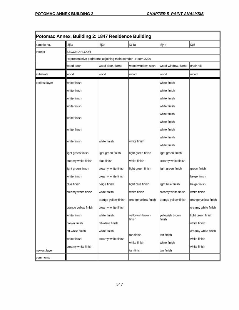
POTOMAC ANNEX BUILDING 2 CHAPTER 5 PAINT ANALYSIS
547
Potomac Annex, Building 2: 1847 Residence Building sample no. I3j3a I3j3b I3j4a I3j4b I3j5
Interior SECOND FLOOR
Representative bedrooms adjoining main corridor - Room 2226
wood door wood door, frame wood window, sash wood window, frame chair rail
substrate wood wood wood wood wood
earliest layer newest layer
white finish white finish white finish white finish white finish white finish white finish light green finish creamy white finish light green finish white finish blue finish creamy white finish orange yellow finish white finish brown finish off-white finish white finish creamy white finish
white finish light green finish blue finish creamy white finish creamy white finish beige finish white finish orange yellow finish creamy white finish white finish off-white finish white finish creamy white finish
white finish light green finish white finish light green finish light blue finish white finish orange yellow finish yellowish brown finish tan finish white finish tan finish
white finish white finish white finish white finish white finish white finish white finish white finish white finish light green finish creamy white finish light green finish light blue finish creamy white finish orange yellow finish yellowish brown finish tan finish white finish tan finish
green finish beige finish beige finish white finish orange yellow finish creamy white finish light green finish white finish creamy white finish white finish white finish
comments

POTOMAC ANNEX BUILDING 2 CHAPTER 5 PAINT ANALYSIS
548
Potomac Annex, Building 2: East Wing Connection sample no. I4a1 I4a2a I4a3a I4b3b I4b1
Interior FIRST FLOOR SECOND FLOOR
Room 2119 Room 2218
plaster wall wood door, frame wood window, sash wood window, frame plaster wall
substrate plaster wood wood wood plaster
earliest layer newest layer
remnant of wall paper light olive green finish light yellow green finish light yellow green finish creamy white finish orange yellow finish creamy white finish creamy white finish blue green finish whitish blue finish light blue green finish whitish green finish white finish creamy white finish white finish white finish white finish
whitish green finish creamy white finish white finish creamy white finish
creamy white finish white finish creamy white finish creamy white finish creamy white finish creamy white finish whitish green finish whitish green finish whitish green finish whitish green finish white finish creamy white finish white finish creamy white finish
creamy white finish bright yellow green finish white finish creamy white finish creamy white finish creamy white finish yellow finish creamy white finish white finish creamy white finish gray finish whitish green finish whitish green finish whitish green finish whitish green finish white finish white finish creamy white finish creamy white finish
whitish green finish whitish brown finish white finish whitish brown finish green finish creamy white finish off-white finish
comments
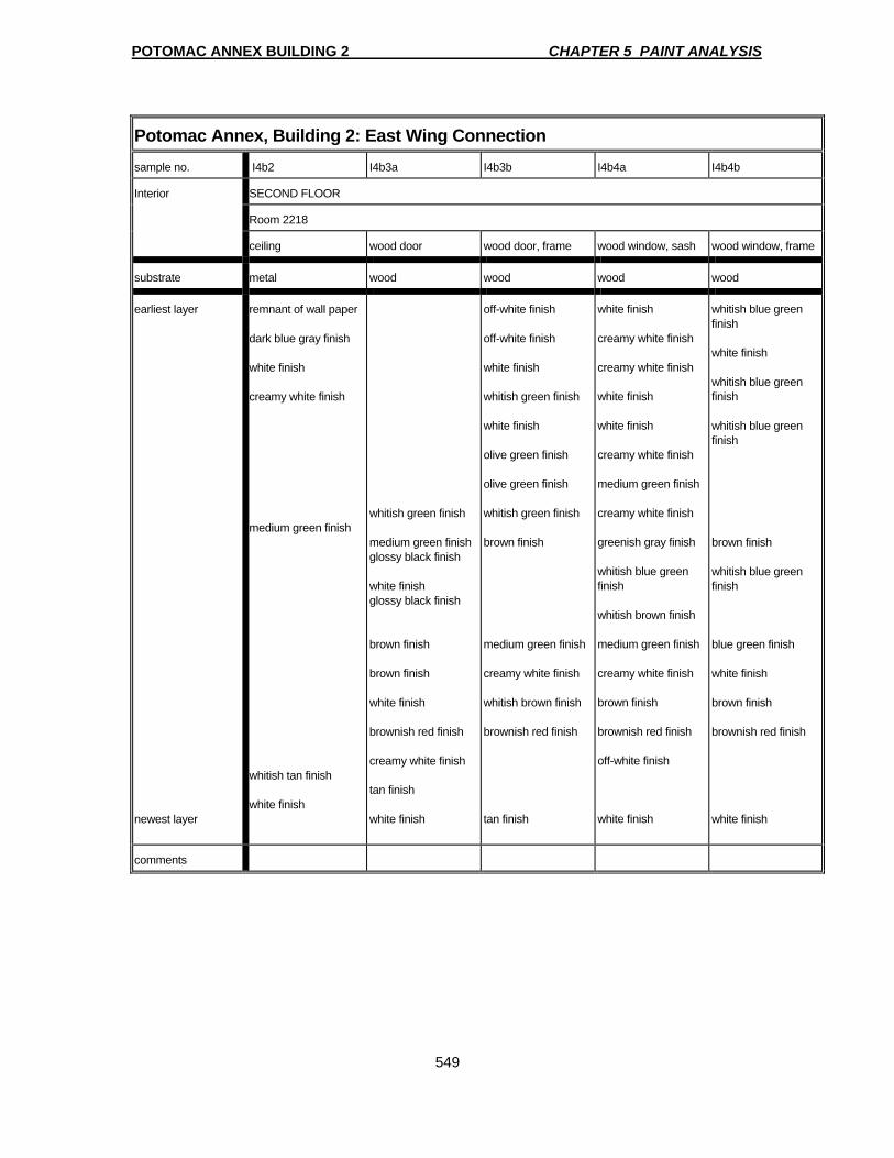
POTOMAC ANNEX BUILDING 2 CHAPTER 5 PAINT ANALYSIS
549
Potomac Annex, Building 2: East Wing Connection sample no. I4b2 I4b3a I4b3b I4b4a I4b4b
Interior SECOND FLOOR
Room 2218
ceiling wood door wood door, frame wood window, sash wood window, frame
substrate metal wood wood wood wood
earliest layer newest layer
remnant of wall paper dark blue gray finish white finish creamy white finish medium green finish whitish tan finish white finish
whitish green finish medium green finish glossy black finish white finish glossy black finish brown finish brown finish white finish brownish red finish creamy white finish tan finish white finish
off-white finish off-white finish white finish whitish green finish white finish olive green finish olive green finish whitish green finish brown finish medium green finish creamy white finish whitish brown finish brownish red finish tan finish
white finish creamy white finish creamy white finish white finish white finish creamy white finish medium green finish creamy white finish greenish gray finish whitish blue green finish whitish brown finish medium green finish creamy white finish brown finish brownish red finish off-white finish white finish
whitish blue green finish white finish whitish blue green finish whitish blue green finish brown finish whitish blue green finish blue green finish white finish brown finish brownish red finish white finish
comments
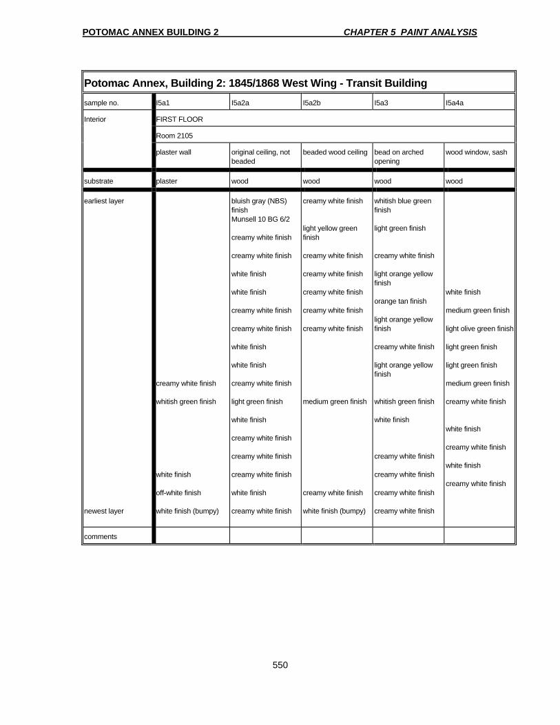
POTOMAC ANNEX BUILDING 2 CHAPTER 5 PAINT ANALYSIS
550
Potomac Annex, Building 2: 1845/1868 West Wing - Transit Building sample no. I5a1 I5a2a I5a2b I5a3 I5a4a
Interior FIRST FLOOR
Room 2105
plaster wall original ceiling, not beaded
beaded wood ceiling bead on arched opening
wood window, sash
substrate plaster wood wood wood wood
earliest layer newest layer
creamy white finish whitish green finish white finish off-white finish white finish (bumpy)
bluish gray (NBS) finish Munsell 10 BG 6/2 creamy white finish creamy white finish white finish white finish creamy white finish creamy white finish white finish white finish creamy white finish light green finish white finish creamy white finish creamy white finish creamy white finish white finish creamy white finish
creamy white finish light yellow green finish creamy white finish creamy white finish creamy white finish creamy white finish creamy white finish medium green finish creamy white finish white finish (bumpy)
whitish blue green finish light green finish creamy white finish light orange yellow finish orange tan finish light orange yellow finish creamy white finish light orange yellow finish whitish green finish white finish creamy white finish creamy white finish creamy white finish creamy white finish
white finish medium green finish light olive green finish light green finish light green finish medium green finish creamy white finish white finish creamy white finish white finish creamy white finish
comments

POTOMAC ANNEX BUILDING 2 CHAPTER 5 PAINT ANALYSIS
551
Potomac Annex, Building 2: 1845/1868 West Wing - Transit Building sample no. I5a4b I5a5 I5a6 I5b1 I5b2
Interior FIRST FLOOR
Room 2105 Room 2104A
wood window, frame wood instrument hatch
wood cornice wood ceiling triple beaded wood ceiling
substrate wood wood wood wood wood
earliest layer newest layer
creamy white finish brown finish tan finish creamy white finish white finish creamy white finish creamy white finish creamy white finish creamy white finish white finish light olive green finish whitish green finish medium green finish creamy white finish white finish creamy white finish creamy white finish
medium green finish creamy white finish creamy white finish creamy white finish creamy white finish creamy white finish white finish off-white finish medium green finish off-white finish off-white finish off-white finish off-white finish off-white finish
creamy white finish creamy white finish medium green finish creamy white finish white finish white finish
bluish gray (NBS) finish Munsell 10 BG 6/2 creamy white finish creamy white finish creamy white finish creamy white finish creamy white finish creamy white finish creamy white finish creamy white finish creamy white finish creamy white finish medium green
creamy white finish light green finish white finish white finish creamy white finish creamy white finish creamy white finish off-white finish off-white finish creamy white finish creamy white finish creamy white finish white finish light green finish creamy white finish creamy white finish white finish white finish white finish white finish
comments
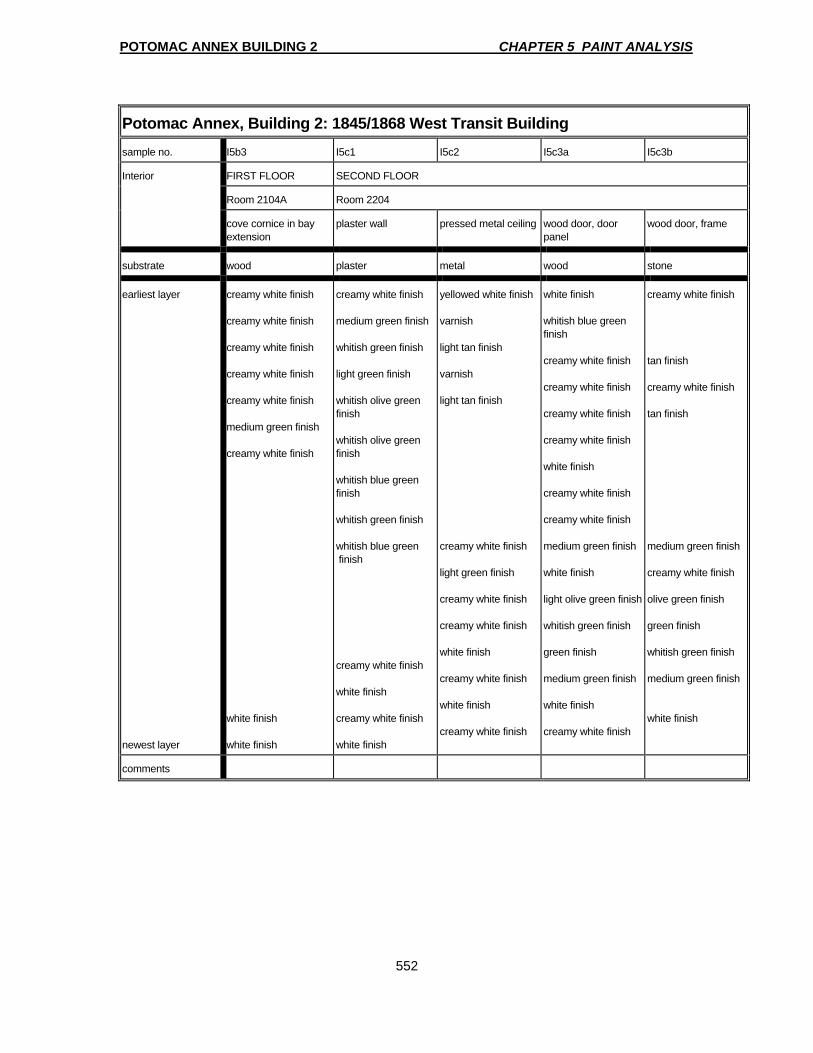
POTOMAC ANNEX BUILDING 2 CHAPTER 5 PAINT ANALYSIS
552
Potomac Annex, Building 2: 1845/1868 West Transit Building sample no. I5b3 I5c1 I5c2 I5c3a I5c3b
Interior FIRST FLOOR SECOND FLOOR
Room 2104A Room 2204
cove cornice in bay extension
plaster wall pressed metal ceiling wood door, door panel
wood door, frame
substrate wood plaster metal wood stone
earliest layer newest layer
creamy white finish creamy white finish creamy white finish creamy white finish creamy white finish medium green finish creamy white finish white finish white finish
creamy white finish medium green finish whitish green finish light green finish whitish olive green finish whitish olive green finish whitish blue green finish whitish green finish whitish blue green finish creamy white finish white finish creamy white finish white finish
yellowed white finish varnish light tan finish varnish light tan finish creamy white finish light green finish creamy white finish creamy white finish white finish creamy white finish white finish creamy white finish
white finish whitish blue green finish creamy white finish creamy white finish creamy white finish creamy white finish white finish creamy white finish creamy white finish medium green finish white finish light olive green finish whitish green finish green finish medium green finish white finish creamy white finish
creamy white finish tan finish creamy white finish tan finish medium green finish creamy white finish olive green finish green finish whitish green finish medium green finish white finish
comments
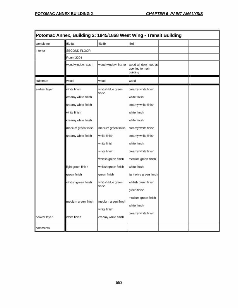
POTOMAC ANNEX BUILDING 2 CHAPTER 5 PAINT ANALYSIS
553
Potomac Annex, Building 2: 1845/1868 West Wing - Transit Building sample no. I5c4a I5c4b I5c5
Interior SECOND FLOOR
Room 2204
wood window, sash wood window, frame wood window hood at opening to main building
substrate wood wood wood
earliest layer newest layer
white finish creamy white finish creamy white finish white finish creamy white finish medium green finish creamy white finish light green finish green finish whitish green finish medium green finish white finish
whitish blue green finish medium green finish white finish white finish white finish whitish green finish whitish green finish green finish whitish blue green finish medium green finish white finish creamy white finish
creamy white finish white finish creamy white finish white finish white finish creamy white finish creamy white finish white finish creamy white finish medium green finish white finish light olive green finish whitish green finish green finish medium green finish white finish creamy white finish
comments
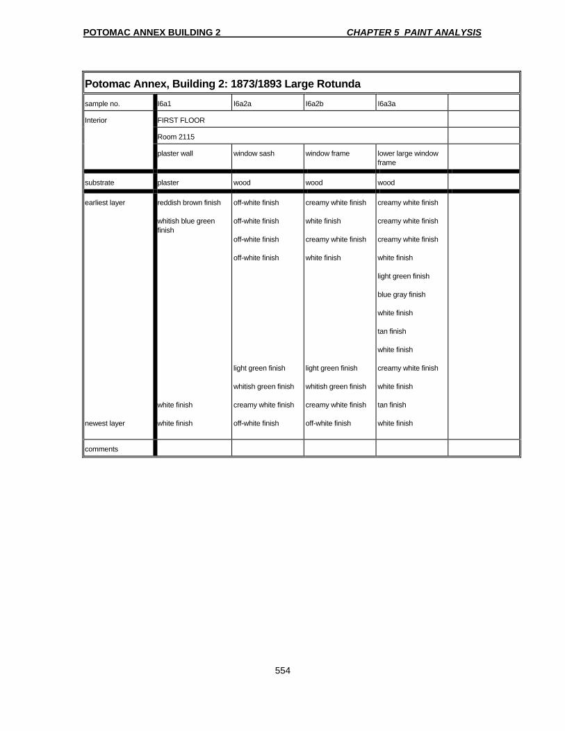
POTOMAC ANNEX BUILDING 2 CHAPTER 5 PAINT ANALYSIS
554
Potomac Annex, Building 2: 1873/1893 Large Rotunda sample no. I6a1 I6a2a I6a2b I6a3a
Interior FIRST FLOOR
Room 2115
plaster wall window sash window frame lower large window frame
substrate plaster wood wood wood
earliest layer newest layer
reddish brown finish whitish blue green finish white finish white finish
off-white finish off-white finish off-white finish off-white finish light green finish whitish green finish creamy white finish off-white finish
creamy white finish white finish creamy white finish white finish light green finish whitish green finish creamy white finish off-white finish
creamy white finish creamy white finish creamy white finish white finish light green finish blue gray finish white finish tan finish white finish creamy white finish white finish tan finish white finish
comments
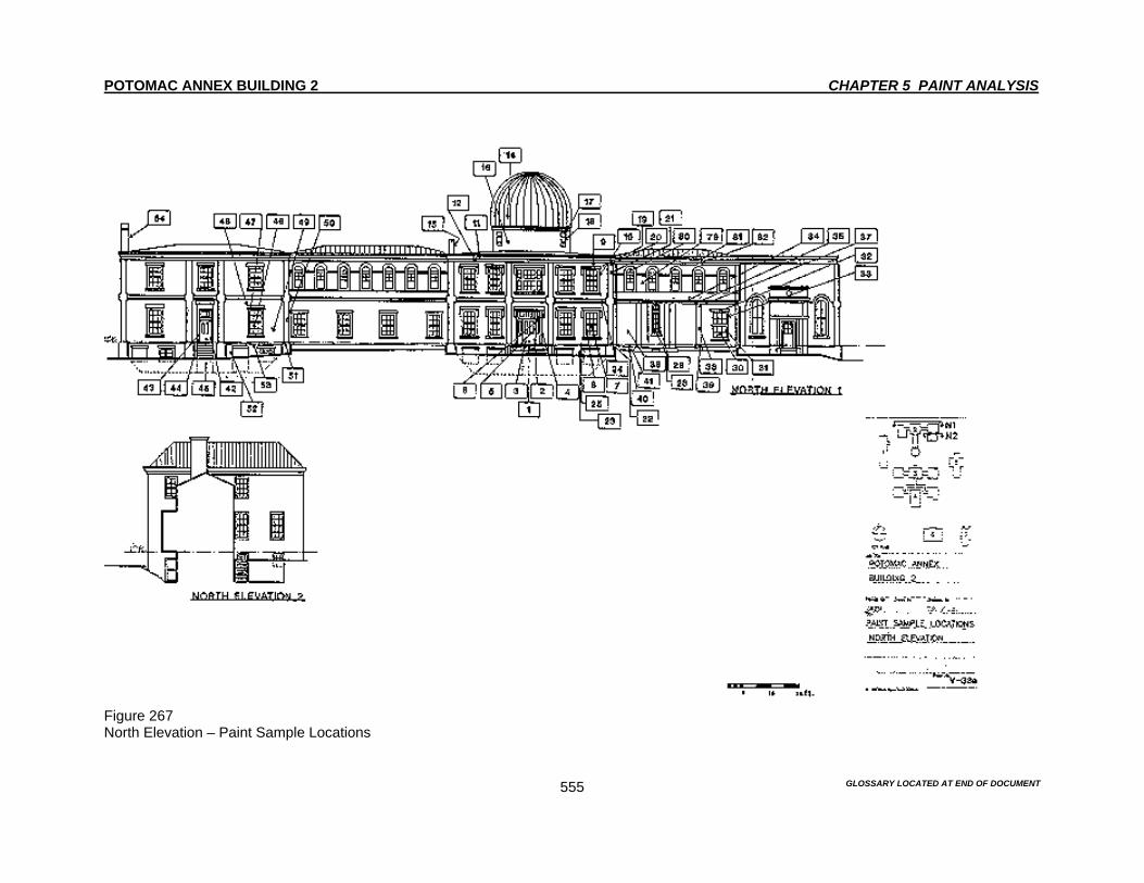
POTOMAC ANNEX BUILDING 2 CHAPTER 5 PAINT ANALYSIS
GLOSSARY LOCATED AT END OF DOCUMENT
555
Figure 267 North Elevation – Paint Sample Locations
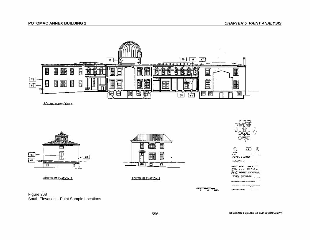
POTOMAC ANNEX BUILDING 2 CHAPTER 5 PAINT ANALYSIS
GLOSSARY LOCATED AT END OF DOCUMENT
556
Figure 268 South Elevation – Paint Sample Locations

POTOMAC ANNEX BUILDING 2 CHAPTER 5 PAINT ANALYSIS
GLOSSARY LOCATED AT END OF DOCUMENT
557
Figure 269 East Elevation – Paint Sample Locations
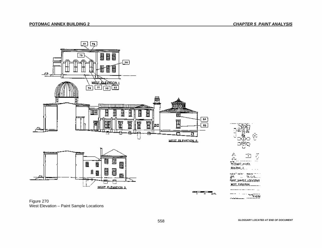
POTOMAC ANNEX BUILDING 2 CHAPTER 5 PAINT ANALYSIS
GLOSSARY LOCATED AT END OF DOCUMENT
558
Figure 270 West Elevation – Paint Sample Locations

POTOMAC ANNEX BUILDING 2 CHAPTER 5 PAINT ANALYSIS
GLOSSARY LOCATED AT END OF DOCUMENT
559
Figure 271 Basement Floor Plan – Paint Sample Locations

POTOMAC ANNEX BUILDING 2 CHAPTER 5 PAINT ANALYSIS
GLOSSARY LOCATED AT END OF DOCUMENT
560
Figure 272 First Floor Plan – Paint Sample Locations

POTOMAC ANNEX BUILDING 2 CHAPTER 5 PAINT ANALYSIS
GLOSSARY LOCATED AT END OF DOCUMENT
561
Figure 273 Second Floor Plan – Paint Sample Locations
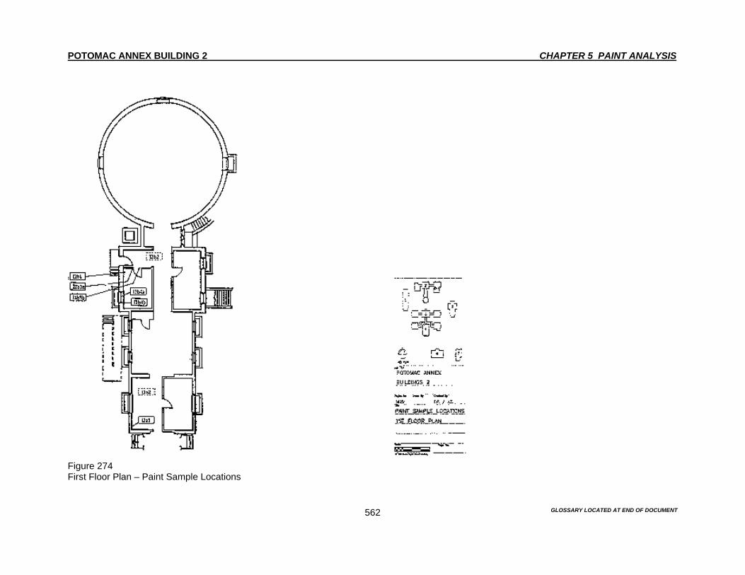
POTOMAC ANNEX BUILDING 2 CHAPTER 5 PAINT ANALYSIS
GLOSSARY LOCATED AT END OF DOCUMENT
562
Figure 274 First Floor Plan – Paint Sample Locations
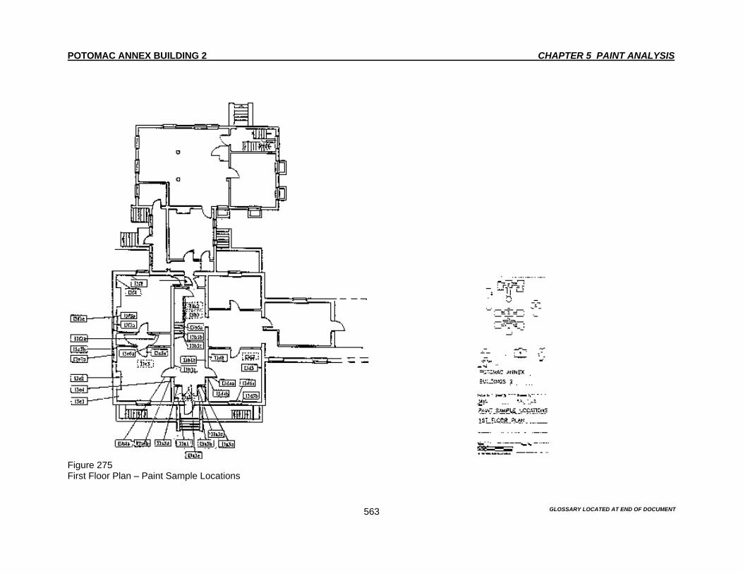
POTOMAC ANNEX BUILDING 2 CHAPTER 5 PAINT ANALYSIS
GLOSSARY LOCATED AT END OF DOCUMENT
563
Figure 275 First Floor Plan – Paint Sample Locations
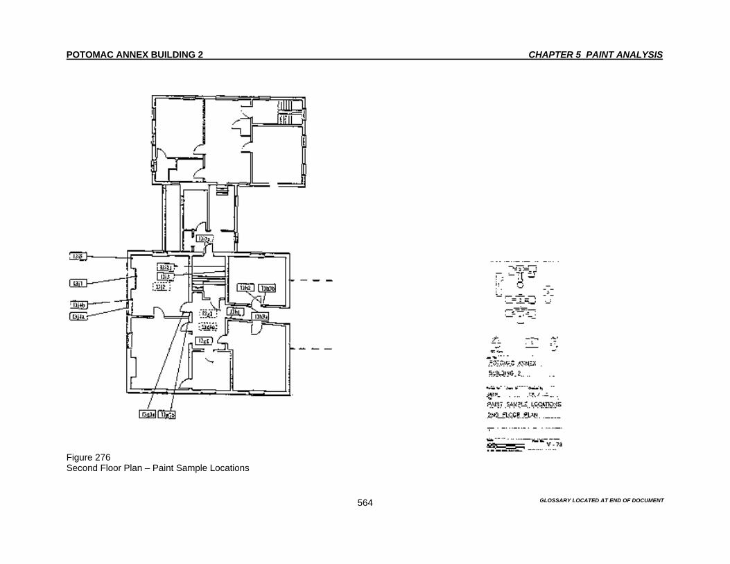
POTOMAC ANNEX BUILDING 2 CHAPTER 5 PAINT ANALYSIS
GLOSSARY LOCATED AT END OF DOCUMENT
564
Figure 276 Second Floor Plan – Paint Sample Locations

POTOMAC ANNEX BUILDING 2 CHAPTER 5 PAINT ANALYSIS
GLOSSARY LOCATED AT END OF DOCUMENT
565
Figure 277 First Floor Plan – Paint Sample Locations
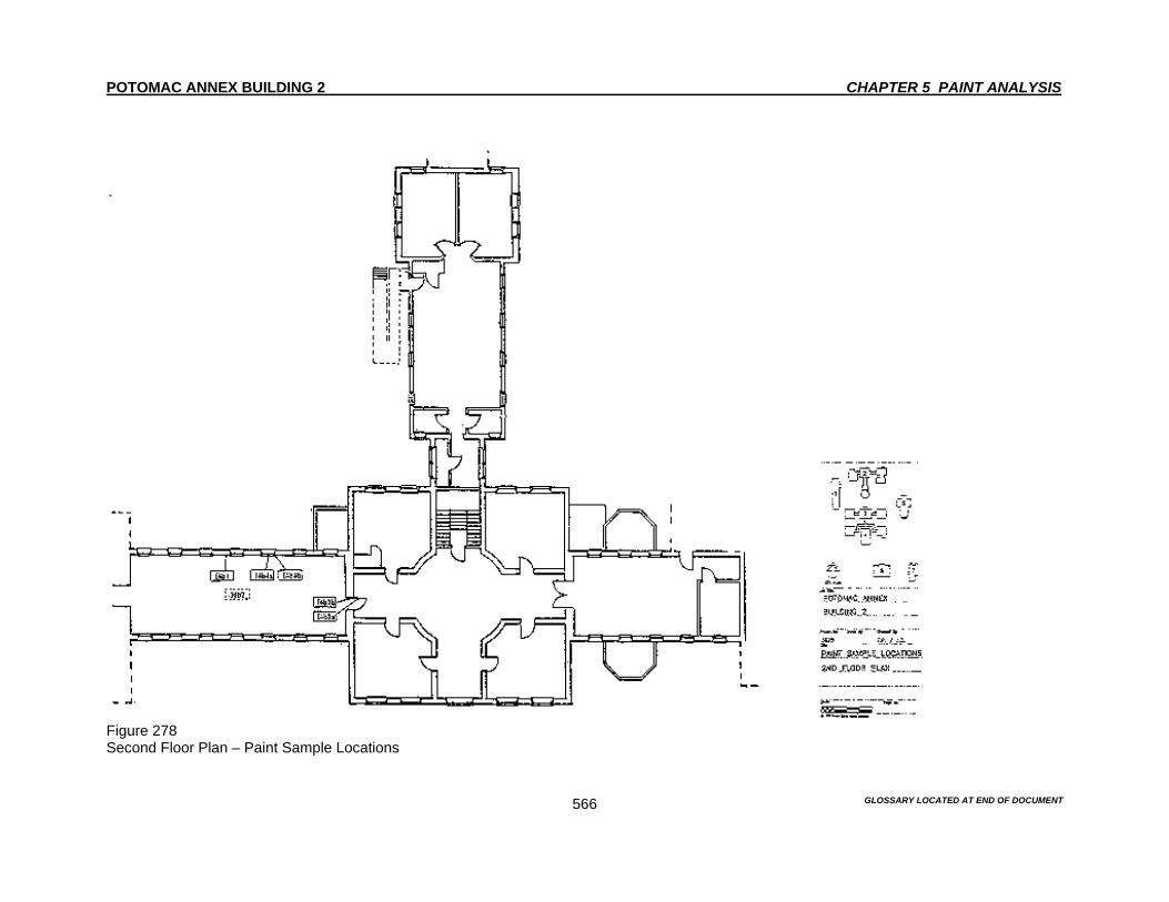
POTOMAC ANNEX BUILDING 2 CHAPTER 5 PAINT ANALYSIS
GLOSSARY LOCATED AT END OF DOCUMENT
566
Figure 278 Second Floor Plan – Paint Sample Locations

POTOMAC ANNEX BUILDING 2 CHAPTER 5 PAINT ANALYSIS
GLOSSARY LOCATED AT END OF DOCUMENT
567
Figure 279 First Floor Plan – Paint Sample Locations

POTOMAC ANNEX BUILDING 2 CHAPTER 5 PAINT ANALYSIS
GLOSSARY LOCATED AT END OF DOCUMENT
568
Figure 280 Second Floor Plan – Paint Sample Locations

POTOMAC ANNEX BUILDING 2 CHAPTER 5 PAINT ANALYSIS
GLOSSARY LOCATED AT END OF DOCUMENT
569
Figure 281 First Floor Plan – Paint Sample Locations

POTOMAC ANNEX BUILDING 2 CHAPTER 5 PAINT ANALYSIS
GLOSSARY LOCATED AT END OF DOCUMENT
570
Figure 282 North Elevation – Exterior Color Scheme

POTOMAC ANNEX BUILDING 2 CHAPTER 5 PAINT ANALYSIS
GLOSSARY LOCATED AT END OF DOCUMENT
571
Figure 283 South Elevation – Exterior Color Scheme
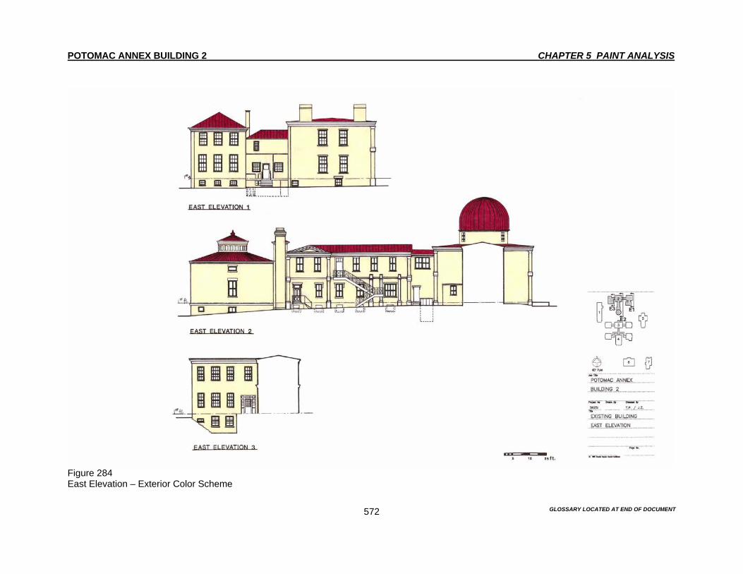
POTOMAC ANNEX BUILDING 2 CHAPTER 5 PAINT ANALYSIS
GLOSSARY LOCATED AT END OF DOCUMENT
572
Figure 284 East Elevation – Exterior Color Scheme
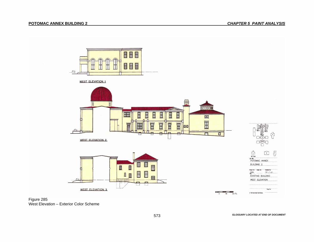
POTOMAC ANNEX BUILDING 2 CHAPTER 5 PAINT ANALYSIS
GLOSSARY LOCATED AT END OF DOCUMENT
573
Figure 285 West Elevation – Exterior Color Scheme

POTOMAC ANNEX BUILDING 2 CHAPTER 5 PAINT ANALYSIS
GLOSSARY LOCATED AT END OF DOCUMENT
574
Figure 286 First Floor Plan – Interior Color Scheme

POTOMAC ANNEX BUILDING 2 CHAPTER 5 PAINT ANALYSIS
GLOSSARY LOCATED AT END OF DOCUMENT
575
Figure 287 Second Floor Plan – Interior Color Scheme
POTOMAC ANNEX BUILDING 2 CHAPTER 6 MATERIALS CONSERVATION ANALYSIS
GLOSSARY LOCATED AT END OF DOCUMENT 576
Introduction The Old Naval Observatory consists of many materials, paint, brick, natural stone, cementitious materials that are not mortar, wood trim elements, wood windows, metals, drainage systems and roofing. The variety of materials has the potential to cause an oversight or neglect in any of these materials. An oversight in any of these materials will cause a further deterioration of the Old Naval Observatory. The proper means to deter and eliminate the deterioration of the Old Naval Observatory and its accompanying materials will insure the Old Naval Observatory will remain as a viable structure. Conservation of these materials is essential to the preservation of the Old Naval Observatory. Each material has its own special properties and conservation methodology. Giving each material special attention to its conservation needs is essential to the preservation of that material in its best possible condition. Not only is the preservation of the existing materials important, but equally vital is the maintenance of any material in the Old Naval Observatory. Any lack of proper maintenance of the original and new materials will only cause further deterioration of the building fabric over time. For it is in the preservation and maintenance of the original materials that will also insure that the Old Naval Observatory remains as an example of the historic fabric of the entire Potomac complex. Purpose Materials Conservation Analysis involves an on-site evaluation of the Old Naval Observatory. This on-site evaluation is often abetted by laboratory analysis. The purpose of Materials Conservation Analysis is to identify the materials of construction, evaluate their condition and identify their locations, sources and types of deterioration. This body of information, in conjunction with information collected under Chapter 7, Mortar Analysis and Chapter 8, Materials Cleaning Analysis, will serve as the foundation for a program of conservation, preservation, stabilization and maintenance. Summary The exterior of the Old Naval Observatory is generally in good condition. While deterioration to the brick is noted in areas where there are drainage problems, other masonry elements are well preserved. The most important condition to be addressed on the exterior is the multiple paint layers covering all masonry elements. The paint coating on the masonry represents a risk to the substrates due to the poor vapor transmission of both new and old paint coatings. Clear evidence of failure of the paint can be seen throughout the exterior due to the inability of water vapor to escape. The opposing effect is the retention of water by the respective masonry materials, brick and natural stone. Serious consideration must be given to removing most of the paint from all elevations. A further and serious complication to any consideration of paint removal is the identification of lead paint found on most of the exterior walls and architectural elements. A program of tightly controlled containment must be carried out during paint removal. Even though there is less of a health hazard to adults, for children it is different. Young children are especially at risk. Exterior Existing Conditions The Old Naval Observatory comprises several masonry materials, which serve both structural and decorative functions. In its current manifestation and during most of its history, the identities of these masonry materials have, for the most part, been obscured by paint. There are two sizes of brick and gray sandstone. There are also two kinds of brownstone, granite, schist, bluestone, stucco, cast stone, wood and sheet metal.

POTOMAC ANNEX BUILDING 2 CHAPTER 6 MATERIALS CONSERVATION ANALYSIS
GLOSSARY LOCATED AT END OF DOCUMENT 577
Paint All elevations and the constitutive materials of Old Naval Observatory have been subjected to many painting campaigns, see Chapter 5 Paint Analysis. Paint appears to have been applied to give a unified and harmonious appearance to the Old Naval Observatory. In Chapter 3, Description of Building as Originally Built, we have referred to an early specification for painting of the Old Naval Observatory. We cannot be sure when the work was performed. Paint analysis does not tell us when it was first painted. There might have been other reasons for painting the brick. The brick may have been of poor quality and started to deteriorate, initiating early repair work. Brick was hand made at the time. This may have been a contributing factor to the brick deteriorating. However, a much better reason might have been the need for waterproofing because the Old Naval Observatory was originally located in a swampy moist area. Refer to Chapter 2, Building History, for description of the land and references to the high incidence of malaria at the Old Naval Observatory. However, the reason for painting the Old Naval Observatory that is most rational remains visual. It was common to unify a building with paint, when it's brick elements were all different sizes, so that it would have a tighter and neater appearance. In the original Old Naval Observatory alone, the visible construction materials were wood, brick, gray sandstone, granite and schist. By the time the Residence and the Connector were built in 1848, another size brick, mortar joint and brownstone were added. Historic images indicate that the Old Naval Observatory was painted by the mid- 1860's. This would coincide with the latest additions that were added to the Old Naval Observatory. In order to match the Old Naval Observatory with the new additions, the Old Naval Observatory was painted. Between the time the Old Naval Observatory was completed and the new additions were added, approximately between 10-12 years, it is likely that the Old Naval Observatory was not painted. The presence of multiple elements are a strong indication that it was painted for visual reasons before the image in the 1865 Carte de Visite from Chapter 3. The state of attachment of the paint layers varies from complete-to-little-to-not at all. Where many layers of paint are present, incipient cracking, cupping, tenting and pealing are noted. These conditions extended to over 80% of the surfaces of most elevations at the time the Old Naval Observatory was surveyed in the fall of 1994.1 The most recent applications of paint are vinyl-latex-based.1 These paints allow for little evaporation of moisture. Any moisture, which can find its way to the various masonry substrates through rising damp cracks in the paint and other means, has few avenues of escape by normal drying processes such as wind, low atmospheric relative humidity and insulation because of the impermeable layers of paint. The moisture within the masonry materials increases the risk of damage due to freezing and the attraction of biological growth to moisture. Where small samples of paint have been removed, the masonry substrate, whether it is brick or stone, is damp to the touch. These materials are therefore subject to possible damage by freezing water and biological growth. Brick Brick is the primary element of the Old Naval Observatory. It comprises the walls of all but two of the additions in the complex.2 Brick is also used decoratively. The West Addition of the Old Naval Observatory contains brick used as pilasters, pilaster bases and capitals, belt courses and semicircular window dressing, Figures 66 and 67.
1 The vinyl-latex paints can be easily removed by several means. However, there is evidence that
underlying paint layers contain lead pigments. These pigments represent a serious health hazard on and near the building as well as to operators who may be involved in paint removal processes.
2 The other two additions are finished in stucco.

POTOMAC ANNEX BUILDING 2 CHAPTER 6 MATERIALS CONSERVATION ANALYSIS
GLOSSARY LOCATED AT END OF DOCUMENT 578
At least two brick types and associated pointing can be found on the Old Naval Observatory. One measuring 2 5/8 inches in height with 1/8 inch flush pointing, Figure 63. Another measuring 2 1/4 inches in height with 1/2 inch recessed joints, Figure 64. The total height of the brick carsing remains the same. Each brick and joint total 2 3/4 inches in height.3 The narrower brick with the simpler pointing is found on the two side elevations of the 1847 Residence. The wider brick with narrow joints comprises most of the remaining brickwork. The finer brick with narrower joints was more expensive and would have been appropriate for the primary elevations, as was done on the Residence. The 1869 South Extension of the West Wing of the Old Naval Observatory has brick and pointing similar to the north elevations of the Residence with wider, somewhat recessed joints. A brick water table, which runs along the lower 18 inches of the front elevations of the Old Naval Observatory, is made with narrower bricks and wider recessed joints. In all cases, the pointing is light in color. The joints are soft but compact and generally in good condition, see Chapter 7 Mortar Analysis. Despite the wetness described under Paint above, most of the brick appears to be in good condition.4 There are a few notable exceptions. Severe displacement is noted at the east basement window to the 1847 Residence. This displacement extends diagonally upward to the sill of the first floor window, Figure 65. Clogged drainage systems on the central section of Residence have allowed accumulations of water within the adjacent brickwork at the northeast corner of the Old Naval Observatory, Figure 66. The trapped excessive moisture has not only detached the paint but has damaged the brickwork and pointing by freezing in cold temperatures and spall of the brick has occurred. Minor stress cracks are found along brick joints, Figure 68. Inexplicably, single bricks are badly damaged on some elevations, Figure 69. Finally, damage to basement window frames has helped to cause displacement of superimposed bricks, Figure 70. Natural Stone Several natural stones complement the brickwork both as decorative and structural elements of the Old Naval Observatory. The variety of materials and the range of their colors and surface appearances may, in part, explain the early commencement of applications of paint to the Old Naval Observatory’s facades. In the Old Naval Observatory there can be found at least three natural building stones. Gray-tan coarse sandstone comprising the window and door brackets and the pilaster bases.5 A light colored granite, as well as a Schist comprises window lintels and sills. These three and probably some gneiss make up the foundation of this and almost every other building in the Old Naval Observatory complex. The 1847 Residence also contains a number of different stones. There is coarse red-orange sandstone for the basement, window lintels and sills. A finer red sandstone for the window lintels and sills for the first and second floors, as well as the pilaster bases and capitals. There is also schist and
3 For further comment on the joint geometry and mortar composition see Chapter VI, Mortar Analysis. 4 The paint may also obscure compromised conditions on the brick. 5 This coarse sandstone may also be used in other areas not yet sampled such as the belt course
which runs through most of the buildings of this complex and the pilaster capitals. We know, for example, that this same stone is used for the belt course for the wing that extends from the central observatory building to the circular room at the rear of the complex. It has also been used for the pilaster bases on the hall that connects the central building to the right wing. Further sampling will reveal the extent of the use of this sandstone.
POTOMAC ANNEX BUILDING 2 CHAPTER 6 MATERIALS CONSERVATION ANALYSIS
GLOSSARY LOCATED AT END OF DOCUMENT 579
gneiss found in the foundation. The slate capstones along the tops of the areaway wall adjacent to the east wall of the Residence back building requires resetting and pointing. A compact gray "bluestone" courses its way in and around the Old Naval Observatory. It forms the sills for the windows in the east and wings of the Old Naval Observatory, as well as in the first floor of wings that were remodeled in 1902, as part of the Second Floor Additions. It also makes up the belt course, window lintels and sills for the 1895 South Rotunda at the rear of the Old Naval Observatory, Figure 74. The stone elements of the Old Naval Observatory are in good condition. There are some vertical cracks in the lintels at the basement level. The vertical cracks appear at the north elevation on the east side of the Old Naval Observatory. There are other cracks at the east side of the Residence, as well as on the south, east and west sides of the Residence. There are also cracks that appear on the lintel above the entrance to the tunnel under the back building of the Residence on the west side. None of these are active and do not require any repairs at this time. This condition should be monitored and documented for the future. A biannual inspection should be implemented. The inspection should occur during the spring and falls periods of the year. This will avoid any inclement weather that may postpone the inspections. This will also allow for any changes to be documented if there was adverse weather during the following season. The exact location of the crack should be noted. The initial inspection should be done with a set of photographs to document the existing conditions of the cracks. After the photos are taken, careful measurements should be done to each crack along its entire length. After the initial inspection, documentation, measurements and photographs are completed, this information and needs to be entered into to a spreadsheet at the minimum. The optimal strategy would be to create a database that would have the initial inspection, documentation, measurements, and photographs to serve as a baseline for any further inspections. During periods of extreme drought, rain, frost and thaw, an additional inspection should be carried out. During these periods, the characteristics of the surrounding earth change dramatically. In order to document any changes, an inspection should be carried out. A building strategy and guidelines should be created to address this as well as other problems that may occur or are occurring. This additional inspection should follow the same guidelines of the initial inspection. The initial as well as the biannual inspection should be incorporated into the building maintenance Standard Operating Procedures. Coordination with maintenance personnel should be done in order to carry out the guidelines. Cementitious Materials (not mortars) Several cementitious materials are used for the decoration of the Old Naval Observatory. There are the walls of the 1918 East and West Stucco Additions, Figures 75 and 76. The foundation walls of the West Addition, which are scored to look, like ashlar. And the "capstone" to the brick water table cited above, Figure 67. Like the rest of the Old Naval Observatory elements, all of these features have been painted. The stucco comprising the wall finish is in poor condition with extensive cracks and rusting metal lath, Figures 75 and 76. The foundation covering the stucco is in good condition while the cement-composite capstones are detached in many places. Wood Trim Elements Wood can be found as trim on the brick pilasters, as hoods resting on the sandstone brackets, as well as at the cornice. This trim has always been painted. There are apparent areas of rot that will require possible replacement and then repainting.
POTOMAC ANNEX BUILDING 2 CHAPTER 6 MATERIALS CONSERVATION ANALYSIS
GLOSSARY LOCATED AT END OF DOCUMENT 580
Wood Windows The windows on the Old Naval Observatory are all wood and date back to different periods in the Old Naval Observatory’s history. Consult Chapter 4 Existing Conditions, for exact dating of the windows. Over the years the wood has been scraped and repainted many times and much of the glass is old. Refer to the Water Leakage Study, of 1993 (RDC 24102) for a complete survey and list of repairs. The presence of air conditioners in the base of the windows adds to conditions that promote rot in the wood and weaken the historic fabric. Most of the windows have been renovated as they now have metal pull chains and non-original hardware. Also the windows are not operable because they have been painted shut. Metals The metals of the Old Naval Observatory are cooper in the dome, galvanized sheet metal at the cornice of the West Addition and the West Stucco Addition and as gutter liners for the built-in wood gutters for the remainder of the roofs. Standard metal gutters occur at the back building to the Residence and the South Rotunda. Roof drains empty into metal downspouts except for two internal drain lines on the West Addition. Sheet metal is also used as flashing at the wood window hoods and wood cornice elements. The general condition of the metal is good with minor repairs required. The one exception is the flashing that has deteriorated badly around the windows. Each window should be checked. The sheet metal at the cornice requires scraping and painting. The gutter liners are covered in roofing membrane and could not be evaluated. The ceiling of the Old Naval Observatory is in good condition. There are no apparent signs of water intrusion or damage. However, a careful inspection should be done on a periodic basis. This inspection should be part of the Old Naval Observatory’s maintenance procedures. Refer to the Water Leakage Study for the condition of the gutters. Drainage Systems Maintenance of the roof drains is very important and impacts the downspouts and the brick walls. One example of how drainage conditions can impact the historic fabric of the Old Naval Observatory can be seen in the northwest corner of the Old Naval Observatory. See the condition description under Brick above. There should be regular monthly inspection of the drains at a minimum. Screens should be placed in each drain. They should be checked for collection of debris after all rains. Leaves should be kept off the roofs. Regular maintenance of this type will help to prevent blockage of the downspouts that in turn, maintains moisture at the brick walls. Roofing While a thorough examination of the roof is not a part of this report, the conditions on the roof over the Old Naval Observatory, Residence and West Addition were easily identified. The existing modified bitumen roofing membrane with an aluminum paint facer is failing. It was installed in 1981 over the

POTOMAC ANNEX BUILDING 2 CHAPTER 6 MATERIALS CONSERVATION ANALYSIS
GLOSSARY LOCATED AT END OF DOCUMENT 581
metal roofing. The different rates of expansion between the two materials have led to a weakening of the roofing membrane. The built-up roof is very dry and collects water at its low end. Both conditions require an investigation for identification of problems and selection of re-roofing methods and materials. Refer to the Water Leakage Study (RDC 24102) for a complete study and recommendations regarding the roofs on the entire Old Naval Observatory. Based on the limited investigation work of this report, both roof areas should be replaced. There should be a complete replacement of the old roofing material down to the wood deck. EXTERIOR TREATMENT OPTIONS AND RECOMMENDATIONS Refer to Chapter 10, Outline Specifications for a more detailed description of the following recommendations and repairs. Peeling and Cupping Paint on Brick and Stone Masonry Figures 282 and 283 There are many layers of paint on the brick, stone masonry and the mortar joints. The
many layers of paint prevent moisture from escaping from the wall. It is causing the brick to deteriorate and must be removed. Further field testing in addition to those that appear in Chapter 8 of this report should be performed before a paint removal project is undertaken.
Peeling and Cupping Paint on Brick and Stone Masonry - Treatment Options • No Treatment: Moisture trapped within the wall will continue to deteriorate the brick and stone
masonry. • Remove Paint: Paint should be removed from the brick, stone masonry and their mortar joints.
Selection of a product and method should be based on field tests in addition to the tests and information in Chapter 8. Care should be taken in removing the paint because of the fragile condition of some of the brick surfaces. There is lead in the paint layers. Removal methods must protect the technicians as well as present and future occupants of the Old Naval Observatory and follow the most recent regulations.
Peeling and Cupping Paint on Brick and Stone Masonry - Treatment Recommendation See Painting and Paint Removal in Chapter 10 specification guidelines • Remove Paint: There is no viable alternative. Because of the varied masonry elements that
support and decorate the Old Naval Observatory, the masonry must be repainted. Open Mortar Joints in Brick and Stone Elements Figures 282, 283 and 285 Brick and stone construction elements are pointed with mortar to provide a watertight skin
to the Old Naval Observatory. Pointing requires periodic maintenance. Where the mortar is cracked, missing or disintegrated, water can enter the wall causing deterioration of metal construction elements or interior decorative materials such as plaster or wood. This

POTOMAC ANNEX BUILDING 2 CHAPTER 6 MATERIALS CONSERVATION ANALYSIS
GLOSSARY LOCATED AT END OF DOCUMENT 582
is even more important when the masonry elements are painted because a certain amount of vapor permeability is lost through the use of paint that is applied to the brick and stone elements.
Open Joints in Brick and Stone elements - Treatment Options • No Treatment: Water will begin or continue to deteriorate the wall with increasing intensity. • Bag and Grout: This is a short cut method of pointing. Mortar is rubbed into the partially cut
joints. Joints are not struck so they never become compacted and watertight. • Cut and Point: Existing mortar should be raked from defective joints to a minimum depth of 3/4
inches. Pack and tool joints with fresh mortar that matches existing pointing mortar in color, texture and profile.
Open Joints in Brick and Stone elements - Treatment Recommendation • Cut and Point: There is no viable alternative to this approach. Stress Cracks in Brickwork Figures 285, 287, and 290 There are scattered hairline cracks in the brick. Building stresses can be transferred from
one element to another. This is why step cracks develop. Moisture entering the wall through open joints causes expansion and contraction stresses within the wall. In masonry construction these stresses are easily transfer due to the nature of the masonry. The weakest elements, the mortar and next the brick will crack, allowing more water to enter which results in further, often more serious deterioration of other building elements.
Stress Cracks in Brickwork - Treatment Options Treatments discussed here are for cracked brick. Open mortar joints associated with the stress cracks should be cut out and re-pointed as above. • No Treatment: Water will continue to cause further deterioration of building elements. • Epoxy Repair: Structural epoxies can mend broken bricks, but this technique is often difficult to
execute and unsightly when completed. • Remove and Replace Brickwork: Bricks are cut out and replacements that match existing in
texture, color and size are reset in mortar to match surrounding pointing in color, texture, and profile.
Stress Cracks in Brickwork - Treatment Recommendation • Remove and Replace Brickwork: This option returns the structural integrity of the wall and also
provides an aesthetically superior solution.
POTOMAC ANNEX BUILDING 2 CHAPTER 6 MATERIALS CONSERVATION ANALYSIS
GLOSSARY LOCATED AT END OF DOCUMENT 583
Spalling, Displacement and Deterioration of the Brickwork Figures 284, 285, and 289 Brick work that is out of alignment with the plane of the exterior wall on the northeast
corner of the Residence is not only unsightly but also becomes a shelf for water to collect. In its present condition, the brickwork that is out of alignment does not appear to contribute to a structural problem for the Residence. However, the potential for possible structural damage may occur if not addressed and corrected. Water may collect and damage the framing members. This may cause rotting of the framing members, which will then impact on the structural integrity of the Residence. On the northeast corner of the Old Naval Observatory there is a large area of disintegrating brick due to presence of excessive moisture being trapped in the wall. A great deal of the original brick has failed and requires replacement. Not only is this a matter of maintaining a watertight wall, but it is unsightly. Fresh paint over the existing paint layers will not help because the brick and paint layers are in such poor condition.
Displacement and Deterioration of the Brickwork - Treatment Options • No Treatment: On the Residence water will collect and enter the wall, eventually causing greater
damage. The appearance of the Residence will be compromised until the displaced brick is repaired. If no action is taken on the Old Naval Observatory, the brick surface will continue to deteriorate.
• Brace Wall Above, Replace Brick and Re-point: Masonry above work area should be braced.
Remove out of plane and deteriorated bricks. Set matching bricks in a clean bed of mortar and allow to cure. Rake out and re-point with mortar that matches original in color, profile and texture. Isolated spalled brick should also be replaced. Once brick has cured, it should be repainted to match the rest of the building.
Displacement and Deterioration of the Brickwork - Treatment Recommendation • Brace Wall Above, Replace Brick and Re-point: This is the correct treatment for this condition. Stress in Brickwork over the Basement Window, West Wing and North Elevation Figures 288, 289 and 292 The frame of the basement level wood window has deteriorated. The bricks above are
separating along the horizontal joint above. The bricks could give way and further damage the water table above. No steel lintel supporting the outer part of the brick can be seen above the wood window frame. This is potentially a structural condition that should be investigated further.
Stress in Brickwork over the Basement Window, West Wing and North Elevation - Treatment Options • No Treatment: The brick is under severe stress. To do nothing is dangerous to the masonry
POTOMAC ANNEX BUILDING 2 CHAPTER 6 MATERIALS CONSERVATION ANALYSIS
GLOSSARY LOCATED AT END OF DOCUMENT 584
above as well as to the wall. • Investigate This Condition: This option allows for an assessment of the condition of the brick, the
wall and the window opening and takes the correct remedial action. If there is no steel or iron type lintel, the framing members need to be inspected. If the framing members under the stressed brickwork are in failure, then these members need to be removed and replaced. When the framing member is removed and replaced the brickwork needs to be re-set and re-pointed.
Stress in Bricks over Basement Window, West Wing, North Elevation - Treatment Recommendation • Investigate This Condition: This option allows for an assessment of the condition of the brick, the
wall and the window opening and takes the correct remedial action. If there is no steel or iron type lintel, the framing members need to be inspected. If the framing members under the stressed brickwork are in failure, then these members need to be removed and replaced. When the framing member is removed and replaced the brickwork needs to be re-set and re-pointed.
Dislodged Slate Capstones along Areaway, East Side of Back Building to the Residence Figure 286 Capstones have both an aesthetic and mechanical function. They are placed at the top of
walls to protect the exposed joints in a brick or concrete block wall or to finish the top of a concrete wall. In order to preserve the wall, capstones require proper maintenance by resetting loose stones and re-pointing the mortar joints.
Dislodged Capstones along Areaway, East Side of Back Building to the Residence - Treatment Options • No Treatment: There is a danger of deterioration to the wall. • Repair by Resetting and Re-pointing: Reset all loose capstones in full bed of mortar. Re-point by
packing joints with mortar and tooling the joint. Dislodged Capstones along Areaway, East Side of Back Building to the Residence -Treatment Recommendation • Repair by Resetting and Re-pointing: This is the only option in order to maintain the integrity of
the wall. At this time there appears to be no deterioration of the wall. However, if the capstones are not reset and re-pointed, there may be a possibility of wall deterioration.
Cracked and Deteriorating Stucco at the East and West Stucco Additions Figures 294 and 295 The stucco finish on the exterior serves both an aesthetic and mechanical function. It
keeps the wall in a watertight condition and presents a cohesive finish. When the stucco cracks, water can enter and can cause corrosion damage to the supporting metal lath and fasteners. As the metal lath corrodes, the stucco cracks get worse. In order to protect the

POTOMAC ANNEX BUILDING 2 CHAPTER 6 MATERIALS CONSERVATION ANALYSIS
GLOSSARY LOCATED AT END OF DOCUMENT 585
wall, cracks should be patched as they occur. This was not done on the East and West Stucco Additions. The result is that the entire stucco surface requires replacement.
Cracked and Deteriorating Stucco at East and West Stucco Additions - Treatment Options • No Treatment: Deterioration will continue and become more severe. The walls are unsightly. • Repair Cracks: The cracks could be individually sounded and the deteriorated stucco removed
and replaced. Corroded lath and fasteners should also be replaced. New flashing should be added to the window and door openings. By the time all of this is done, it would be less expensive to remove all of the stucco and lath and replace with new material.
• Remove and Replace Remove all stucco and lath. Replace any rotted wood sheathing. Install
new metal flashing at window and door heads and sills. Attach new metal lath. Apply stucco in three coats. Use factory mixed stucco for final coat.
Cracked and Deteriorating Stucco at East and West Stucco Additions - Treatment Recommendation • Remove and Replace: Repair the stucco properly, flashing and expansion joints should be
installed. A series of weep holes should also be added as well. This will add to the longevity of the repair. Before any stucco is removed, an analysis of the paint and stucco should be completed to insure that there is no lead content. The lead content should be considered before any work is started. By removing all stucco and replacing it with new stucco, flashing, expansion joints can be incorporated into the work. This is the correct and most economical repair.
Cracked Concrete Pavement East of the East Stucco Addition In order to insure the safety of the building's occupants, cracked concrete paving should
be repaired. By repairing the cracked areas, further deterioration can be prevented. Cracked Concrete Pavement East of the East Stucco Addition - Treatment Options • No Treatment: The concrete will continue to deteriorate adding to the existing safety hazard as
well as being unsightly. • Repair by Re-paving: Concrete should be removed. New gravel bed should be established to
proper depth. Pour new concrete and float to achieve a slip resistant finish. Cracked Concrete Pavement East of the East Stucco Addition - Treatment Recommendation • Repair by Re-paving: This will restore the safety and integrity to the paved areas around the East
Stucco Addition. Failing Paint and Voids in Wood Trim Elements Figures 292 and 296 Failing paint on wood elements allows moisture to penetrate wood, eventually causing rot.

POTOMAC ANNEX BUILDING 2 CHAPTER 6 MATERIALS CONSERVATION ANALYSIS
GLOSSARY LOCATED AT END OF DOCUMENT 586
As the wood starts to rot, fresh coats of paint will no longer adhere to the wood. Paint failure compromises the appearance of the building.
Failing Paint and Voids in Wood Trim Elements - Treatment Options • No Treatment: Deterioration of wood elements will continue unless repairs are undertaken. • Repair Rotted Wood Scrape, Prime and Paint: Remove existing paint from wood. Inspect all
wood for rot. Replace, consolidate or install dutchman as required. Prime and repaint. Failing Paint and Voids in Wood Trim Elements - Treatment Recommendation • Repair Rotted Wood Scrape, Prime and Paint: This is the only viable option. Inability of Wood Windows to Open Paint protects wood from excessive moisture and ultra-violet light damage as well as
decorates a particular element, establishing the tonal pattern on the building elevation. Paint should be renewed to re-establish both of these purposes from time to time. At the time repainting work is undertaken all building elements including the wood windows should be returned to an operable condition.
Inability of Wood Windows to Open - Treatment Options • No Treatment: Windows that will not open need to be stripped of all their paint. The wood frame
then needs to be examined and repaired if there is any damage. Afterwards, the window frames need to be painted, taking extra careful measure to insure that the windows will operate as they were intended to function.
• Free Windows, Remove Excessive Layers of Paint, Repaint: This should be part of the normal
maintenance program every time windows are painted. Inability of Wood Windows to Open - Treatment Recommendation • Free Windows, Remove Excessive Layers of Paint, Repaint: Windows should be made operable. Lack of Maintenance to the Drainage System Figures 285 and 291 Gutters and leaders are provided to conduct water off of the building. When not properly
maintained, water will collect and expand, especially during cold weather. This will cause more extensive damage to the storm drainage system as well as other parts of the building.
Lack of Maintenance to the Drainage System - Treatment Options

POTOMAC ANNEX BUILDING 2 CHAPTER 6 MATERIALS CONSERVATION ANALYSIS
GLOSSARY LOCATED AT END OF DOCUMENT 587
• No Treatment: Deterioration of brick and wood will continue in areas where water builds up above the blockage.
• Clear Gutters, Drains and Leaders: Clean all downspouts and catch basins of all blockages. This
should be part of a regular maintenance program, especially after a severe storm and once the trees have lost all their leaves. Install screens at drain openings on roof. Remove the leaves and other debris from roofs.
Lack of Maintenance to the Drainage System - Treatment Recommendation • Clear Gutters, Drains and Leaders: There is no other choice. Air Conditioning Units in Wood Windows Figure 285 Aesthetically, the installation of air conditioning units in the wood windows compromises
the appearance of the building. The moisture dripping from them is deteriorating the materials of the wall and the paint. The weight of the unit is damaging the historic fabric of the windows.
Air Conditioning Units in Wood Windows - Treatment Options • No Treatment: Wall elements and paint will continue to deteriorate, making the appearance of the
building worse and putting the historic fabric in jeopardy. • Install AC Units in Metal Sleeves: Remove the AC units. Install self-supporting frame to window
jambs. Fabricate new metal sleeves with drain holes. Reinstall the AC units. • Install Central Air System: Remove the existing AC units permanently from window openings.
Provide a new central AC system for the entire building. Air Conditioning Units in Wood Windows - Treatment Recommendation • Install Central AC System. Remove AC Window Units: This is the most expensive solution. It
removes the danger to the historic fabric and restores the integrity to the building's elevations. The installation of a central AC unit will pose a difficult solution to the window AC units. A thorough inspection of the building needs to be completed before any unit is installed. Volumes and the required tonnage need to be calculated. Placement of the outdoor portion of the central AC unit needs to be considered carefully, in order not to impact the building and its historic character. The installation of the internal duct work needs to be done in a manner that will not destroy any of the elements that are present.
Corroded Metal Flashing above Window Hoods and at Small Cornice, West Wing Figure 292 The metal flashing that protects the juncture between the wood and the brick wall as well
as the wood itself is corroded. The flashing needs to be maintained by keeping seams
POTOMAC ANNEX BUILDING 2 CHAPTER 6 MATERIALS CONSERVATION ANALYSIS
GLOSSARY LOCATED AT END OF DOCUMENT 588
soldered. Any corrosion that is present needs to be removed as it occurs. When the flashing has deteriorated beyond its useful service, it needs to be removed and replaced.
Corroded Metal Flashing - Treatment Options • No Treatment: Corrosion of the metal will continue until treatment is undertaken. When it
corrodes, water will penetrate the wood and the brick wall, eventually rotting the wood windows and possibly damaging the interior finishes.
• Replace Flashing: Cut out existing metal and replace. Protect the metal with paint or select non-
corrosive material. Corroded Metal Flashing - Treatment Recommendation • Replace Flashing: There is no other choice. New flashing must be maintained. Failing Paint at Metal Cornice, West Addition Figure 290 Peeling paint disfigures the building. It allows water to get into unprotected elements and
cause deterioration. Failing Paint at Metal Cornice, West Addition - Treatment Options • No Treatment: The building will continue to look unsightly. • Scrape, Prime, and Paint: This will prevent future damage to the building wall and improve the
aesthetics. Failing Paint at Metal Cornice, West Addition - Treatment Options • Scrape, Prime and Paint: There is no other choice.

POTOMAC ANNEX BUILDING 2 CHAPTER 6 MATERIALS CONSERVATION ANALYSIS
GLOSSARY LOCATED AT END OF DOCUMENT 589
Stone Sampling Samples were removed for analysis both by x-ray diffraction and polarizing light microscopy. These samples were taken to assist in the identification of the materials cited under the evaluation of conditions. Sample locations are noted on the floor plans. Identification of stone can be found on the elevations. 2potc1: Stone - 1844 Old Naval Observatory - East Wing; Window Sill 2potc3: Stone - 1844 Old Naval Observatory - East Pilaster Base 2potc4: Stone - 1844 Old Naval Observatory - Basement Window Sill 2potc5: Stone - 1844 Old Naval Observatory – West Pilaster Base 2potc6: Stone - 1844 Old Naval Observatory - East First Floor Window Sill 2potc8: Stone - 1844 Old Naval Observatory - East Door Bracket 2potcr1: Stone - 1844 Old Naval Observatory - West Wing Pilaster Base 2potl4: Stone - 1847 Residence - Basement Window Sill 2potl5: Stone - 1847 Residence - East Pilaster Base 2potl6: Stone - 1847 Residence - Foundation 2potr1: Stone - 1869 West Wing - East Window Sill 2potr3: Stucco - 1917 West Stucco Addition - Wall Stucco 2potwd1: Stone - 1865-73 South Wing Extension - Belt Course 2potwd2: Stone - 1865-73 South Wing Extension - First Floor Window Sill 2potd1: Stone - 1873 South Rotunda - Waist Level Belt Course Conditions of the Stone The overall conditions of the stone work in good. However, there are some stones that need to be reset because they have shifted slightly. When resetting any of the stone work reference Chapter 10 specification and guidelines.
POTOMAC ANNEX BUILDING 2 CHAPTER 6 MATERIALS CONSERVATION ANALYSIS
GLOSSARY LOCATED AT END OF DOCUMENT 590
Recommendations Any sandstone or granite that needs to be reset should be done using Chapter 10 specification and guidelines. Conservation of the Granite and Sandstone In order to maintain the granite and sandstone in their original installed condition, a thorough inspection of all the granite and sandstone needs to be done. This inspection includes documentation and photographs of all these elements. A Biannual inspection of these elements should be done in order to maintain their original installed condition. The initial inspection should serve as a baseline for all further work that these stones may require. A comprehensive program needs to be created to insure that this stonework is maintained. Coordination with the building maintenance personnel needs to be done in order to insure that the program is followed. Analysis X-Ray Diffraction Analytical Protocol Samples were prepared for analysis by grinding in an agate mortar and pestle. The resulting powder was sprinkled on double-sided cellophane tape, which in turn was adhered to a petrographic glass slide. This slide was placed in the sample holder of a Philips 1710 Open Architecture X-ray Diffractometer, which operated at 40 kilivolts and 30 milliamperes. Diffractograms were collected employing the Sietronics Data Collection and File Manipulation Program through which peaks were digitally transferred to the Fein Marquart Search-Match Program, which identifies crystalline phases present in the sample. Results The full reports of the analyses are found at the end of this chapter entitled uPDSM Reports. Sample Name Material 2potc1: quartz, feldspar (microcline), clay (illite) and bluestone (kaolin) 2potc3: quartz, feldspar (anorthoclase?), clay (illite) and sandstone (nacrite?) 2potc4: quartz, feldspar (microcline and albite?) and granite mica (biotite) 2potc5: quartz, feldspar (microcline), mica sandstone (muscovite) and chlorite 2potc6: quartz, feldspar (microcline and albite?) and granite mica (muscovite?) 2potc8: quartz, feldspar (microcline), clay (illite) and sandstone (nacrite?) 2potcr1: quartz, feldspar (microcline), clay (kaolin) and sandstone Lead Carbonate Base
POTOMAC ANNEX BUILDING 2 CHAPTER 6 MATERIALS CONSERVATION ANALYSIS
GLOSSARY LOCATED AT END OF DOCUMENT 591
2potl4: feldspar (albite), mica (muscovite), sandstone and minor quartz (brownstone) 2potl5: feldspar (albite), mica (muscovite), sandstone and quartz (brownstone) 2potl6: feldspar (albite), mica (muscovite) and chlorite schist 2potr1: quartz, clay (illite), chlorite and Lead Carbonate bluestone 2potr3: quartz, calcite, cement and Lead Carbonate stucco** 2potwd1: quartz, feldspar (microcline) and sandstone 2potwd2: quartz, feldspar (microcline), mica, clay and sandstone 2potd1: quartz, feldspar (microcline) and clay (illite) bluestone Stucco **Sample “2potr3 Before this area, where the sample was taken, is removed, a thorough analysis of lead content should be done. If the lead level is too high, then all measures need to be taken that will insure the removal of either the paint or the stucco are completed in a manner that will comply with all federal, state and local regulations. However, if the area is within acceptable levels of lead content, then industry standards should be followed for the removal of the paint and stucco. Polarizing Light Microscopy Analytical Protocol Samples were prepared for light microscopy by embedding the sample in epoxy resin, cutting on a diamond wafering saw, thinning on a diamond wheel, polishing with silicon carbide powders and applying glass cover slips.6 These thin sections were viewed on a Zeiss POL III polarizing microscope at 25X magnification. A calibrated, internal micrometer was used to determine grain sizes. Photographs were taken employing the microscope's automatic exposure system and Kodak 100 ASA color print film. Results Sample 2potc3 The sample contains sub-angular-to-angular grains of quartz, feldspar and some rock fragments. The grains are 0.2 - 0.6 mm in size and therefore are a medium to coarse sediment. The quartz and feldspar show signs of corrosion during diagenesis leading to enhanced porosity. The sediment also contains clay (see XRD results) indicating it is immature. The clasts are only moderately sorted. The matrix comprises nearly 10%.
6 Thin sections were prepared by Leonard Cannone at American Petrographics, 40 Appletree
Lane, Roslyn Height, New York 11577.
POTOMAC ANNEX BUILDING 2 CHAPTER 6 MATERIALS CONSERVATION ANALYSIS
GLOSSARY LOCATED AT END OF DOCUMENT 592
This description could equally fit samples 2potc5, 2potc8, 2potcr1, 2potwd1 and 2potwd2. Conservation Techniques for Bluestone, Granite, Sandstone and Schist In order to conserve the stone work, a thorough inspection and documentation needs to be undertaken. Part of the documentation should include a photograph and measurement of each element of the stone work. This data should be incorporated into a database that will serve as a baseline for any and all work that may need to be done on the stone work. A biannual inspection program should be created to insure that the stone work is maintained in its original condition. This program should be coordinated with the maintenance personnel to insure that the stone work is maintained. Recommendations If the stone work is in need of repair, removal or re-pointing, see Chapter 10 specifications with regard to Bluestone, Granite, Sandstone and Schist. uPDSM Reports The uPDSM Reports employ several analytical techniques. The techniques that were employed for the uPDSM Reports for the Old Naval Observatory were X-Ray Diffraction and Polarizing Light Microscopy. 15 samples were tested and their accompanying reports are at the end of this chapter. The manner in which the reports are presented is that the date and time each sample was tested appears in the upper right hand corner. Under the date and time is the “Input Pattern” header where the actual sample name and number appears. Below the sample name is a set of columns and rows of raw data. This raw data has two headers. One of the headers is the “d” which equals the “d” spacing of the sample. The other header is the “I” which equals the intensity of the “d” spacing. This is the raw data is then analyzed by a computer program that matches each sample tested with a known element or mineral that occurs in nature. Below the “d” spacing and the intensity columns and rows is the information that the computer program analyzed and compared the sample to the information from the database. The database found the nearest naturally occurring element that best matched the sample. In the “Identified Phases” section of the report there are the JCPDS number, SI number, the ML/X number, the At % number and the Identity number. The Raw data in this section of the report is on the left. The element data in this report is on the right. The “JCPDS number refers to the Joint Committee for Powder Diffraction Samples. The “SI“ number is the Similarity Index when compared to the database. The “ML/X” number is the match line vs. the missing line when compared to the database.
The “At %” number is attenuation percentage when compared to the database.
The “Identity” is the best match when the sample is compared to the database.

POTOMAC ANNEX BUILDING 2 CHAPTER 6 MATERIALS CONSERVATION ANALYSIS
GLOSSARY LOCATED AT END OF DOCUMENT 593
The Joint Committee for Powder Diffraction Samples no longer exists. The name has been changed to the International Center for Diffraction Data. For a more in depth understanding of the uPDSM Report please refer to the International Center for Diffraction Data located in Swathmore, PA. The “Summary Report” is the JCPDS program results of its internal analysis of the sample and the raw data. This part of the report gives a more detailed description of the “d” spacing and the “I” intensity of the “d” spacing when compared to the database. The “d” spacing is on the Y-axis and the At % on the x-axis. The uPDSM samples that were analyzed are referenced to the following plans. uPDSM Sample Referenced Plan 1. 2potc1 Figure 306, First Floor Plan – Masonry Sample Locations 2. 2potc3 Figure 306, First Floor Plan – Masonry Sample Locations 3. 2potc4 Figure 305, Basement Floor Plan – Masonry Sample Locations 4. 2potc5 Figure 306, First Floor Plan – Masonry Sample Locations 5. 2potc6 Figure 306, First Floor Plan – Masonry Sample Locations 6. 2potc8 Figure 306, First Floor Plan – Masonry Sample Locations 7. 2potcr1 Figure 306, First Floor Plan – Masonry Sample Locations 8. 2potl4 Figure 305, Basement Floor Plan – Masonry Sample Locations 9. 2potl5 Figure 306, First Floor Plan – Masonry Sample Locations 10. 2potl6 Figure 305, Basement Floor Plan – Masonry Sample Locations 11. 2potr1 Figure 306, First Floor Plan – Masonry Sample Locations 12. 2potr3 Figure 306, First Floor Plan – Masonry Sample Locations 13. 2potwd1 Figure 306, First Floor Plan – Masonry Sample Locations 14. 2potwd2 Figure 306, First Floor Plan – Masonry Sample Locations 15. 2potd1 Figure 306, First Floor Plan – Masonry Sample Locations

POTOMAC ANNEX BUILDING 2 CHAPTER 6 MATERIALS CONSERVATION ANALYSIS
GLOSSARY LOCATED AT END OF DOCUMENT 594
uPDSM REPORTS
POTOMAC ANNEX BUILDING 2 CHAPTER 6 MATERIALS CONSERVATION ANALYSIS
GLOSSARY LOCATED AT END OF DOCUMENT 595
Sample 2potc1 Figure 306, First Floor Plan – Masonry Sample Locations

POTOMAC ANNEX BUILDING 2 CHAPTER 6 MATERIALS CONSERVATION ANALYSIS
GLOSSARY LOCATED AT END OF DOCUMENT 596
POTOMAC ANNEX BUILDING 2 CHAPTER 6 MATERIALS CONSERVATION ANALYSIS
GLOSSARY LOCATED AT END OF DOCUMENT 597
Sample 2potc3 Figure 306, First Floor Plan – Masonry Sample Locations

POTOMAC ANNEX BUILDING 2 CHAPTER 6 MATERIALS CONSERVATION ANALYSIS
GLOSSARY LOCATED AT END OF DOCUMENT 598
POTOMAC ANNEX BUILDING 2 CHAPTER 6 MATERIALS CONSERVATION ANALYSIS
GLOSSARY LOCATED AT END OF DOCUMENT 599
Sample 2potc4 Figure 305, Basement Floor Plan – Masonry Sample Locations

POTOMAC ANNEX BUILDING 2 CHAPTER 6 MATERIALS CONSERVATION ANALYSIS
GLOSSARY LOCATED AT END OF DOCUMENT 600

POTOMAC ANNEX BUILDING 2 CHAPTER 6 MATERIALS CONSERVATION ANALYSIS
GLOSSARY LOCATED AT END OF DOCUMENT 601

POTOMAC ANNEX BUILDING 2 CHAPTER 6 MATERIALS CONSERVATION ANALYSIS
GLOSSARY LOCATED AT END OF DOCUMENT 602
Sample 2potc5 Figure 306, First Floor Plan – Masonry Sample Locations

POTOMAC ANNEX BUILDING 2 CHAPTER 6 MATERIALS CONSERVATION ANALYSIS
GLOSSARY LOCATED AT END OF DOCUMENT 603

POTOMAC ANNEX BUILDING 2 CHAPTER 6 MATERIALS CONSERVATION ANALYSIS
GLOSSARY LOCATED AT END OF DOCUMENT 604

POTOMAC ANNEX BUILDING 2 CHAPTER 6 MATERIALS CONSERVATION ANALYSIS
GLOSSARY LOCATED AT END OF DOCUMENT 605
Sample 2potc6 Figure 306, First Floor Plan – Masonry Sample Locations

POTOMAC ANNEX BUILDING 2 CHAPTER 6 MATERIALS CONSERVATION ANALYSIS
GLOSSARY LOCATED AT END OF DOCUMENT 606
POTOMAC ANNEX BUILDING 2 CHAPTER 6 MATERIALS CONSERVATION ANALYSIS
GLOSSARY LOCATED AT END OF DOCUMENT 607
Sample 2potc8 Figure 306, First Floor Plan – Masonry Sample Locations

POTOMAC ANNEX BUILDING 2 CHAPTER 6 MATERIALS CONSERVATION ANALYSIS
GLOSSARY LOCATED AT END OF DOCUMENT 608

POTOMAC ANNEX BUILDING 2 CHAPTER 6 MATERIALS CONSERVATION ANALYSIS
GLOSSARY LOCATED AT END OF DOCUMENT 609
Sample 2potcr1 Figure 306, First Floor Plan – Masonry Sample Locations

POTOMAC ANNEX BUILDING 2 CHAPTER 6 MATERIALS CONSERVATION ANALYSIS
GLOSSARY LOCATED AT END OF DOCUMENT 610

POTOMAC ANNEX BUILDING 2 CHAPTER 6 MATERIALS CONSERVATION ANALYSIS
GLOSSARY LOCATED AT END OF DOCUMENT 611

POTOMAC ANNEX BUILDING 2 CHAPTER 6 MATERIALS CONSERVATION ANALYSIS
GLOSSARY LOCATED AT END OF DOCUMENT 612
POTOMAC ANNEX BUILDING 2 CHAPTER 6 MATERIALS CONSERVATION ANALYSIS
GLOSSARY LOCATED AT END OF DOCUMENT 613
Sample 2potl4 Figure 305, Basement Floor Plan – Masonry Sample Locations

POTOMAC ANNEX BUILDING 2 CHAPTER 6 MATERIALS CONSERVATION ANALYSIS
GLOSSARY LOCATED AT END OF DOCUMENT 614

POTOMAC ANNEX BUILDING 2 CHAPTER 6 MATERIALS CONSERVATION ANALYSIS
GLOSSARY LOCATED AT END OF DOCUMENT 615
Sample 2potl5 Figure 306, First Floor Plan – Masonry Sample Locations
POTOMAC ANNEX BUILDING 2 CHAPTER 6 MATERIALS CONSERVATION ANALYSIS
GLOSSARY LOCATED AT END OF DOCUMENT 616
POTOMAC ANNEX BUILDING 2 CHAPTER 6 MATERIALS CONSERVATION ANALYSIS
GLOSSARY LOCATED AT END OF DOCUMENT 617
Sample 2potl6 Figure 305, Basement Floor Plan – Masonry Sample Locations

POTOMAC ANNEX BUILDING 2 CHAPTER 6 MATERIALS CONSERVATION ANALYSIS
GLOSSARY LOCATED AT END OF DOCUMENT 618

POTOMAC ANNEX BUILDING 2 CHAPTER 6 MATERIALS CONSERVATION ANALYSIS
GLOSSARY LOCATED AT END OF DOCUMENT 619
Sample 2potr1 Figure 306, First Floor Plan – Masonry Sample Locations

POTOMAC ANNEX BUILDING 2 CHAPTER 6 MATERIALS CONSERVATION ANALYSIS
GLOSSARY LOCATED AT END OF DOCUMENT 620

POTOMAC ANNEX BUILDING 2 CHAPTER 6 MATERIALS CONSERVATION ANALYSIS
GLOSSARY LOCATED AT END OF DOCUMENT 621
Sample 2potr3 Figure 306, First Floor Plan – Masonry Sample Locations

POTOMAC ANNEX BUILDING 2 CHAPTER 6 MATERIALS CONSERVATION ANALYSIS
GLOSSARY LOCATED AT END OF DOCUMENT 622

POTOMAC ANNEX BUILDING 2 CHAPTER 6 MATERIALS CONSERVATION ANALYSIS
GLOSSARY LOCATED AT END OF DOCUMENT 623
Sample 2potwd1 Figure 306, First Floor Plan – Masonry Sample Locations

POTOMAC ANNEX BUILDING 2 CHAPTER 6 MATERIALS CONSERVATION ANALYSIS
GLOSSARY LOCATED AT END OF DOCUMENT 624

POTOMAC ANNEX BUILDING 2 CHAPTER 6 MATERIALS CONSERVATION ANALYSIS
GLOSSARY LOCATED AT END OF DOCUMENT 625
Sample 2potwd2 Figure 306, First Floor Plan – Masonry Sample Locations

POTOMAC ANNEX BUILDING 2 CHAPTER 6 MATERIALS CONSERVATION ANALYSIS
GLOSSARY LOCATED AT END OF DOCUMENT 626
POTOMAC ANNEX BUILDING 2 CHAPTER 6 MATERIALS CONSERVATION ANALYSIS
GLOSSARY LOCATED AT END OF DOCUMENT 627
Sample 2potd1 Figure 306, First Floor Plan – Masonry Sample Locations

POTOMAC ANNEX BUILDING 2 CHAPTER 6 MATERIALS CONSERVATION ANALYSIS
GLOSSARY LOCATED AT END OF DOCUMENT 628

POTOMAC ANNEX BUILDING 2 CHAPTER 6 MATERIALS CONSERVATION ANALYSIS
GLOSSARY LOCATED AT END OF DOCUMENT 629

POTOMAC ANNEX BUILDING 2 CHAPTER 6 MATERIALS CONSERVATION ANALYSIS
GLOSSARY LOCATED AT END OF DOCUMENT 629
Figure 288 1847 Residence, North Elevation. The most pervasive condition on Building 2 is lifting or detachment of paint. Loss of paint in the example shown here also reveals the narrow joints (1/8 inch) and 2 5/8 inch wide bricks which comprise most of the elevations.

POTOMAC ANNEX BUILDING 2 CHAPTER 6 MATERIALS CONSERVATION ANALYSIS
GLOSSARY LOCATED AT END OF DOCUMENT 630
Figure 289 1847 Residence, East Elevation. Paint loss on the east elevation of the 1847 residence reveals narrower (2 1/4 inch) bricks with wider joints (1/2 inch). This pattern of bricks and configuration of joints can be seen at the watertable and below at the connecting wings, and on all east and west facing elevations of the front of Building 2.

POTOMAC ANNEX BUILDING 2 CHAPTER 6 MATERIALS CONSERVATION ANALYSIS
GLOSSARY LOCATED AT END OF DOCUMENT 631
Figure 290 1847 Residence, North Elevation. Severe displacement is noted in the brickwork along the front elevation of Building 2. The paint associated with the displaced brick is not cracked; suggests that the displacement is not active.

POTOMAC ANNEX BUILDING 2 CHAPTER 6 MATERIALS CONSERVATION ANALYSIS
GLOSSARY LOCATED AT END OF DOCUMENT 632
Figure 291 1844 Old Naval Observatory Northeast corner of the main block. Where drainage systems have failed. The nearby brickwork is damaged by freezing water. Severe loss of paint is also noted in these areas. There is also some effoversence and spalling associated with the failed drainage system.
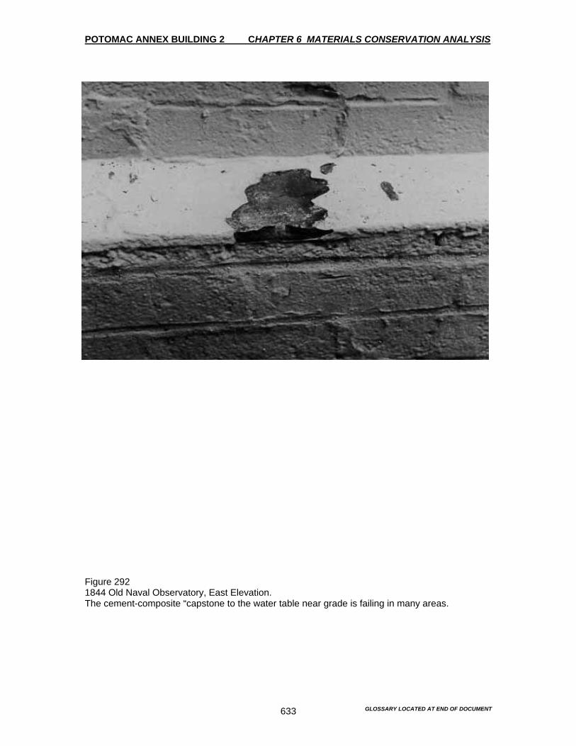
POTOMAC ANNEX BUILDING 2 CHAPTER 6 MATERIALS CONSERVATION ANALYSIS
GLOSSARY LOCATED AT END OF DOCUMENT 633
Figure 292 1844 Old Naval Observatory, East Elevation. The cement-composite “capstone to the water table near grade is failing in many areas.
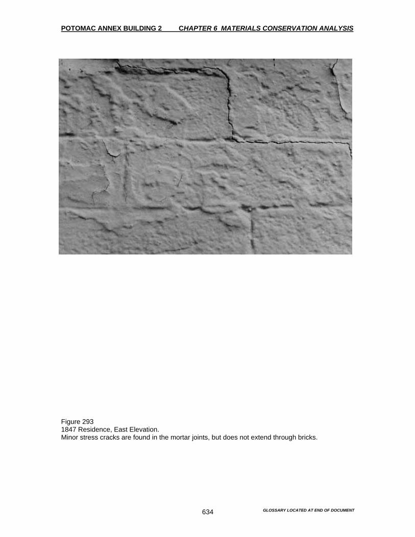
POTOMAC ANNEX BUILDING 2 CHAPTER 6 MATERIALS CONSERVATION ANALYSIS
GLOSSARY LOCATED AT END OF DOCUMENT 634
Figure 293 1847 Residence, East Elevation. Minor stress cracks are found in the mortar joints, but does not extend through bricks.
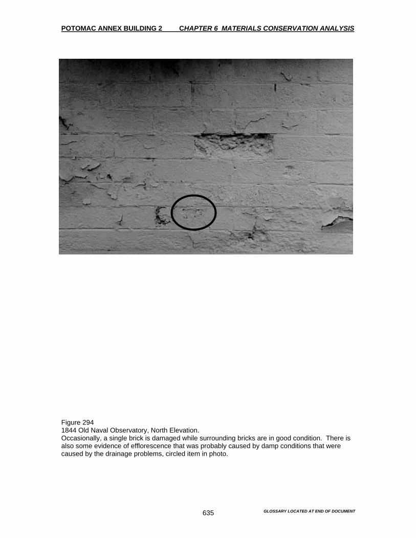
POTOMAC ANNEX BUILDING 2 CHAPTER 6 MATERIALS CONSERVATION ANALYSIS
GLOSSARY LOCATED AT END OF DOCUMENT 635
Figure 294 1844 Old Naval Observatory, North Elevation. Occasionally, a single brick is damaged while surrounding bricks are in good condition. There is also some evidence of efflorescence that was probably caused by damp conditions that were caused by the drainage problems, circled item in photo.

POTOMAC ANNEX BUILDING 2 CHAPTER 6 MATERIALS CONSERVATION ANALYSIS
GLOSSARY LOCATED AT END OF DOCUMENT 636
Figure 295 1844 Old Naval Observatory, West Wing, North Elevation Small, basement level window frames are rotted and the nearby brickwork displaced.

POTOMAC ANNEX BUILDING 2 CHAPTER 6 MATERIALS CONSERVATION ANALYSIS
GLOSSARY LOCATED AT END OF DOCUMENT 637
Figure 296 1895, West Addition, East Elevation. The metal cornice on the north elevation is in good condition. The paint, however, is generally failing. Note the crack in the capital just below the cornice. There are possible roof problems that are effecting this capital, as well as the cornice, see circle in photo.
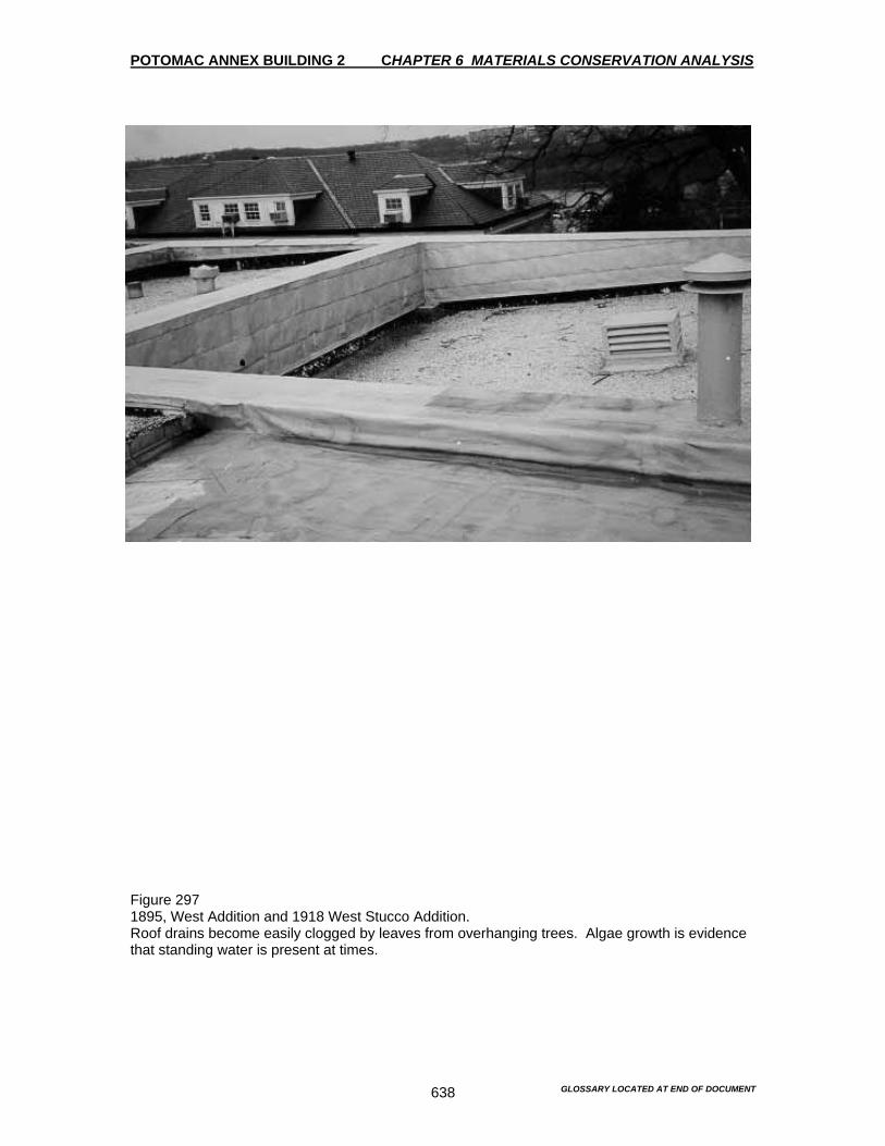
POTOMAC ANNEX BUILDING 2 CHAPTER 6 MATERIALS CONSERVATION ANALYSIS
GLOSSARY LOCATED AT END OF DOCUMENT 638
Figure 297 1895, West Addition and 1918 West Stucco Addition. Roof drains become easily clogged by leaves from overhanging trees. Algae growth is evidence that standing water is present at times.
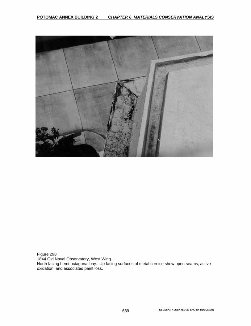
POTOMAC ANNEX BUILDING 2 CHAPTER 6 MATERIALS CONSERVATION ANALYSIS
GLOSSARY LOCATED AT END OF DOCUMENT 639
Figure 298 1844 Old Naval Observatory, West Wing. North facing hemi-octagonal bay. Up facing surfaces of metal cornice show open seams, active oxidation, and associated paint loss.

POTOMAC ANNEX BUILDING 2 CHAPTER 6 MATERIALS CONSERVATION ANALYSIS
GLOSSARY LOCATED AT END OF DOCUMENT 640
Figure 299 1895 Rotunda, South Elevation. Window lintels and sills are made from bluestone on the South Rotunda. Bluestone has also been used for some window -sills on the East and West Wings, North and South elevations. There is also peeling paint throughout this portion of the south elevation wall.

POTOMAC ANNEX BUILDING 2 CHAPTER 6 MATERIALS CONSERVATION ANALYSIS
GLOSSARY LOCATED AT END OF DOCUMENT 641
Figure 300 1918, West Stucco Addition. There is active and extensive damage to the stucco throughout. This damage will continue to expand as the wire mesh further oxidizes.
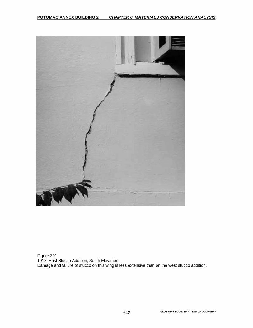
POTOMAC ANNEX BUILDING 2 CHAPTER 6 MATERIALS CONSERVATION ANALYSIS
GLOSSARY LOCATED AT END OF DOCUMENT 642
Figure 301 1918, East Stucco Addition, South Elevation. Damage and failure of stucco on this wing is less extensive than on the west stucco addition.
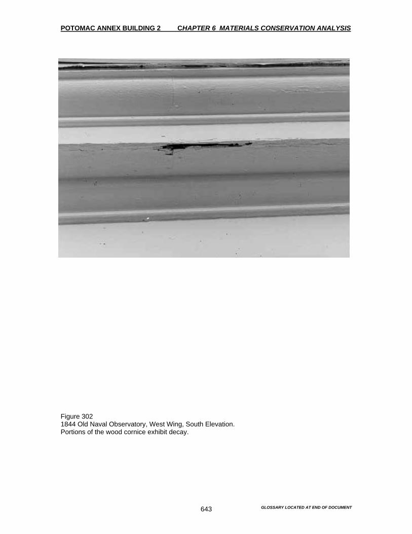
POTOMAC ANNEX BUILDING 2 CHAPTER 6 MATERIALS CONSERVATION ANALYSIS
GLOSSARY LOCATED AT END OF DOCUMENT 643
Figure 302 1844 Old Naval Observatory, West Wing, South Elevation. Portions of the wood cornice exhibit decay.
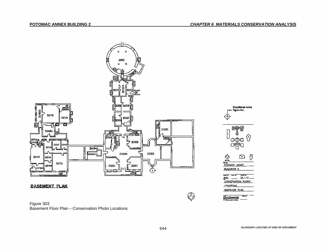
POTOMAC ANNEX BUILDING 2 CHAPTER 6 MATERIALS CONSERVATION ANALYSIS
GLOSSARY LOCATED AT END OF DOCUMENT 644
Figure 303 Basement Floor Plan – Conservation Photo Locations

POTOMAC ANNEX BUILDING 2 CHAPTER 6 MATERIALS CONSERVATION ANALYSIS
GLOSSARY LOCATED AT END OF DOCUMENT 645
Figure 304 First Floor Plan – Conservation Photo Locations

POTOMAC ANNEX BUILDING 2 CHAPTER 6 MATERIALS CONSERVATION ANALYSIS
GLOSSARY LOCATED AT END OF DOCUMENT 646
Figure 305 Basement Floor Plan – Masonry Sample Locations

POTOMAC ANNEX BUILDING 2 CHAPTER 6 MATERIALS CONSERVATION ANALYSIS
GLOSSARY LOCATED AT END OF DOCUMENT 647
Figure 306 First Floor Plan – Masonry Sample Locations

POTOMAC ANNEX BUILDING 2 CHAPTER 6 MATERIALS CONSERVATION ANALYSIS
GLOSSARY LOCATED AT END OF DOCUMENT 648
Figure 307 North Elevation – Masonry Identification

POTOMAC ANNEX BUILDING 2 CHAPTER 6 MATERIALS CONSERVATION ANALYSIS
GLOSSARY LOCATED AT END OF DOCUMENT 649
Figure 308 South Elevation – Masonry Identification

POTOMAC ANNEX BUILDING 2 CHAPTER 6 MATERIALS CONSERVATION ANALYSIS
GLOSSARY LOCATED AT END OF DOCUMENT 650
Figure 309 East Elevation – Masonry Identification
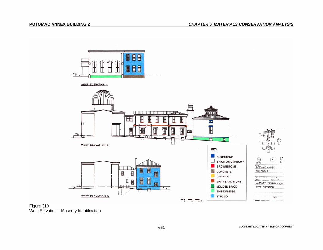
POTOMAC ANNEX BUILDING 2 CHAPTER 6 MATERIALS CONSERVATION ANALYSIS
GLOSSARY LOCATED AT END OF DOCUMENT 651
Figure 310 West Elevation – Masonry Identification
POTOMAC ANNEX BUILDING 2 CHAPTER 7 MORTAR ANALYSIS
GLOSSARY LOCATED AT END OF DOCUMENT 652
Introduction The purpose of a mortar analysis is to determine the compositions of existing mortars used in The Old Naval Observatory. Pointing ensures that there is a watertight "skin" on a building facade. In contemplating any new pointing campaign it is important to attempt to reproduce the color, texture and profile of the mortar which exists. The color, texture and profiles may be reproduced with mortars, which are identical in composition or with mortars whose compositions are different from the original mortars. If a re-pointing of the masonry is necessary, there is a need to insure that the building facades remain watertight. Therefore, the composition of the mortar is important for several reasons. Mortar can be classified as “hard” or “soft,” according to the amount of cement in its composition. This classification also reflects the compressive strength of the mortar, providing the content is held constant. Re-pointing mortar should be less compressive in strength than the original mortar. A mortar that is too “hard” can cause the bricks to crack. This will occur because the bricks are held rigidly in place. The other reason that composition is important is the color of the aggregate. Although aggregate color is vital to any re-pointing effort, when done in the walls of the façade of the Old Naval Observatory, it is less important due to the subsequent exterior paint color scheme that was recommended in Chapter 5. A close match of those areas that will be eventually painted is adequate for re-pointing that is done. However, when re-pointing any unpainted wall, stone or element is done, then aggregate color is vital. The reason color is critical is so that there is a uniform color between the existing mortar and the new mortar that is being installed. If there are two distinct colors throughout the wall, stone or element a visual disparity will result in the uniformity of that portion of the façade, stone work or element. Although it is highly likely that after the paint has been stripped and the areas that need to be re-pointed are completed, a close match in uniform color of the mortar still needs to be maintained. When undertaking a re-pointing effort, there is a need to reproduce the color, texture and profile of the existing mortar when these mortars are not to be repainted after the work has been completed. Color and texture can be derived from the original mortar composition. Profile can be achieved from the tooling of the joint in the same manner as the original mortar. The Old Naval Observatory exhibits no obvious signs of re-pointing campaigns such as differences in color, texture, profile or discontinuity with setting mortars. Therefore, it can be concluded that original mortar compositions were determined prior to the commencement of work. Analysis X-Ray Diffraction Analytical Protocol Samples were removed from the Old Naval Observatory using a small hammer and chisel. Before removal the color of the mortar as well as the joint profile was determined. Procedure • Approximately 100 milligrams of each sample is ground in an agate mortar and
pestle to a fine powder. • The fine powder is sprinkled on double-sticky tape which itself is adhered to a
POTOMAC ANNEX BUILDING 2 CHAPTER 7 MORTAR ANALYSIS
GLOSSARY LOCATED AT END OF DOCUMENT 653
petrographic glass slide. • The slide is placed in the sample holder of the Phillips 1710 diffractometer. • The diffractometer operates at 40 kilivolts and 30 milliamps and scans are obtained
from 3-63 degrees of Bragg angle. The scans are obtained by the Sietronics software, which collects the diffractograms and determines the position and intensity of the resulting peaks. The data is digitally transferred to the Fein-Marquart Search-Match program for phase identification.
Wet Chemical Methods Analytical Protocol Wet chemical methods are used to separate aggregates from binder in mortar samples. These methods generally employ acid digestion techniques. Procedure • Samples were dried in a convection oven at 80 degrees centigrade for 12 hours,
equilibrated to room temperature and relative humidity (approximately 50% RH and 20 degrees Celsius) and weighed.
• Samples are lightly crushed so as not to crush the aggregate and thereby change
the sizes of these particles. • Samples are transferred to Erlenmeyer flask and digested in excess 1 molar
hydrochloric acid for 1 hour noting effervescence if it occurs. • Acid insoluble residue is obtained by filtration and washed with distilled water. • Residues are dried to constant a weight at 80 degrees centigrade in a convection
oven and equilibrated to room temperature and relative humidity and weighed. • Color and granulation is accomplished by sieving where the resulting residue is
noted. • Original mortar composition is calculated and estimated. Acid-soluble fractions in mortars comprise calcite from lime or in the aggregate or gypsum, which may be present due to the conversion of calcite to gypsum by acid rain or sulfur dioxide in combination with water. It is not often that an aggregate comprises calcite. Acid-insoluble fractions in mortar usually comprise the aggregate, cement components or less acid-insoluble lime components. Conclusion Overall, the Old Naval Observatory’s walls, stone lintels and sills and the foundation work are in good condition. However, there are areas in the walls, stone lintels and sills and the foundation walls that vary in their degree of repair. Before any re-pointing of the mortar, removal of brick, stone or any other element that requires new mortar is begun, a thorough analysis, inspection and documentation of the target area should be preformed. This is required in order to determine the

POTOMAC ANNEX BUILDING 2 CHAPTER 7 MORTAR ANALYSIS
GLOSSARY LOCATED AT END OF DOCUMENT 654
appropriate strategy to address the varying degree of repairs that are required. Once a strategy is formatted and a program created, coordination with maintenance personnel needs to be done. Recommendation In order to maintain the integrity of the Old Naval Observatory’s walls, stone lintels and sills and the stone or brickwork of the foundation, a comprehensive program needs to be formatted. This program includes a thorough inspection and documentation of the affected areas that need to be repaired or removed, replaced and repaired. A thorough inspection involves the physical documentation of the target area. After each target area is identified by thoroughly inspecting the entire building, photographs need to be taken to visually document the areas that are in need of repair. These photographs need to be catalogued and documented in an electronic file for future use and reference. Measurements of the affected area need to be done in order to determine scope and scale of the work required. Once the inspection, photographs and measurements are completed, this information needs to be entered into a spreadsheet at the minimum, but preferably in a database. The photographs need to be crossed referenced with the inspection and measurements. All the information needs to be referenced to each other. This will provide a comprehensive database that is interactive and will enable a sound proactive strategy in order to address the target areas. While the information is being gather, a comprehensive plan needs to be created that will insure that all work done on the target areas is completed in a manner that is sensitive to the historic nature of the Old Naval Observatory. A program that has incremental and measurable steps should be formatted. This will insure that each target areas needs are addressed and corrected in a timely fashion. Part of the program will include photographic documentation of the repair work that was completed. This will insure that the work is done is accordance with the prescribe guidelines and to document the work. After the pictures are taken, they need to be entered into the database so that there is a before and after reference. The last part of the program will include coordination with the maintenance personnel on the site. It will be through their experience and knowledge of the Old Naval Observatory that will enable an aggressive, proactive approach to identifying, recognizing, inspecting and documenting any future problems that may contribute to the deterioration of any element or part of the Old Naval Observatory’s fabric. Sample 2potc2 Location: 1844 Old Naval Observatory East Elevation Type: brick pointing mortar Description: nearly white with fine aggregate Profile: Analyses X-Ray Diffraction: calcite, quartz, mica (muscovite), clay (kaolinte) Wet Chemistry: vigorous efflorescence upon addition of acid; solution is colorless with acid
indicating that no reactive iron compounds are present Volumetric Analysis: 1:1 lime to aggregates.
POTOMAC ANNEX BUILDING 2 CHAPTER 7 MORTAR ANALYSIS
GLOSSARY LOCATED AT END OF DOCUMENT 655
Sieve Analysis of Aggregates Mesh Size Weight Percent 10 - 20 3 40 24 60 38 100 22 140 6 180 1 200 2 Pan 4 Aggregates are slightly gray to white. Comments The mortar appears to be mostly quartz-sand and lime with no cement present. Mica and clay are accessory minerals. The recommended re-pointing composition is 1:3 by volume ratio of hydrated lime and quartz-sand with a sieve ratio similar to the above analysis. Some mica and mineral pigment may be added to achieve an exact color match. Sample 2potl1, Figure 311 Location: 1847 Residence East Elevation Type: brick pointing mortar Description: light tan, fine texture, a few dark particles Profile: Analyses X-Ray Diffraction: calcite and quartz Wet Chemistry: vigorous efflorescence upon addition of acid; solution is colorless with acid
indicating no reactive iron compounds are present. Volumetric Analysis: 1.35:1 lime to aggregates Sieve Analysis of Aggregates Mesh Size Weight Percent 10 - 40 35 60 30 100 13 140 6

POTOMAC ANNEX BUILDING 2 CHAPTER 7 MORTAR ANALYSIS
GLOSSARY LOCATED AT END OF DOCUMENT 656
180 1 200 5 Pan 10 Aggregates are light gray to white. Comments The mortar appears to mostly lime and quartz-sand. The recommended re-pointing composition is 1:3 hydrated lime to sand by volume. The sand should primarily and have a sieve ratio similar to the above analysis. Mineral oxide pigments may be added to attain the proper color. Sample 2potl2, Figure 312 Location: 1847 Residence Foundation Wall Type: schist masonry pointing mortar Description: gray-to-white with fine aggregate Profile: Analyses X-Ray Diffraction: quartz, calcite, clinoenstatite, mica (muscovite) Wet Chemistry: vigorous efflorescence upon addition of acid Volumetric Analysis: 1.2:1 lime to aggregates Sieve Analysis of Aggregates Mesh Size Weight Percent 10 - 20 3 40 24 60 38 100 22 140 6 180 1 200 2 Pan 4 Aggregates are a light gray-to-white. Comments Mortar is primarily calcite and quartz. Clinoenstatite and muscovite may have contaminated the mortar from the schist. There seems to be little other explanation for the clinoenstatite. The recommended re-pointing composition is 1:3 lime of the type II Portland cement to sand to match color and sieve ratios. The mortar in this area is not in good condition due to moisture infiltration. Therefore a more water insoluble mortar is suggested.

POTOMAC ANNEX BUILDING 2 CHAPTER 7 MORTAR ANALYSIS
GLOSSARY LOCATED AT END OF DOCUMENT 657
Sample 2potl3 Location: 1847 Residence North Elevation Type: brick pointing mortar Description: nearly white with fine aggregate Profile: Flush. Analyses X-Ray Diffraction: calcite, quartz, clay (dickite) (see uPDSM Report 2POTL3 in Appendix at
the end of this chapter) Wet Chemistry: vigorous efflorescence upon addition of acid Volumetric Analysis: 1.3:1 lime to aggregates Sieve Analysis of Aggregates Mesh Size Weight Percent 10 - 40 38 60 27 100 12 140 7 180 1 200 6 Pan 9 Aggregates are nearly white. Comments The mortar is essentially lime and quartz sand. Like the Old Naval Observatory sample 2potc2, some clay is present. The recommended re-pointing composition: 1:3 lime to sand with a similar sieve analysis shown above. Mineral pigment may be added to achieve a color match. Replication When re-pointing, it is important to match the existing mortar in its aesthetic and physical characteristics, as well as the existing joint profile. When removing any deteriorated brick or pointing mortar, use only the most careful and sensitive methods. Generally, removal of the deteriorated brick or mortar should be done by hand. However, specially trained masons may utilize electric power tools. A guideline specification for joint removal with saws is referenced in the GSA-NCR Preservation Notebook – 04500: Masonry Restoration. Methods of applying new mortar joints are referenced in the Specifications in Chapter 10 of this document.

POTOMAC ANNEX BUILDING 2 CHAPTER 7 MORTAR ANALYSIS
GLOSSARY LOCATED AT END OF DOCUMENT 658
Since the sand component for each of these replication mixes represents the majority of the material used, the sand in a mortar has a significant impact on the color a mortar will ultimately impart. It is very important to match as closely as possible the color, grain shape, grain size and grain size distribution of the original sands. Another factor in the sand is that it should be clean and free of loam, sit, soluble salt, organic mater and conform to ASTM C-44. Additional refinements to the mortar recipe may be necessary to achieve an acceptable color to match the existing mortar. Pigments may be added if they are alkali resistant oxides manufactured for use in cement mixes. Careful color matching of the mortar is particularly important when partially re-pointing any portion of the wall, stone lintels and foundations. Sample mortars and mock-up panels, should be approved by the Contracting Officer, prior to any re-pointing efforts. uPDSM Reports The uPDSM Reports employ several analytical techniques. The techniques that were employed for the uPDSM Reports for the Old Naval Observatory were X-Ray Diffraction and Wet Chemical Methods. Four samples were tested and their accompanying reports are at the end of this chapter. The manner in which the reports are presented is that the date and time each sample was tested appears in the upper right hand corner. Under the date and time is the “Input Pattern” header where the actual sample name and number appears. Below the sample name is a set of columns and rows of raw data. This raw data has two headers. One of the headers is the “d” which equals the “d” spacing of the sample. The other header is the “I” which equals the intensity of the “d” spacing. This is the raw data is then analyzed by a computer program that matches each sample tested with a known element or mineral that occurs in nature. Below the “d” spacing and the intensity columns and rows is the information that the computer program analyzed and compared the sample to the information from the database. The database found the nearest naturally occurring element that best matched the sample. In the “Identified Phases” section of the report there are the JCPDS number, SI number, the ML/X number, the At % number and the Identity number. The Raw data in this section of the report is on the left. The element data in this report is on the right. The “JCPDS number refers to the Joint Committee for Powder Diffraction Samples. The “SI“ number is the Similarity Index when compared to the database.
The “ML/X” number is the match line vs. the missing line when compared to the database.
The “At %” number is attenuation percentage when compared to the database.
The “Identity” is the best match when the sample is compared to the database.
The Joint Committee for Powder Diffraction Samples no longer exists. The name has been changed to the International Center for Diffraction Data. For a more in depth understanding of the uPDSM Report please refer to the International Center for Diffraction Data located in Swathmore, PA. The “Summary Report” is the JCPDS program results of its internal analysis of the sample and the raw data. This part of the report gives a more detailed description of the “d” spacing and the
POTOMAC ANNEX BUILDING 2 CHAPTER 7 MORTAR ANALYSIS
GLOSSARY LOCATED AT END OF DOCUMENT 659
“I” intensity of the “d” spacing when compared to the database. The “d” spacing is on the Y-axis and the At % on the x-axis. The uPDSM samples that were analyzed are referenced to the following plans. uPDSM Sample Referenced Plan 1. 2potc2 Figure 314, First Floor Plan – Masonry Sample Locations 2. 2potl1 Figure 314, First Floor Plan – Masonry Sample Locations 3. 2potl2 Figure 313, Basement Floor Plan – Masonry Sample Locations 4. 2potl3 Figure 314, First Floor Plan – Masonry Sample Locations

POTOMAC ANNEX BUILDING 2 CHAPTER 7 MORTAR ANALYSIS
GLOSSARY LOCATED AT END OF DOCUMENT 660
uPDSM REPORTS

POTOMAC ANNEX BUILDING 2 CHAPTER 7 MORTAR ANALYSIS
GLOSSARY LOCATED AT END OF DOCUMENT 661
Sample 2potc2 Figure 314, First Floor Plan – Masonry Sample Locations

POTOMAC ANNEX BUILDING 2 CHAPTER 7 MORTAR ANALYSIS
GLOSSARY LOCATED AT END OF DOCUMENT 662

POTOMAC ANNEX BUILDING 2 CHAPTER 7 MORTAR ANALYSIS
GLOSSARY LOCATED AT END OF DOCUMENT 663
Sample 2potl1 Figure 314, First Floor Plan – Masonry Sample Locations

POTOMAC ANNEX BUILDING 2 CHAPTER 7 MORTAR ANALYSIS
GLOSSARY LOCATED AT END OF DOCUMENT 664
Sample 2potl2 Figure 313, Basement Floor Plan – Masonry Sample Locations

POTOMAC ANNEX BUILDING 2 CHAPTER 7 MORTAR ANALYSIS
GLOSSARY LOCATED AT END OF DOCUMENT 665

POTOMAC ANNEX BUILDING 2 CHAPTER 7 MORTAR ANALYSIS
GLOSSARY LOCATED AT END OF DOCUMENT 666
POTOMAC ANNEX BUILDING 2 CHAPTER 7 MORTAR ANALYSIS
GLOSSARY LOCATED AT END OF DOCUMENT 667
Sample 2potl3 Figure 314, First Floor Plan – Masonry Sample Locations

POTOMAC ANNEX BUILDING 2 CHAPTER 7 MORTAR ANALYSIS
GLOSSARY LOCATED AT END OF DOCUMENT 668
POTOMAC ANNEX BUILDING 2 CHAPTER 7 MORTAR ANALYSIS
GLOSSARY LOCATED AT END OF DOCUMENT 669
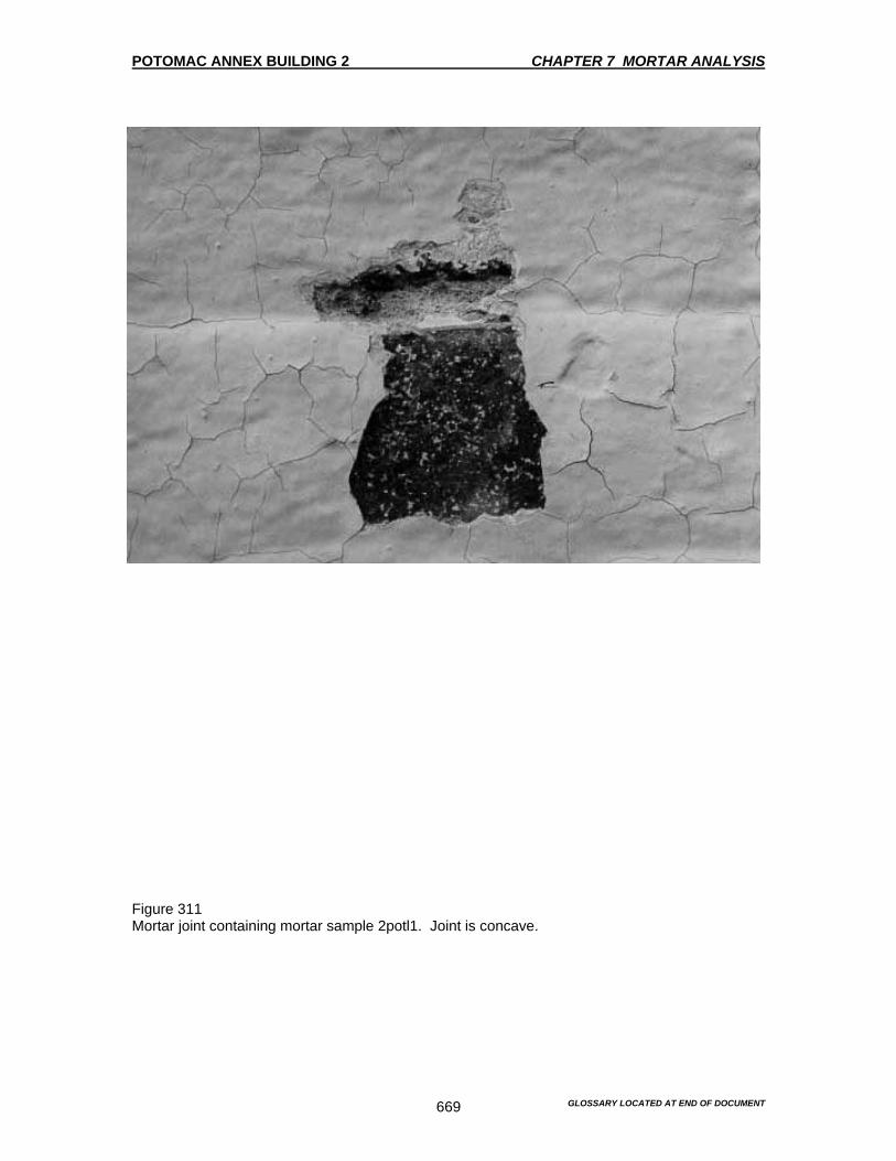
POTOMAC ANNEX BUILDING 2 CHAPTER 7 MORTAR ANALYSIS
GLOSSARY LOCATED AT END OF DOCUMENT 669
Figure 311 Mortar joint containing mortar sample 2potl1. Joint is concave.
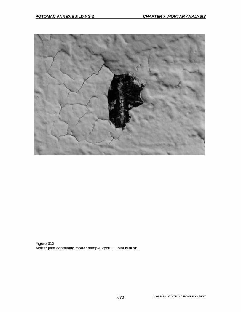
POTOMAC ANNEX BUILDING 2 CHAPTER 7 MORTAR ANALYSIS
GLOSSARY LOCATED AT END OF DOCUMENT 670
Figure 312 Mortar joint containing mortar sample 2potl2. Joint is flush.

POTOMAC ANNEX BUILDING 2 CHAPTER 7 MORTAR ANALYSIS
GLOSSARY LOCATED AT END OF DOCUMENT 671
Figure 313 Basement Floor Plan – Mortar Sample Locations
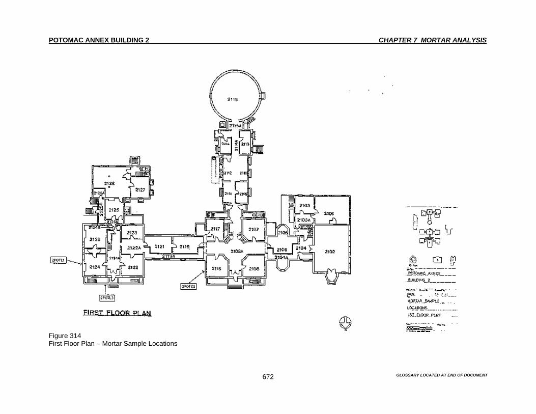
POTOMAC ANNEX BUILDING 2 CHAPTER 7 MORTAR ANALYSIS
GLOSSARY LOCATED AT END OF DOCUMENT 672
Figure 314 First Floor Plan – Mortar Sample Locations

POTOMAC ANNEX BUILDING 2 CHAPTER 8 MATERIALS CLEANING ANALYSIS
GLOSSARY LOCATED AT END OF DOCUMENT
673
Introduction This material cleaning analysis addresses several soiling issues observed at the Old Naval Observatory. This analysis is based on the cleaning and maintenance of the Old Naval Observatory. After each area or element is repaired or removed and replaced, the issue still remains that these newly refurbished areas will need to be kept clean. Allowing these areas or elements to become soiled would hinder the restoration process of the Old Naval Observatory. Maintaining these areas or elements through a programmed cleaning schedule would insure that the restoration work that is completed is still aesthetically vibrant. Purpose of Cleaning The primary purpose of cleaning is to preserve the Old Naval Observatory’s aesthetic character. This character may be disguised by soiling that has replaced or altered the hue, value or chroma of the affected elements. Generally, the soiling issues are minimal to moderate. The impact of the soiling is largely cosmetic. However, if these conditions are allowed to continue, there will be eventual damage to the Old Naval Observatory’s materials. The least destructive method shall be used in all cases, even when such methods will not restore the material or element to their original appearance when they were new. Most soiling that has occurred is in consistent spots or areas. The existing soiling conditions are first summarized and then the results of the cleaning tests are discussed. Overall, the degree of soiling for each area varies only slightly in the manner in which it will be cleaned. Therefore, the recommendations associated with the following cleaning tests are adequate enough to remove both the least and worst damaging degrees of soiling. The specifications for the following cleaning methodology can be found in Chapter 10. Test Procedures and Materials Date: 23 January 1995 Test #1 EnviroStrip #1 Location: Brick Pier on South Elevation of the Old Naval Observatory • 8:30 AM applied with natural bristle brush; covered with plastic. • 3:30 PM softening noted • 4:30 PM removed about 30% and reapplied • 9:15 AM removed about 60% Test #2 EnviroStrip #2 Location: Brick Pier on South Elevation of the Old Naval Observatory • 8:30 AM applied with natural bristle brush; covered with plastic. • 3:30 PM softening and bubbling noted • 4:30 PM removed about 50% and reapplied • 9:15 AM removed about 75%

POTOMAC ANNEX BUILDING 2 CHAPTER 8 MATERIALS CLEANING ANALYSIS
GLOSSARY LOCATED AT END OF DOCUMENT
674
EnviroStrip #2 worked noticeably better than #1 but this still did not achieve complete removal. These results are consistent with those performed by Brisk Waterproofing for the Potomac Annex Exterior Repairs project, RDC 48102. However, their results were generally better due to the use of a power-wash spray to assist in the removal of the paint. Once again, the issue of containment must be emphasized. A power-wash unit may not provide enough containment of the paint that is being removed. Material Cleaning Analysis Light Soiling of Brick Since a majority of the building is painted, this methodology represents a strategy for overall light soiling of the brick that is not painted. Two methods of cleaning were chosen. Application of a detergent, ProSoCo’s 1026, which is followed by a low-pressure wash. Application of an alkaline pre-wash, followed by an acid wash with a low-pressure power wash. The methodology is outlined below. Method 1 1. Application of a detergent using a bristled brush with a dwell time of 10 minutes. 2. Removal of the detergent and soiling with a low-pressure power wash at 400 psi. 3. Rinse the surfaces to remove the remnants of the detergent with low-pressure water at 60 psi. Method 2 1. Application of an alkaline pre-wash of ProSoCo’s 766 diluted 3:1 by volume using a natural
bristle brush with a dwell time of 20 minutes. 2. Removal of pre-wash with a low-pressure power wash. 3. Application of an acid wash, ProSoCo’s Restoration Cleaner, diluted 3:1 by volume using a
natural bristle brush with a dwell time of 5 minutes. 4. Removal of the acid wash with a low-pressure wash. 5. Rinse the surfaces to remove the remnants of detergent with low-pressure water at 60 psi. Conclusion and Recommendation The results of the light soiling of the brick with Method 1 achieved good cleaning results while being safe for the brick. The results of cleaning the light soiling of the brick with Method 2, was more aggressive than Method 1. Therefore, the less aggressive Method 1 is recommended for cleaning the lightly soiled brick. Light Soiling of Granite Since a majority of the building is painted, this methodology represents a strategy for overall light soiling of the granite that is not painted. Two methods of cleaning were chosen.
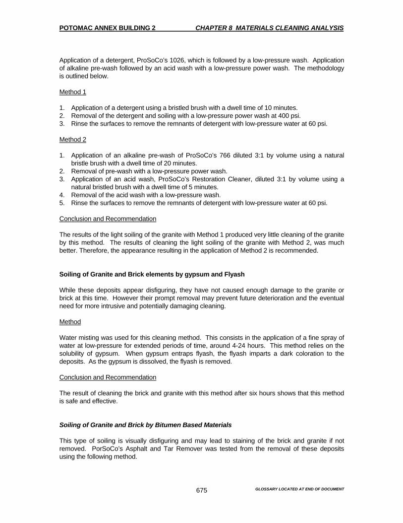
POTOMAC ANNEX BUILDING 2 CHAPTER 8 MATERIALS CLEANING ANALYSIS
GLOSSARY LOCATED AT END OF DOCUMENT
675
Application of a detergent, ProSoCo’s 1026, which is followed by a low-pressure wash. Application of alkaline pre-wash followed by an acid wash with a low-pressure power wash. The methodology is outlined below. Method 1 1. Application of a detergent using a bristled brush with a dwell time of 10 minutes. 2. Removal of the detergent and soiling with a low-pressure power wash at 400 psi. 3. Rinse the surfaces to remove the remnants of detergent with low-pressure water at 60 psi. Method 2 1. Application of an alkaline pre-wash of ProSoCo’s 766 diluted 3:1 by volume using a natural
bristle brush with a dwell time of 20 minutes. 2. Removal of pre-wash with a low-pressure power wash. 3. Application of an acid wash, ProSoCo’s Restoration Cleaner, diluted 3:1 by volume using a
natural bristled brush with a dwell time of 5 minutes. 4. Removal of the acid wash with a low-pressure wash. 5. Rinse the surfaces to remove the remnants of detergent with low-pressure water at 60 psi. Conclusion and Recommendation The results of the light soiling of the granite with Method 1 produced very little cleaning of the granite by this method. The results of cleaning the light soiling of the granite with Method 2, was much better. Therefore, the appearance resulting in the application of Method 2 is recommended. Soiling of Granite and Brick elements by gypsum and Flyash While these deposits appear disfiguring, they have not caused enough damage to the granite or brick at this time. However their prompt removal may prevent future deterioration and the eventual need for more intrusive and potentially damaging cleaning. Method Water misting was used for this cleaning method. This consists in the application of a fine spray of water at low-pressure for extended periods of time, around 4-24 hours. This method relies on the solubility of gypsum. When gypsum entraps flyash, the flyash imparts a dark coloration to the deposits. As the gypsum is dissolved, the flyash is removed. Conclusion and Recommendation The result of cleaning the brick and granite with this method after six hours shows that this method is safe and effective. Soiling of Granite and Brick by Bitumen Based Materials This type of soiling is visually disfiguring and may lead to staining of the brick and granite if not removed. PorSoCo’s Asphalt and Tar Remover was tested from the removal of these deposits using the following method.
POTOMAC ANNEX BUILDING 2 CHAPTER 8 MATERIALS CLEANING ANALYSIS
GLOSSARY LOCATED AT END OF DOCUMENT
676
Method 1. Mix Asphalt and Tar Remover to a paste-like consistency with attapulgite. 2. Apply paste to the surface and cover with aluminum foil and secure with tape and allow a dwell
time of 4 hours. 3. Remove the paste and the dislodged bitumen-base material with a paint scraper, taking care
not to damage the stone or brick substrate. 4. Wash the substrate with a detergent and a natural bristle scrub brush. Conclusion and Recommendation Good cleaning results were achieved with no damage to the substrate. This result may be considered as the best method for cleaning the substrate. Rust Stains on Brick and Granite While these deposits are somewhat disfiguring, they are not now at the stage where they will cause damage to the granite or brick. The impact of the rust is primarily cosmetic. However, the removal of the rust stains should be removed to prevent a build up and future need for more intrusive and potentially damaging cleaning methods. Method Ammonium thioglycolate will effectively remove iron staining of granite, brick and other stone. This method uses the application of poultice from of a 10% solution of ammonium thioglycolate in water for 30 minutes. The poultice is then removed and the surface is rinsed with a low-pressure wash. Soiling of Limestone Although the soiling of the limestone is visually disfiguring, it does not represent a material deterioration hazard to the stone. The four methods below were performed on the limestone. Method 1 Water misting was used for cleaning the limestone. This method consists of applying a fine spray of water at low pressure for an extended time of 4-24 hours. This method relies on the solubility of gypsum. When gypsum entraps flyash, the flyash imparts a dark coloration to the deposits. As the gypsum is dissolved, the flyash is removed. Method 2 1. Application of a detergent using a natural fiber brush with a dwell time of 10 minutes. 2. Removal of the detergent and soiling with a low-pressure power wash at 400 psi. 3. Rinse the surfaces to remove the detergent with a low-pressure wash at 60 psi.

POTOMAC ANNEX BUILDING 2 CHAPTER 8 MATERIALS CLEANING ANALYSIS
GLOSSARY LOCATED AT END OF DOCUMENT
677
Method 3 1. Application of an alkaline pre-wash of ProSoCo’s 766 diluted 3:1 by volume using a natural
bristled brush with a dwell time of 20 minutes. 2. Removal of pre-wash with a low-pressure power wash. 3. Application of the acid wash, ProSoCo’s Restoration Cleaner, diluted 3:1 by volume using a
natural bristled brush with a dwell time of 5 minutes. 4. Removal of the acid wash with a low-pressure wash. 5. Rinse the surfaces to remove the remnants of detergent with low-pressure water at 60 psii. Method 4 Cleaning was also tested with ProSoCo’s 1217 poultice applied for six hours. This was followed by a low-pressure wash at 60 psi. Conclusion/Recommendations Method 1 had little or no cleaning effect after a 24-hour period. Method 2 achieved a good cleaning without any harm to the substrate. Method 3 achieved a good cleaning result, but was somewhat more aggressive than Method 2, the detergent cleaning. Method 4 produced a good cleaning with an intermediate in aggressiveness to the detergent, Method 2 and the alkali pre-wash, acid wash, Method 3. Equally effective cleaning results were achieved by the least aggressive method. That is Method 2, the detergent cleaning with the power wash. Method 2 is recommended for the desired cleaning with little impact to the substrate. Rust Stains on Limestone While these deposits are somewhat disfiguring, they are not now at the stage where they will cause damage to the granite or brick. The impact of the rust is primarily cosmetic. However, the removal of the rust stains should be removed to prevent a build up and future need for more intrusive and potentially damaging cleaning methods. Method Ammonium thioglycolate will effectively remove iron staining of granite, brick and other stone. This method uses the application of poultice from of a 10% solution of ammonium thioglycolate in water for 30 minutes. The poultice is then removed and the surface is rinsed with a low-pressure wash.
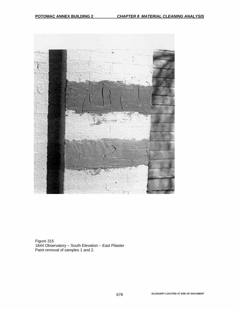
POTOMAC ANNEX BUILDING 2 CHAPTER 8 MATERIAL CLEANING ANALYSIS
GLOSSARY LOCATED AT END OF DOCUMENT 678
Figure 315 1844 Observatory – South Elevation – East Pilaster Paint removal of samples 1 and 2.
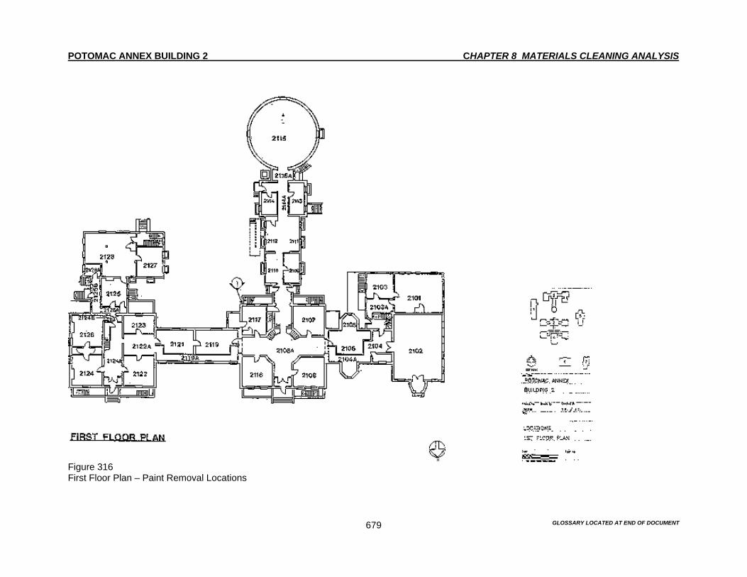
POTOMAC ANNEX BUILDING 2 CHAPTER 8 MATERIALS CLEANING ANALYSIS
GLOSSARY LOCATED AT END OF DOCUMENT 679
Figure 316 First Floor Plan – Paint Removal Locations
POTOMAC ANNEX BUILDING 2 CHAPTER 9 DESIGN GUILDLINES
GLOSSARY LOCATED AT END OF DOCUMENT
680
Introduction The importance of the Potomac Annex site rests primarily with the extraordinary Old Naval Observatory Building, which is a National Historic Landmark. As such, it is deserving of special attention and care. The Old Naval Observatory’s period of significance was during its first phase of use as the Naval Observatory was between 1844 and 1894. However, during the past century, it has housed a museum collection, a medical school and administrative offices. Those use changes, in themselves, were significant to the history of the Old Naval Observatory and the site. They resulted in physical additions and alterations, many of which are also significant. The Late Greek Revival style of the original core building was reflected and sometimes simply replicated in detail as new additions were added. Many of these details, particularly on the exterior, which are still in place, are in good condition. The original arrangement of the facades of the Old Naval Observatory and the Residence are still dominant features of the north elevation. However, the original one-story wings are less discernable features due to the alterations that were made in 1902 and 1903. Furthermore, significant additions constructed while the Old Naval Observatory was in use include, the West Transit Wing and the South Observatory for the Great Equatorial Telescope were completely rebuilt during the 1890’s. The Old Naval Observatory’s interior also reflects its very early adaptive reuse. While some original spatial relationships are still visible, the overall appearance is defined by the alterations that were made during the 1890’s for the Naval Museum of Hygiene and to a lesser degree the additions that were made for the Naval Medical School at the turn of the century. The result is that while the Greek Revival Old Naval Observatory genesis is still visible, the strongest impression is of the Old Naval Observatory’s 1903 appearance. Treating each addition according to its historic period is not possible. Restoration of one section would impact another and cause damages to that other section. This strategy would destroy the visual unity of the Old Naval Observatory as it exists today and create an appearance that never existed historically. Because the Old Naval Observatory has been used as administrative offices continuously for over 50 years, sensitivity is required in making recommendations that respect both the importance of the architecture and historic character of the Old Naval Observatory and the needs of the current users. The Old Naval Observatory still retains much of the building fabric as it existed in the 1902 and 1903. Its strongest visual impression is of its appearance at that time period. The recommendation is to restore the exterior, including the paint finishes that reflect the 1902-1903 period, figures 282-285. Ultimately, such an approach would make the entire Old Naval Observatory and all its additions treated as one, both visually and historically. The interior of the Old Naval Observatory also reflects its turn of the century appearance. The interior has been adapted for the current use requirements. The recommendations for the interior are preservation based rather than restoration required. The recommendations are to retain the architectural features from the 1896-1902 construction campaigns. These campaigns retain some of the 1840’s spatial characteristics and architectural features. It is also recommended that the removal of elements that detract from the 1896-1902 additions of significant spaces and features be removed. However, because the historic spaces have a discrete units, a more interpretive approach to the paint finishes is recommended. This flexibility emphasizes the hierarchy of important spaces, which are already evident by their architectural prominence. This also reflects the 1940’s period of significance. This is an approach that is possible on the interior because the spaces are not viewed on a whole, but rather seen individually. Due to the hard use that the Old Naval Observatory is under, it is recommended that the protection of the few remaining 1840’s interior finishes be restored rather than renovated. A renovation of the finishes would expose them to a high degree of risk and damage, due to the heavy use of the Old Naval Observatory.
POTOMAC ANNEX BUILDING 2 CHAPTER 9 DESIGN GUILDLINES
GLOSSARY LOCATED AT END OF DOCUMENT
681
The main core of the Old Naval Observatory and the first floor of the Residence are most reminiscent of their 1840’s appearance, despite their alterations. The recommendations are to finish these spaces in a fashion that is consistent with the Greek Revival style. For example, the main lobby of the Old Naval Observatory needs to be finished in the original tan and white color scheme, while retaining its 1890’s staircase and metal ceiling, figure 286. The recommendations also address issues and make suggestions for the restoration of a few elements, which have been removed. If followed, the recommendations will enhance the architectural quality of the Old Naval Observatory and insure that it will endure. The 1982 Inventory of Significant Spaces Report provided by the GSA were consulted in preparing this chapter. Categories used here were established in that report. However, it will be important to refer to the Secretary of the Interior's Standards for Rehabilitation as well. Areas of the building have been divided into three categories: Restoration Zones • Areas of particular architectural significance are to be restored, through careful investigation,
to the most historically significant appearance. Rehabilitation Zones • Areas that contain significant details or elements that should be retained or restored as part
of any repair project. Renovation Zones • Areas that do not contain historically significant details, and can be repaired or altered to
insure the usefulness and stability of the building, so long as the areas of restoration and rehabilitation are not affected.
INVENTORY OF SIGNIFICANT EXTERIOR SPACES AND DETAILS 1844 Old Naval Observatory with one-story wings to the East, West and South with the 1864 octagonal bays on West Wing 1. Restoration Zones A. North, South, East and West Elevations 2. Rehabilitation Zones A. Areaways B. Roofs 3. Renovation Zones A. Roof Flashing and Membrane B. Storm Drainage

POTOMAC ANNEX BUILDING 2 CHAPTER 9 DESIGN GUILDLINES
GLOSSARY LOCATED AT END OF DOCUMENT
682
1847-48 Superintendent's Residence and Connecting Hyphen 1. Restoration Zones A. North, South, East and West Elevations 2. Rehabilitation Zones A. Areaways B. Roofs 3. Renovation Zones A. Roof Flashing and Membrane B. Storm Drainage 1865-73 South Wing Extension and 1873 South Rotunda (rebuilt in 1895) 1. Restoration Zones A. East, West and South Elevations 2. Rehabilitation Zones A. Roofs 3. Renovation Zones A. Roof Flashing and Membrane B. Storm Drainage 1869 West Wing (rebuilt in 1895) 1. Restoration Zones A. North and West Elevations 2. Rehabilitation Zones A. Roofs 3. Renovation Zones A. Roof Flashing and Membrane B. Storm Drainage 1902-03 Second Story Additions to the East, West and South Wings 1. Restoration Zones

POTOMAC ANNEX BUILDING 2 CHAPTER 9 DESIGN GUILDLINES
GLOSSARY LOCATED AT END OF DOCUMENT
683
A. North, South, East and West Elevations 2. Rehabilitation Zones A. Roofs 3. Renovation Zones A. Roof Flashing and Membrane B. Storm Drainage 1917-18 West and East Stucco Additions 1. Restoration Zones
None
2. Rehabilitation Zones A. North, South, East and West Elevations B. Roofs 3. Renovation Zones A. Roof Flashing and Membrane B. Storm Drainage Site and Landscaping Undetermined
INVENTORY OF SIGNIFICANT INTERIOR SPACES AND DETAILS 1844 Old Naval Observatory with one-story wings to the East, West and South with the 1864 octagonal bays on West Wing 1. Restoration Zones A. Integrity of Plan While there are few features extant from the 1844 Old Naval Observatory period, the
essential spatial configuration is still evident. Therefore, restoration of the floor plans is highly desirable. For the most part, this would entail the removal of non-original partition walls in the East, West and South Wings of the 1844 Old Naval Observatory.
2. Rehabilitation Zones A. Basement
1. Masonry Piers 2. Plaster Walls
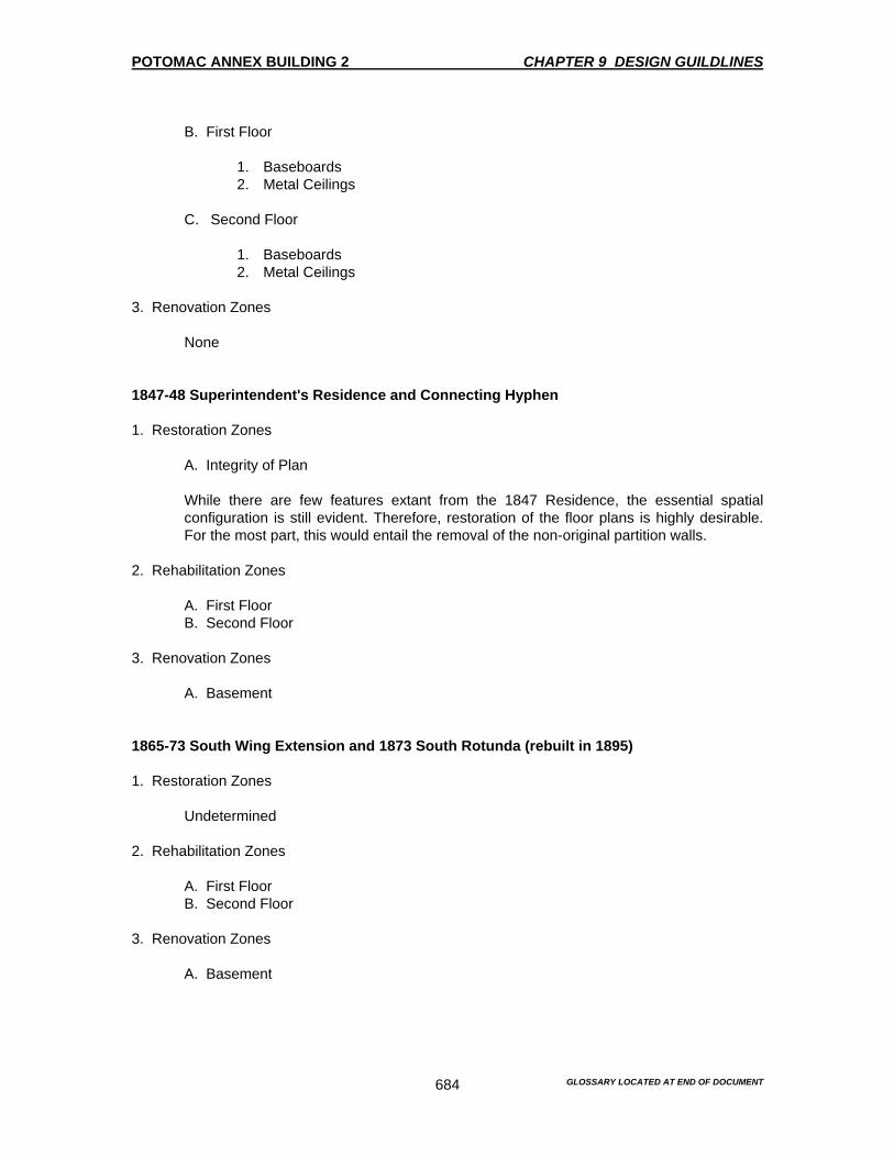
POTOMAC ANNEX BUILDING 2 CHAPTER 9 DESIGN GUILDLINES
GLOSSARY LOCATED AT END OF DOCUMENT
684
B. First Floor
1. Baseboards 2. Metal Ceilings
C. Second Floor
1. Baseboards 2. Metal Ceilings
3. Renovation Zones None 1847-48 Superintendent's Residence and Connecting Hyphen 1. Restoration Zones A. Integrity of Plan While there are few features extant from the 1847 Residence, the essential spatial
configuration is still evident. Therefore, restoration of the floor plans is highly desirable. For the most part, this would entail the removal of the non-original partition walls.
2. Rehabilitation Zones A. First Floor B. Second Floor 3. Renovation Zones A. Basement 1865-73 South Wing Extension and 1873 South Rotunda (rebuilt in 1895) 1. Restoration Zones Undetermined 2. Rehabilitation Zones A. First Floor B. Second Floor 3. Renovation Zones A. Basement
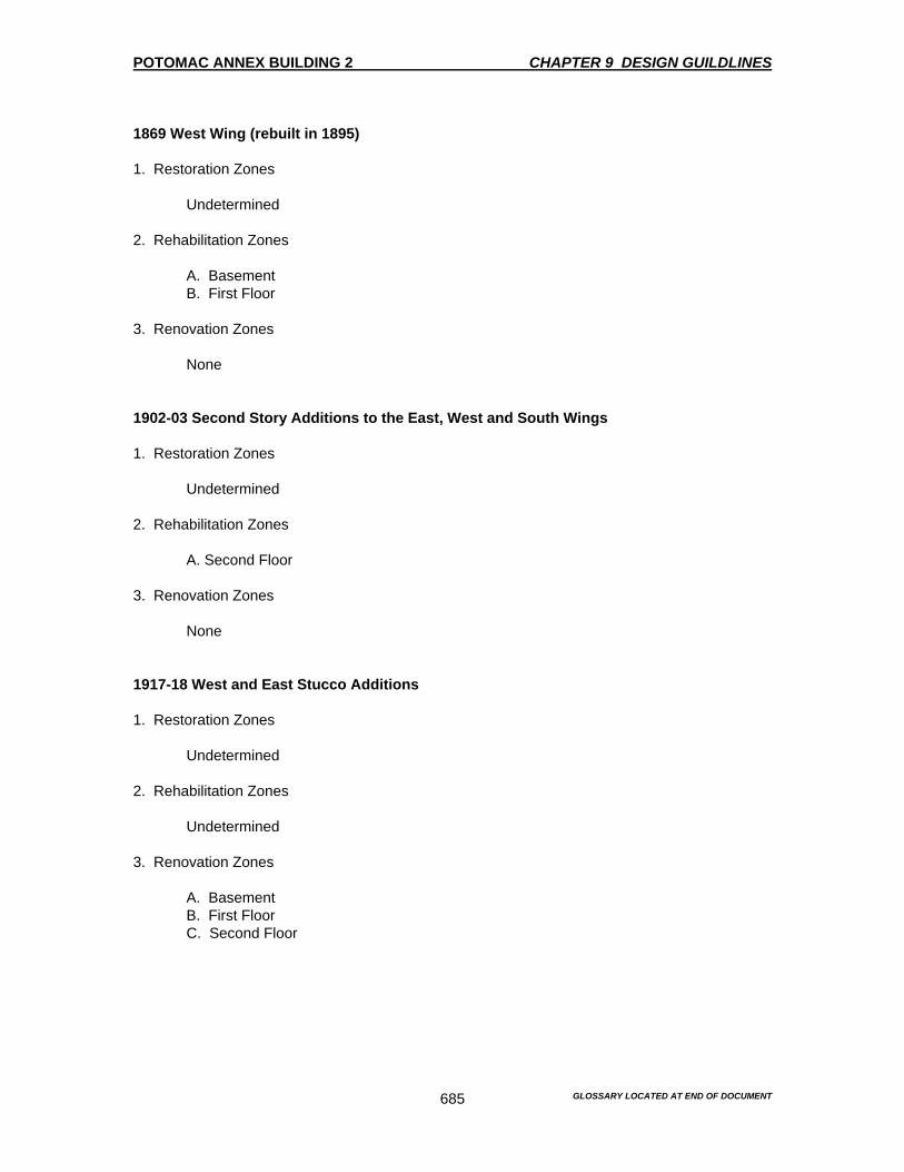
POTOMAC ANNEX BUILDING 2 CHAPTER 9 DESIGN GUILDLINES
GLOSSARY LOCATED AT END OF DOCUMENT
685
1869 West Wing (rebuilt in 1895) 1. Restoration Zones Undetermined 2. Rehabilitation Zones A. Basement B. First Floor 3. Renovation Zones None 1902-03 Second Story Additions to the East, West and South Wings 1. Restoration Zones Undetermined 2. Rehabilitation Zones A. Second Floor 3. Renovation Zones None 1917-18 West and East Stucco Additions 1. Restoration Zones Undetermined 2. Rehabilitation Zones Undetermined 3. Renovation Zones A. Basement B. First Floor C. Second Floor

POTOMAC ANNEX BUILDING 2 CHAPTER 9 DESIGN GUILDLINES
GLOSSARY LOCATED AT END OF DOCUMENT
686
MAINTENANCE GUIDELINES FOR BUILDING MANAGEMENT Mr. Ike Brown, the Facilities Manager for the Potomac Annex, was interviewed concerning the following issues. • Gutters, leaders and storm drainage systems • Window and door sealant • Exterior walks and paving • Floor tiles and cleaning methods • Wooden mantel pieces and cleaning methods • Window cleaning methods • Brass hardware and cleaning methods • Painting schedule • Regular cleaning, dusting and vacuuming Significant maintenance issues were apparent as a result of this interview. These problems are related to funding and contractual requirements for seasonal maintenance. The daily and weekly cleaning and maintenance procedures appear to be appropriate with the exceptions noted below. Gutters, leaders and Storm drainage There is no regular cycle of maintenance for the gutters, leaders or storm drainage. However, it is considered a major work item rather that a cyclical maintenance issue. Therefore, funds should be appropriated to accommodate the cyclical nature of the gutters, leaders and storm drainage. Given the process by which funds are approved and released, it usually takes quite a long time, from the moment a request is submitted to when the funds are available. The last time the drainage system was addressed was 4 to 5 years ago. When it takes longer to acquire the necessary funds to do basic maintenance, the result is that greater harm will occur to areas in the roof and other areas where standing water is present Recommendation There is a need to establish a cycle of maintenance for cleaning and making minor repairs to the drainage system on the Old Naval Observatory. All gutters and storm drains should be cleaned at least once a year in late fall after the leaves have fallen. The gutters and drainage system should be inspected every spring to insure that no damage has occurred during the winter. If there is any damage noted it should be reported to the maintenance personnel and then repaired. Window and Door Sealant The caulking and weather stripping of the windows and doors is not done on a regular basis. Instead, this type of maintenance is viewed as an added extra that requires special funding and authorization. Recommendation There needs to be a regular maintenance cycle that will address the caulking and weather stripping around the windows and doors. This is cycle should be preformed in the late fall prior to the winter season.
POTOMAC ANNEX BUILDING 2 CHAPTER 9 DESIGN GUILDLINES
GLOSSARY LOCATED AT END OF DOCUMENT
687
Exterior Walks and Paving The basic maintenance of the exterior walks and paving are treated as an additional expense that requires special authorization. There is no regular maintenance. Maintenance is only done in connection with occasional repairs. Recommendation Establish a regular cycle of minor repairs during the spring and summer. If there is any organic growth on the walks and paving, chemically spray Round-Up on all areas that exhibit growth. Retreat these growth areas one month later to insure that no growth continues. Repair cracks and potholes that were caused over the winter months. Floor Tiles The floor tiles normally occur in the bathrooms, kitchen and basement areas. Normal wet mopping is done by the housekeepers on a daily basis. Where wood elements are present, like in the doors and window frames a metal strip is inserted between the floor and the base of the door or window frames to prevent moisture from wicking up into the wood. Recommendation The use of the metal strip to prevent moisture from wicking up into the wood appears to be inadequate. In areas where ceramic tile and wood occur together, the tiles should be cleaned with a damp mop, but not a soaking mop. The housekeepers need to be trained to recognize that these wood elements need to be protected and that their cooperation in this venture is required. Wood Maintenance Wood mantel pieces are dusted everyday with a normal furniture polish. No special treatment is used. Recommendation The use of furniture polish should be avoided as this leaves a build-up that will be difficult to remove over time. Woodwork should be dusted with a clean dry duster without any polish or additives. Windows Windows are cleaned twice a year. Normal window cleaner and window cleaning methods are used. Recommendation The window cleaning measures appear to be sufficient in cleaning the windows. No significant force should be applied to the glass during the cleaning process. Any loose sealant glazing, putty and broken panes should be reported to the maintenance personnel and repaired immediately.
POTOMAC ANNEX BUILDING 2 CHAPTER 9 DESIGN GUILDLINES
GLOSSARY LOCATED AT END OF DOCUMENT
688
Brass Hardware Brass polish is used on the brass hardware twice a month when needed. Normal polishing and cleaning methods are used. Recommendation Brass polish should not be used as this leaves a smear and white marks on the surrounding wood. Brass should be allowed to patina naturally. Only dusting and occasionally buffing up with a clean dry buffing cloth is needed. Painting A regular interior painting cycle of 7 years has been established. Partial painting and touch-ups are done more frequently. The build-up of many layers is starting to cause problems with the adhesion of the paint. Interior details have been obscured by the amount of paint that has built up. Visual inspection has revealed that the paint is not being removed sufficiently. If it is removed, it is done with inappropriate methods. Recommendation Woodwork should be stripped, repaired and repainted. Between each painting, woodwork with a semi gloss finish should be cleaned regularly, especially in high traffic areas. Painting too frequent should not be used as a substitute for regular cleaning. Any future paint should include the proper preparation of the surface. This includes cleaning the surface, scraping loose paint and feathering the edges before any new paint is applied.
RECOMMENDATIONS FOR MAINTENANCE, RESTORATION AND ALTERATIONS Exterior Restoration It is recommended that the facades be restored to their 1902-1903 appearance, figures 282-285. Historic photographs and drawings and the Inventory of Significant Spaces should be considered before any work is undertaken Restoration items include the following: • The 1902 color scheme, which was a light palette, should be restored, figures 282-285. • The north entry porch on the west addition should be restored to its 1902 appearance. • The louvered shutters on the 1847 Residence were extant in the 1902 and should be
restored on the north and east elevations. They should not be restored on the south elevation because first floor doors were converted to windows and shutters do not fit the altered openings.

POTOMAC ANNEX BUILDING 2 CHAPTER 9 DESIGN GUILDLINES
GLOSSARY LOCATED AT END OF DOCUMENT
689
• The 1918 Stucco Addition corridor between the Residence and the Back building on the east
side and the 1920’s bathroom addition on the south of the building is important to the program of the Old Naval Observatory as it is currently used. The corridor is on the rear of the Stucco Addition and is reasonably well designed. The corridor does not detract from the architectural quality of the Old Naval Observatory. The corridor should be treated as a restoration element as long as it serves a useful programmatic role. If in the future the corridor becomes unnecessary, its removal and subsequent restoration of the adjoining facades would further enhance the 1902-1903 appearance of the Old Naval Observatory.
Repair The existing original windows and frames should be repaired and have the paint removed. They should be repainted a dark yellowish green found in the 1902 color scheme, figures 282-285. It is recommended that a screen be installed in the lower half of the window openings so that the windows may be operated in warm weather. The frames of the screens should be color finished to match the windows. All wood elements should be inspected for areas that need repair. The elements should then be repaired, scraped and painted dark yellowish green to match the recommended historic color, figures 282-285. Any reconstruction of elements should match the historic condition. All stress cracks in the masonry should be identified and repaired. All open joints in the masonry should be re-pointed with mortar to match the existing. Spall and broken masonry units should be replaced to match the existing. There is an area where the brick is deteriorated in the northeast corner of the Old Naval Observatory. This area should be investigated for what appears to be water damage. The cracked lintel on the north façade of the Residence should be sealed and the broken bricks above should be removed and replaced with bricks to match. All brick and mortar should match the existing in color, size, profile, dimension and texture. The stucco surfaces on the 1918 Stucco Additions are heavily cracked throughout. This stucco should be replaced with stucco to match the existing. All capstones on the areaways should be inspected. All displaced stones should be repaired and reset as necessary. Alterations The non-original front doors should be replaced to match those that were in existence in 1902. The metal stair platform leading to the East Stucco corridor between the Residence and the Back building should be replaced with a stair that is more compatible with the architectural quality of the Old Naval Observatory. A granite stair with simple metal railing would be appropriate. The corrugated metal shed attached to this corridor should be removed. The masonite shed on the southwest façade of the Old Naval Observatory should be removed. It is not consistent with the architectural quality of the Old Naval Observatory All contemporary lighting at the entries should be removed and replaced with the appropriate designed fixtures. See Roger Moss, Lighting for Historic Buildings. The cornice mounted spot lights do not detract significantly from the Old Naval Observatory. However, their housings should be painted the same color scheme as the exterior of the Old Naval Observatory, figures 282-285.
POTOMAC ANNEX BUILDING 2 CHAPTER 9 DESIGN GUILDLINES
GLOSSARY LOCATED AT END OF DOCUMENT
690
All new down spouts should be installed on the corners of the Old Naval Observatory. This will remove them from the front of the building. They should also be painted the same color scheme as the exterior of the Old Naval Observatory, figures 282-285. Site and Landscaping Because of the irreversible nature of many of the landscape alterations, a full restoration is not possible. However, there are some features in the landscape, which should retain. See the inventory of Significant Spaces. Repair Repair of pavements, sidewalks, terraces and stairs should be undertaken Alteration Provide a landscape buffer around the perimeter of the Old Naval Observatory. Refer to the historic photographs for the desired appearance. Provide at least three feet of planted buffer with a curb to separate the parking area from the Old Naval Observatory. This buffer will lessen the occasional damage that may occur to the Old Naval Observatory fabric. Where possible, in areas adjacent to the Old Naval Observatory, reduce the size of the parking lots, or eliminate them entirely. This should be done, particularly on the north side of the Old Naval Observatory. If a new program for site lighting is undertaken in the future, use the existing cast iron lamp posts as the basis for a new design. Although there is good documentation for the appearance of the gas fixtures used during the 19th century, they were not retained in the 20th century. Interior 1844 Old Naval Observatory with the One Story Wings First Floor Restoration Retain the elements listed in the Inventory of Significant Spaces Remove the late 20th century partitions which detract from the architectural character of the supporting arches and from the spatial character of the original open wings. Since the Old Naval Observatory continues to be used for offices, it would be preferable to use partial height or glazed partitions to emphasize the historic character of the space Restore the historic paint scheme from the 1840’s, which is tan with white trim and ceiling. A commercial paint will suffice to accommodate this scheme, figure 286. Restore the historic finish for the 1890’s stair. Replace the non-historic doors in the main lobby with new doors that match the historic 4 panel doors and hardware found at the entry of Room 2108.

POTOMAC ANNEX BUILDING 2 CHAPTER 9 DESIGN GUILDLINES
GLOSSARY LOCATED AT END OF DOCUMENT
691
Replace intrusive box up lights with new fixtures that are designed to be in keeping with the historic character of the Old Naval Observatory. See Roger Moss, Lighting for Historic Buildings. In the office spaces the light fixtures should be replaced by less intrusive designed fixtures that provide ambient light. Make a greater use of task lighting at the desks. Leave the wood floors covered for their protection. When panting wood work, do not strip to the wood. This will help protect the woods historic finish. Second Floor Restoration Retain the elements listed in the Inventory of Significant Spaces. Restore the historic paint scheme from the 1840’s, which was tan with white trim and ceiling, figure 287. Restore the historic finish for the 1890’s stair. Replace the non-historic doors in the main lobby with new doors that match the historic 4 panel doors and hardware found at the entry of Room 2108. Replace intrusive box up lights with new fixtures that are designed to be in keeping with the historic character of the Old Naval Observatory. See Roger Moss, Lighting for Historic Buildings. In the office spaces the light fixtures should be replaced by less intrusive designed fixtures that provide ambient light. Make a greater use of task lighting at the desks. Leave the wood floors covered for their protection. When panting wood work, do not strip to the wood. This will help protect the woods historic finish. 1896 South Rotunda and the 1869 and 1873 South Wing Additions First Floor Restoration Retain the elements listed in the Inventory of Significant Spaces. Restore the historic paint scheme from the 1840’s, which is red walls with white trim in Room 2115 and blue walls with white trim in Room 2114, figure 286. Replace intrusive box up lights with new fixtures that are designed to be in keeping with the historic character of the Old Naval Observatory. See Roger Moss, Lighting for Historic Buildings. In the office spaces the light fixtures should be replaced by less intrusive designed fixtures that provide ambient light. Make a greater use of task lighting at the desks. Leave the wood floors covered for their protection.
POTOMAC ANNEX BUILDING 2 CHAPTER 9 DESIGN GUILDLINES
GLOSSARY LOCATED AT END OF DOCUMENT
692
When panting wood work, do not strip to the wood. This will help protect the woods historic finish. Repair All interior finishes should be repaired as needed. Alteration Any future alterations to the Old Naval Observatory should recognize the Preservation Zones, figures 317-319 Room 2122A and 2123 These rooms on the west side of the Residence have been heavily altered especially Room 2123. This room is now used as a bathroom. There is no documentation or physical evidence to show the original configuration. However, the historic features called out in the Inventory of Significant Spaces should be retained. These include the spatial configuration as it exists, the windows and doors frames, doors and pressed metal ceilings. In the absence of sound documentation and because these are considered secondary spaces, it is recommended to paint the walls and trim white. Residence Second Floor Rehabilitation The second floor of the Residence always constitutes a secondary space. In addition, the west side of this floor was heavily altered to accommodate 20th century uses. Therefore, it is considered a rehabilitation space. However, there are several features of this floor, which should be retained as part of any rehabilitation as noted in the Inventory of Significant Spaces. There is no documentation of physical evidence to support the restoration of the original floor plan, but the plan as it exists should be retained to reduce the possibility of further loss of historic fabric. In addition any non-original doors should be replace with doors to replicate the historic four panel doors. In the absence of sound documentation and because these are considered secondary spaces, it is recommended to paint the walls and trim white. Back Building First and Second Floors Rehabilitation These spaces were always relegated to utilitarian purposes. Since they have been altered, and since there is no documentation to indicate their original surfaces, it is recommended to retain the existing floor plans and to paint the surfaces white. 1902-1903 Secondary Story Additions
POTOMAC ANNEX BUILDING 2 CHAPTER 9 DESIGN GUILDLINES
GLOSSARY LOCATED AT END OF DOCUMENT
693
Rehabilitation The rehabilitation of these spaces should include the retention of the open floor plan and their associated features. 1895 West Addition Rehabilitation The rehabilitation of these spaces should include the retention of its original two-story volume and their associated features. 1918 East and West Stucco Additions Rehabilitation The rehabilitation of these spaces should retain the staircases in the East and West Stucco Additions, as well as in the perimeter wall finishes. While the floor plans do reflect their original configuration, they are not considered significant and can be altered. The basement spaces under the Old Naval Observatory, its wings and in the West Addition should be rehabilitated. This rehabilitation should be done with respect to the integrity of the perimeter walls, the floor plan of the central core and the existing masonry piers.
ADDITTIONAL RECOMMENDED AREAS OR ELEMENTS THAT REQUIRE RESTORATION, RENOVATION AND REHABILITATION
1844 Old Naval Observatory with one-story wings to the East, West and South with the 1864 octagonal bays on West Wing 1. Missing Historic Features to be Replaced A. Wood balustrade B. Time ball on dome C. Shutters on dome D. Exterior doors 2. Exterior Materials Undetermined 3. Interior Materials A. Floors B. Baseboards C. Walls D. Ceilings E. Staircases F. Doors G. Window shutters
POTOMAC ANNEX BUILDING 2 CHAPTER 9 DESIGN GUILDLINES
GLOSSARY LOCATED AT END OF DOCUMENT
694
H. Window and Door trim 4. Redesign of Interior Features A. Partition systems B. Lighting C. Telecommunications and Electrical closets 5. Recommendations for Future Treatment of Spaces Undetermined 1847-48 Superintendent's Residence and Connecting Hyphen 1. Missing Historic Features to be Replaced A. Wood balustrade B. Louvered wood shutters C. Exterior doors 2. Exterior Materials Undetermined 3. Interior Materials A. Floors B. Baseboards C. Walls D. Ceilings E. Staircases F. Fireplaces G. Doors H. Window and Door trim 4. Redesign of Interior Features A. Partition systems B. Lighting C. Telecommunication and Electrical closets 5. Recommendations for Future Treatment of Spaces Undetermined 1865-73 South Wing Extension and 1873 South Rotunda (rebuilt in895) 1. Missing Historic Features to be Replaced

POTOMAC ANNEX BUILDING 2 CHAPTER 9 DESIGN GUILDLINES
GLOSSARY LOCATED AT END OF DOCUMENT
695
None 2. Exterior Materials Undetermined 3. Interior Materials A. Floors B. Baseboards C. Walls D. Ceilings E. Doors F. Window and Door trim 4. Redesign of Interior Features A. Partition systems B. Lighting C. Telecommunications and Electrical closets 5. Recommendations for Future Treatment of Spaces Undetermined 1869 West Wing (rebuilt in 1895) 1. Missing Historic Features to be Replaced A. Front portico 2. Exterior Materials Undetermined 3. Interior Materials A. Floors B. Baseboards C. Walls D. Ceilings E. Doors F. Window and Door trim 4. Redesign of Interior Features A. Lighting B. HVAC closet 5. Recommendations for Future Treatment of Spaces Undetermined
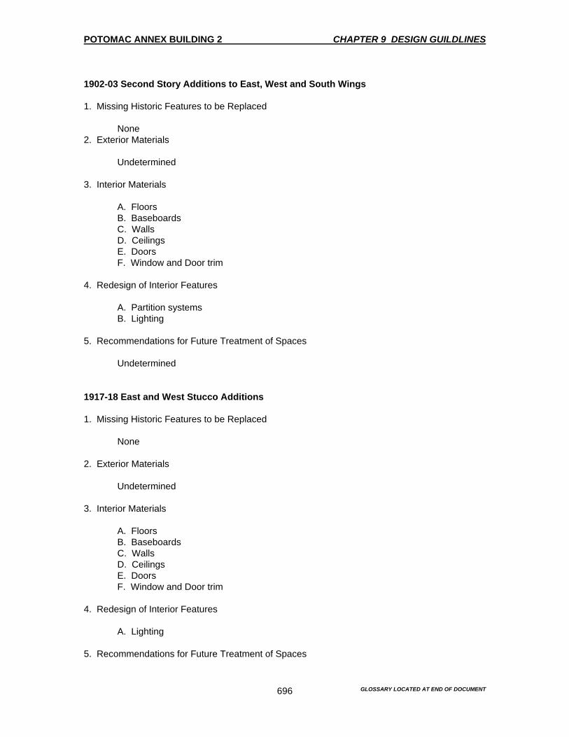
POTOMAC ANNEX BUILDING 2 CHAPTER 9 DESIGN GUILDLINES
GLOSSARY LOCATED AT END OF DOCUMENT
696
1902-03 Second Story Additions to East, West and South Wings 1. Missing Historic Features to be Replaced None 2. Exterior Materials Undetermined 3. Interior Materials A. Floors B. Baseboards C. Walls D. Ceilings E. Doors F. Window and Door trim 4. Redesign of Interior Features A. Partition systems B. Lighting 5. Recommendations for Future Treatment of Spaces Undetermined 1917-18 East and West Stucco Additions 1. Missing Historic Features to be Replaced None 2. Exterior Materials Undetermined 3. Interior Materials A. Floors B. Baseboards C. Walls D. Ceilings E. Doors F. Window and Door trim 4. Redesign of Interior Features A. Lighting 5. Recommendations for Future Treatment of Spaces

POTOMAC ANNEX BUILDING 2 CHAPTER 9 DESIGN GUILDLINES
GLOSSARY LOCATED AT END OF DOCUMENT
697
Undetermined Site and Landscaping 1. Missing Historic Features Undetermined 2. Exterior Materials A. Lighting B. Fences C. Walkways D. Retaining Walls E. Swales F. Parking G. Trees and Shrubs 3. Recommendations for Future Treatment of Spaces Undetermined RECOMMENDATIONS FOR CONFORMANCE WITH THE AMERICANS WITH DISABILITIES ACT (ADA) OF 1990 The Old Naval Observatory as it stands today does not conform to the Americas with Disabilities Act (ADA) of 1990. There are a whole host of issues that need to be addressed. Simple access to the building from the parking lot is at best difficult. Parking that is especially reserved for the disabled is sparse and far removed from the Old Naval Observatory or non-existent. Once in the Old Naval Observatory the various levels that one encounters is another issue, as well as the lack of a motorized lift to the basement or second floor levels. Service areas like the kitchens, bathroom, corridors and basements all lack the proper height, width and depth that is required for any ADA compliance. In total, the Old Naval Observatory and its major additions all lack the required specification that would enable a disabled person to navigate successfully throughout the entire Old Naval Observatory complex without major difficulty. Recommendation Given the above, it is recommended that an American’s with Disabilities study be completed for the Old Naval Observatory and its major additions. This study should use the existing Historic Structures Report (HSR) as a reference for the background of the study. A complete analysis of the exterior of the Old Naval Observatory and the various grades needs to be completed first. Once this exterior study is completed and documented, an interior study needs to be done using the HSR as the foundation. A complete analysis from room to room needs to be done. As with the exterior study, the interior study needs to be documented also. Documentation consists of existing drawings that are complimented with photographs and a written description of the features and elements that need to be addressed for compliance to ADA. After both the exterior and the interior surveys have been completed, this information needs to be entered into a database for ADA compliance and any future reference that may be required. There is also the
POTOMAC ANNEX BUILDING 2 CHAPTER 9 DESIGN GUILDLINES
GLOSSARY LOCATED AT END OF DOCUMENT
698
question of the compliance versus the historic fabric of the Old Naval Observatory. There is a balance that needs to be struck between the issues driving compliance and the retention of the historic fabric of the Old Naval Observatory. The above studies will at least help to determine just how far the Old Naval Observatory is from compliance. Once that is determined, a strategy should be created to format a plan as to how far to go with compliance. A strategy that addresses the issues of compliance and one that retains the historic fabric of the Old Naval Observatory needs to be created. That balance will insure that both issues are addressed. CRITERIA FOR INSTALLATION OF HVAC, COMPUTER CABLING, SECURITY SYSTEMS AND OTHER BUILDING SYSTEMS The criteria for the installation of an HVAC, computer cabling, security systems and other Old Naval Observatory systems needs a thorough analysis of the above systems, the existing conditions and historic fabric of the Old Naval Observatory. Before any system is approved, appropriated or installed a complete study of the Old Naval Observatory’s needs are to be completed. The HSR for this building can serve as a foundation for these studies for each system noted above. HVAC A central HVAC system will alleviate the need to cool and heat the Old Naval Observatory and its additions by using external window mounted units or small space heaters. However, before any HVAC system is installed, appropriated or approved a complete study of the Old Naval Observatory needs to be done. The use of the Old Naval Observatory HSR will provide a good foundation as a start for the needs assessment of a central HVAC system. After the study is completed, issues regarding the historic fabric of the Old Naval Observatory need to be considered. Recommendation If indeed a central HVAC system is determined as a required item and later installed, a careful analysis of the Old Naval Observatory needs to be done. The system that is installed will need to be designed to carry all the heating and cooling requirements of the Old Naval Observatory. Careful placement of the exterior cooling unit as well as the interior-heating unit will need to be considered. The exterior cooling unit will need to be placed in a location that will allow it to function at optimal performance as well as keep the historic fabric of the Old Naval Observatory. If there is a need to place the external-cooling unit close to the Old Naval Observatory, a green screen should be implemented to hide the unit. The internal unit should be placed in a location as per the analysis or study. As with most internal units, a central location will enable the unit to perform to its optimal capabilities. The required ductwork needs to be routed throughout the Old Naval Observatory in a manner that will not destroy the existing historic fabric of the Old Naval Observatory. A careful analysis of the needs and space requirement for the ductwork, as well as the registers will need to be done. Strategic placement of these required elements will insure that the HVAC system will perform as designed. Computer Cabling

POTOMAC ANNEX BUILDING 2 CHAPTER 9 DESIGN GUILDLINES
GLOSSARY LOCATED AT END OF DOCUMENT
699
The need for a computer cabling system will enhance the use of computers and their associated networks. As with most office environments today, the use of the computer is a fore gone conclusion. Therefore, it is without doubt that a system will need to be created and installed to address the computer cabling system. However, there will need to be an assessment of the Old Naval Observatory before any computer cabling system is approved, appropriated or installed. Recommendation After the assessment of the Old Naval Observatory is completed with regard to the computer cabling system, this assessment will need to be coordinated with the needs and requirement of the historic fabric of the Old Naval Observatory. Location of the server and all network connections should be done is a manner that will adhere to the historic fabric of the Old Naval Observatory. A closet that can be maintained in a secured manner will suffice the needs of the server and all associated network cabling. From the server, all cabling should not go through the walls or along the wood baseboards. A preferred routing of the computer cabling should be from underneath. A system in the basement ceiling would suffice. The cabling would then be feed upwards toward each computer. For the second floor offices the same criteria will need to be employed. If there is need to rout the cabling along the baseboards, a type of raceway with an access door will need to be carefully installed. This type of cabling only needs to be done as a last resort if no other strategies can be implemented or created to keep the cabling off the baseboards. Security Systems The need for a security system will enhance the security and safety of the Old Naval Observatory in general. Before any security system is approved, appropriated or installed a study of the Old Naval Observatory needs is to be completed. This assessment of the buildings security needs will need to address the historic fabric of the Old Naval Observatory. Recommendation After the assessment of the Old Naval Observatory is completed with regard to the security system, this assessment will need to be coordinated with the needs and requirements of the historic fabric of the Old Naval Observatory. Entry keypads or locks should be located in a place that will disturb the exterior as little as possible. Any new doors are installed will need to be made so that they are replicas of the doors that were installed in the Old Naval Observatory prior to the 1902-03-construction period. Any door or window sensor will need to be placed so that there is a minimal disturbance to the fabric of the Old Naval Observatory. The wiring or cables that will need to be installed will have to be routed from underneath. The basement ceiling will suffice as a conduit for the security system. Placing the wires in the basement ceiling will enhance their protection. There should not be any security wires or cables that are visible on any floor or wall. Other Building Systems As the need arises, other building systems will probably be needed in the future. Systems like a new phone system, an intercom system, video conferencing, a satellite dish and any other high technology systems. Most of the other building systems will require some sort of new and additional wires or cables. Before any system is approved, appropriated or installed a study of the Old Naval Observatory’s needs is to be completed.

POTOMAC ANNEX BUILDING 2 CHAPTER 9 DESIGN GUILDLINES
GLOSSARY LOCATED AT END OF DOCUMENT
700
Recommendation As with the other systems mentioned above, an assessment will need to be perform in order to determine the requirements of that particular system and the needs of the historic fabric of the Old Naval Observatory. After carefully determining the best strategy for both the system and the Old Naval Observatory, installation should proceed.
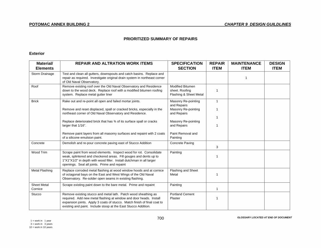
POTOMAC ANNEX BUILDING 2 CHAPTER 9 DESIGN GUILDLINES
GLOSSARY LOCATED AT END OF DOCUMENT 1 = work in 1 year 3 = work in 3 years 10 = work in 10 years
700
PRIORITIZED SUMMARY OF REPAIRS
Exterior
Material/ Elements
REPAIR AND ALTRATION WORK ITEMS SPECIFICATION SECTION
REPAIR ITEM
MAINTENANCE ITEM
DESIGN ITEM
Storm Drainage Test and clean all gutters, downspouts and catch basins. Replace and repair as required. Investigate original drain system in northeast corner of Old Naval Observatory.
1
Roof Remove existing roof over the Old Naval Observatory and Residence down to the wood deck. Replace roof with a modified bitumen roofing system. Replace metal gutter liner
Modified Bitumen sheet. Roofing Flashing & Sheet Metal
1
Brick Rake out and re-point all open and failed mortar joints. Remove and reset displaced, spall or cracked bricks, especially in the northeast corner of Old Naval Observatory and Residence. Replace deteriorated brick that has ¾ of its surface spall or cracks larger that 1/16”. Remove paint layers from all masonry surfaces and repaint with 2 coats of a silicone emulsion paint.
Masonry Re-pointing and Repairs Masonry Re-pointing and Repairs Masonry Re-pointing and Repairs Paint Removal and Painting
1
1
1
1
Concrete Demolish and re-pour concrete paving east of Stucco Addition Concrete Paving 3
Wood Trim Scrape paint from wood elements. Inspect wood for rot. Consolidate weak, splintered and checkered areas. Fill gouges and dents up to 1”X1”X1/2” in depth with wood filler. Install dutchman in all larger openings. Seal all joints. Prime and repaint
Painting 1
Metal Flashing Replace corroded metal flashing at wood window hoods and at cornice of octagonal bays on the East and West Wings of the Old Naval Observatory. Re-solder open seams in existing flashing.
Flashing and Sheet Metal
1
Sheet Metal Cornice
Scrape existing paint down to the bare metal. Prime and repaint Painting 1
Stucco Remove existing stucco and metal lath. Patch wood sheathing as required. Add new metal flashing at window and door heads. Install expansion joints. Apply 3 coats of stucco. Match finish of final coat to existing and paint. Include stoop at the East Stucco Addition.
Portland Cement Plaster
1
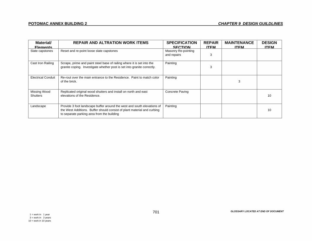
POTOMAC ANNEX BUILDING 2 CHAPTER 9 DESIGN GUILDLINES
GLOSSARY LOCATED AT END OF DOCUMENT 1 = work in 1 year 3 = work in 3 years 10 = work in 10 years
701
Material/ Elements
REPAIR AND ALTRATION WORK ITEMS SPECIFICATION SECTION
REPAIR ITEM
MAINTENANCE ITEM
DESIGN ITEM
Slate capstones Reset and re-point loose slate capstones Masonry Re-pointing and repairs
3
Cast Iron Railing Scrape, prime and paint steel base of railing where it is set into the granite coping. Investigate whether post is set into granite correctly.
Painting 3
Electrical Conduit Re-rout over the main entrance to the Residence. Paint to match color of the brick.
Painting 3
Missing Wood Shutters
Replicated original wood shutters and install on north and east elevations of the Residence.
Concrete Paving 10
Landscape Provide 3 foot landscape buffer around the west and south elevations of the West Additions. Buffer should consist of plant material and curbing to separate parking area from the building
Painting 10

POTOMAC ANNEX BUILDING 2 CHAPTER 9 DESIGN GUILDLINES
GLOSSARY LOCATED AT END OF DOCUMENT 1 = work in 1 year 3 = work in 3 years 10 = work in 10 years
702
Interior
Material/ Elements
REPAIR AND ALTRATION WORK ITEMS SPECIFICATION SECTION
REPAIR ITEM
MAINTENANCE ITEM
DESIGN ITEM
Wood Stair in the Old Naval Observatory
Strip to bare wood. Touch up with wood stain and refinish. Wood Refinishing 10
Walls, Windows and Ceiling
Repaint following the color scheme recommended in Chapter 5, figures 286-287.
Painting 3 t0 10 as required
Communications Closets
Replace existing door and base boards with new elements that match adjacent original base boards and doors.
10
Lighting Replace metal halide metal cased up light with new lights that are more sympathetic to use and style reflect the style of the building.
10
Wood windows Free windows from hardened paints so they operate freely. Touch up existing paint where required.
Painting 3
Wood Window Second Floor Residence
Protect historic glass with interior storm window glazed in acrylic and attached to the frame of the window with brass clips.
3
First Floor Partitions. East and West Wings
Remove and install new low wall partitions 10
Metal raceway Remove existing metal raceways. Install new wood baseboards to match original with false bottom to accommodate hidden wiring behind a removable metal plate.
10
Ceiling in Room 2116
Replace existing with pressed metal ceiling to match existing in other areas.
10
Ceiling in Room 2118-2221
Remove acoustical ceiling and replace with pressed metal ceiling to match existing in other offices.
10
Miscellaneous Plaster Damage
Patch plaster where damaged from where old leaks remain. 3
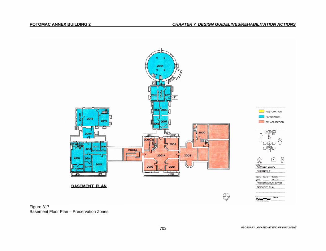
POTOMAC ANNEX BUILDING 2 CHAPTER 7 DESIGN GUIDELINES/REHABILITATION ACTIONS
GLOSSARY LOCATED AT END OF DOCUMENT 703
Figure 317 Basement Floor Plan – Preservation Zones

POTOMAC ANNEX BUILDING 2 CHAPTER 7 DESIGN GUIDELINES/REHABILITATION ACTIONS
GLOSSARY LOCATED AT END OF DOCUMENT 704
Figure 318 First Floor Plan – Preservation Zones

POTOMAC ANNEX BUILDING 2 CHAPTER 7 DESIGN GUIDELINES/REHABILITATION ACTIONS
GLOSSARY LOCATED AT END OF DOCUMENT 705
Figure 319 Second Floor Plan – Preservation Zones
POTOMAC ANNEX BUILDING 2 BIBLIOGRAPHY
GLOSSARY LOCATED AT END OF DOCUMENT B-1
Primary Sources Adams, Quincy. “Message to the 19th Congress.” December 6, 1825. Bureau of Medicine and Surgery. Annual Reports of the Surgeon General. Washingotn, D.C.: GPO, 1880-1960. Gillis, James Melville. “A Report of the Plan and Construction of the Depots of Charts and Instruments.” Report of the Secretary of the Navy to the 28th Congress, 2nd Session, 1845. Maury, Matthew Fontaine. “Blank Charts on Board Public Cruisers.” Southern Literary Messenger. August 1843, pp. 458-461. Newcomb, Simon. The Reminiscences of An Astronomer. Boston, MA: Houghton Mifflin & Co., 1903. Sands, Benjamin F. From Reefer to Rear Admiral: Reminiscences and Journal Jottings of Nearly Half a Century of Navy Life. New York: Frederick A. Stokes Co., 1899. Specifications of Alterations and Additions to the Observatory Buildings, ca. 1842, 1848, 1845, 1847, 1864. OBS Manuscript, Division of the Library of Congress, Box 13. Yarnell, Mordechal. “The Instruments of the Observatory.” Collection of the U.S. Naval Observatory. 1876. Library of Congress Superintendent’s Office Correspondence File, n.d., January – August 1845. Administrative Records of Building, Contracts and Specifications. National Archives Records of the Department of the Navy, Record Group 45.
Letters received by the Secretary of the Navy from Officers below the rank of Commander, 1802 – 1844. Microfilm 148. Navy Department General Letter Book, 1844 – 1845. E3. Microfilm 209. Navy Department Miscellaneous Letters. E21. Microfilm 124. Records of the Naval Observatory, Record Group 78. Letters Received. January 1838 – July 1843. Entry 7. Letters Sent. July 16, 1843 – July 31, 1845.

POTOMAC ANNEX BUILDING 2 BIBLIOGRAPHY
GLOSSARY LOCATED AT END OF DOCUMENT B-2
U.S. General Services Administration Documents “Building Evaluation Report for Potomac Annex Buildings 1-7.” GSA-NCR Repair and Alterations Division. GSA Technical Resource Library, Washington, D.C., May 1981. “General Building Profile.” GSA-NCR Repair and Alterations Division, GSA Technical Resource Library, Washington D.C., 1987. “Historic Places Inventory Form for the Potomac Annex Buildings 1-7.” GSA Technical Resource Library, Washington, D.C., 1872. Microfiche Drawings and Building Files. GSA Technical Resource Library, Washington, D.C. “Potomac Annex Buildings Evaluation Report.” GSA Technical Resource Library, Washington, D.C., 1960. Section 106 Compliance Report. “Inspection, Repair or Replace Existing Doors, Potomac Annex Buildings 1-7.” Project Control Number RDC 28168. GSA-NCR Historic Preservation Building Files. Washington D.C., September 24, 1993. “Water Leakage Study.” Project Control Number RDC 24102. December 7, 1993. Secondary Sources Albion, Robert Greenhalgh. Square Riggers on Schedule. Princeton, NJ: Princeton University Press, 1938. Ames, Mary Clemmer. Ten Years in Washington: Life and Scenes in the National Capitol, As a Woman Sees Them. Hartford, CT: A.D. Worthington & Co., 1874. Dick, Steven J. “How the U.S. Naval Observatory Began, 1830-1865.” Sky and Telescope. Vol. 60, No. 6. December 1980. Dupree, A Hunter. Science in the Federal Government. Cambridge, MA: The Belknap Press. Harvard University Press, 1957. Foner, Eric and John A. Garraty, Ed. The Reader’s Companion to American History. Boston, MA: Houghton Mifflin Co., 1991. Hall, A. An Astronomer’s Wife: The Bibliography of Angeline Hall. Baltimore, MD: Nunn & Co., 1908. Harris, Cyrill M., Ed. Illustrated Dictionary of Historic Architecture. New York, NY: Dover Publications, Inc., 1983. Henderson, David. The Hidden Coasts. Westport, CT: Greenwood Press Publishers, 1953. Herman, Jan K. A Hilltop in Foggy Bottom: Home of the Old Naval Observatory and the Navy Medical Department. Bureau of Medicine and Surgery, Department of the Navy, Washington, D.C., 1991. Herman, Jan K. “The Establishment of the U.S. Naval Observatory.” Vistas in Astronomy. Vol. 28. Great Britain: Pergamon Press Ltd., 1985.
POTOMAC ANNEX BUILDING 2 BIBLIOGRAPHY
GLOSSARY LOCATED AT END OF DOCUMENT B-3
Holder, Edward S. The United States Naval Observatory, Washington.” Science: A Weekly Journal of Scientific Progress. July 3, 1880, pp.1-3. Jaffe, David. The Stormy Petrel and the Whale. Baltimore, MD: Port City Press, 1976. Kern Stephen. The Culture of Time and Space: 1880-1918. Cambridge: Harvard University Press, 1983. De Keim, B. Keim’s Illustrated Hand Book: Washington and its Environs. Washington City: 1884. Lewis, Steven H. and Blanche H. Schroer. “National Register of Historic Places Inventory Nomination Form: Old Naval Observatory.” 1963. Maury, Matthew Fontaine. The Physical Geography of the Sea and Its Meteorology. Cambridge: The Belknap Press, Harvard University Press, 1963. Nourse, J.E. “Memoir of the Founding and Progress of the United States Naval Observatory.” Washington D.C.: GPO, 1873. Nourse, J.E. “Observations in the United States.” Harper’s New Monthly Magazine. No. CCLXXXVI, Vol. XLVIII, March 1874. Paulin Charles Oscar. “Early Movements in the United States for a National Observatory.” Popular Science Monthly. Vol. 71, No. 4, October 1907 Pevsner, Nikolaus. A History of Building Types. Princeton, NJ: Princeton University Press, 1976. Post, R. 1876: A Centennial Exposition. Washington D.C.: Smithsonian Institution Press, 1976. Reingold, N. Science in Nineteenth Century America: A Documentary History. New York, NY: Hill & Wang, 1964. Weber, Gustavus A. The Naval Observatory: It’s History, Activities and Organization. Institute for Government Research Service Monograph of the United States Government. No. 39. Baltimore, MD: The John Hopkins Press, 1926. Webbere-Hall Sandra. “National Register of Historic Places Inventory Nomination Form.” Washington D.C.: George Washington University, October 1984. Wheat, Carolyn E. “Potomac Annex Historic District National Register Nomination Form.” August 1993. Williams, Francis Leigh. Matthew Fontaine: Scientist of the Sea. New Brunswick, NJ: Rutgers University Press, 1963. Withers, Marianne M. “Arrangement and Description in the National Archives.” Record Group 78: Records of the Naval Observatory. Research Seminar in the Use of Archival Resources, Catholic University, December 1981.

POTOMAC ANNEX BUILDING 2 GLOSSARY
G-1
A Acanthus. A common plant of the Mediterranean whose leaves, stylized, form the characteristic decoration of capitals of Corinthian and composite orders. In scroll form it appears on friezes, panels, etc. Apron. A raised panel below a windowsill sometimes shaped and decorated. Architrave. The lintel extending from one column or pier to another. The lowest of the 3 main parts of an entablature. More loosely, the molded frame surrounding a door or window (if this frame turns away at the top at right angles, rises vertically and returns horizontally, forming a shoulder, it is called a shouldered architrave). Archway. A passage through or under an arch. Area well. An open space through one or more floors, as a stairwell or an elevator well. Areaway. A sunken space affording access, air and light to a basement. Ashlar. Hewn blocks of masonry wrought to even faces and square edges and laid in horizontal courses with vertical joints, as opposed to rubble or uncut stone straight from the quarry. Attic. A story built above the wall cornice and under the sloping roof of a house. Axial plan. Of a building planned longitudinally or along an axis, i.e. not centrally planned, e.g. a basilica as opposed to an octagon. B Balcony. A platform projecting from a wall, enclosed by a railing or balustrade, supported on brackets or columns or cantilevered out. A small, decorative balcony projecting from a windowsill, sometimes to hold flowerpots, is called a BALCONETTE. Baluster. A short posts or pillar in a series supporting a rail or coping and thus forming a balustrade. Balustrade, see BALUSTER. Base course. In masonry, the lowest course, or footing, of a wall or pier. Baseboard. A molding covering a joint of a wall and the adjoining floor. Basement. The lowest story of a building, usually below or partly below ground level or, if beginning at ground level, of less height than the story above. It is a living space, as distinct from a cellar. Bay. A vertical division of the exterior of a building marked not by walls but by fenestration, an order, buttresses, units of vaulting, roof compartments, etc. Bead molding. A small cylindrical molding enriched with ornament resembling a string of beads; used in the Romanesque period.

POTOMAC ANNEX BUILDING 2 GLOSSARY
G-2
Beaded-Board. A wood board that has been carved so that it has the appearance of being covered with rows of small spherical beads. Beam. A term applied to a transverse, horizontal piece of timber (or sometimes metal) in roof construction. In the body of a building a main horizontal timber supporting floor or ceiling joists. A dragon beam is set diagonally and projecting at the corner of a building to support the joists of a jetty on two adjacent sides. Bearing wall. A wall supporting a vertical load in addition to its own weight. Bedding planes. A bottom layer of the foundation. Belt course. A continuous horizontal band of masonry, marking a division in the wall plane. Bracket. A small supporting piece of stone or other material, often formed of scrolls or volutes, to carry a projecting weight. Brownstone. A sandstone of reddish brown color. Many so-called "brownstone fronts," however, were of imitation masonry in stucco. Butt hinges. Those employed in the hanging of doors, shutters, casements, etc. They are placed on the edges with the knuckle projecting on the side to which the unit swings. Workmen generally sink the thickness of the hinges flush with the surface of the edge of the closure, and the tail part one half into the jamb. There are several kinds of butt hinges. One type of known as top butt-hinges, which permit the closure to open only to a right angle, or perhaps a little more, without breaking the hinges. Another hinge type is the rising butt hinge that turn upon a screw. These are most employed in doors, and cause the door to rise as it opens, so as to clear the carpet in the apartment. A further type of hinge is the slip-off butt hinge. These are those employed where a door or window blind is required to be taken off occasionally. C Capital. The head or crowning feature of a column, engaged column, pier or pilaster. Casement. (1) The hinged part of a window, attached to the upright side of the window-frame. (2) The wide concave molding in door and window jambs and between compound columns or piers, found in late Gothic architecture. Chair rail or dado rail. A molding round a room to prevent chairs, when pushed back against the walls from damaging their surface. Colonial Revival. The reuse of Georgian and Colonial design in the U.S.A. toward the end of the 19th and into the 20th century, typically in bank buildings, churches, and suburban homes. Colonnade. A row of columns which carry an entablature or arches. Column. A freestanding upright member of circular section and usually slightly tapering, normally intended as a support but sometimes erected independently as a monument. In classical architecture it consists of a shaft, capital and, except in Greek Doric, a base. Concrete. Concrete is 'mortar mixed with small stones to produce a hard monolithic mass' (P. Collins, Concrete, 1959). The use of concrete dated back to the ancient Roman times. Somehow the technology of making concrete was lost after the Romans, but was revived in the 18th century.

POTOMAC ANNEX BUILDING 2 GLOSSARY
G-3
It has become one of the most popular building material in the 20th century. Coping. A capping or covering to a wall, either flat or sloping to throw off water Corbel. A projecting block, usually of stone, supports a beam or other horizontal members. A series, each one projecting beyond the one below, can be used in constructing a vault or arch. Cornice. In classical architecture, the top, projecting section of an entablature; also any projecting ornamental molding along the top of a building, wall, arch, etc., finishing or crowning it. That along the sloping sides of a pediment is called a ranking cornice. Cove or coving. A large concave molding, esp. that produced by the arched junction of wall and ceiling in a 'cove ceiling.' In a rood screen the concave curve supporting the projecting rood loft is called coving. Cyma recta. A double-curved molding, concave above and convex below; also called an ogee molding. Cyma reversa. A double-curved molding, convex above and concave below. Cymatium. The top member of a cornice in a classical entablature. D Deadbolt. A lock bolt without a spring that is not automatically activated, but must be engaged by physically turning or sliding the bolt. Dentil. A small square block used in series in Ionic, Corinthian, Composite, and more rarely Doric cornices. Diaper. An all over pattern with motifs placed in a repeated design, especially on a rectangular or diagonal grid. Dome. Vault of even curvature on a circular base. The section can be segmental, semicircular, pointed, or bulbous. Dormer. A vertical structure, usually housing a window, that projects from a sloping roof and is covered by a separate roof structure. Downspout. A rain leader or vertical pipe to conduct water from the eaves gutter. E Efflorescence. To form or to become covered with a powdery crust. Egg and Dart or egg and tongue. An ovolo molding decorated with a pattern based on alternate eggs and arrowheads. Elevation. The external faces of a building; also a drawing made in projection on a vertical plane to show any one face (or elevation) of a building. Enframement. A general term referring to any elements surrounding a window or door.

POTOMAC ANNEX BUILDING 2 GLOSSARY
G-4
Entablature. The upper part or an order, consisting of architrave, frieze and cornice. Escutcheon. A protective plate surrounding the keyhole on a door. F Fascia. A plain horizontal band, usually in an architrave, which may consist of two or three fasciae over-sailing each other and sometimes separated by a narrow molding. Festoon. A festive decoration of pendant semi-loops with attachments and loose ends, esp. a swag of fabric, or representations of such decorations. Fillet. A narrow, flat, raised band running down a shaft between the flutes in a column or along an arch or a roll molding; also the upper-most member of a cornice. Finish. The final treatment or coating of a surface. Flue. A separate incombustible and heat-resistant enclosed passage within a chimney to control and carry away products of combustion from a fireplace, furnace, or boiler to the outside air. In some cases the brick of the chimney itself encloses the passage. Flute. A groove or channel, especially one of many such parallel grooves, usually semicircular or semi-elliptical in section; used decoratively, along the shaft of a column. Footing. An enlargement at the lower end of a foundation wall, pier, or column to distribute the load. Foundation. An underlying base or support for a wall. Framing. A structure whose weight is carried by the framework instead of a load bearing wall. The term includes modern metal and reinforced concrete structures, as well as timber-framed (half-timbered) buildings. Fresco. A mural painted into fresh lime plaster, using water-based colors, which unite with the plaster. Frieze. 1. The middle division of an entablature, between the architrave and cornice; usually decorated but may be plain. 2. The decorated band along the upper part of an internal wall, immediately below the cornice. Frontispiece. The main facade of a building or its principal entrance bay. G Gable. The triangular upper portion of a wall at the end of a pitched roof corresponding to a pediment in classical architecture. It can be used non-functionally, e.g. on the portal of a Gothic Cathedral. It normally has straight sides, but there are variants. Gable roof or pitched roof. It is the most common type of roof with gables at both ends. Georgian architecture. The prevailing style of the 18th century in England and the North American colonies, so named after George I, George II and George III (1714-1820), but commonly not

POTOMAC ANNEX BUILDING 2 GLOSSARY
G-5
including George IV. Georgian architecture is classical in its major exteriors; but on the smaller domestic scale it still has the sensible plainness of the Queen Anne style. Interiors are more elaborate than exteriors. Girder. A large or principal beam used to support concentrated loads, usually from other beams, at isolated points along its length. Glazed bricks. Polychrome glazed bricks were developed in the ancient Near East in the late 2nd millennium BC and were used for wall decoration on a large scale at Khorsabad (c.8 BC) and Babylon (c.575 BC). Grade. The existing or established level of the ground about a building. Graining. The act of imitating the natural patterning of wood with paints and primers, usually applied to a plaster wall. Greek Revival. Greek architecture which became known to the West only about 1750-60. It was at first regarded as primitive and imitated by only a few architects. The earliest example is a garden temple at Hagley by 'Athenian' STUART (1758). A Grecian fashion began only in the 1780s. Among the earliest believers in the positive value of the simplicity and gravity of the Greek C5 were LEDOUX and SOANE. The Greek Revival culminated in all countries in the 1820s and 1830s Grille. A grating or openwork barrier, usually of metal but sometimes of wood or stone. It is used to cover, conceal, decorate, or protect an opening, as in a wall, floor or outdoor paving. H Hipped roof. A hipped roof has sloped instead of vertical ends. Hearth. That part of a fireplace on which the fire is laid, including the horizontal projection of this surface beyond the fire chamber. Hood. 1. A cover placed above an opening or an object to shelter it. 2. A cover placed over a fire or chimney to create a draft and to direct the smoke, odors, or noxious vapors into a flue; may be supported or hung in space, or attached to a wall. I Indent. A shape chiseled out in a stone slab to receive a brass effigy. J Jamb. The vertical face of an archway, doorway, or window; the part of the jamb which lies between the glass or door and the outer wall-surface is called a reveal. Jointing. Finishing the surface of mortar joints in brickwork or masonry while the mortar is fresh, instead of raking it out and pointing. Joists. Horizontal parallel timbers laid between the walls or the beams of a building to carry the floorboards.
POTOMAC ANNEX BUILDING 2 GLOSSARY
G-6
K Keystone. The central stone of an arch or a rib vault; sometimes carved. Kneeler. The block of stone set at the top of a brick or stone wall to finish the eaves of a parapet or coping; also called a pad-stone, kneestone, or skew. Knee wall. In the attic, the portion of the exterior wall that intersects with the slope of the roof. Knob cap. A projecting handle, usually round or oval, operating a latch. Knuckle. One of the jointing parts of a hinge through which a pin or rivet passes. L Landing. The horizontal plane at the top of a stairway, or a platform interrupting the flight. Lantern. A small circular or polygonal turret with windows all round, crowning the roof of a dome. Lath. Rib-like support of wood or metal upon which plaster is spread. Leader. A vertical pipe that conducts water from a gutter down the face of a building to an outlet at or below grade. Leaf. One part of a double or multiple door. Lift. A metal aid in lifting a sash or door. Limestone. In commercial terms, a sedimentary rock consisting chiefly of calcium carbonate (CaCo3), often containing an accumulation of organic remains such as shells and fossils. Usually unpolished, relatively uniform in texture. Lintel. A horizontal beam or stone bridging an opening. Loop. A small, narrow and often unglazed light. Louvre. 1. An opening, often with a lantern over, in the roof of a wall to let the smoke from a central heart escape; either open-sided, or closed by slanting boards to keep out the rain. 2. One of a series of overlapping boards or slips of glass to admit air and exclude rain. M Mantelpiece. The wood, brick, stone or marble frame surrounding a fireplace, frequently including an over-mantel or mirror above; sometimes called chimney-piece. Masonry. Work by a mason, for example brickwork, stonework. Modillion. A small bracket or console of which a series is frequently used to support the upper member of a Corinthian or Composite cornice, arranged in pairs with a square depression between each pair.
POTOMAC ANNEX BUILDING 2 GLOSSARY
G-7
Molding. A deviation from a plane surface, involving rectangular or curved profiles, or both, with the purpose of effecting a transition or of obtaining a decorative play of light and shade. Monolith. A single stone, usually in the form of a monument or column. Mortar. A mixture of cement (of lime), sand and water, laid between courses of bricks or masonry to even out irregularities and gain greater adhesion; more loosely, any material for and jointing brickwork or stonework. Mortise and tenon joint. A joint formed by a projecting piece (or tenon) fitting into a socket (or mortise). Muntin. The vertical part in the framing of a door, screen, paneling, etc., butting into, or stopped by, the horizontal rails. N Nebule or nebuly molding. A molding with a wavy or serpentine lower edge. Necking. A narrow, annular molding round the bottom of a capital between it and the shaft of the column. Newel. A post terminating the handrail of a stairway at top, bottom or on a landing. Originally the central pillar of a spiral staircase. Nosing. The rounded front edge of a stair. O Offset. The part of a wall exposed horizontally when the portion above it is reduced in thickness; often sloping, with a projecting drip mould on the lower edge to stop water running down the walls, e.g. in Gothic buttresses. Also called water table. Ogee. A double-curved line made up of a convex and concave part (S or inverted S). Open-string. Descriptive of a stairway in which the ends of risers and treads are uncovered on the outside. Orientation. The planing of a building in relation to the rising sun, especially of West European churches, which are usually, oriented east west with the altar at the east end. Nonetheless, there are many exceptions, e.g. St. Peter's, Rome, which is oriented west east. Overhang. Projection of the upper story of a house. P Panel. Strictly any flat surface sunk or raised within a framework. Panic hardware (panic bolt). A door latch operated from one side by pressure against a horizontal bar running across the full width of the door.
POTOMAC ANNEX BUILDING 2 GLOSSARY
G-8
Parapet. A low wall, sometimes battlement, placed to protect any spot where there is a sudden drop, for example, at the edge of a bridge, quay, or housetop. Parquet. Flooring of thin hardwood (about 1/4" thick) laid in patterns on a wood sub-floor and highly polished. Inlaid or plated parquet consists of a veneer of decorative hardwood glued in patterns to squares of softwood backing and then laid on a wood sub-floor. Patina. (1) Any thin oxide film which forms on a metal; often multi-colored. (2) A film, similar in color, which forms on a material other than metal. Pavilion. On a facade, a prominent portion usually central or terminal, identified by projection, height, and special roof forms. Paving. Durable floor, walk, or road surfacing. Pedestal. In classical architecture, the base supporting a column or colonnade; also, more loosely, the base for a statue or any superstructure. Pediment. Not a Greek or Roman term but signifying in classical architecture a low-pitched gable above a portico, formed by running the top member of the entablature along the sides of a gable; also a similar feature above doors, windows etc. It may be straight-sided or curved segmental. Pendill. A carved wood ornament, which terminates the bottom end of second-floor, posts in framed overhang construction. Perron. An exterior platform ascended by steps and leading to the (usually first floor) entrance to a house, church, etc. The door opens onto it. More loosely, the flight or flights of steps ascending to the platform. Picture mould. A molding at the upper part of a wall, or forming the lower edge of an interior cornice, rounded at its top to support picture hooks. Pier. (1) A solid masonry support, as distinct from a column. (2) The solid mass between doors, windows, and other openings in buildings. (3) A name frequently given to Romanesque and Gothic pillars varying from a square to a composite section. Pilaster. A shallow pier or rectangular column projecting only slightly from a wall and, in classical architecture, conforming to one of the orders. Pillar. A freestanding upright member which, unlike a column, need not be cylindrical or conform to any of the orders. Pintle. A pin completing the junction of two members and leaving one or both free to pivot upon it. Plan. The horizontal arrangement of the parts of a building or a drawing or diagram showing such arrangement as horizontal section. Plaster, see STUCCO. Plasterboard. A compositional sheet in various thickness used as a base for a thin finish coat of plaster. Plinth. The projecting base of a wall or column pedestal, generally chamfered or molded at the top.
POTOMAC ANNEX BUILDING 2 GLOSSARY
G-9
Plinth block. A block at the base of the architrave of a door, chimney piece, etc., against which the skirting of the wall is stopped. Pocket doors. Doors which are set on tracks near their top and base, which allow them to be pushed into narrow recesses within adjacent walls. Podium. (1) A continuous base or plinth supporting columns. (2) The platform enclosing the arena in an ancient amphitheater. Pointing. The exposed mortar finishing to brick or masonry joints raked out to receive it. Jointing is more durable. Old brickwork has to be re-pointed by renewing decayed mortar. Pointing is usually flushed at the edges (flush pointing) or slightly recessed (recessed pointing). Porch. The covered entrance to a building; called a portico if it contains columns and a pediment like that of a temple front. Porte-cochere. A porch large enough for wheeled vehicles to pass through. Portico. A roofed space, open or partly enclosed forming the entrance and centerpiece of the facade of a building, often with detached or attached columns and a pediment. Posts. In timber framed buildings the main vertical timbers of the walls. In roof construction vertical timbers which carry longitudinal ones. Pre-cast concrete. Concrete components cast in a factory or on the site before being placed in position. Primer. A ground coat in painting. Q Quirk. A sharp V-shaped incision in molding and between moldings. Quoins. The dressed stones at the corners of buildings usually laid so that their faces are alternately large and small. From the French "coin." R Rail. A horizontal member in the frame of a door, window, panel, etc. Rainwater head. A box-shape structures of metal, usually cast-iron or lead, and sometimes elaborately decorated, in which water from a gutter or parapet is collected and discharged into a down-pipe. Ramp. (1) A slope joining two different levels. (2) Part of a staircase handrail, which rises at a steeper angle than normal, usually, where windows are used. Rear arch. The arch on the inside of a wall spans a doorway or window opening. Reinforced concrete. Since concrete is strong in compression and weak in tension, steel mesh or

POTOMAC ANNEX BUILDING 2 GLOSSARY
G-10
rods are inserted to take the tensile stresses which, in a simple beam, occur in the lower part; the concrete is thus reinforced. Also called Ferro-concrete. Rendering. The plastering of an outer wall. Retaining wall. A wall usually battered which supports or retains a weight of earth or water; also called a revetment. Risers. A vertical member between treads of a stair. Roll molding. Molding of semi-circular or more than semi-circular section. Rotunda. A building (often surrounded by a colonnade) or room circular in plan and usually domed, e.g. the Pantheon. Rustication. Masonry cut in massive blocks (sometimes in its crude, quarry-dressed state) separated from each other by deep joints, employed to give a rich and bold texture to an exterior wall and normally reserved for the lower part of it. S Sandstone. A sedimentary rock made up of grains of sand or other minerals held together by natural cementing agents and formed with a distinct layered structure. Sash. A substantial frame which holds the glass pane or panes of a window. Sash fasts. Hardware mounted on meeting rails of double hung windows, or meeting stiles of casement windows, used to hold the sash in a closed position. Scuttle. A hatchway, usually in a roof, with removable cover. Shaft. The trunk of a column between the base and capital. Also, in medieval architecture, one of several slender columns attached (in a cluster) to a pillar or pier, doorjamb or window surrounds. Side light. 1. A source of artificial illumination located on an interior wall or partition. 2. One of a pair of narrow windows flanks a door. Sill. The horizontal member at the base timber-framed wall into which the posts and studs are normally tenoned. Also the horizontal member at the bottom of a window opening or door frame. Shellac. A type of varnish consisting of Lac carried in alcohol as solvent. Shutter. An extra closure for a window or door, usually of wood, paneled, and one of a pair hinged at the outside jambs. Skirting. The edging, usually of wood, fixed to the base of an internal wall. Skylight. A window set into a roof or ceiling to provide top lighting. Soffits. The underside of an architectural element, e.g. an intrados. Span. The distances between the supports of an arch beam or roof.
POTOMAC ANNEX BUILDING 2 GLOSSARY
G-11
Spandrel. The triangular space between the side of an arch, the horizontal drawn from the level of its apex, and the vertical of its springing, also applied to the surface between two arches in an arcade, and the surface of a vault between adjacent ribs. Splay. A sloped surface, or a surface which makes an oblique angle with another, esp. at the sides of a door, window, proscenium, etc., so the opening is larger on one side than the other; a large chamfer; a reveal at an oblique angle to the exterior face of the wall. Stanchion. A vertically supporting member, nowadays mainly of steel. Stile. The vertical member to which the rails of a door, window or other frames are joined. Stool. An inside sill of a window. Stoop. A platform or small porch, usually up several steps, at the entrance to a house. Story. The space between any two floors or between the floor and roof of a building. Stratigraphy. The arrangement of layers. String course. A continuous horizontal band set in the surface of an exterior wall or projecting from it and usually molded. Strings. The two sloping members which carry the ends of the treads and risers of a staircase. Stucco. A slow-setting plaster composed basically of gypsum, sand and slaked lime with other substances to facilitate modeling and ensure durability. Sub-florescence. A powdery deposit of crystals of various salts occurring from below the surface. Swag. A festoon. T Terne. An alloy of lead and tin typically in a ratio of 4 to 1 that is used as a coating in producing terne-plate. Threshold. A strip fastened to the floor beneath a door usually required to cover the joint where two types of floor material meet; may provide weather protection at exterior doors. Thrust. The outward force of an arch or vault counterbalanced if necessary by buttresses. Torus. A large convex molding of semicircular profile, e.g. at the base of a column. Transom. A horizontal bar of stone or wood across the opening of a window or across a panel. Tread. The horizontal surface of a step. Trim. The framing or edging of openings and other features on a facade or indoors. It is usually of a color and vertical (wood, stucco, or stone) different from that of the adjacent wall surface. Tuscan order. It is the simplest of all orders. It is supposedly derived from the Etruscan-type

POTOMAC ANNEX BUILDING 2 GLOSSARY
G-12
temple. U Underpinning. (1) A foundation replacing a former one or reinforcing it (from below). (2) Support for a structure by propping it up from below, usually temporary. V Varnish. A liquid composition which is converted to a transparent or translucent solid film after application as a thin layer. Vestibule. A small room between an outside door and an inside one, the later frequently opened into a hall. Voussoir. A brick or wedge-shaped stone forms one of the units of an arch. W Wainscot. The timber lining to walls. The term is also applied to the wooden paneling of pews. Water table. A projecting course of molded masonry near ground level, which may be combined with a damp-proofing system. Designed to shed water. Note: Glossary entries have been derived from the following sources. Fleming, John; Hugh Honour; Nikolaus Pevsner. The Penguin Dictionary of Architecture. Penguin Book, London, 1991. Harris, Cyril M. Illustrated Dictionary of Historic Architecture. Dover Publications, Inc., New York, 1977, Saylor, Henry S. Dictionary of Architecture. John Wiley & Sons, 1952.
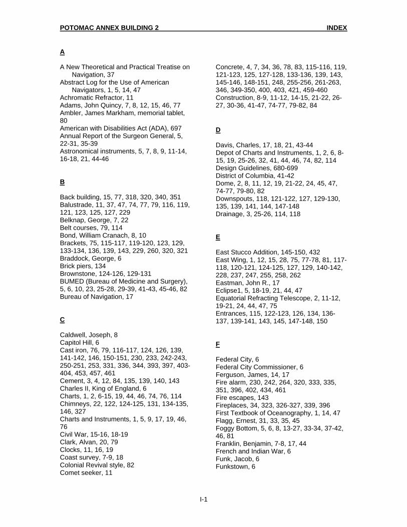
POTOMAC ANNEX BUILDING 2 INDEX
I-1
A A New Theoretical and Practical Treatise on
Navigation, 37 Abstract Log for the Use of American
Navigators, 1, 5, 14, 47 Achromatic Refractor, 11 Adams, John Quincy, 7, 8, 12, 15, 46, 77 Ambler, James Markham, memorial tablet, 80 American with Disabilities Act (ADA), 697 Annual Report of the Surgeon General, 5, 22-31, 35-39 Astronomical instruments, 5, 7, 8, 9, 11-14, 16-18, 21, 44-46 B Back building, 15, 77, 318, 320, 340, 351 Balustrade, 11, 37, 47, 74, 77, 79, 116, 119, 121, 123, 125, 127, 229 Belknap, George, 7, 22 Belt courses, 79, 114 Bond, William Cranach, 8, 10 Brackets, 75, 115-117, 119-120, 123, 129, 133-134, 136, 139, 143, 229, 260, 320, 321 Braddock, George, 6 Brick piers, 134 Brownstone, 124-126, 129-131 BUMED (Bureau of Medicine and Surgery), 5, 6, 10, 23, 25-28, 29-39, 41-43, 45-46, 82 Bureau of Navigation, 17 C Caldwell, Joseph, 8 Capitol Hill, 6 Cast iron, 76, 79, 116-117, 124, 126, 139, 141-142, 146, 150-151, 230, 233, 242-243, 250-251, 253, 331, 336, 344, 393, 397, 403-404, 453, 457, 461 Cement, 3, 4, 12, 84, 135, 139, 140, 143 Charles II, King of England, 6 Charts, 1, 2, 6-15, 19, 44, 46, 74, 76, 114 Chimneys, 22, 122, 124-125, 131, 134-135, 146, 327 Charts and Instruments, 1, 5, 9, 17, 19, 46, 76 Civil War, 15-16, 18-19 Clark, Alvan, 20, 79 Clocks, 11, 16, 19 Coast survey, 7-9, 18 Colonial Revival style, 82 Comet seeker, 11
Concrete, 4, 7, 34, 36, 78, 83, 115-116, 119, 121-123, 125, 127-128, 133-136, 139, 143, 145-146, 148-151, 248, 255-256, 261-263, 346, 349-350, 400, 403, 421, 459-460 Construction, 8-9, 11-12, 14-15, 21-22, 26-27, 30-36, 41-47, 74-77, 79-82, 84 D Davis, Charles, 17, 18, 21, 43-44 Depot of Charts and Instruments, 1, 2, 6, 8-15, 19, 25-26, 32, 41, 44, 46, 74, 82, 114 Design Guidelines, 680-699 District of Columbia, 41-42 Dome, 2, 8, 11, 12, 19, 21-22, 24, 45, 47, 74-77, 79-80, 82 Downspouts, 118, 121-122, 127, 129-130, 135, 139, 141, 144, 147-148 Drainage, 3, 25-26, 114, 118 E East Stucco Addition, 145-150, 432 East Wing, 1, 12, 15, 28, 75, 77-78, 81, 117-118, 120-121, 124-125, 127, 129, 140-142, 228, 237, 247, 255, 258, 262 Eastman, John R., 17 Eclipse1, 5, 18-19, 21, 44, 47 Equatorial Refracting Telescope, 2, 11-12, 19-21, 24, 44, 47, 75 Entrances, 115, 122-123, 126, 134, 136-137, 139-141, 143, 145, 147-148, 150 F Federal City, 6 Federal City Commissioner, 6 Ferguson, James, 14, 17 Fire alarm, 230, 242, 264, 320, 333, 335, 351, 396, 402, 434, 461 Fire escapes, 143 Fireplaces, 34, 323, 326-327, 339, 396 First Textbook of Oceanography, 1, 14, 47 Flagg, Ernest, 31, 33, 35, 45 Foggy Bottom, 5, 6, 8, 13-27, 33-34, 37-42, 46, 81 Franklin, Benjamin, 7-8, 17, 44 French and Indian War, 6 Funk, Jacob, 6 Funkstown, 6

POTOMAC ANNEX BUILDING 2 INDEX
I-2
G Gilliss, James Melville, 1, 9-13, 15-18, 46, 74-78 Glazing, 78, 329 Gneiss, 74, 77, 80, 116 Goldsborough, Louis M., 9 Gorgas, Albert C., 25-25, 27-28, 80 Granite, 4, 12, 74-75, 77, 83, 114, 116-117, 119-120, 122-123, 124, 128, 130-131, 147 Great Equatorial Observatory, 2, 79 Great Equatorial Telescope, 2, 19-20, 47 Greek Revival style, 11, 45, 47, 74, 114, 319 Gray sandstone, 74-74, 114 Gutters, 25, 84, 141, 144 H Hall, Asaph, 1, 5, 16-18, 20-21, 44, 47 Hamburg, 6, 10 Hassler, Ferdinand Rudolph, 7, 9-10 Hay, John, 16 Herman, Jan K., 76, 77, 79, 81, 84 Heating, 33, 34, 36, 76-77, 79, 81 Hunt, Richard Morris, 7, 22, 31 Hurricane, 25 Hyphen Connector (between the Residence
and the Old Naval Observatory, 1 2, 74, 77-78, 124-129, 131, 318, 328, 343
J Jefferson, Thomas, 6, 7, 46 Jenkins Hill, 6 L Landscape, 20, 41, 83, 84, 151 Lecture Hall, 24, 47, 79, 81 L'Enfant, Pierre, 6, 23 Library, 5, 10-11, 23-24, 27-28, 30, 35, 43, 76, 78-79, 80-81, 239, 261 Lincoln, Abraham, 16 Longworth, John, 6 Loomis, Elias, 8, 11, 12 M Magnetic instruments, 2 Magnetic Observatory, 2, 10, 12, 47, 77 Magnetometers, 12, 77 Maps, 84
Mansfield, Colonel Jared, 7 Mantels and mantelpieces, 243, 323, 327 Material Cleaning Analysis, 673-679 Materials Conservation Analysis, 576-651 Maury, Mathew Fontaine, 12-16, 18, 44, 47, 75-77 Mechanical and Electrical Systems, 476 Medical School, U. S. Naval, 1, 2, 74, 78, 81, 84 Medical School and Hospital, U. S. Naval, 2, 5-6, 26-31, 35-36, 38-41, 44, 46-47 Meridian Circle, 12, 17, 47, 75, 78 Meridian Transit, 11-12, 17, 75 Merz and Mahler, 12, 75-76 Meteorological instruments, 11, 17-18 Mexico, 6, 22, 29 Military Academy, U. S., 1, 8 Moons of Mars, 1,5, 29, 44, 47 Mortar Analysis, 652-672 Munsell Book of Color, 478-492-493, 495-497, 499-501 Mural Circle, 11-12, 17, 75, 80 Museum of Hygiene U. S. Naval, 2, 5-6, 22-23-28, 30-31, 44, 46, 74, 79-81, 83 N National Observatory, 1, 6-8, 13, 46 National Register of Historic Places, 46 National University, 6, 8 Navigation, 1, 77 Navigational instruments, 9.6 inch Equatorial
Refracting Telescope, 11-12, 14, 16-17, 19, 21, 47, 75-76, 79-80
Newcomb, Simon, 16-20 O Observatory Hill, 6, 22, 26, 30-31, 40-42, 44-46, 84 Observatory at University of North Carolina, 10 Observatory at Western Reserve College, 8 Observatory at Cincinnati, 8, 10 Observatory at Harvard University, 7, 19 Observatory at West Point, 10-12, 18 Observatory at Williams College, 10 Observatory at Yale University, 10, 31 Orbit of Neptune, 14, 17

POTOMAC ANNEX BUILDING 2 INDEX
I-3
P Paint Analysis, 477-575 Parapet, 74, 138-139, 147 Paving, 4 Peter, Robert, 6, 83 Peter's Hill, 6 Physical Geography of the Sea, 14, 47 Plochere colors, 492-497, 499-501 Plumbing, 80, 342, 476 Polarized Light Microscopy, 591 Porches, 37, 77, 82, 124, 127-128 Portland Cement plaster, 4 Potomac Annex, 3, 5-6, 43, 45-47, 83, 151 Potomac River, 1, 5, 6 21, 24, 46 Prime Meridian, 6, 7, 19 Prime Vertical Transit, 11, 12, 75 R Railings, 77, 115-117, 119, 122-126, 128, 134, 136, 143, 147-149, 404, 442, 460 Rehabilitation Zones, 681-685 Renovation Zones. 681-685 Report to Senate, U.S., 12, 72, 74 Reservation Number 4, 6 Restoration Zones, 681-685 Rodgers, John, 21, 44 Royal Observatory at Greenwich, England, 7, 8, 17, 19 Rust, 4, 116, 123, 134-135, 139, 146-147, 232, 240, 246, 263, 399, 402 S Sands, Benjamin Franklin, 17-20, 44, 74-75, 77 Sandstone, 20, 74-75, 77, 115-116, 119-121, 123-126, 129, 133-134, 136, 139 Schist, 74, 77, 80, 116, 119 Sheet metal, 4, 135, 139, 143-144, 146-148, 150, 405 Shutters, 75-79, 125-127, 129-130, 231-234, 242-245, 320-321, 323, 326-327, 330, 335-37, 339 Sidelights, 75, 114 Slate, 13, 15, 34-25, 77, 125, 128, 136 Stairs, 80, 115-117, 125, 148, 229-230, 234, 241, 255, 258-260 Steps, 74-75, 77-78, 114, 117, 122-124, 126, 134, 136, 139, 147 Stonework, 75-76 Stucco, 2-4, 47, 74, 79, 81, 84, 127-131, 142, 145-150
Surveyor General of the U.S., 7 South Rotunda, 1, 3, 20, 28, 44, 47, 132, 228-229, 239, 248, 255, 263, 392-393, 398 South Wing, 1, 2, 7, 12, 24, 27, 74, 81, 392 Strickland, William, 12, 82-83 Structural Conditions Survey, 475 T Time keeping, 17, 45 Transit Circle Room, 2, 11, 17, 21, 24, 44, 47, 74, 78-80 Transit Instrument in the Prime Vertical, 9, 11-12, 75 Transit Meridian Circle, 47 Transit of Venus, 5, 10, 18, 47 Twenty-Six-Inch Refracting Telescope, 2, 7, 20-21, 30, 32, 37, 75, 79-80 U University Square, 6 uPDSM Reports , 592, 594-628, 658, 660-668 V Vestibules, 230, 259 Vinyl tiles, 235, 240, 248-252, 248-249, 260, 263, 324, 340, 343, 399, 401-402, 405, 460 W Walker, Sears, 14 War Department of, U.S., 7, 10 Washington, D.C., 1, 5-10, 14-16, 18-25, 27, 30-32, 34-35, 37, 40-42, 44-46 Washington, George, 6 Water tables, 116, 119, 121, 123, 125, 128, 131, 133, 135, 138, 140 Wet Chemical Analysis, 653 West Addition, 35, 81-82, 84, 138-140, 145, 420 West Stucco Addition, 2, 3, 74, 145-150, 241, 452 West Wing, 1, 2, 12, 17, 21, 74-75, 79-81, 114-122, 140-142, 148, 228, 236, 246, 255, 261-263 Whaling chart, 1, 5, 14, 47 Wilkes, Charles, 9
POTOMAC ANNEX BUILDING 2 INDEX
I-4
Window sash, 117, 124, 126, 129, 132, 134, 136-137, 139-140, 150, 238-239, 346 World War One, 29, 37, 74, 81 Wrought Iron, 115, 119, 147 X X-Ray Diffraction, 590, 652 Y Yarnall, Mordechai, 79