Positioning Accuracy of the Shearer Based on a Strapdown ...
17
applied sciences Article Positioning Accuracy of the Shearer Based on a Strapdown Inertial Navigation System in Underground Coal Mining Gang Wu 1,2 , Xinqiu Fang 1,2, *, Lei Zhang 1,2 , Minfu Liang 1,2 , Jiakun Lv 1,2 and Zhiqiao Quan 1,2 1 Key Laboratory of Deep Coal Resource Mining, Ministry of Education of China, Xuzhou 221116, China; [email protected] (G.W.); [email protected] (L.Z.); [email protected] (M.L.); [email protected] (J.L.); [email protected] (Z.Q.) 2 School of Mines, University of Mining and Technology, Xuzhou 221116, China * Correspondence: [email protected]; Tel.: +86-516-8359-0577 Received: 2 January 2020; Accepted: 20 March 2020; Published: 23 March 2020 Abstract: Automation and intelligent coal mining comprise the most important fields in coal mining technology research. The key to automation and intelligent coal mining is the automated mining of the working face, and accurate positioning of the shearer is one of the most important technologies in the automated mining process. However, significant defects in non-inertial navigation system (INS)-based methods have led to low positioning accuracy. In this paper, we propose a new shearer positioning technology to further improve the positioning accuracy of the shearer and monitor the shearer position in real time. The shearer positioning system proposed is based on the strapdown inertial navigation system (SINS). We conducted shearer positioning experiments with gyroscopes, accelerometers, and other inertial navigation instruments. The experimental results are thoroughly studied on the basis of error compensation techniques such as inertial instrument zero bias compensation and Kalman filter compensation. Compared with traditional shearer positioning technology, the experimental results show that the shearer positioning system based on SINS can achieve more accurate positioning of the shearer and can accurately reflect the running characteristics of the shearer working the mining face. Keywords: strapdown inertial navigation system; shearer; positioning; gyroscope; accelerometer 1. Introduction China is the largest coal producer and consumer in the world according to the World Energy Annual Report in 2018. In 2017, China produced 3523 million metric tons of coal, accounting for 46% of the world’s coal production, and China’s coal consumption accounts for 51% of the world’s coal consumption. This also led to China becoming the country with the most coal mine accidents and highest number of mining injuries and deaths, especially because >90% of China’s coal is produced in underground coal mines [1]. In view of the above problems, China is implementing intelligent mining technology in coal mines nationwide [2,3]. The goal of intelligent mining technology is to realize highly automated and efficient mining through intelligent sensing of the mining environment, intelligent decision-making, and automatic control of mining equipment [4,5]. Through automated and intelligent technology, miners can be transferred from the dangerous working face to the roadway or to the ground to work during the mining process, thereby greatly reducing casualties [6]. Currently, mechanization of coal mining equipment has been realized in most coal mines in China, but the automation and intelligence level of coal mining needs to be improved [7,8]. To achieve Appl. Sci. 2020, 10, 2176; doi:10.3390/app10062176 www.mdpi.com/journal/applsci
-
Upload
khangminh22 -
Category
Documents
-
view
0 -
download
0
Transcript of Positioning Accuracy of the Shearer Based on a Strapdown ...
applied sciences
Article
Positioning Accuracy of the Shearer Based on aStrapdown Inertial Navigation System inUnderground Coal Mining
Gang Wu 1,2 , Xinqiu Fang 1,2,*, Lei Zhang 1,2, Minfu Liang 1,2, Jiakun Lv 1,2 andZhiqiao Quan 1,2
1 Key Laboratory of Deep Coal Resource Mining, Ministry of Education of China, Xuzhou 221116, China;[email protected] (G.W.); [email protected] (L.Z.); [email protected] (M.L.);[email protected] (J.L.); [email protected] (Z.Q.)
2 School of Mines, University of Mining and Technology, Xuzhou 221116, China* Correspondence: [email protected]; Tel.: +86-516-8359-0577
Received: 2 January 2020; Accepted: 20 March 2020; Published: 23 March 2020�����������������
Abstract: Automation and intelligent coal mining comprise the most important fields in coal miningtechnology research. The key to automation and intelligent coal mining is the automated mining of theworking face, and accurate positioning of the shearer is one of the most important technologies in theautomated mining process. However, significant defects in non-inertial navigation system (INS)-basedmethods have led to low positioning accuracy. In this paper, we propose a new shearer positioningtechnology to further improve the positioning accuracy of the shearer and monitor the shearer positionin real time. The shearer positioning system proposed is based on the strapdown inertial navigationsystem (SINS). We conducted shearer positioning experiments with gyroscopes, accelerometers,and other inertial navigation instruments. The experimental results are thoroughly studied on thebasis of error compensation techniques such as inertial instrument zero bias compensation and Kalmanfilter compensation. Compared with traditional shearer positioning technology, the experimentalresults show that the shearer positioning system based on SINS can achieve more accurate positioningof the shearer and can accurately reflect the running characteristics of the shearer working themining face.
Keywords: strapdown inertial navigation system; shearer; positioning; gyroscope; accelerometer
1. Introduction
China is the largest coal producer and consumer in the world according to the World EnergyAnnual Report in 2018. In 2017, China produced 3523 million metric tons of coal, accounting for 46%of the world’s coal production, and China’s coal consumption accounts for 51% of the world’s coalconsumption. This also led to China becoming the country with the most coal mine accidents andhighest number of mining injuries and deaths, especially because >90% of China’s coal is producedin underground coal mines [1]. In view of the above problems, China is implementing intelligentmining technology in coal mines nationwide [2,3]. The goal of intelligent mining technology is torealize highly automated and efficient mining through intelligent sensing of the mining environment,intelligent decision-making, and automatic control of mining equipment [4,5]. Through automatedand intelligent technology, miners can be transferred from the dangerous working face to the roadwayor to the ground to work during the mining process, thereby greatly reducing casualties [6].
Currently, mechanization of coal mining equipment has been realized in most coal mines inChina, but the automation and intelligence level of coal mining needs to be improved [7,8]. To achieve
Appl. Sci. 2020, 10, 2176; doi:10.3390/app10062176 www.mdpi.com/journal/applsci
Appl. Sci. 2020, 10, 2176 2 of 17
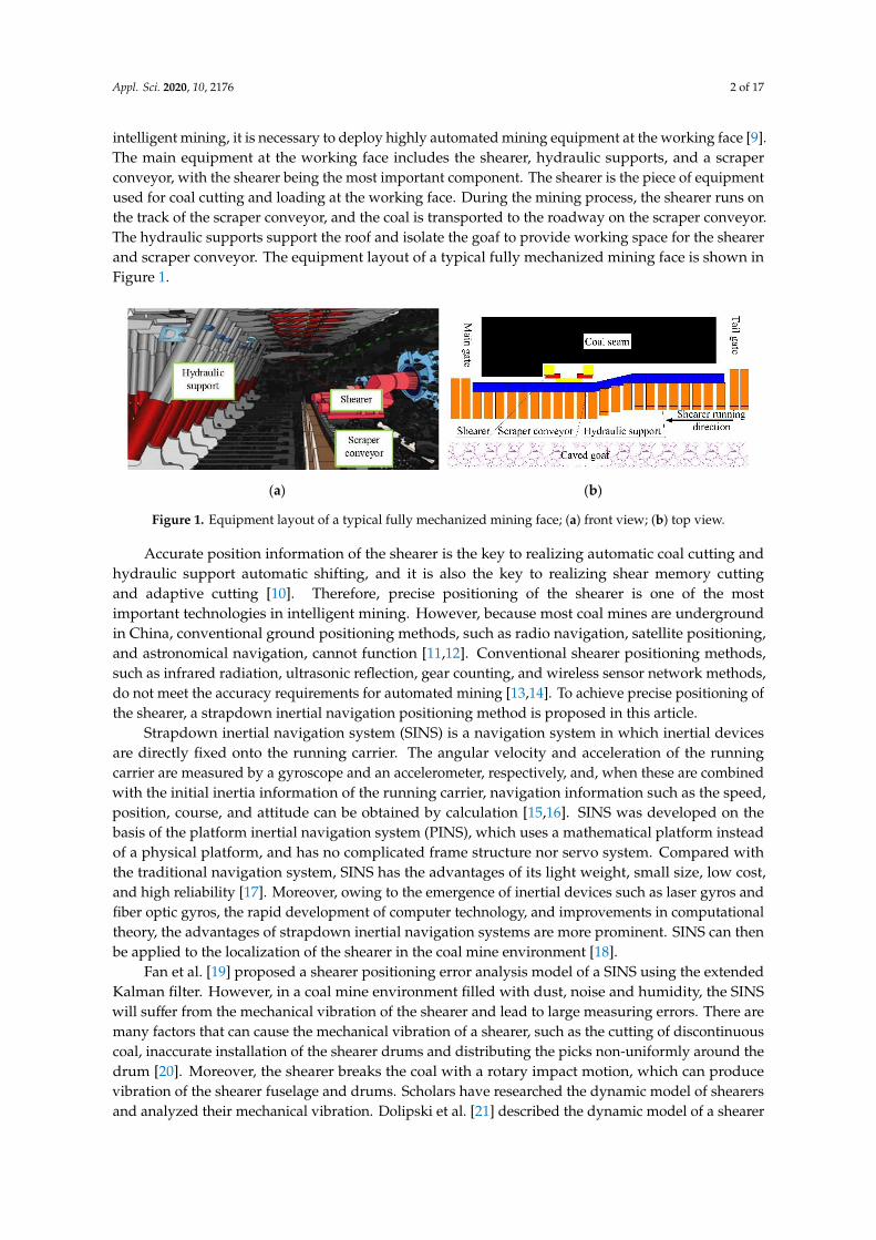
intelligent mining, it is necessary to deploy highly automated mining equipment at the working face [9].The main equipment at the working face includes the shearer, hydraulic supports, and a scraperconveyor, with the shearer being the most important component. The shearer is the piece of equipmentused for coal cutting and loading at the working face. During the mining process, the shearer runs onthe track of the scraper conveyor, and the coal is transported to the roadway on the scraper conveyor.The hydraulic supports support the roof and isolate the goaf to provide working space for the shearerand scraper conveyor. The equipment layout of a typical fully mechanized mining face is shown inFigure 1.
Appl. Sci. 2019, 12, x FOR PEER REVIEW 2 of 18
[9]. The main equipment at the working face includes the shearer, hydraulic supports, and a scraper
conveyor, with the shearer being the most important component. The shearer is the piece of
equipment used for coal cutting and loading at the working face. During the mining process, the
shearer runs on the track of the scraper conveyor, and the coal is transported to the roadway on the
scraper conveyor. The hydraulic supports support the roof and isolate the goaf to provide working
space for the shearer and scraper conveyor. The equipment layout of a typical fully mechanized
mining face is shown in Figure 1.
(a) (b)
Figure 1. Equipment layout of a typical fully mechanized mining face; (a) front view; (b) top view.
Accurate position information of the shearer is the key to realizing automatic coal cutting and
hydraulic support automatic shifting, and it is also the key to realizing shear memory cutting and
adaptive cutting [10]. Therefore, precise positioning of the shearer is one of the most important
technologies in intelligent mining. However, because most coal mines are underground in China,
conventional ground positioning methods, such as radio navigation, satellite positioning, and
astronomical navigation, cannot function [11,12]. Conventional shearer positioning methods, such as
infrared radiation, ultrasonic reflection, gear counting, and wireless sensor network methods, do not
meet the accuracy requirements for automated mining [13,14]. To achieve precise positioning of the
shearer, a strapdown inertial navigation positioning method is proposed in this article.
Strapdown inertial navigation system (SINS) is a navigation system in which inertial devices are
directly fixed onto the running carrier. The angular velocity and acceleration of the running carrier
are measured by a gyroscope and an accelerometer, respectively, and, when these are combined with
the initial inertia information of the running carrier, navigation information such as the speed,
position, course, and attitude can be obtained by calculation [15,16]. SINS was developed on the basis
of the platform inertial navigation system (PINS), which uses a mathematical platform instead of a
physical platform, and has no complicated frame structure nor servo system. Compared with the
traditional navigation system, SINS has the advantages of its light weight, small size, low cost, and
high reliability [17]. Moreover, owing to the emergence of inertial devices such as laser gyros and
fiber optic gyros, the rapid development of computer technology, and improvements in
computational theory, the advantages of strapdown inertial navigation systems are more prominent.
SINS can then be applied to the localization of the shearer in the coal mine environment [18].
Fan et al. [19] proposed a shearer positioning error analysis model of a SINS using the extended
Kalman filter. However, in a coal mine environment filled with dust, noise and humidity, the SINS
will suffer from the mechanical vibration of the shearer and lead to large measuring errors. There are
many factors that can cause the mechanical vibration of a shearer, such as the cutting of discontinuous
coal, inaccurate installation of the shearer drums and distributing the picks non-uniformly around
the drum [20]. Moreover, the shearer breaks the coal with a rotary impact motion, which can produce
vibration of the shearer fuselage and drums. Scholars have researched the dynamic model of shearers
and analyzed their mechanical vibration. Dolipski et al. [21] described the dynamic model of a shearer
cutting system and calculated the differential equations of the dynamic model using the Runge-Kutta
iterative method.
Figure 1. Equipment layout of a typical fully mechanized mining face; (a) front view; (b) top view.
Accurate position information of the shearer is the key to realizing automatic coal cutting andhydraulic support automatic shifting, and it is also the key to realizing shear memory cuttingand adaptive cutting [10]. Therefore, precise positioning of the shearer is one of the mostimportant technologies in intelligent mining. However, because most coal mines are undergroundin China, conventional ground positioning methods, such as radio navigation, satellite positioning,and astronomical navigation, cannot function [11,12]. Conventional shearer positioning methods,such as infrared radiation, ultrasonic reflection, gear counting, and wireless sensor network methods,do not meet the accuracy requirements for automated mining [13,14]. To achieve precise positioning ofthe shearer, a strapdown inertial navigation positioning method is proposed in this article.
Strapdown inertial navigation system (SINS) is a navigation system in which inertial devicesare directly fixed onto the running carrier. The angular velocity and acceleration of the runningcarrier are measured by a gyroscope and an accelerometer, respectively, and, when these are combinedwith the initial inertia information of the running carrier, navigation information such as the speed,position, course, and attitude can be obtained by calculation [15,16]. SINS was developed on thebasis of the platform inertial navigation system (PINS), which uses a mathematical platform insteadof a physical platform, and has no complicated frame structure nor servo system. Compared withthe traditional navigation system, SINS has the advantages of its light weight, small size, low cost,and high reliability [17]. Moreover, owing to the emergence of inertial devices such as laser gyros andfiber optic gyros, the rapid development of computer technology, and improvements in computationaltheory, the advantages of strapdown inertial navigation systems are more prominent. SINS can thenbe applied to the localization of the shearer in the coal mine environment [18].
Fan et al. [19] proposed a shearer positioning error analysis model of a SINS using the extendedKalman filter. However, in a coal mine environment filled with dust, noise and humidity, the SINSwill suffer from the mechanical vibration of the shearer and lead to large measuring errors. There aremany factors that can cause the mechanical vibration of a shearer, such as the cutting of discontinuouscoal, inaccurate installation of the shearer drums and distributing the picks non-uniformly around thedrum [20]. Moreover, the shearer breaks the coal with a rotary impact motion, which can producevibration of the shearer fuselage and drums. Scholars have researched the dynamic model of shearersand analyzed their mechanical vibration. Dolipski et al. [21] described the dynamic model of a shearer
Appl. Sci. 2020, 10, 2176 3 of 17
cutting system and calculated the differential equations of the dynamic model using the Runge-Kuttaiterative method.
Currently, the widely used SINS utilizes low-cost micro electro mechanical systems (MEMS)inertial sensors, which directly measure acceleration and angular rate [22]. Unfortunately, the geareccentricity and manufacturing error and clearances at joints can cause angular vibration and linearvibration of the shearer [23]. The mechanical vibration of the shearer fuselage, including angularvibration and linear vibration, can reduce the accuracy of the measured acceleration and angularvelocity, resulting in the positioning error of the SINS [24]. The angular vibration can lead to a coningerror, which can affect the calculation of the attitude update [25]. Meanwhile, the angular vibrationand linear vibration can lead to a sculling error, which will affect the calculation of velocity update andposition update [26]. The study of these two errors is common. Since Bortz [27] proposed the theoryof the rotation vector in 1971, the noncommutativity error of SINS has been effectively solved [28].Kang et al. [29] proposed a direct coning mitigation algorithm based on the sinusoidal component ofgyro measurements. This algorithm can be applied to the mitigation of sculling errors. Lai et al. [30]analyzed the SINS coning error for the vibration of unmanned aerial vehicles and proposed anintegrated vibration model between sinusoidal angular vibration and random angular vibration.Meanwhile, the coning error is compensated by the multi-sample algorithm.
In this paper, we established a shearer positioning system for a fully mechanized working facebased on the SINS [31], and we conducted an independent positioning experiment on the shearer.The experimental results show that the shearer positioning system based on SINS can accurately reflectthe position information of the shearer.
2. Shearer Positioning System Based on SINS
2.1. Principle of the Shearer Positioning System Based on SINS
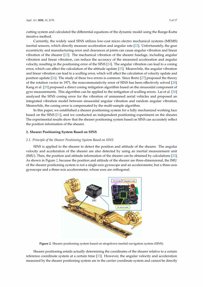
SINS is applied to the shearer to detect the position and attitude of the shearer. The angularvelocity and acceleration of the shearer are also detected by using an inertial measurement unit(IMU). Then, the position and attitude information of the shearer can be obtained by calculations [32].As shown in Figure 2, because the position and attitude of the shearer are three-dimensional, the IMUof the shearer positioning system is not a single-axis gyroscope and an accelerometer, but a three-axisgyroscope and a three-axis accelerometer, whose axes are orthogonal.
Appl. Sci. 2019, 12, x FOR PEER REVIEW 3 of 18
Currently, the widely used SINS utilizes low‐cost micro electro mechanical systems (MEMS)
inertial sensors, which directly measure acceleration and angular rate [22]. Unfortunately, the gear
eccentricity and manufacturing error and clearances at joints can cause angular vibration and linear
vibration of the shearer [23]. The mechanical vibration of the shearer fuselage, including angular
vibration and linear vibration, can reduce the accuracy of the measured acceleration and angular
velocity, resulting in the positioning error of the SINS [24]. The angular vibration can lead to a coning
error, which can affect the calculation of the attitude update [25]. Meanwhile, the angular vibration
and linear vibration can lead to a sculling error, which will affect the calculation of velocity update
and position update [26]. The study of these two errors is common. Since Bortz [27] proposed the
theory of the rotation vector in 1971, the noncommutativity error of SINS has been effectively solved
[28]. Kang et al. [29] proposed a direct coning mitigation algorithm based on the sinusoidal
component of gyro measurements. This algorithm can be applied to the mitigation of sculling errors.
Lai et al. [30] analyzed the SINS coning error for the vibration of unmanned aerial vehicles and
proposed an integrated vibration model between sinusoidal angular vibration and random angular
vibration. Meanwhile, the coning error is compensated by the multi‐sample algorithm.
In this paper, we established a shearer positioning system for a fully mechanized working face
based on the SINS [31], and we conducted an independent positioning experiment on the shearer.
The experimental results show that the shearer positioning system based on SINS can accurately
reflect the position information of the shearer.
2. Shearer Positioning System Based on SINS
2.1. Principle of the Shearer Positioning System Based on SINS
SINS is applied to the shearer to detect the position and attitude of the shearer. The angular
velocity and acceleration of the shearer are also detected by using an inertial measurement unit
(IMU). Then, the position and attitude information of the shearer can be obtained by calculations [32].
As shown in Figure 2, because the position and attitude of the shearer are three‐dimensional, the IMU
of the shearer positioning system is not a single‐axis gyroscope and an accelerometer, but a three‐axis
gyroscope and a three‐axis accelerometer, whose axes are orthogonal.
Figure 2. Shearer positioning system based on strapdown inertial navigation system (SINS).
Shearer positioning entails actually determining the coordinates of the shearer relative to a
certain reference coordinate system at a certain time [33]. However, the angular velocity and
acceleration measured by the shearer positioning system are in the carrier coordinate system and
cannot be directly used for the calculation of the position and attitude of the shearer. To solve the
position and attitude of the shearer, it is necessary to convert the carrier coordinate system to the
navigation coordinate system. Most mine maps are based on the geographic coordinate system. The
Figure 2. Shearer positioning system based on strapdown inertial navigation system (SINS).
Shearer positioning entails actually determining the coordinates of the shearer relative to a certainreference coordinate system at a certain time [33]. However, the angular velocity and accelerationmeasured by the shearer positioning system are in the carrier coordinate system and cannot be directly
Appl. Sci. 2020, 10, 2176 4 of 17
used for the calculation of the position and attitude of the shearer. To solve the position and attitudeof the shearer, it is necessary to convert the carrier coordinate system to the navigation coordinatesystem. Most mine maps are based on the geographic coordinate system. The geographic coordinatesystem is used as the navigation coordinate system; this will alleviate the need to convert the minemap coordinate information in the navigation coordinate system, reducing the calculation burden ofthe positioning system [34–38].
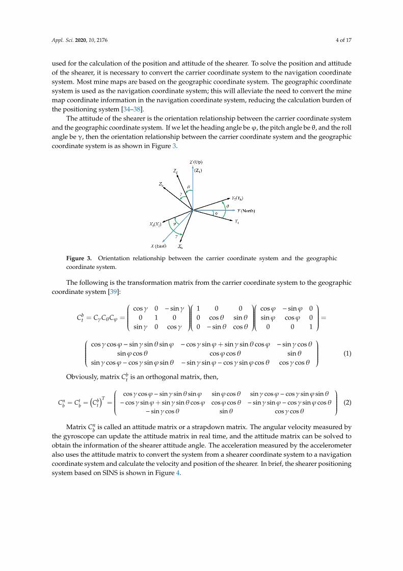
The attitude of the shearer is the orientation relationship between the carrier coordinate systemand the geographic coordinate system. If we let the heading angle beϕ, the pitch angle be θ, and the rollangle be γ, then the orientation relationship between the carrier coordinate system and the geographiccoordinate system is as shown in Figure 3.
Appl. Sci. 2019, 12, x FOR PEER REVIEW 4 of 18
geographic coordinate system is used as the navigation coordinate system; this will alleviate the need
to convert the mine map coordinate information in the navigation coordinate system, reducing the
calculation burden of the positioning system [34–38].
The attitude of the shearer is the orientation relationship between the carrier coordinate system
and the geographic coordinate system. If we let the heading angle be φ, the pitch angle be θ, and the
roll angle be γ, then the orientation relationship between the carrier coordinate system and the
geographic coordinate system is as shown in Figure 3.
Figure 3. Orientation relationship between the carrier coordinate system and the geographic
coordinate system.
The following is the transformation matrix from the carrier coordinate system to the geographic
coordinate system [39]:
cos 0 sin 1 0 0 cos sin 0
= 0 1 0 0 cos sin sin cos 0
sin 0 cos 0 sin cos 0 0 1
btC C C C
cos cos sin sin sin cos sin sin sin cos sin cos
sin cos cos cos sin
sin cos cos sin sin sin sin cos sin cos cos cos
(1)
Obviously, matrix btC is an orthogonal matrix, then,
cos cos sin sin sin sin cos sin cos cos sin sin
cos sin sin sin cos cos cos sin sin cos sin cos
sin cos sin cos cos
Tn t bb b tC C C
(2)
Matrix nbC is called an attitude matrix or a strapdown matrix. The angular velocity measured
by the gyroscope can update the attitude matrix in real time, and the attitude matrix can be solved to
obtain the information of the shearer attitude angle. The acceleration measured by the accelerometer
also uses the attitude matrix to convert the system from a shearer coordinate system to a navigation
coordinate system and calculate the velocity and position of the shearer. In brief, the shearer
positioning system based on SINS is shown in Figure 4.
Figure 3. Orientation relationship between the carrier coordinate system and the geographiccoordinate system.
The following is the transformation matrix from the carrier coordinate system to the geographiccoordinate system [39]:
Cbt = CγCθCϕ =
cosγ 0 − sinγ
0 1 0sinγ 0 cosγ
1 0 00 cosθ sinθ0 − sinθ cosθ
cosϕ − sinϕ 0sinϕ cosϕ 0
0 0 1
=
cosγ cosϕ− sinγ sinθ sinϕ − cosγ sinϕ+ sinγ sinθ cosϕ − sinγ cosθsinϕ cosθ cosϕ cosθ sinθ
sinγ cosϕ− cosγ sinϕ sinθ − sinγ sinϕ− cosγ sinϕ cosθ cosγ cosθ
(1)
Obviously, matrix Cbt is an orthogonal matrix, then,
Cnb = Ct
b =(Cb
t
)T=
cosγ cosϕ− sinγ sinθ sinϕ sinϕ cosθ sinγ cosϕ− cosγ sinϕ sinθ− cosγ sinϕ+ sinγ sinθ cosϕ cosϕ cosθ − sinγ sinϕ− cosγ sinϕ cosθ
− sinγ cosθ sinθ cosγ cosθ
(2)
Matrix Cnb is called an attitude matrix or a strapdown matrix. The angular velocity measured by
the gyroscope can update the attitude matrix in real time, and the attitude matrix can be solved toobtain the information of the shearer attitude angle. The acceleration measured by the accelerometeralso uses the attitude matrix to convert the system from a shearer coordinate system to a navigationcoordinate system and calculate the velocity and position of the shearer. In brief, the shearer positioningsystem based on SINS is shown in Figure 4.
Appl. Sci. 2020, 10, 2176 5 of 17
Appl. Sci. 2019, 12, x FOR PEER REVIEW 5 of 18
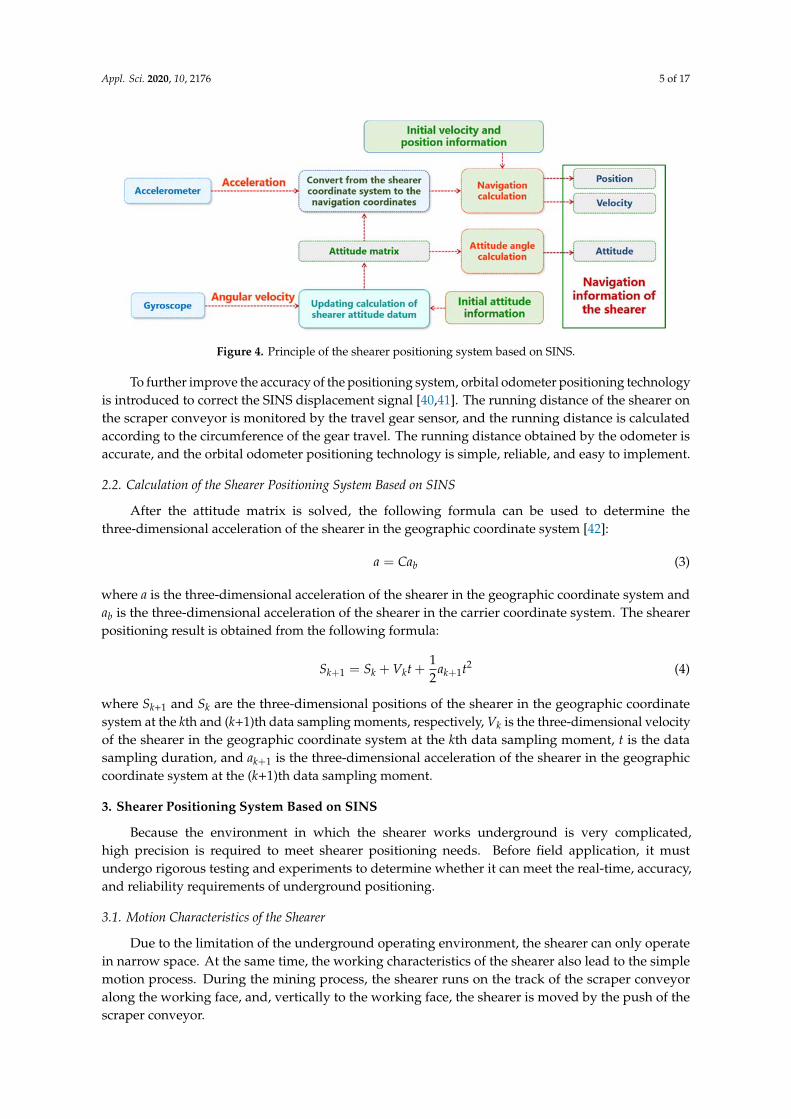
Figure 4. Principle of the shearer positioning system based on SINS.
To further improve the accuracy of the positioning system, orbital odometer positioning
technology is introduced to correct the SINS displacement signal [40,41]. The running distance of the
shearer on the scraper conveyor is monitored by the travel gear sensor, and the running distance is
calculated according to the circumference of the gear travel. The running distance obtained by the
odometer is accurate, and the orbital odometer positioning technology is simple, reliable, and easy to
implement.
2.2. Calculation of the Shearer Positioning System Based on SINS
After the attitude matrix is solved, the following formula can be used to determine the three‐
dimensional acceleration of the shearer in the geographic coordinate system [42]:
ba Ca (3)
where a is the three‐dimensional acceleration of the shearer in the geographic coordinate system
and ba is the three‐dimensional acceleration of the shearer in the carrier coordinate system. The
shearer positioning result is obtained from the following formula:
21 1
1
2k k k kS S V t a t (4)
where Sk+1 and Sk are the three‐dimensional positions of the shearer in the geographic coordinate
system at the kth and (k+1)th data sampling moments, respectively, Vk is the three‐dimensional
velocity of the shearer in the geographic coordinate system at the kth data sampling moment, t is the
data sampling duration, and 1ka is the three‐dimensional acceleration of the shearer in the
geographic coordinate system at the (k+1)th data sampling moment.
3. Shearer Positioning System Based on SINS
Because the environment in which the shearer works underground is very complicated, high
precision is required to meet shearer positioning needs. Before field application, it must undergo
rigorous testing and experiments to determine whether it can meet the real‐time, accuracy, and
reliability requirements of underground positioning.
3.1. Motion Characteristics of the Shearer
Due to the limitation of the underground operating environment, the shearer can only operate
in narrow space. At the same time, the working characteristics of the shearer also lead to the simple
motion process. During the mining process, the shearer runs on the track of the scraper conveyor
along the working face, and, vertically to the working face, the shearer is moved by the push of the
scraper conveyor.
Figure 4. Principle of the shearer positioning system based on SINS.
To further improve the accuracy of the positioning system, orbital odometer positioning technologyis introduced to correct the SINS displacement signal [40,41]. The running distance of the shearer onthe scraper conveyor is monitored by the travel gear sensor, and the running distance is calculatedaccording to the circumference of the gear travel. The running distance obtained by the odometer isaccurate, and the orbital odometer positioning technology is simple, reliable, and easy to implement.
2.2. Calculation of the Shearer Positioning System Based on SINS
After the attitude matrix is solved, the following formula can be used to determine thethree-dimensional acceleration of the shearer in the geographic coordinate system [42]:
a = Cab (3)
where a is the three-dimensional acceleration of the shearer in the geographic coordinate system andab is the three-dimensional acceleration of the shearer in the carrier coordinate system. The shearerpositioning result is obtained from the following formula:
Sk+1 = Sk + Vkt +12
ak+1t2 (4)
where Sk+1 and Sk are the three-dimensional positions of the shearer in the geographic coordinatesystem at the kth and (k+1)th data sampling moments, respectively, Vk is the three-dimensional velocityof the shearer in the geographic coordinate system at the kth data sampling moment, t is the datasampling duration, and ak+1 is the three-dimensional acceleration of the shearer in the geographiccoordinate system at the (k+1)th data sampling moment.
3. Shearer Positioning System Based on SINS
Because the environment in which the shearer works underground is very complicated,high precision is required to meet shearer positioning needs. Before field application, it mustundergo rigorous testing and experiments to determine whether it can meet the real-time, accuracy,and reliability requirements of underground positioning.
3.1. Motion Characteristics of the Shearer
Due to the limitation of the underground operating environment, the shearer can only operatein narrow space. At the same time, the working characteristics of the shearer also lead to the simplemotion process. During the mining process, the shearer runs on the track of the scraper conveyoralong the working face, and, vertically to the working face, the shearer is moved by the push of thescraper conveyor.
Appl. Sci. 2020, 10, 2176 6 of 17
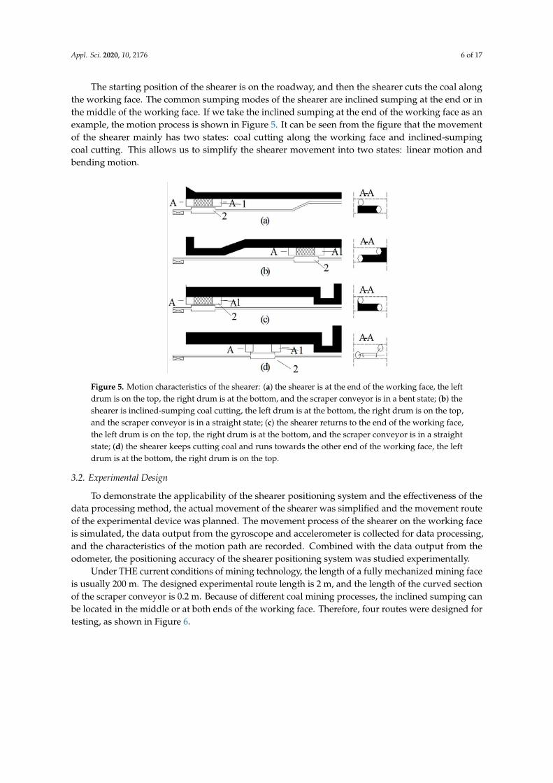
The starting position of the shearer is on the roadway, and then the shearer cuts the coal alongthe working face. The common sumping modes of the shearer are inclined sumping at the end or inthe middle of the working face. If we take the inclined sumping at the end of the working face as anexample, the motion process is shown in Figure 5. It can be seen from the figure that the movementof the shearer mainly has two states: coal cutting along the working face and inclined-sumpingcoal cutting. This allows us to simplify the shearer movement into two states: linear motion andbending motion.
Appl. Sci. 2019, 12, x FOR PEER REVIEW 6 of 18
The starting position of the shearer is on the roadway, and then the shearer cuts the coal along
the working face. The common sumping modes of the shearer are inclined sumping at the end or in
the middle of the working face. If we take the inclined sumping at the end of the working face as an
example, the motion process is shown in Figure 5. It can be seen from the figure that the movement
of the shearer mainly has two states: coal cutting along the working face and inclined‐sumping coal
cutting. This allows us to simplify the shearer movement into two states: linear motion and bending
motion.
Figure 5. Motion characteristics of the shearer: (a) the shearer is at the end of the working face, the left
drum is on the top, the right drum is at the bottom, and the scraper conveyor is in a bent state; (b) the
shearer is inclined‐sumping coal cutting, the left drum is at the bottom, the right drum is on the top,
and the scraper conveyor is in a straight state; (c) the shearer returns to the end of the working face,
the left drum is on the top, the right drum is at the bottom, and the scraper conveyor is in a straight
state; (d) the shearer keeps cutting coal and runs towards the other end of the working face, the left
drum is at the bottom, the right drum is on the top.
3.2. Experimental Design
To demonstrate the applicability of the shearer positioning system and the effectiveness of the
data processing method, the actual movement of the shearer was simplified and the movement route
of the experimental device was planned. The movement process of the shearer on the working face
is simulated, the data output from the gyroscope and accelerometer is collected for data processing,
and the characteristics of the motion path are recorded. Combined with the data output from the
odometer, the positioning accuracy of the shearer positioning system was studied experimentally.
Under THE current conditions of mining technology, the length of a fully mechanized mining
face is usually 200 m. The designed experimental route length is 2 m, and the length of the curved
section of the scraper conveyor is 0.2 m. Because of different coal mining processes, the inclined
sumping can be located in the middle or at both ends of the working face. Therefore, four routes were
designed for testing, as shown in Figure 6.
Figure 5. Motion characteristics of the shearer: (a) the shearer is at the end of the working face, the leftdrum is on the top, the right drum is at the bottom, and the scraper conveyor is in a bent state; (b) theshearer is inclined-sumping coal cutting, the left drum is at the bottom, the right drum is on the top,and the scraper conveyor is in a straight state; (c) the shearer returns to the end of the working face,the left drum is on the top, the right drum is at the bottom, and the scraper conveyor is in a straightstate; (d) the shearer keeps cutting coal and runs towards the other end of the working face, the leftdrum is at the bottom, the right drum is on the top.
3.2. Experimental Design
To demonstrate the applicability of the shearer positioning system and the effectiveness of thedata processing method, the actual movement of the shearer was simplified and the movement routeof the experimental device was planned. The movement process of the shearer on the working faceis simulated, the data output from the gyroscope and accelerometer is collected for data processing,and the characteristics of the motion path are recorded. Combined with the data output from theodometer, the positioning accuracy of the shearer positioning system was studied experimentally.
Under THE current conditions of mining technology, the length of a fully mechanized mining faceis usually 200 m. The designed experimental route length is 2 m, and the length of the curved sectionof the scraper conveyor is 0.2 m. Because of different coal mining processes, the inclined sumping canbe located in the middle or at both ends of the working face. Therefore, four routes were designed fortesting, as shown in Figure 6.
Appl. Sci. 2020, 10, 2176 7 of 17
Appl. Sci. 2019, 12, x FOR PEER REVIEW 6 of 18
The starting position of the shearer is on the roadway, and then the shearer cuts the coal along
the working face. The common sumping modes of the shearer are inclined sumping at the end or in
the middle of the working face. If we take the inclined sumping at the end of the working face as an
example, the motion process is shown in Figure 5. It can be seen from the figure that the movement
of the shearer mainly has two states: coal cutting along the working face and inclined‐sumping coal
cutting. This allows us to simplify the shearer movement into two states: linear motion and bending
motion.
Figure 5. Motion characteristics of the shearer: (a) the shearer is at the end of the working face, the left
drum is on the top, the right drum is at the bottom, and the scraper conveyor is in a bent state; (b) the
shearer is inclined‐sumping coal cutting, the left drum is at the bottom, the right drum is on the top,
and the scraper conveyor is in a straight state; (c) the shearer returns to the end of the working face,
the left drum is on the top, the right drum is at the bottom, and the scraper conveyor is in a straight
state; (d) the shearer keeps cutting coal and runs towards the other end of the working face, the left
drum is at the bottom, the right drum is on the top.
3.2. Experimental Design
To demonstrate the applicability of the shearer positioning system and the effectiveness of the
data processing method, the actual movement of the shearer was simplified and the movement route
of the experimental device was planned. The movement process of the shearer on the working face
is simulated, the data output from the gyroscope and accelerometer is collected for data processing,
and the characteristics of the motion path are recorded. Combined with the data output from the
odometer, the positioning accuracy of the shearer positioning system was studied experimentally.
Under THE current conditions of mining technology, the length of a fully mechanized mining
face is usually 200 m. The designed experimental route length is 2 m, and the length of the curved
section of the scraper conveyor is 0.2 m. Because of different coal mining processes, the inclined
sumping can be located in the middle or at both ends of the working face. Therefore, four routes were
designed for testing, as shown in Figure 6.
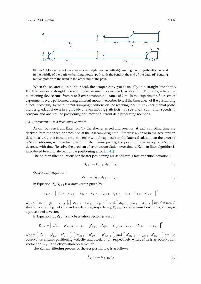
Figure 6. Motion path of the shearer: (a) straight motion path; (b) bending motion path with the bendin the middle of the path; (c) bending motion path with the bend in the end of the path; (d) bendingmotion path with the bend in the other end of the path.
When the shearer does not cut coal, the scraper conveyor is usually in a straight line shape.For this reason, a straight line running experiment is designed, as shown in Figure 6a, where thepositioning device runs from A to B over a running distance of 2 m. In the experiment, four sets ofexperiments were performed using different motion velocities to test the time effect of the positioningeffect. According to the different sumping positions on the working face, three experimental pathsare designed, as shown in Figure 6b–d. Each moving path tests two sets of data at motion speeds tocompare and analyze the positioning accuracy of different data processing methods.
3.3. Experimental Data Processing Methods
As can be seen from Equation (4), the shearer speed and position at each sampling time arederived from the speed and position at the last sampling time. If there is an error in the accelerationdata measured at a certain time, the error will always exist in the later calculation, so the error ofSINS positioning will gradually accumulate. Consequently, the positioning accuracy of SINS willdecrease with time. To solve the problem of error accumulation over time, a Kalman filter algorithm isintroduced to eliminate part of the positioning error [43,44].
The Kalman filter equations for shearer positioning are as follows. State transition equation:
Xk+1 = Φk+1|kXk +ωk. (5)
Observation equation:Zk+1 = Hk+1Xk+1 + νk+1. (6)
In Equation (5), Xk+1 is a state vector, given by
Xk+1 =[
xk+1 vx|k+1 ax|k+1 yk+1 vy|k+1 ay|k+1 zk+1 vz|k+1 az|k+1
]T
where[
xk+1 yk+1 zk+1
],[
vx|k+1 vy|k+1 vz|k+1
], and
[ax|k+1 ay|k+1 az|k+1
]are the actual
shearer positioning, velocity, and acceleration, respectively, Φk+1|k is a state transition matrix, and ωk isa process noise vector.
In Equation (6), Zk+1 is an observation vector, given by
Zk+1 =[
x′k+1 v′x|k+1 a′x|k+1 y′k+1 v′y|k+1 a′y|k+1 z′k+1 v′z|k+1 a′z|k+1
]T
where[
x′k+1 y′k+1 z′k+1
],[
v′x|k+1 v′y|k+1 v′z|k+1
], and
[a′x|k+1 a′y|k+1 a′z|k+1
]are the
observation shearer positioning, velocity, and acceleration, respectively, where Hk+1 is an observationvector and νk+1 is an observation noise vector.
The Kalman filtering process of shearer positioning is as follows:
X̂k+1|k = Φk+1|kX̂k (7)
Appl. Sci. 2020, 10, 2176 8 of 17
where X̂k+1|k is the predicted value of X̂k and X̂k is the optimal estimated state vector of Xk. Also,the predicted value of Pk is
Pk+1|k = Φk+1|kPkΦTk+1|k + Qk (8)
where Pk, Pk+1|k, Qk, and Ok+1 are the covariance matrices of Xk, Xk+1, ωk and νk, respectively, and Pkis the covariance matrix of the state vector.
The filter gain matrix is
Kk+1 = Pk+1|kHTk+1
[Hk+1Pk+1|kHT
k+1|k + Ok+1
]−1(9)
The optimal estimated state vector of Xk+1 is
X̂k+1 = X̂k+1|k + Kk+1
(Zk+1 −Hk+1X̂k+1|k
)(10)
andPk+1 = Pk+1|k(I −Kk+1Hk+1) (11)
where I is the identity matrix.In this experiment, the data obtained after compensation are decomposed along the X- and Y-axis
directions, and the distribution of the estimated points is determined according to the dead reckoningprinciple and formula fitting.
4. Analysis of the Experimental Results
4.1. Straight-Line Running Positioning Experiments
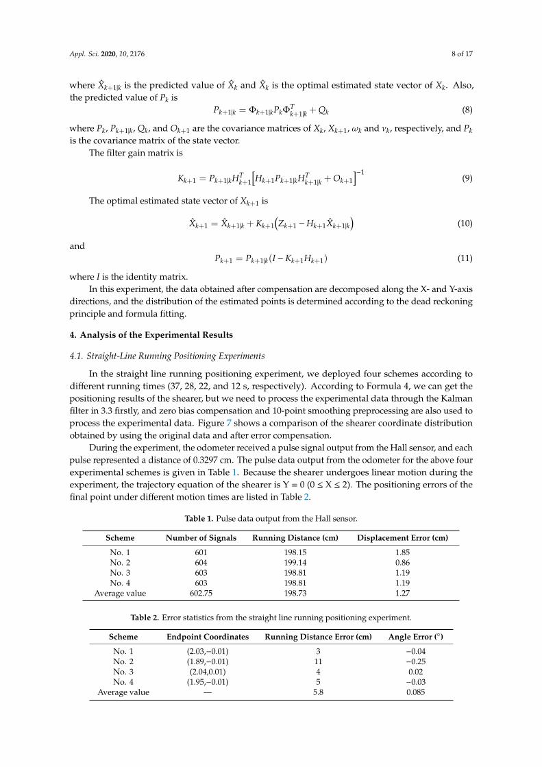
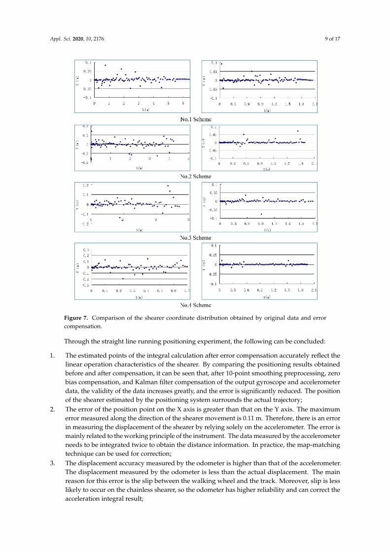
In the straight line running positioning experiment, we deployed four schemes according todifferent running times (37, 28, 22, and 12 s, respectively). According to Formula 4, we can get thepositioning results of the shearer, but we need to process the experimental data through the Kalmanfilter in 3.3 firstly, and zero bias compensation and 10-point smoothing preprocessing are also used toprocess the experimental data. Figure 7 shows a comparison of the shearer coordinate distributionobtained by using the original data and after error compensation.
During the experiment, the odometer received a pulse signal output from the Hall sensor, and eachpulse represented a distance of 0.3297 cm. The pulse data output from the odometer for the above fourexperimental schemes is given in Table 1. Because the shearer undergoes linear motion during theexperiment, the trajectory equation of the shearer is Y = 0 (0 ≤ X ≤ 2). The positioning errors of thefinal point under different motion times are listed in Table 2.
Table 1. Pulse data output from the Hall sensor.
Scheme Number of Signals Running Distance (cm) Displacement Error (cm)
No. 1 601 198.15 1.85No. 2 604 199.14 0.86No. 3 603 198.81 1.19No. 4 603 198.81 1.19
Average value 602.75 198.73 1.27
Table 2. Error statistics from the straight line running positioning experiment.
Scheme Endpoint Coordinates Running Distance Error (cm) Angle Error (◦)
No. 1 (2.03,−0.01) 3 −0.04No. 2 (1.89,−0.01) 11 −0.25No. 3 (2.04,0.01) 4 0.02No. 4 (1.95,−0.01) 5 −0.03
Average value — 5.8 0.085
Appl. Sci. 2020, 10, 2176 9 of 17Appl. Sci. 2019, 12, x FOR PEER REVIEW 9 of 18
Figure 7. Comparison of the shearer coordinate distribution obtained by original data and error
compensation.
During the experiment, the odometer received a pulse signal output from the Hall sensor, and
each pulse represented a distance of 0.3297 cm. The pulse data output from the odometer for the
above four experimental schemes is given in Table 1. Because the shearer undergoes linear motion
during the experiment, the trajectory equation of the shearer is Y = 0 (0 ≤ X ≤ 2). The positioning errors
of the final point under different motion times are listed in Table 2.
Table 1. Pulse data output from the Hall sensor.
Scheme Number of signals Running distance (cm) Displacement error (cm)
No. 1 601 198.15 1.85
No. 2 604 199.14 0.86
No. 3 603 198.81 1.19
No. 4 603 198.81 1.19
Average value 602.75 198.73 1.27
Table 2. Error statistics from the straight line running positioning experiment.
Scheme Endpoint coordinates Running distance error (cm) Angle error (°)
No. 1 (2.03,−0.01) 3 −0.04
No. 2 (1.89,−0.01) 11 −0.25
No. 3 (2.04,0.01) 4 0.02
Figure 7. Comparison of the shearer coordinate distribution obtained by original data and errorcompensation.
Through the straight line running positioning experiment, the following can be concluded:
1. The estimated points of the integral calculation after error compensation accurately reflect thelinear operation characteristics of the shearer. By comparing the positioning results obtainedbefore and after compensation, it can be seen that, after 10-point smoothing preprocessing, zerobias compensation, and Kalman filter compensation of the output gyroscope and accelerometerdata, the validity of the data increases greatly, and the error is significantly reduced. The positionof the shearer estimated by the positioning system surrounds the actual trajectory;
2. The error of the position point on the X axis is greater than that on the Y axis. The maximumerror measured along the direction of the shearer movement is 0.11 m. Therefore, there is an errorin measuring the displacement of the shearer by relying solely on the accelerometer. The error ismainly related to the working principle of the instrument. The data measured by the accelerometerneeds to be integrated twice to obtain the distance information. In practice, the map-matchingtechnique can be used for correction;
3. The displacement accuracy measured by the odometer is higher than that of the accelerometer.The displacement measured by the odometer is less than the actual displacement. The mainreason for this error is the slip between the walking wheel and the track. Moreover, slip is lesslikely to occur on the chainless shearer, so the odometer has higher reliability and can correct theacceleration integral result;
Appl. Sci. 2020, 10, 2176 10 of 17
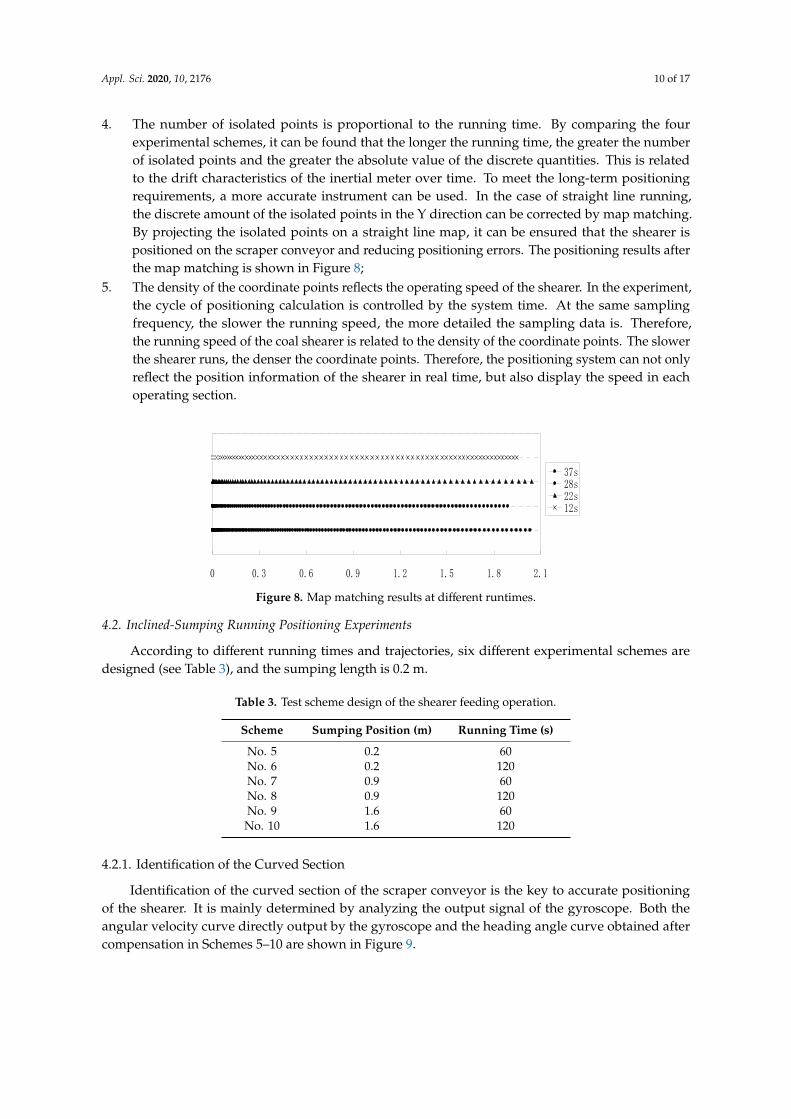
4. The number of isolated points is proportional to the running time. By comparing the fourexperimental schemes, it can be found that the longer the running time, the greater the numberof isolated points and the greater the absolute value of the discrete quantities. This is relatedto the drift characteristics of the inertial meter over time. To meet the long-term positioningrequirements, a more accurate instrument can be used. In the case of straight line running,the discrete amount of the isolated points in the Y direction can be corrected by map matching.By projecting the isolated points on a straight line map, it can be ensured that the shearer ispositioned on the scraper conveyor and reducing positioning errors. The positioning results afterthe map matching is shown in Figure 8;
5. The density of the coordinate points reflects the operating speed of the shearer. In the experiment,the cycle of positioning calculation is controlled by the system time. At the same samplingfrequency, the slower the running speed, the more detailed the sampling data is. Therefore,the running speed of the coal shearer is related to the density of the coordinate points. The slowerthe shearer runs, the denser the coordinate points. Therefore, the positioning system can not onlyreflect the position information of the shearer in real time, but also display the speed in eachoperating section.
Appl. Sci. 2019, 12, x FOR PEER REVIEW 10 of 18
No. 4 (1.95,−0.01) 5 −0.03
Average value — 5.8 0.085
Through the straight line running positioning experiment, the following can be concluded:
1. The estimated points of the integral calculation after error compensation accurately reflect the
linear operation characteristics of the shearer. By comparing the positioning results obtained
before and after compensation, it can be seen that, after 10‐point smoothing preprocessing, zero
bias compensation, and Kalman filter compensation of the output gyroscope and accelerometer
data, the validity of the data increases greatly, and the error is significantly reduced. The position
of the shearer estimated by the positioning system surrounds the actual trajectory;
2. The error of the position point on the X axis is greater than that on the Y axis. The maximum
error measured along the direction of the shearer movement is 0.11 m. Therefore, there is an
error in measuring the displacement of the shearer by relying solely on the accelerometer. The
error is mainly related to the working principle of the instrument. The data measured by the
accelerometer needs to be integrated twice to obtain the distance information. In practice, the
map‐matching technique can be used for correction;
3. The displacement accuracy measured by the odometer is higher than that of the accelerometer.
The displacement measured by the odometer is less than the actual displacement. The main
reason for this error is the slip between the walking wheel and the track. Moreover, slip is less
likely to occur on the chainless shearer, so the odometer has higher reliability and can correct
the acceleration integral result;
4. The number of isolated points is proportional to the running time. By comparing the four
experimental schemes, it can be found that the longer the running time, the greater the number
of isolated points and the greater the absolute value of the discrete quantities. This is related to
the drift characteristics of the inertial meter over time. To meet the long‐term positioning
requirements, a more accurate instrument can be used. In the case of straight line running, the
discrete amount of the isolated points in the Y direction can be corrected by map matching. By
projecting the isolated points on a straight line map, it can be ensured that the shearer is
positioned on the scraper conveyor and reducing positioning errors. The positioning results after
the map matching is shown in Figure 8;
5. The density of the coordinate points reflects the operating speed of the shearer. In the
experiment, the cycle of positioning calculation is controlled by the system time. At the same
sampling frequency, the slower the running speed, the more detailed the sampling data is.
Therefore, the running speed of the coal shearer is related to the density of the coordinate points.
The slower the shearer runs, the denser the coordinate points. Therefore, the positioning system
can not only reflect the position information of the shearer in real time, but also display the speed
in each operating section.
Figure 8. Map matching results at different runtimes.
4.2. Inclined‐Sumping Running Positioning Experiments
According to different running times and trajectories, six different experimental schemes are
designed (see Table 3), and the sumping length is 0.2 m.
0 0.3 0.6 0.9 1.2 1.5 1.8 2.1
37s28s22s12s
Figure 8. Map matching results at different runtimes.
4.2. Inclined-Sumping Running Positioning Experiments
According to different running times and trajectories, six different experimental schemes aredesigned (see Table 3), and the sumping length is 0.2 m.
Table 3. Test scheme design of the shearer feeding operation.
Scheme Sumping Position (m) Running Time (s)
No. 5 0.2 60No. 6 0.2 120No. 7 0.9 60No. 8 0.9 120No. 9 1.6 60No. 10 1.6 120
4.2.1. Identification of the Curved Section
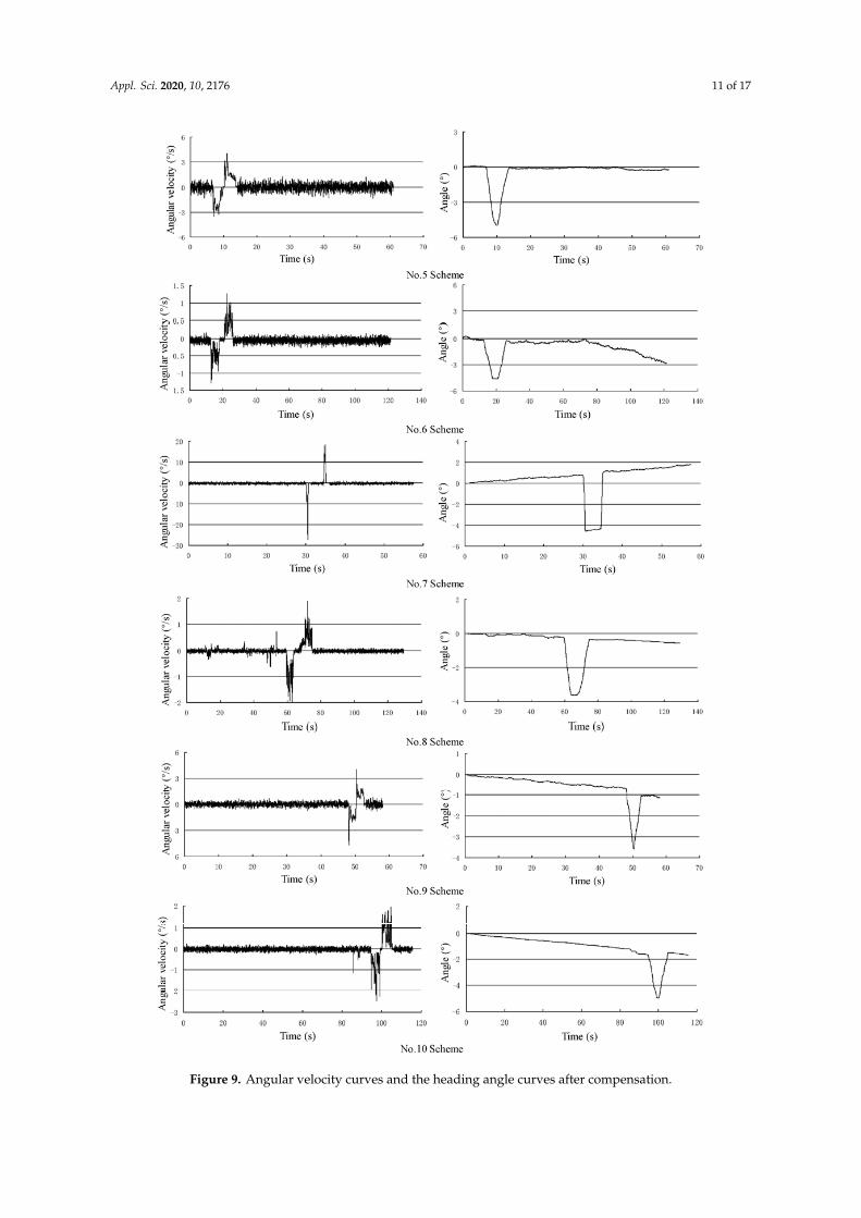
Identification of the curved section of the scraper conveyor is the key to accurate positioningof the shearer. It is mainly determined by analyzing the output signal of the gyroscope. Both theangular velocity curve directly output by the gyroscope and the heading angle curve obtained aftercompensation in Schemes 5–10 are shown in Figure 9.
Appl. Sci. 2020, 10, 2176 11 of 17Appl. Sci. 2019, 12, x FOR PEER REVIEW 12 of 18
Figure 9. Angular velocity curves and the heading angle curves after compensation.
Appl. Sci. 2020, 10, 2176 12 of 17
The angular velocity curve output by the gyroscope shows that, when the shearer moves in astraight line, the output signal of the gyroscope fluctuates around zero, the fluctuation range is small,and the overall change trend is also small. When the shearer enters the curved section, the outputsignal is significantly increased, which is obviously different from the signal when the shearer moves ina straight line. At the same time, the signal from the curved section is biased below zero first, and thenbiased above zero, showing obvious symmetry, which is consistent with the characteristics of theshearer sumping process. When the shearer exits the curved section, the gyroscope output signal keepsfluctuating around zero, and linear motion state characteristics are clearly reflected.
In the above six schemes, the data processing process still consists of 10-point smoothingpreprocessing, zero bias compensation and Kalman filter compensation, and the heading angle curve isobtained after compensation. The change in the heading angle mainly includes three parts. The headingangle fluctuates around zero when the shearer moves in a straight line. When the shearer enters thecurved section, the heading angle gradually changes to a negative number, then gradually changesto zero. Finally, the heading angle changes little and tends to be stable when the shearer moves ina straight line again. The theoretical value of the heading angle in the curved section is 5◦, and thetheoretical value of the heading angle at the endpoint is zero. The maximum values of the headingangles and the values of the heading angle at the endpoints of the experiments are given in Table 4.
Table 4. Data statistics for the heading angle.
Scheme Heading Angle inCurved Section (◦)
Angle Error inCurved Section (◦)
Heading Angle atthe Endpoint (◦)
Angle Error at theEndpoint (◦)
No. 5 −4.96 0.04 −0.23 0.23No. 6 −4.49 0.51 −2.82 2.82No. 7 −4.53 0.47 1.76 1.76No. 8 −3.62 1.38 −0.55 0.55No. 9 −3.53 1.47 −1.13 1.13
No. 10 −4.94 0.06 −1.66 1.66Average value — 0.655 — 1.35
It can be seen from Table 4 that there is an error between the heading angle measured by thegyroscope in the curved section and the theoretical value. Moreover, the errors in certain experimentsare large. However, it is easy to judge whether the shearer enters the curved section via a comparisonwith the data result of the straight running experiment. There is also an error between the measuredheading angle and the theoretical value at the endpoint, mainly because the experimental device doesnot use a thermostat to suppress the temperature change in the instrument; therefore, the zero biascaused by the gyroscope and the temperature variation cannot be fully compensated.
4.2.2. Analysis of Positioning Results
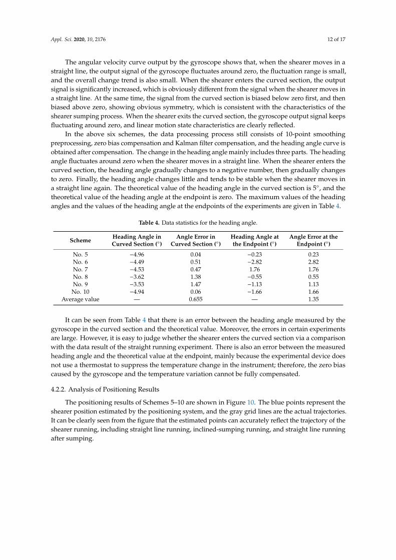
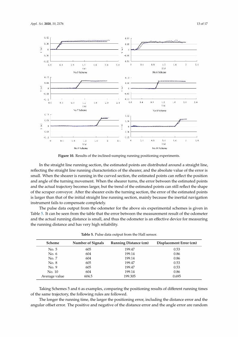
The positioning results of Schemes 5–10 are shown in Figure 10. The blue points represent theshearer position estimated by the positioning system, and the gray grid lines are the actual trajectories.It can be clearly seen from the figure that the estimated points can accurately reflect the trajectory of theshearer running, including straight line running, inclined-sumping running, and straight line runningafter sumping.
Appl. Sci. 2020, 10, 2176 13 of 17Appl. Sci. 2019, 12, x FOR PEER REVIEW 14 of 18
Figure 10. Results of the inclined‐sumping running positioning experiments.
In the straight line running section, the estimated points are distributed around a straight line,
reflecting the straight line running characteristics of the shearer, and the absolute value of the error
is small. When the shearer is running in the curved section, the estimated points can reflect the
position and angle of the turning movement. When the shearer turns, the error between the estimated
points and the actual trajectory becomes larger, but the trend of the estimated points can still reflect
the shape of the scraper conveyor. After the shearer exits the turning section, the error of the
estimated points is larger than that of the initial straight line running section, mainly because the
inertial navigation instrument fails to compensate completely.
The pulse data output from the odometer for the above six experimental schemes is given in
Table 5. It can be seen from the table that the error between the measurement result of the odometer
and the actual running distance is small, and thus the odometer is an effective device for measuring
the running distance and has very high reliability.
Table 5. Pulse data output from the Hall sensor.
Scheme Number of signals Running distance (cm) Displacement error (cm)
No. 5 605 199.47 0.53
No. 6 604 199.14 0.86
No. 7 604 199.14 0.86
No. 8 605 199.47 0.53
No. 9 605 199.47 0.53
No. 10 604 199.14 0.86
Average value 604.5 199.305 0.695
Taking Schemes 5 and 6 as examples, comparing the positioning results of different running times
of the same trajectory, the following rules are followed.
The longer the running time, the larger the positioning error, including the distance error and
the angular offset error. The positive and negative of the distance error and the angle error are
random and have nothing to do with the length of the running time. This is because the drift of the
Figure 10. Results of the inclined-sumping running positioning experiments.
In the straight line running section, the estimated points are distributed around a straight line,reflecting the straight line running characteristics of the shearer, and the absolute value of the error issmall. When the shearer is running in the curved section, the estimated points can reflect the positionand angle of the turning movement. When the shearer turns, the error between the estimated pointsand the actual trajectory becomes larger, but the trend of the estimated points can still reflect the shapeof the scraper conveyor. After the shearer exits the turning section, the error of the estimated pointsis larger than that of the initial straight line running section, mainly because the inertial navigationinstrument fails to compensate completely.
The pulse data output from the odometer for the above six experimental schemes is given inTable 5. It can be seen from the table that the error between the measurement result of the odometerand the actual running distance is small, and thus the odometer is an effective device for measuringthe running distance and has very high reliability.
Table 5. Pulse data output from the Hall sensor.
Scheme Number of Signals Running Distance (cm) Displacement Error (cm)
No. 5 605 199.47 0.53No. 6 604 199.14 0.86No. 7 604 199.14 0.86No. 8 605 199.47 0.53No. 9 605 199.47 0.53No. 10 604 199.14 0.86
Average value 604.5 199.305 0.695
Taking Schemes 5 and 6 as examples, comparing the positioning results of different running timesof the same trajectory, the following rules are followed.
The longer the running time, the larger the positioning error, including the distance error and theangular offset error. The positive and negative of the distance error and the angle error are random
Appl. Sci. 2020, 10, 2176 14 of 17
and have nothing to do with the length of the running time. This is because the drift of the inertialinstrument and the zero offset of the instrument is different after each startup or operation for a periodof time. We know from other studies that the zero offset of inertial instruments will be affected bytemperature and vibration [45,46], an effect which is shown by certain characteristics. But the use ofthreshold filtering and constant compensation cannot completely eliminate this error. Further researchshould be done on the filtering method of inertial instruments in future research.
From the above experiments, the following can be concluded:
1. Compared with the current shearer positioning technology, the shearer positioning system inthis paper can not only accurately describe the shape of the scraper conveyor, but also provideinformation such as the sumping position and angle and length of the shearer and can achievehigher precision positioning of the shearer;
2. The random error of inertial navigation instruments cannot be completely eliminated. Methods toimprove the accuracy of the system include the use of high-precision instruments and better dataprocessing methods, including high-efficiency filtering techniques and map-matching algorithms;
3. The positioning accuracy of the inertial navigation instrument is related to the system runningtime. Periodic correction of the positioning data by the odometer can reduce the influence of timeon the system. Initial calibration of the instrument can be performed when the shearer startsrunning, and the high-precision inertial navigation instrument can achieve the above function.Moreover, the odometer accumulates little error over time; therefore, the navigation data can becorrected by the odometer to achieve higher precision shearer positioning.
5. Conclusions
1. Based on strapdown inertial navigation technology, we analyzed the movement characteristics ofthe shearer on the working face, and we used inertial navigation instruments such as gyroscopesand accelerometers and the dead reckoning principle to propose a shearer positioning system ona fully mechanized working face;
2. In the shearer positioning experiments, the positioning system can accurately reflect the trajectoryof the shearer running, including straight line running, inclined-sumping running, and straightline running after sumping. The experiments also show that the shearer positioning system basedon SINS is indeed a very accurate shearer positioning technology;
3. To improve the positioning accuracy of the shearer positioning system and meet long-termpositioning requirements, high-precision instruments and better data processing methods,including high-efficiency filtering technology and map-matching algorithms, can be used or anodometer can be used to correct the navigation data.
6. Limitations
1. Compared to an actual operating longwall operation (e.g., 200–400 m for 50–70 min), scale (2 m)and time duration (<120 s) of the experimental evaluation is indeed very small. This also leadsto the fact that the experimental results may not reflect the actual situation very accurately. Inthe future, field experiments will be carried out in the coal mine to verify the conclusions inthis paper;
2. Compared with existing commercially available solutions, such as Longwall Automation SteeringCommittee (LASC), Commonwealth Scientific and Industrial Research Organisation (CSIRO),Advanced Shearer Automation (ASA), Joy Global (JOY), etc., those listed may be better than thesolutions in this article in terms of accuracy. However, it is well known that the SINS instrumentscan be used in military weapons, such as missiles, fighter jets and other weapons. An embargohas been imposed upon advanced SINS instruments in China. Even if there are SINS instrumentsthat can be used in China, there are very strict restrictions on their use. On the other hand,the existing commercially available solutions are still too expensive and most coal mines in China
Appl. Sci. 2020, 10, 2176 15 of 17
cannot afford it. In the event that China cannot obtain advanced SINS instruments, it can look toimprove the SINS accuracy based on algorithms, experiments and other aspects. We hope readerscan understand the limitations of China’s scientific research in this regard, and also eagerly hopethis article will attract the attention of relevant researchers around the world, and to obtain helpand guidance from them to improve the theoretical and technical research of shearer positioningin China.
Author Contributions: Conceptualization, G.W. and X.F.; validation, G.W., X.F. and L.Z.; formal analysis, M.L.and J.L.; investigation, G.W., X.F. and Z.Q.; data curation, M.L., J.L. and Z.Q.; writing—original draft preparation,G.W. and X.F.; writing—review and editing, G.W. and L.Z.; supervision, X.F.; funding acquisition, X.F. All authorshave read and agreed to the published version of the manuscript.
Funding: This research was funded by National Natural Science Foundation of China, grant number 51874276.
Acknowledgments: Financial support for this study was provided by the National Natural Science Foundation ofChina (No. 51874276). The authors gratefully acknowledge the financial support of the above organization.
Conflicts of Interest: The authors declare no conflict of interest.
References
1. Jinhua, W.; Zenghua, H. The recent technological development of intelligent mining in China. Engineering2017, 3, 439–444.
2. Ge, S. Key Technology of Intelligent Coal Mining Equipment. Coal Sci. Technol. 2014, 42, 7–11.3. Wang, J.; Huang, Z. Innovation and Development of Intelligent Coal Mining Science and Technology in
China. Coal Sci. Technol. 2014, 42, 1–6.4. Wang, G.; Zhang, D. Innovation practice and development prospect of intelligent fully mechanized technology
for coal mining. J. China Univ. Min. Technol. 2018, 47, 459–467.5. Robert, R.; Rahinul, H. Augmenting GPS with Geolocated Fiducials to Improve Accuracy for Mobile Robot
Applications. Appl. Sci. 2020, 10, 146. [CrossRef]6. Fang, X.; Zhao, J.; Hu, Y. Tests and error analysis of a self-positioning shearer operating at a manless working
face. Min. Sci. Technol. 2010, 20, 53–58. [CrossRef]7. Wang, G. New development of longwall mining equipment based on automation and intelligent technology
for thin seam coal. J. Coal Sci. Eng. 2013, 19, 97–103. [CrossRef]8. Zhang, B.; Fang, X.; Zou, Y.; Yu, R.; Cheng, Y. Auto-positioning system of shearer operating on manless
working face based on gyroscope and odometer. Min. Process. Equip. 2010, 38, 10–13. [CrossRef]9. Reid, D.C.; Dunn, M.T.; Reid, P.B.; Ralston, J.C. A practical inertial navigation solution for continuous
miner automation. In Proceedings of the 12th Coal Operators Conference, Univ Wollongong, Wollongong,Australia, 16–17 February 2012; pp. 115–120.
10. Xinqiu, F.; Jie, H.; Bin, Z.; Minjiang, G. Self-positioning system of the shearer in unmanned workface. J. Xi’anUniv. Sci. Technol. 2008, 28, 349–353.
11. Reid, D.C.; Hainsworth, D.W.; Ralston, J.C.; McPhee, R.J. Shearer guidance: A major advance in longwallmining. In Proceedings of the 4th International Conference on Field and Service Robotics, Mt Fuji, Japan,14–16 July 2003.
12. Zhang, X.; Zhang, P.; Meng, G.; Zhang, X. Development of on time monitoring and measuring system andvisualized platform for coal cutting performances of coal shearer. Coal Eng. 2008, 2008, 101–103.
13. Pytka, J.; Budzynski, P.; Jozwik, J.; Michalowska, J.; Tofil, A.; Lyszczyk, T.; Blazejczak, D. Application ofGNSS/INS and an Optical Sensor for Determining Airplane Takeoff and Landing Performance on a GrassyAirfield. Sensors 2019, 19, 5492. [CrossRef] [PubMed]
14. Hai, Y.; Wei, L.; Chengming, L.; Jinyao, Z.; Zhuoyin, S. Research on error compensation property of strapdowninertial navigation system using dynamic model of shearer. IEEE Access 2016, 4, 2045–2055.
15. Shixin, L.; Fengrong, H.; Shiqian, Q.; Chaonan, F. SINS/Odometer integrated navigation method based onadaptive strong tracking filter. J. Chin. Inert. Technol. 2018, 26, 156–161.
16. Hongsong, Z.; Lingjuan, M.; Jun, S. High accuracy algorithm for SINS/Odometer integrated navigationsystem. Acta Armamentarii 2014, 35, 433–440.
Appl. Sci. 2020, 10, 2176 16 of 17
17. Xiaoyue, Z.; Gongliu, Y.; Chunxi, Z. Integrated navigation method for SINS and odometer. J. Beijing Univ.Aeronaut. Astronaut. 2013, 39, 922–926.
18. Yang, H.; Li, W.; Chengming, L.; Mengbao, F.; Baohua, Y. Experimental study on position and attitudetechnique for shearer using SINS measurement. J. China Coal Soc. 2014, 39, 2550–2556.
19. Qigao, F.; Wei, L.; Chengming, L. Error Analysis and Reduction for Shearer Positioning using the StrapdownInertial Navigation System. Int. J. Comput. Sci. Issues 2012, 9, 49–54.
20. Xin, Z.; Zhongbin, W.; Chao, T.; Rui, J.; Xinhua, L. A novel approach for shearer memory cutting based onfuzzy optimization method. Adv. Mech. Eng. 2013, 1, 1–10.
21. Dolipski, M.; Jaszczuk, M.; Cheluszka, P.; Sobota, P.; Kusak, E.; Kurek, M. Dynamic model of a Shearer’scutting system. In Proceedings of the 9th International Symposium on Mine Planning Equipment Selection,Athens, Greece, 6–9 November 2000; pp. 541–546.
22. Bo, W.; Qian, R.; Zhihong, D.; Mengyin, F. A self-calibration method for nonorthogonal angles betweengimbals of rotational inertial navigation system. IEEE Trans. Ind. Electron. 2015, 62, 2353–2362.
23. Feng, Q.; Xingqun, Z.; Lei, Z. Performance assessment of a low-cost inertial measurement unit based ultra-tightglobal navigation satellite system/inertial navigation system integration for high dynamic applications.IET Radar Sonar Navig. 2014, 8, 828–836.
24. Bin, Z.; Jiangfeng, Y. Vibration analysis of base structure on SINS using PZT actuators. Turk. Electr. Eng.Comput. Sci. 2012, 20, 901–913.
25. Paul, S. Coning algorithm design by explicit frequency shaping. J. Guid. Control Dyn. 2010, 33, 1123–1132.26. Mario, I. Optimal sculling and coning algorithms for analog-sensor systems. J. Guid. Control Dyn. 2012, 35,
851–860.27. John, B. A new mathematical formulation for strapdown inertial navigation. IEEE Trans. Aerosp. Electron.
Syst. 1971, AES-7, 61–66.28. Oleg, S. Applied Inertial Navigation: Problems and Solutions; BMSTU Press: Moscow, Russia, 2004.29. Chul Woo, K.; Nam Ik, C.; Chan Gook, P. Approach to direct coning/sculling error compensation based on
the sinusoidal modelling of IMU signal. IET Radar Sonar Navig. 2013, 7, 527–534.30. Jizhou, L.; Pin, L.; Jianye, L.; Bin, J. Noncommutativity error analysis of strapdown inertial navigation system
under the vibration in UAVs. Int. J. Adv. Robot. Syst. 2012, 9, 1–8.31. Qigao, F.; Wei, L.; Yuqiao, W.; Xuefeng, Y. A shearer dynamic positioning method using strap down inertial
navigation. J. China Coal Soc. 2011, 36, 1758–1761.32. Hai, Y.; Tao, L.; Wei, L.; Li, L.; Yue, R.; ChengMing, L. A Stable SINS/UWB Integrated Positioning Method of
Shearer Based on the Multi Model Intelligent Switching Algorithm. IEEE Access 2019, 7, 29128–29138.33. Nikitenko, M.S.; Kizilov, S.A.; Kuleshov, V.K. Functional schemes of automated and robotic control of
equipment in longwall top coal caving. In Proceedings of the Conference on Challenges for Development inMining Science and Mining Industry, Russian Academy of Sciences, Siberian Branch, Inst Min, Novosibirsk,Russia, 1–5 October 2018.
34. Yaping, J.; Zhipeng, X.; Zeyin, Z.; Xinggao, L. A novel shearer cutting pattern recognition model with chaoticgravitational search optimization. Measurement 2019, 144, 225–233.
35. Post, M.A.; Bianco, A.; Yan, X.T. Autonomous Navigation with Open Software Platform for Field Robots.In Proceedings of the 14th International Conference on Informatics in Control, Automation and Robotics(ICINCO), Madrid, Spain, 26–28 July 2017.
36. Yong, J.; Suilao, L.; Yongyuan, Q.; Richeng, C. Error analysis and compensation of MEMS rotation modulationinertial navigation system. IEEE Sens. J. 2018, 18, 2023–2030. [CrossRef]
37. Gustaysson, A. An Efficient Approach for Detecting Moving Objects and Deriving Their Positions andVelocities. In Proceedings of the Computer Vision Conference (CVC), Las Vegas, NV, USA, 25–26 April 2019.
38. Bo, L.; Yunpei, L.; Quanle, Z. Determination of working resistance based on movement type of the firstsubordinate key stratum in a fully mechanized face with large mining height. Energy Sci. Eng. 2019, 7,777–798.
39. Markiewicz, J.; Abratkiewicz, K.; Gromek, A.; Samczynski, W.; Gromek, D. Geometrical Matching of SARand Optical Images Utilizing ASIFT Features for SAR-based Navigation Aided Systems. Sensors 2019, 19,5500. [CrossRef] [PubMed]
Appl. Sci. 2020, 10, 2176 17 of 17
40. Michal, R.; Matej, H. Dead reckoning in a dynamic quadruped robot: Inertial navigation system aided by alegged odometer. In Proceedings of the 2011 IEEE International Conference on Robotics and Automation,Shanghai, China, 9–13 May 2011.
41. Lubin, C.; Hongyang, H.; Fangjun, Q. In-Motion Initial Alignment for Odometer-Aided Strapdown InertialNavigation System Based on Attitude Estimation. IEEE Sens. J. 2017, 17, 766–773.
42. Valmorbida, A.; Mazzucato, M.; Pertile, M. Calibration procedures of a vision-based system for relativemotion estimation between satellites flying in proximity. Measurement 2020, 151, 107161. [CrossRef]
43. Yuming, C.; Wei, L.; Hai, Y.; Ting, X. Research on the Compensation Strategy of the Initial Alignment of theSINS Based on the Dynamic Model of the Shearer. IEEE Access 2019, 7, 36736–36747.
44. Yuming, C.; Wei, L.; Gaifang, X.; Hai, Y.; Ting, X. An Improved Strong Tracking Kalman Filter Algorithm forthe Initial Alignment of the Shearer. Complexity 2019. [CrossRef]
45. Honglu, H.; Guangyao, L.; Yuan, L. Temperature Characteristic and Compensation of FOG Zero Bias Drift.Process Autom. Instrum. 2019, 40, 59–63, 68.
46. Siying, G.; Jiangning, X.; Feng, L.; Hongyang, H. Modeling and compensation algorithm of FOG temperaturedrift with optimized BP neural network. J. Chin. Inert. Technol. 2016, 24, 93–97.
© 2020 by the authors. Licensee MDPI, Basel, Switzerland. This article is an open accessarticle distributed under the terms and conditions of the Creative Commons Attribution(CC BY) license (http://creativecommons.org/licenses/by/4.0/).