PNEG-250 - Broiler and Breeder Pan Feeding
106
PNEG-250 Broiler and Breeder Pan Feeding (For parts, refer to PNEG-250-PM) Installation and Operation Manual PNEG-250 Version: 14.0 Date: 08-27-19
-
Upload
khangminh22 -
Category
Documents
-
view
1 -
download
0
Transcript of PNEG-250 - Broiler and Breeder Pan Feeding

PNEG-250
Broiler and Breeder Pan Feeding(For parts, refer to PNEG-250-PM)
Installation and Operation Manual
PNEG-250Version: 14.0
Date: 08-27-19

2 PNEG-250 Broiler and Breeder Pan Feeding
All information, illustrations, photos and specifications in this manual are based on the latestinformation available at the time of publication. The right is reserved to make changes at anytime without notice.

Table of Contents
PNEG-250 Broiler and Breeder Pan Feeding 3
ContentsChapter 1 Introduction ..........................................................................................................................................5
Chapter 2 Safety .....................................................................................................................................................6Safety Guidelines ...................................................................................................................................6Cautionary Symbols Definitions .............................................................................................................7Safety Cautions ......................................................................................................................................8General Safety Information ..................................................................................................................10Safety Sign-Off Sheet ..........................................................................................................................12
Chapter 3 Decals ..................................................................................................................................................13Safety Decals and Placement ..............................................................................................................13
Chapter 4 Calculating Weight .............................................................................................................................15Calculating Weight of Feedline at Each Suspension Point ..................................................................15Determine Weight of Entire System .....................................................................................................15
Chapter 5 Capacities and Specifications ...........................................................................................................16
Chapter 6 Planning the System ..........................................................................................................................19House Layout .......................................................................................................................................19
Chapter 7 Winching for Broilers .........................................................................................................................21Building Safety .....................................................................................................................................21Safety when Raising and Lowering ......................................................................................................21Choose the Correct Winching System .................................................................................................21Installing the Ceiling Winch ..................................................................................................................22Installing the Main Winch Cable ...........................................................................................................23Installing the Feed Hopper and Control Pan ........................................................................................27Screw Hook Installation ........................................................................................................................28Installing the Drop Cables ....................................................................................................................29
Chapter 8 Pan Feeder Assembly ........................................................................................................................30Installation Sequence ...........................................................................................................................30Hi-Lo Pan Feeder Assembly ................................................................................................................30“E” Feeder Assembly ...........................................................................................................................32Hi-Lo Plus Pan Feeder Assembly ........................................................................................................33Pro-1 Assembly ....................................................................................................................................34Nutrapan Assembly ..............................................................................................................................35Flooding Applications ...........................................................................................................................36Tubing Assembly ..................................................................................................................................38Feeder Assembly Rooster Feeder .......................................................................................................42Drive Unit/Control Pan Assembly .........................................................................................................47Control Pan Assembly ..........................................................................................................................50Auger Installation .................................................................................................................................60Hopper Assembly .................................................................................................................................64650 Lbs. Hopper Scale .........................................................................................................................65Anti-Roost Wire ....................................................................................................................................67Hopper Level Control Switch ................................................................................................................69
Chapter 9 Rooster Winch Installation ................................................................................................................70“Throwback” Installation .......................................................................................................................70Power Winch Instructions .....................................................................................................................71

Table of Contents
4 PNEG-250 Broiler and Breeder Pan Feeding
Chapter 10 Programming Chart ..........................................................................................................................779' Auger Tube - 358 RPM ...................................................................................................................779' Auger Tube - 716 RPM ...................................................................................................................7810' Auger Tube - 358 RPM .................................................................................................................7910' Auger Tube - 716 RPM .................................................................................................................8012' Auger Tube - 358 RPM .................................................................................................................8112' Auger Tube - 716 RPM .................................................................................................................82
Chapter 11 Troubleshooting ...............................................................................................................................83Safety in Maintenance and Repairs ....................................................................................................83i-Plus3 Troubleshooting Guide ...........................................................................................................85
Chapter 12 Wiring Diagrams ...............................................................................................................................86Rooster/Power Winch Wiring Diagram ...............................................................................................86Microswitch End Control 220V, 1 Phase (7101483) ...........................................................................87Microswitch End Control 3 Phase (07101483-3) ................................................................................88Microswitch Center Control 220V, 1 Phase (7101540) ......................................................................89Microswitch End and Center Control ..................................................................................................90End Control Box, i-Plus3 (C2000535) ................................................................................................91Center Control Box, i-Plus3 (C2000563) ............................................................................................92End Control Box, i-Plus3 3 Phase (C2000590) ..................................................................................93i-Plus3 End and Center Control ..........................................................................................................94LED Light and i-Plus3 End Control .....................................................................................................95Proximity Switch End Control 220V, 1 Phase (7100842) ...................................................................96Proximity Switch Center Control 220V, 1 Phase (C2000528) ............................................................97Proximity End and Center Control ......................................................................................................98Spinner End Control 110V, 1 Phase (7100614) .................................................................................99Spinner End Control 220V, 1 Phase (7100211) ...............................................................................100Spinner Center Control 110V-220V, 1 Phase (C2000306) ...............................................................101Spinner Center Control 220V (7100407) ..........................................................................................102Spinner End and Center Control ......................................................................................................103
Chapter 13 Warranty ..........................................................................................................................................105

PNEG-250 Broiler and Breeder Pan Feeding 5
1. Introduction
The Pan Feeder System is designed to convey granular or powdered poultry feed from external feed bins into the poultry house. It utilizes a flex auger to supply feed to Pan Feeders.
For clean out purposes, the Pan Feeding Lines can be raised up to a high level using a winching system to allow access for cleaning out the building.
Please send any questions, suggestions or comments to Cumberland at the following address:
Contact:
Cumberland1004 E. Illinois St.Assumption, IL. 62510Phone: 1-217-226-4421

6 PNEG-250 Broiler and Breeder Pan Feeding
2. Safety
Safety GuidelinesSafety guidelines are general-to-specific safety rules that must be followed at all times. This manual is written to help you understand safe operating procedures and problems that can be encountered by the operator and other personnel when using this equipment. Read and save these instructions.
As owner or operator, you are responsible for understanding the requirements, hazards, and precautions that exist and to inform others as required. Unqualified persons must stay out of the work area at all times.
Alterations must not be made to the equipment. Alterations can produce dangerous situations resulting in SERIOUS INJURY or DEATH.
This equipment must be installed in accordance with the current installation codes and applicable regulations, which must be carefully followed in all cases. Authorities having jurisdiction must be consulted before installations are made.
When necessary, you must consider the installation location relative to electrical, fuel and water utilities.
Personnel operating or working around equipment must read this manual. This manual must be delivered with equipment to its owner. Failure to read this manual and its safety instructions is a misuse of the equipment.
ST-0001-4

2. Safety
PNEG-250 Broiler and Breeder Pan Feeding 7
Cautionary Symbols Definitions
Cautionary symbols appear in this manual and on product decals. The symbols alert the user of potential safety hazards, prohibited activities and mandatory actions. To help you recognize this information, we use the symbols that are defined below.
NOTICE
DANGER
WARNING
CAUTION
This symbol indicates an imminently hazardous situation which, if not avoided, will result in serious injury or death.
This symbol indicates a potentially hazardous situation which, if not avoided, can result in serious injury or death.
This symbol indicates a potentially hazardous situation which, if not avoided, can result in minor or moderate injury.
This symbol is used to address practices not related to personal injury.
This symbol indicates a general hazard.
This symbol indicates a prohibited activity.
This symbol indicates a mandatory action.
ST-0005-2

2. Safety
8 PNEG-250 Broiler and Breeder Pan Feeding
Safety Cautions
Use Personal Protective Equipment
Eye Protection
Hearing Protection
Hand Protection
Head Protection
Respiratory Protection
Foot Protection
Fall Protection
• Use appropriate personal protective equipment:
• Wear clothing appropriate to the job.
• Remove all jewelry.
• Tie long hair up and back. ST-0004-1
Follow Safety Instructions
• Carefully read all safety messages in this manual and safety signs on your machine. Keep signs in good condition. Replace missing or damaged safety signs. Be sure new equipment components and repair parts include the current safety signs. Replacement safety signs are available from the manufacturer.
• Learn how to operate the machine and how to use controls properly. Do not let anyone operate without instruction.
• If you do not understand any part of this manual or need assistance, contact your dealer.
ST-0002-1
Maintain Equipment and Work Area
• Understand service procedures before doing work. Keep area clean and dry.
• Never service equipment while it is operating. Keep hands, feet, and clothing away from moving parts.
• Keep your equipment in proper working condition. Replace worn or broken parts immediately.
ST-0003-1

2. Safety
PNEG-250 Broiler and Breeder Pan Feeding 9
Install and Operate Electrical Equipment Properly
• Electrical controls must be installed by a qualified electrician and must meet the standards set by applicable local codes (National Electrical Code for the US, Canadian Electric Code, or EN60204 along with applicable European Directives for Europe).
• Lock-out power source before making adjustments, cleaning, or maintaining equipment.
• Make sure all equipment is properly grounded. ST-0027-4
Rotating Auger Hazard
• Keep clear of rotating augers and moving parts.
• Do not remove or modify guards or covers.
• Lock-out power source before making adjustments, cleaning, or maintaining equipment.
• Failure to follow these precautions will result in serious injury or death.
ST-0037-1
Sharp Edge Hazard
• This product has sharp edges, which can cause serious injury.
• To avoid injury, handle sharp edges with caution and always use proper protective clothing and equipment.
ST-0036-2
Verify Building Load Capacity
• Raising and lowering pan feeding system imposes additional loads on the building structure.
• Consult a structural engineer to verify the load capacity of the building and to confirm that the building is able to bear the load of the system.
ST-0079-1

2. Safety
10 PNEG-250 Broiler and Breeder Pan Feeding
General Safety Information
Electrical Safety
An adequate and safe power supply to the Pan Feeding System unit is essential for safety. A competent and qualified electrician must undertake all electrical wiring. All wiring is to be installed according to the National Standards and Regulations relevant to your Country and Region.
A main isolator should be installed with the Pan Feeding System and is essential for safety. This should be installed as indicated in the enclosed installation instructions and in accordance with the relevant codes and directives.
Structural Safety
Raising and lowering the Pan Feeding System in a poultry house imposes additional load on the building. It is essential that the building is able to bear this additional load. Consult a structural engineer to verify the building’s load capacity. See Page 15 for “Calculating the Weight of the System.”
Correct Use of the Pan Feeding System
The Pan Feeding System is designed solely for the purpose of conveying granular or powdered agricultural feed products for poultry feeding. Use of the system in any other way is a misuse of the system and can endanger safety and health.
Only genuine Cumberland parts are to be used in installation and use of the Pan Feeding System. Use of non-genuine parts is a misuse of the system and can endanger the safety and health of you and others.
This machine is not designed for use in atmospheres where there is a risk of explosion. Such environments may include enclosed areas of high dusts concentrations, gas vapors and fumes. Use of the Pan Feeding System in such an environment is prohibited. If in doubt, contact Cumberland or your dealer.
DustUnder normal working conditions, the Pan Feeding System should create little or no dust hazard. However, some feed materials may create dust when being moved. This dust may be harmful to your health if inhaled. Seek advice from your feed supplier and use a suitable dust mask as needed.
NoiseTests on this machine indicate noise levels at a position 1 meter from the drive unit, 1.6 meters above the ground do not exceed 70 dBa, continuous ‘A’ weighted sound pressure or 63 Pa, instantaneous ‘C’ weighted sound pressure.
Use Caution in the Operation of this EquipmentThe design and manufacture of the Pan Feeding System is directed toward operator safety. However, the very nature of a Pan Feeding System requiring electrical power and possessing moving parts does present a hazard to personnel which cannot be completely safeguarded against without interfering with efficient operation and reasonable access to components.
Continued safe, dependable operation of automatic equipment depends, to a great degree, upon the owner/operator. For a safe and dependable Pan Feeding System, follow the recommendations within this manual and make it a practice to regularly inspect the operation of the unit for any developing problems or unsafe conditions.

2. Safety
PNEG-250 Broiler and Breeder Pan Feeding 11
READ THESE INSTRUCTIONS BEFORE OPERATION AND SERVICE SAVE FOR FUTURE REFERENCE
1. Read and understand the operating manual before trying to install or operate the Pan Feeding System.
2. Power supply should be OFF for service of electrical components. Use CAUTION in checking voltage or other procedures requiring power to be ON.
3. Never attempt to operate the Pan Feeding System by jumping or otherwise bypassing any safety devices on the unit.
4. Keep the Pan Feeding System clean. Do not allow debris to collect around drive unit, control pan, hoppers or boots.
5. Use CAUTION in working around the Pan Feeding System’s moving parts.
This product is intended for the use of feed handling only. Any other use is considered a misuse of the product.
Some edges of the product’s components are sharp. Examine each product component to determine if there are any safety considerations to be taken prior to use and/or installation. Any and all necessary personal protective equipment should be worn at all times when handling, assembling, installing and operation of the product and/or its components.
Throughout this manual, guards are removed for illustration purposes only. All guards must be in place before and during operation.
For guidance or assistance on any issues relating to the safe use of Pan Feeding System,
Contact:
Cumberland1004 E. Illinois St.Assumption, IL. 62510Phone: 1-217-226-4421

2. Safety
12 PNEG-250 Broiler and Breeder Pan Feeding
Safety Sign-Off Sheet
Below is a sign-off sheet that can be used to verify that all personnel have read and understood the safety instructions. This sign-off sheet is provided for your convenience and personal record keeping.
Date Employee Name Supervisor Name
ST-0007

PNEG-250 Broiler and Breeder Pan Feeding 13
3. Decals
Safety Decals and Placement
Decal # Decals Location
DC-884 This decal is located on the top of the control pan.
DC-889 This decal is located on end control pans, center control pans, and electrical boxes.
DC-992 This decal is located on the inside of the control pan and boot hoppers.
DC-993This decal is located on the feed hopper.
WARNING
DANGERDANGERHIGH VOLTAGEWill cause injuryor death.Lockout powerbefore servicing.
DC
-889
GSI Group Inc. 217-226-4421
DANGERDANGER
GSI Group 217-226-4421
ROTATING AUGER CANCRUSH AND CUT.Keep clear of movingparts. Disconnect andlockout power beforeservicing.
DC-992
GSI Group, Inc. 217-226-4421
ROTATING AUGERKeep clear of moving parts.Will cause serious injury.Disconnect and lockoutpower before servicing.
DC-993
WARNING

3. Decals
14 PNEG-250 Broiler and Breeder Pan Feeding
DC-851This decal is located on electrical boxes.
DC-857This is located on the winch.
DC-994This is located on the winch.
DC-995This is located on the winch.
Decal # Decals Location
DC-851
WARNINGSHEAR POINTKeep hands clear ofdrum and cables.Disconnect and lockoutpower before servicing.
GSI Group Inc. 217-226-4421 DC-857
DANGERSHEAR POINTKeep hands clear of movingparts. Do not operate withguard removed. Disconnectand lockout power beforeservicing.
GSI Group Inc. 217-226-4421
WARNINGSHEAR POINTKeep hands clear of movingparts. Do not operate withguard removed. Disconnectand lockout power beforeservicing.
DC-995GSI Group Inc. 217-226-4421

PNEG-250 Broiler and Breeder Pan Feeding 15
4. Calculating Weight
The winching system used to raise and lower the feed system in the poultry house imposes additional load on the building. It is essential to confirm that the building is able to carry this extra load. Consult a structural engineer to check the building strength. Details of the estimated weight of the feed system can be calculated using the formulas below. However, if there is any uncertainty, contact your dealer or Cumberland for assistance with calculating the weight.
To calculate the weight of the Pan Feeding system, you must identify the weights of the following components: A) hopper, boot and the feed they will hold, B) weight of tubing, pans, auger and the feed they contain per section of tube and C) weight of control pan and drive unit.
A. From the Capacities and Specifications Section on Pages 16-18, find the weight of the hopper (H) being used, the boot (BT) being used and the capacity (HP) of the hopper being used. Add the weights of these three components together: A = H+BT+HP.
B. Find the pan weight (PW) and the pan capacity weight (PC) using the Capacities and Specifications Section on Pages 16-18. Add these two weights together and multiply by the number of pans per tube section (NP) to get the total pan weight (TPW) per tube section. TPW = (PW+PC)(NP).
Next find the weight of the tubing (T) and auger (AG) being used from the Capacities and Specifications Section on Pages 16-18. Note the tube length (TL). Feed weight (FW) in the tube are: 10' of tubing will hold 3 lbs. of feed, 9' tubing holds 2.7 lbs. and 12' tube holds 3.6 lbs. Figure the total weight per length of tube from the formula: B = T+(AG x TL)+FW+TPW.
C. Find the weight of the control pan (CPW) and drive unit (DU) being used from the Capacities and Specifications Section on Pages 16-18. Add these two weights together: C = CP+DU.
Calculating Weight of Feedline at Each Suspension Point
After determining A, B and C, determine the quantity of each component to be suspended by any suspension point.
Determine Weight of Entire System
System weight (SW) is determined by adding the number of tubes in use (NT), number of drive units in use (ND) and finding the total weight of A, B and C: SW = A+(B x NT)+(C x ND).
NOTE: These estimates are based on the weight of feed calculated at 40 lbs. per cubic foot. If feed to be used is of different density, the weight of the system must be adjusted appropriately.

16 PNEG-250 Broiler and Breeder Pan Feeding
5. Capacities and Specifications
Figure 5A Drive Units
Figure 5B Pans
Figure 5C Boots
Phase HP Voltage Hz Gearbox RPM Weight
Single 1/3 or 1/2 110/220 50 or 60 Direct Drive 358 28.4 lbs. (12.9 kgs)
Three 1/3 or 1/2 190/380//208-230/460 50 or 60 Direct Drive 358 28.4 lbs. (12.9 kgs)
Model Diameter Weight (PW) Capacity (PC)
Hi-Lo 13" (330 mm) 1.6 lbs. (0.7 kgs) 4 lbs.
PRO-1 13" (330 mm) 1.8 lbs. (0.8 kgs) 4 lbs.
Boots Weight
Single Boot 12 lbs.
Double Boot 19.5 lbs.

5. Capacities and Specifications
PNEG-250 Broiler and Breeder Pan Feeding 17
Figure 5D Hoppers (7098232)
Figure 5E Control Pans
Capacity (HP) Height Top Opening Weight
120 lbs. (54 kgs) 21.7" (55 cm) 18" x 18" (45 cm x 45 cm) 22.0 lbs. (10.0 kgs)
200 lbs. (91 kgs) 32.5" (83 cm) 18" x 18" (45 cm x 45 cm) 31.0 lbs. (14.1 kgs)
300 lbs. (136 kgs) 32.5" (83 cm) 24" x 24" (61 cm x 61 cm) 41.9 lbs. (19.0 kgs)
400 lbs. (182 kgs) 42.5" (108 cm) 24" x 24" (61 cm x 61 cm) 58.3 lbs. (26.5 kgs)
Control Pans Pan Style Switch Style Weight (CPW)
End Control
Hi-Lo Microswitch 8.8 lbs. (4.0 kgs)
Hi-Lo Spinner 8.8 lbs. (4.0 kgs)
Hi-Lo Proximity 8.8 lbs. (4.0 kgs)
Center House
Hi-Lo Microswitch 4.1 lbs. (1.8 kgs)
Hi-Lo Spinner 8.8 lbs. (4.0 kgs)
Hi-Lo Proximity 3.7 lbs. (1.6 kgs)

5. Capacities and Specifications
18 PNEG-250 Broiler and Breeder Pan Feeding
Figure 5F Tube Auger
Figure 5G Auger Tube
Feed Weight (FW) Length (TL) Weight (T) Feed Hole Tubes Feed and Brood Hole Tubes (NP)
2.7 lbs. 9 ft. (2.74 m) 7.5 lbs. (3.4 kgs) 0, 1, 2, 4 8 Centered, Staggared (4" or 6")
3.0 lbs. 10 ft. (3.05 m) 8.3 lbs. (3.7 kgs) 0, 1, 3, 4, 5
6 Centered, Staggared, Skipped
9 Double Staggared
8 Centered, Staggared
12 Double Staggared
3.6 lbs. 12 ft. (3.65 m) 9.74 lbs. (4.4 kgs) 0, 2, 3, 4, 5
8 Centered, Staggared
10 Centered, Staggared
12 Double Staggared
15 Double Staggared
O.D. Pitch Weight/Ft. (AG)
1.483" (36.5 mm) 2" (50.8 mm) 0.33 lb. (0.15 kgs)

PNEG-250 Broiler and Breeder Pan Feeding 19
6. Planning the System
House Layout
One-half (1/2) horsepower drive units are recommended for houses over 500' (152.4 m) long. It is not recommended that a drive unit ever be located more than 500' from the hopper/boot.
Figure 6A shows a single boot feed system with the feed tank at the end of the house.
Figure 6A Single Boot Feed System
Ref # Description
1 Drive Unit/Control Pan
2 Tubing
3 Hopper
4 Feeder Pan
5 Flex-Flo Fill System
6 Bulk Feed Tank
7 Curtain
8 Curtain House Control Pan

6. Planning the System
20 PNEG-250 Broiler and Breeder Pan Feeding
House Layout (Continued)
Figure 6B shows a double boot feed system with the feed tank in the middle of the house.
Figure 6B Double Boot Feed System
Ref # Description
1 Drive Unit/Control Pan
2 Tubing
3 Hopper
4 Feeder Pan
5 Flex-Flo Fill System
6 Bulk Feed Tank

PNEG-250 Broiler and Breeder Pan Feeding 21
7. Winching for Broilers
Building Safety
Safety when Raising and Lowering
The main risk when raising and lowering the feed line is that a cable may snap or slip. This may result in cable whip or the feed line falling. Therefore, the use of a hard hat and face shield is recommended.
The winch should be placed in the building so that it is not too close (3' minimum) to any section of the feed line in case of the feed line falling.
Take extreme care when raising and lowering the Pan Feeding System. Cables used for winching are under tension.
• Always check that the cables and clamps are in good condition. Replace any frayed or damaged cables and clamps.
• Never raise or lower the feed line with another person in the building unless they are clear of the system and cables.
• Once the feed line has reached the fully raised position, lock the check chains.
Choose the Correct Winching System
Winching systems must be rated to raise and lower the maximum capacity of the Pan Feeder line and lowered and must bear the CE mark and comply with all the requirements of EC Machinery Directive, Directive 89/392/EEC. Use of non-genuine parts may result in accident, injury or failure of the system.
All winching systems should be fitted with a check chain so that when the feed line is in the raised position, it cannot fall, even if the winch cable snaps or the winch fails.
For proper installation, the feed line must hang straight and reasonably level. Winch systems should be carefully planned to keep all cables clear of building components, trusses, electrical wiring and gas and water lines. Drops to the feed line should be straight so as not to impose improper loads on the system when raised.
Before attempting to install a winching system, it is important to verify the structure of the poultry house can carry the added weight of the Pan Feeding system. Seek advice from a structural engineer and refer to the Capacities and Specifications Section on Pages 16-18 to assess the weight to be carried.
7. Winching for Broilers
22 PNEG-250 Broiler and Breeder Pan Feeding
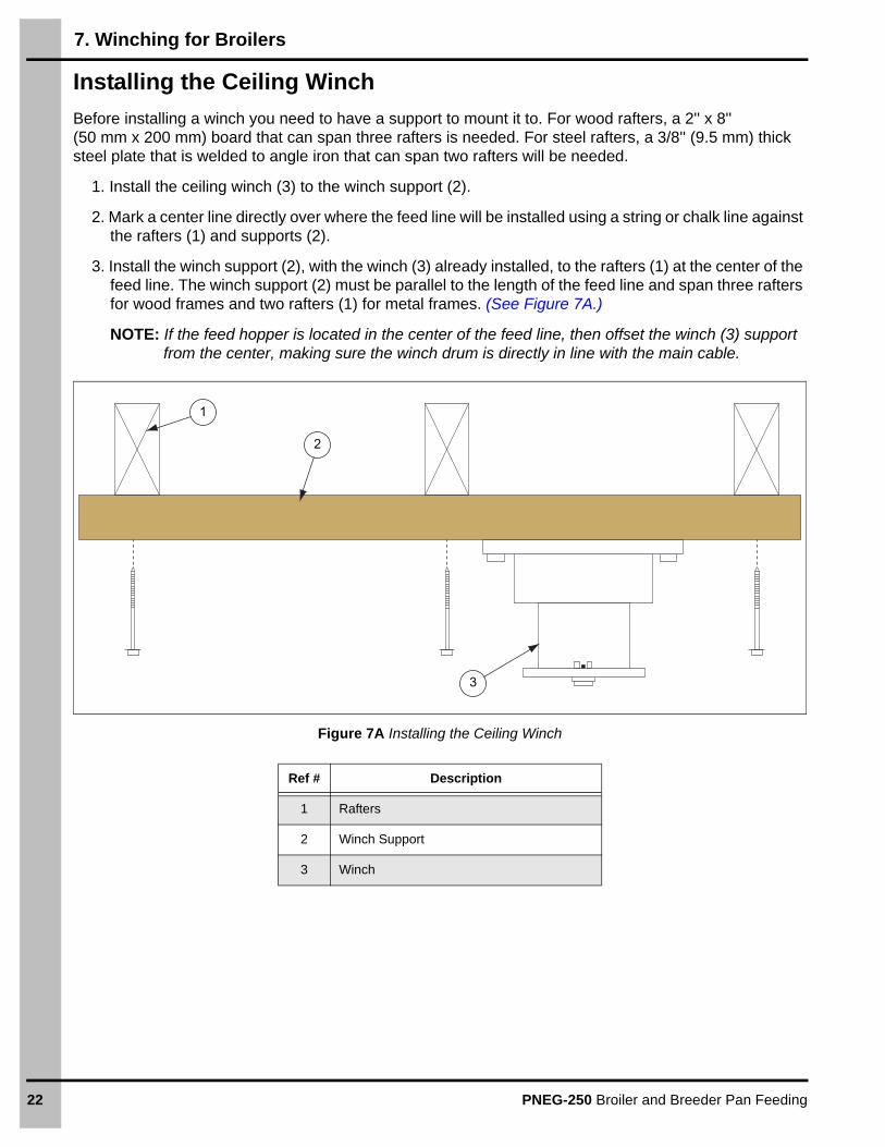
Installing the Ceiling Winch
Before installing a winch you need to have a support to mount it to. For wood rafters, a 2'' x 8'' (50 mm x 200 mm) board that can span three rafters is needed. For steel rafters, a 3/8'' (9.5 mm) thick steel plate that is welded to angle iron that can span two rafters will be needed.
1. Install the ceiling winch (3) to the winch support (2).
2. Mark a center line directly over where the feed line will be installed using a string or chalk line against the rafters (1) and supports (2).
3. Install the winch support (2), with the winch (3) already installed, to the rafters (1) at the center of the feed line. The winch support (2) must be parallel to the length of the feed line and span three rafters for wood frames and two rafters (1) for metal frames. (See Figure 7A.)
NOTE: If the feed hopper is located in the center of the feed line, then offset the winch (3) support from the center, making sure the winch drum is directly in line with the main cable.
Figure 7A Installing the Ceiling Winch
Ref # Description
1 Rafters
2 Winch Support
3 Winch
2
3
1

7. Winching for Broilers
PNEG-250 Broiler and Breeder Pan Feeding 23
Installing the Main Winch Cable
Feed line suspension systems are based on ceiling heights of 14' (4.3 m) with suspension drop points every 8' (2.4 m).
1. Mark a line the full length and directly over where the feed line will be installed using a string or chalk line against the rafters and supports.
2. Make sure the structure overhead the feedline is adequate to support the weight of the Pan Feeding System.
3. Extend the main winch cable (2) the full length of the feed line, plus the length needed to drop from the ceiling to the floor on each end.
4. Temporarily attach the cable (2) to the ceiling with fasteners.
5. Route the cable (2) through the winch drum relief and tighten the set screw (3). (See Figure 7B.)
Figure 7B Installing the Main Winch Cable
Ref # Description
1 Winch Drum Direction of Rotation
2 3/16'' Main Winch Cable
3 Winch Drum Relief with Set Screw
Do not exceed more than 10' (3 m) between suspension drops.
1
23

7. Winching for Broilers
24 PNEG-250 Broiler and Breeder Pan Feeding
6. Turn the winch drum one full revolution (1) guiding the cable against the flange at the bottom of the winch drum. (See Figure 7C.)
NOTE: The cable must not crossover itself on the drum, but wrap against the drum, next to the previous wrap.
Figure 7C Winch Drum Direction of Rotation
Ref # Description
1 Winch Drum Direction of Rotation
1

7. Winching for Broilers
PNEG-250 Broiler and Breeder Pan Feeding 25
7. Assemble the hopper suspension brackets (4) using 5/16'' bolts (5) and nuts (6). (See Figure 7D.)
NOTE: The 300 lbs. and 400 lbs. hopper brackets have additional support brackets (7) that must be installed at the same time. (See Figure 7E.)
Figure 7D Installing the Hopper Suspension Brackets
Figure 7E Installing the Hopper Suspension Support Brackets
8. Install the hopper and hopper suspension brackets (4).
Ref # Description
4 Hopper Suspension Bracket
5 5/16"-18 Bolt
6 5/16"-18 Nut
7 Hopper Suspension Support Bracket

7. Winching for Broilers
26 PNEG-250 Broiler and Breeder Pan Feeding
9. Plan your drop locations so they are no more than 10' (3 m) apart and do not interfere with other equipment.
Required support line drop locations:
• One for each drive unit.
• One within 3' (0.9 m) of the drive.
• Two for each feed hopper (19'' (48.26 cm) apart for 120 lbs. and 200 lbs. hoppers and 25''(63.50 cm) for 300 lbs. and 400 lbs. hoppers).
Figure 7F Systems Short than 360'
Figure 7G Systems Longer than 360' with a Double Back Layout
10. Install the main cable pulleys at each end of the feed line, directly above where the cable will connect to the control pan motor and the feed hopper support bracket.
11. Route the main cable through the main cable pulleys.

7. Winching for Broilers
PNEG-250 Broiler and Breeder Pan Feeding 27
Installing the Feed Hopper and Control Pan
1. Attach one end of the main cable (1) to the control pan motor.
2. Attach one end of the main cable (1) to the feed hopper suspension bracket (3).
NOTE: Install a drop 19'' (120-200 lbs.) or 25'' (300-400 lbs.) from the main line drop to connect to the other side of the hopper support bracket (3).
3. If not already installed, bolt the cable guides (2) to the sides of the hopper (4) using 5/16'' hardware and route the cables through the interlocking slots of the cable guide (2). (See Figure 7H.)
Figure 7H Installing the Feed Hopper and Control Pan
Ref # Description Ref # Description
1 Main Cable 3 Hopper Suspension Bracket
2 Cable Guide 4 Hopper

7. Winching for Broilers
28 PNEG-250 Broiler and Breeder Pan Feeding
Screw Hook Installation
Before you begin, make sure that the ceiling has been marked directly above the feed line. For metal frame installation, some support fabrication may be necessary in order to install pulleys at the recommended spacing.
1. Space the screw hooks (3) 8' (2.4 m) on center. Do not exceed 10' (3 m) spacing for the screw hooks (3). (See Figure 7I.)
NOTE: If the distance raised is greater than the distance between the screw hooks (3) (drop spacing), then offset the hooks by 3'' (7.6 cm) (4) to each side of the main cable (1) to prevent the cable clamps from catching on the pulleys.
Figure 7I Installing the Screw Hook
2. Screw the hooks into the truss the full length of the threads. (See Figure 7J.)
NOTE: Make sure that the screw hook (3) opening is towards the direction of the cable travel (5).
Figure 7J Direction of cable travel
Ref # Description Ref # Description
1 Main Winch Cable 3 Screw Hook
2 Drop Cable 4 3'' (7.6 cm) Offset
Ref # Description
5 Direction of cable travel and direction toward winch.

7. Winching for Broilers
PNEG-250 Broiler and Breeder Pan Feeding 29
Installing the Drop Cables
When installing the cable drops, make sure that there is tension on the main winch cable. Use weights if necessary to maintain tension on the line. Install the cable drops starting from the winch and work your way out towards the feed hopper and control pan.
1. Install the 1-3/4'' cable pulleys onto the screw hooks. (See Figure 7K.)
2. Thread the end of the 1/8'' cable through the pulley towards the winch (1). Clamp this end to the 3/16'' winch cable about 6'' (150 mm) from the last pulley, using a 3/16'' cable clamp (2).
Figure 7K
3. Place the hangers (4) to the feed line directly below each pulley by snapping the wire hanger around the rib of the tube.
NOTE: Be sure the hangers (4) do not touch the shocker wire.
4. Install the cable adjustment clip no more than 6'' (15 cm) above the hanger.
5. Route the drop cable through the hanger (4) and cable adjustment clip (3).
6. Level the feed line using the adjustment clips (3) and trim any excess cable close to the clips.
NOTE: Adjust cables to keep tension on the hanging cables at all times to prevent the pans from resting in the litter.
Figure 7L
Ref # Description
1 Winch
2 Cable Clamp
Ref # Description
3 Cable Adjustment Clip
4 Wire Hanger

30 PNEG-250 Broiler and Breeder Pan Feeding
8. Pan Feeder Assembly
Installation Sequence
This manual outlines the recommended sequence for the installation of the Hi-Lo Pan Feeder System. Observing this sequence provides the safest and easiest method of installation.
Hi-Lo Pan Feeder Assembly
Part Numbers: 7098851, 7101255, 710960 and 7101450
IMPORTANT: Feeders with one-piece drop tubes must be installed onto the tube section before the tubes are assembled together. All Hi-Lo models are assembled in the same manner.
1. Slide the bottom piece (1) of the two-piece drop tube (2) into the top piece, making sure it locks in place.
IMPORTANT: For an assembly that does not use a shut off slide, make sure the notches on the top and bottom piece are aligned. In this position, the SHUT OFF INDICATOR ARROW will point toward the NO SHUT OFF side. To adjust, squeeze the tabs at the bottom of the assembly and pull apart. Failure to do so will result in feed shifting where the drop tube meets the tube.
2. Slide the grill (3) over the drop tube (2).
3. Insert the feed level (4) into the feed level stand (5).
4. Make sure that the clip (7) on the feed level (4) is firmly seated into a notch (6) on the feed level stand (5) by pressing the tabs together. The standard setting is with three notches (6) visible above the feed level (4).
IMPORTANT: If the clip (7) is not in a slot, the feed level (4) can lower and the clip (7) can become stuck outside of a notch (6) and can stop feed from flowing. It can be difficult to return the clip (7) to a slot after it gets stuck.
5. Slide the feed level (4) onto the bottom of the drop tube (2).
6. Insert the pan (8) into the grill (3) by tilting the pan (8) at an angle and snapping it into place.
NOTE: The pan (8) can be removed by lifting one side of the pan (8) and pushing on the opposite side, while also flexing the grill (3) to pop it out.
7. Slide the assembled pan (8) feeders onto the auger tube (9), making sure to align the slot in the drop tube (2) with the rib of the auger tube (9). (See Figure 8A on Page 31.)
NOTE: The number of pans (8) will be determined by the number of feed holes in the auger tube (9).
Do not connect the system to the electrical mains until the final stage of installation. Failure to observe critical sequencing could prove fatal.

8. Pan Feeder Assembly
PNEG-250 Broiler and Breeder Pan Feeding 31
Figure 8A Hi-Lo Pan Feeder Assembly
Ref # Description Ref # Description
1 Bottom Piece 6 Notches
2 Drop Tube 7 Clip
3 Grill 8 Pan
4 Feed Level 9 Auger Tube
5 Feed Level Stand

8. Pan Feeder Assembly
32 PNEG-250 Broiler and Breeder Pan Feeding
“E” Feeder Assembly1. Align a ridge on the outside of the drop tube (1) with channel on the inside of the feed level skirt (2)
and insert drop tube (1) into the feed level skirt (2).
2. Align the arrow on the drop tube assembly (4) with the letter “E” on the grill (3) and then lower the grill (5) onto the drop tube. The drop tube (1) alignment with the arrow aligned with the letter “E” on the grill (3).
3. Assemble the pan (6) to the grill (5) by placing the pan (6) hook over the grill bar to act as a hinge.
4. Pivot the pan up until it is seated into the bottom of the grill (5) and then rotate the pan (6) into the locking position.
5. To install the drop tube (1):
a. For one-piece drop tube (1), slide the drop tube onto the auger tube.
b. For two-piece drop tube (1), snap the drop tube onto the auger tube and slide the drop tube cap onto the drop tube (1).
6. To adjust feeder, you MUST lift the grill (5) out of the locking grooves (7) and rotate and align the arrow indicator on the feed level skirt (2) with “D”, “E” or “F” on the grill (5). Then lower the grill back into the locked position (8). (See Figure 8B.)
Figure 8B “E” Feeder Assembly
Ref # Description Ref # Description
1 Drop Tube 5 Grill
2 Feed Level Skirt 6 Pan
3 Letter “E” on the Grill 7 Locking Grooves
4 Drop Tube Assembly 8 Locked Position

8. Pan Feeder Assembly
PNEG-250 Broiler and Breeder Pan Feeding 33
Hi-Lo Plus Pan Feeder Assembly1. Insert the adjustment ring (1) into the top of the grill (2).
2. Insert the drop tube (3) into the feed level (4).
3. Twist the drop tube (3) and feed level assembly (4) into the grill (2). Align the arrow with number to determine the height.
4. Insert pan (5) into the bottom of the grill (2).
5. Install the pan (5) to the feed tube (7) by placing the drop tube (3) under the hole location and sliding the top cap (6) into the drop tube (3). (See Figure 8C.)
NOTE: To remove the feeder, pinch both tabs on the side of the drop tube (3) and slide off the top cap (6).
Figure 8C Hi-Lo Plus Pan Feeder Assembly
Ref # Description Ref # Description
1 Adjustment Ring 5 Pan
2 Grill 6 Top Cap
3 Drop Tube 7 Feed Tube
4 Feed Level Assembly

8. Pan Feeder Assembly
34 PNEG-250 Broiler and Breeder Pan Feeding
Pro-1 Assembly1. Align a slots in the drop tube (1) with the tabs in the drop tube extension (2) and snap.
2. Align adjustment slots on the lower drop tube (4) with notches on feed level adjustor (5) and snap into the position.
3. Slide clear window guard (3) over lower drop tube (4).
4. Align slot on locking collar (6) with the tab on the lower drop tube (4) and slide over the lower drop tube.
5. Insert the drop tube assembly (1) into the lower drop tube assembly (4).
6. Slide grill (7101254) over the top of the drop tube assembly (4) and snap the pan (7098857) onto the grill. (See Figure 8D.)
Figure 8D Pro-1 Assembly
Ref # Description Ref # Description
1 Drop Tube 4 Lower Drop Tube
2 Drop Tube Extension 5 Feed Level Adjustor
3 Window Guard 6 Locking Collar

8. Pan Feeder Assembly
PNEG-250 Broiler and Breeder Pan Feeding 35
Nutrapan Assembly1. Install the center slide (1) and the cone center into the bottom of the pan (3).
2. Install the feed level skirt (2) and clear window guard onto the pan assembly.
3. Install the pan onto the feed tube (5) by sliding the center cone (6) top over the feed tube (5) and into the slots. (See Figure 8E.)
Figure 8E Nutrapan Assembly
Ref # Description
1 Center Slide
2 Feed Level Skirt
3 Bottom of the Pan
4 Top Cap
5 Feed Tube
6 Center Cone

8. Pan Feeder Assembly
36 PNEG-250 Broiler and Breeder Pan Feeding
Flooding Applications
For flooding applications, the feeder can be used in either a locked position, which prevents the pan from collapsing or in a collapsed position to take advantage of the Hi-Lo feature.
Uncollapsed Pan
1. Lift locking collar (C2000212) and use the tabs on both the locking collar and lower drop tube (C2000210) to rotate the collar into its locked position as shown in Figure 8F and Figure 8G.
2. When the feed line is lowered to ground level, the drop tube is lowered into position to open the flooding windows as shown in Figure 8H.
Figure 8F Figure 8G
Figure 8H

8. Pan Feeder Assembly
PNEG-250 Broiler and Breeder Pan Feeding 37
Collapsed Pan
1. Simply leave the locking collar in its assembled or lowered position to allow the pan to collapse into the grill for standard Hi-Lo operation as shown in Figure 8I.
2. When the feed line is lowered to ground level, the pan is raised into position to open the flooding windows as shown in Figure 8J.
Figure 8I Figure 8J
PRO-1 Retrofit
Converting a standard Hi-Lo feeder to the PRO-1 feeder is simple with the use of the PRO-1 retrofit kit (C2000235). The kit contains the drop tube extension (C2000209), lower drop tube (C2000210), feed level adjustor (C2000211) and the locking collar (C2000212). Simply remove the existing Hi-Lo feed level stand (7098855) and Hi-Lo feed level (7098854) and follow the instructions at the beginning of this section.

8. Pan Feeder Assembly
38 PNEG-250 Broiler and Breeder Pan Feeding
Tubing Assembly
NOTE: Check to see that structural members are overhead to support winching the boot and hopper.(See Section Winching for Broilers on Page 21.)
1. Place the boot (1) in its approximate final position: Single boot at the end of the house, double boot in the center of the house. (See Figure 8K.) Assemble the auger tubing the length of the building, starting with the bell end towards the boot (3). (See Figure 8K and Figure 8L.)
Figure 8K
Figure 8L
Ref # Description
1 Boot
2 1-3/4" Insulator Bracket Assembly
3 Belled End of Tube
Ref # Description
3 Belled End of Tube
4 1-3/4" Tube Clamp
5 Straight End of Tube
Be careful, there are many sharp edges that can cut while assembling the feedline. Wear protective clothing and gloves.
Every fifth (5th) auger tube should receive an insulator bracket assembly for the shocker wire. Do not over tighten the tube clamps or distortion of the tubes may result.

8. Pan Feeder Assembly
PNEG-250 Broiler and Breeder Pan Feeding 39
2. If the winching system is already in place, hang the line at approximately waist level.
3. Shorten the last full length of auger tube on the line (control pan side), if the building size requires it.
4. Secure the auger tubes together with the tube clamps (6) as shown in Figure 8M.
Figure 8M
Programming Poultry Tubes for Pullet and Breeder Applications
NOTE: Pans should already be assembled onto the tubes, in position over the holes (less the anti-rotation clips) and with the belled ends facing the control unit end. Do not attach tube clamps at this time.
1. Starting with the poultry boot, attach a double swedged tube (1) to each outlet on the boot. (If single boot (4) use one, if double boot (5) use two - one on each side of the boot.) Insert the poultry tubes into the double swedged tube. Continue to insert tubes into each other until the end of the line where the control unit will be located. (See Figure 8N below and Figure 8O on Page 40.)
NOTE: It will be necessary to cut off the belled end of the last tube and a small portion of the rib to enable the tube to slide into the control unit bell.
Figure 8N
6
Ref # Description
6 Tube Clamp
Ref # Description
1 Double Swedged Tube (7101478)
2 Tube Clamp
3 Tube End Cut Off
4 Single Boot

8. Pan Feeder Assembly
40 PNEG-250 Broiler and Breeder Pan Feeding
Figure 8O
2. Count and label (number) the tubes starting from the poultry boot and ending at the control unit. It is important to count and number each “group” of tubes (from the boot to the control unit) separately. If using a double boot in the center of the house, this would be considered as two separate groups. (See Figure 8P and Figure 8Q.)
Figure 8P Single Boot
Figure 8Q Double Boot
3. Use the Programming Charts on Pages 77-82 to determine which notch in the anti-rotation clip each tube rib will be inserted into. Charts are listed according to tube length and RPM.
4. When standing at the poultry boot and facing the control unit, snap on an anti-rotation clip on both sides of each pan assembly. With the home plate hole on the tube to the left and above the tube rib, rotate the anti-rotation clips to the proper notch according to the program chart. Do this to each pan assembly on the tube. (See Figure 8R and Figure 8S on Page 41.)
Ref # Description
1 Double Swedged Tube (7101478)
2 Tube Clamp
3 Tube End Cut Off
5 Double Boot

8. Pan Feeder Assembly
PNEG-250 Broiler and Breeder Pan Feeding 41
Figure 8R Anti-Rotation Clip Figure 8S Tube Inserted into Slot on Anti-Rotation Clip
5. Snap the two anti-rotation clips together around each pan assembly on the tube to secure the pans. Rotate the tube to position the bottom of the pans horizontal to the floor. Continue to the next tube. There will be four different positions that tubes will be rotated to. (See Figure 8T and Figure 8U.)
Figure 8T Anti-Rotation Clip Open Figure 8U Anti-Rotation Clip Snapped Together
6. Attach and secure tube clamps where tubes come together.
7. Attach the scissor hangers and S-Hooks the tube at the proper winching positions.
8. It is recommended to use Hi-Speed DDPU’s for all straight line pullet and breeder applications to ensure adequate feed distribution.
9. Large volume hoppers with lower hopper switches are also recommended to ensure the tubes are fully charged and ready for the next feeding when the system shuts down. Before feeding, be sure to pre-fill the feed hoppers.

8. Pan Feeder Assembly
42 PNEG-250 Broiler and Breeder Pan Feeding
Feeder Assembly Rooster Feeder
Two-Piece Drop Tube
1. Place the top of the two-piece drop tube over the hole opening on the tube. (See Figure 8V.)
Figure 8V
2. Push the grill up on to the assembly. (See Figure 8W and Figure 8X.)
Figure 8W Figure 8X
3. Place the funnel restrictor through the drop tube bottom. (See Figure 8Y.)
Figure 8Y

8. Pan Feeder Assembly
PNEG-250 Broiler and Breeder Pan Feeding 43
4. Slide the bottom of the two-piece drop tube on the assembly, making certain the tabs are locked in place. (See Figure 8Z and Figure 8AA.)
Figure 8Z Figure 8AA
IMPORTANT: Top and bottom pieces of the drop tube must be oriented the correct way or feed leakage could occur.
5. For assembly when NO SHUT OFF SLIDE IS USED, the indicator bumps (2) on the top and bottom of the drop tube pieces must be aligned. (See Figure 8AB.) Failure to do so will result in feed sifting where the drop tube meets the tube. If these are not aligned, remove the bottom and turn it 180°.
If a SHUT OFF SLIDE IS USED, indicator bumps (2) must be opposite each other.
Proper alignment can also be found by following the text on the top and bottom drop tube pieces.
Figure 8AB
6. Optional: If the optional shut off slide is used place it under the tube before snapping the lower part of the drop tube in place. When using the shut off slide, indicator bumps (2) on the drop tube should be on opposite sides. (See Figure 8AC.)
Figure 8AC
1
2Ref # Description
1 Tab
2 Indicator Bumps
8. Pan Feeder Assembly
44 PNEG-250 Broiler and Breeder Pan Feeding
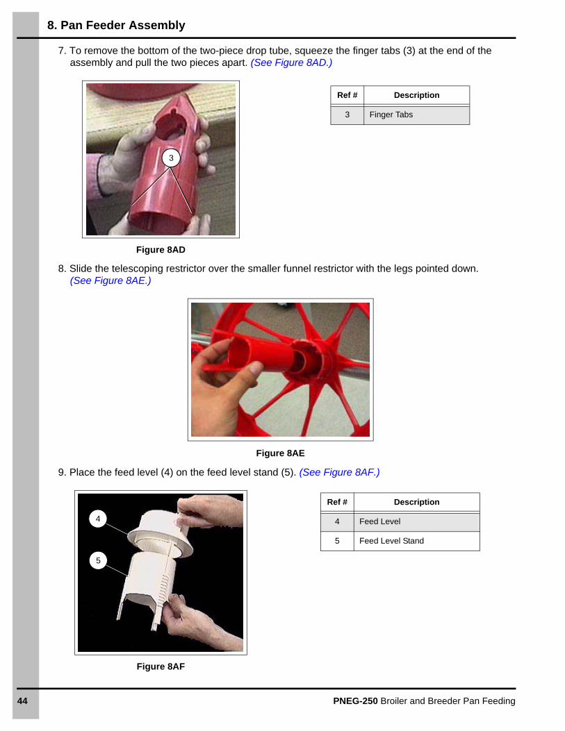
7. To remove the bottom of the two-piece drop tube, squeeze the finger tabs (3) at the end of the assembly and pull the two pieces apart. (See Figure 8AD.)
Figure 8AD
8. Slide the telescoping restrictor over the smaller funnel restrictor with the legs pointed down. (See Figure 8AE.)
Figure 8AE
9. Place the feed level (4) on the feed level stand (5). (See Figure 8AF.)
Figure 8AF
3
Ref # Description
3 Finger Tabs
4
5
Ref # Description
4 Feed Level
5 Feed Level Stand

8. Pan Feeder Assembly
PNEG-250 Broiler and Breeder Pan Feeding 45
10. Place the clip into the preferred notch. (See Figure 8AG.)
Visually check that the clip is securely in a notch. If the clip does not fit into the slot, the feed level can lower and the clip can become fixed out of the notches (6). If the clip becomes fixed while out of a slot, the feed flow can stop. It will be difficult to return the clip (7) to a slot if it becomes fixed while out of a slot.
Optimum results will be obtained by maintaining as shallow of feed depth as possible, while still having sufficient feed flow ability. This is normally three or four notches showing.
Figure 8AG
11. Spread the hold-down clip and slide it over the feed level stand. (See Figure 8AH and Figure 8AI.)
Figure 8AH Figure 8AI
12. Place the feed level on the assembly. (See Figure 8AJ.)
Figure 8AJ
6
7
Ref # Description
6 Notches
7 Clip

8. Pan Feeder Assembly
46 PNEG-250 Broiler and Breeder Pan Feeding
13. Disassembly of the pan and grill may be performed by lifting on one side of the pan while pushing down on the other side and flexing the grill. With practice, this operation will become easy for cleaning.
Place the pan on the assembly. (See Figure 8AK.)
Figure 8AK
14. Slide the hold-down clip up until it snaps in place over the feed level stand. (See Figure 8AL and Figure 8AM.)
Figure 8AL
Figure 8AM

8. Pan Feeder Assembly
PNEG-250 Broiler and Breeder Pan Feeding 47
Drive Unit/Control Pan Assembly
1. Unpack the drive unit and grilled control unit.
2. Connect the drive mount (See Figure 8AO) or anchor plate (See Figure 8AP), depending on the model of the control pan, to the gearbox of the drive unit, (See Figure 8AN) using the four bolts provided with the control unit.
Figure 8AN Figure 8AO
3. The attached unit should look like the picture in Figure 8AQ.
Figure 8AP Figure 8AQ
Ref # Description
1 Bolt Holes
1
Ref # Description
2 Bolts
2

8. Pan Feeder Assembly
48 PNEG-250 Broiler and Breeder Pan Feeding
4. If the pan assembly is not provided with the control pan, assemble the Hi-Lo grill onto the control pan. (See Figure 8AR.)
a. Take off drop tube.
b. Place through grill.
c. Replace drop tube onto control pan base.
d. Assemble remainder of Hi-Lo pan components.
Figure 8AR
5. On the Hi-Lo microswitch control pan, attach slope panel using screws provided. (See Figure 8AS.)
Figure 8AS
6. Attach the control unit/drive unit onto the last auger tube section and secure it with a tube clamp. (See Figure 8AT.)
Figure 8AT

8. Pan Feeder Assembly
PNEG-250 Broiler and Breeder Pan Feeding 49
7. Wire the control pan to the drive unit motor. (See Figure 8AU.)
a. Place cord into motor connection box.
b. Tighten cord connector.
c. Connect wires to motor leads, matching black to brown and blue to white.
Figure 8AU
8. Wire control pan to power source. (See Figure 8AV.)
9. Attach top and bottom covers. (See Figure 8AW.)
Figure 8AV
Figure 8AW
10. Remove the vent plug (6) at the top of the gearbox. (See Figure 8AX on Page 50.)
11. Fill the gearbox with the recommended quantity of lubricant found on the gearbox: (15 ounces (0.9375 pints)).
12. Replace the plug and tighten firmly.
The following type lubricants are recommended for the gear reducer: Standard Oil of Ohio Factolube #2 or equivalent, Gearup 90, Mobilube E.P. 80-90 or a good differential oil SAE 90.
Ref # Description3 Power Out to Black and White Leads on Motor4 Switch5 Power In

8. Pan Feeder Assembly
50 PNEG-250 Broiler and Breeder Pan Feeding
Figure 8AX
Control Pan Assembly
Hi-Lo Center House Control Pan (All Clamp on Models)
Figure 8AY is the Hi-Lo center house control pan with the pre-assembled double bell auger tube. The center house control pan can be mounted between two sections of auger tube by trimming one auger bell as shown in Figure 8AZ on Page 51 and installing it as shown in Figure 8BA on Page 51 with two 1-3/4" U-bolts (included). Depending on the location of the control pan, you may need to install the control pan between two auger tube holes on one section of auger tube. In this case, cut the auger in half and trim back the rib to install the control pan.
Figure 8AY
Ref # Description
6 Vent Plug
6

8. Pan Feeder Assembly
PNEG-250 Broiler and Breeder Pan Feeding 51
Figure 8AZ
Figure 8BA

8. Pan Feeder Assembly
52 PNEG-250 Broiler and Breeder Pan Feeding
If breaking the feed line is not an option, the double belled auger tube can be removed and the center house control pan can then be clamped to the feed line as shown in Figure 8BB.
1. The outlet hole for the center house control pan and two holes in front of the center house pan must be enlarged.
2. Begin by enlarging the feed hole in the auger tube. Use a hacksaw and tin snips to cut out material as shown in Figure 8BB. Make sure that there are no burrs on the inside of the auger that may interfere with the auger operation.
Figure 8BB
3. Remove the #10-24 x 2-1/4" machine screws and lid. Attached center house control pan to feed line as shown in Figure 8BC and Figure 8BD.
Figure 8BC Figure 8BD
Before
After

8. Pan Feeder Assembly
PNEG-250 Broiler and Breeder Pan Feeding 53
Adjusting the Hi-Lo Microswitch Control Pans (End and Center House)
1. Check switch and adjust if necessary. Switch should click with 1/4" of movement. (See Figure 8BE.)
Figure 8BE
2. Assemble remainder of Hi-Lo pan. (See Figure 8BF.)
Figure 8BF

8. Pan Feeder Assembly
54 PNEG-250 Broiler and Breeder Pan Feeding
3. Wire control pan to power source. (See Figure 8BG.)
Figure 8BG
Proximity Switch Sensor Adjustment
All capacitive switches have a potentiometer which allows switch sensitivity to be adjusted for the best results. To establish the proper sensitivity for a particular set of target conditions, follow these procedures.
1. Mount the switch in the application. Set up the worst case condition which can cause a false “OFF” signal. As an example, assume the switch is being used to sense the level of a liquid through a sight glass. The worst case condition exists when moisture is present on the inside surface of the glass. Turn the potentiometer clockwise (CW) until the LED is OFF, then turn the potentiometer counterclockwise (CCW) until it just turns ON.
2. Bring the target into position. In the example, bring the water above the level of the switch. The LED should be OFF. Turn the potentiometer CCW and count the number of turns until the LED turns ON.
3. Turn the potentiometer CW for half the number of turns counted in Step 2. For example if it took four turns for the LED to turn ON, turn the potentiometer two turns CW. The switch will now be set.
Ref # Description
1 Power In
2 To End Control
3 Control Pan Electrical Box
4 Switch
Lock out power before servicing.
L1
L2

8. Pan Feeder Assembly
PNEG-250 Broiler and Breeder Pan Feeding 55
Hi-Lo End Control Pan Assembly with Spinner MotorThe Hi-Lo end control pan has three main sensing components: The PC board (inside the electrical box of the end control pan), the solid state relay (mounted on the back side of the PC board) and the spinner motor (located in the “throat” of the end control and center house control pans). (See Figure 8BI.) Should any part need replaced, the PC board has two diagnostic lights (green and yellow) to help determine the status of the components. (See Figure 8BJ.)
Figure 8BH
Figure 8BI Figure 8BJ
Switch ClosedPulse
Weak
Medium
Strong
None
SW1 SW2 SW3 SW4
GRN RED
BLUE
DC MOTOR
GRN
OP
EN
BLUE
BLUE
BRN
BRN
OU
T
L1
L1
IN
BLKBLK
BLK WHT
Spinner motor
L2L
2
To motor Line power
Ground
BLUE
WHITE
Yellow LED (Indicates DC Motor power)
Ground
Green LED (Indicates solid state relay power)
8. Pan Feeder Assembly
56 PNEG-250 Broiler and Breeder Pan Feeding
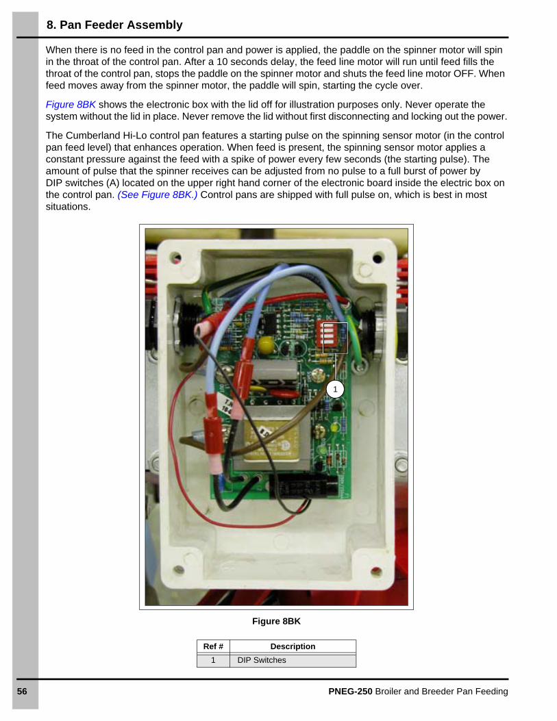
When there is no feed in the control pan and power is applied, the paddle on the spinner motor will spin in the throat of the control pan. After a 10 seconds delay, the feed line motor will run until feed fills the throat of the control pan, stops the paddle on the spinner motor and shuts the feed line motor OFF. When feed moves away from the spinner motor, the paddle will spin, starting the cycle over.
Figure 8BK shows the electronic box with the lid off for illustration purposes only. Never operate the system without the lid in place. Never remove the lid without first disconnecting and locking out the power.
The Cumberland Hi-Lo control pan features a starting pulse on the spinning sensor motor (in the control pan feed level) that enhances operation. When feed is present, the spinning sensor motor applies a constant pressure against the feed with a spike of power every few seconds (the starting pulse). The amount of pulse that the spinner receives can be adjusted from no pulse to a full burst of power by DIP switches (A) located on the upper right hand corner of the electronic board inside the electric box on the control pan. (See Figure 8BK.) Control pans are shipped with full pulse on, which is best in most situations.
Figure 8BK
Ref # Description
1 DIP Switches
1

8. Pan Feeder Assembly
PNEG-250 Broiler and Breeder Pan Feeding 57
Hi-Lo Center House Control Pan Wiring1. Attach switch box assembly (A) (supplied with center house pan) to lid of end control pan (C).
2. Run 20 gauge two wire cord (not supplied) from the center house into the switch box. (See Figure 8BP for Wiring on Page 58.)
3. Remove the electronics box (B) lid on end control unit.
4. The extra lid wired to the switch box is the new lid for the electronics box. (See Figure 8BM, Figure 8BN below and Figure 8BO on Page 58 for connections.)
5. In the center house control pan (D) switch box, connect the wire that you just ran to the leads coming into the back of the box. Match like colors (black to black and white to white).
Figure 8BL
6. In the end control pan electronics box, disconnect the blue and red wires of the circuit board from the black and red wires of the spinner motor by pulling the barrel terminals apart. (See Figure 8BM and Figure 8BN.)
Figure 8BM End Control Pan Figure 8BN
Ref # Description Ref # Description
A Switch Box Assembly C End Control Pan
B Electronics Box D Center House Control Pan
6

8. Pan Feeder Assembly
58 PNEG-250 Broiler and Breeder Pan Feeding
7. Match the four wires on the new lid to the wires that you just disconnected in the electronics box. Match the male to female connections with the following colors: 20 Gauge black to 20 gauge black, 16 gauge red to 20 gauge red, 16 gauge blue to 20 gauge blue and 20 gauge yellow to 20 gauge red. (See Figure 8BO.)
Figure 8BO End Control Pan
8. In the switch box assembly, connect the wire from the center house control pan to the leads from the switch, matching black to black and red to red. (See Figure 8BP.)
Figure 8BP Wiring Diagram for Switch Box
Ref # Description Ref # Description
E Switch Box on End Control PanG
20 Gauge wire to center house control pan (not supplied).F To End Control Pan Electronics Box
Yellow
Blue
Black
Red
Black
Red
Switch

8. Pan Feeder Assembly
PNEG-250 Broiler and Breeder Pan Feeding 59
9. To add a second control pan, run a wire from the second center house control pan to the switch box on the end control pan, as with the first center house control pan. (See Figure 8BQ.) (NOTE: The switch box included in the second center house control pan is not used. Both center house control pans are wired into the same switch.)
Figure 8BQ
10. Connect the black lead to the remaining terminal on the switch and tie the red lead together with the other red and blue leads. (See Figure 8BR.)
Figure 8BR
Ref # Description Ref # Description
C End control panH
20 Gauge wire to second center house control pan (not supplied).D Center house control pans
E Switch Box on End Control PanI
Wiring diagram for switch box adding a second center house control pan.F To End Control Pan Electronics Box
G 20 Gauge wire to center house control pan (not supplied).
Blue Red Red
Black
Black
Black
RedBlack
Red
Yellow

8. Pan Feeder Assembly
60 PNEG-250 Broiler and Breeder Pan Feeding
Auger Installation
1. Remove the bearing cap, bearing and idler shaft from the boot.
2. Remove the cover plate on the control unit.
3. Feed the auger through the boot end into the auger tube, using constant care and inspection. Two people should be used for this operation: One should feed the auger into the auger tube while the other sees that the auger is uncoiled without creating any strain. If feeding long lengths of auger into the auger tube, overcome resistance by rotating the auger while pushing it into the tube.
4. In the event of a bend or kink, try to straighten the auger by hand. If the auger will not straighten by hand, use locking pliers. If the auger still cannot be straightened, cut it on both sides of the bend and remove the bent portion. A hacksaw or bolt cutters can be used to cut the auger. Refer to the auger brazing section to reconnect the auger.
5. Make certain that the 3/4" washer is installed on the gearbox output shaft and is located between the gearbox face and U-bolt (1). Loosen the U-bolt on the gearbox shaft and thread the auger through the U-bolt to within 1/2" (13 mm) of the rear drive wall as shown in Figure 8BS. Tighten the U-bolt (1) securely.
6. Pull the auger from the boot end until all slack is removed.
Figure 8BS
Ref # Description
1 U-Bolt
Watch carefully for wire, tags, metal clips and especially for kinks and bends. If the auger is bent or kinked, it must be straightened prior to operation. Otherwise, excessive auger tube wear will result.
1

8. Pan Feeder Assembly
PNEG-250 Broiler and Breeder Pan Feeding 61
7. Mark the auger (2) at the edge of the boot where the bearing mounts, as shown in Figure 8BT.
Figure 8BT
8. Determine the amount of stretch required, by using the chart. See Auger Stretch Chart.
Auger Stretch Chart
9. Pull the auger out as far as necessary, starting from the “relaxed” mark on the auger and measuring towards the boot.
10. Mark the auger at the point which allows the proper stretch (3). (See Figure 8BU.)
Figure 8BU
Use caution when releasing the tension on the auger. If the auger moves too quickly in any direction, it can injure the operator.
Ref # Description
2 Mark the auger here.
2" Pitch 0.814 I.D.
Length of System Stretch per 100 Ft.
0-100 ft. (0-30.48 m) 7.5" (19.05 cm)
100-200 ft. (30.48-60.96 m) 8.0" (20.32 cm)
200-300 ft. (60.96-91.44 m) 9.0" (22.86 cm)
300-400 ft. (91.44-121.92 m) 10" (25.4 cm)
400-500 ft. (121.92-152.4 m) 11" (27.94 cm)
500 ft.+ (152.4 m+) 12" (30.48 cm)
Ref # Description
3 Proper Stretch

8. Pan Feeder Assembly
62 PNEG-250 Broiler and Breeder Pan Feeding
11. Pull the auger out from the back of the hopper (4) an additional 8" (20.3 cm) and clamp at that point with a pair of locking pliers. (See Figure 8BV.)
12. Allow the pliers to rest against the boot to hold the auger in place.
Figure 8BV
If the auger is allowed to spring back, the bearing race may crack. The auger will pull itself and the bearing plate assembly into the correct position. Do not overtighten the U-clamp or distortion of the auger tube may result. Rapid cooling will cause hardening and embrittlement. The auger must be smooth to prevent feed build-up and premature tube wear.
13. Cut the auger at the mark which allowed proper stretch.
14. Leave the pliers in place against the boot.
15. Insert the idler shaft assembly into the auger and thread the auger through the U-bolt up to 1/2" (1.27 cm) from the bearing.
16. Tighten the U-bolt securely.
17. Slowly release tension on the auger.
18. Re-attach the bearing cap and the U-clamp and tighten them securely.
Figure 8BW
Ref # Description
4 Back of Hopper
Ref # Description
4 Back of Hopper

8. Pan Feeder Assembly
PNEG-250 Broiler and Breeder Pan Feeding 63
19. The auger may be lengthened by brazing two sections of auger together. (See Figure 8BX.)
20. The ends to be brazed should be well filed and cleaned. Weld length should be 1/2" to 3/4" (13 mm to 19 mm).
21. Use a bronze, flux-coated rod and low heat, as overheating could warp the auger.
22. To keep the auger aligned and to prevent warping and kinking, lay the auger into an angle or channel iron and clamp firmly.
23. The auger must not be lapped. This causes a narrow flight spacing and will hamper feed movement.
24. Allow the auger to air-cool slowly.
25. Grind off any rough edges.
Figure 8BX
1/2" to 3/4" 13 mm to 19 mm
Correct
Incorrect

8. Pan Feeder Assembly
64 PNEG-250 Broiler and Breeder Pan Feeding
Hopper Assembly
The head of the bolts should be to the inside of the hopper to help prevent feed from bridging.
1. Assemble the hopper panels with the side flanges on the outside of the hopper.
2. Install the cover, hopper brace (1) and hanger brackets at the top of the hopper. (See Figure 8BY.)
Figure 8BY
3. Slide the assembled hopper onto the top of the boot.
4. Secure the hopper to the boot by inserting the pin (2) from the boot through the holes in the hopper bottom flange and boot top flange as shown in Figure 8BZ.
5. Feed agitation: Most feed will fall through the hopper and boot without agitation. For feed that require agitation, a “cannon ball” agitator is provided. The cannon ball simply rests on the auger inside the boot.
Figure 8BZ
Be careful, there are many sharp edges that can cut while assembling the feedline. Wear protective clothing and gloves.
Ref # Description
1 Hopper Brace
Ref # Description
2 Pin

8. Pan Feeder Assembly
PNEG-250 Broiler and Breeder Pan Feeding 65
650 Lbs. Hopper Scale
Refer to Figure 8CA as the scales are being assembled and installed.
1. Hang the 650# hopper scale assembly (4) with four drops from the main winch cable.
2. Using the cotter pins attached to the unloader (6), assemble the unloader extension (5) to the top of the unloader. With cables, the unloader/extension assembly can now be suspended from the650# hopper scale assembly at the desired height.
3. Assemble the hopper hangers (2) to the hopper (1) during hopper assembly. The hangers for 120/200 lbs. hoppers and 300/400 lbs. hoppers are included with the scale. Use the correct set of hangers for the hopper that you have.
4. Attach the scale gate (3) to the bottom of the hopper and secure into place with the supplied cotter pins.
5. The hopper can now be placed into the scale with the notches in the hopper hanger resting on the hopper scale bars.
Figure 8CA
Ref # Description Ref # Description
1 Hopper 4 650# Hopper Scale Assembly
2 Hopper Hanger 5 Unloader Extension
3 Scale Gate 6 Unloader

8. Pan Feeder Assembly
66 PNEG-250 Broiler and Breeder Pan Feeding
Figure 8CB Hopper Scale Wiring Diagram
220V
SIN
GL
E P
HA
SE
L1L
2G
ND
CIR
CU
ITB
RE
AK
ER
FLE
X-F
LO
CO
NT
RO
L U
NIT
J
UM
PE
R A
DD
ED
IN F
IELD
(HO
PP
ER
LE
VE
L S
WIT
CH
NO
T U
SE
D)
WH
ITE
BLA
CK
GR
EE
N
MO
M. S
WIT
CH
230
V F
EM
ALE
PLU
G
FR
OM
CO
NT
RO
L U
NIT
230
V M
ALE
PLU
G F
RO
M
SC
ALE
SW
ITC
H B
OX
230V
MA
LE
MO
TO
R P
LU
G
230
V F
EM
ALE
PLU
G
FR
OM
SC
ALE
SW
ITC
H B
OX
FLE
X-F
LO M
OT
OR
M
BLACK
WHITE
GREEN
WIR
E O
N T
OP
O
F B
EA
M
PA
DD
LE
SW
ITC
H
RE
LAY
WIR
E O
N B
OT
TO
M
OF
BE
AM
HO
PP
ER
SC
AL
E S
WIT
CH
BO
X

8. Pan Feeder Assembly
PNEG-250 Broiler and Breeder Pan Feeding 67
Anti-Roost Wire
1. Double loop the anti-roost wire around the first insulator at the boot as shown in Figure 8CC.
2. Secure the anti-roost wire around the insulator (1) with the cable clamp sleeves (3) provided as shown in Figure 8CC.
Figure 8CC
3. Thread the anti-roost cable through the slots in the tops of the feeder drop tubes and through the hangers, as shown in Figure 8CD.
Figure 8CD
Ref # Description
1 Insulator
2 Double-Looped Shocker Wire
3 Cable Clamp Sleeve

8. Pan Feeder Assembly
68 PNEG-250 Broiler and Breeder Pan Feeding
The shocker wire is to be installed in 50' (15.24 m) increments maximum.
4. Install an anti-roost wire tension spring, as shown in Figure 8CE at the next insulator, the fifth (5th) auger tube down.
5. Hook one end of the spring over the insulator of the next section of wire as shown in Figure 8CE.
Figure 8CE
There should be 3/4" to 1" (1 cm to 2.5 cm) of stretch on the spring.
6. Cut the cable with enough slack to loop (4) the end of the cable through the spring and secure it with a cable clamp sleeve (3). (See Figure 8CF.)
Figure 8CF
7. Repeat the preceding steps of attaching sections of anti-roost wire until the control pan is reached. (See Figure 8CG.)
8. Attach the anti-roost bracket onto the three insulators onto the lid of the control pan as shown in Figure 8CG.
Figure 8CG
Ref # Description
3 Cable Clamp Sleeve
4 Loop
8. Pan Feeder Assembly
PNEG-250 Broiler and Breeder Pan Feeding 69
Hopper Level Control Switch
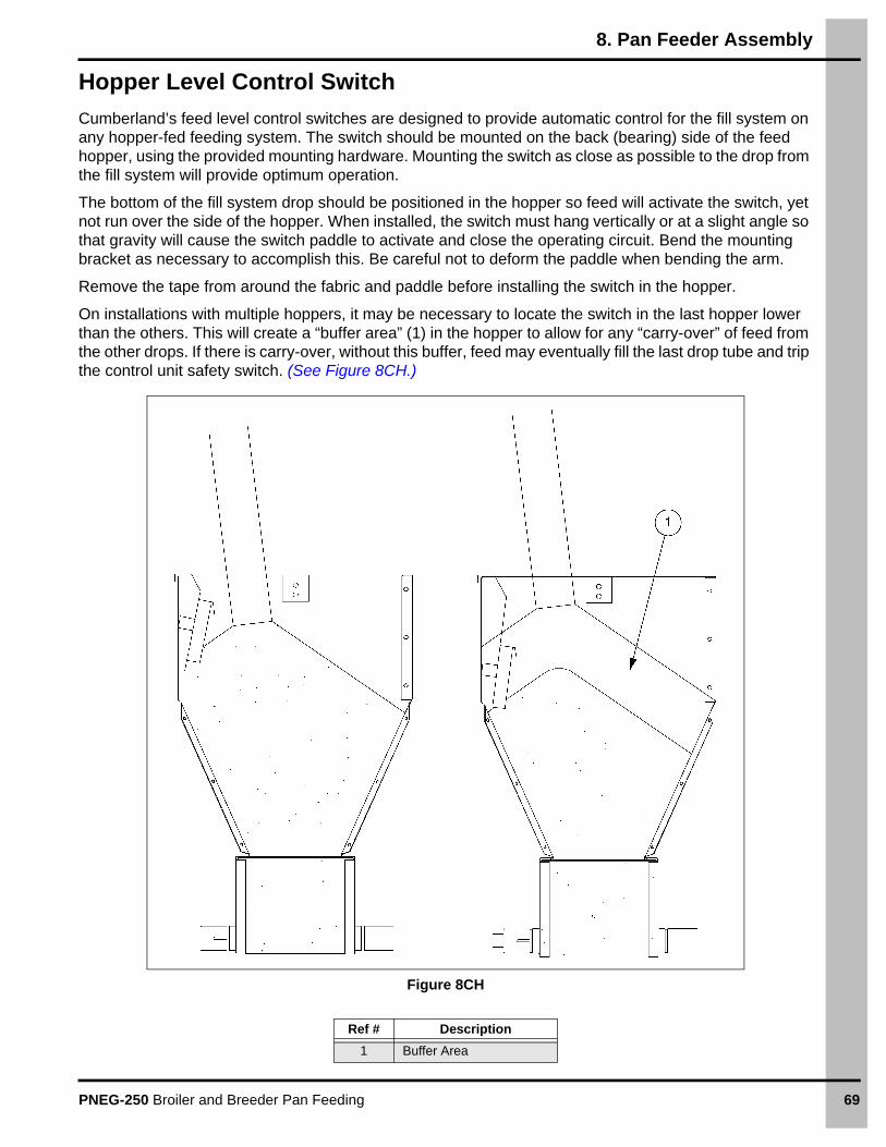
Cumberland’s feed level control switches are designed to provide automatic control for the fill system on any hopper-fed feeding system. The switch should be mounted on the back (bearing) side of the feed hopper, using the provided mounting hardware. Mounting the switch as close as possible to the drop from the fill system will provide optimum operation.
The bottom of the fill system drop should be positioned in the hopper so feed will activate the switch, yet not run over the side of the hopper. When installed, the switch must hang vertically or at a slight angle so that gravity will cause the switch paddle to activate and close the operating circuit. Bend the mounting bracket as necessary to accomplish this. Be careful not to deform the paddle when bending the arm.
Remove the tape from around the fabric and paddle before installing the switch in the hopper.
On installations with multiple hoppers, it may be necessary to locate the switch in the last hopper lower than the others. This will create a “buffer area” (1) in the hopper to allow for any “carry-over” of feed from the other drops. If there is carry-over, without this buffer, feed may eventually fill the last drop tube and trip the control unit safety switch. (See Figure 8CH.)
Figure 8CH
Ref # Description
1 Buffer Area

70 PNEG-250 Broiler and Breeder Pan Feeding
9. Rooster Winch Installation
“Throwback” Installation
Drops located close enough to the winch that they will wrap onto the drum when the feeder line is raised must be connected to the winch cable by a “throwback,” as shown in Figure 9A. This is a suspension drop which routes the cable away from the winch far enough that the cable clamp sleeve and drop cable do not get wound onto the winch drum.
Figure 9A
Maximum distance feeder line is to be raised
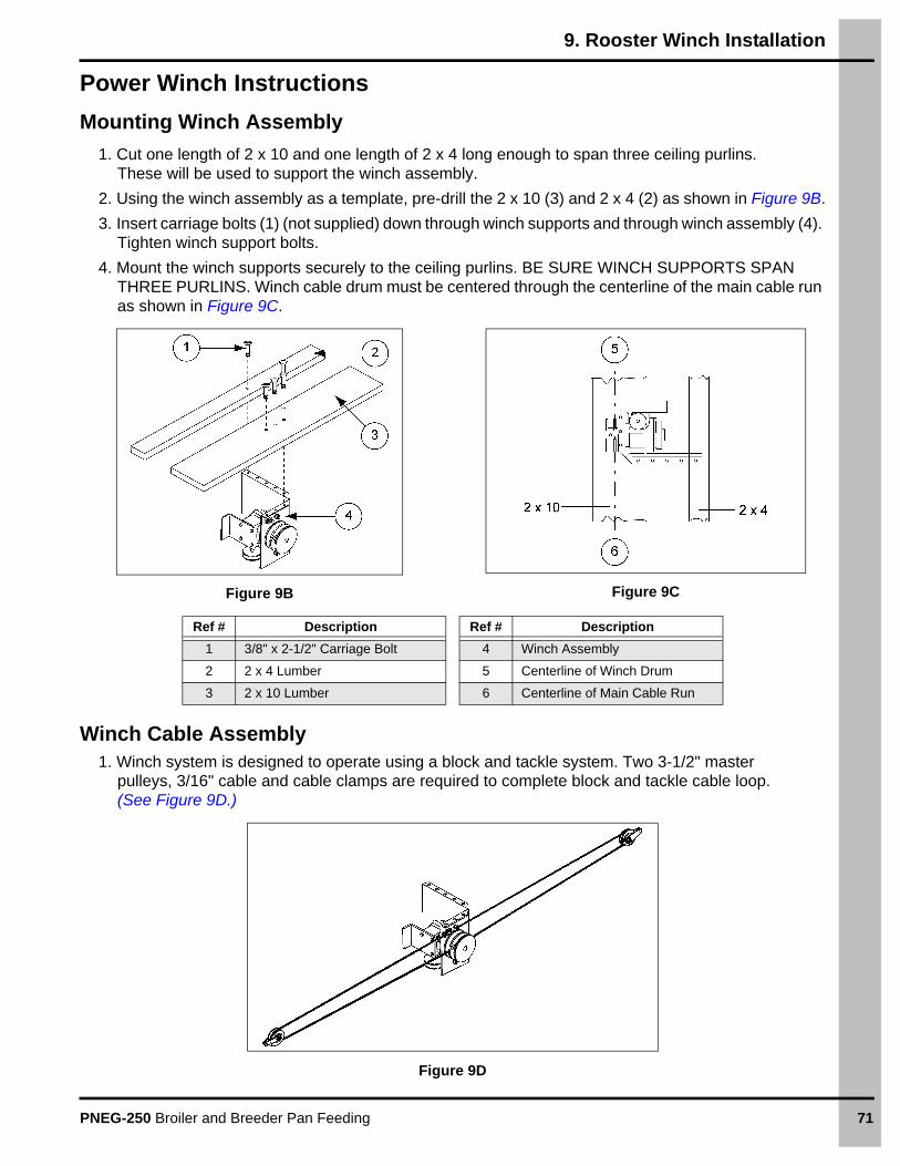
9. Rooster Winch Installation
PNEG-250 Broiler and Breeder Pan Feeding 71
Power Winch Instructions
Mounting Winch Assembly
1. Cut one length of 2 x 10 and one length of 2 x 4 long enough to span three ceiling purlins. These will be used to support the winch assembly.
2. Using the winch assembly as a template, pre-drill the 2 x 10 (3) and 2 x 4 (2) as shown in Figure 9B.
3. Insert carriage bolts (1) (not supplied) down through winch supports and through winch assembly (4). Tighten winch support bolts.
4. Mount the winch supports securely to the ceiling purlins. BE SURE WINCH SUPPORTS SPAN THREE PURLINS. Winch cable drum must be centered through the centerline of the main cable run as shown in Figure 9C.
Figure 9B Figure 9C
Winch Cable Assembly1. Winch system is designed to operate using a block and tackle system. Two 3-1/2" master
pulleys, 3/16" cable and cable clamps are required to complete block and tackle cable loop. (See Figure 9D.)
Figure 9D
Ref # Description Ref # Description
1 3/8" x 2-1/2" Carriage Bolt 4 Winch Assembly
2 2 x 4 Lumber 5 Centerline of Winch Drum
3 2 x 10 Lumber 6 Centerline of Main Cable Run

9. Rooster Winch Installation
72 PNEG-250 Broiler and Breeder Pan Feeding
2. Insert one end of the cable through the “U-bolt” on the winch frame as shown in Figure 9E and use two cable clamps to secure the loop to the cable.
Figure 9E
3. Thread the cable through the two master pulleys and then attach the remaining end of the loop to “U-bolt”.
NOTE: The master pulleys must be attached to the main line cable.
4. Position the cable drum as shown in Figure 9F. CABLE IS NOT TO BE ATTACHED TO THE WINCH DRUM.
Refer to the winch kit instructions in this manual to complete feeder system suspension installation. The drop cable nearest to the winch should not be installed at this time.
Figure 9F Figure 9G
Up rotation

9. Rooster Winch Installation
PNEG-250 Broiler and Breeder Pan Feeding 73
Controls Installation
1. Mount master control box to the wall or other adequate surface. Unit should be mounted as close to winch assembly as possible (not more than 15') only 20' of control cable is supplied. If control box needs to be mounted further away then control cable must be spliced. FOR SAFETY OF OPERATION WHEN RAISING THE SYSTEM YOU SHOULD BE ABLE TO SEE SYSTEM IN CASE OF COMPONENT FAILURE.
2. Mount the winch motor to the motor (1) mount (2) as shown in Figure 9H using 5/16" x 3/4" bolts (5) supplied in hardware bag. DO NOT LIFT MOTOR BY ELECTRICAL CORDS.
Figure 9H
3. Remove belt guard from winch assembly (7). Attach motor mount assembly (6) to the winch frame as shown in Figure 9I using 5/16" carriage bolts (8) supplied in hardware bag.
4. Install drive pulley on motor shaft. Align with drive pulley on gearbox and tighten drive pulley.
5. Install belt onto the two pulleys and check the belt alignment.
6. Tighten drive belt by adjusting bolts on motor mount (6). IMPORTANT: DO NOT OVER TIGHTEN DRIVE BELT THIS WILL REDUCE LIFE OF MOTOR BEARINGS AND GEARBOX BEARINGS. Replace belt guard on winch assembly (7).
Figure 9I
Ref # Description
1 1/3 HP Motor
2 Motor Mount
3 5/16" Nut
4 5/16" Lock Washer
5 5/16" x 3/4" Bolt
Ref # Description
6 Motor/Motor Mount Assembly
7 Winch Assembly
8 5/16" x 3/4" Carriage Bolt

9. Rooster Winch Installation
74 PNEG-250 Broiler and Breeder Pan Feeding
7. The drop cable nearest the winch assembly (7) is to be installed and used as the control cable (12) as shown in Figure 9J. Install the control mounting channel (10) to the ceiling using the two clamps provided. Mount the clamps approximately 1' from each end of channel. The channel must be mounted with the open end down. Mount the channel in close proximity to main cable run (9) without creating interference.
8. Mount one drop pulley (13) at each end of channel. The drop line end pulley must be at least 24" from end of channel for installation purposes.
9. Mount the overhead control box to the channel using channel clips and wing nuts supplied in the hardware bag. The box must be mounted with end marked “UP” towards the point where the control cable (12) will attach to the main cable (9).
10. Mount the up and down microswitches to the control channel (10) using remaining clips and wing nuts. THE ACTIVATOR ARMS ON THE SWITCHES MUST POINT TOWARDS THE END OF THE CONTROL CHANNEL (10).
Figure 9J
Control Cable Installation1. Clamp one end of control cable to main line approximately 24" back towards winch from drop pulley
as shown in Figure 9J.
2. Insert the cable through cable clamp (2) switch block (1) and then other cable clamp (2) as shown in Figure 9K. Do not tighten switch block (1) cable clamps (2) at this time.
3. Run drop cable through control channel (3) and drop end drop pulley and then attach to the feeder line. Be sure that cable does not interfere with switch actuator arms when in operation.
4. Insert switch block (1) into control channel being careful to move switch activator arm down so as not to damage it.
Figure 9K
Ref # Description
9 Main Cable Run
10 Control Channel
11 Channel Mounting Bracket
12 Control Cable
13 Drop Pulley
Ref # Description
1 Switch Block
2 Cable Clamp
3 Control Channel

9. Rooster Winch Installation
PNEG-250 Broiler and Breeder Pan Feeding 75
Primary Wiring
ALL WIRING SHOULD BE DONE BY A QUALIFIED ELECTRICIAN.
System operates on 230V 1 phase power only. 230V Power must be supplied to main control box.
NOTE: Ground wire must be supplied to overhead control box to provide proper grounding for winch motor.
1. Open main control box and note colors of wire connected to terminals 1 through 4. The SJ cord that is connected to these terminals should be run up to the overhead control box.
2. Connect the wires from the SJ cord to the terminal strip in the overhead control box. Terminal 1 should go to terminal 1, terminal 2 should go to terminal 2, etc.
NOTE: Use the terminal strip in the overhead control box that is not connected to the winch motor.
3. The feeder line fill system and the feeder line should get power from terminal 4 and terminal 5 in main control box. THIS WORKS ON SYSTEMS THAT ARE WIRED 220 VOLT 1 PHASE ONLY. For other systems, consult the factory.
See Wiring Schematic on Pages 86-103 for wiring details.
Setting the Microswitches
The span of winching operations is determined by the space between the microswitches and can be increased or decreased by loosening the wing nuts on the microswitches and adjusting them closer or farther apart.
1. Raise the system to the feeding height required by the breed of bird (18" to 24" from floor). The height should be comfortable for the males but not too high for the females.
2. Slide the switch block against the activator arm of the down microswitch until switch clicks. Mark location of black on cable.
3. Release the tie back end of the control cable at the main cable. Pull the cable partially out at the drop end until you have access to the marks on the cable.
4. Pull the switch block to its marked location and tighten the cable clamps on each side of the block. Return the switch block to its position inside the channel. Reconnect the tie back end to the main cable.
5. Raise the system to the desired height for filling.
6. Loosen wing nut holding up the microswitch. Slide switch assembly back against the switch block until the activator arm of the microswitch is activated by the switch block and then retighten wing nut.
IMPORTANT: THE CABLE MUST BE PLACED IN THE DRUM NOTCH DURING IT’S FIRST REVOLUTION.

9. Rooster Winch Installation
76 PNEG-250 Broiler and Breeder Pan Feeding
Power Winch Operation
Start with feeder in down position.
1. Flip DPDT toggle switch in to the up position. Push and hold the UP button until the light illuminates, then release the up button. The feeder should now be in the up position and ready to fill.
2. Flip the feed switch to the ON position. The feeder fill light should be lit and the feeder and fill system should start. System should operate until all pans are filled to proper level.
3. After filling is complete, turn feed switch to the OFF position.
4. The DPDT toggle switch must now be set to the “Down on Clock” position. MAKE SURE THE TIME CLOCK IS SET TO THE PROPER TIME. See the inside of time clock box for instructions on setting the time clock.
5. Pull out two tabs on the time clock at the time you want feeding to begin.
At a pre-determined time, the power winch will lower the feed line to the feeding position. The system can only be raised manually using the UP button and UP toggle switch.

PNEG-250 Broiler and Breeder Pan Feeding 77
10. Programming Chart
9' Auger Tube - 358 RPM
Figure 10A 9' Auger Tube - 358 RPM
D
KQ
V
CC
GG
Prog
ram
min
g C
hart
9' A
uger
Tub
e - 3
58 R
PMTu
be Q
tyTu
be #
3130
2928
2726
2524
2322
2120
1918
1716
1Q
Q2
3Q
V4
VV
5Q
QV
VV
VV
VV
V6
VV
VV
VV
VV
VV
VV
VV
7Q
VV
VV
VV
VV
VV
VV
VV
V8
VV
VV
VV
VV
VV
VV
VV
VV
9V
VV
VV
VV
VV
VV
VV
VV
V10
VV
VV
VV
VV
VV
VV
VV
VV
11V
VV
VV
VV
VV
VV
VV
VV
CC
12V
VV
VV
VV
VV
VV
VV
VC
CC
C13
VV
VV
VV
VV
VV
VV
VC
CC
CC
C14
VV
VV
VV
VV
VV
VV
CC
CC
CC
GG
15V
VV
VV
VV
VV
VV
CC
CC
CC
GG
GG
16V
VV
VV
VV
VV
VC
CC
CC
CG
GG
GG
G17
VV
VV
VV
VV
VC
CC
CC
CG
GG
GG
G18
VV
VV
VV
VV
CC
CC
CC
GG
GG
GG
19V
VV
VV
VV
CC
CC
CC
GG
GG
GG
20V
VV
VV
VC
CC
CC
CG
GG
GG
G21
VV
VV
VC
CC
CC
CG
GG
GG
G22
VV
VV
CC
CC
CC
GG
GG
GG
23V
VV
CC
CC
CC
GG
GG
GG
24V
VC
CC
CC
CG
GG
GG
G25
VC
CC
CC
CG
GG
GG
G26
CC
CC
CC
GG
GG
GG
27C
CC
CG
GG
GG
G28
CC
GG
GG
GG
29G
GG
GG
G30
GG
GG
31G
G
Cum
berla
nd re
com
men
ded
initi
al s
ettin
gs fo
r pro
gram
med
tube
.P
rogr
amm
ing
can
chan
ge p
er re
quire
men
ts fr
om in
tegr
ator
s.
An
ti-ro
tatio
n cl
ip o
rient
atio
n w
hen
view
ed fr
om th
e
hop
per
tow
ard
the
driv
e un
it.
Hom
e pl
ate
with
p
oint
faci
ng d
ow
n

10. Programming Chart
78 PNEG-250 Broiler and Breeder Pan Feeding
9' Auger Tube - 716 RPM
Figure 10B 9' Auger Tube - 716 RPM
Ant
i-rot
atio
n cl
ip o
rient
atio
n w
hen
view
ed fr
om th
e ho
pper
tow
ard
the
driv
e un
it.
Hom
e pl
ate
with
po
int f
acin
g do
wn
D
KQ
V
CC
GG
Prog
ram
min
g C
hart
9' A
uger
Tub
e - 7
16 R
PMTu
be Q
tyTu
be #
3130
2928
2726
2524
2322
2120
1918
1716
1Q
Q2
3Q
V4
VV
5Q
VV
V6
VV
VV
7Q
VV
VV
VV
V8
QV
VV
VV
VV
VV
VV
9Q
QV
VV
VV
VV
VV
VV
V10
QV
VV
VV
VV
VV
VV
VV
11Q
VV
VV
VV
VV
VV
VV
VV
CC
12V
VV
VV
VV
VV
VV
VV
VC
CC
C13
VV
VV
VV
VV
VV
VV
VC
CC
CC
C14
VV
VV
VV
VV
VV
VV
CC
CC
CC
GG
15V
VV
VV
VV
VV
VV
CC
CC
CC
GG
GG
16V
VV
VV
VV
VV
VC
CC
CC
CG
GG
GG
G17
VV
VV
VV
VV
VC
CC
CC
CG
GG
GG
G18
VV
VV
VV
VV
CC
CC
CC
GG
GG
GG
19V
VV
VV
VV
CC
CC
CC
GG
GG
GG
20V
VV
VV
VC
CC
CC
CG
GG
GG
G21
VV
VV
VC
CC
CC
CG
GG
GG
G22
VV
VV
CC
CC
CC
GG
GG
GG
23V
VV
CC
CC
CC
GG
GG
GG
24V
VC
CC
CC
CG
GG
GG
G25
VC
CC
CC
CG
GG
GG
G26
CC
CC
CC
GG
GG
GG
27C
CC
CG
GG
GG
G28
CC
GG
GG
GG
29G
GG
GG
G30
GG
GG
31G
G
Cum
berla
nd re
com
men
ded
initi
al s
ettin
gs fo
r pro
gram
med
tube
.P
rogr
amm
ing
can
chan
ge p
er re
quire
men
ts fr
om in
tegr
ator
s.

10. Programming Chart
PNEG-250 Broiler and Breeder Pan Feeding 79
10' Auger Tube - 358 RPM
Figure 10C 10' Auger Tube - 358 RPM
Ant
i-rot
atio
n cl
ip o
rient
atio
n w
hen
view
ed fr
om th
e ho
pper
tow
ard
the
driv
e un
it.
Hom
e pl
ate
with
po
int f
acin
g do
wn
D
KQ
V
CC
GG
Prog
ram
min
g C
hart
10' A
uger
Tub
e - 3
58 R
PMTu
be Q
tyTu
be #
3130
2928
2726
2524
2322
2120
1918
1716
1Q
Q2
3Q
Q4
QV
5Q
QV
V6
QV
VV
VV
7Q
QV
VV
VV
V8
QV
VV
VV
VV
VV
VV
9Q
QV
VV
VV
VV
VV
VV
VV
V10
VV
VV
VV
VV
VV
VV
VV
VV
11V
VV
VV
VV
VV
VV
VV
VV
CC
12V
VV
VV
VV
VV
VV
VV
VC
CC
C13
VV
VV
VV
VV
VV
VV
VC
CC
CC
C14
VV
VV
VV
VV
VV
VV
CC
CC
CC
GG
15V
VV
VV
VV
VV
VV
CC
CC
CC
GG
GG
16V
VV
VV
VV
VV
VC
CC
CC
CG
GG
GG
G17
VV
VV
VV
VV
VC
CC
CC
CG
GG
GG
G18
VV
VV
VV
VV
CC
CC
CC
GG
GG
GG
19V
VV
VV
VV
CC
CC
CC
GG
GG
GG
20V
VV
VV
VC
CC
CC
CG
GG
GG
G21
VV
VV
VC
CC
CC
CG
GG
GG
G22
VV
VV
CC
CC
CC
GG
GG
GG
23V
VV
CC
CC
CC
GG
GG
GG
24V
VC
CC
CC
CG
GG
GG
G25
VC
CC
CC
CG
GG
GG
G26
CC
CC
CC
GG
GG
GG
27C
CC
CG
GG
GG
G28
CC
GG
GG
GG
29G
GG
GG
G30
GG
GG
31G
G
Cum
berla
nd re
com
men
ded
initi
al s
ettin
gs fo
r pro
gram
med
tube
.P
rogr
amm
ing
can
chan
ge p
er re
quire
men
ts fr
om in
tegr
ator
s.

10. Programming Chart
80 PNEG-250 Broiler and Breeder Pan Feeding
10' Auger Tube - 716 RPM
Figure 10D 10' Auger Tube - 716 RPM
Ant
i-rot
atio
n cl
ip o
rient
atio
n w
hen
view
ed fr
om th
e ho
pper
tow
ard
the
driv
e un
it.
Hom
e pl
ate
with
po
int f
acin
g do
wn
D
KQ
V
CC
GG
Prog
ram
min
g C
hart
10' A
uger
Tub
e - 7
16 R
PMTu
be Q
tyTu
be #
3130
2928
2726
2524
2322
2120
1918
1716
1Q
Q2
3Q
V4
VV
5Q
VV
VV
V6
QV
VV
VV
7Q
VV
VV
V8
VV
VV
VV
VV
9Q
QV
VV
VV
VV
V10
QV
VV
VV
VV
VV
VV
11Q
QV
VV
VV
VV
VV
VV
VV
CC
12V
VV
VV
VV
VV
VV
VV
VC
CC
C13
VV
VV
VV
VV
VV
VV
VC
CC
CC
C14
VV
VV
VV
VV
VV
VV
CC
CC
CC
GG
15V
VV
VV
VV
VV
VV
CC
CC
CC
GG
GG
16V
VV
VV
VV
VV
VC
CC
CC
CG
GG
GG
G17
VV
VV
VV
VV
VC
CC
CC
CG
GG
GG
G18
VV
VV
VV
VV
CC
CC
CC
GG
GG
GG
19V
VV
VV
VV
CC
CC
CC
GG
GG
GG
20V
VV
VV
VC
CC
CC
CG
GG
GG
G21
VV
VV
VC
CC
CC
CG
GG
GG
G22
VV
VV
CC
CC
CC
GG
GG
GG
23V
VV
CC
CC
CC
GG
GG
GG
24V
VC
CC
CC
CG
GG
GG
G25
VC
CC
CC
CG
GG
GG
G26
CC
CC
CC
GG
GG
GG
27C
CC
CG
GG
GG
G28
CC
GG
GG
GG
29G
GG
GG
G30
GG
GG
31G
G
Cum
berla
nd re
com
men
ded
initi
al s
ettin
gs fo
r pro
gram
med
tube
.P
rogr
amm
ing
can
chan
ge p
er re
quire
men
ts fr
om in
tegr
ator
s.

10. Programming Chart
PNEG-250 Broiler and Breeder Pan Feeding 81
12' Auger Tube - 358 RPM
Figure 10E 12' Auger Tube - 358 RPM
Ant
i-rot
atio
n cl
ip o
rient
atio
n w
hen
view
ed fr
om th
e ho
pper
tow
ard
the
driv
e un
it.
Hom
e pl
ate
with
po
int f
acin
g do
wn
D
KQ
V
CC
GG
Prog
ram
min
g C
hart
12' A
uger
Tub
e - 3
58 R
PMTu
be Q
tyTu
be #
3130
2928
2726
2524
2322
2120
1918
1716
1Q
Q2
QV
3Q
QV
V4
VV
VV
5Q
VV
VV
V6
QV
VV
VV
VV
7Q
VV
VV
VV
VV
VV
V8
QV
VV
VV
VV
VV
VV
VV
9Q
QV
VV
VV
VV
VV
VV
VV
V10
VV
VV
VV
VV
VV
VV
VV
VV
11V
VV
VV
VV
VV
VV
VV
VV
CC
12V
VV
VV
VV
VV
VV
VV
VC
CC
C13
VV
VV
VV
VV
VV
VV
VC
CC
CC
C14
VV
VV
VV
VV
VV
VV
CC
CC
CC
GG
15V
VV
VV
VV
VV
VV
CC
CC
CC
GG
GG
16V
VV
VV
VV
VV
VC
CC
CC
CG
GG
GG
G17
VV
VV
VV
VV
VC
CC
CC
CG
GG
GG
G18
VV
VV
VV
VV
CC
CC
CC
GG
GG
GG
19V
VV
VV
VV
CC
CC
CC
GG
GG
GG
20V
VV
VV
VC
CC
CC
CG
GG
GG
G21
VV
VV
VC
CC
CC
CG
GG
GG
G22
VV
VV
CC
CC
CC
GG
GG
GG
23V
VV
CC
CC
CC
GG
GG
GG
24V
VC
CC
CC
CG
GG
GG
G25
VC
CC
CC
CG
GG
GG
G26
CC
CC
CC
GG
GG
GG
27C
CC
CG
GG
GG
G28
CC
GG
GG
GG
29G
GG
GG
G30
GG
GG
31G
G
Cum
berla
nd re
com
men
ded
initi
al s
ettin
gs fo
r pro
gram
med
tube
.P
rogr
amm
ing
can
chan
ge p
er re
quire
men
ts fr
om in
tegr
ator
s.

10. Programming Chart
82 PNEG-250 Broiler and Breeder Pan Feeding
12' Auger Tube - 716 RPM
Figure 10F 12' Auger Tube - 716 RPM
Ant
i-rot
atio
n cl
ip o
rient
atio
n w
hen
view
ed fr
om th
e ho
pper
tow
ard
the
driv
e un
it.
Hom
e pl
ate
with
po
int f
acin
g do
wn
D
KQ
V
CC
GG
Prog
ram
min
g C
hart
12' A
uger
Tub
e - 7
16 R
PMTu
be Q
tyTu
be #
3130
2928
2726
2524
2322
2120
1918
1716
1Q
Q2
3Q
QV
V4
VV
5Q
VV
VV
V6
QV
VV
VV
7Q
VV
VV
VV
V8
VV
VV
VV
VV
VV
VV
9Q
VV
VV
VV
VV
VV
VV
VV
V10
VV
VV
VV
VV
VV
VV
VV
VV
11V
VV
VV
VV
VV
VV
VV
VV
CC
12V
VV
VV
VV
VV
VV
VV
VC
CC
C13
VV
VV
VV
VV
VV
VV
VC
CC
CC
C14
VV
VV
VV
VV
VV
VV
CC
CC
CC
GG
15V
VV
VV
VV
VV
VV
CC
CC
CC
GG
GG
16V
VV
VV
VV
VV
VC
CC
CC
CG
GG
GG
G17
VV
VV
VV
VV
VC
CC
CC
CG
GG
GG
G18
VV
VV
VV
VV
CC
CC
CC
GG
GG
GG
19V
VV
VV
VV
CC
CC
CC
GG
GG
GG
20V
VV
VV
VC
CC
CC
CG
GG
GG
G21
VV
VV
VC
CC
CC
CG
GG
GG
G22
VV
VV
CC
CC
CC
GG
GG
GG
23V
VV
CC
CC
CC
GG
GG
GG
24V
VC
CC
CC
CG
GG
GG
G25
VC
CC
CC
CG
GG
GG
G26
CC
CC
CC
GG
GG
GG
27C
CC
CG
GG
GG
G28
CC
GG
GG
GG
29G
GG
GG
G30
GG
GG
31G
G
Cum
berla
nd re
com
men
ded
initi
al s
ettin
gs fo
r pro
gram
med
tube
.P
rogr
amm
ing
can
chan
ge p
er re
quire
men
ts fr
om in
tegr
ator
s.

PNEG-250 Broiler and Breeder Pan Feeding 83
11. Troubleshooting
Safety in Maintenance and Repairs
Before starting any repairs or maintenance on the Pan Feeding System, observe the following safety steps:
1. Isolate the entire system from the electricity supply by switching OFF the power isolator and locking it out.
2. Keep the lock out key in your possession.
3. When making any repairs to the auger, be aware that it can be under tension. Avoid touching the auger with your hands until you are sure that it is loose at all points. Use a suitable tool to check the auger.
4. Do not reconnect the power supply until all work is completed and all guards are correctly refitted.
Problem Checks Corrective Action
1. Spinner control pan will not shut system OFF.
a. Check to see if the feed has stopped the paddle of the spinner motor and the green light is OFF, but the feed line motor still runs.
a. Replace the solid state relay.
b. Check to see if the feed has stopped the paddle of the spinner motor and the green light is ON, but the feed line motor still runs.
b. Replace the PC board.
c. Check to see if feed reaches the spinner motor, but the paddle continues to “drill” through the feed.
c. Change the pulse settings to a lower pulse, using the DIP switches on the PC board.
d. Check to see if the feed bridges over the throat instead of falling into the pan.
d. Make sure nothing is blocking the throat and that feed is dropping into the center of the throat.
2. Spinner control pan will not restart system when feed is called for.
a. Check to see if the spinner motor in the end control pan does not spin and the yellow light is ON with a bright pulse every 5-10 seconds.
a. Replace the spinner motor.
b. Check that the spinner motors, in a system with a center house control pan, does not spin and the yellow light is ON with a bright pulse every 5-10 seconds.
b1. Make sure the voltage at the spinner motor in the center house pans is between 17 and 24 volts, if center house pans are used.
b2. Make sure the field wiring is correct to the center house control pans, if there is no voltage.
b3. Use a heavier gauge wire, if the voltage is very low.
c. Check to see if the spinner motor does not spin and the yellow light is not ON.
c. Replace the PC board.
d. Check that the spinner motor spins, but the feed line motor does not come ON and the green light comes ON after a 10 seconds delay.
d. Replace the solid state relay.
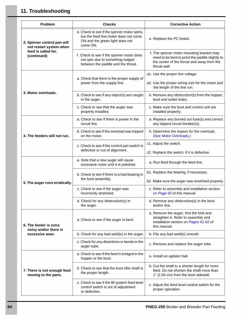
11. Troubleshooting
84 PNEG-250 Broiler and Breeder Pan Feeding
2. Spinner control pan will not restart system when feed is called for. (continued)
e. Check to see if the spinner motor spins, but the feed line motor does not come ON and the green light does not come ON.
e. Replace the PC board.
f. Check to see if the spinner motor does not spin due to something lodged between the paddle and the throat.
f. The spinner motor mounting bracket may need to be bent to point the paddle slightly to the center of the throat and away from the throat wall.
3. Motor overloads.
a. Check that there is the proper supply of power from the supply line.
a1. Use the proper line voltage.
a2. Use the proper wiring size for the motor and the length of the line run.
b. Check to see if any object(s) are caught in the auger.
b. Remove any obstruction(s) from the hopper, boot and outlet holes.
c. Check to see that the auger was properly installed.
c. Make sure the boot and control unit are installed properly.
4. The feeders will not run.
a. Check to see if there is power in the circuit line.
a. Replace any burned out fuse(s) and correct any tripped circuit breaker(s).
b. Check to see if the overload was tripped on the motor.
b. Determine the reason for the overload. (See Motor Overloads.)
c. Check to see if the control pan switch is defective or out of alignment.
c1. Adjust the switch.
c2. Replace the switch, if it is defective.
5. The auger runs erratically.
a. Note that a new auger will cause excessive noise until it is polished.
a. Run feed through the feed line.
b. Check to see if there is a bad bearing in the boot assembly.
b1. Replace the bearing, if necessary.
b2. Make sure the auger was stretched properly.
c. Check to see if the auger was incorrectly stretched.
c. Refer to assembly and installation sectionon Page 60 of this manual.
d. Check for any obstruction(s) in the auger.
d. Remove any obstruction(s) in the boot and/or line.
6. The feeder is extra noisy and/or there is excessive wear.
a. Check to see if the auger is bent.
a. Remove the auger, find the kink and straighten it. Refer to assembly and installation section on Pages 61-62 of this manual.
b. Check for any bad weld(s) in the auger. b. File any bad weld(s) smooth.
c. Check for any distortions or bends in the auger tube.
c. Remove and replace the auger tube.
7. There is not enough feed moving to the pans.
a. Check to see if the feed is bridged in the hopper or the boot.
a. Install an agitator ball.
b. Check to see that the boot idler shaft is the proper length.
b. Cut the shaft to a shorter length for more feed. Do not shorten the shaft more than 1" (2.54 cm) from the boot sidewall.
c. Check to see if the fill system feed level control switch is out of adjustment or defective.
c. Adjust the feed level control switch for the proper operation.
Problem Checks Corrective Action

11. Troubleshooting
PNEG-250 Broiler and Breeder Pan Feeding 85
i-Plus3 Troubleshooting Guide
Problem Possible Cause Solution
1. Power LED is OFF.
a. Loss of 220 VAC power. a. Check the power source and power cable.
b. The PTC is in tripped state. b. Disconnect the power for 5 min.
c. Faulty transformer or voltage regulator.
c. Contact an authorized service center.
2. Auger LED is ON, but the motor is not running.
a. Loss of 220 VAC power to the auger motor.
a. Check the auger motor cable and connections.
b. Faulty relay. b. Contact an authorized service center.
3. Detect LED is ON continuously.
a. Feed in front of the sensor. a. Remove the feed from the sensor.
b. Build-up of dust inside the sensor.b. Use a soft cloth to clean the dust from
inside.
c. Loose screw on CN1 (IR sensor connector).
c. Tighten connector screw.
d. Dirt or moisture on PCB. d. Clean and dry the board.
e. Faulty IR sensor. e. Replace the IR sensor.
f. Faulty electronic part. f. Contact an authorized service center.
4. Detect LED is flashing. a. The system is in time delay. a. Wait for 60 seconds.
5. Detect LED is OFF when the feed is in front of the sensor.
a. Loose screw on CN1 (IR sensor connector).
a. Tighten connector screw.
b. Dirt or moisture on PCB. b. Clean and dry the board.
c. Faulty IR sensor. c. Replace the IR sensor.
d. Faulty electronic part. d. Contact an authorized service center.

86 PNEG-250 Broiler and Breeder Pan Feeding
12. Wiring Diagrams
Rooster/Power Winch Wiring Diagram
MAIN CONTROL UNIT
220V SINGLE PHASE
L1 L2
20 AMP BREAKER (NOT SUPPLIED)
Dashed lines indicate winch with time clock only.
UP BUTTON
UP
OFF
DOWN
UP LIGHT
DOWN LIGHTDOWN BUTTON
FILL SWITCH
FILL SYSTEM LIGHT
TERMINAL STRIP
CLOCK SWITCH
CLOCK MOTOR
FIL
L S
YS
TE
M
R B W BK YG
CEILING CONTROL UNIT
UP MICRO SWITCH
N.C.
N.O.
3 PDT RELAY
TE
RM
INA
L S
TR
IP
YR
BY
BK
G
G
N.C.
N.O.
DOWN MICRO SWITCH
WINCHMOTOR
TERMINALSTRIP
G
GYBKWBR
* FOR SAFE OPERATION CONTROL BOX AND MOTOR SHOULD BE GROUNDED.
G

12. Wiring Diagrams
PNEG-250 Broiler and Breeder Pan Feeding 87
Microswitch End Control 220V, 1 Phase (7101483)
120
" C
ord
line
po
wer
36"
Cor
dTo
pow
er
unit
Gre
en/
Yel
low
Gre
en
Whi
te
Blu
e
Bro
wn
Bla
ck
Com
mon
Nor
mal
ly c
lose
d Nor
mal
lyop
en

12. Wiring Diagrams
88 PNEG-250 Broiler and Breeder Pan Feeding
Microswitch End Control 3 Phase (07101483-3)
Attach line 1, 2 and 3 to the terminals marked L1, L2 and L3
Connect to L1
20 Amp microswitch
07101483-3208V-230V 3 Phase control unit
used on 07101482-3Coil voltage: 200V-240VAC 25 amp
Black
Attach motor leads to T1, T2 and T3.To change the direction of motorrotation, reverse any two motor leads.
Connect to L2/N
L1T1
L2T2 T3
L3 N.O.N.O.
M1M2

12. Wiring Diagrams
PNEG-250 Broiler and Breeder Pan Feeding 89
Microswitch Center Control 220V, 1 Phase (7101540)
Ref # Part # Description
1 20-5060 Switch, Toggle SPST 15A with ON/OFF
2 07101123B C.H. Wires (Black)
3 7101123 C.H. Wires (White)
4 7100348 Cord 120" Long 14/3
5 C2200025 Switch 20 Amp Unimax
6 Normally Closed
7 Normally Open
8 Common
White
Black
Brown Blue
Green/Yellow
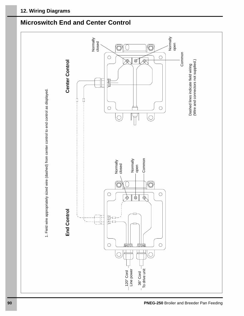
12. Wiring Diagrams
90 PNEG-250 Broiler and Breeder Pan Feeding
Microswitch End and Center Control
1. F
ield
wire
app
rop
riate
ly s
ized
wire
(da
shed
) fr
om c
ente
r co
ntr
ol to
end
co
ntro
l as
dis
pla
yed.
En
d C
on
tro
lC
ente
r C
on
tro
l
Nor
mal
ly
clos
ed
No
rma
lly
open
Com
mon
Das
hed
line
s in
dica
te fi
eld
wiri
ng(W
ire a
nd c
onn
ecto
rs n
ot s
upp
lied.
)
Nor
mal
ly
clos
ed
Nor
mal
ly
open
Co
mm
on
120
" C
ord
Lin
e po
wer
36"
Cor
dTo
driv
e u
nit

12. Wiring Diagrams
PNEG-250 Broiler and Breeder Pan Feeding 91
End Control Box, i-Plus3 (C2000535)
1. F
ield
wire
inpu
t pow
er
(215
VA
C/2
30 V
AC
) w
ith a
ppro
pria
tely
siz
ed w
ire to
end
con
trol
as
dis
pla
yed.
En
d C
on
tro
l
To M
oto
r
Re
d -
L2
Bla
ck -
L1
Gre
en -
Gnd
.
Re
d
Ear
th
Ear
th
Gre
en
Lin
e 2
Lin
e 2
Bla
ck
Red
N.C
.N
.O. C
omLi
ne 1
Au
ger
Rel
ay
Gre
enBla
ck
Gre
en
Bla
ck
Red
Whi
te
12 V
DC
Out
IR S
ens
or c
ord
Red
- L
2
Bla
ck -
L1
Gre
en -
Gnd
.
Inp
ut
Po
wer
215
VA
C/2
30 V
AC

12. Wiring Diagrams
92 PNEG-250 Broiler and Breeder Pan Feeding
Center Control Box, i-Plus3 (C2000563)
Cen
ter
Co
ntr
ol
Ou
tpu
t p
ow
er
to
end
co
ntr
ol
Red
- L
2
Bla
ck -
L1
Gre
en
- G
nd.
Re
d
Ear
th
Ear
th
Gre
en
Lin
e 2
Lin
e 2
Bla
ck Red
N.C
.N
.O. C
omLi
ne 1
Aug
er R
ela
y Gre
en
Bla
ck
Gre
en
Bla
ck
Red
Whi
te
12
VD
C O
ut
IR S
enso
r co
rd
Red
- L
2
Bla
ck -
L1
Gre
en
- G
nd.
Inp
ut
Po
wer
215
VA
C/2
30 V
AC
Bla
ck
Bla
ck
Ce
nter
co
ntro
lO
N/O
FF
sw
itch

12. Wiring Diagrams
PNEG-250 Broiler and Breeder Pan Feeding 93
End Control Box, i-Plus3 3 Phase (C2000590)
1. F
ield
wire
inp
ut p
ower
(21
5 V
AC
/230
VA
C)
with
app
ropr
iate
ly s
ized
wire
to e
nd
cont
rol a
s di
spla
yed.
2. F
ield
wire
app
ropr
iate
ly s
ize
d w
ire fr
om
en
d co
ntro
l to
208
vol
t-23
0 v
olt
3 ph
ase
cont
rol b
ox.
A
ttach
L1,
L2
and
L3
as
dis
play
ed,
atta
ch m
otor
lead
s to
T1,
T2
an
d T
3 as
dis
pla
yed
.
208
Vo
lt-2
30 V
olt
3 p
ha
se
con
tro
l b
ox
Co
il v
olt
age
: 2
00
VA
C-2
40
VA
C 2
5 am
p
To M
oto
r
To c
hang
e th
e di
rect
ion
of m
otor
ro
tatio
n, r
ever
se a
ny tw
o m
oto
r le
ads.
Inp
ut
po
we
r fr
om
e
nd
co
ntr
ol
To 3
ph
ase
c
on
tro
l b
ox
En
d C
on
tro
l
Inp
ut
po
we
r 2
15 V
AC
/230
VA
C
Inp
ut
pow
er
L1
L2
L3
T1
T2
T3
L1 L2
T1
T2
T
3
N.O
.
A2
T1
T2
T
3
N.O
.
A2
Red
- L
2B
lack
- L
1G
ree
n -
Gn
d.
IR S
en
sor
cord
Red
- L
2
Gre
en
- G
nd.
Bla
ck -
L1
Gre
enEar
th
Re
d
Ear
th
Lin
e 2
Lin
e 2
Bla
ck Re
d
N.C
.N
.O. C
omLi
ne 1
Aug
er R
ela
y
Gre
en
Gre
en
Bla
ck
Bla
ck
Re
dW
hite
12
VD
C O
ut

12. Wiring Diagrams
94 PNEG-250 Broiler and Breeder Pan Feeding
i-Plus3 End and Center Control
1. F
ield
wire
app
rop
riate
ly s
ized
wire
(da
shed
) fr
om c
ente
r co
ntr
ol to
en
d co
ntro
l as
dis
pla
yed.
2. F
ield
wire
inpu
t pow
er
(21
5 V
AC
/23
0 V
AC
) w
ith a
ppr
opria
tely
siz
ed w
ire to
cen
ter
cont
rol.
En
d C
on
tro
lC
ente
r C
on
tro
l
Inp
ut
po
wer
2
15 V
AC
/23
0 V
AC
Re
d -
L2
Bla
ck -
L1
Gre
en -
Gn
d.
IR S
en
sor
cord
Ce
nter
co
ntro
lO
N/O
FF
sw
itch
IR S
enso
r co
rd
Gre
enEar
th
Ear
th
Lin
e 2
Line
2
Bla
ck Red
N.C
.N
.O. C
omLi
ne
1
Aug
er R
ela
y
Gre
en
Bla
ck
Bla
ckR
edW
hite
12 V
DC
Out
Gre
en
Re
d -
L2
Gre
en
-
Gnd
.
Bla
ck -
L1
To M
oto
r
Gre
enB
lack
Red
Wh
ite
Bla
ck
Gre
en
Red
Bla
ck
Bla
ck
Gre
en
Bla
ckR
ed
Lin
e 2
Lin
e 2
Ea
rth
Ea
rth
N.C
.N
.O. C
omLi
ne 1
Au
ger
Rel
ay
12
VD
C O
ut
Ou
tpu
t p
ow
er t
o
end
co
ntr
ol
Red
-L2
Bla
ck-L
1
Gre
en-G
nd
Inp
ut
po
wer
fro
m
ce
nte
r c
on
tro
l

12. Wiring Diagrams
PNEG-250 Broiler and Breeder Pan Feeding 95
LED Light and i-Plus3 End Control
1. F
ield
wire
inp
ut p
ow
er (
215
VA
C/2
30 V
AC
) w
ith a
ppro
pria
tely
siz
ed w
ire to
en
d co
ntro
l as
disp
laye
d.2.
Atta
ch p
lug
from
LE
D li
ght a
ssem
bly
to 1
2 V
DC
out
term
inal
as
disp
laye
d.
Re
d -
L2
Gre
en -
G
nd.
Bla
ck -
L1
To M
oto
r
Gre
en
Ear
th
Ear
th
Red
Red
Bla
ck
Line
2
Line
2
Red
Bla
ck
Gre
enGre
en
Wh
ite
IR S
enso
r co
rd
N.C
.N
.O. Com
Lin
e 1
12
VD
C O
ut
Aug
er R
ela
y
Bla
ck
Inp
ut
po
we
r21
5 V
AC
/230
VA
C
Red
- L
2
Gre
en
- G
nd.
Bla
ck -
L1
To L
ED
lig
htas
sem
bly
En
d C
on
tro
l

12. Wiring Diagrams
96 PNEG-250 Broiler and Breeder Pan Feeding
Proximity Switch End Control 220V, 1 Phase (7100842)
Lin
e po
we
rB
lue
Bla
ck
Bro
wn
Gre
en
Blue
Brown
Blu
e
Gre
en
Bro
wn
Coi
l
To m
oto
r

12. Wiring Diagrams
PNEG-250 Broiler and Breeder Pan Feeding 97
Proximity Switch Center Control 220V, 1 Phase (C2000528)
Ref # Part # Description
1 7101128 Relay Assembly for Proximity Units 1 Phase
2 S-7368 Switch, DPDT ON-ON Toggle 15 Amp
White
Red
Black
Black
Coil
Blue
GreenBrown

12. Wiring Diagrams
98 PNEG-250 Broiler and Breeder Pan Feeding
Proximity End and Center Control
1. F
ield
wire
ap
prop
riate
ly s
ized
wire
(da
shed
) fr
om
cen
ter
cont
rol t
o en
d c
ontr
ol a
s d
ispl
aye
d.
Cen
ter
Co
ntr
ol
En
d C
on
tro
l
Bla
ck
Red
Bla
ck
Coil
Wh
ite
Blu
e
Gre
en
Bro
wn
Line
pow
er
Bla
ck
Whi
te
Bla
ck
Blu
e
Blu
e
Bro
wn
Gre
en
Co
il
Gre
en
Gre
en
Bro
wn
Gre
en
Blu
e
Red
To m
otor
Blu
eB
row
n

12. Wiring Diagrams
PNEG-250 Broiler and Breeder Pan Feeding 99
Spinner End Control 110V, 1 Phase (7100614)
Line
pow
er
Gro
und
Gre
en/
Yel
low
Red B
lue
DC
Mot
or
OPEN
Gre
en/Y
ello
w
Blu
e
Bro
wn
Bro
wnL1
OutL1In
L2
L2
Bla
ck
Bla
ck Bla
ck
Blu
e Red
Spi
nner
mo
tor
To m
otor
Sw
itch
Clo
sed
Pu
lse
We
ak
Me
diu
m
Str
ong
No
ne
SW
1S
W2
SW
3S
W4

12. Wiring Diagrams
100 PNEG-250 Broiler and Breeder Pan Feeding
Spinner End Control 220V, 1 Phase (7100211)
Lin
e p
ower
Gro
und
Gre
en/
Yel
low
Red Blu
e
DC
Mot
or
OPEN
Gre
en/Y
ello
w
Blu
e
Bro
wn
Bro
wnL1
OutL1In
L2
L2
Bla
ck
Bla
ck Bla
ck
Blu
e
Red
Spi
nner
mot
or
To m
oto
r
Sw
itch
Clo
sed
Pu
lse
Wea
k
Me
diu
m
Str
on
g
No
ne
SW
1S
W2
SW
3S
W4

12. Wiring Diagrams
PNEG-250 Broiler and Breeder Pan Feeding 101
Spinner Center Control 110V-220V, 1 Phase (C2000306)
Ref # Part # Description
1 S-7398 Connector, 3/8" Cord 14/3
2 7100275 Nut, Conduit 3/8"
3 S-7399 Jamb Nut 3/8"
4 E171-A1017 DC Spinner Motor

12. Wiring Diagrams
102 PNEG-250 Broiler and Breeder Pan Feeding
Spinner Center Control 220V (7100407)
Ref # Part # Description
1 E305-0269 WR, 3" WR-18 Black E106-1003, 3/8
2 1775 Switch ON-OFF-OFF Spot 3 Position
3 E305-0268 WR, 3" WR-18 White E106-1003,1003
4 E305-0270 WR, 3" WR-18 White 3/8, 3/8
5 MH-1462 Nut 16 Gauge Wire
6 7100409 Terminal Female Barrel
7 7100408 Terminal Male Barrel
8 7100435 Wire, 20/4 Viny Jacket
Black
Blue
Yellow
Black
Red
BlackWhite
Blue
Red
Yellow Black

12. Wiring Diagrams
PNEG-250 Broiler and Breeder Pan Feeding 103
Spinner End and Center Control
1. R
emov
e ex
istin
g co
ver
from
end
con
trol
and
dis
card
.2.
Mou
nt s
witc
h b
ox to
top
of e
nd c
ontr
ol u
nit.
3. R
e-w
ire e
nd c
ontr
ol c
over
as
disp
laye
d an
d m
oun
t to
end
cont
rol.
4. F
ield
wire
app
rop
riate
ly s
ized
wire
(da
shed
line
s) fr
om s
witc
h bo
x to
cen
ter
con
trol
as
disp
laye
d.
Das
hed
lines
indi
cate
fiel
d w
iring
(Wire
not
sup
plie
d.)
Cen
ter
Co
ntr
ol
En
d C
on
tro
l Co
ver
Sw
itch
Bo
xE
nd
Co
ntr
ol
Sw
itch
Clo
sed
Pu
lse
We
ak
Me
diu
m
Str
ong
No
ne
SW
1S
W2
SW
3S
W4
Ye
llow
Bla
ck
Re
d
Blu
e
Blu
e
Re
d
Ye
llow
Bla
ck
Bla
ck
Bla
ck
Blu
e Wh
ite
Lin
e po
wer
To m
oto
rD
C M
oto
r
OPEN
L1Out
L1In
L2
L2

104 PNEG-250 Broiler and Breeder Pan Feeding
NOTES

PNEG-250 Broiler and Breeder Pan Feeding 105
13. Warranty
Limited Warranty - Protein Products
The GSI Group, LLC. (“GSI”) warrants products which it manufactures, to be free of defects in materials and workmanship under normal usage and conditions for a period of 12 months from the date of purchase (or, if shipped by vessel, 14 months from the date of arrival at the port of discharge). If, in GSI’s sole judgment, a product is found to have a defect in materials and/or workmanship, GSI will, at its own option and expense, repair or replace the product or refund the purchase price. This Limited Warranty is subject to extension and other terms as set forth below.
Warranty Enhancements:
The warranty period for the following products is enhanced as shown below and is in lieu of (and not in addition to) the above stated warranty period.
Conditions and Limitations:THERE ARE NO WARRANTIES THAT EXTEND BEYOND THE LIMITED WARRANTY DESCRIPTION SET FORTH HEREIN; SPECIFICALLY, GSI DISCLAIMS ANY AND ALL OTHER WARRANTIES OF ANY KIND, EXPRESS OR IMPLIED, INCLUDING, WITHOUT LIMITATION, WARRANTIES OF MERCHANTABILITY OR FITNESS FOR A PARTICULAR PURPOSE OR USE IN CONNECTION WITH: (I) ANY PRODUCT MANUFACTURED OR SOLD BY GSI, OR (II) ANY ADVICE, INSTRUCTION, RECOMMENDATION OR SUGGESTION PROVIDED BY AN AGENT, REPRESENTATIVE OR EMPLOYEE OF GSI REGARDING OR RELATED TO THE CONFIGURATION, INSTALLATION, LAYOUT, SUITABILITY FOR A PARTICULAR PURPOSE, OR DESIGN OF SUCH PRODUCTS.
The sole and exclusive remedy for any claimant is set forth in this Limited Warranty and shall not exceed the amount paid for the product purchased. This Warranty only covers the value of the warranted parts and equipment, and does not cover labor charges for removing or installing defective parts, shipping charges with respect to such parts, any applicable sales or other taxes, or any other charges or expenses not specified in this Warranty. GSI shall not be liable for any other direct, indirect, incidental or consequential damages, including, without limitation, loss of anticipated profits or benefits. Expenses incurred by or on behalf of a claimant without prior written authorization from the GSI warranty department shall not be reimbursed. This warranty is not transferable and applies only to the original end user. GSI shall have no obligation or responsibility for any representations or warranties made by or on behalf of any dealer, agent or distributor. Prior to installation, the end user bears all responsibility to comply with federal, state and local codes which apply to the location and installation of the products.
This Limited Warranty extends solely to products sold by GSI and does not cover any parts, components or materials used in conjunction with the product, that are not sold by GSI. GSI assumes no responsibility for claims resulting from construction defects, unauthorized modifications, corrosion or other cosmetic issues caused by storage, application or environmental conditions. Modifications to products not specifically delineated in the manual accompanying the product at initial sale will void all warranties. This Limited Warranty shall not extend to products or parts which have been damaged by negligent use, misuse, alteration, accident or which have been improperly/inadequately maintained.
Service Parts:
GSI warrants, subject to all other conditions described in this Warranty, Service Parts which it manufactures for a period of 12 months from the date of purchase, unless specified in Enhancements above. Parts not manufactured by GSI will carry the Manufacturer’s Warranty.
Product Warranty Period
AP® Fans Performer Series Direct Drive Fan Motor 3 Years * Warranty prorated from material list price:0 to 3 years - no material cost to end user3 to 5 years - end user pays 25%
5 to 7 years - end user pays 50%
7 to 10 years - end user pays 75%
** Warranty prorated from material list price:0 to 3 years - no material cost to end user3 to 5 years - end user pays 75%
AP® and Cumberland® Flex-Flo/Pan Feeding System Motors 2 Years
Electronic Controls All Protein controls manufactured by GSI24 Months from datecode on part
Cumberland®
Feeding and WateringSystems
Feeder System Pan Assemblies 5 Years, Prorated **
Feed Tubes (1.75" and 2.00") 10 Years, Prorated *
Centerless Augers 10 Years, Prorated *
Watering Nipples 10 Years, Prorated *
(Protein Limited Warranty_REV01_06 November 2018)

Copyright © 2019 by The GSI Group, LLCPrinted in the USA
This equipment shall be installed in accordance with the current installation codes and applicable
regulations, which should be carefully followed in all cases. Authorities having jurisdiction should be
consulted before installations are made.
1004 E. Illinois St. Assumption, IL 62510-0020
Phone: 1-217-226-4421 Fax: 1-217-226-4420
www.gsiag.com
CN-344646
Cumberland is a part of GSI, a worldwide brand of AGCO Corporation.