PM4S Timers - Waterheatertimer.org
24
PM4S Product types Parts name • The PM4S Multi-Range timer allows time units and output contacts to be selected via front switches. MULTI-RANGE ANALOG TIMER PM4S Timers Type /////// Contact arrangement Time range Operating voltage Part No. PM4S Multi-range Timer A type Power ON-delay T.D.: Timed-out 2C INST.: Timed-out 1C Instantaneous 1C (Selected by front switch) 1s/10s/1min/10min (4 time ranges selectable) 100 to 120V AC PM4S-A2C10M-AC120V 200 to 240V AC PM4S-A2C10M-AC240V 12V DC PM4S-A2C10M-DC12V 24V DC PM4S-A2C10M-DC24V PM4S Multi-range Timer B type 3s/30s/3min/30min (4 time ranges selectable) 100 to 120V AC PM4S-A2C30M-AC120V 200 to 240V AC PM4S-A2C30M-AC240V 12V DC PM4S-A2C30M-DC12V 24V DC PM4S-A2C30M-DC24V PM4S Multi-range Ttimer C type 6s/60s/6min/60min (4 time ranges selectable) 100 to 120V AC PM4S-A2C60M-AC120V 200 to 240V AC PM4S-A2C60M-AC240V 12V DC PM4S-A2C60M-DC12V 24V DC PM4S-A2C60M-DC24V PM4S Multi-range Timer D type 1min/10min/1h/10h (4 time ranges selectable) 100 to 120V AC PM4S-A2C10H-AC120V 200 to 240V AC PM4S-A2C10H-AC240V 12V DC PM4S-A2C10H-DC12V 24V DC PM4S-A2C10H-DC24V PM4S Multi-range Timer E type 3min/30min/3h/30h (4 time ranges selectable) 100 to 120V AC PM4S-A2C30H-AC120V 200 to 240V AC PM4S-A2C30H-AC240V 12V DC PM4S-A2C30H-DC12V 24V DC PM4S-A2C30H-DC24V Features 1. Economic pricing that promptly reflects market demands Remarkable economic pricing is implemented in pursuit of cost performance. 2. Output contacts switchable between timed out 2C and timed out 1C/Instantaneous 1C The timed out 1C/Instantaneous 1C output contact enables the efficient addition of self-maintenance circuits. 3. 4 different time ranges selectable on a single unit Five types of timers cover the full range of time settings from 1 second to 30 hours. 4. Equipped with zero-setting instantaneous output Set the dial all the way to “0” for instantaneous operation, so circuit testing can be easily accomplished. 5. Compliant with UL, c-UL and CE. RoHS Directive compatibility information http://www.nais-e.com/ Time unit selector Time range selector Output contact selector All Rights Reserved © COPYRIGHT Matsushita Electric Works, Ltd. http://waterheatertimer.org/How-to-wire-off-delay-timer.html
-
Upload
khangminh22 -
Category
Documents
-
view
0 -
download
0
Transcript of PM4S Timers - Waterheatertimer.org
PM4S
Product types
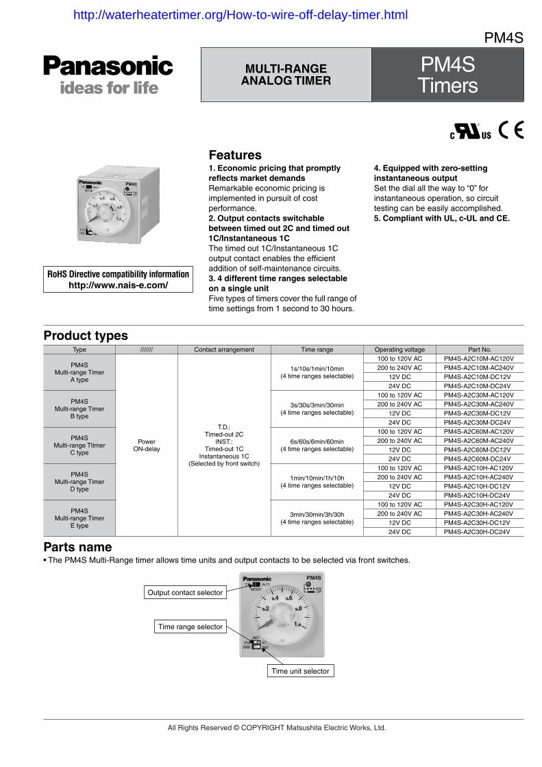
Parts name• The PM4S Multi-Range timer allows time units and output contacts to be selected via front switches.
MULTI-RANGE ANALOG TIMER
PM4S Timers
Type /////// Contact arrangement Time range Operating voltage Part No.
PM4SMulti-range Timer
A type
Power ON-delay
T.D.: Timed-out 2C
INST.: Timed-out 1C
Instantaneous 1C(Selected by front switch)
1s/10s/1min/10min(4 time ranges selectable)
100 to 120V AC PM4S-A2C10M-AC120V200 to 240V AC PM4S-A2C10M-AC240V
12V DC PM4S-A2C10M-DC12V24V DC PM4S-A2C10M-DC24V
PM4SMulti-range Timer
B type
3s/30s/3min/30min(4 time ranges selectable)
100 to 120V AC PM4S-A2C30M-AC120V200 to 240V AC PM4S-A2C30M-AC240V
12V DC PM4S-A2C30M-DC12V24V DC PM4S-A2C30M-DC24V
PM4SMulti-range Ttimer
C type
6s/60s/6min/60min(4 time ranges selectable)
100 to 120V AC PM4S-A2C60M-AC120V200 to 240V AC PM4S-A2C60M-AC240V
12V DC PM4S-A2C60M-DC12V24V DC PM4S-A2C60M-DC24V
PM4SMulti-range Timer
D type
1min/10min/1h/10h(4 time ranges selectable)
100 to 120V AC PM4S-A2C10H-AC120V200 to 240V AC PM4S-A2C10H-AC240V
12V DC PM4S-A2C10H-DC12V24V DC PM4S-A2C10H-DC24V
PM4SMulti-range Timer
E type
3min/30min/3h/30h(4 time ranges selectable)
100 to 120V AC PM4S-A2C30H-AC120V200 to 240V AC PM4S-A2C30H-AC240V
12V DC PM4S-A2C30H-DC12V24V DC PM4S-A2C30H-DC24V
Features1. Economic pricing that promptly reflects market demandsRemarkable economic pricing is implemented in pursuit of cost performance.2. Output contacts switchable between timed out 2C and timed out 1C/Instantaneous 1CThe timed out 1C/Instantaneous 1C output contact enables the efficient addition of self-maintenance circuits.3. 4 different time ranges selectable on a single unitFive types of timers cover the full range of time settings from 1 second to 30 hours.
4. Equipped with zero-setting instantaneous outputSet the dial all the way to “0” for instantaneous operation, so circuit testing can be easily accomplished.5. Compliant with UL, c-UL and CE.
RoHS Directive compatibility informationhttp://www.nais-e.com/
Time unit selector
Time range selector
Output contact selector
All Rights Reserved © COPYRIGHT Matsushita Electric Works, Ltd.
http://waterheatertimer.org/How-to-wire-off-delay-timer.html
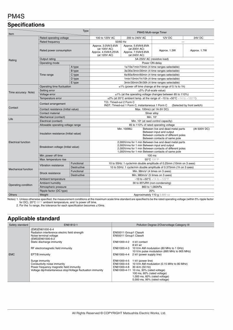
PM4SSpecifications
Applicable standardSafety standard EN61812-1 Pollution Degree 2/Overvoltage Category III
EMC
(EMI)EN61000-6-4Radiation interference electric field strengthNoise terminal voltage(EMS)EN61000-6-2Static discharge immunity
RF electromagnetic field immunity
EFT/B immunity
Surge immunityConductivity noise immunityPower frequency magnetic field immunityVoltage dip/Instantaneous stop/Voltage fluctuation immunity
EN55011 Group1 ClassAEN55011 Group1 ClassA
EN61000-4-2 4 kV contact8 kV air
EN61000-4-3 10 V/m AM modulation (80 MHz to 1 GHz)10 V/m pulse modulation (895 MHz to 905 MHz)
EN61000-4-4 2 kV (power supply line)
EN61000-4-5 1 kV (power line)EN61000-4-6 10 V/m AM modulation (0.15 MHz to 80 MHz)EN61000-4-8 30 A/m (50 Hz)EN61000-4-11 10 ms, 30% (rated voltage)
100 ms, 60% (rated voltage)1,000 ms, 60% (rated voltage)5,000 ms, 95% (rated voltage)
Notes) 1. Unless otherwise specified, the measurement conditions at the maximum scale time standard are specified to be the rated operating voltage (within 5% ripple factor for DC), 20°C 68°F ambient temperature, and 1s power off time.
2. For the 1s range, the tolerance for each specification becomes ±10ms.
TypeItem PM4S Multi-range Timer
Rating
Rated operating voltage 100 to 120V AC 200 to 240V AC 12V DC 24V DCRated frequency 50/60 Hz —
Rated power consumption
Approx. 3.0VA/3.6VA (at 100V AC)
Approx. 4.5VA/5.25VA (at 120V AC)
Approx. 5.6VA/6.8VA (at 200V AC)
Approx. 7.5VA/9.8VA (at 240V AC)
Approx. 1.3W Approx. 1.7W
Output rating 5A 250V AC (resistive load)Operating mode Power ON-delay
Time range
A type 1s/10s/1min/10min (4 time ranges selectable)B type 3s/30s/3min/30min (4 time ranges selectable)C type 6s/60s/6min/60min (4 time ranges selectable)D type 1min/10min/1h/10h (4 time ranges selectable)E type 3min/30min/3h/30h (4 time ranges selectable)
Time accuracy Note)
Operating time fluctuation ±1% (power off time change at the range of 0.1s to 1h)Setting error ±5% (Full-scale value)Voltage error ±1% (at the operating voltage changes between 85 to 110%)Temperature error ±2% (at 20°C ambient temp. at the range of –10 to +50°C +14 to +122°F)
ContactContact arrangement T.D.: Timed-out 2 Form C
INST.: Timed-out 1 Form C, instantaneous 1 Form C (Selected by front switch)Contact resistance (Initial value) Max. 100mΩ (at 1A 6V DC)Contact material Silver alloy
LifeMechanical (contact) Min. 107
Electrical (contact) Min. 105 (at raed control capacity)
Electrical function
Allowable operating voltage range 85 to 110% of rated operating voltage
Insulation resistance (Initial value)
Min. 100MΩ Between live and dead metal parts (At 500V DC)Between input and outputBetween contacts of different polesBetween contacts of same pole
Breakdown voltage (Initial value)
2,000Vrms for 1 min Between live and dead metal parts2,000Vrms for 1 min Between input and output2,000Vrms for 1 min Between contacts of different poles1,000Vrms for 1 min Between contacts of same pole
Min. power off time 100 msMax. temperature rise 55°C 131°F
Mechanical functionVibration resistance
Functional 10 to 55Hz: 1 cycle/min double amplitude of 0.25mm (10min on 3 axes)Destructive 10 to 55Hz: 1 cycle/min double amplitude of 0.375mm (1h on 3 axes)
Shock resistanceFunctional Min. 98m/s2 (4 times on 3 axes)Destructive Min. 980m/s2 (5 times on 3 axes)
Operating condition
Ambient temperature –10 to +50°C +14 to +122°FAmbient humidity 30 to 85%RH (non-condensing)Atmospheric pressure 860 to 1,060hPaRipple factor (DC type) 20%
Others Weight Approximately 110 g 3.880 oz
All Rights Reserved © COPYRIGHT Matsushita Electric Works, Ltd.

PM4SDimension (Unit: mm inch) Tolerance: ±0.5 ±.020
Operation mode
5.5 63.7 14.2.217 2.508 .559
14.5.571
481.890
44.51.752
• Surface mount dimensions
DIN rail terminal blockAT8-DF8K (Sold separately)
102.24.024
Device installation railAT8-DLA1 (Sold separately)
• Panel mount dimensions (with mounting frame) • Panel cut out dimensionsStandard cut out dimensions are shown below.Use mounting frame (AT8-DA4) and rubber gasket (ATC18002).
• Adjacent mounting84.73.335
501.969
Mounting frameAT8-DA4 (Sold separately)
Rear terminal socketAT78041 (Sold separately)
Panel (Thickness 1 to 3.5 mm .039 to .138 inch)
+0.60 45
+.0240 1.772
Min. 803.150
Min. 803.150
+0.60 45
+.0240 1.772
A = (48×n–2.5)
A
+0.60 45
+.0240 1.772
+0.60
A = (1.890×n–.098)+.0240
• Terminal layouts and wiring diagrams
Operatingvoltage
COM COM
NO NO
NC NC
MODE
1
2
3
4 5
6
7
8
T.D.: Timed-out 2 Form CINST.: Timed-out 1 Form C,
instantaneous 1 Form C* Selected by front switch
4 3
1 1
4 3
T. D. I N S T.
Notes:1. Operating voltage signs in parentheses ( ) indicate the polarity
of the DC type.
2. is a time delay contact.
is an instantaneous contact.
1. T.D. mode 2. INST. mode
ON
TON
OFF
OFF
Power supply
Time out (N.O. contact)
1–3 or 6–8OP.LED
Note: Keep 0.1s or more for power off time.
ON
ON
TON
OFF
OFF
OFF
Power supply
Time out (N.O. contact) 6–8
Time out (N.O. contact) 1–3
OP.LED
All Rights Reserved © COPYRIGHT Matsushita Electric Works, Ltd.
PM4SPrecautions during usage
Acquisition of CE marking
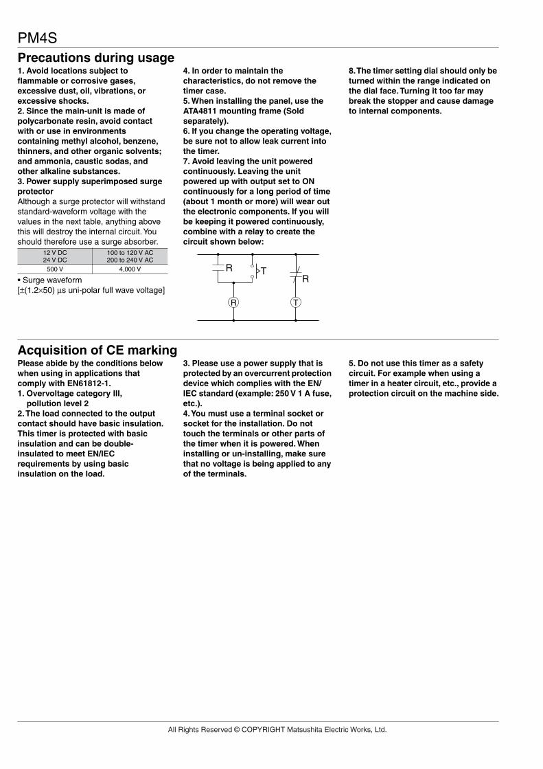
1. Avoid locations subject to flammable or corrosive gases, excessive dust, oil, vibrations, or excessive shocks.2. Since the main-unit is made of polycarbonate resin, avoid contact with or use in environments containing methyl alcohol, benzene, thinners, and other organic solvents; and ammonia, caustic sodas, and other alkaline substances.3. Power supply superimposed surge protectorAlthough a surge protector will withstand standard-waveform voltage with the values in the next table, anything above this will destroy the internal circuit. You should therefore use a surge absorber.
• Surge waveform[±(1.2×50) µs uni-polar full wave voltage]
4. In order to maintain the characteristics, do not remove the timer case.5. When installing the panel, use the ATA4811 mounting frame (Sold separately).6. If you change the operating voltage, be sure not to allow leak current into the timer.7. Avoid leaving the unit powered continuously. Leaving the unit powered up with output set to ON continuously for a long period of time (about 1 month or more) will wear out the electronic components. If you will be keeping it powered continuously, combine with a relay to create the circuit shown below:
8. The timer setting dial should only be turned within the range indicated on the dial face. Turning it too far may break the stopper and cause damage to internal components.
12 V DC24 V DC
100 to 120 V AC200 to 240 V AC
500 V 4,000 V
R T
RR
T
Please abide by the conditions below when using in applications that comply with EN61812-1.1. Overvoltage category III, pollution level 22. The load connected to the output contact should have basic insulation.This timer is protected with basic insulation and can be double-insulated to meet EN/IEC requirements by using basic insulation on the load.
3. Please use a power supply that is protected by an overcurrent protection device which complies with the EN/IEC standard (example: 250 V 1 A fuse, etc.).4. You must use a terminal socket or socket for the installation. Do not touch the terminals or other parts of the timer when it is powered. When installing or un-installing, make sure that no voltage is being applied to any of the terminals.
5. Do not use this timer as a safety circuit. For example when using a timer in a heater circuit, etc., provide a protection circuit on the machine side.
All Rights Reserved © COPYRIGHT Matsushita Electric Works, Ltd.

Features1. 100-240V AC free-voltage input, 48-125V DC type available2. Short body — 62.5mm 2.461 inch (screw terminal type)3. Front panel of IP65 type is protected against water-splash and dust4. Built-in Screw terminals
Screw terminal type is used for easy wiring and reducing additional cost foraccessories.
5. 0 setting instantaneous output operation6. Multiple time ranges — 1 s to 500 h (Max.)7. 8 different operation modes: (PM4H-A)8. Compliant with UL/CSA, CE and LLOYD
481.890
481.890
62.52.461
mm inch
Pin typeScrew terminal type
Product typesType
PM4H-S
PM4H-M
PM4H-A
Operation mode Contactarrangement Time range Rated
operating voltageProtective
construction Terminal type Part number
PM4HA-H-AC240VWPM4HA-H-AC240VSWPM4HA-H-DC125VWPM4HA-H-DC125VSWPM4HA-H-24VWPM4HA-H-24VSWPM4HA-H-DC12VWPM4HA-H-DC12VSWPM4HA-H-AC240VPM4HA-H-AC240VSPM4HA-H-DC125VPM4HA-H-DC125VSPM4HA-H-24VPM4HA-H-24VSPM4HA-H-DC12VPM4HA-H-DC12VSPM4HS-H-AC240VWPM4HS-H-AC240VSWPM4HS-H-DC125VWPM4HS-H-DC125VSWPM4HS-H-24VWPM4HS-H-24VSWPM4HS-H-DC12VWPM4HS-H-DC12VSWPM4HS-H-AC240VPM4HS-H-AC240VSPM4HS-H-DC125VPM4HS-H-DC125VSPM4HS-H-24VPM4HS-H-24VSPM4HS-H-DC12VPM4HS-H-DC12VSPM4HM-H-AC240VWPM4HM-H-AC240VSWPM4HM-H-DC125VWPM4HM-H-DC125VSWPM4HM-H-24VWPM4HM-H-24VSWPM4HM-H-DC12VWPM4HM-H-DC12VSWPM4HM-H-AC240VPM4HM-H-AC240VSPM4HM-H-DC125VPM4HM-H-DC125VSPM4HM-H-24VPM4HM-H-24VSPM4HM-H-DC12VPM4HM-H-DC12VS
16 selectableranges1s to 500h
RelayTimed-out1 Form CInstantaneous1 Form C
RelayTimed-out2 Form C
RelayTimed-out2 Form C
8 operation modes• Pulse ON-delay• Pulse Flicker• Pulse ON-flicker• Differential ON/OFF-delay (1) (2)• Signal OFF-delay• Pulse One-shot• Pulse One-cycle
Power ON-delay
5 operation modes(With instantaneous contact)• Power ON-delay• Power Flicker• Power ON-flicker• Power One-shot• Power One-cycle
11 pinsScrew terminal
11 pinsScrew terminal
11 pinsScrew terminal
11 pinsScrew terminal
11 pinsScrew terminal
11 pinsScrew terminal
11 pinsScrew terminal
11 pinsScrew terminal
8 pinsScrew terminal
8 pinsScrew terminal
8 pinsScrew terminal
8 pinsScrew terminal
8 pinsScrew terminal
8 pinsScrew terminal
8 pinsScrew terminal
8 pinsScrew terminal
8 pinsScrew terminal
8 pinsScrew terminal
8 pinsScrew terminal
8 pinsScrew terminal
8 pinsScrew terminal
8 pinsScrew terminal
8 pinsScrew terminal
8 pinsScrew terminal
100 to 240V AC
48 to 125V DC
24V AC/DC
12V DC
100 to 240V AC
48 to 125V DC
24V AC/DC
12V DC
100 to 240V AC
48 to 125V DC
24V AC/DC
12V DC
100 to 240V AC
48 to 125V DC
24V AC/DC
12V DC
100 to 240V AC
48 to 125V DC
24V AC/DC
12V DC
100 to 240V AC
48 to 125V DC
24V AC/DC
12V DC
IP65
IP50
IP65
IP50
IP65
IP50
If you use this timer under harsh environment, please order above sealed type (IP65 type). IP65 type — Protection dust and water jet splay on the front face.
UL File No.: E122222 CSA File No.: LR39291
PM4H-A/S/M
DIN48 SIZE MULTI-RANGE
ANALOG TIMER
PM4H-A PM4H-S PM4H-M
RoHS Directive compatibility informationhttp://www.nais-e.com/
All Rights Reserved © COPYRIGHT Matsushita Electric Works, Ltd.

SpecificationsPM4H-ATypeItem PM4H-S
100 to 240V AC, 48 to 125V DC, 12V DC, 24V AC/DCRated operating voltage50/60Hz common (AC operating type)
5A 250V AC (resistive load)
Power ON-delay
Pulse ON-delayPulse FlickerPulse ON-FlickerDifferential ON/OFF-delay (1) (2)Signal OFF-delayPulse One-shotPulse One-cycle
Power ON-delayPower FlickerPower ON-flickerPower One-shotPower One-cycle(with instantaneous contact)
Rated frequency
Rated control capacity
1s to 500h (Max.) 16 time ranges switchable±0.3% (power off time change at the range of 0.1s to 1h)
±5% (Full-scale value)±0.5% (at the operating voltage changes between 85 to 110%)
Max. 100mΩ (at 1A 6V DC)
±2% (at 20°C ambient temp. at the range of –10 to +50°C +14 to +122°F)Timed-out 1 Form C
Instantaneous 1 Form C
Time rangeOperating time fluctuation
2×10⁷
105 (at rated control capacity)Mechanical (contact)Electrical (contact)
85 to 110% of rated operating voltage (at 20°C coil temp.)Allowable operating voltage range
–10 to +50°C +14 to +122°FAmbient temperature30 to 85%RH (at 20°C 68°F, non-condensing)Ambient humidity
860 to 1,060hPaAtmospheric pressure20%Ripple factor (DC type)
IP65 on front panel (using rubber gasket ATC18002) <only for IP65 type>Protective construction100g 3.527 oz (Pin type)
110g 3.880 oz (Screw terminal type)Weight
10 to 55Hz: 1 cycle/min double amplitude of 0.25mm (10min on 3 axes)Vibration resistance
10 to 55Hz: 1 cycle/min double amplitude of 0.375mm (1h on 3 axes)Min. 98m/s2 (4 times on 3 axes)
Shock resistanceMin. 980m/s2 (5 times on 3 axes)
FunctionalDestructive
FunctionalDestructive
Between live and dead metal partsBetween input and outputBetween contacts of different polesBetween contacts of same pole
Insulation resistance (Initial value)
2,000Vrms for 1 min Between live and dead metal parts2,000Vrms for 1 min Between input and output2,000Vrms for 1 min Between contacts of different poles1,000Vrms for 1 min Between contacts of same pole
Breakdown voltage (Initial value)
Setting errorVoltage error
Contact resistance (Initial value)
100msMin. power off time55°C 131°F 65°C 149°FMax. temperature rise
Silver alloy Au flash on Silver alloyContact material
Temperature error
Timed-out 2 Form CContact arrangement
Operating mode
Approx. 10VA (100 to 240V AC)Approx. 2.5VA (24V AC)
Approx. 1.5W (12V DC, 24V DC, 48 to 125V DC)Rated power consumption
Rating
Timeaccuracy Note:)
Contact
Life
Electricalfunction
Mechanicalfunction
Operatingcondition
Others
PM4H-M
Min. 100MΩ (At 500V DC)
Note: 1) Unless otherwise specified, the measurement conditions at the maximum scale time standard are specified to be the rated operating voltage (within 5% ripplefactor for DC), 20°C 68°F ambient temperature, and 1s power off time.
2) For the 1s range, the tolerance for each specification becomes ±10ms.
PM4H-A/S/M
PM4H-A/PM4H-S/PM4H-MAll types of PM4H timer have multi-timerange.16 time ranges are selectable.1s to 500h (Max. range) is controlled.
Time range
1
ScaleTime unit
0.1s to 1s
sec min hrs 10h
0.1 min to 1 min 0.1h to 1h 1.0h to 10h
5 0.5s to 5sControltime range
0.5 min to 5 min 0.5h to 5h 5h to 50h
10 1.0s to 10s 1.0 min to 10 min 1.0h to 10h 10h to 100h
50 5s to 50s 5 min to 50 min 5h to 50h 50h to 500h
Note: 0 setting is for instantaneous output operation.
All Rights Reserved © COPYRIGHT Matsushita Electric Works, Ltd.
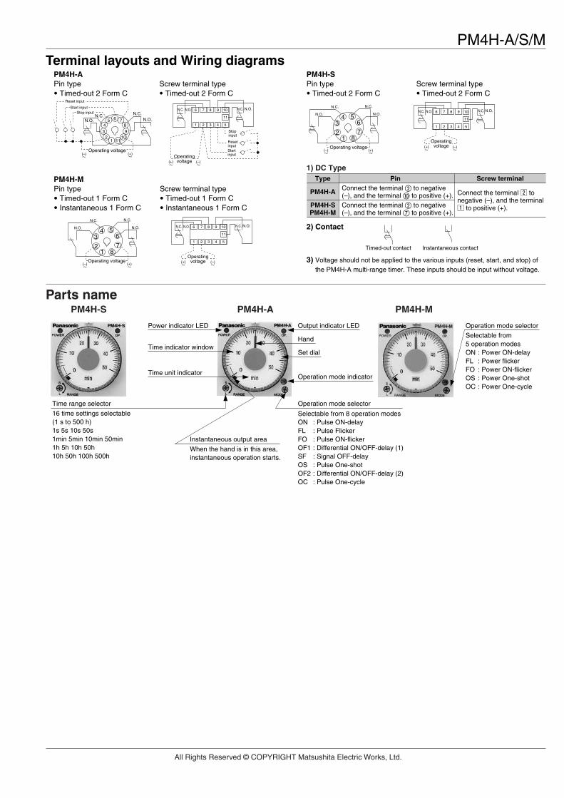
PM4H-A/S/MTerminal layouts and Wiring diagrams
PM4H-APin type• Timed-out 2 Form C
Screw terminal type• Timed-out 2 Form C
PM4H-MPin type• Timed-out 1 Form C• Instantaneous 1 Form C
Screw terminal type• Timed-out 1 Form C• Instantaneous 1 Form C
PM4H-SPin type• Timed-out 2 Form C
Screw terminal type• Timed-out 2 Form C
2) Contact
3) Voltage should not be applied to the various inputs (reset, start, and stop) ofthe PM4H-A multi-range timer. These inputs should be input without voltage.
Timed-out contact Instantaneous contact
Type
PM4H-A
PM4H-SPM4H-M
PinConnect the terminal to negative (–), and the terminal to positive (+). Connect the terminal x to
negative (–), and the terminalz to positive (+).Connect the terminal to negative
(–), and the terminal to positive (+).
Screw terminal
1) DC Type
Start input
Reset input
N.O.N.C.N.C.
3
54
21 11
1098
76Stop input
N.O.
(–) (+)Operating voltage
N.C. N.O.N.C. N.O.
54321
109876
11
(–)(+)Operating
voltage
Stopinput
ResetinputStartinput
(–) (+)
N.C.N.C.
N.O.N.O.
Operating voltage
8
5
17
6
2
34
N.C. N.O.N.C. N.O.
54321
109876
11
(–)(+)Operating
voltage
(–) (+)
N.C.N.C.
N.O.N.O.
Operating voltage
8
5
17
6
2
34
N.C. N.O.N.C. N.O.
54321
109876
11
(–)(+)Operating
voltage
Parts namePM4H-S PM4H-A PM4H-M
Time range selector
16 time settings selectable(1 s to 500 h)1s 5s 10s 50s1min 5min 10min 50min1h 5h 10h 50h10h 50h 100h 500h
Power indicator LED
Time indicator window
Time unit indicator
Output indicator LED
Hand
Operation mode selector
Selectable from 8 operation modesON : Pulse ON-delayFL : Pulse FlickerFO : Pulse ON-flickerOF1 : Differential ON/OFF-delay (1)SF : Signal OFF-delayOS : Pulse One-shotOF2 : Differential ON/OFF-delay (2)OC : Pulse One-cycle
Set dial
Operation mode indicator
Instantaneous output area
When the hand is in this area,instantaneous operation starts.
Operation mode selector
Selectable from 5 operation modesON : Power ON-delayFL : Power flickerFO : Power ON-flickerOS : Power One-shotOC : Power One-cycle
All Rights Reserved © COPYRIGHT Matsushita Electric Works, Ltd.
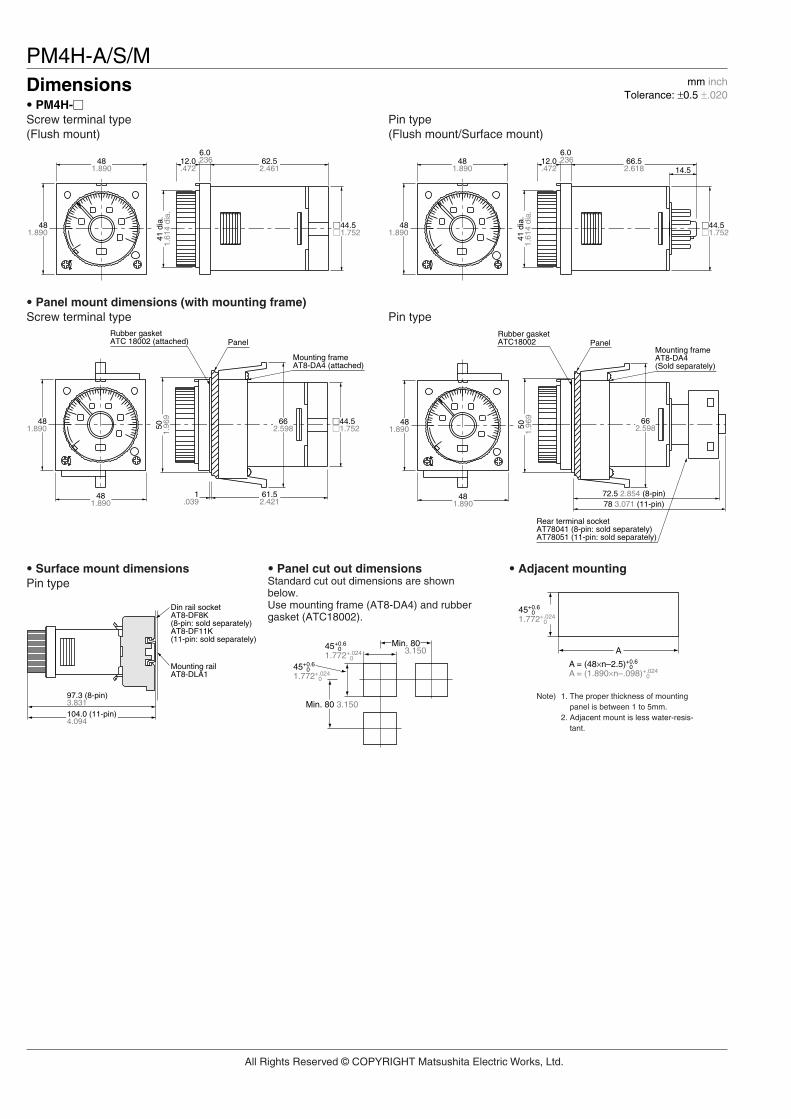
PM4H-A/S/MDimensions mm inch
Tolerance: ±0.5 ±.020• PM4H-Screw terminal type(Flush mount)
• Panel mount dimensions (with mounting frame)Screw terminal type
• Surface mount dimensionsPin type
• Panel cut out dimensionsStandard cut out dimensions are shownbelow.Use mounting frame (AT8-DA4) and rubbergasket (ATC18002).
• Adjacent mounting
Pin type
Pin type(Flush mount/Surface mount)
Note) 1. The proper thickness of mountingpanel is between 1 to 5mm.
2. Adjacent mount is less water-resis-tant.
62.52.461
12.0.472
.2366.0
481.890
481.890
44.51.752
41 d
ia.
1.61
4 di
a.
1.039
481.890
61.52.421
481.890
44.51.75250
1.96
9 662.598
Rubber gasketATC 18002 (attached)
Mounting frameAT8-DA4 (attached)
Panel
481.890
481.890 50
1.96
9 662.598
72.5 2.854 (8-pin)78 3.071 (11-pin)
Rubber gasketATC18002
Mounting frameAT8-DA4(Sold separately)
Rear terminal socketAT78041 (8-pin: sold separately)AT78051 (11-pin: sold separately)
Panel
Din rail socketAT8-DF8K (8-pin: sold separately)AT8-DF11K (11-pin: sold separately)
Mounting railAT8-DLA1
104.0 (11-pin)4.094
97.3 (8-pin)3.831
45+
1.772+.0240
0.60
45+
1.772+.0240
0.60
Min. 803.150
Min. 80 3.150
A
45+
1.772+.0240
0.60
A = (48×n–2.5)+
A = (1.890×n–.098)+.0240
0.60
14.566.52.618
481.890
44.51.752
41 d
ia.
1.61
4 di
a.
481.890
12.0.472
.2366.0
All Rights Reserved © COPYRIGHT Matsushita Electric Works, Ltd.

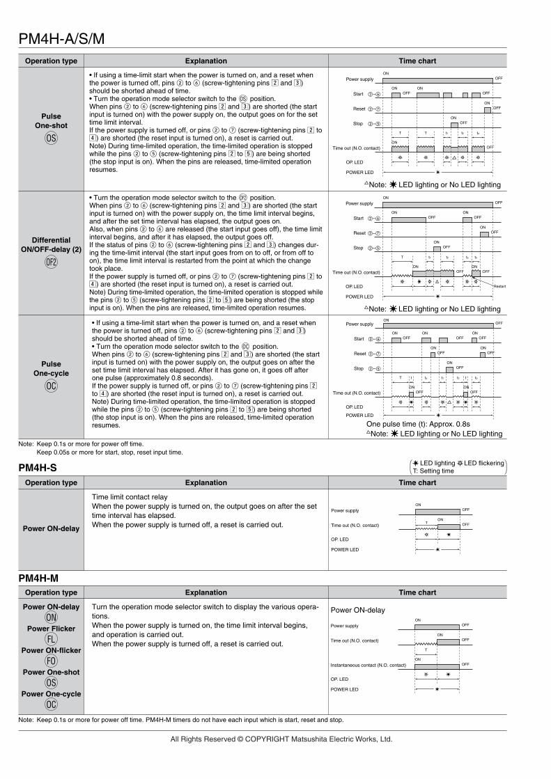
PM4H-A/S/MOperation modePM4H-A
Note: Keep 0.1s or more for power off time.Keep 0.05s or more for start, stop, reset input time.
Operation type Explanation Time chart
• If using a time-limit start when the power is turned on, and a reset whenthe power is turned off, pins 2 to 6 (screw-tightening pins x and c)should be shorted ahead of time.• Turn the operation mode selector switch to the position.If pins 2 to 6 (screw-tightening pins x and c) are shorted (the start inputis turned on) with the power supply on, the output will go on after the settime has elapsed.If the power supply is turned off, or pins 2 to 7 (screw-tightening pins x tov) are shorted (the reset input is turned on), a reset is carried out.Note) During time-limited operation, the time-limited operation is stoppedwhile the pins 2 to 5 (screw-tightening pins x to b) are being shorted(the stop input is on). When the pins are released, time-limited operationresumes.
• Turn the operation mode selector switch to the position.When pins 2 to 6 (screw-tightening pins x and c) are shorted (the startinput is turned on) with the power supply on, the output goes on, and whenpins 2 to 6 (screw-tightening pins x and c) are released (the start inputis turned off), the time limit interval begins. After the set time has elapsed,the output goes off. If start input is entered at any point during the time limitinterval, the time limit interval is reset.Note) During time-limited operation, the time-limited operation is stoppedwhile the pins 2 to 5 (screw-tightening pins x to b) are being shorted(the stop input is on). When the pins are released, time-limited operationresumes.
• Turn the operation mode selector switch to the position.When pins 2 to 6 (screw-tightening pins x and c) are shorted (the startinput is turned on) with the power supply on, the output goes on, and afterthe set time has elapsed, it goes off. Also, when pins 2 to 6 are released (the start input goes off), the outputgoes on, and after the set time has elapsed, it goes off.If the status of pins 2 to 6 (screw-tightening pins x and c) changes dur-ing the time-limit interval (the start input goes from on to off, or from off toon), the time-limit interval is restarted from the point at which the changetook place.If the power supply is turned off, or pins 2 to 7 (screw-tightening pins x tov) are shorted (the reset input is turned on), a reset is carried out.Note) During time-limited operation, the time-limited operation is stopped whilethe pins 2 to 5 (screw-tightening pins x to b) are being shorted (the stopinput is on). When the pins are released, time-limited operation resumes.
• If using a time-limit start when the power is turned on, and a reset whenthe power is turned off, pins 2 to 6 (screw-tightening pins x and c)should be shorted ahead of time.• Turn the operation mode selector switch to the position.When pins 2 to 6 (screw-tightening pins x and c) are shorted (the startinput is turned on) with the power supply on, the output goes on, and afterthe set time has elapsed, it goes off. This process is subsequently repeated.If the power supply is turned off, or pins 2 to 7 (screw-tightening pins x tov) are shorted (the reset input is turned on), a reset is carried out.Note) During time-limited operation, the time-limited operation is stoppedwhile the pins 2 to 5 (screw-tightening pins x to b) are being shorted(the stop input is on). When the pins are released, time-limited operationresumes.
• If using a time-limit start when the power is turned on, and a reset whenthe power is turned off, pins 2 to 6 (screw-tightening pins x and c)should be shorted ahead of time.• Turn the operation mode selector switch to the position.When pins 2 to 6 (screw-tightening pins x and c) are shorted (the startinput is turned on) with the power supply on, the limited time interval begins,and the output goes on after the set time has elapsed. After the output hasgone on, it goes off when the set time has elapsed, and this process is sub-sequently repeated.If the power supply is turned off, or pins 2 to 7 (screw-tightening pins x tov) are shorted (the reset input is turned on), a reset is carried out.Note) During time-limited operation, the time-limited operation is stoppedwhile the pins 2 to 5 (screw-tightening pins x to b) are being shorted(the stop input is on). When the pins are released, time-limited operationresumes.
PulseON-delay
ON
ON
PulseFlicker
FL
FL
PulseON-flicker
FO
FO
DifferentialON/OFF-delay (1)
OF1
OF1
SignalOFF-delay
SF
SF
Power supplyON
OFF
StartON
OFFON ON
OFF
ResetON
OFF
StopON
OFF
Time out (N.O. contact)
OP. LED
POWER LED
–
–
–
ON
T t1 t2
ONOFFOFF
Note: LED lighting or No LED lighting
Power supplyON
OFF
StartON
OFFON
OFFON
OFF
OFFResetON
StopON
OFF
Time out (N.O. contact)
OP. LED
POWER LED
–
–
–
ON
T T t1ta t2 tb
ONOFFOFF
Note: LED lighting or No LED lighting
Power supplyON
OFF
StartON
OFFON
OFFON
OFF
OFFResetON
StopON
OFF
Time out (N.O. contact)
OP. LED
POWER LED
–
–
–
ON
T T t2 Tta tbt1
OFFOFF
Power supplyON
OFF
StartON
OFFON
OFF
ON
Reset
StopON
OFF
Time out (N.O. contact)
OP. LED
POWER LED
–
–
–
ON ON
T t1 t2 ta tb
OFF OFFON
OFF
Restart
OFF
Note: LED lighting or No LED lighting
Power supplyON
OFF
StartON
OFFON
OFF
ONOFF
ON
Reset
Stop
Time out (N.O. contact)
OP. LED
POWER LED
–
–
–
ON
T tbta
OFF
OFF
Note: LED lighting or No LED lighting
LED lighting LED flickeringT: Setting time t1, t2, ta, tb<T t1+t2=T
All Rights Reserved © COPYRIGHT Matsushita Electric Works, Ltd.
PM4H-A/S/M
Note: Keep 0.1s or more for power off time.Keep 0.05s or more for start, stop, reset input time.
Operation type Explanation Time chart
• If using a time-limit start when the power is turned on, and a reset whenthe power is turned off, pins 2 to 6 (screw-tightening pins x and c)should be shorted ahead of time.• Turn the operation mode selector switch to the position.When pins 2 to 6 (screw-tightening pins x and c) are shorted (the startinput is turned on) with the power supply on, the output goes on for the settime limit interval.If the power supply is turned off, or pins 2 to 7 (screw-tightening pins x tov) are shorted (the reset input is turned on), a reset is carried out.Note) During time-limited operation, the time-limited operation is stoppedwhile the pins 2 to 5 (screw-tightening pins x to b) are being shorted(the stop input is on). When the pins are released, time-limited operationresumes.
• If using a time-limit start when the power is turned on, and a reset whenthe power is turned off, pins 2 to 6 (screw-tightening pins x and c)should be shorted ahead of time.• Turn the operation mode selector switch to the position.When pins 2 to 6 (screw-tightening pins x and c) are shorted (the startinput is turned on) with the power supply on, the output goes on after theset time limit interval has elapsed. After it has gone on, it goes off afterone pulse (approximately 0.8 seconds).If the power supply is turned off, or pins 2 to 7 (screw-tightening pins xto v) are shorted (the reset input is turned on), a reset is carried out.Note) During time-limited operation, the time-limited operation is stoppedwhile the pins 2 to 5 (screw-tightening pins x to b) are being shorted(the stop input is on). When the pins are released, time-limited operationresumes.
• Turn the operation mode selector switch to the position.When pins 2 to 6 (screw-tightening pins x and c) are shorted (the startinput is turned on) with the power supply on, the time limit interval begins,and after the set time interval has elapsed, the output goes on.Also, when pins 2 to 6 are released (the start input goes off), the time limitinterval begins, and after it has elapsed, the output goes off.If the status of pins 2 to 6 (screw-tightening pins x and c) changes dur-ing the time-limit interval (the start input goes from on to off, or from off toon), the time limit interval is restarted from the point at which the changetook place.If the power supply is turned off, or pins 2 to 7 (screw-tightening pins x tov) are shorted (the reset input is turned on), a reset is carried out.Note) During time-limited operation, the time-limited operation is stopped whilethe pins 2 to 5 (screw-tightening pins x to b) are being shorted (the stopinput is on). When the pins are released, time-limited operation resumes.
PulseOne-shot
OS
OS
DifferentialON/OFF-delay (2)
OF2
OF2
PulseOne-cycle
OC
OC
PM4H-S
PM4H-M
Operation type Explanation Time chart
Time limit contact relayWhen the power supply is turned on, the output goes on after the settime interval has elapsed.When the power supply is turned off, a reset is carried out.Power ON-delay
Note: Keep 0.1s or more for power off time. PM4H-M timers do not have each input which is start, reset and stop.
Operation type Explanation Time chart
Turn the operation mode selector switch to display the various opera-tions.When the power supply is turned on, the time limit interval begins,and operation is carried out.When the power supply is turned off, a reset is carried out.
Power ON-delay
ONPower Flicker
FLPower ON-flicker
FOPower One-shot
OSPower One-cycle
OC
Power supplyON
OFF
StartON
OFF OFFON
ONOFF
ON
Reset
Stop
Time out (N.O. contact)
OP. LED
POWER LED
–
–
–
ON
T T tat1 t2
OFF
OFF
Note: LED lighting or No LED lighting
Power supplyON
OFF
StartON
OFFON
OFF
ONOFF
OFF
ON
Reset
Stop
Time out (N.O. contact)
OP. LED
POWER LED
–
–
–
ON ON
T tbt1 t2 ta
OFF
OFF
Restart
Note: LED lighting or No LED lighting
Power supplyON
OFF
StartON
OFFON
OFFON
OFF
ONOFF
Reset
Stop
Time out (N.O. contact)
OP. LED
POWER LED
–
–
–
T ta
ONOFF
ONOFF
ONOFF
t t1 tbt2 t
OFF
One pulse time (t): Approx. 0.8s Note: LED lighting or No LED lighting
ON
Power supplyON
OFF
ONOFFTime out (N.O. contact)
OP. LED
POWER LED
T
Power supplyON
OFF
ONOFF
ONOFF
Instantaneous contact (N.O. contact)
Time out (N.O. contact)
Power ON-delay
OP. LED
POWER LED
T
LED lighting LED flickeringT: Setting time
All Rights Reserved © COPYRIGHT Matsushita Electric Works, Ltd.

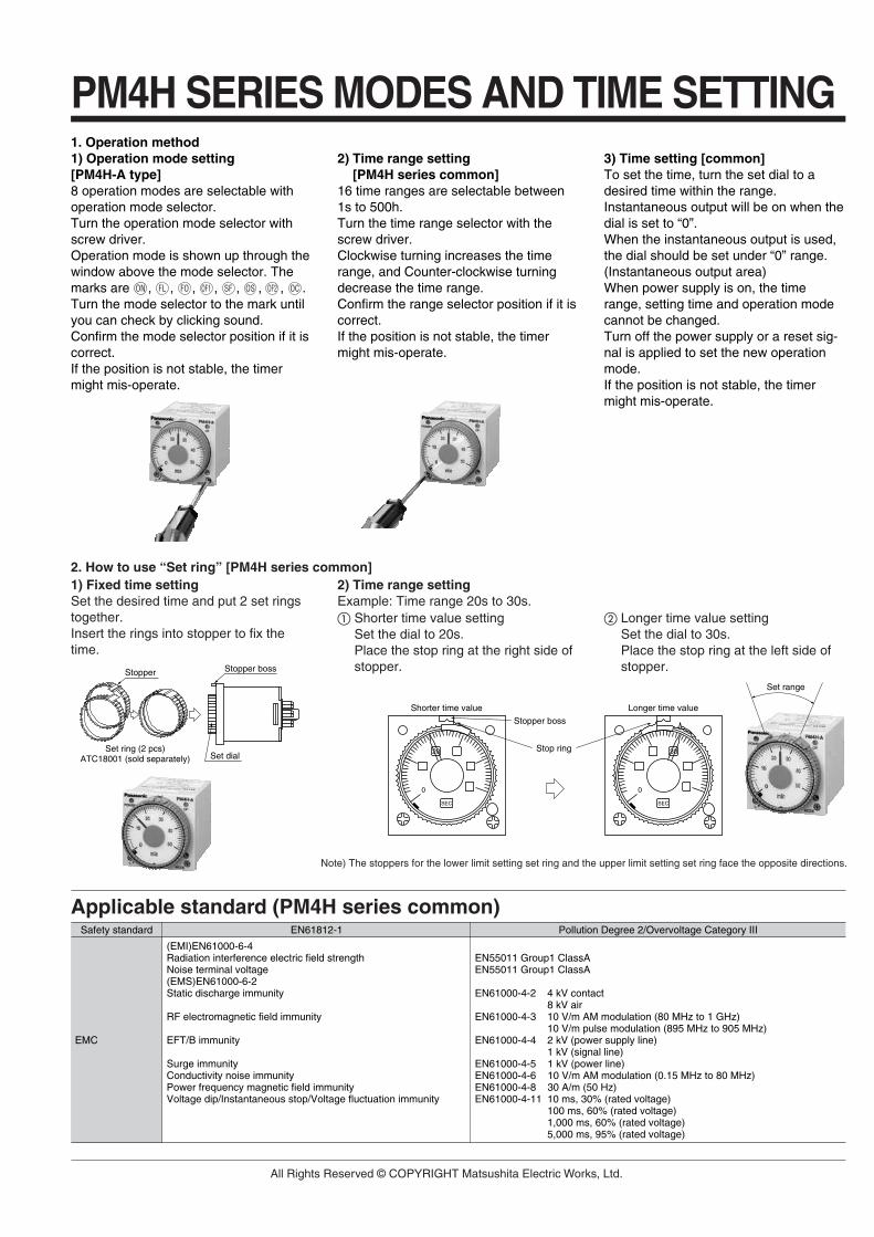
1. Operation method1) Operation mode setting [PM4H-A type]8 operation modes are selectable withoperation mode selector.Turn the operation mode selector withscrew driver.Operation mode is shown up through thewindow above the mode selector. Themarks are , , , , , , , .Turn the mode selector to the mark untilyou can check by clicking sound.Confirm the mode selector position if it iscorrect.If the position is not stable, the timermight mis-operate.
2) Time range setting [PM4H series common]
16 time ranges are selectable between1s to 500h.Turn the time range selector with thescrew driver.Clockwise turning increases the timerange, and Counter-clockwise turningdecrease the time range.Confirm the range selector position if it iscorrect.If the position is not stable, the timermight mis-operate.
3) Time setting [common]To set the time, turn the set dial to adesired time within the range.Instantaneous output will be on when thedial is set to “0”.When the instantaneous output is used,the dial should be set under “0” range.(Instantaneous output area)When power supply is on, the timerange, setting time and operation modecannot be changed.Turn off the power supply or a reset sig-nal is applied to set the new operationmode.If the position is not stable, the timermight mis-operate.
ON FL FO OF1 SF OS OF2 OC
2. How to use “Set ring” [PM4H series common]1) Fixed time settingSet the desired time and put 2 set ringstogether.Insert the rings into stopper to fix thetime.
2) Time range settingExample: Time range 20s to 30s. Shorter time value setting
Set the dial to 20s.Place the stop ring at the right side ofstopper.
Longer time value settingSet the dial to 30s.Place the stop ring at the left side ofstopper.
Set range
Applicable standard (PM4H series common)
Set dialSet ring (2 pcs)
ATC18001 (sold separately)
Stopper bossStopper
Stop ring
Stopper boss
0 0
30
Longer time value
SEC
20
Shorter time value
SEC
PM4H SERIES MODES AND TIME SETTING
Note) The stoppers for the lower limit setting set ring and the upper limit setting set ring face the opposite directions.
Safety standard EN61812-1 Pollution Degree 2/Overvoltage Category III
EMC
(EMI)EN61000-6-4Radiation interference electric field strengthNoise terminal voltage(EMS)EN61000-6-2Static discharge immunity
RF electromagnetic field immunity
EFT/B immunity
Surge immunityConductivity noise immunityPower frequency magnetic field immunityVoltage dip/Instantaneous stop/Voltage fluctuation immunity
EN55011 Group1 ClassAEN55011 Group1 ClassA
EN61000-4-2 4 kV contact 8 kV air
EN61000-4-3 10 V/m AM modulation (80 MHz to 1 GHz) 10 V/m pulse modulation (895 MHz to 905 MHz)
EN61000-4-4 2 kV (power supply line) 1 kV (signal line)
EN61000-4-5 1 kV (power line) EN61000-4-6 10 V/m AM modulation (0.15 MHz to 80 MHz) EN61000-4-8 30 A/m (50 Hz) EN61000-4-11 10 ms, 30% (rated voltage)
100 ms, 60% (rated voltage)1,000 ms, 60% (rated voltage)5,000 ms, 95% (rated voltage)
All Rights Reserved © COPYRIGHT Matsushita Electric Works, Ltd.
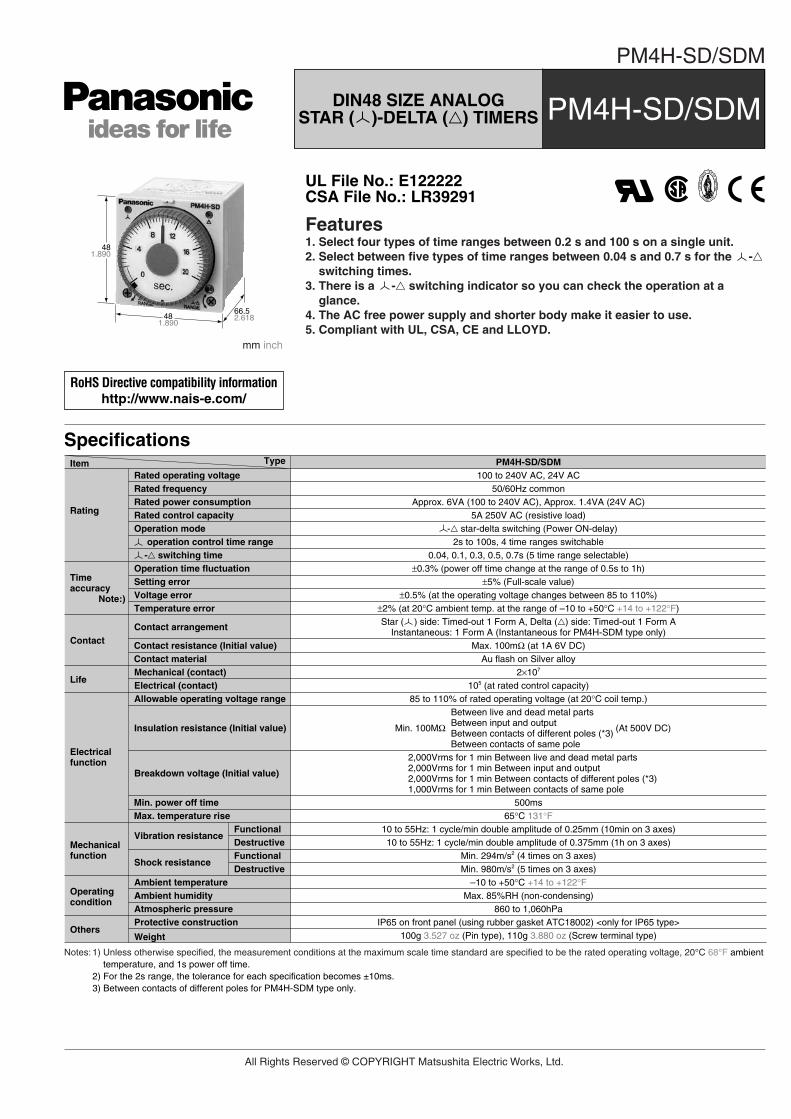
PM4H-SD/SDM
Features1. Select four types of time ranges between 0.2 s and 100 s on a single unit.2. Select between five types of time ranges between 0.04 s and 0.7 s for the -
switching times.3. There is a - switching indicator so you can check the operation at a
glance.4. The AC free power supply and shorter body make it easier to use.5. Compliant with UL, CSA, CE and LLOYD.
481.890
481.890
66.52.618
mm inch
SpecificationsTypeItem PM4H-SD/SDM
100 to 240V AC, 24V ACRated operating voltage50/60Hz common
5A 250V AC (resistive load) - star-delta switching (Power ON-delay)
Rated frequency
Rated control capacity
0.04, 0.1, 0.3, 0.5, 0.7s (5 time range selectable)±0.3% (power off time change at the range of 0.5s to 1h)
±5% (Full-scale value)±0.5% (at the operating voltage changes between 85 to 110%)
Max. 100mΩ (at 1A 6V DC)
±2% (at 20°C ambient temp. at the range of –10 to +50°C +14 to +122°F)Star ( ) side: Timed-out 1 Form A, Delta () side: Timed-out 1 Form A
Instantaneous: 1 Form A (Instantaneous for PM4H-SDM type only)
- switching timeOperation time fluctuation
2×10⁷
105 (at rated control capacity)Mechanical (contact)Electrical (contact)
85 to 110% of rated operating voltage (at 20°C coil temp.)Allowable operating voltage range
–10 to +50°C +14 to +122°FAmbient temperatureMax. 85%RH (non-condensing)Ambient humidity
860 to 1,060hPaAtmospheric pressureIP65 on front panel (using rubber gasket ATC18002) <only for IP65 type>Protective construction
100g 3.527 oz (Pin type), 110g 3.880 oz (Screw terminal type)Weight
Min. 294m/s2 (4 times on 3 axes)Shock resistance
Min. 980m/s2 (5 times on 3 axes)FunctionalDestructive
10 to 55Hz: 1 cycle/min double amplitude of 0.25mm (10min on 3 axes)Vibration resistance
10 to 55Hz: 1 cycle/min double amplitude of 0.375mm (1h on 3 axes)FunctionalDestructive
Between live and dead metal partsBetween input and outputBetween contacts of different poles (*3)Between contacts of same pole
Insulation resistance (Initial value)
2,000Vrms for 1 min Between live and dead metal parts2,000Vrms for 1 min Between input and output2,000Vrms for 1 min Between contacts of different poles (*3)1,000Vrms for 1 min Between contacts of same pole
Breakdown voltage (Initial value)
Setting errorVoltage error
Contact resistance (Initial value)
500msMin. power off time65°C 131°FMax. temperature rise
Au flash on Silver alloyContact material
Temperature error
Contact arrangement
Operation mode
Approx. 6VA (100 to 240V AC), Approx. 1.4VA (24V AC)Rated power consumptionRating
Timeaccuracy Note:)
Contact
Life
Electricalfunction
Mechanicalfunction
Operatingcondition
Others
Min. 100MΩ (At 500V DC)
2s to 100s, 4 time ranges switchable operation control time range
Notes: 1) Unless otherwise specified, the measurement conditions at the maximum scale time standard are specified to be the rated operating voltage, 20°C 68°F ambienttemperature, and 1s power off time.
2) For the 2s range, the tolerance for each specification becomes ±10ms.3) Between contacts of different poles for PM4H-SDM type only.
UL File No.: E122222CSA File No.: LR39291
DIN48 SIZE ANALOG STAR ( )-DELTA () TIMERS PM4H-SD/SDM
RoHS Directive compatibility informationhttp://www.nais-e.com/
All Rights Reserved © COPYRIGHT Matsushita Electric Works, Ltd.

PM4H-SD/SDM
Product types
Terminal layouts and Wiring diagrams
Time range
Dimensions
Operation
mm inch
PM4H-SDStar ( )-Delta() switching
Type Contact arrangement Time range Part numberRated operatingvoltage
Protectiveconstruction
Terminaltype
Operationmode
PM4HSD-S-AC240VWPM4HSD-S-AC240VSWPM4HSD-S-AC24VWPM4HSD-S-AC24VSWPM4HSDM-S-AC240VWPM4HSDM-S-AC240VSWPM4HSDM-S-AC24VWPM4HSDM-S-AC24VSWPM4HSD-S-AC240VPM4HSD-S-AC240VSPM4HSD-S-AC24VPM4HSD-S-AC24VSPM4HSDM-S-AC240VPM4HSDM-S-AC240VSPM4HSDM-S-AC24VPM4HSDM-S-AC24VS
4 selectable ranges over2s to 100s( - switching time:0.04, 0.1, 0.3, 0.5, 0.7s)
Relay Timed-out side: 1 Form A side: 1 Form A
8 pinsScrew terminal
8 pinsScrew terminal
8 pinsScrew terminal
8 pinsScrew terminal
8 pinsScrew terminal
8 pinsScrew terminal
8 pinsScrew terminal
8 pinsScrew terminal
IP65
IP50
100 to 240V AC
24V AC
100 to 240V AC
24V AC
100 to 240V AC
24V AC
100 to 240V AC
24V AC
Star ( )-Delta ()switching
PM4H-SDMStar ( )-Delta() switching(Instantaneouscontact)
PM4H-SDStar ( )-Delta() switching
PM4H-SDMStar ( )-Delta() switching(Instantaneouscontact)
Relay Timed-out side: 1 Form A side: 1 Form AInstantaneous: 1 Form A
Relay Timed-out side: 1 Form A side: 1 Form A
Relay Timed-out side: 1 Form A side: 1 Form AInstantaneous: 1 Form A
Operating voltage
8
5
17
6
2
34
Operating voltage
8
5
17
6
2
34
54321
109876
11
Operatingvoltage
54321
109876
11
Operatingvoltage
side time-delay contact side time-delay contactInstantaneous contact(PM4H-SDM type)
side time-delay contact side time-delay contactInstantaneous contact(PM4H-SDM type)
Powersupply
Instantaneouscontact
side Contact
side Contact
t1 t2 t3
operation time( indicator LED lights) – switching time operation time( indicator LED lights)
t1:
t2:t3:
.2366.0
481.890
66.52.618 14.5
.571
12.0.472
481.890
41 dia.1.614 dia.
44.51.752
Pin type• No instantaneous contact
Screw terminal type• No instantaneous contact • With instantaneous contact• With instantaneous contact
Time range
Time rangeunit
21020100
0.2 to 21 to 102 to 20
10 to 100
0.040.10.30.50.7
Operating (s) - switching time (s)
All Rights Reserved © COPYRIGHT Matsushita Electric Works, Ltd.
1. Operation method1) Operation mode setting [PM4H-A type]8 operation modes are selectable withoperation mode selector.Turn the operation mode selector withscrew driver.Operation mode is shown up through thewindow above the mode selector. Themarks are , , , , , , , .Turn the mode selector to the mark untilyou can check by clicking sound.Confirm the mode selector position if it iscorrect.If the position is not stable, the timermight mis-operate.
2) Time range setting [PM4H series common]
16 time ranges are selectable between1s to 500h.Turn the time range selector with thescrew driver.Clockwise turning increases the timerange, and Counter-clockwise turningdecrease the time range.Confirm the range selector position if it iscorrect.If the position is not stable, the timermight mis-operate.
3) Time setting [common]To set the time, turn the set dial to adesired time within the range.Instantaneous output will be on when thedial is set to “0”.When the instantaneous output is used,the dial should be set under “0” range.(Instantaneous output area)When power supply is on, the timerange, setting time and operation modecannot be changed.Turn off the power supply or a reset sig-nal is applied to set the new operationmode.If the position is not stable, the timermight mis-operate.
ON FL FO OF1 SF OS OF2 OC
2. How to use “Set ring” [PM4H series common]1) Fixed time settingSet the desired time and put 2 set ringstogether.Insert the rings into stopper to fix thetime.
2) Time range settingExample: Time range 20s to 30s. Shorter time value setting
Set the dial to 20s.Place the stop ring at the right side ofstopper.
Longer time value settingSet the dial to 30s.Place the stop ring at the left side ofstopper.
Set range
Applicable standard (PM4H series common)
Set dialSet ring (2 pcs)
ATC18001 (sold separately)
Stopper bossStopper
Stop ring
Stopper boss
0 0
30
Longer time value
SEC
20
Shorter time value
SEC
PM4H SERIES MODES AND TIME SETTING
Note) The stoppers for the lower limit setting set ring and the upper limit setting set ring face the opposite directions.
Safety standard EN61812-1 Pollution Degree 2/Overvoltage Category III
EMC
(EMI)EN61000-6-4Radiation interference electric field strengthNoise terminal voltage(EMS)EN61000-6-2Static discharge immunity
RF electromagnetic field immunity
EFT/B immunity
Surge immunityConductivity noise immunityPower frequency magnetic field immunityVoltage dip/Instantaneous stop/Voltage fluctuation immunity
EN55011 Group1 ClassAEN55011 Group1 ClassA
EN61000-4-2 4 kV contact 8 kV air
EN61000-4-3 10 V/m AM modulation (80 MHz to 1 GHz) 10 V/m pulse modulation (895 MHz to 905 MHz)
EN61000-4-4 2 kV (power supply line) 1 kV (signal line)
EN61000-4-5 1 kV (power line) EN61000-4-6 10 V/m AM modulation (0.15 MHz to 80 MHz) EN61000-4-8 30 A/m (50 Hz) EN61000-4-11 10 ms, 30% (rated voltage)
100 ms, 60% (rated voltage)1,000 ms, 60% (rated voltage)5,000 ms, 95% (rated voltage)
All Rights Reserved © COPYRIGHT Matsushita Electric Works, Ltd.

PM4H-F
Features1. Switch operation times between three types of time ranges of 1 s to 10 s and 1
min to 10 min.2. Instantaneous reset available.3. The shorter body makes it easier to use.4. Compliant with UL, CSA, CE and LLOYD.
481.890
481.890
62.52.461
mm inch
SpecificationsPM4H-F8TypeItem PM4H-F8R
100 to 120V AC, 200 to 240V AC, 24V AC, 12V DC, 24V DCRated operating voltage50/60Hz common (AC operating type)
3A 250V AC (resistive load)Power OFF-delay Power OFF-delay (with reset)
Rated frequency
Rated control capacity
1s to 10s: 3 range switchable 1 min to 10 min: 3 range selectable±0.3%
±5% (Full-scale value)±0.5% (at the operating voltage changes between 85 to 110%)
Max. 100mΩ (at 1A 6V DC)
±2% (at 20°C ambient temp. at the range of –10 to +50°C +14 to +122°F)
Time rangeOperation time fluctuation
107
105 (at rated control capacity)Mechanical (contact)Electrical (contact)
85 to 110% of rated operating voltage (at 20°C coil temp.), 90 to 110% (DC Type)Allowable operating voltage range
–10 to +50°C +14 to +122°FAmbient temperature30 to 85%RH (non-condensing)Ambient humidity
860 to 1,060hPaAtmospheric pressure20%Ripple factor (DC type)
IP65 on front panel (using rubber gasket ATC18002) <only for IP65 type>Protective construction100g 3.527 oz (Pin type), 110g 3.880 oz (Screw terminal type)Weight
Min. 98m/s2 (4 times on 3 axes)Shock resistance
Min. 980m/s2 (5 times on 3 axes)FunctionalDestructive
10 to 55Hz: 1 cycle/min double amplitude of 0.25mm (10min on 3 axes)Vibration resistance
10 to 55Hz: 1 cycle/min double amplitude of 0.375mm (1hr on 3 axes)FunctionalDestructive
Between live and dead metal partsBetween input and outputBetween contacts of different poles (*3)Between contacts of same pole
Insulation resistance (Initial value)
1,500Vrms for 1 min Between live and dead metal parts1,500Vrms for 1 min Between input and output1,000Vrms for 1 min Between contacts of different poles (*3)750Vrms for 1 min Between contacts of same pole
Breakdown voltage (Initial value)
Setting errorVoltage error
Contact resistance (Initial value)
50msMin. reset time
s range type: 100msmin range type: 2sMin. power supply width
55°C 131°FMax. temperature rise
Au flash on Silver alloyContact material
Temperature errorTimed-out 1 Form CTimed-out 2 Form C Timed-out 2 Form CContact arrangement
Operation mode
Approx. 1.6VA (100 to 120V AC, 200 to 240V AC), Approx. 2.3VA (24V AC)Approx. 1.1W (12V DC, 24V DC)Rated power consumption
Rating
Timeaccuracy *1
Contact
Life
Electricalfunction
Mechanicalfunction
Operatingcondition
Others
PM4H-F11R
Min. 100MΩ (At 500V DC)
*Notes: 1) Unless otherwise specified, the measurement conditions at the maximum scale time standard are specified to be the rated operating voltage (within 5% ripplefactor for DC), 20°C 68°F ambient temperature.
2) For the 1s range, the tolerance for each specification becomes ±10ms. When the power goes on, in rush current (0.3A) flows. Cautions should be taken. Theminimum power supplying time after forced reset input is 2s or more.
3) Between contacts of different pools for PM4H-F8, PM4H-F11R types only.
UL File No.: E122222CSA File No.: LR39291
DIN48 SIZE ANALOG MULTIRANGE POWER OFF-DELAY TIMERS
PM4H-F
RoHS Directive compatibility informationhttp://www.nais-e.com/
All Rights Reserved © COPYRIGHT Matsushita Electric Works, Ltd.
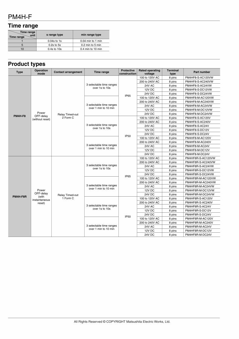
PM4H-F
Product types
PM4H-F8
Type Contact arrangement Time range Part numberRated operatingvoltage
Protectiveconstruction
Terminaltype
Operationmode
PM4HF8-S-AC120VWPM4HF8-S-AC240VWPM4HF8-S-AC24VWPM4HF8-S-DC12VWPM4HF8-S-DC24VWPM4HF8-M-AC120VWPM4HF8-M-AC240VWPM4HF8-M-AC24VWPM4HF8-M-DC12VWPM4HF8-M-DC24VWPM4HF8-S-AC120VPM4HF8-S-AC240VPM4HF8-S-AC24VPM4HF8-S-DC12VPM4HF8-S-DC24VPM4HF8-M-AC120VPM4HF8-M-AC240VPM4HF8-M-AC24VPM4HF8-M-DC12VPM4HF8-M-DC24VPM4HF8R-S-AC120VWPM4HF8R-S-AC240VWPM4HF8R-S-AC24VWPM4HF8R-S-DC12VWPM4HF8R-S-DC24VWPM4HF8R-M-AC120VWPM4HF8R-M-AC240VWPM4HF8R-M-AC24VWPM4HF8R-M-DC12VWPM4HF8R-M-DC24VWPM4HF8R-S-AC120VPM4HF8R-S-AC240VPM4HF8R-S-AC24VPM4HF8R-S-DC12VPM4HF8R-S-DC24VPM4HF8R-M-AC120VPM4HF8R-M-AC240VPM4HF8R-M-AC24VPM4HF8R-M-DC12VPM4HF8R-M-DC24V
8 pins8 pins8 pins8 pins8 pins8 pins8 pins8 pins8 pins8 pins8 pins8 pins8 pins8 pins8 pins8 pins8 pins8 pins8 pins8 pins8 pins8 pins8 pins8 pins8 pins8 pins8 pins8 pins8 pins8 pins8 pins8 pins8 pins8 pins8 pins8 pins8 pins8 pins8 pins8 pins
100 to 120V AC200 to 240V AC
24V AC12V DC24V DC
100 to 120V AC200 to 240V AC
24V AC12V DC24V DC
100 to 120V AC200 to 240V AC
24V AC12V DC24V DC
100 to 120V AC200 to 240V AC
24V AC12V DC24V DC
100 to 120V AC200 to 240V AC
24V AC12V DC24V DC
100 to 120V AC200 to 240V AC
24V AC12V DC24V DC
100 to 120V AC200 to 240V AC
24V AC12V DC24V DC
100 to 120V AC200 to 240V AC
24V AC12V DC24V DC
3 selectable time rangesover 1s to 10s
Relay Timed-out2 Form C
PowerOFF-delay
(without reset)
PM4H-F8R Relay Timed-out1 Form C
PowerOFF-delay
(withinstantaneous
reset)
3 selectable time rangesover 1 min to 10 min
3 selectable time rangesover 1s to 10s
3 selectable time rangesover 1 min to 10 min
3 selectable time rangesover 1s to 10s
3 selectable time rangesover 1 min to 10 min
3 selectable time rangesover 1s to 10s
3 selectable time rangesover 1 min to 10 min
IP65
IP50
IP65
IP50
Time range
Time range
Time rangeunit
1510
0.04s to 1s0.2s to 5s0.4s to 10s
0.04 min to 1 min0.2 min to 5 min0.4 min to 10 min
s range type min range type
All Rights Reserved © COPYRIGHT Matsushita Electric Works, Ltd.

PM4H-F
PM4H-F11R
Type Contact arrangement Time range Part numberRated operatingvoltage
Protectiveconstruction
Terminaltype
Operationmode
PM4HF11R-S-AC120VWPM4HF11R-S-AC120VSWPM4HF11R-S-AC240VWPM4HF11R-S-AC240VSWPM4HF11R-S-AC24VWPM4HF11R-S-AC24VSWPM4HF11R-S-DC12VWPM4HF11R-S-DC12VSWPM4HF11R-S-DC24VWPM4HF11R-S-DC24VSWPM4HF11R-S-AC120VPM4HF11R-S-AC120VSPM4HF11R-S-AC240VPM4HF11R-S-AC240VSPM4HF11R-S-AC24VPM4HF11R-S-AC24VSPM4HF11R-S-DC12VPM4HF11R-S-DC12VSPM4HF11R-S-DC24VPM4HF11R-S-DC24VSPM4HF11R-M-AC120VWPM4HF11R-M-AC120VSWPM4HF11R-M-AC240VWPM4HF11R-M-AC240VSWPM4HF11R-M-AC24VWPM4HF11R-M-AC24VSWPM4HF11R-M-DC12VWPM4HF11R-M-DC12VSWPM4HF11R-M-DC24VWPM4HF11R-M-DC24VSWPM4HF11R-M-AC120VPM4HF11R-M-AC120VSPM4HF11R-M-AC240VPM4HF11R-M-AC240VSPM4HF11R-M-AC24VPM4HF11R-M-AC24VSPM4HF11R-M-DC12VPM4HF11R-M-DC12VSPM4HF11R-M-DC24VPM4HF11R-M-DC24VS
11 pinsScrew terminal
11 pinsScrew terminal
11 pinsScrew terminal
11 pinsScrew terminal
11 pinsScrew terminal
11 pinsScrew terminal
11 pinsScrew terminal
11 pinsScrew terminal
11 pinsScrew terminal
11 pinsScrew terminal
11 pinsScrew terminal
11 pinsScrew terminal
11 pinsScrew terminal
11 pinsScrew terminal
11 pinsScrew terminal
11 pinsScrew terminal
11 pinsScrew terminal
11 pinsScrew terminal
11 pinsScrew terminal
11 pinsScrew terminal
100 to 120V AC
200 to 240V AC
24V AC
12V DC
24V DC
100 to 120V AC
200 to 240V AC
24V AC
12V DC
24V DC
100 to 120V AC
200 to 240V AC
24V AC
12V DC
24V DC
100 to 120V AC
200 to 240V AC
24V AC
12V DC
24V DC
3 selectable time rangesover 1s to 10s
Relay Timed-out2 Form C
PowerOFF-delay
(withinstantaneous
reset)
3 selectable time rangesover 1 min to 10 min
IP65
IP50
IP65
IP50
Dimensions• Screw terminal type (Flush mount) • Pin type (Flush mount/surface mount)
.2366.0
481.890
62.52.461
12.0.472
41 d
ia.
1.61
4 di
a.
481.890
44.51.752
.2366.0
66.52.618
12.0.472
481.890
41 d
ia.
1.61
4 di
a.
44.51.752
481.890
14.5.571
mm inchToletance: ±0.5 ±.020
All Rights Reserved © COPYRIGHT Matsushita Electric Works, Ltd.

PM4H-FTerminal layouts and Wiring diagrams• PM4H-F8 (without reset input)
Pin typeTime-out 2 Form C
Screw-tightening pin typeThe PM4H-F11R should be used for the time-limit 2C.
Screw-tightening pin typeThe PM4H-F11R should be used for the time-limit 1C and to connect reset input.
PM4H-F (with reset) input conditions1. Contact input (pin type example) 2. Non-contact input (pin type example)
• PM4H-F8R (with reset input)Pin typeTime-out 1 Form C, with reset input
• PM4H-F11R (with reset input)Pin typeTime-out 2 Form C, with reset input
Screw terminal typeTime-out 2 Form C, with reset input
(–) (+)
N.O.N.O.
N.C.N.C.
8
5
17
6
2
34
Operating voltage
N.O.
N.C.
8
5
17
6
2
34
Resetinput
(–) (+)Operating voltage
N.O.N.C.N.C.
3
54
21 11
1098
76N.O.
Reset input
(–) (+)Operating voltage
N.C. N.O.N.C. N.O.
54321
109876
11
(–)(+)Operating
voltage
Reset input
Reset input
Reset inputReset input
Reset input
Photo-coupler
Photo-coupler
PM4H-F8R PM4H-F11RPM4H-F8R
PM4H-F11R
Use a contact with good contact relia-bility for the input. Contact bounce canlead to erroneous operation of thetimer, so use a contact with shortbounce time. Make the resistancebetween terminals for a short circuitless than 1k-ohms. Make the resis-tance between terminals for an opencircuit greater than 100k-ohms.
Be sure to use a photo-coupler for non-contactinput.
Check that Vce = 0.6VMax. when ON.
• PM4H-F8 (without reset input) • PM4H-F8R/F11R (with reset input)
Operation
Powersupply
Time-delaycontact N.O.
Time-delaycontact N.C.
Tr
T
Powersupply
Resetinput
Time-delaycontact N.O.
Time-delaycontact N.C.
Tr TrTs Ts
tT
Note: Note:
t<T: Time settingTr: Minimum power supply application time
Note: Ts: Min. 2s (Time to restart operation after reset input is setto OFF: both second type and minute type)
All Rights Reserved © COPYRIGHT Matsushita Electric Works, Ltd.

1. Operation method1) Operation mode setting [PM4H-A type]8 operation modes are selectable withoperation mode selector.Turn the operation mode selector withscrew driver.Operation mode is shown up through thewindow above the mode selector. Themarks are , , , , , , , .Turn the mode selector to the mark untilyou can check by clicking sound.Confirm the mode selector position if it iscorrect.If the position is not stable, the timermight mis-operate.
2) Time range setting [PM4H series common]
16 time ranges are selectable between1s to 500h.Turn the time range selector with thescrew driver.Clockwise turning increases the timerange, and Counter-clockwise turningdecrease the time range.Confirm the range selector position if it iscorrect.If the position is not stable, the timermight mis-operate.
3) Time setting [common]To set the time, turn the set dial to adesired time within the range.Instantaneous output will be on when thedial is set to “0”.When the instantaneous output is used,the dial should be set under “0” range.(Instantaneous output area)When power supply is on, the timerange, setting time and operation modecannot be changed.Turn off the power supply or a reset sig-nal is applied to set the new operationmode.If the position is not stable, the timermight mis-operate.
ON FL FO OF1 SF OS OF2 OC
2. How to use “Set ring” [PM4H series common]1) Fixed time settingSet the desired time and put 2 set ringstogether.Insert the rings into stopper to fix thetime.
2) Time range settingExample: Time range 20s to 30s. Shorter time value setting
Set the dial to 20s.Place the stop ring at the right side ofstopper.
Longer time value settingSet the dial to 30s.Place the stop ring at the left side ofstopper.
Set range
Applicable standard (PM4H series common)
Set dialSet ring (2 pcs)
ATC18001 (sold separately)
Stopper bossStopper
Stop ring
Stopper boss
0 0
30
Longer time value
SEC
20
Shorter time value
SEC
PM4H SERIES MODES AND TIME SETTING
Note) The stoppers for the lower limit setting set ring and the upper limit setting set ring face the opposite directions.
Safety standard EN61812-1 Pollution Degree 2/Overvoltage Category III
EMC
(EMI)EN61000-6-4Radiation interference electric field strengthNoise terminal voltage(EMS)EN61000-6-2Static discharge immunity
RF electromagnetic field immunity
EFT/B immunity
Surge immunityConductivity noise immunityPower frequency magnetic field immunityVoltage dip/Instantaneous stop/Voltage fluctuation immunity
EN55011 Group1 ClassAEN55011 Group1 ClassA
EN61000-4-2 4 kV contact 8 kV air
EN61000-4-3 10 V/m AM modulation (80 MHz to 1 GHz) 10 V/m pulse modulation (895 MHz to 905 MHz)
EN61000-4-4 2 kV (power supply line) 1 kV (signal line)
EN61000-4-5 1 kV (power line) EN61000-4-6 10 V/m AM modulation (0.15 MHz to 80 MHz) EN61000-4-8 30 A/m (50 Hz) EN61000-4-11 10 ms, 30% (rated voltage)
100 ms, 60% (rated voltage)1,000 ms, 60% (rated voltage)5,000 ms, 95% (rated voltage)
All Rights Reserved © COPYRIGHT Matsushita Electric Works, Ltd.

PM4H-W
Features1. A single twin timer unit that repeats (variable) ON/OFF.2. Multiple ranges with a 0.1 s to 500 h time specification on a single unit.3. The output ON/OFF operation is indicated by red and green LED’s.
It’s easy to check the operation at a glance.4. The AC free power supply and shorter body make it easier to use.5. A new screw terminal type has been added to the conventional pin type.
Wiring can be done easily with a screwdriver.6. Compliant with UL, CSA, CE and LLOYD.
481.890
481.890
62.52.461
mm inch
SpecificationsTypeItem PM4H-W
100 to 240V AC, 48 to 125V DC, 12V DC, 24V AC/DCRated operating voltage50/60Hz common (AC operating type)
5A 250V AC (resistive load)Cyclic (OFF-start/Twin operation)
Rated frequency
Rated control capacity
1s to 500h 16 time ranges switchable (T1, T2 time setting individually)±0.3% (power off time change at the range of 0.3s to 1h)
±5% (Full-scale value)±0.5% (at the operating voltage changes between 85 to 110%)
Max. 100mΩ (at 1A 6V DC)Timed-out 2 Form C
±2% (at 20°C ambient temp. at the range of –10 to +50°C +14 to 122°F)
Time rangeOperation time fluctuation
2×10⁷
105 (at rated control capacity)Mechanical (contact)Electrical (contact)
85 to 110% of rated operating voltage (at 20°C coil temp.)Allowable operating voltage range
–10 to +50°C +14 to +122°FAmbient temperature30 to 85%RH (non-condensing)Ambient humidity
860 to 1,060hPaAtmospheric pressure20%Ripple factor (DC type)
IP65 on front panel (using rubber gasket ATC18002) <only for IP65 type>Protective construction120g 4.233 oz (Pin type), 130g 4.586 oz (Screw terminal type)Weight
10 to 55Hz: 1 cycle/min double amplitude of 0.25mm (10min on 3 axes)Vibration resistance
10 to 55Hz: 1 cycle/min double amplitude of 0.375mm (1h on 3 axes)Min. 98m/s2 (4 times on 3 axes)
Shock resistanceMin. 980m/s2 (5 times on 3 axes)
FunctionalDestructive
FunctionalDestructive
Between live and dead metal partsBetween input and outputBetween contacts of different polesBetween contacts of same pole
Insulation resistance (Initial value)
2,000Vrms for 1 min Between live and metal parts2,000Vrms for 1 min Between input and output2,000Vrms for 1 min Between contacts of different poles1,000Vrms for 1 min Between contacts of same pole
Breakdown voltage (Initial value)
Setting errorVoltage error
Contact resistance (Initial value)
300msMin. power off time55°C 131°FMax. temperature rise
Silver alloyContact material
Temperature errorContact arrangement
Operation mode
Approx. 10VA (100 to 240V AC)Approx. 2.5VA (24V AC)
Approx. 1.5W (12V DC, 24V DC, 48 to 125V DC)Rated power consumption
Rating
Timeaccuracy Note:)
Contact
Life
Electricalfunction
Mechanicalfunction
Operatingcondition
Others
Min. 100MΩ (At 500V DC)
Notes: 1) Unless otherwise specified, the measurement conditions at the maximum scale time standard are specified to be the rated operating voltage (within 5% ripplefactor for DC), 20°C 68°F ambient temperature, and 1s power off time.
2) For the 1s range, the tolerance for each specification becomes ±10ms.3) As internal components may become worn when using continuous conduction, the product should be replaced periodically.
UL File No.: E122222CSA File No.: LR39291
DIN48 SIZE ANALOG MULTI-LANGECYCLIC TWIN TIMERS
PM4H-W
RoHS Directive compatibility informationhttp://www.nais-e.com/
All Rights Reserved © COPYRIGHT Matsushita Electric Works, Ltd.

PM4H-W
Product types
PM4H-WTwin timer
Type Contact arrangement Time range Part numberRated Operatingvoltage
Protectivestructure
Terminaltype
Operatingmode
PM4HW-H-AC240VWPM4HW-H-AC240VSWPM4HW-H-DC125VWPM4HW-H-DC125VSWPM4HW-H-24VWPM4HW-H-24VSWPM4HW-H-DC12VWPM4HW-H-DC12VSWPM4HW-H-AC240VPM4HW-H-AC240VSPM4HW-H-DC125VPM4HW-H-DC125VSPM4HW-H-24VPM4HW-H-24VSPM4HW-H-DC12VPM4HW-H-DC12VS
8 pinsScrew terminal
8 pinsScrew terminal
8 pinsScrew terminal
8 pinsScrew terminal
8 pinsScrew terminal
8 pinsScrew terminal
8 pinsScrew terminal
8 pinsScrew terminal
100 to 240V AC
48 to 125V DC
24V AC/DC
12V DC
100 to 240V AC
48 to 125V DC
24V AC/DC
12V DC
16 selectable ranges(1s to 500h)
RelayTimed-out2 Form C
Cyclic(OFF-start,
Twin)
IP65
IP50
Terminal layouts and Wiring diagrams
Dimensions mm inchToletance: ±0.5 ±.020
Pin TypeCyclic timed-out relay contact: 2C
Screw terminal typeCyclic timed-out relay contact: 2C
Operation
(–) (+)
N.C.N.C.
N.O.N.O.
Operating voltage
8
5
17
6
2
34
N.C. N.O.N.C. N.O.
54321
109876
11
(–)(+)Operating
voltage
481.890
62.52.461
17.0.670
6.0.236
481.890 ∅
41∅
1.61
4
44.51.752
17.0.670
6.0.23648
1.890
481.890
66.52.618 14.5
.571
∅41
∅1.
614
44.51.752
Power supply
Time-delay contact(N.O. contact)
Time-delay contact(N.C. contact)
Output ON-OFFindicator
T1 T1T2
Output OFF indicator (green)Output ON indicator (orange)OFF set timeON set time
::
T1:T2:
All types of PM4H-W timer have multi-time range.16 time ranges are selectable.1s to 500h (Max. range) is controlled.
Time range
1
ScaleTime unit
0.1s to 1s
sec min hrs 10h
0.1 min to 1 min 0.1h to 1h 1.0h to 10h
5 0.5s to 5sControltime range
0.5 min to 5 min 0.5h to 5h 5h to 50h
10 1.0s to 10s 1.0 min to 10 min 1.0h to 10h 10h to 100h
50 5s to 50s 5 min to 50 min 5h to 50h 50h to 500h
• Screw terminal type: M3.5 • Pin type
All Rights Reserved © COPYRIGHT Matsushita Electric Works, Ltd.

1. Operation method1) Operation mode setting [PM4H-A type]8 operation modes are selectable withoperation mode selector.Turn the operation mode selector withscrew driver.Operation mode is shown up through thewindow above the mode selector. Themarks are , , , , , , , .Turn the mode selector to the mark untilyou can check by clicking sound.Confirm the mode selector position if it iscorrect.If the position is not stable, the timermight mis-operate.
2) Time range setting [PM4H series common]
16 time ranges are selectable between1s to 500h.Turn the time range selector with thescrew driver.Clockwise turning increases the timerange, and Counter-clockwise turningdecrease the time range.Confirm the range selector position if it iscorrect.If the position is not stable, the timermight mis-operate.
3) Time setting [common]To set the time, turn the set dial to adesired time within the range.Instantaneous output will be on when thedial is set to “0”.When the instantaneous output is used,the dial should be set under “0” range.(Instantaneous output area)When power supply is on, the timerange, setting time and operation modecannot be changed.Turn off the power supply or a reset sig-nal is applied to set the new operationmode.If the position is not stable, the timermight mis-operate.
ON FL FO OF1 SF OS OF2 OC
2. How to use “Set ring” [PM4H series common]1) Fixed time settingSet the desired time and put 2 set ringstogether.Insert the rings into stopper to fix thetime.
2) Time range settingExample: Time range 20s to 30s. Shorter time value setting
Set the dial to 20s.Place the stop ring at the right side ofstopper.
Longer time value settingSet the dial to 30s.Place the stop ring at the left side ofstopper.
Set range
Applicable standard (PM4H series common)
Set dialSet ring (2 pcs)
ATC18001 (sold separately)
Stopper bossStopper
Stop ring
Stopper boss
0 0
30
Longer time value
SEC
20
Shorter time value
SEC
PM4H SERIES MODES AND TIME SETTING
Note) The stoppers for the lower limit setting set ring and the upper limit setting set ring face the opposite directions.
Safety standard EN61812-1 Pollution Degree 2/Overvoltage Category III
EMC
(EMI)EN61000-6-4Radiation interference electric field strengthNoise terminal voltage(EMS)EN61000-6-2Static discharge immunity
RF electromagnetic field immunity
EFT/B immunity
Surge immunityConductivity noise immunityPower frequency magnetic field immunityVoltage dip/Instantaneous stop/Voltage fluctuation immunity
EN55011 Group1 ClassAEN55011 Group1 ClassA
EN61000-4-2 4 kV contact 8 kV air
EN61000-4-3 10 V/m AM modulation (80 MHz to 1 GHz) 10 V/m pulse modulation (895 MHz to 905 MHz)
EN61000-4-4 2 kV (power supply line) 1 kV (signal line)
EN61000-4-5 1 kV (power line) EN61000-4-6 10 V/m AM modulation (0.15 MHz to 80 MHz) EN61000-4-8 30 A/m (50 Hz) EN61000-4-11 10 ms, 30% (rated voltage)
100 ms, 60% (rated voltage)1,000 ms, 60% (rated voltage)5,000 ms, 95% (rated voltage)
All Rights Reserved © COPYRIGHT Matsushita Electric Works, Ltd.

32
1. Input connections (PM4H-A type)1) Be sure not to use terminal as thecommon terminal of the input signal asshown in Fig. A. Otherwise, the internalcircuit of the timer may be damaged.Use terminal as the common terminalas shown in Fig. B.
If the circuits is connected as in Fig. C,the internal circuits must be broken. Besure to connect the circuit as in Fig. D.
2) When one input signal is simultane-ously applied to more than one timer, besure to avoid the wiring shown in Fig. E.Otherwise, the short-circuit current willflow and cause damage. Be sure to alignthe polarity of the power supply asshown in Fig. F.
3) Terminal - (screw terminal x-c)should be connected as the start input.Connect terminals - (screw terminalx-v) for reset signal input. Connect ter-minals - (screw terminal x-b) forstop signal input. Be sure not to connectwith other terminals and apply excessivevoltage. The internal circuit will be dam-aged.4) The input wiring other than the powersupply circuit should avoid these condi-tions, high-voltage wiring and parallelwiring with power wire. Wire in short withusing the shielding wire or metal wiringtube.5) For start, reset and stop input, usegold-plated contact with high reliability.Since contact bouncing causes errors inthe start, use an input contact lessbounce time.6) Keep the minimum signal input timeover 0.05 s.
2. Input signal conditions (PM4H-A type)1) Connection of contact input (Pin typeexample
Use gold-plated contacts with high-relia-bility. The bounce time at the contactscauses errors in the timer operation time.Accordingly, use start input contactwhose bounce time is short. The resis-tance when shorted should be less than1kΩ, and when open resistance shouldbe more than 100kΩ.For the screw terminal type, connect theterminal x to the each input signal.2) Connection of non-contact input (Pintype example) (open-collector)
Apply the open-collector connection. Thecharacteristics of the transistor usedmust be VCEO=10V or more, IC=10mA ormore, and ICBO=6µA or less. Additionally,the input impedance must be 1kΩ orless, and the residual voltage must be0.6V or less.For the screw terminal type, connect theterminal x to the each input signal.
3) Connection of non-contact input (Pintype example)(voltage input)
Even if the open collector is not used,input is also possible from the non-con-tact circuit of 6 to 30V DC. In this case,the start input is turned on when the sig-nal is turned from H to L.The residual voltage must be 0.6V orless when Q is on. On the AC type, aninsulated transformer is required as thepower supply for the photoelectric sen-sor, etc. (power supply for the inputdevices).Note: Keep the minimum input signal time ofeach signal to 0.05s or more.
3. Checking the contacts before use(PM4H-F only)When the power ON time is less than theminimum power application time, thecontacts may remain in an ON state, sothe state of the contacts should bechecked before use. When the contactsare in an ON state, activating them oncewill return them to their normal state (theOFF state after time-out). (Be aware thatrelay characteristics may result in thecontacts being in that same ON state ifexposed to excessive vibration andimpact during transport.)
4. Time settingTo set the time, turn the set dial to adesired time within the range.Instantaneous output will be on when thedial is set to “0”.When the instantaneous output is used,the dial should be set under “0” range.(Instantaneous output area)Note) When power supply is on, the timerange, setting time and operation modecannot be changed.Turn off the power supply or a reset sig-nal is applied to set the new operationmode.If the position is not stable, the timermight mis-operate.
Fig. C
Fig. D
Good
No good
10
6
2
10
6
2
T
T
Fig. E
Fig. F
Good
No good
Contact ornon-contact input
102
102
Powersupply
Powersupply
102
Inputterminal
Inputterminal
Inputterminal
Inputterminal
102
Res
et in
put
Sta
rt in
put
Sto
p in
put
2
5 76
Fig. B
5
2 10
76
Fig. A
No good
Good
5
2 10
76
Operatingvoltage
Operatingvoltage
Contact input(or non-contactinput)
Contact input(or non-contactinput)
PRECAUTIONS IN USING THE PM4H SERIES
2
5 76
Res
et in
put
Sta
rt in
put
Sto
p in
put
Internal circuitwith photoelectricsensor, etc.
[Example ofstart input]
(The start inputis turned on.)
1mA
Q2
5 76

33
PRECAUTIONS IN USING THE PM4H SERIES5. Superimposed surge of power supply (PM4H series common)For the superimposed surge of powersupply, the standard waveform is takenas the standard value for surge-proofvoltage.If external surge occurs exceeding thespecified value, the internal circuit maybreak down. In this case, use a surgeabsorption element.
The positive and negative voltages areapplied each five times between thepower pins.The typical surge absorption elementsinclude a varistor, a capacitor, and adiode. If a surge absorption element isused, use an oscilloscope to seewhether or not the foreign surge exceed-ing the specified value appears.
6. Acquisition of CE markingPlease abide by the conditions belowwhen using in applications that complywith EN61812-1.1) Overvoltage category III, pollutionlevel 22) This timer employs a power supplywithout a transformer, so the power andinput signal terminals are not insulated.(PM4H-A only)(1) When a sensor is connected to theinput circuit, install double insulation onthe sensor side.(2) In the case of contact input, use dual-insulated relays, etc.3) The load connected to the output con-tact should have basic insulation.This timer is protected with basic insula-tion and can be double-insulated to meetEN/IEC requirements by using basicinsulation on the load.4) Please use a power supply that is pro-tected by an overcurrent protectiondevice which complies with the EN/IECstandard (example: 250 V 1 A fuse, etc.).
5) You must use a terminal socket orsocket for the installation. Do not touchthe terminals or other parts of the timerwhen it is powered. When installing orun-installing, make sure that no voltageis being applied to any of the terminals.6) Do not use this timer as a safety cir-cuit. For example when using a timer in aheater circuit, etc., provide a protectioncircuit on the machine side.
Operation voltage100 to 240V AC100 to 120V AC200 to 240V AC48 to 125V DC
Surge voltage
4,000V
12V DC, 24V DC24V AC/DC 500V