Plasma TV fault-finding - World Radio History
68
-
Upload
khangminh22 -
Category
Documents
-
view
3 -
download
0
Transcript of Plasma TV fault-finding - World Radio History
DEVELOPMENTS
•
NEWS AND TECHNOLOGY INSTALLATION SERVICING
Plasma TV fault-finding
•The 405-line era eActive LOPT tester project
eATX power supply faults I 0>
9 7700 411647146
FAULT FINDING FOR TV AUDIO SATELL E VIDEO IT

The Annie 204 Spectrum Analyser Easy to use! Simply the best!
Featuring analogue, digital terrestrial and digital satellite demodulation. View the spectrum, level and quality information or the picture display individually or simultaneously.
4110 Designed for ease of use. Automatic detection of all relevant parameters.
40 Large 14.8 cm (5.8 inch) full colour display
• 30 to 860 and 950 to 2150 MHz frequency range coverage
40 Demodulates terrestrial analogue, digital satellite and digital terrestrial signals producing pictures and sound in addition to B.E.R and signal to noise readout.
• Single button switching to view all programmes in a digital multiplex.
• Nylon carry-case with integral light hood for bright conditions.
• Stores test setups as favourites for rapid repeat measurements.
• UK trade price £1,525 plus vat.
For more information,
visit www.swires.com or phone +44(0)1268 417584.
40, Hornsby Square Southfields Ind.Park, Laindon, Nr Basildon, Essex SS15 6SD.
CONTENTS October 2005
707 Comment Anniversaries.
708 News News from BSkyB. Intel's CE platform. Digital TV trials. 100GB blue-laser discs. Further WEEE postponement. BBC programmes via the internet. Video recorders.
710 Repairing ATX power supplies *lhe pow, er-supply modules used in ATX PC sys-tems are relatively cheap and are generally just replaced when faulty. Many of the faults that occur are straightforward however, and the mod-ules follow a similar pattern. So some repairs are worthwhile. Alun Rawson-Williams on how to go about it.
712 The CHS story Charles Hyde and Son has been serving the con-sumer-electronics repair trade for 45 years. Andrew Shaw traces its history from a single room in Hull to a Europe-wide operation.
714 Bench Notes Adrian (jardiner has been testing several types of lead-free solder and makes various recommenda-tions.
716 The days of 405-line TV It's twenty years since the last 405-line TV trans-mitter was switched off. But it was the 405-line system that got TV as we know it going. Keith Hamer and Garry Smith recount the story, from the start of the service in November 1936 to the January 1985 closedown.
720 Plasma display technology Having described the operation of plasma TV sets in previous instalments in this series, Fawzi Ibrahim concentrates this time on fault-finding, beginning with a description of the start-up process. Also PDP specifications.
728 Wireless technologies in CE products In the (with instalment in this series Graham Maynard takes a look at Bluetooth-enabled cam-corders and set-top boxes then turns to a newer wireless technology, Zigbee.
732 Test Case 514
733 Plasma TV faults Charles Arundel provides a further summary of fault conditions experienced with Daewoo models.
734 DX and Satellite Reception Terrestrial DX and satellite TV reception reports. A DTT receiver for DXing. Broadcast and satellite TV news. C-band extension. Streaming video, the future . . . Roger Bunney reports.
Vol. 55 No.12
737 Help wanted
738 A visit to the drugstore Elaine Everest's recent visit to her local drugstore prompts her to outline a plan for moving the TV trade into the 21st century.
740 A flexible LOPT tester design Commercial LOPT testers cost about £90 trade. This simple, easy-to-use tester can be built for a fraction of that cost.
744 Audio faults
746 Letters Lead-free solder. Who invented the AVO? Same old stories. Widescreen CRT problems. Checking RC units. Trade prospects. A PlayStation repair. J-Beam Aerials. Vintage matters.
748 TV fault finding
751 DVD and home cinema fault reports
752 Books to buy The Television book service, with details of some of the titles you can order.
754 Extended fault reports A few longer reports on complex or tricky fault conditions.
756 What a Life! Professor Isaak and the Doppler effect. Troubles with recent CRTs. Reminiscences on the Ultra Coronation Twin. Correspondence. Donald Bullock's servicing commentary.
758 Satellite notebook
HDTV cont. Digital channel update (28.2°E). A Sky RC extender problem. Rain fade. Eutelsat W2 (16°E). Fault reports.
762 Monitor fault reports
763 Next month in Television
Editor
John A. Reddihough
Deputy Editor
Tessa Winford
Production Editor
Jane Massey
Production Executive
Dean Turner
01322 611206
Display Sales
Executive
Reuben Gurunlian
01322 611 261
Fax 01322 616 339
Editorial Assistant
Katie Butler
01322 611 472
Managing Editor Svetlana Josifovska
01322 611 250
Publishing Director
Tony Greville
Note that we are unable to answer technical queries over the telephone and cannot provide information on spares other than that given in our Spares Guide
Disclaimer We work hard to ensure that the information presented in Television is accurate. However, Television's publisher - Nexus Media Communications - will not take responsibility for any injury or loss of earnings that may result from applying information presented in the magazine. It is your responsibility to familiarise yourself with the laws relating to dealing with your customers and suppliers, and with safety practices relating to working with electrical/electronic circuitry - particularly as regards electric shock, fire hazards and explosions.
Next issue, dated November, on sole October 19
TELEVISION October 2005

&ectronic des
Peak Electronic Design Ltd
Atlas House, Kiln Lane Harpur lelustrial Estate Buxton, SKIT 9JL,,UK
• cHsge, 700
the Atlas ESR60 • Automatically measure capacitance and ESR.
• Can be used in-circuit! • ESR resolution down to 0.01 ohms! • Supports capacitance up to 22,000uF. • Protected against charged capacitors • Gold plated kelvin crocs supplied.
Passive components, semiconductors, power devices, network cabling
Choose your perfect analyser New Low Prices!
"Star Pack" LCR and DCA in carry case £118.00
Carry cases £15.00
SMD Tweezer far LCR 9.00
R e T4-T.y\
CoYg
limited time only
the Atlas LCR40 • Automatically identify Inductors, Capacitors and Resistors.
• Inductors from 1pH to 10H. • Capacitors from 1pF 10,000pF.
• Resistors from Mto2MS2 • 1% Basic accuracy. • Automatic frequency selection.
\es 8, carry cases
Serriic
rr nductor Analysis
model DCA55
www. peaks sc. co. uik all prices include UK Delivery and VAT
Triac and Th ristor Te,sting
Cat5 Cable Testing_
COMMENT COPYRIGHT © Nexus Media Communications 2005. All rights reserved. No part of this publication
may be reproduced, stored or transmitted in
any form or by any means without the writ-ten permission of the publishers.
All reasonable precautions are taken by Television to ensure that the advice and data
published are reliable. We cannot however
guarantee it and we cannot accept legal responsibility for it.
CORRESPONDENCE All correspondence regarding advertisements
should be addressed to the Advertisement
Manager, Television, Nexus Media Communications, Media House, Azalea Drive, Swanley, Kent, BR8 8HU. Editorial cor-
respondence should be addressed to Television, Editorial Department, Nexus
Media Communications, Media House, Azalea Drive, Swanley, Kent, BR8 8HU.
INDEXES AND BINDERS Indexes for Vols. 38 to 54 are available at £3.50
each from SoftCopy Ltd., who can also supply
an fifteen-year consolidated index on comput-er disc. For further details see page 763. Binders that hold twelve issues of Television are available for £6.50 each from Modern
Bookbinders, Pringle Street, Blackburn, BB1 1SA. Telephone: 01254 59 371.
Make cheques payable to "Television Binders".
Newstrade Enquires by Seymour Distribution Ltd.,
86 Newman St, London, W1T 3EX.
ISSN 0032-647X
Newstrade Hotline If you are experiencing problems getti-ig
copies through your newsagent, please call
Debbie Jenner on 01322 611210.
SUBSCRIPTIONS Customer Interface Ltd.,
Cary Court,
Somerton,
TA11 7BR.
Telephone 0870 4287950
Fax 01458 271146
Subscription rates: UK 1 year £39.00 2 years £70.00 3 years £90.00
Mainland Europe 1 year £57.00 2 years £100 00 3 years £135 00
Rest of World 1 year £74.00 2 years £130.00 3 years £175.00
Cheques should be made payable to Television.
BACK NUMBERS If available issues are £4.50 each
NEXUS MEDIA CO M MUNICAT ONS
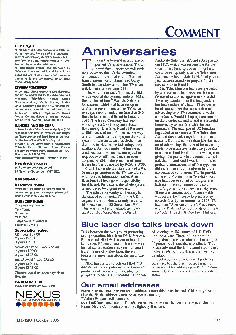
Anniversaries T
his year has brought us a couple of important TV anniversaries. Those of a nostalgic disposition will prob-
ably be aware that it's the twentieth anniversary of the final end of 405-line transmissions. Keith Hamer and Garry Smith tell the story of 405-line TV in an article that starts on page 716. But why in the early Thirties did EMI,
which created the system, settle on 405 as the number of lines? Well the Selsdon Committee, which had been set up to advise the government on the TV system to adopt, recommended not less than 240 lines in its report published in January 1935. The Baird Company had been working on a 240-line system. Isaac Schoenberg (later Sir), Head of Research at EMI, decided on 405 lines as one way of significantly improving upon the Baird system. It was an audacious decision at the time, in view of the technology then available. An odd number of lines was used because interlaced scanning, which requires two half lines, had also been adopted by EMI — the principle of inter-lacing had been patented by RCA in 1933. 405 with its simple division ratios (9 x 9 x 5) made generation of the TV waveform with its sync information easier. Alan Blumlein had been given responsibility for this and, fortunately, the whole system turned out to be a great success. The other noteworthy anniversary is
the start of commercial TV in the UK. It began, in the London area only initially, fifty years ago on 22 September 1955. This was in fact a remarkable achieve-ment for the Independent Television
Authority (later the IBA and subsequently the ITC), which was responsible for the transmitters (amongst other things) and could be set up only after the Television Act became law in July 1954. That gave it just fourteen months to prepare for the new service in Band III. The Television Act had been preceded
by a ferocious debate between those in favour of and those against commercial TV (they decided to call it independent, but independent of what?). There was a lot of unease over the introduction of advertising with TV (commercial radio came later). Would it impinge too much on the broadcasts, and would commercial interests try to interfere with the pro-grammes? The example of US broadcast-ing added to this unease. The Television Act laid down strict regulations on such matters. But it was more than just the mat-ter of advertising: the type of broadcasting likely to be made available also gave rise to concern. Lord Reith for one was against giving "the public what it wants. I would not, did not and said I wouldn't." It was probably condescension of this type that did more than anything else to help the advocates of commercial TV. To provide some sort of control, the Television Act also had a lot to say about programme balance, minority interests and so on. ITV got off to a somewhat shaky start.
There was concern about finance — this was before the "licence to print money" episode. But by the summer of 1957 ITV had over 70 per cent of the TV audience, and the BBC had to improve its offering to compete. The rest, as they say, is history.
Blue-laser disc talks break do wn Talks between the two groups promoting next-generation, blue-laser DVD formats, Blu-ray and HD-DVD, seem to have bro-ken down. Efforts to establish a common format started earlier this year but, apart from the use of a blue laser, there has been little agreement about the specifica-tion. NEC has started to deliver HD-DVD
disc drives to computer manufacturers and producers of video recorders, also for peripheral devices. But Toshiba has decid-
ed to delay its US launch of HD-DVD until next year. There is little point in going ahead unless a substantial catalogue of prerecorded material is available. This is unlikely until the Hollywood studios get a clearer idea of how things are likely to develop. Back-room discussions will probably
continue, but there will be no launch of blue-laser discs and equipment in the con-sumer electronics market in the immediate future.
Our email addresses Please note the change to our email addresses from this issue. Instead of highburybiz.com after the @, the address is now nexusmedia.com, e.g. [email protected] and [email protected] The change relates to the fact that we are now published by Nexus Media Communications, not Highbury Business.
TELEVISION October 2005 707

NEWS
News from BSkyB Some preliminary information has been released on BSkyB's HDTV channel package, which is due to become available in the UK and Ireland in the first half of next year. Three additional Astra transponders will be used for the service. In addition to Premiership football, the chan-nels are likely to include Artsworld, National Geographic and The Discovery Channel. A new HD set-top box will be made available. BSkyB has launched an HD
consumer website. Visitors to the site can find out more about HD, view the frequently-asked ques-tions page and register to receive further information on Sky's HD service. The site features a jargon
buster and provides information on buying HD-ready TV equip-ment and what viewers can expect from Sky's HD service. The site is at www.sky.corri/hd Sky has also announced a
wireless device, the Sky Gnome, that enables subscribers to listen to the audio content of digital radio and TV channels through-out the home. It's compatible with all Sky digiboxes and has a typical range of 30m, in the home or garden. Users will be able to listen to more than 80 digital radio channels and any of the TV channels in their Sky package without extra charge. In addition Sky+ subscribers will be able to use the Gnome to listen
to prerecorded programmes on their Sky+ planner. The Gnome provides stereo sound and has a backlit LCD display that gives full channel and programme information, volume and channel control and the option to preset ten favourite channels. Price details have still to be announced. Before the end of the year
Sky subscribers who take a top-tier package and have a broad-band internet connection will be able to download movies on-demand and view Sky Sports programming with their PC free of charge. There will initially be over 200 movies, increasing with time. Subscribers will be able to browse and download movies,
trailers, behind-the-scenes footage and reviews at any time. Sky World subscribers will also be able to receive video updates from Sky News and Sky Sports News via their mobile phone. BSkyB has issued its results
for the year ending 30 June. At that date there were 7,787,000 subscribers in the UK and Ireland, with 5,619,000 taking one or more of the premium channels. Sky says it is on track to achieve its target of 8m sub-scribers by the end of the year. Turnover increased 11 per cent to £4.048bn, with operating profit before goodwill and exceptional items up 34 per cent at £805m. There are now 888,000 Sky+ subscribers.
Readout Model et the Duel-Leyer Super-Resolution Dine
• • •
1.1ryer lead ., lur e I.. , nm pon
I . ..qv@ m.l.a malem
ne ea pm el .4 op.... Wm...am. erg .
Inage..... ..pre
lue.mel •••••........e. •
* ay warn •.• tee.
.1.••••• dlau ,
• •
liner rcadout mgnal: Im-ntil pl.
100GB blue-laser discs Sharp has developed blue-laser optical-disc technology that uses super-resolution transpar-ent functional film to provide data readout in a dual-layer disc structure. The company claims that use of the technol-ogy will enable blue-laser discs to store 100GB of data, so that they could record approximately nine hours of
high-definition video. This is twice as much data per layer as Blu-ray. Each of the disc's layers
consists of data pits covered by the super-resolution film, whose thermo-optic properties provide very high data read-out. It enables data pits that are smaller (100nm) than the laser beam to be identified.
Intel's CE platform Chipmaker Intel has announced a new technology platform, called Viiv (it rhymes with 'five'), for entertainment-based PCs. It's based on a multi-tasking dual-core proces-sor and will initially be used in conjunction with the Microsoft's Windows Media Center edition. Launch is expected to be in the first quar-ter of next year. Intel says that PCs with Viiv
technology will have the fol-lowing features: remote-control operation and instant on/off switching like a TV set (after the initial boot-up); advanced
graphics and sound capability; content on demand, with inter-net access to movies, music, pictures and games; the ability to record, pause and rewind live TV programmes (with optional TV-tuner card); spe-cial software to make it easier to set up a home network and connect to wireless devices; and provision for up to 7.1 channel surround sound. Such PCs will be available
in different shapes and sizes, from small consumer-electron-ics versions that look like a DVD player to more traditional desktop designs.
BBC via the internet The BBC plans to make its programmes freely available via the internet. The aim is to launch a service next year under the provisional name MyBBCPlayer. It would give licence payers access to BBC radio and TV programmes from the previous seven days, subsequently expand-ing to include an ever-
increasing proportion of the BBC's archive material, also a wider range of local, national and international news. There are also plans to make video clips available to mobile phones. The plans are subject to the
approval of the board of gov-ernors and rights clearance issues being resolved.
708 October 2005 TELEVISION
NEWS
Digital TV trials The Department of Culture, Media and Sport has announced that the digital switchover trial in Wales was a success, adding that those who took part gave it overwhelming support. In March, households in the vil-lages of Ferryside and Llansteffan became the first to switch over to digital TV only, as part of preparations for a UK switchover between 2008-2012. The report and research on the trial show that it was achieved on schedule with no major transmission problems. 81 per cent of the people
involved were able to install the equipment supplied without help from the trial team, though one in five households experi-enced installation difficulties and additional remote-control units were a problem for some, especially the elderly, who pre-ferred much simpler handsets. In 22 per cent of homes the domestic aerial and cable were in poor condition and required some attention. This usually involved a new flylead, not a replacement aerial. Flyleads were often old, damaged or had poor plug connections. Six homes that previously
suffered from very poor ana-logue reception couldn't be
served easily or at all by digital terrestrial transmissions and had to receive digital TV via satel-lite. In the end-of-trial question-naire 99.2 per cent of respon-dents voted to keep digital TV. Nokia's mobile TV trial at
the World Athletics Championships in Helsinki appears to have been a great success. Trade and press visitors were provided with 300 7710 Smartphones that incorporated a prototype receiver module and a built-in aerial. Transmissions were at 610MHz, providing fourteen programmes over an area of approximately 2001=2 — programmes included BBC World, CNN, Eurosport and Finnish sports feeds. As the sig-nal was in packet data form the sound and pictures almost never failed or broke up. A reset was needed with the occasional freeze. MPEG-4 compression was used, with transmission at 250kbits/sec and 15 frames/sec, more than adequate for the 70mm display. A fully-charged battery provided just under three hours' viewing time. The system is due to be
released commercially next year. A cellphone connection is needed to unscramble the signal.
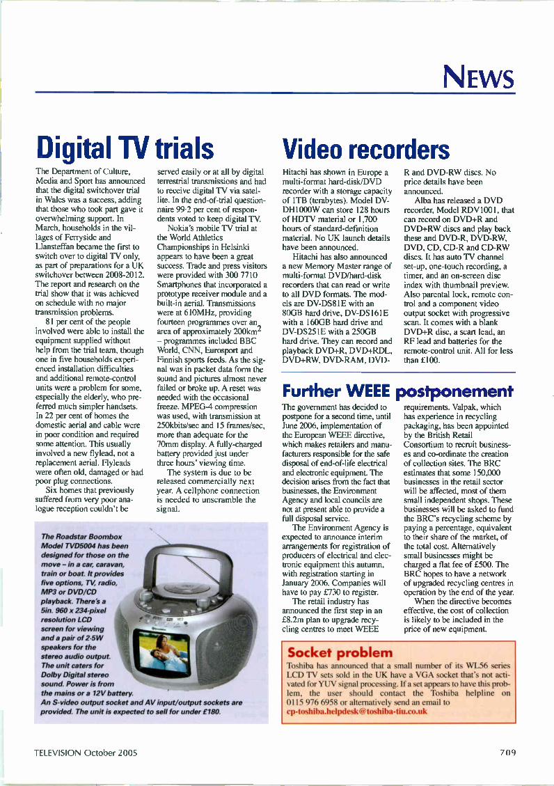
The Roadstar Boombox
Model TVD5004 has been designed for those on the
move - in a car, caravan,
train or boat. It provides five options, TV, radio,
MP3 or DVD/CD
playback. There's a
5in. 960 x 234-pixel resolution LCD screen for viewing anda pair of 2.5 W
speakers for the
stereo audio output. The unit caters for Dolby Digital stereo
sound. Power is from the mains or a 12V battery.
An S-video output socket and AV input/output sockets are provided. The unit is expected to sell for under £180.
Video recorders Hitachi has shown in Europe a multi-format hard-disk/DVD recorder with a storage capacity of 1TB (terabytes). Model DV-DH1000W can store 128 hours of HDTV material or 1,700 hours of standard-definition material. No UK launch details have been announced. Hitachi has also announced
a new Memory Master range of multi-format DVD/hard-disk recorders that can read or write to all DVD formats. The mod-els are DV-DS81E with an 80GB hard drive, DV-DS161E with a 160GB hard drive and DV-DS251E with a 250GB hard drive. They can record and playback DVD+R, DVD+RDL, DVD+RW, DVD-RAM, DVD-
R and DVD-RW discs. No price details have been announced. Alba has released a DVD
recorder, Model RDV1001, that can record on DVD+R and DVD+RW discs and play back these and DVD-R, DVD-RW, DVD, CD, CD-R and CD-RW discs. It has auto TV channel set-up, one-touch recording, a timer, and an on-screen disc index with thumbnail preview. Also parental lock, remote con-trol and a component video output socket with progressive scan. It comes with a blank DVD+R disc, a scart lead, an RF lead and batteries for the remote-control unit. All for less than £100.
Further WEEE postponement The government has decided to postpone for a second time, until June 2006, implementation of the European WEEE directive, which makes retailers and manu-facturers responsible for the safe disposal of end-of-life electrical and electronic equipment. The decision arises from the fact that businesses, the Environment Agency and local councils are not at present able to provide a full disposal service. The Environment Agency is
expected to announce interim arrangements for registration of producers of electrical and elec-tronic equipment this autumn, with registration starting in January 2006. Companies will have to pay £730 to register. The retail industry has
announced the first step in an £8.2m plan to upgrade recy-cling centres to meet WEEE
requirements. Valpak, which has experience in recycling packaging, has been appointed by the British Retail Consortium to recruit business-es and co-ordinate the creation of collection sites. The BRC estimates that some 150,000 businesses in the retail sector will be affected, most of them small independent shops. These businesses will be asked to fund the BRC's recycling scheme by paying a percentage, equivalent to their share of the market, of the total cost. Alternatively small businesses might be charged a flat fee of £500. The BRC hopes to have a network of upgraded recycling centres in operation by the end of the year. When the directive becomes
effective, the cost of collection is likely to be included in the price of new equipment.
Socket problem Toshiba has announced that a small number of its WL56 series LCD TV sets sold in the UK have a VGA socket that's not acti-vated for YUV signal processing. If a set appears to have this prob-lem, the user should contact the Toshiba helpline on 0115 976 6958 or alternatively send an email to [email protected]
TELEVISION October 2005 709
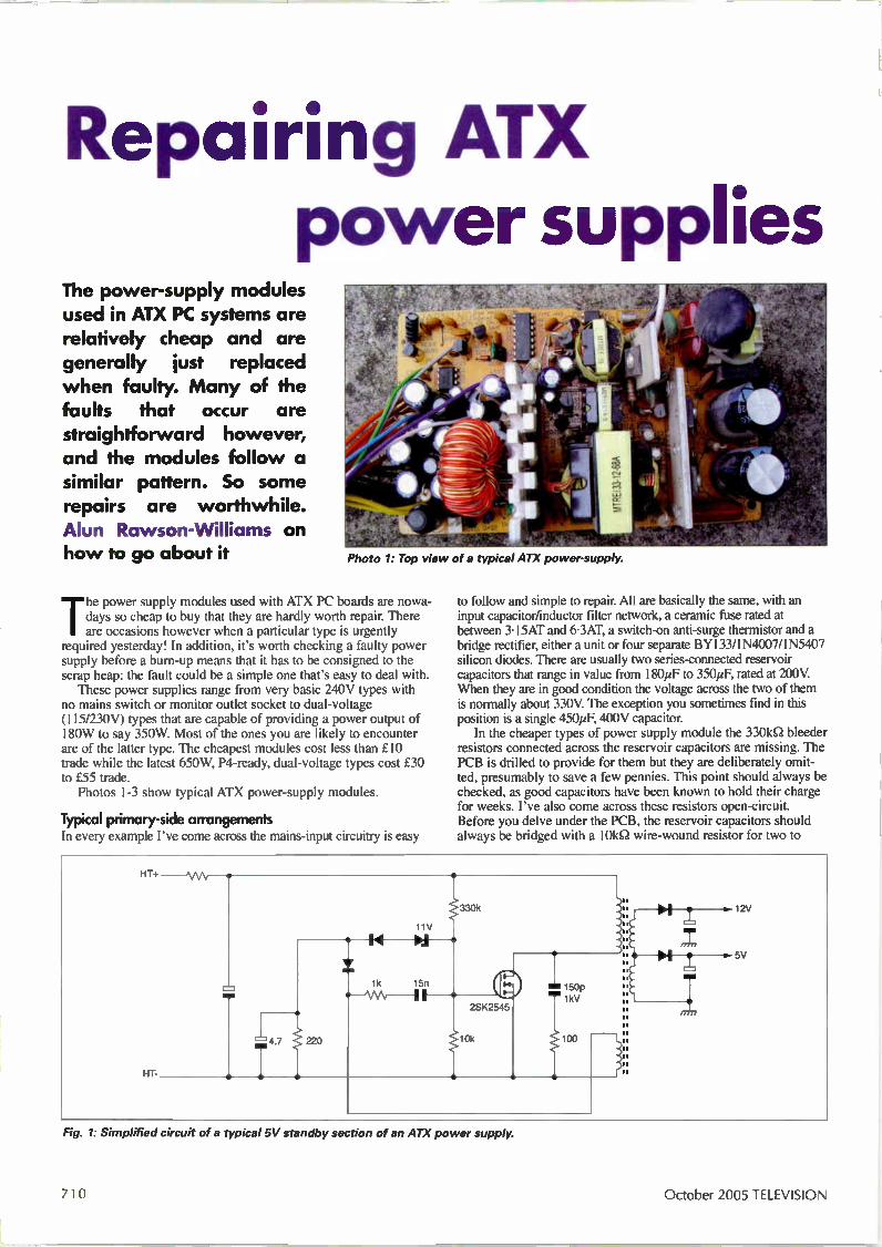
Repairing ATX power supplies
The power-supply modules used in ATX PC systems are relatively cheap and are generally just replaced when faulty. Many of the faults that occur are straightforward however, and the modules follow a similar pattern. So some repairs are worthwhile. Alun Rawson-Williams on how to go about it Photo 1: Top view of a typical ATX power-supply.
The power supply modules used with ATX PC boards are nowa-days so cheap to buy that they are hardly worth repair. There are occasions however when a particular type is urgently
required yesterday! In addition, it's worth checking a faulty power supply before a burn-up means that it has to be consigned to the scrap heap: the fault could be a simple one that's easy to deal with. These power supplies range from very basic 240V types with
no mains switch or monitor outlet socket to dual-voltage (115/230V) types that are capable of providing a power output of 180W to say 350W. Most of the ones you are likely to encounter are of the latter type. The cheapest modules cost less than £10 trade while the latest 650W, P4-ready, dual-voltage types cost £30 to £55 trade. Photos 1-3 show typical ATX power-supply modules.
Typical primary-side arrangements In every example I've come across the mains-input circuitry is easy
to follow and simple to repair. All are basically the same, with an input capacitor/inductor filter network, a ceramic fuse rated at between 3-15AT and 6.3AT, a switch-on anti-surge thennistor and a bridge rectifier, either a unit or four separate BY133/1N4007/1N5407 silicon diodes. There are usually two series-connected reservoir capacitors that range in value from 180µF to 350µF, rated at 200V. When they are in good condition the voltage across the two of them is normally about 330V. The exception you sometimes find in this position is a single 45014F, 400V capacitor. In the cheaper types of power supply module the 330k0 bleeder
resistors connected across the reservoir capacitors are missing. The PCB is drilled to provide for them but they are deliberately omit-ted, presumably to save a few pennies. This point should always be checked, as good capacitors have been known to hold their charge for weeks. I've also come across these resistors open-circuit. Before you delve under the PCB, the reservoir capacitors should always be bridged with a 10k0 wire-wound resistor for two to
HT+ - MA,--•
HT-
4.7 T 220
11V
1k 15n
Fig. 1: Simplified circuit of a typical 5V standby section of an ATX power supply.
7 I H October 2005 TELEVISION
three seconds, just for peace of mind. The 330V HT supply generated in
this way is fed to two separate switch-mode power supplies, a low-current 5V standby supply (see Fig. 1) and a larger, main one that's switched on from the PC's motherboard. In addition there may be a 12V supply. The 5V/1 2V sup-plies are always on when the unit is connected to a live mains power supply.
Fault finding It. u hen the PC is switched on, the 330V supply is established but the main switch-mode power supply remains dead (no cooling-fan operation), check the 5V standby supply. It should be running whenever the power-supply module is connected to a switched-on mains input. For this reason it seems to suffer the greatest stress. Its output can be checked whether connected to the motherboard or not. You should find this output at pin 12 (mauve lead) of the 20-pin socket on the motherboard. Check between here and any of the power supply's common (black) leads. This small power supply is usually based on a switching transistor such as a BUT11 or a MOSFET such as a P3N60/BUK78, sometimes with another small plastic-cased transistor. Failure of the 5V standby supply's
start-up resistor is quite common. If the mains fuse has blown however check whether the switching transistor in the 5V or main power supply is short-circuit, with its emitter/source series resistor (typically 0.25-0•50) open-circuit. These transistors can fail as a result of one of the items (resis-tor/capacitor/diode) in the snubber circuit connected to the col-lector/drain being faulty. On the secondary side of the 5V supply, check whether the 5V rectifier, usually a UF4003, is short-circuit. On rare occasions you might find that the 7805 regulator in the 5V supply is short-circuit. As mentioned above, the main chopper supply is switched on
from the computer's motherboard. Older units use a switching device such as a BUK34 or one with similar ratings. More mod-ern units generally use either a single MOSFET such as a 2SK727 or a push-pull transformer-drive arrangement with MOSFETs such as the P3N60/BUK78 as the switching elements. Fig. 2 shows a two bipolar-transistor transformer-drive arrange-ment. Regulation control is provided by one of the UC3842/3843 family of ICs. Rare examples use a Motorola IC. The usual failure here is the power-switching transistor(s). When
a single MOSFET fails the UC3842/3 regulator device is generally taken out as well, as a drive-coupling capacitor is seldom used between the IC and the gate of the transistor. On the secondary side of the main chopper supply there are
generally three full-wave rectifiers to provide +5V, +12V and —12V outputs. These rectifiers are prone to going short-circuit — either one or both diodes. A nasty fault that occurs from time to time is when the 5V output
is about normal but the 12V supplies are both high. The cause of this is the 5V supply's reservoir capacitor, which may be anything from 1,000pF to 2,200pF depending on the space available on the PCB. The capacitor is usually found to be low in value, and an oscillo-scope will reveal high-frequency ripple on the 5V output. The volt-age-error sensing circuit detects the slightly low 5V output and, via the feedback regulation loop, increases all the outputs — the 12V sup-
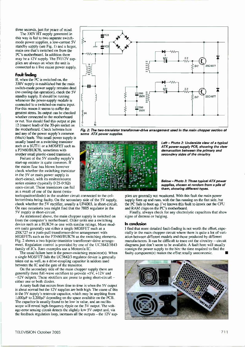
Fig. 2: The two-transistor transformer-drive arrangement used in the main chopper section of some ATX power supplies.
Left - Photo 2: Underside view of a typical ATX power-supply PCB, showing the clear demarcation between the primary and secondary sides of the circuitry.
Below - Photo 3. Three typical ATX power supplies, chosen at random from a pile of them, showing different types.
plies are generally not monitored. With this fault the main power supply fires up and runs, with the fan running on the fast side, but the PC fails to boot up. I've known this fault to knock out the CPU and RAM chips on the PC's motherboard. Finally, always check for any electrolytic capacitors that show
signs of distress or bulging.
In conclusion I find that more detailed fault-finding is not worth the effort, espe-cially in the main chopper circuit where there is quite a lot of vari-ation between different models and those produced by different manufacturers. It can be difficult to trace out the circuitry — circuit diagrams just don't seem to be available. A fault here will usually consign the power supply to the bin: the time required to find the faulty component(s) makes the effort totally uneconomic.
TELEVISION October 2005 7 1 1
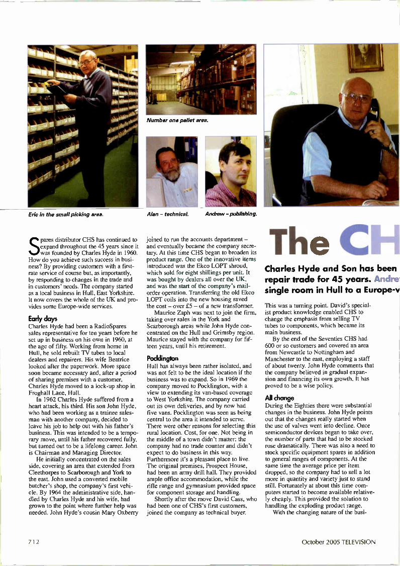
Eric in the small picking area. Alan — technical. Andrew— publishing.
Spares distributor CHS has continued to expand throughout the 45 years since it was founded by Charles Hyde in 1960.
How do you achieve such success in busi-ness? By providing customers with a first-rate service of course but, as importantly, by responding to changes in the trade and in customers' needs. The company started as a local business in Hull, East Yorkshire. It now covers the whole of the UK and pro-vides some Europe-wide services.
Early days Charles Hyde had been a RadioSpares sales representative for ten years before he set up in business on his own in 1960, at the age of fifty. Working from home in Hull, he sold rebuilt TV tubes to local dealers and repairers. His wife Beatrice looked after the paperwork. More space soon became necessary and, after a period of sharing premises with a customer, Charles Hyde moved to a lock-up shop in Froghall Lane, Hull. In 1962 Charles Hyde suffered from a
heart attack, his third. His son John Hyde, who had been working as a trainee sales-man with another company, decided to leave his job to help out with his father's business. This was intended to be a tempo-rary move, until his father recovered fully, but turned out to be a lifelong career. John is Chairman and Managing Director. He initially concentrated on the sales
side, covering an area that extended from Cleethorpes to Scarborough and York to the east. John used a converted mobile butcher's shop, the company's first vehi-cle. By 1964 the administrative side, han-dled by Charles Hyde and his wife, had grown to the point where further help was needed. John Hyde's cousin Mary Oxberry
Number one pallet area.
joined to run the accounts department — and eventually became the company secre-tary. At this time CHS began to broaden its product range. One of the innovative items introduced was the Ekco LOPT shroud, which sold for eight shillings per unit. It was bought by dealers all over the UK, and was the start of the company's mail-order operation. Transferring the old Ekco LOPT coils into the new housing saved the cost — over £.5 — of a new transformer. Maurice Zaph was next to join the firm,
taking over sales in the York and Scarborough areas while John Hyde con-centrated on the Hull and Grimsby region. Maurice stayed with the company for fif-teen years, until his retirement.
Pocklington Hull has always been rather isolated, and was not felt to be the ideal location if the business was to expand. So in 1969 the company moved to Pocklington, with a view to extending its van-based coverage to West Yorkshire. The company carried out its own deliveries, and by now had five vans. Pocklington was seen as being central to the area it intended to serve. There were other reasons for selecting this rural location. Cost, for one. Not being in the middle of a town didn't matter: the company had no trade counter and didn't expect to do business in this way. Furthermore it's a pleasant place to live. The original premises, Prospect House, had been an army drill hall. They provided ample office accommodation, while the rifle range and gymnasium provided space for component storage and handling. Shortly after the move David Cass, who
had been one of CHS's first customers, joined the company as technical buyer.
The CII-1 Charles Hyde and Son has been repair trade for 45 years. unare single room in Hull to a Europe-v
This was a turning point. David's special-ist product knowledge enabled CHS to change the emphasis from selling TV tubes to components, which became its main business. By the end of the Seventies CHS had
600 or so customers and covered an area from Newcastle to Nottingham and Manchester to the east, employing a staff of about twenty. John Hyde comments that the company believed in gradual expan-sion and financing its own growth. It has proved to be a wise policy.
All change During the Eighties there were substantial changes in the business. John Hyde points out that the changes really started when the use of valves went into decline. Once semiconductor devices began to take over, the number of parts that had to be stocked rose dramatically. There was also a need to stock specific equipment spares in addition to general ranges of components. At the same time the average price per item dropped, so the company had to sell a lot more in quantity and variety just to stand still. Fortunately at about this time com-puters started to become available relative-ly cheaply. This provided the solution to handling the exploding product range. With the changing nature of the busi-
712 October 2005 TELEVISION

John and Charles Hyde. Left to right: Derek - company secretary; Dilly - accounts; Eddie and Garry - technical.
Is s to serving the consumer-electronics w Shaw traces its history from a ride operation
ness it became necessary to cover a wider area. This meant switching to an outside carrier and, with the small size of the aver-age order, first-class post could be used for most items. Four of the five vans were dis-pensed with. At about this time Freddie Whipp, who retired a couple of years ago, joined the company. He had worked for Mullard for 17 years and then for a couple of other distributors. Freddie very quickly built up substantial sales in the Midlands. As a result the company decided that it could cover the whole country, and Freddie became National Sales Manager. Coverage now extends from Scotland and the Isle of Man to the Isle of Wight and beyond. At about this time many manufacturers
began to feel that stocking and supplying spare parts would be better dealt with by outside specialists. Sanyo appointed CHS as its partner in the UK in 1989, a close association that continues to the present. CHS subsequently became sole authorised UK spares distributor for a number of brands, and an appointed spares and acces-sories distributor for many of the leading manufacturers. The company stocks exten-sive ranges of spares for other manufactur-ers as well.
More recent times In 1993 Louise Holbrough, granddaughter
From left: Tony- buying; Sue - accounts; Garry - telesales; pre-packing area.
of Charles Hyde, joined the family busi-ness, the first of the third generation to do so. After working in all departments she became a director in 2004. Euras appointed CHS as sole UK part-
ner to promote its faults database in 1995. When Euras closed its UK offices in 2000, CHS was made responsible for handling all customer technical queries in the UK and Ireland. In 1998 CHS became the UK member
of the Aswo European Partnership. This involved a daily delivery of parts for just about every make and model in European CE ranges, plus accessories. Yamaha appointed CHS as sole UK
partner to supply parts to all non-account customers in 2000, and in the following year the company was appointed sole UK distributor for Teac and Tascam spares and accessories. Further franchises were awarded in
2002, when Hitachi appointed CHS to answer its account-holder part-number queries by telephone and fax, and Marantz appointed CHS sole UK distributor for spares and accessories. Teac moved its total spares inventory to CHS, which now distributes Teac spares to all its European Service Agents. In 2003 Sanyo closed its Watford ware-
house and the complete inventory was moved to Pocklington, where CHS is now responsible for the despatch of orders to Sanyo dealers and customers who don't have accounts with Sanyo. In the same year Denon appointed CHS as sole UK partner to handle all out-of-warranty spare-parts orders. That same year CHS enlarged its stock
profile to include computer and digital-camera accessories, and a large range of
wall fixings for LCD and plasma screens was introduced. Denon closed all but three UK spares
accounts in 2004, appointing CHS to look after the rest - including consumers who had not been able to locate a part locally. Also in 2004 CHS moved to 1 Halifax
Way, Pocklington Industrial Estate, giving the company over 30,000 square feet of space. Prospect House continues to be used for some office purposes. Earlier this year Teac France spare parts
distribution closed, all stock now being managed by CHS at Halifax Way. The company is an appointed spares
and accessories distributor for Alba/Bush, Thomson/Ferguson, LG/GoldStar, JVC, Matsui/Saisho, Panasonic, Philips and Sharp. In addition extensive stocks are held for Akai, Nokia, Samsung, Sony and Toshiba TV, video and audio products, and special orders can be met. And of course the company supplies a full range of semi-conductor devices, passive components, LOPTs, remote-control units and so on.
In conclusion Its been a success story indeed - from domestic premises in Hull to a modern, Europe-wide distribution system. You don't achieve this by accident. Meeting customers' needs efficiently, and making it easy to do business, are key elements. Nowadays this is aided by a dedicated CD catalogue and web ordering. The company operates the CHS Part-speed service to make ordering as simple as possible.
4 11 -gr vir
TELEVISION October 2005 713
Adrian Gardiner has been testing several types of lead-free solder and makes various recommendations
Bench Notes Lead-free solder I read with interest Geoff Darby's letter on lead-free solder in the August issue. He points out that there is a distinct lack of knowledge on the subject, and that we are being forced to go lead-free without any real explanation about why. Some setmakers are ordering authorised service agents to do so or lose their franchise. There are plenty of other ways in
which we could have a far greater effect on saving the planet. To add to our prob-lems, a large number of different lead-free solders are available, with different alloy and flux combinations. Although newer products employ lead-free con-struction, most of our repairs involve equipment that was originally made with leaded solder. As Geoff says, there could be problems with mixing these com-pounds. In my last comments on the subject
(Bench Notes, June) I discussed some of the problems when working lead-free, and the type of soldering equipment required. To summarise, you require a temperature-controlled soldering iron with a fast thermal response and recov-ery. It should ideally be fitted with a short tip, to enhance heat transfer to the joint. Where my previous article fell short was on the solder itself. We have been experimenting with
several types of lead-free solder and not-ing their behaviour. Three primary types are listed below, along with their CPC order codes. Lead-free solder requires a higher melting point than the traditional type. In practice I have found that a working temperature of 360°C (10° higher than I would use with leaded sol-der) works well for most applications. I increase this to 410°C when working with large areas of copper, such as the connections to a line output transformer. These temperatures ensure rapid melting of the solder, so that the process can be completed quickly. All three types of solder have the
saine basic composition, 99-7 per cent tin and 0-3 per cent copper. This seems to be the new general standard, with most sol-ders consisting of this mixture. We had
intended testing a silver-mix alloy (96 per cent tin, 4 per cent silver) but it was out of stock at the time of ordering.
Type X39, no-clean flux The first solder has only a tiny flux con-tent (one per cent by weight). The flux is halide-free, zero activation. In use we found that the joints formed look like the original ones in lead-free manufactured products, with the familiar dull appear-ance. The solder has poor wetting char-acteristics, and doesn't flow nicely into a joint. Although the solder is OK when remaking lead-free joints, the results were very poor when mixing into a lead-ed joint — as a result the joint has to be cleaned of old solder before being remade. Overall this solder works all right, but
it's better suited to the latest lead-free equipment. The CPC order code for a 1.2min
250g reel is SD00977.
Type 502 no-clean flux This solder contains a mildly-activated flux (0.2 per cent) with an increased overall content (three per cent by weight). Performance is much the same as the first solder, being OK for lead-free reworking but unsuitable for remaking leaded joints. The wetting is improved, and the solder flows into joints better. But the most significant factor is a nasty smell that's given off in use. So much for health improvements. The fumes are so bad that I would not be able to use this product on a daily basis. Overall I would not recommend this
one. If you wish to try it yourself, the CPC order code is SD00985.
Resin-flux solder This solder contains five cores of halide activated-resin flux. I was surprised by the solder's behaviour in use and had to check that I had in fact ordered a lead-free product. The wetting characteristics are much better than those of the other two varieties tried and it flows easily into the joints. I had no problems when using it to remake lead-free joints but,
more importantly, it mixes well with the leaded solder used in older equipment. The only slight disadvantage is that a cer-tain amount of flux is left after rework. This should ideally be cleaned off. Overall this solder gets 10 out of 10
for ease of use, and we have now switched to the use of this product in our workshop. A 1.2rrun, 500g reel can be ordered using CPC code SD00521.
In general It's worth mentioning that all the solders work well with standard desoldering braid. As mentioned before, there may be
problems when mixing different types of solder. It could be that some of these will be dealt with by a future directive. Until then however we have to proceed on the basis that we are service technicians, not manufacturers. So the thing to do is to choose a solder that you are happy with and that works for you. The resin-flux type is ideal, as you don't have to remove the old solder with products that were made with the leaded type.
What's next? PCs can be very useful, also a total nightmare. Whether you love or hate them however they are here to stay. Next month I begin a new series of arti-cles whose aim will be to help you keep your PC in tip-top condition. The series will also be useful for
those of you who would like to add PC repairs to the services you offer. Most problems that arise are software-related, and getting to grips with them can pro-duce a strong new income stream. I charge an average of £60 for a PC repair and have no shortage of referrals. Unlike the local computer shops, I get to the root of the problem rather than just rein-stalling the operating system. Throughout the series I will welcome
your computer problems, aiming to solve as many as possible in this column. Contact me through the magazine, at the address given on the comment page or email at [email protected]
714 TELEVISION October 2005

tkr
One Stop Shop B-lecei* H B For Your \loges
B B17522
PLASMA & LCD MOUNTS
Kenmark TV StandE The sleek and stylish Kenmark stand range: Are now available from Charles Hyde & Son Ltd
suitable for PLASMA, LCD, CTV & (small Hi-fi systems)
And will support at least 135KG on the top shelf.
Leaflet Available on request.
wwvv.charleshyde.co.uk www.charleshyde.co.uk has been created to give our customers quick and easy access to information about our products. • Secure on-line ordering.
• Fast product search and access.
• Very latest new arrivals.
• On-line special offers.
FIX YOUR REPAIR WHILE OTHERS STILL SEARCH FOR THE FAULT
EURAS is a modular based database system Within its internet community it supports the professional CE service technician with invaluable service information on a daily basis You and ycur workshop can profit from the knowledge of manufacturers specialists and thousands of colleagues
THE PROBLEM: Many repairs are not considered worthwhile because too much time is spent searching for the necessary service information (service manual documents diagrams etc) Due to the increasing number of appliances - n particular no name appliances - the necessary information is often not available or needs to be ordered Consequently Labour costs increase whilst new appliance prices decrease
THE SOLUTION: Shorten your repair time! Save time and money searching for impoli I information' The EURAS Internet system offers quick ai 1 access to important information 24 hours a day. 365 days a year Make use of the wealth of expertise at your
one 0870 990 9474
www.euras.com
—
1111111111111/ 41«1111 .11M .
45 YEARS IN THE CONSUMER ELECTRONICS
SPARES BUSINESS & STILL INDEPENDENT
OWNED
Charles Hyde & Son Ltd Prospect House 1 Halifax Way
Pocklington Industrial Estate Pocklington York Y042-1NR
Telephone: Sales: 0870 990 9474
i.;
TELEVISION October 2005 715
The days of
net TV It's twenty years since the last 405-line TV transmitter was switched off. But it was the
405-line system that got TV as we know it going. Keith Hamer and Garry Smith recount the story, from the start of the service in November 1936 to the January 1985 closedown
Amilestone in the history of British TV broadcasting was reached in January 1985 when the remaining
transmitters of the 405-line network, which had used Channels 1-13 in Bands I and HI, were finally switched off. When it com-menced in 1936, the 405-line BBC service was hailed as "the World's first regular public high-definition television service". That phrasing was careful: there had been transmissions in the US, Germany and elsewhere, but no regular public service. And 405 lines were high-definition in com-parison to previous systems. With the small CRTs then in use, they were more than adequate. The 405-line network continued to expand, particularly in Band III, even when UHF began to be used on a regular basis, at first for BBC-2 in 1964. In its heyday the 405-line network consisted of 157 transmitters, 99 of which used Band I frequencies.
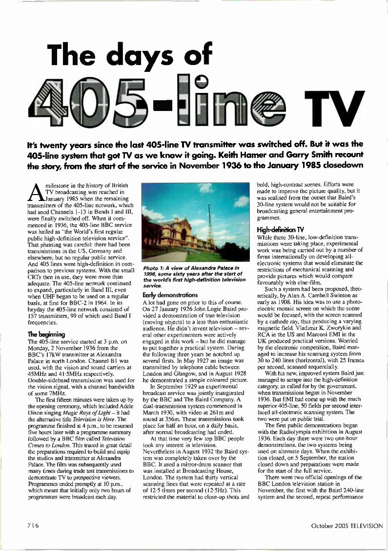
The beginning The 405-line service started at 3 p.m. on Monday, 2 November 1936 from the BBC's 17kW transmitter at Alexandra Palace in north London. Channel B1 was used, with the vision and sound carriers at 45MHz and 41-5MHz respectively. Double-sideband transmission was used for the vision signal, with a channel bandwidth of some 7MHz. The first fifteen minutes were taken up by
the opening ceremony, which included Adele Dixon singing Magic Rays of Light — it had the alternative title Television is Here. The programme finished at 4 p.m., to be resumed five hours later with a programme summary followed by a BBC film called Television Comes to London. This traced in great detail the preparations required to build and equip the studios and transmitter at Alexandra Palace. The film was subsequently used many times during trade test transmissions to demonstrate TV to prospective viewers. Programmes ended promptly at 10 p.m., which meant that initially only two hours of programmes were broadcast each day.
Photo 1: A view of Alexandra Palace in 1996, some sixty years after the start of the world's first high-definition television service
Early demonstrations A lot had gone on prior to this of course. On 27 January 1926 John Logic Baird pro-vided a demonstration of true television (moving objects) to a less than enthusiastic audience. He didn't invent television — sev-eral other experimenters were actively engaged in this work — but he did manage to put together a practical system. During the following three years he notched up several firsts. In May 1927 an image was transmitted by telephone cable between London and Glasgow, and in August 1928 he demonstrated a simple coloured picture. In September 1929 an experimental
broadcast service was jointly inaugurated by the BBC and The Baird Company. A dual-transmission system commenced in March 1930, with video at 261m and sound at 356m. These transmissions took place for half an hour, on a daily basis, after normal broadcasting had ended. At that time very few top BBC people
took any interest in television. Nevertheless in August 1932 the Baird sys-tem was completely taken over by the BBC. It used a mirror-drum scanner that was installed at Broadcasting House, London. The system had thirty vertical scanning lines that were repeated at a rate of 12-5 times per second (12-5Hz). This restricted the material to close-up shots and
bold, high-contrast scenes. Efforts were made to improve the picture quality, but it was realised from the outset that Baird's 30-line system would not be suitable for broadcasting general entertainment pro-grammes.
High-definition TV While these 30-line, low-definition trans-missions were taking place, experimental work was being carried out by a number of firms internationally on developing all-electronic systems that would eliminate the restrictions of mechanical scanning and provide pictures which would compare favourably with cine-film. Such a system had been proposed, theo-
retically, by Alan A. Cambell Swinton as early as 1908. His idea was to use a photo-electric mosaic screen on which the scene would be focused, with the screen scanned by a cathode ray, thus producing a varying magnetic field. Vladimir K. Zworykin and RCA in the US and Marconi EMI in the UK produced practical versions. Worried by the electronic competition, Baird man-aged to increase his scanning system from 30 to 244) lines (horizontal), with 25 frames per second, scanned sequentially. With his new, improved system Baird just
managed to scrape into the high-definition category, as called for by the government, when transmissions began in November 1936. But EMI had come up with the much superior 405-line, 50 fields per second inter-laced all-electronic scanning system. The two were put on public trial. The first public demonstrations began
with the Radiolympia exhibition in August 1936. Each day there were two one-hour demonstrations, the two systems being used on alternate days. When the exhibi-tion closed, on 5 September, the station closed down and preparations were made for the start of the full service. There were two official openings of the
BBC London television station in November, the first with the Baird 240-line system and the second, repeat performance
716 October 2005 TELEVISION

with the EMI 405-line standard. Both con-tinued from Monday to Saturday on an alternate-week basis, so that the two could be given a fair assessment. It wasn't too long before the government decided that Baird should pack away his Nipkow discs. The 405-line system had won the day, and took over sole operation from 8 February 1937. The popularity of the service was given
a boost when the BBC screened the first major outside broadcast in May 1937, the coronation of King George VI. Some 23,000 receivers are estimated to have been in use by September 1939, when the Alexandra Palace transmitter was closed down for the war years. The service reopened in 1946, with the Victory Parade screened on 8 June.
Spread of TV Television subsequently spread throughout the UK, with a transmitter at Sutton Coldfield being opened in 1949 to serve Birmingham and the Midlands, followed by Holme Moss in 1951 to serve Lancashire and Yorkshire then Kirk O'Shotts and Wenvoe in 1952 to serve parts of Scotland and Wales. It was clear from the start of post-War TV that spectrum space limitations would require a more eco-nomical system than Alexandra Palace's double-sideband transmission. Vestigial sideband transmission was therefore adopt-ed, with one sideband transmitted in full and the other as a vestige' extending to about 0.75MHz. The original London transmitter at Alexandra Palace was closed down in March 1956. It was replaced by a 200kW transmitter at Crystal Palace, providing much greater coverage into the Home Counties. As with the other post-war trans-mitters, it used vestigial-sideband transmis-sion.
nels, in particular areas
Commercial IV The first commercial TV station opened on 22 September 1955, with a transmitter at Croydon to serve the London area. Its ERP was 120kW. This marked the start of TV in Band III. The service was provided by Rediffusion, identified by a twirling star logo that cut in between the advertise-ments. It was greeted with a lukewarm response in some quarters, and some thought it wouldn't last a year. As with the BBC services, ITV soon spread to the main centres of population across the UK — with its own transmitter network. Many of the programmes, particularly
the quiz shows such as Take Your Pick, Criss Cross Quiz and Double Your Money, were based on tried and tested US formats. But the ITV companies were taking a gam-ble as to whether the new alternative types of programmes they were offering would prove popular. In fact they were a huge
Photo 2 - left: The Associated Rediffusion Monday-Friday !TA London test card.
Photo 3 - above: The Associated Rediffusion clock.
Photo 4 - below: Holme Moss transmitter
success, and the adverts proved popular as well. Many of the jingles are still fresh in the minds of those who were around at the time. And there were those TV chimps, brewing their favourite pot of tea. There were no domestic
video recorders in those days, but one advantage of the regional ITV service was that programmes were often broadcast at different times or on different days. Thus viewers in overlap areas could take advantage of this, watching their favourite game show on a different day or time by tuning to another channel. Multi-chan-nel programming via cable systems also proved popular, with up to three ITV regions on offer in some areas.
Foreign interference Lots of Continental TV sta-tions entered service in the early Sixties. Many used Band I channels, with a 625-line signal. Summer signalled not only the start of Wimbledon coverage but strange, white sloping lines accompa-nied by rasping buzzes that drowned out the sound channel. The effect was described, during apology announcements, as Continental interference'. It was caused by propagation anomalies within the upper atmospheric layers. Apart from sit it out and be patient, there was little that the viewer could do. The interference affected Band I chan-
served by a channel B2 transmitter as the sound car-rier frequency was the same as the European channel E2 (48.25MHz) — hence the severe buzzing! To alleviate the hardship,
the BBC decided to improve coverage in some of these areas. Several Band HI trans-mitters were installed at sites owned by the ITV network. Thus several transmitters carried BBC-1 in addition to the ITV service, enabling a single wideband Band III aerial to be used. To supplement and
improve the Holme Moss transmitter's coverage, which extended well into North Wales, the North West and Lincolnshire and across the Midlands, co-sited out-lets were installed at Moel-y-Parc (ch. B6, 21kW), Sandale (ch. B6, 28kW), Winter Hill (ch. B12,
125kW) and Belmont (ch. B13, 20kW). To improve reception in the South West, served by North Hessary Tor (ch. B2), Caradon Hill (ch. B12, 200kW) and Wenvoe (ch. B13, 200kW) were added.
av in South Wales Viewers in South Wales could receive two ITV channels, Harlech Welsh and English, which were transmitted from the St. Hilary mast on channels B7 (100kW) and BIO (200kW) respectively. This provision of two services from the same mast was something
TELEVISION October 2005 71 7
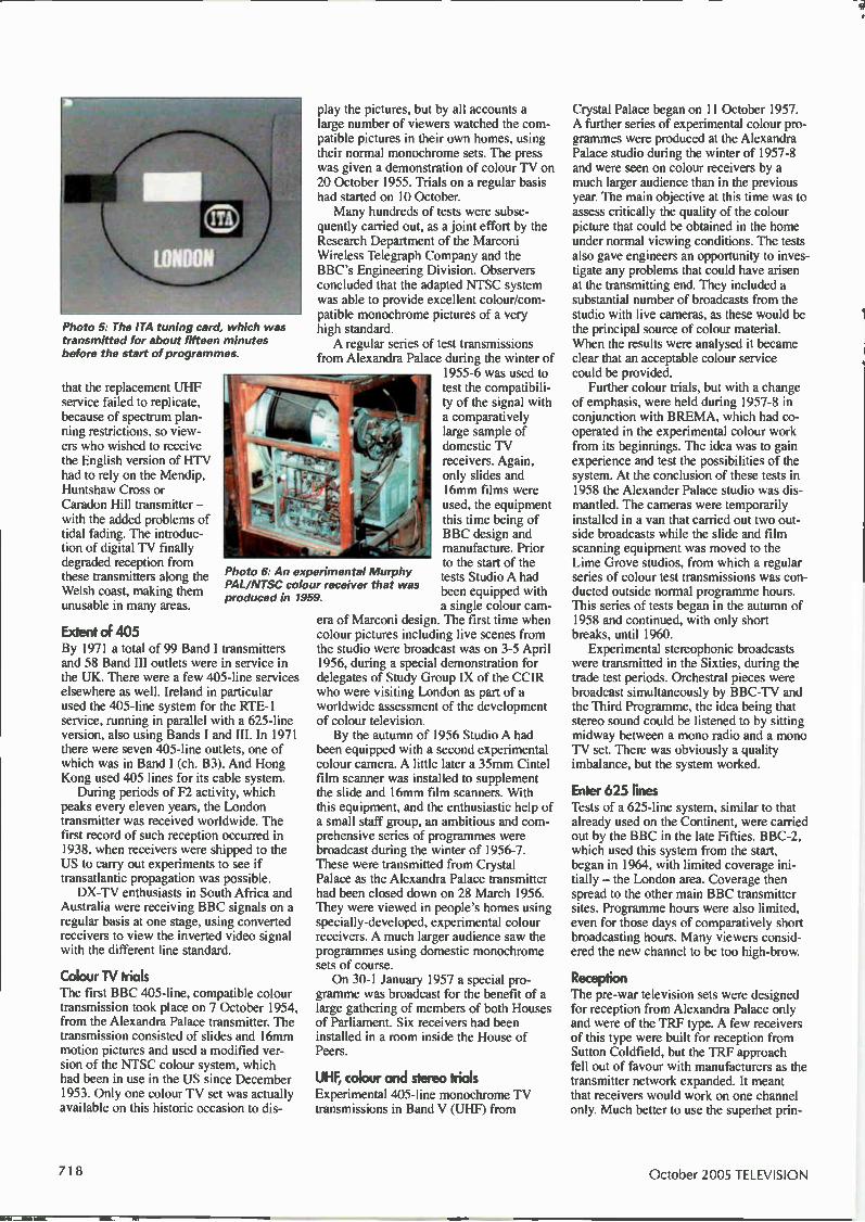
Photo 5: The ITA tuning card, which was transmitted for about fifteen minutes before the start of programmes.
that the replacement UHF service failed to replicate, because of spectrum plan-ning restrictions, so view-ers who wished to receive the English version of HTV had to rely on the Mendip, Huntshaw Cross or Caradon Hill transmitter — with the added problems of tidal fading. The introduc-tion of digital TV finally degraded reception from these transmitters along the Welsh coast, making them unusable in many areas.
Extent of 405 By 1971 a total of 99 Band I transmitters and 58 Band III outlets were in service in the UK. There were a few 405-line services elsewhere as well. Ireland in particular used the 405-line system for the RTE-1 service, running in parallel with a 625-line version, also using Bands I and III. In 1971 there were seven 405-line outlets, one of which was in Band I (ch. B3). And Hong Kong used 405 lines for its cable system. During periods of F2 activity, which
peaks every eleven years, the London transmitter was received worldwide. The first record of such reception occurred in 1938, when receivers were shipped to the US to carry out experiments to see if transatlantic propagation was possible. DX-TV enthusiasts in South Africa and
Australia were receiving BBC signals on a regular basis at one stage, using converted receivers to view the inverted video signal with the different line standard.
Photo 6: An experimental Murphy PAL/NTSC colour receiver that was produced in 1959.
ColouriV trials The first BBC 405-line, compatible colour transmission took place on 7 October 1954, from the Alexandra Palace transmitter. The transmission consisted of slides and 16mm motion pictures and used a modified ver-sion of the NTSC colour system, which had been in use in the US since December 1953. Only one colour TV set was actually available on this historic occasion to dis-
play the pictures, but by all accounts a large number of viewers watched the com-patible pictures in their own homes, using their normal monochrome sets. The press was given a demonstration of colour TV on 20 October 1955. Trials on a regular basis had started on 10 October. Many hundreds of tests were subse-
quently carried out, as a joint effort by the Research Department of the Marconi Wifeless Telegraph Company and the BBC's Engineering Division. Observers concluded that the adapted NTSC system was able to provide excellent colour/com-patible monochrome pictures of a very high standard. A regular series of test transmissions
from Alexandra Palace during the winter of 1955-6 was used to test the compatibili-ty of the signal with a comparatively large sample of domestic TV receivers. Again, only slides and 16mm films were used, the equipment this time being of BBC design and manufacture. Prior to the start of the tests Studio A had been equipped with a single colour cam-
era of Marconi design. The first time when colour pictures including live scenes from the studio were broadcast was on 3-5 April 1956, during a special demonstration for delegates of Study Group IX of the CCIR who were visiting London as part of a worldwide assessment of the development of colour television. By the autumn of 1956 Studio A had
been equipped with a second experimental colour camera. A little later a 35ifun Cintel film scanner was installed to supplement the slide and 16mm film scanners. With this equipment, and the enthusiastic help of a small staff group, an ambitious and com-prehensive series of programmes were broadcast during the winter of 1956-7. These were transmitted from Crystal Palace as the Alexandra Palace transmitter had been closed down on 28 March 1956. They were viewed in people's homes using specially-developed, experimental colour receivers. A much larger audience saw the programmes using domestic monochrome sets of course. On 30-1 January 1957 a special pro-
gramme was broadcast for the benefit of a large gathering of members of both Houses of Parliament. Six receivers had been installed in a room inside the House of Peers.
UHF, colour and stereo trials Experimental 405-line monochrome TV transmissions in Band V (UHF) from
Crystal Palace began on 11 October 1957. A further series of experimental colour pro-grammes were produced at the Alexandra Palace studio during the winter of 1957-8 and were seen on colour receivers by a much larger audience than in the previous year. The main objective at this time was to assess critically the quality of the colour picture that could be obtained in the home under normal viewing conditions. The tests also gave engineers an opportunity to inves-tigate any problems that could have arisen at the transmitting end. They included a substantial number of broadcasts from the studio with live cameras, as these would be the principal source of colour material. When the results were analysed it became clear that an acceptable colour service could be provided. Further colour trials, but with a change
of emphasis, were held during 1957-8 in conjunction with BREMA, which had co-operated in the experimental colour work from its beginnings. The idea was to gain experience and test the possibilities of the system. At the conclusion of these tests in 1958 the Alexander Palace studio was dis-mantled. The cameras were temporarily installed in a van that carried out two out-side broadcasts while the slide and film scanning equipment was moved to the Lime Grove studios, from which a regular series of colour test transmissions was con-ducted outside normal programme hours. This series of tests began in the autumn of 1958 and continued, with only short breaks, until 1960. Experimental stereophonic broadcasts
were transmitted in the Sixties, during the trade test periods. Orchestral pieces were broadcast simultaneously by BBC-TV and the Third Programme, the idea being that stereo sound could be listened to by sitting midway between a mono radio and a mono TV set. There was obviously a quality imbalance, but the system worked.
Enter 625 lines Tests of a 625-line system, similar to that already used on the Continent, were carried out by the BBC in the late Fifties. BBC-2, which used this system from the start, began in 1964, with limited coverage ini-tially — the London area. Coverage then spread to the other main BBC transmitter sites. Programme hours were also limited, even for those days of comparatively short broadcasting hours. Many viewers consid-ered the new channel to be too high-brow.
RecePO W The pre-war television sets were designed for reception from Alexandra Palace only and were of the TRF type. A few receivers of this type were built for reception from Sutton Coldfield, but the TRF approach fell out of favour with manufacturers as the transmitter network expanded. It meant that receivers would work on one channel only. Much better to use the superhet prin-
71 8 October 2005 TELEVISION
ciple, which enabled receivers to tune in to different transmitters. Another feature of the early days, with
only Alexandra Palace in operation, was that some viewers well outside the service area were so desperate to receive the signal that they erected huge aerial systems and had to put up with the constantly changing atmospherics. Some people were able to achieve reception at up to 200 miles from Alexandra Palace. Early tuneable receivers covered the
Band I channels B1-5 only. When ITV start-ed up in 1955, Band III was brought into use and add-on converters were introduced for use with 'BBC-only' receivers. They were produced in large quantities to provide for the demand for the new service. Before long new sets equipped with
turret tuners began to appear. The tuners had clip-in tuning coils, wound according to channel, and could be clicked around sequentially through channels 1-12. Early tuners had Band III coils fitted for chan-nels 8-10 only, as these were the only ones used initially. In the Sixties some turret-tuner dials were marked with adjacent numbers corresponding to the BBC and ITV channels in a particular region. By arranging the coils carefully, the viewer could switch between ITV and BBC with-out having to clunk the knob from say channel 1 round to 9. Some Philips sets had a motorised tuner to save the viewer the inconvenience of having the turn the knob manually. Push-button tuning became popular with many setmakers in the Sixties
Dual-standard sets With the introduction of BBC-2, setmakers had to produce 405/625 dual-standard receivers. This involved a system switch, a long mechanical assembly to alter IF response, the video polarity, the sound sys-tem and the line timebase frequency. They were notoriously unreliable in operation. Some receivers were classified as 'convert-ible', which usually meant that an addition-al IF strip and tuner had to be fitted for UHF. One local TV rental company proud-ly boasted about an 81-channel TV in its advertisements, even though only three programmes were available at the time! Many of the very earliest sets were
also dual-standard of course — 240/405. There seems to be little information on how this operated.
Aerials Band I aerials were massive affairs com-pared with today's compact UHF arrays. A London-area H aerial had elements that were about 1 1 ft. long. Huge arrays with four or five elements were used for fringe-area reception — some of these still survive today. Band III reception meant much smaller aerials, similar in size to the new DAB type. Some aerials had as many as eleven elements.
Combined Band I/III arrays became popular. A Band I dipole sandwiched between shorter elements resonated in both bands, thus avoiding the complication of a second downlead or diplexer. They were mainly used in primary service areas. When BBC-2 started one particular
aerial, golden anodised, had a multi-ele-ment horizontal UHF array with vertical Band III rods and a Band I dipole all shar-ing the same boom.
Colour arrives Colour TV started in late 1967, BBC-2 only at first, using the PAL instead of the NTSC system. There had been quite a bat-tle over which system to use (PAL, NTSC, the French SECAM and some variants). The first sets were relatively expensive and complex, bulky items with their innards hidden inside a massive wooden cabinet. Dual-standard operation was necessary, as only BBC-2 was avail-able in colour. The sets were power-hun-gry: some of the valve models would warm up the room on a cold winter's day. At one stage it was cheaper to buy a mini-van than a colour TV set. On 15 November 1969 BBC-1 and
ITV started to transmit with colour — the services were duplicated at UHF with 625 lines. This signalled the beginning of the end for the 405-line system. Setmakers were not slow to introduce new, single-standard chassis. The simpler receivers had improved efficiency, performance and reliability (though some simply had the 405-line components removed). Dual-standard monochrome sets contin-
ued to be produced, but in our area were available only until about 1971. With colour TV now firmly established, there was little demand for 405-line capable sets.
Final days The final closure of the 405-line system followed an announcement by the Home Secretary in 1983 that the frequencies used should be released for mobile radio communication. Band III radio was even-tually introduced, using bands of multi-plexes. There are guard bands between the multiplexes to reduce the impact of inter-ference on TV reception overseas during tropospheric lifts. The closedown of the last 405-line
transmitter, at Melvaig in West Scotland, was carried out by the local transmitter manager Syd Garrioch. Closedown of the network had been a staggered process, with Melvaig being switched off in early January 1985. At one stage it was estimat-ed that only about half a dozen viewers in Wales continued to use the old system. Towards the end, many transmitters limped gracefully towards retirement on reduced power. Because of the minimal use, hum bars and other defects went unnoticed and unreported. With its switch-off only days away, the
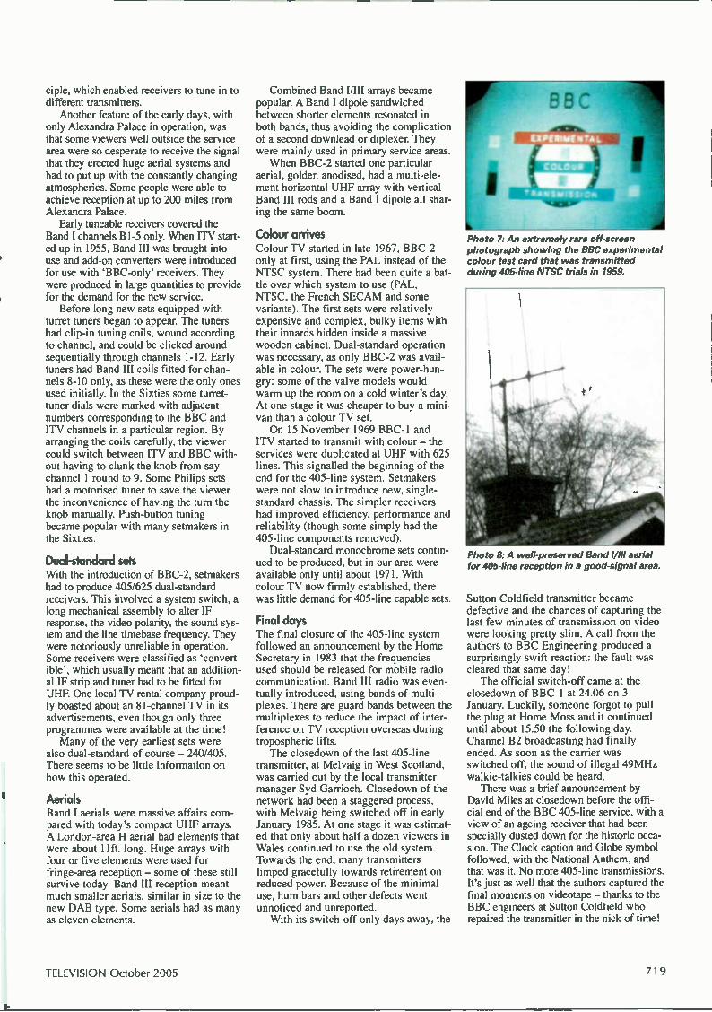
Photo 7. An extremely rare off-screen photograph showing the BBC experimental colour test card that was transmitted during 405-line NTSC trials in 1959.
Photo 8: A well-preserved Band I/III aerial for 405-line reception in a good-signal area.
Sutton Coldfield transmitter became defective and the chances of capturing the last few minutes of transmission on video were looking pretty slim. A call from the authors to BBC Engineering produced a surprisingly swift reaction: the fault was cleared that same day! The official switch-off came at the
closedown of BBC-1 at 24.06 on 3 January. Luckily, someone forgot to pull the plug at Home Moss and it continued until about 15.50 the following day. Channel B2 broadcasting had finally ended. As soon as the carrier was switched off, the sound of illegal 49MHz walkie-talkies could be heard. There was a brief announcement by
David Miles at closedown before the offi-cial end of the BBC 405-line service, with a view of an ageing receiver that had been specially dusted down for the historic occa-sion. The Clock caption and Globe symbol followed, with the National Anthem, and that was it. No more 405-line transmissions. It's just as well that the authors captured the final moments on videotape — thanks to the BBC engineers at Sutton Coldfield who repaired the transmitter in the nick of time!
TELEVISION October 2005 719
Plasma display Having described the operation of plasma TV
sets in previous instalments in this series,
Fawzi Ibrahim concentrates this time on fault-
finding, beginning with a description of the
start-up process
W hen considering faults, their symptoms and fault-find-ing techniques with plasma TV sets, it's important to understand the sequence of events following a cold
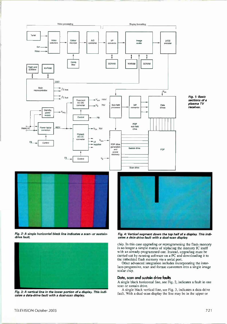
switch-on. Fig 1 shows the main sections of a plasma TV set able to receive analogue terrestrial broadcasts. The audio section is not shown, as it is relatively independent once stereophonic audio has been extracted following demodulation in the tuner. Most modern plasma sets also incorporate a DVB decoder cir-cuit for receiving and decoding digital terrestrial TV broadcasts, commonly known as Freeview.
Start-up sequence
DC power builds up in three distinct stages when the set is switched on: first, in the power-factor correction (PFC) circuit; next in the flyback DC-DC converter; and then in the resonant DC-DC converter. The PFC control system has to generate the pulse-width modulated (PWM) drive required to produce a pre-regulated 400V output. This is used by the flyback DC-DC con-verter to generate the V DA (data drive) supply and the voltages for the signal processing and control sections of the receiver. including the audio section. The 400V supply is also fed to the resonant DC-DC converter, which produces the supplies required to generate the plasma display panel's sustain and scan waveforms.
technology The microcontroller system A separate standby supply provides an output to power the main microcontroller system etc. Build up of DC power is followed by the microcontroller
start-up routine. First, the microcontroller chip downloads the start-up program from the flash memory chip and passes it to the SDRAM chip so that the start-up routine can begin. If the flash memory is faulty or the program is corrupted, the process will be halted and the set will remain in standby. The microcon-troller chip also examines the contents of the non-volatile RAM (NVRAM) to check for individual and other specified settings for incorporation in the start-up routine. The microcontroller's start-up routine involves checking and
initialising all programmable and processing chips to be ready to receive and decode the vi«o and audio information. This process is carried out via an IzC enter IC) serial control bus. More than one of these is used. IzC is a two-line serial control bus, with one line for clock pulses and the other for the control data.
Increased integration As a result of increasing integration, some of the separate blocks shown in Fig. 1 may be incorporated into single chips, as mentioned in Part 3 (August). The flash memory and NVRAM may for example be imbedded in a massive microcontroller
720 October 2005 TELEVISION
Video processing
Tru er
Ext
Video - -e.
Flash and SDRAM
Video selection
NVRAM
Main microcontroller
OSD
Colour decoder
Comb filter
A/D converter converter
SDRAM
Display formatting
Image scalar
NVRAM
Mains AC
I C bus
I2C bus - •.
Standby H power Vstiby
supply
Power-factor correction
Control
400V
FB
4111.
Resonant DC-DC converter
Control
Flyback DC-DC converter
Control
_ ..V.s 195V
75V
FB
VDA 70V
LT supplies
Fig. 2: A single horizontal black line indicates a scan- or sustain-drive fault.
Fig. 3: A vertical line in the lower portion of a display. This indi-cates a data-drive fault with a dual-scan display.
SD RAM
LVDS encoder
Sub-field processor
PDP drive generation and power recovery
S/P converter
PDP sub-field drive
Sustain drive
Scan drive
Data drives
PDP
Fig. 1: Basic sections of a plasma TV receiver.
Fig. 4: Vertical segment down the top half of a display. This indi-cates a data-drive fault with a dual-scan display.
chip. In this case upgrading or reprogramming the flash memory is no longer a simple matter of replacing the memory IC itself with an already-programmed one. Instead, upgrading must be carried out by running software on a PC and downloading it to the imbedded flash memory via a serial port. Other advanced integration includes incorporating the inter-
lace-progressive, scan and format converters into a single image scalar chip.
Data, scan and sustain drive faults A single black horizontal line, see Fig. 2, indicates a fault in one scan or sustain drive. A single black vertical line, see Fig. 3, indicates a data-drive
fault. With a dual-scan display the line may be in the upper or
TELEVISION October 2005 721

Fig. 5: (left) Central area pixel failure. Fig. 6: (centre) Several pixel defects. Fig. 7: (right) Pixel cluster failure.
Fig. 8: Effect of a scan-converter memory fault (address line short-circuit to OV).
Fig. 9: Effect with one colour bit (RO) missing.
Fig. 10: Effect when one LVDS encoder data line is short-circuit to OV.
lower portion. The latter is shown here. A black vertical band, see Fig. 4, indicates failure of a group
of data-drive lines, corresponding to where the band is on the screen. A black horizontal band indicates either scan-or sustain-drive
failure. Check the sustain-pulse waveforms, line by line, at the drive outputs corresponding to the position of the band to ascertain whether there is a sustain fault. Repeat for the scan waveforms if necessary. With all the above conditions the fault could be in the display
panel itself, in which case the panel will have to be replaced.
Pixel defeds There may be a single pixel failure, see Fig. 5, a several-pixel failure, see Fig. 6, or a pixel-cluster failure, see Fig. 7. They all mean a fault in the panel itself. Manufacturers regard a small number of pixel faults, split between the central and outer areas, as being within specification. Any excess means that the panel is a write-off.
Picture faults This includes no picture or a broken picture and/or multiple images and/or colour distortion. The classic no-picture condition is when the set is stuck in standby. In this case there will be no sound either, which generally but not exclusively points to a power supply fault. See later. No picture with normal sound suggests a video or a display-
formatting fault; a sustain, scan or data-drive fault; or a fault in the power supply or the panel itself. Press 'menu' or another option for an on-screen display (OSD). If this appears on the screen the fault precedes the image-scalar section. If the OSD does not appear, the fault may lie in the image scalar, the LVDS-encoder chip and connector, the scan/sustain/data drives, the power supply or the plasma panel itself. Check the image-scalar chip's inputs and outputs, the LVDS encoder chip's data and clock lines, the sustain- and scan-drive waveforms and the power supply. A fatal fault in one of the processing chips, such as the colour
decoder, image scalar, LVDS encoder or sub-field processor, will normally result in no picture with the sound OK. A fatal memo-ry-chip fault (flash, NVRAM, SDRAM) in the control system will result in no picture and no sound with the set normally stuck in standby. Similarly the absence of clock signals, control signals such as enable or chip-select, and signals on the I2C bus lines will result in no picture or stuck in standby. A partial fault however, such as a dry-joint at a memory or
processing chip, a data or address line stuck at zero or one, or a loose connection will result in picture break up and/or multiple images and/or colour distortion. Figs. 8-11 show typical symp-toms with non-fatal faults. Figs. 12-14 illustrate the different type of symptom that occurs when there's a dry-joint at the sub-field processor chip.
The classic stuck in standby fault A fault in the power supply, the microcontroller system or even the video or formatting section will lead to the set reverting to standby — because of the extensive feedback protection employed in PDP sets. Once the set has reverted to standby, with all other power turned off and all control and signal processing halted, it's difficult to find the actual cause of the fault. Checks during the start-up sequence, between switch on and the set reverting to standby, may however provide important clues as to the location of the fault. The exact start-up process differs from one model to another.
They all follow a basic sequence however, as previously out-lined. The following is a series of checks to be carried out immediately after a cold switch-on, before the set goes into standby. They involve switching the set off then on to carry out each test. Start by switching the power on.
October 2005 TELEVISION
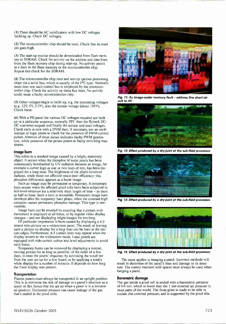
(1) There should be AC rectification with low DC voltages building up. Check DC voltages.
(2) The microcontroller chip should be reset. Check that its reset pin goes high.
(3) The start-up routine should be downloaded from flash mem-ory to SDRAM. Check for activity on the address and data lines from the flash memory chip during start-up. No activity points to a fault in the flash memory or the microcontroller chip. Repeat this check for the SDRAM.
(4) The microcontroller chip tests and sets up various processing chips via a serial bus, which is usually of the I2C type. Normally more than one such control bus is employed by the microcon-troller chip. Check for activity on these bus lines. No activity could mean a faulty microcontroller chip.
(5) Other voltages begin to build up, e.g. the processing voltages (e.g. 12V, 5V, 3.3V), also the sustain voltage (about 195V). Check these.
(6) With a PD panel the various DC voltages required are built up in a particular sequence, normally PFC then the flyback DC-DC converter outputs and finally the sustain and scan voltages. Check each in turn with a DVM then, if necessary, use an oscil-loscope or logic probe to check for the presence of PWM control pulses. Absence of these pulses indicates faulty PWM genera-tion, while presence of the pulses points to faulty switching tran-sistors.
Image burn This refers to a residual image caused by a bright, stationary object. It occurs when the phosphor of some pixels has been continuously bombarded by UV radiation because an image, for example a corner logo or one or two lines of text, has been dis-played for a long time. The brightness of the pixels involved darkens, while those not affected retain their efficiency: this phosphor differential appears as a burnt image. Such an image may be permanent or temporary. A temporary
burn occurs when the affected pixel cells have been subjected to full-level emission for a relatively short length of time — as short as half an hour. Such a burn is reversible. Permanent image burn develops after the temporary burn phase, when the constant high emission causes permanent phosphor damage. This type is irre-versible. Image burn can be avoided by ensuring that a picture with
movement is displayed at all times, or by regular video display changes — and not displaying bright images for too long. Of particular importance is burn caused by displaying a 4:3
aspect ratio picture on a widescreen panel. The result of leaving such a picture on display for a long time can be burn at the pic-ture edges. Furthermore, 4:3 curtain lines may appear when the display reverts to the widescreen mode. Later panels are equipped with side-curtain colour and level adjustments to avoid such burns. Temporary bums can be removed by displaying a normal,
moving picture for as long as possible, of the order of a few days, to reset the pixels' response; by activating the scroll bar from the user set-up for a few hours; or by applying a totally white display for a number of minutes. It depends on how long the fixed display was present.
Transportah•on Plasma panels must always be transported in an upright position. This is to minimise the risk of damage to a panel's structure as a result of flex forces that are set up when a panel is in a horizon-tal position. Horizontal pressure can cause leakage of the gas that's sealed in the pixel cells.
Fig. 11: An image-scalar memory fault - address line short-cir-cuit to OV
Fig. 12: Effect produced by a dry-joint at the sub-field processor.
Fig. 13: Effect produced by a dry-joint at the sub-field processor.
Fig. 14. Effect produced by a dry-joint at the sub-field processor.
The same applies to hanging a panel. Incorrect methods will result in distortion of the panel's base and damage to its struc-ture. The correct brackets with spacer must always be used when hanging a panel.
Barometric damage The gas inside a pixel cell is sealed with a barometric pressure of 0.6 torr, which is lower than the 1 torr external air pressure in most parts of the world. The front glass is made to be able to sustain this external pressure, and is supported by the pixel ribs.
TELEVISION October 2005 723
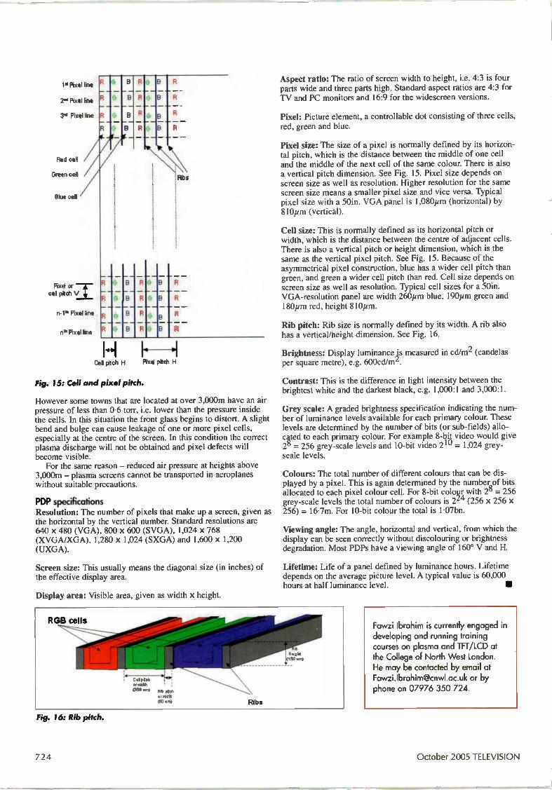
••• ' .1»
le Pixel line
2"' Pixel line
3'1 Pixel line
Red cell
Green cell
Blue cell /
Pixel or cel pitch a
n-1". Pixel line
ni" Pixel line
B R
B
e b—
k B R
F4bs
B R
R B
R
R B
R
R
B R
B R
Cell pitch H Pixel pitch H
Fig. 15: Cell and pixel pitch.
However some towns that are located at over 3,000m have an air pressure of less than 0.6 torr, i.e. lower than the pressure inside the cells. In this situation the front glass begins to distort. A slight bend and bulge can cause leakage of one or more pixel cells, especially at the centre of the screen. In this condition the correct plasma discharge will not be obtained and pixel defects will become visible. For the same reason — reduced air pressure at heights above
3,000m — plasma screens cannot be transported in aeroplanes without suitable precautions.
PDP specifications Resolution: I he number of pixels that make up a screen, given as the horizontal by the vertical number. Standard resolutions are 640 x 480 (VGA), 800 x 600 (SVGA), 1,024 x 768 (XVGA/XGA), 1,280 x 1,024 (SXGA) and 1,600 x 1,200 (UXGA).
Screen size: This usually means the diagonal size (in inches) of the effective display area.
Display area: Visible area, given as width x height.
Ribs
Aspect ratio: The ratio of screen width to height, i.e. 4:3 is four parts wide and three parts high. Standard aspect ratios are 4:3 for TV and PC monitors and 16:9 for the widescreen versions.
Pixel: Picture element, a controllable dot consisting of three cells, red, green and blue.
Pixel size: The size of a pixel is normally defined by its horizon-tal pitch, which is the distance between the middle of one cell and the middle of the next cell of the same colour. There is also a vertical pitch dimension. See Fig. 15. Pixel size depends on screen size as well as resolution. Higher resolution for the same screen size means a smaller pixel size and vice versa. Typical pixel size with a 50in. VGA panel is 1,080pm (horizontal) by 810pm (vertical).
Cell size: This is normally defined as its horizontal pitch or width, which is the distance between the centre of adjacent cells. There is also a vertical pitch or height dimension, which is the same as the vertical pixel pitch. See Fig. 15. Because of the asymmetrical pixel construction, blue has a wider cell pitch than green, and green a wider cell pitch than red. Cell size depends on screen size as well as resolution. Typical cell sizes for a 50M. VGA-resolution panel are width 260pm blue, 1904m green and 180pm red, height 810 m.
Rib pitch: Rib size is normally defined by its width. A rib also has a vertical/height dimension. See Fig. 16.
Brightness: Display luminance ,is measured in cd/m2 (candelas per square metre), e.g. 600cd/mL.
Contrast: This is the difference in light intensity between the brightest white and the darkest black, e.g. 1,000:1 and 3,000:1.
Grey scale: A graded brightness specification indicating the num-ber of luminance levels available for each primary colour. These levels are determined by the number of bits (or sub-fields) allo-ceed to each primary colour. For example 8-1:4t video would give = 256 grey-scale levels and 10-bit video 211/ = 1,024 grey-
scale levels.
Colours: The total number of different colours that can be dis-played by a pixel. This is again determined by the number of bits allocated to each pixel colour cell. For 8-bit coke with 28 = 256 grey-scale levels the total number of colours is 2z4 (256 x 256 x 256) = 16-7m. For 10-bit colour the total is 1.07bn.
Viewing angle: The angle, horizontal and vertical, from which the display can be seen correctly without discolouring or brightness degradation. Most PDPs have a viewing angle of 160° V and H.
Lifetime: Life of a panel defined by luminance hours. Lifetime depends on the average picture level. A typical value is 60,000 hours at half luminance level.
Fig. 16: Rib pitch.
Fawzi Ibrahim is currently engaged in developing and running training courses on plasma and TFT/LCD at the College of North West London. He may be contacted by email at [email protected] or by phone on 07976 350 724.
October 2005 TELEVISION
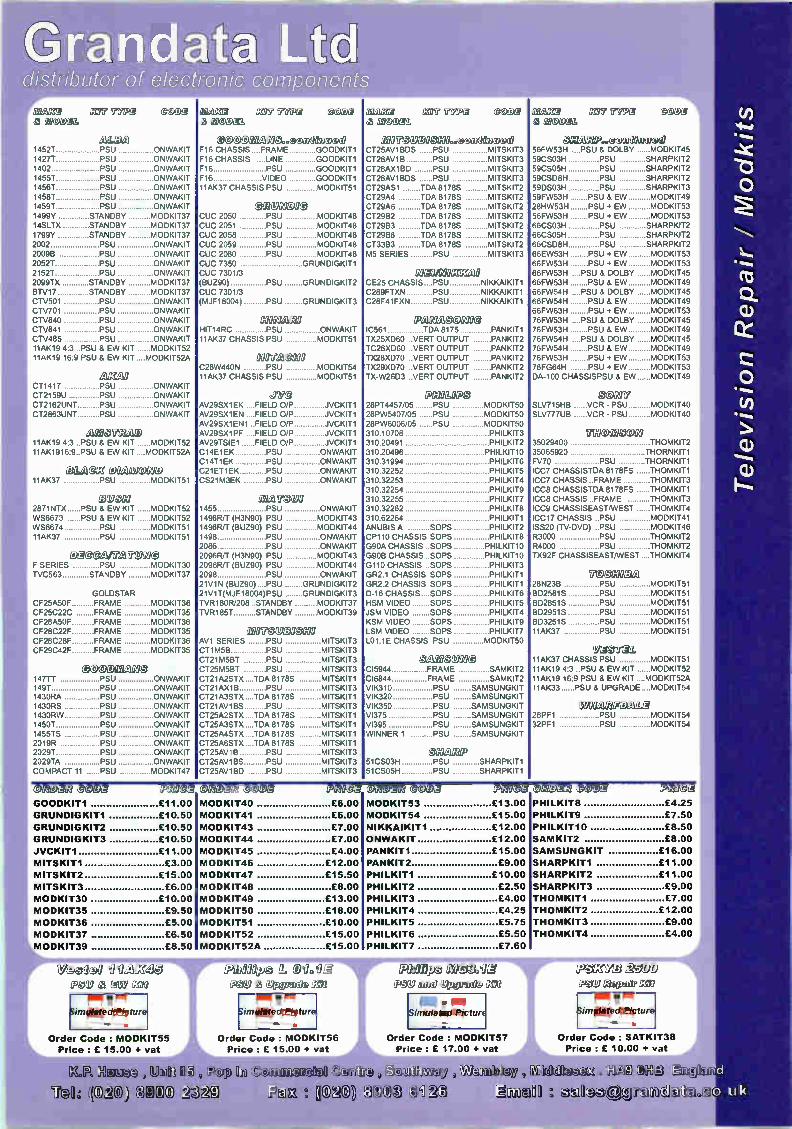
G td distributor of electronic components
OM M C1114 WIPQ eoce â Bocal
ALBA 14521 PSU ONWAKIT 1427T PSU ONWAKIT 1402 PSU ONWAKIT 14551 PSU ONWAKIT 14561 PSU ONWAKIT 14581 PSU ONWAKIT 1459T PSU ONWAKIT 1499Y STANDBY MODKIT37 14SLTX STANDBY MODKIT37 1799Y STANDBY MODKIT37 2002 PSU ONWAKIT 2009B PSU ONWAKIT 20521 PSU ONWAKIT 21521 PSU ONWAKIT 2099TX STANDBY MODKIT37 BTV17 STANDBY MODKIT37 CTV501 PSU ONWAKIT CTV701 PSU ONWAKIT CTV840 PSU ONWAKIT CTV841 PSU ONWAKIT CTV485 PSU ONWAKIT 11AK19 4:3 ..PSU & EW KIT MODKIT52 11AK19 16:9 PSU á EW KIT ....MODKIT52A
GJCE:2 CT1417 PSU ONWAKIT CT2159U PSU ONWAKIT CT2162UNT PSU ONWAKIT CT2863UNT PSU ONWAKIT
LMIC 11AK19 4:3 ..PSU & EW KIT MODKIT52 11AK1916:9..PSU & EW KIT ....MODKIT52A
BLA
TRAD
@CI DO MCMD 11AK37 PSU MODKIT51
OUDH 2871NTX PSU & EW KIT MODKIT52 WS6673 PSU & EW KIT MODKIT52 WS6674 PSU MODKIT51 11AK37 PSU MODKIT51
EM MIFIZ MII0 F SERIES PSU MODKIT30 TVC563 STANDBY MODKIT37
GOLDSTAR CF25A5OF FRAME MODKIT36 CF25C22C FRAME MODKIT35 CF28A5OF FRAME MODKIT36 CF28C22F FRAME MODKIT35 CF28C28F FRAME MODKIT36 CF29C42F FRAME MODKIT35
' DIDL AUCe50 147TÍ PSU ONWAKIT 1497 PSU ONWAKIT 1430RA PSU ONWAKIT 1430RS PSU ONWAKIT 1430RW PSU ONWAKIT 14501 PSU ONWAKIT 1455TS PSU ONWAKIT 2019R PSU ONWAKIT 2029T PSU ONWAKIT 2029TA PSU ONWAKIT COMPACT 11 PSU MODKIT47
MO MIE Cri e aiaati 100031
@ G OD MileweCIG 0000036)Cd F16 CHASSIS FRAME GOODKIT1 F16 CHASSIS LINE GOODKIT1 F16 PSU GOODKIT1 F16 VIDEO GOODKIT1 11AK37 CHASSIS PSU MODKIT51
012UND30 CUC 2050 PSU MODKIT48 CUC 2051 PSU MODKIT48 CUC 2058 PSU MODKIT48 CUC 2059 PSU MODKIT48 CUC 2080 PSU MODKIT48 CUC 7350 GRUNDIGKIT1 CUC 7301/3 BUZ90) PSU GRUNDIGKIT2 CUC 7301/3 MJF18004) PSU GRUNDIGKIT3
XEIC120 HIT14RC PSU ONWAKIT 11AK37 CHASSIS PSU MODKIT51
COOVI2i@NO C28W440N PSU 11AK37 CHASSIS PSU
MODKIT54 MODKIT51
gele AV29SX1EK FIELD 0/P AV29SX1EN FIELD 0/P AV29SX1EN1 .FIELD 0/P AV29SX1PF ...FIELD 0/P AV29TSIE1 FIELD 0/P C14E1EK PSU C14T1EK PSU C21ET1EK PSU CS21M3EK PSU
JVCKIT1 JVCKIT1 JVCKIT1 JVCKIT1 JVCKIT1
ONWAKIT ONWAKIT ONWAKIT ONWAKIT
OU M» 1455 PSU 1496R/T (H3N90) PSU 1496Ft/T (BUZ90) PSU 1498 PSU 2086 PSU 2096R/T (H3N90) PSU 2096R/T (BUZ90) PSU 2098 PSU 21V1N (BUZ90). PSU 21V1T(MJF18004)PSU TVR180R/208 STANDBY TVR1857 STANDBY
ONWAKIT MODKIT43
MODKIT44 ONWAKIT
ONWAKIT MODKIT43 MODKIT44 ONWAKIT GRUNDIGKIT2
GRUNDIGKIT3 MODKIT37 MODKIT39
211070VOO MO AV1 SERIES PSU MITSKIT3 T1M5B PSU MITSKIT3 721M5BT PSU MITSKIT3 CT25M5BT PSU MITSKIT3 CT21A2STX TDA 8178S MITSKIT1 CT21AX1B PSU MITSKIT3 CT21A3STX .TDA 8178S MITSKIT1 T21AV1BS PSU MITSKIT3 CT25A2STX ..TDA 8178S MITSKIT1 CT25A3STX .TDA 8178S MITSKIT1 725A4STX ..TDA 8178S MITSKIT1 CT25A6STX ..TDA 8178S MITSKIT1 CT25AV1B PSU MITSKIT3 725AV1BS PSU MITSKIT3 725AV1BD PSU MITSKIT3
M ICI TrePg eoce MUC e&I6
C6IireeVO MI.,eocoalumee CT25AV1BDS PSU MITSKIT3 CT28AV1B PSU MITSKIT3 CT28AX1BD PSU MITSKIT3 CT28AV1BDS PSU MITSKIT3 CT29AS1 TDA 81785 MITSKIT2 CT29A4 TDA 8178S MITSKIT2 CT29A6 TDA 8178S MITSKIT2 CT29B2 TDA 8178S MITSKIT2 CT29B3 TDA 8178S MITSKIT2 CT29B6 TDA 8178S MITSKIT2 CT33B3 TDA 8178S MITSKIT2 M5 SERIES PSU MITSKIT3
NIMUNITZM CE25 CHASSIS PSU NIKKAIKIT1 C289FTXN PSU NIKKAIKIT1 C28F41FXN PSU NIKKAIKIT1
GUI MIDOit e IC561 TDA 8175 PANKIT1 TX25XD60 .VERT OUTPUT PANKIT2 TC28XD60 .VERT OUTPUT PANKIT2 TX28XD70 .VERT OUTPUT PANKIT2 TX29XD70 VERT OUTPUT PANKIT2 TX-W26D3 .VERT OUTPUT PANKIT2
P8101,22C 28PT4457/05 PSU MODKIT50 28PW5407/05 PSU MODKIT50 28PW6006/05 PSU MODKIT50 310.10708 PHILKIT3 310.20491 PHILKIT2 310.20496 PHILKIT10 310.31994 PHILKIT6 310.32252 PHILKIT5 310.32253 PHILKIT4 310.32254 PHILKIT9 310.32255 PHILKIT7 310.32262 PHILKIT8 310.62264 PHILKIT1 ANUBIS A SOPS PHILKIT2 CP110 CHASSIS SOPS PHILKIT8 G90A CHASSIS SOPS PHILKIT10 G90B CHASSIS SOPS PHILKIT10 G110 CHASSIS SOPS PHILKIT3 GR2.1 CHASSIS SOPS PHILKIT1 GR2.2 CHASSIS SOPS PHILKIT1 D-16 CHASSIS. SOPS PHILKIT6 HSM VIDEO SOPS PHILKIT5 JSM VIDEO SOPS PHILKIT4 KSM VIDEO SOPS PHILKIT9 LSM VIDEO SOPS PHILKIT7 L01.1E CHASSIS PSU MODKIT50
eameutio CI5944 FRAME SAMKIT2 CI6844 FRAME SAMKIT2 VIK310 PSU SAMSUNGKIT VIK320 PSU SAMSUNGKIT VIK350 PSU SAMSUNGKIT
PSU SAMSUNGKIT PSU SAMSUNGKIT
PSU SAMSUNGKIT
VI375 VI395 WINNER 1
emu&D 51CSO3H PSU SHARPKIT1 51CSO5H PSU SHARPKIT1
M RIE ICO? ? Wei a 0:11C eQ6
0.(COGI M35111)e 56FW53H PSU & DOLBY MODKIT45 59CSO3H PSU SHARPKIT2 59CSO5H PSU SHARPKIT2 59CSD8H PSU SHARPKIT2 590S0311 PSU SHARPKIT3 59FW53H PSU & EW MODKIT49 28HW53H PSU + EW MODKIT53 56FW53H PSU + EW MODKIT53 66CS03H PSU SHARPKIT2 66CSO5H PSU SHARPKIT2 66CSD8H PSU SHARPKIT2 66EW53H PSU + EW MODKIT53 66FW53H PSU + EW MODKIT53 66FW53H PSU & DOLBY MODKIT45 66FW53H PSU & EW MODKIT49 66FW54H PSU & DOLBY MODKIT45 66FW54H PSU & EW MODKIT49 66FW63H PSU + EW MODKIT53 76FW53H PSU & DOLBY MODKIT45 76FW53H PSU & EW MODKIT49 76FW54H PSU & DOLBY MODKIT45 76FW54H PSU & EW MODKIT49 76FW53H PSU + EW MODKIT53 76FG64H PSU + EW MODKIT53 DA-100 CHASSISPSU & EW MODKIT49
CDIE7 SLV715HB VCR - PSU MODKIT40 SLV777UB VCR - PSU MODKIT40
V WC2il eigl 35029400 THOMKIT2 35065920 THORNKIT1 FV70 PSU THORNKIT1 ICC7 CHASSISTDA 8178FS THOMKIT1 ICC7 CHASSIS. FRAME THOMKIT3 ICC8 CHASSISTDA 8178FS THOMKIT1 ICC8 CHASSIS FRAME THOMKIT3 ICC9 CHASSISEAST/WEST THOMKIT4 ICC17 CHASSIS PSU MODKIT41 ISS20 (TV-OVO) ..PSU MODKIT46 R3000 PSU THOMKIT2 R4000 PSU THOMKIT2 TX92F CHASSISEAST/WEST THOMKIT4
?C A ME; A 28N23B PSU MODKIT51 BD2581S PSU MODKIT51 BD2851S PSU MODKIT51 BD2951S PSU MODKIT51 BD3251S PSU MODKIT51 11AK37 PSU MODKIT51
enee. 11AK37 CHASSIS PSU MODKIT51 11AK19 4:3 ..PSU & EW KIT MODKIT52 11AK19 16:9 PSU & EW KIT ....MODKIT52A 11AK33 PSU & UPGRADE ....MODKIT54
We e a K ellig 28PF1 PSU MODKIT54 32PF1 PSU MODKIT54
b.i.c.)3'.;_t GOODKIT1 £11.00
GRUNDIGKIT1 £10.50
GRUNDIGKIT2 £10.50
GRUNDIGKIT3 £10.50
JVCKIT1 £11.00
MITSKIT1 £3.00
MITSKIT2 £15.00
MITSKIT3 £6.00
M ODKIT30 £10.00
M ODKIT35 £9.50
M ODKIT36 £5.00
M ODKIT37 £6.50
M ODKIT39 £8.50
C)2C)(412 C ODg 1;4206gf
M ODKIT40 £6.00
M ODKIT41 £6.00
M ODKIT43 £7.00
M ODKIT44 £7.00
M ODKIT45 £4.00
M ODKIT46 £12.00
M ODKIT47 £15.50
M ODKIT48 £8.00
M ODKIT49 £13.00
M ODKIT50 £18.00
M ODKIT51 £10.00
M ODKIT52 £15.00
M ODKIT52A £15.00
OL3Dig2 @OCel IPZIed M ODKIT53
M ODKIT54
NIKKAIKIT1
ON WAKIT
PANKIT1
PANKIT2
PHILKIT1
PHILKIT2
PHILKIT3
PHILKIT4
PHILKIT5
PHILKIT6
PHILKIT7
£13.00
£15.00
£12.00
£12.00
£15.00
£9.00
£10.00
£2.50
£4.00
£4.25
£5.75
£5.50
£7.60
eettoteet eetotg PHILKIT8 £4.25
PHILKIT9 £7.50
PHILKIT10 £8.50
SAMKIT2 £8.00
SAMSUNGKIT £16.00
SHARPKIT1 £11.00
SHARPKIT2 £11.00
SHARPKIT3 £9.00
THOMKIT1 £7.00
THOMKIT2 £12.00
THOMKIT3 £9.00
THOMKIT4 £4.00
Yoece efucem pov ezi
Rimilledgebture
Order Code : M ODKIT55
Price : £ 15.00 + vat
Geg e3 egges leil Ge30 Ir 1 mme legutiel» Mg Philips Dejovfg y li)3)0035c 1 09.9IX
similledgepture
Order Code : M ODK T56
Price : £ 15.00 + vat
I Simulate ancture
Order Code : MODKIT57
Price: £ 17.00 + vat
Xf2: 2:50D j.uu jimpidy jej}
• 5im ffledgefirture
,
Order Code : SATKIT38
Price : 10.00 + vat
Television
EurA »be/.à WIÎ pulD) etyo
11>
Pop In Co rcâni MC)) ee)à, (39 3
.116WM Middlesex . a») d
‘%' tale) e)LrrezmclâtIn.(e.. u k

G,,iuTat2 td distributor of electromc components
Morittôl T®suip®creagu9 ,DolaGicrilreD eletedcm
,ti GegoerIGiei D(.90 1 piiDaii
Spare tip 0 5.3 mm
Spare tip 0 3.0 mm
Spare tip 0 3.0 mm 45°
Spare tip 0 2.0 mm
Cpare Sponge
Adjustable by a potentiometer with Digital read out Comes with a 3.2mm Sloped Tip
Temperature range: 160iC to 480iC
Heater voltage : 24 Volt
Heater power : 48 Watt
Order Code : HQSOLDER30 Price: £ 35.00 + vat
Carriage charged at £ 5.00 + vat
COCecv
HQTIP1
HQTIP2
HQT1P3
HQTIP4
HQSPONGE
Pfl 5 9
£ 2.00 + vat
£ 2.00 + vat
£ 2.00 + vat
£ 2.00 + vat
£ 0.50 + vat
D w)D0,2 eleise ../.4sfa
0.80mm 1.6m 1.50mm 1.6m 2.00mm 1.6m 2.50mm 1.6m 0.80mm 3.0m 1.50mm 3.0m 2.00mm 3.0m 2.50mm 3.0m 2.50mm 15m 3.00mm 15m 1.50mm 30m 2.00mm 30m
-44s.re,r4441111114e,
3 1/2 digits LCD Display
Low Battery indication
Transistor Testing Socket
Audible continuity
Technical Specifications:
DC Voltage: 200mV, 2V, 20V, 200V, 1000V
AC Voltage: 200mV, 2V, 20V, 200V. 750V
DC Current:20uA,200uA,2mA,20mA.200mA,2A,10A AC Current: 200uA, 2mA, 20mA, 200mA, 2A, 10A
Resistance: 200R, 2K, 20K, 200K, 2M, 20M, 200M
VVICKS1 VVICKS2 VVICKS3 WICKS4 VVICKM1 VVICKM2 VVICKM3 VVICKM4 WICKL4 WICKL5 WICKL2 WICKL3
Order Code : TS130 Price: £ 8.00 + vat
ge-DD ma igewa &,Ceroed • eogl ecAdoelop
Order Code : TSSO9 Price: £2. 00 + vat
-41 1 aexo
--quarms[ 10mm x 3.2mm Sloped Tip r Order Code : TSB32 Price: £ 1.50 + vat
10mm x 0.5mm Clonical Tip 'Order Code : TSB05 Price: £ 1.50 + vat
£ 0.75 + vat £ 0.80 + vat £ 0.90 + vat £ 1.00 + vat £ 1.00 + vat £ 1.20 + vat £ 1.30 + vat £ 1.40 + vat £ 6.00 + vat £ 7.00 + vat £ 8.00 + vat £ 10.00 + vat
gtehilieeffleâeeestil
18 SWG 500 grammes
20 SWG 500 grammes
22 SWG 500 grammes
SI10
sill
SI12
Pattec
£ 5.00 + vat
£ 6.50 + vat
£ 7.00 + vat
1.1 I Carriage charged at £ 2.00 + vat £ 5.00 + vat for 3 or more
3 1/2 digits LCD Display
Low Battery indication
Transistor Testing Socket
Audible continuity
Technical Specifications:
DC Voltage: 200mV, 2V. 20V, 200V, 1000V
AC Voltage: 200mV, 2V, 20V, 200V, 750V
DC Current:20uA,200uA,2mA,20mA,200mA,2A,10A
AC Current: 200uA, 2mA, 20mA, 200mA, 2A, 10A
Resistance: 200R, 2K, 20K, 200K, 2M, 20M, 200M
Capacitance: 2nF, 20nF, 200nF, 2uF. 20uF
3 1/2 digits LCD Display
Low Battery indication
Transistor Testing Socket
Audible continuity
Technical Specifications:
DC Voltage: 200mV. 2V, 20V, 200V, 1000V
AC Voltage: 200mV, 2V, 20V. 200V. 750V
DC Current:20uA,200uA,2mA,20mA,200mA,2A,10A
AC Current: 200uA, 2mA, 20mA, 200mA, 2A, 10A
Resistance: 200R, 2K, 20K, 200K, 2M, 20M, 200M
Capacitance: 2nF, 2OnF, 200nF, 2uF, 20uF
Frequency: 2kHz, 20kHz
Order Code : METER01 Order Code : METER02 Price: £ 11.00 + vat Price: £ 14.00 + vat
I Carriage charged at £ 3.00 + vat
Order Code : METER03 Price: £ 17.00 + vat
Carriage charged at £ 3.00 + vat Carriage charged at £ 3.00 + vat

d _t distributor o electronic components
48 lecacûxKoti DIDICeül CoerxutlICAs Receives both digital and analogue signals
For poor to weak strength signal areas
Robust design for low wind loading - 2 peices boom with aluminium wire rod elements
Supplied with F connector and clamp for horizontal and vertical (fits up to 57mm masts)
Ideal for areas with bad picture ghosting
Supplied pad assembled - no tools required
Order Code : 27884R Price : £ 20.00 + vat Carriage charged at £ 6.00 + vat
‘Alceperitlare L!Jr Geoetegxered ago et / UHF TV and FM radio antenna preamplifiers designed for professional aerial installers.
1 way amplifiers come with screw terminals
2 and 4 way amplifiers come with F connectors
Requires 12V DC power supply connected via a downlead
Description
1 way UHF TV Masthead Amplifier 15dB Gain
Order Code : 2783ORPrice : £ 4.30 + vat
1 way UHF TV Masthead Amplifier 26dB Gain
Order Code : 27831RPrice : £ 4.50 + vat
2 way UHF TV Masthead Amplifier 10dB Gain
Order Code : 27837RPrice : £ 9.00 + vat
4 way UHF TV Masthead Amplfier 10dB Gain
Order Code : 27838RPrice : £ 9.50 + vat
4 way UHF TV 8. FM Masthead Amp -10dB Gain
Order Code : 27839RPrice : £ 10.00 + vat
Masthead Amplifier Power Supply
Order Code: 27832RPrice : £ 5.00 + vat
carriage charged at £ 2.00 + vat or £ 6.00 + vat for 2 or more
lipe_
j) iii .v 2..r.i_l Vailleer,- :. LI
Signal/noise ratio of 0.6dB.
Feedhom: 40 mm
Input Frequency 10.7 - 12.75 GHz
Order Code: LNBSINGLE
, Price: £ 5.00 + vat
Tutu LLe'lli
Signal/noise ratio of 0.7dB.
Feedhom: 40 mm
Input Frequency 10.7 - 12.75 GHz
Order Code: LNBTWIN Price : £ 14.00 + vat
Compact design - Backlit meter scale
Audible signal strength reading
Adjustable level control Adjustable sensitivity adjustment
Frequency Range 950 - 2250Mhz
Order Code: 27860R
Price: £ 10.00 + vat...4111h, Price : £ 9.00 + vat Bag of 100
Description
2 way
2 way with Bypass
4 way
4 way with Bypass
6 way
6 way with Bypass
8 way
8 way with Bypass
Gain
18dB
6dB
12dB
6dB
12dB
6dB
12dB
6dB
« MU ,
A range of Aerial amplifers designed to allow distribution of TV Satellite and FM signal without the loss of picture and sound quality
Available with intergrated Digital bypass - to anow the use of SKY' digéye (8).
Main Operated , comes with full instructions
Order Code Price
SLX2
SLX2B
SLX4
SLX4B
SLX6
SLX6B
SLX8
SLX8B
£ 8.00 + vat
£ 9.25 + vat
£ 13.00 + vat
£ 14.00 + vat
£ 18.00 + vat
£ 19.00 + vat
£ 18.50 + vat
£ 20.00 + vat
Carriage charged at £ 2.00 + vat or £ 6.00 + vat for 2 or more
fee Vaollenecel aeadm/ IND Gleowalcv 601
Signal/noise ratio of 0.7dB.
Feedhom: 40 mm
Input Frequency 10.7 - 12.75 GHz
Order Code: LNBQUAD Price : £ 25.00 + vat
ooM m-
Order Code: PLG51
Bag of 10 Price : 1.25 + vat
For use with Multiswitches Signal/noise ratio of 0.7dB.
Feedhom: 40 mm Input Frequency 10.7 - 12.75 GHz
Order Code: LNBQUATTFt0 Price : £ 15.00 + vat
Zgps f.,JJ 5L.:1 1Pfic wj t ,.5
ham Order Code: PLG62
Bag of 10 Price : £ 1.60 + vat
Bag of 100 Price : £1250+ vat
(C Mtiç C),Tn OW' Unliti .çarh/c)er
wypila eân âhatoavlk-
Order Code: PLG101
Bag of 10 Price : £ 1.00 + vat
Bag of 100 Price : £ 6.00 + vat
This advertisement is just a selection of our stock. Please contact us if you cannot find the part you are looking for.
' Please add £1 p+p and VAT to all orders (Unless Otherwise stated) • All components are brand new • We accept payment by Access . Switch , Visa , Cheque and Postal Order
All prices quoted are subject to availabilty and may be changed without prior notice
E & OE
Aerial Installation Accessories
GU% bie ffl 9 U M Pc e
TC;0 M C)) NCO = ç) -entré Soùthw. y
20 ) J9O 1J1(3 naüllt tÉleelegruip.Ish.ict d
0. u k
eamid-,e likke

Photo 1: The Sony Model DCR-IP7BT camcorder.
rp2) In the fourth instalment in this series Graham Maynard takes a look at Bluetooth-enabled camcorders and set-top boxes then turns to a newer wireless technology, Zigbee
The main subject for our atten-tion this month is a newer wireless technology, Zigbee.
Before looking at it however there are a couple of Bluetooth CE appli-cations I didn't get around to men-tioning last month.
Camera products that !linelini ' use Bluetooth
The use of Bluetooth technology in cam-corders has been occa-sional to date. At the
forefront, Sony has been the most prominent and successful user of it. Sony's newer cam-corders tend to feature Bluetooth less frequently however, which is a sign that
higher data-rate wired and wireless technologies such as USB 2.0 and FireWire are becoming prevalent. A good example of a Sony cam-
corder that uses Bluetooth technol-ogy is the Handycam Model DCR-IP55, which has an on-board pop-up flash and can capture still pho-tos at 1,152 x 864 pixel resolution, saving them on a Memory Stick. It has a x10 zoom lens and can also record MPEG-1 video on a Memory Stick or send it to your computer for live videoconferenc-ing or storage on the hard drive. Use of Bluetooth technology in this camcorder means that, with an optional modem adapter, you can upload video clips to the Sony ImageStation photo/video-sharing web site, surf the intemet or send and receive email. The IP55 uses Sony's tiny, proprietary MicroMV videotapes — to see what these look like, go to
http://www.asahi-net.or.jp/—pu4i-aok/pc/videohnicromv.jpg Other Sony camcorders that
have used Bluetooth are Model DCR-IP7BT (see Photo 1), which is another MicroMV type, and the Digital 8 Model DCR-TRV50E. The Panasonic Model NV-EX21,
see Photo 2, has a detachable still camera. The advantage of this is that it doesn't have to share the bat-tery power, and there is a massive reduction in bulk when all you want to do is take still images. At a flick of a switch the lens unit can be removed and placed on a dedi-cated battery unit. The unit features Bluetooth, but only via an adapter that Panasonic has not released in the UK. Still images are stored on an SD card. The camcorder has DV in/out, S video in/out, digital still picture out and digital out to USB. A number of companies have
released still-only digital cameras
728 October 2005 TELEVISION
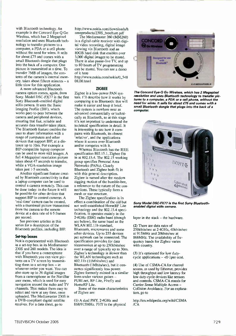
with Bluetooth technology. An example is the Concord Eye-Q Go Wireless, which has 2 Megapixel resolution and uses Bluetooth tech-nology to transfer pictures to a computer, a PDA or a cell phone without the need for wires. It sells for about £75 and comes with a small Bluetooth dongle that plugs into the back of a computer. One picture is transmitted at a time. To transfer 7MB of images, the con-tents of the camera's internal mem-ory, takes about fifteen minutes — a little slow for this application. A more advanced Bluetooth
camera option comes, again, from Sony. Model DSC-FX77 is the first Sony Bluetooth-enabled digital stills camera. It uses the Basic Imaging Profile (BIF), which works peer-to-peer between the camera and peripheral devices, ensuring that fast, reliable and accurate data transfer takes place. The Bluetooth feature enables the user to share information with a range of computers and other devices that support BIP, at a dis-tance up to 10m. For example a BIP-compatible laptop computer can be used to store still images. A full 4 Megapixel resolution picture takes about 47 seconds to transfer, while a VGA-resolution image takes just 1.5 seconds. Another significant feature creat-
ed by Bluetooth connectivity is that a laptop computer can be used to control a camera remotely. This can be done today: in the future it will be possible for other devices that support BIP to control cameras. A 'real-time' camera can be created, with a thumbnail picture transmitted from the camera to the remote device at a data rate of 6.5 frames per second. See previous articles in this
series for a description of the Bluetooth profiles, including BIP.
Set-top boxes Nokia experimented with Bluetooth in a set-top box in its Mediamaster 230S and 260 models. The idea is that if you have a cameraphone with Bluetooth you can view pic-tures on a TV screen by transmit-ting them to a set-top box — in whatever order you want. You can also store up to 36 digital images from a cameraphone in the NaviBar user menu, which is used for easy navigation around the radio and TV channels. This makes them easy to select and view at any time, once uploaded. The Mediamaster 230S is a DVB-compliant digital satellite receiver. For a data sheet, go to
http://www.nokia.com/downloads/h omeproducts/230S_brochure.pdf The Mediamaster 260 (MM260)
is a digital cable receiver with digi-tal video recording, digital image viewing via Bluetooth and an 80GB hard disk that enables over 3,000 digital images to be stored. There is also pause-live TV, and up to 80 hours of TV programming can be stored. You can see a demo of it here http://www.nokia.com/nolcia/0„548 08,00.html
ZIGBEE Zigbee is a low-power PAN sys-tem. I'll describe how it works by comparing it to Bluetooth: this will make it easier and keep it brief. The system is nowhere near as advanced commercially or techni-cally as Bluetooth, so at this stage it's not important to understand the technical specification in detail. It is interesting to see how it com-pares with Bluetooth, its closest 'relative', and the applications where it scores over Bluetooth and/or competes with it. Whereas Bluetooth has the IEEE
specification 802.15.1, Zigbee fits in at 802.15.4. The 802.15 working group specifies Personal Area Networks (PANs). Clearly Bluetooth and Zigbee both fit in with this general description. Zigbee is named after the random zigging motion of the bumble-bee, a reference to the nature of the con-nections. These typically form a mesh or star structure. The Zigbee specification is in
effect a combination of the old but not well-established HomeRF Lite technology and the 802.15.4 speci-fication. It operates mainly in the 2-4GHz (ISM) radio band (though see below), the same band as the WLAN 802.11b standard, Bluetooth, microwaves and some other devices. Up to 255 devices per network can be connected. The specification provides for data transmission at up to 250kbits/sec over a range of typically up to 30m. Zigbe,e's technology is slower than the WLAN technologies such as 802.11b (11Mbits/sec) and Bluetooth (1Mbits/sec), but it con-sumes significantly less power. Zigbee formerly existed in a similar form under various guises — PURLnet, RF-Lite, Firefly and HomeRF Lite. Some of the main characteristics
of Zigbee are:
(1) A dual PHY, 2-4GHz and 868/915MHz. PHY is the physical
•
CONCORD aGo Wireless
Designed tor use with
Bluetooth
2 0 M E G A PI XEL S
The Concord Eye-G Go Wireless, which has 2 Megapixel resolution and uses Bluetooth technology to transfer pic-tures to a computer, a PDA or a cell phone, without the need for wires. It sells for about £75 and comes with a small Bluetooth dongle that plugs into the back of a computer.
Sony Model DSC-FX77 is the first Sony Bluetooth-enabled digital stills camera.
layer in the stack — the hardware.
(2) There are data rates of 250kbits/sec at 2-4GHz, 40kbits/sec at 915MHz and 20kbits/sec at 868MHz. The availability of fre-quency bands for Zigbee varies with country.
(3) It's optimised for low duty-cycle applications — <0.1per cent.
(4) Use of CSMA-CA for channel access, as used by Ethernet, provides high throughput and low latency for low duty-cycle devices like sensors and controls. CSMA-CA stands for Carrier Sense Multiple Access — Collision Avoidance. For an explana-tion, go to
http://en.wikipedia.org/wiki/CSMA /CA
TELEVISION October 2005 729
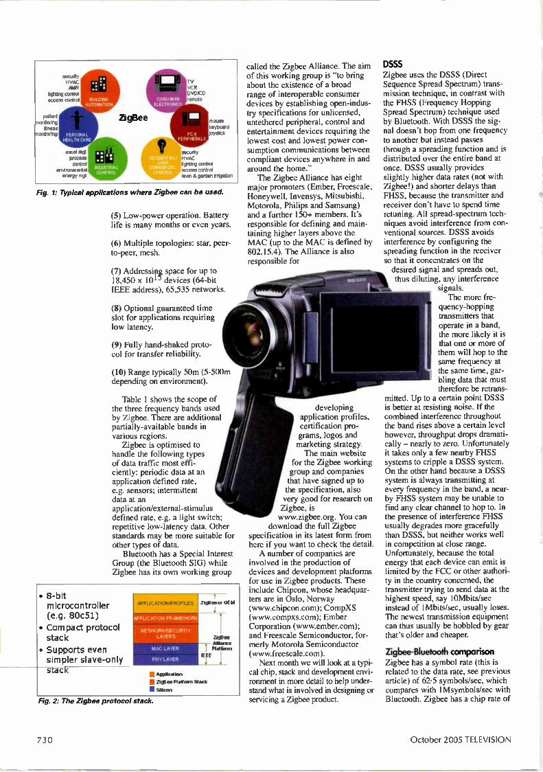
securty
Irghting ccr access conk,'
patient monitoring
fitness monitoring
AUTOMATION
PERSONAL HEALTH CA.Rf .
asset mgt prccess control
environmental energy mgt
ZigBee mouse keybcerd roystick
security HVAC lighting control access control 'aye & garden Irrigation
Fig. 1: Typical applications where Zigbee can be used.
(5) Low-power operation. Battery life is many months or even years.
(6) Multiple topologies: star, peer-to-peer, mesh.
(7) Addressipg space for up to 18,450 x 101) devices (64-bit IEEE address), 65,535 networks.
(8) Optional guaranteed time slot for applications requiring low latency.
(9) Fully hand-shaked proto-col for transfer reliability.
(10) Range typically 50m (5-500m depending on environment).
Table 1 shows the scope of the three frequency bands used by Zigbee. There are additional partially-available bands in various regions. Zigbee is optimised to
handle the following types of data traffic most effi-ciently: periodic data at an application defined rate, e.g. sensors; intermittent data at an application/external-stimulus defined rate, e.g. a light switch; repetitive low-latency data. Other standards may be more suitable for other types of data. Bluetooth has a Special Interest
Group (the Bluetooth SIG) while Zigbee has its own working group
• S-bit microcontroller (e.g. 80c51)
• Compact protocol stack
• Supports even simpler slave-only stack
.21111111111.1111 APPLICATION FRAMEWORK
NE KNORkUSEC URTI Y LAYERS
krta4 LAYER
PHY LAYER
Zigfleeor OEM
ZigElee , Alliance Platform
IEEE
1111 Application
• ZigBee Platform Stack
• Silicon
Fig. 2: The Zigbee protocol stack.
called the Zigbee Alliance. The aim of this working group is "to bring about the existence of a broad range of interoperable consumer devices by establishing open-indus-try specifications for unlicensed, untethered peripheral, control and entertainment devices requiring the lowest cost and lowest power con-sumption communications between compliant devices anywhere in and around the home." The Zigbee Alliance has eight
major promoters (Ember, Freescale, Honeywell, Invensys, Mitsubishi, Motorola, Philips and Samsung) and a further 150+ members. It's responsible for defining and main-taining higher layers above the MAC (up to the MAC is defined by 802.15.4). The Alliance is also responsible for
developing application profiles, certification pro-grams, logos and marketing strategy. The main website
for the Zigbee working group and companies that have signed up to the specification, also very good for research on Zigbee, is www.zigbee.org. You can
download the full Zigbee specification in its latest form from here if you want to check the detail. A number of companies are
involved in the production of devices and development platforms for use in Zigbee products. These include Chipcon, whose headquar-ters are in Oslo, Norway (www.chipcon.com); CompXS (www.compxs.com); Ember Corporation (www.embencom); and Freescale Semiconductor, for-merly Motorola Semiconductor (www.freescale.com). Next month we will look at a typi-
cal chip, stack and development envi-ronment in more detail to help under-stand what is involved in designing or servicing a Zigbee product
DSSS Zigbee uses the DSSS (Direct Sequence Spread Spectrum) trans-mission technique, in contrast with the FHSS (Frequency Hopping Spread Spectrum) technique used by Bluetooth. With DSSS the sig-nal doesn't hop from one frequency to another but instead passes through a spreading function and is distributed over the entire band at once. DSSS usually provides slightly higher data rates (not with Zigbee!) and shorter delays than FHSS, because the transmitter and receiver don't have to spend time retuning. All spread-spectrum tech-niques avoid interference from con-ventional sources. DSSS avoids interference by configuring the spreading function in the receiver so that it concentrates on the desired signal and spreads out, thus diluting, any interference
signals. The more fre-
quency-hopping transmitters that operate in a band, the more likely it is that one or more of them will hop to the same frequency at the same time, gar-bling data that must therefore be retrans-
mitted. Up to a certain point DSSS is better at resisting noise. If the combined interference throughout the band rises above a certain level however, throughput drops dramati-cally — nearly to zero. Unfortunately it takes only a few nearby FHSS systems to cripple a DSSS system. On the other hand because a DSSS system is always transmitting at every frequency in the band, a near-by FHSS system may be unable to find any clear channel to hop to. In the presence of interference FHSS usually degrades more gracefully than DSSS, but neither works well in competition at close range. Unfortunately, because the total energy that each device can emit is limited by the FCC or other authori-ty in the country concerned, the transmitter trying to send data at the highest speed, say 10Mbits/sec instead of 1Mbits/sec, usually loses. The newest transmission equipment can thus usually be hobbled by gear that's older and cheaper.
Zigbee-Bluetooth comparison Zigbee has a symbol rate (this is related to the data rate, see previous article) of 62-5 symbols/sec, which compares with 1Msymbols/sec with Bluetooth. Zigbee has a chip rate of
7 U) October 2005 TELEVISION
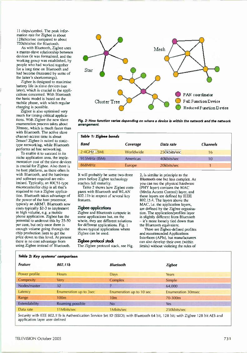
11 chips/symbol. The peak infor-mation rate for Zigbee is about 128kbits/sec compared to about 720kbits/sec for Bluetooth. As with Bluetooth, Zigbee uses
a master-slave relationship between devices (it was formalised, and the working group was established, by people who had worked together for a long time on Bluetooth and had become frustrated by some of the latter's shortcomings). Zigbee is designed to maximise
battery life in slave devices (see later), which is crucial in the appli-cations concerned. With Bluetooth the basic model is based on the mobile phone, with which regular charging is possible. Zigbee is also optimised very
much for timing-critical applica-tions. With Zigbee the new slave enumeration process takes about 30msec, which is much faster than with Bluetooth. The active slave channel-access time is about 2msec! Zigbee is suited to static-type networking, while Bluetooth performs ad hoc networking. To enable it to succeed in its
niche application area, the imple-mentation cost of the slave devices is crucial for Zigbee. Also there is no host platform, as there often is with Bluetooth, and the hardware and software required are min-imised. Typically, an 80051-type microcontroller chip is all that's required to run a Zigbee applica-tion. Bluetooth takes advantage of the power of the host processor, typicaly an ARM7. Bluetooth now costs typically $2-3 to implement in high volume, e.g. a mobile phone application. Zigbee has the potential to undercut this by 25-50 per cent, but only once there is enough volume going through the chip production lines to get the price down to this level. At present there is no cost advantage from using Zigbee instead of Bluetooth.
Star
Cluster Tree
F' AN co or din at or
0 Full Function Device
0 Reduced Function D evice
Fig. 3: How function varies depending on where a device is within the network and the network arrangement.
Table I: Zigbee bands
Band Coverage Data rate Channels
.2.4GHz (ISM)
915MHz (ISM)
868MHz
Worldwide
Americas
Eu rope
250kbits/sec
40kbits/sec
2 Okb its/sec
16
10
1
It will probably be some two-three years before Zigbee technology reaches full maturity. Table 2 shows how Zigbee com-
pares with Bluetooth and WLAN 802.11b in respect of several key features.
Zigbee applications Zigbee and Bluetooth compete in some applications but, on the whole, they are different solutions for different applications. Fig. 1 shows typical applications where Zigbee can be used.
Zigbee protocol stock The Zigbee protocol stack, see Fig.
2, is similar in principle to the Bluetooth one but less complex. As you can see the physical hardware (PHY layer) contains the MAC (Media Access Control) layer, and these layers are defined by IEEE 802.15.4. The layers above the MAC, i.e. the application layers, are defined by the Zigbee organisa-tion. The application/profiles layer is slightly different from Bluetooth — it's more loosely tied down than the Bluetooth equivalent. There are Zigbee-defined profiles
and recommended Applications Interfaces (APIs), but manufacturers can also develop their own (within limits) without violating the rules of
Table 2: Key systems' comparison
Feature 802.11b Bluetooth Zigbee
Power profile
Compexity
Hours
Very
Days
Complex
Nodes/master 32 7
Latency
Range
Extendability
Data rate
Enumeration up to 3sec
loom Roaming possible
11Mbits/sec
Enumeration up to 10 sec
10m
No
1Mb its/sec 11111111ft
Years
Simple
64,000
Enumeration 30msec
70-300m
Yes
250kbits/sec 111111111111 M
Security with IEEE 802.11b is Authentication Service Set ID (SSID); with Bluetooth 64 bit, 128 bit; with Zigbee 128 bit AES and application layer user defined
TELEVISION October 2005 731
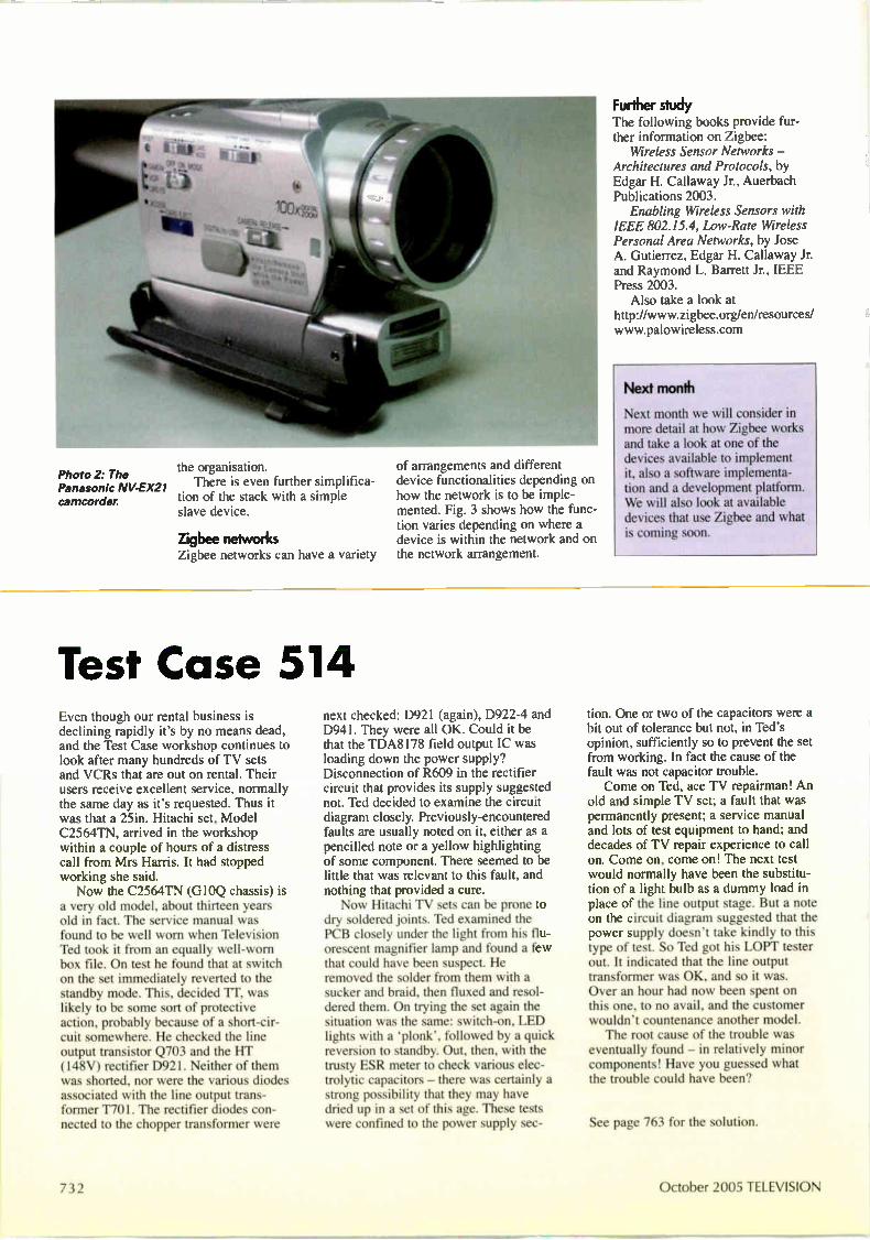
Photo 2: The the organisation. Panasonic NV-EX21 There is even further simplifica-camcorder tion of the stack with a simple
slave device.
Zirabee networks Zigbee networks can have a variety
of arrangements and different device functionalities depending on how the network is to be imple-mented. Fig. 3 shows how the func-tion varies depending on where a device is within the network and on the network arrangement.
Test Case 514 Even though our rental business is declining rapidly it's by no means dead, and the Test Case workshop continues to look after many hundreds of TV sets and VCRs that are out on rental. Their users receive excellent service, normally the same day as it's requested. Thus it was that a 25in. Hitachi set, Model C2564TN, arrived in the workshop within a couple of hours of a distress call from Mrs Harris. It had stopped working she said. Now the C2564TN (GIOQ chassis) is
a very old model, about thirteen years old in fact. The service manual was found to be well worn when Television Ted took it from an equally well-worn box file. On test he found that at switch on the set immediately reverted to the standby mode. This, decided ri', was likely to be some sort of protective action, probably because of a short-cir-cuit somewhere. He checked the line output transistor Q703 and the HT (148V) rectifier D921. Neither of them was shorted, nor were the various diodes associated with the line output trans-former T701. The rectifier diodes con-nected to the chopper transformer were
next checked: D921 (again), D922-4 and D941. They were all OK. Could it be that the TDA8178 field output IC was loading down the power supply? Disconnection of R609 in the rectifier circuit that provides its supply suggested not. Ted decided to examine the circuit diagram closely. Previously-encountered faults are usually noted on it, either as a pencilled note or a yellow highlighting of some component. There seemed to be little that was relevant to this fault, and nothing that provided a cure. Now Hitachi TV sets can be prone to
dry soldered joints. Ted examined the PCB closely under the light from his flu-orescent magnifier lamp and found a few that could have been suspect. He removed the solder from them with a sucker and braid, then fluxed and resol-dered them. On trying the set again the situation was the same: switch-on, LED lights with a 'plonk', followed by a quick reversion to standby. Out, then, with the trusty ESR meter to check various elec-trolytic capacitors — there was certainly a strong possibility that they may have dried up in a set of this age. These tests were confined to the power supply sec-
Further study The following books provide fur-ther information on Zigbee: Wireless Sensor Networks —
Architectures and Protocols, by Edgar H. Callaway Jr., Auerbach Publications 2003. Enabling Wireless Sensors with
IEEE 802.15.4, Low-Rate Wireless Personal Area Networks, by Jose A. Gutierrez, Edgar H. Callaway Jr. and Raymond L. Barrett Jr., IEEE Press 2003. Also take a look at
http://www.zigbee.org/enlresources-www.palowireless.com
Next month
Next month we will consider in more detail at how Zigbee works and take a look at one of the devices available to implement it, also a software implementa-tion and a development platform. We will also look at available devices that use Zigbee and what is coming soon.
tion. One or two of the capacitors were a bit out of tolerance but not, in Ted's opinion, sufficiently so to prevent the set from working. In fact the cause of the fault was not capacitor trouble. Come on Ted, ace TV repairman! An
old and simple TV set; a fault that was permanently present; a service manual and lots of test equipment to hand; and decades of TV repair experience to call on. Come on, come on! The next test would normally have been the substitu-tion of a light bulb as a dummy load in place of the line output stage. But a note on the circuit diagram suggested that the power supply doesn't take kindly to this type of test. So Ted got his LOPT tester out. It indicated that the line output transformer was OK, and so it was. Over an hour had now been spent on this one, to no avail, and the customer wouldn't countenance another model. The root cause of the trouble was
eventually found — in relatively minor components! Have you guessed what the trouble could have been?
See page 763 for the solution.
732 October 2005 TELEVISION

Charles Arundel provides a further summary of fault conditions experienced with Daewoo models
P asma tv ault conditions Model DSP4210GM (SP110 chassis) Thin white line down screen: This indi-cates a short-circuit condition. There are data connector boards along the top and bottom of the plasma panel, looking from the rear. It's possible that while the back screws were being tightened with an electric screwdriver during production burrs came off the screw-heads and fell through the top grills in the back cover. One of these could have fallen on to a data-drive connector to the plasma panel, causing a short-circuit. It may be possible to blow the burr away through the grill. If not, remove and refit the flexible connec-tor concerned. It's very important to know how these
connectors operate, because they can be easily damaged. This would require a new data-drive board.
Thin black line down screen: This indi-cates an open-circuit condition. Look for an open-circuit connector to the data-driver IC boards, either at the top or bot-tom of the panel depending on where the line is on the screen. Check by removing the flexible connector and replacing it. Make sure you know how the connector opens before you do this, as it can easily be damaged. See above.
Very faint line down screen. Shows up clearly with one of the test-mode colour rasters: If the line is still present after replacing the relevant data high and data low boards in the area of the fault symp-tom, check for damage to the flexible connector to the screen. If this is dam-aged, the screen will have to be replaced.
Coloured stripes down the screen only with a digital input to the video socket, from a digital set-top box for example. There are no stripes when the video input is fed with an analogue signal: A clue is provided by the fact that when a monochrome picture is being received there are no stripes but there are coloured dots, as though the colour-killer circuits don't work. Fit a new video board.
No sound: Check that the plug from the audio board to the jack board is secure. Then, if necessary, check the audio board by replacement.
Model DP42SP (SP115 chassis) Set dead, won't come out of standby, LED stays red: The most likely cause is a faulty power module or Y or X sustain board. See report on this fault in the July issue (page 545). It described this type of fault when caused by a short-circuit hybrid IC on the Y sustain board. A simi-lar procedure can be used when the cause is a short-circuit hybrid IC on the X sustain board. When these hybrid ICs go short-circuit they can put a strain on the power module circuitry. The extra current may result in a short-circuit power transistor and six blown resistors. If this has happened you will see three burnt surface-mounted resistors at the top right-hand corner of the power mod-ule and three more burnt resistors farther down, near the top transistor mounted on the right-hand edge of the PCB. If any of the above boards are
replaced, the voltages must be reset to those given on the white label attached to the back of the screen. These adjust-ments must be carried out with the set in the service mode, displaying a white raster. The appropriate service manual is required to establish the location of the relevant test points. Another possible cause of failure to
come out of standby is any of the 28 data-drive ICs going short-circuit. These ICs are connected to the screen on a flexible connector. If one of these ICs is faulty it's likely that the relevant 470Q surface-mounted feed resistor on the sep-arate left or right connector board has gone open-circuit. The data-drive ICs can be checked for a short-circuit condi-tion by carrying out diode measurements across the tiny square copper pads situat-ed nearby on the flexible connector. Unfortunately if one of these ICs is short-circuit the whole screen will have to be replaced.
Screen blank except for a band of blue speckles down some part of the dis-play: The voltages on the Y sustain board need to be reset. See note above.
Excessive buzz from the rear of the plasma panel, especially on scene changes with high white content: A slight buzz is always emitted by the power module and the X and Y sustain boards. If
the buzz is excessive, slight adjustment of the voltages on the power panel may reduce it. If not, replace all three boards one by one to locate the culprit.
Broad black line down screen: See fault note on page 613, August issue. There is also a slight possibility that the cause could be a loose connector or a fault on the digital board, especially if random flickering dots are present within the black band and there is no black band when the set is put into the service mode with a white screen displayed.
Horizontal lines across the screen at switch-on, picture OK after five min-utes: The cause is a faulty video board.
On-screen "no signal input" message: Has the customer set the input button on the remote-control unit or the set itself to the correct input for what has been plugged into the back of the screen? Also check for loose connectors, either at the rear of the screen or at the tuner, STB, satellite receiver, DVD player etc. If all is OK, a jack connector board will prob-ably be required. Note that there are two types: the Korean type has the facility to connect an AV jack and has five bayonet connector sockets along with its PC input; the UK type has only phono sock-ets for the various inputs, along with the PC connector.
No picture but on-screen messages dis-played: The cause could be a faulty jack or video board.
Picture too dark with some inputs: Reset the sub-brightness for the input concerned, in the service mode. For example, if the video input picture is too dark but all other inputs are OK, reset the video input sub-brightness in the service mode, back to 128. Refer to the service manual for exact details.
One or two black dots on the picture: The pixels involved are not switching on. The plasma panel specification allows for a maximum of three dead pix-els in the central area of the screen and three in the outside area. If there are more dead pixels than this the panel should be replaced.
October 2005 TELEVISION 733
DX an Satellite Reception Terrestrial DX and satellite TV recep-tion reports. Broadcast and satellite TV news. C-band extension. Streaming video, the future . .. Roger Bunney reports
A satellite truck identification received via Euteslsat W2 (16°El
periods of good Sporadic E reception continued during July, as this r year's season seems to be surpassing that of last year. There have been no reports so far of transatlantic reception in the UK, though Hugh Cocks reports several instances of really enhanced picture reception in Portugal. The following is a collated SpE log for the UK:
2/7/05 RAI (Italy) ch. IA; TVE (Spain) ch. E2; CRO (Croatia) ch. E4; C+ (Canal Plus, France) ch. IA.
3/7/05 RAI IB; RTP (Portugal) E3. 4/7/05 LTV (Lithuania) RI, 2; LRT (Latvia) R2; NRK
(Norway) E2-4; SVT (Sweden) E3; MO-1 (Moldova) R2; BT (Belarus) Rl.
5/7/05 RAI IA, B; TVE E3; CRO E4. 6/7/05 ETV (Estonia) R2; BT R2, 4; SVT E2-4; NRK E2-4;
C+ L3; Tele-A (Italy) E2— (47.22MHz). 7/7/05 RAI IA, C; TVA (Italy) E2—; ETV R2; CRO E4;
RTL Klub (Hungary) R2. 8/7/05 Tele-A E2—; RAI 113; RTP E3; TVE E3. 14/7/05 TVE E2, 3; RTP E3; RAI IA, B; TVA E2—; NRK
E2-4; SVT E2-4; ETV R2; LTV R2; YLE (Finland) E3; C+ L3, 4.
15/7/05 RAI IA, B; TVA E2—; TVE E2; ORT (Russia) R2. 17/7/05 TVE E2; C+ L3, 4; RAI IA, B; Tele-A E2—; RLT
Klub R2; Nova (Czech Republic) R2. 21/7/05 RAI IA. 23/7/05 TVE E2.
Meanwhile Hugh Cocks was having a TV-DXing ball in the Algarve! From 1930-2030 hours BST on June 29 he received a strong RCTV (Venezuela) ch. A2 signal, identified from the audio and video content, which included a soap opera, commercials and the Dos Milliones Bolivares competition. During the same time radio amateur 9Y4AT was in contact with Portuguese amateurs at 50-110MHz. On July 15 Hugh received WLBZ-TV (Maine) at 2300 hours BST, and on the 16th at midday for about an hour "lots of Canadian stuff up to ch. A4, the CBC breakfast programme on chs. A2 and A4 (with dif-ferent audio), commercials etc." I have listened to emailecl sound clips of RCIN, WLBZ and the Canadian ch. A4. They are quite remarkable — WLBZ-TV has excellent audio quality. An impressive reception list from Hugh. Cyril Willis has just returned from a very hot holiday in Protaras,
Cyprus. It's also hot for DX-TV there. His apartment was on the third floor, facing SE. Using his laptop, WinTV, Icom PCR1000 and a temporary aerial he received many Lebanese, Syrian, Turkish, Cypriot, Greek, Egyptian and Jordanian TV stations in all bands. There have been two reports of TVE reception in ch. E4 during
the recent SpE openings. This suggests that all Band I channels are still active there, though TVE is expected to switch off Band I in September.
DTT receiver for DXing Gareth Foster has recommended a DU receiver that's available from the supermarket chain Lidl. It covers chs. E2-12 and E21-69, scans and saves in the order received, in separate banks for TV and radio, or you can select a specific channel, in bandwidths of 6, 7 or 8MHz. Output is PAL or NTSC. Variables are guard intervals of 1/4, 1/8, 1/16, 1/32; FFT mode 2k, 8k or auto; demodulation QAM, QSPK, 16QAM, 64QAM. PIDS are adjustable, and it handles 16:9 or 4:3. There are two scart sockets and the following outputs: video and audio phono, S-video, AC-3 audio coaxial and optical; also RF input and loop-through; but there's no modulator. The masthead supply is 5V at 75mA — curious voltage! Many languages are catered for, but not Welsh or Gaelic. You have to switch the box off completely to return to analogue reception. Mains input is 100-240V AC. In late July it was selling for £29.99. It would make an ideal digital TV-DXing receiver.
Satellite sightings The satellite arc brought much bad news during July. For some days after the London bombings on the 7th newsfeeds were being uplinked
- October 2005 TELEVISION
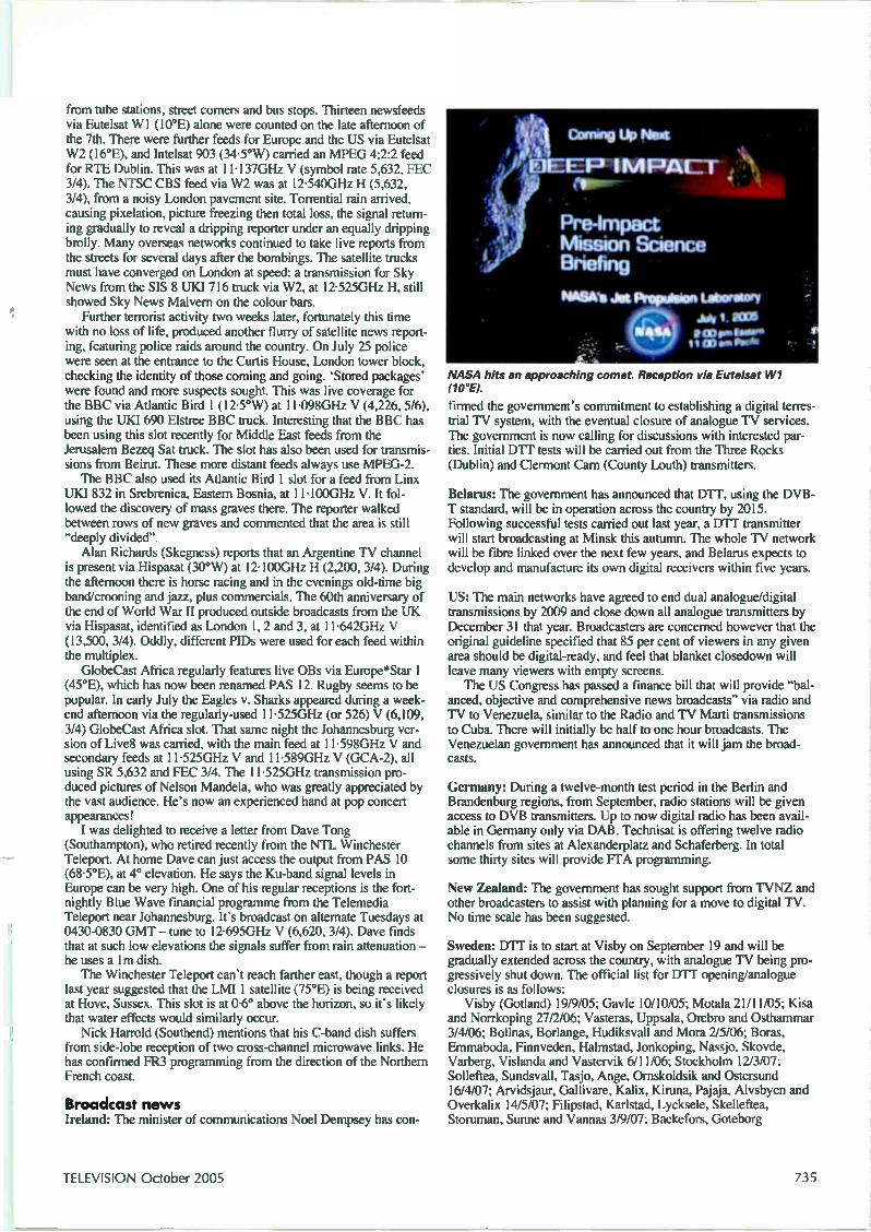
from tube stations, street corners and bus stops. Thirteen newsfeeds via Eutelsat WI (10°E) alone were counted on the late afternoon of the 7th. There were further feeds for Europe and the US via Eutelsat W2 (16°E), and Intelsat 903 (34.5°W) carried an MPEG 4:2:2 feed for RTE Dublin. This was at 11.137GHz V (symbol rate 5,632, FEC 3/4). The NTSC CBS feed via W2 was at 12.540GHz H (5,632, 3/4), from a noisy London pavement site. Torrential rain arrived, causing pixelation, picture freezing then total loss, the signal return-ing gradually to reveal a dripping reporter under an equally dripping brolly. Many overseas networks continued to take live reports from the streets for several days after the bombings. The satellite trucks must have converged on London at speed: a transmission for Sky News from the SIS 8 UKI 716 truck via W2, at 12.525GHz H, still showed Sky News Malvern on the colour bars. Further terrorist activity two weeks later, fortunately this time
with no loss of life, produced another flurry of satellite news report-ing, featuring police raids around the country. On July 25 police were seen at the entrance to the Curtis House, London tower block, checking the identity of those coming and going. 'Stored packages' were found and more suspects sought. This was live coverage for the BBC via Atlantic Bird 1 (12.5°W) at 11.098GHz V (4,226, 5/6), using the UKI 690 Elstree BBC truck. Interesting that the BBC has been using this slot recently for Middle East feeds from the Jerusalem Bezeq Sat truck. The slot has also been used for transmis-sions from Beirut. These more distant feeds always use MPEG-2. The BBC also used its Atlantic Bird 1 slot for a feed from Linx
UKI 832 in Srebrenica, Eastern Bosnia, at 1 1 -100GHz V. It fol-lowed the discovery of mass graves there. The reporter walked between rows of new graves and commented that the area is still "deeply divided". Alan Richards (Skegness) reports that an Argentine 1'V channel
is present via Hispasat (30°W) at 12.100GHz H (2,200, 3/4). During the afternoon there is horse racing and in the evenings old-time big band/crooning and jazz, plus commercials. The 60th anniversary of the end of World War II produced outside broadcasts from the UK via Hispasat, identified as London 1, 2 and 3, at 11.642GHz V (13,500, 3/4). Oddly, different PIDs were used for each feed within the multiplex. GlobeCast Africa regularly features live OBs via Europe*Star 1
(45°E), which has now been renamed PAS 12. Rugby seems to be popular. In early July the Eagles v. Sharks appeared during a week-end afternoon via the regularly-used 11.525GHz (or 526) V (6,109, 3/4) GlobeCast Africa slot. That same night the Johannesburg ver-sion of Live8 was carried, with the main feed at 11.598GHz V and secondary feeds at 11.525GHz V and 11.589GHz V (GCA-2), all using SR 5,632 and FEC 3/4. The 1 1.525GHz transmission pro-duced pictures of Nelson Mandela, who was greatly appreciated by the vast audience. He's now an experienced hand at pop concert appearances! I was delighted to receive a letter from Dave Tong
(Southampton), who retired recently from the NTL Winchester Teleport. At home Dave can just access the output from PAS 10 (68-5°E), at 4° elevation. He says the Ku-band signal levels in Europe can be very high. One of his regular receptions is the fort-nightly Blue Wave financial programme from the Telemedia Teleport near Johannesburg. It's broadcast on alternate Tuesdays at 0430-0830 GMT — tune to 12-695GHz V (6,620, 3/4). Dave finds that at such low elevations the signals suffer from rain attenuation — he uses a 1m dish. The Winchester Teleport can't reach farther east, though a report
last year suggested that the LMI 1 satellite (75°E) is being received at Hove, Sussex. This slot is at 0-6° above the horizon, so it's likely that water effects would similarly occur. Nick Harrold (Southend) mentions that his C-band dish suffers
from side-lobe reception of two cross-channel microwave links. He has confirmed FR3 programming from the direction of the Northern French coast.
Broadcast news I r(.1 a 11(1: The minister of communications Noel Dempsey has con-
'4 1 Coming Up Next
• FIEEP IMPACT '
:IP
Pre-Impact Mission Science Briefing
Pmews.mt Premise» tallanisry Joif 001111 eixtrilier* ar mor. , •
NASA hits an approaching comet. Reception via Eutelsat W1 (10°E).
firmed the government's commitment to establishing a digital terres-trial TV system, with the eventual closure of analogue TV services. The government is now calling for discussions with interested par-ties. Initial UM' tests will be carried out from the Three Rocks (Dublin) and Clermont Cam (County Louth) transmitters.
Belarus: The government has announced that DIT, using the DVB-T standard, will be in operation across the country by 2015. Following successful tests carried out last year, a UM' transmitter will start broadcasting at Minsk this autumn. The whole TV network will be fibre linked over the next few years, and Belarus expects to develop and manufacture its own digital receivers within five years.
US: The main networks have agreed to end dual analogue/digital transmissions by 2009 and close down all analogue transmitters by December 31 that year. Broadcasters are concerned however that the original guideline specified that 85 per cent of viewers in any given area should be digital-ready, and feel that blanket closedown will leave many viewers with empty screens. The US Congress has passed a finance bill that will provide "bal-
anced, objective and comprehensive news broadcasts" via radio and TV to Venezuela, similar to the Radio and TV Marti transmissions to Cuba. There will initially be half to one hour broadcasts. The Venezuelan government has announced that it will jam the broad-casts.
Germany: During a twelve-month test period in the Berlin and Brandenburg regions, from September, radio stations will be given access to DVB transmitters. Up to now digital radio has been avail-able in Germany only via DAB. Technisat is offering twelve radio channels from sites at Alexanderplatz and Schaferberg. In total some thirty sites will provide FTA programming.
New Zealand: The government has sought support from TVNZ and other broadcasters to assist with planning for a move to digital TV. No time scale has been suggested.
Sweden: DIT is to start at Visby on September 19 and will be gradually extended across the country, with analogue TV being pro-gressively shut down. The official list for UM' opening/analogue closures is as follows: Visby (Gotland) 19/9/05; Gavle 10/10/05; Momia 21/11/05; ICisa
and Norrkoping 27/2/06; Vasteras, Uppsala, Orebro and Osthammar 3/4/06; Bollnas, Borlange, Hudiksvall and Mora 2/5/06; Boras, Emmaboda, Finnveden, Halmstad, Jonkoping, Nassjo, Skovde, Varberg, Vislanda and Vastervik 6/11/06; Stockholm 12/3/07; Solleftea, Sundsvall, Tasjo, Ange, Ornskoldsik and Ostersund 16/4/07; Arvidsjaur, Gallivare, Kalix, Kiruna, Pajaja, Alvsbyen and Overkalix 14/5/07; Filipstad, Karlstad, Lycksele, Skelleftea, Storuman, Sunne and Vannas 3/9/07; Backefors, Goteborg
TELEVISION October 2005 735
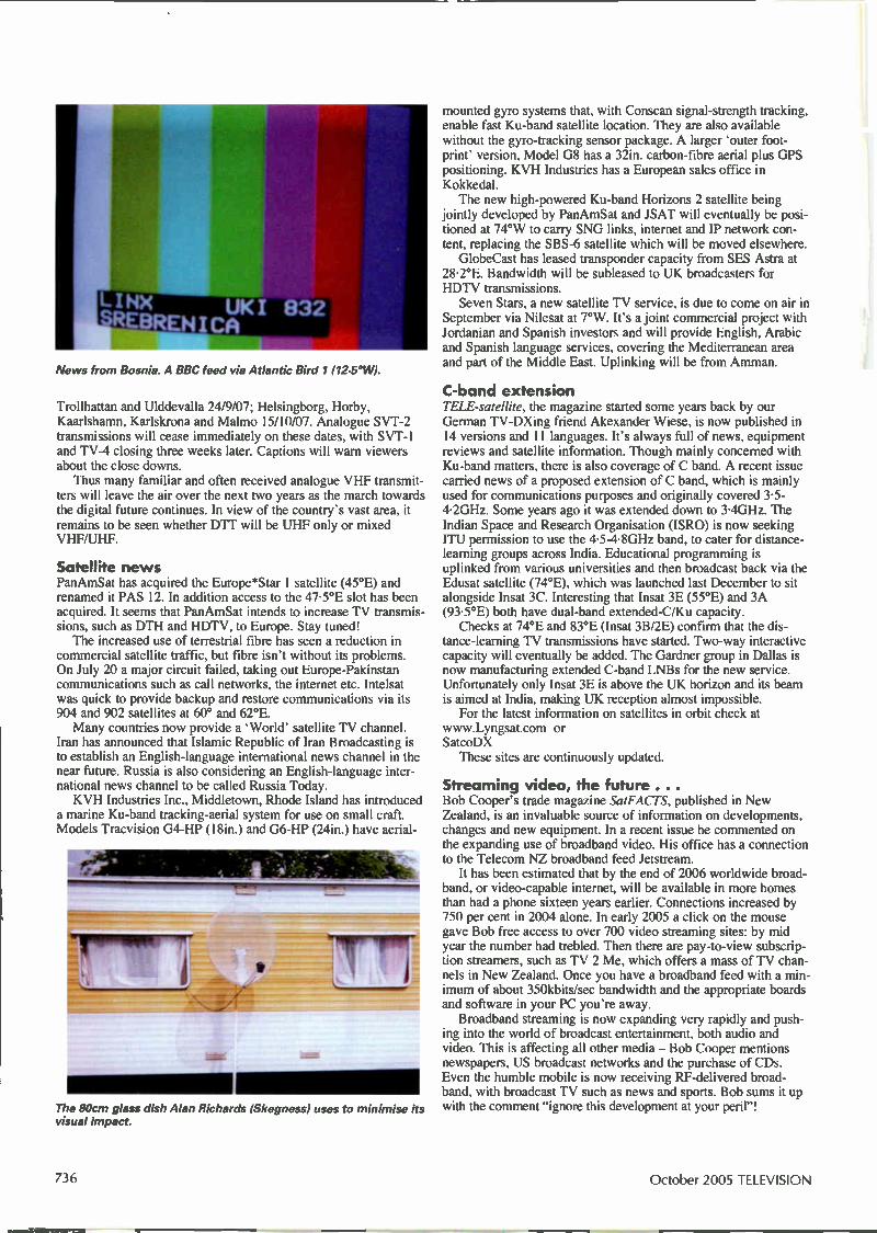
News from Bosnia. A BBC feed via Atlantic Bird 1 (12.5° W).
Trollhattan and Ulddevalla 24/9/07; Helsingborg, Horby, Kaarlshamn, Karlskrona and Malmo 15/10/07. Analogue SVT-2 transmissions will cease inunediately on these dates, with SVT-1 and 1'V-4 closing three weeks later. Captions will warn viewers about the close downs. Thus many familiar and often received analogue VHF transmit-
ters will leave the air over the next two years as the march towards the digital future continues. In view of the country's vast area, it remains to be seen whether DTT will be UHF only or mixed VHF/UHF.
Satellite news PanAmSat has acquired the Europe*Star 1 satellite (45°E) and renamed it PAS 12. In addition access to the 47.5°E slot has been acquired. It seems that PanAmSat intends to increase TV transmis-sions, such as DTH and HDTV, to Europe. Stay tuned! The increased use of terrestrial fibre has seen a reduction in
commercial satellite traffic, but fibre isn't without its problems. On July 20 a major circuit failed, taking out Europe-Pakinstan communications such as call networks, the internet etc. Intelsat was quick to provide backup and restore communications via its 904 and 902 satellites at 60° and 62°E. Many countries now provide a 'World' satellite TV channel.
Iran has announced that Islamic Republic of Iran Broadcasting is to establish an English-language international news channel in the near future. Russia is also considering an English-language inter-national news channel to be called Russia Today. KVH Industries Inc., Middletown, Rhode Island has introduced
a marine Ku-band tracking-aerial system for use on small craft. Models Tracvision G4-HP (18in.) and G6-HP (24in.) have aerial-
The 80cm glass dish Alan Richards (Skegness) uses to minimise its visual impact.
mounted gyro systems that, with Conscan signal-strength tracking, enable fast Ku-band satellite location. They are also available without the gyro-tracking sensor package. A larger 'outer foot-print' version, Model G8 has a 32in. carbon-fibre aerial plus UPS positioning. KVH Industries has a European sales office in Koklcedal. The new high-powered Ku-band Horizons 2 satellite being
jointly developed by PanAmSat and JSAT will eventually be posi-tioned at 74°W to carry SNG links, internet and IP network con-tent, replacing the SBS-6 satellite which will be moved elsewhere. GlobeCast has leased transponder capacity from SES Astra at
28.2°E. Bandwidth will be subleased to UK broadcasters for HDTV transmissions. Seven Stars, a new satellite TV service, is due to come on air in
September via Nilesat at 7°W. It's a joint commercial project with Jordanian and Spanish investors and will provide English, Arabic and Spanish language services, covering the Mediterranean area and part of the Middle East. Uplinking will be from Amman.
C-band extension TELE-satellite, the magazine started some years back by our German TV-DXing friend Akexander Wiese, is now published in 14 versions and 11 languages. It's always full of news, equipment reviews and satellite information. Though mainly concerned with Ku-band matters, there is also coverage of C band. A recent issue carried news of a proposed extension of C band, which is mainly used for communications purposes and originally covered 3.5-4.2GHz. Some years ago it was extended down to 3.4GHz. The Indian Space and Research Organisation (ISRO) is now seeking ITU permission to use the 4-5-4.8GHz band, to cater for distance-learning groups across India. Educational programming is uplinked from various universities and then broadcast back via the Edusat satellite (74°E), which was launched last December to sit alongside Insat 3C. Interesting that Insat 3E (55°E) and 3A (93.5°E) both have dual-band extended-C/Ku capacity. Checks at 74°E and 83°E (Insat 3B/2E) confirm that the dis-
tance-learning TV transmissions have started. Two-way interactive capacity will eventually be added. The Gardner group in Dallas is now manufacturing extended C-band LNBs for the new service. Unfortunately only Insat 3E is above the UK horizon and its beam is aimed at India, making UK reception almost impossible. For the latest information on satellites in orbit check at
www.Lyngsat.com or SatcoDX These sites are continuously updated.
Streaming video, the future . . . Bob Cooper's trade magazine SatFACTS, published in New Zealand, is an invaluable source of information on developments, changes and new equipment. In a recent issue he commented on the expanding use of broadband video. His office has a connection to the Telecom NZ broadband feed Jetstream. It has been estimated that by the end of 2006 worldwide broad-
band, or video-capable internet, will be available in more homes than had a phone sixteen years earlier. Connections increased by 750 per cent in 2004 alone. In early 2005 a click on the mouse gave Bob free access to over 700 video streaming sites: by mid year the number had trebled. Then there are pay-to-view subscrip-tion streamers, such as TV 2 Me, which offers a mass of TV chan-nels in New Zealand. Once you have a broadband feed with a min-imum of about 350kbits/sec bandwidth and the appropriate boards and software in your PC you're away. Broadband streaming is now expanding very rapidly and push-
ing into the world of broadcast entertainment, both audio and video. This is affecting all other media — Bob Cooper mentions newspapers, US broadcast networks and the purchase of CDs. Even the humble mobile is now receiving RF-delivered broad-band, with broadcast TV such as news and sports. Bob sums it up with the comment "ignore this development at your peril"!
October 2005 TELEVISION
H ELP Wanted: Service manual for the Panasonic camcorder Model NV-M10, to beg/borrow/ buy, or can someone scan the audio circuit diagrams and email them to me? Alternatively, does anyone know why one of them should have no audio play or record or headphone monitoring? Please email Geoff Darby on [email protected] Wanted: Basic microwave oven shell, i.e. no door, components etc., for the Sanyo Model EM-C1850. Willing to pay plus costs for a good, sound example. Phone Brian Long on 01593 741 249 (Caithness). For disposal: Approximately 50kg of ser-vice manuals in lever-arch folders, mostly dating from the 70s and 80s, TV, radio, hi-fi etc. Free for cost of postage. For further details contact William Williamson, Leeskol, North-a-Voe, Yell, Shetland, ZE2 9DA or email [email protected] Wanted: Old half-inch diameter ferrite rods. Must be six inches or more long. Will pay very good money for them. Peter Tankard, 16A Birkendale Road, Sheffield, S6
The help wanted column is primarily intended to assist readers who require a part, circuit etc. that's difficult to obtain. Requests are published at the discretion of the editor. Send them to the editorial department — do not write to or phone the advertisement department. If you have access to email they can be sent to [email protected]
3NL. Phone 0114 231 6321 between 9 a.m. and 10 p.m. Wanted: Batteries for an Avometer Model 40. Phone Spud Cox on 01256 472 906. For sale: Retired TV engineer has classic and modern test instruments for sale. For a list please contact John Stacey (G8BX0), 3 West Park, South Molton, Devon, EX36 4HJ. Phone 01769 573 382. For disposal: Free to a collector/enthusiast, a vintage Pye radiogram manufactured in 1952. In good working order with dark oak cabinet in good condition. R. Weston, 44 Grange Crescent, Rubery, Birmingham. Phone 01214 533 786. Wanted: Quad 33, 34 or 44 preamplifiers, 405 power amplifiers and FM2, FM3 or FM4 tuners for spares. Also boards and modules for these. Contact Mike on 01758 613 790. Wanted/for disposal: Require a Toshiba Model V804B VCR (redundant machine will do) and a working Panasonic Alpha 1 TV chassis. Have for disposal Television maga-zines 1990-2001, mostly in mint condition; a Sony TXT-100B teletext unit; a Sony Trinico HVC3000P video camera with case; two Sony SL-C9UB Beta VCRs in working con-dition with modified DC-DCs plus a number of panels etc. and a service manual. Contact Bruce, 11 New Zealand Way, Rainham,
Essex, RM13 8JP. Phone 01708 558 792. Wanted: Service manual or circuit diagram for the Philips tape recorder Model N4450 (photocopy OK). Please call lain Hare on 01726 72 050 or email [email protected]. For disposal: Two working Philips G8 TV sets. One still has the original tube, the other a regunned tube that was fitted in 1986. Both in good working order with some spare boards. Also a quantity of valves (about 100), mostly audio and early colour and monochrome TV types. Free to a good home. Phone Steve Ball on 01733 347 678 (Peterborough) or email [email protected] Wanted: Grundig Yacht Boy radio. Must be Model 210 dating from 1970-74. Will pay very good money for a set in mint condition. Peter Tankard, 16A Birkendale Road, Sheffield, S6 3NL. Phone 0114 231 6321 between 9 a.m. and 10 p.m. Wanted: Non-working Panasonic VCR Model NVFJ611B, preferably to collect within Bristol postal area. Please phone Cedric Crook on 01275 879 620 (Clevedon, N. Somerset). For disposal: A large number of Grundig modules, also Philips Gll and KT3/30 and Thom 3000/3500. Alan Bray, 12 Westward Way, Kenton, Harrow, Middlesex, HA3 OSE. Phone 020 8907 2920.
1/2 page Horizontal
TELEVISION October 2005 737

A visit to the drugstore Elaine Everest's recent visit to her local drugstore prompts her to outline a plan for moving the TV trade into the 21st century
Arecent comment column in the magazine led me to think about the state of the radio and TV trade. No wonder it's oing down the pan. Consumer electrical and electronics
products are being sold in every conceivable type of shop. Only last month I was browsing at the make-up stand in one of our more popular high street shops when I noticed a customer who had a query. "Excuse me luv, can you tell me something?" an elderly man
called to a young girl who was piling nappies in the baby sec-tion. "We're rather confused about these boxes you're selling"
added his wife. The girl dropped her nappies and joined the couple, who
were peering at the display of Freeview boxes. "What's the problem, sir?" she asked. "Well, we wanted one of these boxes, because Doris wants
to watch her Coronation Street repeats and I want to watch the football. Can both of these boxes do that, and why is one twen-ty quid dearer than the other one." "Er, I'm not really sure sir, I'll have
to ask the manager." She scuffled off towards the
storeroom as the elderly gentleman called after her "ask her if some-one can come and fix it, and what happens if it breaks down?"
Nitty gritty By now I was only a few feet away from the couple. The man had asked the very questions that had occurred to me. It's all very well popping out to the local supermarket to buy a pint of milk and coming home with a widescreen TV set, but what hap-pens when you can't set it up and it breaks down? The nearest our local Asda can
get to a home delivery service is to provide a young lad to wheel your purchases out to your car on a wobbly shopping trolley. They have as much idea about getting your TV set into the car as they do about packing your carrier bag —
the eggs are always at the bottom! Back at the drugstore another young woman had appeared.
She was apparently the Manageress. Not being more than a few years older than the shelf-stacker, one can only assume that she had passed her 0 level in nail-varnish knowledge — and chav talk in order to be able to control her staff.
A word of help By this time I had joined the conversation with the elderly cou-ple and had looked at the two Freeview boxes. It was obvious that the cheaper one didn't have scart leads and other parapher-nalia that would be needed to set up the system. It also had a brand name I'd never heard of. If all else fails, I always advise my husband's customers to buy a brand they recognise. This may save you having to phone Hong Kong with a query. I had just jotted down the phone number and address of the
repair shop where himself earns a crust. I had pointed out to them that for the same money they would get full advice on set-
ting up the system, and also a call-out repair service whenever it was needed.
An altercation The manageress was not amused when the elderly couple handed back the box they had been looking at and went to the counter to pay for their purchase of the buy one get one free denture fix. She fixed me with an icy stare. "I'll
ask you not to interfere with our cus-tomers, madam" she hissed. It was at this point that I saw red. If we
don't start to stick up for our own business interests, the demise of the electrical retail-er will come even sooner than expected. Our trade would be handed over to the likes of the nail-varnish queen, who was aiming her most venomous stare in my direction. I pulled myself up to all of my five
foot and three inches and glared back at her. "Look here, dear, let's make a deal, shall we" I said, "if you promise to stop selling consumer electronics products in your chemist shop, we won't stock wax-ing kits and eyelash curlers. OK?" But I suppose I had better steer clear
738 October 2005 TELEVISION

of that particular shop for now. I wonder if Currys or Dixons sell sun-tan cream?
A plan My little encounter really made me think about the situation. The electronics repair trade needs a swift kick up its backside to stop it sliding into oblivion. Then, to quote Baldrick, I had a cunning plan! The repair business needs a drastic revamp. It must be made
more attractive to the customer. Take a look at the gardening trade. A couple of TV programmes and a few hunky men to demonstrate how to prune our roses and, Bob's your uncle, everyone wants to employ a landscape gardener! Just think. If you had the likes of Diannuid Gavin, Lawrence
Llewellyn Bowen and Alan Tichmarsh working in your repair department the ladies would be queuing at the door to get their bits and pieces repaired! Now take a look at the typical TV repair shop. Not a pretty
sight, is it? I know of one highly salubrious place that never opens before midday. The staff look as though they've just fall-en out of a tent from the 1964 Isle of Wight pop festival, and dead flies in the window display date back to before the millen-nium. My plan would revolutionise the repair industry and would-
n't cost a fortune — and even that's tax deductible.
The details So here goes. What you do is:
(1) Make the workplace completely open-plan and decorate it in vibrant colours. It will then attract / customers instead of flies, and keep your workers awake. Have a room tucked away at the back of the shop — I will explain why later.
(2) Install an internet café or burger bar, depending on the type of area in which you are located. This will entice a younger element to take an interest in your business and, let's face it, they are the ones with the money these days.
(3) Revamp your engineers. This may take a little time. A yearly membership to the local gym would help. Added to this you could have staff exer-cises before the workshop opens each morning, and a five-mile jogging session when you close for lunch.
(4) Uniforms are needed. To attract the cus-tomers and show off the new physiques, I suggest cut-off T-shirts and shorts. And add to this a weekly session at the tan-ning shop to give them a golden glow.
(5) You may have a problem with older staff who won't fit into the revamped business. This is where the room at the back of the shop comes in. I'm afraid I'm going to be very ageist here. You need to lock away these employees. They don't do your business any good and don't fit in with the young image you are now por-traying. Regular supplies of tea and meat pies will keep them happy — and The Archers on the radio. (Now then Elaine, if B&Q can
manage to make good use of older
staff, why can't we? They add assurance to the scene. Editor.)
(6) Most of you will have a female who serves customers. For quite a few it's probably the wife. This probably doesn't fit with the new image I'm suggesting. An older person might be OK for doctors' surgeries, but not for us. Yes, you've guessed it, she's in the back room too. Give her a copy of Woman's Weekly, and she can chat with the old boys, ring her mates and do the odd bit of credit control. She does that anyway? Well, no problem then, you don't need to change her contract — if indeed she has one. In her place
we'll have someone younger, on roller blades and in cheerleader outfits — compa-ny colours of course! Her or their tasks are twofold: to serve customers in the interne café or burger bar — then use their roller blades to transport equip-ment to customers' vehicles.
back to be
(7) Finally, you. Yes, I know we can't hide you away in that already overstaffed room. You need out front, finger on the pulse and all that. So how about a
facelift, tummy-tuck or do something about that hair? I'm sure you know a way of making this look like a valid business expense. That's a skill you've probably honed to perfection over the years! And how about some designer
clothes? Tell the tax man they're over-alls. Then a quick top-up on the tan. No sunbed for you: have a cruise at the company's expense.
And there you are, the new busi-ness is complete!
Thanks You don't need to thank me for these valuable business tips. Just send chocolates via Tessa at the address in the front of the maga-zine. Oh, and if anyone is thinking of sending the equal opportunity people after me, you'll find that I am in the backroom of hubby's workshop, listening to Desert Island Discs and
reading my Woman's Weekly.
TELEVISION October 2005 739

, ) E .1 tester design A flexibl
1.0friX TESTER
2/111CV- ORANGE.
Commercial LOPT testers cost about £90. This simple, easy-to-use tester, designed by Paul Coles, can be built for a fraction of that cost
re line output transformer tester described in this article was designed primarily to reduce diagnostic time with sets in which the line timebase is under the control of the microcon-
troller chip. In the event of a line output stage fault such sets will switch on for a second then revert to standby. Alternatively the
power supply may go into the excess-current protection mode. This tester enables the transformer to be quickly eliminated as a possible cause. It has been in use in our workshop for over three years, with all sorts of TV sets, and has saved us a considerable amount of time. The line output transformer is often suspected when the
cause of the trouble is elsewhere, for example shorted line scan coils etc. The latter is a common fault with small portables that use Orion tubes. A check with the tester will avoid a faulty diag-nosis in a situation like this. For example a Sony Model KV1410 was blowing fuses in the supply to the line output stage. This is usually caused by a faulty transformer. The tester cleared it, and further work revealed that the field output IC was the cause — it was short-circuit. A replacement chip cured the fault.
Dairdetaik Fig. 1 shows the circuit diagram of the tester, which is based on the popular Signetics 555 timer chip (IC1). It's used as an astable oscillator to provide the LOPT being tested with drive at approxi-mately 15.61(Hz. The supply end of the LOPT's primary winding is fed with about 8.5V via a current-limiting resistor (R11, main PCB). As a result the line output stage runs at about 1/25th of the normal energy level. In this condition it will not be notably affected by shorted components, for example ICs etc., fed from a scan-derived supply. The peak collector voltage in this condition can be checked
with an oscilloscope. A good transformer should produce a pulse that peaks at about 50V. There will also be about 800V at the first anode connector. This can be checked with an oscilloscope or fed to a meter for a derived ENT reading. This checks for shorted diodes etc. across the secondary windings.
Main PCB
R13
R14
D1 4
R15 R16
D2
•InC5 nu C6 min ▪ C4
C3
— UF-P12
Tr3
• •
o Oscilloscope connections
:C2
LOPT being tested
EHT (anode cap)
Collector pin
o HT pin
11
ABL pin
Meter PCB
R8 R9 R10 R7 AA AA AA vvv vvv vvv
: C3
Tr2
Fig. 1: Circuit diagram of the LOPT tester, which is built on two boards (main and meter).
740 October 2005 TELEVISION

The meter used was a ready-to-hand VU type from a scrap Philips cassette recorder. When checked it was found to read 300pA at full-scale deflection. As the EHT section of a good transformer will provide only 18-20pA when operated in this way, a FET amplifier circuit was designed to increase the meter sensitivity to 20/4A at FSD. At switch on with no test leads connected the
Fig. 2: Alternative meter scales. 25kV-30kV LOPT OK, otherwise LOPT faulty.
------..„ ee'tej ov
lOpsec. 20Vidly
\ 10 e«, 20V/do
la)
er--- - - - 7 , e s' jej °fr
65use,
V
800
o
20 \Prim 10 probe
Good LOPT
LOPT faulty
Fig. 3: (a) Meter reading and oscilloscope waveform with a good LOPT. (b) Meter reading and oscilloscope waveform with a faulty LOPT. (c) Meter reading and oscilloscope waveform with incorrect connection or an open-circuit winding. (d) Conditions at the anode connector with a good and a faulty LOPT, oscilloscope check.
voltmeter circuit will check the battery condition, as the needle will shift away from zero with decreasing battery voltage. Any 100-300pA meter can be used however — just decrease the value of R6 to reduce the sensitivity. Aim for FSD with 18pA through R7.
Construdion This is flexible. Different versions can be built depending on use. For example if the tester is to be used only in the workshop, the meter circuit can be omitted and, for ease of construction, a much larger case could be used, with the battery fitted internally and an on/off switch and flashing on LED indicator added. To use this version, connect the HT and collector leads to the transformer's primary winding after disconnecting its collector pin. Use an oscilloscope to monitor the peak waveform at the collector. 50V = OK. Then switch your oscilloscope to 20V/cm and check at the anode connector with a x10 probe. DC ripple at approximately 700V should be seen. The version I built (see photograph) was made
small enough to fit inside the ever-decreasing space in my toolbox. The only reason the meter was fitted was for use during service calls. The VU meter used was fitted from inside the case, with the scale protruding through the cutout.
Setting up ( 1) Connect a new 9V battery.
(2) Adjust R2 on the meter PCB to zero the meter. (3) Set R16 to mid-position. Connect an oscilloscope or frequency counter across Tr3 (oscilloscope connec-tions). With no transformer connected, adjust R13 for a reading of 15.6kHz on the counter or pulses at 64psec on the oscilloscope.
(4) Connect the collector and HT connectors to the pri-mary winding of a known good LOPT. An oscilloscope
should show a peak collector voltage of approximately 50V. If necessary, adjust R16 very slightly for minimum ringing at the bottom of the waveform.
(5) Connect the anode lead. The meter should show 25-30kV (derived).
Use Remove the CRT's anode con-nector, then desolder the LOPT's collector pin. Connect the HT and collector pin leads of the tester. Connect the earth lead to focus earth or the LOPT's ABL pin.
Edge of case
Nut and washer
Battery connector
Bolt
Systoflex insulation sleeve. Fit inside
Fig. 4: Method of fitting the
battery connector to
the case.
Display with a good LOPT.
TELEVISION October 2005 741
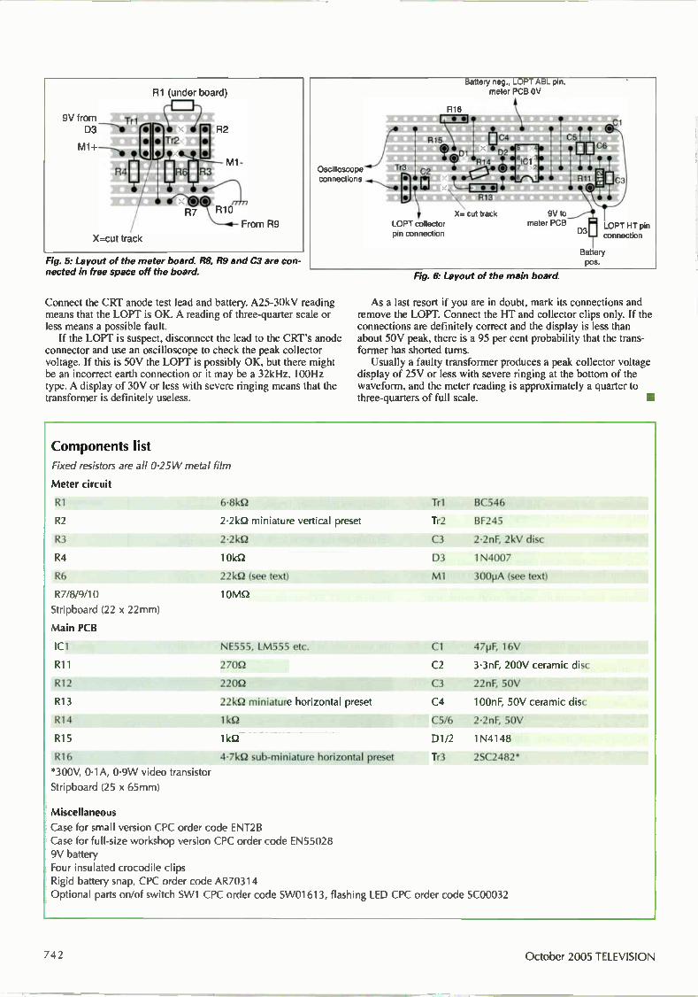
R1 (under board)
9V from Tri
M1+--- e
R.z El
é
X=cut track
Fig. 5: Layout of the meter board. R8, R9 and C3 are con-nected in free space off the board.
Oscilloscope connections
T 3 ire • •
attery neg., meter PCB OV
R16
R15 C4
01 D2 R14
C2
R13
X= cut track LOPT collector pin connection
pin,
•
9V to meter PCB
D3
Cl
LOPT HT pin connection
Battery pos.
Connect the CRT anode test lead and battery. A25-30kV reading means that the LOPT is OK. A reading of three-quarter scale or less means a possible fault. If the LOPT is suspect, disconnect the lead to the CRT's anode
connector and use an oscilloscope to check the peak collector voltage. If this is 50V the LOPT is possibly OK, but there might be an incorrect earth connection or it may be a 32kHz, 100Hz type. A display of 30V or less with severe ringing means that the transformer is definitely useless.
Fig. 6: Layout of the main board.
As a last resort if you are in doubt, mark its connections and remove the LOPT. Connect the HT and collector clips only. If the connections are definitely correct and the display is less than about 50V peak, there is a 95 per cent probability that the trans-former has shorted turns. Usually a faulty transformer produces a peak collector voltage
display of 25V or less with severe ringing at the bottom of the waveform, and the meter reading is approximately a quarter to three-quarters of full scale.
Components list
Fixed resistors are all 0.25 W metal film
Meter circuit
R1
R2
R3
R4
R6
R7/8/9/10
Stripboard (22 x 22mm)
Main PCB
IC1
R11
R12
R13
R14
R15
R16
*300V, 0.1A, 0.9W video transistor
Stripboard (25 x 65mm)
6-8kQ
2.2kQ miniature vertical preset
2.2k0
10kQ
221S2 (see text)
10MQ
NE555, LM555 etc.
270Q
220Q
221(52 miniature horizontal preset
11Q
lkQ
4.7k5-2 sub-miniature horizontal preset
Tri BC546
Tr2 BF245
C3 2.2nF, 2kV disc
D3 1 N4007
M1 300pA (see text)
Cl 47pF, 16V
C2 .3.3nF, 200V ceramic disc
C3 22nF, 50V
C4 100nF, 50V ceramic disc
C5/6 2.2nF, 50V
01/2 1N4148
Tr3 2SC2482*
Miscellaneous
Case for small version CPC order code ENT2B Case for full-size workshop version CPC order code EN55028 9V battery Four insulated crocodile clips Rigid battery snap, CPC order code AR70314
Optional parts on/of switch SW1 CPC order code SW01613, flashing LED CPC order code SC00032
742 October 2005 TELEVISION

°LOUR TRADE POSSIRLY
LA R GEST F. cLors EST. rro
THE fly EST FOP 20 YEA RS
Wholesaler Distributors & Expert Agents of Domestic Electronics & Appliances
FULL RANGE OF FACTORY GRADED TV's DVD / VIDEOS HI-FI SMALL & LARGE DO MESTIC GOODS
MAIN DEALER
• Thompson • Sanyo • Beko
on Digital Satellite Meter
www.colourtrade.com WHOLESALE MADE EASY ON LINE, SIGN UP NOW FOR OUR WHOLESALE PRICES.
ALL ORDERS DISPATCHED ON THE SAME DAY. N o w A vailable
TV's, D VD's, V CR & A U DI O Over 40 years of genuine experience
Experts on:. Thomson • Sanyo • Beko • LG • Tatung • Ferguson Bush • Funai • Pacific • Dansai • Samsung & more
TECHNICAL SUPPORT 0907 076 70 80
Call cost 6jp min
it*
Ion
Tel: 0121 359 7020 Fax: 0121 359 6344 Phoenix House, 190 Bridge St. West, Newtown, Birmingham B19 2YT
Email: [email protected] m
1 1.11.1
Horizon Digital erréstrial MT'S • Displays Signal Strength (R.F level)
and Pre and Post BER together • 32 pre programmed transmitters
(via website) or all channel step through • Audible tune-ln, with back light • Automatic constellation • RF Input range 167-862 MHz
• Input dynamic range -72dBot---20dlim
HDSM
• Signal Strength and BER displayed together • 32 Transponders or 16 satellites, horizontal & vertical
• Audible tune-in, with back light
• DVB, C&Ku baad, Mpeg, V Sat compatible • Figure of 8 mains input connector. 2.1 mm Female PSU plug
11 . 1.J 1
I I
kri -1d, For a reliable solutiont
www.horizonhge.com
ember. Satellite Me rs
a
• Cost effective • Small and Compact • Measure two vats at same time • Sidt powered via rechargeable NIMH batteries • Powered na built In batteries, charger or receiver
AI L
L andau,
'1 • Also available from the following distributors Eurosat Midlands 01922 639299 www.eurosatmidlands.com Eurosat North 01924 423602 www.eurosatmidlands.com Gras Nottingham 0115 927 9993 www.grax.co.uk Gras Manchester 0161 747 2007 www.grax.co.uk Graz Leeds 0113 26 33 500 www.grax.co.uk
Solutions Group 08456 444 000 www.solutionsgroup-plc.com
Or contact Horizon direct for your local supplier
on +44 (0)20 8344 8230
or email [email protected]
TELEVISION October 2005 743
App L_ID FA X Reports from
Geoff Darby
Chris Bowers
Andrew Benyon
Philip Rosbottom and
Martin McCluskey
We welcome fault reports from readers - payment for each fault is made after publication.
Reports can be sent by post to:
Television Magazine Fault Reports, Nexus Media Communications, Media House, Azalea Drive, Swanley, Kent BR8 8HU
or e-mailed to: [email protected]
Sony MZ-N710 The owner's complaint about this personal MiniDisc recorder was "not playing - keeps searching for disc". There were cer-tainly sled search noises when I tried it but, other than this, not a lot happened. With the lid open I used a cotton bud for an experimental prod at the optical block. Instead of resisting, it moved freely from side to side. So there was clearly no con-nection between the laser and the worm drive. I stripped the unit and removed the
PCB. This sounds drastic, but it takes only a few minutes. It was then obvious what had gone wrong. The pawl that engages with the sled drive worm is made from a thin piece of shaped phosphor bronze and is secured to the optical block by a single, tiny screw. The screw had become loose, and as a result the pawl twisted off to one side and lost its engagement with the worm. I repositioned the piece and tightened its
screw, adding a tiny amount of locking compound. This restored the normal mechanical coupling - and correct opera-tion once the unit had been reassembled. G.D.
Sony HST-D307 This hi-fi unit's FM radio operation was very intermittent. You couldn't force it to go off: it just did so whenever it felt inclined. It sounded as if it was muting. Checks along the IF strip revealed a good level of 10.7MHz signal at the output from CF301 and, after amplification by Q303 and Q304, the signal arrived at CF303. The output from this ceramic filter was very variable however and, when reception cut out, there was quite a violent 'bounce' in the IF waveform at this point. This effect was not present at the input
side of CF303, which suggested that the problem was either in the filter itself or in something nearby and downstream from it. I decided to replace the filter as a first move. When I rummaged through the con-tents of my component drawer marked 'fil-ters and xtals asst' I found a suitable replacement and fitted it. This provided a complete cure. I assume that the output from this filter
periodically fell below the demodulation threshold of the IF subsystem and demodu-lator chip IC301, which then muted. G.D.
Sony HCD-RX70 When 1 connected speakers to this one and powered it up I was greeted with a rasping buzz from both channels. Suspecting power supply trouble I headed for the smoothing capacitors, scope probe in hand. This quickly showed that C954 had
massive ripple, with bursts of oscillation. across it. When this 2,200µF, 16V capacitor was removed a slight bulge in its top could be seen. Once a replacement, more conserva-tively rated at 25V, had been fitted there was normal operation. A nice easy one for a change. G.D.
LG FFH-5670AD Long ago, when 1 was a fresh-faced and enthusiastic youth, my workshop mentor taught me that I carried my best diagnostic equipment, superior to a meter, scope or anything else, around with me all the time. He was referring to my nose, ears, eyes and fingers of course. You can tell a lot about what's going on in a piece of equip-ment by careful observation of sounds and smells, sometimes component temperature, and just as often by spending a few min-utes carefully looking. Causes of faults can often be found without having to resort to the use of any equipment or diag-nostic procedures. This was a good exam-ple. When the unit was powered it would start to come on but, after an initial burst of display and CD motor activity, it would simply 'freeze', usually with just 'non-sense' segments alight in the display and all the controls inoperative. There was a smell of warm transistor plastic, and a good look over the main PCB revealed crystallised joints at Q202. In addition the board was discoloured around the transis-tor's legs. It was a fairly small transistor, type 2SA1273. The A in the type number normally indicates a pnp device with stan-dard Japanese nomenclature, so I hunted through my component drawers and soon came up with a somewhat beefier alterna-tive. Once it had been fitted the unit sprang to life and worked normally. I had no circuit diagram for the unit, and have no idea what the function of the tran-sistor is. I would guess that it's a regulator or DC switch of some kind. But, with a lit-tle observation, the unit was repaired with no need for documentation or test equip-ment. G.D.
Sony MDS-JB920 The complaint with this unit was digital noise during playback. The cause of the trouble was on board BD, where the ATRAC decoding chip was faulty. Its part no. is 8-752-389-44. A replacement restored normal playback. C.B.
Sony STR-DE595 When this FM/AM receiver's volume level was at 62 the right-channel output for the headphones wouldn't increase as the level was turned up. The cause of the trouble
October 2005 TELEVISION

was a misfunctioning chip, IC1601, on the digital board. A new type has to be fitted, part no. 6-803-245-01. There was normal operation once this had been done. C.B.
Sony HCD-ED1 This unit wouldn't play CDs. It would spin clockwise then anticlockwise, as if trying to read the disc. Inspection of the top of the spindle motor revealed that the three ball bearings which hold the disc and stabiliser in place had broken off. As a result the disc was slipping. A new spindle motor, reference no. M101, part no. X-491-752-34, restored normal CD playback operation. C.B.
Sony HCD-SA30 AM reception was excessively noisy with this unit. I was told by Sony technical that a new vibrator crystal, X450, on the amplifier board would be needed — but only if the problem occurs when the set is tuned to one of the following stations, 765/770/774/1,539/1,540kHz, or the noise is audible with strong signals. It was. A replacement, part no. 1-813-122-11, restored normal AM reception. C.B.
Sharp CD-C421H When three discs were loaded into this CD player it wouldn't recognise their presence. Inspection inside revealed the cause of the trouble: the optical pickup lens was covered with dust. Once the lens had been cleaned, using a lens cleaner, there was normal operation. C.B.
Sony HCD-XB500 When this unit was switched on immedi-ately after plugging the AC power cord in it displayed "protect" — the protect mes-sage didn't appear when power was switched off and back on. Multimeter checks inside revealed that the microcon-troller chip IC501 on the main board was malfunctioning. A replacement, part no. 8-759-639-96, restored normal operation. C.B.
Linn Kairn preamplifier The reported fault was that the display came on and went off almost immediate-ly. I quickly found that the —24V supply was missing. The power supply in this preamplifier is a separate switch-mode unit in a can known as the "Brilliant". When I removed the unit from its can I found that a surface-mounted tantalum capacitor, C20, is connected across the —24V output. It was short-circuit. When this was replaced the power sup-ply still started up only intermittently. Further testing with an ESR meter
Photo 1: The Sansui AU919 power amplifier and heatsink removed from the case.
revealed that C2, C3, C4 and C7 were all faulty — most of them measured open-circuit. Replacements finally cured the fault. A.B.
Kenwood A97 amplifier A common fault with these amplifiers is no output because the speaker protection relay doesn't pull in. This is in turn because of a DC voltage at the output of one of the main front channels. The cause is not, as might be expected, faulty output transistors but the driver IC, type STK350-030. It's available from SEME. A.B.
Mission Cyrus One/Two amplifier You sometimes find that one channel has a lower output than the other. The cause is usually one of the two non-polarised 470µF, 6.3V coupling capacitors beneath the ribbon cable that runs from the front to the back of the PCB. It's best to replace them both. Suitable capacitors are available from Farnell and RS Components. A.B.
Sansui AU919 This was Sansui's premier amplifier in 1978-9. It provides 100W output and weighs a ton. The problem was that the protection circuit was in operation all the time. I found a burnt-up 390Q resistor on the power amplifier PCB: it feeds the Darlington-connected output transistors. There was also an open-circuit 560Q resistor from a driver transistor's emitter to the output common rail. Further checks showed that one of the output
V re
-al
transistors was short-circ sistors have Sansui in-ho direct equivalents are not (MJ21193/4?). One of the tors and a TO220 in the D were faulty, in the same ch I would not like to specu
cause of the failure. But the ing the T0220 transistors to heatsink were loose. They co collectors to the PCB. Or ma put transistor just gave up? Photo 1 shows the amplifie
heatsink removed from the cas
uit. These tran-se numbers and obvious TO126 transis-arlington series annel. late on the screws hold-the small nnect the be the out-
board and e. P.R.
Ministry of Sound MOSMN008 This midi CD stereo system was dead with the 1.25A glass mains input fuse blown. The audio output circuitry uses a separate TDA7295S output IC for each channel, with +35V and —35V supply rails. Both the output chips were short-cir-
cuit from the negative supply pin to chas-sis. So I fited a new pair of TDA7295S ICs and a new fuse, then switched on full of confidence. Three seconds later both new chips went up in a puff of smoke! Thinking enviously of the repair-
industry people who are near retirement age, I inspected the PCB a little more closely and found that the smoothing capacitors for the positive and negative rails, CE913 and CE914, had bulging tops. I fitted two 3,300µF, 50V replace-ments (the originals were rated at 35V), a pair of new TDA7295S output ICs and another fuse. This time when I switched on I was rewarded with the sound of sweet music. M.McC.
TELEVISION October 2005 745
LETTER
Lead-free solder 1 read with interest Geoff Darby's letter (August) on lead-free solder. In addition to doing repairs I spend one day a week working for a local coil-winding compa-ny. In this role I was asked to obtain information on the European directive that covers the use of lead in electronic equipment. Here are a few points that might be of interest. "Article 2 Paragraph 3. This directive
does not apply to spares for the repair, or to the reuse, of electrical and electronic equipment put on the market before 1 July 2006." Under the list of exemptions, one of
them states "lead in solders for network-ing infrastructure, equipment for switch-ing, signalling, transmission, as well as network management for telecommunica-tions." The company I work for has also been
told that components for military and medical equipment are exempt. This seems to suggest that there is a
known reliability problem with joints made using lead-free solder. It appears to be mainly the consumer market that is being forced to use lead-free solder. To burn off the enamel, most of the
coils made by the company I work for are dipped tinned in high-temperature solder pots. Surprisingly, these are also exempt from the directive as it states that any high melting-point solder containing over 85 per cent lead is exempt. One of the reasons why lead is added
is to reduce the tin content of solder, because whiskers start to grow from sol-der joints with a high percentage of tin. Some interesting photographs of this can be seen at the NASA website — go to http://www.nepp.nasa.gov/WHISKER/ Michael Bennett, Romford, Essex.
Send letters to "Television", Nexus Media Communications, Media House, Azalea Drive, Swanley, Kent, BR8 8HU or e-mail [email protected]
using subject heading 'Television Letters'.
Please send plain text messages. Do NOT send attachments. Be sure to type your full
name, address, postcode, telephone and e-mail address (if any). Your address and telephone number will not be published but your e-mail address will
unless you state otherwise.
Who invented the AVO? It was interesting to read Conrad Edel's letter on Avometers in the July issue. He is incorrect however in suggesting that the first Avometer invented by Donald Macadie for the Post Office was an AC/DC instrument. I have a copy of an unpublished AVO document that shows the first Avometer made to "Macadie's patent". It looks at first like a cubic Model 7 prototype. The left-hand switch selects Amps, Volts or Ohms, but the instrument is strictly DC only. The right-hand "switch" controls a rheostat which is in series with the meter on the current ranges. I have yet to discover why the PO required this feature. By chance, I have a "production"
derivative of the 1923 original. It has a moulded front panel and a case with rounded corners — much like a Model 7. It has the odd 0-120 scaling of the origi-nal and retains the queer rheostat function with the right-hand knob. The voltage ranges are at 333QN. The 1923 instrument had three current
ranges, three voltage ranges and two resistance ranges. Mine has four current ranges, five voltage ranges and two resist-ance ranges on the internal dry cell. It's still DC only. I am trying to find an ancient tele-
phone engineer who can remember why the instrument was produced with what appears to be a very odd specification. Stan H. Falmouth, Cornwall.
Same old stories In the early 1980s I worked as a bench engineer at the local Comet service department. In those days people buying a new TV would take out an extra four-year warranty for £25. The majority of customers did this and in fact most of our repair work was covered by these extend-ed warranties. Customers should have been happy, but they weren't — especially if a breakdown occurred just after the 'five-year guarantee' had expired. They would phone up, argue with the reception staff and think of all sorts of reasons why they should get a free repair. We would hear the same old stories over and over again. At the time I wrote down
the best ones, assembled them as a 'Top 10' and pinned the list on the workshop notice board where it caused a lot of amusement. Twenty years on, I hope you find the list as entertaining as I do: (1) It's the same fault as last time. (2) We never called you out at all in five years and now it's gone wrong. (3) It's never been right since the last engineer was here (three years ago). (4) It shouldn't break down when it's only five years old. (5) We've hardly ever used it. (6) We had a black-and-white set for 20 years and it only ever needed one valve. (7) My brother has exactly the same set and it's never gone wrong at all. (8) I've just come out of hospital. (9) We're pensioners. (10) We were away on holiday when the guarantee ran out. My favourite! Martin McCluskey, Bishop Auckland, Durham.
Widescreen CRTs The high failure rate of CRTs in widescreen sets has been a problem in recent times, leaving otherwise working sets beyond economic repair. Some sug-gestions on possible temporary or long-term cures have been made in these pages before, such as placing the set face down and tapping the neck of the CRT to clear debris from the gun assembly, or provid-ing an isolated heater supply from a sepa-rate transformer or an experimental over-winding. These ideas are fine, and I've used them all. Recently however I've adopted another approach with two Philips chassis, the A8.0E and A10E, that were used in many models released over the last five or so years. The A1OE is the one that has the now infamous 'painter' chip. If you look at the circuit diagram for
these chassis you will see that the heater winding on the line output transformer, between pins 11 and 12, is unusual in that ground pin 12 is not connected to any other winding internally. It's grounded externally however. The print layout from this pin goes two ways. One broad ground land is connected in a semicircle around the pin, while a finer print line goes off in parallel with the one from pin
746 October 2005 TELEVISION
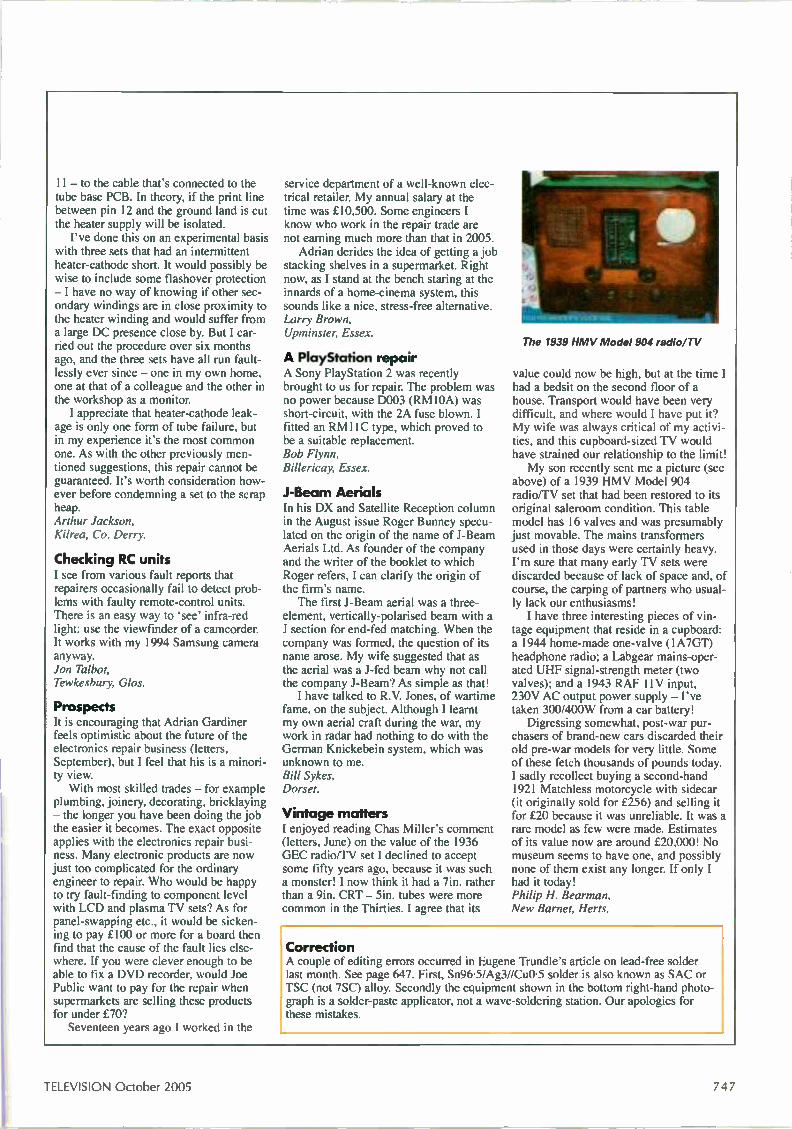
11 — to the cable that's connected to the tube base PCB. In theory, if the print line between pin 12 and the ground land is cut the heater supply will be isolated. I've done this on an experimental basis
with three sets that had an intermittent heater-cathode short. It would possibly be wise to include some flashover protection — I have no way of knowing if other sec-ondary windings are in close proximity to the heater winding and would suffer from a large DC presence close by. But I car-ried out the procedure over six months ago, and the three sets have all run fault-lessly ever since — one in my own home, one at that of a colleague and the other in the workshop as a monitor. I appreciate that heater-cathode leak-
age is only one form of tube failure, but in my experience it's the most common one. As with the other previously men-tioned suggestions, this repair cannot be guaranteed. It's worth consideration how-ever before condemning a set to the scrap heap. Arthur Jackson, Kilrea, Co. Derry.
Checking RC units I see from various fault reports that repairers occasionally fail to detect prob-lems with faulty remote-control units. There is an easy way to 'see' infra-red light: use the viewfinder of a camcorder. It works with my 1994 Samsung camera anyway. Jon Talbot, Tewkesbury, Glos.
Prospects It is encouraging that Adrian Gardiner feels optimistic about the future of the electronics repair business (letters, September), but I feel that his is a minori-ty view. With most skilled trades — for example
plumbing, joinery, decorating, bricklaying — the longer you have been doing the job the easier it becomes. The exact opposite applies with the electronics repair busi-ness. Many electronic products are now just too complicated for the ordinary engineer to repair. Who would be happy to try fault-finding to component level with LCD and plasma TV sets? As for panel-swapping etc., it would be sicken-ing to pay £100 or more for a board then find that the cause of the fault lies else-where. If you were clever enough to be able to fix a DVD recorder, would Joe Public want to pay for the repair when supermarkets are selling these products for under £70? Seventeen years ago I worked in the
service department of a well-known elec-trical retailer. My annual salary at the time was £10,500. Some engineers I know who work in the repair trade are not earning much more than that in 2005. Adrian derides the idea of getting a job
stacking shelves in a supermarket. Right now, as I stand at the bench staring at the innards of a home-cinema system, this sounds like a nice, stress-free alternative. Larry Brown, Upminster, Essex.
A PlayStation repair A Sony PlayStation 2 was recently brought to us for repair. The problem was no power because D003 (RMIOA) was short-circuit, with the 2A fuse blown. I fitted an RM11C type, which proved to be a suitable replacement. Bob Flynn, Billericay, Essex.
.1-Beam Aerials In his DX and Satellite Reception column in the August issue Roger Bunney specu-lated on the origin of the name of J-Beam Aerials Ltd. As founder of the company and the writer of the booklet to which Roger refers, I can clarify the origin of the firm's name. The first J-Beam aerial was a three-
element, vertically-polarised beam with a J section for end-fed matching. When the company was formed, the question of its name arose. My wife suggested that as the aerial was a J-fed beam why not call the company J-Beam? As simple as that! I have talked to R.V. Jones, of wartime
fame, on the subject. Although I learnt my own aerial craft during the war, my work in radar had nothing to do with the German Knickebein system, which was unknown to me. Bill Sykes, Dorset.
Vintage matters I enjoyed reading Chas Miller's comment (letters, June) on the value of the 1936 GEC radio/TV set I declined to accept some fifty years ago, because it was such a monster! I now think it had a 7in. rather than a 9in. CRT — 5in, tubes were more common in the Thirties. I agree that its
The 1939 HMV Model 904 radio/TV
value could now be high, but at the time I had a bedsit on the second floor of a house. Transport would have been very difficult, and where would I have put it? My wife was always critical of my activi-ties, and this cupboard-sized TV would have strained our relationship to the limit! My son recently sent me a picture (see
above) of a 1939 HMV Model 904 radio/TV set that had been restored to its original saleroom condition. This table model has 16 valves and was presumably just movable. The mains transformers used in those days were certainly heavy. I'm sure that many early TV sets were discarded because of lack of space and, of course, the carping of partners who usual-ly lack our enthusiasms! I have three interesting pieces of vin-
tage equipment that reside in a cupboard: a 1944 home-made one-valve (1A7GT) headphone radio; a Labgear mains-oper-ated UHF signal-strength meter (two valves); and a 1943 RAF 11V input, 230V AC output power supply — I've taken 300/400W from a car battery! Digressing somewhat, post-war pur-
chasers of brand-new cars discarded their old pre-war models for very little. Some of these fetch thousands of pounds today. I sadly recollect buying a second-hand 1921 Matchless motorcycle with sidecar (it originally sold for £256) and selling it for £20 because it was unreliable. It was a rare model as few were made. Estimates of its value now are around £20,000! No museum seems to have one, and possibly none of them exist any longer. If only I had it today! Philip H. Bearman, New Barnet, Herts.
Correction A couple of editing errors occurred in Eugene Trundle's article on lead-free solder last month. See page 647. First, Sn96-5/Ag3//Cu0•5 solder is also known as SAC or TSC (not 7SC) alloy. Secondly the equipment shown in the bottom right-hand photo-graph is a solder-paste applicator, not a wave-soldering station. Our apologies for these mistakes.
TELEVISION October 2005 747
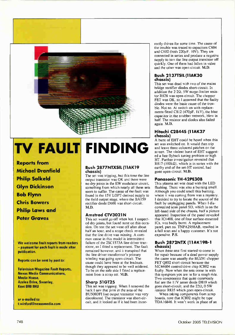
•••
TV FAULT Reports from
Michael Dranfield
Philip Salkeld
Glyn Dickinson
Bob Flynn
Chris Bowers
Philip Laws and
Peter Graves
We welcome fault reports from readers - payment for each fault is made after publication.
Reports can be sent by post to:
Television Magazine Fault Reports, Nexus Media Communications, Media House, Azalea Drive, Swanley, Kent BR8 8HU
or e-mailed to: [email protected]
FINDING Bush 2877NTXSIL (11AK19 chassis) The set was tripping, but this time the line output transistor was OK and there were no dry-joints in the EW modulator circuit, something from which nearly all these sets seem to suffer. The cause of the fault was found in the 15V LOPT-derived supply to the field output stage, where the BA159 rectifier diode D606 was short-circuit. M.D.
Amstrad CTV3021 N This set would go off when hot. I suspect-ed dry-joints, but found none on this occa-sion. On test the set went off after about half an hour, and a scope check revealed that the line drive was missing. A com-mon cause in this model is intermittent failure of the 2SC1573A line driver tran-sistor, so I fitted a replacement. The fault remained however, and it transpired that the line driver transformer's primary winding was going open-circuit. The cause could have been at the leadouts, though they appeared to be well soldered. To be on the safe side I fitted a replace-ment from a scrap set. M.D.
Sharp 51GT25 This set was tripping. When I removed the back I saw that print in the area of the BU508DFI line output transistor was very discoloured. The transistor was short-cir-cuit, and it looked as if it had been incor-
rectly driven for some time. The cause of the trouble was traced to capacitors C604 and C602 (both 220pF, 10V). They are connected in series and produce a negative supply to turn the line output transistor off quickly. One of them had fallen in value and the other was open-circuit. M.D.
Bush 2137TSIL (11AK30 chassis) This set was dead with two of the mains bridge rectifier diodes short-circuit. In addition the 2-2Q, 5W surge-limiter resis-tor R828 was open-circuit. The chopper FET was OK, so I assumed that the faulty diodes were the basic cause of the trou-ble. Not so. At switch on with replace-ments fitted C812 (470pF, IkV), the blue capacitor in the snubber network, blew in half. The resistor and diodes also failed again. M.D.
Hitachi C2844S (11AK37 chassis) A burst of EHT could be heard when this set was switched on. It would then trip and leave three coloured patches on the screen. The violent burst of EHT suggest-ed a line flyback tuning problem or high HT. Further investigation revealed that R817 (100kQ), which is in series with the earthy end of the set-HT control, had gone open-circuit. M.D.
Panasonic TH-42PE3OB This plasma set was dead with the LED flashing. There was also a burning smell. Although you could smell this burning, where it was coming from was a mystery. I decided to try to locate the source of the fault by unplugging panels. When I dis-connected scan panel SD, which is on the left-hand side of the chassis, half a picture appeared. Inspection of the panel revealed that IC6408, one of four surface-mounted ICs, was badly burnt. A replacement panel, part no. TNPA2958AB, resulted in a full scan and a happy customer. It's not expensive. P.S.
Bush 2872NTX (11AK19B-1 chassis) When these sets first started to come in for repair because of a dead power supply the cause was usually the BUZ91 chopper FET Q802 short-circuit because the MC44604 control/drive chip IC802 was faulty. Now when the sets come in with this symptom you are in for a rough ride. Two components that quite commonly fail are the 11V zener diode D819 which goes short-circuit, and the 22Q, 0.5W resistor R835 which goes open-circuit. When taking components from scrap
boards, note that IC802 might be type TDA16846. It won't work in place of an
October 2005 TELEVISION

MC44604 — the result will be a com-pletely dead set. P.S.
LG RZ-15LA32 There was a blanking fault with this small LCD set: the picture would appear momentarily then disappear. With little experience of this type of set, the best course seemed to be to phone LG techni-cal. I was pleased to find that it's a known fault. The cure is to replace C51 and C55, which are both 220nF polyester capacitors, part no. OCF2241N5AA. When you take the back off you find a large screening can that has to be removed. You then remove the PCB to replace the capacitors. P.S.
JVC AV28GT1BJF (11AK45B5 chassis) This set was dead with the 2.5A mains fuse blasted. The first thing to do was to check the chopper transistor Q102, where only two of the pins read short-circuit. Normally if the cause of the fault is Q102 the device is completely short-cir-cuit. Further checks brought me to D111 (BY229) which was the short-circuit cul-prit. All that was necessary to get the set back working again was to replace D111 and fit a new anti-surge fuse. P.S.
Philips 32PW9544/05 (2.IE chassis) This set was dead. When it was switched on the LED went red then changed to amber followed by green. The HT rose to 145V. The set would try to start up then closed down. A slight noise came from the line output transformer, and this was the clue. A replacement, part no. 4822 140 10559, brought this large set back to working order. I must say that the trans-formers from Philips are quite reasonably priced. P.S.
DeGraf 51KS This old ex-rental Granada set came from a hotel. The instruction was to go ahead and repair it if this could be done cheap-ly. The fault with the set, which remind-ed me of some Sanyo models, was stuck in standby. I recalled disconnecting the field output chip IC431 to see if the set would then start up. My memory served me well. When I took this action the set came on with sound and field collapse. A new LA7832 field output IC restored normal operation. P.S.
SEG CT2802-S (11AK37 chassis) The fault with this set was tripping. In this situation I normally start by measur-ing the resistance across the line output transistor, where I fully expect a short-
circuit reading. I was not disappointed. Next I check the UF5407 HT rectifier diode D808, which I have found to be short-circuit on many occasions. But not this time. The short-circuit was still pre-sent when the diode was removed. A check from the collector of the line out-put transistor to chassis produced the fault reading, which cleared when the line output transformer was disconnect-ed. A new transformer restored normal operation. P.S.
Toshiba 21TO1B This set was tripping because the line output transformer had failed. As it was just out of guarantee I decided to order the OEM part from Toshiba. Big mis-take! The set is made by Samsung, and the transformer supplied by Toshiba pro-duced a picture with top foldover because the —10V supply was low. The replacement transformer was the wrong type. I eventually obtained one from CHS, using the part number on the trans-former itself, FSV14A004H — it's equiv-alent to the HR8628. G.D.
Matsui 20TIOB There was an odd fault with this Beko made set, several black dotted lines a few inches apart across the picture. When I eased the chassis out the fault cleared, but no dry-joints were obvious. I then found that the on-screen display was missing when the lines were present — in fact they consisted of the OSD without sync. This gave me something to go on, despite not having a service manual. I found a sync pulse in the OSD cir-
cuit and traced it back to a transistor and integrator circuit. Touching the surface-mounted capacitor here, C410 (1F), made the fault come and go. Resoldering it made the fault permanent! Once a new capacitor had been fitted the lines stayed away. G.D.
Philips 25PT632A (GR2.4 chassis) There was a white raster with just a hint of a picture in the background and fly-back lines. The sound was OK. The basic supplies to the tube's base panel were correct and, after running out of other ideas, I decided to try replacement of the tube's base socket. Bingo! B.F.
Toshiba 28N23B (11AK37 chassis) "Went bang then dead" with these sets usually means a power supply rebuild. SEME can supply a kit, part no. RK351. In this case however C860 (1nF, IkV) had split apart, blowing fuse F801. C860 and the other two capacitors, C803 and
C804, associated with the bridge rectifier were all of the beige-coloured type that often causes problems. So I replaced all three with a better type — the ones in a nice blue colour. B.F.
Mitsubishi CT2IA5STX (E14SF chassis) With both the picture and teletext the contrast was very low. Adjustment from one end of the scale to the other had no effect, nor did the sub-contrast poten-tiometer. All other adjustments were OK. The cause of the fault was traced to R563 (1501(52) in the beam-limiter circuit. B.F.
Toshiba 21N21B2 The 2SD2499 line output transistor Q401 was short-circuit because of a poor con-nection at the line driver transformer T401. In turn, the 2SK2651 chopper FET Q501 had gone short-circuit with D528 (18V zener diode) and R509 (0.22Q, 1W) both open-circuit. Power was restored once these items had been replaced, but when selecting an untuned channel the power would try to collapse. The cause of this was R516 (1•2Q), which had risen in value to 4.5Q. When talking to Techline about this
fault it became apparent that there is another version of this set, using the same model number but different parts. B.F.
Hitachi C2886TN (A7 chassis) Intermittently this set would start to change channels continuously or the menu would appear and the set would scroll down this continuously. The cause was eventually traced to a modification that had been added during manufacture. It consists of some diodes and a wire between IC953 and Q4000. The bare end of the wire soldered to Q4000 was short-ing to some adjacent components. B.F.
Fidelity CTV3221 (PTII chassis) There was no sound apart from a rare brief reappearance. The cause was traced to a tiny break in the print to pin 1 of connector S901 on the sound module. B.F.
Grundig CUC2059 chassis At switch on the power LED would go green then the set would make a grunting noise and revert to standby. There are always dry-joints in this chassis, but resoldering them made no difference. I then noticed that the set uses an EHT tripler — it was even green in colour, just like the older models. Once it had been disconnected from the line output trans-former the set remained on. A replace-ment tripler from CPC restored normal
TELEVISION October 2005 749
operation. The part no. is 29201-474-0101. B.F.
Sony KV-32FQ75U (AE5 chassis) This set was dead. Checks on board D revealed that IC6604 and transistor Q6806 had failed, with the result that R6666 (110, 0•5W) was open-circuit. Replacement of these items cured the power-up problem. The part numbers are R6666 1-202-933-61, IC6604 8-729-045-40 and Q6806 8-729-047-59. C.B.
Philips 32P W9586/05 There was no sound from this set's right-hand speaker. Checks in the audio output section revealed that IC7700 was short-circuit. Further checks showed that the right-hand speaker (2H52R) was open-circuit. Replacements restored normal operation. C.B.
Sony KV-281560U (AE6B chassis) This set reverted to standby after power-ing on. A visual inspection of the power supply revealed poor wire crimping that connects to CN6004 on board G. A call to Sony Technical produced the recom-mendation to replace the "coil/choke" with the original type, part no. 1-424-855-11. This cured the problem. C.B.
Sony KD-28CL106 There was a power supply problem with this set. When it was put into standby the 135V line remained high though the other voltages were switched off. As a result there was increased current via R5056, R5048 and R5068 and the reliability of the connections to these resistors was affected. If you come across this problem check the value of R6019 on board A. If it's 4-71(Q, replacing it with a 1 kS2, 1/10W chip resistor, part no. 1-216-049-11, will help resolve the problem. C.B.
Toshiba 32ZP18Q There was no sound or picture. Meter checks revealed that the 8V supply was low. The cause was the 2A fusible link Z890, which had gone high-resistance. A replacement restored the sound and pic-ture. C.B.
Technosonic WCT2816T The report with this set said that it flashed and went off. There was no sound or picture. When I advanced the setting of the Al control on the line output trans-former a picture appeared, but it was streaky with green bands and a ticking noise carne from the CRT's base panel. Close inspection of the panel revealed
that one leg of the Al supply's decou-pling capacitor was bent and arcing to an adjacent track. Cutting the leg and clean-ing the print stopped the arcing but left a blank raster. A new STV5112 RGB out-put IC completed the repair. P.L.
Nail«) N1003 This 15in. LCD/DVD combi set appeared to be dead apart from a blue light around the power button. When this was pressed you could toggle the blue light on and off. With the blue light on the DVD couldn't be ejected, but it could with the light off. This was in fact normal, as the blue light indicates the standby mode. When switching between modes —
DVD/AUX/PC/TV — a brief oscillation could be heard, and during this oscillation there was a glimmer of display. This led me to the converter PCB, which drives the fluorescent backlight. Close inspec-tion revealed that there had been a lot of heat around the driver ICs. Reflowing the solder at the pins of these ICs and replac-ing the two 150µF, 30V electrolytic capacitors provided a lasting cure. P.L.
Samsung CI5070AN There was no sound or picture when this set was brought out of standby and the power supply was buzzing. I didn't have a circuit diagram, but simple fault-find-ing was sufficient. There was 123V at the collector of the line output transistor. This fell to 40V when a dummy load was connected. A quick check at the primary side of the power supply produced a reading of only 260V across the mains bridge rectifier's reservoir capacitor C808, which was open-circuit. A new 1500F, 400V capacitor restored normal operation. P.L.
Bush 2874NTX (11AK19E3 chassis) This set came in with the usual chirping power supply because of a short-circuit line output transistor (Q605). The usual dry-joints were dealt with — in this case the link that earths the emitter of Q605 was the cause of its failure. Then, after fitting a replacement, the set was stuck in standby. A check at pin 41 (standby) of the
microcontroller IC used in this version of the chassis revealed that it was trying to switch on. The voltage here rose from OV to 2.5V, which seemed low. Checks were then carried out around Q805 and Q806 in the power supply standby-switching circuit where I discovered two extra tran-sistors, Q833 and Q834, that are not shown in my circuit diagram. The loading on the standby-switching
line seemed to be related to Q833. A long time was spent drawing out the circuitry associated with these two transistors. I discovered that Q833 monitors the output from the 8V regulator. A check from its output to chassis produced a reading of 52e. The cause of the trouble was IC401 (TDA8843). A replacement completed this lengthy repair. P.L.
Hitachi C28 WD2TN (A7 chassis) This set would trip intermittently, some-times at switch on sometimes not. To cut a nightmare story short, R950 (68kQ) in the power supply was going high in value intermittently. It's in series with the HT preset VR950. Note that ZD950 (BZVIO) in this circuit is a 6.2V voltage-reference diode, which measures high-resistance naturally. Make sure you use the correct type. I replaced it as well, to great acclaim. Two weeks later the tube shorted!
P.G.
Alba CTV3409 The owner of this set reported that it went dead at the same time that the fish-tank pump blew up! There appeared to be a short-circuit chopper transistor, but the short remained when it had been removed. The short was actually in the small chopper transformer, part no. PTX6074. A replacement plus a new fuse got things going again. This was not quite the end of the story
however, as some channels had 'locked up' and some had changed their pro-gramme numbers. About half of all pro-grammes, about forty of them as I recall, had to be unlocked manually via the menu before retuning the main five. I was then allowed home! No fish were harmed in the process.
Beko 14272TD8 (12.7 chassis) About fifteen black horizontal lines approximately 3mm thick were superim-posed on this portable's otherwise normal picture. The lines were quite solid, and had steps in them. Where to start? Phone someone who knows! I was told to check C410, a 1nF capacitor that's almost exactly in the centre of the PCB. Spot on. A replacement cured the fault. Incidentally like most of us I always
resolder the line output and power stages regardless of the reported fault. Note in this respect that with partial field collapse you will find a short reading across R508. which is a surface-mounted resistor in the line output stage area. The cure is to remove the solder blob across R508! P.(;.
750 October 2005 TELEVISION
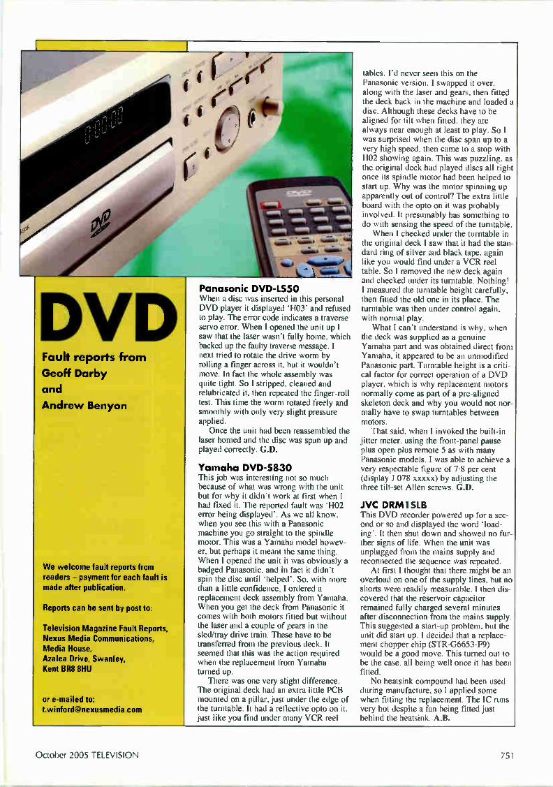
DVD Fault reports from Geoff Darby
and
Andrew Benyon
We welcome fault reports from readers — payment for each fault is made after publication.
Reports can be sent by post to:
Television Magazine Fault Reports, Nexus Media Communications, Media House, Azalea Drive, Swanley, Kent BR8 8HU
or e-mailed to: [email protected]
Panasonic DVD-LS50 When a disc was inserted in this personal DVD player it displayed 'HO3' and refused to play. The error code indicates a traverse servo error. When I opened the unit up I saw that the laser wasn't fully home, which backed up the faulty traverse message. I next tried to rotate the drive worm by rolling a finger across it, but it wouldn't move. In fact the whole assembly was quite tight. So I stripped, cleaned and relubricated it, then repeated the finger-roll test. This time the worm rotated freely and smoothly with only very slight pressure applied. Once the unit had been reassembled the
laser homed and the disc was spun up and played correctly. G.D.
Yamaha DVD-5830 This job was interesting not so much because of what was wrong with the unit but for why it didn't work at first when I had fixed it. The reported fault was 'HO2 error being displayed'. As we all know, when you see this with a Panasonic machine you go straight to the spindle motor. This was a Yamaha model howev-er, but perhaps it meant the same thing. When I opened the unit it was obviously a badged Panasonic, and in fact it didn't spin the disc until 'helped'. So, with more than a little confidence, I ordered a replacement deck assembly from Yamaha. When you get the deck from Panasonic it comes with both motors fitted but without the laser and a couple of gears in the sled/tray drive train. These have to be transferred from the previous deck. It seemed that this was the action required when the replacement from Yamaha turned up. There was one very slight difference.
The original deck had an extra little PCB mounted on a pillar, just under the edge of the turntable. It had a reflective opto on it, just like you find under many VCR reel
tables. I'd never seen this on the Panasonic version. I swapped it over, along with the laser and gears, then fitted the deck back in the machine and loaded a disc. Although these decks have to be aligned for tilt when fitted, they are always near enough at least to play. So I was surprised when the disc span up to a very high speed, then came to a stop with H02 showing again. This was puzzling, as the original deck had played discs all right once its spindle motor had been helped to start up. Why was the motor spinning up apparently out of control? The extra little board with the opto on it was probably involved. It presumably has something to do with sensing the speed of the turntable. When I checked under the turntable in
the original deck I saw that it had the stan-dard ring of silver and black tape, again like you would find under a VCR reel table. So I removed the new deck again and checked under its turntable. Nothing! I measured the turntable height carefully, then fitted the old one in its place. The turntable was then under control again, with normal play. What I can't understand is why, when
the deck was supplied as a genuine Yamaha part and was obtained direct from Yamaha, it appeared to be an unmodified Panasonic part. Turntable height is a criti-cal factor for correct operation of a DVD player, which is why replacement motors normally come as part of a pre-aligned skeleton deck and why you would not nor-mally have to swap turntables between motors. That said, when I invoked the built-in
jitter meter, using the front-panel pause plus open plus remote 5 as with many Panasonic models, I was able to achieve a very respectable figure of 7-8 per cent (display J 078 xxxxx) by adjusting the three tilt-set Allen screws. G.D.
JVC DRM1SLB This DVD recorder powered up for a sec-ond or so and displayed the word 'load-ing'. It then shut down and showed no fur-ther signs of life. When the unit was unplugged from the mains supply and reconnected the sequence was repeated. At first I thought that there might be an
overload on one of the supply lines, but no shorts were readily measurable. I then dis-covered that the reservoir capacitor remained fully charged several minutes after disconnection from the mains supply. This suggested a start-up problem, but the unit did start up. I decided that a replace-ment chopper chip (STR-G6653-F9) would be a good move. This turned out to be the case, all being well once it has been fitted. No heatsink compound had been used
during manufacture, so I applied some when fitting the replacement. The IC runs very hot despite a fan being fitted just behind the heatsink. A.B.
October 2005 TELEVISION 751

TELEVISION BOOKS AND HOME ELECTRONICS REPAIR
The Television Book Service offers access to our team of specialist publishing experts. We can order any book or CD-ROM currently in print from War And Peace to the Newnes Guide to Television and Video Technology. All books are delivered free of charge within the UK unless otherwise stated. Contact us at the numbers below: Telephone: 01737 812727 or 01737 812676 Fax: 01737 81 3526
Email: [email protected]
P CLOSED CIRCUIT TELEVISION: CCTV INSTALLATION, MAINTENANCE AND OPERATION Joe Cieszynski
CCPI surveillance is one of the fastest growing areas in the security industry, and this is a thorough guide to the technical side of CCTV — including installation, maintenance, video recording, cameras and monitors. The second edition is fully dual-standard for PAL and NTSC systems.
TELEVISION
2nd edition A Sept 2003 • 256 pages Glossary A Index A PB A Published in UK nl5nh 02R u £24.99
DICTIONARY OF VIDEO AND - TELEVISION TECHNOLOGY Jack Tsatsoulin
This work provides comprehensive and contemporary information on the essential concepts and terms in video and television, including coverage of test and measurement procedures. The CD accompanying the text includes on electronic version of the book.
Sept 2002 à 365 pages 8 CD-Rom
Published in UK
£29.99
DVD PLAYERS AND DRIVES F Ibrahim (College of North West London)
This text is based on hands-on experience and acts as a guide to DVD technology and its application, with a special focus on design issues. The principles of the subject are introduced from the basics, and DVD applications ore illustrated by genuine technical information.
DVD plagers and
Aug 2003 A 256 pages • Glossary A Index
PB A Published in UK
(ode 0-7506-5736-i £24.99
ELECTRONIC CLASSICS: COLLECTING, RESTORATION AND REPAIR Andrew Emmerson
This text encompasses all aspects of buying, collecting, restoring, repairing, sourcing parts, professional services, clubs and societies. The first part covers technical aspects of restoration and details where components can be found; the second presents useful information for collectors.
Aug 1998 A 256 pages A Index 10 halftones • 50 line illustrations • PB Published in UK
Code 0-7506 3788.9 £2199
INTRODUCTION TO DIGITAL SYSTEMS John Crisp
This self -study text introduces digital electronics from first principles, before going on to cover all the main areas of knowledge and expertise It covers the practicalities of designing and building circuits, including fault-finding nod the use of test equipment.
Feb 2000 A 302 pages • Glossary • Index P8 A Published in UK
Code 0-1506-4583-0 £18.99
NEWNES DICTIONARY OF ELECTRONICS SW Amos; R S Amos
Aimed at engineers, technicians and students working in the field of electronics, this dictionary provides clear and concise definitions, including TV, radio and computing terms, with illustrations and circuit diagrams.
4th edition A Mar 2002 A 394 pages 100 illustrations A PB • Published in UK
(ode O-106.5642.5 £12.99
NEWNES GUIDE TO TELEVISION & VIDEO TECHNOLOGY Eugene Trundle
An exploration of television and video technology. It covers the fundamentals of digital television (satellite, cable and terrestrial) and digital video, as well as providing a grounding in analogue systems.
Television & Video Technology
3rd edition A Feb 2001 • 432 pages • Index PB A Published in UK
(oe-. • £17.99
NEWNES GUIDE TO DIGITAL TV Richard Brice
Covering all aspects of digital television, this text encompasses the electronics of the equipment, data compression, television production, servicing and the different transition methods - terrestrial, satellite and cable. The text has been updated with developments since the 2000 edition.
2nd edition A Oct 2002 • 304 popes • Index 45 illustrations • 15 photographs • HB Published in UK
£24.99
PRACTICAL ELECTRONIC FAULT FINDING AND TROUBLESHOOTING
11111à1b
Robin Pain (Design Engineer, Cotag International Ud)
A text using simple circuit examples to illustrate jprinciples and concepts fundamental to the process of analog and digital fault finding. It aims to help the reader tackle any ¡ab, from fixing a IV to improving the sound of a hi-fi. A digital multimeter and oscilloscope are needed for these ¡obs.
Apr 1996 • 284 pages • Index 50 line illustrations • PB A Published in UK
£21.99
PRACTICAL ELECTRONICS HANDBOOK Ian Sinclair
A collection of all the key data, forts, practical guidance and circuit design basics needed by a spectrum of students, electronics enthusiasts, technicians and circuit designers. It provides explanations and practical guidance, and includes new sections on SHF I:chigoes and intruder alarms.
Practical Electronic Handbook
5th edition • Feb 2000 A 571 pages Illustrations A PB • Published ir UK
£16.99
RSGB RADIO 11, ELECTRONICS COOKBOOK Radio Society of Great Britain
Only a basic knowledge of electronics is assumed for this collection of electronics projects, and it is ideal for all electronics and DIY enthusiasts and experimenters. Designed by the RSGB, the UK radio amateurs federation, the projects are clearly explained step by step.
COORBO011t
Nov 2000 A 336 pages A P8 A Illustrations
Published in UK
Code 0-7506-5214- £17.99
REFERENCE DATA FOR ENGINEERS: RADIO, ELECTRONICS, COMPUTERS AND COMMUNICATIONS Mac E Van Valkenburg; Edited by Wendy Middleton
Written by professionals for professionals, this is a complete reference for engineers. As well as addressing radio technology data, it covers digital electronics, computers and communications.
9th edition A Aug 2001 1568 pages 8. CD-Rom A 1385 line illustrations 118 • Published in UK
£90.00
SERVICE ENGINEER'S POCKET BOOK Lewis & Sinclair
This title aims to provide the service engineer with all the necessary information to carry out work on domestic electronics . equipment. The coverage ranges from satellite reception to NICAM. Both analogue and digital equipment are covered, and there are chapters on common problems.
sacTul.r,
Jan 1998 A 238 pages A HB
Code BUTO-7506-3448 0 £14.99
SERVICING TV, SATELLITE & VIDEO EQUIPMENT Eugene Trundle
A practical hands-on guide for service engineers, installation technicians end servicing students, this text emphasises the practical business of fault diagnosis and repair of TV, satellite and video equipment.
Revised 2nd edition A Nov 2001 • 336 pages Symptom index à PB à Published in UK
Code 0-7506-5507-0 £21.9S

TELEVISION MICROPROCESSOR IC DATA FILES 1 Edwards
Microprocessor ICs are the most complicated part of TV equipment ard present special problems to the engineer. This text covers the most popular microprocessor ICs. Each device is presented graphically with the relevant data information given against each pin.
Mar 1997 • 240 pages • 200 line drawings
PB • Published in UK
£19.99
TELEVISION IC DATA FILES 1 Edwards
A compendium of data on all the most common integrated circuits used in televisions. Each device is illustrated with a pin-out diagram, and all the measurements and signal dota in the book were taken under actual working conditions. This second edition contains over 10 new ICs.
Television IC Data files
2nd edition A Jan 2000 • 245 pages
PB A Published in UK
Cort £18.99
VCR FAULT-FINDING GUIDE Edited by Peter Marlow
A distillation of the most used fault reports from 11 years of Television magazine. Arranged by make and model, it features over 2000 reports on over 200 models of VCR, including diagnosis and repair advice.
11111 V CR
Mar 2000 • 447 pages • Illustrations A PB Published in UK
Code 0-1506 -4634 £20.99
VCR IC DATA FILES J Edwards
This text aims to provide the workshop technician and the field engineer with o convenient method of fault-finding without the need to consult workshop manuals. The most popular ICs used in video recorders are covered. Each device is presented graphically with data given against each pin.
Jul 1998 • 448 pages • 200 line illustrations PB • Published in UK
f 20.99
THE DIGITAL SATELLITE TV HANDBOOK Mark E Long
A handbook and CD-ROM pack on digital satellite television. It provides an overview of all the digital TV platforms in use world-wide. It includes satellite coverage maps and transmission parameters that readers will need to receive digital TV ser vices from any location in the world.
Ile 1111111Silellile If 'calms!!
Ak
Sept 1999 A 201 pages & CD Rom A PB
(ode BUIO /506 /Ili c £41.99
7171EWNES GUIDE TO RADIO AND COMMUNICATIONS TECHNOLOGY Ian Poole
This is a guide to the technology and applications of modern radio and communications equipment. The author's approach provides o useful foundation for college students and technicians seeking on update on the latest technology.
Jul 2003 • 352 pages • Index • P8 Published in UK
(.ude Li /506 5612,3 £16.99
VALVE RADIO & AUDIO REPAIR HANDBOOK
Charles Miller
A practical manual for collectors, dealers and service engineen of valve audio and radio equipment. This edition includes new material art restoration and valve amplifiers.
VAUV RADIO& AUDI))
REPAIR HANDBOOK
2nd edition • Apr 2000 • 280 pages A 10 halftones A 50 line illustrations A PB Published in UK
-506 399' £20.99
NEWNES TV & VIDEO ENGINEER'S POCKET BOOK Eugene Trundle
This updated text provides 0 pocket tool for service engineers. It presents o range of essential information in a compact form, covering television reception, satellite and cable television, video recorders, colour camera technology, teletext and faultfinding.
3rd edition • Oct 1999 A 512 pages • FIB f 17.99
TV FAULT-FINDING GUIDE Edited by Peter Marlow
A distillation of the most-used fault reports from 11 years of Television magazine. Arranged by make and model, it features over 200 reports on over 300 models of television, including diagnosis and repair advice.
ieeTV
Mar 2000 A 387 pages • Illustrations
PB • Published in UK
f 20.99
VALVE AMPLIFIERS Morgan Jones
The author's straightforward approach, using as little moths as possible, should be of use to those with only a limited knowledge of the field as well as being the standard reference for experts in valve audio. Design principles and construction techniques ore also provided.
3rd edition • Aug 2003 A 624 pages A Index PB A Published in UK
£29.99
VIDEO AND CAMCORDER SERVICING AND TECHNOLOGY Steve Beeching
A comprehensive guide to domestic VCR technology and repair techniques. This edition brings the information fully-up-to-date, with expanded coverage of camcorders, sections on DOD equipment and the latest VCR technology
5th edition • Apr 2001 A 323 pages Illustrations • PB • Published in UK
£20.99
VIDEO DEMYSTIFIED Keith Jack
This edition has been updated to include information on digital television, datacasting, interactive video, digital camcorders and VCRs, and video interfacing. Coverage is international, including European, Asian and North/South American video standards, methods and techniques.
3rd edition • Jul 2001 A 784 pages & CD-Rom References A Glossary A Index • PB Published in UK
£50.00
TELEVISION ORDER FORM
Please order or search the following:
(ode Description Qty
POSTAGE & PACKING FREE IN THE UK* TOTAL
Nome Daytime Tel
Address
Price
Postcode
I enclose a cheque/postal order value payable to 'Boffin Books Ltd'
Please debit my Access/Visa/Switch/Delta cord Issue number (Switch only)
Cord Number
Signed
• Postage charges outside the UK available upon request or email: [email protected]
Post to Boffin Books Ltd, 24 Walton Street, Walton-on-the-Hill, Todwortft Surrey KT20 7RT, UK
Expiry Dole
If you ore ordering by credit card, need further information, in would like louse ow search faciKties
01731 812727 Fax 01737 813526 The order /helpline n open rom 9om to 5pm or leave your order on our out of hours onswerline or email us at
salesieamw boffinbooks demon co uk When placing orders please quple • Horne • Address (home A deliver y) • Daytime telephone number • Debit/Credit card nod*
• Expiry date • Detods of order Please note that prices may change, but are correct at time al going to press
Extended Reports Reports on complex or tricky TV fault conditions are sometimes too long for inclusion in our basic fault-finding section. We've put a few of them together in this extended fault report feature
Reports from
Michael Dranfield
Bob Longhurst
Arthur Jackson
Bob Flynn and
John Tennant
We welcome fault reports from readers — payment for each fault is made after publication.
Reports can be sent by post to:
Television Magazine Fault Reports, Nexus Media Communications, Media House, Azalea Drive, Swanley, Kent BR8 8HU
or e-mailed to: [email protected]
Fault Naiko N1003 hisI5in. LCD set incorporates a DVD player. At switch on the screen would light up momentarily, with the word AUX' vis-ible for a split second in the corner. The set would then trip out. I couldn't get hold of a service manual and, as a result, had to play it by ear, wasting much time chasing a red herring. At the outset I assumed that the inverter was OK, as the screen lit momentarily. This was my first mistake. With so little time to look for the cause
of the fault, as the set powered up for only a split second, this was going to be a chal-lenge. I eventually discovered a 27MHz crystal that wasn't oscillating. It was con-nected to a logic chip, forming an oscilla-tor that didn't work because its supply voltage was missing. I traced the source back to a switched 5V regulator, 1Q7. Its input was OK, but there was no output. The chip wasn't faulty however: pin 5 must be held high for there to be an out-put. I traced back from pin 5 to a little switching transistor that had 0.7V at its base and was thus turning the regulator off. I decided to earth its base and see what happened. The 5V supply then appeared and the 27MHz clock oscillator ran, but the fault was still present. While scoping around, I discovered a
very large switching pulse on the 12V sup-ply from the mains adapter. It occurred only as the screen lit up, just before the set tripped out. But it didn't come from the mains adapter. More careful scope checks revealed that it came from the inverter panel. I then found that the two supply decoupling capacitors on the panel, Cl and C2 (both 1500F, 30V), were very low in value. The fault was cured by replacing these capacitors. I used very high-quality, low-ESR Panasonic capacitors. As for the 27MHz clock oscillator that
didn't run, it turned out that this is used for
the DVD player and is active only during DVD operation. M.D.
Bush W576735IL (11AK19 chassis) I had repaired this set a few weeks previ-ously, when the fault had been loss of all video with just a blank raster when the first anode voltage was increased. Replacement of the TDA6108JF ROB out-put IC on the CRT PCB/socket assembly had restored normal pictures. It was now back with the same fault. I decided to contact Bush technical,
where the ever-helpful Victor is always ready to solve fault problems. He said that the PCB itself is the cause of the problem — it's a very small rectangular board with one corner cut off diagonally. Because the spac-ing between the base socket pins is very close, inter-pin capacitance can cause a dis-charge effect, damaging the IC. An improved PCB/socket assembly is available I was able to obtain this very cheaply
from Charles Hyde, the order code being ALB1614. In addition to being larger, the new PCB has slots drilled between all the CRT socket's pins to prevent flashovers etc. There are sockets that have to be removed to accommodate the hard-wiring to the main PCB. The only wires that have to be swapped over are those in the four-wire ribbon cable — these carry the 200V, heater etc. supplies. The six-way ribbon cable can be soldered in place of the removed socket, with the wires in the same order. This modification is well worth carry-
ing out if the TDA6108JF IC has failed. B.L.
Philips 32P W9534/05 (MD2.25 chassis) The initial fault with this set was that it would revert to standby after about two hours' use. If it was left to cool down it would work again. I was called in when, one day, it went off and stayed off! The line output transistor had been destroyed because of dry-joints at the pins of the driver transformer. Fairly straightforward I thought. At switch on however all that happened
was that the red LED flashed — the set refused to come out of standby. To deal with this second fault I had to locate the service socket' S89, which is near the microcontroller chip. You short across pins 1 and 2 of this socket to enter the service mode — an explanatory diagram is printed on the PCB itself. Once this had been done the set switched on normally and worked perfectly! At this point, while the set is working, change the short so that it's across pins 2 and 3. In this mode error codes are displayed. In my case error codes 44 and 47 were
754 October 2005 TELEVISION

shown, among other numbers. This indi-cates that the FET, circuit reference 7470, has expired. It's type IRF620F1. Fortunately a replacement FET cured this little problem. Phew! You have to empty the current fault codes from the 'error buffer' once the repair has been complet-ed. B.L.
Philips 36P W9525 (MG3.1 chassis) l'his 36m, model is heavy and access for servicing is difficult. Fortunately it has proved to be very reliable. This one had a problem with starting up however. Sometimes it would refuse to start up fully. It would attempt to come out of standby, then make a screeching sound and click off again. This would be repeat-ed several times. If it did come on fully a normal picture would appear and the set would run for a short time. Then an unusual screeching sound would occur and the set would cycle on/off to and from standby. I think the symptom got worse with picture content that produced a high beam current. I wanted to enter the service mode to
read any recorded errors, but couldn't get the set to run long enough for this to be done. Eventually I discovered that if the tube's heaters were disconnected the set would continue to run, giving me enough time to enter the service mode via the remote-control procedure (0 6 2 5 9 6 — OSD). I then reconnected the heaters while the set was running and was able to read out errors 067 and 068 before the set tripped out again. These errors suggest a power supply
fault. As I now had something to go on, I decided to check the Philips on-line symptom/cure service and was delighted to find that the problem is a known one and is detailed there. The faulty compo-nent is C2204 (680pF, part no. 5322 121 51214), which is connected to pins 1 and 2 of the power control chip IC7205. These pins are connected to an internal oscillator, which explained the unusual screeching sound when the set shut down. A genuine replacement was obtained from Philips and, when fitted, the fault symp-toms had gone. A.J.
Thomson TEKNO2 (Eurocombo 2 chassis) The fault with this modem TV/VCR combi unit was no teletext or on-screen display for menus etc. It had apparently been this way for some months and became a problem only when the cus-tomer wanted to tune in an extra channel but couldn't because no menu could be displayed. Our general service manual for the chassis doesn't provide any informa-tion on the type of text or microcontroller
chip in the set — they are on a separate PCB that's mounted on plastic supports on top of the VCR screening can. When I contacted Thomson I found
that a supplement sheet is available (part no. 351-313-10) and was advised to replace the microcontroller chip IR001 (part no. 10663550) and the EEPROM IR003 (part no. 20977300). These items were obtained and the ICs were fitted — but the fault remained! At least I now had a circuit diagram.
The cause of the trouble was quickly traced to absence of the horizontal sync pulse at pin 49 of IR001. Checking back, I found that there was a pulse at pin 15 of connector BROO1 (input to the subpanel) and up to the base of transistor TR022. It should be passed from the collector of TR022 to IR001 via RR126, but was absent here because TR022 had no supply. The faulty component was the surface-mounted collector load resistor RR026 (6-8kO), which was open-circuit. In fact it was cracked across its body — slight pres-sure restored the supply to TR022 and cleared the problem. All that was required was a suitable replacement resistor. A.J.
Philips 28P W6332 (MD1.2E chassis) The fault note with this set said that it was dead. When I carried out tests it seemed to be in some sort of protection mode. At switch on the red LED appeared then, as normal, briefly turned amber and after that green. The sound should then appear followed, a few seconds later, by a pic-ture. But in this case after four seconds the green LED went red again. The red-amber-green-red cycle continued, but no sound or picture appeared. Checks in the power supply revealed
that the standby protection line at the input to transistor Tr7593 rose and fell as the set tried to start up. Tracing back to the line output stage I found that the beam-current monitoring and the EW cir-cuit are connected to this line. Cold checks then revealed that the MTP3055EF EW drive FET (part no. 4822 130 63726) was very leaky — 100Q source to drain. The reason for its failure was a dry/arcing connection to the EW balance coil L5424. A replacement FET and resoldering of
the coil restored excellent reception. As these sets are now ageing, this may become a common fault. A.J.
Daewoo DWF2881GB (CP885/ WP895 chassis) I had been to the house previously to install a Freeview unit and noticed that this set's picture displayed trapezium and field distortion. The customer thought that it was under guarantee, so I left. A couple of weeks later she phoned to say that it
wasn't under guarantee and that the pic-ture was now upside down! It was indeed upside down, and inside
out with all sorts of geometry problems. Several things have been reported with these sets, so I started by improving the connection between the line output trans-former and transistor as it didn't look too good. I also replaced D403 (BY228) and IC301 (TDA8358J). None of this made any difference. The next most common problem is
EEPROM corruption, possibly triggered by the poor connection to the line output transformer. I entered the service mode by selecting channel 91, adjusted the sharp-ness to minimum, exited the menus then quickly pressed red, green and menu in that order. The set went into the service mode, but I couldn't see the adjustments properly because of the distortion. The EEPROM would have to be
replaced, so I phoned SEME who didn't have one listed for this model. I quoted the type, 24LC16B, and was told that it had been replaced by the BR24C16F. When it arrived it turned out to be a sur-face-mounted type that couldn't be fitted. I found that I had a BR24C16 which had been removed from a scrap Panasonic TX24DX1 (Euro-4 chassis). Once this had been fitted and a few minor adjust-ments had been carried out in the service mode the set was OK. B.F.
Toshiba 285T8B There was a fearful howl from the speak-ers when this set was switched on from cold. After a couple of minutes the noise would subside and the standby LED would come on. The set resisted all attempts to start it up however. If it was left for a few minutes the LED would begin to pulsate, as if the power supply was tripping. Suspecting capacitor trouble, I decided
to replace the four electrolytics on the pri-mary side of the power supply, C845 (2214F), C814 (47µF), C820 (100µF) and C819 (1µF). Unfortunately the symptoms remained exactly the same, so I decided to study the circuit diagram. This chassis has two power supplies.
One produces the main 147V HT supply, with an optocoupler that provides standby switching. The second power supply pro-duces an always-present 5V supply for the microcontroller chip and the standby switching circuit. The cause of the prob-lem was revealed when I checked for 5V at regulator Q805 in this second power supply — the output at pin 5 was low at only 3V. The input to the regulator, at pin 1, was also low at 4.5V. The 330/4F, 25V reservoir capacitor C842 turned out to be open-circuit. A replacement restored nor-mal operation. J.T.
TELEVISION October 2005 755
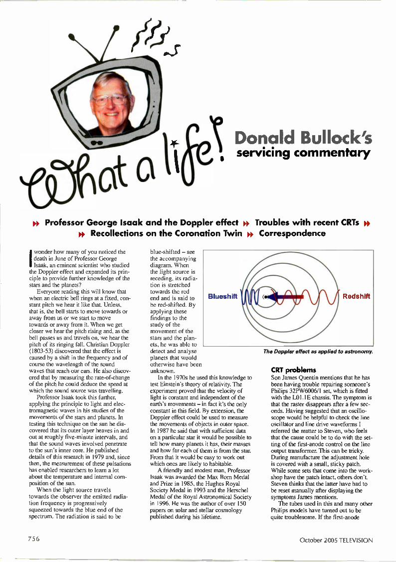
1 Donald Bullock's • servicing commentary
» Professor George Isaak and the Doppler effect » Troubles with recent CRTs » » Recollections on the Coronation Twin » Correspondence
Iwonder how many of you noticed the death in June of Professor George Isaak, an eminent scientist who studied the Doppler effect and expanded its prin-ciple to provide further knowledge of the stars and the planets? Everyone reading this will know that
when an electric bell rings at a fixed, con-stant pitch we hear it like that. Unless, that is, the bell starts to move towards or away from us or we start to move towards or away from it. When we get closer we hear the pitch rising and, as the bell passes us and travels on, we hear the pitch of its ringing fall. Christian Doppler (1803-53) discovered that the effect is caused by a shift in the frequency and of course the wavelength of the sound waves that reach our ears. He also discov-ered that by measuring the rate-of-change of the pitch he could deduce the speed at which the sound source was travelling. Professor Isaak took this further,
applying the principle to light and elec-tromagnetic waves in his studies of the movements of the stars and planets. In testing this technique on the sun he dis-covered that its outer layer heaves in and out at roughly five-minute intervals, and that the sound waves involved penetrate to the sun's inner core. He published details of this research in 1979 and, since then, the measurement of these pulsations has enabled researchers to learn a lot about the temperature and internal com-position of the sun. When the light source travels
towards the observer the emitted radia-tion frequency is progressively squeezed towards the blue end of the spectrum. The radiation is said to be
blue-shifted — see the accompanying diagram. When the light source is receding, its radia-tion is stretched towards the red end and is said to be red-shifted. By applying these findings to the study of the movement of the stars and the plan-ets, he was able to detect and analyse planets that would otherwise have been unknown. In the 1970s he used this knowledge to
test Einstein's theory of relativity. The experiment proved that the velocity of light is constant and independent of the earth's movements — in fact it's the only constant in this field. By extension, the Doppler effect could be used to measure the movements of objects in outer space. In 1987 he said that with sufficient data on a particular star it would be possible to tell how many planets it has, their masses and how far each of them is from the star. From that it would be easy to work out which ones are likely to habitable. A friendly and modest man, Professor
Isaak was awarded the Max Born Medal and Prize in 1985, the Hughes Royal Society Medal in 1993 and the Herschel Medal of the Royal Astronomical Society in 1996. He was the author of over 150 papers on solar and stellar cosmology published during his lifetime.
The Doppler effect as applied to astronomy.
CRT problems Son James Quentin mentions that he has been having trouble repairing someone's Philips 32PW6006/1 set, which is fitted with the L01.1E chassis. The symptom is that the raster disappears after a few sec-onds. Having suggested that an oscillo-scope would be helpful to check the line oscillator and line drive waveforms I referred the matter to Steven, who feels that the cause could be to do with the set-ting of the first-anode control on the line output transformer. This can be tricky. During manufacture the adjustment hole is covered with a small, sticky patch. While some sets that come into the work-shop have the patch intact, others don't. Steven thinks that the latter have had to be reset manually after displaying the symptoms James mentions. The tubes used in this and many other
Philips models have turned out to be quite troublesome. If the first-anode
756 October 2005 TELEVISION
voltage is slightly off, which seems to happen when the tubes wear and the beam current increases, the protection system senses the beam current increase and shuts the set down. It's possible, by constantly resetting the channel selector, to fool the protection system by depriv-ing it of enough uninterrupted time to be able to monitor the beam current. The monitoring system needs up to five sec-onds, and a further second or so is required for the shutdown. During chan-nel change, the field circuit blanks the screen. Thus if the set fails some six sec-onds or so after switch on, this condition is usually the cause of the fault. Alternatively the cause could be a
short-circuit, perhaps intermittent, in one of the guns. To check on this tap the CRT's neck to see if the gun sparks and the set shuts down. Steven says that the 32in. tubes are the worst offenders, 25in. ones being affected less. According to Steven several sets that suffer from the fault are brought in each week. The Philips tubes are also used in Panasonic sets, but in this case a Panasonic label is usually placed over the Philips one. The problem arises mainly with sets that are fitted with the Philips A10 chassis and Panasonic DK I and DK2 series sets built two-four years ago. At present Steven mentions that a Philips 28PW6515 and two Panasonic TX32DK1 sets are in the workship with short-circuit Philips tubes, also a Toshiba Model 28W8DB. The tubes and the painter chip prob-
lems must have cost Philips dearly, as many of the failures have been during the warranty period. Philips has also subsidised the cost of replacement tubes for some customers whose sets have been over four years old. Recompensing other setmakers who have used the tubes has added to the problem. I have also discussed the problem of
James's faulty set with Alan J. Roberts, who has contributed servicing articles to Television in the past, mainly on Philips models. While settling down to talk to me he sat on his cat, which had crept into the armchair. That made my day! Apparently it bounced around the walls like a shell as we spoke, illustrat-ing the Doppler effect in ongoing waves that put my description of it to shame. Alan has been an expert on Philips sets for many years and, after discussing the set's fault condition with James, came to the conclusion that the tube was indeed the cause of the trouble. I dare-say we shall know more in time for the next column!
The Ultra Coronation Twin Malcolm Burrell's vintage repair article last month struck a chord, as such arti-cles often do. It was on the Ultra Coronation Twin battery/mains portable radio, and reminded me of one we had
in for repair in the early Fifties. The customer was a high-ranking
and starchy ex-colonial governor who, after a lifetime's government service in remote parts, had retired to Cheltenham. He had brought his cook, batman and maid to look after him there. They had bought him the set from the large, central furniture shop where I worked at the time. During the first few months the set
had given him trouble, and a little fur had flown. First the selenium rectifier had failed, filling his house with the obnoxious smell this fault produces. Then the DK96 frequency-changer valve had gone soft. Following this one of the mains dropper sections had gone open-circuit. The set had then failed again. This time George, the service manager, had carefully repaired the set himself. He then spoke to the governor on the phone. Now soothed, the gover-nor decided to call in forthwith to col-lect it. We had a young fellow, Rob, work-
ing as an apprentice. "Rob, here, clean up the cabinet — make it look like new! Let's see if we can bring a smile to his face after the trouble he's had with it" George had said. Rob found a bit of clear bench and
got busy with a duster. Just as he had got it looking like new, he spotted a tiny mark on the top of the plastic. So he reached for the spout-can of switch-cleaner, sprinlded the contents liberally on the cabinet top, and started to rub with his duster. Horror of horrors! The duster seized up, and was now firmly attached to the cabinet top! When George saw it his face went
white and he began to gibber. The showroom salesman downstairs then came on the internal phone to tell us that the governor had arrived. George added a dance to his act and snatched the phone. "For God's sake, walk him around the outside windows for five minutes!" he screamed. George shot through the door and
down the stairs. Rob and I followed him discreetly. We reached the show-room just in time to see the mystified salesman almost frog-marching the erect and protesting governor out through the door as, at the far end of the showroom, George crouched and darted around the radio display area like a burglar. He found a new and identical Ultra Coronation Twin, grabbed it and, rubbing it with his hanky as he went, walked to the front of the shop. He arrived with perfect timing to meet the bemused governor on his return. We watched as George smiled,
shook the governor's hand, made a little speech and handed him the new radio. The governor was delighted and
thanked the salesman for showing him
round the extensive window displays. "Jolly good of you to explain how and where all the furniture is made, uphol-stered and varnished" he said, "if I ever need any furniture I'll give you a call, what?" He then departed, with the new radio under his arm. Back in the workshop, George
looked at Rob mournfully. "Don't clean any more Ultra Twin radios with switch-cleaner, there's a good chap" he said. As I mentioned to Rob later, mis-
takes are easy to make. I recalled one wet Saturday morning when the shop where I had been working was full. A chap came in for a demonstration of a quality valve amplifier that Pye had been promoting in a series of lively advertisements. I was given the job of connecting it up. After placing it on a table, I plugged the mains lead into its two-pin 5A socket and the other end into the mains socket. There followed an almighty bang, and all the shop lights went out. A curling cloud of blue smoke climbed from the amplifier's output transformer. Pye, in its wisdom, had arranged that
identical 5A sockets were used for the mains input and the speaker output. I recall the customer tactfully suggesting that he should call again in a week's time...
Correspondence Chris Drew of Essex tells me that he has had a call from A. Boyle in Cheshire acknowledging safe receipt of and thanking him for the Grundig TK830 tape recorder. We would be interested to hear how the renovation goes. John Woodgate of Rayleigh, Essex,
an audio consultant, has sent me an email following my comments on hear-ing aids last month. "I used to be involved in the design and manufacture of deaf aids" he says, "but until I became deaf myself I had no idea that the major factor in their use is correct volume-control setting. Turn the vol-ume right down, then increase it care-fully until you can just hear Greeneyes' dulcet tones in your ear. You will then have set the control too high! Carefully turn the control back until her voice is no longer 'in your ear'. Although it will now seem that the aid is not doing any-thing, it is in fact amplifying only the previously lost sibilants, or consonants with hissing sounds. It's the loss of these that makes speech indistinct, and only they need amplification." Well I tried it, John, and it works.
My thanks. Go to the top of the class! Alick Cowan wants to know who
handles spares for Aiwa products. I understand that they are now stocked by Sony, KSA Wholesale Components, CPC and SEME.
TELEVISION October 2005 757
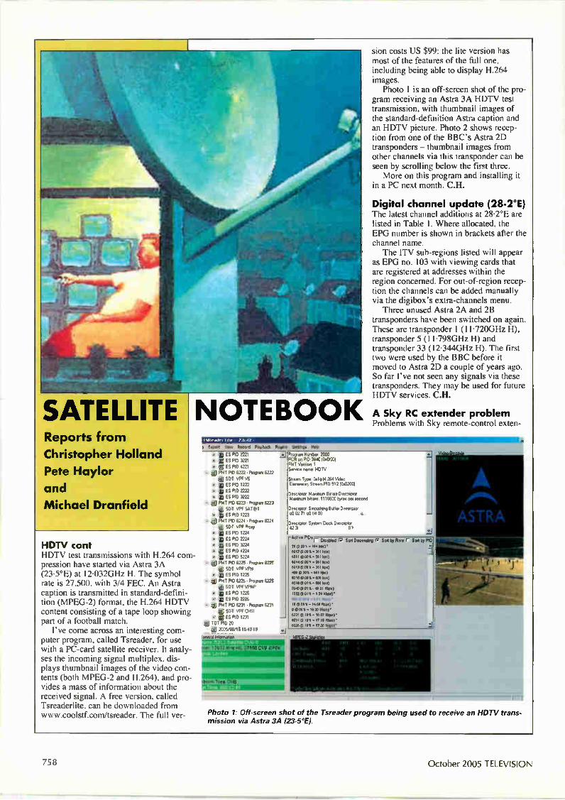
SATELLITE Reports from
Christopher Holland
Pete Haylor
and
Michael Dranfield
HDTV cont HDTV test transmissions with H.264 com-pression have started via Astra 3A (23.5°E) at 12.032GHz H. The symbol rate is 27,500, with 3/4 FEC. An Astra caption is transmitted in standard-defini-tion (MPEG-2) format, the H.264 HDTV content consisting of a tape loop showing part of a football match. I've come across an interesting com-
puter program, called Tsreader, for use with a PC-card satellite receiver. It analy-ses the incoming signal multiplex, dis-plays thumbnail images of the video con-tents (both MPEG-2 and H.264), and pro-vides a mass of information about the received signal. A free version, called Tsreaderlite, can be downloaded from www.coolstícom/tsreader. The full ver-
sion costs US $99: the lite version has most of the features of the full one, including being able to display H.264 images. Photo 1 is an off-screen shot of the pro-
gram receiving an Astra 3A HDTV test transmission, with thumbnail images of the standard-definition Astra caption and an HDTV picture. Photo 2 shows recep-tion from one of the BBC's Astra 2D transponders — thumbnail images from other channels via this transponder can be seen by scrolling below the first three. More on this program and installing it
in a PC next month. C.H.
Digital channel update (28.2°E) The latest channel additions at 28.2°E are listed in Table 1. Where allocated, the EPG number is shown in brackets after the channel name. The ITV sub-regions listed will appear
as EPG no. 103 with viewing cards that are registered at addresses within the region concerned. For out-of-region recep-tion the channels can be added manually via the digibox's extra-channels menu. Three unused Astra 2A and 2B
transponders have been switched on again. These are transponder 1 (11•720GHz H), transponder 5 (11.798GHz H) and transponder 33 (12.344GHz H). The first two were used by the BBC before it moved to Astra 2D a couple of years ago. So far I've not seen any signals via these transponders. They may be used for future HDTV services. C.H.
NOTEBOOK A Sky RC extender problem Problems with Sky remote-control exten-
d Mosbock MA O M e e 04*
• z PO) 2221 .e.I • & ID PID 3221 • *I ES FIO 4221 P141 FID 6222 • %pan 6222
I SOT VPF VS 4 ES MD 1222 • ES ND 2222 • ES PID 3222 * P141 PID 6223 . %peen 6223 di SOT VPF SAT*1
• 11 ES P10 1223 - * P141 POD 6224 • Pmgran 6224
* SDI VPF Pro* • a ES MD 1224 • 0 ES FIO 2221 • go ES FID 3224 • 0 ES P1D 4221 • * ES F1D 5221
- ylij P11T P1D 6225 • %pun 6225 dJ SOT VPF VF14 • ii ES PM 1225
- ye PAC RD 6226 • Propen, 6225 ill S OT VPFVPNP
• IN ES P1D ins • 1 ES RD 2226
- * PMT FID 6231 . %gore 6231 id SOT VPf CHS1
• 0 ES PID 1231 * TOT RD 20 um 2005/06/15 15 40 19 ^ ••
Rogan Rueter 2000 POR on PO 33401110001 !Tee Verson 1 Seneca nuns 4DTV
Seem Type D1bH 264 VPeo Eivnereary Seem PI0 512 (041200)
DeecnoIce Rumor, Bepee Desupta elpenurn Uwe 1116600 oymo pI. 1000
Deseptor Sonothng 8,1144 Deenptof c00271 c013400
Desepta System Clock Dace°, 42 3 57
.11
rec "Pips r Dimblod I/ San Dieordro e Soo le Rots ( SM by PID m moos - mo mm• 8212 0101 .311 10) 0.111 01011 • 3111 2.0) 82140201 201 00 0200 -Ill 00
400 0-001 - 0100)
8210 0000 • On 102 MO 0811 • 1210
300 0311 .•31 100
'moots - 31 olm)' 500 (I) 05 - 0 t Kep.) • IS OD110 - 14 » 1000•
O ems - is m Mmol'
8220 0.10% IO W 0110 . 8231 0.101 • 170)100 .
8220 0.101 ma. somr.
PI\ ASTRA
r— r
Photo 1: Off-screen shot of the Tsreader program being used to receive an HDTV trans-mission via Astra 3A (23.5°E).
758 October 2005 TELEVISION

der systems were discussed here in the August issue (see page 631). Since then I have come across an unusual problem that I've not encountered before. The digibox was installed in a large house, with several RC pickup eyes (they are also known as mice) that were coupled to a distribution amplifier. The amplifier passed the RC signals back to the digibox in the main room as well as amplifying the UHF out-put signals (terrestrial plus digibox UHF modulator) fed to each of the other rooms. The digibox's RF2 output socket provided 9V to power the amplifier and the eyes, via the coaxial signal cable. The system had worked well for about
a year. Then, suddenly, channel changing in all the rooms with remote-control eyes became intermittent, though remote-con-trol operation in the main room remained normal. The symptoms were similar to what you might experience with a mal-functioning remote-control unit: stepping up and down through the channels worked most of the time, though entering numbers or trying to access the TV guide was almost impossible. After some experimentation and testing
the cause of the problem was found to be one of the pickup mice connected to the amplifier. Disconnecting it and installing a replacement restored normal operation. The faulty mouse wasn't drawing exces-sive current, so it wasn't loading down the 9V supply. Unfortunately I didn't get to the bottom of why the mouse was causing the whole system to misbehave. C.H.
Rain fade It's well known that rain attenuates satel-lite signals in the 11-12GHz band. Very heavy rain in the vicinity of a receiving dish can even cause loss of signal, usually for only a short time. If the receiving dish is not correctly aligned with the satellite, resulting in marginal signal strength to start with, even a small amount of rain can cause signal loss. Signals in the 4GHz band are affected by rain much less. It is less well known that heavy rain in
the vicinity of a Ku-band uplink can cause the same signal-fade problem. Recently I noticed that the signals from all the BBC transponders at 28.2°E became much weaker and eventually failed for a few minutes. The Sky and ITV signals, trans-mitted from different sites, remained strong. To get round the problem with OBs, a second uplink some distance away is sometimes used as a back-up, being switched in if heavy rain affects the main site. I don't know how the link between the venue and the back-up site is made — it wouldn't be via satellite! C.H.
Eutelsat W2 (16°E) This month we take a look at the signals available via this satellite. It has a very wide footprint, and there are so many sig-nals that I'll list only those in the 12-5-I 2.75GHz spectrum this month.
Fie Reed Playback Flues
• ES PID 5103 ES F1D ES PID 2137 ES P1D 2103 ES P1D 21,3 E5 F1D 2112 ESP* 2113
• ES MD 2114 j ES P1D 2118 e POT P11) 550) FIAT F1D %warn 6363 1111 SOT BBC fi Gy m ES P1D 5i01
e TOT PID 20 • 2005/08/15 '5 34 13
e 111 TOT RD 20 a zoos/flans -5 34 13
Bli CAT P1D 1
ICA DescApto Newt Dower!, CA Descnixo Delacom 83 SDT PID 17
BAT PICI 17
6301 BBC 1 Lona.,, 6302 BBC 2 Ended 6304 BBC NEWS 24 6317 C8BC Cnerned
di 6318 CHeoeb. 6331 BBC 1 F
a 6363 BBC R :yrs. Ge m"' irlionetion
Prung MPEG vex, strew from progarn 6315 or PIC, 5200
-Ae" ''r Dstablid IP Son Docontr ee Ste b3. ROW (' Son WPID, not oaks - MN kbore)• son gas • 23236 *NJ' 6102 61 141 • 2321/ Mon
eiloi ems - DIX/ MOO' 6101 (0301. • 341 74 16104) • 17(0111.24712 NM)
11l P M II 35l is.) • I 2334 (I et . 418 /1 N W .
I uko(1113t .4614141e
f fl (73111 • 1.04 1100)
640/11 161 • 234 3.104/• •00 (11331 • 3 34 limpo)•
120602 1611 337 1404/ .
f fl MI 6310(13321. 3110 me)• 11110 (13111 • 347 13114) • 61610 (16 111 • 4.011 U M'
'Moo Decode
Photo 2: Off-screen shot of the Tsreader program being used to receive one of the BBC's Astra 2D transponders
Photo 3: Reception of the Italian Horseracing Channel via Eutelsat W2.
COSA VEDREMO rrI.S rsr-sr-SABATO 23 LUGLI O
11.30 ICentralidiieri" 15.00 Sport & Scommesse
15.10 POMERIGGIO
MILANO TRIESTE
NE WBURY - lnghitterra 20.00 Polo - Gold Cup 2005 - Troll » Audi 20.25 SERA All ffir SIRACUSA mono
ROMA 7110770
NAPOLI 110170 NIONTECAT1N I
GROSSETO
SKY
NE WS BIRMINGHAM
PLEASE INSERT PICTURES
Photo 4: Ski News via Eutelsat W2.
UNIREsat
UNIREsat
Photo 5: Sky News via Eutelsat W2.
Spoils Been Bookings
Satellite Operations:
TELEVISION October 2005 -01
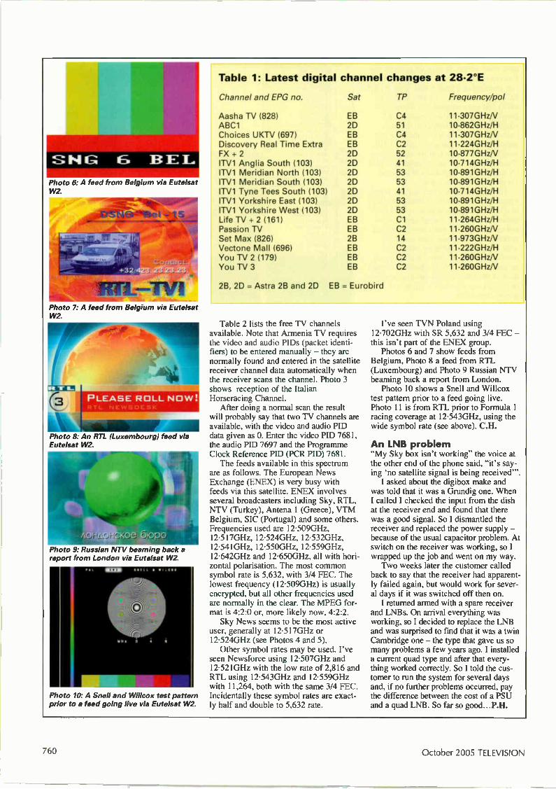
U
Photo 6: A feed from Belgium via Eutelsat W2.
Photo 7: A feed from Belgium via Eutelsat W2.
PLEASE ROLL NOW
Photo 8: An RTL (Luxemboura) feed via Eutelsat W2.
Photo 9: Russian NTV beaming back a report from London via Eutelsat W2
Photo 10. A Snell and Willcox test pattern prior to a feed going live via Eutelsat W2.
Table 1: Latest digital channel changes at 28-2°E
Channel and EPG no.
Aasha TV (828) ABC1 Choices UKTV (697) Discovery Real Time Extra FX + 2 ITV1 Anglia South (103) ITV1 Meridian North (103) ITV1 Meridian South (103) ITV1 Tyne Tees South (103) ITV1 Yorkshire East (103) ITV1 Yorkshire West (103) Life TV + 2 (161) Passion TV Set Max (826) Vectone Mall (6961 You TV 2 (179) You TV 3
Sat TP Frequency/pol
EB C4 11•307GHzN 2D 51 10•862GHz/H EB C4 11 •307GHz/V EB C2 11 -224GHz/H 2D 52 10-877GHzN 2D 41 10.714GHz/H 20 53 10•891GHz/H 2D 53 10-891GHz/H 2D 41 10.714GHz/H 2D 53 10•891GHz/H 2D 53 10•891GHz/H EB Cl 11•264GHz/H EB C2 11•260GHzN 2B 14 11•973GHzN EB C2 11•222GHz/H EB C2 11 -260GHzN EB C2 11•260GHzN
2B, 20 = Astra 2B and 20 EB = Eurobird
Table 2 lists the free TV channels available. Note that Armenia TV requires the video and audio PIDs (packet identi-fiers) to be entered manually — they are normally found and entered in the satellite receiver channel data automatically when the receiver scans the channel. Photo 3 shows reception of the Italian Horseracing Channel. After doing a normal scan the result
will probably say that two TV channels are available, with the video and audio PID data given as 0. Enter the video ND 7681, the audio PID 7697 and the Programme Clock Reference PID (PCR PI)) 7681. The feeds available in this spectrum
are as follows. The European News Exchange (ENEX) is very busy with feeds via this satellite. ENEX involves several broadcasters including Sky, RTL, NTV (Turkey), Antena 1 (Greece), VTM Belgium, SIC (Portugal) and some others. Frequencies used are 12-509GHz, 12-517GHz, 12.524GHz, 12.532GHz, 12.541GHz, 12•550GHz, 12-559GHz, 12-642GHz and 12-650GHz, all with hori-zontal polarisation. The most common symbol rate is 5,632, with 3/4 FEC. The lowest frequency (12•509GHz) is usually encrypted, but all other frequencies used are normally in the clear. The MPEG for-mat is 4:2:0 or, more likely now, 4:2:2. Sky News seems to be the most active
user, generally at 12.517GHz or 12.524GHz (see Photos 4 and 5). Other symbol rates may be used. I've
seen Newsforce using 12-507GHz and 12-521GHz with the low rate of 2,816 and RTL using 12.543GHz and 12-559GHz with 11,264, both with the same 3/4 FEC. Incidentally these symbol rates are exact-ly half and double to 5,632 rate.
I've seen TVN Poland using 12•702GHz with SR 5,632 and 3/4 FEC — this isn't part of the ENEX group. Photos 6 and 7 show feeds from
Belgium, Photo 8 a feed from RTL (Luxembourg) and Photo 9 Russian NTV beaming back a report from London. Photo 10 shows a Snell and Willcox
test pattern prior to a feed going live. Photo 11 is from RTL prior to Formula 1 racing coverage at 12.543GHz, using the wide symbol rate (see above). C.H.
An LNB problem "My Sky box isn't working" the voice at the other end of the phone said, "it's say-ing 'no satellite signal is being received—
I asked about the digibox make and was told that it was a Grundig one. When I called I checked the input from the dish at the receiver end and found that there was a good signal. So I dismantled the receiver and replaced the power supply — because of the usual capacitor problem. At switch on the receiver was working, so I wrapped up the job and went on my way. Two weeks later the customer called
back to say that the receiver had apparent-ly failed again, but would work for sever-al days if it was switched off then on. I returned armed with a spare receiver
and LNBs. On arrival everything was working, so I decided to replace the LNB and was surprised to find that it was a twin Cambridge one — the type that gave us so many problems a few years ago. I installed a current quad type and after that every-thing worked correctly. So I told the cus-tomer to run the system for several days and, if no further problems occurred, pay the difference between the cost of a PSU and a quad LNB. So far so good...P.H.
October 2005 TELEVISION
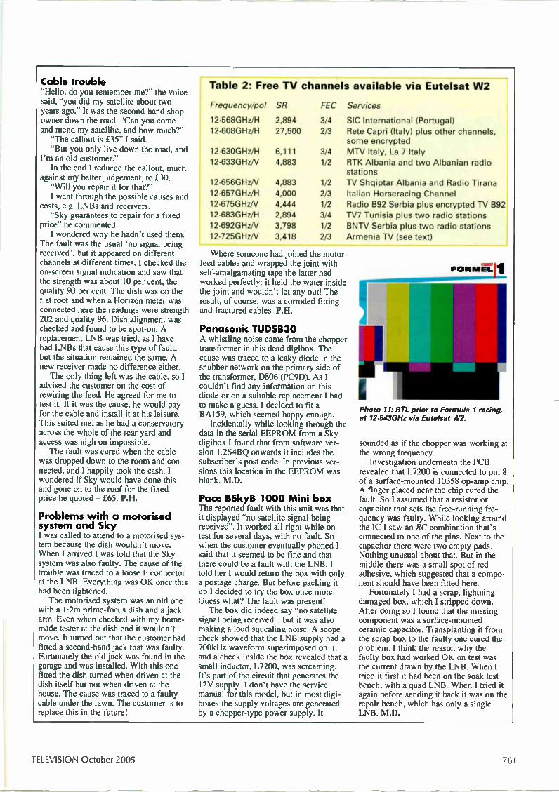
Cable trouble "Hello, do you remember me?" the voice said, "you did my satellite about two years ago." It was the second-hand shop owner down the road. "Can you come and mend my satellite, and how much?" "The callout is £35" I said. "But you only live down the road, and
I'm an old customer." In the end I reduced the callout, much
against my better judgement, to £30. "Will you repair it for that?" I went through the possible causes and
costs, e.g. LNBs and receivers. "Sky guarantees to repair for a fixed
price" he commented. I wondered why he hadn't used them.
The fault was the usual no signal being received', but it appeared on different channels at different times. I checked the on-screen signal indication and saw that the strength was about 10 per cent, the quality 90 per cent. The dish was on the flat roof and when a Horizon meter was connected here the readings were strength 202 and quality 96. Dish alignment was checked and found to be spot-on. A replacement LNB was tried, as I have had LNBs that cause this type of fault, but the situation remained the same. A new receiver made no difference either. The only thing left was the cable, so I
advised the customer on the cost of rewiring the feed. He agreed for me to test it. If it was the cause, he would pay for the cable and install it at his leisure. This suited me, as he had a conservatory across the whole of the rear yard and access was nigh on impossible. The fault was cured when the cable
was dropped down to the room and con-nected, and I happily took the cash. I wondered if Sky would have done this and gone on to the roof for the fixed price he quoted — £65. P.II.
Problems with a motorised system and Sky I was called to attend to a motorised sys-tem because the dish wouldn't move. When I arrived I was told that the Sky system was also faulty. The cause of the trouble was traced to a loose F connector at the LNB. Everything was OK once this had been tightened. The motorised system was an old one
with a 1.2m prime-focus dish and a jack arm. Even when checked with my home-made tester at the dish end it wouldn't move. It turned out that the customer had fitted a second-hand jack that was faulty. Fortunately the old jack was found in the garage and was installed. With this one fitted the dish turned when driven at the dish itself but not when driven at the house. The cause was traced to a faulty cable under the lawn. The customer is to replace this in the future!
Table 2: Free TV channels available via Eutelsat W2
Frequency/poi SR FEC
12.568GHz/H 2,894 3/4 12.608G Hz/H 27,500 2/3
12•630GHz/H 6,111 3/4 12.633GHzN 4,883 1/2
12.656GHzN 4,883 1/2 12.657GHz/H 4,000 2/3 12.675G Hz/V 4,444 1/2 12.683GHz/H 2,894 3/4 12.692GHzN 3,798 1/2 12.725GHz/V 3,418 2/3
Services
SIC International (Portugal) Rete Capri (Italy) plus other channels, some encrypted MTV Italy, La 7 Italy RTK Albania and two Albanian radio stations TV Shqiptar Albania and Radio Tirana Italian Horseracing Channel Radio B92 Serbia plus encrypted N B92 TV7 Tunisia plus two radio stations BNTV Serbia plus two radio stations Armenia TV (see text)
Where someone had joined the motor-feed cables and wrapped the joint with self-amalgamating tape the latter had worked perfectly: it held the water inside the joint and wouldn't let any out! The result, of course, was a corroded fitting and fractured cables. P.H.
Panasonic TUDSB30 A whistling noise came from the chopper transformer in this dead digibox. The cause was traced to a leaky diode in the snubber network on the primary side of the transformer, D806 (PC9D). As I couldn't find any information on this diode or on a suitable replacement I had to make a guess. I decided to fit a BA159, which seemed happy enough. Incidentally while looking through the
data in the serial EEPROM from a Sky digibox I found that from software ver-sion 1.2S4BQ onwards it includes the subscriber's post code. In previous ver-sions this location in the EEPROM was blank. M.D.
Pace BSkyB 1000 Mini box The reported fault with this unit was that it displayed "no satellite signal being received". It worked all right while on test for several days, with no fault. So when the customer eventually phoned I said that it seemed to be fine and that there could be a fault with the LNB. I told her I would return the box with only a postage charge. But before packing it up I decided to try the box once more. Guess what? The fault was present! The box did indeed say "no satellite
signal being received", but it was also making a loud squealing noise. A scope check showed that the LNB supply had a 700kHz waveform superimposed on it, and a check inside the box revealed that a small inductor, L7200, was screaming. It's part of the circuit that generates the 12V supply. I don't have the service manual for this model, but in most digi-boxes the supply voltages are generated by a chopper-type power supply. It
Photo 11: RTL prior to Formula 1 racing, at 12-543GHz via Eutelsat W2.
sounded as if the chopper was working at the wrong frequency. Investigation underneath the PCB
revealed that L7200 is connected to pin 8 of a surface-mounted 10358 op-amp chip. A finger placed near the chip cured the fault. So I assumed that a resistor or capacitor that sets the free-running fre-quency was faulty. While looking around the IC I saw an RC combination that's connected to one of the pins. Next to the capacitor there were two empty pads. Nothing unusual about that. But in the middle there was a small spot of red adhesive, which suggested that a compo-nent should have been fitted here. Fortunately I had a scrap, lightning-
damaged box, which I stripped down. After doing so I found that the missing component was a surface-mounted ceramic capacitor. Transplanting it from the scrap box to the faulty one cured the problem. I think the reason why the faulty box had worked OK on test was the current drawn by the LNB. When I tried it first it had been on the soak test bench, with a quad LNB. When I tried it again before sending it back it was on the repair bench, which has only a single LNB. M.D.
TELEVISION October 2005 761
-
MONITORS Fault reports from
Alun Rawson-Williams
and Bob Bradley
We welcome fault reports from readers — payment for each fault is made after publication.
Reports can be sent by post to:
Television Magazine Fault Reports, Nexus Media Communications, Media House, Azalea Drive, Swanley, Kent BR8 8HU
or e-mailed to: [email protected]
Tagra TM4269-2 This monitor was at the customer's site about 45 miles away and it was already late afternoon. I didn't relish the thought of a 90-mile round trip to fix it! When I got there and opened it up I found that the monitor had a distinctive LG look about it, though I had not come across this model before. The fault symptom was that the display was in lime green only, though the OSD showed up in blue when it was selected. I hate these jobs. In most cases they
involve removal of the metal screening from the CRT base PCB and the numerous earthing connections between the PCB and the main board, the metal chassis and the CRT. The situation was the same here, with the added complication that the screening was box-like, completely sur-rounding the CRT base panel, and the seams were soldered up. Then the penny dropped. Why was I
contemplating taking the CRT panel apart? If the OSD had blue content, the problem was probably to do with the LM1281N colour-amplifier chip IC401 on the main PCB or the signals lead to the CRT panel. Continuity tests showed that the lead was OK, so attention was turned to the IC and its peripheral circuitry. When you don't have the circuit diagram for a monitor I've found, over the years, that reference to chip manufacturers' data is invaluable. It often includes a practical circuit for use with the device concerned. One of the best websites for such data is www.alldatasheet.co.kr When I had downloaded the data for the
LM1281N IC to my laptop I found that the circuit was remarkably similar to the one in the faulty monitor. Voltage checks on the IC in the monitor showed that the blue input (pin 11) was at 12V, the supply volt-age, while the red (pin 5) and green (pin 8) inputs were at 2-7V. It seemed likely that the IC was faulty, and a new LM1281N cured the problem. A.R-W.
Digital PCXCV-D W This 14in. monitor is the same as the LG Electronics Model CS456 (CA-47 chas-sis). When it was connected to a running PC the screen was completely blank, but when the signals' lead was disconnected the CRT produced, in repeat order, pure flooded red, green and blue rasters. The front mode LEDs changed along with the screen colour changes. The CRT's cath-odes are driven by separate transistor out-put stages (Q341, Q351 and Q361). When the MC 13281BP video processor chip IC901 had been replaced the monitor pro-duced an excellent display considering that it is now about eight years old. A.R.W.
Philips 1091140 The owner of this 19in. monitor com-plained about field crampingJfoldover at the bottom of the display. Stripping down the monitor to gain access is straightfor-ward, but note that a number of earth straps have to be disconnected, also the usual scan-coil plug, display rotation plug. degaussing plug, a connector from the front control panel and the EHT lead. After this the chassis tray can be slid out from the monitor's casing together with the CRT base assembly. To withdraw the chassis from the tray, remove a few screws and washers and a plastic retaining clip at the left-hand side of the chassis. The cause of the fault was C2157
(4700F, 16V), which is the reservoir capacitor for the TDA8172 (IC7404) field output chip's 12V supply. A new capaci-tor followed by a good soak test after reassembly confirmed the cure. B.B.
Panasonic Panaflat LC40 This TFT monitor came into the workshop because it was dead. A check on the AC adapter revealed that there was no output — there should have been 14V at 4A. For safety reasons many AC adapters
are sealed and impossible to open. But this one had a screw hidden underneath the product label and could be dismantled. Very often an AC adapter's cable cracks internally with use, either near the gland where it comes out of the adapter or at the plug end that connects with the monitor. In this case however the cable wasn't dam-aged. The cause of the trouble was the start-up capacitor C7 (47 g, 50V). A replacement cured the fault and the monitor tested OK with the repaired adapter. B.B.
Taxan RX174 The complaint with this 17in. Crystal Vision 780 l'Fr monitor was streaking on green when cold. The customer said that as the monitor warmed up with use the streaking became less noticeable until. after an hour or so, the symptom had almost disappeared. This indicated a ther-mal fault. Stripping down the monitor to gain
access turned out to be reasonably straightforward and presented no prob-lems. Once the main board was visible I saw three electrolytic capacitors in the vicinity of the M52743BSP video pream-plifier IC. When one of these capacitors was subjected to freezing the green streaked very badly, while heating it reduced the problem. The capacitor is an electrolytic, C67 (lpF, 50V), which pro-vides signal coupling. A replacement proved that it had been the cause of the fault. B.B.
October 2005 TELEVISION
Solution to Test Case 514 - see page 732 -
Many faults in Hitachi TV chassis have well-known caus-es making them, in most cases, easy for the initiated to repair. The fault on this occasion was not a common one however. It was probably brought on by old age. Some would say the same about Ted, now a sexagenarian, but that's not true of course! It was he who found the cause of the fault, and he who added another note on the circuit diagram - perhaps the last that will go there. Using an oscilloscope, Ted found that at switch on all
worked well for a split second, during which the line out-put stage sprang to life. Then the power supply shut down. Now one of the protection systems in this set is based on three parallel-connected resistors, R945/6/7, through which the current in three of the chopper trans-former's secondary windings, including the HT one, flows. If the voltage across these resistors exceeds a cer-tain level two different protection arrangements come into operation, one activated by transistor Q951 and the other by transistor Q950. The resistors, which should be I SI (1W), 0.5Q (2W) and 0.5S1 (2W) respectively, pro-duced readings of 5.8Q, 0.580 and HQ - varying! - when checked. They looked very grey, old and distressed (we'll draw no more parallels with Ted), obviously hav-ing overheated as their resistances increased. Replacements brought the set back to life, and made
both Ted and Mrs Harris very happy. The lady had in fact been unable to master her loan set . . .
HIM GYOKInl u VOICM
At the IFA Show The Internationale Funkausstellung (IFA), which is held in Berlin every two years, is the world's largest consumer electronics show. George Cole has been there to report for us. Highlights this year included digital recording, high-definition TV, mobile TV and broadband-delivered enter-tainment including digital music. The Blu-ray and HD-DVD discs both had a high profile, with each determined to
show why it should become the de facto standard for the next generation of CE optical discs.
The problem of older sets Many people write off older sets when they go wrong, though they are often better built than more recent offer-ings. Large numbers of sets can be given an extra lease of life with a little effort. Michael Maurice confronts the prob-lem and describes a number of examples of successful repair/restoration.
Review: the Humax LGB32TPVR Here's a TV set that was designed with the future in view - 32in. LCD screen, HD-TV capability, a built-in personal video recorder and other advanced features. Roger Thomas bought one and reports on his experiences with it.
TELEVISION INDEX fit DIRECTORY 2005
Plus hard-copy index and reprints service
Here's the essential repair information you need! The Television Index & Directory 2005, in CD-ROM form, con-tains the text of over 16,000 high quality fault reports on TVs, VCRs, Camcorders, DVD players, Monitors, Satellite TV units, Audio equipment and CD players, searchable by make and model, plus the text of 200 Test Cases and over 300 major servicing articles, from seventeen years of Television magazine. It also contains a full seventeen-year index of Television, a Spares Guide, a directory of Trade and Professional Organisations, an International TV Standards guide, a satellite TV Channel Finder, a TV trans-mitter list and a compendium of internet resources for service engineers. The software is quick and easy to use, and runs on any PC with Windows 95, 98, ME, NT, XP or 2000.
Television Index & Directory 2005 CD-ROM, £199
Television Index & Directory 2005 CD-ROM upgrade, £47 (to qualify for this upgrade you need to have purchased a previous version of the Television Index on floppy disk or on CD-ROM)
A six-month update of the index and fault reports will be available in May 2005. If you wish to take advantage of this, £10 should be added to your order.
Television Index only, 1988-2004, £36
Television Index only upgrade from previous versions, £20
Hard-copy indexes of Television magazine are available for Volumes 38 (1988) to 54 (2004) at £3.50 per volume.
Reprints of articles from Television back to 1988 are also available, at the flat rate of £4.00 per article — you can order through our web site, or write to the address below.
The above prices include UK postage and VAT where applicable. Add an extra £1 postage for non-UK EC orders, or £5 for non-EC overseas orders, although Channel Island residents do not need to add any extra postage. Cheques should be made payable to SoftCopy Ltd. All major credit and debit cards are accepted. Please use our new secure website for your orders, details below. Allow up to 28 days for delivery (UK).
SoftCopy Limited, 1 Vineries Close, Cheltenham, GL53 ONU, UK
Telephone 01242 241 455 Fax 01242 241 468 e-mail: salese,softcopy.co.uk
web site: http://www.televisionmag.co.uk
Published on the third Wednesday of each month by Nexus Media Communications, Media House, Azalea Drive, Swanley, Kent, BR8 8HU. Nexus Media Communications is a trading name of Nexus Holdings Ltd. Registered in the UK, number 5346404. Registered office Hanover House, Hanover Square, London W1S I HP. Filmsetting by Impress Repro, Unit 2, Parkway, Southgate Way, Orton Southgate, Peterborough PE2 6YN. Printed in England by William Gibbons Ltd, 26 Planetary Road, Willenhall, West Midlands, WV133XT Distributed by Seymour Distribution Ltd, 86 Newman St, London, WIT 3EX. Sole Agents for Australia and New Zealand, Gordon and Gotch (Asia) Ltd.; South Africa, Central News Agency Ltd. Television is sold subject to the following conditions, namely that it shall not, without the written consent of the Publishers first having been given, be lent, resold, hired out or otherwise disposed by way of Trade at more than the recommended selling price shown on the cover, excluding Eire where the selling price is subject to currency exchange fluctuations and VAT, and that it shall not be lent, resold, hired or otherwise disposed of in a mutilated condition or in any unauthorised cover by way of Trade or affixed to or as part of any publication or advertising, literary or pictorial matter whatsoever.
TELEVISION October 2005 763
SERVICE @au. rtA-21
effl.e• ••••••••••
• ••••••••••••••••••••• M•••••••
• ••••••••••••••• ••••••••••••is
• Sms, ••••• moms..
• am•MMInnsmat mi••••••••• se re
Leaden estnbutors to the aenal and satearte trade
where new? 1•••••••,••••• M mal ••••1
•MIMesm fra me bmis
c.,‘...._ twerewwweadawdl MICCIZ M M = WWI 11310:1111:1 !
C=1 =1 •11111 111=111111111111B1 1111 =11 11
CzE2 ur. TO JO FREE
• • —•
Alltrade Aerial & Satellite Ltd www.alltrade.co.uk Leading distributor to the trade. Full e-commerce site with over 1500 products with in-stock quantities!! We supply everything associated with Digital/Analogue Terrestrial & DTH/Motorised Satellite reception. All Antennas. All Brackets. All Cables. All Connectors. All Amplifiers. We provide a free MATV/SMATV planning service as well. Trade Counters @ Brighton, Cardiff, Dartford and Watford Phone 0845 075 0751 Fax 0870 770 9151
Charles Hyde & Son Ltd www.charleshyde.co.uk Search for both original and copy spare parts in our extensive database covering Akai, Alba, Bush, Ferguson, Goldstar, Hitachi, LG, Matsui, Nokia, Saisho, Sanyo, Sony, Sharp, Thomson, Panasonic, Philips, Samsung, Tascam, Teac, Toshiba, Yamaha and many more. In addition huge ranges of Lasers, Lopts, Remote controls and Semiconductors may be accessed.
To reserve your web site space telephone Tel: 01322 611261 Fax: 01322 616339 E-MAILS [email protected]
Amtel Electronics www.amtel.co.uk Amtel Electronics provide service manuals and service sheets for most major brands of TV, video, Satellite, Audio equipment etc OEM service information is available for most european, USA and Far Eastern makes and models. Amtel electronics is one of the leading service information suppliers. Please contact us with your requirements via our contact page or telephone 01955 611313.
•••••••••••••••••••• OM. » 111 m1 «. •••••••••• r oam ». Lamm ,••••n
»Calla« D fl ranalSierkaa. teaCalvete
NAW M••••• W P M SK.Me no•
Welcome! M ee • Ult Greer, aPea•eaeo roone", an flo wdslrille 1.1 .1•01... . Oft . ml•••••11.•••••1••••1
T.« M e, a• mod far Me am, abymmi SaMille M M. ara anMema Ma , enta Mbon
Ve . • lon e of ar m . Mg Pm, Spee And ems,
bo Lose Pmbed r m. ., ors, loted
nwee e qe mme arel M a * %M M ., •••••fbers
M . epuoment and me * Seed n ••••
Ws ru m M ee re Meol mtele n onm a m .
M Mid
••••••••••••mt
* a «O M MOMS T M . meta am..
Call Novel +44 20 8 344 8230
Or E-Mail Us' [email protected]
e
Horizon www.horizonhge.com Horizon is a UK company specialising in the design and manufacture of test equipment for the digital satellite and terrestrial market, the meters are used for the easy alignment of satellite dishes and antenna during installation. At around 1kg they are light and easy to use, packed with features normally found on expensive and heavier spectrum analysers. Manufactured in the UK we have meters used in over 21 countries.
IRWIN ELECTRONICS www.irwinelectronics.co.uk As classic distributors we compliment our existing mail and trade counter business with our website. You can order parts on-line quickly and easily. We intend to explore alternative ways of assisting engineers to run their business successfully.
Swires Research www.swires.com Swires Research produce high quality instruments for the television industry, including portable signal level meters and spectrum analysers for digital and analogue RF signal measurements.
IZA
[ M M. , «J. krre merle, rae-ibufe,1
9 < nr,S.
CNIsr
Wizard Distributors www.wizard-distributors.co.uk
Main distributor for major brands. Search by make/model for LOPTX; switches; remotes etc. Find ICs; semicons; service kits; lasers; capacitors; resistors and a huge range of service aids, tools and other products.
764 TELEVISION October 2005
3 Year Warranty Digital LCD Oscilloscopes
Still waiting to buy that kit you've always wanted?
Mains or battery
Call now and quote Television magazine for our special offer discounts
Two Year Warranty Analogue/Digital Scopes 35MHz-200MHz, 10GS/s...
Spectrum Analysers 1GHz to 3GHz...
Generation & Measurement Systems from DC to 3GHz...
HAMEG UK LIMITED 78 SINGER WAY. KEMPSTON. BEDS. MK42 7PU Tel: 01234 856345 Fax: 01234 856100 e-mail [email protected] www.hameguk.co.uk
41111111 111111111111111111 Miller--- 1, tin &
e 1fl w 1043 LEEDS ROAD,
BRADFORD BD3 7DB ELECTR1tS LIMITED
Tel: 01274 665670 01274 660196 01274 665246
Email: [email protected]
PHILIPS
A WARD WI N NI N G P L A S M A & L C D T V AT COMPETITIVE PRICES RING FOR STOCK ofic PRICE
* REAL FLAT TV'S From £215
* INTEGRATED DIGITAL From £239 ,, 14" COMBI From £65
* DVD From £34
* VCR From £39
* MICRO SYSTEMS From £27 * DVD / VCR COMBI £79
* DVD SURROUND SYSTEMS FROM £96
* Always a full selection of current models with slight marks at knock down prices
. FAX your letter heading for bulk trade price list
As NEW MANUFACTURERS GRADED PRODUCT
No MARKS • ORIGINAL PACKING • FULLY GUARANTEED
NEXT DAY DELIVERY • CREDIT CARDS WELCOME
PO Box 73, Oakengates TF I 8WR Tel ee 44(0)195:273130 F 44 0 1952 40 478 —
D C I
C ® m9Jj ® L naet
0
ti n Jo e r
LUCD C.D0
SIE MLI C C/141D U CT OIRS O ver a igs..00 o Sylvi a* of
transistors IC's M oslem si.c_ er ulvolonts stisicksiat
We take your hassle Some suppliers just won't help.We will work really hard to find those difficult
parts - Just ask and let our 'no holds barred' enquiry hound work for you.I I I
- - - CI Ill CI I CI, c. Ic it tli el. ...../...---. sp ccical offcce-s
B UT11 A @ ,q1 each B UT11 AF ®IrN. Lab each
13 U508 A @ e"ln e.1• each Fully wired ecart lead _ell
CI Sli g ht i 111 CC> 1111 ‘r C., In i e il C C. - - v olt; elltr.,t btr y oli o' r:. iiiitsul w ilt:.
EllJ208A X 5 75p ea T E A2018 A X 5 99p ea BL.1508 A X 5 79p ea tJ C3842 X 5 59p ea 1BILJ508 AF X 5 85p ea C N X62A X 5 29p ea 13I.J50813 X 5 89p ea S2000AF X 5 84p ea B UT11 A X 5 29p ea T D A3853B X 5 55p ea B UT11 AF X 5 47p ea T D A365-4 X 5 82p ea Philips type 1.2 volt Back up battery X 5 59p ea Philips type 2.4 volt Back up battery X 5 120p ea Scart - Sc,art lead 1.5 m Fully wired X 2 89p ea Po..s.itar PT37,TH98009 (White) x 5 59p ea Tho m TX100 Chassis 110 D GR LOPTX each £11.24 Philips CP90 Chassis LOPTX each £11.63
cm - - lc cal»4->iairi <> lim a-‘Écallai.- li m itirl.an.- y !toll gibm ic.- Ila-.11 Re me mber £1.50 post & handling
All major credit cards accepted
• r t . c • Is lost) S4 • , up P• proçe end pule, MI 'Peps . . , 1 .Ple11. Web:patch ey rn•Pelloo ,.tleoptlit ernet.
eve ne r idea particulterty welcome
o
(•#:g
catalogue out NOW cameras, monitors, switches quads, multiplexers, the lot.
TELEVISION October 2005 765
SKY+ Repairs & Upgrades We specialise in the repair of all makes and models of BSkyB digital receivers.
UPGRADE NOW your existing faulty Sky+ from 20 to 130 Hrs
FIXED PRICE includes *FREE COLLECTION (price includes all faults - Micro processor. Modem, Software corruption. BGA replacement, any cosmetic changes and return delivery. No fix no fee)
Arrange collection online
Refurbished digiboxes with for 67, El LEE 4 five Collection arranged from anywhere in the UK & Eire including Scottish Isles
*free collection when you send more than one box at a time
Receive our free technical newsletter. sign up at: www.digirepairs.co.uk
Contact Digi Repairs (UK & Ireland) Unit 25, Enniskillen Business Centre Tempo Road Enniskillen BT74 4RL
0845 6441628(local rate) 02866327293 (National)
04866327293 (From R.0.1)
1111 ler caD EMI Iffl
CRT SUPPLY AND DISPOSAL
NEW TUBES AVAILABLE FROM STOCK FOR PHILIPS, PANASONIC, THOMSON, TO NAME A FEW, ALL NEW WITH A ONE YEAR G/TEE GIVE US A CALL!
) 11 Dilec Components Ltd
D'Lec Components Limited, Unit 10, Albion Parade, Canal Basin, Gravesend, Kent DA12 2RN Tel 01474 361276/327677 Fax 01474 335228 Email salesedlec.co.uk Visit www.dlec.co.uk
BSMART (CRAWLEY) LTD m u m /
Largest selection of
MAJOR MANUFACTURERS NE W "B"
GRADE PRODUCTS
T.V. VIDEO AUDIO MICRO WAVE OVENS
Contact Paul Bean
BSMART (CRAWLEY) LTD. 10/11 LLOYDS COURT, MANOR ROYAL,
CRAWLEY, SUSSEX RH10 2QX
Tel: (01293) 618000 Fax: (01293) 400133
ECU Trans Ltd Large Quantity of Ex-rental TV's Videos Hi-Fi & DVD
Worldwide Export, also UK Wholesale/Retails
Over 2000 items per week go through our warehouses
Call now on!
Tel: 01753 543 244 or 572 444 Fax: 01753 543 224 or 572 333 e.mail: [email protected]
Unit 11. Middlegreen Trading Estate Middlegreen Road, Langley
Berks, SL3 6DF
5 mins from M4 - Junction 5
October 2005 TELEVISION
WEB SITE VVWW.JOHNSRADIO-UK.COM VVWW.JOHNRADIO.COM JOHNSRADIO ELECTRONICS TEST AND COMMUNICATION EQPT
LARGE QUANTITY SALE EX M.O.D. MARCONI TF2019A Synthesized Signal Generators - 80Khz to 1040Mc/s
AM - FM - High Class with many functions - £285 each. TEKTRONIX 2445 A OSCILLOSCOPE 150Mc/s Four Channel £300.
HP COMMUNICATION TEST SET 8922M - 10 - 1000Mc/s + GMS 83220E Converter 1710 - 1900Mc/s DCS - PCS - MS £500
HP COMMUNICATION TEST SET 8922M OPT 010(Dual) etc £750. ALL UNITS AND PRICED EX WORKS WITH INSTRUCTIONS - TESTED BASIC
WORKING. CARR + PACKING IF REQUIRED EXTRA. Phone for appointment or to request item lists, photos, site map. All welcome, Private or Trade, sales, workshop repairs or calibration
PLEASE CONTACT PATRICIA AT WHITEHALL WORKS, 84 WHITEHALL ROAD
EAST, BIRKENSHAW, BRADFORD, WEST YORKSHIRE, BD11 2ER.
Tel: 01274 684007 Fax: 01274 651160 WEB SITE VVWW.JOHNSRADIO-UK.COM VVVVW.JOHNRADIO.COM
This Magazine reaches,fc) r
lees war com ma Ir ma Itself us e Irockures, 1:1111110,110S. Leaflets et other premetlesal
literatureP Would you like them read by approx. 9000 relevant people within the Consumer
Electronics industry?
By inserting them into Television and Consumer Electronics Magazine, you will be able to target a large number of potential customers, enabling your brochure or leaflet to be rategically r
distributed titoughout the K within the magazine.
For further information on how Inserts can work for you, call Reuben on 01322 611261, or email: [email protected]
FRUSTRATED! Looking for ICs TRANSISTORS? A phone call to us could get a result. We offer an extensive
range and with a World-wide database at our fingertips, we are able
to source even more. We specialise in
devices with the following prefix (to name but a few).
2N 2SA 2SB 2SC 2SD 2P 2SJ 2SK 3N 3SK 4N 6N 17 40 AD
TEA TIC TIP TIPL TEA TL TLC TMP TMS TPU U UA
MRF NJM NE OM OP PA PAL PIC PN RC S SAA SAB SAD SAJ SAS SDA SG SI SL SN SO STA STK STR STRD STRM STRS SV1 T TA TAA TAG TBA TC TCA TDA TDB
UAA UC UDN ULN UM UPA UPC UPD VN X XR Z ZN ZTX + many others
ADC AN AM AY BA BC BID BDT BDV BDW BDX BF BFR BFS BFT BFW BFX BFY BLY BLX BS BR BRX BRY BS BSS BSV BSW BSX BT BTA BTB BRW BU BUK BUT BUV BUW BUX BUY BUZ CA CD DX CXA. DAC DG DM DS DTA DTC GL GM HA HCF HID HEF ICL ICM IRF J KA KIA L LA LB LC LD LF LM M M5M MA MAB MAX MB MC MDAJ MJE MJF MM MN MPS MPSA MPSH MPSU
Please visit our website at www.cricklewoodelectronics.com 17 thousand components in stock
Mail, phone, Fax, Credit Card orders Sz callers welcome.
VISA 1 Connect]
Cricklewood Electronics Ltd 40-42 Cricldewood Broadway, London NW2 3ET
Tel: 020 8452 0161 Fax: 020 8208 1441 Visit our new w ww.cricklewoodelelectronics.co m
Email: salesra cricklewoodelectronics.com
P.J.HILL
TV. VCR. SPARES FLYBACK TRANSFORMERS BY ELDOR, OREGA, TERMAL, CLASSIC
ALSO BUDGET RANGE. Enquire by No's off old transformer & model No. For Akai, Akora, Alba, Aiwa, Bush, Beko. Daewoo, Ferguson. Formentii. Goodmans, Grundig, Hinari, ITT, JVC, Matsui, Net, Orion, Panasonic. Philips. Samsung, Sanyo, SEG, Sharp, Sony, Thomson,
Tatung, Toshiba. etc
RE MOTE CONTROL BY CLASSIC
Video heads & spares. CD Lasers, belts, mains switches, semi conductors, valves, switch mode transformers (including Matsui 2196N) service kits, T/V, VCR & satellite resistors, capacitors, valves,
tuners, tripiers etc.
ASK ABOUT OUR SERVICE MANUAL LIBRARY FOR TV VIDEO & MICROWAVE & AUDIO.
MOST CREDIT & DEBIT CARDS
P.J.HILL
SiCi DISTRIBUTOR
E7 NORTHWAY TRADING EST,
NORTHWAY LANE, TEWKESBURY,
GLos, GL20 8JH,
TEL: 01684 296902
FAX: 01684 294317
TELEVISION October 2005

Service Link TELEPHONE 01322 611261 FAX 01322 616376
FOR SALE SERVICE DATA RECRUITMENT
o tokwilice toveloor, *hew*?
ICCI7 LOPTX Kit Ferguson F170231.. etc. Thomson 2-111"K 231' etc Pt no. 106086 70P 1 £24.95
GRUNDIG ENT TRAY
BG 1899022644 £18.95
www.IrwinElectronics.co.uk Telephone 0114 273 9622
LINEAGE PRIVATE RETAILER has excellent part
exchange colour televisions and videos to
clear. Tel: 01494 814317.
SERVICE DATA
SERVICE MANUALS
and Sers ice Sheets for TV - VIDEO - AUDIO
Prices start at CTV s/sheet 5.00 VCR s/sheet 7.00
CTV s/man 10.00
VCR s/man 13.00 No p/p or VAT
- Other items POA - AMTEL Huna,
Caithness KW I 4YL 01955 611313 www.amtel.co.uk
SERVICE DATA
OPEN 6 DAYS
TV/VCR CIRCUITS (WE DO NOT STOCK AUDIO OR MONITOR INFORMATION)
A.T.V. on
çJ 0114 285 4254 CTV Circuits from £5.00 VCR Circuits from £7.00 CTV Manuals from £10.50 VCR Manuals from £14.50 (P/P add £2.50 to each order)
41.9 LANGSETT ROAD SHEFFIELD S6 2LL
www.atvcircuitsandservicemanuals.co.uk MANUAL COLLECTIONS PURCHASED, Lid (POST 2000)
NEED HELP NOW? Then ring the
*ELECTRON TECHNICAL HELPLINE*
Genuine help available to all repairers of
TV. - V.C.R - SAT - AUDIO (Inc Valves)
Over 30 years experience and vast data base
9 Chapel Street, Donisthorpe, Derbyshire DE12 7PS
0906 470 1706 Calls cost 60p per minute
00,6 Se,V 4.
f * :1 S TA RTEC — Services
Require
Field/Workshop Engineer - Brown Goods Combined Field/Workshop for TVNCR/DVD & AUDIO
Based in beautiful East Sussex covering 2-3 days field service remainder in workshop the applicant must be fit and hold relevant qualifications and experience, however training will be given on advance technologies
including PLASMA & LCD. Recent qualifications in electronics with little or no experience?
we could be interested. Excellent performance related salary bonuses and benefits.
Please Contact Paul on 01323 412012 or email infoestartec.tv
WANTED
WANTED Surplus or Obsolete Electronic Components Turn your excess stock into instant cash!
SEND OR FAX YOUR LIST IN STRICTEST CONFIDENCE
Will collect anywhere in the UK
fle S lw, Mushroom RE Kpo„EN,
28 College Street, Kempston, Bedfordshire, MK42 8LU Tel: 01234 363611 Fax: 01234 326611 E-mail: sales @mushroom.co.uk Internet: www.mushroom.co.uk
BEST CASH PRICES PAID
FOR VALVES KT88, PX4 AND MOST AUDIO/OTHER
TYPES.
Tel: 01403 784961 Billington Export Ltd Sussex RH14 9EZ Fax 01403 783519
Email: [email protected] Visitors by appointment
For a
F R E E

Finally, your search for FREEV1EW replacement remote controls is over... Look no further than Classic for your Freeview remote controls. We already cover a vast range of models and more are being added all the time.
Fos, If 'jive have a requirement for a Freeview remote control not listed,
ve us a call on 01635 278678 and we may be able to add it to our development programme.
411011011111 "."-
Brand Model IRC No Brand Model 1RC No
Alba Alba Black Diamond Black Diamond Bush Bush Daewoo Digifusion Digifusion Digifusion Digifusion Di jam Ferguson Ferguson Fusion Fusion Fusion Fusion Goodmans Goodmans Goodmans Goodmans Goodmans Grundig Grundig Grundig Hitachi Labgear Matsui Matsui Matsui
STB1X1 IRC83079 Nokia 1211 IRC83078 STBX3 IRC83106 Nokia 2211 IRC83078 BD65DSF IRC83079 Panasonic TUCT20 IRC83088 BD68STB IRC83079 Panasonic TUCT30 IRC83088 DFTA 1X1 IRC83079 Philips DTR100 IRC83101 DFTA1 IRC83079 Philips DTR1500 IRC83083 DS608P IRC83082 Philips DTR500 IRC83083 FRT100 IRC83108 Philips DTX6370 IRC83087 FRT101 IRC83108 Philips DTX6371 IRC 83087 FVRT100 IRC83107 Philips DTX6372 IRC83087 FVRT150 IRC83107 Sagem ITD58 IRC83105 32VU DVB-T IRC83082 Sagem ITD59 IRC83105 FDT2000 IRC83077 Sagem ITD60 IRC83105 FDT500 IRC83077 Sagem ITD601 IRC83105 FRT100 IRC83108 Sagem ITD602 IRC83105 FRT101 IRC83108 Sagem ITD61 IRC83105 FVRT100 IRC83107 Sagem ITD611 IRC83105 FVRT150 IRC83107 Sagem ITD62 IRC83105 GDB1 IRC83079 Sagem ITD64 IRC83105 GDB2 IRC83079 Sagem ITD66 IRC83105 GDB3 IRC83079 Sagem ITD68 IRC83105 GDB4 IRC83079 Sagem ITD72 IRC83105 GDB5 IRC83104 Tatung TFR100G IRC83108 GDT1000 IRC83081 Techwood TWDFV1 IRC83079 GDT1500 IRC83081 Thomson DHD4000 IRC83086 GDT2000 IRC83077 Thomson DTI1000 IRC83080 HDB60 IRC83079 Thomson DTI1002 IRC83080 DTT100 IRC83082 Thomson DTI2300 IRC83086 DTAR10 IRC83104 Thomson DTI2305 IRC83086 DTR 1 IRC83079 Thomson DTI550 IRC83080 DTR 2 IRC83079 Triax DVB2000T IRC83082
And, if you're after the latest Panasonic or Philips replacement remotes... We've got these as well! Our already comprehensive range has grown still further and now covers even more of the latest models including IDTV, LCD, Plasma and TV/DVD combles. Visit www.classic-serviceparts.com and click on the 'NEWS' link to see the recent additions to the range.
Technical helpline 01635 278678
All products listed are available from your usual Classic distributor. For more information on the complete Classic range visit www.classic-serviceparts.com, phone us on 01635 278678 or email us at uksales©classic-serviceparts.com

TELEVISION TEST PATTERN GENERATORS P R O M A X The new GV 998 is a digital pattern generator offering more advanced features at again a realistic price. Those features include :
• MPEG-2 format Transport Stream generation
• Video and audio included in the TS
• Video and audio inputs • Generation of a variable frequency sound carrier for decoding verification • Multistandard and multisystem analogue TV signal generation • Possibility to edit different fields of the TS database to present the name of the
service provider • Remote control via a personal computer • Moving video patterns to check MPEG-2 decoders
Chan 40 74.8 dBuV
FOR TELEVISION PATTERN GENERATORS, THERE'S NO WIDER CHOICE THAN WITH PROMAX
IDEAL FOR PLASMA DISPLAYS
PIR O M A X
A mmo
C i e
11 II
u
l op e( Z: r.:-.
IDEAL FOR WIDE SCREEN
PROMAX GV SERIES
• Choice of 12 instruments • NICAM and Teletext • 4:3 and 16:9 Formats • Full field and VITS • Computer Controlled • Front panel memories • Own Company Logo • Computer Monitor testers • Hand Held Models • Multi Standard, PAL. NTSC, SECAM • High Quality Construction • Attractive Price Levels • Full After Sales Service • Available from Stock
-•
p
:" Nei m u m
ogee c.10
iNr 1 . Pee l, •:1:13:',.?
1.1 ME, 1111311111n ••• ••• 7$3EmAIZI
w .
SELECTED ITEMS FROM THE PROMAX RANGE OF TEST EQUIPMENT
Analogue and Digital Satellite Detector.
PRODIG 1+ Satellite Dish Installer's Meter Does more than just BSkyB
PRODIG 2 Analogue & Digital Aerial Meter
Measures digital channel power and C/N
MC 577 Analogue & Digital, Satellite & Terrestrial
Measures channel power and C/N
PROLINK 3 + 4 PREMIUM Satellite & Terrestrial, Analogue & Digital.
Spectrum Analyser with BER (optional on P3)
Alban) ALBAN ELECTRONICS LIMITED
THE PROMAX SERVICE CENTRE
6 Caxton Centre, Porters W ood,
St. Albans, Hertfordshire, AL3 6XT.
TEL: 01727 832266 FAX: 01727 810546
WEB: www.albanelectronics.co.uk
EMAIL: info ealbanelectronics.co.uk
SALES + SERVICE + CALIBRATION