Fault Finding/Cable Length Measurement TDR User Manual
36
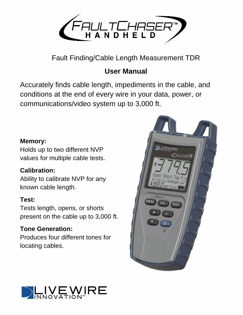
Fault Finding/Cable Length Measurement TDR User Manual Accurately finds cable length, impediments in the cable, and conditions at the end of every wire in your data, power, or communications/video system up to 3,000 ft. Memory: Holds up to two different NVP values for multiple cable tests. Calibration: Ability to calibrate NVP for any known cable length. Test: Tests length, opens, or shorts present on the cable up to 3,000 ft. Tone Generation: Produces four different tones for locating cables.
-
Upload
khangminh22 -
Category
Documents
-
view
3 -
download
0
Transcript of Fault Finding/Cable Length Measurement TDR User Manual
Fault Finding/Cable Length Measurement TDR
User Manual
Accurately finds cable length, impediments in the cable, and conditions at the end of every wire in your data, power, or communications/video system up to 3,000 ft.
Memory: Holds up to two different NVP values for multiple cable tests.
Calibration: Ability to calibrate NVP for any known cable length.
Test: Tests length, opens, or shorts present on the cable up to 3,000 ft.
Tone Generation: Produces four different tones for locating cables.
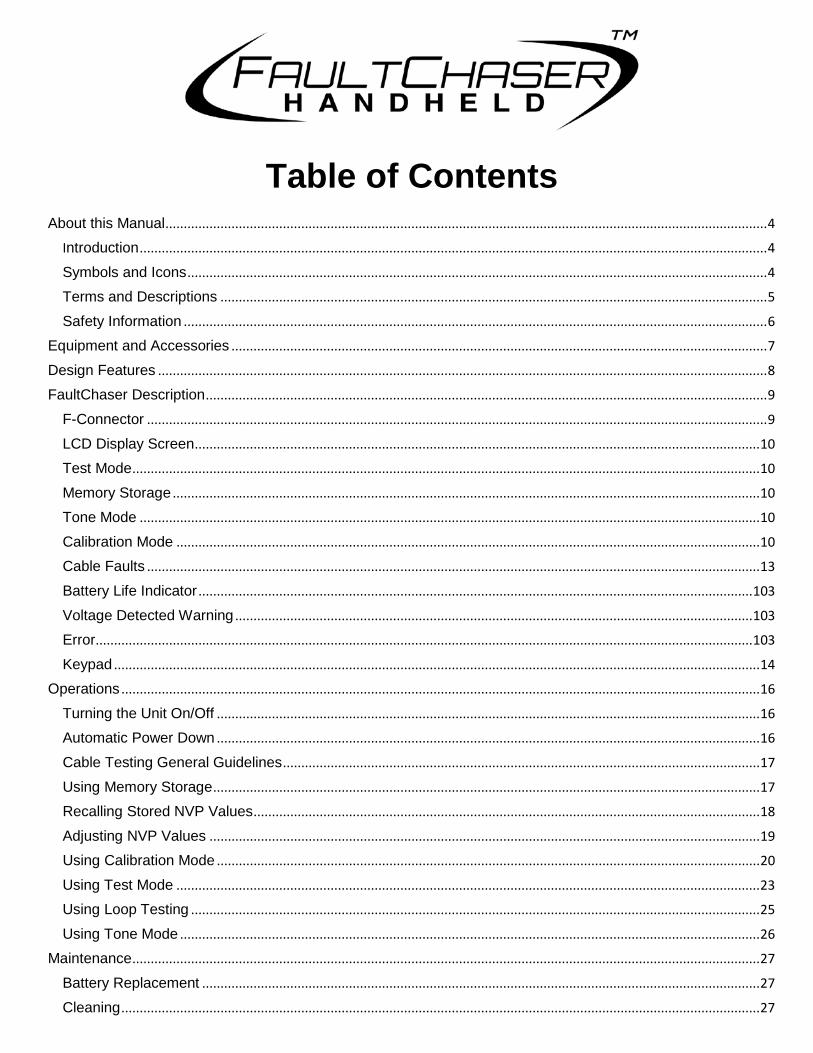
Table of Contents About this Manual .................................................................................................................................................................... 4
Introduction ........................................................................................................................................................................... 4
Symbols and Icons .............................................................................................................................................................. 4
Terms and Descriptions ..................................................................................................................................................... 5
Safety Information ............................................................................................................................................................... 6
Equipment and Accessories .................................................................................................................................................. 7
Design Features ...................................................................................................................................................................... 8
FaultChaser Description ......................................................................................................................................................... 9
F-Connector ......................................................................................................................................................................... 9
LCD Display Screen .......................................................................................................................................................... 10
Test Mode ........................................................................................................................................................................... 10
Memory Storage ................................................................................................................................................................ 10
Tone Mode ......................................................................................................................................................................... 10
Calibration Mode ............................................................................................................................................................... 10
Cable Faults ....................................................................................................................................................................... 13
Battery Life Indicator ....................................................................................................................................................... 103
Voltage Detected Warning ............................................................................................................................................. 103
Error ................................................................................................................................................................................... 103
Keypad ................................................................................................................................................................................ 14
Operations .............................................................................................................................................................................. 16
Turning the Unit On/Off .................................................................................................................................................... 16
Automatic Power Down .................................................................................................................................................... 16
Cable Testing General Guidelines .................................................................................................................................. 17
Using Memory Storage ..................................................................................................................................................... 17
Recalling Stored NVP Values .......................................................................................................................................... 18
Adjusting NVP Values ...................................................................................................................................................... 19
Using Calibration Mode .................................................................................................................................................... 20
Using Test Mode ............................................................................................................................................................... 23
Using Loop Testing ........................................................................................................................................................... 25
Using Tone Mode .............................................................................................................................................................. 26
Maintenance ........................................................................................................................................................................... 27
Battery Replacement ........................................................................................................................................................ 27
Cleaning .............................................................................................................................................................................. 27
Storage................................................................................................................................................................................ 27
Customer Service .................................................................................................................................................................. 28
Contacting LiveWire Innovation ...................................................................................................................................... 28
Additional Accessories ..................................................................................................................................................... 28
Warranty Information ........................................................................................................................................................ 29
Product Registration ......................................................................................................................................................... 29
Disposal .............................................................................................................................................................................. 29
Returns................................................................................................................................................................................ 29
Specifications ......................................................................................................................................................................... 30
Appendix A ............................................................................................................................................................................. 32
3
Patents/Intellectual Property........................................................................................................................................... 29
About this Manual Introduction
The FaultChaser is a self-contained, hand-held, battery powered test unit operated by contractors, repair technicians, and other authorized users. This device is used to accurately test voice, data, and video cables. The FaultChaser determines cable length, identifies cable faults, and quickly discovers the Nominal Velocity of Propagation (NVP) for a cable using Spread Spectrum Time Domain Reflectometry (SSTDR).
Symbols and Icons
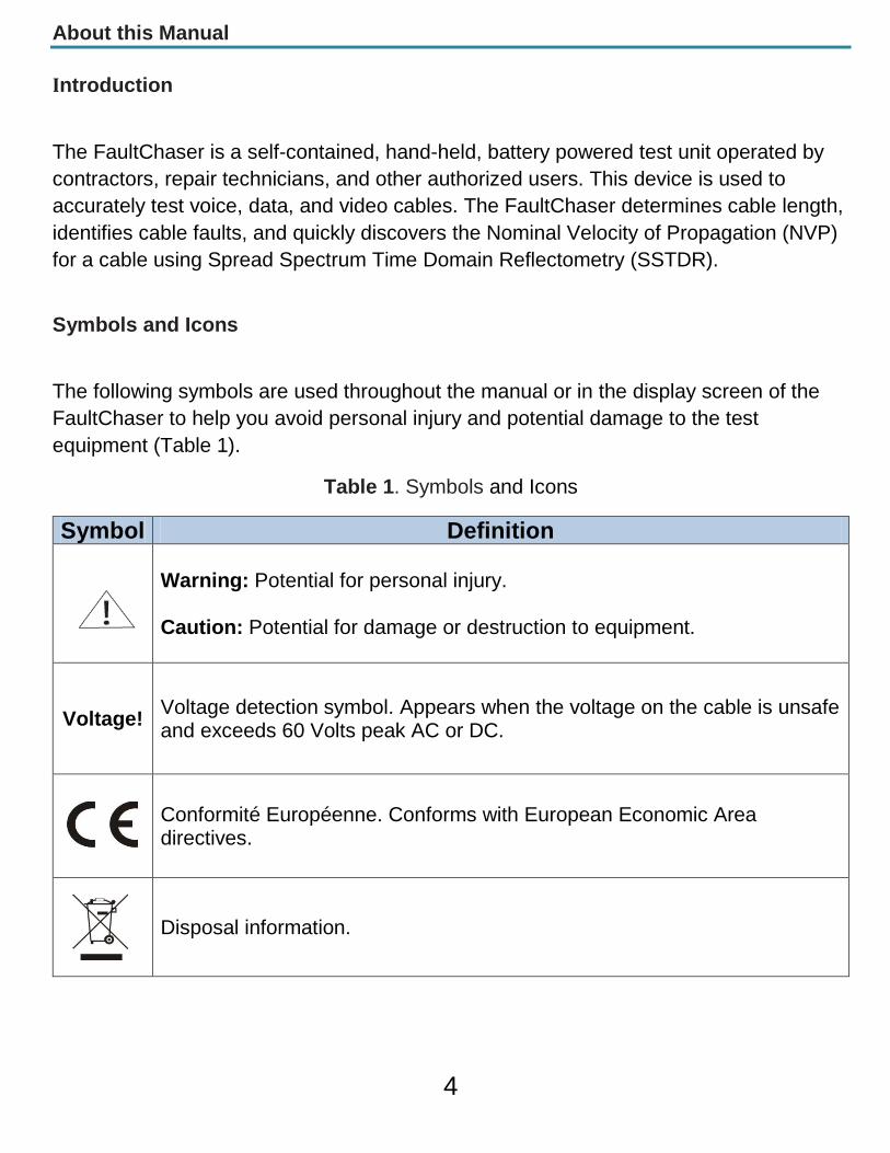
The following symbols are used throughout the manual or in the display screen of the FaultChaser to help you avoid personal injury and potential damage to the test equipment (Table 1).
Table 1. Symbols and Icons
Symbol Definition
Warning: Potential for personal injury. Caution: Potential for damage or destruction to equipment.
Voltage! Voltage detection symbol. Appears when the voltage on the cable is unsafe and exceeds 60 Volts peak AC or DC.
Conformité Européenne. Conforms with European Economic Area directives.
Disposal information.
4
Terms and Descriptions
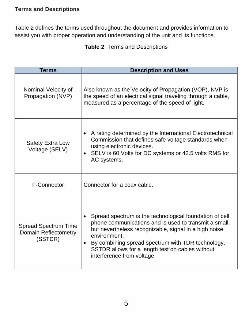
Table 2 defines the terms used throughout the document and provides information to assist you with proper operation and understanding of the unit and its functions.
Table 2. Terms and Descriptions
Terms Description and Uses
Nominal Velocity of Propagation (NVP)
Also known as the Velocity of Propagation (VOP), NVP is the speed of an electrical signal traveling through a cable, measured as a percentage of the speed of light.
Safety Extra Low Voltage (SELV)
• A rating determined by the International Electrotechnical
Commission that defines safe voltage standards when using electronic devices.
• SELV is 60 Volts for DC systems or 42.5 volts RMS for AC systems.
F-Connector Connector for a coax cable.
Spread Spectrum Time Domain Reflectometry
(SSTDR)
• Spread spectrum is the technological foundation of cell
phone communications and is used to transmit a small, but nevertheless recognizable, signal in a high noise environment.
• By combining spread spectrum with TDR technology, SSTDR allows for a length test on cables without interference from voltage.
5
Safety Information
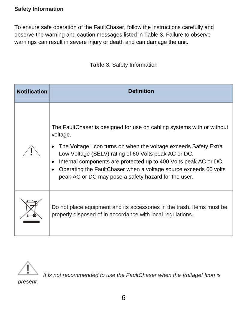
To ensure safe operation of the FaultChaser, follow the instructions carefully and observe the warning and caution messages listed in Table 3. Failure to observe warnings can result in severe injury or death and can damage the unit.
Table 3. Safety Information
Notification Definition
The FaultChaser is designed for use on cabling systems with or without voltage.
• The Voltage! Icon turns on when the voltage exceeds Safety Extra Low Voltage (SELV) rating of 60 Volts peak AC or DC.
• Internal components are protected up to 400 Volts peak AC or DC. • Operating the FaultChaser when a voltage source exceeds 60 volts
peak AC or DC may pose a safety hazard for the user.
Do not place equipment and its accessories in the trash. Items must be properly disposed of in accordance with local regulations.
It is not recommended to use the FaultChaser when the Voltage! Icon is present.
6
Equipment and Accessories
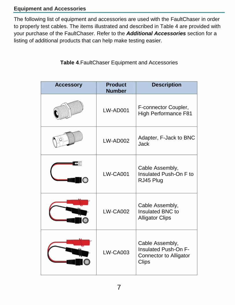
The following list of equipment and accessories are used with the FaultChaser in order to properly test cables. The items illustrated and described in Table 4 are provided with your purchase of the FaultChaser. Refer to the Additional Accessories section for a listing of additional products that can help make testing easier.
Table 4.FaultChaser Equipment and Accessories
Accessory Product Number
Description
LW-AD001
F-connector Coupler, High Performance F81
LW-AD002
Adapter, F-Jack to BNC Jack
LW-CA001
Cable Assembly, Insulated Push-On F to RJ45 Plug
LW-CA002
Cable Assembly, Insulated BNC to Alligator Clips
LW-CA003
Cable Assembly, Insulated Push-On F-Connector to Alligator Clips
7
Design Features
Distance to Fault Accuracy:
o Controlled Impedance Cables
+/- 1 ft. (length < 50 ft.)
+/- 1 % (length > 50 ft.)
o Uncontrolled Impedance Cables
+/- 2 ft. (length < 50 ft.)
+/- 2 % (length > 50 ft.)
Ability to measure cables with voltage
Stores up to two NVP values
Displays length reading in feet or meters
Easy to Operate
Extra-large seven-segment, back lit LCD screen with icons that clearly display test
results
Tests any copper cable including data, voice, video, lamp wire, and Romex cables
Discovers NVP value for cables with known length
Automatic pre-test voltage checks
Identifies cable faults
Tone generator with selectable tone cadence to easily trace cables
Conserves power and supports long battery life with Auto-off feature and battery
life indicator
8
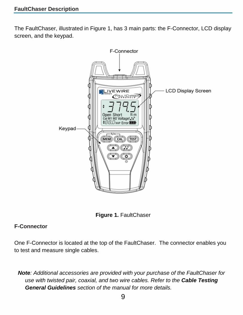
FaultChaser Description
The FaultChaser, illustrated in Figure 1, has 3 main parts: the F-Connector, LCD display screen, and the keypad.
Figure 1. FaultChaser
F-Connector
One F-Connector is located at the top of the FaultChaser. The connector enables you to test and measure single cables.
Note: Additional accessories are provided with your purchase of the FaultChaser for use with twisted pair, coaxial, and two wire cables. Refer to the Cable Testing General Guidelines section of the manual for more details.
9
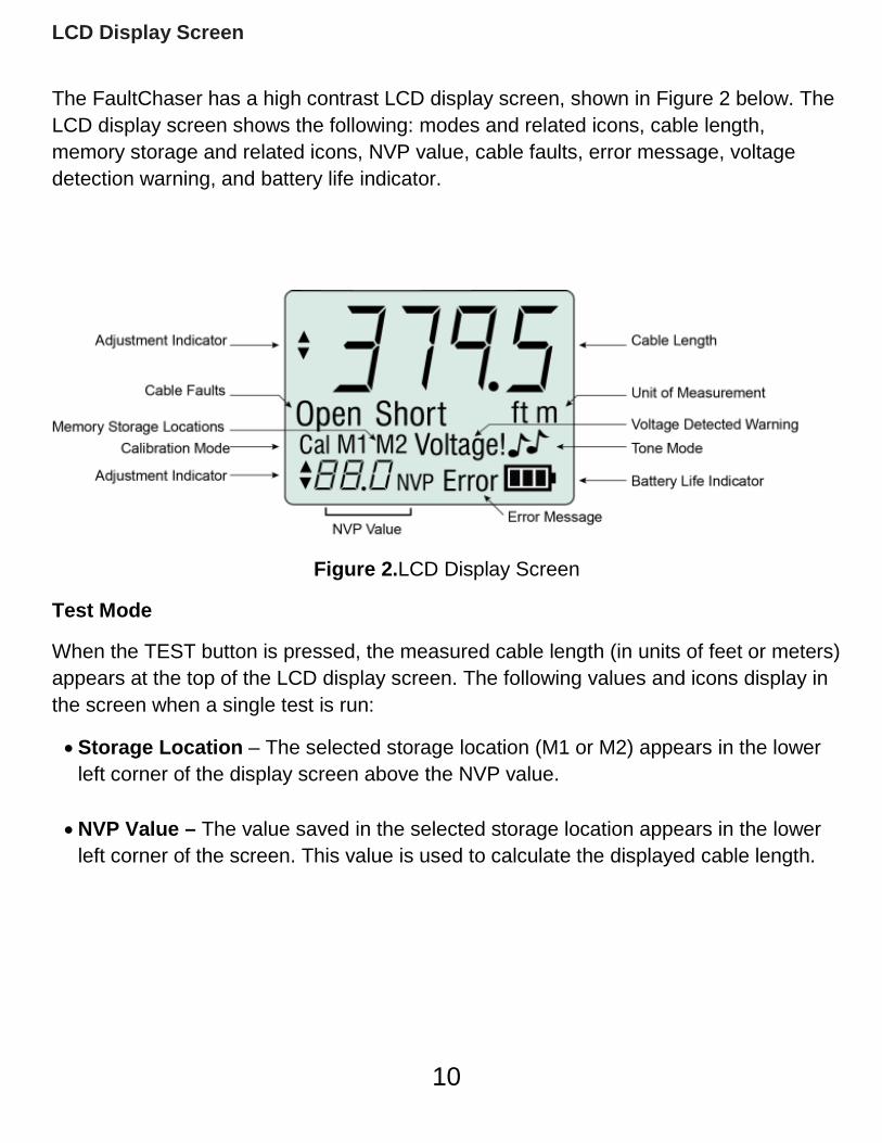
LCD Display Screen
The FaultChaser has a high contrast LCD display screen, shown in Figure 2 below. The LCD display screen shows the following: modes and related icons, cable length, memory storage and related icons, NVP value, cable faults, error message, voltage detection warning, and battery life indicator.
Figure 2.LCD Display Screen
Test Mode
When the TEST button is pressed, the measured cable length (in units of feet or meters) appears at the top of the LCD display screen. The following values and icons display in the screen when a single test is run:
• Storage Location – The selected storage location (M1 or M2) appears in the lower left corner of the display screen above the NVP value.
• NVP Value – The value saved in the selected storage location appears in the lower left corner of the screen. This value is used to calculate the displayed cable length.
10
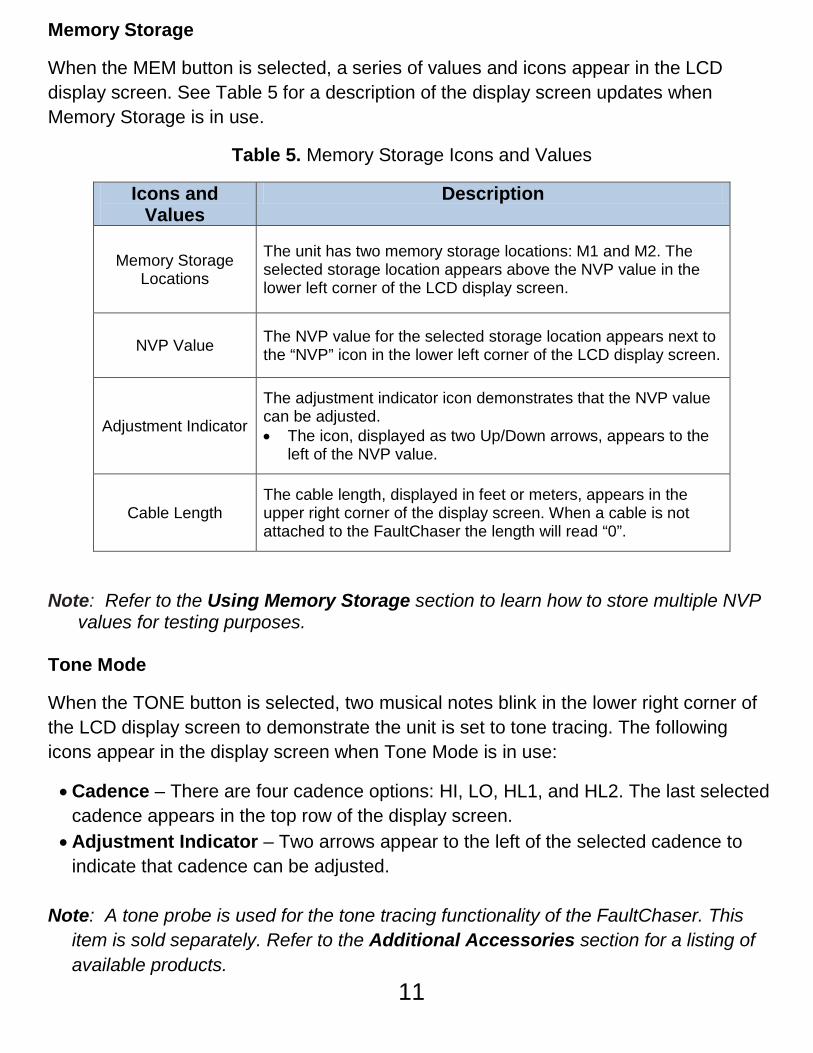
Memory Storage
When the MEM button is selected, a series of values and icons appear in the LCD display screen. See Table 5 for a description of the display screen updates when Memory Storage is in use.
Table 5. Memory Storage Icons and Values
Icons and Values
Description
Memory Storage Locations
The unit has two memory storage locations: M1 and M2. The selected storage location appears above the NVP value in the lower left corner of the LCD display screen.
NVP Value The NVP value for the selected storage location appears next to the “NVP” icon in the lower left corner of the LCD display screen.
Adjustment Indicator
The adjustment indicator icon demonstrates that the NVP value can be adjusted. • The icon, displayed as two Up/Down arrows, appears to the
left of the NVP value.
Cable Length The cable length, displayed in feet or meters, appears in the upper right corner of the display screen. When a cable is not attached to the FaultChaser the length will read “0”.
Note: Refer to the Using Memory Storage section to learn how to store multiple NVP values for testing purposes.
Tone Mode
When the TONE button is selected, two musical notes blink in the lower right corner of the LCD display screen to demonstrate the unit is set to tone tracing. The following icons appear in the display screen when Tone Mode is in use:
• Cadence – There are four cadence options: HI, LO, HL1, and HL2. The last selected cadence appears in the top row of the display screen.
• Adjustment Indicator – Two arrows appear to the left of the selected cadence to indicate that cadence can be adjusted.
Note: A tone probe is used for the tone tracing functionality of the FaultChaser. This
item is sold separately. Refer to the Additional Accessories section for a listing of available products.
11
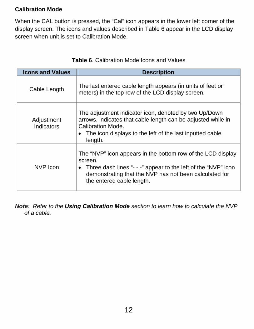
Calibration Mode
When the CAL button is pressed, the “Cal” icon appears in the lower left corner of the display screen. The icons and values described in Table 6 appear in the LCD display screen when unit is set to Calibration Mode.
Table 6. Calibration Mode Icons and Values
Icons and Values Description
Cable Length
The last entered cable length appears (in units of feet or meters) in the top row of the LCD display screen.
Adjustment Indicators
The adjustment indicator icon, denoted by two Up/Down arrows, indicates that cable length can be adjusted while in Calibration Mode. • The icon displays to the left of the last inputted cable
length.
NVP Icon
The “NVP” icon appears in the bottom row of the LCD display screen. • Three dash lines “- - -” appear to the left of the “NVP” icon
demonstrating that the NVP has not been calculated for the entered cable length.
Note: Refer to the Using Calibration Mode section to learn how to calculate the NVP of a cable.
12
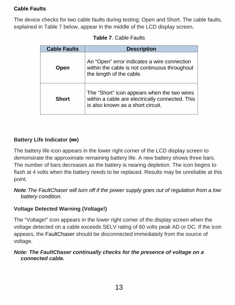
Cable Faults
The device checks for two cable faults during testing: Open and Short. The cable faults, explained in Table 7 below, appear in the middle of the LCD display screen.
Table 7. Cable Faults
Cable Faults Description
Open
An “Open” error indicates a wire connection within the cable is not continuous throughout the length of the cable.
Short
The “Short” icon appears when the two wires within a cable are electrically connected. This is also known as a short circuit.
Battery Life Indicator ( )
The battery life icon appears in the lower right corner of the LCD display screen to demonstrate the approximate remaining battery life. A new battery shows three bars. The number of bars decreases as the battery is nearing depletion. The icon begins to flash at 4 volts when the battery needs to be replaced. Results may be unreliable at this point.
Note: The FaultChaser will turn off if the power supply goes out of regulation from a low battery condition.
Voltage Detected Warning (Voltage!)
The “Voltage!” icon appears in the lower right corner of the display screen when the voltage detected on a cable exceeds SELV rating of 60 volts peak AD or DC. If the icon appears, the FaultChaser should be disconnected immediately from the source of voltage.
Note: The FaultChaser continually checks for the presence of voltage on a connected cable.
13
Error
The “Error” message appears in the lower right corner of the LCD display screen under the following circumstances:
• Calibration results in an invalid NVP value outside of the 20 to 99.9 NVP value range.
• SSTDR reflection was not detected due to a properly terminated cable or excess signal loss.
Note: Refer to the Using Calibration Mode and Using Test Mode sections for trouble-shooting the “Error” message when using either of these modes.
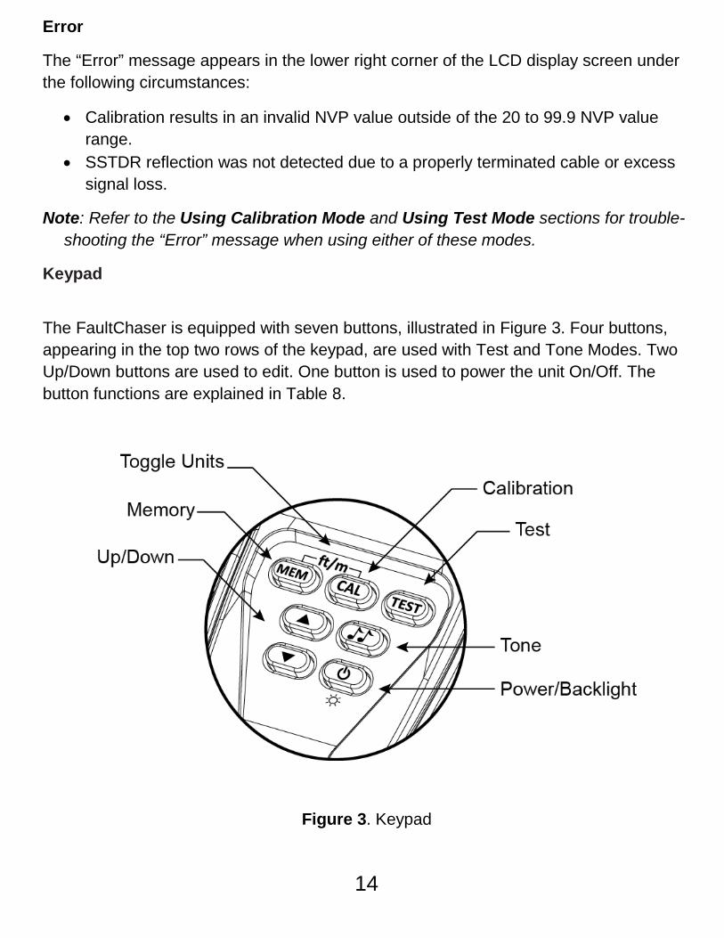
Keypad
The FaultChaser is equipped with seven buttons, illustrated in Figure 3. Four buttons, appearing in the top two rows of the keypad, are used with Test and Tone Modes. Two Up/Down buttons are used to edit. One button is used to power the unit On/Off. The button functions are explained in Table 8.
Figure 3. Keypad
14
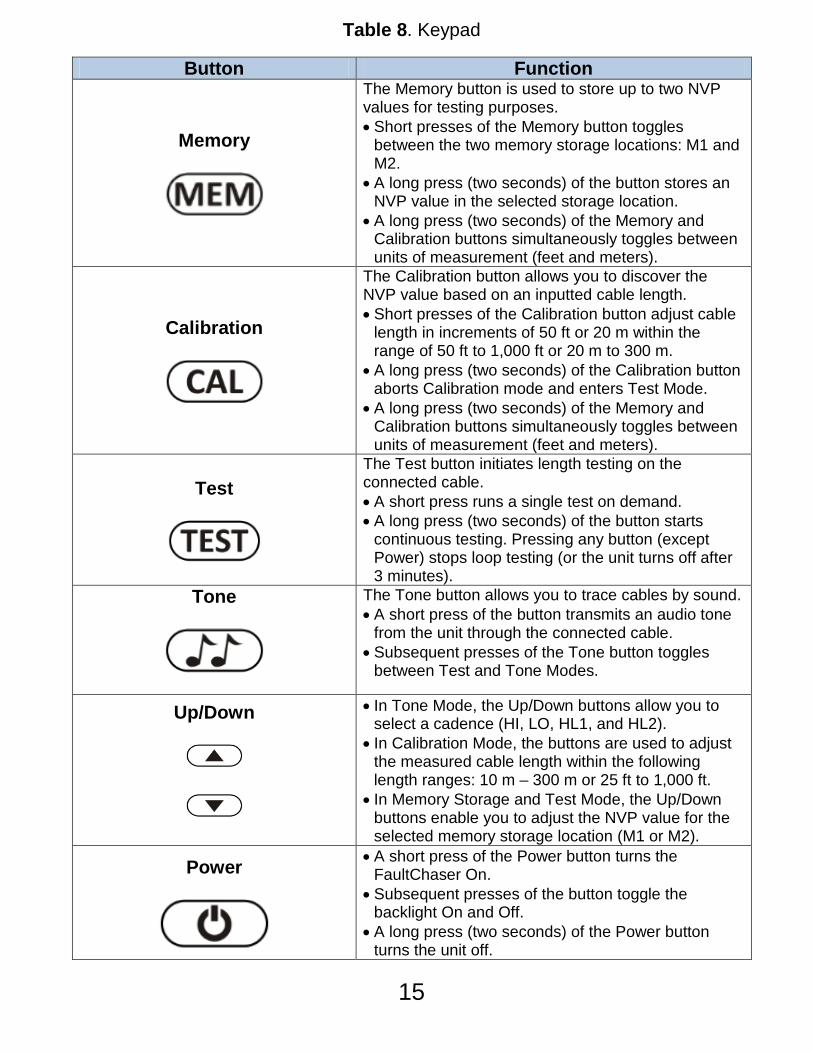
Table 8. Keypad
Button Function
Memory
The Memory button is used to store up to two NVP values for testing purposes. • Short presses of the Memory button toggles
between the two memory storage locations: M1 and M2.
• A long press (two seconds) of the button stores an NVP value in the selected storage location.
• A long press (two seconds) of the Memory and Calibration buttons simultaneously toggles between units of measurement (feet and meters).
Calibration
The Calibration button allows you to discover the NVP value based on an inputted cable length. • Short presses of the Calibration button adjust cable
length in increments of 50 ft or 20 m within the range of 50 ft to 1,000 ft or 20 m to 300 m.
• A long press (two seconds) of the Calibration button aborts Calibration mode and enters Test Mode.
• A long press (two seconds) of the Memory and Calibration buttons simultaneously toggles between units of measurement (feet and meters).
Test
The Test button initiates length testing on the connected cable. • A short press runs a single test on demand. • A long press (two seconds) of the button starts
continuous testing. Pressing any button (except Power) stops loop testing (or the unit turns off after 3 minutes).
Tone
The Tone button allows you to trace cables by sound. • A short press of the button transmits an audio tone
from the unit through the connected cable. • Subsequent presses of the Tone button toggles
between Test and Tone Modes.
Up/Down
• In Tone Mode, the Up/Down buttons allow you to select a cadence (HI, LO, HL1, and HL2).
• In Calibration Mode, the buttons are used to adjust the measured cable length within the following length ranges: 10 m – 300 m or 25 ft to 1,000 ft.
• In Memory Storage and Test Mode, the Up/Down buttons enable you to adjust the NVP value for the selected memory storage location (M1 or M2).
Power
• A short press of the Power button turns the FaultChaser On.
• Subsequent presses of the button toggle the backlight On and Off.
• A long press (two seconds) of the Power button turns the unit off.
15
Operations
To ensure safe operation of the FaultChaser, follow the instructions carefully and pay attention to the warning and caution symbols. Failure to observe warnings can result in severe injury or death and can damage the unit.
Turning the Unit On/Off
Turn Unit On
• Press the POWER button to turn the unit ON. • The FaultChaser immediately runs a length test when powered ON.
Turn Unit Off
• Press and hold down the POWER button for two seconds to turn the unit OFF. The display screen goes blank.
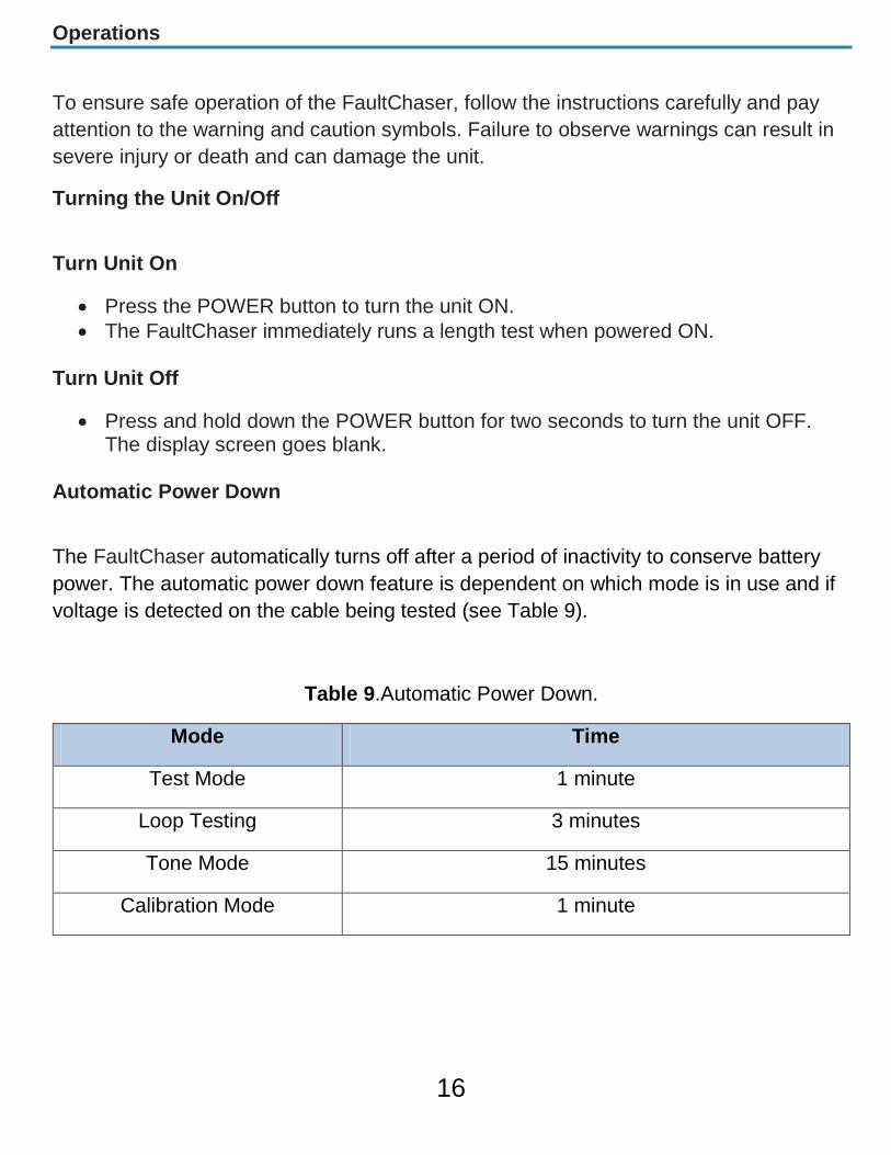
Automatic Power Down
The FaultChaser automatically turns off after a period of inactivity to conserve battery power. The automatic power down feature is dependent on which mode is in use and if voltage is detected on the cable being tested (see Table 9).
Table 9.Automatic Power Down.
Mode Time
Test Mode 1 minute
Loop Testing 3 minutes
Tone Mode 15 minutes
Calibration Mode 1 minute
16
Cable Testing General Guidelines
The FaultChaser determines the length of a variety of cable types, calculates the NVP value of a cable with a known length, and identifies cables by sound.
Important Points to Note
The Accessories provided with the FaultChaser must be used to properly connect cables.
• For coaxial cables, affix the F-Connector Coupler to the F-Connector on the top of the unit. Then connect the end of the cable to be tested to the other side of the F-Connector Coupler.
• When testing a cable with an RJ45 jack, connect the F-Connector Coupler to the F-Connector on the top of the unit. Then attach the Insulated Push-On F to RJ45 Plug.
• To run tests using the Alligator Clips, first affix the F-Connector Coupler (or F-Jack to BNC Jack) to the top of unit. Then attach the proper Cable Assembly to Alligator Clip accessory.
Important Safety Points
The Voltage! Icon appears when the voltage surpasses SELV rating of 60 volts peak AC or DC. It is not recommended to operate the FaultChaser on cable systems exceeding a voltage value of 60 volts.
If the Voltage! icon appears the FaultChaser should be disconnected immediately from the source of the voltage.
Internal components of the FaultChaser are protected to 400 volts peak AC or DC. Connecting the unit to cabling systems with voltage above 400 volts peak AC or DC may damage the test unit and pose a safety hazard for the user.
Using Memory Storage The FaultChaser features two memory storage locations (M1 and M2) allowing you to save two NVP values for cable testing.
Note: For the first use of the Memory Storage feature, the default NVP values for both M1 and M2 storage locations is 84.6 NVP. This is a common value for testing RG6 coax cables.
When Memory Storage is in use, the connected cable is tested for the presence of voltage. If detected, a dynamic voltage warning displays until the unit is disconnected from the voltage source.
17
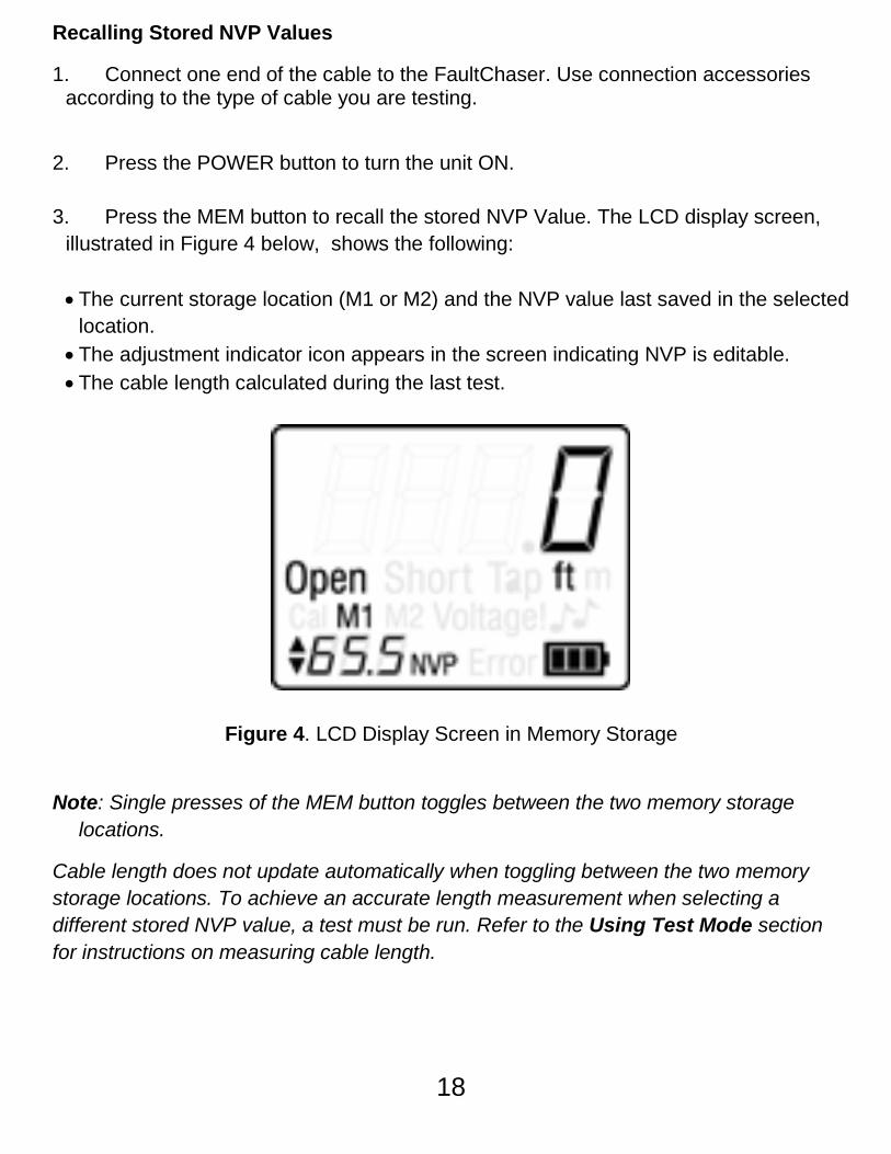
Recalling Stored NVP Values
1. Connect one end of the cable to the FaultChaser. Use connection accessories according to the type of cable you are testing.
2. Press the POWER button to turn the unit ON. 3. Press the MEM button to recall the stored NVP Value. The LCD display screen,
illustrated in Figure 4 below, shows the following:
• The current storage location (M1 or M2) and the NVP value last saved in the selected location.
• The adjustment indicator icon appears in the screen indicating NVP is editable. • The cable length calculated during the last test.
Figure 4. LCD Display Screen in Memory Storage
Note: Single presses of the MEM button toggles between the two memory storage locations.
Cable length does not update automatically when toggling between the two memory storage locations. To achieve an accurate length measurement when selecting a different stored NVP value, a test must be run. Refer to the Using Test Mode section for instructions on measuring cable length.
18

Adjusting NVP Values
1. Power the unit ON. 2. Select the memory storage location you would like to adjust (M1 or M2) through
short presses of the MEM button. 3. Press the UP and DOWN buttons to increment or decrement the NVP value.
Press and hold the UP or DOWN buttons to quickly increase or decrease the NVP value.
Note: If the NVP value is unknown, you can determine the NVP value for the cable you
are testing in the following ways:
• View the listing of common NVPs by cable type on the backside of the FaultChaser.
• Refer to Appendix A for an extended listing of NVP values.
• Calibrate the NVP value if the length of the cable is known. Refer to the Using Calibration Mode section for instructions on calculating NVP.
4. Press and hold down the MEM button for two seconds to save the adjusted NVP
value. The adjusted NVP value will be stored in the unit’s memory for the specified storage location.
Note: A short press of the MEM button or selection of any other buttons during editing will discard the adjusted value.
If the unit is turned OFF prior to saving the edited NVP value, the FaultChaser will recall the adjusted NVP value. However, the adjusted value will not be saved in either of the two storage locations.
19
Using Calibration Mode Use Calibration Mode to calculate the NVP value for a known cable length between 25 ft - 1,000 ft or between 10 m - 300 m. The determined NVP value can be stored in the unit’s memory allowing you to easily test cables without recalibrating the NVP every test.
Note: Calibration Mode is used with unterminated cables only.
For the first use of Calibration Mode, the unit defaults to a cable length of 50 ft, when the unit is set to feet, or 20 m when the FaultChaser is set to meters.
When Calibration Mode is in use, the connected cable is tested for the presence of voltage. If detected, a dynamic voltage warning displays until the unit is disconnected from the voltage source.
1. Connect a cable to the FaultChaser. Use connection accessories according to the type of cable you are testing.
Note: The FaultChaser cannot be calibrated without a cable attached to the unit.
2. Press the POWER button to turn the unit ON.
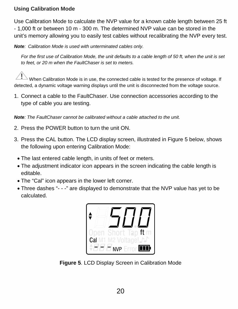
3. Press the CAL button. The LCD display screen, illustrated in Figure 5 below, shows the following upon entering Calibration Mode:
• The last entered cable length, in units of feet or meters. • The adjustment indicator icon appears in the screen indicating the cable length is
editable. • The “Cal” icon appears in the lower left corner. • Three dashes “- - -” are displayed to demonstrate that the NVP value has yet to be
calculated.
Figure 5. LCD Display Screen in Calibration Mode
20
4. Verify the FaultChaser is set to your desired unit of measurement (feet or meters). To change the unit of measurement, press and hold down the MEM and CAL buttons simultaneously for two seconds. The unit of measurement will adjust in the LCD display screen.
5. Enter the length of the attached cable. See Table 10 for a description of how to
adjust cable length using the Up/Down and Calibration buttons. Table 10. Adjusting Cable Length.
Buttons Description
Up/Down
The Up/Down buttons allow you to adjust the cable length within the
range of 10 m – 300 m or 25 ft to 1000 ft. • Press the UP and DOWN buttons to increment or decrement the
length. • Press and hold the UP or DOWN buttons to quickly increase or
decrease the cable length.
Calibration
• Press the CAL button to increase cable length in 50 ft or 20 m
increments according to the unit of measurement selected (feet or meters).
Note: Once the maximum length (1,000 ft or 300 m) is reached through use of the CAL button, a
subsequent press of the button adjusts the cable length to the default cable length (50 ft or 20 m).
To abort Calibration Mode and retain your previous inputted cable length, press and hold down the CAL button. The unit defaults to Test Mode.
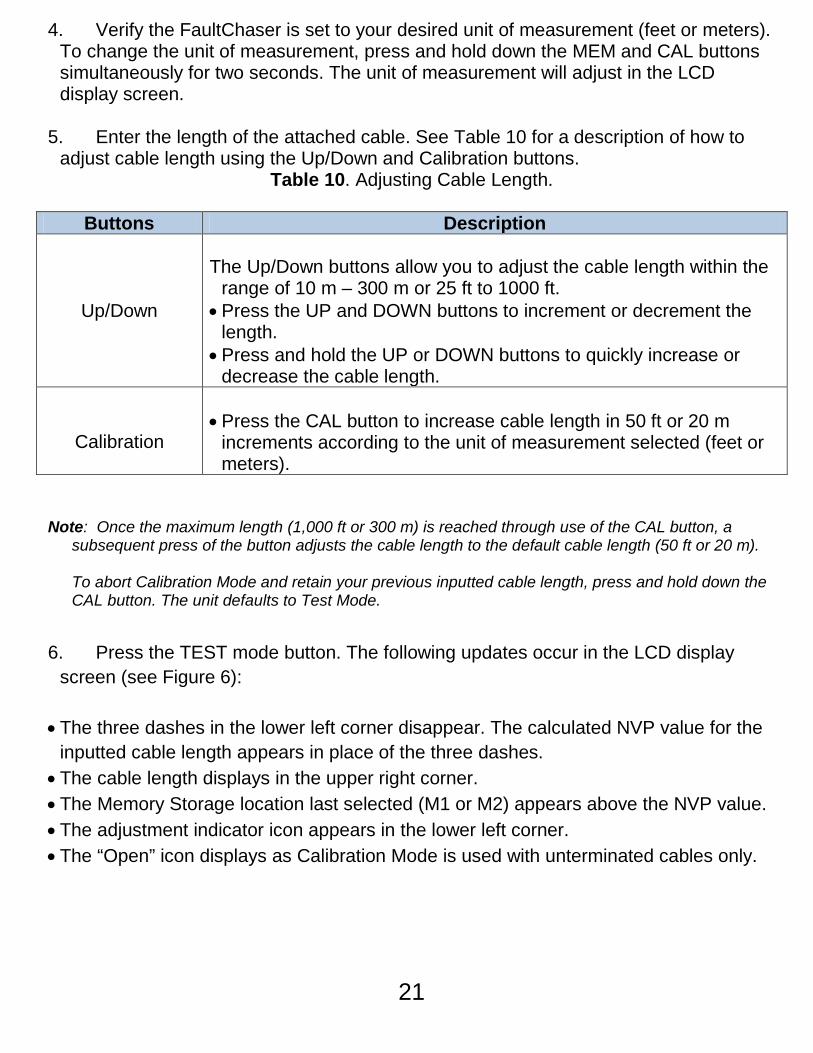
6. Press the TEST mode button. The following updates occur in the LCD display screen (see Figure 6):
• The three dashes in the lower left corner disappear. The calculated NVP value for the
inputted cable length appears in place of the three dashes. • The cable length displays in the upper right corner. • The Memory Storage location last selected (M1 or M2) appears above the NVP value. • The adjustment indicator icon appears in the lower left corner. • The “Open” icon displays as Calibration Mode is used with unterminated cables only.
21
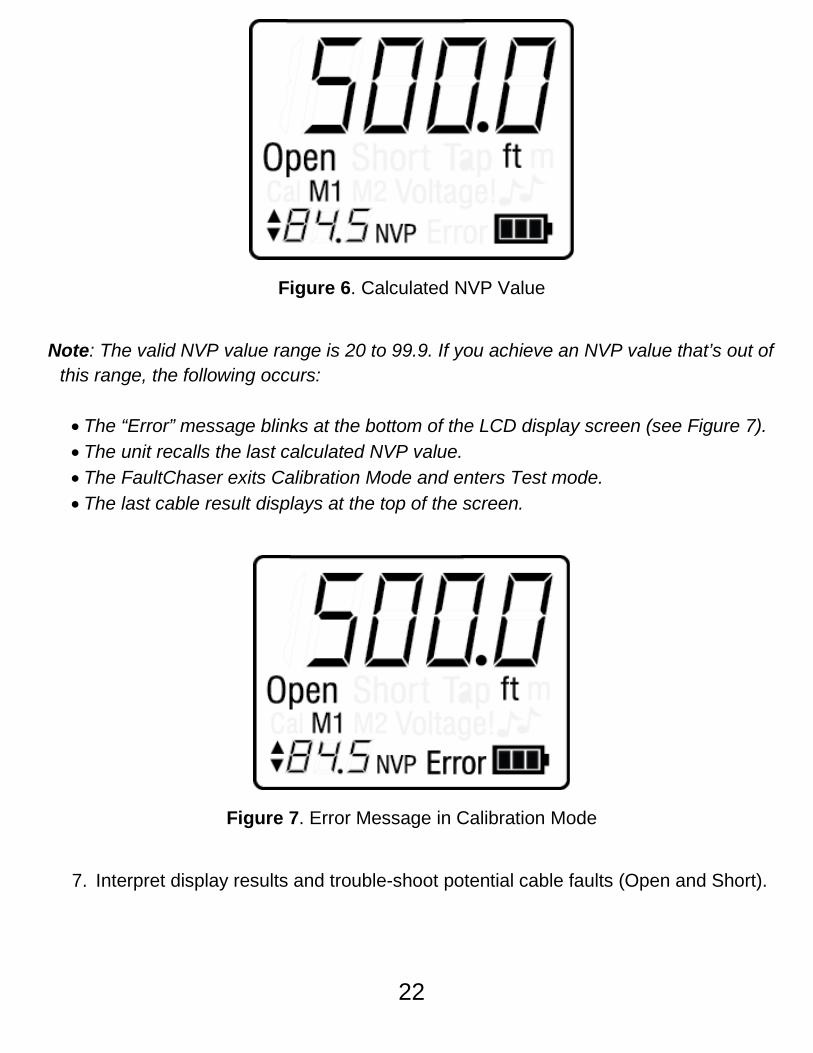
Figure 6. Calculated NVP Value
Note: The valid NVP value range is 20 to 99.9. If you achieve an NVP value that’s out of
this range, the following occurs:
• The “Error” message blinks at the bottom of the LCD display screen (see Figure 7). • The unit recalls the last calculated NVP value. • The FaultChaser exits Calibration Mode and enters Test mode. • The last cable result displays at the top of the screen.
Figure 7. Error Message in Calibration Mode
7. Interpret display results and trouble-shoot potential cable faults (Open and Short).
22
Using Test Mode
Use Test Mode to calculate the length of unterminated cables. A termination with impedance closely matching the characteristic impedance of the cable can produce inaccurate test results. One of the following error messages may appear in the LCD display screen:
• “Short” icon appears demonstrating the cable is terminated. • “Error” message blinks to indicate that SSTDR reflection was not detected due to a
properly terminated cable or excess signal loss.
When Test Mode is in use, the connected cable is tested for the presence of voltage. If detected, a dynamic voltage warning displays until the unit is disconnected from the voltage source.
1. Connect a cable to the FaultChaser. Use connection accessories according to the type of cable you are testing.
Note: Connection to the cable should be as short as possible to minimize the impedance discontinuity at the cable attachment point. Otherwise, The FaultChaser may see a fault at the connection point.
2. Press the POWER button to turn the unit ON. 3. Select the memory storage location (M1 or M2) with the desired NVP value for
testing. The NVP value requires adjustment if neither storage location contains an NVP value matching the type of cable you are testing.
Note: Refer to the Using Memory Storage section for instructions on adjusting NVP values.
A listing of common NVPs by cable type is on the backside of the FaultChaser. You may also refer to Appendix A for an extended list of NVP values.
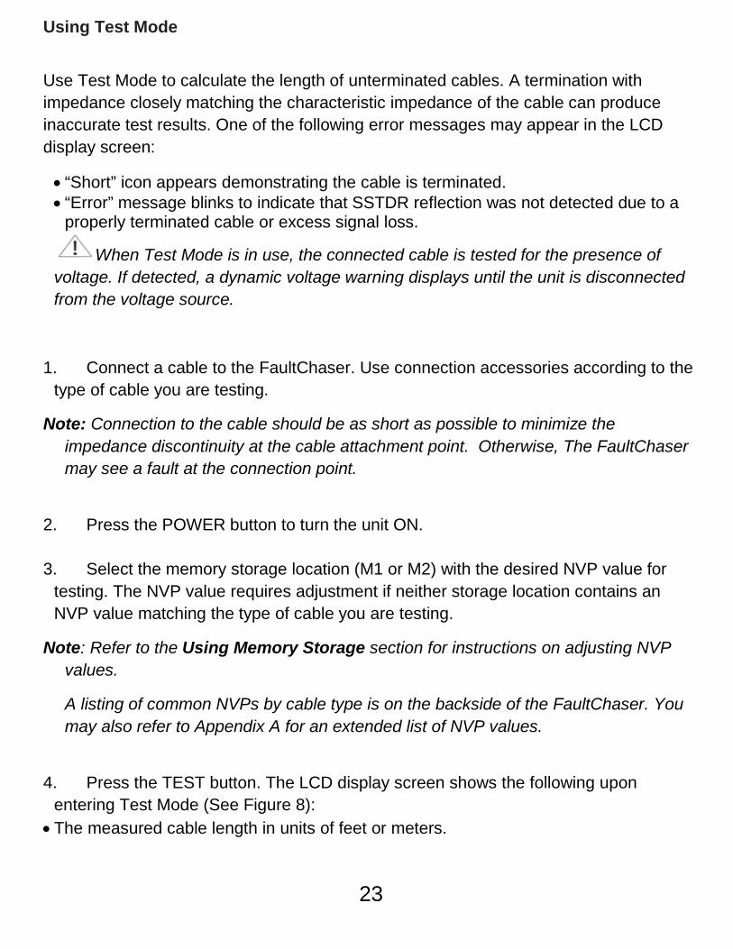
4. Press the TEST button. The LCD display screen shows the following upon
entering Test Mode (See Figure 8): • The measured cable length in units of feet or meters.
23
• The storage location (M1 or M2) with its associated NVP value used to calculate the connected cable’s length.
• The adjustment indicator icon appears in the lower left corner. • The cable faults (Open or Short).
Figure 8. LCD Display Screen in Test Mode
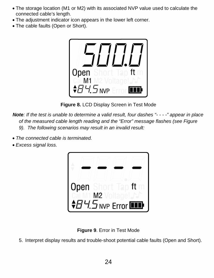
Note: If the test is unable to determine a valid result, four dashes “- - - -” appear in place of the measured cable length reading and the “Error” message flashes (see Figure 9). The following scenarios may result in an invalid result:
• The connected cable is terminated. • Excess signal loss.
Figure 9. Error in Test Mode
5. Interpret display results and trouble-shoot potential cable faults (Open and Short).
24
Using Loop Testing
The FaultChaser can run a continuous test on a connected cable allowing you accurately measure long cables susceptible to signal loss. Loop testing offers ease of use by enabling you to test multiple cables without repeatedly pressing the TEST button.
1. Press the POWER button to turn the unit ON. 2. Verify the unit is set to the desired unit of measurement (feet or meters). To
change the unit of measurement, press and hold down the MEM and CAL buttons for two seconds.
3. Select the memory storage location (M1 or M2) that contains the NVP value for
the type of cable you are testing. Note: Refer to the Using Memory Storage section for instructions on adjusting the NVP value. 4. Press and hold down the TEST button for two seconds to run a continuous test.
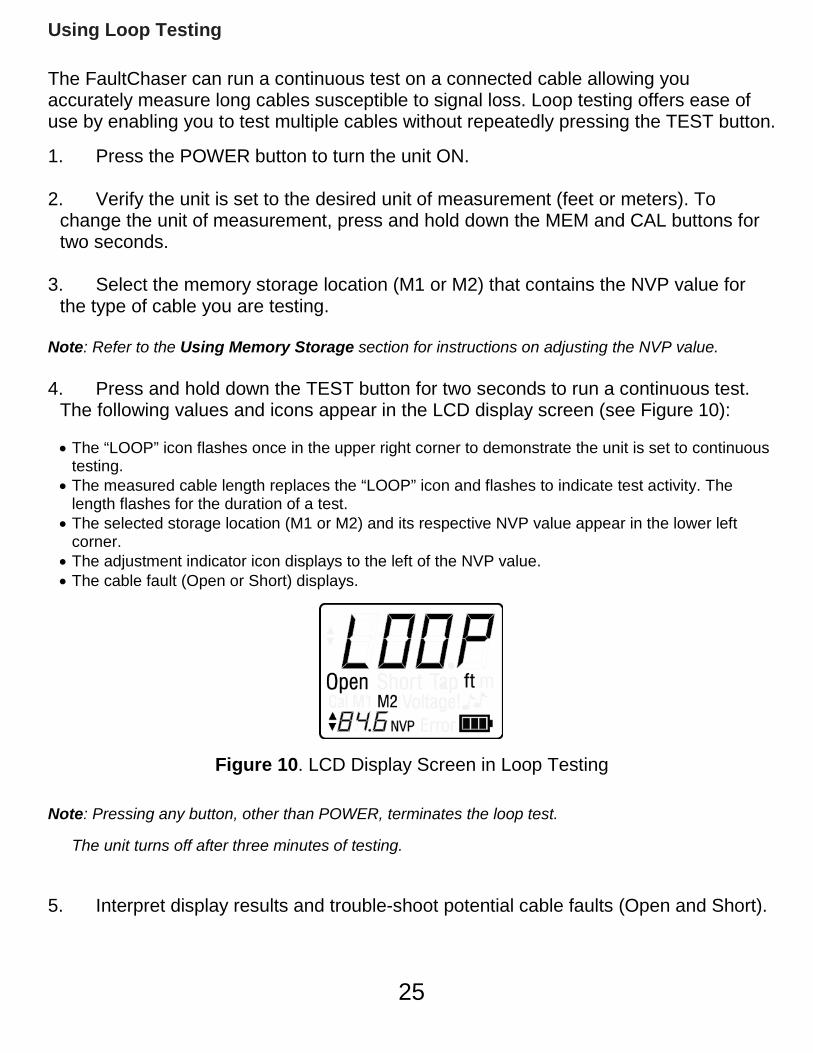
The following values and icons appear in the LCD display screen (see Figure 10): • The “LOOP” icon flashes once in the upper right corner to demonstrate the unit is set to continuous
testing. • The measured cable length replaces the “LOOP” icon and flashes to indicate test activity. The
length flashes for the duration of a test. • The selected storage location (M1 or M2) and its respective NVP value appear in the lower left
corner. • The adjustment indicator icon displays to the left of the NVP value. • The cable fault (Open or Short) displays.
Figure 10. LCD Display Screen in Loop Testing
Note: Pressing any button, other than POWER, terminates the loop test.
The unit turns off after three minutes of testing.
5. Interpret display results and trouble-shoot potential cable faults (Open and Short).
25
Using Tone Mode
Tone Mode is used to trace cables by sound. Selection of this mode emits a cadence from the unit through the connected cable. Cadence is detected by a tone probe.
When Tone Mode is in use, the connected cable is tested for the presence of voltage. If detected, a dynamic voltage warning displays until the unit is disconnected from the voltage source.
1. Connect a cable to the FaultChaser. Use connection accessories according to the type of cable you are testing.
2. Press the POWER button to turn the unit ON. 3. Press the TONE button. The LCD display screen updates with the following
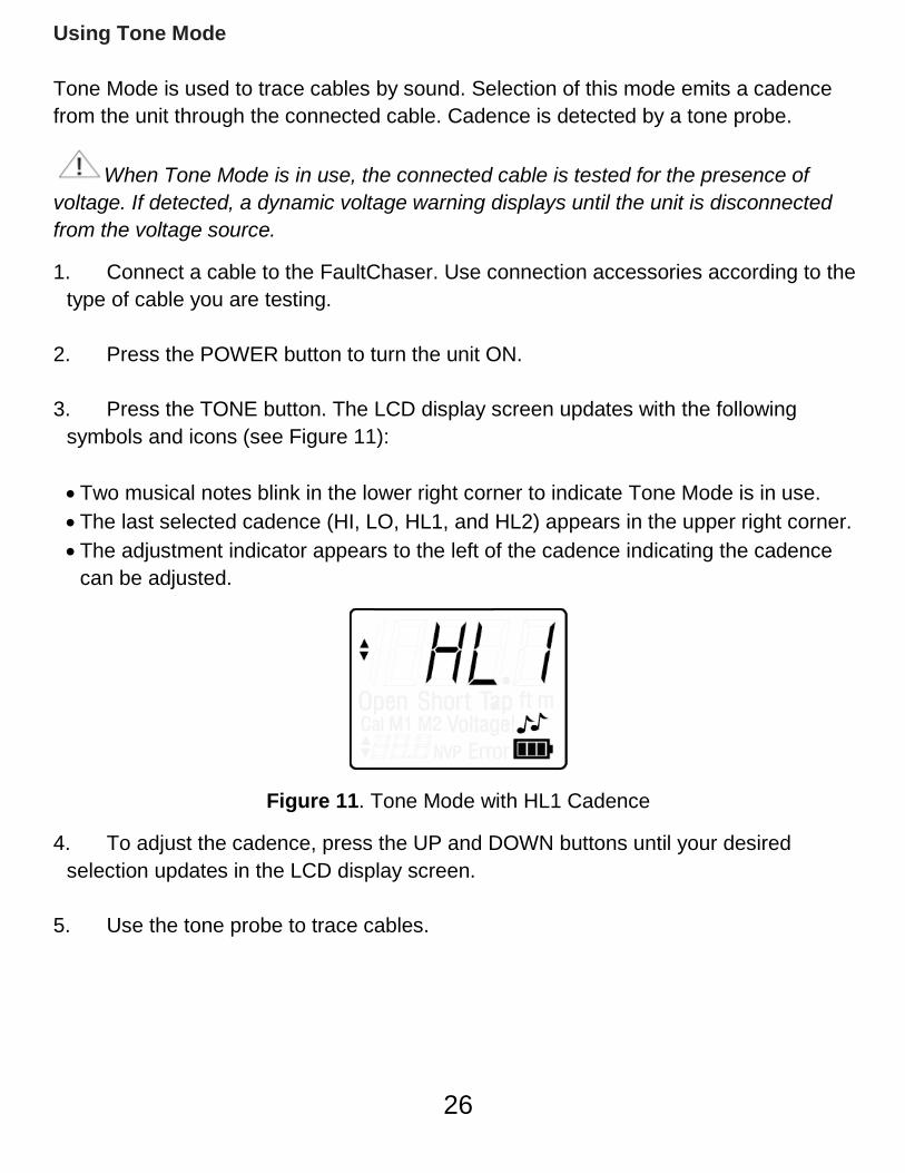
symbols and icons (see Figure 11):
• Two musical notes blink in the lower right corner to indicate Tone Mode is in use. • The last selected cadence (HI, LO, HL1, and HL2) appears in the upper right corner. • The adjustment indicator appears to the left of the cadence indicating the cadence
can be adjusted.
Figure 11. Tone Mode with HL1 Cadence
4. To adjust the cadence, press the UP and DOWN buttons until your desired selection updates in the LCD display screen.
5. Use the tone probe to trace cables.
26
Maintenance
Battery Replacement
1. Remove the single screw on the battery door, located in the back of the FaultChaser towards the bottom of the unit, with a #1 Philips head screwdriver.
2. Take off the battery door and remove old batteries.
3. Replace with four AA Alkaline batteries. Slide batteries into the battery cartridge according to the diagram imprinted on the bottom of the battery compartment.
4. Return the battery door to the unit and tighten the screw to secure the battery door.
Do not over tighten the battery door. Doing so can damage the test unit.
Cleaning
Use a damp, clean cloth to clean the test unit.
Disconnect all cables from the FaultChaser prior to cleaning. Failing to do so can damage the unit and result in personal injury.
Do not use abrasive, harsh cleaners, or solvents to clean the FaultChaser.
Storage
When the FaultChaser is not in use, store in a dry, protective case. The batteries should be removed if the unit is stored for a long period of time.
Do not expose the FaultChaser to high temperatures or humidity. When stored in temperatures exceeding the limits listed in the Specifications section, allow the FaultChaser to return to the normal, recommended operating conditions prior to use.
27
Customer Service
Contacting LiveWire Innovation For technical information and customer support, please visit www.livewireinnovation.com or send an email to [email protected].
Contact Information:
Phone:
Toll Free: 1-855-346-3358
Local: 801-293-8300
Email: [email protected]
Address:
LiveWire Innovation
10288 South Jordan Gateway, Ste A
South Jordan, UT 84095
USA
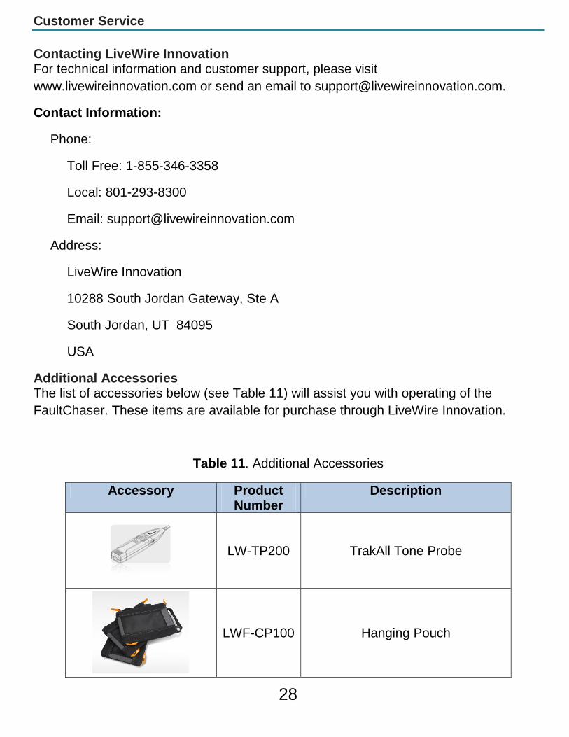
Additional Accessories The list of accessories below (see Table 11) will assist you with operating of the FaultChaser. These items are available for purchase through LiveWire Innovation.
Table 11. Additional Accessories
Accessory Product Number
Description
LW-TP200 TrakAll Tone Probe
LWF-CP100 Hanging Pouch
28
Warranty Information
LiveWire FaultChaser is the trademark of LiveWire Innovation, Inc. and is covered by one or more patents as described at:http://livewireinnovation.com/about/patents-trademarks/.
Product Registration Registration of your purchased equipment and accessories allows you to access support information and receive notifications of product updates. To register products, please visit the LiveWire Innovation website at www.livewireinnovation.com/warranty.
Disposal
WEEE Compliant: Prior to disposal of this product, please contact LiveWire Innovation for proper disposal options.
Returns You must first request a Return Materials Authorization number and receiving shipping instructions by contacting the Customer Service Department at 855-346-3358 or by emailing [email protected].
Note: Shipments will not be accepted without this number, which must be clearly marked on the shipping label.
29
Patents/Intellectual Property
LiveWire FaultChaser is covered by the Limited Product Warranty set forth in and subject to the terms, conditions, limitations and disclaimers set forth in LiveWire's General Terms, http://livewireinnovation.com/terms/. No further warranties either implied or express will apply, nor will responsibility for operation of this device be assumed by LiveWire Innovation.
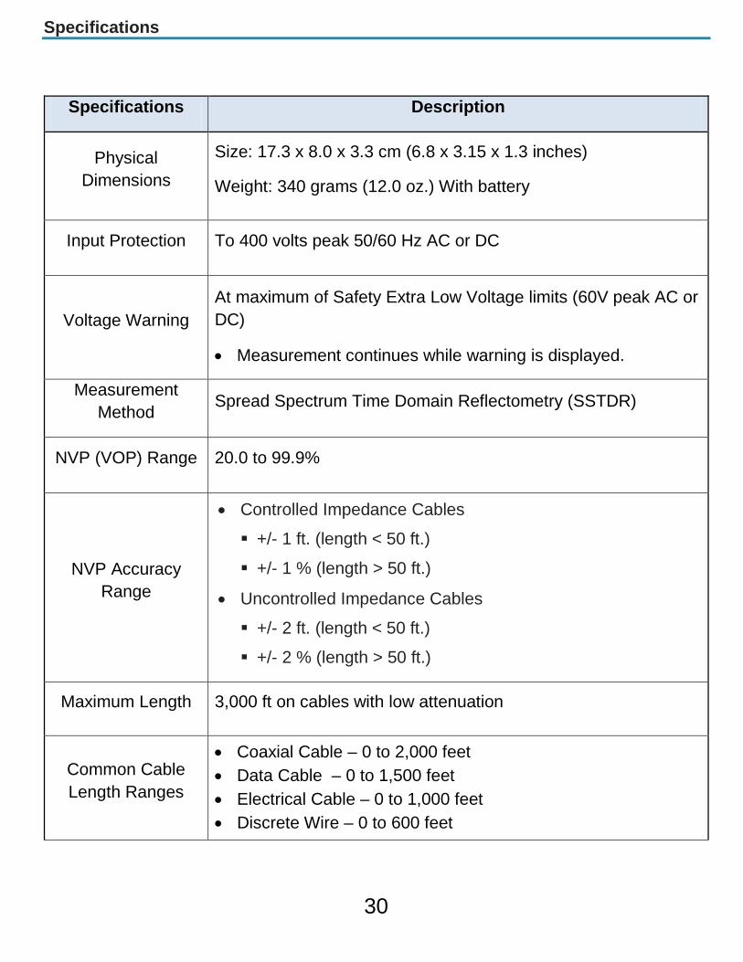
Specifications
Specifications Description
Physical Dimensions
Size: 17.3 x 8.0 x 3.3 cm (6.8 x 3.15 x 1.3 inches)
Weight: 340 grams (12.0 oz.) With battery
Input Protection To 400 volts peak 50/60 Hz AC or DC
Voltage Warning At maximum of Safety Extra Low Voltage limits (60V peak AC or DC)
• Measurement continues while warning is displayed.
Measurement Method Spread Spectrum Time Domain Reflectometry (SSTDR)
NVP (VOP) Range 20.0 to 99.9%
NVP Accuracy Range
• Controlled Impedance Cables
+/- 1 ft. (length < 50 ft.)
+/- 1 % (length > 50 ft.)
• Uncontrolled Impedance Cables
+/- 2 ft. (length < 50 ft.)
+/- 2 % (length > 50 ft.)
Maximum Length 3,000 ft on cables with low attenuation
Common Cable Length Ranges
• Coaxial Cable – 0 to 2,000 feet• Data Cable – 0 to 1,500 feet• Electrical Cable – 0 to 1,000 feet• Discrete Wire – 0 to 600 feet
30
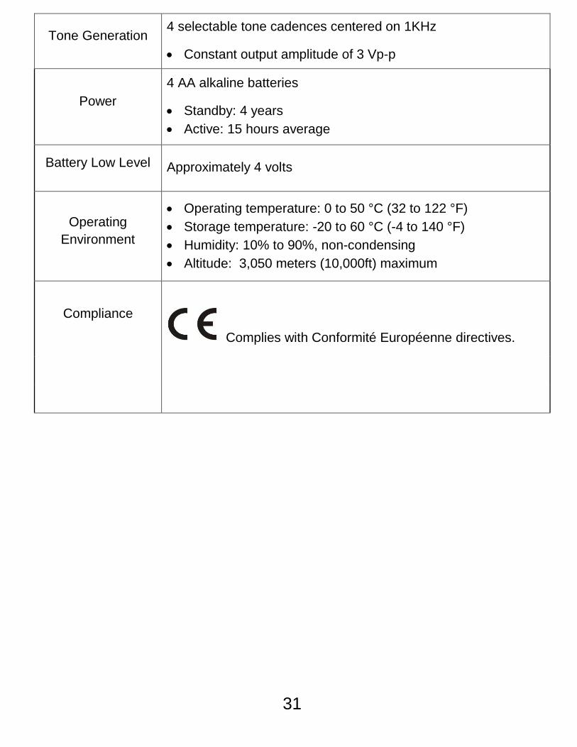
Tone Generation 4 selectable tone cadences centered on 1KHz
• Constant output amplitude of 3 Vp-p
Power 4 AA alkaline batteries
• Standby: 4 years• Active: 15 hours average
Battery Low Level Approximately 4 volts
Operating Environment
• Operating temperature: 0 to 50 °C (32 to 122 °F)• Storage temperature: -20 to 60 °C (-4 to 140 °F)• Humidity: 10% to 90%, non-condensing• Altitude: 3,050 meters (10,000ft) maximum
Compliance
Complies with Conformité Européenne directives.
31
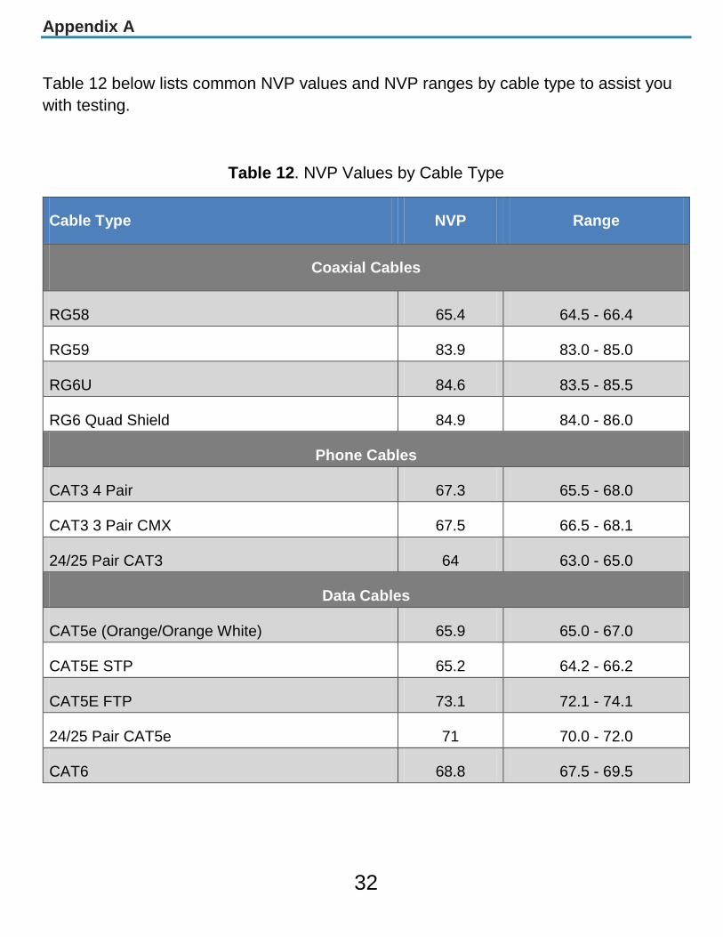
Appendix A
Table 12 below lists common NVP values and NVP ranges by cable type to assist you with testing.
Table 12. NVP Values by Cable Type
Cable Type NVP Range
Coaxial Cables
RG58 65.4 64.5 - 66.4
RG59 83.9 83.0 - 85.0
RG6U 84.6 83.5 - 85.5
RG6 Quad Shield 84.9 84.0 - 86.0
Phone Cables
CAT3 4 Pair 67.3 65.5 - 68.0
CAT3 3 Pair CMX 67.5 66.5 - 68.1
24/25 Pair CAT3 64 63.0 - 65.0
Data Cables
CAT5e (Orange/Orange White) 65.9 65.0 - 67.0
CAT5E STP 65.2 64.2 - 66.2
CAT5E FTP 73.1 72.1 - 74.1
24/25 Pair CAT5e 71 70.0 - 72.0
CAT6 68.8 67.5 - 69.5
32
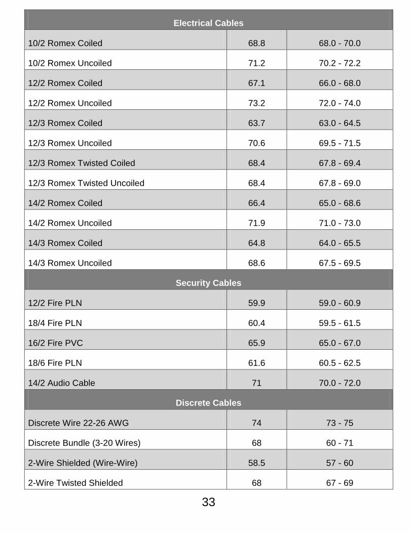
Electrical Cables
10/2 Romex Coiled 68.8 68.0 - 70.0
10/2 Romex Uncoiled 71.2 70.2 - 72.2
12/2 Romex Coiled 67.1 66.0 - 68.0
12/2 Romex Uncoiled 73.2 72.0 - 74.0
12/3 Romex Coiled 63.7 63.0 - 64.5
12/3 Romex Uncoiled 70.6 69.5 - 71.5
12/3 Romex Twisted Coiled 68.4 67.8 - 69.4
12/3 Romex Twisted Uncoiled 68.4 67.8 - 69.0
14/2 Romex Coiled 66.4 65.0 - 68.6
14/2 Romex Uncoiled 71.9 71.0 - 73.0
14/3 Romex Coiled 64.8 64.0 - 65.5
14/3 Romex Uncoiled 68.6 67.5 - 69.5
Security Cables
12/2 Fire PLN 59.9 59.0 - 60.9
18/4 Fire PLN 60.4 59.5 - 61.5
16/2 Fire PVC 65.9 65.0 - 67.0
18/6 Fire PLN 61.6 60.5 - 62.5
14/2 Audio Cable 71 70.0 - 72.0
Discrete Cables
Discrete Wire 22-26 AWG 74 73 - 75
Discrete Bundle (3-20 Wires) 68 60 - 71
2-Wire Shielded (Wire-Wire) 58.5 57 - 60
2-Wire Twisted Shielded 68 67 - 69
33


Fault Finding/Cable Length Measurement TDR
User Manual For technical information and customer support please visit livewireinnovation.com or
send an email to [email protected]
Contact Numbers:
Toll Free: 1-855-346-3358
Local: 801-293-8300
Address:
LiveWire Innovation
10288 South Jordan Gateway, Ste A
South Jordan, UT 84095
USA
livewireinnovation.com