PLANNING MANUAL - Best SunBeds
245
PLANNING MANUAL Exhaust air systems and accessories Connecting to controls and audio units Multivision Information on air conditioning Technical information ➔ ➔ ➔ ➔ ➔ ➔ EXCELLENCE IQ ➔ EXCELLENCE 800 ➔ EXCELLENCE 700 ➔ EVOLUTION IQ ➔ EVOLUTION 600 ➔ EVOLUTION 575 ➔ EVOLUTION 500 ➔ ADVANTAGE 400 ➔ ADVANTAGE 350 ➔ LOUNGE ➔ OPEN SUN A.R.T. 600 ➔ OPEN SUN A.R.T. 450 ➔ CLASSIC 300 ➔ CLASSIC 200 ➔ CLASSIC 8000
-
Upload
khangminh22 -
Category
Documents
-
view
0 -
download
0
Transcript of PLANNING MANUAL - Best SunBeds

PLANNINGMANUAL
Exhaust air systems and accessories
Connecting to controls andaudio units
Multivision
Information on air conditioning
Technical information
EXCELLENCE IQ EXCELLENCE 800
EXCELLENCE 700 EVOLUTION IQ
EVOLUTION 600 EVOLUTION 575
EVOLUTION 500 ADVANTAGE 400
ADVANTAGE 350 LOUNGE
OPEN SUN A.R.T. 600
OPEN SUN A.R.T. 450 CLASSIC 300
CLASSIC 200 CLASSIC 8000
PHB_12.2004 GB 20.06.2005 12:07 Uhr Seite 1

Ergoline – The No. 1 professional tanner
Planning Manual18502302 / Index „k“ / en / 06.2005
for the ErgolineProfessional Sunbed Programm
Profi-Tanning by Ergoline is a synonym for innovative technol-ogies and future-oriented product design. The success of Ergo-line GmbH is no coincidence but the result of a targeted orien-tation to the requirements and wishes of the customers. Over 25 years of experience have given Ergoline a know-how ad-vantage for constantly perfected technical manufacture and quality assurance. Convincing tanning performance, exemplary comfort and, not least, the excellent workmanship of the products make Ergoline No. 1 regarding Professional Sunbed products.

Introduction Planning Manual
2 – Introduction
Dear Customer,
In choosing an Ergoline professional sunbed you have acquired high-performance equipment featuring advanced technology. Your professional sunbed has been manufactured at Ergoline with the greatest care and precision, having under-gone numerous quality controls and safety checks. We have done everything to ensure the safe and trouble-free operation of your sunbed. However, you also can do a lot to ensure pro-longed satisfaction with your Ergoline product. The present planning manual provides important planning in-formation and some examples, so that an Ergoline sunbed can be used to full advantage and, with correct adjustment of the ventilation system, a comfortable room climate can be achieved as a condition of a high degree of customer satisfac-tion.For correct on-site implementation, your authorised dealer (agent) is available as your first point of contact. He has the necessary experience in handling all types of site-related ventilation problems.In the event of technical defects or should you have any spare part queries, please contact your agent.Of course, we are also available should you have any ques-tions.
Contact adresse:
JK-Global Service GmbH
After-sales serviceRottbitzer Straße 6953604 Bad Honnef (Rottbitze)Germany
Telephone: +49 (0) 22 24 / 818-861Telefax: +49 (0) 22 24 / 818-205e-Mail: [email protected]
www.ergoline.com
Yours sincerely,
Ergoline International GmbH
We reserve the right to make technical alterations to any repre-sentations and statements made in this planning manual.Reprinting or duplication - in whole or in part - is only permitted with our prior written approval and reference to the source.

Planning Manual Contents
Contents – 1
Cont
ents
GeneralTanning devices
Excellence IQ Intelligent Power SystemExcellence 800 Automatic Power SystemExcellence 800 Turbo PowerExcellence 800 Automatic Power SystemExcellence 700 Turbo PowerEvolution IQ Intelligent Power SystemEvolution 600 Automatic Power SystemEvolution 600 Super PowerEvolution 600 Turbo PowerEvolution 575 Turbo PowerEvolution 500 Automatic Power SystemEvolution 500 Turbo PowerEvolution 500 Super PowerAdvantage 400 Automatic Power SystemAdvantage 400 Turbo PowerAdvantage 400 Super PowerAdvantage 350 Turbo PowerAdvantage 350 Super PowerAmbition 250 Super PowerLounge Turbo PowerOpen Sun A.R.T. 600 Super PowerOpen Sun A.R.T. 450 Super PowerClassic 300 Super PowerClassic 200 Super PowerClassic 8000 Ultra
Planning inlet air and exhaust airControls
Hand-held remote control MCS III plusICS Individual Cash SystemCoin device MCS IV plusCoin device MCS VIStudiopilotAccessories: Tower and Tower-Desk
AQUA FRESH-AROMA systemMULTIVISIONSound systems
3D soundSound system, Excellence, EvolutionSound system Open Sun 600Sound system Classic
AppendixPerformance and air requirements – OverviewInlet and exhaust air cross-sectionsMaximum exhaust pipe length without
additional ventilatorWeights

Planning Manual General
General – 1
Gene
ral
Contents
Meaning of Symbols . . . . . . . . . . . . . . . . . . . . . . . . . .2Danger information . . . . . . . . . . . . . . . . . . . . . . . . . . . . . 2Important information. . . . . . . . . . . . . . . . . . . . . . . . . . . . 2
Guidelines . . . . . . . . . . . . . . . . . . . . . . . . . . . . . . . . . .2
Intended use . . . . . . . . . . . . . . . . . . . . . . . . . . . . . . . .2
Acrylic glass panel lower part . . . . . . . . . . . . . . . . . .3
Export . . . . . . . . . . . . . . . . . . . . . . . . . . . . . . . . . . . . . .3
Safety . . . . . . . . . . . . . . . . . . . . . . . . . . . . . . . . . . . . . .3
UV Rays . . . . . . . . . . . . . . . . . . . . . . . . . . . . . . . . . . . .3
Ozone . . . . . . . . . . . . . . . . . . . . . . . . . . . . . . . . . . . . . .3
Climatic Requirements . . . . . . . . . . . . . . . . . . . . . . . .4
Permissible Floor / Ceiling Loads . . . . . . . . . . . . . . .4
Cabin Sizes . . . . . . . . . . . . . . . . . . . . . . . . . . . . . . . . .4
Mains Supply Lines . . . . . . . . . . . . . . . . . . . . . . . . . . .5
Electrical Connections . . . . . . . . . . . . . . . . . . . . . . . .5
Air Conditioning Technology . . . . . . . . . . . . . . . . . . .6Air humidity . . . . . . . . . . . . . . . . . . . . . . . . . . . . . . . . . . . 6
Acoustic Terminology . . . . . . . . . . . . . . . . . . . . . . . . .6
Environmental Declaration . . . . . . . . . . . . . . . . . . . . .7
Environmental Regulations . . . . . . . . . . . . . . . . . . . .7Disposal of lamps . . . . . . . . . . . . . . . . . . . . . . . . . . . . . . 7Disposal of electronic components and batteries . . . . . . 7Packaging . . . . . . . . . . . . . . . . . . . . . . . . . . . . . . . . . . . . 7Disposal of recyclable materials . . . . . . . . . . . . . . . . . . . 7

General Planning Manual
2 – General
Gene
ral
Danger information Important information
Ergoline devices have been made in conformity with the follo-wing guidelines:• EC directive "Electromagnetic compatibility" 89/336/EEC
(as last amended).• Low voltage directives 72/23/ECC (as last amended).
Ergoline devices carry the following quality marks:
The device is meant for commercial use only, not for home use.This device is used for tanning one adult person at a time, with a skin type suitable for tanning.Nursing infants and small children through age 7 years may not use this device.The following applies for children and teenagers between the ages of 8 and 17 years: Only use tanning devices in agreement with a parent or guardian, or after consulting a physicianThe acrylic glass panels are designed for a maximum allowable weight of 135 kg.
The purpose of the coin devices is to pay for the tanning time of the Ergoline sunbed. In order that proper operation is en-sured, the coin device must be adapted to the properties of the sunbed. The recommended tanning times depend on the tan-ning device. The tanning times can be taken from the respec-tive operating instructions of the tanning device.Any other use shall be considered improper. The manufacturer cannot be held liable for damage or injuries resulting from this. The operator bears the sole risk for this.The proper use also includes compliance with the manufac-turer's instructions, operating and maintenance conditions. The device may only be operated, maintained and repaired by per-sons familiar with these tasks and that have been informed of the dangers involved.
Meaning of Symbols
Danger!This safety triangle with the word “Danger” indicates that there is a particular danger for personnel (danger to life, danger of injury).
e.g.:
Danger!Risk of personal injury from electrical voltage!
Caution!This safety triangle with the word “Caution” indicates that there is a particular danger for devices, equip-ment and the environment.
Note!This symbol is not a safety warning, but provides you with information to help you understand operating pro-cesses more easily.
Guidelines
Intended use

Planning Manual General
General – 3
Gene
ral
The acrylic glass panels for the tanning devices are produced of acrylic glass developed especially for this application. The acrylics used are characterised by a particularly high UV permeability and resistance, as well as an easy-care, hygienic surface that is gentle to the skin.The acrylic glass panels are formed to their shapes for the spe-cific devices in a technically complex production process. Despite state-of-the-art production know-how, the presence of minor spots, air bubbles or streaks in the acrylic panels is un-avoidable. In addition, microfine hairline cracks can occur on the bed surface during operation.
These occurrences are material-dependent and are unavoida-ble in processing, however have no significant effect on the utility value and can therefore not be recognised as defects.Cosmetics or sun screen products must be removed prior to tanning as they can cause damage (e.g. fine cracks on the surface) when used continuously.
Export of the aforementioned Ergoline sunbeds to the USA and Canada, and the operation of these sunbeds in those coun-tries, is forbidden. In the event of contravention, Ergoline refus-es all liability. We point out expressly that in the event of in-fringement of this regulation, high risks of liability can arise for the exporter and/or the operator.
Please note that only authorised service and erection person-nel may be used for the erection and installation, as well as the start-up and extension of the Ergoline devices.The electric connections must be undertaken in accordance with local regulations by a company licensed for this purpose
Danger and safety notices fixed to the device may not be re-moved or covered. The safety instruction must be easily seen and must be adhered to. Safety installations (e.g. panel switch-es or filter panels) may not be removed or taken out of action.Further information can be taken from the operating instruc-tions of the respective Ergoline device.
Depending on the model, Ergoline sunbeds emit a certain amount of UV rays at the place where they are installed. This can cause possible discoloration or fading of the materials used, such as: ceilings, wood, carpets, textiles, etc. For this reason make certain of the UV resistance of the mate-rials during planning.
Certain wavelengths are reliably filtered out by the lamp glass and the built-in filter panels in the UV low-pressure and UV high-pressure lamps used by Ergoline. Thus, the formation of ozone in damaging concentrations or of other odours is not possible.
Acrylic glass panel lower part
Export
Safety
UV Rays
Ozone

General Planning Manual
4 – General
Gene
ral
All Ergoline devices are intended for installation in dry rooms without the danger of splash and drip-water. The maximum humidity of this room may not exceed 70 %. To prevent an excessively high temperature on the bed surface of sunbeds, the room temperature should be a maximum of 3 to 4 °C higher than the outside temperature. However, the tem-perature in the room may not exceed 32 °C. The optimum tem-perature range is 25 to 30 °C.Sufficient ventilation must always be ensured.The devices may only be transported and stored at tempera-tures from 2 to 50 °C
When installing sunbeds for professional use, you should al-ways make sure that the floors and ceilings in commercially used rooms are designed to support a maximum load of 3500 N/m2.
If the actual maximum load exceeds this value, the operator must provide separate documentary evidence in conformity with DIN 1055 – 3, October 2002, for the use of these rooms.Examples of ceiling loads (based on normal cabin dimensions, 1 tanning device, two persons and small items of furniture):Tanning devices up to 450 kg: Ceiling load approx. 1500 N/m2
Tanning devices up to 700 kg: Ceiling load approx. 1840 N/m2
The respective minimum installation surfaces are given in the descriptions of the tanning devices.The minimum installation surfaces refer to the dimensions:
The height HK of the cabin is dependent on the local conditions and is not given.
Climatic Requirements
03583 / 0
Permissible Floor / Ceiling Loads
Caution!
The load-bearing capacity of wooden beam ceilings must be proven in individual cases.
03578 / 0
Cabin Sizes
BK Width of cabinTK Depth of cabin
BK
HK
TK
02877 / 0

Planning Manual General
General – 5
Gene
ral
The following supply services must be taken into account in the planning of the position for an Ergoline Professional sunbed and must be laid on before installation of the device:• Power connection cable• Electrical control line (e.g. token/coin box)• Headphone line
In addition, and depending on the equipment desired, planning must be made for the following supply lines:• Loudspeaker line• Line for external music• Line for channel selection switching• Bus line for data Bus• Condensation hoseFurther information, as well as the position of connections to the device, can be found in the description of the respective device.
Please note that the electric connection may only be carried out by an electrical contractor. The electrical installation must com-ply with national safety regulations.
RecommendationsAt the site, we recommend a selective current-operated e.l.c.b. system (nominal ground current 30 mA) as well as lightning protection and a UPS installation for control and PC installa-tions.
Connection requirementsThe electrical installation is to be fitted with an easily accessible all pole isolating device (master switch) on the building side, complying with overvoltage category III. This means that each pin shall have a contact opening width complying with the con-ditions of overvoltage category III for full isolation.If it is connected via a plug and socket, the plug system used shall comply with EN 60309-1/A11; 5-pin; 400 V AC ~ (10 A to 35 A) shall be used. The required rated fusing for a tanning de-vice can be found in the chapter “Technical data” of the tanning device. The required connection voltages must lie within a tolerance range of +/- 5% in order to ensure a malfunction-free and guar-anteed operation of the devices. In the design of the electric power lines, a simultaneity factor of 1 must be expected. Time delay fuses must be supplied for protection.The prescribed connection line per device is H05VV-F 5G x,x (x,x = 1.5 / 2.5 / 4.0 / 6.0) or local equivalent.The cross-section of the power lines must be selected in con-formity with local regulations and depends on:• The length of the cable• The power cable connected to it• as well as a supply cable per device.
The mains connector cable must be laid prior to assembly of the device. In doing so, care must be taken to allow for cabling reserve, for instance in the tanning cabins, for connection of further devices. We recommend direct mains connection, i.e. without making any additional external contact points on the equipment. Further information can be obtained from the re-spective device descriptions.The arrangement of the power cables must be recorded by means of corresponding labeling for the later installation of the devices.Data, bus and/or control cables must be laid with a minimum distance of 10 cm from the mains supply. Therefore, the power supply and the control cables must not be placed in the same cabling trough
Ripple control system (TRA)In some cases, depending on the local power supply company, the sunbeds may adversely affect the mains supply network in the building where the sunbeds are installed, causing interfer-ence with the ripple control system (TRA) operated by the pow-er supply company. This may cause malfunctions, for example, of night storage heaters.If the sunbeds cause this type of interference, the sunbed op-erator is responsible for installing an audio frequency blocking filter in the building wiring system. Please contact your firm of electricians. Your firm of electricians will be familiar with the technical connection conditions as applied by your local power supply company and will thus be able to match the audio fre-quency blocking filter to the mains supply of your power supply company.
Mains Supply Lines
Electrical Connections

General Planning Manual
6 – General
Gene
ral
Ergoline sunbeds with air conditioning make it possible to influ-ence the temperature for the ergonomic panel, surround air and the cabins. With the installed air-cooled air conditioning units, all essential factors involved in air conditioning can be ad-justed throughout the entire year to meet the user's wishes and requirements.
Air conditioning can• regulate the temperature of the warm air Cool;• regulate interior humidity Dehumidify in the summer;• clean the interior air.
Air humidity
Relative humidityAir is able to absorb water vapour. This ability to absorb in-creases with increasing air temperature. For instance, 1 kg air at 15 ºC can take up 10.78 g of water vapour but 20.34 g at 25 ºC.If 1 kg of air at 25 ºC only contains 10 g water vapour, then the air can absorb a further 10.34 g. In this case, relative humidity is 50%.
Absolute humidityAbsolute humidity is the mass of water vapour that can be con-tained in a kilogram of air. Maximum humidity xs is reached when the air is saturated with water vapour. Relative humidity is then 100%.Relative humidity ϕ is derived from the relationship between absolute and maximum humidity: ϕ = XXs x 100%.ϕ = relative humidityx = absolute humidityxs = maximum humidity
Condensation waterAir-cooled air conditioning units have a surface temperature of 4 °C to 12 °C. As the air cools, relative humidity increases, as the ability to absorb water vapour decreases. If the air temper-ature continues to fall, the temperature drops below dewpoint temperature. The air is then no longer able to hold a part of the water vapour mass it contains, and condensation occurs on the cooler surfaces. The water thus formed is referred to as condensation water. Absolute humidity is reduced by this water mass.
Condensation drainageOn all air-cooled air conditioning units, condensation ( condensation water) is expelled via the fan ring in the con-denser fan. Part of the condensation is evaporated or pumped off by the condensation pump and fed to a condensation con-tainer via a plastic hose. The amount of water given off varies and depends on the air as well as the output of the cooling sys-tem. Dehumidification output can be as much as 2.8 litres per hour. When laying the plastic hose, please ensure that the hose is not longer than 20 meters and is not higher than 3 meters. The amount of condensation per device can vary even when there are the same devices in the same studio.
The sound pressure level measurement LpA is used at a meas-uring distance d = 1 meter for characterising the acoustic sources in an enclosed space. The measurement is carried out with exhaust air and a switched-on main and body ventilator as
well as air conditioning (when available, limiting temperature 20 ºC).
Air Conditioning Technology
Acoustic Terminology
Terms ExplanationsSound Sound is generated by mechanical vibrations. It propagates itself in gaseous, fluid and solid bodies.
Frequency
No. of vibrations per second. Unit: 1 Hertz = 1 Hz = 1/s. The pitch rises with the frequency. Frequency range of human hearing: 16 Hz ... 20,000 Hz.
Acoustic level A measure of the strength of the sound (acoustic energy).Decibel (db) Standard unit for the acoustic level depicted on a logarithmic scale.
dB (A)
As the human ear finds that different high tones (frequencies) of the same acoustic level have different strengths, the noise must be correspondingly damped with filters at certain frequencies. The frequency evaluation curve with filter A takes this into account and provides a subjective hearing impression. A difference of 10 db (A) corresponds somewhat to a doubling (or halving) of the perceived noise level.

Planning Manual General
General – 7
Gene
ral
The JK corporate group is subject to the strict regulations of EC Directive 761/2001 and the standard EN ISO 14001:1996, and undergoes regular internal and external environment audits performed by trained auditors.
Disposal of lampsUV low-pressure lamps and UV high-pressure lamps contain fluorescent materials and other waste containing mercury.According to the national waste disposal laws and in accord-ance with the municipal waste regulations, proof must be pro-vided of the proper disposal of UV lamps.Your local sales agency will be happy to assist you with the dis-posal1) of UV lamps and batteries.• Report the number of UV lamps to your local Ergoline agen-
cy by telephone or in writing.• Together with a disposal company, the agency then sees to
the collection of the lamps and their proper disposal.
Disposal of electronic components and batteriesBatteries and printed circuits contain heavy metal compounds. These and electronic devices must be disposed of as special waste in accordance with national waste laws and community waste bylaws. Approach your regional waste recycling associ-ation for disposal of batteries, printed circuits and electronic devices.
PackagingAll packaging consists of 100 % recyclable materials. Pakkaging brought into circulation by the JK Corporate Group that is no longer required can be returned to the JK Corporate Group. Your agency partner or dealer will be happy to advise you.
Disposal of recyclable materialsThe device has been produced of recyclable materials. When being scrapped later, the device must be disposed of properly. The JK Corporate Group will provide you with information on the content or potential hazards of the materials used.
Environmental Declaration
Environmental Regulations
1) Studio user liable for costs

Planning Manual Excellence IQ
Excellence IQ – 1
Exce
llenc
e IQ
The IQ sensor is a highly sensitive, photoelectronic precision instrument that is capable of analysing the state of the skin accurately and reliably. For this reason, the IQ sensor is auto-matically tested for proper working order and measurement accuracy after every measurement cycle. It is also recom-mended to recalibrate the IQ sensor after approximately 30 hours of operation. For further information refer to the oper-ating instructions.
Contents
Device descripition. . . . . . . . . . . . . . . . . . . . . . . . . . . 2
Technical Data. . . . . . . . . . . . . . . . . . . . . . . . . . . . . . . 3
Dimensions . . . . . . . . . . . . . . . . . . . . . . . . . . . . . . . . . 4
Planning example for double rear wall . . . . . . . . . . . 5With exhaust-air adapter . . . . . . . . . . . . . . . . . . . . . . . . 5Without exhaust-air adapter . . . . . . . . . . . . . . . . . . . . . . 5
Maximum exhaust pipe lengths. . . . . . . . . . . . . . . . . 6
Equipment cooling . . . . . . . . . . . . . . . . . . . . . . . . . . . 7
Surround cooling . . . . . . . . . . . . . . . . . . . . . . . . . . . . 7
Exhaust air accessories. . . . . . . . . . . . . . . . . . . . . . . 8
Electrical connections . . . . . . . . . . . . . . . . . . . . . . . . 9
MULTIVISION. . . . . . . . . . . . . . . . . . . . . . . . . . . . . . . . 9
Sound system . . . . . . . . . . . . . . . . . . . . . . . . . . . . . . . 9
Controls . . . . . . . . . . . . . . . . . . . . . . . . . . . . . . . . . . . . 9
Air conditioner . . . . . . . . . . . . . . . . . . . . . . . . . . . . . . 9
AQUA FRESH AROMA system . . . . . . . . . . . . . . . . . 9
IR Interface . . . . . . . . . . . . . . . . . . . . . . . . . . . . . . . . . 9
IQ sensor . . . . . . . . . . . . . . . . . . . . . . . . . . . . . . . . . . 10
04607 / 0

Excellence IQ Planning Manual
2 – Excellence IQ
Exce
llenc
e IQ
1. Face tanner (UV high-pressure lamps)2. Shoulder tanner3. IQ sensor and base station4. Neck tanner5. Headphone connection6. UV low-pressure lamps, lower part7. Intermediate panel8. Infrared interface9. Acrylic glass panel lower part10. Air nozzles body cooling, feet end11. UV low-pressure lamps, side part12. UV low-pressure lamps, canopy13. Nozzles AQUA FRESH14. Air nozzles body cooling15. Air nozzles body cooling head end and
AROMA16. Central exhaust air bracket (optional)17. Accent lighting canopy (two coloured)18. Accent lighting canopy19. Accent lighting base20. Accent lighting front panel (blue)21. Accent lighting internal (blue)
Device descripition
4
5
2
3
679 8
13 13
12
11
14 15 1816
20 1921
17
1
10
04862 / 0

Planning Manual Excellence IQ
Excellence IQ – 3
Exce
llenc
e IQ
Technical Data
Electrical dataNominal power consumption: 16500 WNominal voltage: 400 – 415 V ~3NNominal frequency: 50 HzRated fusing: 3 x 35 A (time-delay)Performance:
Canopy:UV low pressure lamps 24 x 120-180 W1)
1) Electronically controlled
UV high pressure lamps 3 x 520 WLower part:UV low pressure lamps 19 x 120-180 W1)
Side part:UV low pressure lamps 8 x 120-180 W1)
UV high pressure lamps 1 x 520 WNeck tanner:UV low pressure lamps 6 x 25 WShoulder tanner:UV low pressure lamps 7 x 25 W
Noise emissionAcoustic pressure level: 68.9 db (A)Inlet and exhaust airTemperature difference, supply/exhaust air: 15 °CMax. air requirement: 2800 m3/hOpt. ambient temperature: 25 °C – 30 °CMax. ambient temperature: 15 °C – 40 °CMax. inlet air temperature: 40 °CExhaust cross section w/o exhaust system: 588 cm2
Cabin inlet air cross section at 1.5 m/s: 5200 cm2
Exhaust cross section with exhaust system: 710 cm2
Warm air return: possible

Excellence IQ Planning Manual
4 – Excellence IQ
Exce
llenc
e IQ
Dimensions
B 1428 mmB1 850 mmB2 188 mmB+ 1510 mmL 2323 mmL1 2110 mmL2 1730 mmL3 238 mmL4 265 mmL5 867 mmL7 1116 mmH 1373 mmH1 1830 mmH2 1078 mmH3 – mmH4 400 mmH5 114 mmH6 1887 mmH7 1974 mmH8 2197 mmH9 2342 mmX 1224 mmY 472 mmZ 2235 mm∅ 300 mmBK 2370 mmTK 2300 mm
H2
Z
B1
L
H1HY
X
L2 L4 L3
H4 H5
L1
B+B
TKBK
04863 / 0
L7
L5
o
H9
H7 H6
H8
B2
04864 / 0

Planning Manual Excellence IQ
Excellence IQ – 5
Exce
llenc
e IQ
Installing “exhaust air ducting via a suspended ceiling and with a double rear wall” is an optically elegant solution without using the central exhaust air bracket. An intermediate wall (1) (e.g. chipboard) tightly enclosing the sunbed at the rear serves as an upward channel for the exhaust air (2), if required right up to the suspended ceil-ing. So that the exhaust air is properly extracted, a slight vacuum is required behind the intermediate wall (1); an auxiliary fan must be installed if necessary.
With exhaust-air adapterA cut-out must be made in the intermediate wall (see table for dimensions). A rubber profile on the exhaust-air adapter (3) ensures an air-tight seal on the intermediate wall.
Without exhaust-air adapterThe intermediate wall (1) must securely enclose the rear of the tanning bed.
If a tanner is replaced with a new tanner, the intermediate wall (1) must be adapted or replaced so that there are no gaps through which leakage air is drawn. Provision must be made for the inspection doors at the head and foot of the tanner so that the canopy lifting device can be adjusted.
Planning example for double rear wall
DimensionsL1 1116 mm Tanning bed foot end up to centre of adapterL2 590 mm Long adapter, inner edgesH 1355 mm Height from floor to inner upper edge of rubber
profileH1 1125 mm Height from floor to inner lower edgeH2 230 mm Height of adapter (inside)
DimensionsB1 max. 170 mmB2 57 mmH1 1078 mm
03834 / 0
2
3
1
H2H1 H
L1L2
03840 / 0
H1
B1
B2 03985 / 0
2
1

Excellence IQ Planning Manual
6 – Excellence IQ
Exce
llenc
e IQ
Maximum exhaust pipe lengths
Calculation base (without additional ventilator):Back pressure 100 PascalAir pressure 100,000 PascalAir temperature 40 °CDensity 1.112 kg/m3
Dynamic inertia of the air 1.92E-05 Pa x s
Corrugated pipe∅
Roughness(at centre)kabsolute
Flow volume Loss coefficient 90° bend in line(metal)
Permissible length of
straight linemm mm m³/h of pipe of bend pieces m
300 8 2500 0.1821)
1) zeta value (ζ)
0.211)
0 101 92 83 7
Smooth pipe∅
Roughness(at centre)kabsolute
Flow volume Loss coefficient 90° bend in line(metal)
Permissible length of
straight linemm mm m³/h of pipe of bend pieces m
300 0.1 2500 0.0611) 0.211)
0 301 262 223 18

Planning Manual Excellence IQ
Excellence IQ – 7
Exce
llenc
e IQ
Cabin or studio air is drawn in beneath the front panel (1) of the lower part of the sunbed and over the filter mats in the canopy (2) (inlet air) in order to cool the equipment.The inlet air is first cleaned in a filter, then fed past the hot UV low-pressure and high-pressure lamps and finally expelled as warm exhaust air via the central exhaust air bracket (3) at the rear of the sunbed.
Surround air ventilation for the user is provided automatically. The intensity is adjusta-ble in 9 steps. Cabin or studio air is drawn in and used for cooling.The air is fed through several nozzles over the whole length in the middle of the canopy. In the head area there are two air nozzles that can be switched on separately.Studio air is also supplied via the air inlet slots beneath the front panel of the sunbed base and fed to two nozzles at feet level at the lying surface height, thus surrounding the body with cooling air.The user can have a pleasant cooling mist (AQUA FRESH) sprayed from the outer nozzles in the body area.In automatic mode the initial temperature of the air conditioner (Climatronic, standard equipment) is automatically preselected dependent on the lamp power.In maximum mode the user can preselect the temperature of the air conditioner (Climatronic, standard equipment).The temperature of the air conditioner can be adjusted at any time during the tanning.
Equipment cooling
Surround cooling
1
32
04865 / 0
04866 / 0

Excellence IQ Planning Manual
8 – Excellence IQ
Exce
llenc
e IQ
Connection to a central exhaust system is possible upwards, upwards right, upwards left and to the rear.The apertures intended for this purpose are located above the central exhaust air bracket.
Corrugated pipe
Suitable device exhaust is possible with an exhaust pipe up to 10 metres in length (with-out 90° bend). An auxiliary fan is required for exhaust pipes longer than 10 metres.
Smooth pipe
Suitable device exhaust is possible with an exhaust pipe up to 30 metres in length (with-out 90° bend). An auxiliary fan is required for exhaust pipes longer than 30 metres.
Warm air recycling
Warm air recycling is a technically advanced, secure device which feeds part of the hot cooling air back to the studio via a motor-controlled air choke. A thermostat provides fully automatic control of the studio temperature, between 15 °C and 25 °C as required.The exhaust air bracket and warm air recycling can also be retrofitted.
Exhaust air accessories
Item Accessory parts Article No. Notes1 Central exhaust air bracket Techno Grey with
warm air recycling, thermostatically controlled including connector piece, see Item 4
3452620 With connection possible for exhaust air pipes (∅ 300 mm) on the top, top right, top left and to the rear
Central exhaust air bracket Techno Grey, but without warm air recycling
3452630
2 90° Pipe bend in Techno Grey 3452110 For inlet and exhaust air ducting to right, left or to rear, plus tube adapter for direct connection to central exhaust air bracket [possible with tube (∅ 300 mm)]
3 Corrugated pipe (∅ 300 mm, 6 m length, fle-xible, grey) including 2 pipe clamps
3450280 –
4 Corrugated pipe connector piece (∅ 300 mm)
3450270 For connecting two corrugated pipes
5 Connector bracket for corrugated pipe (∅ 300 mm)
3450360 Connection of the corrugated pipe, e.g. to a canal
6 Exhaust air adapter in black (not shown) 3452660 For double rear wall
04867 / 0
1
43 325

Planning Manual Excellence IQ
Excellence IQ – 9
Exce
llenc
e IQ
Equipment variant, retrofitting not possible.
Standard equipment.3D sound: Equipment variant, retrofitting not possible.
Standard equipment: Climatronic for bed surface and Surround Cooling with fully integrated climate control of body cooling; Cabin climate control via body cooling run-on (temperature-controlled).
Standard equipment: Aroma and body cooling for the user.
Standard equipment: Access to the device data with a hand-held unit (Palm).
Electrical connections
Mains supply line noneElectr. control line noneLine for external music and channel selection none
MULTIVISION
Sound system
Controls
Control Article No. NotesMCS III plus hand-held remote control 3401060 With chip card terminalMCS IV plus 3401040 With electronic coin testerMCS VI 3400970 With electronic coin tester + chip card terminalStudiopilot 3400990 With electronic coin tester + chip card terminalStudio-Manager 3452900 Software
Air conditioner
AQUA FRESH AROMA system
IR Interface

Excellence IQ Planning Manual
10 – Excellence IQ
Exce
llenc
e IQ
Standard equipment: The user determines his tanning ability by using the integrated IQ sensor to measure face and body. When operating the sensor, the user is assisted by VoiceGuide.Step one: The first measurement is performed on the forehead. A beep confirms a suc-cessful measurement. The VoiceGuide then prompts you to perform the second meas-urement, this time on your body.
Step two: Perform the second measurement on the palest part of your body: e.g. your buttocks or insides of your arms. It's important that this part of the body is included in your tanning assessment. This way, allowance is made for pigmentation progress at the next tanning session and tanning power is increased.The Intelligent Power System now takes just a few seconds to compute your personal tanning programme from your measurement readings.
IQ sensor
1
Step one ...
04734 / 0
Step two ...
2
04821 / 0
Planning Manual Excellence 800 APS
Excellence 800 APS – 1
Exce
llenc
e 800
APS
The Automatic Power System sensor is a highly sensitive, pho-toelectronic precision instrument that is capable of analysing the state of the skin accurately and reliably. For this reason, the IQ sensor is automatically tested for proper working order and measurement accuracy after every measurement cycle. It is also recommended to recalibrate the APS sensor after approxi-mately 30 hours of operation. For further information refer to the operating instructions.
Contents
Device descripition. . . . . . . . . . . . . . . . . . . . . . . . . . . 2
Technical Data. . . . . . . . . . . . . . . . . . . . . . . . . . . . . . . 2
Dimensions . . . . . . . . . . . . . . . . . . . . . . . . . . . . . . . . . 3
Planning example for double rear wall . . . . . . . . . . . 4With exhaust-air adapter . . . . . . . . . . . . . . . . . . . . . . . . 4Without exhaust-air adapter . . . . . . . . . . . . . . . . . . . . . . 4
Maximum exhaust pipe lengths. . . . . . . . . . . . . . . . . 5
Equipment cooling . . . . . . . . . . . . . . . . . . . . . . . . . . . 6
Surround cooling . . . . . . . . . . . . . . . . . . . . . . . . . . . . 6
Exhaust air accessories. . . . . . . . . . . . . . . . . . . . . . . 7
Electrical connections . . . . . . . . . . . . . . . . . . . . . . . . 8
MULTIVISION. . . . . . . . . . . . . . . . . . . . . . . . . . . . . . . . 8
Sound system . . . . . . . . . . . . . . . . . . . . . . . . . . . . . . . 8
Controls . . . . . . . . . . . . . . . . . . . . . . . . . . . . . . . . . . . . 8
Air conditioner . . . . . . . . . . . . . . . . . . . . . . . . . . . . . . 9
AQUA FRESH AROMA system . . . . . . . . . . . . . . . . . 9
IR Interface . . . . . . . . . . . . . . . . . . . . . . . . . . . . . . . . . 9
APS sensor . . . . . . . . . . . . . . . . . . . . . . . . . . . . . . . . . 9
04607 / 0

Excellence 800 APS Planning Manual
2 – Excellence 800 APS
Exce
llenc
e 800
APS
1. Face tanner (UV high-pressure lamps)2. Shoulder tanner3. APS sensor and base station4. Neck tanner5. Headphone connection6. UV low-pressure lamps, lower part7. Intermediate panel8. Infrared interface9. Acrylic glass panel lower part10. Air nozzles body cooling, feet end11. UV low-pressure lamps, side part12. UV low-pressure lamps, canopy13. Nozzles AQUA FRESH14. Air nozzles body cooling15. Air nozzles body cooling head end
and AROMA16. Central exhaust air bracket (optional)17. Accent lighting canopy (two coloured)18. Accent lighting canopy19. Accent lighting base20. Accent lighting front panel (blue)21. Accent lighting internal (blue)
Device descripition
4
5
2
3
679 8
13 13
12
11
14 15 1816
20 1921
17
1
10
04862 / 0
Technical Data
Electrical dataNominal power consumption: 18300 WNominal voltage: 400 – 415 V ~3NNominal frequency: 50 HzRated fusing: 3 x 35 A (time-delay)Performance:
Canopy:UV low pressure lamps 24 x 160 WUV high pressure lamps 3 x 520 WLower part:UV low pressure lamps 19 x 160 WSide part:UV low pressure lamps 8 x 160 WUV high pressure lamps 1 x 520 WNeck tanner:UV low pressure lamps 6 x 25 WShoulder tanner:UV low pressure lamps 7 x 25 W
Noise emissionAcoustic pressure level: 68.9 db (A)Inlet and exhaust airTemperature difference, supply/exhaust air: 15 °CMax. air requirement: 2800 m3/hOpt. ambient temperature: 25 °C – 30 °CMax. ambient temperature: 15 °C – 40 °CMax. inlet air temperature: 40 °CExhaust cross section w/o exhaust system: 588 cm2
Cabin inlet air cross section at 1.5 m/s: 5200 cm2
Exhaust cross section with exhaust system: 710 cm2
Warm air return: possible

Planning Manual Excellence 800 APS
Excellence 800 APS – 3
Exce
llenc
e 800
APS
Dimensions
B 1428 mmB1 850 mmB2 188 mmB+ 1510 mmL 2323 mmL1 2110 mmL2 1730 mmL3 238 mmL4 265 mmL5 867 mmL7 1116 mmH 1373 mmH1 1830 mmH2 1078 mmH3 – mmH4 400 mmH5 114 mmH6 1887 mmH7 1974 mmH8 2197 mmH9 2342 mmX 1224 mmY 472 mmZ 2235 mm∅ 300 mmBK 2370 mmTK 2300 mm
H2
Z
B1
L
H1HY
X
L2 L4 L3
H4 H5
L1
B+B
TKBK
04863 / 0
L7
L5
o
H9
H7 H6
H8
B2
04864 / 0

Excellence 800 APS Planning Manual
4 – Excellence 800 APS
Exce
llenc
e 800
APS
Installing “exhaust air ducting via a suspended ceiling and with a double rear wall” is an optically elegant solution without using the central exhaust air bracket. An intermediate wall (1) (e.g. chipboard) tightly enclosing the sunbed at the rear serves as an upward channel for the exhaust air (2), if required right up to the suspended ceil-ing. So that the exhaust air is properly extracted, a slight vacuum is required behind the intermediate wall (1); an auxiliary fan must be installed if necessary.
With exhaust-air adapterA cut-out must be made in the intermediate wall (see table for dimensions). A rubber profile on the exhaust-air adapter (3) ensures an air-tight seal on the intermediate wall.
Without exhaust-air adapterThe intermediate wall (1) must securely enclose the rear of the tanning bed.
If a tanner is replaced with a new tanner, the intermediate wall (1) must be adapted or replaced so that there are no gaps through which leakage air is drawn. Provision must be made for the inspection doors at the head and foot of the tanner so that the canopy lifting device can be adjusted.
Planning example for double rear wall
DimensionsL1 1116 mm Tanning bed foot end up to centre of adapterL2 590 mm Long adapter, inner edgesH 1355 mm Height from floor to inner upper edge of rub-
ber profileH1 1125 mm Height from floor to inner lower edgeH2 230 mm Height of adapter (inside)
DimensionsB1 max. 170 mmB2 57 mmH1 1078 mm
03834 / 0
2
3
1
H2H1 H
L1L2
03840 / 0
H1
B1
B2 03985 / 0
2
1
Planning Manual Excellence 800 APS
Excellence 800 APS – 5
Exce
llenc
e 800
APS
Maximum exhaust pipe lengths
Calculation base (without additional ventilator):Back pressure 100 PascalAir pressure 100,000 PascalAir temperature 40 °CDensity 1.112 kg/m3
Dynamic inertia of the air 1.92E-05 Pa x s
Corrugated pipe∅
Roughness(at centre)kabsolute
Flow volume Loss coefficient 90° bend in line(metal)
Permissible length of
straight linemm mm m³/h of pipe of bend pieces m
300 8 2500 0.1821)
1) zeta value (ζ)
0.211)
0 101 92 83 7
Smooth pipe∅
Roughness(at centre)kabsolute
Flow volume Loss coefficient 90° bend in line(metal)
Permissible length of
straight linemm mm m³/h of pipe of bend pieces m
300 0.1 2500 0.0611) 0.211)
0 301 262 223 18
Excellence 800 APS Planning Manual
6 – Excellence 800 APS
Exce
llenc
e 800
APS
Cabin or studio air is drawn in beneath the front panel (1) of the lower part of the sunbed and over the filter mats in the canopy (2) (inlet air) in order to cool the equipment.The inlet air is first cleaned in a filter, then fed past the hot UV low-pressure and high-pressure lamps and finally expelled as warm exhaust air via the central exhaust air bracket (3) at the rear of the sunbed.
Surround air ventilation for the user is provided automatically. The intensity is adjusta-ble in 9 steps. Cabin or studio air is drawn in and used for cooling.The air is fed through several nozzles over the whole length in the middle of the canopy. In the head area there are two air nozzles that can be switched on separately.Studio air is also supplied via the air inlet slots beneath the front panel of the sunbed base and fed to two nozzles at feet level at the lying surface height, thus surrounding the body with cooling air.The user can have a pleasant cooling mist (AQUA FRESH) sprayed from the outer noz-zles in the body area.In automatic mode the initial temperature of the air conditioner (Climatronic, standard equipment) is automatically preselected dependent on the lamp power.In maximum mode the user can preselect the temperature of the air conditioner (Climatronic, standard equipment).The temperature of the air conditioner can be adjusted at any time during the tanning.
Equipment cooling
Surround cooling
1
32
04865 / 0
04866 / 0

Planning Manual Excellence 800 APS
Excellence 800 APS – 7
Exce
llenc
e 800
APS
Connection to a central exhaust system is possible upwards, upwards right, upwards left and to the rear.The apertures intended for this purpose are located above the central exhaust air bracket.
Corrugated pipe
Suitable device exhaust is possible with an exhaust pipe up to 10 metres in length (with-out 90° bend). An auxiliary fan is required for exhaust pipes longer than 10 metres.
Smooth pipe
Suitable device exhaust is possible with an exhaust pipe up to 30 metres in length (with-out 90° bend). An auxiliary fan is required for exhaust pipes longer than 30 metres.
Warm air recycling
Warm air recycling is a technically advanced, secure device which feeds part of the hot cooling air back to the studio via a motor-controlled air choke. A thermostat provides fully automatic control of the studio temperature, between 15 °C and 25 °C as required.The exhaust air bracket and warm air recycling can also be retrofitted.
Exhaust air accessories
Item Accessory parts Article No. Notes1 Central exhaust air bracket Techno Grey with
warm air recycling, thermostatically controlled including connector piece, see Item 4
3452620 With connection possible for exhaust air pipes (∅ 300 mm) on the top, top right, top left and to the rear
Central exhaust air bracket Techno Grey, but without warm air recycling
3452630
2 90° Pipe bend in Techno Grey 3452110 For inlet and exhaust air ducting to right, left or to rear, plus tube adapter for direct connection to central exhaust air bracket [possible with tube (∅ 300 mm)]
3 Corrugated pipe (∅ 300 mm, 6 m length, flexible, grey) including 2 pipe clamps
3450280 –
4 Corrugated pipe connector piece (∅ 300 mm)
3450270 For connecting two corrugated pipes
5 Connector bracket for corrugated pipe (∅ 300 mm)
3450360 Connection of the corrugated pipe, e.g. to a canal
6 Exhaust air adapter in black (not shown) 3452660 For double rear wall
04867 / 0
1
43 325

Excellence 800 APS Planning Manual
8 – Excellence 800 APS
Exce
llenc
e 800
APS
Equipment variant, retrofitting not possible.
Standard equipment.3D sound: Equipment variant, retrofitting not possible.
Electrical connections
Mains supply line noneElectr. control line noneLine for external music and channel selection none
MULTIVISION
Sound system
Controls
Control Article No. NotesMCS III plus hand-held remote control 3401060 With chip card terminalICS-Unit 3453200 Chip card terminal for APS devicesMCS IV plus 3401040 With electronic coin testerMCS VI 3400970 With electronic coin tester + chip card terminalStudiopilot 3400990 With electronic coin tester + chip card terminalStudio-Manager 3452900 Software

Planning Manual Excellence 800 APS
Excellence 800 APS – 9
Exce
llenc
e 800
APS
Standard equipment: Climatronic for bed surface and Surround Cooling with fully integrated climate control of body cooling; Cabin climate control via body cooling run-on (temperature-controlled).
Standard equipment: Aroma and body cooling for the user.
Standard equipment: Access to the device data with a hand-held unit (Palm).
Standard equipment: The user determines his tanning ability by using the integrated APS sensor to measure face and body. When operating the sensor, the user is assisted by VoiceGuide.Step one: The first measurement is performed on the forehead. A beep confirms a suc-cessful measurement. The VoiceGuide then prompts you to perform the second meas-urement, this time on your body.
Step two: Perform the second measurement on the palest part of your body: e.g. your buttocks or insides of your arms. It's important that this part of the body is included in your tanning assessment. This way, allowance is made for pigmentation progress at the next tanning session and tanning power is increased.The Automatic Power System now takes just a few seconds to compute your personal tanning programme from your measurement readings.
Air conditioner
AQUA FRESH AROMA system
IR Interface
APS sensor
1
Step one ...
04734 / 0
Step two ...
2
04821 / 0

Planning Manual Excellence 800
Excellence 800 – 1
Exce
llenc
e 800
Turbo Power
Contents
Device descripition. . . . . . . . . . . . . . . . . . . . . . . . . . . 2
Technical Data. . . . . . . . . . . . . . . . . . . . . . . . . . . . . . . 2
Dimensions . . . . . . . . . . . . . . . . . . . . . . . . . . . . . . . . . 3
Planning example for double rear wall . . . . . . . . . . . 4With exhaust-air adapter . . . . . . . . . . . . . . . . . . . . . . . . 4Without exhaust-air adapter . . . . . . . . . . . . . . . . . . . . . . 4
Maximum exhaust pipe lengths. . . . . . . . . . . . . . . . . 5
Equipment cooling . . . . . . . . . . . . . . . . . . . . . . . . . . . 6
Surround cooling . . . . . . . . . . . . . . . . . . . . . . . . . . . . 6
Exhaust air accessories. . . . . . . . . . . . . . . . . . . . . . . 7
Electrical connections . . . . . . . . . . . . . . . . . . . . . . . . 8
MULTIVISION. . . . . . . . . . . . . . . . . . . . . . . . . . . . . . . . 8
Sound system . . . . . . . . . . . . . . . . . . . . . . . . . . . . . . . 8
Controls . . . . . . . . . . . . . . . . . . . . . . . . . . . . . . . . . . . . 8
Air conditioner . . . . . . . . . . . . . . . . . . . . . . . . . . . . . . 8
AQUA FRESH AROMA system . . . . . . . . . . . . . . . . . 8
IR Interface . . . . . . . . . . . . . . . . . . . . . . . . . . . . . . . . . 8
03330 / 0

Excellence 800 Planning Manual
2 – Excellence 800
Exce
llenc
e 800
1. Face tanner (UV high-pressure lamps)2. Shoulder tanner3. Neck tanner4. Headphone connection5. UV low-pressure lamps, lower part6. Intermediate panel7. Infrared interface8. Acrylic glass panel lower part9. Air nozzles body cooling, feet end10. UV low-pressure lamps, side part11. UV low-pressure lamps, canopy12. Air nozzle/nozzle AQUA FRESH 13. Air nozzles body cooling14. Air nozzles body cooling head end
and AROMA15. Central exhaust air bracket (optional)16. Accent lighting canopy (two coloured)17. Accent lighting canopy18. Accent lighting base19. Accent lighting front panel (blue)20. Accent lighting internal (blue)
Device descripition
3
4
2
568 7
12 12
11
10
13 14 1715
19 1820
16
1
9
03336 / 1
Technical Data
Electrical dataNominal power consumption: 18300 WNominal voltage: 400 – 415 V ~3NNominal frequency: 50 HzRated fusing: 3 x 35 A (time-delay)Performance:
Canopy:UV low pressure lamps 24 x 160 WUV high pressure lamps 3 x 520 WLower part:UV low pressure lamps 19 x 160 WSide part:UV low pressure lamps 8 x 160 WUV high pressure lamps 1 x 520 WNeck tanner:UV low pressure lamps 6 x 25 WShoulder tanner:UV low pressure lamps 7 x 25 W
Noise emissionAcoustic pressure level: 68.9 db (A)Inlet and exhaust airTemperature difference, supply/exhaust air: 15 °CMax. air requirement: 2800 m3/hOpt. ambient temperature: 25 °C – 30 °CMax. ambient temperature: 15 °C – 40 °CMax. inlet air temperature: 40 °CExhaust cross section w/o exhaust system: 588 cm2
Cabin inlet air cross section at 1.5 m/s: 5200 cm2
Exhaust cross section with exhaust system: 710 cm2
Warm air return: possible

Planning Manual Excellence 800
Excellence 800 – 3
Exce
llenc
e 800
Dimensions
B 1428 mmB1 850 mmB2 188 mmB+ 1510 mmL 2323 mmL1 2110 mmL2 1730 mmL3 238 mmL4 265 mmL5 867 mmL7 1116 mmH 1373 mmH1 1830 mmH2 1078 mmH3 – mmH4 400 mmH5 114 mmH6 1887 mmH7 1974 mmH8 2197 mmH9 2342 mmX 1224 mmY 472 mmZ 2235 mm∅ 300 mmBK 2370 mmTK 2300 mm
TKBK
03314 / 0
H2
Z
B1
L
H1HY
X
L2 L4 L3
H4 H5
L1
B+B
L7
L5
o
H9
H7 H6
H8
B2
03315 / 0

Excellence 800 Planning Manual
4 – Excellence 800
Exce
llenc
e 800
Installing “exhaust air ducting via a suspended ceiling and with a double rear wall” is an optically elegant solution without using the central exhaust air bracket. An intermediate wall (1) (e.g. chipboard) tightly enclosing the sunbed at the rear serves as an upward channel for the exhaust air (2), if required right up to the suspended ceil-ing. So that the exhaust air is properly extracted, a slight vacuum is required behind the intermediate wall (1); an auxiliary fan must be installed if necessary.
With exhaust-air adapterA cut-out must be made in the intermediate wall (see table for dimensions). A rubber profile on the exhaust-air adapter (3) ensures an air-tight seal on the intermediate wall.
Without exhaust-air adapterThe intermediate wall (1) must securely enclose the rear of the tanning bed.
If a tanner is replaced with a new tanner, the intermediate wall (1) must be adapted or replaced so that there are no gaps through which leakage air is drawn. Provision must be made for the inspection doors at the head and foot of the tanner so that the canopy lifting device can be adjusted.
Planning example for double rear wall
DimensionsL1 1116 mm Tanning bed foot end up to centre of adapterL2 590 mm Long adapter, inner edgesH 1355 mm Height from floor to inner upper edge of rubber
profileH1 1125 mm Height from floor to inner lower edgeH2 230 mm Height of adapter (inside)
DimensionsB1 max. 170 mmB2 57 mmH1 1078 mm
03834 / 0
2
3
1
H2H1 H
L1L2
03840 / 0
H1
B1
B2 03985 / 0
2
1

Planning Manual Excellence 800
Excellence 800 – 5
Exce
llenc
e 800
Maximum exhaust pipe lengths
Calculation base (without additional ventilator):Back pressure 100 PascalAir pressure 100,000 PascalAir temperature 40 °CDensity 1.112 kg/m3
Dynamic inertia of the air 1.92E-05 Pa x s
Corrugated pipe∅
Roughness(at centre)kabsolute
Flow volume Loss coefficient 90° bend in line(metal)
Permissible length of
straight linemm mm m³/h of pipe of bend pieces m
300 8 2500 0.1821)
1) zeta value (ζ)
0.211)
0 101 92 83 7
Smooth pipe∅
Roughness(at centre)kabsolute
Flow volume Loss coefficient 90° bend in line(metal)
Permissible length of
straight linemm mm m³/h of pipe of bend pieces m
300 0.1 2500 0.0611) 0.211)
0 301 262 223 18

Excellence 800 Planning Manual
6 – Excellence 800
Exce
llenc
e 800
Cabin or studio air is drawn in beneath the front panel (1) of the lower part of the sunbed and over the filter mats in the canopy (2) (inlet air) in order to cool the equipment.The inlet air is first cleaned in a filter, then fed past the hot UV low-pressure and high-pressure lamps and finally expelled as warm exhaust air via the central exhaust air bracket (3) at the rear of the sunbed.
Surround air ventilation for the user is provided automatically. The intensity is adjusta-ble in 9 steps. Cabin or studio air is drawn in and used for cooling.The air is fed through several nozzles over the whole length in the middle of the canopy. In the head area there are two air nozzles that can be switched on separately.Studio air is also supplied via the air inlet slots beneath the front panel of the sunbed base and fed to two nozzles at feet level at the lying surface height, thus surrounding the body with cooling air.The user can have a pleasant cooling mist (AQUA FRESH) sprayed from the outer noz-zles in the body area.The user can preselect the temperature of the air conditioner (Climatronic) provided as standard equipment, and therefore adjust the temperature of the bed surface and body air in accordance with his/her wishes.
Equipment cooling
Surround cooling
1
32
03333 / 0
03334 / 0

Planning Manual Excellence 800
Excellence 800 – 7
Exce
llenc
e 800
Connection to a central exhaust system is possible upwards, upwards right, upwards left and to the rear.The apertures intended for this purpose are located above the central exhaust air bracket.
Corrugated pipe
Suitable device exhaust is possible with an exhaust pipe up to 10 metres in length (with-out 90° bend). An auxiliary fan is required for exhaust pipes longer than 10 metres.
Smooth pipe
Suitable device exhaust is possible with an exhaust pipe up to 30 metres in length (with-out 90° bend). An auxiliary fan is required for exhaust pipes longer than 30 metres.
Warm air recycling
Warm air recycling is a technically advanced, secure device which feeds part of the hot cooling air back to the studio via a motor-controlled air choke. A thermostat provides fully automatic control of the studio temperature, between 15 °C and 25 °C as required.The exhaust air bracket and warm air recycling can also be retrofitted.
Exhaust air accessories
Item Accessory parts Article No. Notes1 Central exhaust air bracket Techno Grey with
warm air recycling, thermostatically controlled including connector piece, see Item 4
3452620 With connection possible for exhaust air pipes (∅ 300 mm) on the top, top right, top left and to the rear
Central exhaust air bracket Techno Grey, but without warm air recycling
3452630
2 90° Pipe bend in Techno Grey 3452110 For inlet and exhaust air ducting to right, left or to rear, plus tube adapter for direct connection to central exhaust air bracket [possible with tube (∅ 300 mm)]
3 Corrugated pipe (∅ 300 mm, 6 m length, flexible, grey) including 2 pipe clamps
3450280 –
4 Corrugated pipe connector piece (∅ 300 mm)
3450270 For connecting two corrugated pipes
5 Connector bracket for corrugated pipe (∅ 300 mm)
3450360 Connection of the corrugated pipe, e.g. to a canal
6 Exhaust air adapter in black (not shown) 3452660 For double rear wall
03335 / 0
1
43 325

Excellence 800 Planning Manual
8 – Excellence 800
Exce
llenc
e 800
Equipment variant, retrofitting not possible.
Equipment variant, retrofitting not possible.3D sound: Equipment variant, retrofitting not possible.
Standard equipment: Climatronic for bed surface and Surround Cooling with fully integrated climate control of body cooling; Cabin climate control via body cooling run-on (temperature-controlled).
Standard equipment: Aroma and body cooling for the user.
Standard equipment: Access to the device data with a hand-held unit (Palm).
Electrical connections
Mains supply line noneElectr. control line noneLine for external music and channel selection none
MULTIVISION
Sound system
Controls
Control Article No. NotesMCS III plus hand-held remote control 3401060 With chip card terminalMCS IV plus 3401040 With electronic coin testerMCS VI 3400970 With electronic coin tester + chip card terminalStudiopilot 3400990 With electronic coin tester + chip card terminalStudio-Manager 3452900 Software
Air conditioner
AQUA FRESH AROMA system
IR Interface

Planning Manual Excellence 700 APS
Excellence 700 APS – 1
Exce
llenc
e 700
APS
The Automatic Power System sensor is a highly sensitive, pho-toelectronic precision instrument that is capable of analysing the state of the skin accurately and reliably. For this reason, the IQ sensor is automatically tested for proper working order and measurement accuracy after every measurement cycle. It is also recommended to recalibrate the APS sensor after approx-imately 30 hours of operation. For further information refer to the operating instructions.
Contents
Device descripition. . . . . . . . . . . . . . . . . . . . . . . . . . . 2
Technical Data. . . . . . . . . . . . . . . . . . . . . . . . . . . . . . . 2
Dimensions . . . . . . . . . . . . . . . . . . . . . . . . . . . . . . . . . 3
Planning example for double rear wall . . . . . . . . . . . 4With exhaust-air adapter . . . . . . . . . . . . . . . . . . . . . . . . 4Without exhaust-air adapter . . . . . . . . . . . . . . . . . . . . . . 4
Maximum exhaust pipe lengths. . . . . . . . . . . . . . . . . 5
Equipment cooling . . . . . . . . . . . . . . . . . . . . . . . . . . . 6
Surround cooling . . . . . . . . . . . . . . . . . . . . . . . . . . . . 6
Exhaust air accessories. . . . . . . . . . . . . . . . . . . . . . . 7
Electrical connections . . . . . . . . . . . . . . . . . . . . . . . . 8
MULTIVISION. . . . . . . . . . . . . . . . . . . . . . . . . . . . . . . . 8
Sound system . . . . . . . . . . . . . . . . . . . . . . . . . . . . . . . 8
Controls . . . . . . . . . . . . . . . . . . . . . . . . . . . . . . . . . . . . 8
Air conditioner . . . . . . . . . . . . . . . . . . . . . . . . . . . . . . 8
AQUA FRESH AROMA system . . . . . . . . . . . . . . . . . 8
IR Interface . . . . . . . . . . . . . . . . . . . . . . . . . . . . . . . . . 8
APS sensor . . . . . . . . . . . . . . . . . . . . . . . . . . . . . . . . . 9
04607 / 0

Excellence 700 APS Planning Manual
2 – Excellence 700 APS
Exce
llenc
e 700
APS
1. Face tanner (UV high-pressure lamps)2. Shoulder tanner3. APS sensor and base station4. Neck tanner5. Headphone connection6. UV low-pressure lamps, lower part7. Intermediate panel8. Infrared interface9. Acrylic glass panel lower part10. Air nozzles body cooling, feet end11. UV low-pressure lamps, side part12. UV low-pressure lamps, canopy13. Nozzles AQUA FRESH14. Air nozzles body cooling15. Air nozzles body cooling head end
and AROMA16. Central exhaust air bracket (optional)17. Accent lighting canopy (two coloured)18. Accent lighting canopy19. Accent lighting base20. Accent lighting front panel (blue)21. Accent lighting internal (blue)
Device descripition
4
5
2
3
679 8
13 13
12
11
14 15 1816
20 1921
17
1
10
04862 / 0
Technical Data
Electrical dataNominal power consumption: 18300 WNominal voltage: 400 – 415 V ~3NNominal frequency: 50 HzRated fusing: 3 x 35 A (time-delay)Performance:
Canopy:UV low pressure lamps 24 x 160 WUV high pressure lamps 3 x 520 WLower part:UV low pressure lamps 19 x 160 WSide part:UV low pressure lamps 8 x 160 WUV high pressure lamps 1 x 520 WNeck tanner:UV low pressure lamps 6 x 25 WShoulder tanner:UV low pressure lamps 7 x 25 W
Noise emissionAcoustic pressure level: 68.9 db (A)Inlet and exhaust airTemperature difference, supply/exhaust air: 15 °CMax. air requirement: 2800 m3/hOpt. ambient temperature: 25 °C – 30 °CMax. ambient temperature: 15 °C – 40 °CMax. inlet air temperature: 40 °CExhaust cross section w/o exhaust system: 588 cm2
Cabin inlet air cross section at 1.5 m/s: 5200 cm2
Exhaust cross section with exhaust system: 710 cm2
Warm air return: possible

Planning Manual Excellence 700 APS
Excellence 700 APS – 3
Exce
llenc
e 700
APS
Dimensions
B 1428 mmB1 850 mmB2 188 mmB+ 1510 mmL 2323 mmL1 2110 mmL2 1730 mmL3 238 mmL4 265 mmL5 867 mmL7 1116 mmH 1373 mmH1 1830 mmH2 1078 mmH3 – mmH4 400 mmH5 114 mmH6 1887 mmH7 1974 mmH8 2197 mmH9 2342 mmX 1224 mmY 472 mmZ 2235 mm∅ 300 mmBK 2370 mmTK 2300 mm
H2
Z
B1
L
H1HY
X
L2 L4 L3
H4 H5
L1
B+B
TKBK
04863 / 0
L7
L5
o
H9
H7 H6
H8
B2
04864 / 0

Excellence 700 APS Planning Manual
4 – Excellence 700 APS
Exce
llenc
e 700
APS
Installing “exhaust air ducting via a suspended ceiling and with a double rear wall” is an optically elegant solution without using the central exhaust air bracket. An intermediate wall (1) (e.g. chipboard) tightly enclosing the sunbed at the rear serves as an upward channel for the exhaust air (2), if required right up to the suspended ceil-ing. So that the exhaust air is properly extracted, a slight vacuum is required behind the intermediate wall (1); an auxiliary fan must be installed if necessary.
With exhaust-air adapterA cut-out must be made in the intermediate wall (see table for dimensions). A rubber profile on the exhaust-air adapter (3) ensures an air-tight seal on the intermediate wall.
Without exhaust-air adapterThe intermediate wall (1) must securely enclose the rear of the tanning bed.
If a tanner is replaced with a new tanner, the intermediate wall (1) must be adapted or replaced so that there are no gaps through which leakage air is drawn. Provision must be made for the inspection doors at the head and foot of the tanner so that the canopy lifting device can be adjusted.
Planning example for double rear wall
DimensionsL1 1116 mm Tanning bed foot end up to centre of adapterL2 590 mm Long adapter, inner edgesH 1355 mm Height from floor to inner upper edge of rubber
profileH1 1125 mm Height from floor to inner lower edgeH2 230 mm Height of adapter (inside)
DimensionsB1 max. 170 mmB2 57 mmH1 1078 mm
03834 / 0
2
3
1
H2H1 H
L1L2
03840 / 0
H1
B1
B2 03985 / 0
2
1

Planning Manual Excellence 700 APS
Excellence 700 APS – 5
Exce
llenc
e 700
APS
Maximum exhaust pipe lengths
Calculation base (without additional ventilator):Back pressure 100 PascalAir pressure 100,000 PascalAir temperature 40 °CDensity 1.112 kg/m3
Dynamic inertia of the air 1.92E-05 Pa x s
Corrugated pipe∅
Roughness(at centre)kabsolute
Flow volume Loss coefficient 90° bend in line(metal)
Permissible length of
straight linemm mm m³/h of pipe of bend pieces m
300 8 2500 0.1821)
1) zeta value (ζ)
0.211)
0 101 92 83 7
Smooth pipe∅
Roughness(at centre)kabsolute
Flow volume Loss coefficient 90° bend in line(metal)
Permissible length of
straight linemm mm m³/h of pipe of bend pieces m
300 0.1 2500 0.0611) 0.211)
0 301 262 223 18

Excellence 700 APS Planning Manual
6 – Excellence 700 APS
Exce
llenc
e 700
APS
Cabin or studio air is drawn in beneath the front panel (1) of the lower part of the sunbed and over the filter mats in the canopy (2) (inlet air) in order to cool the equipment.The inlet air is first cleaned in a filter, then fed past the hot UV low-pressure and high-pressure lamps and finally expelled as warm exhaust air via the central exhaust air bracket (3) at the rear of the sunbed.
Surround air ventilation for the user is provided automatically. The intensity is adjusta-ble in 9 steps. Cabin or studio air is drawn in and used for cooling.The air is fed through several nozzles over the whole length in the middle of the canopy. In the head area there are two air nozzles that can be switched on separately.Studio air is also supplied via the air inlet slots beneath the front panel of the sunbed base and fed to two nozzles at feet level at the lying surface height, thus surrounding the body with cooling air.The user can have a pleasant cooling mist (AQUA FRESH) sprayed from the outer nozzles in the body area.In automatic mode the initial temperature of the air conditioner (Climatronic, standard equipment) is automatically preselected dependent on the lamp power.In maximum mode the user can preselect the temperature of the air conditioner (Climatronic, standard equipment).The temperature of the air conditioner can be adjusted at any time during the tanning.
Equipment cooling
Surround cooling
1
32
04865 / 0
04866 / 0

Planning Manual Excellence 700 APS
Excellence 700 APS – 7
Exce
llenc
e 700
APS
Connection to a central exhaust system is possible upwards, upwards right, upwards left and to the rear.The apertures intended for this purpose are located above the central exhaust air bracket.
Corrugated pipe
Suitable device exhaust is possible with an exhaust pipe up to 10 metres in length (with-out 90° bend). An auxiliary fan is required for exhaust pipes longer than 10 metres.
Smooth pipe
Suitable device exhaust is possible with an exhaust pipe up to 30 metres in length (with-out 90° bend). An auxiliary fan is required for exhaust pipes longer than 30 metres.
Warm air recycling
Warm air recycling is a technically advanced, secure device which feeds part of the hot cooling air back to the studio via a motor-controlled air choke. A thermostat provides fully automatic control of the studio temperature, between 15 °C and 25 °C as required.The exhaust air bracket and warm air recycling can also be retrofitted.
Exhaust air accessories
Item Accessory parts Article No. Notes1 Central exhaust air bracket Techno Grey with
warm air recycling, thermostatically controlled including connector piece, see Item 4
3452620 With connection possible for exhaust air pipes (∅ 300 mm) on the top, top right, top left and to the rear
Central exhaust air bracket Techno Grey, but without warm air recycling
3452630
2 90° Pipe bend in Techno Grey 3452110 For inlet and exhaust air ducting to right, left or to rear, plus tube adapter for direct connection to central exhaust air bracket [possible with tube (∅ 300 mm)]
3 Corrugated pipe (∅ 300 mm, 6 m length, flexible, grey) including 2 pipe clamps
3450280 –
4 Corrugated pipe connector piece (∅ 300 mm)
3450270 For connecting two corrugated pipes
5 Connector bracket for corrugated pipe (∅ 300 mm)
3450360 Connection of the corrugated pipe, e.g. to a canal
6 Exhaust air adapter in black (not shown) 3452660 For double rear wall
04867 / 0
1
43 325

Excellence 700 APS Planning Manual
8 – Excellence 700 APS
Exce
llenc
e 700
APS
Equipment variant, retrofitting not possible.
Standard equipment.3D sound: Equipment variant, retrofitting not possible.
Standard equipment: Climatronic for bed surface and Surround Cooling with fully integrated climate control of body cooling; Cabin climate control via body cooling run-on (temperature-controlled).
Standard equipment: Aroma and body cooling for the user.
Standard equipment: Access to the device data with a hand-held unit (Palm).
Electrical connections
Mains supply line noneElectr. control line noneLine for external music and channel selection none
MULTIVISION
Sound system
Controls
Control Article No. NotesMCS III plus hand-held remote control 3401060 With chip card terminalICS-Unit 3453200 Chip card terminal for APS devicesMCS IV plus 3401040 With electronic coin testerMCS VI 3400970 With electronic coin tester + chip card terminalStudiopilot 3400990 With electronic coin tester + chip card terminalStudio-Manager 3452900 Software
Air conditioner
AQUA FRESH AROMA system
IR Interface

Planning Manual Excellence 700 APS
Excellence 700 APS – 9
Exce
llenc
e 700
APS
Standard equipment: The user determines his tanning ability by using the integrated APS sensor to measure face and body. When operating the sensor, the user is assisted by VoiceGuide.Step one: The first measurement is performed on the forehead. A beep confirms a suc-cessful measurement. The VoiceGuide then prompts you to perform the second meas-urement, this time on your body.
Step two: Perform the second measurement on the palest part of your body: e.g. your buttocks or insides of your arms. It's important that this part of the body is included in your tanning assessment. This way, allowance is made for pigmentation progress at the next tanning session and tanning power is increased.The Automatic Power System now takes just a few seconds to compute your personal tanning programme from your measurement readings.
APS sensor
1
Step one ...
04734 / 0
Step two ...
2
04821 / 0

Planning Manual Excellence 700
Excellence 700 – 1
Exce
llenc
e 700
Turbo Power
Contents
Device descripition. . . . . . . . . . . . . . . . . . . . . . . . . . . 2
Technical Data. . . . . . . . . . . . . . . . . . . . . . . . . . . . . . . 2
Dimensions . . . . . . . . . . . . . . . . . . . . . . . . . . . . . . . . . 3
Planning example for double rear wall . . . . . . . . . . . 4With exhaust-air adapter . . . . . . . . . . . . . . . . . . . . . . . . 4Without exhaust-air adapter . . . . . . . . . . . . . . . . . . . . . . 4
Maximum exhaust pipe lengths. . . . . . . . . . . . . . . . . 5
Equipment cooling . . . . . . . . . . . . . . . . . . . . . . . . . . . 6
Surround cooling . . . . . . . . . . . . . . . . . . . . . . . . . . . . 6
Exhaust air accessories. . . . . . . . . . . . . . . . . . . . . . . 7
Electrical connections . . . . . . . . . . . . . . . . . . . . . . . . 8
MULTIVISION. . . . . . . . . . . . . . . . . . . . . . . . . . . . . . . . 8
Sound system . . . . . . . . . . . . . . . . . . . . . . . . . . . . . . . 8
Controls . . . . . . . . . . . . . . . . . . . . . . . . . . . . . . . . . . . . 8
Air conditioner . . . . . . . . . . . . . . . . . . . . . . . . . . . . . . 8
AQUA FRESH AROMA system . . . . . . . . . . . . . . . . . 8
IR Interface . . . . . . . . . . . . . . . . . . . . . . . . . . . . . . . . . 8
03330 / 0
Excellence 700 Planning Manual
2 – Excellence 700
Exce
llenc
e 700
1. Face tanner (UV high-pressure lamps)2. Shoulder tanner3. Neck tanner4. Headphone connection5. UV low-pressure lamps, lower part6. Intermediate panel7. Infrared interface8. Acrylic glass panel lower part9. Air nozzles body cooling, feet end10. UV low-pressure lamps, side part11. UV low-pressure lamps, canopy12. Air nozzle/nozzle AQUA FRESH
(dependent on equipment)13. Air nozzles body cooling14. Air nozzles body cooling head end
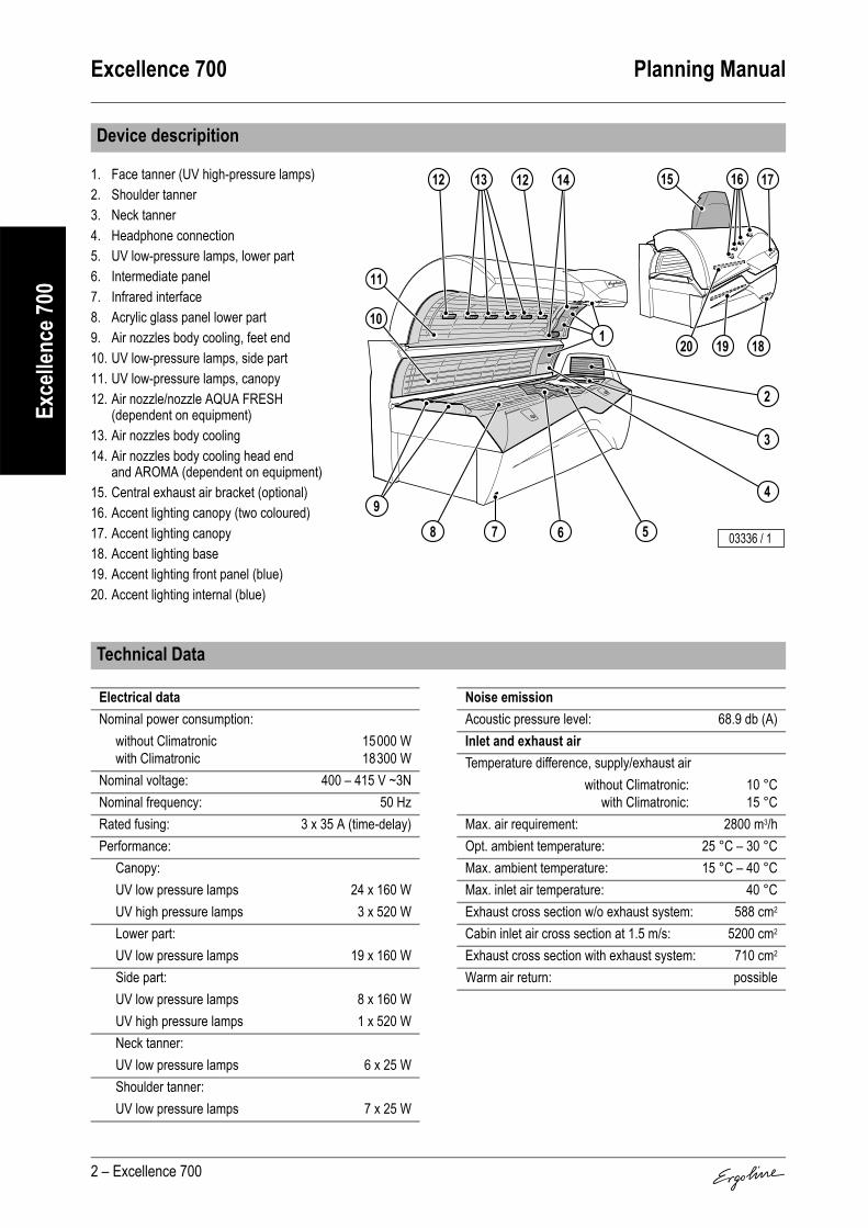
and AROMA (dependent on equipment)15. Central exhaust air bracket (optional)16. Accent lighting canopy (two coloured)17. Accent lighting canopy18. Accent lighting base19. Accent lighting front panel (blue)20. Accent lighting internal (blue)
Device descripition
3
4
2
568 7
12 12
11
10
13 14 1715
19 1820
16
1
9
03336 / 1
Technical Data
Electrical dataNominal power consumption:
without Climatronicwith Climatronic
15000 W18300 W
Nominal voltage: 400 – 415 V ~3NNominal frequency: 50 HzRated fusing: 3 x 35 A (time-delay)Performance:
Canopy:UV low pressure lamps 24 x 160 WUV high pressure lamps 3 x 520 WLower part:UV low pressure lamps 19 x 160 WSide part:UV low pressure lamps 8 x 160 WUV high pressure lamps 1 x 520 WNeck tanner:UV low pressure lamps 6 x 25 WShoulder tanner:UV low pressure lamps 7 x 25 W
Noise emissionAcoustic pressure level: 68.9 db (A)Inlet and exhaust airTemperature difference, supply/exhaust air
without Climatronic:with Climatronic:
10 °C15 °C
Max. air requirement: 2800 m3/hOpt. ambient temperature: 25 °C – 30 °CMax. ambient temperature: 15 °C – 40 °CMax. inlet air temperature: 40 °CExhaust cross section w/o exhaust system: 588 cm2
Cabin inlet air cross section at 1.5 m/s: 5200 cm2
Exhaust cross section with exhaust system: 710 cm2
Warm air return: possible

Planning Manual Excellence 700
Excellence 700 – 3
Exce
llenc
e 700
Dimensions
B 1428 mmB1 850 mmB2 188 mmB+ 1510 mmL 2323 mmL1 2110 mmL2 1730 mmL3 238 mmL4 265 mmL5 867 mmL7 1116 mmH 1373 mmH1 1830 mmH2 1078 mmH3 – mmH4 400 mmH5 114 mmH6 1887 mmH7 1974 mmH8 2197 mmH9 2342 mmX 1224 mmY 472 mmZ 2235 mm∅ 300 mmBK 2370 mmTK 2300 mm
TKBK
03314 / 0
H2
Z
B1
L
H1HY
X
L2 L4 L3
H4 H5
L1
B+B
L7
L5
o
H9
H7 H6
H8
B2
03315 / 0

Excellence 700 Planning Manual
4 – Excellence 700
Exce
llenc
e 700
Installing “exhaust air ducting via a suspended ceiling and with a double rear wall” is an optically elegant solution without using the central exhaust air bracket. An intermediate wall (1) (e.g. chipboard) tightly enclosing the sunbed at the rear serves as an upward channel for the exhaust air (2), if required right up to the suspended ceil-ing. So that the exhaust air is properly extracted, a slight vacuum is required behind the intermediate wall (1); an auxiliary fan must be installed if necessary.
With exhaust-air adapterA cut-out must be made in the intermediate wall (see table for dimensions). A rubber profile on the exhaust-air adapter (3) ensures an air-tight seal on the intermediate wall.
Without exhaust-air adapterThe intermediate wall (1) must securely enclose the rear of the tanning bed.
If a tanner is replaced with a new tanner, the intermediate wall (1) must be adapted or replaced so that there are no gaps through which leakage air is drawn. Provision must be made for the inspection doors at the head and foot of the tanner so that the canopy lifting device can be adjusted.
Planning example for double rear wall
DimensionsL1 1116 mm Tanning bed foot end up to centre of adapterL2 590 mm Long adapter, inner edgesH 1355 mm Height from floor to inner upper edge of rubber
profileH1 1125 mm Height from floor to inner lower edgeH2 230 mm Height of adapter (inside)
DimensionsB1 max. 170 mmB2 57 mmH1 1078 mm
03834 / 0
2
3
1
H2H1 H
L1L2
03840 / 0
H1
B1
B2 03985 / 0
2
1

Planning Manual Excellence 700
Excellence 700 – 5
Exce
llenc
e 700
Maximum exhaust pipe lengths
Calculation base (without additional ventilator):Back pressure 100 PascalAir pressure 100,000 PascalAir temperature 40 °CDensity 1.112 kg/m3
Dynamic inertia of the air 1.92E-05 Pa x s
Corrugated pipe∅
Roughness(at centre)kabsolute
Flow volume Loss coefficient 90° bend in line(metal)
Permissible length of
straight linemm mm m³/h of pipe of bend pieces m
300 8 2500 0.1821)
1) zeta value (ζ)
0.211)
0 101 92 83 7
Smooth pipe∅
Roughness(at centre)kabsolute
Flow volume Loss coefficient 90° bend in line(metal)
Permissible length of
straight linemm mm m³/h of pipe of bend pieces m
300 0.1 2500 0.0611) 0.211)
0 301 262 223 18

Excellence 700 Planning Manual
6 – Excellence 700
Exce
llenc
e 700
Cabin or studio air is drawn in beneath the front panel (1) of the lower part of the sunbed and over the filter mats in the canopy (2) (inlet air) in order to cool the equipment.The inlet air is first cleaned in a filter, then fed past the hot UV low-pressure and high-pressure lamps and finally expelled as warm exhaust air via the central exhaust air bracket (3) at the rear of the sunbed.
Surround air ventilation for the user is provided automatically. The intensity is adjusta-ble in 9 steps. Cabin or studio air is drawn in and used for cooling.The air is fed through several nozzles over the whole length in the middle of the canopy. In the head area there are two air nozzles that can be switched on separately.Studio air is also supplied via the air inlet slots beneath the front panel of the sunbed base and fed to two nozzles at feet level at the lying surface height, thus surrounding the body with cooling air.Depending on equipment the user can have a pleasant cooling mist (AQUA FRESH) sprayed from the outer nozzles in the body area.With a Climatronic (at additional charge) the user can preselect the temperature to adjust the temperature of the bed surface and the body air in accordance with his/her wishes.
Equipment cooling
Surround cooling
1
32
03333 / 0
03334 / 0

Planning Manual Excellence 700
Excellence 700 – 7
Exce
llenc
e 700
Connection to a central exhaust system is possible upwards, upwards right, upwards left and to the rear.The apertures intended for this purpose are located above the central exhaust air bracket.
Corrugated pipe
Suitable device exhaust is possible with an exhaust pipe up to 10 metres in length (with-out 90° bend). An auxiliary fan is required for exhaust pipes longer than 10 metres.
Smooth pipe
Suitable device exhaust is possible with an exhaust pipe up to 30 metres in length (with-out 90° bend). An auxiliary fan is required for exhaust pipes longer than 30 metres.
Warm air recycling
Warm air recycling is a technically advanced, secure device which feeds part of the hot cooling air back to the studio via a motor-controlled air choke. A thermostat provides fully automatic control of the studio temperature, between 15 °C and 25 °C as required.The exhaust air bracket and warm air recycling can also be retrofitted.
Exhaust air accessories
Item Accessory parts Article No. Notes1 Central exhaust air bracket Techno Grey with
warm air recycling, thermostatically controlled including connector piece, see Item 4.
3452620 With connection possible for exhaust air pipes (∅ 300 mm) on the top, top right, top left and to the rear
Central exhaust air bracket Techno Grey, but without warm air recycling
3452630
2 90° Pipe bend in Techno Grey 3452110 For inlet and exhaust air ducting to right, left or to rear, plus tube adapter for direct connection to central exhaust air bracket [possible with tube (∅ 300 mm)]
3 Corrugated pipe (∅ 300 mm, 6 m length, flexible, grey) including 2 pipe clamps
3450280 –
4 Corrugated pipe connector piece (∅ 300 mm)
3450270 For connecting two corrugated pipes
5 Connector bracket for corrugated pipe (∅ 300 mm)
3450360 Connection of the corrugated pipe, e.g. to a canal
6 Exhaust air adapter in black (not shown) 3452660 For double rear wall
03335 / 0
1
43 325

Excellence 700 Planning Manual
8 – Excellence 700
Exce
llenc
e 700
Equipment variant, retrofitting not possible.
Equipment variant, retrofitting not possible.3D sound: Equipment variant, retrofitting not possible.
Climatronic for bed surface and Surround Cooling with fully integrated climate control of body cooling;Cabin climate control via body cooling run-on (temperature-controlled).Equipment variant, retrofitting not possible.
Equipment variant: Aroma and body cooling for the user; retrofitting not possible.
Standard equipment: Access to the device data with a hand-held unit (Palm).
Electrical connections
Mains supply line noneElectr. control line noneLine for external music and channel selection none
MULTIVISION
Sound system
Controls
Control Article No. NotesMCS III plus hand-held remote control 3401060 With chip card terminalMCS IV plus 3401040 With electronic coin testerMCS VI 3400970 With electronic coin tester + chip card terminalStudiopilot 3400990 With electronic coin tester + chip card terminalStudio-Manager 3452900 Software
Air conditioner
AQUA FRESH AROMA system
IR Interface

Planning Manual Evolution IQ
Evolution IQ – 1
Evol
utio
n IQ
The IQ sensor is a highly sensitive, photoelectronic precision instrument that is capable of analysing the state of the skin ac-curately and reliably. For this reason, the IQ sensor is automat-ically tested for proper working order and measurement accuracy after every measurement cycle. It is also recom-mended to recalibrate the IQ sensor after approximately 30 hours of operation. For further information refer to the oper-ating instructions.
Contents
Device descripition. . . . . . . . . . . . . . . . . . . . . . . . . . . 2
Technical Data. . . . . . . . . . . . . . . . . . . . . . . . . . . . . . . 2
Dimensions . . . . . . . . . . . . . . . . . . . . . . . . . . . . . . . . . 3
Planning example for double rear wall . . . . . . . . . . . 4With exhaust-air adapter . . . . . . . . . . . . . . . . . . . . . . . . 4Without exhaust-air adapter . . . . . . . . . . . . . . . . . . . . . . 4
Maximum exhaust pipe lengths. . . . . . . . . . . . . . . . . 5
Equipment cooling . . . . . . . . . . . . . . . . . . . . . . . . . . . 6
Surround cooling . . . . . . . . . . . . . . . . . . . . . . . . . . . . 6
Exhaust air accessories. . . . . . . . . . . . . . . . . . . . . . . 7
Electrical connections . . . . . . . . . . . . . . . . . . . . . . . . 8
MULTIVISION. . . . . . . . . . . . . . . . . . . . . . . . . . . . . . . . 8
Sound system . . . . . . . . . . . . . . . . . . . . . . . . . . . . . . . 8
Controls . . . . . . . . . . . . . . . . . . . . . . . . . . . . . . . . . . . . 8
Air conditioner . . . . . . . . . . . . . . . . . . . . . . . . . . . . . . 8
AQUA FRESH AROMA system . . . . . . . . . . . . . . . . . 8
IR Interface . . . . . . . . . . . . . . . . . . . . . . . . . . . . . . . . . 8
IQ sensor . . . . . . . . . . . . . . . . . . . . . . . . . . . . . . . . . . . 9
06008 / 0

Evolution IQ Planning Manual
2 – Evolution IQ
Evol
utio
n IQ
1. Face tanner (UV high-pressure lamps)2. Shoulder tanner3. IQ sensor and base station4. Neck tanner5. Headphone connection6. UV low-pressure lamps, lower part7. Intermediate panel8. Infrared interface9. Acrylic glass panel lower part10. Air nozzles body cooling, feet end11. UV low-pressure lamps, side part12. UV low-pressure lamps, canopy13. Air nozzle/nozzle AQUA FRESH
(dependent on equipment)14. Air nozzles body cooling15. Air nozzles body cooling head end
and AROMA (dependent on equipment)16. Central exhaust air bracket (optional)17. Accent lighting canopy (two coloured)18. Accent lighting canopy19. Accent lighting front panel (blue)20. Accent lighting internal (blue)
Device descripition
Technical Data
4
5
2
3
679
1813 13
12
11
14 15
1
10
1716
1920
8 06144 / 0
Electrical dataNominal power consumption: 12600 WNominal voltage: 400 – 415 V ~3NNominal frequency: 50 HzRated fusing: 3 x 35 A (time-delay)Performance:
Canopy:UV low pressure lamps 21 x 120-180 W1)
1) Electronically controlled
UV high pressure lamps 2 x 520 WLower part:UV low pressure lamps 17 x 120-180 W1)
Side part:UV low pressure lamps 8 x 120-180 W1)
UV high pressure lamps 1 x 520 WNeck tanner:UV low pressure lamps 6 x 25 WShoulder tanner:UV low pressure lamps 7 x 25 W
Noise emissionAcoustic pressure level: 67.2 db (A)Inlet and exhaust airTemperature difference, supply/exhaust air: 11 °CMax. air requirement: 2800 m3/hOpt. ambient temperature: 25 °C – 30 °CMax. ambient temperature: 15 °C – 40 °CMax. inlet air temperature: 40 °CExhaust cross section w/o exhaust system: 588 cm2
Cabin inlet air cross section at 1.5 m/s: 4200 cm2
Exhaust cross section with exhaust system: 710 cm2
Warm air return: possible
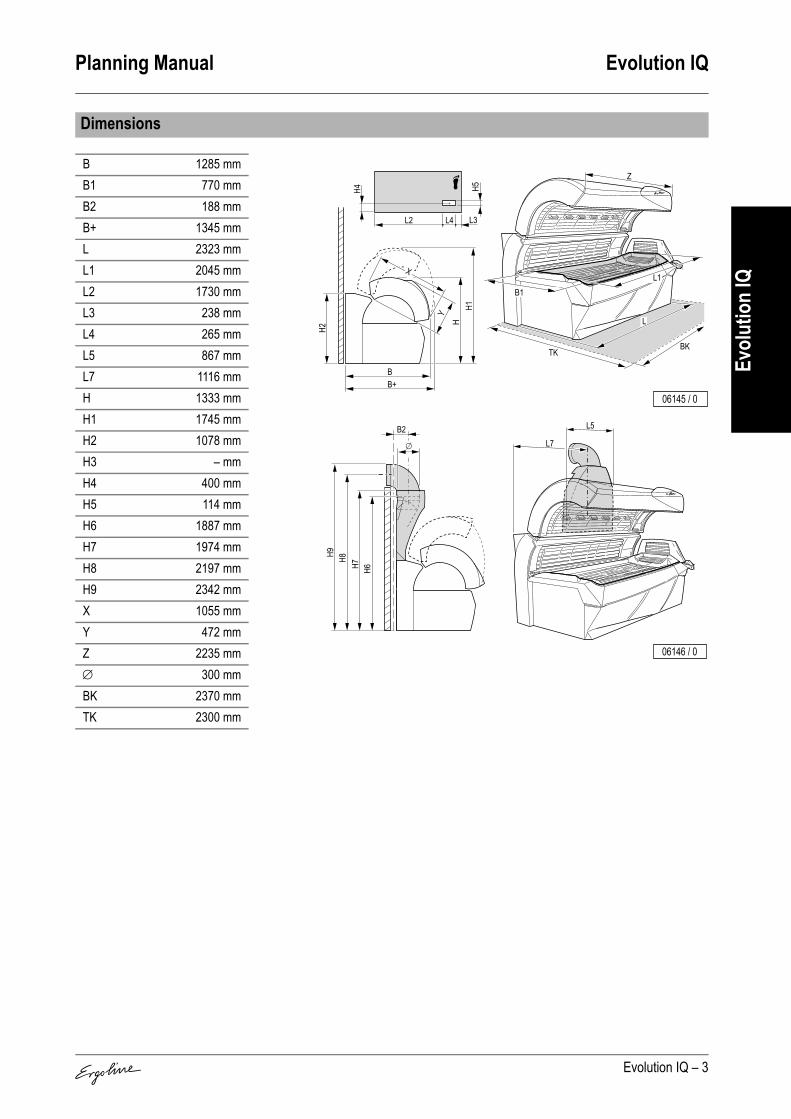
Planning Manual Evolution IQ
Evolution IQ – 3
Evol
utio
n IQ
Dimensions
B 1285 mmB1 770 mmB2 188 mmB+ 1345 mmL 2323 mmL1 2045 mmL2 1730 mmL3 238 mmL4 265 mmL5 867 mmL7 1116 mmH 1333 mmH1 1745 mmH2 1078 mmH3 – mmH4 400 mmH5 114 mmH6 1887 mmH7 1974 mmH8 2197 mmH9 2342 mmX 1055 mmY 472 mmZ 2235 mm∅ 300 mmBK 2370 mmTK 2300 mm
TKBK
06145 / 0
Z
B1L1
L
L2 L4 L3
H4 H5
H2
H1H
Y
X
B+B
L7
L5
o
H9
H7 H6
H8
B2
06146 / 0

Evolution IQ Planning Manual
4 – Evolution IQ
Evol
utio
n IQ
Installing “exhaust air ducting via a suspended ceiling and with a double rear wall” is an optically elegant solution without using the central exhaust air bracket.An intermediate wall (1) (e.g. chipboard) tightly enclosing the sunbed at the rear serves as an upward channel for the exhaust air (2), if required right up to the suspended ceil-ing. So that the exhaust air is properly extracted, a slight vacuum is required behind the intermediate wall (1); an auxiliary fan must be installed if necessary.
With exhaust-air adapterA cut-out must be made in the intermediate wall (see table for dimensions). A rubber profile on the exhaust-air adapter (3) ensures an air-tight seal on the intermediate wall.
Without exhaust-air adapterThe intermediate wall (1) must securely enclose the rear of the tanning bed.
If a tanner is replaced with a new tanner, the intermediate wall (1) must be adapted or replaced so that there are no gaps through which leakage air is drawn. Provision must be made for the inspection doors at the head and foot of the tanner so that the canopy lifting device can be adjusted.
Planning example for double rear wall
DimensionsL1 1116 mm Tanning bed foot end up to centre of adapterL2 590 mm Long adapter, inner edgesH 1355 mm Height from floor to inner upper edge of rubber
profileH1 1125 mm Height from floor to inner lower edgeH2 230 mm Height of adapter (inside)
DimensionsB1 max. 170 mmB2 57 mmH1 1078 mm
03984 / 0
2
3
1
H2H1 H
L1L2
03840 / 0
H1
B1
B2 03322 / 1
1
2

Planning Manual Evolution IQ
Evolution IQ – 5
Evol
utio
n IQ
Maximum exhaust pipe lengths
Calculation base (without additional ventilator):Back pressure 100 PascalAir pressure 100,000 PascalAir temperature 40 °CDensity 1.112 kg/m3
Dynamic inertia of the air 1.92E-05 Pa x s
Corrugated pipe∅
Roughness(at centre)kabsolute
Flow volume Loss coefficient 90° bend in line(metal)
Permissible length of
straight linemm mm m³/h of pipe of bend pieces m
300 8 2500 0.1821)
1) zeta value (ζ)
0.211)
0 101 92 83 7
Smooth pipe∅
Roughness(at centre)kabsolute
Flow volume Loss coefficient 90° bend in line(metal)
Permissible length of
straight linemm mm m³/h of pipe of bend pieces m
300 0.1 2500 0.0611) 0.211)
0 301 262 223 18

Evolution IQ Planning Manual
6 – Evolution IQ
Evol
utio
n IQ
Cabin or studio air is drawn in beneath the front panel (1) of the lower part of the sunbed and over the filter mats in the canopy (2) (inlet air) in order to cool the equipment.The inlet air is first cleaned in a filter, then fed past the hot UV low-pressure and high-pressure lamps and finally expelled as warm exhaust air via the central exhaust air bracket (3) at the rear of the sunbed.
Surround air ventilation for the user is provided automatically. The intensity is adjusta-ble in 9 steps. Cabin or studio air is drawn in and used for cooling.The air is fed through several nozzles over the whole length in the middle of the canopy. In the head area there are two air nozzles that can be switched on separately.Studio air is also supplied via the air inlet slots beneath the front panel of the sunbed base and fed to two nozzles at feet level at the lying surface height, thus surrounding the body with cooling air.Depending on equipment the user can have a pleasant cooling mist (AQUA FRESH) sprayed from the outer nozzles in the body area.In automatic mode the initial temperature of the air conditioner (Climatronic, standard equipment) is automatically preselected dependent on the lamp power.In maximum mode the user can preselect the temperature of the air conditioner (Climatronic, standard equipment).The temperature of the air conditioner can be adjusted at any time during the tanning.
Equipment cooling
Surround cooling06147 / 01
2 3
06148 / 0

Planning Manual Evolution IQ
Evolution IQ – 7
Evol
utio
n IQ
Connection to a central exhaust system is possible upwards, upwards right, upwards left and to the rear.The apertures intended for this purpose are located above the central exhaust air bracket.
Corrugated pipe
Suitable device exhaust is possible with an exhaust pipe up to 10 metres in length (with-out 90° bend). An auxiliary fan is required for exhaust pipes longer than 10 metres.
Smooth pipe
Suitable device exhaust is possible with an exhaust pipe up to 30 metres in length (with-out 90° bend). An auxiliary fan is required for exhaust pipes longer than 30 metres.
Warm air recycling
Warm air recycling is a technically advanced, secure device which feeds part of the hot cooling air back to the studio via a motor-controlled air choke. A thermostat provides fully automatic control of the studio temperature, between 15 °C and 25 °C as required.The exhaust air bracket and warm air recycling can also be retrofitted.
Exhaust air accessories
Item Accessory parts Article No. Notes1 Central exhaust air bracket Techno Grey with
warm air recycling, thermostatically controlled including connector piece, see Item 4
3452620 With connection possible for exhaust air pipes (∅ 300 mm) on the top, top right, top left and to the rear
Central exhaust air bracket Techno Grey, but without warm air recycling
3452630
2 90° Pipe bend in Techno Grey 3452110 For inlet and exhaust air ducting to right, left or to rear, plus tube adapter for direct connection to central exhaust air bracket [possible with tube (∅ 300 mm)]
3 Corrugated pipe (∅ 300 mm, 6 m length, flexible, grey) including 2 pipe clamps
3450280 –
4 Corrugated pipe connector piece (∅ 300 mm)
3450270 For connecting two corrugated pipes
5 Connector bracket for corrugated pipe (∅ 300 mm)
3450360 Connection of the corrugated pipe, e.g. to a canal
6 Exhaust air adapter in black (not shown) 3452660 For double rear wall
06149 / 0
1
43 325

Evolution IQ Planning Manual
8 – Evolution IQ
Evol
utio
n IQ
Equipment variant, retrofitting not possible.
Standard equipment.3D sound: Equipment variant, retrofitting not possible.
Standard equipment: Climatronic for bed surface and Surround Cooling with fully integrated climate control of body cooling; Cabin climate control via body cooling run-on (temperature-controlled).
Equipment variant: Aroma and body cooling for the user; retrofitting not possible.
Standard equipment: Access to the device data with a hand-held unit (Palm).
Electrical connections
Mains supply line noneElectr. control line noneLine for external music and channel selection none
MULTIVISION
Sound system
Controls
Control Article No. NotesMCS III plus hand-held remote control 3401060 With chip card terminalMCS IV plus 3401040 With electronic coin testerMCS VI 3400970 With electronic coin tester + chip card terminalStudiopilot 3400990 With electronic coin tester + chip card terminalStudio-Manager 3452900 Software
Air conditioner
AQUA FRESH AROMA system
IR Interface

Planning Manual Evolution IQ
Evolution IQ – 9
Evol
utio
n IQ
Standard equipment: The user determines his tanning ability by using the integrated IQ sensor to measure face and body. When operating the sensor, the user is assisted by VoiceGuide.Step one: The first measurement is performed on the forehead. A beep confirms a suc-cessful measurement. The VoiceGuide then prompts you to perform the second meas-urement, this time on your body.
Step two: Perform the second measurement on the palest part of your body: e.g. your buttocks or insides of your arms. It's important that this part of the body is included in your tanning assessment. This way, allowance is made for pigmentation progress at the next tanning session and tanning power is increased.The Intelligent Power System now takes just a few seconds to compute your personal tanning programme from your measurement readings.
IQ sensor
1
Step one ...
04734 / 0
Step two ...
2
04821 / 0

Planning Manual Evolution 600 APS
Evolution 600 APS – 1
Evol
utio
n 60
0 APS
The Automatic Power System sensor is a highly sensitive, pho-toelectronic precision instrument that is capable of analysing the state of the skin accurately and reliably. For this reason, the IQ sensor is automatically tested for proper working order and measurement accuracy after every measurement cycle. It is also recommended to recalibrate the APS sensor after approx-imately 30 hours of operation. For further information refer to the operating instructions.
Contents
Device descripition. . . . . . . . . . . . . . . . . . . . . . . . . . . 2
Technical Data. . . . . . . . . . . . . . . . . . . . . . . . . . . . . . . 2
Dimensions . . . . . . . . . . . . . . . . . . . . . . . . . . . . . . . . . 3
Planning example for double rear wall . . . . . . . . . . . 4With exhaust-air adapter . . . . . . . . . . . . . . . . . . . . . . . . 4Without exhaust-air adapter . . . . . . . . . . . . . . . . . . . . . . 4
Maximum exhaust pipe lengths. . . . . . . . . . . . . . . . . 5
Equipment cooling . . . . . . . . . . . . . . . . . . . . . . . . . . . 6
Surround cooling . . . . . . . . . . . . . . . . . . . . . . . . . . . . 6
Exhaust air accessories. . . . . . . . . . . . . . . . . . . . . . . 7
Electrical connections . . . . . . . . . . . . . . . . . . . . . . . . 8
MULTIVISION. . . . . . . . . . . . . . . . . . . . . . . . . . . . . . . . 8
Sound system . . . . . . . . . . . . . . . . . . . . . . . . . . . . . . . 8
Controls . . . . . . . . . . . . . . . . . . . . . . . . . . . . . . . . . . . . 8
Air conditioner . . . . . . . . . . . . . . . . . . . . . . . . . . . . . . 8
AQUA FRESH AROMA system . . . . . . . . . . . . . . . . . 8
IR Interface . . . . . . . . . . . . . . . . . . . . . . . . . . . . . . . . . 8
APS sensor . . . . . . . . . . . . . . . . . . . . . . . . . . . . . . . . . 9
06008 / 0

Evolution 600 APS Planning Manual
2 – Evolution 600 APS
Evol
utio
n 60
0 APS
1. Face tanner (UV high-pressure lamps)2. Shoulder tanner3. APS sensor and base station4. Neck tanner5. Headphone connection6. UV low-pressure lamps, lower part7. Intermediate panel8. Infrared interface9. Acrylic glass panel lower part10. Air nozzles body cooling, feet end11. UV low-pressure lamps, side part12. UV low-pressure lamps, canopy13. Air nozzle/nozzle AQUA FRESH
(dependent on equipment)14. Air nozzles body cooling15. Air nozzles body cooling head end
and AROMA (dependent on equipment)16. Central exhaust air bracket (optional)17. Accent lighting canopy (two coloured)18. Accent lighting canopy19. Accent lighting front panel (blue)20. Accent lighting internal (blue)
Device descripition
4
5
2
3
679
1813 13
12
11
14 15
1
10
1716
1920
8 06144 / 0
Technical Data
Electrical dataNominal power consumption: 14500 WNominal voltage: 400 – 415 V ~3NNominal frequency: 50 HzRated fusing: 3 x 35 A (time-delay)Performance:
Canopy:UV low pressure lamps 21 x 160 WUV high pressure lamps 2 x 520 WLower part:UV low pressure lamps 17 x 160 WSide part:UV low pressure lamps 8 x 160 WUV high pressure lamps 1 x 520 WNeck tanner:UV low pressure lamps 6 x 25 WShoulder tanner:UV low pressure lamps 7 x 25 W
Noise emissionAcoustic pressure level: 67.2 db (A)Inlet and exhaust airTemperature difference, supply/exhaust air: 11 °CMax. air requirement: 2800 m3/hOpt. ambient temperature: 25 °C – 30 °CMax. ambient temperature: 15 °C – 40 °CMax. inlet air temperature: 40 °CExhaust cross section w/o exhaust system: 588 cm2
Cabin inlet air cross section at 1.5 m/s: 4200 cm2
Exhaust cross section with exhaust system: 710 cm2
Warm air return: possible

Planning Manual Evolution 600 APS
Evolution 600 APS – 3
Evol
utio
n 60
0 APS
Dimensions
B 1285 mmB1 770 mmB2 188 mmB+ 1345 mmL 2323 mmL1 2045 mmL2 1730 mmL3 238 mmL4 265 mmL5 867 mmL7 1116 mmH 1333 mmH1 1745 mmH2 1078 mmH3 – mmH4 400 mmH5 114 mmH6 1887 mmH7 1974 mmH8 2197 mmH9 2342 mmX 1055 mmY 472 mmZ 2235 mm∅ 300 mmBK 2370 mmTK 2300 mm
TKBK
06145 / 0
Z
B1L1
L
L2 L4 L3
H4 H5
H2
H1H
Y
X
B+B
L7
L5
o
H9
H7 H6
H8
B2
06146 / 0

Evolution 600 APS Planning Manual
4 – Evolution 600 APS
Evol
utio
n 60
0 APS
Installing “exhaust air ducting via a suspended ceiling and with a double rear wall” is an optically elegant solution without using the central exhaust air bracket.An intermediate wall (1) (e.g. chipboard) tightly enclosing the sunbed at the rear serves as an upward channel for the exhaust air (2), if required right up to the suspended ceil-ing. So that the exhaust air is properly extracted, a slight vacuum is required behind the intermediate wall (1); an auxiliary fan must be installed if necessary.
With exhaust-air adapterA cut-out must be made in the intermediate wall (see table for dimensions). A rubber profile on the exhaust-air adapter (3) ensures an air-tight seal on the intermediate wall.
Without exhaust-air adapterThe intermediate wall (1) must securely enclose the rear of the tanning bed.
If a tanner is replaced with a new tanner, the intermediate wall (1) must be adapted or replaced so that there are no gaps through which leakage air is drawn. Provision must be made for the inspection doors at the head and foot of the tanner so that the canopy lifting device can be adjusted.
Planning example for double rear wall
DimensionsL1 1116 mm Tanning bed foot end up to centre of adapterL2 590 mm Long adapter, inner edgesH 1355 mm Height from floor to inner upper edge of rubber
profileH1 1125 mm Height from floor to inner lower edgeH2 230 mm Height of adapter (inside)
DimensionsB1 max. 170 mmB2 57 mmH1 1078 mm
03984 / 0
2
3
1
H2H1 H
L1L2
03840 / 0
H1
B1
B2 03322 / 1
1
2

Planning Manual Evolution 600 APS
Evolution 600 APS – 5
Evol
utio
n 60
0 APS
Maximum exhaust pipe lengths
Calculation base (without additional ventilator):Back pressure 100 PascalAir pressure 100,000 PascalAir temperature 40 °CDensity 1.112 kg/m3
Dynamic inertia of the air 1.92E-05 Pa x s
Corrugated pipe∅
Roughness(at centre)kabsolute
Flow volume Loss coefficient 90° bend in line(metal)
Permissible length of
straight linemm mm m³/h of pipe of bend pieces m
300 8 2500 0.1821)
1) zeta value (ζ)
0.211)
0 101 92 83 7
Smooth pipe∅
Roughness(at centre)kabsolute
Flow volume Loss coefficient 90° bend in line(metal)
Permissible length of
straight linemm mm m³/h of pipe of bend pieces m
300 0.1 2500 0.0611) 0.211)
0 301 262 223 18

Evolution 600 APS Planning Manual
6 – Evolution 600 APS
Evol
utio
n 60
0 APS
Cabin or studio air is drawn in beneath the front panel (1) of the lower part of the sunbed and over the filter mats in the canopy (2) (inlet air) in order to cool the equipment.The inlet air is first cleaned in a filter, then fed past the hot UV low-pressure and high-pressure lamps and finally expelled as warm exhaust air via the central exhaust air bracket (3) at the rear of the sunbed.
Surround air ventilation for the user is provided automatically. The intensity is adjusta-ble in 9 steps. Cabin or studio air is drawn in and used for cooling.The air is fed through several nozzles over the whole length in the middle of the canopy. In the head area there are two air nozzles that can be switched on separately.Studio air is also supplied via the air inlet slots beneath the front panel of the sunbed base and fed to two nozzles at feet level at the lying surface height, thus surrounding the body with cooling air.Depending on equipment the user can have a pleasant cooling mist (AQUA FRESH) sprayed from the outer nozzles in the body area.In automatic mode the initial temperature of the air conditioner (Climatronic, standard equipment) is automatically preselected dependent on the lamp power.In maximum mode the user can preselect the temperature of the air conditioner (Climatronic, standard equipment).The temperature of the air conditioner can be adjusted at any time during the tanning.
Equipment cooling
Surround cooling06147 / 01
2 3
06148 / 0
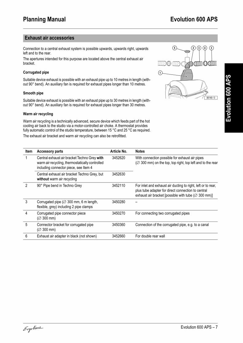
Planning Manual Evolution 600 APS
Evolution 600 APS – 7
Evol
utio
n 60
0 APS
Connection to a central exhaust system is possible upwards, upwards right, upwards left and to the rear.The apertures intended for this purpose are located above the central exhaust air bracket.
Corrugated pipe
Suitable device exhaust is possible with an exhaust pipe up to 10 metres in length (with-out 90° bend). An auxiliary fan is required for exhaust pipes longer than 10 metres.
Smooth pipe
Suitable device exhaust is possible with an exhaust pipe up to 30 metres in length (with-out 90° bend). An auxiliary fan is required for exhaust pipes longer than 30 metres.
Warm air recycling
Warm air recycling is a technically advanced, secure device which feeds part of the hot cooling air back to the studio via a motor-controlled air choke. A thermostat provides fully automatic control of the studio temperature, between 15 °C and 25 °C as required.The exhaust air bracket and warm air recycling can also be retrofitted.
Exhaust air accessories
Item Accessory parts Article No. Notes1 Central exhaust air bracket Techno Grey with
warm air recycling, thermostatically controlled including connector piece, see Item 4
3452620 With connection possible for exhaust air pipes (∅ 300 mm) on the top, top right, top left and to the rear
Central exhaust air bracket Techno Grey, but without warm air recycling
3452630
2 90° Pipe bend in Techno Grey 3452110 For inlet and exhaust air ducting to right, left or to rear, plus tube adapter for direct connection to central exhaust air bracket [possible with tube (∅ 300 mm)]
3 Corrugated pipe (∅ 300 mm, 6 m length, flexible, grey) including 2 pipe clamps
3450280 –
4 Corrugated pipe connector piece (∅ 300 mm)
3450270 For connecting two corrugated pipes
5 Connector bracket for corrugated pipe (∅ 300 mm)
3450360 Connection of the corrugated pipe, e.g. to a canal
6 Exhaust air adapter in black (not shown) 3452660 For double rear wall
06149 / 0
1
43 325

Evolution 600 APS Planning Manual
8 – Evolution 600 APS
Evol
utio
n 60
0 APS
Equipment variant, retrofitting not possible.
Standard equipment.3D sound: Equipment variant, retrofitting not possible.
Standard equipment: Climatronic for bed surface and Surround Cooling with fully integrated climate control of body cooling; Cabin climate control via body cooling run-on (temperature-controlled).
Equipment variant: Aroma and body cooling for the user; retrofitting not possible.
Standard equipment: Access to the device data with a hand-held unit (Palm).
Electrical connections
Mains supply line noneElectr. control line noneLine for external music and channel selection none
MULTIVISION
Sound system
Controls
Control Article No. NotesMCS III plus hand-held remote control 3401060 With chip card terminalICS-Unit 3453200 Chip card terminal for APS devicesMCS IV plus 3401040 With electronic coin testerMCS VI 3400970 With electronic coin tester + chip card terminalStudiopilot 3400990 With electronic coin tester + chip card terminalStudio-Manager 3452900 Software
Air conditioner
AQUA FRESH AROMA system
IR Interface

Planning Manual Evolution 600 APS
Evolution 600 APS – 9
Evol
utio
n 60
0 APS
Standard equipment: The user determines his tanning ability by using the integrated APS sensor to measure face and body. When operating the sensor, the user is assisted by VoiceGuide.Step one: The first measurement is performed on the forehead. A beep confirms a suc-cessful measurement. The VoiceGuide then prompts you to perform the second meas-urement, this time on your body.
Step two: Perform the second measurement on the palest part of your body: e.g. your buttocks or insides of your arms. It's important that this part of the body is included in your tanning assessment. This way, allowance is made for pigmentation progress at the next tanning session and tanning power is increased.The Automatic Power System now takes just a few seconds to compute your personal tanning programme from your measurement readings.
APS sensor
1
Step one ...
04734 / 0
Step two ...
2
04821 / 0

Planning Manual Evolution 600
Evolution 600 – 1
Evol
utio
n 60
0
Turbo Power
Super Power
Contents
Device descripition. . . . . . . . . . . . . . . . . . . . . . . . . . . 2
Technical Data. . . . . . . . . . . . . . . . . . . . . . . . . . . . . . . 3Technical Data – Evolution 600 Turbo Power. . . . . . . . . 3Technical Data – Evolution 600 Super Power . . . . . . . . 3
Dimensions . . . . . . . . . . . . . . . . . . . . . . . . . . . . . . . . . 4
Planning example for double rear wall . . . . . . . . . . . 5With exhaust-air adapter . . . . . . . . . . . . . . . . . . . . . . . . 5Without exhaust-air adapter . . . . . . . . . . . . . . . . . . . . . . 5
Maximum exhaust pipe lengths. . . . . . . . . . . . . . . . . 6
Equipment cooling . . . . . . . . . . . . . . . . . . . . . . . . . . . 6
Surround cooling . . . . . . . . . . . . . . . . . . . . . . . . . . . . 7
Exhaust air accessories. . . . . . . . . . . . . . . . . . . . . . . 7
Electrical connections . . . . . . . . . . . . . . . . . . . . . . . . 8
MULTIVISION. . . . . . . . . . . . . . . . . . . . . . . . . . . . . . . . 8
Sound system . . . . . . . . . . . . . . . . . . . . . . . . . . . . . . . 8
Controls . . . . . . . . . . . . . . . . . . . . . . . . . . . . . . . . . . . . 8
Air conditioner . . . . . . . . . . . . . . . . . . . . . . . . . . . . . . 8
AQUA FRESH AROMA system . . . . . . . . . . . . . . . . . 8
IR Interface . . . . . . . . . . . . . . . . . . . . . . . . . . . . . . . . . 8
03286 / 0

Evolution 600 Planning Manual
2 – Evolution 600
Evol
utio
n 60
0
1. Face tanner (UV high-pressure lamps)2. Shoulder tanner3. Neck tanner4. Headphone connection5. UV low-pressure lamps, lower part6. Intermediate panel7. Infrared interface8. Acrylic glass panel lower part9. Air nozzles body cooling, feet end10. UV low-pressure lamps, side part11. UV low-pressure lamps, canopy12. Air nozzle/nozzle AQUA FRESH
(dependent on equipment)13. Air nozzles body cooling14. Air nozzles body cooling head end
and AROMA (dependent on equipment)15. Central exhaust air bracket (optional)16. Accent lighting canopy (two coloured)17. Accent lighting canopy18. Accent lighting front panel (blue)19. Accent lighting internal (blue)
Device descripition
3
4
2
568
1712 12
11
10
13 14
1
9
1615
1819
7 03472 / 1

Planning Manual Evolution 600
Evolution 600 – 3
Evol
utio
n 60
0
Technical Data – Evolution 600 Turbo Power
Technical Data – Evolution 600 Super Power
Technical Data
Electrical dataNominal power consumption:
without Air conditioning:with Air conditioning:
13300 W14500 W
Nominal voltage: 400 – 415 V ~3NNominal frequency: 50 HzRated fusing: 3 x 35 A (time-delay)Performance:
Canopy:UV low pressure lamps 21 x 160 WUV high pressure lamps 2 x 500 WLower part:UV low pressure lamps 17 x 160 WSide part:UV low pressure lamps 8 x 160 WUV high pressure lamps 1 x 500 WNeck tanner:UV low pressure lamps 6 x 25 WShoulder tanner:UV low pressure lamps 7 x 25 W
Noise emissionAcoustic pressure level: 67.2 db (A)Inlet and exhaust airTemperature difference, supply/exhaust air:
without Air conditioning:with Air conditioning:
6 °C11 °C
Max. air requirement: 2800 m3/hOpt. ambient temperature: 25 °C – 30 °CMax. ambient temperature: 15 °C – 40 °CMax. inlet air temperature: 40 °CExhaust cross section w/o exhaust system: 588 cm2
Cabin inlet air cross section at 1.5 m/s: 4200 cm2
Exhaust cross section with exhaust system: 710 cm2
Warm air return: possible
Electrical dataNominal power consumption:
without Air conditioning:with Air conditioning:
9800 W11000 W
Nominal voltage: 400 – 415 V ~3NNominal frequency: 50 HzRated fusing: 3 x 25 A (time-delay)Performance:
Canopy:UV low pressure lamps 21 x 100 WUV high pressure lamps 2 x 400 WLower part:UV low pressure lamps 17 x 100 WSide part:UV low pressure lamps 8 x 100 WUV high pressure lamps 1 x 400 WNeck tanner:UV low pressure lamps 6 x 25 WShoulder tanner:UV low pressure lamps 7 x 25 W
Noise emissionAcoustic pressure level: 67.2 db (A)Inlet and exhaust airTemperature difference, supply/exhaust air:
without Air conditioning:with Air conditioning
6 °C11 °C
Max. air requirement: 2800 m3/hOpt. ambient temperature: 25 °C – 30 °CMax. ambient temperature: 15 °C – 40 °CMax. inlet air temperature: 40 °CExhaust cross section w/o exhaust system: 588 cm2
Cabin inlet air cross section at 1.5 m/s: 4200 cm2
Exhaust cross section with exhaust system: 710 cm2
Warm air return: possible

Evolution 600 Planning Manual
4 – Evolution 600
Evol
utio
n 60
0
Dimensions
B 1285 mmB1 770 mmB2 188 mmB+ 1345 mmL 2323 mmL1 2045 mmL2 1730 mmL3 238 mmL4 265 mmL5 867 mmL7 1116 mmH 1333 mmH1 1745 mmH2 1078 mmH3 – mmH4 400 mmH5 114 mmH6 1887 mmH7 1974 mmH8 2197 mmH9 2342 mmX 1055 mmY 472 mmZ 2235 mm∅ 300 mmBK 2370 mmTK 2300 mm
TKBK
03316 / 0
Z
B1L1
L
L2 L4 L3
H4 H5
H2
H1H
Y
X
B+B
L7
L5
o
H9
H7 H6
H8
B2
03317 / 0

Planning Manual Evolution 600
Evolution 600 – 5
Evol
utio
n 60
0
Installing “exhaust air ducting via a suspended ceiling and with a double rear wall” is an optically elegant solution without using the central exhaust air bracket.An intermediate wall (1) (e.g. chipboard) tightly enclosing the sunbed at the rear serves as an upward channel for the exhaust air (2), if required right up to the suspended ceil-ing. So that the exhaust air is properly extracted, a slight vacuum is required behind the intermediate wall (1); an auxiliary fan must be installed if necessary.
With exhaust-air adapterA cut-out must be made in the intermediate wall (see table for dimensions). A rubber profile on the exhaust-air adapter (3) ensures an air-tight seal on the intermediate wall.
Without exhaust-air adapterThe intermediate wall (1) must securely enclose the rear of the tanning bed.
If a tanner is replaced with a new tanner, the intermediate wall (1) must be adapted or replaced so that there are no gaps through which leakage air is drawn. Provision must be made for the inspection doors at the head and foot of the tanner so that the canopy lifting device can be adjusted.
Planning example for double rear wall
DimensionsL1 1116 mm Tanning bed foot end up to centre of adapterL2 590 mm Long adapter, inner edgesH 1355 mm Height from floor to inner upper edge of rub-
ber profileH1 1125 mm Height from floor to inner lower edgeH2 230 mm Height of adapter (inside)
DimensionsB1 max. 170 mmB2 57 mmH1 1078 mm
03984 / 0
2
3
1
H2H1 H
L1L2
03840 / 0
H1
B1
B2 03322 / 1
1
2

Evolution 600 Planning Manual
6 – Evolution 600
Evol
utio
n 60
0
Cabin or studio air is drawn in beneath the front panel (1) of the lower part of the sunbed and over the filter mats in the canopy (2) (inlet air) in order to cool the equipment.The inlet air is first cleaned in a filter, then fed past the hot UV low-pressure and high-pressure lamps and finally expelled as warm exhaust air via the central exhaust air bracket (3) at the rear of the sunbed.
Maximum exhaust pipe lengths
Calculation base (without additional ventilator):Back pressure 100 PascalAir pressure 100,000 PascalAir temperature 40 °CDensity 1.112 kg/m3
Dynamic inertia of the air 1.92E-05 Pa x s
Corrugated pipe∅
Roughness(at centre)kabsolute
Flow volume Loss coefficient 90° bend in line(metal)
Permissible length of
straight linemm mm m³/h of pipe of bend pieces m
300 8 2500 0.1821)
1) zeta value (ζ)
0.211)
0 101 92 83 7
Smooth pipe∅
Roughness(at centre)kabsolute
Flow volume Loss coefficient 90° bend in line(metal)
Permissible length of
straight linemm mm m³/h of pipe of bend pieces m
300 0.1 2500 0.0611) 0.211)
0 301 262 223 18
Equipment cooling
03327 / 01
2 3

Planning Manual Evolution 600
Evolution 600 – 7
Evol
utio
n 60
0
Surround air ventilation for the user is provided automatically. The intensity is adjusta-ble in 9 steps. Cabin or studio air is drawn in and used for cooling.The air is fed through several nozzles over the whole length in the middle of the canopy. In the head area there are two air nozzles that can be switched on separately.Studio air is also supplied via the air inlet slots beneath the front panel of the sunbed base and fed to two nozzles at feet level at the lying surface height, thus surrounding the body with cooling air.Depending on equipment the user can have a pleasant cooling mist (AQUA FRESH) sprayed from the outer nozzles in the body area.Depending on the equipment, an air conditioner enables the additional climate control of the bed surface and the body air.
Connection to a central exhaust system is possible upwards, upwards right, upwards left and to the rear.The apertures intended for this purpose are located above the central exhaust air bracket.
Corrugated pipe
Suitable device exhaust is possible with an exhaust pipe up to 10 metres in length (with-out 90° bend). An auxiliary fan is required for exhaust pipes longer than 10 metres.
Smooth pipe
Suitable device exhaust is possible with an exhaust pipe up to 30 metres in length (with-out 90° bend). An auxiliary fan is required for exhaust pipes longer than 30 metres.
Warm air recycling
Warm air recycling is a technically advanced, secure device which feeds part of the hot cooling air back to the studio via a motor-controlled air choke. A thermostat provides fully automatic control of the studio temperature, between 15 °C and 25 °C as required.The exhaust air bracket and warm air recycling can also be retrofitted.
Surround cooling
Exhaust air accessories
Item Accessory parts Article No. Notes1 Central exhaust air bracket Techno Grey with
warm air recycling, thermostatically controlled including connector piece, see Item 4
3452620 With connection possible for exhaust air pipes (∅ 300 mm) on the top, top right, top left and to the rear
Central exhaust air bracket Techno Grey, but without warm air recycling
3452630
2 90° Pipe bend in Techno Grey 3452110 For inlet and exhaust air ducting to right, left or to rear, plus tube adapter for direct connection to central exhaust air bracket [possible with tube (∅ 300 mm)]
3 Corrugated pipe (∅ 300 mm, 6 m length, flexible, grey) including 2 pipe clamps
3450280 –
4 Corrugated pipe connector piece (∅ 300 mm) 3450270 For connecting two corrugated pipes5 Connector bracket for corrugated pipe
(∅ 300 mm)3450360 Connection of the corrugated pipe, e.g. to a canal
6 Exhaust air adapter in black (not shown) 3452660 For double rear wall
03328 / 0
03329 / 0
1
43 325

Evolution 600 Planning Manual
8 – Evolution 600
Evol
utio
n 60
0
Equipment variant, retrofitting not possible.
Standard equipment.3D sound: Equipment variant, retrofitting not possible.
Equipment variant: Air condition for the bed surface and the body air; retrofitting not possible.
Equipment variant: Aroma and body cooling for the user; retrofitting not possible.
Standard equipment: Access to the device data with a hand-held unit (Palm).
Electrical connections
Mains supply line noneElectr. control line noneLine for external music and channel selection none
MULTIVISION
Sound system
Controls
Control Article No. NotesMCS III plus hand-held remote control 3401060 With chip card terminalMCS IV plus 3401040 With electronic coin testerMCS VI 3400970 With electronic coin tester + chip card terminalStudiopilot 3400990 With electronic coin tester + chip card terminalStudio-Manager 3452900 Software
Air conditioner
AQUA FRESH AROMA system
IR Interface

Planning Manual Evolution 575
Evolution 575 – 1
Evol
utio
n 57
5
Turbo Power
Contents
Device descripition. . . . . . . . . . . . . . . . . . . . . . . . . . . 2
Technical Data. . . . . . . . . . . . . . . . . . . . . . . . . . . . . . . 3
Dimensions . . . . . . . . . . . . . . . . . . . . . . . . . . . . . . . . . 4
Planning example for double rear wall . . . . . . . . . . . 5With exhaust-air adapter . . . . . . . . . . . . . . . . . . . . . . . . 5Without exhaust-air adapter . . . . . . . . . . . . . . . . . . . . . . 5
Maximum exhaust pipe lengths. . . . . . . . . . . . . . . . . 6
Equipment cooling . . . . . . . . . . . . . . . . . . . . . . . . . . . 6
Surround cooling . . . . . . . . . . . . . . . . . . . . . . . . . . . . 7
Exhaust air accessories. . . . . . . . . . . . . . . . . . . . . . . 7
Electrical connections . . . . . . . . . . . . . . . . . . . . . . . . 8
MULTIVISION. . . . . . . . . . . . . . . . . . . . . . . . . . . . . . . . 8
Sound system . . . . . . . . . . . . . . . . . . . . . . . . . . . . . . . 8
Controls . . . . . . . . . . . . . . . . . . . . . . . . . . . . . . . . . . . . 8
Air conditioner . . . . . . . . . . . . . . . . . . . . . . . . . . . . . . 8
AQUA FRESH AROMA system . . . . . . . . . . . . . . . . . 8
IR Interface . . . . . . . . . . . . . . . . . . . . . . . . . . . . . . . . . 8
03286 / 0

Evolution 575 Planning Manual
2 – Evolution 575
Evol
utio
n 57
5
1. Shoulder tanner2. Neck tanner3. Headphone connection4. UV low-pressure lamps, lower part5. Intermediate panel6. Infrared interface7. Acrylic glass panel lower part8. Air nozzles body cooling, feet end9. UV low-pressure lamps (spaghetti);
side part10. UV low-pressure lamps, side part11. UV low-pressure lamps (spaghetti);
canopy12. UV low-pressure lamps; canopy13. Air nozzle/nozzle AQUA FRESH
(dependent on equipment)14. Air nozzles body cooling15. Air nozzles head end and AROMA
(dependent on equipment)16. Central exhaust air bracket (optional)17. Accent lighting canopy (two coloured)18. Accent lighting canopy19. Accent lighting front panel (blue)20. Accent lighting internal (blue)
Device descripition
2
3
1
457 6
1813 1312
11
10
9
14 15
8
1716
1920
03996 / 0

Planning Manual Evolution 575
Evolution 575 – 3
Evol
utio
n 57
5
Technical Data
Electrical dataNominal power consumption:
without Air conditioning:with Air conditioning:
10100 W11500 W
Nominal voltage: 400 – 415 V ~3NNominal frequency: 50 HzRated fusing: 3 x 25 A (time-delay)Performance:
Canopy:UV low pressure lamps 12 x 180 WUV low pressure lamps (Spaghetti) 33 x 25 WLower part:UV low pressure lamps 17 x 160 WSide part:UV low pressure lamps 5 x 180 WUV low pressure lamps (Spaghetti) 12 x 25 WNeck tanner:UV low pressure lamps 6 x 25 WShoulder tanner:UV low pressure lamps 7 x 25 W
Noise emissionAcoustic pressure level: 67.2 db (A)Inlet and exhaust airTemperature difference, supply/exhaust air:
without Air conditioning:with Air conditioning:
6 °C11 °C
Max. air requirement: 2800 m3/hOpt. ambient temperature: 25 °C – 30 °CMax. ambient temperature: 15 °C – 40 °CMax. inlet air temperature: 40 °CExhaust cross section w/o exhaust system: 588 cm2
Cabin inlet air cross section at 1.5 m/s: 4200 cm2
Exhaust cross section with exhaust system: 710 cm2
Warm air return: possible
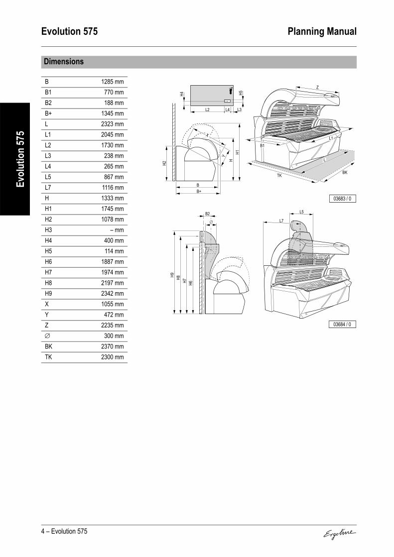
Evolution 575 Planning Manual
4 – Evolution 575
Evol
utio
n 57
5
Dimensions
B 1285 mmB1 770 mmB2 188 mmB+ 1345 mmL 2323 mmL1 2045 mmL2 1730 mmL3 238 mmL4 265 mmL5 867 mmL7 1116 mmH 1333 mmH1 1745 mmH2 1078 mmH3 – mmH4 400 mmH5 114 mmH6 1887 mmH7 1974 mmH8 2197 mmH9 2342 mmX 1055 mmY 472 mmZ 2235 mm∅ 300 mmBK 2370 mmTK 2300 mm
TKBK
03683 / 0
Z
B1L1
L
L2 L4 L3
H4 H5
H2
H1H
Y
X
B+B
L7
L5
o
H9
H7 H6
H8
B2
03684 / 0

Planning Manual Evolution 575
Evolution 575 – 5
Evol
utio
n 57
5
Installing “exhaust air ducting via a suspended ceiling and with a double rear wall” is an optically elegant solution without using the central exhaust air bracket.An intermediate wall (1) (e.g. chipboard) tightly enclosing the sunbed at the rear serves as an upward channel for the exhaust air (2), if required right up to the suspended ceil-ing. So that the exhaust air is properly extracted, a slight vacuum is required behind the intermediate wall (1); an auxiliary fan must be installed if necessary.
With exhaust-air adapterA cut-out must be made in the intermediate wall (see table for dimensions). A rubber profile on the exhaust-air adapter (3) ensures an air-tight seal on the intermediate wall.
Without exhaust-air adapterThe intermediate wall (1) must securely enclose the rear of the tanning bed.
If a tanner is replaced with a new tanner, the intermediate wall (1) must be adapted or replaced so that there are no gaps through which leakage air is drawn. Provision must be made for the inspection doors at the head and foot of the tanner so that the canopy lifting device can be adjusted.
Planning example for double rear wall
DimensionsL1 1116 mm Tanning bed foot end up to centre of adapterL2 590 mm Long adapter, inner edgesH 1355 mm Height from floor to inner upper edge of rubber
profileH1 1125 mm Height from floor to inner lower edgeH2 230 mm Height of adapter (inside)
DimensionsB1 max. 170 mmB2 57 mmH1 1078 mm
03984 / 0
2
3
1
H2H1 H
L1L2
03840 / 0
H1
B1
B2 03322 / 1
1
2

Evolution 575 Planning Manual
6 – Evolution 575
Evol
utio
n 57
5
Cabin or studio air is drawn in beneath the front panel (1) of the lower part of the sunbed and over the filter mats in the canopy (2) (inlet air) in order to cool the equipment.The inlet air is first cleaned in a filter, then fed past the hot UV low-pressure lamps and finally expelled as warm exhaust air via the central exhaust air bracket (3) at the rear of the sunbed.
Maximum exhaust pipe lengths
Calculation base (without additional ventilator):Back pressure 100 PascalAir pressure 100,000 PascalAir temperature 40 °CDensity 1.112 kg/m3
Dynamic inertia of the air 1.92E-05 Pa x s
Corrugated pipe∅
Roughness(at centre)kabsolute
Flow volume Loss coefficient 90° bend in line(metal)
Permissible length of
straight linemm mm m³/h of pipe of bend pieces m
300 8 2500 0.1821)
1) zeta value (ζ)
0.211)
0 101 92 83 7
Smooth pipe∅
Roughness(at centre)kabsolute
Flow volume Loss coefficient 90° bend in line(metal)
Permissible length of
straight linemm mm m³/h of pipe of bend pieces m
300 0.1 2500 0.0611) 0.211)
0 301 262 223 18
Equipment cooling
03327 / 01
2 3

Planning Manual Evolution 575
Evolution 575 – 7
Evol
utio
n 57
5
Surround air ventilation for the user is provided automatically. The intensity is adjusta-ble in 9 steps. Cabin or studio air is drawn in and used for cooling.The air is fed through several nozzles over the whole length in the middle of the canopy. In the head area there are two air nozzles that can be switched on separately.Studio air is also supplied via the air inlet slots beneath the front panel of the sunbed base and fed to two nozzles at feet level at the lying surface height, thus surrounding the body with cooling air.Depending on equipment the user can have a pleasant cooling mist (AQUA FRESH) sprayed from the outer nozzles in the body area.Depending on the equipment, an air conditioner enables the additional climate control of the bed surface and the body air.
Connection to a central exhaust system is possible upwards, upwards right, upwards left and to the rear.The apertures intended for this purpose are located above the central exhaust air bracket.
Corrugated pipe
Suitable device exhaust is possible with an exhaust pipe up to 10 metres in length (with-out 90° bend). An auxiliary fan is required for exhaust pipes longer than 10 metres.
Smooth pipe
Suitable device exhaust is possible with an exhaust pipe up to 30 metres in length (with-out 90° bend). An auxiliary fan is required for exhaust pipes longer than 30 metres.
Warm air recycling
Warm air recycling is a technically advanced, secure device which feeds part of the hot cooling air back to the studio via a motor-controlled air choke. A thermostat provides fully automatic control of the studio temperature, between 15 °C and 25 °C as required.The exhaust air bracket and warm air recycling can also be retrofitted.
Surround cooling
Exhaust air accessories
Item Accessory parts Article No. Notes1 Central exhaust air bracket Techno Grey with
warm air recycling, thermostatically controlled including connector piece, see Item 4
3452620 With connection possible for exhaust air pipes (∅ 300 mm) on the top, top right, top left and to the rear
Central exhaust air bracket Techno Grey, but without warm air recycling
3452630
2 90° Pipe bend in Techno Grey 3452110 For inlet and exhaust air ducting to right, left or to rear, plus tube adapter for direct connection to central exhaust air bracket [possible with tube (∅ 300 mm)]
3 Corrugated pipe (∅ 300 mm, 6 m length, flexible, grey) including 2 pipe clamps
3450280 –
4 Corrugated pipe connector piece (∅ 300 mm) 3450270 For connecting two corrugated pipes5 Connector bracket for corrugated pipe
(∅ 300 mm)3450360 Connection of the corrugated pipe, e.g. to a canal
6 Exhaust air adapter in black (not shown) 3452660 For double rear wall
03654 / 0
03329 / 0
1
43 325

Evolution 575 Planning Manual
8 – Evolution 575
Evol
utio
n 57
5
Equipment variant, retrofitting not possible.
Equipment variant, retrofitting not possible.3D sound: Equipment variant, retrofitting not possible.
Equipment variant: (Air condition for the bed surface and the body air) retrofitting not possible.
Equipment variant: Aroma and body cooling for the user; retrofitting not possible.
Standard equipment: Access to the device data with a hand-held unit (Palm).
Electrical connections
Mains supply line noneElectr. control line noneLine for external music and channel selection none
MULTIVISION
Sound system
Controls
Control Article No. NotesMCS III plus hand-held remote control 3401060 With chip card terminalMCS IV plus 3401040 With electronic coin testerMCS VI 3400970 With electronic coin tester + chip card terminalStudiopilot 3400990 With electronic coin tester + chip card terminalStudio-Manager 3452900 Software
Air conditioner
AQUA FRESH AROMA system
IR Interface

Planning Manual Evolution 500 APS
Evolution 500 APS – 1
Evol
utio
n 50
0 APS
The Automatic Power System sensor is a highly sensitive, pho-toelectronic precision instrument that is capable of analysing the state of the skin accurately and reliably. For this reason, the IQ sensor is automatically tested for proper working order and measurement accuracy after every measurement cycle. It is also recommended to recalibrate the APS sensor after approx-imately 30 hours of operation. For further information refer to the operating instructions.
Contents
Device descripition. . . . . . . . . . . . . . . . . . . . . . . . . . . 2
Technical Data. . . . . . . . . . . . . . . . . . . . . . . . . . . . . . . 2
Dimensions . . . . . . . . . . . . . . . . . . . . . . . . . . . . . . . . . 3
Planning example for double rear wall . . . . . . . . . . . 4With exhaust-air adapter . . . . . . . . . . . . . . . . . . . . . . . . 4Without exhaust-air adapter . . . . . . . . . . . . . . . . . . . . . . 4
Maximum exhaust pipe lengths. . . . . . . . . . . . . . . . . 5
Equipment cooling . . . . . . . . . . . . . . . . . . . . . . . . . . . 5
Surround cooling . . . . . . . . . . . . . . . . . . . . . . . . . . . . 6
Exhaust air accessories. . . . . . . . . . . . . . . . . . . . . . . 6
Electrical connections . . . . . . . . . . . . . . . . . . . . . . . . 7
MULTIVISION. . . . . . . . . . . . . . . . . . . . . . . . . . . . . . . . 7
Sound system . . . . . . . . . . . . . . . . . . . . . . . . . . . . . . . 7
Controls . . . . . . . . . . . . . . . . . . . . . . . . . . . . . . . . . . . . 7
Air conditioner . . . . . . . . . . . . . . . . . . . . . . . . . . . . . . 7
AQUA FRESH AROMA system . . . . . . . . . . . . . . . . . 7
IR Interface . . . . . . . . . . . . . . . . . . . . . . . . . . . . . . . . . 7
APS sensor . . . . . . . . . . . . . . . . . . . . . . . . . . . . . . . . . 8
06106 / 0

Evolution 500 APS Planning Manual
2 – Evolution 500 APS
Evol
utio
n 50
0 APS
1. Face tanner (UV high-pressure lamps)2. Shoulder tanner 3. APS sensor and base station4. Reflector5. Headphone connection6. UV low-pressure lamps, lower part7. Intermediate panel8. Infrared interface9. Acrylic glass panel lower part10. UV low-pressure lamps, side part11. UV low-pressure lamps, canopy12. Air nozzle/nozzle AQUA FRESH
(dependent on equipment)13. Air nozzles body cooling14. Air nozzles body cooling head end
and AROMA (dependent on equipment)15. Central exhaust air bracket (optional)16. Accent lighting canopy
Device descripition
4
3
5
2
679
161512 12
11
10
13 14
1
8 06150 / 0
Technical Data
Electrical dataNominal power consumption: 13900 WNominal voltage: 400 – 415 V ~3NNominal frequency: 50 HzRated fusing: 3 x 35 A (time-delay)Performance:
Canopy:UV low pressure lamps 18 x 160 WUV high pressure lamps 2 x 520 WLower part:UV low pressure lamps 17 x 160 WSide part:UV low pressure lamps 8 x 160 WUV high pressure lamps 1 x 520 WShoulder tanner:UV low pressure lamps 7 x 25 W
Noise emissionAcoustic pressure level: 68.8 db (A)Inlet and exhaust airTemperature difference, supply/exhaust air: 11 °CMax. air requirement: 2800 m3/hOpt. ambient temperature: 25 °C – 30 °CMax. ambient temperature: 15 °C – 40 °CMax. inlet air temperature: 40 °CExhaust cross section w/o exhaust system: 588 cm2
Cabin inlet air cross section at 1.5 m/s: 4200 cm2
Exhaust cross section with exhaust system: 710 cm2
Warm air return: possible

Planning Manual Evolution 500 APS
Evolution 500 APS – 3
Evol
utio
n 50
0 APS
Dimensions
B 1285 mmB1 770 mmB2 188 mmB+ 1345 mmL 2323 mmL1 2045 mmL2 1730 mmL3 238 mmL4 265 mmL5 867 mmL7 1116 mmH 1333 mmH1 1660 mmH2 1078 mmH3 – mmH4 400 mmH5 114 mmH6 1887 mmH7 1974 mmH8 2197 mmH9 2342 mmX 1055 mmY 472 mmZ 2235 mm∅ 300 mmBK 2370 mmTK 2300 mm
TKBK
06151 / 0
Z
B1L1
L
L2 L4 L3
H4 H5
H2
H1H
Y
X
B+B
o
H9
H7 H6
H8
B2L7
L5
06152 / 0

Evolution 500 APS Planning Manual
4 – Evolution 500 APS
Evol
utio
n 50
0 APS
Installing “exhaust air ducting via a suspended ceiling and with a double rear wall” is an optically elegant solution without using the central exhaust air bracket.An intermediate wall (1) (e.g. chipboard) tightly enclosing the sunbed at the rear serves as an upward channel for the exhaust air (2), if required right up to the suspended ceil-ing. So that the exhaust air is properly extracted, a slight vacuum is required behind the intermediate wall (1); an auxiliary fan must be installed if necessary.
With exhaust-air adapterA cut-out must be made in the intermediate wall (see table for dimensions). A rubber profile on the exhaust-air adapter (3) ensures an air-tight seal on the intermediate wall.
Without exhaust-air adapterThe intermediate wall (1) must securely enclose the rear of the tanning bed.
If a tanner is replaced with a new tanner, the intermediate wall (1) must be adapted or replaced so that there are no gaps through which leakage air is drawn. Provision must be made for the inspection doors at the head and foot of the tanner so that the canopy lifting device can be adjusted.
Planning example for double rear wall
DimensionsL1 1116 mm Tanning bed foot end up to centre of adapterL2 590 mm Long adapter, inner edgesH 1355 mm Height from floor to inner upper edge of rubber
profileH1 1125 mm Height from floor to inner lower edgeH2 230 mm Height of adapter (inside)
DimensionsB1 max. 170 mmB2 57 mmH1 1078 mm
03984 / 0
2
3
1
H2H1 H
L1L2
03840 / 0
H1
B1
B2 03322 / 1
1
2

Planning Manual Evolution 500 APS
Evolution 500 APS – 5
Evol
utio
n 50
0 APS
Cabin or studio air is drawn in beneath the front panel (1) of the lower part of the sunbed and over the filter mats in the canopy (2) (inlet air) in order to cool the equipment.The inlet air is first cleaned in a filter, then fed past the hot UV low-pressure and high-pressure lamps and finally expelled as warm exhaust air via the central exhaust air bracket (3) at the rear of the sunbed.
Maximum exhaust pipe lengths
Calculation base (without additional ventilator):Back pressure 100 PascalAir pressure 100,000 PascalAir temperature 40 °CDensity 1.112 kg/m3
Dynamic inertia of the air 1.92E-05 Pa x s
Corrugated pipe∅
Roughness(at centre)kabsolute
Flow volume Loss coefficient 90° bend in line(metal)
Permissible length of
straight linemm mm m³/h of pipe of bend pieces m
300 8 2500 0.1821)
1) zeta value (ζ)
0.211)
0 101 92 83 7
Smooth pipe∅
Roughness(at centre)kabsolute
Flow volume Loss coefficient 90° bend in line(metal)
Permissible length of
straight linemm mm m³/h of pipe of bend pieces m
300 0.1 2500 0.0611) 0.211)
0 301 262 223 18
Equipment cooling
1
2 3
06153 / 0

Evolution 500 APS Planning Manual
6 – Evolution 500 APS
Evol
utio
n 50
0 APS
Surround air ventilation for the user is provided automatically. The intensity is adjusta-ble in 9 steps. Cabin or studio air is drawn in and used for cooling.The air is fed through several nozzles over the whole length in the middle of the canopy. In The head area there are two air nozzles that can be switched on separately.Depending on the equipment, the user can have a pleasant cooling mist (AQUA FRESH) sprayed from the outer nozzles in the body area.An air conditioner enables the additional climate control of the bed surface and the body air.
Connection to a central exhaust system is possible upwards, upwards right, upwards left and to the rear.The apertures intended for this purpose are located above the central exhaust air bracket.
Corrugated pipe
Suitable device exhaust is possible with an exhaust pipe up to 10 metres in length (with-out 90° bend). An auxiliary fan is required for exhaust pipes longer than 10 metres.
Smooth pipe
Suitable device exhaust is possible with an exhaust pipe up to 30 metres in length (with-out 90° bend). An auxiliary fan is required for exhaust pipes longer than 30 metres.
Warm air recycling
Warm air recycling is a technically advanced, secure device which feeds part of the hot cooling air back to the studio via a motor-controlled air choke. A thermostat provides fully automatic control of the studio temperature, between 15 °C and 25 °C as required.The exhaust air bracket and warm air recycling can also be retrofitted.
Surround cooling
Exhaust air accessories
Item Accessory parts Article No. Notes1 Central exhaust air bracket Techno Grey with
warm air recycling, thermostatically controlled including connector piece, see Item 4
3452620 With connection possible for exhaust air pipes (∅ 300 mm) on the top, top right, top left and to the rear
Central exhaust air bracket Techno Grey, but without warm air recycling
3452630
2 90° Pipe bend in Techno Grey 3452110 For inlet and exhaust air ducting to right, left or to rear, plus tube adapter for direct connection to central exhaust air bracket [possible with tube (∅ 300 mm)]
3 Corrugated pipe (∅ 300 mm, 6 m length, flexible, grey) including 2 pipe clamps
3450280 –
4 Corrugated pipe connector piece (∅ 300 mm) 3450270 For connecting two corrugated pipes5 Connector bracket for corrugated pipe
(∅ 300 mm)3450360 Connection of the corrugated pipe, e.g. to a canal
6 Exhaust air adapter in black (not shown) 3452660 For double rear wall
06154 / 0
06155 / 0
1
43 325

Planning Manual Evolution 500 APS
Evolution 500 APS – 7
Evol
utio
n 50
0 APS
Equipment variant, retrofitting not possible.
Standard equipment.3D sound: Equipment variant, retrofitting not possible.
Standard equipment: Air condition for the bed surface and the body air.
Equipment variant: Aroma and body cooling for the user; retrofitting not possible.
Standard equipment: Access to the device data with a hand-held unit (Palm).
Electrical connections
Mains supply line noneElectr. control line noneLine for external music and channel selection none
MULTIVISION
Sound system
Controls
Control Article No. NotesMCS III plus hand-held remote control 3401060 With chip card terminalICS-Unit 3453200 Chip card terminal for APS devicesMCS IV plus 3401040 With electronic coin testerMCS VI 3400970 With electronic coin tester + chip card terminalStudiopilot 3400990 With electronic coin tester + chip card terminalStudio-Manager 3452900 Software
Air conditioner
AQUA FRESH AROMA system
IR Interface

Evolution 500 APS Planning Manual
8 – Evolution 500 APS
Evol
utio
n 50
0 APS
Standard equipment: The user determines his tanning ability by using the integrated APS sensor to measure face and body. When operating the sensor, the user is assisted by VoiceGuide.Step one: The first measurement is performed on the forehead. A beep confirms a suc-cessful measurement. The VoiceGuide then prompts you to perform the second meas-urement, this time on your body.
Step two: Perform the second measurement on the palest part of your body: e.g. your buttocks or insides of your arms. It's important that this part of the body is included in your tanning assessment. This way, allowance is made for pigmentation progress at the next tanning session and tanning power is increased.The Automatic Power System now takes just a few seconds to compute your personal tanning programme from your measurement readings.
APS sensor
1
Step one ...
04734 / 0
Step two ...
2
04821 / 0

Planning Manual Evolution 500
Evolution 500 – 1
Evol
utio
n 50
0
Turbo Power
Super Power
Contents
Device descripition. . . . . . . . . . . . . . . . . . . . . . . . . . . 2
Technical Data. . . . . . . . . . . . . . . . . . . . . . . . . . . . . . . 3Technical Data – Evolution 500 Turbo Power. . . . . . . . . 3Technical Data – Evolution 500 Super Power . . . . . . . . 3
Dimensions . . . . . . . . . . . . . . . . . . . . . . . . . . . . . . . . . 4
Planning example for double rear wall . . . . . . . . . . . 5With exhaust-air adapter . . . . . . . . . . . . . . . . . . . . . . . . 5Without exhaust-air adapter . . . . . . . . . . . . . . . . . . . . . . 5
Maximum exhaust pipe lengths. . . . . . . . . . . . . . . . . 6
Equipment cooling . . . . . . . . . . . . . . . . . . . . . . . . . . . 6
Surround cooling . . . . . . . . . . . . . . . . . . . . . . . . . . . . 7
Exhaust air accessories. . . . . . . . . . . . . . . . . . . . . . . 7
Electrical connections . . . . . . . . . . . . . . . . . . . . . . . . 8
MULTIVISION. . . . . . . . . . . . . . . . . . . . . . . . . . . . . . . . 8
Sound system . . . . . . . . . . . . . . . . . . . . . . . . . . . . . . . 8
Controls . . . . . . . . . . . . . . . . . . . . . . . . . . . . . . . . . . . . 8
Air conditioner . . . . . . . . . . . . . . . . . . . . . . . . . . . . . . 8
AQUA FRESH AROMA system . . . . . . . . . . . . . . . . . 8
IR Interface . . . . . . . . . . . . . . . . . . . . . . . . . . . . . . . . . 8
03285 / 0

Evolution 500 Planning Manual
2 – Evolution 500
Evol
utio
n 50
0
1. Face tanner (UV high-pressure lamps)2. Shoulder tanner
(Evolution 500 Turbo Power)3. Reflector4. Headphone connection5. UV low-pressure lamps, lower part6. Intermediate panel
(Evolution 500 Turbo Power)7. Infrared interface8. Acrylic glass panel lower part9. UV low-pressure lamps, side part10. UV low-pressure lamps, canopy11. Air nozzle/nozzle AQUA FRESH
(dependent on equipment)12. Air nozzles body cooling13. Air nozzles body cooling head end
and AROMA (dependent on equipment)14. Central exhaust air bracket (optional)15. Accent lighting canopy
Device descripition
3
4
2
568
151411 11
10
9
12 13
1
7 03471 / 1

Planning Manual Evolution 500
Evolution 500 – 3
Evol
utio
n 50
0
Technical Data – Evolution 500 Turbo Power
Technical Data – Evolution 500 Super Power
Technical Data
Electrical dataNominal power consumption:
without Air conditioning:with Air conditioning:
12700 W13900 W
Nominal voltage: 400 – 415 V ~3NNominal frequency: 50 HzRated fusing: 3 x 25 A (time-delay)Performance:
Canopy:UV low pressure lamps 18 x 160 WUV high pressure lamps 2 x 500 WLower part:UV low pressure lamps 17 x 160 WSide part:UV low pressure lamps 8 x 160 WUV high pressure lamps 1 x 500 WShoulder tanner:UV low pressure lamps 7 x 25 W
Noise emissionAcoustic pressure level: 68.8 db (A)Inlet and exhaust airTemperature difference, supply/exhaust air:
without Air conditioning:with Air conditioning:
6 °C11 °C
Max. air requirement: 2800 m3/hOpt. ambient temperature: 25 °C – 30 °CMax. ambient temperature: 15 °C – 40 °CMax. inlet air temperature: 40 °CExhaust cross section w/o exhaust system: 588 cm2
Cabin inlet air cross section at 1.5 m/s: 4200 cm2
Exhaust cross section with exhaust system: 710 cm2
Warm air return: possible
Electrical dataNominal power consumption:
without Air conditioning: 8400 WNominal voltage: 400 – 415 V ~3NNominal frequency: 50 HzRated fusing: 3 x 16 A (time-delay)Performance:
Canopy:UV low pressure lamps 18 x 100 WUV high pressure lamps 2 x 400 WLower part:UV low pressure lamps 17 x 100 WSide part:UV low pressure lamps 8 x 100 WUV high pressure lamps 1 x 400 W
Noise emissionAcoustic pressure level: 67.2 db (A)Inlet and exhaust airTemperature difference, supply/exhaust air: 6 °CMax. air requirement: 2800 m3/hOpt. ambient temperature: 25 °C – 30 °CMax. ambient temperature: 15 °C – 40 °CMax. inlet air temperature: 40 °CExhaust cross section w/o exhaust system: 588 cm2
Cabin inlet air cross section at 1.5 m/s: 4200 cm2
Exhaust cross section with exhaust system: 710 cm2
Warm air return: possible

Evolution 500 Planning Manual
4 – Evolution 500
Evol
utio
n 50
0
Dimensions
B 1285 mmB1 770 mmB2 188 mmB+ 1345 mmL 2231 mmL* 2323 mmL1 2045 mmL2 1730 mmL3 238 mmL4 265 mmL5 867 mmL7 1116 mmH 1333 mmH1 1660 mmH2 1078 mmH3 – mmH4 400 mmH5 114 mmH6 1887 mmH7 1974 mmH8 2197 mmH9 2342 mmX 1055 mmY 472 mmZ 2235 mm∅ 300 mmBK 2370 mmTK 2300 mm* with shoulder tanner
TKBK
H2
Z
B1L1
L L
H1HY
X
B+B
L2 L4 L3
H4 H5
03312 / 0
o
H9
H7 H6
H8
B2L7
L5
03313 / 0

Planning Manual Evolution 500
Evolution 500 – 5
Evol
utio
n 50
0
Installing “exhaust air ducting via a suspended ceiling and with a double rear wall” is an optically elegant solution without using the central exhaust air bracket.An intermediate wall (1) (e.g. chipboard) tightly enclosing the sunbed at the rear serves as an upward channel for the exhaust air (2), if required right up to the suspended ceil-ing. So that the exhaust air is properly extracted, a slight vacuum is required behind the intermediate wall (1); an auxiliary fan must be installed if necessary.
With exhaust-air adapterA cut-out must be made in the intermediate wall (see table for dimensions). A rubber profile on the exhaust-air adapter (3) ensures an air-tight seal on the intermediate wall.
Without exhaust-air adapterThe intermediate wall (1) must securely enclose the rear of the tanning bed.
If a tanner is replaced with a new tanner, the intermediate wall (1) must be adapted or replaced so that there are no gaps through which leakage air is drawn. Provision must be made for the inspection doors at the head and foot of the tanner so that the canopy lifting device can be adjusted.
Planning example for double rear wall
DimensionsL1 1116 mm Tanning bed foot end up to centre of adapterL2 590 mm Long adapter, inner edgesH 1355 mm Height from floor to inner upper edge of rubber
profileH1 1125 mm Height from floor to inner lower edgeH2 230 mm Height of adapter (inside)
DimensionsB1 max. 170 mmB2 57 mmH1 1078 mm
03984 / 0
2
3
1
H2H1 H
L1L2
03840 / 0
H1
B1
B2 03322 / 1
1
2

Evolution 500 Planning Manual
6 – Evolution 500
Evol
utio
n 50
0
Cabin or studio air is drawn in beneath the front panel (1) of the lower part of the sunbed and over the filter mats in the canopy (2) (inlet air) in order to cool the equipment.The inlet air is first cleaned in a filter, then fed past the hot UV low-pressure and high-pressure lamps and finally expelled as warm exhaust air via the central exhaust air bracket (3) at the rear of the sunbed.
Maximum exhaust pipe lengths
Calculation base (without additional ventilator):Back pressure 100 PascalAir pressure 100,000 PascalAir temperature 40 °CDensity 1.112 kg/m3
Dynamic inertia of the air 1.92E-05 Pa x s
Corrugated pipe∅
Roughness(at centre)kabsolute
Flow volume Loss coefficient 90° bend in line(metal)
Permissible length of
straight linemm mm m³/h of pipe of bend pieces m
300 8 2500 0.1821)
1) zeta value (ζ)
0.211)
0 101 92 83 7
Smooth pipe∅
Roughness(at centre)kabsolute
Flow volume Loss coefficient 90° bend in line(metal)
Permissible length of
straight linemm mm m³/h of pipe of bend pieces m
300 0.1 2500 0.0611) 0.211)
0 301 262 223 18
Equipment cooling
1
2 3
03323 / 0

Planning Manual Evolution 500
Evolution 500 – 7
Evol
utio
n 50
0
Surround air ventilation for the user is provided automatically. The intensity is adjusta-ble in 9 steps. Cabin or studio air is drawn in and used for cooling.The air is fed through several nozzles over the whole length in the middle of the canopy. In The head area there are two air nozzles that can be switched on separately.Depending on the equipment, the user can have a pleasant cooling mist (AQUA FRESH) sprayed from the outer nozzles in the body area.Depending on the equipment, an air conditioner enables the additional climate control of the bed surface and the body air (Evolution 500 Turbo Power only).
Connection to a central exhaust system is possible upwards, upwards right, upwards left and to the rear.The apertures intended for this purpose are located above the central exhaust air bracket.
Corrugated pipe
Suitable device exhaust is possible with an exhaust pipe up to 10 metres in length (with-out 90° bend). An auxiliary fan is required for exhaust pipes longer than 10 metres.
Smooth pipe
Suitable device exhaust is possible with an exhaust pipe up to 30 metres in length (with-out 90° bend). An auxiliary fan is required for exhaust pipes longer than 30 metres.
Warm air recycling
Warm air recycling is a technically advanced, secure device which feeds part of the hot cooling air back to the studio via a motor-controlled air choke. A thermostat provides fully automatic control of the studio temperature, between 15 °C and 25 °C as required.The exhaust air bracket and warm air recycling can also be retrofitted.
Surround cooling
Exhaust air accessories
Item Accessory parts Article No. Notes1 Central exhaust air bracket Techno Grey with
warm air recycling, thermostatically controlled including connector piece, see Item 4
3452620 With connection possible for exhaust air pipes (∅ 300 mm) on the top, top right, top left and to the rear
Central exhaust air bracket Techno Grey, but without warm air recycling
3452630
2 90° Pipe bend in Techno Grey 3452110 For inlet and exhaust air ducting to right, left or to rear, plus tube adapter for direct connection to central exhaust air bracket [possible with tube (∅ 300 mm)]
3 Corrugated pipe (∅ 300 mm, 6 m length, flexible, grey) including 2 pipe clamps
3450280 –
4 Corrugated pipe connector piece (∅ 300 mm) 3450270 For connecting two corrugated pipes5 Connector bracket for corrugated pipe
(∅ 300 mm)3450360 Connection of the corrugated pipe, e.g. to a canal
6 Exhaust air adapter in black (not shown) 3452660 For double rear wall
03324 / 0
03325 / 0
1
43 325

Evolution 500 Planning Manual
8 – Evolution 500
Evol
utio
n 50
0
Equipment variant, retrofitting not possible.
Equipment variant, retrofitting not possible.3D sound: Equipment variant, retrofitting not possible.
With Evolution 500 Turbo Power: Equipment variant: Air condition for the bed surface and the body air; retrofitting not possible.
Equipment variant: Aroma and body cooling for the user; retrofitting not possible.
Standard equipment: Access to the device data with a hand-held unit (Palm).
Electrical connections
Mains supply line noneElectr. control line noneLine for external music and channel selection none
MULTIVISION
Sound system
Controls
Control Article No. NotesMCS III plus hand-held remote control 3401060 With chip card terminalMCS IV plus 3401040 With electronic coin testerMCS VI 3400970 With electronic coin tester + chip card terminalStudiopilot 3400990 With electronic coin tester + chip card terminalStudio-Manager 3452900 Software
Air conditioner
AQUA FRESH AROMA system
IR Interface

Planning Manual Advantage 400 APS
Advantage 400 APS – 1
Adva
ntag
e 400
APS
The Automatic Power System sensor is a highly sensitive, pho-toelectronic precision instrument that is capable of analysing the state of the skin accurately and reliably. For this reason, the IQ sensor is automatically tested for proper working order and measurement accuracy after every measurement cycle. It is also recommended to recalibrate the APS sensor after approx-imately 30 hours of operation. For further information refer to the operating instructions.
Contents
Device descripition. . . . . . . . . . . . . . . . . . . . . . . . . . . 2
Technical Data. . . . . . . . . . . . . . . . . . . . . . . . . . . . . . . 2
Dimensions . . . . . . . . . . . . . . . . . . . . . . . . . . . . . . . . . 3
Maximum exhaust pipe lengths. . . . . . . . . . . . . . . . . 4
Equipment cooling . . . . . . . . . . . . . . . . . . . . . . . . . . . 4
Surround cooling . . . . . . . . . . . . . . . . . . . . . . . . . . . . 5
Exhaust air accessories. . . . . . . . . . . . . . . . . . . . . . . 5
Electrical connections . . . . . . . . . . . . . . . . . . . . . . . . 6
Sound system . . . . . . . . . . . . . . . . . . . . . . . . . . . . . . . 6
Controls . . . . . . . . . . . . . . . . . . . . . . . . . . . . . . . . . . . . 6
Air conditioner . . . . . . . . . . . . . . . . . . . . . . . . . . . . . . 6
IR Interface . . . . . . . . . . . . . . . . . . . . . . . . . . . . . . . . . 6
APS sensor . . . . . . . . . . . . . . . . . . . . . . . . . . . . . . . . . 7

Advantage 400 APS Planning Manual
2 – Advantage 400 APS
Adva
ntag
e 400
APS
1. Face tanner (UV high-pressure lamps)2. Loudspeaker3. Headphone connection4. APS sensor and base station5. Reflector6. UV low-pressure lamps, lower part7. Intermediate panel
(only with air conditioner)8. Infrared interface9. Acrylic glass panel lower part10. UV low-pressure lamps, canopy11. Air nozzles body cooling12. Air nozzles body cooling head end 13. Central exhaust air bracket (optional)14. Accent lighting canopy15. Accent lighting front panel16. Accent lighting interal
Device descripition
Technical Data
Electrical dataNominal power consumption:
without Air conditioning:with Air conditioning:
9700 W10700 W
Nominal voltage: 400 – 415 V ~3NNominal frequency: 50 HzRated fusing:
without Air conditioning:with Air conditioning:
3 x 20 A (time-delay)3 x 25 A (time-delay)
Performance:Canopy:UV low pressure lamps 26 x 140 (160) WUV high pressure lamps 3 x 400 WLower part:UV low pressure lamps 14 x 140 (160) W
Noise emissionAcoustic pressure level: 66.4 db (A)Inlet and exhaust airTemperature difference, supply/exhaust air:
without Air conditioning:with Air conditioning:
7 °C10 °C
Max. air requirement: 2700 m3/hOpt. ambient temperature: 25 °C – 30 °CMax. ambient temperature: 15 °C – 40 °CMax. inlet air temperature: 40 °CExhaust cross section w/o exhaust system: 430 cm2
Cabin inlet air cross section at 1.5 m/s: 5000 cm2
Exhaust cross section with exhaust system: 710 cm2
Warm air return: possible

Planning Manual Advantage 400 APS
Advantage 400 APS – 3
Adva
ntag
e 400
APS
Dimensions
B- 1310 mmB1 1180 mmB2 1300 mmB+ 1430 mmL 2300 mmL1 2015 mmL2 1615 mmL3 35 mmL4 273 mmL5 867 mmL6 1100 mmH 1256 mmH1 1575 mmH2 390 mmH3 – mmH4 264 mmH5 167 mmH6 1679 mmH7 1760 mmH8 1979 mmH9 2124 mmX 1220 mmY 673 mmZ 2226 mm∅ 300 mmBK 2400 mmTK 2100 mm

Advantage 400 APS Planning Manual
4 – Advantage 400 APS
Adva
ntag
e 400
APS
Cabin or studio air is drawn in beneath the front panel (1) of the lower part of the sunbed and over the filter mats in the canopy (2) (inlet air) in order to cool the equipment.The inlet air is first cleaned in a filter, then fed past the hot UV low-pressure and high-pressure lamps and finally expelled as warm exhaust air via the central exhaust air bracket (3) at the rear of the sunbed.
Maximum exhaust pipe lengths
Calculation base (without additional ventilator):Back pressure 100 PascalAir pressure 100,000 PascalAir temperature 40 °CDensity 1.112 kg/m3
Dynamic inertia of the air 1.92E-05 Pa x s
Corrugated pipe∅
Roughness(at centre)kabsolute
Flow volume Loss coefficient 90° bend in line(metal)
Permissible length of
straight linemm mm m³/h of pipe of bend pieces m
300 8 2300 0.1821)
1) zeta value (ζ)
0.211)
0 121 112 103 9
Smooth pipe∅
Roughness(at centre)kabsolute
Flow volume Loss coefficient 90° bend in line(metal)
Permissible length of
straight linemm mm m³/h of pipe of bend pieces m
300 0.1 2300 0.0611) 0.211)
0 361 332 293 26
Equipment cooling

Planning Manual Advantage 400 APS
Advantage 400 APS – 5
Adva
ntag
e 400
APS
Surround air ventilation for the user is provided automatically. The intensity is adjusta-ble in 9 steps. Cabin or studio air is drawn in and used for cooling.The air is fed through several nozzles in the middle of the canopy and in the head area.Depending on the equipment, an air conditioner enables the additional climate control of the bed surface and the body air.
Connection to a central exhaust system is possible upwards, upwards right, upwards left and to the rear.The apertures intended for this purpose are located above the central exhaust air bracket.
Corrugated pipe
Suitable device exhaust is possible with an exhaust pipe up to 12 metres in length (with-out 90° bend). An auxiliary fan is required for exhaust pipes longer than 12 metres.
Smooth pipe
Suitable device exhaust is possible with an exhaust pipe up to 36 metres in length (with-out 90° bend). An auxiliary fan is required for exhaust pipes longer than 36 metres.
Warm air recycling
Warm air recycling is a technically advanced, secure device which feeds part of the hot cooling air back to the studio via a motor-controlled air choke. A thermostat provides fully automatic control of the studio temperature, between 15 °C and 25 °C as required.The exhaust air bracket and warm air recycling can also be retrofitted.
Surround cooling
Exhaust air accessories
Item Accessory parts Article No. Notes1 Central exhaust air bracket Techno Grey with
warm air recycling, thermostatically controlled including connector piece, see Item 4
3452840 With connection possible for exhaust air pipes (∅ 300 mm) on the top, top right, top left and to the rear
Central exhaust air bracket Techno Grey, but without warm air recycling
3452830
2 90° Pipe bend in Techno Grey 3452110 For inlet and exhaust air ducting to right, left or to rear, plus tube adapter for direct connection to central exhaust air bracket [possible with tube (∅ 300 mm)]
3 Corrugated pipe (∅ 300 mm, 6 m length, flexible, grey) including 2 pipe clamps
3450280 –
4 Corrugated pipe connector piece (∅ 300 mm)
3450270 For connecting two corrugated pipes
5 Connector bracket for corrugated pipe (∅ 300 mm)
3450360 Connection of the corrugated pipes, e.g. to a canal

Advantage 400 APS Planning Manual
6 – Advantage 400 APS
Adva
ntag
e 400
APS
Equipment variant, retrofitting not possible.
Equipment variant: Air condition for the bed surface and the body air, retrofitting not possible.
Standard equipment: Access to the device data with a hand-held unit (Palm).
Electrical connections
Mains supply line noneElectr. control line noneLine for external music and channel selection none
Sound system
Controls
Control Article No. NotesMCS III plus hand-held remote control 3401060 With chip card terminalICS-Unit 3453200 Chip card terminal for APS devicesMCS IV plus 3401040 With electronic coin testerMCS VI 3400970 With electronic coin tester + chip card terminalStudiopilot 3400990 With electronic coin tester + chip card terminalStudio-Manager 3452900 Software
Air conditioner
IR Interface

Planning Manual Advantage 400 APS
Advantage 400 APS – 7
Adva
ntag
e 400
APS
Standard equipment: The user determines his tanning ability by using the integrated APS sensor to measure face and body. When operating the sensor, the user is assisted by VoiceGuide.Step one: The first measurement is performed on the forehead. A beep confirms a suc-cessful measurement. The VoiceGuide then prompts you to perform the second meas-urement, this time on your body.
Step two: Perform the second measurement on the palest part of your body: e.g. your buttocks or insides of your arms. It's important that this part of the body is included in your tanning assessment. This way, allowance is made for pigmentation progress at the next tanning session and tanning power is increased.The Automatic Power System now takes just a few seconds to compute your personal tanning programme from your measurement readings.
APS sensor
1
Step one ...
04734 / 0
Step two ...
2
04821 / 0

Planning Manual Advantage 400
Advantage 400 – 1
Adva
ntag
e 400
Turbo Power
Super Power
Contents
Device descripition. . . . . . . . . . . . . . . . . . . . . . . . . . . 2
Technical Data. . . . . . . . . . . . . . . . . . . . . . . . . . . . . . . 3Technical Data – Advantage 400 Turbo Power . . . . . . . 3Technical Data – Advantage 400 Super Power . . . . . . . 3
Dimensions . . . . . . . . . . . . . . . . . . . . . . . . . . . . . . . . . 4
Maximum exhaust pipe lengths. . . . . . . . . . . . . . . . . 5
Equipment cooling . . . . . . . . . . . . . . . . . . . . . . . . . . . 5
Surround cooling . . . . . . . . . . . . . . . . . . . . . . . . . . . . 6
Exhaust air accessories. . . . . . . . . . . . . . . . . . . . . . . 6
Electrical connections . . . . . . . . . . . . . . . . . . . . . . . . 7
Sound system . . . . . . . . . . . . . . . . . . . . . . . . . . . . . . . 7
Controls . . . . . . . . . . . . . . . . . . . . . . . . . . . . . . . . . . . . 7
Air conditioner . . . . . . . . . . . . . . . . . . . . . . . . . . . . . . 7
IR Interface . . . . . . . . . . . . . . . . . . . . . . . . . . . . . . . . . 7
Advantage 400 Planning Manual
2 – Advantage 400
Adva
ntag
e 400
1. Face tanner (UV high-pressure lamps)2. Loudspeaker3. Headphone connection4. Reflector5. UV low-pressure lamps, lower part6. Intermediate panel
(only with air conditioner)7. Infrared interface8. Acrylic glass panel lower part9. UV low-pressure lamps, canopy10. Air nozzles body cooling11. Air nozzles body cooling head end12. Central exhaust air bracket (optional)13. Accent lighting canopy14. Accent lighting Frontblende15. Accent lighting Innenraum
Device descripition
Planning Manual Advantage 400
Advantage 400 – 3
Adva
ntag
e 400
Technical Data – Advantage 400 Turbo Power
Technical Data – Advantage 400 Super Power
Technical Data
Electrical dataNominal power consumption:
without Air conditioning:with Air conditioning:
9700 W10700 W
Nominal voltage: 400 – 415 V ~3NNominal frequency: 50 HzRated fusing:
without Air conditioning:with Air conditioning:
3 x 20 A (time-delay)3 x 25 A (time-delay)
Performance:Canopy:UV low pressure lamps 26 x 140 (160) WUV high pressure lamps 3 x 400 WLower part:UV low pressure lamps 14 x 140 (160) W
Noise emissionAcoustic pressure level: 66.4 db (A)Inlet and exhaust airTemperature difference, supply/exhaust air:
without Air conditioning:with Air conditioning:
7 °C10 °C
Max. air requirement: 2700 m3/hOpt. ambient temperature: 25 °C – 30 °CMax. ambient temperature: 15 °C – 40 °CMax. inlet air temperature: 40 °CExhaust cross section w/o exhaust system: 430 cm2
Cabin inlet air cross section at 1.5 m/s: 5000 cm2
Exhaust cross section with exhaust system: 710 cm2
Warm air return: possible
Electrical dataNominal power consumption:
without Air conditioning: 7700 WNominal voltage: 400 – 415 V ~3NNominal frequency: 50 HzRated fusing: 3 x 16 A (time-delay)Performance:
Canopy:UV low pressure lamps 26 x 100 WUV high pressure lamps 3 x 360 WLower part:UV low pressure lamps 14 x 100 W
Noise emissionAcoustic pressure level: 66.4 db (A)Inlet and exhaust airTemperature difference, supply/exhaust air: 7 °CMax. air requirement: 2700 m3/hOpt. ambient temperature: 25 °C – 30 °CMax. ambient temperature: 15 °C – 40 °CMax. inlet air temperature: 40 °CExhaust cross section w/o exhaust system: 430 cm2
Cabin inlet air cross section at 1.5 m/s: 5000 cm2
Exhaust cross section with exhaust system: 710 cm2
Warm air return: possible

Advantage 400 Planning Manual
4 – Advantage 400
Adva
ntag
e 400
Dimensions
B- 1310 mmB1 1180 mmB2 1300 mmB+ 1430 mmL 2226 mmL1 2015 mmL2 1615 mmL3 35 mmL4 273 mmL5 867 mmL6 1100 mmH 1256 mmH1 1575 mmH2 390 mmH3 – mmH4 264 mmH5 167 mmH6 1679 mmH7 1760 mmH8 1979 mmH9 2124 mmX 1220 mmY 673 mmZ 2226 mm∅ 300 mmBK 2300 mmTK 2100 mm

Planning Manual Advantage 400
Advantage 400 – 5
Adva
ntag
e 400
Cabin or studio air is drawn in beneath the front panel (1) of the lower part of the sunbed and over the filter mats in the canopy (2) (inlet air) in order to cool the equipment.The inlet air is first cleaned in a filter, then fed past the hot UV low-pressure and high-pressure lamps and finally expelled as warm exhaust air via the central exhaust air bracket (3) at the rear of the sunbed.
Maximum exhaust pipe lengths
Calculation base (without additional ventilator):Back pressure 100 PascalAir pressure 100,000 PascalAir temperature 40 °CDensity 1.112 kg/m3
Dynamic inertia of the air 1.92E-05 Pa x s
Corrugated pipe∅
Roughness(at centre)kabsolute
Flow volume Loss coefficient 90° bend in line(metal)
Permissible length of
straight linemm mm m³/h of pipe of bend pieces m
300 8 2300 0.1821)
1) zeta value (ζ)
0.211)
0 121 112 103 9
Smooth pipe∅
Roughness(at centre)kabsolute
Flow volume Loss coefficient 90° bend in line(metal)
Permissible length of
straight linemm mm m³/h of pipe of bend pieces m
300 0.1 2300 0.0611) 0.211)
0 361 332 293 26
Equipment cooling

Advantage 400 Planning Manual
6 – Advantage 400
Adva
ntag
e 400
Surround air ventilation for the user is provided automatically. The intensity is adjusta-ble in 9 steps. Cabin or studio air is drawn in and used for cooling.The air is fed through several nozzles in the middle of the canopy and in the head area.Depending on the equipment, an air conditioner enables the additional climate control of the bed surface and the body air (Advantage 400 Turbo Power only).
Connection to a central exhaust system is possible upwards, upwards right, upwards left and to the rear.The apertures intended for this purpose are located above the central exhaust air bracket.
Corrugated pipe
Suitable device exhaust is possible with an exhaust pipe up to 12 metres in length (with-out 90° bend). An auxiliary fan is required for exhaust pipes longer than 12 metres.
Smooth pipe
Suitable device exhaust is possible with an exhaust pipe up to 36 metres in length (with-out 90° bend). An auxiliary fan is required for exhaust pipes longer than 36 metres.
Warm air recycling
Warm air recycling is a technically advanced, secure device which feeds part of the hot cooling air back to the studio via a motor-controlled air choke. A thermostat provides fully automatic control of the studio temperature, between 15 °C and 25 °C as required.The exhaust air bracket and warm air recycling can also be retrofitted.
Surround cooling
Exhaust air accessories
Item Accessory parts Article No. Notes1 Central exhaust air bracket Techno Grey with
warm air recycling, thermostatically controlled including connector piece, see Item 4
3452840 With connection possible for exhaust air pipes (∅ 300 mm) on the top, top right, top left and to the rear
Central exhaust air bracket Techno Grey, but without warm air recycling
3452830
2 90° Pipe bend in Techno Grey 3452110 For inlet and exhaust air ducting to right, left or to rear, plus tube adapter for direct connection to central exhaust air bracket [possible with tube (∅ 300 mm)]
3 Corrugated pipe (∅ 300 mm, 6 m length, flexible, grey) including 2 pipe clamps
3450280 –
4 Corrugated pipe connector piece (∅ 300 mm)
3450270 For connecting two corrugated pipes
5 Connector bracket for corrugated pipe (∅ 300 mm)
3450360 Connection of the corrugated pipes, e.g. to a canal

Planning Manual Advantage 400
Advantage 400 – 7
Adva
ntag
e 400
Equipment variant, retrofitting not possible.
Equipment variant: Air condition for the bed surface and the body air, retrofitting not possible.
Standard equipment: Access to the device data with a hand-held unit (Palm).
Electrical connections
Mains supply line noneElectr. control line noneLine for external music and channel selection none
Sound system
Controls
Control Article No. NotesMCS III plus hand-held remote control 3401060 With chip card terminalMCS IV plus 3401040 With electronic coin testerMCS VI 3400970 With electronic coin tester + chip card terminalStudiopilot 3400990 With electronic coin tester + chip card terminalStudio-Manager 3452900 Software
Air conditioner
IR Interface

Planning Manual Advantage 350
Advantage 350 – 1
Adva
ntag
e 350
Turbo Power
Super Power
Contents
Device descripition. . . . . . . . . . . . . . . . . . . . . . . . . . . 2
Technical Data. . . . . . . . . . . . . . . . . . . . . . . . . . . . . . . 3Technical Data – Advantage 350 Turbo Power . . . . . . . 3Technical Data – Advantage 350 Super Power . . . . . . . 3
Dimensions . . . . . . . . . . . . . . . . . . . . . . . . . . . . . . . . . 4
Maximum exhaust pipe lengths. . . . . . . . . . . . . . . . . 5
Equipment cooling . . . . . . . . . . . . . . . . . . . . . . . . . . . 5
Surround cooling . . . . . . . . . . . . . . . . . . . . . . . . . . . . 6
Exhaust air accessories. . . . . . . . . . . . . . . . . . . . . . . 6
Electrical connections . . . . . . . . . . . . . . . . . . . . . . . . 7
Sound system . . . . . . . . . . . . . . . . . . . . . . . . . . . . . . . 7
Controls . . . . . . . . . . . . . . . . . . . . . . . . . . . . . . . . . . . . 7
Air conditioner (not available) . . . . . . . . . . . . . . . . . . 7
04174 / 0

Advantage 350 Planning Manual
2 – Advantage 350
Adva
ntag
e 350
1. Face tanner (UV high-pressure lamps)2. Loudspeaker3. Headphone connection4. Reflector5. UV low-pressure lamps, lower part6. Acrylic glass panel lower part7. Infrared interface8. UV low-pressure lamps, canopy9. Air nozzles body cooling head end10. Central exhaust air bracket (optional)11. Accent lighting canopy12. Accent lighting internal
Device descripition
4
56
11
12
10
8
9
7
23
1
04532 / 0

Planning Manual Advantage 350
Advantage 350 – 3
Adva
ntag
e 350
Technical Data – Advantage 350 Turbo Power
Technical Data – Advantage 350 Super Power
Technical Data
Electrical dataNominal power consumption:
without Air conditioning: 9600 WNominal voltage: 400 – 415 V ~3NNominal frequency: 50 HzRated fusing: 3 x 20 A (time-delay)Performance:
Canopy:UV low pressure lamps 24 x 140 (160) WUV high pressure lamps 3 x 400 WLower part:UV low pressure lamps 14 x 140 (160) W
Noise emissionAcoustic pressure level: 68.1 db (A)Inlet and exhaust airTemperature difference, supply/exhaust air: 10 °CMax. air requirement: 2700 m3/hOpt. ambient temperature: 25 °C – 30 °CMax. ambient temperature: 15 °C – 40 °CMax. inlet air temperature: 40 °CExhaust cross section w/o exhaust system: 430 cm2
Cabin inlet air cross section at 1.5 m/s: 5000 cm2
Exhaust cross section with exhaust system: 710 cm2
Warm air return: possible
Electrical dataNominal power consumption:
without Air conditioning: 7600 WNominal voltage: 400 – 415 V ~3NNominal frequency: 50 HzRated fusing: 3 x 16 A (time-delay)Performance:
Canopy:UV low pressure lamps 24 x 100 WUV high pressure lamps 3 x 360 WLower part:UV low pressure lamps 14 x 100 W
Noise emissionAcoustic pressure level: 68.1 db (A)Inlet and exhaust airTemperature difference, supply/exhaust air: 7 °CMax. air requirement: 2700 m3/hOpt. ambient temperature: 25 °C – 30 °CMax. ambient temperature: 15 °C – 40 °CMax. inlet air temperature: 40 °CExhaust cross section w/o exhaust system: 430 cm2
Cabin inlet air cross section at 1.5 m/s: 5000 cm2
Exhaust cross section with exhaust system: 710 cm2
Warm air return: possible

Advantage 350 Planning Manual
4 – Advantage 350
Adva
ntag
e 350
Dimensions
B- 1230 mmB1 1170 mmB2 1290 mmB+ 1350 mmL 2200 mmL1 2015 mmL2 1615 mmL3 35 mmL4 273 mmL5 867 mmL6 1100 mmH 1125 mmH1 1415 mmH2 390 mmH3 – mmH4 264 mmH5 167 mmH6 1679 mmH7 1760 mmH8 1979 mmH9 2124 mmX 1114 mmY 536 mmZ 2200 mm∅ 300 mmBK 2300 mmTK 2100 mm
H1HY
L1
B-B1
TK
BK
L
BL
Z
X
L2 L4 L3
H4H2 H5
04365 / 0
H9
H7 H6
H8
o
B3L6
L5
B+B2
B4
04368 / 0

Planning Manual Advantage 350
Advantage 350 – 5
Adva
ntag
e 350
Cabin or studio air is drawn in beneath the front panel (1) of the lower part of the sunbed and over the filter mats in the canopy (2) (inlet air) in order to cool the equipment.The inlet air is first cleaned in a filter, then fed past the hot UV low-pressure and high-pressure lamps and finally expelled as warm exhaust air via the central exhaust air bracket (3) at the rear of the sunbed.
Maximum exhaust pipe lengths
Calculation base (without additional ventilator):Back pressure 100 PascalAir pressure 100,000 PascalAir temperature 40 °CDensity 1.112 kg/m3
Dynamic inertia of the air 1.92E-05 Pa x s
Corrugated pipe∅
Roughness(at centre)kabsolute
Flow volume Loss coefficient 90° bend in line(metal)
Permissible length of
straight linemm mm m³/h of pipe of bend pieces m
300 8 2300 0.1821)
1) zeta value (ζ)
0.211)
0 121 112 103 9
Smooth pipe∅
Roughness(at centre)kabsolute
Flow volume Loss coefficient 90° bend in line(metal)
Permissible length of
straight linemm mm m³/h of pipe of bend pieces m
300 0.1 2300 0.0611) 0.211)
0 361 332 293 26
Equipment cooling
2 3
1 04390 / 0

Advantage 350 Planning Manual
6 – Advantage 350
Adva
ntag
e 350
Surround air ventilation for the user is provided automatically. The intensity is adjusta-ble in 4 steps. Cabin or studio air is drawn in and used for cooling.The air is fed through several nozzles in the middle of the canopy and in the head area.
Connection to a central exhaust system is possible upwards, upwards right, upwards left and to the rear.The apertures intended for this purpose are located above the central exhaust air bracket.
Corrugated pipe
Suitable device exhaust is possible with an exhaust pipe up to 12 metres in length (with-out 90° bend). An auxiliary fan is required for exhaust pipes longer than 12 metres.
Smooth pipe
Suitable device exhaust is possible with an exhaust pipe up to 36 metres in length (with-out 90° bend). An auxiliary fan is required for exhaust pipes longer than 36 metres.
Warm air recycling
Warm air recycling is a technically advanced, secure device which feeds part of the hot cooling air back to the studio via a motor-controlled air choke. A thermostat provides fully automatic control of the studio temperature, between 15 °C and 25 °C as required.The exhaust air bracket and warm air recycling can also be retrofitted.
Surround cooling
Exhaust air accessories
Item Accessory parts Article No. Notes1 Central exhaust air bracket Techno Grey with
warm air recycling, thermostatically controlled including connector piece, see Item 4
3452840 With connection possible for exhaust air pipes (∅ 300 mm) on the top, top right, top left and to the rear
Central exhaust air bracket Techno Grey, but without warm air recycling
3452830
2 90° Pipe bend in Techno Grey 3452110 For inlet and exhaust air ducting to right, left or to rear, plus tube adapter for direct connection to central exhaust air bracket [possible with tube (∅ 300 mm)]
3 Corrugated pipe (∅ 300 mm, 6 m length, flexible, grey) including 2 pipe clamps
3450280 –
4 Corrugated pipe connector piece (∅ 300 mm)
3450270 For connecting two corrugated pipes
5 Connector bracket for corrugated pipe (∅ 300 mm)
3450360 Connection of the corrugated pipes, e.g. to a canal
04465 / 0
1
43 325
04466 / 0

Planning Manual Advantage 350
Advantage 350 – 7
Adva
ntag
e 350
Equipment variant, retrofitting not possible.
No air conditioner can be supplied with this device model.
Electrical connections
Mains supply line noneElectr. control line noneLine for external music and channel selection none
Sound system
Controls
Control Article No. NotesMCS III plus hand-held remote control 3401060 With chip card terminalMCS IV plus 3401040 With electronic coin testerMCS VI 3400970 With electronic coin tester + chip card terminalStudiopilot 3400990 With electronic coin tester + chip card terminalStudio-Manager 3452900 Software
Air conditioner (not available)

Planning Manual Ambition 250
Ambition 250 – 1
Ambi
tion
250
Super Power
Contents
Device descripition. . . . . . . . . . . . . . . . . . . . . . . . . . . 2
Technical Data. . . . . . . . . . . . . . . . . . . . . . . . . . . . . . . 2
Dimensions . . . . . . . . . . . . . . . . . . . . . . . . . . . . . . . . . 3
Equipment cooling . . . . . . . . . . . . . . . . . . . . . . . . . . . 3
Surround cooling . . . . . . . . . . . . . . . . . . . . . . . . . . . . 4
Electrical connections . . . . . . . . . . . . . . . . . . . . . . . . 4
Sound system . . . . . . . . . . . . . . . . . . . . . . . . . . . . . . . 4
Controls . . . . . . . . . . . . . . . . . . . . . . . . . . . . . . . . . . . . 4

Ambition 250 Planning Manual
2 – Ambition 250
Ambi
tion
250
1. Face tanner (UV high-pressure lamps)2. Operating panel3. UV low-pressure lamps, lower part4. Acrylic glass panel lower part5. Fan body cooling6. UV low-pressure lamps, canopy7. Accent lighting canopy
Device descripition
Technical Data
Electrical dataNominal power consumption:
without Air conditioning: 6300 WNominal voltage: 400 – 415 V ~3NNominal frequency: 50 HzRated fusing: 3 x 16 A (time-delay)Performance:
Canopy:UV low pressure lamps 18 x 100 WUV high pressure lamps 3 x 400 WLower part:UV low pressure lamps 18 x 100 W
Noise emissionAcoustic pressure level: 63.6 db (A)Inlet and exhaust airTemperature difference, supply/exhaust air:
without air conditioning: 15 °CMax. air requirement: 1600 m3/hOpt. ambient temperature: 25 °C – 30 °CMax. ambient temperature: 15 °C – 40 °CMax. inlet air temperature: 40 °CExhaust cross section w/o exhaust system: 802 cm2
Warm air return: not possible

Planning Manual Ambition 250
Ambition 250 – 3
Ambi
tion
250
To cool the equipment, cabin or studio air is drawn in through two filters in the lower part of the sunbed and two filters at the rear of the canopy (inlet air).The inlet air is fed past the hot UV low-pressure and high-pressure lamps and finally expelled as warm exhaust air via two exhaust air openings at the rear of the sunbed.
Dimensions
B 1193 mmB1 1130 mmB2 140 mmBL 808 mmL 2306 mmL1 2071 mmL2 24 mmL3 851 mmL4 104 mmL5 226 mmL6 488 mmL8 70 mmH 1049 mmH1 1383 mmH2 613 mmH4 206 mmH5 50 mmH6 87 mmX 995 mmY 400 mmZ 2172 mmBK 2400 mmTK 2100 mm
Equipment cooling
Ambition 250 Planning Manual
4 – Ambition 250
Ambi
tion
250
Surround air ventilation for the user is provided automatically, but can be switched off and on again as the user wishes. Cabin or studio air is drawn in and used for cooling.
Surround cooling
Electrical connections
Mains supply line noneElectr. control line noneLine for external music and channel selection none
Sound system
Audio unit not availableLoudspeaker not available
Controls
Control Article No. NotesMCS III plus hand-held remote control 3401060 With chip card terminalMCS IV plus 3401040 With electronic coin testerMCS VI 3400970 With electronic coin tester + chip card terminalStudiopilot 3400990 With electronic coin tester + chip card terminalStudio-Manager 3452900 Software
Planning Manual Lounge
Lounge – 1
Loun
ge
Turbo Power
Contents
Device descripition. . . . . . . . . . . . . . . . . . . . . . . . . . . 2
Technical Data. . . . . . . . . . . . . . . . . . . . . . . . . . . . . . . 2
Dimensions . . . . . . . . . . . . . . . . . . . . . . . . . . . . . . . . . 3
Installation of a coin device. . . . . . . . . . . . . . . . . . . . 3
Planning example for double rear wall . . . . . . . . . . . 4
Maximum exhaust pipe lengths. . . . . . . . . . . . . . . . . 5
Equipment cooling . . . . . . . . . . . . . . . . . . . . . . . . . . . 5
Surround cooling . . . . . . . . . . . . . . . . . . . . . . . . . . . . 6
Exhaust air accessories. . . . . . . . . . . . . . . . . . . . . . . 6
Electrical connections . . . . . . . . . . . . . . . . . . . . . . . . 7
Sound system . . . . . . . . . . . . . . . . . . . . . . . . . . . . . . . 7
Controls . . . . . . . . . . . . . . . . . . . . . . . . . . . . . . . . . . . . 7
Air conditioner (not available) . . . . . . . . . . . . . . . . . . 7
IR Interface . . . . . . . . . . . . . . . . . . . . . . . . . . . . . . . . . 7
04451 / 1

Lounge Planning Manual
2 – Lounge
Loun
ge
1. Exhaust air slots, equipment cooling2. Lighting of comfort cabin3. Mirror4. Inside door lock5. Clothes and shoe storage6. Inside door handle7. UV low pressure lamps inner doors8. UV low pressure lamps outer doors9. Clearance for the air supply (50 mm)10. Infrared interface11. Operating panel with display12. Outer doors13. Inner doors14. Ventilator15. Loudspeaker (accessories)16. Cable for emergency unlocking
behind the filter mat)17. Base cover
Device descripition
151413
78
1212
11
10
1
5
3
4
1769
2
16
04503 / 1
Technical Data
Electrical dataNominal power consumption: 12500 WNominal voltage: 400 – 415 V ~3NNominal frequency: 50 HzRated fusing: 3 x 25 A (time-delay)Performance:
Device door, right side:UV low pressure lamps 20 x 180 WDevice door, left side:UV low pressure lamps 20 x 180 WDoor of comfort cabin, right side:UV low pressure lamps 5 x 180 WDoor of comfort cabin, left side:UV low pressure lamps 5 x 180 W
Noise emissionAcoustic pressure level: 72.2 db (A)Inlet and exhaust airTemperature difference, supply/exhaust air: 10 °C
Max. air requirement: 2900 m3/hOpt. ambient temperature: 25 °C – 30 °CMax. ambient temperature: 15 °C – 40 °CMax. inlet air temperature: 40 °CExhaust cross section w/o exhaust system: 430 cm²
Cabin inlet air cross section at 1.5 m/s: 5370 cm²Exhaust cross section with exhaust system: 710 cm² 1)
Warm air return: not possible1) when using a 300 mm exhaust air adapter (see Exhaust air
accessories)

Planning Manual Lounge
Lounge – 3
Loun
geAt the rear part of the tanning device, the coin devices MCS IV plus, MCS VI or Studiopilot can be mounted to the wall of the tanning device (alternatively left or right).See also “MCS IV plus”, “MCS VI” or “Studiopilot” – “Installation variation tanning device”.
The drilling template must be flush with the front edge (2) of the wall segment.
Dimensions
B 1200 mmB1 1500 mmB2 325 mmB3 326 mmB4 600 mmB5 680 mmB6 930 mmB7 620 mmH* 2420 mmH1* 2645 mmH2* 2145 mmH3 50 mmH6* 2145 mmH7* 2355 mmH8* 2696 mmH9* 2846 mmT 1600 mmT1 1650 mmT2 730 mmT3 480 mm∅ 300 mmBK 1600 mmTK 2300 mm* incl. baseplate
H2
H3H6H7
B3
H8H9
BK TK
H1
H
T
04431 / 1
BB1
B5B6
T T1
B4
B7
T3T2
04432 / 0
Installation of a coin device
A 45.5 mmH 1023 mm level of lower edge of drilling template
(ex lower edge of side wall)1 drilling template 86820
1
A
H
1 2
04600 / 1
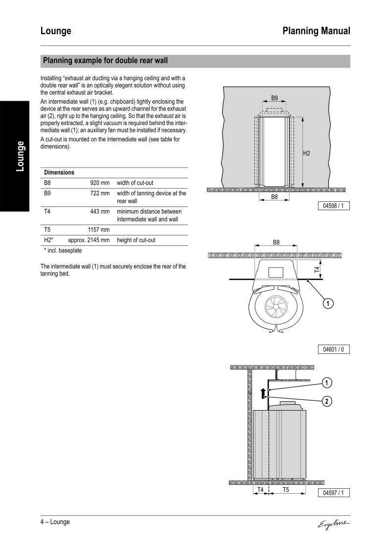
Lounge Planning Manual
4 – Lounge
Loun
ge
Installing “exhaust air ducting via a hanging ceiling and with a double rear wall” is an optically elegant solution without using the central exhaust air bracket.An intermediate wall (1) (e.g. chipboard) tightly enclosing the device at the rear serves as an upward channel for the exhaust air (2), right up to the hanging ceiling. So that the exhaust air is properly extracted, a slight vacuum is required behind the inter-mediate wall (1); an auxiliary fan must be installed if necessary.A cut-out is mounted on the intermediate wall (see table for dimensions).
The intermediate wall (1) must securely enclose the rear of the tanning bed.
Planning example for double rear wall
DimensionsB8 920 mm width of cut-outB9 722 mm width of tanning device at the
rear wallT4 443 mm minimum distance between
intermediate wall and wallT5 1157 mmH2* approx. 2145 mm height of cut-out* incl. baseplate
B8
B9
H2
04598 / 1
B8
T4
1
04601 / 0
2
1
T5T4 04597 / 1

Planning Manual Lounge
Lounge – 5
Loun
geCabin or studio air can be drawn in (supply air) along the edges of the door (1) in order to cool the outer doors. Air is drawn in through the openings in the rear of the doors to cool the inner doors.The inlet air is first cleaned in a filter, then fed past the hot UV low-pressure lamps and finally expelled as warm exhaust air (2).
Maximum exhaust pipe lengths
Calculation base (without additional ventilator):Back pressure 100 PascalAir pressure 100,000 PascalAir temperature 40 °CDensity 1.112 kg/m3
Dynamic inertia of the air 1.92E-05 Pa x s
Corrugated pipe∅
Roughness(at centre)kabsolute
Flow volume Loss coefficient 90° bend in line(metal)
Permissible length of
straight linemm mm m³/h of pipe of bend pieces m
300 8 2600 0.1821)
1) zeta value (ζ)
0.211)
0 101 8.52 7.53 6
Smooth pipe∅
Roughness(at centre)kabsolute
Flow volume Loss coefficient 90° bend in line(metal)
Permissible length of
straight linemm mm m³/h of pipe of bend pieces m
300 0.1 2600 0.0611) 0.211)
0 291 252 213 18
Equipment cooling
1
2
1
04504 / 1

Lounge Planning Manual
6 – Lounge
Loun
ge
A fan (3) is used to provide body cooling. Cabin or studio air will be drawn-in through the fan and routed past the person beneath it.The fan has 9 speeds.
Connection to a central exhaust system is possible upwards, upwards right, upwards left and to the rear.The apertures intended for this purpose are located on top of the comfort cabin.
Corrugated pipe
Suitable device exhaust is possible with an exhaust pipe up to 10 metres in length (with-out 90° bend). An auxiliary fan is required for exhaust pipes longer than 10 metres.
Smooth pipe
Suitable device exhaust is possible with an exhaust pipe up to 29 metres in length (with-out 90° bend). An auxiliary fan is required for exhaust pipes longer than 29 metres.The exhaust air bracket and warm air recycling can also be retrofitted.
Surround cooling
Exhaust air accessories
Item Accessory parts Article No. Notes1 90° Pipe bend in Techno Grey 3452110 For inlet and exhaust air ducting to right, left or to rear,
plus tube adapter for direct connection to central exhaust air bracket [possible with tube (∅ 300 mm)]
2 Corrugated pipe (∅ 300 mm, 6 m length, flexible, grey) including 2 pipe clamps
3450280 –
3 Corrugated pipe connector piece (∅ 300 mm)
3450270 For connecting two corrugated pipes
4 Connector bracket for corrugated pipe (∅ 300 mm)
3450360 Connection of the corrugated pipes, e.g. to a canal
5 Exhaust air adapter 3452850 –
3
04505 / 1
04506 / 0
32 214
5

Planning Manual Lounge
Lounge – 7
Loun
ge
M = plus surchargeA = Equipment variant, plus surcharge, retrofitting not possible
No air conditioner can be supplied with this device model.
Standard equipment: Access to the device data with a hand-held unit (Palm).
Electrical connections
Mains supply line noneElectr. control line noneLine for external music and channel selection none
Sound system
Artikel-Nr. BemerkungenAudio package A 3452720Loudspeaker set M 3452860
Controls
Control Article No. NotesMCS III plus hand-held remote control 3401060 With chip card terminalMCS IV plus 3401040 With electronic coin testerMCS VI 3400970 With electronic coin tester + chip card terminalStudiopilot 3400990 With electronic coin tester + chip card terminalStudio-Manager 3452900 Software
Air conditioner (not available)
IR Interface

Planning Manual Open Sun A.R.T. 600
Open Sun A.R.T. 600 – 1
Open
Sun
A.R
.T. 6
00
Super Power
Contents
Device descripition. . . . . . . . . . . . . . . . . . . . . . . . . . . 2
Technical Data. . . . . . . . . . . . . . . . . . . . . . . . . . . . . . . 2
Dimensions . . . . . . . . . . . . . . . . . . . . . . . . . . . . . . . . . 3
Maximum exhaust pipe length. . . . . . . . . . . . . . . . . . 4
Equipment cooling . . . . . . . . . . . . . . . . . . . . . . . . . . . 4
Surround cooling . . . . . . . . . . . . . . . . . . . . . . . . . . . . 5
Exhaust air accessories. . . . . . . . . . . . . . . . . . . . . . . 5
Electrical connections . . . . . . . . . . . . . . . . . . . . . . . . 6
Sound system . . . . . . . . . . . . . . . . . . . . . . . . . . . . . . . 6
Controls . . . . . . . . . . . . . . . . . . . . . . . . . . . . . . . . . . . . 6
Air conditioner (not available) . . . . . . . . . . . . . . . . . . 6
00006 / 2

Open Sun A.R.T. 600 Planning Manual
2 – Open Sun A.R.T. 600
Open
Sun
A.R
.T. 6
00
1. Front panel with inlet air aperture (air inlet for equipment cooling)
2. Feet end3. Acrylic glass panel lower part4. UV high pressure lamps (feet end)5. 2 Reflector banks (glass)6. Central exhaust air bracket (column)7. Reflector arm with surround air8. Control panel with display9. UV high-pressure lamps (head end)10. Head end
Device descripition
00017 / 1
9
9
2 1
3
4
5 76 8
10
Technical Data
Electrical dataNominal power consumption: 13300 WNominal voltage: 400 – 415 V ~3NNominal frequency: 50 HzRated fusing: 3 x 25 A (time-delay)Performance:
Canopy:UV low pressure lamps 17 x 100 WLower part:UV high pressure lamps in the upper body region 6 x 800 W
UV high pressure lamps in thefeet region 4 x 700 W
Noise emissionAcoustic pressure level: 62.3 db (A)Inlet and exhaust airTemperature difference, supply/exhaust air: 11 °C
Max. air requirement: 2500 m3/hOpt. ambient temperature: 25 °CMax. ambient temperature: 40 °CMax. inlet air temperature: 550 cm²Exhaust cross section w/o exhaust system: 4100 cm²
Cabin inlet air cross section490 cm²
(710 cm²) 1)
Warm air return: not possible1) when using a 300 mm pipe adapter (see Exhaust air accessories)

Planning Manual Open Sun A.R.T. 600
Open Sun A.R.T. 600 – 3
Open
Sun
A.R
.T. 6
00
Dimensions
B 1660 mmB1 850 mmB2 127 mmL 2332 mmL1 2100 mmL2 780 mmL3 1100 mmH 1600 mmH1 1780 mmH2 800 mmH3 470 mmH4 900 mmH5 1430 mmH6 700 mmH7 1910 mmH8 2370 mmH9 2496 mm∅ 250 mmBK 2400 mmTK 2500 mm
L1
B
H H1
LL2
H4 H2H3
L
B1
00036 / 2
BKTK
H7H5
H6
B2 L3
H8H9
00069 / 2

Open Sun A.R.T. 600 Planning Manual
4 – Open Sun A.R.T. 600
Open
Sun
A.R
.T. 6
00
Cabin or studio air (inlet air) is drawn in under the front panel (1) for cooling the device.The air is first cleaned in a filter, fed past the hot UV low-pressure and high-pressure lamps and finally expelled as warm exhaust air via the central exhaust air bracket (2).
Maximum exhaust pipe length
Calculation base (without additional ventilator):Back pressure 100 PascalAir pressure 100,000 PascalAir temperature 40 °CDensity 1.112 kg/m3
Dynamic inertia of the air 1.92E-05 Pa x s
Corrugated pipe∅
Roughness(at centre)kabsolute
Flow volume Loss coefficient 90° bend in line(metal)
Permissible length of
straight linemm mm m³/h of pipe of bend pieces m
250(300)1)
1) can be extended
8 2500 0.1822)
2) zeta value (ζ)
0.212)
0 121 102 83 6
Equipment cooling
00018 / 21
2

Planning Manual Open Sun A.R.T. 600
Open Sun A.R.T. 600 – 5
Open
Sun
A.R
.T. 6
00
Surround air is supplied to the user via an oscillating fan in the reflector arm (3). Cabin or studio air is drawn in via air inlet slots above the reflector arm and supplied to the user via outlet nozzles underneath the reflector arm. Infinite adjustment of the fan can be made manually at any time, to suit the user's com-fort requirements.
Connection to a central exhaust air system at the rear or upwards is possible.The apertures intended for this purpose are located above the central exhaust air bracket.Adequate ventilation of the equipment is possible up to an exhaust air pipe length of 12 meters (without 90° bend). For exhaust air pipe lengths greater than 12 meters, you will require an additional fan.
Surround cooling
Exhaust air accessories
Item Accessory parts Article No. Notes1 Central exhaust air bracket in blue, without
warm air recycling (∅ 250 mm)3452140 with tube adapter (see Item 6) connection to a corruga-
ted pipe of ∅ 300 mm is possible2 Connector bracket for corrugated pipe
(∅ 250 mm)3450350 Connection of the corrugated pipe, e.g. to a canal
3 Corrugated pipe (∅ 250 mm, 6 m length, flexible, grey) including 2 hose clips
3400580 –
4 Corrugated pipe connector piece (∅ 250 mm)
3400670 For connecting two pipes
5 90° tube bend in blue for exhaust air connec-tion, upwards
3452190 Installation angle can be offset by 45°
6 Tube adapter (∅ 250 mm to ∅ 300 mm) 3452200 –
02912 / 0
3
00026 / 1
2
3 4 3 5 6 5
1

Open Sun A.R.T. 600 Planning Manual
6 – Open Sun A.R.T. 600
Open
Sun
A.R
.T. 6
00
= as standard
No air conditioner can be supplied with this device model.
Electrical connections
Mains supply line providedElectr. control line noneLine for external music and channel selection approx. 3000 mm
Sound system
Article No. NotesAudio package – Audio unit with VoiceGuideLoudspeaker set –
Controls
Control Article No. NotesMCS III plus hand-held remote control 3401060 With chip card terminalMCS IV plus 3401040 With electronic coin testerMCS VI 3400970 With electronic coin tester + chip card terminalStudiopilot 3400990 With electronic coin tester + chip card terminalStudio-Manager 3452900 Software
Air conditioner (not available)

Planning Manual Open Sun A.R.T. 450
Open Sun A.R.T. 450 – 1
Open
Sun
A.R
.T. 4
50
Super Power
Contents
Device descripition. . . . . . . . . . . . . . . . . . . . . . . . . . . 2
Technical Data. . . . . . . . . . . . . . . . . . . . . . . . . . . . . . . 2
Dimensions . . . . . . . . . . . . . . . . . . . . . . . . . . . . . . . . . 3
Maximum exhaust pipe length. . . . . . . . . . . . . . . . . . 4
Equipment cooling . . . . . . . . . . . . . . . . . . . . . . . . . . . 4
Surround cooling . . . . . . . . . . . . . . . . . . . . . . . . . . . . 4
Exhaust air accessories. . . . . . . . . . . . . . . . . . . . . . . 5
Electrical connections . . . . . . . . . . . . . . . . . . . . . . . . 6
Sound system . . . . . . . . . . . . . . . . . . . . . . . . . . . . . . . 6
Controls . . . . . . . . . . . . . . . . . . . . . . . . . . . . . . . . . . . . 6
Air conditioner (not available) . . . . . . . . . . . . . . . . . . 6
02514 / 0

Open Sun A.R.T. 450 Planning Manual
2 – Open Sun A.R.T. 450
Open
Sun
A.R
.T. 4
50
1. Canopy with air inlet 2. Operating elements3. Decorative canopy4. Central exhaust nozzle (optional)5. Glass reflectors for the face tanner6. Sunbed base (component board, fan, etc.)7. Face tanner with protective goggles8. Accent lighting9. Front panel with air inlet10. Acrylic glass panel lower part11. Base12. Air nozzle (surround cooling, feet end)13. Side part14. Canopy
Device descripition
68
6
9
10
11
12
13
14
2 3 4
5
7
1
00076 / 1
Technical Data
Electrical dataNominal power consumption: 8300 WNominal voltage: 400 – 415 V ~3NNominal frequency: 50 HzRated fusing: 3 x 16 A (time-delay)Performance:
Canopy:UV low pressure lamps 18 x 100 WLower part:UV low pressure lamps 18 x 100 WUV high pressure lamps 2 x 600 WSide part:UV low pressure lamps 9 x 100 W
Noise emissionAcoustic pressure level: 63.2 db (A)Inlet and exhaust airTemperature difference, supply/exhaust air: 10 °C
Max. air requirement: 2100 m3/hOpt. ambient temperature: 25 °CMax. ambient temperature: 40 °CMax. inlet air temperature: 435 cm²Exhaust cross section w/o exhaust system: 4000 cm²
Cabin inlet air cross section 710 cm²Warm air return: not possible

Planning Manual Open Sun A.R.T. 450
Open Sun A.R.T. 450 – 3
Open
Sun
A.R
.T. 4
50
Dimensions
B 1310 mmB1 1075 mmB2 181 mmL 2270 mmL1 2160 mmL2 860 mmL3 867 mmL4 1330 mmH 1160 mmH1 1555 mmH2 720 mmH3 175 mmH4 620 mmH7 1475 mmH8 1555 mmH9 1780 mmH10 1930 mmX 1020 mmY 320 mmZ 1914 mm∅ 300 mmBK 2370 mmTK 2300 mm
B
L
Z
1005
L2
65
H3
H2
X
YH8 H
L
B1L1
H1
H4
00079 / 1
BK TK
H9
L4
L3
L4
H9
H7 H6
H8
oB2
00078 / 3

Open Sun A.R.T. 450 Planning Manual
4 – Open Sun A.R.T. 450
Open
Sun
A.R
.T. 4
50
Air is drawn in at the air inlet of the canopy (1) through a filter for cooling the device. The air is led past the warmed UV lamps and is exhausted to the outside through the central exhaust bracket (2) at the rear of the sunbed.
Because of the open construction in the region of the head, a foot ventilator is sufficient for cooling the whole body of the user. The foot ventilator is supplied with filtered ambient air through the air inlet above the front plate (3). The intensity of body cooling can be individually adjusted in 5 steps.
Maximum exhaust pipe length
Calculation base (without additional ventilator):Back pressure 100 PascalAir pressure 100,000 PascalAir temperature 40 °CDensity 1.112 kg/m3
Dynamic inertia of the air 1.92E-05 Pa x s
Corrugated pipe∅
Roughness(at centre)kabsolute
Flow volume Loss coefficient 90° bend in line(metal)
Permissible length of
straight linemm mm m³/h of pipe of bend pieces m
300 8 2150 0.1821)
1) zeta value (ζ)
0.211)
0 121 102 83 6
Equipment cooling
Surround cooling
2
1 00077 / 2
3 02911 / 0
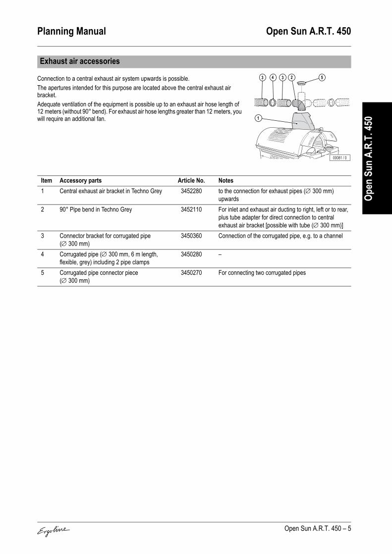
Planning Manual Open Sun A.R.T. 450
Open Sun A.R.T. 450 – 5
Open
Sun
A.R
.T. 4
50
Connection to a central exhaust air system upwards is possible.The apertures intended for this purpose are located above the central exhaust air bracket.Adequate ventilation of the equipment is possible up to an exhaust air hose length of 12 meters (without 90° bend). For exhaust air hose lengths greater than 12 meters, you will require an additional fan.
Exhaust air accessories
Item Accessory parts Article No. Notes1 Central exhaust air bracket in Techno Grey 3452280 to the connection for exhaust pipes (∅ 300 mm)
upwards2 90° Pipe bend in Techno Grey 3452110 For inlet and exhaust air ducting to right, left or to rear,
plus tube adapter for direct connection to central exhaust air bracket [possible with tube (∅ 300 mm)]
3 Connector bracket for corrugated pipe (∅ 300 mm)
3450360 Connection of the corrugated pipe, e.g. to a channel
4 Corrugated pipe (∅ 300 mm, 6 m length, flexible, grey) including 2 pipe clamps
3450280 –
5 Corrugated pipe connector piece (∅ 300 mm)
3450270 For connecting two corrugated pipes
1
4 33 2 5
00081 / 0

Open Sun A.R.T. 450 Planning Manual
6 – Open Sun A.R.T. 450
Open
Sun
A.R
.T. 4
50
M = plus surcharge
No air conditioner can be supplied with this device model.
Electrical connections
Mains supply line providedElectr. control line approx. 2000 mmLine for external music and channel selection approx. 3000 mm
Sound system
Article No. NotesAudio package M 3452270 Audio unit; volume control and channel selection switch
are integrated in the control cockpit(Consisting of control box without CD-ROM drive, installation instructions)
Loudspeaker set M 3452230
Controls
Control Article No. NotesMCS III plus hand-held remote control 3401060 With chip card terminalMCS IV plus 3401040 With electronic coin testerMCS VI 3400970 With electronic coin tester + chip card terminalStudiopilot 3400990 With electronic coin tester + chip card terminalStudio-Manager 3452900 Software
Air conditioner (not available)

Planning Manual Classic 300
Classic 300 – 1
Clas
sic 30
0
Super Power
Contents
Device descripition. . . . . . . . . . . . . . . . . . . . . . . . . . . 2
Technical Data. . . . . . . . . . . . . . . . . . . . . . . . . . . . . . . 2
Dimensions . . . . . . . . . . . . . . . . . . . . . . . . . . . . . . . . . 3
Maximum exhaust pipe length. . . . . . . . . . . . . . . . . . 3
Equipment cooling . . . . . . . . . . . . . . . . . . . . . . . . . . . 4
Surround cooling . . . . . . . . . . . . . . . . . . . . . . . . . . . . 4
Exhaust air accessories. . . . . . . . . . . . . . . . . . . . . . . 5
Electrical connections . . . . . . . . . . . . . . . . . . . . . . . . 5
Sound system . . . . . . . . . . . . . . . . . . . . . . . . . . . . . . . 5
Controls . . . . . . . . . . . . . . . . . . . . . . . . . . . . . . . . . . . . 6
Air conditioner (not available) . . . . . . . . . . . . . . . . . . 6
00001 / 2

Classic 300 Planning Manual
2 – Classic 300
Clas
sic 30
0
1. Sunbed base2. Inlet air (Air inlet for cooling the equipment)3. Feet end4. Central air outlet vent5. Acrylic glass panel lower part6. Surround fan (feet end)7. Sunbed canopy8. Face tanner (UV high-pressure lamps)9. Operating elements10. Surround fan (head end)
Device descripition
00009 / 1
4
9
6
5
3
10
1
2
2
7 8
Technical Data
Electrical dataNominal power consumption: 7000 WNominal voltage: 400 – 415 V ~3NNominal frequency: 50 HzRated fusing: 3 x 16 A (time-delay)Performance:
Canopy:UV low pressure lamps 23 x 100 WUV high pressure lamps 3 x 400 WLower part:UV low pressure lamps 15 x 100 W
Noise emissionAcoustic pressure level: 74.0 db (A)Inlet and exhaust airTemperature difference, supply/exhaust air: 15 °C
Max. air requirement: 950 m3/hOpt. ambient temperature: 25 °CMax. ambient temperature: 40 °CMax. inlet air temperature: 450 cm²Exhaust cross section w/o exhaust system: 1300 cm²
Cabin inlet air cross section 490 cm²Warm air return: not possible

Planning Manual Classic 300
Classic 300 – 3
Clas
sic 30
0
Dimensions
B 1023 mmB1 970 mmB2 730 mmL 2250 mmL1 1885 mmH 1010 mmH1 1250 mmX 970 mmY 420 mmZ 1885 mm∅ 250 mmBK 2300 mmTK 2000 mm
00032 / 2
L1L
BKTK
Z
B1
B
B2
X
H1H
Y
Maximum exhaust pipe length
Calculation base (without additional ventilator):Back pressure 100 PascalAir pressure 100,000 PascalAir temperature 40 °CDensity 1.112 kg/m3
Dynamic inertia of the air 1.92E-05 Pa x s
Corrugated pipe∅
Roughness(at centre)kabsolute
Flow volume Loss coefficient 90° bend in line(metal)
Permissible length of
straight linemm mm m³/h of pipe of bend pieces m
250 8 950 0.1821) 0.211)
0 81 62 43 2
1) zeta value (ζ)

Classic 300 Planning Manual
4 – Classic 300
Clas
sic 30
0
To cool the sunbed, cabin or studio air (inlet air) is drawn in at the head and feet ends of the sunbed base (1). The inlet air is first cleaned in a filter, then fed past the hot UV low-pressure and high-pressure lamps and finally expelled on the left or right as warm exhaust air via the central exhaust air bracket (2).
The surround air for the person using the sunbed is supplied via fans at the head end (4) and feet end (3) by means of an incremental control device. The cabin or studio air is drawn in via air inlet slots and supplied to the user via outlet nozzles.
Equipment cooling
Surround cooling
00010 / 1
2
1
1

Planning Manual Classic 300
Classic 300 – 5
Clas
sic 30
0
The appropriate corrugated pipe is 250 mm in diameter. With pipe lengths in excess of 4 meters, you will require an additional fan.The size of the additional fan depends on the overall length of the exhaust channel passage and the number of sunbeds connected. For further advice, please consult your ventilation technician!We offer various accessories that permit easier connection to a central exhaust system or to the individual device exhaust lines.
M = plus surchargeo = not available
Exhaust air accessories
Item Accessory parts Article No. Notes1 Central exhaust air bracket, galvanised steel
plate; length 952 mm, height 315 mm, depth 280 mm
3400570 Direct connection possibilities of a ∅ 250 mm circular corrugated pipe or a rectangular pipe with a cross sec-tion 320 x 270 mm. Connection is to the bottom right or bottom left - not to the top!
2 Central extraction adapter 3451640 Connection to the central exhaust air channel3 Corrugated pipe (∅ 250 mm, 6 m length, fle-
xible, grey) including 2 hose clips3400580 –
4 orrugated pipe connector piece (∅ 250 mm) 3400670 For connecting two corrugated pipes5 Connector bracket for corrugated pipe
(∅ 250 mm)3450350 Connection of the corrugated pipes, e.g. to a canal
Electrical connections
Mains supply line available
Electr. control line Connection made on external contact point of the sunbed
Line for external music and channel selection –
Sound system
Article No. NotesAudio package o –Loudspeaker set M 3460010
00022 / 1
32 4 5
1

Classic 300 Planning Manual
6 – Classic 300
Clas
sic 30
0
No air conditioner can be supplied with this device model.
Controls
Control Article No. NotesMCS III plus hand-held remote control 3401070 With chip card terminalMCS IV plus 3401050 With electronic coin testerMCS VI 3401020 With electronic coin tester + chip card terminalStudiopilot 3400990 With electronic coin tester + chip card terminalStudio-Manager 3452900 Software
Air conditioner (not available)

Planning Manual Classic 200
Classic 200 – 1
Clas
sic 20
0
Super Power
Contents
Device descripition. . . . . . . . . . . . . . . . . . . . . . . . . . . 2
Technical Data. . . . . . . . . . . . . . . . . . . . . . . . . . . . . . . 2
Dimensions . . . . . . . . . . . . . . . . . . . . . . . . . . . . . . . . . 3
Maximum exhaust pipe length. . . . . . . . . . . . . . . . . . 3
Equipment cooling . . . . . . . . . . . . . . . . . . . . . . . . . . . 4
Surround cooling . . . . . . . . . . . . . . . . . . . . . . . . . . . . 4
Exhaust air accessories. . . . . . . . . . . . . . . . . . . . . . . 5
Electrical connections . . . . . . . . . . . . . . . . . . . . . . . . 5
Sound system . . . . . . . . . . . . . . . . . . . . . . . . . . . . . . . 5
Controls . . . . . . . . . . . . . . . . . . . . . . . . . . . . . . . . . . . . 6
Air conditioner (not available) . . . . . . . . . . . . . . . . . . 6
00001 / 2

Classic 200 Planning Manual
2 – Classic 200
Clas
sic 20
0
1. Sunbed base2. Inlet air (Air inlet for cooling the equipment)3. Feet end4. Central air outlet vent5. Acrylic glass panel lower part6. Surround fan (feet end)7. Sunbed canopy8. Face tanner 9. (UV high-pressure lamps)10. Operating elements11. Surround fan (head end)
Device descripition
00009 / 1
4
9
6
5
3
10
1
2
2
7 8
Technical Data
Electrical dataNominal power consumption: 6200 WNominal voltage: 400 – 415 V ~3NNominal frequency: 50 HzRated fusing: 3 x 16 A (time-delay)Performance:
Canopy:UV low pressure lamps 17 x 100 WUV high pressure lamps 3 x 400 WLower part:UV low pressure lamps 15 x 100 W
Noise emissionAcoustic pressure level: 74.0 db (A)Inlet and exhaust airTemperature difference, supply/exhaust air: 15 °C
Max. air requirement: 950 m3/hOpt. ambient temperature: 25 °CMax. ambient temperature: 40 °CMax. inlet air temperature: 450 cm²Exhaust cross section w/o exhaust system: 1300 cm²
Cabin inlet air cross section 490 cm²Warm air return: not possible
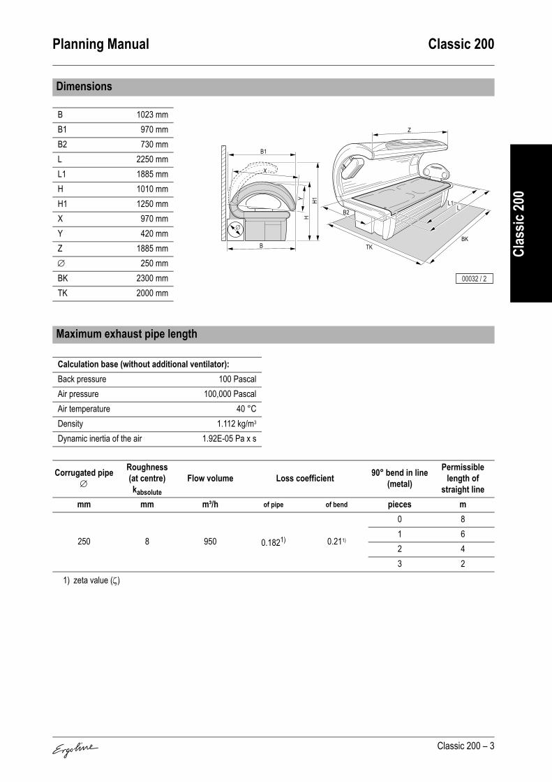
Planning Manual Classic 200
Classic 200 – 3
Clas
sic 20
0
Dimensions
B 1023 mmB1 970 mmB2 730 mmL 2250 mmL1 1885 mmH 1010 mmH1 1250 mmX 970 mmY 420 mmZ 1885 mm∅ 250 mmBK 2300 mmTK 2000 mm
00032 / 2
L1L
BKTK
Z
B1
B
B2
X
H1H
Y
Maximum exhaust pipe length
Calculation base (without additional ventilator):Back pressure 100 PascalAir pressure 100,000 PascalAir temperature 40 °CDensity 1.112 kg/m3
Dynamic inertia of the air 1.92E-05 Pa x s
Corrugated pipe∅
Roughness(at centre)kabsolute
Flow volume Loss coefficient 90° bend in line(metal)
Permissible length of
straight linemm mm m³/h of pipe of bend pieces m
250 8 950 0.1821) 0.211)
0 81 62 43 2
1) zeta value (ζ)

Classic 200 Planning Manual
4 – Classic 200
Clas
sic 20
0
To cool the sunbed, cabin or studio air (inlet air) is drawn in at the head and feet ends of the sunbed base (1). The inlet air is first cleaned in a filter, then fed past the hot UV low-pressure and high-pressure lamps and finally expelled on the left or right as warm exhaust air via the central exhaust air bracket (2).
The body air for the person using the sunbed is supplied via fans at the head end (4) and feet end (3) by means of an incremental control device.For this purpose the cabin or studio air is drawn in via air inlet slots and supplied to the user via outlet nozzles.
Equipment cooling
Surround cooling
00010 / 1
2
1
1

Planning Manual Classic 200
Classic 200 – 5
Clas
sic 20
0
The appropriate corrugated pipe is 250 mm in diameter. With pipe lengths in excess of 4 meters, you will require an additional fan. The size of the additional fan depends on the overall length of the exhaust channel pas-sage and the number of sunbeds connected. For further advice, please consult your ventilation technician!We offer various accessories that permit easier connection to a central exhaust system or to the individual device exhaust lines.
M = plus surchargeo = not available
Exhaust air accessories
Item Accessory parts Article No. Notes1 Central exhaust air bracket, galvanized steel
plate; length 952 mm, height 315 mm, depth 280 mm
3400570 Direct connection possibilities of a ∅ 250 mm circular corrugated pipe or a rectangular pipe with a cross sec-tion 320 x 270 mm. Connection is to the bottom right or bottom left - not to the top!
2 Central extraction adapter 3451640 Connection to the central exhaust air canal3 Corrugated pipe (∅ 250 mm, 6 m length, fle-
xible, grey) including 2 hose clips3400580 –
4 Corrugated pipe connector piece (∅ 250 mm)
3400670 For connecting two corrugated pipes
5 Connector bracket for corrugated pipe (∅ 250 mm)
3450350 Connection of the corrugated pipes, e.g. to a canal
Electrical connections
Mains supply line available
Electr. control line Connection made on external contact point of the sun-bed
Line for external music and channel selection –
Sound system
Article No. NotesAudio package o –Loudspeaker set M 3460010
00022 / 1
32 4 5
1

Classic 200 Planning Manual
6 – Classic 200
Clas
sic 20
0
No air conditioner can be supplied with this device model.
Controls
Control Article No. NotesMCS III plus hand-held remote control 3401070 With chip card terminalMCS IV plus 3401050 With electronic coin testerMCS VI 3401020 With electronic coin tester + chip card terminalStudiopilot 3400990 With electronic coin tester + chip card terminalStudio-Manager 3452900 Software
Air conditioner (not available)

Planning Manual Classic 8000 Ultra
Classic 8000 Ultra – 1
Clas
sic 80
00 U
ltra
Ultra
Contents
Device descripition. . . . . . . . . . . . . . . . . . . . . . . . . . . 2
Technical Data. . . . . . . . . . . . . . . . . . . . . . . . . . . . . . . 2
Dimensions . . . . . . . . . . . . . . . . . . . . . . . . . . . . . . . . . 3
Planning example . . . . . . . . . . . . . . . . . . . . . . . . . . . . 3
Equipment cooling . . . . . . . . . . . . . . . . . . . . . . . . . . . 4
Surround cooling . . . . . . . . . . . . . . . . . . . . . . . . . . . . 4
Exhaust air accessories. . . . . . . . . . . . . . . . . . . . . . . 4
Electrical connections . . . . . . . . . . . . . . . . . . . . . . . . 5
Sound system . . . . . . . . . . . . . . . . . . . . . . . . . . . . . . . 5
Controls . . . . . . . . . . . . . . . . . . . . . . . . . . . . . . . . . . . . 5
Air conditioner (not available) . . . . . . . . . . . . . . . . . . 5
00004 / 2

Classic 8000 Ultra Planning Manual
2 – Classic 8000 Ultra
Clas
sic 80
00 U
ltra
1. Sunbed base2. Adjustable footrest3. Ergonomic bucket seat4. Central air outlet vent5. Sunbed canopy (with UV high-pressure lamps and
surround air)6. Control panel
Device descripition
00013 / 3
1
2
3
4
5
6
Technical Data
Electrical dataNominal power consumption: 5500 WNominal voltage: 400 – 415 V ~3NNominal frequency: 50 HzRated fusing: 3 x 16 A (time-delay)Performance:
Canopy:Face tanner UV high pressure lamps 6 x 500 WHand tannerUV high pressure lamps 2 x 280 W
Noise emissionAcoustic pressure level: 57.5 db (A)Inlet and exhaust airTemperature difference, supply/exhaust air: 8 °C
Max. air requirement: 1200 m3/hOpt. ambient temperature: 25 °CMax. ambient temperature: 40 °CMax. inlet air temperature: 430 cm²Exhaust cross section w/o exhaust system: 2200 cm²
Cabin inlet air cross section not possible

Planning Manual Classic 8000 Ultra
Classic 8000 Ultra – 3
Clas
sic 80
00 U
ltra
A central air exhaust is only possible via a connection to a so-called double rear wall.This intermediate wall (2) with exhaust air connection (1) (e.g. chipboard) is designed to fit directly against the rear side of the sunbed and serves as a channel for the exhaust air upwards, if required up to a hanging ceiling.The corresponding dimensions of such a rear wall for cutting, as well as its positioning, can be taken from the Chapter “Di-mensions”. Warm air recycling to the studio air conditioning is not provided with this type of tanning equipment.1. Exhaust air connection2. Intermediate wall (e.g. pressed chip board)3. Connection for exhaust air hoseThe additional exhaust air connection is required as a neces-sary accessory in a double rear wall (see Chapter “Exhaust air accessories”).
Dimensions
B 1350 mmB1 1120 mmL 1710 mmH 1730 mmH1 2010 mmH2 1460 mmX 1200 mmY 500 mmZ 890 mm∅ 300 mmBK 2000 mmTK 2000 mm
B1B
H2H
H1
Y
L
Z
X
00034 / 4
min. 200
min.
300
10710
05
(814)
min. 18001080
623,5
40
390
922
1446 1528
00057 / 2
Planning example
3
1
2
300
00056 / 3

Classic 8000 Ultra Planning Manual
4 – Classic 8000 Ultra
Clas
sic 80
00 U
ltra
To cool the equipment, cabin or studio air is drawn in beneath the front panel (1) and at the front edge of the sunbed canopy (3) (inlet air).The air is first cleaned in a filter package, then fed past the hot UV high-pressure lamps and finally expelled as warm air via the exhaust air nozzles (2) at the rear of the sunbed.
Surround air is supplied to the user via an infinitely adjustable fan in the canopy (3) of the partial tanner.Cabin or studio air is drawn in via air inlet slots on the outside of the sunbed canopy (3) and then fed towards the face and upper body of the user via an asymmetrically ar-ranged, adjustable outlet nozzle.
Exhaust air can only be connected to a central exhaust air system via a double rear wall.
Equipment cooling
Surround cooling
Exhaust air accessories
Item Accessory parts Article No. Notes1 Exhaust air connection to connection on
double rear wall3451860 Without warm air recycling
00014 / 3
1
2
3
02909 / 1
3
00024 / 2
1

Planning Manual Classic 8000 Ultra
Classic 8000 Ultra – 5
Clas
sic 80
00 U
ltra
M = plus surcharge
No air conditioner can be supplied with this device model.
Electrical connections
Mains supply line ProvidedElectr. control line approx. 1000 mmLine for external music and channel selection approx. 500 mm
Sound system
Article No. NotesAudio package M 3452050 Audio unit; volume control and channel selection switch
are integrated in the control cockpitLoudspeaker set –
Controls
Control Article No. NotesMCS III plus hand-held remote control 3401060 With chip card terminalMCS IV plus 3401040 With electronic coin testerMCS VI 3400970 With electronic coin tester + chip card terminalStudiopilot 3400990 With electronic coin tester + chip card terminalStudio-Manager 3452900 Software
Air conditioner (not available)

Planning Manual Planning inlet air and exhaust air
Planning inlet air and exhaust air – 1
Plan
ning
inlet
air a
nd …
Contents
Planning requirements. . . . . . . . . . . . . . . . . . . . . . . . 2Inlet and exhaust connection with and without double rear wall . . . . . . . . . . . . . . . . . . . . . . . . . . . . . . . . . . . . . 3Inlet and exhaust air connection via a hanging studio ceiling with a separate exhaust air ducting . . . . . . . . . . 5Inlet and exhaust air connection via a hanging studio ceiling without an exhaust air ducting system . . . . . . . . 6

Planning inlet air and exhaust air Planning Manual
2 – Planning inlet air and exhaust air
Plan
ning
inlet
air a
nd …
Points that you must observe when planning inlet air and exhaust air ducting in the studio.
When planning ventilation in the studio, you must ensure that the required air throughput for each piece of equipment is con-stant over the entire tube or hose system and is not reduced by obstructions. To support the flow of exhaust air throughput, it may be neces-sary to take an additional fan in the system into account, if ap-plicable (see calculation example for design of additional fan).The inlet air temperature must not exceed 40 °C. Tempera-tures in excess of 40 °C could impede the operation of the sunbed.Additional filtering of the inlet air is especially recommended.There are 3 possible inlet and exhaust air assembly variants for Ergoline sunbeds. The following planning examples can be ap-plied to all Ergoline sunbeds contained in the sunbed range presented in this Planning Manual. Additional information is a given in the respective device descriptions for devices that make special requirements on installation.
When fitted with the correct central bracket for inlet and ex-haust air, Ergoline sunbeds can also be operated with a free air outlet, i.e. without being connected to a ventilation system in the studio. Installing “exhaust air ducting via a suspended ceiling and with a double rear wall” is an optically elegant solution without using the central exhaust air bracket. If you want to use hot air recirculation in conjunction with an ex-haust duct, the exhaust duct cannot be routed above a sus-pended ceiling.
Planning requirements
Caution!
Before putting a tanning device into operation, the transport pallet must be removed from under the tan-ning unit. Installation on the transport pallet may result in damage to the device due to obstruction of the air routing.

Planning Manual Planning inlet air and exhaust air
Planning inlet air and exhaust air – 3
Plan
ning
inlet
air a
nd …
Inlet and exhaust connection with and without double rear wall
With double rear wall
Without exhaust-air adapter: An intermediate wall (1) (e.g. chipboard) tightly enclosing the sunbed at the rear serves as an upward channel for the exhaust air (2), if required right up to the hanging ceiling. So that the exhaust air is properly ex-tracted, a slight vacuum is required behind the intermediate wall (1); an auxiliary fan must be installed if necessary.This installation variant is used mostly for single devices.
With exhaust air adapter: A cut-out is mounted on the inter-mediate wall. A rubber profile on the exhaust-air adapter (3) ensures an air-tight seal on the intermediate wall.
03579 / 0
1
2
03834 / 0
2
3
1

Planning inlet air and exhaust air Planning Manual
4 – Planning inlet air and exhaust air
Plan
ning
inlet
air a
nd …
Variant A, transverse ventilation:
The equipment exhaust air (2) is fed upwards through the exhaust air channel (space behind the double rear wall, approx. 15 cm) underneath the studio ceiling and is expelled there through opposing exhaust air openings.
Variant B, direct exhaust air:The equipment exhaust air (2) is channelled directly outside through the exterior wall.
02872 / 0
02873 / 0

Planning Manual Planning inlet air and exhaust air
Planning inlet air and exhaust air – 5
Plan
ning
inlet
air a
nd …
Inlet and exhaust air connection via a hanging studio ceiling with a separate exhaust air ducting
To utilise all the benefits of the innovative ventilation concept of Ergoline sunbeds and to prevent the unnecessary heating of the studio, we recommend that the inlet air for cooling the air conditioning units be supplied from outside via a filtered (as air-tight as possible) hanging ceiling and that the exhaust air be ex-pelled to the outside via a separate hose or duct system.
Exhaust air connection is made using a separate, heat-insula-ted ducting system (1) inside a hanging studio ceiling. The space in between the room ceiling and the hanging ceiling ser-ves as a channelling space for the equipment inlet air.
02875 / 0
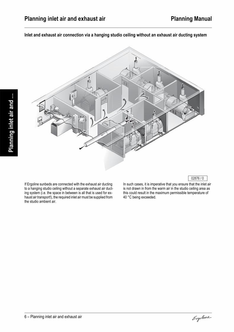
Planning inlet air and exhaust air Planning Manual
6 – Planning inlet air and exhaust air
Plan
ning
inlet
air a
nd …
Inlet and exhaust air connection via a hanging studio ceiling without an exhaust air ducting system
If Ergoline sunbeds are connected with the exhaust air ducting to a hanging studio ceiling without a separate exhaust air duct-ing system (i.e. the space in between is all that is used for ex-haust air transport!), the required inlet air must be supplied from the studio ambient air.
In such cases, it is imperative that you ensure that the inlet air is not drawn in from the warm air in the studio ceiling area as this could result in the maximum permissible temperature of 40 °C being exceeded.
02876 / 0

Planning Manual Controls
Controls – 1
Cont
rols
Contents
Connection options . . . . . . . . . . . . . . . . . . . . . . . . . . 2
Connection to Compatible Time Control Devices (Open Sun, Classic) . . . . . . . . . . . . . . . . . . . . . . . . . . 3
Connection to Compatible Time Control Devices (Excellence, Evolution, Advantage, Ambition, Lounge) . . . . . . . . . . . . . . . . . . . . . . . . . . . . . . . . . . . . 3
Connection to Ergoline Coin Boxes (Open Sun, Classic) . . . . . . . . . . . . . . . . . . . . . . . . . . . . . . . . . . . . 4
Connection to Ergoline Coin Boxes (Excellence, Evolution, Advantage, Ambition, Lounge) . . . . . . . . 5

Controls Planning Manual
2 – Controls
Cont
rols
The Ergoline sunbeds can be connected either to a remote control or a coin box. It is also possible to connect them to time controls from other suppliers.
Depending on the sunbed, some change-overs will be neces-sary for connection to the various control devices. For further information on this subject, please refer to the descriptions of the respective sunbeds.
Connection options
Caution!
• The device operating time must be dual controlled with a timing device to the standards EN 60335-2-27 and A1 2000 Section 22.108 and 22.109.
• In the case of failure of the controls, it must be en-sured that the sunbed is automatically switched off at the most after <110% of the selected tanning time.
• If a timer with a longer running time is used, this can result in injuries to the skin, and in the long run in skin disease.

Planning Manual Controls
Controls – 3
Cont
rols
When connecting a compatible time control, the voltage must be supplied from the sunbed.The sunbed must only be operated with timer control, 30 minu-tes max. running time. The control scale on the timer must match the time recommended in the tanning program.
Legend:
1. Coin device without microprocessor2. Flexible control line H 05 VV - F 7 G 1.53. Socket4. Installed control line NYM 7 x 1.5 mm²5. Plug (Art. No. 70010440 / Part No. 10440)
The wiring is connected directly to the connection terminals of the sunbed.When connecting a compatible time control, the voltage must be supplied from the sunbed.The sunbed must only be operated with timer control, 30 min-utes max. running time. The control scale on the timer must match the time recommended in the tanning program.
Legend:
1. Coin device without microprocessor2. Flexible control line H 05 VV - F 7 G 1.53. Socket4. Installed control line NYM 7 x 1.5 mm²5. Plug (Art. No. 70010440 / Part No. 10440)
Connection to Compatible Time Control Devices (Open Sun, Classic)
2
1
24
3
5
01588 / 1
Connection to Compatible Time Control Devices (Excellence, Evolution, Advantage, Ambition, Lounge)
2
1
54
3
03584 / 0

Controls Planning Manual
4 – Controls
Cont
rols
Should the service cable for the coin device with microproces-sor be extended, a flexible and shielded control line (8 x 0.5 mm² Art. No. 70060740 / Part No. 60740) should be laid.For further information for installation of coin devices and accessories that can be supplied, please refer to the individual device descriptions.
Legend:
1. Coin device with microprocessor2. Plug (Art. No. 70010683 / Part No. 10683)3. Tanning device4. Parts support (controller)
Connection to Ergoline Coin Boxes (Open Sun, Classic)
1
24
3
03588 / 0

Planning Manual Controls
Controls – 5
Cont
rols
The plug (3) on the coin device (1) must be removed if necessary. The control cable (2) is connected direct-ly to the connection strip (5) of the sunbed. The red and the black wires (4) are to be insulated individually.Should the service cable for the coin device with microprocessor be extended, a flexible and shielded control line (8 x 0.5 mm² Art. No. 70060740 / Part No. 60740) should be laid.For further information for installation of coin devices and accessories that can be supplied, please refer to the individual device descriptions.
Legend:
1. Coin device with microprocessor2. Flexible, shielded control cable (10 m) included as
standard equipment3. Plug4. Wires to be insulated (red and black)5. Connection strip in sunbed
Wires:
Connection to Ergoline Coin Boxes (Excellence, Evolution, Advantage, Ambition, Lounge)
sw – blackgn – greenbr – brownrt – redge – yellowor – orangeab – shielding
COM
CH1
CH2
CH3
CH4
A-L
GNDL
GNDR
A-R
24AC
OAC
OAC
PE Tr Tr STR1
STR2
STR3
STR4
PE N N 230V
Z-L
Z-L
01 02 03 04 05 06 07 08 09 10 11 12 13 14 15 16 17 18 19 20 21 22 23 24 25
or ge (ab) gn br
LI N B5 T6 T8T7
(ab)or ge rt br gn sw
3
21
5
4
03470 / 1

Planning Manual Hand-held remote control MCS III plus
Hand-held remote control MCS III plus – 1
MCS
III pl
us
The circuit board performance MCS is the interface between the hand-held remote control and the professional sunbed devices from Ergoline without inherent electronics (Ergoline 200/300, Classic 200/300).
Article No.: 3401060without performance circuit board
Article No.: 3401070with performance circuit board*
Contents
Device descripition. . . . . . . . . . . . . . . . . . . . . . . . . . . 2
Technical Data. . . . . . . . . . . . . . . . . . . . . . . . . . . . . . . 2
Accessories. . . . . . . . . . . . . . . . . . . . . . . . . . . . . . . . . 2Accessories supplied . . . . . . . . . . . . . . . . . . . . . . . . . . . 2
Connection diagram for Open Sun, Classic. . . . . . . 3
Connection diagram for Excellence, Evolution, Advantage, Ambition, Lounge. . . . . . . . . . . . . . . . . . 3
03597 / 0
)
*)

Hand-held remote control MCS III plus Planning Manual
2 – Hand-held remote control MCS III plus
MCS
III pl
us
1. Display2. Operating keys3. Chip card slot
Dual safety cutout switch to standards EN 60335-2-27 and A1 2000 sections 22.108 and 22.109
Accessories supplied
Device descripition
Technical Data
Equipment: Relay control for connection to a sunbed, with chip card readerOperating voltage: Supply from the respective sunbed with a 7-pole plug / direct connectionColour: Techno GreyMax. ambient temperature: 0 to 40 °CMax. relative air moisture content: 70 %Max. storage temperature: 0 to 50 °CDimensions [mm]:
width x height x depth 100 x 180 x 36
Accessories
Accessories Article / Part No. NotesMaster Card (1 piece) –Control line (5 m) Connector plug (extra-low voltage)
2
3
1
04178 / 0

Planning Manual Hand-held remote control MCS III plus
Hand-held remote control MCS III plus – 3
MCS
III pl
us
Legend:
1. Remote control with microprocessor2. Plug3. Sunbed4. Parts support (controller)
Connection diagram for Open Sun, Classic
Caution!The green/black plug may only be used on the Ergo-line hand-held remote control. 2
4
3
1
04162 / 0

Hand-held remote control MCS III plus Planning Manual
4 – Hand-held remote control MCS III plus
MCS
III pl
us
The plug on the hand-held remote con-trol (1) must be re-moved. The control cable (2) is connected directly to the con-nection strip (3) of the sunbed. The white wire is to be insulated.
Legend:
1. Hand-held remote control with micro-processor2. Connection cable (control line)3. Bridge4. Connection strip in sunbed
Wires:
Connection diagram for Excellence, Evolution, Advantage, Ambition, Lounge
1 – pink2 – yellow3 – white4 – brown5 – green6 – green-yellow
1
12
3 45
6
1
2
2
04161 / 0
1 2 6 5 4
12
3 45
6
2
3
4
04160 / 0

Planning Manual ICS Individual Cash System
ICS Individual Cash System – 1
ICS
unit
For automatic power systems, the ICS unit is the chip card ter-minal for a fair and comprehensible calculation: It calculates in-dividually the credits to be deducted for the tanning perform-ance determined personally.The ICS should preferably be installed in a cabin for controlling an APS tanning system, but it can also be added to universal control systems in a databus.
Contents
Device descripition. . . . . . . . . . . . . . . . . . . . . . . . . . . 2
Technical Data. . . . . . . . . . . . . . . . . . . . . . . . . . . . . . . 2
ICS unit functions . . . . . . . . . . . . . . . . . . . . . . . . . . . . 2
Accessories. . . . . . . . . . . . . . . . . . . . . . . . . . . . . . . . . 3Accessories Supplied . . . . . . . . . . . . . . . . . . . . . . . . . . . 3Accessories (plus surcharge) . . . . . . . . . . . . . . . . . . . . . 3Accessories from the dealership . . . . . . . . . . . . . . . . . . 3
Dimensions and mounting. . . . . . . . . . . . . . . . . . . . . 4Dimensions of ICS . . . . . . . . . . . . . . . . . . . . . . . . . . . . . 4Assembly variations . . . . . . . . . . . . . . . . . . . . . . . . . . . . 4
Connection diagram . . . . . . . . . . . . . . . . . . . . . . . . . . 6
06467 / 0

ICS Individual Cash System Planning Manual
2 – ICS Individual Cash System
ICS
unit
1. Display2. Buttons input confirmation (OK) and abort (Stop)3. Adjust buttons (+/-)4. Chip card entry1)
Not shown: Connection lines
Dual safety cutout switch to standards EN 60335-2-27 and A1 2000 sections 22.108 and 22.109
1) Chip card (customer)Studio card (Studio personnel)Master card (Studio operator)
Please consult the sale documents for additional information on the functions provided by the ICS unit.
Control unit for APS tanning systems• Operation by the client using chip card payment• Controls APS tanning systems in “Time”or “Dose” mode• Databus capable• Direct control of a tanning system possible• Installation preferably in the cabin
Counter terminal (loading station for chip cards at the counter)• For direct loading and reading of chip cards by studio staff• No tanning system control• Installation without a databus connection at the counter possible• Databus capable
Device descripition
Technical Data
Equipment: Supply over external power supplyOperating voltage: 24 V ACColour: Light silver mattMax. ambient temperature: 0 to 40 °CMax. relative air moisture content: 70 %Max. storage temperature: 0 to 50 °CConnections for external devices: noneDimensions [mm]:
width x height x depth 132 x 200 x 122Weight: 2.5 kg
ICS unit functions
3
4 1
2 06468 / 0

Planning Manual ICS Individual Cash System
ICS Individual Cash System – 3
ICS
unit
Accessories Supplied
Accessories (plus surcharge)
Accessories from the dealership
Accessories
Accessories Part no. NotesMaster card (1 unit) –Studio card (1 unit) TN 11673Operating instructions TN 834678Assembly instructions/drilling template TN 8427235 m lead TN 61439 Direct connection without plugPower supply unit TN 12180
Accessories Article no. NotesMaster card (Information and service card) – Only one card required per studio.
If the Master card is lost, please contact Customer Service.Studio card 3401010 10 Pieces (Personnel card)Chip cards with printed matter 3400950 100 Pieces per unitChip cards with printed matter 3452470 400 Pieces per unitChip cards without printed matter 3800050 100 Pieces per unitTanner interface 2 3452910TV interface 3452380Control line 3451040 per 100 metresExtension for connecting line 3400610 8 x 0.56 mm2 per running meter
Accessories Article no. Notes
Cable duct, e.g. LF, halogen-free – Manufacturer: Tehalitwww.tehalit.com

ICS Individual Cash System Planning Manual
4 – ICS Individual Cash System
ICS
unit
Dimensions of ICSH: 200 mmB: 132 mmT: 122 mm
Assembly variationsThe system must be assembled only on a solid wall. Consult the assembly instructions for detailed information (Order no. 842723).
Assembly variations: On the wall, cable bushing through the wall
When assembling on the wall, please allow for the correspon-ding cable bushing:
Dimensions and mounting
B
T
H
900 mm
06636 / 0
Note!
As a power supply unit is used, a socket in the immediate vicinity is necessary. Power supplied via the tanning system is not allowed!
06472 / 0
2570
52
900
mm
06635 / 0

Planning Manual ICS Individual Cash System
ICS Individual Cash System – 5
ICS
unit
Assembly variations: On the wall, cable bushing on the plaster
No cable bushing is necessary in this case. We recommend covering the cable with a cable duct.
06605 / 0

ICS Individual Cash System Planning Manual
6 – ICS Individual Cash System
ICS
unit
The ICS unit is usually connected directly to a tanning system, but it can also be operated in a network alongside other coin systems or studio pilots.
Connection requirements:The ICS unit can only be connected in conjunction with tanner interface 2. Tanner interface 1 is not compatible.Please consult the assembly instructions which accompany the ICS unit for details.
Connection as control unit – terminal unit (in a databus or connected directly to the tanning system):The connection is made through the X3 terminal on the connec-tion strip in the tanning system.
Connection as control unit in a databus – not as terminal unit:For other modes of connection, refer to the wiring diagram on the control box or ask the Customer Service department for in-formation.
Connection as counter terminal
The ICS unit is either incorporated into a databus: Connection is the same as connection as a control unit. Or the ICS unit is operated in isolation without a tanning system: In this case, no connection is made.
Connection diagram
230 V AC
X3STR1STR2
24 V AC
06637 / 0
Note!
If it is used as a counter terminal in a databus, you must set a cabin number in the ICS which is unoccupied (see operating instructions for the ICS unit).

Planning Manual Coin device MCS IV plus
Coin device MCS IV plus – 1
MCS
IV p
lus
The circuit board performance MCS is the interface between the hand-held remote control and the professional sunbed de-vices from Ergoline without inherent electronics (Ergoline 200/300, Classic 200/300).
Article No.: 3401040without performance circuit board
Article No.: 3401050with performance circuit board*
Contents
Device descripition. . . . . . . . . . . . . . . . . . . . . . . . . . . 2
Technical Data. . . . . . . . . . . . . . . . . . . . . . . . . . . . . . . 2
Dimensions . . . . . . . . . . . . . . . . . . . . . . . . . . . . . . . . . 3
Accessories. . . . . . . . . . . . . . . . . . . . . . . . . . . . . . . . . 3Accessories supplied . . . . . . . . . . . . . . . . . . . . . . . . . . . 3Accessories (plus surcharge) . . . . . . . . . . . . . . . . . . . . . 3
Installation Dimensions . . . . . . . . . . . . . . . . . . . . . . . 4
Connection diagram for Open Sun, Classic. . . . . . . 5
Connection diagram for Excellence, Evolution, Advantage, Ambition, Lounge. . . . . . . . . . . . . . . . . . 5
02920 / 0
)
*)

Coin device MCS IV plus Planning Manual
2 – Coin device MCS IV plus
MCS
IV p
lus
1) 0.5, 1 and 2 Euro coins; tokens (27 mm brass tokens)
Not shown: Mains supply line
Dual safety cutout switch to standards EN 60335-2-27 and A1 2000 sections 22.108 and 22.109
Device descripition1. Housing lock; simultaneous switching
from operation to the menus (info, service, config.)
2. Control panel3. Time display (remaining time)4. Text display5a Button input confirmation (T3)5b Button abort (T4)6a Adjust button - (T1)6b Adjust button + (T2)7. Coin box8. Coin box lock9. Coin return slot10. Coin return button11. Coin insert1)
12. Chip card slot w/o function
Technical Data
Equipment: with electronic coin testerModel: Relay control for connection to a sunbedAssembly/Positioning: Wall-mounting/flush-mountingCoin box removal: Lockable coin box at device or central connection by means of coin tube
Note!When a coin tube is connected, the tube for catching the coins must be led through the rear wall of the coin drawer. Rated break points are predetermined (see installation instructions Part No. 86866).
Operating voltage: Supply from the respective sunbed with a 9-pole plugColour: Light silver mattMax. ambient temperature: 0 to 40 °CMax. relative air moisture content: 70 %Max. storage temperature: 0 to 50 °C
1
8
7
9
10
11
12
5a 5b6a 6b 02679 / 0
32
4

Planning Manual Coin device MCS IV plus
Coin device MCS IV plus – 3
MCS
IV p
lus
0
Accessories supplied
Accessories (plus surcharge)
Dimensions
Height H [mm] 475Width B [mm] 165Depth T [mm] 162
HK [mm] 480Space requirement TK [mm] 170Connection control line AWeight (without coins) [kg] 7.4
Accessories
Accessories Article / Part No. Notes2 Keys for the housing –2 Keys for the coin box –Drilling template 86820Operating instructions 800068Installation instructions 86866Mains supply line 61439
Accessories Article / Part No. NotesBrass tokens for coin devices 3400530 50 Pieces per unitExtension for connecting line 3400610 8 x 0.5 mm2 per running meterPlug and socket part 3400540 For connecting the extension lead to the connecting line.Coin tube 3401030 For connecting to a central coin collecting box.Special accessories 3452340 For connecting the coin device to tanning devices of other
manufacturers.
H
T
HK
B A
TK
02921 / 0

Coin device MCS IV plus Planning Manual
4 – Coin device MCS IV plus
MCS
IV p
lus
You can choose between the following installation variants:
Installation variation Against the wall
The installation of the box must only be undertaken against a solid (e.g. brick) wall. Detailed information can be found in the installation instructions (Part No. 86866).When installing against the wall, please make sure that a corresponding cable feed is available.
Installation variation Tanning device
See Ergoline „Lounge“.
Installation variation In the wall
The maximum built-in depth T1 is 55 mm. When installing, ensure that there is a stable backing. Detailed information can be found in the installation instructions (Part No. 86866).
Installation variation In the tower
Further information can be found in the description of the tower.
Installation Dimensions
1. Cable feed in the wall2. Cable feed in the rear wall of the coin
housingH1 35 mmH2 38 mm
02855 / 0
T1
02507 / 0
T1
02507 / 0
21H2
H1
00082 / 1

Planning Manual Coin device MCS IV plus
Coin device MCS IV plus – 5
MCS
IV p
lus
Legend:
1. Coin device with microprocessor2. Plug (Art. No. 70010683 / Part
No. 10683)3. Sunbed4. Parts support (controller))
The plug (3) on the coin device (1) must be removed if necessary. The control cable (2) is connected directly to the connection strip (5) of the sunbed. The red and the black wires (4) are to be insulated individually.
Legend:
1. Coin device with microprocessor2. Flexible, shielded control cable
(10 m) included as standard equipment
3. Plug4. Wires to be insulated (red and
black)5. Connection strip in sunbed
Wires:
Connection diagram for Open Sun, Classic
Connection diagram for Excellence, Evolution, Advantage, Ambition, Lounge
sw – blackgn – greenbr – brownrt – redge – yellowor – orangeab – shielding
1
24
3
03588 / 0
COM
CH1
CH2
CH3
CH4
A-L
GNDL
GNDR
A-R
24AC
OAC
OAC
PE Tr Tr STR1
STR2
STR3
STR4
PE N N 230V
Z-L
Z-L
01 02 03 04 05 06 07 08 09 10 11 12 13 14 15 16 17 18 19 20 21 22 23 24 25
or ge (ab) gn br
LI N B5 T6 T8T7
(ab)or ge rt br gn sw
3
21
5
4
03470 / 1

Planning Manual Coin device MCS VI
Coin device MCS VI – 1
MCS
VI
The circuit board performance MCS is the interface between the hand-held remote control and the professional sunbed de-vices from Ergoline without inherent electronics (Ergoline 200/300, Classic 200/300).
Article No.: 3400970without performance circuit board
Article No.: 3401020with performance circuit board*
Contents
Device descripition. . . . . . . . . . . . . . . . . . . . . . . . . . . 2
Technical Data. . . . . . . . . . . . . . . . . . . . . . . . . . . . . . . 2
Dimensions . . . . . . . . . . . . . . . . . . . . . . . . . . . . . . . . . 3
Accessories. . . . . . . . . . . . . . . . . . . . . . . . . . . . . . . . . 3Accessories supplied . . . . . . . . . . . . . . . . . . . . . . . . . . . 3Accessories (plus surcharge) . . . . . . . . . . . . . . . . . . . . . 3Accessories commercially available. . . . . . . . . . . . . . . . 4
Installation Dimensions . . . . . . . . . . . . . . . . . . . . . . . 4
Connection diagram for Open Sun, Classic. . . . . . . 5
Connection diagram for Excellence, Evolution, Advantage, Ambition, Lounge. . . . . . . . . . . . . . . . . . 5
02920 / 0
*)
)

Coin device MCS VI Planning Manual
2 – Coin device MCS VI
MCS
VI
1. Housing lock2. Control panel3. Time display (remaining time)4. Text display5. Buttons input confirmation (OK) and abort
(Stop)6. Adjust buttons (+/-)7. Coin box8. Coin box lock9. Coin return slot10. Coin return button11. Coin insert1)
12. Chip card entry2)
Not shown: Mains supply line
1) 0.5, 1 and 2 Euro coins; tokens (27 mm brass tokens)
2) For Chip Card (customer)Studio Card (Studio personnel) Master Card (Studio operator)
Dual safety cutout switch to standardsEN 60335-2-27 and A1 2000 sections 22.108 and 22.109
Device descripition
Technical Data
Equipment: with electronic coin tester and chip card terminalModel: Relay control for connection to a sunbedexternal connections: Serial printer interfaceAssembly/Positioning: Wall-mounting/flush-mountingCoin box removal: Lockable coin box at device or central connection by means of coin tube
Note!When a coin tube is connected, the tube for catching the coins must be led through the rear wall of the coin drawer. Rated break points are predetermined (see installation instructions Part No. 86866).
Operating voltage: Supply from the respective sunbed with a 9-pole plugColour: Light silver mattMax. ambient temperature: 0 to 40 °CMax. relative air moisture content: 70 %Max. storage temperature: 0 to 50 °C
1
8
7
9
10
11
12
6 5 02502 / 0
32
4

Planning Manual Coin device MCS VI
Coin device MCS VI – 3
MCS
VI
0
Accessories supplied
Accessories (plus surcharge)
Dimensions
Height H [mm] 475Width B [mm] 165Depth T [mm] 162
HK [mm] 480Space requirement TK [mm] 170Connection control line AWeight (without coins) [kg] 7.4
Accessories
Accessories Article / Part No. Notes2 Keys for the housing –2 Keys for the coin box –Master Card (1 piece) –Studio Card (1 piece) 11673Drilling template 86820Operating instructions 86821Installation instructions 86866Mains supply line 61439
Accessories Article / Part No. Notes
Master Card (Info- and Service Card) – Only one card required per studio.If the Master Card is lost, please contact Customer Service.
Studio Card 3401010 10 Pieces per unitBrass tokens for coin devices 3400530 50 Pieces per unitChip Cards with printed matter 3400950 100 Pieces per unitChip Cards with printed matter 3452470 400 Pieces per unitChip Cards without printed matter 3800050 100 Pieces per unitExtension for connecting line 3400610 8 x 0.5 mm2, per running meterPlug and socket part 3400540 For connecting the extension lead to the connecting lineCoin tube 3401030 For connecting to a central coin collecting boxSpecial accessories 3452340 For connecting the coin device to tanning devices of other
manufacturers.
HT
HK
B A
TK
02921 / 0

Coin device MCS VI Planning Manual
4 – Coin device MCS VI
MCS
VI
Accessories commercially available
You can choose between the following installation variants:
Installation variation Against the wall
The installation of the box must only be undertaken against a solid (e.g. brick) wall. Detailed information can be found in the installation instructions (Part No. 86866).When installing against the wall, please make sure that a corresponding cable feed is available.
Installation variation Tanning device
See Ergoline „Lounge“.
Installation variation In the wall
The maximum built-in depth T1 is 55 mm. When installing, ensure that there is a stable backing. Detailed information can be found in the installation instructions (Part No. 86866).
Installation variation In the tower
Further information can be found in the description of the tower.
If you wish to print out working, daily and total data, a receipt printer can be connected to the coin device.A suitable printer, for instance is the Epson type LX-300+ (with serial interface or a fully compatible device.The printed must be adjusted to the settings given in the table for the coin device. Information of the printer settings can be found in the operating instructions for the printer.
Settings of the coin device interfaceFunction Setting
Input buffer size ≥ 1000 ByteWord size 8 bitParity noneBaudrate 19200 BaudSoftware ESC/P
Installation Dimensions
1. Cable feed in the wall2. Cable feed in the rear wall of the coin
housingH1 35 mmH2 38 mm
02855 / 0
T1
02507 / 0 02856 / 0
21
H2
H1
00082 / 1

Planning Manual Coin device MCS VI
Coin device MCS VI – 5
MCS
VI
Legend:
1. Coin device with microprocessor2. Plug (Art. No. 70010683 / 3. Part No. 10683)4. Sunbed5. Parts support (controller)
The plug (3) on the coin device (1) must be removed if necessary. The control cable (2) is connected directly to the connection strip (5) of the sunbed. The red and the black wires (4) are to be insulated individually.
Legend:
1. Coin device with microprocessor2. Flexible, shielded control cable
(10 m) included as standard equipment
3. Plug4. Wires to be insulated (red and
black)5. Connection strip in sunbed
Wires:
Connection diagram for Open Sun, Classic
Connection diagram for Excellence, Evolution, Advantage, Ambition, Lounge
sw – blackgn – greenbr – brownrt – redge – yellowor – orangeab – shielded
1
24
3
03588 / 0
COM
CH1
CH2
CH3
CH4
A-L
GNDL
GNDR
A-R
24AC
OAC
OAC
PE Tr Tr STR1
STR2
STR3
STR4
PE N N 230V
Z-L
Z-L
01 02 03 04 05 06 07 08 09 10 11 12 13 14 15 16 17 18 19 20 21 22 23 24 25
or ge (ab) gn br
LI N B5 T6 T8T7
(ab)or ge rt br gn sw
3
21
5
4
03470 / 1

Planning Manual Studiopilot
Studiopilot – 1
Stud
iopi
lot
The Studiopilot controls up to 20 sunbeds via a data Bus. With this Bus, the cabin occupation can be shown on a monitor and the sales data of the Sudiopilot can be transmitted to a PC database.The Studiopilot is offered in various packages that contain different accessory components for networking your studio.
Package 1: Article No.: 3452920
Package 2: Article No.: 3452930
Contents
Device descripition. . . . . . . . . . . . . . . . . . . . . . . . . . . 2
Technical Data. . . . . . . . . . . . . . . . . . . . . . . . . . . . . . . 3
Dimensions . . . . . . . . . . . . . . . . . . . . . . . . . . . . . . . . . 3
Accessoires. . . . . . . . . . . . . . . . . . . . . . . . . . . . . . . . . 4Accessories supplied . . . . . . . . . . . . . . . . . . . . . . . . . . . 4Accessories (plus surcharge) . . . . . . . . . . . . . . . . . . . . . 4Accessories commercially available. . . . . . . . . . . . . . . . 5
Installation Dimensions . . . . . . . . . . . . . . . . . . . . . . . 5
Connection diagram . . . . . . . . . . . . . . . . . . . . . . . . . . 6
04593 / 0

Studiopilot Planning Manual
2 – Studiopilot
Stud
iopi
lot
1. Housing lock2. Control panel3. Cabin number or sunbed number4. Text display5. Buttons input confirmation (OK)
and abort (Stop)6. Adjust buttons (+/-)7. Coin box8. Coin box lock9. Coin return slot10. Coin return button11. Coin insert1)
12. Chip card entry2)
Not shown: Connection line for Studiopilot
1) 0.5, 1 and 2 Euro coins; tokens (27 mm brass tokens)
2) For Chip Card (customer)Studio Card (Studio personnel) Master Card (Studio operator)
Dual safety cutout switch to standardsEN 60335-2-27 and A1 2000 sections 22.108 and 22.109
Package description
Quantity Article No. / Part No.Package 1 3452920
Package 2 3452930Component
1 1 Studiopilot 34009901 1 TV interface with power supply 3452380– 1 Studio-Manager software 3452900
400 400 Chip Cards with printed matter, coloured 3452470
Device descripition
1
8
7
9
10
11
12
6 5 02502 / 0
32
4
Note!The studio-manager may only be opera-ted in conjunction with the accessories listed by Ergoline (computer and other hardware).

Planning Manual Studiopilot
Studiopilot – 3
Stud
iopi
lot
0
Technical Data
Equipment: with electronic coin tester and chip card terminal
Model: Control of max. 20 sunbeds via data Bus. Cabin selection at monitor possible. Transfer of sales data to PC database (Studio Manager1)).
external connections: Serial printer interfaceAssembly/Positioning: Wall-mounting/flush-mountingCoin box removal: Lockable coin box at device or central connection by means of coin tube
Note!When a coin tube is connected, the tube for catching the coins must be led through the rear wall of the coin drawer. Rated break points are predetermined (see installation instructions Part No. 86866).
Operating voltage: Supply over external power supplyColour: Light silver mattMax. ambient temperature: 0 to 40 °CMax. relative air moisture content: 70 %Max. storage temperature: 0 to 50 °C
Dimensions
Height H [mm] 475Width B [mm] 165Depth T [mm] 162
HK [mm] 480Space requirement TK [mm] 170Connection control line AWeight (without coins) [kg] 7.4
H
T
HKB A
TK
02921 / 0

Studiopilot Planning Manual
4 – Studiopilot
Stud
iopi
lot
Accessories supplied
Accessories (plus surcharge)
Accessoires
Accessories Article / Part No. Notes2 Keys for the housing –2 Keys for the coin box –Master Card (1 piece) –Studio Card (1 piece) 11673Drilling template 86820Operating instructions 86170Installation instructions 86866Mains supply line 61439Power supply 12180
Accessories Article / Part No. Notes
Master Card (Info- and Service Card) – Only one card required per studio.If the Master Card is lost, please contact Customer Service.
Studio Card 3401010 10 Pieces per unitBrass tokens for coin devices 3400530 50 Pieces per unitChip Cards with printed matter 3400950 100 Pieces per unitChip Cards with printed matter 3452470 400 Pieces per unitChip Cards without printed matter 3800050 100 Pieces per unitExtension for connecting line 3400610 8 x 0.5 mm2, per running meterPlug and socket part 3400540 For connecting the extension lead to the connecting lineCoin tube 3401030 For connecting to a central coin collecting boxSpecial accessories 3452340 For connecting the coin device to tanning devices of other
manufacturers.Sunbed interface 1 3452370 Control for tanning devices (only Classic, Ambition,
Advantage 350, Open Sun, other manufacturers)Sunbed interface 2 3452910 Control for tanning devices (only Advantage 400, Lounge,
Evolution, Excellence)TV interface 3452380 Control modul for monitor or TVStudio-Manager software 3452900Control line 3451040 per 100 metresTower Studiopilot 3452410Tower Desk 3452420

Planning Manual Studiopilot
Studiopilot – 5
Stud
iopi
lot
Accessories commercially available
You can choose between the following installation variants:
Installation variation Against the wall
The installation of the box must only be undertaken against a solid (e.g. brick) wall. Detailed information can be found in the installation instructions (Part No. 86866).When installing against the wall, please make sure that a corresponding cable feed is available.
Installation variation Tanning device
See Ergoline „Lounge“.
Installation variation In the wall
The maximum built-in depth T1 is 55 mm. When installing, ensure that there is a stable backing. Detailed information can be found in the installation instructions (Part No. 86866).
Installation variation In the tower
Further information can be found in the description of the tower.
If you wish to print out working, daily and total data, a receipt printer can be connected to the coin device.A suitable printer, for instance is the Epson type LX-300+ (with serial interface or a fully compatible device.The printed must be adjusted to the settings given in the table for the coin device. Information of the printer settings can be found in the operating instructions for the printer.
Settings of the coin device interfaceFunction Setting
Input buffer size ≥ 1000 ByteWord size 8 bitParity noneBaudrate 19200 BaudSoftware ESC/P
Installation Dimensions
1. Cable feed in the wall2. Cable feed in the rear wall of the coin
housingH1 35 mmH2 38 mm
02855 / 0
T1
02507 / 0 02856 / 0
21
H2
H1
00082 / 1

Studiopilot Planning Manual
6 – Studiopilot
Stud
iopi
lot
The studiopilot can be networked, i.e. it can be connected to a data Bus and can control up to 20 sunbeds.In addition a monitor can be connected to the data Bus for showing cabin occupation The monitor is connected to the Bus by means of a TV interface.The sunbeds are connected via the so-called sunbed-interface with the studi-opilots over the data Bus.Also, several Studiopilots can be oper-ated over a data Bus, for instance, to control two storeys of a studio.As an option, there is the possibility of exchanging sales data with a PC data-base, e.g. the Ergoline Studio Manag-er, and to evaluate them on a custom-er-specific basis. For this purpose a PC interface for connection to your computer is available.On the next page there is shown a planning example for a studio with• 6 sunbeds• 2 Studiopilots• A monitor for showing the cabin
occupation and selection, as well as
• A PC database (Ergoline Studio Manager) for managing the cus-tomer data and for evaluation of the sales data.
The required installation as well as the components required can be taken from this planning example.
Connection diagram
02923 / 0

Classic 200
Classic 300
Classic 8000
Open Sun A.R.T. 450
Open Sun A.R.T. 600
1 L1
T1
N
T7
+49 (0) 22 24 / 818-864
Service
Planning Manual
06344 / 1
Lounge
Advantage 350
Advantage 400
Advantage 400 APS
Ambition 250
Evolution 500
Evolution 500 APS
Evolution 600
Evolution 600 APS
Evolution 575
Evolution IQ
Excellence 700
Excellence 700 APS
Excellence 800
Excellence 800 APS
Excellence IQ
02514 / 002514 / 0
ISDN
S6TV1
T1
B1
C1
B2 B3 B...
B6
St 1
B1 T1
A
A
230 V AC
1500 mm
1500 mm
24 V AC
24 V AC
S1
< 4 m
1
S1PC1
C1
Com 2
USB
LPT 1ISDN
PC1 C1
B1
T1
R
1
St 1 T1
S...S2
S1
Data-BUS
230 V AC
B6
S6
B5
T1
230 V AC
TV Interface
9 V DC
TV1
C1
St 1
PC
C1
St 1
S1
S2
S3
S4
S5
S6TV1
3459020
Art.-No. 3452930
Option
Option
3451040
DATA-BusLIYCY 2 x 0.5 mm2 (100 m)
3459010
3459030
3459050
3459100
3459040
1 x 3452380
3452370
3459070
3459080
3459090
3459060
1 x 3400990
3401010 (1 x)
3400950 (100 x)3452470 (400 x)
R
Chip-
CARD
STUDIO-CARD
3452410
3452420
3452530
MonitorMonitor
230 V / 50 HzTEHALIT
230 V / 50 Hz
WK 100
TAE 6N / ISDN
160 x 160 x 65230 V AC NYM 3 x 1.5 mm2
YSTY 2 x 2 / ISDN
UPSUPS
3452900
3452470 (400 x)
Chip-
CARD
USB

Planning Manual Tower and Tower Desk
Tower and Tower Desk – 1
Towe
r / T
ower
Des
k
TowerArticle No.: 3452410
Tower DeskArticle No.: 3452420
Contents
Description – Tower . . . . . . . . . . . . . . . . . . . . . . . . . . 2
Description – Tower Desk . . . . . . . . . . . . . . . . . . . . . 2
Technical Data – Tower . . . . . . . . . . . . . . . . . . . . . . . 3
Dimensions . . . . . . . . . . . . . . . . . . . . . . . . . . . . . . . . . 3
Assembly. . . . . . . . . . . . . . . . . . . . . . . . . . . . . . . . . . . 4
02925 / 0

Tower and Tower Desk Planning Manual
2 – Tower and Tower Desk
Towe
r / T
ower
Des
k
1. Installation space2. Cable feed3. Hole for coin tube for central connection4. Cable feed5. Safe6. Coin tube from coin device in the safe7. Decorative lighting
1. Tower Desk2. Cable feed3. Cover for wall anchorin
Description – Tower
Description – Tower Desk
1
7
2
3
416
14
02926 / 0
31
2
02827 / 0

Planning Manual Tower and Tower Desk
Tower and Tower Desk – 3
Towe
r / T
ower
Des
k
0
Technical Data – Tower
Connections: Plug strip for decorative lighting and coin deviceAssembly/Positioning: ree-standing, anchored against the wall and to the floorCoin box removal: Safe or central connection via coin tube
Note!When a coin tube is connected, the tube for catching the coins must be led through the rear wall of the tower. Rated break points are predetermined (see installation instructions Part No. 800192)..
Max. ambient temperature: 0 to 40 °CMax. relative air moisture content: 70 %Max. storage temperature: 0 to 50 °C
Dimensions
B 250 mmB1 176 mmB2 600 mmB3 356 mmL 1035 mmL1 600 mmL2 124 mmL3 385 mmL4 782 mmH 1780 mmH1 1120 mmH2 1116 mmH3 280 mm
L3L4L
B2
L2
H3H2
BB1
B3B2
H1
H
H1
L1
02928 / 0

Tower and Tower Desk Planning Manual
4 – Tower and Tower Desk
Towe
r / T
ower
Des
k
The Tower must be fastened to the floor (1) and against the wall (2) in order to en-sure stability.
If a Tower Desk is to be installed additio-nally, then the cover (1) between the To-wer and wall must be installed and the To-wer must be fixed to the floor (2) and against the wall (3).
Detailed information can be found in the installation instructions (Part No. 800192).
Assembly
1
2
02929 / 0
T1
02507 / 0

Planning Manual AQUA FRESH AROMA System
AQUA FRESH AROMA System – 1
AQUA
FRE
SH …
The AQUA FRESH AROMA system consists of the functions AQUA FRESH and AROMA.
• The AQUA FRESH function sprays a fine liquid mist into the interior of the sunbed for body cooling.
• With the AROMA function aromas stream into the sunbed interior and the cabin.
The AQUA FRESH AROMA system is an optional extra that is not available as a retrofit kit. Please observe the capabilities of the respective tanning device during planning.
Contents
System description – AQUA FRESH (Evolution and Excellence only) . . . . . . . . . . . . . . . . 2
System description – AROMA system (Evolution and Excellence only) . . . . . . . . . . . . . . . . 2
Accessories. . . . . . . . . . . . . . . . . . . . . . . . . . . . . . . . . 3
03540 / 0

AQUA FRESH AROMA System Planning Manual
2 – AQUA FRESH AROMA System
AQUA
FRE
SH …
1. Intermediate tank2. Air compressor3. Reservoir tank4. Pump5. Aqua Fresh (body nozzle)6. Aqua Fresh (head nozzle)7. Operating element - Aqua Fresh body
nozzle8. Operating element - Aqua Fresh head
nozzle
1. Air compressor2. Aroma nozzles (between the facial
tanners)3. Aroma container (RELAX)4. Aroma container (CABIN)5. Aroma container (VITAL)6. Operating element - RELAX7. Operating element - VITAL
System description – AQUA FRESH (Evolution and Excellence only)
System description – AROMA system (Evolution and Excellence only)
3
4
2
56
1
03541 / 203581 / 0
7 8
34
5
1 2
03542 / 0
03582 / 0
6 7

Planning Manual AQUA FRESH AROMA System
AQUA FRESH AROMA System – 3
AQUA
FRE
SH …
Can be ordered from:
JK-Licht GmbHEduard-Rhein-Str. 353639 KönigswinterGermany
+49 (0) 22 24 / 92 39-0+49 (0) 22 24 / 92 39-24
Accessories
Accessories Article / Part No. RemarkAQUA SOLAR WITH SKIN+ ADDITIVE 365 1303 Canister with liquid for AQUA FRESHAroma “Relax” 365 2003 Aroma pot, 100 mlAroma “Vital” 365 2103 Aroma pot, 100 mlAroma “Cabin” 365 2203 Aroma pot, 100 ml

Planning Manual MULTIVISION
MULTIVISION – 1
MULT
IVIS
ION
MULTIVISION provides the complete range of TV programmes and sundry options for designing an individual programme with DVD or video content for the Excellence and Evolution produc-tion models. This manual depicts the options and the required system crite-ria for configuring MULTIVISION to best suit your individual requirements and the technical possibilities.MULTIVISION is offered in a range of packages which are designed for different TV reception modes.
Contents
Device descripition. . . . . . . . . . . . . . . . . . . . . . . . . . . 2
Dimensions . . . . . . . . . . . . . . . . . . . . . . . . . . . . . . . . . 2
Technical data . . . . . . . . . . . . . . . . . . . . . . . . . . . . . . . 3
Fittings and external connections. . . . . . . . . . . . . . . 3
TV reception options . . . . . . . . . . . . . . . . . . . . . . . . . 4Digital Satellite Reception . . . . . . . . . . . . . . . . . . . . . . . 4Digital terrestrial television . . . . . . . . . . . . . . . . . . . . . . . 4Analogue TV (cable/antenna). . . . . . . . . . . . . . . . . . . . . 4
Which TV connection shall I choose for a new connection? . . . . . . . . . . . . . . . . . . . . . . . . . . . . . . . . 4
MULTIVISION options – and what can't be done! . . 5MULTIVISION option: DVD channel. . . . . . . . . . . . . . . . 5MULTIVISION option: Studio channel . . . . . . . . . . . . . . 5MULTIVISION option: Service point . . . . . . . . . . . . . . . . 6Not possible . . . . . . . . . . . . . . . . . . . . . . . . . . . . . . . . . . 6
MULTIVISION packages . . . . . . . . . . . . . . . . . . . . . . . 6
Accessories. . . . . . . . . . . . . . . . . . . . . . . . . . . . . . . . . 7Basic Accessories . . . . . . . . . . . . . . . . . . . . . . . . . . . . . 7Components for DVB-S . . . . . . . . . . . . . . . . . . . . . . . . . 8Components for DVB-T . . . . . . . . . . . . . . . . . . . . . . . . . 9Components for cable connection/analogue antenna from takeover point. . . . . . . . . . . . . . . . . . . . . . . . . . . . . 9
Assembly. . . . . . . . . . . . . . . . . . . . . . . . . . . . . . . . . . 10
06280 / 0

MULTIVISION Planning Manual
2 – MULTIVISION
MULT
IVIS
ION
1. TFT monitor2. Shoulder tanner3. Acrylic mount for protection of the
MULTIVISION box4. MULTIVISION box (Control Unit)5. DVD box for optional DVD drive6. Headset socket7. 3D sound unit with sub-woofer8. Controls
Device descripition
Dimensions
B1 760 mmB2 996 mmB3 430 mmKL 3900* mmH 1005 mmH1 270 mmH2 340 mmH3 1850 mmL 200 mmL1 133 mmL2 97 mmL3 L4 + 100 mmBK1 BK + 100 mm
* with extension: max. 8900 mm
3
5
6
4
7
21
8
06282 / 0
L
L1
H
B1
B2H3
H1H2
KL
L2B3
06293 / 0
L
L1
H
B1
B2
H3
H1H2
KL
L2B3
06293 / 0

Planning Manual MULTIVISION
MULTIVISION – 3
MULT
IVIS
ION
A MULTIVISION package comprises a MULTIVISION TV unit (with or without an IQ/APS system) and MULTIVISION box (matched to the TV receiver).
Technical data
Performance:Shoulder tanner 4 x 25 W (controlled via the tanning device)
replaces production standard/optional shoulder tannerMULTIVISION Box Nominal power consumption:Nominal voltage:Nominal frequency:Rated fusing:
200 W (MULTIVISION box)~ 220 - 240 V50 Hz10 A
Power supply: MULTIVISION unit via the tanning deviceMULTIVISION box via jack plugoptional: DVD box via USB or jack plug
Colour: Light silver-mattMax. ambient temperature: 0 to 40 °CMax. relative humidity: 70 %Max. storage temperature: 0 to 50 °CWeight: 46.70 kg (with IQ sensor: 48.20 kg)
Fittings and external connections
Multivision TV unit Shoulder tanner, TFT monitor, 3D SOUND system (with swivelling loudspeakers and sub-woofer), separate controller (fitted to the tanning device controller), with sensor/base sta-tion for IQ or APS devices as required.
MULTIVISION box: Control unit plus DVD box for housing an external DVD drive (optional), acrylic mount.external connections to the MULTIVISION box:
PS/2 connections for service point, external DVD driveS-video connection for external video recorder or home DVD player TV connection (varies according to the MULTIVISION box fittings)

MULTIVISION Planning Manual
4 – MULTIVISION
MULT
IVIS
ION
The following TV connection options are available:
Digital Satellite ReceptionDigital satellite television (DVB-S) can be received all over Europe, regardless of lo-cation. The channel choice is immense at over 1000 channels; it also offers foreign language channels and niche pro-grammes, which can offer benefits, ac-cording to the customer's layout.As a rule, installation is more expensive than with other types of connection: The line-up of the satellite dish and its fitting (usually to the building) must be feasible. The MULTIVISION box acts as the satel-lite receiver.
Digital terrestrial televisionDVB-T (omni-directional television) is available in some conurbations and will in the foreseeable future replace analogue television via an antenna.There are currently up to 24 channels available, but M-TV, VIVA and DSF are (still) not available in some areas!
Analogue TV (cable/antenna)Analogue reception is currently still avail-able throughout Germany, but will in the future be replaced progressively by ter-restrial television. ARD, ZDF, the third lo-cal channel and, occasionally, a few other programmes, are available.With cable reception, the cable service provider offers you at least 30 German language channels, but cable reception is only an option where the area has been wired previously for cable TV. You will in-cur costs for using a cable connection.
MULTIVISION with analogue satellite TV or digital cable connection is not possible!
If there is no TV connection in the studio, then then following table provides a decision-making aid:
* With a very strong signal, a room antenna may suffice, and the lessee may then not always require a licence. Nonetheless, you should plan for a roof or external antenna, as a stronger signal can then be received.
You must clarify in advance for all TV receivers, whether
• reception is theoretically possible (signal strength, local network availability).• the lessor's permission is required for leases.• all structural criteria have been met and that an antenna or satellite dish can be fitted.• the maximum cable lengths listed can be complied with.
We recommend that you ask an expert before taking a decision and planning a system, as only an expert can plan for local conditions and thus plan thoroughly.
TV reception options
Which TV connection shall I choose for a new connection?
Analogue antenna
*Digital antenna
Digital satellite
Analogue cable
External installation necessary? Yes Yes Yes NoFor leases: Does the lessee require a licence? Yes Yes* Yes YesRestricted availability? No Yes, obviously No YesConnectable MULTIVISION units Unrestricted with the relevant technologyCan an external DVD player be connected via USB? YesCan S-video be connected via the S-video connection? YesCan an external DVD player be connected via the S-video connection? Yes
Channels approx. 5 approx. 24 approx. 200 approx. 30

Planning Manual MULTIVISION
MULTIVISION – 5
MULT
IVIS
ION
MULTIVISION option: DVD channelThe DVD channel is produced via an external DVD drive. This makes a DVD available to the tanner, which is usually controlled via the MULTIVISION keyboard – provided the DVD is suitable for this.
Requirement:• DVD drive (external) with USB connection, suitable for vertical operation.• 1 jack plug for connecting the DVD drive to the power supply.
Restriction:• Home burned DVDs can sometimes skip or not be played back.• Only DVDs with the regional code 2 or the marking ALL can be played back..
MULTIVISION option: Studio channelThe studio channel cannot be controlled via the MULTIVISION keyboard, and thus can be selected only as an independent channel such as a TV channel.
Requirement:• Connection of a home DVD player or S-VHS video recorder via S-video.
Digital cable TV is also sometimes connected via S-video, but again the channel can only be selected on the receiver box. The MULTIVISION keyboard cannot be used as the control.
• Connect the leads as shown in the wiring diagram.
MULTIVISION options – and what can't be done!
2 4
3
126
5
5
2
1
4
06557 / 0

MULTIVISION Planning Manual
6 – MULTIVISION
MULT
IVIS
ION
MULTIVISION option: Service pointThe service point is called up from the tanning device default mode and allows the customer to set various parameters (e.g. volume, tone, DVD connection, S-video connection, TV channel selection) and access to some functions (TV channel search).
Requirement:• Connection of a PS/2 keyboard to the MULTIVISION box for the setting up period.
Not possible• Playback of music CDs
MULTIVISION packages
Package Part no. NotesMULTIVISION TV Unit
MULTIVISION unit without IQ/APS sensor 34592000MULTIVISION unit with IQ/APS sensor 34592007
and MULTIVISION boxMULTIVISION box analogue 34592009 For analogue cable and antenna receptionMULTIVISION box DVB-S 34592010 For satellite receptionMULTIVISION box DVB-T 34592011 For digital antenna
The package also includes:DVD box for external DVD drive –Leads between MULTIVISION box and unit –Acrylic mount –MULTIVISION Reflex sun visor 703606MULTIVISION Reflex sun visor with anti-theft device
705130
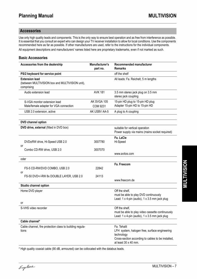
Planning Manual MULTIVISION
MULTIVISION – 7
MULT
IVIS
ION
Use only high quality leads and components. This is the only way to ensure best operation and as free from interference as possible. It is essential that you consult an expert who can design your TV receiver installation to allow for local conditions. Use the components recommended here as far as possible. If other manufacturers are used, refer to the instructions for the individual components.All equipment descriptions and manufacturers' names listed here are proprietary trademarks, even if not marked as such.
Basic Accessories
* High quality coaxial cable (90 dB, armoured) can be collocated with the databus leads.
Accessories
Accessories from the dealership Manufacturer's part no.
Recommended manufacturerRemarks
PS/2 keyboard for service point off the shelfExtension lead (between MULTIVISION box and MULTIVISION unit), comprising
All leads: Fa. Reichelt, 5 m lengths
Audio extension lead AVK 181 3.5 mm stereo jack plug on 3.5 mm stereo jack coupling
S-VGA monitor extension leadMale/female adapter for VGA connection
AK SVGA 105COM 9231
15-pin HD plug to 15-pin HD plugAdapter 15-pin HD to 15-pin HD
USB 2.0 extension, active AK USBV AA-5 A plug to A coupling
DVD channel optionDVD drive, external (fitted in DVD box) suitable for vertical operation
Power supply via mains (mains socket required)
DVD±RW drive, Hi-Speed USB 2.0or
Combo CD-RW drive, USB 2.0
3007780
3007070
Fa. LaCieHi-Speed
www.avitos.comoder
FS-5 CD-RW/DVD COMBO, USB 2.0or
FS-50 DVD+/-RW 8x DOUBLE LAYER, USB 2.0
22842
24113
Fa. Freecom
www.freecom.deStudio channel optionHome DVD player
or
Off the shelf,must be able to play DVD continuouslyLead: 1 x 4-pin (audio), 1 x 3.5 mm jack plug
S-VHS video recorder Off the shelf,must be able to play video cassette continuouslyLead: 1 x 4-pin (audio), 1 x 3.5 mm jack plug
Cable channel*Cable channel, fire protection class to building regula-tions
Fa. Tehalit LFH system, halogen free, surface engineering technologyCross-section according to cables to be installed, at least 30 x 40 mm.

MULTIVISION Planning Manual
8 – MULTIVISION
MULT
IVIS
ION
Components for DVB-SSee the DVB-S studio plan for the wiring diagram.
Accessories from the dealership Manufacturer's part no.
Recommended manufacturerRemarks
SAT dishfixing extra
TD 88 Fa. Triax, TD type, at least 88 cm ∅
Quatro-LNB (digital) Fa. MITBlueline Quattro digi
Multiswitch SMS 5802 NF FA. Spornwith 8 outputs, with 5 inputs:VH = Vertically high VL = Vertically low HH = Horizontal valley high HL = Horizontal valley lowVHF (not used) (230V mains supply required!)
4 x coax leads, each max. 25 m miscellaneous,90 dB, armoured
8 x F plugs miscellaneousextra for each MULTIVISION unitF-socket jack DSE 652 Fa. Schwaiger
2 SAT-ZF connections, 2 dB1 x coax lead, max. 56 m miscellaneous,
90 dB, armoured1 x coax lead, max. 1 m miscellaneous,
90 dB, armoured3 x F plugs miscellaneous

Planning Manual MULTIVISION
MULTIVISION – 9
MULT
IVIS
ION
Components for DVB-TSee the DVB-T studio plan for the wiring diagram.
Components for cable connection/analogue antenna from takeover pointSee the analogue TV studio plan for the wiring diagram.
Accessories from the dealership Manufacturer's part no.
Recommended manufacturerRemarks
AntennaRoof/wall mounted antenna
fixing extraor
LOG 2845 F Fa. FTEdigital
Room antenna ZIFA D2 Fa. Hirschmanndigital
1 x coax lead, max. 25 m miscellaneous,90 dB, armoured
6-way hub VTF 8826 Fa. Schwaiger1 input, 6 outputs, backwards compatible
or amplifier TVS 5 Axing, 30 dB2 x F plugs miscellaneousextra for each MULTIVISION unit1 x coax lead, max. 56 m miscellaneous,
90 dB, armoured1 x F-plug (at hub) off the shelfHF-socket jack FS 12 D Fa. Hirschmann1 x coax lead, max. 1 m miscellaneous,
90 dB, armoured, incl. HF plug/HF coupling
Accessories from the dealership Manufacturer's part no.
Recommended manufacturerRemarks
1 x coax lead, max. 25 m miscellaneous,90 dB, armoured
Domestic connection amplifier AV 34G Profi Fa. DigiSatGain: 34/26 dB, frequency range: 5-862 MHz, return channel, max. 6 connections (230V mains supply needed!)
1 x coax lead, max. 1 m miscellaneous,90 dB, armoured
6-way hub VTF 8826 Fa. Schwaiger1 input, 6 outputs, backwards compatible
4 x F plugs miscellaneousextra for each MULTIVISION unit1 x coax lead, max. 56 m miscellaneous,
90 dB, armoured1 x F-plug (at hub) off the shelfHF-socket jack FS 12 D Fa. Hirschmann1 x coax lead, max. 1 m miscellaneous,
90 dB, armoured, incl. HF plug/HF coupling

MULTIVISION Planning Manual
10 – MULTIVISION
MULT
IVIS
ION
The MULTIVISION TV unit is mounted on the tanning device.The positioning of the drilled holes for fixing the MULTIVISION box, DVD box and acrylic mount is given in the drawing oppo-site.
Assembly
210
1837
962
188
687
174
168
345
352
1850
913
340
292
430 350
12
269
06142 / 0

02514 / 002514 / 0
S1
S2
S3
S4
S5
S6
MS1
< 1 m
K1
Art.-No. 34592010
Option SAT
Per MULTIVISION
34592000
230 V / 50 HzTEHALIT
LFHTEHALIT
8 x F-plug
1 x TD 88
1 x DS 652
1 x LNBBlueline Quatro digi
1 x MultiswitchSMS 5802 NF
1 x Coax 90dBarmoured
< 1 m
1 x Coax 90dBarmoured
< 56 m
4 x Coax 90dBarmoured
< 56 m
3 x F-plug + 1 xTEHALIT
K1
S6 B1
DS 652
Option
34592007 Coax < 56 m
Multiswitch
Coax < 25 mTD 88
230 V AC
USB
USB
USB
S6
Option DVD-Channel Option Studio-Channel
COM 9231
S1
S2
S...
B1
< 8900 mm
+ 5000 mm
< 3900 mm
5000 mm
AV K 181
AK SVGA
AK USBV AA-5
3.5 jack plug
4-pinUSB
B2S-Video / DVD
DVD
MS1
3.5 jackplug
15-pin
230 V AC
PS/2
Option Service Point
3.5 jack plug
USB
15-pin
B1 B1
B2
Planning Manual SAT-Digital (DVB-S)
06347 / 1

02514 / 002514 / 0
S1
S2
S3
S4
S5
S6
MS1
< 1 m
K1
Art.-No. 34592011
Option DVB-T
Per MULTIVISION
34592000
230 V / 50 HzTEHALIT
LFHTEHALIT
2 x F-plug
1 x LOG 2845 F
1 x FS 12D
ZIFA D2
1 x 6-way-hubVTF 8826
1 x Coax lead
< 1 m
1 x Coax 90dBarmoured
< 56 m
1 x Coax 90dBarmoured
< 56 m
1 x F-plug+ 1 xTEHALIT
HF plug
HF jack
K1
S6
Option
34592007
B1
USB
USB
USB
S6
Option DVD-Channel Option Studio-Channel
230 V AC
COM 9231
S1
S2
S...
B1
< 8900 mm
+ 5000 mm
< 3900 mm
5000 mm
AV K 181
AK SVGA
AK USBV AA-5
3.5 jack plug
4-pinUSB
B2S-Video / DVD
DVD
MS1
3.5 jackplug
15-pin
FS 12D
B1
HFplug
LOG 2845 F 6-way-hub
Coax < 56 m
Coax < 25 m
PS/2
Option Service Point
3.5 jack plug
USB
15-pin
Digital terrestrial (DVB-T)
B1
Planning Manual
06345 / 1

Planning Manual Sound Systems
Sound Systems – 1
Soun
d Sy
stem
s
Contents
General . . . . . . . . . . . . . . . . . . . . . . . . . . . . . . . . . . . . 2
Connection options and music control . . . . . . . . . . 3For Ergoline Evolution and Excellence. . . . . . . . . . . . . . 3For Ergoline Open Sun A.R.T. 600. . . . . . . . . . . . . . . . . 3For Ergoline Classic 8000 Ultra . . . . . . . . . . . . . . . . . . . 3Planning examples . . . . . . . . . . . . . . . . . . . . . . . . . . . . . 4

Sound Systems Planning Manual
2 – Sound Systems
Soun
d Sy
stem
s
Ergoline sound systems are available in different models. Please refer to the respective device descriptions regarding the possibilities of the individual sunbeds.When planning, note that the studio space amplification must not be driven by the same amplifier as the audio unit of the sunbed. If this is not taken into account, difficulties can arise with sound regulation. For this reason, a separate amplifier should be available for every audio unit. On no account must car radios with bridge steps be utilised. A connection cable 6 x 0.5 mm² must be used for connecting the amplifier and the audio unit. For further information on the technology, please re-fer to the descriptions of the individual serial model modifica-tions. External amplifiers and CD players are not included in the Ergoline scope of supply.Please also note the reporting and fee responsibilities for play-ing background music in the studio. For information please contact your district office responsible for your place of resi-dence or business.
Contact addresses for Germany:GEMAGesellschaft für musikalische Aufführungen und mechanische Vervielfältigungsrechte
Bezirksdirektion NRWSüdwall 17-1944137 DortmundGermany
Telefon: +49 (0) 231 / 5 77 01-0Telefax: +49 (0) 231 / 5 77 01-120E-Mail: [email protected]
www.gema.de
GEZGebühreneinzugszentrale der öffentlich-rechtlichen Rundfunkanstalten in der Bundesrepublik Deutschland
Freimersdorfer Weg 650829 KölnGermany
Telefon: +49 (0) 180 / 5 01 65 65Telefax: +49 (0) 180 / 5 51 07 00E-Mail: [email protected]
www.gez.de
Contact address for Austria:AKMPostfach 334/348Baumannstr. 8-101031 WienAustria
Telefon: +43 1 / 717 14Telefax: +43 1 / 717 14 107
www.akm.co.at
Contact addresses for Switzerland:SUISABellariastrasse 828038 ZürichSwitzerland
Telefon: +41 1 / 48 56 666Telefax: +41 1 / 48 24 333
www.suisa.ch
SSARue Centrale 12Case Postale 38931002 LausanneSwitzerland
Telefon: +41 21 / 31 34 467Telefax: +41 21 / 31 34 476
www.ssa.ch
General

Planning Manual Sound Systems
Sound Systems – 3
Soun
d Sy
stem
s
The following connection options are available with the Ergo-line sound systems for the control and playing of music.
For Ergoline Evolution and ExcellenceSound system with audio unit without integral music CD player, connected to an external music source:This can be e.g. a pre-amplifier (CD player output), a pack am-plifier (loudspeaker connection of a music amplifier) or a 100 V system. Four relay outputs are available for connection of an additional channel selection. The volume and channel number can be selected on the con-trol panel.
For Ergoline Open Sun A.R.T. 600Sound system with basic audio unit (with integrated CD drive) connected to an external music source:The music CD player of the audio unit can be combined with an external music source. You can control the volume as well as the track number or channel number of both music sources on the control panel.
For Ergoline Classic 8000 UltraSound system with audio unit (with integrated CD drive) as standalone solution:A music CD can be played in every sunbed. The volume and track number can be selected in the control panel. There is no need for complex wiring in the studio.
Connection options and music control
Accessories Article No.7-channel distributor box M 3451440 Connection of max. 8 audio unitsInterface for the 7-channel distributor box (available on request)
M – Component for connection of VoiceGuide to the 7-channel distributor box
Transmitter M 3452350 For some amplifiers for neutralising humming sounds

Sound Systems Planning Manual
4 – Sound Systems
Soun
d Sy
stem
s
Planning examples
1. Ergoline sound system with a CD player and one audio unit without channel selection per cabin Effect: The same music is played in all the cabins.
2. Ergoline sound system with 5 CD players and one audio unit with channel selection per cabin Effect: From each cabin, one of the CD players assigned to the four cabins can be selected.
CD
CD
CD
CD
CD
V1
V2
V3
S3 S4
S1 S2
V4
VR
V1
V2
V3
V4
VR
CD
00043 / 1
1
2

Planning Manual 3D sound
3D sound – 1
3D so
und
3D sound is a high end sound system with integrated shoulder tanner for the Excellence and Evolution system series.
Contents
Device descripition. . . . . . . . . . . . . . . . . . . . . . . . . . . 2
Dimensions . . . . . . . . . . . . . . . . . . . . . . . . . . . . . . . . . 2
Technical Data. . . . . . . . . . . . . . . . . . . . . . . . . . . . . . . 3
Equipment . . . . . . . . . . . . . . . . . . . . . . . . . . . . . . . . . . 3
3D sound packages . . . . . . . . . . . . . . . . . . . . . . . . . . 3
04951 / 0

3D sound Planning Manual
2 – 3D sound
3D so
und
1. Shoulder tanner2. Headset socket3. Loudspeaker with subwoofer
Device descripition
Dimensions
A 850 mmB1 760 mmB2 996 mmC 200 mmC1 133 mm
2
3
1
06639 / 0
C
A
B2B1
C1
06139 / 0
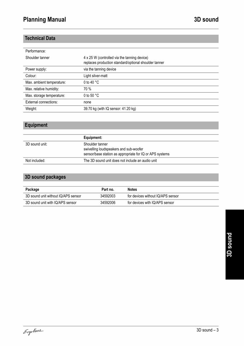
Planning Manual 3D sound
3D sound – 3
3D so
und
Technical Data
Performance:Shoulder tanner 4 x 25 W (controlled via the tanning device)
replaces production standard/optional shoulder tannerPower supply: via the tanning deviceColour: Light silver-mattMax. ambient temperature: 0 to 40 °CMax. relative humidity: 70 %Max. storage temperature: 0 to 50 °CExternal connections: noneWeight: 39.70 kg (with IQ sensor: 41.20 kg)
Equipment
Equipment:3D sound unit: Shoulder tanner
swivelling loudspeakers and sub-woofersensor/base station as appropriate for IQ or APS systems
Not included: The 3D sound unit does not include an audio unit
3D sound packages
Package Part no. Notes3D sound unit without IQ/APS sensor 34592003 for devices without IQ/APS sensor3D sound unit with IQ/APS sensor 34592006 for devices with IQ/APS sensor

Planning Manual Sound System Evolution, Excellence
Sound System Evolution, Excellence – 1
Soun
d Sy
stem
…
The devices Evolution 500 Turbo Power, Evolution 575 Turbo Power, Evolution 600, Evolution APS, Evolution IQ, Excellence 700, 800, Excellence APS, and Excellence IQ contain a com-plete sound system (depending on equipement):• Circuit board with connection for
– external music and channel selection– pre-amplifier and output amplifier– 100 V system
• Headphone jack including wiring harness • Vibra panel loudspeaker in shoulder tanner
Contents
Audio circuit board. . . . . . . . . . . . . . . . . . . . . . . . . . . 2Connecting an external music source with channel selection 2Connecting an external music source without channel selection . . . . . . . . . . . . . . . . . . . . . . . . . . . . . . . . . . . . . . . . 2
Vibra panel loudspeaker . . . . . . . . . . . . . . . . . . . . . . 3
VoiceGuide and Info . . . . . . . . . . . . . . . . . . . . . . . . . . 3
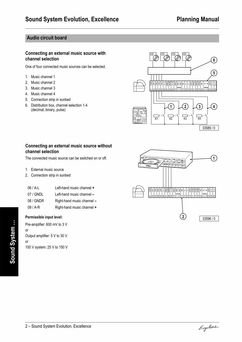
Sound System Evolution, Excellence Planning Manual
2 – Sound System Evolution, Excellence
Soun
d Sy
stem
…
Connecting an external music source with channel selectionOne of four connected music sources can be selected.
1. Music channel 12. Music channel 23. Music channel 34. Music channel 45. Connection strip in sunbed6. Distribution box, channel selection 1-4
(decimal, binary, pulse)
Connecting an external music source without channel selectionThe connected music source can be switched on or off.
1. External music source2. Connection strip in sunbed
Permissible input level:
Pre-amplifier: 600 mV to 3 VorOutput amplifier: 5 V to 30 Vor100 V system: 25 V to 150 V
Audio circuit board
06 / A-L Left-hand music channel +07 / GNDL Left-hand music channel –08 / GNDR Right-hand music channel –09 / A-R Right-hand music channel +
COM
CH1
CH2
CH3
CH4
A—L
GNDL
GNDR
A—R
24AC
OAC
OAC
PE Tr Tr STR1
STR2
STR3
STR4 PE N N 230V
Z—L
Z—L
01 02 03 04 05 06 07 08 09 10 11 12 13 14 15 16 17 18 19 20 21 22 23 24 25
CD
K1 K2 K4K3
CD CD CD
5
6
4321
03589 / 0
COM
CH1
CH2
CH3
CH4
A—L
GNDL
GNDR
A—R
24AC
OAC
OAC
PE Tr Tr STR1
STR2
STR3
STR4 PE N N 230V
Z—L
Z—L
01 02 03 04 05 06 07 08 09 10 11 12 13 14 15 16 17 18 19 20 21 22 23 24 25
2
1
03596 / 0
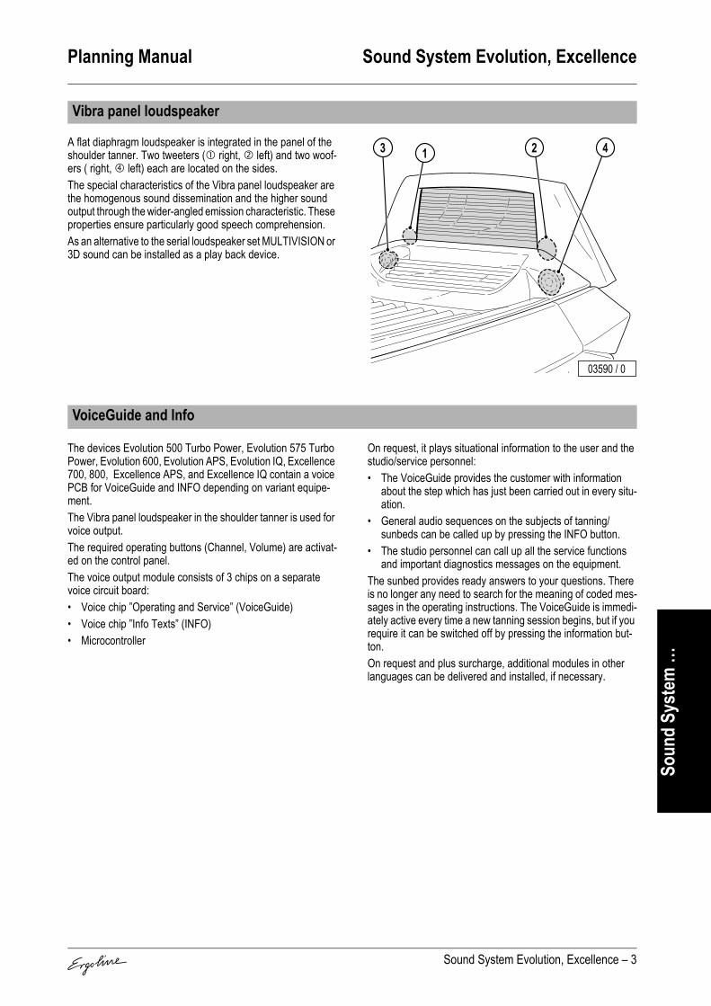
Planning Manual Sound System Evolution, Excellence
Sound System Evolution, Excellence – 3
Soun
d Sy
stem
…
A flat diaphragm loudspeaker is integrated in the panel of the shoulder tanner. Two tweeters ( right, left) and two woof-ers ( right, left) each are located on the sides.The special characteristics of the Vibra panel loudspeaker are the homogenous sound dissemination and the higher sound output through the wider-angled emission characteristic. These properties ensure particularly good speech comprehension.As an alternative to the serial loudspeaker set MULTIVISION or 3D sound can be installed as a play back device.
The devices Evolution 500 Turbo Power, Evolution 575 Turbo Power, Evolution 600, Evolution APS, Evolution IQ, Excellence 700, 800, Excellence APS, and Excellence IQ contain a voice PCB for VoiceGuide and INFO depending on variant equipe-ment.The Vibra panel loudspeaker in the shoulder tanner is used for voice output.The required operating buttons (Channel, Volume) are activat-ed on the control panel.The voice output module consists of 3 chips on a separate voice circuit board:• Voice chip ”Operating and Service” (VoiceGuide)• Voice chip ”Info Texts” (INFO)• Microcontroller
On request, it plays situational information to the user and the studio/service personnel:• The VoiceGuide provides the customer with information
about the step which has just been carried out in every situ-ation.
• General audio sequences on the subjects of tanning/sunbeds can be called up by pressing the INFO button.
• The studio personnel can call up all the service functions and important diagnostics messages on the equipment.
The sunbed provides ready answers to your questions. There is no longer any need to search for the meaning of coded mes-sages in the operating instructions. The VoiceGuide is immedi-ately active every time a new tanning session begins, but if you require it can be switched off by pressing the information but-ton.On request and plus surcharge, additional modules in other languages can be delivered and installed, if necessary.
Vibra panel loudspeaker
2 413
03590 / 0
VoiceGuide and Info

Planning Manual Sound System Open Sun 600
Sound System Open Sun 600 – 1
Soun
d Sy
stem
…
Contents
Audio unit with VoiceGuide . . . . . . . . . . . . . . . . . . . . 2
Connecting an external music system to a VoiceGuide . . . . . . . . . . . . . . . . . . . . . . . . . . . . . . . . . 3

Sound System Open Sun 600 Planning Manual
2 – Sound System Open Sun 600
Soun
d Sy
stem
…
The Open Sun A.R.T. 600 sunbed contains a complete sound system as standard (audio unit with VoiceGuide). The scope of supply of a sound system on the above-men-tioned sunbeds consists of: • Control box (1) with internal CD drives for music (2) and
speech (3) (VoiceGuide)• Loudspeakers and headphone jack, with cable harness• Control units for volume and channel selection or informa-
tion reproduction• Operating and assembly instructions
The assembly position for the control box with the audio unit and VoiceGuide is always located in the sunbed base.For connection of older music systems it may be necessary to use an additional transmitter (Art. No. 3452350).
VoiceGuideOn request, it plays situational information to the user and the studio/service personnel:• The VoiceGuide provides the customer with information
about the step which has just been carried out in every situ-ation.
• General audio sequences on the subjects of tanning/sunbeds can be called up by pressing the INFO button.
• The studio personnel can call up all the service functions and important diagnostics messages on the equipment.
The sunbed provides ready answers to your questions. There is no longer any need to search for the meaning of coded mes-sages in the operating instructions. The VoiceGuide is immedi-ately active every time a new tanning session begins, but if you require it can be switched off by pressing the INFO button.
Audio unit with VoiceGuide

Planning Manual Sound System Open Sun 600
Sound System Open Sun 600 – 3
Soun
d Sy
stem
…
An external music system is connected to an Ergoline sunbed with VoiceGuide by means of 2 plugged connections (plugs 91 and 92) on the control box (1) of the sunbed.• Through jack 91 (4), Article No.: 79494, external music is
supplied to the VoiceGuide and• through jack 92 (5), Article No.: 50047, the channel selec-
tion of the Ergoline sunbed is supplied to the music system.The jacks must be ordered as accessories from Ergoline. For detailed information about the installation, setting and opera-tion of an external music system on an Ergoline sunbed with VoiceGuide, see the operating instructions of the appropriate sunbed.
Volume adjustment during tanning is controlled by the sunbed's electronics system (see the operating instructions). The vol-ume of the music signal connected to the sunbed must not be adjusted once the system has been connected.To adjust the volume to the internal CD drives, there is a switch (7) in the control box (1) for coarse adjustment and two pre-set potentiometers (10 + 11) for fine-tuning. Depending on the po-sition of the switch, the permissible levels of the input signal are as shown in the table below:
An interface for the Ergoline 7-channel distributor box (availa-ble on request) enables the connection of the VoiceGuide sys-tem to Ergoline's 7-channel distributor box. One interface is re-quired per sunbed..
Connecting an external music system to a VoiceGuide
2 413
03590 / 0
AUDIO-CD
VOICEGUIDE-CD
1
2
3
4
5
02932 / 1
2 413
03590 / 0
AUDIO-CD
VOICEGUIDE-CD
1
6
7
1098 11 03593 / 0
Switch position Permissible input level6 Pre-amplifier 600 mV to 3 V8 Pack amplifier 5 V to 30 V9 100 V system 25 V to 150 V
2 413
03590 / 0
VOICE GUIDE-CD
AUDIO-CD
1 45
3 2 03594 / 0
2 413
03590 / 0
VOICE GUIDE-CD
AUDIO-CD
1 6
7
1098
11
03595 / 0

Sound System Open Sun 600 Planning Manual
4 – Sound System Open Sun 600
Soun
d Sy
stem
…
Connection arrangement at jack 91 (3) for music signals: Connection arrangement at jack 92 (4) for channel selection:
The electrical limit values of the relay contacts are 100 V DC and 500 mA per contact.The number of external audio channels can be selected in the service module ”No. OF EXTERNAL AUDIO CHANNELS” in the range of 0 to 16. The setting ”0” switches the use of external music sources Off.You must determine the channel control depending on which-ever music system is used. The Ergoline sound system sup-ports the following channel controls:• BCD code• Pulse• Decimal code
Pin designation FunctionL1 Music signal external left⊥ Common earthN Music signal external right
L1 N
BEZ
IND
BEZ
IND
BEZ
IND
3
02934 / 0
Pin designation FunctionL1 Relay 1 for channel selectionL2 Relay 2 for channel selection⊥ Common contactN Relay 3 for channel selectionL3 Relay 4 for channel selection
L2 N
BEZ
IND
BEZ
IND
BEZ
IND
BEZ
IND
L1
BEZ
IND
L1
BEZ
IND
L3
BEZ
IND
4
02935 / 0

Planning Manual Sound System Classic
Sound System Classic – 1
Soun
d Sy
stem
Clas
sic
Article No.: 3452020
Article No.: 3452030
Article No.: 3452040
Article No.: 3452050
Contents
Audio unit for the Ergoline Classic 8000 Ultra. . . . . 2

Sound System Classic Planning Manual
2 – Sound System Classic
Soun
d Sy
stem
Clas
sic
The scope of supply for Ergoline Classic 8000 consists of: • Control box for audio unit• Headphone jack including cable harness for loudspeaker
connection• Volume control and channel selection control, integrated in
the operating cockpit• Channel selection board• Operating and assembly instructionsWhen fitting Ergoline sunbeds with a sound system, one audio unit per sunbed is required. Also, when more than one audio unit is installed, a single distributor box is necessary. Example: For a studio with 4 Ergoline Classic 8000, 4 audio units are re-quired, but only one distributor box.The distributor box enables you to connect and operate max. 7 amplifiers independently on up to 8 sunbeds.
Example: While the customer on sunbed 1 is listening to clas-sical music, the customer on sunbed 5 can listen to pop music and the customer on sunbed 7 can listen to jazz.The music signals are output via the headphone jack and can be controlled via the volume control over 8 volume levels.The channel selection switch enables you to select the various CD players offering all kinds of different music.Connection:100 Volt amplifier (min. output 100 Watt)
Audio unit for the Ergoline Classic 8000 Ultra
Caution!
Do not use an 8 Ω amplifier.
Note:
When connecting to an external music installation, it is possible that some strong humming noises may arise. In such a case the use of a transmitter is recommended (Art. No.: 3452350).

Planning Manual Appendix
Appendix – 1
Appe
ndix
Contents
Performance and air requirements . . . . . . . . . . . . . . 2
Inlet and exhaust air cross-sections. . . . . . . . . . . . . 3
Maximum exhaust pipe length without additional ventilator . . . . . . . . . . . . . . . . . . . . . . . . . . . . . . . . . . . 4
Weights . . . . . . . . . . . . . . . . . . . . . . . . . . . . . . . . . . . . 5
Note:The assorted technical information in this chapter applies to all variants of each device type.

Appendix Planning Manual
2 – Appendix
Appe
ndix
1) All the tanning devices are connected to 400-415V ~3N only delay-action fuses must be used.The specified connection voltages must lie within a tolerance range from +/- 5% to retain the guaranteed output data for Ergoline sunbeds.
2) Feet area3) Upper-body area4) Ambient temperature max. 25 °C and inlet air max. 40 °C5) without air conditioner6) with air conditioner7) UV low pressure lamps (25W) in canopy and side part
With the electrical connected rating in a studio, a simultaneity factor of 1 must be expected.
Performance and air requirements
Ergoline professional sunbed
Capacity Fuses1) UV low pressure lamps
UV high pressure lamps
Temperature difference
Air requirement max.4)
w/o with performance performance exhaust / supply airAir conditioner
Watt Watt Ampere Watt Watt °C m³/hExcellence IQIntelligent Power System – 16500 3 x 35 51 x 120-180 4 x 520 15 2800
Excellence 800Automatic Power System – 18300 3 x 35 51 x 160 4 x 520 15 2800
Excellence 800 Turbo Power – 18300 3 x 35 51 x 160 4 x 520 15 2800Excellence 700Automatic Power System – 18300 3 x 35 51 x 160 4 x 520 15 2800
Excellence 700 Turbo Power 15000 18300 3 x 35 51 x 160 4 x 520 105)
156) 2800
Evolution IQIntelligent Power System – 12600 3 x 35 46 x 120-160 3 x 520 11 2800
Evolution 600Automatic Power System – 14500 3 x 35 46 x 160 3 x 520 11 2800
Evolution 600 Turbo Power 13300 14500 3 x 35 46 x 160 3 x 500 65)
116) 2800
Evolution 600 Super Power 9800 11000 3 x 25 46 x 100 3 x 500 65)
116) 2800
Evolution 575 Turbo Power 10100 11500 3 x 25 17 x 16017 x 180 45 x 25 7) 65)
116) 2800
Evolution 500Automatic Power System – 13900 3 x 35 43 x 160 3 x 520 11 2800
Evolution 500 Turbo Power 12700 13900 3 x 35 43 x 160 3 x 500 65)
116) 2800
Evolution 500 Super Power 8400 – 3 x 16 43 x 100 3 x 400 6 2800Advantage 400Automatic Power System
9700 – 3 x 20 40 x 160 3 x 400 75)2700
– 10700 3 x 25 40 x 160 3 x 400 106)
Advantage 400 Turbo Power9700 – 3 x 20 40 x 160 3 x 400 75)
2700– 10700 3 x 25 40 x 160 3 x 400 106)
Advantage 400 Super Power 7700 – 3 x 16 40 x 100 3 x 360 7 2700Advantage 350 Turbo Power 9600 – 3 x 20 38 x 160 3 x 400 10 2700Advantage 350 Super Power 7600 – 3 x 16 38 x 100 3 x 360 7 2700Ambition 250 Super Power 6300 – 3 x 16 36 x 100 3 x 400 15 1600Lounge Turbo Power 12500 – 3 x 25 50 x 180 – 10 2900Open Sun A.R.T. 600Super Power 13300 – 3 x 25 17 x 100 4 x 7002)
6 x 8003) 11 2500
Open Sun A.R.T. 450Super Power 8300 – 3 x 16 45 x 100 2 x 600 10 2100
Classic 300 Super Power 7000 – 3 x 16 38 x 100 3 x 400 15 950Classic 200 Super Power 6200 – 3 x 16 32 x 100 3 x 400 15 950Classic 8000 Ultra 5500 – 3 x 16 – 6 x 500 8 1200

Planning Manual Appendix
Appendix – 3
Appe
ndix
1) Device exit opening2) Can be extended
Inlet and exhaust air cross-sections
Ergoline professional sunbed
Exhaust air cross-sections without
exhaust air system
Pipe ∅ Cabin Inlet air cross- section at 1.5 m/s
Inlet and exhaust air cross-sections with
exhaust system
Exhaust air 1)
cm² mm cm²Exhaust air
cm²Excellence IQ
588 300 5200 710Excellence 800Excellence 700
Evolution IQ
588 300 4200 710Evolution 600Evolution 575Evolution 500
Advantage 400430 300 5000 710
Advantage 350
Ambition 250 802 – – –
Lounge 430 300 5370 710
Open Sun A.R.T. 600 435 300 4000 710Open Sun A.R.T. 450 550 250 (300) 2) 4100 490 (710) 2)
Classic 300450 250 1300 490
Classic 200Classic 8000 Ultra 430 – 2200 –

Appendix Planning Manual
4 – Appendix
Appe
ndix
1) zeta value (ζ)Permissible only for direct connection of the exhaust air from inside to outside via a special canal system with pipe bends with smooth surfaces.
Maximum exhaust pipe length without additional ventilator
Calculation base (without additional ventilator):Back pressure 100 PascalAir pressure 100,000 PascalAir temperature 40 °CDensity 1.112 kg/m3
Dynamic inertia of the air 1.92E-05 Pa x s
Ergoline professional sunbed
Corrugated pipe∅
Roughness(at centre)
Flow volume Loss coefficient 90° bend in line (metal)
Permissible length of straight
linekabsolute of bend of pipe
mm mm m³/h pieces m
ExcellenceIQ / 800 / 700 300 8 2500 0.1821) 0.211)
0 101 92 83 7
EvolutionIQ / 600 / 575 / 500 300 8 2500 0.1821) 0.211)
0 101 92 83 7
Advantage 400 / 350 300 8 2300 0.1821) 0.211)
0 121 112 103 9
Lounge 300 8 2600 0.1821) 0.211)
0 101 8.52 7.53 6
Open Sun A.R.T. 600 250 8 2500 0.1821) 0.211)
0 121 102 83 6
Open Sun A.R.T. 450 300 8 2150 0.1821) 0.211)
0 121 102 83 6
Classic 300 / 200 250 8 950 0.1821) 0.211)
0 81 62 43 2

Planning Manual Appendix
Appendix – 5
Appe
ndix
1) all datas are round figures
Weights
Ergoline professional sunbed
without air conditioner with air conditioner
kg 1) kg 1)
Excellence IQIntelligent Power System – 681
Excellence 800Automatic Power System – 649
Excellence 800 Turbo Power – 647Excellence 700Automatic Power System – 680
Excellence 700 Turbo Power 618 678Evolution IQIntelligent Power System – 626
Evolution 600Automatic Power System – 636
Evolution 600 Turbo Power 556 634Evolution 600 Super Power 556 634Evolution 575 Turbo Power 567 637Evolution 500Automatic Power System 562 630
Evolution 500 Turbo Power 560 628Evolution 500 Super Power 504 –Advantage 400Automatic Power System 405 473
Advantage 400 Turbo Power 403 –Advantage 400 Super Power 373 –Advantage 350 Turbo Power 388 –Advantage 350 Super Power 368 –Ambition 250 Super Power 265 –Lounge Turbo Power 546 –Open Sun A.R.T. 600Super Power 450 –
Open Sun A.R.T. 450Super Power 547 –
Classic 300 Super Power 232 –Classic 200 Super Power 226 –Classic 8000 Ultra 340 –

ERGOLINE GMBH
Köhlershohner Straße
53578 Windhagen/GERMANY
Internet: www.ergoline.de
E-Mail: [email protected]
Telefon: + 49 (0)2224/818-0
Telefax: + 49 (0)2224/818-116
18 5
023
02
PHB_12.2004 GB 20.06.2005 12:07 Uhr Seite 2