
Physical Layer Security of Intelligent Reflective Surface Aided ...
30
arXiv:2011.03417v1 [eess.SP] 6 Nov 2020 1 Physical Layer Security of Intelligent Reflective Surface Aided NOMA Networks Zhiqing Tang, Tianwei Hou, Student Member, IEEE, Yuanwei Liu, Senior Member, IEEE, Jiankang Zhang, Senior Member, IEEE, and Lajos Hanzo, Fellow, IEEE Abstract Intelligent reflective surface (IRS) technology is emerging as a promising performance enhancement technique for next-generation wireless networks. Hence, we investigate the physical layer security of the downlink in IRS-aided non-orthogonal multiple access networks in the presence of an eavesdropper, where an IRS is deployed for enhancing the quality by assisting the cell-edge user to communicate with the base station. To characterize the network’s performance, the expected value of the new channel statistics is derived for the reflected links in the case of Nakagami-m fading. Furthermore, the per- formance of the proposed network is evaluated both in terms of the secrecy outage probability (SOP) and the average secrecy capacity (ASC). The closed-form expressions of the SOP and the ASC are derived. We also study the impact of various network parameters on the overall performance of the network considered. To obtain further insights, the secrecy diversity orders and the high signal-to-noise ratio slopes are obtained. We finally show that: 1) the expectation of the channel gain in the reflected links is determined both by the number of IRSs and by the Nakagami-m fading parameters; 2) The SOP of both receiver 1 and receiver 2 becomes unity, when the number of IRSs is sufficiently high; 3) The secrecy diversity orders are affected both by the number of IRSs and by the Nakagami-m fading parameters, whereas the high-SNR slopes are not affected by these parameters. Our Monte-Carlo simulations perfectly demonstrate the analytical results. Part of this work has been submitted to IEEE International Conference on Communications (ICC) 2021 [1]. This work was supported in part by the National Science Foundation of China under Grant 61571401, in part by the National Science Foundation for Young Scientists of China under Grant 61901416. Z. Tang is with Zhengzhou University, Zhengzhou, China (email:[email protected]). T. Hou is with Beijing Jiaotong University, Beijing, China (email:[email protected]). Y. Liu is with Queen Mary University of London, London, UK (email:[email protected]). J. Zhang and L. Hanzo are with University of Southampton, Southampton, U.K. (email:[email protected]; [email protected]).
-
Upload
khangminh22 -
Category
Documents
-
view
1 -
download
0
Transcript of Physical Layer Security of Intelligent Reflective Surface Aided ...

arX
iv:2
011.
0341
7v1
[ee
ss.S
P] 6
Nov
202
01
Physical Layer Security of Intelligent
Reflective Surface Aided NOMA Networks
Zhiqing Tang, Tianwei Hou, Student Member, IEEE, Yuanwei Liu, Senior
Member, IEEE, Jiankang Zhang, Senior Member, IEEE, and
Lajos Hanzo, Fellow, IEEE
Abstract
Intelligent reflective surface (IRS) technology is emerging as a promising performance enhancement
technique for next-generation wireless networks. Hence, we investigate the physical layer security of
the downlink in IRS-aided non-orthogonal multiple access networks in the presence of an eavesdropper,
where an IRS is deployed for enhancing the quality by assisting the cell-edge user to communicate
with the base station. To characterize the network’s performance, the expected value of the new channel
statistics is derived for the reflected links in the case of Nakagami-m fading. Furthermore, the per-
formance of the proposed network is evaluated both in terms of the secrecy outage probability (SOP)
and the average secrecy capacity (ASC). The closed-form expressions of the SOP and the ASC are
derived. We also study the impact of various network parameters on the overall performance of the
network considered. To obtain further insights, the secrecy diversity orders and the high signal-to-noise
ratio slopes are obtained. We finally show that: 1) the expectation of the channel gain in the reflected
links is determined both by the number of IRSs and by the Nakagami-m fading parameters; 2) The
SOP of both receiver 1 and receiver 2 becomes unity, when the number of IRSs is sufficiently high;
3) The secrecy diversity orders are affected both by the number of IRSs and by the Nakagami-m
fading parameters, whereas the high-SNR slopes are not affected by these parameters. Our Monte-Carlo
simulations perfectly demonstrate the analytical results.
Part of this work has been submitted to IEEE International Conference on Communications (ICC) 2021 [1].
This work was supported in part by the National Science Foundation of China under Grant 61571401, in part by the National
Science Foundation for Young Scientists of China under Grant 61901416.
Z. Tang is with Zhengzhou University, Zhengzhou, China (email:[email protected]).
T. Hou is with Beijing Jiaotong University, Beijing, China (email:[email protected]).
Y. Liu is with Queen Mary University of London, London, UK (email:[email protected]).
J. Zhang and L. Hanzo are with University of Southampton, Southampton, U.K. (email:[email protected];

2
Index Terms
Intelligent reflective surface, non-orthogonal multiple access, physical layer security.
I. INTRODUCTION
In recent years, intelligent reflective surfaces (IRSs1) have been proposed for beneficially
influencing wireless signal propagation [2]–[4]. They can be installed on walls, ceilings, building
facades and other infrastructure elements. Secondly, because they may be readily integrated into
the existing wireless networks, they constitute a promising cost-effective spectral efficiency (SE)
and/or energy efficiency (EE) improvement technique capable of controlling the scattering,
reflection and refraction characteristics of the radio waves [5], [6]. However, the design and opti-
mization of IRS-aided networks requires further study. By appropriately adjusting the amplitude-
reflection and phase coefficients, the signals reflected by the IRS can be superimposed on the
direct link for enhancing the received signals [7], [8]. As another benefit, IRSs also have the
ability to eliminate undesired signals, such as co-channel interference [9]. It was also revealed that
IRSs are capable of reducing the outage probability (OP) of optical communication networks [10].
In [11], the authors jointly optimized the active beamforming at the access point (AP) and the
passive beamforming at the IRS of a specific scenario for maximizing the power harvested by an
energy harvesting receiver. In [12], the authors studied the weighted sum-power maximization
problem of an IRS-aided wireless information and power transfer (SWIPT) network, while the
authors of [13] conceived beam index modulation for millimeter wave communication relying
on IRSs.
As a parallel development, power domain non-orthogonal multiple access (NOMA2) has
the capability of providing services for multiple users within the same physical time and/or
frequency resource block at the same time, thereby significantly improving the SE and con-
nection density [14]–[16]. In [17], the authors studied the OP of the single cell multi-carrier
NOMA downlink, where the transmitter side only has statistical channel state information (CSI)
knowledge. In [18], the authors pointed out that the secrecy diversity order and the asymptotic
secrecy outage probability (SOP) of a pair of NOMA users are determined by that specific user,
which has poorer channel gains. As demonstrated in [19], to unleash the full potential of NOMA
1Also known as Reconfigurable Intelligent Surfaces (RISs).
2Throughout this paper, we focus our attention on the family of power-domain NOMA schemes. Hence we simply use
“NOMA” to refer to “power-domain NOMA” in the following.

3
it is important to ensure that an appropriate power difference exists between the users. The IRS
has the ability to change the channel gains for the sake of enhancing the performance of NOMA,
hence their intrinsic amalgam has substantial benefits.
Motivated by the potential joint benefits of IRS and NOMA, IRS-aided NOMA networks have
been proposed in [20] for enhancing both the SE and EE. Furthermore, both the downlink (DL)
and uplink of IRS-aided NOMA networks were studied [21]. Additionally, IRS-aided NOMA
transmission was contrasted to spatial division multiple access (SDMA) in [22]. The perfor-
mance of IRS-aided NOMA networks relying on both idealized perfect and imperfect successive
interference cancellation was investigated in [23]. In [24], the authors considered both ideal and
realistic non-ideal IRS assumptions by jointly optimizing the active beamforming at the BS and
the passive beamforming at the IRS of a link to maximize the sum rate. Furthermore, in [25],
the authors jointly optimized the active beamforming at the BS and the passive beamforming at
the IRS of a link for minimizing the total transmit power. In [26], the authors derived the closed-
form expression of the coverage probability of appropriately paired NOMA users and proved
that the performance of the IRS-aided NOMA network is better than that of the traditional
NOMA network. A new type of multi-cell IRS-aided NOMA resource allocation framework
was proposed in [27], while an IRS-aided millimeter wave (mmWave) NOMA network was
considered in [28]. In [29], machine learning techniques were adopted in an IRS-aided NOMA
network for maximizing the EE.
Given the broadcast nature of wireless transmission, the issue of physical layer security (PLS)
has attracted widespread interests [30], [31]. Although rigorous efforts have been dedicated to
the PLS of wireless communications, the overall progress has remained relatively slow [32].
However, the emergence of IRS technology provides a new horizon for PLS problems. In [33],
the authors studied the secrecy performance of an IRS-aided wireless communication network in
the presence of an eavesdropper (Eve). Similarly, in [34], the authors investigated an IRS-aided
secure wireless communication network, where the eavesdropping channels are stronger than the
legitimate communication channels. In [35], the authors studied the SOP of IRS-aided NOMA
networks in a multi-user scenario. In [36], the authors investigated whether the use of artificial
noise is helpful in terms of enhancing the secrecy rate of IRS-aided networks. Additionally, a
mobile wiretap network was also investigated [37], in which an unmanned aerial vehicle (UAV)
equipped with IRS was considered. The PLS of an IRS-aided vehicular network was studied
in [38].

4
TABLE I: Conclusion of the current literature, and the objective of the proposed model.
[6] [24] [33] [35] [38] [39] Proposed scheme
IRS-aided network X X X X X X X
OMA scheme X X X X X
NOMA scheme X X X X
Approximated distribution X X X
Exact distribution X
SOP analysis X X X X
Secrecy diversity order X
ASC analysis X X
High-SNR slpoe X
A. Motivation and Contribution
Most of the existing contributions on PLS in IRS-aided networks studied the problem of max-
imizing the secrecy rate. An IRS-aided multiple-input single-output and multiple-input multiple-
output network has been studied in [39]. Furthermore, in [40], [41], IRS-aided multiple-input
single-output networks have been studied. As mentioned above, PLS has been studied in diverse
scenarios, but there is a paucity of investigations on IRS-aided NOMA, which motivates this
contribution. Table I boldly and explicitly contrasts our schemes to the pertinent literature.
Specifically, we consider the scenario of an IRS-aided NOMA network, where a BS supports
a cell-center user as well as a cell-edge user, and NOMA is invoked. Additionally, an Eve is
close to the cell-edge users. Explicitly, we consider a NOMA network in which the cell-edge
user cannot directly communicate with the BS, hence relies on the IRS to communicate with
the BS. Our new contributions can be summarized in more detail as follows:
• We investigate the secrecy performance of IRS-aided NOMA networks, where BS commu-
nicates with a pair of NOMA users in the presence of an Eve. In particular, we investigate
the SOP and the average secrecy capacity (ASC).
• We adopt the Nakagami-m fading model for the reflected links so that it can be either
Line-of-sight (LoS) or non-line-of-sight (NLoS). Correspondingly, we derive new channel
statistics for the reflected links based on the associated Laplace transforms and moments.
We demonstrate that the expectation of the channel gain for the reflected links is determined
by the number of IRSs and the Nakagami-m fading parameters.
• We derive closed-form expressions of the SOP and the ASC for the proposed network.

5
To glean further insights, we derive asymptotic approximations of the SOP and the ASC
in the high signal-to-noise ratio (SNR) regime to derive both the secrecy diversity order
and the high-SNR slope. We demonstrate that the number of IRSs and Nakagami-m fading
parameters directly affect the secrecy diversity order, but have no effect on the high-SNR
slope.
B. Organization
The rest of the paper is organized as follows. In Section II, the model of the IRS-aided NOMA
network is discussed. In Section III, the new channel statistics of the reflected links are derived,
and then the performance analysis of IRS-aided NOMA networks is conducted. Furthermore,
our numerical and simulation results are composed in Section IV. Finally, our conclusions are
offered in Section V.
In this paper, scalars are denoted by italic letters. For a scalar s, s! denotes the factorial of s.
Vectors and matrices are denoted by boldface letters. For a vector v, vT denotes the transpose of
v, and diag(v) denotes a diagonal matrix in which each diagonal element is the corresponding
element in v, respectively. P(·) denotes the probability, and E(·) represents the expectation.
II. SYSTEM MODEL
As shown in Fig. 1, we consider the secure DL of an IRS-aided NOMA network, where a BS
communicates with two legitimate users in the presence of an Eve. For the pair of legitimate
users, the NOMA transmission protocol is invoked. It is assumed that the BS, the paired NOMA
users and Eve are equipped with a single antenna. We also assumed that Eve has powerful
detection capability, which is capable of detecting the messages of the paired NOMA users. We
have an IRS at the appropriate location, who has N intelligent surfaces. More specifically, user
2 is the cell-edge user, who needs help from the IRS to communicate with the BS. At the same
time, user 1 is the cell-center user who can directly communicate with the BS. Furthermore,
there is no direct link between the IRS and user 1, as well as between the BS supporting user
2 and Eve, due to their long-distance and the presence of blocking objects.
The small-scale fading vector between the BS and IRSs is denoted by
h = [h1, h2, · · · , hN ]T. (1)

6
IRSs
Direct Link Reflected Link
BS
1Bh 2Bg
Eg
User1
User2
Eve
h
Blocking
objects
Fig. 1: An IRS-aided NOMA secure communication.
The small-scale fading vectors between the IRSs and user 2 and that between the IRSs and
Eve are given by
gB2 = [g2,1, g2,2, · · · , g2,N ] , (2)
and
gE = [gE,1, gE,2, · · · , gE,N ] , (3)
respectively. The elements in h, gB2 and gE obey the Nakagami-m distribution having fading
parameters of m1, m2, and m3, respectively. Moreover, the direct link between the BS and user
1 is modelled by Rayleigh fading, which is denoted by hB1.
The BS sends the following signal to the paired NOMA users
s =√a1s1 +
√a2s2, (4)
where s1 and s2 are the signal intended for user 1 and user 2, respectively, while√a1 and
√a2
are the power allocation factors of user 1 and user 2, respectively. Based on the NOMA protocol,
the power allocation coefficients satisfy the condition that a1 + a2 = 1.
The signal received by user 1 and user 2 are given by
y1 = hB1
√
d−αB1
B1 Ps+ n1, (5)

7
and
y2 = gB2Φh
√
d−α1
1 d−αB2
B2 Ps+ n2, (6)
respectively, where dB1 and d1 denote the distances from the BS to user 1 and the IRS,
respectively. Furthermore, dB2 denotes the distance from the IRS to user 2, αB1, α1 and αB2
represent the path loss exponents of the BS-user 1 link, BS-IRS links and IRS-user 2 links,
respectively. Still referring to P denotes the transmit power of the BS, n1 and n2 represent
additive white Gaussian noise (AWGN) at user 1 and user 2, respectively, which is modeled
as a realization of a zero-mean complex circularly symmetric Gaussian variable with variance
σ2. Additionally, Φ , diag[β1φ1, β2φ2, . . . , βNφN ] is a diagonal matrix, which represents the
effective phase shift applied by all IRSs, where βn ∈ (0, 1] is the amplitude reflection coefficient
of the IRSs, while φn = exp(jθn), j =√−1, ∀n = 1, 2, . . . , N and θn ∈ [0, 2π), represents the
phase shift caused by the n-th IRS. The signal received by Eve is given by
yE = gEΦh
√
d−α1
1 d−αE
E Ps+ nE , (7)
where dE is the distance form the IRS to Eve, αE denotes the path loss exponent of the IRS-EVE
link and nE represents the AWGN at Eve.
III. PERFORMANCE AND ANALYSIS
In this section, we consider an IRS design similar to [21]. Specifically, in order to simulta-
neously control multiple IRSs, the CSI of the paired NOMA users’ channels is assumed to be
perfectly known. However, the CSI of Eve is not available. We first derive new channel statistics
for both the direct link and reflected links. Then the SOP and the ASC are illustrated in the
following subsections.
A. New Channel Statistics
According to the previous assumption, the instantaneous signal-to-noise ratio (SNR) of user 1
and the instantaneous signal-to-interference-plus-noise ratio (SINR) of user 2 can be expressed
as
γB1 = ρa1|h1|2d−αB1
B1 , (8)
and
γB2 =a2|hB2|2d−α1
1 d−αB2
B2
a1|hB2|2d−α1
1 d−αB2
B2 + 1ρ
, (9)

8
respectively, where ρ denotes the transmit SNR and hB2 =∑N
n=1 |g2,n||hn| represents the
equivalent channel of the BS-IRS-user 2 links.
The phase shifts are designed for user 2, hence the effective channel gain of Eve cannot be
evaluated. In this paper, we consider the worst-case scenario of the IRS-aided NOMA network,
in which all of the BS-IRS-Eve signals are co-phased. Therefore, the equivalent channel of Eve
is similar to that of user 2, which can be expressed as
hE =
N∑
n=1
|gE,n||hn|. (10)
Therefore, the instantaneous SNR of detecting the information of user 1 and user 2 can be
expressed as:
γEi= ρeai|hE |2d−α1
1 d−αE
E , (11)
where i ∈ {1, 2}.
Lemma 1. The cumulative distribution function (CDF) of γB1 is
FγB1(x) = 1− e
− x
a1ρd−αB1B1 , (12)
Proof. the CDF of |hB1|2 is F|hB1|2(x) = 1− e−x. Then, FγB1can be derived as
FγB1(x) = P (γB1 < x)
= F|hB1|2
(
x
a1ρd−αB1
B1
)
= 1− e− x
a1ρd−αB1B1 .
(13)
This completes the proof.
Lemma 2. Recall that the fading parameters of the elements in h and gB2 are m1 and m2,
respectively. The CDF of γB2 in the low-SNR regimes and the high-SNR regimes (when m1 6= m2)
are given by
FγB2(x) = 1−Q 1
2
(√λ,
√x
N(1− ǫ)ρ(a2 − a1x)d−α1
1 d−αB2
B2
)
, (14)

9
and
F 0+γB2
(x) =mN (4msml)
−msN
Γ(2msN)γ
2msN,2√msmlx
√
ρ(a2 − a1x)d−α1
1 d−αB2
B2
, (15)
respectively, where x < a2a1
, Qα(·, ·) is the Marcum Q-function, ǫ = 1m1m2
(Γ(m1+
1
2)
Γ(m1)
)2 (Γ(m2+1
2)
Γ(m2)
)2
,
λ = Nǫ1−ǫ
, m =√π4ms−ml+1(msml)
ms Γ(2ms)Γ(2ml−2ms)
Γ(ms)Γ(ml)Γ(ml−ms+1
2)
, ml = max (m1, m2), ms = min (m1, m2),
Γ(·) denotes the Gamma function and γ(·, ·) is the lower incomplete Gamma function.
Proof. Please refer to Appendix A.
Lemma 3. Upon introducing Z =∑N
n=1 |gq,n||hn|, where q ∈ {2, E}, the expectation of Z2 is
given by
E(Z2) = aNωNd−aNkN1 ℧, (16)
where a = 2mc, b = mc−md+12, c = mc+md+
12, d = 2
√mcmd, ω =
√π4mc−md+1(mcmd)
mcΓ(2mc)Γ(2md)
Γ(mc)Γ(md)Γ(mc+md+1
2)
and ℧ = ℧1 + ℧2 − ℧3 + ℧4 with ℧1 = aN+1d2
, ℧2 =4ab2k22c2d2k2
1
(N − 1), ℧3 = 4abNk2cd2k1
and ℧4 =
4(a+1)(b2+b)(c2+c)d2
k3 − 4bcd2
k2. Furthermore, k1 = 2F1 (a, b; c;−1), k2 = 2F1 (a + 1, b+ 1; c+ 1;−1)
and k3 = 2F1 (a+ 2, b+ 2; c+ 2;−1) are the Gauss hypergeometric function [42, eq. (9.100)].
In the case of q = 2, we have mc = min(m1, m2), md = max(m1, m2) and E(Z2) denotes
the average channel gain of the BS-IRS-user 2 links, otherwise, we have mc = min(m1, m3),
md = max(m1, m3) and E(Z2) denotes the average channel gain of the BS-IRS-Eve links.
Proof. Please refer to Appendix B.
Remark 1. The second moment E(Z2) is accurate for the global CSIs. Hence, we observe
from (16) that the expectation of the channel gain for the reflected links is determined by the
number of IRSs and the Nakagami-m fading parameters.
B. Secrecy Outage Probability
In the proposed network, the capacity of the main channel for the i-th user is given by
CBi= log(1 + γBi
), while the capacity of Eve’s channel for the i-th user is quantified by
CEi= log(1 + γEi
). As such, the secrecy rate of the i-th user can be expressed as
Ci = [CBi− CEi
]+ , (17)
where [x]+ = max{x, 0}.

10
1) SOP analysis:
Next, we focus our attention on the SOP of user 1 and user 2. For the i-th user, we note that,
if Ci < Ri, information transmission at a rate of Ri is compromised. The SOP of the i-th user
can be expressed as
Pi(Ri) = P (C < Ri)
= P
(
log2
(1 + γBi
1 + γEi
)
< Ri
)
= P(γBi < 2Ri (1 + γEi)− 1
).
(18)
Then we derive the SOP of user 1 and user 2 in the following theorems.
Theorem 1. In the IRS-aided NOMA network considered, the SOP of user 1 is given by
P1(R1) ≈ 1− e
−y1
a1ρd−αB1B1 , (19)
where y1 = 2R1
(1 + a1ρeµd
−α1
1 d−αE
E
)− 1, and µ = E
(
|hE|2)
which can be obtained from
Lemma 3 in the case of mc = min(m1, m3) and md = max(m1, m3).
Proof. Based on (11) and (18), we have
P1(R1) = P(γB1
< 2R1 (1 + γE1)− 1
)
≈ P
(
γB1< 2R1
(
1 + |hE|2d−α1
1 d−αE
E
)
− 1)
= FγB1
(
2R1
(
1 + ρea1E(
|hE|2)
d−α1
1 d−αE
E
)
− 1)
.
(20)
Then, by substituting (12) and (16) into (20), in the case of mc = min(m1, m3) and md =
max(m1, m3), we arrive at (19) after some further manipulations. This completes the proof.
Theorem 2. The SOP of user 2 in the low-SNR and high-SNR regimes (when m1 6= m2) are
given by
P l2(R2) ≈ e−
λ2
∞∑
k=0
λkγ(k + 1
2, yl2
)
k!2kΓ(k + 1
2
) , (21)
and
P h2 (R2) ≈
mN(4msml)−msN
Γ(2msN)γ (2msN, 2
√msmlyh) , (22)

11
respectively, where we have
yl =y2
N(1− ǫ)ρ(a2 − a1y2)d−α1
1 d−αB2
B2
, (23)
yh =
√y2
√
ρ(a2 − a1y2)d−α1
1 d−αB2
B2
, (24)
and
y2 = 2R2(1 + a2µρed
−α1
1 d−αE
E
)− 1. (25)
Proof. Based on (11), (18) and Lemma 2, the SOP of user 2 in the low-SNR regime can be
expressed as
P l2(R2) = P
(γB2
< 2R2 (1 + γE2)− 1
)
≈ FγB2
(
2R2
(
1 + a2ρeE(
|hE|2)
d−α1
1 d−αE
E
)
− 1)
.(26)
Then, by substituting (14) and (16) into (26), in the case of mc = min(m1, m3) and md =
max(m1, m3), (21) can be obtained after some further mathematical manipulations.
The SOP of user 2 in the high-SNR regime can be expressed as
P h2 (R2) = P
(γB2
< 2R2 (1 + γE2)− 1
)
≈ F 0+γB2
(
2R2
(
1 + a2ρeE(
|hE |2)
d−α1
1 d−αE
E
)
− 1)
.(27)
Then, by substituting (15) and (16) into (27), in the case of mc = min(m1, m3) and md =
max(m1, m3), (22) can be obtained after some further mathematical manipulations. This com-
pletes the proof.
Proposition 1. Both the SOP of user 1 and the SOP of user 2 are 1 when the number of IRSs
is sufficiently high.
Proof. By substituting N → ∞ into (16), we have
µ ≈ a2N2ωNd−aN−2kN1
(
1− 2bk2ck1
)2
≈ a2N2
(ωk1
d
)N (
1− 2bk2ck1
)2
.
(28)
Since we have c = 1+a− b, k1 can be rewritten as k1 =Γ(mc+md+
1
2)Γ(1+mc)
Γ(1+2mc)Γ(md+1
2)
. Let µ1 =ωk1d
, then
12
by substituting k1 into µ1, we have
µ1 =
√π4mc−md+1(mcmd)
mcΓ(2mc)Γ(2md)
Γ(mc)Γ(md)Γ(mc +md +
12
)Γ(mc +md +
12)Γ(1 +mc)
2√mcmdΓ(1 + 2mc)Γ(md +
12)
=
√π4mc−md+1(mcmd)
mcΓ(2mc)Γ(2md)Γ(1 +mc)
Γ(mc)2√mcmdΓ(1 + 2mc)Γ(md +
12)
.
(29)
Given that Γ(1 + x) = xΓ(x) and Γ(x)Γ(x+ 12) = 21−2x
√πΓ(2x), (29) can be rewritten as
µ1 = 22mc−1(mcmd)mc− 1
2Γ(mc)Γ(md). (30)
Since md > mc ≥ 12, we have µ1 > 1. Then by substituting µ1 into (28), we have µ → ∞ when
N → ∞. By substituting µ in to Theorem 1 and Theorem 2, in the case of N → ∞, we have
P1(R1) = 1 and P2(R2) = 1. This completes the proof.
2) Asymptotic SOP and Secrecy Diversity Order Analysis:
In order to derive the secrecy diversity order to gain further insights into the network’s
operation in the high-SNR regime, the asymptotic behavior is analyzed. Again, as the worst-
case scenario, we assume that Eve has a powerful detection capability, hence all of the reflected
signals are co-phased. Without loss of generality, it is assumed that the transmit SNR for the
paired NOMA users is sufficiently high (i.e., ρ → ∞), and the SNR of the BS-IRS-Eve links is
set to arbitrary values. Please note that the SOP tends to 1, when Eve’s transmit SNR ρe → ∞.
The secrecy diversity order can be defined as follows:
ds = − limρ→∞
logP∞
log ρ, (31)
where P∞ is the asymptotic SOP.
Corollary 1. The asymptotic SOP of user 1 is given by
P∞1 (R1) =
y1
a1ρd−αB1
B1
. (32)
Proof. By expanding the exponential function in (19) and extracting the leading-order term, (32)
is obtained. This completes the proof.
Remark 2. Upon substituting (32) into (31), the secrecy diversity order of user 1 is 1.

13
Proposition 2. The floor of P1(R1) in the case of ρe = ρ is given by
P∞1,∞(R1) =
2R1µd−α1
1 d−αE
E
d−αB1
B1
. (33)
Proof. By Substituting ρe = ρ into (32), after some mathematical manipulations, (33) can be
obtained. This completes the proof.
Corollary 2. The asymptotic SOP of user 2 is given by
P∞2 (R2) =
mNy2msNh
Γ(2msN + 1). (34)
Proof. Based on Theorem 2, we have the SOP of user 2 in the high-SNR regime. Then, by
using the expansions of the lower incomplete Gamma function [42, eq. (8.354.1)], (22) can be
represented as
P∞2 (R2) =
mN (4msml)−msN
Γ(2msN)
∞∑
k=0
(−1)k(2√msmlyh
)2msN+k
k! (2msN + k). (35)
By extracting the leading-order term in (35), (34) can be obtained. This completes the proof.
Remark 3. Upon substituting (34) into (31), the secrecy diversity order of user 2 is msN .
Remark 4. The secrecy diversity order of user 1 is not affected by the number of IRSs and by
the Nakagami-m fading parameters. By contrast, the secrecy diversity order of user 2 is affected
by the number of IRSs and by the Nakagami-m fading parameters.
In this paper, based on the assumptions of using perfect SIC for the paired NOMA users
and strong detection capability of Eve, the secrecy outage occurrences of user 1 and user 2 are
independent. As a consequence, we define the SOP for the network as that of either the outage
of user 1 or of user 2.
P1,2 = 1− (1− P1)(1− P2), (36)
where P1 and P2 are given by Theorem 1 and Theorem 2, respectively.
Proposition 3. The secrecy diversity order of the network can be expressed as
ds = min(1, msN). (37)
Proof. Based on Corollary 1 as well as Corollary 2, and upon substituting (32) and (34) into

14
(36), the asymptotic SOP for the network can be expressed as
P∞1,2 = P∞
1 + P∞2 − P∞
1 P∞2
≈
mN
Γ(2msN+1)
(
y2
ρ(a2−a1y2)d−α11
d−αB2B2
)msN
, 1 > msN
y1
a1ρd−αB1B1
, 1 < msN
.(38)
By substituting (38) into (31), we arrive at (37). The proof is completed.
Remark 5. The secrecy diversity order of the network is determined by the smallest between 1
and msN .
Remark 5 provides insightful guidelines for improving the SOP of the network considered
by invoking IRS-aided NOMA. The SOP of the network is determined by user 1 in the case
of N ≥ 2, because the Nakagami-m fading parameters obey m ≥ 12. Specifically, the SOP of
the network is determined by user 1, when the links between the BS and IRS as well as that
between the IRS and user 2 is Rayleigh or Rician fading.
C. Average Secrecy Capacity Analysis
1) Approximate ASC:
In this subsection, we derive analytical expressions for the ASC of the network. The secrecy
capacity in (17) can be rewritten as
Ci =
log2 (1 + γBi)− log2 (1 + γEi
) , γBi> γEi
0, γBi≤ γEi
. (39)
The approximate ASC can be expressed as
Ci ≈ RBi−REi
, (40)
where RBiand REi
are the ergodic rates of the paired NOMA users and Eve, respectively, which
can be expressed as
RBi= E
[
log2 (1 + γBi)]
, (41)
and
REi= E
[
log2 (1 + γEi)]
, (42)

15
respectively.
The ergodic rates of the paired NONA users have been studied in [21], and that of Eve is
necessary for obtaining the ASC. Hence, the ergodic rate of Eve and the approximate ASC are
presented in the following theorems.
Theorem 3. In the IRS-aided NOMA network considered, the ergodic rate of Eve is given by
REi=
1
ln(2)e−
λe2
∞∑
k=0
λke
k!2kΓ(k + 1
2
)
u1∑
l=0
ω1,lJ1,i(xl), (43)
where xl is the l-th root of the Laguerre polynomial Ln(x), and the weight ω1,l is given by
w1,l =xl
(n + 1)2 [Ln+1 (xl)]2 , (44)
and
J1,i(x) =Γ(l + 1
2
)− γ
(
l + 12, tai
)
1 + xex, (45)
with t = x
2ρeN(1−ǫe)d−α11
d−αEE
.
Proof. Please refer to Appendix C.
a) Approach 1:
Theorem 4. In the IRS-aided NOMA network considered, the approximate ASC of user 1 can
be represented as
C1 ≈ − 1
ln(2)e
1
a1ρd−αB1B1 Ei
(
− 1
a1ρd−αB1
B1
)
− 1
ln(2)e−
λe2
∞∑
k=0
λke
k!2kΓ(k + 1
2
)
u1∑
l=0
ω1,lJ1,1(xl), (46)
where Ei(·) is the exponential integral.
Proof. Based on [21], the ergodic rate of user 1 is
RB1= − 1
ln(2)e
1
a1ρd−αB1B1 Ei
(
− 1
a1ρd−αB1
B1
)
. (47)
By Substituting (43) and (47) into (40), (46) can be obtained. This completes the proof.
Theorem 5. In the IRS-aided NOMA network considered, the approximate ASC of user 2 can

16
be represented as
C2 ≈ log2
(
1 +a2
a1
)
− 1
ln(2)e−
λ2
∞∑
i=0
λi
i!2iΓ(i+ 1
2
)
u2∑
p=0
ωpJ2(tp)
− 1
ln(2)e−
λe2
∞∑
k=0
λke
k!2kΓ(k + 1
2
)
u1∑
l=0
ω1,lJ1,2(xl),
(48)
where ωp =πu2
, tp = cos(
2p−12u2
π)
and
J2(t) =
γ
(
p+ 12, t+1
N(1−ǫ)ρa1(1−t)d−α11
d−αB2B2
)
1 + t+ 2a1a2
√1− t2. (49)
Proof. Based on [21], the ergodic rate of user 2 is
RB2≈ log2
(
1 +a2
a1
)
− 1
ln(2)e−
λ2
∞∑
i=0
λi
i!2iΓ(i+ 1
2
)
u2∑
p=0
ωpJ2(tp). (50)
By substituting (43) and (50) into (40), (48) can be obtained. This completes the proof.
b) Approach 2:
For the approximate ASC of user 2, we provide a more convenient approach. It is worth noting
that (51) also produces highly accurate results, despite the computational complexity reduction
compared to (48), as it will be demonstrated in Section IV.
Theorem 6. In the IRS-aided NOMA network considered, the approximate ASC of user 2 can
be represented as
Cb2 ≈ log2
(
µ2ρd−α1
1 d−αB1
B1+ 1
(a1µ2ρd−α1
1 d−αB1
B1+ 1)(1 + a2µd
−α1
1 d−αE
E ρe)
)
, (51)
where µ2 is the expectation of |hB2|2, which can be obtained from Lemma 3 in the case of
mc = min(m1, m2) and md = max(m1, m2).
Proof. It can be seen from (40) that the approximate ASC is defined as a difference function
of the ergodic rate, while the ergodic rate is defined as a logarithmic function. Thus, we can
define an approximate bound to the solution in (41) and (42) by invoking Jensen’s inequality [42,

17
eq. (12.411)]. Therefore, the ergodic rate of user 2 and Eve are
E
[
log2 (1 + γB2)]
≤ log2 [1 + E(γB2)]
≤ log2
(
1 +a2µ2d
−α1
1 d−αB1
B1
a1µ2d−α1
1 d−αB1
B1+ 1
ρ
)
,(52)
and
E
[
log2 (1 + γE2)]
≤ log2 [1 + E(γE2)]
= log2(1 + a2µd
−α1
1 d−αE
E ρe),
(53)
respectively.
In this way, the approximate ASC can be expressed as a difference function of two approximate
bounds. Then, upon substituting (52) and (53) into (40), (51) can be obtained. This completes
the proof.
2) Asymptotic ASC:
Again we consider ρ → ∞. Based on this assumption, the asymptotic expression of the ASC
is given by [43]
C∞i ≈ R∞
Bi−REi
. (54)
To obtain it, the asymptotic expressions of user 1’s ASC and the ceiling of user 2’s ASC are
derived in the following corollaries.
Corollary 3. The asymptotic ASC of user 1 is given by
C∞1 ≈ log2
(
1
a1ρd−αB1
B1
)
− Ec
ln(2)− 1
ln(2)e−
λe2
∞∑
k=0
λke
k!2kΓ(k + 1
2
)
u1∑
l=0
ω1,lJ1,1(xl), (55)
where Ec denotes the Euler constant.
Proof. Based on [21], the asymptotic ergodic rate of user 1 is given by
R∞B1
= log2
(
1
a1ρd−αB1
B1
)
− Ec
ln(2). (56)
Then, by substituting (56) into (54), (55) can be obtained. This completes the proof.

18
Corollary 4. The ceiling of C2 in the high-SNR regime is given by
C∞2 ≈ log2(1 +
a2
a1)− 1
ln(2)e−
λe2
∞∑
k=0
λke
k!2kΓ(k + 1
2
)
u1∑
l=0
ω1,lJ1,2(xl), (57)
or
Cb,∞2 ≈ log2
(
1
a1(1 + a2µρed
−α1
1 d−αE
E
)
)
. (58)
Proof. Based on [21], the asymptotic ergodic rate of user 1 is given by
R∞B2
= log2
(
1 +a2
a1
)
. (59)
Then, by substituting (59) into (54), (57) can be obtained. Finally, by substituting ρ → ∞ into
(51), (58) can be obtained. This completes the proof.
Remark 6. Both the ASCs of user 1 and user 2 are affected by the number of IRSs and by the
Nakagami-m fading parameters.
To gain deep insights into the network’s performance, the high-SNR slope is worth estimating.
Therefore, we first express the high-SNR slope as
S = limρ→∞
C(ρ)
log2(ρ). (60)
In this analysis, we also consider ρ → ∞, and maintain the consideration of arbitrary values
of the average SNR of Eve’s channel.
Proposition 4. By substituting (55) into (60), the high-SNR slope of the user 1 can be illustrated
as
S1 = 1. (61)
Then restituting (57) or (58) into (60), the high-SNR slope of the user 2 can be illustrated as
S2 = 0. (62)
Remark 7. Both the high-SNR slopes of user 1 and user 2 remain unaffected by the number of
IRSs and by the Nakagami-m fading parameters.
Having completed the analyses of the IRS-aided network, all results related to both the secrecy
diversity order and to the high-SNR slope are summarized in Table II. The orthogonal multiple
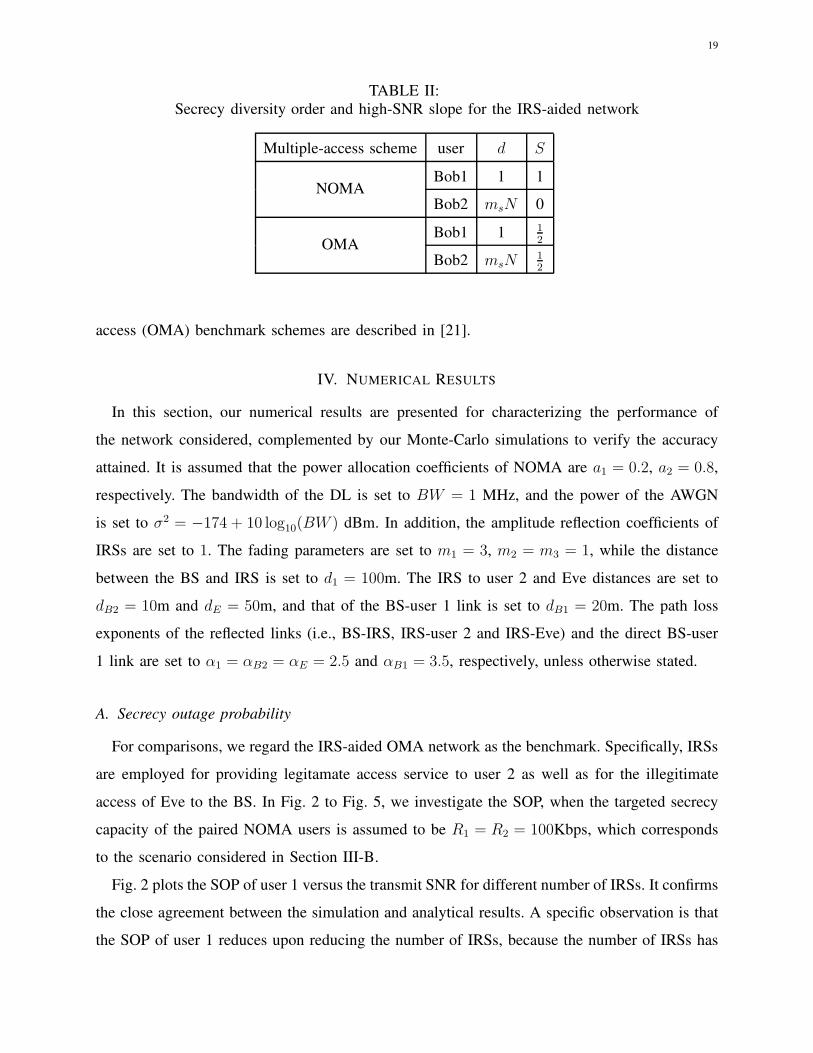
19
TABLE II:
Secrecy diversity order and high-SNR slope for the IRS-aided network
Multiple-access scheme user d S
NOMABob1 1 1
Bob2 msN 0
OMABob1 1 1
2
Bob2 msN12
access (OMA) benchmark schemes are described in [21].
IV. NUMERICAL RESULTS
In this section, our numerical results are presented for characterizing the performance of
the network considered, complemented by our Monte-Carlo simulations to verify the accuracy
attained. It is assumed that the power allocation coefficients of NOMA are a1 = 0.2, a2 = 0.8,
respectively. The bandwidth of the DL is set to BW = 1 MHz, and the power of the AWGN
is set to σ2 = −174 + 10 log10(BW ) dBm. In addition, the amplitude reflection coefficients of
IRSs are set to 1. The fading parameters are set to m1 = 3, m2 = m3 = 1, while the distance
between the BS and IRS is set to d1 = 100m. The IRS to user 2 and Eve distances are set to
dB2 = 10m and dE = 50m, and that of the BS-user 1 link is set to dB1 = 20m. The path loss
exponents of the reflected links (i.e., BS-IRS, IRS-user 2 and IRS-Eve) and the direct BS-user
1 link are set to α1 = αB2 = αE = 2.5 and αB1 = 3.5, respectively, unless otherwise stated.
A. Secrecy outage probability
For comparisons, we regard the IRS-aided OMA network as the benchmark. Specifically, IRSs
are employed for providing legitamate access service to user 2 as well as for the illegitimate
access of Eve to the BS. In Fig. 2 to Fig. 5, we investigate the SOP, when the targeted secrecy
capacity of the paired NOMA users is assumed to be R1 = R2 = 100Kbps, which corresponds
to the scenario considered in Section III-B.
Fig. 2 plots the SOP of user 1 versus the transmit SNR for different number of IRSs. It confirms
the close agreement between the simulation and analytical results. A specific observation is that
the SOP of user 1 reduces upon reducing the number of IRSs, because the number of IRSs has

20
30 40 50 60 70 80
Transmit SNR (dB)
10-3
10-2
10-1
100
Sec
recy
out
age
prob
abili
ty
SimulationAnalysisOMAFloor
N=10
N=20
Fig. 2: The SOP of user 1 versus the transmit SNR. The analytical results and the floor are
calculated from (19) and (33).
no effect on the channel gain of user 1. By contrast, the channel gain of Eve increases, as the
number of IRSs increases. As a benchmark, the SOP curves of the IRS-aided OMA network are
plotted for comparison. We observe that for user 1 in the IRS-aided OMA network has a better
performance than that in the IRS-aided NOMA network in the high-SNR regime. This is because
the transmit power allocated to user 1 in the NOMA network is lower than that in the OMA
network due to the influence of the power allocation factor. As the transmit SNR increases, we
find that the SOP of user 1 tends to a constant, which is consistent with Proposition 2.
Fig. 3 plots the SOP of user 2 versus the transmit SNR. We observe that, owing to the central
limit theorem (CLT) of the channel statistics of user 2, the analytical results are accurate in the
low-SNR regime, but inaccurate in the high-SNR regime. As a benchmark, the SOP curves of
the IRS-aided OMA network are also plotted for comparison. We observe that the performance
of user 2 in the IRS-aided NOMA network is better than that of the IRS-aided OMA network.
This is because the transmit power allocated to user 2 in the NOMA network is higher than that
in the OMA network due to the influence of the power allocation factor.
Since the SOP of user 2 in the high-SNR regime is not accurate in Fig. 3, we further plot
the high-SNR asymptotic curves in the cases of N = 1 and N = 3 in Fig. 4. We observe that
the SOPs of user 1 and user 2 gradually approach their respective asymptotic curves, which
validates our analysis. Furthermore, we also observe that in the cases of N = 1 and N = 3, the

21
30 35 40 45 50 55 60
Transmit SNR (dB)
10-3
10-2
10-1
100
Sec
recy
out
age
prob
abili
ty
SimulationAnalysisOMA
N=20N=10
Fig. 3: The SOP of user 2 versus the transmit SNR. The analytical results are calculated from (21).
40 50 60 70 80 90
Transmit SNR (dB)
10-4
10-3
10-2
10-1
100
Sec
recy
out
age
prob
abili
ty
SimulationAsymptotic
N=1
User 2
N=3
User 1
Fig. 4: Asymptotic SOP versus the transmit power results in the case of ρe = 10 dB. The
asymptotic results are calculated from (32) and (34).
secrecy diversity orders of user 1 are both 1 and the secrecy diversity orders of user 2 are 1 and
3, respectively, which is consistent with Remark 2 and Remark 3.
In Fig. 5, the SOP curves versus the number of IRSs are depicted. We observe that, since we
have global CSI for user 1, the SOP of user 1 is accurate. On the other hand, the SOP of user 2
is accurate in the low-SNR regime. However, the SOP of user 2 is inaccurate in the high-SNR

22
4 6 8 10 12 14 16 18 20
Number of IRSs
10-3
10-2
10-1
100
Sec
recy
out
age
prob
abili
ty
SimulationAnalysis
=50 dB =45 dB
User 2
User 1
Fig. 5: The SOP versus the number of IRSs. The analytical results are calculated from (19)
and (21).
regime, owing to using the CLT-based channel statistics of user 2. We also observe that the
SOP of user 1 increases as the number of IRSs increases since the ergodic rate of user 1 is not
affected by the number of IRSs. By contrast, the SOP of user 2 decreases as the number of IRSs
increases, since the IRS-aided transmissions to Eve experience more severe path loss then that
destined for user 2.
B. Average Secrecy Capacity
In this subsection, the number of points for the Chebyshev-Gauss and Gauss-Laguerre quadra-
tures are set to u1 = u2 = 100. In Fig. 6 and Fig. 7, we investigate the ASC of the IRS-aided
NOMA network, which corresponds to the scenario considered in Section III-C.
In Fig. 6, the ASC curves for the IRS-aided NOMA network are depicted. On the one hand,
for user 1, we observe that the simulation results match well with the analytical results, and
the asymptotic results derived are accurate. On the other hand, for user 2, we observe that the
analytical results both of approaches are highly accurate. Furthermore, the asymptotic results
derived both from (57) and (58) are also accurate. Additionally, we also observe that the high-
SNR slope of user 1 is 1, while the ASC of user 2 approaches a ceiling in the high-SNR regime,
which coincides with Proposition 4.

23
30 35 40 45 50 55 60 65 70
Transmit SNR (dB)
0
1
2
3
4
5
6
Ave
rage
Sec
recy
Cap
acity
(B
PC
U)
SimulationAnalysis: approach 1Analysis: approach 2Asymptotic: approach 1Asymptotic: approach 1
User 2
User 1
Fig. 6: The ASC versus the transmit SNR in the case of N=30 and ρe = 30 dB. The analytical
results are calculated from (46), (48) and (51), respectively. The asymptotic curves are calculated
from (55), (57) and (58), respectively.
Fig. 7: The ASC versus the numbers of IRS and the transmit SNR.
Fig. 7 plots the ASC of an IRS-aided NOMA network versus the number of IRSs and the
transmit SNR. We assume that the transmit SNR of the paired NOMA users and Eve are identical.
For user 1, we can observe that the ASC increases as the transmit SNR increases, since the BS-
IRS-Eve links experience more servere path loss then the BS-user 1 link. We can also observe
the ASC of user 1 decreases upon increasing the number of IRSs, since the ergodic rate of user

24
1 is not affected by the number of IRSs, while the ergodic rate of Eve increases upon increasong
the number of IRSs. For user 2, we observe that the ASC increases as the number of IRSs as
well as the transmit SNR increase up to the ceiling given by Corollary 3 and then decreases as
the number of IRSs or the transmit SNR increase. This is because Eve has strong eavesdropping
capability, which leads to an ergodic rate increase of Eve as increase the transmit SNR and the
number of IRSs is.
V. CONCLUSIONS
In this paper, the secrecy performance of IRS-aided NOMA networks was studied. Specifically,
we first derived new channel gain expressions for the reflected links. Then, based on the new
channel statistics, the closed-form SOP and ASC expressions were derived. Numerical results
were presented for validating our results. Furthermore, the secrecy diversity orders and the high-
SNR slopes have also been determined. The presence of the direct link between the BS and the
cell-edge user as well as Eve deserves further investigation in our future research.
APPENDIX A: PROOF OF LEMMA 2
Firstly, according to [21], the CDF of X =(∑N
n=1|g2,n||hn|)
2
N(1−ǫ)in the low-SNR regime is given
by
FX(x) = 1−Q 1
2
(√λ,
√x)
= e−λ2
∞∑
i=0
λiγ(i+ 1
2, x2
)
i!2iΓ(i+ 1
2
) .(A.1)
Hence, the CDF of γB2 in the low-SNR regime can be derived as
FγB2(x) = P (γB2 < x)
= FX
(x
N(1 − ǫ)ρ(a2 − a1x)d−α1
1 d−αB2
B2
)
= 1−Q 1
2
(√λ,
√x
N(1− ǫ)ρ(a2 − a1x)d−α1
1 d−αB2
B2
)
.
(A.2)
Then, according to [21], the CDF of Y =∑N
n=1 |g2,n||hn| in the high-SNR regime is given
by
FY (y) =mN(4msml)
−msN
Γ(2msN)γ (2msN, 2
√msmly) . (A.3)
25
Therefore, the CDF of γB2 in the high-SNR regime can be formulated as
F 0+γB2
(x) = P (γB2 < x)
= FY
(√x
ρ(a2 − a1x)d−α1
1 d−αB2
B2
)
=mN (4msml)
−msN
Γ(2msN)γ
2msN,2√msmlx
√
ρ(a2 − a1x)d−α1
1 d−αB2
B2
.
(A.4)
This completes the proof.
APPENDIX B: PROOF OF LEMMA 3
By stipulating that zn = |gq,n||hn|, and that fzn is the probability density function (PDF) of
zn, according to [21], the Laplace transform of fzn is given by
Lfzn(s) = ω(s+2
√mcmd)
−2mc2F1
(
2mc, mc −md +1
2;mc +md +
1
2;s− 2
√mcmd
s+ 2√mcmd
)
. (B.1)
Assuming that fZ is the PDF of Z, the Laplace transform of fZ is given by
LfZ(s) = ωN(s+ d)−aN
︸ ︷︷ ︸
f(s)
(
2F1
(
a, b; c;s− d
s+ d
))N
︸ ︷︷ ︸
g(s)
. (B.2)
According to the relationship between the Laplace transform and moments, we have
E(Z2) = L′′
fZ(0). (B.3)
From (B.2), we have
L′
fZ(s) = J1(s) + J2(s)J4(s), (B.4)
where
J1(s) = −aNωN (s+ d)−aN−1g(s), (B.5)
J2(s) = f(s)N
(
2F1
(
a, b; c;s− d
s+ d
))N−1
︸ ︷︷ ︸
J3(s)
, (B.6)
and
J4(s) =ab
c2F1
(
a+ 1, b+ 1; c+ 1;s− d
s+ d
)2d
(s+ d)2. (B.7)

26
Furthermore, we have
L′′
fZ(s) = J
′
1(s) + J′
2(s)J4(s) + J2(s)J′
4(s), (B.8)
where
J′
1(s) = aN(aN + 1)ωN(s+ d)−aN−2g(s)− aNωN(s+ d)−aN−1J3(s)J4(s), (B.9)
J′
2(s) = −aNωN (s+ d)−aN−1J3(s) + f(s)N(N − 1)
(
2F1
(
a, b; c;s− d
s+ d
))N−2
J4(s),
(B.10)
J′
4(s) =2abd
c(−2)(s+ d)−3
2F1
(
a + 1, b+ 1; c+ 1;s− d
s+ d
)
+
2abd
c(s+ d)2(a+ 1)(b+ 1)
c+ 12F1
(
a+ 2, b+ 2; c+ 2;s− d
s+ d
)2d
(s+ d)2.
(B.11)
By substituting s = 0 into J2, J4, (B.9), (B.10) and (B.11), we have
J2(0) = ωNd−aNNkN1 , (B.12)
J4(0) =2ab
cdk2, (B.13)
J′
1(0) = aNωNd−aN−2kN−11
(
(aN + 1)k1 −2ab
cNk2
)
, (B.14)
J′
2(0) = ωNd−aN−1NkN−21
(2ab
c(N − 1)k2 − aNk1
)
, (B.15)
J′
4(0) =4a(a+ 1)b(b+ 1)
c(c+ 1)d2k3 −
4ab
cd2k2. (B.16)
Then, by substituting (B.12)-(B.16) into (B.8), and after some further mathematical manipula-
tions, (16) can be obtained. This completes the proof.

27
APPENDIX C: PROOF OF THEOREM 3
Based on the above assumptions, the CDF of γEiin the low-SNR regime can be expressed as
FγEi(x) = FX
(x
aiρeN(1 − ǫe)d−α1
1 d−αE
E
)
= 1−Q 1
2
(√
λe,
√x
aiρeN(1− ǫe)d−α1
1 d−αE
E
)
= e−λe2
∞∑
k=0
λkeγ
(
k + 12, x
2aiρeN(1−ǫe)d−α11
d−αEE
)
k!2kΓ(k + 1
2
) ,
(C.1)
where we have ǫe =1
m1m3
(Γ(m1+
1
2)
Γ(m1)
)2 (Γ(m3+1
2)
Γ(m3)
)2
and λe =Nǫe1−ǫe
.
Therefore, the ergodic rate of Eve can be expressed as
REi= E (log2(1 + γEi
))
=
∫ ∞
0
log2(1 + x)dfγEi(x)
=
∫ ∞
0
(1− FγEi(x))d log2(1 + x)
=1
ln(2)e−
λe2
∞∑
k=0
λke
k!2kΓ(k + 1
2
)J5,i,
(C.2)
where
J5,i =
∫ ∞
0
Γ(k + 1
2
)− γ
(
k + 12, x
2aiρeN(1−ǫe)d−α11
d−αEE
)
1 + xdx. (C.3)
Next, by using the Gauss-Laguerre quadrature, (C.3) can be rewritten as
J5,i ≈n∑
l=0
ω5,lJ5(x5,l), (C.4)
where x5,l is the l-th root of the Laguerre polynomial Ln(x), the weight ω5,l is given by
w5,l =xl
(n + 1)2 [Ln+1 (xl)]2 , (C.5)
and
J5,i(x) =Γ(l + 1
2
)− γ
(
l + 12, tai
)
1 + xex, (C.6)
with t = x
2ρeN(1−ǫe)d−α11
d−αEE
. This completes the proof.

28
REFERENCES
[1] Z. Tang, T. Hou, Y. Liu, and J. Zhang, “Secrecy performance analysis for intelligent reflecting surface aided NOMA
network,” in IEEE International Conference on Communications (ICC) 2021, Submitted for publication.
[2] Q. Wu and R. Zhang, “Intelligent reflecting surface enhanced wireless network via joint active and passive beamforming,”
IEEE Trans. Wireless Commun., vol. 18, no. 11, pp. 5394–5409, Aug. 2019.
[3] O. Ozdogan, E. Bjornson, and E. G. Larsson, “Intelligent reflecting surfaces: Physics, propagation, and pathloss modeling,”
IEEE Wireless Commun. Lett., vol. 9, no. 5, pp. 581–585, Dec. 2019.
[4] Q. Wu and R. Zhang, “Towards smart and reconfigurable environment: Intelligent reflecting surface aided wireless network,”
IEEE Commun. Mag., vol. 58, no. 1, pp. 106–112, Nov. 2019.
[5] R. Alghamdi, R. Alhadrami, D. Alhothali, H. Almorad, A. Faisal, S. Helal, R. Shalabi, R. Asfour, N. Hammad, A. Shams,
N. Saeed, H. Dahrouj, T. Y. Al-Naffouri, and M.-S. Alouini, “Intelligent surfaces for 6G wireless networks: A survey of
optimization and performance analysis techniques,” arXiv preprint arXiv:2006.06541, Jun. 2020.
[6] C. Huang, A. Zappone, G. C. Alexandropoulos, M. Debbah, and C. Yuen, “Reconfigurable intelligent surfaces for energy
efficiency in wireless communication,” IEEE Trans. Wireless Commun., vol. 18, no. 8, pp. 4157–4170, Jun. 2019.
[7] M. Di Renzo, M. Debbah, D.-T. Phan-Huy, A. Zappone, M.-S. Alouini, C. Yuen, V. Sciancalepore, G. C. Alexandropoulos,
J. Hoydis, H. Gacanin et al., “Smart radio environments empowered by reconfigurable AI meta-surfaces: An idea whose
time has come,” EURASIP J. Wireless Commun. Netw., vol. 2019, no. 1, pp. 1–20, May 2019.
[8] M. Di Renzo and J. Song, “Reflection probability in wireless networks with metasurface-coated environmental objects: An
approach based on random spatial processes,” EURASIP J. Wireless Commun. Netw., vol. 2019, no. 1, p. 99, Apr. 2019.
[9] T. Hou, Y. Liu, Z. Song, X. Sun, and Y. Chen, “MIMO-NOMA networks relying on reconfigurable intelligent surface: A
signal cancellation based design,” arXiv preprint arXiv:2003.02117, Mar. 2020.
[10] H. Wang, Z. Zhang, B. Zhu, J. Dang, L. Wu, L. Wang, K. Zhang, and Y. Zhang, “Performance of wireless optical
communication with reconfigurable intelligent surfaces and random obstacles,” arXiv preprint arXiv:2001.05715, Jan.
2020.
[11] W. Shi, X. Zhou, L. Jia, Y. Wu, F. Shu, and J. Wang, “Enhanced secure wireless information and power transfer via
intelligent reflecting surface,” arXiv preprint arXiv:1911.01001, Nov. 2019.
[12] Q. Wu and R. Zhang, “Weighted sum power maximization for intelligent reflecting surface aided SWIPT,” IEEE Wireless
Commun. Lett., vol. 9, no. 5, pp. 586–590, Dec. 2019.
[13] S. Gopi, S. Kalyani, and L. Hanzo, “Intelligent reflecting surface assisted beam index-modulation for millimeter wave
communication,” arXiv preprint arXiv:2003.12049, Oct. 2020.
[14] Y. Liu, Z. Qin, M. Elkashlan, Z. Ding, A. Nallanathan, and L. Hanzo, “Non-orthogonal multiple access for 5G and beyond,”
IEEE Proc., vol. 105, no. 12, pp. 2347–2381, Dec. 2017.
[15] L. Dai, B. Wang, Y. Yuan, S. Han, I. Chih-Lin, and Z. Wang, “Non-orthogonal multiple access for 5G: solutions, challenges,
opportunities, and future research trends,” IEEE Commun. Mag., vol. 53, no. 9, pp. 74–81, Sep. 2015.
[16] Z. Ding, Y. Liu, J. Choi, Q. Sun, M. Elkashlan, I. Chih-Lin, and H. V. Poor, “Application of non-orthogonal multiple
access in LTE and 5G networks,” IEEE Commun. Mag., vol. 55, no. 2, pp. 185–191, Feb. 2017.
[17] S. Li, M. Derakhshani, S. Lambotharan, and L. Hanzo, “Outage probability analysis for the multi-carrier NOMA downlink
relying on statistical CSI,” IEEE Trans. Commun., vol. 68, no. 6, pp. 3572–3587, Jun. 2020.
[18] Y. Liu, Z. Qin, M. Elkashlan, Y. Gao, and L. Hanzo, “Enhancing the physical layer security of non-orthogonal multiple
access in large-scale networks,” IEEE Trans. Wireless Commun., vol. 16, no. 3, pp. 1656–1672, Mar. 2017.

29
[19] Z. Ding, P. Fan, and H. V. Poor, “Impact of user pairing on 5G nonorthogonal multiple-access downlink transmissions,”
IEEE Trans. Veh. Technol., vol. 65, no. 8, pp. 6010–6023, Sep. 2015.
[20] T. Hou, Y. Liu, Z. Song, X. Sun, Y. Chen, and L. Hanzo, “Reconfigurable intelligent surface aided NOMA networks,”
IEEE J. Sel. Areas Commun., pp. 1–1, Jul. 2020.
[21] Y. Cheng, K. H. Li, Y. Liu, K. C. Teh, and H. V. Poor, “Downlink and uplink intelligent reflecting surface aided networks:
NOMA and OMA,” arXiv preprint arXiv:2005.00996, Mar. 2020.
[22] Z. Ding and H. V. Poor, “A simple design of IRS-NOMA transmission,” IEEE Commun. Lett., vol. 24, no. 5, pp. 1119–1123,
May 2020.
[23] X. Yue and Y. Liu, “Performance analysis of intelligent reflecting surface assisted NOMA networks,” arXiv preprint
arXiv:2002.09907, Jun. 2020.
[24] X. Mu, Y. Liu, L. Guo, J. Lin, and N. Al-Dhahir, “Exploiting intelligent reflecting surfaces in multi-antenna aided NOMA
systems,” arXiv preprint arXiv:1910.13636, Jun. 2019.
[25] M. Fu, Y. Zhou, and Y. Shi, “Reconfigurable intelligent surface empowered downlink non-orthogonal multiple access,”
arXiv preprint arXiv:1910.07361, Mar. 2020.
[26] C. Zhang, W. Yi, Y. Liu, Z. Qin, and K. K. Chai, “Downlink analysis for reconfigurable intelligent surfaces aided NOMA
networks,” arXiv preprint arXiv:2006.13260, Jun. 2020.
[27] W. Ni, X. Liu, Y. Liu, H. Tian, and Y. Chen, “Resource allocation for Multi-Cell IRS-Aided NOMA networks,” arXiv
preprint arXiv:2006.11811, Jun. 2020.
[28] J. Zuo, Y. Liu, E. Basar, and O. A. Dobre, “Intelligent reflecting surface enhanced millimeter-wave NOMA systems,” arXiv
preprint arXiv:2005.01562, May 2020.
[29] X. Liu, Y. Liu, Y. Chen, and H. V. Poor, “RIS enhanced massive non-orthogonal multiple access networks: Deployment
and passive beamforming design,” IEEE J. Sel. Areas Commun., pp. 1–1, Aug. 2020.
[30] X. Wang, P. Hao, and L. Hanzo, “Physical-layer authentication for wireless security enhancement: Current challenges and
future developments,” IEEE Commun. Mag., vol. 54, no. 6, pp. 152–158, Jun. 2016.
[31] Y. Wu, A. Khisti, C. Xiao, G. Caire, K.-K. Wong, and X. Gao, “A survey of physical layer security techniques for 5G
wireless networks and challenges ahead,” IEEE J. Sel. Areas Commun., vol. 36, no. 4, pp. 679–695, Apr. 2018.
[32] A. Almohamad, A. M. Tahir, A. Al-Kababji, H. M. Furqan, T. Khattab, M. O. Hasna, and H. Arslan, “Smart and secure
wireless communications via reflecting intelligent surfaces: A short survey,” arXiv preprint arXiv:2006.14519, Jul. 2020.
[33] L. Yang, Y. Jinxia, W. Xie, M. Hasna, T. Tsiftsis, and M. Di Renzo, “Secrecy performance analysis of RIS-Aided wireless
communication systems,” IEEE Trans. Veh. Technol., pp. 1–1, Jul. 2020.
[34] M. Cui, G. Zhang, and R. Zhang, “Secure wireless communication via intelligent reflecting surface,” IEEE Wireless
Commun. Lett., vol. 8, no. 5, pp. 1410–1414, May 2019.
[35] L. Yang and Y. Yuan, “Secrecy outage probability analysis for RIS-assisted NOMA systems,” Electronics Letters, vol. 56,
no. 23, pp. 1254–1256, Nov. 2020.
[36] X. Guan, Q. Wu, and R. Zhang, “Intelligent reflecting surface assisted secrecy communication: Is artificial noise helpful
or not?” IEEE Wireless Commun. Lett., vol. 9, no. 6, pp. 778–782, Jan. 2020.
[37] H. Long, M. Chen, Z. Yang, B. Wang, Z. Li, X. Yun, and M. Shikh-Bahaei, “Reflections in the sky: Joint trajectory
and passive beamforming design for secure UAV networks with reconfigurable intelligent surface,” arXiv preprint
arXiv:2005.10559, Jun. 2020.
[38] A. U. Makarfi, K. M. Rabie, O. Kaiwartya, K. Adhikari, X. Li, M. Quiroz-Castellanos, and R. Kharel, “Reconfigurable
intelligent surfaces-enabled vehicular networks: A physical layer security perspective,” arXiv preprint arXiv:2004.11288,
Apr. 2020.
30
[39] L. Dong and H.-M. Wang, “Secure MIMO transmission via intelligent reflecting surface,” IEEE Wireless Commun. Lett.,
vol. 9, no. 6, pp. 787–790, Jan. 2020.
[40] Z. Chu, W. Hao, P. Xiao, and J. Shi, “Intelligent reflecting surface aided multi-antenna secure transmission,” IEEE Wireless
Commun. Lett., vol. 9, no. 1, pp. 108–112, Sep. 2020.
[41] H. Shen, W. Xu, S. Gong, Z. He, and C. Zhao, “Secrecy rate maximization for intelligent reflecting surface assisted
multi-antenna communications,” IEEE Commun. Lett., vol. 23, no. 9, pp. 1488–1492, Jun. 2019.
[42] I. S. Gradshteyn and I. M. Ryzhik, Table of Integrals, Series, and Products, 7th ed. Amsterdam, The Netherlands: Elsevier,
2007.
[43] J. M. Moualeu, D. B. da Costa, F. J. Lopez-Martinez, W. Hamouda, T. M. Nkouatchah, and U. S. Dias, “Transmit antenna
selection in secure MIMO systems over α − µ fading channels,” IEEE Trans. Commun., vol. 67, no. 9, pp. 6483–6498,
Jun. 2019.