
A preliminary Petri net model of the transshipment processes in the Taranto container terminal

Performance Evaluation for the Design ofAgent-based Systems: A Petri Net Approach?Jos�e Merseguer, Javier Campos, and Eduardo MenaDpto. de Inform�atica e Ingenier��a de Sistemas, University of Zaragoza, Spainfjmerse,jcampos,[email protected]. Software design and implementation using mobile agents arenowadays involved in a scepticism halo. There are researchers who ques-tion its utility because it could be a new technology that does providenew skills but it could introduce new problems. Security and performanceare the most critical aspects for this new kind of software. In this paperwe present a formal approach to analyse performance for this class ofsystems. Our approach is integrated in the early stages of the softwaredevelopment process. In this way, it is possible to predict the behaviourwithout the necessity to carry out the complete implementation phase.To show the approach, we model a software retrieval service system ina pragmatic way, later, the corresponding formal model is obtained andanalysed in order to study performance.Keywords: Software performance, Petri nets, UML, mobile agent1 IntroductionIn the last years, distributed software applications have increased their possibil-ities making use of Internet capabilities, positioning distributed software devel-opment as a very interesting approach. The client/server model has become thekey paradigm to support distributed software development. It is widely recog-nised that there are four main technologies which advocate for client/server de-velopments: relational database management systems (RDBMS), TP monitors,groupware and distributed objects. It is well accepted that distributed objectsin conjunction with mobile agents [15, 11] technology are a very interesting ap-proach to address certain kind of software domains like e-commerce, informationretrieval and network management and administration.Although there are researchers who question mobile software, it takes sensein distributed environments [9] because it is a technology with appropriate newskills for these kind of systems. But it could introduce new problems as the in-appropriate use of the net resources. In this way time consuming could becomea problem for users. So, we are concerned to develop new techniques and meth-ods which minimize these problems. In this context, software performance [18]appears as a discipline inside software engineering to deal with model perfor-mance on software systems design. Like many people concerned about software? This work has been developed within the project TAP98-0679 of the Spanish CICYT.

performance, we believe that the performance evaluation must be accomplishedduring the early stages of the software development process.Uni�ed Modeling Language (UML) [2] is widely accepted as a standard no-tation to model software systems. Unfortunately, UML lacks of the necessaryexpressiveness to accurately describe performance skills. There have been sev-eral approaches to solve this lack [19, 20, 16]. One of the goals of this paper isthe study of the performance indices in mobile agent systems, thus, we proposea UML with performance annotations (pa-UML) to deal with performance skillson these kind of systems. Our approach to solve the problem is as follows: wemodel the problem domain using pa-UML, describing static and dynamic viewswhen necessary. pa-UML models will give us the necessary background to obtainthe corresponding formal model expressed as Petri nets [13]. From pa-UML, wederive a time interpretation of Petri nets leading to Generalized Stochastic PetriNets (GSPN) [1]. Thus, we implicitly give a semantics for pa-UML in terms ofPetri nets. Performance indices may be computed for GSPN by applying quan-titative analysis techniques already developed in the literature.The rest of the paper is organised as follows. In section 2, we describe asystem, based on agents, which has been taken from [12]. In section 3, we giveour proposal to annotate system performance aspects in UML (pa-UML) andwe develop the pa-UML models for the system presented in section 2. Section 4is dedicated to transform pa-UML diagrams into Petri nets in order to achievethe desired formal model. Finally, some performance results and conclusions arepresented.2 An example: the Software Retrieval Service in theANTARCTICA systemIn this section we brie y present ANTARCTICA1. The system has been takenfrom [12] and it will be used as an example along this paper to study performanceon mobile agent systems.The goal of the system is to provide mobile computer users with di�erentservices that enhance the capabilities of their computer. One of these servicesis the Software Retrieval Service, that allows users to select and download newsoftware in an easy and e�cient way. This service has been thought to work ina wireless network media and provides several interesting features:{ The system manages the knowledge needed to retrieve software without userintervention, using an ontology.{ The location and access method to remote software is transparent to users.{ There is a \catalog" browsing feature to help user in software selection.{ The system maintains up to date the information related to the availablesoftware.In the following, we brie y describe the system paying attention in its com-ponents. There is a \majordomo" named Alfred, which is an agent specialised in1 Autonomous ageNT bAsed aRChitecture for cusTomized mobIle Computing Assis-tance.

user interaction. There is a Software Manager agent whose task is to create acatalog which will help the user to select the required software. Another agent,the Browser will help the user in selecting the software. Finally, a Salesmanagent is in charge of performing any action previous to the installation of theselected software, like e-commerce.The system was proposed in [12] using di�erent technologies, namely CORBA[14], HTTP and mobile agents. Some performance tests were applied to di�erentimplementations, in order to select the best way of accessing remote software.Conclusions were the following:{ Time corresponding to CORBA and mobile implementations are almostidentical for a wide range of �les to be downloaded.{ Mobile agent approaches are fast enough to compete with client/server ap-proach.Although considering the importance and the relevance of the results of thework [12], we would like to stress the enormous cost of implementing di�erentprototypes in order to evaluate the performance of the di�erent alternatives.In the rest of this paper, we model the system in a pragmatic way using pa-UML, annotating consistently the system load (we have annotated the systemload taking as a basis the experiments and experience of the authors of thecited paper). After that, we can interpret the pa-UML model in terms of Petrinets and derive the corresponding performance model which will be properlyanalysed. This analysis is used to evaluate the system.3 Modelling the system using pa-UMLIn the previous section, we have explained the general features of the targetsystem. Now, we focus on modelling it using pa-UML notation. We have con-sidered UML and not the notation of methodologies such as OMT [7], OOSE[10] or Fusion [6] because of its wider acceptance in the software engineeringcommunity.The system description in UML accomplishes with static and dynamic viewsin order to give a complete description of the system. For the sake of simplicityand for the convenience of our problem, we only describe the dynamic view ofthe system.Figure 1 shows the use cases needed to describe the dynamic behaviour ofthe system. We deal with three di�erent use cases, \show services", \softwareretrieval service" and \e-commerce". Also, we can see the unique actor whichinteracts with the system, the \user". The use cases are described in the follow-ing.Show services use case description.{ Principal event ow: the use case goal is to show to the user the availableservices that the system o�ers. The Software Retrieval Service is one of thoseservices and it is also described as a use case.

ElectronicUser
Commerce
RetrievalSoftware
Service
ServicesShow
Fig. 1. Use CasesSoftware retrieval service use case description.{ Principal event ow: the user requests the system for the desired software.The Browser gets a catalog and the majordomo, Alfred, shows it to the user,who selects the software s/he needs.{ Exceptional event ow: if the user is not satis�ed with the catalog presented,s/he can ask for a re�nement. This process could be repeated as many timesas necessary until the user selects a concrete piece of software.Electronic commerce use case description.{ Principal event ow: the goal is to provide the user an e-commerce activityand the download of the software selected.Show services and e-commerce use cases are out of the scope of this article,thus, we concentrate on the Software Retrieval Service.Pragmatic object-oriented methodologies such as [6, 7, 10] do not deal withperformance skills. So, we can say that there is not an accepted method tomodel and study system performance in the object-oriented software develop-ment process. This lack implies that there is not a well-de�ned language ornotation to annotate system load, system delays and routing rates. On the con-trary, formal speci�cation languages, such as LOTOS [17], or Petri nets [13], haveconsidered and studied the problem in depth. Thus, there are several proposalswhere we can learn from.As we remarked, it is our objective to propose a UML extension (pa-UML) todeal with performance on the software development process at the design stage.We consider that our proposal must accomplish with both, the method and thenotation. First, the method will give us the process to model the system and therelevant parameters to be taken into account. We advocate for a pattern-orientedapproximation. Lately, design patterns [8] have gained relevance in software de-velopment due to their simplicity and exibility. But this will be subject of futureresearch. Second, concerning the notation, it will be treated in this work.In order to have a complete performance notation, the UML behavioural andstructural models must be considered. Also, performance will play a prominentrole in the implementation diagrams. In this paper, we are interested only inbehavioural aspects, concretely in the sequence diagram and the state transitiondiagrams. Future works will deal with the rest of the UML diagrams to describebehaviour (use case diagrams, activity diagrams, collaboration diagrams), struc-tural aspects, and implementation diagrams.
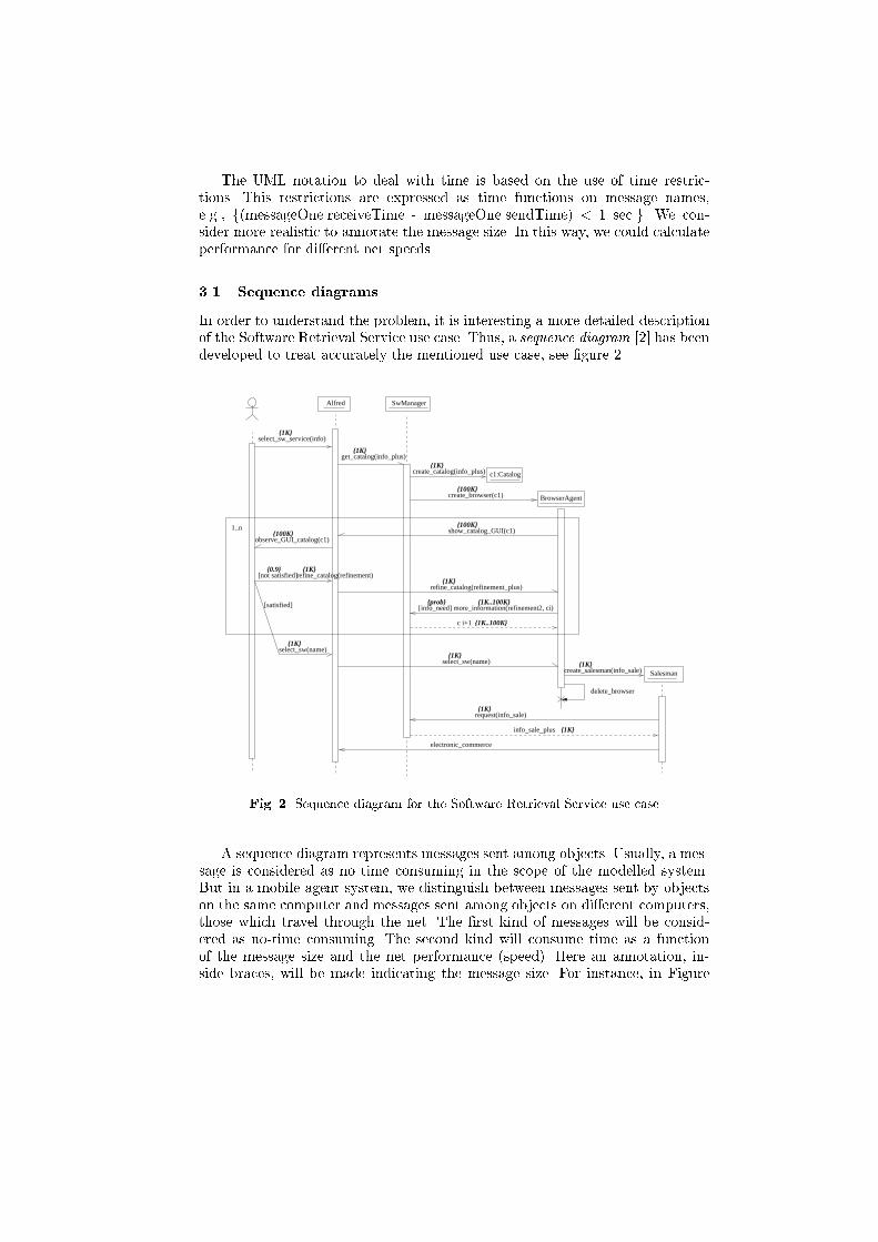
The UML notation to deal with time is based on the use of time restric-tions. This restrictions are expressed as time functions on message names,e.g., f(messageOne.receiveTime - messageOne.sendTime) < 1 sec.g. We con-sider more realistic to annotate the message size. In this way, we could calculateperformance for di�erent net speeds.3.1 Sequence diagramsIn order to understand the problem, it is interesting a more detailed descriptionof the Software Retrieval Service use case. Thus, a sequence diagram [2] has beendeveloped to treat accurately the mentioned use case, see �gure 2.{1K}
{100K}{100K}
{100K}
{1K}
{0.9}
{1K}
{1K}{1K}
{1K}
{1K}
{1K}
{1K}
{1K..100K}
refine_catalog(refinement_plus)
select_sw_service(info)
c1:Catalogcreate_catalog(info_plus)
observe_GUI_catalog(c1)
select_sw(name)
[info_need] more_information(refinement2, ci)
{1K}
{prob} {1K..100K}[satisfied]
create_salesman(info_sale)
[not satisfied]
1..n show_catalog_GUI(c1)
create_browser(c1)
get_catalog(info_plus)
refine_catalog(refinement)
electronic_commerce
info_sale_plus
request(info_sale)
delete_browser
select_sw(name)
c i+1
Salesman
BrowserAgent
SwManagerAlfred
Fig. 2. Sequence diagram for the Software Retrieval Service use caseA sequence diagram represents messages sent among objects. Usually, a mes-sage is considered as no time consuming in the scope of the modelled system.But in a mobile agent system, we distinguish between messages sent by objectson the same computer and messages sent among objects on di�erent computers,those which travel through the net. The �rst kind of messages will be consid-ered as no-time consuming. The second kind will consume time as a functionof the message size and the net performance (speed). Here an annotation, in-side braces, will be made indicating the message size. For instance, in Figure

2, select sw service message is labelled with f1 Kbyteg, while show catalog GUIrequires the movement of f100 Kbytesg. Also, it will be possible to annotate arange for the size in the UML common way, like in more information message,where a f1K..100Kg label appears.In a sequence diagram, conditions represent the possibility that the messagethat they have associated with could be sent. An annotation, also inside braces,expressing the event probability success will be associated to each condition. Arange is accepted too. See, for instance, the probability f0.9g associated in Figure2 to the condition not satis�ed. Sometimes, it is possible that the probability isunknown when modelling. Also, it could be that the probability a message occursis a parameter subject to study. In our example, the condition info need associ-ated to the more information message is critical for the system, because it revealshow much intelligent the Browser is; so, we want to study it. In such situations,we will annotate an identi�er, corresponding to the unknown probability.3.2 State Transition diagramsSequence diagrams show how objects interact, but to take a complete view of thesystem dynamics, it is also interesting to understand the life of objects. In UML,the state transition diagram is the tool that describes this aspect of the system.For each class with relevant dynamic behaviour a state transition diagram mustbe speci�ed.In a state transition diagram two elements will be considered, the activitiesand the guards. Activities represent tasks performed by an object in a givenstate. Such activities consume computation time that must be measured andannotated. The annotation will be inside braces showing the time needed toperform it. If it is necessary, a minimum and a maximum values could be an-notated. See, for example, bold labels between braces in Figures 4, 5, 6 and 7.Guards show conditions in a transition that must hold in order to �re the corre-sponding event. A probability must be associated to them. It will be annotatedin the same way as guards were annotated in the sequence diagram, and thesame considerations must be taken into account. See, for instance, label f0.9gjoined to condition [not ^user.satis�ed] in Figure 4.Message size may be omitted since this information appears in the sequencediagram. In the example, we have duplicated this information to gain readability.We now present the state transition diagrams for our system using the pa-UML notation.User state transition diagram. In Figure 3, the behaviour of a user is rep-resented. The user is in the wait state until s/he activates a select sw serviceevent. This event sets the user in the waiting for catalog state. The ob-serve GUI catalog event, sent by Alfred, allows the user to examine the cat-alog to look for the desired software, if it is in the catalog, the users selectsthe select sw event, in other case s/he selects the re�ne catalog event.Alfred state transition diagram. The example supposes that Alfred is al-ways present in the system, no creation event is relevant for our purposes.So the state transition diagram begins when a view services event is sent

[not satisfied]^Alfred.refine_catalog(refinement)
^Alfred.select_sw(name){1K}
WAIT
{1K}
Do:observe
observe_GUI_catalog(c1){100K}
{0.9}
^Alfred.select_sw_service(info)
catalogWaiting for
{1K}
Fig. 3. State transition diagram for the userto the user. Alfred's behaviour is typical for a server object behaviour. Itwaits for an event requesting a service (select sw service, show catalog GUI,re�ne catalog or select sw). For each of these requests it performs a concreteaction, and when it is completed, a message is sent to the corresponding ob-ject in order to complete the task. After the message is sent, Alfred returnsto its wait state to serve another request. Figure 4 shows Alfred's behaviour.The stereotyped transition � more services � means that Alfred may at-tend other services that are not of interest here.{0.9}
show_catalog_GUI(ci)
[not ^user.satisfied]refine_catalog(refinement)
^browser.refine_catalog(refinement_plus)
{0.1}
{1K}
{100K}
{1K}
{1K}
^browser.select_sw(name)
Do:create_GUI(c)^user.observe_GUI_catalog(ci)
Do:add_info3 Do:add_info2
Do:add_info1
[^user.satisfied]select_sw(name)
<<more_services>>WAIT
select_sw_service(info) ^SwManager.get_catalog(info_plus)
{1K}
{1sg}
{1K}
{100K}
{1K}
{1sg}
{1sg}
{1sg}Fig. 4. State transition diagram for AlfredSoftware Manager state transition diagram. Like Alfred, the SoftwareManager behaves as an server object. It is waiting for a request event(more information, get catalog, request) to enable the actions to accomplishthe task. Figure 5 shows its state transition diagram; it is interesting to notethe actions performed to respond the get catalog request. First, an ontologyis consulted and, after that, two di�erent objects are created, those involvedin task management.Browser state transition diagram. The state transition diagram in Figure6 describes the Browser's life. It is as follows: once the Browser is created it

WAIT
request(info_sale)
Do:add_info4
^salesman.reply(info_sale_plus)
^browser.reply(catalog){100K}
{0.5sg..50sg}
{1K}
{1sg}
get_catalog(info_plus)
[info_need] more_information(refinement2,ci){1K..100K}{prob}
Do:get_info
{1K}
Do: create_catalog
Do: create_browser
^browser.create_browser(ci) {1K}
^catalog.create_catalog(info_plus)
{1sg}
{1 min}{1K}
{1K}Fig. 5. State transition diagram for the Software Managermust go to theMU Place, where it invokes Alfred's shows catalog GUImethodto visualize the previously obtained catalog. At this state it can attend twodi�erent events, re�ne catalog or select sw. If the �rst event occurs there aretwo di�erent possibilities: �rst, if the Browser has the necessary knowledgeto solve the task, a re�nement action is directly performed; second, if itcurrently has not this background, the Browser must obtain informationfrom the Software Manager, by sending a more information request or bytravelling to the software place. If the select sw event occurs, the Browsermust create a Salesman instance and die.^alfred.show_catalog_GUI(ci)
Do:goto_Sw_place
Do:goto_MU_Place
create_browser(c)
delete_browser
Do:goto_MU_Place
{1K}
{1K}{100K} {100K}
{1K}
{100K}
{1K..100K}
{100K..200K}
^salesman.create_salesman(info_sale)
^SwManager.more_in-formation(refinement2, ci)
[not info_need]
[info_need_travel]
select_sw(name)
refine_catalog(refinement_plus)
{1K..100K}
WAIT
[not info_need or info_need_local][info_need_travel]
[info_need_local]
Do: refine
^alfred.show_catalog_GUI(ci+1){100K}
{1sg}
reply
Fig. 6. State transition diagram for the BrowserSalesman State Transition Diagram. The Salesman's goal is to give e-commerce services, as we can see in Figure 7. After its creation it asksthe Software Manager for sale information. With this information the e-commerce can start. This is a complex task that must be described with itsown use case and sequence diagram which is out of the scope of this paper.The pa-UML models that we have developed are expressive enough to accom-plish with di�erent implementations. A necessary condition to design methods
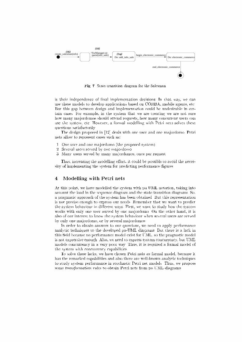
begin_electronic_commerceDo: electronic_commerce
create_salesman(info){1K}
Do: add_info_sale
^SwManager.re-quest(info_sale)
{1K}
end_electronic_commerce
{1sg}
Fig. 7. State transition diagram for the Salesmanis their independence of �nal implementation decisions. In that way, we canuse these models to develop applications based on CORBA, mobile agents, etc.But this gap between design and implementation could be undesirable in cer-tain cases. For example, in the system that we are treating we are not surehow many majordomos should attend requests, how many concurrent users canuse the system, etc. However, a formal modelling with Petri nets solves thesequestions satisfactorily.The design proposed in [12] deals with one user and one majordomo. Petrinets allow to represent cases such as:1. One user and one majordomo (the proposed system).2. Several users served by one majordomo.3. Many users served by many majordomos, once per request.Thus, increasing the modelling e�ort, it could be possible to avoid the neces-sity of implementing the system for predicting performance �gures.4 Modelling with Petri netsAt this point, we have modelled the system with pa-UML notation, taking intoaccount the load in the sequence diagram and the state transition diagrams. So,a pragmatic approach of the system has been obtained. But this representationis not precise enough to express our needs. Remember that we want to predictthe system behaviour in di�erent ways. First, we want to study how the systemworks with only one user served by one majordomo. On the other hand, it isalso of our interest to know the system behaviour when several users are servedby only one majordomo, or by several majordomos.In order to obtain answers to our questions, we need to apply performanceanalytic techniques to the developed pa-UML diagrams. But there is a lack inthis �eld because no performance model exist for UML, so the pragmatic modelis not expressive enough. Also, we need to express system concurrency, but UMLmodels concurrency in a very poor way. Thus, it is required a formal model ofthe system with concurrency capabilities.To solve these lacks, we have chosen Petri nets as formal model, because ithas the remarked capabilities and also there are well-known analytic techniquesto study system performance in stochastic Petri net models. Thus, we proposesome transformation rules to obtain Petri nets from pa-UML diagrams.

In the following, we model with Petri nets the �rst two proposed systems, thethird one will be developed in a future work. For the �rst system, one user andone majordomo, GSPN have the expressive power to accomplish the task. Tostudy the second system, several users served by one majordomo, stochastic well-formed coloured Petri nets [3] are of interest. Once the systems are modelled, weuse analytic techniques implemented in GreatSPN [4] tool to obtain the targetperformance requirements.4.1 Petri net model for a system with one majordomo and one userFirst, we are going to obtain a Petri net for each system class, the componentnets. Obviously, every annotated state transition diagram will give us the guide,and the following general transformation rules will be applied:Rule 1. Two di�erent kinds of transitions can be identi�ed in a state transitiondiagram. Transitions which do not spend net resources and transitions whichdo. The �rst kind will be translated into \immediate" transitions (that �re inzero time) in the Petri net. The second kind will be \timed" transitions in thePetri net. The mean of the exponentially distributed random variable for thetransition �ring time will be calculated as a constant function of the messagesize and net speed. More elaborated proposals like those given in [5] could betaken into account, but we have considered more important to gain simplicity.Rule 2. Actions inside a state of the state transition diagram are consideredas time consuming, so in the Petri net model they will be consider as timedtransitions. The time will be calculated from the CPU and disk operations neededto perform the action.Rule 3. Guards in the state transition diagram will become immediate transi-tions with the associated corresponding probabilities for the resolution of con- icts.Rule 4. States in the state transition diagram will be places in the Petri net.But there will be not the unique places in the net, because additional places willbe needed as an input to con icting immediate transitions (obtained by applyingRule 3).Figures 8, 9, 10, 11 and 12 represent the nets needed to model our systemcomponents taking into account the previous transformation rules. According toGSPN notation [1], immediate transitions (�ring in zero time) are drawn as bars(�lled), while timed transitions are depicted as boxes (un�lled). Timed transi-tions are annotated with �ring rates, while immediate transitions are annotatedwith probabilities for con ict resolution.The sequence diagram will be the guide to obtain a complete Petri net forthe system using the previous component nets. We must consider that UMLdistinguishes, in a concurrent system, two di�erent kind of messages in a sequencediagram:{ those represented by a full arrowhead (wait semantics), and

P15P7
wait_for_service wait_UserforCatalog P4
P6
observe_GUI_catalog
alfred.select_sw_service
alfred_refine_catalog
alfred.select_sw
electronic_commerce
end_ec
begin_ecFig. 8. User Petri net componentwait_Alfred
P36
P3P4
P5
P6
P7
P8
P9
show_GUI_catalog
add_info3
add_info1 user.observe_GUI_catalogSw_Manager.getcatalog
add_info2
create_GUI
browser.select_sw_browser browser.refine_catalog
refine_catalogselect_software
select_sw_service
Fig. 9. Alfred Petri net component{ those represented by a half arrowhead (no-wait semantics).The following transformation rules will be used to obtain the net system. But�rst, it must be taken into account that, for every message in the sequence dia-gram, there are two transitions with the same name in two di�erent componentnets, the net representing the sender and the net representing the receiver.Rule 5. If the message has wait semantics, only one transition will appear inthe complete net system; this transition will support the incoming and outcomingarcs from both net components.wait
P3
P4
P5
P6
P7
P8
browser.reply_remote add_info4request
salesman.reply
get_catalogmore_information_remote
browser.create_browser
create_catalog
get_info
browser.reply_local
more_information_localFig. 10. Software Manager Petri net component

P1
P2
P3
wait
P5P6
P7
P8
P9
P10
P11
P12
P13
P15
P16
P17
P18
P19
P20
SwManager.more_information_remote
reply_local
reply_remote
goto_MU_Place2
create_browser_agent
alfred.show_catalog_GUI
refine_catalog_browser
select_sw_browser
salesman.create_salesman
goto_Sw_Place
refine
goto_MU_Place
not_info_need_or_local
info_need_travel1
SwManager.more_information_local
info_need_local
info_need_travel
not_info_need
delete_browser
Fig. 11. Browser Petri net componentP1 P2 begin_add_info_sale
end_add_info_saleP5P6
SwManager.requestcreate_salesman
user.electronic_commerce
add_info_saleuser.end_ec
user.begin_ecFig. 12. Salesman Petri net componentRule 6. If the message has no-wait semantics, the two transitions will appear inthe net system and also an extra place will be added modelling the communicationbu�er. This place will receive an arc from the sender transition and will add anarc to the receiver transition.The net system for the example is shown in Figure 13. In order to under-stand how to apply the previous rules, we are going to explain how to obtainthe observe GUI catalog transition in the net system (Figure 13) from the ob-serve GUI catalog message sent by Alfred to the user in the sequence diagram.We can observe in Alfred's net (Figure 9) and in the user's net (Figure 8) thepresence of that transition. So, in the net system the transition appears with theunion of the incoming and outcoming arcs of the components, synchronising inthis way both objects.Finally, we remark with an example that the concurrency expressed in UMLhas been achieved in the net system by synchronising component nets. Whencreate salesman transition �res one token is placed in P20 and one token is placedin P31, allowing a concurrent execution of the request and delete browser transi-tions.4.2 Petri net model for a system with one majordomo and severalusersIn order to model with Petri nets the situation of several users being servedby one majordomo, we need to include several tokens in some places like, for

P1
wait_SwManager
P5
P6
P7
P8
wait_UserforService
wait_UserforCatalog
P15
P16
P17 P18
P19
P20
begin_add_info_sale
P22P23end_add_info_sale
P25
P26P27
wait_Browser
P29
P30
P31
wait_Alfred
P35
P36
P37
P38
P39
P40
P41 P42
P43
P46
P44
P45 P47
P49
P48
P50
P51
P52
P53
P54
P55
P56browser.reply_remote
goto_MU_Place2
get_info
observe_GUI_catalog
more_information_remote
goto_MU_Place
goto_Sw_Place
add_info_sale
show_catalog_GUI
create_catalog
add_info4
create_salesman
add_info3
add_info2
add_info
refine
create_BrowserAgentcreate_GUI
browser.reply_local
info_need_travel
info_need_local
select_sw
refine_catalog
not_info_need
salesman.reply
request
select_sw_browser
refine_catalog_browser
select_sw_service get_catalog
t38
t37
t36
electronic_commerce
not_info_need_or_localinfo_need_travel1
more_information_local
delete_browser
begin_ecend_ec
Fig.13.ThePetrinetforthewholesystem
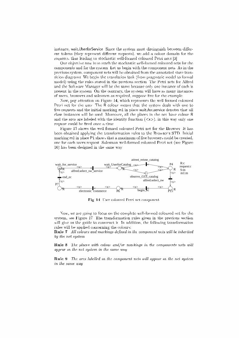
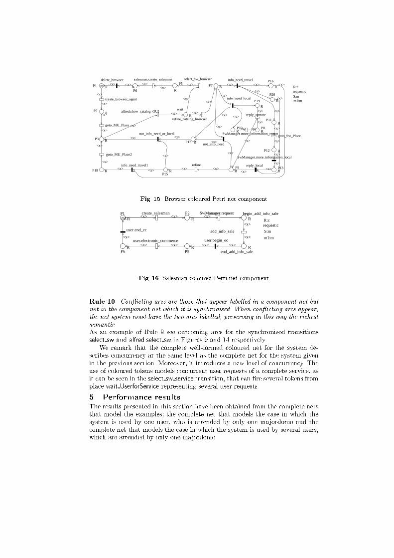
instance, wait UserforService. Since the system must distinguish between di�er-ent tokens (they represent di�erent requests), we add a colour domain for therequests, thus leading to stochastic well-formed coloured Petri nets [3].Our objective now is to reach the stochastic well-formed coloured nets for thecomponents and for the system. Let us begin with the component nets. As in theprevious system, component nets will be obtained from the annotated state tran-sition diagrams. We begin the translation task (from pragmatic model to formalmodel) using the rules stated in the previous section. The Petri nets for Alfredand the Software Manager will be the same because only one instance of each ispresent in the system. On the contrary, the system will have as many instancesof users, browsers and salesmen as required, suppose �ve for the example.Now, pay attention on Figure 14, which represents the well-formed colouredPetri net for the user. The R colour means that the system deals with one to�ve requests and the initial marking m1 in place wait for service denotes that allclass instances will be used. Moreover, all the places in the net have colour Rand the arcs are labeled with the identity function (<x>), in this way only onerequest could be �red once a time.Figure 15 shows the well-formed coloured Petri net for the Browser. It hasbeen obtained applying the transformation rules to the Browser`s STD. Initialmarking m1 in place P1 shows that a maximum of �ve browsers could be created,one for each users request. Salesman well-formed coloured Petri net (see Figure16) has been designed in the same way.P15 R
P7
R
wait_for_service
Rm1wait_UserforCatalog
R
P4
R
P6R
observe_GUI_catalog
alfred.select_sw_service
alfred_refine_catalog
alfred.select_sw
electronic_commerce
end_ec
begin_ec<x> <x>
<x>
<x>
<x> <x>
<x>
<x>
<x><x><x><x><x><x>
R:crequest:cS:mm1:m
Fig. 14. User coloured Petri net componentNow, we are going to focus on the complete well-formed coloured net for thesystem, see Figure 17. The transformation rules given in the previous sectionwill give us the guide to construct it. In addition, the following transformationrules will be applied concerning the colours:Rule 7. All colours and markings de�ned in the component nets will be inheritedby the net system.Rule 8. The places with colour and/or markings in the components nets willappear in the net system in the same way.Rule 9. The arcs labelled in the component nets will appear in the net systemin the same way.
P1 Rm1
P2R
P3 R
wait
R
P5
RP6R P7 R
P8R
P9R
P10R
P11R
P12 R
P13R
P15R
P16
R
P17 R
P18 R
P19
R
P20
R
SwManager.more_information_remot
reply_local
reply_remote
goto_MU_Place2
create_browser_agent
alfred.show_catalog_GUI
refine_catalog_browser
select_sw_browsersalesman.create_salesman
goto_Sw_Place
refine
goto_MU_Place
not_info_need_or_local
info_need_travel1
SwManager.more_information_local
info_need_local
info_need_travel
not_info_need
delete_browser
<x>
<x>
<x>
<x>
<x>
<x>
<x>
<x><x>
<x>
<x>
<x>
<x>
<x>
<x>
<x>
<x>
<x>
<x>
<x>
<x>
<x>
<x>
<x>
<x>
<x>
<x>
<x>
<x><x><x><x>
<x>
<x>
<x>
<x>
<x>
<x>
<x><x><x>
<x><x><x> <x>
<x>
R:crequest:cS:mm1:m
Fig. 15. Browser coloured Petri net componentP1
Rm1P2
Rbegin_add_info_sale
R
end_add_info_saleR
P5R
P6R
SwManager.requestcreate_salesman
user.electronic_commerce
add_info_saleuser.end_ec
user.begin_ec
<x>
<x><x><x>
<x>
<x> <x> <x> <x>
<x>
R:crequest:c
S:m
m1:m
Fig. 16. Salesman coloured Petri net componentRule 10. Con icting arcs are those that appear labelled in a component net butnot in the component net which it is synchronised. When con icting arcs appear,the net system must have the two arcs labelled, preserving in this way the richestsemantic.As an example of Rule 9 see outcoming arcs for the synchronised transitionsselect sw and alfred.select sw in Figures 9 and 14 respectively.We remark that the complete well-formed coloured net for the system de-scribes concurrency at the same level as the complete net for the system givenin the previous section. Moreover, it introduces a new level of concurrency. Theuse of coloured tokens models concurrent user requests of a complete service, asit can be seen in the select sw service transition, that can �re several tokens fromplace wait UserforService representing several user requests.5 Performance resultsThe results presented in this section have been obtained from the complete netsthat model the examples; the complete net that models the case in which thesystem is used by one user, who is attended by only one majordomo and thecomplete net that models the case in which the system is used by several users,which are attended by only one majordomo.

P1R
wait_SwManager
P5R
P6R
P7
R
P8 R
wait_UserforServiceRm1
wait_UserforCatalogR
P15R
P16R
P17R P18
R
P19 Rm1
P20R
begin_add_info_saleR
P22R
P23R
end_add_info_sale R
P25R m1
P26RP27R
wait_BrowserR
P29R
P30R
P31R
wait_Alfred
P35R
P36R
P37
R
P38
R
P39 R
P40R
P41R
P42R
P43R
P46R
P44R
P45RP47
R
P49
R
P48R
P50R
P51R
P52
R
P53R
P54R
P55R
P56R browser.reply_remote
goto_MU_Place2
get_info
observe_GUI_catalog
more_information_remote
goto_MU_Place
goto_Sw_Place
add_info_sale
show_catalog_GUI
create_catalog
add_info4
create_salesman
add_info3
add_info2
add_info
refine
create_BrowserAgentcreate_GUI
browser.reply_local
info_need_travel
info_need_local
select_sw
refine_catalog
not_info_need
salesman.reply
request
select_sw_browser
refine_catalog_browser
select_sw_serviceget_catalog
t38
t37
t36
electronic_commerce
not_info_need_or_localinfo_need_travel1
more_information_local
delete_browser
begin_ecend_ec
<x>
<x>
<x>
<x>
<x>
<x><x>
<x>
<x>
<x>
<x>
<x>
<x>
<x>
<x>
<x>
<x>
<x>
<x>
<x>
<x><x>
<x><x>
<x>
<x>
<x>
<x><x>
<x>
<x>
<x>
<x><x>
<x><x>
<x>
<x>
<x>
<x>
<x>
<x>
<x>
<x>
<x>
<x> <x>
<x>
<x>
<x> <x>
<x><x>
<x>
<x><x>
<x>
<x>
<x><x>
<x>
<x>
<x> <x>
<x>
<x>
<x><x>
<x><x>
<x><x>
<x><x>
<x>
<x>
<x><x>
<x>
<x>
<x><x>
<x> <x>
<x>
<x>
<x><x>
<x> <x>
<x><x>
<x>
<x>
<x>
<x>
<x>
<x><x>
<x>
<x>
R:crequest:c
S:m
m1:m
Fig.17.ThecolouredPetrinetforthewholesystem

It is of our interest to study the system response time in the presence of a userrequest. To obtain the response time, �rst the throughput of the select sw servicetransition, in the net system, will be calculated by computing the steady statedistribution of the isomorphic Continuous Time Markov Chain (CTMC) withGreatSPN [4]; �nally, the inverse of the previous result gives the system responsetime. We want to know which are the bottlenecks of the system and identify theirimportance. There are two possible parts which can decrease system performance.First, the trips of the Browser from the \user place" to the \software place" (andway back) in order to obtain new catalogs. Second, the user requests for catalogre�nements, because s/he is not satis�ed with it.In order to study the two possible bottlenecks, we have developed a testtaking into account the following possibilities:1. When the Browser needs a new catalog (under request of the user) there areseveral possibilities:{ The Browser has enough information to accomplish the task or it needsto ask for the information. It is measured by the not info need transi-tion. We have considered an \intelligent Browser" which does not needinformation the 70% of the times that the user asks for a re�nement.{ When the Browser needs information to perform the task, it may re-quest it by a remote procedure call (RPC) (represented in the net sys-tem by the info need local transition) or it may travel through the net tothe Software place (represented in the net system by the info need traveltransition) to get the information and then travel back to the MU Place.In this case, we have considered two scenarios. First, a probability equalto 0.3 to perform a RPC, so a probability equal to 0.7 to travel throughthe net. Second, the opposite situation, a probability equal to 0.7 to per-form a RPC, therefore a probability equal to 0.3 to travel through thenet.2. To test the user re�nement request, we have considered two di�erent possi-bilities. An \expert user" requesting a mean of 10 re�nements, and a \naiveuser" requesting a mean of 50 re�nements.3. The size of the catalog obtained by the Browser can also decrease the systemperformance. We have used �ve di�erent sizes for the catalog: 1 Kbyte, 25Kbytes, 50 Kbytes, 75 Kbytes and 100 Kbytes.4. The speed of the net is very important to identify bottlenecks. We have con-sidered two cases: a net with a speed of 100 Kbytes/sec. (\fast" connectionspeed) and a net with a speed of 10 Kbytes/sec. (\slow" connection speed).Figure 18(a) shows system response time (in minutes), for the net in Fig-ure 13, supposing \fast" connection speed, \expert user" and an \intelligent"Browser. One of the lines represents a probability equal to 0.7 to travel and0.3 to perform a RPC, the other line represents the opposite situation. We canobserve that there are small di�erences between the RPC and travel strategies.Such a di�erence is due to the round trip of the agent. As the agent size doesnot change, this di�erence is not relevant for the global system performance.Thus, we show that the use of mobile agents for this task does not decrease theperformance.

0
5
10
15
20
25
30
file size
min
ute
s
travel 0,3;RPC 0,7
travel 0,7;RPC 0,3
travel 0,3; RPC 0,7 13,6277 16,7842 20,0803 23,6072 26,6667
travel 0,7; RPC 0,3 13,8313 16,9895 20,2758 23,8095 26,8817
1 Kbyte 25 Kbyte 50 Kbyte 75 Kbyte100
Kbyte
0
1
2
3
4
5
6
7
8
9
10
file size
min
ute
s
travel 0,3;RPC 0,7
travel 0,7;RPC 0,3
travel 0,3; RPC 0,7 5,63825 6,36862 7,12555 7,93273 8,64454
travel 0,7; RPC 0,3 6,03865 6,76956 7,52785 8,3375 9,04323
1 Kbyte 25 Kbyte 50 Kbyte 75 Kbyte100
Kbyte
0
5
10
15
20
25
30
35
40
file size
min
ute
s
travel 0,3;RPC 0,7
travel 0,7;RPC 0,3
travel 0,3; RPC 0,7 16,7001 20,4248 24,2954 28,4075 32,0513
travel 0,7; RPC 0,3 18,7477 22,4921 26,3421 30,4303 34,0832
1 Kbyte 25 Kbyte 50 Kbyte 75 Kbyte100
Kbyte
0
1
2
3
4
5
6
7
file size
min
ute
stravel 0,3;RPC 0,7
travel 0,7;RPC 0,3
travel 0,3; RPC 0,7 3,706999 4,326757 4,970673 5,663156 6,260957
travel 0,7; RPC 0,3 3,747002 4,366431 5,011024 5,703856 6,301197
1 Kbyte 25 Kbyte 50 Kbyte 75 Kbyte100
Kbyte
(a) (b)
(c) (d)Fig. 18. Response time for a di�erent scenarios with an \intelligent Browser". (a) and(b) represent a \fast" connection speed, (c) and (d) a \slow" connection speed; (a) and(c) an \expert user" and (b) and (d) a \naive user".Figure 18(b) shows system response time (in minutes), supposing \fast con-nection", \intelligent" Browser, \naive user". The lines have identical meaningthan in Figure 18(a). The two solutions still remain identical.Someone could suspect that there exist small di�erences because of the netspeed. So, we have decreased the net speed to 10 Kbytes/sec., (Figures 18(c)and 18(d)). It can be seen how the di�erences still remain non signi�cant.Finally, Figure 19 represents a test for an \intelligent Browser", an \expert"user, a probability for RPC equal to 0.7 and equal to 0.3 to travel. Now, wehave tested the system for a di�erent number of requests ranging from 1 to4, thus the coloured model in Figure 17 has been used. Observe that when thenumber of requests is increased, the response time for each request increases, i.e.,tasks cannot execute completely in parallel. Alfred and the Software Managerare not duplicated with simultaneous requests. Thus, they are the bottleneckfor the designed system with respect to the number of concurrent requests ofthe service. Therefore, the next step in the performance analysis of the modelwould be to consider several majordomos (we do not include here due to spacelimitations).
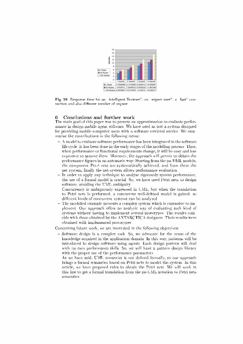
0
2
4
6
8
10
12
14
16
18
min
ute
s
1 Kbyte
50 Kbytes
100 Kbytes
1 Kbyte 3,7069988 6,1319598 8,3640013 10,506961
50 Kbytes 4,970673 7,2605823 9,5529232 11,862396
100 Kbytes 6,2609567 9,2157405 12,30315 15,500271
1 request 2 request 3 request 4 requestFig. 19. Response time for an \intelligent Browser", an \expert user", a \fast" con-nection and also di�erent number of request.6 Conclusions and further workThe main goal of this paper was to present an approximation to evaluate perfor-mance in design mobile agent software. We have used as test a system designedfor providing mobile computer users with a software retrieval service. We sum-marise the contributions in the following items:{ Amodel to evaluate software performance has been integrated in the softwarelife cycle. It has been done in the early stages of the modelling process. Thus,when performance or functional requirements change, it will be easy and lessexpensive to assume them. Moreover, the approach will permit to obtain theperformance �gures in an automatic way: Starting from the pa-UML models,the component Petri nets are systematically achieved, and from these thenet system, �nally the net system allows performance evaluation.{ In order to apply any technique to analyse rigorously system performance,the use of a formal model is crucial. So, we have used Petri nets to designsoftware, avoiding the UML ambiguity.{ Concurrency is ambiguously expressed in UML, but when the translationto Petri nets is performed, a concurrent well-de�ned model is gained, sodi�erent kinds of concurrent systems can be analysed.{ The modelled example presents a complex system which is expensive to im-plement. Our approach o�ers an analytic way of evaluating such kind ofsystems without having to implement several prototypes. The results coin-cide with those obtained by the ANTARCTICA designers. Their results wereobtained with implemented prototypes.Concerning future work, we are interested in the following objectives:{ Software design is a complex task. So, we advocate for the reuse of theknowledge acquired in the application domain. In this way, patterns will beintroduced to design software using agents. Each design pattern will dealwith its own performance skills. So, we will have a pattern design librarywith the proper use of the performance parameters.{ As we have said, UML semantics is not de�ned formally, so our approachbrings a formal semantics based on Petri nets to model the system. In thisarticle, we have proposed rules to obtain the Petri nets. We will work inthis line to get a formal translation from the pa-UML notation to Petri netssemantics.

References[1] M. Ajmone Marsan, G. Balbo, and G. Conte, A class of generalized stochastic Petrinets for the performance evaluation of multiprocessor systems, ACM Transactionson Computer Systems 2 (1984), no. 2, 93{122.[2] G. Booch, I. Jacobson, and J. Rumbaugh, OMG Uni�ed Modeling Language spec-i�cation, June 1999, version 1.3.[3] G. Chiola, C. Dutheillet, G. Franceschinis, and S. Haddad, Stochastic well-formedcoloured nets for symmetric modelling applications, IEEE Transactions on Com-puters 42 (1993), no. 11, 1343{1360.[4] G. Chiola, G. Franceschinis, R. Gaeta, and M. Ribaudo, GreatSPN 1.7: GRaphicalEditor and Analyzer for Timed and Stochastic Petri Nets, Performance Evaluation24 (1995), 47{68.[5] J. Dilley, R. Friedrich, T. Jin, and J. Rolia, Web server performance measurementand modeling techniques, Performance Evaluation (1998), no. 33, 5{26.[6] D. Coleman et Al., Object oriented development. the Fusion method, Object Ori-ented, Prentice Hall, 1994.[7] J. Rumbaugh et Al., Object oriented modeling and design, Prentice-Hall, 1991.[8] E. Gamma, R. Helm, R. Johnson, and J. Vlissides, Design Patterns: Elements ofreusable object-oriented software, Addison-Wesley, 1995.[9] C. Harrison, D. Chess, and A. Kershenbaum,Mobile agents: are they a good idea?,Mobile Object Systems: Towards the Programmable Internet, 1997, pp. 46{48.[10] I. Jacobson, M. Christenson, P. Jhonsson, and G. Overgaard, Object-oriented soft-ware engineering: A use case driven approach, Addison-Wesley, 1992.[11] E. Kovacs, K. R�ohrle, and M. Reich, Mobile agents OnTheMove -integrating anagent system into the mobile middleware, Acts Mobile Summit (Rhodos, Grece),June 1998.[12] E. Mena, A. Illarramendi, and A. Go~ni, Customizable software retrieval facilityfor mobile computers using agents, Proceedings of the 7th International Confer-ence on Parallel and Distributed Systems (ICPADS'2000), Workshop InternationalFlexible Networking and Cooperative Distributed Agents (FNCDA'2000) (Iwate(Japan)), IEEE Computer Society, July 2000.[13] T. Murata, Petri nets: Properties, analysis, and applications, Proceedings of theIEEE 77 (1989), no. 4, 541{580.[14] Object Management Group, The common object request broker: Architecture andspeci�cation, June 1999, Revision 2.3.[15] E. Pitoura and G. Samaras, Data management for mobile computing, Kluwer Aca-demic Publishers, 1998.[16] R. Pooley and P. King, The uni�ed modeling language and performance engineer-ing, IEE Proceedings Software, IEE, March 1999.[17] N. Rico and G.V. Bochman, Performance description and analysis for distrib-uted systems using a variant of LOTOS, 10th International IFIP Symposium onProtocol Speci�cation, Testing an Validation, July 1990.[18] C. U. Smith, Performance engineering of software systems, The Sei Series in Soft-ware Engineering, Addisson{Wesley, 1990.[19] G. Waters, P. Linington, D. Akehurst, and A. Symes, Communications softwareperformance prediction, 13th UK Workshop on Performance Engineering of Com-puters and Telecommunication Systems (Ilkley), Demetres Kouvatsos Ed., July1997, pp. 38/1{38/9.[20] M. Woodside, C. Hrischuck, B. Selic, and S. Bayarov, A wide band approach to in-tegrating performance prediction into a software design environment, Proceedingsof the 1st International Workshop on Software Performance (WOSP'98), 1998.
Copyright © 2022 FDOKUMEN