Performance Analysis of Round Trip Time in Narrowband RF Networks For Remote Wireless Communications
20
International Journal of Computer Science & Information Technology (IJCSIT) Vol 5, No 5, October 2013 DOI : 10.5121/ijcsit.2013.5501 1 Performance Analysis of Round Trip Time in Narrowband RF Networks For Remote Wireless Communications El miloud Ar reyouchi #1 , Kamal Ghoumid #2 , Koutaiba Ameziane #3, and Otman El Mrabet #4 #1#3 #4 Department of physique, faculty of Science, Abdelmalek Essaadi university, Tetouan ,Morroco. #2 Department of Electronics, Informatics and Telecommunications, ENSAO, Oujda, Morocco. ABSTRACT This article provides an overview of Performance Analysis of Round Trip Time (RTT) in Narrowband RF Networks for remote wireless communications using narrow band radios modem &Routers ((RipEX unit) ,as a means of transmission to communicate between the loins broadcast sites TV/FM. RTT delay measurement is influenced by different parameters of Narrowband RF Networks. We illustrate, in this paper, how RTT varies (in remote wireless practical communications application) versus distance, modulation, baud rates, number of hops and throughput, between source and destination. Also, we will see how the Forward Error Correction (FEC) affect, in the same time, the RTT according the factors cited above. KEYWORDS Round-Trip Time, Narrowband RF Networks, remote wireless communications, Radio modem &Router, Network protocol. 1. INTRODUCTION The narrow band microwaves amplifiers are very used in the communication and detection systems (radio broadcasting, spatial telecommunication, radio communication, control system …) [1]. Data rate in bits-per-second (bps) is directly proportional to bandwidth. To go swifter r with a narrowing bandwidth necessitates more complicated modulation. Usual data rates for 25 kHz, 12.5 kHz, and 6.25 kHz are 9,600, 4,800, and 2,400 bps, respectively, using currently modulation technology. The transceivers based on new technology are able to send Ethernet interface speed (ETH UDP/IP, ETH TCP/IP) or the baud rate [bps] for the serial (COM) interface: 115200 kbps, 38400 kbps, 19200 kbps), 9600kbs, 4800kps, 2400kbps. Putting in service TCP in lieu of UDP lowers the total network capacity thanks to the higher TCP overhead (ETH – UDP/IP) and serial options
-
Upload
independent -
Category
Documents
-
view
4 -
download
0
Transcript of Performance Analysis of Round Trip Time in Narrowband RF Networks For Remote Wireless Communications
International Journal of Computer Science & Information Technology (IJCSIT) Vol 5, No 5, October 2013
DOI : 10.5121/ijcsit.2013.5501 1
Performance Analysis of Round Trip Time in
Narrowband RF Networks For Remote Wireless Communications
El miloud Ar reyouchi #1, Kamal Ghoumid #2 , Koutaiba Ameziane #3,and Otman
El Mrabet #4
#1#3 #4 Department of physique, faculty of Science, Abdelmalek Essaadi university, Tetouan ,Morroco.
#2 Department of Electronics, Informatics and Telecommunications, ENSAO, Oujda, Morocco.
ABSTRACT This article provides an overview of Performance Analysis of Round Trip Time (RTT) in Narrowband RF Networks for remote wireless communications using narrow band radios modem &Routers ((RipEX unit) ,as a means of transmission to communicate between the loins broadcast sites TV/FM. RTT delay measurement is influenced by different parameters of Narrowband RF Networks. We illustrate, in this paper, how RTT varies (in remote wireless practical communications application) versus distance, modulation, baud rates, number of hops and throughput, between source and destination. Also, we will see how the Forward Error Correction (FEC) affect, in the same time, the RTT according the factors cited above. KEYWORDS Round-Trip Time, Narrowband RF Networks, remote wireless communications, Radio modem &Router, Network protocol. 1. INTRODUCTION
The narrow band microwaves amplifiers are very used in the communication and detection systems (radio broadcasting, spatial telecommunication, radio communication, control system …) [1]. Data rate in bits-per-second (bps) is directly proportional to bandwidth. To go swifter r with a narrowing bandwidth necessitates more complicated modulation. Usual data rates for 25 kHz, 12.5 kHz, and 6.25 kHz are 9,600, 4,800, and 2,400 bps, respectively, using currently modulation technology. The transceivers based on new technology are able to send Ethernet interface speed (ETH UDP/IP, ETH TCP/IP) or the baud rate [bps] for the serial (COM) interface: 115200 kbps, 38400 kbps, 19200 kbps), 9600kbs, 4800kps, 2400kbps. Putting in service TCP in lieu of UDP lowers the total network capacity thanks to the higher TCP overhead (ETH – UDP/IP) and serial options

International Journal of Computer Science & Information Technology (IJCSIT) Vol 5, No 5, October 2013
2
are equal. This will continue state-of-the-art until even more advanced modulation schemes become practical for user. Narrow band radio modem & Router transceivers (RipEX unit) transmit and receive data over a very narrow bandwidth (a few kHz) in the licensed privy radio frequency (RF) spectrums. However, with expanded spectrum technology, data is broadcast across a very wide bandwidth (several MHz) in the unlicensed 900 MHz radio spectrum Data from field stations are regained at a computer base station. The base station can communicate with several remote stations over a (SFN) Single Frequency Network. Different communication modem can also access an RF network. Field stations and repeater stations can be located to permit communication over a large coverage area. The maximum distance between any two communicating stations is around 24 miles and must be line-of-sight (unobstructed by mountains, large buildings, etc.). Coverage of longer distances and rough terrain may demand intermediate repeater station(s). RF data transmission hardware includes radios, antennas system, and radio modems & Router and adequate power source. Supply power at the field and repeater stations is provided by sealed rechargeable batteries trickle-charged by solar or ac power. The use of narrowband, licensed, UHF/VHF radios, often provides: stability, long-range, wireless communication. The benefits and advantages of a narrow band RF communication system are various:
Measurement sites can be located in isolated areas (without other communication means )
Eliminates cables. Supports local and remote data retrieval. Permits remote control of data logger functions.
The industrial narrow band communication systems particularized principally by the European standard EN 300 113 [2] are used in challenging environmental and radio conditions. Such systems request for a dynamic range in the vicinity of 90 dB, strict adjacent channel transmitted power requirements, high data sensitivity, adjacent channel selectivity, radio blocking or desensitization, co-channel rejection and others [2],[3]. The Radio modem& Router transceiver has to be small in dimensions, consuming low power and remains all the parameters over wide industrial temperature range and over the extensive period of time for reasonable price and at the same time provides enough flexibility to accommodate different channel bandwidths, various digital modulations formats and data rates. The Radio Router can be set up to allow each site to operate as individual Drop repeaters with the ability to call specific repeater sites like an ALL CALL function. Each site with its specific NAC code will operate as a local repeater only. At the moment that the drop repeater receives a NAC code for an identify site it will key up that site only. Radio modem & router is appropriate for transmission of a large number of short messages where a guaranteed delivery time is needed, i.e. for mission crucial applications.
International Journal of Computer Science & Information Technology (IJCSIT) Vol 5, No 5, October 2013
3
The standard radio modems (UHF or VHF) offer different rate baud digital communication channel. Factors affecting Radio modem &Router performance are: the height of the site and antenna tower, antenna type, the sensitivity of the radio, the output power of the radio and the quality of feeder and connecting cable. Radio modem & router wireless can increase the transmission performance of a complex network of processes and monitoring radio. Transmissions and receptions are accomplished by an antenna system and can be Directional (Point-to-point focused using high frequencies) or Omnidirectional (Waves propagating in all directions using lower frequencies) Wireless Network communications is a rapidly growing domain of the communications industry, with the potential to assure high-speed high-quality information exchange between portable devices located wherever in the world [4]. RTT is the time required for a packet to travel from the source to the destination and back again. RTT is an important measure in determining the accomplishment of a connection. RTT is efficacy and profitable in measuring the congestion window size and retransmission timeout of a connection, as well as the available bandwidth on an along path [5]. This information can help fixed determine factors that limit data flow rates and cause congestion [6]. When known at a network link along the path, RTT can also aid efficient queue management and buffer provisioning. Moreover, RTT can be used to ameliorate node distribution in peer-to-peer and coverage networks [7]. The mission of RTT measurement is to collect and preprocess the information from all Radio modem & Router nodes in the network operating. In such wireless network having some important sites of broadcast TV/FM identification of node, locating the distance of target node with respect to reference node[8] and detection of failed node becomes most difficult [9]. Malfunction detection of node in WN is essential because failed or malfunctioning node may cause incorrect information or no information, which will affect the principal quality of the entire WN. Manually checking of such failed Radio modem & Router node in WN is difficult and occasionally impossible. Round Trip Time is dependent on a number of factors, including the data transfer rate of the source, the nature of the transmission medium, the distance between the source and the destination, the number of nodes between the source and the destination, the amount of traffic or bandwidth on the network that is being used, the number of other requests being processed by the receiver or nodes from end to end the transmission path , the processing capabilities of the source, receiver, and nodes, and the presence of interference. Forward Error Correction (FEC) is a technology that not only can control errors in data transmission and detect an error on the received signal, but adds enough redundancy of the data so that it can correct the erroneous bit. It can correct two wrong bits. Since redundancy increases the data-rate of the packet. Narrow band Radio modem &Router uses Forward-Error-Correction (FEC) algorithms in order to furnish protection against noise errors as in the case of a DTT (Digital Terrestrial Television) broadcasting system [10].

International Journal of Computer Science & Information Technology (IJCSIT) Vol 5, No 5, October 2013
4
So it is necessary (according which above) to study the relationship between the round trip time and router node distance, modulation mode, baud rates , number of hops and throughput on the one hand and how these factors varies depending on the presence of FEC on the other hand. To prove this relationship, except parameters analyzed other parameters affecting RTT measurement are kept constant. The graph plotted between round trip time and Radio modem &Router node distance baud rates, number of hops, prove a linear relationship between it [11, 12]. In this paper we focus on Round Trip Time (RTT) because it is both simple to measure and interpret, and widely used in the design of performance sensitive applications such as network unicast [ 13 ], [ 14 ] or media content delivery [ 15], [ 16 ]. This paper is organized into five sections including introduction. Section 2 gives a main of objectives of our experiment. Section 3 gives overview of round trip delay, factors affecting it. Section 4 describes the experimental setup used to prove this relationship. In Section 5 results of practical measures in real time hardware are presented. Conclusion and subject of future works are given in Section 6. 2. OBJECTIVES The centers of broadcasting TV/FM in rural mountainous are often located in sites of high altitude and the access is very difficult and sometimes inaccessible (during the bad weather) which has a high error rate. In the case of a failure we do not know at what level to find the failure, in order to prepare the mission, in addition, these centers are isolated; their operation is not monitored nor operates or has remote control. Therefore this allows the better functioning of the communication with local fixed networks (which are the centers of broadcasting TV / FM) and one or two mobile devices (which are the regional maintenance teams) using RipEX Radio modem & Router as the transmission medium with Simple Network Management Protocol (SNMP) and line of Line of sight (LoS) as of propagation mode. The main objective is to see how RTT (between source and destination) varies depending on the distance, baud rates, number of hops and packet Length in a practical and particular WN (shown in Figure 1), to operates in lower population density areas, using channels in the VHF and UHF bands and which a coverage of the rural area around a village, shown in Figure 1 that we created to control the equipment TV / FM broadcast centers i.e. : transmitter TV / FM, satellite receiver multiplexers, inverters, energy parameters etc.... See Figure 2.

International Journal of Computer Science & Information Technology (IJCSIT) Vol 5, No 5, October 2013
5
Fig 1: Wireless Network containing seven nodes with maximum 1 path (round-trip) for RTT measurement
The round trip time and confidence factor is the most powerful tools between them [17].The minimum imposed condition for RTT measurement is that at least 3 radio router nodes should be present in a loop in an communication full-duplex system.. This RTT time measurement is affected by various parameters. In WN having ‘N’ Radio modem &Router nodes if any one node fails or starts producing wrong data (inoperative) the time delays related to this Radio modem & Router node will change. This will introduce errors into the RTT estimates. A brief analysis of RTT time errors can be found in [18].
Fig 2: The equipment’s TV and radio FM broadcast centers (S5)
3. ROUND TRIP TIME (RTT)
Round-trip time delay (RTT), also recognized as round-trip delay (RTD), is the time required for a signal pulse or packet to travel from a precise source node (transmitter) thru path containing other node (receiver) and return again. The round trip y time can range from a few milliseconds
International Journal of Computer Science & Information Technology (IJCSIT) Vol 5, No 5, October 2013
6
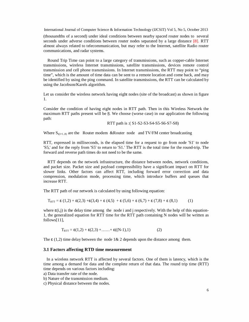
(thousandths of a second) under ideal conditions between nearby spaced router nodes to several seconds under adverse conditions between router nodes separated by a large distance [8]. RTT almost always related to telecommunication, but may refer to the Internet, satellite Radio router communications, and radar systems. Round Trip Time can point to a large category of transmissions, such as copper-cable Internet transmissions, wireless Internet transmissions, satellite transmissions, devices remote control transmission and cell phone transmissions. In Internet transmissions, the RTT may point to “ping time”, which is the amount of time data can be sent to a remote location and come back, and may be identified by using the ping command. In satellite transmissions, the RTT can be calculated by using the Jacobson/Karels algorithm. Let us consider the wireless network having eight nodes (site of the broadcast) as shown in figure 1. Consider the condition of having eight nodes in RTT path. Then in this Wireless Network the maximum RTT paths present will be 8. We choose (worse case) in our application the following path: RTT path is :( S1-S2-S3-S4-S5-S6-S7-S8)
Where Si(i=1..8) are the Router modem &Router node and TV/FM center broadcasting RTT, expressed in milliseconds, is the elapsed time for a request to go from node 'S1' to node 'S5,' and for the reply from 'S5' to return to 'S1.' The RTT is the total time for the round-trip. The forward and reverse path times do not need to be the same. RTT depends on the network infrastructure, the distance between nodes, network conditions, and packet size. Packet size and payload compressibility have a significant impact on RTT for slower links. Other factors can affect RTT, including forward error correction and data compression, modulation mode, processing time, which introduce buffers and queues that increase RTT. The RTT path of our network is calculated by using following equation: TRTT = ԑ (1,2) + ԑ(2,3) +ԑ(3,4) + ԑ (4,5) + ԑ (5,6) + ԑ (6,7) + ԑ (7,8) + ԑ (8,1) (1) where ԑ(i,j) is the delay time among the node i and j respectively. With the help of this equation-1, the generalized equation for RTT time for the RTT path containing N nodes will be written as follows[11], TRTT = ԑ(1,2) + ԑ(2,3) +……+ ԑ((N-1),1) (2) The ԑ (1,2) time delay between the node 1& 2 depends upon the distance among them. 3.1 Factors affecting RTD time measurement In a wireless network RTT is affected by several factors. One of them is latency, which is the time among a demand for data and the complete return of that data. The round trip time (RTT) time depends on various factors including: a) Data transfer rate of the node. b) Nature of the transmission medium. c) Physical distance between the nodes.

International Journal of Computer Science & Information Technology (IJCSIT) Vol 5, No 5, October 2013
7
d) Number of nodes in the RTT path. e) Number of other demands being manipulate by intermediate nodes. f) Speed between intermediate nodes and source node functions. g) Modulation mode. h) Presence of interference in the circuit. i) FEC (Forward Error Correction) As stated above the round trip delay time is a function of various parameters of the wireless network and can be expressed by following equation: RTT = ƒ (speed, distance, modulation, medium, noise, nodes in RTT path & request handled+FEC)
= Ts + Td + Tmod +Tm + Tn + TnRTD +Toreq +TFEC (3)
A theoretical minimum is imposed on the RTT (minimum 3 in RipEX unit in path because it can never be less than this value, if no,it will not form a loop in transmission medium. As the RTT measurement depends upon various parameters [17, 9] of Radio Router Node and Wireless network. The Wireless Network for several paths round trip time (RTT) measurements has to be classified as Symmetrical or Asymmetrical network. A Wireless network is briefly defined as Symmetrical network if 1) All the nodes are located at equal distance from each other. 2) All nodes should have same sensitivity. 3) Operating speed of all nodes (Routers) processing unit has to be equal. 4) Same wireless communication module is for all nodes Radio Routers (RipEX unit ) Otherwise the Radio Router Wireless Network will be defined as Asymmetrical network (in our application). 3.2 Limitation of s RipEX unit nodes in RTT path.
As mentioned in above pointed round trip time depends on the number of RipEX unit nodes present in RTT path. The network requires more than 3 RipEX unit nodes to form a round trip time. The minimum number of RipEX unit nodes required to form RTT path are 3 [8-19] and maximum RipEX unit nodes in round trip time paths should not be more than (N-1).This will put the limits on the RipEX unit nodes used in round trip time path. This limit of RipEX unit nodes in RTT path for Wireless network with ‘N’ RipEX unit nodes is as following:
3 ≤ n ≤ (N-1) (4) where ‘n’ is the number of Ripex units nodes present in the respective RTT path. 3.3 . Determination of number of RTT paths in WN The number of RTT paths in WN depend upon the number of RipEX unit nodes selected for RTT path. Maximum possible RTT paths in WN having ‘N’ RipEX unit nodes can be calculated by following equation
n RTD = N (N- m) (5)

International Journal of Computer Science & Information Technology (IJCSIT) Vol 5, No 5, October 2013
8
where ‘n RTD’ is the number of RTT paths having ‘m’ RipEX unit nodes in WN consisting ‘N’ RipEX unit nodes. In the network having less number of RipEX unit nodes, minimum criteria (m=3) for number of RipEX unit nodes in RTT path can be used. This will results in optimum number RTT paths. But if the number of RipEX unit nodes in WN are large then minimum condition (m=3) for selection of RipEX unit node should not be used because it will result in large numbers of RTD paths. 4. EXPERIMENTAL SETUP
4.1. Hardware Selection and Configuration
The equipment’s, including computer software used, are: - EagleEye V1.1 monitoring Software adapts to particular needs by providing tools for the
supervision and control of the installations of the equipment’s of broadcasting. This software can secretly send the logs to your email address and we can know everything that occurs on your computer even when you're miles away with Eagle Eye. It can collect, at the S1 and S5, site all information about the sites between the source and destination.
- Eight RipEX units (Radio modem & routers) which are characterized by the SNMP management that will support the base MIB (Management Information Base) SNMP (Simple Network Management Protocol) Protocol through the MIB browser.
- The RipEX units(Radio modem & Router) use the same band VHF /UHF (band IV and V), VHF/UHF bands 350 MHz this band is somewhere between 160 and 450 MHz, destined to broadcasters have highly advantageous propagation characteristics. Penetrating through foliage and structures, they reach far and wide distance more than Wimax [20].
- We can use the omnidirectional antenna KA160.3 which is designed for base radio stations working in bands of 158-174 MHz The antenna ,used in our application, has an Omni-directional radiation pattern with the gain of 3 dB and is adapted for the top-mounting. The antenna is broadband and that is why it is well-chosen for duplex operations. Also we can use the same antenna system, for transmission, that is already used by the broadcast Digital Terrestrial Television (DTT) UHF system or radio FM VHF.
- The values received at the level of each site vary between 38 and 70 dBµV what is recommended to plug user for correct operation of household appliances for the bands III, IV and V.
- The output power of each router varies between 0.1 and 10 watts (default=10watts) and this in order to achieve the long distance which separates the TV/FM broadcast site. And that the purpose of selection techniques and interconnection equipment to build a logical architecture for local area network (sites at each TV / FM). We will select sites in our application area (northern Morocco) in such a way or path that the
distance between these sites successively are equal Fig 3. To the left of Figure3 is the measurement, of broadcast equipment TV and FM radio, has
selected, in the right wireless network where will practice RTD measurements.

International Journal of Computer Science & Information Technology (IJCSIT) Vol 5, No 5, October 2013
9
Figure 3: Real interface Control equipment (with EagleEye V1.1) which exists in the main center of broadcast TV/FM (center "Palomas" number S5 see Figures 1and 5)
We are in the condition where a signal travels over the air directly from a wireless transmitter to a wireless receiver without passing an obstruction Line-of-sight (LOS), because in LOS environment, signal can reach longer distance with better signal strength and higher throughput. The obtaining of the round-trip time (RTT), using the Dock light V2 or «Ping» (acronyme de Packet InNternet Groper) followed by the IP address of the destination S5 (See Figure 5). To measure the RTT, packets are sent from the source to the destination using the ping utility, over different route lengths. If no fault is detected on Wireless network RipEX units, the correct data centers measurements are obtained correctly (see inverted variables interface, make Eaton, in Figure 4). Malfunction detection of radio modem & router node in WN, thanks to RTT, is indispensable because failed or malfunctioning RipEX units node may produce incorrect data or no data, which will affect the overall quality of the entire WN. Manually checking of such failed Radio Router node in WN is troublesome and impossible.
Fig 4: example of (inverted variables make Eaton) measurements of equipment device (Powerware 9355-20KVA UPS) after verification of WN by means of RTT

International Journal of Computer Science & Information Technology (IJCSIT) Vol 5, No 5, October 2013
10
4.2. Selection of various network conditions.
As the RTT measurement is affected by various parameters of the wireless network mentioned in above equation 3. The divers conditions have to be required on the selection of network in advance of applying this method. So except distance, baud rates, and number of hops other parameters affecting RTD measurement are kept constant. These conditions are mentioned in table 1.
Table1. Condition Imposed on selected network.
Sr. No. Factors Affecting RTT measurement Condition Chosen or demanded
1 Modulation rate [kbps] Payload modulation
83.33| 16DEQAM-
2 FEC (Forward Error Correction) Off 3 ACK ON 4 Interface speed ETH TCP/IP (see 5.2) 5 The nature of the transmission medium. Wireless 6 The physical distance between the
RipEX units(radio modem & router) nodes
Variable with Symmetrical network
7 The number of RipEX units (radio modem & router) nodes in the RTD path
(m=08) the same path round trip
8 The number of other requests being handled by intermediate nodes
NIL
9 The speed with which intermediate nodes and source node functions
Same due identical hardware (in sec)
10 Proceeding Time 20ms on all RipEX units 11 The presence of interference in the circuit Insignificant
Data transfer rate and speed of communication of nodes are same as RipEX units wireless communication module. If more nodes are used in RTT path it will increase the RTT [8]. But this will not affect the linear relationship of the RTT versus RipEX units node distance, baud rates and number of hops. 5. RESULTS OF PRACTICAL MEASUREMENTS Each RipEX units node in Wireless Network (as showed in figure 5) is defined for a selected round trip time path by configuring them, with source and destination addresses, using the protocol SCADA software. RTT path selected here is RTT (S1-S2-S3-S4-S5-S6-S7-S8-S1) and the RTT path distance is 5 Km.
International Journal of Computer Science & Information Technology (IJCSIT) Vol 5, No 5, October 2013
11
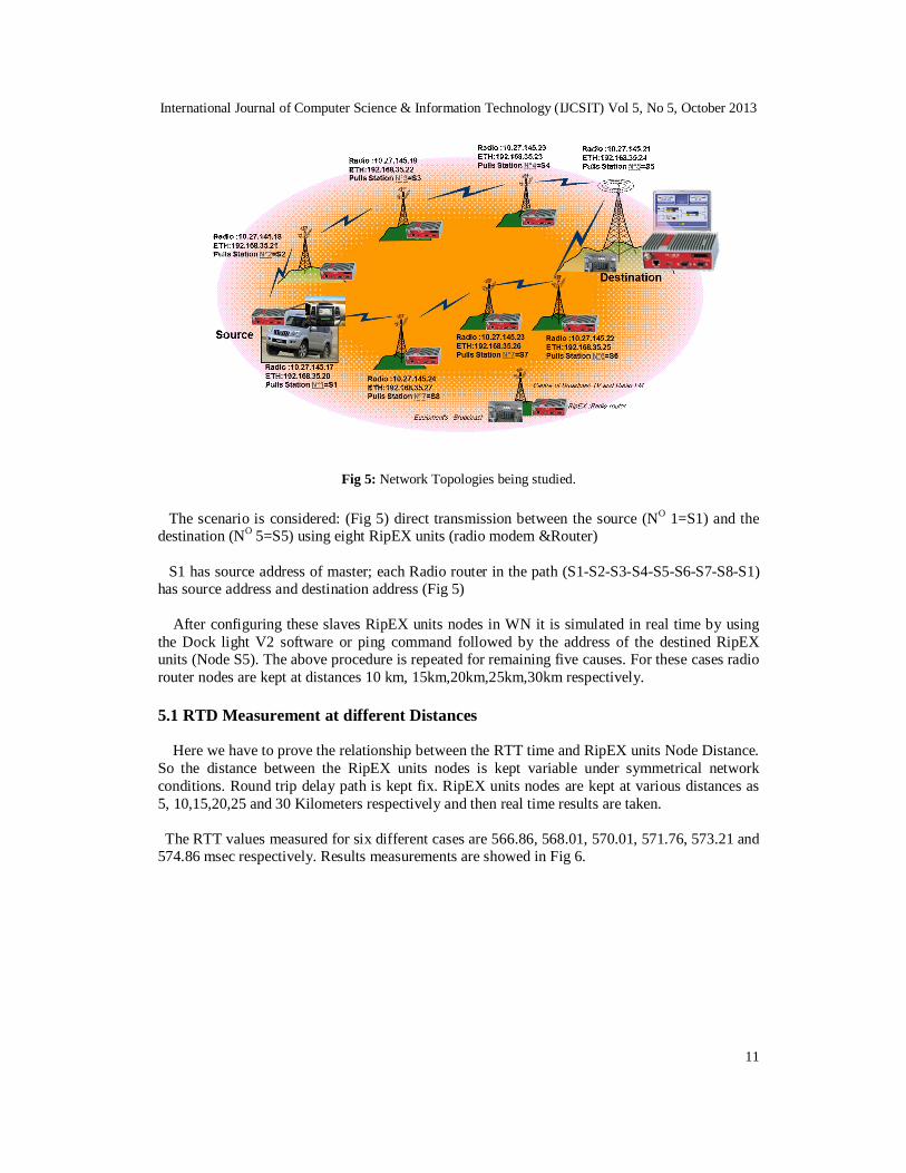
Fig 5: Network Topologies being studied.
The scenario is considered: (Fig 5) direct transmission between the source (NO 1=S1) and the destination (NO 5=S5) using eight RipEX units (radio modem &Router) S1 has source address of master; each Radio router in the path (S1-S2-S3-S4-S5-S6-S7-S8-S1) has source address and destination address (Fig 5) After configuring these slaves RipEX units nodes in WN it is simulated in real time by using the Dock light V2 software or ping command followed by the address of the destined RipEX units (Node S5). The above procedure is repeated for remaining five causes. For these cases radio router nodes are kept at distances 10 km, 15km,20km,25km,30km respectively. 5.1 RTD Measurement at different Distances
Here we have to prove the relationship between the RTT time and RipEX units Node Distance. So the distance between the RipEX units nodes is kept variable under symmetrical network conditions. Round trip delay path is kept fix. RipEX units nodes are kept at various distances as 5, 10,15,20,25 and 30 Kilometers respectively and then real time results are taken. The RTT values measured for six different cases are 566.86, 568.01, 570.01, 571.76, 573.21 and 574.86 msec respectively. Results measurements are showed in Fig 6.

International Journal of Computer Science & Information Technology (IJCSIT) Vol 5, No 5, October 2013
12
5 10 15 20 25 30565
570
575
580
585
590
595
Distance (Kilometers) Between RipEX unit in RTT path
Rou
nd T
rip T
ime
in (m
sec)
RTTagainst RipEX – Radio router Distance
RTT without FECRTT with FEC
Figure 6: RTT against Radio Router Node Distance.
From the readings it observed that as distances changes in ‘Kilometers’ the RTT changes in ‘msec’. As the distance between Radio Router nodes in WN changes, it will change the time delay between the consecutive radio router nodes, which in terms affect the RTT measurement [8]. The change in RTT time against distance between radio router nodes is verified by considering six cases. The round trip delay time (msec) against radio router node distance (kilometers) graph is shown in figure 6, which shows us the linear relationship between the distance and RTT of radio modem & router nodes [8] It is noted from above results that as the distance between the radio router nodes in round trip delay path augments the round trip time (RTT) time also increases. A In above experimental case the parameters affecting RTT measurement except distance are kept identical. So the round trip time (RTT) measurement in these cases is purely a function of distance between the radio router nodes. Time delay is directly proportional to distance and showed as: ԑ(1,2) ∝ d(1,2) (6) RTT showed and expressed in equation (1) depends on the various time delays in the selected path. All these time delays are linear function of distances. Hence RTT should be a linear function of distance between operational nodes.
So there, linear relationship exists between round trip delay time and radio router node distance in Wireless Network (WN).
In addition, the introduction of Forward Error Correction (FEC 3/4) can also promote a slight increase in RTT The graph plotted between round trip delay time and router node distance proves a linear relationship between it.
International Journal of Computer Science & Information Technology (IJCSIT) Vol 5, No 5, October 2013
13
5.2. RTT Measurement at different modulation modes
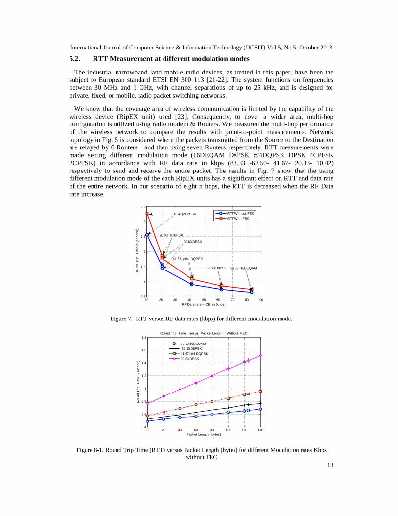
The industrial narrowband land mobile radio devices, as treated in this paper, have been the subject to European standard ETSI EN 300 113 [21-22]. The system functions on frequencies between 30 MHz and 1 GHz, with channel separations of up to 25 kHz, and is designed for private, fixed, or mobile, radio packet switching networks. We know that the coverage area of wireless communication is limited by the capability of the wireless device (RipEX unit) used [23]. Consequently, to cover a wider area, multi-hop configuration is utilized using radio modem & Routers. We measured the multi-hop performance of the wireless network to compare the results with point-to-point measurements. Network topology in Fig. 5 is considered where the packets transmitted from the Source to the Destination are relayed by 6 Routers and then using seven Routers respectively. RTT measurements were made setting different modulation mode (16DEQAM D8PSK π/4DQPSK DPSK 4CPFSK 2CPFSK) in accordance with RF data rate in kbps (83.33 -62.50- 41.67- 20.83- 10.42) respectively to send and receive the entire packet. The results in Fig. 7 show that the using different modulation mode of the each RipEX units has a significant effect on RTT and data rate of the entire network. In our scenario of eight n hops, the RTT is decreased when the RF Data rate increase.
10 20 30 40 50 60 70 80 900.5
1
1.5
2
2.5
3
3.5
Rou
nd T
rip T
ime
in (s
econ
d)
RF Data rate – CE in (kbps)
RTT Without FECRTT With FEC
62.50|D8PSK
41.67| pi/4 -DQPSK
20.83|DPSK
20.83| 4CPFSK
10.42|2CPFSK
83.33| 16DEQAM
Figure 7. RTT versus RF data rates (kbps) for different modulation mode.
0 20 40 60 80 100 120 1400.4
0.6
0.8
1
1.2
1.4
1.6
1.8
Rou
nd T
rip T
ime
(se
cond
)
Packet Length (bytes)
Round Trip Time versus Packet Length Without FEC
83.33|16DEQAM 62.50|D8PSK41.67|pi/4-DQPSK20.83|DPSK
Figure 8-1. Round Trip Time (RTT) versus Packet Length (bytes) for different Modulation rates Kbps without FEC

International Journal of Computer Science & Information Technology (IJCSIT) Vol 5, No 5, October 2013
14
0 20 40 60 80 100 120 1400.5
1
1.5
2
Rou
nd T
rip T
ime
(se
cond
)
Packet Length (bytes)
Round Trip Time versus Packet Length With FEC
83.33|16DEQAM 62.50| D8PSK41.67| pi/4 -DQPSK20.83| DPSK
Figure 8-2. Round Trip Time (RTT) versus Packet Length (bytes) for different Modulation rates Kbps with FEC
The results in Fig. 8-1 and Fig 8-2 show, Round Trip Time (RTT) versus Packet Length (bytes) for different Modulation rates Kbps (without FEC and with FEC respectively. RTT is increased when the packet length increase, the introduction of Forward Error Correction (FEC 3/4) can also promote a slight increase in RTT. This measurement to primary goal of this paragraph is to describe the beneficial properties of operational modes based on advanced nonlinear and linear digital modulation techniques so as to easy the decision on their usage and thus to help system integrators to increase the efficiency of the narrowband radio channel utilization allocated to the new generation of the industrial narrowband land mobile radio devices. Based on the results found, the most important concluding notes can be seen in the following:
When the long distance coverage as well as the overall power efficiency are of the primary application concern, the use of exponential modulation techniques 2CPFSK and 4CPFSK at comparatively low symbol rates e.g 10.4 kBaud can be the registered option.
The selection of higher symbol rates lead to a power efficiency loss (and their main advantage) of the exponential modulation techniques significantly. Further increase of the exponential modulation spectrum efficiency from the values actually being used by the narrowband systems (up to 1 bit/s/Hz) can be therefore considered ineffective.
From all the modulation formats studied, the π/4-DQPSK can offer the narrowband land mobile radio system with communication efficiency closest to the optimal communication systems.
Where higher data throughputs are needed the additional increase in spectrum efficiency can be gained by D8PSK and 16-DEQAM modulation types. However, compared to π/4-DQPSK, an increase on the whole communication efficiency cannot be expected, while there is the unavoidable penalty in power efficiency characteristic.

International Journal of Computer Science & Information Technology (IJCSIT) Vol 5, No 5, October 2013
15
5.3. RTD Measurement at different baud rates
The aim of this experiment is to measure the RTT of the RipEX units as a function of the baud rates and the packet length to gain a sense as how does the baud rate affect the latency of the modules communicating over SCADA protocol. In our practical application, the topology showed in Fig. 5 is well-respected. RipEX units module configured as a source S1 sends packets to destination S5 and come back to S1 and calculates the total transmission time. Various measurements are effectuated, in comparison to different values of packet length and baud rates, each RipEX units module may support up to 1500 bytes (User data size without any headers (IP, TCP, UDP …).of RF payload. Therefore, to avoid reception overcharge with the SCADA communication protocol, we used a lower value of packet length up to 140 bytes. in this case the shape of RTT curve is shown as a function of packet size and the baud rate as illustrated in Fig.9-1 and Fig 9-2.
0 20 40 60 80 100 120 1400
0.5
1
1.5
2
2.5
3
3.5
Rou
nd T
rip T
ime
(sec
ond)
Packet Length (bytes)
Round Trip Time versus different baud rates Without FEC
ETH UDP/IPETH TCP/IP115200 bps38400 bps19200 bps
Figure 9-1. RTT versus packet size depending of different baud rates without FEC
0 20 40 60 80 100 120 140
0
0.5
1
1.5
2
2.5
3
3.5
Rou
nd T
rip T
ime
(sec
ond)
Packet Length (bytes)
Round Trip Time versus different baud rates With FEC
ETH UDP/IPETH TCP/IP115200 bps38400 bps19200 bps
Figure 9-2. RTT versus packet size depending of different baud rates with FEC

International Journal of Computer Science & Information Technology (IJCSIT) Vol 5, No 5, October 2013
16
This experimental trial is repeated ten times. Furthermore, this experiment was conducted to have a performance baseline for wireless networks using RipEX units modules. It was observed that the network RTT decreases as the baud rate increases. The introduction of Forward Error Correction (FEC 3/4) can also promote a slight increase in RTT. 5.4. Packet Delay
Another significant indicator of RipEX units Wireless Network performance is the packet delay between two consecutive packets accurately received by the source S1. The packet delays for this practical application is defined as the duration between sending a packet and until the entire packet has been received by the source. The distance between Radio modem &Router Nodes is 5km and packet Length is fixed for 125bytes. Fig 8 shows the results of direct transmission from a source to Destination and indirect transmission through Radio Routers. We repeated the previous experiments with three, four, five six seven and eight hops network respectively. Data throughput measurements were made setting the Ethernet interface speed ETH TCP/IP and measuring time to send and receive the entire packet. For tree hops transmission (without FEC) figure a, the average delay is around 0.19 sec for the maximum payload offered, while 0.28 sec for four hops, 0, 38 sec for five hops, 0.47sec for six hops , 0.57 sec for seven hops and 0.66 sec for eight hops respectively. The Fig 10-1 and Fig 10-2 we show how RTT varies in terms of different packet length (0 up to 140 bytes) of different hops with (FEC 3/4) and without (FEC 3/4) respectively.
0 20 40 60 80 100 120 1400.1
0.2
0.3
0.4
0.5
0.6
0.7
0.8
Rou
nd T
rip T
ime
(sec
ond)
Packet Length (bytes)
Number of Hops versus Packet Delay (Without FEC)
3 Hops4 Hops5 Hops6 Hops7 Hops8 Hops
Figure: 10-1. Figure.10-2. RTT measurement results of RipEX units network for multi-hop configuration (without FEC)

International Journal of Computer Science & Information Technology (IJCSIT) Vol 5, No 5, October 2013
17
0 20 40 60 80 100 120 140
0.1
0.2
0.3
0.4
0.5
0.6
0.7
0.8
Packet Length (bytes)
Rou
nd T
rip T
ime
(sec
ond)
Number of Hops versus Packet Delay (With FEC)
3 Hops4 Hops5 Hops6 Hops7 Hops8 Hops
Figure.10-2. RTT measurement results of RipEX units network for multi-hop configuration (With FEC)
The results (without FEC) in Fig.10-1 and Fig 10-2 show that the presence of the Radio Routers of different value of packet length has a significant effect on Round Trip Time of the entire network, whereas the introduction of FEC significantly increased RTT. The introduction of Forward Error Correction (FEC 3/4) can also promote a slight increase in RTT. Therefore, the packet delay increases importantly with the number of hops thanks to an extra processing delay at the Radio modem & Routers and retransmission delay due to additional hop. 5.5. RTT Measurement in different values of Throughput Network
We measured the RTT performance of the RipEX units network to compare the results RTT measurements versus throughput with FEC and without FEC. Network topology in Fig. 5 is considered where the packets transmitted from the S1 to the S5 and back de S5 to S1 are relayed using three RipEX units (Radio modem & Router) for go and two for back. Data throughput measurements were carried by means Ethernet interface ETH TCP/IP(between device and RipEX unit) and measuring time is the delay to send and receive the entire packet. The results in Fig. 11 show that the The RTT is shown as a function of packet size and the FEC as illustrated in Fig.11. It was observed that the network RTT decreases as throughput increases. On the other hand, the RTT increased significantly with the presence of Forward Error Correction (FEC).

International Journal of Computer Science & Information Technology (IJCSIT) Vol 5, No 5, October 2013
18
20 30 40 50 60 70 80 90 1000.5
0.6
0.7
0.8
0.9
1
1.1
1.2
1.3
Rou
nd T
rip T
ime
(sec
ond)
Throughput (Kbit/sec)
RTT without FECRTT with FEC
Figure 11. RTT versus for different values of Throughput kbit/sec (without FEC and with FEC) 6. CONCLUSIONS AND FUTURE WORKS In this paper, we have analyzed the performance of practical network topology of RipEX units wireless communication module based on Narrowband RF Networks for remote wireless communications. We considered a scenario with direct wireless transmission round- trip from the source S1 to the destination S5 and come back from source S1 with the presence of (RipEX units) Radio modem & Routers for relaying messages. For multi-hop transmission with RipEX units, our results show that: - As the distance between the radio router nodes in round trip delay path increases, also the
round trip time (RTT) increases. - The modulation mode has an influence on RTT. When the baud rate of each modulation type
increases, RTT decreases with different values that may take packet length. - It was observed that the network RTT time decreases greatly with the augmentation value of
interface speed, Ethernet interface speed or the baud rate [bps] for the serial (COM) interface.
- The packet delay increases considerably with the number of hops, in the route, occasioned by a supplementary processing delay at the Radio Routers network and retransmission delay due to additional hop. It was also observed that the RTT varies with the packet size.
- It was observed that the RTT network decreases as throughput increases. - In addition to this observation of results, the introduction of Forward Error Correction
(FEC 3/4) can also promote a slight increase in RTT.
Therefore, to improve the system performance, the number of transmitting nodes should be minimized or find efficacious techniques and methods to improve the factors affecting RTT measurement which will be the subject of our future works. ACKNOWLEDGMENTS We would like to thank to the direction of the broadcasting of Moroccan SNRT (Society National of Radio Television) for we implement provision sites of broadcast and central laboratory measuring devices. The authors would like to thank the reviewers for their valuable advices and comments.

International Journal of Computer Science & Information Technology (IJCSIT) Vol 5, No 5, October 2013
19
REFERENCES [1] Max W. Medley, Jr, “Microwave and RF Circuits: Analysis, Synthesis and Design,” Artech House,
1993. [2] ETSI EN 300 113-1 V1.6.1, Electromagnetic compatibility and Radio spectrum Matters (ERM),
Part 1: Technical characteristics and methods of measurement. European Standard. ETSI, 07–2007. [3] DANĚK, K. Efficient use of mobile radio channel II. Radioengineering, June 2000, vol. 9, no.2, p.1-
4. [4] D. Kliazovich,,S. Redana,F. Granelli ‘’Cross-layer error recovery in wireless access networks: The
ARQ proxy approach’’accepted for International Journal of Communication Systems Volume 25, Issue 4, pages 461–477, April 2012
[5] Jain, M., Dovrolis, C.: End-to-end available bandwidth: measurement methodology, dynamics, and relation with tcp throughput. In: SIGCOMM, ACM (2002)
[6] Zhang, Y., Breslau, L., Paxson, V., Shenker, S.: On the characteristics and origins of Internet flow rates. In: SIGCOMM, ACM (2002)
[7] Ratnasamy, S., Handley, M., Karp, R., Shenker, S.: Topologically-aware overlay construction and server selection. In: INFOCOM, IEEE (2002).
[8] AlessioD Angelis,Antonio Moschitta, Peter Händel and Paolo Carbone “Experimental Radio Indoor Positioning Systems Based on Round-Trip Time Measurement” Advances in Measurement Systems, April 2010,pp.196-219
[9] J. Yli-Hietanen, K. Koppinen, and J. Astola, “Time-delay selection for robust angle of arrival estimation,” in Proceedingsof the IASTED International Conference on Signal and Image Processing,1999, pp. 81–83.
[10] El Miloud Ar Reyouchi, Kamal Ghoumid, Amezian Koutaiba, Otman Mrabet, ‘MIMO-OFDM Coded for Digital Terrestrial Television Broadcasting Systems’, World Academy of Science, Engineering and Technology 76 2013,april 2013, p. 617-621
[11] Ravindra N Duche, N.P.Sarwade “Round Trip Delay Time As A Linear Function Of Distance Between The Sensor Nodes In Wireless Sensor Network ” accepted for International Journal of Engineering Sciences & Emerging Technologies, Feb 2012.ISSN: 2231 – 6604 Volume 1, Issue 2, pp: 20-26 ©IJESET.
[12] Rajeev Piyare, Seong-ro Lee “Performance Analysis of XBee ZB Module Based Wireless Sensor Networks” International Journal of Scientific & Engineering Research, Volume 4, Issue 4, April-2013 , pp 1615-1621.
[13] M. J. Freedman, K. Lakshminarayanan, and D. Mazi`eres. OASIS: anycast for any service. In Proc. of ACM NSDI, volume 3, 2006.
[14] E. Mykoniati, L. Latif, R. Landa, B. Yang, R. Clegg, D. Griffin, and M. Rio. Distributed overlay anycast table using space filling curves. In Proc. of the IEEE INFOCOM Global Internet Symposium, 2009.
[15] S. Agarwal and J. R. Lorch. Matchmaking for online games and other latency-sensitive P2P systems. In Proc. of ACM SIGCOMM, pages 315– 326, 2009.
[16] M. Szymaniak, D. Presotto, G. Pierre, and M. van Steen. Practical large-scale latency estimation. Comput. Netw., 52(7):1343–1364, May 2008.
[17] T. W. Pirinen∗ J. Yli-Hietanen, P. Pertil ¨a and A. Visa “Detection and compensation of Sensor malfunction in time delay based direction of arrival estimation ” IEEE Circuits and Systems,vol.4,May 2004,pp.872-875.
[18] T. Pirinen, P. Pertil¨a, and A. Visa, “Toward intelligent sensors - reliability for time delay based direction of arrival estimates,” in Proceedings of the 2003 IEEE International Conference on Acoustics, Speech and Signal Processing (ICASSP’03), 2003, Volume V, p.197-200.
[19] K. Varma, T. Ikuma, and A. A. Beex, “Robust TDE-based DOA-estimation for compact audio arrays,” in Proceedings of the Second IEEE Sensor Array and Multichannel Signal Processing Workshop (SAM 2002), 2002, pp. 214–218.
[20] Dapeng Wu, Ruyan Wang and Yan Zhen#Link stability-aware reliable packet transmitting mechanism in mobile ad hoc network# International Journal of Communication Systems,Volume 25, Issue 12, pages 1568–1584, December 2012.
[21] ETSI EN 300 113-1 V1.6.2 (2009-11), Electromagnetic compatibility and Radio spectrum Matters (ERM), Part 1: Technical characteristics and methods of measurement. European Standard. ETSI, 11/2009.
International Journal of Computer Science & Information Technology (IJCSIT) Vol 5, No 5, October 2013
20
[22] ETSI EN 302 561 V1.2.1 (2009-12), Electromagnetic compatibility and Radio spectrum Matters (ERM), Land Mobile Service; Radio Equipment using constant or non-constant envelope modulation operating in a channel bandwidth of 25 kHz, 50 kHz, 100 kHz or 150 kHz; Harmonized EN covering essential requirements of article 3.2 of the R&TTE Directive. European Standard. ETSI, 12/2009.
[23] M. A. B. Sarijari, R. A. Rashid, M. R. A. Rahim, and N. H. Mahalin, "Wireless Home Security and Automation System Utilizing ZigBee based Multi-hop Communication," in Telecommunication Technologies 2008 and 2008 2nd Malaysia Conference on Photonics. NCTT-MCP 2008. 6th National Conference on, 2008, pp. 242-245.
Authors EL MILOUD AR REYOUCHI holds an Engineer degree specialized in Telecommunication from INPT institute national of telecommunication RABAT Morocco , MS in industrial computer and his CPD / DEA degree in automatic and industrial computer from E.T.S computer engineering , Department Computer Science and Control ,Madrid Spain, and his PhD student in Telecommunication and Computer Engineering from Faculty of Sciences , Abdelmalek Essaadi University Tetouan Morrocco. Her research interest include telecommunication, broadcasting TV/FM, engineering automatic systems, mobile wireless network, antennas& propagation, and is currently Regional Manager of the centers of the broadcast TV / radio FM of SNRT (society national of Radio Television) AL Hoceima in northern Morocco. Kamal Ghoumid received his PhD degree from the ’Institut TELECOM, TELECOM Sud-Paris’, Evry, France, and ’Institute FEMTO-ST’ of the Franche-Comté University (Besaçon, France), in 2008. He previously graduated as a specializing Master in ’Technics of Radiocommunications’, also got his Master ’Communication Systems’ of Paris-Est University (Paris, France). He has worked as postdoctoral researcher at Jean Lamour Institute of Henri Poincaré University (Nancy, France), during 2008-2009, and at the Institut FEMTO-ST of the Franche-Comté University, Besançon. Currently, he is a Ass. Professor in National school of applied sciences (ENSAO) in the Mohammed Premier University of Oujda (Morocco). His research interests are mainly in Signal processing and integrated optic components in the field of telecommunications, Wireless and Optical Networks, Radio over Fiber, he has also the experience in research areas of digital communications. Koutaiba Ameziane received the PhD degree in Atomics Physics from the Claude Bernard University ,Lyon France in 1990, as an Full Professor. His research interests are Spectroscopy Atomic and Molecular, Telecommunication and Physics of Matter. Otman El Mrabet received the PhD degree in Electronics and Telecommunication from the Faculty of Sciences, University of Abdelmalek Essaadi Morocco, in 2004. In June2009, he joined the Electronics and Microwave Group, Faculty of Sciences, Abdelmalek Essaadi University, as an assistant Professor. From March to October, 2005, he was with the Rennes Institute of Electronics and Telecommunications, France, as a Visiting Researcher. From September 2007 to August 2009, he was with the Millimeter Wave Laboratory, Universidad Pública de Navarra, Spain, as a postdoctoral researcher. His research interests are UWB antenna design, RFID Tag antennas, Metamaterials, FSS circuits and active circuits using the finite difference time domain method (FDTD).