PDF - Fundamentals of Papermaking
82
Professor Bo Norman Paper Technology Department, Royal Institute of Technology and Swedish Pulp Ff Paper Research Institute, Stockholm, Sweden Abstract OVERVIEW OF THE PHYSICS OF FORMING In this overview forming covers all processes from the dilution of thick stock into a mix, using recirculated white water in the short circulation , to the dewa- tering in the wire section. Grammage nonuniformity in the paper web is to a predominant degree generated by the forming process, and especially the small scale variations summarized in the term formation . The term mass formation is recommended when only grammage is considered and not the optical impressions thereof. The forming process also generates the main part of the large scale variations, that is the MD-, CD- and residual grammage variance. Mass formation has traditionally been evaluated using beta radiography, combined with microdensitometry or image analysis. A new technique involving thedirect recording of electron beam transmission is under development, with promises of faster processing, perhaps even on-line, and high geometrical reso- lution. Characterization techniques based on the co-occurrence matrix, applica- ble to image analysis, can be a useful complement to the traditional power spec- tra techniques . Preferred citation: B. Norman. Overview of the physics of forming. In Fundamentals of Papermaking, Trans. of the IXth Fund. Res. Symp. Cambridge, 1989, (C.F. Baker & V. Punton, eds), pp 73–149, FRC, Manchester, 2018. DOI: 10.15376/frc.1989.3.73.
-
Upload
khangminh22 -
Category
Documents
-
view
1 -
download
0
Transcript of PDF - Fundamentals of Papermaking
Professor Bo NormanPaper Technology Department, Royal Institute of Technology andSwedish Pulp Ff Paper Research Institute, Stockholm, Sweden
Abstract
OVERVIEW OF THE PHYSICS OFFORMING
In this overview forming covers all processes from the dilution of thick stockinto a mix, using recirculated white water in the short circulation , to the dewa-tering in the wire section.
Grammage nonuniformity in the paper web is to a predominant degreegenerated by the forming process, and especially the small scale variationssummarized in the termformation . The term massformation is recommendedwhen only grammage is considered and not the optical impressions thereof. Theforming process also generates the main part of the large scale variations, that isthe MD-, CD- and residual grammage variance.
Mass formation has traditionally been evaluated using beta radiography,combined with microdensitometry or image analysis. A new technique involvingthedirect recording of electron beam transmission is under development, withpromises of faster processing, perhaps even on-line, and high geometrical reso-lution. Characterization techniques based on the co-occurrence matrix, applica-ble to image analysis, can be a useful complement to the traditional power spec-tra techniques .
Preferred citation: B. Norman. Overview of the physics of forming. In Fundamentals of Papermaking, Trans. of the IXth Fund. Res. Symp. Cambridge, 1989, (C.F. Baker & V. Punton, eds), pp 73–149, FRC, Manchester, 2018. DOI: 10.15376/frc.1989.3.73.
74
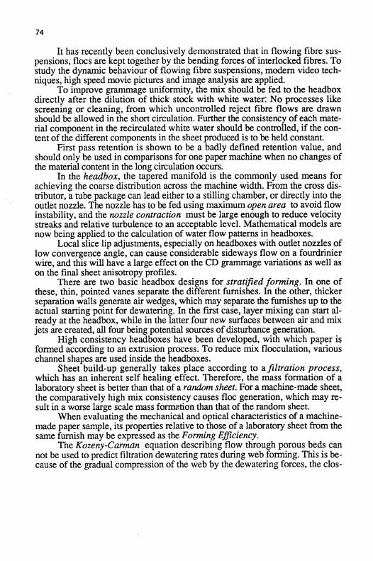
It has recently been conclusively demonstrated that in flowing fibre sus-pensions, flocs are kept together by the bending forces of interlocked fibres . Tostudy the dynamic behaviour of flowing fibre suspensions, modern video tech-niques, high speed movie pictures and image analysis are applied.
To improve grammage uniformity, the mix should be fed to the headboxdirectly after the dilution of thick stock with white water No processes likescreening or cleaning, from which uncontrolled reject fibre flows are drawnshould be allowed in the short circulation . Further the consistency of each mate-rial component in the recirculated white water should be controlled, if the con-tent of the different components in the sheet produced is to be held constant.
First pass retention is shown to be a badly defined retention value, andshould only be used in comparisons for one paper machine when no changes ofthe material content in the long circulation occurs .
In the headbox, the tapered manifold is the commonly used means forachieving the coarse distribution across the machine width . From the cross dis-tributor, a tube package can lead either to a stilling chamber, or directly into theoutlet nozzle . The nozzle has to be fed using maximum open area to avoid flowinstability, and the nozzle contraction must be large enough to reduce velocitystreaks and relative turbulence to an acceptable level. Mathematical models arenow being applied to the calculation of water flow patterns in headboxes .
Local slice lip adjustments, especially on headboxes with outlet nozzles oflow convergence angle, can cause considerable sideways flow on a fourdrinierwire, and this will have a large effect on the CD grammage variations as well ason the final sheet anisotropy profiles .
There are two basic headbox designs for stratified forming . In one ofthese, thin, pointed vanes separate the different furnishes. In the other, thickerseparation walls generate air wedges, which may separate the furnishes up to theactual starting point for dewatering. In the first case, layer mixing can start al-ready at the headbox, while in the latter four new surfaces between air and mixjets are created, all four being potential sources of disturbance generation.
High consistency headboxes have been developed, with which paper isformed according to an extrusion process . To reduce mix flocculation, variouschannel shapes are used inside the headboxes .
Sheet build-up generally takes place according to afiltration process,which has an inherent self healing effect. Therefore, the mass formation of alaboratory sheet is better than that of a random sheet. For a machine-made sheet,the comparatively high mix consistency causes floc generation, which may re-sult in a worse large scale mass formation than that of the random sheet.
When evaluating the mechanical and optical characteristics of a machine-made paper sample, its properties relative to those of a laboratory sheet from thesame furnish may be expressed as the Forming Efficiency.
The Kozeny-Carman equation describing flow through porous beds cannot be used to predict filtration dewatering rates during web forming . This is be-cause of the gradual compression of the web by the dewatering forces, the clos-

75
ing of some pores, turbulent flow situations etc. Dewatering capacities must sofar be predicted using empirical equations, and parameters evaluated on the basisof dewatering experiments .
The development of forming wires has led to multi-layer designs whereboth the paper side and the wear side can be optimized simultaneously .
Pressure pulses in hydraulic headboxes are detrimental to fourdrinier de-watering, since attenuation due to standing wave generation on the wire cancreate large MD grammage variations.
In fourdrinier dewatering, several new dewatering elements have been de-veloped, allowing a better control of the activity in the mix on the wire, andthus also of the mass formation of the web formed.
In conventional twin-wire forming, the dewatering pressure is generatedby wire tension according to one of two basic principles : roll dewatering withconstant or blade dewatering with pulsating dewatering pressure . A combinationof these two principles may result in an improved combination of mass forma-tion and retention . Recently a new method for the generation of dewateringpressure has been demonstrated, in which the pressure along the forming zonecan be controlled freely, since it is generated by application of local forces andthus not by wire tension .
Multi-ply products manufactured through simultaneousforming are nowused for low grammage products. The problem is to achieve acceptable layerpurity as well as layer mass formation . Controlled pressure pulse dewateringcould provide the means to reach optimum dewatering conditions .
The influence of forming conditons on product properties is a vast areawithin which two subjects are discussed : the interrelationship between massformation and paper strength and finally fibre orientation anisotropy.
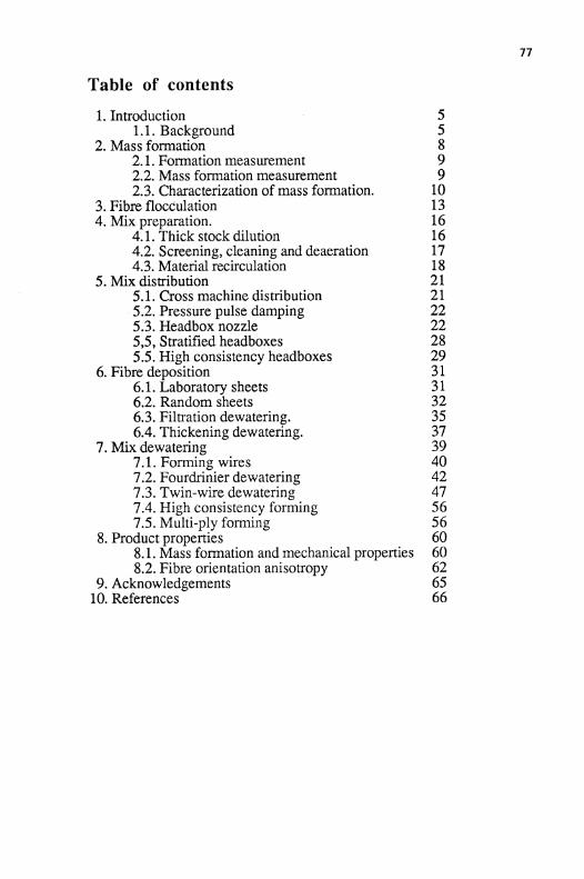
Table of contents
1 . Introduction
51 .1 . Background
52. Mass formation
82.1 . Formation measurement
92.2. Mass formation measurement
92.3. Characterization of mass formation.
103. Fibre flocculation
134. Mix preparation.
164.1 . Thick stock dilution
164.2 . Screening, cleaning and deaeration
174.3. Material recirculation
185. Mix distribution
215.1 . Cross machine distribution
215.2 . Pressure pulse damping
225.3 . Headbox nozzle
225,5, Stratified headboxes
285.5. High consistency headboxes
296. Fibre deposition
316.1. Laboratory sheets
316.2. Random sheets
326.3. Filtration dewatering .
356.4. Thickening dewatering.
377 . Mix dewatering
397.1 . Forming wires
407.2. Fourdrinier dewatering
427.3. Twin-wire dewatering
477.4. High consistency forming
567.5. Multi-ply forming
568. Product properties
608.1. Mass formation and mechanical properties
608.2 . Fibre orientation anisotropy
629. Acknowledgements
6510. References
66
78
1. Introduction
In this overview, forming is defined in a wide sense as all processes involvedin transforming the thick stock flow into a wet web . Conventional forming in-cludes three stages as in Table 1 .
Table 1 : Theforming process
The actual processes included in the forming of a paper web are extremelycomplex, and many random (or with a more popular physics term : chaotic)events are involved. The interaction between all processes involved, both in the"forward" and in the "feed-back" sense, further adds to the complexity.
No detailed theoretical treatment of the complete sheet build-up processhas yet even been seriously attempted, and this is in sharp contrast to for in-stance the wet pressing process, where extensive models have recently been setup at several universities and research establishments . In some cases however,basic models have been developed for individual parts of the forming process,with which qualitative predictions can be made.
1.1 . Background
Peter Wrist's excellent paper Dynamics ofsheetformation on the Four-drinier machine at the 1961 SymposiumW deals with the forming process inthe light of basic knowledge . Among many other things, Wrist discussed thebasics of air cushion headboxes with perforated rolls , the dewatering mecha-nisms of table rolls and foils as well as quantitative descriptions of dewatering
79
capacity .Joe Parker's now classic book from 1972, The Sheet Forming Process
(2), gives a good picture of basic forming knowledge around 1970. 60% ofParker's 140 literature references were published after the Wrist paper, whichindicates the amount of fundamental forming work undertaken during the1960's . Parker treated fibre networks and their reaction to turbulence energy,dewatering resistance, material distribution in the plane as well as in the z-direc-tion of the sheet and in a final chapter "Practical applications", headboxes andforming methods were discussed. "Two-wire formers" were mentioned, but itshould be remembered that Parker's book was published just before twin-wireforming made its large industrial breakthrough. Within the TAPPI FluidMechanics committee, work is under way to update Parker's original book.
Ben Radvan's chapter Forming , in the "Wiggins Teape Epos"Papermaking Science () covers mainly the same areas as Wrist and Parker did,and adds basic work published from 1970 to 1977 .
A serious reader, not well aquainted with the background described inthese contributions, should make a break here, study the three references , andthen continue with this overview .
During the last decade, the demands on machine speed, production effi-ciency, product quality, quality evenness and environmental control have all in-creased at an accelerating rate. It follows that, today more than ever before, notonly the basic sheet build-up process in the wire section has to be consideredwhen a forming section is designed .
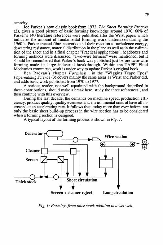
A typical layout of the forming process is shown in Fig . 1 .
Fig, 1 : Forming, from thick stock addition to a wet web .

80
As indicated in fig 1, screening and cleaning which basically belong to stockpreparation are normally placed within the forming domain . This is however anunsatisfactory solution since it leads to a large number of internal circulationloops with inherent concentration variations and variable fibre reject rates .
The increasing requirement for control of recirculated material through thewhite water system will focus interest on the retention level . This in turnstresses the use of process chemicals, a subject that is dealt with in a separatereview by Lindstrom (4) 1 .
Dry forming has attracted increased interest for special products, but spacedoes not allow its discussion in this overview .
In the following, the physical forming areas listed below will be dis-cussed :
Sheet qualityFibre suspensionsMixpreparationMix distributionFibre depositionMix dewateringProductproperties
Since these seven areas each have a large enough background to motivate an in-dividual review, it follows that it will be impossible in this overview to go inany detail into all the vast literature covering the whole field. The choice of lit-erature references is therefore highly personal with some older, original refer-ences and some more recent ones . All those which space and time did not allowto be included this time may be just as significant.
Finally, it should be pointed out that to manufacture efficiently an endproduct with given properties, the forming process cannot be studied in isola-tion . There has to be an overall optimization including the preceding raw mate-rial preparation as well as the downstream pressing, drying and surface treat-ment operations .
1 Setting an all time symposium record with 103 pages and 260 references!
2. Mass formation
The forming process, as defined in table 1, has a large impact on resulting sheetproperties and especially on their variability. All grammage variations, apartfrom long term variations in the machine direction, are exclusively generatedduring forming.
Of increasing importance for the sheet properties is also the distribution ofmaterial and fibre orientation at different levels in the z-direction of the sheet,which is to a high degree determined during forming . The final development ofsheet properties can however be manipulated during the pressing, drying andsurface treatment operations . .
Mix preparation and mix jet generation are the main sources of grammagevariations . Large scale grammage variance is usually subdivided into MD vari-ance, CD variance and Residual variance and can be evaluated on-line usingbeta ray absorption . However, on-line equipment today cannot record gram-mage variations smaller in geometrical size than about 20 mm.
Small scale grammage variations, often referred to as formation, aremainly caused by the flocculation tendency of fibre suspensions, and can bestrongly affected during forming. Formation is a very general term according tothe ISO definition : "The manner in which the fibres are distributed, disposedand intermixed to constitute the paper" . This is a very wide definition of thecomplete forming process, including the resulting sheet structure.
Wahren (5) tried to connect the termformation with small scale grammagevariations and look-through with the appearance of sheet unevenness, viewedin transmitted light . This has not however been generally accepted, since today"formation" is used to denote both "look-through" and "formation" as well as"forming" . A new term is therefore necessary to specify strictly small scalegrammage variations.
Corte (6 used the term Distribution of Mass Density, DMD, which hasnever been generally accepted, probably because of its being too complicated .
In this overview, the term mass formation2 will be used to denote small-scale grammage variations . Formation can then continue to be an unspecifiedcharacteristic, denoting for example the optical unevenness of paper . There ishowever no need to use it also to denote forming, as Peter Wrist already did.
2Introduced by Douglas Wahren, STORA .
8 1

82
2.1 . Formation measurement
The classical formation meter is the QNSM-meter (Z) from the 1960's, while to-day the NUI meter ($) in North America, and the M-formation meter (9) areusually used to quantify optical formation . All three meters record the variationsin light transmission through a paper sheet. They are valuable for the compari-son of similar products from one paper machine, but they are not useful forfurther quantitative evaluation.Recently, equipment using image analysis techniques for recording variations inlight transmission has been developed by Papworth (IQ) .
Light transmission measurements can never be used to evaluate mass for-mation of sheets made of components with different optical properties, such asfilled sheets, or of calendered sheets where local variations in light scatteringcoefficient make the correlation between light transmission and local grammageambiguous (11,12) .
2.2. Mass formation measurement
Beta ray absorption is commonly accepted for on-line measurements of largescale grammage variations . Corte (6) used direct measurement of beta ray ab-sorption, with 1 mm geometrical resolution to evaluate mass distribution .
In beta radiography , the complete picture of beta ray transmission througha test sheet is recorded on an X-ray film. As beta ray source, C-14 is useful,although the particle energy limits maximum local grammage to around 120g/m2 with reasonable exposure times (13) . The maximum geometrical resolutionusing diffuse beta radiation is of the same order as the sheet thickness .
Cresson has studied the details of exposing and developing beta radio-graphs (14) .
Local grammage variations can be evaluated from an exposed x-ray filmby optical scanning using a micro-densitometer (L5), see Fig . 2, or an imageanalyser (L4,16 .
With soft x-rays , a more parallel beam of radiation can be generated. Thispermits an improved geometrical resolution, allowing individual fibres to be re-produced (17) . Further advantages are the short exposure time and the unlimitedgrammage range . A problem is the difficulty of obtaining a low energy x-raybeam of acceptable cross sectional size, without too disturbing gradients in ra-diation intensity .
A recent development which looks extremely promising is to record localgrammage via the absorption of electron beams, a method under developmentby Luner and co-workers (18) . This could be the ultimate way of evaluatingmass formation, with possibilities even of on-line measurement .

83
Fig . 2 : Local grammage variations along a standard newsprintsample. Beta radiograph scanned in a microdensitometerusing 0.1 mm resolution (M.
2.3 . Characterization of mass formation.
The simplest way to characterize local variations is by the standard deviation 6.It is suggested that the dimensionless coefficient of variation, i .e . the standarddeviation divided by the mean value, be called the massformation number anddenoted F. In turbulence research, the coefficient of variation of local flow ve-locity is called the degree ofturbulence .
It should be pointed out that the geometrical resolution of the measuringequipment directly determines the amount of variations recorded.
It should also be pointed out that mean grammage has a large effect on themass formation number. For a random fibre distribution there is an inverse rela-tionship between the mass formation number and the square root of the meangrammage. For a comparison between sheets of different grammage, the follow-ing equation can be used for normalisation3
Fo =F w/wo(l)
where the mass formation number F is measured at grammage w and FO is thecorresponding mass formation number at the reference grammage wo (19} .
3-The inclusion of mathematical expressions in this publication is intended only to clarify thecontextual descriptions of the processes. They are not intended as analytical supplements. Inkeeping with this function, units of the terms are unnecessary and have been omitted" (2) .

84
2.3.1 . The Power Spectrum
For a more complete characterization of grammage variations using beta radiog-raphy, a two dimensional description is useful. Besides a variation numbersome measure of the geometrical size ofthe variations is needed.
Already during the 1930's, the autocorrelation and its courier transform,thefrequency power spectrum, were introduced (2Q,) . The frequency powerspectrum describes how the variance, a2, is distributed in different frequencyranges . The power spectrum is especially useful to characterize variables withnormal amplitude distribution, but it does not quantify the occurence of gradi-ents .
To characterize mass formation in paper sheets as well as turbulence andflocculation in flowing suspensions, it has proved useful to transform the fre-quency specrum into a wavelength spectrum . The wavelength 1 is calculatedfrom the frequency n and the radiograph scanning speed (or flow velocity) uusing the simple transformation
1= u/n
(2)
and the frequency spectral density has to be transformed into a wavelengthspectral density accordingly (21) .
The advantage of the wavelength spectrum over the frequency spectrum isthe possibility of directly evaluating the geometrical scales in the variations, i .e.flocs in paper sheets and fibre suspensions or eddies in fluid flows . It should beremembered, however, that under turbulent conditions the transformation is notentirely strict, since "the scanning speed u" in eq. (2) should then be replaced bythe local flow velocity .
A beta radiograph can be analysed in a microdensitometer, and the wave-length power spectrum of mass formation recorded. By scanning in both themachine and cross directions, the anisotropy of fibre orientation can be evalu-ated from the difference between the spectra (22) .
To condense the information of a complete power spectrum, it is possibleto present the variations within a few wavelength ranges . An STFI standard is toexpress the mass formation number F for the two floc size ranges 0.3 - 3 mm(F1) and 3-30 mm (F2) . The values F1 and F2 then represent the mean floc sizesof lmm and 10mm respectively.
As already mentioned, the geometrical resolution of the measuring equip-ment determines the amount of variations recorded . There are approximatelyequal contributions to the variance of grammage variations for each decade ofwavelength . If we assume that a measurement of mass formation covers awavelength range of 2.5 decades, e.g . 0.1mm - 30 mm, 40% of the variancewould be lost if the resolution were changed from 0.1mm to lmm. Because ofthe quadratic relationship between variance and F-value, the latter would de-crease by approximately 20% due to the change in resolution .

85
With an image analyser, the two dimensional power spectrum can be eval-uated, which is useful when floc shapes and two dimensional structures of peri-odic variations like wire mark are to be characterized. For high resolution in thepower spectrum, the computer of a standard image analyser is not enough . Amainframe computer is therefore needed for an accurate numerical evaluation ofthe one dimensional wavelength spectrum U).
2.3.2 . Mass formation scales
There are other ways of characterizing the scale of variations, such as microscale and macro scale (23), which are also concepts from turbulence theory.
The specific perimeter is evaluated as the total periphery offibre flocs, de-fined as areas of above average grammage (24) . Mean floc size is then inverselyproportional to the specific perimeter.
A comparison between different variation and scale values to characterizegammage variations is given in (14) .
2.3.3 . Co-occurrence matrix
In image analysis, the texture can be described by second-order statistics usingdifferent algorithms . The spatial grey level dependence method sometimescalled the Co-occurrence Matrix 1(4, 18) has been applied to characterize massformation . It quantifies the probability of occurrence of a specific grey leveltransition between two pixels of a given spatial separation .
In Cresson's thesis, ( 14 ), several parameters, see Table 2, are used tocharacterize laboratory sheets and simulated sheets, see further section 6.3 .Unfortunately, detailed comparisons with earlier results are not possible, sincepower spectra were never calculated.
Table 2 : Parameters derived using the spatial grey leveldependence method (L4J .
This new method of texture analysis could be be a useful complement to spectralanalysis of mass formation .
Floc Morphology Texture maps 2:nd-order statistics
Floc probability Probability peak EnergyLWZ probability Ellipse major axis EntropyEdge probability Ellipse minor axis CorrelationFloc size index Ellipse area HomogeneityFloc distance index Ellipse eccentricity ContrastNumber of flocs per line Formation index

86
3. Fibre flocculation
It can be shown that if fibres are added to water under very gentle mixing condi-tions, no fibre networks of appreciable strength are formed. However, the intro-duction of turbulent shear into the suspension causes local fibre deformations,which result in mechanical network forming when the turbulent shear energydecays .
The effect of fibre properties and hydrodynamic conditions on the formingand disruption of fibre flocs is therefore an important research area which hasbeen dealt with by many researchers. Summaries have been published by,Parker (2), Norman et al (25), Kerekes (26,2J7 and Wahren (28) .
Just as old as the art of papermaking itself is the knowledge that fibreconsistency during dewatering is the most critical parameter controlling the uni-formity of the wet web . Wahren et.al . (29) showed that fibre flocs are formedby mechanical entanglement, and that a minimum of three contact points withsurrounding fibres is required to lock a fibre in an unnatural shape . Fibre con-sistency and fibre slenderness were shown to be the main parameters determin-ing the degree of fibre flocculation .
An approximate relationship between average number of contact points n,fibre consistency c and fibre slenderness L/d has been derived by Wahren andMeyer (30) :
cn-
16nL
(3)2L n 3d + -
(n - 1)dn
n - 1
Sediment consistency, which is the final consistency reached when a highly di-luted fibre suspension is left undisturbed and allowed to settle under the influ-ence of gravity, is the lowest consistency at which fibre flocs form mechanicalnetworks . Application of eq.(3) indicates that the average number of contactpoints at sediment consistency falls between 3 and 4, which agrees well with theminimum average value of n=3 for floc forming mentioned above . Usually,thick stock has to be diluted down to or below the sediment consistency, for aproper sheet to be formed with conventional forming systems .
Recently, Soszynski and Kerekes (J 1) performed an elegant experiment inwhich they formed flocs in a rotating vessel according to the Jacquelin method(M. At constant rotation they then diluted the suspension, and the lowest start-ing concentration at which flocs stayed intact during dilution they namedthreshold concentration . A comparison between threshold concentration and eq .(3) is shown in Fig . 3 .

87
Fig . 3 : Comparison between Threshold concentration (JI) andMeyer-Wahren model (eq. 3) t
From fig . 3 it can also be concluded that stiffer fibres have a lower thresholdconcentration .
Soszynski and Kerekes further verified the concept of flocs forming fromelastic bending of fibres . They formed flocs from nylon fibres, which were thentreated at a temperature in excess of the glass transition point of the fibre material . The stresses in the bent fibres in the flocs could relax, and compared to un-treated flocs, the treated flocs were much more easily broken up by stirring in adilute suspension (33) .
Riitala has applied percolation theory to evaluate sediment consistency inrelation to eq . (3) with promising results QJ4 .
Optical, "one dimensional", transmission or reflectance methods have gen-erally been used to study local consistency fluctuations in flowing fibre suspen-sions 2(25) . Recently advanced video techniques have also been applied (M.From video films it is possible to evaluate both floc shapes and floc behaviour.
A basic study of the forming and dispersion of fibre flocs was performedusing high speed photography in a well defined Couette flow between twomoving transparent walls (J) . Two types of floc breakdown were found: oneglobal, stochastic process in which a fibre floc is broken down by fragmentationor stretching and one rate-dependent local erosion process .

88
Laser Doppler Velocimetry is a common optical technique to evaluate vari-able flow velocities, usually with the help of seeded particles . In fibre suspen-sions, however, the technique is difficult to apply because of the large amountof naturally occurring scattering surfaces . These cause secondary scattering ef-fects, making a correct signal evaluation difficult, unless the fibre consistency isvery low.
Steen used a mixture of benzyl and ethyl alcohol for refractive indexmatching between fibres and fluid (37 ) and studied turbulence structure in pipeflow of fibre suspensions up to 1.2% fibre consistency ($),see Fig . 4 : .
Fig . 4:
Turbulentfluid velocity as afunction ofdistance yfrom pipe wallat Re=8.5 103 (~L8) .

4. Mix preparation .
89
The consistency of the thick stock delivered from the machine chest usually liesin the range 3-4%, which is much too high for conventional sheet forming.Therefore, the thick stock has to be initially diluted, using recirculated whitewater in the short circulation loop from the wire section,.to a mix which can befed to the headbox. The mix should be at about the sediment consistency, withdeviations from this value for different paper grades .
In the nix, for the first time, the fibre concentration is low enough forscreening and centrifugal cleaning to be performed using conventional equip-ment, and they are therefore generally included in the short circulation loop, seefig . 1, although they really belong to the stock preparation domain. Screeningand cleaning both require reject loops, in which consistency and flow rate fluc-tuations can be a serious cause ofresidual grammage variations in the final prod-uct.
The mix usuallyalso passes a deaerator, where air originating from thewhite water is removed .
The ideal, as far as grammage stability is concerned, would be to feed themix directly from thick stock dilution to the headbox, and thus avoid screening,cleaning as well as deaeration of the mix flow .
Since the retention of material in the wire secdon is below 100%, materialwill be recirculated by the short circulation loop as well as by the long circula-tion loop . The long circulation recirculates material to positions upstream in thestock preparation process, which means that internally recirculated material isalso included in the thick stock .
4.1 . Thick stock dilution
Traditionally, little thought had to be put into the process of mixing thickstock with white water. The mixing pump was always running at full speed,and the mix flow rate was controlled by a throttling valve.The pump was thengenerally operating far from its optimum design point, and all the excess energywas in reality used for mixing . Following the introduction of variable speedpumps, more attention has to be paid to mixing if the residual grammage varia-tions are to be kept under control .
Norman and Tegengren (39) added the thick stock at a considerable excessspeed centrally in a straight mixing pipe with white water surrounding it . Thisdesign works according to the jet pump principle, with good mixing propertiesat sufficient excess speed of the thick stock feed . As can be seen in Fig . S , a ve-locity ratio greater than five is needed for good mixing .

90
Fig. 5 :
Mixing of thick stock and white water at different ratiosof Thick stock velocity /.White water velocity (DJ.
Top : 1 .5 - Centre: 5.3 - Bottom: 10.8
4.2 . Screening, cleaning and deaeration.
Unfortunately, screens, and especially cleaners, require quite substantial rejectrates . This necessitates up to two stages of screen reject recovery and five stagesof cleaning reject recovery . This in turn introduces several new loops with dif-ferent fibre consistencies, which may also vary in time . Finally brought to-gether, the individual flows will generate consistency fluctuations in the mix fedto the headbox.
Today there are screens which run efficiently even at high consistencies. Ifthe thick stock is screened, it would thus not be necessary to introduce mixscreening . High consistency screening is made possible in one design by flu-idizing the fibre suspension in front of the screen plate (40) and in another de-sign by a flow situation which generates local dilution in the screen plate areaGit .
It has so far been possible to perform centrifugal cleaning efficiently onlyat fibre consistencies below 1 % . Above this consistency, so much turbulentshear has to be introduced to individualize shives, sand particles etc . from fibreflocs, that large-scale turbulent mixing overshadows the centrifugal separation

9 1
effects . A new cleaning process development is however under way, in whichthe fibre network is sufficiently fluidized to separate sand particles efficiently at3% feed consistency (42) .
The shive-removing task of cleaners could probably be taken over byproperly designed screen systems, and this function could thus also be movedfrom mix to thick stock.
Since most of the air in the mix flow originates from the recirculated whitewater, it would be logical to deaerate the white water before adding the thickstock see Fig . 6.
Fig 6: Short circulation designformaximum grammage stability
With a design according to the principle shown in fig. 6, all the fibres in thecarefully controlled thick stock flow would be fed directely to the headbox,which would mean a much more stable operation than with today's conventionaldesign, see fig. l .
In high consistency forming, the thick stock flow is fed directly to theheadbox, which means that no short circulation loop is required at all .
4.3 . Material recirculation
As mentioned aleady in the introduction, material with less than 100% wire re-tention is recirculated in both the short and the long circulation loops . Material inthe short circulation will return directly in the dilution of the thick stock whilematerial in the long circulation may take a considerable time before returning aspart of the thick stock, see fig. 1 .

92
Three parameters have to be specified to define a retention value.
A)
material component,B)
starting position in processC)
end position in process .
The retention R is then defined as follows :
R- Amount of component passing start position
(4)Amount of component passing end position
Any unspecified "retention" value would today be interpreted as "First PassRetention" (FPR), which is defined as follows :
FPR = 1 -Total consistency of white water in short circulation
(5)Total consistency in headbox
From a comparison of eqs. (4) and (5) it is clear that FPR does not even fullfilthe basic requirements for a retention value, since consistency only and not massflow is considered.
Further, all components are included instead of one specific. This is lesssuitable, since the retention value is then dependent on stock composition, andnot only on the process as such .
The starting position in the process is defined as the headbox. The endposition in the process is undefined however, since it depends on how whitewater is collected to the short circulation, and completely neglects all materialgoing to the long circulation . On industrial newsprint machines, for instance, asmuch as 50% of the "fines" in the machine chest may be recirculated material inthe long circulation .
The retention on twin-wire machines will often be overestimated comparedwith fourdrinier machines, if FPR only is the basis for comparison. This is be-cause on a fourdrinier machine it is possible to separate the rich white waterfrom the lean, and preferably bring the former to the short circulation. On twin-wire machines this separation is sometimes not possible, which means that thematerial concentrations in the short and long circulations are more equal .
Still, FPR can be of considerable value if applied to a specific system, andif the white water system is unchanged . To give even more useful results, how-ever, component retention such as "fines retention" or "filler retention" shouldbe evaluated, and the long circulation should be taken into account.
93
In a fully "closed" white water system, all material will finally end up in the pa-per web regardless of the retention level, but there are still several reasons forkeeping wire retention values high and the white waters as clean as possible .
Cleaner white water means less problem with slime and dirt build up,which in turn will mean higher machine efficiency .
Cleaner white water means less circulating material, and therefore lesschanges in mix composition with fluctuating retention levels . This willmean a more constant quality of the product.
Cleaner white water means less material carry-over between machineswith connecting white water systems .
Cleaner white water means a faster response to grade changes and otherprocess changes, and thus a lower level of broke generation . This isespecially important for the long circulation loop (1~) .

94
5. Mix distribution
The main task of the headbox is to transform the mix pipe flow into a thin jetwith an extremely precise velocity, direction and thickness across the entire wirewidth . In this section, basics of flow in headboxes will be dealt with . Those in-terested in the design features of today's headboxes are referred to an overviewpresented by Waller (44) .
5.1 . Cross machine distribution
The tapered manifold has been the completely dominating cross-machine distri-bution system for headboxes for over two decades, and a thorough descriptionthereof was given by Trufitt (45) . In principle, a large number of tubes, orholes, redirect the mix flow 90 degrees from the manifold channel into the ma-chine direction .
An equal amount of mix flow is fed into each tube or hole, by keeping aconstant static pressure along the manifold channel. This is possible by design-ing the channel cross-section area so that the pressure recovery through successively decreasing flow velocity along the channel (Bernoulli equation) is exactlybalanced by the pressure drop along the manifold channel due to wall friction .The greater the pressure drop across the tube/hole section the less sensitive is theheadbox flow profile to deviations from constant pressure along the channel .
To adjust the static pressure along the manifold channel, the amount ofoverflow from the exit side can be varied. If the mix flow in a headbox is in-creased too much above the original design point, it may be necessary to replacethe channel to attain a constant enough pressure across the machine width .
The separation between the individual holes/pipes leading from the mani-fold channel must be sufficiently great so that fibre stapling on the downstreamside of the openings is avoided . Further, the flow velocity into the tubes/holesmust be comparatively large, if sufficient pressure drop is to be generated. Thisleads to a design with rather low open area on the upstream side of the tube/holesection .
The cross section of the tubes/holes is generally expanded towards thedownstream side, or their centres are brought together . This is in order to give alarge open flow area at the entrance to the next section, and thus to improvedownstream flow stability .
Syrj ala, Saarenrinne and Karvinen (46) have studied manifold flow usingthree-dimensional numerical flow analysis, and compared the results with mea-surements in an air loop .
Bubik and Christ (4J described discrete increases of the tube cross sec-tional area, thus introducing the"step diffuser concept" . This allowed a con-trolled turbulence generation with limited eddy size. Model experiments wereperformed with air, which allowed the use of hot wire anemometers for mean

5.2 . Pressure pulse damping
95
velocity and turbulence evaluation.Lin (4) has made a numerical study of turbulent flow through a circular
step diffuser .The mix flow from a cross machine distributor is fed either directly to an
outlet nozzle, or into a stilling chamber followed by some pressure drop generat-ing device such as perforated rolls or tube bundles . In the stilling chamber,cross flow can occur, thus improving the cross machine evenness of theemerging jet .
In an air pad headbox, a compressed air volume above the stilling chamber canabsorb pressure variations in the approach flow .
In hydraulic headboxes, a narrow channel may lead from a stilling cham-ber to a connected air volume, which can absorb high frequency pulsations .Usually, however, hydraulic headboxes exhibit a very stiff design from a flowviewpoint. If such a headbox is applied to a fourdrinier machine, special damp-ing equipment may therefore have to be inserted in front of the headbox to avoidexcessive grammage pulsations, see section 7.2.3 . In the damper, an air volumemay be located directly above the mix suspension surface or a membrane mayseparate the two.
5.3 . Headbox nozzle
Already in 1961, Mardon discussed the relationship between headbox designand jet quality, and especially the degree of wake effect remaining in theemerging jet (42). During the late 1960's and the 1970's several investigationsregarding jet quality were undertaken, mainly because of the increasing machinespeeds and the introduction of hydraulic headboxes for twin-wire formers .
5.3.1 . Headbox nozzle feed area and contraction ratio .
To keep a low degree of turbulence in the jet emerging from a headbox, a tech-nique also used in e.g . wind tunnels is adopted. With a given absolute level ofturbulent energy in the flow entering the outlet nozzle, the degree of turbulencein the emerging jet can be reduced in proportion to the acceleration of flow. Thelarger the nozzle contraction, the larger, the reduction in degree of turbulence inthe jet.
Reiner and Wahren studied the change in the turbulence spectrum in aheadbox jet due to changes in headbox operating conditions (0). They analysedwater flow in a headbox jet using an impact probe for turbulence recording .Considering the above mentioned relationship between turbulent energy and de-gree of turbulence as well as the fact that the degree ofjet turbulence is indepen-
96
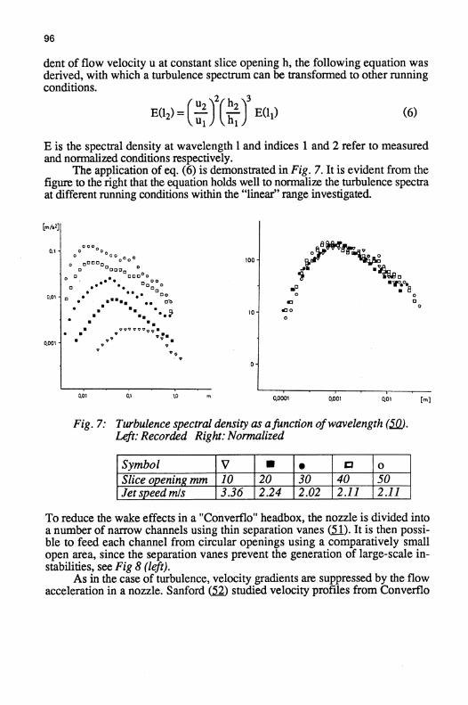
dent of flow velocity u at constant slice opening h, the following equation wasderived, with which a turbulence spectrum can be transformed to other runningconditions .
U2 h2E(12) = Cui )2(hi )3
E(11)
(6)
E is the spectral density at wavelength 1 and indices 1 and 2 refer to measuredand normalized conditions respectively .
The application of eq . (6) is demonstrated in Fig . 7. It is evident from thefigure to the right that the equation holds well to normalize the turbulence spectraat different running conditions within the "linear" range investigated.
Fig . 7 : Turbulence spectral density as afunction ofwavelength (5M .Left: Recorded Right: Normalized
To reduce the wake effects in a "Converflo" headbox, the nozzle is divided intoa number of narrow channels using thin separation vanes (51) . It is then possi-ble to feed each channel from circular openings using a comparatively smallopen area, since the separation vanes prevent the generation of large-scale in-stabilities, see Fig 8 (left) .
As in the case of turbulence, velocity gradients are suppressed by the flowacceleration in a nozzle . Sanford (S2) studied velocity profiles from Converflo
Symbol 0 a a IM oSlice opening mm 10 20 30 40 SOJet speed mls 3 .36 12 .24 12.02 12 .11 12.11

97
channels, and the effect of slice opening is demonstrated in Fig . 8 (right) . Asmaller slice opening means larger headbox nozzle contraction ratio, and thusalso better evening out of the velocity streaks from the holes feeding the nozzleentrance.
Fig 8:
Left:
Separate channels in headbox nozzle(divider sheet outside) (51 j
Right: Flowprofile at channel outlet (52) .
During the early 1970's, a "high turbulence" hydraulic headbox was designed,with a tube bundle of nearly 90% open area feeding the headbox nozzle (5) . Toreach such a high open area, the pipes in the tube bundle were deformed into ahexagonal shape at the downstream end, and tightly packed at the entrance to theheadbox nozzle . The same basic principle with high open area has later alsobeen adopted by other manufacturers.
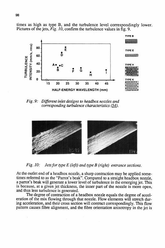
Valmet has studied the effect onjet quality of different geometries of theinlet section to the headbox nozzle . Turbulence spectra were measured, and the"half energy wavelength" of turbulence was calculated (5J44 . This is the wave-length dividing the turbulence spectrum into two equal parts, and thus one mea-sure of the mean scale of the turbulent eddies .
Fig . 9 shows some different inlet designs and corresponding turbulencecharacteristics . It can e.g. be observed that the entrance section of type E is three
98
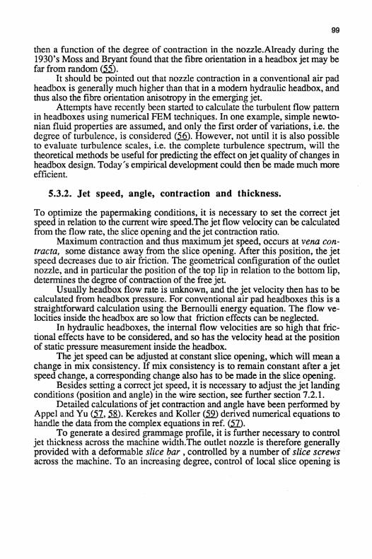
times as high as type B, and the turbulence level correspondingly lower.Pictures of the jets, Fig . 10, confirm the turbulence values in fig . 9 .
Fig . 9 : Different inlet designs to headbox nozzles andcorresponding turbulence characteristics (5.
Fig . 10 :
Jetsfor type E (left) and type B (right) entrance sections .
At the outlet end, of a headbox nozzle, a sharp contraction may be applied some-times referred to as the "Parrot's beak". Compared to a straight headbox nozzle,a parrot's beak will generate a lower level of turbulence in the emerging jet. Thisis because, at a given jet thickness, the inner part of the nozzle is more open,and thus less turbulence is generated .
The degree of contraction of a headbox nozzle equals the degree of accel-eration of the mix flowing through that nozzle. Flow elements will stretch dur-ing acceleration, and their cross section will contract correspondingly . This flowpattern causes fibre alignment, and the fibre orientation anisotropy in the jet is
99
then a function of the degree of contraction in the nozzle.Already during the1930's Moss and Bryant found that the fibre orientation in a headbox jet may befar from random (&.
It should be pointed out that nozzle contraction in a conventional air padheadbox is generally much higher than that in a modern hydraulic headbox, andthus also the fibre orientation anisotropy in the emergingjet .
Attempts have recently been started to calculate the turbulent flow patternin headboxes using numerical FEM techniques . In one example, simple newto-nian fluid properties are assumed, and only the first order of variations, i .e. thedegree of turbulence, is considered (56) . However, not until it is also possibleto evaluate turbulence scales, i .e . the complete turbulence spectrum, will thetheoretical methods be useful for predicting the effect onjet quality of changes inheadbox design. Today's empirical development could then be made much moreefficient .
5.3.2 . Jet speed, angle, contraction and thickness .
To optimize the papermaking conditions, it is necessary to set the correct jetspeed in relation to the current wire speed.The jet flow velocity can be calculatedfrom the flow rate, the slice opening and the jet contraction ratio.
Maximum contraction and thus maximum jet speed, occurs at vena con-tracta, some distance away from the slice opening . After this position, the jetspeed decreases due to air friction. The geometrical configuration of the outletnozzle, and in particular the position of the top lip in relation to the bottom lip,determines the degree of contraction of the free jet.
Usually headbox flow rate is unknown, and the jet velocity then has to becalculated from headbox pressure . For conventional air pad headboxes this is astraightforward calculation using the Bernoulli energy equation . The flow ve-locities inside the headbox are so low that friction effects can be neglected.
In hydraulic headboxes, the internal flow velocities are so high that fric-tional effects have to be considered, and so has the velocity head at the positionof static pressure measurement inside the headbox .
The jet speed can be adjusted at constant slice opening, which will mean achange in mix consistency . If mix consistency is to remain constant after a jetspeed change, a corresponding change also has to be made in the slice opening .
Besides setting a correct jet speed, it is necessary to adjust the jet landingconditions (position and angle) in the wire section, see further section 7.2.1 .
Detailed calculations ofjet contraction and angle have been performed byAppel and Yu (57, 558 . Kerekes and Koller
derived numerical equations tohandle the data from the complex equations in ref. Cam) .
To generate a desired grammage profile, it is further necessary to controljet thickness across the machine width.The outlet nozzle is therefore generallyprovided with a deformable slice bar, controlled by a number of slice screwsacross the machine . To an increasing degree, control of local slice opening is

100
made automatically using special algorithms, taking into account the actual sliceopening profile as well a :. the difference between actual and target grammageprofiles (6Q) .
It has long been hypothesized, and it has recently also been theoreticallyshown (Ll), that a local deformation of the slice lip, apart from locally changingjet thickness, will also cause transverse iokr . The transverse flow componentcan have a large effect on the final grammage profile, but will also affect localfibre orientation in the final product. The shape of the outlet nozzle is very im-portant in this context, and the transverse flow component inci°eases with de-creasing contraction angle of a nozzle, see Fig 11 .
Fig 11 : Effect of nozzle contraction angle on cross directionflow (.61 .
Ideal flow conditions in a headbox can occur only with a constant pressurealong the manifold channel and a constant slice opening profile across the wholemachine width, see further section 8.2 . If the slice profile is deformed from thisideal state, transverse flow is inevitably generated .
Due to later deformation in the wire section as well as in the drying sectionof the grammage profile actually delivered from the headbox, the target profilefor the headbox is never constant grammage across the whole wire width.
As an example, preferential cross machine shrinkage at the edges in thedrying section require low grammage edges to be delivered from the headbox, toachieve even grammage profile at the -P1 . This in turn requires distortion of theslice at the edges, and as a consequence transverse flow is generated, causinglocal variations in fibre orientation anisotropy . The prevention of uneven cross

machine shrinkage is therefore a prerequisite if anisotropy profiles as well asgrammage profile are to be even all across the paper machine .
Finally, it could be mentioned that the target fibre weight profile at thereel-up may have to be adjusted because of moisture considerations.
5.4 . Stratified headboxes
The simplest way to form a stratified sheet is from a stratified jet. A stratifiedjetcan be delivered using a headbox with different mix suspensions in differentlayers .
There are two main types of headbox in industrial use today for stratifiedforming of two-layer or three-layer products.
In one design, the mix layers are separated by thin foils (Q, which mayor may not protrude from the slice opening, see Fig . 12 . . The longer the foil,the later the mixing between the different layers can start. In a three-layer design, however, the friction conditions in the centre layer differ from those in theouter layers, and this generates velocity differences between the layers .
The degree ofmixing between the different mix layers is very sensitive tothe shape of the downstream end of the foils . They have to be tapered, sinceblunt edges cause severe layer mixing.
Fig . 12 :
Multiply headbox with thin separationfoil (_62JTop : Foil ends inside Bottom : Foil extends outside headbox.

102
In a second design, the layers are separated using comparatively thick wallswhich protrude from the slice opening, and behind which air wedges form,(U3) . In this case, one individual jet for each layer is delivered from the head-box, see Fig 13 .
With air wedges between the different layers, these can be kept separateduntil dewatering actually starts . However, air wedges mean that extra surfacesbetween mix and air are created, and instabilities in these surfaces will affectmass formation for the individual layers in a negative way .
Fig 13: Thick separation wall and air wedge in multiply headbox (0) .
5.5. High consistency headboxes
Forming at a fibre concentration as high as thick stock consistency, 3 - 4 %,would mean large process simplifications, since the short white water circulationwould be unnecessary. This would mean reductions in both capital investmentand energy consumption .
The basic difference between high consistency forming and conventionalforming is the same as that between thickening and filtration dewatering, seesection 6. To form high quality HC-paper, a uniform network of fibres has to bedelivered from a high consistency headbox, since no radical improvements in fi-bre distribution can be imposed during the dewatering process, in contrast towhat is possible in conventional forming .
Pioneering work in high consistency forming was performed by Reinerand Wahren (_4) around 1970 . The basic idea was to introduce dispersing tur-bulence energy into a high consistency fibre suspension, by forcing it through anarrow forming channel with high local pressure drops . After dispersion, thelocal energy input was decreased to a level low enough for the turbulence to de-cay . The flowing fibre suspension then transformed into a fibre network, and

103
the generation of large scale flocculation during the turbulence decay phase wasavoided "mechanically" by the narrow dimension of the channel . Different flowchannel shapes were introduced, to induce shear of suitable levels, resulting inan improved fibre distribution (&, see Fig. 17.
Fig 17: High consistency forming channels according topatent drawings (65)
A further improvement was the introduction of an "eddy chamber", fed from theindividual pipes of the cross machine distributor M).The fibre suspension isfed tangentially into the chamber, and to reach the outlet, the flow has to make asharp turn . This causes a large contraction of the flow into the forming channel .A high pressure drop is generated, which is benificial for the final cross distri-bution of fibre suspension inside the eddy chamber . Furthermore, this designhas good runnability, since it can even be started filled with a high consistencyfibre suspension .
Recently high consistency headboxes with flow channels similar to thosedescribed in ref . (65) have also been tried in a Japaneese development project(U.

104
6. Fibre deposition
Radvan et.al . demonstrated that fibre suspension dewatering can be either a fil-tration or a thickening process (68). Fig 15 illustrates the principle differencebetween the two .
6.1 . Laboratory sheets
Fig . 15 :
Fibre deposition by :Left: Filtration process
Right: Thickening process (2) .
In the filtration case, the fibres are laid down individually from a dilute fibresuspension . The result is a strongly layered sheet structure with rather poor me-chanical properties in the z-direction . Conventional sheet forming of the four-drinier type and of the twin-wire type are thought to be mainly filtration pro-cesses .
The main reasons for making laboratory sheets is to evaluate the potential of agiven pulp, and not to simulate industrial forming conditions . In laboratorysheet forming processes, a high degree of dilution is therefore used, to avoid fi-bre flocculation and thus to make as uniform a sheet as possible . These pro-cesses are therefore typical filtration processes .
The British Standard Handsheet is the traditional laboratory sheet, formedfrom a fibre suspension of about 0.02 % consistency, which is about 25 moredilute than in industrial forming . Because of the high dilution, the sheet build-upfollows an ideal filtration process, resulting in a far better than random fibredistribution, see section 6.2 . The result is a laboratory sheet with mechanical
105
and optical properties superior to those of machine-made paper.On the other hand, the retention using the original British Standard
Handsheet Machine is comparatively low, due to the absence of white water re-circulation . For mechanical pulps, or for products where fines or filler content isimportant, means of recirculating the white water should therefore be consideredQ0.
The fines and filler tend to be concentrated to the wire side in laboratorysheets, while the opposite is true for machine-made fourdrinier sheets . In twin--wire sheets, the distribution generally shows a symmetrical form with maximasomewhere between the centre and the surfaces (2) .
Formette Dynamique (M) is a rotating laboratory sheet former developedin Grenoble. It dewaters a sheet on a removable bronze wire, placed against theinside of a perforated drum, and the dewatering pressure is generated throughcentrifugal forces . One advantage of this former is the large sheet size of 250mm x 800 mm, which allows more complete testing than the smaller, circularBritish Standard Handsheets . Furthermore, Formette Dynamique is well suitedto the making ofmulti-ply sheets .
The fibre consistency in the feed to the former is as high as 0.3-0.4 % butnormal fibre flocculation is still avoided since the actual fibre deposition onto theweb takes place by centrifugation through a 10 mm thick water layer . Thismakes it easy to align fibres in the direction of rotation, and thus to make ori-ented sheets . With Formette Dynamique, it is in fact difficult to make isotropicsheets .
When evaluating paper samples taken from industrial machines or pilotmachines, a comparison with laboratory sheets made from the same furnish isuseful .- The ratio between the properties of a machine sample and those of a laboratory sample is a measure of how well the potential of a specific furnish is de-veloped on the machine, i.e . of the Forming Efficiency . When evaluating FEXsamples, Formette Dynamique laboratory sheets made from the same furnish areused as reference for the calculation of Forming Efficiency, (71) .
6.2 . Random sheets
It was already suggested by Wrist (1) that dewatering on the Fourdrinier was tosome extent a self-healing process The reason for this was that areas of lowerthan average local grammage also exhibit lower than average dewatering resis-tance . Therefore, extra dewatering would take place at areas of low grammage,and the extra fibres deposited would then result in an overall levelling of gram-mage over the sheet area .
Early simulations of a random sheet structure by Corte and Kallmes (7)were made by drawing black lines, representing fibres, with random positionand orientation . In this way, however, only very low grammages sheets couldbe represented, since at realistic sheet grammage the random sheet would appearalmost completely black, with no floc structures . The grammage was therefore
106
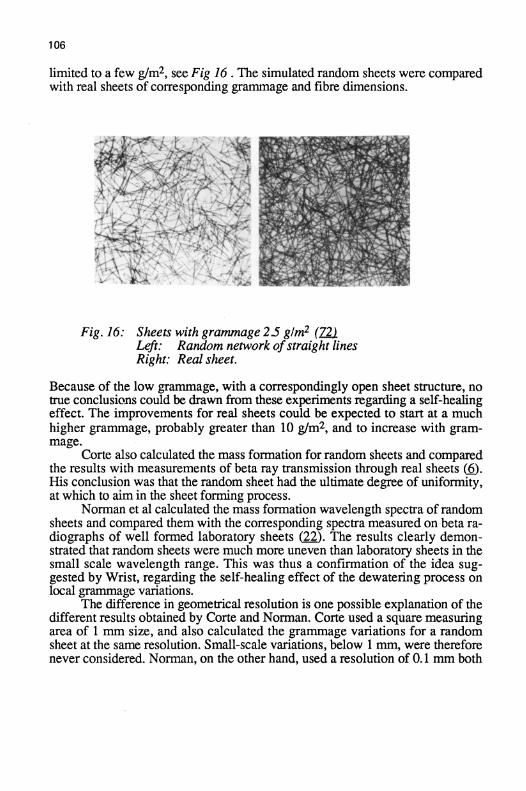
limited to a few g/m2, see Fig 16 . The simulated random sheets were comparedwith real sheets of corresponding grammage and fibre dimensions .
Fig . 16:
Sheets with grammage 2.5 g1m2 (Z21Left :
Random network ofstraight linesRight : Real sheet .
Because of the low grammage, with a correspondingly open sheet structure, notrue conclusions could be drawn from these experiments regarding a self-healingeffect . The improvements for real sheets could be expected to start at a muchhigher grammage, probably greater than 10 g/m2 , and to increase with gram-mage.
Corte also calculated the mass formation for random sheets and comparedthe results with measurements of beta ray transmission through real sheets (6) .His conclusion was that the random sheet had the ultimate degree of uniformity,at which to aim in the sheet forming process .
Norman et al calculated the mass formation wavelength spectra of randomsheets and compared them with the corresponding spectra measured on beta ra-diographs of well formed laboratory sheets (22) . The results clearly demonstrated that random sheets were much more uneven than laboratory sheets in thesmall scale wavelength range . This was thus a confirmation of the idea sug-gested by Wrist, regarding the self-healing effect of the dewatering process onlocal grammage variations .
The difference in geometrical resolution is one possible explanation of thedifferent results obtained by Corte and Norman. Corte used a square measuringarea of 1 mm size, and also calculated the grammage variations for a randomsheet at the same resolution. Small-scale variations, below 1 mm, were thereforenever considered . Norman, on the other hand, used a resolution of 0.1 mm both
107
in the measurement and in the calculations .In Norman's case, the large amount of random variations in the small-
-scale region overshadowed the more even random structure at large wave-lengths, in comparison with the real sheet . In Corte's case instead, the largervariations obtained for real than for random sheets could have been caused bythe more frequent occurence of fibre flocs in the real sheets .
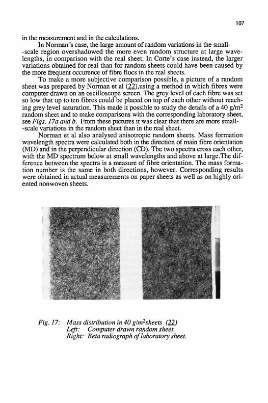
To make a more subjective comparison possible, a picture of a randomsheet was prepared by Norman et al (,using a method in which fibres werecomputer drawn on an oscilloscope screen . The grey level of each fibre was setso low that up to ten fibres could be placed on top of each other without reach-ing grey level saturation. This made it possible to study the details of a 40 g/m2random sheet and to make comparisons with the corresponding laboratory sheet,see Figs . 17a and b. From these pictures it was clear that there are more small--scale variations in the random sheet than in the real sheet.
Norman et al also analysed anisotropic random sheets . Mass formationwavelength spectra were calculated both in the direction of main fibre orientation(MD) and in the perpendicular direction (CD). The two spectra cross each other,with the MD spectrum below at small wavelengths and above at large.The dif-ference between the spectra is a measure of fibre orientation . The mass forma-tion number is the same in both directions, however. Corresponding resultswere obtained in actual measurements on paper sheets as well as on highly ori-ented nonwoven sheets .
Fig . 17:
Mass distribution in 40 glm2sheets QJ2Left:
Computer drawn random sheet.Right: Beta radiograph oflaboratory sheet.
108
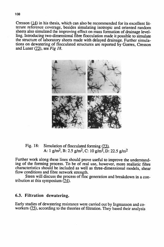
Cresson 14) in his thesis, which can also be recommended for its excellent lit-terure reference coverage, besides simulating isotropic and oriented randomsheets also simulated the improving effect on mass formation of drainage level-ling . Introducing two-dimensional fibre flocculation made it possible to simulatethe structure of laboratory sheets made with delayed drainage . Further simula-tions on dewatering of flocculated structures are reported by Gorres, Cressonand Luner (22), see Fig 18 .
Fig . 18 :
Simulation of flocculated forming (M.A : 1 g/m2 , B : 2.5 g/m2, C : 10 g/m2 , D: 22.5 g/m2
Further work along these lines should prove useful to improve the understand-ing of the forming process . To be of real use, however, more realistic fibrecharacteristics should be included as well as three-dimensional models, shearflow conditions and fibre network strength .
Steen will discuss the process of floc generation and breakdown in a con-tribution at this symposium (74) .
6.3 . Filtration dewatering.
Early studies of dewatering resistance were carried out by Ingmanson and co-workers (75), according to the theories of filtration . They based their analysis

109
on the Kozeny-Carman equation :
_dQ__1 (1-C)3 1dt
K S2C2 -Op
where dQ/dt is rate of drainage per unit area of the web, Ap is the pressure gra-dient across the web, C is the volume fraction of the web occupied by solids, Sis the specific surface area of the solids per unit volume, g is the viscosity of thefluid and K is the Kozeny Constant.
The Kozeny-Carman equation assumes laminar flow through a bunch ofparallel capillaries in an incompresssible medium. Neither of these assumptionsare true in the case of wet paper webs. The Kozeny-Carman equation in its present form can thus not be used for useful predictions . Substantial modificationsmust be incorporated, before it can successfully be applied to paper webs.Application of the equation results in values of the surface area S an order ofmagnitude different from the surface area estimated using other methods (3) .
In connection with his discussions of the hydrodynamics of dewatering,Radvan states that "the progress of technology has overtaken the need for de-tailed understanding of the original process" . There may be reason to put aquestion mark to the use of the word "need" in this context, but there is nodoubt whatsoever that the rapid development of fourdrinier as well as twin-wiredewatering principles, which has taken place also after Radvan's statement, hascompletely outpaced the corresponding theoretical understanding.
During the dewatering process in the wire section, a suspension is forcedagainst a compressible, porous web, backed by the surface of a woven wire .The solid particles such as fibres, fines, filler etc. in the suspension are to a certain degree trapped, initially by the wire surface and later in the pores of the ac-cumulating wet web . The resistance to flow through the web is influenced byseveral parameters, such as :
the distribution of material and voids in the z-direction and in the planeof the web
the chemical properties of web and suspension components
the mechanical compression properties of the web
the mode of flow (laminar, turbulent) through the pore system
the time event of the pressure driving the dewatering
It follows, that the dewatering of a well defined furnish subject to a knownpressure (or force) event is extremely difficult to describe . Schopper Riegler

number or Canadian Standard Freeness level, as evaluated in standard labora-tory equipment is not enough to predict the actual dewatering capacity on a papermachine.
Fundamental work on dewatering has been summarized by Radvan (3) .Several devices to study filtration dewatering resistance have been developed.They are based on constant filtration rate, constant filtration pressure or combi-nations of these two modes. Since these idealised conditions differ significantlyfrom those prevailing in a real wire section, attempts have been made to makerealistic modifications of the laboratory devices .
One example is the development by Pires, Springer and Kumar (76), whoused a Britt Jar device 77 and with some modifications designed a "Drainageand Vacuum Retention Tester". The introduction of six electrodes made it pos-sible to follow the drainage event, and shear rates in the fibre suspension as wellas pressure events on the downstream side of the wire comparable to those en-countered in paper machines were introduced . They used the device in connec-tion with modelling of fourdrinier drainage on a pilot plant machine, see furthersection 7.2.5 .
For practical use, empirical equations are often used to predict the influ-ence of process conditions on dewatering. One example is the equation ofWahlstrom and O'Blenes (78) :
t -G
wa (d )n
8C p
where t is the time to form a web of grammage w, under a constant pressuredrop Ap. C is the suspension consistency and G, a and n are empirical con-stants .
6.4 . Thickening dewatering.
Even in a conventional forming process, all fibres are not free to move individ-ually during dewatering . Some fibres are mechanically connected in fibre flocs,which are successively compressed during dewatering. This event can be de-scribed as a thickening process . Compared to filtration dewatering, the resultingsheet structure will be more "three-dimensional", since the fibres are more en-tangled in the z-direction . This can be expected to give improved properties inthe z-direction, together with some losses in the plane of the sheet.
Britt, Unbehand and Shridharan (80) suggest that the level of fines reten-tion is a measure of the distribution between filtration and thickening dewater-ing . A low retention level indicates mainly thickening dewatering, while a highretention level is an indication of filtration dewatering . In experiments using aBritt Dynamic Drainage Jar with controllable dewatering vacuum, they couldapply a desired degree of dewatering pulsation . They thus claim to be able to

simulate real dewatering processes by applying suitable dewatering pulses . Auniform dewatering pressure would result in pure filtration dewatering, whilepressure pulses would generate their definition of thickening deatering.
When the filtration process is finalized on a fourdrinier wire or in a twin--wire section, further dewatering will cause consolidation by thickening. In thetwin wire case, when the web is squeezed between the two wires, the web willbe subject to mechanical compression. This type of dewatering follows the samebasic rules as those in wet pressing, which means that the pressure applied isdivided between hydraulic and mechanical pressure in the web . The amplitudeof pressure applicable is limited by the allowable amount of wire mark em-bossed into the web surface .
The last part of dewatering in the wire section is performed by air suction .Water removal during this phase is a displacement process in which water is ex-changed for air. This process differs considerably from a filtration or a thickening processes . The sheet dryness after the couch is therefore not a simple func-tion of the flow resistance of the web .
It should be advantageous for final web dryness to keep the sheet mechan-ically compressed during air suction. Also, as little water as possible should beleft in the wire, since much of that water may follow the web at the point of sep-aration of wire and web .
Britt and Unbehend (IIJ found in laboratory experiments that differentstocks often behaved quite differently during initial dewatering (up to the dryline ) and during the final vacuum dewatering . There is no general correlationbetween initial and final dewatering rates, which makes it difficult to predict theoverall dewatering characteristics for a specific paper pulp .

7. Mix dewatering
When the mix suspension is dewaeerind in the wire section of a paper machine,the actual process differs highly from the idealised conditions in laboratory sheetformers . Since the fibre consistency in real forming may be at least an order ofmagnitude higher than that in laboratory sheet forming, measures have to be un-dertaken to improve the mass formation of the paper produced. These measuresare: drainage, orientedfluid shear and turbulence (2), see Fig . 19 .
Fig . 19: Drainage, Orientedfluid shear and Turbulence (2) .
As mentioned in section 6.2, drainage has a self-healing effect on grammagevariations . Oriented shear is originally generated by a velocity difference be-tween mix jet and wire, and may also be generated by shaking of a fourdrinierwire and by gradients in the fluid pressure applied in twin-wire formers .Oriented shear will move free fibres in a fibre suspension relative to one an-other, and may also disrupt fibre flocs . Oriented shear will affect the orientationof fibres and fibre segments, and will therefore have a strong effect on theanisotropy of the sheet properties .
Turbulent velocity fluctuations may occur in the mix jet from the headbox,and may also be generated in the wire section. The scale of the turbulence is vitalfor its interaction with the fibres in a suspension . Only eddies up to the sameorder of size as the fibre flocs will have a disrupting effect, while larger eddieswill mainly superimpose floc motion . On a fourdrinier wire, turbulence can begenerated by vertical movements of the wire as it passes over dewatering ele-ments. In twin-wire forming, turbulence can be generated by pressure fluctua-tions between the wires .
The degree to which these effects occur in a given drainage section and thedegree to which they are relevant to reach desired product qualities is still mainlyunknown, and much more research is needed to extend the knowledge withinthe area.
In this chapter, basic process aspects in the wire section will be discussed,
starting with forming wires and followed by fourdrinier forming, twin wireforming and multi-ply forming .7.1 . Forming wires
Helle recently presented an overview of the development of forming wires dur-ing this century ($2)-
Earlier, forming wires were made of bronze, they were single layered andof two shed design . Neither the material nor the design was a good choice formaintaining a long wire running time combined with high paper quality on highspeed paper machines . When wires of polymeric materials were developed inthe 1970's, the bronze wires therefore quickly disappeared from the market.
7.1.1 . Wire surfaces
For good wire wear resistance, it is an advantage to have as much CD yarn ma-terial as possible facing the stationary wire support. This means that the machinedirection threads, which take the main mechanical load, are subject to less me-chanical abrasion, which in turn increases wire life. The influence of wire de-sign parameters on the amount of material available for wear has been describedin a theoretical model by Batty (U).
The wire side of a paper replicates the forming wire to some extent. Apredomination ofpaper side MD nuckles, which is the case for a single layeredwire with a predominance of CD nuckles on the bottom side, leads to increaseddeflection of fibres into the wire openings, "blinding" and reduced dewateringcapacity ($_4) . The preferential machine direction orientation of fibres on the wireside of the paper is one reason for this effect . Beran (;~5 introduced a "FiberSupport Index" to quantify the top surface quality of a wire.
The surface of the wires is also important for the generation of wire mark,which can be analysed using optical techniques M).
It is thus obvious that a single layered forming wire cannot be optimisedfor both running time and paper quality. The introduction of polymeric materialsmade it possible, however, to design double layered wires, on which the topand bottom sides are more independent. Recently the use of "shute support" ondouble layered wires, which extra threads on the paper side of the wire has im-proved the support for the fibres during dewatering . Further, multi-layeredwires have been introduced, which in principle consist of a fine top wire for pa-per support combined with a coarse bottom wire for runnability . Multi-layeredwires are now introduced for most paper grades ($7_) .
Good mechanical wire properties are important. This is accentuated be-cause the dewatering pressure in twin-wire formers is generated by wire ten-sion, and a uniform tension profile across the whole machine width is essentialfor a good cross machine grammage profile .

7.1.2 . Dewatering properties
The traditional criteria for evaluating the drainage efficiency of forming wireswere :
the relative vertically projected open areathe air or water flow resistance .
The relative open area concept ignored the fact that modern wires exhibit ahighly three dimensional structure, in which the openness varies considerably inthe thickness direction of the wire.
A better way of characterizing the openness is therefore to describe thedistribution of material and voids in the thickness direction of the wire (88), seeFig 20 . The influence of MD and CD threads can then be separately quantified.
Fig 20
Mass I void volume distribution through wiresLeft: Single layer wire
Right: Multi-layer wire
The wire design is also important for the level of retention of fibre material, butthe size of the wire openings makes it extremely hard to filter out fines and filler,see Fig . 21 (88) .
Johnson (89) studied the deposition of air-suspended fibres onto differenttypes of wires in a 32 times scaled up experiment . He found an improved reten-tion going from a single layered to a double layered wire design . He also foundthat drainage was strongly influenced by the degree of sheet support for the firstlayer of fibre web .

Fig . 21 : Size ofwire mesh "window" is 200yx 200,u ($$) .
Fibre carry back is a term which refers to fibres which do not follow the wetsheet on its removal, but which are instead left on the wire surface and thus re-turn to the forming zone . These fibres disturb sheet dewatering, by locally in-creasing the dewatering resistance of the forming wire, and cause a deteriorationin mass formation . In twin-wire forming, the geometrical and mechanical prop-erties of forming wires have a marked influence on the amount of fibre carryback (9Q) .
7.2 . Fourdrinier dewatering
The history of fourdrinier dewatering was recently presented in an interestingpaper by Hansen (91) . Classical fourdrinier dewatering has been described insome detail in references (1_), (2) and (3).
7.2.1 . Initial dewatering
The setting of the jet onto the wire and its initial dewatering is extremely impor-tant for both the dewatering capacity and the product quality . The jet shouldideally hit the wire immediately in front of a supporting forming board.If the jethits the wire much ahead of this board,too rapid dewatering will result in a dete-riorated mass formation , whereas air will be trapped and disturb forming if thejet hits the wire on top of the forming board.
wahren has theoretically analysed the situation when ajet hits a wire. Hepostulates that the ideal situation occurs when that part of the jet which remainson the wire will move horizontally as a result of the impulse exchange when partof the jet is deflected downwards C2)2 . The influence ofjet angle, jet thickness,horizontal and vertical distance from headbox to forming board, front angle offorming board and fraction of jet deflected downwards is analysed.
Osterberg applies a laboratory former to study the initial part of the dewa-teri.ng process (22) .
7.2.2 . Jet velocity pulsations
Pressure pulsations in the mix feed flow generate jet velocity pulsations whenhydraulic headboxes are used . In fourdrinier forming applications, these veloc-ity pulsations can result in serious grammage variations . Grammage variationsup to ten times as large as the jet velocity variations have been observed.
One explanation for this amplification is the generation of standing waveson a fourdrinier wire (2 4 .Maximum amplification will occur when maximumwave amplitude coincides with the dry line . The distance from headbox to dryline then corresponds to one fourth of the total wavelength of the standing wave,and the frequence is then normally in the range 10-20 Hz .
Another explanation of the amplified grammage variations could be theforward and backward movement of the position at which the jet hits the wire
In twin wire forming, jet velocity pulsations do not generally cause seri-ous problems . Since the bet is immediately enclosed between two wires, amplifi-cation due to standing wave generation is avoided .
7.2.3 . Improvement of mass formation
To improve mass formation, horizontal shaking of the wire has been very use-ful, especially at low speeds . Recently it has however also been applied atspeeds as high as 600-700 m/min.
A dandy roll, applied on the wire at a position where the average consis-tency is aound 2.5% improves mass formation by introducing shear in the sus-pension . A better effect would be achieved ifthe dandy roll were applied at evenlower consistencies, but then severe downstream spouting cannot be avoided.This is because the dandy roll is not a dewatering element . and the suspensionconsistency is therefore approximately the same on the upstream and the down-stream sides of the roll .
A new dandy roll application has been presented by Kallmes andLangdok, who used the roll for dewatering a). They led the fourdrinier wireupwards on the downstream side of the dandy roll and also introduced a returnroll, see Fig 22 Having watched a demonstration run of this principle on theIPC experimental wet end, I am still amazed at the way water clung to the inside

of the roll, allowing axial removal at "9:00 o'clock".
Fig . 22 Scheme ofMIK Dandy Roll Former (W.
Mainly because of cleaning problems, dandy rolls have not been used on highspeed machines . As far as the effect of mass formation improvement is con-cerned, the twin wire former can be interpreted as being a development from thedandy roll, since it can be run with low ingoing fibre consistency and still yielda sufficiently high outlet consistency. Many fourdrinier machines, especiallythose manufacturing printing grades, have been modernized to hybridformers(see section 7.3.3) by the introduction of "extended dandy rolls" in the form oftop wires .
7.2 .5 . Dewatering devices .
Originally, all dewatering relied on gravity effects, and supporting rolls wereintroduced only to keep the wire horizontal while causing a minimum offrictiondrag . Today, dewatering devices are applied to fourdrinier wires with the objectboth of creating dewatering effects and also of providing means for controllingthe degree of fibre flocculation in the sheet formed .
Taly1e rolls
The basic principle for table roll dewatering was understood during the 1950's,and was described in work of Wrist (22), Taylor (98,99) and Bergstrom
At a table roll, a suction pressure peak is generated in the downstream ex-pansion zone between wire and roll . This causes a local downward deflection of

the wire immediately after the roll, and a corresponding upward movement ofthe wire then has to occur before the next dewatering element is reached. Thevertical motions of the wire generate turbulence in the suspension on the wire,which may to some degree improve final mass formation .
Pires, Springer and Kumar developed a computer program for the evalua-tion of drainage on a fourdrinier wire supplied with table rolls and vacuumboxes . They used the equation for table roll drainage developed by Taylor anddetermined the specific filtration resistance experimentally using their DVRT-tester (M), see section 6.
The amplitude of the table roll suction pressure is proportional to thesquare of the wire speed. There is an upper speed limit for the application oftable rolls of approximately 500 m/min, above which the vertical wire movementis so intense that the high degree of turbulence generated disturbs the final massformation.
A modified table roll which has recently been introduced is the Sonic Roll(1Ql ). It can be described as a gear wheel of wire section width, with each toothbroken at regular intervals along its length . During rotation, each tooth causes alocal upward lift of the wire, and the amplitude of the wire movement is deter-mined by tooth width and separation. For very slow machines it has been founduseful to drive the Sonic Roll at an excess speed, which makes it possible toshake the wire at its resonant frequency
Foils
Foils were introduced during the 1960's (1), and took over as the standard de-watering element at speeds where table rolls could no longer be used . Just as inthe case of table rolls, the maximum amplitude of the suction pulse is propor-tional to the square of wire speed - in fact it equals the dynamic pressure of themix on the wire . However, by choosing a very small angle between foil surfaceand wire, as low as even below one degree, a suitable suction pressure can beachieved even at high wire speed .
Usually several foil elements are used in combination, and to increase theoverall dewatering effect they are mounted in vacuum boxes .
The overall optimization of the individual foiles angles and separation dis-tances is a complex procedure . Schmid (1 3) performed an experimental study,and evaluated the turbulence level introduced by watching the surface of thesuspension on the wire using a strobe light. The amplitude of surface distur-bances was graded as "activity" in numbers from 1 (smooth surface) to 10(severe stock jump) . Among other things he found that an increase in foil anglealong the wire gave an optimum combination of dewatering capacity and sheetmass formation.

Step f i1
One disadvantage with conventional foils is that a complete element has to bereplaced if the dewatering pulse is to be changed . This makes optimization ofsheet mass formation through suitable activity in the mix on the wire rathercomplex.
The Step foil is a design in which the mix activity can be controlled byvacuum (1~}4 . The distance between the foil element and the wire undergoes astep increase, see Fig . 23, and the vacuum level in the foils box determines theextent to which the wire is deflected into the step . An increased vacuum levelcauses a larger vertical wire deflection, and thus create a greater activity in themix on the wire .
Cadieux 1(,~4) performed a study on 2 pilot fourdrinier machine using stepfoils for the main part of the dewatering, and on the basis of the results he set upa mathematical model to describe dewatering. The equation is an expansion ofthe Kozeny-Carman equation, and the difference between a "static" laboratorysheet former and dynamic fourdrinier dewatering is taken account of by aFourdrinier Factor. Of all the 17 independent variables tested, those found to bemost significant were fibre compressibility, the first zone of the drainage ele-ment pressure pulse, drainage element position along the wire and headbox jetconfiguration .
Fig . 23 : The Step Foil (104J .
ISO-flo foil
Iso-flo foils are horizontal support blades mounted in a vacuum box. Every sec-ond blade is slightly lowered, and thus the wire is be subject to vertical move-

120
ments when running over the box with vacuum applied. The degree of activityon the wire is then controlled by the vertical distance between the blades .
as ade foil
A cascade foil consists of several gently sloping sections with horizontal con-nections . A single cascade foil can have a capacity of several millimetres of de-watering, without the application of vacuum. Contrary to ordinary foils, the cas-cade foil does not introduce any activity in the fibre suspension on the wire . Thereason for this is that the vertical wire movements are stabilized by the introduc-tion of the neutral zones between the dewatering zones
Flexi-Former
A dewatering device which acts from the top of the mix suspension on the wireis the Flexi-Former (M. A flexible (or stiff) blade is pressed against the mix,and dewatering occurs by the pressure generated in the suspension between astationary upper surface and the moving wire . See further description in section7.3 .1 .
7.3 . Twin-wire dewatering
Principles for twin-wire forming were patented as early as during the last cen-tury, but not until the 1950's were machines developed which could be used forpractical paper/board making . The new developments avoided the simultaneousmechanical guiding of both wires within the forming zone, a task impossible toperform with the required accuracy . The secret to success was always to let oneof the two wires automatically adjust to the wire separation required by the pre-vailing forming conditions .
David Webster's (
) privately developed twin-wire former for paperproduction and Brian Attwood's (1_Da) "Inverform" design, developed for boardproduction at St Anne's Board Mill, were the first two designs of practicalvalue.
The Webster patent for the rollformer principle was acquired by BarjeWahlstrom of KMW, where the basic development continued and commercialequipment was produced . The roll former concept was also studied at PPRIC(1 9 and equipment was manufactured in co-operation with DominionEngineering Works (110) .
Twin-wire blade formers with stationary dewatering elements were de-veloped by Beloit 4(11 l) and Black Clawson 112 .
In pure twin wire formers, the mix jet is delivered directly into the gap
4An earlier development by Times Inc. was taken over by Beloit .
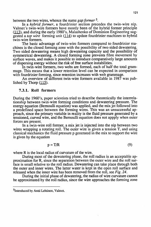
between the two wires, whence the name gapformerIn a hybrid former, a fourdrinier section precedes the twin-wire nip .
Valmet's twin-wire formers have mostly been of the hybrid former principle11 ), and during the early 1980's, Malashenko of Dominion Engineering suggested a top wire forming unit (114) to update fourdrinier machines to hybridtwin-wire formers .
The basic advantage of twin-wire formers compared to fourdrinier ma-chines is the closed forming zone with the possibility of two sided dewatering .Two sided dewatering means high dewatering capacity and the possibility ofsymmetrical dewatering . A closed forming zone prevents fibre movement bysurface waves, and makes it possible to introduce comparatively large amountsof dispersing energy without the risk of free surface instabilities .
In twin-wire formers, two webs are formed, each of half the total gram-mage . This means that a lower retention level can be expected in comparisonwith fourdrinier forming, since retention increases with web grammage .
An overview of different twin-wire formers available in 1987 was pub-lished by Thorp 1I).
7.3.1 . Roll formers
During the 1960's, paper scientists tried to describe theoretically the interrela-tionship between twin-wire forming conditions and dewatering pressure . Theenergy equation (Bernoulli equation) was applied, and the mixjet followed intoa predefined space between the forming wires . This was an unsuccessful ap-proach, since the primary variable in reality is the fluid pressure generated by atensioned, curved wire, and the Bernoulli equation does not appply when outerforces are present .
In a twin-wire roll former, a mix jet is injected into the nip between twowires wrapping a rotating roll . The outer wire is given a tension T, and usingclassical mechanics the fluid pressure p generated in the mix to support the wireis given by the equation
p = T/R
(9)
where R is the local radius of curvature of the wire.During most of the dewatering phase, the roll radius is an acceptable ap-
proximation for R, since the separation between the outer wire and the roll sur-face is small relative to the roll radius . Dewatering can take place through boththe outer and inner wires . The latter water is kept in the open roll surface andreleased when the inner wire has been removed from the roll, see Fig . 24 .
During the initial phase of dewatering, the radius of wire curvature cannotbe approximated by the roll radius, since the wire approaches the forming zone
51ntroduced by Antti Lehtinen, Valmet .
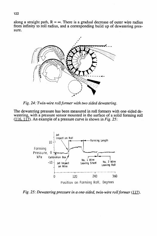
122
along a straight path, R = -. There is a gradual decrease of outer wire radiusfrom infinity to roll radius, and a corresponding build up of dewatering pres-sure .
Fig . 24: Twin-wire rollformer with two sided dewatering .
The dewatering pressure has been measured in roll formers with one-sided de-watering, with a pressure sensor mounted in the surface of a solid forming roll11
lam). An example of a pressure curve is shown in Fig . 25 :
Fig . 25: Dewatering pressure in a one-sided, twin-wire rollformer (1O.
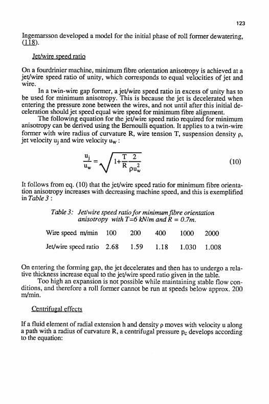
123
Ingemarsson developed a model for the initial phase of roll former dewatering,118) .
Jet/wire speed ratio
On a fourdrinier machine, minimum fibre orientation anisotropy is achieved at ajet/wire speed ratio of unity, which corresponds to equal velocities of jet andwire .
In a twin-wire gap former, ajet/wire speed ratio in excess of unity has tobe used for minimum anisotropy . This is because the jet is decelerated whenentering the pressure zone between the wires, and not until after this initial de-celeration shouldjet speed equal wire speed for minimum fibre alignment .
The following equation for the jet/wire speed ratio required for minimumanisotropy can be derived using the Bernoulli equation . It applies to a twin-wireformer with wire radius of curvature R, wire tension T, suspension density p,jet velocity uj and wire velocity uW
uj- =
l+T 2
10)u
R 2puW
It follows from eq . (10) that the jet/wire speed ratio for minimum fibre orienta-tion anisotropy increases with decreasing machine speed, and this is exemplified.in Table 3
Table 3: Jet/wire speed ratiofor minimumfibre orientationanisotropy with T=6 k1V/m andR = 0.7m .
Wire speed m/min
100
200
400
1000
2000
Jet/wire speed ratio
2.68
1 .59
1 .18
1 .030
1 .008
On entering the forming gap, the jet decelerates and then has to undergo a rela-tive thickness increase equal to the jet/wire speed ratio given in the ,table.
Too high an expansion is not possible while maintaining stable flow con-ditions, and therefore a roll former cannot be run at speeds below approx . 200m/min .
Centrifueal effects
If a fluid element of radial extension h and density p moves with velocity u alonga path with a radius of curvature R, a centrifugal pressure pc develops accordingto the equation :

124
u2
p.= ph R (11)
It is often claimed that the dewatering pressure in a roll former is generated bycentrifugal forces . This is however entirely incorrect, and centrifugal forces infact only tend to decrease inwards dewatering 1(07,) . To counteract this effect,and thus still get symmetrical dewatering, roll formers are supplied with vacuumzones to increase inwards dewatering, see fig. 24 .
The ratio between centrifugal pressure pc and wire generated pressure pwcan be described by the following equation 119
PC phu2PW T
(12)
If the centrifugal pressure were to exceed the wire pressure, unstable conditionswould result. This means that there is a practical upper limit for the pc/pw-ratioof unity . From eq . (12) it is clear that these conditions are reached independentlyof the local radius of wire curvature R. Corresponding values for fibre suspen-sion radial thickness h and machine speed u are shown in Fig . 26 (119) .
Machine speeds in excess of those indicated in fig . 26 would result in un-stable forming conditions .
Fig . 26 :
Maximum wire speed u�z as afunction of the suspension radialthickness h and wire tension T according to eq . (12)
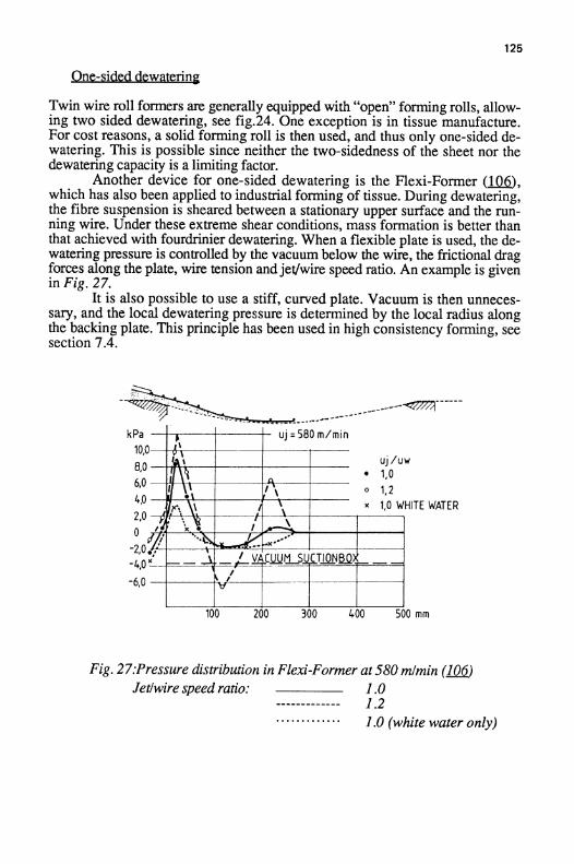
125
One-sided dewaterinta
Twin wire roll formers are generally equipped with "open" forming rolls, allow-ing two sided dewatering, see fig.24 . One exception is in tissue manufacture .For cost reasons, a solid forming roll is then used, and thus only one-sided de-watering . This is possible since neither the two-sidedness of the sheet nor thedewatering capacity is a limiting factor .
Another device for one-sided dewatering is the Flexi-Former (106,which has also been applied to industrial forming of tissue . During dewatering,the fibre suspension is sheared between a stationary upper surface and the run-ning wire . Under these extreme shear conditions, mass formation is better thanthat achieved with fourdrinier dewatering . When a flexible plate is used, the de-watering pressure is controlled by the vacuum below the wire, the frictional dragforces along the plate, wire tension andjet/wire speed ratio . An example is givenin Fig . 27 .
It is also possible to use a stiff, curved plate . Vacuum is then unneces-sary, and the local dewatering pressure is determined by the local radius alongthe backing plate . This principle has been used in high consistency forming, seesection 7.4 .
Fig . 27:Pressure distribution in Flexi-Former at580 m1min (16Jetlwire speed ratio :
1 .0------------- 1 .2
1.0 (white water only)

12 6
7.3.2 . Blade formers
As late as during the Internationl Water Removal Conference in London,1975,the basic principle for a blade former was explained as being due to the samemechanism as that in roll forming (1~). The dewatering pressure over a BelBaie forming shoe was calculated according to eq . (9), and the radius ofmounting for the blade tips was inserted instead of the radius R of wire curva-ture . The radius was one order of magnitude larger than that of a roll former.The hypothetically lower dewatering pressure was suggested to be the main rea-son for the improved mass formation obtainable in a blade former .
The pulsating nature of dewatering in blade formers was however empha-sized by Norman lM, the deflection of the wires over the individual bladesbeing the basis for the generation of the dewatering forces F according to theequation :
F = 2T sin al2
(13)
where T is the wire tension and a wire deflection angle over a blade tip . It wassuggested that the pulsating nature of the dewatering pressure creates internalshear in the fibre suspension between the wires, and thus improves the massformation of the sheet produced .
This basic principle has later been generally accepted . The shape of thepressure pulse generated by the blade force F depends on several factors, suchas wire speed, wire separation and wire stiffness. No attempts to describe thedetailed pressure event mathematically has been made as yet .
Measurement of the shape of the pressure pulses has been undertaken byBeloit, using a static pressure probe extending from within the headbox into thefibre suspension between the wires . Examples of pressure measurements areshown in Figs . 28 and 29,
1( 21).There is a general tendency that, compared with roll formers with uniform
dewatering pressure, blade formers with pulsating dewatering pressure producesheets with superior mass formation but with lower retention of fines and filler.
The fibre orientation anisotropy cannot be manipulated to the same degreeusing the speed difference between jet and wire as variable in a blade former asin a roll former. This is because the pressure pulses along the forming zone allaffect fibre orientation, and only the conditions in the very beginning of theforming zone can be controlled by the jet speed . As a rule, a blade former givesa higher minimum anisotropy than a roll former .

127
Fig . 28 :
Pressure pulses, Bel Baie blades . 48 glm2 , T = 4.4 kNlmLeft: 460 mlmin . Right : 920 mlmin.
Fig . 29 :
Pressure pulses, Bel Baie, 48 glm2 , 920 mlmin, T = 7 kNlrnLeft: Standard blades
Right: Vacuum shoe
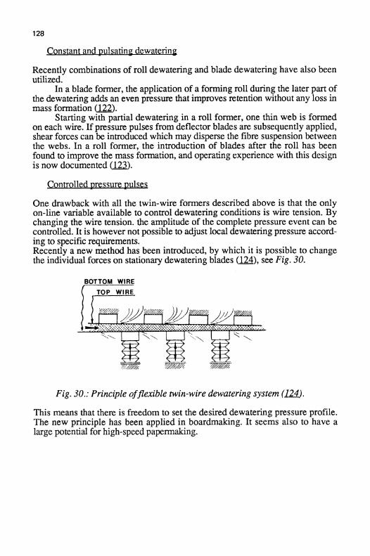
128
Constant and pulsating dewatering
Recently combinations of roll dewatering and blade dewatering have also beenutilized .
In a blade former, the application of a forming roll during the later part ofthe dewatering adds an even pressure that improves retention without any loss inmass formation (122) .
Starting with partial dewatering in a roll former, one thin web is formedon each wire. If pressure pulses from deflector blades are subsequently applied,shear forces can be introduced which may disperse the fibre suspension betweenthe webs . In a roll former, the introduction of blades after the roll has beenfound to improve the mass formation, and operating experience with this designis now documented (12 ).
Controlled pressure pulses
One drawback with all the twin-wire formers described above is that the onlyon-line variable available to control dewatering conditions is wire tension . Bychanging the wire tension. the amplitude of the complete pressure event can becontrolled. It is however not possible to adjust local dewatering pressure accord-ing to specific requirements.Recently a new method has been introduced, by which it is possible to changethe individual forces on stationary dewatering blades
), see Fig. 30 .
Fig. 30 . : Principle offlexible twin-wire dewatering system (L2J4 .
This means that there is freedom to set the desired dewatering pressure profile .The new principle has been applied in boardmaking . It seems also to have alarge potential for high-speed papermaking.
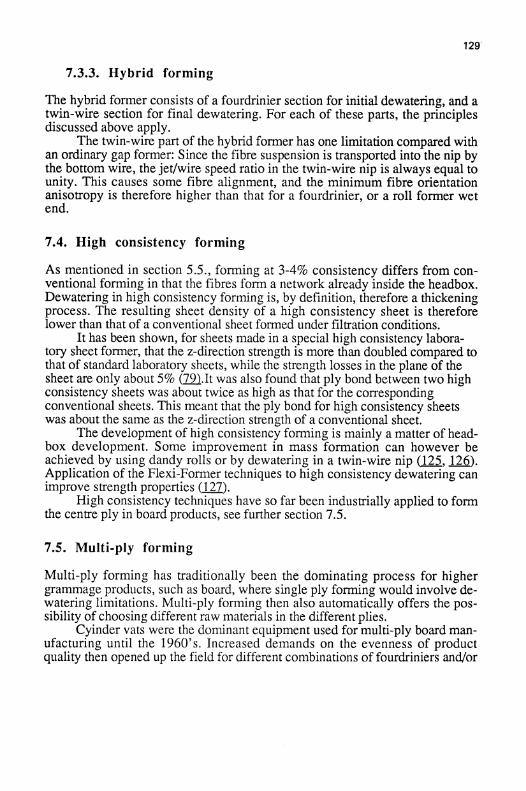
7.3 .3 . Hybrid forming
129'
The hybrid former consists of a fourdrinier section for initial dewatering, and atwin-wire section for final dewatering . For each of these parts, the principlesdiscussed above apply .
The twin-wire part of the hybrid former has one limitation compared withan ordinary gap former : Since the fibre suspension is transported into the nip bythe bottom wire, the jet/wire speed ratio in the twin-wire nip is always equal tounity . This causes some fibre alignment, and the minimum fibre orientationanisotropy is therefore higher than that for a fourdrinier, or a roll former wetend .
7.4 . High consistency forming
As mentioned in section 5 .5 ., forming at 3-4% consistency differs from con-ventional forming in that the fibres form a network already inside the headbox.Dewatering in high consistency forming is, by definition, therefore a thickeningprocess . The resulting sheet density of a high consistency sheet is thereforelower than that of a conventional sheet formed under filtration conditions .
It has been shown, for sheets made in a special high consistency labora-tory sheet former, that the z-direction strength is more than doubled compared tothat of standard laboratory sheets, while the strength losses in the plane of thesheet are only about 5% (79~.It was also found that ply bond between two highconsistency sheets was about twice as high as that for the correspondingconventional sheets . This meant that the ply bond for high consistency sheetswas about the same as the z-direction strength of a conventional sheet.
The development of high consistency forming is mainly a matter of head-box development . Some improvement in mass formation can however beachieved by using dandy rolls or by dewatering in a twin-wire nip
, 126).Application of the Flexi-Former techniques to high consistency dewatering canimprove strength properties (127) .
High consistency techniques have so far been industrially applied to formthe centre ply in board products, see further section 7.5 .
7.5 . Multi-ply forming
Multi-ply forming has traditionally been the dominating process for highergrammage products, such as board, where single ply forming would involve de-watering limitations . Multi-ply forming then also automatically offers the pos-sibility of choosing different raw materials in the different plies .
Cyinder vats were the dominant equipment used for multi-ply board man-ufacturing until the 1960's . Increased demands on the evenness of productquality then opened up the field for different combinations of fourdriniers and/or

130
twin-wire arrangements .A recent summary of multi-ply forming concepts hasbeen made by White (12$) .
Lately, increased interest has also been paied to the manufacturing of lowgrammage products, such as tissue and fine paper, using stratified headboxes .In this overview, the term simultaneousforming will be used when all plies aredelivered from one headbox, while separateforming indicates the use of severalheadboxes . These terms are preferred to the previously used terms multilayerand multiply respectively, which do not seem to be clear enough .
For the forming principles of a single ply in a multi-ply product, referenceis made to the preceeding discussions within that area . In addition, ply bondbetween the differeent plies has to be considered, a property which is often criti-cally low in multi-ply products .
Ply bond is influenced by the amount of fine material at the interface be-tween two plies, and is therefore highly influenced by the forming methodsused . As an example, the low fines content on the wire side of a fourdriniersheet can be critical if this side is facing another ply in a multi-ply design . Theproblem is often accentuated if mechanical pulp is used as raw material in morethan one ply.There are four basic ways of forming a two-ply product:
I
Two plies are formed separately, and couched together.
II
A second ply is formed on top of a first ply, and dewateringis made away from the first ply .
III
A second ply is formed on top of a first ply, and dewateringis made through the first ply .
IV
Both plies are formed simultaneously from a stratified headbox .
Generally, ply bond between the two plies will successively increase along thislist of forming principles .
As mentioned in section 7 .3, twin-wire forming at very low machinespeeds generally causes instability problems . However, the application of con-trolled pressure pulses .in a twin-wire forming unit, permits the forming of ahigh grammage ply even at speeds below 100 m/min (129) :
High consistency forming of the centre ply in a board product results in amore bulky sheet and higher z-direction strength as well as ply bond comparedto conventional forming . Therefore, the greatest potential for high consistencyforming is as the centre ply in board products, since the positive effects theninclude product properties as well as investment costs (1 Q) .
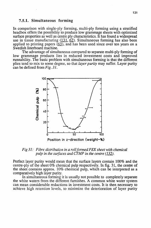
7.5.1 . Simultaneous forming
In comparison with single-ply forming, multi-ply forming using a stratifiedheadbox offers the possibility to produce low grammage sheets with optimizedsurface properties as well as centre ply characteristics . It has found a widespreaduse in tissue manufacturing ( 131 , 62 ) . Simultaneous forming has also beenapplied to printing papers (63), and has been used since over ten years on aSwedish linerboard machine .
The advantage of simultaneous compared to separate multi-ply forming oflow grammage products lies in reduced investment costs and improvedrunnability . The basic problem with simultaneous forming is that the differentplies tend to mix to some degree, so that layer purity may suffer. Layer puritycan be defined from Fig . 31 .
Fig 31: Fibre distribution in a rollformed FEX sheet with chemicalpulp in the surfaces and CTMP in the centre (1J2.
Perfect layer purity would mean that the surface layers contain 100% and thecentre-ply of the sheet 0% chemical pulp respectively . In fig. 31, the centre ofthe sheet contains approx . 10% chemical pulp, which can be interpreted as acomparatively high layer purity.
In simultaneous forming it is usually not possible to completely separatethe white waters from the different furnishes . A common white water systemcan mean considerable reductions in investment costs.It is then necessary toachieve high retention levels, to minimize the deterioration of layer purity
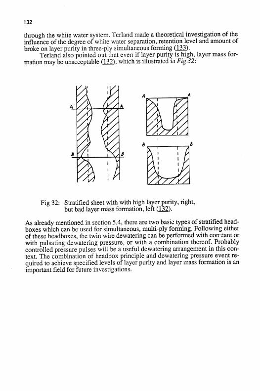
132
through the white water system. Terland made a theoretical investigation of theinfluence of the degree of white water separation, retention level and amount ofbroke on layer purity in three-ply simultaneous forming 1(33) .
Terland also pointed out that even if layer purity is high, layer mass for-mation may be unacceptable ( 132 ), which is illustrated iii Fig 32:
Fig 32 :
Stratified sheet with with high layer purity, right,but bad layer mass formation, left (_132) .
As already mentioned in section 5 .4, there are two basic types of stratified head-boxes which can be used for simultaneous, multi-ply forming . Following eitherof these headboxes, the twin wire dewatering can be performed with con;cant orwith pulsating dewatering pressure, or with a combination thereof. Probablycontrolled pressure pulses will be a useful dewatering arrangement in this con-text. The combination of headbox principle and dewatering pressure event re-quired to achieve specified levels of layer purity and layer mass formation is animportant field for future investigations .

133
8. Product properties .The vast literature relating forming conditions to product properties cannot becovered in this overview . Only two specific areas will be briefly discussed inthis section, firstly the relationship between mass formation and strength andsecondly fibre orientation anisotropy as a result of process conditions .
A recent literature review on paper quality aspects of twin-wire formedpaper in comparison to fourdrinier formed paper has been prepared by Sinkeyand Wahren (134) .
8.1 . Mass formation and mechanical properties .
It is well known that higher dilution of a fibre suspension before drainage re-sults in better mass formation as well as higher paper strength . This can be ex-plained by the self healing effect of dewatering on fibre distribution mentionedin section 6.2 .
Corte made experiments using a modified laboratory sheet former, by in-creasing the height of the suspension tank so that the initial fibre consistencycould be decreased one order of magnitude from the standard value of 0.02% .Also in this range he found improved product properties with increased dilution
Terland and Fellers {136) studied the effect of forming consistency onsheet properties in twin-wire roll forming . They found a considerable influenceon tensile index and elongation to rupture, see Fig . 33, as well as burst, butnegligible effects on tensile stiffness and tear index .
Fig 33 . :
Influence offorming consistency in the FEX rollformer uniton tensile index ("left) and elongation to rupture (right) (L&.
It has been claimed that multi-ply forming results in improved product propertieswhen compared to a single ply product . Terland and Fellers 137) showed that

134
this may be a matter of forming consistency . Single-ply and two-ply productswere formed on the FEX machine, and using the same forming consistencythere was no significant difference between the product properties . However,two-ply forming made it possible to decrease the forming consistency in eachlayer compared to single ply forming, with a resulting improvement in sheetmass formation as well as in mechanical properties .
It has been demonstrated in several investigations that twin-wire bladeforming yields better mass formation than roll forming and thereby also bettermechanical properties, see e.g . (136) . Further esults by Reiner demonstratedthat in a linerboard blade former, an improvement in mass formation as a resultof an increased blade pressure pulse had a negative effect on the burst value.
It has further been demonstrated that an improved mass formation througheccessive retention aid addition has no effect on the strength properties of theproduct 13 ) .
It can thus be concluded that mass formation is not unambiguously relatedto paper strength . The effect on product strength of an improved mass formationis therefore determined by the what type of change in forming consitions gene-rated the improvement.
Finally it should be pointed out that paper strength is not determined ex-clusively by forming consistency, but also by other variables such as the degreeof refining of the furnish . In a practical application with given dewatering ca-pacity, an optimization of the degree of refining and the forming consistency hasto be performed. This is demonstrated in Fig . 34, in which also the different re-sponse to forming consistency for long fibre and short fibre pulps respectivelyis demonstrated (Hallgren and Lindstrom 71) .
Fig. 34 : The effect of forming consistency and refining on thetensile index-mass formation relationship in the FEXroll former unit . Left: Softwood . Right : Hardwood (2J1 .
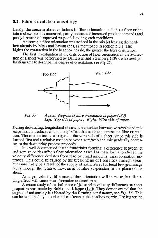
8.2 . Fibre orientation anisotropy
Lately, the concern about variations in fibre orientation and about fibre orien-tation skewness has increased, partly because of increased product demands andpartly because of improved ways ofdetecting such conditions .
Anisotropic fibre orientation was noticed in the mixjet leaving the head-box already by Moss and Bryant (_55), as mentioned in section 5.3 .1 . Thehigher the contraction in the headbox nozzle, the greater the fibre orientation .
The first investigation of the distribution of fibre orientation in the z-direc-tion of a sheet was performed by Danielsen and Steenberg (129), who used po-lar diagrams to describe the degree of orientation, see Fig 35 .
Fig . 35:
Apolar diagram offibre orientation inpaper (12J9Left: Top side ofpaper, Right: Wire side ofpaper.
135
During dewatering, longitudinal shear at the interface between wire/web and mixsuspension introduces a "combing" effect that tends to increase the fibre orienta-tion . The orientation is stronger on the wire side of a sheet, since this side isformed first and a relative motion between wire/web and mix gradually decrea-ses as the dewatering process proceeds .
It is well documented that in fourdrinier forming, a difference between jetand wire velocities affects fibre orientation as well as mass formation.When thevelocity difference deviates from zero by small amounts, mass formation improves . This could be caused by the breaking up of fibre flocs through shear,but more likely be a result of the supply of extra fibres for local low grammageareas through the relative movement of fibre suspension in the plane of thesheet .
At larger velocity differences, fibre orientation will increase, but distur-bing effects will cause mass formation to deteriorate .
A recent study of the influence ofjet to wire velocity difference on sheetproperties was made by Bubik and Kleppe (14Q) . They demonstrated that thedegree of anisotropy is affected by the forming consistency, see Fig . 36 . Thiscan be explained by the orientation effects in the headbox nozzle . The higher the
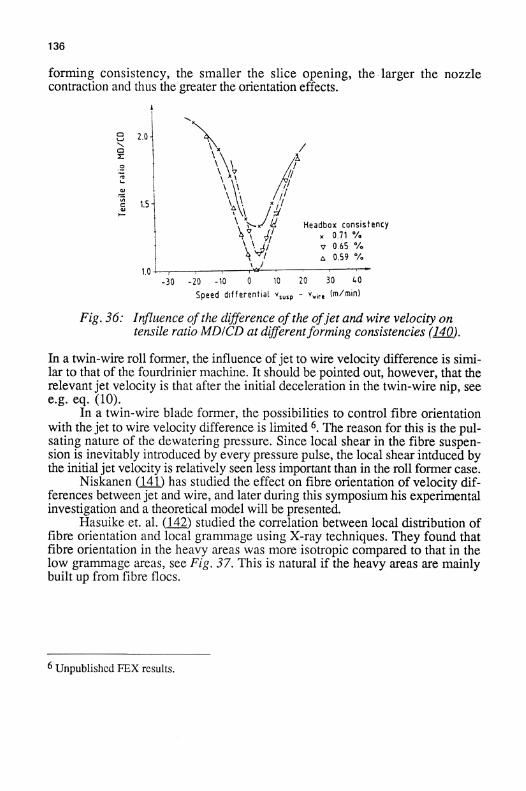
136
forming consistency, the smaller the slice opening, the - larger the nozzlecontraction and thus the greater the orientation effects .
Fig . 36 : Influence ofthe difference of the ofjet and wire velocity ontensile ratio MD/CD at differentforming consistencies (140) .
In a twin-wire roll former, the influence ofjet to wire velocity difference is simi-lar to that of the fourdrinier machine . It should be pointed out, however, that therelevant jet velocity is that after the initial deceleration in the twin-wire nip, seee.g . eq . (10) .
In a twin-wire blade former, the possibilities to control fibre orientationwith the jet to wire velocity difference is limited 6 . The reason for this is the pul-sating nature of the dewatering pressure . Since local shear in the fibre suspen-sion is inevitably introduced by every pressure pulse, the local shear intduced bythe initial jet velocity is relatively seen less important than in the roll former case .
Niskanen QA1) has studied the effect on fibre orientation of velocity dif-ferences between jet and wire, and later during this symposium his experimentalinvestigation and a theoretical model will be presented.
Hasuike et . al . (142 ) studied the correlation between local distribution offibre orientation and local grammage using X-ray techniques. They found thatfibre orientation in the heavy areas was more isotropic compared to that in thelow grammage areas, see Fig . 37 . This is natural if the heavy areas are mainlybuilt up from fibre flocs .
6 Unpublished FEX results .

137
Fig . 37 : Fibre orientation in high grammage andlow grammage areas respectively (142) .
It should be pointed out that when the anisotropic properties of a sheet arediscussed, besides the effect of headbox and dewatering also the increase inanisotropy in the free draw after the press section and the final increase inanisotropy by tension during drying have to be taken into consideration.
8.2.1 . Skew fibre orientation
So far, symmetric fibre orientation with respect to the machine direction hasbeen assumed in this overview. Skew fibre orientation often occurs, and can becaused by a headbox jet velocity vector not in line with the machine direction orby sideways flow generated in the wire sction .
Holik and Weisshuhn (143 ) demonstrated that even with an angular devia-tion between jet and machine directions as small as a half degree, a considerablecross flov velocity arises on a modern high speed paper machine . The sum ofthis cross flow velocity component and the difference between machine speedand jet MD-speed form a velocity vector representing the relative suspensionmovement on the wire .
Holik and Weisshuhn pointed out that local variations in the angle of thisrelative velocity is largest when the MD-component is low, and that the angle ofskewness will even change sign with a change from excess jet velocity to deficitjet velocity, see Fig . 38 . They further exemplified the impact of imperfections inheadbox design on jet skewness .

138
Fig. 38: The relative velocity urel as afunction ofthe differencebetween jet and wire speeds, uj - uw and crossflow ucross*
Left: uj - uw > 0, Centere : uj - uw = 0, Right : uj - uw > 0
As already mentioned, Westmayer (61) has calculated the effect of headboxnozzle shape on the amount of sideways flow caused by a local change of sliceopening . A low angle headbox nozzle can be over four times as sensitive as aheadbox with vertical front wall in this respect .
To completely avoid sideways flow from a headbox, the cross machinedistribution must be perfect and the slice opening constant across the whole ma-chine width, see further section 5.3.2 .
9 . Acknowledgements
The author is indebted to Dr Anthony Bristow for the linguistic revision of thematerial.
Ping, Anna-Karin, Qlof and Brian volounteered to spend the Saturdayevening and Sunday night immediately before my flight to Cambridge, prepa-ring the 350 copies of this overview required at the symposium. This help isgratefully acknowledged .
Finally, I would like to thank the responsible persons within FRC for notstriking out this contribution when deadlines were not met, and instead allowingits presentation in this third volume of the proceedings .
139
10. References
I
"Formation and Structure ofPaper" Trans of the 2nd FundamentalResearch Symposium in Oxford, 1961 . Francis Bolam, Ed. Techn Sec .British Paper and Board Makers Assoc., London (1962) .
II
"Consolidation of the paper web" Trans . of the Symposium held atCambridge, 1965 . Francis Bolam, Ed . Techn Sec . British Paper andBoard Makers Assoc., London (1966) .
III
"The Fundamental Properties of Paper Related to its Uses", Trans . of theSymposium held at Cambridge, 1973. Francis Bolam, Ed . Techn . Sect .BPBIF, London (1976) .
IV
"Fibre - Water Interactions in Paper-Making". Trans . of the Symposiumheld at Oxford, 1977 . FRC Ed. Techn.Div. BPBIF, London (1978).
V
"The Role of Fundamental Research in Paper Making" . Trans . of theSymposium held at Cambridge, 1981. James Brander, Ed . Mech.Eng .Publ.Ltd., London (1983) .
VI
"Papermaking Raw Materials" . Trans . of the 8th Fundamental ResearchSymposium held at Oxford, 1985. Vaughan Punton, Ed. Mech . Eng .Publ . Ltd., London (1985) .
VII
"Fundamentals of Papermaking". Trans . of the 9th FundamentalResearch Symposium held at Cambridge, 1989 . C . Baker andW.Punton Ed. Mech.Eng.Publ.Ltd., London (1989) .
1
Wrist, P . : Dynamics of Sheet Formation on the Fourdrinier Machine.In Ref I, 839.
2
Parker, J . : The Sheet-Forming Process, TAPPI STAP no 9 (1972) . .
3
Radvan, B . : Forming . Papermaking Science, Elsevier, 176 (1976) .
4
Lindstr6m, T. : Some fundamental chemical aspects on paper forming .In Ref VII, 309 .
5
Wahren, D. : Proposed definitions of some basic papermaking terms . Sv .Papperstidn . 70 (21), 725 (1967) .

140
6
Corte, H . : Ober die Verteilung der Massendichte in Papier. Das Papier24 (5), 261 (1970) .
7
Burkhard,G., Wrist,P.E . and Mounce,G.R . : A Formation Meter WhichGraphically Records Paper Formation. Pulp and Paper Mag. of Canada61 (6), T139 (1960) .
8
Daunais, R. and Garner, R . : The NUI formation tester - an evaluation,modification and comparison with other techniques . Int . Paper PhysicsConf, 43 (1987) .
9
Kallmes, O. and Ayer, J. : Light scanning system provides qualitativeformation measurement . Int. Paper Physics Conf., 209 (1987) .
10
Papworth, S . : The application of image analysis to evaluate opticalproperties of paper. 6th Scand. Conf. on Image Analysis, 808 (1989) .
11
Norman, B . and Wahren, D. : Mass distribution and sheet properties. InRef III, 7 .
12
Komppa,A. and Ebeling,K . : Correlation between the Areal Mass andOptical Densities of Paper In Ref V, 603 .
13
Norman, B . and Wahren, D. : The measurement of mass distribution inpaper sheets using a beta radiographic method . Sv . Papperstidn 77 (11),397 (1974) .
14
Cresson, T . : The Sensing, Analysis and Simulation of Paper Formation .Thesis, Syracuse, New York (1988) .
15
Paper Structure and Properties . Anthony Bristow and Petter KolsethEd., Marcel Dekker, New York (1986) .
16
Kajanto, Komppa,Ritala : How formation should be measured andcharacterized. Nordic Pulp and Paper Research Journal, 4 (3) (1989) .
17
Yuhara, T., Hasuike, M. and Murakami, K. : Application of ImageProcess Technique for Analysis of Sheet Structure of Paper.Japan Tappi 61 (1), 85 (1986) .
18
Tomimasu, H., Luner, P . and Hanna, R . : Rapid imaging of massdistribution in paper by electron beams . In Ref VII, 159 .
19
Norman, B and Axell, O . : A Method for Measurement of ChalkDistribution in Paper Sheets . In Ref. VI, 577 .
20
Taylor, G.I . : The Spectrum of Turbulence . Proc . Roy . Soc . Lond., A164, 476 (1938) .
21
Norman, B . and Wahren, D. : A comprehensive method for thedescription of mass distribution in sheets and flocculation and turbulencein suspnsions . Sv. Papperstidn . 75 (), 807 (1972) .
22
Haglund, L, Norman, B. and Wahren, D. : "Mass Distribution inRandom Sheets . Theoretical Evaluation and Comparison with RealSheets . Sv. Papperstidn .77 (10), 362 (1974) .
23
Taylor, G.I . : Statistical theory of turbulence . Proc.Royal.Soc . London .A151 , 421 (1935) .
24
Jordan, B .D . and Nguyen, N.G . : Specific perimeter . A graininessparameter for formation and print-mottle textures" Paperi ja Puu 68 (6-7) : 476, 1986 .
25
Duffy, G., Ek, R., M611er, K . and Norman, B . : Hydrodynamics ofpapermaking fibres in water suspensions . In Ref IV, 195 .
26
Kerekes, R., Soszynski, R . and Tam Doo, P. : The Flocculation of PulpFibres . In ref VI, 265 .
27
Kerekes, R . : Pulp flocculation in decaying turbulence : A literaturereview.Journ . of Pulp and Paper Sci . 9 (3), TR 86 (1983) .
28
Wahren, D. : Fibre Network Structures in Papermaking Operations . TheCutting Edge Conf., Inst of Paper Chemistry, 112 (1979) .
29
Steenberg, B, Thalen, N. and Wahren, D. : Formation and properties offibre networks. In Ref 11, 177 .
30
Wahren, D. and Meyer, R. : On the Elastic Properties of Three-Dimensional Fibre Networks . Sv Papperstidning, 67 (10), 432 (1964) .
31
Soszynski, R . and Kerekes, R . : Elastic interlocking of nylon fibressuspended in liquid . Part 1 . Nature of cohesion among fibres . NordicPulp & Paper Research Journal, 3 (4), 172 (1988)
32
Jacquelin, G . : Prepared contribution . In Ref. II, 299 .
14 2
33
Soszynski, R . and Kerekes, R . : Elastic interlocking of nylon fibressuspended in liquid. Part 2 . Process of interlcking . Nordic Pulp & PaperResearch Journal, 3 (4), 180 (1988) .
34
Riitala, R. and Huiku, M. : Scaling, percolation and network theories :new insights into papermaking. In Ref VII, 195 .
35
Onabe F . and Sakurai, K . : Applications of flow visualisation techniquein wet end chemsitry . In ref VII, 219 .
36
Wagle, D ., Lee, C . and Broadkey, R. : Further coments on a visualstudy of pulp floc dispersion mechanisms. Tapi J . 71 (8), 137 (1988) .
37
Steen, M. : The application of refractive index matching for two-phaseflow measurements in turbulent fiber suspensions by laser doppleranemometry . Nordic Pulp & PaperRes. Journ. 4 (4), (1989) .
38
Steen, M. : On turbulence structure in vertical pipe flow of fibersuspensions . Nordic Pulp & Paper Res Journ. 4 (4), (1989) .
39
Norman, B. and Tegengren A. : Mixing of thich stock and white water .XXIII Eucepa Conf., 51 (1988) .
40
Norman, B ., Wedin, P-O ., Grundstr6m, K-J . and Hagen, N. :Visualization of flow in a high consistency screen . TAPPI Eng . Conf.,585 (1986) .
41
Goldenburg, P., Fredriksson, B . and Leblanc, P . : The Beloit S-screen -a new concept for high consistency screening. New AvailableTechnique, SPCI, 1063 (1987).
42
Carlsson, Bengt and Gistren, Henrik. : A new design for highconsistency cleaning . Graduate work, Royal Inst . of Techn . (1989)
43
R6ding, S., and Norman, B . : FEX the STFI experimental papermachine - design of white water system . Tappi Eng. Conf., 449 (1985) .
44
Waller, M. : Recent developments in headboxes . Tappi J . 701 (l), 33(1987) .
45
Trufitt, A . : Design aspects of manifold type flowspreaders . TAPPI Pulpand Paper Technology Series, 32 (1975) .

46
Syrjala, S ., Saarenrinne, P. and Karvinen, R. : Fluid dynamics oftapered manifold flow spreader. TAPPI Engineering Conference, 233(1988) .
47
Bubik, A. and Christ, A . : Step diffuser - the hydraulics of Escher Wyssheadboxes . Tappi Eng . Conf., A 149 (1976) .
48
Lin, J . : A numericla study of turbulent flow through a circular stepdiffuser. TAPPI Eng . Conf., 21 (1988) .
49
Mardon, J . : Discussion . In Ref . I, 889 (1961) .
50
Reiner, L., and Wahren, D. : The Characterization of Flow from theHeadbox of a Paper Machine . S vensk Papperstidn, 74 (8), 225 (1971).
51
Parker, J . and Hergert, R . : Simultaneous convergence - a new conceptin headbox design . Tappi 51 . (10), 425 (1968) .
52
Sanford L . : Characteristics of flow from a two-dimensional nozzle withmultiple-tube inlet . Tappi Eng . Conf, A 159 (1976) .
53
Wolf,K. and Egelhof, D. : The W-type High-Turbulence Headbox - itsdevelopment concept and basic arrangement . Paper Techn . if (2), 77(1974) .
54
Ilmoniemi, E., Aroviita, L . and Yli-Kokko, E . : The role of headboxturbulence generators in grammage uniformity. Appita 39 (1), 36(1986) .
55
Moss, L and Bryant,E . : Photographic study of the Motion of Fibres andWater in Flowing Fiber Suspensions . Paper Trade J., 106 (April 14)Tappi Section, 226 (1938) .
56
Jones, G. and Ginnow, R . : Modeling headbox performance withcomputational fluid mechanics . TAPPI Eng . Conf., 15 (1988) .
57
Appel, D. and Yu, Y. : Free-streamline analysis of flow from nozzles,flow through side inlets and flow past corners. Studies in EngineeringMechanics, No 17, Center for Research in Engineering Science,University of Kansas, Lawrence (1963) .
58
For the results in ref. (57), see alternatively : TAPPI TIS 014-2,3,4.
143

144
59
Kerekes, R. and Koller, E . : Equations for calculating headbox jetcontraction and angle of outflow . Tappi 64 (1), 95 (1981), withcorrection in 64 (4), 104 (1981) .
60
Karlsson, H. and Eriksson, L . : Controllability of Paper Making .In Ref VII .
61
Westermeyer, W.N. : Modellierung der Stromung in derStoffauflaufduse and auf dem Langsieb im Hinblick auf dasFlachengewichts-Querprofil der Papierbahn . Das Paper 41 (11), 591(1987)
62
Linkletter, M. : Tissue layering . PIRA Conf. : New Technologies inMultiply & Multilayer Structures, paper 6 (1987) .
63
Stenberg, G. : A new headbox for multilayered printing paper. Tappi J.70 (9), 49 (1987) .
64
Swedish pat. 355 .615
65
Swedish pat. 385.029
66
Swedish pat. 412.078
67
Nomura, T., Wada, K. and Shimizu, T . : High consistency sheetforming. 1 : Research and development of headboxes.Tappi J . 72 (1),115 (1989) .
68
Radvan, B., Dodson, D. and Skold, C.G . : Detection and cause of thelayered structure of paper. In Ref II, 189 .
69
Mohlin, U.-B . : Mechanical pulp properties - the importance of finesretention . Sv. Papperstidn . 80 (3), 84 (1977) .
70
Sauret, G., Trinh, H. and Lefebvre, G. : Experiments to reproducemulti-ply boards in the laboratory (in German) Das Papier 23 (1), 8(1969)
71
Hallgren, H . and Lindstrom, T . : The influence of stock preparation onpaper forming efficiency . XXIII EUCEPA Conf., 35 (1988) .
72
Corte, H. and Kallmes, 0. : Statistical geometry of a fibrous netwok. InRef I, 13 .
73
Gorres, J ., Cresson, T . and Luner, P . : Sheet formation from flocculatedstructures . Journ of Pulp and Paper Science 15 (2), J55 (1989) .
74
Steen, M. : A concept for fibre flocculation in turbulent flow .In Ref VII, 251 .
75
Ingmanson, W.L . and Andrews, B.D. : High-Velocity Water FlowThrough Fiber Mats. Tappi 46 (3), 150 (1963) .
76
Pires, E., Springer, A . and Kumar, V. :Computational model for waterdrainage in fouidlnier paper machines . Tappi J . 71 (4), 133 (1988) .
77
Britt, K. : Mechanisms of Retention During Paper Formation. Tappi 56(10), 47 (1973) .
78
Wahlstr6m, B . and O'Blenes, G. : The Drainage of Pulps at Paper-Making Rates and Consistencies Using a New Drainage Tester. Pulp andPaper Mag of Canada, 63 (8), T405 (1962) .
79
Grundstr6m, K.-J ., Hartog, S ., Norman, B. and Reiner, L . : Basicprinciples of high consistency forming and the mechanical properties offelted structures . Int . Paper Physics Conf, 11 8 (1975) .
80
Britt, K., Unbehend, J . and Shridharan, R . : Observations on waterremoval in papermaking . Tappi J . 69 (7), 76 (1986) .
81
Britt, W. and Unbehend,J. : Water removal during paper formation .Tappi. J . 68 (4), 105 (1985) .
82
Torbjbrn Helle : Paper forming wires over 75 years . 75th AnnualMeeting, Technical Section CPPA, B 285 (1989)
83
Batty, R . : A mathematical model to aid in the design of paper machineforming fabrics . Journ of Pulp and Paper Sci . 9 (1), T25.(1983) .
145
84
Helle, T . The influence of wire structure on sheet forming. Paper Techn& Ind . 21 (4), 123 (1980) .
85
Beran, R. : The evaluation and selection of forming fabrics . Tappi J. 62(4), 39 (1979) .
86
Helle, T . : Analysis of wire mark in printing paper. Journ of Pulp &Paper Science 14 (4), 91 (1988) .

146
87
Lewyta, J. : Recent developments in paper machine clothing: formingfabrics . Tappi J. 70 (2), 39 (1987) .
88
Helle, T. : On the evaluation of the forming characteristics ofpapermaking wires, International Water Removal Symposium, 93(1982) .
89
Johnson, D. : Retention & drainage of forming wires . International WaterRemoval Symposium, 67 (1982) .
90
Nordiskafilt . Unpublished FEX results (1986) .
91
Hansen, V. : Draining and forming through the years . 75th AnnualMeeting, Technical Section CPPA, B 63 (1989) .
92
Wahren, D. : Fourdrinier jet geometry . Nordic Pulp and Paper Res .Journ . 3 (special issue), 29 (1988) .
93
Osterberg, L. : Initial dewatering . The Ekman Days (abstract only)(1988) .
94
Parker, J. and Epton J. : Wet end barring . Tappi 60 (10), 90 (1977) .
95
Moen, C. : Basis weight barring. Tappi 60 (10), 116 (1977) .
96
Kallmes, O. and Langdok, R. : Initial operation trials of a dandy rollformer. Tappi J. 71 (4), 74 (1988) .
97
Wrist, P . : The Papermaking Process as a Filtration Problem. Pulp PaperMag Can. .55 (6), 115 (1954) .
98
Taylor, G.I . : Drainage at a Table Roll . Pulp Paper Mag Can 57 (3), 267(1956) .
99
Taylor, G.I. : Drainage at a Table Roll and a Foil. Pulp Paper Mag Can59 (C), 172 (1956) .
100
Bergstrom, J. : Table Roll Drainage . Sv Papperstidn 600 (1), 1 (1957) .
101
Kufferath, W., Kallmes, O. and Steffen, H.-R . : Die Sonic Roll,Das Paper, 42 (l0A), V141 (1988) .
102
Kallmes, a., Marinari, G . and Perez, M. : Forming a sheet on a fabricvibrating at or near its resonant frequency. Tappi PapermakersConference, 153 (1989) .
103
Schmid,W . : Stroboskopische Untersuchungen in der Blattbildungszone .Wochenblatt fur Papierfabrikation, 109 (11/12), 371 (1981) .
104
Cadieux, S. :
Amathematical drainage model for Fourdrinier papermachines. Joum of Pulp & Paper Sci . 9 (4), TR 111 (1983) .
105
Kufferath, W., Kallmes, 0. and S teffen, R . : The Cascade-Foil .Das Paper 41 (l0A), V136 (1987) .
106
Reiner, L . : The Flexforming concept .Journ Pulp & Paper Sci . 10.(2), J30 (1984) .
107
Norman, B . : Principles of twin-wire forming.Sv . Pappersteidning, 82 (11), 330 (1979) .
108
Attwood, B . and Lawrence, L . : Inverform - An account of theexperimental work during the development of a new method ofpaperand paperboard manufacture. Paper Techn . 1 (5), T195 (1960) .
109
de Montigny, R., Pye, I . and Hedley, T . : The Papriformer (1) - themachine and its performance . Pulp Paper Mag. Can. 68 (10), T482(1967)
110
Atkinson, W. and Malashenko, A. : Commercial development ofthePapriformer. Tappi, 54 (9), 1464 (1971) .
111
Gustavsson, D. and Dennis, L. : The "Bel-Baie" twin wire former.Tappi, 53 (3), 483 (1970) .
112
Stewart, R. and Howarth, J. : Verti-Forma versus fourdrinier. PulpPaper 5 (13), 70 (1971) .
113
Mauranen, P. and Hujala, J . : Valmets former for paper machine rebuildsand new paper machines. CPPA Ann. Mtg., B 195 (1983) .
114
Malashenko, A., Deperis, G . and Lindstr6m, R. : DominionDynaformer . 68th CPPA Ann Meeting, A139 (1982) .
115
Thorp, B. : Fundamental and commercial overview of twin wire andmultiple wire forming. Tappi Twin Wire seminar, 1 (1989)
147
148
116
Stenberg, G . : The KMW - Papriformer. KMW Sales Conference,Karlstad (1971) .
117
Hergert, R. and Sanford, L. : Pressure measurements in the formingzone of a twin-wire tissue machine . International Water RemovalSymposium, 47 (1982)
118
Ingemarsson, G. : Mathematical modelling to explain roll formerbehaviour . International Water Removal Symposium, 73 (1982)
119
Norman, B. : On the mechanisms of dewatering in twin-wire and presssections . Nordic Pulp & Paper Res Journ, Especial issue), 39 (1987)
120
Gustavsson, D. : Water removal from the Bel-Baie former . InternationalWater Removal Symposium, 1:234 (1975) .
121
Nash, J. : Twin wire forming development . Tappi Twin Wire Seminar,79 (1989)
122
Hergert, R. and Harwood, J . : Retention, drainage and formation on highspeed formers . Tappi Papermakers Conf., 271 (1988) .
123
Odell, M. : Drainage Mechanism ofa Roll and Blade Former. Tappi Eng.Conf. (1989) .
124
Baumann,W.-D . : Duoformer D - A new approach to top wire forming .Tappi Twin Wire Seminar, 115 (1989) .
125
Blomquist, B . : Alform-Technologies for Multilayer Board. XXIIIEUCEPA Conf., 187 (1988) .
126
Nomura, T., Wada, K. and Shimizu, T. : High consistency sheetforming. 2 : Pilot plant tests . Tappi J . 72(4), 171 (1989) .
127
Reiner, L . : Flexforming (abstract only), The Ekman days (1988) .
128
White, C. : The concept of multiply & multilayer paper & boardproducts . PIRA Conf: New Technologies in Multiply & MultilayerStructures, paper 3 (1987) .
129
Meinecke, A. : The Duoformer (D) - Concept and Operating Results .XXIII EUCEPA Conf., 97 (1988) .
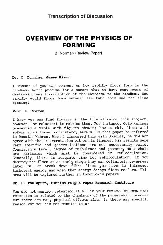
OVERVIEW OF THE PHYSICS OFFORMING
Dr . C . Dunning, James River
B . Norman (Review Paper)
I wonder if you can comment on how rapidly flocs form in theheadbox . Let's presume for a moment that we have some means ofdestroying any flocculation at the entrance to the headbox . Howrapidly would flocs form between the tube bank and the sliceopening?
Prof. B . Norman
I know you can find figures in the literature on this subject,however I am reluctant to rely on them . For instance, Otto Kallmespresented a Table with figures showing how quickly flocs willreform at different consistency levels . In that paper he referredto Douglas Wahren . When I discussed this with Douglas, he did notagree with the interpretation put on his figures . His results werevery specific and generalisations are not necessarily valid.Consistency level, degree of turbulence and geometry as a wholeare variables which must be considered in reflocculation .Generally, there is adequate time for reflocculation . If youdestroy the flocs at an early stage they can definitely re-appearlater on . To break down fibre flocs you have to introduceturbulent energy and when that energy decays flocs re-form . Thisarea will be explored further in tomorrow's papers .
Dr . H . Paulapuro, Finnish Pulp & Paper Research Institute
You did not mention retention at all in your review . We know thatretention is related to the chemistry of the papermaking processbut there are many physical effects also. Is there any specificreason why you did not mention this?
Transcription of Discussion
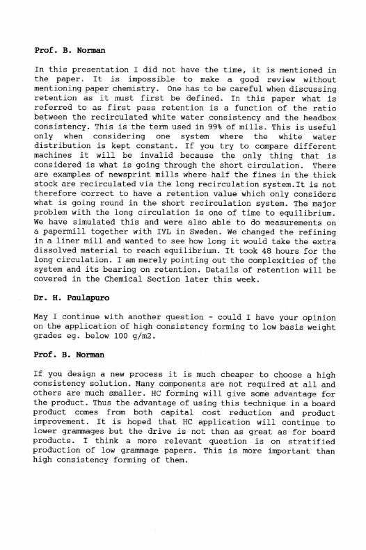
Prof . B. Norman
In this presentation I did not have the time, it is mentioned inthe paper . It is impossible to make a good review withoutmentioning paper chemistry . One has to be careful when discussingretention as it must first be defined. In this paper what isreferred to as first pass retention is a function of the ratiobetween the recirculated white water consistency and the headboxconsistency. This is the term used in 99% of mills . This is usefulonly when considering one system where the white waterdistribution is kept constant . . If you try to compare differentmachines it will be invalid because the only thing that isconsidered is :what is going through the short circulation . Thereare examples of newsprint mills where half the fines in the thickstock are recirculated via the long recirculation system . It is nottherefore correct to have a retention value which only considerswhat is going round in the short recirculation system . The majorproblem with the long circulation is one of time to equilibrium .We have simulated this and were also able to do measurements ona papermill together with IVL in Sweden . We changed the refiningin a liner mill and wanted to see how long it would take the extradissolved material to reach equilibrium . It took 48 hours for thelong circulation . I am merely pointing out the complexities of thesystem and its bearing on retention . Details of retention will becovered in the Chemical Section later this week .
Dr . H. Paulapuro
May I continue with another question - could I have your opinionon the application of high consistency forming to low basis weightgrades eg . below 100 g/m2 .
Prof . B. Norman
If you design a new process it is much cheaper to choose a highconsistency solution . Many components are not required at all andothers are much smaller . HC forming will give some advantage forthe product . Thus the advantage of using this technique in a boardproduct comes from both capital cost reduction and productimprovement . It is hoped that HC application will continue tolower grammages but the drive is not then as great as for boardproducts . I think a more relevant question is on stratifiedproduction of low grammage papers . This is more important thanhigh consistency forming of them.

Dr . G .A . Baum, James River
You implied that modern high speed headboxes with a jet to wirevelocity ratio near to one could lead to instabilities in termsof the fibre orientation distribution . Could you comment on thecontribution of automatic slice adjustments to that problem?
Prof. B . Norman
In devices with automatic slice flow adjustment you have toconsider the influence of cross flow on the skewness ofanisotropy, which has not been done so far . You cannot justcontrol the grammage profile to what you want .
Dr . A . Ibraham, Papyrus, USA
I would like to understand more about your comments on contractionin the nozzle . If I understand you correctly are you in favour ofreducing turbulence by increasing the contraction coefficient?
Prof. B . Norman
A higher nozzle contraction will mean a lower degree of relativeturbulence which is an advantage in paper forming . It isparticularly advantageous to have a perfect jet when you areconsidering twin wire forming .
Dr . A . Ibraham
In that case we are going to meet high L/b ratio . The jet is goingto travel further down through the wire and it is going toflocculate further as shown by Kerekes . I am really against thatconcept . High L/b and low angle is not good for formation .
Prof. B . Norman
I am referring to the contraction within the headbox nozzle notthe impact onto the wire . It is a function of flow velocityentering the nozzle and flow velocity leaving the nozzle . What yourefer to is a separate topic .
Dr . M .B . Lyne, International Paper, USA
In your talk you were describing the sources of variation inorientation angle across the papermachine . Would you care to offeran explanation or a model for variations in orientation angle in

the Z direction during forming? The difference in fibreorientation angle between the top and wire side of a sheet is animportant factor in the complex curl of paper sheets .
Prof . B . Norman
The jet to web speed difference in a given CD position willgradually decrease as dewatering proceeds . The original cross flowcomponent in the same CD position will, by definition, movesideways during dewatering, and thus successively influence otherCD positions .
Dr . M . MacGregor, KTH (Voith), Sweden
Is the non-uniform shrinkage which occurs during drying and theneed to have uniform basis weight possible to optimise, or doesit lead to
compromise situation?
Prof . B . Norman
It is theoretically impossible to have both uniform orientationand grammage in the cross direction if you have non uniform crossmachine shrinkage .There is a paper later this week which says howyou can restrain the paper to avoid shrinkage in the crossdirection during drying
Dr. M. MacGregor
If basis weight control is by flow redirection, then I agree -which it is in most cases .
Prof . B . Norman
Unless you control local consistency in the headbox which is atheoretical solution . When you control grammage with slice openingthe aforementioned problems are always present .
Dr . M . MacGregor
So in general the papermaker does not realise that he is givingup many things to achieve a nice flat reel .
Dr . T . Uesaka, PPRIC, Canada
In one of your slides you mentioned the tensile ratio between MDand CD as a function of jet speed and wire speed ratio - I
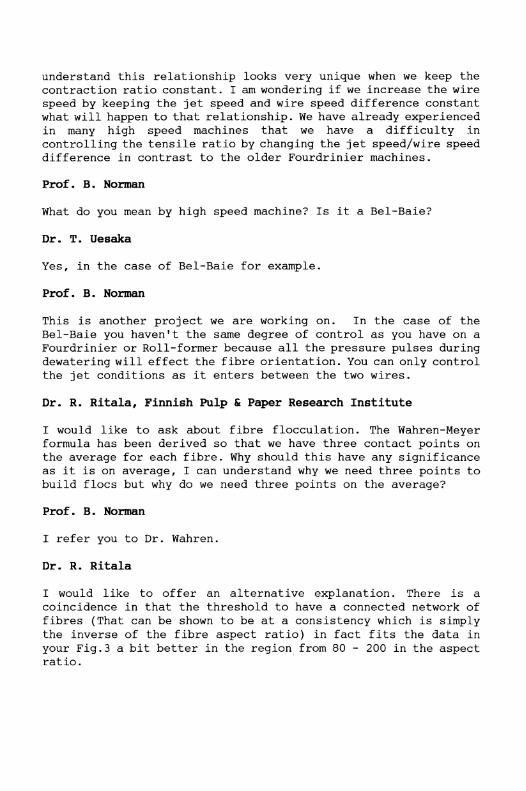
understand this relationship looks very unique when we keep thecontraction ratio constant . I am wondering if we increase the wirespeed by keeping the jet speed and wire speed difference constantwhat will happen to that relationship . We have already experiencedin many high speed machines that we have a difficulty incontrolling the tensile ratio by changing the jet speed/wire speeddifference in contrast to the older Fourdrinier machines .
Prof . B . Norman
What do you mean by high speed machine? Is it a Bel-Bale?
Dr . T . Uesaka
Yes, in the case of Bel-Baie for example .
Prof . B . Norman
This is another project we are working on . In the case of theBel-Baie you haven't the same degree of control as you have on aFourdrinier or Roll-former because all the pressure pulses duringdewatering will offect the fibre orientation . You can only controlthe jet conditions as it enters between the two wires .
Dr . R . Ritala, Finnish Pulp & Paper Research Institute
I would like to ask about fibre flocculation . The Wahren-Meyerformula has been derived so that we have three contact points onthe average for each fibre . Why should this have any significanceas it is on average, I can understand why we need three points tobuild flocs but why do we need three points on the average?
Prof . B . Norman
I refer you to Dr . Wahren .
Dr . R . Ritala
I would like to offer an alternative explanation . There is acoincidence in that the threshold to have a connected network offibres (That can be shown to be at a consistency which is simplythe inverse of the fibre aspect ratio) in fact fits the data inyour Fig .3 a bit better in the region from 80 - 200 in the aspectratio .

Prof . B . Norman
Yesterday you mentioned this new reference from a physics paperto me . This will be interesting to see . It would simplify thingsif the sediment consistency is equal to the fibre diameter dividedby the fibre length .