PATIENT MONITORING SYSTEM TO REMOTE DOCTORS USING GSM AND ZIGBEE TECHNOLOGY
105
Patient monitoring system to Remote Doctors using GSM and Zigbee technology FROM: Engr Rana Muhammad Shakeel [email protected] https://www.facebook.com/EngnrShakeel plz like my page: https://www.facebook.com/Electrical4Electronics For MORE PROJECTS: http://electro-technolgy.blogspot.com CHAPTER-1 INTRODUCTION 1 Dept of Medical electronics SSIT, Tumkur
Transcript of PATIENT MONITORING SYSTEM TO REMOTE DOCTORS USING GSM AND ZIGBEE TECHNOLOGY
Patient monitoring system to Remote Doctors using GSM and
Zigbee technology
FROM:
Engr Rana Muhammad Shakeel
https://www.facebook.com/EngnrShakeel
plz like my page:
https://www.facebook.com/Electrical4Electronics
For MORE PROJECTS:http://electro-technolgy.blogspot.com
CHAPTER-1
INTRODUCTION
1Dept of Medical electronics SSIT, Tumkur
Patient monitoring system to Remote Doctors using GSM and
Zigbee technology
1.1. PROJECT OBJECTIVE
In this chapter introduction of the PATIENT MONITORING
SYSTEM TO REMOTE DOCTORS USING GSM AND ZIGBEE TECHNOLOGY are
discussed. It gives overall view of the project design and the
related literature and the environment to be considered. Chapter
wise organization of the thesis and the appendices is given at
the end of this chapter. At first we discuss the main processing
done using 8051 microcontroller is and then what is the process
that can be automated which is within the scope of the work. Then
we discuss the implementation aspects.
1.2. OVERVIEW
In case of emergency and dangerous situations we have to
alert the doctor immediately. For this we are using a Zigbee
based network for doctor to patient communication in the hospital
and even to communicate and indicate the status of the patient
through SMS. This way of communication is actually done with
Zigbee network topology and with the GSM network. Each patient
will be given this module and with the help of this module the
patient health condition is monitored and if there is any change
in the condition of the health then it immediately sends that
2Dept of Medical electronics SSIT, Tumkur
Patient monitoring system to Remote Doctors using GSM and
Zigbee technology
changed data through Zigbee to the local system where the main
module is connected to the computer to maintain the status of the
patient.
The heart beat is monitored with the pulse rate of the
body. The high intensity light sensor senses the expansion and
contraction of the heart with the help of the nerves. That beam
will transmit the signal to the receiver and the minute change in
the pulse is noticed as the heart beat. If there is any change in
the pulses then it is noticed as the change in the heart and then
the controller will get a disturbed pulse count which indicates
the fault or malfunction of the heart. The controller is fixed
for a no. of pulses initially. If there is any change in the any
of the pulse count then it considers as a malfunction of the
heart and then it transmits the pulse count with the patients ID
to the doctor in the hospital and at the same to it sends a sms
to a fixed number in the microcontroller. This is convenient
process to monitor the patients health conditions form any of the
distance we present. Since we are using both the networks like
Zigbee and GSM this makes the user to communicate for internal
system and as well as to the longer distances.
1.3. AIM OF THE PROJECT
3Dept of Medical electronics SSIT, Tumkur
Patient monitoring system to Remote Doctors using GSM and
Zigbee technology
The main processes involved in this type of control
system are to monitor the patient’s health status. Zigbee is a
wireless connection network that is used to connect different
devices at a frequency of 2.4GHz. For medical applications also
this Zigbee is widely used. The Zigbee can communicate with the
devices of about 1km. The other network is GSM network. This can
be operated from any distance to any point of control. The
communication is done with the help of local network support.
This can get communicated to any part of the world which the
network of the local system is applicable. Here we are using for
the hospital communication for monitoring the patient.
1.4. LITERATURE SURVEY
The technical brilliance and development in differentfields has led to a drastic in our lives, one among them is
embedded systems. The application of these devices is to monitor
the patient health status. Zigbee is a wireless connection
network that is used to connect different devices at a frequency
of 2.4GHz. For medical applications also this Zigbee is widely
used. The Zigbee can communicate with the devices of about 75 m.
The other network is GSM network. This can be operated from any
distance to any point of control. The communication is done with
the help of local network support. This can get communicated to
4Dept of Medical electronics SSIT, Tumkur
Patient monitoring system to Remote Doctors using GSM and
Zigbee technology
any part of the world which the network of the local system is
applicable. Here we are using for the hospital communication for
monitoring the patient.
1.5. ORGANIZATION OF THE THESIS
Chapter 2: ECG, Heart rate, Body temperature
This chapter gives brief explanation about biological knowledge
and measures, physiological conditions of ECG, Heart rate and
Body temperature
Chapter 3: Detailed system description and development
environment
This chapter gives a brief explanation of the overall design
processing and detailed functionality of the circuit and also
covers the literature survey i.e. general introduction and
features of the hardware elements involved.
Chapter 4: Design Elements
This chapter describes the complete design elements of the
project for the microcontroller along with GSM Modem, Zigbee
module, sensors and Liquid Crystal Display.
Chapter 5: Circuit Description
5Dept of Medical electronics SSIT, Tumkur
Patient monitoring system to Remote Doctors using GSM and
Zigbee technology
This chapter includes the circuit operation of the system.
Chapter 6: Software Explanation
In this chapter it includes the total software explanation
of the KIEL U VISION 3,microcontroller coding, scope software and
flash magic.
Chapter 7: Future Scope
This chapter includes the future scope regarding the
project.
Chapter 8: Conclusion
This chapter includes the overall conclusion of the
project.
CHAPTER-2
ECG, HEART RATE AND BODY TEMPERATURE
2.1 Human Heart
6Dept of Medical electronics SSIT, Tumkur
Patient monitoring system to Remote Doctors using GSM and
Zigbee technology
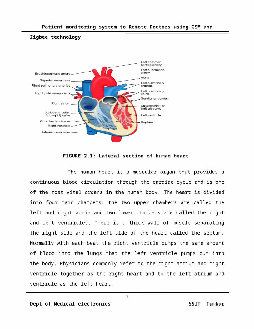
FIGURE 2.1: Lateral section of human heart
The human heart is a muscular organ that provides a
continuous blood circulation through the cardiac cycle and is one
of the most vital organs in the human body. The heart is divided
into four main chambers: the two upper chambers are called the
left and right atria and two lower chambers are called the right
and left ventricles. There is a thick wall of muscle separating
the right side and the left side of the heart called the septum.
Normally with each beat the right ventricle pumps the same amount
of blood into the lungs that the left ventricle pumps out into
the body. Physicians commonly refer to the right atrium and right
ventricle together as the right heart and to the left atrium and
ventricle as the left heart.
7Dept of Medical electronics SSIT, Tumkur
Patient monitoring system to Remote Doctors using GSM and
Zigbee technology
The electric energy that stimulates the heart occurs in
the sinoatrial node which produces a definite potential and then
discharges, sending an impulse across the atria. In the atria the
electrical signal move from cell to cell while in the ventricles
the signal is carried by specialized tissue called the Purkinje
fibers which then transmit the electric charge to the myocardium.
2.2 ELECTROCARDIOGRAPH (ECG)
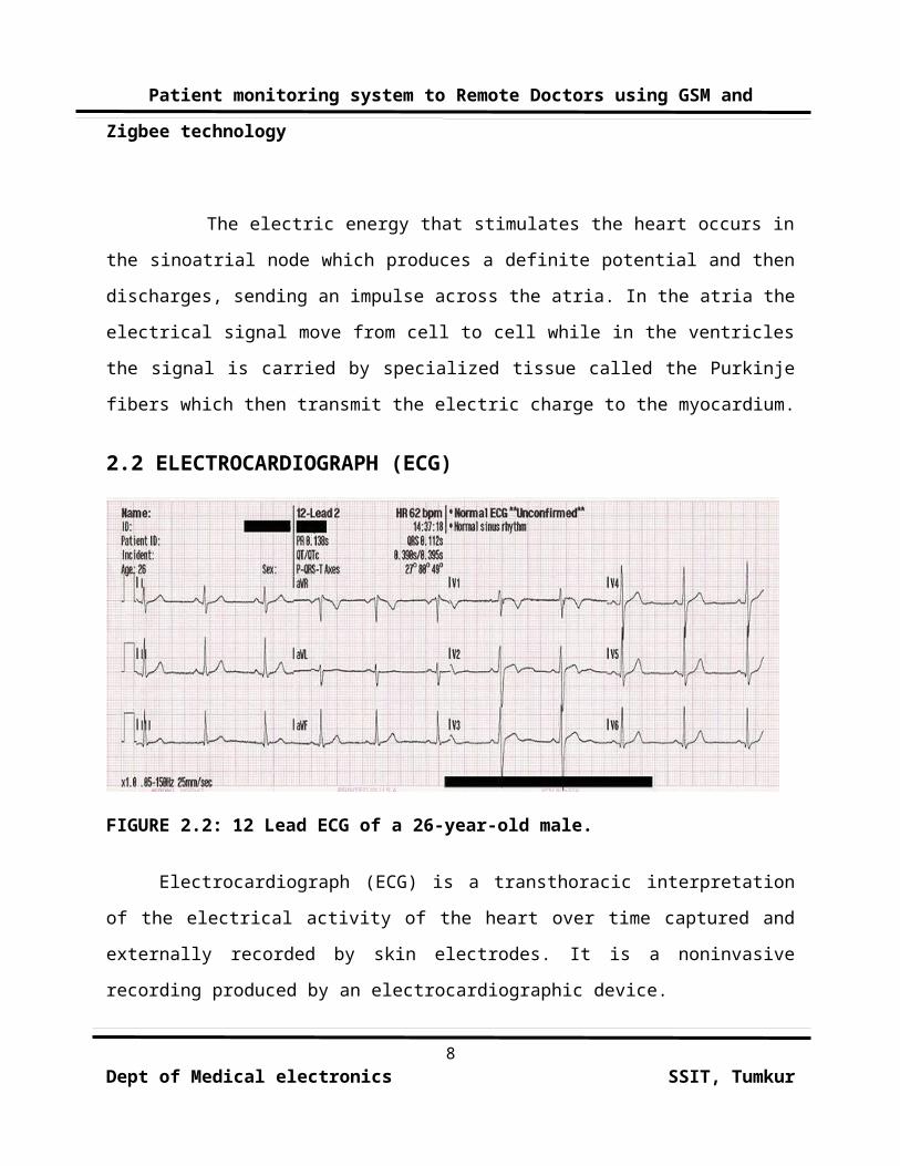
FIGURE 2.2: 12 Lead ECG of a 26-year-old male.
Electrocardiograph (ECG) is a transthoracic interpretation
of the electrical activity of the heart over time captured and
externally recorded by skin electrodes. It is a noninvasive
recording produced by an electrocardiographic device.
8Dept of Medical electronics SSIT, Tumkur
Patient monitoring system to Remote Doctors using GSM and
Zigbee technology
The ECG works mostly by detecting and amplifying the tiny
electrical changes on the skin that are caused when the heart
muscle "depolarizes" during each heart beat. At rest, each heart
muscle cell has a charge across its outer wall, or cell membrane
reducing this charge towards zero is called de-polarization,
which activates the mechanisms in the cell that cause it to
contract. During each heartbeat a healthy heart will have an
orderly progression of a wave of depolarization that is triggered
by the cells in the sinoatrial node, spreads out through the
atrium, passes through "intrinsic conduction pathways" and then
spreads all over the ventricles. This is detected as tiny rises
and falls in the voltage between two electrodes placed either
side of the heart which is displayed as a wavy line either on a
screen or on paper. This display indicates the overall rhythm of
the heart and weaknesses in different parts of the heart muscle.
2.3 HEART RATE
Heart rate is the number of heartbeats per unit of
time, typically expressed as beats per minute (bpm). Heart rate can
vary as the body's need to absorb oxygen and excrete carbon
dioxide changes, such as during exercise or sleep.
9Dept of Medical electronics SSIT, Tumkur
Patient monitoring system to Remote Doctors using GSM and
Zigbee technology
The measurement of heart rate is used by medical
professionals to assist in the diagnosis and tracking of medical
conditions. It is also used by individuals, such as athletes, who
are interested in monitoring their heart rate to gain maximum
efficiency from their training. The R wave to R wave interval (RR
interval) is the inverse of the heart rate.
Heart rate is measured by finding the pulse of the body.
This pulse rate can be measured at any point on the body where
the artery's pulsation is transmitted to the surface by
pressuring it with the index and middle fingers; often it is
compressed against an underlying structure like bone. The thumb
should not be used for measuring another person's heart rate, as
its strong pulse may interfere with discriminating the site of
pulsation.
The resting heart rate (HRrest) is a person's heart rate when
they are at rest, that is lying down but awake, and not having
recently exerted themselves. The typical healthy resting heart
rate in adults is 60–80 bpm, with rates below 60 bpm referred to
as bradycardia, and rates above 100 bpm referred to as
tachycardia. Note however that conditioned athletes often have
resting heart rates below 60 bpm. and it is not unusual for
people doing regular exercise to get below 50 bpm. 10
Dept of Medical electronics SSIT, Tumkur
Patient monitoring system to Remote Doctors using GSM and
Zigbee technology
2.4 THERMOREGULATION
Thermoregulation is the ability of an organism to
keep its body temperature within certain boundaries, even when
the surrounding temperature is very different. This process is
one aspect of homeostasis: a dynamic state of stability between
an animal's internal environment and its external environment or
If the body is unable to maintain a normal temperature and it
increases significantly above normal, a condition known as
hyperthermia occurs. This occurs when the body is exposed to
constant temperatures of approximately 55° C, any prolonged
exposure (longer than a few hours) at this temperature and up to
around 70° C death is almost inevitable. The opposite condition,
when body temperature decreases below normal levels, is known as
hypothermia
Different parts of the body have different temperatures.
Rectal and vaginal measurements, or measurements taken directly
inside the body cavity, are typically slightly higher than oral
measurements, and oral measurements are somewhat higher than skin
11Dept of Medical electronics SSIT, Tumkur
Patient monitoring system to Remote Doctors using GSM and
Zigbee technology
temperature. The commonly accepted average core body temperature
(taken internally) is 37.0 °C (98.6 °F). The typical oral (under
the tongue) measurement is slightly cooler, at 36.8±0.7 °C, or
98.2±1.3 °F. In Russia and former Soviet countries, the commonly
quoted value is 36.6 °C (97.9 °F), based on an armpit (auxiliary)
reading. Although some people think of these numbers as
representing the normal temperature, a wide range of temperatures
has been found in healthy people. In samples of normal adult men
and women, the observed range for oral temperature is 33.2–38.2
°C (92–101 °F), for rectal it is 34.4–37.8 °C (94–100 °F), for
the Tympanic cavity it is 35.4–37.8 °C (96–100 °F) and for
auxiliary it is 35.5–37.0 °C (96–99 °F).
12Dept of Medical electronics SSIT, Tumkur
Patient monitoring system to Remote Doctors using GSM and
Zigbee technology
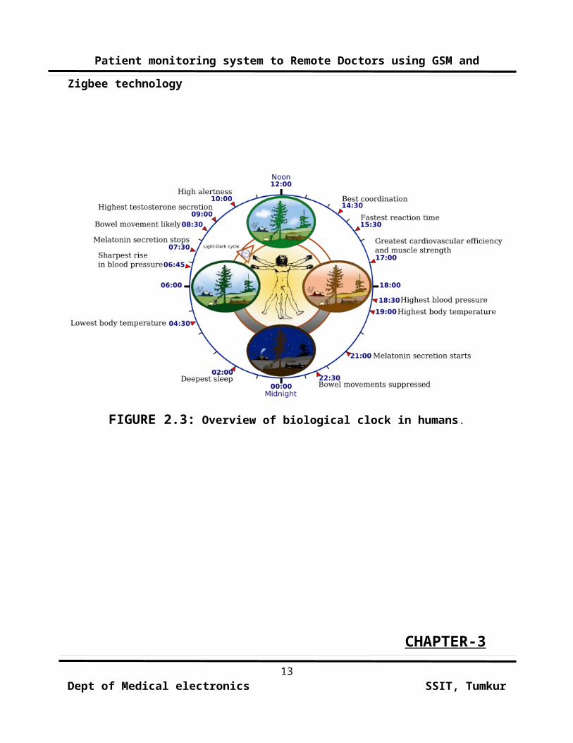
FIGURE 2.3: Overview of biological clock in humans.
CHAPTER-313
Dept of Medical electronics SSIT, Tumkur
Patient monitoring system to Remote Doctors using GSM and
Zigbee technology
SYSTEM ENVIRONMENT
3.1. INTRODUCTION
The flat form for this project is based on Embedded
System. An Embedded system is a special-purpose system in which
the computer is completely encapsulated by the device it
controls. Unlike a general-purpose computer, such as a personal
computer, an embedded system performs one or a few pre-defined
tasks, usually with very specific requirements. Since the system
is dedicated to specific tasks, design engineers can optimize it,
reducing the size and cost of the product. Embedded systems are
often mass-produced, so the cost savings may be multiplied by
millions of items.
An embedded system is a special-purpose computer
system designed to perform a dedicated function. Unlike a
general-purpose computer, such as a personal computer, an
embedded system performs one or a few pre-defined tasks, usually
with very specific requirements. Since the system is dedicated to
specific tasks, design engineers can optimize it, reducing the
size and cost of the product. Embedded system comprises of both
hardware and software. Embedded system is fast growing technology
in various fields like industrial automation, home appliances,
14Dept of Medical electronics SSIT, Tumkur
Patient monitoring system to Remote Doctors using GSM and
Zigbee technology
automobiles, aeronautics etc. Embedded technology is implemented
to perform a specified task and the programming is done using
assembly language programming or embedded C. Ours being a
developing country the power consumption is increasing on large
scale to meet the growing need of the people. Power generation is
widely based on the non-renewable sources and these sources being
depleting some means have to be found for power saving.
3.2. DESIGN OF EMBEDDED SYSTEMS
Intelligent, programmable and computing electronic device
designed to perform specific tasks based on a fixed time frame.
An embedded system is a combination of hardware and software,
perhaps with some mechanical and other components designed to
perform a specific task. The
15Dept of Medical electronics SSIT, Tumkur
Patient monitoring system to Remote Doctors using GSM and
Zigbee technology
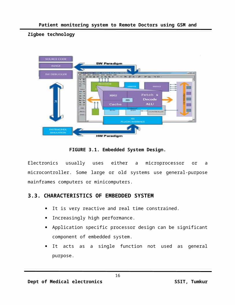
FIGURE 3.1. Embedded System Design.
Electronics usually uses either a microprocessor or a
microcontroller. Some large or old systems use general-purpose
mainframes computers or minicomputers.
3.3. CHARACTERISTICS OF EMBEDDED SYSTEM
It is very reactive and real time constrained.
Increasingly high performance.
Application specific processor design can be significant
component of embedded system.
It acts as a single function not used as general
purpose.
16Dept of Medical electronics SSIT, Tumkur
Patient monitoring system to Remote Doctors using GSM and
Zigbee technology
3.4. REQUIREMENTS OF EMBEDDED SYSTEM:
Functional Requirement
Direct digital control
Data collection
Man-machine interaction
Temporal Requirement
Tasks may have dead lines
Minimal error detection latency
Timing requirement
Human-interface requirements.
Dependability Requirement
Reliability
Safety
Availability
Maintainability
Security
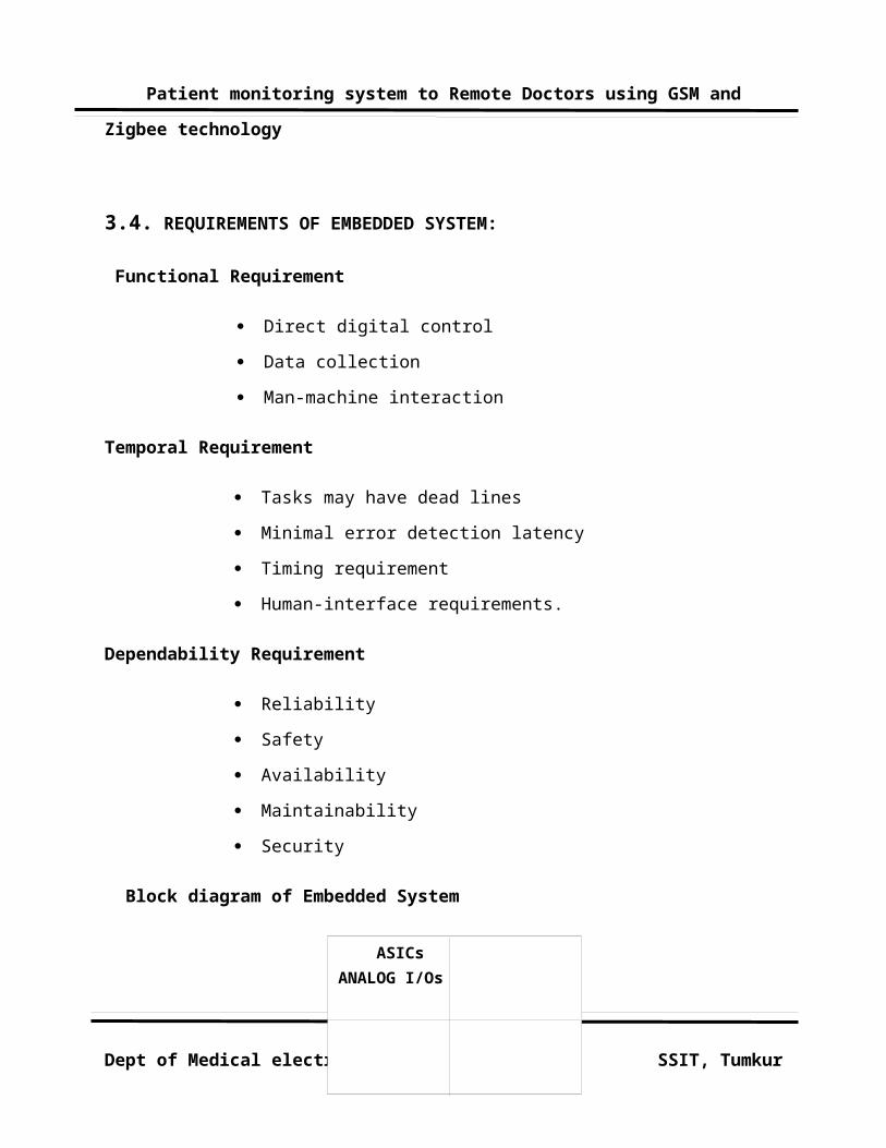
Block diagram of Embedded System
17Dept of Medical electronics SSIT, Tumkur
ASICs ANALOG I/Os
PROCESSOR
Patient monitoring system to Remote Doctors using GSM and
Zigbee technology
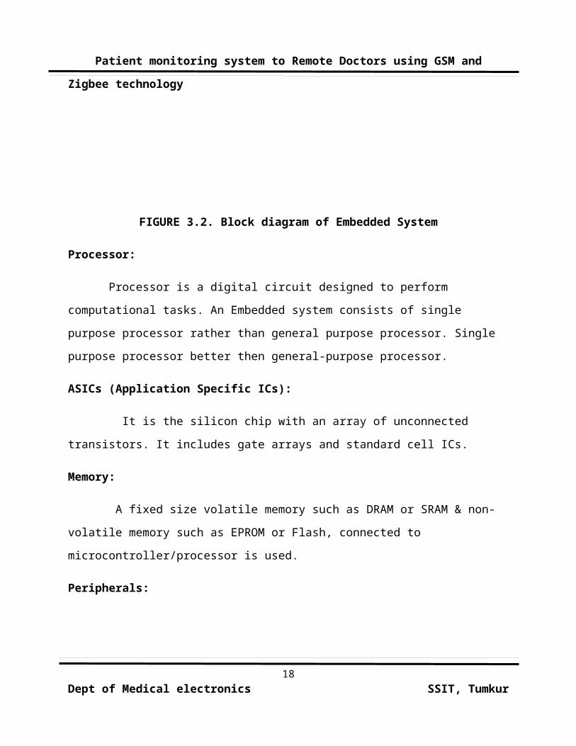
FIGURE 3.2. Block diagram of Embedded System
Processor:
Processor is a digital circuit designed to perform
computational tasks. An Embedded system consists of single
purpose processor rather than general purpose processor. Single
purpose processor better then general-purpose processor.
ASICs (Application Specific ICs):
It is the silicon chip with an array of unconnected
transistors. It includes gate arrays and standard cell ICs.
Memory:
A fixed size volatile memory such as DRAM or SRAM & non-
volatile memory such as EPROM or Flash, connected to
microcontroller/processor is used.
Peripherals:
18Dept of Medical electronics SSIT, Tumkur
Patient monitoring system to Remote Doctors using GSM and
Zigbee technology
According to the block diagram analog I/O consists of the
several peripherals according to the requirement or the
application. some of the peripherals are listed below:
Timer, counter
UART
Pulse Width Modulators
LCD controller
DMA controller
Keypad controller
Stepper motor controller
ADC converter
Real Time clock
CHAPTER-4
DESIGN ELEMENTS
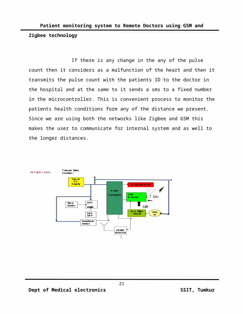
4.1. INTRODUCTION Mainly the block diagram of the project consists
of microcontroller, sensors, GSM modem, Zigbee module, power
supply and Liquid Crystal Display. In case of emergency and
dangerous situations we have to alert the doctor immediately. For19
Dept of Medical electronics SSIT, Tumkur
Patient monitoring system to Remote Doctors using GSM and
Zigbee technology
this we are using a Zigbee based network for doctor to patient
communication in the hospital and even to communicate and
indicate the status of the patient through SMS. This way of
communication is actually done with Zigbee network topology and
with the GSM network. Each patient will be given this module and
with the help of this module the patient health condition is
monitored and if there is any change in the condition of the
health then it immediately sends that changed data through Zigbee
to the local system where the main module is connected to the
computer to maintain the status of the patient. The same
information is transfer as message to GSM to the corresponding or
the relevant person.
In this we check the patient’s health condition by
monitoring the heart beat. The heart beat is monitored with the
pulse rate of the body. . The high intensity light sensor senses
the expansion and contraction of the heart with the help of the
nerves. That beam will transmit the signal to the receiver and
the minute change in the pulse is noticed as the heart beat. If
there is any change in the pulses then it is noticed as the
change in the heart and then the controller will get a disturbed
pulse count which indicates the fault or malfunction of the
heart. The controller is fixed for a no. of pulses initially.
20Dept of Medical electronics SSIT, Tumkur
Patient monitoring system to Remote Doctors using GSM and
Zigbee technology
If there is any change in the any of the pulse
count then it considers as a malfunction of the heart and then it
transmits the pulse count with the patients ID to the doctor in
the hospital and at the same to it sends a sms to a fixed number
in the microcontroller. This is convenient process to monitor the
patients health conditions form any of the distance we present.
Since we are using both the networks like Zigbee and GSM this
makes the user to communicate for internal system and as well to
the longer distances.
21Dept of Medical electronics SSIT, Tumkur
Patient monitoring system to Remote Doctors using GSM and
Zigbee technology
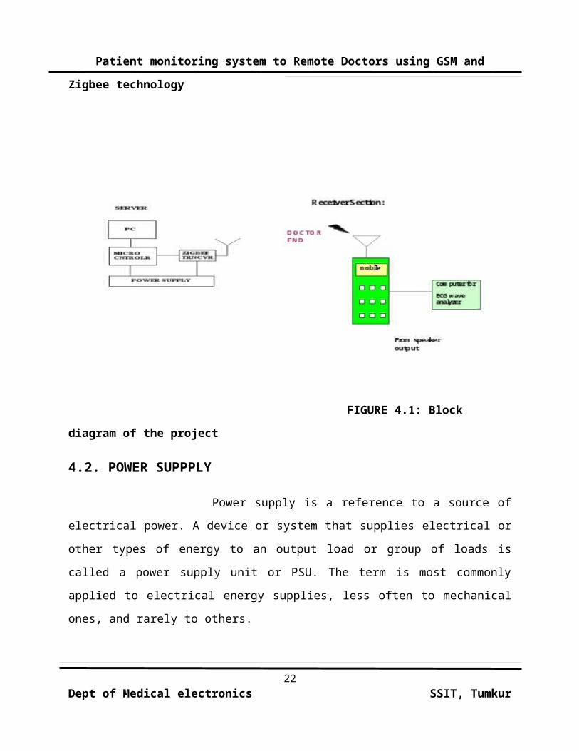
FIGURE 4.1: Block diagram of the project
4.2. POWER SUPPPLY
Power supply is a reference to a source of
electrical power. A device or system that supplies electrical or
other types of energy to an output load or group of loads is
called a power supply unit or PSU. The term is most commonly
applied to electrical energy supplies, less often to mechanical
ones, and rarely to others.
22Dept of Medical electronics SSIT, Tumkur

Patient monitoring system to Remote Doctors using GSM and
Zigbee technology
FIGURE 4.2. Circuit diagram of power supply
A 230v, 50Hz Single phase AC power supply is given to
a step down transformer to get 12v supply. This voltage is
converted to DC voltage using a Bridge Rectifier. The converted
pulsating DC voltage is filtered by a 2200uf capacitor and then
given to 7805 voltage regulator to obtain constant 5v supply.
This 5v supply is given to all the components in the circuit. A
RC time constant circuit is added to discharge all the capacitors
quickly. To ensure the power supply a LED is connected for
indication purpose.
Voltage Regulator:
FIGURE 4.3. Voltage Regulator23
Dept of Medical electronics SSIT, Tumkur
Patient monitoring system to Remote Doctors using GSM and
Zigbee technology
4.3. SENSORS
TEMPERATURE SENSOR:
Several temperature sensing techniques are
currently in widespread usage. The most common of these are RTDs,
thermocouples, thermistors, and sensor ICs. The right one for
your application depends on the required temperature range,
linearity, accuracy, cost, features, and ease of designing the
necessary support circuitry. In this section we discuss the
characteristics of the most common temperature sensing
techniques. But the cost of real time temperature sensor is not
affordable. Hence in this project we used a potentiometer to
display body temperature. By using this we are showing a
prototype how it can works when we use an LM35 sensor.
HEART BEAT SENSOR:
Heart beat sensor is designed to give digital output
of heat beat when a finger is placed on it. When the heart beat
detector is working, the beat LED flashes in unison with each
heart beat. This digital output can be connected to
microcontroller directly to measure the Beats Per Minute (BPM)
rate. It works on the principle of light modulation by blood flow
through finger at each pulse. However this sensor is of high
24Dept of Medical electronics SSIT, Tumkur
Patient monitoring system to Remote Doctors using GSM and
Zigbee technology
cost, hence in this project we are using a transducer to
demonstrate the measure of heart beat rate. we are just showing a
prototype and demonstrating how we can measure heart beat rate
and send to remote doctors.
FEATURES
Microcontroller based SMD design
Heat beat indication by LED
Instant output digital signal for directly connecting to
microcontroller
Compact Size
Working Voltage +5V DC
APPLICATIONS
Digital Heart Rate monitor
Patient Monitoring System
Bio-Feedback control of robotics and applications.
4.4. MICROCONTROLLER
Microcontrollers as the name suggests are small
controllers. They are like single chip computers that are often
embedded into other systems to function as processing/controlling25
Dept of Medical electronics SSIT, Tumkur
Patient monitoring system to Remote Doctors using GSM and
Zigbee technology
unit. For example the remote control you are using probably has
microcontrollers inside that do decoding and other controlling
functions. They are also used in automobiles, washing machines,
microwave ovens, toys ... etc, where automation is needed.
Micro-controllers are useful to the extent that they
communicate with other devices, such as sensors, motors,
switches, keypads, displays, memory and even other micro-
controllers. Many interface methods have been developed over the
years to solve the complex problem of balancing circuit design
criteria such as features, cost, size, weight, power consumption,
reliability, availability, manufacturability. Many
microcontroller designs typically mix multiple interfacing
methods. In a very simplistic form, a micro-controller system can
be viewed as a system that reads from (monitors) inputs, performs
processing and writes to (controls) outputs. Embedded system
means the processor is embedded into the required application. An
embedded product uses a microprocessor or microcontroller to do
one task only. In an embedded system, there is only one
application software that is typically burned into ROM. Example:
printer, keyboard, video game player.
Microprocessor - A single chip that contains the CPU or most of
the computer
26Dept of Medical electronics SSIT, Tumkur
Patient monitoring system to Remote Doctors using GSM and
Zigbee technology
Microcontroller - A single chip used to control other devices
Microcontroller differs from a microprocessor in many ways.
First and the most important is its functionality. In order for
a microprocessor to be used, other components such as memory,
or components for receiving and sending data must be added to
it. In short that means that microprocessor is the very heart
of the computer. On the other hand, microcontroller is designed
to be all of that in one.
FEATURES:
8K Bytes of In-System Reprogrammable Flash Memory
Endurance: 1,000 Write/Erase Cycles
Fully Static Operation: 0 Hz to 24 MHz
256 x 8-bit Internal RAM
32 Programmable I/O Lines
Three 16-bit Timer/Counters
Eight Interrupt Sources
Programmable Serial Channel
Low-power Idle and Power-down Modes.
4.5. GSM MODEM
27Dept of Medical electronics SSIT, Tumkur
Patient monitoring system to Remote Doctors using GSM and
Zigbee technology
GSM (Global System for Mobile Communications: originally
from Group Special Mobile) is the world's most popular standard for
mobile telephony systems. The GSM Association estimates that 80%
of the global mobile market uses the standard. GSM is used by
over 1.5 billion people across more than 212 countries and
territories. This ubiquity means that subscribers can use their
phones throughout the world, enabled by international roaming
arrangements between mobile network operators. GSM differs from
its predecessor technologies in that both signaling and speech
channels are digital, and thus GSM is considered a second generation
(2G) mobile phone system. This also facilitates the wide-spread
implementation of data communication applications into the
system.
The GSM standard has been an advantage to both consumers,
who may benefit from the ability to roam and switch carriers
without replacing phones, and also to network operators, who can
choose equipment from many GSM equipment vendors. GSM also
pioneered low-cost implementation of the short message service
(SMS), also called text messaging, which has since been supported
on other mobile phone standards as well. The standard includes a
worldwide emergency telephone number feature (112).
28Dept of Medical electronics SSIT, Tumkur
Patient monitoring system to Remote Doctors using GSM and
Zigbee technology
Newer versions of the standard were backward-compatible with
the original GSM system. For example, Release '97 of the standard
added packet data capabilities by means of General Packet Radio
Service (GPRS). Release '99 introduced higher speed data
transmission using Enhanced Data Rates for GSM Evolution (EDGE).
4.6. ZIGBEE MODULE
Zigbee is a specification for a suite of high level
communication protocols using small, low-power digital radios or
Low-Rate Wireless Personal Area Networks (LR-WPANs), such as
wireless light switches with lamps, electrical meters with in-
home-displays, consumer electronics equipment via short-range
radio. The technology defined by the Zigbee specification is
intended to be simpler and less expensive than other WPANs, such
as Bluetooth. Zigbee is targeted at radio-frequency (RF)
applications that require a low data rate, long battery life, and
secure networking. Zigbee is a low-cost, low-power, wireless mesh
networking standard. First, the low cost allows the technology to
be widely deployed in wireless control and monitoring
applications. Second, the low power-usage allows longer life with
smaller batteries. Third, the mesh networking provides high
reliability and more extensive range.
29Dept of Medical electronics SSIT, Tumkur
Patient monitoring system to Remote Doctors using GSM and
Zigbee technology
It is not capable of power line networking though other
elements of the Open HAN standards suite promoted by openAMI and
UtilityAMI deal with communications co-extant with AC power
outlets. In other words, Zigbee is intended not to support power
line networking but to interface with it at least for smart
metering and smart appliance purposes. Utilities, e.g. Penn
Energy, have declared the intent to require them to interoperate
again via the open HAN standards.
4.7. LIQUID CRYSTAL DISPLAY
A liquid crystal display (LCD) is a thin, flat display
device made up of any number of color or monochrome pixels
arrayed in front of a light source or reflector. Each pixel
consists of a column of liquid crystal molecules suspended
between two transparent electrodes, and two polarizing filters,
the axes of polarity of which are perpendicular to each other.
Without the liquid crystals between them, light passing through
one would be blocked by the other. The liquid crystal twists the
polarization of light entering one filter to allow it to pass
through the other. Many microcontroller devices use 'smart LCD'
displays to output visual information. LCD displays designed
around Hitachi's LCD HD44780 module, are inexpensive, easy to
30Dept of Medical electronics SSIT, Tumkur
Patient monitoring system to Remote Doctors using GSM and
Zigbee technology
use, and it is even possible to produce a readout using the 8x80
pixels of the display.
They have a standard ASCII set of characters and
mathematical symbols. For an 8-bit data bus, the display
requires a +5V supply plus 11 I/O lines. For a 4-bit data bus it
only requires the supply lines plus seven extra lines. When the
LCD display is not enabled, data lines are tri-state and they do
not interfere with the operation of the microcontroller. Data can
be placed at any location on the LCD.:
First line 80 81 82 83 84 85 86 through 8F
Second line C0 C1 C2 C3 C4 C5 C6 through CF
SIGNALS TO THE LCD
The LCD also requires 3 control lines from the
microcontroller:
1) Enable (E) This line allows access to the display
through R/W and RS lines. When this line is low, the LCD is
disabled and ignores signals from R/W and RS. When (E) line is
high, the LCD checks the state of the two control lines and
responds accordingly.
31Dept of Medical electronics SSIT, Tumkur
Patient monitoring system to Remote Doctors using GSM and
Zigbee technology
2) Read/Write (R/W)
This line determines the direction of data
between the LCD and microcontroller. When it is low, data is
written to the LCD. When it is high, data is read from the LCD.
3) Register selects (RS)
With the help of this line, the LCD
interprets the type of data on data lines. When it is low, an
instruction is being written to the LCD. When it is high, a
character is being written to the LCD.
PIN DESCRIPTION
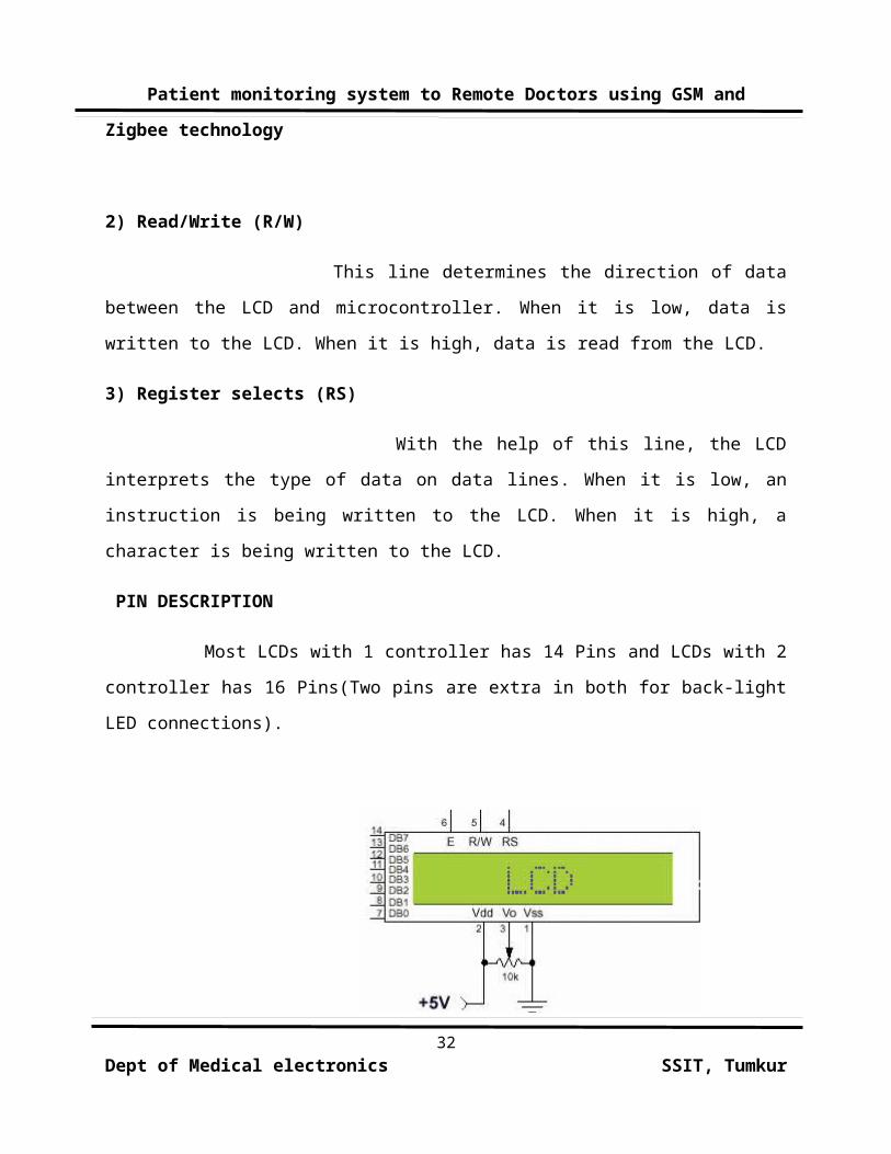
Most LCDs with 1 controller has 14 Pins and LCDs with 2
controller has 16 Pins(Two pins are extra in both for back-light
LED connections).
32
Dept of Medical electronics SSIT, Tumkur
Patient monitoring system to Remote Doctors using GSM and
Zigbee technology
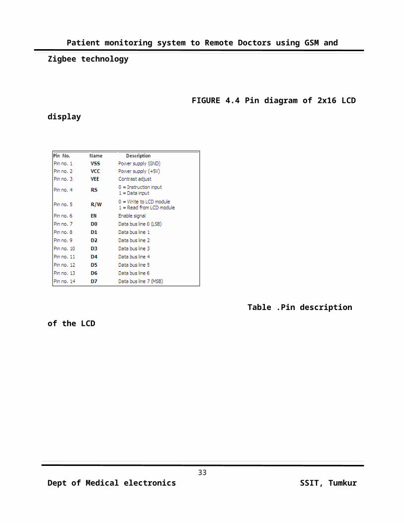
FIGURE 4.4 Pin diagram of 2x16 LCD
display
Table .Pin description
of the LCD
33Dept of Medical electronics SSIT, Tumkur
Patient monitoring system to Remote Doctors using GSM and
Zigbee technology
CHAPTER-5
CIRCUIT DESCRIPTION
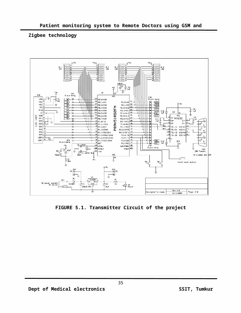
The circuit diagram of the project consists of transmitter
and receiver circuits. The transmitter circuit transmits the
signals to the mobile phone and to the Zigbee receiver module.
The below circuits represents the interfacing of Microcontroller
to GSM, Zigbee, LCD and Heart Beat Sensor, interfacing of
Microcontroller to Zigbee receiver module respectively.
34Dept of Medical electronics SSIT, Tumkur
Patient monitoring system to Remote Doctors using GSM and
Zigbee technology
FIGURE 5.1. Transmitter Circuit of the project
35Dept of Medical electronics SSIT, Tumkur
Patient monitoring system to Remote Doctors using GSM and
Zigbee technology
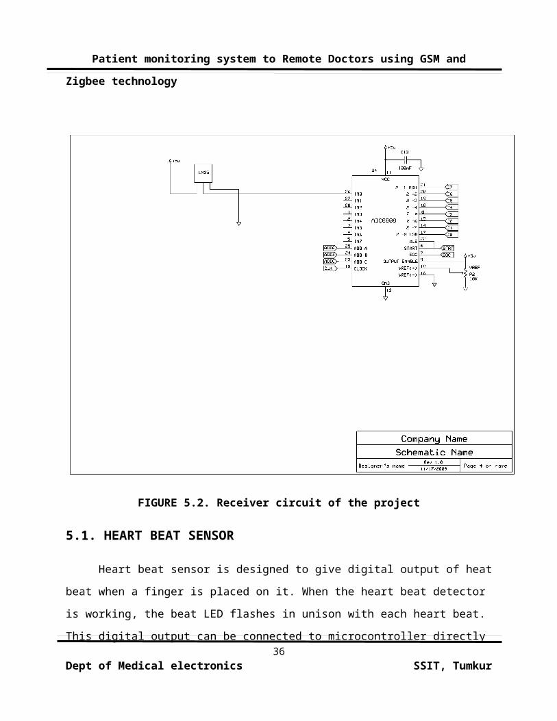
FIGURE 5.2. Receiver circuit of the project
5.1. HEART BEAT SENSOR
Heart beat sensor is designed to give digital output of heat
beat when a finger is placed on it. When the heart beat detector
is working, the beat LED flashes in unison with each heart beat.
This digital output can be connected to microcontroller directly 36
Dept of Medical electronics SSIT, Tumkur
Patient monitoring system to Remote Doctors using GSM and
Zigbee technology
to measure the Beats Per Minute (BPM) rate. It works on the
principle of light modulation by blood flow through finger at
each pulse.
FEATURES:
Microcontroller based SMD design
Heat beat indication by LED
Instant output digital signal for directly connecting to
microcontroller
Compact Size
Working Voltage +5V DC
APPLICATIONS:
Digital Heart Rate monitor
Patient Monitoring System
Bio-Feedback control of robotics and applications
37Dept of Medical electronics SSIT, Tumkur
Patient monitoring system to Remote Doctors using GSM and
Zigbee technology
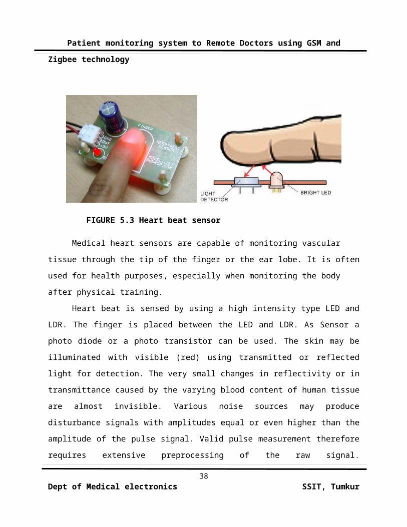
FIGURE 5.3 Heart beat sensor
Medical heart sensors are capable of monitoring vascular
tissue through the tip of the finger or the ear lobe. It is often
used for health purposes, especially when monitoring the body
after physical training.
Heart beat is sensed by using a high intensity type LED and
LDR. The finger is placed between the LED and LDR. As Sensor a
photo diode or a photo transistor can be used. The skin may be
illuminated with visible (red) using transmitted or reflected
light for detection. The very small changes in reflectivity or in
transmittance caused by the varying blood content of human tissue
are almost invisible. Various noise sources may produce
disturbance signals with amplitudes equal or even higher than the
amplitude of the pulse signal. Valid pulse measurement therefore
requires extensive preprocessing of the raw signal.
38Dept of Medical electronics SSIT, Tumkur
Patient monitoring system to Remote Doctors using GSM and
Zigbee technology
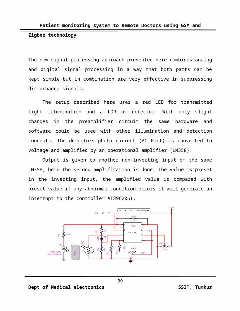
The new signal processing approach presented here combines analog
and digital signal processing in a way that both parts can be
kept simple but in combination are very effective in suppressing
disturbance signals.
The setup described here uses a red LED for transmitted
light illumination and a LDR as detector. With only slight
changes in the preamplifier circuit the same hardware and
software could be used with other illumination and detection
concepts. The detectors photo current (AC Part) is converted to
voltage and amplified by an operational amplifier (LM358).
Output is given to another non-inverting input of the same
LM358; here the second amplification is done. The value is preset
in the inverting input, the amplified value is compared with
preset value if any abnormal condition occurs it will generate an
interrupt to the controller AT89C2051.
39Dept of Medical electronics SSIT, Tumkur
Patient monitoring system to Remote Doctors using GSM and
Zigbee technology
FIGURE 5.4. Heart beat Monitor
Circuit
This circuit made from an infrared phototransistor and infrared
LED. This transducer works with the principle of light
reflection,in this case the light is infrared. The skin is used
as a
reflective surface for infrared light. The density of blood in
the skin will affect on the IR reflectivity. The pumping action
of heart causes the blood density rises and falls. So that we can
calculate the heart rate based on the rise and fall of intensity
of infrared that reflected by skin.
5.2 TEMPERATURE SENSOR:
The LM35 series are precision integrated-circuit temperature
sensors, whose output voltage is linearly proportional to the
Celsius (Centigrade) temperature. The LM35 thus has an advantage
over linear temperature sensors calibrated in ° Kelvin, as the
user is not required to subtract a large constant voltage from
its output to obtain convenient Centigrade scaling. The LM35 does
not require any external calibration or trimming to provide
typical accuracies of ±1⁄4°C at room temperature and ±3⁄4°C over a
full −55 to +150°C temperature range. Low cost is assured by40
Dept of Medical electronics SSIT, Tumkur
Patient monitoring system to Remote Doctors using GSM and
Zigbee technology
trimming and calibration at the wafer level. The LM35’s low
output impedance, linear output, and precise inherent calibration
make interfacing to readout or control circuitry especially easy.
It can be used with single power supplies, or with plus and minus
supplies.
As it draws only 60 μA from its supply, it has very low
self-heating, less than 0.1°C in still air. The LM35 is rated to
operate over a −55° to +150°C temperature range, while the LM35C
is rated for a −40° to +110°C range (−10° with improved
accuracy). The LM35 series is available packaged in hermetic TO-
46 transistor packages, while the LM35C, LM35CA, and LM35D are
also available in the plastic TO-92 transistor package. The LM35D
is also available in an 8-lead surface mount small outline
package and a plastic TO-220 package.
FEATURES:
Calibrated directly in ° Celsius (Centigrade)
Linear + 10.0 mV/°C scale factor
0.5°C accuracy guarantee able (at +25°C)
Rated for full −55° to +150°C range
Suitable for remote applications
Low cost due to wafer-level trimming41
Dept of Medical electronics SSIT, Tumkur
Patient monitoring system to Remote Doctors using GSM and
Zigbee technology
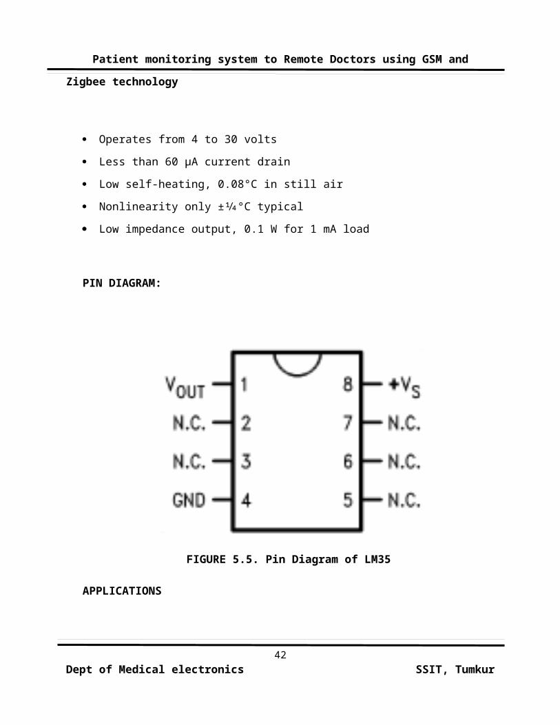
Operates from 4 to 30 volts
Less than 60 μA current drain
Low self-heating, 0.08°C in still air
Nonlinearity only ±1⁄4°C typical
Low impedance output, 0.1 W for 1 mA load
PIN DIAGRAM:
FIGURE 5.5. Pin Diagram of LM35
APPLICATIONS
42Dept of Medical electronics SSIT, Tumkur
Patient monitoring system to Remote Doctors using GSM and
Zigbee technology
The LM35 can be applied easily in the same way as other
integrated-circuit temperature sensors. It can be glued or
cemented to a surface and its temperature will be within about
0.01§C of the surface temperature.
This presumes that the ambient air temperature is almost the
same as the surface temperature; if the air temperature were much
higher or lower than the surface temperature, the actual
temperature of the LM35 die would be at an intermediate
temperature between the surface temperature and the air
temperature. This is especially true for the TO-92 plastic
package, where the copper leads are the principal thermal path to
carry heat into the device, so its temperature might be closer to
the air temperature than to the surface temperature.
To minimize this problem, be sure that the wiring to the
LM35, as it leaves the device, is held at the same temperature as
the surface of interest. The easiest way to do this is to cover
up these wires with a bead of epoxy which will insure that the
leads and wires are all at the same temperature as the surface,
and that the LM35 die's temperature will not be affected by the
air temperature.
5.3. ECG FILTER CIRCUIT
43Dept of Medical electronics SSIT, Tumkur
Patient monitoring system to Remote Doctors using GSM and
Zigbee technology
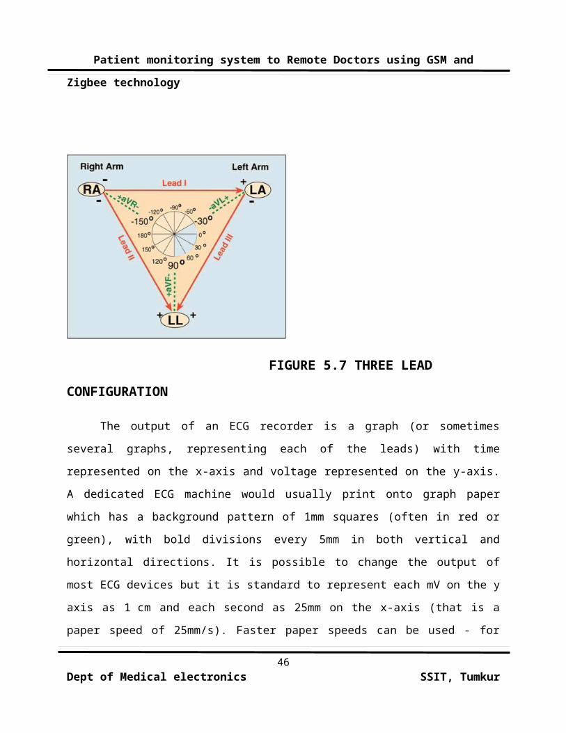
Usually more than 2 electrodes are used and they can be combined
into a number of pairs (For example: Left arm (LA), right arm (RA) and
left leg (LL) electrodes form the pairs: LA+RA, LA+LL, RA+LL). The
output from each pair is known as a lead. Each lead is said to look at
the heart from a different angle. Different types of ECGs can be
referred to by the number of leads that are recorded, for example 3-
lead, 5-lead or 12-lead ECGs (sometimes simply "a 12-lead"). A 12-
lead ECG is one in which 12 different electrical signals are recorded
at approximately the same time and will often be used as a one-off
recording of an ECG, typically printed out as a paper copy. 3- and 5-
lead ECGs tend to be monitored continuously and viewed only on the
screen of an appropriate monitoring device, for example during an
operation or whilst being transported in an ambulance. There may, or
may not be any permanent record of a 3- or 5-lead ECG depending on the
equipment used.
It is the best way to measure and diagnose abnormal rhythms
of the heart, particularly abnormal rhythms caused by damage to
the conductive tissue that carries electrical signals, or
abnormal rhythms caused by electrolyte imbalances. In a
myocardial infarction (MI), the ECG can identify if the heart
muscle has been damaged in specific areas, though not all areas
of the heart are covered. The ECG cannot reliably measure the
pumping ability of the heart, for which ultrasound-based
(echocardiography) or nuclear medicine tests are used. It is44
Dept of Medical electronics SSIT, Tumkur
Patient monitoring system to Remote Doctors using GSM and
Zigbee technology
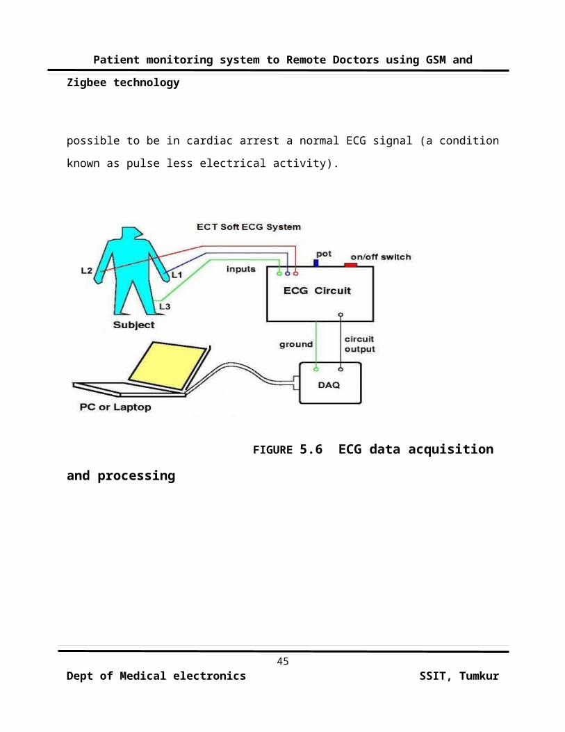
possible to be in cardiac arrest a normal ECG signal (a condition
known as pulse less electrical activity).
FIGURE 5.6 ECG data acquisition
and processing
45Dept of Medical electronics SSIT, Tumkur
Patient monitoring system to Remote Doctors using GSM and
Zigbee technology
FIGURE 5.7 THREE LEAD
CONFIGURATION
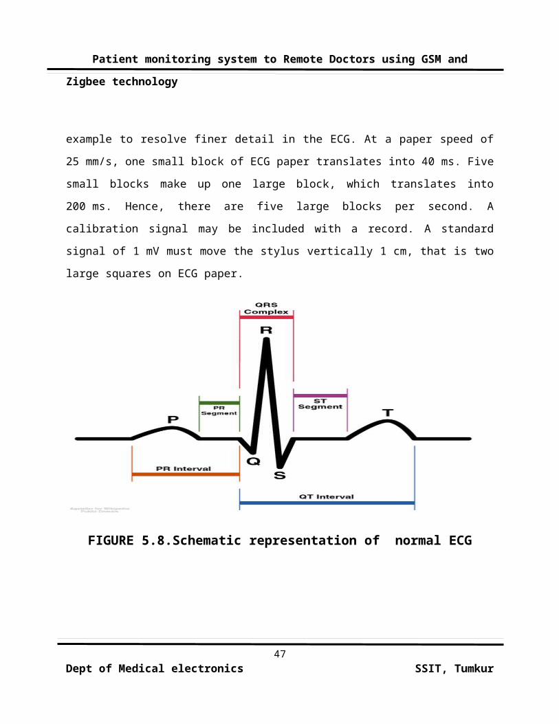
The output of an ECG recorder is a graph (or sometimes
several graphs, representing each of the leads) with time
represented on the x-axis and voltage represented on the y-axis.
A dedicated ECG machine would usually print onto graph paper
which has a background pattern of 1mm squares (often in red or
green), with bold divisions every 5mm in both vertical and
horizontal directions. It is possible to change the output of
most ECG devices but it is standard to represent each mV on the y
axis as 1 cm and each second as 25mm on the x-axis (that is a
paper speed of 25mm/s). Faster paper speeds can be used - for
46Dept of Medical electronics SSIT, Tumkur
Patient monitoring system to Remote Doctors using GSM and
Zigbee technology
example to resolve finer detail in the ECG. At a paper speed of
25 mm/s, one small block of ECG paper translates into 40 ms. Five
small blocks make up one large block, which translates into
200 ms. Hence, there are five large blocks per second. A
calibration signal may be included with a record. A standard
signal of 1 mV must move the stylus vertically 1 cm, that is two
large squares on ECG paper.
FIGURE 5.8.Schematic representation of normal ECG
47Dept of Medical electronics SSIT, Tumkur
Patient monitoring system to Remote Doctors using GSM and
Zigbee technology
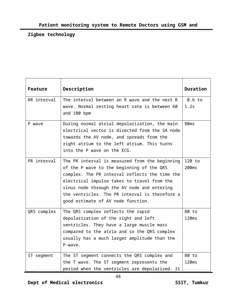
Feature
Description
Duration
RR interval The interval between an R wave and the next R wave. Normal resting heart rate is between 60 and 100 bpm
0.6 to 1.2s
P wave During normal atrial depolarization, the main electrical vector is directed from the SA nodetowards the AV node, and spreads from the right atrium to the left atrium. This turns into the P wave on the ECG.
80ms
PR interval The PR interval is measured from the beginningof the P wave to the beginning of the QRS complex. The PR interval reflects the time theelectrical impulse takes to travel from the sinus node through the AV node and entering the ventricles. The PR interval is therefore agood estimate of AV node function.
120 to 200ms
QRS complex The QRS complex reflects the rapid depolarization of the right and left ventricles. They have a large muscle mass compared to the atria and so the QRS complex usually has a much larger amplitude than the P-wave.
80 to 120ms
ST segment The ST segment connects the QRS complex and the T wave. The ST segment represents the period when the ventricles are depolarized. It
80 to 120ms
48Dept of Medical electronics SSIT, Tumkur
Patient monitoring system to Remote Doctors using GSM and
Zigbee technology
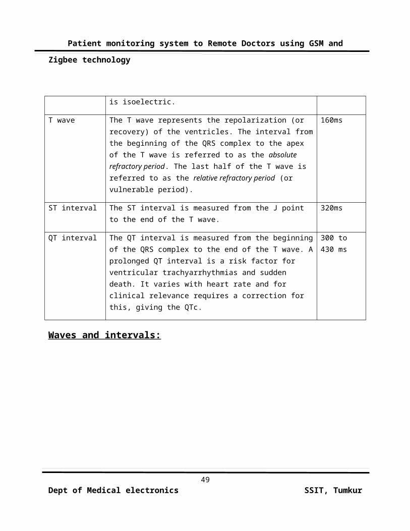
is isoelectric.
T wave The T wave represents the repolarization (or recovery) of the ventricles. The interval fromthe beginning of the QRS complex to the apex of the T wave is referred to as the absolute refractory period. The last half of the T wave is referred to as the relative refractory period (or vulnerable period).
160ms
ST interval The ST interval is measured from the J point to the end of the T wave.
320ms
QT interval The QT interval is measured from the beginningof the QRS complex to the end of the T wave. Aprolonged QT interval is a risk factor for ventricular trachyarrhythmias and sudden death. It varies with heart rate and for clinical relevance requires a correction for this, giving the QTc.
300 to 430 ms
Waves and intervals:
49Dept of Medical electronics SSIT, Tumkur

Patient monitoring system to Remote Doctors using GSM and
Zigbee technology
FIGURE 5.9 A normal adult 12-lead ECG
5.4. MICROCONTROLLER 89C51RD2
DESCRIPTION:
The AT89C51 is a low-power, high-performance CMOS 8-bit
microcomputer with 8Kbytes of Flash programmable and erasable
read only memory (PEROM). The on-chip Flash allows the program
memory to be reprogrammed in-system or by a conventional
nonvolatile memory programmer. By combining a versatile 8-bit CPU
with Flash on a monolithic chip, the Philips AT89C51 is a50
Dept of Medical electronics SSIT, Tumkur

Patient monitoring system to Remote Doctors using GSM and
Zigbee technology
powerful microcomputer, which provides a highly flexible and
cost-effective solution to many embedded control applications.
. By the mid-1980s, most of the previously external system
components had been integrated into the same chip as the
processor, resulting in integrated circuits called
microcontrollers, and widespread use of embedded systems became
feasible.
Product specification.
Partitioning of the design into its software and hardware
components.
Iteration and refinement of partitioning.
Independent hardware and software design tasks
Integration of hardware and software components.
Product testing and release.
51Dept of Medical electronics SSIT, Tumkur
Patient monitoring system to Remote Doctors using GSM and
Zigbee technology
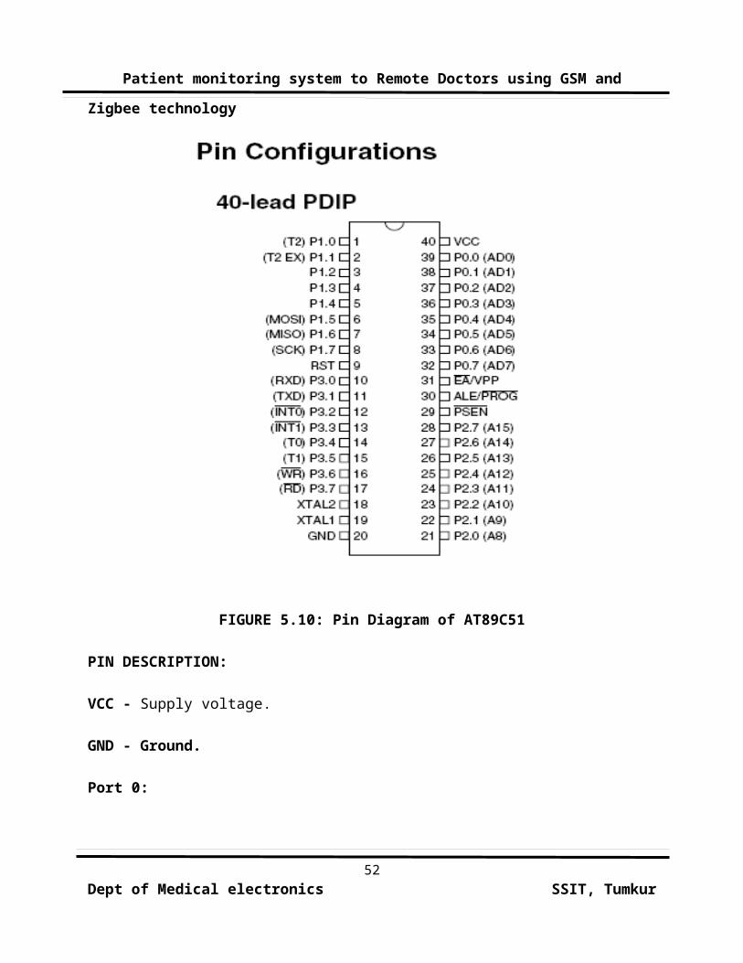
FIGURE 5.10: Pin Diagram of AT89C51
PIN DESCRIPTION:
VCC - Supply voltage.
GND - Ground.
Port 0:
52Dept of Medical electronics SSIT, Tumkur
Patient monitoring system to Remote Doctors using GSM and
Zigbee technology
Port 0 is an 8-bit open drain bi-directional I/O port. As an
output port, each pin can sink eight TTL inputs. When 1s are
written to port 0 pins, the pins can be used as high. Impedance
inputs. Port 0 can also be configured to be the multiplexed low-
order address/data bus during accesses to external program and
data memory. In this mode, P0 has internal pull-ups. Port 0 also
receives the code bytes during Flash programming and outputs the
code bytes during program verification. External pull-ups are
required during program verification.
Port 1:
Port 1 is an 8-bit bi-directional I/O port with internal
pull-ups. The Port 1 output buffers can sink/source four TTL
inputs. When 1s are written to Port 1 pins, they are pulled high
by the internal pull-ups and can be used as inputs. As inputs,
Port 1 pins that are externally being pulled low will source
current (IIL) because of the internal pull-ups. In addition, P1.0
and P1.1 can be configured to be the timer/counter 2 external
count input (P1.0/T2) and the timer/counter 2 trigger input
(P1.1/T2EX), respectively.
PORT PIN ALTERNATE FUNCTIONS:
P1.0 T2 (external count input to Timer/Counter 2), clock-out
53Dept of Medical electronics SSIT, Tumkur
Patient monitoring system to Remote Doctors using GSM and
Zigbee technology
P1.1 T2EX (Timer/Counter 2 capture/reload trigger and direction
control
Port 2:
Port 2 is an 8-bit bi-directional I/O port with internal
pull-ups. The Port 2output buffers can sink/source four TTL
inputs. When 1s are written to Port 2 pins, they are pulled high
by the internal pull-ups and can be used as inputs. As inputs,
Port 2 pins that are externally being
pulled low will source current (I IL) because of the internal
pull-ups. Port 2 emits the high-order address byte during fetches
from external program memory and during accesses to external data
memory that uses 16-bit addresses (MOVX @ DPTR). In this
application, Port 2 uses strong internal pull-ups when emitting
1s. During accesses to external data memory that uses 8-bit
addresses (MOVX @ RI), Port 2 emits the contents of the P2
Special Function Register. Port 2 also receives the high-order
address bits and some control signals during Flash programming
and verification.
Port 3:
Port 3 is an 8-bit bi-directional I/O port with internal
pull-ups. The Port 3 output buffers can sink/source four TTL
inputs. When 1s are written to Port 3 pins, they are pulled high
54Dept of Medical electronics SSIT, Tumkur
Patient monitoring system to Remote Doctors using GSM and
Zigbee technology
by the internal pull-ups and can be used as inputs. As inputs,
Port 3 pins that are externally being pulled low will source
current (I IL) because of the pull-ups. Port 3 also serves the
functions of various special features of the AT89C51. Port 3 also
receives some control signals for Flash programming and
verification.
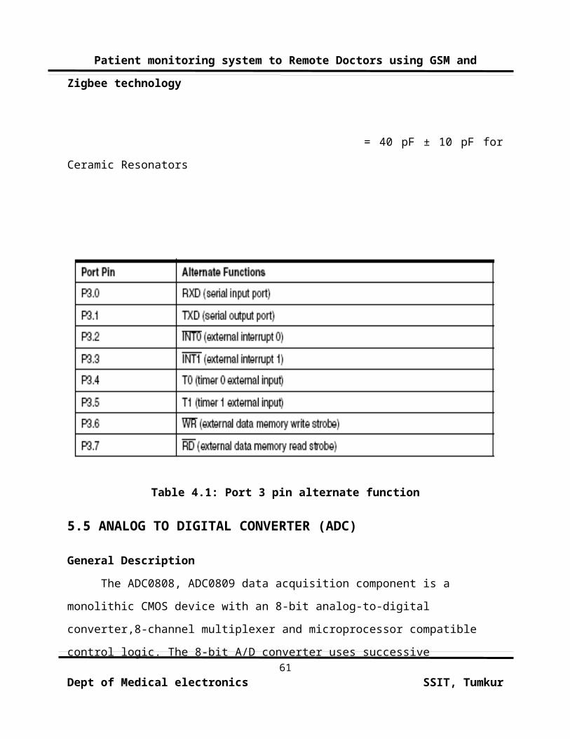
PORT PIN ALTERNATE FUNCTIONS:
P3.0 RXD (serial input port)
P3.1 TXD (serial output port)
P3.2 INT0 (external interrupt 0)
P3.3 INT1 (external interrupt 1)
P3.4 T0 (timer 0 external input)
P3.5 T1 (timer 1 external input)
P3.6 WR (external data memory write strobe)
P3.7 RD (external data memory read strobe).
RST: Reset input. A high on this pin for two machine cycles
while the oscillator is running resets the device.
ALE/PROG:
55Dept of Medical electronics SSIT, Tumkur
Patient monitoring system to Remote Doctors using GSM and
Zigbee technology
Address Latch Enable is an output pulse for latching the low
byte of the address during accesses to external memory. This pin
is also the program pulse input (PROG) during flash programming.
In normal operation, ALE is emitted at a constant rate of 1/6 the
oscillator frequency and may be used for external timing or
clocking purposes. However, that one ALE pulse is skipped during
each access to external data memory. If desired, ALE operation
can be disabled by setting bit 0 of SFR location 8EH. With the
bit set, ALE is active only during a MOVX or MOVC instruction.
Otherwise, the pin is weakly pulled high. Setting the ALE-disable
bit has no effect if the microcontroller is in external execution
mode.
PSEN:
Program Store Enable is the read strobe to external program
memory. When the AT89C51 is executing code from external program
memory, PSEN is activated twice each machine cycle, except that
two PSEN activations are skipped during each access to external
data memory.
EA/VPP:
External Access Enable (EA) must be strapped to GND in order
to enable the device to fetch code from external pro-gram memory
56Dept of Medical electronics SSIT, Tumkur
Patient monitoring system to Remote Doctors using GSM and
Zigbee technology
locations starting at 0000H up to FFFFH. However, if lock bit 1
is programmed, EA will be internally latched on reset. EA should
be strapped to VCC for internal program executions. This pin also
receives the 12V programming enable voltage (VPP) during Flash
programming when 12V programming is selected.
XTAL1:
Input to the inverting oscillator amplifier and input to the
internal clock operating circuit.
XTAL2:
It is an output from the inverting oscillator
amplifier.
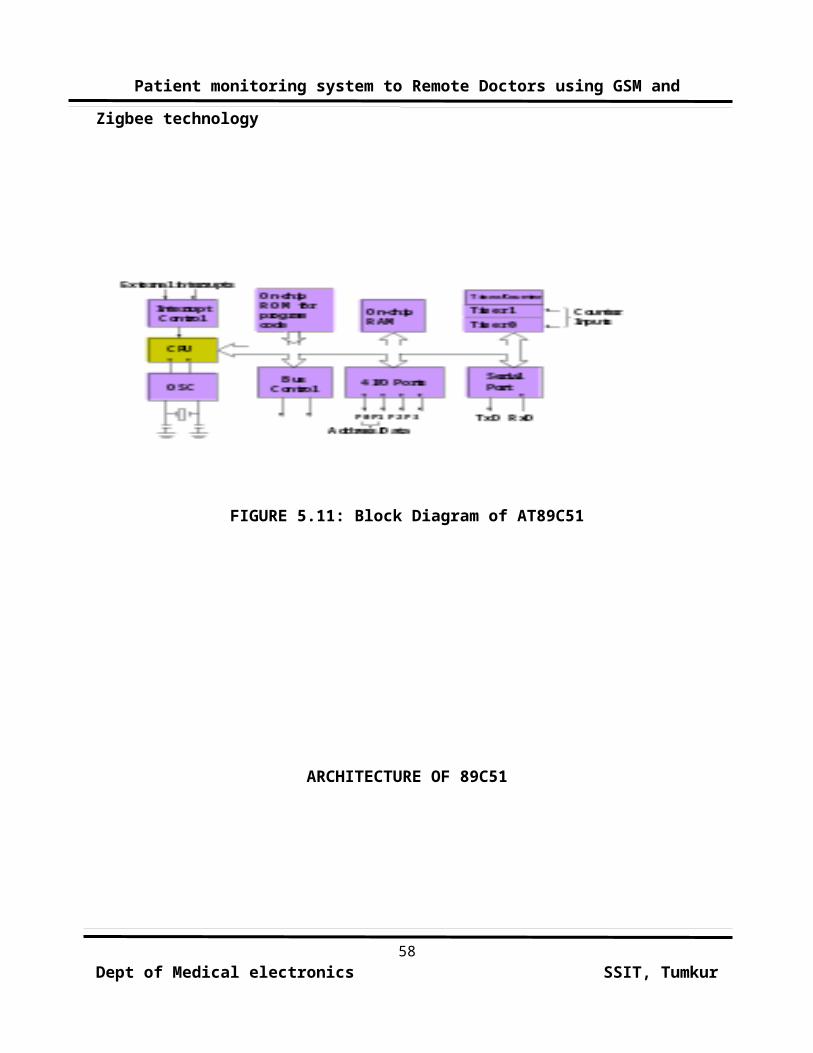
BLOCK DIAGRAM OF 89C51
57Dept of Medical electronics SSIT, Tumkur
Patient monitoring system to Remote Doctors using GSM and
Zigbee technology
FIGURE 5.11: Block Diagram of AT89C51
ARCHITECTURE OF 89C51
58Dept of Medical electronics SSIT, Tumkur

Patient monitoring system to Remote Doctors using GSM and
Zigbee technology
59Dept of Medical electronics SSIT, Tumkur

Patient monitoring system to Remote Doctors using GSM and
Zigbee technology
FIGURE 5.12: Architecture of AT89C51
OSCILLATOR CHARACTERISTICS:
XTAL1 and XTAL2 are the input and output, respectively, of
an inverting amplifier, which can be configured for use as an on-
chip oscillator. Either a quartz crystal or ceramic resonator may
be used. To drive the device from an external clock source, XTAL2
should be left unconnected while XTAL1 is driven. There are no
requirements on the duty cycle of the external clock signal,
since the input to the internal clocking circuitry is through a
divide-by-two flip-flop, but minimum and maximum voltage high and
low time specifications must be observed.
FIGURE 5.9: FIGURE 5.13 Oscillator Connections
Note: C1, C2 = 30 pF ± 10 pF for Crystals
60Dept of Medical electronics SSIT, Tumkur
Patient monitoring system to Remote Doctors using GSM and
Zigbee technology
= 40 pF ± 10 pF for
Ceramic Resonators
Table 4.1: Port 3 pin alternate function
5.5 ANALOG TO DIGITAL CONVERTER (ADC)
General Description
The ADC0808, ADC0809 data acquisition component is a
monolithic CMOS device with an 8-bit analog-to-digital
converter,8-channel multiplexer and microprocessor compatible
control logic. The 8-bit A/D converter uses successive 61
Dept of Medical electronics SSIT, Tumkur
Patient monitoring system to Remote Doctors using GSM and
Zigbee technology
approximation as the conversion technique. The converter features
a high impedance chopper stabilized comparator, a 256R voltage
divider with analog switch tree and a successive approximation
register. The 8-channel multiplexer can
directly access any of 8-single-ended analog signals.
Features
Easy interface to all microprocessors
Operates ratiometrically or with 5 VDC or analog span
adjusted voltage reference
No zero or full-scale adjust required
8-channel multiplexer with address logic
0V to 5V input range with single 5V power supply
Outputs meet TTL voltage level specifications
ADC0808 equivalent to MM74C949
ADC0809 equivalent to MM74C949-1
Key Specifications
n Resolution 8 Bits
n Total Unadjusted Error ±1⁄2 LSB and ±1 LSB
n Single Supply 5 VDC
n Low Power 15 mW
n Conversion Time 100 μs
62Dept of Medical electronics SSIT, Tumkur
Patient monitoring system to Remote Doctors using GSM and
Zigbee technology
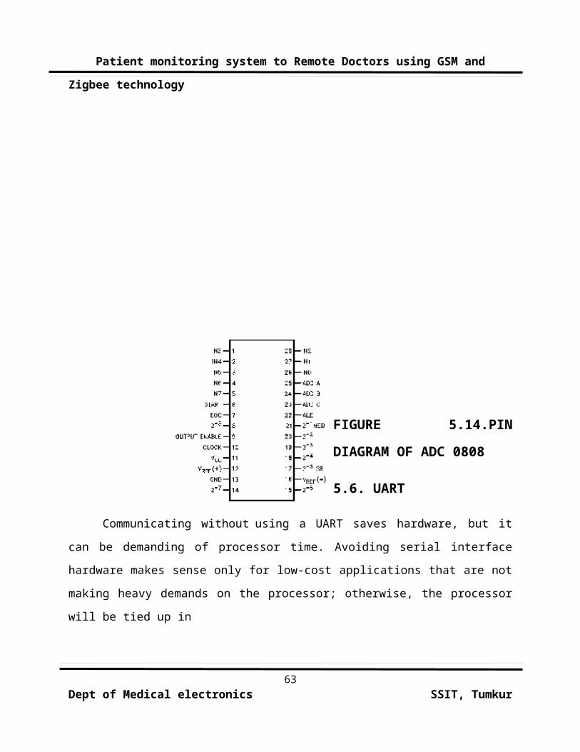
FIGURE 5.14.PIN
DIAGRAM OF ADC 0808
5.6. UART
Communicating without using a UART saves hardware, but it
can be demanding of processor time. Avoiding serial interface
hardware makes sense only for low-cost applications that are not
making heavy demands on the processor; otherwise, the processor
will be tied up in
63Dept of Medical electronics SSIT, Tumkur
Patient monitoring system to Remote Doctors using GSM and
Zigbee technology
fairly rapid, time-critical activities. Use this approach only
when you must minimize hardware cost and still have a serial
interface.If you are communicating only between nearby devices,
consider generating a separately clocked serial protocol like SPI
or I2C. Both protocols are compatible with standard 5V ports.
Since microcontroller port pins put out only logic levels, for
RS-232 you would need a driver chip, although you could use the
protocol with TTL levels between two agreeing devices.
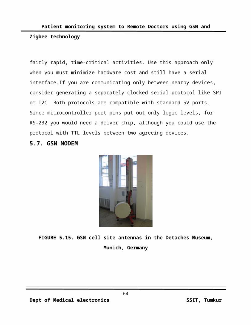
5.7. GSM MODEM
FIGURE 5.15. GSM cell site antennas in the Detaches Museum,
Munich, Germany
64Dept of Medical electronics SSIT, Tumkur
Patient monitoring system to Remote Doctors using GSM and
Zigbee technology
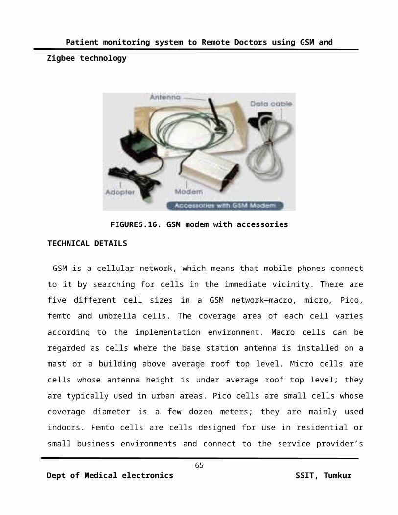
FIGURE5.16. GSM modem with accessories
TECHNICAL DETAILS
GSM is a cellular network, which means that mobile phones connect
to it by searching for cells in the immediate vicinity. There are
five different cell sizes in a GSM network—macro, micro, Pico,
femto and umbrella cells. The coverage area of each cell varies
according to the implementation environment. Macro cells can be
regarded as cells where the base station antenna is installed on a
mast or a building above average roof top level. Micro cells are
cells whose antenna height is under average roof top level; they
are typically used in urban areas. Pico cells are small cells whose
coverage diameter is a few dozen meters; they are mainly used
indoors. Femto cells are cells designed for use in residential or
small business environments and connect to the service provider’s
65Dept of Medical electronics SSIT, Tumkur
Patient monitoring system to Remote Doctors using GSM and
Zigbee technology
network via a broadband internet connection. Umbrella cells are
used to cover shadowed regions of smaller cells and fill in gaps in
coverage between those cells.
GSM CARRIER FREQUENCIES
GSM networks operate in a number of different carrier
frequency ranges (separated into GSM frequency ranges for 2G and
UMTS frequency bands for 3G), with most 2G GSM networks operating
in the 900 MHz or 1800 MHz bands. Where these bands were already
allocated, the 850 MHz and 1900 MHz bands were used instead (for
example in Canada and the United States). In rare cases the 400 and
450 MHz frequency bands are assigned in some countries because they
were previously used for first-generation systems.
Most 3G networks in Europe operate in the 2100 MHz
frequency band. Regardless of the frequency selected by an
operator, it is divided into timeslots for individual phones to
use. This allows eight full-rate or sixteen half-rate speech
channels per radio frequency. These eight radio timeslots (or eight
burst periods) are grouped into a TDMA frame. Half rate channels
use alternate frames in the same timeslot. The channel data rate
for all 8 channels is 270.833 Kbit/s, and the frame duration is
4.615 ms. The transmission power in the handset is limited to a
66Dept of Medical electronics SSIT, Tumkur
Patient monitoring system to Remote Doctors using GSM and
Zigbee technology
maximum of 2 watts in GSM850/900 and 1 watt in GSM1800/1900.
NETWORK STRUCTURE
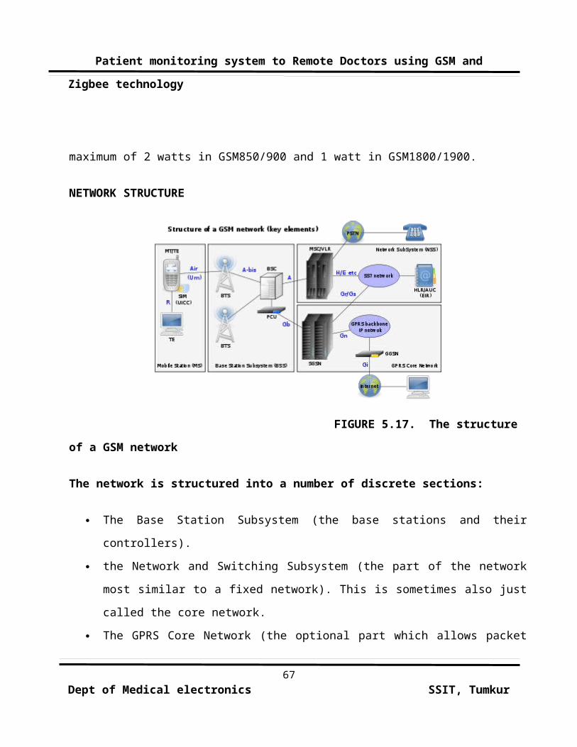
FIGURE 5.17. The structure
of a GSM network
The network is structured into a number of discrete sections:
The Base Station Subsystem (the base stations and their
controllers).
the Network and Switching Subsystem (the part of the network
most similar to a fixed network). This is sometimes also just
called the core network.
The GPRS Core Network (the optional part which allows packet
67Dept of Medical electronics SSIT, Tumkur
Patient monitoring system to Remote Doctors using GSM and
Zigbee technology
based Internet connections).
The Operations support system (OSS) for maintenance of the
network.
SUBSCRIBER IDENTITY MODULE
One of the key features of GSM is the Subscriber Identity
Module, commonly known as a SIM card. The SIM is a detachable smart
card containing the user's subscription information and phone book.
This allows the user to retain his or her information after
switching handsets. Alternatively, the user can also change
operators while retaining the handset simply by changing the SIM.
Some operators will block this by allowing the phone to use only a
single SIM, or only a SIM issued by them; this practice is known as
SIM locking.
5.8. ZIGBEE MODULE
Zigbee is a specification for a suite of high level
communication protocols using small, low-power digital radios or
Low-Rate Wireless Personal Area Networks (LR-WPANs), such as
wireless light switches with lamps, electrical meters with in-home-
displays, consumer electronics equipment via short-range radio. The
technology defined by the Zigbee specification is intended to be68
Dept of Medical electronics SSIT, Tumkur

Patient monitoring system to Remote Doctors using GSM and
Zigbee technology
simpler and less expensive than other WPANs, such as Bluetooth.
Zigbee is targeted at radio-frequency (RF) applications that
require a low data rate, long battery life, and secure
networking.Zigbee is a low-cost, low-power, wireless mesh
networking standard. First, the low cost allows the technology to
be widely deployed in wireless control and monitoring applications.
Second, the low power-usage allows longer life with smaller
batteries. Third, the mesh networking provides high reliability and
more extensive range..
The relationship between IEEE 802.15.4 and Zigbee is
similar to that between IEEE 802.11 and the Wi-Fi Alliance. The
Zigbee 1.0 specification was ratified on 14 December 2004 and is
available to members of the Zigbee Alliance. Most recently, the
Zigbee 2007 specification was posted on 30 October 2007. The first
Zigbee Application Profile, Home Automation, was announced 2
November 2007. As amended by NIST, the Smart Energy Profile 2.0
specification will remove the dependency on IEEE 802.15.4. Device
manufacturers will be able to implement any MAC/PHY, such as IEEE
802.15.4(x) and IEEE P1901, under an IP layer based on 6LoWPAN.
Zigbee operates in the industrial, scientific
and medical (ISM) radio bands; 868 MHz in Europe, 915 MHz in the69
Dept of Medical electronics SSIT, Tumkur
Patient monitoring system to Remote Doctors using GSM and
Zigbee technology
USA and Australia, and 2.4 GHz in most jurisdictions worldwide. The
technology is intended to be simpler and less expensive than other
WPANs such as Bluetooth. Zigbee chip vendors typically sell
integrated radios and microcontrollers with between 60 KB and
256 KB flash memory..
Radios are also available as stand-alone components to be
used with any processor or microcontroller. Generally, the chip
vendors also offer the Zigbee software stack, although independent
ones are also available.
Because Zigbee can activate (go from sleep to active mode)
in 30 msec or less, the latency can be very low and devices can be
very responsive — particularly compared to Bluetooth wake-up
delays, which are typically around three seconds. [3] Because
Zigbees can sleep most of the time, average power consumption can
be very low, resulting in long battery life.
LICENSING
For non-commercial purposes, the Zigbee specification is
available free to the general public. An entry level membership in
the Zigbee Alliance, called Adopter, provides access to the as-yet
unpublished specifications and permission to create products for
70Dept of Medical electronics SSIT, Tumkur
Patient monitoring system to Remote Doctors using GSM and
Zigbee technology
market using the specifications. The click through license on the
Zigbee specification requires a commercial developer to join the
Zigbee Alliance. "No part of this specification may be used in
development of a product for sale without becoming a member of
Zigbee Alliance." This causes problems for open-source developers
because the annual fee conflicts with the GNU General Public
License
USES
Zigbee protocols are intended for use in embedded applications
requiring low data rates and low power consumption. Zigbee's
current focus is to define a general-purpose, inexpensive, self-
organizing mesh network that can be used for industrial control,
embedded sensing, medical data collection, smoke and intruder
warning, building automation, home automation, etc. The resulting
network will use very small amounts of power — individual devices
must have a battery life of at least two years to pass Zigbee
certification.
Typical application areas include
Home Entertainment and Control — Smart lighting, advanced
71Dept of Medical electronics SSIT, Tumkur
Patient monitoring system to Remote Doctors using GSM and
Zigbee technology
temperature control, safety and security, movies and music
Wireless Sensor Networks' — starting with individual sensors
like Telosb/Tmote, Memsic.
PROTOCOLS
The protocols build on recent algorithmic research (Ad-hoc
On-demand Distance Vector, neuRFon) to automatically construct a
low-speed ad-hoc network of nodes. In most large network instances,
the network will be a cluster of clusters. It can also form a mesh
or a single cluster. The current profiles derived from the Zigbee
protocols support beacon and non-beacon enabled networks.In non-
beacon-enabled networks (those whose beacon order is 15), an
unslotted CSMA/CA channel access mechanism is used. In this type of
network, Zigbee Routers typically have their receivers continuously
active, requiring a more robust power supply.
However, this allows for heterogeneous networks in which
some devices receive continuously, while others only transmit when
an external stimulus is detected. The typical example of a
heterogeneous network is a wireless light switch: The Zigbee node
at the lamp may receive constantly, since it is connected to the
mains supply, while a battery-powered light switch would remain
72Dept of Medical electronics SSIT, Tumkur
Patient monitoring system to Remote Doctors using GSM and
Zigbee technology
asleep until the switch is thrown. The switch then wakes up, sends
a command to the lamp, receives an acknowledgment, and returns to
sleep. In such a network the lamp node will be at least a Zigbee
Router, if not the Zigbee Coordinator; the switch node is typically
a Zigbee End Device.
In beacon-enabled networks, the special network nodes
called Zigbee Routers transmit periodic beacons to confirm their
presence to other network nodes. Nodes may sleep between beacons,
thus lowering their duty cycle and extending their battery life.
Beacon intervals may range from 15.36 milliseconds to 15.36 ms * 214
= 251.65824 seconds at 250 kbit/s, from 24 milliseconds to 24 ms *
214 = 393.216 seconds at 40 kbit/s and from 48 milliseconds to 48 ms
* 214 = 786.432 seconds at 20 kbit/s. However, low duty cycle
operation with long beacon intervals requires precise timing, which
can conflict with the need for low product cost.
SOFTWARE AND HARDWARE
The software is designed to be easy to develop on small,
inexpensive microprocessors. The radio design used by Zigbee has
been carefully optimized for low cost in large scale production. It
73Dept of Medical electronics SSIT, Tumkur
Patient monitoring system to Remote Doctors using GSM and
Zigbee technology
has few analog stages and uses digital circuits wherever possible.
Even though the radios themselves are inexpensive, the
Zigbee Qualification Process involves a full validation of the
requirements of the physical layer. This amount of concern about
the Physical Layer has multiple benefits, since all radios derived
from that semiconductor mask set would enjoy the same RF
characteristics. On the other hand, an uncertified physical layer
that malfunctions could cripple the battery lifespan of other
devices on a Zigbee network. Where other protocols can mask poor
sensitivity or other esoteric problems in a fade compensation
response, Zigbee radios have very tight engineering constraints:
they are both power and bandwidth constrained. Thus, radios are
tested to the ISO 17025 standard with guidance given by Clause 6 of
the 802.15.4-2006 Standard. Most vendors plan to integrate the
radio and microcontroller onto a single chip getting smaller
devices.
74Dept of Medical electronics SSIT, Tumkur
Patient monitoring system to Remote Doctors using GSM and
Zigbee technology
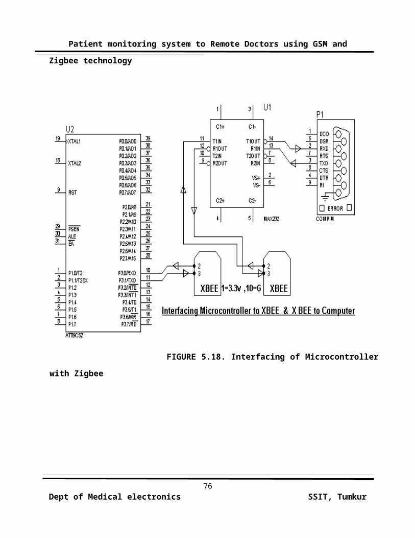
ZIGBEE MODULE INTERFACING WITH 8089C51 MICROCONTROLLER
75Dept of Medical electronics SSIT, Tumkur
Patient monitoring system to Remote Doctors using GSM and
Zigbee technology
FIGURE 5.18. Interfacing of Microcontroller
with Zigbee
76Dept of Medical electronics SSIT, Tumkur
Patient monitoring system to Remote Doctors using GSM and
Zigbee technology
CHAPTER-6
SOFTWARE EXPLANATION
6.1 INTRODUCTION:
Many companies provide the 8051 assembler, some of them
provide shareware version of their product on the Web, Kiel is one
of them. We can download them from their Websites. However, the
size of code for these shareware versions is limited and we have to
consider which assembler is suitable for our application.
6.2 KEIL U VISION3:
This is an IDE (Integrated Development Environment) thathelps you write, compile, and debug embedded programs. It
encapsulates the following components:
A project manager
A make facility
Tool configuration
77Dept of Medical electronics SSIT, Tumkur
Patient monitoring system to Remote Doctors using GSM and
Zigbee technology
Editor
A powerful debugger
BUILDING AN APPLICATION IN UVISION3:
To build (compile, assemble, and link) an application in
uVision2, you must:
Select Project–Open Project
(For example, \C166\EXAMPLES\HELLO\HELLO.UV3)
Select Project - Rebuild all target files or Build target.
UVision2 compiles, assembles, and links the files in your
project.
CREATING YOUR OWN APPLICATION IN UVISION3:
To create a new project in uVision2, you must:
Select Project - New Project.
Select a directory and enter the name of the project file.
Select Project - Select Device and select an 8051, 251, or
C16x/ST10 device from the Device
Database
Create source files to add to the project.
Select Project - Targets, Groups, and Files. Add/Files, select
78Dept of Medical electronics SSIT, Tumkur
Patient monitoring system to Remote Doctors using GSM and
Zigbee technology
Source Group1, and add the source file to the project.
Select Project - Options and set the tool options. Note when
you select the target device from the Device Database all-
special options are set automatically. You only need to
configure memory map of your target hardware. Default memory
model settings are optimal for most.
Select Project - Rebuild all target files or Build target.
DEBUGGING AN APPLICATION IN U VISION3:
To debug an application created using uVision3, you must:
Select Debug - Start/Stop Debug Session.
Use the Step toolbar buttons to single-step through your
program. You may enter G, main in the Output Window to execute
to the main C function.
Open the Serial Window using the Serial #1 button on the
toolbar.
Debug your program using standard options like Step, Go,
Break, and so on.
LIMITATIONS OF EVALUATION SOFTWARE:
There are several very important limitations in the
evaluation version of Keil’s Developer's Kit that users need be
79Dept of Medical electronics SSIT, Tumkur
Patient monitoring system to Remote Doctors using GSM and
Zigbee technology
aware of when writing software for the 8051.
OBJECT CODE MUST BE LESS THAN 2 KBYTES:
The compiler will compile any-sized source code file, but
the final object code may not exceed 2 Kbytes. If it does, the
linker will refuse to create a final binary executable (or HEX
file) from it. Along the same lines, the debugger will refuse any
files that are over 2Kbytes, even if they were compiled using a
different software package.
Few student projects will cross this 2Kbyte threshold, but
programmers should be aware of it to understand why code may no
longer compile when the project grows too large.
PROGRAM CODE STARTS AT ADDRESS 0X4000:
All C code compiled and linked using the Keil tools will
begin at address 0x4000 in code memory. Such code may not be
programmed into devices with less than 16Kbytes of Read-Only
Memory. Code written in assembly may circumvent this limitation by
using the "origin" keyword to set the start to address 0x0000. No
such work-around exists for C programs, though. However, the
integrated debugger in the evaluation software may still be used
for testing code. Once tested, the code may be compiled by the full
80Dept of Medical electronics SSIT, Tumkur

Patient monitoring system to Remote Doctors using GSM and
Zigbee technology
version of the Keil software, or by another compiler that supports
the C extensions used by Keil.
The following limitations apply to the evaluation versions of the
C51, C251, or C166 tool chains. C51 Evaluation Software
Limitations:
The compiler, assembler, linker, and debugger are limited to
2 Kbytes of object code but source Code may be any size.
Programs that generate more than 2 Kbytes of object code will
not compile, assemble, or link the startup code generated
includes LJMP's and cannot be used in single-chip devices
supporting Less than 2 Kbytes of program space like the
Philips 750/751/752.
The debugger supports files that are 2 Kbytes and smaller.
Programs begin at offset 0x0800 and cannot be programmed into
single-chip devices.
No hardware support is available for multiple DPTR registers.
No support is available for user libraries or floating-point
arithmetic.
PERIPHERAL SIMULATION:
The u vision3 debugger provides complete simulation for the
81Dept of Medical electronics SSIT, Tumkur
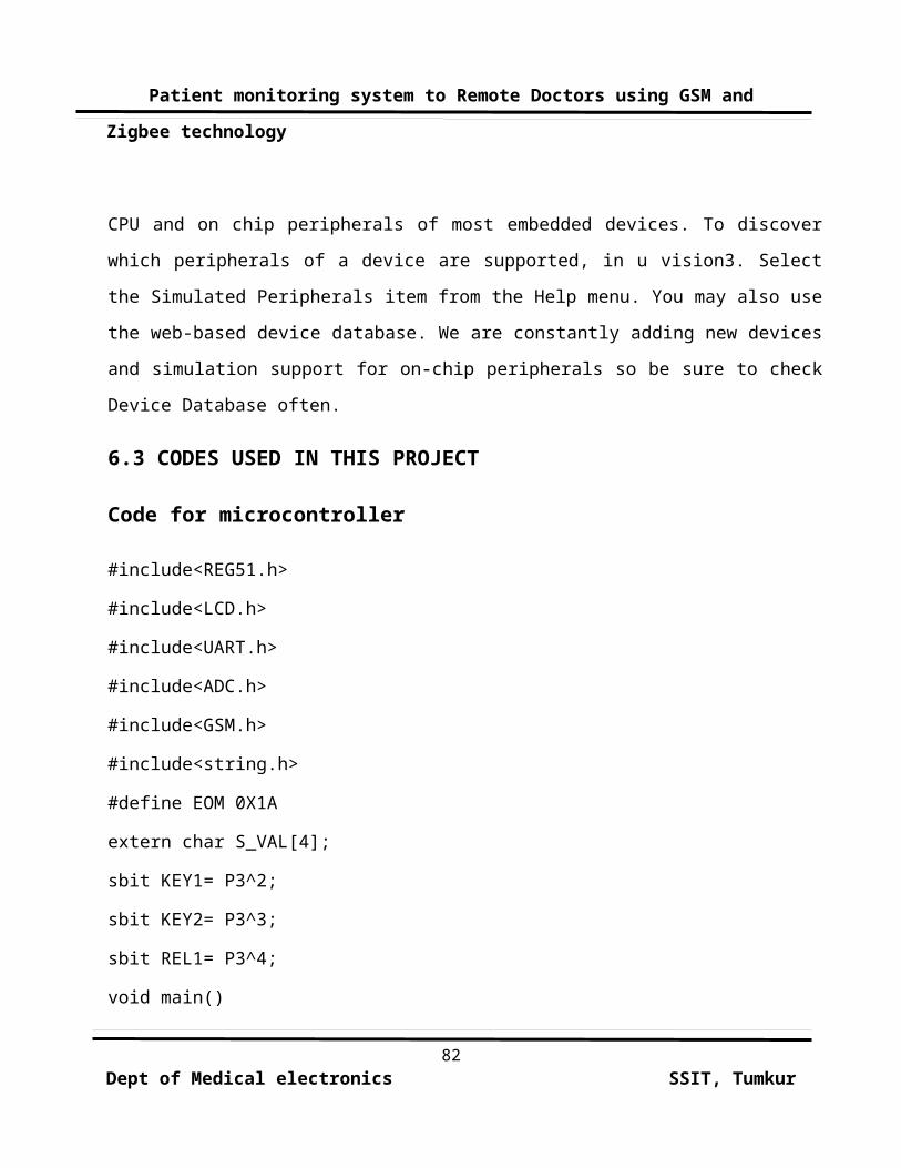
Patient monitoring system to Remote Doctors using GSM and
Zigbee technology
CPU and on chip peripherals of most embedded devices. To discover
which peripherals of a device are supported, in u vision3. Select
the Simulated Peripherals item from the Help menu. You may also use
the web-based device database. We are constantly adding new devices
and simulation support for on-chip peripherals so be sure to check
Device Database often.
6.3 CODES USED IN THIS PROJECT
Code for microcontroller
#include<REG51.h>
#include<LCD.h>
#include<UART.h>
#include<ADC.h>
#include<GSM.h>
#include<string.h>
#define EOM 0X1A
extern char S_VAL[4];
sbit KEY1= P3^2;
sbit KEY2= P3^3;
sbit REL1= P3^4;
void main()
82Dept of Medical electronics SSIT, Tumkur
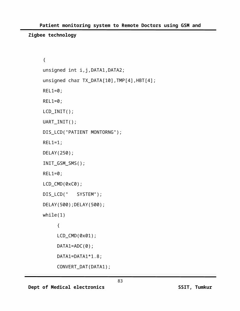
Patient monitoring system to Remote Doctors using GSM and
Zigbee technology
{
unsigned int i,j,DATA1,DATA2;
unsigned char TX_DATA[10],TMP[4],HBT[4];
REL1=0;
REL1=0;
LCD_INIT();
UART_INIT();
DIS_LCD("PATIENT MONTORNG");
REL1=1;
DELAY(250);
INIT_GSM_SMS();
REL1=0;
LCD_CMD(0xC0);
DIS_LCD(" SYSTEM");
DELAY(500);DELAY(500);
while(1)
{
LCD_CMD(0x01);
DATA1=ADC(0);
DATA1=DATA1*1.8;
CONVERT_DAT(DATA1);
83Dept of Medical electronics SSIT, Tumkur
Patient monitoring system to Remote Doctors using GSM and
Zigbee technology
for(i=0;i<3;i++)
{
TX_DATA[i]= S_VAL[i];
}
TX_DATA[i]='*';
strcpy(TMP,S_VAL);
DIS_LCD("BODY TMP : ");
LCD_CMD(0x8A);
DIS_LCD(S_VAL);
DATA2=ADC(1);
CONVERT_DAT(DATA2);
j=4;
for(i=0;i<3;i++)
{
TX_DATA[j]= S_VAL[i];
j++;
}
TX_DATA[j]='\0';
strcpy(HBT,S_VAL);
LCD_CMD(0xC0);
DIS_LCD("HEART BT :");
84Dept of Medical electronics SSIT, Tumkur
Patient monitoring system to Remote Doctors using GSM and
Zigbee technology
LCD_CMD(0xCA);
DIS_LCD(S_VAL);
if(DATA2>80)
{
LCD_CMD(0x80);
DIS_LCD("CALL THE DOCTOR");
if(KEY1==0)
{
REL1=1;
DELAY(250);
CALL();
REL1=0;
DELAY(250);
}
}
if(DATA2<70)
{
LCD_CMD(0x80);
DIS_LCD("CALL THE DOCTOR");
if(KEY1==0)
{
85Dept of Medical electronics SSIT, Tumkur
Patient monitoring system to Remote Doctors using GSM and
Zigbee technology
REL1=1;
DELAY(250);
CALL();
REL1=0;
DELAY(250);
}
}
if(KEY2==0)
{
REL1=1;
DELAY(250);
TR1=1;
SEND_SMS();
SEND_STRING_UART("BODY TEMP: ");
SEND_STRING_UART(TMP);
SEND_STRING_UART("HEART BEAT: ");
SEND_STRING_UART(HBT);
SEND_CRLF(EOM);
REL1=0;
DELAY(250);
}
86Dept of Medical electronics SSIT, Tumkur
Patient monitoring system to Remote Doctors using GSM and
Zigbee technology
DELAY(500);
SEND_STRING_UART(TX_DATA);
}
}
Code for LCD display
#include<reg51.h>
#include<LCD.h>
unsigned char CMD_ARRAY[]={0x20,0x28,0x28,0x0e,0x00,0x01,0x00,0x06,0x00,0x80},X;
void LCD_INIT()
{
for(X=0;X<9;X++)
{
LCD_CMD(CMD_ARRAY[X]);
}
}
void LCD_CMD(unsigned int CMD)
{
unsigned int CMD1,j=0;
87Dept of Medical electronics SSIT, Tumkur
Patient monitoring system to Remote Doctors using GSM and
Zigbee technology
CMD1=((CMD&0xf0)>>2);
P1=CMD1;
RS=0;
EN=1;
EN=0;
CMD1=((CMD&0x0f)<<2);
P1=CMD1;
RS=0;
EN=1;
EN=0;
DELAY(1);
// for(j=0;j<5;j++);
}
void DIS_LCD(unsigned char *dat)
{
unsigned char i;
for(i=0;*dat!='\0';i++)
{
unsigned int dta1;
if(i==16)
88Dept of Medical electronics SSIT, Tumkur
Patient monitoring system to Remote Doctors using GSM and
Zigbee technology
LCD_CMD(0xc0); //stepping to 2nd line
if(i>=16)
LCD_CMD(0x06); //to increment the cursor
dta1=((*dat&0xf0)>>2);
P1=dta1;
RS=1;
EN=1;
DELAY(10);
EN=0;
dta1=((*dat&0x0f)<<2);
P1=dta1;
RS=1;
EN=1;
DELAY(10);
EN=0;
DELAY(10);
dat++;
}
}
void DELAY(unsigned int n)
{
89Dept of Medical electronics SSIT, Tumkur
Patient monitoring system to Remote Doctors using GSM and
Zigbee technology
unsigned int i,j;
for(i=0;i<=n;i++)
for(j=0;j<=100;j++);
}
Code for ADC:
#include<ADC.h>
#include<REG51.h>
#include<LCD.h>
sbit a=P2^0; // channel select bits
sbit b=P2^1;
sbit c=P2^2;
sbit SC=P2^3; // start of conversion
sbit EOC=P2^4; // end of conversion
//sbit OE=P3^5;
sfr adcdata=0x80;
sbit CLOCK=P2^5;//for adc
unsigned char S_VAL[4];
unsigned int ADC(unsigned int AD)
90Dept of Medical electronics SSIT, Tumkur
Patient monitoring system to Remote Doctors using GSM and
Zigbee technology
{
unsigned int value;
TH0|=0XD2; //timer settings(time period 100 micro sec)
IE=0X82; // intrpt enable
TR0=1;
EOC=1;
// OE=0;
SC=0;
a=AD;
b=0;
c=0;
DELAY(50);
SC=1;
DELAY(50);
SC=0;
while(EOC==1);
while(EOC==0);
// OE=1;
DELAY(50);
91Dept of Medical electronics SSIT, Tumkur
Patient monitoring system to Remote Doctors using GSM and
Zigbee technology
value=adcdata;
// OE=0;
return(value);
}
void timer(void) interrupt 1
{
CLOCK = ~CLOCK;
}
void CONVERT_DAT(unsigned int hex)
{
unsigned int msb1=0,msb2=0,lsb0=0;
S_VAL[0]='\0';S_VAL[1]='\0';S_VAL[2]='\0';
while(hex>=100)
{
hex=hex-100;
msb1++;
}
while(hex>=10)
{
hex=hex-10;
msb2++;
92Dept of Medical electronics SSIT, Tumkur
Patient monitoring system to Remote Doctors using GSM and
Zigbee technology
}
lsb0=hex;
msb1=msb1+0x30;
msb2=msb2+0x30;
lsb0=lsb0+0x30;
S_VAL[0]=msb1;
S_VAL[1]=msb2;
S_VAL[2]=lsb0;
S_VAL[4]='\0';
}
Code for GSM:
#include<GSM.h>
#include<REG51.h>
#define CR 0X0D
#define LF 0X0D
unsigned char code CMD_6[]="AT+CMGS=\"9739461441\"";
unsigned char code CMD_7[]="AT+VGT=45";
93Dept of Medical electronics SSIT, Tumkur
Patient monitoring system to Remote Doctors using GSM and
Zigbee technology
unsigned char code CMD_8[]="ATD+919739461441;";
unsigned char ASD;
void INIT_GSM_SMS()
{
unsigned char code CMD_1[]="AT";
unsigned char code CMD_2[]="ATE0";
// unsigned char code CMD_3[]="AT&W";
unsigned char code CMD_4[]="AT+CMGF=1";
unsigned char code CMD_5[]="AT+CNMI=2,2,0,0,0";
SEND_CMD(CMD_1,2);
while((ASD=RECIEV_MSG())!='K');
SEND_CMD(CMD_2,4);
while((ASD=RECIEV_MSG())!='K');
SEND_CMD(CMD_4,9);
while((ASD=RECIEV_MSG())!='K');
94Dept of Medical electronics SSIT, Tumkur
Patient monitoring system to Remote Doctors using GSM and
Zigbee technology
SEND_CMD(CMD_5,17);
while((ASD=RECIEV_MSG())!='K');
// RECIEV_MSG();
// RECIEV_MSG();
}
void SEND_CMD(unsigned char *BASE_ADD,unsigned char COUNT)
{
unsigned char I;
for(I=0;I<COUNT;I++)
{
SBUF=*BASE_ADD;
while(TI==0);
TI=0;
BASE_ADD++;
}
SEND_CRLF(CR);
SEND_CRLF(LF);
}
void SEND_CRLF(unsigned char b)
95Dept of Medical electronics SSIT, Tumkur
Patient monitoring system to Remote Doctors using GSM and
Zigbee technology
{
SBUF=b;
while(TI==0);
TI=0;
}
unsigned char RECIEV_MSG()
{
unsigned char MESSAGE;
RI=0;
while(RI==0);
MESSAGE=SBUF;
return(MESSAGE);
}
void SEND_SMS()
{
SEND_CMD(CMD_6,21);
// while((ASD=RECIEV_MSG())!='>');
}
void CALL()
{
96Dept of Medical electronics SSIT, Tumkur
Patient monitoring system to Remote Doctors using GSM and
Zigbee technology
//SEND_CMD(CMD_7,9);
SEND_CMD(CMD_8,17);
}
6.4 SCOPE SOFTWARE
This software can be used for the display and analysis
of sound waves. The data can be recorded both directly from the
sound card (with a microphone or LINE input), or from a source such
as a CD or Mediaplayer. The input to the oscilloscope is defined by
the Windows sound mixer . The software obtains its input data for
the sound card via the Windows interface. It does not communicate
directly with the sound card. Therefore sound card problems should
be troubleshot at the operating system level.
The user interface is arranged like a conventional oscilloscope.
However, in the program window, additional XY display, frequency
analysis, and settings are provided.
Oscilloscope:
97Dept of Medical electronics SSIT, Tumkur
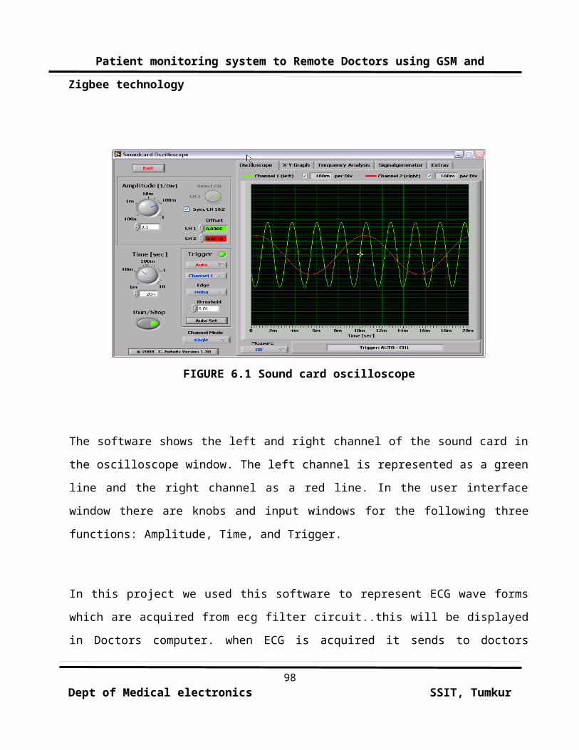
Patient monitoring system to Remote Doctors using GSM and
Zigbee technology
FIGURE 6.1 Sound card oscilloscope
The software shows the left and right channel of the sound card in
the oscilloscope window. The left channel is represented as a green
line and the right channel as a red line. In the user interface
window there are knobs and input windows for the following three
functions: Amplitude, Time, and Trigger.
In this project we used this software to represent ECG wave forms
which are acquired from ecg filter circuit..this will be displayed
in Doctors computer. when ECG is acquired it sends to doctors
98Dept of Medical electronics SSIT, Tumkur
Patient monitoring system to Remote Doctors using GSM and
Zigbee technology
mobile using GSM network. The doctor mobile handset is connected to
PC.there the doctor can analyses the ECG waveforms
CHAP
TER-7
99Dept of Medical electronics SSIT, Tumkur
Patient monitoring system to Remote Doctors using GSM and
Zigbee technology
ADVANTAGES AND LIMITATIONS
ADVANTAGES:
Zigbee technology enables doctor to monitor the patientsconditions even sitting in his room .
Doctor will get call when patients body temperature and heart
beat rises so that he can take precautionary .measures even
though he will be in remote place.
Patient care takers can monitor the equipment easily.
LIMITATIONS:
• Bitter Expensive.
• Accumulation of noise with ECG signal.
• Communication for longer distance is quite difficult through
Zigbee technology
• Interference of noise in GSM modem due to high Radio frequency
signals.
• Accuracy will be less.
100Dept of Medical electronics SSIT, Tumkur
Patient monitoring system to Remote Doctors using GSM and
Zigbee technology
CHAPTER
-8
FUTURE
SCOPE
Monitoring the patient’s condition can be done by using
biomedical telemetry method where there is a mobile communication
between microcontrollers. The temperature, heart beat and blood
pressure are all sensed by using the appropriate sensors which are
placed near the patient’s body that is under investigation. The
biomedical telemetry system consists of temperature sensor, heart
beat sensor, pressure sensor, A/D converter, signal conditioning
circuit, microcontroller, data cable, mobile phone, LCD display.
The temperature sensor is used to sense the temperature value of
101Dept of Medical electronics SSIT, Tumkur
Patient monitoring system to Remote Doctors using GSM and
Zigbee technology
the patient’s body.
The sensed output is given to A/D converter where the
analog signal is converted to digital signal. The digital output is
given to microcontroller. The microcontroller delivers the signal
for mobile phone through data cable. Then the signal is transmitted
to other mobile through GSM network. The receiver mobile receives
the signal and it is given for a PC. The signal from data cable is
given to PC and the value gets displayed using monitor. The
pressure sensor is used to sense the pressure value of the
patient’s body .The sensed output is given to A/D converter where
the analog signal is converted to digital signal. The digital
output is given to microcontroller.
The microcontroller delivers the signal for mobile phone
through data cable. Then the signal is transmitted to other mobile
through GSM network. The receiver mobile receives the signal and it
is given for a PC. The signal from data cable is given to PC and
the value gets displayed using monitor. Heart beat can be sensed by
using heart beat sensor which is then given to a signal
conditioning circuit. This unit delivers a train of pulses to
microcontroller and the value gets displayed using LCD display.
102Dept of Medical electronics SSIT, Tumkur
Patient monitoring system to Remote Doctors using GSM and
Zigbee technology
CHAPTER-9
CONCLUSION
We presented the design and implementation of a Remote Patient
Monitoring system based on wireless technology using a cellular
phone, to send an SMS (Short Message Service) to the medical staff.
The proposed system combines two commonly used technologies namely,
Global System for Mobile (GSM) and Zigbee technology. This indeed
is an easy, practical, inexpensive and yet very effective way for
transmitting vital information to the healthcare staff and
healthcare providers.
The system monitors patient's health status, such as ECG, heart
rate, and temperature. In case, the value for any of these
parameters exceeds preset critical values, the position parameters,
from the attached GPS module, are transmitted to pre-defined phone
number in form of SMS using a GSM module.
All the information obtained from the human body from
sensors and ECG filter circuit is then transmitted to the
microcontroller system as digital values. The values obtained from103
Dept of Medical electronics SSIT, Tumkur
Patient monitoring system to Remote Doctors using GSM and
Zigbee technology
like ECG, heart rate and temperature is also displayed on to the
attached LCD in alphanumerical form. In the conclusion we consider
how this system can be further improved in future, may be by adding
new type of sensors as well as using new approaches for the
security and triggering alarm.
BIBLIOGRAPHY
[1] A. Goldsmith, Wireless Communications, Cambridge Press, 2005.
[2] S. Haykin, Communication Systems, Wiley, New York, 2002.
[3] Ashish Kumar Agarwal, Innovation In Wireless CommunicationFor Industrial Automation.
104Dept of Medical electronics SSIT, Tumkur

Patient monitoring system to Remote Doctors using GSM and
Zigbee technology
[4] Gunnar Heine, GSM Networks: Protocols, Terminology &Implementation.
[5] Introducing Zigbee RF4CE". Daintree Networks
[6] Introduction to Sensors
[7] Waldemar Nawrocki And Tadeusz Nawalaniec, Sensors AndCommunications In
Environment Monitoring Systems.
1. www.allthedatasheets.com
2. www.complextoreal.com
3. www.atmel.com
4. www.sensor-networks.org
5. www.commsdesign.com
6. www.Zigbee.org
7. www.microcontroller.com
8. www.howstuffworks.com
105Dept of Medical electronics SSIT, Tumkur