Path Planning Using Elevation Maps for Mobile Robots
6
Path Planning Using Elevation Maps for Mobile Robots L. Tamas * , I. Szoke * Robotics Research Center, Technical University of Cluj-Napoca Dorobantilor 71-73, 400609, Romania Abstract This paper presents a work-in-progress aimed at constructing 3D environment maps for navigation purposes using mobile robots. The developed 3D laser ranger custom hardware setup is able to scan both indoor and outdoor scenes. For the map registration a nonlinear variant of the iterative closest point (ICP) algorithm was used with initial alignment from the odometry information. Given the increasing interest in 3D navigation for the mobile robots, our aim was to use the created maps for both indoor and outdoor navigation purposes. The elevation maps built from the merged scans were tested for a wide range of data sets including terrain, urban and office environments. Key words: 3D perception, map registration, path planning. 1. Introduction The demand for 3D perception and action for the mobile robots increased rapidly in the recent years. There are several applications in which the complex environment representation is essential including architecture, automotive, mining, tunnels pipe and instrumentation[1] For a set of applications like architecture or factory design off-line 3D data is required, which can be acquired using 3D scanners from multiple views. Other applications like autonomous navigation may require real-time data from the environment in order to operate a mobile robot [2]. There are several variants for the spatial perception of the environment including stereo-cameras, laser rangers, time-of flight cameras, range cameras, ultrasonic rangers or the recently adopted structured light sensors [3] . Each of these sensors has its own limitation regarding the range, precision and robustness of the measurements. Although computer vision techniques in- cluding stereo image processing increased in performance [4] the data from laser range finders offer more robustness and they are surface texture independent. The planar laser scanners are popular in the robotics due to its high speed and precision. They are mainly used for 2D mapping and navigation purposes, although by augmenting the two axial motion with an additional degree of freedom, an ac- curate 3D ranger can be obtained [5]. For the sweeping of the 2D laser several variants may be used, including the moving of the base platform during the scan [6] or by means of a mechan- ical actuator controlled independently of the vehicle displace- ment [7]. In our approach we used the second variant with the custom mechanically actuated 2D laser. For the applications * Corresponding author. Tel.:+40 264 401 586, Fax:+40 264 401 220 Email addresses: [email protected] (L. Tamas), [email protected] (I. Szoke) the scans taken from different views are useless unless they are registered, i.e. merged in a common coordinate frame in order to have a map of the surrounding environment. The registration can be interpreted also an optimization problem of the spatial transformations among different overlapping scans [8]. The registration process is highly dependent on the charac- teristics of the measured data including noise, sparseness and robustness. Thus several techniques were developed for regis- tration in different environments like geometric feature based registration for urban scenes [9], [10] or raw point cloud reg- istration for cluttered environments [11], [12]. The registration could be done also based on the moving robot’s position, but due to the uncertainty in the robot localization the error accu- mulated during the displacement may corrupt the registration. Although at short distances between two consecutive scans the odometry information may be used for initial alignment, and the ICP algorithm [13] for the fine tuning of the registration. The registered map can be further used for navigation pur- poses in case of a mobile robot platform. Both for indoor and outdoor applications the detection of the terrain unevenness is necessary in order to ensure a safe navigation in an unexplored environment [14]. The 3D laser map can be used to detect pos- itive elevation hazards, different cracks on the terrain surface. Negative elevation hazards representing sudden downgrade in the landscape may also be detected [15], although the detec- tion of these hazards may not lead to the optimal path planning. Further on, the terrain characteristics may be classified using salient feature [14] for local region in point clouds. In this paper several types of terrains are analyzed includ- ing indoor, outdoor and terrestrial data sets for the hazards that may encounter a mobile robot during navigation. In the sec- tion 2 the hardware and software details regarding the custom 3D laser scanner are presented. The next section describes the used map registration techniques, while section 4 introduces the applications from the navigation domain for these maps. Preprint submitted to Elsevier January 18, 2012
Transcript of Path Planning Using Elevation Maps for Mobile Robots

Path Planning Using Elevation Maps for Mobile Robots
L. Tamas∗, I. Szoke∗
Robotics Research Center, Technical University of Cluj-NapocaDorobantilor 71-73, 400609, Romania
Abstract
This paper presents a work-in-progress aimed at constructing 3D environment maps for navigation purposes using mobile robots.The developed 3D laser ranger custom hardware setup is able to scan both indoor and outdoor scenes. For the map registrationa nonlinear variant of the iterative closest point (ICP) algorithm was used with initial alignment from the odometry information.Given the increasing interest in 3D navigation for the mobile robots, our aim was to use the created maps for both indoor andoutdoor navigation purposes. The elevation maps built from the merged scans were tested for a wide range of data sets includingterrain, urban and office environments.
Key words: 3D perception, map registration, path planning.
1. Introduction
The demand for 3D perception and action for the mobilerobots increased rapidly in the recent years. There are severalapplications in which the complex environment representationis essential including architecture, automotive, mining, tunnelspipe and instrumentation[1]
For a set of applications like architecture or factory designoff-line 3D data is required, which can be acquired using 3Dscanners from multiple views. Other applications like autonomousnavigation may require real-time data from the environment inorder to operate a mobile robot [2].
There are several variants for the spatial perception of theenvironment including stereo-cameras, laser rangers, time-offlight cameras, range cameras, ultrasonic rangers or the recentlyadopted structured light sensors [3] . Each of these sensors hasits own limitation regarding the range, precision and robustnessof the measurements. Although computer vision techniques in-cluding stereo image processing increased in performance [4]the data from laser range finders offer more robustness and theyare surface texture independent.
The planar laser scanners are popular in the robotics dueto its high speed and precision. They are mainly used for 2Dmapping and navigation purposes, although by augmenting thetwo axial motion with an additional degree of freedom, an ac-curate 3D ranger can be obtained [5]. For the sweeping of the2D laser several variants may be used, including the moving ofthe base platform during the scan [6] or by means of a mechan-ical actuator controlled independently of the vehicle displace-ment [7]. In our approach we used the second variant with thecustom mechanically actuated 2D laser. For the applications
∗Corresponding author. Tel.:+40 264 401 586, Fax:+40 264 401 220Email addresses: [email protected] (L. Tamas),
[email protected] (I. Szoke)
the scans taken from different views are useless unless they areregistered, i.e. merged in a common coordinate frame in orderto have a map of the surrounding environment. The registrationcan be interpreted also an optimization problem of the spatialtransformations among different overlapping scans [8].
The registration process is highly dependent on the charac-teristics of the measured data including noise, sparseness androbustness. Thus several techniques were developed for regis-tration in different environments like geometric feature basedregistration for urban scenes [9], [10] or raw point cloud reg-istration for cluttered environments [11], [12]. The registrationcould be done also based on the moving robot’s position, butdue to the uncertainty in the robot localization the error accu-mulated during the displacement may corrupt the registration.Although at short distances between two consecutive scans theodometry information may be used for initial alignment, andthe ICP algorithm [13] for the fine tuning of the registration.
The registered map can be further used for navigation pur-poses in case of a mobile robot platform. Both for indoor andoutdoor applications the detection of the terrain unevenness isnecessary in order to ensure a safe navigation in an unexploredenvironment [14]. The 3D laser map can be used to detect pos-itive elevation hazards, different cracks on the terrain surface.Negative elevation hazards representing sudden downgrade inthe landscape may also be detected [15], although the detec-tion of these hazards may not lead to the optimal path planning.Further on, the terrain characteristics may be classified usingsalient feature [14] for local region in point clouds.
In this paper several types of terrains are analyzed includ-ing indoor, outdoor and terrestrial data sets for the hazards thatmay encounter a mobile robot during navigation. In the sec-tion 2 the hardware and software details regarding the custom3D laser scanner are presented. The next section describes theused map registration techniques, while section 4 introduces theapplications from the navigation domain for these maps.
Preprint submitted to Elsevier January 18, 2012
2. 3D laser range finder on a mobile robot
This section introduces the design and construction detailsregarding the 3D laser scanner module mounted on a mobilerobot platform. This module is based on a commercial SickLMS200 2D laser product for which an auxiliary mechanicalpart was constructed in order to earn 3rd degree of freedom.
2.1. Actuated 2D laser ranger
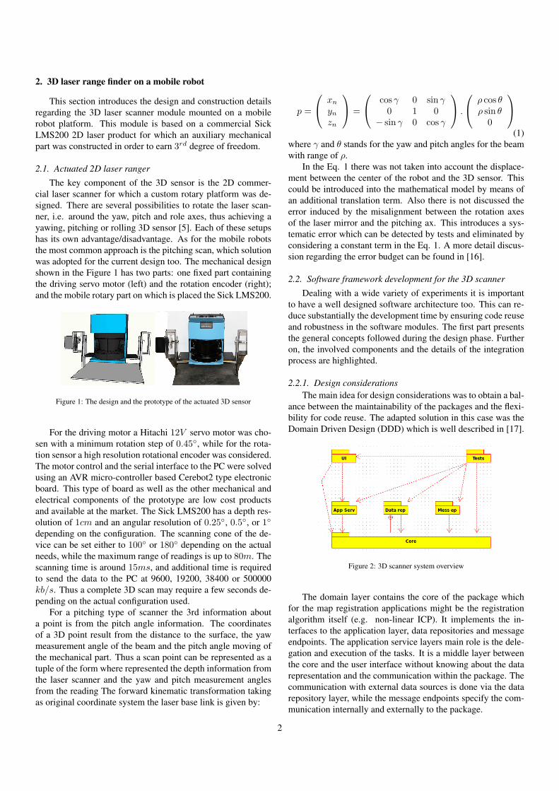
The key component of the 3D sensor is the 2D commer-cial laser scanner for which a custom rotary platform was de-signed. There are several possibilities to rotate the laser scan-ner, i.e. around the yaw, pitch and role axes, thus achieving ayawing, pitching or rolling 3D sensor [5]. Each of these setupshas its own advantage/disadvantage. As for the mobile robotsthe most common approach is the pitching scan, which solutionwas adopted for the current design too. The mechanical designshown in the Figure 1 has two parts: one fixed part containingthe driving servo motor (left) and the rotation encoder (right);and the mobile rotary part on which is placed the Sick LMS200.
Figure 1: The design and the prototype of the actuated 3D sensor
For the driving motor a Hitachi 12V servo motor was cho-sen with a minimum rotation step of 0.45◦, while for the rota-tion sensor a high resolution rotational encoder was considered.The motor control and the serial interface to the PC were solvedusing an AVR micro-controller based Cerebot2 type electronicboard. This type of board as well as the other mechanical andelectrical components of the prototype are low cost productsand available at the market. The Sick LMS200 has a depth res-olution of 1cm and an angular resolution of 0.25◦, 0.5◦, or 1◦
depending on the configuration. The scanning cone of the de-vice can be set either to 100◦ or 180◦ depending on the actualneeds, while the maximum range of readings is up to 80m. Thescanning time is around 15ms, and additional time is requiredto send the data to the PC at 9600, 19200, 38400 or 500000kb/s. Thus a complete 3D scan may require a few seconds de-pending on the actual configuration used.
For a pitching type of scanner the 3rd information abouta point is from the pitch angle information. The coordinatesof a 3D point result from the distance to the surface, the yawmeasurement angle of the beam and the pitch angle moving ofthe mechanical part. Thus a scan point can be represented as atuple of the form where represented the depth information fromthe laser scanner and the yaw and pitch measurement anglesfrom the reading The forward kinematic transformation takingas original coordinate system the laser base link is given by:
p =
xn
ynzn
=
cos γ 0 sin γ0 1 0
− sin γ 0 cos γ
.
ρ cos θρ sin θ
0
(1)
where γ and θ stands for the yaw and pitch angles for the beamwith range of ρ.
In the Eq. 1 there was not taken into account the displace-ment between the center of the robot and the 3D sensor. Thiscould be introduced into the mathematical model by means ofan additional translation term. Also there is not discussed theerror induced by the misalignment between the rotation axesof the laser mirror and the pitching ax. This introduces a sys-tematic error which can be detected by tests and eliminated byconsidering a constant term in the Eq. 1. A more detail discus-sion regarding the error budget can be found in [16].
2.2. Software framework development for the 3D scanner
Dealing with a wide variety of experiments it is importantto have a well designed software architecture too. This can re-duce substantially the development time by ensuring code reuseand robustness in the software modules. The first part presentsthe general concepts followed during the design phase. Furtheron, the involved components and the details of the integrationprocess are highlighted.
2.2.1. Design considerationsThe main idea for design considerations was to obtain a bal-
ance between the maintainability of the packages and the flexi-bility for code reuse. The adapted solution in this case was theDomain Driven Design (DDD) which is well described in [17].
Figure 2: 3D scanner system overview
The domain layer contains the core of the package whichfor the map registration applications might be the registrationalgorithm itself (e.g. non-linear ICP). It implements the in-terfaces to the application layer, data repositories and messageendpoints. The application service layers main role is the dele-gation and execution of the tasks. It is a middle layer betweenthe core and the user interface without knowing about the datarepresentation and the communication within the package. Thecommunication with external data sources is done via the datarepository layer, while the message endpoints specify the com-munication internally and externally to the package.
2

All layers have their test units defined. The adopted solu-tion for unit tests is based on the test doubles, i.e. stub objects,which act as the other packages during the test. This may beuseful for larger projects to separate the testing for layers [18].
2.2.2. Involved API componentsSeveral components were developed for the experiments on
different platforms (Windows or Linux), thus it was importantto have cross platform libraries which could be merged intoa single application. Also different developing languages likeC++, Python or Matlab M-code needed to be used in the sameapplication. The target language was C++ on a Linux platform.The cross compilation of the M-code could be easily done bythe Matlab Compiler both under Windows and Linux. TheRobotics Operation System (ROS) [19] seemed to be a goodchoice for integrating transparently the different hardware andsoftware modules.
3. Map registration
Several range scans are necessary in order to build a 3D el-evation map of the environment. In order to use these scans asa coherent dataset, they have to be unified in a common coordi-nate frame. Unless the position and orientation of the mappingrobot is know accurate, the range scan registration needs to bedone using registration algorithms. As in our case, the robotposition could not be determined with a sufficiently accuratebetween the several measurement steps, the registration algo-rithms were adopted for creating the elevation maps.
3.1. 3D data acquisition
The laser scanner presented in Figure 1 was mounted on aP3 type mobile robot in order to perform both the indoor andoutdoor scans. The scan area was of 180◦(h) x 100◦(v) with ahorizontal resolution of 361 and a vertical one with 200 steps.This configuration ensured an optimal resolution and number ofdata in the point cloud for th further data processing. The scan-ning of the environment with the mobile robot was performedin a stop-scan-go fashion, a single scan taking up to 9 seconds.All the measured data was integrated in the ROS environmentwhere each logging was timestamped in order to be able to pro-cess easier off-line.
3.2. 3D registration problem
The registration problem can also be viewed as an optimiza-tion of a cost function describing the quality of the alignment ofdifferent scans. The registration algorithm determines the rigidtransformation which minimizes this cost function [2]. Thetype of the algorithm applied for the frame alignment stronglydepends on the measured data set type. For the 3D laser scansthe iterative closest point (ICP) and derivatives are popular inthe field of robotics [8] [13] [20] [21]. The ICP computes therigid transformation which minimizes the the distance amongtwo point sets by associating a point from one frame to theclosed point in the target frame. Several variants were devel-oped in order to increase the robustness and the speed of the
Figure 3: The 3D scanner on the mobile robot
algorithm. A comprehensive overview and qualitative evalua-tion of different approaches for the registration problem can befound in [22].
A common approach for boosting the ICP robustness is theaugmentation of the points with additional features like pointcolor, geometric features or point histograms [23]. This trans-poses the optimization problem in a higher order dimensionalspace search. In our approach we used the optimized versionof the point feature histograms (PFH) [24] in order to augmentthe three dimensional space with pose-invariant local features.Based on the discriminative power of the PFH, the initial align-ment for the ICP can be solved using a sample consensus basedapproach.
(a) (b)
Figure 4: Initial correspondence (a) refined correspondence(b)
The complete ICP algorithm was presented in the works [8][13], so here only a short overview is given, with emphases onthe augmented information for the points. The ICP with initialalignment is described in the algorithm 1.
It has two input point clouds, Ps for the source and Pt forthe target. The steps 1 and 2 extracts the PFH features for thesource and target set of points (these two steps can be substi-
3

Algorithm 1 ICP with initial alignmentInput: Ps, Pt
1: Fs = ComputePFH(Ps);2: Ft = ComputePFH(Pt);3: (t∗, Af ) = SACInitialAligment(Fs, Ft);4: while (errordiff < ε)or(iteration < iterationmax) do5: Ad = getClosestPoints(t∗, Ps, Pt);6: t∗ = argmin
(1
|Ad|∑
j∈Adwj |t(ps)− pt|2
);
7: end while8: return t∗
tuted with arbitrary point cloud feature search), while in thestep 3 the initial alignment t∗ is determined within a sampleconsensus framework. In the while cycle in each iteration a setof associations is taken Ad for which the best transform is de-termined. The loop exit conditions are related to the error vari-ation or to the maximum number of iterations both specifiedas input parameters for the algorithm. Finally, the algorithmreturns the computed transformation between the two datasets.Further details regarding the implementation of the ICP withsample consensus initial alignment can be found in [24].
The parameter values are presented in Table 1.
Table 1: Feature descriptor comparisonDataset RuntimeNARF RuntimeFPFH ScoreNARF ScoreFPFH
Indoor cluttered 0.12 45 0.071 0.032Indoor plane 0.06 12 0.094 0.057
Outdoor 0.09 26 0.083 0.044
3.3. Multiple scan merging
The structure of adopted map registration algorithm followsthe 3D mapping techniques commonly used in similar applica-tions in the way it tackles the frame-to-frame matching. Asthe number of scan to be merged increases, the computationalcomplexity of the merging grows too [25].
Thus several problem specific solutions were adopted in or-der to have an acceptable compromise between speed and accu-racy. Such solutions included the scan data filtering, key-pointdetection, and in some cases the odometry information fusionfor the initial alignment.
For the filtering the voxel grid filter was used with a down-sampling factor of 5 to 10 for different data sets. Within thisrange was the best compromise between the computation speedand the merging accuracy.
For outdoor data sets the geometric constrains were also in-cluded in the initial alignment phase, i.e. the during the incre-mental registration the consecutive scans could aligned only inwithin a certain region of the global scan. For the worst cases,when the initial alignment failed (due to less distinctive fea-tures, mainly in corridor environment), the same dynamics ofmotion were assumed to be performed between the last pair offrames as in the case of the previous frame registration.
(a) (b)
Figure 5: Initial alignment (a) refined alignment(b)
4. Navigation using elevation maps
This section describes the elevation map creation and thenavigation based on the generated map. The algorithms wereevaluated on several data sets including indoor, outdoor and ter-rain data.
4.1. Creating elevation mapsThe main advantage of using elevation maps is due to the
computational cost at the navigation phase. These maps calledalso 2.5D maps, represent the 3D data as a set of referenceplanes at a certain coordinate with the corresponding elevation[]. In this paper, a deterministic approach is presented for var-ious data sets. For the reference plan or cell selection, thereare several methods that can be used including deterministicand probabilistic ones []. The size of these cells determinethe computational cost of the elevation map generation, and isalso related to the characteristics of the recorded 3D map. Withsmaller cell size, the representation of the environment is finer,but it it requires a higher computational cost. The elevation mapis represented as a mxn matrix, where the rows and columnsare given by the size of the map and the cell size as follows:
m = round
(mapsizexcellsize
);n = round
(mapsizeycellsize
)(2)
For each pair of points from the 3D map P (x, y, z), in thefist step of the elevation map creation, the corresponding cellis determined based on the x, y coordinates. After each pointis assigned to a particular cell, the elevation of the cell is com-puted as an average of the point heights in the correspondingzone [].
Figure 6: Office elevation map
The described elevation map creation was tested on severaldata sets, including indoor, urban and terrain data. The indoor
4
and urban data set was recorded using measurement configura-tion presented in the section 2. The terrain data was recordedby TerraMetric Ltd [].
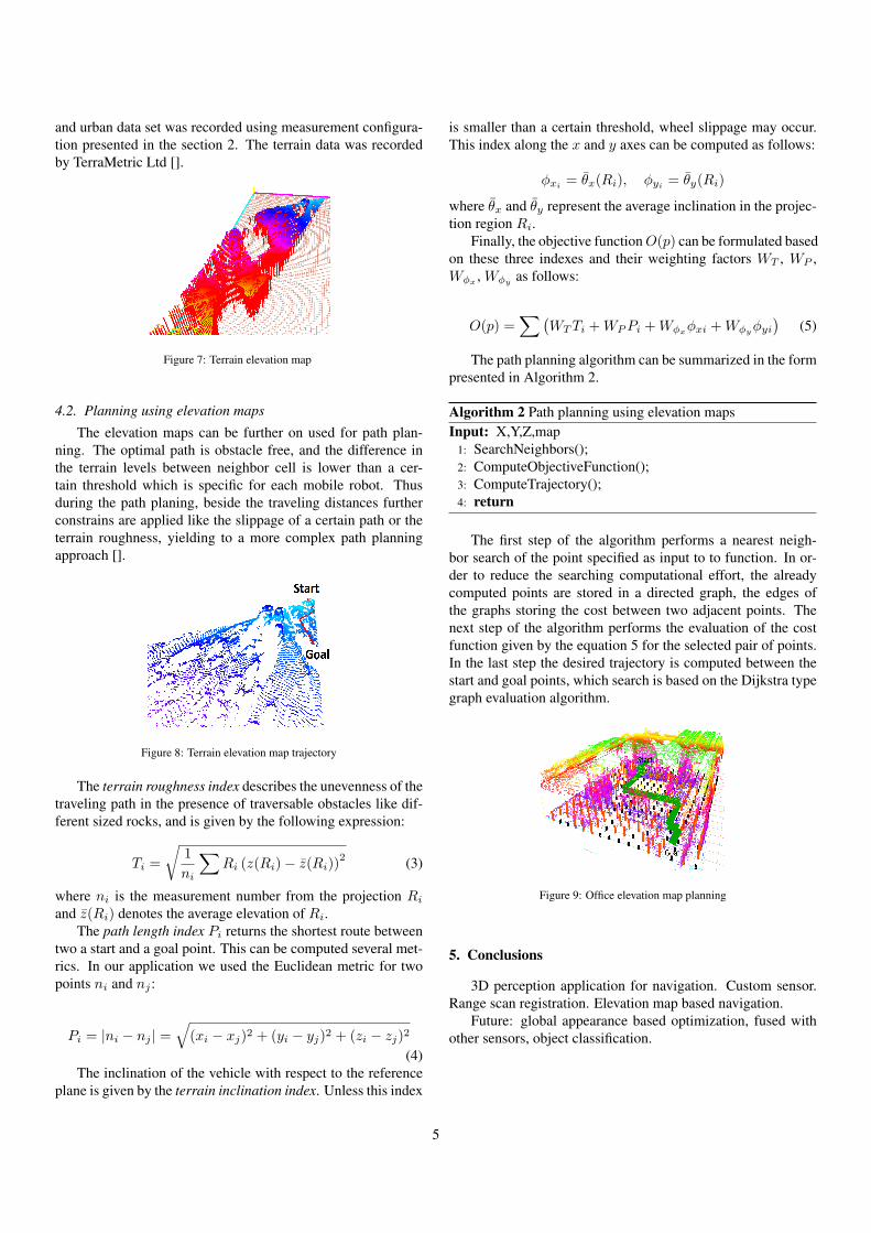
Figure 7: Terrain elevation map
4.2. Planning using elevation maps
The elevation maps can be further on used for path plan-ning. The optimal path is obstacle free, and the difference inthe terrain levels between neighbor cell is lower than a cer-tain threshold which is specific for each mobile robot. Thusduring the path planing, beside the traveling distances furtherconstrains are applied like the slippage of a certain path or theterrain roughness, yielding to a more complex path planningapproach [].
Figure 8: Terrain elevation map trajectory
The terrain roughness index describes the unevenness of thetraveling path in the presence of traversable obstacles like dif-ferent sized rocks, and is given by the following expression:
Ti =
√1
ni
∑Ri (z(Ri)− z̄(Ri))
2 (3)
where ni is the measurement number from the projection Ri
and z̄(Ri) denotes the average elevation of Ri.The path length index Pi returns the shortest route between
two a start and a goal point. This can be computed several met-rics. In our application we used the Euclidean metric for twopoints ni and nj :
Pi = |ni − nj | =√(xi − xj)2 + (yi − yj)2 + (zi − zj)2
(4)The inclination of the vehicle with respect to the reference
plane is given by the terrain inclination index. Unless this index
is smaller than a certain threshold, wheel slippage may occur.This index along the x and y axes can be computed as follows:
φxi = θ̄x(Ri), φyi = θ̄y(Ri)
where θ̄x and θ̄y represent the average inclination in the projec-tion region Ri.
Finally, the objective function O(p) can be formulated basedon these three indexes and their weighting factors WT , WP ,Wφx , Wφy as follows:
O(p) =∑(
WTTi +WPPi +Wφxφxi +Wφyφyi
)(5)
The path planning algorithm can be summarized in the formpresented in Algorithm 2.
Algorithm 2 Path planning using elevation mapsInput: X,Y,Z,map
1: SearchNeighbors();2: ComputeObjectiveFunction();3: ComputeTrajectory();4: return
The first step of the algorithm performs a nearest neigh-bor search of the point specified as input to to function. In or-der to reduce the searching computational effort, the alreadycomputed points are stored in a directed graph, the edges ofthe graphs storing the cost between two adjacent points. Thenext step of the algorithm performs the evaluation of the costfunction given by the equation 5 for the selected pair of points.In the last step the desired trajectory is computed between thestart and goal points, which search is based on the Dijkstra typegraph evaluation algorithm.
Figure 9: Office elevation map planning
5. Conclusions
3D perception application for navigation. Custom sensor.Range scan registration. Elevation map based navigation.
Future: global appearance based optimization, fused withother sensors, object classification.
5

Acknowledgment
This paper was supported by the project ”Develop and supportmultidisciplinary postdoctoral programs in primordial technical areasof national strategy of the research - development - innovation” 4D-POSTDOC, contract nr. POSDRU/89/1.5/S/52603, project co-fundedfrom European Social Fund through Sectorial Operational ProgramHuman Resources 2007-2013.
References
[1] F. Droeschel, D. Wisspeintner, T. May, S. Surmann, H. Maurelli, A 3dlaser scanner system for autonomous vehicle navigation, ICAR, Muchen,,2009.
[2] H. Surmann, A. Nchter, J. Hertzberg, An autonomous mobile robot witha 3d laser range finder for 3d exploration and digitalization of indoor en-vironments, Robotics and Autonomous Systems 45 (3-4) (2003) 181 –198.
[3] J. Gruener, G. Siegwart, R. Weingarten, A state-of-the-art 3d sensor forrobot navigation, Proceedings of the IEEE/RSJ International Conferenceon Intelligent Robots and (2004) 2155–2160.
[4] D. Scharstein, R. Szeliski, A taxonomy and evaluation of dense two-framestereo correspondence algorithms, Int. J. Comput. Visio 47 (1-3) (2002)7–42.
[5] O. Wulf, B. Wagner, Fast 3d-scanning methods for laser measurementsystems, in: International Conference on Control Systems and ComputerScience (CSCS14), 2003.
[6] A. Howard, D. F. Wolf, G. S. Sukhatme, Towards 3d mapping in largeurban environments, in: 2004 IEEE/RSJ International Conference on In-telligent Robots and Systems (IROS), Vol. 1, 2004, pp. 419–424, cited By(since 1996): 21.URL www.scopus.com
[7] H. Surmann, K. Lingemann, A. Nchter, J. Hertzberg, A 3d laser rangefinder for autonomous mobile robots, Proceedings of the 32nd Interna-tional Symposium on Robotics (ISR’01) (2001) 153–158Cited By (since1996): 52.URL www.scopus.com
[8] P. J. Besl, N. D. McKay, A method for registration of 3-d shapes, IEEETransactions on Pattern Analysis and Machine Intelligence 14 (2) (1992)239–256.
[9] K. Pathak, A. Birk, N. Vaskevicius, J. Poppinga, Fast registration basedon noisy planes with unknown correspondences for 3d mapping, IEEETransactions on Robotics 26 (3) (2010) 424–441.
[10] J. Poppinga, N. Vaskevicius, A. Birk, K. Pathak, Fast plane detection andpolygonalization in noisy 3d range images, in: International Conferenceon Intelligent Robots and Systems (IROS), IEEE Press, 2008, pp. 3378 –3383.
[11] L. Lucchese, G. Doretto, G. Cortelazzo, A frequency domain techniquefor range data registration (2002).
[12] M. Martin, L. Achim, D. Tom, Scan registration for autonomous miningvehicles using 3D-NDT (2007).
[13] Z. Zhang, Iterative point matching for registration of free-form curves(1992).
[14] N. Vandapel, D. F. Huber, A. Kapuria, M. Hebert, Natural terrain classifi-cation using 3-d ladar data, in: Proceedings - IEEE International Confer-ence on Robotics and Automation, Vol. 2004, 2004, pp. 5117–5122.
[15] L. Henriksen, E. Krotkov, Natural terrain hazard detection with a laserrangefinder, in: IEEE International Conference on Robotics and Automa-tion, 1997.
[16] A. Zhang, S. Hu, Y. Chen, H. Liu, F. Yang, J. Liu, Fast continuous 360 de-gree color 3d laser scanner, The International Archives of the Photogram-metry, Remote Sensing and Spatial Information Sciences, 2008, pp. 409–415.
[17] E. Evans, Domain-Driven Design: Tackling Complexity in the Heart ofSoftware, Addison-Wesley Professional, 2003.
[18] G. Meszaros, xUnit Test Patterns: Refactoring Test Code, Addison-Wesley, 2007.
[19] WillowGarage (2011). [link].URL http://www.ros.org/wiki/
[20] A. Nuechter, 3D Robotic Mapping, Springer Tracts in Advanced Robotics(STAR), Springer, 2009.
[21] A. Birk, N. Vaskevicius, K. Pathak, S. Schwertfeger, J. Poppinga,H. Buelow, 3d perception and modeling: Motion level teleoperation andintelligent autonomous functions, IEEE Robotics and Automation Maga-zine (RAM) 6 (4) (2009) 53–60.
[22] J. Salvi, C. Matabosch, D. Fofi, J. Forest, A review of recent range imageregistration methods with accuracy evaluation, Image Vision Comput. 25(2007) 578–596.
[23] G. C. Sharp, S. W. Lee, D. K. Wehe, Icp registration using invariant fea-tures, IEEE Transactions on Pattern Analysis and Machine Intelligence(PAMI) (2002) 90–102.
[24] R. B. Rusu, A. Sundaresan, B. Morisset, K. Hauser, M. Agrawal, L. Jean-Claude, M. Beetz, Leaving flatland: Effcient real-time three-dimensionalperception and motion planning, Journal of Field Robotics 26 (10) (2009)841–862, cited By (since 1996): 4.URL www.scopus.com
[25] P. Henry, M. Krainin, E. Herbst, X. Ren, D. Fox, Rgbd mapping: Us-ing depth cameras for dense 3d modeling of indoor environments, in:In RGB-D: Advanced Reasoning with Depth Cameras Workshop in con-junction with RSS, 2010.
6