
Patent Review
12
OREGON TECH. CLASS REE511, PROJECT 1: STATE-OF-THE-ART PATENT SEARCHING. Abstract— The rising of the world demand for energy together with the resistance to the usage of fossil fuels due to environmental impacts have pushed wind energy to grow remarkably in terms of total installed capacity. Wind Power Plants are more numerous and have higher capacity. The trend has pushed companies, researchers around the world to work hard on R&D to reduce cost, increase efficiency, and increase reliability. Their work resulted in an impressive number of patents in design and control of Wind Turbine Systems (WTS). This paper review recent patents and patent applications in design and control of FSC-based WTS. This emerging technology has superior advantages over older technologies. Index Terms—Wind energy, power conversion, full scale power converter, wind turbine systems, recent patents. I. NOMENCLATURE WTS Wind Turbines System WPP Wind Power Plant FSC Full Scale Converter DFIG Doubly Fed Induction Generator GC Grid Code FOC Field Oriented Control PWM Pulse Width Modulation FRT Fault Ride-Through PMSG Permanent Magnet Synchronous Generator II. INTRODUCTION The fifth Scientific Assessment on global climate by IPCC (the Intergovernmental Panel on Climate Change) concluded: The earth doesn’t stop warming, and human is the main cause for that. The assessment goes thousands of pages, comprises prudently checked reports by hundreds of scientists around the world [2]. Scientists agree that with the current burning rate of fossil fuels, the climate will soon come to a critical point where we cannot turn back [2]. On the other hand, latest catastrophes happening around the world, like typhoon Haiyan or hurricane Katrina, with the intensity at a record level in history further confirm the looming danger that scientists have anticipated [2]. Not only causing detrimental effect to our climate, fossil fuels also have limited resources and with the quickly increasing of the world’s energy demand, they will sooner or later run out. Renewable sources of energy, like wind energy, on the contrary, have many advantages. The wind is abundant, and it doesn’t seem to stop blowing at any time soon. Harnessing wind energy is a clean process and almost harmless to the environment. In some cases, electricity generated from the wind has even at lower cost per kWh compared coal. However, a drawback of wind energy is its variability. The intermittent nature of wind shrank the capacity factor of wind farms to really low, at about 22%. Today’s new technology in converter design together with the large-scale implementation of WPP increase the capacity factor of wind farm substantially. Some new wind farms have capacity factor higher than 50%. In near future, new grid-scale energy storage technologies potentially can bring the capacity factor to even higher. For example: Ocean Renewable Energy Storage from MIT [20], Wind Hydrogen storage systems are very promising. In addition, today’s advanced technologies have enable Wind Power Plant (WPP) to behave just as good as conventional fossil fuel or nuclear power plans. Gigantic WPP nowadays can actively participate in grid voltage/frequency regulation on both primary and secondary control, eliminate all the anxiety about high wind energy penetration might make the grid become unstable. Renewable sources of energy will be an important part of the solution to the climate and energy problems. With all the advantages, wind energy will be involved to be a main source of energy for the world. In recent years, technologists and companies have been trying to lower the cost of wind energy by increasing the output power by making Wind Turbine bigger and bigger (Fig. 1). Recently, the utilization of full scale power electronics converter in WTS has allowed a complete control of power conversion and optimization process, increases wind turbine efficiency as well as reliability and allows WTS to meet the Recent Patents in Design and Control of FSC-based Wind Turbine Systems Tai Huynh, Student Member, IEEE. Fig. 1. The evolution of WTS. Source: IPCC (2011), “Special report on renewable energy”
-
Upload
independent -
Category
Documents
-
view
1 -
download
0
Transcript of Patent Review

OREGON TECH. CLASS REE511, PROJECT 1: STATE-OF-THE-ART PATENT SEARCHING.
Abstract— The rising of the world demand for energy together
with the resistance to the usage of fossil fuels due to
environmental impacts have pushed wind energy to grow
remarkably in terms of total installed capacity. Wind Power
Plants are more numerous and have higher capacity. The trend
has pushed companies, researchers around the world to work
hard on R&D to reduce cost, increase efficiency, and increase
reliability. Their work resulted in an impressive number of
patents in design and control of Wind Turbine Systems (WTS).
This paper review recent patents and patent applications in
design and control of FSC-based WTS. This emerging technology
has superior advantages over older technologies.
Index Terms—Wind energy, power conversion, full scale
power converter, wind turbine systems, recent patents.
I. NOMENCLATURE
WTS Wind Turbines System
WPP Wind Power Plant
FSC Full Scale Converter DFIG Doubly Fed Induction Generator
GC Grid Code
FOC Field Oriented Control PWM Pulse Width Modulation
FRT Fault Ride-Through
PMSG Permanent Magnet Synchronous Generator
II. INTRODUCTION
The fifth Scientific Assessment on global climate by IPCC
(the Intergovernmental Panel on Climate Change) concluded:
The earth doesn’t stop warming, and human is the main cause
for that. The assessment goes thousands of pages, comprises
prudently checked reports by hundreds of scientists around the
world [2]. Scientists agree that with the current burning rate of
fossil fuels, the climate will soon come to a critical point
where we cannot turn back [2]. On the other hand, latest
catastrophes happening around the world, like typhoon Haiyan
or hurricane Katrina, with the intensity at a record level in
history further confirm the looming danger that scientists have
anticipated [2]. Not only causing detrimental effect to our
climate, fossil fuels also have limited resources and with the
quickly increasing of the world’s energy demand, they will
sooner or later run out.
Renewable sources of energy, like wind energy, on the
contrary, have many advantages. The wind is abundant, and it
doesn’t seem to stop blowing at any time soon. Harnessing
wind energy is a clean process and almost harmless to the
environment. In some cases, electricity generated from the
wind has even at lower cost per kWh compared coal.
However, a drawback of wind energy is its variability. The
intermittent nature of wind shrank the capacity factor of wind
farms to really low, at about 22%. Today’s new technology in
converter design together with the large-scale implementation
of WPP increase the capacity factor of wind farm
substantially. Some new wind farms have capacity factor
higher than 50%. In near future, new grid-scale energy storage
technologies potentially can bring the capacity factor to even
higher. For example: Ocean Renewable Energy Storage from
MIT [20], Wind Hydrogen storage systems are very
promising. In addition, today’s advanced technologies have
enable Wind Power Plant (WPP) to behave just as good as
conventional fossil fuel or nuclear power plans. Gigantic WPP
nowadays can actively participate in grid voltage/frequency
regulation on both primary and secondary control, eliminate
all the anxiety about high wind energy penetration might make
the grid become unstable. Renewable sources of energy will
be an important part of the solution to the climate and energy
problems. With all the advantages, wind energy will be
involved to be a main source of energy for the world.
In recent years, technologists and companies have been
trying to lower the cost of wind energy by increasing the
output power by making Wind Turbine bigger and bigger (Fig.
1). Recently, the utilization of full scale power electronics
converter in WTS has allowed a complete control of power
conversion and optimization process, increases wind turbine
efficiency as well as reliability and allows WTS to meet the
Recent Patents in Design and Control of
FSC-based Wind Turbine Systems
Tai Huynh, Student Member, IEEE.
Fig. 1. The evolution of WTS. Source: IPCC (2011), “Special report on
renewable energy”

OREGON TECH. CLASS REE511, PROJECT 1: STATE-OF-THE-ART PATENT SEARCHING.
most stringent Grid Code (GC) requirements.
Today’s high levels of renewable energy penetration has
driven the need for “renewable generators” having the
capability to provide active power control (APC) services,
which are inherent in “traditional generators”. These ancillary
services features in new FSC for WTS are crucial for grid
reliability and lay the foundation for renewable energy to
completely replace traditional sources of energy. The use of a
Full Scale Converter in WTS seems to be the most successful
configuration for the near future, winning the DFIG actual
market share [4], [1].
This review studies recent advancements of the design and
control of Full Scale Converter for WTS. This emerging
technology has many advantages over other Wind Turbines’
technologies including: higher efficiency, higher reliability,
and especially future GC conformity.
III. SEARCH METHODOLOGY AND INCLUSION CRITERIA
A search was conducted to locate issued patents and patent
applications published by the United States Patent &
Trademark Office (USPTO) in the last five years (since 2008).
The search criteria required a patents to disclose the design
and control of Full Scale Converter for WTS. The search
excluded patents that are related to maintenance and safety
issues of WTS. Also excluded are patents related to DFIG
converter technology. Although, both DFIG and FSC based
WTS can offer compliance with current Grid Codes (GCs),
there is a strong trend to migrate towards FSC as future GCs
can challenge DFIG conformity, especially in the case of
asymmetrical grid faults [5]. In addition, the search criteria
excluded patents related to Current Source Converter (CSC) or
Z-Source Converter (ZSC). Although CSC and ZSC are very
promising technologies for High Power, Medium Voltage
WTS, a lot of work need to put into R&D to make these types
of converters practicable for commercial applications. Voltage
Source Converter is still the dominant technology in FSC for
WTS right now.
The search results were found under several USPTO
classifications. The most common subclass is 290/44, which
directs toward Prime-Mover Dynamo Plants including control
of, by or through an electric circuit. The next most relevant
subclass was 363/37, which is for electric power conversion
systems by semiconductor rectifier and inverter.
The strategy for patents searching was composed from the
most relevant keywords with time information. For example a
query: ("full scale" OR "full-scale") AND power AND
(converter OR inverter) AND wind AND "wind turbine"
reveals 172 publications. When limit searching results to last 5
years, revealed results showed 122 publications. Limiting
searching results to 3 years reveals 72 publications. So
approximately, 70% of the patents in this field were invented
in the last 5 years and 42% were invented in the last 3 years.
This paper reviews 14 latest and novel patents and patent
applications disclosing the design and control of Full Scale
Converter for WTS.
IV. REVIEW OF RECENT PATENTS
Patents reviewed in this paper can be classified into three
categories. The first category is related to topology of circuit
design in FSC. The second category is related to control
techniques for FSC and the third category is related to Fault
Ride-Through capability of WTS. Table I summarizes all the
patents being reviewed.
A. Design Topology
Typically, in a LV 690V/2MW Wind Turbine Systems,
there is a phase current of 1700A power transmitted from a
nacelle (which is a chamber at the top of a wind tower, can be
as high as 100 ft. in the air) to the ground. This requires a
parallel connection of multiple cables per phase and a
considerable voltage drop and conductor loss in the
transmission line. The drawback can be mitigated by
employing a transformer in the nacelle to increase the voltage
before transmission. However, the structure to backing the
nacelle weight introduces extremely higher costs [6]. Issued
US Patent 8129853 discloses a transformerless converter
topology in harmony with generator to produce a high voltage
output, which then can be transmitted to the tower bottom
efficiently Fig. 2.
The general concept of the invention involves cascading of
power stages to create high voltage output from multiple
isolated low voltage power supplies. To be able to do
cascading of power stages, the invention requires multiple
isolated power supplies from Wind Turbines to feed directly
into each power stage. Each power stage may receive at least
one of the isolated power supplies. In an embodiment of the
invention, each power stage is a single phase full-bridge
TABLE I
SUMMARY AND CLASSIFICATION OF PATENTS REVIEWED
Design Topology Control of WT Fault Ride-through
US Pat. No. 8129853 US20130181532
US Pat. No. 8395360 US20120056602
US20120313593
US Pat. No. 8089171 US20120255215
US20130200620
US20130200621
US Pat. No. 8471534 US20130207394
US20130234522
US Pat. No. 8183706 US Pat. No. 8487462
Fig. 2. Block diagram of a multi-level wind energy conversion system in
accordance with one embodiment of the invention [6]

OREGON TECH. CLASS REE511, PROJECT 1: STATE-OF-THE-ART PATENT SEARCHING.
converter. By serial cascading of power stages we can built a
high voltage converter efficiently from low voltage
semiconductor devices.
In another embodiment of the invention, a power stage may
be built from a multilevel converter which can also produce a
relatively high voltage output from low voltage switching
devices. An eminent drawback of multilevel converter is
capacitor voltage balancing problem. However, with multiple
isolated power supplies input directly from generator, there is
no problem with capacitor voltage balancing anymore.
Another aspect of the invention is a generator that can
provide multiple isolated power outputs directly to multiple
power stages of a power converter [6]. The idea is illustrated
by a design example in the patent publication (Fig. 2a). The
invention goes further by suggesting a double layer windings
pattern to reduce overall machine size and weight.
Said methods to build a high voltage, transformerless
converter has many advantages: lower harmonic distortion,
lower switching loss, lower voltage change rate (dv/dt),
smaller filter elements, lower cost, etc. However the
disadvantages are complicated wiring and control. The idea of
cascading voltage is not new, but Teco-Westinghouse Motor
Company was among the first who saw the need of high-
voltage converter for WTS and successfully applied the idea to
remove the weighty transformer in their design of
Transformerless High-voltage converter. The patent was
granted and published on March 06, 2012. However, their
priority dated back from June 30, 2009.
Patent application publication US 20130181532 also
discloses a different approach for removing the traditional
step-up transformer. The idea was also serially connecting low
voltage switching units so that together they can work under
high voltage. However, connecting switching devices in series
is known to be a pretty difficult task due to voltage balancing
problems arising from different switching times of the
switching devices. If the voltage across serial connected
switching devices are not properly balanced, overvoltage
levels typically ends up on a particular switching devices [7]
and create damage to the whole system. So the patent further
discloses circuit to balance voltage between serially connected
switching units Fig. 15.
In one aspect of the invention (Fig. 3.), a high-voltage
power converter comprising a number of switching blocks,
each of which comprising a pluralities of series connected
switching units, said high-voltage power converter further
comprising: a resonance circuit comprising a link inductor and
a link capacitor, and a plurality of serial connected clamping
circuits, each clamping circuit comprising a clamping
capacitor and a clamping switching unit [7]. An advantage of
this topology is simple wiring and control but disadvantages
are high voltage change rate (dv/dt), higher switching loss, and
harmonic distortion. Once again, the old idea was first applied
by Vestas Wind Systems A/S to assuage strong needs and
wishes to remove step-up transformer from WTG.
B. Control of Wind Turbine.
Field Oriented Control (FOC) has been the most popular
control techniques in the industry, for motor control as well as
generator and grid converter control. FOC is based on a
synchronous rotating reference frame (dq frame) attached to
the rotor of generator, with q axis (quadrature axis)
perpendicular to the rotor magnetic field. The idea behind
FOC is to control the quadrature id and direct iq components of
the stator current phasor on the synchronous dq reference
frame. Theoretically, this allows decouple control of flux and
torque component created by stator current id and iq. Thus, a
non-linear control problem become two linear ones, which can
be solved easily with a simple PI controller. However, in real
control systems, there are always errors in sensors reading,
calculations and the response of PI control loop is not
instantaneous, creating some shortcomings, for example, (a) a
difficulty of maintaining correct decoupling between the flux
and torque producing components of the stator currents, (b)
controlling the currents using at high speeds and high
modulation index [8]. US Patent 8395360 discloses a method
to directly control the flux vector generated by stator. Unlike
previous implementation of FOC which indirectly controls
stator flux by controlling the stator current id and iq, the new
method directly gets feedback and controls the stator flux.
This leads to a more robust and simpler system [8].
Fig. 2a. A cross-section view of an exemplary three-phase, six-pole 72 slot
double layer windings permanent magnet generator [6]
Fig. 3. A high-voltage inverter including series-connected chopper/dump
load circuits in the DC-link [7]

OREGON TECH. CLASS REE511, PROJECT 1: STATE-OF-THE-ART PATENT SEARCHING.
According to an embodiment of the invention, stator’s flux
vector of the generator is estimated and feedback to the
control system. Then the PWM for switching devices are
calculated and updated based on the different between said
feedback flux vector and a set point Fig. 6. The invention also
discloses a method to quickly derive the optimum PWM for
switching devices based on the flux vector difference. Overall,
the improved FOC method allows not only better dynamic
response, but also has a simpler system design and results in
reduction of CPU processing power [8].
In another effort of trying to improve the traditional FOC
techniques, U.S. Patent Application publication 20120056602
discloses a complicated amendment for the FOC combining
PID, fuzzy logic and adaptive control. The patent publication
includes a very detailed mathematical analysis of traditional
FOC algorithms. It is shown that some implementations of
FOC neglect the difference between the d- and q- axis
synchronous inductances of stator, Ld, Lq, and the effect of
rotor flux linkage ψf . As a consequence, the control dynamic
output is not good and WTS don’t really operate at the
Maximum Power Point. According to the application, the d-
and q- axis component of stator current depend on both d- and
q- axis component of voltage [9]:
So controlling q-axis of voltage output have effect on the d-
axis current and vice versa. The publication then discloses a
correct control block diagram which take into account the
effect of Ld, Lq, and ψf .
The application goes further by showing in a simulation that
even with the precise mathematical model for the traditional
FOC control system, the output is not good when generator
rotates at high speed. This is because the required Vdq output
exceeds the linear modulation limit of the converter. Based on
that, the application suggest a non-linear control method
combining PID, fuzzy and adaptive control techniques. With
the proposed non-linear control technique, the publication
shows in a simulation that there is a lots of improvement in
tracking the maximum power point under variable and gust
wind. Besides the output power is also more stable compared
to the traditional FOC method.
Renewable energy sources are said to “lack natural inertia.”
Wind and solar are not something that we can control (e.g.,
putting more “fossil fuel”). Controlling of wind generator to
behave as good as conventional generators do without
compromising for less energy harvested or higher cost with
added battery is one of the topics keeping researchers from
universities around the world busy. There are some patents
and patent applications aim to do just that. These advanced
control techniques help to make WTS capable of supporting
grid stability just as good as conventional generator do. Not
surprisingly, most of the features are mandated by new GC.
U.S. Patent Application 20120313593 disclose and advanced
control method to stabilize the grid when there is a frequency
disturbance due to outage, generation loss or sudden increase
in consumed power, etc.
Previously, in November 2008, issued U.S. Patent 7345373
already disclosed a method for stabilizing the swing in grid
frequency by implementing an integrator that emulates a
virtual frequency inertia with a custom magnitude m. The
ideas of electrical frequency inertia is exactly what we see in
mechanical world: inertia of a body measured by its mass m.
By implementing an ability to sluggishly response to change
we can stabilize the oscillation. The bigger the inertia
magnitude m, the higher the ability it can absorb oscillations.
Choosing inertia magnitude is a trade-off between control
system’s dynamic response and the ability to absorb
oscillation.
A simple Inertia Response (IR) is a good way to stabilize
the grid frequency most of the time. However it is not enough
to do well in some circumstances. U.S. Patent Application
20120313593 discloses many necessary improvements to the
old method in issued U.S. Patent 7345373. In an embodiment
of the invention, the virtual Inertia Response is implemented
by controlling the amount of active power P injected into the
grid in such a way that the frequency oscillation is reduced. In
power generation systems, grid frequency reflects the balance
of generated and consumed active power. So if frequency is
lower than the nominal frequency, we need to reduce the
injected power to bring the frequency back to normal and vice
versa.
In another embodiment of the invention, the IR may be
combined with a frequency recovery function, which makes
sure that activation of the IR function does not subsequently
lead to over frequency events. If the total frequency at the
point of interconnection above a certain threshold, the soft
recovery function is activated and power output is adjusted
according to a specified droop curve [10].
In another embodiment of the invention, the IR function is
only activated when the error in grid frequency is above a
specified threshold. So most of the time when grid frequency
is within a specified range of the nominal frequency, (which is
Fig. 4. A schematic representation of a fault ride-through switch shown in
accordance with an embodiment of the invention [8]

OREGON TECH. CLASS REE511, PROJECT 1: STATE-OF-THE-ART PATENT SEARCHING.
50Hz in US) the IR function is disable. The thresholds for
activating and deactivating the IR function are different. The
hysteresis in the operation of IR function is needed to keep the
overall system more stable.
In another embodiment of the invention, the normal
operation of Wind Turbine is controlled to avoid a “double
dip”, which may occur when system return to normal
operation after an Inertia Response [10]. After an IR, the
Turbine’s Rotor rotation speed might be higher or lower than
before the IR. If we reactivate the normal operation
immediately after the IR, a “double dip” may occur. To avoid
this undesirable effect, the real power reference is temporarily
controlled to allow turbine’s rotor rotation speed return to that
of the present or determined optimal operating condition [10].
And then the normal operation is allowed to be reactivated.
The Inertia Response might create oscillation in the
mechanical systems of wind turbine which might create
system failure in the long run. So the invention goes further by
suggesting that if the number of IR is over a certain limits,
depending on the current rotor rotational speed, WTS may
decide not to do an IR to stabilize grid’s frequency disturbance
in order to protect the Wind Turbine itself.
Fig. 6 showed a graph of an actual grid frequency according
to the conventional method compare to an embodiment of a
method in this patent application.
In wind turbines nowadays, generators play the most
important role in generating power. They are like the heart of
turbine. The principle of generator is the winds captured by
the blades will, in result, twist the shaft of the wind turbines.
This shaft can be connected directly to the rotor shaft or
through a gear box. The rotor will rotate proportionally to the
speed of the shaft, and therefore the rotor flux which is created
by permanent magnet or windings will cross the stator flux.
By Faraday’s Law, when this incidence takes place in
generator, it will generate a power at the output, or in other
word, wind turbine’s generators convert mechanical power to
electrical power. The electromagnetic power of generator can
be determined by the magnitude of the stator flux and its
position respect to the rotor flux. Therefore, it is possible to
apply a voltage to the stator accordingly to the position of the
rotor which can position the stator flux to get a desired output
voltage, at a rotational speed. A method to determine the
position of rotor is disclosed in U.S. Patent 8089171 issued to
Li, Bing, et al, on Jan 3, 2012 [13]
The method comprising three steps as illustrated in Fig. 6.
The first step is to determine the voltage of electrical
generator; this duty is assigned for block 401. After the
voltage of generator is known, block 403 will determine rotor
position angle based on this information (second step). Block
405 is called feedback block which means it will combine the
rotor position angle estimate (block 404) with the voltage of
generator, and feed the combined information to block 403 to
determine the subsequent rotor position (third step). With this
achieved rotor position, an appropriate voltage will be applied
to the stator to get a desired a desired output voltage [13].
In full scale wind turbines, faults may occur in a power
electronic converter. To avoid the faults of converter causing
the output of WTS disturb, a plurality of converters are
connected in parallel to share of the power generated by wind
turbine. When one converter is not operational or failure, the
WTS can continue to operate with the power reduced to the
lower combined converter capacity. With the plurality of
converters used in WTS, the switching inside converters will
generate the frequency other than the frequency of the grid.
This frequency is called the switching harmonic. With the
strict of grid codes in some countries, this harmonic has to be
resolved so that the frequency generated by WTS will be
matched with the grid frequency. In order to do that, it
requires significant filter requirements to filter out the
harmonic. There is a system so-called “interleaving” wherein
the switching harmonic is spread over with higher frequencies
and lower amplitude by displacing the switching waveforms
of each converter over a switching period. It has proven to
reduce the cost also the requirements of harmonic filtering.
However, since the interleaving system operates based on a
synchronization clock which may add to the complexity and
the cost of the design; more importantly, all the converters
have to restart and be synchronized to the clock all over again
if one converter is strip; therefore, according to general terms
of the embodiments, the present invention U.S. Patent
Application 20120155125 published on Jun 21, 2012 proposes
a method that might not require the synchronization clock and
Fig. 5. Actual grid frequency according to the conventional method (401)
compare to an embodiment of a method in this patent application (402) [10]
Fig. 6. Block diagram for determining rotor position in accordance with an
embodiment of the invented method [13]
OREGON TECH. CLASS REE511, PROJECT 1: STATE-OF-THE-ART PATENT SEARCHING.
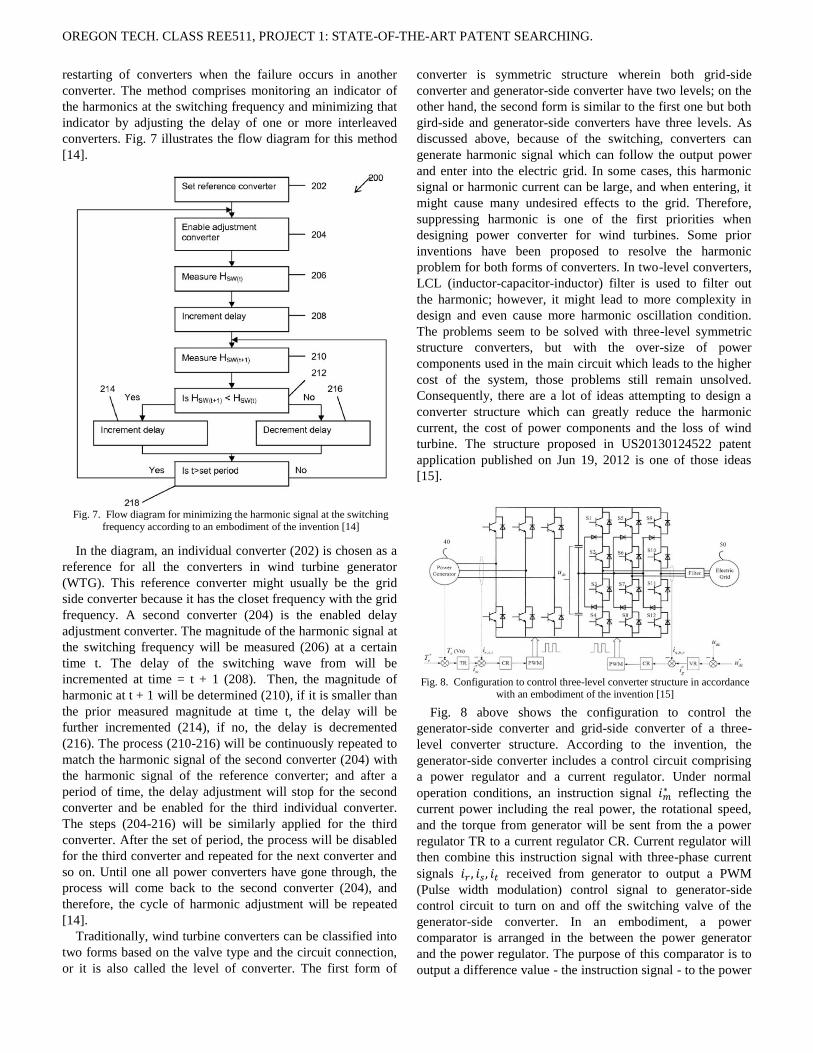
restarting of converters when the failure occurs in another
converter. The method comprises monitoring an indicator of
the harmonics at the switching frequency and minimizing that
indicator by adjusting the delay of one or more interleaved
converters. Fig. 7 illustrates the flow diagram for this method
[14].
In the diagram, an individual converter (202) is chosen as a
reference for all the converters in wind turbine generator
(WTG). This reference converter might usually be the grid
side converter because it has the closet frequency with the grid
frequency. A second converter (204) is the enabled delay
adjustment converter. The magnitude of the harmonic signal at
the switching frequency will be measured (206) at a certain
time t. The delay of the switching wave from will be
incremented at time = t + 1 (208). Then, the magnitude of
harmonic at t + 1 will be determined (210), if it is smaller than
the prior measured magnitude at time t, the delay will be
further incremented (214), if no, the delay is decremented
(216). The process (210-216) will be continuously repeated to
match the harmonic signal of the second converter (204) with
the harmonic signal of the reference converter; and after a
period of time, the delay adjustment will stop for the second
converter and be enabled for the third individual converter.
The steps (204-216) will be similarly applied for the third
converter. After the set of period, the process will be disabled
for the third converter and repeated for the next converter and
so on. Until one all power converters have gone through, the
process will come back to the second converter (204), and
therefore, the cycle of harmonic adjustment will be repeated
[14].
Traditionally, wind turbine converters can be classified into
two forms based on the valve type and the circuit connection,
or it is also called the level of converter. The first form of
converter is symmetric structure wherein both grid-side
converter and generator-side converter have two levels; on the
other hand, the second form is similar to the first one but both
gird-side and generator-side converters have three levels. As
discussed above, because of the switching, converters can
generate harmonic signal which can follow the output power
and enter into the electric grid. In some cases, this harmonic
signal or harmonic current can be large, and when entering, it
might cause many undesired effects to the grid. Therefore,
suppressing harmonic is one of the first priorities when
designing power converter for wind turbines. Some prior
inventions have been proposed to resolve the harmonic
problem for both forms of converters. In two-level converters,
LCL (inductor-capacitor-inductor) filter is used to filter out
the harmonic; however, it might lead to more complexity in
design and even cause more harmonic oscillation condition.
The problems seem to be solved with three-level symmetric
structure converters, but with the over-size of power
components used in the main circuit which leads to the higher
cost of the system, those problems still remain unsolved.
Consequently, there are a lot of ideas attempting to design a
converter structure which can greatly reduce the harmonic
current, the cost of power components and the loss of wind
turbine. The structure proposed in US20130124522 patent
application published on Jun 19, 2012 is one of those ideas
[15].
Fig. 8 above shows the configuration to control the
generator-side converter and grid-side converter of a three-
level converter structure. According to the invention, the
generator-side converter includes a control circuit comprising
a power regulator and a current regulator. Under normal
operation conditions, an instruction signal reflecting the
current power including the real power, the rotational speed,
and the torque from generator will be sent from the a power
regulator TR to a current regulator CR. Current regulator will
then combine this instruction signal with three-phase current
signals received from generator to output a PWM
(Pulse width modulation) control signal to generator-side
control circuit to turn on and off the switching valve of the
generator-side converter. In an embodiment, a power
comparator is arranged in the between the power generator
and the power regulator. The purpose of this comparator is to
output a difference value - the instruction signal - to the power
Fig. 7. Flow diagram for minimizing the harmonic signal at the switching
frequency according to an embodiment of the invention [14]
Fig. 8. Configuration to control three-level converter structure in accordance
with an embodiment of the invention [15]

OREGON TECH. CLASS REE511, PROJECT 1: STATE-OF-THE-ART PATENT SEARCHING.
regulator based on the difference between the received
parameters reflecting the current power of the generator and
the preset parameter. A current comparator is also arranged
between the power regulator and the current regulator. Its
purpose is to receive the instruction signal and compare it with
the three-phase current to output a difference value to the
current regulator [15].
On the gird-side converter, the converter structure includes
grid-side control circuit which contains voltage regulator and a
current regulator. A voltage comparator will combine the DC
voltage and the reference voltage to output a
difference value or instruction signal. The voltage regulator
will receive this instruction signal and sent it to a current
comparator which is settled between the voltage regulator and
the current regulator. The current comparator will combine the
instruction signal and the three phase signals and
to give a difference value to the current regulator CR. Based
on this instruction signal or difference value, the current
regulator will send a PMW control signal to the grid-side
control circuit to turn on and off the power switching valves of
the grid-side converter.
Patent application 20130200621 published on Aug 8, 2013
proposes a general method to motoring harmonic signals, and
modifying the output power based on the detected oscillation
to a pre-defined reference value. Fig. 9 illustrates
schematically the disclosed method according to one
embodiment of the invention [19].
According to one embodiment of the invented method, a
sensor (119) will measure the output quantity including the
voltage, real power and reactive power at point close to the
output terminal (123). The signal containing all the
information of the output quantity (121) will be sent to the
arrangement (103). The arrangement will detect whether the
output has any oscillation according to a set of reference
value. Depend on the amplitude of the harmonic, the
arrangement will derive an instruction signal supplied to the
wind turbine controller to adjust the output quantity. The
arrangement might also further send a signal to a switch (139),
which in the case of faults will disconnect the wind turbine
from the power grid [19].
The advantage of this disclosed method is that it means to
control the output quantity of the wind turbine to be at a pre-
defined reference output quantity; however, with the
characteristic of disconnecting the wind turbine from the grid
in the event of faults, it does not adhere to the new grid codes
today any more.
C. Fault Ride-through.
As mandatory by new GCs, high power WTS are required
to have fault ride-through (FRT) capability. FRT is the ability
of WTS to stay connected to the grid during temporary grid
fault without tripping offline, which could further destabilize
the grid. Many kinds of faults may occur such as voltage
surges (over voltage), voltage sag (voltage dip), short-circuit.
When there is a grid fault, WTS cannot export power into
the grid suddenly, resulting in an impulsive change in
generator torque. The step reduction in torque can cause
detrimental mechanical oscillation in the drive train of the
WTS [11] Fig. 10. This effect can be mitigated by introducing
a dynamic braking resistor (DBR) to absorb at least part of the
power that cannot be exported into the grid during fault. If the
DBR is fully rated, then all of the power can be absorbed until
power can start to be exported into the grid again Fig. 11.
However the DBR which can absorb 3MW in a typical FSC
based wind turbine generator is very costly, switching devices
to support dynamic braking are also very expensive and they
are normally required liquid cooling. U.S. Patent Application
20130207394 discloses a cost saving method to control the
generator torque by control the DBR during grid fault, so that
there is no vibration and only require a much smaller DBR.
Fig. 9. Method of detecting harmonic and controlling the output voltage
according to one embodiment of invention. [19]
Fig. 10. The inability to push power into the grid during grid fault, results in nearly step reduction in generator torque and harmful vibration to WTS. [11]

OREGON TECH. CLASS REE511, PROJECT 1: STATE-OF-THE-ART PATENT SEARCHING.
In an embodiment of the invention, a WTS comprising a
generator and a rotating mechanical drive train having a
natural period Tn. When there is a fault condition, the
generator torque is controlled to decrease in smaller step
changes describe by the formula below [11]:
Where t is time, n is an integer and C is a constant.
In contrast to absorbing all the energy during grid fault, the
new method only needs to absorb part of the energy and still
can eliminate almost all the mechanical oscillations Fig. 12.
And as a consequence, the DBR can have much smaller rating
compared to old method where the DBR is fully rated. The
total system cost can be greatly reduced by having smaller
DBR, cooling system, power electronics, etc.
Issued US Patent 8471534 also discloses an inexpensive
though effective fault ride through switch for power
generation systems, including WTS. During grid fault, the
switch can automatically absorb electrical power to reduce the
quick acceleration and harmful vibration in power generation
systems. The switch design doesn’t employ any expensive
power electronics device Fig. 13.
In an embodiment of the invention, the fault ride through
switch is coupled in series between power generator and grid
electricity. The switch has two branches. The first branch has
a LC resonance circuit at each phase and almost no resistance,
which is configured to transfer electric current during normal
operation conditions. The second branch is coupled in parallel
with the first branch and has a resistor and an inductor coupled
in series at each phase [12] Fig. 13.
During normal operation, the first branch acts as a short
circuit to transfer all electricity from WTS to utility grid Fig.
14. In an event of fault, the power is diverted from the first
branch and flow through the second branch which has a
resistor to absorb at least part of the power during fault
conditions reducing quick acceleration and harmful vibrations
in WTS. Fig. 15.
Fig. 13. A schematic representation of a fault ride-through switch shown in
accordance with an embodiment of the invention [12]
Fig. 11. All power is absorbed by a fully rated DBR during grid fault. [11]
Fig. 12. By controlling the generator torque to decrease in smaller step sizes, all mechanical oscillation can be reduced substantially. [11]

OREGON TECH. CLASS REE511, PROJECT 1: STATE-OF-THE-ART PATENT SEARCHING.
Wind generators convert wind kinetic energy to electrical
energy for power grid. In variable-speed wind turbine, the
power generated from the generators will be transferred to the
grid through the power converter. Under normal conditions,
the generated power will be equal to the power supplied to the
grid, or it can be called as power balance in technical terms. In
the events of wind gust or grid fault, the power generated will
be larger than the power fed to the grid causing the power
imbalance. Such power imbalance might lead to undesired
tower oscillations, drive train damage or turbine stripping.
Normally, a wind turbine will manage wind gust by pitching
the blades to reduce the rotational speed of rotor leading to a
lower excess power generated. However, in some cases, the
pitching does not respond fast enough to sudden wind gust; so
pitching wind turbine blades is not an effective way to handle
this kind of situation. Using power dissipating unit such as
crowbar or load dump seems to be very promising, and has
been proposed to use widely in wind turbines recent years.
The US20130200620 patent application published on May
22, 2012 discloses a method using load dump to dissipate the
excess power over during converter fault or gird fault.
According to Fir. 16, in full-scale wind turbine, the generator
is usually connected to the power grid (210) though a
transmission path. This transmission path contains a generator
converter side (204) that is connected to the output of the
generator, and a grid converter side (206) connected to the
power grid. The generator converter side is used to convert
AC-(alternative current) to-DC (direct current), on the other
hand, the grid converter side converts DC-to-AC, and this
converter might be connected to the power grid through a
transformer (210). There exists a DC link (209) comprising a
DC capacitor to couple AC-to-DC converter and DC-to-AC
converter. A controlling unit which is called power converter
controller is arranged in wind turbine to detect the failures of
either the grid or the converter. One or two load dump is used
to dissipate the over power in case of faults occur. The first
load dump is directly connected to the output of the generator,
thus this load dump is usually called AC load dump (212), and
it will be turned on by power converter controller when the
converter failure occurs. The second load dump is call DC
load dump (216) because it is connect across the DC link. This
load dump comprises a bank of resistor to dissipate power in
case of grid fault. Due to the weight of converter and the size
of nacelle, both load dumps can share one bank of resistors
and be located in one container. [16].
As in Fig. 17, when generator operates normally, the switch
SW1 and SW2 are close so the full output power from
generator will go through two converters and merge into the
gird. Switch SW3, SW5 and switches SW5, SW6 remain
open. When power converter controller detects a fault
occurring in any of the converters, or in case of any of the
converters is not operational, the power controller will open
the switch SW1 to cut off the power path to the AC-to-DC
converter, and it will close switch SW3 and some of the fifth
switches SW5 so that the output power from generator will be
dissipated in one or more than one resistors in resistor bank.
The switch SW4 and switches SW6, in this case, still remain
open. In case of the grid failure, the controlling unit will send
the signal to close the switch SW4 and some of the switches
SW5, SW6. This will create a path for the output power to
Fig. 14. A diagrammatic illustration of the fault ride-through switch of Fig.
4 operating in pre-fault and post-fault conditions [12]
Fig. 15. A diagrammatic illustration of the fault ride-through switch of Fig.
4 operating in a fault condition [12]
Fig. 16. Load dump arrangement in accordance of with an embodiment of
the invention [16]
Fig. 17. Resistor bank and switches of load dump in accordance with an
embodiment of the invention [16]

OREGON TECH. CLASS REE511, PROJECT 1: STATE-OF-THE-ART PATENT SEARCHING.
dissipate in one or some resistors, and depend on the condition
of the gird at that time, partial of the real output power or none
of it will be sent to the grid.
Load dump offers the way to dissipate the excess power in
the events of imbalance power. However, it is still not the
most effective way, since the resistor in the dump load might
experience the enormous stress over a long time of power
dissipation. Hence, the US8183706 issued on May, 22, 2012
discloses an improved way to handle the excess power in case
of imbalance power. Fig. 17 illustrates the arrangement of load
dump in wind turbine power converter.
In Fig. 18, the load dump unit used in converter is a chopper
circuit containing a switch SW1 and a resistor (114). It is
arranged across the DC link 113, and in the between
generator-side converter (110) and grid-side converter (111).
A converter controller (120) comprising a generator-side
converter controller (121) and grid-side converter controller
(122) will be under control of wind turbine controller (123),
which is in charge of controlling the operation of the wind
turbine overall. To assure not to leave the load dump under
stress, the switch SW1 is open when the power is in balance
and close in a period of time when the imbalance power
occurs. The control of the operation of the switch SW1 can be
understood by describing Fig. 19 below
One of the factors used to close the switch SW1 and
activate the chopper circuit is the voltage at DC link; this is
because the DC link voltage reflects the excess power which is
not fed to the grid when there is imbalance power. Generally,
in Fig. 19, the reference DC link voltage (202) will be
combined with the actual DC link voltage by a comparator.
The difference (205) between these two values is send to a PI
(Proportional Integral) (201) to output a DC link error power
signal (206). Another comparator will then receive this signal
and the feed forward power, which is the difference between
the power supplied to the generator-side converter (207) and
the power transferred by the grid-side converter (208), to
operate a duty ratio and determine the total power to be
dissipated. Duty ratio is the percentage of time period when
the chopper circuit is activated in one cycle; it is usually equal
zero under normal conditions, and when there is imbalance
power, this value is from 0 to 1. For example, when the duty
ratio is 0.7, the chopper circuit is only turned on for 70% of
the time in one duty cycle. Similarly, when the duty ratio has a
value of 0.15, the power dissipating unit will be only activated
for 15% of duty cycle.
The advantage of duty ratio is that only the excess power in
the wind turbine is dissipated in a sufficient time; therefore, it
leaves less stress on the load dump, and thus the maximum
power delivered to the grid is warrantied. Another advantage
of this invention is the feed forward power which gives the
fast activation of the chopper circuit in case of imbalance
power; therefore the oscillation of the wind turbines due to the
wind gust can be avoided.
In case of grid faults, the rotor’s speed will rapidly increases
due to the excessive aero-dynamical power. This may cause
serious oscillation of the wind turbine, and a large amount of
power generated by generator will suddenly enter to the power
converter, which is not desired. Therefore, the aero-dynamical
power should be suppressed during the occurrence of grid
faults. One way to do it is to trip offline wind turbine
generator. However, the Low voltage ride through (LVRT)
requires the wind turbine generator stay connected, thus this
method is not applicable. With other ideas, pitching the blades
of wind turbine seems to have more advantages and because it
maintains the rotor speed under an over speed strip limit,
hence it can adhere to the LVRT grid code. Issued US Patent
Fig. 18. Dump load arrangement in accordance of with an embodiment of
the invention [17]
Fig. 19. Control algorithm of chopper circuit in accordance of with an
embodiment of the invention [17]
Fig. 20. Method to return to the operational setting of normal grid code of
wind turbine in accordance of with an embodiment of the invention [18]

OREGON TECH. CLASS REE511, PROJECT 1: STATE-OF-THE-ART PATENT SEARCHING.
8487462 discloses method comprising four steps provides an
effective method to operate a wind turbine with the
operational setting of normal grid code. Fig. 20 illustrates
those four steps of the invented control method.
The normal operation block (0) will detect a utility grid
fault event. If it detects a fault, the method will go to the first
state: initial control (1). The purpose of second stage is to
pitch one or more rotor blades out of the wind immediately for
avoiding the over speed of the rotor due to excessive aero-
dynamical power. If the fault is suitably short, a short dip is
detected and it will resume the normal operation condition for
wind turbine. If the fault lasts too long, in one embodiment of
invention, the blades are pitched until it reaches the “no
acceleration pitch angle” (NOPA) where the acceleration of
generator is approximately equal zero, and the algorithm will
go to second state (2): intermediate control. According to
another embodiment, when the gird recovers from the fault
before NOPA is reached, the invented algorithm will still go to
the second state since the sudden jump back to the normal
operation condition will cause negative impact on the wind
turbine.
The basic task of the second state is to keep the wind
turbine operating under the control of wind turbine controller
and staying connected to the electric grid. If the NOPA is
reached, the wind turbine controller will keep the rotational
speed of the rotor constant at a level above the nominal speed.
If the grid recovers before reaching NOPA, the second state
will be initiated and the pre-defined control parameters are re-
obtained (cited). All the control sequences just mentioned will
stay in state 2 until the recovery of the grid occurs. At the last
state (3): final control, the turbine blades are pitched back to
their operation position by reapplying thrust based on the
means of oscillation sensor. If the means present, the pitch is
ramped back to normal operation condition with the maximum
pitch velocity in counter phase to oscillation; otherwise, the
pitch value will be re-obtained with pre-defined control
parameters.
V. CURRENT AND FUTURE DIRECTION
The search results showed that most of the new patents are
in the following two categories: control of WTS and FRT
capability for WTS. Controlling of wind generator to behave
as good as conventional generator without compromising for
less energy harvested or higher cost with added battery are
among the most attractive topics right now. Besides, many
patents focus on new GC conformity which is an essential
outcome to manage the high level of wind energy penetration
to the utility grid. The evolution of GC and WTS will continue
to generate more patents as the wind energy penetration grows
higher.
The main research drivers for future development of WTS
are always reduction in cost and increased in reliability.
The evolution of modern wind turbines is an impressive
story involves scientific, engineering along with strong
entrepreneurial spirit. The story is far from finished. Many
technical and economic challenges are waiting to be solved;
more impressive achievements will comes.
VI. CONCLUSION
In this paper, we have particularly reviewed the circuit
design topology, the control techniques and the fault-ride-
through capabilities of full scale wind turbine system over
fourteen patents and patent applications. It has shown the wind
power is on its rapid growth with many supporting
technologies. The paper also includes a current and future
direction of full scale wind turbine system based on further
research.
REFERENCES
[1] S. Wietlisbach “Opportunities and Threats for Rare Earth Minerals –
Chemical Economic Handbook Report.” IHS Research, Jun. 13, 2013.
[2] “Climate Change 2013: The physical Science Basis.” A full scientific and technical assessment undertaken by Working Group I in
contribution to the IPCC 5th Assessment Report.
[3] P. Gardner, A. Garrad, P. Jamieson, H. Snodin, A. Tindal and Partners,
“Turbine Technology” in Wind Energy – The Facts, Volume I:
Technology. The European Wind Energy Association, U.K. 2013.
[Online]. Available:
http://www.ewea.org/fileadmin/ewea_documents/docume
nts/publications/WETF/WETF.pdf
[4] R. Teodorescu, M. Liserre, P. Rodriguez, “Grid Converter Structures for
Wind Turbine Systems” in Grid Converters for Photovoltaic and Wind
Power Systems, 1st ed. Chichester, UK. John Wiley & Sons, 2011, pp.
123-143.
[5] R. Teodorescu, M. Liserre, P. Rodriguez, “Grid requirements for WT
Systems,” in Grid Converters for Photovoltaic and Wind Power Systems 1st ed. Chichester, UK. John Wiley & Sons, 2011.
[6] M. Abolhassani, R. Edwards, H. Karmaker, T. Keister, E. Ledezma, A.
Skorcz, “Power converter for use with wind generator.” U.S. Patent 8129853, Mar. 06, 2012.
[7] P. Carne, “High-voltage power converter.” U.S. Patent Application
20130181532, Jul 18, 2013. [8] A. Tripathi, C. S. Yu, A. H. Jörgensen, L. Helle, S. Gupta, “Direct
power and stator flux vector control of a generator for wind energy
conversion system.” U.S. Patent 8395360, Mar 12, 2013. [9] T. A. Haskew, S. Li, “Control of a permanent magnet synchronous
generator wind turbine,” U.S. Patent Application 20120056602, Mar 8,
2012. [10] T. Knüppel, S. Kumar, P. Thuring, “Arrangement for generating a
control signal for controlling a power output of a power generation
system,” U.S. Patent Application 20120313593, Dec 13, 2012. [11] D. D. Banham-Hall, G. A. Taylor, C. A. Smith, “Generator torque
control methods,” U.S. Patent Application 20130207394, Aug 15, 2013.
[12] A. Panosyan, G. Drobnjak, S. H. Schramm, “Fault ride through switch for power generation system” U.S. Patent 8471534, Jun 25, 2013.
[13] Li, Bing, et al. "Method for determining a rotor position of an electrical
generator in a wind turbine." U.S. Patent No. 8089171, Jan 3, 2012. [14] Zhang, Yanfeng, et al. "WIND TURBINE GENERATOR." U.S. Patent
Application 20120255215, Jun 21, 2012.
[15] Tan, Jing-Tao, Z. H. O. U. Zhi-Jian, Zhi Li, Shuo Huang, and L. I. U.
Wei-Xing. "Power circuit, converter structure and wind power
generation system thereof." U.S. Patent Application 20130234522, June
19, 2012. [16] Gupta, Amit Kumar, Anshuman Tripathi, Ramasamy Anbarasu, Ove
Styhm, Gil Lampong Opina, Yugarajan Karuppanan, Bing Li, and Shu
Yu Cao. "Wind turbine." U.S. Patent Application 20130200620, December 27, 2012.
[17] Gupta, Amit Kumar, Sridhar Sahukaki. “Method for operating a power
dissipating unit in a wind turbine.” US Patent 8183706, May 22, 2012. [18] A. Nyborgs, “Methods for controlling a wind turbine connected to the
utility grid, wind turbine and wind park.” U.S. Patent 8487462, Jul 16,
2013. [19] Slocum, A.H.; Fennell, G.E.; Dundar, G.; Hodder, B.G.; Meredith,
J.D.C.; Sager, M.A., "Ocean Renewable Energy Storage (ORES) System: Analysis of an Undersea Energy Storage Concept," Proceedings
of the IEEE , vol.101, no.4, pp.906,924, April 2013.

OREGON TECH. CLASS REE511, PROJECT 1: STATE-OF-THE-ART PATENT SEARCHING.
[20] Slocum, A.H.; Fennell, G.E.; Dundar, G.; Hodder, B.G.; Meredith,
J.D.C.; Sager, M.A., "Ocean Renewable Energy Storage (ORES) System: Analysis of an Undersea Energy Storage Concept," Proceedings
of the IEEE , vol.101, no.4, pp.906,924, April 2013.


![Ulllted States Patent [19] [11] Patent Number: 6,138,671](https://static.fdokumen.com/doc/165x107/6317fbc571e3f2062906ff7d/ulllted-states-patent-19-11-patent-number-6138671.jpg)