password based security gate system powered by hybrid ...
56
PASSWORD BASED SECURITY GATE SYSTEM POWERED BY HYBRID POWER SUPPLY WITH SOLAR CHARGING SYSTEM Final year project design submitted to Kampala international University in partial fulfillment Of the requirement for the award of the degree Of Bachelor of Science In Electrical Engineering By Iya Ahmad Sadiq BSEE/4265/143/DF DEPARTMENT OF ELECTRICAL, COMPUTER AND TELECOMMUNICATION ENGINEERING SCHOOL OF ENGINEERING AND APPLIED SCIENCES SEPTEMBER, 2018
-
Upload
khangminh22 -
Category
Documents
-
view
0 -
download
0
Transcript of password based security gate system powered by hybrid ...
PASSWORD BASED SECURITY GATE SYSTEM POWERED BY HYBRID
POWER SUPPLY WITH SOLAR CHARGING SYSTEM
Final year project design submitted to
Kampala international University in partial fulfillment
Of the requirement for the award of the degree
Of
Bachelor of Science
In Electrical Engineering
By
Iya Ahmad Sadiq
BSEE/4265/143/DF
DEPARTMENT OF ELECTRICAL, COMPUTER AND
TELECOMMUNICATION ENGINEERING
SCHOOL OF ENGINEERING AND APPLIED SCIENCES
SEPTEMBER, 2018

i
DECLARATION
I declare the project titled PASSWORD BASED SECURITY GATE SYSTEM POWERED
BY HYBRID POWER SUPPLY WITH SOLAR CHARGING SYSTEM CASE STUDY:
NIGERIA is original, and purely my effort, and has never been presented to any institution of
higher learning for the award of bachelor of engineering in electrical engineering.

ii
APPROVAL
This is to certify and therefore to affirm that after serious study, this work has been found as the
students’ original work and true record of what he was able to do for his final year design project
under the supervision of Mr. Owere Elijah Zeblon and Mr. Adabara Ibrahim.
…..……………………………… …..………………………………
Mr. Owere Elijah Zeblon Date
…..……………………………… …..………………………………
Adabara Ibrahim Date
Asst. Lecturer
Email. [email protected]
Web-site: technologyvigilant.wordpress.com

iii
DEDICATION
I dedicate this project design to my family and friends and my fellow students of electrical
engineering as well as all the people who assisted me in its compilation, financially and ethically.
May Allah bless them all.

iv
ACKNOWLEDGMENT
First of all, I thank the Almighty God the most gracious and most merciful for the wisdom and
knowledge, the health and protection and all that he has bestowed on me so that this report and
design become a success.
Sincere gratitude to my beloved parents and family members for the spiritual moral and financial
support accorded to me throughout the entire course of education.
I would like to take this opportunity to express my gratitude towards all the people who have in
various ways, helped in the successful completion of my project design.
I must relay my gratitude to Mr. Owere Elijah Zeblon and Mr. Adabara Ibrahim for giving
me the constant source of inspiration and help in preparing this project, personally correcting my
work and providing encouragement throughout the project.
I also thank all my faculty members for steering us through the tough as well as easy phases of
the project in a result-oriented manner with concern attention.

v
ABSTRACT
Automatic gate is one of most usefully thing to use in companies, colonies, collages, homes, and
schools. There is some type to operate a gate such as a sliding on screw or on rack and pinion,
piston operated, rotary. Design is available for some type of operation and it is most costly also
When installation and maintenance cost is not yet been considered. The main objective of this
Project is to study, analyze, and provide an enhanced design and performance of power supply,
and also use it to power the automatic gate system. There are different types of mechanism used
to operate gate. Those methods are finite element modeling and mechanical design concept and
theories.
In this system, the microcontroller is programmed with a default password. Whenever the right
password is entered using 4x4 keypad. The microcontroller will give command to motor driver,
and DC motor will open and close after some seconds. At the same time, LCD display the
Situation, red LED shows the gate is closed, green LED shows the password is correct. In
addition to this, a push button is added so that you can press it when you are coming out, you
don’t need to password again.
The power supply is of two types, hybrid. There is AC main power stepped down from 220V to
12V. The DC power is from rechargeable battery, recharged by a 10W solar panel.
The work was successful. It is evidence that the use MCU with the right circuitry can be used to
operate a security system, and the project was effective to give maximum security. So the
implementation rate is inexpensive and it is reasonable by a common person. Hence it can be
afforded to purchase such security gate system to keep your property safe without any worries.
I also recommend to improve on this project by adding other features like, using Bluetooth signal
or remote signal. It can also be a finger print module.
Lastly, I give my further research about the 12V rechargeable battery, the circuit needs 9V
battery to be connected together with the AC supply. So my recommendation of further research
is to improve on this circuit so that you can be able to step the 12V battery to 9V

vi
LIST OF CONTENTS
DECLARATION ............................................................................................................................. i
APPROVAL ................................................................................................................................... ii
DEDICATION ............................................................................................................................... iii
ACKNOWLEDGMENT................................................................................................................ iv
ABSTRACT .................................................................................................................................... v
LIST OF CONTENTS ................................................................................................................... vi
TABLE OF FIGURES ................................................................................................................. viii
LIST OF TABLES ......................................................................................................................... ix
LIST OF NUMENCLATURES AND ABBREVIATIONS ........................................................... x
CHAPTER ONE ............................................................................................................................. 1
INTRODUCTION .......................................................................................................................... 1
1.0 Introduction .......................................................................................................................... 1
1.1 Background of the Study ..................................................................................................... 1
1.2 Problem Statement ............................................................................................................... 3
1.3 Objectives ............................................................................................................................ 3
1.3.1 Main Objective ............................................................................................................. 3
1.3.2 Specific Objectives ....................................................................................................... 3
1.4 Significance of the Study ..................................................................................................... 3
1.5 Scope of the project ............................................................................................................. 3
1.5.1 Context Scope ............................................................................................................... 3
1.5.2 Geographical Scope ...................................................................................................... 4
1.5.3 Time Scope ................................................................................................................... 4
CHAPTER TWO ............................................................................................................................ 5
LITERATURE REVIEW ............................................................................................................... 5
2.0 Introduction .......................................................................................................................... 5
2.1 Existing Security Systems.................................................................................................... 5
2.1.1 Password Gate Security System ................................................................................... 5
2.1.2 Solar Charging System ................................................................................................. 7
2.2 Major Components used ...................................................................................................... 9

vii
2.2.1 Components Used for Hybrid power supply ................................................................ 9
2.2.2 Components Used Security Gate System ................................................................... 11
CHAPTER THREE ...................................................................................................................... 15
METHODOLOGY ....................................................................................................................... 15
3.0 Introduction ........................................................................................................................ 15
3.1 Hybrid Power Supply with Solar Battery Charging System Design ................................. 15
3.1.1 Working Principle of the Circuit ................................................................................ 17
3.2 Password Based Security Gate System Design ................................................................. 18
3.2.1 Working Principle of the Circuit ................................................................................ 19
3.3 Flow Chart Diagram .......................................................................................................... 21
CHAPTER FOUR ......................................................................................................................... 22
SYSTEM ANALYSIS AND DESIGN ......................................................................................... 22
4.0 Introduction ........................................................................................................................ 22
4.1 Analysis of the System....................................................................................................... 22
CHAPTER FIVE .......................................................................................................................... 25
CONCLUSIONS AND RECOMMENDATTIONS ..................................................................... 25
5.0 Introduction ........................................................................................................................ 25
5.1 Conclusions ........................................................................................................................ 25
5.2 Recommendations .............................................................................................................. 25
5.3 Further Research ................................................................................................................ 26
REFERENCES ............................................................................................................................. 27
APPENDIX ................................................................................................................................... 30
APPENDIX A: GANTT CHART SHOWING PROJECT TIMELINE ....................................... 30
APPENDIX B: BUDGET USED ................................................................................................. 31
APPENDIX C: SECURITY SYSTEM CODES........................................................................... 32
APPENDIX D: PHOTOS SHOWING THE OUTPUT OF THE PROJECT ............................... 44

viii
TABLE OF FIGURES
Figure 1: 10W 12V Solar Panel (jaycar.com) ................................................................................. 9
Figure 2: Step-down Transformer (robohaat.com) ......................................................................... 9
Figure 3: 12V Rechargeable Battery (amronintl.com) ................................................................. 10
Figure 4: 12V and 5V Voltage Regulators (sparkfun.com & microsolution.com.pk) .................. 10
Figure 5: Bridge Rectifier (hackaday.com) .................................................................................. 11
Figure 6: ATMEGA 328P Pin Diagram (elektro.caslav.cz) ......................................................... 11
Figure 7: ATMEGA 328P MCU Chip (ktechnics.com) ............................................................... 12
Figure 8: 16x2 Liquid Crystal Display (m.alibaba.com) .............................................................. 12
Figure 9: 4x4 Keypad Membrane (techtutorialsx.com) ................................................................ 13
Figure 10: L293D Motor Driver (huckster.io) .............................................................................. 13
Figure 11: Pushbutton (Sparkfun.com) ......................................................................................... 14
Figure 12: Electronic Buzzer (potentiallabs.com) ........................................................................ 14
Figure 13: Block Diagram of the Hybrid Power Supply .............................................................. 16
Figure 14: Circuit Diagram ........................................................................................................... 16
Figure 15: Block Diagram Password Based Security Gate system .............................................. 18
Figure 16 Circuit Diagram ............................................................................................................ 19
Figure 17: The House Constructed ............................................................................................... 20
Figure 18: System Flow Chart ...................................................................................................... 21
Figure 19: Hybrid Power Supply Circuit Design .......................................................................... 22
Figure 20: Circuit Design of the Security Gate System ................................................................ 23
Figure 21: LEDs and Buzzer Circuit ............................................................................................ 24

ix
LIST OF TABLES
Table 1 showing the Budget Estimated and Used ........................................................................ 31

x
LIST OF NUMENCLATURES AND ABBREVIATIONS
AD Anno Domini
ATM Automated Teller Machine
AVR Alf and Vergard’s RISC processor
DC Direct Current
EEPROM Electronically Erasable Programmable Read Only Memory
IDE Integrated Development Environment
LCD Liquid Cristal Display
LED Light Emitting Diode
MCU Microcontroller Unit
PV Photovoltaic
RISC Reduced Instruction Set Computer

1
CHAPTER ONE
INTRODUCTION
1.0 Introduction
Nowadays, in the globalization era there are always the foundation of new technologies features
every year. As a result of enhanced civilization and modernization, the human nature demands
more comfort to his life. Man seeks ways to do things easily and which saves time. So thus,
password based security gates are one of the examples that human nature invents to bring
comfort and ease in its daily life. Password based security gate is an automated moveable gate
which will be implemented in the entry of a house or facility to restrict access, provide ease of
opening and closing a gate.
The idea to harness the power of the sun to charge batteries has been known since France
decided it needed an alternative source of energy in the 70’s. Satellite technology has given clear
pictures to designers about solar energy intensity exploration and distribution worldwide. Solar
energy research emphasis over the past three decades has concentrated on solar energy direct
heat production and solar energy electricity production.
1.1 Background of the Study
Passwords are ancient. The practice of demanding proof of identity in exchange for something of
value – be it peace, information, or passage to save haven – has been around far longer than
anyone often cares to think. When you think of the origin of password, you might think of the
first days of computing, the first edition of a video game save, or may be even dusty old
cryptography methods days only recently past. We often forget – secrets are nothing new. Why,
then, should the desire to protect those secrets be seen as a modern innovation?
A modern password is just another extension of digital cryptography – one factor in password
security that protects the door to personal, corporate or otherwise private information. That’s
where the journey to understanding the origins of the password begins – with cryptography,
(Christopher Perry, 2015).
In the 1st century AD, Greek mathematician Heron of Alexandria invented the first known
automatic door. He described two different automatic door operations. The first application used

2
heat from a fire lit by the city’s temple priest. After a few hours’ atmospheric pressure built up in
a brass vessel causing it to pump water into adjacent containers. These containers acted as
weights that, through a series of ropes and pulleys, would open the temple’s doors at about the
time people were to arrive for prayer. Heron used similar application to open the gates to the
city.
In 1931, engineers Horace H. Raymond and Sheldon S. Roby of the tool and hardware
manufacture Stanley Works designed the first model of an optical device triggering the opening
of an automatic door.
In 1954, Dee Horton and Lew Hewitt invented the first sliding automatic door. The automatic
door used a mat actuator. In 1960, the co-founded Horton Automatics Inc. and placed the first
commercial automatic sliding door on the market, (Wikipedia).
The first commercial electric gate systems were hydraulic and designed for reliability and ease of
use.
Electric gates alone, however solid and imposing they may be, cannot guarantee a completely
secure environment electric locks, are often needed to boost the locking effectiveness of the gate
motors. Electric gates are recommended to be used in combination with other security features to
install a full security system. A few of these features are closed circuits with security cameras,
additional gates in conjunction with the main gate, electronic keycards and keypads, security
guards, etc. (Wikipedia).
Solar power technology is not a recent development; in fact, it dates back to the mid-1800s to the
industrial revolution when solar energy plants were developed to heat water that created steam to
drive machinery. In 1839 Alexandre Edmond Becquerel observes the photovoltaic effect via an
electrode in a conductive solution exposed to light. He claimed that “shining light on an
electrode submerged in a conductive solution would create an electric current.” However, even
after much research and development subsequent to the discovery, photovoltaic power continued
to be inefficient and solar cells were used mainly for the purpose of measuring light. Over 100
years later, in 1941, Russel Ohl invented the solar cell, after the invention of the transistor
(Wikipedia).

3
1.2 Problem Statement
The frequent theft and insecurity to lives and properties is creating fear, anxiety, and it has been
a prime concern in the home and office management. Coming out with the result of improving
security and reinforcing safety. Also, the problem of having power supply for some hours less
than 24hours a day, which will be eradicated by harnessing the power of the sun to charge
batteries which will be used as a backup.
1.3 Objectives
1.3.1 Main Objective
The main objective of this project is to provide an enhanced design and performance of power
supply to the security system which can be installed in homes, offices, companies, by allowing
only the authorized personnel to use the security system to access the restricted area. The
concern is for the lives and the physical property and also for the intellectual property. For this
reason, only the authorized person with a valid password will be allowed into the secured
premises.
1.3.2 Specific Objectives
To implement a hybrid power supply to the security gate system comprising of main
power and solar.
To implement solar charging system with solar panel.
To implement a security gate system that operates automatically.
To provide a backup power supply to the security system in case of prolong power
outage.
1.4 Significance of the Study
The project will work anywhere that need security system like, homes, offices, industries, etc.
and it has issue of power outage for some time or for a long period of time. In this process, it
provides security to the restricted area and also solve the problem of power outage.
1.5 Scope of the project
1.5.1 Context Scope
i. Solar panel converts solar energy to electrical energy.
ii. Solar system acting as a backup power supply.
iii. Keypad acting as the input for the password.

4
iv. microcontroller as the processing unit of the system
v. LCD module will display the situation of the system.
vi. Motor driver drives the motor to open and close the gate.
1.5.2 Geographical Scope
This project is set to or can work where the power supply is less than 24hrs a day.
1.5.3 Time Scope
The time taken used in carrying out this project is from November 2017 to September 2018,
expressed with the use of Gant chart. Refer to appendix A

5
CHAPTER TWO
LITERATURE REVIEW
2.0 Introduction
Literature survey is carried out to gain information and knowledge before starting with the
design and analyses of this project, I referred many research papers, videos, manuals, documents
related to the concept of the project. In this chapter, it briefly explains previous projects carried
out by other students. This include the design and implementation of password based security
lock system, password protected lock system designed using microcontroller, design and
development of low cost auto gate system for house, and for the power supply its include
experimental designed and construction of an enhanced solar battery charger, and project report
on solar charger circuit using IC LM317.
2.1 Existing Security Systems
2.1.1 Password Gate Security System
This Project, design and implement password based security lock system, is a system that is
password based and allows only authorized person to access it with a password. It also has the
provision of changing the password. The system is fully controlled by the 8-bit microcontroller
of 8051 families. The password is stored in an EEPROM, interfaced to the microcontroller and
the password can be changed any time unlike a fixed one burnt permanently on to the
microcontroller. A keypad is used to enter the password and a relay to lock or unlock the electric
door, which is indicated by a lamp. Any wrong attempt to open the door (by entering the wrong
password) an alert will be actuated, indicated by another lamp, (M. Hymavathi, etal, 2017).
In this paper, automatic password based door lock system, detail information about system has
been given in which we can unlock the door by using pre-decided password. It increases the
security level to prevent an unauthorized unlocking done by attacker. In case the user forgets the
both passwords, this system gives the flexibility to the user to change or reset the password. This
automatic password based lock system will give user more secure way of locking-unlocking
system. First the user combination will be compared with prerecorded password which are stored
in the system memory. User can go for certain number of wrong combinations before the system
6
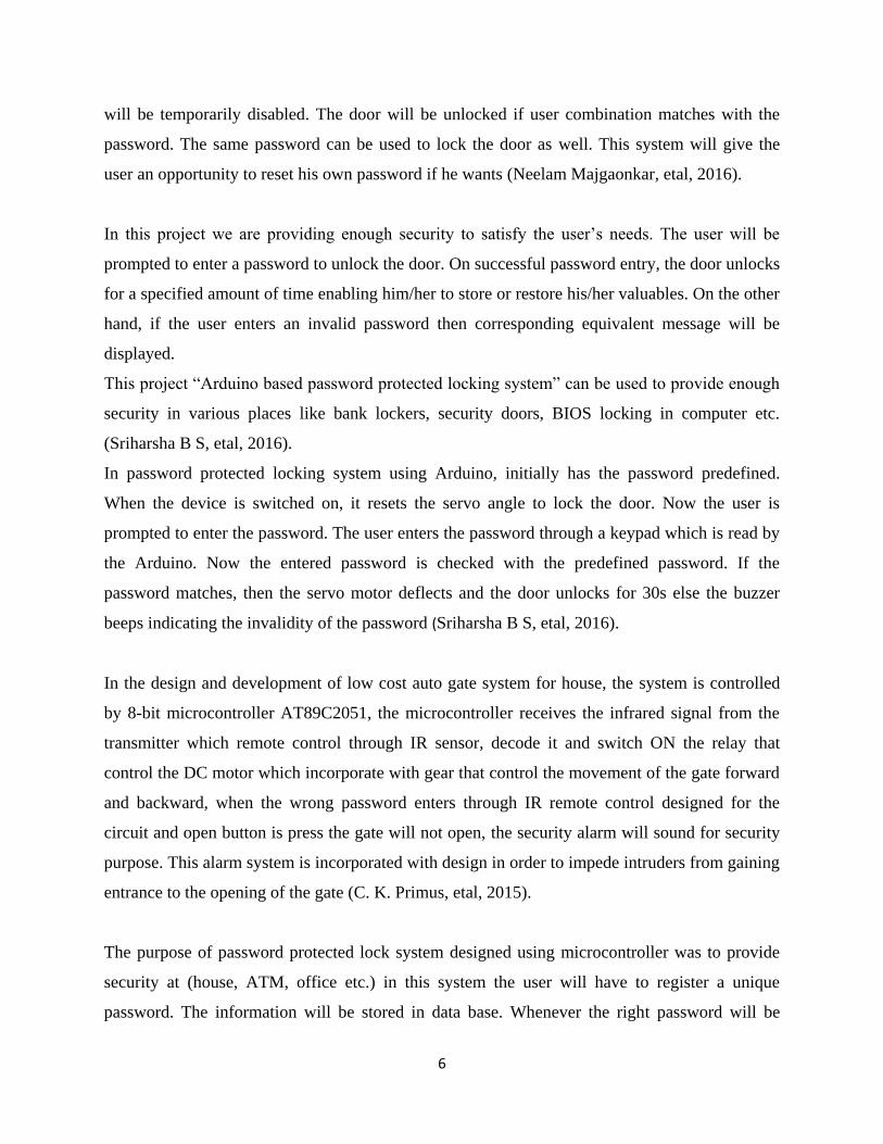
will be temporarily disabled. The door will be unlocked if user combination matches with the
password. The same password can be used to lock the door as well. This system will give the
user an opportunity to reset his own password if he wants (Neelam Majgaonkar, etal, 2016).
In this project we are providing enough security to satisfy the user’s needs. The user will be
prompted to enter a password to unlock the door. On successful password entry, the door unlocks
for a specified amount of time enabling him/her to store or restore his/her valuables. On the other
hand, if the user enters an invalid password then corresponding equivalent message will be
displayed.
This project “Arduino based password protected locking system” can be used to provide enough
security in various places like bank lockers, security doors, BIOS locking in computer etc.
(Sriharsha B S, etal, 2016).
In password protected locking system using Arduino, initially has the password predefined.
When the device is switched on, it resets the servo angle to lock the door. Now the user is
prompted to enter the password. The user enters the password through a keypad which is read by
the Arduino. Now the entered password is checked with the predefined password. If the
password matches, then the servo motor deflects and the door unlocks for 30s else the buzzer
beeps indicating the invalidity of the password (Sriharsha B S, etal, 2016).
In the design and development of low cost auto gate system for house, the system is controlled
by 8-bit microcontroller AT89C2051, the microcontroller receives the infrared signal from the
transmitter which remote control through IR sensor, decode it and switch ON the relay that
control the DC motor which incorporate with gear that control the movement of the gate forward
and backward, when the wrong password enters through IR remote control designed for the
circuit and open button is press the gate will not open, the security alarm will sound for security
purpose. This alarm system is incorporated with design in order to impede intruders from gaining
entrance to the opening of the gate (C. K. Primus, etal, 2015).
The purpose of password protected lock system designed using microcontroller was to provide
security at (house, ATM, office etc.) in this system the user will have to register a unique
password. The information will be stored in data base. Whenever the right password will be

7
received, the controller will accordingly give instruction to dc motor. DC motor will perform the
action on door unlocking. We want to utilize the electronic technology to build an integrated and
fully customized home security system at a reasonable cost, (Aarfin Ashraf, etal, 2016).
2.1.2 Solar Charging System
According to this project; experimental design and construction of an enhanced solar battery
charger,the Solar Battery Charger circuit is designed, built and tested. It acts as a control circuit
to monitor and regulate the process of charging several batteries ranging from 4 volts to 12 volts,
using a photovoltaic (PV) solar panel as the input source for the battery charging process. The
circuit is economical and can be easily constructed from discrete electronic components. The
circuit operation is based on matching the solar panel terminal load voltage to the input terminal
of the charging circuit and the appropriate number of battery cell units to be charged to the
output circuit through the use of a current limited voltage regulator, allowing fast charging while
limiting heat build-up and gassing and a rotary switch for easy selection of the appropriate
voltage depending on the solar light intensity, (Faithpraise Fina, etal, 2016).
In This project report on solar charger circuit using IC LM317, it makes a simple solar charger
which can be used on the go. Solar panels don’t supply regulated voltage while batteries need so
for charging. He used an external adjustable voltage regulator to have the desired constant
voltage. A zener diode switches on to ensure charging is cut off at the saturation point (Neha
Kondekar, 2015).
Solar Power Management is the project in which the controller automatically checks the status
and switches the battery having highest voltage to the load and the battery having lowest voltage
to the solar panel for charging. In this project it also displays the voltage status of four batteries
and also the voltage status of solar panel on Liquid Crystal Display (LCD). LCD also displays
the number position of the battery which is connected to the load and solar panel. In this project
an attempt is made to use a PIC controller which is an advance version of microcontroller with
the help of this a program is made for the appropriate switching of the battery in desired
condition. Thus by this dissertation we try to do the efficient management of solar power (Mr.
Ravi Patel, etal, 2014).

8
In an Intelligent lead acid battery management system for solar and off-peak energy storage, the
battery management system has the function of monitoring the system that measures the levels of
current and voltage in the solar panels battery bank. The battery management system also helps
the battery to work in a more efficient way. The battery performance deteriorates when
substantial differences occur in the voltage levels among individual cells. Therefore, identifying
the cells with high or low voltage levels becomes necessary to trigger the equalization process to
balance the cell voltage. The off-peak energy management system provides stored energy during
high electric power demand periods. The strategy here was to store energy during low load
periods and release energy during high demand periods. During the day time, the system stores
the energy generated from the solar panels in the battery bank for consumption in the evening. At
midnight, the system also charges the battery by importing cheap energy from public utility
power grid. This provides the base energy for the next day’s load, and it also helps the sulfating
process in the lead-acid battery, which occurs if the battery stays in a low state of charge for too
long (Ming-Chieh Chen, 2012).
This thesis deals with the design and implementation of a charge controller for multiple lead-acid
batteries from a solar system. The controller enables an independent connection and charge
control for each of more batteries with the possibility of different parameters. It is in contrast
with solutions with one connection for multiple batteries connected in parallel, where mixing
different types is not recommended. The controller offers very high scalability of energy storage
in solar system (Korenciak, P, 2011).
Design of a cost efficient solar charge controller for solar photovoltaic system has two stage
charge controller using Arduino Nano board. The Arduino MCU senses the solar panel and
battery voltages. It then decides how to charge the battery and control the load. The amount of
charging current is determined by difference between battery voltage and charge set point
voltages. The controller uses two stages charging algorithm. It also gives a fixed frequency
PWM signal according to the frequency algorithm, to the solar panel side p-MOSFET. The
controller gives high or low command to the load side p-MOSFET according to the dusk/dawn
and battery voltage (Abu Nayem Md. Hasib, 2016).

9
2.2 Major Components used
2.2.1 Components Used for Hybrid power supply
10 watts, 12-volt solar panel absorbs sunlight as a source of energy to generate
electricity. A photovoltaic solar panel module is a packaged, connected assembly of
typically 6x10 photovoltaic solar cells. Photovoltaic modules constitute of the
photovoltaic array of a photovoltaic system that generates and supplies solar electricity in
commercial and residential applications. The solar panel was used to charge the battery.
Figure 1: 10W 12V Solar Panel (jaycar.com)
Step-down Transformer; is an electric device that transfers electrical energy between
two or more circuits through electromagnetic induction. A varying current in one coil of
the transformer produces a varying magnetic field, which in turn induces a voltage in a
second coil. A step down transformer is used to step down from 220V to 12V gotten from
AC main power
Figure 2: Step-down Transformer (robohaat.com)
10
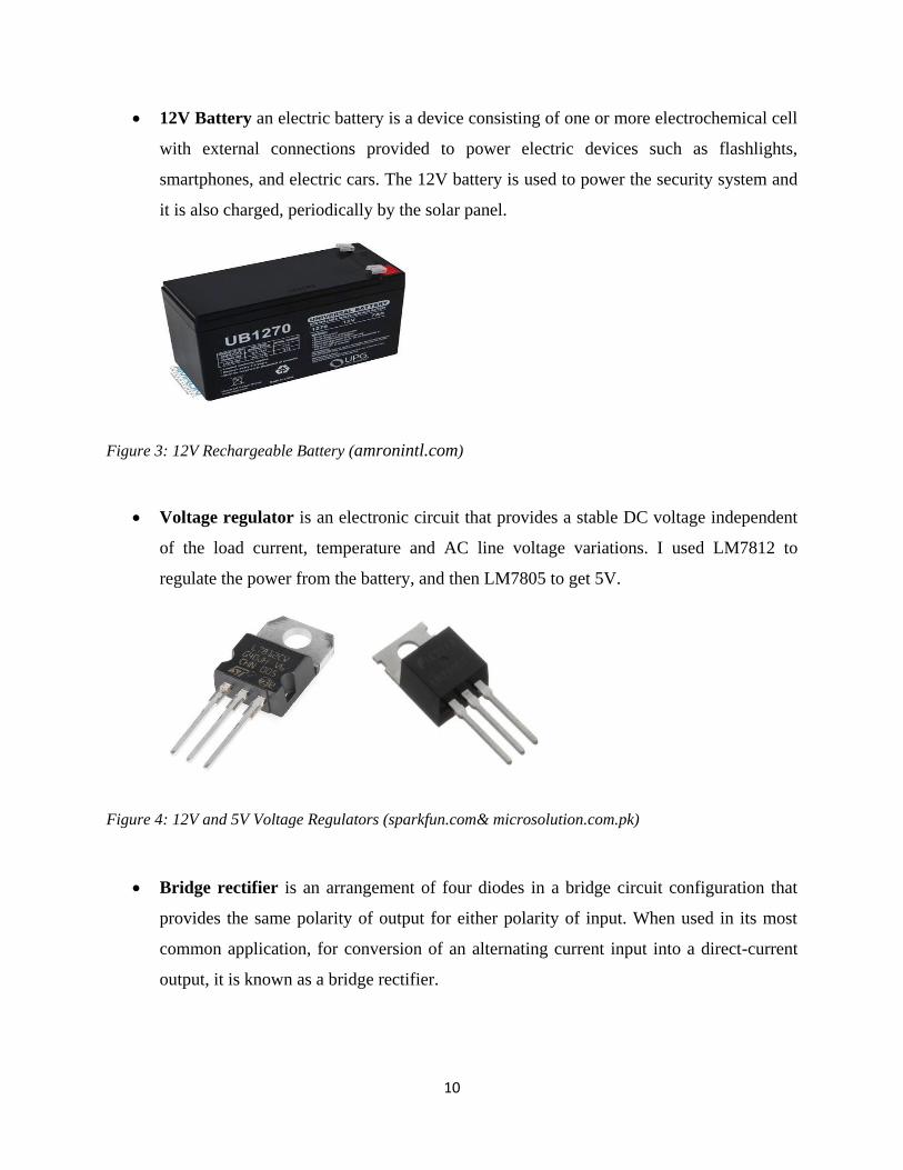
12V Battery an electric battery is a device consisting of one or more electrochemical cell
with external connections provided to power electric devices such as flashlights,
smartphones, and electric cars. The 12V battery is used to power the security system and
it is also charged, periodically by the solar panel.
Figure 3: 12V Rechargeable Battery (amronintl.com)
Voltage regulator is an electronic circuit that provides a stable DC voltage independent
of the load current, temperature and AC line voltage variations. I used LM7812 to
regulate the power from the battery, and then LM7805 to get 5V.
Figure 4: 12V and 5V Voltage Regulators (sparkfun.com& microsolution.com.pk)
Bridge rectifier is an arrangement of four diodes in a bridge circuit configuration that
provides the same polarity of output for either polarity of input. When used in its most
common application, for conversion of an alternating current input into a direct-current
output, it is known as a bridge rectifier.
11
Figure 5: Bridge Rectifier (hackaday.com)
2.2.2 Components Used Security Gate System
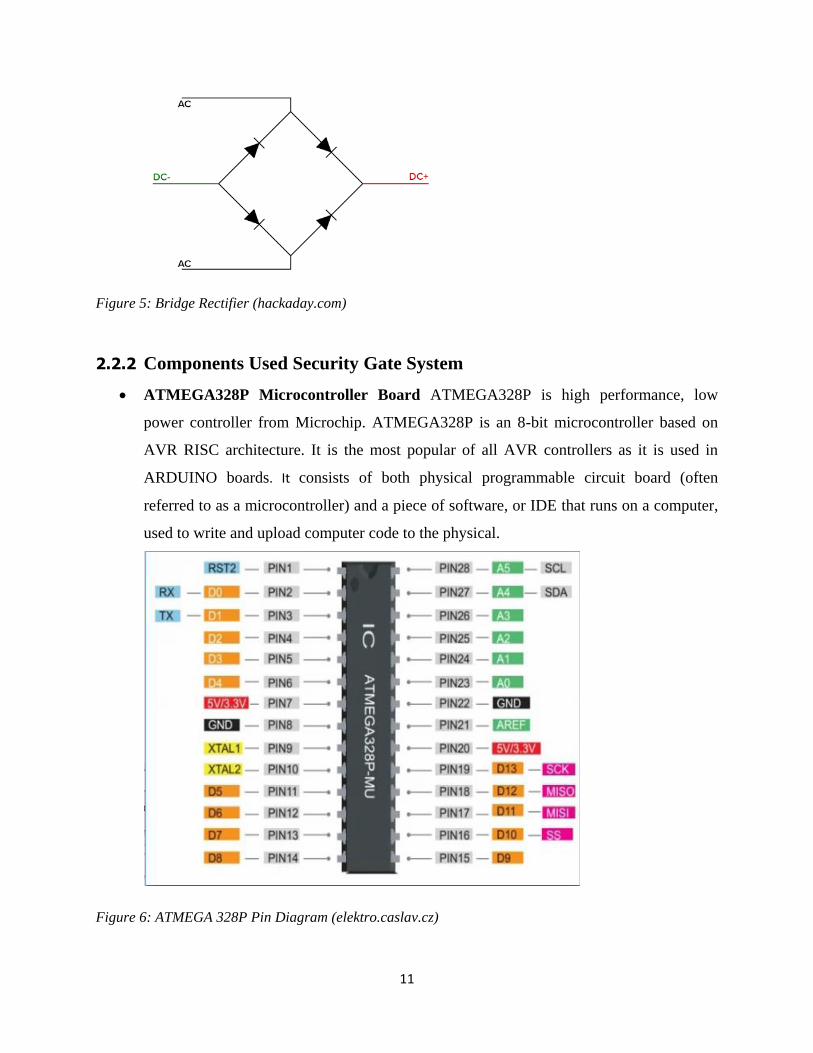
ATMEGA328P Microcontroller Board ATMEGA328P is high performance, low
power controller from Microchip. ATMEGA328P is an 8-bit microcontroller based on
AVR RISC architecture. It is the most popular of all AVR controllers as it is used in
ARDUINO boards. It consists of both physical programmable circuit board (often
referred to as a microcontroller) and a piece of software, or IDE that runs on a computer,
used to write and upload computer code to the physical.
Figure 6: ATMEGA 328P Pin Diagram (elektro.caslav.cz)

12
Figure 7:ATMEGA 328P MCU Chip(ktechnics.com)
Liquid Crystal Display (LCD) is a flat-panel display or other electronically modulated
optical device that uses the light-modulated properties of liquid crystals. The type of LCD
used isan alphanumeric with 2 lines of 16 characters.
Figure 8: 16x2 Liquid Crystal Display (m.alibaba.com)
Keypad is a set of buttons arranged in a block or “pad” which bear digits, symbols or
alphabetical letters. Pads mostly containing numbers are called numeric keypad. The
keypad that will be used will be 4x4 keypad and is used to input password to access the
facility from outside.

13
Figure 9: 4x4 Keypad Membrane (techtutorialsx.com)
Motor Driver is a little current amplifier; the function of motor driver is to take a low-
current control signal and then turn it into a higher-current signal that can drive a motor.
The motor driver is used to drive the Motor to open and close the gate.
Figure 10: L293D Motor Driver (huckster.io)

14
Push Button is a simple switch mechanism for controlling some aspect of a machine or a
process. The pushbutton is used to open the gate from inside the facility.
Figure 11: Pushbutton (Sparkfun.com)
Buzzer or a beeper is an audio signally device, which may be mechanical,
electromechanical, or piezoelectric. Typical uses of buzzers and beepers include alarm
devices, timers, and confirmation of user input such as a mouse click or keystroke.
Figure 12: Electronic Buzzer (potentiallabs.com)
2.3 Software Used
The softwares used are proteos 8.6 and Arduino 1.5.3 for designing the circuit diagram and
programming the MCU, respectively

15
CHAPTER THREE
METHODOLOGY
3.0 Introduction
This chapter explains how this password based security gate system powered by hybrid power
supply with solar charging system is designed and implemented. The first design is the power
supply; the second design is the password based security system.
I also did research through textbooks, past reports in the existing bird control techniques,
journals patents and browsing different websites on internet on the content relating to the project.
The data collected helped determine various techniques being used and how I should make my
design to be more efficient and effective.
3.1 Hybrid Power Supply with Solar Battery Charging System Design
240V AC
Supply
Step-Down
Transformer
Bridge
Rectifier Filter
Voltage
Regulator
12V
Switching
Diodes
Battery
Voltage
Regulator
5V
Circuit
Charge
Controller
Solar
Panel

16
Figure 13: Block Diagram of the Hybrid Power Supply
The above block diagram shows briefly how the hybrid power supply is designed. It starts with
A.C. main power, connecting it to a step-down transformer which is then rectified and filtered to
get 12V. Two diodes were connected between the battery and the main power, so that it will be
switching when one source is off. The solar panel is used to charge the battery.
Figure 14: Circuit Diagram
The hybrid power supply operates using both solar panel and main power to charge and provide
to the circuit respectively. The solar panel was placed outside; in the sun, photons of light strike
the electrons in the p-n junction and energize them, knocking them free of their atoms.
The first power supply is the main power supply, which is A.C. This A.C. is at 220V and it is
stepped down to 12V with the use of a step-down transformer. It is then rectified with the use of
four diodes by the method of bridge rectifying. A capacitor of 220µC smoothen or filter the
output and connecting it to a voltage regulator of 12V in between two capacitors of 10µC to get
exactly 12V. Two diodes are connected, which I called them “the switching diodes”. D1 is
connected from the 12V voltage regulator and D2 from the 12V battery, and completing the
circuit with a 5V voltage regulator in between two 10µC capacitors to get exactly 5V which the
circuit needs.

17
3.1.1 Working Principle of the Circuit
The working principle of this hybrid power supply is simple. When the main power is available,
the voltage supplied is at 12V, while the battery voltage is at 9V. As long as power is supplied by
the main power supply, the voltage that the circuit receives is 11.4V (there is a 0.6V drop across
D1). At the same time, D2’s anode is more negative in voltage than its cathode by 2.6V (11.4V
minus 9.0V), which means D2 blocks current flow from the battery, hence preventing battery
drain. Now, when there is blackout, causing the power supply to fail, D2’s anode becomes more
positive in voltage than its cathode, and it allows current to flow from the battery to the load. At
the same time, D1 acts to block current from flowing from the battery into the power supply.
(This is exactly how the inter-changing of the main power and the battery supposed to be. But
there is a setback, I couldn’t get a rechargeable battery of 9V, instead I get a rechargeable battery
of 12V. I will give my recommendations on how to use the 12V battery in this circuit properly in
the next chapter).
The solar panel charges the battery through by connecting it to the battery. The microcontroller
monitors the level of the battery when it is full, the relay trips cutting-off the voltage from the
solar panel, leaving it in float mode. The battery gives additional advantage of surplus power in
case the power outage of main power is prolonged. Hence, making the battery to have enough
energy for a long time. Here I use 12V battery as a solar panel when designing the circuit, as
there is no solar panel in the software.
18
3.2 Password Based Security Gate System Design
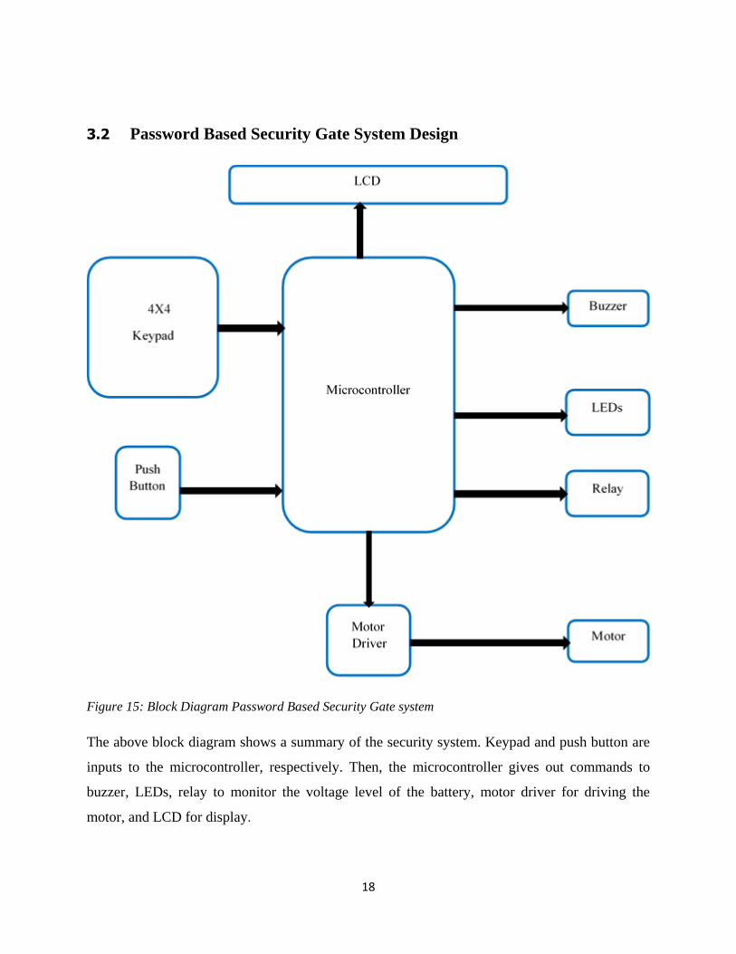
Figure 15: Block Diagram Password Based Security Gate system
The above block diagram shows a summary of the security system. Keypad and push button are
inputs to the microcontroller, respectively. Then, the microcontroller gives out commands to
buzzer, LEDs, relay to monitor the voltage level of the battery, motor driver for driving the
motor, and LCD for display.

19
Figure 16 Circuit Diagram
Atmega 328P microcontroller is used in this circuit. This microcontroller unit has 28 pins. The
LCD is connected to 6 pins of the MCU, from A0 to A5 respectively. A 10k potentiometer is
connected to the LCD to adjust the brightness for clear vision. D0 is used to monitor the voltage
of the battery while charging. Relay pin is D1 which trips when the battery is fully charged. D1
and D2 were connected to motor driver for forward and backward directions respectively. The
4x4 keypad has 8 pins, and connected to D4-D11 of the MCU, D12 goes with the pushbutton,
and LEDs were connected to D13.
3.2.1 Working Principle of the Circuit
The working principle of this system is based on Atmega 328P microcontroller, which is the
brain of the circuit. When the circuit is powered, the LCD serves as the display showing
instructions, and status of the password entered. The potentiometer is used to adjust the contrast
of the LCD for clear display. The Keypad serves as input for password and if it is correct the
Microcontroller will give command or send signal to motor driver and driving the motor to open
the gate. The gate will open for some seconds and will close automatically in which the motor
20
driver drives the motor to open and close the gate. At the same time LCD displays “password
Correct, Opening Gate”. If the password is not correct, LCD will display “wrong Password, Pls
Try Again” or “press # to change password”. When changing password, you will’ve to put your
current password first correctly, then put a new one.
In addition to this keypad to unlock the gate automatically, a push button is connected from
inside, let say the house. Which when pressed it opens the gate too without asking for password,
and also close the gate after some seconds. This is because, it will be inconvenient to go outside
again and open the gate using the keypad and want to come out with your car, which there will
not be enough time before you come out. So, the pushbutton makes things easier for you. A
green LED is used to indicate if the password is correct, and a red LED is used to indicate the
gate is closed.
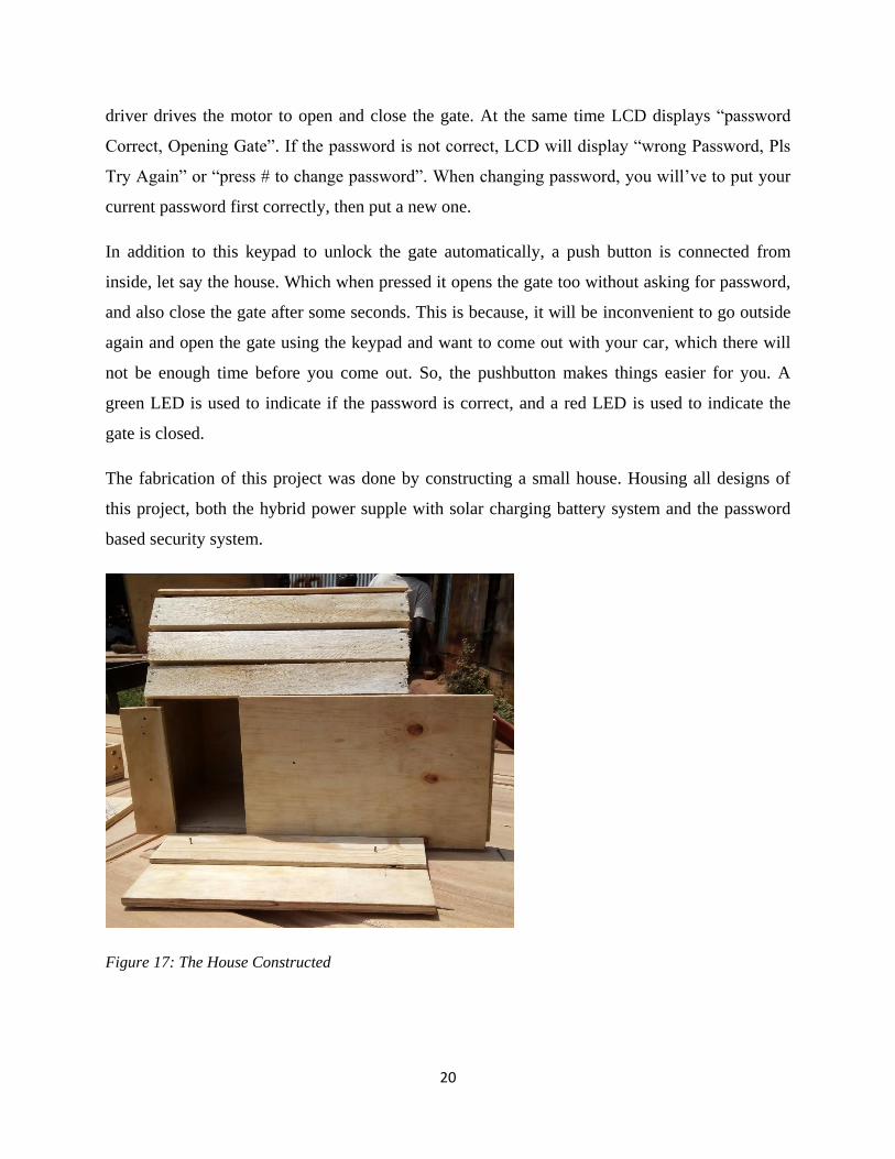
The fabrication of this project was done by constructing a small house. Housing all designs of
this project, both the hybrid power supple with solar charging battery system and the password
based security system.
Figure 17: The House Constructed

21
3.3 Flow Chart Diagram
Start
Is the
password
entered
correct
No
Refresh
Yes
Display
Wrong
Password, Try
Again
Gate Stays
Closed
Press # to
Change
Password
# Pressed,
enter current
password,
then new
password
Display
Done
Initialize
All
VariablesIs
Pushbutt
on
Pressed
NoGate Stays
Closed
Yes
Open
Gate for
2s, then
Close
Gate
Refresh
RefreshRead
Voltage or
Charge
Level of
Battery
Charge
Level up
to
Standard
Yes
No
Open
Gate for
2s, then
Close
Gate
Refresh
Relay On.
Charge
Battery
Relay Off
Figure 18: System Flow Chart

22
CHAPTER FOUR
SYSTEM ANALYSIS AND DESIGN
4.0 Introduction
This section explained how the constructed power supply, and the security gate system were
analyzed and achieved after the design.
4.1 Analysis of the System
The power supply circuit shown below was designed using a bridge rectifier for changing the
220V AC supply to DC, a voltage regulator that produced 12V after being rectified. 12V battery
for additional power when AC is off. Then a voltage regulator of 5V to power the security
system.
Figure 19: Hybrid Power Supply Circuit Design

23
The security gate system circuit was made up of an LCD for display together with a
potentiometer to adjust it brightness, a microcontroller unit that gives out commands, a relay for
cutting off the battery when it is fully charged by the solar panel, a motor driver that drives the
motor to open and close the gate, a 4x4 keypad used for putting password, and a push button that
also opens and closes the gate when pressed from inside the facility. The MCU was programmed
Arduino IDE software. This circuit was powered by the above power supply at the rate of 5V.
Figure 20: Circuit Design of the Security Gate System
24
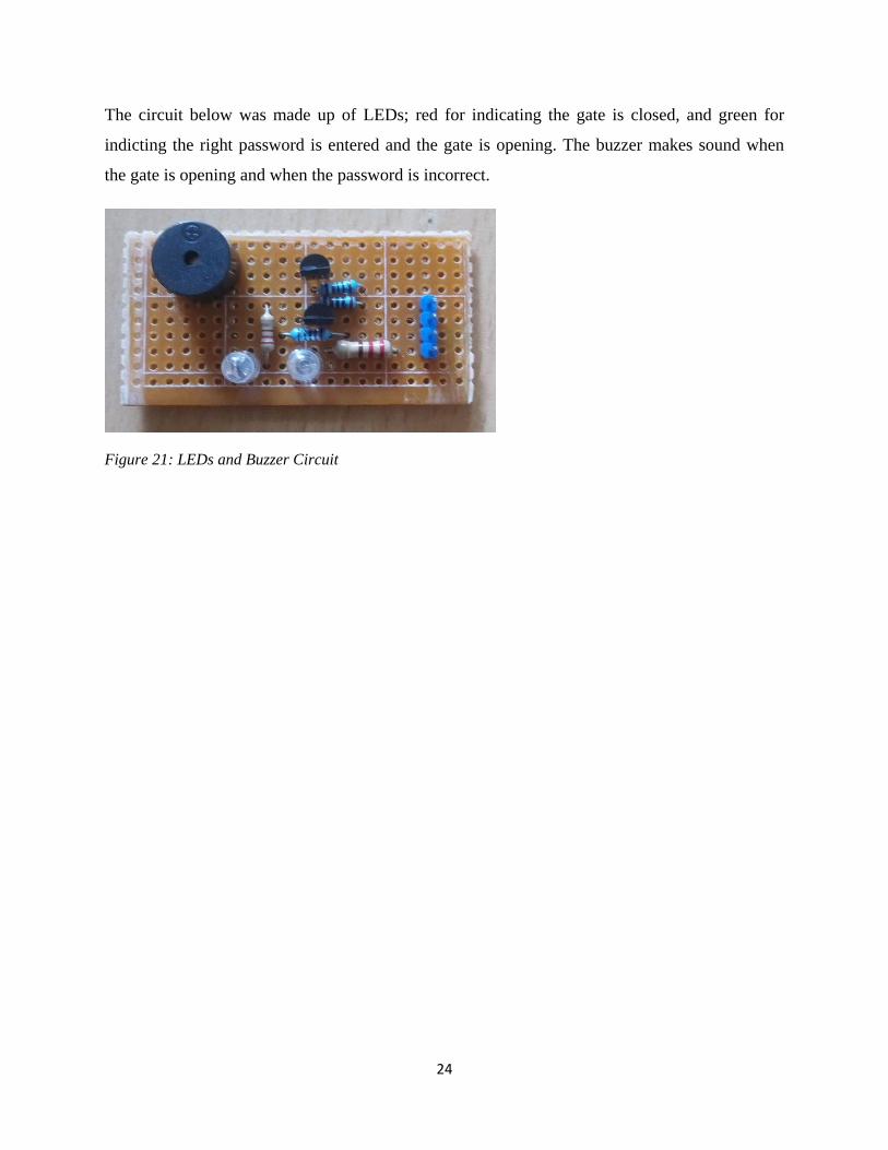
The circuit below was made up of LEDs; red for indicating the gate is closed, and green for
indicting the right password is entered and the gate is opening. The buzzer makes sound when
the gate is opening and when the password is incorrect.
Figure 21: LEDs and Buzzer Circuit

25
CHAPTER FIVE
CONCLUSIONS AND RECOMMENDATTIONS
5.0 Introduction
In this chapter, I briefly give my conclusion of this project which was a success, by achieving the
objectives stated. I also recommend some areas that can be improved like adding Bluetooth
device, or finger print module, even eye scanner. There is also further research that is needed on
this project which is the part of the battery, i.e. to create circuit that can be able to step down the
12V of the battery to 9V needed by the power supply circuit.
5.1 Conclusions
The main objective of this project was to provide an enhanced design and performance of power
supply to the security system which can be installed in homes, offices, companies, by allowing
only the authorized personnel to use the security system to access the restricted area. The
concern is for the lives and the physical property and also for the intellectual property. For this
reason, only the authorized person with a valid password will be allowed into the secured
premises.
Also, the specific objectives were to implement a hybrid power supply to the security gate
system comprising of main power and solar, to have a solar charging system with solar panel, to
implement a security gate system that operates automatically, and to provide a backup power
supply to the security system in case AC power is off.
The work was successful. It is evidence that the use MCU with the right circuitry can be used to
operate a security system, and the project was effective to give maximum security. So the
implementation rate is inexpensive and it is reasonable by a common person. Hence it can be
afforded to purchase such security gate system to keep your property safe without any worries.
5.2 Recommendations
As this system was built successfully, I would like to give my recommendations. First of all, is to
undertake more study about this project in order to get good understanding about it. Also, I
would like to whoever will improve on this project build a stand for the solar panel so that it can
face the sun comfortably, and also use or improve on the opening and closing mechanism of the

26
gate. I would also like to recommend to improve on this project by adding other features like,
using Bluetooth signal, remote signal, voice recognition, or eye scanner. It can also be a finger
print module. Hence when connecting this project, please do not connect AC supply together
with the battery. Currently, they have the same voltage which is 12V, but to get what the circuit
needs from the battery which is 9V, it would need a circuit to step it down to 9V from the 12V.
5.3 Further Research
As I have said earlier about the 12V rechargeable battery, the circuit needs 9V battery to be
connected together with the AC supply. So my recommendation of further research is to improve
on this circuit so that you can be able to step the 12V battery to 9V.
Also, when I was designing the security gate system, I run-out of pins and there is no pin for
buzzer. You can also look for other microcontrollers that has more pins, so that you can be able
to connect it.

27
REFERENCES
Aarfin Ashraf, Deepak Rasaily, Anita Dahal. (2016). Password Protected Lock System Designed
using Microcontroller IJETT-Vol.32 No.4.
Sriharsha B S, Zabiullah, Vishnu S B and Sanju V.(2016) Password Protected Locking System
Using Arduino, BIJIT – BVCAM’s International Journal of Information Technology.
Razykov, T.M., Ferekides, C.S., Morel, D., Stefanakos, E., Ullal, H.S., Upadhyaya H.M.
(2011)Solar photovoltaic electricity: Current status and future prospects, Solar Energy
Neha Kondekar, guided by Amit K. Gupta, Prof. Navakant Bhat, (2015)Project Report on Solar
Charger Circuit using IC LM317.
Adamu Murtala Zungeru and Paul Obafemi Abraham-Attah, A digital Automatic Sliding Door
with A Room Light Control System.
M. Hymavathi, V. Srilatha, C. Hemalatha, R. Swaroopa, Faisal Khaled Awadh al Saleh,
(2017)Design and implementation of Password Based Security Lock System IJIRCCE, vol. 5,
Issue 2.
Prajapati Dipali K., Raj Roshani D, Patel Komal C., Hilali Marhaba A. (2014). Automatic Gate
Opening System for Vehicles with RFID or Password IJEER, Vol. 2, Issue 2, April-June 2014.
Shihab Sultan Salim Al-Kalbani. Remotely Controlled Secure Main Gate System.
Sundus K. E., Al Mamare S. H. (2014) Using Digital Image Processing to Make an Intelligent
Gate. IJACSA, Vol. 5, No. 5.
Philip A. Adewuyi, Muniru O. Okelola, Adewale O. Jemilehin. (2013) PIC Based Model of an
Intelligent Gate Controller. IJEAT, Vol. 2, Issue 3.
Ming-Chieh Chen (2012) An Intelligent Lead Acid Battery Management System for Solar and
off-peak Energy Storage. University of Toledo.
Korenciak, P. (2011) Charge Controller for Solar Panel Based Charging of Lead-acid Batteries.
Brno University of Technology.

28
Abu Nayem Md. Hasib, Saila Siddique Aurin, Moury Ahmed Tushty, Mostafa Abdur Rahman,
(2016) Design of a cost Efficient Solar Charge Controller for Solar Photovoltaic System. Brac
University.
O. Shoew, O. T. Baruwa. (2006) Design of a Microprocessor Based Automatic Gate.The Pacific
Journal of Science and Technology. Vol 7, NO.1
Mr. Ravi Patel, Mr. Mehul Patel, Mr. Ashish Maheshwari, Mr. Vinesh Agarwal. (2014) Design
and Implementation of Battery Management System Using Solar Power. IJSRD. Vol. 2, Issue 01
Faithpraise, Fina, Bassey, Donatus, Charles, Mfon, Osahon, Okoro, Udoh, Monday, Chatwin,
Chris. (2016) Experimental Design and Construction of an Enhanced Solar Battery
ChargerIOSR-JEEEVolume 11, Issue 2 Ver. III. PP 11-16.
C. K. Primus, N.S. yahya, A. Arbai, N. A. N. Dandang. N. O.AFI. (2015).DESIGN AND
DEVELOPMENT OF LOW COST AUTO GATE SYSTEM FOR HOUSE, PART 4IDPC.
Christopher Perry. (2015).the Origin of Passwords, Password Security.
https://www.portalguard.com/blog/2015/09/14/the-origin-of-password-security.
Neelam Majgaonkar, Ruhina Hodekar, Priyanka Bandagale. (2016).Automatic Door Locking
System.IJEDR, Volume 4, Issue 1: page 495-499,
https://en.wikipedia.org/wiki/Automatic_door
https://en.wikipedia.org/wiki/Electric_gates
https://www.energymatters.com.au/panels-modules
https://en.m.wikipedia.org/wiki/Timeline_of_solar_cells
https://www.theorycircuit.com/battery-charger-circuit-diagram-auto-cut-off
https://m.alibaba.com/product/60450503199/customize-16x2-lcd-display-module-
for.html?subject=customize--16x2--lcd--display--module--
for&detailId=60450503199&redirect=1
https://ktechnics.com/shop/atmega328p-pu
http://elektro.caslav.cz/arduino-2/
https://techtutorialsx.com/2017/03/18/esp8266-interfacing-with-a-4x4-matrix-keypad/
https://www.sparkfun.com/products/97

29
https://potentiallabs.com/cart/buzzer
https://www.sparkfun.com/products/12766
http://www.microsolution.com.pk/product/voltage-regulator-ic-lm7805-pakistan/
https://hackaday.com/2014/12/03/scope-noob-bridge-rectifier/
https://www.hackster.io/hoffmanjon/controlling-a-motor-with-an-h-bridge-fd13b2
https://www.jaycar.com.au/solar-panel-charger-kit-12v-10w/p/ZM9051
https://www.amronintl.com/amron-12vdc-rechargeable-slide-terminal-gel-cell-battery-2890-
05.html
https://robohaat.com/home/215-12-0-12-step-down-transformer-1a-85043100.html

30
APPENDIX
APPENDIX A: GANTT CHART SHOWING PROJECT TIMELINE
10-Nov-17 30-Dec-17 18-Feb-18 9-Apr-18 29-May-18 18-Jul-18 6-Sep-18
Research on Projects and Selection of Topic
Topic Approval By Department
Deep Research on Project Title
Meeting With Supervisors
Correction of Project Report and Preparing for Proposal
Presenting Project Proposal To Panel
Gathering Project Requirement
System Design and Implementation
Testing System Design and Analysis
Report Writing, Approval and Preparing for Presentation
Presenting Designed Project and Final Report Submission
Gantt Chart Showing Timeline of the Project
Start Date Duration

31
APPENDIX B: BUDGET USED
Table 1 showing the Budget Estimated and Used
SERIAL NUMBER NAME UNIT PRICE
(Shs)
QUANTITY TOTAL
(Shs)
001 Microcontroller unit 250,000 1 250,000
002 Jumper wire 500 70 35,000
003 Buzzer 5,000 2 10,000
004 Motor Driver 40,000 1 40,000
005 Voltage Regulator 8,000 2 16,000
006 Keypad 10,000 1 10,000
007 Motor 70,000 1 70,000
008 Transistor 500 20 10,00
009 Resistor 500 30 15,000
010 Diodes 500 30 15,000
011 Transformer 25,000 2 50,000
012 PCB 10,000 5 50,000
013 Capacitors 500 30 15,000
014 Breadboard 15,000 2 30,000
015 LED 700 5 3,500
016 LCD 30,000 1 30,000
018 Potentiometer 5,000 2 10,000
019 Relay 8,000 2 16,000
020 Push Button 5,000 2 10,000
021 Solar Panel 120,000 1 120,000
022 12V Battery 80,000 1 80,000
023 Construction 250,000 250,000
024 Miscellaneous 300,000 300,000
TOTAL 1,435,500

32
APPENDIX C: SECURITY SYSTEM CODES
//https://electrosome.com/door-lock-arduino/
#include <Keypad.h>
#include<LiquidCrystal.h>
#include<EEPROM.h>
LiquidCrystal lcd(A1,A2,A3,A4,A5,0);
char password[4];
#define Relay_pin 4
#define Button_pin 2
char pass[4],pass1[4];
int i=0;
char customKey=0;
const byte ROWS = 4; //four rows
const byte COLS = 4; //four columns
char hexaKeys[ROWS][COLS] = {
{'1','2','3','A'},
{'4','5','6','B'},
{'7','8','9','C'},
{'*','0','#','D'}
};

33
//byte rowPins[ROWS] = {A0,A1,A2,A3}; //connect to the row pinouts of the keypad
//byte colPins[COLS] = {A4,A5,3,2}; //connect to the column pinouts of the keypad
byte rowPins[ROWS] = {3,5,6,7 }; //connect to the row pinouts of the keypad
byte colPins[COLS] = {8,11,10,9}; //connect to the column pinouts of the keypad//66 was 4
//initialize an instance of class NewKeypad
Keypad customKeypad = Keypad( makeKeymap(hexaKeys), rowPins, colPins, ROWS, COLS);
int Led = 1;
int Buzzer = 14;
int MotorForward = 12;
int MotorBackward = 13;
void setup()
{
lcd.begin(16,2);
pinMode(Led, OUTPUT); //Set Led Pin as an Ouput
pinMode(Buzzer, OUTPUT); //Set Buzzer Pin as an Output
pinMode(MotorForward, OUTPUT); //Set the Forward (Open) Direction of the Motor as
an Output
pinMode(MotorBackward, OUTPUT); //Set the Backward (Close) Direction of the Motor
as an Output

34
digitalWrite(MotorForward,LOW); //Forward Direction of the Motor is off
digitalWrite(Led,HIGH); //LED is on
digitalWrite(MotorBackward,LOW); //Backward Direction of the Motor is off
pinMode(Button_pin,INPUT_PULLUP);
digitalWrite(Button_pin,HIGH);
pinMode(Relay_pin,OUTPUT); //Set Relay Pin as an Output
digitalWrite(Relay_pin,LOW); //Relay Pin is off
lcd.print(" Electronic "); //First Line of the LCD Prints "Electronic"
lcd.setCursor(0,1);
lcd.print(" Keypad Lock "); //Second Line of the LCD Prints "keypad lock"
Serial.print(" Keypad Lock ");
delay(2000); //LCD Delays for 2 seconds
lcd.clear(); //LCD then Clear
lcd.print("Enter Ur Passkey:"); //LCD Prints "Enter Ur Passkey"
Serial.println("Enter Ur Passkey:");
lcd.setCursor(0,1);
for(int j=0;j<4;j++)

35
EEPROM.write(j, j+49);
for(int j=0;j<4;j++)
pass[j]=EEPROM.read(j);
}
void loop()
{
if(digitalRead(Button_pin)==LOW)
{
digitalWrite(Led, HIGH);
digitalWrite(MotorForward,HIGH);
digitalWrite(MotorBackward,LOW);
lcd.clear();
lcd.print("BUTTON PRESSED");
delay(2000);
digitalWrite(MotorForward,LOW);
digitalWrite(MotorBackward,LOW);
delay(2000);
digitalWrite(MotorForward,LOW);
36
digitalWrite(MotorBackward,HIGH);
delay(2000);
digitalWrite(MotorForward,LOW);
digitalWrite(MotorBackward,LOW);
lcd.clear();
lcd.print("Enter Ur Passkey:");
lcd.setCursor(0,1);
}
else
{
int N=analogRead(A0);
float voltage=N*5;
voltage/=1024;
//voltage=voltage*2.8;
if(voltage>=13.5)
{
digitalWrite(Relay_pin,LOW);

37
}
if(voltage<13.5)
{
digitalWrite(Relay_pin,HIGH);
}
digitalWrite(11, HIGH);
customKey = customKeypad.getKey();
if(customKey=='#')
change();
if (customKey)
{
password[i++]=customKey;
//lcd.print(customKey);
lcd.print("*");
Serial.print(customKey);
beep();
}
if(i==4)
{
delay(200);
38
for(int j=0;j<4;j++)
pass[j]=EEPROM.read(j);
if(!(strncmp(password, pass,4)))
{
digitalWrite(Led, HIGH);
digitalWrite(MotorForward,HIGH); //MotorForward Pin is Forward (open)
digitalWrite(MotorBackward,LOW); //MotorBackward Pin is Off
beep();
lcd.clear();
lcd.print("Passkey Accepted"); //LCD prints "Passkey accepted"
delay(2000); //then LCD Delays for 2 seconds
digitalWrite(MotorForward,LOW); //Forward Direction of the Motor is off
digitalWrite(MotorBackward,LOW); //Backward Direction of the Motor is off
lcd.setCursor(0,1);
lcd.print("#.Change Passkey"); //LCD ask you to Press # to Change your Passkey
Serial.println("#.Change Passkey");
delay(2000); //LCD delays for 2 seconds
digitalWrite(MotorForward,LOW); //MotorForward Pin is Off
digitalWrite(MotorBackward,HIGH); //MotorBackward Pin is Backward (close)
delay(2000); //Microcontroller Delays for 2 seconds

39
digitalWrite(MotorForward,LOW); //Forward Direction of the Motor is off
digitalWrite(MotorBackward,LOW); //Backward Direction of the Motor is off
lcd.clear();
lcd.print("Enter Passkey:");
Serial.println("Enter Passkey:");
lcd.setCursor(0,1);
i=0;
digitalWrite(Led, LOW); //LED Pin is Off
}
else //If not the above Loop, Else Loop then,
{
digitalWrite(MotorForward,LOW); //Forward Direction of the Motor is off
digitalWrite(MotorBackward,LOW); //Backward Direction of the Motor is off
digitalWrite(Buzzer, HIGH); //Buzzer Pin will be High
lcd.clear();
lcd.print("Access Denied...");
Serial.println("Access Denied..."); //then LCD Prints "Access Denied"
lcd.setCursor(0,1);
lcd.print("#.Change Passkey");
Serial.println("#.Change Passkey"); //LCD Prints "# to Change Ur Passkey"
delay(2000); //Microcontroller Delays for 2 seconds

40
lcd.clear(); //then LCD Clears the Screen
lcd.print("Enter Passkey:"); //LCD Prints "Enter Passkey"
Serial.println("Enter Passkey:");
lcd.setCursor(0,1);
i=0;
digitalWrite(Buzzer, LOW); //Buzzer pin is low
}
}
}
}
void change() //Void Loop for Changing Passkey
{
int j=0;
lcd.clear();
lcd.print("UR Current Passk"); //LCD Prints "Enter Ur Current Passkey"
Serial.println("UR Current Passk");
lcd.setCursor(0,1);
while(j<4)
{
char key=customKeypad.getKey();
if(key)

41
{
pass1[j++]=key;
lcd.print(key);
Serial.print(key);
beep();
}
key=0;
}
delay(500);
if((strncmp(pass1, pass, 4)))
{
lcd.clear();
lcd.print("Wrong Passkey...");
Serial.println("Wrong Passkey..."); //MCU tells you "Wrong Passkey"
lcd.setCursor(0,1);
lcd.print("Better Luck Again"); //MCU ask you to "Try Again Pls"
Serial.println("Better Luck Again");
delay(1000); //MCU delays for 1 second
digitalWrite(Led,LOW);
}

42
else //If not the above loop, then else loop
{
digitalWrite(Led,HIGH);
j=0;
lcd.clear();
lcd.print("Enter New Passk:"); //MCU ask you to Enter New passkey
Serial.println("Enter New Passk:");
lcd.setCursor(0,1);
while(j<4)
{
char key=customKeypad.getKey();
if(key)
{
pass[j]=key;
lcd.print(key);
Serial.print(key);
EEPROM.write(j,key);
j++;
beep();
}
}

43
lcd.print(" Done......");
Serial.println(" Done......"); //LCD then Prints Done....
delay(1000); //MCU delays for 1 second
}
lcd.clear(); //LCD clears the Screen
lcd.print("Enter Ur Passk:");
Serial.println("Enter Ur Passk:"); //MCU asks you to Enter ur Passkey
lcd.setCursor(0,1);
customKey=0;
}
void beep() //Void Loop for Buzzer
{
digitalWrite(Buzzer, HIGH); //Buzzer pin is On
delay(20); //Buzzer Pin delays for 20 Micro Milli seconds, then
digitalWrite(Buzzer, LOW); //Buzzer pin is Off
}

44
APPENDIX D: PHOTOS SHOWING THE OUTPUT OF THE PROJECT

45