PAS201010PDF EC51.indd - KIKUSUI
8
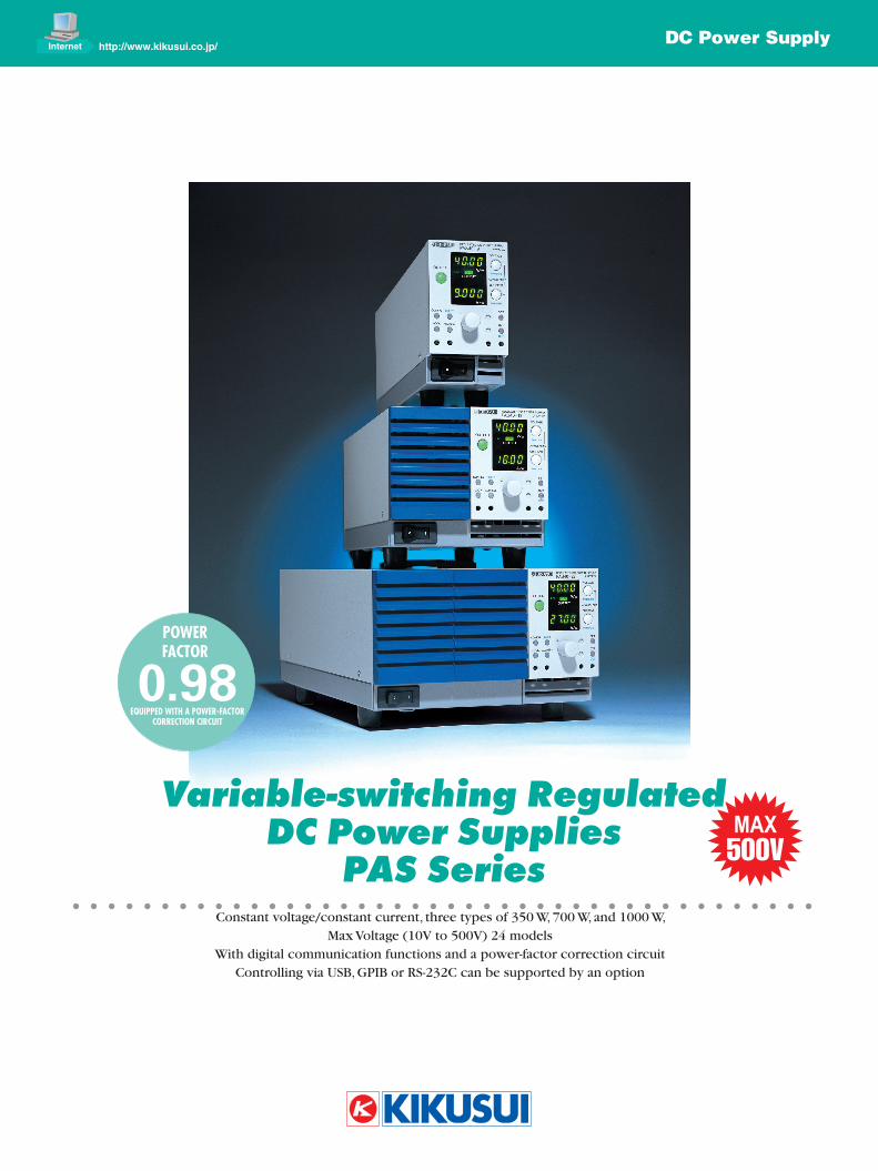
DC Power Supply Internet http://www.kikusui.co.jp/ Constant voltage/constant current, three types of 350 W, 700 W, and 1000 W, Max Voltage (10V to 500V) 24 models With digital communication functions and a power-factor correction circuit Controlling via USB, GPIB or RS-232C can be supported by an option Variable-switching Regulated DC Power Supplies PAS Series 0.98 EQUIPPED WITH A POWER-FACTOR CORRECTION CIRCUIT POWER FACTOR MAX 500V
-
Upload
khangminh22 -
Category
Documents
-
view
4 -
download
0
Transcript of PAS201010PDF EC51.indd - KIKUSUI
DC Power SupplyInternet http://www.kikusui.co.jp/
Constant voltage/constant current, three types of 350 W, 700 W, and 1000 W, Max Voltage (10V to 500V) 24 models
With digital communication functions and a power-factor correction circuitControlling via USB, GPIB or RS-232C can be supported by an option
Variable-switching RegulatedDC Power Supplies
PAS Series
0.98EquippEd with a powEr-Factor
corrEction circuit
powEr Factor
MAX500V
2
Analog read-back function Monitor output (voltage output)
Output voltage monitoring
Output current monitoring
Status signal output (contact signal output)
CV mode signal, CC mode signal, Output ON
signal, Alarm signal, POWER ON signal
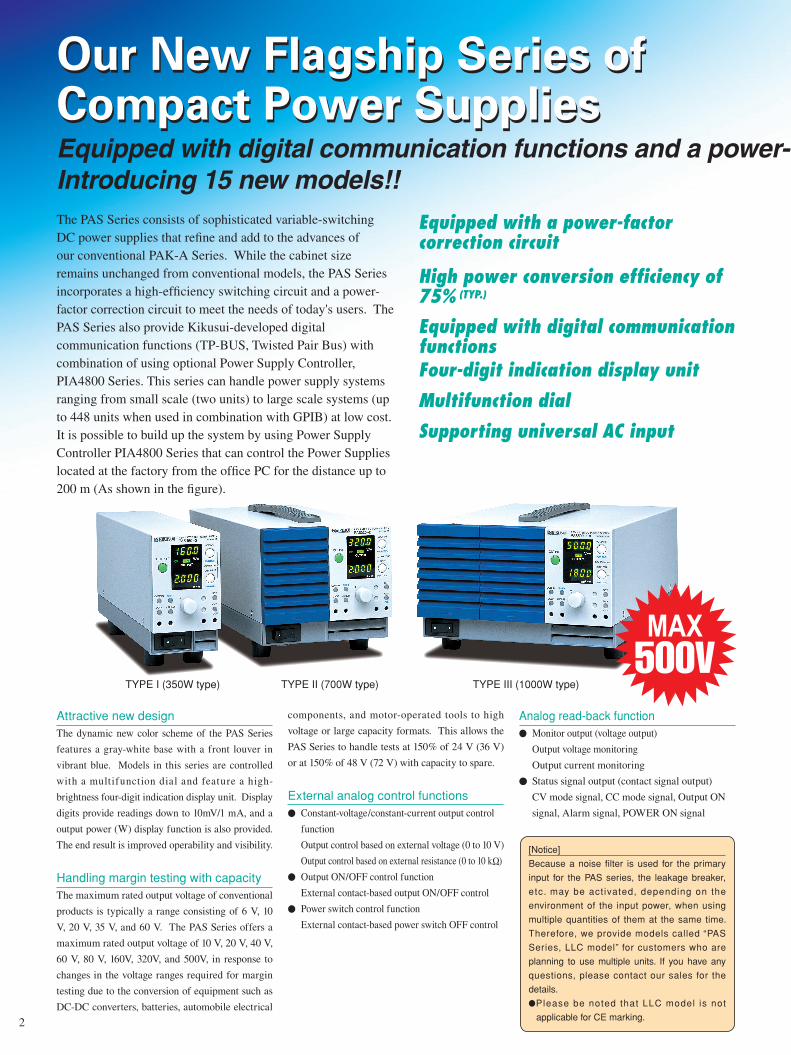
The PAS Series consists of sophisticated variable-switching DC power supplies that refine and add to the advances of our conventional PAK-A Series. While the cabinet size remains unchanged from conventional models, the PAS Series incorporates a high-efficiency switching circuit and a power-factor correction circuit to meet the needs of today's users. The PAS Series also provide Kikusui-developed digitalcommunication functions (TP-BUS, Twisted Pair Bus) with combination of using optional Power Supply Controller, PIA4800 Series. This series can handle power supply systems ranging from small scale (two units) to large scale systems (up to 448 units when used in combination with GPIB) at low cost. It is possible to build up the system by using Power Supply Controller PIA4800 Series that can control the Power Supplies located at the factory from the office PC for the distance up to 200 m (As shown in the figure).
Attractive new designThe dynamic new color scheme of the PAS Series
features a gray-white base with a front louver in
vibrant blue. Models in this series are controlled
with a multifunction dial and feature a high-
brightness four-digit indication display unit. Display
digits provide readings down to 10mV/1 mA, and a
output power (W) display function is also provided.
The end result is improved operability and visibility.
Handling margin testing with capacityThe maximum rated output voltage of conventional
products is typically a range consisting of 6 V, 10
V, 20 V, 35 V, and 60 V. The PAS Series offers a
maximum rated output voltage of 10 V, 20 V, 40 V,
60 V, 80 V, 160V, 320V, and 500V, in response to
changes in the voltage ranges required for margin
testing due to the conversion of equipment such as
DC-DC converters, batteries, automobile electrical
components, and motor-operated tools to high
voltage or large capacity formats. This allows the
PAS Series to handle tests at 150% of 24 V (36 V)
or at 150% of 48 V (72 V) with capacity to spare.
External analog control functions Constant-voltage/constant-current output control
function
Output control based on external voltage (0 to 10 V)
Output control based on external resistance (0 to 10 kΩ)
Output ON/OFF control function
External contact-based output ON/OFF control
Power switch control function
External contact-based power switch OFF control
TYPE I (350W type) TYPE III (1000W type) TYPE II (700W type)
Four-digit indication display unit
Multifunction dial
Supporting universal AC input
Equipped with a power-factor correction circuit
High power conversion efficiency of 75% (TYP.)
Equipped with digital communication functions
Equipped with digital communication functions and a power- factor correction circuit.Introducing 15 new models!!
MAX500V
[Notice]
Because a noise filter is used for the primary
input for the PAS series, the leakage breaker,
etc. may be act ivated, depending on the
environment of the input power, when using
multiple quantities of them at the same time.
Therefore, we provide models called “PAS
Series, LLC model” for customers who are
planning to use multiple units. If you have any
questions, please contact our sales for the
details.
Please be noted that LLC model is not
applicable for CE marking.
3
0 to 160 Voutput
Master
SlaveControl signal
0 to 210 Aoutput
Master
SlaveControl signal
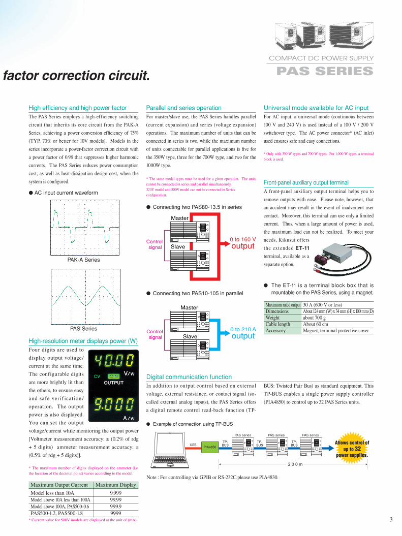
Parallel and series operationFor master/slave use, the PAS Series handles parallel
(current expansion) and series (voltage expansion)
operations. The maximum number of units that can be
connected in series is two, while the maximum number
of units connectable for parallel applications is five for
the 350W type, three for the 700W type, and two for the
1000W type.
* The same model types must be used for a given operation. The units cannot be connected in series and parallel simultaneously.320V model and 500V model can not be connected in Seriesconfiguration.
Digital communication functionIn addition to output control based on external
voltage, external resistance, or contact signal (so-
called external analog inputs), the PAS Series offers
a digital remote control read-back function (TP-
Universal mode available for AC inputFor AC input, a universal mode (continuous between
100 V and 240 V) is used instead of a 100 V / 200 V
switchover type. The AC power connector* (AC inlet)
used ensures safe and easy connections.
* Only with 350 W types and 700 W types. For 1,000 W types, a terminal block is used.
Connecting two PAS80-13.5 in series
Connecting two PAS10-105 in parallel
Example of connection using TP-BUS
High-resolution meter displays power (W)Four digits are used to
display output voltage/
current at the same time.
The configurable digits
are more brightly lit than
the others, to ensure easy
and safe ver if icat ion /
operation. The output
power is also displayed.
You can set the output
voltage/current while monitoring the output power
[Voltmeter measurement accuracy: ± (0.2% of rdg
+ 5 digits) ammeter measurement accuracy: ±
(0.5% of rdg + 5 digits)].
* The maximum number of digits displayed on the ammeter (i.e. the location of the decimal point) varies according to the model.
Maximum Output Current Maximum Display
Model less than 10A 9.999 Model above 10A less than 100A 99.99 Model above 100A, PAS500-0.6 999.9 PAS500-1.2, PAS500-1.8 9999* Current value for 500V models are displayed at the unit of (mA)
PAK-A Series
PAS Series
AC input current waveform
High efficiency and high power factorThe PAS Series employs a high-efficiency switching
circuit that inherits its core circuit from the PAK-A
Series, achieving a power conversion efficiency of 75%
(TYP. 70% or better for 10V models). Models in the
series incorporate a power-factor correction circuit with
a power factor of 0.98 that suppresses higher harmonic
currents. The PAS Series reduces power consumption
cost, as well as heat-dissipation design cost, when the
system is configured. Front-panel auxiliary output terminal A front-panel auxiliary output terminal helps you to
remove outputs with ease. Please note, however, that
an accident may result in the event of inadvertent user
contact. Moreover, this terminal can use only a limited
current. Thus, when a large amount of power is used,
the maximum load can not be realized. To meet your
needs, Kikusui offers
the extended ET-11 terminal, available as a
separate option.
Maximum rated output 30 A (600 V or less) Dimensions About 124 mm (W) x 34 mm (H) x 100 mm (D) Weight about 700 g Cable length About 60 cm Accessory Magnet, terminal protective cover
The ET-11 is a terminal block box that is mountable on the PAS Series, using a magnet.
BUS: Twisted Pair Bus) as standard equipment. This
TP-BUS enables a single power supply controller
(PIA4850) to control up to 32 PAS Series units.
COMPACT DC POWER SUPPLY PAS SERIESEquipped with digital communication functions and a power- factor correction circuit.
Introducing 15 new models!!
TP-BUS
2 0 0 m
Allows control of up to 32
power supplies.
PIA4850
PAS series PAS series PAS series
USBTP-BUS
TP-BUS
TP-BUS
Note : For controlling via GPIB or RS-232C,please use PIA4830.
4
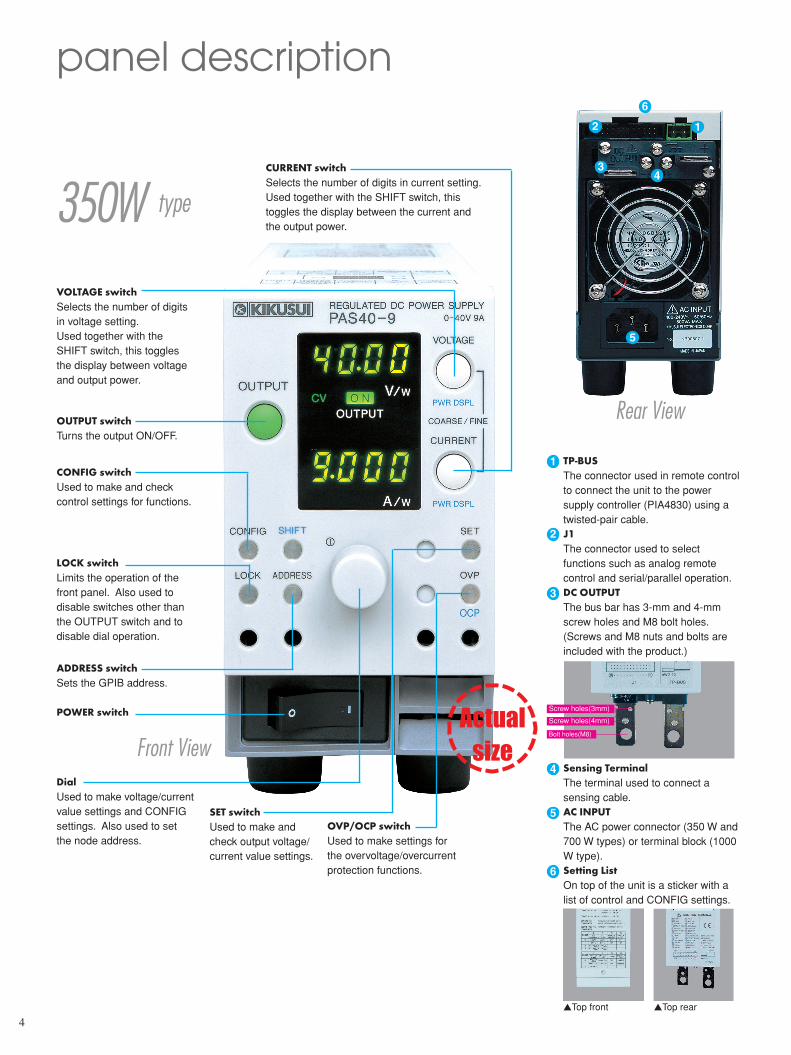
panel description
350W type
Front View
Rear View
Actual size
OUTPUT switchTurns the output ON/OFF.
12
34
5
6
CURRENT switchSelects the number of digits in current setting.Used together with the SHIFT switch, this toggles the display between the current and the output power.
VOLTAGE switchSelects the number of digits in voltage setting.Used together with the SHIFT switch, this toggles the display between voltage and output power.
CONFIG switchUsed to make and check control settings for functions.
LOCK switchLimits the operation of the front panel. Also used to disable switches other than the OUTPUT switch and to disable dial operation.
ADDRESS switchSets the GPIB address.
POWER switch
DialUsed to make voltage/current value settings and CONFIG settings. Also used to set the node address.
SET switchUsed to make and check output voltage/current value settings.
OVP/OCP switchUsed to make settings for the overvoltage/overcurrent protection functions.
TP-BUSThe connector used in remote control to connect the unit to the power supply controller (PIA4830) using a twisted-pair cable. J1The connector used to select functions such as analog remote control and serial/parallel operation.DC OUTPUTThe bus bar has 3-mm and 4-mm screw holes and M8 bolt holes. (Screws and M8 nuts and bolts are included with the product.)
Sensing TerminalThe terminal used to connect a sensing cable.AC INPUTThe AC power connector (350 W and 700 W types) or terminal block (1000 W type).Setting ListOn top of the unit is a sticker with a list of control and CONFIG settings.
1
2
3
4
5
6
Top front Top rear
Screw holes(3mm)
Screw holes(4mm)
Bolt holes(M8)
5
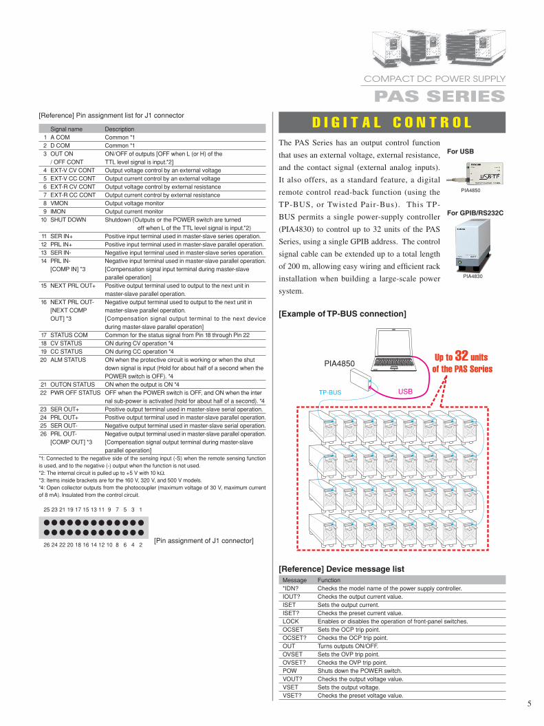
Signal name Description 1 A COM Common *1 2 D COM Common *1 3 OUT ON ON/OFF of outputs [OFF when L (or H) of the / OFF CONT TTL level signal is input.*2] 4 EXT-V CV CONT Output voltage control by an external voltage 5 EXT-V CC CONT Output current control by an external voltage 6 EXT-R CV CONT Output voltage control by external resistance 7 EXT-R CC CONT Output current control by external resistance 8 VMON Output voltage monitor 9 IMON Output current monitor 10 SHUT DOWN Shutdown (Outputs or the POWER switch are turned off when L of the TTL level signal is input.*2) 11 SER IN+ Positive input terminal used in master-slave series operation. 12 PRL IN+ Positive input terminal used in master-slave parallel operation. 13 SER IN- Negative input terminal used in master-slave series operation. 14 PRL IN- Negative input terminal used in master-slave parallel operation. [COMP IN] *3 [Compensation signal input terminal during master-slave parallel operation] 15 NEXT PRL OUT+ Positive output terminal used to output to the next unit in master-slave parallel operation. 16 NEXT PRL OUT- Negative output terminal used to output to the next unit in [NEXT COMP master-slave parallel operation. OUT] *3 [Compensation signal output terminal to the next device during master-slave parallel operation] 17 STATUS COM Common for the status signal from Pin 18 through Pin 22 18 CV STATUS ON during CV operation *4 19 CC STATUS ON during CC operation *4 20 ALM STATUS ON when the protective circuit is working or when the shut down signal is input (Hold for about half of a second when the POWER switch is OFF). *4 21 OUTON STATUS ON when the output is ON *4 22 PWR OFF STATUS OFF when the POWER switch is OFF, and ON when the inter nal sub-power is activated (hold for about half of a second). *4 23 SER OUT+ Positive output terminal used in master-slave serial operation. 24 PRL OUT+ Positive output terminal used in master-slave parallel operation. 25 SER OUT- Negative output terminal used in master-slave serial operation. 26 PRL OUT- Negative output terminal used in master-slave parallel operation. [COMP OUT] *3 [Compensation signal output terminal during master-slave parallel operation]*1: Connected to the negative side of the sensing input (-S) when the remote sensing function is used, and to the negative (-) output when the function is not used.*2: The internal circuit is pulled up to +5 V with 10 kΩ. *3: Items inside brackets are for the 160 V, 320 V, and 500 V models.*4: Open collector outputs from the photocoupler (maximum voltage of 30 V, maximum current of 8 mA). Insulated from the control circuit.
25 23 21 19 17 15 13 11 9 7 5 3 1
26 24 22 20 18 16 14 12 10 8 6 4 2
[Reference] Pin assignment list for J1 connector
[Pin assignment of J1 connector]
D I G I T A L C O N T R O L
USB
PIA4850
TP-BUS
The PAS Series has an output control function
that uses an external voltage, external resistance,
and the contact signal (external analog inputs).
It also offers, as a standard feature, a digital
remote control read-back function (using the
TP-BUS, or Twisted Pair-Bus). This TP-
BUS permits a single power-supply controller
(PIA4830) to control up to 32 units of the PAS
Series, using a single GPIB address. The control
signal cable can be extended up to a total length
of 200 m, allowing easy wiring and efficient rack
installation when building a large-scale power
system.
[Example of TP-BUS connection]
[Reference] Device message list Message Function *IDN? Checks the model name of the power supply controller. IOUT? Checks the output current value. ISET Sets the output current. ISET? Checks the preset current value. LOCK Enables or disables the operation of front-panel switches. OCSET Sets the OCP trip point. OCSET? Checks the OCP trip point. OUT Turns outputs ON/OFF. OVSET Sets the OVP trip point. OVSET? Checks the OVP trip point. POW Shuts down the POWER switch. VOUT? Checks the output voltage value. VSET Sets the output voltage. VSET? Checks the preset voltage value.
COMPACT DC POWER SUPPLY PAS SERIES
PIA4830
PIA4850
For USB
For GPIB/RS232C
New
6
applications
J1External voltage 0 to about 10 V
Dual-core shielded cable (connected to the negative output terminal) or twisted pair cable
Output 0 to maximum rated output
J1External resistance0 kΩ to about 10 kΩ
Dual-core shielded cable (connected to the negative output terminal) or twisted pair cable
Output 0 to maximum rated output
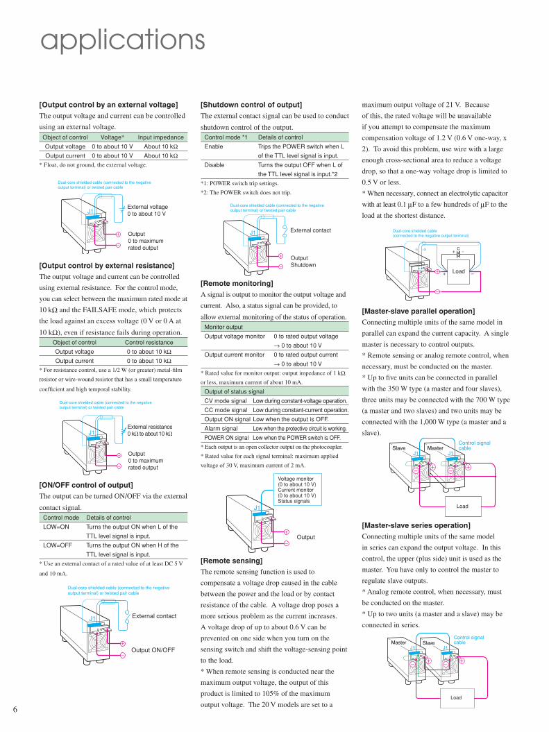
[Output control by an external voltage]The output voltage and current can be controlled
using an external voltage. Object of control Voltage* Input impedance
Output voltage 0 to about 10 V About 10 kΩ Output current 0 to about 10 V About 10 kΩ* Float, do not ground, the external voltage.
[Output control by external resistance]The output voltage and current can be controlled
using external resistance. For the control mode,
you can select between the maximum rated mode at
10 kΩ and the FAILSAFE mode, which protects
the load against an excess voltage (0 V or 0 A at
10 kΩ), even if resistance fails during operation. Object of control Control resistance
Output voltage 0 to about 10 kΩ Output current 0 to about 10 kΩ* For resistance control, use a 1/2 W (or greater) metal-film
resistor or wire-wound resistor that has a small temperature
coefficient and high temporal stability.
[ON/OFF control of output]The output can be turned ON/OFF via the external
contact signal. Control mode Details of control
LOW=ON Turns the output ON when L of the
TTL level signal is input.
LOW=OFF Turns the output ON when H of the
TTL level signal is input.
* Use an external contact of a rated value of at least DC 5 V
and 10 mA.
J1
Dual-core shielded cable (connected to the negative output terminal) or twisted pair cable
External contact
Output ON/OFF
[Shutdown control of output]The external contact signal can be used to conduct
shutdown control of the output. Control mode *1 Details of control
Enable Trips the POWER switch when L
of the TTL level signal is input.
Disable Turns the output OFF when L of
the TTL level signal is input.*2
*1: POWER switch trip settings.
*2: The POWER switch does not trip.
J1
Dual-core shielded cable (connected to the negative output terminal) or twisted pair cable
External contact
Output Shutdown
Output
J1
Voltage monitor (0 to about 10 V)Current monitor (0 to about 10 V)Status signals
-S +S C
Dual-core shielded cable (connected to the negative output terminal)
Load
J1J1SlaveMaster
Load
Control signal cable
MasterJ1J1
Slave
Load
Control signal cable
[Remote monitoring]A signal is output to monitor the output voltage and
current. Also, a status signal can be provided, to
allow external monitoring of the status of operation. Monitor output
Output voltage monitor 0 to rated output voltage
→ 0 to about 10 V
Output current monitor 0 to rated output current
→ 0 to about 10 V
* Rated value for monitor output: output impedance of 1 kΩ
or less, maximum current of about 10 mA.
Output of status signal
CV mode signal Low during constant-voltage operation.
CC mode signal Low during constant-current operation.
Output ON signal Low when the output is OFF.
Alarm signal Low when the protective circuit is working.
POWER ON signal Low when the POWER switch is OFF.
* Each output is an open collector output on the photocoupler.
* Rated value for each signal terminal: maximum applied
voltage of 30 V, maximum current of 2 mA.
[Remote sensing]The remote sensing function is used to
compensate a voltage drop caused in the cable
between the power and the load or by contact
resistance of the cable. A voltage drop poses a
more serious problem as the current increases.
A voltage drop of up to about 0.6 V can be
prevented on one side when you turn on the
sensing switch and shift the voltage-sensing point
to the load.
* When remote sensing is conducted near the
maximum output voltage, the output of this
product is limited to 105% of the maximum
output voltage. The 20 V models are set to a
maximum output voltage of 21 V. Because
of this, the rated voltage will be unavailable
if you attempt to compensate the maximum
compensation voltage of 1.2 V (0.6 V one-way, x
2). To avoid this problem, use wire with a large
enough cross-sectional area to reduce a voltage
drop, so that a one-way voltage drop is limited to
0.5 V or less.
* When necessary, connect an electrolytic capacitor
with at least 0.1 µF to a few hundreds of µF to the
load at the shortest distance.
[Master-slave parallel operation]Connecting multiple units of the same model in
parallel can expand the current capacity. A single
master is necessary to control outputs.
* Remote sensing or analog remote control, when
necessary, must be conducted on the master.
* Up to five units can be connected in parallel
with the 350 W type (a master and four slaves),
three units may be connected with the 700 W type
(a master and two slaves) and two units may be
connected with the 1,000 W type (a master and a
slave).
[Master-slave series operation]Connecting multiple units of the same model
in series can expand the output voltage. In this
control, the upper (plus side) unit is used as the
master. You have only to control the master to
regulate slave outputs.
* Analog remote control, when necessary, must
be conducted on the master.
* Up to two units (a master and a slave) may be
connected in series.
7
Input voltage .........................100 to 240 V AC (85 to 250 V AC), single phase, 47 to 63 Hz
Power factor .........................0.98 typical valueEfficiency .............................75% or better (70% or better for 10V models) *TYPTemperature coefficient ........Constant-voltage output: 100 ppm/°C typ. Constant-current output: 200 ppm/°C typ.Indication meters Voltmeter (23±5°C) ...........Maximum display: 99.99, Four-digit green LED display
(Model below 80V) 999.9 (Model above 160V) Measurement accuracy:± (0.2% of rdg* + 5digits)Ammeter (23±5°C) ...............Maximum display: Four-digit green LED display Maximum Output Current Maximum Display Model less than 10A 9.999 Model above 10A less than 100A 99.99 Model above 100A, PAS500-0.6 999.9 PAS500-1.2, PAS500-1.8 9999 * Current value for 500V models are displayed at the unit of (mA)
Measurement accuracy:± (0.5% of rdg* + 5digits) *:rdg = reading Protective circuits Overvoltage protection ......Voltage setting range: 10% to 110% of rated output
voltage Overcurrent protection ......Current setting range: 10% to 110% of rated output
current Overheat protection ...........Activated by elevated internal temperatures
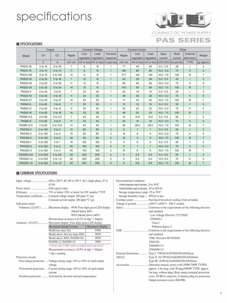
SpEciFicationS Output Constant Voltage Constant Current Other
CV CC Ripple
Line Load Transient Ripple
Line Load Input Rush External Weight
Model
regulation regulation response regulation regulation current current dimensions
V A mV rms mV or less mV or less ms (typical value) mA rms mA or less mA or less AC(100V/200V)A Ap to peak (Max) TYPE kg (approx.)
PAS10-35 0 to 10 0 to 35 7 8 10 1 77 45 45 5.0 / 2.5 35 I 3
PAS10-70 0 to 10 0 to 70 11 8 10 1 185 80 80 10.0 / 5.0 70 II 5
PAS10-105 0 to 10 0 to 105 14 8 10 1 277 120 120 15.0 / 7.5 105 III 7
PAS20-18 0 to 20 0 to 18 7 13 15 1 40 28 28 5.0 / 2.5 35 I 3
PAS20-36 0 to 20 0 to 36 11 13 15 1 95 46 46 10.0 / 5.0 70 II 5
PAS20-54 0 to 20 0 to 54 14 13 15 1 143 69 69 15.0 / 7.5 105 III 7
PAS40-9 0 to 40 0 to 9 7 23 25 1 20 19 19 5.0 / 2.5 35 I 3
PAS40-18 0 to 40 0 to 18 11 23 25 1 48 28 28 10.0 / 5.0 70 II 5
PAS40-27 0 to 40 0 to 27 14 23 25 1 71 42 42 15.0 / 7.5 105 III 7
PAS60-6 0 to 60 0 to 6 7 33 35 1 13 16 16 5.0 / 2.5 35 I 3
PAS60-12 0 to 60 0 to 12 11 33 35 1 32 22 22 10.0 / 5.0 70 II 5
PAS60-18 0 to 60 0 to 18 14 33 35 1 48 33 33 15.0 / 7.5 105 III 7
PAS80-4.5 0 to 80 0 to 4.5 7 43 45 1 10 14.5 14.5 5.0 / 2.5 35 I 3
PAS80-9 0 to 80 0 to 9 11 43 45 1 24 19 19 10.0 / 5.0 70 II 5
PAS80-13.5 0 to 80 0 to 13.5 14 43 45 1 36 28.5 28.5 15.0 / 7.5 105 III 7
PAS160-2 0 to 160 0 to 2 10 83 85 2 5 7 7 5.0 / 2.5 35 I 3
PAS160-4 0 to 160 0 to 4 15 83 85 2 10 9 9 10.0 / 5.0 70 II 5
PAS160-6 0 to 160 0 to 6 20 83 85 2 15 11 11 15.0 / 7.5 105 III 7
PAS320-1 0 to 320 0 to 1 15 163 165 2 5 6 6 5.0 / 2.5 35 I 3
PAS320-2 0 to 320 0 to 2 20 163 165 2 5 7 7 10.0 / 5.0 70 II 5
PAS320-3 0 to 320 0 to 3 30 163 165 2 10 8 8 15.0 / 7.5 105 III 7
PAS500-0.6 0 to 500 0 to 0.6 20 253 255 2 5 5.6 5.6 5.0 / 2.5 35 I 3
PAS500-1.2 0 to 500 0 to 1.2 30 253 255 2 5 6.2 6.2 10.0 /5.0 70 II 5
PAS500-1.8 0 to 500 0 to 1.8 40 253 255 2 5 6.8 6.8 15.0 / 7.5 105 III 7
coMMon SpEciFicationS
Environmental conditions Ambient temperature range for operation ..0 to 50°C Ambient humidity range for operation ..20 to 85%rh Storage temperature range -25 to 70°C Storage humidity range .....90%rh or less Cooling system .....................Fan-based forced-air cooling, front air-intakeVoltage to ground ..................±500 V (±600 V : 500 V model)Safety ....................................Conforms to the requirements of the following directive
and standard. Low Voltage Directive 73/23/EEC
EN61010-1 Class I Pollution degree 2
EMC ......................................Conforms to the requirements of the following directive and standard. EMC Directive 89/336/EEC
EN61326 EN61000-3-2 EN61000-3-3External dimensions .............Type I: 71W124(150)H350(420)Dmm(MAX) Type II: 142.5W124(160)H350(420)Dmm Type III: 214W124(160)H350(420)DmmAccessories ...........................Operation manual, power cord (350W/700W TYPES:
approx. 2.4m long, with 3P plug/1000W TYPE: approx. 3m long, without plug), Rear output terminal protection cover, TP-BUS connector, J1 dummy plug for protection, Output terminal screws (M4/M8)
specificationsCOMPACT DC POWER SUPPLY PAS SERIES
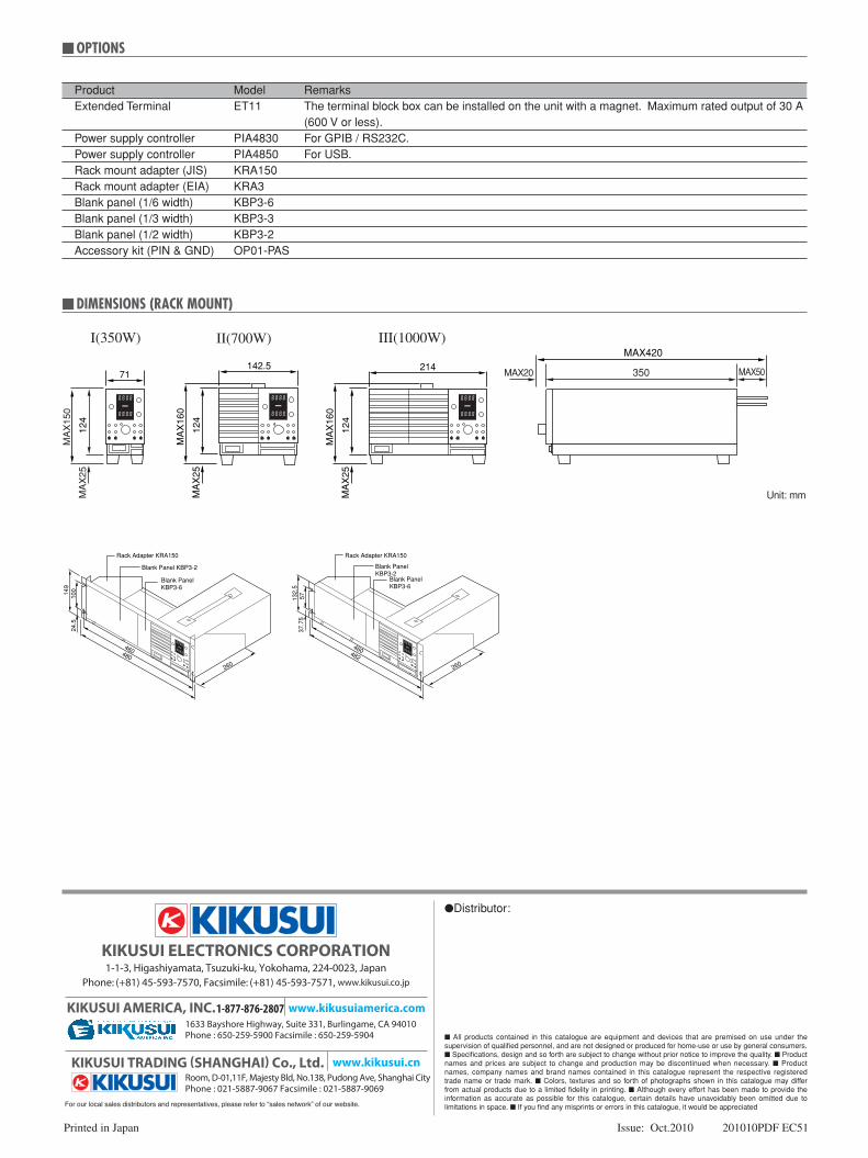
Product Model Remarks Extended Terminal ET11 The terminal block box can be installed on the unit with a magnet. Maximum rated output of 30 A (600 V or less). Power supply controller PIA4830 For GPIB / RS232C. Power supply controller PIA4850 For USB. Rack mount adapter (JIS) KRA150 Rack mount adapter (EIA) KRA3 Blank panel (1/6 width) KBP3-6 Blank panel (1/3 width) KBP3-3 Blank panel (1/2 width) KBP3-2 Accessory kit (PIN & GND) OP01-PAS
optionS
260
132.
5
460482
57
Rack Adapter KRA150
Blank PanelKBP3-2
Blank PanelKBP3-6
37.7
5
149
460480
100
Rack Adapter KRA150
Blank Panel KBP3-2
Blank PanelKBP3-6
24.5
260
diMEnSionS (racK Mount)
MAX20 MAX50350
MA
X15
0
MA
X25
71
124
142.5
MA
X16
0
MA
X25
124
MA
X16
0
MA
X25
124
214MAX420
I(350W) II(700W) III(1000W)
Unit: mm
Printed in Japan Issue: Oct.2010 201010PDF EC51
All products contained in this catalogue are equipment and devices that are premised on use under the supervision of qualified personnel, and are not designed or produced for home-use or use by general consumers.Specifications, design and so forth are subject to change without prior notice to improve the quality.Product names and prices are subject to change and production may be discontinued when necessary.Product names, company names and brand names contained in this catalogue represent the respective registered trade name or trade mark.Colors, textures and so forth of photographs shown in this catalogue may differ from actual products due to a limited fidelity in printing.Although every effort has been made to provide the information as accurate as possible for this catalogue, certain details have unavoidably been omitted due to limitations in space.If you find any misprints or errors in this catalogue, it would be appreciated
Distributor:
1633 Bayshore Highway, Suite 331, Burlingame, CA 94010Phone : 650-259-5900 Facsimile : 650-259-5904
www.kikusuiamerica.com1-877-876-2807
www.kikusui.cnRoom, D-01,11F, Majesty Bld, No.138, Pudong Ave, Shanghai City Phone : 021-5887-9067 Facsimile : 021-5887-9069