Part 2, Rule Requirements for Materials and Welding 2002
384
RULE REQUIREMENTS FOR MATERIALS AND WELDING 2002 PART 2 American Bureau of Shipping Incorporated by Act of Legislature of the State of New York 1862 Copyright 2001 American Bureau of Shipping ABS Plaza 16855 Northchase Drive Houston, TX 77060 USA
-
Upload
khangminh22 -
Category
Documents
-
view
0 -
download
0
Transcript of Part 2, Rule Requirements for Materials and Welding 2002
RULE REQUIREMENTS FOR
MATERIALS AND WELDING2002
PART 2
American Bureau of ShippingIncorporated by Act of Legislature ofthe State of New York 1862
Copyright 2001American Bureau of ShippingABS Plaza16855 Northchase DriveHouston, TX 77060 USA
ii ABS RULE REQUIREMENTS FOR MATERIALS AND WELDING . 2002
Rule Change Notice (2002)
The effective date of each technical change since 1993 is shown in parenthesis at the end of thesubsection/paragraph titles within the text of each Part. Unless a particular date and month are shown,the years in parentheses refer to the following effective dates:
(2000) and after 1 January 2000 (and subsequent years) (1996) 9 May 1996
(1999) 12 May 1999 (1995) 15 May 1995
(1998) 13 May 1998 (1994) 9 May 1994
(1997) 19 May 1997 (1993) 11 May 1993
Listing by Effective Dates of Changes from the 2001 Rules
EFFECTIVE DATE 1 January 2001(based on the contract date for construction)
Part/Para. No. Title/Subject Status/Remarks
2-1-1/15.1 Permissible Variations inDimensions – Scope
To clarify that mill scale is to be considered when theplate is produced for compliance with the specifiedunder tolerance
Section 2-4-4 Piping To align ABS requirements with IACS UR P2 regardingfabrication of piping and non-destructive examinations,and to outline the requirements for the heat treatment ofpiping. This Section is applicable only to piping forinstallation on vessels to be built in accordance with theRules for Building and Classing Steel Vessels.

ABS RULE REQUIREMENTS FOR MATERIALS AND WELDING . 2002 iii
P A R T
2
Foreword
For the 1996 edition, the “Rules for Building and Classing Steel Vessels – Part 2: Materials andWelding” was re-titled “Rule Requirements for Materials and Welding – Part 2.” The purpose of thisgeneric title was to emphasize the common applicability of the material and welding requirements in“Part 2” to ABS-classed vessels, other marine structures and their associated machinery, and therebymake “Part 2” more readily a common “Part” of the various ABS Rules and Guides, as appropriate.
Accordingly, the subject booklet, Rule Requirements for Materials and Welding – Part 2, is to beconsidered, for example, as being applicable and comprising a “Part” of the following ABS Rules andGuides:
- Rules for Building and Classing Steel Vessels.
- Rules for Building and Classing Steel Vessels Under 90 Meters (295 Feet) in Length
- Rules for Building and Classing Mobile Offshore Drilling Units
- Guide for Building and Classing High Speed Craft
For the 2002 edition, a new Section 4, “Piping” has been added to Part 2, Chapter 4, “Welding andFabrication”. This new Section is applicable only to piping for installation on vessels to be built inaccordance with the Rules for Building and Classing Steel Vessels.

ABS RULE REQUIREMENTS FOR MATERIALS AND WELDING . 2002 v
P A R T
2Rule Requirements for Materials and Welding
CONTENTSCHAPTER 1 Materials for Hull Construction................................ 1
Section 1 General Requirements....................................... 3
Section 2 Ordinary-strength Hull Structural Steel............ 15
Section 3 Higher-strength Hull Structural Steel ............... 29
Section 4 Low Temperature Materials............................. 39
Section 5 Hull Steel Castings .......................................... 41
Section 6 Hull Steel Forgings .......................................... 45
CHAPTER 2 Materials for Equipment ......................................... 49
Section 1 Anchors............................................................ 51
Section 2 Anchor Chain ................................................... 59
Section 3 Rolled Steel Bars for Chain ............................. 77
CHAPTER 3 Materials for Machinery, Boilers, PressureVessels, and Piping ................................................ 81
Section 1 General Requirements..................................... 87
Section 2 Steel Plates for Machinery, Boilers andPressure Vessels............................................. 95
Section 3 Seamless Forged-steel Drums ...................... 109
Section 4 Seamless-steel Pressure Vessels ................. 111
Section 5 Boiler and Superheater Tubes....................... 113
Section 6 Boiler Rivet and Staybolt Steel and Rivets .... 129
Section 7 Steel Machinery Forgings.............................. 131
Section 8 Hot-rolled Steel Bars for Machinery............... 157
Section 9 Steel Castings for Machinery, Boilers andPressure Vessels........................................... 159
Section 10 Ductile (Nodular) Iron Castings ..................... 163
Section 11 Gray-iron Castings......................................... 167
Section 12 Steel Piping.................................................... 169
Section 13 Piping, Valves and Fittings forLow-Temperature Service[Below -18°C (0°F)]........................................ 193
Section 14 Bronze Castings ............................................ 197
Section 15 Austenitic Stainless Steel PropellerCastings......................................................... 205
vi ABS RULE REQUIREMENTS FOR MATERIALS AND WELDING . 2002
Section 16 Seamless Copper Piping ............................... 207
Section 17 Seamless Red-brass Piping .......................... 211
Section 18 Seamless Copper Tube................................. 215
Section 19 Condenser and Heat Exchanger Tube .......... 229
Section 20 Copper-Nickel Tube and Pipe........................ 229
Section 21 Monel Pipe and Tube..................................... 239
CHAPTER 4 Welding and Fabrication .......................................249
Section 1 Hull Construction ........................................... 251
Section 2 Boilers, Unfired Pressure Vessels, Pipingand Engineering Structures ........................... 259
Section 3 Weld Tests..................................................... 289
Section 4 Piping ............................................................. 313
APPENDIX 1 List of Destructive and Nondestructive TestsRequired in Part 2, Chapters 1, 2 and 3 andResponsibility for Verifying ..................................323
APPENDIX 2 Requirements for the Approval of Filler Metals...329
Section 1 General .......................................................... 331
Section 2 Electrodes for Shielded Metal Arc Welding ... 347
Section 3 Wire-Flux Combinations for Submerged ArcWelding.......................................................... 357
Section 4 Wire and Wire Gas Combinations for GasMetal Arc Welding and Flux Cored Wiresfor Flux Cored Arc Welding............................ 367
APPENDIX 3 Application of Filler Metals to ABS Steels ...........377
ABS RULE REQUIREMENTS FOR MATERIALS AND WELDING . 2002 1
P A R T
2C H A P T E R 1 Materials for Hull Construction
CONTENTSSECTION 1 General Requirements.............................................. 3
1 Testing and Inspection ............................................. 5
3 Defects ..................................................................... 6
5 Identification of Materials ......................................... 6
7 Manufacturer’s Certificates ...................................... 6
9 Marking and Retests ................................................ 7
11 Standard Test Specimens........................................ 7
13 Definition and Determination of Yield Point andYield Strength........................................................... 9
15 Permissible Variations in Dimensions...................... 9
17 Through Thickness Properties ............................... 13
19 Formed Materials ................................................... 14
21 Ultrasonic Examination of Plate Material ............... 14
SECTION 2 Ordinary-strength Hull Structural Steel................. 15
1 Ordinary-strength Hull Structural Steel .................. 17
3 Process of Manufacture ......................................... 17
5 Chemical Composition ........................................... 17
7 Condition of Supply ................................................ 18
9 Tensile Properties .................................................. 19
11 Impact Properties ................................................... 20
13 Marking................................................................... 21
15 Surface Finish ........................................................ 22
SECTION 3 Higher-strength Hull Structural Steel .................... 29
1 Higher-strength Hull Structural Steel...................... 31
3 General................................................................... 31
5 Fine Grain Practice................................................. 31
7 Additional Requirements of TMCP Steel ............... 32
SECTION 4 Low Temperature Materials.................................... 39
1 General................................................................... 39
3 Marking................................................................... 39
5 Toughness Tests.................................................... 39
7 Service Temperature 0°C (32°F) or Above ............ 39

2 ABS RULE REQUIREMENTS FOR MATERIALS AND WELDING . 2002
9 Service Temperature at or Above -55°C (-67°F)up to 0°C (32°F) ..................................................... 40
11 Service Temperature at or Above -196°C (-320°F)up to -55°C (-67°F)................................................ 40
13 Service Temperatures below -196°C (-320°F)....... 40
SECTION 5 Hull Steel Castings ..................................................41
1 Process of Manufacture ......................................... 41
3 Marking and Retests .............................................. 41
5 Heat Treatment ...................................................... 41
7 Tensile Properties .................................................. 42
9 Test Specimens...................................................... 42
11 Number of Tests..................................................... 42
13 Inspection and Repair ............................................ 42
SECTION 6 Hull Steel Forgings..................................................45
1 Process of Manufacture ......................................... 45
3 Marking and Retests .............................................. 45
5 Heat Treatment ...................................................... 46
7 Tensile Properties .................................................. 46
9 Test Specimens...................................................... 47
11 Number of Tests..................................................... 47
ABS RULE REQUIREMENTS FOR MATERIALS AND WELDING . 2002 3
P A R T
2C H A P T E R 1 Materials for Hull Construction
S E C T I O N 1 General Requirements
CONTENTS1 Testing and Inspection............................................................ 5
1.1 General..................................................................................... 5
1.3 Test and Test Data................................................................... 5
1.5 Certification on the Basis of the ABS Quality AssuranceProgram for Rolled Products .................................................... 5
1.7 Rejection of Previously Accepted Material............................... 6
1.9 Calibrated Testing Machines.................................................... 6
1.11 Structural Pipe.......................................................................... 6
1.13 ASTM References .................................................................... 6
3 Defects ..................................................................................... 6
5 Identification of Materials ....................................................... 6
7 Manufacturer’s Certificates .................................................... 6
7.1 Form of Certificate.................................................................... 6
7.3 Other Certificates ..................................................................... 7
9 Marking and Retests ............................................................... 7
9.1 Identification of Specimens ...................................................... 7
9.3 Defects in Specimens............................................................... 7
9.5 Retests ..................................................................................... 7
9.7 Rejected Material...................................................................... 7
11 Standard Test Specimens....................................................... 7
11.1 General..................................................................................... 7
11.3 Test Specimens Orientation ..................................................... 8
11.5 Tension Test Specimens, Plates and Shapes ......................... 8
11.7 Tension Test Specimens, Castings and Forgings.................... 8
11.9 Bend Test Specimens, Castings and Forgings ........................ 8
11.11 Impact Test Specimens............................................................ 8
11.13 Tolerances................................................................................ 8

4 ABS RULE REQUIREMENTS FOR MATERIALS AND WELDING . 2002
13 Definition and Determination of Yield Point and YieldStrength....................................................................................9
13.1 Yield Point ................................................................................ 9
13.3 Yield Strength ........................................................................... 9
15 Permissible Variations in Dimensions....................................9
15.1 Scope ....................................................................................... 9
15.3 Plates........................................................................................ 9
15.5 Shapes and Bars ...................................................................... 9
17 Through Thickness Properties..............................................13
17.1 Sampling................................................................................. 13
17.3 Test Specimen........................................................................ 13
17.5 Test Results............................................................................ 13
17.7 Retest ..................................................................................... 13
17.9 Ultrasonic Inspection .............................................................. 13
17.11 Marking................................................................................... 14
19 Formed Materials ...................................................................14
21 Ultrasonic Examination of Plate Material .............................14
FIGURE 1 Standard Tension Test Specimen .............................10
FIGURE 2 Standard Round Tension Test Specimen with50 mm (2 in.) Gauge Length.......................................11
FIGURE 3 Charpy V-notch Impact Test Specimens ..................12
ABS RULE REQUIREMENTS FOR MATERIALS AND WELDING . 2002 5
P A R T
2C H A P T E R 1 Materials for Hull Construction
S E C T I O N 1 General Requirements 2 - 1 - 1
1 Testing and Inspection 2-1-1/1
1.1 General 2-1-1/1.1
All materials subject to test and inspection, intended for use in the construction of hulls andequipment of vessels classed or proposed for classification, are to be to the satisfaction of theSurveyor and in accordance with the following requirements or their equivalent. Materials, testspecimens, and mechanical testing procedures having characteristics differing from those prescribedherein may be approved upon application, due regard being given to established practices in thecountry in which the material is produced and the purpose for which the material is intended, such asthe parts for which it is to be used, the type of vessel and intended service, and the nature of theconstruction of the vessel.
1.3 Test and Test Data 2-1-1/1.3
1.3.1 Witnessed Tests 2-1-1/1.3.1
The designation (W) indicates that the Surveyor is to witness the testing unless the plant andproduct is approved under the Bureau’s Quality Assurance Program.
1.3.2 Manufacturer’s Data 2-1-1/1.3.2
The designation (M) indicates that test data is to be provided by the manufacturer withoutverification by a Surveyor of the procedures used or the results obtained.
1.3.3 Other Tests 2-1-1/1.3.3
The designation (A) indicates those tests for which test data is to be provided by the supplierand audited by the Surveyor to verify that the procedures used and random tests witnessed arein compliance with Rule requirements.
See Part 2, Appendix 1 for complete listing of indicated designations for the various tests called outby Part 2, Chapter 1 and Part 2, Chapter 2 of this Part.
1.5 Certification on the Basis of the ABS Quality Assurance Program for RolledProducts 2-1-1/1.5
Upon application, consideration will be given to the acceptance of plates, shapes, and bars withoutwitnessing of mechanical tests by the Surveyor, on the basis of compliance with the Bureau’s QualityAssurance Program.

Part 2 Rule Requirements for Materials and WeldingChapter 1 Materials for Hull ConstructionSection 1 General Requirements 2-1-1
6 ABS RULE REQUIREMENTS FOR MATERIALS AND WELDING . 2002
1.7 Rejection of Previously Accepted Material 2-1-1/1.7
In the event of any material proving unsatisfactory in the process of being worked, it is to be rejected,notwithstanding any previous certificate of satisfactory testing.
1.9 Calibrated Testing Machines 2-1-1/1.9
The Surveyor is to satisfy himself that the testing machines are maintained in a satisfactory andaccurate condition and is to keep a record of the dates and by whom the machines were rechecked orcalibrated.
1.11 Structural Pipe 2-1-1/1.11
Pipes intended for structural use are to be tested to the physical requirements of Section 2-3-12.
1.13 ASTM References (1998) 2-1-1/1.13
Frequent references will be found within Part 2, Chapter 1 through Part 2, Chapter 3 to variousAmerican Society for Testing and Materials (ASTM) specification designations without yearnotations. Unless otherwise noted, the current issue of the ASTM specification is to be used.
3 Defects 2-1-1/3
All materials are to be free from cracks, injurious surface flaws, injurious laminations, and similardefects. Except as indicated for specific materials, welding or dressing for the purpose of remedyingdefects is not permitted unless and until sanctioned by the Surveyor. In such cases where sanction isrequired for materials to be so treated, the Surveyor may prescribe further probing and necessary heattreatment; then, if found satisfactory, the part treated is to be stamped with the Surveyor’sidentification mark and surrounded by a ring of paint.
5 Identification of Materials 2-1-1/5
The manufacturer is to adopt a system for the identification of ingots, slabs, finished plates, shapes,castings and forgings which will enable the material to be traced to its original heat and the Surveyoris to be given every facility for so tracing the material.
7 Manufacturer’s Certificates 2-1-1/7
7.1 Form of Certificate 2-1-1/7.1
Unless requested otherwise, four copies of the certified mill test reports and shipping information(may be separate or combined documents) of all accepted material indicating the grade of material,heat identification numbers, test results and weight shipped are to be furnished to the Surveyor. Onecopy of the mill test report is to be endorsed by the Surveyor and forwarded to the Purchaser, three tobe retained for the use of the Bureau. Before the certified mill tests reports and shipping informationare distributed to the local Bureau office, the manufacturer is to furnish the Surveyor with a certificatestating that the material has been made by an approved process and that it has withstood satisfactorilythe prescribed tests. The following form of certificate will be accepted if printed on each certified milltest report with the name of the firm and initialed by the authorized representative of themanufacturer:
Part 2 Rule Requirements for Materials and WeldingChapter 1 Materials for Hull ConstructionSection 1 General Requirements 2-1-1
ABS RULE REQUIREMENTS FOR MATERIALS AND WELDING . 2002 7
‘‘We hereby certify that the material described herein has been made to the applicable specificationby the ________ process (state process) and tested in accordance with the requirements of___________ (the American Bureau of Shipping Rules or state other specification) with satisfactoryresults.’’
At the request of manufacturers, consideration may be given to modifications in the form of thecertificate, provided it correspondingly indicates compliance with the requirements of the Rules to noless degree than indicated in the foregoing statement.
7.3 Other Certificates 2-1-1/7.3
Where steel is not produced in the works at which it is rolled or forged, a certificate is to be suppliedto the Surveyor stating the process by which it was manufactured, the name of the manufacturer whosupplied it, the number of the heat from which it was made and the ladle analysis. The number of theheat is to be marked on each ingot, bloom, slab or billet for the purpose of identification.
9 Marking and Retests 2-1-1/9
9.1 Identification of Specimens 2-1-1/9.1
Where test specimens are required to be selected by the Surveyor, they are not to be detached untilstamped with his identification mark, nor are they to be detached until the material has received itsfinal treatment.
9.3 Defects in Specimens 2-1-1/9.3
If any test specimen shows defective machining or develops defects, it may be discarded and anotherspecimen substituted, except that for forgings a retest is not allowed if a defect develops during testingwhich is caused by rupture, cracks, or flakes in the steel.
9.5 Retests 2-1-1/9.5
If the percentage of elongation of any tension test specimen is less than that specified and any part ofthe fracture is more than 19 mm (0.75 in.) from the center of the gauge length of a 50 mm (2 in.)specimen, or is outside the middle half of the gauge length of a 200 mm (8 in.) specimen, as indicatedby scribe scratches marked on the specimen before testing, a retest is to be allowed.
9.7 Rejected Material 2-1-1/9.7
In the event that any set of test specimens fails to meet the requirements, the material from which suchspecimens have been taken is to be rejected and the required markings withheld or obliterated.
11 Standard Test Specimens 2-1-1/11
11.1 General 2-1-1/11.1
The tension test specimens are to be of the full thickness or section of material as rolled, except asotherwise specified. The specimens are to receive no other preparation than that prescribed and are toreceive similarly and simultaneously all the treatment given the material from which they are cut.Straightening of specimens distorted by shearing is to be carried out while the piece is cold.
Part 2 Rule Requirements for Materials and WeldingChapter 1 Materials for Hull ConstructionSection 1 General Requirements 2-1-1
8 ABS RULE REQUIREMENTS FOR MATERIALS AND WELDING . 2002
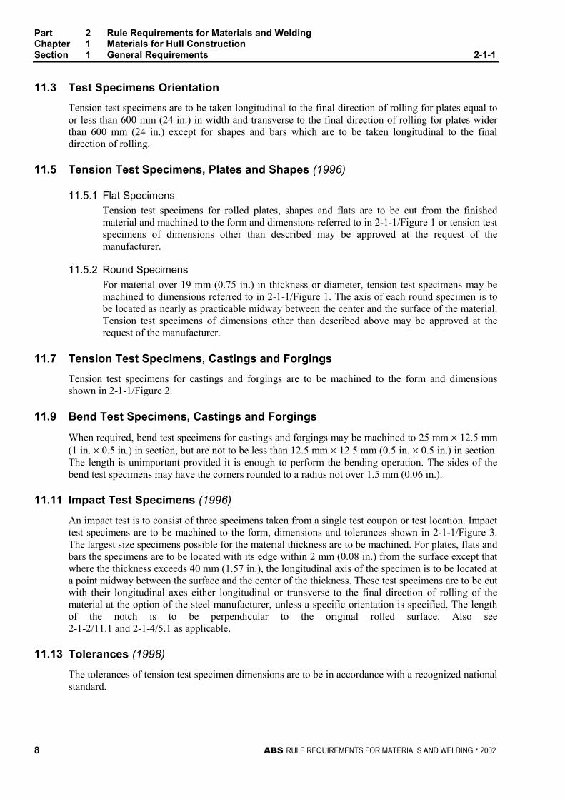
11.3 Test Specimens Orientation 2-1-1/11.3
Tension test specimens are to be taken longitudinal to the final direction of rolling for plates equal toor less than 600 mm (24 in.) in width and transverse to the final direction of rolling for plates widerthan 600 mm (24 in.) except for shapes and bars which are to be taken longitudinal to the finaldirection of rolling.
11.5 Tension Test Specimens, Plates and Shapes (1996) 2-1-1/11.5
11.5.1 Flat Specimens 2-1-1/11.5.1
Tension test specimens for rolled plates, shapes and flats are to be cut from the finishedmaterial and machined to the form and dimensions referred to in 2-1-1/Figure 1 or tension testspecimens of dimensions other than described may be approved at the request of themanufacturer.
11.5.2 Round Specimens 2-1-1/11.5.2
For material over 19 mm (0.75 in.) in thickness or diameter, tension test specimens may bemachined to dimensions referred to in 2-1-1/Figure 1. The axis of each round specimen is tobe located as nearly as practicable midway between the center and the surface of the material.Tension test specimens of dimensions other than described above may be approved at therequest of the manufacturer.
11.7 Tension Test Specimens, Castings and Forgings 2-1-1/11.7
Tension test specimens for castings and forgings are to be machined to the form and dimensionsshown in 2-1-1/Figure 2.
11.9 Bend Test Specimens, Castings and Forgings 2-1-1/11.9
When required, bend test specimens for castings and forgings may be machined to 25 mm × 12.5 mm(1 in. × 0.5 in.) in section, but are not to be less than 12.5 mm × 12.5 mm (0.5 in. × 0.5 in.) in section.The length is unimportant provided it is enough to perform the bending operation. The sides of thebend test specimens may have the corners rounded to a radius not over 1.5 mm (0.06 in.).
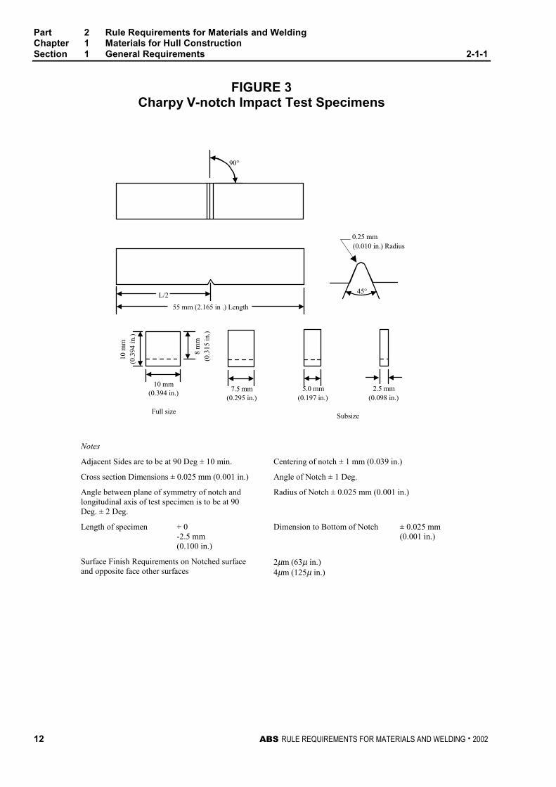
11.11 Impact Test Specimens (1996) 2-1-1/11.11
An impact test is to consist of three specimens taken from a single test coupon or test location. Impacttest specimens are to be machined to the form, dimensions and tolerances shown in 2-1-1/Figure 3.The largest size specimens possible for the material thickness are to be machined. For plates, flats andbars the specimens are to be located with its edge within 2 mm (0.08 in.) from the surface except thatwhere the thickness exceeds 40 mm (1.57 in.), the longitudinal axis of the specimen is to be located ata point midway between the surface and the center of the thickness. These test specimens are to be cutwith their longitudinal axes either longitudinal or transverse to the final direction of rolling of thematerial at the option of the steel manufacturer, unless a specific orientation is specified. The lengthof the notch is to be perpendicular to the original rolled surface. Also see2-1-2/11.1 and 2-1-4/5.1 as applicable.
11.13 Tolerances (1998) 2-1-1/11.13
The tolerances of tension test specimen dimensions are to be in accordance with a recognized nationalstandard.
Part 2 Rule Requirements for Materials and WeldingChapter 1 Materials for Hull ConstructionSection 1 General Requirements 2-1-1
ABS RULE REQUIREMENTS FOR MATERIALS AND WELDING . 2002 9
13 Definition and Determination of Yield Point and YieldStrength 2-1-1/13
13.1 Yield Point 2-1-1/13.1
The yield point is the first stress in a material, less than the maximum obtainable stress, at which anincrease in strain occurs without an increase in stress. Yield point may be determined by the halt ofthe pointer, or autographic diagram. The 0.5% total extension under load method will also beconsidered acceptable.
13.3 Yield Strength 2-1-1/13.3
The yield strength is the stress at which a material exhibits a specified limiting deviation from theproportionality of stress to strain. Yield strength is to be determined by the 0.2% offset method.Alternatively, for material whose stress-strain characteristics are well known from previous tests inwhich stress-strain diagrams were plotted the 0.5% extension under load method may be used.
15 Permissible Variations in Dimensions (1994) 2-1-1/15
15.1 Scope (2002) 2-1-1/15.1
The under tolerance specified below represents the minimum material certification requirements andis to be considered as the lower limit of the usual range of variations (plus/minus) from the specifieddimension.
The responsibility for meeting the tolerances rests with the manufacturer who is to maintain aprocedure acceptable to the Surveyor. Where any tolerance (including over thickness tolerance) to beused is more stringent than the normal commercial tolerance, the Bureau is to be advised before thesteel is presented for acceptance to assure that the thickness measuring procedure is appropriate.
In all cases, the thickness of the steel is to comply with the under tolerance specified below. The steelmill is to consider the effect of mill scale on the resulting measurement.
For classification purposes, including the assessment of deterioration at future thickness gaugings, thethickness indicated on the approved plan is to be used.
15.3 Plates (1996) 2-1-1/15.3
The maximum permissible under thickness tolerance for hull steel plates and wide flats of 5 mm(0.20 in.) or more in thickness is 0.3 mm (0.012 in.).
The thickness is to be measured at a distance of 10 mm (0.375 in.) or more from the edge.
The under thickness tolerance for plates and wide flats less than 5 mm (0.2 in.) in thickness will bespecially considered.
15.5 Shapes and Bars 2-1-1/15.5
The undertolerance of cross sectional dimensions for shapes and bars are based on the ordereddimensions and are to conform to those given in ASTM A6 or other recognized standards as may bespecified in the purchase order.
Part 2 Rule Requirements for Materials and WeldingChapter 1 Materials for Hull ConstructionSection 1 General Requirements 2-1-1
10 ABS RULE REQUIREMENTS FOR MATERIALS AND WELDING . 2002
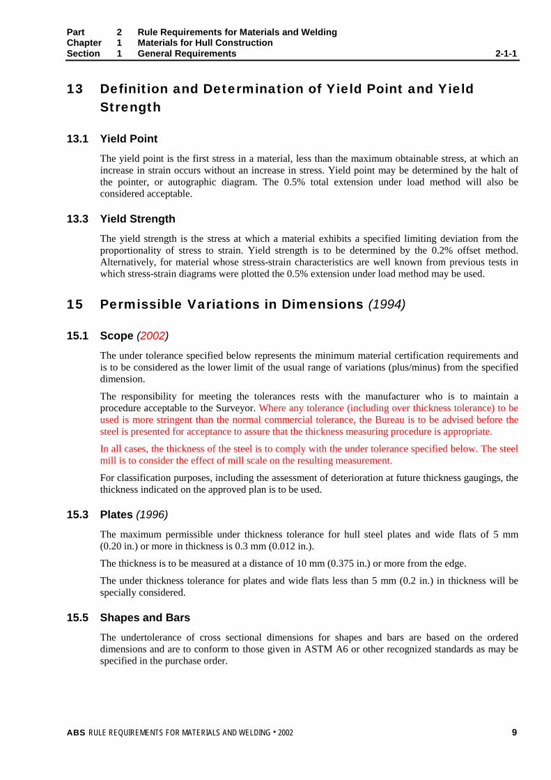
FIGURE 1Standard Tension Test Specimen (1) (1995)
dab
LoLcAR
= diameter in mm= thickness in mm= width in mm= gauge length in mm= parallel test length in mm
= cross sectional area in mm2
= transition radius in mm
Round Specimen
Flat Specimen
A
A
O
R
R
d
b
a
L
L C
������������������������
����������������
d a b Lo Lc R
Flat specimenAlternative A
– t (2) 25 5.65 A Lo + 2 A 25
Flat specimenAlternative B
– t (2) 25 200 225 25
Round specimenAlternative C
14 – – 70 85 10
Notes:1 Standard specimen in accordance with ASTM E8/E8M or A370 will also be acceptable in conjunction with the
corresponding elongation requirements in 2-1-2/Table 2 or 2-1-3/Table 2.
2 t is the full thickness of the material as produced. If the capacity of the testing machine does not allow fullthickness specimens to be broken, the thickness may be reduced by machining one surface only.
Part 2 Rule Requirements for Materials and WeldingChapter 1 Materials for Hull ConstructionSection 1 General Requirements 2-1-1
ABS RULE REQUIREMENTS FOR MATERIALS AND WELDING . 2002 11
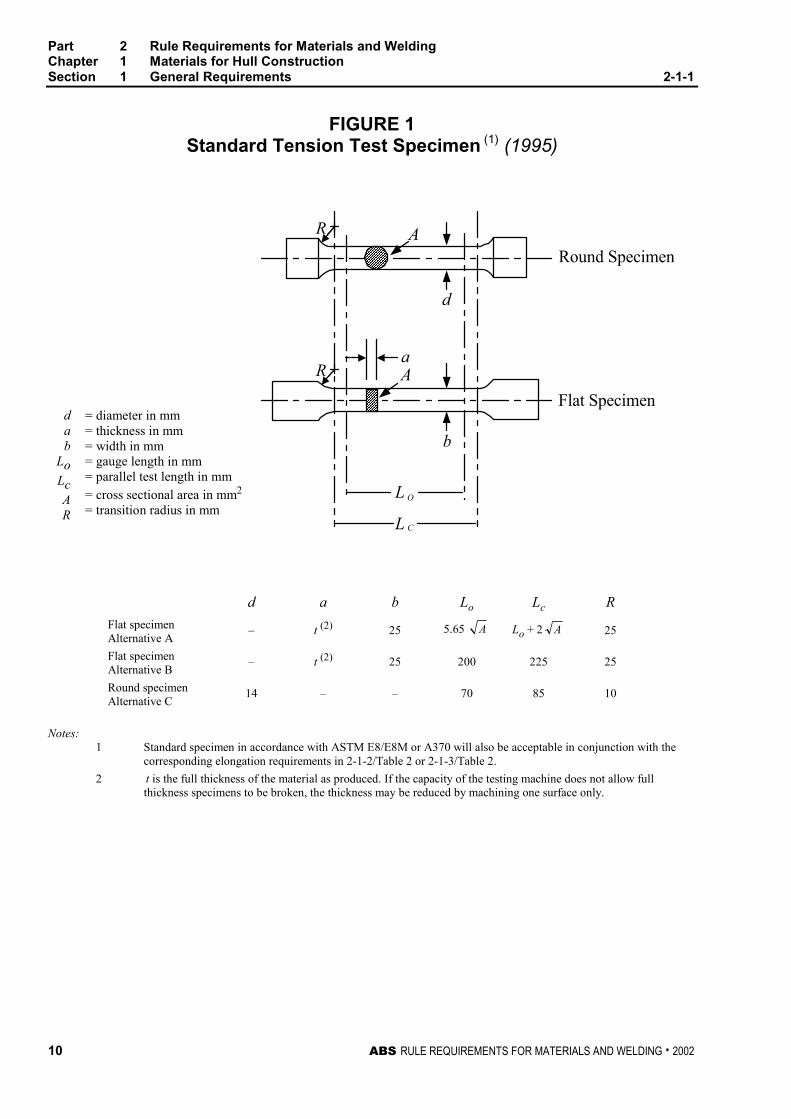
FIGURE 2Standard Round Tension Test Specimenwith 50 mm (2 in.) Gauge Length (2001)
50 mm ± 0.125 mm(2 in. ± 0.005 in.)
12.5 mm ± 0.25 mm(0.500 in. ± 0.010 in.)
Reduced Section60 mm (2.25 in.) min.
Radius 10 mm(0.375 in.) min.
Gauge length for measuringelongation after fracture
Note:The gauge length and fillets are to be as shown, but the ends may be of any shape to fit the holdersof the testing machine in such a way that the load is to be axial. The reduced section may have agradual taper from the ends towards the center, with the ends not more than 0.13 mm (0.005 in.)larger in diameter than the center.
Part 2 Rule Requirements for Materials and WeldingChapter 1 Materials for Hull ConstructionSection 1 General Requirements 2-1-1
12 ABS RULE REQUIREMENTS FOR MATERIALS AND WELDING . 2002
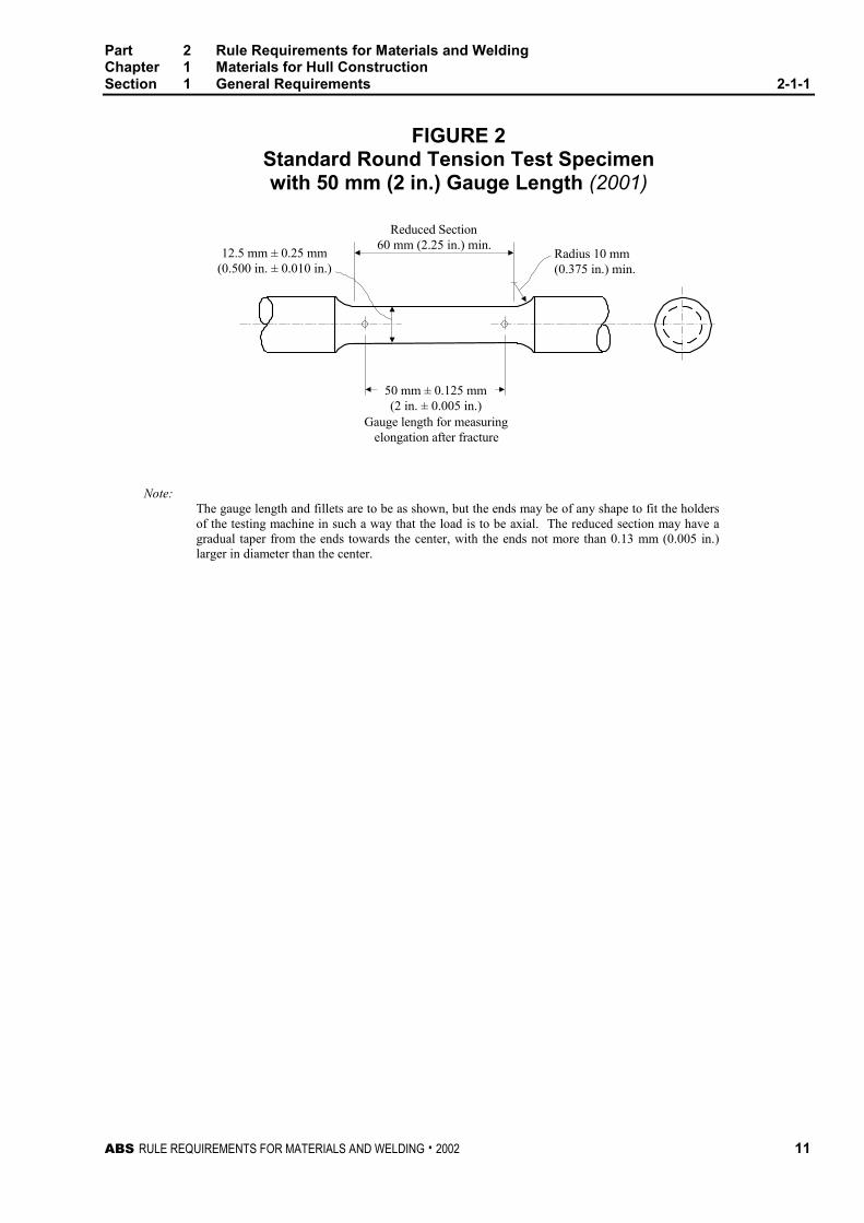
FIGURE 3Charpy V-notch Impact Test Specimens
10 mm(0.394 in.)
10 m
m(0
.394
in.)
8 m
m(0
.315
in.)
(0.295 in.)7.5 mm 5.0 mm
(0.197 in.) (0.098 in.)2.5 mm
0.25 mm(0.010 in.) Radius
Full sizeSubsize
90°
45°
55 mm (2.165 in .) Length
L/2
Notes
Adjacent Sides are to be at 90 Deg ± 10 min. Centering of notch ± 1 mm (0.039 in.)
Cross section Dimensions ± 0.025 mm (0.001 in.) Angle of Notch ± 1 Deg.
Angle between plane of symmetry of notch andlongitudinal axis of test specimen is to be at 90Deg. ± 2 Deg.
Radius of Notch ± 0.025 mm (0.001 in.)
Length of specimen + 0-2.5 mm(0.100 in.)
Dimension to Bottom of Notch ± 0.025 mm(0.001 in.)
Surface Finish Requirements on Notched surfaceand opposite face other surfaces
2µm (63µ in.)4µm (125µ in.)
Part 2 Rule Requirements for Materials and WeldingChapter 1 Materials for Hull ConstructionSection 1 General Requirements 2-1-1
ABS RULE REQUIREMENTS FOR MATERIALS AND WELDING . 2002 13
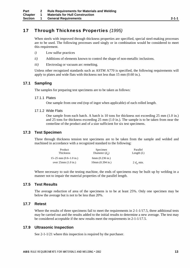
17 Through Thickness Properties (1995) 2-1-1/17
When steels with improved through thickness properties are specified, special steel-making processesare to be used. The following processes used singly or in combination would be considered to meetthis requirement.
i) Low sulfur practices
ii) Additions of elements known to control the shape of non-metallic inclusions.
iii) Electroslag or vacuum arc remelting.
Unless other recognized standards such as ASTM A770 is specified, the following requirements willapply to plates and wide flats with thickness not less than 15 mm (0.60 in.).
17.1 Sampling 2-1-1/17.1
The samples for preparing test specimens are to be taken as follows:
17.1.1 Plates 2-1-1/17.1.1
One sample from one end (top of ingot when applicable) of each rolled length.
17.1.2 Wide Flats 2-1-1/17.1.2
One sample from each batch. A batch is 10 tons for thickness not exceeding 25 mm (1.0 in.)and 25 tons for thickness exceeding 25 mm (1.0 in.). The sample is to be taken from near thecenterline of the product and of a size sufficient for six test specimens.
17.3 Test Specimen 2-1-1/17.3
Three through thickness tension test specimens are to be taken from the sample and welded andmachined in accordance with a recognized standard to the following:
ProductThickness
SpecimenDiameter (do)
ParallelLength (L)
15–25 mm (0.6–1.0 in.) 6mm (0.236 in.)
over 25mm (1.0 in.) 10mm (0.394 in.) 2 do min.
Where necessary to suit the testing machine, the ends of specimens may be built up by welding in amanner not to impair the material properties of the parallel length.
17.5 Test Results 2-1-1/17.5
The average reduction of area of the specimens is to be at least 25%. Only one specimen may bebelow the average but is not to be less than 20%.
17.7 Retest 2-1-1/17.7
Where the results of three specimens fail to meet the requirements in 2-1-1/17.5, three additional testsmay be carried out and the results added to the initial results to determine a new average. The test maybe considered acceptable if the new results meet the requirements in 2-1-1/17.5.
17.9 Ultrasonic Inspection 2-1-1/17.9
See 2-1-1/21 where this inspection is required by the purchaser.
Part 2 Rule Requirements for Materials and WeldingChapter 1 Materials for Hull ConstructionSection 1 General Requirements 2-1-1
14 ABS RULE REQUIREMENTS FOR MATERIALS AND WELDING . 2002
17.11 Marking 2-1-1/17.11
See 2-1-2/13.11.
19 Formed Materials 2-1-1/19
When material is hot or cold formed, confirmatory mechanical tests are to be conducted whenrequired by 2-4-1/3.13.
21 Ultrasonic Examination of Plate Material 2-1-1/21
In order to be specially marked in accordance with paragraph 2-1-2/13.13, ABS steels are to beultrasonically examined in accordance with a recognized specification such as ASTM A435 orequivalent.
ABS RULE REQUIREMENTS FOR MATERIALS AND WELDING . 2002 15
P A R T
2C H A P T E R 1 Materials for Hull Construction
S E C T I O N 2 Ordinary-strength Hull StructuralSteel
CONTENTS1 Ordinary-strength Hull Structural Steel ............................... 17
3 Process of Manufacture ........................................................ 17
3.1 Plates Produced from Coils.................................................... 17
5 Chemical Composition.......................................................... 17
5.1 Ladle Analysis ........................................................................ 17
5.3 Product Analysis..................................................................... 17
5.5 Special Compositions............................................................. 18
5.7 Fine Grain Practice................................................................. 18
7 Condition of Supply .............................................................. 18
7.1 Heat Treatment ...................................................................... 18
7.3 Controlled Manufacturing Process ......................................... 18
9 Tensile Properties ................................................................. 19
9.1 Required Tensile Properties................................................... 19
9.3 Tension Test Specimens........................................................ 19
9.5 Exceptions .............................................................................. 19
9.7 Elongation Deduction for Material Under 7.9 mm (0.313 in.)Thick ....................................................................................... 19
9.9 Omission of Elongation Requirements................................... 19
9.11 Retests ................................................................................... 20
9.13 Unsatisfactory Tests............................................................... 20
11 Impact Properties .................................................................. 20
11.1 Impact Tests........................................................................... 20
11.3 Impact Test Frequency........................................................... 20
11.5 Initial Test Requirements........................................................ 20
11.7 Retests ................................................................................... 21
11.9 Unsatisfactory Tests............................................................... 21
11.11 Thin Plates.............................................................................. 21
16 ABS RULE REQUIREMENTS FOR MATERIALS AND WELDING . 2002
13 Marking...................................................................................21
13.1 Stamped or Stenciled Material ............................................... 21
13.3 Coils, Lifts and Bundles.......................................................... 21
13.5 Flanging-quality Identification................................................. 22
13.7 Special Stamping and Marking............................................... 22
13.9 Special Impact Testing ........................................................... 22
13.11 Steel with Improved Through Thickness Properties............... 22
13.13 Steel with Ultrasonic Examination .......................................... 22
13.15 Shipping Procedure................................................................ 22
13.17 Steel at Secondary Sources................................................... 22
15 Surface Finish ........................................................................22
15.1 Surface Inspection.................................................................. 22
15.3 Treatment of Surface Defects – Plates .................................. 23
15.5 Treatment of Surface Defects – Shapes ................................ 23
15.7 Bar-stock Repairs ................................................................... 24
15.9 Rivet Steel and Rivets ............................................................ 24
TABLE 1 Chemical Properties of Ordinary Strength HullStructural Steel 100 mm (4.0 in.) and Under.............25
TABLE 2 Tensile Properties of Ordinary Strength HullStructural Steel 100 mm (4.0 in.) and Under.............26
TABLE 3 Elongation Requirements for Alternative BSpecimen ....................................................................26
TABLE 4 Impact Properties of Ordinary-Strength HullStructural Steel 100 mm (4.0 in.) and Under.............27
TABLE 5 Condition of Supply and Frequency of ImpactTests Ordinary Strength Hull Structural Steel..........28
ABS RULE REQUIREMENTS FOR MATERIALS AND WELDING . 2002 17
P A R T
2C H A P T E R 1 Materials for Hull Construction
S E C T I O N 2 Ordinary-strength Hull StructuralSteel 2 - 1 - 2
1 Ordinary-strength Hull Structural Steel (1996) 2-1-2/1
The requirements in this subsection are intended for products of the following thicknesses.
Plates and Wide Flats up to and including 100 mm (4.0 in.)
Sections and Bars up to and including 50 mm (2.0 in.)
3 Process of Manufacture 2-1-2/3
The steel is to be made by one or more of the following processes: open-hearth, basic-oxygen,electric-furnace, vacuum-arc remelt, electro-slag remelt, or such other process as may be speciallyapproved. The steel may be cast in ingots or may be strand (continuous) cast. The ratio of reduction ofthickness from a strand (continuous) cast slab to finished plate is to be a minimum of 3 to 1 unlessspecially approved. Data in support of mechanical properties, weldability and compliance with theRules in all respects are to be submitted by the steel manufacturer for review and approval when newor special steels or production methods are proposed or when new steel mills begin production.
3.1 Plates Produced from Coils 2-1-2/3.1
For coiled plate, the manufacturer or processor is to submit supporting data for review and approval toindicate that the manufacturing, processing, and testing will provide material which is in compliancewith the Rules.
5 Chemical Composition 2-1-2/5
5.1 Ladle Analysis 2-1-2/5.1
The chemical composition is to be determined by the steel manufacturer on samples taken from eachladle of each heat and is to conform to the applicable chemical requirements of the grades of steellisted in 2-1-2/Table 1.
5.3 Product Analysis 2-1-2/5.3
When product (check) analysis is required, the chemical tolerances of ASTM A6 or of othernationally recognized standards are to be applied.
Part 2 Rule Requirements for Materials and WeldingChapter 1 Materials for Hull ConstructionSection 2 Ordinary-strength Hull Structural Steel 2-1-2
18 ABS RULE REQUIREMENTS FOR MATERIALS AND WELDING . 2002
5.5 Special Compositions 2-1-2/5.5
Material differing in chemical composition, deoxidation practice, mechanical properties or heattreatment from that shown in 2-1-2/Table 1 will be subjected to special approval.
5.7 Fine Grain Practice 2-1-2/5.7
Where steel is required to be made using fine grain practice, the requirement is to be met by addingaluminum, unless some other method is specially approved. The fine grain requirement may bedetermined by one of the following methods.
5.7.1 2-1-2/5.7.1
A McQuaid-Ehn austenite grain size of 5 or finer in accordance with ASTM E112 for eachladle of each heat, or
5.7.2 2-1-2/5.7.2
Minimum Acid-soluble Aluminum content of 0.015% or minimum total Aluminum content of0.020% for each ladle of each heat.
7 Condition of Supply (1995) 2-1-2/7
The conditions of supply are to be in accordance with the requirements in 2-1-2/Table 5 and thefollowing:
Controlled manufacturing processes require approval for each plant and combination of grade andthickness limit.
7.1 Heat Treatment (1995) 2-1-2/7.1
7.1.1 Normalizing Heat Treatment 2-1-2/7.1.1
A normalizing heat treatment is to consist of heating plates, wide flats, bars or shapes from anappropriate temperature below the transformation range to the proper temperature above thetransformation range, holding for a sufficient time to effect the desired transformation andthen individually cooling the material in air. Normalizing heat treatments are usuallyconducted at the steel manufacturer’s plant. Such heat treatment may be carried out at ashipyard or fabricator’s plant provided the Surveyor is satisfied with the heat-treatingfacilities and procedures. In such cases, the shipyard or fabricator is to indicate on hispurchase order that the mill tests are to be made on normalized coupons. Otherwise, tests onthe normalized material will be required at the shipyard or fabricator’s plant.
7.1.2 Special Heat Treatment 2-1-2/7.1.2
Other types of heat treatment are to be specially approved.
7.3 Controlled Manufacturing Process (1995) 2-1-2/7.3
7.3.1 Controlled Rolling 2-1-2/7.3.1
Controlled rolling is a procedure in which generally the final rolling temperature is controlledwithin the range used for normalizing heat treatments so that the austenite completelyrecrystallizes.
Part 2 Rule Requirements for Materials and WeldingChapter 1 Materials for Hull ConstructionSection 2 Ordinary-strength Hull Structural Steel 2-1-2
ABS RULE REQUIREMENTS FOR MATERIALS AND WELDING . 2002 19
7.3.2 Thermo-mechanical Controlled Processing 2-1-2/7.3.2
Thermo-mechanical controlled processing involves the strict control of the steel temperatureand the rolling reduction. Generally a high proportion of the rolling reduction is carried outclose to or below the Ar3 transformation temperature and may involve rolling towards thelower end of the temperature range of the intercritical duplex phase region thus permittinglittle if any recrystallization of the austenite.
The use of accelerated cooling on completion of rolling may also be accepted subject to thespecial approval of the Bureau.
9 Tensile Properties 2-1-2/9
9.1 Required Tensile Properties 2-1-2/9.1
The material, except as specified in 2-1-2/9.5, is to conform to the requirements of 2-1-2/Table 2 as totensile properties.
9.3 Tension Test Specimens 2-1-2/9.3
One tension test is to be made on two different plates, shapes or bars from each heat of steel, unlessthe finished material from a heat is less than 50 tons, when one tension test will be sufficient. If,however, material from one heat differs 9.5 mm (0.375 in.) or more in thickness or diameter, onetension test is to be made from both the thickest and the thinnest material rolled, regardless of theweight represented. One tension test is to be made on each plate as quenched and tempered. For platesfrom coils, tension tests are to be made from not less than two coils from each heat, except where asingle coil is to be certified in which case tension test specimens from that coil only need be tested.Two tension tests are to be made from each coil tested. One tension test specimen is to be obtainedfrom a location immediately prior to the first plate produced and a second test specimen obtainedfrom the approximate center lap. When the coiled material from one heat differs by 1.6 mm (1/16 in.)or more in thickness, test specimens are to be obtained from both the thinnest and the thickest materialrolled.
9.5 Exceptions 2-1-2/9.5
Shapes less than 645 mm2 (1 in2) in cross section and bars, other than flats, less than 12.5 mm (1/2 in.)in thickness or diameter need not be subject to tension test, but chemistry consistent with the requiredtensile properties is to be applied.
9.7 Elongation Deduction for Material Under 7.9 mm (0.313 in.) Thick (1996) 2-1-2/9.7
For material under 7.9 mm (0.313 in.) in thickness or diameter, a deduction of 1.25% from thepercentage of elongation in 200 mm (8 in.) specified in 2-1-2/Table 2 and 2-1-2/Table 3 is to be madefor each decrease of 0.8 mm (0.031 in.) of the specified thickness or diameter below 7.9 mm (0.313in.).
9.9 Omission of Elongation Requirements 2-1-2/9.9
For raised-pattern floor plates not exceeding 12.5 mm (0.50 in.) in thickness, the requirement forelongation is waived.
Part 2 Rule Requirements for Materials and WeldingChapter 1 Materials for Hull ConstructionSection 2 Ordinary-strength Hull Structural Steel 2-1-2
20 ABS RULE REQUIREMENTS FOR MATERIALS AND WELDING . 2002
9.11 Retests (1996) 2-1-2/9.11
Where the results of the tension test do not comply with the requirements, two further tests may becarried out on specimens taken from the same sample. For elongation retest, 2-1-1/9.5 is to becomplied with. For plates from coils the retest specimens are to be taken adjacent to the originalspecimen.
If the results of both additional tests meet the requirements, the material tested or represented by thetest may be accepted.
When the results of one or both additional tests do not meet the requirements, the sample is to berejected unless the manufacturer elects to resubmit it after heat treatment or reheat treatment, or asanother grade. The rest of the material represented by the test may be treated under 2-1-2/9.13.
9.13 Unsatisfactory Tests (1996) 2-1-2/9.13
Where the tests under 2-1-2/9.3 and 2-1-2/9.13 fail, the remaining material from the same heat may beaccepted, provided satisfactory results are obtained on both of two additional plates, shapes or barsselected in accordance with 2-1-2/9.3.
When the results of one or both samples do not meet the requirements, all materials represented by thetests are to be rejected unless the manufacturer elects to submit each piece individually, or to resubmitthe lot after heat treatment or reheat treatment or as another grade.
11 Impact Properties 2-1-2/11
11.1 Impact Tests (1996) 2-1-2/11.1
Charpy V-notch impact tests are to be carried out in accordance with 2-1-2/Table 4. These samerequirements apply for flats, rounds, and shapes when specially ordered in these grades unless agreedotherwise. For rolled sections impact tests specimens are to be taken from the flanges of beams,channels, and tees, and from the legs of angles and bulb angles. One set of three impact specimens isto be obtained from the thickest material rolled except when the maximum thickness or diameter ofthe material represented by the test differs by 9.5 mm (0.375 in.) or more, in which case, one set ofimpacts is to be made from both the thickest and the thinnest material represented, regardless of theirweight. See 2-1-1/11.11.
For plates produced from coils, impact test coupons are to be obtained adjacent to both tension testcoupons and a third impact test coupon is to be obtained immediately after the last plate produced tothe qualifying grade or specification; in no case, however, is the frequency of impact testing to be lessthan that given above for plates, and where additional testing is required, three sets of specimens areto be obtained from each coil tested.
11.3 Impact Test Frequency 2-1-2/11.3
The frequency of impact testing is to be in accordance with 2-1-2/Table 5.
11.5 Initial Test Requirements 2-1-2/11.5
The average value of three specimens is to comply with the required average value in the Tables. Onlyone individual value may be below the required average and it is not to be less than 70% of therequired average.
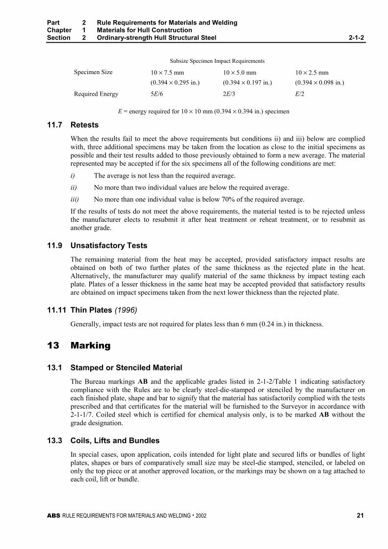
Where the subsize specimens in 2-1-1/Figure 2 are to be used, the modified energy values will applyas follows:
Part 2 Rule Requirements for Materials and WeldingChapter 1 Materials for Hull ConstructionSection 2 Ordinary-strength Hull Structural Steel 2-1-2
ABS RULE REQUIREMENTS FOR MATERIALS AND WELDING . 2002 21
Subsize Specimen Impact Requirements
Specimen Size 10 × 7.5 mm 10 × 5.0 mm 10 × 2.5 mm
(0.394 × 0.295 in.) (0.394 × 0.197 in.) (0.394 × 0.098 in.)
Required Energy 5E/6 2E/3 E/2
E = energy required for 10 × 10 mm (0.394 × 0.394 in.) specimen
11.7 Retests 2-1-2/11.7
When the results fail to meet the above requirements but conditions ii) and iii) below are compliedwith, three additional specimens may be taken from the location as close to the initial specimens aspossible and their test results added to those previously obtained to form a new average. The materialrepresented may be accepted if for the six specimens all of the following conditions are met:
i) The average is not less than the required average.
ii) No more than two individual values are below the required average.
iii) No more than one individual value is below 70% of the required average.
If the results of tests do not meet the above requirements, the material tested is to be rejected unlessthe manufacturer elects to resubmit it after heat treatment or reheat treatment, or to resubmit asanother grade.
11.9 Unsatisfactory Tests 2-1-2/11.9
The remaining material from the heat may be accepted, provided satisfactory impact results areobtained on both of two further plates of the same thickness as the rejected plate in the heat.Alternatively, the manufacturer may qualify material of the same thickness by impact testing eachplate. Plates of a lesser thickness in the same heat may be accepted provided that satisfactory resultsare obtained on impact specimens taken from the next lower thickness than the rejected plate.
11.11 Thin Plates (1996) 2-1-2/11.11
Generally, impact tests are not required for plates less than 6 mm (0.24 in.) in thickness.
13 Marking 2-1-2/13
13.1 Stamped or Stenciled Material 2-1-2/13.1
The Bureau markings AB and the applicable grades listed in 2-1-2/Table 1 indicating satisfactorycompliance with the Rules are to be clearly steel-die-stamped or stenciled by the manufacturer oneach finished plate, shape and bar to signify that the material has satisfactorily complied with the testsprescribed and that certificates for the material will be furnished to the Surveyor in accordance with2-1-1/7. Coiled steel which is certified for chemical analysis only, is to be marked AB without thegrade designation.
13.3 Coils, Lifts and Bundles 2-1-2/13.3
In special cases, upon application, coils intended for light plate and secured lifts or bundles of lightplates, shapes or bars of comparatively small size may be steel-die stamped, stenciled, or labeled ononly the top piece or at another approved location, or the markings may be shown on a tag attached toeach coil, lift or bundle.
Part 2 Rule Requirements for Materials and WeldingChapter 1 Materials for Hull ConstructionSection 2 Ordinary-strength Hull Structural Steel 2-1-2
22 ABS RULE REQUIREMENTS FOR MATERIALS AND WELDING . 2002
13.5 Flanging-quality Identification 2-1-2/13.5
All material intended for cold flanging, when specially approved in accordance with 3-1-2/1.1 is to beadditionally marked F to signify that it is of such quality.
13.7 Special Stamping and Marking 2-1-2/13.7
Material other than those grades listed in 2-1-2/Table 1 is to be marked with both the initials AB/Sand with either the applicable specification number, or such other markings as may be required forready identification, to signify that the material has been produced and satisfactorily tested inaccordance with the specification. When a specification does not specifically require normalizing butthe material is so ordered and so produced, then the plates are also to be marked with the initial N toindicate that the material has been normalized. A shipyard or fabricator who carries out a normalizingheat treatment in accordance with 2-1-2/7 is to also mark such material with the initial N.
13.9 Special Impact Testing 2-1-2/13.9
When steel is impact tested at temperatures other than those specified in 2-1-2/Table 4, the grademarking is to be followed by the test temperature in degrees Celsius. A prefix ‘‘O’’ to the testtemperature is to indicate a temperature colder than zero degrees Celsius.
13.11 Steel with Improved Through Thickness Properties 2-1-2/13.11
Steel plates meeting the requirements of 2-1-1/17 are to have the letter Z marked after the gradedesignation.
13.13 Steel with Ultrasonic Examination 2-1-1/13.13
Steels meeting the requirements of 2-1-1/21 are to have the letter U marked after the gradedesignation as a final letter.
13.15 Shipping Procedure 2-1-2/13.15
No material bearing these markings is to be forwarded from the steel works until the prescribed testshave been satisfactorily carried out in accordance with the Rules.
13.17 Steel at Secondary Sources 2-1-2/13.17
Secondary sources for ABS Grade Steel are required to assure traceability of steel intended for Bureaucertification. To retain proper identification, steel may be marked with the information indicated bythe manufacturer’s markings to the satisfaction of the Surveyor.
15 Surface Finish 2-1-2/15
15.1 Surface Inspection 2-1-2/15.1
The material will be surface inspected by the Surveyor when specially requested by the purchaser. Itis to be free from defects and have a workmanlike finish subject to the conditions given in thefollowing subparagraphs.
Part 2 Rule Requirements for Materials and WeldingChapter 1 Materials for Hull ConstructionSection 2 Ordinary-strength Hull Structural Steel 2-1-2
ABS RULE REQUIREMENTS FOR MATERIALS AND WELDING . 2002 23
15.3 Treatment of Surface Defects – Plates 2-1-2/15.3
Plates may be conditioned by the manufacturer for the removal of surface defects on either surface bygrinding, provided each ground area is well faired and the grinding does not reduce the thickness ofthe plate
i) more than 7% under the nominal thickness and in no case more than 3.2 mm (0.125 in.) whenordered to weight or;
ii) below the minimum thickness permissible under 2-1-1/15.3 when ordered to thickness.
Plates may have surface defects removed by chipping, grinding or gouging and then depositing weldmetal, subject to the following limiting conditions.
15.3.1 Extent of Weld Repaired Area 2-1-2/15.3.1
The total weld repaired area of each surface of a plate is not to exceed 2% of the area of thatsurface.
15.3.2 Minimum Thickness Before Weld Repairs 2-1-2/15.3.2
After removal of any defect preparatory to welding, the thickness of the plate is not to bereduced by more than 20% of the nominal thickness.
15.3.3 Inspection Before Weld Repairs 2-1-2/15.3.3
An experienced mill inspector is to examine the work to see that the defects have beenremoved completely and that the foregoing limitations have not been exceeded. The Surveyoris to be given full opportunity to make this same inspection. To assure removal of defects,magnetic particle or liquid penetrant examination may be required.
15.3.4 Repair-welding Quality 2-1-2/15.3.4
All welding is to be performed by qualified operators, using an approved welding procedureand low hydrogen filler metal/practice. The welding is to be sound, thoroughly fused, andwithout undercutting or overlap. Weld metal is to have at least 1.6 mm (0.063 in.)reinforcement, which is to be removed by grinding or chipping and grinding flush with therolled surface, and is to present a workmanlike finish.
15.5 Treatment of Surface Defects – Shapes 2-1-2/15.5
Shapes may be conditioned by the manufacturer for the removal of surface defects by grinding or bychipping to sound metal and depositing weld metal, in accordance with the following limitations.
15.5.1 Chipping and Grinding Material Under 9.5 mm (0.375 in.) in Thickness 2-1-2/15.5.1
For material less than 9.5 mm (0.375 in.) thickness, in which the defects are not more than0.8 mm (0.031 in.) in depth, the defects may be removed by grinding or chipping andgrinding with the edges well faired.
15.5.2 Chipping and Grinding Material 9.5 mm (0.375 in.) and Over in Thickness 2-1-2/15.5.2
For material 9.5 mm (0.375 in.) and over in thickness, in which the defects are not more than1.6 mm (0.063 in.) in depth, the defects may be removed by grinding or chipping andgrinding with the edges well faired.
15.5.3 Welding Repairs 2-1-2/15.5.3
Surface defects which are greater in depth than the limits shown above may be removed bychipping or grinding and then depositing weld metal, subject to the following limitingconditions.
Part 2 Rule Requirements for Materials and WeldingChapter 1 Materials for Hull ConstructionSection 2 Ordinary-strength Hull Structural Steel 2-1-2
24 ABS RULE REQUIREMENTS FOR MATERIALS AND WELDING . 2002
15.5.3(a) The total area of the chipped or ground surface of any piece is not to exceed 2% ofthe total surface area of that piece.
15.5.3(b) After removal of any defect preparatory to welding, the thickness of the shape isnot to be reduced by more than 30% of the nominal thickness, nor is the depth of depressionprior to welding to exceed 12.5 mm (0.50 in.) in any case.
15.5.3(c) The toes of angles, beams, channels and zees and the stems and toes of tees may beconditioned by grinding or chipping and welding. Prior to welding, the depth of depression,measured from the toe inward, is to be limited to the thickness of the material at the base ofthe depression, with a maximum depth limit of 12.5 mm (0.50 in.).
15.5.3(d) An experienced mill inspector is to inspect and the welding is to be done inaccordance with the requirements of 2-1-2/15.3.3 and 2-1-2/15.3.4.
15.7 Bar-stock Repairs 2-1-2/15.7
Bars may be conditioned by the manufacturer for the removal of surface defects by grinding, chippingor some other means, provided the conditioned area is well faired and the depth of depression doesnot extend below the nominal thickness or diameter by more than 1.5%.
15.9 Rivet Steel and Rivets (1996) 2-1-2/15.9
Material test requirements for rivet steel are to comply with the requirements of Section 25 of the1969 Rules for Building and Classing Steel Vessels.

Part 2 Rule Requirements for Materials and WeldingChapter 1 Materials for Hull ConstructionSection 2 Ordinary-strength Hull Structural Steel 2-1-2
ABS RULE REQUIREMENTS FOR MATERIALS AND WELDING . 2002 25
TABLE 1Chemical Properties of Ordinary Strength Hull Structural Steel
100 mm (4.0 in.) and Under (1996)
Grade A B D E
DeoxidationKilled or semi-killed (1)
(t ≤ 50 mm (2.0 in.))Killed (t > 50 mm (2.0 in.))
Killed or semi-killed
(t ≤ 50 mm (2.0 in.))Killed (t > 50 mm (2.0 in.))
Killed (t ≤ 25 mm (1.0in.))
Killed and fine grain
(t > 25 mm (1.0 in.)) (2)Killed and fine
grain (2)
Chemical Composition (Ladle Analysis), % max. unless specified otherwise.(8)
C 0.21 (3) 0.21 0.21 0.18
Mn,min. 2.5 × C 0.80 (4) 0.60 0.70
Si 0.50 0.35 0.10–0.35 (5) 0.10–0.35 (5)
P 0.035 0.035 0.035 0.035
S 0.035 0.035 0.035 0.035
Ni See Note (6) See Note (6) See Note (6) See Note (6)
Cr See Note (6) See Note (6) See Note (6) See Note (6)
Mo See Note (6) See Note (6) See Note (6) See Note (6)
Cu See Note (6) See Note (6) See Note (6) See Note (6)
C + Mn/6 0.40 0.40 0.40 0.40
Marking AB/A AB/B AB/D (7) AB/E
Notes:1 For Grade A, rimmed steel sections may be accepted up to and including 12.5 mm (0.5 in).
2 Grade D steel over 25 mm and Grade E steel are to contain at least one of the grain refining elements in sufficientamount to meet the fine grain practice requirements. (See 2-1-2/5.7.)
3 A maximum carbon content of 0.23% is acceptable for Grade A sections.
4 For Grade B steel of cold flanging quality or where fully killed, the lower limit of manganese may be reduced to0.60%.
5 Where the content of soluble aluminum is not less than 0.015%, the minimum required silicon content does notapply.
6 The contents of nickel, chromium, molybdenum and copper are to be determined and reported. When the amountdoes not exceed 0.02%, these elements may be reported as ≤0.02%.
7 Grade D hull steel which is normalized, thermo-mechanical control processed or control rolled is to be markedAB/DN.
8 Intentionally added elements are to be determined and reported.
Part 2 Rule Requirements for Materials and WeldingChapter 1 Materials for Hull ConstructionSection 2 Ordinary-strength Hull Structural Steel 2-1-2
26 ABS RULE REQUIREMENTS FOR MATERIALS AND WELDING . 2002
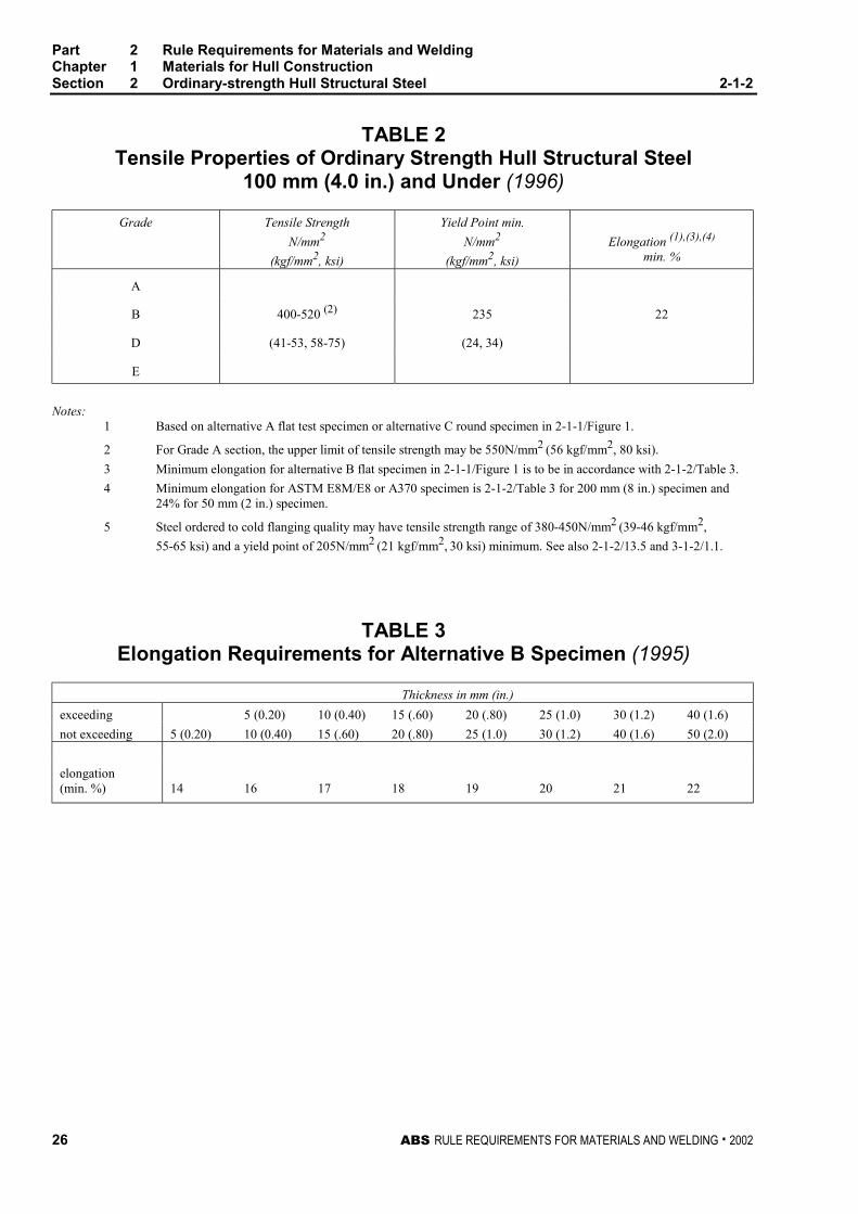
TABLE 2Tensile Properties of Ordinary Strength Hull Structural Steel
100 mm (4.0 in.) and Under (1996)
Grade Tensile Strength
N/mm2
(kgf/mm2, ksi)
Yield Point min.
N/mm2
(kgf/mm2, ksi)
Elongation (1),(3),(4)
min. %
A
B 400-520 (2) 235 22
D (41-53, 58-75) (24, 34)
E
Notes:1 Based on alternative A flat test specimen or alternative C round specimen in 2-1-1/Figure 1.
2 For Grade A section, the upper limit of tensile strength may be 550N/mm2 (56 kgf/mm2, 80 ksi).
3 Minimum elongation for alternative B flat specimen in 2-1-1/Figure 1 is to be in accordance with 2-1-2/Table 3.
4 Minimum elongation for ASTM E8M/E8 or A370 specimen is 2-1-2/Table 3 for 200 mm (8 in.) specimen and24% for 50 mm (2 in.) specimen.
5 Steel ordered to cold flanging quality may have tensile strength range of 380-450N/mm2 (39-46 kgf/mm2,
55-65 ksi) and a yield point of 205N/mm2 (21 kgf/mm2, 30 ksi) minimum. See also 2-1-2/13.5 and 3-1-2/1.1.
TABLE 3Elongation Requirements for Alternative B Specimen (1995)
Thickness in mm (in.)
exceeding 5 (0.20) 10 (0.40) 15 (.60) 20 (.80) 25 (1.0) 30 (1.2) 40 (1.6)
not exceeding 5 (0.20) 10 (0.40) 15 (.60) 20 (.80) 25 (1.0) 30 (1.2) 40 (1.6) 50 (2.0)
elongation(min. %) 14 16 17 18 19 20 21 22
Part 2 Rule Requirements for Materials and WeldingChapter 1 Materials for Hull ConstructionSection 2 Ordinary-strength Hull Structural Steel 2-1-2
ABS RULE REQUIREMENTS FOR MATERIALS AND WELDING . 2002 27
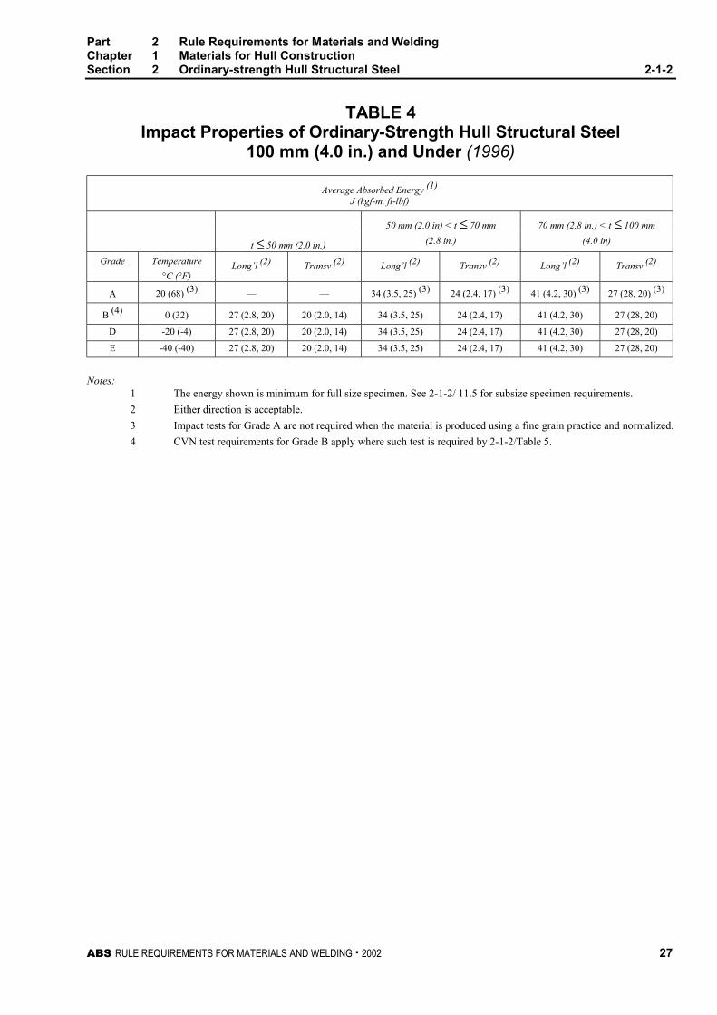
TABLE 4Impact Properties of Ordinary-Strength Hull Structural Steel
100 mm (4.0 in.) and Under (1996)
Average Absorbed Energy (1)
J (kgf-m, ft-lbf)
50 mm (2.0 in) < t ≤ 70 mm 70 mm (2.8 in.) < t ≤ 100 mm
t ≤ 50 mm (2.0 in.) (2.8 in.) (4.0 in)
Grade Temperature
°C (°F)Long’l (2) Transv (2) Long’l (2) Transv (2) Long’l (2) Transv (2)
A 20 (68) (3) — — 34 (3.5, 25) (3) 24 (2.4, 17) (3) 41 (4.2, 30) (3) 27 (28, 20) (3)
B (4) 0 (32) 27 (2.8, 20) 20 (2.0, 14) 34 (3.5, 25) 24 (2.4, 17) 41 (4.2, 30) 27 (28, 20)
D -20 (-4) 27 (2.8, 20) 20 (2.0, 14) 34 (3.5, 25) 24 (2.4, 17) 41 (4.2, 30) 27 (28, 20)
E -40 (-40) 27 (2.8, 20) 20 (2.0, 14) 34 (3.5, 25) 24 (2.4, 17) 41 (4.2, 30) 27 (28, 20)
Notes:1 The energy shown is minimum for full size specimen. See 2-1-2/ 11.5 for subsize specimen requirements.
2 Either direction is acceptable.
3 Impact tests for Grade A are not required when the material is produced using a fine grain practice and normalized.
4 CVN test requirements for Grade B apply where such test is required by 2-1-2/Table 5.
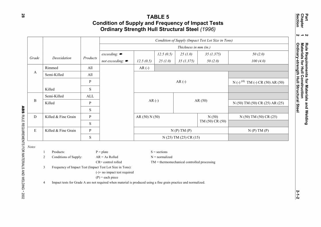
TABLE 5Condition of Supply and Frequency of Impact Tests
Ordinary Strength Hull Structural Steel (1996)
Condition of Supply (Impact Test Lot Size in Tons)
Thickness in mm (in.)
exceeding: ➨ 12.5 (0.5) 25 (1.0) 35 (1.375) 50 (2.0)Grade Deoxidation Products
not exceeding: ➨ 12.5 (0.5) 25 (1.0) 35 (1.375) 50 (2.0) 100 (4.0)
Rimmed All AR (-)
Semi-Killed All
P AR (-) N (-) (4) TM (-) CR (50) AR (50)
A
Killed S
Semi-Killed ALL
Killed P N (50) TM (50) CR (25) AR (25)B
S
AR (-) AR (50)
Killed & Fine Grain P N (50) TM (50) CR (25)D
S
AR (50) N (50) N (50)TM (50) CR (50)
Killed & Fine Grain P N (P) TM (P) N (P) TM (P)E
S N (25) TM (25) CR (15)
Notes
1 Products: P = plate S = sections
2 Conditions of Supply: AR = As Rolled N = normalized
CR= control rolled TM = thermomechanical controlled processing
3 Frequency of Impact Test (Impact Test Lot Size in Tons):
(-)= no impact test required
(P) = each piece
4 Impact tests for Grade A are not required when material is produced using a fine grain practice and normalized.
Part
2R
ule R
equ
iremen
ts fo
r Materials an
d W
eldin
gC
hap
ter1
Materials fo
r Hu
ll Co
nstru
ction
Sectio
n2
Ord
inary-stren
gth
Hu
ll Stru
ctural S
teel2-1-2
28A
BS
RULE REQUIREMENTS FOR MATERIALS AND WELDING . 2002
ABS RULE REQUIREMENTS FOR MATERIALS AND WELDING . 2002 29
P A R T
2C H A P T E R 1 Materials for Hull Construction
S E C T I O N 3 Higher-strength Hull StructuralSteel
CONTENTS1 Higher-strength Hull Structural Steel................................... 31
3 General................................................................................... 31
5 Fine Grain Practice................................................................ 31
7 Additional Requirements of TMCP Steel ............................. 32
7.1 Carbon Equivalent.................................................................. 32
7.3 Cold Cracking Susceptibility................................................... 32
TABLE 1 Chemical Properties of Higher-strength HullStructural Steel 100 mm (4.0 in.) and Under ............ 33
TABLE 2 Tensile Properties of Higher-strength HullStructural Steel 100 mm (4.0 in.) and Under ............ 34
TABLE 3 Elongation Requirements for Alternative BSpecimen.................................................................... 34
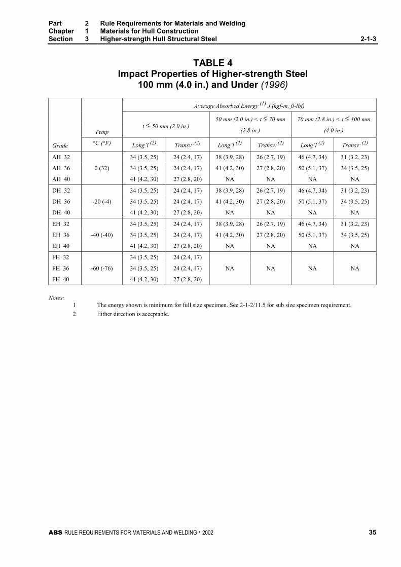
TABLE 4 Impact Properties of Higher-strength Steel100 mm (4.0 in.) and Under ....................................... 35
TABLE 5 Condition of Supply and Frequency of ImpactTests Higher-strength Hull Structural Steel ............. 36
TABLE 6 Carbon Equivalent for Higher-strength HullStructural Steel 100 mm (4.0 in.) and UnderProduced by TMCP.................................................... 37

ABS RULE REQUIREMENTS FOR MATERIALS AND WELDING . 2002 31
P A R T
2C H A P T E R 1 Materials for Hull Construction
S E C T I O N 3 Higher-strength Hull StructuralSteel 2 - 1 - 3
1 Higher-strength Hull Structural Steel (1996) 2-1-3/1
The requirements in this subsection are intended for products for the following thicknesses:
Plates and Wide Flats
AH32, DH32, EH32, AH36, DH36 and EH36 steels: up to and including 100 mm (4 in.)
AH40, DH40, EH40, FH32, FH36 and FH40 steels: up to and including 50 mm (2 in.)
Sections and Bars up to and including 50 mm (2 in.)
3 General (1996) 2-1-3/3
The requirements in 2-1-2/3 through 2-1-2/15 are also applicable to higher-strength hull structuralsteels with the following paragraphs and Tables replaced by the higher-strength requirements asindicated.
2-1-2/Table 1 replaced by 2-1-3/Table 1
2-1-2/Table 2 replaced by 2-1-3/Table 2
2-1-2/Table 3 replaced by 2-1-3/Table 3
2-1-2/Table 4 replaced by 2-1-3/Table 4
2-1-2/Table 5 replaced by 2-1-3/Table 5
2-1-2/5.7 replaced by 2-1-3/5
5 Fine Grain Practice (1996) 2-1-3/5
Where steel is required to be made using fine grain practice, the requirement may be met by one of thefollowing conditions.
i) A McQuaid-Ehn austenite grain size of 5 or finer in accordance with ASTM E112 for eachladle of each heat, or
ii) Minimum Acid-soluble Aluminum content of 0.015% or minimum total Aluminum content of0.020% for each ladle of each heat, or

Part 2 Rule Requirements for Materials and WeldingChapter 1 Materials for Hull ConstructionSection 3 Higher-strength Hull Structural Steel 2-1-3
32 ABS RULE REQUIREMENTS FOR MATERIALS AND WELDING . 2002
iii) Minimum Columbium (Niobium) content of 0.020% or minimum Vanadium content of0.050% for each ladle of each heat, or
iv) When Vanadium and Aluminum are used in combination, minimum Vanadium content of0.030% and minimum acid-soluble Aluminum content of 0.010% or minimum totalAluminum content of 0.015%.
v) When Columbium (Niobium) and Aluminum are used in combination, minimum Columbium(Niobium) content of 0.010% and minimum acid-soluble Aluminum content of 0.010% orminimum total Aluminum content of 0.015%.
7 Additional Requirements of TMCP Steel (1996) 2-1-3/7
7.1 Carbon Equivalent 2-1-3/7.1
The carbon equivalent Ceq as determined from the ladle analysis in accordance with the followingequation is to meet the requirements in 2-1-3/Table 6:
Ceq = 5
VMoCr
6
MnC
++++ ( )%15
CuNi ++
7.3 Cold Cracking Susceptibility 2-1-3/7.3
Unless otherwise specified by the purchaser, the clod cracking susceptibility
Pcm may be calculated in accordance with the following equation:
20
Cr
60
Ni
20
Cu
20
Mn
30
SiC +++++=cmP ( )%5B
10
V
15
Mo +++
Selection of the maximum value for Pcm is a matter to be agreed between the fabricator and the steelmill when the steel is ordered.
Part 2 Rule Requirements for Materials and WeldingChapter 1 Materials for Hull ConstructionSection 3 Higher-strength Hull Structural Steel 2-1-3
ABS RULE REQUIREMENTS FOR MATERIALS AND WELDING . 2002 33
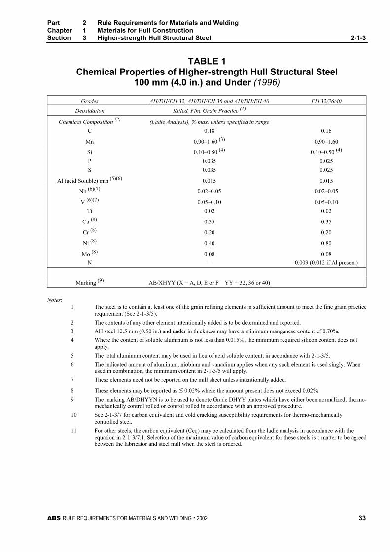
TABLE 1Chemical Properties of Higher-strength Hull Structural Steel
100 mm (4.0 in.) and Under (1996)
Grades AH/DH/EH 32, AH/DH/EH 36 and AH/DH/EH 40 FH 32/36/40
Deoxidation Killed, Fine Grain Practice (1)
Chemical Composition (2) (Ladle Analysis), % max. unless specified in range
C 0.18 0.16
Mn 0.90–1.60 (3) 0.90–1.60
Si 0.10–0.50 (4) 0.10–0.50 (4)
P 0.035 0.025
S 0.035 0.025
Al (acid Soluble) min.(5)(6) 0.015 0.015
Nb (6)(7) 0.02–0.05 0.02–0.05
V (6)(7) 0.05–0.10 0.05–0.10
Ti 0.02 0.02
Cu (8) 0.35 0.35
Cr (8) 0.20 0.20
Ni (8) 0.40 0.80
Mo (8) 0.08 0.08
N — 0.009 (0.012 if Al present)
Marking (9) AB/XHYY (X = A, D, E or F YY = 32, 36 or 40)
Notes:1 The steel is to contain at least one of the grain refining elements in sufficient amount to meet the fine grain practice
requirement (See 2-1-3/5).
2 The contents of any other element intentionally added is to be determined and reported.
3 AH steel 12.5 mm (0.50 in.) and under in thickness may have a minimum manganese content of 0.70%.
4 Where the content of soluble aluminum is not less than 0.015%, the minimum required silicon content does notapply.
5 The total aluminum content may be used in lieu of acid soluble content, in accordance with 2-1-3/5.
6 The indicated amount of aluminum, niobium and vanadium applies when any such element is used singly. Whenused in combination, the minimum content in 2-1-3/5 will apply.
7 These elements need not be reported on the mill sheet unless intentionally added.
8 These elements may be reported as ≤ 0.02% where the amount present does not exceed 0.02%.
9 The marking AB/DHYYN is to be used to denote Grade DHYY plates which have either been normalized, thermo-mechanically control rolled or control rolled in accordance with an approved procedure.
10 See 2-1-3/7 for carbon equivalent and cold cracking susceptibility requirements for thermo-mechanicallycontrolled steel.
11 For other steels, the carbon equivalent (Ceq) may be calculated from the ladle analysis in accordance with theequation in 2-1-3/7.1. Selection of the maximum value of carbon equivalent for these steels is a matter to be agreedbetween the fabricator and steel mill when the steel is ordered.
Part 2 Rule Requirements for Materials and WeldingChapter 1 Materials for Hull ConstructionSection 3 Higher-strength Hull Structural Steel 2-1-3
34 ABS RULE REQUIREMENTS FOR MATERIALS AND WELDING . 2002
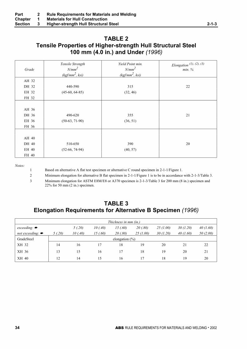
TABLE 2Tensile Properties of Higher-strength Hull Structural Steel
100 mm (4.0 in.) and Under (1996)
Grade
Tensile Strength
N/mm2
(kgf/mm2, ksi)
Yield Point min.
N/mm2
(kgf/mm2, ksi)
Elongation (1), (2), (3)
min. %
AH 32
DH 32 440-590 315 22
EH 32 (45-60, 64-85) (32, 46)
FH 32
AH 36
DH 36 490-620 355 21
EH 36 (50-63, 71-90) (36, 51)
FH 36
AH 40
DH 40 510-650 390 20
EH 40 (52-66, 74-94) (40, 57)
FH 40
Notes:1 Based on alternative A flat test specimen or alternative C round specimen in 2-1-1/Figure 1.
2 Minimum elongation for alternative B flat specimen in 2-1-1/Figure 1 is to be in accordance with 2-1-3/Table 3.
3 Minimum elongation for ASTM E8M/E8 or A370 specimen is 2-1-3/Table 3 for 200 mm (8 in.) specimen and22% for 50 mm (2 in.) specimen.
TABLE 3Elongation Requirements for Alternative B Specimen (1996)
Thickness in mm (in.)
exceeding: ➨ 5 (.20) 10 (.40) 15 (.60) 20 (.80) 25 (1.00) 30 (1.20) 40 (1.60)
not exceeding: ➨ 5 (.20) 10 (.40) 15 (.60) 20 (.80) 25 (1.00) 30 (1.20) 40 (1.60) 50 (2.00)
GradeSteel elongation (%)
XH 32 14 16 17 18 19 20 21 22
XH 36 13 15 16 17 18 19 20 21
XH 40 12 14 15 16 17 18 19 20
Part 2 Rule Requirements for Materials and WeldingChapter 1 Materials for Hull ConstructionSection 3 Higher-strength Hull Structural Steel 2-1-3
ABS RULE REQUIREMENTS FOR MATERIALS AND WELDING . 2002 35
TABLE 4Impact Properties of Higher-strength Steel
100 mm (4.0 in.) and Under (1996)
Average Absorbed Energy (1) J (kgf-m, ft-lbf)
Tempt ≤ 50 mm (2.0 in.)
50 mm (2.0 in.) < t ≤ 70 mm
(2.8 in.)
70 mm (2.8 in.) < t ≤ 100 mm
(4.0 in.)
Grade °C (°F) Long’l (2) Transv..(2) Long’l (2) Transv..(2) Long’l (2) Transv..(2)
AH 32 34 (3.5, 25) 24 (2.4, 17) 38 (3.9, 28) 26 (2.7, 19) 46 (4.7, 34) 31 (3.2, 23)
AH 36 0 (32) 34 (3.5, 25) 24 (2.4, 17) 41 (4.2, 30) 27 (2.8, 20) 50 (5.1, 37) 34 (3.5, 25)
AH 40 41 (4.2, 30) 27 (2.8, 20) NA NA NA NA
DH 32 34 (3.5, 25) 24 (2.4, 17) 38 (3.9, 28) 26 (2.7, 19) 46 (4.7, 34) 31 (3.2, 23)
DH 36 -20 (-4) 34 (3.5, 25) 24 (2.4, 17) 41 (4.2, 30) 27 (2.8, 20) 50 (5.1, 37) 34 (3.5, 25)
DH 40 41 (4.2, 30) 27 (2.8, 20) NA NA NA NA
EH 32 34 (3.5, 25) 24 (2.4, 17) 38 (3.9, 28) 26 (2.7, 19) 46 (4.7, 34) 31 (3.2, 23)
EH 36 -40 (-40) 34 (3.5, 25) 24 (2.4, 17) 41 (4.2, 30) 27 (2.8, 20) 50 (5.1, 37) 34 (3.5, 25)
EH 40 41 (4.2, 30) 27 (2.8, 20) NA NA NA NA
FH 32 34 (3.5, 25) 24 (2.4, 17)
FH 36 -60 (-76) 34 (3.5, 25) 24 (2.4, 17) NA NA NA NA
FH 40 41 (4.2, 30) 27 (2.8, 20)
Notes:1 The energy shown is minimum for full size specimen. See 2-1-2/11.5 for sub size specimen requirement.
2 Either direction is acceptable.
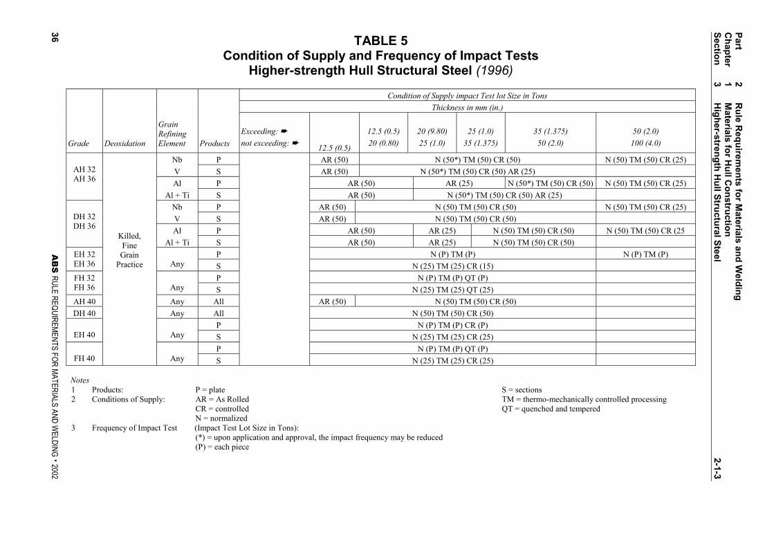
TABLE 5Condition of Supply and Frequency of Impact Tests
Higher-strength Hull Structural Steel (1996)
Condition of Supply impact Test lot Size in Tons
Thickness in mm (in.)
Exceeding: ➨ 12.5 (0.5) 20 (9.80) 25 (1.0) 35 (1.375) 50 (2.0)
Grade Deoxidation
GrainRefiningElement Products not exceeding: ➨
12.5 (0.5)20 (0.80) 25 (1.0) 35 (1.375) 50 (2.0) 100 (4.0)
Nb P AR (50) N (50*) TM (50) CR (50) N (50) TM (50) CR (25)
V S AR (50) N (50*) TM (50) CR (50) AR (25)
Al P AR (50) AR (25) N (50*) TM (50) CR (50) N (50) TM (50) CR (25)
AH 32AH 36
Al + Ti S AR (50) N (50*) TM (50) CR (50) AR (25)
Nb P AR (50) N (50) TM (50) CR (50) N (50) TM (50) CR (25)
V S AR (50) N (50) TM (50) CR (50)
Al P AR (50) AR (25) N (50) TM (50) CR (50) N (50) TM (50) CR (25
DH 32DH 36
Al + Ti S AR (50) AR (25) N (50) TM (50) CR (50)
P N (P) TM (P) N (P) TM (P)EH 32EH 36 Any S N (25) TM (25) CR (15)
P N (P) TM (P) QT (P)FH 32FH 36 Any S N (25) TM (25) QT (25)
AH 40 Any All AR (50) N (50) TM (50) CR (50)
DH 40 Any All N (50) TM (50) CR (50)
P N (P) TM (P) CR (P)EH 40 Any S N (25) TM (25) CR (25)
P N (P) TM (P) QT (P)FH 40
Killed,FineGrain
Practice
Any S N (25) TM (25) CR (25)
Notes1 Products: P = plate S = sections2 Conditions of Supply: AR = As Rolled TM = thermo-mechanically controlled processing
CR = controlled QT = quenched and temperedN = normalized
3 Frequency of Impact Test (Impact Test Lot Size in Tons):(*) = upon application and approval, the impact frequency may be reduced(P) = each piece
Part
2R
ule R
equ
iremen
ts fo
r Materials an
d W
eldin
gC
hap
ter1
Materials fo
r Hu
ll Co
nstru
ction
Sectio
n3
Hig
her-stren
gth
Hu
ll Stru
ctural S
teel
2-1-3
36A
BS
RULE REQUIREMENTS FOR MATERIALS AND WELDING . 2002
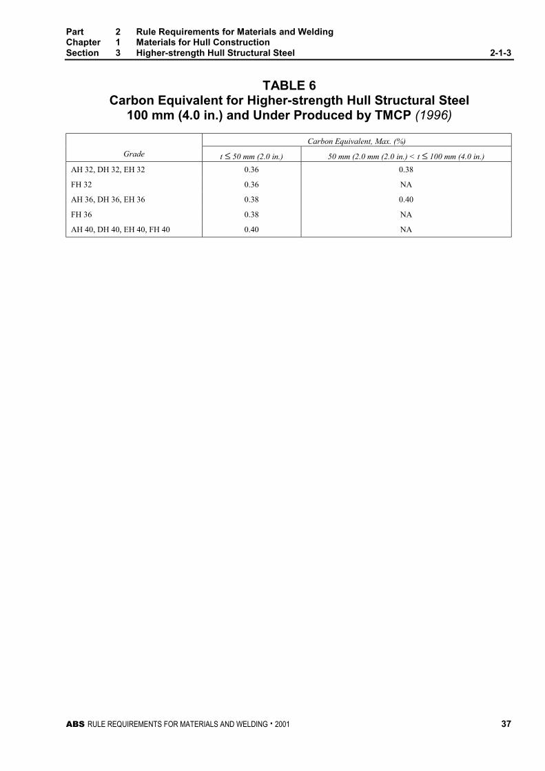
Part 2 Rule Requirements for Materials and WeldingChapter 1 Materials for Hull ConstructionSection 3 Higher-strength Hull Structural Steel 2-1-3
ABS RULE REQUIREMENTS FOR MATERIALS AND WELDING . 2001 37
TABLE 6Carbon Equivalent for Higher-strength Hull Structural Steel
100 mm (4.0 in.) and Under Produced by TMCP (1996)
Carbon Equivalent, Max. (%)
Grade t ≤ 50 mm (2.0 in.) 50 mm (2.0 mm (2.0 in.) < t ≤ 100 mm (4.0 in.)
AH 32, DH 32, EH 32 0.36 0.38
FH 32 0.36 NA
AH 36, DH 36, EH 36 0.38 0.40
FH 36 0.38 NA
AH 40, DH 40, EH 40, FH 40 0.40 NA

ABS RULE REQUIREMENTS FOR MATERIALS AND WELDING . 2002 39
P A R T
2C H A P T E R 1 Materials for Hull Construction
S E C T I O N 4 Low Temperature Materials 2 - 1 - 4
1 General 2-1-4/1
Materials for Liquefied Gas Carriers are also to comply with the requirements of Section 5-8-6.
3 Marking 2-1-4/3
In addition to the Bureau marking requirements, the name or brand of the manufacturer, the letterindicating the grade designation, the manufacturer’s identification numbers and for pressure vesselquality material the letters PV are to be legibly marked at each end of the finished plate.
Aluminum sheet and plate is to be identified at each end with the manufacturer’s name or trade mark,the applicable alloy and temper designation, and in addition for plate, with the lot number and thespecification number.
5 Toughness Tests 2-1-4/5
5.1 Charpy V-notch 2-1-4/5.1
The specimen is to be transverse to the final direction of rolling for plates and longitudinal to the finaldirection of rolling for profiles, shapes and bars. Subject to special approval acceptance may be basedon a minimum lateral expansion opposite the notch of 0.38 mm (0.015 in.) for transverse specimensand 0.50 mm (0.020 in.) for longitudinal specimens. See 2-1-1/11.11.
5.3 Drop-weight Test 2-1-4/5.3
Where drop-weight tests are required, they are to be conducted for no-break performance of twospecimens in accordance with ASTM E208, Conducting Drop-weight Tests to Determine Nil-ductilityTransition Temperature of Ferritic Steels.’’ Drop-weight tests are not to be conducted on material ofless than 12.5 mm (0.5 in.) thickness. For thickness between 12.5 mm (0.5 in.) and 16 mm (0.63 in.),the E208 specimen P-3 machined to 12.5 mm (0.5 in.) thickness is to be used with a stop distance of2.29 mm (0.09 in.).
7 Service Temperature 0°C (32°F) or Above 2-1-4/7
See 5-8-6/Table 1.
Part 2 Rule Requirements for Materials and WeldingChapter 1 Materials for Hull ConstructionSection 4 Lower Temperature Materials 2-1-4
40 ABS RULE REQUIREMENTS FOR MATERIALS AND WELDING . 2002
9 Service Temperature at or Above -55°C (-67°F) up to 0°C(32°F) 2-1-4/9
See 5-8-6/Table 2 (ABS). Steels intended for this temperature range are normally carbon manganesesteels furnished fully killed fine grain normalized.
These steels meeting the requirements in 5-8-6/Table 2 (ABS) may be marked AB/V-OXX orAB/VH-OXX, indicating by XX the test temperature in Celsius below zero in accordance with2-1-2/13.9.
11 Service Temperature at or Above -196°C (-320°F) up to-55°C (-67°F) 2-1-4/11
See 5-8-6/Table 3 and 5-8-6/Table 4. Steels intended for the temperature range are normally of theferritic nickel-alloy type made with fine-grain practice, but austenitic stainless steels or aluminumalloys may be used. In general, the following ASTM grades of material or their equivalents may beused for the temperature listed below. The chemical composition, heat treatment, tensile and impactproperties are to conform to the requirements of the applicable approved specification.
A203, 21/4% Ni -62°C (-80°F)-59°C (-75°F)
for Grade Afor Grade B
A203, 31/2% Ni -90°C (-130°F)-79°C (-110°F)
for Grade Dfor Grade E
A645, 5% Ni -105°C(-155°F)1
A353, 9% Ni -196°C(-320°F)
A553, 9% Ni -196°C(-320°F)
Austenitic stainless steels -196°C(-320°F)
A658, 36% Ni -196°C(-320°F)2
B209, Type 5083, Alum. Alloy -196°C(-320°F)
Notes1 5% Nickel steel may be used down to -165°C (-265°F) upon special consideration provided that impact
tests are conducted at -196°C (-320°F).
2 Chemistry will be specially considered for lowering the coefficient of expansion.
13 Service Temperatures below -196°C (-320°F) 2-1-4/13
Austenitic low carbon (less than 0.10%) stainless steels and aluminum alloys are to be used for thesetemperatures. The chemical composition, heat treatment, and tensile properties are to conform to therequirements of the approved specification. Stainless steels types 304, 304L, and 347 and type 5083aluminum alloy do not require toughness testing for service temperatures above -254°C (-425°F).Toughness tests for -254°C (-425°F) service temperature and below will be subject to specialconsideration.
ABS RULE REQUIREMENTS FOR MATERIALS AND WELDING . 2002 41
P A R T
2C H A P T E R 1 Materials for Hull Construction
S E C T I O N 5 Hull Steel Castings 2 - 1 - 5
Note: In substantial agreement with ASTM A27 Mild to Medium-strength Carbon-steel Castings for GeneralApplication. (Grade 60-30 Class I.)
1 Process of Manufacture 2-1-5/1
The following requirements cover carbon-steel castings intended to be used in hull construction andequipment as distinguished from high-temperature applications. This does not preclude the use ofalloy steels in accordance with the permissibility expressed in Section 2-1-1. The steel is to be madeby one or more of the following processes: open-hearth, basic-oxygen, electric-furnace, or such otherprocess as may be approved.
3 Marking and Retests 2-1-5/3
3.1 Marking 2-1-5/3.1
The manufacturer’s name or identification mark and the pattern number is to be cast on all castingsexcept those of such small size as to make this type of marking impracticable. The Bureau markings,indicating satisfactory compliance with the Rule requirements, and as furnished by the Surveyor, is tobe stamped on all castings accepted in such location as to be discernible after machining andinstallation. In addition, identification numbers of the heats used for pouring the castings are to bestamped on all castings individually weighing 227 kg (500 lb) or more.
3.3 Retests 2-1-5/3.3
If the results of the physical tests for any casting or any lot of castings do not conform to therequirements specified, the manufacturer may reheat-treat the castings. Retests of additional specimenor specimens are to be made and are to conform to the requirements specified.
5 Heat Treatment 2-1-5/5
Except in cases specifically approved otherwise, all castings are to be either fully annealed,normalized or normalized and tempered in a furnace of ample proportions to bring the whole castingto a uniform temperature above the transformation range on the annealing or normalizing cycle. Theyare to be held ‘‘soaking’’ at the proper temperature for at least a length of time equivalent to one hourper 25.5 mm (1 in.) of thickness of the heaviest member for the first 127.5 mm (5.00 in.) plus anadditional 15 minutes for each additional 25.5 mm (1.00 in.) over 127.5 mm (5.00 in.) of thickness.
Part 2 Rule Requirements for Materials and WeldingChapter 1 Materials for Hull ConstructionSection 5 Hull Steel Castings 2-1-5
42 ABS RULE REQUIREMENTS FOR MATERIALS AND WELDING . 2002
No annealed casting is to be removed from the furnace until the temperature of the entire furnacecharge has fallen to or below a temperature of 455°C (850°F). Local heating or cooling, also bendingand straightening of annealed castings, are not permitted except with the express sanction of theSurveyor.
7 Tensile Properties 2-1-5/7
Steel castings are to conform to the following requirements as to tensile properties.
Tensile strength min., N/mm2 (kgf/mm2, psi) 415 (42, 60000)
Yield point min., N/mm2 (kgf/mm2, psi) 205 (21, 30000)
Elongation in 50 mm (2 in.) min., % 24
Reduction of area min., % 35
9 Test Specimens 2-1-5/9
9.1 Material Coupons (1998) 2-1-5/9.1
The physical properties are to be determined from test specimens prepared from coupons which,except as specified in 2-1-5/9.3, are to be cast integral with the casting to be inspected. When this isimpracticable, the coupons may be cast with and gated to the casting. In either case these coupons arenot to be detached until the heat treatment of the castings has been completed, nor until the couponshave been stamped by the Surveyor for identification. Where the material identification system of themanufacture is found acceptable to the Bureau and is maintained in that condition through initial andperiodical verification by the Bureau, it may be considered in lieu of stamping by the Surveyor beforedetachment.
9.3 Separately Cast Coupons 2-1-5/9.3
In the case of small castings having an estimated weight of less than 908 kg (2000 lb) each, thecoupons may be cast separately, provided the Surveyor is furnished an affidavit by the manufacturerstating that the separately cast coupons were cast from the same heat as the castings represented andthat they were heat-treated with the castings.
11 Number of Tests 2-1-5/11
At least one tension test is to be made from each heat in each heat-treatment charge. However, if themanufacturer’s quality-control procedure includes satisfactory automatic chart recording oftemperature and time, then one tension test from each heat for castings subject to same heat-treatingprocedure may be allowed at the discretion of the attending Surveyor.
13 Inspection and Repair 2-1-5/13
13.1 General 2-1-5/13.1
All castings are to be inspected by the Surveyor after final heat treatment and thorough cleaning toinsure that the castings are free from defects.
Part 2 Rule Requirements for Materials and WeldingChapter 1 Materials for Hull ConstructionSection 5 Hull Steel Castings 2-1-5
ABS RULE REQUIREMENTS FOR MATERIALS AND WELDING . 2002 43
13.3 Minor Defects 2-1-5/13.3
Defects are to be considered minor when the cavity prepared for welding has a depth not greater than20% of the actual wall thickness, but in no case greater than 25 mm (1 in.) and has no linealdimension greater than 4 times the wall thickness nor greater than 150 mm (6 in.). Repairs of minordefects where welding is required are to be in accordance with an approved procedure.
13.5 Major Defects 2-1-5/13.5
Defects other than minor defects with dimensions greater than those given in 2-1-5/13.3 above, may,with the Surveyor’s approval, be repaired by welding using an approved procedure.
13.7 Welded Repair 2-1-5/13.7
The defects are to be removed to sound metal, and before welding the excavation is to be investigatedby suitable approved non-destructive examination methods to ensure that the defect has beenremoved. In the case of repair of major defects on large castings such as rudder horns, stern frames,shoe pieces and rudder stocks, welding is not permitted on unheat-treated castings. Corrective weldingis to be associated with the use of preheat.
13.9 Post Weld Repair Heat Treatment 2-1-5/13.9
All welded repairs of major defects are to be given a suitable post weld heat treatment.
13.11 Non-destructive Testing 2-1-5/13.11
Important hull castings such as cast-steel stern frames and rudder horns are to be subjected to surfaceinspection by magnetic particle, dye penetrant or other equivalent means. Cast-steel stern frames areto be subjected to such inspection over the entire skeg portion of the casting, including the enlargedportion forming the junction to the propeller post, and at such other critical locations as may beindicated on the approved plan of the stern frame. These surfaces are to be clean and free of allsubstances that will affect the sensitivity of the magnetic-particle test and the degree of magnetizationare to produce a satisfactory magnetic potential on the surfaces being tested. In addition to surfaceinspection, cast-steel rudder horns are to be inspected by radiographic means or, at the discretion ofthe attending Surveyor, in accordance with an approved ultrasonic procedure at the area just below theconnection to the shell, and at such other locations as may be indicated on the approved plan. Theradiographic acceptance standard for all categories of defects is to be at least equivalent to severitylevel 4 of ASTM E186, E280 or E446. The ultrasonic acceptance standard is to be at least equivalentto quality level 4 of ASTM A609.

ABS RULE REQUIREMENTS FOR MATERIALS AND WELDING . 2002 45
P A R T
2C H A P T E R 1 Materials for Hull Construction
S E C T I O N 6 Hull Steel Forgings 2 - 1 - 6
Note: In substantial agreement with ASTM A668 Carbon-steel Forgings for General Industrial Use (Class B = Grade 2).
1 Process of Manufacture 2-1-6/1
1.1 General 2-1-6/1.1
The following requirements cover carbon-steel forgings intended to be used in hull construction andequipment as distinguished from high-temperature applications. This does not preclude the use ofother steels as permitted by Section 2-1-1. The steel is to be fully killed and is to be made by one ormore of the following processes: open-hearth, basic-oxygen, electric-furnace, or such other process asmay be approved.
1.3 Degree of Reduction 2-1-6/1.3
The cross-sectional area of the main body of the unmachined, finished forging is not to exceed one-third of the area of the ingot; palms, flanges and similar enlargements on the forging are not to exceedtwo-thirds of the area of the ingot.
1.5 Discard 2-1-6/1.5
A sufficient discard is to be made from each ingot to secure freedom from piping and unduesegregation.
1.7 Chemical Composition 2-1-6/1.7
The chemical composition is to be reported and the carbon content is not to exceed 0.35% unlessspecially approved. Specially approved grades having more than 0.35% carbon are to have S markedafter the grade number.
3 Marking and Retests 2-1-6/3
3.1 Marking 2-1-6/3.1
In addition to appropriate identification markings of the manufacturer, the Bureau markings,indicating satisfactory compliance with the Rule requirements, and as furnished by the Surveyor are tobe stamped on all forgings accepted in such location as to be discernible after machining andinstallation. Grade 2 forgings are to be stamped AB/2.
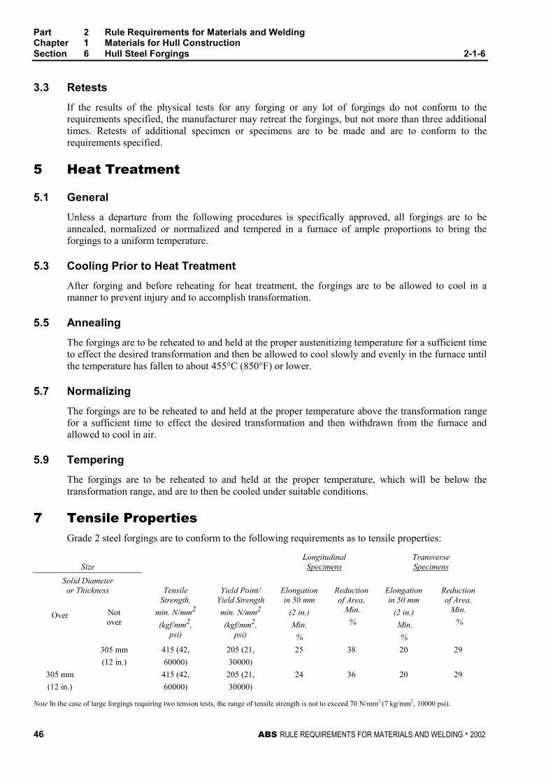
Part 2 Rule Requirements for Materials and WeldingChapter 1 Materials for Hull ConstructionSection 6 Hull Steel Forgings 2-1-6
46 ABS RULE REQUIREMENTS FOR MATERIALS AND WELDING . 2002
3.3 Retests 2-1-6/3.3
If the results of the physical tests for any forging or any lot of forgings do not conform to therequirements specified, the manufacturer may retreat the forgings, but not more than three additionaltimes. Retests of additional specimen or specimens are to be made and are to conform to therequirements specified.
5 Heat Treatment 2-1-6/5
5.1 General 2-1-6/5.1
Unless a departure from the following procedures is specifically approved, all forgings are to beannealed, normalized or normalized and tempered in a furnace of ample proportions to bring theforgings to a uniform temperature.
5.3 Cooling Prior to Heat Treatment 2-1-6/5.3
After forging and before reheating for heat treatment, the forgings are to be allowed to cool in amanner to prevent injury and to accomplish transformation.
5.5 Annealing 2-1-6/5.5
The forgings are to be reheated to and held at the proper austenitizing temperature for a sufficient timeto effect the desired transformation and then be allowed to cool slowly and evenly in the furnace untilthe temperature has fallen to about 455°C (850°F) or lower.
5.7 Normalizing 2-1-6/5.7
The forgings are to be reheated to and held at the proper temperature above the transformation rangefor a sufficient time to effect the desired transformation and then withdrawn from the furnace andallowed to cool in air.
5.9 Tempering 2-1-6/5.9
The forgings are to be reheated to and held at the proper temperature, which will be below thetransformation range, and are to then be cooled under suitable conditions.
7 Tensile Properties 2-1-6/7
Grade 2 steel forgings are to conform to the following requirements as to tensile properties:
SizeLongitudinalSpecimens
TransverseSpecimens
Solid Diameteror Thickness
Over Notover
TensileStrength,
min. N/mm2
(kgf/mm2,psi)
Yield Point/Yield Strength
min. N/mm2
(kgf/mm2,psi)
Elongationin 50 mm
(2 in.)
Min.
%
Reductionof Area,
Min.
%
Elongationin 50 mm
(2 in.)
Min.
%
Reductionof Area,
Min.
%
305 mm 415 (42, 205 (21, 25 38 20 29
(12 in.) 60000) 30000)
305 mm 415 (42, 205 (21, 24 36 20 29
(12 in.) 60000) 30000)
Note In the case of large forgings requiring two tension tests, the range of tensile strength is not to exceed 70 N/mm2 (7 kg/mm2, 10000 psi).
Part 2 Rule Requirements for Materials and WeldingChapter 1 Materials for Hull ConstructionSection 6 Hull Steel Forgings 2-1-6
ABS RULE REQUIREMENTS FOR MATERIALS AND WELDING . 2002 47
9 Test Specimens 2-1-6/9
9.1 Location and Orientation of Specimens 2-1-6/9.1
The mechanical properties are to be determined from test specimens taken from prolongations havinga sectional area not less than that of the body of the forging. Specimens may be taken in a directionparallel to the axis of the forgings in the direction in which the metal is most drawn out or may betaken transversely. The axis of longitudinal specimens is to be located at any point midway betweenthe center and the surface of solid forgings and at any point midway between the inner and outersurfaces of the wall of hollow forgings. The axis of transverse specimens may be located close to thesurface of the forgings. In the case of carbon steel forgings, test results from other locations may bespecially approved provided appropriate supporting information is presented, which indicates that theproperties at the specified location will be in conformity with the specified tensile properties.
9.3 Hollow-drilled Specimens 2-1-6/9.3
In lieu of prolongations, the test specimens may be taken from forgings submitted for each test lot; orif satisfactory to the Surveyor, test specimens may be taken from forgings with a hollow drill.
9.5 Small Forgings 2-1-6/9.5
In the cases of small forgings weighing less than 114 kg (250 lb) each, where the foregoingprocedures are impracticable, a special forging may be made for the purpose of obtaining testspecimens, provided the Surveyor is satisfied that these test specimens are representative of theforgings submitted for testing. In such cases the special forgings are to be subjected to approximatelythe same amount of working and reduction as the forgings represented and are to be heat-treated withthose forgings.
9.7 Specimen Identification (1998) 2-1-6/9.7
The test specimens are not to be detached from the forgings until the final heat treatment of theforgings has been completed nor until the test specimens have been stamped by the Surveyor foridentification. Where the material identification system of the manufacture is found acceptable to theBureau and is maintained in that condition through initial and periodical verification by the Bureau, itmay be considered in lieu of stamping by the Surveyor before detachment.
11 Number of Tests 2-1-6/11
11.1 Tension Test 2-1-6/11.1
11.1.1 Large Forgings 2-1-6/11.1.1
In the case of large forgings with rough machined weights of 3180 kg (7000 lb) or over, onetension test is to be made from each end of the forging.
11.1.2 Intermediate-sized Forgings 2-1-6/11.1.2
In the case of forgings with rough machined weights less than 3180 kg (7000 lb), except asnoted in the following paragraph, at least one tension test is to be made from each forging.
11.1.3 Small Forgings 2-1-6/11.1.3
In the case of small forgings with rough machined weights less than 2270 kg (5000 lb), onetension test may be taken from one forging as representative of a lot provided the forgings ineach such lot are of similar size, are of one grade and kind only, are made from the same heatand are heat-treated in the same furnace charge.
Part 2 Rule Requirements for Materials and WeldingChapter 1 Materials for Hull ConstructionSection 6 Hull Steel Forgings 2-1-6
48 ABS RULE REQUIREMENTS FOR MATERIALS AND WELDING . 2002
11.3 Brinell Hardness Test 2-1-6/11.3
Each forging, except those with rough machined weights less than 113 kg (250 lb.) are to be BrinellHardness tested and are to meet the following requirements.
GradeBrinell Hardness Number Minimum
10 mm ball, 3000 kg load
2 120
11.5 Special Situations 2-1-6/11.5
In the cases of a number of pieces cut from a single forging, individual tests need not necessarily bemade for each piece, but forgings may be tested in accordance with whichever of the foregoingprocedures is applicable to the primary forging involved.
11.7 Inspection 2-1-6/11.7
All forgings are to be inspected by the Surveyor after final heat treatment and they are to be foundfree from defects.
ABS RULE REQUIREMENTS FOR MATERIALS AND WELDING . 2002 49
P A R T
2C H A P T E R 2 Equipment
CONTENTSSECTION 1 Anchors ................................................................... 51
1 Process of Manufacture ......................................... 53
3 Annealing ............................................................... 53
5 Testing and Inspection ........................................... 53
7 Details of Tests for Anchors ................................... 54
9 Marking for Anchors ............................................... 55
SECTION 2 Anchor Chain .......................................................... 59
1 Scope ..................................................................... 61
3 General................................................................... 61
5 Specially Approved Chain ...................................... 61
7 Qualification of Manufacturers ............................... 61
9 Chain Dimensions and Tolerances ........................ 62
11 Material for Chain................................................... 64
13 Material Testing...................................................... 64
15 Heat Treatment of Chain Lengths.......................... 66
17 Testing and Inspection of Chain Lengths............... 66
19 Details of Tests on Chain Lengths ......................... 67
21 Marking for Chain................................................... 68
23 Anchor Chain Accessories ..................................... 68
25 Unstudded Short-link Chain ................................... 70
SECTION 3 Rolled Steel Bars for Chain .................................... 77
1 General................................................................... 77
3 Material Testing...................................................... 78

ABS RULE REQUIREMENTS FOR MATERIALS AND WELDING . 2002 51
P A R T
2C H A P T E R 2 Equipment
S E C T I O N 1 Anchors
CONTENTS1 Process of Manufacture ........................................................ 53
3 Annealing............................................................................... 53
5 Testing and Inspection.......................................................... 53
5.1 Calibrated Testing Machines.................................................. 53
5.3 Test Coupons ......................................................................... 53
7 Details of Tests for Anchors................................................. 54
7.1 Bend Tests ............................................................................. 54
7.3 Drop Tests .............................................................................. 54
7.5 Hammering Tests ................................................................... 54
7.7 Fabricated Steel Anchors ....................................................... 54
7.9 Proof Tests ............................................................................. 54
9 Marking for Anchors ............................................................. 55
9.1 Kind of Markings..................................................................... 55
9.3 Provisions for Marks............................................................... 55
……
TABLE 1 Proof Tests for Anchors............................................ 56
FIGURE 1 Proof Load Application ............................................. 54
FIGURE 2 Stockless Anchor....................................................... 55

ABS RULE REQUIREMENTS FOR MATERIALS AND WELDING . 2002 53
P A R T
2C H A P T E R 2 Equipment
S E C T I O N 1 Anchors 2 - 2 - 1
1 Process of Manufacture 2-2-1/1
Anchors and anchor shackles are to be forged or cast from steel made by the open-hearth, basic-oxygen or electric-furnace process or such other materials or processes (e.g., plate or bar used infabricated steel anchors) as may be specially approved. Anchor shackles are to be of a design andmaterial suitable to the service for which the anchor is intended. The strength level of chain to whichthe shackle will be coupled should be a consideration.
3 Annealing 2-2-1/3
Each cast or forged part of a steel anchor is to be thoroughly annealed. Each part is to be held at theannealing temperature for at least a length of time equivalent to one hour per 25.5 mm (1.00 in.) ofthickness of the heaviest member for the first 127.5 mm (5.00 in.), plus an additional 15 minutes foreach additional 25.5 mm (1.00 in.) over 127.5 mm (5.00 in.) of thickness, and is not to be removedfrom the annealing furnace until the temperature has dropped to 370°C (700°F).
5 Testing and Inspection 2-2-1/5
5.1 Calibrated Testing Machines 2-2-1/5.1
All anchors are to be inspected and tested in the presence of a Surveyor, the proof testing being donein a machine recognized for such purposes. The Surveyor is to satisfy himself that the testingmachines are maintained in a satisfactory and accurate condition and is to keep a record of the datesand by whom the machines were rechecked or calibrated.
5.3 Test Coupons 2-2-1/5.3
A coupon sufficient to provide two or three standard bend test specimens are to be cast integral witheach casting submitted for approval, and is not to be detached from the casting until after theannealing is complete nor until it has been stamped by the Surveyor for identification.

Part 2 Rule Requirements for Materials and WeldingChapter 2 EquipmentSection 1 Anchors 2-2-1
ABS RULE REQUIREMENTS FOR MATERIALS AND WELDING . 200254
7 Details of Tests for Anchors 2-2-1/7
7.1 Bend Tests 2-2-1/7.1
At least one bend test is to be carried out on each cast piece of cast-steel anchors by subjecting astandard bend test specimen to a cold bend through an angle of 120 degrees around a 25 mm (1 in.)radius without any appearance of fracture. See also 2-1-5/3.3 for retests.
7.3 Drop Tests 2-2-1/7.3
Each piece of a cast-steel anchor is to be raised to a height of 3.7 m (12 ft) and dropped on an ironslab without fracturing.
7.5 Hammering Tests 2-2-1/7.5
Hammering tests are to be carried out on each piece of a cast-steel anchor, which is to be slung clearof the ground and well hammered to test the soundness of the material.
7.7 Fabricated Steel Anchors 2-2-1/7.7
For specially approved fabricated steel anchors, a magnetic particle examination of welds is to beperformed after proof testing and indicate freedom from injurious surface defects to the satisfaction ofthe Surveyor.
7.9 Proof Tests 2-2-1/7.9
Proof tests are to be carried out on all anchors after being temporarily assembled. The proof tests areto be in accordance with the values given in 2-2-1/Table 1. Anchors of proven superior holding abilityare to be proof-tested for a weight equal to 1.33 times the actual weight of the anchor. Anchor flukesare to be free to rotate between stops. The proof load is to be applied on the fluke at a location one-third of the distance from the tip of the fluke to the center of the crown as shown in 2-2-1/Figure 1.Both flukes are to be tested at the same time, first on one side of the shank, then reversed and testedon the other. After proof testing, anchors are to be visually inspected to insure that they are free fromsurface defects and excessive deformation due to seating.
The gauge lengths (see 2-2-1/Figure 1) under a load equal to one-tenth of the proof test load are to bedetermined before and after the application of full proof load on each side. The gauge length after theapplication of full proof load is to be not more than 1% in excess of the corresponding gauge lengthbefore the application of full proof load.
FIGURE 1Proof Load Application
Gauge Length
L
2 / 3L
1 / 3L
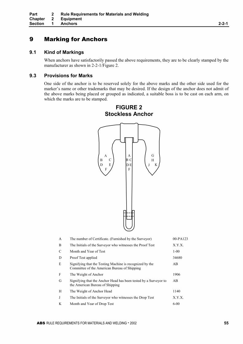
Part 2 Rule Requirements for Materials and WeldingChapter 2 EquipmentSection 1 Anchors 2-2-1
ABS RULE REQUIREMENTS FOR MATERIALS AND WELDING . 2002 55
9 Marking for Anchors 2-2-1/9
9.1 Kind of Markings 2-2-1/9.1
When anchors have satisfactorily passed the above requirements, they are to be clearly stamped by themanufacturer as shown in 2-2-1/Figure 2.
9.3 Provisions for Marks 2-2-1/9.3
One side of the anchor is to be reserved solely for the above marks and the other side used for themarker’s name or other trademarks that may be desired. If the design of the anchor does not admit ofthe above marks being placed or grouped as indicated, a suitable boss is to be cast on each arm, onwhich the marks are to be stamped.
FIGURE 2Stockless Anchor
A
F
BD E
C
J
AB C
D EF
HG
K
A The number of Certificate. (Furnished by the Surveyor) 00-PA123
B The Initials of the Surveyor who witnesses the Proof Test X.Y.X.
C Month and Year of Test 1-00
D Proof Test applied 34680
E Signifying that the Testing Machine is recognized by theCommittee of the American Bureau of Shipping
AB
F The Weight of Anchor 1906
G Signifying that the Anchor Head has been tested by a Surveyor tothe American Bureau of Shipping
AB
H The Weight of Anchor Head 1140
J The Initials of the Surveyor who witnesses the Drop Test X.Y.X.
K Month and Year of Drop Test 6-00
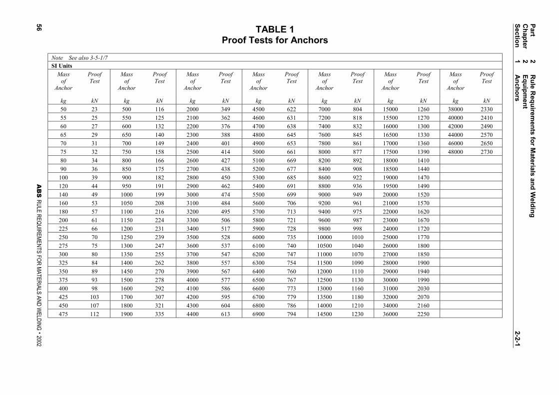
TABLE 1Proof Tests for Anchors
Note See also 3-5-1/7SI Units
Massof
Anchor
ProofTest
Massof
Anchor
ProofTest
Massof
Anchor
ProofTest
Massof
Anchor
ProofTest
Massof
Anchor
ProofTest
Massof
Anchor
ProofTest
Massof
Anchor
ProofTest
kg kN kg kN kg kN kg kN kg kN kg kN kg kN
50 23 500 116 2000 349 4500 622 7000 804 15000 1260 38000 2330
55 25 550 125 2100 362 4600 631 7200 818 15500 1270 40000 2410
60 27 600 132 2200 376 4700 638 7400 832 16000 1300 42000 2490
65 29 650 140 2300 388 4800 645 7600 845 16500 1330 44000 2570
70 31 700 149 2400 401 4900 653 7800 861 17000 1360 46000 2650
75 32 750 158 2500 414 5000 661 8000 877 17500 1390 48000 2730
80 34 800 166 2600 427 5100 669 8200 892 18000 1410
90 36 850 175 2700 438 5200 677 8400 908 18500 1440
100 39 900 182 2800 450 5300 685 8600 922 19000 1470
120 44 950 191 2900 462 5400 691 8800 936 19500 1490
140 49 1000 199 3000 474 5500 699 9000 949 20000 1520
160 53 1050 208 3100 484 5600 706 9200 961 21000 1570
180 57 1100 216 3200 495 5700 713 9400 975 22000 1620
200 61 1150 224 3300 506 5800 721 9600 987 23000 1670
225 66 1200 231 3400 517 5900 728 9800 998 24000 1720
250 70 1250 239 3500 528 6000 735 10000 1010 25000 1770
275 75 1300 247 3600 537 6100 740 10500 1040 26000 1800
300 80 1350 255 3700 547 6200 747 11000 1070 27000 1850
325 84 1400 262 3800 557 6300 754 11500 1090 28000 1900
350 89 1450 270 3900 567 6400 760 12000 1110 29000 1940
375 93 1500 278 4000 577 6500 767 12500 1130 30000 1990
400 98 1600 292 4100 586 6600 773 13000 1160 31000 2030
425 103 1700 307 4200 595 6700 779 13500 1180 32000 2070
450 107 1800 321 4300 604 6800 786 14000 1210 34000 2160
475 112 1900 335 4400 613 6900 794 14500 1230 36000 2250
Part
2R
ule R
equ
iremen
ts fo
r Materials an
d W
eldin
gC
hap
ter2
Eq
uip
men
tS
ection
1A
nch
ors
2-2-1
56A
BS
RULE REQUIREMENTS FOR MATERIALS AND WELDING . 2002

TABLE 1 (continued)Proof Tests for Anchors
Note See also 3-5-1/7Metric Units
Massof
Anchor
ProofTest
Massof
Anchor
ProofTest
Massof
Anchor
ProofTest
Massof
Anchor
ProofTest
Massof
Anchor
ProofTest
Massof
Anchor
ProofTest
Massof
Anchor
ProofTest
kg kgf kg kgf kg kgf kg kgf kg kgf kg kgf kg kgf
50 2370 500 11800 2000 35600 4500 63400 7000 82000 15000 128000 38000 238000
55 2570 550 12700 2100 36900 4600 64300 7200 83400 15500 130000 40000 246000
60 2760 600 13500 2200 38300 4700 65100 7400 84800 16000 133000 42000 254000
65 2950 650 14300 2300 39600 4800 65800 7600 86200 16500 136000 44000 262000
70 3130 700 15200 2400 40900 4900 66600 7800 87800 17000 139000 46000 270000
75 3300 750 16100 2500 42200 5000 67400 8000 89400 17500 142000 48000 278000
80 3460 800 16900 2600 43500 5100 68200 8200 91000 18000 144000
90 3700 850 17800 2700 44700 5200 69000 8400 92600 18500 147000
100 3990 900 18600 2800 45900 5300 69800 8600 94000 19000 150000
120 4520 950 19500 2900 47100 5400 70500 8800 95400 19500 152000
140 5000 1000 20300 3000 48300 5500 71300 9000 96800 20000 155000
160 5430 1050 21200 3100 49400 5600 72000 9200 98000 21000 160000
180 5850 1100 22000 3200 50500 5700 72700 9400 99400 22000 165000
200 6250 1150 22800 3300 51600 5800 73500 9600 100600 23000 170000
225 6710 1200 23600 3400 52700 5900 74200 9800 101800 24000 175000
250 7180 1250 24400 3500 53800 6000 74900 10000 103000 25000 180000
275 7640 1300 25200 3600 54800 6100 75500 10500 106000 26000 184000
300 8110 1350 26000 3700 55800 6200 76200 11000 109000 27000 189000
325 8580 1400 26700 3800 56800 6300 76900 11500 111000 28000 194000
350 9050 1450 27500 3900 57800 6400 77500 12000 113000 29000 198000
375 9520 1500 28300 4000 58800 6500 78200 12500 115000 30000 203000
400 9980 1600 29800 4100 59800 6600 78800 13000 118000 31000 207000
425 10500 1700 31300 4200 60700 6700 79400 13500 120000 32000 211000
450 10900 1800 32700 4300 61600 6800 80200 14000 123000 34000 220000
475 11400 1900 34200 4400 62500 6900 81000 14500 125000 36000 229000
Part
2R
ule R
equ
iremen
ts fo
r Materials an
d W
eldin
gC
hap
ter2
Eq
uip
men
tS
ection
1A
nch
ors
2-2-1
AB
S RULE REQUIREMENTS FOR MATERIALS AND W
ELDING . 200257
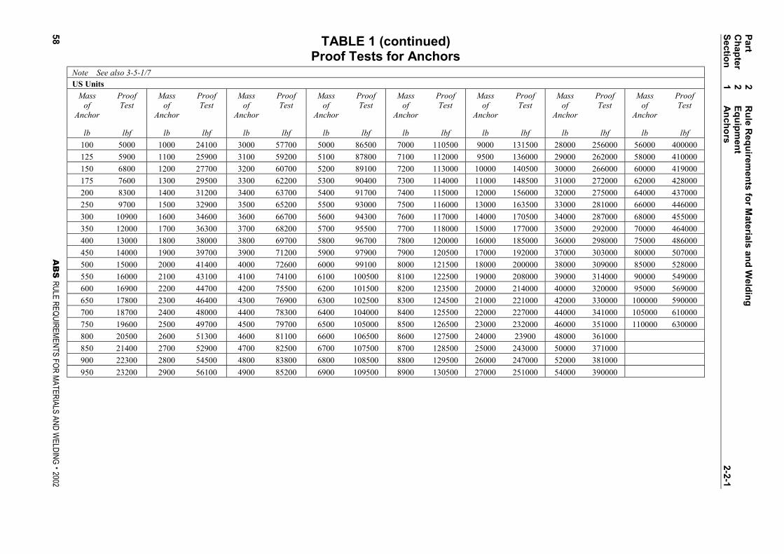
TABLE 1 (continued)Proof Tests for Anchors
Note See also 3-5-1/7US Units
Massof
Anchor
ProofTest
Massof
Anchor
ProofTest
Massof
Anchor
ProofTest
Massof
Anchor
ProofTest
Massof
Anchor
ProofTest
Massof
Anchor
ProofTest
Massof
Anchor
ProofTest
Massof
Anchor
ProofTest
lb lbf lb lbf lb lbf lb lbf lb lbf lb lbf lb lbf lb lbf
100 5000 1000 24100 3000 57700 5000 86500 7000 110500 9000 131500 28000 256000 56000 400000
125 5900 1100 25900 3100 59200 5100 87800 7100 112000 9500 136000 29000 262000 58000 410000
150 6800 1200 27700 3200 60700 5200 89100 7200 113000 10000 140500 30000 266000 60000 419000
175 7600 1300 29500 3300 62200 5300 90400 7300 114000 11000 148500 31000 272000 62000 428000
200 8300 1400 31200 3400 63700 5400 91700 7400 115000 12000 156000 32000 275000 64000 437000
250 9700 1500 32900 3500 65200 5500 93000 7500 116000 13000 163500 33000 281000 66000 446000
300 10900 1600 34600 3600 66700 5600 94300 7600 117000 14000 170500 34000 287000 68000 455000
350 12000 1700 36300 3700 68200 5700 95500 7700 118000 15000 177000 35000 292000 70000 464000
400 13000 1800 38000 3800 69700 5800 96700 7800 120000 16000 185000 36000 298000 75000 486000
450 14000 1900 39700 3900 71200 5900 97900 7900 120500 17000 192000 37000 303000 80000 507000
500 15000 2000 41400 4000 72600 6000 99100 8000 121500 18000 200000 38000 309000 85000 528000
550 16000 2100 43100 4100 74100 6100 100500 8100 122500 19000 208000 39000 314000 90000 549000
600 16900 2200 44700 4200 75500 6200 101500 8200 123500 20000 214000 40000 320000 95000 569000
650 17800 2300 46400 4300 76900 6300 102500 8300 124500 21000 221000 42000 330000 100000 590000
700 18700 2400 48000 4400 78300 6400 104000 8400 125500 22000 227000 44000 341000 105000 610000
750 19600 2500 49700 4500 79700 6500 105000 8500 126500 23000 232000 46000 351000 110000 630000
800 20500 2600 51300 4600 81100 6600 106500 8600 127500 24000 23900 48000 361000
850 21400 2700 52900 4700 82500 6700 107500 8700 128500 25000 243000 50000 371000
900 22300 2800 54500 4800 83800 6800 108500 8800 129500 26000 247000 52000 381000
950 23200 2900 56100 4900 85200 6900 109500 8900 130500 27000 251000 54000 390000
Part
2R
ule R
equ
iremen
ts fo
r Materials an
d W
eldin
gC
hap
ter2
Eq
uip
men
tS
ection
1A
nch
ors
2-2-1
58A
BS
RULE REQUIREMENTS FOR MATERIALS AND WELDING . 2002

ABS RULE REQUIREMENTS FOR MATERIALS AND WELDING . 2002 59
P A R T
2C H A P T E R 2 Equipment
S E C T I O N 2 Anchor Chain
CONTENTS1 Scope ..................................................................................... 61
3 General................................................................................... 61
5 Specially Approved Chain .................................................... 61
7 Qualification of Manufacturers ............................................. 61
7.1 General................................................................................... 61
7.3 Locking Pins in Accessories................................................... 62
7.5 Stud Attachment..................................................................... 62
9 Chain Dimensions and Tolerances ...................................... 62
9.1 Shape ..................................................................................... 62
9.3 Dimensions............................................................................. 62
9.5 Tolerances.............................................................................. 62
9.7 Length Over Five Links .......................................................... 63
11 Material for Chain .................................................................. 64
11.1 General................................................................................... 64
13 Material Testing ..................................................................... 64
13.1 Heat Treatment of Test Specimens ....................................... 64
13.3 Number of Tests..................................................................... 64
13.5 Tension Test Specimens........................................................ 64
13.7 Bend Test Specimens ............................................................ 65
13.9 Impact Test Specimens.......................................................... 65
13.11 Additional Tests before Rejection........................................... 65
13.13 Manufacturer’s Option ............................................................ 65
15 Heat Treatment of Chain Lengths ........................................ 66
15.1 Flash Butt-welded Chain ........................................................ 66
15.3 Drop-forged, Cast-steel and Extra-high-strength Chain......... 66
15.5 Sequence of Heat Treatment ................................................. 66
17 Testing and Inspection of Chain Lengths............................ 66
17.1 General................................................................................... 66
17.3 Chain Identification................................................................. 66
60 ABS RULE REQUIREMENTS FOR MATERIALS AND WELDING . 2002
17.5 Testing Precautions................................................................ 66
17.7 Weighing of Tested Chain ...................................................... 66
17.9 Testing of Used Chain............................................................ 67
19 Details of Tests on Chain Lengths........................................67
19.1 Breaking Test ......................................................................... 67
19.3 Proof Test ............................................................................... 67
19.5 Mechanical Tests on Completed Chain.................................. 67
19.7 Mechanical and Breaking Tests on Chain Produced in LongContinuous Lengths ............................................................... 68
21 Marking for Chain ..................................................................68
23 Anchor Chain Accessories....................................................68
23.1 Dimensions and Dimensional Tolerances.............................. 68
23.3 Material Testing ...................................................................... 68
23.5 Cast Accessories.................................................................... 69
23.7 Forged Accessories................................................................ 69
23.9 Inspection ............................................................................... 69
23.11 Hardness Test ........................................................................ 70
23.13 Break Test .............................................................................. 70
23.15 Proof Tests ............................................................................. 70
23.17 Markings ................................................................................. 70
25 Unstudded Short-link Chain..................................................70
25.1 General................................................................................... 70
25.3 Testing.................................................................................... 71
25.5 Marking................................................................................... 71
TABLE 1 Chain Materials – Mechanical Properties .................71
TABLE 2 Stud-link Anchor-chain Proof and Break Tests........72
TABLE 3 Unstudded Short-link Chain ......................................75
FIGURE 1 Location and Orientation of Test Specimens...........65
FIGURE 2 Marking for Chain.......................................................69
ABS RULE REQUIREMENTS FOR MATERIALS AND WELDING . 2002 61
P A R T
2C H A P T E R 2 Equipment
S E C T I O N 2 Anchor Chain 2 - 2 - 2
1 Scope 2-2-2/1
Three grades of stud-link anchor chain are covered, and are described as follows:
Strength Level Grade Method of Manufacture
Normal Strength 1 Flash Butt-welded
High Strength2a2b
Flash Butt-welded or Drop-forgedCast Steel
Extra-high Strength3a3b
Flash Butt-welded or Drop-forgedCast Steel
3 General 2-2-2/3
All chain is to have a workmanlike finish and be free from injurious defects. There is to be an oddnumber of links in each shot of anchor chain cable to insure shackles leading over the windlass in thesame position.
5 Specially Approved Chain 2-2-2/5
Steel chain made by processes or to requirements differing from those shown in 2-2-2/Table 1 andcertain types of drop-forged chain will be subject to special consideration.
7 Qualification of Manufacturers 2-2-2/7
7.1 General 2-2-2/7.1
Manufacturers of Grades 2 and 3 chain and chain accessories are to submit their manufacturingprocess and material specifications for review. Data in support of mechanical properties, weldsoundness (when applicable) and compliance with the Rules in all respects are also to be submittedfor review and approval.
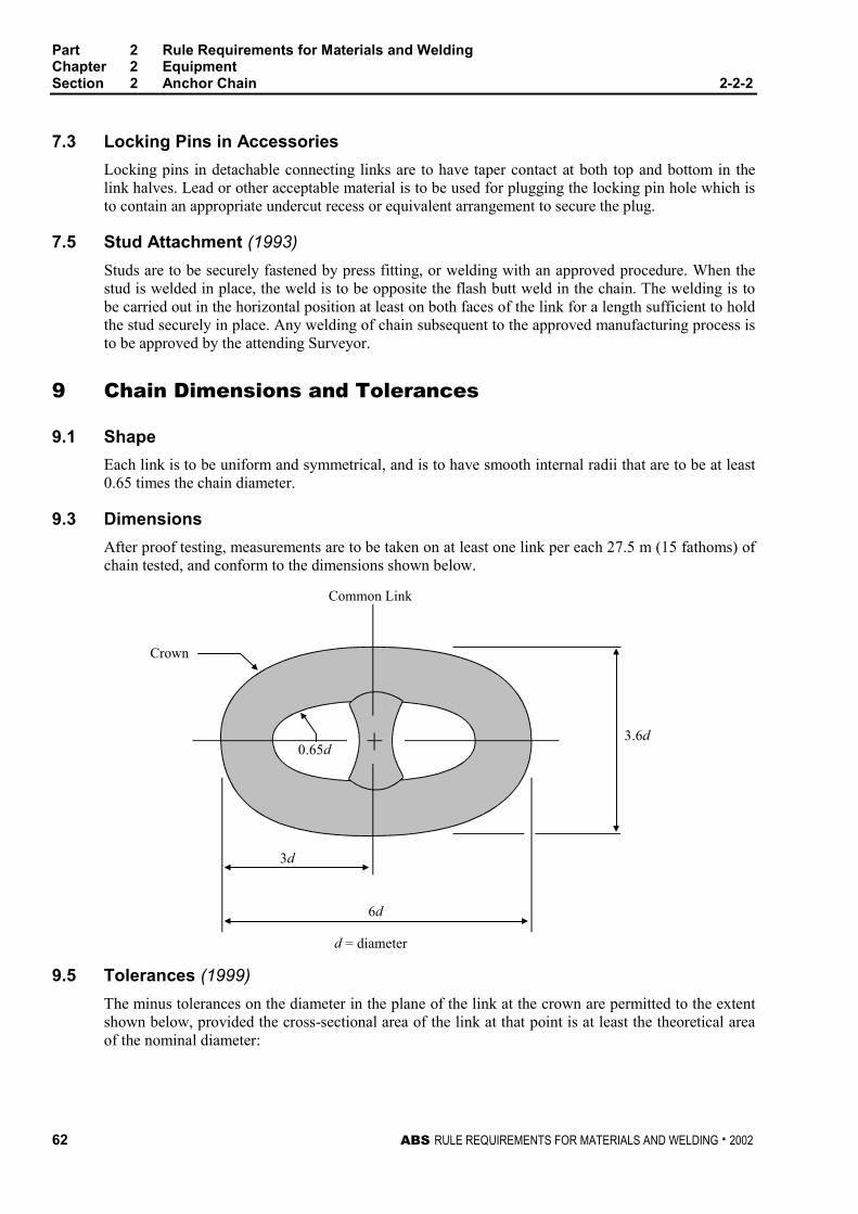
Part 2 Rule Requirements for Materials and WeldingChapter 2 EquipmentSection 2 Anchor Chain 2-2-2
62 ABS RULE REQUIREMENTS FOR MATERIALS AND WELDING . 2002
7.3 Locking Pins in Accessories 2-2-2/7.3
Locking pins in detachable connecting links are to have taper contact at both top and bottom in thelink halves. Lead or other acceptable material is to be used for plugging the locking pin hole which isto contain an appropriate undercut recess or equivalent arrangement to secure the plug.
7.5 Stud Attachment (1993) 2-2-2/7.5
Studs are to be securely fastened by press fitting, or welding with an approved procedure. When thestud is welded in place, the weld is to be opposite the flash butt weld in the chain. The welding is tobe carried out in the horizontal position at least on both faces of the link for a length sufficient to holdthe stud securely in place. Any welding of chain subsequent to the approved manufacturing process isto be approved by the attending Surveyor.
9 Chain Dimensions and Tolerances 2-2-2/9
9.1 Shape 2-2-2/9.1
Each link is to be uniform and symmetrical, and is to have smooth internal radii that are to be at least0.65 times the chain diameter.
9.3 Dimensions 2-2-2/9.3
After proof testing, measurements are to be taken on at least one link per each 27.5 m (15 fathoms) ofchain tested, and conform to the dimensions shown below.
Common Link
Crown
0.65d
3d
6d
3.6d
d = diameter
9.5 Tolerances (1999) 2-2-2/9.5
The minus tolerances on the diameter in the plane of the link at the crown are permitted to the extentshown below, provided the cross-sectional area of the link at that point is at least the theoretical areaof the nominal diameter:
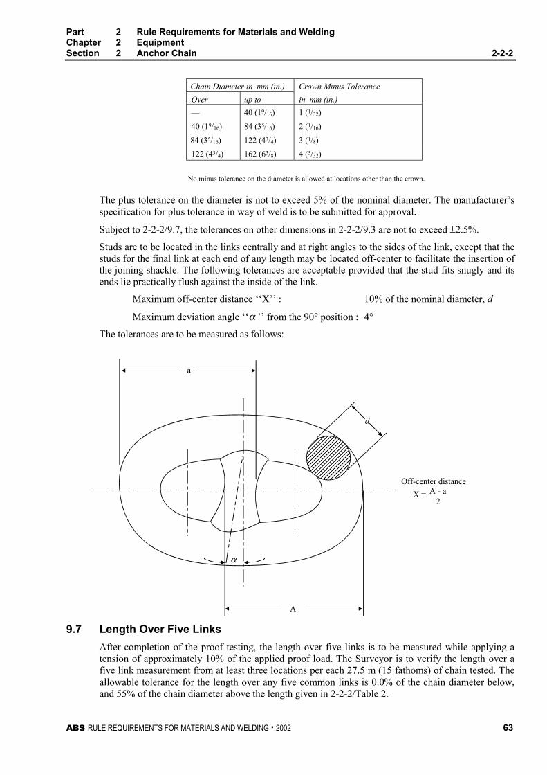
Part 2 Rule Requirements for Materials and WeldingChapter 2 EquipmentSection 2 Anchor Chain 2-2-2
ABS RULE REQUIREMENTS FOR MATERIALS AND WELDING . 2002 63
Chain Diameter in mm (in.) Crown Minus Tolerance
Over up to in mm (in.)
— 40 (19/16) 1 (1/32)
40 (19/16) 84 (35/16) 2 (1/16)
84 (35/16) 122 (43/4) 3 (1/8)
122 (43/4) 162 (63/8) 4 (5/32)
No minus tolerance on the diameter is allowed at locations other than the crown.
The plus tolerance on the diameter is not to exceed 5% of the nominal diameter. The manufacturer’sspecification for plus tolerance in way of weld is to be submitted for approval.
Subject to 2-2-2/9.7, the tolerances on other dimensions in 2-2-2/9.3 are not to exceed ±2.5%.
Studs are to be located in the links centrally and at right angles to the sides of the link, except that thestuds for the final link at each end of any length may be located off-center to facilitate the insertion ofthe joining shackle. The following tolerances are acceptable provided that the stud fits snugly and itsends lie practically flush against the inside of the link.
Maximum off-center distance ‘‘X’’ : 10% of the nominal diameter, d
Maximum deviation angle ‘‘α ’’ from the 90° position : 4°
The tolerances are to be measured as follows:
������������
a
A
α
d
X = A - a2
Off-center distance
9.7 Length Over Five Links 2-2-2/9.7
After completion of the proof testing, the length over five links is to be measured while applying atension of approximately 10% of the applied proof load. The Surveyor is to verify the length over afive link measurement from at least three locations per each 27.5 m (15 fathoms) of chain tested. Theallowable tolerance for the length over any five common links is 0.0% of the chain diameter below,and 55% of the chain diameter above the length given in 2-2-2/Table 2.

Part 2 Rule Requirements for Materials and WeldingChapter 2 EquipmentSection 2 Anchor Chain 2-2-2
64 ABS RULE REQUIREMENTS FOR MATERIALS AND WELDING . 2002
11 Material for Chain 2-2-2/11
11.1 General 2-2-2/11.1
11.1.1 Process of Steel Manufacture and Deoxidation (1996) 2-1-2/11.1.1
The steel used for the manufacture of chain is to be made by the open-hearth, basic-oxygen,electric-furnace or such other process as may be specially approved.
Rimmed steel is not acceptable for any grade of chain.
11.1.2 Chemical Composition (1996) 2-1-2/11.1.2
The chemical composition of the material for chain manufacture is to be determined by thesteelmaker on samples taken from each ladle of each heat and is to comply with the approvedspecification of the chain manufacturer.
13 Material Testing 2-2-2/13
13.1 Heat Treatment of Test Specimens 2-2-2/13.1
Test specimens are to be taken from material heat-treated in the same manner as intended for thefinished chain, except that in the case of Grades 1 and 2a flash butt-welded chain, test specimens maybe taken from material in either the as-rolled or heat-treated condition.
13.3 Number of Tests 2-2-2/13.3
One set of tests consisting of one tension, and one bend or three impact test specimens as required in2-2-2/Table 1 are to be taken from the largest casting or drop forging from each lot of 50 tons orfraction thereof from each heat.
13.5 Tension Test Specimens (1996) 2-2-2/13.5
For cast or drop-forged links, machined type specimens are to be used. They are to be cut and notchedas shown in 2-2-2/Figure 1. The tension-test results for stud-link anchor chain materials are to meetthe applicable requirements shown in 2-2-2/Table 1.
The required minimum percentage elongation values in 2-2-2/Table 1 are based on specimens havinggauge lengths equal to 5 times the diameter. For specimens having other gauge lengths the equivalentelongation value is to be calculated by the following equation:
4.0)/(2 LAEn =
where
n = equivalent minimum elongation
A = actual cross-sectional area of the specimen
L = actual gauge length
E = specified minimum percentage elongation for specimens having a gauge length of5 times the diameter
The above equation is not applicable to quenched and tempered steel, for which the specimen is tohave a gauge length of 5 times the specimen diameters.
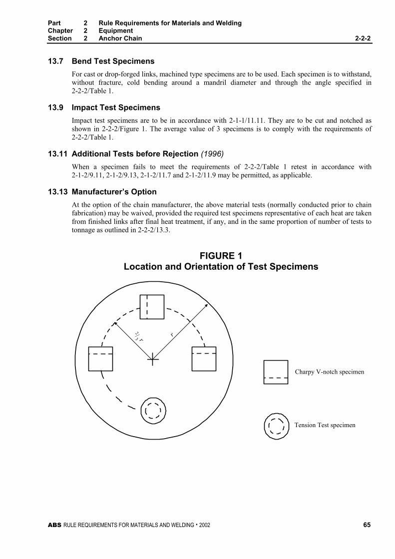
Part 2 Rule Requirements for Materials and WeldingChapter 2 EquipmentSection 2 Anchor Chain 2-2-2
ABS RULE REQUIREMENTS FOR MATERIALS AND WELDING . 2002 65
13.7 Bend Test Specimens 2-2-2/13.7
For cast or drop-forged links, machined type specimens are to be used. Each specimen is to withstand,without fracture, cold bending around a mandril diameter and through the angle specified in2-2-2/Table 1.
13.9 Impact Test Specimens 2-2-2/13.9
Impact test specimens are to be in accordance with 2-1-1/11.11. They are to be cut and notched asshown in 2-2-2/Figure 1. The average value of 3 specimens is to comply with the requirements of2-2-2/Table 1.
13.11 Additional Tests before Rejection (1996) 2-2-2/13.11
When a specimen fails to meet the requirements of 2-2-2/Table 1 retest in accordance with2-1-2/9.11, 2-1-2/9.13, 2-1-2/11.7 and 2-1-2/11.9 may be permitted, as applicable.
13.13 Manufacturer’s Option 2-2-2/13.13
At the option of the chain manufacturer, the above material tests (normally conducted prior to chainfabrication) may be waived, provided the required test specimens representative of each heat are takenfrom finished links after final heat treatment, if any, and in the same proportion of number of tests totonnage as outlined in 2-2-2/13.3.
FIGURE 1Location and Orientation of Test Specimens
2/3 r r
Charpy V-notch specimen
Tension Test specimen
Part 2 Rule Requirements for Materials and WeldingChapter 2 EquipmentSection 2 Anchor Chain 2-2-2
66 ABS RULE REQUIREMENTS FOR MATERIALS AND WELDING . 2002
15 Heat Treatment of Chain Lengths 2-2-2/15
15.1 Flash Butt-welded Chain 2-2-2/15.1
Grades 1 and 2a, flash butt-welded chain may be supplied in either the as-welded or normalizedcondition.
15.3 Drop-forged, Cast-steel and Extra-high-strength Chain 2-2-2/15.3
Grade 2a drop-forged chain, Grade 2b cast-steel chain and Grades 3a and 3b extra-high-strength chainare to be normalized, normalized and tempered or quenched and tempered in accordance with themanufacturer’s approved specification.
15.5 Sequence of Heat Treatment 2-2-2/15.5
Heat treatment is to be completed prior to the proof and breaking tests.
17 Testing and Inspection of Chain Lengths 2-2-2/17
17.1 General (1996) 2-2-2/17.1
All anchor chain is to be subjected to breaking and proof tests in the presence of a Surveyor. TheSurveyor is to satisfy himself that the testing machines are maintained in a satisfactory and accuratecondition and is to keep a record of the dates and by whom the machines were rechecked orcalibrated. Prior to test and inspection the chain is to be free from paint or other coating which wouldtend to conceal defects. After proof testing, links are to be carefully examined for workmanship,concentricity, distortion, stud attachment, test grip damage, surface appearance and alignment of buttwelds.
Provided their depth is not greater than 5% of the link diameter, surface discontinuities may beremoved by grinding and blending to a smooth contour. The cross sectional area in way of thegrinding is to be not less than the theoretical area of nominal chain diameter. Links repaired bygrinding are to be subjected to magnetic particle or dye penetrant inspection.
17.3 Chain Identification 2-2-2/17.3
Each shot is to be stamped with a distinctive mark in order to identify it through the several processesof gauging, testing, measuring, examining, repairing and weighing, and in the event of the Surveyorbeing in attendance at the works while forged chains are being fabricated, which will be ultimatelysubmitted for testing, he will select the break test specimens as far as possible during the process offabrication.
17.5 Testing Precautions 2-2-2/17.5
Care is to be taken that arrangements are made for each link to be tested at least once. The grippingarrangements are to be such that they do not put any stress on the end links of the portion under testexcept such stress as is equally applied to every link tested.
17.7 Weighing of Tested Chain 2-2-2/17.7
When chains have satisfactorily passed the requirements, they are to be weighed, together with theshackles forming the outfit, and this actual weight will be given on the certificate of test.
Part 2 Rule Requirements for Materials and WeldingChapter 2 EquipmentSection 2 Anchor Chain 2-2-2
ABS RULE REQUIREMENTS FOR MATERIALS AND WELDING . 2002 67
17.9 Testing of Used Chain 2-2-2/17.9
When a chain, which has been in use, is submitted for testing or retesting, the size for testing purposesis to be the original chain diameter. The certificate issued for such chain will include for descriptivepurposes the original chain diameter as well as the mean diameter of the part most worn, and will bemarked, “This chain is not new, but has been previously used’’.
19 Details of Tests on Chain Lengths 2-2-2/19
19.1 Breaking Test 2-2-2/19.1
A break-test specimen consisting of at least three links is to be taken from the chain or produced at thesame time and the same way as the chain. Where produced separately, the specimen is to be securelyattached to the chain during any heat treatment. One specimen is to be taken from each four 27.5 m,(15 fathoms) lengths or less, of flash butt-welded or drop-forged chain, and one from each heattreatment batch with a minimum of one from each four 27.5 m, (15 fathoms) lengths or less of cast-steel chain. Each specimen is to be subjected to the applicable breaking load given in 2-2-2/Table 2(stud-link chain). A specimen will be considered to have successfully passed the test if there is no signof fracture after application of the required load. Where the first test is not satisfactory, one morespecimen may be cut out and subjected to the breaking load. If this test fails, the shot is to be rejected,and additional specimens are to be cut from each of the three remaining shots of 27.5 m, (15 fathoms)or less and subjected to the breaking load. In such cases, each shot from which the satisfactory breakspecimens have been taken is to be rejoined and may be accepted, provided it passes the requiredproof test. All breaking test specimens are to be subsequently discarded.
Alternative test procedures to the required breaking test of chain of Grades 2a, 2b, 3a, and 3b may beaccepted. This alternative procedure consists of additional mechanical tests and the preparation ofmacro sections on a two or three link sample of chain taken from every four lengths of 27.5 m, (15fathoms) or less of completed chain. In the case of Grade 3a or 3b chain, the two or three link sampleis not to be taken from the same length of chain as that length from which the link to be mechanicallytested according to 2-2-2/19.5 is taken.
19.3 Proof Test 2-2-2/19.3
Each shot of chain of 27.5 m, (15 fathoms) length or less and the entire length of chain whenproduced in lengths longer than 27.5 m, (15 fathoms) is to withstand the applicable proof loadindicated in 2-2-2/Table 2 (stud-link chain). Upon special request and when approved by the Bureau,detachable links may be subjected to a greater proof load than required for the chain. After the prooftest, the length of chain is to be ascertained and the chain carefully examined. Any link showingsurface defects or excessive deformation is to be taken out and the chain repaired, after which theproof test is again to be applied and the chain re-examined. If one link breaks under the proof test, ajoining link is to be inserted and the proof test again applied; if a second link breaks, the shot or lengthunder test is to be rejected. For chain produced in long continuous lengths, if more than one linkbreaks, under proof test, the entire length is to be rejected unless approved otherwise.
19.5 Mechanical Tests on Completed Chain (1996) 2-2-2/19.5
One link from every 4 lengths of 27.5 m, (15 fathoms) or less of
Grade 2a flash butt welded chain delivered in as welded condition, and
Grades 3a or 3b chain
is to be subjected to a set of mechanical tests consisting of one tension and three impact tests.
Part 2 Rule Requirements for Materials and WeldingChapter 2 EquipmentSection 2 Anchor Chain 2-2-2
68 ABS RULE REQUIREMENTS FOR MATERIALS AND WELDING . 2002
In the case of a welded chain, the above mentioned test specimens are to be taken from the base metalof the link opposite to the weldment and, additionally, three impact specimens are to be taken withnotches at the weld center. The results of the tests are to comply with the requirements given in2-2-2/Table 1. When the results of original tests fail to meet the requirements, retests in accordancewith 2-1-2/9.11 and 2-1-2/11.7 may be permitted, as applicable.
19.7 Mechanical and Breaking Tests on Chain Produced in Long ContinuousLengths 2-2-2/19.7
When chain is produced in lengths longer than 27.5 m, (15 fathoms), the test frequency for themechanical and breaking tests required in 2-2-2/19.1 and 2-2-2/19.5 are to be based on tests at regularintervals according to the following table:
Nominal Chain SizeMaximum SpecifiedLength to Obtain Samples
mm in. m ft
Min to 48 Min to 17/8 91 300
50 to 60 2 to 23/8 110 360
64 to 73 21/2 to 27/8 131 430
76 to 85 3 to 33/8 152 500
87 to 98 31/2 to 37/8 175 575
102 to 111 4 to 43/8 198 650
If an order or a fraction of an order is less than the specified length, that length is to be subject to alltests required for a full length.
21 Marking for Chain (2001) 2-2-2/21
The shackles and the end links of each length and one link in every 27.5 m, (15 fathoms) of stud-linkchain, made in a continuous length without joining shackles, are to be clearly stamped by themanufacturer as shown in 2-2-2/Figure 2 in location A, B, and C. When Kenter shackles are used, themarking is to be clearly stamped on the Kenter shackle and on both adjoining common links. Anyaccessory tested to a break load for a lower grade chain, as permitted in 2-2-2/23.13, is to be markedwith the grade of the chain to which it is tested.
23 Anchor Chain Accessories 2-2-2/23
23.1 Dimensions and Dimensional Tolerances (1996) 2-2-2/23.1
The dimensions of anchor chain accessories are to be in accordance with a recognized standard suchas ISO 1704. The following tolerances are applicable to anchor chain accessories.
nominal diameter : +5%, -0%
other dimensions : ±2.5%
23.3 Material Testing 2-2-2/23.3
Test specimens are to be taken either from finished accessories, or from special test bars indicated in2-2-2/23.5 and 2-2-2/23.7. In all cases the specimens are to be taken from pieces representing thelargest diameter accessory in the lot. A lot is defined as the accessories of the same grade, made fromthe same heat of steel and heat treated in the same furnace charge where the diameter does not differby more than 25 mm (1 in.). Test results are to comply with 2-2-2/Table 1 or such other specification
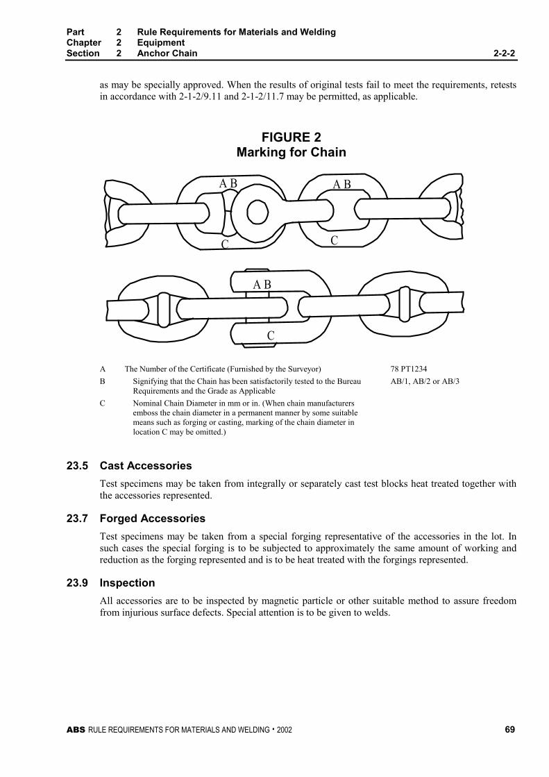
Part 2 Rule Requirements for Materials and WeldingChapter 2 EquipmentSection 2 Anchor Chain 2-2-2
ABS RULE REQUIREMENTS FOR MATERIALS AND WELDING . 2002 69
as may be specially approved. When the results of original tests fail to meet the requirements, retestsin accordance with 2-1-2/9.11 and 2-1-2/11.7 may be permitted, as applicable.
FIGURE 2Marking for Chain
A B A B
C C
A B
C
A The Number of the Certificate (Furnished by the Surveyor) 78 PT1234
B Signifying that the Chain has been satisfactorily tested to the BureauRequirements and the Grade as Applicable
AB/1, AB/2 or AB/3
C Nominal Chain Diameter in mm or in. (When chain manufacturersemboss the chain diameter in a permanent manner by some suitablemeans such as forging or casting, marking of the chain diameter inlocation C may be omitted.)
23.5 Cast Accessories 2-2-2/23.5
Test specimens may be taken from integrally or separately cast test blocks heat treated together withthe accessories represented.
23.7 Forged Accessories 2-2-2/23.7
Test specimens may be taken from a special forging representative of the accessories in the lot. Insuch cases the special forging is to be subjected to approximately the same amount of working andreduction as the forging represented and is to be heat treated with the forgings represented.
23.9 Inspection 2-2-2/23.9
All accessories are to be inspected by magnetic particle or other suitable method to assure freedomfrom injurious surface defects. Special attention is to be given to welds.
Part 2 Rule Requirements for Materials and WeldingChapter 2 EquipmentSection 2 Anchor Chain 2-2-2
70 ABS RULE REQUIREMENTS FOR MATERIALS AND WELDING . 2002
23.11 Hardness Test 2-2-2/23.11
All accessories are to be subjected to a Brinell hardness test to meet the following:
GradeBrinell Hardness Number Minimum10 mm ball, 3000 kg load
1 120
2 145
3 207
23.13 Break Test (2001) 2-2-2/23.13
Break tests are to be made on 1 out of 25 accessories (or 1 out of 50 in the case of Kenter shackles)representative of the same type, grade and heat treatment procedure, but not necessarily representativeof each heat of steel, heat treatment charge or individual purchase order. When the range of Brinellhardness readings of these accessories in the batch exceed 30 Brinell hardness numbers, theaccessories represented by the lowest and highest Brinell hardness readings are to be tested. Thisrequirement may be waived when the range of properties represented by the Brinell hardness numbersis established to the satisfaction of the Surveyor. For accessories from the same lot (see 2-2-2/23.3),the Surveyor may reduce the number of break tests to a minimum of two per lot. All parts of theaccessory subjected to a break test required by this subparagraph are to be subsequently discardedexcept where further use is permitted by 2-2-2/23.13.1 below.
23.13.1 Use of Break Tested Parts (2001)
Where it is demonstrated by either one of the following methods that the accessories canwithstand at least 140% of the breaking test load prescribed in 2-2-2/Table 2 for the chain inwhich they are intended, such accessories may be used in service provided:
23.13.1(a) the material of the accessories is of higher grade than the chain (e.g., grade 3accessories of grade 2 size in grade 2 chain), or
23.13.1(b) where an accessory of increased dimension is specially approved for the particularapplication and a procedure test is completed at 140% of the 2-2-2/Table 2 break test load. Allparts of the accessories used in this procedure test are to be subsequently discarded.
In either case, each accessory requiring a break test is to be tested to 100% of the 2-2-2/Table2 break load for the chain in which it is intended to be used.
23.15 Proof Tests 2-2-2/23.15
Each accessory is to be subjected to a proof test in accordance with 2-2-2/19.3.
23.17 Markings 2-2-2/23.17
The certificate number, AB/Chain Grade, and nominal chain diameter are to be steel die stamped oneach accessory. The stamping of the nominal chain diameter may be omitted provided the nominalchain diameter is cast or forged into the accessory. Markings are to be located in such a manner as tobe readily visible when completely assembled together with the chain.
25 Unstudded Short-link Chain 2-2-2/25
25.1 General 2-2-2/25.1
Unstudded short-link chain is to meet the requirements specified in 2-2-2/3 and 2-2-2/11. Material isto be in accordance with the manufacturer’s specification which is to be the equivalent of normalstrength Grade 1 requirements of 2-2-2/Table 1.
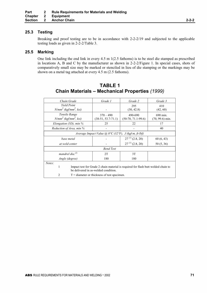
Part 2 Rule Requirements for Materials and WeldingChapter 2 EquipmentSection 2 Anchor Chain 2-2-2
ABS RULE REQUIREMENTS FOR MATERIALS AND WELDING . 2002 71
25.3 Testing 2-2-2/25.3
Breaking and proof testing are to be in accordance with 2-2-2/19 and subjected to the applicabletesting loads as given in 2-2-2/Table 3.
25.5 Marking 2-2-2/25.5
One link including the end link in every 4.5 m 1(2.5 fathoms) is to be steel die stamped as prescribedin locations A, B and C by the manufacturer as shown in 2-2-2/Figure 1. In special cases, shots ofcomparatively small size may be marked or stenciled in lieu of die stamping or the markings may beshown on a metal tag attached at every 4.5 m (2.5 fathoms).
TABLE 1Chain Materials – Mechanical Properties (1999)
Chain Grade Grade 1 Grade 2 Grade 3Yield Point
N/mm2 (kgf/mm2, ksi) -295
(30, 42.8)410
(42, 60)
Tensile Range
N/mm2 (kgf/mm2, ksi)370 – 490
(38-51, 53.7-71.1)490-690
(50-70, 71.1-99.6)690 min.
(70, 99.6) min.
Elongation (5D), min % 25 22 17
Reduction of Area, min % - - 40
Average Impact Value @ 0°C (32°F), J (kgf-m, ft-lbf)
base metal - 27 (1) (2.8, 20) 60 (6, 43)
at weld center - 27 (1) (2.8, 20) 50 (5, 36)
Bend Test
mandrel dia.(2) 2T 3T
Angle (degree) 180 180
Notes:1 Impact test for Grade 2 chain material is required for flash butt welded chain to
be delivered in as-welded condition.
2 T = diameter or thickness of test specimen.
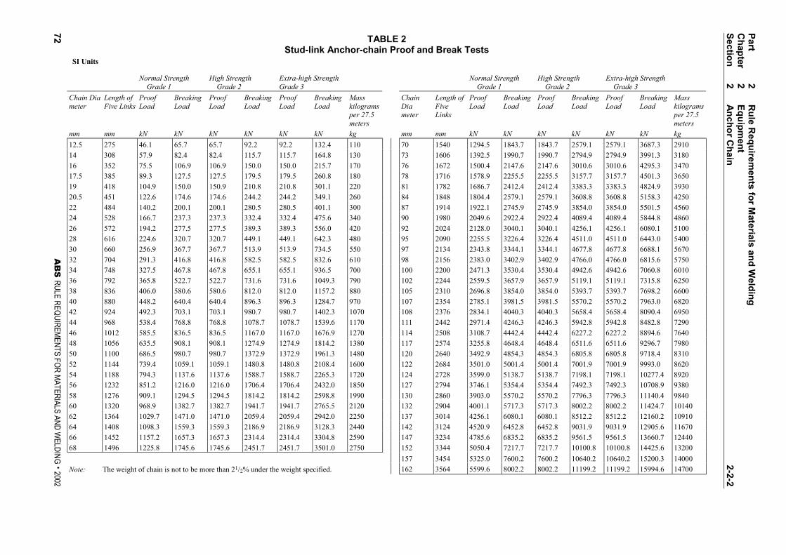
TABLE 2Stud-link Anchor-chain Proof and Break Tests
SI Units
Normal Strength Grade 1 .
High Strength Grade 2 .
Extra-high StrengthGrade 3 .
Normal Strength Grade 1 .
High Strength Grade 2 .
Extra-high Strength Grade 3 .
Chain Diameter
Length ofFive Links
ProofLoad
BreakingLoad
ProofLoad
BreakingLoad
ProofLoad
BreakingLoad
Masskilogramsper 27.5meters
ChainDiameter
Length ofFiveLinks
ProofLoad
BreakingLoad
ProofLoad
BreakingLoad
ProofLoad
BreakingLoad
Masskilogramsper 27.5meters
mm mm kN kN kN kN kN kN kg mm mm kN kN kN kN kN kN kg
12.5 275 46.1 65.7 65.7 92.2 92.2 132.4 110 70 1540 1294.5 1843.7 1843.7 2579.1 2579.1 3687.3 2910
14 308 57.9 82.4 82.4 115.7 115.7 164.8 130 73 1606 1392.5 1990.7 1990.7 2794.9 2794.9 3991.3 3180
16 352 75.5 106.9 106.9 150.0 150.0 215.7 170 76 1672 1500.4 2147.6 2147.6 3010.6 3010.6 4295.3 3470
17.5 385 89.3 127.5 127.5 179.5 179.5 260.8 180 78 1716 1578.9 2255.5 2255.5 3157.7 3157.7 4501.3 3650
19 418 104.9 150.0 150.9 210.8 210.8 301.1 220 81 1782 1686.7 2412.4 2412.4 3383.3 3383.3 4824.9 3930
20.5 451 122.6 174.6 174.6 244.2 244.2 349.1 260 84 1848 1804.4 2579.1 2579.1 3608.8 3608.8 5158.3 4250
22 484 140.2 200.1 200.1 280.5 280.5 401.1 300 87 1914 1922.1 2745.9 2745.9 3854.0 3854.0 5501.5 4560
24 528 166.7 237.3 237.3 332.4 332.4 475.6 340 90 1980 2049.6 2922.4 2922.4 4089.4 4089.4 5844.8 4860
26 572 194.2 277.5 277.5 389.3 389.3 556.0 420 92 2024 2128.0 3040.1 3040.1 4256.1 4256.1 6080.1 5100
28 616 224.6 320.7 320.7 449.1 449.1 642.3 480 95 2090 2255.5 3226.4 3226.4 4511.0 4511.0 6443.0 5400
30 660 256.9 367.7 367.7 513.9 513.9 734.5 550 97 2134 2343.8 3344.1 3344.1 4677.8 4677.8 6688.1 5670
32 704 291.3 416.8 416.8 582.5 582.5 832.6 610 98 2156 2383.0 3402.9 3402.9 4766.0 4766.0 6815.6 5750
34 748 327.5 467.8 467.8 655.1 655.1 936.5 700 100 2200 2471.3 3530.4 3530.4 4942.6 4942.6 7060.8 6010
36 792 365.8 522.7 522.7 731.6 731.6 1049.3 790 102 2244 2559.5 3657.9 3657.9 5119.1 5119.1 7315.8 6250
38 836 406.0 580.6 580.6 812.0 812.0 1157.2 880 105 2310 2696.8 3854.0 3854.0 5393.7 5393.7 7698.2 6600
40 880 448.2 640.4 640.4 896.3 896.3 1284.7 970 107 2354 2785.1 3981.5 3981.5 5570.2 5570.2 7963.0 6820
42 924 492.3 703.1 703.1 980.7 980.7 1402.3 1070 108 2376 2834.1 4040.3 4040.3 5658.4 5658.4 8090.4 6950
44 968 538.4 768.8 768.8 1078.7 1078.7 1539.6 1170 111 2442 2971.4 4246.3 4246.3 5942.8 5942.8 8482.8 7290
46 1012 585.5 836.5 836.5 1167.0 1167.0 1676.9 1270 114 2508 3108.7 4442.4 4442.4 6227.2 6227.2 8894.6 7640
48 1056 635.5 908.1 908.1 1274.9 1274.9 1814.2 1380 117 2574 3255.8 4648.4 4648.4 6511.6 6511.6 9296.7 7980
50 1100 686.5 980.7 980.7 1372.9 1372.9 1961.3 1480 120 2640 3492.9 4854.3 4854.3 6805.8 6805.8 9718.4 8310
52 1144 739.4 1059.1 1059.1 1480.8 1480.8 2108.4 1600 122 2684 3501.0 5001.4 5001.4 7001.9 7001.9 9993.0 8620
54 1188 794.3 1137.6 1137.6 1588.7 1588.7 2265.3 1720 124 2728 3599.0 5138.7 5138.7 7198.1 7198.1 10277.4 8920
56 1232 851.2 1216.0 1216.0 1706.4 1706.4 2432.0 1850 127 2794 3746.1 5354.4 5354.4 7492.3 7492.3 10708.9 9380
58 1276 909.1 1294.5 1294.5 1814.2 1814.2 2598.8 1990 130 2860 3903.0 5570.2 5570.2 7796.3 7796.3 11140.4 9840
60 1320 968.9 1382.7 1382.7 1941.7 1941.7 2765.5 2120 132 2904 4001.1 5717.3 5717.3 8002.2 8002.2 11424.7 10140
62 1364 1029.7 1471.0 1471.0 2059.4 2059.4 2942.0 2250 137 3014 4256.1 6080.1 6080.1 8512.2 8512.2 12160.2 10910
64 1408 1098.3 1559.3 1559.3 2186.9 2186.9 3128.3 2440 142 3124 4520.9 6452.8 6452.8 9031.9 9031.9 12905.6 11670
66 1452 1157.2 1657.3 1657.3 2314.4 2314.4 3304.8 2590 147 3234 4785.6 6835.2 6835.2 9561.5 9561.5 13660.7 12440
68 1496 1225.8 1745.6 1745.6 2451.7 2451.7 3501.0 2750 152 3344 5050.4 7217.7 7217.7 10100.8 10100.8 14425.6 13200
157 3454 5325.0 7600.2 7600.2 10640.2 10640.2 15200.3 14000
Note: The weight of chain is not to be more than 21/2% under the weight specified. 162 3564 5599.6 8002.2 8002.2 11199.2 11199.2 15994.6 14700
Part
2R
ule R
equ
iremen
ts fo
r Materials an
d W
eldin
gC
hap
ter2
Eq
uip
men
tS
ection
2A
nch
or C
hain
2-2-2
72A
BS
RULE REQUIREMENTS FOR MATERIALS AND WELDING . 2002
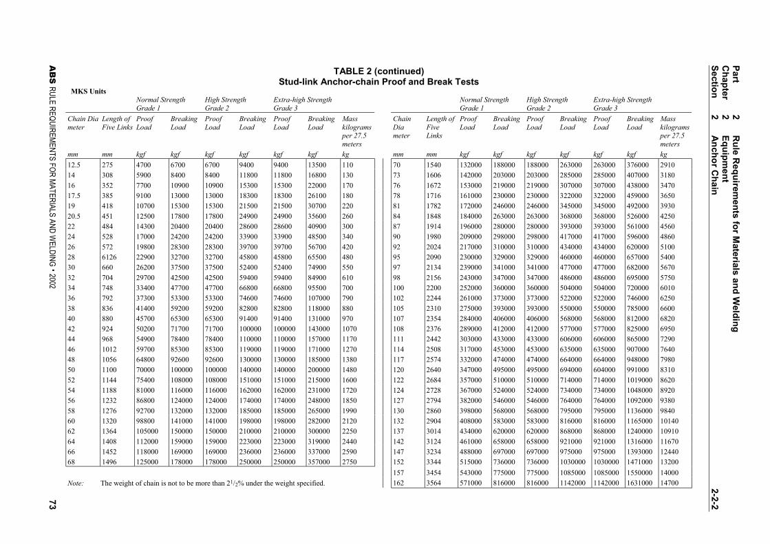
TABLE 2 (continued)Stud-link Anchor-chain Proof and Break Tests
MKS UnitsNormal StrengthGrade 1
High StrengthGrade 2
Extra-high StrengthGrade 3
Normal StrengthGrade 1
High StrengthGrade 2
Extra-high StrengthGrade 3
Chain Diameter
Length ofFive Links
ProofLoad
BreakingLoad
ProofLoad
BreakingLoad
ProofLoad
BreakingLoad
Masskilogramsper 27.5meters
ChainDiameter
Length ofFiveLinks
ProofLoad
BreakingLoad
ProofLoad
BreakingLoad
ProofLoad
BreakingLoad
Masskilogramsper 27.5meters
mm mm kgf kgf kgf kgf kgf kgf kg mm mm kgf kgf kgf kgf kgf kgf kg
12.5 275 4700 6700 6700 9400 9400 13500 110 70 1540 132000 188000 188000 263000 263000 376000 2910
14 308 5900 8400 8400 11800 11800 16800 130 73 1606 142000 203000 203000 285000 285000 407000 3180
16 352 7700 10900 10900 15300 15300 22000 170 76 1672 153000 219000 219000 307000 307000 438000 3470
17.5 385 9100 13000 13000 18300 18300 26100 180 78 1716 161000 230000 230000 322000 322000 459000 3650
19 418 10700 15300 15300 21500 21500 30700 220 81 1782 172000 246000 246000 345000 345000 492000 3930
20.5 451 12500 17800 17800 24900 24900 35600 260 84 1848 184000 263000 263000 368000 368000 526000 4250
22 484 14300 20400 20400 28600 28600 40900 300 87 1914 196000 280000 280000 393000 393000 561000 4560
24 528 17000 24200 24200 33900 33900 48500 340 90 1980 209000 298000 298000 417000 417000 596000 4860
26 572 19800 28300 28300 39700 39700 56700 420 92 2024 217000 310000 310000 434000 434000 620000 5100
28 6126 22900 32700 32700 45800 45800 65500 480 95 2090 230000 329000 329000 460000 460000 657000 5400
30 660 26200 37500 37500 52400 52400 74900 550 97 2134 239000 341000 341000 477000 477000 682000 5670
32 704 29700 42500 42500 59400 59400 84900 610 98 2156 243000 347000 347000 486000 486000 695000 5750
34 748 33400 47700 47700 66800 66800 95500 700 100 2200 252000 360000 360000 504000 504000 720000 6010
36 792 37300 53300 53300 74600 74600 107000 790 102 2244 261000 373000 373000 522000 522000 746000 6250
38 836 41400 59200 59200 82800 82800 118000 880 105 2310 275000 393000 393000 550000 550000 785000 6600
40 880 45700 65300 65300 91400 91400 131000 970 107 2354 284000 406000 406000 568000 568000 812000 6820
42 924 50200 71700 71700 100000 100000 143000 1070 108 2376 289000 412000 412000 577000 577000 825000 6950
44 968 54900 78400 78400 110000 110000 157000 1170 111 2442 303000 433000 433000 606000 606000 865000 7290
46 1012 59700 85300 85300 119000 119000 171000 1270 114 2508 317000 453000 453000 635000 635000 907000 7640
48 1056 64800 92600 92600 130000 130000 185000 1380 117 2574 332000 474000 474000 664000 664000 948000 7980
50 1100 70000 100000 100000 140000 140000 200000 1480 120 2640 347000 495000 495000 694000 604000 991000 8310
52 1144 75400 108000 108000 151000 151000 215000 1600 122 2684 357000 510000 510000 714000 714000 1019000 8620
54 1188 81000 116000 116000 162000 162000 231000 1720 124 2728 367000 524000 524000 734000 734000 1048000 8920
56 1232 86800 124000 124000 174000 174000 248000 1850 127 2794 382000 546000 546000 764000 764000 1092000 9380
58 1276 92700 132000 132000 185000 185000 265000 1990 130 2860 398000 568000 568000 795000 795000 1136000 9840
60 1320 98800 141000 141000 198000 198000 282000 2120 132 2904 408000 583000 583000 816000 816000 1165000 10140
62 1364 105000 150000 150000 210000 210000 300000 2250 137 3014 434000 620000 620000 868000 868000 1240000 10910
64 1408 112000 159000 159000 223000 223000 319000 2440 142 3124 461000 658000 658000 921000 921000 1316000 11670
66 1452 118000 169000 169000 236000 236000 337000 2590 147 3234 488000 697000 697000 975000 975000 1393000 12440
68 1496 125000 178000 178000 250000 250000 357000 2750 152 3344 515000 736000 736000 1030000 1030000 1471000 13200
157 3454 543000 775000 775000 1085000 1085000 1550000 14000
Note: The weight of chain is not to be more than 21/2% under the weight specified. 162 3564 571000 816000 816000 1142000 1142000 1631000 14700
Part
2R
ule R
equ
iremen
ts fo
r Materials an
d W
eldin
gC
hap
ter2
Eq
uip
men
tS
ection
2A
nch
or C
hain
2-2-2
AB
S RULE REQUIREMENTS FOR MATERIALS AND W
ELDING . 200273
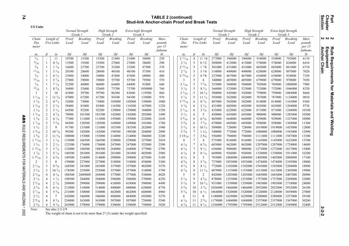
TABLE 2 (continued)Stud-link Anchor-chain Proof and Break Tests
US UnitsNormal Strength
Grade 1High Strength
Grade 2Extra-high Strength
Grade 3Normal Strength
Grade 1High Strength
Grade 2Extra-high Strength
Grade 3ChainDia
meter
Length ofFive Links
ProofLoad
BreakingLoad
ProofLoad
BreakingLoad
ProofLoad
BreakingLoad
Masspoundsper 15
fathoms
ChainDia
meter
Length ofFive Links
ProofLoad
BreakingLoad
ProofLoad
BreakingLoad
ProofLoad
BreakingLoad
Masspoundsper 15
fathomsin. ft in lbf lbf lbf lbf lbf lbf lb in. ft In lbf lbf lbf lbf lbf lbf lb1/2 - 11 10700 15300 15300 21400 21400 30600 230 2 11/16 4 11 1/8 277000 396000 396000 554000 554000 792000 61109/16 1 0 3/8 13500 19300 19300 27000 27000 38600 290 2 3/4 5 0 1/2 289000 413000 413000 578000 578000 826000 64105/8 1 1 3/4 16600 23700 23700 33200 33200 47500 370 2 13/16 5 1 7/8 301000 431000 431000 603000 603000 861000 6710
11/16 1 3 1/8 20100 28600 28600 40100 40100 57300 410 2 7/8 5 3 1/4 314000 449000 449000 628000 628000 897000 70203/4 1 4 1/2 23800 34000 34000 47600 47600 68000 480 2 15/16 5 4 5/8 327000 467000 467000 654000 654000 934000 7330
13/16 1 5 7/8 27800 39800 39800 55700 55700 79500 570 3 5 6 340000 485000 485000 679000 679000 970000 76507/8 1 7 1/4 32200 46000 46000 64400 64400 91800 660 3 1/16 5 7 3/8 353000 504000 504000 705000 705000 1008000 7980
15/16 1 8 5/8 36800 52600 52600 73700 73700 1050000 760 3 1/8 5 8 3/4 366000 523000 523000 732000 732000 1046000 83201 1 10 41800 59700 59700 86300 83600 119500 860 3 3/16 5 10 1/8 380000 542000 542000 759000 759000 1084000 8660
1 1/16 1 11 3/8 47000 67200 67200 94100 94100 135000 970 3 1/4 5 11 1/2 393000 562000 562000 787000 787000 1124000 90101 1/8 2 0 3/4 52600 75000 75000 105000 105000 150000 1080 3 15/16 6 0 7/8 407000 582000 582000 814000 814000 1163000 93601 3/16 2 2 1/8 58400 83400 83400 116500 116500 167000 1220 3 3/8 6 2 1/4 421000 602000 602000 843000 843000 1204000 97301 1/4 2 3 1/2 64500 92200 92200 129000 129000 184000 1350 3 7/16 6 3 5/8 435000 622000 622000 871000 871000 1244000 101001 5/16 2 4 7/8 70900 101500 101500 142000 142000 203000 1490 3 1/2 6 5 450000 643000 643000 900000 900000 1285000 105001 3/8 2 6 1/4 77500 111000 111000 155000 155000 222000 1630 3 9/16 6 6 3/8 465000 664000 664000 929000 929000 1327000 109001 7/16 2 7 5/8 84500 120500 120500 169000 169000 241000 1780 3 5/8 6 7 3/4 479000 685000 685000 958000 958000 1369000 113001 1/2 2 9 91700 131000 131000 183500 183500 262000 1940 3 3/4 6 10 1/2 509000 728000 728000 1019000 1919000 1455000 120001 9/16 2 10 3/8 99200 142000 142000 198500 198500 284000 2090 3 7/8 7 1 1/4 540000 772000 772000 1080000 1080000 1543000 129001 5/8 2 11 3/4 108000 153000 153000 214000 214000 306000 2240 3 15/16 7 2 5/8 556000 794000 794000 1111000 1111000 1587000 13300
1 11/16 3 1 1/8 115000 166500 166500 229000 229000 327000 2410 4 7 4 571000 816000 816000 1143000 1143000 1632000 137001 3/4 3 2 1/2 123500 176000 176000 247000 247000 352000 2590 4 1/8 7 6 3/4 603000 862000 862000 1207000 1207000 1724000 14600
1 13/16 3 3 7/8 132000 188500 188500 264000 264000 377000 2790 4 1/4 7 9 1/2 636000 908000 908000 1272000 1272000 1817000 154001 7/8 3 5 1/4 140500 201000 201000 281000 281000 402000 2980 4 3/8 8 0 1/4 669000 956000 956000 1338000 1338000 1911000 16200
1 15/16 3 6 5/8 149500 214000 214000 299000 299000 427000 3180 4 1/2 8 3 703000 1004000 1004000 1405000 1405000 2008000 171002 3 8 159000 227000 227000 318000 318000 454000 3360 4 5/8 8 5 3/4 737000 1053000 1053000 1474000 1474000 2105000 18000
2 1/16 3 9 3/8 168500 241000 241000 337000 337000 482000 3570 4 3/4 8 8 1/2 772000 1102000 1102000 1543000 1543000 2204000 189002 1/8 3 10 3/4 178500 255000 255000 357000 357000 510000 3790 4 7/8 8 11 1/4 807000 1153000 1153000 1613000 1613000 2305000 199002 3/16 4 0 1/8 188500 2609000 269000 377000 377000 538000 4020 5 9 2 842000 1203000 1203000 1685000 1685000 2407000 209002 1/4 4 1 1/2 198500 284000 284000 396000 396000 570000 4250 5 1/8 9 4 3/4 878000 1255000 1255000 1757000 1757000 2509000 220002 5/16 4 2 7/8 209000 299000 299000 418000 418000 598000 4490 5 3/8 9 10 1/4 951000 1359000 1359000 1903000 1903000 2718000 240002 3/8 4 4 1/4 212000 314000 314000 440000 440000 628000 4730 5 5/8 10 3 3/4 1026000 1466000 1466000 2052000 2052000 2932000 261002 7/16 4 5 5/8 231000 330000 330000 462000 462000 660000 4960 5 3/4 10 6 1/2 1064000 1520000 1520000 2128000 2128000 3039000 270002 1/2 4 7 242000 346000 346000 484000 484000 692000 5270 6 11 0 1140000 1629000 1629000 2280000 2280000 3257000 291002 9/16 4 8 3/8 254000 363000 363000 507000 507000 726000 5540 6 1/8 11 2 3/4 1179000 1684000 1684000 2357000 2357000 3367000 302002 5/8 4 9 3/4 265000 379000 379000 530000 530000 758000 5820 6 3/8 11 8 1/4 1256000 1795000 1795000 2512000 2512000 3589000 32400
Note: See also 2-2-2/9The weight of chain is not to be more than 21/2% under the weight specified.
Part
2R
ule R
equ
iremen
ts fo
r Materials an
d W
eldin
gC
hap
ter2
Eq
uip
men
tS
ection
2A
nch
or C
hain
2-2-2
74A
BS
RULE REQUIREMENTS FOR MATERIALS AND WELDING . 2002
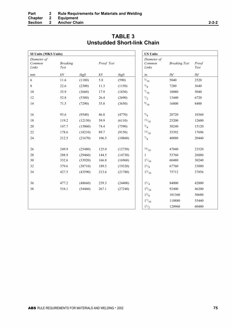
Part 2 Rule Requirements for Materials and WeldingChapter 2 EquipmentSection 2 Anchor Chain 2-2-2
ABS RULE REQUIREMENTS FOR MATERIALS AND WELDING . 2002 75
TABLE 3Unstudded Short-link Chain
SI Units (MKS Units) US Units
Diameter ofCommonLinks
BreakingTest
Proof TestDiameter ofCommonLinks
Breaking Test ProofTest
mm kN (kgf) kN (kgf) in. lbf lbf
6 11.6 (1180) 5.8 (590) 5/16 5040 2520
8 22.6 (2300) 11.3 (1150) 3/8 7280 3640
10 35.9 (3660) 17.9 (1830) 7/16 10080 5040
12 52.8 (5380) 26.4 (2690) 1/2 13440 6720
14 71.5 (7290) 35.8 (3650) 9/16 16800 8400
16 93.6 (9540) 46.8 (4770) 5/8 20720 10360
18 119.2 (12150) 59.9 (6110) 11/16 25200 12600
20 147.7 (15060) 74.4 (7590) 3/4 30240 15120
22 178.6 (18210) 89.7 (9150) 13/16 35392 17696
24 212.5 (21670) 106.5 (10860) 7/8 40880 20440
26 249.9 (25480) 125.0 (12750) 15/16 47040 23520
28 288.9 (29460) 144.5 (14730) 1 53760 26880
30 332.6 (33920) 166.8 (16960) 11/16 60480 30240
32 379.6 (38710) 189.5 (19320) 11/8 67760 33880
34 427.5 (43590) 213.6 (21780) 13/16 75712 37856
36 477.2 (48660) 239.3 (24400) 11/4 84000 42000
38 534.1 (54460) 267.1 (27240) 15/16 92400 46200
13/8 101360 50680
17/16 110880 55440
11/2 120960 60480

ABS RULE REQUIREMENTS FOR MATERIALS AND WELDING . 2002 77
P A R T
2C H A P T E R 2 Equipment
S E C T I O N 3 Rolled Steel Bars for Chain 2 - 2 - 2
1 General (1999) 2-2-2/11
Rolled steel bars Grades U1, U2 or U3 for Grade 1, 2 or 3 chains are to be in accordance with thissection. Bars for offshore mooring chains are to be in accordance with the Guide for the Certificationof Offshore Mooring Chain.
These Rules are not intended to replace or modify any part of a chain manufacturer’s specificationapproved by the Bureau.
1.1 Process of Manufacture (1999) 2-1-2/11.3.1
The steel is to be made by the open-hearth, basic oxygen, vacuum-arc remelt, electro-slag remeltelectric-furnace or such other process as may be specially approved.
1.3 Deoxidation Practice
Bars are to be fully killed and in addition, Grade U2 or U3 bars are to be produced to a fine grainpractice.
1.5 Chemical Composition and Heat Treatment (1999) 2-1-2/11.3.2
The chemical composition and heat treatment are to be in accordance with the manufacturer’sspecification that is to be approved by the Bureau. In general, they are to conform to 2-2-3/Table 1.
1.7 Mechanical Properties (1999) 2-1-2/11.3.3
Mechanical tests are to be carried out in accordance with 2-2-3/3 and the results are to meet therequirements in 2-2-2/Table 1.
1.9 Dimensional properties (1999) 2-1-2/11.3.4
Unless otherwise approved, the tolerances on diameter and roundness (dmax − dmin) are to be within
the limits listed in 2-2-3/Table 2, where dmax and dmin are the maximum and minimum diameter
measured at the section under consideration.
Part 2 Rule Requirements for Materials and WeldingChapter 2 EquipmentSection 3 Rolled Steel Bars for Chain 2-2-3
78 ABS RULE REQUIREMENTS FOR MATERIALS AND WELDING . 2002
3 Material Testing 2-2-2/13
3.1 Heat Treatment of Test Specimens 2-2-2/13.1
Test specimens are to be taken from material heat-treated in the same manner as intended for thefinished chain.
3.3 Number of Tests 2-2-2/13.3
One tensile and three impact test specimens are to be taken from two different bars of steel from eachheat unless the material from a heat is less than 50 metric tons (49.21 long tons) in which case testsfrom one bar will be sufficient. If, however, the material from one heat differs 9.5 mm (0.375 in.) ormore in diameter, one set of tests is to be taken from the thinnest and thickest material rolled.
3.5 Tension Test Specimens (1996) 2-2-2/13.5
Tension test specimens for bar material are to be taken at 2/3r as shown in 2-2-3/Figure 1 or as closethereto as possible and machined to 2-1-1/Figure 1 or appropriate national standard specimen.
The required minimum percentage elongation values in 2-2-2/Table 1 are based on specimens havinggauge lengths equal to 5 times the diameter. For specimens having other gauge lengths the equivalentelongation value is to be calculated by the following equation:
4.0)/(2 LAEn =
where
n = equivalent minimum elongation
A = actual cross-sectional area of the specimen
L = actual gauge length
E = specified minimum percentage elongation for specimens having a gauge length of5 times the diameter
The above equation is not applicable to quenched and tempered steel, for which the specimen is tohave a gauge length of 5 times the specimen diameters.
3.7 Bend Test Specimens 2-2-2/13.7
Bend test specimens may be either the full section of the bar or may be machined at the option of themanufacturer to a 25 mm (1 in.) diameter or to a rectangular cross section of 25 mm × 12.5 mm (1 in.× 0.5 in.) but not less than 12.5 mm × 12.5 mm (0.5 in. × 0.5 in.). Each specimen is to withstand,without fracture, cold bending around a mandrel diameter and through the angle specified in2-2-2/Table 1.
3.9 Impact Test Specimens 2-2-2/13.9
Impact test specimens are to be in accordance with 2-1-1/11.11. They are to be cut and notched asshown in 2-2-2/Figure 1. The average value of 3 specimens is to comply with the requirements of2-2-2/Table 1.
3.11 Additional Tests before Rejection (1996) 2-2-2/13.11
When a specimen fails to meet the requirements of 2-2-2/Table 1 retests in accordance with2-1-2/9.11, 2-1-2/9.13, 2-1-2/11.7 and 2-1-2/11.9 may be permitted, as applicable.

Part 2 Rule Requirements for Materials and WeldingChapter 2 EquipmentSection 3 Rolled Steel Bars for Chain 2-2-3
ABS RULE REQUIREMENTS FOR MATERIALS AND WELDING . 2002 79
3.13 Manufacturer’s Option 2-2-2/13.13
At the option of the chain manufacturer, the above material tests (normally conducted prior to chainfabrication) may be waived, provided the required test specimens representative of each heat are takenfrom finished links after final heat treatment, if any, and in the same proportion of number of tests totonnage as outlined in 2-2-2/3.3.
TABLE 1Rolled Bars for Chain – Chemical Composition and Heat Treatment (1999)
Bar Stock Grade U1 U2 U3
Intended Chain Grade Grade 1 Grade 2 Grade 3
Deoxidation fully killed fully killed, fine grain fully killed, fine grain
Heat Treatment as rolled as rolled or normalized4) quenched and tempered
Chemical Composition (1), (Ladle Analysis) - % max unless specified otherwise
C 0.20 0.24 0.36
Si 0.15 - 0.35 0.15 - 0.55 0.15 - 0.55
Mn 0.40 min. 1.00 - 1.60 1.00 - 1.90
P 0.040 0.035 0.035
S 0.040 0.035 0.035
Al (2) (total) min. - 0.020 0.020
Bar Stock Marking AB/U1 AB/U2 (3), (4) AB/U3
Notes:1 Other intentionally added elements are to be reported on the mill sheet.
2 Specified aluminum contents may be partly replaced by other grain refining elements. See 2-1-3/5.
3 Bars impact tested in accordance with Note 1) to 2-2-2/Table 1 to be marked AB/U2AW.
4 Normalized bars for Grade 2 chains are to be marked AB/U2N.
TABLE 2Rolled Bar for Chain – Dimensional Tolerances (1999)
Specified Bar Diameter, mm (in.) Tolerance on Diameter, Tolerance on (dmax – dmin,)
over up to mm (in.) mm (in.)
less than 25 (1.0) - 0, + 1.0 (0.04) 0.6 (0.02)
25 (1.0) or above 35 (1.37) - 0, + 1.2 (0.05) 0.8 (0.03)
35 (1.37) 50 (2.0) - 0, + 1.6 (0.06) 1.1 (0.04)
50 (2.0) 80 (3.12) - 0, + 2.0 (0.08) 1.50 (0.06)
80 (3.12) 100 (4.0) - 0, + 2.6 (0.10) 1.95 (0.08)
100 (4.0) 120 (4.75) - 0, + 3.0 (0.12) 2.25 (0.09)
120 (4.75) 160 (6.25) - 0, + 4.0 (0.16) 3.00 (0.12)

ABS RULE REQUIREMENTS FOR MATERIALS AND WELDING . 2002 81
P A R T
2C H A P T E R 3 Materials for Machinery, Boilers,
Pressure Vessels, and Piping
CONTENTSSECTION 1 General Requirements............................................ 87
1 Testing and Inspection ........................................... 89
3 Defects ................................................................... 90
5 Identification of Materials ....................................... 90
7 Manufacturer’s Certificates .................................... 90
9 Marking and Retests .............................................. 91
11 Standard Test Specimens...................................... 92
13 Definition and Determination of Yield Point andYield Strength......................................................... 94
15 Permissible Variations in Dimensions.................... 94
SECTION 2 Steel Plates for Machinery, Boilers and PressureVessels .................................................................... 95
1 General Requirements for All Grades of SteelPlates for Machinery, Boilers, and PressureVessels................................................................... 97
3 Steel Plates for Intermediate-temperatureService ................................................................. 100
5 Steel Plates for Intermediate- and Higher-temperature Service............................................. 101
7 Steel Plates for Intermediate- and Lower-temperature Service............................................. 103
9 Materials for Low Temperature Service[Below -18°C (0°F)] .............................................. 104
SECTION 3 Seamless Forged-steel Drums............................. 109
1 Tests and Inspections .......................................... 109
3 Heat Treatment .................................................... 109
SECTION 4 Seamless-steel Pressure Vessels........................ 111
1 General................................................................. 111
3 Tension Test......................................................... 111
5 Flattening Test...................................................... 111
7 Hydrostatic Test ................................................... 111
9 Inspection ............................................................. 111
82 ABS RULE REQUIREMENTS FOR MATERIALS AND WELDING . 2002
11 Marking................................................................. 112
SECTION 5 Boiler and Superheater Tubes..............................113
1 Scope ................................................................... 115
3 General................................................................. 115
5 Process of Manufacture ....................................... 116
7 Marking................................................................. 117
9 Chemical Composition – Ladle Analysis .............. 117
11 Check Analysis..................................................... 117
13 Mechanical Tests Required.................................. 118
15 Test Specimens.................................................... 118
17 Tensile Properties ................................................ 119
19 Flattening Test...................................................... 119
21 Reverse Flattening Test ....................................... 119
23 Flange Test .......................................................... 120
25 Flaring Test .......................................................... 120
27 Crush Test............................................................ 120
29 Hardness Tests .................................................... 121
31 Hydrostatic Test ................................................... 121
33 Nondestructive Electric Test (NDET) ................... 122
35 Retests ................................................................. 124
37 Finish.................................................................... 124
39 Permissible Variations in Dimensions .................. 124
SECTION 6 Boiler Rivet and Staybolt Steel and Rivets ..........129
1 Process of Manufacture ....................................... 129
3 Marking and Retests ............................................ 129
5 Tensile Properties ................................................ 130
7 Bending Properties............................................... 130
9 Test Specimens.................................................... 130
11 Number of Tests................................................... 130
13 Tests of Finished Rivets....................................... 130
SECTION 7 Steel Machinery Forgings .....................................131
1 Carbon Steel Machinery Forgings........................ 133
3 Alloy Steel Gear Assembly Forgings.................... 137
5 Alloy Steel Shaft and Stock Forgings................... 141
7 General Shipboard Alloy Steel Forgings.............. 145
SECTION 8 Hot-rolled Steel Bars for Machinery ....................157
1 Hot-rolled Steel Bars ............................................ 157
3 Number of Tests................................................... 157
SECTION 9 Steel Castings for Machinery, Boilers andPressure Vessels...................................................159
1 General................................................................. 159
3 Marking and Retests ............................................ 159
5 Heat Treatment .................................................... 160
7 Tensile Properties ................................................ 160
ABS RULE REQUIREMENTS FOR MATERIALS AND WELDING . 2002 83
9 Application............................................................ 160
11 Test Specimens ................................................... 161
13 Number of Tests................................................... 161
15 Inspection and Repair .......................................... 161
17 Castings for Ice-strengthened Propellers............. 162
SECTION 10 Ductile (Nodular) Iron Castings............................ 163
1 Manufacture and Test .......................................... 163
3 Heat Treatment .................................................... 166
5 Weld Repairs........................................................ 166
SECTION 11 Gray-iron Castings................................................ 167
1 Process of Manufacture ....................................... 167
3 Tensile Strength ................................................... 167
5 Higher-strength Castings ..................................... 167
SECTION 12 Steel Piping ........................................................... 169
1 Scope ................................................................... 173
3 General................................................................. 173
5 Process of Manufacture ....................................... 174
7 Marking................................................................. 175
9 Chemical Composition ......................................... 176
11 Ladle Analysis ...................................................... 176
13 Check Analysis..................................................... 176
15 Mechanical Tests Required.................................. 177
17 Tension Test Specimens...................................... 177
19 Bend and Flattening Test Specimens .................. 178
21 Testing Temperature............................................ 178
23 Tensile Properties ................................................ 178
25 Bend Test ............................................................. 178
27 Flattening Test...................................................... 179
29 Hydrostatic Test ................................................... 180
31 Nondestructive Electric Test (NDET) forSeamless Pipe ..................................................... 182
33 Retests ................................................................. 183
35 Pipe Testing and Inspection................................. 183
37 Permissible Variation in Wall Thickness .............. 184
39 Permissible Variations in Outside Diameter......... 184
SECTION 13 Piping, Valves and Fittings for Low-temperatureService [ Below -18°C (0°F) ] ................................ 193
1 Scope ................................................................... 193
3 Designation .......................................................... 193
5 Manufacture ......................................................... 194
7 Heat Treatment .................................................... 194
9 Marking................................................................. 194
11 Chemical Composition ......................................... 194
13 Mechanical Tests ................................................. 194
84 ABS RULE REQUIREMENTS FOR MATERIALS AND WELDING . 2002
15 Impact Properties ................................................. 194
17 Steels for Service Temperatures Between-18°C (0°F) and -196°C (-320°F) ......................... 194
19 Steels for Service Temperatures Below-196°C (-320°F) .................................................... 194
21 Materials for Nuts and Bolts ................................. 195
23 Toughness............................................................ 195
25 Impact Test Temperature..................................... 195
27 Witnessed Tests................................................... 195
29 Retests ................................................................. 195
31 Welding ................................................................ 195
SECTION 14 Bronze Castings ....................................................197
1 For General Purposes.......................................... 199
3 Propellers and Propeller Blades........................... 199
5 Castings for Ice-Strengthened Propellers ............ 203
SECTION 15 Austenitic Stainless Steel Propeller Castings .....205
1 Process of Manufacture ....................................... 205
3 Inspection and Repair .......................................... 205
5 Chemical Composition ......................................... 205
7 Tensile Properties ................................................ 206
9 Tests and Marking................................................ 206
11 Castings for Ice-strengthened Propellers............. 206
SECTION 16 Seamless Copper Piping.......................................207
1 Scope ................................................................... 207
3 General................................................................. 207
5 Process of Manufacture ....................................... 207
7 Marking................................................................. 208
9 Chemical Composition ......................................... 208
11 Tension Test......................................................... 208
13 Expansion Test..................................................... 208
15 Flattening Test...................................................... 208
17 Hydrostatic Test ................................................... 209
19 Number of Tests................................................... 209
21 Retests ................................................................. 209
23 Permissible Variations in Dimensions .................. 210
SECTION 17 Seamless Red-brass Piping..................................211
1 Process of Manufacture ....................................... 211
3 Marking................................................................. 211
5 Scope ................................................................... 211
7 Chemical Composition ......................................... 211
9 Expansion Test..................................................... 212
11 Flattening Test...................................................... 212
13 Mercurous Nitrate Test......................................... 212
15 Bend Test ............................................................. 212
ABS RULE REQUIREMENTS FOR MATERIALS AND WELDING . 2002 85
17 Hydrostatic Test ................................................... 212
19 Number of Tests................................................... 213
21 Retests ................................................................. 213
23 Permissible Variations in Dimensions.................. 213
SECTION 18 Seamless Copper Tube......................................... 215
1 Scope ................................................................... 215
3 General................................................................. 215
5 Process of Manufacture ....................................... 215
7 Marking................................................................. 216
9 Chemical Composition ......................................... 216
11 Tension Test......................................................... 216
13 Expansion Test..................................................... 216
15 Flattening Test...................................................... 216
17 Hydrostatic Test ................................................... 217
19 Number of Tests................................................... 217
21 Retests ................................................................. 217
23 Permissible Variations in Dimensions.................. 218
SECTION 19 Condenser and Heat Exchanger Tube................. 219
1 Scope ................................................................... 221
3 General................................................................. 221
5 Process of Manufacture ....................................... 221
7 Marking................................................................. 222
9 Chemical Composition ......................................... 222
11 Tension Test......................................................... 222
13 Expansion Test..................................................... 223
15 Flattening Test...................................................... 223
17 Nondestructive Electric Test (NDET) ................... 223
19 Hydrostatic Test ................................................... 224
21 Number of Tests................................................... 224
23 Retests ................................................................. 224
25 Finish.................................................................... 225
27 Dimensions and Tolerances................................. 225
SECTION 20 Copper-Nickel Tube and Pipe............................... 229
1 Scope ................................................................... 231
3 General................................................................. 231
5 Process of Manufacture ....................................... 232
7 Marking................................................................. 232
9 Chemical Composition ......................................... 232
11 Tension Test......................................................... 233
13 Expansion Test..................................................... 233
15 Flattening Test...................................................... 234
17 Nondestructive Examination ................................ 234
19 Hydrostatic Test ................................................... 234
21 Number of Tests................................................... 235
86 ABS RULE REQUIREMENTS FOR MATERIALS AND WELDING . 2002
23 Retests ................................................................. 235
25 Finish.................................................................... 235
27 Dimensions and Tolerances................................. 235
SECTION 21 Monel Pipe and Tube.............................................239
1 Scope ................................................................... 241
3 General................................................................. 241
5 Process of Manufacture ....................................... 242
7 Marking................................................................. 242
9 Chemical Composition ......................................... 243
11 Tension Test......................................................... 243
13 Flattening Test...................................................... 244
15 Flare Test ............................................................. 244
17 Flange Test .......................................................... 244
19 Number of Tests................................................... 244
21 Hydrostatic Test ................................................... 245
23 Nondestructive Electric Test (NDET) ................... 245
25 Retests ................................................................. 246
27 Finish.................................................................... 246
29 Dimensions and Tolerances................................. 247

ABS RULE REQUIREMENTS FOR MATERIALS AND WELDING . 2002 87
P A R T
2C H A P T E R 3 Materials for Machinery, Boilers,
Pressure Vessels, and Piping
S E C T I O N 1 General Requirements
CONTENTS1 Testing and Inspection.......................................................... 89
1.1 General................................................................................... 89
1.3 Test and Test Data................................................................. 89
1.5 Rejection of Previously Accepted Material............................. 89
1.7 Calibrated Testing Machines.................................................. 90
1.9 ASTM References .................................................................. 90
3 Defects ................................................................................... 90
5 Identification of Materials ..................................................... 90
7 Manufacturer’s Certificates .................................................. 90
7.1 Form of Certificate.................................................................. 90
7.3 Other Certificates ................................................................... 90
9 Marking and Retests ............................................................. 91
9.1 Identification of Test Specimens ............................................ 91
9.3 Defects in Specimens............................................................. 91
9.5 Retests ................................................................................... 91
9.7 Rejected Material.................................................................... 91
11 Standard Test Specimens..................................................... 92
11.1 General................................................................................... 92
11.3 Test Specimens...................................................................... 92
11.5 Tension Test Specimens for Plates and Shapes ................... 92
11.7 Tension Test Specimens for Castings (Other than Iron)and Forgings........................................................................... 92
11.9 Tension Test Specimens (for Cast Iron) ................................ 92
11.11 Transverse or Flexure Test Specimens for Cast Iron ............ 92
11.13 Bend Test Specimens for Steel Castings and Forgings ........ 92
88 ABS RULE REQUIREMENTS FOR MATERIALS AND WELDING . 2002
13 Definition and Determination of Yield Point and YieldStrength..................................................................................94
13.1 Yield Point .............................................................................. 94
13.3 Yield Strength ......................................................................... 94
15 Permissible Variations in Dimensions..................................94
15.1 Scope ..................................................................................... 94
15.3 Plates...................................................................................... 94
FIGURE 1 Standard Rectangular Tension Test Specimenwith 200 mm (8 in.) Gauge Length.............................91
FIGURE 2 Standard Round Tension Test Specimen with50 mm (2 in.) Gauge Length.......................................93
FIGURE 3 Tension Test Specimen Machined fromTransverse or Flexure Test Bars...............................93
ABS RULE REQUIREMENTS FOR MATERIALS AND WELDING . 2002 89
P A R T
2C H A P T E R 3 Materials for Machinery, Boilers,
Pressure Vessels, and Piping
S E C T I O N 1 General Requirements 2 - 3 - 1
1 Testing and Inspection 2-3-1/1
1.1 General 2-3-1/1.1
All materials subject to test and inspection, intended for use in boilers, pressure vessels, andmachinery of vessels classed or proposed for classification, are to be tested and inspected by theSurveyor in accordance with the following requirements or their equivalent. Materials, test specimens,and testing procedures having characteristics differing from those prescribed herein require specialapproval for each application of such materials and the physical tests may be modified to suitconditions as approved in connection with the design.
1.3 Test and Test Data 2-3-1/1.3
1.3.1 Witnessed Tests 2-3-1/1.3.1
The designation (W) indicates that the Surveyor is to witness the testing unless the plant andproduct is approved under the Bureau’s Quality Assurance Program.
1.3.2 Manufacturer’s Data 2-3-1/1.3.2
The designation (M) indicated that test data is to be provided by the manufacturer withoutverification by a Surveyor of the procedures used or the results obtained.
1.3.3 Other Tests 2-3-1/1.3.3
The designation (A) indicates those tests for which test data is to be provided by the supplierand audited by the Surveyor to verify that the procedures used and random tests witnessed arein compliance with Rule requirements.
See Part 2, Appendix 1 for complete listing of indicated designations for the various testscalled out by Part 2, Chapter 3.
1.5 Rejection of Previously Accepted Material 2-3-1/1.5
In the event of any material proving unsatisfactory in the process of being worked, it is to be rejected,notwithstanding any previous certificate of satisfactory testing.
Part 2 Rule Requirements for Materials and WeldingChapter 3 Materials for Machinery, Boilers, Pressure Vessels and PipingSection 1 General Requirements 2-3-1
90 ABS RULE REQUIREMENTS FOR MATERIALS AND WELDING . 2002
1.7 Calibrated Testing Machines 2-3-1/1.7
The Surveyor is to satisfy himself that the testing machines are maintained in a satisfactory andaccurate condition and is to keep a record of the dates and by whom the machines were rechecked orcalibrated.
1.9 ASTM References 2-3-1/1.9
For identification of ASTM references, see 2-1-1/1.13.
3 Defects 2-3-1/3
All materials are to be free from cracks, injurious surface flaws, injurious laminations, and similardefects. Except as indicated for specific materials, welding or dressing for the purpose of remedyingdefects is not permitted unless and until sanctioned by the Surveyor. In such cases, where sanction isrequired for materials to be so treated, the Surveyor may prescribe further probing and necessary heattreatment; then, if found satisfactory, the part treated is to be stamped with the Surveyor’sidentification mark and surrounded by a ring of paint.
5 Identification of Materials 2-3-1/5
The manufacturer is to adopt a system of marking ingots, slabs, finished plates, shapes, castings andforgings which will enable the material to be traced to its original heat; and the Surveyor is to begiven every facility for so tracing material.
7 Manufacturer’s Certificates 2-3-1/7
7.1 Form of Certificate 2-3-1/7.1
Unless requested otherwise, four copies of the certified mill test reports and shipping information(may be separate or combined documents) of all accepted material indicating the grade of steel, heatidentification numbers, test results and weight shipped are to be furnished to the Surveyor. One copyof the mill test report is to be endorsed by the Surveyor and forwarded to the Purchaser, three to beretained for the use of the Bureau. Before the certified mill test reports and shipping information aredistributed to the local Bureau office, the manufacturer is to furnish the Surveyor with a certificatestating that the material has been made by an approved process and that it has withstood satisfactorilythe prescribed tests. The following form of certificate will be accepted if printed on each certified milltest report with the name of the firm and initialed by the authorized representative of themanufacturer:
‘‘We hereby certify that the material described herein has been made to the applicable specificationby the _________ process (state process) and tested in accordance with the requirements of_______________ (the American Bureau of Shipping Rules or state other specification) withsatisfactory results.’’
At the request of manufacturers, consideration may be given to modifications in the form of thecertificate, provided it correspondingly indicates compliance with the requirements of the Rules to noless degree than indicated in the foregoing statement.
7.3 Other Certificates 2-3-1/7.3
Where steel is not produced in the works at which it is rolled or forged, a certificate is to be suppliedto the Surveyor stating the process by which it was manufactured, the name of the manufacturer whosupplied it and the number of the heat from which it was made. The number of the heat is to bemarked on each plate or bar for the purpose of identification.
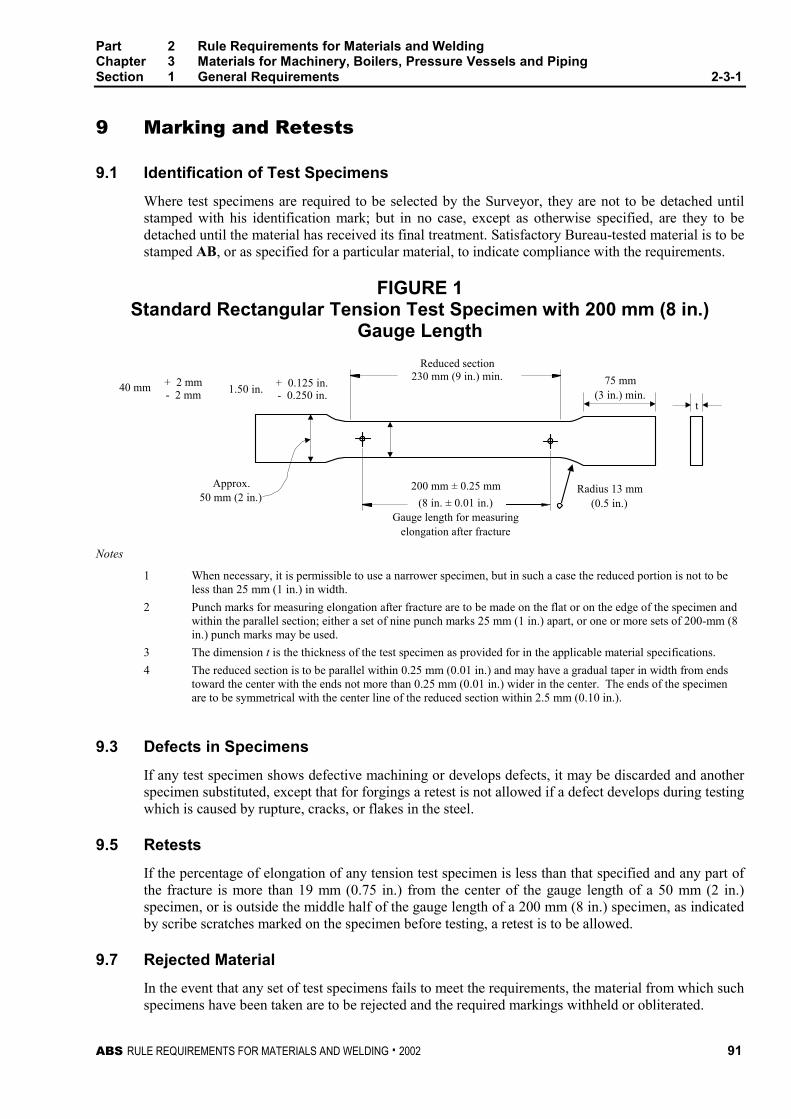
Part 2 Rule Requirements for Materials and WeldingChapter 3 Materials for Machinery, Boilers, Pressure Vessels and PipingSection 1 General Requirements 2-3-1
ABS RULE REQUIREMENTS FOR MATERIALS AND WELDING . 2002 91
9 Marking and Retests 2-3-1/9
9.1 Identification of Test Specimens 2-3-1/9.1
Where test specimens are required to be selected by the Surveyor, they are not to be detached untilstamped with his identification mark; but in no case, except as otherwise specified, are they to bedetached until the material has received its final treatment. Satisfactory Bureau-tested material is to bestamped AB, or as specified for a particular material, to indicate compliance with the requirements.
FIGURE 1Standard Rectangular Tension Test Specimen with 200 mm (8 in.)
Gauge Length
(3 in.) min.
Reduced section
40 mm + 2 mm- 2 mm - 0.250 in.
+ 0.125 in.1.50 in.
Approx.50 mm (2 in.)
200 mm ± 0.25 mm Radius 13 mm(0.5 in.)
Gauge length for measuringelongation after fracture
75 mm
t
(8 in. ± 0.01 in.)
230 mm (9 in.) min.
Notes
1 When necessary, it is permissible to use a narrower specimen, but in such a case the reduced portion is not to beless than 25 mm (1 in.) in width.
2 Punch marks for measuring elongation after fracture are to be made on the flat or on the edge of the specimen andwithin the parallel section; either a set of nine punch marks 25 mm (1 in.) apart, or one or more sets of 200-mm (8in.) punch marks may be used.
3 The dimension t is the thickness of the test specimen as provided for in the applicable material specifications.
4 The reduced section is to be parallel within 0.25 mm (0.01 in.) and may have a gradual taper in width from endstoward the center with the ends not more than 0.25 mm (0.01 in.) wider in the center. The ends of the specimenare to be symmetrical with the center line of the reduced section within 2.5 mm (0.10 in.).
9.3 Defects in Specimens 2-3-1/9.3
If any test specimen shows defective machining or develops defects, it may be discarded and anotherspecimen substituted, except that for forgings a retest is not allowed if a defect develops during testingwhich is caused by rupture, cracks, or flakes in the steel.
9.5 Retests 2-3-1/9.5
If the percentage of elongation of any tension test specimen is less than that specified and any part ofthe fracture is more than 19 mm (0.75 in.) from the center of the gauge length of a 50 mm (2 in.)specimen, or is outside the middle half of the gauge length of a 200 mm (8 in.) specimen, as indicatedby scribe scratches marked on the specimen before testing, a retest is to be allowed.
9.7 Rejected Material 2-3-1/9.7
In the event that any set of test specimens fails to meet the requirements, the material from which suchspecimens have been taken are to be rejected and the required markings withheld or obliterated.
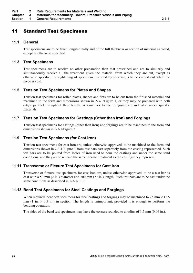
Part 2 Rule Requirements for Materials and WeldingChapter 3 Materials for Machinery, Boilers, Pressure Vessels and PipingSection 1 General Requirements 2-3-1
92 ABS RULE REQUIREMENTS FOR MATERIALS AND WELDING . 2002
11 Standard Test Specimens 2-3-1/11
11.1 General 2-3-1/11.1
Test specimens are to be taken longitudinally and of the full thickness or section of material as rolled,except as otherwise specified.
11.3 Test Specimens 2-3-1/11.3
Test specimens are to receive no other preparation than that prescribed and are to similarly andsimultaneously receive all the treatment given the material from which they are cut, except asotherwise specified. Straightening of specimens distorted by shearing is to be carried out while thepiece is cold.
11.5 Tension Test Specimens for Plates and Shapes 2-3-1/11.5
Tension test specimens for rolled plates, shapes and flats are to be cut from the finished material andmachined to the form and dimensions shown in 2-3-1/Figure 1, or they may be prepared with bothedges parallel throughout their length. Alternatives to the foregoing are indicated under specificmaterials.
11.7 Tension Test Specimens for Castings (Other than Iron) and Forgings 2-3-1/11.7
Tension test specimens for castings (other than iron) and forgings are to be machined to the form anddimensions shown in 2-3-1/Figure 2.
11.9 Tension Test Specimens (for Cast Iron) 2-3-1/11.9
Tension test specimens for cast iron are, unless otherwise approved, to be machined to the form anddimensions shown in 2-3-1/Figure 3 from test bars cast separately from the casting represented. Suchtest bars are to be poured from ladles of iron used to pour the castings and under the same sandconditions, and they are to receive the same thermal treatment as the castings they represent.
11.11 Transverse or Flexure Test Specimens for Cast Iron 2-3-1/11.11
Transverse or flexure test specimens for cast iron are, unless otherwise approved, to be a test bar ascast with a 50 mm (2 in.) diameter and 700 mm (27 in.) length. Such test bars are to be cast under thesame conditions as described in 2-3-1/11.9.
11.13 Bend Test Specimens for Steel Castings and Forgings 2-3-1/11.13
When required, bend test specimens for steel castings and forgings may be machined to 25 mm × 12.5mm (1 in. × 0.5 in.) in section. The length is unimportant, provided it is enough to perform thebending operation.
The sides of the bend test specimens may have the corners rounded to a radius of 1.5 mm (0.06 in.).
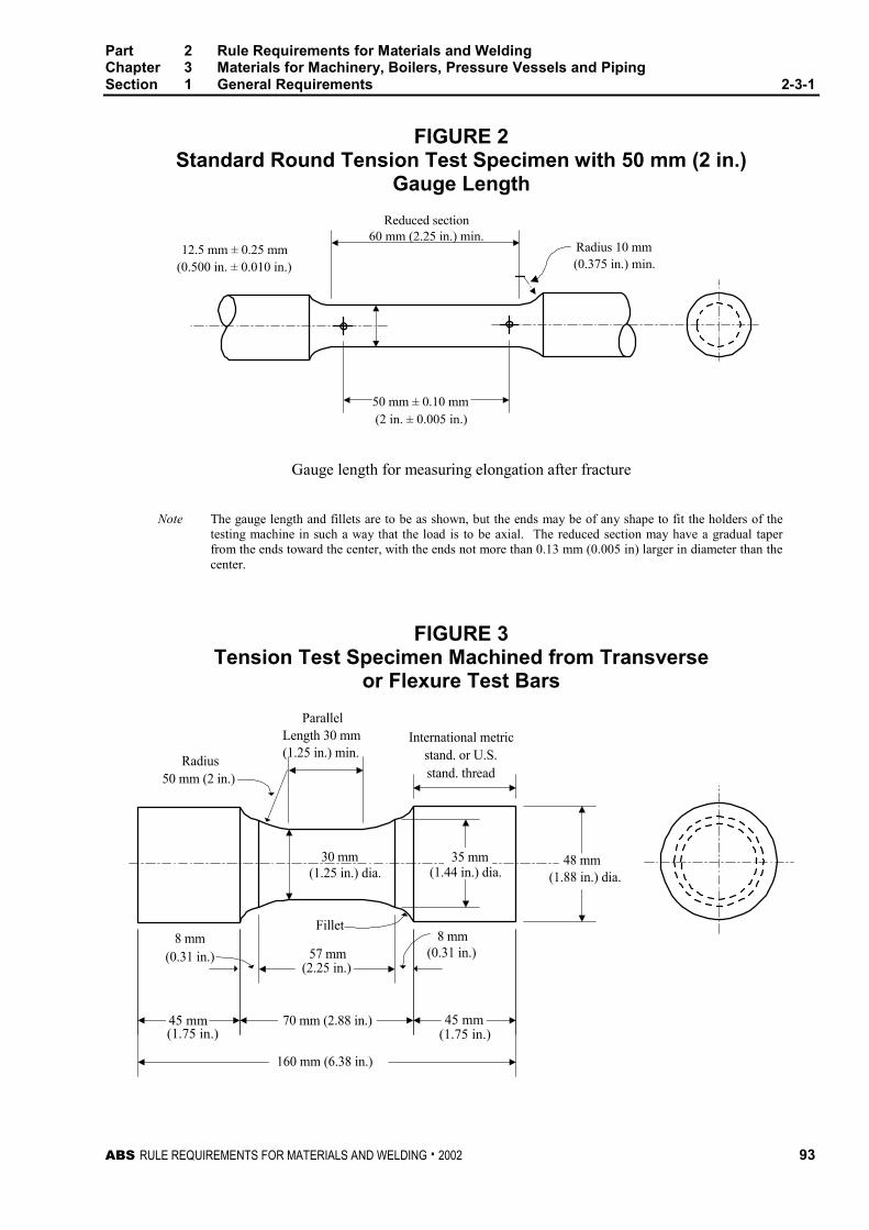
Part 2 Rule Requirements for Materials and WeldingChapter 3 Materials for Machinery, Boilers, Pressure Vessels and PipingSection 1 General Requirements 2-3-1
ABS RULE REQUIREMENTS FOR MATERIALS AND WELDING . 2002 93
FIGURE 2Standard Round Tension Test Specimen with 50 mm (2 in.)
Gauge Length
Reduced section
12.5 mm ± 0.25 mm(0.500 in. ± 0.010 in.)
Radius 10 mm(0.375 in.) min.
(2 in. ± 0.005 in.)
60 mm (2.25 in.) min.
50 mm ± 0.10 mm
Gauge length for measuring elongation after fracture
Note The gauge length and fillets are to be as shown, but the ends may be of any shape to fit the holders of thetesting machine in such a way that the load is to be axial. The reduced section may have a gradual taperfrom the ends toward the center, with the ends not more than 0.13 mm (0.005 in) larger in diameter than thecenter.
FIGURE 3Tension Test Specimen Machined from Transverse
or Flexure Test Bars
(1.88 in.) dia.(1.44 in.) dia.
ParallelLength 30 mm(1.25 in.) min.
Radius50 mm (2 in.)
30 mm(1.25 in.) dia.
International metricstand. or U.S.stand. thread
57 mm
Fillet
(0.31 in.)8 mm
(1.75 in.) (1.75 in.)
(0.31 in.)
8 mm
(2.25 in.)
160 mm (6.38 in.)
70 mm (2.88 in.)45 mm 45 mm
35 mm 48 mm
Part 2 Rule Requirements for Materials and WeldingChapter 3 Materials for Machinery, Boilers, Pressure Vessels and PipingSection 1 General Requirements 2-3-1
94 ABS RULE REQUIREMENTS FOR MATERIALS AND WELDING . 2002
13 Definition and Determination of Yield Point and YieldStrength 2-3-1/13
13.1 Yield Point 2-3-1/13.1
The yield point is the first stress in a material, less than the maximum obtainable stress, at which anincrease in strain occurs without an increase in stress. Yield point may be determined by the halt ofthe pointer, or autographic diagram. The 0.5% total extension under load method will also beconsidered acceptable.
13.3 Yield Strength 2-3-1/13.3
The yield strength is the stress at which a material exhibits a specified limiting deviation from theproportionality of stress to strain. Yield strength is to be determined by the 0.2% offset method.Alternatively, for material whose stress-strain characteristics are well known from previous tests inwhich stress-strain diagrams were plotted the 0.5% extension under load method may be used.
15 Permissible Variations in Dimensions (1994) 2-3-1/15
15.1 Scope 2-3-1/15.1
The under tolerance specified below represents the minimum material certification requirements andis to be considered as the lower limit of usual range of variations (plus/minus) from the specifieddimension.
The responsibility for meeting the specified tolerances rests with the manufacturer who is to maintaina procedure acceptable to the Surveyor
15.3 Plates (1996) 2-3-1/15.3
The maximum permissible under thickness tolerance for plates and wide flats for construction ofmachinery, excluding boilers, pressure vessels and independent tanks for liquefied gases andchemicals (see 2-3-2/1.15), is to be in accordance with the following:
Nominal Thickness, t, in mm (in.) Under Thickness Tolerance in mm. (in.)
5 ≤ t < 8 mm (0.20 ≤ t < 0.32 in.) 0.4 mm (0.016 in.)
8 ≤ t < 15 mm (0.32 ≤ t < 0.59 in.) 0.5 mm (0.02 in.)
15 ≤ t < 25 mm (0.59 ≤ t < 0.98 in.) 0.6 mm (0.024 in.)
25 ≤ t < 40 mm (0.98 ≤ t < 1.57 in.) 0.8 mm (0.032 in.)
t ≥ 40 mm (t ≥ 1.57 in.) 1.0 mm (0.04 in.)
The thickness is to be measured at a distance of 10 mm (0.375 in.) or more from the edge.
The under thickness tolerance for plates and wide flats less than 5 mm (0.20 in.) in thickness will bespecially considered.
ABS RULE REQUIREMENTS FOR MATERIALS AND WELDING . 2002 95
P A R T
2C H A P T E R 3 Materials for Machinery, Boilers,
Pressure Vessels, and Piping
S E C T I O N 2 Steel Plates for Machinery, Boilersand Pressure Vessels
CONTENTS
1 General Requirements for All Grades of Steel Plates forMachinery, Boilers, and Pressure Vessels .......................... 97
1.1 General................................................................................... 97
1.3 Marking................................................................................... 97
1.5 Process of Manufacture ......................................................... 98
1.7 Chemical Composition ........................................................... 98
1.9 Test Specimens...................................................................... 99
1.11 Tensile Properties .................................................................. 99
1.13 Retests ................................................................................. 100
1.15 Thickness Variation .............................................................. 100
1.17 Finish .................................................................................... 100
1.19 Weldability ............................................................................ 100
3 Steel Plates for Intermediate-temperature Service ........... 100
3.1 Scope ................................................................................... 100
3.3 General................................................................................. 100
3.5 Chemical Composition ......................................................... 101
3.7 Specimen Preparation.......................................................... 101
3.9 Tensile Properties ................................................................ 101
5 Steel Plates for Intermediate- and Higher-temperatureService ................................................................................. 101
5.1 Scope ................................................................................... 101
5.3 General................................................................................. 102
5.5 Heat Treatment .................................................................... 102
5.7 Chemical Composition ......................................................... 102
5.9 Test Specimens.................................................................... 102
5.11 Tensile Properties ................................................................ 103
96 ABS RULE REQUIREMENTS FOR MATERIALS AND WELDING . 2002
7 Steel Plates for Intermediate- and Lower-temperatureService..................................................................................103
7.1 Scope ................................................................................... 103
7.3 General................................................................................. 103
7.5 Heat Treatment..................................................................... 103
7.7 Chemical Composition ......................................................... 104
7.9 Test Specimens.................................................................... 104
7.11 Tensile Properties................................................................. 104
9 Materials for Low Temperature Service[Below -18°C (0°F)]...............................................................104
TABLE 1 Chemical Composition for Plate Grades MD, ME,MF, MG, H, I, J...........................................................105
TABLE 2 Tensile Properties for Plate Grades MD, ME, MF,MG, H, I, J..................................................................105
TABLE 3 Chemical Composition for Plate GradesK, L, M, N...................................................................106
TABLE 4 Tensile Properties for Plate Grades K, L, M, N .......107
ABS RULE REQUIREMENTS FOR MATERIALS AND WELDING . 2002 97
P A R T
2C H A P T E R 3 Materials for Machinery, Boilers,
Pressure Vessels, and Piping
S E C T I O N 2 Steel Plates for Machinery, Boilersand Pressure Vessels 2 - 3 - 2
1 General Requirements for All Grades of Steel Plates forMachinery, Boilers, and Pressure Vessels 2-3-2/1
1.1 General 2-3-2/1.1
1.1.1 Inspection at Mills 2-3-2/1.1.1
The grades of steel covered in 2-3-2/3, 2-3-2/5 and 2-3-2/7 are rolled plates intended for usein machinery, boilers and other pressure vessels. All tests are to be conducted in the presenceof the Surveyor at the place of manufacture prior to shipping, unless the plant is approvedunder the Bureau’s Quality Assurance Program for Rolled Products. The material will besurface-inspected by the Surveyor when specially requested by the purchaser. Plates are to befree from defects and have a workmanlike finish subject to the conditions given under2-3-2/1.17.
1.1.2 Alloy Steels or Special Carbon Steels 2-3-2/1.1.2
When alloy steels or carbon steels differing from those indicated herein are proposed for anypurpose, the purchaser’s specification is to be submitted for approval in connection with theapproval of the design for which the material is proposed. Specifications such as ASTM A387(Grade C or Grade D) or other steels suitable for the intended service will be considered.
1.3 Marking 2-3-2/1.3
1.3.1 Plates and Test Specimens 2-3-2/1.3.1
The name or brand of the manufacturer, the letter indicating the grade of steel, themanufacturer’s identification numbers and the letters PV to indicate pressure-vessel qualityare to be legibly stamped (except as specified in 2-3-2/1.3.4) on each finished plate in twoplaces, not less than 300 mm (12 in.) from the edges. Plates, the maximum lengthwise andcrosswise dimensions of which do not exceed 1800 mm (72 in.), are to have the markingstamped in one place approximately midway between the center and an edge. Themanufacturer’s test identification number is to be legibly stamped on each test specimen. Alltest specimens are to be ring-stamped, match-marked or otherwise suitably identified to thesatisfaction of the attending Surveyor before being detached.
Part 2 Rule Requirements for Materials and WeldingChapter 3 Materials for Machinery, Boilers, Pressure Vessels and PipingSection 2 Steel Plates for Machinery, Boilers and Pressure Vessels 2-3-2
98 ABS RULE REQUIREMENTS FOR MATERIALS AND WELDING . 2002
1.3.2 Heat-treatment Marking 2-3-2/1.3.2
When the heat treatment is to be carried out by the fabricator as covered in 2-3-2/5.5 and2-3-2/7.5, the letter G is to also be stamped on each plate by the steel producer to indicate thatthe material is in the unheat-treated (green) condition. After heat treatment at the fabricator’splant, the letter T is to be stamped following the letter G.
1.3.3 Bureau Markings 2-3-2/1.3.3
The Bureau markings AB, indicating satisfactory compliance with the Rule requirements andother markings as furnished by the Surveyor, are to be stamped on all plates near the markingspecified in 2-3-2/1.3.1 to signify that the material has satisfactorily complied with the testprescribed, and that certificates for the material will be furnished to the Surveyor inaccordance with 2-3-1/7. For coiled steel which is certified for chemical analysis only, themarking AB without grade designation is to be marked on the outer wrap of each coilshipped.
1.3.4 Thin Plates 2-3-2/1.3.4
Plates under 6.4 mm (0.25 in.) in thickness are to be legibly stenciled with the markingsspecified in 2-3-2/1.3.1 and 2-3-2/1.3.2 instead of stamped.
1.3.5 Special Impact Testing 2-3-2/1.3.5
When steel is impact tested in accordance with 2-3-2/9 the grade marking is to be followed bythe test temperature in degrees Celsius. A prefix ‘‘0’’ to the test temperature is to indicate atemperature colder than zero degrees Celsius.
1.5 Process of Manufacture 2-3-2/1.5
The steel is to be made by one or more of the following processes: open-hearth, basic-oxygen orelectric-furnace. The steel may be cast in ingots or may be strand (continuous) cast. The ratio ofreduction of thickness from strand (continuous) cast slab to finished plate is to be a minimum of 3 to 1unless specially approved.
1.5.1 Plates Produced from Coils 2-3-2/1.5.1
For coiled plate, the manufacturer or processor is to submit supporting data for review andapproval to indicate that the manufacturing, processing, and testing will provide materialwhich is in compliance with the Rules.
1.7 Chemical Composition 2-3-2/1.7
1.7.1 Ladle Analysis 2-3-2/1.7.1
An analysis of each heat of steel is to be made by the manufacturer to determine thepercentage of the elements specified. This analysis is to be made from a test sample takenduring pouring of the heat. The chemical composition thus determined is to be reported to theSurveyor and is to conform to the requirements as specified for each grade in 2-3-2/3.5,2-3-2/5.7 or 2-3-2/7.7.
1.7.2 Check Analysis 2-3-2/1.7.2
The chemical composition determined by check analysis is to conform to the requirements asspecified for each Grade in 2-3-2/3.5, 2-3-2/5.7, and 2-3-2/7.7.
Part 2 Rule Requirements for Materials and WeldingChapter 3 Materials for Machinery, Boilers, Pressure Vessels and PipingSection 2 Steel Plates for Machinery, Boilers and Pressure Vessels 2-3-2
ABS RULE REQUIREMENTS FOR MATERIALS AND WELDING . 2002 99
1.9 Test Specimens 2-3-2/1.9
1.9.1 Selection of Specimens 2-3-2/1.9.1
One tension test specimen is to be taken from each plate as rolled in such manner that thelongitudinal axis of the specimens is transverse to the final direction of rolling of the plate.The tension test specimen is to be taken from a corner of the plate. If the final rollingdirection of the plate is parallel to the original longitudinal ingot axis, the tension testspecimen is to be taken from the ‘‘bottom’’ end of the plate. If the final direction of rolling ofthe plate is transverse to the original longitudinal ingot axis, or if the relationship of finalrolling direction and original ingot axis is unknown, the tension test specimen may be takenfrom either end. For plates produced from coils, two tension test specimens are to be madefrom each coil. One tension test specimen is to be obtained from a location immediately priorto the first plate produced and a second test specimen obtained from the approximate centerlap. When required, impact tests are to be obtained adjacent to both tension test coupons and athird coupon is to be obtained immediately after the last plate produced to the qualifyinggrade or specification.
1.9.2 Specimens from Plates 19 mm (0.75 in.) and Under in Thickness 2-3-2/1.9.2
For plates 19 mm (0.75 in.) and under in thickness, tension test specimens are to be the fullthickness of the material and are to be machined to the form and dimensions shown in2-3-1/Figure 1 or with both edges parallel.
1.9.3 Specimens from Plates Over 19 mm (0.75 in.) Thickness 2-3-2/1.9.3
For plates over 19 mm (0.75 in.) in thickness, tension test specimens may be machined to theform and dimensions shown in 2-3-1/Figure 2, and the axis of each such specimen is to belocated as nearly as practicable midway between the center and the surface of the plate, or forplates up to 101.6 mm (4 in.) inclusive in thickness, they may be the full thickness of thematerial and of the form shown in 2-3-1/Figure 1 when adequate testing-machine capacity isavailable.
1.9.4 Stress Relieving 2-3-2/1.9.4
When required, test specimens are to be stress-relieved by gradually and uniformly heatingthem to 590–650°C (1100–1200°F), holding at temperature for at least 1 hour per 25 mm(1 in.) thickness and cooling in still atmosphere to a temperature not exceeding 315°C(600°F). If applicable, in the case of plates which are to be heat-treated and subsequentlystress-relieved, the test specimens for such plates are to, before testing, be stress-relievedfollowing the heat treatment.
1.11 Tensile Properties 2-3-2/1.11
1.11.1 Tensile Requirements 2-3-2/1.11.1
The material is to conform to the tensile requirements as specified for each grade in 2-3-2/3.9,2-3-2/5.11 or 2-3-2/7.11.
1.11.2 Elongation Deduction for Material Under 7.9 mm (0.313 in.) Thick 2-3-2/1.11.2
For material under 7.9 mm (0.313 in.) in thickness, a deduction from the specified percentageof elongation in 200 mm (8 in.) of 1.25% is to be made for each decrease of 0.8 mm (0.031in.) of the specified thickness below 7.9 mm (0.313 in.).
Part 2 Rule Requirements for Materials and WeldingChapter 3 Materials for Machinery, Boilers, Pressure Vessels and PipingSection 2 Steel Plates for Machinery, Boilers and Pressure Vessels 2-3-2
100 ABS RULE REQUIREMENTS FOR MATERIALS AND WELDING . 2002
1.11.3 Elongation Deduction for Material Over 88.9 mm (3.50 in.) Thick 2-3-2/1.11.3
For material over 88.9 mm (3.50 in.) in thickness, a deduction from the specified percentageof elongation in 50 mm (2 in.) of 0.50% is to be made for each increase of 12.7 mm (0.50 in.)of the specified thickness above 88.9 mm (3.50 in.). This deduction is not to exceed 3%.
1.13 Retests 2-3-2/1.13
1.13.1 For All Thicknesses 2-3-2/1.13.1
When the result of any of the physical tests specified for any of the material does not conformto the requirements, two additional specimens may, at the request of the manufacturer, betaken from the same plate and tested in the manner specified, but in such case, both of thespecimens are to conform to the requirements (see 2-3-1/9.5).
1.13.2 For Heat-treated Material 2-3-2/1.13.2
If any heat-treated material fails to meet the mechanical requirements, the material may bereheat-treated, and all physical tests are to be repeated. Where plates are specially orderedrequiring surface inspection, the Surveyor is to reinspect the plate surfaces following anyadditional heat treatment.
1.15 Thickness Variation 2-3-2/1.15
No plate is to vary more than 0.25 mm (0.01 in.) or 6% under the thickness specified, whichever is thelesser (See 4-4-1/1.4).
1.17 Finish 2-3-2/1.17
Except when ordered for riveted construction, plates may be conditioned by the manufacturer, for theremoval of surface defects on either surface by grinding, provided the ground area is well faired andgrinding does not reduce the thickness of the plate below the permissible minimum thickness.
1.19 Weldability 2-3-2/1.19
All of the grades covered in 2-3-2/3, 2-3-2/5 and 2-3-2/7 are intended for fusion welding, but weldingtechnique is of fundamental importance and welding procedure is to be in accordance with approvedmethods. See Part 2, Chapter 4.
3 Steel Plates for Intermediate-temperature Service 2-3-2/3
3.1 Scope 2-3-2/3.1
Three grades of low and intermediate-tensile-strength carbon-steel plates designated MA, MB, andMC are covered.
3.3 General 2-3-2/3.3
The various grades are in substantial agreement with ASTM designations as follows.
ASTM – A285 Grades A, B, C
ABS – Grades MA, MB, MC
The maximum thickness of these grades is to be 50.8 mm (2.0 in.).
Part 2 Rule Requirements for Materials and WeldingChapter 3 Materials for Machinery, Boilers, Pressure Vessels and PipingSection 2 Steel Plates for Machinery, Boilers and Pressure Vessels 2-3-2
ABS RULE REQUIREMENTS FOR MATERIALS AND WELDING . 2002 101
3.5 Chemical Composition 2-3-2/3.5
The steel is to conform to the following requirements as to chemical composition.
Grade MA Grade MB Grade MC
Carbon, max., % 0.17 0.22 0.28
Manganese, max., % 0.90 0.90 0.90
Phosphorus, max., % 0.035 0.035 0.035
Sulfur, max., % 0.045 0.045 0.045
Copper•, when Copper Steel isspecified
Ladle Analysis 0.20/0.35 0.20/0.35 0.20/0.35
Check Analysis 0.18/0.37 0.18/0.37 0.18/0.37
Note See 2-3-2/1.7.•When specified, the maximum incidental copper content is to be 0.25%.
3.7 Specimen Preparation 2-3-2/3.7
Test specimens are to be prepared for testing from material in its rolled condition.
3.9 Tensile Properties 2-3-2/3.9
The material is to conform to the following requirements as to tensile properties.
Grade MA Grade MB Grade MC
Tensile Strength N/mm2 (kgf/ mm2)(psi)
310–450(31.5–46)
(45000–65000)
345–485(35–49)
(50000–70000)
380–515(39–53)
(55000–75000)
Yield Strength, min., N/mm2
(kgf/mm2, psi)165
(17, 24000)185
(19, 27000)205
(21, 30000)
Elongation in 200 mm (8 in.) min.,%•
27 25 23
Elongation in 50 mm (2 in.) min., % 30 28 27
• See 2-3-2/1.11.2 and 2-3-2/1.11.3.
5 Steel Plates for Intermediate- and Higher-temperatureService 2-3-2/5
5.1 Scope 2-3-2/5.1
Seven grades of steel plates designated MD, ME, MF, MG, H, I and J are covered. Grades MD, ME,MF and MG cover intermediate and higher-tensile-strength ranges in carbon-silicon steel plates;Grades H, I and J cover three high-tensile-strength ranges in carbon-molybdenum steel plates.
Part 2 Rule Requirements for Materials and WeldingChapter 3 Materials for Machinery, Boilers, Pressure Vessels and PipingSection 2 Steel Plates for Machinery, Boilers and Pressure Vessels 2-3-2
102 ABS RULE REQUIREMENTS FOR MATERIALS AND WELDING . 2002
5.3 General 2-3-2/5.3
The various grades are in substantial agreement with ASTM designations as follows:
ASTM – A515 Grades 55, 60, 65, 70 ABS – Grades MD, ME, MF, MG
ASTM – A204 Grades A, B, C ABS – Grades H, I, J
Plates are limited in thickness as follows: Grade MD to 304.8 mm (12.0 in.); Grades ME, MF and MGto 203.2 mm (8.0 in.); Grades H and I to 152.4 mm (6.0 in.) and Grade J to 101.6 mm (4 in.).
5.5 Heat Treatment 2-3-2/5.5
5.5.1 Treatment 2-3-2/5.5.1
Plates of Grades MD, ME, MF and MG over 50.8 mm (2.0 in.) and Grades H, I and J over38.1 mm (1.5 in.) in thickness are to be treated either by normalizing or heating uniformly forhot forming. If the required treatment is to be obtained in conjunction with the hot-formingoperation, the temperature to which the plates are heated for hot forming is to be equivalent toand is not to exceed significantly the normalizing temperature. If this treatment is not done atthe rolling mill, the testing is to be carried out in accordance with 2-3-2/5.5.3.
5.5.2 Heat-treatment Instructions on Orders 2-3-2/5.5.2
Orders to the plate manufacturer or the fabricator are to specify when plates are to be heat-treated and any special requirement that the test specimens be stress-relieved, so that properprovision may be made for the heat treatment of the test specimens. The purchaser is to alsoindicate in his orders to the mill whether the rolling mill or the fabricator is to perform therequired heat treatment of the plates.
5.5.3 Responsibility for Heat Treatment 2-3-2/5.5.3
When a fabricator is equipped and elects to perform the required normalizing or fabricates byhot forming as provided in 2-3-2/5.5.1, the plates are to be accepted on the basis of tests madeat the plate manufacturer’s plant on specimens heat-treated in accordance with the purchaser’sorder requirements. If the heat-treatment temperatures are not indicated on the purchase order,the plate manufacturer is to heat-treat the specimens under conditions he considersappropriate to meet the test requirements. The plate manufacturer is to inform the fabricatorof the procedure followed in treating the specimens at the mill for guidance in treating theplates. When the plates are to be normalized at the plate manufacturer’s plant, the mechanicalproperties are to be determined on specimens simultaneously treated with the plates.
5.7 Chemical Composition 2-3-2/5.7
The steel is to conform to the requirements of 2-3-2/Table 1 as to chemical composition.
5.9 Test Specimens 2-3-2/5.9
5.9.1 Plates Not Requiring Heat Treatment 2-3-2/5.9.1
For plates not requiring heat treatment (see 2-3-2/5.5.1), the test specimens are to be preparedfor testing from the material in its rolled condition. When Grades H, I and J plates are to beused in a boiler or pressure vessel which is to be stress-relieved, the test specimens for GradesH, I and J are to be stress-relieved. See 2-3-2/1.9.
Part 2 Rule Requirements for Materials and WeldingChapter 3 Materials for Machinery, Boilers, Pressure Vessels and PipingSection 2 Steel Plates for Machinery, Boilers and Pressure Vessels 2-3-2
ABS RULE REQUIREMENTS FOR MATERIALS AND WELDING . 2002 103
5.9.2 Plates Requiring Heat Treatment 2-3-2/5.9.2
For plates requiring heat treatment (see 2-3-2/5.5.1), the test specimens are to be preparedfrom the material in its heat-treated condition, or from full-thickness samples similarly andsimultaneously treated. When Grades H, I and J plates are to be used in a boiler or pressurevessel which is to be stress-relieved, the test specimens for Grades H, I and J are to be stress-relieved following the heat treatment. See 2-3-2/1.9 and 2-3-2/5.5.
5.11 Tensile Properties 2-3-2/5.11
The material is to conform to the requirements of 2-3-2/Table 2 as to tensile properties.
7 Steel Plates for Intermediate- and Lower-temperatureService 2-3-2/7
7.1 Scope 2-3-2/7.1
Four grades of carbon-manganese-silicon steel plates made to fine-grain practice in four tensile-strength ranges designated K, L, M, N are covered.
7.3 General 2-3-2/7.3
The various grades are in substantial agreement with ASTM designations as follows.
ASTM – A516 Grades 55, 60, 65, 70
ABS – Grades K, L, M, N
Plates are limited in thickness as follows: Grade K to 304.8 mm (12.0 in.); Grades L, M and N to203.2 mm (8.0 in.).
Materials for Liquefied Gas Carriers are to comply with Section 5-8-6.
7.5 Heat Treatment 2-3-2/7.5
7.5.1 Grain Refinement 2-3-2/7.5.1
Plates over 38.1 mm (1.5 in.) are to be heat-treated to produce grain refinement either bynormalizing or heating uniformly for hot forming. If the required treatment is to be obtainedin conjunction with hot forming, the temperature to which the plates are heated for hotforming is to be equivalent to and is not to exceed significantly the normalizing temperature.If this treatment is not done at the rolling mill, the testing is to be carried out in accordancewith 2-3-2/7.5.3. When improved notch toughness is required for plates 38 mm (1.5 in.) andunder in thickness, heat treatment is to be specified as above.
7.5.2 Heat-treatment Instructions on Orders 2-3-2/7.5.2
Orders to the plate manufacturer or the fabricator are to specify when plates are to be heat-treated for grain refinement, and any special requirements that the test specimens be stress-relieved, so that proper provision may be made for the heat treatment of the test specimens.The purchaser is also to indicate in his orders to the mill whether the rolling mill or thefabricator is to perform the required heat treatment of the plates.
Part 2 Rule Requirements for Materials and WeldingChapter 3 Materials for Machinery, Boilers, Pressure Vessels and PipingSection 2 Steel Plates for Machinery, Boilers and Pressure Vessels 2-3-2
104 ABS RULE REQUIREMENTS FOR MATERIALS AND WELDING . 2002
7.5.3 Responsibility for Heat Treatment 2-3-2/7.5.3
When a fabricator is equipped and elects to perform the required normalizing or fabricates byhot forming as provided in 2-3-2/7.5.1, the plates are to be accepted on the basis of tests madeat the plate manufacturer’s plant on specimens heat-treated in accordance with the purchaser’sorder requirements. If the heat-treatment temperatures are not indicated on the purchase order,the plate manufacturer is to heat-treat the specimens under conditions he considersappropriate for grain refinement, and to meet the test requirements. The plate manufacturer isto inform the fabricator of the procedure followed in treating the specimens at the mill forguidance in treating the plates. When the plates are to be normalized at the platemanufacturer’s plant, the mechanical properties are to be determined on specimenssimultaneously treated with the plates.
7.7 Chemical Composition 2-3-2/7.7
The steel is to conform to the requirements of 2-3-2/Table 3 as to chemical composition.
7.9 Test Specimens 2-3-2/7.9
7.9.1 Plates 38.1 mm (1.5 in.) and Under in Thickness 2-3-2/7.9.1
For plates 38.1 mm (1.5 in.) and under in thickness, not requiring heat treatment, the testspecimens are to be prepared for testing from the material in its rolled condition.
7.9.2 Plates Requiring Heat Treatment 2-3-2/7.9.2
For plates 38.1 mm (1.5 in.) and under in thickness requiring heat treatment (see 2-3-2/7.5.1),or for plates over 38.1 mm (1.5 in.) in thickness, the test specimens are to be prepared fromthe material in its heat-treated condition, or from full-thickness samples similarly andsimultaneously treated.
7.11 Tensile Properties 2-3-2/7.11
The material is to conform to the requirements of 2-3-2/Table 4 as to tensile properties.
9 Materials for Low Temperature Service [Below -18°C (0°F)]2-3-2/9
Materials intended for service temperatures of below -18°C (0°F) may be provided in accordance withthose listed in 2-1-4/7, or be other specially approved low temperature materials, if Charpy V-notchimpact tests are conducted at 5°C (10°F) below minimum design temperature in accordance with2-1-4/5.1 and meet the applicable requirements of 2-1-2/11 and 5-8-6/Table 2 (ABS). Such tests arenot required for austenitic stainless steels, or aluminum alloys such as type 5083.
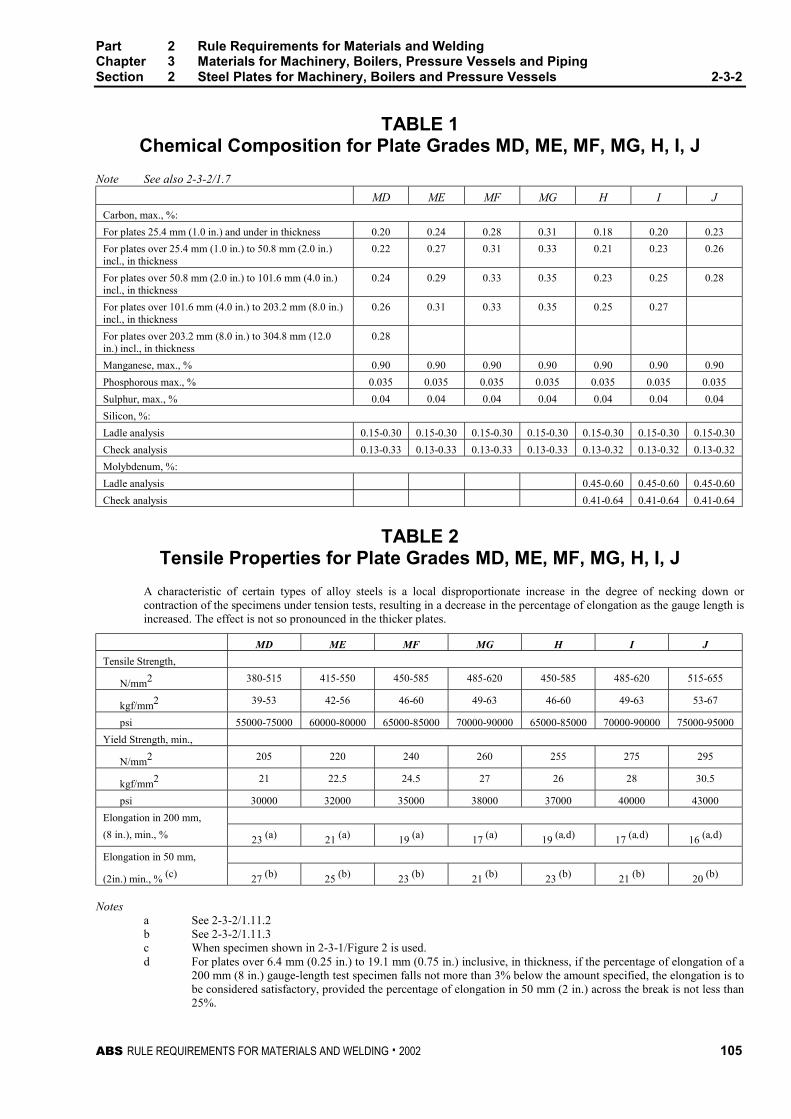
Part 2 Rule Requirements for Materials and WeldingChapter 3 Materials for Machinery, Boilers, Pressure Vessels and PipingSection 2 Steel Plates for Machinery, Boilers and Pressure Vessels 2-3-2
ABS RULE REQUIREMENTS FOR MATERIALS AND WELDING . 2002 105
TABLE 1Chemical Composition for Plate Grades MD, ME, MF, MG, H, I, J
Note See also 2-3-2/1.7
MD ME MF MG H I J
Carbon, max., %:
For plates 25.4 mm (1.0 in.) and under in thickness 0.20 0.24 0.28 0.31 0.18 0.20 0.23
For plates over 25.4 mm (1.0 in.) to 50.8 mm (2.0 in.)incl., in thickness
0.22 0.27 0.31 0.33 0.21 0.23 0.26
For plates over 50.8 mm (2.0 in.) to 101.6 mm (4.0 in.)incl., in thickness
0.24 0.29 0.33 0.35 0.23 0.25 0.28
For plates over 101.6 mm (4.0 in.) to 203.2 mm (8.0 in.)incl., in thickness
0.26 0.31 0.33 0.35 0.25 0.27
For plates over 203.2 mm (8.0 in.) to 304.8 mm (12.0in.) incl., in thickness
0.28
Manganese, max., % 0.90 0.90 0.90 0.90 0.90 0.90 0.90
Phosphorous max., % 0.035 0.035 0.035 0.035 0.035 0.035 0.035
Sulphur, max., % 0.04 0.04 0.04 0.04 0.04 0.04 0.04
Silicon, %:
Ladle analysis 0.15-0.30 0.15-0.30 0.15-0.30 0.15-0.30 0.15-0.30 0.15-0.30 0.15-0.30
Check analysis 0.13-0.33 0.13-0.33 0.13-0.33 0.13-0.33 0.13-0.32 0.13-0.32 0.13-0.32
Molybdenum, %:
Ladle analysis 0.45-0.60 0.45-0.60 0.45-0.60
Check analysis 0.41-0.64 0.41-0.64 0.41-0.64
TABLE 2Tensile Properties for Plate Grades MD, ME, MF, MG, H, I, J
A characteristic of certain types of alloy steels is a local disproportionate increase in the degree of necking down orcontraction of the specimens under tension tests, resulting in a decrease in the percentage of elongation as the gauge length isincreased. The effect is not so pronounced in the thicker plates.
MD ME MF MG H I J
Tensile Strength,
N/mm2 380-515 415-550 450-585 485-620 450-585 485-620 515-655
kgf/mm2 39-53 42-56 46-60 49-63 46-60 49-63 53-67
psi 55000-75000 60000-80000 65000-85000 70000-90000 65000-85000 70000-90000 75000-95000
Yield Strength, min.,
N/mm2 205 220 240 260 255 275 295
kgf/mm2 21 22.5 24.5 27 26 28 30.5
psi 30000 32000 35000 38000 37000 40000 43000
Elongation in 200 mm,
(8 in.), min., % 23 (a) 21 (a) 19 (a) 17 (a) 19 (a,d) 17 (a,d) 16 (a,d)
Elongation in 50 mm,
(2in.) min., % (c) 27 (b) 25 (b) 23 (b) 21 (b) 23 (b) 21 (b) 20 (b)
Notesa See 2-3-2/1.11.2b See 2-3-2/1.11.3c When specimen shown in 2-3-1/Figure 2 is used.d For plates over 6.4 mm (0.25 in.) to 19.1 mm (0.75 in.) inclusive, in thickness, if the percentage of elongation of a
200 mm (8 in.) gauge-length test specimen falls not more than 3% below the amount specified, the elongation is tobe considered satisfactory, provided the percentage of elongation in 50 mm (2 in.) across the break is not less than25%.
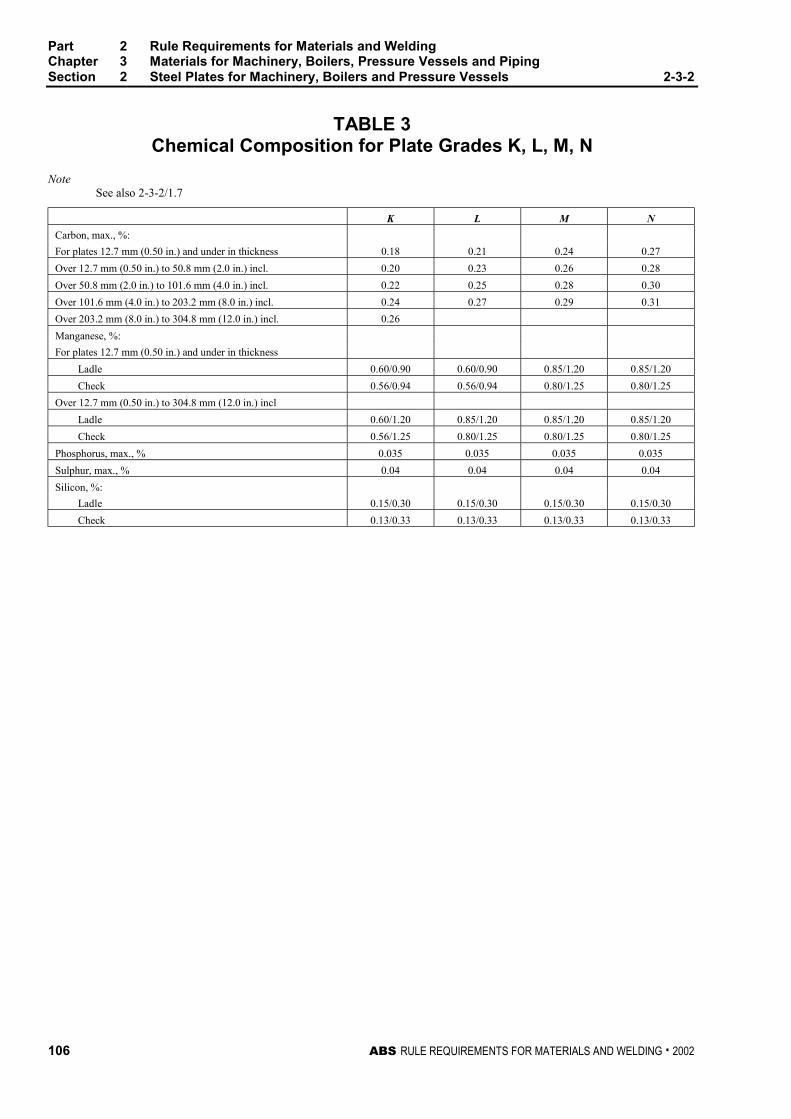
Part 2 Rule Requirements for Materials and WeldingChapter 3 Materials for Machinery, Boilers, Pressure Vessels and PipingSection 2 Steel Plates for Machinery, Boilers and Pressure Vessels 2-3-2
106 ABS RULE REQUIREMENTS FOR MATERIALS AND WELDING . 2002
TABLE 3Chemical Composition for Plate Grades K, L, M, N
NoteSee also 2-3-2/1.7
K L M N
Carbon, max., %:
For plates 12.7 mm (0.50 in.) and under in thickness 0.18 0.21 0.24 0.27
Over 12.7 mm (0.50 in.) to 50.8 mm (2.0 in.) incl. 0.20 0.23 0.26 0.28
Over 50.8 mm (2.0 in.) to 101.6 mm (4.0 in.) incl. 0.22 0.25 0.28 0.30
Over 101.6 mm (4.0 in.) to 203.2 mm (8.0 in.) incl. 0.24 0.27 0.29 0.31
Over 203.2 mm (8.0 in.) to 304.8 mm (12.0 in.) incl. 0.26
Manganese, %:
For plates 12.7 mm (0.50 in.) and under in thickness
Ladle 0.60/0.90 0.60/0.90 0.85/1.20 0.85/1.20
Check 0.56/0.94 0.56/0.94 0.80/1.25 0.80/1.25
Over 12.7 mm (0.50 in.) to 304.8 mm (12.0 in.) incl
Ladle 0.60/1.20 0.85/1.20 0.85/1.20 0.85/1.20
Check 0.56/1.25 0.80/1.25 0.80/1.25 0.80/1.25
Phosphorus, max., % 0.035 0.035 0.035 0.035
Sulphur, max., % 0.04 0.04 0.04 0.04
Silicon, %:
Ladle 0.15/0.30 0.15/0.30 0.15/0.30 0.15/0.30
Check 0.13/0.33 0.13/0.33 0.13/0.33 0.13/0.33

Part 2 Rule Requirements for Materials and WeldingChapter 3 Materials for Machinery, Boilers, Pressure Vessels and PipingSection 2 Steel Plates for Machinery, Boilers and Pressure Vessels 2-3-2
ABS RULE REQUIREMENTS FOR MATERIALS AND WELDING . 2002 107
TABLE 4Tensile Properties for Plate Grades K, L, M, N
K L M N
Tensile Strength,
N/mm2 380-515 415-550 450-585 485-620
kgf/mm2 39 to 53 42 to 56 46 to 60 49 to 63
psi 55000-75000 60000-80000 65000-85000 70000-90000
Yield Strength, min.,
N/mm2 205 220 240 260
kgf/mm2 21 22.5 24.5 27
psi 30000 32000 35000 38000
Elongation in 200 mm, (8 in.), min., % 23 (a) 21 (a) 19 (a) 17 (a)
Elongation in 50 mm, (2 in.), min., % (c) 27 (b) 25 (b) 23 (b) 21 (b)
Notesa See 2-3-2/1.11.2b See 2-3-2/1.11.3c When specimen shown in 2-3-1/Figure 2 is used.

ABS RULE REQUIREMENTS FOR MATERIALS AND WELDING . 2002 109
P A R T
2C H A P T E R 3 Materials for Machinery, Boilers,
Pressure Vessels, and Piping
S E C T I O N 3 Seamless Forged-steel Drums 2 - 3 - 3
Note: In substantial agreement with ASTM A266 as to physical properties for Classes 1 and 3.
1 Tests and Inspections 2-3-3/1
In the event that any seamless forged-steel drums are presented for inspection after special approvalfor each specific application, they are to be tested and inspected in general accordance with theapplicable procedures given for steel forgings. One tension test is to be taken from each end of theforging midway between the inner and outer surfaces of the wall in a tangential direction, the twospecimens being taken from opposite sides of the drum. Grade A material is to have the followingminimum properties, tensile strength 415 N/mm2 (42 kgf/mm2, 60,000 psi), yield strength 205 N/mm2
(21 kgf/mm2, 30,000 psi), elongation 23% in a 50 mm (2 in.) gauge length; Grade B material is tohave the following minimum properties, tensile strength 515 N/mm2 (53 kgf/mm2, 75,000 psi), yieldstrength 260 N/mm2 (26.5 kgf/mm2, 37,500 psi), elongation 19% in a 50 mm (2 in.) gauge length.
3 Heat Treatment 2-3-3/3
Except as specified herein, tests for acceptance are to be made after final treatment of the forgings.When the ends of drums are closed in by reforging after machining, the drums may be treated andtested prior to reforging. After reforging, the whole of the forging is to be simultaneously re-treated. Ifthe original treatment was annealing the re-anneal is to be above the transformation range, but notabove the temperature of the first anneal. If the original treatment was normalizing and tempering, there-treatment is to be identical with the original.


ABS RULE REQUIREMENTS FOR MATERIALS AND WELDING . 2002 111
P A R T
2C H A P T E R 3 Materials for Machinery, Boilers,
Pressure Vessels, and Piping
S E C T I O N 4 Seamless-steel Pressure Vessels 2 -
3 - 4
1 General 2-3-4/1
The material for the manufacture of and the finished seamless pressure vessels are to be free fromseams, cracks or other defects. Test specimens are to be cut from each cylinder before the necking-down process, stamped with the identification mark of the Surveyor and is to receive all heattreatments simultaneously with the cylinders.
3 Tension Test 2-3-4/3
A standard test specimen cut either longitudinally or circumferentially from each cylinder is to showthe material to have a minimum tensile strength of 415 N/mm2 (42 kgf/mm2, 60,000 psi), maximumyield point of 70% of the tensile strength and a minimum elongation of 10% in 200 mm (8 in.).
5 Flattening Test 2-3-4/5
A ring 200 mm (8 in.) long is to be cut from each cylinder and is to stand being flattened, withoutsigns of fracture, until the outside distance over the parallel sides is not greater than six times thethickness of the material.
7 Hydrostatic Test 2-3-4/7
Each cylinder is to be subjected to a hydrostatic pressure of not less than one and one-half times theworking pressure while submerged in a water jacket for a period of at least thirty seconds. Thepermanent volumetric expansion is not to exceed 5% of the total volumetric expansion at theprescribed test pressure. This test is to be made without previously subjecting the cylinder to anypressure in excess of one-third of the working pressure.
9 Inspection 2-3-4/9
All cylinders are to be properly annealed and be free from dirt and scale. Before necking-down, theSurveyor is to examine the cylinders carefully for defects and gauge the cylinder walls to ascertainthat the thickness of the material is in accordance with the approved plan.
Part 2 Rule Requirements for Materials and WeldingChapter 3 Materials for Machinery, Boilers, Pressure Vessels and PipingSection 4 Seamless-steel Pressure Vessels 2-3-4
112 ABS RULE REQUIREMENTS FOR MATERIALS AND WELDING . 2002
11 Marking 2-3-4/11
Upon satisfactory compliance with the above requirements the cylinders will be stamped AB with theidentification mark of the Surveyor, the serial number, hydrostatic pressure and the date ofacceptance.
ABS RULE REQUIREMENTS FOR MATERIALS AND WELDING . 2002 113
P A R T
2C H A P T E R 3 Materials for Machinery, Boilers,
Pressure Vessels, and Piping
S E C T I O N 5 Boiler and Superheater Tubes
CONTENTS1 Scope ................................................................................... 115
3 General................................................................................. 115
3.1 Grades D and F.................................................................... 115
3.3 Grade G................................................................................ 115
3.5 Grade H ................................................................................ 115
3.7 Grade J................................................................................. 115
3.9 Grades K, L and M ............................................................... 115
3.11 Grades N, O and P............................................................... 115
3.13 Grades R and S.................................................................... 116
3.15 ASTM Designation ............................................................... 116
5 Process of Manufacture ...................................................... 116
5.1 Grades D, F, and G .............................................................. 116
5.3 Grades H, J, K, L, and M...................................................... 116
5.5 Grades N, O, and P.............................................................. 116
5.7 Grades R and S.................................................................... 117
7 Marking ................................................................................ 117
9 Chemical Composition – Ladle Analysis ........................... 117
11 Check Analysis.................................................................... 117
11.1 General................................................................................. 117
11.3 Samples................................................................................ 118
11.5 Grades D, F, G, and H ......................................................... 118
11.7 Grades J, K, L, M, N, O, P, R, and S ................................... 118
11.9 Retests for Seamless Tubes ................................................ 118
11.11 Retests for Electric-resistance-welded Tubes...................... 118
13 Mechanical Tests Required ................................................ 118
15 Test Specimens ................................................................... 118
15.1 Selection of Specimens........................................................ 118
15.3 Tension Test Specimens...................................................... 118
114 ABS RULE REQUIREMENTS FOR MATERIALS AND WELDING . 2002
15.5 Testing Temperature ............................................................ 119
17 Tensile Properties................................................................119
19 Flattening Test .....................................................................119
19.1 Seamless and Electric-resistance-welded Tubes ................ 119
19.3 Electric-resistance-welded Tubes ........................................ 119
21 Reverse Flattening Test.......................................................119
23 Flange Test...........................................................................120
25 Flaring Test ..........................................................................120
27 Crush Test ............................................................................120
29 Hardness Tests ....................................................................121
29.1 Type of Test.......................................................................... 121
29.3 Brinell Hardness Test ........................................................... 121
29.5 Rockwell Hardness Test....................................................... 121
29.7 Tubes with Formed Ends ..................................................... 121
29.9 Maximum Permissible Hardness.......................................... 121
31 Hydrostatic Test...................................................................121
31.1 General................................................................................. 121
31.3 Maximum Hydrostatic Test Pressure ................................... 122
31.5 Duration of Test.................................................................... 122
31.7 Alternate Tests ..................................................................... 122
31.9 Rejection............................................................................... 122
33 Nondestructive Electric Test (NDET) ..................................122
33.1 General................................................................................. 122
33.3 Ultrasonic Calibration Standards.......................................... 123
33.5 Eddy-current Calibration Standards ..................................... 123
33.7 Flux Leakage Calibration Standards .................................... 123
33.9 Rejection............................................................................... 123
33.11 Affidavits ............................................................................... 124
35 Retests..................................................................................124
37 Finish ....................................................................................124
39 Permissible Variations in Dimensions................................124
39.1 Wall Thickness ..................................................................... 124
39.3 Outside Diameter.................................................................. 124
TABLE 1 Chemical Composition for Tubes............................125
TABLE 2 Mechanical Tests......................................................126
TABLE 3 Tensile Properties of Tubes.....................................127
TABLE 4 Permissible Variations in Outside Diameterfor Tubes...................................................................128

ABS RULE REQUIREMENTS FOR MATERIALS AND WELDING . 2002 115
P A R T
2C H A P T E R 3 Materials for Machinery, Boilers,
Pressure Vessels, and Piping
S E C T I O N 5 Boiler and Superheater Tubes 2 - 3 - 5
1 Scope (1998) 2-3-5/1
The following specifications cover thirteen grades of boiler and superheater tubes designated D, F, G,H, J, K, L, M, N, O, P, R, and S.
3 General 2-3-5/3
3.1 Grades D and F 2-3-5/3.1
Grades D and F cover electric-resistance-welded tubes made of carbon steel and intended for boilertubes, boiler flues, superheater flues and safe ends. Grade F tubes are not suitable for safe-ending byforge-welding.
3.3 Grade G 2-3-5/3.3
Grade G covers electric-resistance-welded, steel boiler and superheater tubes intended for high-pressure service.
3.5 Grade H 2-3-5/3.5
Grade H covers seamless carbon-steel boiler tubes and superheater tubes intended for high-pressureservice.
3.7 Grade J 2-3-5/3.7
Grade J covers seamless medium carbon-steel boiler tubes and superheater tubes, boiler flues,including safe ends, arch and stay tubes. Grade J tubes are not suitable for safe-ending by forge-welding.
3.9 Grades K, L and M 2-3-5/3.9
Grades K, L and M cover seamless carbon-molybdenum alloy-steel boiler and superheater tubes.
3.11 Grades N, O and P 2-3-5/3.11
Grades N, O and P cover seamless chromium-molybdenum alloy-steel boiler and superheater tubes.
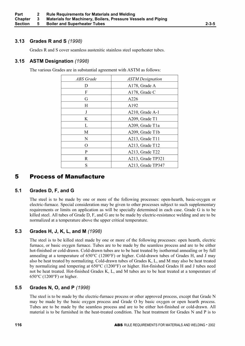
Part 2 Rule Requirements for Materials and WeldingChapter 3 Materials for Machinery, Boilers, Pressure Vessels and PipingSection 5 Boiler and Superheater Tubes 2-3-5
116 ABS RULE REQUIREMENTS FOR MATERIALS AND WELDING . 2002
3.13 Grades R and S (1998) 2-3-5/3.13
Grades R and S cover seamless austenitic stainless steel superheater tubes.
3.15 ASTM Designation (1998) 2-3-5/3.15
The various Grades are in substantial agreement with ASTM as follows:
ABS Grade ASTM Designation
D A178, Grade A
F A178, Grade C
G A226
H A192
J A210, Grade A-1
K A209, Grade T1
L A209, Grade T1a
M A209, Grade T1b
N A213, Grade T11
O A213, Grade T12
P A213, Grade T22
R A213, Grade TP321
S A213, Grade TP347
5 Process of Manufacture 2-3-5/5
5.1 Grades D, F, and G 2-3-5/5.1
The steel is to be made by one or more of the following processes: open-hearth, basic-oxygen orelectric-furnace. Special consideration may be given to other processes subject to such supplementaryrequirements or limits on application as will be specially determined in each case. Grade G is to bekilled steel. All tubes of Grade D, F, and G are to be made by electric-resistance welding and are to benormalized at a temperature above the upper critical temperature.
5.3 Grades H, J, K, L, and M (1998) 2-3-5/5.3
The steel is to be killed steel made by one or more of the following processes: open hearth, electricfurnace, or basic oxygen furnace. Tubes are to be made by the seamless process and are to be eitherhot-finished or cold-drawn. Cold-drawn tubes are to be heat treated by isothermal annealing or by fullannealing at a temperature of 650°C (1200°F) or higher. Cold-drawn tubes of Grades H, and J mayalso be heat treated by normalizing. Cold-drawn tubes of Grades K, L, and M may also be heat treatedby normalizing and tempering at 650°C (1200°F) or higher. Hot-finished Grades H and J tubes neednot be heat treated. Hot-finished Grades K, L, and M tubes are to be heat treated at a temperature of650°C (1200°F) or higher.
5.5 Grades N, O, and P (1998) 2-3-5/5.5
The steel is to be made by the electric-furnace process or other approved process, except that Grade Nmay be made by the basic oxygen process and Grade O by basic oxygen or open hearth process.Tubes are to be made by the seamless process and are to be either hot-finished or cold-drawn. Allmaterial is to be furnished in the heat-treated condition. The heat treatment for Grades N and P is to
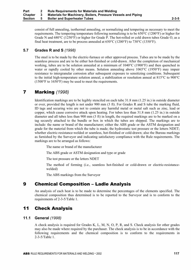
Part 2 Rule Requirements for Materials and WeldingChapter 3 Materials for Machinery, Boilers, Pressure Vessels and PipingSection 5 Boiler and Superheater Tubes 2-3-5
ABS RULE REQUIREMENTS FOR MATERIALS AND WELDING . 2002 117
consist of full annealing, isothermal annealing, or normalizing and tempering as necessary to meet therequirements. The tempering temperature following normalizing is to be 650°C (1200°F) or higher forGrade N and 680°C (1250°F) or higher for Grade P. The hot-rolled or cold drawn tubes Grade O, as afinal heat treatment, are to be process annealed at 650°C (1200°F) to 730°C (1350°F).
5.7 Grades R and S (1998) 2-3-5/5.7
The steel is to be made by the electric-furnace or other approved process. Tubes are to be made by theseamless process and are to be either hot-finished or cold-drawn. After the completion of mechanicalworking, tubes are to be solution annealed at a minimum of 1040°C (1900°F) and then quenched inwater or rapidly cooled by other means. Solution annealing above 1065°C (1950°F) may impairresistance to intergranular corrosion after subsequent exposure to sensitizing conditions. Subsequentto the initial high-temperature solution anneal, a stabilization or resolution anneal at 815°C to 900°C(1500°F to 1650°F) may be used to meet the requirements.
7 Marking (1998) 2-3-5/7
Identification markings are to be legibly stenciled on each tube 31.8 mm (1.25 in.) in outside diameteror over, provided the length is not under 900 mm (3 ft). For Grades R and S tube the marking fluid,ID tags and securing wire are not to contain any harmful metal or metal salt such as zinc, lead orcopper, which cause corrosive attack upon heating. For tubes less than 31.8 mm (1.25 in.) in outsidediameter and all tubes less than 900 mm (3 ft) in length, the required markings are to be marked on atag securely attached to the bundle or box in which the tubes are shipped. The markings are toinclude: the name or brand of the manufacturer; either the ABS grade or the ASTM designation andgrade for the material from which the tube is made; the hydrostatic test pressure or the letters NDET;whether electric-resistance-welded or seamless, hot-finished or cold-drawn; also the Bureau markingsas furnished by the Surveyor and indicating satisfactory compliance with the Rule requirements. Themarkings are to be arranged as follows:
The name or brand of the manufacturer
The ABS grade or ASTM designation and type or grade
The test pressure or the letters NDET
The method of forming (i.e., seamless hot-finished or cold-drawn or electric-resistance-welded)
The ABS markings from the Surveyor
9 Chemical Composition – Ladle Analysis 2-3-5/9
An analysis of each heat is to be made to determine the percentages of the elements specified. Thechemical composition thus determined is to be reported to the Surveyor and is to conform to therequirements of 2-3-5/Table 1.
11 Check Analysis 2-3-5/11
11.1 General (1998) 2-3-5/11.1
A check analysis is required for Grades K, L, M, N, O, P, R, and S. Check analysis for other gradesmay also be made where required by the purchaser. The check analysis is to be in accordance with thefollowing requirements and the chemical composition is to conform to the requirements in2-3-5/Table 1.
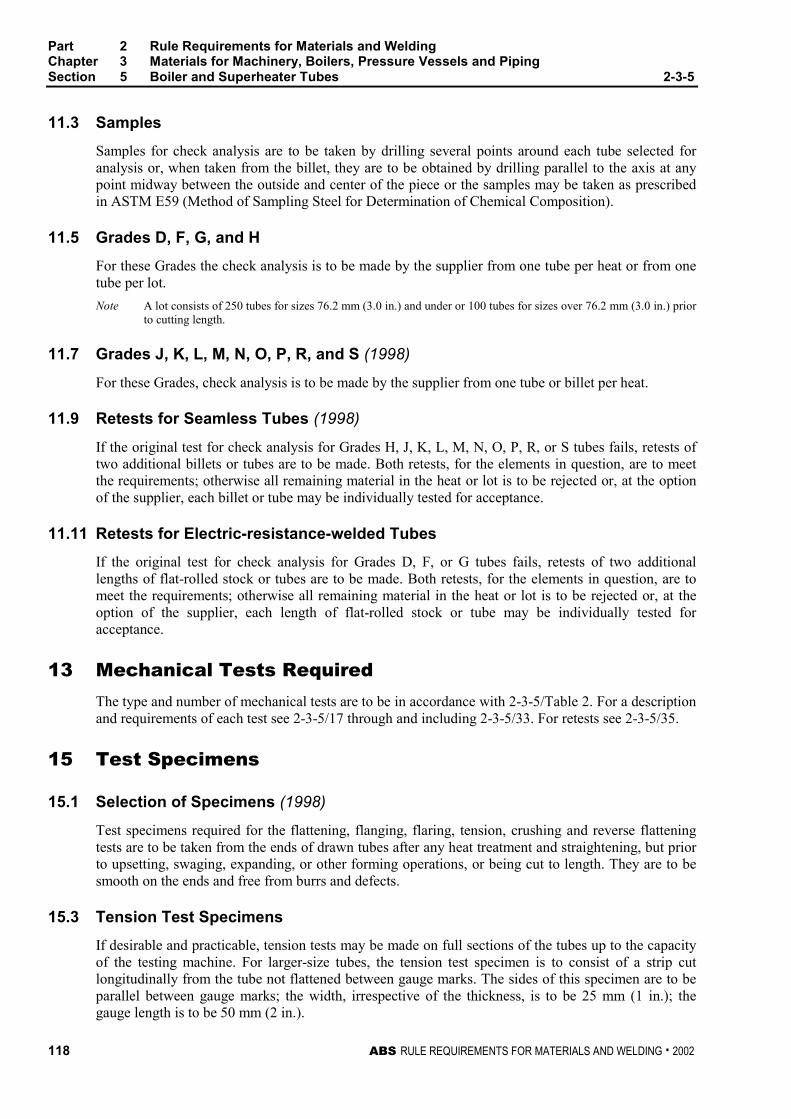
Part 2 Rule Requirements for Materials and WeldingChapter 3 Materials for Machinery, Boilers, Pressure Vessels and PipingSection 5 Boiler and Superheater Tubes 2-3-5
118 ABS RULE REQUIREMENTS FOR MATERIALS AND WELDING . 2002
11.3 Samples 2-3-5/11.3
Samples for check analysis are to be taken by drilling several points around each tube selected foranalysis or, when taken from the billet, they are to be obtained by drilling parallel to the axis at anypoint midway between the outside and center of the piece or the samples may be taken as prescribedin ASTM E59 (Method of Sampling Steel for Determination of Chemical Composition).
11.5 Grades D, F, G, and H 2-3-5/11.5
For these Grades the check analysis is to be made by the supplier from one tube per heat or from onetube per lot.
Note A lot consists of 250 tubes for sizes 76.2 mm (3.0 in.) and under or 100 tubes for sizes over 76.2 mm (3.0 in.) priorto cutting length.
11.7 Grades J, K, L, M, N, O, P, R, and S (1998) 2-3-5/11.7
For these Grades, check analysis is to be made by the supplier from one tube or billet per heat.
11.9 Retests for Seamless Tubes (1998) 2-3-5/11.9
If the original test for check analysis for Grades H, J, K, L, M, N, O, P, R, or S tubes fails, retests oftwo additional billets or tubes are to be made. Both retests, for the elements in question, are to meetthe requirements; otherwise all remaining material in the heat or lot is to be rejected or, at the optionof the supplier, each billet or tube may be individually tested for acceptance.
11.11 Retests for Electric-resistance-welded Tubes 2-3-5/11.11
If the original test for check analysis for Grades D, F, or G tubes fails, retests of two additionallengths of flat-rolled stock or tubes are to be made. Both retests, for the elements in question, are tomeet the requirements; otherwise all remaining material in the heat or lot is to be rejected or, at theoption of the supplier, each length of flat-rolled stock or tube may be individually tested foracceptance.
13 Mechanical Tests Required 2-3-5/13
The type and number of mechanical tests are to be in accordance with 2-3-5/Table 2. For a descriptionand requirements of each test see 2-3-5/17 through and including 2-3-5/33. For retests see 2-3-5/35.
15 Test Specimens 2-3-5/15
15.1 Selection of Specimens (1998) 2-3-5/15.1
Test specimens required for the flattening, flanging, flaring, tension, crushing and reverse flatteningtests are to be taken from the ends of drawn tubes after any heat treatment and straightening, but priorto upsetting, swaging, expanding, or other forming operations, or being cut to length. They are to besmooth on the ends and free from burrs and defects.
15.3 Tension Test Specimens 2-3-5/15.3
If desirable and practicable, tension tests may be made on full sections of the tubes up to the capacityof the testing machine. For larger-size tubes, the tension test specimen is to consist of a strip cutlongitudinally from the tube not flattened between gauge marks. The sides of this specimen are to beparallel between gauge marks; the width, irrespective of the thickness, is to be 25 mm (1 in.); thegauge length is to be 50 mm (2 in.).
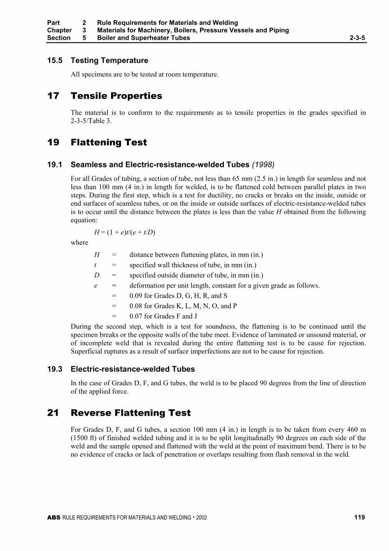
Part 2 Rule Requirements for Materials and WeldingChapter 3 Materials for Machinery, Boilers, Pressure Vessels and PipingSection 5 Boiler and Superheater Tubes 2-3-5
ABS RULE REQUIREMENTS FOR MATERIALS AND WELDING . 2002 119
15.5 Testing Temperature 2-3-5/15.5
All specimens are to be tested at room temperature.
17 Tensile Properties 2-3-5/17
The material is to conform to the requirements as to tensile properties in the grades specified in2-3-5/Table 3.
19 Flattening Test 2-3-5/19
19.1 Seamless and Electric-resistance-welded Tubes (1998) 2-3-5/19.1
For all Grades of tubing, a section of tube, not less than 65 mm (2.5 in.) in length for seamless and notless than 100 mm (4 in.) in length for welded, is to be flattened cold between parallel plates in twosteps. During the first step, which is a test for ductility, no cracks or breaks on the inside, outside orend surfaces of seamless tubes, or on the inside or outside surfaces of electric-resistance-welded tubesis to occur until the distance between the plates is less than the value H obtained from the followingequation:
H = (1 + e)t/(e + t/D)
where
H = distance between flattening plates, in mm (in.)
t = specified wall thickness of tube, in mm (in.)
D = specified outside diameter of tube, in mm (in.)
e = deformation per unit length, constant for a given grade as follows.
= 0.09 for Grades D, G, H, R, and S
= 0.08 for Grades K, L, M, N, O, and P
= 0.07 for Grades F and J
During the second step, which is a test for soundness, the flattening is to be continued until thespecimen breaks or the opposite walls of the tube meet. Evidence of laminated or unsound material, orof incomplete weld that is revealed during the entire flattening test is to be cause for rejection.Superficial ruptures as a result of surface imperfections are not to be cause for rejection.
19.3 Electric-resistance-welded Tubes 2-3-5/19.3
In the case of Grades D, F, and G tubes, the weld is to be placed 90 degrees from the line of directionof the applied force.
21 Reverse Flattening Test 2-3-5/21
For Grades D, F, and G tubes, a section 100 mm (4 in.) in length is to be taken from every 460 m(1500 ft) of finished welded tubing and it is to be split longitudinally 90 degrees on each side of theweld and the sample opened and flattened with the weld at the point of maximum bend. There is to beno evidence of cracks or lack of penetration or overlaps resulting from flash removal in the weld.
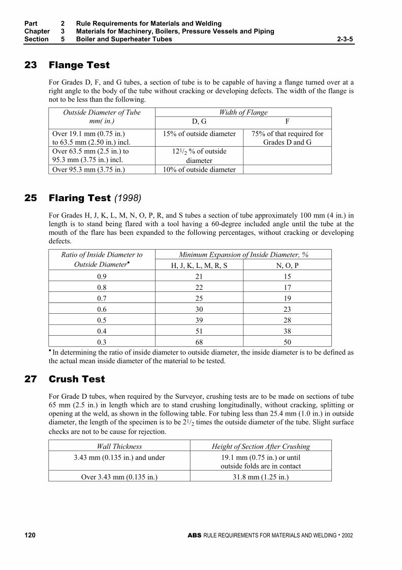
Part 2 Rule Requirements for Materials and WeldingChapter 3 Materials for Machinery, Boilers, Pressure Vessels and PipingSection 5 Boiler and Superheater Tubes 2-3-5
120 ABS RULE REQUIREMENTS FOR MATERIALS AND WELDING . 2002
23 Flange Test 2-3-5/23
For Grades D, F, and G tubes, a section of tube is to be capable of having a flange turned over at aright angle to the body of the tube without cracking or developing defects. The width of the flange isnot to be less than the following.
Width of FlangeOutside Diameter of Tubemm( in.) D, G F
Over 19.1 mm (0.75 in.)to 63.5 mm (2.50 in.) incl.
15% of outside diameter 75% of that required forGrades D and G
Over 63.5 mm (2.5 in.) to95.3 mm (3.75 in.) incl.
121/2 % of outsidediameter
Over 95.3 mm (3.75 in.) 10% of outside diameter
25 Flaring Test (1998) 2-3-5/25
For Grades H, J, K, L, M, N, O, P, R, and S tubes a section of tube approximately 100 mm (4 in.) inlength is to stand being flared with a tool having a 60-degree included angle until the tube at themouth of the flare has been expanded to the following percentages, without cracking or developingdefects.
Minimum Expansion of Inside Diameter, %Ratio of Inside Diameter toOutside Diameter• H, J, K, L, M, R, S N, O, P
0.9 21 15
0.8 22 17
0.7 25 19
0.6 30 23
0.5 39 28
0.4 51 38
0.3 68 50• In determining the ratio of inside diameter to outside diameter, the inside diameter is to be defined asthe actual mean inside diameter of the material to be tested.
27 Crush Test 2-3-5/27
For Grade D tubes, when required by the Surveyor, crushing tests are to be made on sections of tube65 mm (2.5 in.) in length which are to stand crushing longitudinally, without cracking, splitting oropening at the weld, as shown in the following table. For tubing less than 25.4 mm (1.0 in.) in outsidediameter, the length of the specimen is to be 21/2 times the outside diameter of the tube. Slight surfacechecks are not to be cause for rejection.
Wall Thickness Height of Section After Crushing
3.43 mm (0.135 in.) and under 19.1 mm (0.75 in.) or untiloutside folds are in contact
Over 3.43 mm (0.135 in.) 31.8 mm (1.25 in.)
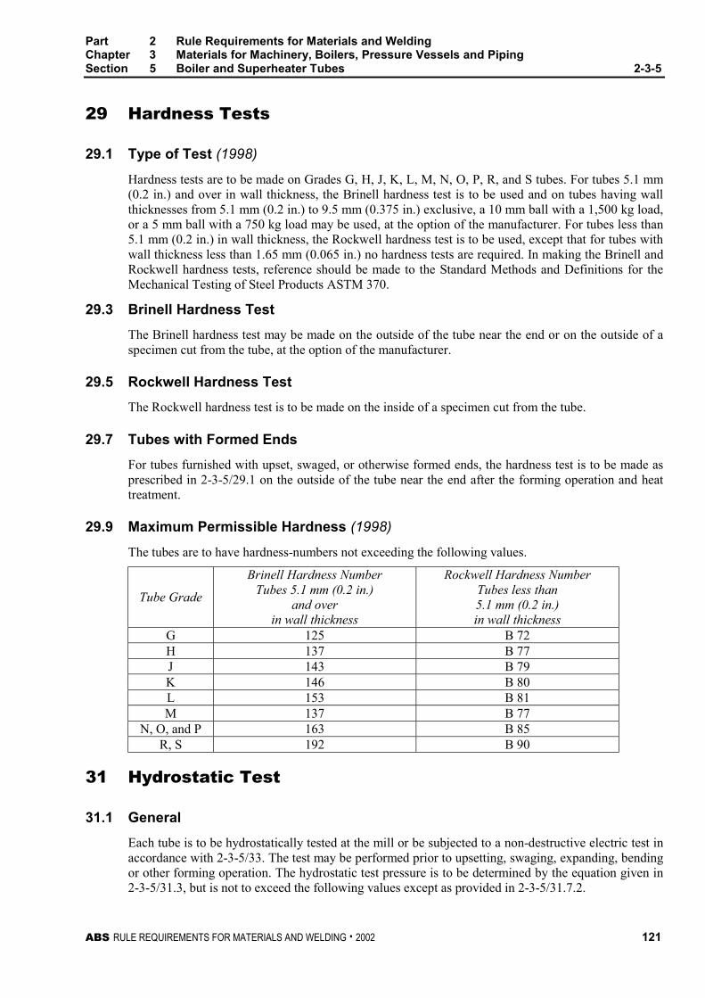
Part 2 Rule Requirements for Materials and WeldingChapter 3 Materials for Machinery, Boilers, Pressure Vessels and PipingSection 5 Boiler and Superheater Tubes 2-3-5
ABS RULE REQUIREMENTS FOR MATERIALS AND WELDING . 2002 121
29 Hardness Tests 2-3-5/29
29.1 Type of Test (1998) 2-3-5/29.1
Hardness tests are to be made on Grades G, H, J, K, L, M, N, O, P, R, and S tubes. For tubes 5.1 mm(0.2 in.) and over in wall thickness, the Brinell hardness test is to be used and on tubes having wallthicknesses from 5.1 mm (0.2 in.) to 9.5 mm (0.375 in.) exclusive, a 10 mm ball with a 1,500 kg load,or a 5 mm ball with a 750 kg load may be used, at the option of the manufacturer. For tubes less than5.1 mm (0.2 in.) in wall thickness, the Rockwell hardness test is to be used, except that for tubes withwall thickness less than 1.65 mm (0.065 in.) no hardness tests are required. In making the Brinell andRockwell hardness tests, reference should be made to the Standard Methods and Definitions for theMechanical Testing of Steel Products ASTM 370.
29.3 Brinell Hardness Test 2-3-5/29.3
The Brinell hardness test may be made on the outside of the tube near the end or on the outside of aspecimen cut from the tube, at the option of the manufacturer.
29.5 Rockwell Hardness Test 2-3-5/29.5
The Rockwell hardness test is to be made on the inside of a specimen cut from the tube.
29.7 Tubes with Formed Ends 2-3-5/29.7
For tubes furnished with upset, swaged, or otherwise formed ends, the hardness test is to be made asprescribed in 2-3-5/29.1 on the outside of the tube near the end after the forming operation and heattreatment.
29.9 Maximum Permissible Hardness (1998) 2-3-5/29.9
The tubes are to have hardness-numbers not exceeding the following values.
Tube Grade
Brinell Hardness NumberTubes 5.1 mm (0.2 in.)
and overin wall thickness
Rockwell Hardness NumberTubes less than5.1 mm (0.2 in.)in wall thickness
G 125 B 72H 137 B 77J 143 B 79K 146 B 80L 153 B 81M 137 B 77
N, O, and P 163 B 85R, S 192 B 90
31 Hydrostatic Test 2-3-5/31
31.1 General 2-3-5/31.1
Each tube is to be hydrostatically tested at the mill or be subjected to a non-destructive electric test inaccordance with 2-3-5/33. The test may be performed prior to upsetting, swaging, expanding, bendingor other forming operation. The hydrostatic test pressure is to be determined by the equation given in2-3-5/31.3, but is not to exceed the following values except as provided in 2-3-5/31.7.2.

Part 2 Rule Requirements for Materials and WeldingChapter 3 Materials for Machinery, Boilers, Pressure Vessels and PipingSection 5 Boiler and Superheater Tubes 2-3-5
122 ABS RULE REQUIREMENTS FOR MATERIALS AND WELDING . 2002
Outside Diam. of Tubes, mm (in.)Test Pressure,
bar (kgf/cm2, psi)Under 25.4 (1.0 in.) 69 (70.3, 1000)25.4 (1.0 in.) to 38.1 (1.5 in.), excl. 103 (105, 1500)38.1 (1.5 in.) to 50.8 (2.0 in.), excl. 140 (140, 2000)50.8 (2.0 in.) to 76.2 (3.0 in.), excl. 170 (175, 2500)76.2 (3.0 in.) to 127 (5.0 in.), excl. 240 (245, 3500)127 (5.0 in.) and over 310 (315, 4500)
31.3 Maximum Hydrostatic Test Pressure 2-3-5/31.3
SI Units MKS Units US UnitsP = 20St/D P = 200St/D P = 2St/DS = PD/20t S = PD/200t S = PD/2t
where
P = hydrostatic test pressure, in bar (kgf/cm2, psi)
S = allowable fiber stress of 110 N/mm2 (11 kgf/mm2, 16,000 psi)
t = specified wall thickness, in mm (in.)
D = specified outside diameter, in mm (in.)
31.5 Duration of Test 2-3-5/31.5
The test pressure is to be held for a minimum of 5 seconds.
31.7 Alternate Tests 2-3-5/31.7
31.7.1 2-3-5/31.7.1
When requested by the purchaser and so stated in the order, tubes are to be tested to one andone-half times the specified working pressure (when one and one-half times the specifiedworking pressure exceeds the test pressure prescribed in 2-3-5/31.1), provided the fiber stresscorresponding to those test pressures does not exceed 110 N/mm2 (11 kgf/mm2, 16,000 psi) ascalculated in accordance with 2-3-5/31.3.
31.7.2 2-3-5/31.7.2
When requested by the purchaser and so stated in the order, or at the option of themanufacturer, tubes are to be tested at pressures, calculated in accordance with 2-3-5/31.1corresponding to a fiber stress of more than 110 N/mm2 (11 kgf/mm2, 16,000 psi), but notmore than 165 N/mm2 (17 kgf/mm2, 24,000 psi).
31.9 Rejection 2-3-5/31.9
If any tube shows leaks during the hydrostatic test, it is to be rejected.
33 Nondestructive Electric Test (NDET) (1998) 2-3-5/33
33.1 General 2-3-5/33.1
When specified by the purchaser, each ferritic steel tube, Grades D, F, G, H, J, K, L, M, N, O, and P,is to be tested in accordance with ASTM E213, for Ultrasonic Examination of Metal Pipe and Tubingor ASTM E309, for Eddy-Current Examination of Steel Tubular Products Using Magnetic Saturation,
Part 2 Rule Requirements for Materials and WeldingChapter 3 Materials for Machinery, Boilers, Pressure Vessels and PipingSection 5 Boiler and Superheater Tubes 2-3-5
ABS RULE REQUIREMENTS FOR MATERIALS AND WELDING . 2002 123
ASTM E570, for Flux Leakage Examination of Ferromagnetic Steel Tubular Products, or otherapproved standard. When specified by the purchaser, each austenitic stainless steel tube, Grades R andS, is to be tested in accordance with ASTM E213, for Ultrasonic Examination of Metal Pipe andTubing or ASTM E426, for Electromagnetic (Eddy-Current) Examination of Seamless and WeldedTubular Products, Austenitic Stainless Steel and Similar Alloys, or other approved standard. It is theintent of this test to reject tubes containing defects and the Surveyor is to be satisfied that thenondestructive testing procedures are used in a satisfactory manner
33.3 Ultrasonic Calibration Standards 2-3-5/33.3
Notches on the inside or outside surfaces may be used. The depth of the notch is not to exceed 12.5%of the specified wall thickness of the tube or 0.1 mm (0.004 in.), whichever is greater. The width ofthe notch is not to exceed two times the depth.
33.5 Eddy-current Calibration Standards 2-3-5/33.5
In order to accommodate the various types of nondestructive electric testing equipment andtechniques in use, and manufacturing practices employed, any one of the following calibrationstandards may be used at the option of the producer, to establish a minimum sensitivity level forrejection. For welded tubing, they are to be placed in the weld if visible.
33.5.1 Drilled Hole 2-3-5/33.5.1
Three or more holes not larger than 0.785 mm (0.031 in.) in diameter and equally spacedabout the pipe circumference and sufficiently separated longitudinally to ensure a separatelydistinguishable response are to be drilled radially and completely through tube wall, carebeing taken to avoid distortion of the tube while drilling. Alternatively, one hole may be usedprovided that the calibration tube is scanned at a minimum of three locations each 120degrees apart, or at more frequent scans with smaller angular increments provided that theentire 360 degrees of the eddy-current coil is checked.
33.5.2 Transverse Tangential Notch 2-3-5/33.5.2
Using a round tool or file with a 6.35 mm (0.25 in.) diameter, a notch is to be filed or milledtangential to the surface and transverse to the longitudinal axis of the tube. Said notch is tohave a depth not exceeding 12.5% of the nominal wall thickness of the tube or 0.1 mm(0.004 in.), whichever is greater.
33.5.3 Longitudinal Notch 2-3-5/33.5.3
A notch 0.785 mm (0.031 in.) or less in width is to be machined in a radial plane parallel tothe tube axis on the outside surface of the tube, to have depth not exceeding 12.5% of thenominal wall thickness of the tube or 0.1 mm (0.004 in.), whichever is greater. The length ofthe notch is to be compatible with the testing method.
33.7 Flux Leakage Calibration Standards 2-3-5/33.7
The depth of longitudinal notches on the inside and outside surfaces is not to exceed 12.5% of thespecified wall thickness of the tube or 0.1 mm (0.004 in.), whichever is greater. The width of thenotch is not to exceed the depth, and the length of the notch is not to exceed 25.4 mm (1.0 in.).Outside and inside surface notches are to be located sufficiently apart to allow distinct identificationof the signal from each notch.
33.9 Rejection 2-3-5/33.9
Tubing producing a signal equal to or greater than the calibration defect is to be subject to rejection.

Part 2 Rule Requirements for Materials and WeldingChapter 3 Materials for Machinery, Boilers, Pressure Vessels and PipingSection 5 Boiler and Superheater Tubes 2-3-5
124 ABS RULE REQUIREMENTS FOR MATERIALS AND WELDING . 2002
33.11 Affidavits 2-3-5/33.11
When each tube is subjected to an approved nondestructive electric test as a regular procedure duringthe process of manufacture, an affidavit covering this test may be accepted by the Surveyor.
35 Retests (1998) 2-3-5/35
For all grades of tubes, if the results of the mechanical tests do not conform to the requirements,retests may be made on additional tubes from the same lot, double the original number specified, eachof which is to conform to the requirements. If heat-treated tubes fail to conform to the testrequirements, the individual tubes, groups or lots of tubes represented, may be re-heat-treated andresubmitted for retest as indicated. Only two reheat treatments will be permitted.
37 Finish (1998) 2-3-5/37
Tubes of all grades are to be surface inspected by the Surveyor prior to fabrication or installation, andare to be reasonably straight and have smooth ends free from burrs. At a minimum, the finished tubesare to be visually inspected at the same frequency as that required for the flattening test specified in2-3-5/Table 2 for the applicable grade. They are to be free from defects and are to have aworkmanlike finish. Grade R and S tubes are to be free from scale by pickling or by the use of brightannealing. Minor defects may be removed by grinding provided the wall thicknesses are not decreasedbeyond the permissible variations in dimensions. Welding repair to any tube is not to be carried outwithout the purchasers approval and is to be to the Surveyors satisfaction.
39 Permissible Variations in Dimensions (1998) 2-3-5/39
At a minimum, the finished tubes are to be measured at the same frequency as that required for theflattening test specified in 2-3-5/Table 2 for the applicable grade.
39.1 Wall Thickness 2-3-5/39.1
The permissible variations in wall thickness for all tubes are based on the ordered thickness andshould conform to that given in the applicable ASTM designation for acceptance, but the minimumthickness for all tubes is not to be less than that required by the Rules for a specific applicationregardless of such prior acceptance.
39.3 Outside Diameter 2-3-5/39.3
Variations from the ordered outside diameter are not to exceed the amounts prescribed in 2-3-5/Table4.
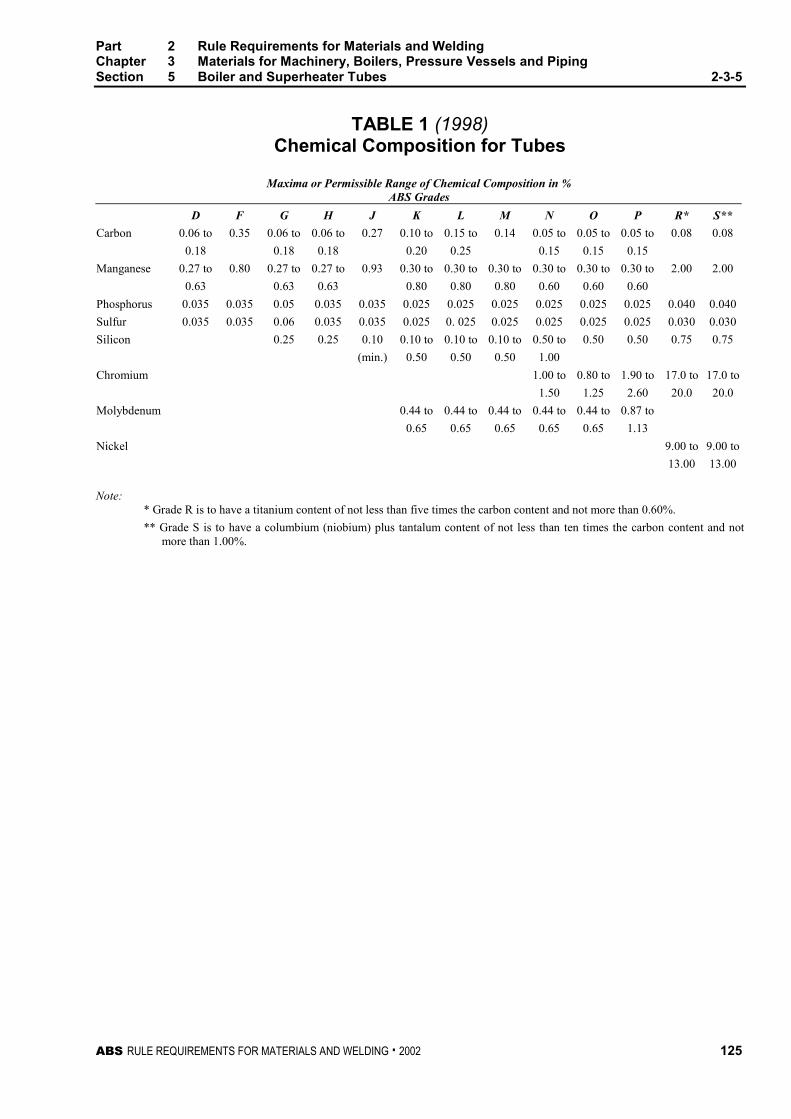
Part 2 Rule Requirements for Materials and WeldingChapter 3 Materials for Machinery, Boilers, Pressure Vessels and PipingSection 5 Boiler and Superheater Tubes 2-3-5
ABS RULE REQUIREMENTS FOR MATERIALS AND WELDING . 2002 125
TABLE 1 (1998)Chemical Composition for Tubes
Maxima or Permissible Range of Chemical Composition in %ABS Grades
D F G H J K L M N O P R* S**
Carbon 0.06 to 0.35 0.06 to 0.06 to 0.27 0.10 to 0.15 to 0.14 0.05 to 0.05 to 0.05 to 0.08 0.08
0.18 0.18 0.18 0.20 0.25 0.15 0.15 0.15
Manganese 0.27 to 0.80 0.27 to 0.27 to 0.93 0.30 to 0.30 to 0.30 to 0.30 to 0.30 to 0.30 to 2.00 2.00
0.63 0.63 0.63 0.80 0.80 0.80 0.60 0.60 0.60
Phosphorus 0.035 0.035 0.05 0.035 0.035 0.025 0.025 0.025 0.025 0.025 0.025 0.040 0.040
Sulfur 0.035 0.035 0.06 0.035 0.035 0.025 0. 025 0.025 0.025 0.025 0.025 0.030 0.030
Silicon 0.25 0.25 0.10 0.10 to 0.10 to 0.10 to 0.50 to 0.50 0.50 0.75 0.75
(min.) 0.50 0.50 0.50 1.00
Chromium 1.00 to 0.80 to 1.90 to 17.0 to 17.0 to
1.50 1.25 2.60 20.0 20.0
Molybdenum 0.44 to 0.44 to 0.44 to 0.44 to 0.44 to 0.87 to
0.65 0.65 0.65 0.65 0.65 1.13
Nickel 9.00 to 9.00 to
13.00 13.00
Note:* Grade R is to have a titanium content of not less than five times the carbon content and not more than 0.60%.
** Grade S is to have a columbium (niobium) plus tantalum content of not less than ten times the carbon content and notmore than 1.00%.
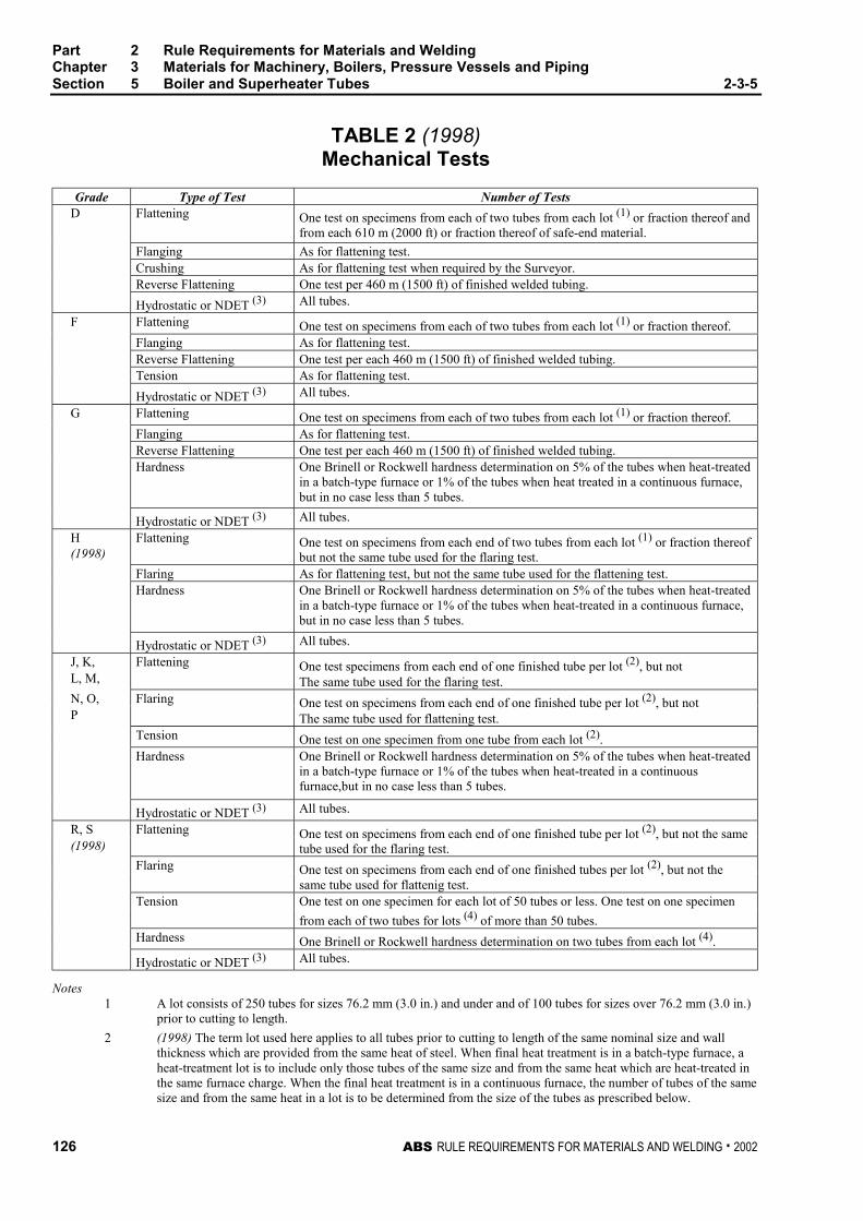
Part 2 Rule Requirements for Materials and WeldingChapter 3 Materials for Machinery, Boilers, Pressure Vessels and PipingSection 5 Boiler and Superheater Tubes 2-3-5
126 ABS RULE REQUIREMENTS FOR MATERIALS AND WELDING . 2002
TABLE 2 (1998)Mechanical Tests
Grade Type of Test Number of TestsD Flattening One test on specimens from each of two tubes from each lot (1) or fraction thereof and
from each 610 m (2000 ft) or fraction thereof of safe-end material.
Flanging As for flattening test.Crushing As for flattening test when required by the Surveyor.Reverse Flattening One test per 460 m (1500 ft) of finished welded tubing.
Hydrostatic or NDET (3) All tubes.
F Flattening One test on specimens from each of two tubes from each lot (1) or fraction thereof.Flanging As for flattening test.Reverse Flattening One test per each 460 m (1500 ft) of finished welded tubing.Tension As for flattening test.
Hydrostatic or NDET (3) All tubes.
G Flattening One test on specimens from each of two tubes from each lot (1) or fraction thereof.Flanging As for flattening test.Reverse Flattening One test per each 460 m (1500 ft) of finished welded tubing.Hardness One Brinell or Rockwell hardness determination on 5% of the tubes when heat-treated
in a batch-type furnace or 1% of the tubes when heat treated in a continuous furnace,but in no case less than 5 tubes.
Hydrostatic or NDET (3) All tubes.
H(1998)
Flattening One test on specimens from each end of two tubes from each lot (1) or fraction thereofbut not the same tube used for the flaring test.
Flaring As for flattening test, but not the same tube used for the flattening test.Hardness One Brinell or Rockwell hardness determination on 5% of the tubes when heat-treated
in a batch-type furnace or 1% of the tubes when heat-treated in a continuous furnace,but in no case less than 5 tubes.
Hydrostatic or NDET (3) All tubes.
J, K,L, M,
Flattening One test specimens from each end of one finished tube per lot (2), but notThe same tube used for the flaring test.
N, O,P
Flaring One test on specimens from each end of one finished tube per lot (2), but notThe same tube used for flattening test.
Tension One test on one specimen from one tube from each lot (2).Hardness One Brinell or Rockwell hardness determination on 5% of the tubes when heat-treated
in a batch-type furnace or 1% of the tubes when heat-treated in a continuousfurnace,but in no case less than 5 tubes.
Hydrostatic or NDET (3) All tubes.
R, S(1998)
Flattening One test on specimens from each end of one finished tube per lot (2), but not the sametube used for the flaring test.
Flaring One test on specimens from each end of one finished tubes per lot (2), but not thesame tube used for flattenig test.
Tension One test on one specimen for each lot of 50 tubes or less. One test on one specimen
from each of two tubes for lots (4) of more than 50 tubes.Hardness One Brinell or Rockwell hardness determination on two tubes from each lot (4).
Hydrostatic or NDET (3) All tubes.
Notes1 A lot consists of 250 tubes for sizes 76.2 mm (3.0 in.) and under and of 100 tubes for sizes over 76.2 mm (3.0 in.)
prior to cutting to length.
2 (1998) The term lot used here applies to all tubes prior to cutting to length of the same nominal size and wallthickness which are provided from the same heat of steel. When final heat treatment is in a batch-type furnace, aheat-treatment lot is to include only those tubes of the same size and from the same heat which are heat-treated inthe same furnace charge. When the final heat treatment is in a continuous furnace, the number of tubes of the samesize and from the same heat in a lot is to be determined from the size of the tubes as prescribed below.
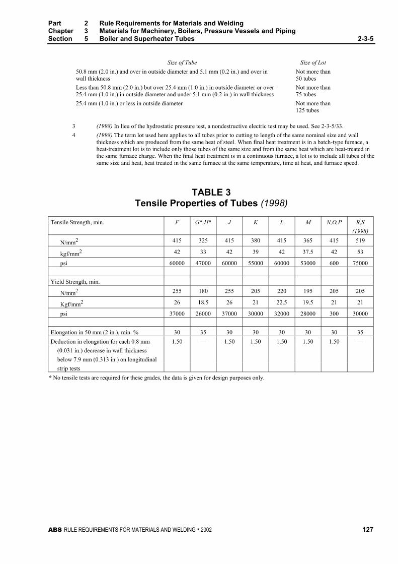
Part 2 Rule Requirements for Materials and WeldingChapter 3 Materials for Machinery, Boilers, Pressure Vessels and PipingSection 5 Boiler and Superheater Tubes 2-3-5
ABS RULE REQUIREMENTS FOR MATERIALS AND WELDING . 2002 127
Size of Tube Size of Lot
50.8 mm (2.0 in.) and over in outside diameter and 5.1 mm (0.2 in.) and over inwall thickness
Not more than50 tubes
Less than 50.8 mm (2.0 in.) but over 25.4 mm (1.0 in.) in outside diameter or over25.4 mm (1.0 in.) in outside diameter and under 5.1 mm (0.2 in.) in wall thickness
Not more than75 tubes
25.4 mm (1.0 in.) or less in outside diameter Not more than125 tubes
3 (1998) In lieu of the hydrostatic pressure test, a nondestructive electric test may be used. See 2-3-5/33.
4 (1998) The term lot used here applies to all tubes prior to cutting to length of the same nominal size and wallthickness which are produced from the same heat of steel. When final heat treatment is in a batch-type furnace, aheat-treatment lot is to include only those tubes of the same size and from the same heat which are heat-treated inthe same furnace charge. When the final heat treatment is in a continuous furnace, a lot is to include all tubes of thesame size and heat, heat treated in the same furnace at the same temperature, time at heat, and furnace speed.
TABLE 3Tensile Properties of Tubes (1998)
Tensile Strength, min. F G*,H* J K L M N,O,P R,S
(1998)
N/mm2 415 325 415 380 415 365 415 519
kgf/mm2 42 33 42 39 42 37.5 42 53
psi 60000 47000 60000 55000 60000 53000 600 75000
Yield Strength, min.
N/mm2 255 180 255 205 220 195 205 205
Kgf/mm2 26 18.5 26 21 22.5 19.5 21 21
psi 37000 26000 37000 30000 32000 28000 300 30000
Elongation in 50 mm (2 in.), min. % 30 35 30 30 30 30 30 35
Deduction in elongation for each 0.8 mm 1.50 — 1.50 1.50 1.50 1.50 1.50 —
(0.031 in.) decrease in wall thickness
below 7.9 mm (0.313 in.) on longitudinal
strip tests
* No tensile tests are required for these grades, the data is given for design purposes only.
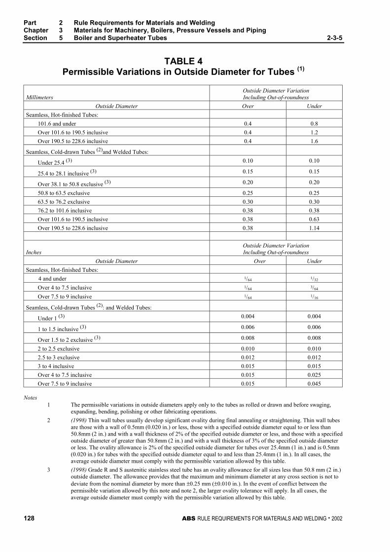
Part 2 Rule Requirements for Materials and WeldingChapter 3 Materials for Machinery, Boilers, Pressure Vessels and PipingSection 5 Boiler and Superheater Tubes 2-3-5
128 ABS RULE REQUIREMENTS FOR MATERIALS AND WELDING . 2002
TABLE 4Permissible Variations in Outside Diameter for Tubes (1)
MillimetersOutside Diameter VariationIncluding Out-of-roundness
Outside Diameter Over Under
Seamless, Hot-finished Tubes:
101.6 and under 0.4 0.8
Over 101.6 to 190.5 inclusive 0.4 1.2
Over 190.5 to 228.6 inclusive 0.4 1.6
Seamless, Cold-drawn Tubes (2)and Welded Tubes:
Under 25.4 (3) 0.10 0.10
25.4 to 28.1 inclusive (3) 0.15 0.15
Over 38.1 to 50.8 exclusive (3) 0.20 0.20
50.8 to 63.5 exclusive 0.25 0.25
63.5 to 76.2 exclusive 0.30 0.30
76.2 to 101.6 inclusive 0.38 0.38
Over 101.6 to 190.5 inclusive 0.38 0.63
Over 190.5 to 228.6 inclusive 0.38 1.14
InchesOutside Diameter VariationIncluding Out-of-roundness
Outside Diameter Over Under
Seamless, Hot-finished Tubes:
4 and under 1/64 1/32
Over 4 to 7.5 inclusive 1/64 3/64
Over 7.5 to 9 inclusive 1/64 1/16
Seamless, Cold-drawn Tubes (2): and Welded Tubes:
Under 1 (3) 0.004 0.004
1 to 1.5 inclusive (3) 0.006 0.006
Over 1.5 to 2 exclusive (3) 0.008 0.008
2 to 2.5 exclusive 0.010 0.010
2.5 to 3 exclusive 0.012 0.012
3 to 4 inclusive 0.015 0.015
Over 4 to 7.5 inclusive 0.015 0.025
Over 7.5 to 9 inclusive 0.015 0.045
Notes1 The permissible variations in outside diameters apply only to the tubes as rolled or drawn and before swaging,
expanding, bending, polishing or other fabricating operations.
2 (1998) Thin wall tubes usually develop significant ovality during final annealing or straightening. Thin wall tubesare those with a wall of 0.5mm (0.020 in.) or less, those with a specified outside diameter equal to or less than50.8mm (2 in.) and with a wall thickness of 2% of the specified outside diameter or less, and those with a specifiedoutside diameter of greater than 50.8mm (2 in.) and with a wall thickness of 3% of the specified outside diameteror less. The ovality allowance is 2% of the specified outside diameter for tubes over 25.4mm (1 in.) and is 0.5mm(0.020 in.) for tubes with the specified outside diameter equal to and less than 25.4mm (1 in.). In all cases, theaverage outside diameter must comply with the permissible variation allowed by this table.
3 (1998) Grade R and S austenitic stainless steel tube has an ovality allowance for all sizes less than 50.8 mm (2 in.)outside diameter. The allowance provides that the maximum and minimum diameter at any cross section is not todeviate from the nominal diameter by more than ±0.25 mm (±0.010 in.). In the event of conflict between thepermissible variation allowed by this note and note 2, the larger ovality tolerance will apply. In all cases, theaverage outside diameter must comply with the permissible variation allowed by this table.
ABS RULE REQUIREMENTS FOR MATERIALS AND WELDING . 2002 129
P A R T
2C H A P T E R 3 Materials for Machinery, Boilers,
Pressure Vessels, and Piping
S E C T I O N 6 Boiler Rivet and Staybolt Steeland Rivets 2 - 3 - 6
Note In substantial agreement with ASTM A31 Boiler Rivet Steel and Rivets.
1 Process of Manufacture 2-3-6/1
The steel is to be made by one or more of the following processes: open-hearth, basic-oxygen orelectric-furnace. All such bars and rivets will be surface inspected at the mills by the Surveyor whenspecially requested by the purchaser. They are to be free from defects and have a workmanlike finish.
3 Marking and Retests 2-3-6/3
3.1 Manufacturer’s Markings 2-3-6/3.1
The bars and rivets, when loaded for shipment, are to be properly separated in bundles or containersmarked with the name or brand of the manufacturer, the letter indicating the grade of steel and heatnumber of identification.
3.3 Bureau Markings 2-3-6/3.3
The Bureau markings, indicating satisfactory compliance with the Rule requirements, and asfurnished by the Surveyor are to be marked on the material or on each bundle or container near themarking specified in 2-3-6/3.1.
3.5 Retests 2-3-6/3.5
When the result of any of the physical tests specified for any of the material does not conform to therequirements, two additional specimens may, at the request of the manufacturer, be taken from thesame lot and tested in the manner specified, but in such case, both of the specimens must conform tothe requirements. In the case of tension tests, this retest is to be allowed if the percent of elongationobtained is less than required.
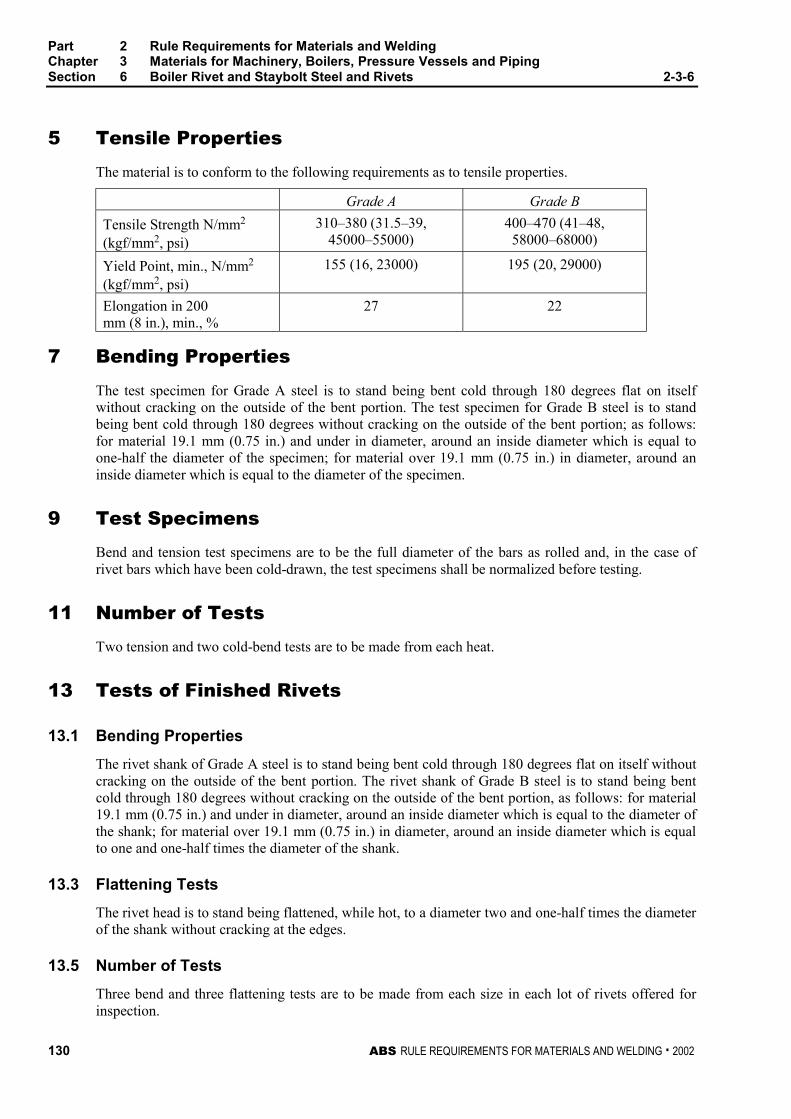
Part 2 Rule Requirements for Materials and WeldingChapter 3 Materials for Machinery, Boilers, Pressure Vessels and PipingSection 6 Boiler Rivet and Staybolt Steel and Rivets 2-3-6
130 ABS RULE REQUIREMENTS FOR MATERIALS AND WELDING . 2002
5 Tensile Properties 2-3-6/5
The material is to conform to the following requirements as to tensile properties.
Grade A Grade B
Tensile Strength N/mm2
(kgf/mm2, psi)310–380 (31.5–39,
45000–55000)400–470 (41–48,58000–68000)
Yield Point, min., N/mm2
(kgf/mm2, psi)155 (16, 23000) 195 (20, 29000)
Elongation in 200mm (8 in.), min., %
27 22
7 Bending Properties 2-3-6/7
The test specimen for Grade A steel is to stand being bent cold through 180 degrees flat on itselfwithout cracking on the outside of the bent portion. The test specimen for Grade B steel is to standbeing bent cold through 180 degrees without cracking on the outside of the bent portion; as follows:for material 19.1 mm (0.75 in.) and under in diameter, around an inside diameter which is equal toone-half the diameter of the specimen; for material over 19.1 mm (0.75 in.) in diameter, around aninside diameter which is equal to the diameter of the specimen.
9 Test Specimens 2-3-6/9
Bend and tension test specimens are to be the full diameter of the bars as rolled and, in the case ofrivet bars which have been cold-drawn, the test specimens shall be normalized before testing.
11 Number of Tests 2-3-6/11
Two tension and two cold-bend tests are to be made from each heat.
13 Tests of Finished Rivets 2-3-6/13
13.1 Bending Properties 2-3-6/13.1
The rivet shank of Grade A steel is to stand being bent cold through 180 degrees flat on itself withoutcracking on the outside of the bent portion. The rivet shank of Grade B steel is to stand being bentcold through 180 degrees without cracking on the outside of the bent portion, as follows: for material19.1 mm (0.75 in.) and under in diameter, around an inside diameter which is equal to the diameter ofthe shank; for material over 19.1 mm (0.75 in.) in diameter, around an inside diameter which is equalto one and one-half times the diameter of the shank.
13.3 Flattening Tests 2-3-6/13.3
The rivet head is to stand being flattened, while hot, to a diameter two and one-half times the diameterof the shank without cracking at the edges.
13.5 Number of Tests 2-3-6/13.5
Three bend and three flattening tests are to be made from each size in each lot of rivets offered forinspection.
ABS RULE REQUIREMENTS FOR MATERIALS AND WELDING . 2002 131
P A R T
2C H A P T E R 3 Materials for Machinery, Boilers,
Pressure Vessels, and Piping
S E C T I O N 7 Steel Machinery Forgings
CONTENTS1 Carbon Steel Machinery Forgings...................................... 133
1.1 Process of Manufacture ....................................................... 133
1.3 Marking, Retests and Rejection ........................................... 134
1.5 Heat treatment...................................................................... 134
1.7 Tensile Properties ................................................................ 135
1.9 Test Specimens.................................................................... 135
1.11 Number and Location of Tests ............................................. 135
1.13 Inspection ............................................................................. 137
3 Alloy Steel Gear Assembly Forgings ................................. 137
3.1 Process of Manufacture ....................................................... 137
3.3 Marking, Retests and Rejection ........................................... 138
3.5 Heat Treatment .................................................................... 138
3.7 Mechanical Properties.......................................................... 139
3.9 Test Specimens.................................................................... 140
3.11 Inspection ............................................................................. 141
5 Alloy Steel Shaft and Stock Forgings ................................ 141
5.1 Process of Manufacture ....................................................... 141
5.3 Marking, Retests and Rejection ........................................... 142
5.5 Heat Treatment .................................................................... 142
5.7 Mechanical Properties.......................................................... 143
5.9 Test Specimens.................................................................... 144
5.11 Inspection ............................................................................. 145
7 General Shipboard Alloy Steel Forgings ........................... 145
7.1 Process of Manufacture ....................................................... 145
7.3 Marking, Retests and Rejection ........................................... 146
7.5 Heat Treatment .................................................................... 146
7.7 Mechanical Properties.......................................................... 147
7.9 Mechanical Testing .............................................................. 147
132 ABS RULE REQUIREMENTS FOR MATERIALS AND WELDING . 2002
7.11 Number and Location of Tests ............................................. 148
7.13 Inspection ............................................................................. 149
TABLE 1 Chemical Composition Requirements,in percent ..................................................................149
TABLE 2 Tensile Property Requirements for Carbon-steelMachinery Forgings .................................................150
TABLE 3 Chemical Composition Requirements,in percent ..................................................................151
TABLE 4 Tensile Property Requirements...............................152
TABLE 5 Chemical Composition Requirements,in percent ..................................................................153
TABLE 6 Tensile Property Requirements...............................153
TABLE 7 Chemical Composition Requirements,in percent ..................................................................154
TABLE 8 Tensile Property Requirements...............................155
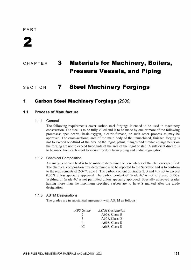
ABS RULE REQUIREMENTS FOR MATERIALS AND WELDING . 2002 133
P A R T
2C H A P T E R 3 Materials for Machinery, Boilers,
Pressure Vessels, and Piping
S E C T I O N 7 Steel Machinery Forgings 2 - 3 - 7
1 Carbon Steel Machinery Forgings (2000) 2-3-7/1
1.1 Process of Manufacture 2-3-7/1.1
1.1.1 General 2-3-7/1.1.1
The following requirements cover carbon-steel forgings intended to be used in machineryconstruction. The steel is to be fully killed and is to be made by one or more of the followingprocesses: open-hearth, basic-oxygen, electric-furnace, or such other process as may beapproved. The cross-sectional area of the main body of the unmachined, finished forging isnot to exceed one-third of the area of the ingot; palms, flanges and similar enlargements onthe forging are not to exceed two-thirds of the area of the ingot or slab; A sufficient discard isto be made from each ingot to secure freedom from piping and undue segregation.
1.1.2 Chemical Composition 2-3-7/1.1.2
An analysis of each heat is to be made to determine the percentages of the elements specified.The chemical composition thus determined is to be reported to the Surveyor and is to conformto the requirements of 2-3-7/Table 1. The carbon content of Grades 2, 3 and 4 is not to exceed0.35% unless specially approved. The carbon content of Grade 4C is not to exceed 0.55%.Welding of Grade 4C is not permitted unless specially approved. Specially approved gradeshaving more than the maximum specified carbon are to have S marked after the gradedesignation.
1.1.3 ASTM Designations 2-3-7/1.1.3
The grades are in substantial agreement with ASTM as follows:
ABS Grade ASTM Designation2 A668, Class B3 A668, Class D4 A668, Class E
4C A668, Class E
Part 2 Rule Requirements for Materials and WeldingChapter 3 Materials for Machinery, Boilers, Pressure Vessels and PipingSection 7 Steel Machinery Forgings 2-3-7
134 ABS RULE REQUIREMENTS FOR MATERIALS AND WELDING . 2002
1.3 Marking, Retests and Rejection 2-3-7/1.3
1.3.1 Marking 2-3-7/1.3.1
In addition to appropriate identification markings of the manufacturer, Bureau markings,indicating satisfactory compliance with the Rule requirements, and as furnished by theSurveyor, are to be stamped on all forgings in such locations as to be discernable aftermachining and installation. In addition Grade 2, Grade 3, Grade 4, and Grade 4C forgings areto be stamped AB/2, AB/3, AB/4 and AB/4C, respectively.
1.3.2 Retests 2-3-7/1.3.2
If the results of the mechanical tests for any forging or any lot of forgings do not conform tothe requirements specified, a retest may be carried out in accordance with 2-3-1/9 or themanufacturer may re-treat the forgings in accordance with 2-3-1/1.5.6. After re-heat treating,the forgings are to be submitted for all mechanical testing.
1.3.3 Rejection 2-3-7/1.3.3
Any forging having injurious discontinuities that are observed prior to or subsequent toacceptance at the manufacturer’s plant is to be subject to rejection.
1.5 Heat treatment 2-3-7/1.5
1.5.1 General 2-3-7/1.5.1
Unless a departure for the following procedures is specifically approved, Grade 2 and 3forgings are to be annealed, normalized or normalized and tempered. Grade 4 and 4Cforgings are to be normalized and tempered or double-normalized and tempered. The furnaceis to be of ample proportions to bring the forgings to a uniform temperature.
1.5.2 Cooling Prior to Heat Treatment 2-3-7/1.5.2
After forging and before reheating for heat treatment, the forgings are allowed to cool in amanner to prevent injury and to accomplish transformation. The cooling rate is to beapproximately 55°C (100°F) per hour until temperature below 315°C (600°F) is reached.
1.5.3 Annealing 2-3-7/1.5.3
The forgings are to be reheated to and held at the proper austenitizing temperature for asufficient time to effect the desired transformation and then be allowed to cool slowly andevenly in the furnace until the temperature has fallen to about 455°C (850°F) or lower.
1.5.4 Normalizing 2-3-7/1.5.4
The forgings are to be reheated to and held at the proper temperature above the transformationrange for a sufficient time to effect the desired transformation and then withdrawn from thefurnace and allowed to cool in air. Water sprays and air blasts may be specially approved foruse to achieve more rapid cooling. The faster cooling rates are to be agreed by the purchaser.
1.5.5 Tempering 2-3-7/1.5.5
The forgings are to be reheated to and held at the proper temperature, which will be below thetransformation range, and are then to be cooled under suitable conditions to 315°C (600°F) orlower
1.5.6 Retreatment 2-3-7/1.5.6
The manufacturer may re-heat treat the forging, but not more than three additional times.
Part 2 Rule Requirements for Materials and WeldingChapter 3 Materials for Machinery, Boilers, Pressure Vessels and PipingSection 7 Steel Machinery Forgings 2-3-7
ABS RULE REQUIREMENTS FOR MATERIALS AND WELDING . 2002 135
1.7 Tensile Properties 2-3-7/1.7
The forging tensile properties are to conform the requirements of 2-3-7/Table 2
1.9 Test Specimens 2-3-7/1.9
1.9.1 Location and Orientation of Specimens 2-3-7/1.9.1
Mechanical properties are to be determined from test specimens taken from prolongationshaving a sectional area not less than the body of the forging. Specimens may be taken in adirection parallel to the axis of the forging in the direction in which the metal is most drawnout or may be taken transversely. The axes of longitudinal specimens are to be located at anypoint midway between the center and the surface of the solid forgings and at any pointmidway between the inner and outer surfaces of the wall of hollow forgings. The axes oftransverse specimens may be located close to the surface of the forgings. In the cases ofreduction gears ring forgings, reduction gear pinions and gear forgings, and reduction gearshaft forgings, the test specimen location and orientation are specified in 2-3-7/1.11.1(d),2-3-7/1.11.1(e) and 2-3-7/1.11.1(f) respectively. Test results from other locations may bespecially approved, provided appropriate supporting information is presented, which indicatesthat the specified location will be in conformity with the specified tensile properties.
1.9.2 Hollow-drilled Specimens 2-3-7/1.9.2
In lieu of prolongations, the test specimens may be taken from forgings submitted for eachtest lot; or if satisfactory to the Surveyor, test specimens, may be taken from forgings with ahollow drill.
1.9.3 Very Small Forgings 2-3-7/1.9.3
In the cases of very small forgings weighing less than 113 kg (250 lb) each, where theforegoing procedures are impractical, a special forging may be made for the purpose ofobtaining test specimens, provided the Surveyor is satisfied that these test specimens arerepresentative of the forgings submitted for test. In such cases the special forgings should besubjected to the same amount of working and reduction as the forgings represented andshould be heat-treated with those forgings.
1.9.4 Identification of Specimens 2-3-7/1.9.4
The test specimens are not to be detached from the forgings until the final heat treatment ofthe forgings has been completed and test specimens have been stamped by the Surveyor foridentification. Where the material identification system of the manufacturer is foundacceptable to the Bureau and is maintained in that condition through initial and periodicalverification by the Bureau, it may be considered in lieu of stamping by the Surveyor beforedetachment.
1.11 Number and Location of Tests 2-3-7/1.11
1.11.1 Tension Test 2-3-7/1.11.1
1.11.1(a) Large Forgings. In the case of large forgings with rough machined weights of3180 kg (7000 lb) or over, one tension test specimen is to be taken from each end of theforging. In the case of ring and hollow cylindrical forgings, the two tensile test specimensmay be taken 180 degrees apart from the same end of the forging.
1.11.1(b) Intermediate-Sized Forgings. In the case of forgings with rough machined weightsless than 3180 kg. (7000 lb), except as noted in the following paragraph, at least one tensiontest specimen is to be taken form each forging.
Part 2 Rule Requirements for Materials and WeldingChapter 3 Materials for Machinery, Boilers, Pressure Vessels and PipingSection 7 Steel Machinery Forgings 2-3-7
136 ABS RULE REQUIREMENTS FOR MATERIALS AND WELDING . 2002
1.11.1(c) Small Forgings. In the case of small forgings with rough machined weights lessthan 2270 kg (5000 lb), one tension test specimen may be taken from one forging asrepresentative of a lot provided the forgings in the lot are of a similar size, are of one gradeand kind only, are made from the same heat and are heat-treated in the same furnace charge.The maximum lot size for testing purposes is twenty-five (25) forgings.
1.11.1(d) Reduction Gear Ring Forgings. In the case of ring forgings for reduction gears,two tension tests are to be taken 180 degrees apart from a full-size prolongation left on oneend of each individual forging or both ends of each multiple forging. Test specimens are tobe in a tangential orientation at mid-wall of the ring as close as practical to the end of therough machined surface of the forging.
1.11.1(e) Reduction Gear Pinion and Gear Forgings. In the case of pinion and gear forgingsfor reduction gears, the tension test is to be taken in the longitudinal or tangential orientationfrom a location as close as practical to the mid-radius location of the main body (toothedportion) of solid forgings or the mid-wall of bored forgings. Extending the axial length of themain body (toothed portion) of the forging for a sufficient distance would be an acceptablelocation for tension specimen removal.
1.11.1(f) Reduction Gear Shaft Forgings. In the case of shaft forgings for reduction gears,the tension test is to be taken in the longitudinal direction at the mid-radius location of a fullsize prolongation.
1.11.2 Hardness Tests 2-3-7/1.11.2
1.11.2(a) Large, Intermediate and Small Sized Forgings. Each forging except those withrough machined weights of less than 113 kg (250 lbs) is to be hardness tested to meet thefollowing requirements. The variation in hardness of any forging is not to exceed 30 BrinellHardness numbers.
ABS GradeHardness, BHN, Minimum,
(10 mm dia. ball, 3000 kg load)
2 120
3 150
4, 4C 170
1.11.2(b) Reduction Gear Forgings. In the case of ring forgings for reduction gears, Brinellhardness tests are to be taken at approximately 1/4 of the radial thickness from the outsidediameter and in accordance with the following frequency and locations:
Outside Diameter, cm.(in) Number of Hardness Tests
To 102 (40) 1 on each end, 180 degrees apart
102 to 203 (40 to 80) 2 on each end, 180 degrees apart
203 to 305 (80 to 120) 3 on each end, 120 degrees apart
Over 305 (120) 4 on each end, 90 degrees apart
1.11.2(c) Reduction Gear Pinion and Gear Forgings. In the case of case of pinion and gearforgings with diameters 203 mm (8 in) and over, four Brinell hardness tests are to be made onthe outside surface of that portion of the forging on which teeth will be cut, two tests beingmade on each helix 180 degrees apart and the tests on the two Helices are to be 90 degreesapart. On each forging under 203 mm (8 in) in diameter, two Brinell hardness tests are to bemade on each helix 180 degrees apart. Hardness tests are to be taken at the quarter-face widthof the toothed portion diameter.
Part 2 Rule Requirements for Materials and WeldingChapter 3 Materials for Machinery, Boilers, Pressure Vessels and PipingSection 7 Steel Machinery Forgings 2-3-7
ABS RULE REQUIREMENTS FOR MATERIALS AND WELDING . 2002 137
1.11.2(d) Disc, Ring and Hollow Forgings. Each forging except those with rough machinedweights of less than 113 kg (250 lbs) is to be hardness tested to meet the requirements of2-3-7/1.11.2(a). Forgings are to be tested at the approximate mid-radius and 180 degrees aparton each flat surface of the forging; the testing locations on opposite sides are to be offset by90 degrees.
1.11.2(e) Very Small Forgings. In cases involving very small forgings weighing less than113 kg (250 lb) each, where the foregoing procedures are impractical, the hardness tests maybe made from broken tension test specimens, or on a special forging representing the lot; see2-3-7/1.9.3.
1.13 Inspection 2-3-7/1.13
All forgings are to be inspected by the Surveyor after the final heat treatment and they are to be foundfree from defects.
1.13.1 Surface Inspection of Tail Shaft Forgings 2-3-7/1.13.1
All tail shaft forgings are to be subjected to a nondestructive examination such as magneticparticle, dye penetrant or other nondestructive method. Discontinuities are to be removed tothe satisfaction of the Surveyor. (See 4-3-2/3.7.3 of the Rules for Building and Classing SteelVessels, for surface inspection requirements in finished machined condition.)
1.13.2 Ultrasonic Examination of Tail Shaft Forgings 2-3-7/1.13.2
Forgings for tail shafts 455 mm (18 in.) and over in finished diameter are to be ultrasonicallyexamined to the satisfaction of the attending Surveyor. Conformity with the Bureau’sseparately issued Guideline for Ultrasonic Examination of Carbon Steel Forgings for TailShafts, or equivalent, will be considered to meet this requirement.
3 Alloy Steel Gear Assembly Forgings (2000) 2-3-7/3
3.1 Process of Manufacture 2-3-7/3.1
3.1.1 General 2-3-7/3.1.1
The following requirements cover gear and pinion alloy steel forgings intended to be usedprincipally for propulsion units and auxiliary turbines. Typical components include forgingrims and blanks for steel gears and pinions, used in shipboard gear assemblies. The steel is tobe fully killed and is to be made by one or more of the following processes: open- hearth,basic-oxygen, electric-furnace or such other processes as may be approved. The cross-sectional area of the main body of the unmachined, finished forging is not to exceed one-thirdof the area of the ingot or slab; palms, flanges and similar enlargements on the forging are notto exceed two-thirds of the area of the ingot. A sufficient discard is to be made from eachingot to secure freedom from piping and undue segregation. The forging process is to haveample power to adequately flow the metal within the maximum cross-section of the forging.
3.1.2 Chemical Composition 2-3-7/3.1.2
An analysis of each heat is to be made to determine the percentages of the elements specified.The chemical composition thus determined is to be reported to the Surveyor and is to conformto the requirements of 2-3-7/Table 3. The analysis is to be carried out with a coupon castduring the pouring of the heat.
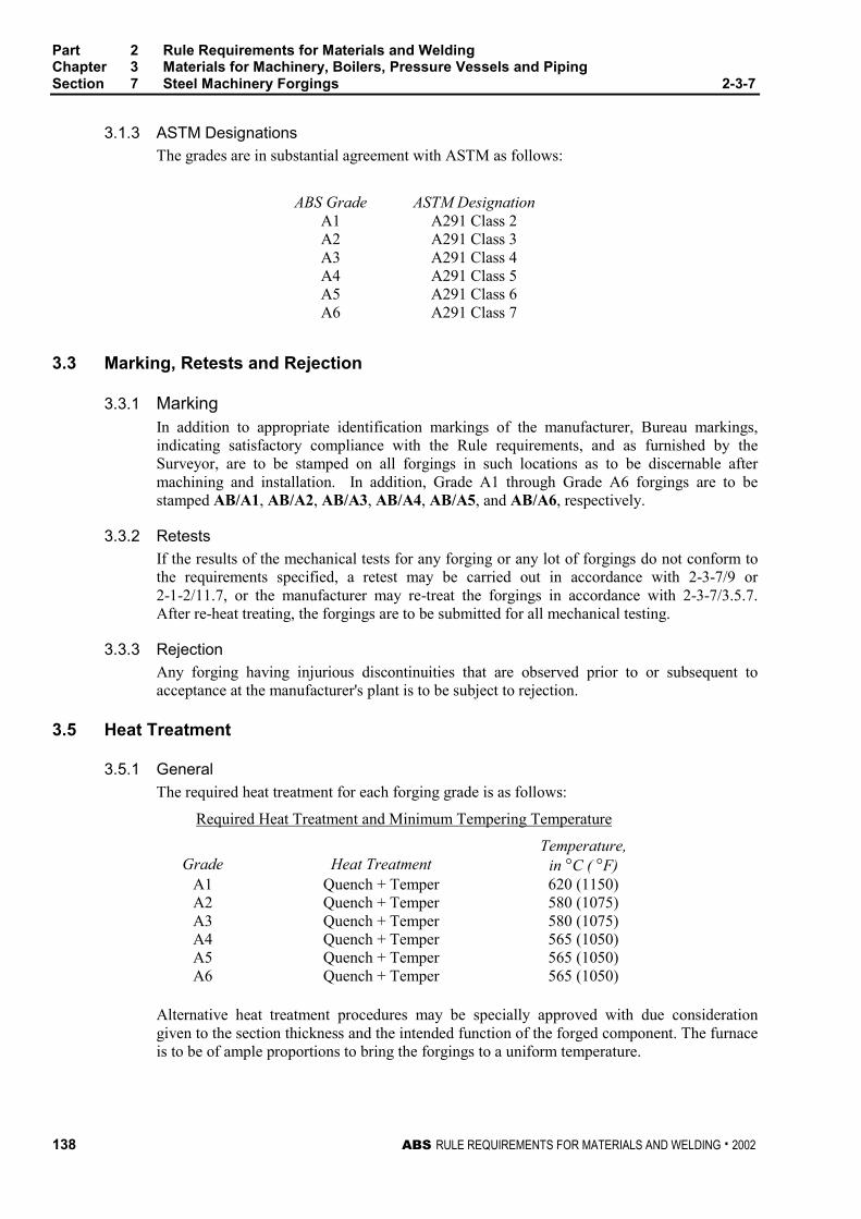
Part 2 Rule Requirements for Materials and WeldingChapter 3 Materials for Machinery, Boilers, Pressure Vessels and PipingSection 7 Steel Machinery Forgings 2-3-7
138 ABS RULE REQUIREMENTS FOR MATERIALS AND WELDING . 2002
3.1.3 ASTM Designations 2-3-7/3.1.3
The grades are in substantial agreement with ASTM as follows:
ABS Grade ASTM DesignationA1 A291 Class 2A2 A291 Class 3A3 A291 Class 4A4 A291 Class 5A5 A291 Class 6A6 A291 Class 7
3.3 Marking, Retests and Rejection 2-3-7/3.3
3.3.1 Marking 2-3-7/3.3.1
In addition to appropriate identification markings of the manufacturer, Bureau markings,indicating satisfactory compliance with the Rule requirements, and as furnished by theSurveyor, are to be stamped on all forgings in such locations as to be discernable aftermachining and installation. In addition, Grade A1 through Grade A6 forgings are to bestamped AB/A1, AB/A2, AB/A3, AB/A4, AB/A5, and AB/A6, respectively.
3.3.2 Retests 2-3-7/3.3.2
If the results of the mechanical tests for any forging or any lot of forgings do not conform tothe requirements specified, a retest may be carried out in accordance with 2-3-7/9 or2-1-2/11.7, or the manufacturer may re-treat the forgings in accordance with 2-3-7/3.5.7.After re-heat treating, the forgings are to be submitted for all mechanical testing.
3.3.3 Rejection 2-3-7/3.3.3
Any forging having injurious discontinuities that are observed prior to or subsequent toacceptance at the manufacturer's plant is to be subject to rejection.
3.5 Heat Treatment 2-3-7/3.5
3.5.1 General 2-3-7/3.5.1
The required heat treatment for each forging grade is as follows:
Required Heat Treatment and Minimum Tempering Temperature
Grade Heat TreatmentTemperature,
in °C ( °F)A1 Quench + Temper 620 (1150)A2 Quench + Temper 580 (1075)A3 Quench + Temper 580 (1075)A4 Quench + Temper 565 (1050)A5 Quench + Temper 565 (1050)A6 Quench + Temper 565 (1050)
Alternative heat treatment procedures may be specially approved with due considerationgiven to the section thickness and the intended function of the forged component. The furnaceis to be of ample proportions to bring the forgings to a uniform temperature.
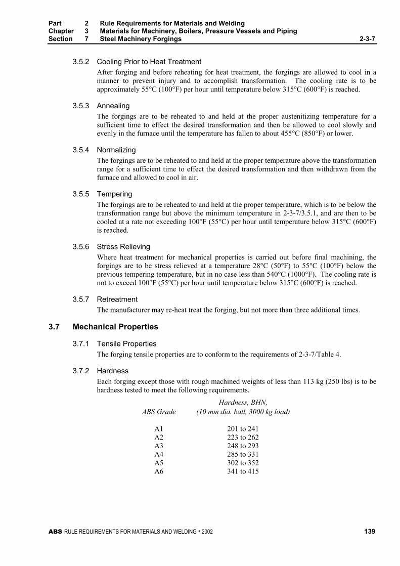
Part 2 Rule Requirements for Materials and WeldingChapter 3 Materials for Machinery, Boilers, Pressure Vessels and PipingSection 7 Steel Machinery Forgings 2-3-7
ABS RULE REQUIREMENTS FOR MATERIALS AND WELDING . 2002 139
3.5.2 Cooling Prior to Heat Treatment 2-3-7/3.5.2
After forging and before reheating for heat treatment, the forgings are allowed to cool in amanner to prevent injury and to accomplish transformation. The cooling rate is to beapproximately 55°C (100°F) per hour until temperature below 315°C (600°F) is reached.
3.5.3 Annealing 2-3-7/3.5.3
The forgings are to be reheated to and held at the proper austenitizing temperature for asufficient time to effect the desired transformation and then be allowed to cool slowly andevenly in the furnace until the temperature has fallen to about 455°C (850°F) or lower.
3.5.4 Normalizing 2-3-7/3.5.4
The forgings are to be reheated to and held at the proper temperature above the transformationrange for a sufficient time to effect the desired transformation and then withdrawn from thefurnace and allowed to cool in air.
3.5.5 Tempering 2-3-7/3.5.5
The forgings are to be reheated to and held at the proper temperature, which is to be below thetransformation range but above the minimum temperature in 2-3-7/3.5.1, and are then to becooled at a rate not exceeding 100°F (55°C) per hour until temperature below 315°C (600°F)is reached.
3.5.6 Stress Relieving 2-3-7/3.5.6
Where heat treatment for mechanical properties is carried out before final machining, theforgings are to be stress relieved at a temperature 28°C (50°F) to 55°C (100°F) below theprevious tempering temperature, but in no case less than 540°C (1000°F). The cooling rate isnot to exceed 100°F (55°C) per hour until temperature below 315°C (600°F) is reached.
3.5.7 Retreatment 2-3-7/3.5.7
The manufacturer may re-heat treat the forging, but not more than three additional times.
3.7 Mechanical Properties 2-3-7/3.7
3.7.1 Tensile Properties 2-3-7/3.7.1
The forging tensile properties are to conform to the requirements of 2-3-7/Table 4.
3.7.2 Hardness 2-3-7/3.7.2
Each forging except those with rough machined weights of less than 113 kg (250 lbs) is to behardness tested to meet the following requirements.
Hardness, BHN,ABS Grade (10 mm dia. ball, 3000 kg load)
A1 201 to 241A2 223 to 262A3 248 to 293A4 285 to 331A5 302 to 352A6 341 to 415
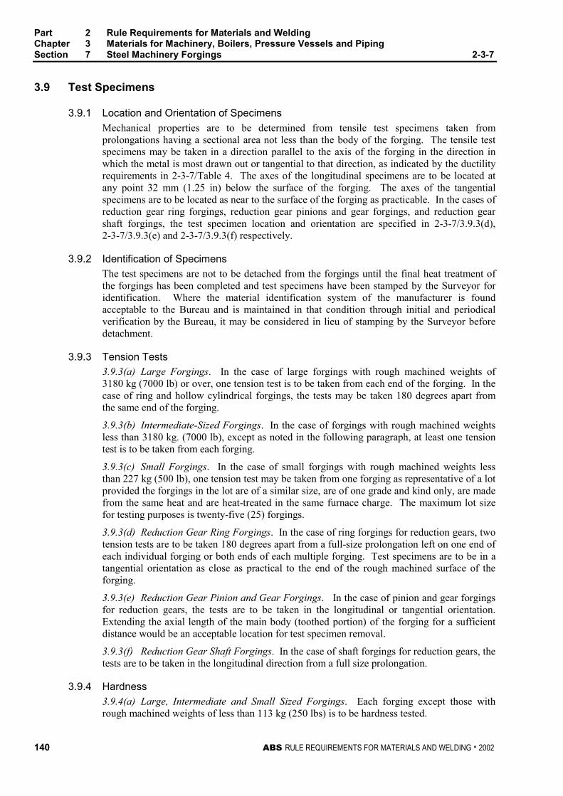
Part 2 Rule Requirements for Materials and WeldingChapter 3 Materials for Machinery, Boilers, Pressure Vessels and PipingSection 7 Steel Machinery Forgings 2-3-7
140 ABS RULE REQUIREMENTS FOR MATERIALS AND WELDING . 2002
3.9 Test Specimens 2-3-7/3.9
3.9.1 Location and Orientation of Specimens 2-3-7/3.9.1
Mechanical properties are to be determined from tensile test specimens taken fromprolongations having a sectional area not less than the body of the forging. The tensile testspecimens may be taken in a direction parallel to the axis of the forging in the direction inwhich the metal is most drawn out or tangential to that direction, as indicated by the ductilityrequirements in 2-3-7/Table 4. The axes of the longitudinal specimens are to be located atany point 32 mm (1.25 in) below the surface of the forging. The axes of the tangentialspecimens are to be located as near to the surface of the forging as practicable. In the cases ofreduction gear ring forgings, reduction gear pinions and gear forgings, and reduction gearshaft forgings, the test specimen location and orientation are specified in 2-3-7/3.9.3(d),2-3-7/3.9.3(e) and 2-3-7/3.9.3(f) respectively.
3.9.2 Identification of Specimens 2-3-7/3.9.2
The test specimens are not to be detached from the forgings until the final heat treatment ofthe forgings has been completed and test specimens have been stamped by the Surveyor foridentification. Where the material identification system of the manufacturer is foundacceptable to the Bureau and is maintained in that condition through initial and periodicalverification by the Bureau, it may be considered in lieu of stamping by the Surveyor beforedetachment.
3.9.3 Tension Tests 2-3-7/3.9.3
3.9.3(a) Large Forgings. In the case of large forgings with rough machined weights of3180 kg (7000 lb) or over, one tension test is to be taken from each end of the forging. In thecase of ring and hollow cylindrical forgings, the tests may be taken 180 degrees apart fromthe same end of the forging.
3.9.3(b) Intermediate-Sized Forgings. In the case of forgings with rough machined weightsless than 3180 kg. (7000 lb), except as noted in the following paragraph, at least one tensiontest is to be taken from each forging.
3.9.3(c) Small Forgings. In the case of small forgings with rough machined weights lessthan 227 kg (500 lb), one tension test may be taken from one forging as representative of a lotprovided the forgings in the lot are of a similar size, are of one grade and kind only, are madefrom the same heat and are heat-treated in the same furnace charge. The maximum lot sizefor testing purposes is twenty-five (25) forgings.
3.9.3(d) Reduction Gear Ring Forgings. In the case of ring forgings for reduction gears, twotension tests are to be taken 180 degrees apart from a full-size prolongation left on one end ofeach individual forging or both ends of each multiple forging. Test specimens are to be in atangential orientation as close as practical to the end of the rough machined surface of theforging.
3.9.3(e) Reduction Gear Pinion and Gear Forgings. In the case of pinion and gear forgingsfor reduction gears, the tests are to be taken in the longitudinal or tangential orientation.Extending the axial length of the main body (toothed portion) of the forging for a sufficientdistance would be an acceptable location for test specimen removal.
3.9.3(f) Reduction Gear Shaft Forgings. In the case of shaft forgings for reduction gears, thetests are to be taken in the longitudinal direction from a full size prolongation.
3.9.4 Hardness 2-3-7/3.9.4
3.9.4(a) Large, Intermediate and Small Sized Forgings. Each forging except those withrough machined weights of less than 113 kg (250 lbs) is to be hardness tested.
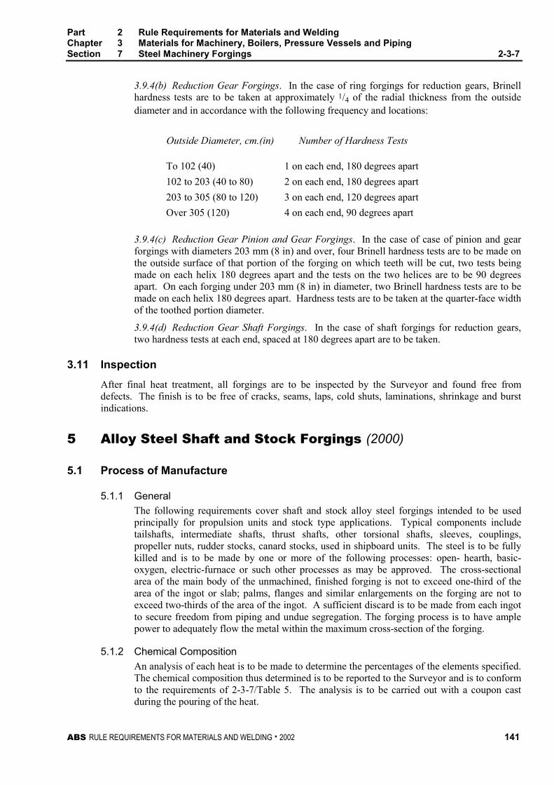
Part 2 Rule Requirements for Materials and WeldingChapter 3 Materials for Machinery, Boilers, Pressure Vessels and PipingSection 7 Steel Machinery Forgings 2-3-7
ABS RULE REQUIREMENTS FOR MATERIALS AND WELDING . 2002 141
3.9.4(b) Reduction Gear Forgings. In the case of ring forgings for reduction gears, Brinellhardness tests are to be taken at approximately 1/4 of the radial thickness from the outsidediameter and in accordance with the following frequency and locations:
Outside Diameter, cm.(in) Number of Hardness Tests
To 102 (40) 1 on each end, 180 degrees apart
102 to 203 (40 to 80) 2 on each end, 180 degrees apart
203 to 305 (80 to 120) 3 on each end, 120 degrees apart
Over 305 (120) 4 on each end, 90 degrees apart
3.9.4(c) Reduction Gear Pinion and Gear Forgings. In the case of case of pinion and gearforgings with diameters 203 mm (8 in) and over, four Brinell hardness tests are to be made onthe outside surface of that portion of the forging on which teeth will be cut, two tests beingmade on each helix 180 degrees apart and the tests on the two helices are to be 90 degreesapart. On each forging under 203 mm (8 in) in diameter, two Brinell hardness tests are to bemade on each helix 180 degrees apart. Hardness tests are to be taken at the quarter-face widthof the toothed portion diameter.
3.9.4(d) Reduction Gear Shaft Forgings. In the case of shaft forgings for reduction gears,two hardness tests at each end, spaced at 180 degrees apart are to be taken.
3.11 Inspection 2-3-7/3.11
After final heat treatment, all forgings are to be inspected by the Surveyor and found free fromdefects. The finish is to be free of cracks, seams, laps, cold shuts, laminations, shrinkage and burstindications.
5 Alloy Steel Shaft and Stock Forgings (2000) 2-3-7/5
5.1 Process of Manufacture 2-3-7/5.1
5.1.1 General 2-3-7/5.1.1
The following requirements cover shaft and stock alloy steel forgings intended to be usedprincipally for propulsion units and stock type applications. Typical components includetailshafts, intermediate shafts, thrust shafts, other torsional shafts, sleeves, couplings,propeller nuts, rudder stocks, canard stocks, used in shipboard units. The steel is to be fullykilled and is to be made by one or more of the following processes: open- hearth, basic-oxygen, electric-furnace or such other processes as may be approved. The cross-sectionalarea of the main body of the unmachined, finished forging is not to exceed one-third of thearea of the ingot or slab; palms, flanges and similar enlargements on the forging are not toexceed two-thirds of the area of the ingot. A sufficient discard is to be made from each ingotto secure freedom from piping and undue segregation. The forging process is to have amplepower to adequately flow the metal within the maximum cross-section of the forging.
5.1.2 Chemical Composition 2-3-7/5.1.2
An analysis of each heat is to be made to determine the percentages of the elements specified.The chemical composition thus determined is to be reported to the Surveyor and is to conformto the requirements of 2-3-7/Table 5. The analysis is to be carried out with a coupon castduring the pouring of the heat.
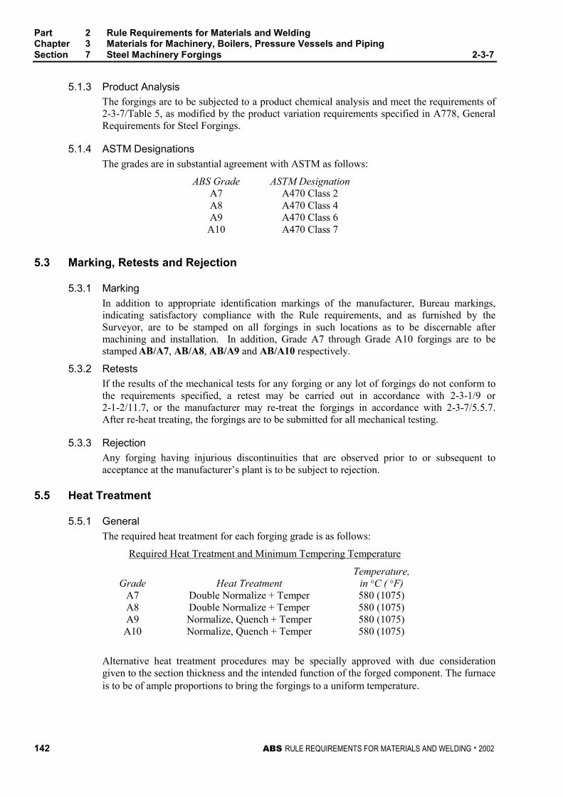
Part 2 Rule Requirements for Materials and WeldingChapter 3 Materials for Machinery, Boilers, Pressure Vessels and PipingSection 7 Steel Machinery Forgings 2-3-7
142 ABS RULE REQUIREMENTS FOR MATERIALS AND WELDING . 2002
5.1.3 Product Analysis 2-3-7/5.1.3
The forgings are to be subjected to a product chemical analysis and meet the requirements of2-3-7/Table 5, as modified by the product variation requirements specified in A778, GeneralRequirements for Steel Forgings.
5.1.4 ASTM Designations 2-3-7/5.1.4
The grades are in substantial agreement with ASTM as follows:
ABS Grade ASTM DesignationA7 A470 Class 2A8 A470 Class 4A9 A470 Class 6A10 A470 Class 7
5.3 Marking, Retests and Rejection 2-3-7/5.3
5.3.1 Marking 2-3-7/5.3.1
In addition to appropriate identification markings of the manufacturer, Bureau markings,indicating satisfactory compliance with the Rule requirements, and as furnished by theSurveyor, are to be stamped on all forgings in such locations as to be discernable aftermachining and installation. In addition, Grade A7 through Grade A10 forgings are to bestamped AB/A7, AB/A8, AB/A9 and AB/A10 respectively.
5.3.2 Retests 2-3-7/5.3.2
If the results of the mechanical tests for any forging or any lot of forgings do not conform tothe requirements specified, a retest may be carried out in accordance with 2-3-1/9 or2-1-2/11.7, or the manufacturer may re-treat the forgings in accordance with 2-3-7/5.5.7.After re-heat treating, the forgings are to be submitted for all mechanical testing.
5.3.3 Rejection 2-3-7/5.3.3
Any forging having injurious discontinuities that are observed prior to or subsequent toacceptance at the manufacturer’s plant is to be subject to rejection.
5.5 Heat Treatment 2-3-7/5.5
5.5.1 General 2-3-7/5.5.1
The required heat treatment for each forging grade is as follows:
Required Heat Treatment and Minimum Tempering Temperature
Grade Heat TreatmentTemperature,
in °C ( °F)A7 Double Normalize + Temper 580 (1075)A8 Double Normalize + Temper 580 (1075)A9 Normalize, Quench + Temper 580 (1075)A10 Normalize, Quench + Temper 580 (1075)
Alternative heat treatment procedures may be specially approved with due considerationgiven to the section thickness and the intended function of the forged component. The furnaceis to be of ample proportions to bring the forgings to a uniform temperature.
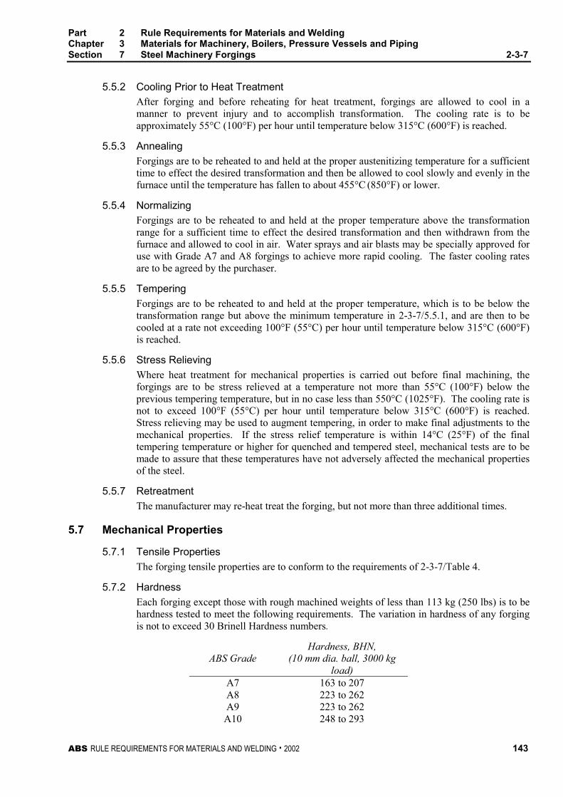
Part 2 Rule Requirements for Materials and WeldingChapter 3 Materials for Machinery, Boilers, Pressure Vessels and PipingSection 7 Steel Machinery Forgings 2-3-7
ABS RULE REQUIREMENTS FOR MATERIALS AND WELDING . 2002 143
5.5.2 Cooling Prior to Heat Treatment 2-3-7/5.5.2
After forging and before reheating for heat treatment, forgings are allowed to cool in amanner to prevent injury and to accomplish transformation. The cooling rate is to beapproximately 55°C (100°F) per hour until temperature below 315°C (600°F) is reached.
5.5.3 Annealing 2-3-7/5.5.3
Forgings are to be reheated to and held at the proper austenitizing temperature for a sufficienttime to effect the desired transformation and then be allowed to cool slowly and evenly in thefurnace until the temperature has fallen to about 455°C (850°F) or lower.
5.5.4 Normalizing 2-3-7/5.5.4
Forgings are to be reheated to and held at the proper temperature above the transformationrange for a sufficient time to effect the desired transformation and then withdrawn from thefurnace and allowed to cool in air. Water sprays and air blasts may be specially approved foruse with Grade A7 and A8 forgings to achieve more rapid cooling. The faster cooling ratesare to be agreed by the purchaser.
5.5.5 Tempering 2-3-7/5.5.5
Forgings are to be reheated to and held at the proper temperature, which is to be below thetransformation range but above the minimum temperature in 2-3-7/5.5.1, and are then to becooled at a rate not exceeding 100°F (55°C) per hour until temperature below 315°C (600°F)is reached.
5.5.6 Stress Relieving 2-3-7/5.5.6
Where heat treatment for mechanical properties is carried out before final machining, theforgings are to be stress relieved at a temperature not more than 55°C (100°F) below theprevious tempering temperature, but in no case less than 550°C (1025°F). The cooling rate isnot to exceed 100°F (55°C) per hour until temperature below 315°C (600°F) is reached.Stress relieving may be used to augment tempering, in order to make final adjustments to themechanical properties. If the stress relief temperature is within 14°C (25°F) of the finaltempering temperature or higher for quenched and tempered steel, mechanical tests are to bemade to assure that these temperatures have not adversely affected the mechanical propertiesof the steel.
5.5.7 Retreatment 2-3-7/5.5.7
The manufacturer may re-heat treat the forging, but not more than three additional times.
5.7 Mechanical Properties 2-3-7/5.7
5.7.1 Tensile Properties 2-3-7/5.7.1
The forging tensile properties are to conform to the requirements of 2-3-7/Table 4.
5.7.2 Hardness 2-3-7/5.7.2
Each forging except those with rough machined weights of less than 113 kg (250 lbs) is to behardness tested to meet the following requirements. The variation in hardness of any forgingis not to exceed 30 Brinell Hardness numbers.
Hardness, BHN,ABS Grade (10 mm dia. ball, 3000 kg
load)A7 163 to 207A8 223 to 262A9 223 to 262A10 248 to 293
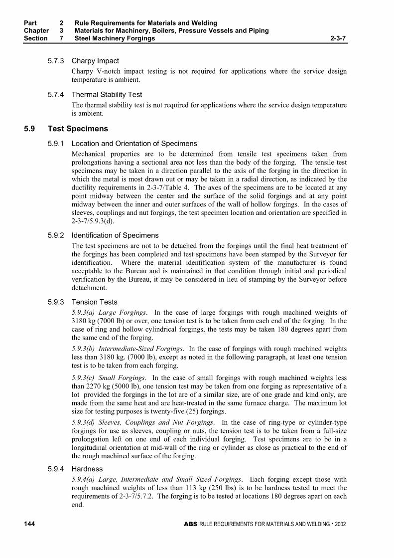
Part 2 Rule Requirements for Materials and WeldingChapter 3 Materials for Machinery, Boilers, Pressure Vessels and PipingSection 7 Steel Machinery Forgings 2-3-7
144 ABS RULE REQUIREMENTS FOR MATERIALS AND WELDING . 2002
5.7.3 Charpy Impact 2-3-7/5.7.3
Charpy V-notch impact testing is not required for applications where the service designtemperature is ambient.
5.7.4 Thermal Stability Test 2-3-7/5.7.4
The thermal stability test is not required for applications where the service design temperatureis ambient.
5.9 Test Specimens 2-3-7/5.9
5.9.1 Location and Orientation of Specimens 2-3-7/5.9.1
Mechanical properties are to be determined from tensile test specimens taken fromprolongations having a sectional area not less than the body of the forging. The tensile testspecimens may be taken in a direction parallel to the axis of the forging in the direction inwhich the metal is most drawn out or may be taken in a radial direction, as indicated by theductility requirements in 2-3-7/Table 4. The axes of the specimens are to be located at anypoint midway between the center and the surface of the solid forgings and at any pointmidway between the inner and outer surfaces of the wall of hollow forgings. In the cases ofsleeves, couplings and nut forgings, the test specimen location and orientation are specified in2-3-7/5.9.3(d).
5.9.2 Identification of Specimens 2-3-7/5.9.2
The test specimens are not to be detached from the forgings until the final heat treatment ofthe forgings has been completed and test specimens have been stamped by the Surveyor foridentification. Where the material identification system of the manufacturer is foundacceptable to the Bureau and is maintained in that condition through initial and periodicalverification by the Bureau, it may be considered in lieu of stamping by the Surveyor beforedetachment.
5.9.3 Tension Tests 2-3-7/5.9.3
5.9.3(a) Large Forgings. In the case of large forgings with rough machined weights of3180 kg (7000 lb) or over, one tension test is to be taken from each end of the forging. In thecase of ring and hollow cylindrical forgings, the tests may be taken 180 degrees apart fromthe same end of the forging.
5.9.3(b) Intermediate-Sized Forgings. In the case of forgings with rough machined weightsless than 3180 kg. (7000 lb), except as noted in the following paragraph, at least one tensiontest is to be taken from each forging.
5.9.3(c) Small Forgings. In the case of small forgings with rough machined weights lessthan 2270 kg (5000 lb), one tension test may be taken from one forging as representative of alot provided the forgings in the lot are of a similar size, are of one grade and kind only, aremade from the same heat and are heat-treated in the same furnace charge. The maximum lotsize for testing purposes is twenty-five (25) forgings.
5.9.3(d) Sleeves, Couplings and Nut Forgings. In the case of ring-type or cylinder-typeforgings for use as sleeves, coupling or nuts, the tension test is to be taken from a full-sizeprolongation left on one end of each individual forging. Test specimens are to be in alongitudinal orientation at mid-wall of the ring or cylinder as close as practical to the end ofthe rough machined surface of the forging.
5.9.4 Hardness 2-3-7/5.9.4
5.9.4(a) Large, Intermediate and Small Sized Forgings. Each forging except those withrough machined weights of less than 113 kg (250 lbs) is to be hardness tested to meet therequirements of 2-3-7/5.7.2. The forging is to be tested at locations 180 degrees apart on eachend.
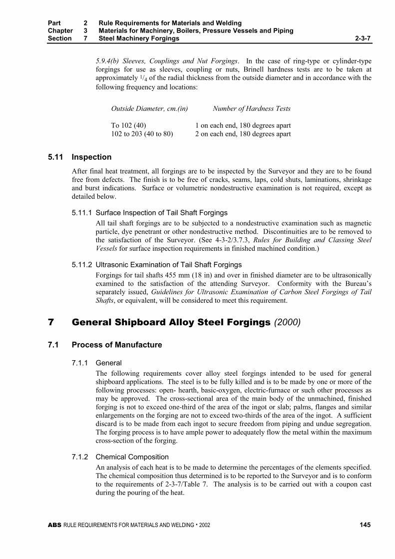
Part 2 Rule Requirements for Materials and WeldingChapter 3 Materials for Machinery, Boilers, Pressure Vessels and PipingSection 7 Steel Machinery Forgings 2-3-7
ABS RULE REQUIREMENTS FOR MATERIALS AND WELDING . 2002 145
5.9.4(b) Sleeves, Couplings and Nut Forgings. In the case of ring-type or cylinder-typeforgings for use as sleeves, coupling or nuts, Brinell hardness tests are to be taken atapproximately 1/4 of the radial thickness from the outside diameter and in accordance with thefollowing frequency and locations:
Outside Diameter, cm.(in) Number of Hardness Tests
To 102 (40) 1 on each end, 180 degrees apart102 to 203 (40 to 80) 2 on each end, 180 degrees apart
5.11 Inspection 2-3-7/5.11
After final heat treatment, all forgings are to be inspected by the Surveyor and they are to be foundfree from defects. The finish is to be free of cracks, seams, laps, cold shuts, laminations, shrinkageand burst indications. Surface or volumetric nondestructive examination is not required, except asdetailed below.
5.11.1 Surface Inspection of Tail Shaft Forgings 2-3-7/5.11.1
All tail shaft forgings are to be subjected to a nondestructive examination such as magneticparticle, dye penetrant or other nondestructive method. Discontinuities are to be removed tothe satisfaction of the Surveyor. (See 4-3-2/3.7.3, Rules for Building and Classing SteelVessels for surface inspection requirements in finished machined condition.)
5.11.2 Ultrasonic Examination of Tail Shaft Forgings 2-3-7/5.11.2
Forgings for tail shafts 455 mm (18 in) and over in finished diameter are to be ultrasonicallyexamined to the satisfaction of the attending Surveyor. Conformity with the Bureau’sseparately issued, Guidelines for Ultrasonic Examination of Carbon Steel Forgings of TailShafts, or equivalent, will be considered to meet this requirement.
7 General Shipboard Alloy Steel Forgings (2000) 2-3-7/7
7.1 Process of Manufacture 2-3-7/7.1
7.1.1 General 2-3-7/7.1.1
The following requirements cover alloy steel forgings intended to be used for generalshipboard applications. The steel is to be fully killed and is to be made by one or more of thefollowing processes: open- hearth, basic-oxygen, electric-furnace or such other processes asmay be approved. The cross-sectional area of the main body of the unmachined, finishedforging is not to exceed one-third of the area of the ingot or slab; palms, flanges and similarenlargements on the forging are not to exceed two-thirds of the area of the ingot. A sufficientdiscard is to be made from each ingot to secure freedom from piping and undue segregation.The forging process is to have ample power to adequately flow the metal within the maximumcross-section of the forging.
7.1.2 Chemical Composition 2-3-7/7.1.2
An analysis of each heat is to be made to determine the percentages of the elements specified.The chemical composition thus determined is to be reported to the Surveyor and is to conformto the requirements of 2-3-7/Table 7. The analysis is to be carried out with a coupon castduring the pouring of the heat.
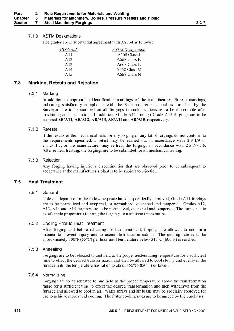
Part 2 Rule Requirements for Materials and WeldingChapter 3 Materials for Machinery, Boilers, Pressure Vessels and PipingSection 7 Steel Machinery Forgings 2-3-7
146 ABS RULE REQUIREMENTS FOR MATERIALS AND WELDING . 2002
7.1.3 ASTM Designations 2-3-7/7.1.3
The grades are in substantial agreement with ASTM as follows:
ABS Grade ASTM DesignationA11 A668 Class JA12 A668 Class KA13 A668 Class LA14 A668 Class MA15 A668 Class N
7.3 Marking, Retests and Rejection 2-3-7/7.3
7.3.1 Marking 2-3-7/7.3.1
In addition to appropriate identification markings of the manufacturer, Bureau markings,indicating satisfactory compliance with the Rule requirements, and as furnished by theSurveyor, are to be stamped on all forgings in such locations as to be discernable aftermachining and installation. In addition, Grade A11 through Grade A15 forgings are to bestamped AB/A11, AB/A12, AB/A13, AB/A14 and AB/A15, respectively.
7.3.2 Retests 2-3-7/7.3.2
If the results of the mechanical tests for any forging or any lot of forgings do not conform tothe requirements specified, a retest may be carried out in accordance with 2-3-1/9 or2-1-2/11.7, or the manufacturer may re-treat the forgings in accordance with 2-3-7/7.5.6.After re-heat treating, the forgings are to be submitted for all mechanical testing.
7.3.3 Rejection 2-3-7/7.3.3
Any forging having injurious discontinuities that are observed prior to or subsequent toacceptance at the manufacturer’s plant is to be subject to rejection.
7.5 Heat Treatment 2-3-7/7.5
7.5.1 General 2-3-7/7.5.1
Unless a departure for the following procedures is specifically approved, Grade A11 forgingsare to be normalized and tempered, or normalized, quenched and tempered. Grades A12,A13, A14 and A15 forgings are to be normalized, quenched and tempered. The furnace is tobe of ample proportions to bring the forgings to a uniform temperature.
7.5.2 Cooling Prior to Heat Treatment 2-3-7/7.5.2
After forging and before reheating for heat treatment, forgings are allowed to cool in amanner to prevent injury and to accomplish transformation. The cooling rate is to beapproximately 100°F (55°C) per hour until temperature below 315°C (600°F) is reached.
7.5.3 Annealing 2-3-7/7.5.3
Forgings are to be reheated to and held at the proper austenitizing temperature for a sufficienttime to effect the desired transformation and then be allowed to cool slowly and evenly in thefurnace until the temperature has fallen to about 455°C (850°F) or lower.
7.5.4 Normalizing 2-3-7/7.4
Forgings are to be reheated to and held at the proper temperature above the transformationrange for a sufficient time to effect the desired transformation and then withdrawn from thefurnace and allowed to cool in air. Water sprays and air blasts may be specially approved foruse to achieve more rapid cooling. The faster cooling rates are to be agreed by the purchaser.
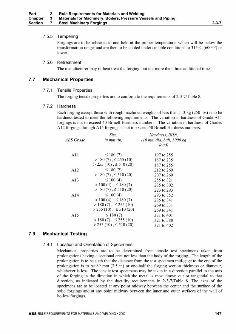
Part 2 Rule Requirements for Materials and WeldingChapter 3 Materials for Machinery, Boilers, Pressure Vessels and PipingSection 7 Steel Machinery Forgings 2-3-7
ABS RULE REQUIREMENTS FOR MATERIALS AND WELDING . 2002 147
7.5.5 Tempering 2-3-7/7.5.5
Forgings are to be reheated to and held at the proper temperature, which will be below thetransformation range, and are then to be cooled under suitable conditions to 315°C (600°F) orlower.
7.5.6 Retreatment 2-3-7/7.5.6
The manufacturer may re-heat treat the forging, but not more than three additional times.
7.7 Mechanical Properties 2-3-7/7.7
7.7.1 Tensile Properties 2-3-7/7.7.1
The forging tensile properties are to conform to the requirements of 2-3-7/Table 8.
7.7.2 Hardness 2-3-7/7.7.2
Each forging except those with rough machined weights of less than 113 kg (250 lbs) is to behardness tested to meet the following requirements. The variation in hardness of Grade A11forgings is not to exceed 40 Brinell Hardness numbers. The variation in hardness of GradesA12 forgings through A15 forgings is not to exceed 50 Brinell Hardness numbers.
Size, Hardness, BHN,ABS Grade in mm (in) (10 mm dia. ball, 3000 kg
load)
A11 ≤ 180 (7)> 180 (7) , ≤ 255 (10)
> 255 (10) , ≤ 510 (20)
197 to 255187 to 235187 to 255
A12 ≤ 180 (7)> 180 (7) , ≤ 510 (20)
212 to 269207 to 269
A13 ≤ 100 (4)> 100 (4) , ≤ 180 (7)> 180 (7) , ≤ 510 (20)
255 to 321235 to 302223 to 293
A14 ≤ 100 (4)> 100 (4) , ≤ 180 (7)> 180 (7) , ≤ 255 (10)> 255 (10) , ≤ 510 (20)
293 to 352285 to 341269 to 331269 to 341
A15 ≤ 180 (7)> 180 (7) , ≤ 255 (10)> 255 (10) , ≤ 510 (20)
331 to 401321 to 388321 to 402
7.9 Mechanical Testing 2-3-7/7.9
7.9.1 Location and Orientation of Specimens 2-3-7/7.9.1
Mechanical properties are to be determined from tensile test specimens taken fromprolongations having a sectional area not less than the body of the forging. The length of theprolongation is to be such that the distance from the test specimen mid-gage to the end of theprolongation is to be 89 mm (3.5 in) or one-half the forging section thickness or diameter,whichever is less. The tensile test specimens may be taken in a direction parallel to the axisof the forging in the direction in which the metal is most drawn out or tangential to thatdirection, as indicated by the ductility requirements in 2-3-7/Table 8. The axes of thespecimens are to be located at any point midway between the center and the surface of thesolid forgings and at any point midway between the inner and outer surfaces of the wall ofhollow forgings.
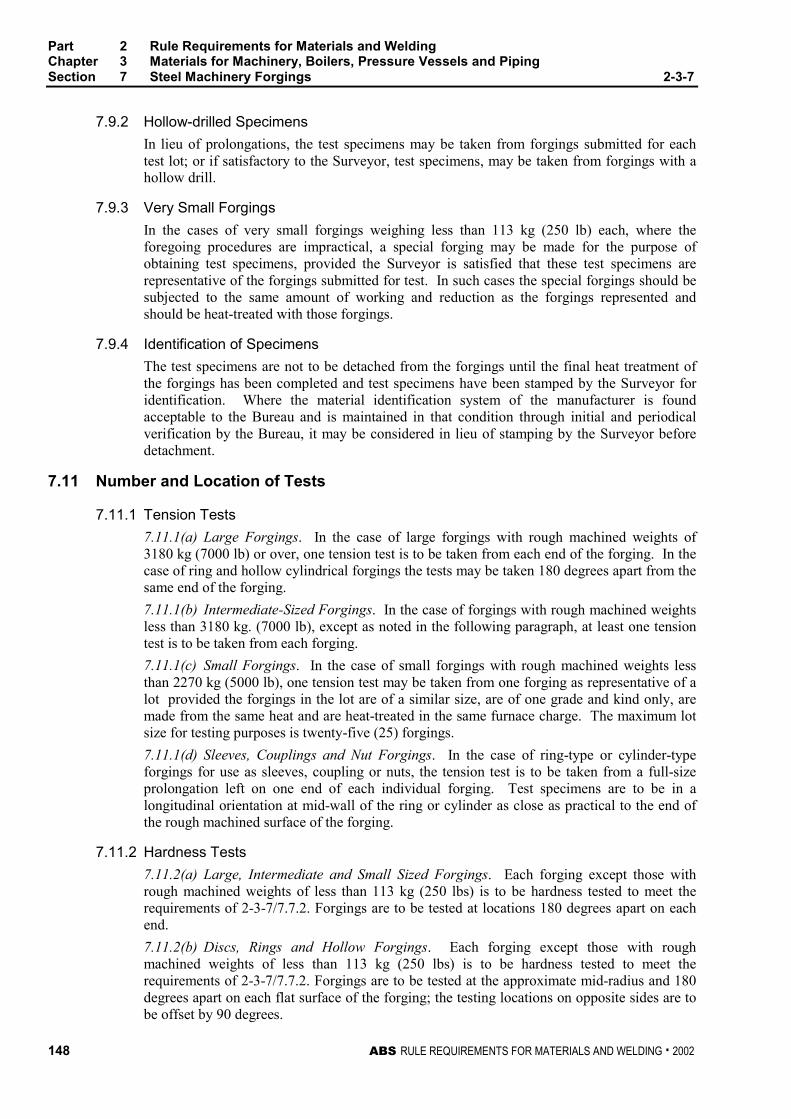
Part 2 Rule Requirements for Materials and WeldingChapter 3 Materials for Machinery, Boilers, Pressure Vessels and PipingSection 7 Steel Machinery Forgings 2-3-7
148 ABS RULE REQUIREMENTS FOR MATERIALS AND WELDING . 2002
7.9.2 Hollow-drilled Specimens 2-3-7/7.9.2
In lieu of prolongations, the test specimens may be taken from forgings submitted for eachtest lot; or if satisfactory to the Surveyor, test specimens, may be taken from forgings with ahollow drill.
7.9.3 Very Small Forgings 2-3-7/7.9.3
In the cases of very small forgings weighing less than 113 kg (250 lb) each, where theforegoing procedures are impractical, a special forging may be made for the purpose ofobtaining test specimens, provided the Surveyor is satisfied that these test specimens arerepresentative of the forgings submitted for test. In such cases the special forgings should besubjected to the same amount of working and reduction as the forgings represented andshould be heat-treated with those forgings.
7.9.4 Identification of Specimens 2-3-7/7.9.4
The test specimens are not to be detached from the forgings until the final heat treatment ofthe forgings has been completed and test specimens have been stamped by the Surveyor foridentification. Where the material identification system of the manufacturer is foundacceptable to the Bureau and is maintained in that condition through initial and periodicalverification by the Bureau, it may be considered in lieu of stamping by the Surveyor beforedetachment.
7.11 Number and Location of Tests 2-3-7/7.11
7.11.1 Tension Tests 2-3-7/7.11.1
7.11.1(a) Large Forgings. In the case of large forgings with rough machined weights of3180 kg (7000 lb) or over, one tension test is to be taken from each end of the forging. In thecase of ring and hollow cylindrical forgings the tests may be taken 180 degrees apart from thesame end of the forging.
7.11.1(b) Intermediate-Sized Forgings. In the case of forgings with rough machined weightsless than 3180 kg. (7000 lb), except as noted in the following paragraph, at least one tensiontest is to be taken from each forging.
7.11.1(c) Small Forgings. In the case of small forgings with rough machined weights lessthan 2270 kg (5000 lb), one tension test may be taken from one forging as representative of alot provided the forgings in the lot are of a similar size, are of one grade and kind only, aremade from the same heat and are heat-treated in the same furnace charge. The maximum lotsize for testing purposes is twenty-five (25) forgings.
7.11.1(d) Sleeves, Couplings and Nut Forgings. In the case of ring-type or cylinder-typeforgings for use as sleeves, coupling or nuts, the tension test is to be taken from a full-sizeprolongation left on one end of each individual forging. Test specimens are to be in alongitudinal orientation at mid-wall of the ring or cylinder as close as practical to the end ofthe rough machined surface of the forging.
7.11.2 Hardness Tests 2-3-7/7.11.2
7.11.2(a) Large, Intermediate and Small Sized Forgings. Each forging except those withrough machined weights of less than 113 kg (250 lbs) is to be hardness tested to meet therequirements of 2-3-7/7.7.2. Forgings are to be tested at locations 180 degrees apart on eachend.
7.11.2(b) Discs, Rings and Hollow Forgings. Each forging except those with roughmachined weights of less than 113 kg (250 lbs) is to be hardness tested to meet therequirements of 2-3-7/7.7.2. Forgings are to be tested at the approximate mid-radius and 180degrees apart on each flat surface of the forging; the testing locations on opposite sides are tobe offset by 90 degrees.
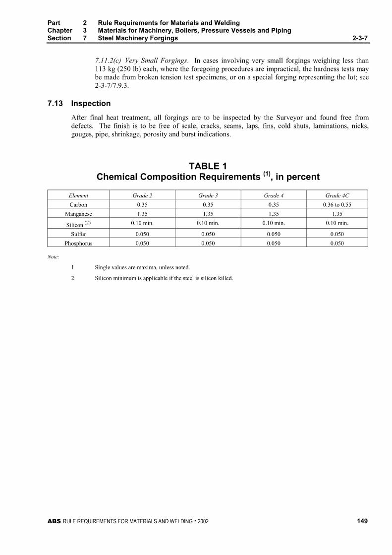
Part 2 Rule Requirements for Materials and WeldingChapter 3 Materials for Machinery, Boilers, Pressure Vessels and PipingSection 7 Steel Machinery Forgings 2-3-7
ABS RULE REQUIREMENTS FOR MATERIALS AND WELDING . 2002 149
7.11.2(c) Very Small Forgings. In cases involving very small forgings weighing less than113 kg (250 lb) each, where the foregoing procedures are impractical, the hardness tests maybe made from broken tension test specimens, or on a special forging representing the lot; see2-3-7/7.9.3.
7.13 Inspection 2-3-7/7.13
After final heat treatment, all forgings are to be inspected by the Surveyor and found free fromdefects. The finish is to be free of scale, cracks, seams, laps, fins, cold shuts, laminations, nicks,gouges, pipe, shrinkage, porosity and burst indications.
TABLE 1Chemical Composition Requirements (1), in percent
Element Grade 2 Grade 3 Grade 4 Grade 4C
Carbon 0.35 0.35 0.35 0.36 to 0.55
Manganese 1.35 1.35 1.35 1.35
Silicon (2) 0.10 min. 0.10 min. 0.10 min. 0.10 min.
Sulfur 0.050 0.050 0.050 0.050
Phosphorus 0.050 0.050 0.050 0.050
Note:
1 Single values are maxima, unless noted.
2 Silicon minimum is applicable if the steel is silicon killed.
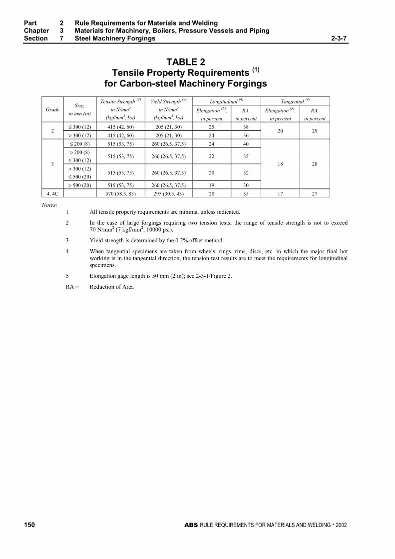
Part 2 Rule Requirements for Materials and WeldingChapter 3 Materials for Machinery, Boilers, Pressure Vessels and PipingSection 7 Steel Machinery Forgings 2-3-7
150 ABS RULE REQUIREMENTS FOR MATERIALS AND WELDING . 2002
TABLE 2Tensile Property Requirements (1)
for Carbon-steel Machinery Forgings
Longitudinal (4) Tangential (4)
GradeSize,
in mm (in)
Tensile Strength (2)
in N/mm2
(kgf/mm2, ksi)
Yield Strength (3)
in N/mm2
(kgf/mm2, ksi)Elongation (5),
in percent
RA,
in percent
Elongation (5),
in percent
RA,
in percent
≤ 300 (12) 415 (42, 60) 205 (21, 30) 25 382
> 300 (12) 415 (42, 60) 205 (21, 30) 24 3620 29
≤ 200 (8) 515 (53, 75) 260 (26.5, 37.5) 24 40
> 200 (8)
≤ 300 (12)515 (53, 75) 260 (26.5, 37.5) 22 35
> 300 (12)
≤ 500 (20)515 (53, 75) 260 (26.5, 37.5) 20 32
3
> 500 (20) 515 (53, 75) 260 (26.5, 37.5) 19 30
18 28
4, 4C 570 (58.5, 83) 295 (30.5, 43) 20 35 17 27
Notes:1 All tensile property requirements are minima, unless indicated.
2 In the case of large forgings requiring two tension tests, the range of tensile strength is not to exceed70 N/mm2 (7 kgf/mm2, 10000 psi).
3 Yield strength is determined by the 0.2% offset method.
4 When tangential specimens are taken from wheels, rings, rims, discs, etc. in which the major final hotworking is in the tangential direction, the tension test results are to meet the requirements for longitudinalspecimens.
5 Elongation gage length is 50 mm (2 in); see 2-3-1/Figure 2.
RA = Reduction of Area
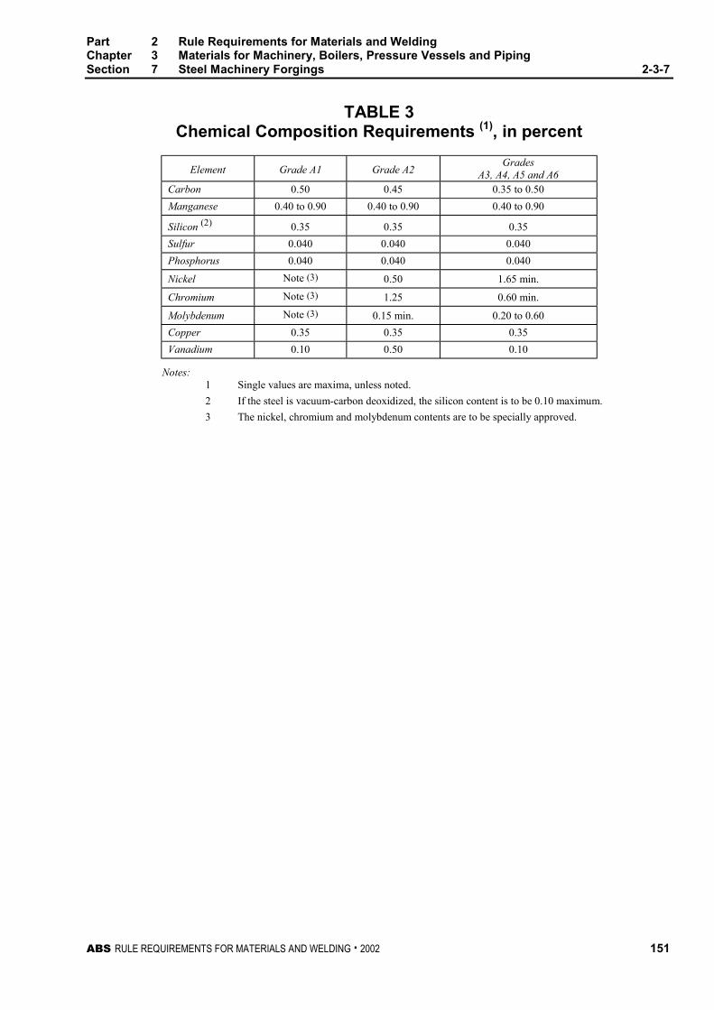
Part 2 Rule Requirements for Materials and WeldingChapter 3 Materials for Machinery, Boilers, Pressure Vessels and PipingSection 7 Steel Machinery Forgings 2-3-7
ABS RULE REQUIREMENTS FOR MATERIALS AND WELDING . 2002 151
TABLE 3Chemical Composition Requirements (1), in percent
Element Grade A1 Grade A2Grades
A3, A4, A5 and A6Carbon 0.50 0.45 0.35 to 0.50
Manganese 0.40 to 0.90 0.40 to 0.90 0.40 to 0.90
Silicon (2) 0.35 0.35 0.35
Sulfur 0.040 0.040 0.040
Phosphorus 0.040 0.040 0.040
Nickel Note (3) 0.50 1.65 min.
Chromium Note (3) 1.25 0.60 min.
Molybdenum Note (3) 0.15 min. 0.20 to 0.60
Copper 0.35 0.35 0.35
Vanadium 0.10 0.50 0.10
Notes:1 Single values are maxima, unless noted.
2 If the steel is vacuum-carbon deoxidized, the silicon content is to be 0.10 maximum.
3 The nickel, chromium and molybdenum contents are to be specially approved.
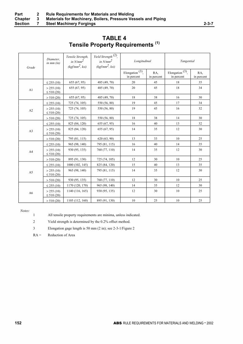
Part 2 Rule Requirements for Materials and WeldingChapter 3 Materials for Machinery, Boilers, Pressure Vessels and PipingSection 7 Steel Machinery Forgings 2-3-7
152 ABS RULE REQUIREMENTS FOR MATERIALS AND WELDING . 2002
TABLE 4Tensile Property Requirements (1)
Diameter,in mm (in)
Tensile Strength,
in N/mm2
(kgf/mm2, ksi)
Yield Strength (2),
in N/mm2
(kgf/mm2, ksi)
Longitudinal Tangential
Grade
Elongation (3),in percent
RA,in percent
Elongation (3),in percent
RA,in percent
≤ 255 (10) 655 (67, 95) 485 (49, 70) 20 45 18 35
> 255 (10)≤ 510 (20)
655 (67, 95) 485 (49, 70) 20 45 18 34A1
> 510 (20) 655 (67, 95) 485 (49, 70) 18 38 16 30
≤ 255 (10) 725 (74, 105) 550 (56, 80) 19 45 17 34
> 255 (10)≤ 510 (20)
725 (74, 105) 550 (56, 80) 19 45 16 32A2
> 510 (20) 725 (74, 105) 550 (56, 80) 18 38 14 30
≤ 255 (10) 825 (84, 120) 655 (67, 95) 16 40 13 32
> 255 (10)≤ 510 (20)
825 (84, 120) 655 (67, 95) 14 35 12 30A3
> 510 (20) 795 (81, 115) 620 (63, 90) 13 33 10 25
≤ 255 (10) 965 (98, 140) 795 (81, 115) 16 40 14 35
> 255 (10)≤ 510 (20)
930 (95, 135) 760 (77, 110) 14 35 12 30A4
> 510 (20) 895 (91, 130) 725 (74, 105) 12 30 10 25
≤ 255 (10) 1000 (102, 145) 825 (84, 120) 15 40 13 35
> 255 (10)≤ 510 (20)
965 (98, 140) 795 (81, 115) 14 35 12 30A5
> 510 (20) 930 (95, 135) 760 (77, 110) 12 30 10 25
≤ 255 (10) 1170 (120, 170) 965 (98, 140) 14 35 12 30
> 255 (10)≤ 510 (20)
1140 (116, 165) 930 (95, 135) 12 30 10 25A6
> 510 (20) 1105 (112, 160) 895 (91, 130) 10 25 10 25
Notes:1 All tensile property requirements are minima, unless indicated.
2 Yield strength is determined by the 0.2% offset method.
3 Elongation gage length is 50 mm (2 in); see 2-3-1/Figure 2
RA = Reduction of Area

Part 2 Rule Requirements for Materials and WeldingChapter 3 Materials for Machinery, Boilers, Pressure Vessels and PipingSection 7 Steel Machinery Forgings 2-3-7
ABS RULE REQUIREMENTS FOR MATERIALS AND WELDING . 2002 153
TABLE 5Chemical Composition Requirements (1), in percent
Element Grade A7 Grade A8 Grades A9 and A10
Carbon 0.25 0.28 0.28
Manganese 0.20 to 0.60 0.20 to 0.60 0.20 to 0.60
Silicon 0.15 to 0.30 (2) 0.15 to 0.30 (2) 0.10 (3)
Sulfur 0.015 0.015 0.015
Phosphorus 0.012 0.012 0.012
Nickel 2.50 min. 2.50 min. 3.25 to 4.00
Chromium 0.75 0.75 1.25 to 2.00
Molybdenum 0.25 min. 0.25 min. 0.25 to 0.60
Vanadium 0.03 min. 0.03 min. 0.05 to 0.15
Antimony Note (4) Note (4) Note (4)
Notes:1 Single values are maxima, unless noted.
2 If the steel is vacuum-carbon deoxidized, the silicon content is to be 0.10 maximum.
3 If the steel is vacuum arc remelted, the silicon content range may be 0.15% to 0.30%.
4 The antimony content is to be reported for information.
TABLE 6Tensile Property Requirements (1)
Longitudinal Radial
Grade
Tensile Strength,
in N/mm2
(kgf/mm2, ksi)
Yield Strength (2),
in N/mm2
(kgf/mm2, ksi)
Yield Strength (3),
in N/mm2
(kgf/mm2, ksi)Elongation (4),
in percent
RA,
in percent
Elongation (4),
in percent
RA,
in percent
A7 550 (56, 80) 415 (42, 60) 380 (39, 55) 22 50 20 50
A8 725 (74, 105) 620 (63, 90) 585 (60, 85) 17 45 16 40
A9725 (74, 105) to
860 (88, 125)620 (63, 90) 585 (60, 85) 18 52 17 50
A10825 (84, 120) to
930 (95, 135)690 (70, 100) 655 (67, 95) 18 52 17 50
Notes:1 All tensile property requirements are minima, unless indicated.
2 Yield strength is determined by the 0.2% offset method.
3 Yield strength is determined by the 0.2% offset method.
4 Elongation gage length is 50 mm (2 in); see 2-3-1/Figure 2.
RA = Reduction of Area
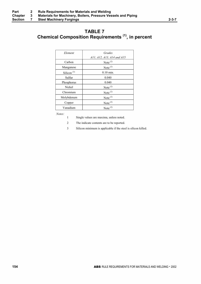
Part 2 Rule Requirements for Materials and WeldingChapter 3 Materials for Machinery, Boilers, Pressure Vessels and PipingSection 7 Steel Machinery Forgings 2-3-7
154 ABS RULE REQUIREMENTS FOR MATERIALS AND WELDING . 2002
TABLE 7Chemical Composition Requirements (1), in percent
Element Grades
A11, A12, A13, A14 and A15
Carbon Note (2)
Manganese Note (2)
Silicon (3) 0.10 min.
Sulfur 0.040
Phosphorus 0.040
Nickel Note (2)
Chromium Note (2)
Molybdenum Note (2)
Copper Note (2)
Vanadium Note (2)
Notes:1 Single values are maxima, unless noted.
2 The indicate contents are to be reported.
3 Silicon minimum is applicable if the steel is silicon killed.

Part 2 Rule Requirements for Materials and WeldingChapter 3 Materials for Machinery, Boilers, Pressure Vessels and PipingSection 7 Steel Machinery Forgings 2-3-7
ABS RULE REQUIREMENTS FOR MATERIALS AND WELDING . 2002 155
TABLE 8Tensile Property Requirements (1)
Longitudinal Tangential
GradeSize,
in mm (in)
Tensile Strength,
in N/mm2
(kgf/mm2, ksi)
Yield Strength (2),
in N/mm2
(kgf/mm2, ksi)Elongation (3),
in percent
RA,
in percent
Elongation (3),
in percent
RA,
in percent
≤ 180 (7) 655 (67, 95) 485 (49, 70) 20 50 18 40
> 180 (7)
≤ 255 (10)620 (63, 90) 450 (46, 65) 20 50 18 40
A11
> 255 (10)
≤ 510 (20)620 (63, 90) 450 (46, 65) 18 48 16 40
≤ 180 (7) 725 (74, 105) 550 (56, 80) 20 50 18 40
> 180 (7)
≤ 255 (10)690 (70, 100) 515 (53, 75) 19 50 17 40
A12
> 255 (10)
≤ 510 (20)690 (70, 100) 515 (53, 75) 18 48 16 40
≤ 100 (4) 860 (88, 125) 725 (74, 105) 16 50 14 40
> 100 (4)
≤ 180 (7)795 (81, 115) 655 (67, 95) 16 45 14 35
> 180 (7)
≤ 255 (10)760 (77, 110) 585 (60, 85) 16 45 14 35
A13
> 255 (10)
≤ 510 (20)760 (77, 110) 585 (60, 85) 14 40 12 30
≤ 100 (4) 1000 (102, 145) 825 (84, 120) 15 45 13 35
> 100 (4)
≤ 180 (7)965 (98, 140) 795 (81, 115) 14 40 12 30
> 180 (7)
≤ 255 (10)930 (95, 135) 760 (77, 110) 13 40 12 30
A14
> 255 (10)
≤ 510 (20)930 (95, 135) 760 (77, 110) 12 38 11 30
≤ 100 (4) 1170 (120, 170) 965 (98, 140) 13 40 11 30
> 100 (4)
≤ 180 (7)1140 (116, 165) 930 (95, 135) 12 35 11 30
> 180 (7)
≤ 255 (10)1105 (112, 160) 895 (91, 130) 11 35 10 28
A15
> 255 (10)
≤ 510 (20)1105 (112, 160) 895 (91, 130) 11 35 10 28
Notes:1 All tensile property requirements are minima, unless indicated.
2 Yield strength is determined by the 0.2% offset method.
3 Elongation gage length is 50 mm (2 in); see 2-3-1/Figure 2
RA = Reduction of Area


ABS RULE REQUIREMENTS FOR MATERIALS AND WELDING . 2002 157
P A R T
2C H A P T E R 3 Materials for Machinery, Boilers,
Pressure Vessels, and Piping
S E C T I O N 8 Hot-rolled Steel Bars forMachinery 2 - 3 - 8
1 Hot-rolled Steel Bars 2-3-8/1
Hot-rolled steel bars up to and including 305 mm (12 in.) diameter, presented for inspection afterspecial approval for each specific application, are to be made by one or more of the followingprocesses: open-hearth, basic-oxygen, electric-furnace or such other process as may be approved. Hot-rolled bars used in lieu of carbon-steel forgings (see Section 2-3-7) are to be fully killed, heat treatedin accordance with 2-3-7/1.5, and the cross-sectional area of the unmachined finished bar is not toexceed one-sixth of the cross-sectional area of the ingot. In addition, hot-rolled bars used in lieu offorgings for tail shafts are to meet the nondestructive examination requirements of 2-3-7/1.13.1. Thetensile properties are to meet the requirements of 2-3-7/1.7 for the proposed application.
3 Number of Tests 2-3-8/3
Four tension tests are to be taken from each lot of material exceeding 907 kg (2000 lb) in weight.When the weight of a lot is 907 kg (2000 lb) or less, two tension tests may be taken. In any case onlyone tension test will be required from any one bar. A lot is to consist of bars from the same heat; if thebars are heat-treated, then a lot is to consist of bars from the same heat which have been heat-treatedin the same furnace charge. If the bars in a lot differ 9.5 mm (0.375 in.) or more in diameter, the testspecimens taken are to be representative of the greatest and least diameter bar.


ABS RULE REQUIREMENTS FOR MATERIALS AND WELDING . 2002 159
P A R T
2C H A P T E R 3 Materials for Machinery, Boilers,
Pressure Vessels, and Piping
S E C T I O N 9 Steel Castings for Machinery,Boilers and Pressure Vessels 2 - 3 - 9
1 General 2-3-9/1
1.1 Process of Manufacture 2-3-9/1.1
The following requirements cover carbon-steel castings intended to be used in machinery, boiler andpressure-vessel construction. This does not preclude the use of alloy steels in accordance with thepermissibility expressed in 2-3-1/1. The steel is to be made by one or more of the following processes:open-hearth, basic-oxygen, electric-furnace, or such other process as may be approved by theCommittee.
1.3 ASTM Designations 2-3-9/1.3
The various Grades are in substantial agreement with ASTM as follows:
ABS Grade ASTM Designation
1 A27, Grade 60–30
2 A27, Grade 70–36
3 A216, Grade WCA
4 A216, Grade WCB
3 Marking and Retests 2-3-9/3
3.1 Marking 2-3-9/3.1
The manufacturer’s name or identification mark and pattern number is to be cast on all castings exceptthose of such small size as to make this type of marking impracticable. The Bureau markings,indicating satisfactory compliance with the Rule requirements, and as furnished by the Surveyor is tobe stamped on all castings accepted in such location as to be discernible after machining andinstallation; Grade 1, 2, 3 and 4 castings are to be stamped AB/1, AB/2, AB/3 and AB/4, respectively.In addition identification numbers of the heats used for pouring the castings are to be stamped on allcastings individually weighing 227 kg (500 lb) or more.
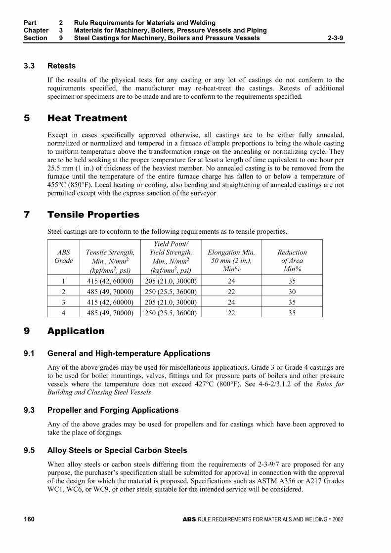
Part 2 Rule Requirements for Materials and WeldingChapter 3 Materials for Machinery, Boilers, Pressure Vessels and PipingSection 9 Steel Castings for Machinery, Boilers and Pressure Vessels 2-3-9
160 ABS RULE REQUIREMENTS FOR MATERIALS AND WELDING . 2002
3.3 Retests 2-3-9/3.3
If the results of the physical tests for any casting or any lot of castings do not conform to therequirements specified, the manufacturer may re-heat-treat the castings. Retests of additionalspecimen or specimens are to be made and are to conform to the requirements specified.
5 Heat Treatment 2-3-9/5
Except in cases specifically approved otherwise, all castings are to be either fully annealed,normalized or normalized and tempered in a furnace of ample proportions to bring the whole castingto uniform temperature above the transformation range on the annealing or normalizing cycle. Theyare to be held soaking at the proper temperature for at least a length of time equivalent to one hour per25.5 mm (1 in.) of thickness of the heaviest member. No annealed casting is to be removed from thefurnace until the temperature of the entire furnace charge has fallen to or below a temperature of455°C (850°F). Local heating or cooling, also bending and straightening of annealed castings are notpermitted except with the express sanction of the surveyor.
7 Tensile Properties 2-3-9/7
Steel castings are to conform to the following requirements as to tensile properties.
ABSGrade
Tensile Strength,Min., N/mm2
(kgf/mm2, psi)
Yield Point/Yield Strength,Min., N/mm2
(kgf/mm2, psi)
Elongation Min.50 mm (2 in.),
Min%
Reductionof AreaMin%
1 415 (42, 60000) 205 (21.0, 30000) 24 35
2 485 (49, 70000) 250 (25.5, 36000) 22 30
3 415 (42, 60000) 205 (21.0, 30000) 24 35
4 485 (49, 70000) 250 (25.5, 36000) 22 35
9 Application 2-3-9/9
9.1 General and High-temperature Applications 2-3-9/9.1
Any of the above grades may be used for miscellaneous applications. Grade 3 or Grade 4 castings areto be used for boiler mountings, valves, fittings and for pressure parts of boilers and other pressurevessels where the temperature does not exceed 427°C (800°F). See 4-6-2/3.1.2 of the Rules forBuilding and Classing Steel Vessels.
9.3 Propeller and Forging Applications 2-3-9/9.3
Any of the above grades may be used for propellers and for castings which have been approved totake the place of forgings.
9.5 Alloy Steels or Special Carbon Steels 2-3-9/9.5
When alloy steels or carbon steels differing from the requirements of 2-3-9/7 are proposed for anypurpose, the purchaser’s specification shall be submitted for approval in connection with the approvalof the design for which the material is proposed. Specifications such as ASTM A356 or A217 GradesWC1, WC6, or WC9, or other steels suitable for the intended service will be considered.
Part 2 Rule Requirements for Materials and WeldingChapter 3 Materials for Machinery, Boilers, Pressure Vessels and PipingSection 9 Steel Castings for Machinery, Boilers and Pressure Vessels 2-3-9
ABS RULE REQUIREMENTS FOR MATERIALS AND WELDING . 2002 161
11 Test Specimens 2-3-9/11
11.1 Preparation and Identification of Test Coupons (1998) 2-3-9/11.1
The physical properties are to be determined from test specimens prepared from coupons which,except as specified in 2-3-9/11.3, are to be cast integral with the casting to be inspected. When this isimpracticable, the coupons may be cast with and gated to the casting. In either case these coupons arenot to be detached until the heat treatment of the castings has been completed, nor until the couponshave been stamped by the Surveyor for identification. Where the material identification system of themanufacture is found acceptable to the Bureau and is maintained in that condition through initial andperiodical verification by the Bureau, it may be considered in lieu of stamping by the Surveyor beforedetachment.
11.3 Small Castings 2-3-9/11.3
In the case of small castings having an estimated weight of less than 907 kg (2000 lb), each of thecoupons may be cast separately, provided the Surveyor is furnished an affidavit by the manufacturerstating that the separately cast coupons were cast from the same heat as the castings represented andthat they were heat-treated with the castings.
13 Number of Tests 2-3-9/13
13.1 Machinery Castings 2-3-9/13.1
At least one tension test is to be made from each heat in each heat-treatment charge. However, if themanufacturer’s quality-control procedure includes satisfactory automatic chart recording oftemperature and time, then one tension test from each heat for castings subject to the same heat-treating procedure may be allowed at the discretion of the attending Surveyor.
13.3 Steel Propeller Castings 2-3-9/13.3
One tension test is to be made from each blade of a built-up propeller, and for solid propellers there isto be one tension test from each of two opposite blades when the propeller is over 2130 mm (7 ft) indiameter and one tension test from one of the blades when the diameter of the propeller is 2130 mm(7 ft) or smaller.
15 Inspection and Repair 2-3-9/15
15.1 General 2-3-9/15.1
All castings are to be inspected by the Surveyor after final heat treatment and thorough cleaning toinsure that the castings are free from defects.
15.3 Minor Defects 2-3-9/15.3
Defects are to be considered minor when the cavity prepared for welding has a depth not greater than20% of the actual wall thickness, but in no case greater than 25 mm (1 in.) and has no linealdimension greater than 4 times the wall thickness nor greater than 150 mm (6 in.). Repairs of minordefects where welding is required are to be in accordance with an approved procedure.
15.5 Major Defects 2-3-9/15.5
Defects other than minor defects with dimensions greater than those given in 2-3-9/15.3 above, may,with the Surveyor’s approval, be repaired by welding using an approved procedure.
Part 2 Rule Requirements for Materials and WeldingChapter 3 Materials for Machinery, Boilers, Pressure Vessels and PipingSection 9 Steel Castings for Machinery, Boilers and Pressure Vessels 2-3-9
162 ABS RULE REQUIREMENTS FOR MATERIALS AND WELDING . 2002
15.7 Welded Repair 2-3-9/15.7
The defects are to be removed to sound metal, and before welding the excavation is to be investigatedby suitable approved non-destructive examination methods to ensure that the defect has beenremoved. In the case of repair of major defects, welding is not permitted on unheat-treated castings.Corrective welding is to be associated with the use of preheat.
15.9 Postweld-repair Heat Treatment 2-3-9/15.9
All welded repairs of major defects are to be given a suitable postweld heat treatment.
15.11 Crankshaft Castings 2-3-9/15.11
The foregoing provisions may not apply in their entirety to the repair of crankshaft castings. In thecase of repair of crankshaft castings, the applicable procedures and extent of repairs will be speciallyconsidered.
17 Castings for Ice-strengthened Propellers 2-3-9/17
Castings for ice-strengthened propellers are to comply with 2-3-14/5.

ABS RULE REQUIREMENTS FOR MATERIALS AND WELDING . 2002 163
P A R T
2C H A P T E R 3 Materials for Machinery, Boilers,
Pressure Vessels, and Piping
S E C T I O N 10 Ductile (Nodular) Iron Castings 2 - 3 -
1 0
Notes Grade 60-40-18 is in substantial agreement with ASTM A395.
Grade 65-45-12 is in substantial agreement with ASTM A536 Grade 65-45-12.
1 Manufacture and Test 2-3-10/1
1.1 General 2-3-10/1.1
These requirements cover ductile (nodular) iron castings. The melting method and metal treatment isto be optional with the foundry. All castings are to be inspected by the Surveyor after final heattreatment (as applicable) and thorough cleaning, and they are to be free from defects. The Bureaumarkings, indicating satisfactory compliance with the Rule requirements, and as furnished by theSurveyor, are to be stamped on all castings accepted at such location as to be discernible aftermachining.
1.3 Tension Test Requirements 2-3-10/1.3
The metal represented by the appropriate test specimen is to conform to the following minimumtensile requirements.
Grade 60-40-18 Grade 65-45-12
Tensile strength, min., N/mm2 (kgf/mm2, psi) 415 (42, 60000) 450 (46, 65000)
Yield strength, min., N/mm2 (kgf/mm2, psi) 275 (28, 40000) 310 (31.5, 45000)
Elongation in 50 mm, (2 in.), min., % 18 12
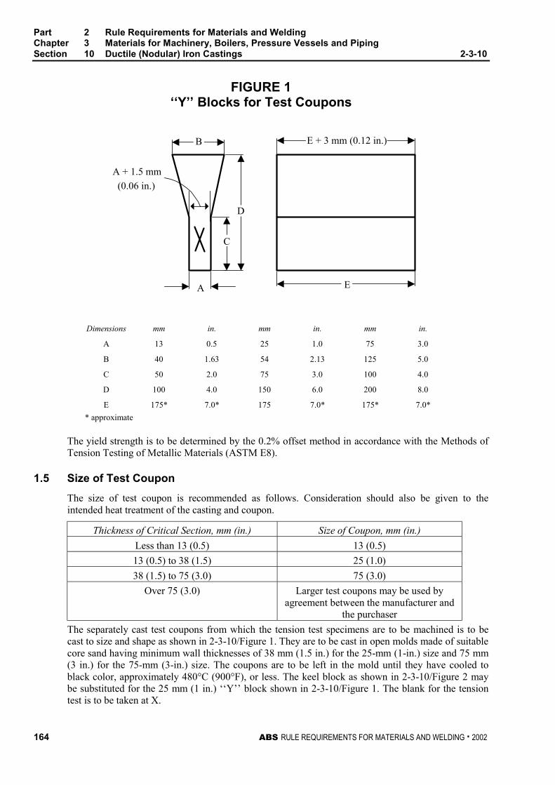
Part 2 Rule Requirements for Materials and WeldingChapter 3 Materials for Machinery, Boilers, Pressure Vessels and PipingSection 10 Ductile (Nodular) Iron Castings 2-3-10
164 ABS RULE REQUIREMENTS FOR MATERIALS AND WELDING . 2002
FIGURE 1‘‘Y’’ Blocks for Test Coupons
A + 1.5 mm
(0.06 in.)
E + 3 mm (0.12 in.)
A
C
D
B
E
Dimensions mm in. mm in. mm in.
A 13 0.5 25 1.0 75 3.0
B 40 1.63 54 2.13 125 5.0
C 50 2.0 75 3.0 100 4.0
D 100 4.0 150 6.0 200 8.0
E 175* 7.0* 175 7.0* 175* 7.0*
* approximate
The yield strength is to be determined by the 0.2% offset method in accordance with the Methods ofTension Testing of Metallic Materials (ASTM E8).
1.5 Size of Test Coupon 2-3-10/1.5
The size of test coupon is recommended as follows. Consideration should also be given to theintended heat treatment of the casting and coupon.
Thickness of Critical Section, mm (in.) Size of Coupon, mm (in.)
Less than 13 (0.5) 13 (0.5)
13 (0.5) to 38 (1.5) 25 (1.0)
38 (1.5) to 75 (3.0) 75 (3.0)
Over 75 (3.0) Larger test coupons may be used byagreement between the manufacturer and
the purchaser
The separately cast test coupons from which the tension test specimens are to be machined is to becast to size and shape as shown in 2-3-10/Figure 1. They are to be cast in open molds made of suitablecore sand having minimum wall thicknesses of 38 mm (1.5 in.) for the 25-mm (1-in.) size and 75 mm(3 in.) for the 75-mm (3-in.) size. The coupons are to be left in the mold until they have cooled toblack color, approximately 480°C (900°F), or less. The keel block as shown in 2-3-10/Figure 2 maybe substituted for the 25 mm (1 in.) ‘‘Y’’ block shown in 2-3-10/Figure 1. The blank for the tensiontest is to be taken at X.
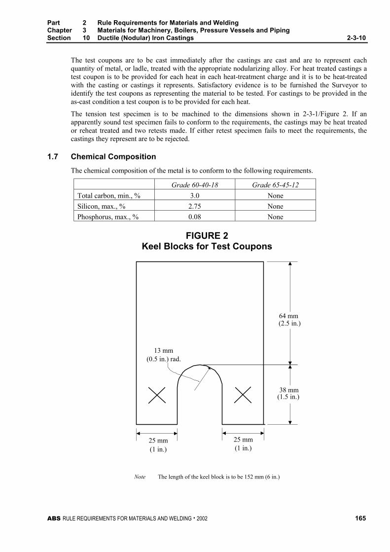
Part 2 Rule Requirements for Materials and WeldingChapter 3 Materials for Machinery, Boilers, Pressure Vessels and PipingSection 10 Ductile (Nodular) Iron Castings 2-3-10
ABS RULE REQUIREMENTS FOR MATERIALS AND WELDING . 2002 165
The test coupons are to be cast immediately after the castings are cast and are to represent eachquantity of metal, or ladle, treated with the appropriate nodularizing alloy. For heat treated castings atest coupon is to be provided for each heat in each heat-treatment charge and it is to be heat-treatedwith the casting or castings it represents. Satisfactory evidence is to be furnished the Surveyor toidentify the test coupons as representing the material to be tested. For castings to be provided in theas-cast condition a test coupon is to be provided for each heat.
The tension test specimen is to be machined to the dimensions shown in 2-3-1/Figure 2. If anapparently sound test specimen fails to conform to the requirements, the castings may be heat treatedor reheat treated and two retests made. If either retest specimen fails to meet the requirements, thecastings they represent are to be rejected.
1.7 Chemical Composition 2-3-10/1.7
The chemical composition of the metal is to conform to the following requirements.
Grade 60-40-18 Grade 65-45-12
Total carbon, min., % 3.0 None
Silicon, max., % 2.75 None
Phosphorus, max., % 0.08 None
FIGURE 2Keel Blocks for Test Coupons
25 mm(1 in.) (1 in.)
25 mm
(1.5 in.)
13 mm(0.5 in.) rad.
38 mm
64 mm(2.5 in.)
Note The length of the keel block is to be 152 mm (6 in.)
Part 2 Rule Requirements for Materials and WeldingChapter 3 Materials for Machinery, Boilers, Pressure Vessels and PipingSection 10 Ductile (Nodular) Iron Castings 2-3-10
166 ABS RULE REQUIREMENTS FOR MATERIALS AND WELDING . 2002
3 Heat Treatment 2-3-10/3
3.1 Grade 60-40-18 Castings 2-3-10/3.1
Grade 60-40-18 castings are to be given a ferritizing anneal which is to produce a substantially ferriticmatrix structure. When specially approved, castings may be stress-relieved in lieu of ferritizing.
3.3 Grade 65-45-12 Castings 2-3-10/3.3
Grade 65-45-12 castings may be furnished in the as-cast or heat treated condition.
5 Weld Repairs 2-3-10/5
Weld repairs to ductile (nodular) iron castings are subject to special approval. See 2-4-2/1.7.
ABS RULE REQUIREMENTS FOR MATERIALS AND WELDING . 2002 167
P A R T
2C H A P T E R 3 Materials for Machinery, Boilers,
Pressure Vessels, and Piping
S E C T I O N 11 Gray-iron Castings 2 - 3 - 1 1
Note In substantial agreement with ASTM A48 (Class No. 20).
1 Process of Manufacture 2-3-11/1
Iron for castings is to be made by the ‘‘Cupola’’ or other process approved by the Committee. Thematerial must be of uniform grain, free from injurious blowholes, injurious porous spots, or otherdefects. The tensile strength of the material is to be determined by a tension test (2-3-1/Figure 3 and2-3-1/11), or by a transverse or flexure test. The test bars are to be poured separately and from ladlesof iron used to pour the castings, and under the same sand conditions and they are to receive the samethermal treatment as the castings represented. The bars are to have a diameter of 50 mm (2 in.).Satisfactory evidence is to be furnished the Surveyor to identify the test bars as representing thematerial to be tested.
3 Tensile Strength 2-3-11/3
The minimum tensile strength of the machined test specimen is not to be less than 138 N/mm2
(14 kgf/mm2, 20,000 psi) and the minimum breaking strength of the test bars in the transverse offlexure test are not to be less than 26,700 N (2720 kgf, 6000 lbf) with the points of support 610 mm(24 in.) apart.
5 Higher-strength Castings 2-3-11/5
When higher-strength cast iron is proposed for any purpose, the purchaser’s specifications are to besubmitted specially for approval in connection with the approval of the design for which the materialis intended.

ABS RULE REQUIREMENTS FOR MATERIALS AND WELDING . 2002 169
P A R T
2C H A P T E R 3 Materials for Machinery, Boilers,
Pressure Vessels, and Piping
S E C T I O N 12 Steel Piping
CONTENTS1 Scope ................................................................................... 173
3 General................................................................................. 173
3.1 Grades 1, 2 and 3................................................................. 173
3.3 Grades 4 and 5..................................................................... 173
3.5 Grade 6................................................................................. 173
3.7 Grades 7, 11, 12, 13 and 14................................................. 173
3.9 Grades 8 and 9..................................................................... 174
3.11 ASTM Designations.............................................................. 174
5 Process of Manufacture ...................................................... 174
5.1 Grades 1, 2 and 3................................................................. 174
5.3 Grades 4 and 5..................................................................... 174
5.5 Grades 6 and 7..................................................................... 175
5.7 Grades 8 and 9..................................................................... 175
5.9 Grades 11, 12, 13 and 14..................................................... 175
7 Marking ................................................................................ 175
9 Chemical Composition........................................................ 176
11 Ladle Analysis ..................................................................... 176
13 Check Analysis.................................................................... 176
13.1 General................................................................................. 176
13.3 Samples................................................................................ 176
13.5 Grades 1, 2 and 3................................................................. 176
13.7 Grades 4 and 5..................................................................... 176
13.9 Grades 6, 7, 11, 12, 13 and 14............................................. 176
13.11 Grades 8 and 9..................................................................... 176
13.13 Retests for Grades 1, 2, 3, 4 and 5 ...................................... 177
13.15 Retests for Grades 6, 7, 11, 12, 13 and 14 .......................... 177
13.17 Retests for Grades 8 and 9 .................................................. 177
15 Mechanical Tests Required ................................................ 177
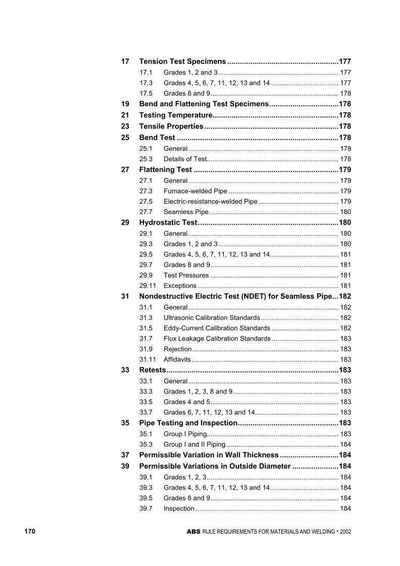
170 ABS RULE REQUIREMENTS FOR MATERIALS AND WELDING . 2002
17 Tension Test Specimens .....................................................177
17.1 Grades 1, 2 and 3................................................................. 177
17.3 Grades 4, 5, 6, 7, 11, 12, 13 and 14..................................... 177
17.5 Grades 8 and 9..................................................................... 178
19 Bend and Flattening Test Specimens.................................178
21 Testing Temperature............................................................178
23 Tensile Properties................................................................178
25 Bend Test .............................................................................178
25.1 General................................................................................. 178
25.3 Details of Test....................................................................... 178
27 Flattening Test .....................................................................179
27.1 General................................................................................. 179
27.3 Furnace-welded Pipe ........................................................... 179
27.5 Electric-resistance-welded Pipe ........................................... 179
27.7 Seamless Pipe...................................................................... 180
29 Hydrostatic Test...................................................................180
29.1 General................................................................................. 180
29.3 Grades 1, 2 and 3................................................................. 180
29.5 Grades 4, 5, 6, 7, 11, 12, 13 and 14..................................... 181
29.7 Grades 8 and 9..................................................................... 181
29.9 Test Pressures ..................................................................... 181
29.11 Exceptions ............................................................................ 181
31 Nondestructive Electric Test (NDET) for Seamless Pipe...182
31.1 General................................................................................. 182
31.3 Ultrasonic Calibration Standards.......................................... 182
31.5 Eddy-Current Calibration Standards .................................... 182
31.7 Flux Leakage Calibration Standards .................................... 183
31.9 Rejection............................................................................... 183
31.11 Affidavits ............................................................................... 183
33 Retests..................................................................................183
33.1 General................................................................................. 183
33.3 Grades 1, 2, 3, 8 and 9......................................................... 183
33.5 Grades 4 and 5..................................................................... 183
33.7 Grades 6, 7, 11, 12, 13 and 14............................................. 183
35 Pipe Testing and Inspection................................................183
35.1 Group I Piping....................................................................... 183
35.3 Group I and II Piping............................................................. 184
37 Permissible Variation in Wall Thickness ............................184
39 Permissible Variations in Outside Diameter ......................184
39.1 Grades 1, 2, 3....................................................................... 184
39.3 Grades 4, 5, 6, 7, 11, 12, 13 and 14..................................... 184
39.5 Grades 8 and 9..................................................................... 184
39.7 Inspection ............................................................................. 184
ABS RULE REQUIREMENTS FOR MATERIALS AND WELDING . 2002 171
TABLE 1 Maxima or Permissible Range of ChemicalComposition in Percent for Pipe............................. 185
TABLE 2 Lot Sizes for Pipe Grades 6, 7, 11, 12, 13 and 14... 185
TABLE 3 Mechanical Tests for Pipe....................................... 186
TABLE 4 Tensile Requirements for Pipe................................ 188
TABLE 5 Hydrostatic-test Pressure for Welded andSeamless Plain-end Steel Pipe ............................... 190
TABLE 6 Out-of-roundness Variation .................................... 192


ABS RULE REQUIREMENTS FOR MATERIALS AND WELDING . 2002 173
P A R T
2C H A P T E R 3 Materials for Machinery, Boilers,
Pressure Vessels, and Piping
S E C T I O N 12 Steel Piping 2 - 3 - 1 2
1 Scope (1998) 2-3-12/1
The following specifications cover thirteen grades of steel pipe designated 1, 2, 3, 4, 5, 6, 7, 8, 9, 11,12, 13 and 14.
3 General 2-3-12/3
3.1 Grades 1, 2 and 3 2-3-12/3.1
Grades 1, 2 and 3 cover seamless and welded steel pipe. Pipe ordered under these grades is nominal(average) wall thickness suitable for welding and suitable for forming operations involving coiling,bending and flanging, subject to the following limitations: Grade 1 furnace-butt-welded pipe is notintended for flanging: when seamless or electric-resistance-welded pipe is required for close-coilingor cold-bending, Grade 2 should be specified; this provision is not intended to prohibit the cold-bending of Grade 3 pipe. When pipe is required for close-coiling, this is to be specified on the order.Electric-resistance-welded Grades 2 and 3 may be furnished either non-expanded or cold-expanded atthe option of the manufacturer. When pipe is cold expanded, the amount of expansion is not to exceed1.5% of the outside diameter pipe size.
3.3 Grades 4 and 5 2-3-12/3.3
Grades 4 and 5 cover seamless carbon-steel pipe for high-temperature service. Pipe ordered to thesegrades is nominal (average) wall thickness and is to be suitable for bending, flanging and similarforming operations. Grade 4 rather than Grade 5 pipe should be used for close-coiling, cold-bendingor forge-welding; this provision is not intended to prohibit the cold-bending of Grade 5 pipe.
3.5 Grade 6 2-3-12/3.5
Grade 6 covers seamless carbon-molybdenum alloy-steel pipe for high-temperature service. Pipeordered to this grade is nominal (average) wall thickness and is to be suitable for bending, flanging(vanstoning) and similar forming operations, and for fusion-welding.
3.7 Grades 7, 11, 12, 13 and 14 (1998) 2-3-12/3.7
Grades 7, 11, 12, 13 and 14 cover seamless chromium-molybdenum alloy-steel pipe for high-temperature service. Pipe ordered to these grades is nominal (average) wall thickness and is to be suitable for bending, flanging (vanstoning) and similar forming operations, and for fusion-welding.
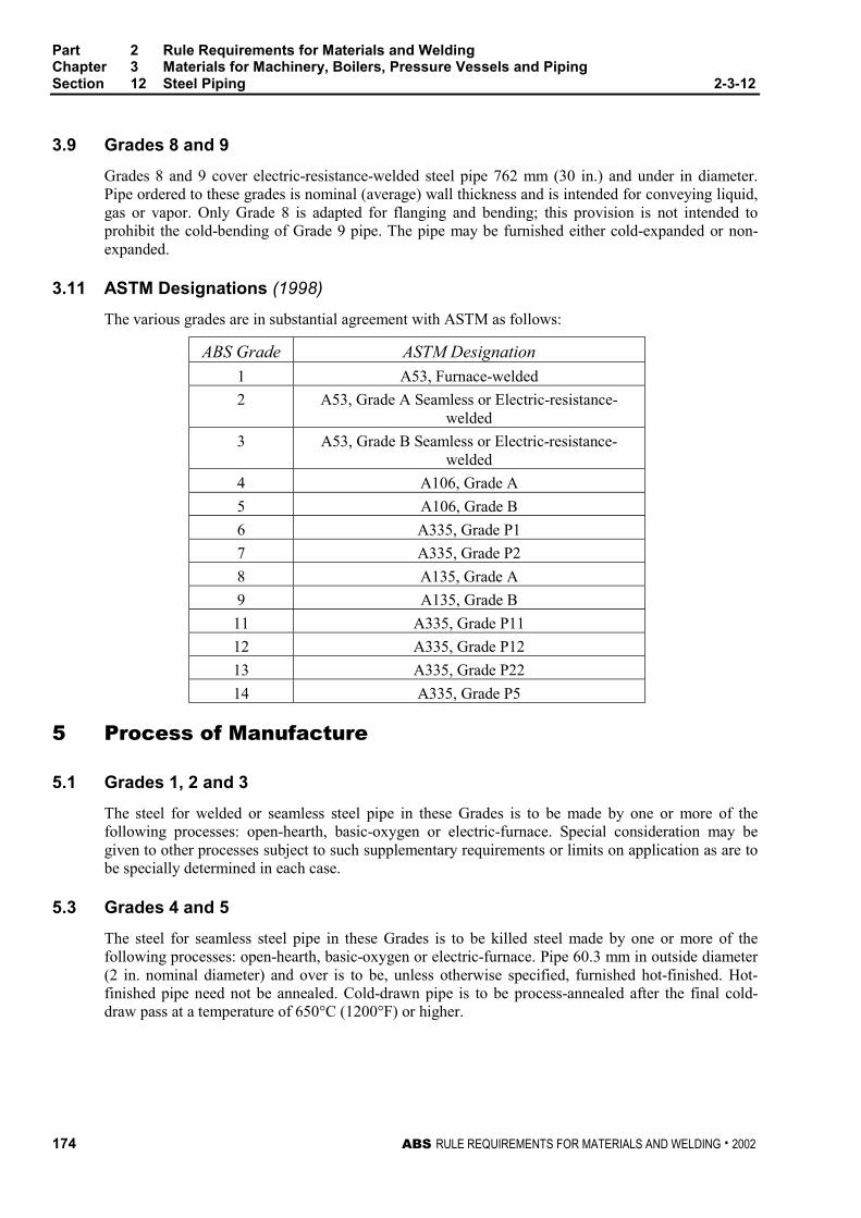
Part 2 Rule Requirements for Materials and WeldingChapter 3 Materials for Machinery, Boilers, Pressure Vessels and PipingSection 12 Steel Piping 2-3-12
174 ABS RULE REQUIREMENTS FOR MATERIALS AND WELDING . 2002
3.9 Grades 8 and 9 2-3-12/3.9
Grades 8 and 9 cover electric-resistance-welded steel pipe 762 mm (30 in.) and under in diameter.Pipe ordered to these grades is nominal (average) wall thickness and is intended for conveying liquid,gas or vapor. Only Grade 8 is adapted for flanging and bending; this provision is not intended toprohibit the cold-bending of Grade 9 pipe. The pipe may be furnished either cold-expanded or non-expanded.
3.11 ASTM Designations (1998) 2-3-12/3.11
The various grades are in substantial agreement with ASTM as follows:
ABS Grade ASTM Designation
1 A53, Furnace-welded
2 A53, Grade A Seamless or Electric-resistance-welded
3 A53, Grade B Seamless or Electric-resistance-welded
4 A106, Grade A
5 A106, Grade B
6 A335, Grade P1
7 A335, Grade P2
8 A135, Grade A
9 A135, Grade B
11 A335, Grade P11
12 A335, Grade P12
13 A335, Grade P22
14 A335, Grade P5
5 Process of Manufacture 2-3-12/5
5.1 Grades 1, 2 and 3 2-3-12/5.1
The steel for welded or seamless steel pipe in these Grades is to be made by one or more of thefollowing processes: open-hearth, basic-oxygen or electric-furnace. Special consideration may begiven to other processes subject to such supplementary requirements or limits on application as are tobe specially determined in each case.
5.3 Grades 4 and 5 2-3-12/5.3
The steel for seamless steel pipe in these Grades is to be killed steel made by one or more of thefollowing processes: open-hearth, basic-oxygen or electric-furnace. Pipe 60.3 mm in outside diameter(2 in. nominal diameter) and over is to be, unless otherwise specified, furnished hot-finished. Hot-finished pipe need not be annealed. Cold-drawn pipe is to be process-annealed after the final cold-draw pass at a temperature of 650°C (1200°F) or higher.

Part 2 Rule Requirements for Materials and WeldingChapter 3 Materials for Machinery, Boilers, Pressure Vessels and PipingSection 12 Steel Piping 2-3-12
ABS RULE REQUIREMENTS FOR MATERIALS AND WELDING . 2002 175
5.5 Grades 6 and 7 2-3-12/5.5
The steel for seamless steel pipe in these Grades is to be made by either or both the open-hearth orelectric-furnace process or other approved process. A sufficient discard is to be made from each ingotto secure freedom from injurious piping and undue segregation. Pipe 60.3 mm in outside diameter(2 in. nominal size) and over is to be, unless otherwise specified, furnished hot-finished and pipeunder 60.3 mm O.D. (2 in. diameter) may be furnished either hot-finished or cold-drawn. The hot-rolled or cold-drawn pipe Grades 6 and 7 as a final heat treatment, are to be stress-relief-annealed at650°C (1200°F) to 705°C (1300°F). The steel from which Grade 7 pipe is made is to be a coarse-grained steel having a carburized austenitic grain size of 1 to 5 as determined in accordance with theMethods for Estimating the Average Grain Size of Metals (ASTM E112) and its Plate IV, bycarburizing at 925°C (1700°F) for 8 hours. The specimen is to be taken from the bloom or billet.
5.7 Grades 8 and 9 2-3-12/5.7
The steel for electric-resistance-welded steel pipe in these Grades is to be made by one or more of thefollowing processes: open-hearth, basic-oxygen or electric-furnace.
5.9 Grades 11, 12, 13 and 14 (1998) 2-3-12/5.9
The steel for seamless alloy steel pipe is to be made by the electric-furnace process or other approvedprocess, except that Grade 12 may be made by the open-hearth process. A sufficient discard is to bemade from each ingot to secure freedom from injurious piping and undue segregation. Pipe 60.3 mmin outside diameter (2 in. nominal diameter) and over is to be, unless otherwise specified, furnishedhot-finished and pipe under 60.3 mm O.D. (2 in. nominal diameter) may be furnished either hot-finished or cold-drawn. The steel for Grade 12 pipe is to be made by coarse-grain melting practice.Grades 11, 13 and 14 pipe are to be reheated and furnished in the full-annealed, isothermal annealedor normalized and tempered condition; if furnished in the normalized and tempered condition, or ifcold drawn pipe is furnished, the temperature for tempering following normalizing or cold drawing isto be 677°C (1250°F) or higher for Grades 13 and 14, and 650°C (1200°F) or higher for Grade 11.The hot-rolled or cold-drawn Grade 12 pipe, as a final heat treatment, is to be given a stress-relievingtreatment at 650°C (1200°F) to 705°C (1300°F).
7 Marking (1998) 2-3-12/7
Identification markings are to be legibly stenciled, stamped, or rolled on each length of pipe, exceptthat in the case of small-diameter pipe which is bundled, the required markings are to be placed on atag securely attached to the bundle. The markings are to be arranged and are to include the followinginformation:
Name or brand of the manufacturer
ABS Grade or ASTM Designation and Type or Grade Heat number or manufacturer’s number bywhich the heat can be identified (For Grades 6, 7, 11, 12, 13and 14 pipe only)
Test pressure or the letters NDE
Method of forming (i.e. butt-welded, lap-welded, electric-resistance-welded or seamless hot-finishedor cold-drawn)
‘‘XS’’ for extra strong or ‘‘XXS’’ for double-extra strong (when applicable for Grades 1, 2 and 3 pipeonly)
ABS markings by the Surveyor
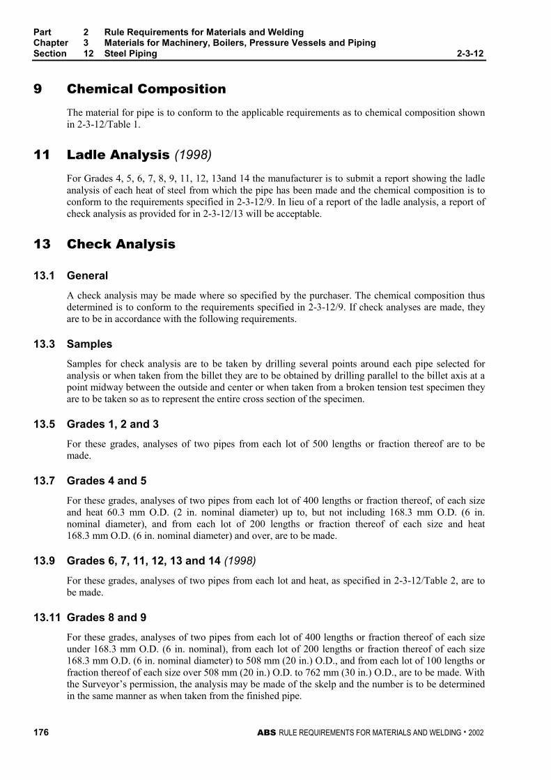
Part 2 Rule Requirements for Materials and WeldingChapter 3 Materials for Machinery, Boilers, Pressure Vessels and PipingSection 12 Steel Piping 2-3-12
176 ABS RULE REQUIREMENTS FOR MATERIALS AND WELDING . 2002
9 Chemical Composition 2-3-12/9
The material for pipe is to conform to the applicable requirements as to chemical composition shownin 2-3-12/Table 1.
11 Ladle Analysis (1998) 2-3-12/11
For Grades 4, 5, 6, 7, 8, 9, 11, 12, 13and 14 the manufacturer is to submit a report showing the ladleanalysis of each heat of steel from which the pipe has been made and the chemical composition is toconform to the requirements specified in 2-3-12/9. In lieu of a report of the ladle analysis, a report ofcheck analysis as provided for in 2-3-12/13 will be acceptable.
13 Check Analysis 2-3-12/13
13.1 General 2-3-12/13.1
A check analysis may be made where so specified by the purchaser. The chemical composition thusdetermined is to conform to the requirements specified in 2-3-12/9. If check analyses are made, theyare to be in accordance with the following requirements.
13.3 Samples 2-3-12/13.3
Samples for check analysis are to be taken by drilling several points around each pipe selected foranalysis or when taken from the billet they are to be obtained by drilling parallel to the billet axis at apoint midway between the outside and center or when taken from a broken tension test specimen theyare to be taken so as to represent the entire cross section of the specimen.
13.5 Grades 1, 2 and 3 2-3-12/13.5
For these grades, analyses of two pipes from each lot of 500 lengths or fraction thereof are to bemade.
13.7 Grades 4 and 5 2-3-12/13.7
For these grades, analyses of two pipes from each lot of 400 lengths or fraction thereof, of each sizeand heat 60.3 mm O.D. (2 in. nominal diameter) up to, but not including 168.3 mm O.D. (6 in.nominal diameter), and from each lot of 200 lengths or fraction thereof of each size and heat168.3 mm O.D. (6 in. nominal diameter) and over, are to be made.
13.9 Grades 6, 7, 11, 12, 13 and 14 (1998) 2-3-12/13.9
For these grades, analyses of two pipes from each lot and heat, as specified in 2-3-12/Table 2, are tobe made.
13.11 Grades 8 and 9 2-3-12/13.11
For these grades, analyses of two pipes from each lot of 400 lengths or fraction thereof of each sizeunder 168.3 mm O.D. (6 in. nominal), from each lot of 200 lengths or fraction thereof of each size168.3 mm O.D. (6 in. nominal diameter) to 508 mm (20 in.) O.D., and from each lot of 100 lengths orfraction thereof of each size over 508 mm (20 in.) O.D. to 762 mm (30 in.) O.D., are to be made. Withthe Surveyor’s permission, the analysis may be made of the skelp and the number is to be determinedin the same manner as when taken from the finished pipe.
Part 2 Rule Requirements for Materials and WeldingChapter 3 Materials for Machinery, Boilers, Pressure Vessels and PipingSection 12 Steel Piping 2-3-12
ABS RULE REQUIREMENTS FOR MATERIALS AND WELDING . 2002 177
13.13 Retests for Grades 1, 2, 3, 4 and 5 2-3-12/13.13
If an analysis for these grades does not conform to the requirements specified, analyses are to be madeon additional pipes of double the original number from the same lot, each of which is to conform tothe requirements specified.
13.15 Retests for Grades 6, 7, 11, 12, 13 and 14 (1998) 2-3-12/13.15
If a check or ladle analysis for these grades does not conform to the requirements specified, ananalysis of each billet or pipe from the same heat or lot may be made, and all billets or pipeconforming to the requirements are to be accepted.
13.17 Retests for Grades 8 and 9 2-3-12/13.17
For these grades, if the analysis of either length of pipe or length of skelp does not conform to therequirements, analyses of two additional lengths from the same lot are to be made, each of which is toconform to the requirements specified.
15 Mechanical Tests Required (1998) 2-3-12/15
The type and number of mechanical tests are to be in accordance with 2-3-12/Table 3. For adescription and the requirements of each test see 2-3-12/17 through and including 2-3-12/29. Forretests see 2-3-12/33.
17 Tension Test Specimens 2-3-12/17
17.1 Grades 1, 2 and 3 2-3-12/17.1
For these grades, tension test specimens are to be cut longitudinally from the end of the pipe and notflattened between gauge marks. The sides of strip specimens are to be parallel between gauge marks;the width is to be 38 mm (1.5 in.) and the gauge length 50 mm (2 in.). If desired, tension testspecimens may consist of a full section of pipe. When impracticable to pull a test specimen in fullthickness, the tension test specimen shown in 2-3-1/Figure 2 may be used. The transverse-weldtension test specimens from electric-resistance-welded Grade 2 and Grade 3 pipe are to be taken withthe weld at the center of the specimen and are to be 38 mm (1.5 in.) wide in the gauge length.
17.3 Grades 4, 5, 6, 7, 11, 12, 13 and 14 (1998) 2-3-12/17.3
For these grades, the tension test specimens are to be cut longitudinally, but may be cut transverselyfor pipe 219.1 mm in outside diameter (8 in. nominal diameter) and over.
17.3.1 Longitudinal Tension Test Specimens 2-3-12/17.3.1
The longitudinal tension test may be made in full section of the pipe up to the capacity of thetesting machine. For larger sizes, tension test specimens are to consist of strips cut from thepipe; the width of these specimens is to be 38 mm (1.5 in.) and they are to have a gaugelength of 50 mm (2 in.). When the pipe-wall thickness is 19.1 mm (0.75 in.) and over, thetension test specimen shown in 2-3-1/Figure 2 may be used. Longitudinal tension testspecimens are not to be flattened between gauge marks. The sides of the specimens are to beparallel between gauge marks.
17.3.2 Transverse Tension Test Specimens 2-3-12/17.3.2
Transverse tension test specimens may be taken from a ring cut from the pipe or from sectionsresulting from the flattening tests. Test specimens are to consist of strips cut transversely fromthe pipe; the width of the specimens is to be 38 mm (1.5 in.) and their gauge length 50 mm
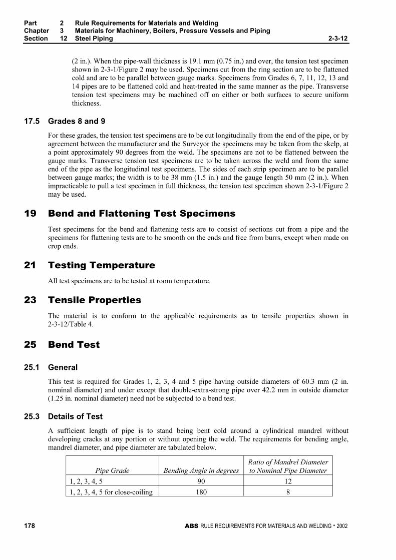
Part 2 Rule Requirements for Materials and WeldingChapter 3 Materials for Machinery, Boilers, Pressure Vessels and PipingSection 12 Steel Piping 2-3-12
178 ABS RULE REQUIREMENTS FOR MATERIALS AND WELDING . 2002
(2 in.). When the pipe-wall thickness is 19.1 mm (0.75 in.) and over, the tension test specimenshown in 2-3-1/Figure 2 may be used. Specimens cut from the ring section are to be flattenedcold and are to be parallel between gauge marks. Specimens from Grades 6, 7, 11, 12, 13 and14 pipes are to be flattened cold and heat-treated in the same manner as the pipe. Transversetension test specimens may be machined off on either or both surfaces to secure uniformthickness.
17.5 Grades 8 and 9 2-3-12/17.5
For these grades, the tension test specimens are to be cut longitudinally from the end of the pipe, or byagreement between the manufacturer and the Surveyor the specimens may be taken from the skelp, ata point approximately 90 degrees from the weld. The specimens are not to be flattened between thegauge marks. Transverse tension test specimens are to be taken across the weld and from the sameend of the pipe as the longitudinal test specimens. The sides of each strip specimen are to be parallelbetween gauge marks; the width is to be 38 mm (1.5 in.) and the gauge length 50 mm (2 in.). Whenimpracticable to pull a test specimen in full thickness, the tension test specimen shown 2-3-1/Figure 2may be used.
19 Bend and Flattening Test Specimens 2-3-12/19
Test specimens for the bend and flattening tests are to consist of sections cut from a pipe and thespecimens for flattening tests are to be smooth on the ends and free from burrs, except when made oncrop ends.
21 Testing Temperature 2-3-12/21
All test specimens are to be tested at room temperature.
23 Tensile Properties 2-3-12/23
The material is to conform to the applicable requirements as to tensile properties shown in2-3-12/Table 4.
25 Bend Test 2-3-12/25
25.1 General 2-3-12/25.1
This test is required for Grades 1, 2, 3, 4 and 5 pipe having outside diameters of 60.3 mm (2 in.nominal diameter) and under except that double-extra-strong pipe over 42.2 mm in outside diameter(1.25 in. nominal diameter) need not be subjected to a bend test.
25.3 Details of Test 2-3-12/25.3
A sufficient length of pipe is to stand being bent cold around a cylindrical mandrel withoutdeveloping cracks at any portion or without opening the weld. The requirements for bending angle,mandrel diameter, and pipe diameter are tabulated below.
Pipe Grade Bending Angle in degreesRatio of Mandrel Diameterto Nominal Pipe Diameter
1, 2, 3, 4, 5 90 12
1, 2, 3, 4, 5 for close-coiling 180 8
Part 2 Rule Requirements for Materials and WeldingChapter 3 Materials for Machinery, Boilers, Pressure Vessels and PipingSection 12 Steel Piping 2-3-12
ABS RULE REQUIREMENTS FOR MATERIALS AND WELDING . 2002 179
27 Flattening Test 2-3-12/27
27.1 General 2-3-12/27.1
Flattening tests are to be made for all Grades of pipe except Grades 1, 2 and 3 double extra strong andGrades 1, 2, 3, 4 and 5 in sizes 60.3 mm in outside diameter (2 in. nominal diameter) and under. Thetest is to consist of flattening cold a section of pipe between parallel plates.
27.3 Furnace-welded Pipe 2-3-12/27.3
For Grade 1 furnace-welded pipe, the test section is not to be less than 100 mm (4 in.) in length andthe weld is to be located 45 degrees from the line of direction of the applied force. The test is to bemade in three steps.
27.3.1 Test Step No. 1 2-3-12/27.3.1
During the first step, which is a test for quality of the weld, no cracks or breaks on the inside,outside or end surfaces are to occur until the distance between the plates is less than three-fourths of the original outside diameter.
27.3.2 Test Step No. 2 2-3-12/27.3.2
During the second step, which is a test for ductility exclusive of the weld, the flattening is tobe continued and no cracks or breaks on the inside, outside or end surfaces are to occur untilthe distance between the plates is less than 60% of the original outside diameter for butt-welded pipe.
27.3.3 Test Step No. 3 2-3-12/27.3.3
During the third step, which is a test for soundness, the flattening is to be continued until thetest specimen breaks or the opposite walls of the pipe meet. Evidence of laminated or unsoundmaterial or of incomplete weld that is revealed during the entire flattening test is to be causefor rejection. Superficial ruptures as a result of surface imperfections are not to be cause forrejection.
27.5 Electric-resistance-welded Pipe 2-3-12/27.5
For electric-resistance-welded pipe of Grades 2, 3, 8 and 9 the crop ends, at least 100 mm (4 in.) inlength, cut from each end of each single length of pipe are to be flattened and the tests from each endare to be made alternately with the welds at 0 degrees and 90 degrees from the line of direction offorce. When produced in multiple lengths, flattening tests are required from each end of each multiplelength or coil with the weld at 90 degrees from the line of direction of force; in addition tests are to bemade on two intermediate rings cut from each multiple length or coil with the weld at 0 degrees fromthe line of direction of force. The test is to be made in three steps.
27.5.1 Test Step No. 1 2-3-12/27.5.1
During the first step, which is a test for ductility of the weld, no cracks or breaks on the insideor outside surfaces are to occur until the distance between the plates is less than two-thirds ofthe original outside diameter of the pipe.
27.5.2 Test Step No. 2 2-3-12/27.5.2
During the second step, which is a test for ductility exclusive of the weld, the flattening is tobe continued and no cracks or breaks on the inside or outside surfaces, elsewhere than in theweld, are to occur until the distance between the plates is less than one-third of the originaloutside diameter of the pipe.
Part 2 Rule Requirements for Materials and WeldingChapter 3 Materials for Machinery, Boilers, Pressure Vessels and PipingSection 12 Steel Piping 2-3-12
180 ABS RULE REQUIREMENTS FOR MATERIALS AND WELDING . 2002
27.5.3 Test Step No. 3 2-3-12/27.5.3
During the third step, which is a test for soundness, the flattening is to be continued until thetest specimen breaks or the opposite walls of the pipe meet. Evidence of laminated, burned orunsound material or of incomplete weld that is revealed during the entire flattening test is tobe cause for rejection. Superficial ruptures as a result of surface imperfections are not to because for rejection.
27.7 Seamless Pipe (1998) 2-3-12/27.7
For seamless pipe of Grades 2, 3, 4, 5, 6, 7, 11, 12, 13 and 14 the test section is not to be less than63.5 mm (2.5 in.) in length. The test is to be made in two steps.
27.7.1 Test Step No. 1 2-3-12/27.7.1
During the first step, which is a test for ductility, no cracks or breaks on the inside or outsideor end surfaces are to occur until the distance between the plates is less than the value of Hobtained from the following equation:
H = (1 + e)t/(e + t/D)
where
H = distance between flattening plates, in mm (in.)
t = specified wall thickness of pipe, in mm (in.)
D = specified outside diameter of pipe, in mm (in.)
e = deformation per unit length, constant for a given Grade as follows.
= 0.09 for Grade 2
= 0.08 for Grades 4, 6, 7, 11, 12, 13 and 14
= 0.07 for Grades 3 and 5
27.7.2 Test Step No. 2 2-3-12/27.7.2
During the second step, which is a test for soundness, the flattening is to be continued untilthe specimen breaks or the opposite walls of the pipe meet. Evidence of laminated, burned orunsound material that is revealed during the entire flattening test is to be cause for rejection.
29 Hydrostatic Test 2-3-12/29
29.1 General (1998) 2-3-12/29.1
Except when intended for structural use, such as stanchions, each length of pipe of all grades is to behydrostatically tested at the mill in accordance with the following requirements, or when specified bythe purchaser, seamless pipe is to be subjected to a non-destructive electric test in accordance with2-3-12/31. When each pipe is hydrostatically tested as a regular procedure during process ofmanufacture, an affidavit covering this test may be accepted by the Surveyor.
29.3 Grades 1, 2 and 3 (1999) 2-3-12/29.3
For these grades, each pipe is to withstand an internal hydrostatic pressure as shown in 2-3-12/Table5. This does not prohibit testing at a higher pressure, but the maximum fiber stress produced by thetest is not to exceed 90% of the minimum specified yield strength of the material. Welded pipe60.3 mm O.D. (2 in. nominal diameter) and larger is to be jarred near one end while under testpressure. The hydrostatic pressure is to be maintained for not less than 5 seconds for all sizes ofseamless and electric-welded pipe.
Part 2 Rule Requirements for Materials and WeldingChapter 3 Materials for Machinery, Boilers, Pressure Vessels and PipingSection 12 Steel Piping 2-3-12
ABS RULE REQUIREMENTS FOR MATERIALS AND WELDING . 2002 181
29.5 Grades 4, 5, 6, 7, 11, 12, 13 and 14 (1999) 2-3-12/29.5
For these grades, each pipe is to withstand an internal hydrostatic test pressure which will produce inthe pipe wall a stress of not less than 60% of the minimum specified yield point at room temperature.This pressure is to be determined by the equation given in 2-3-12/29.9. The hydrostatic test pressuredetermined by the equation is to be rounded to the nearest 5 bar (5 kgf/cm2, 50 psi) for pressuresbelow 70 bar (70 kgf/cm2, 1000 psi) and to the nearest 10 bar (10 kgf/cm2, 100 psi) for pressures70 bar (70 kgf/cm2, 1000 psi) and above. Regardless of the pipe wall stress determined by theequation in 2-3-12/29.9, the minimum hydrostatic test pressure required to satisfy this requirementneed not exceed 170 bar (170 kgf/cm2, 2500 psi) for sizes 88.9 mm O.D. (3 in. nominal diameter) andunder, or 190 bar (190 kgf/cm2, 2800 psi) for all sizes over 88.9 mm O.D. (3 in. nominal diameter).This does not prohibit testing at a higher pressure, but the maximum fiber stress produced by the testis not to exceed 90% of the minimum specified yield strength of the material. The hydrostaticpressure is to be maintained for not less than 5 seconds.
29.7 Grades 8 and 9 2-3-12/29.7
For these grades, each pipe is to withstand an internal hydrostatic test pressure calculated from theequation given in 2-3-12/29.9. The maximum test pressure is not to exceed 172 bar (176 kgf/cm2,2500 psi). For pipe with a wall thickness greater than 3.9 mm (0.154 in.) the pipe is to be jarred nearboth ends with a 1 kg (2 lb.) hammer or its equivalent while under the test pressure. The hydrostaticpressure is to be maintained for not less than 5 seconds.
29.9 Test Pressures (1999) 2-3-12/29.9
The test pressures for applicable grades are to be determined by the following equation.
P = KSt/D
where
K = 20 (200, 2)
P = maximum hydrostatic-test pressure, in bar (kgf/cm2, psi)
t = specified thickness of pipe wall, in mm (in.)
D = specified outside diameter of pipe, in mm (in.)
S = permissible fiber stress
= 0.60 times the specified yield point, in N/mm2 (kgf/mm2 or psi), for ABS Grades4, 5, 6, 7, 11, 12, 13 and 14
= 110 N/mm2 (11 kgf/mm2, 16000 psi) to 125 N/mm2 (12.5 kgf/mm2, 18000 psi),but in no case is the stress produced to exceed 80% of the specified yield pointfor ABS Grade 8
= 140 N/mm2 (14 kgf/mm2, 20000 psi) to 150 N/mm2 (15.5 kgf/mm2, 22000 psi),but in no case is the stress produced to exceed 80% of the specified yield pointfor ABS Grade 9
29.11 Exceptions (1999) 2-3-12/29.11
The maximum test pressure for special service pipes, such as diesel engine high pressure fuelinjection piping, will be specially considered. The manufacturer is to submit the proposed maximumtest pressure along with technical justification and manufacturing control process for the piping. Thejustification is to include pipe fiber stress analysis and substantiating prototype test results.
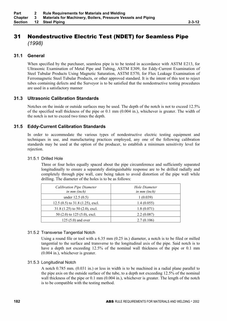
Part 2 Rule Requirements for Materials and WeldingChapter 3 Materials for Machinery, Boilers, Pressure Vessels and PipingSection 12 Steel Piping 2-3-12
182 ABS RULE REQUIREMENTS FOR MATERIALS AND WELDING . 2002
31 Nondestructive Electric Test (NDET) for Seamless Pipe(1998) 2-3-12/31
31.1 General 2-3-12/31.1
When specified by the purchaser, seamless pipe is to be tested in accordance with ASTM E213, forUltrasonic Examination of Metal Pipe and Tubing, ASTM E309, for Eddy-Current Examination ofSteel Tubular Products Using Magnetic Saturation, ASTM E570, for Flux Leakage Examination ofFerromagnetic Steel Tubular Products, or other approved standard. It is the intent of this test to rejecttubes containing defects and the Surveyor is to be satisfied that the nondestructive testing proceduresare used in a satisfactory manner
31.3 Ultrasonic Calibration Standards 2-3-12/31.3
Notches on the inside or outside surfaces may be used. The depth of the notch is not to exceed 12.5%of the specified wall thickness of the pipe or 0.1 mm (0.004 in.), whichever is greater. The width ofthe notch is not to exceed two times the depth.
31.5 Eddy-Current Calibration Standards 2-3-12/31.5
In order to accommodate the various types of nondestructive electric testing equipment andtechniques in use, and manufacturing practices employed, any one of the following calibrationstandards may be used at the option of the producer, to establish a minimum sensitivity level forrejection.
31.5.1 Drilled Hole 2-3-12/31.5.1
Three or four holes equally spaced about the pipe circumference and sufficiently separatedlongitudinally to ensure a separately distinguishable response are to be drilled radially andcompletely through pipe wall, care being taken to avoid distortion of the pipe wall whiledrilling. The diameter of the holes is to be as follows:
Calibration Pipe Diameterin mm (inch)
Hole Diameterin mm (inch)
under 12.5 (0.5) 1 (0.039)
12.5 (0.5) to 31.8 (1.25), excl. 1.4 (0.055)
31.8 (1.25) to 50 (2.0), excl. 1.8 (0.071)
50 (2.0) to 125 (5.0), excl. 2.2 (0.087)
125 (5.0) and over 2.7 (0.106)
31.5.2 Transverse Tangential Notch 2-3-12/31.5.2
Using a round file or tool with a 6.35 mm (0.25 in.) diameter, a notch is to be filed or milledtangential to the surface and transverse to the longitudinal axis of the pipe. Said notch is tohave a depth not exceeding 12.5% of the nominal wall thickness of the pipe or 0.1 mm(0.004 in.), whichever is greater.
31.5.3 Longitudinal Notch 2-3-12/31.5.3
A notch 0.785 mm. (0.031 in.) or less in width is to be machined in a radial plane parallel tothe pipe axis on the outside surface of the tube, to a depth not exceeding 12.5% of the nominalwall thickness of the pipe or 0.1 mm (0.004 in.), whichever is greater. The length of the notchis to be compatible with the testing method.
Part 2 Rule Requirements for Materials and WeldingChapter 3 Materials for Machinery, Boilers, Pressure Vessels and PipingSection 12 Steel Piping 2-3-12
ABS RULE REQUIREMENTS FOR MATERIALS AND WELDING . 2002 183
31.7 Flux Leakage Calibration Standards 2-3-12/31.7
The depth of longitudinal notches on the inside and outside surfaces is not to exceed 12.5% of thespecified wall thickness of the pipe or 0.1 mm (0.004 in.), whichever is greater. The width of thenotch is not to exceed the depth, and the length of the notch is not to exceed 25.4 mm (1.0 in.).Outside and inside surface notches are to be located sufficiently apart to allow distinct identificationof the signal from each notch.
31.9 Rejection 2-3-12/31.9
Tubing producing a signal equal to or greater than the calibration defect is to be subject to rejection.
31.11 Affidavits 2-3-12/31.11
When each tube is subjected to an approved nondestructive electric test as a regular procedure duringthe process of manufacture, an affidavit covering this test may be accepted by the Surveyor.
33 Retests 2-3-12/33
33.1 General (1998) 2-3-12/33.1
For all grades of pipe, if the results of the mechanical tests of any lot do not conform to therequirements, retests may be made on additional pipe of double the original number from the samelot, each of which is to conform to the requirements specified.
33.3 Grades 1, 2, 3, 8 and 9 2-3-12/33.3
For these grades, should any section fail when flattening tests are made on the crop ends of eachlength of welded pipe, other pieces from the length may be cut until satisfactory tests are obtained,otherwise the length is to be rejected.
33.5 Grades 4 and 5 2-3-12/33.5
For these grades, should a crop end of a finished pipe fail in the flattening test, one retest may bemade from the failed end. Pipe may be normalized either before or after the first test, but pipe is to besubjected to only two normalizing treatments.
33.7 Grades 6, 7, 11, 12, 13 and 14 (1998) 2-3-12/33.7
For these grades, should individual lengths of pipe selected to represent any lot fail to conform to themechanical requirements the lot may be re-heat-treated and resubmitted for test, except that anyindividual lengths which meet the test requirements before re-treating will be accepted.
35 Pipe Testing and Inspection 2-3-12/35
35.1 Group I Piping (1998) 2-3-12/35.1
Pipes intended for use in Group I piping systems (Class I and Class II, see 4-6-1/3, Rules for Buildingand Classing Steel Vessels) are to be tested, preferably at the mill, to the satisfaction of the Surveyor.The material will be surface inspected by the Surveyor when specially requested by the purchaser. Seealso 4-6-7/3.5.1 of the Rules for Building and Classing Steel Vessels.
Part 2 Rule Requirements for Materials and WeldingChapter 3 Materials for Machinery, Boilers, Pressure Vessels and PipingSection 12 Steel Piping 2-3-12
184 ABS RULE REQUIREMENTS FOR MATERIALS AND WELDING . 2002
35.3 Group I and II Piping (1998) 2-3-12/35.3
The pipes are to be reasonably straight, free from defects, and have a workmanlike finish. At aminimum, the finished pipe is to be visually inspected at the same frequency as that required for thetension test specified in 2-3-12/Table 3 for the applicable grade. Welding repair to the pipe is not to becarried out without the purchasers approval and is to be the Surveyors satisfaction.
37 Permissible Variation in Wall Thickness (1998) 2-3-12/37
The permissible variations in wall thickness for all pipe are based on the ordered thickness and are toconform to that given in the applicable ASTM designation for acceptance, but the minimum thicknessfor all pipe is not to be less than that required by the Rules for a specific application regardless of suchprior acceptance. At a minimum, the finished pipe is to be measured at the same frequency as thatrequired for the tension test specified in 2-3-12/Table 3 for the applicable grade.
39 Permissible Variations in Outside Diameter 2-3-12/39
39.1 Grades 1, 2, 3 2-3-12/39.1
For pipe of these grades 48.3 mm O.D. (1.5 in. nominal diameter) and under, the outside diameter atany point is not to vary more than 0.4 mm (0.016 in.) over nor more than 0.8 mm (0.131 in.) under thespecified diameter. For pipe 60.3 mm O.D. (2 in. nominal diameter) and over, the outside diameter isnot to vary more than plus or minus 1% from the specified diameter.
39.3 Grades 4, 5, 6, 7, 11, 12, 13 and 14 (1998) 2-3-12/39.3
For these grades, variation in outside diameter from that specified is not to exceed the amountprescribed in 2-3-12/Table 6.
39.5 Grades 8 and 9 2-3-12/39.5
For these grades, the outside diameter is not to vary more than plus or minus 1% from the nominaldiameter specified.
39.7 Inspection (1998) 2-3-12/39.7
At a minimum, the finished pipe is to be measured at the same frequency as that required for thetension test specified in 2-3-12/Table 3 for the applicable grade.
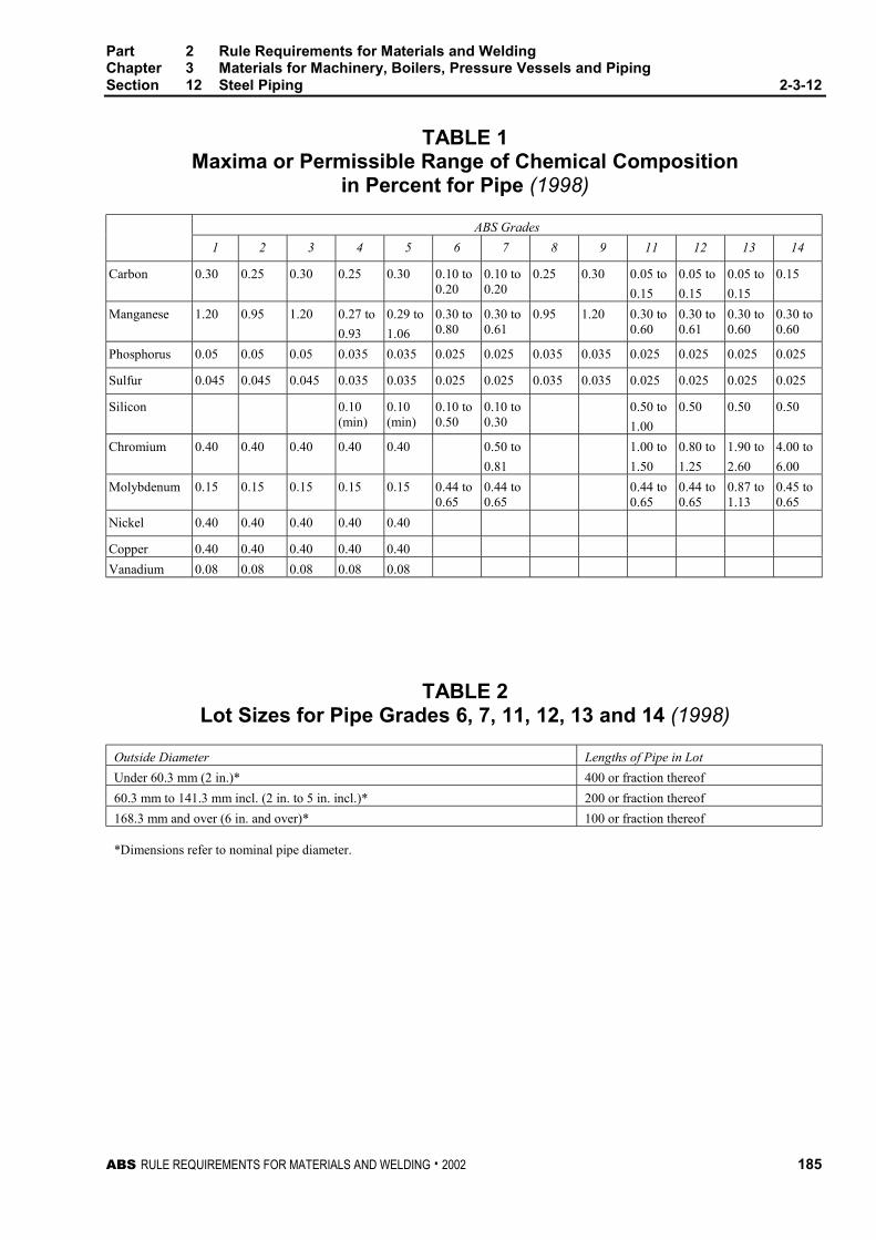
Part 2 Rule Requirements for Materials and WeldingChapter 3 Materials for Machinery, Boilers, Pressure Vessels and PipingSection 12 Steel Piping 2-3-12
ABS RULE REQUIREMENTS FOR MATERIALS AND WELDING . 2002 185
TABLE 1Maxima or Permissible Range of Chemical Composition
in Percent for Pipe (1998)
ABS Grades
1 2 3 4 5 6 7 8 9 11 12 13 14
Carbon 0.30 0.25 0.30 0.25 0.30 0.10 to0.20
0.10 to0.20
0.25 0.30 0.05 to
0.15
0.05 to
0.15
0.05 to
0.15
0.15
Manganese 1.20 0.95 1.20 0.27 to
0.93
0.29 to
1.06
0.30 to0.80
0.30 to0.61
0.95 1.20 0.30 to0.60
0.30 to0.61
0.30 to0.60
0.30 to0.60
Phosphorus 0.05 0.05 0.05 0.035 0.035 0.025 0.025 0.035 0.035 0.025 0.025 0.025 0.025
Sulfur 0.045 0.045 0.045 0.035 0.035 0.025 0.025 0.035 0.035 0.025 0.025 0.025 0.025
Silicon 0.10(min)
0.10(min)
0.10 to0.50
0.10 to0.30
0.50 to
1.00
0.50 0.50 0.50
Chromium 0.40 0.40 0.40 0.40 0.40 0.50 to
0.81
1.00 to
1.50
0.80 to
1.25
1.90 to
2.60
4.00 to
6.00
Molybdenum 0.15 0.15 0.15 0.15 0.15 0.44 to0.65
0.44 to0.65
0.44 to0.65
0.44 to0.65
0.87 to1.13
0.45 to0.65
Nickel 0.40 0.40 0.40 0.40 0.40
Copper 0.40 0.40 0.40 0.40 0.40
Vanadium 0.08 0.08 0.08 0.08 0.08
TABLE 2Lot Sizes for Pipe Grades 6, 7, 11, 12, 13 and 14 (1998)
Outside Diameter Lengths of Pipe in Lot
Under 60.3 mm (2 in.)* 400 or fraction thereof
60.3 mm to 141.3 mm incl. (2 in. to 5 in. incl.)* 200 or fraction thereof
168.3 mm and over (6 in. and over)* 100 or fraction thereof
*Dimensions refer to nominal pipe diameter.
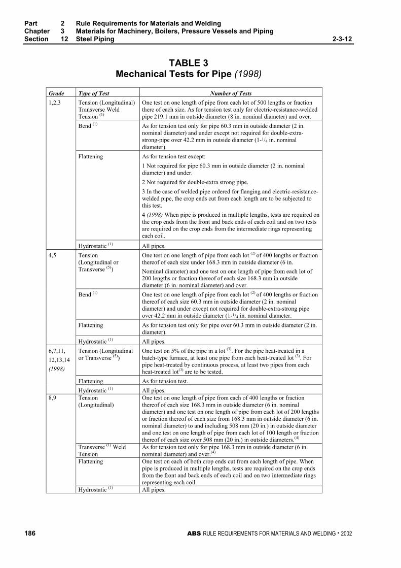
Part 2 Rule Requirements for Materials and WeldingChapter 3 Materials for Machinery, Boilers, Pressure Vessels and PipingSection 12 Steel Piping 2-3-12
186 ABS RULE REQUIREMENTS FOR MATERIALS AND WELDING . 2002
TABLE 3Mechanical Tests for Pipe (1998)
Grade Type of Test Number of Tests
1,2,3 Tension (Longitudinal)Transverse WeldTension (1)
One test on one length of pipe from each lot of 500 lengths or fractionthere of each size. As for tension test only for electric-resistance-weldedpipe 219.1 mm in outside diameter (8 in. nominal diameter) and over.
Bend (1) As for tension test only for pipe 60.3 mm in outside diameter (2 in.nominal diameter) and under except not required for double-extra-strong-pipe over 42.2 mm in outside diameter (1-1/4 in. nominaldiameter).
As for tension test except:
1 Not required for pipe 60.3 mm in outside diameter (2 in. nominaldiameter) and under.
2 Not required for double-extra strong pipe.
3 In the case of welded pipe ordered for flanging and electric-resistance-welded pipe, the crop ends cut from each length are to be subjected tothis test.
Flattening
4 (1998) When pipe is produced in multiple lengths, tests are required onthe crop ends from the front and back ends of each coil and on two testsare required on the crop ends from the intermediate rings representingeach coil.
Hydrostatic (1) All pipes.
4,5 Tension(Longitudinal orTransverse (5))
One test on one length of pipe from each lot (2) of 400 lengths or fractionthereof of each size under 168.3 mm in outside diameter (6 in.
Nominal diameter) and one test on one length of pipe from each lot of200 lengths or fraction thereof of each size 168.3 mm in outsidediameter (6 in. nominal diameter) and over.
Bend (1) One test on one length of pipe from each lot (2) of 400 lengths or fractionthereof of each size 60.3 mm in outside diameter (2 in. nominaldiameter) and under except not required for double-extra-strong pipeover 42.2 mm in outside diameter (1-1/4 in. nominal diameter.
Flattening As for tension test only for pipe over 60.3 mm in outside diameter (2 in.diameter).
Hydrostatic (1) All pipes.
6,7,11,
12,13,14
(1998)
Tension (Longitudinalor Transverse (5))
One test on 5% of the pipe in a lot (3). For the pipe heat-treated in abatch-type furnace, at least one pipe from each heat-treated lot (3). Forpipe heat-treated by continuous process, at least two pipes from eachheat-treated lot(3) are to be tested.
Flattening As for tension test.
Hydrostatic (1) All pipes.8,9 Tension
(Longitudinal)One test on one length of pipe from each of 400 lengths or fractionthereof of each size 168.3 mm in outside diameter (6 in. nominaldiameter) and one test on one length of pipe from each lot of 200 lengthsor fraction thereof of each size from 168.3 mm in outside diameter (6 in.nominal diameter) to and including 508 mm (20 in.) in outside diameterand one test on one length of pipe from each lot of 100 length or fractionthereof of each size over 508 mm (20 in.) in outside diameters.(4)
Transverse (1) WeldTension
As for tension test only for pipe 168.3 mm in outside diameter (6 in.nominal diameter) and over.(4)
Flattening One test on each of both crop ends cut from each length of pipe. Whenpipe is produced in multiple lengths, tests are required on the crop endsfrom the front and back ends of each coil and on two intermediate ringsrepresenting each coil.
Hydrostatic (1) All pipes.
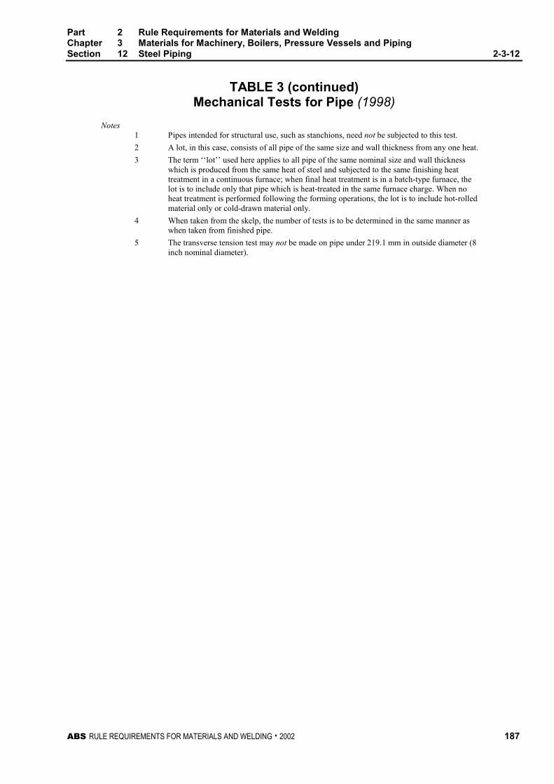
Part 2 Rule Requirements for Materials and WeldingChapter 3 Materials for Machinery, Boilers, Pressure Vessels and PipingSection 12 Steel Piping 2-3-12
ABS RULE REQUIREMENTS FOR MATERIALS AND WELDING . 2002 187
TABLE 3 (continued)Mechanical Tests for Pipe (1998)
Notes1 Pipes intended for structural use, such as stanchions, need not be subjected to this test.
2 A lot, in this case, consists of all pipe of the same size and wall thickness from any one heat.
3 The term ‘‘lot’’ used here applies to all pipe of the same nominal size and wall thicknesswhich is produced from the same heat of steel and subjected to the same finishing heattreatment in a continuous furnace; when final heat treatment is in a batch-type furnace, thelot is to include only that pipe which is heat-treated in the same furnace charge. When noheat treatment is performed following the forming operations, the lot is to include hot-rolledmaterial only or cold-drawn material only.
4 When taken from the skelp, the number of tests is to be determined in the same manner aswhen taken from finished pipe.
5 The transverse tension test may not be made on pipe under 219.1 mm in outside diameter (8inch nominal diameter).

Part 2 Rule Requirements for Materials and WeldingChapter 3 Materials for Machinery, Boilers, Pressure Vessels and PipingSection 12 Steel Piping 2-3-12
188 ABS RULE REQUIREMENTS FOR MATERIALS AND WELDING . 2002
TABLE 4Tensile Requirements for Pipe (1998)
SI Units & MKS Units
ABS Grades1 2 (c) 3 (c) 4 5 6
and7
8 (b) 9 (b) 11,12,13,14(1998)
310 330 415 330 415 380 330 415 415Tensile Strength, min. N/mm2
(kgf/mm2) (31.5) (33.7) (42) (33.7) (42) (39) (33.7) (42) (42)
170 205 240 205 240 205 205 240 205Yield Strength, min. N/mm2
(kgf/mm2) (17.5) (21) (24.5) (21) (24.5) (21) (21) (24.5) (21)
Elongation in 200 mm,min., % 20 (a)
Elongation in 50 mm.min., percent. Basicminimum elongationfor walls 7.9 mm andover, strip tests, and forall small sizes tested infull section.
25 16.5 20 20 Transverse Longitudinal 35 30 35 30 30 35 30 30
When standard round50 mm gauge lengthtest specimen is used.
20 12 14 14 Transverse Longitudinal 30 28 22 28 22 22 22
Deduction in elongationfor each 0.8 mmdecrease in wallthickness below 7.9mm for strip test.
1.25 1.00 1.00 1.00 Transverse Longitudinal 1.75 1.50 1.75 1.50 1.50 1.75 1.50 1.50
Notesa Gauge distances for measuring elongation on pipe of 26.7 mm O.D. and smaller are to be as
follows:
O.D. Gauge Length26.7 mm and 21.3 mm 150 mm17.1 mm and 13.7 mm 100 mm
103 mm 50 mm
b The test specimen taken across the weld is to show a tensile strength not less than theminimum specified for the grade pipe ordered. This test will not be required for pipe under168.3 mm in outside diameter.
c The test specimen taken across the weld is to show a tensile strength not less than theminimum specified for the grade of pipe ordered. This test will not be required for pipe under219.1 mm in outside diameter.
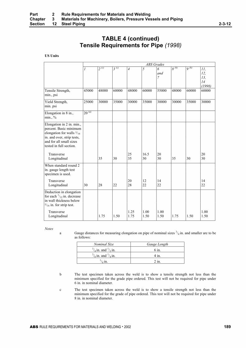
Part 2 Rule Requirements for Materials and WeldingChapter 3 Materials for Machinery, Boilers, Pressure Vessels and PipingSection 12 Steel Piping 2-3-12
ABS RULE REQUIREMENTS FOR MATERIALS AND WELDING . 2002 189
TABLE 4 (continued)Tensile Requirements for Pipe (1998)
US Units
ABS Grades1 2 (c) 3 (c) 4 5 6
and7
8 (b) 9 (b) 11,12,13,14(1998)
45000 48000 60000 48000 60000 55000 48000 60000 60000Tensile Strength,min., psi
25000 30000 35000 30000 35000 30000 30000 35000 30000Yield Strength,min. psi
20 (a)Elongation in 8 in.,min., %
Elongation in 2 in. min.,percent. Basic minimumelongation for walls 5/16
in. and over, strip tests,and for all small sizestested in full section.
25 16.5 20 20 Transverse Longitudinal 35 30 35 30 30 35 30 30
When standard round 2in. gauge length testspecimen is used.
20 12 14 14 Transverse Longitudinal 30 28 22 28 22 22 22
Deduction in elongationfor each 1/32 in. decreasein wall thickness below5/16 in. for strip test.
1.25 1.00 1.00 1.00 Transverse Longitudinal 1.75 1.50 1.75 1.50 1.50 1.75 1.50 1.50
Notesa Gauge distances for measuring elongation on pipe of nominal sizes 3/4 in. and smaller are to be
as follows:
Nominal Size Gauge Length3/4 in. and 1/2 in. 6 in.3/8 in. and 1/4 in. 4 in.
1/8 in. 2 in.
b The test specimen taken across the weld is to show a tensile strength not less than theminimum specified for the grade pipe ordered. This test will not be required for pipe under6 in. in nominal diameter.
c The test specimen taken across the weld is to show a tensile strength not less than theminimum specified for the grade of pipe ordered. This test will not be required for pipe under8 in. in nominal diameter.
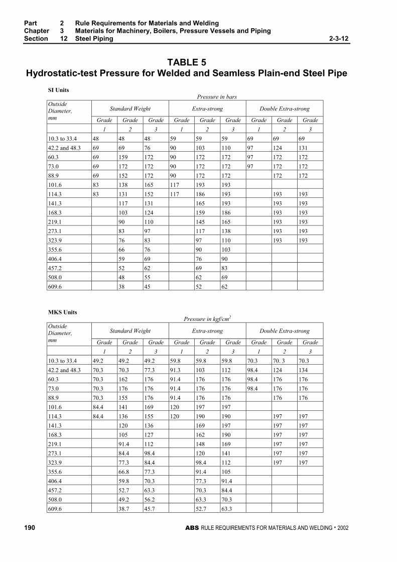
Part 2 Rule Requirements for Materials and WeldingChapter 3 Materials for Machinery, Boilers, Pressure Vessels and PipingSection 12 Steel Piping 2-3-12
190 ABS RULE REQUIREMENTS FOR MATERIALS AND WELDING . 2002
TABLE 5Hydrostatic-test Pressure for Welded and Seamless Plain-end Steel Pipe
SI UnitsPressure in bars
Standard Weight Extra-strong Double Extra-strongOutsideDiameter,mm Grade Grade Grade Grade Grade Grade Grade Grade Grade
1 2 3 1 2 3 1 2 3
10.3 to 33.4 48 48 48 59 59 59 69 69 69
42.2 and 48.3 69 69 76 90 103 110 97 124 131
60.3 69 159 172 90 172 172 97 172 172
73.0 69 172 172 90 172 172 97 172 172
88.9 69 152 172 90 172 172 172 172
101.6 83 138 165 117 193 193
114.3 83 131 152 117 186 193 193 193
141.3 117 131 165 193 193 193
168.3 103 124 159 186 193 193
219.1 90 110 145 165 193 193
273.1 83 97 117 138 193 193
323.9 76 83 97 110 193 193
355.6 66 76 90 103
406.4 59 69 76 90
457.2 52 62 69 83
508.0 48 55 62 69
609.6 38 45 52 62
MKS UnitsPressure in kgf/cm2
Standard Weight Extra-strong Double Extra-strongOutsideDiameter,mm Grade Grade Grade Grade Grade Grade Grade Grade Grade
1 2 3 1 2 3 1 2 3
10.3 to 33.4 49.2 49.2 49.2 59.8 59.8 59.8 70.3 70. 3 70.3
42.2 and 48.3 70.3 70.3 77.3 91.3 103 112 98.4 124 134
60.3 70.3 162 176 91.4 176 176 98.4 176 176
73.0 70.3 176 176 91.4 176 176 98.4 176 176
88.9 70.3 155 176 91.4 176 176 176 176
101.6 84.4 141 169 120 197 197
114.3 84.4 136 155 120 190 190 197 197
141.3 120 136 169 197 197 197
168.3 105 127 162 190 197 197
219.1 91.4 112 148 169 197 197
273.1 84.4 98.4 120 141 197 197
323.9 77.3 84.4 98.4 112 197 197
355.6 66.8 77.3 91.4 105
406.4 59.8 70.3 77.3 91.4
457.2 52.7 63.3 70.3 84.4
508.0 49.2 56.2 63.3 70.3
609.6 38.7 45.7 52.7 63.3

Part 2 Rule Requirements for Materials and WeldingChapter 3 Materials for Machinery, Boilers, Pressure Vessels and PipingSection 12 Steel Piping 2-3-12
ABS RULE REQUIREMENTS FOR MATERIALS AND WELDING . 2002 191
TABLE 5 (continued)Hydrostatic-test Pressure for Welded and Seamless Plain-end Steel Pipe
US Units
Pressure in psiIPS Size,in. Standard Weight Extra-strong Double Extra-strong
Grade Grade Grade Grade Grade Grade Grade Grade Grade1 2 3 1 2 3 1 2 3
1/8 to 1 700 700 700 850 850 850 1000 1000 1000
11/4 and 11/2 1000 1000 1100 1300 1500 1600 1400 1800 1900
2 1000 2300 2500 1300 2500 2500 1400 2500 2500
21/2 1000 2500 2500 1300 2500 2500 1400 2500 2500
3 1000 2200 2500 1300 2500 2500 2500 2500
31/2 1200 2000 2400 1700 2800 2800
4 1200 1900 2200 1700 2700 2800 2800 2800
5 1700 1900 2400 2800 2800 2800
6 1500 1800 2300 2700 2800 2800
8 1300 1600 2100 2400 2800 2800
10 1200 1400 1700 2000 2800 2800
12 1100 1200 1400 1600 2800 2800
14 950 1100 1300 1500
16 850 1000 1100 1300
18 750 900 1000 1200
20 700 800 900 1000
24 550 650 750 900
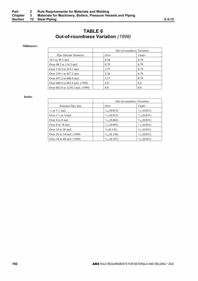
Part 2 Rule Requirements for Materials and WeldingChapter 3 Materials for Machinery, Boilers, Pressure Vessels and PipingSection 12 Steel Piping 2-3-12
192 ABS RULE REQUIREMENTS FOR MATERIALS AND WELDING . 2002
TABLE 6Out-of-roundness Variation (1998)
Millimeters
Out-of-roundness Variation
Pipe Outside Diameter Over Under
10.3 to 48.3 incl. 0.38 0.79
Over 48.3 to 114.3 incl. 0.79 0.79
Over 114.3 to 219.1 incl. 1.57 0.79
Over 219.1 to 457.2 incl. 2.36 0.79
Over 457.2 to 660.4 incl. 3.17 0.79
Over 660.4 to 863.6 incl. (1998) 4.0 0.8
Over 863.6 to 1219.2 incl. (1998) 4.8 0.8
Inches
Out-of-roundness Variation
Nominal Pipe Size Over Under1/8 to 11/2 incl. 1/64 (0.015) 1/32 (0.031)
Over 11/2 to 4 incl. 1/32 (0.031) 1/32 (0.031)
Over 4 to 8 incl. 1/16 (0.062) 1/32 (0.031)
Over 8 to 18 incl. 3/32 (0.093) 1/32 (0.031)
Over 18 to 26 incl. 1/8 (0.125) 1/32 (0.031)
Over 26 to 34 incl. (1998) 5/32 (0.156) 1/32 (0.031)
Over 34 to 48 incl. (1998) 3/16 (0.187) 1/32 (0.031)
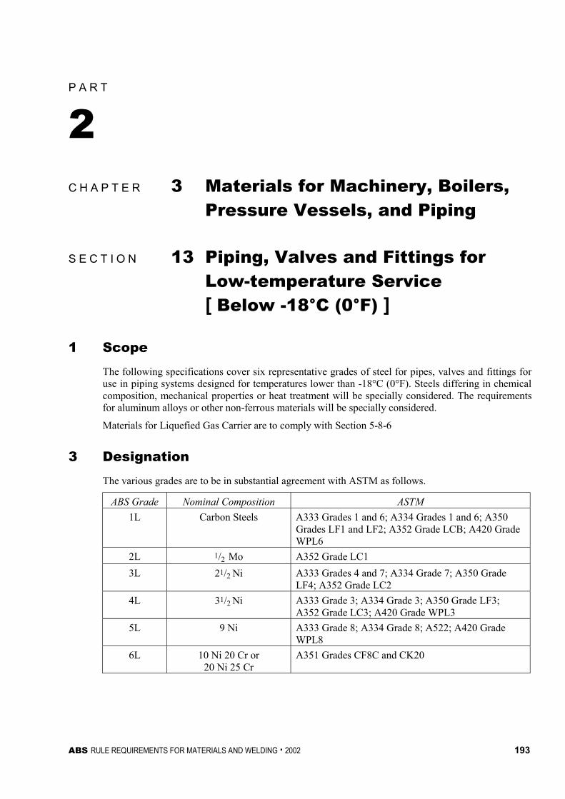
ABS RULE REQUIREMENTS FOR MATERIALS AND WELDING . 2002 193
P A R T
2C H A P T E R 3 Materials for Machinery, Boilers,
Pressure Vessels, and Piping
S E C T I O N 13 Piping, Valves and Fittings forLow-temperature Service[ Below -18°C (0°F) ] 2 - 3 - 1 3
1 Scope 2-3-13/1
The following specifications cover six representative grades of steel for pipes, valves and fittings foruse in piping systems designed for temperatures lower than -18°C (0°F). Steels differing in chemicalcomposition, mechanical properties or heat treatment will be specially considered. The requirementsfor aluminum alloys or other non-ferrous materials will be specially considered.
Materials for Liquefied Gas Carrier are to comply with Section 5-8-6
3 Designation 2-3-13/3
The various grades are to be in substantial agreement with ASTM as follows.
ABS Grade Nominal Composition ASTM
1L Carbon Steels A333 Grades 1 and 6; A334 Grades 1 and 6; A350Grades LF1 and LF2; A352 Grade LCB; A420 GradeWPL6
2L 1/2 Mo A352 Grade LC1
3L 21/2 Ni A333 Grades 4 and 7; A334 Grade 7; A350 GradeLF4; A352 Grade LC2
4L 31/2 Ni A333 Grade 3; A334 Grade 3; A350 Grade LF3;A352 Grade LC3; A420 Grade WPL3
5L 9 Ni A333 Grade 8; A334 Grade 8; A522; A420 GradeWPL8
6L 10 Ni 20 Cr or20 Ni 25 Cr
A351 Grades CF8C and CK20
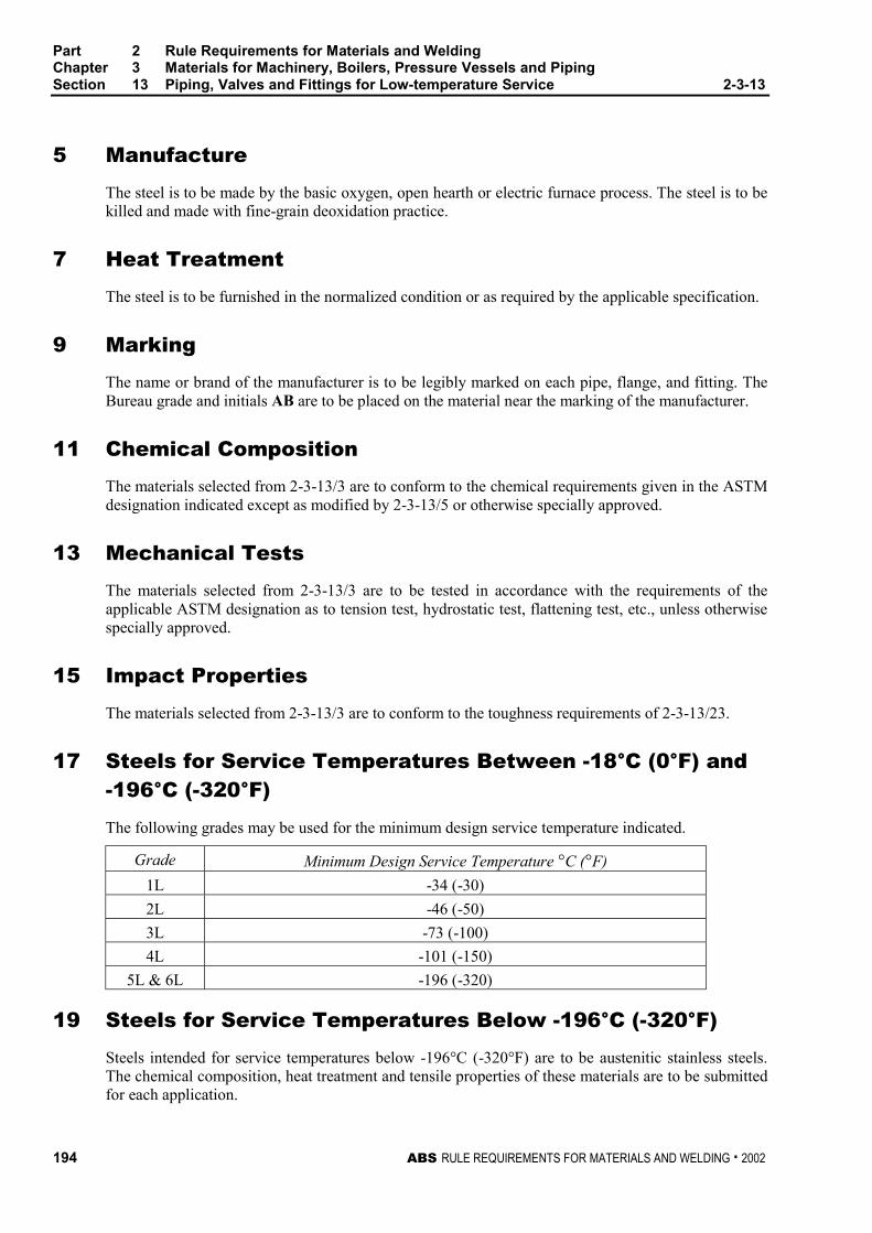
Part 2 Rule Requirements for Materials and WeldingChapter 3 Materials for Machinery, Boilers, Pressure Vessels and PipingSection 13 Piping, Valves and Fittings for Low-temperature Service 2-3-13
194 ABS RULE REQUIREMENTS FOR MATERIALS AND WELDING . 2002
5 Manufacture 2-3-13/5
The steel is to be made by the basic oxygen, open hearth or electric furnace process. The steel is to bekilled and made with fine-grain deoxidation practice.
7 Heat Treatment 2-3-13/7
The steel is to be furnished in the normalized condition or as required by the applicable specification.
9 Marking 2-3-13/9
The name or brand of the manufacturer is to be legibly marked on each pipe, flange, and fitting. TheBureau grade and initials AB are to be placed on the material near the marking of the manufacturer.
11 Chemical Composition 2-3-13/11
The materials selected from 2-3-13/3 are to conform to the chemical requirements given in the ASTMdesignation indicated except as modified by 2-3-13/5 or otherwise specially approved.
13 Mechanical Tests 2-3-13/13
The materials selected from 2-3-13/3 are to be tested in accordance with the requirements of theapplicable ASTM designation as to tension test, hydrostatic test, flattening test, etc., unless otherwisespecially approved.
15 Impact Properties 2-3-13/15
The materials selected from 2-3-13/3 are to conform to the toughness requirements of 2-3-13/23.
17 Steels for Service Temperatures Between -18°C (0°F) and-196°C (-320°F) 2-3-13/17
The following grades may be used for the minimum design service temperature indicated.
Grade Minimum Design Service Temperature °C (°F)
1L -34 (-30)
2L -46 (-50)
3L -73 (-100)
4L -101 (-150)
5L & 6L -196 (-320)
19 Steels for Service Temperatures Below -196°C (-320°F) 2-3-13/19
Steels intended for service temperatures below -196°C (-320°F) are to be austenitic stainless steels.The chemical composition, heat treatment and tensile properties of these materials are to be submittedfor each application.
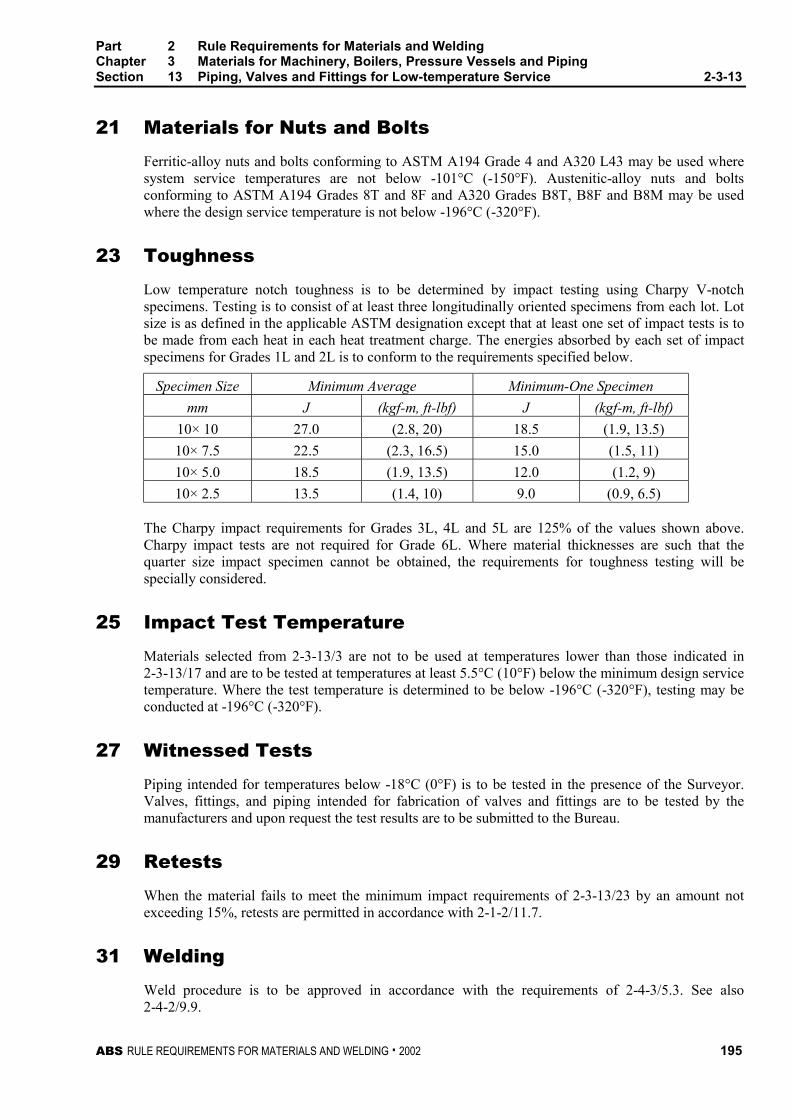
Part 2 Rule Requirements for Materials and WeldingChapter 3 Materials for Machinery, Boilers, Pressure Vessels and PipingSection 13 Piping, Valves and Fittings for Low-temperature Service 2-3-13
ABS RULE REQUIREMENTS FOR MATERIALS AND WELDING . 2002 195
21 Materials for Nuts and Bolts 2-3-13/21
Ferritic-alloy nuts and bolts conforming to ASTM A194 Grade 4 and A320 L43 may be used wheresystem service temperatures are not below -101°C (-150°F). Austenitic-alloy nuts and boltsconforming to ASTM A194 Grades 8T and 8F and A320 Grades B8T, B8F and B8M may be usedwhere the design service temperature is not below -196°C (-320°F).
23 Toughness 2-3-13/23
Low temperature notch toughness is to be determined by impact testing using Charpy V-notchspecimens. Testing is to consist of at least three longitudinally oriented specimens from each lot. Lotsize is as defined in the applicable ASTM designation except that at least one set of impact tests is tobe made from each heat in each heat treatment charge. The energies absorbed by each set of impactspecimens for Grades 1L and 2L is to conform to the requirements specified below.
Specimen Size Minimum Average Minimum-One Specimen
mm J (kgf-m, ft-lbf) J (kgf-m, ft-lbf)
10× 10 27.0 (2.8, 20) 18.5 (1.9, 13.5)
10× 7.5 22.5 (2.3, 16.5) 15.0 (1.5, 11)
10× 5.0 18.5 (1.9, 13.5) 12.0 (1.2, 9)
10× 2.5 13.5 (1.4, 10) 9.0 (0.9, 6.5)
The Charpy impact requirements for Grades 3L, 4L and 5L are 125% of the values shown above.Charpy impact tests are not required for Grade 6L. Where material thicknesses are such that thequarter size impact specimen cannot be obtained, the requirements for toughness testing will bespecially considered.
25 Impact Test Temperature 2-3-13/25
Materials selected from 2-3-13/3 are not to be used at temperatures lower than those indicated in2-3-13/17 and are to be tested at temperatures at least 5.5°C (10°F) below the minimum design servicetemperature. Where the test temperature is determined to be below -196°C (-320°F), testing may beconducted at -196°C (-320°F).
27 Witnessed Tests 2-3-13/27
Piping intended for temperatures below -18°C (0°F) is to be tested in the presence of the Surveyor.Valves, fittings, and piping intended for fabrication of valves and fittings are to be tested by themanufacturers and upon request the test results are to be submitted to the Bureau.
29 Retests 2-3-13/29
When the material fails to meet the minimum impact requirements of 2-3-13/23 by an amount notexceeding 15%, retests are permitted in accordance with 2-1-2/11.7.
31 Welding 2-3-13/31
Weld procedure is to be approved in accordance with the requirements of 2-4-3/5.3. See also2-4-2/9.9.

ABS RULE REQUIREMENTS FOR MATERIALS AND WELDING . 2002 197
P A R T
2C H A P T E R 3 Materials for Machinery, Boilers,
Pressure Vessels, and Piping
S E C T I O N 14 Bronze Castings
CONTENTS1 For General Purposes ......................................................... 199
1.1 Tensile Properties ................................................................ 199
1.3 Number of Tests................................................................... 199
3 Propellers and Propeller Blades......................................... 199
3.1 Castings................................................................................ 199
3.3 Chemical Composition ......................................................... 199
3.5 Zinc Equivalent ..................................................................... 200
3.7 Alternative Zinc Equivalent................................................... 200
3.9 Tensile Properties ................................................................ 200
3.11 Test Specimens.................................................................... 201
3.13 Separately Cast Coupons .................................................... 201
3.15 Integrally Cast Coupons ....................................................... 201
3.17 Number of Tests................................................................... 201
3.19 Special Compositions........................................................... 202
3.21 Inspection and Repair .......................................................... 202
3.23 Marking................................................................................. 202
5 Castings for Ice-Strengthened Propellers ......................... 203
FIGURE 1 Test Coupons........................................................... 202

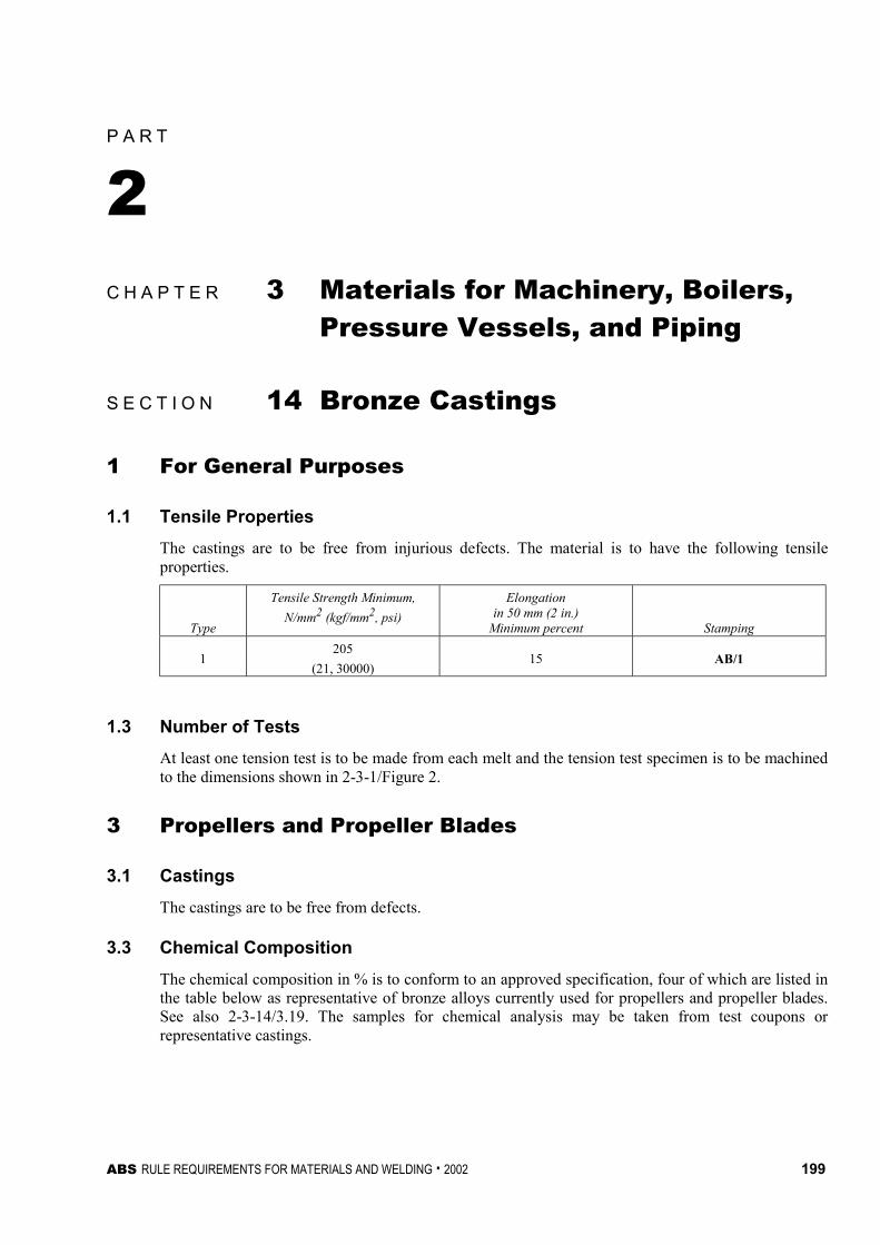
ABS RULE REQUIREMENTS FOR MATERIALS AND WELDING . 2002 199
P A R T
2C H A P T E R 3 Materials for Machinery, Boilers,
Pressure Vessels, and Piping
S E C T I O N 14 Bronze Castings 2 - 3 - 1 4
1 For General Purposes 2-3-14/1
1.1 Tensile Properties 2-3-14/1.1
The castings are to be free from injurious defects. The material is to have the following tensileproperties.
Type
Tensile Strength Minimum,
N/mm2 (kgf/mm2, psi)
Elongationin 50 mm (2 in.)
Minimum percent Stamping
2051
(21, 30000)15 AB/1
1.3 Number of Tests 2-3-14/1.3
At least one tension test is to be made from each melt and the tension test specimen is to be machinedto the dimensions shown in 2-3-1/Figure 2.
3 Propellers and Propeller Blades 2-3-14/3
3.1 Castings 2-3-14/3.1
The castings are to be free from defects.
3.3 Chemical Composition 2-3-14/3.3
The chemical composition in % is to conform to an approved specification, four of which are listed inthe table below as representative of bronze alloys currently used for propellers and propeller blades.See also 2-3-14/3.19. The samples for chemical analysis may be taken from test coupons orrepresentative castings.

Part 2 Rule Requirements for Materials and WeldingChapter 3 Materials for Machinery, Boilers, Pressure Vessels and PipingSection 14 Bronze Castings 2-3-14
200 ABS RULE REQUIREMENTS FOR MATERIALS AND WELDING . 2002
Type 2Mn Bronze
Type 3Ni-MnBronze
Type 4Ni-Al
Bronze
Type 5Mn-Ni-AlBronze
Copper 55–60 53.5–57 78 min 71 min
Tin 1.00 max 1.00 max — —
Lead 0.40 max 0.20 max 0.03 max 0.03 max
Iron 0.4–2.0 1.0–2.5 3.0–5.0 2.0–4.0
Manganese 1.5 max 2.5–4.0 3.5 max 11.0–14.0
Aluminum 0.5–1.5 2.0 max 8.5–11.0 7.0–8.5
Nickel 0.5 max 2.5–4.0 3.0–5.5 1.5–3.0
Silicon — — — 0.10 max
Zinc Remainder Remainder — —
Total Others — — 0.50 max 0.50 max
3.5 Zinc Equivalent 2-3-14/3.5
The chemical composition of Type 2 and Type 3 alloys are to be so controlled that the zincequivalent, based on the following equation, does not exceed 45.0%.
% zinc equivalent = 100 −
+×
A
copper
100
%100
where A is the algebraic sum of the following zinc replacement factors:
Tin = +1.0 × % Sn
Iron = -0.1 × % Fe
Aluminum = +5.0 × % Al
Lead = 0.0
Manganese = -0.5 × % Mn
Nickel = -2.3 × % Ni
3.7 Alternative Zinc Equivalent 2-3-14/3.7
When the alpha content of a specimen taken from the end of the acceptance test bar is determined bymicroscopic measurement to be 20% or more, the foregoing ‘‘zinc equivalent’’ requirement will bewaived.
3.9 Tensile Properties (1998) 2-3-14/3.9
The material represented by the test specimens machined from separately cast test coupons is toconform to the following minimum tensile properties.
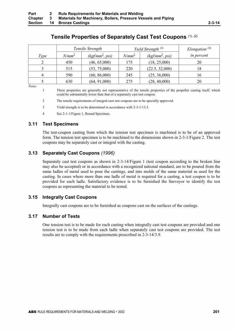
Part 2 Rule Requirements for Materials and WeldingChapter 3 Materials for Machinery, Boilers, Pressure Vessels and PipingSection 14 Bronze Castings 2-3-14
ABS RULE REQUIREMENTS FOR MATERIALS AND WELDING . 2002 201
Tensile Properties of Separately Cast Test Coupons (1), (2)
Tensile Strength Yield Strength (3)
Type N/mm2 (kgf/mm2, psi) N/mm2 (kgf/mm2, psi)
Elongation (4)
in percent
2 450 (46, 65,000) 175 (18, 25,000) 20
3 515 (53, 75,000) 220 (22.5, 32,000) 18
4 590 (60, 86,000) 245 (25, 36,000) 16
5 630 (64, 91,000) 275 (28, 40,000) 20Notes
1 These properties are generally not representative of the tensile properties of the propeller casting itself, whichcould be substantially lower than that of a separately cast test coupon.
2 The tensile requirements of integral-cast test coupons are to be specially approved.
3 Yield strength is to be determined in accordance with 2-3-1/13.3.
4 See 2-1-1/Figure 1, Round Specimen.
3.11 Test Specimens 2-3-14/3.11
The test-coupon casting from which the tension test specimen is machined is to be of an approvedform. The tension test specimen is to be machined to the dimensions shown in 2-3-1/Figure 2. The testcoupons may be separately cast or integral with the casting.
3.13 Separately Cast Coupons (1996) 2-3-14/3.13
Separately cast test coupons as shown in 2-3-14/Figure 1 (test coupon according to the broken linemay also be accepted) or in accordance with a recognized national standard, are to be poured from thesame ladles of metal used to pour the castings, and into molds of the same material as used for thecasting. In cases where more than one ladle of metal is required for a casting, a test coupon is to beprovided for each ladle. Satisfactory evidence is to be furnished the Surveyor to identify the testcoupons as representing the material to be tested.
3.15 Integrally Cast Coupons 2-3-14/3.15
Integrally cast coupons are to be furnished as coupons cast on the surfaces of the castings.
3.17 Number of Tests 2-3-14/3.17
One tension test is to be made for each casting when integrally cast test coupons are provided and onetension test is to be made from each ladle when separately cast test coupons are provided. The testresults are to comply with the requirements prescribed in 2-3-14/3.9.
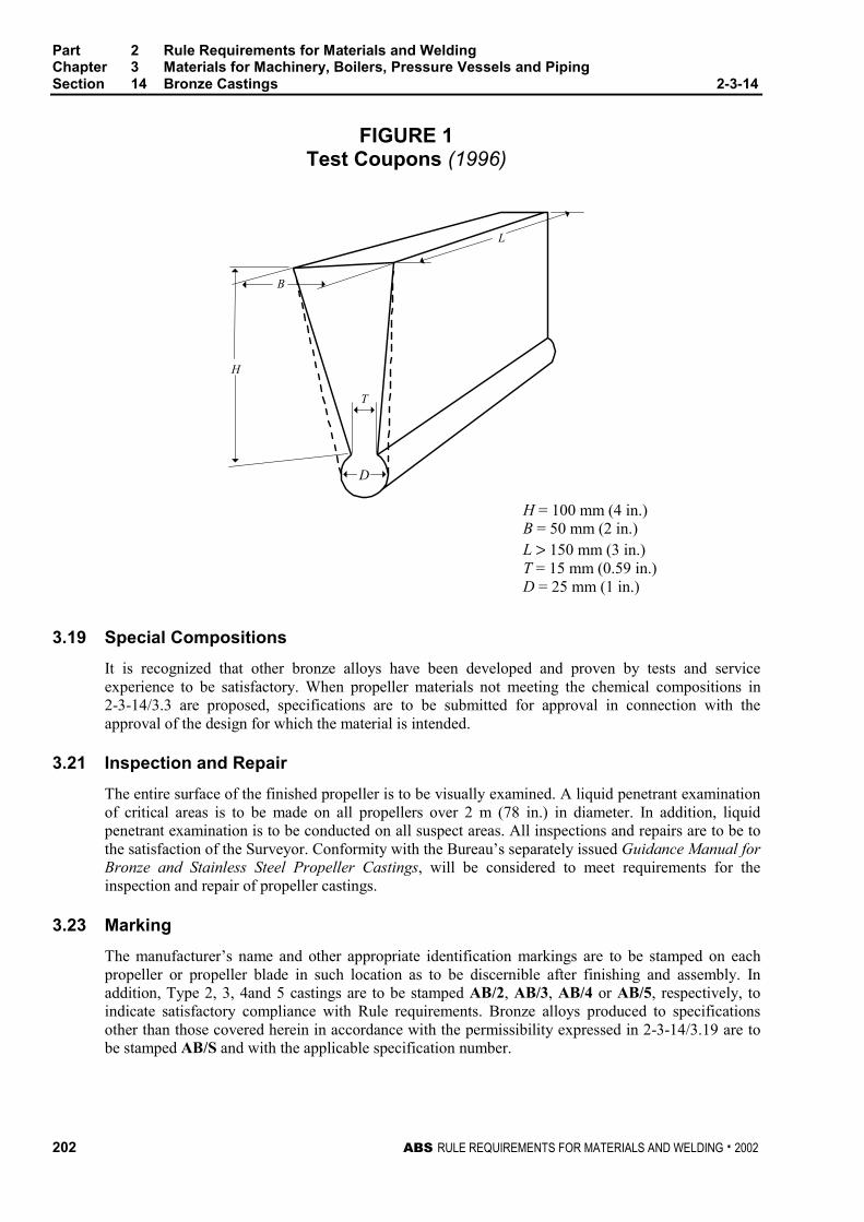
Part 2 Rule Requirements for Materials and WeldingChapter 3 Materials for Machinery, Boilers, Pressure Vessels and PipingSection 14 Bronze Castings 2-3-14
202 ABS RULE REQUIREMENTS FOR MATERIALS AND WELDING . 2002
FIGURE 1Test Coupons (1996)
L
B
H
T
D
H = 100 mm (4 in.)B = 50 mm (2 in.)L > 150 mm (3 in.)T = 15 mm (0.59 in.)D = 25 mm (1 in.)
3.19 Special Compositions 2-3-14/3.19
It is recognized that other bronze alloys have been developed and proven by tests and serviceexperience to be satisfactory. When propeller materials not meeting the chemical compositions in2-3-14/3.3 are proposed, specifications are to be submitted for approval in connection with theapproval of the design for which the material is intended.
3.21 Inspection and Repair 2-3-14/3.21
The entire surface of the finished propeller is to be visually examined. A liquid penetrant examinationof critical areas is to be made on all propellers over 2 m (78 in.) in diameter. In addition, liquidpenetrant examination is to be conducted on all suspect areas. All inspections and repairs are to be tothe satisfaction of the Surveyor. Conformity with the Bureau’s separately issued Guidance Manual forBronze and Stainless Steel Propeller Castings, will be considered to meet requirements for theinspection and repair of propeller castings.
3.23 Marking 2-3-14/3.23
The manufacturer’s name and other appropriate identification markings are to be stamped on eachpropeller or propeller blade in such location as to be discernible after finishing and assembly. Inaddition, Type 2, 3, 4and 5 castings are to be stamped AB/2, AB/3, AB/4 or AB/5, respectively, toindicate satisfactory compliance with Rule requirements. Bronze alloys produced to specificationsother than those covered herein in accordance with the permissibility expressed in 2-3-14/3.19 are tobe stamped AB/S and with the applicable specification number.
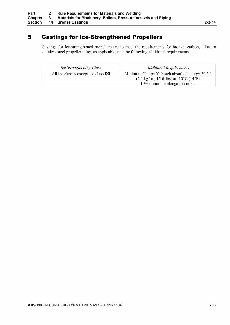
Part 2 Rule Requirements for Materials and WeldingChapter 3 Materials for Machinery, Boilers, Pressure Vessels and PipingSection 14 Bronze Castings 2-3-14
ABS RULE REQUIREMENTS FOR MATERIALS AND WELDING . 2002 203
5 Castings for Ice-Strengthened Propellers 2-3-14/5
Castings for ice-strengthened propellers are to meet the requirements for bronze, carbon, alloy, orstainless steel propeller alloy, as applicable, and the following additional requirements.
Ice Strengthening Class Additional Requirements
All ice classes except ice class D0 Minimum Charpy V-Notch absorbed energy 20.5 J(2.1 kgf-m, 15 ft-lbs) at -10°C (14°F)
19% minimum elongation in 5D

ABS RULE REQUIREMENTS FOR MATERIALS AND WELDING . 2002 205
P A R T
2C H A P T E R 3 Materials for Machinery, Boilers,
Pressure Vessels, and Piping
S E C T I O N 15 Austenitic Stainless SteelPropeller Castings 2 - 3 - 1 5
Note In substantial agreement with ASTM A-743, Grade CF-3
1 Process of Manufacture 2-3-15/1
The following requirements cover austenitic stainless steel castings intended to be used for propellersand propeller blades. The stainless steel is to be melted by the electric arc or electric inductionprocess, or other process as may be approved.
3 Inspection and Repair 2-3-15/3
The entire surface of the finished propeller is to be visually examined. A liquid penetrant examinationof critical areas is to be made. In addition, all suspect areas should be examined by the liquidpenetrant method. The surfaces of all propellers are to be suitably protected from the corrosive effectsof industrial environments until fitted on the vessel. All inspections and repairs are to be to thesatisfaction of the Surveyor. Conformity with the Bureau’s separately issued Guidance Manual forBronze and Stainless Steel Propeller Castings, will be considered to meet requirements for theinspection and repair of propeller castings.
5 Chemical Composition 2-3-15/5
An analysis of each heat is to be made by the manufacturer from a test sample that is representative ofthe heat and that is taken during the pouring of the heat. The chemical composition in % thusdetermined is to conform to the requirements specified below.
•Carbon max. 0.03
Manganese max. 1.50
Silicon max. 2.00
Phosphorus max. 0.04
Sulfur max. 0.04
Chromium 17.0–21.0
Nickel 8.0–12.0A carbon content up to and including 0.0345% is considered to meet the 0.03 maximum requirement.
Part 2 Rule Requirements for Materials and WeldingChapter 3 Materials for Machinery, Boilers, Pressure Vessels and PipingSection 15 Austenitic Stainless Steel Propeller Castings 2-3-15
206 ABS RULE REQUIREMENTS FOR MATERIALS AND WELDING . 2002
7 Tensile Properties 2-3-15/7
The metal represented by the test specimens is to conform to the following minimum tensileproperties.
Tensile Strength N/mm2 Yield Strength N/mm2 Elongation inGrade (kgf/mm2, psi) (kgf/mm2, psi) 50 mm (2 in.) %
CF-3 485 (49, 70,000) 205 (21, 30,000) 35
9 Tests and Marking 2-3-15/9
9.1 Test Specimens 2-3-15/9.1
The test-coupon casting from which the tension test specimen is machined is to be of an approvedform. The tension test specimen is to be machined to the dimensions shown in 2-3-1/Figure 2. The testcoupons may be separately or integrally cast.
9.3 Separately Cast Coupons 2-3-15/9.3
Separately cast test coupons are to be poured from the same ladles of metal used to pour the castings,and into molds of the same material as used for the casting. In cases where more than one ladle ofmetal is required for a casting, a test coupon is to be provided for each ladle. Satisfactory evidence isto be furnished the Surveyor to identify the test coupons as representing the material to be tested.
9.5 Integral Coupons 2-3-15/9.5
Integral test coupons are to be furnished as coupons cast on the surfaces of the castings.
9.7 Number of Tests 2-3-15/9.7
One tension test is to be made for each casting when integrally cast test coupons are provided and onetension test is to be made from each ladle when separately cast test coupons are provided. The testresults are to comply with the requirements prescribed in 2-3-15/7.
9.9 Special Compositions 2-3-15/9.9
It is recognized that other alloys have been developed and proven by tests and service experience tobe satisfactory. When propeller materials not meeting the chemical compositions in 2-3-15/5 areproposed, specifications are to be submitted for approval in connection with the approval of thedesign for which the material is intended.
9.11 Marking 2-3-15/9.11
The manufacturer’s name and other appropriate identification markings are to be stamped on eachpropeller or propeller blade in such location as to be discernible after finishing and assembly. Inaddition, Grade CF-3 castings are to be stamped AB/CF–3 to indicate satisfactory compliance withRule requirements. Alloys produced to specifications other than those covered herein in accordancewith the permissibility expressed in 2-3-15/9.9 are to be stamped AB/S, and with the applicablespecification number.
11 Castings for Ice-strengthened Propellers 2-3-15/11
Castings for ice-strengthened propellers are to comply with 2-3-14/5.
ABS RULE REQUIREMENTS FOR MATERIALS AND WELDING . 2002 207
P A R T
2C H A P T E R 3 Materials for Machinery, Boilers,
Pressure Vessels, and Piping
S E C T I O N 16 Seamless Copper Piping (1998) 2 - 3 - 1 6
Note In substantial agreement with ASTM B42.
1 Scope 2-3-16/1
The following specifications cover seven grades of seamless copper pipe designated C1, C2, C3, C4,C5, C6 and C7.
3 General 2-3-16/3
3.1 Grades C1, C2, C3, C4, C5, C6 and C7 2-3-16/3.1
These grades cover seamless copper pipe intended for boiler feed-water lines, plumbing, and othersimilar service. Pipe ordered in all standard pipe sizes both regular and extra strong, under thesegrades is considered suitable for welding and brazing.
3.3 ASTM Designation 2-3-16/3.3
These grades are in substantial agreement with ASTM as follows:
ABS Grade ASTM Designation
C1 UNS C10100
C2 B42, UNS C10200
C3 B42, UNS C10300
C4 B42, UNS C10800
C5 B42, UNS C12000
C6 B42, UNS C12200
C7 UNS C14200
5 Process of Manufacture 2-3-16/5
The material is to be produced by either hot or cold working operations, or both. It is to be finished,unless otherwise specified, by such cold working and annealing or heat treatment as may be necessaryto meet the properties specified. All pipe is to be normally furnished in the drawn-temper condition,(H55). Hard-drawn temper (H80) may be furnished also. When pipe is required for bending, the pipe

Part 2 Rule Requirements for Materials and WeldingChapter 3 Materials for Machinery, Boilers, Pressure Vessels and PipingSection 16 Seamless Copper Piping 2-3-16
208 ABS RULE REQUIREMENTS FOR MATERIALS AND WELDING . 2002
is to be furnished with a proper bending temper, or annealed temper (061). All pipes for workingpressures over 10 bar (10.5 kgf/cm2, 150 psi) are to be tested and inspected at the mills by theSurveyor. The pipe is to be commercially round and is to be free from defects that interfere withnormal applications.
7 Marking 2-3-16/7
7.1 Manufacturer’s Marking 2-3-16/7.1
The name or brand of the manufacturer, the designation B42, and the test pressure are to be legiblymarked by stamping or stenciling on each length of pipe. On small-diameter pipe, which is bundled,this information may be marked on a tag securely attached to each bundle.
7.3 Bureau Markings 2-3-16/7.3
The Bureau markings, indicating satisfactory compliance with the Rule requirements, and asfurnished by the Surveyor, are to be placed on the material near the markings specified in 2-3-16/7.1.
9 Chemical Composition 2-3-16/9
The material is to conform to the applicable requirements as to chemical composition as shown in2-3-16/Table 1.
11 Tension Test 2-3-16/11
11.1 Tension Test Specimens 2-3-16/11.1
Tensile test specimens are to be full section of the pipe. For larger sizes, tension test specimens are toconsist of longitudinal strips cut from the pipe in accordance with ASTM E8.
11.3 Tensile Properties 2-3-16/11.3
The material is to conform to the applicable requirements as to tensile properties shown in2-3-16/Table 2.
13 Expansion Test 2-3-16/13
Specimens selected for test, after annealing, are to withstand an expansion of 25% of the outsidediameter when expanded by a tapered pin having a 60-degree included angle. The expanded tube is toshow no cracking or rupture visible to the unaided eye.
15 Flattening Test 2-3-16/15
As an alternate to the expansion test for pipe over 114.3 mm outside diameter (4 in. nominal size) inthe annealed condition, a section 100 mm (4 in.) in length is to be cut from the end of one of thelengths for a flattening test. This 100 mm (4 in.) specimen is to be flattened so that a gauge set at threetimes the wall thickness will pass over the pipe freely throughout the flattened part. The pipe so testedis to develop no cracks or defects visible to the unaided eye as a result of this test. In making theflattening test the specimens are to be slowly flattened by one stroke of the press.
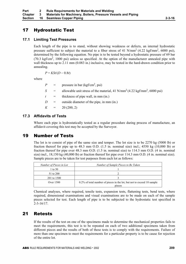
Part 2 Rule Requirements for Materials and WeldingChapter 3 Materials for Machinery, Boilers, Pressure Vessels and PipingSection 16 Seamless Copper Piping 2-3-16
ABS RULE REQUIREMENTS FOR MATERIALS AND WELDING . 2002 209
17 Hydrostatic Test 2-3-16/17
17.1 Limiting Test Pressures 2-3-16/17.1
Each length of the pipe is to stand, without showing weakness or defects, an internal hydrostaticpressure sufficient to subject the material to a fiber stress of 41 N/mm2 (4.22 kgf/mm2, 6000 psi),determined by the following equation. No pipe is to be tested beyond a hydrostatic pressure of 69 bar(70.3 kgf/cm2, 1000 psi) unless so specified. At the option of the manufacturer annealed pipe withwall thickness up to 2.11 mm (0.083 in.) inclusive, may be tested in the hard-drawn condition prior toannealing.
P = KSt/(D − 0.8t)
where
P = pressure in bar (kgf/cm2, psi)
S = allowable unit stress of the material, 41 N/mm2 (4.22 kgf/mm2, 6000 psi)
t = thickness of pipe wall, in mm (in.)
D = outside diameter of the pipe, in mm (in.)
K = 20 (200, 2)
17.3 Affidavits of Tests 2-3-16/17.3
Where each pipe is hydrostatically tested as a regular procedure during process of manufacture, anaffidavit covering this test may be accepted by the Surveyor.
19 Number of Tests 2-3-16/19
The lot is to consist of pipe of the same size and temper. The lot size is to be 2270 kg (5000 lb) orfraction thereof for pipe up to 48.3 mm O.D. (1.5 in. nominal size) incl.; 4550 kg (10,000 lb) orfraction thereof for pipe over 48.3 mm O.D. (1.5 in. nominal size) to 114.3 mm O.D. (4 in. nominalsize) incl., 18,150 kg (40,000 lb) or fraction thereof for pipe over 114.3 mm O.D. (4 in. nominal size).Sample pieces are to be taken for test purposes from each lot as follows:
Number of Pieces in Lot Number of Sample Pieces to Be Taken
1 to 50 1
51 to 200 2
201 to 1500 3
Over 1500 0.2% of total number of pieces in the lot, but not to exceed 10 samplepieces
Chemical analyses, where required, tensile tests, expansion tests, flattening tests, bend tests, whererequired, dimensional examinations and visual examinations are to be made on each of the samplepieces selected for test. Each length of pipe is to be subjected to the hydrostatic test specified in2-3-16/17.
21 Retests 2-3-16/21
If the results of the test on one of the specimens made to determine the mechanical properties fails tomeet the requirements, this test is to be repeated on each of two additional specimens taken fromdifferent pieces and the results of both of these tests is to comply with the requirements. Failure ofmore than one specimen to meet the requirements for a particular property is to be cause for rejectionof the entire lot.
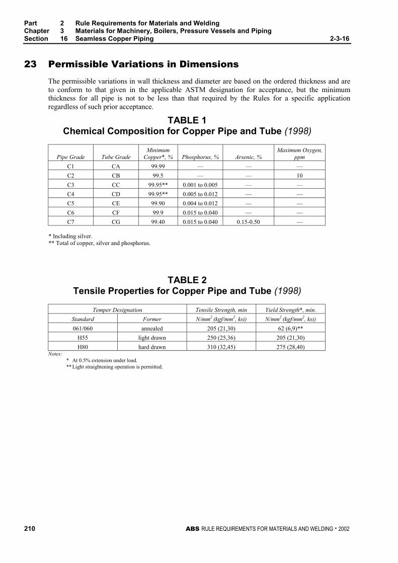
Part 2 Rule Requirements for Materials and WeldingChapter 3 Materials for Machinery, Boilers, Pressure Vessels and PipingSection 16 Seamless Copper Piping 2-3-16
210 ABS RULE REQUIREMENTS FOR MATERIALS AND WELDING . 2002
23 Permissible Variations in Dimensions 2-3-16/23
The permissible variations in wall thickness and diameter are based on the ordered thickness and areto conform to that given in the applicable ASTM designation for acceptance, but the minimumthickness for all pipe is not to be less than that required by the Rules for a specific applicationregardless of such prior acceptance.
TABLE 1Chemical Composition for Copper Pipe and Tube (1998)
Pipe Grade Tube GradeMinimum
Copper*, % Phosphorus, % Arsenic, %Maximum Oxygen,
ppm
C1 CA 99.99 — — —
C2 CB 99.5 — — 10
C3 CC 99.95** 0.001 to 0.005 — —
C4 CD 99.95** 0.005 to 0.012 — —
C5 CE 99.90 0.004 to 0.012 — —
C6 CF 99.9 0.015 to 0.040 — —
C7 CG 99.40 0.015 to 0.040 0.15-0.50 —
* Including silver.** Total of copper, silver and phosphorus.
TABLE 2Tensile Properties for Copper Pipe and Tube (1998)
Temper Designation Tensile Strength, min Yield Strength*, min.
Standard Former N/mm2 (kgf/mm2, ksi) N/mm2 (kgf/mm2, ksi)
061/060 annealed 205 (21,30) 62 (6,9)**
H55 light drawn 250 (25,36) 205 (21,30)
H80 hard drawn 310 (32,45) 275 (28,40)Notes:
* At 0.5% extension under load.** Light straightening operation is permitted.

ABS RULE REQUIREMENTS FOR MATERIALS AND WELDING . 2002 211
P A R T
2C H A P T E R 3 Materials for Machinery, Boilers,
Pressure Vessels, and Piping
S E C T I O N 17 Seamless Red-brass Piping 2 - 3 - 1 7
Note: In substantial agreement with ASTM B43.
1 Process of Manufacture 2-3-17/1
The material is to be produced by either hot or cold working operations, or both. It is to be finished,unless otherwise specified, by such cold working and annealing or heat treatment as may be necessaryto meet the properties specified. All pipe is normally to be furnished in the annealed condition. Thedegree of anneal is to be sufficient to show complete recrystallization and to enable the pipe to meetthe test requirements prescribed in these specifications. The pipe may be furnished in the drawn-temper condition instead of the annealed condition if so specified by the purchaser. All pipes forworking pressures over 10 bar (10.5 kgf/cm2, 150 psi) are to be tested and inspected at the mills bythe Surveyor. The pipe is to be commercially round and is to be free from defects that interfere withnormal applications.
3 Marking 2-3-17/3
3.1 Manufacturer’s Marking 2-3-17/3.1
The name or brand of the manufacturer, the designation B43, and the test pressure is to be legiblymarked by stamping or stenciling on each length of pipe. On small-diameter pipe, which is bundled,this information may be marked on a tag securely attached to each bundle.
3.3 Bureau Marking 2-3-17/3.3
The Bureau markings, indicating satisfactory compliance with the Rule requirements, and asfurnished by the Surveyor, are to be marked on the material near the markings specified in 2-3-17/3.1.
5 Scope 2-3-17/5
These specifications cover seamless red-brass pipe in all standard sizes both regular and extra strong.
7 Chemical Composition 2-3-17/7
The material is to conform to the following requirements as to chemical composition.
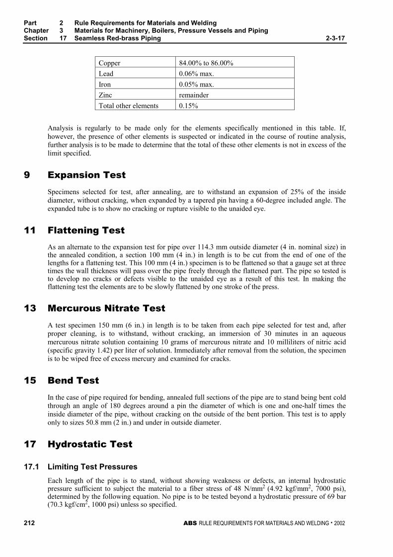
Part 2 Rule Requirements for Materials and WeldingChapter 3 Materials for Machinery, Boilers, Pressure Vessels and PipingSection 17 Seamless Red-brass Piping 2-3-17
212 ABS RULE REQUIREMENTS FOR MATERIALS AND WELDING . 2002
Copper 84.00% to 86.00%
Lead 0.06% max.
Iron 0.05% max.
Zinc remainder
Total other elements 0.15%
Analysis is regularly to be made only for the elements specifically mentioned in this table. If,however, the presence of other elements is suspected or indicated in the course of routine analysis,further analysis is to be made to determine that the total of these other elements is not in excess of thelimit specified.
9 Expansion Test 2-3-17/9
Specimens selected for test, after annealing, are to withstand an expansion of 25% of the insidediameter, without cracking, when expanded by a tapered pin having a 60-degree included angle. Theexpanded tube is to show no cracking or rupture visible to the unaided eye.
11 Flattening Test 2-3-17/11
As an alternate to the expansion test for pipe over 114.3 mm outside diameter (4 in. nominal size) inthe annealed condition, a section 100 mm (4 in.) in length is to be cut from the end of one of thelengths for a flattening test. This 100 mm (4 in.) specimen is to be flattened so that a gauge set at threetimes the wall thickness will pass over the pipe freely through the flattened part. The pipe so tested isto develop no cracks or defects visible to the unaided eye as a result of this test. In making theflattening test the elements are to be slowly flattened by one stroke of the press.
13 Mercurous Nitrate Test 2-3-17/13
A test specimen 150 mm (6 in.) in length is to be taken from each pipe selected for test and, afterproper cleaning, is to withstand, without cracking, an immersion of 30 minutes in an aqueousmercurous nitrate solution containing 10 grams of mercurous nitrate and 10 milliliters of nitric acid(specific gravity 1.42) per liter of solution. Immediately after removal from the solution, the specimenis to be wiped free of excess mercury and examined for cracks.
15 Bend Test 2-3-17/15
In the case of pipe required for bending, annealed full sections of the pipe are to stand being bent coldthrough an angle of 180 degrees around a pin the diameter of which is one and one-half times theinside diameter of the pipe, without cracking on the outside of the bent portion. This test is to applyonly to sizes 50.8 mm (2 in.) and under in outside diameter.
17 Hydrostatic Test 2-3-17/17
17.1 Limiting Test Pressures 2-3-17/17.1
Each length of the pipe is to stand, without showing weakness or defects, an internal hydrostaticpressure sufficient to subject the material to a fiber stress of 48 N/mm2 (4.92 kgf/mm2, 7000 psi),determined by the following equation. No pipe is to be tested beyond a hydrostatic pressure of 69 bar(70.3 kgf/cm2, 1000 psi) unless so specified.
Part 2 Rule Requirements for Materials and WeldingChapter 3 Materials for Machinery, Boilers, Pressure Vessels and PipingSection 17 Seamless Red-brass Piping 2-3-17
ABS RULE REQUIREMENTS FOR MATERIALS AND WELDING . 2002 213
P = KSt/(D − 0.8t)
where
P = pressure, in bar (kgf/cm2, psi)
S = allowable unit stress of the material, 48 N/mm2 (4.92 kgf/mm2, 7000 psi)
t = thickness of pipe wall, in mm (in.)
D = outside diameter of the pipe, in mm (in.)
K = 20 (200, 2)
17.3 Affidavits of Tests 2-3-17/17.3
Where each pipe is hydrostatically tested as a regular procedure during process of manufacture, anaffidavit covering this test may be accepted by the Surveyor.
19 Number of Tests 2-3-17/19
The lot size is to be 2270 kg (5000 lb) or fraction thereof for pipe up to 48.3 mm O.D. (1.5 in.nominal size) incl., 4540 kg (10,000 lb) or fraction thereof for pipe over 48.3 mm O.D. (1.5 in.nominal size) to 114.3 mm O.D. incl. (4 in. nominal size), 18,150 kg (40,000 lb) or fraction thereoffor pipe over 114.3 mm O.D. (4 in. nominal size). Sample pieces are to be taken for test purposesfrom each lot as follows.
Number of Pieces in Lot Number of Sample Pieces to Be Taken
1 to 50 1
51 to 200 2
701 to 1500 3
over 1500 0.2% of total number of pieces in the lot, but not to exceed 10sample pieces
Expansion, flattening and bend tests, where required, are to be made on each of the sample piecesselected for test. Each length of pipe is to be subjected to the hydrostatic test specified in 2-3-17/17.1.
21 Retests 2-3-17/21
If the results of the test on one of the specimens made to determine the physical properties fails tomeet the requirements, this test is to be repeated on each of two additional specimens taken fromdifferent pieces and the results of both of these tests are to comply with the requirements. Failure ofmore than one specimen to meet the requirements for a particular property is to be cause for rejectionof the entire lot.
23 Permissible Variations in Dimensions 2-3-17/23
The permissible variations in wall thicknesses are based on the ordered thicknesses and is to conformto that given in the applicable ASTM designation for acceptance, but the minimum thickness for allpipe is not to be less than that required by the Rules for a specific application regardless of such prioracceptance.

ABS RULE REQUIREMENTS FOR MATERIALS AND WELDING . 2002 215
P A R T
2C H A P T E R 3 Materials for Machinery, Boilers,
Pressure Vessels, and Piping
S E C T I O N 18 Seamless Copper Tube (1998) 2 - 3 - 1 8
Note: In substantial agreement with ASTM B75.
1 Scope 2-3-18/1
The following specifications cover seven grades of seamless copper tube designated CA, CB, CC,CD, CE, CF and CG.
3 General 2-3-18/3
3.1 Grades CA, CB, CC, CD, CE, CF and CG 2-3-18/3.1
These grades cover seamless copper tube intended for boiler feedwater lines, plumbing, and generalengineering applications. Tube is to be ordered to outer diameter and wall thickness specified by thepurchaser and approved for the application. Tube ordered under these grades are considered suitablefor welding and brazing. Seamless round copper tube in standard pipe sizes and schedules isconsidered to be pipe and is covered by Section 2-3-16.
3.3 ASTM Designation 2-3-18/3.3
The grades are in substantial agreement with ASTM as follows:
ABS Grade ASTM Designation
CA B75, UNS C10100
CB B75, UNS C10200
CC B75, UNS C10300
CD B75, UNS C10800
CE B75, UNS C12000
CF B75, UNS C12200
CG B75, UNS C14200
5 Process of Manufacture 2-3-18/5
The material is to be produced by either hot or cold working operations, or both. It is to be finished,unless otherwise specified, by such cold working and annealing or heat treatment as may be necessaryto meet the properties specified. All tube is to be normally furnished in the drawn-temper condition,
Part 2 Rule Requirements for Materials and WeldingChapter 3 Materials for Machinery, Boilers, Pressure Vessels and PipingSection 18 Seamless Copper Tube 2-3-18
216 ABS RULE REQUIREMENTS FOR MATERIALS AND WELDING . 2002
(H55). Hard-drawn temper (H80) may be furnished also. When tube is required for bending, the tubeis to be furnished with a proper bending temper, or annealed temper (O60). All tubes for workingpressures over 10 bar (10.5 kgf/cm2, 150 psi) are to be tested and inspected at the mills by theSurveyor. The tube is to be commercially round and is to be free from defects that interfere withnormal applications.
7 Marking 2-3-18/7
7.1 Manufacturer’s Marking 2-3-18/7.1
The name or brand of the manufacturer, the designation B75, and the test pressure are to be legiblymarked by stamping or stenciled on each length of tube. On small-diameter tube, which is bundled,this information may be marked on a tag securely attached to each bundle.
7.3 Bureau Markings 2-3-18/7.3
The Bureau markings, indicating satisfactory compliance with the Rule requirements, and asfurnished by the Surveyor, are to be placed on the material near the markings specified in 2-3-18/7.1.
9 Chemical Composition 2-3-18/9
The material is to conform to the applicable requirements as to chemical composition as shown in2-3-16/Table 1.
11 Tension Test 2-3-18/11
11.1 Tension Test Specimens 2-3-18/11.1
Tensile test specimens are to be full section of the tube. For larger sizes, tension test specimens are toconsist of longitudinal strips cut from the tube in accordance with ASTM E8.
11.3 Tensile Properties 2-3-18/11.3
The material is to conform to the applicable requirements as to tensile properties shown in2-3-16/Table 2.
13 Expansion Test 2-3-18/13
Note: This test is required for tubes manufactured in the annealed temper.
Specimens selected for test, after annealing, are to withstand an expansion of the outside diameterwhen expanded by a tapered pin having a 60-degree included angle to 30 percent for tube over19.0 mm (3/4 in.) in outside diameter and to 40 percent for smaller sized tube. The expanded tube is toshow no cracking or rupture visible to the unaided eye.
15 Flattening Test 2-3-18/15
As an alternate to the expansion test for tube over 114.3 mm outside diameter (4 in. nominal size) inthe annealed condition, a section 100 mm (4 in.) in length is to be cut from the end of one of thelengths for a flattening test. This 100 mm (4 in.) specimen is to be flattened so that a gauge set at threetimes the wall thickness will pass over the pipe freely throughout the flattened part. The tube so testedis to develop no cracks or defects visible to the unaided eye as a result of this test. In making theflattening test the specimens are to be slowly flattened by one stroke of the press.
Part 2 Rule Requirements for Materials and WeldingChapter 3 Materials for Machinery, Boilers, Pressure Vessels and PipingSection 18 Seamless Copper Tube 2-3-18
ABS RULE REQUIREMENTS FOR MATERIALS AND WELDING . 2002 217
17 Hydrostatic Test 2-3-18/17
17.1 Limiting Test Pressures 2-3-18/17.1
Each length of the tube is to stand, without showing weakness or defects, an internal hydrostaticpressure sufficient to subject the material to a fiber stress of 41 N/mm2 (4.22 kgf/mm2, 6000 psi),determined by the following equation. No pipe is to be tested beyond a hydrostatic pressure of 69 bar(70.3 kgf/cm2, 1000 psi) unless so specified. At the option of the manufacturer annealed tube withwall thickness up to 2.11 mm (0.083 in.) inclusive, may be tested in the hard-drawn condition prior toannealing.
P = KSt/(D − 0.8t)
where
P = pressure, in bar (kgf/cm2, psi)
S = allowable unit stress of the material, 41 N/mm2 (4.22 kgf/mm2, 6000 psi)
t = thickness of pipe wall, in mm (in.)
D = outside diameter of the pipe, in mm (in.)
K = 20 (200, 2)
17.3 Affidavits of Tests 2-3-18/17.3
Where each tube is hydrostatically tested as a regular procedure during process of manufacture, anaffidavit covering this test may be accepted by the Surveyor.
19 Number of Tests 2-3-18/19
The lot is to consist of tubes of the same size and temper. The lot size is to be 4540 kg (10,000 lb) orfraction thereof. Sample pieces are to be taken for test purposes at random from each lot as follows:
Number of Pieces in Lot Number of Sample Pieces to be Taken
1 to 50 1
51 to 200 2
201 to 1500 3
over 1500 0.2% of total number of pieces in the lot, but not to exceed10 sample pieces
Chemical analyses, where required, tensile tests, expansion tests, flattening tests, bend tests, whererequired, dimensional examinations and visual examinations are to be made on each of the samplepieces selected for test. Each length of pipe is to be subjected to the hydrostatic test specified in2-3-18/19.
21 Retests 2-3-18/21
If the results of the test on one of the specimens made to determine the mechanical properties fails tomeet the requirements, this test is to be repeated on each of two additional specimens taken fromdifferent pieces and the results of both of these tests is to comply with the requirements. Failure ofmore than one specimen to meet the requirements for a particular property is to be cause for rejectionof the entire lot.
Part 2 Rule Requirements for Materials and WeldingChapter 3 Materials for Machinery, Boilers, Pressure Vessels and PipingSection 18 Seamless Copper Tube 2-3-18
218 ABS RULE REQUIREMENTS FOR MATERIALS AND WELDING . 2002
23 Permissible Variations in Dimensions 2-3-18/23
The permissible variations in wall thickness and diameter are based on the ordered thickness and areto conform to that given in the applicable ASTM for acceptance, but the minimum thickness for allpipe is not to be less than that required by the Rules for a specific application regardless of any prioracceptance.
ABS RULE REQUIREMENTS FOR MATERIALS AND WELDING . 2002 219
P A R T
2C H A P T E R 3 Materials for Machinery, Boilers,
Pressure Vessels, and Piping
S E C T I O N 19 Condenser and Heat ExchangerTube
CONTENTS1 Scope ................................................................................... 221
3 General................................................................................. 221
3.1 Grades CNA and CNB ......................................................... 221
3.3 ASTM Designation ............................................................... 221
5 Process of Manufacture ...................................................... 221
5.1 Grade CNA........................................................................... 221
5.3 Grade CNB........................................................................... 222
7 Marking ................................................................................ 222
9 Chemical Composition........................................................ 222
9.1 Chemical Requirements ....................................................... 222
9.3 Chemical Analysis Sampling ................................................ 222
11 Tension Test ........................................................................ 222
11.1 Tension Test Specimens...................................................... 222
11.3 Tensile Properties ................................................................ 222
13 Expansion Test.................................................................... 223
15 Flattening Test..................................................................... 223
17 Nondestructive Electric Test (NDET) ................................. 223
19 Hydrostatic Test .................................................................. 224
19.1 Limiting Test Pressures........................................................ 224
19.3 Affidavits of Tests ................................................................ 224
21 Number of Tests .................................................................. 224
23 Retests ................................................................................. 224
25 Finish.................................................................................... 225
220 ABS RULE REQUIREMENTS FOR MATERIALS AND WELDING . 2002
27 Dimensions and Tolerances................................................225
27.1 Diameter ............................................................................... 225
27.3 Wall Thickness Tolerances ................................................. 225
27.5 Length................................................................................... 226
27.7 Squareness of Cut................................................................ 226
TABLE 1 Chemical Composition for Copper NickelPipe and Tube...........................................................227
TABLE 2 Tensile Properties for Seamless Copper NickelPipe and Tube...........................................................227
ABS RULE REQUIREMENTS FOR MATERIALS AND WELDING . 2002 221
P A R T
2C H A P T E R 3 Materials for Machinery, Boilers,
Pressure Vessels, and Piping
S E C T I O N 19 Condenser and Heat ExchangerTube (1998) 2 - 3 - 1 9
Note: In substantial agreement with ASTM B111.
1 Scope 2-3-19/1
The following specifications covers two grades of seamless copper-nickel tube designated CNA andCNB.
3 General 2-3-19/3
3.1 Grades CNA and CNB 2-3-19/3.1
Grades CNA, and CNB cover seamless copper-nickel tube intended for use in condensers,evaporators, and heat exchanger which may use sea water as the cooling medium. Tube ordered underthese grades are considered suitable for welding, and suitable for forming operations involvingcoiling, bending, flaring, and tube rolling. Tube is to be ordered to outer diameter and wall thicknessspecified by the purchaser and approved for the application.
3.3 ASTM Designation 2-3-19/3.3
The grades are in substantial agreement with ASTM as follows:
ABS Grade ASTM Designation
CNA B111, UNS C70600
CNB B111, UNS C71500
5 Process of Manufacture 2-3-19/5
5.1 Grade CNA 2-3-19/5.1
Grade CNA tube is to be cold worked to the specified size. The tube may be supplied either in theannealed temper (O61) or in the light drawn temper (H55).
Part 2 Rule Requirements for Materials and WeldingChapter 3 Materials for Machinery, Boilers, Pressure Vessels and PipingSection 19 Condenser and Heat Exchanger Tube 2-3-19
222 ABS RULE REQUIREMENTS FOR MATERIALS AND WELDING . 2002
5.3 Grade CNB 2-3-19/5.3
Grade CNB tube is to be cold worked to the specified size. The tube may be supplied either in theannealed temper (O61) or in the drawn and stress relieved temper (HR50).
All grades of tube shall be round, straight, clean, smooth and free from harmful defects anddeleterious films in the bore.
7 Marking 2-3-19/7
Identification markings are to be legibly stenciled, or suitably marked on each length of tube, exceptthat in the case of smaller-diameter tube which is bundled, the required markings are to be placed on atag securely attached to the bundle. The markings are to be arranged and are to include the followinginformation:
Name or brand of the manufacturer
ABS Grade or ASTM Designation and Grade
Temper number
Tube diameter
Wall thickness
Test Pressure, or the letters NDET
ABS markings by the Surveyor
9 Chemical Composition 2-3-19/9
9.1 Chemical Requirements 2-3-19/9.1
The material is to conform to the applicable requirements as to chemical composition as shown in2-3-19/Table 1.
9.3 Chemical Analysis Sampling 2-3-19/9.3
Samples may be taken at the time the metal is cast or may be taken from semi-finished product, orfrom finished product in accordance with sampling in 2-3-19/21.
11 Tension Test 2-3-19/11
11.1 Tension Test Specimens 2-3-19/11.1
Tensile test specimens are to be full section of the tube. For larger sizes, tension test specimens are toconsist of longitudinal strips cut from the tube in accordance with ASTM E8, for Tension Testing ofMetallic Materials.
11.3 Tensile Properties 2-3-19/11.3
The material is to conform to the applicable requirements as to tensile properties shown in2-3-19/Table 2.
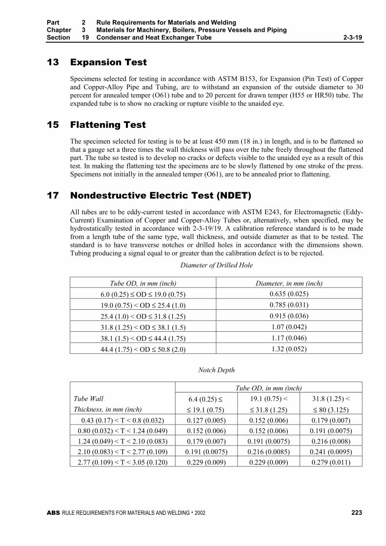
Part 2 Rule Requirements for Materials and WeldingChapter 3 Materials for Machinery, Boilers, Pressure Vessels and PipingSection 19 Condenser and Heat Exchanger Tube 2-3-19
ABS RULE REQUIREMENTS FOR MATERIALS AND WELDING . 2002 223
13 Expansion Test 2-3-19/13
Specimens selected for testing in accordance with ASTM B153, for Expansion (Pin Test) of Copperand Copper-Alloy Pipe and Tubing, are to withstand an expansion of the outside diameter to 30percent for annealed temper (O61) tube and to 20 percent for drawn temper (H55 or HR50) tube. Theexpanded tube is to show no cracking or rupture visible to the unaided eye.
15 Flattening Test 2-3-19/15
The specimen selected for testing is to be at least 450 mm (18 in.) in length, and is to be flattened sothat a gauge set a three times the wall thickness will pass over the tube freely throughout the flattenedpart. The tube so tested is to develop no cracks or defects visible to the unaided eye as a result of thistest. In making the flattening test the specimens are to be slowly flattened by one stroke of the press.Specimens not initially in the annealed temper (O61), are to be annealed prior to flattening.
17 Nondestructive Electric Test (NDET) 2-3-19/17
All tubes are to be eddy-current tested in accordance with ASTM E243, for Electromagnetic (Eddy-Current) Examination of Copper and Copper-Alloy Tubes or, alternatively, when specified, may behydrostatically tested in accordance with 2-3-19/19. A calibration reference standard is to be madefrom a length tube of the same type, wall thickness, and outside diameter as that to be tested. Thestandard is to have transverse notches or drilled holes in accordance with the dimensions shown.Tubing producing a signal equal to or greater than the calibration defect is to be rejected.
Diameter of Drilled Hole
Tube OD, in mm (inch) Diameter, in mm (inch)
6.0 (0.25) ≤ OD ≤ 19.0 (0.75) 0.635 (0.025)
19.0 (0.75) < OD ≤ 25.4 (1.0) 0.785 (0.031)
25.4 (1.0) < OD ≤ 31.8 (1.25) 0.915 (0.036)
31.8 (1.25) < OD ≤ 38.1 (1.5) 1.07 (0.042)
38.1 (1.5) < OD ≤ 44.4 (1.75) 1.17 (0.046)
44.4 (1.75) < OD ≤ 50.8 (2.0) 1.32 (0.052)
Notch Depth
Tube OD, in mm (inch)
Tube Wall 6.4 (0.25) ≤ 19.1 (0.75) < 31.8 (1.25) <
Thickness, in mm (inch) ≤ 19.1 (0.75) ≤ 31.8 (1.25) ≤ 80 (3.125)
0.43 (0.17) < T < 0.8 (0.032) 0.127 (0.005) 0.152 (0.006) 0.179 (0.007)
0.80 (0.032) < T < 1.24 (0.049) 0.152 (0.006) 0.152 (0.006) 0.191 (0.0075)
1.24 (0.049) < T < 2.10 (0.083) 0.179 (0.007) 0.191 (0.0075) 0.216 (0.008)
2.10 (0.083) < T < 2.77 (0.109) 0.191 (0.0075) 0.216 (0.0085) 0.241 (0.0095)
2.77 (0.109) < T < 3.05 (0.120) 0.229 (0.009) 0.229 (0.009) 0.279 (0.011)
Part 2 Rule Requirements for Materials and WeldingChapter 3 Materials for Machinery, Boilers, Pressure Vessels and PipingSection 19 Condenser and Heat Exchanger Tube 2-3-19
224 ABS RULE REQUIREMENTS FOR MATERIALS AND WELDING . 2002
19 Hydrostatic Test 2-3-19/19
19.1 Limiting Test Pressures 2-3-19/19.1
As an alternate to the eddy-current test, hydrostatic testing may be performed. Each tube that is testedis to stand, without showing evidence of leakage, an internal hydrostatic pressure sufficient to subjectthe material to a fiber stress of 48 N/mm2 (4.92 kgf/mm2, 7000 psi), determined by the followingequation for thin hollow cylinders under tension. The tube is not to be tested at a hydrostatic pressureof over 69 bar (70.3 kgf/cm2, 1000 psi) unless so specified.
P = KSt/(D − 0.8t)
where
P = pressure in bar (kgf/cm2, psi)
S = allowable unit stress of the material, 48 N/mm2 (4.92 kgf/mm2, 7000 psi)
t = thickness of pipe wall, in mm (in.)
D = outside diameter of the pipe, in mm (in.)
K = 20 (200, 2)
19.3 Affidavits of Tests 2-3-19/19.3
Where each tube is hydrostatically tested as a regular procedure during process of manufacture, anaffidavit covering this test may be accepted by the Surveyor.
21 Number of Tests 2-3-19/21
The lot is to consist of tubes of the same size and temper. The lot size is to be 4540 kg (10,000 lb) orfraction thereof. Sample pieces are to be taken for test purposes at random from each lot as follows:
Number of Pieces in Lot Number of Sample Pieces to be Taken
1 to 50 1
51 to 200 2
201 to 1500 3
over 1500 0.2% of total number of pieces in the lot, but not to exceed 10sample pieces
Chemical analyses, where required, tensile tests, expansion tests, flattening tests, dimensionalexaminations and visual examinations are to be made on each of the sample pieces selected for test.Each length of pipe is to be subjected to the eddy-current test or the hydrostatic test.
23 Retests 2-3-19/23
If the results of the test on one of the specimens made to determine the mechanical properties fails tomeet the requirements, this test is to be repeated on each of two additional specimens taken fromdifferent pieces and the results of both of these tests is to comply with the requirements. Failure ofmore than one specimen to meet the requirements for a particular property is to be cause for rejectionof the entire lot.
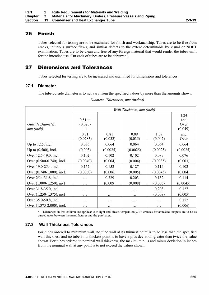
Part 2 Rule Requirements for Materials and WeldingChapter 3 Materials for Machinery, Boilers, Pressure Vessels and PipingSection 19 Condenser and Heat Exchanger Tube 2-3-19
ABS RULE REQUIREMENTS FOR MATERIALS AND WELDING . 2002 225
25 Finish 2-3-19/25
Tubes selected for testing are to be examined for finish and workmanship. Tubes are to be free fromcracks, injurious surface flaws, and similar defects to the extent determinable by visual or NDETexamination. Tubes are to be clean and free of any foreign material that would render the tubes unfitfor the intended use. Cut ends of tubes are to be deburred.
27 Dimensions and Tolerances 2-3-19/27
Tubes selected for testing are to be measured and examined for dimensions and tolerances.
27.1 Diameter 2-3-19/27.1
The tube outside diameter is to not vary from the specified values by more than the amounts shown.
Diameter Tolerances, mm (inches)
Wall Thickness, mm (inch)
Outside Diameter,mm (inch)
0.51 to(0.020)
to
1.24and
Over(0.049)
0.71(0.028*)
0.81(0.032)
0.89(0.035)
1.07(0.042)
andOver
Up to 12.5, incl. 0.076 0.064 0.064 0.064 0.064
Up to (0.500), incl. (0.003) (0.0025) (0.0025) (0.0025) (0.0025)
Over 12.5-19.0, incl. 0.102 0.102 0.102 0.089 0.076
Over (0.500-0.740), incl. (0.0040) (0.004) (0.004) (0.0035) (0.003)
Over 19.0-25.4, incl 0.152 0.152 0.127 0.114 0.102
Over (0.740-1,000), incl. (0.0060) (0.006) (0.005) (0.0045) (0.004)
Over 25.4-31.8, incl. … 0.229 0.203 0.152 0.114
Over (1.000-1.250), incl … (0.009) (0.008) (0.006) (0.0045)
Over 31.8-35.0, incl. … … … 0.203 0.127
Over (1.250-1.375), incl … … … (0.008) (0.005)
Over 35.0-50.8, incl. … … … … 0.152
Over (1.375-2.000), incl. … … … … (0.006)
* Tolerances in this column are applicable to light and drawn tempers only. Tolerances for annealed tempers are to be asagreed upon between the manufacturer and the purchaser.
27.3 Wall Thickness Tolerances 2-3-19/27.3
For tubes ordered to minimum wall, no tube wall at its thinnest point is to be less than the specifiedwall thickness and no tube at its thickest point is to have a plus deviation greater than twice the valueshown. For tubes ordered to nominal wall thickness, the maximum plus and minus deviation in inchesfrom the nominal wall at any point is to not exceed the values shown.
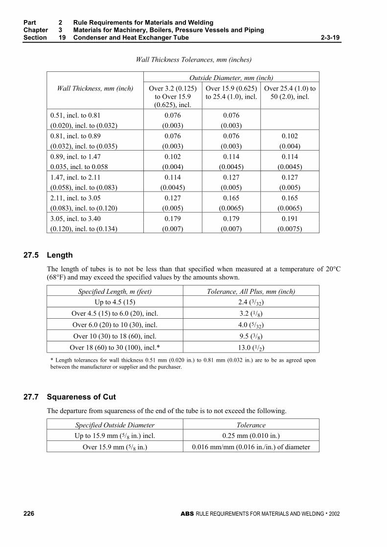
Part 2 Rule Requirements for Materials and WeldingChapter 3 Materials for Machinery, Boilers, Pressure Vessels and PipingSection 19 Condenser and Heat Exchanger Tube 2-3-19
226 ABS RULE REQUIREMENTS FOR MATERIALS AND WELDING . 2002
Wall Thickness Tolerances, mm (inches)
Outside Diameter, mm (inch)
Wall Thickness, mm (inch) Over 3.2 (0.125)to Over 15.9(0.625), incl.
Over 15.9 (0.625)to 25.4 (1.0), incl.
Over 25.4 (1.0) to50 (2.0), incl.
0.51, incl. to 0.81 0.076 0.076
(0.020), incl. to (0.032) (0.003) (0.003)
0.81, incl. to 0.89 0.076 0.076 0.102
(0.032), incl. to (0.035) (0.003) (0.003) (0.004)
0.89, incl. to 1.47 0.102 0.114 0.114
0.035, incl. to 0.058 (0.004) (0.0045) (0.0045)
1.47, incl. to 2.11 0.114 0.127 0.127
(0.058), incl. to (0.083) (0.0045) (0.005) (0.005)
2.11, incl. to 3.05 0.127 0.165 0.165
(0.083), incl. to (0.120) (0.005) (0.0065) (0.0065)
3.05, incl. to 3.40 0.179 0.179 0.191
(0.120), incl. to (0.134) (0.007) (0.007) (0.0075)
27.5 Length 2-3-19/27.5
The length of tubes is to not be less than that specified when measured at a temperature of 20°C(68°F) and may exceed the specified values by the amounts shown.
Specified Length, m (feet) Tolerance, All Plus, mm (inch)
Up to 4.5 (15) 2.4 (3/32)
Over 4.5 (15) to 6.0 (20), incl. 3.2 (1/8)
Over 6.0 (20) to 10 (30), incl. 4.0 (5/32)
Over 10 (30) to 18 (60), incl. 9.5 (3/8)
Over 18 (60) to 30 (100), incl.* 13.0 (1/2)
* Length tolerances for wall thickness 0.51 mm (0.020 in.) to 0.81 mm (0.032 in.) are to be as agreed uponbetween the manufacturer or supplier and the purchaser.
27.7 Squareness of Cut 2-3-19/27.7
The departure from squareness of the end of the tube is to not exceed the following.
Specified Outside Diameter Tolerance
Up to 15.9 mm (5/8 in.) incl. 0.25 mm (0.010 in.)
Over 15.9 mm (5/8 in.) 0.016 mm/mm (0.016 in./in.) of diameter
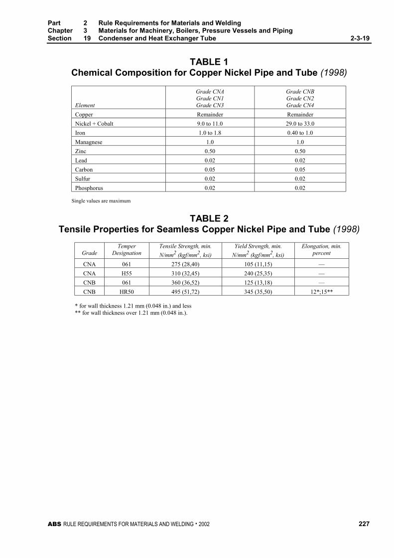
Part 2 Rule Requirements for Materials and WeldingChapter 3 Materials for Machinery, Boilers, Pressure Vessels and PipingSection 19 Condenser and Heat Exchanger Tube 2-3-19
ABS RULE REQUIREMENTS FOR MATERIALS AND WELDING . 2002 227
TABLE 1Chemical Composition for Copper Nickel Pipe and Tube (1998)
Element
Grade CNAGrade CN1Grade CN3
Grade CNBGrade CN2Grade CN4
Copper Remainder Remainder
Nickel + Cobalt 9.0 to 11.0 29.0 to 33.0
Iron 1.0 to 1.8 0.40 to 1.0
Managnese 1.0 1.0
Zinc 0.50 0.50
Lead 0.02 0.02
Carbon 0.05 0.05
Sulfur 0.02 0.02
Phosphorus 0.02 0.02
Single values are maximum
TABLE 2Tensile Properties for Seamless Copper Nickel Pipe and Tube (1998)
GradeTemper
DesignationTensile Strength, min.
N/mm2 (kgf/mm2, ksi)
Yield Strength, min.
N/mm2 (kgf/mm2, ksi)
Elongation, min.percent
CNA 061 275 (28,40) 105 (11,15) —
CNA H55 310 (32,45) 240 (25,35) —
CNB 061 360 (36,52) 125 (13,18) —
CNB HR50 495 (51,72) 345 (35,50) 12*;15**
* for wall thickness 1.21 mm (0.048 in.) and less** for wall thickness over 1.21 mm (0.048 in.).

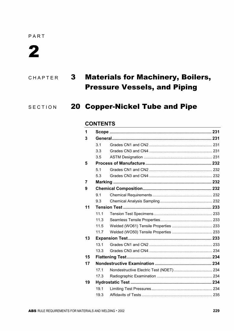
ABS RULE REQUIREMENTS FOR MATERIALS AND WELDING . 2002 229
P A R T
2C H A P T E R 3 Materials for Machinery, Boilers,
Pressure Vessels, and Piping
S E C T I O N 20 Copper-Nickel Tube and Pipe
CONTENTS1 Scope ................................................................................... 231
3 General................................................................................. 231
3.1 Grades CN1 and CN2 .......................................................... 231
3.3 Grades CN3 and CN4 .......................................................... 231
3.5 ASTM Designation ............................................................... 231
5 Process of Manufacture ...................................................... 232
5.1 Grades CN1 and CN2 .......................................................... 232
5.3 Grades CN3 and CN4 .......................................................... 232
7 Marking ................................................................................ 232
9 Chemical Composition........................................................ 232
9.1 Chemical Requirements ....................................................... 232
9.3 Chemical Analysis Sampling ................................................ 232
11 Tension Test ........................................................................ 233
11.1 Tension Test Specimens...................................................... 233
11.3 Seamless Tensile Properties................................................ 233
11.5 Welded (WO61) Tensile Properties ..................................... 233
11.7 Welded (WO50) Tensile Properties ..................................... 233
13 Expansion Test.................................................................... 233
13.1 Grades CN1 and CN2 .......................................................... 233
13.3 Grades CN3 and CN4 .......................................................... 234
15 Flattening Test..................................................................... 234
17 Nondestructive Examination .............................................. 234
17.1 Nondestructive Electric Test (NDET) ................................... 234
17.3 Radiographic Examination ................................................... 234
19 Hydrostatic Test .................................................................. 234
19.1 Limiting Test Pressures........................................................ 234
19.3 Affidavits of Tests ................................................................. 235
230 ABS RULE REQUIREMENTS FOR MATERIALS AND WELDING . 2002
21 Number of Tests...................................................................235
23 Retests..................................................................................235
25 Finish ....................................................................................235
27 Dimensions and Tolerances................................................235
27.1 Diameter ............................................................................... 235
27.3 Roundness ........................................................................... 236
27.5 Wall Thickness Tolerances .................................................. 236
27.7 Length................................................................................... 236
27.9 Squareness of Cut................................................................ 237
27.11 Straightness Tolerances....................................................... 237
ABS RULE REQUIREMENTS FOR MATERIALS AND WELDING . 2002 231
P A R T
2C H A P T E R 3 Materials for Machinery, Boilers,
Pressure Vessels, and Piping2 - 3 - 2 0
S E C T I O N 20 Copper-Nickel Tube and Pipe (1998)
Note In substantial agreement with ASTM B466 and B467.
1 Scope 2-3-20/1
This specification covers four grades of seamless and welded copper-nickel tube and pipe designatedCN1, CN2, CN3 and CN4.
3 General 2-3-20/3
3.1 Grades CN1 and CN2 2-3-20/3.1
Grades CN1 and CN2 cover seamless copper-nickel tube and pipe intended for use generalengineering applications requiring seawater corrosion resistance. Tube and pipe ordered under thesegrades are considered suitable for welding, and suitable for forming operations involving bending,flaring, and flanging. Tube is to be ordered to outer diameter and wall thickness specified by thepurchaser and approved for the application.
3.3 Grades CN3 and CN4 2-3-20/3.3
Grades CN3 and CN4 cover welded copper-nickel pipe intended for use general engineeringapplications requiring seawater corrosion resistance. Pipe ordered under these grades are consideredsuitable for welding, and suitable for forming operations involving bending, flaring, and flanging.
3.5 ASTM Designation 2-3-20/3.5
These grades are in substantial agreement with ASTM as follows:
ABS Grade ASTM Designation
CN1 B466, UNS C70600
CN2 B466, UNS C71500
CN3 B467, UNS C70600
CN4 B467, UNS C71500
Part 2 Rule Requirements for Materials and WeldingChapter 3 Materials for Machinery, Boilers, Pressure Vessels and PipingSection 20 Copper Nickel Tube and Pipe 2-3-20
232 ABS RULE REQUIREMENTS FOR MATERIALS AND WELDING . 2002
5 Process of Manufacture 2-3-20/5
The material is to be produced by either hot or cold working operations, or both. The tubing is to befinished, unless otherwise specified, by such cold working or annealing or heat treatment as may benecessary to meet the properties for either annealed or light drawn material. The light drawnproperties apply only to grades CN1 and CN3.
5.1 Grades CN1 and CN2 2-3-20/5.1
Grade CN1 may be supplied in either annealed (O60) or light drawn (H55) tempers. Grade CN2 maybe supplied in only annealed (O60) temper.
5.3 Grades CN3 and CN4 2-3-20/5.3
Grade CN3 may be supplied in either the welded from annealed skelp temper (WM50), or the weldedand fully finished as annealed temper (WO61). Grade CN4 may be supplied in the welded and fullyfinished as annealed temper (WO61). The internal and external flash is to be removed by scarfing andthere is to be no crevice in the weld seam visible to the unaided eye.
7 Marking 2-3-20/7
Identification markings are to be legibly stenciled, or suitably marked on each length of tubular,except that in the case of small-diameter tubular which is bundled, the required markings are to beplaced on a tag securely attached to the bundle. The markings are to be arranged and are to include thefollowing information:
Name or brand of the manufacturer
ABS Grade or ASTM Designation and Grade
Temper number
Diameter
Wall thickness or Pipe Schedule
Test Pressure, or the letters NDET
ABS markings by the Surveyor
9 Chemical Composition 2-3-20/9
9.1 Chemical Requirements 2-3-20/9.1
The material is to conform to the chemical requirements specified in 2-3-19/Table 1.
9.3 Chemical Analysis Sampling 2-3-20/9.3
Samples may be taken at the time the metal is cast or may be taken from semi-furnished product, orfrom finished product in accordance with sampling in 2-3-20/21.
Part 2 Rule Requirements for Materials and WeldingChapter 3 Materials for Machinery, Boilers, Pressure Vessels and PipingSection 20 Copper Nickel Tube and Pipe 2-3-20
ABS RULE REQUIREMENTS FOR MATERIALS AND WELDING . 2002 233
11 Tension Test 2-3-20/11
11.1 Tension Test Specimens 2-3-20/11.1
Tensile test specimens are to be full section of the tube. For larger sizes, tension test specimens are toconsist of longitudinal strips cut from the tube in accordance with ASTM E8, for Tension Testing ofMetallic Materials.
11.3 Seamless Tensile Properties 2-3-20/11.3
Seamless material is to conform to the applicable requirements as to tensile properties shown.
Temper Number Temper Grade
Tensile Strength,min. N/mm2
(kgf/mm2, ksi)
Yield Strength,min. N/mm2
(kgf/mm2, ksi)
060 Soft anneal CN1 260 (27, 38) 90 (9, 13)
CN2 360 (37, 52) 125 (13, 18)
H55 Light Drawn CN1 310 (32, 45) 240 (25, 35)
11.5 Welded (WO61) Tensile Properties 2-3-20/11.5
Welded and fully finished pipe furnished in the annealed temper (WO61) is to conform to theapplicable requirements as to the tensile properties shown.
GradeOutside Diameter,
mm (inch)
Tensile Strengthmin. N/mm2
(kgf/mm2, ksi)
Yield Strength,min. N/mm2
(kgf/mm2, ksi)Elongation
percent
CN3 Up to 114 (4.5), incl. 275 (28, 40) 105 (11, 15) 25.0
over 114 (4.5) 260 (27, 38) 90 (9, 13) 25.0
CN4 Up to 114 (4.5), incl. 345 (35, 50) 140 (14, 20) 30.0
over 114 (4.5) 310 (32, 45) 105 (11, 15) 30.0
11.7 Welded (WO50) Tensile Properties 2-3-20/11.7
As-welded pipe fabricated from annealed strip (WO50) is to conform to the applicable requirementsas to the tensile properties shown.
Grade
Outside Diameter,mm (inch)
Tensile Strength,min. N/mm2
(kgf/mm2, ksi)Yield Strength, min.
N/mm2 (kgf/mm2, ksi)
CN3 up to 114 (4.5), incl. 310 (32, 45) 205 (21, 30)
13 Expansion Test 2-3-20/13
Note: This test is required for tubes manufactured in the annealed temper.
13.1 Grades CN1 and CN2 2-3-20/13.1
Annealed specimens selected for testing in accordance with ASTM B153, for Expansion (Pin Test) ofCopper and Copper-Alloy Pipe and Tubing, are to withstand an expansion of the outside diameter to30 percent. The expanded specimen is to show no cracking or rupture visible to the unaided eye.
Part 2 Rule Requirements for Materials and WeldingChapter 3 Materials for Machinery, Boilers, Pressure Vessels and PipingSection 20 Copper Nickel Tube and Pipe 2-3-20
234 ABS RULE REQUIREMENTS FOR MATERIALS AND WELDING . 2002
13.3 Grades CN3 and CN4 2-3-20/13.3
Annealed specimens selected for testing in accordance with ASTM B153, for Expansion (Pin Test) ofCopper and Copper-Alloy Pipe and Tubing, are to withstand an expansion of the outside diameter to30 percent. As welded specimens are to withstand an expansion of the outside diameter to 20 percentwhen similarly tested. The expanded specimen is to show no cracking or rupture visible to the unaidedeye.
15 Flattening Test 2-3-20/15
As an alternate to the expansion test for seamless material over 100 mm (4 in.) in diameter and in theannealed condition, a flattening test may be carried out. This specimen selected for testing is to be atleast 450 mm (18 in.) in length, and is to be flattened so that a gauge set at three times the wallthickness will pass over the tube freely throughout the flattened part. The tube so tested is to developno cracks or defects visible to the unaided eye as a result of this test. In making the flattening test thespecimens are to be slowly flattened by one stroke of the press. Specimens not initially in theannealed temper (O60), are to be annealed prior to flattening.
17 Nondestructive Examination 2-3-20/17
17.1 Nondestructive Electric Test (NDET) 2-3-20/17.1
All tubes are to be eddy-current tested in accordance with ASTM E243, for Electromagnetic (Eddy-Current) Examination of Copper and Copper-Alloy Tubes or, alternatively, when specified, may behydrostatically tested in accordance with 2-3-19/19. A calibration reference standard is to be madefrom a length tube of the same type, wall thickness, and outside diameter as that to be tested. Thestandard is to have transverse notches of depth when rounded to 0.25 mm (0.001 in.) represents22 percent of the wall thickness. The notch depth tolerance is to be 0.013 mm (0.0005 in.). Tubularsproducing a signal equal to or greater than the calibration defect are to be rejected.
17.3 Radiographic Examination 2-3-20/17.3
When specified, the welds of Grades CN3 and CN4 are to be examined by radiography.
19 Hydrostatic Test 2-3-20/19
19.1 Limiting Test Pressures 2-3-20/19.1
As an alternate to the eddy-current test, hydrostatic testing may be performed. Each tube that is testedto stand, without showing evidence of leakage, an internal hydrostatic pressure sufficient to subjectthe material to a fiber stress of 48 N/mm2 (4.92 kgf/mm2, 7000 psi), determined by the followingequation for thin hollow cylinders under tension. The tube is not to be tested at a hydrostatic pressureof 69 bar (70.3 kgf/cm2, 1000 psi) unless so specified.
P = KSt/(D − 0.8t)
where
P = pressure in bar (kgf/cm2, psi)
S = allowable unit stress of the material, 48 N/mm2 (4.92 kgf/mm2, 7000 psi)
t = thickness of tube wall, in mm (in.)
D = outside diameter of the tube, in mm (in.)
K = 20 (200, 2)
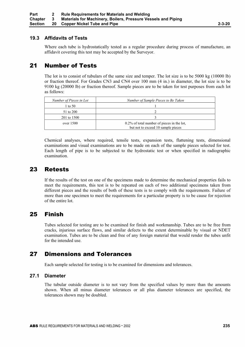
Part 2 Rule Requirements for Materials and WeldingChapter 3 Materials for Machinery, Boilers, Pressure Vessels and PipingSection 20 Copper Nickel Tube and Pipe 2-3-20
ABS RULE REQUIREMENTS FOR MATERIALS AND WELDING . 2002 235
19.3 Affidavits of Tests 2-3-20/19.3
Where each tube is hydrostatically tested as a regular procedure during process of manufacture, anaffidavit covering this test may be accepted by the Surveyor.
21 Number of Tests 2-3-20/21
The lot is to consist of tubulars of the same size and temper. The lot size is to be 5000 kg (10000 lb)or fraction thereof. For Grades CN3 and CN4 over 100 mm (4 in.) in diameter, the lot size is to be9100 kg (20000 lb) or fraction thereof. Sample pieces are to be taken for test purposes from each lotas follows:
Number of Pieces in Lot Number of Sample Pieces to Be Taken
1 to 50 1
51 to 200 2
201 to 1500 3
over 1500 0.2% of total number of pieces in the lot,but not to exceed 10 sample pieces
Chemical analyses, where required, tensile tests, expansion tests, flattening tests, dimensionalexaminations and visual examinations are to be made on each of the sample pieces selected for test.Each length of pipe is to be subjected to the hydrostatic test or when specified in radiographicexamination.
23 Retests 2-3-20/23
If the results of the test on one of the specimens made to determine the mechanical properties fails tomeet the requirements, this test is to be repeated on each of two additional specimens taken fromdifferent pieces and the results of both of these tests is to comply with the requirements. Failure ofmore than one specimen to meet the requirements for a particular property is to be cause for rejectionof the entire lot.
25 Finish 2-3-20/25
Tubes selected for testing are to be examined for finish and workmanship. Tubes are to be free fromcracks, injurious surface flaws, and similar defects to the extent determinable by visual or NDETexamination. Tubes are to be clean and free of any foreign material that would render the tubes unfitfor the intended use.
27 Dimensions and Tolerances 2-3-20/27
Each sample selected for testing is to be examined for dimensions and tolerances.
27.1 Diameter 2-3-20/27.1
The tubular outside diameter is to not vary from the specified values by more than the amountsshown. When all minus diameter tolerances or all plus diameter tolerances are specified, thetolerances shown may be doubled.
Part 2 Rule Requirements for Materials and WeldingChapter 3 Materials for Machinery, Boilers, Pressure Vessels and PipingSection 20 Copper Nickel Tube and Pipe 2-3-20
236 ABS RULE REQUIREMENTS FOR MATERIALS AND WELDING . 2002
Average Diameter
Specified Diameter
mm (inch)
Tolerance,
Plus and Minus, mm (inch)
Up to 15.9 (5/8), incl. 0.064 (0.0025)
Over 15.9 (5/8) to 25.4 (1.0), incl. 0.076 (0.003)
Over 25.4 (1.0) to 50 (2.0), incl. 0.102 (0.004)
Over 50 (2.0) to 76 (3.0), incl. 0.127 (0.005)
Over 76 (3.0) to 100 (4.0) incl. 0.152 (0.006)
Over 100 (4.0) to 125 (5.0), incl. 0.203 (0.008)
Over 125 (5.0) to 150 (6.0), incl. 0.229 (0.009)
Over 150 (6.0) to 200 (8.0), incl. 0.254 (0.010)
Over 200 (8.0) to 255 (10.0), incl. 0.330 (0.013)
Over 255 (10.0) to 305 (12.0), incl. 0.381 (0.015)
Over 305 (12.0) 0.5%
27.3 Roundness 2-3-20/27.3
The difference between the major diameter and the minor diameter as determined at any one crosssection is not the following.
Roundness
Grade t/D (2) Tolerance Percent (3)
CN1 (1) and CN2 (1) 0.01 to 0.03, incl. 1.5
Over 0.03 to 0.05, incl. 1.0
Over 0.05 to 0.10, incl. 0.8*
Over 0.10 0.7*
CN3 and CN4 All ratios 3.0
1 Drawn, unannealed straight lengths, wall thickness not less than 0.41 mm (0.016 in.)
2 Ration of wall thickness to outside diameter
3 Percent of outside diameter, to nearest 0.025mm (0.001 in.)
* Or 0.051 mm (0.002 in.) whichever is greater
27.5 Wall Thickness Tolerances 2-3-20/27.5
The permissible variations in wall thickness for all tubulars are based upon the ordered thickness andare to conform to that given in the applicable ASTM designation for acceptance.
27.7 Length 2-3-20/27.7
The length of tubulars is to not be less than that specified when measured at a temperature of 20°C(68°F) and may exceed specified values by the amounts shown. The tolerance for stock lengths andfor specific lengths with ends is 25.4 mm (1.0 in.).
Part 2 Rule Requirements for Materials and WeldingChapter 3 Materials for Machinery, Boilers, Pressure Vessels and PipingSection 20 Copper Nickel Tube and Pipe 2-3-20
ABS RULE REQUIREMENTS FOR MATERIALS AND WELDING . 2002 237
Length Tolerance, mm (inch)Applicable Only to Full-Length Pieces
Grades CN1 and CN2
Specified Lengths≤ 25 mm (1 in.)
> 25.4 mm (1 in.)< 100 mm (4 in.) > 100 mm (4 in.)
GradesCN3CN4
Up to 150 mm (6in.), incl.
0.8 (1/32) 1.5 (1/16) — 1.5 (1/16)
Over 150 to 600mm (6 in. to 2
ft.), incl.
1.5 (1/16) 2.5 (3/32) 3.0 (1/8) 2.5 (3/32)
Over 600 to 2000mm (2 to 6 ft.),
incl.
2.5 (3/32) 3.0 (1/8) 6.0 (1/4) 3.0 (1/8)
Over 2000 to4000 mm (6 to 14
ft.), incl.
6.0 (1/4) 6.0 (1/4) 6.0 (1/4) 6.0 (1/4)
Over 4000 mm(14 ft)
12.0 (1/2) 12.0 (1/2) 12.0 (1/2) 12.0 (1/2)
27.9 Squareness of Cut 2-3-20/27.9
The departure from squareness of the end of the tube is to not exceed the following:
Specified Outside Diameter Tolerance
Up to 15.9 mm (5/8 in.) incl. of CN1 and CN2 0.25 mm (0.010 in.)
All diameters of CN3 and CN4. 0.016 mm/mm (0.016 in./in.) of diameter
27.11 Straightness Tolerances 2-3-20/27.11
For seamless tubulars of any drawn temper, 6.0 mm (0.25 in.) to 100 mm (3.5 in.) in outside diameter,inclusive, but not for redrawn, extruded or annealed tubulars, the straightness tolerances are as shown.
Maximum Curvature
Length, mm (feet) (Depth of Arc), mm (inch)
Over 1000 to 2000 (3 to 6), incl. 5.0 ( 3/16)
Over 2000 to 2500 (6 to 8), incl. 8.0 (5/16)
Over 2500 to 3000 (8 to 10), incl. 12.0 (1/2)
For lengths greater than 3000 mm (10 ft.) the maximum curvature is to not exceed 12.5 mm (1/2 in.) inany 3000 mm (10 ft.) portion of the total length.

ABS RULE REQUIREMENTS FOR MATERIALS AND WELDING . 2002 239
P A R T
2C H A P T E R 3 Materials for Machinery, Boilers,
Pressure Vessels, and Piping
S E C T I O N 21 Monel Pipe and Tube
CONTENTS1 Scope ................................................................................... 241
3 General................................................................................. 241
3.1 Grades M1 and M2............................................................... 241
3.3 Grades M3 and M4............................................................... 241
3.5 ASTM Designation ............................................................... 241
5 Process of Manufacture ...................................................... 242
5.1 Grades M1 and M2............................................................... 242
5.3 Grades M3 and M4............................................................... 242
7 Marking ................................................................................ 242
9 Chemical Composition........................................................ 243
9.1 Ladle Analysis ...................................................................... 243
9.3 Chemical Composition – Check Analysis............................. 243
11 Tension Test ........................................................................ 243
11.1 Tension Test Specimens...................................................... 243
11.3 Annealed Tensile Properties ................................................ 243
11.5 Stress Relieved Tensile Properties ...................................... 243
13 Flattening Test..................................................................... 244
15 Flare Test ............................................................................. 244
17 Flange Test .......................................................................... 244
19 Number of Tests .................................................................. 244
19.1 Chemical Analysis ................................................................ 244
19.3 Other Tests........................................................................... 244
21 Hydrostatic Test .................................................................. 245
21.1 Limiting Test Pressures........................................................ 245
21.3 Exceeding Limiting Test Pressures...................................... 245
21.5 Affidavits of Tests ................................................................. 245

240 ABS RULE REQUIREMENTS FOR MATERIALS AND WELDING . 2002
23 Nondestructive Electric Test (NDET) ..................................245
23.1 General................................................................................. 245
23.3 Ultrasonic Calibration Standards.......................................... 246
23.5 Eddy-Current Calibration Standards .................................... 246
23.7 Rejection............................................................................... 246
23.9 Affidavits ............................................................................... 246
25 Retests..................................................................................246
27 Finish ....................................................................................246
29 Dimensions and Tolerances................................................247
29.1 Diameter ............................................................................... 247
29.3 Wall Thickness – Seamless ................................................. 247
29.5 Wall Thickness – Welded ..................................................... 248
29.7 Cut Ends............................................................................... 248
29.9 Straightness.......................................................................... 248
ABS RULE REQUIREMENTS FOR MATERIALS AND WELDING . 2002 241
P A R T
2C H A P T E R 3 Materials for Machinery, Boilers,
Pressure Vessels, and Piping
S E C T I O N 21 Monel Pipe and Tube (1999) 2 - 3 - 2 1
1 Scope 2-3-21/1
This specification covers four grades of seamless and welded nickel-copper (Monel) pipe and tube,designated M1, M2, M3, and M4.
3 General2-3-21/3
3.1 Grades M1 and M2 2-3-21/3.1
Grades M1 and M2 cover cold-worked, seamless nickel-copper pipe and pipe intended for use ingeneral engineering applications requiring superior seawater corrosion resistance. Pipe and tubeordered under these grades are considered suitable for welding, and suitable for forming operationsinvolving bending, flaring, and flanging. Pipe is to be ordered to ANSI B36.19. Tube is to be orderedto an outer diameter and a nominal or minimum wall thickness specified by the purchaser andapproved for the application.
3.3 Grades M3 and M4 2-3-21/3.3
Grades M3 and M4 cover welded, cold-worked nickel-copper pipe and pipe intended for use ingeneral engineering applications requiring superior seawater corrosion resistance. Pipe and tubeordered under these grades are considered suitable for welding, and suitable for forming operationsinvolving bending, flaring, and flanging. Pipe is to be ordered to ANSI B36.19. Tube is to be orderedto an outer diameter and a nominal or minimum wall thickness specified by the purchaser andapproved for the application.
3.5 ASTM Designation 2-3-21/3.5
The grades are in substantial agreement with ASTM as follows:
ABS Grade Heat Treatment ASTM Designation Product Form
M1 Annealed B165, UNS N04400 Seamless Pipe and Tube
M2 Stress Relieved B165, UNS N04400 Seamless Pipe and Tube
M3 Annealed B730, UNS N04400 Welded Pipe and Tube
M4 Stress Relieved B730, UNS N04400 Welded Pipe and Tube

Part 2 Rule Requirements for Materials and WeldingChapter 3 Materials for Machinery, Boilers, Pressure Vessels and PipingSection 21 Monel Pipe and Tube 2-3-21
242 ABS RULE REQUIREMENTS FOR MATERIALS AND WELDING . 2002
5 Process of Manufacture 2-3-21/5
5.1 Grades M1 and M2 2-3-21/5.1
These grades are to be finished by cold-working in order to assure that acceptable corrosion resistancein the weld area and base metal will be developed during heat treatment. These grades of pipe andtube are to be supplied in the annealed, Grade M1, or stress-relieved, Grade M2, condition.
5.3 Grades M3 and M4 2-3-21/5.3
These grades are to be made from flat-rolled material by an automatic welding process with noaddition of filler metal. After welding but before heat treatment, the pipe and tube are to be coldworked in order to assure that acceptable corrosion resistance in the weld area and base metal will bedeveloped during heat treatment. Heat treatment is to consist of annealing, as Grade M3, or stress-relieving, as Grade M4. Welded pipe and tube are to be furnished with a scale-free finish. Whenbright annealing is used, descaling is not necessary.
7 Marking 2-3-21/7
Identification markings are to be legibly stenciled, or marked on each length of pipe and tube. Themarking fluid is not to be harmful to the pipe and tube and is not to rub off or smear in normalhandling. The fluid is not to be affected by solvents used in subsequent cleaning and preservationoperations, but is to be readily removed by hot alkaline solution. In the case of small-diameter tube orpipe with an outside diameter less than 19.0 mm (3/4 in.) which is bundled or boxed, the requiredmarkings are to be placed on a tag securely attached to the bundle or box or on the box. The markingsare to be arranged and are to include the following information:
Name or brand of the manufacturer
ABS Grade or ASTM Specification and Grade
UNS Alloy Number
Heat number or manufacturer’s number by which the heat can be identified
Temper designation
Tube diameter/NPS Designation
Wall thickness (specify minimum or nominal)/NPS schedule
Test pressure
NDET if so tested
ABS markings by Surveyor
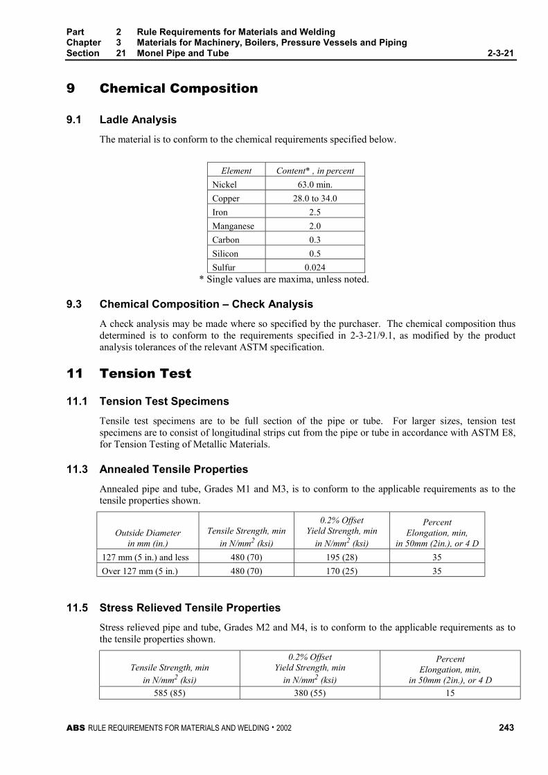
Part 2 Rule Requirements for Materials and WeldingChapter 3 Materials for Machinery, Boilers, Pressure Vessels and PipingSection 21 Monel Pipe and Tube 2-3-21
ABS RULE REQUIREMENTS FOR MATERIALS AND WELDING . 2002 243
9 Chemical Composition 2-3-21/9
9.1 Ladle Analysis 2-3-21/9.1
The material is to conform to the chemical requirements specified below.
Element Content* , in percent
Nickel 63.0 min.
Copper 28.0 to 34.0
Iron 2.5
Manganese 2.0
Carbon 0.3
Silicon 0.5
Sulfur 0.024* Single values are maxima, unless noted.
9.3 Chemical Composition – Check Analysis 2-3-21/9.3
A check analysis may be made where so specified by the purchaser. The chemical composition thusdetermined is to conform to the requirements specified in 2-3-21/9.1, as modified by the productanalysis tolerances of the relevant ASTM specification.
11 Tension Test 2-3-21/11
11.1 Tension Test Specimens 2-3-21/11.1
Tensile test specimens are to be full section of the pipe or tube. For larger sizes, tension testspecimens are to consist of longitudinal strips cut from the pipe or tube in accordance with ASTM E8,for Tension Testing of Metallic Materials.
11.3 Annealed Tensile Properties 2-3-21/11.3
Annealed pipe and tube, Grades M1 and M3, is to conform to the applicable requirements as to thetensile properties shown.
Outside Diameterin mm (in.)
Tensile Strength, min
in N/mm2 (ksi)
0.2% OffsetYield Strength, min
in N/mm2 (ksi)
PercentElongation, min,
in 50mm (2in.), or 4 D
127 mm (5 in.) and less 480 (70) 195 (28) 35
Over 127 mm (5 in.) 480 (70) 170 (25) 35
11.5 Stress Relieved Tensile Properties 2-3-21/11.5
Stress relieved pipe and tube, Grades M2 and M4, is to conform to the applicable requirements as tothe tensile properties shown.
Tensile Strength, min
in N/mm2 (ksi)
0.2% OffsetYield Strength, min
in N/mm2 (ksi)
PercentElongation, min,
in 50mm (2in.), or 4 D
585 (85) 380 (55) 15
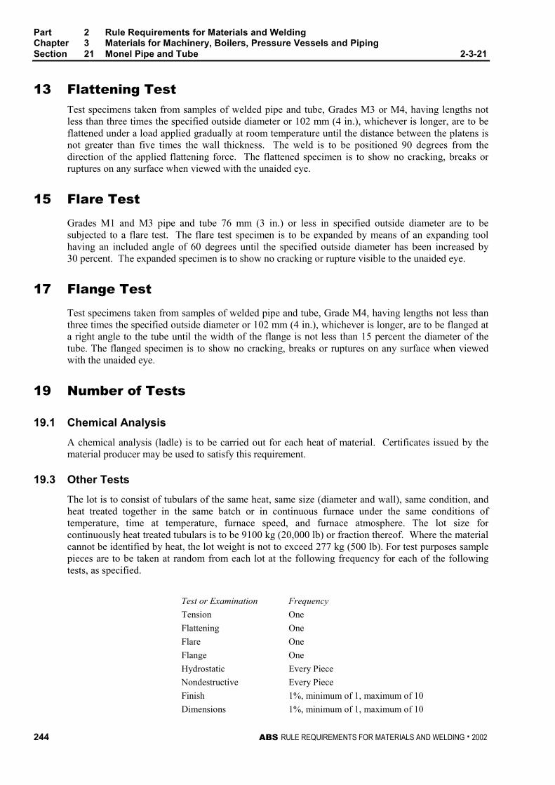
Part 2 Rule Requirements for Materials and WeldingChapter 3 Materials for Machinery, Boilers, Pressure Vessels and PipingSection 21 Monel Pipe and Tube 2-3-21
244 ABS RULE REQUIREMENTS FOR MATERIALS AND WELDING . 2002
13 Flattening Test 2-3-21/13
Test specimens taken from samples of welded pipe and tube, Grades M3 or M4, having lengths notless than three times the specified outside diameter or 102 mm (4 in.), whichever is longer, are to beflattened under a load applied gradually at room temperature until the distance between the platens isnot greater than five times the wall thickness. The weld is to be positioned 90 degrees from thedirection of the applied flattening force. The flattened specimen is to show no cracking, breaks orruptures on any surface when viewed with the unaided eye.
15 Flare Test 2-3-21/15
Grades M1 and M3 pipe and tube 76 mm (3 in.) or less in specified outside diameter are to besubjected to a flare test. The flare test specimen is to be expanded by means of an expanding toolhaving an included angle of 60 degrees until the specified outside diameter has been increased by30 percent. The expanded specimen is to show no cracking or rupture visible to the unaided eye.
17 Flange Test 2-3-21/17
Test specimens taken from samples of welded pipe and tube, Grade M4, having lengths not less thanthree times the specified outside diameter or 102 mm (4 in.), whichever is longer, are to be flanged ata right angle to the tube until the width of the flange is not less than 15 percent the diameter of thetube. The flanged specimen is to show no cracking, breaks or ruptures on any surface when viewedwith the unaided eye.
19 Number of Tests 2-3-21/19
19.1 Chemical Analysis 2-3-21/19.1
A chemical analysis (ladle) is to be carried out for each heat of material. Certificates issued by thematerial producer may be used to satisfy this requirement.
19.3 Other Tests 2-3-21/19.3
The lot is to consist of tubulars of the same heat, same size (diameter and wall), same condition, andheat treated together in the same batch or in continuous furnace under the same conditions oftemperature, time at temperature, furnace speed, and furnace atmosphere. The lot size forcontinuously heat treated tubulars is to be 9100 kg (20,000 lb) or fraction thereof. Where the materialcannot be identified by heat, the lot weight is not to exceed 277 kg (500 lb). For test purposes samplepieces are to be taken at random from each lot at the following frequency for each of the followingtests, as specified.
Test or Examination Frequency
Tension One
Flattening One
Flare One
Flange One
Hydrostatic Every Piece
Nondestructive Every Piece
Finish 1%, minimum of 1, maximum of 10
Dimensions 1%, minimum of 1, maximum of 10
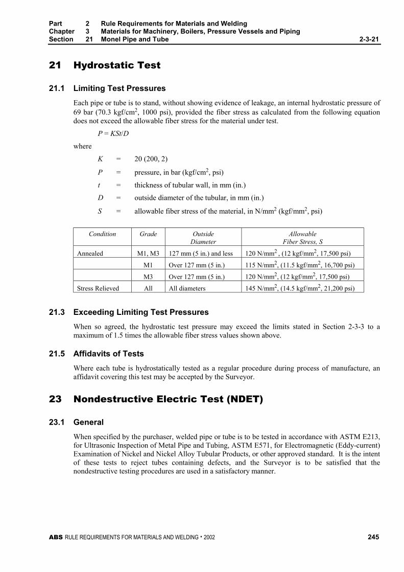
Part 2 Rule Requirements for Materials and WeldingChapter 3 Materials for Machinery, Boilers, Pressure Vessels and PipingSection 21 Monel Pipe and Tube 2-3-21
ABS RULE REQUIREMENTS FOR MATERIALS AND WELDING . 2002 245
21 Hydrostatic Test 2-3-21/21
21.1 Limiting Test Pressures 2-3-21/21.1
Each pipe or tube is to stand, without showing evidence of leakage, an internal hydrostatic pressure of69 bar (70.3 kgf/cm2, 1000 psi), provided the fiber stress as calculated from the following equationdoes not exceed the allowable fiber stress for the material under test.
P = KSt/D
where
K = 20 (200, 2)
P = pressure, in bar (kgf/cm2, psi)
t = thickness of tubular wall, in mm (in.)
D = outside diameter of the tubular, in mm (in.)
S = allowable fiber stress of the material, in N/mm2 (kgf/mm2, psi)
Condition Grade OutsideDiameter
AllowableFiber Stress, S
Annealed M1, M3 127 mm (5 in.) and less 120 N/mm2 , (12 kgf/mm2, 17,500 psi)
M1 Over 127 mm (5 in.) 115 N/mm2, (11.5 kgf/mm2, 16,700 psi)
M3 Over 127 mm (5 in.) 120 N/mm2, (12 kgf/mm2, 17,500 psi)
Stress Relieved All All diameters 145 N/mm2, (14.5 kgf/mm2, 21,200 psi)
21.3 Exceeding Limiting Test Pressures 2-3-21/21/3
When so agreed, the hydrostatic test pressure may exceed the limits stated in Section 2-3-3 to amaximum of 1.5 times the allowable fiber stress values shown above.
21.5 Affidavits of Tests 2-3-21/21.3
Where each tube is hydrostatically tested as a regular procedure during process of manufacture, anaffidavit covering this test may be accepted by the Surveyor.
23 Nondestructive Electric Test (NDET) 2-3-21/23
23.1 General 2-3-21/23.1
When specified by the purchaser, welded pipe or tube is to be tested in accordance with ASTM E213,for Ultrasonic Inspection of Metal Pipe and Tubing, ASTM E571, for Electromagnetic (Eddy-current)Examination of Nickel and Nickel Alloy Tubular Products, or other approved standard. It is the intentof these tests to reject tubes containing defects, and the Surveyor is to be satisfied that thenondestructive testing procedures are used in a satisfactory manner.

Part 2 Rule Requirements for Materials and WeldingChapter 3 Materials for Machinery, Boilers, Pressure Vessels and PipingSection 21 Monel Pipe and Tube 2-3-21
246 ABS RULE REQUIREMENTS FOR MATERIALS AND WELDING . 2002
23.3 Ultrasonic Calibration Standards 2-3-21/23.3
Longitudinal notches machined on the outside surface and on the inside surface are to be used. Thenotch depth is to not exceed 12.5 % of the specified wall thickness or 0.004 inch (0.10 mm),whichever is greater. The notch is to be placed in the weld if visible.
23.5 Eddy-Current Calibration Standards 2-3-21/23.5
In order to accommodate the various types of nondestructive electric testing equipment andtechniques in use, and manufacturing practices employed, any one of the following calibrationstandards may be used at the option of the producer, to establish a minimum sensitivity level forrejection. The holes and notches are to be placed in the weld if visible.
23.5.1 Drilled Hole 2-3-21/23.5.1
A hole not larger than 0.79 mm (0.031 in.) in diameter to be drilled radially and completelythrough tube wall, care being taken to avoid distortion of the tube while drilling.
23.5.2 Transverse Tangential Notch 2-3-21/23.5.2
Using a round file or tool with a 6.4 mm (0.25 in.) diameter, a notch is to be filed or milledtangential to the surface and transverse to the longitudinal axis of the tube. Said notch is tohave a depth not exceeding 12.5 % of the nominal wall thickness of the tube or 0.10 mm(0.004 in.), whichever is greater.
23.5.3 Longitudinal Notch 2-3-21/23.5.3
A notch 0.79 mm. (0.031 in.) or less in width is to be machined in a radial plane parallel tothe tube axis on the outside surface of the tube, to a depth not exceeding 12.5 % of thenominal wall thickness of the tube or 0.10 mm (0.004 in.), whichever is greater. The lengthof the notch is to be compatible with the testing method.
23.7 Rejection 2-3-21/23.7
Tubulars producing a signal equal to or greater than the calibration defect are to be subject torejection.
23.9 Affidavits 2-3-21/23.9
When each tubular is subjected to an approved nondestructive electric test as a regular procedureduring the process of manufacture, an affidavit covering this test may be accepted by the Surveyor.
25 Retests 2-3-21/25
If the results of the test on one of the specimens made to determine the mechanical properties fails tomeet the requirements, this test is to be repeated on each of two additional specimens taken fromdifferent pieces from same group or lot, and the results of both of these tests are to comply with therequirements. Failure of more than one specimen to meet the requirements for a particular property isto be cause for rejection of the entire lot.
27 Finish 2-3-21/27
Pipe or tube selected for testing is to be examined for finish and workmanship. The samplesexamined are to be free from cracks, injurious surface flaws, and similar defects to the extentdeterminable by visual or NDET examination. All pipe or tube is to be clean and free of any foreignmaterial that would render the tubulars unfit for the intended use.
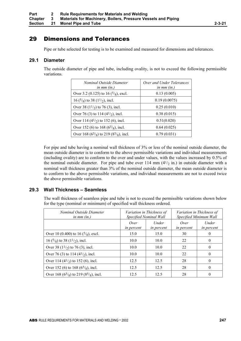
Part 2 Rule Requirements for Materials and WeldingChapter 3 Materials for Machinery, Boilers, Pressure Vessels and PipingSection 21 Monel Pipe and Tube 2-3-21
ABS RULE REQUIREMENTS FOR MATERIALS AND WELDING . 2002 247
29 Dimensions and Tolerances 2-3-21/29
Pipe or tube selected for testing is to be examined and measured for dimensions and tolerances.
29.1 Diameter 2-3-21/29.1
The outside diameter of pipe and tube, including ovality, is not to exceed the following permissiblevariations.
Nominal Outside Diameterin mm (in.)
Over and Under Tolerancesin mm (in.)
Over 3.2 (0.125) to 16 (5/8), excl. 0.13 (0.005)
16 (5/8) to 38 (11/2), incl. 0.19 (0.0075)
Over 38 (11/2) to 76 (3), incl. 0.25 (0.010)
Over 76 (3) to 114 (41/2), incl. 0.38 (0.015)
Over 114 (41/2) to 152 (6), incl. 0.51(0.020)
Over 152 (6) to 168 (65/8), incl. 0.64 (0.025)
Over 168 (65/8) to 219 (85/8), incl. 0.79 (0.031)
For pipe and tube having a nominal wall thickness of 3% or less of the nominal outside diameter, themean outside diameter is to conform to the above permissible variations and individual measurements(including ovality) are to conform to the over and under values, with the values increased by 0.5% ofthe nominal outside diameter. For pipe and tube over 114 mm (41/2 in.) in outside diameter with anominal wall thickness greater than 3% of the nominal outside diameter, the mean outside diameter isto conform to the above permissible variations, and individual measurements are not to exceed twicethe above permissible variations.
29.3 Wall Thickness – Seamless 2-3-21/29.3
The wall thickness of seamless pipe and tube is not to exceed the permissible variations shown belowfor the type (nominal or minimum) of specified wall thickness ordered.
Nominal Outside Diameterin mm (in.)
Variation in Thickness ofSpecified Nominal Wall
Variation in Thickness ofSpecified Minimum Wall
Overin percent
Underin percent
Overin percent
Underin percent
Over 10 (0.400) to 16 (5/8), excl. 15.0 15.0 30 0
16 (5/8) to 38 (11/2), incl. 10.0 10.0 22 0
Over 38 (11/2) to 76 (3), incl. 10.0 10.0 22 0
Over 76 (3) to 114 (41/2), incl. 10.0 10.0 22 0
Over 114 (41/2) to 152 (6), incl. 12.5 12.5 28 0
Over 152 (6) to 168 (65/8), incl. 12.5 12.5 28 0
Over 168 (65/8) to 219 (85/8), incl. 12.5 12.5 28 0
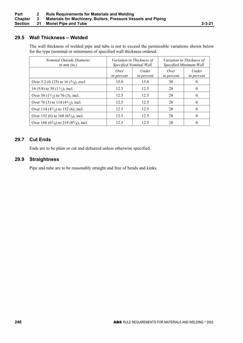
Part 2 Rule Requirements for Materials and WeldingChapter 3 Materials for Machinery, Boilers, Pressure Vessels and PipingSection 21 Monel Pipe and Tube 2-3-21
248 ABS RULE REQUIREMENTS FOR MATERIALS AND WELDING . 2002
29.5 Wall Thickness – Welded 2-3-21/29.5
The wall thickness of welded pipe and tube is not to exceed the permissible variations shown belowfor the type (nominal or minimum) of specified wall thickness ordered.
Nominal Outside Diameterin mm (in.)
Variation in Thickness ofSpecified Nominal Wall
Variation in Thickness ofSpecified Minimum Wall
Overin percent
Underin percent
Overin percent
Underin percent
Over 3.2 (0.125) to 16 (5/8), excl 15.0 15.0 30 0
16 (5/8) to 38 (11/2), incl. 12.5 12.5 28 0
Over 38 (11/2) to 76 (3), incl. 12.5 12.5 28 0
Over 76 (3) to 114 (41/2), incl. 12.5 12.5 28 0
Over 114 (41/2) to 152 (6), incl. 12.5 12.5 28 0
Over 152 (6) to 168 (65/8), incl. 12.5 12.5 28 0
Over 168 (65/8) to 219 (85/8), incl. 12.5 12.5 28 0
29.7 Cut Ends 2-3-21/29.7
Ends are to be plain or cut and deburred unless otherwise specified.
29.9 Straightness 2-3-21/29.9
Pipe and tube are to be reasonably straight and free of bends and kinks.
ABS RULE REQUIREMENTS FOR MATERIALS AND WELDING . 2002 249
P A R T
2C H A P T E R 4 Welding and Fabrication
CONTENTSSECTION 1 Hull Construction.................................................. 251
1 General................................................................. 253
3 Preparation for Welding ....................................... 254
5 Production Welding .............................................. 255
7 Butt Welds ............................................................ 257
SECTION 2 Boilers, Unfired Pressure Vessels, Piping andEngineering Structures ........................................ 259
1 General Considerations ....................................... 263
3 Plans and Specifications ...................................... 265
5 Workmanship and Supervision ............................ 265
7 Details of Joints .................................................... 266
9 Forms of Welded Joints Required........................ 268
11 Preheat................................................................. 270
13 General Requirements for Postweld HeatTreatment ............................................................. 271
15 Fusion-welded Boilers.......................................... 271
17 Fusion-welded Pressure Vessels......................... 275
19 Pipe Connections and Engineering Structures .... 277
21 Postweld Heat-treatment Details.......................... 277
23 Radiography......................................................... 278
25 Hydrostatic Test ................................................... 280
SECTION 3 Weld Tests............................................................. 289
1 General................................................................. 291
3 Filler Metals .......................................................... 291
5 Approval of Welding Procedures.......................... 292
7 Workmanship Tests ............................................. 293
9 Radiographic or Ultrasonic Inspection ................. 294
11 Welders ................................................................ 295
SECTION 4 Piping [Applicable for SVR only] ......................... 313
1 General................................................................. 315
3 Welding Procedures and Welders........................ 316
5 Types of Welded Joints........................................ 316
250 ABS RULE REQUIREMENTS FOR MATERIALS AND WELDING 2001
7 Preheat................................................................. 318
9 Post-weld Heat Treatment ................................... 318
11 Non-destructive Examination ............................... 319
13 Weld Repair.......................................................... 320
15 Pipe Forming and Bending................................... 321
17 Additional Requirements for Low TemperaturePiping [below -10°C (14°F)].................................. 321
ABS RULE REQUIREMENTS FOR MATERIALS AND WELDING . 2002 251
P A R T
2C H A P T E R 4 Welding and Fabrication
S E C T I O N 1 Hull Construction
CONTENTS1 General................................................................................. 253
1.1 Hull Welding ......................................................................... 253
1.3 Plans and Specifications ...................................................... 253
1.5 Workmanship and Supervision............................................. 253
1.7 Welding Procedures ............................................................. 253
1.9 TMCP Plates – Note to Users .............................................. 254
3 Preparation for Welding...................................................... 254
3.1 Edge Preparation and Fitting................................................ 254
3.3 Alignment.............................................................................. 254
3.5 Cleanliness ........................................................................... 254
3.7 Tack Welds........................................................................... 254
3.9 Run-on and Run-off Tabs..................................................... 255
3.11 Stud Welding ........................................................................ 255
3.13 Forming ................................................................................ 255
5 Production Welding............................................................. 255
5.1 Environment ......................................................................... 255
5.3 Sequence ............................................................................. 255
5.5 Preheat ................................................................................. 255
5.7 Low-hydrogen Electrodes or Welding Processes ................ 256
5.9 Back Gouging....................................................................... 256
5.11 Peening ................................................................................ 256
5.13 Fairing and Flame Shrinking ................................................ 256
5.15 Surface Appearance and Weld Soundness ......................... 256
5.17 Inspection of Welds .............................................................. 257
5.19 Repair Welding..................................................................... 257
252 ABS RULE REQUIREMENTS FOR MATERIALS AND WELDING . 2002
7 Butt Welds ............................................................................257
7.1 Manual Welding Using Covered Electrodes......................... 257
7.3 Submerged-arc Welding....................................................... 258
7.5 Gas Metal-arc and Flux Cored-arc Welding......................... 258
7.7 Electroslag and Electrogas Welding..................................... 258
7.9 Special Welding Techniques ................................................ 258
ABS RULE REQUIREMENTS FOR MATERIALS AND WELDING . 2002 253
P A R T
2C H A P T E R 4 Welding and Fabrication
S E C T I O N 1 Hull Construction 2 - 4 - 1
1 General 2-4-1/1
1.1 Hull Welding 2-4-1/1.1
Welding in hull construction is to comply with the requirements of this section, unless speciallyapproved otherwise. It is recommended that appropriate permanent markings be applied to the sideshell of welded vessels to indicate the location of bulkheads for reference. In all instances weldingprocedures and filler metals are to produce sound welds having strength and toughness comparable tothe base material. For weld design, see Section 3-2-19.
1.3 Plans and Specifications 2-4-1/1.3
The plans submitted are to indicate clearly the proposed extent of welding to be used in the principalparts of the structure. The welding process, filler metal and joint design are to be shown on the detaildrawings or in separate specifications submitted for approval which should distinguish betweenmanual and automatic welding. The shipbuilders are to prepare and file with the Surveyor a plannedprocedure to be followed in the erection and welding of the important structural members.
1.5 Workmanship and Supervision 2-4-1/1.5
The Surveyor is to satisfy himself that all welders and welding operators to be employed in theconstruction of vessels to be classed are properly qualified and are experienced in the work proposed.The Surveyor is also to be satisfied as to the employment of a sufficient number of skilled supervisorsto ensure a thorough supervision and control of all welding operations. Inspection of welds employingmethods outlined in 2-4-1/5.17 is to be carried out to the satisfaction of the Surveyor.
1.7 Welding Procedures 2-4-1/1.7
1.7.1 General 2-4-1/1.7.1
Procedures for the welding of all joints are to be established before construction for thewelding processes, types of electrodes, edge preparations, welding techniques, and positionsproposed. See 2-4-3/5. Details of proposed welding procedures and sequences may berequired to be submitted for review depending on the intended application.
1.7.2 Weld Metal Toughness – Criteria for ABS Grades of Steel 2-4-1/1.7.2
For steels shown in 2-1-2/Table 5 and 2-1-3/Table 5. Approved filler metals appropriate to thegrades shown in Part 2, Appendix 3 may be used.
Part 2 Rule Requirements for Materials and WeldingChapter 4 Welding and FabricationSection 1 Hull Construction 2-4-1
254 ABS RULE REQUIREMENTS FOR MATERIALS AND WELDING . 2002
1.7.3 Weld Metal Toughness – Criteria for Other Steels 2-4-1/1.7.3
Weld metal is to exhibit Charpy V-notch toughness values at least equivalent to transversebase metal requirements (2/3 of the longitudinal base metal requirements).
1.9 TMCP Plates – Note to Users (1996) 2-4-1/1.9
When considering thermo-mechanically controlled steels for further heating for forming or stressrelieving, or for high heat input welding, the attention of fabricator is drawn to the possible reductionin the mechanical properties. A procedure test using representative material is to be considered.
3 Preparation for Welding 2-4-1/3
3.1 Edge Preparation and Fitting 2-4-1/3.1
The edge preparation is to be accurate and uniform and the parts to be welded are to be fitted inaccordance with the approved joint detail. All means adopted for correcting improper fitting are to beto the satisfaction of the Surveyor. The Surveyor may accept a welding procedure for build up of eachedge that does not exceed one half the thickness of the member or 12.5 mm (0.5 in.), whichever is thelesser. The Surveyor may accept edge build up in excess of the above up to the full thickness of themember on a case-by-case basis provided he is notified of such cases before the members are weldedtogether. Where plates to be joined differ in thickness and have an offset on either side of more than3 mm (1/8 in.), a suitable transition taper is to be provided. For the transverse butts in bottom shell,sheerstrake, and strength deck plating within the midship portion of the hull, and other joints whichmay be subject to comparatively high stresses, the transition taper length is to be not less than threetimes the offset. The transition may be formed by tapering the thicker member or by specifying a weldjoint design which will provide the required transition.
3.3 Alignment 2-4-1/3.3
Means are to be provided for maintaining the parts to be welded in correct position and alignmentduring the welding operation. In general, strong backs, or other appliances used for this purpose are tobe so arranged as to allow for expansion and contraction during production welding. The removal ofsuch items is to be carried out to the satisfaction of the Surveyor.
3.5 Cleanliness 2-4-1/3.5
All surfaces to be welded are to be free from moisture, grease, loose mill scale, excessive rust, orpaint. Primer coatings of ordinary thickness, thin coatings of linseed oil, or equivalent coatings maybe used provided it is demonstrated that their use has no adverse effect in the production ofsatisfactory welds. Slag and scale are to be removed not only from the edges to be welded but alsofrom each pass or layer before the deposition of subsequent passes or layers. Weld joints prepared byarc-air gouging may require additional preparation by grinding or chipping and wire brushing prior towelding to minimize the possibility of excessive carbon on the scarfed surfaces. Compliance withthese cleanliness requirements is of prime importance in the welding of higher-strength steelsespecially those which are quenched and tempered.
3.7 Tack Welds 2-4-1/3.7
Tack welds of consistent good quality, made with the same grade of filler metal as intended forproduction welding and deposited in such a manner as not to interfere with the completion of the finalweld, need not be removed provided they are found upon examination to be thoroughly clean and freefrom cracks or other defects. Preheat may be necessary prior to tack welding when the materials to bejoined are highly restrained. Special consideration is to be given to use the same preheat as specifiedin the welding procedure when tack welding higher-strength steels, particularly those materials whichare quenched and tempered. These same precautions are to be followed when making any permanentwelded markings.
Part 2 Rule Requirements for Materials and WeldingChapter 4 Welding and FabricationSection 1 Hull Construction 2-4-1
ABS RULE REQUIREMENTS FOR MATERIALS AND WELDING . 2002 255
3.9 Run-on and Run-off Tabs 2-4-1/3.9
When used, run-on and run-off tabs are to be designed to minimize the possibility of high-stressconcentrations and base-metal and weld-metal cracking.
3.11 Stud Welding 2-4-1/3.11
The attachment of pins, hangers, studs, and other related items to ordinary and higher-strength hullstructural steels or equivalent, by stud welding may be approved at the discretion of the Surveyor.Stud welded attachment to quenched and tempered steel is to be specially approved. At the Surveyor’sdiscretion, trial stud welds may be tested to demonstrate that the base material in way of the studwelds is free from cracking and excessively high hardness. The use of stud welding for structuralattachments is subject to special approval and may require special procedure tests appropriate to eachapplication.
3.13 Forming 2-4-1/3.13
Steel is not to be formed between the upper and lower critical temperatures; forming in the rangebetween 205°C (400°F) and 425°C (800°F) should be avoided. If the forming temperature exceeds650°C (1200°F) for as-rolled, controlled rolled, thermo-mechanical controlled rolled or normalizedsteels, or is not at least 28°C (50°F) lower than the tempering temperature for quenched and temperedsteels, mechanical tests are to be made to assure that these temperatures have not adversely affectedthe mechanical properties of the steel. See 2-4-1/1.9.
For applications where toughness is of particular concern (such as Class IV or Class V 3-1-2/Table 2),when steel is formed below 650°C (1200°F) beyond 3% strain* on the outer fiber supporting data is tobe provided to the satisfaction of the Surveyor indicating that the impact properties meet minimumrequirements after forming. After straining, specimens used in charpy impact tests are to be subjectedto an artificial aging treatment of 288°C (550°F) for 1 hour before testing. Rule steels of 2-1-2/Table 5and 2-1-3/Table 5 or equivalent steels used for radius gunwales (in accordance with 3-1-2/Table 1)may be cold formed to a minimum radius of 15t without requiring stress relieving or other supportingdata.
* Calculated on the basis of % strain = radiusouter
thicknessplate65 ×
5 Production Welding 2-4-1/5
5.1 Environment 2-4-1/5.1
Proper precautions are to be taken to insure that all welding is done under conditions where thewelding site is protected against the deleterious effects of moisture, wind and severe cold.
5.3 Sequence 2-4-1/5.3
Welding is to be planned to progress symmetrically so that shrinkage on both sides of the structurewill be equalized. The ends of frames and stiffeners should be left unattached to the plating at thesubassembly stage until connecting welds are made in the intersecting systems of plating, framing andstiffeners at the erection stage. Welds are not to be carried across an unwelded joint or beyond anunwelded joint which terminates at the joint being welded unless specially approved.
5.5 Preheat 2-4-1/5.5
The use of preheat and interpass temperature control are to be considered when welding higher-strength steels, materials of thick cross-section or materials subject to high restraint. When welding isperformed under high humidity conditions or when the temperature of steel is below 0°C (32°F) thebase metal is to be preheated to at least 16°C (60°F) or temperature appropriate to the alloy and thethickness, whichever is higher. The control of interpass temperature is to be specially consideredwhen welding quenched and tempered higher-strength steels. When preheat is used, the preheat and
Part 2 Rule Requirements for Materials and WeldingChapter 4 Welding and FabricationSection 1 Hull Construction 2-4-1
256 ABS RULE REQUIREMENTS FOR MATERIALS AND WELDING . 2002
interpass temperatures are to be in accordance with the accepted welding procedure and to thesatisfaction of the Surveyor. In all cases preheat and interpass temperature control are to be sufficientto maintain dry surfaces and minimize the possibility of the formation of fractures.
5.7 Low-hydrogen Electrodes or Welding Processes 2-4-1/5.7
5.7.1 Welding of Ordinary and Higher Strength Steel 2-4-1/5.7.1
The use of low-hydrogen electrodes or welding processes is recommended for welding allhigher-strength steel and may also be considered for ordinary-strength steel weldmentssubject to high restraint. When using low-hydrogen electrodes or processes, properprecautions are to be taken to ensure that the electrodes, fluxes and gases used for welding areclean and dry.
5.7.2 Welding of Quenched and Tempered Steels 2-4-1/5.7.2
Unless approved otherwise matching strength, low-hydrogen electrodes or welding processesare to be used for welding quenched and tempered steels and overmatching should begenerally avoided. When welding quenched and tempered steels to other steels, the weld fillermetal selection is to be based on the lower strength base material being joined and lowhydrogen practice being comparable to that for the higher strength material. In all cases, fillermetal strength is to be no less than that of the lowest strength member of the joint unlessapproved otherwise. The Surveyor is to be satisfied that the procedures for handling andbaking filler metals and fluxes are commensurate with the low-hydrogen practices appropriateto the highest strength steel.
5.9 Back Gouging 2-4-1/5.9
Chipping, grinding, arc-air gouging or other suitable methods are to be employed at the root orunderside of the weld to obtain sound metal before applying subsequent beads for all full-penetrationwelds. When arc-air gouging is employed, a selected technique is to be used so that carbon buildupand burning of the weld or base metal is minimized. Quenched and tempered steels are not to be flamegouged.
5.11 Peening 2-4-1/5.11
The use of peening is not recommended for single-pass welds and the root or cover passes onmultipass welds. Peening, when used to correct distortion or to reduce residual stresses, is to beeffected immediately after depositing and cleaning each weld pass.
5.13 Fairing and Flame Shrinking 2-4-1/5.13
Fairing by heating or flame shrinking and other methods of correcting distortion or defectiveworkmanship in fabrication of main strength members within the midship portion of the vessel andother plating which may be subject to high stresses is to be carried out only with the express approvalof the Surveyor. These corrective measures are to be kept to an absolute minimum when the higher-strength steels are involved, due to high local stresses and the possible degradation of the mechanicalproperties of the base material. See 2-4-1/1.9.
5.15 Surface Appearance and Weld Soundness 2-4-1/5.15
5.15.1 Surface Appearance 2-4-1/5.15.1
The surfaces of welds are to be visually inspected and are to be regular and uniform with aminimum amount of reinforcement and reasonably free from undercut and overlap. Weldsand adjacent base metal are to be free from injurious arc strikes.
Part 2 Rule Requirements for Materials and WeldingChapter 4 Welding and FabricationSection 1 Hull Construction 2-4-1
ABS RULE REQUIREMENTS FOR MATERIALS AND WELDING . 2002 257
5.15.2 Weld Soundness 2-4-1/5.15.2
Welds are to be sound, crack free throughout the weld cross section, and fused to the basematerial to the satisfaction of the attending Surveyor and should generally be considered onthe basis of 2-4-1/1.5 Workmanship and Supervision, 2-4-1/1.7 Welding ProcedureQualification, and 2-4-1/5.17 Nondestructive Inspection of Welds.
5.17 Inspection of Welds 2-4-1/5.17
Inspection of welded joints in important locations is to be carried out by an approved nondestructivetest method such as radiographic, ultrasonic, magnetic-particle or dye-penetrant inspection. TheBureau’s separately issued Rules for Nondestructive Inspection of Hull Welds or an approvedequivalent standard is to be used in evaluating radiographs and ultrasonic indications. Evaluation ofradiographs and ultrasonic indications is one of the factors in assessing shipyard weld quality control.Radiographic or ultrasonic inspection, or both, is to be used when the overall soundness of the weldcross section is to be evaluated. Magnetic-particle or dye-penetrant inspection or other approvedmethods are to be used when investigating the outer surface of welds or may be used as a check ofintermediate weld passes such as root passes and also to check back-gouged joints prior to depositingsubsequent passes. Surface inspection of important tee or corner joints in critical locations, using anapproved magnetic particle or dye penetrant method, is to be conducted to the satisfaction of theSurveyor. Extra high-strength steels, [415-690 N/mm2 (42-70 kgf/mm2, 60,000–100,000 psi)minimum yield strength] may be susceptible to delayed cracking. When welding these materials thefinal nondestructive testing is to be delayed sufficiently to permit detection of such defects. Weld run-on or run-off tabs may be used where practical and be sectioned for examination. Where a method(such as radiographic or ultrasonic) is selected as the primary nondestructive method of inspection,the acceptance standards of such method govern. However, if additional inspection by any methodshould indicate the presence of defects that could jeopardize the integrity of structure, removal andrepair of such defects are to be to the satisfaction of the attending Surveyor.
5.19 Repair Welding 2-4-1/5.19
Defective welds and other injurious defects, as determined by visual inspection, nondestructive testmethods, or leakage are to be excavated in way of the defects to sound metal and corrected byrewelding, using a suitable repair welding procedure to be consistent with the material being welded.Removal by grinding of minor surface imperfections such as scars, tack welds and arc strikes may bepermitted at the discretion of the attending Surveyor. Special precautions, such as the use of preheat,interpass temperature control, and low-hydrogen electrodes, are to be considered when repairingwelds in all higher strength steel, ordinary strength steel of thick cross section, or steel subject to highrestraint. Materials thicker than approximately 19 mm (3/4 in.) are considered to be of thick cross-section. In all cases preheat and interpass temperature control are to be sufficient to maintain drysurfaces and minimize the possibility of the formation of fractures.
7 Butt Welds 2-4-1/7
7.1 Manual Welding Using Covered Electrodes 2-4-1/7.1
Manual welding using covered electrodes may be ordinarily employed for butt welds in members notexceeding 6.5 mm (1/4 in.) in thickness without beveling the abutting edges. Members exceeding6.5 mm (1/4 in.) are to be prepared for welding in a manner acceptable to the Surveyor by using anappropriate edge preparation, root opening and root face (land) to provide for welding from one orboth sides. For welds made from both sides, the root of the first side welded is to be removed to soundmetal by an approved method before applying subsequent weld passes on the reverse side. Wherewelding is to be deposited from one side only, using ordinary welding techniques, appropriate backing(either permanent or temporary) is to be provided. The backing is to be fitted so that spacing betweenthe backing and the members to be joined is in accordance with established procedures. Unlessspecially approved otherwise, splices in permanent backing strips are to be welded with fullpenetration welds prior to making the primary weld.
Part 2 Rule Requirements for Materials and WeldingChapter 4 Welding and FabricationSection 1 Hull Construction 2-4-1
258 ABS RULE REQUIREMENTS FOR MATERIALS AND WELDING . 2002
7.3 Submerged-arc Welding 2-4-1/7.3
Submerged-arc welding, using wire-flux combinations for butt welds in members not exceeding16 mm (5/8 in.) in thickness, may be ordinarily employed without beveling the abutting edges.Members exceeding 16 mm (5/8 in.) are normally to be prepared for welding in a manner acceptable tothe Surveyor by using an appropriate edge preparation, root opening and root face (land) to providefor welding from one or both sides. When it is determined that sound welds can be made without backgouging, the provisions of 2-4-1/5.9 are not applicable. Where the metal is to be deposited from oneside only, using ordinary welding techniques, backing (either permanent or temporary) is to beprovided and the members are to be beveled and fitted in accordance with established procedures.
7.5 Gas Metal-arc and Flux Cored-arc Welding 2-4-1/7.5
Manual semiautomatic or machine automatic gas metal-arc welding and flux cored-arc welding usingwire-gas combinations and associated processes, may be ordinarily employed utilizing the conditionsas specified in 2-4-1/7.1, except that specific joint designs may differ between processes.
Gas metal-arc welding utilized short circuiting-arc transfer technique (the consumable electrode isdeposited during repeated short circuits) is to be restricted to welding thickness up to 6.5 mm(0.25 in.) unless specially approved otherwise, (see 2-4-3/11.3 for special requirement for welderqualification)
7.7 Electroslag and Electrogas Welding 2-4-1/7.7
The use of electroslag and electrogas welding processes will be subject to special consideration,depending upon the specific application and the mechanical properties of the resulting welds and heat-affected zones. See 2-4-1/1.9.
7.9 Special Welding Techniques 2-4-1/7.9
Special welding techniques employing any of the basic welding processes mentioned in 2-4-1/7.1through 2-4-1/7.7 will be specially considered, depending upon the extent of the variation from thegenerally accepted technique. Such special techniques include one-side welding, narrow-gap welding,tandem-arc welding, open-arc welding and consumable-nozzle electroslag welding. The use of gastungsten-arc welding will also be subject to special consideration, depending upon the application andwhether the process is used manually or automatically.
ABS RULE REQUIREMENTS FOR MATERIALS AND WELDING . 2002 259
P A R T
2C H A P T E R 4 Welding and Fabrication
S E C T I O N 2 Boilers, Unfired Pressure Vessels,Piping and Engineering Structures
CONTENTS1 General Considerations ...................................................... 263
1.1 Fabrication............................................................................ 263
1.3 Welding Approval ................................................................. 263
1.5 Grouping of Welded Structures............................................ 263
1.7 Weld Repairs to Ductile (Nodular) Iron ................................ 265
3 Plans and Specifications .................................................... 265
3.1 Details................................................................................... 265
3.3 Base Materials...................................................................... 265
5 Workmanship and Supervision .......................................... 265
5.1 Construction ......................................................................... 265
5.3 Joint Tolerance..................................................................... 265
5.5 Surfaces of Parts.................................................................. 266
5.7 Out of Roundness ................................................................ 266
7 Details of Joints................................................................... 266
7.1 Dimensions and Shape ........................................................ 266
7.3 Double-welded Butt Joints.................................................... 266
7.5 Single-welded Butt Joints ..................................................... 266
7.7 Joint Finish ........................................................................... 266
7.9 Lap Joints ............................................................................. 267
7.11 Head to Shell Attachments................................................... 267
7.13 Bending Stresses in Welds .................................................. 267
7.15 Connections.......................................................................... 267
7.17 Nozzles................................................................................. 267
7.19 Limitations ............................................................................ 268
9 Forms of Welded Joints Required...................................... 268
9.1 Boilers and Group I Pressure Vessels ................................. 268
9.3 Group II Pressure Vessels ................................................... 268
9.5 Group I Pipe Connections .................................................... 269
260 ABS RULE REQUIREMENTS FOR MATERIALS AND WELDING . 2002
9.7 Group II Pipe Connections ................................................... 270
9.9 Low-temperature Piping Systems (Below -18°C (0°F))........ 270
9.11 Engineering Structures......................................................... 270
11 Preheat..................................................................................270
11.1 Boilers, Pressure Vessels, and Group I Piping .................... 270
11.3 Group I Pipe Connections .................................................... 271
13 General Requirements for Postweld Heat Treatment ........271
13.1 General................................................................................. 271
13.3 Heat-treatment Determination .............................................. 271
15 Fusion-welded Boilers.........................................................271
15.1 Postweld Heat Treatment..................................................... 271
15.3 Lower Temperatures – Carbon and Carbon MolybdenumSteels.................................................................................... 272
15.5 Heat-treatment Exceptions for Fusion-welded Boilers –ABS Plate Grades MA, MB, MC, MD, ME, MF, MG, K,L, M, N, Tube Grades D, F, G, H, J and Group I PipingGrades 1, 2, 3, 4, 5, 8, and 9................................................ 272
15.7 Heat-treatment Exceptions for Fusion-welded Boilers –ABS Plate Grades H, I, J, Tube Grades K, L, M, andGroup I Piping Grades 6 and 7............................................. 273
15.9 Heat Treatment Exceptions for Fusion-welded Boilers –ABS Tube Grades N, O and Group I Pipe Grades 11and 12................................................................................... 273
15.11 Heat Treatment Exceptions for Fusion Welded Boilers –ABS Tube Grade P and Group I Pipe Grade 13 .................. 274
15.13 Other Materials ..................................................................... 275
15.15 Other Welded Connections .................................................. 275
15.17 Welded Joints ....................................................................... 275
17 Fusion-welded Pressure Vessels........................................275
17.1 Postweld Heat Treatment..................................................... 275
17.3 Heat-treatment Exceptions – ABS Plate Grades MA, MB,MC, MD, ME, MF, MG, K, L, M, N and Tube Grades D,F, G, H, J .............................................................................. 275
17.5 Heat-treatment Exceptions – ABS Plate Grades, H, I, Jand Tube Grades K, L, M .................................................... 276
17.7 Heat-treatment Exceptions – Attachments........................... 276
17.9 Other Materials ..................................................................... 276
17.11 Welded Connections ............................................................ 277
19 Pipe Connections and Engineering Structures .................277
19.1 Group I Pipe Connections .................................................... 277
19.3 Group II Pipe Connections ................................................... 277
19.5 Group I Engineering Structures............................................ 277
19.7 Group II Engineering Structures........................................... 277
19.9 Low-temperatures Piping Systems (Below -18°C (0°F))...... 277
21 Postweld Heat-treatment Details.........................................277
21.1 Boilers and Pressure Vessels .............................................. 277
21.3 Pipe Connections ................................................................. 277
ABS RULE REQUIREMENTS FOR MATERIALS AND WELDING . 2002 261
21.5 Other Steels.......................................................................... 277
21.7 Clad Pressure Vessels ......................................................... 278
21.9 Opening Connections........................................................... 278
21.11 Seal Welding ........................................................................ 278
23 Radiography ........................................................................ 278
23.1 General................................................................................. 278
23.3 Boilers................................................................................... 279
23.5 Other Pressure Vessels ....................................................... 279
23.7 Group I Pipe Connections .................................................... 279
23.9 Group II Pipe Connections ................................................... 279
23.11 Low Temperature Piping Connections(Below -18°C (0°F)) .............................................................. 280
23.13 Group I Engineering Structures............................................ 280
23.15 Group II Engineering Structures........................................... 280
23.17 Engine Bedplates ................................................................. 280
23.19 Miscellaneous....................................................................... 280
25 Hydrostatic Test .................................................................. 280
25.1 Boilers and Pressure Vessels .............................................. 280
25.3 Group I Piping Welded Joints............................................... 280
25.5 Group II Piping...................................................................... 280
25.7 Defects ................................................................................. 281
25.9 Retest ................................................................................... 281
FIGURE 1 Head to Shell Attachments...................................... 282
FIGURE 2 Types of Fusion-welded Construction Details....... 285

ABS RULE REQUIREMENTS FOR MATERIALS AND WELDING . 2002 263
P A R T
2C H A P T E R 4 Welding and Fabrication 2 - 4 - 2
S E C T I O N 2 Boilers, Unfired Pressure Vessels,Piping and Engineering Structures
1 General Considerations 2-4-2/1
1.1 Fabrication 2-4-2/1.1
Drums or shells, other pressure parts of boilers, unfired pressure vessels, pipes and pipe connections,and other engineering structures may be fabricated by means of an approved process of fusionwelding in accordance with the following requirements provided they comply in all other respectswith the applicable requirements of Part 4, Chapter 4 and Part 4, Chapter 6 respectively.
1.3 Welding Approval 2-4-2/1.3
Before undertaking the welding of any structure subject to the requirements of these Rules, amanufacturer is to prove to the satisfaction of the Surveyor that electrodes and the process heproposes to use have been approved and that his welders and welding operators are duly qualified forthe work intended. See 2-4-3/3 and 2-4-2/5.
1.5 Grouping of Welded Structures 2-4-2/1.5
While in general all welding and tests are to be executed in accordance with the requirements of thissection, the Rules necessarily vary according to the application in each case and the work is thereforedivided into the following groups for the purpose of these Rules.

Part 2 Rule Requirements for Materials and WeldingChapter 4 Welding and FabricationSection 2 Boilers, Unfired Pressure Vessels, Piping and Engineering Structures 2-4-2
264 ABS RULE REQUIREMENTS FOR MATERIALS AND WELDING . 2002
Limitations
Category Service Pressure Temperature
Max. MetalThickness
(See Note 1)
Boilersand
Boilers: Allpressure parts.
Over 3.4 bar (3.5 kgf/cm2, 50 psi) All None
Group I Unfired Pressure
Pressure Vessels for:
Vessels a Vapors or Gases Over 41.4 bar (42.2 kgf/ cm2, 600 psi) Over 371°C(700°F)
None
b Liquids Over 41.4 bar (42.2 kgf/ cm2, 600 psi) Over 204°C(400°F)
None
Group II Unfired Pressure
Pressure Vessels for:
Vessels a Vapors or Gases 41.4 bar (42.2 kgf/cm2, 600 psi) andunder
371°C (700°F)and under
38.1 mm(1.5 in.)
b Liquids 41.4 bar (42.2 kgf/cm2, 600 psi) andunder (See Note 2)
204°C (400°F)and under
38.1 mm(1.5 in.)
Notes1 The maximum metal thickness does not apply to heads made from a single plate.
2 Pressure limit does not apply to hydraulic pressure at atmospheric temperature.
1.5.1 Boilers and Pressure Vessels 2-4-2/1.5.1
The group designation of a pressure vessel is determined by the design pressure ortemperature or material thickness in accordance with the table above.
1.5.2 Pipe Connections 2-4-2/1.5.2
1.5.2(a) Application – General. Group I in general includes all piping intended for workingpressures or temperatures in various services as follows:
Service Pressure bar (kgf/cm2, psi) Temperature °C (°F)
Vapor and gas Over 10.3 (10.5, 150) over 343 (650)
Water Over 15.5 (15.8, 225) over 177 (350)
Lubricating oil Over 15.5 (15.8, 225) over 204 (400)
Fuel oil Over 10.3 (10.5, 150) over 66 (150)
Hydraulic fluid Over 15.5 (15.8, 225) over 204 (400)
Group II includes all piping intended for working pressures and temperatures at or belowthose stipulated under Group I, cargo-oil and tank-cleaning piping, and in addition such open-ended lines as drains, overflows, vents and boiler escape pipes.
1.5.2(b) Application – Rules for Building and Classing Steel Vessels. For piping intended forvessels to be built in accordance with the Rules for Building and Classing Steel Vessels(SVR), the pipe classes are as defined in 4-6-1/Table 1 of the Rules for Building and ClassingSteel Vessels, and the welding and fabrication requirements are to be in accordance withSection 2-4-4 of this Chapter.
Part 2 Rule Requirements for Materials and WeldingChapter 4 Welding and FabricationSection 2 Boilers, Unfired Pressure Vessels, Piping and Engineering Structures 2-4-2
ABS RULE REQUIREMENTS FOR MATERIALS AND WELDING . 2002 265
1.5.3 Engineering Structures 2-4-2/1.5.3
Group I includes turbine casings, valve bodies, manifolds and similar constructions whichnormally would come under Group I Pressure Vessels with the same requirements forworkmanship tests, except that where there is no longitudinal seam, no test plates will berequired. See also 4-6-2/5.5. Group I also includes gear elements, gear casings and dieselengine entablatures, frames, bedplates and other load support structures.
Group II includes turbine casings, valve bodies, manifolds and similar constructions whichnormally would come under Group II Pressure Vessels and are to meet the samerequirements, except that where there is no longitudinal seam, no workmanship tests arerequired; Group II includes also engine frames, base plates and other machinery parts notexposed to internal pressures or direct load support. See also 4-6-2/5.13.
1.7 Weld Repairs to Ductile (Nodular) Iron 2-4-2/1.7
Weld repairs to ductile (nodular) iron castings are subject to special approval. For applications wherereduced strength and ductility are permitted, welds which demonstrate satisfactory tensile strength andsoundness in procedure tests may be approved.
3 Plans and Specifications 2-4-2/3
3.1 Details 2-4-2/3.1
All details regarding the process and extent of welding proposed for use in the fabrication of thepressure parts of boilers, unfired pressure vessels, piping and engineering structures, together with thetypes of joints and welds and the proposed method of procedure are to be clearly shown on the plansand specifications submitted for approval.
3.3 Base Materials 2-4-2/3.3
All base materials used in fusion-welding construction are to conform to the specifications approvedfor the design in each case and in ordinary carbon steels the carbon content is not to exceed 0.35%unless specially approved otherwise.
5 Workmanship and Supervision 2-4-2/5
5.1 Construction 2-4-2/5.1
Construction is to be carried out in accordance with approved plans and in compliance with Rulerequirements. Manufacturers, in all cases, are to be responsible for the quality of the work and, wherespecial supervision is required as stipulated in the applicable section of the Rules, the Surveyor is tosatisfy himself that procedure and workmanship, as well as the material used, are in accordance withthe Rule requirements and approved plans. Inspection of welds is to be carried out to the satisfactionof the Surveyor in accordance with the acceptance criteria of 2-4-3/9.3.
5.3 Joint Tolerance 2-4-2/5.3
Plates, shapes or pipes which are to be joined by fusion welding are to be accurately cut to size and,where forming is necessary, this should be done by pressure and not by blows. A tapered transitionhaving a length not less than three times the offset between the adjacent surfaces of abutting sectionsis to be provided at joints between sections that differ in thickness by more than one-fourth thethickness of the thinner section or by 3 mm (1/8 in.) whichever is less. The transition may be formedby any process that will provide a uniform taper. The weld may be partly or entirely in the taperedsection or adjacent to it. Alignment of sections at edges to be butt welded are to be such that themaximum offset is not greater than the applicable amount as listed in the following table, where t isthe nominal thickness of the thinner section at the joint.
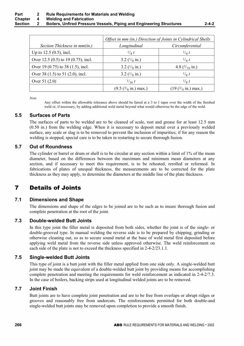
Part 2 Rule Requirements for Materials and WeldingChapter 4 Welding and FabricationSection 2 Boilers, Unfired Pressure Vessels, Piping and Engineering Structures 2-4-2
266 ABS RULE REQUIREMENTS FOR MATERIALS AND WELDING . 2002
Offset in mm (in.) Direction of Joints in Cylindrical Shells
Section Thickness in mm(in.) Longitudinal Circumferential
Up to 12.5 (0.5), incl. 1/4 t 1/4 t
Over 12.5 (0.5) to 19 (0.75), incl. 3.2 (1/8 in.) 1/4 t
Over 19 (0.75) to 38 (1.5), incl. 3.2 (1/8 in.) 4.8 (3/16 in.)
Over 38 (1.5) to 51 (2.0), incl. 3.2 (1/8 in.) 1/8 t
Over 51 (2.0) 1/16 t 1/8 t
(9.5 (3/8 in.) max.) (19 (3/4 in.) max.)
NoteAny offset within the allowable tolerance above should be faired at a 3 to 1 taper over the width of the finishedweld or, if necessary, by adding additional weld metal beyond what would otherwise be the edge of the weld.
5.5 Surfaces of Parts 2-4-2/5.5
The surfaces of parts to be welded are to be cleaned of scale, rust and grease for at least 12.5 mm(0.50 in.) from the welding edge. When it is necessary to deposit metal over a previously weldedsurface, any scale or slag is to be removed to prevent the inclusion of impurities; if for any reason thewelding is stopped, special care is to be taken in restarting to secure thorough fusion.
5.7 Out of Roundness 2-4-2/5.7
The cylinder or barrel or drum or shell is to be circular at any section within a limit of 1% of the meandiameter, based on the differences between the maximum and minimum mean diameters at anysection, and if necessary to meet this requirement, is to be reheated, rerolled or reformed. Infabrications of plates of unequal thickness, the measurements are to be corrected for the platethickness as they may apply, to determine the diameters at the middle line of the plate thickness.
7 Details of Joints 2-4-2/7
7.1 Dimensions and Shape 2-4-2/7.1
The dimensions and shape of the edges to be joined are to be such as to insure thorough fusion andcomplete penetration at the root of the joint.
7.3 Double-welded Butt Joints 2-4-2/7.3
In this type joint the filler metal is deposited from both sides, whether the joint is of the single- ordouble-grooved type. In manual welding the reverse side is to be prepared by chipping, grinding orotherwise cleaning out, so as to secure sound metal at the base of weld metal first deposited beforeapplying weld metal from the reverse side unless approved otherwise. The weld reinforcement oneach side of the plate is not to exceed the thickness specified in 2-4-2/23.1.1.
7.5 Single-welded Butt Joints 2-4-2/7.5
This type of joint is a butt joint with the filler metal applied from one side only. A single-welded buttjoint may be made the equivalent of a double-welded butt joint by providing means for accomplishingcomplete penetration and meeting the requirements for weld reinforcement as indicated in 2-4-2/7.3.In the case of boilers, backing strips used at longitudinal welded joints are to be removed.
7.7 Joint Finish 2-4-2/7.7
Butt joints are to have complete joint penetration and are to be free from overlaps or abrupt ridges orgrooves and reasonably free from undercuts. The reinforcements permitted for both double-andsingle-welded butt joints may be removed upon completion to provide a smooth finish.

Part 2 Rule Requirements for Materials and WeldingChapter 4 Welding and FabricationSection 2 Boilers, Unfired Pressure Vessels, Piping and Engineering Structures 2-4-2
ABS RULE REQUIREMENTS FOR MATERIALS AND WELDING . 2002 267
7.9 Lap Joints 2-4-2/7.9
Where lapped joints are permitted, they are to be made with an overlap of the edges not less than fourtimes the thickness of the thinner plate, except as noted in 2-4-2/Figure 1.
7.11 Head to Shell Attachments 2-4-2/7.11
7.11.1 Length of Flange 2-4-2/7.11.1
Dished heads other than concaved hemispherical to the pressure which are to be attached bybutt-welding, and flanged heads or flanged furnace connections which are to be fillet-weldedare to have a length of flange not less than 25 mm (1 in.) for heads or furnace openings notover 610 mm (24 in.) in external diameter and not less than 38 mm (1.5 in.) for heads orfurnace openings over 610 mm (24 in.) in diameter. For unfired pressure vessels, see2-4-2/Figure 1 for details.
7.11.2 Inserted Heads 2-4-2/7.11.2
When dished heads are fitted inside or over a shell, they are to have a driving fit beforewelding.
7.11.3 Connections 2-4-2/7.11.3
Acceptable types of fusion-welded connections of heads to shells are illustrated in2-4-2/Figure 1, subject to the tabulated limitations in 4-4-1A1/Table 1.
7.13 Bending Stresses in Welds 2-4-2/7.13
The design of a Group I or II welded container is to be such that the weld will not be subjected todirect bending stresses [see 2-4-2/Figure 1(m)]. Corner welds are not to be used unless the platesforming the corner are supported independently of the welds.
7.15 Connections 2-4-2/7.15
All welding for fusion-welded connections is to be equivalent to that required for the joints of thevessel to which they are attached.
7.17 Nozzles 2-4-2/7.17
Acceptable types of fusion-welded nozzle connections are illustrated in 2-4-2/Figure 2 and are tocomply with the following.
7.17.1 2-4-2/Figure 2(a) and (b) 2-4-2/7.17.1
Necks abutting the vessel wall are to be attached by a full penetration groove weld.
7.17.2 2-4-2/Figure 2(c) through (h) 2-4-2/7.17.2
Necks inserted into or through a hole cut in the vessel wall and without additional reinforcingelements are to be attached by a full penetration groove weld or by two partial penetrationwelds, one on each face of the vessel wall. These may be any desired combination of fillet,single-bevel and single-J welds.
7.17.3 2-4-2/Figure 2(l), (m), (n), (o) and (p) 2-4-2/7.17.3
Inserted type necks having added reinforcement in the form of one or more separatereinforcing plates are to be attached by welds at the outer edge of the reinforcing plate and atthe nozzle-neck periphery. The welds attaching the neck to the vessel wall and to thereinforcement plate are to consist of one of the following combinations.
7.17.3(a) Single-bevel or single-J weld in the shell plate, and full penetration groove weld ora single-bevel or single-J weld in each reinforcement plate. See 2-4-2/Figure 2(n) and (p).
Part 2 Rule Requirements for Materials and WeldingChapter 4 Welding and FabricationSection 2 Boilers, Unfired Pressure Vessels, Piping and Engineering Structures 2-4-2
268 ABS RULE REQUIREMENTS FOR MATERIALS AND WELDING . 2002
7.17.3(b) A full penetration groove weld in the shell plate, and a fillet, single-bevel, or single-J weld or a full penetration groove weld in each reinforcement plate. See 2-4-2/Figure 2(m)and (o).
7.17.3(c) A full penetration groove weld in each reinforcement plate, and a fillet, single-bevel, or single-J weld in the shell plate. See 2-4-2/Figure 2(l).
7.17.4 2-4-2/Figure 2(k), (q), (r), (s) and (t) 2-4-2/7.17.4
Nozzles with integral reinforcement in the form of extended necks or saddle type pads are tobe attached by a full penetration weld or by means of a fillet weld along the outer edge and afillet, single-bevel, or single-J weld along the inner edge.
7.17.5 2-4-2/Figure 2(u), (v), (w) and (x) 2-4-2/7.17.5
Fittings with internal threads are to be attached by a full penetration groove weld or by twofillet or partial penetration welds, one on each face of the vessel wall. See 2-4-2/Figure 2(u),(v), (w) and (x). Internally threaded fittings not exceeding 89 mm OD (3 in. NPS) may beattached by a fillet groove weld from the outside only. See 2-4-2/Figure 2(w-3).
For all cases the strength of the welded connection is to be in accordance with therequirements of 4-4-1A1/7.9.3ii).
7.19 Limitations 2-4-2/7.19
The use of various types of welded construction is subject to the limitations of the group for which itis intended as well as the limitations tabulated in 4-4-1A1/Table 1.
9 Forms of Welded Joints Required 2-4-2/9
9.1 Boilers and Group I Pressure Vessels 2-4-2/9.1
Joints are to be in accordance with the following details.
9.1.1 Double-welded 2-4-2/9.1.1
All joints are to be of the double-welded butt type, single-or double-grooved, except where asingle-welded butt joint is made the equivalent of a double-welded butt joint. See 2-4-2/7.5.
9.1.2 Nozzles and Other Connections 2-4-2/9.1.2
Some acceptable types of welded nozzles and other connections to shells, drums and headersare shown in 2-4-2/Figure 2.
9.1.3 Closing Plates 2-4-2/9.1.3
Closing plates of headers for boilers and superheaters as well as flat heads of other pressurevessels may be attached by welding as indicated in 2-4-2/Figure 1(g) or (h) and4-4-1A1/Figure 7.
9.3 Group II Pressure Vessels 2-4-2/9.3
Joints are to be the same as Group I except as noted below.
9.3.1 Single-welded 2-4-2/9.3.1
Butt joints welded from one side, with or without backing strips, are subject to the tabulatedlimitations in 4-4-1A1/Table 1. When backing strips are used, they may be left in place orremoved.
Part 2 Rule Requirements for Materials and WeldingChapter 4 Welding and FabricationSection 2 Boilers, Unfired Pressure Vessels, Piping and Engineering Structures 2-4-2
ABS RULE REQUIREMENTS FOR MATERIALS AND WELDING . 2002 269
9.3.2 Full-fillet Lap 2-4-2/9.3.2
Double full-fillet lap joints or single full-fillet lap joints, with or without plug welds, whenused, are subject to the tabulated limitations in 4-4-1A1/Table 1. See also 2-4-2/Figure 1.
9.5 Group I Pipe Connections 2-4-2/9.5
Welded joints are to be in accordance with the following.
9.5.1 Pipes Over 89 mm OD (3 in. NPS) 2-4-2/9.5.1
Joints for connecting two lengths of pipe or a pipe to a welding fitting, valve or flange are tobe of the grooved type. In welding single-welded butt joints, complete penetration at the rootis required and is to be demonstrated by the qualification of the procedure used. If completepenetration cannot otherwise be secured, the procedure is to include backing. The depth ofweld is to be not less than the minimum thickness permitted by the applicable materialspecifications for the particular size and thickness of the pipe used.
9.5.2 Pipes 89 mm OD (3 in. NPS) and Below 2-4-2/9.5.2
Joints for connecting two lengths of pipe may be made by sleeves fitted over the joint andattached by fillet welds or by using socket-type joints with a fillet weld. For sleeve joints, theinside diameter of the sleeve is not to exceed the outside diameter of the pipe by more than2.0 mm (0.080 in.). The fit and fillet weld sizes are to be in accordance with an applicablerecognized standard (e.g., ANSI B16.11 for socket-type joints, ASTM F682 for sleeve-typejoints and ANSI B31.1 for fillet weld sizes). The depth of insertion of the pipe into the sleeveor socket fitting is to be at least 9.5 mm (0.375 in.). A minimum gap of approximately 2.0 mm(0.080 in.) is to be provided between the ends of the pipe for a sleeve joint or between thepipe and socket shoulder for socket-type joints prior to welding. The fittings are to bereasonably centered around the pipe.
9.5.3 Flanges 2-4-2/9.5.3
ANSI slip-on flanges may be attached to piping by double-fillet welds for applications withservice rating no higher than ANSI 300 Class provided the throats of the fillet welds are notless than 0.7 times the thickness of the part to which the flange is attached. For boiler externalpiping, the use of slip-on flanges is additionally limited to sizes not exceeding 114 mm OD (4in. NPS) and the throats of fillet welds may be not less than 0.7 times the thickness of the partto which the flange is attached. Slip-on flanges for higher ratings which comply with ASMEor other recognized standards will be subject to special consideration.
Socket-type flanges up to and including ANSI 600 Class may be used in piping 89 mm OD (3in. NPS) or less and up to and including the ANSI 1500 Class in piping 73 mm OD (2.5 in.NPS) pipe size or less.
9.5.4 Backing 2-4-2/9.5.4
Backing for grooved joints may be omitted in pipes under 33 mm OD (1 in. NPS). Backing isrecommended for welding pipes on shipboard for all sizes 33 mm OD (1 in. NPS) and abovewhen welded with single butt joints.
9.5.5 Welding 2-4-2/9.5.5
Welding in pipe lines is to be done in the shop as far as practicable and joints made in theinstallation on board ship are to be in positions accessible for proper welding.
Part 2 Rule Requirements for Materials and WeldingChapter 4 Welding and FabricationSection 2 Boilers, Unfired Pressure Vessels, Piping and Engineering Structures 2-4-2
270 ABS RULE REQUIREMENTS FOR MATERIALS AND WELDING . 2002
9.7 Group II Pipe Connections 2-4-2/9.7
The type of welded joints in the construction of piping under this Group is to be similar to those inGroup I except for the following modifications. For 2-4-2/9.7.1, 2-4-2/9.7.2 and 2-4-2/9.7.3 below,full penetration welds are required.
9.7.1 Single-groove 2-4-2/9.7.1
Single-groove welded-butt joints may be without backing in all sizes if the weld is chipped orground off flush on the root side.
9.7.2 Backing 2-4-2/9.7.2
Backing may also be dispensed with, without grinding the root of the weld in such services astank-vent and overflow pipes.
9.7.3 Square-groove Welds 2-4-2/9.7.3
Square-groove welds may be used in lieu of the single-V groove weld for tank vent andoverflow pipes where the thickness of the pipe does not exceed 4.8 mm (3/16 in.).
9.7.4 Sleeves 2-4-2/9.7.4
Sleeves fitted over the joint and attached by fillet welds or socket-type joints with a fillet weldwill be acceptable in all sizes. The fit and fillet weld sizes are to be in accordance with anapplicable recognized standard (e.g., ANSI B16.11 for socket joints, ASTM F682 for sleevetype joints and ANSI B31.1 for fillet weld sizes.) The depth of insertion and gap are to be asper 2-4-2/9.5.2. The fittings are to be reasonably centered around the pipe.
9.9 Low-temperature Piping Systems (Below -18°C (0°F)) 2-4-2/9.9
For service temperatures lower than -18°C (0°F), each welding procedure is to be approved inaccordance with the requirements of 2-4-3/5 and Part 5, Chapter 8. All piping systems over 10.3 bar(10.5 kgf/cm2, 150 psi) are to be considered Group I piping systems except that socket-weld joints,slip-on flanges, single-welded butt joints with backing strips left in place, pipe-joining sleeves andthreaded joints are not to be used except where permitted by Part 5, Chapter 8.
9.11 Engineering Structures 2-4-2/9.11
The type of welded joints used in either Group I or II in this class of construction is subject to specialconsideration in connection with the design in each case
11 Preheat 2-4-2/11
11.1 Boilers, Pressure Vessels, and Group I Piping 2-4-2/11.1
When ambient temperatures are below 10°C (50°F), the welded parts of boilers, pressure vessels, andGroup I piping are to be preheated, prior to welding, so that the parts to be joined by welding will beat a temperature not less than 10°C (50°F). Higher preheat is required for material composition,thicknesses, and carbon content in accordance with the following paragraphs.
11.1.1 General 2-4-2/11.1.1
The thicknesses referred to are nominal at the weld for the parts to be joined. Where thequalification procedure specifies a higher preheat, this higher preheat is to be used. Wheredifferent materials having different preheat requirements are joined by welding, the higherpreheat is to be used. For materials refer to 2-3-2/1, 2-3-2/3, 2-3-2/5, 2-3-2/7, Section 2-3-5and Section 2-3-12.
Part 2 Rule Requirements for Materials and WeldingChapter 4 Welding and FabricationSection 2 Boilers, Unfired Pressure Vessels, Piping and Engineering Structures 2-4-2
ABS RULE REQUIREMENTS FOR MATERIALS AND WELDING . 2002 271
11.1.2 Preheat Temperatures 2-4-2/11.1.2
Welds joining pressure parts or attachments to pressure parts are to be preheated to not lessthan the following temperatures.
11.1.2(a) ABS Plate Grades MA, MB, MC, MD, ME, MF, MG, K, L, M, N, Tube Grades D, F,H, J, and Pipe Grades 1, 2, 3, 4, 5, 8, and 9. to 79°C (175°F) for material which has bothspecified maximum carbon content in excess of 0.30% and a thickness at the joint in excess of25.4 mm (1.0 in.).
11.1.2(b) ABS Plate Grades H, I, J, Tube Grades K, L, M and Pipe Grades 6 and 7. to 79°C(175°F) for material which has either a specified minimum tensile strength in excess of 485N/mm2 (49 kgf/mm2, 70,000 psi) or a thickness at the joint in excess of 16.0 mm (0.625 in.).
11.1.2(c) ABS Tube Grades N and O and Piping Grades 11 and 12. to 121°C (250°F) formaterial which has a thickness at the joint in excess of 12.5 mm (0.5 in.).
11.1.2(d) ABS Tube Grade P and Piping Grade 13. to 149°C (300°F) regardless of thickness.
11.1.2(e) Other Materials. The preheating of other materials will be subject to specialconsideration.
11.3 Group I Pipe Connections 2-4-2/11.3
All Group I pipe connections defined in 2-4-2/1.5.2 are to be preheated in accordance with 2-4-2/11.
13 General Requirements for Postweld Heat Treatment 2-4-2/13
13.1 General 2-4-2/13.1
Prior to the application of the following requirements, satisfactory weld-procedure qualifications ofthe procedures to be used are to be performed in accordance with all the essential variables of Section2-4-3, including conditions of postweld heat treatment or lack of postweld heat treatment and otherrestrictions as listed in the following paragraphs.
13.3 Heat-treatment Determination 2-4-2/13.3
Except as otherwise specifically provided for, all welded pressure parts of boilers and all weldedpressure vessels or pressure parts are to be given a postweld heat treatment at a temperature not lessthan that specified in the following paragraphs. Where pressure parts of two different materials arejoined by welding, the postweld heat treatment is to be that specified for the material requiring thehigher postweld temperature. When nonpressure parts are welded to pressure parts, the postweld-heat-treatment temperature of the pressure part is to control.
15 Fusion-welded Boilers 2-4-2/15
15.1 Postweld Heat Treatment 2-4-2/15.1
All boilers of plate, pipe, and tube materials listed in 2-3-2/3, 2-3-2/5, 2-3-2/7, Section 2-3-5 andSection 2-3-12 are to be given a post-weld heat treatment after all pads, flanges, or nozzles have beenwelded in place. Postweld heat treatment is to be as follows.

Part 2 Rule Requirements for Materials and WeldingChapter 4 Welding and FabricationSection 2 Boilers, Unfired Pressure Vessels, Piping and Engineering Structures 2-4-2
272 ABS RULE REQUIREMENTS FOR MATERIALS AND WELDING . 2002
Minimum Holding Time at NormalTemperature for Weld Thickness (Nominal)
GradesMinimum •
Holding Temperature Up to 51 mm (2 in.) Over 51 mm (2 in.)
All Plates,Tubes and Pipes
except Grade N, O and PTubes and Grade 11, 12
and 13 Pipes
593°C(1100°F)
1 hr/25 mm(1 in.) 15 min
minimum
2 hr plus 15 min.for each additional
25 mm (1 in.)
Tube Grades N and O andPipe Grades 11 and 12
593°C(1100°F)
1 hr/25 mm(1 in.) 15 min.
minimum
1 hr/25 mm (1in.) to127 mm (5 in.) plus
15 min. for eachadditional 25 mm
(1 in.)
Tube Grade P and PipeGrade 13
677°C(1250°F)
1 hr/25 mm(1 in.) 15 min.
minimum
1 hr/25 mm (1 in.) to127 mm (5 in.) plus
15 min. for eachadditional 25 mm
(1 in.)• Maximum temperature is to be at least 28°C (50°F) below base material tempering temperature.
15.3 Lower Temperatures – Carbon and Carbon Molybdenum Steels 2-4-2/15.3
When it is impractical to postweld heat-treat materials listed in 2-4-2/15.5 and 2-4-2/15.7 at thetemperature specified in 2-4-2/15.1, it is permissible to heat-treat at lower temperatures for longerperiods as follows.
Lower Min. Temp. degrees °C (°F)Min. Holding Time at Decreased Temp.
in hr/25 mm (hr/in.)
566 (1050) 2
538 (1000) 3
510 (950) 5
482 (900) 10
15.5 Heat-treatment Exceptions for Fusion-welded Boilers – ABS Plate Grades MA,MB, MC, MD, ME, MF, MG, K, L, M, N, Tube Grades D, F, G, H, J and Group IPiping Grades 1, 2, 3, 4, 5, 8, and 9 2-4-2/15.5
Postweld heat treatment of these materials and other equivalent pipe plate, and tube material is notrequired under the following conditions.
15.5.1 Circumferential Welds 2-4-2/15.5.1
For circumferential welds in pipes, tubes or headers where the pipe, tube or header complieswith a nominal wall thickness of 19.1 mm (0.75 in.) or less at the joint.
15.5.2 Fillet Welds 2-4-2/15.5.2
For fillet welds, attaching nonpressure parts to pressure parts that have a throat thickness of12.7 mm (0.50 in.) or less, provided preheat to a minimum temperature of 93°C (200°F) isapplied when the thickness of the pressure part exceeds 19.1 mm (0.75 in).
Part 2 Rule Requirements for Materials and WeldingChapter 4 Welding and FabricationSection 2 Boilers, Unfired Pressure Vessels, Piping and Engineering Structures 2-4-2
ABS RULE REQUIREMENTS FOR MATERIALS AND WELDING . 2002 273
15.5.3 Heat-absorbing Surfaces 2-4-2/15.5.3
For welds used to attach extended heat-absorbing surfaces to tubes and insulation attachmentpins to pressure parts.
15.5.4 Tubes 2-4-2/15.5.4
For tubes or pressure retaining hand hole and inspection plugs or fittings that are secured byphysical means (rolling, shoulder construction, machine threads, etc.) and seal welded,provided the seal weld has a throat thickness of 9.5 mm (0.375 in.) or less.
15.5.5 Studs 2-4-2/15.5.5
For studs welded to pressure parts for purposes not included in 2-4-2/15.5.3, provided preheatto a minimum temperature of 93°C (200°F) is applied when the thickness of the pressure partexceeds 19.1 mm (0.75 in.).
15.7 Heat-treatment Exceptions for Fusion-welded Boilers – ABS Plate Grades H, I,J, Tube Grades K, L, M, and Group I Piping Grades 6 and 7 2-4-2/15.7
Postweld heat treatment of these materials and other equivalent pipe, plate, and tube material is notrequired under the following conditions.
15.7.1 Circumferential Welds 2-4-2/15.7.1
For circumferential welds in pipes, tubes or headers where the pipes, tubes, or headers complywith both a nominal wall thickness of 16 mm (0.625 in.) or less, and a specified maximumcarbon content of not more than 0.25%.
15.7.2 Fillet Welds 2-4-2/15.7.2
For fillet welds attaching nonpressure parts having a specified maximum carbon content notmore than 0.25% that have a throat thickness of 12.7 mm (0.5 in.) or less, provided preheat toa minimum temperature of 93°C (200°F) is applied when the pressure part exceeds 15.9 mm(0.625 in.).
15.7.3 Heat-absorbing Surfaces 2-4-2/15.7.3
For welds used to attach extended heat-absorbing surfaces to tubes and insulation attachmentpins to pressure parts.
15.7.4 Tubes 2-4-2/15.7.4
For tubes or pressure-retaining handhole and inspection plugs or fittings that are secured byphysical means (rolling, shoulder construction, machine threads, etc.) and seal welded,provided the seal weld has a throat thickness of not more than 9.5 mm (0.375 in.).
15.7.5 Studs 2-4-2/15.7.5
Postweld heat treatment is not mandatory for studs welded to pressure parts for purposes notincluded in 2-4-2/15.7.3 and which have a specified maximum carbon content of not morethan 0.25%, provided a preheat to a minimum temperature of 93°C (200°F) is applied whenthe thickness of the pressure part exceeds 16 mm (0.625 in.).
15.9 Heat Treatment Exceptions for Fusion-welded Boilers – ABS Tube Grades N, Oand Group I Pipe Grades 11 and 12 2-4-2/15.9
Postweld heat treatment of these materials and other equivalent pipe and tube material with 0.15%carbon maximum is not required under the following conditions.
Part 2 Rule Requirements for Materials and WeldingChapter 4 Welding and FabricationSection 2 Boilers, Unfired Pressure Vessels, Piping and Engineering Structures 2-4-2
274 ABS RULE REQUIREMENTS FOR MATERIALS AND WELDING . 2002
15.9.1 Circumferential Welds 2-4-2/15.9.1
For circumferential welds where the pipe or tubes comply with all of the following.
15.9.1(a) a maximum outside diameter of 101.6 mm (4 in.)
15.9.1(b) a maximum thickness of 16 mm (0.625 in.)
15.9.1(c) a minimum preheat of 121°C (250°F)
15.9.2 Fillet Welds 2-4-2/15.9.2
For fillet welds attaching non-pressure parts to pressure parts, provided the fillet weld has aspecified throat thickness of 12.5 mm (0.5 in.) or less and the pressure part meets therequirements of 2-4-2/15.9.1(a) and 2-4-2/15.9.1(b).
15.9.3 Heat-absorbing Surfaces and Studs 2-4-2/15.9.3
For heat-absorbing surfaces and non-load-carrying studs provided the material is preheated to121°C (250°F) minimum and the pressure part meets the requirements of 2-4-2/15.9.1(a) and2-4-2/15.9.1(b).
15.9.4 Tubes 2-4-2/15.9.4
For tubes or pressure retaining handhole and inspection plugs or fittings that are secured byphysical means (rolling, shoulder construction, machine threads, etc.) and seal welded,provided the seal weld has a throat thickness of 9.5 mm (0.375 in.) or less.
15.11 Heat Treatment Exceptions for Fusion Welded Boilers – ABS Tube Grade P andGroup I Pipe Grade 13 2-4-2/15.11
Postweld heat treatment of this material and other equivalent pipe and tube material with 0.15%carbon maximum is not required under the following conditions.
15.11.1 Circumferential Welds 2-4-2/15.11.1
For circumferential welds where the pipe or tube complies with all of the following.
15.11.1(a) a maximum outside diameter of 101.6 mm (4 in.)
15.11.1(b) a maximum thickness of 16 mm (0.625 in.)
15.11.1(c) a minimum preheat of 149°C (300°F)
15.11.2 Fillet Welds 2-4-2/15.11.2
For fillet welds attaching non-pressure parts that have a specified throat thickness of 12.5 mm(0.5 in.) or less, provided the pressure part meets the requirements of 2-4-2/15.11.1(a) and2-4-2/15.11.1(b).
15.11.3 Heat-absorbing Surfaces and Studs 2-4-2/15.11.3
Heat-absorbing surfaces and non-load-carrying studs provided the material is preheated to149°C (300°F) and the pressure part meets the requirements of 2-4-2/15.11.1(a) and2-4-2/15.11.1(b).
15.11.4 Tubes 2-4-2/15.11.4
For tubes or pressure retaining handhole and inspection plugs or fittings with a specifiedmaximum chrome content of 6% that are secured by physical means (rolling, shoulderconstruction, machine threads, etc.) and seal welded, provided the seal weld has a throatthickness of 9.5 mm (0.375 in.) or less.
Part 2 Rule Requirements for Materials and WeldingChapter 4 Welding and FabricationSection 2 Boilers, Unfired Pressure Vessels, Piping and Engineering Structures 2-4-2
ABS RULE REQUIREMENTS FOR MATERIALS AND WELDING . 2002 275
15.13 Other Materials 2-4-2/15.13
Postweld heat treatment of other materials for boilerplate and tubes will be subject to specialconsideration.
15.15 Other Welded Connections 2-4-2/15.15
Nozzles or other welded attachments for which postweld heat treatment is required may be locallypostweld heat-treated by heating a circumferential band around the entire vessel with the weldedconnection located at the middle of the band. The width of the band is to be at least three times thewall thickness of the vessel wider than the nozzle or other attachment weld, and is to be located insuch a manner that the entire band will be heated to the temperature and held for the time specified in2-4-2/15.1 for post-weld heat treatment.
15.17 Welded Joints 2-4-2/15.17
In the case of welded joints in pipes, tubes and headers the width of the heated circumferential band isto be at least three times the width of the widest part of the welding groove, but in no case less thantwice the width of the weld reinforcement.
17 Fusion-welded Pressure Vessels 2-4-2/17
17.1 Postweld Heat Treatment 2-4-2/17.1
17.1.1 General 2-4-2/17.1.1
All pressure vessels and pressure-vessel parts are to be given a postweld heat treatment at atemperature not less than that specified in 2-4-2/15.1 and 2-4-2/15.3 when the nominalthickness, including corrosion allowance of any welded joint in the vessel or vessel partexceeds the limits as noted in 2-4-2/17.3 and 2-4-2/17.5. In addition, postweld heat treatmentis required for the following.
17.1.1(a) For all independent cargo tanks where required by Part 5, Chapter 8.
17.1.1(b) For all carbon or carbon manganese steel pressure vessels and independent cargopressure vessels not covered by 2-4-2/17.1.1(a), when the metal temperature is below -29°C(-20°F).
17.1.1(c) For all pressure vessels and independent cargo pressure vessels, which arefabricated of carbon or carbon manganese steel and intended to carry anhydrous ammonia.
17.1.2 Welded Joints 2-4-2/17.1.2
When the welded joint connects parts that are of different thickness, the thickness to be usedin applying these requirements is to be the thinner of two adjacent butt-welded plates,including head to shell connections, the thickness of the head or shell plate in nozzleattachment welds, and the thickness of the nozzle neck at the joint in nozzle neck to flangeconnections, the thickness of the shell in connections to tube sheets, flat heads, covers orsimilar connections, and the thicker of plate in connections of the type shown in 2-4-2/Figure 1(f).
17.3 Heat-treatment Exceptions – ABS Plate Grades MA, MB, MC, MD, ME, MF, MG,K, L, M, N and Tube Grades D, F, G, H, J 2-4-2/17.3
Postweld heat treatment of these materials is not required under the following conditions.
Part 2 Rule Requirements for Materials and WeldingChapter 4 Welding and FabricationSection 2 Boilers, Unfired Pressure Vessels, Piping and Engineering Structures 2-4-2
276 ABS RULE REQUIREMENTS FOR MATERIALS AND WELDING . 2002
17.3.1 38.1 mm (1.5 in.) and Under 2-4-2/17.3.1
For material up to and including 38.1 mm (1.5 in.) thickness, provided that material over31.8 mm (1.25 in.) thickness is preheated to a minimum temperature of 93°C (200°F) duringwelding.
17.3.2 Over 38.1 mm (1.5 in.) 2-4-2/17.3.2
For material over 38.1 mm (1.5 in.) thickness, all welded connections and attachments are tobe postweld heat-treated except that postweld heat treatment is not required for:
17.3.2(a) Nozzle Connections. Fillet welds with a throat not over 12.7 mm (0.50 in.) andgroove welds not over 12.7 mm (0.50 in.) in size that attach nozzle connections having afinished inside diameter not greater than 50.8 mm (2 in.), provided the connections do notform ligaments that require an increase in shell or head thickness, and preheat to a minimumtemperature of 93°C (200°F) is applied.
17.3.2(b) Nonpressure Attachments. Fillet welds having a throat not over 12.7 mm (0.5 in.),or groove welds not over 12.7 mm (0.50 in.) in size, used for attaching nonpressure parts topressure parts, and preheat to a minimum temperature of 93°C (200°F) is applied when thethickness of the pressure part exceeds 19 mm (0.75 in.).
17.5 Heat-treatment Exceptions – ABS Plate Grades, H, I, J and Tube Grades K, L, M2-4-2/17.5
Postweld heat treatment of these materials is not required under the following conditions.
17.5.1 15.9 mm (0.625 in.) and Under 2-4-2/17.5.1
For material up to and including 15.9 mm (0.625 in.) in thickness having a specifiedmaximum carbon content of not more than 0.25%, provided a welding procedure qualificationhas been made in equal or greater thickness than the production weld.
17.5.2 Over 15.9 mm (0.625 in.) 2-4-2/17.5.2
For material over 15.9 mm (0.625 in.) thicknesses all welded connections and attachments areto be postweld heat-treated except that postweld treatment is not required for:
17.5.2(a) Nonpressure Attachments. Attaching to pressure parts which have a specifiedmaximum carbon content of not more than 0.25% and nonpressure parts with fillet welds thathave a throat thickness of 12.7 mm (0.50 in.) or less, provided preheat to a minimumtemperature of 80°C (175°F) is applied.
17.5.2(b) Tube or Pipe Attachments. Circumferential welds in pipes or tubes where the pipesor tubes have both a nominal wall thickness of 12.7 mm (0.50 in.) or less, and a specifiedmaximum carbon content of not more than 0.25%.
17.7 Heat-treatment Exceptions – Attachments 2-4-2/17.7
On pressure vessels which do not require postweld heat treatment as a whole, connections and otherattachments after being attached by fusion welding need not be post-weld heat-treated. See also2-4-2/21.11 for nozzles or other welded attachments for which postweld heat treatment is notrequired.
17.9 Other Materials 2-4-2/17.9
Postweld heat treatment of other materials for boiler plate and tubes will be subject to specialconsideration.
Part 2 Rule Requirements for Materials and WeldingChapter 4 Welding and FabricationSection 2 Boilers, Unfired Pressure Vessels, Piping and Engineering Structures 2-4-2
ABS RULE REQUIREMENTS FOR MATERIALS AND WELDING . 2002 277
17.11 Welded Connections 2-4-2/17.11
Nozzles or other welded attachments for which postweld heat treatment is required may be heat-treated by heating a circumferential band around the entire vessel in such a manner that the entireband is to be brought up uniformly to the required temperature and held for the specified time. Thecircumferential band is to extend around the entire vessel and include the nozzle or weldedattachment, and is to extend at least six times the plate thickness beyond the welding which connectsthe nozzle or other attachment to the vessel. The portion of the vessel outside of the circumferentialband is to be protected so that the temperature gradient is not harmful.
19 Pipe Connections and Engineering Structures 2-4-2/19
19.1 Group I Pipe Connections 2-4-2/19.1
All Group I Pipe connections defined in 2-4-2/1.5 are to be postweld heat-treated in accordance with2-4-2/15 or the American National Standard ANSI B31.1.
19.3 Group II Pipe Connections 2-4-2/19.3
Unless specially required, connections in Group II piping need not be postweld heat-treated.
19.5 Group I Engineering Structures 2-4-2/19.5
All welded structures under this group are to be postweld heat-treated in accordance with theapplicable requirements of 2-4-2/17.
19.7 Group II Engineering Structures 2-4-2/19.7
Postweld heat treatment of structures under this group depends on the type and purpose of theconstruction, and the matter will be subject to special consideration in connection with the approval ofthe design.
19.9 Low-temperatures Piping Systems [Below -18°C (0°F)] 2-4-2/19.9
In general, all piping weldments except socket-weld joints and slip-on flanges, where permitted, are tobe postweld heat-treated. Exceptions will be considered for specific materials where it can be shownthat postweld heat treatment is unnecessary.
21 Postweld Heat-treatment Details 2-4-2/21
21.1 Boilers and Pressure Vessels 2-4-2/21.1
The weldment is to be heated uniformly and slowly to the temperature and time specified in2-4-2/15.1, and is to be allowed to cool slowly in a still atmosphere to a temperature not exceeding427°C (800°F). The postweld heat treatment may be done either by heating the complete weldedstructure as a whole or by heating a complete section containing the parts to be postweld heat-treated.The postweld-heat-treatment temperature is to be controlled by at least two pyrometric instruments toavoid the possibility of error.
21.3 Pipe Connections 2-4-2/21.3
In the case of welded pipe connections requiring postweld heat treatment the adjacent pipes or fittingsare to be heated in a circumferential band at least 3 times the width of the widest part of the weldinggroove but not less than twice the width of the weld reinforcement.
21.5 Other Steels 2-4-2/21.5
The postweld heat treatment of other steels not specifically covered in Part 2, Chapter 3 will besubject to special consideration.
Part 2 Rule Requirements for Materials and WeldingChapter 4 Welding and FabricationSection 2 Boilers, Unfired Pressure Vessels, Piping and Engineering Structures 2-4-2
278 ABS RULE REQUIREMENTS FOR MATERIALS AND WELDING . 2002
21.7 Clad Pressure Vessels 2-4-2/21.7
Postweld heat treatment of vessels or parts of vessels constructed of integrally clad or appliedcorrosion-resistant lining material will be subject to special consideration.
21.9 Opening Connections 2-4-2/21.9
Welded connections may be added to a vessel after post-weld heat treatment without requiringrepostweld heat treatment, provided the following conditions are met.
21.9.1 Size of Weld 2-4-2/21.9.1
The inside and outside attachment welds do not exceed 9.5 mm (0.375 in.) throat dimension.
21.9.2 Opening Diameter 2-4-2/21.9.2
The diameter of the attachment opening in the vessel shell does not exceed that allowed for anunreinforced opening, or does not exceed 50.8 mm (2 in.), whichever is smaller.
21.9.3 Exception 2-4-2/21.9.3
This provision does not apply to those connections so placed as to form ligaments in the shell,the efficiency of which will affect the shell thickness. Such added connections are to bepostweld heat-treated.
21.11 Seal Welding 2-4-2/21.11
Seal welding consisting of a fillet weld under 9.5 mm (0.375 in.) without subsequent stress relievingmay be applied to secure tightness of connections where the construction is such that no design stressis placed upon the weld even though the structure itself has to be stress-relieved in accordance withthese Rules.
23 Radiography 2-4-2/23
23.1 General 2-4-2/23.1
23.1.1 Welded-joint Preparation 2-4-2/23.1.1
All welded joints to be radiographed are to be prepared as follows: The weld ripples or weldsurface irregularities, on both the inside and outside, are to be removed by any suitablemechanical process to such a degree that the resulting radiographic contrast due to anyirregularities cannot mask or be confused with the image of any objectionable defect. Also,the weld surface is to merge smoothly into the plate surface. The finished surface of thereinforcement of all butt-welded joints may be flush with the plate or may have a reasonablyuniform crown not to exceed the following thickness.
Plate Thickness, in mm (in.) Thickness of Reinforcement, in mm (in.)
Up to 12.7 (0.5) incl. 1.6 (1/16)
Over 12.7 (0.5) to 25.4 (1.0) 2.4 (3/32)
Over 25.4 (1.0) to 50.8 (2.0) 3.2 (1/8)
Over 50.8 (2.0) 4.0 (5/32)
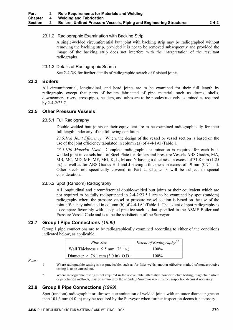
Part 2 Rule Requirements for Materials and WeldingChapter 4 Welding and FabricationSection 2 Boilers, Unfired Pressure Vessels, Piping and Engineering Structures 2-4-2
ABS RULE REQUIREMENTS FOR MATERIALS AND WELDING . 2002 279
23.1.2 Radiographic Examination with Backing Strip 2-4-2/23.1.2
A single-welded circumferential butt joint with backing strip may be radiographed withoutremoving the backing strip, provided it is not to be removed subsequently and provided theimage of the backing strip does not interfere with the interpretation of the resultantradiographs.
23.1.3 Details of Radiographic Search 2-4-2/23.1.3
See 2-4-3/9 for further details of radiographic search of finished joints.
23.3 Boilers 2-4-2/23.3
All circumferential, longitudinal, and head joints are to be examined for their full length byradiography except that parts of boilers fabricated of pipe material, such as drums, shells,downcomers, risers, cross-pipes, headers, and tubes are to be nondestructively examined as requiredby 2-4-2/23.7.
23.5 Other Pressure Vessels 2-4-2/23.5
23.5.1 Full Radiography 2-4-2/23.5.1
Double-welded butt joints or their equivalent are to be examined radiographically for theirfull length under any of the following conditions.
23.5.1(a) Joint Efficiency. Where the design of the vessel or vessel section is based on theuse of the joint efficiency tabulated in column (a) of 4-4-1A1/Table 1.
23.5.1(b) Material Used. Complete radiographic examination is required for each butt-welded joint in vessels built of Steel Plate for Boilers and Pressure Vessels ABS Grades, MA,MB, MC, MD, ME, MF, MG, K, L, M and N having a thickness in excess of 31.8 mm (1.25in.) as well as for ABS Grades H, I and J having a thickness in excess of 19 mm (0.75 in.).Other steels not specifically covered in Part 2, Chapter 3 will be subject to specialconsideration.
23.5.2 Spot (Random) Radiography 2-4-2/23.5.2
All longitudinal and circumferential double-welded butt joints or their equivalent which arenot required to be fully radiographed in 2-4-2/23.5.1 are to be examined by spot (random)radiography where the pressure vessel or pressure vessel section is based on the use of thejoint efficiency tabulated in column (b) of 4-4-1A1/Table 1. The extent of spot radiography isto compare favorably with accepted practice such as that specified in the ASME Boiler andPressure Vessel Code and is to be the satisfaction of the Surveyor.
23.7 Group I Pipe Connections (1999) 2-4-2/23.7
Group I pipe connections are to be radiographically examined according to either of the conditionsindicated below, as applicable.
Pipe Size Extent of Radiography1,2
Wall Thickness > 9.5 mm (3/8 in.) 100%
Diameter > 76.1 mm (3.0 in) O.D. 100%Notes
1 Where radiographic testing is not practicable, such as for fillet welds, another effective method of nondestructivetesting is to be carried out.
2 Where radiographic testing is not required in the above table, alternative nondestructive testing, magnetic particleor penetration methods, may be required by the attending Surveyor when further inspection deems it necessary
23.9 Group II Pipe Connections (1999) 2-4-2/23.9
Spot (random) radiographic or ultrasonic examination of welded joints with an outer diameter greaterthan 101.6 mm (4.0 in) may be required by the Surveyor when further inspection deems it necessary.
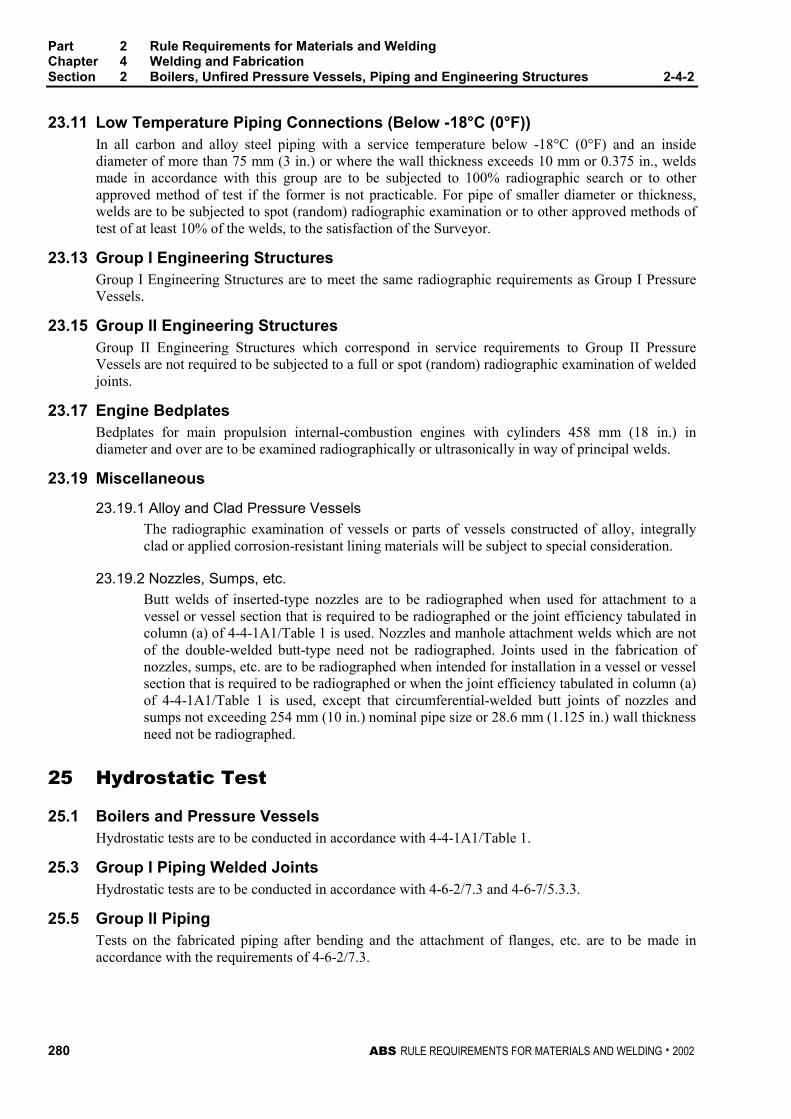
Part 2 Rule Requirements for Materials and WeldingChapter 4 Welding and FabricationSection 2 Boilers, Unfired Pressure Vessels, Piping and Engineering Structures 2-4-2
280 ABS RULE REQUIREMENTS FOR MATERIALS AND WELDING . 2002
23.11 Low Temperature Piping Connections (Below -18°C (0°F)) 2-4-2/23.11
In all carbon and alloy steel piping with a service temperature below -18°C (0°F) and an insidediameter of more than 75 mm (3 in.) or where the wall thickness exceeds 10 mm or 0.375 in., weldsmade in accordance with this group are to be subjected to 100% radiographic search or to otherapproved method of test if the former is not practicable. For pipe of smaller diameter or thickness,welds are to be subjected to spot (random) radiographic examination or to other approved methods oftest of at least 10% of the welds, to the satisfaction of the Surveyor.
23.13 Group I Engineering Structures 2-4-2/23.13
Group I Engineering Structures are to meet the same radiographic requirements as Group I PressureVessels.
23.15 Group II Engineering Structures 2-4-2/23.15
Group II Engineering Structures which correspond in service requirements to Group II PressureVessels are not required to be subjected to a full or spot (random) radiographic examination of weldedjoints.
23.17 Engine Bedplates 2-4-2/23.17
Bedplates for main propulsion internal-combustion engines with cylinders 458 mm (18 in.) indiameter and over are to be examined radiographically or ultrasonically in way of principal welds.
23.19 Miscellaneous 2-4-2/23.19
23.19.1 Alloy and Clad Pressure Vessels
The radiographic examination of vessels or parts of vessels constructed of alloy, integrallyclad or applied corrosion-resistant lining materials will be subject to special consideration.
23.19.2 Nozzles, Sumps, etc.
Butt welds of inserted-type nozzles are to be radiographed when used for attachment to avessel or vessel section that is required to be radiographed or the joint efficiency tabulated incolumn (a) of 4-4-1A1/Table 1 is used. Nozzles and manhole attachment welds which are notof the double-welded butt-type need not be radiographed. Joints used in the fabrication ofnozzles, sumps, etc. are to be radiographed when intended for installation in a vessel or vesselsection that is required to be radiographed or when the joint efficiency tabulated in column (a)of 4-4-1A1/Table 1 is used, except that circumferential-welded butt joints of nozzles andsumps not exceeding 254 mm (10 in.) nominal pipe size or 28.6 mm (1.125 in.) wall thicknessneed not be radiographed.
25 Hydrostatic Test 2-4-2/25
25.1 Boilers and Pressure Vessels 2-4-2/25.1
Hydrostatic tests are to be conducted in accordance with 4-4-1A1/Table 1.
25.3 Group I Piping Welded Joints 2-4-2/25.3
Hydrostatic tests are to be conducted in accordance with 4-6-2/7.3 and 4-6-7/5.3.3.
25.5 Group II Piping 2-4-2/25.5
Tests on the fabricated piping after bending and the attachment of flanges, etc. are to be made inaccordance with the requirements of 4-6-2/7.3.
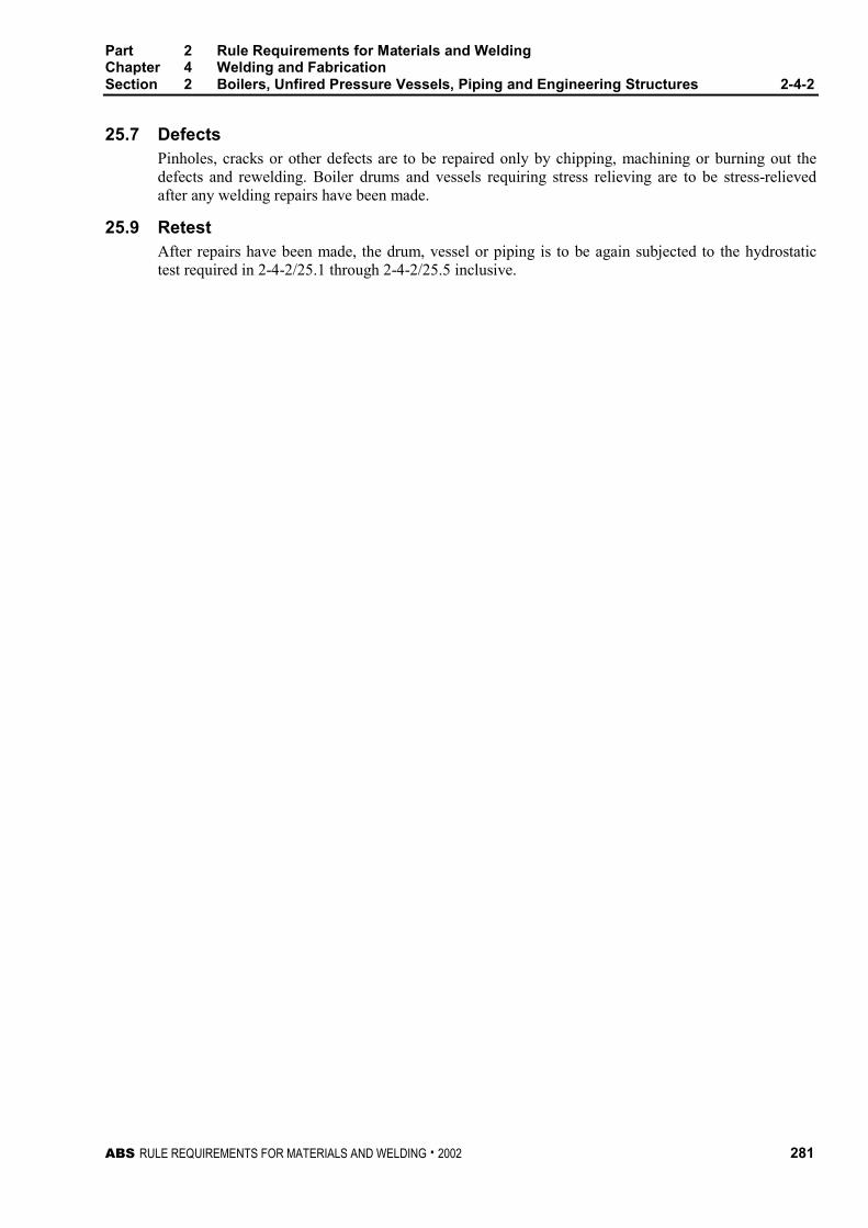
Part 2 Rule Requirements for Materials and WeldingChapter 4 Welding and FabricationSection 2 Boilers, Unfired Pressure Vessels, Piping and Engineering Structures 2-4-2
ABS RULE REQUIREMENTS FOR MATERIALS AND WELDING . 2002 281
25.7 Defects 2-4-2/25.7
Pinholes, cracks or other defects are to be repaired only by chipping, machining or burning out thedefects and rewelding. Boiler drums and vessels requiring stress relieving are to be stress-relievedafter any welding repairs have been made.
25.9 Retest 2-4-2/25.9
After repairs have been made, the drum, vessel or piping is to be again subjected to the hydrostatictest required in 2-4-2/25.1 through 2-4-2/25.5 inclusive.
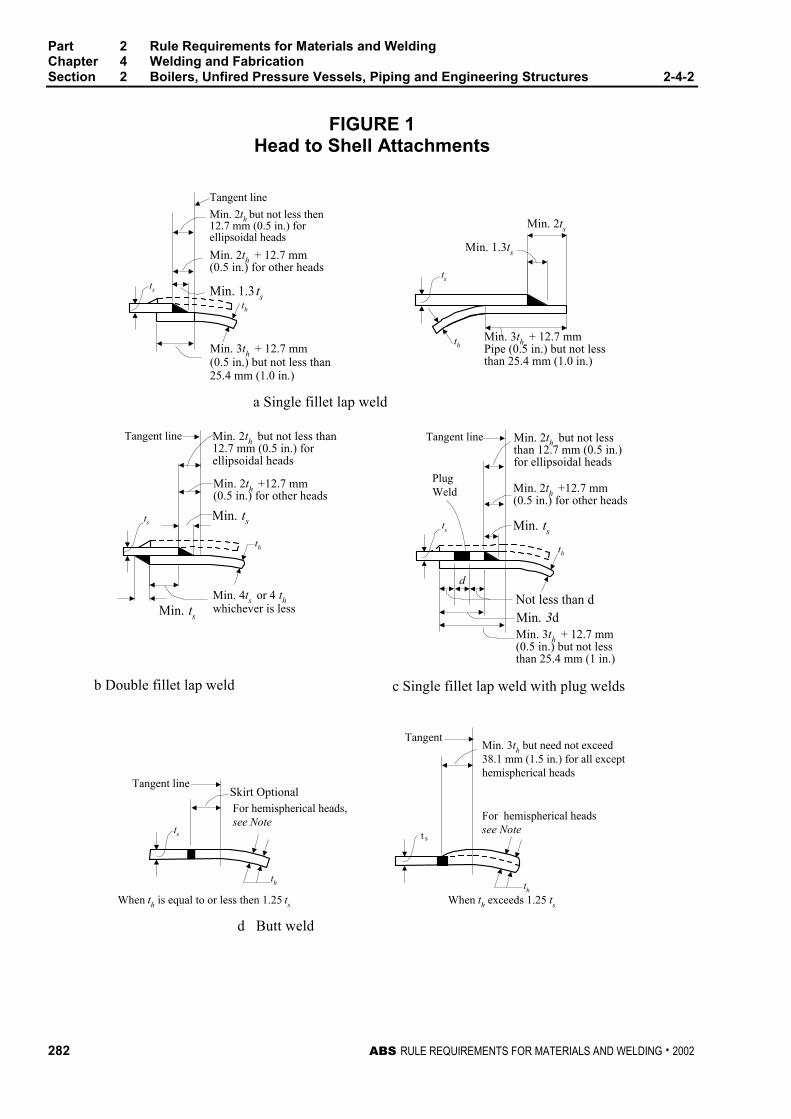
Part 2 Rule Requirements for Materials and WeldingChapter 4 Welding and FabricationSection 2 Boilers, Unfired Pressure Vessels, Piping and Engineering Structures 2-4-2
282 ABS RULE REQUIREMENTS FOR MATERIALS AND WELDING . 2002
FIGURE 1Head to Shell Attachments
Min. 2th but not less then12.7 mm (0.5 in.) forellipsoidal heads
d
Tangent line
ts
st
Min. 2th + 12.7 mm(0.5 in.) for other heads
Min. 1.3 tsth
Min. 3th + 12.7 mm(0.5 in.) but not less than25.4 mm (1.0 in.)
thMin. 3th + 12.7 mmPipe (0.5 in.) but not lessthan 25.4 mm (1.0 in.)
Min. 2ts
Min. 1.3ts
ts
Tangent line Min. 2th but not less than12.7 mm (0.5 in.) forellipsoidal heads
Min. 2th +12.7 mm(0.5 in.) for other heads
Min. ts
th
Min. ts
ts
Tangent line Min. 2th but not lessthan 12.7 mm (0.5 in.)for ellipsoidal heads
Min. 2th +12.7 mm(0.5 in.) for other heads
Min. tsts
PlugWeld
Min. 3dNot less than d
Min. 3th + 12.7 mm(0.5 in.) but not lessthan 25.4 mm (1 in.)
a Single fillet lap weld
b Double fillet lap weld c Single fillet lap weld with plug welds
d Butt weld
Tangent line
ts
th
Skirt OptionalFor hemispherical heads,see Note
When th is equal to or less then 1.25 ts
th
TangentMin. 3th but need not exceed38.1 mm (1.5 in.) for all excepthemispherical heads
For hemispherical headssee Note
When th exceeds 1.25 ts
th
Min. 4ts or 4 thwhichever is less
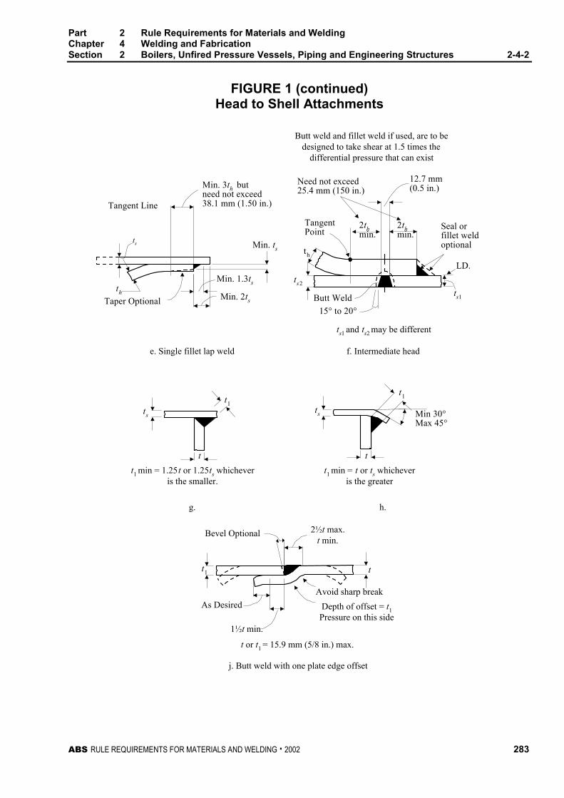
Part 2 Rule Requirements for Materials and WeldingChapter 4 Welding and FabricationSection 2 Boilers, Unfired Pressure Vessels, Piping and Engineering Structures 2-4-2
ABS RULE REQUIREMENTS FOR MATERIALS AND WELDING . 2002 283
FIGURE 1 (continued)Head to Shell Attachments
Min. ts
Min. 3th butneed not exceed38.1 mm (1.50 in.)Tangent Line
Taper Optional
Min. 1.3ts
Min. 2ts
th
ts
Need not exceed25.4 mm (150 in.)
th
ts2
TangentPoint
2thmin.
2thmin.
12.7 mm(0.5 in.)
Seal orfillet weldoptional
Butt Weld
15° to 20°
ts1
LD.
Butt weld and fillet weld if used, are to bedesigned to take shear at 1.5 times the
differential pressure that can exist
ts1 and ts2 may be different
Min 30°Max 45°
ts
t1
t1 min = t or ts whicheveris the greater
ts
t1
tt
t1 min = 1.25t or 1.25ts whicheveris the smaller.
h.g.
Bevel Optional 2½t max.t min.
tt1
As Desired
1½t min.
Depth of offset = t1Pressure on this side
Avoid sharp break
f. Intermediate heade. Single fillet lap weld
t or t1 = 15.9 mm (5/8 in.) max.
j. Butt weld with one plate edge offset
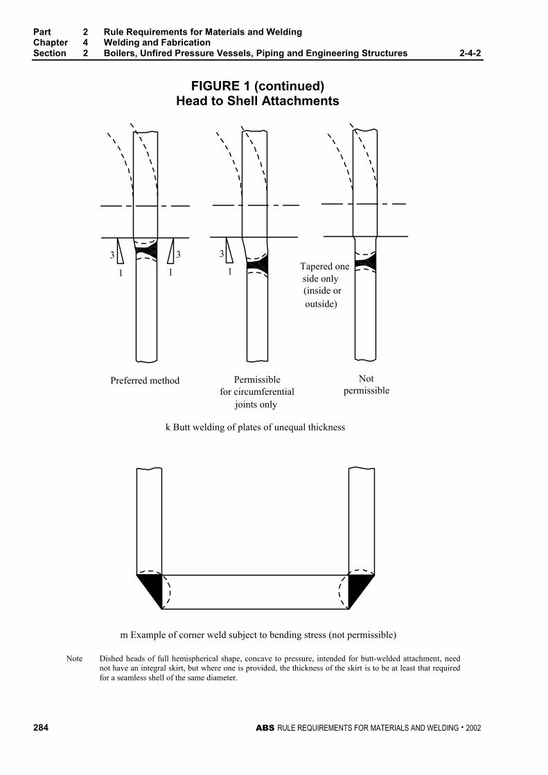
Part 2 Rule Requirements for Materials and WeldingChapter 4 Welding and FabricationSection 2 Boilers, Unfired Pressure Vessels, Piping and Engineering Structures 2-4-2
284 ABS RULE REQUIREMENTS FOR MATERIALS AND WELDING . 2002
FIGURE 1 (continued)Head to Shell Attachments
m Example of corner weld subject to bending stress (not permissible)
Notpermissible
Preferred method Permissiblefor circumferential
joints only
Tapered oneside only(inside oroutside)
k Butt welding of plates of unequal thickness
3
1 1
3 3
1
Note Dished heads of full hemispherical shape, concave to pressure, intended for butt-welded attachment, neednot have an integral skirt, but where one is provided, the thickness of the skirt is to be at least that requiredfor a seamless shell of the same diameter.
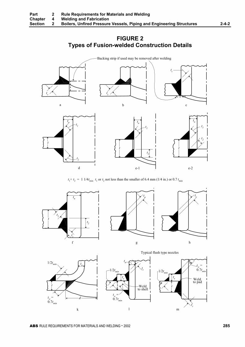
Part 2 Rule Requirements for Materials and WeldingChapter 4 Welding and FabricationSection 2 Boilers, Unfired Pressure Vessels, Piping and Engineering Structures 2-4-2
ABS RULE REQUIREMENTS FOR MATERIALS AND WELDING . 2002 285
FIGURE 2Types of Fusion-welded Construction Details
Backing strip if used may be removed after welding
tc
a b c
e-2e-1d
Typical flush type nozzles
g hf
k l m
Weldto shell
to padWeld
t
t t
d
tc
tc
tnt1
t2
t1
tn
t2
t
tnt1
t2
t
t1+ t2 = 1 1/4tmin t1 or t2 not less than the smaller of 6.4 mm (1/4 in.) or 0.7 tmin
tn
t1
t2t
tc
tc tc
tw =0.7tmin
tn
t
tn
1/2tmin
tw =0.7tmin
te
tc
1/2tmin
1/2tmin
te
tw =0.7tmin
tc
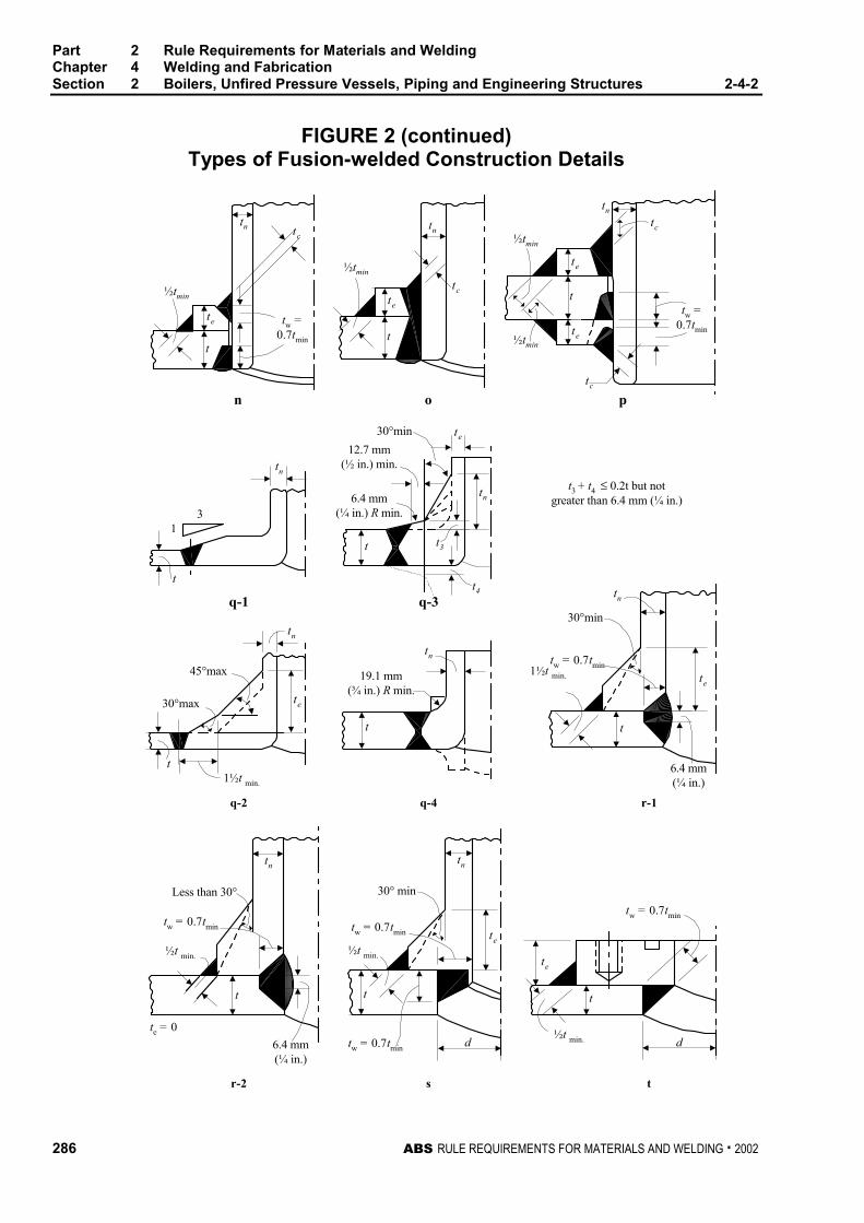
Part 2 Rule Requirements for Materials and WeldingChapter 4 Welding and FabricationSection 2 Boilers, Unfired Pressure Vessels, Piping and Engineering Structures 2-4-2
286 ABS RULE REQUIREMENTS FOR MATERIALS AND WELDING . 2002
FIGURE 2 (continued)Types of Fusion-welded Construction Details
tn tc
te
t
½tmin
tw =0.7tmin
½tmin
tn
tc
te
t
½tmin
tn
tc
te
t
te½tmin
tc
tw =0.7tmin
n o p
13
tn
t
q-3q-1
t t3
t4
tn
te30°min
12.7 mm(½ in.) min.
6.4 mm(¼ in.) R min.
t3 + t4 ≤ 0.2t but notgreater than 6.4 mm (¼ in.)
45°max
30°max
t1½t min.
te
tn
19.1 mm(¾ in.) R min.
tn
t
q-4q-2 r-1
tn
30°min
tw = 0.7tmin1½t min.
t
6.4 mm(¼ in.)
te
tn
Less than 30°
½t min.
tw = 0.7tmin
t
6.4 mm(¼ in.)
te = 0
30° min
tw = 0.7tmin
½t min.
tn
te
tw = 0.7tmind
t
tw = 0.7tmin
te
t
d½t min.
sr-2 t
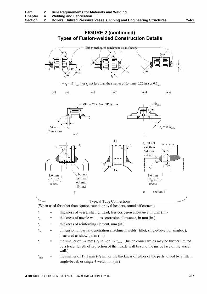
Part 2 Rule Requirements for Materials and WeldingChapter 4 Welding and FabricationSection 2 Boilers, Unfired Pressure Vessels, Piping and Engineering Structures 2-4-2
ABS RULE REQUIREMENTS FOR MATERIALS AND WELDING . 2002 287
FIGURE 2 (continued)Types of Fusion-welded Construction Details
t c
t1 + t2 = 1¼tmin t1 or t2 not less than the smaller of 6.4 mm (0.25 in.) or 0.7tmin
u-1
t1
t2
Either method of attachment is satisfactory
tc
t1
t2
t1
t c
t2
t c
u-2 v-1 v-2 w-1 w-2
89mm OD (3in. NPS) max
64 mm(¼ in.) min.
tw
½tmin
tw = 0.7tmin
w-3 x
tn but notless than6.4 mm(¼ in.)
tw
tc
section 1-1
1.6 mm(1/16 in.)recess
z
t c
tn
1
1
tctn
1.6 mm(1/16 in.)recess
tn but notless than6.4 mm(¼ in.)
tw
y
Typical Tube Connections(When used for other than square, round, or oval headers, round off corners)
t = thickness of vessel shell or head, less corrosion allowance, in mm (in.)
tn = thickness of nozzle wall, less corrosion allowance, in mm (in.)
te = thickness of reinforcing element, mm (in.)
tw = dimension of partial-penetration attachment welds (fillet, single-bevel, or single-J),measured as shown, mm (in.)
tc = the smaller of 6.4 mm (1/4 in.) or 0.7 tmin. (Inside corner welds may be further limitedby a lesser length of projection of the nozzle wall beyond the inside face of the vesselwall.)
tmin = the smaller of 19.1 mm (3/4 in.) or the thickness of either of the parts joined by a fillet,single-bevel, or single-J weld, mm (in.)


ABS RULE REQUIREMENTS FOR MATERIALS AND WELDING . 2002 289
P A R T
2C H A P T E R 4 Welding and Fabrication
S E C T I O N 3 Weld Tests
CONTENTS1 General................................................................................. 291
1.1 Weld Groups ........................................................................ 291
1.3 Tests..................................................................................... 291
3 Filler Metals.......................................................................... 291
3.1 General................................................................................. 291
3.3 Approval Basis...................................................................... 292
5 Approval of Welding Procedures ....................................... 292
5.1 Approved Filler Metals.......................................................... 292
5.3 Surveyor’s Acceptance......................................................... 292
5.5 New Procedures and Methods ............................................. 292
5.7 Tests..................................................................................... 292
5.9 Special Tests ........................................................................ 293
5.11 Repair and Cladding of Stern Tube and Tail Shafts ............ 293
7 Workmanship Tests ............................................................ 293
7.1 Hull Construction .................................................................. 293
7.3 Boilers and Group I Pressure Vessels ................................. 293
7.5 Other Pressure Vessels ....................................................... 294
7.7 Group I Pipe Connections .................................................... 294
7.9 Group II Pipe Connections ................................................... 294
7.11 Group I Engineering Structures............................................ 294
7.13 Group II Engineering Structures........................................... 294
9 Radiographic or Ultrasonic Inspection .............................. 294
9.1 Hull Construction .................................................................. 294
9.3 Boilers and Pressure Vessels .............................................. 295
11 Welders ................................................................................ 295
11.1 General Requirements ......................................................... 295
11.3 Qualification Tests................................................................ 296
11.5 Tests Nos. Q1, Q2, Q3, and Q4........................................... 296
290 ABS RULE REQUIREMENTS FOR MATERIALS AND WELDING . 2002
TABLE 1 Welder Qualification Tests.......................................296
FIGURE 1 Preparation of Test Plates and Pipes for WeldTests Nos. 1 and 2....................................................297
FIGURE 2 Typical Arrangement of Test Plates forWorkmanship Tests in Group B1 ............................299
FIGURE 3 Test No. 1 – Reduced-section Tension Test forPlate ..........................................................................300
FIGURE 4 Test No. 1 – Reduced-section Tension Test forPipe ...........................................................................301
FIGURE 5 Test No. 2 – Guided Bend Test for Root Bendand Face Bend (Plate or Pipe) .................................302
FIGURE 6 Test No. 2 – Guided Bend Test for Side Bend(Plate or Pipe) ...........................................................302
FIGURE 7 Guided Bend Test Jig...............................................303
FIGURE 8 Test No. 3 – Fillet-weld Test.....................................304
FIGURE 9 Welder Qualification Test No. Q1 ............................305
FIGURE 10 Welder Qualification Test No. Q2 ............................306
FIGURE 11 Welder Qualification Test No. Q3R..........................307
FIGURE 12 Welder Qualification Test No. Q4 ............................310
FIGURE 13 Orientation and Location of Charpy V-notchSpecimens for Weld and Heat Affected ZoneProperties .................................................................311

ABS RULE REQUIREMENTS FOR MATERIALS AND WELDING . 2002 291
P A R T
2C H A P T E R 4 Welding and Fabrication
S E C T I O N 3 Weld Tests 2 - 4 - 3
1 General 2-4-3/1
The steps to be taken in obtaining approval by the Bureau of electrodes and welding procedure forqualifying welders and for demonstrating satisfactory workmanship are given below.
1.1 Weld Groups 2-4-3/1.1
The various groups of welds are designated by index letters and numbers, by which they are referredto in subsequent paragraphs, as follows.
Hull Construction H All hull structures
Boilers, etc. Group I B1
Unfired Pressure Vessels Group II B2
Piping Group I P1 As defined in 2-4-2/1.5
Piping Group II P2
Engineering Structures Group I E1
Engineering Structures Group II E2
1.3 Tests 2-4-3/1.3
Details of tests, preparation of specimens and test results required for approval in each application aregiven in 2-4-3/3 to 2-4-3/9, and 2-4-3/Figure 1 to 2-4-3/Figure 13. Where position of welding isreferred to, the same is to be defined in the American Welding Society definitions.
3 Filler Metals 2-4-3/3
3.1 General (1997) 2-4-3/3.1
Filler metals are to be a type suitable to produce sound welds that have strength and toughnesscomparable to the materials being welded. The Bureau maintains a separately issued list of approvedfiller metals entitled, ‘‘Approved Welding Consumables.’’ This list indicates the grade and generalapplication for which such filler metals may be employed. It is intended that this list will serve as auseful guide in the selection of suitable filler metals for various welding applications.
Part 2 Rule Requirements for Materials and WeldingChapter 4 Welding and FabricationSection 3 Weld Tests 2-4-3
292 ABS RULE REQUIREMENTS FOR MATERIALS AND WELDING . 2002
3.3 Approval Basis 2-4-3/3.3
Filler metals will be approved and listed subject to tests conducted at a manufacturer’s plant. Uponsatisfactory completion of tests, a certificate will be issued for general approval, indicating, whereapplicable, the ABS Grade, operating characteristics, and limits of application. Test assemblies are tobe prepared in the presence of the Surveyor and all tests are to be carried out in his presence and to hissatisfaction. Procedure and testing is to comply with either of the following standards.
3.3.1 Bureau Standards 2-4-3/3.3.1
Approval of filler metals for welding vessels and other engineering structures will be grantedupon compliance with the Requirements for the Approval of Filler Metals, contained inPart 2, Appendix 2.
3.3.2 Standards of Other Agencies 2-4-3/3.3.2
Filler metals will be considered for approval based upon tests conducted to standardsestablished by The American Welding Society or other recognized agencies.
3.3.3 Special Approval 2-4-3/3.3.3
Under circumstances where exact specifications have not been established, the Bureau willconsider approval on the basis of a filler metal manufacturer’s guaranteed requirements.Qualified approvals will also be considered, with and without classifying as to grade, forspecial applications with reliance upon procedure tests at a user’s plant.
5 Approval of Welding Procedures 2-4-3/5
5.1 Approved Filler Metals 2-4-3/5.1
The type of approved filler metals used on Bureau classed weldments will depend upon the specificapplication for which the filler metal is intended. Procedure tests may be required at the discretion ofthe attending Surveyor to determine the shipyard or fabricator’s capability in the application of theproposed filler metal to the base material. The extent of such tests may vary depending upon theintended application, but generally are to follow those tests outlined in 2-4-3/5.7.
5.3 Surveyor’s Acceptance 2-4-3/5.3
The Surveyor may, at his discretion, accept a filler metal, welding procedure, or both, in a shipyard orfabricator’s plant where it is established to his satisfaction that they have been effectively used forsimilar work under similar conditions.
5.5 New Procedures and Methods 2-4-3/5.5
Weld tests using procedures and materials similar to those intended for production welding may berequired to be prepared by each shipyard or fabricator when new or unusual methods, base metals orfiller metals are proposed. All tests are to be made in the presence of the Surveyor and carried out tohis satisfaction.
5.7 Tests 2-4-3/5.7
Unless otherwise approved, the number of specimens is to be as indicated. The minimum test resultsrequired are stated with the following figures.
Test No. 1 (For butt welds) Reduced-section Tension Test (2-4-3/Figure 3 or 2-4-3/Figure 4). Twospecimens made in each position involved.
Test No. 2 (For butt welds) Guided Bend Test (2-4-3/Figure 5 and 2-4-3/Figure 6). For material19 mm (0.75 in.) thick and under, two face-bend and two root-bend specimens for each positionexcept that, at the option of the fabricator, four side bends may be substituted for material thickness
Part 2 Rule Requirements for Materials and WeldingChapter 4 Welding and FabricationSection 3 Weld Tests 2-4-3
ABS RULE REQUIREMENTS FOR MATERIALS AND WELDING . 2002 293
over 9.5 mm (3/8 in.). For material over 19 mm (0.75 in.) thick, four side-bend specimens for eachposition involved. The bending jig and test requirements are indicated in 2-4-3/Figure 7.
Test No. 3 Fillet-weld Test (2-4-3/Figure 8). One specimen made in each position involved.
5.9 Special Tests 2-4-3/5.9
All weld-metal tension, Charpy V-notch impact, macro-etch or other relevant tests may be requiredfor certain applications, such as higher-strength steels, electroslag welding, one-side welding, etc., andthe results submitted for consideration. 2-4-3/Figure 13 defines the location of Charpy V-notch impacttests when heat affected zone tests are required. A Charpy V-notch test is to consist of threespecimens per location.
5.11 Repair and Cladding of Stern Tube and Tail Shafts 2-4-3/5.11
Weld repairs and cladding on stern tube shafts and tail shafts are to be performed in an approvedfacility.
Approval of welding procedures for the repair or cladding of stern tube shafts and tail shafts is to be inaccordance with the ABS Guide for Repair and Cladding of Shafts.
7 Workmanship Tests 2-4-3/7
7.1 Hull Construction 2-4-3/7.1
The Surveyor may, when it is considered desirable, require welders to prepare specimens for Fillet-weld Tests (Test No. 3) for the positions involved. Details of the specimen are shown in 2-4-3/Figure8.
7.3 Boilers and Group I Pressure Vessels 2-4-3/7.3
7.3.1 Required Tests 2-4-3/7.3.1
The following tests are to be made using equivalent material of the same thickness as theboiler or pressure vessel. The results required are stated with the applicable figures and in2-4-3/9.3.
Test No. 1 Reduced-section Tension Test (2-4-3/Figure 3)
Test No. 2 Guided Bend Test, (2-4-3/Figure 5 or 2-4-3/Figure 6)
Test No. 3 Radiographic Search of Welds on Finished Joint
7.3.2 Test Exceptions 2-4-3/7.3.2
Test Nos. 1 and 2 are not required for cylindrical pressure parts of Boilers and Group IPressure Vessels constructed of ABS Steel Plate for Boilers and Pressure Vessels Grades Athrough G inclusive and Grades K through N inclusive whose welded joints are fullyexamined by radiography.
7.3.3 Attached Test Plates 2-4-3/7.3.3
Structures made in accordance with the requirements of Group B1 of materials other thanthose given in 2-4-3/7.3.2 are to have test plates attached as shown in 2-4-3/Figure 2 to permitthe longitudinal joint of the shell and test plates to be welded continuously. The test plate is tobe of sufficient length to provide two specimens for each of Tests Nos. 1 and 2 detailedabove. One specimen is to be tested; the other specimen is for use in retesting, if necessary.
Part 2 Rule Requirements for Materials and WeldingChapter 4 Welding and FabricationSection 3 Weld Tests 2-4-3
294 ABS RULE REQUIREMENTS FOR MATERIALS AND WELDING . 2002
7.3.4 Separate Test Plates 2-4-3/7.3.4
Circumferential joints of a boiler or pressure vessel need not be provided with test platesunless there be no longitudinal welded joint, in which case test plates are required to bewelded separately.
7.3.5 Number of Test Plates 2-4-3/7.3.5
Where several drums or vessels of the same design and grade of material are welded insuccession, a set of test plates for each linear 61 m (200 ft) of longitudinal joints, or 61 m(200 ft) of circumferential joints where there are no longitudinal joints, will be acceptable,provided the joints are welded by the same operators and the same welding method. Shellshaving no longitudinal joints may be considered as being of the same design if the platethicknesses fall within a range of 6.4 mm (0.25 in.) and the shell diameters do not vary bymore than 150 mm (6 in.).
7.3.6 Test-plate Heat Treatment and Retests 2-4-3/7.3.6
In all cases the welded test plates are to be treated as to stress relieving, etc., in the samemanner as the work which they represent. Should any of the tests fail, one retest is to be madefor each failure; and should the retest also fail, the welding represented is to be chipped orgouged out and rewelded and new test plates provided.
7.5 Other Pressure Vessels 2-4-3/7.5
Workmanship test plates are not required for structures in this Group. Test No. 3 is to be carried outwhen required in 2-4-2/23.3.
7.7 Group I Pipe Connections 2-4-3/7.7
In carbon and carbon-molybdenum steel piping for all diameters where the thickness exceeds 9.5 mm(0.375 in.) and other alloy-steel piping 76 mm (3 in.) in diameter and over regardless of thickness,welds made in accordance with the requirements of this group are to be subjected to 100%Radiographic Search - Test No. 3, or to other approved method of test, where the former is notapplicable.
7.9 Group II Pipe Connections 2-4-3/7.9
No workmanship tests are required.
7.11 Group I Engineering Structures 2-4-3/7.11
Group I Engineering Structures are to meet the same requirements as 2-4-3/7.3, except that wherethere is no longitudinal joint, no test plates will be required.
7.13 Group II Engineering Structures 2-4-3/7.13
Welds in structures in this group which correspond in service requirements to Group B2 are to betested in the same manner as Group B2, except that where there is no longitudinal joint, no tests willbe required.
9 Radiographic or Ultrasonic Inspection 2-4-3/9
9.1 Hull Construction 2-4-3/9.1
Where radiographic or ultrasonic inspection is required such testing should be carried out inaccordance with the Bureau’s separately issued Rules for Nondestructive Inspection of Hull Welds.
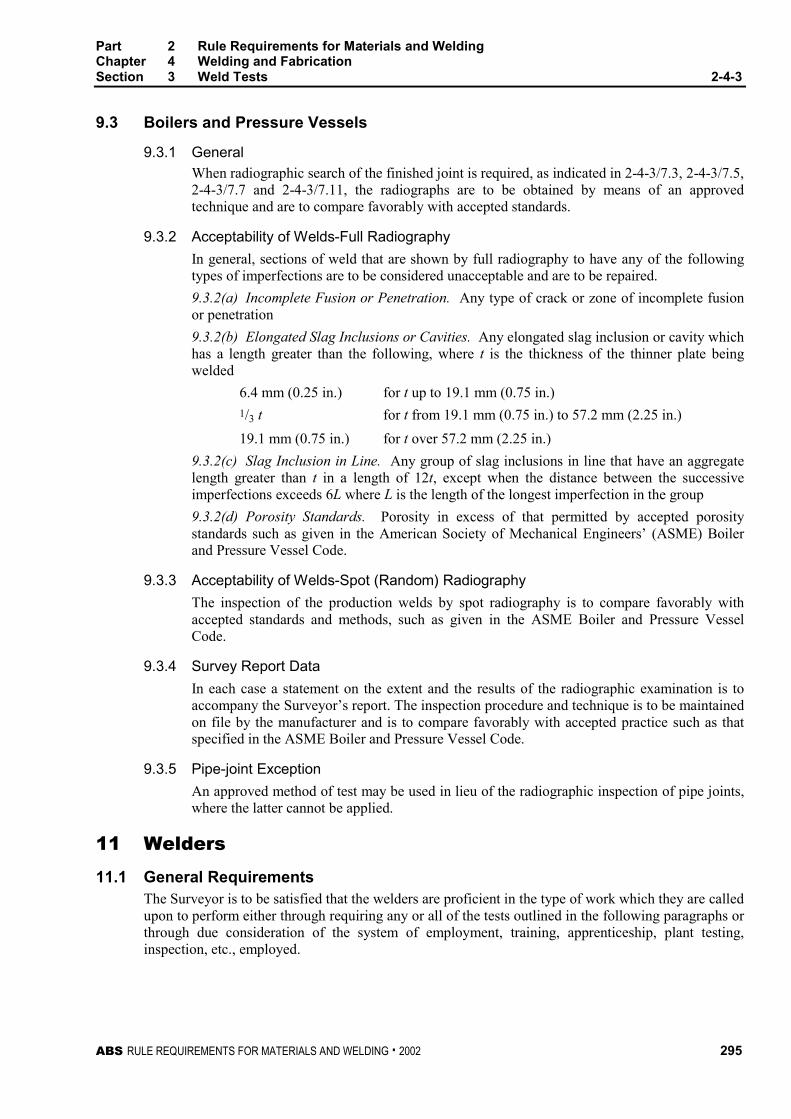
Part 2 Rule Requirements for Materials and WeldingChapter 4 Welding and FabricationSection 3 Weld Tests 2-4-3
ABS RULE REQUIREMENTS FOR MATERIALS AND WELDING . 2002 295
9.3 Boilers and Pressure Vessels 2-4-3/9.3
9.3.1 General 2-4-3/9.3.1
When radiographic search of the finished joint is required, as indicated in 2-4-3/7.3, 2-4-3/7.5,2-4-3/7.7 and 2-4-3/7.11, the radiographs are to be obtained by means of an approvedtechnique and are to compare favorably with accepted standards.
9.3.2 Acceptability of Welds-Full Radiography 2-4-3/9.3.2
In general, sections of weld that are shown by full radiography to have any of the followingtypes of imperfections are to be considered unacceptable and are to be repaired.
9.3.2(a) Incomplete Fusion or Penetration. Any type of crack or zone of incomplete fusionor penetration
9.3.2(b) Elongated Slag Inclusions or Cavities. Any elongated slag inclusion or cavity whichhas a length greater than the following, where t is the thickness of the thinner plate beingwelded
6.4 mm (0.25 in.) for t up to 19.1 mm (0.75 in.)1/3 t for t from 19.1 mm (0.75 in.) to 57.2 mm (2.25 in.)
19.1 mm (0.75 in.) for t over 57.2 mm (2.25 in.)
9.3.2(c) Slag Inclusion in Line. Any group of slag inclusions in line that have an aggregatelength greater than t in a length of 12t, except when the distance between the successiveimperfections exceeds 6L where L is the length of the longest imperfection in the group
9.3.2(d) Porosity Standards. Porosity in excess of that permitted by accepted porositystandards such as given in the American Society of Mechanical Engineers’ (ASME) Boilerand Pressure Vessel Code.
9.3.3 Acceptability of Welds-Spot (Random) Radiography 2-4-3/9.3.3
The inspection of the production welds by spot radiography is to compare favorably withaccepted standards and methods, such as given in the ASME Boiler and Pressure VesselCode.
9.3.4 Survey Report Data 2-4-3/9.3.4
In each case a statement on the extent and the results of the radiographic examination is toaccompany the Surveyor’s report. The inspection procedure and technique is to be maintainedon file by the manufacturer and is to compare favorably with accepted practice such as thatspecified in the ASME Boiler and Pressure Vessel Code.
9.3.5 Pipe-joint Exception 2-4-3/9.3.5
An approved method of test may be used in lieu of the radiographic inspection of pipe joints,where the latter cannot be applied.
11 Welders 2-4-3/11
11.1 General Requirements 2-4-3/11.1
The Surveyor is to be satisfied that the welders are proficient in the type of work which they are calledupon to perform either through requiring any or all of the tests outlined in the following paragraphs orthrough due consideration of the system of employment, training, apprenticeship, plant testing,inspection, etc., employed.
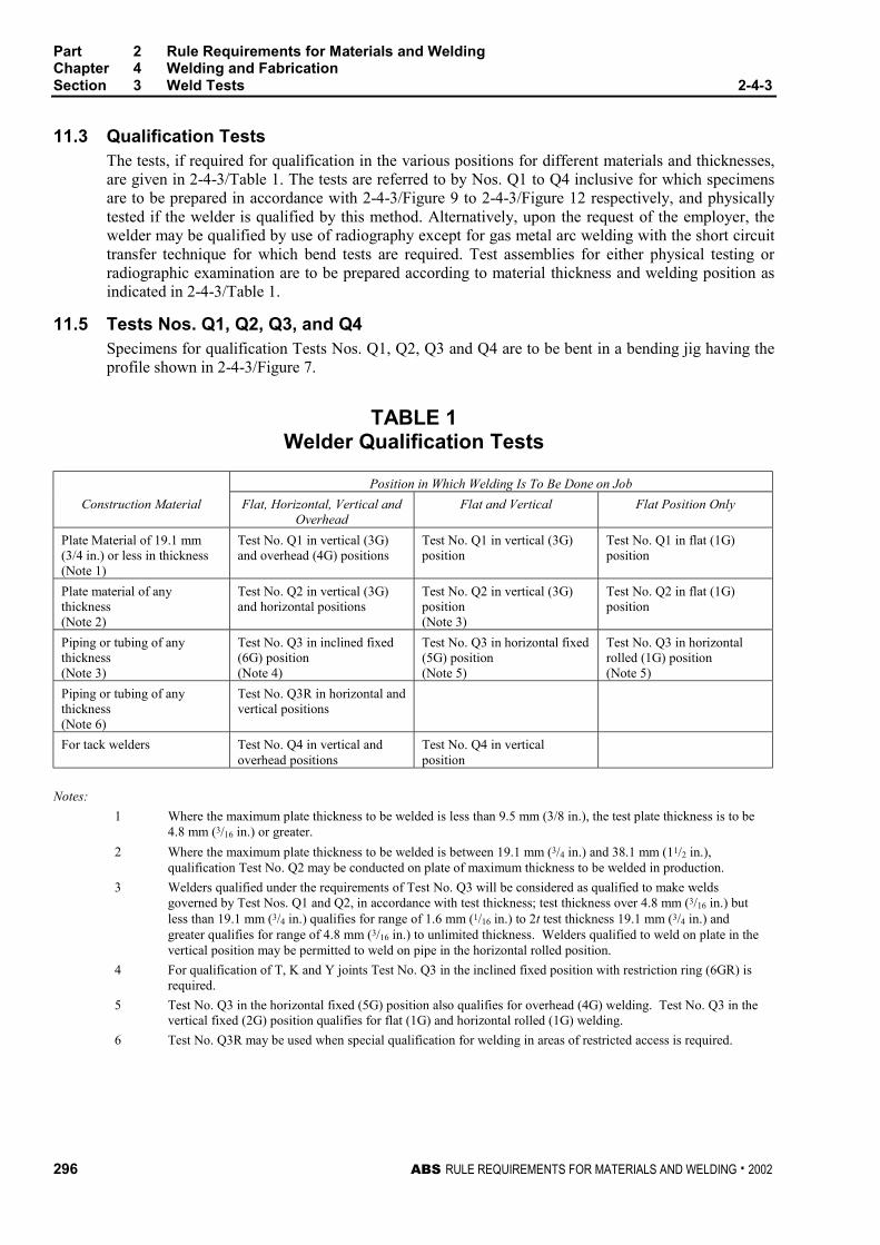
Part 2 Rule Requirements for Materials and WeldingChapter 4 Welding and FabricationSection 3 Weld Tests 2-4-3
296 ABS RULE REQUIREMENTS FOR MATERIALS AND WELDING . 2002
11.3 Qualification Tests 2-4-3/11.3
The tests, if required for qualification in the various positions for different materials and thicknesses,are given in 2-4-3/Table 1. The tests are referred to by Nos. Q1 to Q4 inclusive for which specimensare to be prepared in accordance with 2-4-3/Figure 9 to 2-4-3/Figure 12 respectively, and physicallytested if the welder is qualified by this method. Alternatively, upon the request of the employer, thewelder may be qualified by use of radiography except for gas metal arc welding with the short circuittransfer technique for which bend tests are required. Test assemblies for either physical testing orradiographic examination are to be prepared according to material thickness and welding position asindicated in 2-4-3/Table 1.
11.5 Tests Nos. Q1, Q2, Q3, and Q4 2-4-3/11.5
Specimens for qualification Tests Nos. Q1, Q2, Q3 and Q4 are to be bent in a bending jig having theprofile shown in 2-4-3/Figure 7.
TABLE 1Welder Qualification Tests
Position in Which Welding Is To Be Done on Job
Construction Material Flat, Horizontal, Vertical andOverhead
Flat and Vertical Flat Position Only
Plate Material of 19.1 mm(3/4 in.) or less in thickness(Note 1)
Test No. Q1 in vertical (3G)and overhead (4G) positions
Test No. Q1 in vertical (3G)position
Test No. Q1 in flat (1G)position
Plate material of anythickness(Note 2)
Test No. Q2 in vertical (3G)and horizontal positions
Test No. Q2 in vertical (3G)position(Note 3)
Test No. Q2 in flat (1G)position
Piping or tubing of anythickness(Note 3)
Test No. Q3 in inclined fixed(6G) position(Note 4)
Test No. Q3 in horizontal fixed(5G) position(Note 5)
Test No. Q3 in horizontalrolled (1G) position(Note 5)
Piping or tubing of anythickness(Note 6)
Test No. Q3R in horizontal andvertical positions
For tack welders Test No. Q4 in vertical andoverhead positions
Test No. Q4 in verticalposition
Notes:
1 Where the maximum plate thickness to be welded is less than 9.5 mm (3/8 in.), the test plate thickness is to be4.8 mm (3/16 in.) or greater.
2 Where the maximum plate thickness to be welded is between 19.1 mm (3/4 in.) and 38.1 mm (11/2 in.),qualification Test No. Q2 may be conducted on plate of maximum thickness to be welded in production.
3 Welders qualified under the requirements of Test No. Q3 will be considered as qualified to make weldsgoverned by Test Nos. Q1 and Q2, in accordance with test thickness; test thickness over 4.8 mm (3/16 in.) butless than 19.1 mm (3/4 in.) qualifies for range of 1.6 mm (1/16 in.) to 2t test thickness 19.1 mm (3/4 in.) andgreater qualifies for range of 4.8 mm (3/16 in.) to unlimited thickness. Welders qualified to weld on plate in thevertical position may be permitted to weld on pipe in the horizontal rolled position.
4 For qualification of T, K and Y joints Test No. Q3 in the inclined fixed position with restriction ring (6GR) isrequired.
5 Test No. Q3 in the horizontal fixed (5G) position also qualifies for overhead (4G) welding. Test No. Q3 in thevertical fixed (2G) position qualifies for flat (1G) and horizontal rolled (1G) welding.
6 Test No. Q3R may be used when special qualification for welding in areas of restricted access is required.
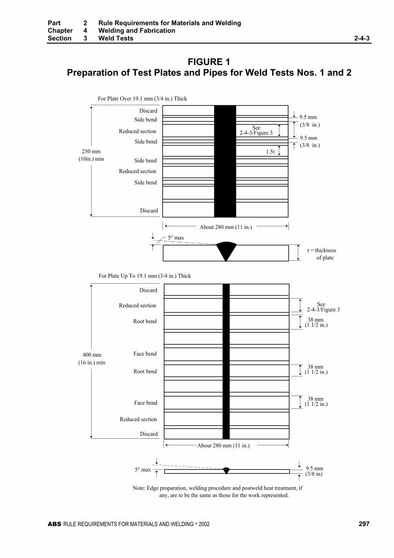
Part 2 Rule Requirements for Materials and WeldingChapter 4 Welding and FabricationSection 3 Weld Tests 2-4-3
ABS RULE REQUIREMENTS FOR MATERIALS AND WELDING . 2002 297
FIGURE 1Preparation of Test Plates and Pipes for Weld Tests Nos. 1 and 2
(10in.) min
See2-4-3/Figure 3
1.5t
9.5 mm(3/8 in.)
9.5 mm
t = thickness of plate
See2-4-3/Figure 3
38 mm
9.5 mm(3/8 in)
5° max
5° max
Note: Edge proparation, welding procedure and postweld heat treatment, if any, are to be the same as those for the work represented.
Discard
Face bend
Reduced section
Root bend
Face bend
Root bend
Reduced section
Discard
Reduced section
Discard
Side bend
Side bend
Side bend
Side bend
Discard
Reduced section
For Plate Up To 19.1 mm (3/4 in.) Thick
For Plate Over 19.1 mm (3/4 in.) Thick
250 mm(3/8 in.)
(1 1/2 in.)
About 280 mm (11 in.)
(16 in.) min400 mm
About 280 mm (11 in.)
38 mm(1 1/2 in.)
38 mm(1 1/2 in.)
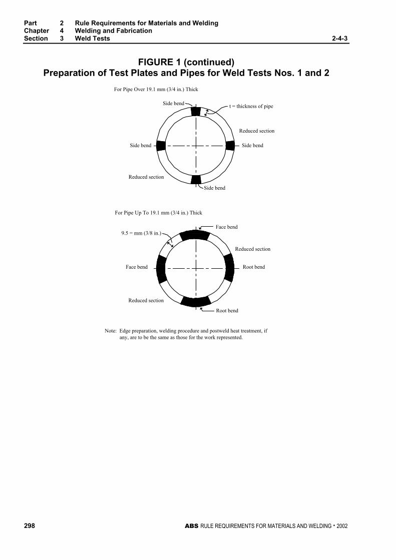
Part 2 Rule Requirements for Materials and WeldingChapter 4 Welding and FabricationSection 3 Weld Tests 2-4-3
298 ABS RULE REQUIREMENTS FOR MATERIALS AND WELDING . 2002
FIGURE 1 (continued)Preparation of Test Plates and Pipes for Weld Tests Nos. 1 and 2
Side bend
For Pipe Over 19.1 mm (3/4 in.) Thick
t = thickness of pipe
Side bend
Side bend
Reduced section
Reduced section
For Pipe Up To 19.1 mm (3/4 in.) Thick
Face bend
Reduced section
Reduced section
Root bend
Face bend
Root bend
9.5 = mm (3/8 in.)
Note: Edge preparation, welding procedure and postweld heat treatment, if any, are to be the same as those for the work represented.
Side bend
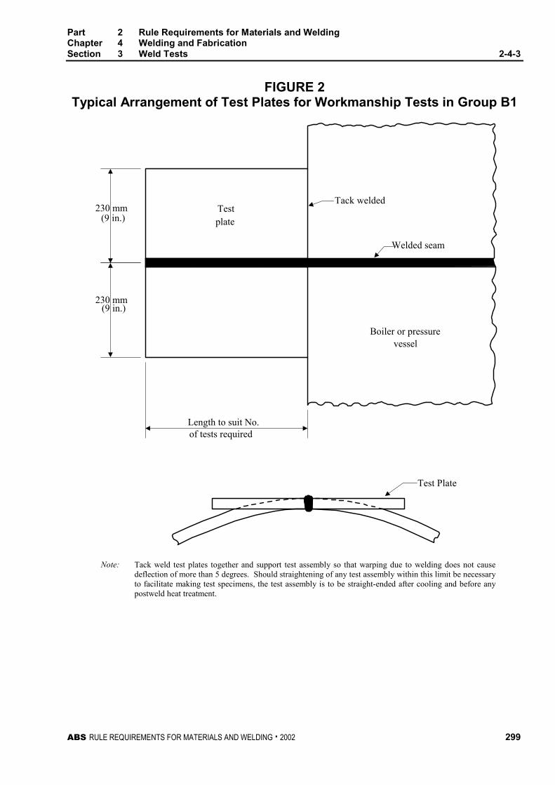
Part 2 Rule Requirements for Materials and WeldingChapter 4 Welding and FabricationSection 3 Weld Tests 2-4-3
ABS RULE REQUIREMENTS FOR MATERIALS AND WELDING . 2002 299
FIGURE 2Typical Arrangement of Test Plates for Workmanship Tests in Group B1
Test Plate
Boiler or pressurevessel
Welded seam
Tack weldedTestplate(9 in.)
(9 in.)
Length to suit No.of tests required
230 mm
230 mm
Note: Tack weld test plates together and support test assembly so that warping due to welding does not causedeflection of more than 5 degrees. Should straightening of any test assembly within this limit be necessaryto facilitate making test specimens, the test assembly is to be straight-ended after cooling and before anypostweld heat treatment.
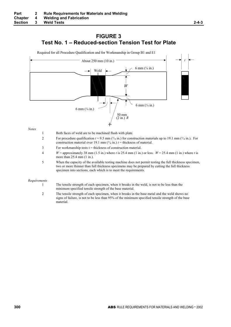
Part 2 Rule Requirements for Materials and WeldingChapter 4 Welding and FabricationSection 3 Weld Tests 2-4-3
300 ABS RULE REQUIREMENTS FOR MATERIALS AND WELDING . 2002
FIGURE 3Test No. 1 – Reduced-section Tension Test for Plate
6 mm (¼ in.)
6 mm (¼ in.)6 mm (¼ in.)
50 mm(2 in.) R
Required for all Procedure Qualification and for Workmanship in Group B1 and E1
About 250 mm (10 in.)
Weld
t
W
Notes1 Both faces of weld are to be machined flush with plate.
2 For procedure qualification t = 9.5 mm (3/8 in.) for construction materials up to 19.1 mm (3/4 in.). Forconstruction material over 19.1 mm (3/4 in.) t = thickness of material.
3 For workmanship tests t = thickness of construction material.
4 W = approximately 38 mm (1.5 in.) where t is 25.4 mm (1 in.) or less. W = 25.4 mm (1 in.) where t ismore than 25.4 mm (1 in.).
5 When the capacity of the available testing machine does not permit testing the full thickness specimen,two or more thinner than full thickness specimens may be prepared by cutting the full thicknessspecimen into sections, each which is to meet the requirements.
Requirements1 The tensile strength of each specimen, when it breaks in the weld, is not to be less than the
minimum specified tensile strength of the base material.
2 The tensile strength of each specimen, when it breaks in the base metal and the weld shows nosigns of failure, is not to be less than 95% of the minimum specified tensile strength of the basematerial.
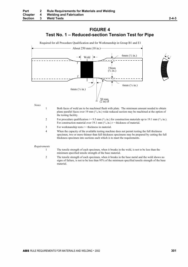
Part 2 Rule Requirements for Materials and WeldingChapter 4 Welding and FabricationSection 3 Weld Tests 2-4-3
ABS RULE REQUIREMENTS FOR MATERIALS AND WELDING . 2002 301
FIGURE 4Test No. 1 – Reduced-section Tension Test for Pipe
Required for all Procedure Qualification and for Workmanship in Group B1 and E1
6mm (¼ in.)
19mm(¾ in.)
6mm (¼ in.)6mm (¼ in.)
50 mm(2 in) R
f
f
About 250 mm (10 in.)
Weld t
Notes1 Both faces of weld are to be machined flush with plate. The minimum amount needed to obtain
plane parallel faces over 19 mm (3/4 in.) wide reduced section may be machined at the option ofthe testing facility.
2 For procedure qualification t = 9.5 mm (3/4 in.) for construction materials up to 19.1 mm (3/4 in.).For construction material over 19.1 mm (3/4 in.) t = thickness of material.
3 For workmanship tests t = thickness in material.
4 When the capacity of the available testing machine does not permit testing the full thicknessspecimen, two or more thinner than full thickness specimens may be prepared by cutting the fullthickness specimen into sections each which is to meet the requirements.
Requirements1 The tensile strength of each specimen, when it breaks in the weld, is not to be less than the
minimum specified tensile strength of the base material.
2 The tensile strength of each specimen, when it breaks in the base metal and the weld shows nosigns of failure, is not to be less than 95% of the minimum specified tensile strength of the basematerial.
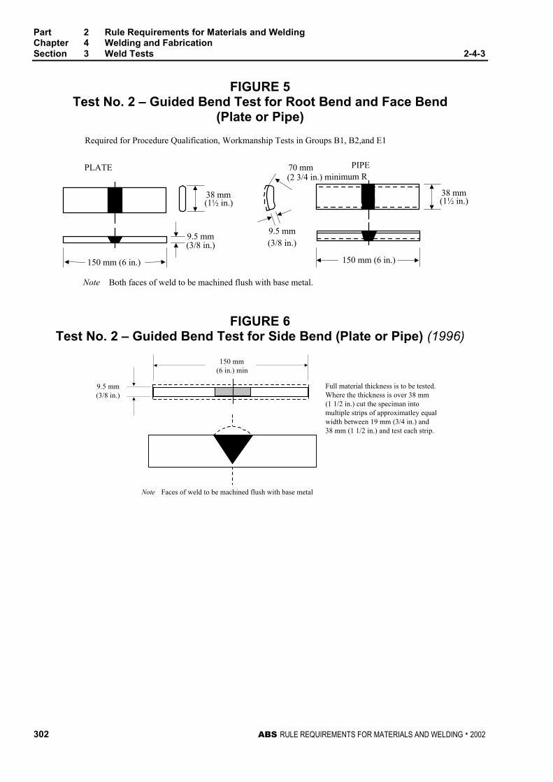
Part 2 Rule Requirements for Materials and WeldingChapter 4 Welding and FabricationSection 3 Weld Tests 2-4-3
302 ABS RULE REQUIREMENTS FOR MATERIALS AND WELDING . 2002
FIGURE 5Test No. 2 – Guided Bend Test for Root Bend and Face Bend
(Plate or Pipe)
PLATE
Required for Procedure Qualification, Workmanship Tests in Groups B1, B2,and E1
PIPE
Note Both faces of weld to be machined flush with base metal.
38 mm(1½ in.)
9.5 mm(3/8 in.)
38 mm(1½ in.)
(3/8 in.)9.5 mm
70 mm(2 3/4 in.) minimum R
150 mm (6 in.) 150 mm (6 in.)
FIGURE 6Test No. 2 – Guided Bend Test for Side Bend (Plate or Pipe) (1996)
150 mm(6 in.) min
9.5 mm(3/8 in.)
Note Faces of weld to be machined flush with base metal
Full material thickness is to be tested.Where the thickness is over 38 mm(1 1/2 in.) cut the speciman intomultiple strips of approximatley equalwidth between 19 mm (3/4 in.) and38 mm (1 1/2 in.) and test each strip.
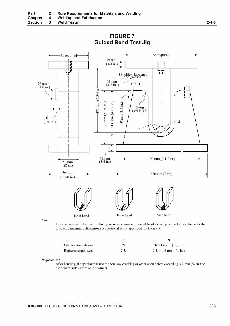
Part 2 Rule Requirements for Materials and WeldingChapter 4 Welding and FabricationSection 3 Weld Tests 2-4-3
ABS RULE REQUIREMENTS FOR MATERIALS AND WELDING . 2002 303
FIGURE 7Guided Bend Test Jig
29 mm(1 1/8 in.)
6 mm(1/4 in.)
50 mm(2 in.)
(3 7/8 in.)
19 mm(3/4 in.)
f
ff
A
B
f f
19 mm(3/4 in.) R
19 m
m (
3/4
in.)
13 mm(1/2 in .)
Shoulders hardenedand greased
19 mm(3/4 in.)
Root bend Face bend Side bend
As required
171
mm
(6
3/4
in.)
114
mm
(4
1/2
in.)
133
mm
(5
1/4
in.)
190 mm (7 1/2 in.)
230 mm (9 in.)
As required
96 mm
NoteThe specimen is to be bent in this jig or in an equivalent guided bend roller jig around a mandrel with thefollowing maximum dimensions proportional to the specimen thickness (t).
A B
Ordinary strength steel 2t 3t + 1.6 mm (1/16 in.)
Higher strength steel 2.5t 3.5t + 1.6 mm (1/16 in.)
RequirementAfter bending, the specimen is not to show any cracking or other open defect exceeding 3.2 mm (1/8 in.) onthe convex side except at the corners.

Part 2 Rule Requirements for Materials and WeldingChapter 4 Welding and FabricationSection 3 Weld Tests 2-4-3
304 ABS RULE REQUIREMENTS FOR MATERIALS AND WELDING . 2002
FIGURE 8Test No. 3 – Fillet-weld Test
75 mm(3 in.) min
Bendhere
Single or multiple passweld whichever used
(5 in.) min
t
t
250 mm (10 in.) min 127 mm
Notes1 For procedure qualification t = 9.5 mm (3/8 in.) for construction materials up to 19.1 mm (3/4 in.).
For construction material over 19.1 mm (3/4 in.) t = thickness of material.
2 Base and standing web is to be straight and in intimate contact and securely tacked at ends beforefillet-weld is made, to insure maximum restraint.
3 The test plate may be flame cut into short sections to facilitate breaking open.
RequirementsThe fillet is to be of the required contour and size, free from undercutting and overlapping. when broken,as indicated, the fractured surface is to be free from cracks. Visible porosity, incomplete fusion at the rootcorners and inclusions may be acceptable, provided the total length of these discontinuities is not morethan 10% of the total length of the weld.

Part 2 Rule Requirements for Materials and WeldingChapter 4 Welding and FabricationSection 3 Weld Tests 2-4-3
ABS RULE REQUIREMENTS FOR MATERIALS AND WELDING . 2002 305
FIGURE 9Welder Qualification Test No. Q1
For Plate Material 19.1 mm (3/4 in.) or less
Direction of plate rolling
Discard
Face bend
Root bend
Discard
Diameter of electrodecore wire
9.5mm (3/8 in.)
6mm (1/4 in.) min.25 mm(1 in.)
Warping 5° max.
38 mm(1½in.)
(1½in.)38 mm
(1 1/8 in.)29 mm
29 mm(1 1/8 in.)
250 mm (10 in.)
60°
(6 in.)150 mm
Notes1 Weld is to be made with the maximum size of electrodes that will be used in production.
2 Machine reinforcement and backing strap flush. Do not remove any undercutting.
3 Machining is to be done transverse to weld.
4 All specimens are to be machined or sawed from plate.
5 Backing strap is to be contiguous with plates.
6 Joints welded in the vertical position are to be welded upwards.
7 Welding is to be done from one side only.
8 Break edges of specimens to a radius of t/6 maximum.
9 Bend specimens in Guided Bend Test Jig (2-4-3/Figure 7)
10 1 Face Bend and 1 Root Bend required.
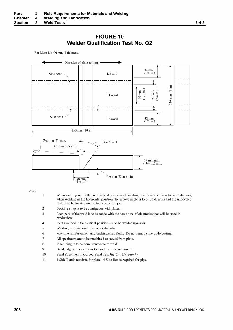
Part 2 Rule Requirements for Materials and WeldingChapter 4 Welding and FabricationSection 3 Weld Tests 2-4-3
306 ABS RULE REQUIREMENTS FOR MATERIALS AND WELDING . 2002
FIGURE 10Welder Qualification Test No. Q2
For Materials Of Any Thickness.
Side bend
Side bend
Discard
Discard
Discard
Direction of plate rolling
f
ff
32 mm(1¼ in.)
45 m
m(1
3/4
in.)
9.5
mm
(3/8
in.)
32 mm(1¼ in.)
Warping 5° max.
9.5 mm (3/8 in.)See Note 1
6 mm (¼ in.) min.38 mm
(1½ in.)
19 mm min.( 3/4 in.) min.
250 mm (10 in)
150
mm
(6
in)
Notes1 When welding in the flat and vertical positions of welding, the groove angle is to be 25 degrees;
when welding in the horizontal position, the groove angle is to be 35 degrees and the unbeveledplate is to be located on the top side of the joint.
2 Backing strap is to be contiguous with plates.
3 Each pass of the weld is to be made with the same size of electrodes that will be used inproduction.
4 Joints welded in the vertical position are to be welded upwards.
5 Welding is to be done from one side only.
6 Machine reinforcement and backing strap flush. Do not remove any undercutting.
7 All specimens are to be machined or sawed from plate.
8 Machining is to be done transverse to weld.
9 Break edges of specimens to a radius of t/6 maximum.
10 Bend Specimen in Guided Bend Test Jig (2-4-3/Figure 7).
11 2 Side Bends required for plate. 4 Side Bends required for pipe.
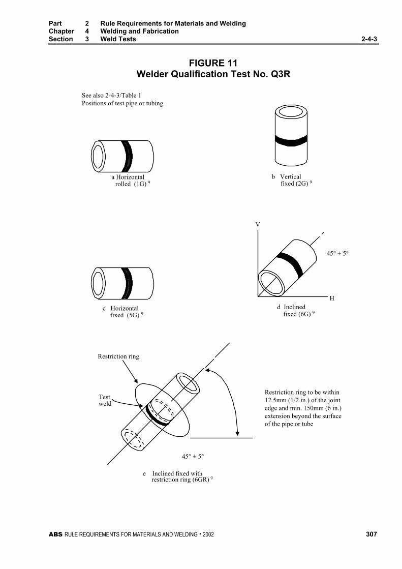
Part 2 Rule Requirements for Materials and WeldingChapter 4 Welding and FabricationSection 3 Weld Tests 2-4-3
ABS RULE REQUIREMENTS FOR MATERIALS AND WELDING . 2002 307
FIGURE 11Welder Qualification Test No. Q3R
See also 2-4-3/Table 1Positions of test pipe or tubing
a Horizontal
c Horizontalfixed (5G) 9
Restriction ring
b Verticalfixed (2G) 9
d Inclinedfixed (6G) 9
Testweld
e Inclined fixed withrestriction ring (6GR) 9
H
V
45° ± 5°
rolled (1G) 9
45° ± 5°
Restriction ring to be within12.5mm (1/2 in.) of the jointedge and min. 150mm (6 in.)extension beyond the surfaceof the pipe or tube
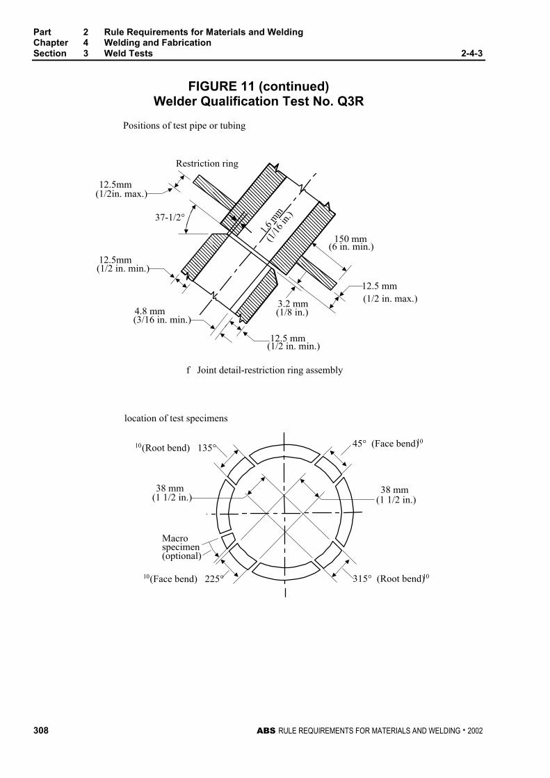
Part 2 Rule Requirements for Materials and WeldingChapter 4 Welding and FabricationSection 3 Weld Tests 2-4-3
308 ABS RULE REQUIREMENTS FOR MATERIALS AND WELDING . 2002
FIGURE 11 (continued)Welder Qualification Test No. Q3R
��������������������
������������
�������������������������
Positions of test pipe or tubing
Restriction ring
12.5mm(1/2in. max.)
37-1/2°
12.5mm(1/2 in. min.)
Macrospecimen(optional)
location of test specimens
38 mm(1 1/2 in.)
45° (Face bend)10
38 mm(1 1/2 in.)
4.8 mm(3/16 in. min.)
150 mm(6 in. min.)
12.5 mm(1/2 in. max.)3.2 mm
(1/8 in.)
12.5 mm(1/2 in. min.)
f Joint detail-restriction ring assembly
1.6
mm
(1/1
6 in
.)���������
������������
������������
315° (Root bend)10 10(Face bend) 225°
10(Root bend) 135°
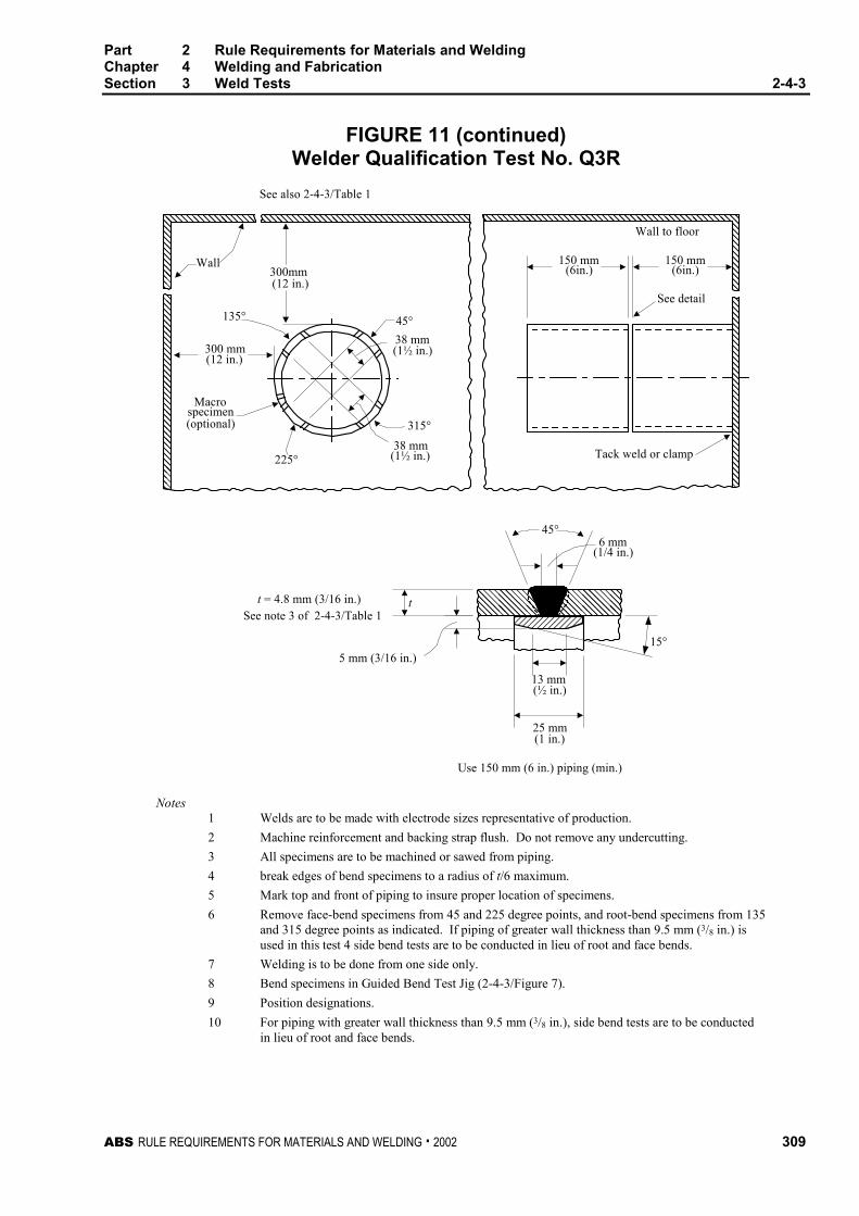
Part 2 Rule Requirements for Materials and WeldingChapter 4 Welding and FabricationSection 3 Weld Tests 2-4-3
ABS RULE REQUIREMENTS FOR MATERIALS AND WELDING . 2002 309
FIGURE 11 (continued)Welder Qualification Test No. Q3R
������
������
����������������������������������������
Use 150 mm (6 in.) piping (min.)
See note 3 of 2-4-3/Table 1
See also 2-4-3/Table 1
150 mm(6in.)
t = 4.8 mm (3/16 in.)
5 mm (3/16 in.)
25 mm(1 in.)
(½ in.)13 mm
6 mm
(1½ in.)
(1/4 in.)
15°
(optional)specimen
Macro
225°
300 mm(12 in.)
135°
(12 in.)
38 mm
315°
Wall to floor
See detail
Tack weld or clamp
45°
38 mm(1½ in.)
Wall
t
300mm
45°
��������������������
����������������
����������������
150 mm(6in.)
��������
����
Notes1 Welds are to be made with electrode sizes representative of production.
2 Machine reinforcement and backing strap flush. Do not remove any undercutting.
3 All specimens are to be machined or sawed from piping.
4 break edges of bend specimens to a radius of t/6 maximum.
5 Mark top and front of piping to insure proper location of specimens.
6 Remove face-bend specimens from 45 and 225 degree points, and root-bend specimens from 135and 315 degree points as indicated. If piping of greater wall thickness than 9.5 mm (3/8 in.) isused in this test 4 side bend tests are to be conducted in lieu of root and face bends.
7 Welding is to be done from one side only.
8 Bend specimens in Guided Bend Test Jig (2-4-3/Figure 7).
9 Position designations.
10 For piping with greater wall thickness than 9.5 mm (3/8 in.), side bend tests are to be conductedin lieu of root and face bends.
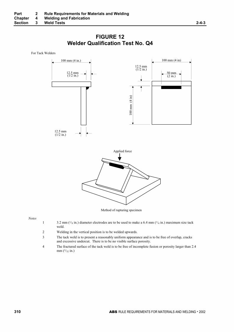
Part 2 Rule Requirements for Materials and WeldingChapter 4 Welding and FabricationSection 3 Weld Tests 2-4-3
310 ABS RULE REQUIREMENTS FOR MATERIALS AND WELDING . 2002
FIGURE 12Welder Qualification Test No. Q4
For Tack Welders
Method of rupturing specimen
(1/2 in.)
(1/2 in.)
(2 in.)
12.5 mm(1/2 in.)
Applied force
12.5 mm
100 mm (4 in.)
12.5 mm10
0 m
m (
4 in
)
50 mm
100 mm (4 in)
Notes1 3.2 mm (1/8 in.) diameter electrodes are to be used to make a 6.4 mm (1/4 in.) maximum size tack
weld.
2 Welding in the vertical position is to be welded upwards.
3 The tack weld is to present a reasonably uniform appearance and is to be free of overlap, cracksand excessive undercut. There is to be no visible surface porosity.
4 The fractured surface of the tack weld is to be free of incomplete fusion or porosity larger than 2.4mm (3/32 in.)
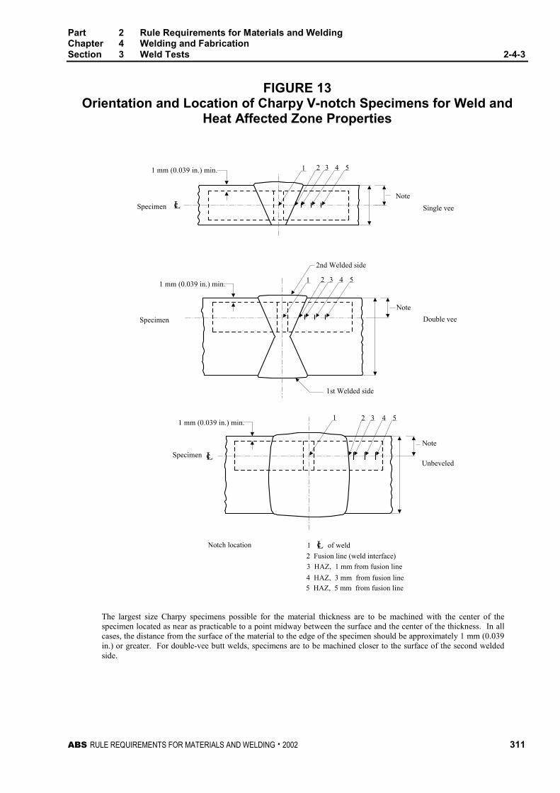
Part 2 Rule Requirements for Materials and WeldingChapter 4 Welding and FabricationSection 3 Weld Tests 2-4-3
ABS RULE REQUIREMENTS FOR MATERIALS AND WELDING . 2002 311
FIGURE 13Orientation and Location of Charpy V-notch Specimens for Weld and
Heat Affected Zone Properties
1 2 3 4 5
Note
Single vee
Double vee
Note
Unbeveled
Note
Specimen
Specimen
Specimen Lc
1st Welded side
2nd Welded side
Notch location 1 of weld
2 Fusion line (weld interface)
3 HAZ, 1 mm from fusion line
4 HAZ, 3 mm from fusion line
5 HAZ, 5 mm from fusion line
1 mm (0.039 in.) min.
1 mm (0.039 in.) min.
1 mm (0.039 in.) min.
1 2 3 4 5
Lc
Lc
1 2 3 4 5
The largest size Charpy specimens possible for the material thickness are to be machined with the center of thespecimen located as near as practicable to a point midway between the surface and the center of the thickness. In allcases, the distance from the surface of the material to the edge of the specimen should be approximately 1 mm (0.039in.) or greater. For double-vee butt welds, specimens are to be machined closer to the surface of the second weldedside.


ABS RULE REQUIREMENTS FOR MATERIALS AND WELDING . 2002 313
P A R T
2C H A P T E R 4 Welding and Fabrication
S E C T I O N 4 Piping (2002) *
* Note: This Section is applicable only to piping for installation on vessels to be built in accordance with theRules for Building and Classing Steel Vessels.
CONTENTS1 General................................................................................. 315
1.1 Application ............................................................................ 315
1.3 Pipe Classes......................................................................... 315
1.5 Materials ............................................................................... 315
1.7 Welding Filler Metals ............................................................ 316
3 Welding Procedures and Welders...................................... 316
3.1 Welding Procedures ............................................................. 316
3.3 Welders and Welding Operators .......................................... 316
5 Types of Welded Joints....................................................... 316
5.1 Full Penetration Butt Joints .................................................. 316
5.3 Square-groove Butt Joint...................................................... 317
5.5 Fillet-welded Joints............................................................... 317
5.7 Flange Attachment Welds .................................................... 317
5.9 Branch Connections ............................................................. 318
5.11 Tack Welding........................................................................ 318
7 Preheat ................................................................................. 318
9 Post-weld Heat Treatment................................................... 318
9.1 Procedure ............................................................................. 318
9.3 Requirement ......................................................................... 319
11 Non-destructive Examination ............................................. 319
11.1 Visual Examination............................................................... 319
11.3 Butt Weld Joints.................................................................... 319
11.5 Fillet Weld Joints .................................................................. 320
13 Weld Repair.......................................................................... 320
15 Pipe Forming and Bending ................................................. 321
15.1 Cold Forming........................................................................ 321
15.3 Hot Forming.......................................................................... 321
314 ABS RULE REQUIREMENTS FOR MATERIALS AND WELDING . 2002
17 Additional Requirements for Low Temperature Piping[below -10°C (14°F)] .............................................................321
17.1 Application ............................................................................ 321
17.3 Welding Procedure............................................................... 321
17.5 Pipe Joints ............................................................................ 321
17.7 Post-weld Heat Treatment.................................................... 322
17.9 Non-Destructive Examination............................................... 322

ABS RULE REQUIREMENTS FOR MATERIALS AND WELDING . 2002 315
P A R T
2C H A P T E R 4 Welding and Fabrication
S E C T I O N 4 Piping (2002) *
* Note: This Section is applicable only to piping for installation on vessels to be built in accordance with theRules for Building and Classing Steel Vessels, (SVR).
1 General
1.1 ApplicationThe provisions of this section are intended for welding of steel pipes in systems covered in Part 4,Chapter 6 of the Rules for Building and Classing Steel Vessels, (SVR). Additional provisions, as maybe specified for piping systems of specialized carriers in Part 5 of the Rules for Building and ClassingSteel Vessels, where applicable, are also to be complied with. Consideration will be given tocompliance with a recognized national or international welding standard that is considered equallyeffective.
1.3 Pipe ClassesPipe classes are as defined in 4-6-1/Table 1, (SVR). Classes I and II pipes are to comply with all theprovisions of this section. Class III pipes are to comply at least with 2-4-3/1.7, 2-4-3/3, 2-4-3/5 and2-4-3/11.1 of these provisions.
1.5 MaterialsFor purpose of determining welding requirements, steel pipe materials are grouped as follows:
Representative standards (1)
Material group DescriptionABS grade ASTM grade
C and C/MnCarbon;
carbon manganese
1, 2, 3, 4, 5;
8, 9
A53, A106;
A135
0.5 Mo
0.5 Mo/0.5 Cr
Up to 0.5% Molybdenum;
0.5% Molybdenum & 0.5%Chromium
6; 7A335 P1;
A335 P2
1Cr/0.5Mo1.0 - 1.25% Chromium &0.5% Molybdenum 11; 12
A335 P11;
A335 P12
2.25Cr/1Mo2.25% Chromium and 1.0%Molybdenum
13 A335 P22
1 Other materials complying with recognized national or international standardsare also acceptable.
Part 2 Rule Requirements for Materials and WeldingChapter 4 Welding and FabricationSection 4 Piping 2-4-4
316 ABS RULE REQUIREMENTS FOR MATERIALS AND WELDING . 2002
1.7 Welding Filler MetalsAll welding filler metals are to be certified by their manufacturers as complying with appropriaterecognized national or international standards. Welding filler metals tested, certified and listed by theBureau in its publication Approved Welding Consumables for meeting such a standard may be used inall cases. See Part 2, Appendix 2 for approval of filler metals. Welding filler metals not so listed mayalso be accepted provided that:
they are of the same type as that proven in qualifying the welding procedure; and
they are of a make acceptable to the Surveyor; and
for welding of Class I piping, representative production test pieces are to be taken to prove themechanical properties of the weld metal.
3 Welding Procedures and Welders
3.1 Welding ProceduresBefore proceeding with welding, the responsible fabricator is to prove to the satisfaction of theSurveyor that the intended welding process, welding filler metal, preheat, post weld heat treatment,etc. as applicable, have been qualified for joining the base metal. In general, the intended weldingprocedure is to be supported by welding procedure qualification record (PQR) conducted in thepresence of the Surveyor. Properly documented PQR certified by a recognized body may besubmitted to the Surveyor for acceptance. The PQR is to be conducted in accordance with arecognized standard, such as the ASME Boiler and Pressure Vessel Code, Section IX. The PQR maybe used to support those welding procedures whose welding variables (e.g. base metal thickness,welding current, etc.) are within the ranges defined in the recognized welding standard being used.
3.3 Welders and Welding OperatorsBefore proceeding with welding, the responsible fabricator is to prove to the satisfaction of theSurveyor that the welder or the welding operator is qualified for performing the intended weldingprocedure. In general, welders and welding operators are to be qualified in accordance with2-4-4/11 in the presence of the Surveyor. Properly documented welder performance qualificationrecords (WPQ) conducted in accordance with a recognized welding standard being used (such as theASME Boiler and Pressure Vessel Code, Section IX) and certified by recognized body may bepresented to the Surveyor for acceptance as evidence of qualification. Once deemed qualified, thewelder or the welding operator is permitted to perform the welding as qualified, as well as otherwelding, provided the welding variables (e.g. position, with or without backing, pipe size, etc.) ofsuch welding are within specified ranges defined by the recognized welding standard being used.
5 Types of Welded Joints
5.1 Full Penetration Butt Joints
5.1.1 GeneralFull penetration butt joints for pipes are to have welds deposited on properly prepared singlevee, double vee or other suitable types of grooves, with or without backing rings. The edgepreparation and fit-up tolerances are to be as indicated in 2-4-3/5.1.2 and2-4-3/5.1.3. Joints welded without backing ring are to assure complete root penetration andfusion by employing qualified welding procedure and qualified welder demonstrating thatsuccessful joints can be achieved. All full penetration butt joints in Classes I and II pipingsystems are subject to radiographic examination or equivalent to the extent as indicated in2-4-3/11 to assure that complete root penetration is achieved and the welds do not containunacceptable imperfection.
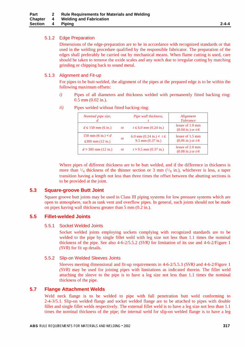
Part 2 Rule Requirements for Materials and WeldingChapter 4 Welding and FabricationSection 4 Piping 2-4-4
ABS RULE REQUIREMENTS FOR MATERIALS AND WELDING . 2002 317
5.1.2 Edge Preparation
Dimensions of the edge-preparation are to be in accordance with recognized standards or thatused in the welding procedure qualified by the responsible fabricator. The preparation of theedges shall preferably be carried out by mechanical means. When flame cutting is used, careshould be taken to remove the oxide scales and any notch due to irregular cutting by matchinggrinding or chipping back to sound metal.
5.1.3 Alignment and Fit-up
For pipes to be butt-welded, the alignment of the pipes at the prepared edge is to be within thefollowing maximum offsets:
i) Pipes of all diameters and thickness welded with permanently fitted backing ring:0.5 mm (0.02 in.).
ii) Pipes welded without fitted backing ring:
Nominal pipe size,d
Pipe wall thickness,t
AlignmentTolerance
d ≤ 150 mm (6 in.) or t ≤ 6.0 mm (0.24 in.)lesser of 1.0 mm(0.04 in.) or t/4
150 mm (6 in.) < d
≤300 mm (12 in.)or 6.0 mm (0.24 in.) < t ≤
9.5 mm (0.37 in.)lesser of 1.5 mm(0.06 in.) or t/4
d > 300 mm (12 in.) or t > 9.5 mm (0.37 in.)lesser of 2.0 mm(0.08 in.) or t/4
Where pipes of different thickness are to be butt welded, and if the difference in thickness ismore than 1/4 thickness of the thinner section or 3 mm (1/8 in.), whichever is less, a tapertransition having a length not less than three times the offset between the abutting sections isto be provided at the joint.
5.3 Square-groove Butt JointSquare groove butt joints may be used in Class III piping systems for low pressure systems which areopen to atmosphere, such as tank vent and overflow pipes. In general, such joints should not be madeon pipes having wall thickness greater than 5 mm (0.2 in.).
5.5 Fillet-welded Joints
5.5.1 Socket Welded Joints
Socket welded joints employing sockets complying with recognized standards are to bewelded to the pipe by single fillet weld with leg size not less than 1.1 times the nominalthickness of the pipe. See also 4-6-2/5.5.2 (SVR) for limitation of its use and 4-6-2/Figure 1(SVR) for fit up details.
5.5.2 Slip-on Welded Sleeves Joints
Sleeves meeting dimensional and fit-up requirements in 4-6-2/5.5.3 (SVR) and 4-6-2/Figure 1(SVR) may be used for joining pipes with limitations as indicated therein. The fillet weldattaching the sleeve to the pipe is to have a leg size not less than 1.1 times the nominalthickness of the pipe.
5.7 Flange Attachment WeldsWeld neck flange is to be welded to pipe with full penetration butt weld conforming to2-4-3/5.1. Slip-on welded flange and socket welded flange are to be attached to pipes with doublefillet and single fillet welds respectively. The external fillet weld is to have a leg size not less than 1.1times the nominal thickness of the pipe; the internal weld for slip-on welded flange is to have a leg
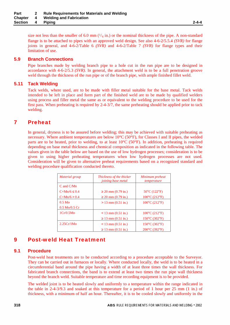
Part 2 Rule Requirements for Materials and WeldingChapter 4 Welding and FabricationSection 4 Piping 2-4-4
318 ABS RULE REQUIREMENTS FOR MATERIALS AND WELDING . 2002
size not less than the smaller of 6.0 mm (1/4 in.) or the nominal thickness of the pipe. A non-standardflange is to be attached to pipes with an approved weld design. See also 4-6-2/5.5.4 (SVR) for flangejoints in general, and 4-6-2/Table 6 (SVR) and 4-6-2/Table 7 (SVR) for flange types and theirlimitation of use.
5.9 Branch ConnectionsPipe branches made by welding branch pipe to a hole cut in the run pipe are to be designed inaccordance with 4-6-2/5.3 (SVR). In general, the attachment weld is to be a full penetration grooveweld through the thickness of the run pipe or of the branch pipe, with ample finished fillet weld.
5.11 Tack WeldingTack welds, where used, are to be made with filler metal suitable for the base metal. Tack weldsintended to be left in place and form part of the finished weld are to be made by qualified weldersusing process and filler metal the same as or equivalent to the welding procedure to be used for thefirst pass. When preheating is required by 2-4-3/7, the same preheating should be applied prior to tackwelding.
7 Preheat
In general, dryness is to be assured before welding; this may be achieved with suitable preheating asnecessary. Where ambient temperatures are below 10°C (50°F), for Classes I and II pipes, the weldedparts are to be heated, prior to welding, to at least 10°C (50°F). In addition, preheating is requireddepending on base metal thickness and chemical composition as indicated in the following table. Thevalues given in the table below are based on the use of low hydrogen processes; consideration is to begiven to using higher preheating temperatures when low hydrogen processes are not used.Consideration will be given to alternative preheat requirements based on a recognized standard andwelding procedure qualification conducted thereto.
Material group Thickness of the thickerjoining base metal
Minimum preheattemperature
C and C/Mn
C+Mn/6 ≤ 0.4 ≥ 20 mm (0.79 in.) 50°C (122°F)
C+Mn/6 > 0.4 ≥ 20 mm (0.79 in.) 100°C (212°F)
0.5 Mo
0.5 Mo/0.5 Cr
> 13 mm (0.51 in.) 100°C (212°F)
1Cr/0.5Mo < 13 mm (0.51 in.) 100°C (212°F)
≥ 13 mm (0.51 in.) 150°C (302°F)
2.25Cr/1Mo < 13 mm (0.51 in.) 150°C (302°F)
≥ 13 mm (0.51 in.) 200°C (392°F)
9 Post-weld Heat Treatment
9.1 ProcedurePost-weld heat treatments are to be conducted according to a procedure acceptable to the Surveyor.They can be carried out in furnaces or locally. Where conducted locally, the weld is to be heated in acircumferential band around the pipe having a width of at least three times the wall thickness. Forfabricated branch connections, the band is to extend at least two times the run pipe wall thicknessbeyond the branch weld. Suitable temperature and time recording equipment is to be provided.
The welded joint is to be heated slowly and uniformly to a temperature within the range indicated inthe table in 2-4-3/9.3 and soaked at this temperature for a period of 1 hour per 25 mm (1 in.) ofthickness, with a minimum of half an hour. Thereafter, it is to be cooled slowly and uniformly in the
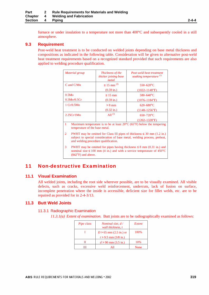
Part 2 Rule Requirements for Materials and WeldingChapter 4 Welding and FabricationSection 4 Piping 2-4-4
ABS RULE REQUIREMENTS FOR MATERIALS AND WELDING . 2002 319
furnace or under insulation to a temperature not more than 400°C and subsequently cooled in a stillatmosphere.
9.3 RequirementPost-weld heat treatment is to be conducted on welded joints depending on base metal thickness andcompositions as indicated in the following table. Consideration will be given to alternative post-weldheat treatment requirements based on a recognized standard provided that such requirements are alsoapplied to welding procedure qualification.
Material group Thickness of thethicker joining base
metal
Post-weld heat treatmentsoaking temperature (1)
C and C/Mn ≥ 15 mm (2)
(0.59 in.)
550–620°C
(1022–1148°F)
0.5Mo
0.5Mo/0.5Cr
≥ 15 mm
(0.59 in.)
580–640°C
(1076–1184°F)
1 Cr/0.5Mo > 8 mm
(0.32 in.)
620–680°C
(1148–1256°F)
2.25Cr/1Mo All (3) 650–720°C
(1202–1328°F)1 Maximum temperature is to be at least 20°C (65°F) below the tempering
temperature of the base metal.
2 PWHT may be omitted for Class III pipes of thickness ≤ 30 mm (1.2 in.)subject to special consideration of base metal, welding process, preheat,and welding procedure qualification.
3 PWHT may be omitted for pipes having thickness ≤ 8 mm (0.31 in.) andnominal size ≤ 100 mm (4 in.) and with a service temperature of 450°C(842°F) and above.
11 Non-destructive Examination
11.1 Visual ExaminationAll welded joints, including the root side wherever possible, are to be visually examined. All visibledefects, such as cracks, excessive weld reinforcement, undercuts, lack of fusion on surface,incomplete penetration where the inside is accessible, deficient size for fillet welds, etc. are to berepaired as provided for in 2-4-3/13.
11.3 Butt Weld Joints
11.3.1 Radiographic Examination
11.3.1(a) Extent of examination. Butt joints are to be radiographically examined as follows:
Pipe class Nominal size, d /wall thickness, t
Extent
I D > 65 mm (2.5 in.) or
t > 9.5 mm (3/8 in.)
100%
II d > 90 mm (3.5 in.) 10%
III All None
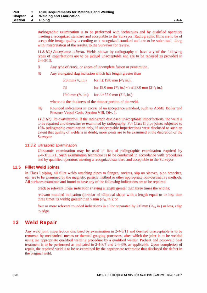
Part 2 Rule Requirements for Materials and WeldingChapter 4 Welding and FabricationSection 4 Piping 2-4-4
320 ABS RULE REQUIREMENTS FOR MATERIALS AND WELDING . 2002
Radiographic examination is to be performed with techniques and by qualified operatorsmeeting a recognized standard and acceptable to the Surveyor. Radiographic films are to be ofacceptable image quality according to a recognized standard and are to be submitted, alongwith interpretation of the results, to the Surveyor for review.
11.3.1(b) Acceptance criteria. Welds shown by radiography to have any of the followingtypes of imperfections are to be judged unacceptable and are to be repaired as provided in2-4-3/13.
i) Any type of crack, or zones of incomplete fusion or penetration.
ii) Any elongated slag inclusion which has length greater than
6.0 mm (1/4 in.) for t ≤ 19.0 mm (3/4 in.),
t/3 for 19.0 mm (3/4 in.) < t ≤ 57.0 mm (21/4 in.)
19.0 mm (3/4 in.) for t > 57.0 mm (21/4 in.)
where t is the thickness of the thinner portion of the weld.
iii) Rounded indications in excess of an acceptance standard, such as ASME Boiler andPressure Vessel Code, Section VIII, Div. 1.
11.3.1(c) Re-examination. If the radiograph disclosed unacceptable imperfections, the weld isto be repaired and thereafter re-examined by radiography. For Class II pipe joints subjected to10% radiographic examination only, if unacceptable imperfections were disclosed to such anextent that quality of welds is in doubt, more joints are to be examined at the discretion of theSurveyor.
11.3.2 Ultrasonic Examination
Ultrasonic examination may be used in lieu of radiographic examination required by2-4-3/11.3.1. Such examination technique is to be conducted in accordance with proceduresand by qualified operators meeting a recognized standard and acceptable to the Surveyor.
11.5 Fillet Weld JointsIn Class I piping, all fillet welds attaching pipes to flanges, sockets, slip-on sleeves, pipe branches,etc. are to be examined by the magnetic particle method or other appropriate non-destructive methods.All surfaces examined and found to have any of the following indications are to be repaired.
crack or relevant linear indication (having a length greater than three times the width);
relevant rounded indication (circular of elliptical shape with a length equal to or less thanthree times its width) greater than 5 mm (3/16 in.); or
four or more relevant rounded indications in a line separated by 2.0 mm (1/16 in.) or less, edgeto edge.
13 Weld Repair
Any weld joint imperfection disclosed by examination in 2-4-3/11 and deemed unacceptable is to beremoved by mechanical means or thermal gouging processes, after which the joint is to be weldedusing the appropriate qualified welding procedure by a qualified welder. Preheat and post-weld heattreatment is to be performed as indicated in 2-4-3/7 and 2-4-3/9, as applicable. Upon completion ofrepair, the repaired weld is to be re-examined by the appropriate technique that disclosed the defect inthe original weld.
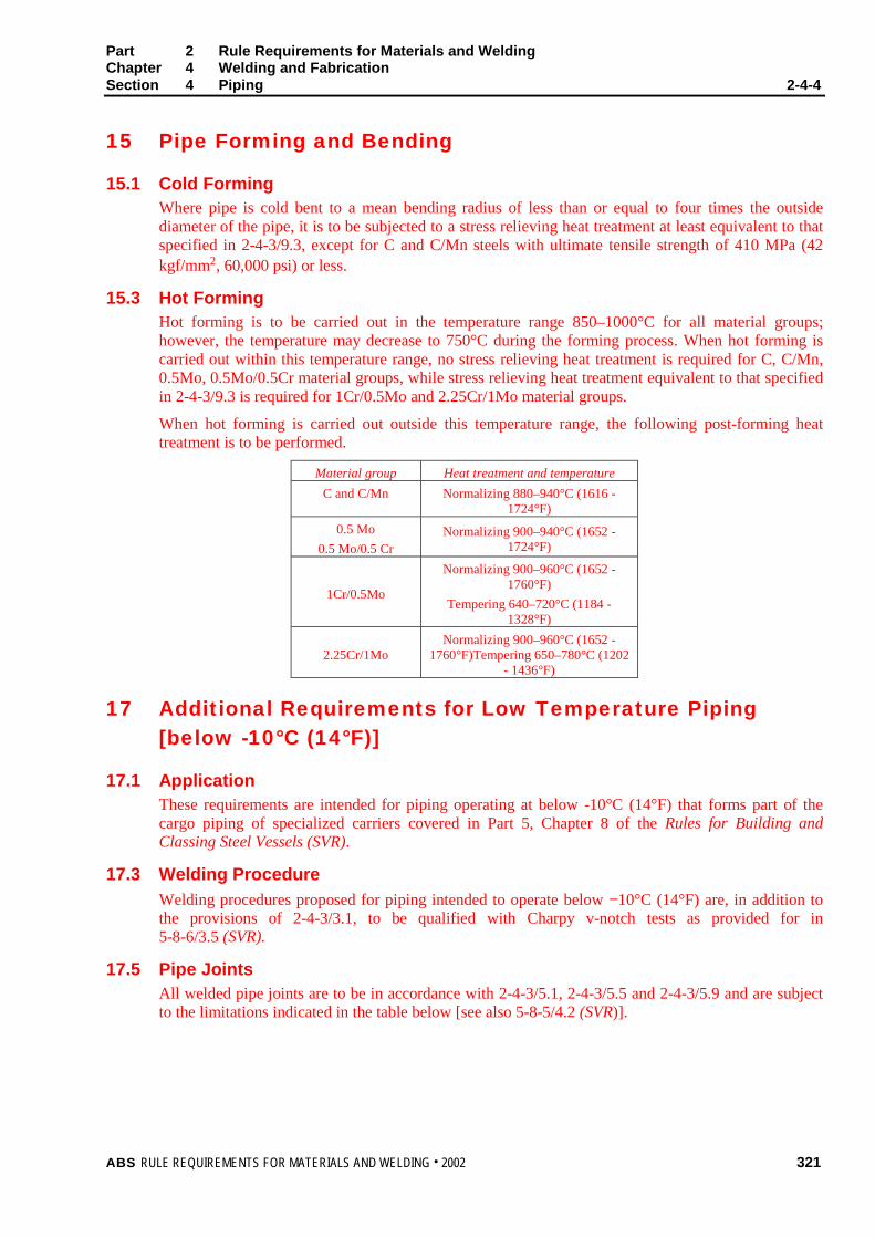
Part 2 Rule Requirements for Materials and WeldingChapter 4 Welding and FabricationSection 4 Piping 2-4-4
ABS RULE REQUIREMENTS FOR MATERIALS AND WELDING . 2002 321
15 Pipe Forming and Bending
15.1 Cold FormingWhere pipe is cold bent to a mean bending radius of less than or equal to four times the outsidediameter of the pipe, it is to be subjected to a stress relieving heat treatment at least equivalent to thatspecified in 2-4-3/9.3, except for C and C/Mn steels with ultimate tensile strength of 410 MPa (42kgf/mm2, 60,000 psi) or less.
15.3 Hot FormingHot forming is to be carried out in the temperature range 850–1000°C for all material groups;however, the temperature may decrease to 750°C during the forming process. When hot forming iscarried out within this temperature range, no stress relieving heat treatment is required for C, C/Mn,0.5Mo, 0.5Mo/0.5Cr material groups, while stress relieving heat treatment equivalent to that specifiedin 2-4-3/9.3 is required for 1Cr/0.5Mo and 2.25Cr/1Mo material groups.
When hot forming is carried out outside this temperature range, the following post-forming heattreatment is to be performed.
Material group Heat treatment and temperature
C and C/Mn Normalizing 880–940°C (1616 -1724°F)
0.5 Mo
0.5 Mo/0.5 CrNormalizing 900–940°C (1652 -
1724°F)
1Cr/0.5Mo
Normalizing 900–960°C (1652 -1760°F)
Tempering 640–720°C (1184 -1328°F)
2.25Cr/1MoNormalizing 900–960°C (1652 -
1760°F)Tempering 650–780°C (1202- 1436°F)
17 Additional Requirements for Low Temperature Piping[below -10°C (14°F)]
17.1 ApplicationThese requirements are intended for piping operating at below -10°C (14°F) that forms part of thecargo piping of specialized carriers covered in Part 5, Chapter 8 of the Rules for Building andClassing Steel Vessels (SVR).
17.3 Welding Procedure
Welding procedures proposed for piping intended to operate below −10°C (14°F) are, in addition tothe provisions of 2-4-3/3.1, to be qualified with Charpy v-notch tests as provided for in5-8-6/3.5 (SVR).
17.5 Pipe JointsAll welded pipe joints are to be in accordance with 2-4-3/5.1, 2-4-3/5.5 and 2-4-3/5.9 and are subjectto the limitations indicated in the table below [see also 5-8-5/4.2 (SVR)].
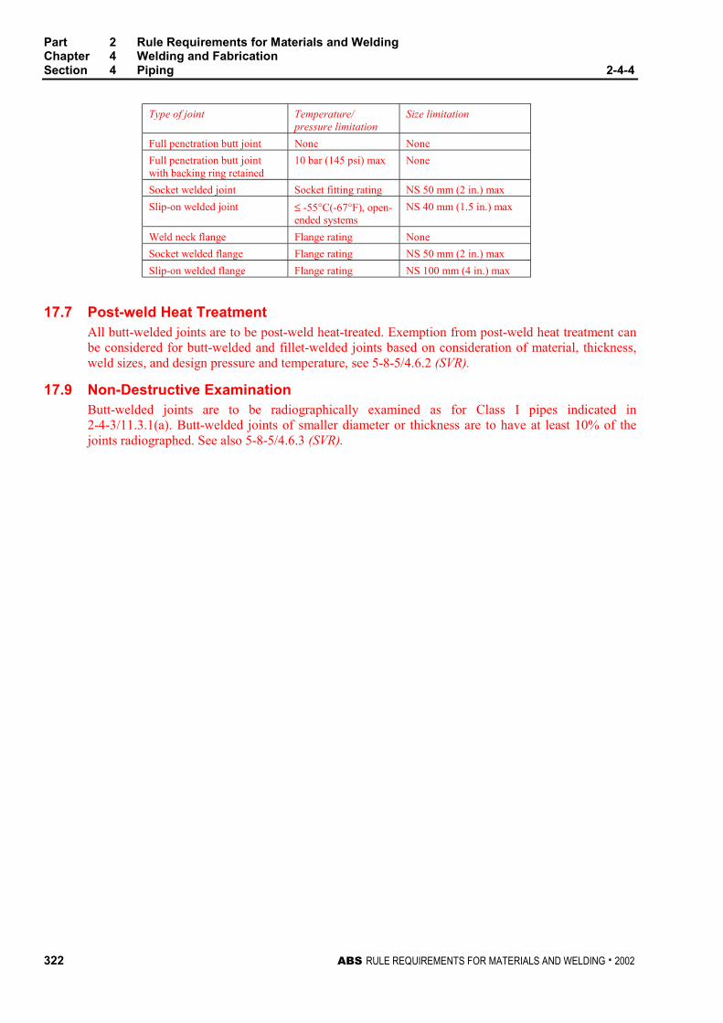
Part 2 Rule Requirements for Materials and WeldingChapter 4 Welding and FabricationSection 4 Piping 2-4-4
322 ABS RULE REQUIREMENTS FOR MATERIALS AND WELDING . 2002
Type of joint Temperature/pressure limitation
Size limitation
Full penetration butt joint None None
Full penetration butt jointwith backing ring retained
10 bar (145 psi) max None
Socket welded joint Socket fitting rating NS 50 mm (2 in.) max
Slip-on welded joint ≤ -55°C(-67°F), open-ended systems
NS 40 mm (1.5 in.) max
Weld neck flange Flange rating None
Socket welded flange Flange rating NS 50 mm (2 in.) max
Slip-on welded flange Flange rating NS 100 mm (4 in.) max
17.7 Post-weld Heat TreatmentAll butt-welded joints are to be post-weld heat-treated. Exemption from post-weld heat treatment canbe considered for butt-welded and fillet-welded joints based on consideration of material, thickness,weld sizes, and design pressure and temperature, see 5-8-5/4.6.2 (SVR).
17.9 Non-Destructive ExaminationButt-welded joints are to be radiographically examined as for Class I pipes indicated in2-4-3/11.3.1(a). Butt-welded joints of smaller diameter or thickness are to have at least 10% of thejoints radiographed. See also 5-8-5/4.6.3 (SVR).

ABS RULE REQUIREMENTS FOR MATERIALS AND WELDING . 2002 323
P A R T
2A P P E N D I X 1 List of Destructive and
Nondestructive Tests Required inPart 2, Chapters 1; 2; and 3, andResponsibility for Verifying 2 - A 1
Test and Test Datai) Witnessed Tests The designation (W) indicates that the Surveyor is to witness the testing
unless the plant and product is approved under the Bureau’s Quality Assurance Program.
ii) Manufacturer’s Data The designation (M) indicates that test data is to be provided by themanufacturer without verification by a Surveyor of the procedures used or the resultsobtained.
iii) Other Tests The designation (A) indicates those tests for which test data is to be provided bythe supplier and audited by the Surveyor to verify that the procedures used and random testswitnessed are in compliance with Rule requirements.
2-1-1 General2-1-1/17 Through Thickness Properties (W)
2-1-2 Ordinary-Strength Hull Structural Steel2-1-2/5.1 Ladle Analysis (M)2-1-2/5.3 Product Analysis (M)2-1-2/5.7.1 McQuaid - Ehn (M)2-1-2/9.1 Tension Test (W)2-1-2/11.1 Charpy V-notch Impact Test (W)
2-1-3/1 Higher-Strength Hull Structural Steel2-1-3/3 Ladle Analysis (M)2-1-3/3 Tension Test (W)2-1-3/3 Charpy V-notch Impact Test (W)2-1-3/3 Product Analysis (M)2-1-3/5 McQuaid - Ehn (M)
2-1-4 Materials for Low Temperature Service2-1-4/5.1 Charpy V-notch Impact Test (W)2-1-4/5.3 Drop-weight Test (NDTT) (W)

Part 2 Rule Requirements for Materials and WeldingAppendix 1 List of Destructive and Nondestructive Tests Required in Part 2, Chapters 1; 2;
and 3, and Responsibility for Verifying 2-A1
324 ABS RULE REQUIREMENTS FOR MATERIALS AND WELDING . 2002
2-1-5 Hull Steel Castings2-1-5/7 Tension Test (W)2-1-5/13.11 Magnetic Particle Inspection (A)2-1-5/13.11 Dye Penetrant Inspection (A)2-1-5/13.11 Ultrasonic Inspection (A)
2-1-6 Hull Steel Forgings2-1-6/1.7 Ladle Analysis (M)2-1-6/7 Tension Test (W)2-1-6/11.3 Brinell Hardness Test (BHN) (W)
2-2-1 Anchors2-2-1/7.1 Bend Test (W)2-2-1/7.3 Percussive Test (W)2-2-1/7.5 Hammering Test (W)2-2-1/7.7 Magnetic Particle Test (W)2-2-1/7.9 Proof Test (W)
2-2-2 Anchor Chain2-2-2/11.3 Ladle Analysis (M)2-2-2/13.5, 2-2-2/19.5 and 2-2-2/23.3 Tension Test (W)2-2-2/13.7 and 2-2-2/23.3 Bend Test (W)2-2-2/13.9, 2-2-2/19.5 and 2-2-2/23.3 Charpy V-notch Impact Test (W)2-2-2/17.1, 2-2-2/19.1 and 2-2-2/23.13 Breaking Test (W)2-2-2/17.1, 2-2-2/19.3 and 2-2-2/23.15 Proof Test (W)2-2-2/23.9 Magnetic Particle Inspection (A)2-2-2/23.11 Brinell Hardness Test (W)
2-2-2/25 Unstudded Short-link Chain2-2-2/25.1 Ladle Analysis (M)2-2-2/25.1 Tension Test (W)2-2-2/25.1 Bend Test (W)2-2-2/25.3 Breaking Test (W)2-2-2/25.3 Proof Test (W)
2-3-2 General Requirements for All Grades of Steel Plates for Machinery, Boilers, andPressure Vessels2-3-2/1.7.1 Ladle Analysis (M)2-3-2/1.7.2 Product Analysis (M)2-3-2/1.9.1, 2-3-2/1.9.2, and 2-3-2/1.9.3 Test Specimens (W)2-3-2/1.11.1, 2-3-2/1.11.2, and 2-3-2/1.11.3 Tensile Properties (W)
2-3-2/3 Steel Plates for Intermediate Temperature Service2-3-2/3.5 Chemical Composition (M)2-3-2/3.9 Tensile Properties (W)
2-3-2/5 Steel Plates for Intermediate and Higher-Temperature Service2-3-2/5.7 Chemical Composition (M)2-3-2/5.11 Tensile Properties (W)

Part 2 Rule Requirements for Materials and WeldingAppendix 1 List of Destructive and Nondestructive Tests Required in Part 2, Chapters 1; 2;
and 3, and Responsibility for Verifying 2-A1
ABS RULE REQUIREMENTS FOR MATERIALS AND WELDING . 2002 325
2-3-2/7 Steel Plates for Intermediate and Lower-Temperature Service2-3-2/7.1 McQuaid-Ehn (M)2-3-2/7.7 Chemical Composition (M)2-3-2/7.11 Tensile Properties (W)
2-3-2/9 Materials for Low Temperature Service [Below -18C (0 F)]Those listed in Section 2-1-4 and 2-3-2/9
2-3-3 Seamless Forged-Steel Drums2-3-3/1 Tension Tests (W)
2-3-4 Seamless-Steel Pressure Vessels2-3-4/3 Tension Test (W)2-3-4/5 Flattening Test (W)2-3-4/7 Hydrostatic Test (W)2-3-4/9 Thickness Test (W)
2-3-5 Boiler and Superheater Tubes2-3-5/9 Chemical Composition (M)2-3-5/11 Product Analysis (M)2-3-5/17 Tensile Properties (W)2-3-5/19 Flattening Test (W)2-3-5/21 Reverse Flattening Test (W)2-3-5/23 Flange Test (W)2-3-5/25 Flaring Test (W)2-3-5/27 Crush Test (W)2-3-5/29 Hardness Test (W)2-3-5/31 Hydrostatic Test (W)2-3-5/33 Nondestructive Electric Test (NDET) (A)2-3-5/39 Thickness Test (A)
2-3-6 Boiler Rivet and Staybolt Steel and Rivets2-3-6/5 Tensile Properties (W)2-3-6/7 Bending Properties (Bars) (W)2-3-6/13.1 Bending Properties (Rivets) (W)2-3-6/13.3 Flattening Test (W)
2-3-7 Steel Machinery Forgings2-3-7/1.1.2, 2-3-7/3.1.2, 2-3-7/5.1.2,2-3-7/7.1.2
Chemical Composition (M)
2-3-7/1.7, 2-3-7/3.7, 2-3-7/5.7, 2-3-7/7.7 Tensile Properties (W)2-3-7/1.13.1, 2-3-7/5.11.1 Surface Inspection of Tailshaft Forgings (W)2-3-7/1.13.2, 2-3-7/5.11.2 Ultrasonic Examination of Tail Shaft Forgings (A)2-3-7/1.11.2, 2-3-7/3.7.2, 2-3-7/5.9.4,2-3-7/7.7.2
Hardness Test (W)
2-3-8 Hot-rolled Steel Bars for Machinery2-3-8/1 Those listed in Section 2-3-7 above
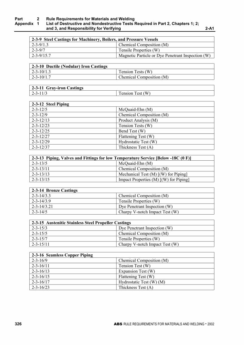
Part 2 Rule Requirements for Materials and WeldingAppendix 1 List of Destructive and Nondestructive Tests Required in Part 2, Chapters 1; 2;
and 3, and Responsibility for Verifying 2-A1
326 ABS RULE REQUIREMENTS FOR MATERIALS AND WELDING . 2002
2-3-9 Steel Castings for Machinery, Boilers, and Pressure Vessels2-3-9/1.3 Chemical Composition (M)2-3-9/7 Tensile Properties (W)2-3-9/15.7 Magnetic Particle or Dye Penetrant Inspection (W)
2-3-10 Ductile (Nodular) Iron Castings2-3-10/1.3 Tension Tests (W)2-3-10/1.7 Chemical Composition (M)
2-3-11 Gray-iron Castings2-3-11/3 Tension Test (W)
2-3-12 Steel Piping2-3-12/5 McQuaid-Ehn (M)2-3-12/9 Chemical Composition (M)2-3-12/13 Product Analysis (M)2-3-12/23 Tension Tests (W)2-3-12/25 Bend Test (W)2-3-12/27 Flattening Test (W)2-3-12/29 Hydrostatic Test (W)2-3-12/37 Thickness Test (A)
2-3-13 Piping, Valves and Fittings for low Temperature Service [Below -18C (0 F)]2-3-13/5 McQuaid-Ehn (M)2-3-13/11 Chemical Composition (M)2-3-13/13 Mechanical Test (M) [(W) for Piping]2-3-13/15 Impact Properties (M) [(W) for Piping]
2-3-14 Bronze Castings2-3-14/3.3 Chemical Composition (M)2-3-14/3.9 Tensile Properties (W)2-3-14/3.21 Dye Penetrant Inspection (W)2-3-14/5 Charpy V-notch Impact Test (W)
2-3-15 Austenitic Stainless Steel Propeller Castings2-3-15/3 Dye Penetrant Inspection (W)2-3-15/5 Chemical Composition (M)2-3-15/7 Tensile Properties (W)2-3-15/11 Charpy V-notch Impact Test (W)
2-3-16 Seamless Copper Piping2-3-16/9 Chemical Composition (M)2-3-16/11 Tension Test (W)2-3-16/13 Expansion Test (W)2-3-16/15 Flattening Test (W)2-3-16/17 Hydrostatic Test (W) (M)2-3-16/23 Thickness Test (A)
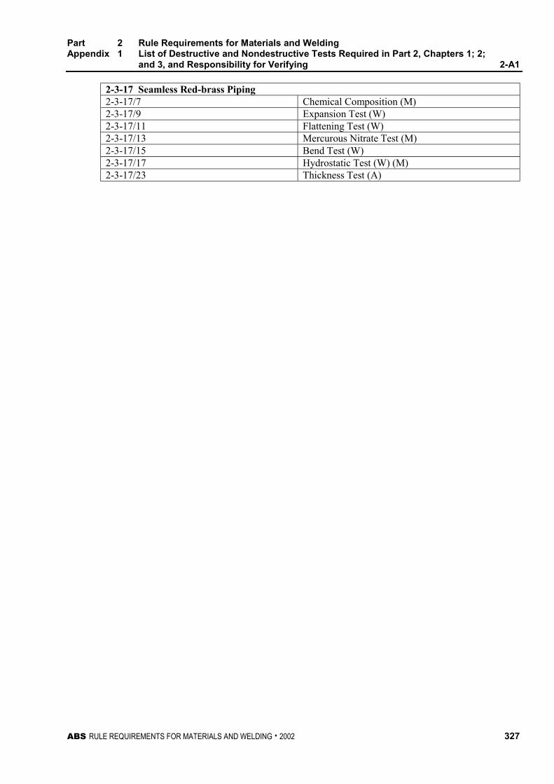
Part 2 Rule Requirements for Materials and WeldingAppendix 1 List of Destructive and Nondestructive Tests Required in Part 2, Chapters 1; 2;
and 3, and Responsibility for Verifying 2-A1
ABS RULE REQUIREMENTS FOR MATERIALS AND WELDING . 2002 327
2-3-17 Seamless Red-brass Piping2-3-17/7 Chemical Composition (M)2-3-17/9 Expansion Test (W)2-3-17/11 Flattening Test (W)2-3-17/13 Mercurous Nitrate Test (M)2-3-17/15 Bend Test (W)2-3-17/17 Hydrostatic Test (W) (M)2-3-17/23 Thickness Test (A)

ABS RULE REQUIREMENTS FOR MATERIALS AND WELDING . 2002 329
P A R T
2A P P E N D I X 2 Requirements for the Approval of
Filler Metals
CONTENTSSECTION 1 General .................................................................. 331
1 Scope ................................................................... 333
3 Grading................................................................. 333
5 Manufacturer’s Guarantee ................................... 334
7 Plant Inspection.................................................... 334
9 Test Requirements............................................... 335
11 Welding Conditions .............................................. 336
13 Chemical Analysis ................................................ 336
15 Deposited Metal Tension Test ............................. 336
17 Butt Weld Tension Test........................................ 336
19 Impact Test........................................................... 337
21 Butt Weld Bend Test ............................................ 337
23 Diffusible Hydrogen Test...................................... 338
25 Special Tests........................................................ 339
27 Licensee Approvals.............................................. 339
29 Annual Check Tests ............................................. 339
31 Quality Assurance Program ................................. 340
33 Retests ................................................................. 340
SECTION 2 Electrodes for Shielded Metal Arc Welding......... 347
1 General................................................................. 349
3 Chemical Analysis ................................................ 349
5 Deposited Metal Test Assemblies........................ 349
7 Butt Weld Test Assemblies .................................. 350
9 Fillet Weld Test Assemblies ................................. 350
11 Low Hydrogen Approval....................................... 351
13 Annual Check Tests ............................................. 352
SECTION 3 Wire-Flux Combinations for Submerged ArcWelding.................................................................. 357
1 General................................................................. 359
3 Chemical Analysis ................................................ 359
330 ABS RULE REQUIREMENTS FOR MATERIALS AND WELDING . 2002
5 Deposited Metal Test Assemblies for Multi-runTechnique............................................................. 359
7 Butt Weld Test Assemblies for Multi-runTechnique............................................................. 360
9 Butt Weld Assemblies for Two-run Technique..... 360
11 Fillet Weld Tests................................................... 361
13 Low Hydrogen Approval ....................................... 361
15 Annual Check Tests ............................................. 361
17 Multiple Electrodes ............................................... 362
19 Electroslag Welding.............................................. 362
SECTION 4 Wire and Wire Gas Combinations for GasMetal Arc Welding and Flux Cored Wiresfor Flux Cored Arc Welding ..................................367
1 General................................................................. 369
3 Chemical Analysis and Shielding GasCompositions........................................................ 369
5 Deposited Metal Test Assemblies forSemi-automatic and Automatic Testing ............... 370
7 Butt Weld Test Assemblies for Semi-automaticand Automatic Techniques................................... 370
9 Butt Weld Test Assemblies for Two-runTechnique............................................................. 371
11 Fillet Weld Tests................................................... 372
13 Low Hydrogen Approval ....................................... 372
15 Annual Check Tests ............................................. 373
17 Electrogas Welding .............................................. 373
ABS RULE REQUIREMENTS FOR MATERIALS AND WELDING . 2002 331
P A R T
2A P P E N D I X 2 Requirements for the Approval of
Filler Metals
S E C T I O N 1 General
CONTENTS1 Scope ................................................................................... 333
1.1 Condition of Approval ........................................................... 333
1.3 Approval Procedure.............................................................. 333
3 Grading ................................................................................ 333
3.1 ABS Grades.......................................................................... 333
3.3 Other Standards ................................................................... 334
3.5 Special Properties ................................................................ 334
5 Manufacturer’s Guarantee .................................................. 334
7 Plant Inspection................................................................... 334
7.1 Initial Inspection.................................................................... 334
7.3 Annual Inspection................................................................. 334
9 Test Requirements .............................................................. 335
9.1 General................................................................................. 335
9.3 Test Plate Material ............................................................... 335
11 Welding Conditions............................................................. 336
13 Chemical Analysis............................................................... 336
15 Deposited Metal Tension Test ............................................ 336
15.1 Specimen Type and Preparation.......................................... 336
15.3 Hydrogen Removal............................................................... 336
15.5 Test Requirements ............................................................... 336
17 Butt Weld Tension Test....................................................... 336
17.1 Specimen Type and Preparation.......................................... 336
17.3 Test Requirements ............................................................... 336
19 Impact Test .......................................................................... 337
19.1 Specimen Type and Preparation.......................................... 337
19.3 Test Requirements ............................................................... 337
19.5 Retest ................................................................................... 337
332 ABS RULE REQUIREMENTS FOR MATERIALS AND WELDING . 2002
21 Butt Weld Bend Test ............................................................337
21.1 Specimen Type and Preparation.......................................... 337
21.3 Test Requirements .............................................................. 337
21.5 Alternative Test for YQ-Grades ............................................ 338
23 Diffusible Hydrogen Test.....................................................338
23.1 Optional or Required Test .................................................... 338
23.3 Test Methods........................................................................ 338
23.5 Alternative Test Method ....................................................... 338
23.7 Test Requirements ............................................................... 339
25 Special Tests........................................................................339
25.1 Nondestructive Testing......................................................... 339
25.3 Additional Tests .................................................................... 339
27 Licensee Approvals .............................................................339
29 Annual Check Tests.............................................................339
29.1 Upgrading and Uprating ....................................................... 340
31 Quality Assurance Program ................................................340
33 Retests..................................................................................340
TABLE 1 Tension Test Requirements.....................................344
TABLE 2 Impact Test Requirements.......................................345
FIGURE 1 Deposited Metal Tension Test Specimen ...............341
FIGURE 2 Butt Weld Tension Test Specimen..........................341
FIGURE 3 Charpy V-Notch Impact Test Specimen..................342
FIGURE 4 Bending Elongation Test .........................................343
ABS RULE REQUIREMENTS FOR MATERIALS AND WELDING . 2002 333
P A R T
2A P P E N D I X 2 Requirements for the Approval of
Filler Metals
S E C T I O N 1 General 2 - A 2 - 1
1 Scope 2-A2-1/1
1.1 Condition of Approval 2-A2-1/1.1
The scope and conditions of classification contained in Part 1, Chapter 1 of the ABS Rules forBuilding and Classing Steel Vessels are applicable to the approval of welding filler metals insofar asthey are appropriate. Approval will be for each plant of each manufacturer carrying out its ownquality control inspection and certification.
1.3 Approval Procedure (1 October 1993) 2-A2-1/1.3
Welding filler metals intended for hull construction will be approved by ABS subject to compliancewith the requirements and test schedules as outlined herein. The requirements are based on thefollowing:
1.3.1 2-A2-1/1.3.1
Guarantee by the manufacturer of the minimum properties
1.3.2 2-A2-1/1.3.2
Inspection of the manufacturing facility by an ABS Surveyor
1.3.3 2-A2-1/1.3.3
Testing of selected samples
The test assemblies are to be prepared and tested in the presence of an ABS Surveyor. The Surveyor isto be satisfied that the manufacturer’s plant and method of filler metal production are capable ofensuring reasonable uniformity in production. The Bureau is to be notified of any alterations proposedto be made in the production of filler metals.
3 Grading 2-A2-1/3
3.1 ABS Grades (1997) 2-A2-1/3.1
Filler metals are divided into three groups based on the steel for which they are intended.
Ordinary-Strength Steel No suffix.(2-1-2/Table 1 through 2-1-2/Table 4)
Part 2 Rule Requirements for Materials and WeldingAppendix 2 Requirements for the Approval of Filler MetalsSection 1 General 2-A2-1
334 ABS RULE REQUIREMENTS FOR MATERIALS AND WELDING . 2002
Higher-Strength Steel Suffix Y and Y400(2-1-3/Table 1 through 2-1-3/Table 4)
Quenched and Tempered Steel Suffix Y420 through Y690(MODU Rules 3-1-A3/Tables 1 and 2)
Each group is further divided into multiple levels based on the strength and/or toughness, the latterbeing represented by the toughness digit 1 through 5. Exact combination of digit/suffix andcorresponding tensile and impact requirements are indicated in 2-A2-1/Table 1 and 2-A2-1/Table 2.
3.3 Other Standards 2-A2-1/3.3
At the option of the manufacturer, filler metals may be approved to a recognized standard. Therequired tests and procedures for such approval are to be in accordance with the specified standard. Inaddition, annual inspection and testing is to be carried out for continued approval.
3.5 Special Properties 2-A2-1/3.5
Welding filler metals may be approved to the manufacturer’s guaranteed minimum properties overand above or in addition to the requirements for the applicable standard. Notations indicatingguaranteed minimum properties will be added as appropriate upon verification by test.
5 Manufacturer’s Guarantee (1 Oct. 1994) 2-A2-1/5
Each plant of the manufacturer is to file an application for each filler metal indicating the following:
Specification and Grade/Classification
Electrode (wire) size and welding position
Flux or shielding gas
Current/Polarity
Recommended volts and amperage
Guaranteed all-weld-metal chemical and mechanical properties
Guaranteed hydrogen content (for H15, H10, H5, Y or Y400 designation)
7 Plant Inspection 2-A2-1/7
7.1 Initial Inspection 2-A2-1/7.1
Before marketing the product, each plant manufacturing welding filler metals submitted for ABSapproval is to be inspected by an ABS Surveyor to satisfy himself that the facilities, productionmethod, quality assurance procedures, etc., in that plant are adequate to maintain uniform andacceptable quality in production.
The Surveyor is also to satisfy himself that the testing machines are maintained in an accuratecondition and that a record of periodical calibration is maintained up to date.
Where a plant approved by ABS intends to commence production of a new product, plant inspectionmay be required for the facilities, production methods, and quality control procedures for the newproduct.
7.3 Annual Inspection (1 October 1993) 2-A2-1/7.3
Each plant manufacturing ABS approved welding filler metals is to be inspected by an ABS Surveyorat an interval of approximately 12 months. The extent of the inspection is as indicated in 2-A2-1/7.1.
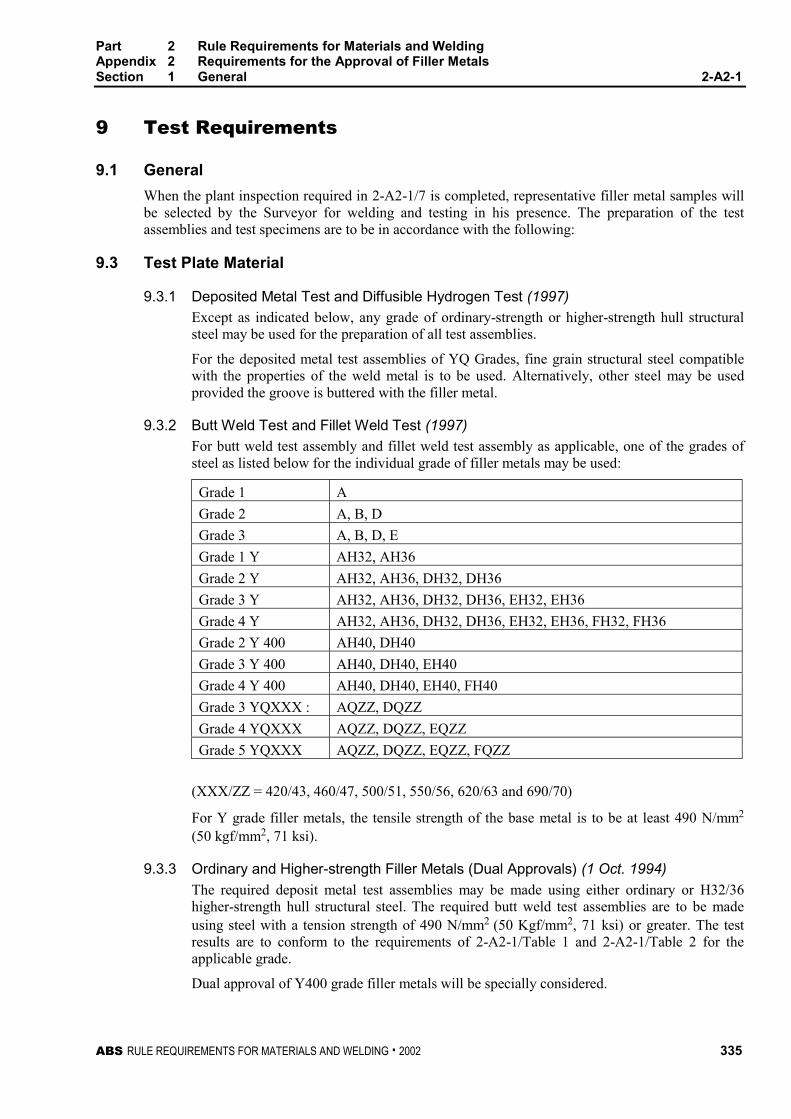
Part 2 Rule Requirements for Materials and WeldingAppendix 2 Requirements for the Approval of Filler MetalsSection 1 General 2-A2-1
ABS RULE REQUIREMENTS FOR MATERIALS AND WELDING . 2002 335
9 Test Requirements 2-A2-1/9
9.1 General 2-A2-1/9.1
When the plant inspection required in 2-A2-1/7 is completed, representative filler metal samples willbe selected by the Surveyor for welding and testing in his presence. The preparation of the testassemblies and test specimens are to be in accordance with the following:
9.3 Test Plate Material 2-A2-1/9.3
9.3.1 Deposited Metal Test and Diffusible Hydrogen Test (1997) 2-A2-1/9.3.1
Except as indicated below, any grade of ordinary-strength or higher-strength hull structuralsteel may be used for the preparation of all test assemblies.
For the deposited metal test assemblies of YQ Grades, fine grain structural steel compatiblewith the properties of the weld metal is to be used. Alternatively, other steel may be usedprovided the groove is buttered with the filler metal.
9.3.2 Butt Weld Test and Fillet Weld Test (1997) 2-A2-1/9.3.2
For butt weld test assembly and fillet weld test assembly as applicable, one of the grades ofsteel as listed below for the individual grade of filler metals may be used:
Grade 1 A
Grade 2 A, B, D
Grade 3 A, B, D, E
Grade 1 Y AH32, AH36
Grade 2 Y AH32, AH36, DH32, DH36
Grade 3 Y AH32, AH36, DH32, DH36, EH32, EH36
Grade 4 Y AH32, AH36, DH32, DH36, EH32, EH36, FH32, FH36
Grade 2 Y 400 AH40, DH40
Grade 3 Y 400 AH40, DH40, EH40
Grade 4 Y 400 AH40, DH40, EH40, FH40
Grade 3 YQXXX : AQZZ, DQZZ
Grade 4 YQXXX AQZZ, DQZZ, EQZZ
Grade 5 YQXXX AQZZ, DQZZ, EQZZ, FQZZ
(XXX/ZZ = 420/43, 460/47, 500/51, 550/56, 620/63 and 690/70)
For Y grade filler metals, the tensile strength of the base metal is to be at least 490 N/mm2
(50 kgf/mm2, 71 ksi).
9.3.3 Ordinary and Higher-strength Filler Metals (Dual Approvals) (1 Oct. 1994) 2-A2-1/9.3.3
The required deposit metal test assemblies may be made using either ordinary or H32/36higher-strength hull structural steel. The required butt weld test assemblies are to be madeusing steel with a tension strength of 490 N/mm2 (50 Kgf/mm2, 71 ksi) or greater. The testresults are to conform to the requirements of 2-A2-1/Table 1 and 2-A2-1/Table 2 for theapplicable grade.
Dual approval of Y400 grade filler metals will be specially considered.
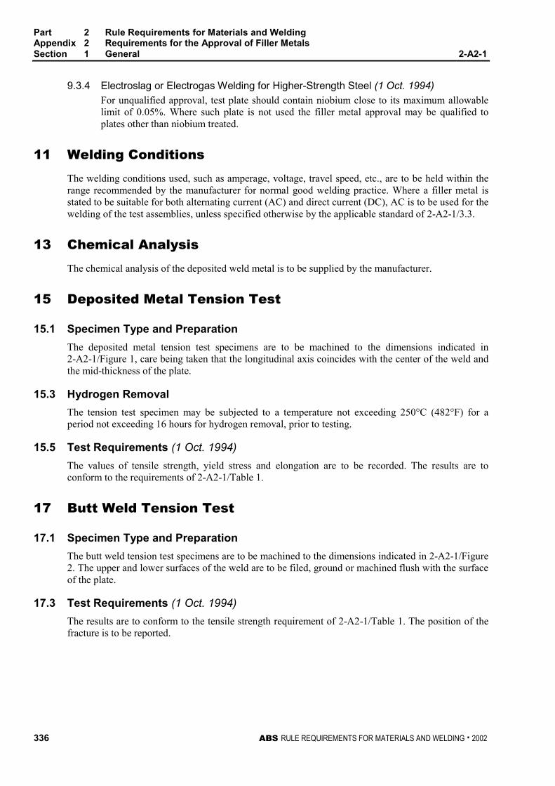
Part 2 Rule Requirements for Materials and WeldingAppendix 2 Requirements for the Approval of Filler MetalsSection 1 General 2-A2-1
336 ABS RULE REQUIREMENTS FOR MATERIALS AND WELDING . 2002
9.3.4 Electroslag or Electrogas Welding for Higher-Strength Steel (1 Oct. 1994) 2-A2-1/9.3.4
For unqualified approval, test plate should contain niobium close to its maximum allowablelimit of 0.05%. Where such plate is not used the filler metal approval may be qualified toplates other than niobium treated.
11 Welding Conditions 2-A2-1/11
The welding conditions used, such as amperage, voltage, travel speed, etc., are to be held within therange recommended by the manufacturer for normal good welding practice. Where a filler metal isstated to be suitable for both alternating current (AC) and direct current (DC), AC is to be used for thewelding of the test assemblies, unless specified otherwise by the applicable standard of 2-A2-1/3.3.
13 Chemical Analysis 2-A2-1/13
The chemical analysis of the deposited weld metal is to be supplied by the manufacturer.
15 Deposited Metal Tension Test 2-A2-1/15
15.1 Specimen Type and Preparation 2-A2-1/15.1
The deposited metal tension test specimens are to be machined to the dimensions indicated in2-A2-1/Figure 1, care being taken that the longitudinal axis coincides with the center of the weld andthe mid-thickness of the plate.
15.3 Hydrogen Removal 2-A2-1/15.3
The tension test specimen may be subjected to a temperature not exceeding 250°C (482°F) for aperiod not exceeding 16 hours for hydrogen removal, prior to testing.
15.5 Test Requirements (1 Oct. 1994) 2-A2-1/15.5
The values of tensile strength, yield stress and elongation are to be recorded. The results are toconform to the requirements of 2-A2-1/Table 1.
17 Butt Weld Tension Test 2-A2-1/17
17.1 Specimen Type and Preparation 2-A2-1/17.1
The butt weld tension test specimens are to be machined to the dimensions indicated in 2-A2-1/Figure2. The upper and lower surfaces of the weld are to be filed, ground or machined flush with the surfaceof the plate.
17.3 Test Requirements (1 Oct. 1994) 2-A2-1/17.3
The results are to conform to the tensile strength requirement of 2-A2-1/Table 1. The position of thefracture is to be reported.
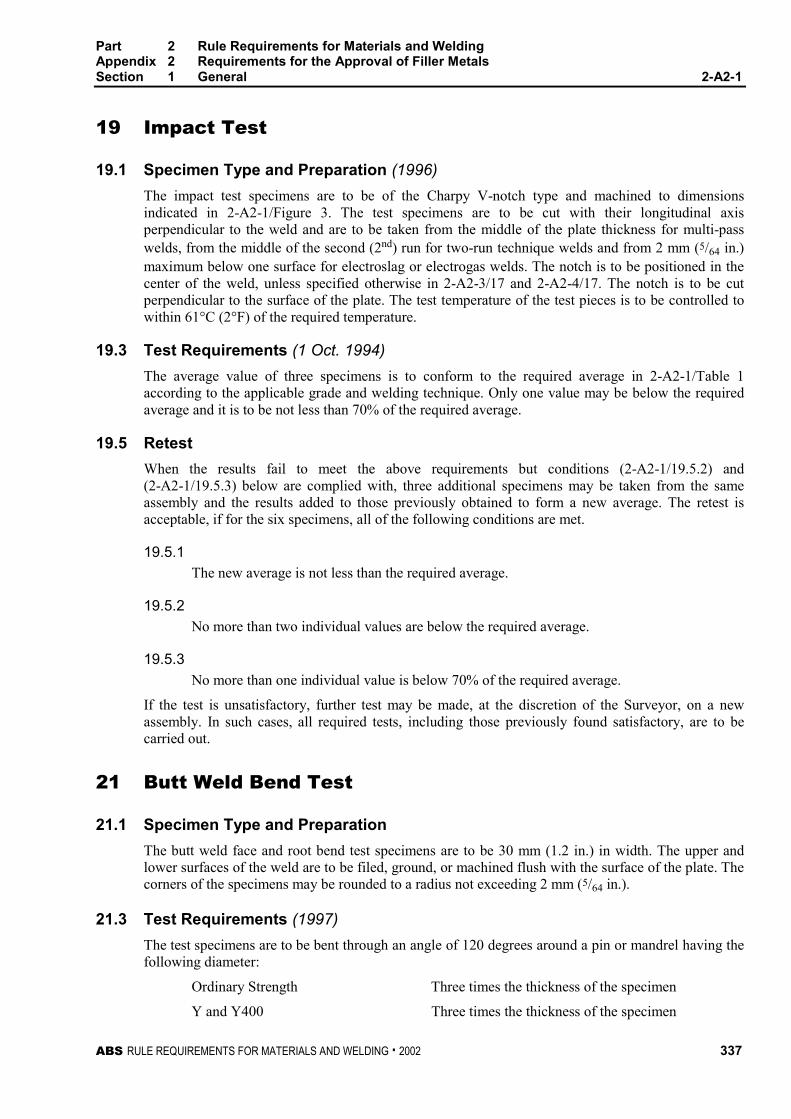
Part 2 Rule Requirements for Materials and WeldingAppendix 2 Requirements for the Approval of Filler MetalsSection 1 General 2-A2-1
ABS RULE REQUIREMENTS FOR MATERIALS AND WELDING . 2002 337
19 Impact Test 2-A2-1/19
19.1 Specimen Type and Preparation (1996) 2-A2-1/19.1
The impact test specimens are to be of the Charpy V-notch type and machined to dimensionsindicated in 2-A2-1/Figure 3. The test specimens are to be cut with their longitudinal axisperpendicular to the weld and are to be taken from the middle of the plate thickness for multi-passwelds, from the middle of the second (2nd) run for two-run technique welds and from 2 mm (5/64 in.)maximum below one surface for electroslag or electrogas welds. The notch is to be positioned in thecenter of the weld, unless specified otherwise in 2-A2-3/17 and 2-A2-4/17. The notch is to be cutperpendicular to the surface of the plate. The test temperature of the test pieces is to be controlled towithin 61°C (2°F) of the required temperature.
19.3 Test Requirements (1 Oct. 1994) 2-A2-1/19.3
The average value of three specimens is to conform to the required average in 2-A2-1/Table 1according to the applicable grade and welding technique. Only one value may be below the requiredaverage and it is to be not less than 70% of the required average.
19.5 Retest 2-A2-1/19.5
When the results fail to meet the above requirements but conditions (2-A2-1/19.5.2) and(2-A2-1/19.5.3) below are complied with, three additional specimens may be taken from the sameassembly and the results added to those previously obtained to form a new average. The retest isacceptable, if for the six specimens, all of the following conditions are met.
19.5.1 2-A2-1/19.5.1
The new average is not less than the required average.
19.5.2 2-A2-1/19.5.2
No more than two individual values are below the required average.
19.5.3 2-A2-1/19.5.3
No more than one individual value is below 70% of the required average.
If the test is unsatisfactory, further test may be made, at the discretion of the Surveyor, on a newassembly. In such cases, all required tests, including those previously found satisfactory, are to becarried out.
21 Butt Weld Bend Test 2-A2-1/21
21.1 Specimen Type and Preparation 2-A2-1/21.1
The butt weld face and root bend test specimens are to be 30 mm (1.2 in.) in width. The upper andlower surfaces of the weld are to be filed, ground, or machined flush with the surface of the plate. Thecorners of the specimens may be rounded to a radius not exceeding 2 mm (5/64 in.).
21.3 Test Requirements (1997) 2-A2-1/21.3
The test specimens are to be bent through an angle of 120 degrees around a pin or mandrel having thefollowing diameter:
Ordinary Strength Three times the thickness of the specimen
Y and Y400 Three times the thickness of the specimen
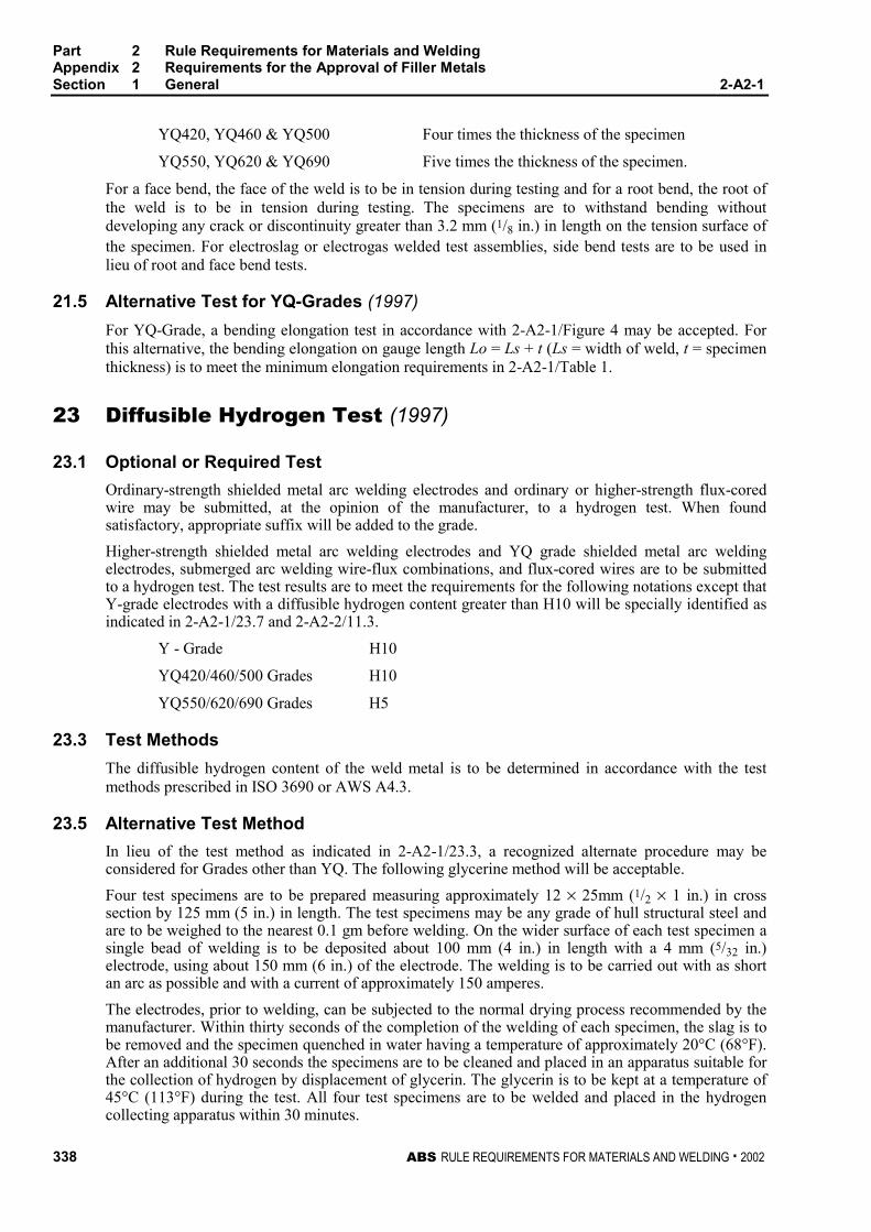
Part 2 Rule Requirements for Materials and WeldingAppendix 2 Requirements for the Approval of Filler MetalsSection 1 General 2-A2-1
338 ABS RULE REQUIREMENTS FOR MATERIALS AND WELDING . 2002
YQ420, YQ460 & YQ500 Four times the thickness of the specimen
YQ550, YQ620 & YQ690 Five times the thickness of the specimen.
For a face bend, the face of the weld is to be in tension during testing and for a root bend, the root ofthe weld is to be in tension during testing. The specimens are to withstand bending withoutdeveloping any crack or discontinuity greater than 3.2 mm (1/8 in.) in length on the tension surface ofthe specimen. For electroslag or electrogas welded test assemblies, side bend tests are to be used inlieu of root and face bend tests.
21.5 Alternative Test for YQ-Grades (1997) 2-A2-1/21.5
For YQ-Grade, a bending elongation test in accordance with 2-A2-1/Figure 4 may be accepted. Forthis alternative, the bending elongation on gauge length Lo = Ls + t (Ls = width of weld, t = specimenthickness) is to meet the minimum elongation requirements in 2-A2-1/Table 1.
23 Diffusible Hydrogen Test (1997) 2-A2-1/23
23.1 Optional or Required Test 2-A2-2/23.1
Ordinary-strength shielded metal arc welding electrodes and ordinary or higher-strength flux-coredwire may be submitted, at the opinion of the manufacturer, to a hydrogen test. When foundsatisfactory, appropriate suffix will be added to the grade.
Higher-strength shielded metal arc welding electrodes and YQ grade shielded metal arc weldingelectrodes, submerged arc welding wire-flux combinations, and flux-cored wires are to be submittedto a hydrogen test. The test results are to meet the requirements for the following notations except thatY-grade electrodes with a diffusible hydrogen content greater than H10 will be specially identified asindicated in 2-A2-1/23.7 and 2-A2-2/11.3.
Y - Grade H10
YQ420/460/500 Grades H10
YQ550/620/690 Grades H5
23.3 Test Methods 2-A2-1/23.3
The diffusible hydrogen content of the weld metal is to be determined in accordance with the testmethods prescribed in ISO 3690 or AWS A4.3.
23.5 Alternative Test Method 2-A2-1/23.5
In lieu of the test method as indicated in 2-A2-1/23.3, a recognized alternate procedure may beconsidered for Grades other than YQ. The following glycerine method will be acceptable.
Four test specimens are to be prepared measuring approximately 12 × 25mm (1/2 × 1 in.) in crosssection by 125 mm (5 in.) in length. The test specimens may be any grade of hull structural steel andare to be weighed to the nearest 0.1 gm before welding. On the wider surface of each test specimen asingle bead of welding is to be deposited about 100 mm (4 in.) in length with a 4 mm (5/32 in.)electrode, using about 150 mm (6 in.) of the electrode. The welding is to be carried out with as shortan arc as possible and with a current of approximately 150 amperes.
The electrodes, prior to welding, can be subjected to the normal drying process recommended by themanufacturer. Within thirty seconds of the completion of the welding of each specimen, the slag is tobe removed and the specimen quenched in water having a temperature of approximately 20°C (68°F).After an additional 30 seconds the specimens are to be cleaned and placed in an apparatus suitable forthe collection of hydrogen by displacement of glycerin. The glycerin is to be kept at a temperature of45°C (113°F) during the test. All four test specimens are to be welded and placed in the hydrogencollecting apparatus within 30 minutes.
Part 2 Rule Requirements for Materials and WeldingAppendix 2 Requirements for the Approval of Filler MetalsSection 1 General 2-A2-1
ABS RULE REQUIREMENTS FOR MATERIALS AND WELDING . 2002 339
The specimens are to be kept immersed in the glycerin for a period of 48 hours and after removal areto be cleaned in water or suitable solvent, dried, and weighed to the nearest 0.1 gram to determine theamount of weld deposited. The amount of gas evolved is to be measured to the nearest 0.01 ml andcorrected for temperature and pressure to 0°C (32°F) and 760 mm (30 in.) Hg.
23.7 Test Requirements 2-A2-1/23.7
The individual and average diffusible hydrogen content of the four specimens is to be reported and theaverage value in milliliters (ml) per 100 grams is not to exceed the following:
Suffix AWS A4.3 or ISO 3690 Glycerin Suffix Method
H15 15 10
H10 10 5
H5 5 -
All higher-tensile strength steel grade electrodes with an average value above the H10 requirementwill be identified ‘‘non-low hydrogen electrode, requires special approval for use with higher-strengthsteel’’.
25 Special Tests 2-A2-1/25
25.1 Nondestructive Testing 2-A2-1/25.1
The welded assemblies may be subjected to radiographic or ultrasonic examination to ascertain anydiscontinuities in the weld prior to testing.
25.3 Additional Tests 2-A2-1/25.3
This Bureau may specify any additional tests as may be necessary.
27 Licensee Approvals 2-A2-1/27
When a filler metal is manufactured in more than one plant of the same company or by a licenseecompany, a complete set of approval tests is to be carried out on the samples selected from productsof the main plant. In the other plants a reduced test program equivalent to annual check tests plusdiffusible hydrogen test may be permitted, if the main plant and licensee can certify that the materialsused, the fabrication process and final products by the licensee are identical with those in the mainplant. An affidavit from both the main plant and licensee are to be submitted attesting to this fact.However, should there be any doubt, a complete test series may be required.
29 Annual Check Tests (1996) 2-A2-1/29
The facilities and associated quality control systems where approved filler metals are manufacturedare subject to an annual inspection in accordance with 2-A2-1/7.3. Annual check tests are to beconducted in accordance with 2-A2-2/13; 2-A2-3/15 and 2-A2-3/19.3; 2-A2-4/15; or 2-A2-4/17.3whichever is applicable for the welding process. The test data is to conform to the applicablerequirements.
Part 2 Rule Requirements for Materials and WeldingAppendix 2 Requirements for the Approval of Filler MetalsSection 1 General 2-A2-1
340 ABS RULE REQUIREMENTS FOR MATERIALS AND WELDING . 2002
29.1 Upgrading and Uprating (1 October 1993) 2-A2-1/29.1
Upgrading and uprating of welding filler metals will be considered at the manufacturer’s request.Generally, tests from butt weld assemblies and where applicable diffusible hydrogen test will berequired in addition to the normal annual check tests. The data is to conform to the applicablerequirements.
29.1.1 Upgrading 2-A2-1/29.1.1
Upgrading refers to notch toughness and consequently Charpy V-notch impact tests arerequired from butt weld and deposited metal test assemblies. The impact tests are to beconducted at the upgraded temperature.
29.1.2 Uprating 2-A2-1/29.1.2
Uprating refers to the extension of approval to also cover the welding of higher-strength steels(dual approvals). For this purpose butt-weld tests are to be carried out as required in2-A2-1/9.3.3.
31 Quality Assurance Program (1 October 1993) 2-A2-1/31
Where an ABS approved Quality Assurance Program is maintained and periodical audit is carried outsatisfactorily, the attendance of the Surveyor at the annual check test may be waived provided theresults of annual check test are examined by the Surveyor and found in accordance with the applicablerequirements.
33 Retests 2-A2-1/33
Where the result of a tension or bend test does not comply with the requirements, two test specimensof the same type are to be prepared and tested from the original test assembly, if possible. A newassembly may be prepared using welding consumables from the same batch. The new assembly is tobe made with the same procedure (particularly number of runs) as the original assembly. See2-A2-1/19.5 for impact retests.

Part 2 Rule Requirements for Materials and WeldingAppendix 2 Requirements for the Approval of Filler MetalsSection 1 General 2-A2-1
ABS RULE REQUIREMENTS FOR MATERIALS AND WELDING . 2002 341
FIGURE 1Deposited Metal Tension Test Specimen
50 mm (2.00 in.)
60 mm (2.40 in.)
70 mm (2.80 in.) min.
10 mm (0.40 in.)
5 mm (0.20 in.) min. radius
12 mm (0.5 in.) min.To suit grips
Gauge length
Parallel length
FIGURE 2Butt Weld Tension Test Specimen
Width to suit grips
50 mm (2.00 in.) radius
Parallel length - width of weldplus 6mm (0.25 in.) each side
6 mm (0.25 in.)6 mm (0.25 in.)
30 mm (1.20 in.)
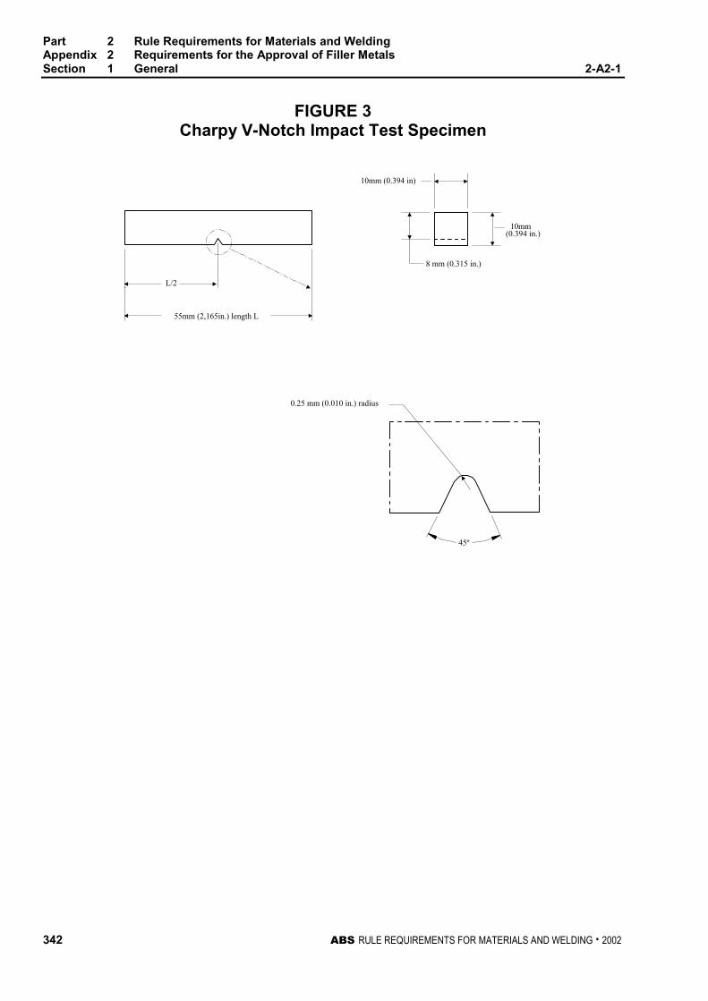
Part 2 Rule Requirements for Materials and WeldingAppendix 2 Requirements for the Approval of Filler MetalsSection 1 General 2-A2-1
342 ABS RULE REQUIREMENTS FOR MATERIALS AND WELDING . 2002
FIGURE 3Charpy V-Notch Impact Test Specimen
10mm(0.394 in.)
0.25 mm (0.010 in.) radius
8 mm (0.315 in.)
10mm (0.394 in)
L/2
55mm (2,165in.) length L
45º
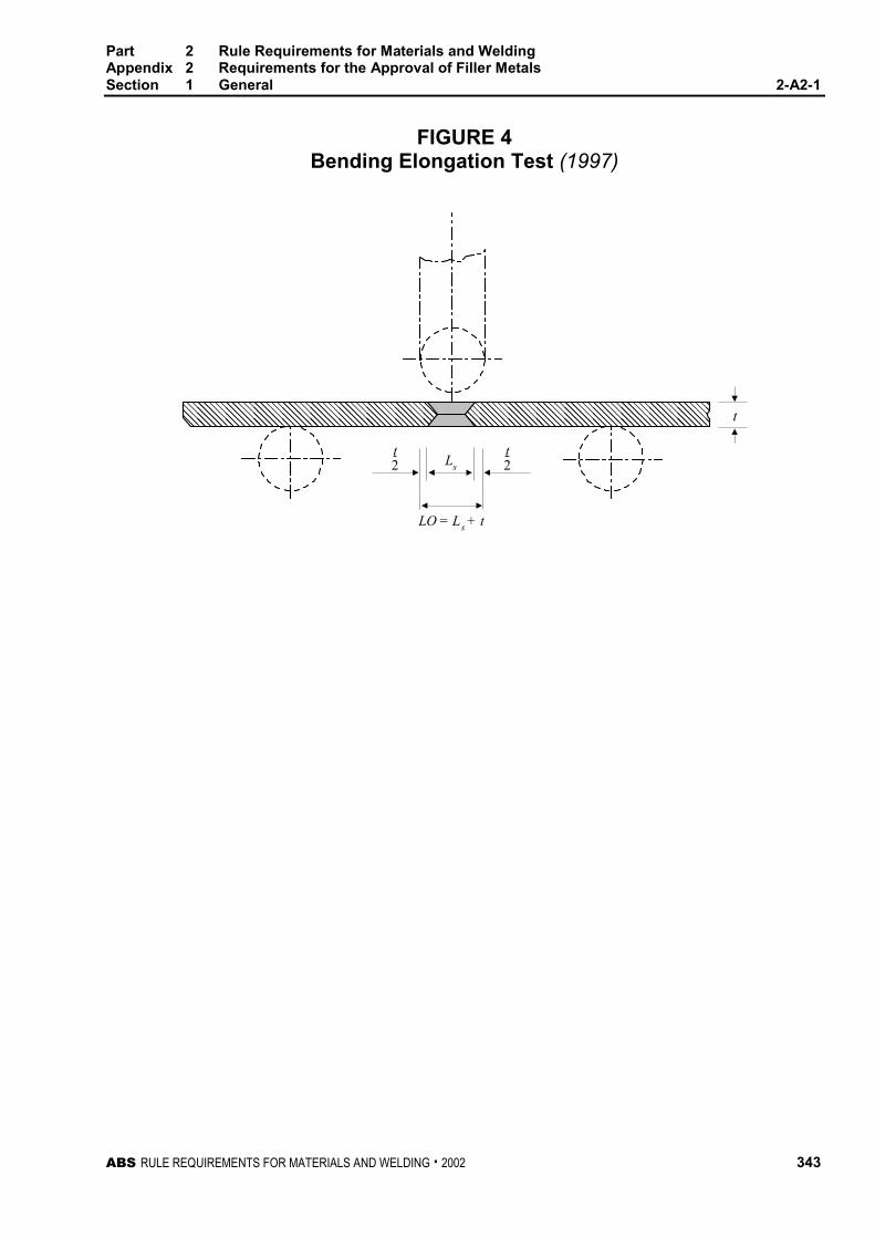
Part 2 Rule Requirements for Materials and WeldingAppendix 2 Requirements for the Approval of Filler MetalsSection 1 General 2-A2-1
ABS RULE REQUIREMENTS FOR MATERIALS AND WELDING . 2002 343
FIGURE 4Bending Elongation Test (1997)
����������������������������������������
t2
t2Ls
LO = Ls + t
t
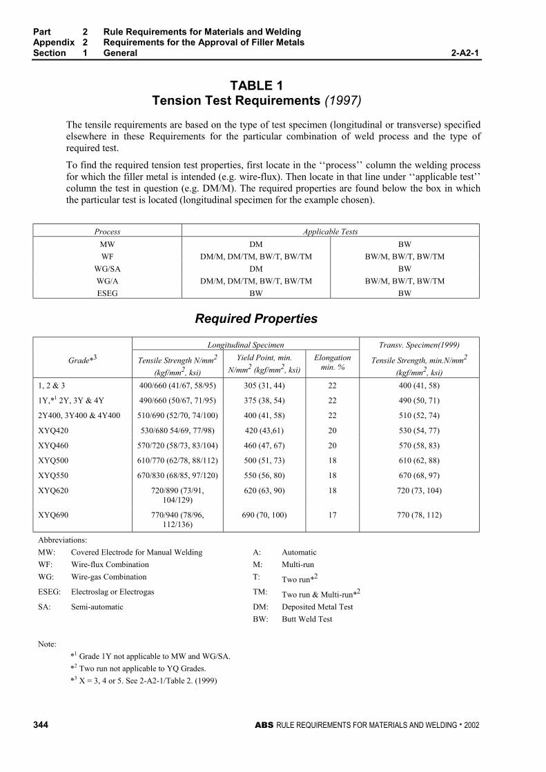
Part 2 Rule Requirements for Materials and WeldingAppendix 2 Requirements for the Approval of Filler MetalsSection 1 General 2-A2-1
344 ABS RULE REQUIREMENTS FOR MATERIALS AND WELDING . 2002
TABLE 1Tension Test Requirements (1997)
The tensile requirements are based on the type of test specimen (longitudinal or transverse) specifiedelsewhere in these Requirements for the particular combination of weld process and the type ofrequired test.
To find the required tension test properties, first locate in the ‘‘process’’ column the welding processfor which the filler metal is intended (e.g. wire-flux). Then locate in that line under ‘‘applicable test’’column the test in question (e.g. DM/M). The required properties are found below the box in whichthe particular test is located (longitudinal specimen for the example chosen).
Process Applicable Tests
MW DM BW
WF DM/M, DM/TM, BW/T, BW/TM BW/M, BW/T, BW/TM
WG/SA DM BW
WG/A DM/M, DM/TM, BW/T, BW/TM BW/M, BW/T, BW/TM
ESEG BW BW
Required Properties
Longitudinal Specimen Transv. Specimen(1999)
Grade*3 Tensile Strength N/mm2
(kgf/mm2, ksi)
Yield Point, min.
N/mm2 (kgf/mm2, ksi)
Elongationmin. %
Tensile Strength, min.N/mm2
(kgf/mm2, ksi)
1, 2 & 3 400/660 (41/67, 58/95) 305 (31, 44) 22 400 (41, 58)
1Y,*1 2Y, 3Y & 4Y 490/660 (50/67, 71/95) 375 (38, 54) 22 490 (50, 71)
2Y400, 3Y400 & 4Y400 510/690 (52/70, 74/100) 400 (41, 58) 22 510 (52, 74)
XYQ420 530/680 54/69, 77/98) 420 (43,61) 20 530 (54, 77)
XYQ460 570/720 (58/73, 83/104) 460 (47, 67) 20 570 (58, 83)
XYQ500 610/770 (62/78, 88/112) 500 (51, 73) 18 610 (62, 88)
XYQ550 670/830 (68/85, 97/120) 550 (56, 80) 18 670 (68, 97)
XYQ620 720/890 (73/91,104/129)
620 (63, 90) 18 720 (73, 104)
XYQ690 770/940 (78/96,112/136)
690 (70, 100) 17 770 (78, 112)
Abbreviations:
MW: Covered Electrode for Manual Welding A: Automatic
WF: Wire-flux Combination M: Multi-run
WG: Wire-gas Combination T: Two run*2
ESEG: Electroslag or Electrogas TM: Two run & Multi-run*2
SA: Semi-automatic DM: Deposited Metal Test
BW: Butt Weld Test
Note:
*1 Grade 1Y not applicable to MW and WG/SA.
*2 Two run not applicable to YQ Grades.
*3 X = 3, 4 or 5. See 2-A2-1/Table 2. (1999)
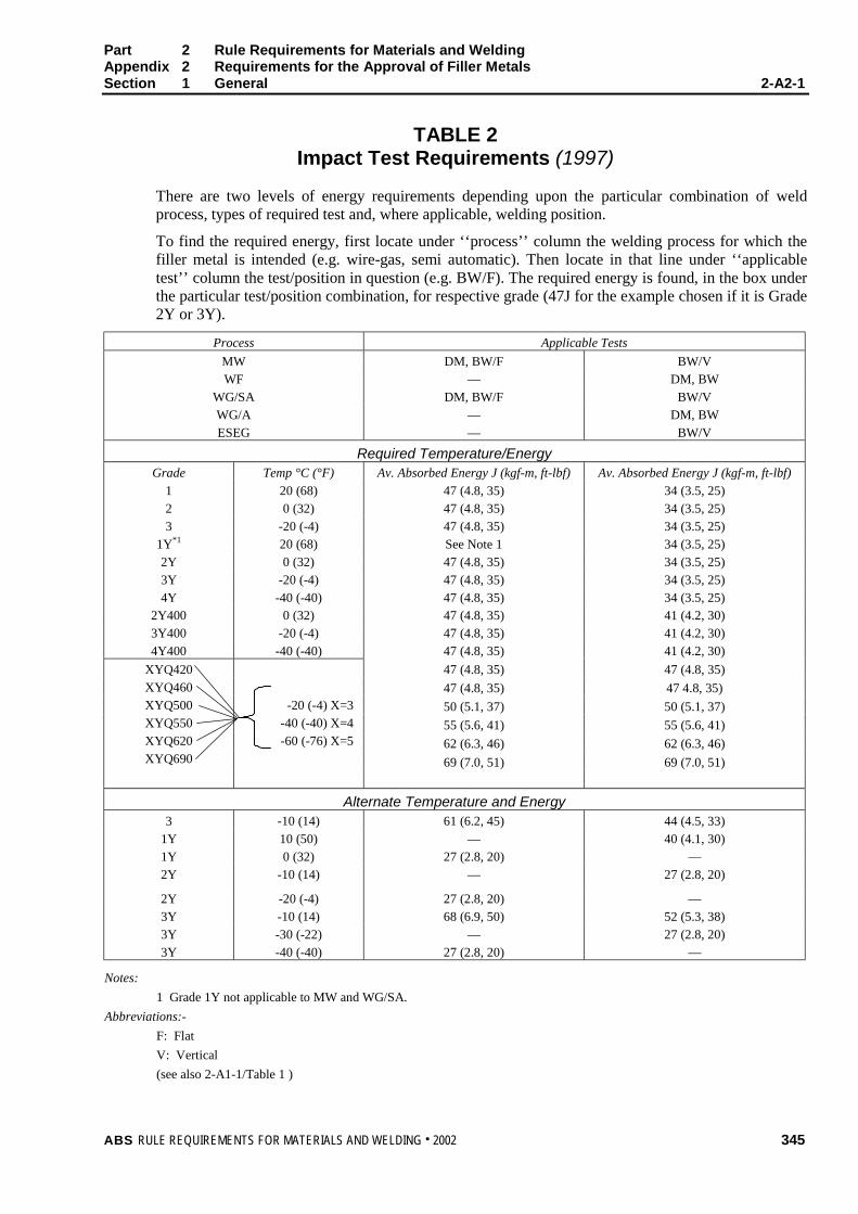
Part 2 Rule Requirements for Materials and WeldingAppendix 2 Requirements for the Approval of Filler MetalsSection 1 General 2-A2-1
ABS RULE REQUIREMENTS FOR MATERIALS AND WELDING . 2002 345
TABLE 2Impact Test Requirements (1997)
There are two levels of energy requirements depending upon the particular combination of weldprocess, types of required test and, where applicable, welding position.
To find the required energy, first locate under ‘‘process’’ column the welding process for which thefiller metal is intended (e.g. wire-gas, semi automatic). Then locate in that line under ‘‘applicabletest’’ column the test/position in question (e.g. BW/F). The required energy is found, in the box underthe particular test/position combination, for respective grade (47J for the example chosen if it is Grade2Y or 3Y).
Process Applicable Tests
MW DM, BW/F BW/V
WF — DM, BW
WG/SA DM, BW/F BW/V
WG/A — DM, BW
ESEG — BW/V
Required Temperature/EnergyGrade Temp °C (°F) Av. Absorbed Energy J (kgf-m, ft-lbf) Av. Absorbed Energy J (kgf-m, ft-lbf)
1 20 (68) 47 (4.8, 35) 34 (3.5, 25)
2 0 (32) 47 (4.8, 35) 34 (3.5, 25)
3 -20 (-4) 47 (4.8, 35) 34 (3.5, 25)
1Y*1 20 (68) See Note 1 34 (3.5, 25)
2Y 0 (32) 47 (4.8, 35) 34 (3.5, 25)
3Y -20 (-4) 47 (4.8, 35) 34 (3.5, 25)
4Y -40 (-40) 47 (4.8, 35) 34 (3.5, 25)2Y400 0 (32) 47 (4.8, 35) 41 (4.2, 30)
3Y400 -20 (-4) 47 (4.8, 35) 41 (4.2, 30)
4Y400 -40 (-40) 47 (4.8, 35) 41 (4.2, 30)
47 (4.8, 35) 47 (4.8, 35)
47 (4.8, 35) 47 4.8, 35)
50 (5.1, 37) 50 (5.1, 37)
55 (5.6, 41) 55 (5.6, 41)
62 (6.3, 46) 62 (6.3, 46)
69 (7.0, 51) 69 (7.0, 51)
XYQ420
XYQ460
XYQ500
XYQ550
XYQ620
XYQ690
-20 (-4) X=3
-40 (-40) X=4
-60 (-76) X=5
Alternate Temperature and Energy3 -10 (14) 61 (6.2, 45) 44 (4.5, 33)
1Y 10 (50) — 40 (4.1, 30)
1Y 0 (32) 27 (2.8, 20) —
2Y -10 (14) — 27 (2.8, 20)
2Y -20 (-4) 27 (2.8, 20) —
3Y -10 (14) 68 (6.9, 50) 52 (5.3, 38)
3Y -30 (-22) — 27 (2.8, 20)
3Y -40 (-40) 27 (2.8, 20) —
Notes:
1 Grade 1Y not applicable to MW and WG/SA.
Abbreviations:-
F: Flat
V: Vertical
(see also 2-A1-1/Table 1 )

ABS RULE REQUIREMENTS FOR MATERIALS AND WELDING . 2002 347
P A R T
2A P P E N D I X 2 Requirements for the Approval of
Filler Metals
S E C T I O N 2 Electrodes for Shielded Metal ArcWelding
CONTENTS1 General................................................................................. 349
3 Chemical Analysis............................................................... 349
5 Deposited Metal Test Assemblies ...................................... 349
5.1 Test Assembly...................................................................... 349
5.3 Test Specimens.................................................................... 349
7 Butt Weld Test Assemblies................................................. 350
7.1 Test Assemblies ................................................................... 350
7.3 Welding Procedure............................................................... 350
7.5 Test Specimens.................................................................... 350
9 Fillet Weld Test Assemblies ............................................... 350
9.1 General................................................................................. 350
9.3 Test Assemblies ................................................................... 351
9.5 Welding Procedure............................................................... 351
9.7 Test Specimens.................................................................... 351
11 Low Hydrogen Approval ..................................................... 351
11.1 Ordinary-Strength Filler Metals ............................................ 351
11.3 Higher-Strength Filler Metals................................................ 352
11.5 YQ Grade Filler Metals......................................................... 352
13 Annual Check Tests ............................................................ 352
13.1 General................................................................................. 352
13.3 Upgrading and Uprating ....................................................... 352

348 ABS RULE REQUIREMENTS FOR MATERIALS AND WELDING . 2002
FIGURE 1 Deposited-Metal Test Assembly for Manualand Gas-Metal Arc Welding ....................................353
FIGURE 2 Butt-Weld Test Assembly for Manual andGas-Metal Arc Welding ............................................354
FIGURE 3 Fillet-Weld Test Assembly .......................................355
FIGURE 4 Fillet Weld Hardness Test Locations ......................355
ABS RULE REQUIREMENTS FOR MATERIALS AND WELDING . 2002 349
P A R T
2A P P E N D I X 2 Requirements for the Approval of
Filler Metals
S E C T I O N 2 Electrodes for Shielded Metal ArcWelding 2 - A 2 - 2
1 General 2-A2-2/1
The annual check test shall consist of two deposited metal test assemblies welded and tested inaccordance with 2-A2-2/5.
3 Chemical Analysis 2-A2-2/3
The chemical analysis of the deposited weld metal is to be supplied by the manufacturer.
5 Deposited Metal Test Assemblies 2-A2-2/5
5.1 Test Assembly 2-A2-2/5.1
Two deposited metal test assemblies as indicated in 2-A2-2/Figure 1 are to be welded in the flatposition, one using 4 mm (5/32 in.) electrodes or the smallest size manufactured whichever is greaterand the other using the largest size manufactured. If an electrode is produced in one size only or if thelargest size produced is less than 4 mm (5/32 in.), one test assembly is sufficient. The weld metal is tobe deposited in single or multi-run layers according to normal practice, and the direction of depositionof each layer is to alternate from each end of the plate, each run of weld metal being not less than2 mm (5/64 in.) and not more than 4 mm (5/32 in.) thick. Between each run the assembly is to be left instill air until it has cooled to 250°C (482°F), the temperature being taken in the center of the weld, onthe surface of the seam. After being welded the test assemblies are not to be subjected to any heattreatment, except hydrogen removal as permitted in 2-A2-1/15.3.
5.3 Test Specimens (1 Oct. 1994) 2-A2-2/5.3
One tension and one set of three impact specimens are to be prepared from each deposited metal testassembly as indicated in 2-A2-2/Figure 1 and the results are to conform to the requirements of2-A2-1/Table 1 and 2-A2-1/Table 2 for the applicable grade and welding technique.
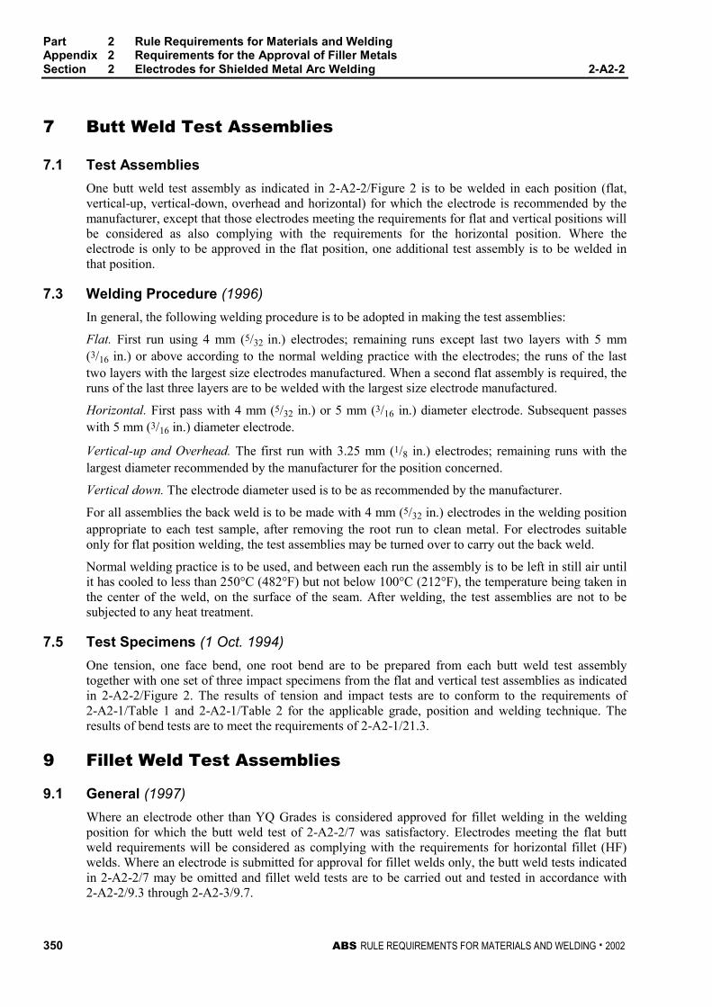
Part 2 Rule Requirements for Materials and WeldingAppendix 2 Requirements for the Approval of Filler MetalsSection 2 Electrodes for Shielded Metal Arc Welding 2-A2-2
350 ABS RULE REQUIREMENTS FOR MATERIALS AND WELDING . 2002
7 Butt Weld Test Assemblies 2-A2-2/7
7.1 Test Assemblies 2-A2-2/7.1
One butt weld test assembly as indicated in 2-A2-2/Figure 2 is to be welded in each position (flat,vertical-up, vertical-down, overhead and horizontal) for which the electrode is recommended by themanufacturer, except that those electrodes meeting the requirements for flat and vertical positions willbe considered as also complying with the requirements for the horizontal position. Where theelectrode is only to be approved in the flat position, one additional test assembly is to be welded inthat position.
7.3 Welding Procedure (1996) 2-A2-2/7.3
In general, the following welding procedure is to be adopted in making the test assemblies:
Flat. First run using 4 mm (5/32 in.) electrodes; remaining runs except last two layers with 5 mm(3/16 in.) or above according to the normal welding practice with the electrodes; the runs of the lasttwo layers with the largest size electrodes manufactured. When a second flat assembly is required, theruns of the last three layers are to be welded with the largest size electrode manufactured.
Horizontal. First pass with 4 mm (5/32 in.) or 5 mm (3/16 in.) diameter electrode. Subsequent passeswith 5 mm (3/16 in.) diameter electrode.
Vertical-up and Overhead. The first run with 3.25 mm (1/8 in.) electrodes; remaining runs with thelargest diameter recommended by the manufacturer for the position concerned.
Vertical down. The electrode diameter used is to be as recommended by the manufacturer.
For all assemblies the back weld is to be made with 4 mm (5/32 in.) electrodes in the welding positionappropriate to each test sample, after removing the root run to clean metal. For electrodes suitableonly for flat position welding, the test assemblies may be turned over to carry out the back weld.
Normal welding practice is to be used, and between each run the assembly is to be left in still air untilit has cooled to less than 250°C (482°F) but not below 100°C (212°F), the temperature being taken inthe center of the weld, on the surface of the seam. After welding, the test assemblies are not to besubjected to any heat treatment.
7.5 Test Specimens (1 Oct. 1994) 2-A2-2/7.5
One tension, one face bend, one root bend are to be prepared from each butt weld test assemblytogether with one set of three impact specimens from the flat and vertical test assemblies as indicatedin 2-A2-2/Figure 2. The results of tension and impact tests are to conform to the requirements of2-A2-1/Table 1 and 2-A2-1/Table 2 for the applicable grade, position and welding technique. Theresults of bend tests are to meet the requirements of 2-A2-1/21.3.
9 Fillet Weld Test Assemblies 2-A2-2/9
9.1 General (1997) 2-A2-2/9.1
Where an electrode other than YQ Grades is considered approved for fillet welding in the weldingposition for which the butt weld test of 2-A2-2/7 was satisfactory. Electrodes meeting the flat buttweld requirements will be considered as complying with the requirements for horizontal fillet (HF)welds. Where an electrode is submitted for approval for fillet welds only, the butt weld tests indicatedin 2-A2-2/7 may be omitted and fillet weld tests are to be carried out and tested in accordance with2-A2-2/9.3 through 2-A2-3/9.7.
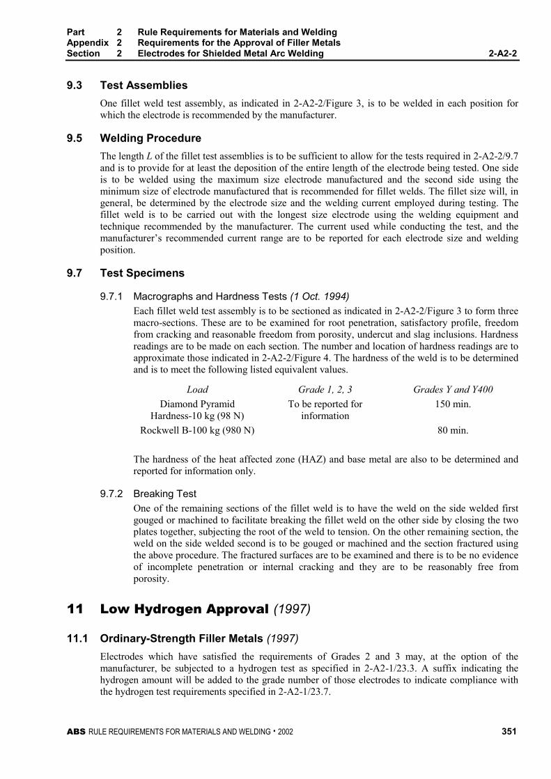
Part 2 Rule Requirements for Materials and WeldingAppendix 2 Requirements for the Approval of Filler MetalsSection 2 Electrodes for Shielded Metal Arc Welding 2-A2-2
ABS RULE REQUIREMENTS FOR MATERIALS AND WELDING . 2002 351
9.3 Test Assemblies 2-A2-2/9.3
One fillet weld test assembly, as indicated in 2-A2-2/Figure 3, is to be welded in each position forwhich the electrode is recommended by the manufacturer.
9.5 Welding Procedure 2-A2-2/9.5
The length L of the fillet test assemblies is to be sufficient to allow for the tests required in 2-A2-2/9.7and is to provide for at least the deposition of the entire length of the electrode being tested. One sideis to be welded using the maximum size electrode manufactured and the second side using theminimum size of electrode manufactured that is recommended for fillet welds. The fillet size will, ingeneral, be determined by the electrode size and the welding current employed during testing. Thefillet weld is to be carried out with the longest size electrode using the welding equipment andtechnique recommended by the manufacturer. The current used while conducting the test, and themanufacturer’s recommended current range are to be reported for each electrode size and weldingposition.
9.7 Test Specimens 2-A2-2/9.7
9.7.1 Macrographs and Hardness Tests (1 Oct. 1994) 2-A2-2/9.7.1
Each fillet weld test assembly is to be sectioned as indicated in 2-A2-2/Figure 3 to form threemacro-sections. These are to be examined for root penetration, satisfactory profile, freedomfrom cracking and reasonable freedom from porosity, undercut and slag inclusions. Hardnessreadings are to be made on each section. The number and location of hardness readings are toapproximate those indicated in 2-A2-2/Figure 4. The hardness of the weld is to be determinedand is to meet the following listed equivalent values.
Load Grade 1, 2, 3 Grades Y and Y400
Diamond PyramidHardness-10 kg (98 N)
To be reported forinformation
150 min.
Rockwell B-100 kg (980 N) 80 min.
The hardness of the heat affected zone (HAZ) and base metal are also to be determined andreported for information only.
9.7.2 Breaking Test 2-A2-2/9.7.2
One of the remaining sections of the fillet weld is to have the weld on the side welded firstgouged or machined to facilitate breaking the fillet weld on the other side by closing the twoplates together, subjecting the root of the weld to tension. On the other remaining section, theweld on the side welded second is to be gouged or machined and the section fractured usingthe above procedure. The fractured surfaces are to be examined and there is to be no evidenceof incomplete penetration or internal cracking and they are to be reasonably free fromporosity.
11 Low Hydrogen Approval (1997) 2-A2-2/11
11.1 Ordinary-Strength Filler Metals (1997) 2-A2-2/11.1
Electrodes which have satisfied the requirements of Grades 2 and 3 may, at the option of themanufacturer, be subjected to a hydrogen test as specified in 2-A2-1/23.3. A suffix indicating thehydrogen amount will be added to the grade number of those electrodes to indicate compliance withthe hydrogen test requirements specified in 2-A2-1/23.7.
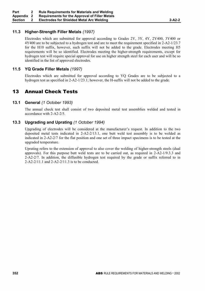
Part 2 Rule Requirements for Materials and WeldingAppendix 2 Requirements for the Approval of Filler MetalsSection 2 Electrodes for Shielded Metal Arc Welding 2-A2-2
352 ABS RULE REQUIREMENTS FOR MATERIALS AND WELDING . 2002
11.3 Higher-Strength Filler Metals (1997) 2-A2-2/11.3
Electrodes which are submitted for approval according to Grades 2Y, 3Y, 4Y, 2Y400, 3Y400 or4Y400 are to be subjected to a hydrogen test and are to meet the requirement specified in 2-A2-1/23.7for the H10 suffix, however, such suffix will not be added to the grade. Electrodes meeting H5requirements will be so identified. Electrodes meeting the higher-strength requirements, except forhydrogen test will require special approval for use on higher strength steel for each user and will be soidentified in the list of approved electrodes.
11.5 YQ Grade Filler Metals (1997) 2-A2-2/11.5
Electrodes which are submitted for approval according to YQ Grades are to be subjected to ahydrogen test as specified in 2-A2-1/23.1; however, the H-suffix will not be added to the grade.
13 Annual Check Tests 2-A2-2/13
13.1 General (1 October 1993) 2-A2-2/13.1
The annual check test shall consist of two deposited metal test assemblies welded and tested inaccordance with 2-A2-2/5.
13.3 Upgrading and Uprating (1 October 1994) 2-A2-2/13.3
Upgrading of electrodes will be considered at the manufacturer’s request. In addition to the twodeposited metal tests indicated in 2-A2-2/13.1, one butt weld test assembly is to be welded asindicated in 2-A2-2/7 for the flat position and one set of three impact specimens is to be tested at theupgraded temperature.
Uprating refers to the extension of approval to also cover the welding of higher-strength steels (dualapprovals). For this purpose butt weld tests are to be carried out, as required in 2-A2-1/9.3.3 and2-A2-2/7. In addition, the diffusible hydrogen test required by the grade or suffix referred to in2-A2-2/11.1 and 2-A2-2/11.3 is to be conducted.
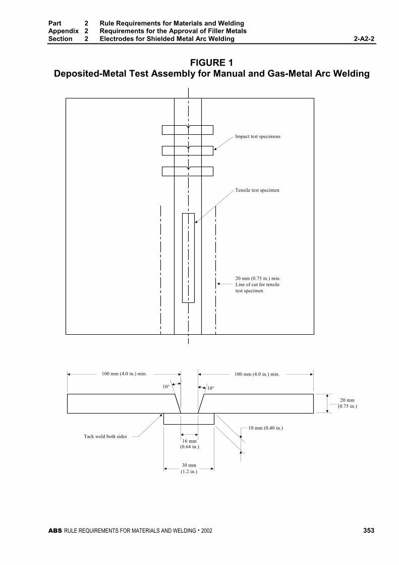
Part 2 Rule Requirements for Materials and WeldingAppendix 2 Requirements for the Approval of Filler MetalsSection 2 Electrodes for Shielded Metal Arc Welding 2-A2-2
ABS RULE REQUIREMENTS FOR MATERIALS AND WELDING . 2002 353
FIGURE 1Deposited-Metal Test Assembly for Manual and Gas-Metal Arc Welding
Tack weld both sides
(0.64 in.)
(1.2 in.)
(0.75 in.)
Impact test specimens
Tensile test specimen
20 mm (0.75 in.) min.Line of cut for tensiletest specimen
20 mm
10 mm (0.40 in.)
16 mm
10° 10°
100 mm (4.0 in.) min. 100 mm (4.0 in.) min.
30 mm
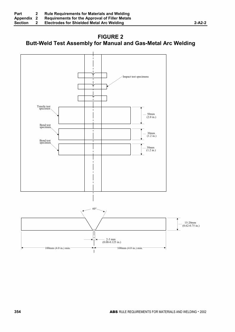
Part 2 Rule Requirements for Materials and WeldingAppendix 2 Requirements for the Approval of Filler MetalsSection 2 Electrodes for Shielded Metal Arc Welding 2-A2-2
354 ABS RULE REQUIREMENTS FOR MATERIALS AND WELDING . 2002
FIGURE 2Butt-Weld Test Assembly for Manual and Gas-Metal Arc Welding
Impact test specimens
Tensile testspecimen
Bend testspecimen
Bend testspecimen
50mm(2.0 in.)
30mm(1.2 in.)
30mm(1.2 in.)
15-20mm(0.62-0.75 in.)
(0.08-0.125 in.)
100mm (4.0 in.) min.
2-3 mm
100mm (4.0 in.) min.
60°
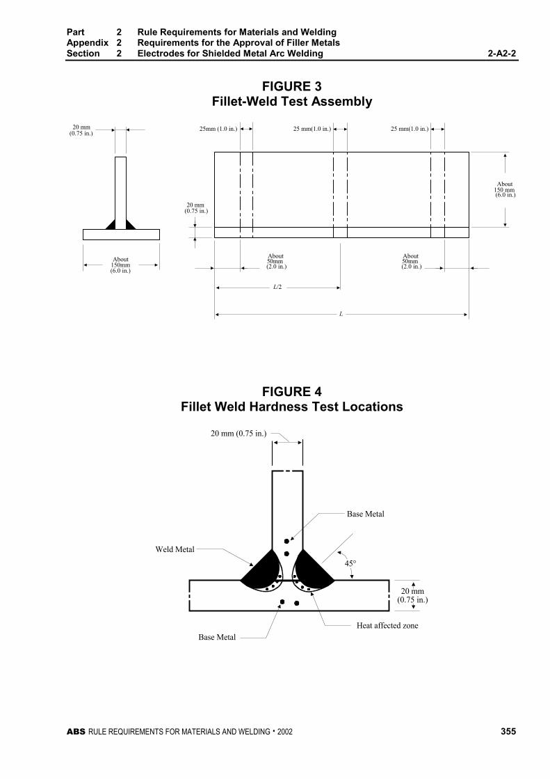
Part 2 Rule Requirements for Materials and WeldingAppendix 2 Requirements for the Approval of Filler MetalsSection 2 Electrodes for Shielded Metal Arc Welding 2-A2-2
ABS RULE REQUIREMENTS FOR MATERIALS AND WELDING . 2002 355
FIGURE 3Fillet-Weld Test Assembly
About
About150mm(6.0 in.)
About50mm(2.0 in.)
20 mm(0.75 in.)
(0.75 in.)
(6.0 in.)
25 mm(1.0 in.)25 mm(1.0 in.)20 mm 25mm (1.0 in.)
L
L/2
150 mm
About50mm(2.0 in.)
FIGURE 4Fillet Weld Hardness Test Locations
Base Metal
45°
Heat affected zone
Weld Metal
Base Metal
20 mm(0.75 in.)
20 mm (0.75 in.)

ABS RULE REQUIREMENTS FOR MATERIALS AND WELDING . 2002 357
P A R T
2A P P E N D I X 2 Requirements for the Approval of
Filler Metals
S E C T I O N 3 Wire-Flux Combinations forSubmerged Arc Welding
CONTENTS1 General................................................................................. 359
3 Chemical Analysis............................................................... 359
5 Deposited Metal Test Assemblies for Multi-runTechnique ............................................................................ 359
5.1 Test Assembly...................................................................... 359
5.3 Test Specimens.................................................................... 360
7 Butt Weld Test Assemblies for Multi-run Technique ........ 360
7.1 Test Assembly...................................................................... 360
7.3 Test Specimens.................................................................... 360
9 Butt Weld Assemblies for Two-run Technique.................. 360
9.1 Test Assemblies ................................................................... 360
9.3 Test Specimens.................................................................... 360
9.5 Longitudinal All-Weld-Metal Tension Test............................ 361
11 Fillet Weld Tests .................................................................. 361
13 Low Hydrogen Approval ..................................................... 361
13.1 YQ Grade Wires – Flux Combination................................... 361
15 Annual Check Tests ............................................................ 361
15.1 General................................................................................. 361
15.3 Upgrading and Uprating ....................................................... 361
17 Multiple Electrodes.............................................................. 362
19 Electroslag Welding ............................................................ 362
19.1 General................................................................................. 362
19.3 Annual Tests ........................................................................ 362
19.5 Upgrading and Uprating ....................................................... 362
358 ABS RULE REQUIREMENTS FOR MATERIALS AND WELDING . 2002
FIGURE 1 Deposited-Metal Test Assembly for SubmergedArc Welding – Multi-run Technique andAutomatic Gas-Metal Arc Welding .........................363
FIGURE 2 Butt-Weld Test Assembly for Submerged ArcWelding – Multi-run Technique ...............................364
FIGURE 3 Butt-Weld Test Assembly for Submerged ArcWelding – Two-run Technique.................................365
FIGURE 4 Butt-Weld Impact Specimen Location forSubmerged and Gas-Metal Arc Welding –Two-run Technique ..................................................366
ABS RULE REQUIREMENTS FOR MATERIALS AND WELDING . 2002 359
P A R T
2A P P E N D I X 2 Requirements for the Approval of
Filler Metals
S E C T I O N 3 Wire-Flux Combinations forSubmerged Arc Welding 2 - A 2 - 3
1 General (1997) 2-A2-3/1
This test program is intended for the approval of automatic or semi-automatic, single-electrodesubmerged arc welding. Provisions are made for the testing of weld metal deposited by multi-run andtwo-run (one pass each side) techniques. For YQ Grades automatic welding, multi-run technique iscontemplated. Application for high heat input process, such as automatic welding two-run technique,may be considered under 2-A2-1/3.5 and approval by a technical office. Where a manufacturer statesthat a particular wire-flux combination is suitable for welding with both techniques, both series oftests are to be carried out. The suffix T, M, or TM will be added to the grade to indicate two-runtechnique, multi-run technique, or both techniques respectively.
3 Chemical Analysis 2-A2-3/3
The chemical analysis of the deposited weld metal is to be supplied by the manufacturer.
5 Deposited Metal Test Assemblies for Multi-run Technique 2-
A2-3/5
5.1 Test Assembly 2-A2-3/5.1
One deposited metal test assembly as indicated in 2-A2-3/Figure 1 is to be welded in the flat positionusing the wire size recommended by the manufacturer. The direction of deposition of each run is toalternate from each end of the plate and after completion of each run the flux and welding slag are tobe removed. The thickness of each layer is not to be less than the size of the wire, or 4 mm (5/32 in.),whichever is the greater. Between each run the assembly is to be left in still air until it has cooled to250°C (482°F), the temperature being taken in the center of the weld, on the surface of the seam. Thewelding conditions (amperage, voltage, and travel speed) are to be in accordance with therecommendations of the manufacturer and are to conform with normal good welding practice formulti-run welding. The welded test assembly is not to be subjected to heat treatment, except hydrogenremoval as permitted in 2-A2-1/15.3.
Part 2 Rule Requirements for Materials and WeldingAppendix 2 Requirements for the Approval of Filler MetalsSection 3 Wire-Flux Combinations for Submerged Arc Welding 2-A2-3
360 ABS RULE REQUIREMENTS FOR MATERIALS AND WELDING . 2002
5.3 Test Specimens (1 Oct. 1994) 2-A2-3/5.3
Two tension and one set of three impact specimens are to be prepared from the deposited metal testassembly as indicated in 2-A2-3/Figure 1 and the results are to conform to the requirements of2-A2-1/Table 1 and 2-A2-1/Table 2 for the applicable grade and welding technique.
7 Butt Weld Test Assemblies for Multi-run Technique 2-A2-3/7
7.1 Test Assembly 2-A2-3/7.1
One butt weld test assembly as indicated in 2-A2-3/Figure 2 is to be welded in the flat position usingthe wire size recommended by the manufacturer. The welding conditions are to be essentially thesame as those indicated in 2-A2-3/5.1 for deposited metal test assembly. The back weld is to beapplied in the flat position after removing the root run to clean metal. After being welded the testassembly is not to be subjected to any heat treatment.
7.3 Test Specimens 2-A2-3/7.3
Two tension, two face bend and two root bend together with one set of three impact specimens are tobe prepared from the butt weld test assembly as indicated in 2-A2-3/Figure 2, and the results oftension and impact tests are to conform to the requirements of 2-A2-1/Table 1 and 2-A2-1/Table 2 forthe applicable grade and welding technique. The results of bend tests are to meet the requirements of2-A2-1/21.3.
9 Butt Weld Assemblies for Two-run Technique 2-A2-3/9
9.1 Test Assemblies 2-A2-3/9.1
Two butt weld test assemblies as indicated in 2-A2-3/Figure 3 are to be welded in the flat position.The maximum size of wire, grades of steel plate, and the edge preparation to be used are also to be inaccordance with 2-A2-3/Figure 3. At the request of the manufacturer, small deviations in the edgepreparation may be allowed. The root gap is not to exceed 1.0 mm (0.04 in.). Each test assembly is tobe welded in two runs, one from each side, using welding conditions (amperage, voltage, and travelspeed) which are in accordance with the recommendations of the manufacturer and normal goodwelding practice. After completion of the first run, the flux and welding slag are to be removed andthe assembly is to be left in still air until it has cooled to 100°C (212°F), the temperature being takenin the center of the weld, on the surface of the seam. After being welded the test assemblies are not tobe subjected to any treatment.
9.3 Test Specimens (1 Oct. 1994) 2-A2-3/9.3
Two tension, one face bend, one root bend, and one set of three impact specimens are to be preparedfrom each butt weld assembly as indicated in 2-A2-3/Figure 3 and 2-A2-3/Figure 4 and the results oftension and impact tests are to conform to the requirements of 2-A2-1/Table 1 and 2-A2-1/Table 2 forthe applicable grade and welding technique. The results of bend tests are to meet the requirements of2-A2-1/21.3. The edges of all test specimens and also the discards are to be examined to ensurecomplete fusion and interpenetration of the welds.
Part 2 Rule Requirements for Materials and WeldingAppendix 2 Requirements for the Approval of Filler MetalsSection 3 Wire-Flux Combinations for Submerged Arc Welding 2-A2-3
ABS RULE REQUIREMENTS FOR MATERIALS AND WELDING . 2002 361
9.5 Longitudinal All-Weld-Metal Tension Test (1 Oct. 1994) 2-A2-3/9.5
Where the combination is to be approved for two-run technique only, one longitudinal all-weld-metaltension specimen is to be cut from the thicker butt weld test assembly as indicated in 2-A2-3/Figure 3,and machined to the dimensions indicated in 2-A2-1/Figure 1, care being taken that the longitudinalaxis coincides with the center of the weld and is approximately 7 mm (0.28 in.) below the platesurface on the side from which the second run is made. The test specimen may be subjected to atemperature not exceeding 250°C (482°F) for up to 16 hours for hydrogen removal, prior to testing.The results of the tests are to conform to the requirements of 2-A2-1/Table 1.
11 Fillet Weld Tests 2-A2-3/11
Where a wire-flux combination is submitted for approval for fillet welds only, then the butt weld testsmay be omitted, and fillet weld tests are to be carried out and tested in accordance with the applicableparts of 2-A2-4/11.3 to 2-A2-4/11.7.
13 Low Hydrogen Approval (1997) 2-A2-3/13
13.1 YQ Grade Wires – Flux Combination 2-A2-3/13.1
All wire-flux combination of this grade are to be submitted to the diffusible hydrogen test as requiredby 2-A2-1/23.1; however, the H-suffix will not be added to the grade.
15 Annual Check Tests 2-A2-3/15
15.1 General (1996) 2-A2-3/15.1
The annual check tests for each approved technique shall consist of the following.
Multi-run Technique. One deposited metal test assembly is to be welded in accordance with2-A2-3/5.1. One tension and one set of three impact specimens are to be prepared and tested inaccordance with 2-A2-3/5.3.
Two-run Technique. One butt weld test assembly of 20 mm (0.75 in.) thickness is to be welded inaccordance with 2-A2-3/9.1. One transverse tension, one face bend, one root bend, and one set ofthree impact specimens are to be prepared and tested in accordance with 2-A2-3/9.3 and 2-A2-3/9.5.One longitudinal tension test specimen is also to be prepared where wire-flux combination isapproved solely for the two-run technique.
15.3 Upgrading and Uprating (1 October 1993) 2-A2-3/15.3
Upgrading of wire-flux combinations will be considered at the manufacturer’s request. For multi-runtechnique, in addition to the deposited metal test indicated in 2-A2-3/15.1, one butt weld testassembly is to be welded as indicated in 2-A2-3/7 and one set of three impact specimens is to betested at the upgraded temperature.
Uprating refers to the extension of approval to also cover welding of higher-strength steels (dualapprovals). For this purpose butt weld tests are to be carried out as required in 2-A2-3/7 and 2-A2-3/9,and 2-A2-1/9.3.3, as applicable.
Part 2 Rule Requirements for Materials and WeldingAppendix 2 Requirements for the Approval of Filler MetalsSection 3 Wire-Flux Combinations for Submerged Arc Welding 2-A2-3
362 ABS RULE REQUIREMENTS FOR MATERIALS AND WELDING . 2002
17 Multiple Electrodes 2-A2-3/17
Wire-flux combinations for multiple electrode submerged arc welding will be subject to separateapproval tests. They are to be carried out generally in accordance with the requirements of thissection.
19 Electroslag Welding (1996) 2-A2-3/19
19.1 General (1997) 2-A2-3/19.1
Where approval is requested for wire-flux combinations other that YQ Grades, (with or withoutconsumable nozzles) for use in electroslag welding, two test assemblies of 20–25 mm (0.75–1.0 in.)and 35–40 mm (1.38–1.58 in.) or more in thickness are to be prepared with a minimum root openingof 16 mm (0.63 in.), or with another joint design sufficient to allow the selection of the following testspecimens. The chemical composition of the plates including the content of grain refining elements isto be reported.
2 longitudinal tension specimens from the axis to the weld,
2 transverse tension specimens,
2 side bend specimens,
3 Charpy-V specimens notched at the center of the weld,
3 Charpy-V specimens with their notches in the weld metal at 2 mm (5/64 in.) from the fusionline,
2 macro-sections.
The results are to conform to the requirements of 2-A2-1/Table 1 and 2-A2-1/Table 2 according to theapplicable grade and welding technique.
19.3 Annual Tests (1996) 2-A2-3/19.3
One butt test assembly of 20–25 mm (0.75–1.0 in.) or more in thickness is to be prepared. Onelongitudinal tension, one transverse tension, two side bend and two sets of three Charpy V-notchspecimens are to be prepared and tested. The notch of the impact specimens is to be located at thecenter of the weld and 2 mm (0.08 in.) from the fusion line in the weld. One macro-section is also tobe examined.
The test results are to conform to the requirements of 2-A2-1/Table 1 and 2-A2-1/Table 2 accordingto the applicable grade and welding technique.
19.5 Upgrading and Uprating (1996) 2-A2-3/19.5
Upgrading and uprating will be considered at the manufacturer’s request. Full tests as indicated in2-A2-3/19.1 will be required.
The test results are to conform to the requirements of 2-A2-1/Table 1 and 2-A2-1/Table 2 accordingto the applicable grade and welding technique.
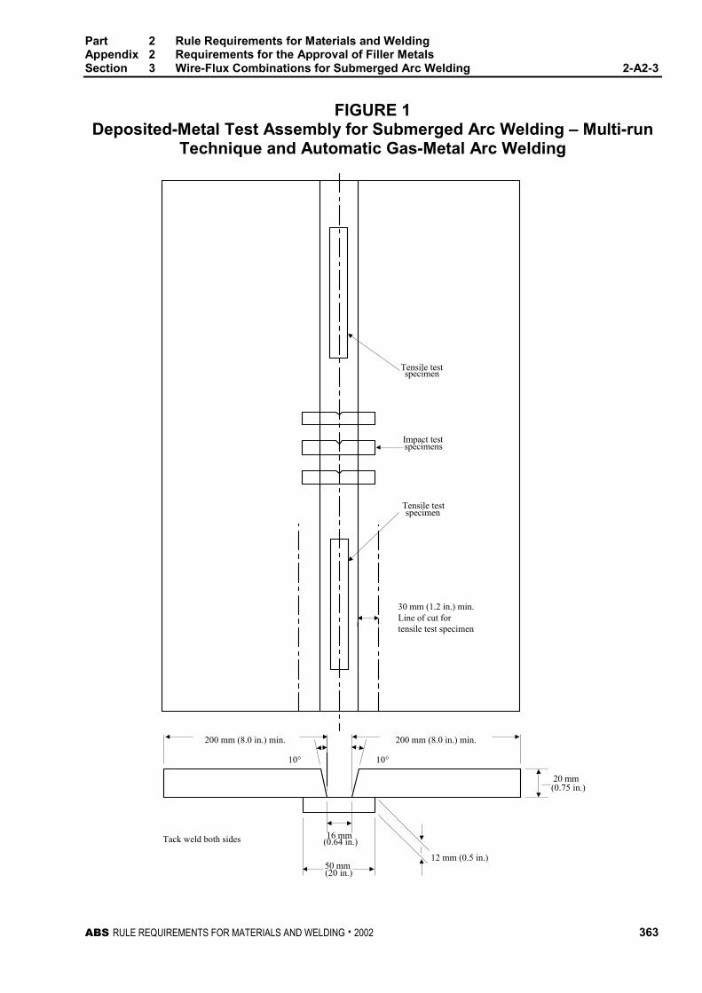
Part 2 Rule Requirements for Materials and WeldingAppendix 2 Requirements for the Approval of Filler MetalsSection 3 Wire-Flux Combinations for Submerged Arc Welding 2-A2-3
ABS RULE REQUIREMENTS FOR MATERIALS AND WELDING . 2002 363
FIGURE 1Deposited-Metal Test Assembly for Submerged Arc Welding – Multi-run
Technique and Automatic Gas-Metal Arc Welding
Tensile testspecimen
Impact test
Tensile test
specimens
specimen
30 mm (1.2 in.) min.Line of cut fortensile test specimen
Tack weld both sides
(0.75 in.)20 mm
12 mm (0.5 in.)
16 mm(0.64 in.)
(20 in.)
10° 10°
50 mm
200 mm (8.0 in.) min. 200 mm (8.0 in.) min.
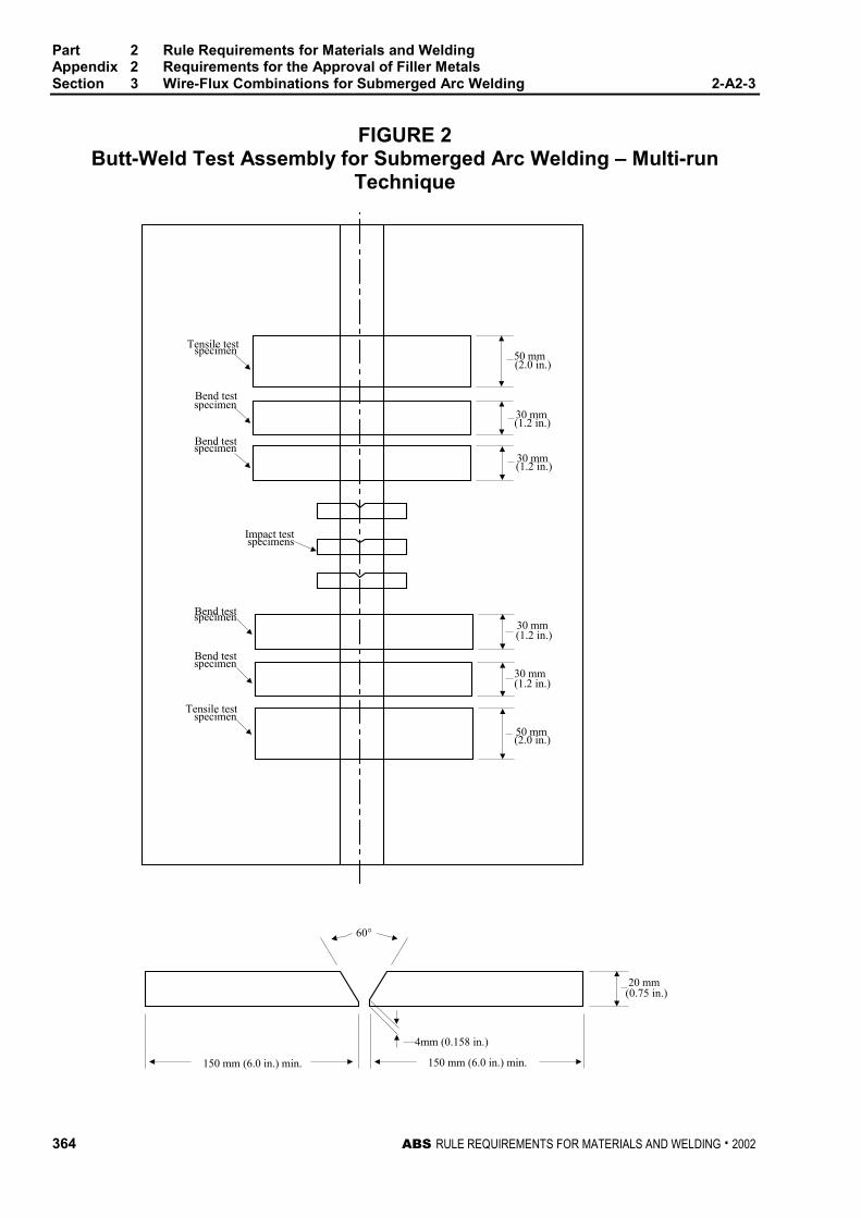
Part 2 Rule Requirements for Materials and WeldingAppendix 2 Requirements for the Approval of Filler MetalsSection 3 Wire-Flux Combinations for Submerged Arc Welding 2-A2-3
364 ABS RULE REQUIREMENTS FOR MATERIALS AND WELDING . 2002
FIGURE 2Butt-Weld Test Assembly for Submerged Arc Welding – Multi-run
Technique
Tensile testspecimen
Bend testspecimen
specimenBend test
Impact testspecimens
specimenBend test
Bend testspecimen
Tensile testspecimen
50 mm(2.0 in.)
30 mm(1.2 in.)
30 mm(1.2 in.)
30 mm(1.2 in.)
30 mm(1.2 in.)
50 mm(2.0 in.)
20 mm(0.75 in.)
4mm (0.158 in.)
60°
150 mm (6.0 in.) min.150 mm (6.0 in.) min.
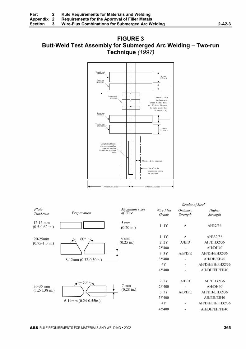
Part 2 Rule Requirements for Materials and WeldingAppendix 2 Requirements for the Approval of Filler MetalsSection 3 Wire-Flux Combinations for Submerged Arc Welding 2-A2-3
ABS RULE REQUIREMENTS FOR MATERIALS AND WELDING . 2002 365
FIGURE 3Butt-Weld Test Assembly for Submerged Arc Welding – Two-run
Technique (1997)
Tensile testspecimen
Bend test
Impact test
Bend testspecimen
Tensile textspecimen
Longitudinal tensiletest specimen (when
approval requiredfor two run technique
only)
Line of cut forlongitudinal tensiletest specimen
30 mm (1.2 in.) minimum
30 mm (1.2in.)for plates up to
20 mm (0.75in) thickor 1 1/2 times thickness
for plates greater than20 mm (0.75 in)
(2.0 in..)
(2.0 in..)
50mm
specimen
specimen
50 mm
150mm(6.0in.)min 150mm(6.0in.)min
Grades of Steel
Wire FluxGrade
OrdinaryStrength
HigherStrength
1, 1Y A AH32/36
1, 1Y A AH332/36
2, 2Y A/B/D AH/DH32/36
2Y400 - AH/DH40
3, 3Y A/B/D/E AH/DH/EH32/36
3Y400 - AH/DH/EH40
4Y - AH/DH/EH/FH32/36
4Y400 - AH/DH/EH/FH40
2, 2Y A/B/D AH/DH32/36
2Y400 - AH/DH40
3, 3Y A/B/D/E AH/DH/EH32/36
3Y400 - AH/EH/EH40
PlateThickness
12-15 mm
PreparationMaximum sizesof Wire
(0.5-0.62 in.)
20-25mm(0.75-1.0 in.)
30-35 mm(1.2-1.38 in.)
7 mm(0.28 in.)
6 mm(0.25 in.)
5 mm(0.20 in.)
8-12mm (0.32-0.50in.)
6-14mm (0.24-0.55in.)
60°
70°
4Y - AH/DH/EH/FH32/36
4Y400 - AH/DH/EH/FH40
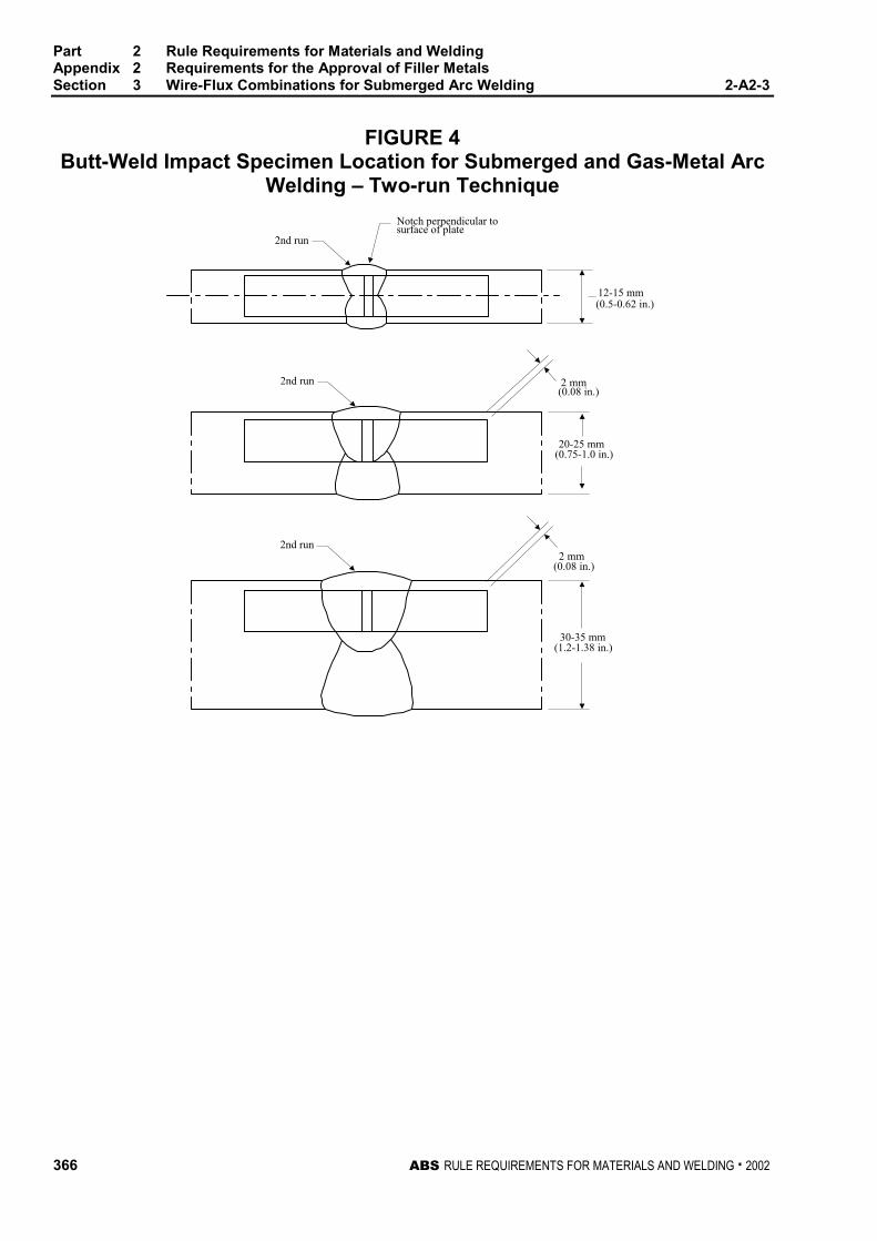
Part 2 Rule Requirements for Materials and WeldingAppendix 2 Requirements for the Approval of Filler MetalsSection 3 Wire-Flux Combinations for Submerged Arc Welding 2-A2-3
366 ABS RULE REQUIREMENTS FOR MATERIALS AND WELDING . 2002
FIGURE 4Butt-Weld Impact Specimen Location for Submerged and Gas-Metal Arc
Welding – Two-run Technique
Notch perpendicular tosurface of plate
2nd run
2nd run
2nd run
(0.5-0.62 in.)
(0.75-1.0 in.)
(0.08 in.)
(0.08 in.)
12-15 mm
2 mm
2 mm
(1.2-1.38 in.)
20-25 mm
30-35 mm
ABS RULE REQUIREMENTS FOR MATERIALS AND WELDING . 2002 367
P A R T
2A P P E N D I X 2 Requirements for the Approval of
Filler Metals
S E C T I O N 4 Wire and Wire Gas Combinationsfor Gas Metal Arc Welding andFlux Cored Wires for Flux CoredArc Welding
CONTENTS1 General................................................................................. 369
3 Chemical Analysis and Shielding Gas Compositions....... 369
5 Deposited Metal Test Assemblies for Semi-automaticand Automatic Testing........................................................ 370
5.1 Semi-automatic Test Assemblies ......................................... 370
5.3 Test Specimens for Semi-automatic .................................... 370
5.5 Automatic Test Assembly..................................................... 370
5.7 Test Specimens for Automatic ............................................. 370
7 Butt Weld Test Assemblies for Semi-automatic andAutomatic Techniques ........................................................ 370
7.1 Test Assemblies ................................................................... 370
7.3 Welding Procedure............................................................... 370
7.5 Test Specimens.................................................................... 371
9 Butt Weld Test Assemblies for Two-run Technique ......... 371
9.1 Test Assemblies ................................................................... 371
9.3 Test Specimens.................................................................... 371
9.5 Longitudinal All-Weld-Metal Tension Test............................ 371
11 Fillet Weld Tests .................................................................. 372
11.1 General................................................................................. 372
11.3 Test Assemblies ................................................................... 372
11.5 Welding Procedure............................................................... 372
11.7 Test Requirements ............................................................... 372
368 ABS RULE REQUIREMENTS FOR MATERIALS AND WELDING . 2002
13 Low Hydrogen Approval......................................................372
13.1 Flux Cored Wire ................................................................... 372
15 Annual Check Tests.............................................................373
15.1 General................................................................................. 373
15.3 Upgrading and Uprating ....................................................... 373
17 Electrogas Welding..............................................................373
17.1 General................................................................................. 373
17.3 Annual Tests......................................................................... 374
17.5 Upgrading and Uprating ....................................................... 374
FIGURE 1 Butt-Weld Test Assembly for Gas-Metal ArcWelding – Two-run Technique.................................375
ABS RULE REQUIREMENTS FOR MATERIALS AND WELDING . 2002 369
P A R T
2A P P E N D I X 2 Requirements for the Approval of
Filler Metals
S E C T I O N 4 Wire and Wire Gas Combinationsfor Gas Metal Arc Welding andFlux Cored Wires for Flux CoredArc Welding 2 - A 2 - 4
1 General (1997) 2-A2-4/1
This test program is intended for the approval of wire-gas combinations and flux cored wires with orwithout shielding gas intended for semi-automatic or automatic arc welding techniques. For bothtechniques, the welding gun provides continuous wire feed; for semi-automatic welding the weldinggun is held manually, and for automatic welding, the welding gun is machine held with variousdegrees of controlled motion provided by the machine. The impact requirements for the semi-automatic welding technique and those for the automatic welding technique are indicated separately in2-A2-1/Table 1 and 2-A2-1/Table 2 according to the applicable grade. The suffix SA will be added tothe grade to indicate approval for manual semi-automatic or machine-automatic gas-metal arcwelding. The suffix A will be added to the Grade to indicate approval for machine automatic weldingonly. An additional suffix T will be added to the grade to indicate approval for two-run (one pass eachside) technique for machine automatic welding. Wire-gas combinations and flux cored wires approvedfor semi-automatic welding may be used for automatic welding under the procedure recommended bythe manufacturer except that for the two-run automatic technique, testing in accordance with 2-A2-4/9is required. For YQ Grades semi-automatic or automatic welding, multi run technique iscontemplated. Application for high heat input process, such as semi-automatic or automatic weldingtwo-run technique, may be considered under 2-A2-1/3.5 and approval by technical office.
3 Chemical Analysis and Shielding Gas Compositions 2-A2-4/3
The chemical analysis of the deposited weld metal is to be supplied by the manufacturer. The tradename of the shielding gas when used, as well as its composition, are to be reported.
Part 2 Rule Requirements for Materials and WeldingAppendix 2 Requirements for the Approval of Filler MetalsSection 4 Wire and Wire Gas Combinations for Gas Metal Arc Welding 2-A2-4
370 ABS RULE REQUIREMENTS FOR MATERIALS AND WELDING . 2002
5 Deposited Metal Test Assemblies for Semi-automatic andAutomatic Testing 2-A4-4/5
5.1 Semi-automatic Test Assemblies (1996) 2-A2-4/5.1
Two deposited metal test assemblies as indicated in 2-A2-2/Figure 1 are to be welded in the flatposition, one using 1.2 mm (0.045 in.) wire or the smallest size manufactured whichever is greaterand the other using 2.4 mm (3/32 in.) wire or the largest size manufactured. The weld metal is to bedeposited in single or multi-run layers according to recommended practice and the thickness of eachlayer of weld metal is to be between 2 mm (5/64 in.) and 6 mm (15/64 in.). Between each run theassembly is to be left in still air until it has cooled to 250°C (482°F), the temperature being taken inthe center of the weld, on the surface of the seam. After being welded the test assemblies are not to besubjected to any heat treatment, except hydrogen removal as permitted in 2-A2-1/15.3.
5.3 Test Specimens for Semi-automatic 2-A2-4/5.3
One tension and one set of three impact specimens are to be prepared from each deposited metal testassembly as indicated in 2-A2-2/Figure 1 and the results are to conform to the requirements of2-A2-1/Table 1 and 2-A2-1/Table 2 for the applicable grade.
5.5 Automatic Test Assembly 2-A2-4/5.5
For automatic welding one test assembly as indicated in 2-A2-3/Figure 1 is to be welded in the flatposition using 2.4 mm (3/32 in.) wire or the largest size manufactured. The thickness of each layer isnot to be less than 3 mm (1/8 in.). Between each run the assembly is to be left in still air until it hascooled to 250°C (482°F), the temperature being taken in the center of the weld, on the surface of theseam. After being welded the test assembly is not to be subjected to any heat treatment, excepthydrogen removal as permitted in 2-A2-1/15.3
5.7 Test Specimens for Automatic 2-A2-4/5.7
Two tension and one set of three impact specimens are to be prepared from the test assembly asindicated in 2-A2-3/Figure 1, and the results are to conform to the requirements of 2-A2-1/Table 1and 2-A2-1/Table 2 for the applicable grade.
7 Butt Weld Test Assemblies for Semi-automatic andAutomatic Techniques 2-A2-4/7
7.1 Test Assemblies 2-A2-4/7.1
One butt weld test assembly as indicated in 2-A2-2/Figure 2 is to be welded in each position (flat,vertical-up, vertical-down, overhead, and horizontal) for which the wire is recommended by themanufacturer, except that wires meeting the requirements for flat and vertical positions will beconsidered as also complying with the requirements for horizontal position. Where the wire is only tobe approved in the flat position, one additional test assembly is to be welded in that position.
7.3 Welding Procedure 2-A2-4/7.3
In general, the following welding procedure is to be adopted in making the test assemblies:
Flat. First run using 1.2 mm (0.045 in.) wire or the smallest size manufactured, whichever is greater;remaining runs with 2.4 mm (3/32 in.) wire or the largest size manufactured. Where a second flatassembly is required, it is to be prepared using wires of different sizes.
Part 2 Rule Requirements for Materials and WeldingAppendix 2 Requirements for the Approval of Filler MetalsSection 4 Wire and Wire Gas Combinations for Gas Metal Arc Welding 2-A2-4
ABS RULE REQUIREMENTS FOR MATERIALS AND WELDING . 2002 371
Vertical-up, Vertical-down, Overhead and Horizontal. First run with 1.2 mm (0.045 in.) wire or thesmallest size manufactured, whichever is greater; remaining runs using the largest size wirerecommended by the manufacturer for the position involved.
In all cases the back weld is to be made with 1.2 mm (0.045 in.) wire or the smallest sizemanufactured, whichever is greater, after removing the root run to clean metal. Normal weldingpractice is to be used and between each run the assembly is to be left in still air until it has cooled to250°C (482°F), the temperature being taken in the center of the weld on the surface of the seam. Afterbeing welded the test assemblies are not to be subjected to any heat treatment.
7.5 Test Specimens 2-A2-4/7.5
One tension, one face bend and one root bend are to be prepared from each butt-weld test assemblytogether with sets of three impact specimens from the flat and vertical test assemblies as indicated in2-A2-2/Figure 2. The results of tension and impact tests are to conform to the requirements of2-A2-1/Table 1 and 2-A2-1/Table 2 for the applicable grade, position and welding technique. Theresults of bend tests are to meet the requirements of 2-A2-1/21.3.
9 Butt Weld Test Assemblies for Two-run Technique 2-A2-4/9
9.1 Test Assemblies 2-A2-4/9.1
Two butt weld test assemblies as indicated in 2-A2-4/Figure 1 are to be welded in the flat position.One test assembly is to be welded using 1.2 mm (0.045 in.) wire or the smallest size manufactured,whichever is greater and one test assembly using 2.4 mm (3/32 in.) wire or the largest size wirerecommended by the manufacturer for two-run technique. Each test assembly is to be welded in tworuns, one from each side. Between each run the assembly is to be left in still air until it has cooled to100°C (212°F), the temperature being taken in the center of the weld, on the surface of the seam.After being welded the test assemblies are not to be subjected to any heat treatment.
9.3 Test Specimens (1996) 2-A2-4/9.3
Two tension, one face bend, one root bend and one set of three impact specimens are to be preparedfrom each butt weld test assembly as indicated in 2-A2-4/Figure 1 and 2-A2-3/Figure 4. If approval isrequested for welding plate thicker than 25 mm (1.0 in.), one assembly is to be prepared using platesapproximately 20 mm (0.75 in.) in thickness and the other using plates of the maximum thickness forwhich approval is requested. For assemblies using plates over 25 mm (1.0 in.) in thickness, the edgepreparation is to be reported for information. The results of tension and impact tests are to conform tothe requirements of 2-A2-1/Table 1 and 2-A2-1/Table 2 for the applicable grade. The results of bendtests are to meet the requirements of 2-A2-1/21.3. The edges of all test specimens and also thediscards are to be examined to ensure complete fusion and interpenetration of the welds.
9.5 Longitudinal All-Weld-Metal Tension Test 2-A2-4/9.5
Where the wire is to be approved for two-run technique only, one longitudinal all-weld-metal tensionspecimen is to be cut from the thicker butt weld test assembly as indicated in 2-A2-4/Figure 1 andmachined to the dimensions indicated in 2-A2-1/Figure 1 care being taken that the longitudinal axiscoincides with the center of the weld and is about 7 mm (0.28 in.) below the plate surface on the sidefrom which the second run is made. The test specimen may be subjected to a temperature notexceeding 250°C (482°F) for a period not exceeding 16 hours for hydrogen removal, prior to testing.The results of the test are to conform to the requirements of 2-A2-1/Table 1 and 2-A2-1/Table 2 forthe applicable grade.
Part 2 Rule Requirements for Materials and WeldingAppendix 2 Requirements for the Approval of Filler MetalsSection 4 Wire and Wire Gas Combinations for Gas Metal Arc Welding 2-A2-4
372 ABS RULE REQUIREMENTS FOR MATERIALS AND WELDING . 2002
11 Fillet Weld Tests 2-A2-4/11
11.1 General 2-A2-4/11.1
A wire-gas combination or flux cored wire is considered approved for fillet welding in the weldingposition for which the butt weld test of 2-A2-4/7 was satisfactory. A wire-gas combination or fluxcored wire meeting the flat butt weld requirements will be considered as complying with therequirements for horizontal fillet (HF) welds. Where a wire-gas combination or a flux cored wire issubmitted for approval for fillet welding only, the butt weld tests indicated in 2-A2-4/7 and 2-A2-4/9may be omitted, and fillet weld tests are to be carried out and tested in accordance with 2-A2-4/11.3and 2-A2-4/11.5.
11.3 Test Assemblies 2-A2-4/11.3
One fillet weld test assembly, as indicated in 2-A2-2/Figure 3, is to be welded in each weldingposition for which the wire is recommended by the manufacturer.
11.5 Welding Procedure 2-A2-4/11.5
The length L of the fillet weld test assemblies is to be sufficient to allow for the tests prescribed in2-A2-2/95. One side is to be welded using the maximum size wire manufactured and the second sideis to be welded using the minimum size wire manufactured and recommended for fillet welding. Thefillet size will in general be determined by the wire size and the welding current employed duringtesting. The fillet welding is to be carried out with the welding equipment and techniquerecommended by the manufacturer. The manufacturer’s recommended current range is to be reportedfor each wire size and welding position.
11.7 Test Requirements 2-A2-4/11.7
The results of hardness and breaking tests are to meet the requirements of 2-A2-2/9.7.
13 Low Hydrogen Approval 2-A2-4/13
13.1 Flux Cored Wire 2-A2-4/13.1
13.1.1 Ordinary or Higher-Strength Wires (1997) 2-A2-4/13.1.1
A flux cored wire which has satisfied the above requirements, at the manufacturer’s option,may be submitted to the diffusible hydrogen test as detailed in 2-A2-1/23.3 or 2-A2-1/23.5,using the manufacturer’s recommended welding conditions. The deposition rate may beadjusted to give a weight of weld deposit per sample similar to manual electrodes. When theresults are in compliance with the requirements of 2-A2-1/23.7, appropriate suffix will beadded to the Grade.
13.1.2 YQ-Grade Wires (1997) 2-A2-4/13.1.2
All flux-cored wires of this grade are to be submitted to the diffusible hydrogen test asrequired by 2-A2-1/23.1; however, the H-suffix will not be added to the grade.
Part 2 Rule Requirements for Materials and WeldingAppendix 2 Requirements for the Approval of Filler MetalsSection 4 Wire and Wire Gas Combinations for Gas Metal Arc Welding 2-A2-4
ABS RULE REQUIREMENTS FOR MATERIALS AND WELDING . 2002 373
15 Annual Check Tests 2-A2-4/15
15.1 General (1 October 1993) 2-A2-4/15.1
The annual check tests for each approved technique shall consist of the following:
Semi-automatic and Automatic. One deposited metal test assembly is to be welded using 2.4 mm(3/32 in.) wire or the largest size manufactured in accordance with 2-A2-4/5.1 or 2-A2-4/5.5 asapplicable. One tension and one set of three impact specimens are to be prepared and tested inaccordance with 2-A2-4/5.3 or 2-A2-4/5.7 as applicable.
Two-run Automatic Technique. One butt weld test assembly of 20 mm (0.75 in.) thickness is to bewelded using 2.4 mm (3/32 in.) or the largest size manufactured in accordance with 2-A2-4/9.1. Onelongitudinal tension, one face bend, one root bend and one set of three impact specimens are to beprepared and tested in accordance with 2-A2-4/9.3 and 2-A2-4/9.5. A longitudinal tension test will notbe required for wires also approved for multi-run technique.
15.3 Upgrading and Uprating (1 October 1993) 2-A2-4/15.3
Upgrading of wire-gas combinations and flux cored wires will be considered at the manufacturer’srequest. For semi-automatic and automatic welding, in addition to the deposited metal test indicated in2-A2-4/15.1, one butt weld test assembly is to be welded as indicated in 2-A2-4/7 and one set of threeimpact specimens is to be tested at the upgraded temperature.
Uprating refers to the extension of approval to also cover welding of higher-strength steels (dualapprovals). For this purpose butt weld tests are to be carried out as required in 2-A2-4/7 or 2-A2-4/9,and 2-A2-1/9.3.3, as applicable.
17 Electrogas Welding (1996) 2-A2-4/17
17.1 General (1997) 2-A2-4/17.1
Where approval is requested for wire-gas combinations other than YQ Grades, (with or withoutconsumable nozzles or self-shielding gas) for use in electrogas welding, two test assemblies of20–25 mm (0.75–1.0 in.) and 35–40 mm (1.38–1.58 in.) or more in thickness are to be prepared with aminimum root opening of 16 mm (0.63 in.), or with another joint design sufficient to allow theselection of the following test specimens. The chemical composition of the plates including thecontent of grain refining elements is to be reported.
2 longitudinal tension specimens from the axis to the weld.
2 transverse tension specimens,
2 side bend specimens,
3 Charpy-V specimens notched at the center of the weld,
3 Charpy-V specimens with their notches in the weld metal at 2 mm (5/64 in.) from the fusionline,
2 macro-sections.
The results are to conform to the requirements of 2-A2-1/Table 1 and 2-A2-1/Table 2 according to theapplicable grade and welding technique.
Part 2 Rule Requirements for Materials and WeldingAppendix 2 Requirements for the Approval of Filler MetalsSection 4 Wire and Wire Gas Combinations for Gas Metal Arc Welding 2-A2-4
374 ABS RULE REQUIREMENTS FOR MATERIALS AND WELDING . 2002
17.3 Annual Tests (1996) 2-A2-4/17.3
One butt test assembly of 20–25 mm (0.75–1.0 in.) or more in thickness is to be prepared. Onelongitudinal tension, one transverse tension, two side bend and two sets of three Charpy V-notchspecimens are to be prepared and tested. The notch of the impact specimens is to be located at thecenter of the weld and 2 mm (0.08 in.) from the fusion line in the weld. One macro-section is also tobe examined.
The test results are to conform to the requirements of 2-A2-1/Table 1 and 2-A2-1/Table 2 accordingto the applicable grade and welding technique.
17.5 Upgrading and Uprating (1996) 2-A2-4/17.5
Upgrading and uprating will be considered at the manufacturer’s request. Full tests as indicated in2-A2-4/17.1 will be required.
The test results are to conform to the requirements of 2-A2-1/Table 1 and 2-A2-1/Table 2 accordingto the applicable grade and welding technique.
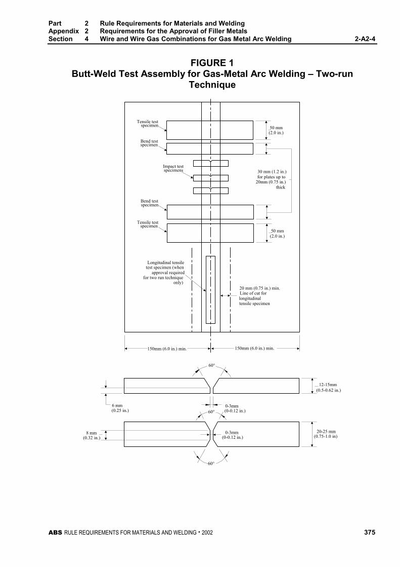
Part 2 Rule Requirements for Materials and WeldingAppendix 2 Requirements for the Approval of Filler MetalsSection 4 Wire and Wire Gas Combinations for Gas Metal Arc Welding 2-A2-4
ABS RULE REQUIREMENTS FOR MATERIALS AND WELDING . 2002 375
FIGURE 1Butt-Weld Test Assembly for Gas-Metal Arc Welding – Two-run
Technique
Tensile testspecimen
Bend testspecimen
Impact testspecimens
Bend testspecimen
Tensile testspecimen
Longitudinal tensiletest specimen (when
approval requiredfor two run technique
only)20 mm (0.75 in.) min.Line of cut forlongitudinaltensile specimen
30 mm (1.2 in.)for plates up to
20mm (0.75 in.)thick
(2.0 in.)
(2.0 in.)
(0.25 in.)
(0.32 in.)
(0.5-0.62 in.)
(0.75-1.0 in)
(0-0.12 in.)
(0-0.12 in.)
50 mm
50 mm
12-15mm
8 mm
6 mm
60°
60°
60°
0-3mm
150mm (6.0 in.) min.150mm (6.0 in.) min.
0-3mm
20-25 mm

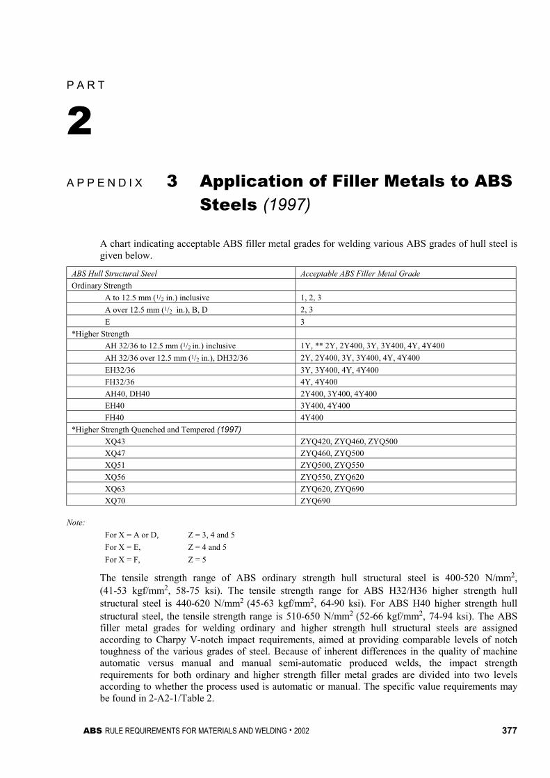
ABS RULE REQUIREMENTS FOR MATERIALS AND WELDING . 2002 377
P A R T
2A P P E N D I X 3 Application of Filler Metals to ABS
Steels (1997) 2 - A 3
A chart indicating acceptable ABS filler metal grades for welding various ABS grades of hull steel isgiven below.
ABS Hull Structural Steel Acceptable ABS Filler Metal Grade
Ordinary Strength
A to 12.5 mm (1/2 in.) inclusive 1, 2, 3
A over 12.5 mm (1/2 in.), B, D 2, 3
E 3
*Higher Strength
AH 32/36 to 12.5 mm (1/2 in.) inclusive 1Y, ** 2Y, 2Y400, 3Y, 3Y400, 4Y, 4Y400
AH 32/36 over 12.5 mm (1/2 in.), DH32/36 2Y, 2Y400, 3Y, 3Y400, 4Y, 4Y400
EH32/36 3Y, 3Y400, 4Y, 4Y400
FH32/36 4Y, 4Y400
AH40, DH40 2Y400, 3Y400, 4Y400
EH40 3Y400, 4Y400
FH40 4Y400
*Higher Strength Quenched and Tempered (1997)
XQ43 ZYQ420, ZYQ460, ZYQ500
XQ47 ZYQ460, ZYQ500
XQ51 ZYQ500, ZYQ550
XQ56 ZYQ550, ZYQ620
XQ63 ZYQ620, ZYQ690
XQ70 ZYQ690
Note:
For X = A or D, Z = 3, 4 and 5
For X = E, Z = 4 and 5
For X = F, Z = 5
The tensile strength range of ABS ordinary strength hull structural steel is 400-520 N/mm2,(41-53 kgf/mm2, 58-75 ksi). The tensile strength range for ABS H32/H36 higher strength hullstructural steel is 440-620 N/mm2 (45-63 kgf/mm2, 64-90 ksi). For ABS H40 higher strength hullstructural steel, the tensile strength range is 510-650 N/mm2 (52-66 kgf/mm2, 74-94 ksi). The ABSfiller metal grades for welding ordinary and higher strength hull structural steels are assignedaccording to Charpy V-notch impact requirements, aimed at providing comparable levels of notchtoughness of the various grades of steel. Because of inherent differences in the quality of machineautomatic versus manual and manual semi-automatic produced welds, the impact strengthrequirements for both ordinary and higher strength filler metal grades are divided into two levelsaccording to whether the process used is automatic or manual. The specific value requirements maybe found in 2-A2-1/Table 2.
Part 2 Rule Requirements for Materials and WeldingAppendix 3 Application of Filler Metals to ABS Steels 2-A3
378 ABS RULE REQUIREMENTS FOR MATERIALS AND WELDING . 2002
*Non-low hydrogen type covered electrode approvals for welding higher strength steels (denoted by *in the list) are subject to satisfactory procedure tests at the user’s plant. These procedure tests shouldinclude fabrication of a double fillet weld assembly(ies) representative of material(s) and thickness(es)to be used in production. Weld on the first side is to be allowed to cool to ambient temperature beforethe second side weld is made. Three macrosections (a section from the center, and a section at oneinch from each end), taken 72 hours (min.) after welding are to be free of weld and heat affected zonecracks when etched and examined at 10X magnification.
**Grade 1Y not applicable to manual welding electrodes and semi-automatic wire-gas combinations.