Parsing Sewing Patterns into 3D Garments - CiteSeerX
11
Parsing Sewing Patterns into 3D Garments Floraine Berthouzoz 1 Akash Garg 2 Danny M. Kaufman 2 Eitan Grinspun 2 Maneesh Agrawala 1 1 University of California,Berkeley 2 Columbia University Figure 1: Our parser automatically converted a diverse set of sewing patterns into 3D garment models for this small crowd of women. Abstract We present techniques for automatically parsing existing sewing patterns and converting them into 3D garment models. Our parser takes a sewing pattern in PDF format as input and starts by ex- tracting the set of panels and styling elements (e.g. darts, pleats and hemlines) contained in the pattern. It then applies a combina- tion of machine learning and integer programming to infer how the panels must be stitched together to form the garment. Our system includes an interactive garment simulator that takes the parsed re- sult and generates the corresponding 3D model. Our fully automatic approach correctly parses 68% of the sewing patterns in our collec- tion. Most of the remaining patterns contain only a few errors that can be quickly corrected within the garment simulator. Finally we present two applications that take advantage of our collection of parsed sewing patterns. Our garment hybrids application lets users smoothly interpolate multiple garments in the 2D space of patterns. Our sketch-based search application allows users to navigate the pattern collection by drawing the shape of panels. CR Categories: I.3.8 [Computer Graphics]: Applications Keywords: Diagram parsing, garment modeling Links: DL PDF WEB VIDEO 1 Introduction Sewing patterns describe the cutting, folding and stitching opera- tions required to physically fabricate clothing. While websites such as burdastyle.de and voguepatterns.com provide ready access to thousands of such patterns online, the patterns themselves are terse and encode many of the sewing operations implicitly (e.g. how pieces of the garment are stitched together). To identify the com- plete sequence of operations required to construct a garment, skilled human tailors usually have to rely on their experience and under- standing of the conventions of sewing patterns. Garment designers for virtual characters in films and games do not exploit the rich collection of sewing patterns available online to generate 3D clothing. Instead, they manually create virtual clothing using special-purpose garment modeling and sculpting tools. This process requires significant expertise and is very time-consuming. Recent sketch-based garment design systems [Wang et al. 2003; Decaudin et al. 2006; Turquin et al. 2007; Robson et al. 2011; Umetani et al. 2011] facilitate this process, but usually produce gar- ment models that are simpler than real-world garments. Creating detailed 3D garment models remains a challenging task. We present techniques for automatically parsing sewing patterns and converting them into 3D garment models. Given a pattern in PDF format, our parser first extracts the panels or shaped pieces of cloth that form the garment. It then extracts styling elements such as darts, pleats and hemlines contained within the panels. The key step in parsing is to determine how the panels must be stitched together. Our parser combines machine learning with integer programming to infer the stitching edge correspondences between panels. Our system includes an interactive garment simulator to generate a 3D model of the garment and drape it on a mannequin. The simulator extends Sensitive Couture [Umetani et al. 2011] with a small set of features that allow it to support a larger variety of input patterns. Our fully automatic approach correctly parses 68% of the sewing patterns in our collection. Most of the remaining patterns contain only a few errors that can be quickly corrected within the garment simulator. Our system automatically generated all of the 3D gar- ments in Figure 1 without any parsing errors.
-
Upload
khangminh22 -
Category
Documents
-
view
3 -
download
0
Transcript of Parsing Sewing Patterns into 3D Garments - CiteSeerX

Parsing Sewing Patterns into 3D Garments
Floraine Berthouzoz1 Akash Garg2 Danny M. Kaufman2 Eitan Grinspun2 Maneesh Agrawala1
1University of California,Berkeley 2Columbia University
Figure 1: Our parser automatically converted a diverse set of sewing patterns into 3D garment models for this small crowd of women.
Abstract
We present techniques for automatically parsing existing sewingpatterns and converting them into 3D garment models. Our parsertakes a sewing pattern in PDF format as input and starts by ex-tracting the set of panels and styling elements (e.g. darts, pleatsand hemlines) contained in the pattern. It then applies a combina-tion of machine learning and integer programming to infer how thepanels must be stitched together to form the garment. Our systemincludes an interactive garment simulator that takes the parsed re-sult and generates the corresponding 3D model. Our fully automaticapproach correctly parses 68% of the sewing patterns in our collec-tion. Most of the remaining patterns contain only a few errors thatcan be quickly corrected within the garment simulator. Finally wepresent two applications that take advantage of our collection ofparsed sewing patterns. Our garment hybrids application lets userssmoothly interpolate multiple garments in the 2D space of patterns.Our sketch-based search application allows users to navigate thepattern collection by drawing the shape of panels.
CR Categories: I.3.8 [Computer Graphics]: Applications
Keywords: Diagram parsing, garment modeling
Links: DL PDF WEB VIDEO
1 Introduction
Sewing patterns describe the cutting, folding and stitching opera-tions required to physically fabricate clothing. While websites suchas burdastyle.de and voguepatterns.com provide ready access tothousands of such patterns online, the patterns themselves are terseand encode many of the sewing operations implicitly (e.g. howpieces of the garment are stitched together). To identify the com-plete sequence of operations required to construct a garment, skilledhuman tailors usually have to rely on their experience and under-standing of the conventions of sewing patterns.
Garment designers for virtual characters in films and games do notexploit the rich collection of sewing patterns available online togenerate 3D clothing. Instead, they manually create virtual clothingusing special-purpose garment modeling and sculpting tools. Thisprocess requires significant expertise and is very time-consuming.Recent sketch-based garment design systems [Wang et al. 2003;Decaudin et al. 2006; Turquin et al. 2007; Robson et al. 2011;Umetani et al. 2011] facilitate this process, but usually produce gar-ment models that are simpler than real-world garments. Creatingdetailed 3D garment models remains a challenging task.
We present techniques for automatically parsing sewing patternsand converting them into 3D garment models. Given a pattern inPDF format, our parser first extracts the panels or shaped pieces ofcloth that form the garment. It then extracts styling elements such asdarts, pleats and hemlines contained within the panels. The key stepin parsing is to determine how the panels must be stitched together.Our parser combines machine learning with integer programmingto infer the stitching edge correspondences between panels. Oursystem includes an interactive garment simulator to generate a 3Dmodel of the garment and drape it on a mannequin. The simulatorextends Sensitive Couture [Umetani et al. 2011] with a small set offeatures that allow it to support a larger variety of input patterns.
Our fully automatic approach correctly parses 68% of the sewingpatterns in our collection. Most of the remaining patterns containonly a few errors that can be quickly corrected within the garmentsimulator. Our system automatically generated all of the 3D gar-ments in Figure 1 without any parsing errors.
Building a collection of parsed sewing patterns opens the door tomyriad data-driven applications. To demonstrate this potential, wedraw inspiration from recent work on the reuse, alteration, resiz-ing and retargeting of garments [Wang et al. 2005; Apeagyei andOtieno 2007; Geng et al. 2009; Meng et al. 2012b; Brouet et al.2012] and present two applications that allow users to further ex-plore the space of garment design. Our first application uses theseparsed patterns to smoothly interpolate multiple garment panels inthe 2D pattern space. Users can now rapidly create and exploremultiple design variants via hybrids and combinations of exisitinggarment designs. Our second application allows users to navigateavailable pattern collections by sketch-based search.
2 Previous Work
Parsing diagrams. People often use diagrams to communicate in-formation. For example, sewing patterns are diagrams that describethe operations necessary to assemble a garment. Researchers havedeveloped automatic parsers that can reconstruct the informationcontained in many different types of diagrams, including engineer-ing drawings [Haralick and Queeney 1982] and cartographic roadmaps [Mena 2003]. These parsers rely on image-processing meth-ods and domain-specific knowledge to extract and interpret the di-agrams. To the best of our knowledge, our work is the first to applya similar approach to parsing sewing patterns.
Sketch-based apparel design. Sketch-based interfaces constructan internal representation of clothing from input strokes and annota-tions. In that sense our parser shares some similarities with sketch-based approaches. Turquin et al. [2004; 2007] ask users to overs-ketch a character’s body with a garment’s silhouette and infer thegarment’s geometry and drape. Robson et al. [2011] further incor-porate contextual knowledge of key factors that affect a garment’sshape. Wang et al. [2003] and Decaudin et al. [2006] ask users tosketch on a mannequin, dividing the body into extruded panels; thelatter work then develops the panels into a design pattern.
There are also important differences between sketch-based toolsand our setting. First, most sketching interfaces oversketch a 3Dmannequin, whereas we interpret the 2D lines and text of a pattern.Second, sketching gives strokes an orientation and temporal order-ing; it allows for gestures. This data is not available in printed pat-terns. On the other hand, sketching interfaces must be interpretedonline, constructing a model only from past strokes; our patternsare interpreted offline, allowing for global analysis.
Computer-aided design and fitting of sewing patterns. Sewingpatterns are the singular standard for specification of apparel de-signs in the fashion industry. For this reason, a considerable num-ber of academic works and commercial software tools have beendeveloped for computer-aided garment pattern design [Meng et al.2012a]; representative samples include ClothAssembler [Fontanaet al. 2005], Optitex PDS (Pattern Design Software), MarvelousDesigner, and Pattern Works Int’l. Interpretation of sewing pat-terns and prediction of their drape is an important technology fordeveloping a virtual fitting room [Protopsaltou and Luible 2002;Cordier et al. 2003; Meng et al. 2010], ideally one that accom-modates virtual people in all shapes, sizes, and poses [Guan et al.2012]. Igarashi and Hughes [2002] presented an interactive tool forplacing garment panels on a mannequin. In this work, we extendSensitive Couture [Umetani et al. 2011] to assemble parsed patternsand automatically drape them on a mannequin.
3 Sewing Patterns
We purchased 50 sewing patterns from burdastyle.de. While manypattern collections are available online, we chose Burdastyle be-cause its collection of over 8000 patterns is large, diverse, and in-
expensive ($3 to $15 per pattern). We have also examined patternsfrom a number of sites and found that they all use standardized dia-grammatic elements to help tailors understand the steps required tostitch and assemble the garment.
3.1 Diagrammatic Elements of Sewing Patterns
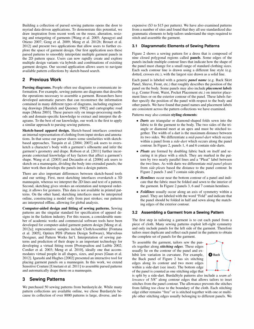
Figure 2 shows a sewing pattern for a dress that is composed ofnine closed polygonal regions called panels. Some edges of thepanels include multiple contour lines that indicate how the shape ofthe panel must change for a small range of standard clothing sizes.Each such contour line is drawn using a different line style (e.g.dotted, crosses etc.), with the largest size drawn as a solid line.
Each panel is labeled with a generic panel name (e.g. Back SkirtPanel, Sleeve, Front, etc.) that roughly describes the position of thepanel on the body. Some panels may also include placement labels(e.g. Center Front, Waist, Pocket Placement etc.) on interior place-ment lines or on the exterior contour of the panel. These labels fur-ther specify the position of the panel with respect to the body andother panels. We have found that panel names and placement labelsare consistent across the pattern collections we have examined.
Patterns may also contain styling elements:
• Darts are triangular or diamond-shaped folds sewn into thefabric to fit the garment to the body. The two sides of the tri-angle or diamond meet at an apex and must be stitched to-gether. The width of a dart is the maximum distance betweenits two sides. We differentiate a mid-panel-dart which occurswithin a panel from a side-dart which occurs along the panelcontour. In Figure 2, panels 1, 4 and 6 contain side-darts.
• Pleats are formed by doubling fabric back on itself and se-curing it in place with a stitch. They are marked in the pat-tern by two nearly parallel lines and a “Pleat” label betweenthe two lines. As with darts we differentiate mid-panel-pleatsfrom side-pleats based the distance to the panel contour. InFigure 2 panels 3 and 7 contain side-pleats.
• Hemlines occur near the bottom contour of a panel and indi-cate that the fabric must be folded and sewn to the interior ofthe garment. In Figure 2 panels 3, 6 and 7 contain hemlines.
• Foldlines usually occur along an axis of symmetry within apanel. They are labeled with the word “Fold” and indicate thatthe panel should be folded in half and sewn along the match-ing edges of the exterior contour.
3.2 Assembling a Garment from a Sewing Pattern
The first step in tailoring a garment is to cut each panel from apiece of cloth. Many sewing patterns exploit left-right symmetryand only include panels for the left side of the garment. Thereforetailors must duplicate and reflect each panel in the pattern to obtainthe complete set of panels for the garment.
Back4
To assemble the garment, tailors sew the pan-els together along stitching edges. These edgesusually lie on the contour of the panel and ex-hibit low variation in curvature. For example,the Back panel of Figure 2 has six stitchingedges along its contour and two more edgeswithin a side-dart (see inset). The bottom edgeof the panel is counted as one stitching edge thatis split by a side-dart. BurdaStyle patterns also include a seam al-lowance of 5/8” along contour edges that allows tailors to insetstitches from the panel contour. The allowance prevents the stitchesfrom falling too close to the boundary of the cloth. Each stitchingedge either remains “free” or is stitched together with one or multi-ple other stitching edges usually belonging to different panels. We

EUQI TSALE /
GNI SAC CI TSALEADASAPERTNE A
MO
G
43
63
83
04
ILP
EUGEILP
I LPEU
GEI LP
I LPEU
GEI LP
ILPE
UGEI LP
24
ILP
EUGEILP
ILP
EUGEILP
NI ARG THGI ARTS
OLI H ODI TNESLI F TI ORD
ILPEU
GEI LP
ILPE
UGEILP
ILPE
UGEILP
44
43
43
43
ENIL
DLOF-
MEH
TELR
UOʼL E
D ER
UILP
ZELBO
D ED AE
NIL-OLLI
DALBO
D
11 4
)mc3(
"ECNA
WOLLA
MEH
OLLIDALBOD ED NE
GRAM
TELRUOʼD RUELAV
43
43
43
43 . 9
01
PLEA
T
PLEA
T
PLEA
T
PLEA
T
TAELP
PLEA
T
PLEA
T
TAELP
PLEA
T
Side-Pleat
1
01
CEN
TER
FR
ON
T FO
LD, S
TRAI
GH
T G
RAI
NM
ILIE
U D
EVAN
T PL
IUR
E, D
RO
IT F
IL
44
24
04
83
63
43
43
43
743
5
4
FrontSide-Dart
Center Front
1
Sleeve7
3
5
44
43
43
743
CEN
TER
BAC
K ZI
PPER
STR
AIG
HT
GR
AIN
MED
IO P
OST
. CR
EMAL
LER
A, D
IREC
CIO
N H
ILO
MIL
IEU
DO
S, F
ERM
. A G
LISS
., D
RO
IT-F
IL 24
04
83
63
43
Back
Side-Dart
Center Back
4
Corner-MatchCircles
Back Skirt Panel6
POT
ARRIBAEN HAUT
NIAR
G TH
GIARTS
OLIH
ODIT
NESLIF TI
OR
D
44
USSIT U
D ER
UILPZEL B
OD E
D OT
N AC
D LO F
CIRBAF
TN
ORF
RETNE
C
ORET
NALED
ORT
NEC
TNAVE
D UEILI
M
3
2
1
634
34
43
44
24
04
83
63
43
9 0
Front Band2
NIA
RG
TH
GIA
RTS
OLI
H O
DIT
NES
LIF
TIO
RD
44
3 REPP
I Z K
CAB
RET
NEC
ARE
LLA
MER
C .TS
OP
OIDE
M. S
SIL
G A .
MRE
F ,S
OD
UEI L
IM4
83 04
43 24
34
POT
ABI RRATUAH NE
63
34
Back Band5
Front Skirt Panel3
CEN
TER
FR
ON
T FO
LD, S
TRAI
GH
T G
RAI
N
MED
IO D
ELAN
TER
O D
OBL
EZ S
ENT.
HIL
OM
ILIE
U D
EVAN
T PL
IUR
E, D
RO
IT F
IL
1 14 )mc3("
ECNAWOLLA MEH
OLLIDALBOD ED NEGRAM
TELRUOʼD RUELAV
2
36
ENILDLOF-MEH
TELRUOʼL ED ERUILPZELBOD ED AENIL-OLLIDALBOD
438
4442
38
TAELP
ILPEUGEILP
40
TSIAW
ELLIATARUTNIC
TAELP
ILPEUGEILP
40
42
38
36
34
34
44
Cent
er F
ront
Waist
Hemline
ENILDLOF-MEH
TELRUOʼL ED ERUILPZELBOD ED AENIL-OLLIDALBOD
CEN
TER
BAC
K ZI
PPER
MED
IO P
OST
. CR
EMAL
LER
AM
ILIE
U D
OS,
FER
M. A
GLI
SS.
43
43
44
44
24
04
STR
AIG
HT
GR
AIN
SEN
TID
O H
ILO
DR
OIT
FIL
TSIAW
ELLIATARUTNIC
83
SEAM
CO
UTU
RE
CO
STU
RA
63
1 14 )mc3("
ECNAWOLLA MEH
OLLIDALBOD ED NEGRAM
TELRUOʼD RUELAV
43
443
Cent
er B
ack
Waist
Back Facing
RETNEC
.TSOP ORTNEC
SOD UEI LI M
43 44 .6
44
KCAB
9
Center Back DL OF TNORF RETNEC
ZELBOD , ORETNALED OI DE MVED UEI LI M USSI T UD ERUI LP
Front Facing8
CenterFront
ENILDLOF-MEH
ELRUOʼL ED ERUILPAENIL-OLLIDALBOD
Corner-MatchCircles
44
24
04
83
63
743
Hemline
Hem
line
Side-Dart
2DNAB TNORF
ROIRETNA AFENEC
TNAVED ETTAP/TNEMERAP
5 8"ERUTUOC ED RUELAV CEVA
)mc5,1(
DEDULCNI ECNAWOLLA MAES
ARUTSOC ED NEGRAM NOC
DLOF EHT NOX ODALBOD OTNAC NOC
USSIT UD ERUILP AL SNAD1
5 8" AVEC VALEUR DE COUTURE(1,5cm)
SEAM ALLOWANCE INCLUDED
CON MARGEN DE COSTURA
PAREMENT DOSBACK BAND
CENEFA POST.
2 X
5
GNICAF KCAB
.TSOP ATSIV
SOD ERUTNEMERAP
2 X
9
5 8" ERUTUOC ED RUEAV CEVA)mc5,1(
DEDULCNI ECNAWOLLAAES
ARUTSOCEDNEGRAMNOC
4KCAB
ADLAPSESOD
2 X
5 8" ERUTUOC ED RUELAV CEVA)mc5,1(
DEDULCNI ECNAWOLLA MAES
ARUTSOC ED NEGRAM NOC
ON THE FOLDX
CON CANTO DOBLADODANS LA PLIURE DU TISSU1
5 8" AVEC VALEUR DE COUTURE(1,5cm)
SEAM ALLOWANCE INCLUDED
CON MARGEN DE COSTURA
FRONT FACING
VISTA DELANTERAPAREMENTURE DEVANT
8
DLOF EHT NOX
ODALBOD OTNAC NOCUSSIT UD ERUILP AL SNAD1
1
5 8" ERUTUOC ED RUELAV CEVA)mc5,1(
DEDULCNI ECNAWOLLA MAES
ARUTSOC ED NEGRAM NOC
TNORF
ORETNALEDTNAVED
3LENAP TRIKS TNORF
ROIRETNA ADLAFEPUJ ED TNAVED
DLOF EHT NOX
ODALBOD OTNAC NOCUSSIT UD ERUILP AL SNAD1
5 8" ERUTUOC ED RUELAV CEVA)mc5,1(
DEDULCNI ECNAWOLLA MAES
ARUTSOC ED NEGRAM NOC 6LENAP TRIKS KCAB
.TSOP ADLAFEPUJ ED SOD
2 X
5 8" ERUTUOC ED RUELAV CEVA)mc5,1(
DEDULCNI ECNAWOLLA MAES
ARUTSOC ED NEGRAM NOC
EVEELS
AGNAMEHCNAM
2 X
5 8" ERUTUOC ED RUELAV CEVA)mc5,1(
DEDULCNI ECNAWOLLA MAES
ARUTSOC ED NEGRAM NOC
7
44
7
24
0
Corn
er-M
atch
Circ
les
I LPEU
GEI LP
I LPE
UGEI LP
I LPEU
GEI LP
ILPE
UGEILP
ILPE
UGEILP
43
43
43
PLEA
T
PLEA
TPL
EAT
PLEA
T
PLEA
T
Hem
line
a
b
a
b
δ
2δ
a
b
Side
-Ple
atSi
de-D
art
Figure 2: A sewing pattern from our collection containing nine panels. Each panel contains multiple contour lines that represent differentgarment sizes and are drawn using different line styles (dotted, crosses, etc.) We have annotated some styling elements including darts(brown), pleats (purple), and hemlines (green) as well as placement labels (blue) and corner-match circles (red). The side-dart and side-pleatinsets show how the edges marked a and b must be sewn together to properly form the styling element. The hemline inset shows how the panelmust be folded at the line marked as a hemline stitched along an additional line (dotted) located at twice the distance δ from the nearby panelcontour. The corner-match circles inset shows the number 7 circles from the Back and Front panels. These circles indicate matching panelcorners. Readers can zoom into the PDF to see the text provided in the original pattern as well as the different line styles on panel contours.
say that these attached stitching edges are in correspondence.
Patterns usually include a sparse set of annotations we call corner-match circles that are designed to help tailors infer the correspon-dences between stitching edges. These numbered circles alwaysappear at the intersection of two stitching edges and tailors mustmatch the number across different panels to identify a correspon-dence between panel corners (Figure 2). While corner-match cir-cles aid tailors in understanding how to sew together the garment,they only specify how panels join together at a few corners. Tai-lors must usually consider multiple corner-match circles as well thepanel names and placement labels to determine the complete set ofcorrespondences along stitching edges.
While most of the panels in a pattern form the main-body of thegarment, many patterns also include a few decorative panels such aspockets, ruffles and belts. Since panel names are consistent acrosspatterns, tailors can easily distinguish between main-body panelsand decorative panels based on their names. Tailors often considerthe main-body panels first and once they have understood how theseare assembled they add in the decorative panels.
4 Overview
Converting a sewing pattern into a 3D garment model involves twocomponents; a sewing pattern parser (Section 5) and a garmentsimulator (Section 6). Our work primarily focuses on the parser. Ittakes a sewing pattern in PDF format as input and starts by extract-ing the set of panels and styling elements contained in the pattern. Itthen identifies the stitching edges for each panel. Finally it applies acombination of machine learning and integer programming to inferthe most likely correspondences between the stitching edges. Ourgarment simulator then uses these correspondences to generate and
drape a 3D model of the garment. It extends the Sensitive Couturesystem of Umetani et al. [2011] with a small set of features thatallow it to support a larger variety of real-world input patterns.
5 Parser
Our parser includes two stages, a panel extractor and a correspon-dence identifier. It outputs a list of panels, styling elements andstitching edge correspondences that together describe how the pan-els must be stitched together to form the garment.
5.1 Extractor
Our input sewing patterns are vector graphics files in PDF formatand are composed of two basic types of elements: line segments andtext. The panel extractor is responsible for analyzing this collectionof segments and text to identify the panels and styling elementsalong with their associated labels, placement labels, stitching edgesand corner-match circles.
5.1.1 Extracting Panels
To identify the panels the extractor considers all solid line segmentsand groups them into connected components. In most cases each re-sulting component represents a single panel. For example Figure 3(top-left) shows the Sleeve connected component for the pattern inFigure 2. In some instances, however, a component may representa mid-panel styling element rather than a complete panel. Thus, foreach component the extractor checks if it is fully enclosed by anyother component and if so it groups them together.
The extractor then traces out the external contour of each panel atthe largest clothing size. It starts with the line segment that is fur-

Sleeve7
Connected Components Stitching Edges
Styling ElementCorrespondences Grouped Stitching Edge
Figure 3: Extracting the Sleeve panel. The connected component(top-left) and stitching edges (top-right) of the panel. The pleats andhemline stitching edge correspondences (bottom-left). Grouping thestitching edges adjacent to side-pleats.(bottom-right).
thest away from the center of the panel and then steps along con-nected segments, while always choosing the outermost segment ifthe path branches. This tracing procedure ends when the extractorreturns to the initial segment. The result is a closed contour loop.
The extractor next considers the set of line segments and text thatlie within the contour of each panel. It identifies the largest textelement within the panel as the panel name. The extractor differen-tiates between main-body panels and decorative panels based on thepanel name. As a one-time pre-process we manually built a lookuptable mapping the panel name to each of these two categories.
The extractor also collects all of the interior line segments andchains the connected segments into longer continuous lines. It thenassociates any remaining text elements with nearby interior linesand contour lines if the distance between the text and line is withina small threshold. These labeled lines represent either placementlines, foldlines or hemlines. In some cases a placement line coin-cides with only a part of a contour line and the extent of the place-ment line is delineated by two short perpendicular line segments.We identify these boundary segments to properly mark the extentof the placement line. To identify the corner-match circles, the ex-tractor finds interior line segments that form small circles. It thentreats nearby numerical text element as the corner-match label.
The extractor splits the contour and interior lines into stitchingedges. As we have noted stitching edges are relatively smooth anddo not contain sharp corners. Therefore the extractor breaks theselines into stitching edges whenever the angle between consecutivesegments is larger than a threshold (we use 25◦). In Figure 3 (top-right), red circles indicate endpoints of stitching edges. Note thatour implementation directly treats the contours of extracted panelsas stitching edges and does not adjust for the 5/8” seam allowance.
5.1.2 Extracting Styling Elements
To identify pleats the extractor looks for a pair of nearly parallelinterior lines that contain the text label “Pleat” between them. Itdifferentiates mid-panel-pleats from side-pleats based on whetheror not the pleat lines touch the panel contour. To identify darts theextractor looks for loops in the set of lines comprising the panel.It marks loops that only include interior lines as mid-panel-dartsand loops that include part of the panel contour as side-darts. Forexample, the dart in the Front panel of Figure 2 contains part of thepanel contour and is therefore classified as a side-dart.
Styling elements such as darts, pleats, hemlines and foldlines di-
Probabilities Chosen Correspondences
Sleev
eBa
ck
e1e2e3e4e5...
Sleeve
...
Back ... Free
Main
-Bod
y Stit
ching
Edge
sDe
cora
tive
Stitc
hing E
dges
Belt
...
e1e2e3e4e5...Sleeve Back ... Freee1e2e3e4e5...
Figure 4: Probability tables for the main-body panel stitchingedges (top-left) and decorative panel stitching edges (bottom-left).Red indicates higher probability of correspondence. Optimal stitch-ing edge correspondences chosen by our integer program (right).
rectly encode their corresponding stitching edges and the extractorimmediately marks these correspondences. In a dart, for example,the two interior lines that meet at the apex form two correspondingstitching edges that must be sewn together. In a pleat the two paral-lel stitching edges correspond to one another. For a hemline we firstform an additional stitching edge located at twice the distance δ be-tween the hemline and contour. This additional edge corresponds tothe parallel contour stitching edge. To handle a foldline we reflectthe panel stitching edges across the foldline. If the reflected edgeslie near existing stitching edges we mark them as corresponding.Otherwise we create new stitching edges at the reflected locationsand mark those as corresponding. We color-code pleat and hemlinecorrespondences for the Sleeve panel in Figure 3 (bottom-left).
Note that when side-darts or side-pleats are sewn into a garmentthey eliminate a portion of the contour stitching edge. Thereforewe group the adjacent contour stitching edges on either side of thedart or pleat and treat them as a single stitching edge. In Figure 3(bottom-right), the top of the Sleeve includes 9 side-pleats and wegroup the adjacent edges (black) into a single stitching edge.
5.2 Correspondence Identifier
The correspondence identifier is responsible for determining howthe panels should be stitched together to form the garment. It infersthe most likely correspondences between all of the remaining stitch-ing edges in the garment using a combination of machine learningand integer programming.
Assuming the sewing patterns exploit left-right symmetry, the cor-respondence identifier first duplicates and mirrors all panels. Toform a complete garment, it is essential to stitch together the main-body panels. The decorative panels serve to further embellish thegarment but are less important. Therefore, our approach is to firstprocess the main-body panels (step 1) and then handle the decora-tive panels (step 2).
In each step we build a table of probabilities P where each entryPi,j captures the likelihood of a correspondence between a pair ofstitching edges (ei, ej) (Figure 4). In the first step we consider allpairs (ei, ej) where both ei and ej belong to main-body panels. Inthe second step we focus on stitching edge pairs where the first edgeei belongs to a decorative panel and the second edge ej belongsto a main-body panel. We augment both of these tables with anextra column to capture the probability Pi,n+1 that stitching edge
ei remains “free” and is not attached to any other edge. We describehow we compute these probabilities in Section 5.2.2.
This probability table allows us to find the most likely correspon-dences. Let ω : [1 . . . n] → [1 . . . n + 1] map the index i of eachedge ei to a corresponding edge index ω(i), with ω(i) = n + 1indicating a free (unmatched) edge. We further restrict ω, in a waywe will soon make precise, to respect a few important properties ofgarments. We seek the map ω that maximizes the joint probability
n∏i=1
Pi,ω(i) .
Using the monotonicity of the logarithm, we equivalently seekto maximize
∑ni=1 logPi,ω(i). We encode ω by the n × n + 1
indicator matrix X, with unit entries encoding correspondences(∀i, xi,ω(i) = 1), and remaining entries zero. This gives rise tothe integer programming problem
argmaxx
n∑i=1
n+1∑j=1
xi,j logPi,j (1)
subject to∑n+1j=1 xi,j = 1 one corresp. per row i (2)∑ni=1 xii = 0 no self corresp. (3)
∀i, j, xij − xji = 0 mutual corresp. (ω is symmetric) (4)xps + xpt + xqs + xqt = 1 one corresp. per circle (5)
Typically each stitching edge either remains free or corresponds toexactly one other stitching edge. Constraint (2) enforces this re-quirement; we will soon modify this constraint to handle multiplestitching edge correspondences. Constraint (3) prevents stitchingedges from corresponding with themselves. Constraint (4) forcesmutual correspondence between stitching edges.
Constraint (5) considers stitching edges that are adjacentto corner-match circles. These circles indicate matchingcorners on two different panels and limit the potential
es
eteq
ep
7 7
correspondences to four stitching edge pairs. Asshown in the inset, edges ep and eq are adjacentto the first circle and edges es and et are adja-cent to the second circle. Constraint (5) ensuresthat exactly one of the four potential correspon-dences between these edges is active.
We solve for X using a built-in MATLAB integer programmingroutine1, which implements a linear program solver using branch-and-bound [Wolsey 2000]. Figure 4 shows the optimal set of stitch-ing edge correspondences for our example.
5.2.1 Handling Multiple Correspondences
Some panels contain stitching edges that correspond to more thanone other stitching edge. For example, one edge of a Sleeve oftenattaches to both a Front panel and a Back panel (Figure 2). We havemanually examined our collection of patterns to identify a small setof panels that contain such multi-correspondence stitching edges.In the panel extractor we mark edges that belong to these panels aspotential multi-correspondence edges.
Another example occurs when the garment contains multiple lay-ers stitched at the same edge. In this case a corner-match circlewith the same number appears on more than two panels. We markedges adjacent to these corner-match circles as potential multi-correspondence edges.
1bintprog(): http://www.mathworks.com/help/optim/ug/binary-integer-programming-algorithms.html
Feature Histograms
SleeveFront
Back
Sleeve
Back
...
Orientation
Average Curvature
Normalized Length
...
Free
Panel-Panel Table
Back Band
...
...
...
... ... ... ... ... ... ...
pane
l nam
e
...
panel name ...
Back Band
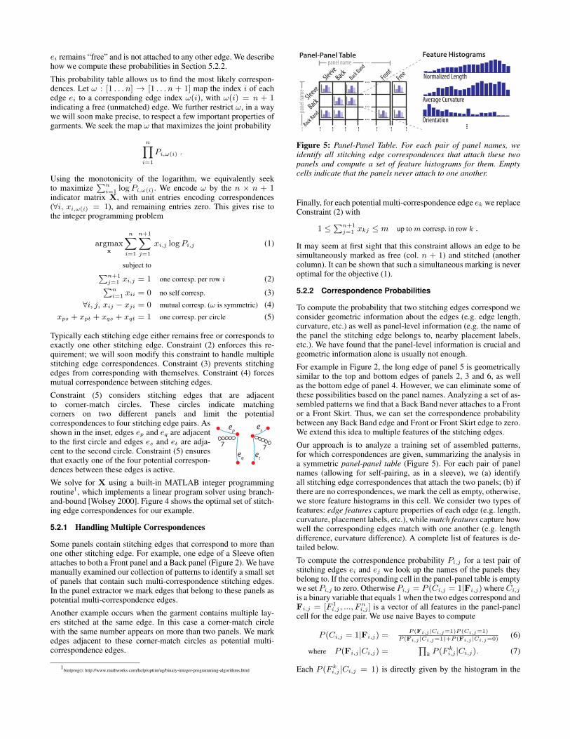
Figure 5: Panel-Panel Table. For each pair of panel names, weidentify all stitching edge correspondences that attach these twopanels and compute a set of feature histograms for them. Emptycells indicate that the panels never attach to one another.
Finally, for each potential multi-correspondence edge ek we replaceConstraint (2) with
1 ≤∑n+1
j=1 xkj ≤ m up to m corresp. in row k .
It may seem at first sight that this constraint allows an edge to besimultaneously marked as free (col. n + 1) and stitched (anothercolumn). It can be shown that such a simultaneous marking is neveroptimal for the objective (1).
5.2.2 Correspondence Probabilities
To compute the probability that two stitching edges correspond weconsider geometric information about the edges (e.g. edge length,curvature, etc.) as well as panel-level information (e.g. the name ofthe panel the stitching edge belongs to, nearby placement labels,etc.). We have found that the panel-level information is crucial andgeometric information alone is usually not enough.
For example in Figure 2, the long edge of panel 5 is geometricallysimilar to the top and bottom edges of panels 2, 3 and 6, as wellas the bottom edge of panel 4. However, we can eliminate some ofthese possibilities based on the panel names. Analyzing a set of as-sembled patterns we find that a Back Band never attaches to a Frontor a Front Skirt. Thus, we can set the correspondence probabilitybetween any Back Band edge and Front or Front Skirt edge to zero.We extend this idea to multiple features of the stitching edges.
Our approach is to analyze a training set of assembled patterns,for which correspondences are given, summarizing the analysis ina symmetric panel-panel table (Figure 5). For each pair of panelnames (allowing for self-pairing, as in a sleeve), we (a) identifyall stitching edge correspondences that attach the two panels; (b) ifthere are no correspondences, we mark the cell as empty, otherwise,we store feature histograms in this cell. We consider two types offeatures: edge features capture properties of each edge (e.g. length,curvature, placement labels, etc.), while match features capture howwell the corresponding edges match with one another (e.g. lengthdifference, curvature difference). A complete list of features is de-tailed below.
To compute the correspondence probability Pi,j for a test pair ofstitching edges ei and ej we look up the names of the panels theybelong to. If the corresponding cell in the panel-panel table is emptywe set Pi,j to zero. Otherwise Pi,j = P (Ci,j = 1|Fi,j) whereCi,j
is a binary variable that equals 1 when the two edges correspond andFi,j = [F 1
i,j , ..., Fni,j ] is a vector of all features in the panel-panel
cell for the edge pair. We use naive Bayes to compute
P (Ci,j = 1|Fi,j) =P (Fi,j |Ci,j=1)P (Ci,j=1)
P (Fi,j |Ci,j=1)+P (Fi,j |Ci,j=0)(6)
where P (Fi,j |Ci,j) =∏
k P (F ki,j |Ci,j). (7)
Each P (F ki,j |Ci,j = 1) is directly given by the histogram in the

panel-panel cell and we multiply them together to form the likeli-hood P (Fi,j |Ci,j = 1). We compute P (F k
i,j |Ci,j = 0) by firstaggregating the histograms across all other cells in the panel-paneltable and then form P (Fi,j |Ci,j = 0) as the product of these fea-ture probabilities. We treat the prior probability P (Ci,j = 1) asa constant for all pairs of stitching edges and can thus neglect theterm in Equation 6.
Computing Edge and Match Features. We compute a number offeatures for each pair of stitching edges. Several of these featuresrely on panel-level geometric information. So as a pre-process, wecompute the axis-aligned bounding box and the up orientation ofeach panel. We use styling elements and placement labels to com-pute the up orientation as follows. Since hemlines occur near thebottom contour of a panel (Section 3) if a panel contains a hemlinewe set the up vector perpendicular to it. Similarly the Top placementlabel occurs along the top contour of a panel and we set the up vec-tor perpendicular to it. In the absence of such labels we set the upvector to the longest edge of the bounding box. We then computethe following edge features.
• Normalized length. We compute the length of the stitchingedge normalized by the length of the diagonal of the panelbounding box. This feature captures the length of the stitchingedge compared to the size of its panel.
• Average curvature. Each stitching edge is a polyline. We firstfit a degree 5 polynomial curve to the polyline and then com-pute it’s curvature at constant intervals. We average togetherthese curvatures to form the final feature.
• Orientation. To capture the orientation of each stitching edgewe compute the dot product of the vector connecting the end-points of the stitching edge with the up vector.
• Placement label We determine if the stitching edge has aplacement label associated with it. We set the feature to Emptyif the stitching edge is not labeled and to the label name oth-erwise.
• Styling element. If the stitching edge is adjacent to a side-dart,side-pleat or near a hemline we set the feature to the name ofthe styling element. Otherwise we set the feature to Empty.
To obtain the match features for a pair of stitching edges we sim-ply compute the L2 distance between their normalized length, aver-age curvature and orientation features. For the placement label andstyling element features we build a binary feature that is set to 1 ifthe corresponding edge features have the same value.
6 Simulator
Once we have parsed a sewing pattern we use a garment simulatorto generate the corresponding 3D model and drape it on a virtualmannequin. Work on dynamic, physical simulation of cloth spansover two decades [Terzopoulos et al. 1989; Baraff and Witkin 1998;Choi and Ko 2002; House and Breen 2000; Bridson 2003; Rohmeret al. 2010]. We build on the Sensitive Couture interactive garmentmodeler [Umetani et al. 2011]. Sensitive Couture provides synchro-nized, interactive, bidirectional creation and editing of 2D clothingpatterns and their corresponding physically simulated 3D garment.This interface is a natural front-end for our parser since it not onlyprovides a 3D garment model but also enables users to immediatelycustomize the parsed patterns via manipulation and editing with di-rect feedback on changes to the corresponding 3D physical drape.
To support a large variety of real-world sewing patterns we haveextended Sensitive Couture with a small set of additional features:
Positioning panels. To successfully drape a garment in Sensi-tive Couture, it is critical to provide good initial seed positions in3D for all garment panels. In the original Sensitive Couture users
had to manually specify the seed position. However, in our pat-tern collection, each panel name roughly describes the position ofthe panel with respect to the body (e.g. all Sleeve panels must bedraped around arms). As a one-time pre-process we manually builta lookup table mapping main-body panel names to a rough 3D posi-tion on the virtual mannequin. We have modified Sensitive Coutureto use this table to assign the seed position for main-body panels.We also rotate the main-body panels so that they point outwardswith respect to the mannequin. Finally, we position decorative pan-els at a small offset from the main-body panels they attach to.
Interior stitching edges. The original Sensitive Couture only al-lowed stitching edges to occur along panel contours. However,styling elements like darts, pleats, and hemlines require interiorstitching edges. To properly handle such interior edges we havemodified Sensitive Couture to locally remesh the underlying sim-ulation mesh around them [Shewchuk 2002]. This modification iscrucial to obtain proper folding around the styling elements.
Sequential draping. Most garments are comprised of multiple lay-ers (e.g. a Ruffle panel attaches on top of a Front main-body panel).Tailors generally drape the most interior layers first. We modifiedSensitive Couture to allow draping in layers so that the most inte-rior layers are draped first and then frozen in place before adding thenext layer. This feature improves convergence speeds of the simu-lation and reduces the overhead of collision-processing.
7 Results
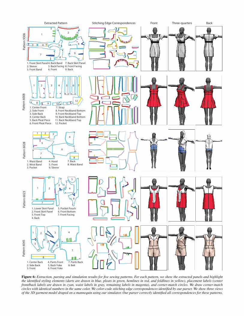
Figure 6 shows the parsing results as well as the simulated garmentsfor five example patterns from the set of 50 patterns we purchasedfrom burdastyle.de. Pattern 9306 is the garment we generate for thepattern shown in Figure 2. All patterns use styling elements. Forexample pattern 6045 includes darts and pleats to fit the garmentclose to the body. Four of the patterns use decorative panels suchas a belt (6045), pockets (6008, 6023, 6028), multiple dress lay-ers (6023) or additional pleat panels that are inserted between themain dress panels (6008). Figure 1 shows a variety of additionalgarments models generated by our system.
To evaluate our system, we processed all 50 patterns in our dataset.This collection is largely comprised of women’s dresses but also in-cludes some tops (e.g. blouses, sweatshirts, etc.) and trousers. Eachpattern contains 10 to 30 panels that are attached to one anotherby an average of 33 (std: 17) stitching edge correspondence. Pars-ing the patterns is relatively fast: our MATLAB implementation re-quires 5-10 seconds for pattern extraction and a few seconds forcorrespondence identification. Our simulator requires about 15 sec-onds to drape the 3D garment model and fully converge.
To test the parser we first built ground-truth data by manually anno-tating all of the stitching edge correspondences for all 50 patterns.We used leave-one-out cross validation to evaluate our correspon-dence identifier. Thus, for each pattern we treated all of the other 49patterns as a training set. We also excluded information about thetest pattern from manually constructed look-up tables. We foundthat for 68% of the patterns (34 out of the 50 ) our parser correctlyidentified all stitching edge correspondences. For the other 32%,our parser incorrectly marked an average of 4.4 (std: 4.7) corre-spondences. Note that all results shown in Figures 1 and 6 wereparsed correctly, and did not require any manual correction.
Aggregating across all patterns our parser correctly identified 87%of the stitching edge correspondences. Corner-match circles are themost informative indicators of a correspondence. For each pair ofcircles with the same label, exactly one pair of adjacent edges cor-respond. To determine how much corner-match circles contribute tothe learning, we manually annotated correspondences indicated bycorner-match circles in our ground truth data. We then found that
Patt
ern
6008
1 2 3 4 5 6 7
8 9 10 1112
1. Center Front2. Side Front3. Side Back4. Center Back5. Back Pleat Piece6. Front Pleat Piece
7. Strap8. Front Neckband Bottom9. Front Neckband Top10. Back Neckband Bottom11. Back Neckband Top12. Pocket
Patt
ern
6028
1. Waist Band2. Wrist Band3. Pocket
4. Hood5. Front6. Sleeve
7. Back8. Waist Band
1 2 34
5
6
7
8
Front Three-quarters BackExtracted Pattern Stitching Edge Correspondences
1. Front Skirt Panel2. Sleeve3. Front Band
4. Back Band5. Back Facing6. Front
7. Back Skirt Panel8. Front Facing9. Back
Patt
ern
9306 1
2
3 4 5 6
78
9
1. Lower Skirt Panel2. Front Skirt Panel3. Front Top4. Back
5. Pocket Pouch6. Front Bottom7. Front Facing
Patt
ern
6023
1 23
4
5
6
7
Patt
ern
6045
1. Center Back2. Side Back3. Front
4. Pants Front5. Back Yoke6. Front Yoke
7. Pants Back8. Belt
1 2 3 4
56
7
8
Figure 6: Extraction, parsing and simulation results for five sewing patterns. For each pattern, we show the extracted panels and highlightthe identified styling elements (darts are drawn in blue, pleats in green, hemlines in red, and foldlines in yellow), placement labels (centerfront/back labels are drawn in cyan, waist labels in gray, remaining labels in magenta), and corner-match circles. We draw corner-matchcircles with identical numbers in the same color. We color-code stitching edge correspondences identified by our parser. We show three viewsof the 3D garment model draped on a mannequin using our simulator. Our parser correctly identified all correspondences for these patterns.

incorrectcorresp.
incorrectcorresp.
missedcorresp.
missedcorresp.
Front Three-quarters BackExtracted Pattern Stitching Edge Correspondences
1. Back2. Sleeve3. Waistband Front4. Waistband Back
5. Wristband6. Front7. Back Facing8. Front Facing
Patt
ern
6030
1
2
3 45
6 78
incorrectcorresp.
1. Front2. Wristband3. Waistband Front4. Waistband Back
5. Back Facing6. Upper Sleeve7. Back 8. Under Sleeve
Patt
ern
6003
1
34
6
7 8
2
5
missedcorresp.
Figure 7: Garments with incorrect or missed correspondences. For Pattern 6030, the incorrect correspondence causes the jacket to be sewntogether in the front. For Pattern 6003, the missed correspondences cause the sleeve panels to be incorrectly attached to the main body.
our parser correctly marked 97% of these correspondences. Thesenumbers confirm that corner-match circles are very helpful in deter-mining how the panels attach to one another. However, patterns areonly sparsely annotated with such circles. Only 27% of all corre-spondences in our dataset were indicated with corner-match circles.
While not perfect, the correspondences identified by our parser pro-vide the user with a good starting point. Figure 7 shows some ex-amples of garments with a few incorrect correspondences. In thesecases, the user can still load the pattern into our simulator to pro-duce a 3D model. They can then use the interactive tools in Sensi-tive Couture to quickly correct the problems. For example, the usercan select two stitching edges to add or remove a correspondence.
Limitations. Currently, our parser only processes patterns fromburdastyle.de and extracts the panels at the largest clothing size.Furthermore, it assumes that all patterns exploit the left-right sym-metry and only includes panels for the left side of the garment.Although this assumption is violated by patterns for asymmetricgarments, such patterns typically annotate panels that should notbe duplicated. Our current implementation does not process suchannotations. As future work, we plan to extract multiple sizes andhandle asymmetric patterns correctly.
8 Applications
Users can take advantage of our collection of parsed sewing pat-terns to explore the space of garment designs. We have developedtwo applications that support such exploration. Our garment hy-brids application lets users smoothly interpolate multiple garmentsin the 2D space of patterns. Our sketch-based search applicationallows users to navigate the pattern collection by drawing panels.
8.1 Garment Hybrids
We have developed an algorithm that allows users to smoothly inter-polate multiple sewing patterns and thereby create garment hybrids.Users must choose two input patterns and can either interpolate allthe panels or select individual panels to interpolate. Our interpola-
Left Sleeve
Left Back
Free
Left Front Band
P1: Left Front
Left Back
Left Sleeve
Left BackRight Front
Left Front Band
LB LS LB LFB F
LB LS LB LFB RF F
P1:
P2:
LB
LS
F
LFB
LB
LB
LS
RF
LFB
P2: Left Front
Left BackLB
Alignment
FreeF
NULL
Figure 8: Aligning two panels. We first identify the attachment la-bels for the two panels and then compute the best alignment be-tween these labels using string edit distance.
tion algorithm works in the space of 2D patterns to ensure that eachintermediate result maintains a valid garment design. Interpolatingthe 3D shape of each garment would require users to manually spec-ify correspondences and would likely violate constraints imposedby the panels, styling elements and stitching correspondences.
To interpolate between two garments we identify all of the panelsthat they have in common based on the panel names. We then inter-polate the contour stitching edges between each pair of panels andthen interpolate the styling elements within the panels.
8.1.1 Interpolating Panel Contour Stitching Edges
Stitching edges on panel contours serve to attach the panel to sur-rounding panels. When interpolating between two garments it isessential to maintain these stitching edge correspondences as muchas possible to ensure proper connectivity of the interpolated result.
Given two panels P1 and P2 with the same name, but from differentpatterns, we start by computing an alignment between their contourstitching edges. This alignment ensures that we interpolate between
interpolation
virtual dart
P1 P2
virtualhemline
P2P1
s1
s2
Side-Dart Interpolation
Hemline Interpolation
{
>ω
>ω
{
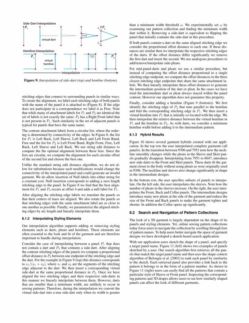
Figure 9: Interpolation of side-dart (top) and hemline (bottom).
stitching edges that connect to surrounding panels in similar ways.To create the alignment, we label each stitching edge of both panelswith the name of the panel it is attached to (Figure 8). If the edgedoes not participate in a correspondence we label it as Free. Notethat while many of attachment labels for P1 and P2 are identical theset of labels is not exactly the same; P2 has a Right Front label thatis not present in P1. Such similarity in the set of adjacent panels istypical for panels that have the same name.
The contour attachment labels form a circular list, where the order-ing is determined by connectivity of the edges. In Figure 8, the listfor P1 is Left Back, Left Sleeve, Left Back and Left Front Band,Free and the list for P2 is Left Front Band, Right Front, Free, LeftBack, Left Sleeve and Left Back. We use string edit distance tocompute the the optimal alignment between these lists. Since thelists are circular, we compute the alignment for each circular offsetof the second list and choose the best one.
Unlike the standard string edit distance algorithm, we do not al-low for substitutions because such modifications would change theconnectivity of the interpolated panel and could generate an invalidgarment. We do allow insertion of Null labels into either string fora constant cost. Null insertion corresponds to adding a zero lengthstitching edge to the panel. In Figure 8 we find that the best align-ment for P1 and P2 occurs at offset 4 and adds a null label for P1.
After aligning the stitching edge labels we translate the panels sothat their centers of mass are aligned. We also rotate the panels sothat stitching edges with the same attachment label are as close toone another as possible. Finally, we parameterize the aligned stitch-ing edges by arc length and linearly interpolate them.
8.1.2 Interpolating Styling Elements
Our interpolation algorithm supports adding or removing stylingelements such as darts, pleats and hemlines. These elements areoften essential to the look and fit of the garment and are thereforeimportant to handle during interpolation.
Consider the case of interpolating between a panel P1 that doesnot contain a dart and P2 that contains a side-dart. After aligningthe contour stitching edges of the panels we compute a proportionaloffset distance in P2 between one endpoint of the stitching edge andthe dart. For the example in Figure 9 (top) this distance correspondsto s1/(s1 + s2), where s1 and s2 are the segments of the stitchingedge adjacent to the dart. We then insert a corresponding virtualside-dart at the same proportional distance in P2. Once we havealigned the two stitching edges and their respective side-darts inthis manner we linearly interpolate between them. However, dartsthat are smaller than a minimum width, are unlikely to occur insewing patterns. Therefore, during the interpolation we convert thevirtual side-dart into a true side-dart only when its width is greater
than a minimum width threshold ω. We experimentally set ω byexamining our pattern collection and finding the minimum widthdart within it. Removing a side-dart is equivalent to flipping thepanel that initially contains the side-dart in this procedure.
If both panels contain a dart on the same aligned stitching edge weconsider the proportional offset distance to each one. If these dis-tances are similar then we interpolate the respective stitching edgesof the darts. If the offset distance differ significantly we removethe first dart and insert the second. We use analogous procedures toadd/remove/interpolate side-pleats.
For mid-panel-darts and pleats we use a similar procedure, butinstead of computing the offset distance proportional to a singlestitching edge endpoint, we compute the offset distances to the threeclosest stitching edge endpoints that share the same attachment la-bels. We then linearly interpolate these offset distances to generatethe intermediate position of the dart or pleat. In the cases we havetried the intermediate dart or pleat always stayed within the panelcontour. However our algorithm does not guarantee this property.
Finally, consider adding a hemline (Figure 9 (bottom)). We firstidentify the stitching edge of P2 that runs parallel to the hemlineand find the corresponding stitching edge in P1. We then insert avirtual hemline into P1 that is initially co-located with the edge. Wethen interpolate the relative distance between the virtual hemline inP1 and the hemline in P2. As with darts, we consider a minimumhemline width before adding it to the intermediate pattern.
8.1.3 Hybrid Results
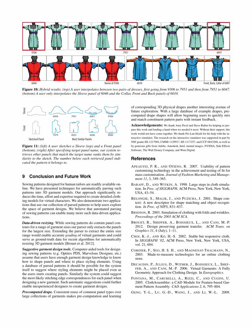
Figure 10 shows several garment hybrids created with our appli-cation. In the top row the user interpolated complete garments (allpanels). In the transition between 9306 and 7951 note how the neck-line smoothly changes while the pleats in the Sleeve and Skirt pan-els gradually disappear. Interpolating from 7951 to 6047, introducenew side-darts to the Front and Skirt panels. These darts fit the gar-ment closer to the body without using pleats as were originally usedin 9306. The neckline and sleeves also change significantly in shapein the intermediate designs.
In the bottom row, the user specifies subsets of panels to interpo-late. On the left side, the user interpolates the sleeves. Note how thenumber of pleats in the sleeves increase. On the right, the user inter-polates the Front, Back and Collar panels. The intermediate designsintroduce many new pleats at the side of the garment and reduce thesize of the Front and Back panels to make the garment tighter andshorter. In addition the Collar opens up significantly.
8.2 Search and Navigation of Pattern Collections
The look of a 3D garment is largely dependent on the shape of itspanels and styling elements. Yet, online sewing pattern collectionstoday force users to navigate the collection by scrolling through listsof pattern names. To help users better navigate the space of garmentdesigns we have developed a sketch-based search application.
With our application users sketch the shape of a panel, and specifya target panel name. Figure 11 (left) shows two examples of panelssketched by a user. Our search algorithm first retrieves all the pan-els that match the target panel name and then uses the shape contextalgorithm of Belongie et al. [2001] to rank each panel by similarityto the sketch. Each retrieved panel also provides a link back to thepattern it belongs to in the form of a pattern number. As shown inFigure 11 (right) users can easily find all the patterns that contain aparticular style of Sleeve or Front panel. Inspecting the correspond-ing patterns and 3D drapes allows users to see how similarly shapedpanels can affect the look of different garments.
9306 7951 6047
6046 Sleeve of 9306 6010 Front, Back, Collar of 6007
Figure 10: Hybrid results. (top) A user interpolates between two pairs of dresses, first going from 9306 to 7951 and then from 7951 to 6047.(bottom) A user only interpolates the Sleeve panel of 6046 and the Collar, Front and Back panels of 6010.
Sketched Panel Most Similar Panels
6009 7951 6061 9306
7979 6052 6046 6060
Front
Sleev
e
Figure 11: (left) A user sketches a Sleeve (top) and a Front panel(bottom). (right) After specifying target panel name, our system re-trieves other panels that match the target name ranks them by sim-ilarity to the sketch. The number below each retrieved panel indi-cated the pattern it belongs to.
9 Conclusion and Future Work
Sewing patterns designed for human tailors are readily available on-line. We have presented techniques for automatically parsing suchpatterns into 3D garment models. Our approach significantly re-duces the time, effort and expertise required to create detailed cloth-ing models for virtual characters. We also demonstrate two applica-tions that use our collection of parsed patterns to help users explorethe space of garment designs. We believe that automated parsingof sewing patterns can enable many more such data-driven applica-tions.
Data-driven resizing. While sewing patterns do contain panel con-tours for a range of garment sizes our parser only extracts the panelsfor the largest size. Extending the parser to extract the entire sizerange would enable accurate grading of virtual garments and couldserve as ground-truth data for recent algorithms for automaticallyresizing 3D garment models [Brouet et al. 2012].
Suggestive garment design tools. Computer-aided tools for design-ing sewing patterns (e.g. Optitex PDS, Marvelous Designer, etc.)assume that users have enough garment design knowledge to knowhow to shape panels and where to place styling elements. Usinga database of parsed patterns it should be possible for the systemitself to suggest where styling elements might be placed even asthe users starts creating panels. Similarly the system could suggestthe most likely stitching edge correspondences for each panel whendesigning a new garment. Such automatic suggestions could furtherenable inexperienced designers to create garment designs.
Precomputed drape. Consistent reuse of common panel types overlarge collections of garments makes pre-computation and learning
of corresponding 3D physical drapes another interesting avenue offuture exploration. With a large database of example drapes, pre-computed drape shapes will allow beginning users to quickly mixand match constituent pattern parts with instant feedback.
Acknowledgements: We thank Amy Pavel and Steve Rubin for helping us pre-pare this work and lending a hand when we needed it most. Without their support, thiswork would not have come together. We thank Pei-Lun Hsieh for his help with the in-teractive simulator. The research on the interactive simulator was supported in part byNSF grants IIS-1217904, CMMI-1129917, IIS-1117257, and CCF-0643268, as well asby generous gifts from Adobe, Autodesk, Intel, mental images, NVIDIA, Side EffectsSoftware, The Walt Disney Company, and Weta Digital.
References
APEAGYEI, P. R., AND OTIENO, R. 2007. Usability of patterncustomising technology in the achievement and testing of fit formass customisation. Journal of Fashion Marketing and Manage-ment 11, 3, 349–365.
BARAFF, D., AND WITKIN, A. 1998. Large steps in cloth simula-tion. In Proc. of SIGGRAPH, ACM Press, New York, New York,USA, 43–54.
BELONGIE, S., MALIK, J., AND PUZICHA, J. 2001. Shape con-text: A new descriptor for shape matching and object recogni-tion. In Proc. of NIPS, 831–837.
BRIDSON, R. 2003. Simulation of clothing with folds and wrinkles.Proceedings of the 2003 ACM SCA.
BROUET, R., SHEFFER, A., BOISSIEUX, L., AND CANI, M.-P.2012. Design preserving garment transfer. ACM Trans. onGraphics 31, 4 (July), 1–11.
CHOI, K.-J., AND KO, H.-S. 2002. Stable but responsive cloth.In SIGGRAPH ’02, ACM Press, New York, New York, USA,vol. 21, 604.
CORDIER, F., SEO, H. S. H., AND MAGNENAT-THALMANN, N.,2003. Made-to-measure technologies for an online clothingstore.
DECAUDIN, P., JULIUS, D., WITHER, J., BOISSIEUX, L., SHEF-FER, A., AND CANI, M.-P. 2006. Virtual Garments: A FullyGeometric Approach for Clothing Design. In Eurographics.
FONTANA, M., CARUBELLI, A., RIZZI, C., AND CUGINI, U.2005. ClothAssembler: a CAD Module for Feature-based Gar-ment Pattern Assembly. CAD Applications 2, 6, 795–804.
GENG, Y.-L., LU, G.-D., WANG, J., AND LI, W.-L. 2009.

Sketch-Based 3D Sleeve Modeling and Reusing Method for Gar-ment CAD. In In Proc. of CSIE, IEEE, vol. 1, 711–715.
GUAN, P., REISS, L., HIRSHBERG, D. A., WEISS, A., ANDBLACK, M. J. 2012. DRAPE: Dressing Any Person. ACMTrans. on Graphics 31, 4 (July), 1–10.
HARALICK, R., AND QUEENEY, D. 1982. Understanding engi-neering drawings. Computer Graphics and Image Processing20, 3, 244–258.
HOUSE, D., AND BREEN, D., Eds. 2000. Cloth Modeling andAnimation. A K Peters/CRC Press.
IGARASHI, T., AND HUGHES, J. F. 2002. Clothing manipulation.In Proc. of UIST, ACM Press, New York, New York, USA, 91.
MENA, J. 2003. State of the art on automatic road extraction forgis update: a novel classification. Pattern Recognition Letters24, 16, 3037–3058.
MENG, Y., MOK, P., AND JIN, X. 2010. Interactive virtual try-onclothing design systems. Proc. of CAD 42, 4 (Apr.), 310–321.
MENG, Y., MOK, P., AND JIN, X. 2012. Computer aided clothingpattern design with 3D editing and pattern alteration. Proc. ofCAD 44, 8 (Aug.), 721–734.
MENG, Y., WANG, C. C., AND JIN, X. 2012. Flexible shapecontrol for automatic resizing of apparel products. Proc. of CAD44, 1 (Jan.), 68–76.
PROTOPSALTOU, D., AND LUIBLE, C. 2002. A body and garmentcreation method for an internet-based virtual fitting room. InAdvances in Modeling, Animation and Rendering, J. Vince andR. Earnshaw, Eds. Springer-Verlag, 105—-122.
ROBSON, C., MAHARIK, R., SHEFFER, A., AND CARR, N. 2011.Context-aware garment modeling from sketches. Computers &Graphics 35, 3 (June), 604–613.
ROHMER, D., POPA, T., CANI, M.-P., HAHMANN, S., ANDSHEFFER, A. 2010. Animation wrinkling: augmenting coarsecloth simulations with realistic-looking wrinkles. ACM Trans.on Graphics TOG 29, 6, 157.
SHEWCHUK, J. 2002. Delaunay refinement algorithms for triangu-lar mesh generation. In Proc. CGTA 22, 21–74.
TERZOPOULOS, D., PLTT, J., BARR, A., ZELTZER, D., WITKIN,A., AND BLINN, J. 1989. Physically-based modeling: past,present, and future. ACM SIGGRAPH 23, 5 (Dec.), 191–209.
TURQUIN, E., CANI, M.-P., AND HUGHES, J. F. 2004. Sketchinggarments for virtual characters. In Courses, ACM, J. A. Jorgeand J. F. Hughes, Eds., SIGGRAPH ’06, 175–182.
TURQUIN, E., WITHER, J., BOISSIEUX, L., CANI, M.-P., ANDHUGHES, J. F. 2007. A Sketch-Based Interface for ClothingVirtual Characters. IEEE CGA 27, 1 (Jan.), 72–81.
UMETANI, N., KAUFMAN, D., IGARASHI, T., AND GRINSPUN,E. 2011. Sensitive Couture for Interactive Garment Editing andModeling. ACM Transactions on Graphics (Proc. of SIGGRAPH2011) 30, 4 (Aug).
WANG, C. C. L., WANG, Y., AND YUEN, M. M. F. 2003. Featurebased 3D garment design through 2D sketches. Proc. of CAD35, 7, 659–672.
WANG, C. C., WANG, Y., AND YUEN, M. M. 2005. Designautomation for customized apparel products. Proc. of CAD 37,7 (June), 675–691.
WOLSEY, L. 2000. Integer programming. IIE Transactions 32,273–285.