PACKET RADIO from AEA to Z___Page 1 ABOUT THE ...
50
______________________ PACKET RADIO from AEA to Z___Page 1 ABOUT THE AUTHOR G. E. "Buck" Rogers Sr. K4ABT, is Senior Systems Engineer for ERICSSON Communications. Buck is a pioneer of packet radio, having written many feature articles for the leading Amateur radio, commercial and trade publications. He is PACKET RADIO Editor for CQ MAGAZINE CQ MAGAZINE, and authors the PACKET USERS NOTEBOOK, a monthly column in CQ CQ. Some of Buck’s books about PACKET RADIO & Digital communications are: The PACKET RADIO AEA to Z Handbook The PACKET RADIO Beginner’s Guidebook The PACKET RADIO X-1J SysOp’s Handbook The PACKET RADIO Operator’s Handbook The PACKET RADIO OPERATORS MANUAL The PACKET RADIO General Information Handbook The "PRIME" Packet Radio Is Made Easy The PACKET USERS NOTEBOOK The ADVANCED PACKET RADIO HANDBOOK The PACKET COMMANDS HANDBOOK The GLOSSARY of PACKET TERMS HANDBOOK The RS-232 as related to PACKET HANDBOOK Buck conducts forums and seminars on packet radio and digital communications. Buck is an RF and Data Communications Engineer. He was instrumental in the design and implementation of the U. S. Air Force Local Area Network, Wide Area Network, and Global Information Networks (LAN, WAN & GIN). His credentials in other fields of R F communications include terrestrial microwave systems design, television/radio broadcast station design, and Public Service EDACS systems design. His communications consulting travels include the United States, Europe, Asia, and countries throughout the world. Buck is a licensed Amateur of 44 years, and holds the "lifetime" Commercial FCC First Class license (now called the General Class Commercial license) ABOUT THIS BOOK
-
Upload
khangminh22 -
Category
Documents
-
view
2 -
download
0
Transcript of PACKET RADIO from AEA to Z___Page 1 ABOUT THE ...

______________________ PACKET RADIO from AEA to Z___Page 1
ABOUT THE AUTHOR
G. E. "Buck" Rogers Sr. K4ABT, is Senior Systems Engineer for ERICSSON Communications. Buck is a pioneer ofpacket radio, having written many feature articles for the leading Amateur radio, commercial and trade publications. He is PACKET RADIO Editor for CQ MAGAZINECQ MAGAZINE, and authors the PACKET USERS NOTEBOOK, a monthlycolumn in CQCQ.
Some of Buck’s books about PACKET RADIO & Digital communications are:
The PACKET RADIO AEA to Z Handbook
The PACKET RADIO Beginner’s Guidebook
The PACKET RADIO X-1J SysOp’s Handbook
The PACKET RADIO Operator’s Handbook The PACKET RADIO OPERATORS MANUAL
The PACKET RADIO General Information Handbook
The "PRIME" Packet Radio Is Made Easy
The PACKET USERS NOTEBOOK
The ADVANCED PACKET RADIO HANDBOOK
The PACKET COMMANDS HANDBOOK
The GLOSSARY of PACKET TERMS HANDBOOK
The RS-232 as related to PACKET HANDBOOK
Buck conducts forums and seminars on packet radio and digital communications.
Buck is an RF and Data Communications Engineer. He was instrumental in the design andimplementation of the U. S. Air Force Local Area Network, Wide Area Network, and Global InformationNetworks (LAN, WAN & GIN). His credentials in other fields of R F communications include terrestrialmicrowave systems design, television/radio broadcast station design, and Public Service EDACSsystems design. His communications consulting travels include the United States, Europe, Asia, andcountries throughout the world.
Buck is a licensed Amateur of 44 years, and holds the "lifetime" Commercial FCC First Class license(now called the General Class Commercial license)
ABOUT THIS BOOK
______________________ PACKET RADIO from AEA to Z___Page 2
This book will provide detailed information for the newcomer to Packet Radio and to the seasonedveteran.
There is information for the new Packet Radio user that begins with the Packet Radio basics andtutors the newcomer all the way to the use of the Packet bulletin board systems (BBS).
This book will also provide the system or network operator with new ways to build an X-1J TheNETnode or a network of nodes using the PK-96 as the primary building block. I will include drawings andsupport information that enables the network node operator to build a solid system of backbones andtrunks.
Included in this book, is information on many other applications of Packet Radio communications.
You will find illustrations that help you interface your Terminal Node Controller (TNC) and yourtransceiver. Additional drawings are provided that assist the Packet Radio operator with theinterfacing of the TNC and computer combinations. Reproduction or use, without express permission of the author, of editorial or pictorial content, in any manner, is prohibited. While everyprecaution has been taken in the preparation of this book, the author and publisher assume no responsibility for errors or omissions. Neither isany liability assumed for damages resulting from the use of the information contained herein.
The information in this document has been checked and is believed to be entirely reliable. However, no responsibility is assumed forinaccuracies.
Copyright (c) 1995Glynn E. "Buck" Rogers Sr.
All rights reserved
Credits, trademarks ™ & Copyright ©
AEA AEA is a trademark of Advanced Electronics Applications,Inc.APPLEAPPLE & Apple Macintosh trademarks of Apple computers Inc.ERICSSON ERICSSON ////// & ERICSSON //// // GE are ™ & © of ERICSSON Communications & General Electric Mobile Communications.IBM and IBM PCIBM and IBM PC are trademarks of International Business Machines.WindowsWindows is a trademark of MicrosoftTAPRTAPR Tucson Amateur Packet Radio is a non-profit research group dedicated to amateur digital communications.
TABLE of CONTENTS
PACKET RADIO from AEA to Z
About the Author Page 1

______________________ PACKET RADIO from AEA to Z___Page 3
About this handbook; Credits and Trademarks Page 2
CHAPTER 1 PACKET RADIO BASICS PAGE 4
CHAPTER 2 LEARNING ABOUT PACKET CONTROLLERS PAGE 6
CHAPTER 3 VIEWING PACKET RADIO THROUGH THE PC PakRatt Window PAGE 10
CHAPTER 4 THE PACKET BULLETIN BOARD SYSTEM PAGE 19
CHAPTER 5 FEATURES OF THE X-1J+ NODE PAGE 22
CHAPTER 6 THE STAR OF THE SHOW PAGE 25
CHAPTER 7 AN INTRODUCTION TO NETWORK NODES PAGE 30
CHAPTER 8 TECHNIQUES FOR NODE STACKING THE PK-96 NODES PAGE 36
CHAPTER 9 SETUP AND CONFIGURATION OF THE X-1J+ NODES PAGE 38
CHAPTER 10 SYSOP VALIDATION OR “DEALING WITH THE PASSWORD” PAGE 45
CHAPTER 11 THE USERS GUIDE FOR THE PKX-1J NODES PAGE 47
USER NOTES PAGE 50
ILLUSTRATIONS Modifying the PK-96 for PKX-1J+ node use
ILLUSTRATION 1 TOP VIEWOF THE PK-96 TNC AND PKX-1J NODE MODIFICATION NOTES. PAGE 37ILLUSTRATION 2 BOTTOM VIEW OF THE PK-96 AND PKX-1J NODE MODIFICATION NOTES PAGE 37
______________________ PACKET RADIO from AEA to Z___Page 4
CHAPTER ONE
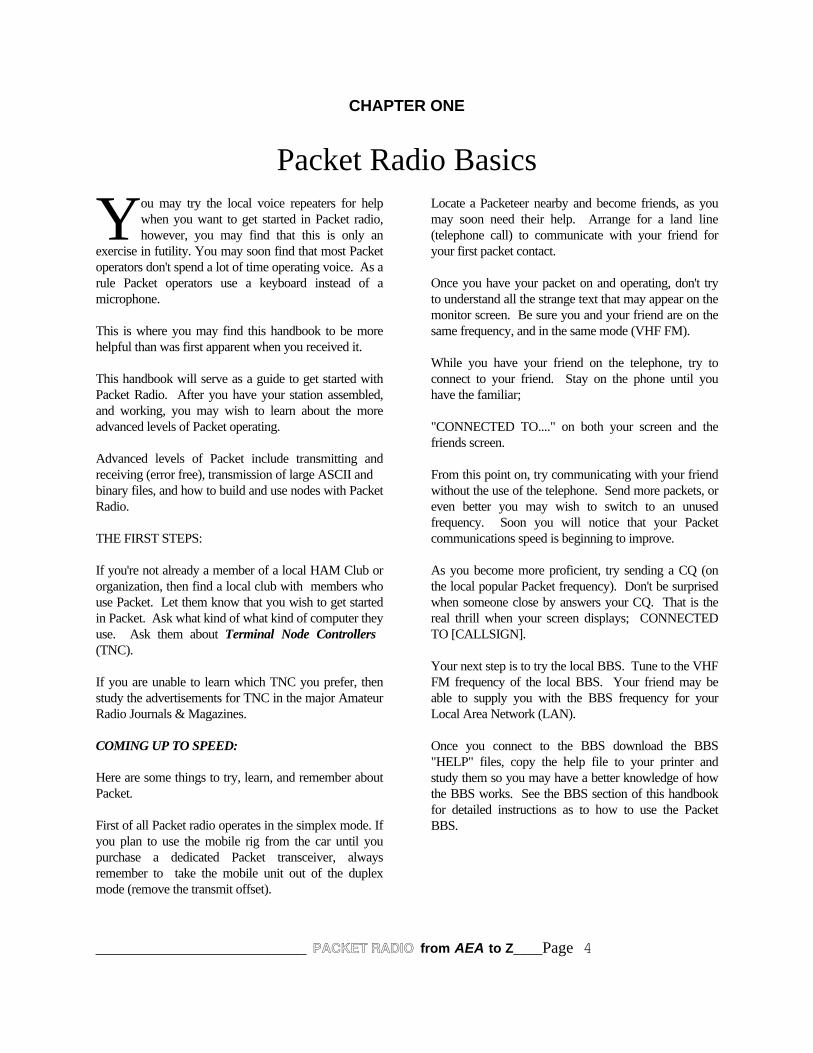
Packet Radio Basicsou may try the local voice repeaters for helpwhen you want to get started in Packet radio,however, you may find that this is only an
exercise in futility. You may soon find that most Packetoperators don't spend a lot of time operating voice. As arule Packet operators use a keyboard instead of amicrophone.
This is where you may find this handbook to be morehelpful than was first apparent when you received it.
This handbook will serve as a guide to get started withPacket Radio. After you have your station assembled,and working, you may wish to learn about the moreadvanced levels of Packet operating.
Advanced levels of Packet include transmitting andreceiving (error free), transmission of large ASCII andbinary files, and how to build and use nodes with PacketRadio.
THE FIRST STEPS:
If you're not already a member of a local HAM Club ororganization, then find a local club with members whouse Packet. Let them know that you wish to get startedin Packet. Ask what kind of what kind of computer theyuse. Ask them about Terminal Node Controllers (TNC).
If you are unable to learn which TNC you prefer, thenstudy the advertisements for TNC in the major AmateurRadio Journals & Magazines.
COMING UP TO SPEED:
Here are some things to try, learn, and remember aboutPacket.
First of all Packet radio operates in the simplex mode. Ifyou plan to use the mobile rig from the car until youpurchase a dedicated Packet transceiver, alwaysremember to take the mobile unit out of the duplexmode (remove the transmit offset).
Locate a Packeteer nearby and become friends, as youmay soon need their help. Arrange for a land line(telephone call) to communicate with your friend foryour first packet contact.
Once you have your packet on and operating, don't tryto understand all the strange text that may appear on themonitor screen. Be sure you and your friend are on thesame frequency, and in the same mode (VHF FM).
While you have your friend on the telephone, try toconnect to your friend. Stay on the phone until youhave the familiar;
"CONNECTED TO...." on both your screen and thefriends screen.
From this point on, try communicating with your friendwithout the use of the telephone. Send more packets, oreven better you may wish to switch to an unusedfrequency. Soon you will notice that your Packetcommunications speed is beginning to improve.
As you become more proficient, try sending a CQ (onthe local popular Packet frequency). Don't be surprisedwhen someone close by answers your CQ. That is thereal thrill when your screen displays; CONNECTEDTO [CALLSIGN].
Your next step is to try the local BBS. Tune to the VHFFM frequency of the local BBS. Your friend may beable to supply you with the BBS frequency for yourLocal Area Network (LAN).
Once you connect to the BBS download the BBS"HELP" files, copy the help file to your printer andstudy them so you may have a better knowledge of howthe BBS works. See the BBS section of this handbookfor detailed instructions as to how to use the PacketBBS.
Y

______________________ PACKET RADIO from AEA to Z___Page 5
Practice your skill on the BBS by listing and readingmessages. Get to know how you can write messagesand save them in an ASCII file before you connect withthe BBS.
Send a message to your friend via the BBS. Have yourfriend return a message. Send a message to a ham friendin a distant state. His BBS may not be on the samefrequency as yours, or you may not even know hisfrequency, it makes no difference. It will help if youknow his home BBS call.
Explore the files section of your BBS, and learn aboutYAPP and the NTS messages.
YAPP is a protocol that is universally used to transferbinary files to and from the BBS system. As soon asyou feel that you have a good working knowledge ofPacket operating, then begin looking at the moreadvance software terminal packages which enable usersupport for other multimode digital operations. Onesuch advanced software package that provides thesefeatures is PC PakRatt for Windows™. We'll discussthis amazing program later in this handbook.
Soon you will find that it was well worth the shortperiod it took to hit your Packet stride. Before long youmay be so much into Packet that you are running yourown node.
1 2 3
FIGURE 1The three basic components of a Packet Radiostation.
1. Computer or Dumb Terminal2. Packet Radio Terminal Node
Controller (TNC)3. VHF or UHF Transceiver

______________________ PACKET RADIO from AEA to Z___Page 6
CHAPTER TWO
LEARNING ABOUT PACKET CONTROLLERS
THE "PACKET ONLY" CONTROLLERS:
If you plan to operate packet only, but you wish to use both HF and VHF packet, you may want to look for a controllerwhich has a tuning indicator for use on the HF bands. Most of these controllers operate both HF and VHF Packet.
Almost all Terminal Node Controllers (TNC) operate both HF and VHF, but to try operating HF packet without a tuningindicator is like fishing without bait, your chances of catching a fish are, little to none. We will discuss the more advancedAEA PK-232 and AEA PK-900 controllers later in this chapter.
Now if you just want to operate VHF packet, there are numerous TNC that will fill your need. All AEA TNC nowsupport the "AEA MailDrop" feature. This allows the user to set the MailDrop command ON while the computer orterminal is being used for other tasks, such as letter writing, and data processing. The mailbox will receive and storemessages while you are away.
AEA PK-12:
The AEA PK-12 TNC is a Packet only controller that offers the AEA “MailDrop” feature we’ve just discussed. In additionyou may use it to send and receive error free Packet communications with the best of them.
As the model implies, the AEA PK-12, is a 1200 baud TNC that is designed specifically for the casual Packet user. If youwant a Packet controller to access the local full service BBS to read your mail, this is it. If you need a TNC that willenable you to monitor the DX packet spotting network, here is just the ticket for that job too.
______________________ PACKET RADIO from AEA to Z___Page 7
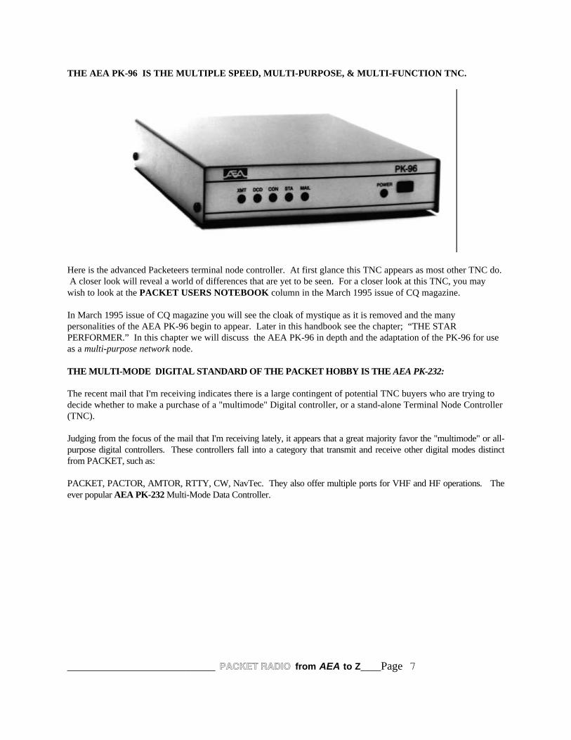
THE AEA PK-96 IS THE MULTIPLE SPEED, MULTI-PURPOSE, & MULTI-FUNCTION TNC.
Here is the advanced Packeteers terminal node controller. At first glance this TNC appears as most other TNC do. A closer look will reveal a world of differences that are yet to be seen. For a closer look at this TNC, you maywish to look at the PACKET USERS NOTEBOOK column in the March 1995 issue of CQ magazine.
In March 1995 issue of CQ magazine you will see the cloak of mystique as it is removed and the manypersonalities of the AEA PK-96 begin to appear. Later in this handbook see the chapter; “THE STARPERFORMER.” In this chapter we will discuss the AEA PK-96 in depth and the adaptation of the PK-96 for useas a multi-purpose network node.
THE MULTI-MODE DIGITAL STANDARD OF THE PACKET HOBBY IS THE AEA PK-232:
The recent mail that I'm receiving indicates there is a large contingent of potential TNC buyers who are trying todecide whether to make a purchase of a "multimode" Digital controller, or a stand-alone Terminal Node Controller(TNC).
Judging from the focus of the mail that I'm receiving lately, it appears that a great majority favor the "multimode" or all-purpose digital controllers. These controllers fall into a category that transmit and receive other digital modes distinctfrom PACKET, such as:
PACKET, PACTOR, AMTOR, RTTY, CW, NavTec. They also offer multiple ports for VHF and HF operations. Theever popular AEA PK-232 Multi-Mode Data Controller.
______________________ PACKET RADIO from AEA to Z___Page 8
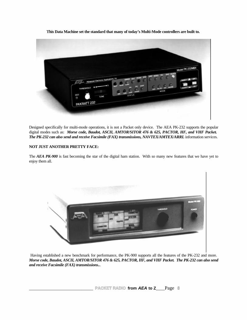
This Data Machine set the standard that many of today’s Multi-Mode controllers are built to.
Designed specifically for multi-mode operations, it is not a Packet only device. The AEA PK-232 supports the populardigital modes such as: Morse code, Baudot, ASCII, AMTOR/SITOR 476 & 625, PACTOR, HF, and VHF Packet. The PK-232 can also send and receive Facsimile (FAX) transmissions, NAVTEX/AMTEX/ARRL information services.
NOT JUST ANOTHER PRETTY FACE:
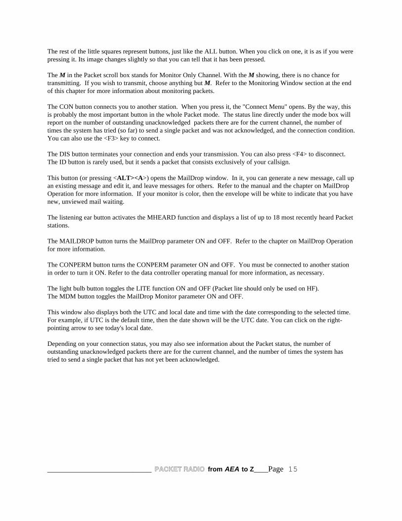
The AEA PK-900 is fast becoming the star of the digital ham station. With so many new features that we have yet toenjoy them all.
Having established a new benchmark for performance, the PK-900 supports all the features of the PK-232 and more. Morse code, Baudot, ASCII, AMTOR/SITOR 476 & 625, PACTOR, HF, and VHF Packet. The PK-232 can also sendand receive Facsimile (FAX) transmissions...

______________________ PACKET RADIO from AEA to Z___Page 9
Signal Identification & Acquisition Mode (SIAM™) automatically identifies incoming Baudot, ASCII, AMTOR/SITOR,PACTOR and Time Division Multiplex (TDM) signals. Then all that is required is for the operator to issue a fewkeystrokes and the recognized mode begins the display with the correct format.
A set of 8 Pole chebyshev bandpass filters provide six software selectable tone shifts @ 170 to 1000 hertz. To add morebeauty to this filtering technique, post detection linear phase low pass filters are optimized for all data rates from 45 to2000 baud’s.
For the Packet operator who is in tune with the latest networking and satellite operations, the PK-900 can be outfitted witha 9600 baud modem. This allows you to move far and away out front into the fast-lane of digital Packet communications.
To round out the PK-900 story, this controller supports a feature that enables you to use the HF port to communicate withstations in an approved HF mode while communicating with a VHF Packet station through the VHF or opposite port, andboth at the same time.
As if this is not enough, another user or operator on either the HF port or on VHF can connect through the gateway ofyour PK-900 to another station via the opposite port. All these features are shown in a user accessible “help” menu alsoprovided in the firmware of the PK-900.
AND THERE IS DIGITAL SIGNAL PROCESSING (DSP):
For the operator who wants the best of all digital worlds, the AEA DSP-2232 brings all the features you’ve heard aboutand wanted to experience.
All the power you want in a digital controller; Morse code, Baudot, ASCII, AMTOR/SITOR 476 & 625, PACTOR, HF,and VHF Packet. The AEA DSP 2232 features include multiple grayscale imaging display in real-time from the NOAAHF WeFAX services. The images are captured to several display formats including BMP, GIF, PCX, TIG and others.
When using the DSP-2232 for satellite communications, you have a new feature to help enhance these up/down contacts. The automatic doppler correction feature of the DSP-2232 sets the stepping of the controller to control changes in theradio’s frequency.

______________________ PACKET RADIO from AEA to Z___Page 10
CHAPTER THREE
VIEWING PACKET RADIO THROUGH THE PC PAKRATT WINDOW
AEA knows that good Packet software can make all the difference in whether or not you find your hobby apleasure. PC PakRatt for Windows ™ has been designed with this in mind.
The opening screen of PC PakRatt for Windows shown above.
PC PakRatt for Windows is a true Windows application, allowing you to run other programs while controllingyour data controller. PC PakRatt for Windows is truly state-of-the-art! It operates on Windows 3.1, Windows '95,and Windows N/T. The graphical user interface makes program functions quick and easy to access. That's right,PC PakRatt for Windows 2.0 is fully compatible with Log Windows 2.0. This means you can have the powerfulTNC control of PPWin, coupled with the great database, logging, and tracking features of Log Windows.
Run two data controllers at once! Using Windows' multi-tasking abilities, you can have dual-, tri-, or even quad-port operation with two full-featured AEA data controllers.

______________________ PACKET RADIO from AEA to Z___Page 11
Imagine working an AMTOR DX station through your PK-232MBX, receiving information from a local packet neton your PK-900's port 2, and working PACTOR on port 1 of the PK-900, all at the same time! Or, use your PK-900 and DSP-2232 for four simultaneous ports! ANSI Graphics. Sending and receiving ANSI graphics inPACTOR is now possible. You now have access to this exciting form of computer art with PC PakRatt forWindows 2.0.
Separate parameter files means setting up your TNC once and forgetting about it. Parameter changes are easy withthe complete parameter windows, and each mode has a different parameter set, allowing each controller's setup tobe easily optimized for each mode. There is even a parameter set for 9600 bps operation called High-Speed Packet.
MORE EXCITING FEATURES!
Other features include separate windows for mailbox operation, QSO logging, file transfers, and much more. And,of course, PC PakRatt for Windows contains a comprehensive Help section to explain everything from parameterdefinitions to how to run a dual-port controller.
PC PakRatt for Windows supports all AEA Data Controllers. PC PakRatt for Windows supports AEA's completeline of data controllers, including the PK-88, PCB-88, PK-12, PK-96, PK-232MBX, PK-900, DSP-1232, and DSP-2232.
Requirements: Windows 3.1, With 4 MB of free hard disk storage space, and 2 MB RAM (4 MB recommended).
PC PakRatt for Windows package contains the following items:.
• 5.25-inch floppy disks• 3.5-inch not-so-floppy disks• 1 operating manual (PC PakRatt for Windows version 2.0)
In order for your data controller and PC PakRatt for Windows version 2.0 to work properly, your computer systemmust be configured as follows:
• 100% IBM-PC/AT compatible hardware• 286 or better computer; 386 or better highly recommended• Windows 3.1 or higher, Windows NT 3.5, and OS/2 2.1• Microsoft-compatible mouse• One (or more) available serial ports (16550A recommended)• 4MB RAM• 3MB free disk space• VGA (or Super VGA) card and monitor• Firmware in your AEA TNC must be dated 1991 or later. Contact AEA if you need a firmware
upgrade.
Since it first appeared, Packet radio has been very popular. PC PakRatt for Windows makes operating in eitherVHF or HF Packet mode more fun than ever. Be sure you have read and clearly understand all of the informationin your data controller operating manual addressing Packet theory and operation.

______________________ PACKET RADIO from AEA to Z___Page 12
PACKET PARAMETERS:
Before you begin operating in either VHF or HF Packet mode you probably should check the default parameters tomake sure they agree with your setup. Here's how...
1. Open the PARAMETERS menu.2. Click on TNC1 VHF Packet Params or TNC2 VHF Packet Params (or, if you're working in HF
Packet, then click on TNC1 HF Packet Params or TNC2 HF Packet Params) once. A window similar to the one shown on the next page will be displayed.
Unless you're doing something really exotic in your Packet operations, the default parameters should be just finefor your first QSOs. For now, make sure your callsign is in the MYCALL box. It should have been automaticallyset by the system when you installed the software.
There are a few parameters you will want to change from time to time. The MONITOR command, for example, isuseful because it determines exactly what your data controller actually monitors. When the system is up andrunning, the default of 4 is probably fine. When you shut down everything except the data controller, though, youshould probably change it to zero.
You should also set the TXDELAY as described in the data controller operating manual. Remember, you canalways get help on a particular command by clicking on the HELP button on any displayed parameter window.As you can see, VHF and HF Packet Parameters are almost the same. The only differences are Paclen and Tone.The Paclen parameter shows the number of characters you can type before sending a packet. In VHF, you can typeup to 128 characters; in HF, you can type up to 64 characters. The Tone parameter is automatically set by thesoftware and represents the modem tones. In most cases, it will not even be accessible. If it is accessible and youwant more information, click on HELP. If that doesn't answer your questions, call AEA at (206)775-7373.
Go ahead and click on HELP for an explanation of each Packet Parameter. If everything looks fine, then click onOK to return to the Packet window.
If you change any parameters that you want to be permanent, go to the FILE menu and save the parameters for theappropriate port and TNC.
THE PACKET WINDOW:
If you are working with PC PakRatt for Windows for the first time, then the VHF Packet window will probably bethe first one you see. If it's not, or if you have been working elsewhere and want to begin using it now, click onceon the arrow that is next to the mode box and then click on your choice in the list that appears.
The VHF and HF Packet windows are identical except in the mode box and baud box. Several of the Packet push-buttons, and of course, the mode box, are common to many mode windows. Refer to the chapter, Using PCPakRatt for Windows, for a refresher on what the various common push-buttons are for. Here's a rundown on theothers:
The baud box controls the on-the-air packet speed and defaults to 1200 baud for VHF and 300 baud for HF mode.You can see the list of baud options and choose one by clicking on the arrow to the right of the baud box and thenclicking on your choice in the list.

______________________ PACKET RADIO from AEA to Z___Page 13
Shown here is a PcPakratt for Windows ™, screen that illustrates how the split screens are used to observe bothports of the PK-900. To access either port, use the mouse to move the cursor to the port screen heading and clickon it. You are ready to use the active port for communications.

______________________ PACKET RADIO from AEA to Z___Page 14
In this illustration, I have both the HF port and VHF port active. Although both screens display transmit andreceive text, the screen with the TNC1 PK-900 displayed is the window that is active. In this case, it is the topwindow. I'm in QSO with Dick, KA0NSW. Note the PACTOR turnover to KA0NSW de K4ABT, and the Ctrl Z. The turnover is completed using only the PgDn key.
If you're using DSP products, the PK-96, or the PK-900 with the optional modem, you have access to the highspeed packet option for 9600 bps operation. This option allows you to save parameters for 9600 bps operation.
The ALL button allows you to select the channels whose input you can see in the Receive area. For example, if youaccept the default, and the ALL button is active, you will see transmissions coming in on all channels, each in adifferent color. If you "press" the button (by clicking on it once), you can choose which one channel to isolate. Atthis point, the button will read CH, for channel, instead of ALL.
Regardless of your choice, you can send to any channel one at a time. That channel number is displayed in thechannel box to the right of the ALL button.
You may also change the color of incoming text. Refer to the chapter on Miscellaneous Information forinformation on how to change both text and background colors.
______________________ PACKET RADIO from AEA to Z___Page 15
The rest of the little squares represent buttons, just like the ALL button. When you click on one, it is as if you werepressing it. Its image changes slightly so that you can tell that it has been pressed.
The M in the Packet scroll box stands for Monitor Only Channel. With the M showing, there is no chance fortransmitting. If you wish to transmit, choose anything but M. Refer to the Monitoring Window section at the endof this chapter for more information about monitoring packets.
The CON button connects you to another station. When you press it, the "Connect Menu" opens. By the way, thisis probably the most important button in the whole Packet mode. The status line directly under the mode box willreport on the number of outstanding unacknowledged packets there are for the current channel, the number oftimes the system has tried (so far) to send a single packet and was not acknowledged, and the connection condition.You can also use the <F3> key to connect.
The DIS button terminates your connection and ends your transmission. You can also press <F4> to disconnect.The ID button is rarely used, but it sends a packet that consists exclusively of your callsign.
This button (or pressing <ALT><A>) opens the MailDrop window. In it, you can generate a new message, call upan existing message and edit it, and leave messages for others. Refer to the manual and the chapter on MailDropOperation for more information. If your monitor is color, then the envelope will be white to indicate that you havenew, unviewed mail waiting.
The listening ear button activates the MHEARD function and displays a list of up to 18 most recently heard Packetstations.
The MAILDROP button turns the MailDrop parameter ON and OFF. Refer to the chapter on MailDrop Operationfor more information.
The CONPERM button turns the CONPERM parameter ON and OFF. You must be connected to another stationin order to turn it ON. Refer to the data controller operating manual for more information, as necessary.
The light bulb button toggles the LITE function ON and OFF (Packet lite should only be used on HF).The MDM button toggles the MailDrop Monitor parameter ON and OFF.
This window also displays both the UTC and local date and time with the date corresponding to the selected time.For example, if UTC is the default time, then the date shown will be the UTC date. You can click on the right-pointing arrow to see today's local date.
Depending on your connection status, you may also see information about the Packet status, the number ofoutstanding unacknowledged packets there are for the current channel, and the number of times the system hastried to send a single packet that has not yet been acknowledged.

______________________ PACKET RADIO from AEA to Z___Page 16
CONNECTING TO ANOTHER STATION:
With PC PakRatt for Windows, connecting to another station is a snap. You can type in the callsign and otherconnection parameters of the station to which you wish to connect to, or you can select one from a list of callsignsand let the system automatically connect you. If you're like most ham radio operators, you'd rather translate theConstitution of the United States and all its Amendments into Morse code than type.
PC PakRatt for Windows can't eliminate the need for typing entirely, but you can create a list of frequently calledstations and save that list so that you only have to type the information once. Then, the next time you want toconnect to the same station, you simply select that callsign from the list, click on it once and bingo! You'reconnected. Here are the step-by-step procedures:
1. Click once on the CON button. The Connect Menu will open.
2. Type in the callsign of the station to which you wish to connect and proceed to step 3. For example, if you have made the "loopback" connection described in the data controller operating manual, then type your own callsign. Do NOT place "C" before the callsign as called for in the data controller operating manual. If you have attached the data controller to your transceiver as described in Chapter 3 of the data controller operating manual, you can connect to yourself by digipeating through another station. Just type yourcall v othercall.ORClick once on the desired callsign in the list below the data entry box and proceed to step 4. When there are more callsigns than will fit in one box, you'll see arrows in the top and bottom right-hand corners. You can use those boxes to scroll through the list when you are searching for a station.
3. If this is a station you expect to call again, click once on ADD and it will be added to the list below the data entry box.
4. Click on CONN to initiate the connection and you'll see a message that tells you the system is initializing the connection. After the connection has been made successfully, you'll automatically return to the Packet window.
If you want to see a list of the stations your data controller has heard recently, click once on the listening ear push-button or press <END>. If DAYSTAMP is ON (see VHF or HF Packet Parameters), you will also see the date theywere heard. For more information, click on the HELP push-button.
If a connection was not made on the first try, the connect signal will be transmitted as many times as the RETRYcommand specifies. The default is 10 times.
TheNET CONNECTS:
If you plan to connect to another station via a X-1J TheNET node, PC PakRatt for Windows will handle itautomatically. For example, if your local node is named SEA and you want to connect to station N7ML throughthe node, just type SEA;C N7ML in the Connect window. The semicolon (;) tells PC PakRatt for Windows thatthe preceding callsign is a X-1J TheNET node. The text after the semicolon (C N7ML) will be sent to the nodecausing it to make the connection to N7ML.

______________________ PACKET RADIO from AEA to Z___Page 17
TRANSMITTING TO ANOTHER STATION:
Odds are that once you've connected to another station, you're going to want to transmit something to them.Nothing could be easier (depending, of course, on how you feel about typing, since you first have to type out yourmessage).
1. Once the connection has been successfully completed, you'll find yourself back in the Packetwindow with the cursor sitting in the transmit portion. Just type in your message or call upthe desired macro (refer to the chapter on Macros for more information on creating andusing time-saving macros). If you're in HF Packet mode, the system will automaticallytransmit your text after the number of characters specified in PACLEN (the default is 64characters) and will keep doing so every so many characters until you are finished (thenyou'll have to send the rest _ see step 2). If you are in VHF Packet mode, the PACLENdefault is 128 characters.
NOTEWhen you are typing your message, do NOT press <ENTER>. The text will automatically wrap from one line tothe next. When you press <ENTER>, you will SEND (i.e., transmit) the text.
2. When you're through typing your message, just press <ENTER>. Your message will be transferred to the data controller and transmitted at the first opportunity. If PACKET ECHO is enabled, you will be able to see the text you typed as well as any incoming text in the receive portion of the window. If you have a color monitor, the incoming text will be a different color than the outgoing text.
NOTEIf you clicked on the HOLD push-button, then no text will be transmitted until you release the push-button (byclicking on it again).
BBS CONNECTS:
When you connect to a Packet Bulletin Board station, one of the most common activities is to list and read themessages. In the old days, you had to have to list the messages, write down the appropriate message numbers, thenread the individual messages.
With PC PakRatt for Windows version 2.0, you simply go to the Scroll Back Buffer, use the mouse to point at themessage number you want to read and double-click. PC PakRatt for Windows version 2.0 will automatically bringup the Quick BBS Dialog for you.
From the Quick BBS Dialog, you can read, kill, or reply to the selected message automatically.
DISCONNECTING FROM ANOTHER STATION:
When you're through "talking" to another station, just click on the DIS push-button. If you click on it once, you'llstart the disconnection process. When the other side acknowledges, both stations will be disconnected. You canclick on DIS twice and effect an immediate disconnection, but this is not advised as it may leave the other station"hanging." If you were connected to a bulletin board or mailbox station, you should type the letter B (for "Bye")and press <ENTER> instead of clicking on DIS.

______________________ PACKET RADIO from AEA to Z___Page 18
MONITORING OTHER STATIONS:
PC PakRatt offers a Packet Monitor Window to display unproto packets. In order for the Packet Monitor Windowto display data, the TNC and port must be in packet mode. This window will not display nonpacket data nor will itdisplay data which is directed towards a specific channel, only monitored data will be displayed.
Clicking the Port 1 button enables displaying monitored data from Port 1. The Port 2 button works similarly. Thelabel to the right of these buttons denotes which TNC is affected. The Receive Erase button clears the receivewindow and the Monitor Window Scroll Back Buffer.
The File Capture (disk with left-pointing arrow) button begins saving incoming received text to disk. When a filecapture is in progress, the button stays depressed. Click on the depressed button to stop the file capture.The File Capture hold/release button looks like a computer disk. When a file capture is taking place, the buttonchanges to green. Clicking on the button while it is green will temporarily pause the file capture. The button willthen change to red. Clicking on the button will change it back to green and the file capture will continue. Whenthe file capture is terminated, the button will return back to gray.
The printer button saves incoming data so it can be printed. When data is being saved, the button will change togreen. Click on the button again to stop saving data and spool the data to the printer. Be sure to set the printer fontand point size before printing.
The Packet Monitor Window receives its data from the respective TNC window, so if there are no TNC windowsopen, data is not being received from the TNC and nothing will be displayed in the monitor window. Data from aTNC and data in the Monitor Channel will be displayed in the same color. For example, data from TNC 2 will bedisplayed in the same color as the Monitor Channel for TNC 2. While connected, MCON should be set to 4 orhigher to be able to display monitored packets in the monitor window.
KEYBOARD COMMANDS:
If you don't have a mouse or just plain don't like using one, you can still use PC PakRatt for Windows version 2.0.Here are the keyboard commands that accomplish the same functions as clicking on the various push-buttons:
<ALT><A> Opens MailDrop dialog box. <ALT><B> Change HBaud rate.<ALT><I> Issues ID command to the TNC. <ALT><K> Quick call exchange.<ALT><M> Opens the Macro dialog box. <ALT><Q> Refreshes the window.<ALT><R> Clears Receive window. <ALT><S> Hold/Release for Transmit buffer.<ALT><U> Starts a File Capture process. <ALT><V> Toggles radio ports on DSP-1232<ALT><X> Opens File Transfer dialog box. <ALT><Y> Clear TX window.<ALT><Z> Change mode. <SH><INSERT> Pastes text from Clipboard<PAGE UP> Opens the Scroll Back Buffer. <HOME> Opens the QSO Log dialog box.<END> Opens the MHEARD dialog box. <PRNT SCRN> Prints incoming data to the printer.<F3> Opens the Connect dialog box. <F4> Issues a Disconnect command.<F6> Toggles LITE feature on and off. <CTRL><F6> Issues a free memory inquiry.<F7> Toggles MDMON on and off. <SH><F7> Toggles MailDrop on and off.<F8> Toggles CONPERM on and off. <Up Arrow> Increases Packet channel.<Dn Arrow> Decreases Packet channel. <SH><TAB> Set focus to next TNC window.<CTRL-T> Sets TIME if the DAYTIME clock has been set.

______________________ PACKET RADIO from AEA to Z___Page 19
CHAPTER FOUR
The Packet BULLETIN BOARD SYSTEM:
There are many different packet mailbox systems in use. Some systems are large and require the use of a dedicatedcomputer. Other systems are small, like the personal MailDrop built into your AEA Packet controllers.
Large systems are often called Packet Bulletin Board Systems or BBS since they serve as electronic messagecenters for a local area. BBS's are a source of information as well as a gateway for messages that can be sent to,and received from, other parts of the country or world.
You will probably want to locate the PBBS nearest you and connect to it from time to time. Most mailbox systemsare easy to use and, whether they are small or large, operate in much the same way. Another nice feature ofmailboxes and other automatic systems is that they usually have a Help file or menu available to the caller byentering an "H" or "?" after a command line. Feel free to experiment with mailboxes and other packet systems, butbe courteous and experiment during off-peak hours.
Because there are so many variations and versions of Packet Bulletin Board Systems (BBS), I've put together a compositeof the most used BBS commands. In the list of commands that follow, I will address instructions that are used with someof the more common BBS types. These commands are therefore associated with Packet BBS, and not related to thecommon telephone type BBS.
As a matter of interest to the Packet BBS user, there is no waiting period to access other "WHAT" files sections of aPacket BBS. Packet BBS’s allow the immediate access to all levels of the BBS where the telephone BBSes often require a24 or 48, hour (and sometimes a week) waiting period after initial access, before the user is allowed full BBS operatingprivileges.
Once you have answered the four questions, BBS access is there ready and waiting at your service. Just remember thatother users await access to the BBS so limit yourself. This same consideration may be in your favor at a later time.
Some BBSes allow multiple connects to them. When this is the case, BBS activity may slow down while multiple usersare downloading files from the BBS.
A connect to your local area network (LAN) BBS is made in the same manner as a connect to another Packet station. Ifthis is your first connect to the BBS, you will need to provide some information about yourself. There are four questions,and the answers to them are short, so the time spent answering these questions are not like the complex answers that wereneeded when you accessed a telephone BBS.
If it is your first time on the BBS you will be asked to enter your NAME, QTH, ZIP CODE and HOME BBS. Theformat is as follows.
N BUCKNQ LYNCHBURG, VANZ 24550NH WD4ELJ
______________________ PACKET RADIO from AEA to Z___Page 20
The N command can be used to register your name or QTH. You should enter both. To enter your name;type; N yourname.
Example: N BUCK
To enter your QTH, use the command NQ your QTH.Example: NQ EVINGTON, VA
To enter your ZIP or Postal Code, use NZ code.Example: NZ 24550
To enter the BBS that you use to receive mail on use NH callsign.Example: NH [Your home BBS]
The BBS will then greet you using your name; In some cases the BBS greeting will contain both the name and callsign. After the greeting a list of abbreviated commands will appear on the screen. The greeting may appear similar to thefollowing:
WD4ELJ> Hello BUCK, K4ABT Welcome to WD4ELJ BBS [BBS type/number]WD4ELJ> A,B,C,D,G,H,I,J,K,L,M,N,P,R,S,U,V,W,X,?,*
The following is a list meanings for the abbreviated command letters shown above.
B - Bye C - Conference D - Download G - File searchH - Help I - Information J - Calls heard K - Kill messageL - List Messages M - Message of the dayN - Enter name/QTH P - Path to callR - Read message S - Send Message U - Current usersV - VERSION/INFO about BBS W - What files X - Expert?x- Info about command x * - Comment line
The Abort command can be used to abort the output from many of the BBS commands, like Download, List and Read forexample.
The Bye command disconnects you from the BBS. Use it when you are done!
The Conference command should not be used on the BBS if it is on a LAN frequency with high usage. The conferencemode of a BBS can present a grid-lock situation if the BBS is being accessed by other users at the same time theconference is in use.
The Download command is used to read a file stored on the system. The format of the command is "D filename" where[filename] is the name of the file to down load.
To see what files are available for downloading, use the W command. To download a file in a subdirectory, use DFILENAME.
I by itself gives hardware configuration of the system.
ID gives a list of the ports and digipeaters/gateways available.
______________________ PACKET RADIO from AEA to Z___Page 21
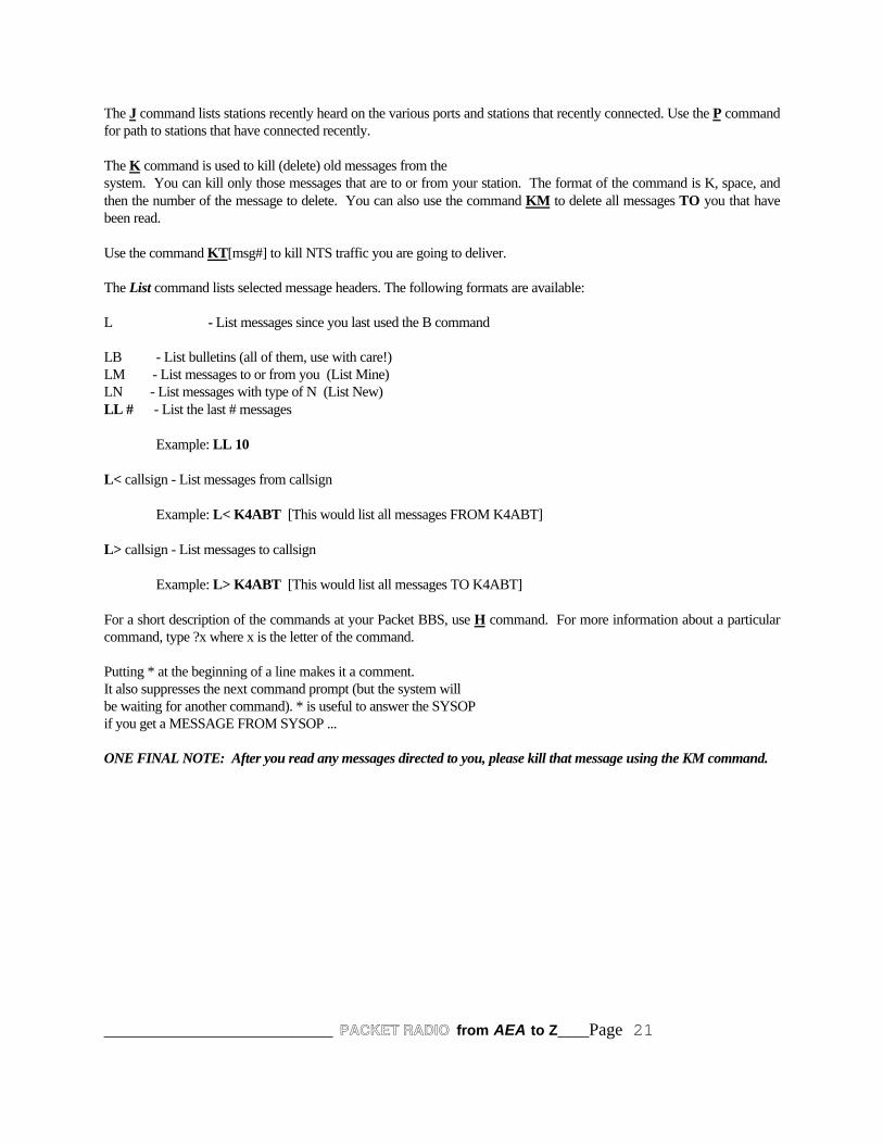
The J command lists stations recently heard on the various ports and stations that recently connected. Use the P commandfor path to stations that have connected recently.
The K command is used to kill (delete) old messages from thesystem. You can kill only those messages that are to or from your station. The format of the command is K, space, andthen the number of the message to delete. You can also use the command KM to delete all messages TO you that havebeen read.
Use the command KT[msg#] to kill NTS traffic you are going to deliver.
The List command lists selected message headers. The following formats are available:
L - List messages since you last used the B command
LB - List bulletins (all of them, use with care!)LM - List messages to or from you (List Mine)LN - List messages with type of N (List New)LL # - List the last # messages
Example: LL 10
L< callsign - List messages from callsign
Example: L< K4ABT [This would list all messages FROM K4ABT]
L> callsign - List messages to callsign
Example: L> K4ABT [This would list all messages TO K4ABT]
For a short description of the commands at your Packet BBS, use H command. For more information about a particularcommand, type ?x where x is the letter of the command.
Putting * at the beginning of a line makes it a comment.It also suppresses the next command prompt (but the system willbe waiting for another command). * is useful to answer the SYSOPif you get a MESSAGE FROM SYSOP ...
ONE FINAL NOTE: After you read any messages directed to you, please kill that message using the KM command.
______________________ PACKET RADIO from AEA to Z___Page 22
CHAPTER FIVE
FEATURES OF THE X-1J+ NODE
The X1 node is beginning to attract many users, and it is a "natural" for our Local Area Networks (LAN) frequencies. Not only can it be used as a node to connect out of the LAN. It also doubles for use as round-table packet session whenusing the "TALK" command/mode.
The outgrowth of this node can be used for networking, in a network of several nodes. There are many features that timeand space prohibit explanation here. To find out more about this new networking node see the March 1995 issue of CQmagazine.
BUILDING AN EPROM FOR THE AEA PK-96 NODE:
The X1J code is burned into a 27C512 EPROM which fits into the AEA PK-96 TNC.
By now you are aware of the need for an EPROM burner. One of the EPROM burners that I'm most familiar with is thePB-10 from Needham Electronics. The PB-10 EPROM burner supports the latest EPROMS for user friendly program forEPROM maintenance.
As I described in the March 1995 issue of CQ magazine (PACKET USERS NOTEBOOK), the EPROM for the X1 nodeis burned into a 27C512 EPROM in two parts. It is then installed into the AEA PK-96.
I will cover more of the attributes of theNET PKX-1J4 later in this book.
The Needham Electronics EPROM burner makes the process easy because we can set the first address to blow theEPROM from 0000 to 7FFF, then the second half of the EPROM is burned from address (HEX) 8000 to FFFF.
The EPROM programmer makes the job easy is through if it has a Zero Insertion Force (ZIF) socket. The ZIF socket ofthe Programmer should accept several sizes of EPROMS including the ONE MEGABYTE EPROMS (27C1001,27C1010 etc).
INITIALIZING:
Once the EPROM is installed into the TNC2 or clone, the initializing process is easy. Turn it ON, set the parameters, therest is history.
The node sends out update broadcasts to inform other nodes that it is active. The operating parameters are set in thefirmware and are available for easy changing by the SYSOP. The parameters shown under the "P" command of the X1nodes are similar to those used in the early TheNET 1.01 node.
The credit for this new network node firmware goes to the developers; They are:
Dave Roberts G8KBB
Dave is the author of the X1 code. The X1 version is based on the original TheNET 1.01 platform that was developed bythe Nord><Link group.

______________________ PACKET RADIO from AEA to Z___Page 23
TALK
The Talk command allows a group of users to hold a conference call. It also allows a user to send a message to anotheruser of the node provided that user is connected to the switch but is not patched through to another station and is notcurrently trying to connect to another station.
A user enters the conference by giving the command 'talk'. He/she gets a message informing them of this and remindingthem that the command to escape from the talk command is '/exit'. Any other users currently in the conference get amessage from the node telling them of the callsign of the user who has joined them.
At this point, every line sent by a user in the conference is copied to all other users in the conference, preceded by theircallsign.
To exit from the conference, the command '/exit' is used. This causes a message to be sent to the user.
At the same time, all of those left in the conference get a message from the node telling them of the station who has leftthe conference.
If you force a disconnect, the other stations are not told of your departure.
A string of text may be entered on the same line as the talk command when the command is given. If this is done, beforethe user is connected to the conference, that string of text is sent to all the other users of the node who appear in the "user"list but are not connected to anything else.
For example if while I'm connected to the node as a user, and W4WWQ connected to the node and typed:
TALK , Hello Buck can we have a chat? If so, PSE type TALK
Then I would receive the following on my screen. Additionally, and other users connected to the node, and notconnected through would see the following:
W4WWQ > K4ABT>>TALK ,Hello Buck can we chat? If so, PSE type TALK
Each user in a round-table receives all the information from every other user in the NET or round-table.
The only exception to this is that sysops are not sent the message.MHeard
If enabled, the heard list shows the last few stations heard. The number of entries is limited and set by the sysop so anystations not heard for a while may get pushed out of the list by others heard.
Assuming that a station is not pushed out in this manner, the display shows the number of packets heard from that stationsince it appeared in the list and the time since it was last heard. The time is hours, minutes and seconds. The list alsoshows the port on which the station was heard ( port 0 is the radio port ), and if it hears IP frames or Net/Rom frames, itadds a note to show that the station is a node and/or a TCP/IP station.
If the list is long enough so that a station is not heard for 12 hours, it will get deleted anyway.

______________________ PACKET RADIO from AEA to Z___Page 24
______________________ PACKET RADIO from AEA to Z___Page 25
PACKET DEVIATION IS IMPORTANT:
The 1200 baud Packet modulation / deviation is important. In contrast to the 5 KHz deviation of VHF FM voice,Packet modulation should be set to, or just below 3 KHz.
Often, packet stations are set up, and the audio level tweaked until it appears to work reasonably error free. The idea ofthis add-on is that, having done that, you then connect to the node and display the heard list to see an indication of youractual deviation. It may then be fine tuned to set it correctly. Local advice must be taken over the correct setting as itdepends on the channel spacing being used ( e.g. 12.5, 25 or other KHz ).
Using the AEA DM-1 allows the Packet user to set the deviation of the Packet Station in accordance to the use of thefrequency where Packet operation will be conducted. The AEA DM-1 Deviation Meter is a self-contained instrumentthat is an easy to use tool for both Packet Radio and voice calibration of deviation levels.
More information about the PKX-1J TheNET can be found in the PACKET USERS NOTEBOOK column in the March1995 issue of CQ Magazine.
OTHER SOURCES OF INFORMATION FOR THE DIGITAL HAM:
To keep abreast of the many useful devices for the digital ham, be sure that he or she has a current subscription to CQmagazine. The PACKET USERS NOTEBOOK in CQ magazine gives the digital Amateur a first hand look at what ishappening in the world of digital communications.

______________________ PACKET RADIO from AEA to Z___Page 26
CHAPTER SIX
THE STAR OF THE SHOW
The PK-96 was designed by AEA to provide you with a superior packet operating platform when connected to yourcomputer and a VHF or UHF transceiver.
WE’VE COVERED THE TOPIC OF 9600 BAUD’S MANY TIMES, BUT MOSTLY AT THE 9600 BAUDNETWORK NODE LEVEL. LOOKING OVER OUR PACKET PROLOG WE DISCOVER THAT WEARE LONG PAST DUE COVERING 9600 BAUD’S WITH RESPECT TO USER LEVELTRANSCEIVERS AND TERMINAL NODE CONTROLLERS.
MOST OF OUR EFFORTS FOR 9600 BAUD APPLICATIONS HAVE MEANT THAT WE CHOP,CHANNEL, AND MODIFY OUR TRANSCEIVER AUDIO MODULATION AND DEMODULATIONCIRCUITS TO ACCOMMODATE THE USE OF 9600 BAUD’S.
CORNY COMMUNICATIONS:
Ever hear the old cliché, “sooner or later, every ole hawg comes across a good ear of corn
ENTER; THE AEA PK-96:
The AEA PK-96 has been engineered around a different CPU, and it has the features that are not found in othercommercial, off-the-shelf (COTS) TNC. In addition the user full-featured mailbox which we will discuss later inthis months PACKET USERS NOTEBOOK.
The AEA PK-96 terminal baud rates will vary according to the kind of computer you use, and the associatedterminal software. When operating the PK-96 at the radio baudrate of 9600 baud’s, the terminal speed should beset for a speed greater than 9600 baud’s. I use either 19200 baud’s, and on the late model PC’s I set it for 38,400baud’s. The latter is used only when the terminal program (software) will support this rate.
AEA offers several terminal (software) programs for the IBM and compatibles. In addition AEA now has the PCPakRatt for Windows™. They also have a software package for the Macintosh called MacRATT.
All hardware level controls and interface connections are made at the rear of the AEA PK-96. I’ve drawn a rearview of the PK-96 shown in illustration six (6).
Setting timing parameters in a 1200 baud station is more or less straight forward, and in many TNC the defaultparameters will suffice.
I found that using TNC parameters similar to the following provided optimum performance at 9600 baud’s.
TXDelay = 10 to 15 (not the usual 30 or 35)Dwait = 5 (not the usual 16 to 33)Frack = 2 (not the default of 5)MAXFrame = 7 ..... let it all hang out!
As we become more acquainted with our 9600 baud system we may try fine-tuning our 9600 baud station evenfurther. For now I am well pleased with it’s performance.

______________________ PACKET RADIO from AEA to Z___Page 27
INTERMEDIATE AND EXPERT COMMANDS:
If you are new to Packet Radio, the PK-96 has a measure of support for the beginner. Use of all the Packetcommands is not employed at the intermediate or beginner level. As you progress and become more proficient inthe use of Packet you can activate the “advanced” command level within the firmware of the PK-96.The advanced level commands allow the users to fine-tune the PK-96 for much better performance, especiallywhen moving into the higher speed of the AEA PK-96.
To make the shift, or advance to the “EXPERT” level, use the EXPert command. At the cmd: prompt, type;
EXP ON
This activates a much larger command list within the firmware of the PK-96. The user should spend a fewminutes looking over the command list in the AEA PK-96 users manual.
The AEA PK-96 can operate at either 1200 or 9600 radio port baudrates.
To switch from 1200 baud’s (default) to 9600 baud’s, at the command prompt (cmd:) type:HB 9600 [Enter]
To return to radio data rate of 1200 baud’s, the command is similar; cmd: HB 1200 [Enter]
AND THE FUN IS JUST BEGINNING:
In many ways the AEA PK-96 offers features not found in all terminal node controllers. In this case, the term“node” is reinforced by truly supporting a node within the PK-96 firmware. This node is similar in some ways tothe network nodes. It allow other station users to connect to it and from it to other stations or nodes that are withinits range, frequency, and baudrate.
The AEA PK-96 node has additional features that are displayed after the user connects to the PK-96 node. Thenode name of callsign is entered using the MYGATE command entry. One of the features allows us to connectand issue the “L” or listen command. The “listen” command can be toggled ON and OFF while a user station isconnected into the PK-96 MYGATE callsign.
To activate the node in the PK-96, the PK-96 owner must set the MYGATE callsign. In this illustration I will usethe MYGATE callsign of K4ABT-7. In addition to the MYGATE callsign, the node sysop (owner) must also setthe number of gate users that will be allowed to use the node. This is done by setting the GUSER command tothree (3). With the GUSERS set to three, you have enabled three pairs or up to 6 stations to be connected throughyour PK-96 node. At the command (cmd:) prompt I set the MYGATE call as follows:
cmd: MYGATE K4ABT-7 [ENTER]
When first connecting to the MYGATE call, the user receives the following reply:
*** CONNECTED to K4ABT-7*** K4ABT-7 Gateway, Type ? for help.de K4ABT-7 (B, C, D, J, L, N, S, ?) >

______________________ PACKET RADIO from AEA to Z___Page 28
After connecting to my PK-96 node the user types and enters the “?.” The node user will to receive the followinghelp menu:
B(ye) Log off gatewayC(onnect) n Connect to station ‘n’C n STAY Stay connected to gateway when ‘n’ disconnects.D(isconnect) Cancel a connect attempt.J(heard) Display stations heard.L(isten) Toggle monitoring.N(nodes) Display nodes heard (up to 10 TheNET type nodes.)S(end) Broadcast unproto (CQ, UI, etc...)de K4ABT-7 (B, C, D, J, L, N, S, ?)
Having connected to your AEA PK-96 gateway the user may then issue a connect request to another station oranother node that is on the same frequency, at the same baudrate and in range of your PK-96 node.
LISTEN , MY FAVORITE FEATURE IS “LISTEN”:
I’ve already settled on my favorite feature of the PK-96 node. The “LISTEN” feature allows a user to connect tothe MYGATE callsign and issue the L or listen command. This toggles the “listen” feature ON and while the useris connected to the PK-96 node, the node will send the call or station received information to the connected stationthat issued the L command. When the user is finished with the listen feature, they may issue another “L” to thePK-96 node and toggle the listen feature OFF. After the listen feature is OFF, they may connect to a stationcallsign that was seen while in the listen mode, or execute another command within the node feature menu.
If no other command is desired, the user may issue a “B” or bye command and exit the node/gateway.
MAIL DROP:
NO, you don’t have to leave your computer ON while your mailbox is ON. I think this is the most often askedquestion I hear from new Packeteers at my forums and Packet seminars.
The AEA PK-96 MailDrop enables the users to take the computer off-line to perform other functions like word-processing, letter writing, games, cadd, ... etc.
The MailDrop also has the capability to forward to other MailDrops or to a properly configured bulletin boardsystem (BBS).
The PK-96 comes with a large mailbox that can hold over 15, one thousand byte messages. However, should thePK-96 owner wish to enlarge the PK-96 MailDrop capacity, additional RAM can be ordered from AEA.
Along with this very professional MailDrop, the user has built-in options that enable the customization of theMailDrop connect text messages.
MailDrop configuration in the PK-96 can be as simple as you like, or as the owner quickly discovers; The PK-96MailDrop can become the community electronic post office.
As the new PK-96 owner begins to learn about the PK-96 MailDrop, they find that a full chapter of the PK-96manual is dedicated to application and multiple configurations of the AEA PK-96 MailDrop.
So far I’ve only touched on a few of the many features the new PK-96 owner will discover when the PK-96 isplaced into operation. Now that we have some insight into the PK-96, lets interface the PK-96 to our transceiver.
______________________ PACKET RADIO from AEA to Z___Page 29
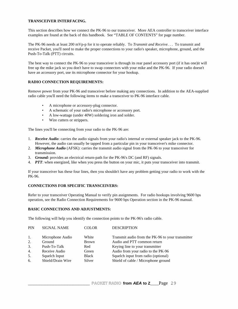
TRANSCEIVER INTERFACING.
This section describes how we connect the PK-96 to our transceiver. More AEA controller to transceiver interfaceexamples are found at the back of this handbook. See “TABLE OF CONTENTS” for page number.
The PK-96 needs at least 200 mVp-p for it to operate reliably. To Transmit and Receive. . . To transmit andreceive Packet, you'll need to make the proper connections to your radio's speaker, microphone, ground, and thePush-To-Talk (PTT) circuits.
The best way to connect the PK-96 to your transceiver is through its rear panel accessory port (if it has one)it willfree up the mike jack so you don't have to swap connectors with your mike and the PK-96. If your radio doesn'thave an accessory port, use its microphone connector for your hookup.
RADIO CONNECTION REQUIREMENTS:
Remove power from your PK-96 and transceiver before making any connections. In addition to the AEA-suppliedradio cable you'll need the following items to make a transceiver to PK-96 interface cable.
• A microphone or accessory-plug connector.• A schematic of your radio's microphone or accessory port.• A low-wattage (under 40W) soldering iron and solder.• Wire cutters or strippers.
The lines you'll be connecting from your radio to the PK-96 are:
1. Receive Audio: carries the audio signals from your radio's internal or external speaker jack to the PK-96. However, the audio can usually be tapped from a particular pin in your transceiver's mike connector.
2. Microphone Audio (AFSK): carries the transmit audio signal from the PK-96 to your transceiver fortransmission.
3. Ground: provides an electrical return-path for the PK-96's DC (and RF) signals.4. PTT: when energized, like when you press the button on your mic, it puts your transceiver into transmit.
If your transceiver has these four lines, then you shouldn't have any problem getting your radio to work with thePK-96.
CONNECTIONS FOR SPECIFIC TRANSCEIVERS:
Refer to your transceiver Operating Manual to verify pin assignments. For radio hookups involving 9600 bpsoperation, see the Radio Connection Requirements for 9600 bps Operation section in the PK-96 manual.
BASIC CONNECTIONS AND ADJUSTMENTS:
The following will help you identify the connection points to the PK-96's radio cable.
PIN SIGNAL NAME COLOR DESCRIPTION
1. Microphone Audio White Transmit audio from the PK-96 to your transmitter2. Ground Brown Audio and PTT common return3. Push-To-Talk Red Keying line to your transmitter4. Receive Audio Green Audio from your radio to the PK-965. Squelch Input Black Squelch input from radio (optional)6. Shield/Drain Wire Silver Shield of cable / Microphone ground

______________________ PACKET RADIO from AEA to Z___Page 30
TALKING TO YOURSELF:
Most of us are a little nervous when we first get on-the-air in a new mode. In packet, fortunately, you're able to geta lot of practice just by talking to yourself before you send your first CQ or connect to someone else who has sent aCQ. Once you feel comfortable with the basic operation of packet, going on-the-air is a breeze! To get somepractice, you can learn the important commands by talking to yourself.
In Chapter 2 of the PK-96 manual there is a loop-back test where the green and white wires are tied together at theend of the radio cable? You'll do roughly the same thing here. First, remove the RADIO cable. Then, cut a shortlength of any single-conductor wire that may be lying around your shack and insert one bare end into Pin 1 of theRADIO port and the other bare end into Pin 4. With your communications program and PK-96 running so that thecmd: prompt is displayed, you're now all set to have a thrilling monologue.
CONNECTING:
When you want to chat with a station in packet, you "connect" to it. The abbreviation of the connect command isthe letter, C. Go ahead and connect to yourself by entering: C yourcall. If your call happens to be KX4XXX, you'll type:
cmd: C KX4XXX
The following should appear on your screen:
*** CONNECTED to KX4XXX
You have now changed from the Command mode to the Converse mode the CON (CONnected) light is lit on thePK-96's front panel. Go ahead and type a quick sentence and press (RETURN). Your sentence will echo back atyou. If you were the receiving station, the echo you see is exactly what would appear on your screen. Type inanother sentence, but this time as you press (RETURN), watch the PK-96's front panel. The XMT and STA lightscome on, then the XMT light will go out. A few moments later, the XMT light will come on briefly, then both theCON and STA lights will go out.
What's happening here? It's all part of packet's error-checking scheme. When you pressed [Enter] or the CarriageRETURN key, the XMT light came on because the PK-96 was keying up your transmitter and sending your packetto the other station. Once the packet has been sent, the XMT light goes out and your transmitter unkeys. The STAlight stays on because the PK-96 is waiting for the packet you just sent to be acknowledged (acked) by the receivingstation. After the other station receives your packet and checks it over to see that it was received okay, it sendsback a quick ack signal. When your PK-96 receives the other station's ack signal, it "acks the ack"; yourtransmitter is momentarily keyed for this to happen.
Leave the Converse mode by entering a CTRL-C (hold the Ctrl key down while pressing the C key). Now you'reback in the Command mode. Notice that the CON light is lit this is because you're still connected with a station. When you enter a (CTRL-C) while you're connected, you've essentially put the other station "on hold" like youwould with a telephone; you can go do anything that you can normally do while in the Command mode.
You have a couple of options now: you can either return to the Converse mode and continue chatting with the otherstation, or you can disconnect; which ends the QSO. To go back to the QSO enter the letter K for "K"onverse nextto the cmd: prompt. While in the Command mode, if you decide to end the connection, enter the letter D, forDisconnect. In this example with KX4XXX, you'd see: *** DISCONNECTED: KX4XXXKX4XXX *> KX4XXX(UA)
Congratulations! You performed the basic steps you need to initiate and end a basic packet contact. Try thisexercise a few more times until you feel comfortable with it. When you are, remove the jumper from the RADIOport and insert the radio cable.

______________________ PACKET RADIO from AEA to Z___Page 31
CHAPTER SEVEN
AN INTRODUCTION TO NETWORK NODES
If you have not used a TNC based node before, the following notes on the operation ofthe 'dumb terminal' port may be of use.
When pin 23 on the RS232 interface is high, and with a terminal or terminal emulator onthe RS232 port, the node will not appear to respond to anything. If you send an 'escape'character, the node should respond with a '* '. If it does not, look at the TNC status LED.It should be dimly lit with a little bit of a flicker. If not, the node is not operating. If it is,you have an RS232 problem. If you receive unsolicited garbage whenever the TNCreceives data, you have pin 23 tied low and you are receiving crosslink or kiss frames.
If it does respond with a star and a space, you can type one of 3 characters - C, D or P.
1. P will display or set the current password.2. D will disconnect you from the node.3. C will connect you to the node.
Try the C command. You should get a 'connected' message. Hit '?' followed by return andyou will get a list of all commands.
Escape commands only work on the RS232 port when in dumb terminal mode. Don'tforget to disconnect from the node before you disconnect the terminal.
The main documentation details the new commands added to the original TheNet 1.01. Itdoes not cover the original commands unless they have been changed. The commands ofinterest are :
ConnectNodeRouteUserCQParmsSysopInfoReset

______________________ PACKET RADIO from AEA to Z___Page 32
The Sysop aspects of the commands are described as follows :
NODE:
The Node command may be used to make a manual entry in the node table. When this isdone, it may also make an entry in the routes table if necessary. The syntax of thecommand is :
NODE Callsign + Ident Quality Count Port Neighbor
• Callsign is the callsign of the destination node• Ident is the alias of the destination node• Quality is the node quality for the entry• Count is the obsolescence count to be given to the entry• Port is the level 2 port ( 0 for radio, 1 for RS232 )• Neighbor is the callsign of the neighboring node to route through
So to make a path entry that will never expire to SEDAN:K4ABT-6 where the node isaccessed directly on the radio port with a quality of 123, enter
NODE K4ABT-6 + SEDAN 123 0 0 K4ABT-6
If the same station is not heard directly but is accessed through node WB4EDZ-7 over theradio, and the entry will expire when its obsolescence drops to zero from an initial countof 8, enter :
NODE K4ABT-6 + SEDAN 123 8 0 WB4EDZ-7
An entry may be deleted by substituting minus “-”' for the plus “+” sign.
The “ROUTE” COMMAND, AND LOCKING ROUTES:
The routing table tells the node the routes to neighboring nodes. It can also be used tomake a manual entry as follows :
ROUTE Port Callsign [ Digilist ... ] + pathquality
Port is the AX.25 port number, 0 for radio and 1 for RS232Callsign is the neighboring node's callsign
CAVEAT:
Please take note; The PKX-1J4 node code is NOT the same code as the X-1J2 & X-1J3 code that used in theTNC2 clones. The PKX-1J4 code simply will not work a TNC2 clone. HOWEVER; A PKX-1J2 node will workin concert with another TNC2 node (see Chapter 8 Figure 1) or in a node stack (see Chapter 8 Figure 2) that hasexisting TNC2 nodes that use the X-1J2 node code written for the TNC2 clones.

______________________ PACKET RADIO from AEA to Z___Page 33
The sysop has the best of all worlds as he/she may now establish different baud rates via ports and gateways toother frequencies.
It is also important to note that future AEA PK-96’s (“C” version and later) will have a set of solder lands to makethe PK-96 TNC modification easy. It will be as simple as placing a jumper across two existing traces (seeiillustrations; at the back of this handbook “Modifying the PK-96 as an X-1J+ node”)..
The modification described in this article applies only to those AEA PK-96 TNC’s that have the suffix “B”stamped inside and near the right front of the PC board (see iillustrations; at the back of this handbook“Modifying the PK-96 as an X-1J+ node”)..
FROM NECESSITY COMES INVENTION:
Having characterized the evolution of the PKX-1J4 node, it is time to present the next addition to your node stackfor the network’s 9600 baud backbone.
The beauty of using the AEA PKX-1J4 as a node is that the radio port baud rates are set in software and thus canbe configured by the sysop without traveling to the node site.
This feature provides the sysop with another element of control for the remote node. In the past, the node sysophad to travel to the site to make hardware changes to switch between radio port baud rates. Even then, there wasthe cross connect formula for setting the DIP switches on the node. This configuration of switch settings had to becommitted to memory or written on a piece of paper...... that you forgot to bring with you to the site.
Since the PK-96 uses software terminal and radio port software setup, Dave included an easy setup of the PKX-1J4node by the remote sysop. Why not, the capability to do so was already in the PK-96 TNC.
With the PKX-1J4 node ware Dave has provided us with the baud rate command “BRATE” that enables the remotesysop to set either or both the radio (port 0) or the RS232 (port 1) baud rate.
BAUD RATE(S) SETUP METHOD:
The PK-96 hardware does not have the TNC2 hardware switched baud rates. Instead, it has software selected baudrates and a 9600 baud modem as well as the 1200 baud modem. The node software supports this by the inclusionin the ROM default values of initial baud rates and by a sysop only switch command to allow those to be changedduring operation.
Each baud rate may be set in the range 300 to 19200 baud to one of 7 standard rates (see Table 1) This does notimply the code will handle data at 19200 baud’s but it seemed fun to include it.
The ROM defaults may be overridden by the BRATE command. The syntax of this is similar to the PARMS,MODE etc. commands, and has two parameters.
The first number is the radio port baudrate, while the second is the RS232 port baudrate. (e.g. BRATE 5 5) Values are in the range 0 to 6 and have the following meanings :
Setting Baud Rate0 3001 6002 12003 24004 48005 96006 19200TABLE 1

______________________ PACKET RADIO from AEA to Z___Page 34
When the BRATE command is used to change a setting, it DOES NOT take immediate effect. It will take effectafter a warmstart. A coldstart will, of course, restore the ROM defaults. A warmstart may be effected by theRESET command (as sysop) or by powering the PK-96 OFF and ON again.
The radio baud rate setting also controls the modem selection. If the selected baud rate is 1200, then the 1200baud modem is selected. If any other rate is selected, the 9600 baud modem is selected, but with the baud raterequested.
NO, NOT THE REAR PANEL PUSH (RESET) SWITCH:
Pressing the rear panel switch will perform a coldstart. This may be done at any time other than just after a resetwhen interrupts are ignored. The easy way to perform a warmstart is to switch the power off and on again.If you are setting the BRATE remotely, simply send “RESET” to the node. Send only the word reset, nothing else.
When building your ROM image for the EPROM; Please be sure to use the new patcher, called:
PATCH96.EXE
Notice that bank switching is different with the PK-96. No need for wires, just plug the EPROM in. The EPROM(27C512) is the same size/type as that used with the TNC2 thenet version.
Both the PK-96 version THENET1.PKX and THENET2.PKX are configured in the same manner as were theTHENET1.X1J & THENET2.X1J used in the TNC2’s. Only THENET1.PKX is patched with the ROM defaultshowever, and THENET2.PKX as a consequence is 4K shorter. The HELP text in THENET2.PKX may nothowever be 4 K longer. Therefore, the patcher modifies only THENET1.PKX.
CROSSLINK SELECTION:
The PK-96 prior to version “C” of the PCB does not support pin 23 of the RS232 for mode selection signal used incrosslink or dumb terminal mode. If you have version “C” or later, insert JP5 to connect the signal to RS232 pin23.
IMPORTANT - the signal goes directly to a CMOS gate input, so it must eitherbe left open circuit ( for terminal mode ) or connected to GROUND ( forcrosslink or KISS protocol mode ). Do not connect it to any other voltage.
The easy way to ground it is to connect JP4 in the TNC which puts ground on pin 10. Connect pin 10 to pin 23 forcrosslink (see PK-96 Node Illustrations at Addendum A), and remove the connection, JP4 or JP5 for terminalmode.
If you have version B of the PCB it can be modified with a bit of care. To see if it is version B, remove the coverand look at the type number next to the power ON/OFF switch. It should read something like:
013-135 B
The 'B' signifies revision B (see ILLUSTRATIONS “Modifying the PK-96 for use as an X-1J+ node”). . Cautionis the only advice I can give the sysop who attempts this modification. I am not responsible for mistakes, or errors. Having said that, proceed as follows.
1. Find yourself an anti-static work area and use it. You will be soldering to CMOS inputs.
2. Switch off. Remove power cord and other cables. Remove the case by removing the four case screws (twodown each side ), the RS232 connector mounting pillars on the back of the unit and the fixing ring for theaudio connector jack socket, also on the rear.

______________________ PACKET RADIO from AEA to Z___Page 35
3. Remove the battery link connector ( next to the battery ) and subsequently take care not to short circuit thebattery.
4. Remove the 4 PCB mounting screws ( two at the front on each side, one near the DIN connector behindthe reset switch, one at the site of the 5V regulator behind the fuse ).
5. Slide the PCB backwards to clear the LEDs and power switch from the front panel and lift it clear.
6. Locate pin 52 of the CPU. The CPU is the 64 pin device ( 0.07 inch pin spacing ) located between the 40pin 8530 chip, the ROM and the RAM. It is denoted U1 on the PCB silk screen. This pin is connected toground by tracks on both the top and the bottom of the board. Use desoldering braid or a desoldering toolto completely desolder it and carefully bend it up and out of the hole so that it can have a wire soldered toit. If you cannot completely desolder it, get a very fine screwdriver behind the pin on the top of the boardand gently bend it out whilst applying minimum heat to the pin with a soldering iron from below. Do itcarefully and the pin will come out without damaging the PCB tracks.
7. Locate pin 12 of U15. This is a 74HCT04 or similar located between the CPU, the 8530 and the modemdisconnect header. Connect a short fine wire on the top of the board from pin 12 of U15 to pin 52 ( theone you bent out ) of the CPU.
8. Turn the board over. There is a short piece of track between pins 13 and 14 of U15. Cut it with a scalpel.
9. Connect a 10K resistor between pins 13 and 14. Keep it close to the board as you will need to replace theboard in the case soon.
10. Locate pin 23 of the RS232 connector on the bottom of the board. ( remember that RS232 connectorsnumber their pins along each row, so pin 23 will be third from the end nearest the power connector of theshorter row of PCB pins ). Connect a short piece of wire on the bottom of the board from RS232 pin 23 topin 13 of U15.
11. Remove the EPROM and replace it with the TheNet EPROM.
12. Connect a short piece of wire from pin 10 of the RS232 connector to ground. A convenient point to use isone of the connector mounting points where the metal parts of the connector body are soldered to ground.
13. Replace the PCB in the case and refit the four mounting screws. Check that there are no shorts from thewiring to the case.
14. Connect a voltmeter to pin 52 of the CPU with the negative lead to ground. Apply power the TNC andswitch on. All LEDs apart from the XMT LED should light and extinguish again if the node is working.
The MAIL LED will then start to flash once per 2 seconds. The voltmeter should read low (i.e. about 0Volts). Link pin 10 to pin 23 of the RS232 connector. The voltmeter should read 5V (approx.). If thisdoes not work correctly, switch off and recheck it.
15. Switch off and remove the power lead and replace the battery link connector at JP1.
17. Check the PCB mounting screws are tight and replace the case. Replace the RS232 mounting posts, audioconnector ring and all 4 case screws. Reconnect the cables, switch on, and check it.

______________________ PACKET RADIO from AEA to Z___Page 36
JP1
B1
J1J4
J3S
W2
FU
SE
R 3
8R
43
J2
C52
C41
U6
C8
**
U15
Y
U1
13233
6452
U10
Y
27C
512
EP
RO
M
AE
A S
TA
TE
U9
(C)
AE
A V
ER
2.0
away
from
PC
boa
rd.
Des
olde
r w
ick
or s
olde
r su
cker
sho
uld
be u
sed
toex
trac
t all
sold
er fr
om a
roun
d pi
n52
. U
se ti
ny s
crew
-driv
e to
pul
lU
1 pi
n 52
from
hol
e.
Use
sm
all w
ire to
con
nect
pin
52
of U
1 to
pin
12
of U
15 (
still
atta
ched
to P
CB
).
AE
A P
K-9
6T
OP
VIE
WC
OM
PO
NE
NT
SID
E
TN
C
J1J4
SW
2J2
13233
64
R 3
8R
43 JP
1
AE
A P
K-9
6 T
NC
BO
TT
OM
VIE
W
(SO
LDE
R S
IDE
)
Buc
K4A
BT
TH
IS M
OD
IFIC
AT
ION
AP
PLI
ES
TO
"B
"V
ER
SIO
N O
NLY
.JU
MP
ER
S A
RE
PR
OV
IDE
D O
N T
HE
013-135 B
1
2
25
26
PK
-96
"C"
AN
DLA
TE
R M
OD
ELS
.
J3
U10
J52
1
26
25
AD
D J
UM
PE
R F
RO
M U
15 P
IN 1
3T
O P
IN 2
3 O
F J
2 (R
S-2
32 C
ON
NE
CT
OR
).
AD
D 1
0,00
0 oh
m (
10K
) R
ES
IST
OR
BE
TW
EE
N P
INS
13
& 1
4 O
F U
15.
AD
D J
UM
PE
R F
RO
M P
IN 1
0 O
F J
2 (R
S-2
32)
TO
NE
AR
BY
GR
OU
ND
.
10k
OF
U15
.C
UT
TR
AC
E B
ET
WE
EN
PIN
13
& 1
4
U152
U15
BA
TT
ER
Y
The
dra
win
gs s
how
n he
re il
lust
rate
the
chan
ges
mad
e to
the
early
mod
el P
K96
. R
ecen
tm
anuf
actu
rere
d m
odel
s ar
e co
nfig
ured
with
jum
pers
that
mak
e th
e no
de m
odifi
catio
n in
toa
ten
min
ute
chan
ge.
Com
plet
e de
tails
for
mod
ifica
tion
and
setu
p ar
e fo
und
in th
e
PK
X1J
The
NE
TE
PR
OM
HE
RE
!
HE
RE
!E
PR
OM
PK
X1J
The
NE
T
text
.

______________________ PACKET RADIO from AEA to Z___Page 37
PKX-1J4 NODE CODE EPROM:
If you have version B of the PK-96 PCB it can be modified with a bit of care. To see if it is version B, remove thecover and look at the type number next to the power ON/OFF switch. It should read something like:
013-135 B
If you prefer, I burn EPROMs for the PK-96 X1J4 TheNET node. You must supply the folling information:CALLSIGN,SSID,ALIAS,PASSWORD(The Password should be in uppercase letters and between 10 and 25 letters long.Each EPROM is fully tested in a PK-96 before being shipped. A Test Data sheet is included with the EPROM.Price is $20.00 plus $5.00 shipping and handling, USA ONLY!.
Contact information is:BUX Communications Consultants211 Luenburg DriveEvington, VA 24550-1705
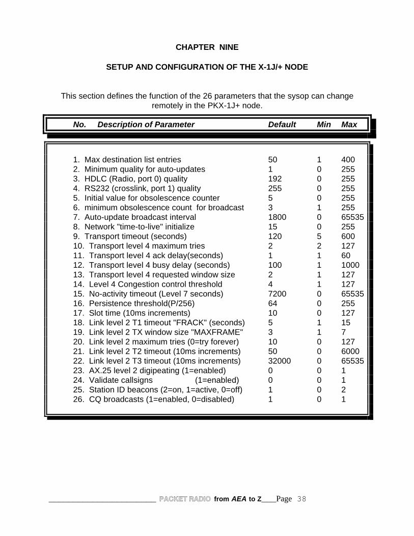
______________________ PACKET RADIO from AEA to Z___Page 38
CHAPTER NINE
SETUP AND CONFIGURATION OF THE X-1J/+ NODE
This section defines the function of the 26 parameters that the sysop can changeremotely in the PKX-1J+ node.
No. Description of Parameter Default Min Max
1. Max destination list entries 50 1 4002. Minimum quality for auto-updates 1 0 2553. HDLC (Radio, port 0) quality 192 0 2554. RS232 (crosslink, port 1) quality 255 0 2555. Initial value for obsolescence counter 5 0 2556. minimum obsolescence count for broadcast 3 1 2557. Auto-update broadcast interval 1800 0 655358. Network "time-to-live" initialize 15 0 2559. Transport timeout (seconds) 120 5 60010. Transport level 4 maximum tries 2 2 12711. Transport level 4 ack delay(seconds) 1 1 6012. Transport level 4 busy delay (seconds) 100 1 100013. Transport level 4 requested window size 2 1 12714. Level 4 Congestion control threshold 4 1 12715. No-activity timeout (Level 7 seconds) 7200 0 6553516. Persistence threshold(P/256) 64 0 255
17. Slot time (10ms increments) 10 0 12718. Link level 2 T1 timeout "FRACK" (seconds) 5 1 1519. Link level 2 TX window size "MAXFRAME" 3 1 720. Link level 2 maximum tries (0=try forever) 10 0 12721. Link level 2 T2 timeout (10ms increments) 50 0 600022. Link level 2 T3 timeout (10ms increments) 32000 0 6553523. AX.25 level 2 digipeating (1=enabled) 0 0 124. Validate callsigns (1=enabled) 0 0 125. Station ID beacons (2=on, 1=active, 0=off) 1 0 226. CQ broadcasts (1=enabled, 0=disabled) 1 0 1

______________________ PACKET RADIO from AEA to Z___Page 39
Parameter 1
Max destination list entries (default=50, minimum=1, maximum=400)
Defines the maximum allowable number of destinations in the node's routing table. Each destination consumes 32 bytes of RAM. The sysop or network manager can usethis parameter to limit the amount of RAM that is allocated to the routing table, thusensuring that sufficient space remains for frame buffering.
Parameter 2
Worst quality for auto-updates (default=10, minimum=0, maximum=255)
Defines the poorest route quality that will be automatically added to the node's routingtable. The network manager can use this parameter to limit the automatic routingupdate function to accept only higher-quality routes.
In addition, the automatic update function can be disabled altogether by setting thisparameter to zero.
Parameter 3
Radio port 0 (HDLC) quality (default=50, minimum=0, maximum=255)
Defines the quality of the radio frequency connected to the node's HDLC port. Thenetwork manager should set this parameter to an appropriate quality value inaccordance with the speed, reliability, and congestion anticipated on the frequency. The default value of 192 is appropriate for a 1200-baud user-accessible frequency...ifthe actual frequency quality is better (e.g., a UHF backbone frequency) or worse (e.g.,an HF link), the parameter value shouldbe changed accordingly.
Parameter 4
Com port 1 (RS232) quality (default=255, minimum=0, maximum=255)
Defines the quality of the TNC-to-TNC interconnect frequency connected to the node'sRS232 port. The network manager should set this parameter to an appropriate qualityvalue in accordance with the speed, reliability, and congestion anticipated on thefrequency. The default value of 255 is appropriate for a 9600-baud two-modeminterconnect cable...if the actual frequency quality is worse (e.g., a three- or four-portinterconnect, or a satellite link), the parameter value should be changed accordingly.
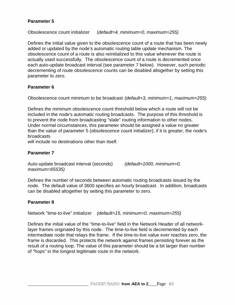
______________________ PACKET RADIO from AEA to Z___Page 40
Parameter 5
Obsolescence count initializer (default=4, minimum=0, maximum=255)
Defines the initial value given to the obsolescence count of a route that has been newlyadded or updated by the node's automatic routing table update mechanism. Theobsolescence count of a route is also reinitialized to this value whenever the route isactually used successfully. The obsolescence count of a route is decremented onceeach auto-update broadcast interval (see parameter 7 below). However, such periodicdecrementing of route obsolescence counts can be disabled altogether by setting thisparameter to zero.
Parameter 6
Obsolescence count minimum to be broadcast (default=3, minimum=1, maximum=255)
Defines the minimum obsolescence count threshold below which a route will not beincluded in the node's automatic routing broadcasts. The purpose of this threshold isto prevent the node from broadcasting "stale" routing information to other nodes. Under normal circumstances, this parameter should be assigned a value no greaterthan the value of parameter 5 (obsolescence count initializer); if it is greater, the node'sbroadcastswill include no destinations other than itself.
Parameter 7
Auto-update broadcast interval (seconds) (default=1000, minimum=0,maximum=65535)
Defines the number of seconds between automatic routing broadcasts issued by thenode. The default value of 3600 specifies an hourly broadcast. In addition, broadcastscan be disabled altogether by setting this parameter to zero.
Parameter 8
Network "time-to-live" initializer (default=15, minimum=0, maximum=255)
Defines the initial value of the "time-to-live" field in the Network Header of all network-layer frames originated by this node. The time-to-live field is decremented by eachintermediate node that relays the frame. If the time-to-live value ever reaches zero, theframe is discarded. This protects the network against frames persisting forever as theresult of a routing loop. The value of this parameter should be a bit larger than numberof "hops" in the longest legitimate route in the network.

______________________ PACKET RADIO from AEA to Z___Page 41
Parameter 9
Transport timeout (seconds) (default=200, minimum=5, maximum=600)
Defines the number of seconds between transport-layer retries.
Parameter 10
Transport maximum tries (default=2, minimum=2, maximum=127)
Defines the maximum number of transport-layer tries attempted before a circuit failureis reported.
Parameter 11
Transport acknowledge delay (seconds) (default=1, minimum=1, maximum=60)
Defines the number of seconds' delay used by the transport layer from the time itreceives an information message until it sends an information acknowledge message. The purpose of this delay is to give the acknowledgment an opportunity to be"piggybacked" upon an outgoing information message.
Parameter 12
Transport busy delay (seconds) (default=120, minimum=1, maximum=1000)
Defines the maximum number of seconds that the transport layer will remain "choked"as the result of an incoming message that has the choke flag bit set. The purpose ofthis timeout is to prevent an indefinite hang-up in the event that the "unchoke" messageis lost.
Parameter 13
Transport requested window size (frames) (default=2, minimum=1, maximum=127)
Defines the maximum number of incoming out-of-sequence information messages thatthe transport layer will buffer while waiting for the next expected information messageto arrive. Also defines the maximum number of outgoing information messages that thetransport layer will send without receiving acknowledgment.
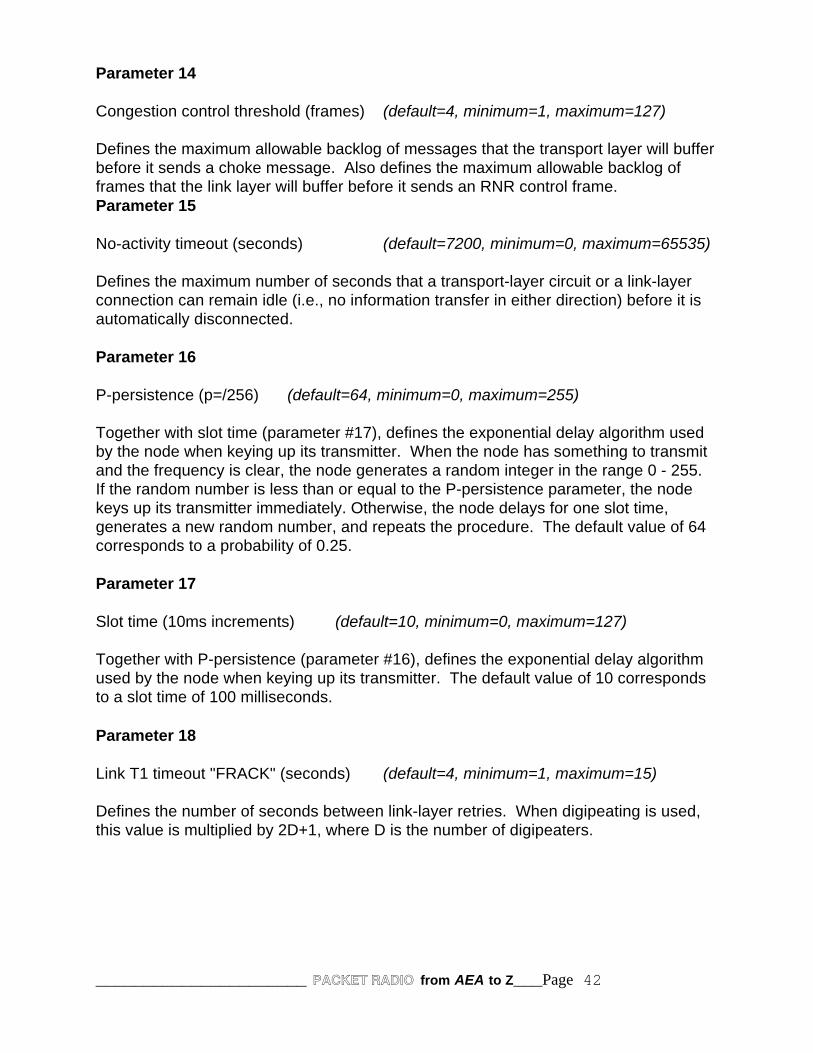
______________________ PACKET RADIO from AEA to Z___Page 42
Parameter 14
Congestion control threshold (frames) (default=4, minimum=1, maximum=127)
Defines the maximum allowable backlog of messages that the transport layer will bufferbefore it sends a choke message. Also defines the maximum allowable backlog offrames that the link layer will buffer before it sends an RNR control frame.Parameter 15
No-activity timeout (seconds) (default=7200, minimum=0, maximum=65535)
Defines the maximum number of seconds that a transport-layer circuit or a link-layerconnection can remain idle (i.e., no information transfer in either direction) before it isautomatically disconnected.
Parameter 16
P-persistence (p=/256) (default=64, minimum=0, maximum=255)
Together with slot time (parameter #17), defines the exponential delay algorithm usedby the node when keying up its transmitter. When the node has something to transmitand the frequency is clear, the node generates a random integer in the range 0 - 255. If the random number is less than or equal to the P-persistence parameter, the nodekeys up its transmitter immediately. Otherwise, the node delays for one slot time,generates a new random number, and repeats the procedure. The default value of 64corresponds to a probability of 0.25.
Parameter 17
Slot time (10ms increments) (default=10, minimum=0, maximum=127)
Together with P-persistence (parameter #16), defines the exponential delay algorithmused by the node when keying up its transmitter. The default value of 10 correspondsto a slot time of 100 milliseconds.
Parameter 18
Link T1 timeout "FRACK" (seconds) (default=4, minimum=1, maximum=15)
Defines the number of seconds between link-layer retries. When digipeating is used,this value is multiplied by 2D+1, where D is the number of digipeaters.
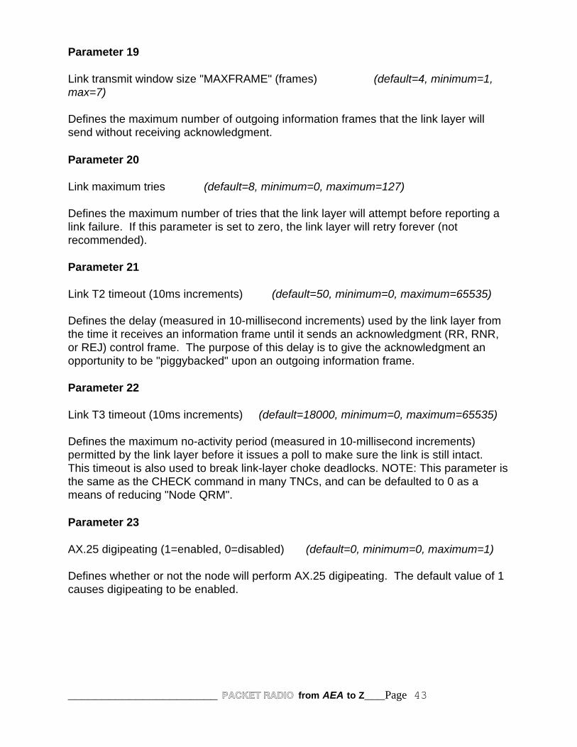
______________________ PACKET RADIO from AEA to Z___Page 43
Parameter 19
Link transmit window size "MAXFRAME" (frames) (default=4, minimum=1,max=7)
Defines the maximum number of outgoing information frames that the link layer willsend without receiving acknowledgment.
Parameter 20
Link maximum tries (default=8, minimum=0, maximum=127)
Defines the maximum number of tries that the link layer will attempt before reporting alink failure. If this parameter is set to zero, the link layer will retry forever (notrecommended).
Parameter 21
Link T2 timeout (10ms increments) (default=50, minimum=0, maximum=65535)
Defines the delay (measured in 10-millisecond increments) used by the link layer fromthe time it receives an information frame until it sends an acknowledgment (RR, RNR,or REJ) control frame. The purpose of this delay is to give the acknowledgment anopportunity to be "piggybacked" upon an outgoing information frame.
Parameter 22
Link T3 timeout (10ms increments) (default=18000, minimum=0, maximum=65535)
Defines the maximum no-activity period (measured in 10-millisecond increments)permitted by the link layer before it issues a poll to make sure the link is still intact. This timeout is also used to break link-layer choke deadlocks. NOTE: This parameter isthe same as the CHECK command in many TNCs, and can be defaulted to 0 as ameans of reducing "Node QRM".
Parameter 23
AX.25 digipeating (1=enabled, 0=disabled) (default=0, minimum=0, maximum=1)
Defines whether or not the node will perform AX.25 digipeating. The default value of 1causes digipeating to be enabled.

______________________ PACKET RADIO from AEA to Z___Page 44
Parameter 24
Validate callsigns (1=enabled, 0=disabled) (default=0, minimum=0, maximum=1)
Defines whether or not the node will perform validation checks on amateur callsigns. The default value of 1 causes callsign validation to be enabled. NOTE: If callsignvalidation is turned OFF (0), users will experience long delays if they request connectsto inactive nodes before getting back a "Failure with" response.
Parameter 25
Station ID beacons (2=on, 1=conditional, 0=off) (default=1, minimum=0, maximum=2)
Defines whether or not the node will broadcast station-identification beacons. Thedefault value of 2 causes station identification to be broadcast every 10 minutes. Thevalue of 1 causes station identification to be broadcast only if the node has transmittedsince the last beacon. The value 0 disables station identification beacons altogether.
NOTE: Many sysops set this parameter to 0 as a means to reduce unnecessarynode QRM on the frequency. The node ID's each time it sends a packet, so nolegal requirement to have ID's turned on. In the MODES PARAMS, settingBEACON time to 600 will cause an ID by the X-IJ+ node.
Parameter 26
CQ Broadcasts (1=0n, 0=off) (default=1, minimum=0, maximum=1)
Defines whether or not the node will broadcast AX.25 UI-frames in response to the CQcommand. Even if such broadcasts are disabled by setting this parameter to zero, theother features of the CQ command continue to operate normally. The default value of 1causes CQ broadcasts to be enabled.
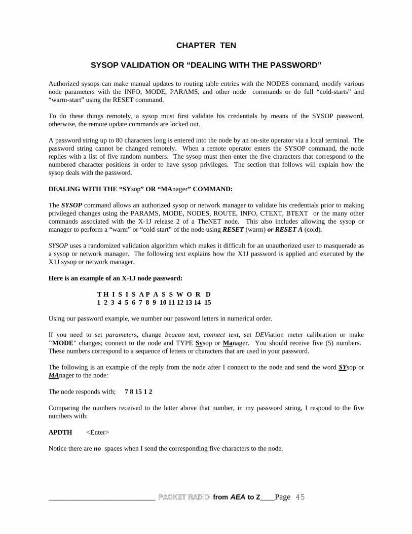
______________________ PACKET RADIO from AEA to Z___Page 45
CHAPTER TEN
SYSOP VALIDATION OR “DEALING WITH THE PASSWORD”
Authorized sysops can make manual updates to routing table entries with the NODES command, modify variousnode parameters with the INFO, MODE, PARAMS, and other node commands or do full “cold-starts” and“warm-start” using the RESET command.
To do these things remotely, a sysop must first validate his credentials by means of the SYSOP password,otherwise, the remote update commands are locked out.
A password string up to 80 characters long is entered into the node by an on-site operator via a local terminal. Thepassword string cannot be changed remotely. When a remote operator enters the SYSOP command, the nodereplies with a list of five random numbers. The sysop must then enter the five characters that correspond to thenumbered character positions in order to have sysop privileges. The section that follows will explain how thesysop deals with the password.
DEALING WITH THE “SYsop” OR “MAnager” COMMAND:
The SYSOP command allows an authorized sysop or network manager to validate his credentials prior to makingprivileged changes using the PARAMS, MODE, NODES, ROUTE, INFO, CTEXT, BTEXT or the many othercommands associated with the X-1J release 2 of a TheNET node. This also includes allowing the sysop ormanager to perform a “warm” or “cold-start” of the node using RESET (warm) or RESET A (cold).
SYSOP uses a randomized validation algorithm which makes it difficult for an unauthorized user to masquerade asa sysop or network manager. The following text explains how the X1J password is applied and executed by theX1J sysop or network manager.
Here is an example of an X-1J node password:
T H I S I S A P A S S W O R D1 2 3 4 5 6 7 8 9 10 11 12 13 14 15
Using our password example, we number our password letters in numerical order.
If you need to set parameters, change beacon text, connect text, set DEViation meter calibration or make"MODE" changes; connect to the node and TYPE Sysop or Manager. You should receive five (5) numbers. These numbers correspond to a sequence of letters or characters that are used in your password.
The following is an example of the reply from the node after I connect to the node and send the word SYsop orMAnager to the node:
The node responds with; 7 8 15 1 2
Comparing the numbers received to the letter above that number, in my password string, I respond to the fivenumbers with:
APDTH <Enter>
Notice there are no spaces when I send the corresponding five characters to the node.
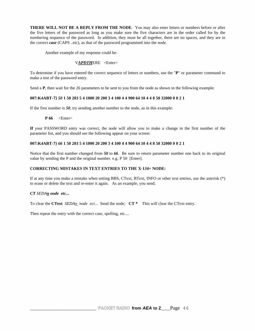
______________________ PACKET RADIO from AEA to Z___Page 46
THERE WILL NOT BE A REPLY FROM THE NODE. You may also enter letters or numbers before or afterthe five letters of the password as long as you make sure the five characters are in the order called for by thenumbering sequence of the password. In addition, they must be all together, there are no spaces, and they are inthe correct case (CAPS ..etc), as that of the password programmed into the node.
Another example of my response could be:
VAPDTHERE <Enter>
To determine if you have entered the correct sequence of letters or numbers, use the "P" or parameter command tomake a test of the password entry.
Send a P, then wait for the 26 parameters to be sent to you from the node as shown in the following example:
007:K4ABT-7} 50 1 50 203 5 4 1000 20 200 3 4 100 4 4 900 64 10 4 4 8 50 32000 0 0 2 1
If the first number is 50, try sending another number to the node, as in this example:
P 66 <Enter>
If your PASSWORD entry was correct, the node will allow you to make a change in the first number of theparameter list, and you should see the following appear on your screen:
007:K4ABT-7} 66 1 50 203 5 4 1000 20 200 3 4 100 4 4 900 64 10 4 4 8 50 32000 0 0 2 1
Notice that the first number changed from 50 to 66. Be sure to return parameter number one back to its originalvalue by sending the P and the original number. e.g. P 50 [Enter].
CORRECTING MISTAKES IN TEXT ENTRIES TO THE X-1J4+ NODE:
If at any time you make a mistake when setting BBS, CText, BText, INFO or other text entries, use the asterisk (*)to erase or delete the text and re-enter it again. As an example, you send;
CT SEDAn node etc...
To clear the CText SEDAn node ect... Send the node; CT * This will clear the CText entry.
Then repeat the entry with the correct case, spelling, etc....

______________________ PACKET RADIO from AEA to Z___Page 47
CHAPTER ELEVEN
THE USER’S GUIDE FOR THE PKX-1J NODES
CONNECTING THROUGH THE X1 NODES:
Suppose you are a user with access to a local node, and you want to contact another user station who is also withinrange of the same node. You can, of course, connect to the other station "the old way" by using the node as adigipeater. To take advantage of the store-and-forward capabilities of the node, however, you would use this two-step procedure: (1) connect to the node ("uplink"); then, (2) issue a CONNECT command with the callsign oridentifier of the other user station ("downlink").
UPLINK-DOWNLINK CONNECTIONS:
All AX.25 frames include the callsigns of both the originating station and the destination station. When yourequest a downlink, the node "adopts" your callsign as the originating station (rather than using its own callsign).This is necessary so the destination station can properly identify you as the connecting user station.
The node does NOT use your "exact" callsign, but if it did, and, if there happened to be a direct path between yourstation and the destination station, that station would then see two stations using the same callsign. This cancreate confusion at the destination station or on the network... BIG-TIME!
To avoid this problem, the down linking node "adopts" your basic callsign, by changing the SSID (or adding acallsign suffix) from N to 15-N. For example, if your callsign is NT4XXX, the downlink uses NT4XXX-15; ifyour callsign is W4KGS-2, the downlink uses W4KGS-13; and so forth. To utilize the full store-and-forwardcapability of the nodes, you would use a three-step procedure:
(1) Connect to your local node; then.(2) Issue a CONNECT command with the callsign or node identifier of the distant
node.(3) Issue a CONNECT command with the callsign of the other user station.
UPLINK, CROSSLINK, AND DOWNLINK, CONNECTIONS:
When you perform step (2) of this procedure, you are asking your local node to create a "circuit" for you betweenyour local node and the distant node. If the two nodes are sufficiently far apart, the circuit may have to passthrough several intermediate nodes. In any case, the routing is performed automatically by the node. Your circuitis carried by a series of AX.25 "crosslinks" between pairs of adjacent nodes.
CQ FEATURE:
The CQ command is used to broadcast a short text message from a node, andto enable other user stations that receive the broadcast to connect to thestation that originated the broadcast. An example is:
CQ This is George, Connect to me at the CALL & SSID displayed
All text after the CQ is optional and can be any string up to 77 characters long.
In response to a CQ command, the node broadcasts the specified message in"unproto" mode, using the callsign of the originating user (with a translated SSID) as the source and "CQ" as thedestination. The broadcast is made in the form of an AX.25 UI-frame.

______________________ PACKET RADIO from AEA to Z___Page 48
If WA4GSO in Wadesboro, North Carolina sent the CQ through several nodes to a node in Macon, Georgia, thedisplay at the Macon node would appear similar to the following:
WA4GSO-15>CQ: George in Wadesboro, NC
After making the broadcast in response to the CQ command, the node "arms" a mechanism to permit other stationsto reply to the CQ. A station wishing to reply may do so simply by connecting to the displayed callsign shown inthe local Macon node broadcast (WA4GSO-15). A CQ command remains "armed" to accept replies for 15 minutesprovided that PARMS Parameter 15 is set to 900, or until WA4GSO issues another command or if he drops thelink (disconnects).
Any station connected to the MCN node at Macon, Georgia can determine if there are any other stations awaiting areply to a CQ by issuing the USERS command. If there is an "armed" CQ at MCN node, the station who issues theUSERS command will see:
(Circuit, WA4GSO-7 Uplink) <--> CQ WA4GSO
The station may reply to such a pending CQ by issuing a CONNECT to the user callsign; In our example; CWA4GSO-15, the callsign and SSID specified in the CQ(...) portion of the USERS display. It is not necessary forthe station to disconnect from the node and reconnect.
Users of the CQ command are cautioned to be patient in awaiting a response. Your CQ will remain armed for 15minutes and will be visible to any user who issues a USERS command during that time. Consequently there's nopoint in issuing additional CQs - give other stations a chance to reply to your first one! Note the setting ofPARAMETER 15 for duration of the CQ call, time-to-live.
HAPPY PACKETING, de BucK4ABT

______________________ PACKET RADIO from AEA to Z___Page 49
NOTES:

______________________ PACKET RADIO from AEA to Z___Page 50
NOTES: