PA-2FE-TX and PA-2FE-FX 2-Port Fast Ethernet Port Adapter ...
82
Americas Headquarters Cisco Systems, Inc. 170 West Tasman Drive San Jose, CA 95134-1706 USA http://www.cisco.com Tel: 408 526-4000 800 553-NETS (6387) Fax: 408 527-0883 PA-2FE-TX and PA-2FE-FX Two-Port Fast Ethernet Port Adapter Installation and Configuration Product Number: PA-2FE-TX=, PA-2FE-FX= Platforms Supported: Cisco 7100 Series Routers, Cisco 7200 Series Routers, Cisco uBR7200 Series Routers, Cisco 7200 VXR Routers, Cisco 7201 Router, Cisco 7301 Router, Cisco 7304 PCI Port Adapter Carrier Card in the Cisco 7304 Router, Cisco 7401ASR Router, and VIP in the Cisco 7500 Series Routers Text Part Number: OL-3474-07
-
Upload
khangminh22 -
Category
Documents
-
view
4 -
download
0
Transcript of PA-2FE-TX and PA-2FE-FX 2-Port Fast Ethernet Port Adapter ...
PA-2FE-TX and PA-2FE-FX Two-Port Fast Ethernet Port Adapter Installation and ConfigurationProduct Number: PA-2FE-TX=, PA-2FE-FX=Platforms Supported: Cisco 7100 Series Routers, Cisco 7200 Series Routers, Cisco uBR7200 Series Routers, Cisco 7200 VXR Routers, Cisco 7201 Router, Cisco 7301 Router, Cisco 7304 PCI Port Adapter Carrier Card in the Cisco 7304 Router, Cisco 7401ASR Router, and VIP in the Cisco 7500 Series Routers
Americas HeadquartersCisco Systems, Inc.170 West Tasman DriveSan Jose, CA 95134-1706 USAhttp://www.cisco.comTel: 408 526-4000
800 553-NETS (6387)Fax: 408 527-0883
Text Part Number: OL-3474-07

THE SPECIFICATIONS AND INFORMATION REGARDING THE PRODUCTS IN THIS MANUAL ARE SUBJECT TO CHANGE WITHOUT NOTICE. ALL STATEMENTS, INFORMATION, AND RECOMMENDATIONS IN THIS MANUAL ARE BELIEVED TO BE ACCURATE BUT ARE PRESENTED WITHOUT WARRANTY OF ANY KIND, EXPRESS OR IMPLIED. USERS MUST TAKE FULL RESPONSIBILITY FOR THEIR APPLICATION OF ANY PRODUCTS.
THE SOFTWARE LICENSE AND LIMITED WARRANTY FOR THE ACCOMPANYING PRODUCT ARE SET FORTH IN THE INFORMATION PACKET THAT SHIPPED WITH THE PRODUCT AND ARE INCORPORATED HEREIN BY THIS REFERENCE. IF YOU ARE UNABLE TO LOCATE THE SOFTWARE LICENSE OR LIMITED WARRANTY, CONTACT YOUR CISCO REPRESENTATIVE FOR A COPY.
The following information is for FCC compliance of Class A devices: This equipment has been tested and found to comply with the limits for a Class A digital device, pursuant to part 15 of the FCC rules. These limits are designed to provide reasonable protection against harmful interference when the equipment is operated in a commercial environment. This equipment generates, uses, and can radiate radio-frequency energy and, if not installed and used in accordance with the instruction manual, may cause harmful interference to radio communications. Operation of this equipment in a residential area is likely to cause harmful interference, in which case users will be required to correct the interference at their own expense.
The following information is for FCC compliance of Class B devices: The equipment described in this manual generates and may radiate radio-frequency energy. If it is not installed in accordance with Cisco’s installation instructions, it may cause interference with radio and television reception. This equipment has been tested and found to comply with the limits for a Class B digital device in accordance with the specifications in part 15 of the FCC rules. These specifications are designed to provide reasonable protection against such interference in a residential installation. However, there is no guarantee that interference will not occur in a particular installation.
Modifying the equipment without Cisco’s written authorization may result in the equipment no longer complying with FCC requirements for Class A or Class B digital devices. In that event, your right to use the equipment may be limited by FCC regulations, and you may be required to correct any interference to radio or television communications at your own expense.
You can determine whether your equipment is causing interference by turning it off. If the interference stops, it was probably caused by the Cisco equipment or one of its peripheral devices. If the equipment causes interference to radio or television reception, try to correct the interference by using one or more of the following measures:
• Turn the television or radio antenna until the interference stops.
• Move the equipment to one side or the other of the television or radio.
• Move the equipment farther away from the television or radio.
• Plug the equipment into an outlet that is on a different circuit from the television or radio. (That is, make certain the equipment and the television or radio are on circuits controlled by different circuit breakers or fuses.)
Modifications to this product not authorized by Cisco Systems, Inc. could void the FCC approval and negate your authority to operate the product.
The Cisco implementation of TCP header compression is an adaptation of a program developed by the University of California, Berkeley (UCB) as part of UCB’s public domain version of the UNIX operating system. All rights reserved. Copyright © 1981, Regents of the University of California.
NOTWITHSTANDING ANY OTHER WARRANTY HEREIN, ALL DOCUMENT FILES AND SOFTWARE OF THESE SUPPLIERS ARE PROVIDED “AS IS” WITH ALL FAULTS. CISCO AND THE ABOVE-NAMED SUPPLIERS DISCLAIM ALL WARRANTIES, EXPRESSED OR IMPLIED, INCLUDING, WITHOUT LIMITATION, THOSE OF MERCHANTABILITY, FITNESS FOR A PARTICULAR PURPOSE AND NONINFRINGEMENT OR ARISING FROM A COURSE OF DEALING, USAGE, OR TRADE PRACTICE.
IN NO EVENT SHALL CISCO OR ITS SUPPLIERS BE LIABLE FOR ANY INDIRECT, SPECIAL, CONSEQUENTIAL, OR INCIDENTAL DAMAGES, INCLUDING, WITHOUT LIMITATION, LOST PROFITS OR LOSS OR DAMAGE TO DATA ARISING OUT OF THE USE OR INABILITY TO USE THIS MANUAL, EVEN IF CISCO OR ITS SUPPLIERS HAVE BEEN ADVISED OF THE POSSIBILITY OF SUCH DAMAGES.
PA-2FE-TX and PA-2FE-FX Two-Port Fast Ethernet Port Adapter Installation and Configuration© 2007 Cisco Systems, Inc. All rights reserved.
CCVP, the Cisco Logo, and the Cisco Square Bridge logo are trademarks of Cisco Systems, Inc.; Changing the Way We Work, Live, Play, and Learn is a service mark of Cisco Systems, Inc.; and Access Registrar, Aironet, BPX, Catalyst, CCDA, CCDP, CCIE, CCIP, CCNA, CCNP, CCSP, Cisco, the Cisco Certified Internetwork Expert logo, Cisco IOS, Cisco Press, Cisco Systems, Cisco Systems Capital, the Cisco Systems logo, Cisco Unity, Enterprise/Solver, EtherChannel, EtherFast, EtherSwitch, Fast Step, Follow Me Browsing, FormShare, GigaDrive, HomeLink, Internet Quotient, IOS, iPhone, IP/TV, iQ Expertise, the iQ logo, iQ Net Readiness Scorecard, iQuick Study, LightStream, Linksys, MeetingPlace, MGX, Networking Academy, Network Registrar, Packet, PIX, ProConnect, RateMUX, ScriptShare, SlideCast, SMARTnet, StackWise, The Fastest Way to Increase Your Internet Quotient, and TransPath are registered trademarks of Cisco Systems, Inc. and/or its affiliates in the United States and certain other countries.
All other trademarks mentioned in this document or Website are the property of their respective owners. The use of the word partner does not imply a partnership relationship between Cisco and any other company. (0704R)
PA-2FE-TX anOL-3474-07
C O N T E N T S
Preface vii
Document Revision History vii
Objectives viii
Organization viii
Related Documentation viii
Obtaining Documentation, Obtaining Support, and Security Guidelines xi
C H A P T E R 1 Overview 1-1
Port Adapter Overview 1-1
Fast Ethernet Overview 1-2
IEEE 802.3u 100BASE-T Specifications 1-2
LEDs 1-4
Receptacles, Cables, and Pinouts 1-4
Network Management 1-6
Port Adapter Slot Locations on the Supported Platforms 1-7
Cisco 7100 Series Routers Slot Numbering 1-7
Cisco 7200 Series Routers and Cisco 7200 VXR Routers Slot Numbering 1-8
Cisco uBR7200 Series Router Slot Numbering 1-9
Cisco 7201 Router Slot Numbering 1-10
Cisco 7301 Router Slot Numbering 1-10
Cisco 7304 PCI Port Adapter Carrier Card Slot Numbering 1-11
Cisco 7401ASR Router Slot Numbering 1-12
Cisco 7500 Series Routers with VIP Slot Numbering 1-12
Identifying Interface Addresses 1-16
Cisco 7120 Router and Cisco 7140 Router Interface Addresses 1-17
Cisco 7200 Series Routers and Cisco 7200 VXR Routers Interface Addresses 1-17
Cisco uBR7200 Series Routers Interface Addresses 1-18
Cisco 7201 Router Interface Addresses 1-18
Cisco 7301 Router Interface Addresses 1-18
Cisco 7304 PCI Port Adapter Carrier Card Interface Addresses 1-18
Cisco 7401ASR Router Interface Addresses 1-18
Cisco 7500 Series Routers VIP Interface Addresses 1-19
iiid PA-2FE-FX Two-Port Fast Ethernet Port Adapter Installation and Configuration

Contents
C H A P T E R 2 Preparing for Installation 2-1
Required Tools and Equipment 2-1
Software and Hardware Requirements 2-2
Checking Hardware and Software Compatibility 2-2
Safety Guidelines 2-3
Safety Warnings 2-3
Warning Definition 2-3
Electrical Equipment Guidelines 2-8
Telephone Wiring Guidelines 2-9
Preventing Electrostatic Discharge Damage 2-9
FCC Class A Compliance 2-10
C H A P T E R 3 Removing and Installing Port Adapters 3-1
Handling Port Adapters 3-1
Online Insertion and Removal 3-2
Warnings and Cautions 3-3
Port Adapter Removal and Installation 3-4
Cisco 7100 Series—Removing and Installing a Port Adapter 3-5
Cisco 7200 Series Routers and Cisco 7200 VXR Routers—Removing and Installing a Port Adapter 3-6
Cisco uBR7200 Series Routers—Removing a Port Adapter 3-7
Cisco uBR7200 Series Routers—Installing a Port Adapter 3-8
Cisco 7201 Router—Removing and Installing a Port Adapter 3-9
Cisco 7301 Router—Removing and Installing a Port Adapter 3-10
Cisco 7304 PCI Port Adapter Carrier Card—Removing and Installing a Port Adapter 3-11
Cisco 7401ASR Router—Removing and Installing a Port Adapter 3-13
Cisco 7500 Series Router VIP—Removing and Installing a Port Adapter 3-13
Removing and Installing a VIP Carrier Card in the Cisco 7500 Series Router 3-14
Removing and Installing the Port Adapter in the VIP Carrier Card 3-15
Connecting a PA-2FE RJ-45 or SC Cable 3-16
C H A P T E R 4 Configuring the PA-2FE 4-1
Using the EXEC Command Interpreter 4-1
Configuring the Interfaces 4-2
Shutting Down an Interface 4-2
Performing a Basic Interface Configuration 4-7
Checking the Configuration 4-9
Using show Commands to Verify the New Interface Status 4-9
ivPA-2FE-TX and PA-2FE-FX Two-Port Fast Ethernet Port Adapter Installation and Configuration
OL-3474-07

Contents
Using the show version or show hardware Commands 4-11
Using the show diag Command 4-14
Using the show interfaces Command 4-18
Using the ping Command to Verify Network Connectivity 4-21
vPA-2FE-TX and PA-2FE-FX Two-Port Fast Ethernet Port Adapter Installation and Configuration
OL-3474-07

Contents
viPA-2FE-TX and PA-2FE-FX Two-Port Fast Ethernet Port Adapter Installation and Configuration
OL-3474-07
Preface
This preface describes the objectives and organization of this document and explains how to find additional information on related products and services. This preface contains the following sections:
• Document Revision History, page vii
• Objectives, page viii
• Organization, page viii
• Related Documentation, page viii
• Obtaining Documentation, Obtaining Support, and Security Guidelines, page xi
Document Revision HistoryThe Document Revision History table below, beginning with version OL-10589-05, records technical changes to this document.
Document Version Date Change Summary
OL-3474-07 April, 2007 Adding Cisco 7201 router information.
OL-3474-06 December, 2006 Correcting software support information.
OL-3474-05 November, 2006 Correcting the RJ-45 pinout information.
viiPA-2FE-TX and PA-2FE-FX Two-Port Fast Ethernet Port Adapter Installation and Configuration
OL-3474-07
PrefaceObjectives
ObjectivesThis document describes how to install and configure the PA-2FE-TX and PA-2FE-FX two-port Fast Ethernet port adapters, hereafter referred to as the PA-2FE, which are used in the following platforms:
• Cisco 7100 series routers, consisting of the Cisco 7120 series and Cisco 7140 series
• Cisco 7200 series routers and Cisco 7200 VXR routers, consisting of the two-slot Cisco 7202, four-slot Cisco 7204 and Cisco 7204VXR, and the six-slot Cisco 7206 and Cisco 7206VXR
• Cisco uBR7200 series universal broadband routers
• Cisco 7201 router
• Cisco 7301 router
• Cisco 7304 PCI port adapter carrier card in Cisco 7304 router
• Cisco 7401ASR router
• Versatile Interface Processor (VIP) in Cisco 7500 series routers (VIP2, VIP4, VIP6-80)
OrganizationThis document contains the following chapters:
Related DocumentationYour router and the Cisco IOS software running on it contain extensive features and functionality, which are documented in the following resources:
• Cisco IOS software:
For configuration information and support, refer to the modular configuration and modular command reference publications in the Cisco IOS software configuration documentation set that corresponds to the software release installed on your Cisco hardware.
Note You can access Cisco IOS software configuration and hardware installation and maintenance documentation on the World Wide Web at http://www.cisco.com, http://www-china.cisco.com, or http://www-europe.cisco.com.
Section Title Description
Chapter 1 Overview Describes the PA-2FE and its LED displays, cables, and receptacles.
Chapter 2 Preparing for Installation Describes safety considerations, tools required, and procedures you should perform before the actual installation.
Chapter 3 Removing and Installing Port Adapters
Describes the procedures for installing and removing PA-2FE port adapters in the supported platforms.
Chapter 4 Configuring the PA-2FE Provides instructions for configuring the PA-2FE on the supported platforms.
viiiPA-2FE-TX and PA-2FE-FX Two-Port Fast Ethernet Port Adapter Installation and Configuration
OL-3474-07
PrefaceRelated Documentation
• Cisco 7100 series routers:
– For an online directory to quickly access documents for Cisco 7100 series routers, refer to the Cisco 7100 Series Documentation roadmap at the following URL:
http://www.cisco.com/en/US/products/hw/vpndevc/ps333/products_product_index09186a00800fa142.html
– For hardware installation and configuration information refer to the Cisco 7100 Series VPN Router Installation and Configuration Guide.
• Cisco 7200 series routers:
– For an online directory to quickly access documents for Cisco 7200 series routers, refer to the Cisco 7200 Series Routers Documentation Roadmap at the following URL:
http://www.cisco.com/en/US/products/hw/routers/ps341/products_documentation_roadmap09186a00801c0915.html
– For hardware installation and configuration information (including the Cisco 7206 or Cisco 7206VXR as a router shelf in a Cisco AS5800 Universal Access Server), refer to the online installation and configuration guide and quick start for your Cisco 7200 series router.
– For port adapter hardware and memory configuration guidelines, refer to the Cisco 7200 Series Port Adapter Hardware Configuration Guidelines.
– For information on network processing engines or network services engines, refer to the Network Processing Engine and Network Services Engine Installation and Configuration document.
• Cisco 7200 VXR routers:
– For an online directory to quickly access documents for Cisco 7200 VXR routers, refer to the Cisco 7200 Series Routers Documentation Roadmap at the following URL:
http://www.cisco.com/en/US/products/hw/routers/ps341/products_documentation_roadmap09186a00801c0915.html
– For hardware installation and maintenance information, refer to the Cisco 7200 VXR Installation and Configuration Guide or the Cisco 7200 VXR Routers Quick Start Guide.
– For more information about the Cisco 7206 or the Cisco 7206VXR as a router shelf, see the Cisco AS5800 Series Universal Gateways documents at the following URL:
http://www.cisco.com/en/US/products/hw/univgate/ps509/tsd_products_support_series_home.html
• Cisco uBR7200 series routers:
– For an online directory to quickly access documents for Cisco uBR7200 Universal Broadband routers, refer to the Cisco uBR7200 Universal Broadband Router Documentation Roadmap at the following URL:
http://www.cisco.com/en/US/products/hw/cable/ps2217/products_documentation_roadmap09186a00805e0d0c.html
• Cisco 7201 router:
– For an online directory to quickly access documents for the Cisco 7201 router, refer to the Cisco 7201 Router Documentation Roadmap at the following URL:
http://www.cisco.com/en/US/customer/products/hw/routers/ps341/products_documentation_roadmap09186a00807f635a.html
– For hardware installation and maintenance information, refer to the Cisco 7201 Installation and Configuration Guide or the Cisco 7201 Router Quick Start Guide.
ixPA-2FE-TX and PA-2FE-FX Two-Port Fast Ethernet Port Adapter Installation and Configuration
OL-3474-07

PrefaceRelated Documentation
• Cisco 7301 router:
– For an online directory to quickly access documents for the Cisco 7301 router, refer to the Cisco 7301 Internet Router Documentation Roadmap at the following URL:
http://www.cisco.com/en/US/products/hw/routers/ps352/products_documentation_roadmap09186a00801c0f21.html
– For hardware installation and maintenance information, refer to the Cisco 7301 Installation and Configuration Guide or the Cisco 7301 Router Quick Start Guide.
• Cisco 7304 PCI port adapter carrier card in Cisco 7304 router:
– For an online directory to quickly access documents for the Cisco 7304 PCI Port Adapter Carrier Card in the Cisco 7301 router, refer to the Cisco 7304 Router Line Card, Carrier Card, Port Adapter, Modular Services Card, and Shared Port Adapter Documentation Roadmap at the following URL:
http://www.cisco.com/en/US/products/hw/routers/ps352/products_documentation_roadmap09186a00801c0f5e.html
– For hardware installation and maintenance information, refer to the Cisco 7304 PCI Port Adapter Carrier Card Installation and Configuration Guide.
• Cisco 7401ASR router:
– For an online directory to quickly access documents for the Cisco 7401ASR router, refer to the Cisco 7401ASR Router Documentation Roadmap at the following URL:
http://www.cisco.com/en/US/products/hw/routers/ps354/products_documentation_roadmap09186a00801c0fd5.html
– For hardware installation and maintenance information, refer to the Cisco 7401ASR Installation and Configuration Guide or the Cisco 7401ASR Router Quick Start Guide.
• Cisco 7500 series routers
– For an online directory to quickly access documents for the Cisco 7500 series routers, refer to the Cisco 7500 Series Routers Documentation Roadmap at the following URL:
http://www.cisco.com/en/US/products/hw/routers/ps359/products_documentation_roadmap09186a00801c0f9b.html
– For hardware installation and maintenance information, refer to the Cisco 7500 Series Installation and Configuration Guide or the quick start for your Cisco 7500 series router.
• For international agency compliance, safety, and statutory information for WAN interfaces, refer to the following documents. Use the documentation roadmap for your particular router to link to the appropriate documents for your router:
– Regulatory Compliance and Safety Information for Cisco 7100 Series VPN Routers
– Regulatory Compliance and Safety Information for Cisco 7200 Series Routers
– Regulatory Compliance and Safety Information for the Cisco uBR7200 Series Universal Broadband Routers
– Regulatory Compliance and Safety Information for the Cisco 7301 Internet Router
– Regulatory Compliance and Safety Information for the Cisco 7304 Internet Router
– Regulatory Compliance and Safety Information for the Cisco 7401ASR Internet Router
– Regulatory Compliance and Safety Information for the Cisco 7500 Series Routers
xPA-2FE-TX and PA-2FE-FX Two-Port Fast Ethernet Port Adapter Installation and Configuration
OL-3474-07
PrefaceObtaining Documentation, Obtaining Support, and Security Guidelines
• Fast Ethernet Port Adapter Family (PA-FE and PA-2FE) Datasheet
http://www.cisco.com/en/US/products/hw/modules/ps2033/products_data_sheet09186a0080091c92.html
Obtaining Documentation, Obtaining Support, and Security Guidelines
For information on obtaining documentation, obtaining support, providing documentation feedback, security guidelines, and also recommended aliases and general Cisco documents, see the monthly What’s New in Cisco Product Documentation, which also lists all new and revised technical documentation at:
http://www.cisco.com/en/US/docs/general/whatsnew/whatsnew.html
xiPA-2FE-TX and PA-2FE-FX Two-Port Fast Ethernet Port Adapter Installation and Configuration
OL-3474-07

PrefaceObtaining Documentation, Obtaining Support, and Security Guidelines
xiiPA-2FE-TX and PA-2FE-FX Two-Port Fast Ethernet Port Adapter Installation and Configuration
OL-3474-07
PA-2FE-TX and PA-2FE-FX Two-Port Fast EOL-3474-07
C H A P T E R1
OverviewThis chapter describes the PA-2FE port adapter and contains the following sections:
• Port Adapter Overview, page 1-1
• Fast Ethernet Overview, page 1-2
• IEEE 802.3u 100BASE-T Specifications, page 1-2
• LEDs, page 1-4
• Receptacles, Cables, and Pinouts, page 1-4
• Network Management, page 1-6
• Port Adapter Slot Locations on the Supported Platforms, page 1-7
• Identifying Interface Addresses, page 1-16
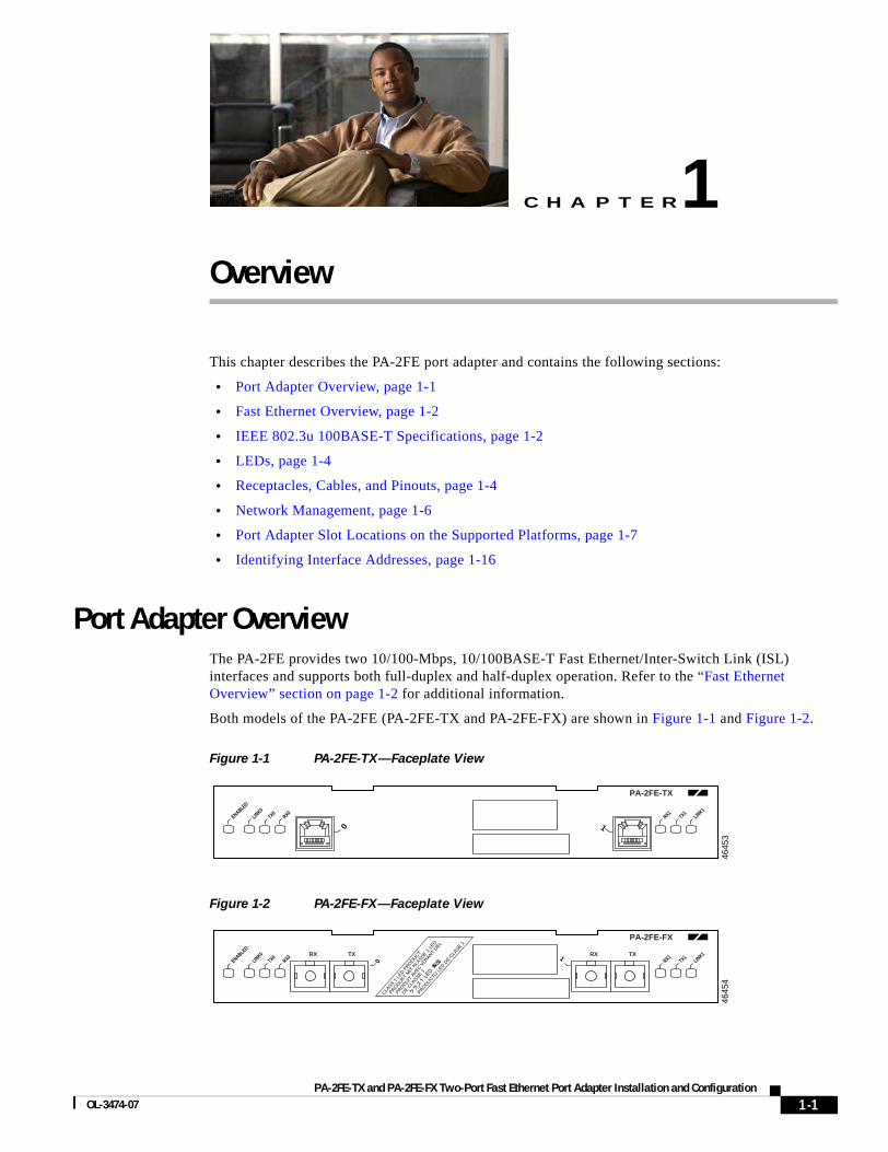
Port Adapter OverviewThe PA-2FE provides two 10/100-Mbps, 10/100BASE-T Fast Ethernet/Inter-Switch Link (ISL) interfaces and supports both full-duplex and half-duplex operation. Refer to the “Fast Ethernet Overview” section on page 1-2 for additional information.
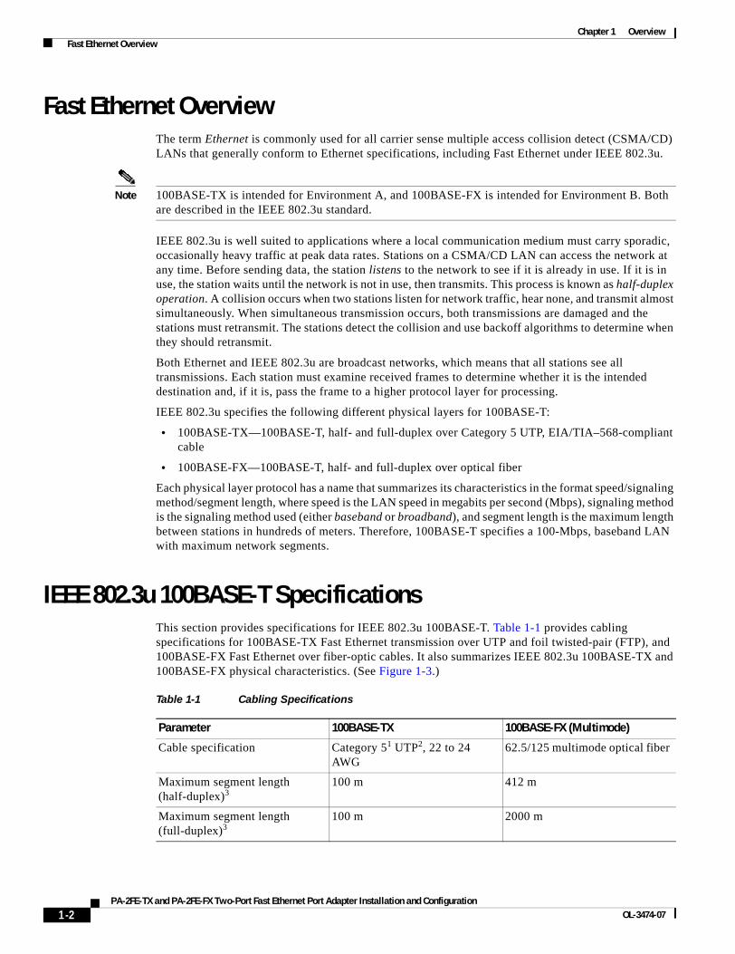
Both models of the PA-2FE (PA-2FE-TX and PA-2FE-FX) are shown in Figure 1-1 and Figure 1-2.
Figure 1-1 PA-2FE-TX—Faceplate View
Figure 1-2 PA-2FE-FX—Faceplate View
4645
3
ENABLED
LINK0TX0
RX0RX1
LINK1TX1
PA-2FE-TX
0 1
4645
4
ENABLED
0LINK0TX0
RX0RX1
LINK1TX1TXRX 1 TX
PA-2FE-FX
RX
CLASS 1
LED P
RODUCT
P
RODUKT
MIT
KLA
SSE 1 L
ED
PRO
DUIT A
VEC VOYA
NT DEL
D
E CLA
SSE 1PRO
DUCTO L
ED DE C
LASE 1
1-1thernet Port Adapter Installation and Configuration
Chapter 1 Overview Fast Ethernet Overview
Fast Ethernet OverviewThe term Ethernet is commonly used for all carrier sense multiple access collision detect (CSMA/CD) LANs that generally conform to Ethernet specifications, including Fast Ethernet under IEEE 802.3u.
Note 100BASE-TX is intended for Environment A, and 100BASE-FX is intended for Environment B. Both are described in the IEEE 802.3u standard.
IEEE 802.3u is well suited to applications where a local communication medium must carry sporadic, occasionally heavy traffic at peak data rates. Stations on a CSMA/CD LAN can access the network at any time. Before sending data, the station listens to the network to see if it is already in use. If it is in use, the station waits until the network is not in use, then transmits. This process is known as half-duplex operation. A collision occurs when two stations listen for network traffic, hear none, and transmit almost simultaneously. When simultaneous transmission occurs, both transmissions are damaged and the stations must retransmit. The stations detect the collision and use backoff algorithms to determine when they should retransmit.
Both Ethernet and IEEE 802.3u are broadcast networks, which means that all stations see all transmissions. Each station must examine received frames to determine whether it is the intended destination and, if it is, pass the frame to a higher protocol layer for processing.
IEEE 802.3u specifies the following different physical layers for 100BASE-T:
• 100BASE-TX—100BASE-T, half- and full-duplex over Category 5 UTP, EIA/TIA–568-compliant cable
• 100BASE-FX—100BASE-T, half- and full-duplex over optical fiber
Each physical layer protocol has a name that summarizes its characteristics in the format speed/signaling method/segment length, where speed is the LAN speed in megabits per second (Mbps), signaling method is the signaling method used (either baseband or broadband), and segment length is the maximum length between stations in hundreds of meters. Therefore, 100BASE-T specifies a 100-Mbps, baseband LAN with maximum network segments.
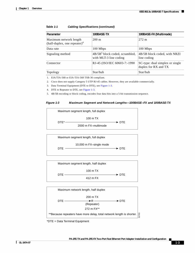
IEEE 802.3u 100BASE-T SpecificationsThis section provides specifications for IEEE 802.3u 100BASE-T. Table 1-1 provides cabling specifications for 100BASE-TX Fast Ethernet transmission over UTP and foil twisted-pair (FTP), and 100BASE-FX Fast Ethernet over fiber-optic cables. It also summarizes IEEE 802.3u 100BASE-TX and 100BASE-FX physical characteristics. (See Figure 1-3.)
Table 1-1 Cabling Specifications
Parameter 100BASE-TX 100BASE-FX (Multimode)
Cable specification Category 51 UTP2, 22 to 24 AWG
62.5/125 multimode optical fiber
Maximum segment length (half-duplex)3
100 m 412 m
Maximum segment length (full-duplex)3
100 m 2000 m
1-2PA-2FE-TX and PA-2FE-FX Two-Port Fast Ethernet Port Adapter Installation and Configuration
OL-3474-07
Chapter 1 Overview IEEE 802.3u 100BASE-T Specifications
Figure 1-3 Maximum Segment and Network Lengths—100BASE--FX and 100BASE-TX
Maximum network length (half-duplex, one repeater)4
200 m 272 m
Data rate 100 Mbps 100 Mbps
Signaling method 4B/5B5 block coded, scrambled, with MLT-3 line coding
4B/5B block coded, with NRZI line coding
Connector RJ-45 (ISO/IEC 60603-7:-1990 SC-type: dual simplex or single duplex for RX and TX
Topology Star/hub Star/hub
1. EIA/TIA-568 or EIA-TIA-568 TSB-36 compliant.
2. Cisco does not supply Category 5 UTP RJ-45 cables. However, they are available commercially.
3. Data Terminal Equipment (DTE to DTE), see Figure 1-3.
4. DTE to Repeater to DTE, see Figure 1-3.
5. 4B/5B encoding or block coding, encodes four data bits into a 5-bit transmission sequence.
Table 1-1 Cabling Specifications (continued)
Parameter 100BASE-TX 100BASE-FX (Multimode)
Maximum segment length, full duplex
100 m TXDTEDTE*
*DTE = Data Terminal Equipment
**Because repeaters have more delay, total network length is shorter.
2000 m FX–multimode
Maximum segment length, half duplex
100 m TXDTEDTE
412 m FX
Maximum segment length, full duplex
10,000 m FX–single modeDTEDTE
Maximum network length, half duplex
200 m TXDTEDTE R
(Repeater)
272 m FX**
3170
3
1-3PA-2FE-TX and PA-2FE-FX Two-Port Fast Ethernet Port Adapter Installation and Configuration
OL-3474-07
Chapter 1 Overview LEDs
Note PA-2FE-FX uses 62.5/125-micron multimode fiber with an SC connector.
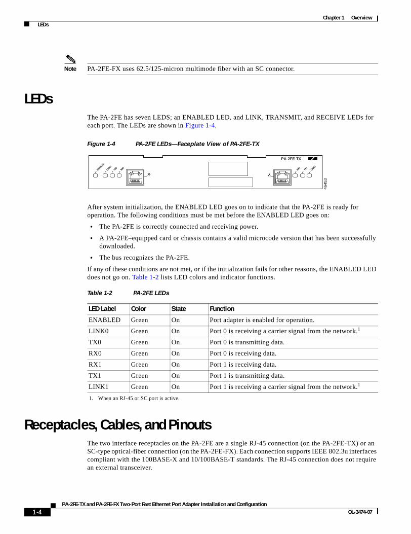
LEDsThe PA-2FE has seven LEDS; an ENABLED LED, and LINK, TRANSMIT, and RECEIVE LEDs for each port. The LEDs are shown in Figure 1-4.
Figure 1-4 PA-2FE LEDs—Faceplate View of PA-2FE-TX
After system initialization, the ENABLED LED goes on to indicate that the PA-2FE is ready for operation. The following conditions must be met before the ENABLED LED goes on:
• The PA-2FE is correctly connected and receiving power.
• A PA-2FE–equipped card or chassis contains a valid microcode version that has been successfully downloaded.
• The bus recognizes the PA-2FE.
If any of these conditions are not met, or if the initialization fails for other reasons, the ENABLED LED does not go on. Table 1-2 lists LED colors and indicator functions.
Receptacles, Cables, and PinoutsThe two interface receptacles on the PA-2FE are a single RJ-45 connection (on the PA-2FE-TX) or an SC-type optical-fiber connection (on the PA-2FE-FX). Each connection supports IEEE 802.3u interfaces compliant with the 100BASE-X and 10/100BASE-T standards. The RJ-45 connection does not require an external transceiver.
4645
3
ENABLED
LINK0TX0
RX0RX1
LINK1TX1
PA-2FE-TX
0 1
Table 1-2 PA-2FE LEDs
LED Label Color State Function
ENABLED Green On Port adapter is enabled for operation.
LINK0 Green On Port 0 is receiving a carrier signal from the network.1
1. When an RJ-45 or SC port is active.
TX0 Green On Port 0 is transmitting data.
RX0 Green On Port 0 is receiving data.
RX1 Green On Port 1 is receiving data.
TX1 Green On Port 1 is transmitting data.
LINK1 Green On Port 1 is receiving a carrier signal from the network.1
1-4PA-2FE-TX and PA-2FE-FX Two-Port Fast Ethernet Port Adapter Installation and Configuration
OL-3474-07
Chapter 1 Overview Receptacles, Cables, and Pinouts
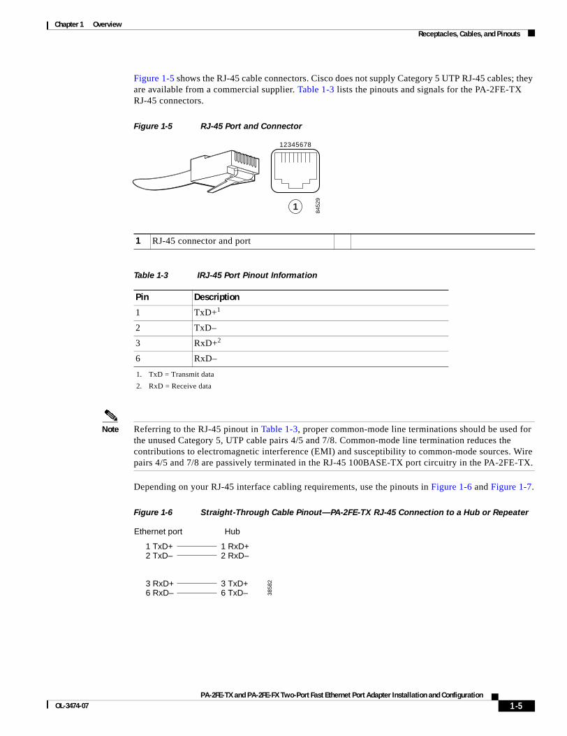
Figure 1-5 shows the RJ-45 cable connectors. Cisco does not supply Category 5 UTP RJ-45 cables; they are available from a commercial supplier. Table 1-3 lists the pinouts and signals for the PA-2FE-TX RJ-45 connectors.
Figure 1-5 RJ-45 Port and Connector
Note Referring to the RJ-45 pinout in Table 1-3, proper common-mode line terminations should be used for the unused Category 5, UTP cable pairs 4/5 and 7/8. Common-mode line termination reduces the contributions to electromagnetic interference (EMI) and susceptibility to common-mode sources. Wire pairs 4/5 and 7/8 are passively terminated in the RJ-45 100BASE-TX port circuitry in the PA-2FE-TX.
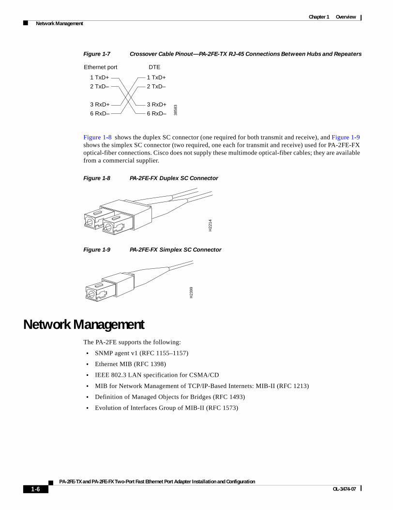
Depending on your RJ-45 interface cabling requirements, use the pinouts in Figure 1-6 and Figure 1-7.
Figure 1-6 Straight-Through Cable Pinout—PA-2FE-TX RJ-45 Connection to a Hub or Repeater
1 RJ-45 connector and port
Table 1-3 IRJ-45 Port Pinout Information
Pin Description
1 TxD+1
1. TxD = Transmit data
2 TxD–
3 RxD+2
2. RxD = Receive data
6 RxD–
8452
9
12345678
1
Ethernet port Hub
1 TxD+2 TxD–
3 RxD+6 RxD–
1 RxD+2 RxD–
3 TxD+6 TxD– 38
582
1-5PA-2FE-TX and PA-2FE-FX Two-Port Fast Ethernet Port Adapter Installation and Configuration
OL-3474-07
Chapter 1 Overview Network Management
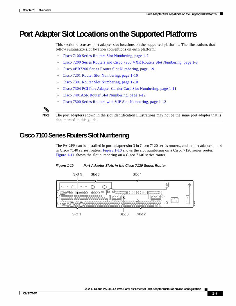
Figure 1-7 Crossover Cable Pinout—PA-2FE-TX RJ-45 Connections Between Hubs and Repeaters
Figure 1-8 shows the duplex SC connector (one required for both transmit and receive), and Figure 1-9 shows the simplex SC connector (two required, one each for transmit and receive) used for PA-2FE-FX optical-fiber connections. Cisco does not supply these multimode optical-fiber cables; they are available from a commercial supplier.
Figure 1-8 PA-2FE-FX Duplex SC Connector
Figure 1-9 PA-2FE-FX Simplex SC Connector
Network ManagementThe PA-2FE supports the following:
• SNMP agent v1 (RFC 1155–1157)
• Ethernet MIB (RFC 1398)
• IEEE 802.3 LAN specification for CSMA/CD
• MIB for Network Management of TCP/IP-Based Internets: MIB-II (RFC 1213)
• Definition of Managed Objects for Bridges (RFC 1493)
• Evolution of Interfaces Group of MIB-II (RFC 1573)
Ethernet port
1 TxD+
2 TxD–
3 RxD+
6 RxD–
1 TxD+
2 TxD–
3 RxD+
6 RxD– 3858
3
DTE
H22
14
H23
99
1-6PA-2FE-TX and PA-2FE-FX Two-Port Fast Ethernet Port Adapter Installation and Configuration
OL-3474-07
Chapter 1 Overview Port Adapter Slot Locations on the Supported Platforms
Port Adapter Slot Locations on the Supported PlatformsThis section discusses port adapter slot locations on the supported platforms. The illustrations that follow summarize slot location conventions on each platform:
• Cisco 7100 Series Routers Slot Numbering, page 1-7
• Cisco 7200 Series Routers and Cisco 7200 VXR Routers Slot Numbering, page 1-8
• Cisco uBR7200 Series Router Slot Numbering, page 1-9
• Cisco 7201 Router Slot Numbering, page 1-10
• Cisco 7301 Router Slot Numbering, page 1-10
• Cisco 7304 PCI Port Adapter Carrier Card Slot Numbering, page 1-11
• Cisco 7401ASR Router Slot Numbering, page 1-12
• Cisco 7500 Series Routers with VIP Slot Numbering, page 1-12
Note The port adapters shown in the slot identification illustrations may not be the same port adapter that is documented in this guide.
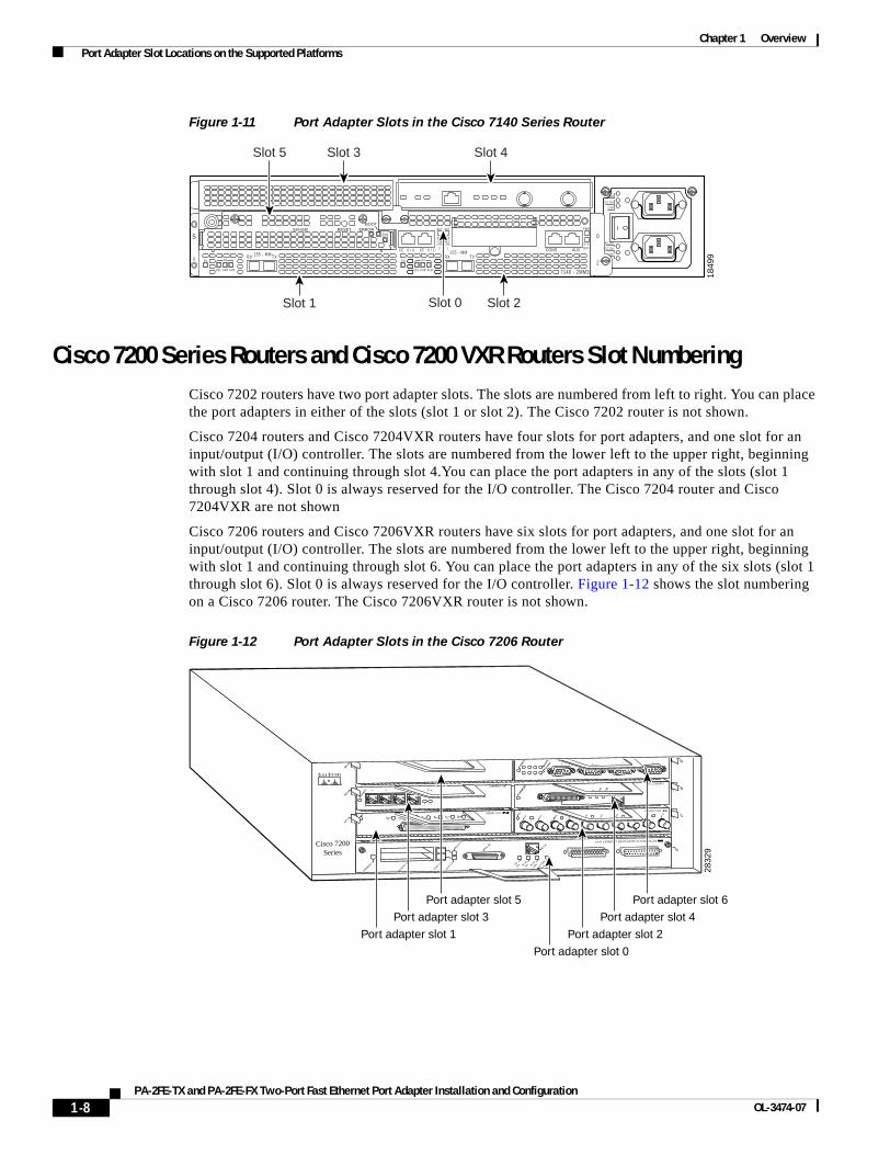
Cisco 7100 Series Routers Slot Numbering The PA-2FE can be installed in port adapter slot 3 in Cisco 7120 series routers, and in port adapter slot 4 in Cisco 7140 series routers. Figure 1-10 shows the slot numbering on a Cisco 7120 series router. Figure 1-11 shows the slot numbering on a Cisco 7140 series router.
Figure 1-10 Port Adapter Slots in the Cisco 7120 Series Router
SLOT 0 SLOT 1
0
2
FE 0 / 0 FE AUX
7120 - AE3
RXTXE3RXEN
CEL CAR ALM
5
ICONS
ACT
0 / 1
ACT
LNK0
LNK1
PWR
SYSRDY
Slot 1 Slot 0
Slot 3 Slot 4Slot 5
1849
8
Slot 2
1-7PA-2FE-TX and PA-2FE-FX Two-Port Fast Ethernet Port Adapter Installation and Configuration
OL-3474-07
Chapter 1 Overview Port Adapter Slot Locations on the Supported Platforms
Figure 1-11 Port Adapter Slots in the Cisco 7140 Series Router
Cisco 7200 Series Routers and Cisco 7200 VXR Routers Slot NumberingCisco 7202 routers have two port adapter slots. The slots are numbered from left to right. You can place the port adapters in either of the slots (slot 1 or slot 2). The Cisco 7202 router is not shown.
Cisco 7204 routers and Cisco 7204VXR routers have four slots for port adapters, and one slot for an input/output (I/O) controller. The slots are numbered from the lower left to the upper right, beginning with slot 1 and continuing through slot 4.You can place the port adapters in any of the slots (slot 1 through slot 4). Slot 0 is always reserved for the I/O controller. The Cisco 7204 router and Cisco 7204VXR are not shown
Cisco 7206 routers and Cisco 7206VXR routers have six slots for port adapters, and one slot for an input/output (I/O) controller. The slots are numbered from the lower left to the upper right, beginning with slot 1 and continuing through slot 6. You can place the port adapters in any of the six slots (slot 1 through slot 6). Slot 0 is always reserved for the I/O controller. Figure 1-12 shows the slot numbering on a Cisco 7206 router. The Cisco 7206VXR router is not shown.
Figure 1-12 Port Adapter Slots in the Cisco 7206 Router
SLOT 0 SLOT 1
AC OK
DC OK
OTF
AC OK
DC OK
OTF
5
155 - MMRXRXEN
CEL CAR ALM
TXI155 - MM CONSFE 0 / 0 FE
ACT
0 / 1 AUX
0
2RX
7140 - 2MM3
RXEN
CEL CAR ALM
TX
ACT
LNK0
LNK1
PWR
SYSRDY
ENERROR
BOOTRESETSM-ISM
1849
9
Slot 1 Slot 0 Slot 2
Slot 4Slot 5 Slot 3
2832
9
2ETHERNET-10BFL
EN
RX
0 1 2 3 4TX RX TX RX TX RX TX RX TX
0
4
1
3
56
TOKEN RING
0 1 2 3
Cisco 7200Series
FAST ETHERNET INPUT/OUTPUT CONTROLLER
ENABLED
PCMCIA
EJECT
SLOT 0
SLOT 1
FE MII
EN
0 71 2 3 4 5 6SERIAL-V.35
ETHERNET 10BT
ENABLE
D
0 2
1 3
LINK
0 1 2 3
MII
EN RJ-45
EN
RJ-45
RJ-45
LINK
1O P
WR
OK
ENABLE
D
MII
LIN
K
RJ4
5
FAST ETHERNET
0
Port adapter slot 5
Port adapter slot 3
Port adapter slot 1
Port adapter slot 6
Port adapter slot 4
Port adapter slot 2
Port adapter slot 0
1-8PA-2FE-TX and PA-2FE-FX Two-Port Fast Ethernet Port Adapter Installation and Configuration
OL-3474-07

Chapter 1 Overview Port Adapter Slot Locations on the Supported Platforms
Cisco uBR7200 Series Router Slot NumberingThe Cisco uBR7223 router has one port adapter slot (slot 1). Slot 0 is always reserved for the I/O controller—if present. The Cisco uBR7223 router is not shown.
The Cisco uBR7246 router and Cisco uBR7246VXR router have two port adapter slots (slot1 and slot 2). Slot 0 is always reserved for the I/O controller—if present. Figure 1-13 shows the slot numbering of port adapters on a Cisco uBR7246VXR router. The Cisco uBR7246 router is not shown.
Figure 1-13 Port Adapter Slots in the Cisco uBR7246VXR Router
ENABLED
DSuBR - MCI6
US USUS US0 1 2
5
ENABLED
DSuBR - MCI6
US USUS US0 1 2
5
ENABLED
DSuBR - MCI6
US USUS US
US US0 1 2 3 4 5
ENABLED
DSuBR - MCI6
US USUS US0 1 2
5
H11
323
Cable modem card slot 3Cable modem card slot 4
Cable modem card slot 5Cable modem card slot 6
Port adapter slot 0(I/O controller)
Port adapter slot 1 (blank)
Port adapter slot 2
1-9PA-2FE-TX and PA-2FE-FX Two-Port Fast Ethernet Port Adapter Installation and Configuration
OL-3474-07
Chapter 1 Overview Port Adapter Slot Locations on the Supported Platforms
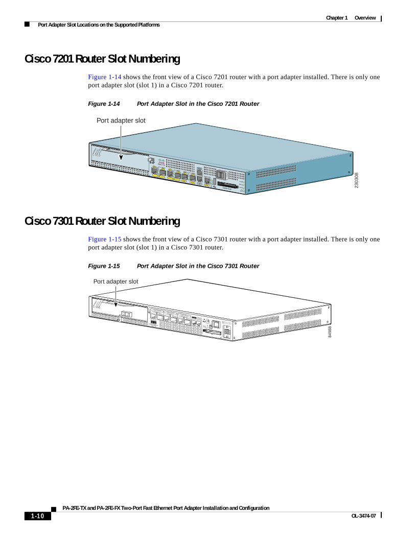
Cisco 7201 Router Slot NumberingFigure 1-14 shows the front view of a Cisco 7201 router with a port adapter installed. There is only one port adapter slot (slot 1) in a Cisco 7201 router.
Figure 1-14 Port Adapter Slot in the Cisco 7201 Router
Cisco 7301 Router Slot NumberingFigure 1-15 shows the front view of a Cisco 7301 router with a port adapter installed. There is only one port adapter slot (slot 1) in a Cisco 7301 router.
Figure 1-15 Port Adapter Slot in the Cisco 7301 Router
230308
ENAB
LED
RX CE
LLS
RX CA
RRIER
RX AL
ARM
ATM
GE 0/0
GE 0/1GE 0/2
GE 0/3AUX
CONSOLE
MNGMNT USE ONLY
FELINK
0FE 0/0
RJ45SFP
SFPSFP
SFP
LINK/ACTV
ALARM
PWR OK
STATUS
CFACTV
COMPACT FLASH
LINK/ACTV
RXTX
LINK/ACTV
LINK/ACTV
RXTX
EN
RJ45 EN
PASLOT 1
Cisco 7201
Port adapter slot
ALARM
RJ45 ENLINK
TXRX
GBIC
GIGABIT ETHERNET 0/2
CISCO 7400SERIESCISCO 7411
SLOT 1
CONSOLEAUX
COMPACTFLASH STATUS
100-240V, 2A, 50/60 Hz24V=9A, 48 - 60V=5A
RJ45 ENLINK
TXRX
GBIC
GIGABIT ETHERNET 0/1
RJ45 ENLINK
TXRX
GBIC
GIGABIT ETHERNET 0/0
ENAB
LED
RX CE
LLS
RX CA
RRIER
RX AL
ARM
ATM
8498
8
Port adapter slot
1-10PA-2FE-TX and PA-2FE-FX Two-Port Fast Ethernet Port Adapter Installation and Configuration
OL-3474-07
Chapter 1 Overview Port Adapter Slot Locations on the Supported Platforms
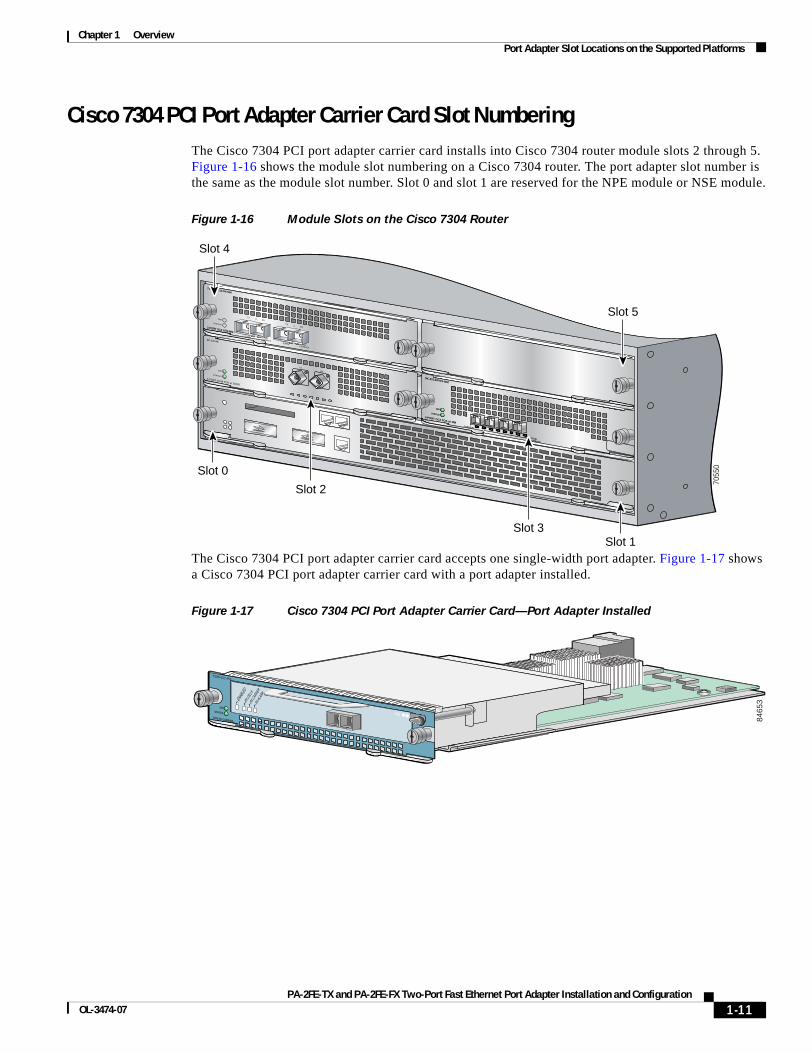
Cisco 7304 PCI Port Adapter Carrier Card Slot Numbering The Cisco 7304 PCI port adapter carrier card installs into Cisco 7304 router module slots 2 through 5. Figure 1-16 shows the module slot numbering on a Cisco 7304 router. The port adapter slot number is the same as the module slot number. Slot 0 and slot 1 are reserved for the NPE module or NSE module.
Figure 1-16 Module Slots on the Cisco 7304 Router
The Cisco 7304 PCI port adapter carrier card accepts one single-width port adapter. Figure 1-17 shows a Cisco 7304 PCI port adapter carrier card with a port adapter installed.
Figure 1-17 Cisco 7304 PCI Port Adapter Carrier Card—Port Adapter Installed
TX
9K-10C48
1-PORT OC48 POS w/ SMSR
OIR
STATUS
RX
OIR
STATUS
9K-40C3/POS-MM
4-PORT OC3 POS w/ MM
OIR
STATUS
CARRIER/ALARM
0
ACTIVE/LOOPBACK
12
3
CARRIER/ALARM ACTIVE/LOOPBACK CARRIER/ALARM ACTIVE/LOOPBACK
7300-2OC3ATM-MM
2-PORT OC3 ATM MM
OIR
STATUS
0 RXTX
1 RXTX
7055
0
Slot 1
Slot 0
Slot 2
Slot 3
Slot 4
Slot 5
8465
3
7300-CC-PA
OIRSTATUS
7300 PA CARRIER
ENAB
LED
RX CE
LLS
RX CA
RRIER
RX AL
ARM
ATM
1-11PA-2FE-TX and PA-2FE-FX Two-Port Fast Ethernet Port Adapter Installation and Configuration
OL-3474-07
Chapter 1 Overview Port Adapter Slot Locations on the Supported Platforms
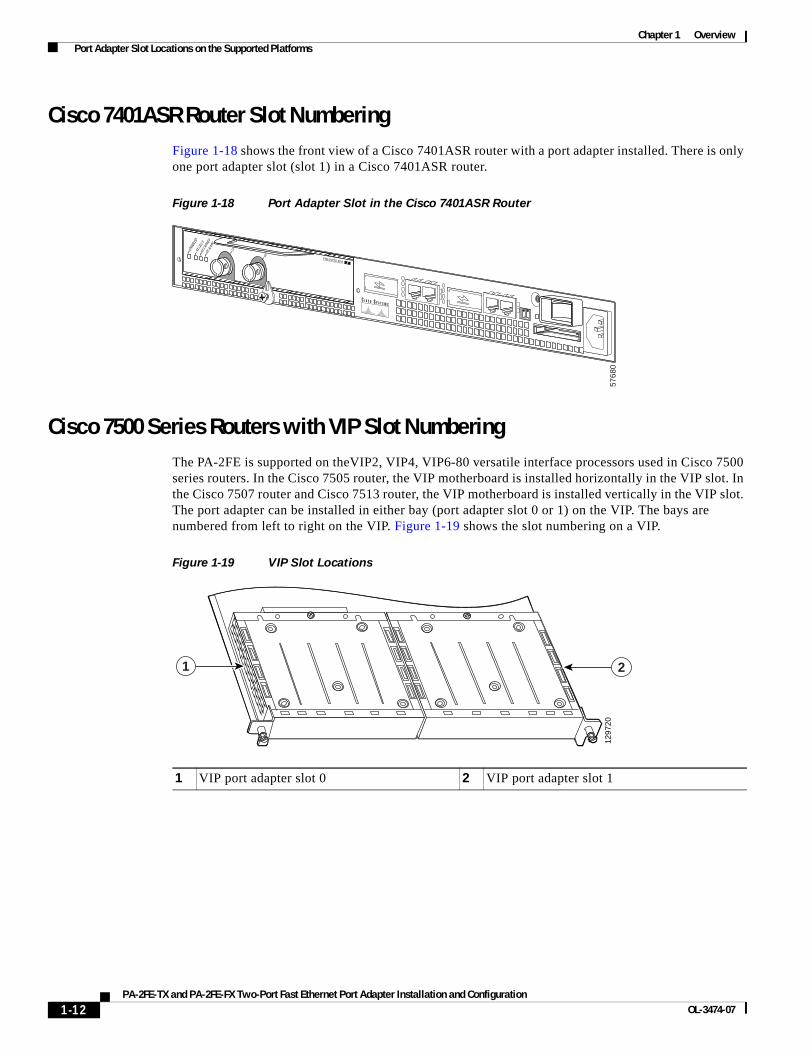
Cisco 7401ASR Router Slot NumberingFigure 1-18 shows the front view of a Cisco 7401ASR router with a port adapter installed. There is only one port adapter slot (slot 1) in a Cisco 7401ASR router.
Figure 1-18 Port Adapter Slot in the Cisco 7401ASR Router
Cisco 7500 Series Routers with VIP Slot NumberingThe PA-2FE is supported on theVIP2, VIP4, VIP6-80 versatile interface processors used in Cisco 7500 series routers. In the Cisco 7505 router, the VIP motherboard is installed horizontally in the VIP slot. In the Cisco 7507 router and Cisco 7513 router, the VIP motherboard is installed vertically in the VIP slot. The port adapter can be installed in either bay (port adapter slot 0 or 1) on the VIP. The bays are numbered from left to right on the VIP. Figure 1-19 shows the slot numbering on a VIP.
Figure 1-19 VIP Slot Locations
5768
0
ENAB
LED
RX CE
LLS
RX CA
RRIER
RX AL
ARM
TX
RX ENHANCED ATM
1 VIP port adapter slot 0 2 VIP port adapter slot 1
1297
20
21
1-12PA-2FE-TX and PA-2FE-FX Two-Port Fast Ethernet Port Adapter Installation and Configuration
OL-3474-07

Chapter 1 Overview Port Adapter Slot Locations on the Supported Platforms
Cisco 7505 routers have four slots for port adapters, and one slot for a Route Switch Processor (RSP). The slots are numbered from bottom to top. You can place the port adapters in any of the VIP interface slots (slot 0 through 3). One slot is always reserved for the RSP. Figure 1-20 shows the slot numbering on a Cisco 7505 router.
Figure 1-20 VIP Slots in the Cisco 7505 Router
1 RSP 4 VIP interface—slot 1
2 VIP interface—slot 3 5 VIP interface—slot 0
3 VIP interface—slot 2
1221
93
EJECT
SLOT 0SLO
T 1
NORMAL CPU HALT
RESET
AUX.
CONSOLE
ROUTE SWITCH PROCESSOR
ENABLE
ENABLE
1
2
3
4
5
1-13PA-2FE-TX and PA-2FE-FX Two-Port Fast Ethernet Port Adapter Installation and Configuration
OL-3474-07
Chapter 1 Overview Port Adapter Slot Locations on the Supported Platforms
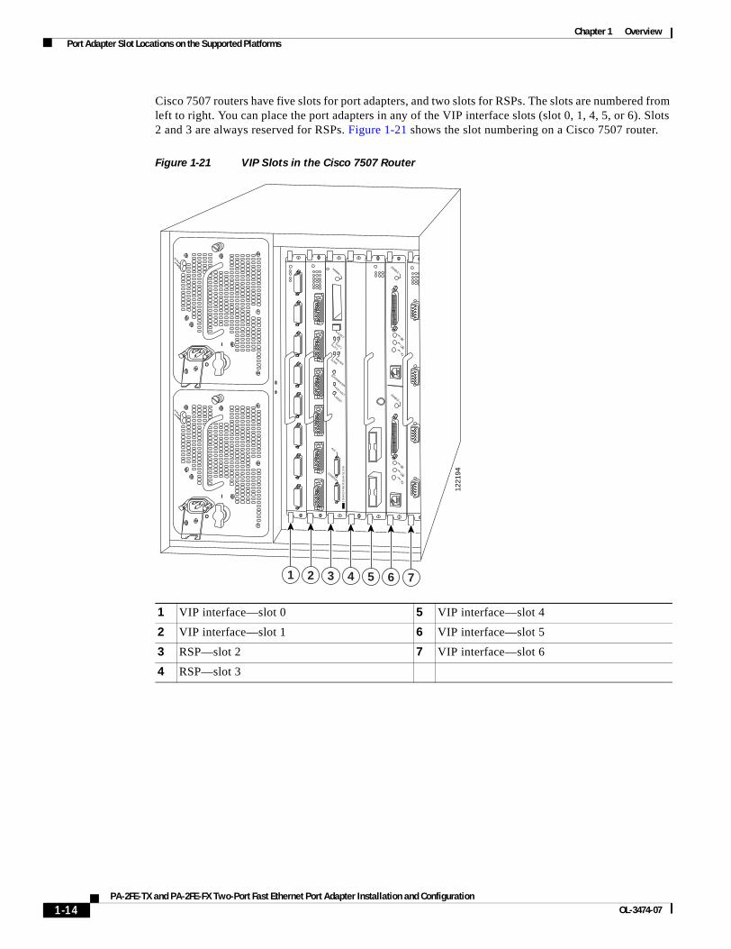
Cisco 7507 routers have five slots for port adapters, and two slots for RSPs. The slots are numbered from left to right. You can place the port adapters in any of the VIP interface slots (slot 0, 1, 4, 5, or 6). Slots 2 and 3 are always reserved for RSPs. Figure 1-21 shows the slot numbering on a Cisco 7507 router.
Figure 1-21 VIP Slots in the Cisco 7507 Router
1 VIP interface—slot 0 5 VIP interface—slot 4
2 VIP interface—slot 1 6 VIP interface—slot 5
3 RSP—slot 2 7 VIP interface—slot 6
4 RSP—slot 3
ENABLE
ENABLE
EJECT
SLOT 0
SLOT 1
NORMAL
CPU HALTRESET
AUX.
CONSOLE
RO
UT
E SW
ITC
H PR
OC
ESSO
R 2
SLAVE
MASTER
SLAVE/MASTER
1221
94
I
O
DC FAILAC POWER
I
O
DC FAILAC POWER
1 2 3 4 5 6 7
1-14PA-2FE-TX and PA-2FE-FX Two-Port Fast Ethernet Port Adapter Installation and Configuration
OL-3474-07

Chapter 1 Overview Port Adapter Slot Locations on the Supported Platforms
Cisco 7513 routers have eleven slots for port adapters, and two slots for RSPs. The slots are numbered from left to right. You can place the port adapters in any of the VIP interface slots (slots 0 through 5, or slots 9 through 12). Slots 6 and 7 are always reserved for RSPs. Figure 1-22 shows the slot numbering on a Cisco 7513 router.
Figure 1-22 VIP Slots in the Cisco 7513 Router
1 VIP interface—slot 0 8 RSP—slot 7
2 VIP interface—slot 1 9 VIP interface—slot 8
3 VIP interface—slot 2 10 VIP interface—slot 9
4 VIP interface—slot 3 11 VIP interface—slot 10
5 VIP interface—slot 4 12 VIP interface—slot 11
6 VIP interface—slot 5 13 VIP interface—slot 12
7 RSP—slot 6
EJECT
SLOT 0
SLOT 1
NORMAL
CPU HALTRESET
AUX.
CONSOLE
RO
UT
E SW
ITC
H PR
OC
ESSO
R 2
SLAVE
MASTER
SLAVE/MASTER
ENABLE
ENABLE
1221
95
EJECT
SLOT 0
SLOT 1
NORMAL
CPU HALTRESET
AUX.
CONSOLE
RO
UT
E SW
ITC
H PR
OC
ESSO
R 2
SLAVE
MASTER
SLAVE/MASTER
0
I
ACOK
FANOK
OUTPUTFAIL
0
I
ACOK
FANOK
OUTPUTFAIL
POWER
APOWER
B
12
34
56
78
910
1112
13
1-15PA-2FE-TX and PA-2FE-FX Two-Port Fast Ethernet Port Adapter Installation and Configuration
OL-3474-07
Chapter 1 Overview Identifying Interface Addresses
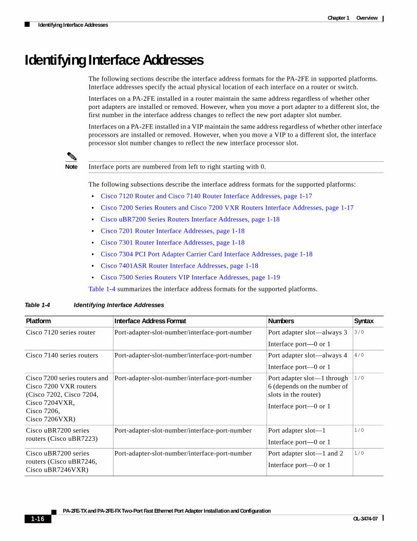
Identifying Interface Addresses The following sections describe the interface address formats for the PA-2FE in supported platforms. Interface addresses specify the actual physical location of each interface on a router or switch.
Interfaces on a PA-2FE installed in a router maintain the same address regardless of whether other port adapters are installed or removed. However, when you move a port adapter to a different slot, the first number in the interface address changes to reflect the new port adapter slot number.
Interfaces on a PA-2FE installed in a VIP maintain the same address regardless of whether other interface processors are installed or removed. However, when you move a VIP to a different slot, the interface processor slot number changes to reflect the new interface processor slot.
Note Interface ports are numbered from left to right starting with 0.
The following subsections describe the interface address formats for the supported platforms:
• Cisco 7120 Router and Cisco 7140 Router Interface Addresses, page 1-17
• Cisco 7200 Series Routers and Cisco 7200 VXR Routers Interface Addresses, page 1-17
• Cisco uBR7200 Series Routers Interface Addresses, page 1-18
• Cisco 7201 Router Interface Addresses, page 1-18
• Cisco 7301 Router Interface Addresses, page 1-18
• Cisco 7304 PCI Port Adapter Carrier Card Interface Addresses, page 1-18
• Cisco 7401ASR Router Interface Addresses, page 1-18
• Cisco 7500 Series Routers VIP Interface Addresses, page 1-19
Table 1-4 summarizes the interface address formats for the supported platforms.
Table 1-4 Identifying Interface Addresses
Platform Interface Address Format Numbers Syntax
Cisco 7120 series router Port-adapter-slot-number/interface-port-number Port adapter slot—always 3
Interface port—0 or 1
3/0
Cisco 7140 series routers Port-adapter-slot-number/interface-port-number Port adapter slot—always 4
Interface port—0 or 1
4/0
Cisco 7200 series routers and Cisco 7200 VXR routers (Cisco 7202, Cisco 7204, Cisco 7204VXR, Cisco 7206, Cisco 7206VXR)
Port-adapter-slot-number/interface-port-number Port adapter slot—1 through 6 (depends on the number of slots in the router)
Interface port—0 or 1
1/0
Cisco uBR7200 series routers (Cisco uBR7223)
Port-adapter-slot-number/interface-port-number Port adapter slot—1
Interface port—0 or 1
1/0
Cisco uBR7200 series routers (Cisco uBR7246, Cisco uBR7246VXR)
Port-adapter-slot-number/interface-port-number Port adapter slot—1 and 2
Interface port—0 or 1
1/0
1-16PA-2FE-TX and PA-2FE-FX Two-Port Fast Ethernet Port Adapter Installation and Configuration
OL-3474-07
Chapter 1 Overview Identifying Interface Addresses
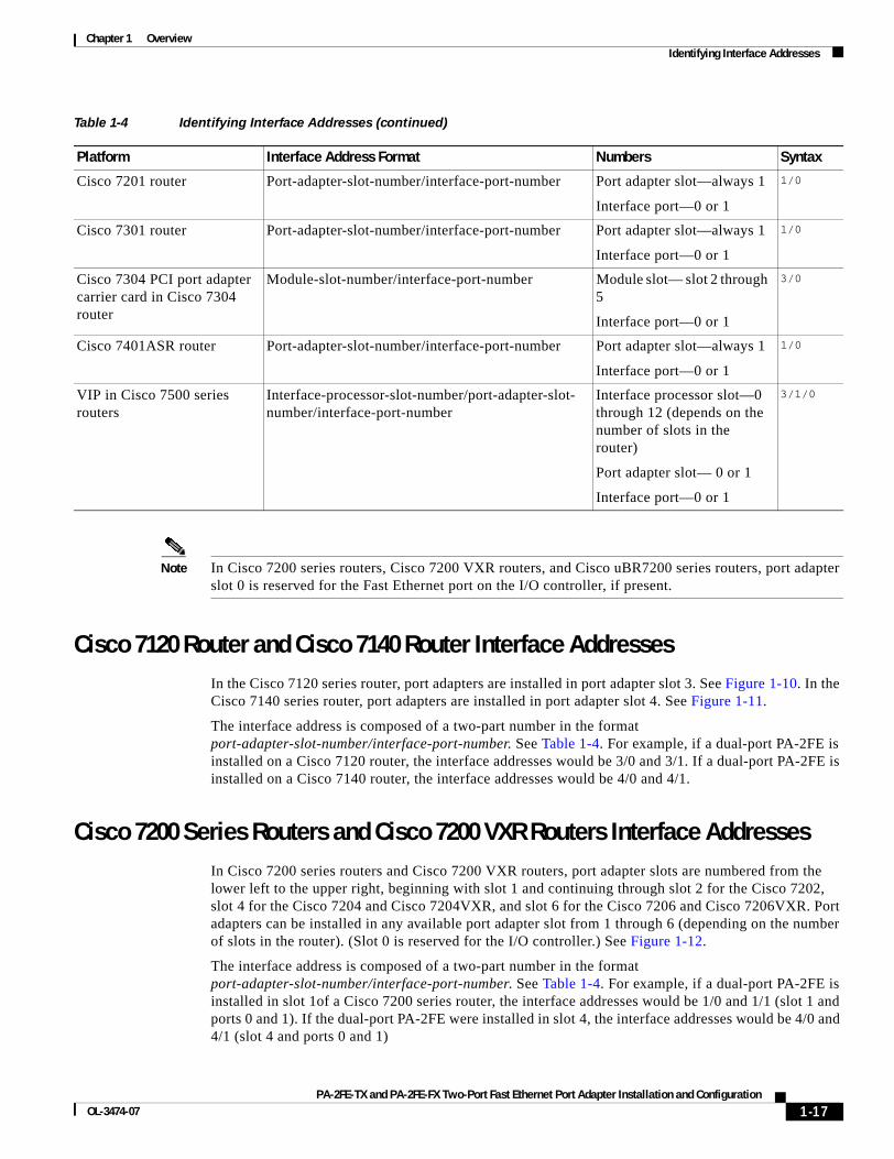
Note In Cisco 7200 series routers, Cisco 7200 VXR routers, and Cisco uBR7200 series routers, port adapter slot 0 is reserved for the Fast Ethernet port on the I/O controller, if present.
Cisco 7120 Router and Cisco 7140 Router Interface AddressesIn the Cisco 7120 series router, port adapters are installed in port adapter slot 3. See Figure 1-10. In the Cisco 7140 series router, port adapters are installed in port adapter slot 4. See Figure 1-11.
The interface address is composed of a two-part number in the format port-adapter-slot-number/interface-port-number. See Table 1-4. For example, if a dual-port PA-2FE is installed on a Cisco 7120 router, the interface addresses would be 3/0 and 3/1. If a dual-port PA-2FE is installed on a Cisco 7140 router, the interface addresses would be 4/0 and 4/1.
Cisco 7200 Series Routers and Cisco 7200 VXR Routers Interface Addresses In Cisco 7200 series routers and Cisco 7200 VXR routers, port adapter slots are numbered from the lower left to the upper right, beginning with slot 1 and continuing through slot 2 for the Cisco 7202, slot 4 for the Cisco 7204 and Cisco 7204VXR, and slot 6 for the Cisco 7206 and Cisco 7206VXR. Port adapters can be installed in any available port adapter slot from 1 through 6 (depending on the number of slots in the router). (Slot 0 is reserved for the I/O controller.) See Figure 1-12.
The interface address is composed of a two-part number in the format port-adapter-slot-number/interface-port-number. See Table 1-4. For example, if a dual-port PA-2FE is installed in slot 1of a Cisco 7200 series router, the interface addresses would be 1/0 and 1/1 (slot 1 and ports 0 and 1). If the dual-port PA-2FE were installed in slot 4, the interface addresses would be 4/0 and 4/1 (slot 4 and ports 0 and 1)
Cisco 7201 router Port-adapter-slot-number/interface-port-number Port adapter slot—always 1
Interface port—0 or 1
1/0
Cisco 7301 router Port-adapter-slot-number/interface-port-number Port adapter slot—always 1
Interface port—0 or 1
1/0
Cisco 7304 PCI port adapter carrier card in Cisco 7304 router
Module-slot-number/interface-port-number Module slot— slot 2 through 5
Interface port—0 or 1
3/0
Cisco 7401ASR router Port-adapter-slot-number/interface-port-number Port adapter slot—always 1
Interface port—0 or 1
1/0
VIP in Cisco 7500 series routers
Interface-processor-slot-number/port-adapter-slot- number/interface-port-number
Interface processor slot—0 through 12 (depends on the number of slots in the router)
Port adapter slot— 0 or 1
Interface port—0 or 1
3/1/0
Table 1-4 Identifying Interface Addresses (continued)
Platform Interface Address Format Numbers Syntax
1-17PA-2FE-TX and PA-2FE-FX Two-Port Fast Ethernet Port Adapter Installation and Configuration
OL-3474-07
Chapter 1 Overview Identifying Interface Addresses
Cisco uBR7200 Series Routers Interface Addresses In the Cisco uBR7223 router, only one slot accepts port adapters and it is numbered slot 1.
In the Cisco uBR7246 router and Cisco uBR7246VXR router, port adapters can be installed in two port adapter slots (slot1 and slot 2). Slot 0 is always reserved for the I/O controller—if present. See Figure 1-13.
The interface address is composed of a two-part number in the format port-adapter-slot-number/interface-port-number. See Table 1-4. For example, if a dual-port PA-2FE is installed in slot 1of a Cisco uBR7223 series router, the interface addresses would be 1/0 and 1/1 (slot 1 and ports 0 and 1). If the dual-port port adapter were installed in slot 2 of a Cisco uBR7246 or Cisco uBR7248VXR router, the interface addresses would be 2/0 and 2/1 (slot 2 and ports 0 and 1).
Cisco 7201 Router Interface AddressesIn the Cisco 7201 router, only one slot accepts port adapters and it is numbered slot 1. See Figure 1-14.
The interface address is composed of a two-part number in the format port-adapter-slot-number/interface-port-number. See Table 1-4. For example, if a dual-port PA-2FE is installed on a Cisco 7201 router, the interface addresses would be 1/0 and 1/1.
Cisco 7301 Router Interface AddressesIn the Cisco 7301 router, only one slot accepts port adapters and it is numbered slot 1. See Figure 1-15.
The interface address is composed of a two-part number in the format port-adapter-slot-number/interface-port-number. See Table 1-4. For example, if a dual-port PA-2FE is installed on a Cisco 7301 router, the interface addresses would be 1/0 and 1/1.
Cisco 7304 PCI Port Adapter Carrier Card Interface AddressesIn the Cisco 7304 router, port adapters are installed in a Cisco 7304 PCI port adapter carrier card, which installs in Cisco 7304 router module slots 2 through 5. The port adapter slot number is the same as the module slot number. See Figure 1-16.
The interface address is composed of a two-part number in the format module-slot-number/interface-port-number. See Table 1-4. For example, if a dual-port PA-2FE is installed in the Cisco 7304 PCI port adapter carrier card in Cisco 7304 router module slot 3, the interface addresses would be 3/0 and 3/2.
Cisco 7401ASR Router Interface AddressesIn the Cisco 7401ASR router, only one slot accepts port adapters and it is numbered slot 1. See Figure 1-18.
The interface address is composed of a two-part number in the format port-adapter-slot-number/interface-port-number. See Table 1-4. For example, if a dual-port PA-2FE is installed on a Cisco 7401ASR router, the interface addresses would be 1/0 and 1/1.
1-18PA-2FE-TX and PA-2FE-FX Two-Port Fast Ethernet Port Adapter Installation and Configuration
OL-3474-07
Chapter 1 Overview Identifying Interface Addresses
Cisco 7500 Series Routers VIP Interface AddressesIn Cisco 7500 series routers, port adapters are installed on a versatile interface processor (VIP), which installs in interface processor slots 0 through 12 (depending on the number of slots in the router). The port adapter can be installed in either bay (port adapter slot 0 or 1) on the VIP. See Figure 1-19, Figure 1-20, Figure 1-21, and Figure 1-22.
The interface address for the VIP is composed of a three-part number in the format interface-processor-slot-number/port-adapter-slot-number/interface-port-number. See Table 1-4.
The first number identifies the slot in which the VIP is installed (slot 0 through 12, depending on the number of slots in the router).
The second number identifies the bay (port adapter slot) on the VIP in which the port adapter is installed (0 or 1). The bays are numbered from left to right on the VIP.
The third number identifies the physical port number (interface port number) on the port adapter. The port numbers always begin at 0 and are numbered from left to right. The PA-2FE is a dual-port port adapter, therefore the port can be 0 or 1.
For example, if a dual-port PA-2FE is installed in a VIP in interface processor slot 3, port adapter slot 1, the interface addresses would be 3/1/0 and 3/1/1.
Note Although the processor slots in the seven-slot Cisco 7507 and the thirteen-slot Cisco 7513 chassis are vertically oriented and those in the five-slot Cisco 7505 are horizontally oriented, all Cisco 7500 series routers use the same method for slot and port numbering.
1-19PA-2FE-TX and PA-2FE-FX Two-Port Fast Ethernet Port Adapter Installation and Configuration
OL-3474-07

Chapter 1 Overview Identifying Interface Addresses
1-20PA-2FE-TX and PA-2FE-FX Two-Port Fast Ethernet Port Adapter Installation and Configuration
OL-3474-07
PA-2FE-TX and PA-2FE-FX Two-Port Fast EOL-3474-07
C H A P T E R2
Preparing for InstallationThis chapter describes the general equipment, safety, and site preparation requirements for installing the PA-2FE. This chapter contains the following sections:
• Required Tools and Equipment, page 2-1
• Software and Hardware Requirements, page 2-2
• Checking Hardware and Software Compatibility, page 2-2
• Safety Guidelines, page 2-3
• FCC Class A Compliance, page 2-10
Required Tools and EquipmentYou need the following tools and parts to install a PA-2FE. If you need additional equipment, contact a service representative for ordering information.
• PA-2FE-TX or PA-2FE-FX
• VIP (for installation in Cisco 7500 series chassis only)
• Cisco 7304 PCI port adapter carrier card (for installation in Cisco 7304 router only)
• Cables appropriate for the PA-2FE interfaces (RJ-45 and multimode optical-fiber cables are not available from Cisco; they are available from commercial vendors.)
• Number 1 Phillips and a 3/16-inch flat-blade screwdriver (for VIP installation only)
• Number 2 Phillips screwdriver
• Your own electrostatic discharge (ESD)-prevention equipment or the disposable grounding wrist strap included with all upgrade kits, field-replaceable units (FRUs), and spares
• Antistatic mat
• Antistatic container
2-1thernet Port Adapter Installation and Configuration
Chapter 2 Preparing for Installation Software and Hardware Requirements
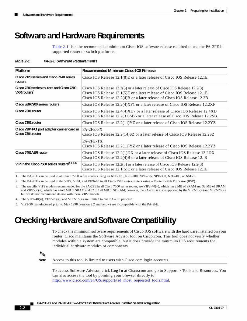
Software and Hardware RequirementsTable 2-1 lists the recommended minimum Cisco IOS software release required to use the PA-2FE in supported router or switch platforms.
Checking Hardware and Software CompatibilityTo check the minimum software requirements of Cisco IOS software with the hardware installed on your router, Cisco maintains the Software Advisor tool on Cisco.com. This tool does not verify whether modules within a system are compatible, but it does provide the minimum IOS requirements for individual hardware modules or components.
Note Access to this tool is limited to users with Cisco.com login accounts.
To access Software Advisor, click Log In at Cisco.com and go to Support > Tools and Resources. You can also access the tool by pointing your browser directly to http://www.cisco.com/en/US/support/tsd_most_requested_tools.html.
Table 2-1 PA-2FE Software Requirements
Platform Recommended Minimum Cisco IOS Release
Cisco 7120 series and Cisco 7140 series routers
Cisco IOS Release 12.1(8)E or a later release of Cisco IOS Release 12.1E
Cisco 7200 series routers and Cisco 7200 VXR routers1
1. The PA-2FE can be used in all Cisco 7200 series routers using an NPE-175, NPE-200, NPE-225, NPE-300, NPE-400, or NSE-1.
Cisco IOS Release 12.2(3) or a later release of Cisco IOS Release 12.2(3)Cisco IOS Release 12.1(5)E or a later release of Cisco IOS Release 12.1ECisco IOS Release 12.2(4)B or a later release of Cisco IOS Release 12.2B
Cisco uBR7200 series routers Cisco IOS Release 12.2(4)XF1 or a later release of Cisco IOS Release 12.2XF
Cisco 7201 router Cisco IOS Release 12.4(4)XD7 or a later release of Cisco IOS Release 12.4XDCisco IOS Release 12.2(31)SB5 or a later release of Cisco IOS Release 12.2SB.
Cisco 7301 router Cisco IOS Release 12.2(11)YZ or a later release of Cisco IOS Release 12.2YZ
Cisco 7304 PCI port adapter carrier card in Cisco 7304 router
PA-2FE-FXCisco IOS Release 12.2(14)SZ or a later release of Cisco IOS Release 12.2SZ
PA-2FE-TXCisco IOS Release 12.2(11)YZ or a later release of Cisco IOS Release 12.2YZ
Cisco 7401ASR router Cisco IOS Release 12.2(1)DX or a later release of Cisco IOS Release 12.2DXCisco IOS Release 12.2(4)B or a later release of Cisco IOS Release 12. B
VIP in the Cisco 7500 series routers2, 3, 4, 5
2. The PA-2FE can be used in the VIP2, VIP4, and VIP6-80 in all Cisco 7500 series routers using a Route Switch Processor (RSP).
3. The specific VIP2 models recommended for the PA-2FE in all Cisco 7500 series router, are VIP2-40(=), which has 2 MB of SRAM and 32 MB of DRAM, and VIP2-50(=), which has 4 to 8 MB of SRAM and 32 to 128 MB of SDRAM; however, the PA-2FE is also supported by the VIP2-15(=) and VIP2-20(=), but we do not recommend its use with these VIP2 models.
4. The VIP2-40(=), VIP2-20(=), and VIP2-15(=) are limited to one PA-2FE per card.
5. VIP2-50 manufactured prior to May 1998 (version 2.2 and below) are incompatible with the PA-2FE.
Cisco IOS Release 12.2(3) or a later release of Cisco IOS Release 12.2(3)Cisco IOS Release 12.1(5)E or a later release of Cisco IOS Release 12.1E
2-2PA-2FE-TX and PA-2FE-FX Two-Port Fast Ethernet Port Adapter Installation and Configuration
OL-3474-07
Chapter 2 Preparing for Installation Safety Guidelines
Choose a product family or enter a specific product number to search for the minimum supported software release needed for your hardware.
Safety GuidelinesThis section provides safety guidelines that you should follow when working with any equipment that connects to electrical power or telephone wiring.
Safety WarningsSafety warnings appear throughout this publication in procedures that, if performed incorrectly, might harm you. A warning symbol precedes each warning statement.
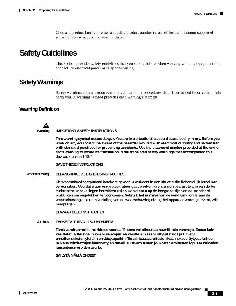
Warning Definition
Warning IMPORTANT SAFETY INSTRUCTIONS
This warning symbol means danger. You are in a situation that could cause bodily injury. Before you work on any equipment, be aware of the hazards involved with electrical circuitry and be familiar with standard practices for preventing accidents. Use the statement number provided at the end of each warning to locate its translation in the translated safety warnings that accompanied this device. Statement 1071
SAVE THESE INSTRUCTIONS
Waarschuwing BELANGRIJKE VEILIGHEIDSINSTRUCTIES
Dit waarschuwingssymbool betekent gevaar. U verkeert in een situatie die lichamelijk letsel kan veroorzaken. Voordat u aan enige apparatuur gaat werken, dient u zich bewust te zijn van de bij elektrische schakelingen betrokken risico's en dient u op de hoogte te zijn van de standaard praktijken om ongelukken te voorkomen. Gebruik het nummer van de verklaring onderaan de waarschuwing als u een vertaling van de waarschuwing die bij het apparaat wordt geleverd, wilt raadplegen.
BEWAAR DEZE INSTRUCTIES
Varoitus TÄRKEITÄ TURVALLISUUSOHJEITA
Tämä varoitusmerkki merkitsee vaaraa. Tilanne voi aiheuttaa ruumiillisia vammoja. Ennen kuin käsittelet laitteistoa, huomioi sähköpiirien käsittelemiseen liittyvät riskit ja tutustu onnettomuuksien yleisiin ehkäisytapoihin. Turvallisuusvaroitusten käännökset löytyvät laitteen mukana toimitettujen käännettyjen turvallisuusvaroitusten joukosta varoitusten lopussa näkyvien lausuntonumeroiden avulla.
SÄILYTÄ NÄMÄ OHJEET
2-3PA-2FE-TX and PA-2FE-FX Two-Port Fast Ethernet Port Adapter Installation and Configuration
OL-3474-07

Chapter 2 Preparing for Installation Safety Guidelines
Attention IMPORTANTES INFORMATIONS DE SÉCURITÉ
Ce symbole d'avertissement indique un danger. Vous vous trouvez dans une situation pouvant entraîner des blessures ou des dommages corporels. Avant de travailler sur un équipement, soyez conscient des dangers liés aux circuits électriques et familiarisez-vous avec les procédures couramment utilisées pour éviter les accidents. Pour prendre connaissance des traductions des avertissements figurant dans les consignes de sécurité traduites qui accompagnent cet appareil, référez-vous au numéro de l'instruction situé à la fin de chaque avertissement.
CONSERVEZ CES INFORMATIONS
Warnung WICHTIGE SICHERHEITSHINWEISE
Dieses Warnsymbol bedeutet Gefahr. Sie befinden sich in einer Situation, die zu Verletzungen führen kann. Machen Sie sich vor der Arbeit mit Geräten mit den Gefahren elektrischer Schaltungen und den üblichen Verfahren zur Vorbeugung vor Unfällen vertraut. Suchen Sie mit der am Ende jeder Warnung angegebenen Anweisungsnummer nach der jeweiligen Übersetzung in den übersetzten Sicherheitshinweisen, die zusammen mit diesem Gerät ausgeliefert wurden.
BEWAHREN SIE DIESE HINWEISE GUT AUF.
Avvertenza IMPORTANTI ISTRUZIONI SULLA SICUREZZA
Questo simbolo di avvertenza indica un pericolo. La situazione potrebbe causare infortuni alle persone. Prima di intervenire su qualsiasi apparecchiatura, occorre essere al corrente dei pericoli relativi ai circuiti elettrici e conoscere le procedure standard per la prevenzione di incidenti. Utilizzare il numero di istruzione presente alla fine di ciascuna avvertenza per individuare le traduzioni delle avvertenze riportate in questo documento.
CONSERVARE QUESTE ISTRUZIONI
Advarsel VIKTIGE SIKKERHETSINSTRUKSJONER
Dette advarselssymbolet betyr fare. Du er i en situasjon som kan føre til skade på person. Før du begynner å arbeide med noe av utstyret, må du være oppmerksom på farene forbundet med elektriske kretser, og kjenne til standardprosedyrer for å forhindre ulykker. Bruk nummeret i slutten av hver advarsel for å finne oversettelsen i de oversatte sikkerhetsadvarslene som fulgte med denne enheten.
TA VARE PÅ DISSE INSTRUKSJONENE
Aviso INSTRUÇÕES IMPORTANTES DE SEGURANÇA
Este símbolo de aviso significa perigo. Você está em uma situação que poderá ser causadora de lesões corporais. Antes de iniciar a utilização de qualquer equipamento, tenha conhecimento dos perigos envolvidos no manuseio de circuitos elétricos e familiarize-se com as práticas habituais de prevenção de acidentes. Utilize o número da instrução fornecido ao final de cada aviso para localizar sua tradução nos avisos de segurança traduzidos que acompanham este dispositivo.
GUARDE ESTAS INSTRUÇÕES
2-4PA-2FE-TX and PA-2FE-FX Two-Port Fast Ethernet Port Adapter Installation and Configuration
OL-3474-07
Chapter 2 Preparing for Installation Safety Guidelines
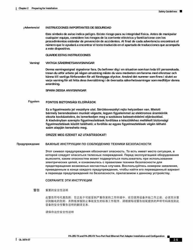
¡Advertencia! INSTRUCCIONES IMPORTANTES DE SEGURIDAD
Este símbolo de aviso indica peligro. Existe riesgo para su integridad física. Antes de manipular cualquier equipo, considere los riesgos de la corriente eléctrica y familiarícese con los procedimientos estándar de prevención de accidentes. Al final de cada advertencia encontrará el número que le ayudará a encontrar el texto traducido en el apartado de traducciones que acompaña a este dispositivo.
GUARDE ESTAS INSTRUCCIONES
Varning! VIKTIGA SÄKERHETSANVISNINGAR
Denna varningssignal signalerar fara. Du befinner dig i en situation som kan leda till personskada. Innan du utför arbete på någon utrustning måste du vara medveten om farorna med elkretsar och känna till vanliga förfaranden för att förebygga olyckor. Använd det nummer som finns i slutet av varje varning för att hitta dess översättning i de översatta säkerhetsvarningar som medföljer denna anordning.
SPARA DESSA ANVISNINGAR
2-5PA-2FE-TX and PA-2FE-FX Two-Port Fast Ethernet Port Adapter Installation and Configuration
OL-3474-07
Chapter 2 Preparing for Installation Safety Guidelines
Aviso INSTRUÇÕES IMPORTANTES DE SEGURANÇA
Este símbolo de aviso significa perigo. Você se encontra em uma situação em que há risco de lesões corporais. Antes de trabalhar com qualquer equipamento, esteja ciente dos riscos que envolvem os circuitos elétricos e familiarize-se com as práticas padrão de prevenção de acidentes. Use o número da declaração fornecido ao final de cada aviso para localizar sua tradução nos avisos de segurança traduzidos que acompanham o dispositivo.
GUARDE ESTAS INSTRUÇÕES
Advarsel VIGTIGE SIKKERHEDSANVISNINGER
Dette advarselssymbol betyder fare. Du befinder dig i en situation med risiko for legemesbeskadigelse. Før du begynder arbejde på udstyr, skal du være opmærksom på de involverede risici, der er ved elektriske kredsløb, og du skal sætte dig ind i standardprocedurer til undgåelse af ulykker. Brug erklæringsnummeret efter hver advarsel for at finde oversættelsen i de oversatte advarsler, der fulgte med denne enhed.
GEM DISSE ANVISNINGER
2-6PA-2FE-TX and PA-2FE-FX Two-Port Fast Ethernet Port Adapter Installation and Configuration
OL-3474-07

Chapter 2 Preparing for Installation Safety Guidelines
2-7PA-2FE-TX and PA-2FE-FX Two-Port Fast Ethernet Port Adapter Installation and Configuration
OL-3474-07
Chapter 2 Preparing for Installation Safety Guidelines
Electrical Equipment GuidelinesFollow these basic guidelines when working with any electrical equipment:
• Before beginning any procedures requiring access to the chassis interior, locate the emergency power-off switch for the room in which you are working.
• Disconnect all power and external cables before moving a chassis
• Do not work alone when potentially hazardous conditions exist.
• Never assume that power has been disconnected from a circuit; always check.
• Do not perform any action that creates a potential hazard to people or makes the equipment unsafe; carefully examine your work area for possible hazards such as moist floors, ungrounded power extension cables, and missing safety grounds.
2-8PA-2FE-TX and PA-2FE-FX Two-Port Fast Ethernet Port Adapter Installation and Configuration
OL-3474-07

Chapter 2 Preparing for Installation Safety Guidelines
Telephone Wiring GuidelinesUse the following guidelines when working with any equipment that is connected to telephone wiring or to other network cabling:
• Never install telephone wiring during a lightning storm.
• Never install telephone jacks in wet locations unless the jack is specifically designed for wet locations.
• Never touch uninsulated telephone wires or terminals unless the telephone line has been disconnected at the network interface.
• Use caution when installing or modifying telephone lines.
Preventing Electrostatic Discharge DamageElectrostatic discharge (ESD) damage, which can occur when electronic cards or components are improperly handled, results in complete or intermittent failures. Port adapters and processor modules comprise printed circuit boards that are fixed in metal carriers. Electromagnetic interference (EMI) shielding and connectors are integral components of the carrier. Although the metal carrier helps to protect the board from ESD, use a preventive antistatic strap during handling.
Following are guidelines for preventing ESD damage:
• Always use an ESD wrist or ankle strap and ensure that it makes good skin contact.
• Connect the equipment end of the strap to an unfinished chassis surface.
• When installing a component, use any available ejector levers or captive installation screws to properly seat the bus connectors in the backplane or midplane. These devices prevent accidental removal, provide proper grounding for the system, and help to ensure that bus connectors are properly seated.
• When removing a component, use any available ejector levers or captive installation screws to release the bus connectors from the backplane or midplane.
• Handle carriers by available handles or edges only; avoid touching the printed circuit boards or connectors.
• Place a removed board component-side-up on an antistatic surface or in a static shielding container. If you plan to return the component to the factory, immediately place it in a static shielding container.
• Avoid contact between the printed circuit boards and clothing. The wrist strap only protects components from ESD voltages on the body; ESD voltages on clothing can still cause damage.
• Never attempt to remove the printed circuit board from the metal carrier.
Caution For safety, periodically check the resistance value of the antistatic strap. The measurement should be between 1 and 10 megohms (Mohms).
2-9PA-2FE-TX and PA-2FE-FX Two-Port Fast Ethernet Port Adapter Installation and Configuration
OL-3474-07
Chapter 2 Preparing for Installation FCC Class A Compliance
FCC Class A ComplianceThis equipment has been tested and found to comply with the limits for a Class A digital device, pursuant to part 15 of the FCC rules. These limits are designed to provide reasonable protection against harmful interference when the equipment is operated in a commercial environment. This equipment generates, uses, and can radiate radio-frequency energy and, if not installed and used in accordance with the instruction manual, may cause harmful interference to radio communications. Operation of this equipment in a residential area is likely to cause harmful interference, in which case users will be required to correct the interference at their own expense.
You can determine whether your equipment is causing interference by turning it off. If the interference stops, it was probably caused by the Cisco equipment or one of its peripheral devices. If the equipment causes interference to radio or television reception, try to correct the interference by using one or more of the following measures:
• Turn the television or radio antenna until the interference stops.
• Move the equipment to one side or the other of the television or radio.
• Move the equipment farther away from the television or radio.
• Plug the equipment into an outlet that is on a different circuit from the television or radio. (That is, make certain the equipment and the television or radio are on circuits controlled by different circuit breakers or fuses.)
Note The PA-2FE port adapter has been designed to meet these requirements. Modifications to this product that are not authorized by Cisco Systems, Inc. could void the various approvals and negate your authority to operate the product.
2-10PA-2FE-TX and PA-2FE-FX Two-Port Fast Ethernet Port Adapter Installation and Configuration
OL-3474-07
PA-2FE-TX and PA-2FE-FX Two-Port Fast EOL-3474-07
C H A P T E R3
Removing and Installing Port AdaptersThis chapter describes how to remove the PA-2FE port adapter from supported platforms and also how to install a new or replacement port adapter. This chapter contains the following sections:
• Handling Port Adapters, page 3-1
• Online Insertion and Removal, page 3-2
• Warnings and Cautions, page 3-3
• Port Adapter Removal and Installation, page 3-4
• Connecting a PA-2FE RJ-45 or SC Cable, page 3-16
Handling Port AdaptersEach port adapter circuit board is mounted to a metal carrier and is sensitive to electrostatic discharge (ESD) damage.
Note When a port adapter slot is not in use, a blank port adapter must fill the empty slot to allow the router or switch to conform to electromagnetic interference (EMI) emissions requirements and to allow proper airflow across the port adapters. If you plan to install a new port adapter in a slot that is not in use, you must first remove the blank port adapter.
Caution When powering off the router, wait a minimum of 30 seconds before powering it on again.
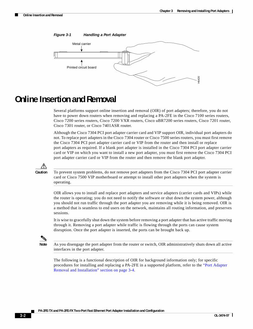
Caution Always handle the port adapter by the carrier edges and handle; never touch the port adapter components or connector pins. (See Figure 3-1.)
3-1thernet Port Adapter Installation and Configuration
Chapter 3 Removing and Installing Port Adapters Online Insertion and Removal
Figure 3-1 Handling a Port Adapter
Online Insertion and RemovalSeveral platforms support online insertion and removal (OIR) of port adapters; therefore, you do not have to power down routers when removing and replacing a PA-2FE in the Cisco 7100 series routers, Cisco 7200 series routers, Cisco 7200 VXR routers, Cisco uBR7200 series routers, Cisco 7201 router, Cisco 7301 router, or Cisco 7401ASR router.
Although the Cisco 7304 PCI port adapter carrier card and VIP support OIR, individual port adapters do not. To replace port adapters in the Cisco 7304 router or Cisco 7500 series routers, you must first remove the Cisco 7304 PCI port adapter carrier card or VIP from the router and then install or replace port adapters as required. If a blank port adapter is installed in the Cisco 7304 PCI port adapter carrier card or VIP on which you want to install a new port adapter, you must first remove the Cisco 7304 PCI port adapter carrier card or VIP from the router and then remove the blank port adapter.
Caution To prevent system problems, do not remove port adapters from the Cisco 7304 PCI port adapter carrier card or Cisco 7500 VIP motherboard or attempt to install other port adapters when the system is operating.
OIR allows you to install and replace port adapters and service adapters (carrier cards and VIPs) while the router is operating; you do not need to notify the software or shut down the system power, although you should not run traffic through the port adapter you are removing while it is being removed. OIR is a method that is seamless to end users on the network, maintains all routing information, and preserves sessions.
It is wise to gracefully shut down the system before removing a port adapter that has active traffic moving through it. Removing a port adapter while traffic is flowing through the ports can cause system disruption. Once the port adapter is inserted, the ports can be brought back up.
Note As you disengage the port adapter from the router or switch, OIR administratively shuts down all active interfaces in the port adapter.
The following is a functional description of OIR for background information only; for specific procedures for installing and replacing a PA-2FE in a supported platform, refer to the “Port Adapter Removal and Installation” section on page 3-4.
H64
20
Metal carrier
Printed circuit board
3-2PA-2FE-TX and PA-2FE-FX Two-Port Fast Ethernet Port Adapter Installation and Configuration
OL-3474-07
Chapter 3 Removing and Installing Port Adapters Warnings and Cautions
Each PA-2FE has a bus connector that connects it to the router. The connector has a set of tiered pins in three lengths that send specific signals to the system as they make contact with the port adapter. The system assesses the signals it receives and the order in which it receives them to determine if a port adapter is being removed from or introduced to the system. From these signals, the system determines whether to reinitialize a new interface or to shut down a disconnected interface.
Specifically, when you insert a port adapter, the longest pins make contact with the port adapter first, and the shortest pins make contact last. The system recognizes the signals and the sequence in which it receives them.
When you remove or insert a port adapter, the pins send signals to notify the system of changes. The router then performs the following procedure:
1. Rapidly scans the system for configuration changes.
2. Initializes newly inserted port adapters or administratively shuts down any vacant interfaces.
3. Brings all previously configured interfaces on the port adapter back to their previously installed state. Any newly inserted interface is put in the administratively shutdown state, as if it was present (but not configured) at boot time. If a similar port adapter type is reinserted into a slot, its ports are configured and brought online up to the port count of the originally installed port adapter of that type.
Note Before you begin installation, read Chapter 2, “Preparing for Installation,” for a list of parts and tools required for installation.
Warnings and CautionsObserve the following warnings and cautions when installing or removing port adapters.
Caution Do not slide a port adapter all the way into the slot until you have connected all required cables. Trying to do so disrupts normal operation of the router or switch.
Caution To prevent jamming the carrier between the upper and the lower edges of the port adapter slot, and to ensure that the edge connector at the rear of the port adapter mates with the connection at the rear of the port adapter slot, make certain that the carrier is positioned correctly, as shown in the cutaway illustrations in the “Port Adapter Removal and Installation” section on page 3-4.
Warning During this procedure, wear grounding wrist straps to avoid ESD damage to the card. Do not directly touch the midplane with your hand or any metal tool, or you could shock yourself. Statement 181
3-3PA-2FE-TX and PA-2FE-FX Two-Port Fast Ethernet Port Adapter Installation and Configuration
OL-3474-07

Chapter 3 Removing and Installing Port Adapters Port Adapter Removal and Installation
Port Adapter Removal and InstallationIn this section, the illustrations that follow give step-by-step instructions on how to remove and install port adapters. This section contains the following illustrations:
• Cisco 7100 Series—Removing and Installing a Port Adapter, page 3-5
• Cisco 7200 Series Routers and Cisco 7200 VXR Routers—Removing and Installing a Port Adapter, page 3-6
• Cisco uBR7200 Series Routers—Removing a Port Adapter, page 3-7
• Cisco uBR7200 Series Routers—Installing a Port Adapter, page 3-8
• Cisco 7201 Router—Removing and Installing a Port Adapter, page 3-9
• Cisco 7301 Router—Removing and Installing a Port Adapter, page 3-10
• Cisco 7304 PCI Port Adapter Carrier Card—Removing and Installing a Port Adapter, page 3-11
• Cisco 7401ASR Router—Removing and Installing a Port Adapter, page 3-13
• Cisco 7500 Series Router VIP—Removing and Installing a Port Adapter, page 3-13
Tip If a port adapter lever or other retaining mechanism does not move to the locked position, the port adapter is not completely seated in the midplane. Carefully pull the port adapter halfway out of the slot, reinsert it, and move the port adapter lever or other mechanism to the locked position.
3-4PA-2FE-TX and PA-2FE-FX Two-Port Fast Ethernet Port Adapter Installation and Configuration
OL-3474-07
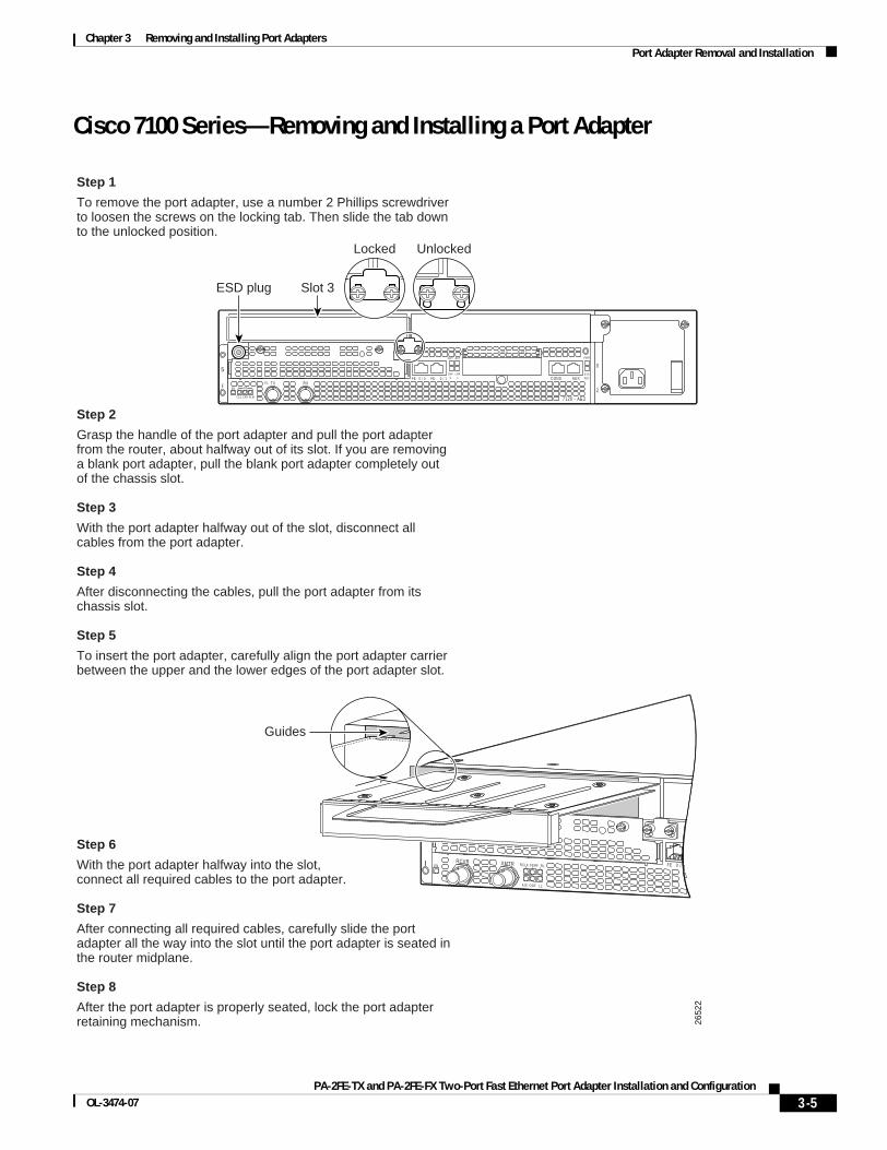
Chapter 3 Removing and Installing Port Adapters Port Adapter Removal and Installation
Cisco 7100 Series—Removing and Installing a Port Adapter
SLOT 0 SLOT 1
0
2
FE 0 / 0 FE AUX
7120 - AE3
RXTXE3RXEN
CEL CAR ALM
5
ICONS
ACT
0 / 1
ACT
LNK0
LNK1
PWR
SYSRDY
Unlocked
Slot 3ESD plug
Locked
2652
2
5
I FE 0 /XMTRRCVREN RCLK FERF RL
AIS OOF LL
Guides
Step 1
To remove the port adapter, use a number 2 Phillips screwdriver to loosen the screws on the locking tab. Then slide the tab down to the unlocked position.
Step 2
Grasp the handle of the port adapter and pull the port adapter from the router, about halfway out of its slot. If you are removing a blank port adapter, pull the blank port adapter completely out of the chassis slot.
Step 3
With the port adapter halfway out of the slot, disconnect all cables from the port adapter.
Step 4
After disconnecting the cables, pull the port adapter from its chassis slot.
Step 5
To insert the port adapter, carefully align the port adapter carrier between the upper and the lower edges of the port adapter slot.
Step 6
With the port adapter halfway into the slot,connect all required cables to the port adapter.
Step 7
After connecting all required cables, carefully slide the port adapter all the way into the slot until the port adapter is seated in the router midplane.
Step 8
After the port adapter is properly seated, lock the port adapter retaining mechanism.
3-5PA-2FE-TX and PA-2FE-FX Two-Port Fast Ethernet Port Adapter Installation and Configuration
OL-3474-07
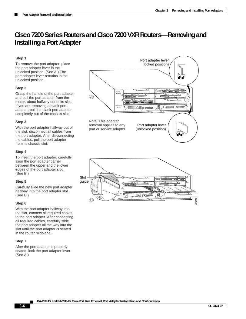
Chapter 3 Removing and Installing Port Adapters Port Adapter Removal and Installation
Cisco 7200 Series Routers and Cisco 7200 VXR Routers—Removing and Installing a Port Adapter
Step 1
To remove the port adapter, place the port adapter lever in the unlocked position. (See A.) Theport adapter lever remains in the unlocked position.
Step 2
Grasp the handle of the port adapter and pull the port adapter from the router, about halfway out of its slot. If you are removing a blank port adapter, pull the blank port adapter completely out of the chassis slot.
Step 3
With the port adapter halfway out of the slot, disconnect all cables from the port adapter. After disconnecting the cables, pull the port adapter from its chassis slot.
Step 4
To insert the port adapter, carefully align the port adapter carrier between the upper and the lower edges of the port adapter slot.(See B.)
Step 5
Carefully slide the new port adapter halfway into the port adapter slot. (See B.)
Step 6
With the port adapter halfway into the slot, connect all required cables to the port adapter. After connecting all required cables, carefully slide the port adapter all the way into the slot until the port adapter is seated in the router midplane.
Step 7
After the port adapter is properly seated, lock the port adapter lever. (See A.)
2799
6
2
0
4
1
3
56
FAST SERIAL
ENTD TC RD RC LB CD TD TC RD RC LB CD TD TC RD RC LB CD TD TC RD RC LB CD
TOKEN RING
0 1 2 3
Cisco 7200Series
CPU RESET
ENABLED
MII
EN R
J45
EN R
J45
LINK
1O P
WR
OK
RJ-45
FAST ETHERNET INPUT/OUTPUT CONTROLLER
PCMCIA
EJECT
SLOT 0
SLOT 1
FE MII
ENABLE
D
MII
LIN
K
RJ4
5
FAST ETHERNET
0
ETHERNET 10BT
ENABLE
D
0 2
1 3
LINK
0 1 2 3
Port adapter lever(locked position)
Port adapter lever(unlocked position)
Note: This adapter removal applies to any port or service adapter.
A
BM
II
EN R
J45
EN R
J45
LINK
1O P
WR
OK
RJ-45
CPU RESET
FAST ETHERNET INPUT/OUTPUT CONTROLLER
ENABLED
PCMCIA
EJECT
SLOT 0
SLOT 1
FE MII
2
4
6
Cisco 7200Series
1
3
5
ETHERNET 10BT
ENABLE
D
0 2
1 3
LINK
0 1 2 3
ENABLE
D
MII
LIN
K
RJ4
5
FAST ETHERNET
0
TOKEN RING
0 1 2 3Slotguide
3-6PA-2FE-TX and PA-2FE-FX Two-Port Fast Ethernet Port Adapter Installation and Configuration
OL-3474-07

Chapter 3 Removing and Installing Port Adapters Port Adapter Removal and Installation
Cisco uBR7200 Series Routers—Removing a Port Adapter
Port adapter lever(locked position)
Port adapters
Port adapter lever(unlocked position)
Port adapter retention clip(locked position)
Port adapters
Port adapter retention clip(unlocked position)
Step 1
To remove the port adapter, unlock the port adapter retaining mechanism. The port adapter lever remains in the unlocked position.
Place the port adapter lever (Cisco uBR7223, see A), or the port adapter retention clip (Cisco uBR7246 and Cisco uBR7246 VXR, see B) in the unlocked position. Either mechanism remains in the unlocked position.
Step 2
Grasp the handle of the port adapter and pull the port adapter from the router, about halfway out of its slot.If you are removing a blankport adapter, pull the blank port adapter completely out of the chassis slot.
Step 3
With the port adapter halfway out of the slot, disconnect all cables from the port adapter. After disconnecting the cables, pull the port adapter from its chassis slot.
2652
3
Note: This adapter removal applies to any port or service adapter.
A
B
3-7PA-2FE-TX and PA-2FE-FX Two-Port Fast Ethernet Port Adapter Installation and Configuration
OL-3474-07
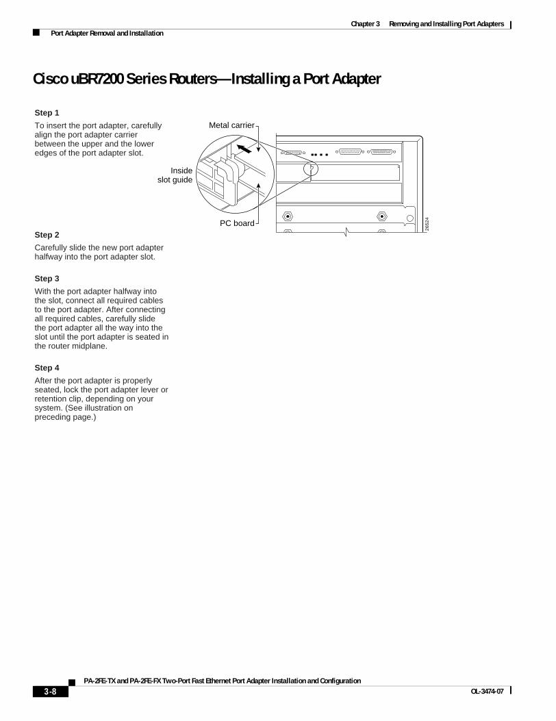
Chapter 3 Removing and Installing Port Adapters Port Adapter Removal and Installation
Cisco uBR7200 Series Routers—Installing a Port Adapter
Step 1
To insert the port adapter, carefully align the port adapter carrier between the upper and the lower edges of the port adapter slot.
Step 2
Carefully slide the new port adapter halfway into the port adapter slot.
Step 3
With the port adapter halfway into the slot, connect all required cables to the port adapter. After connecting all required cables, carefully slide the port adapter all the way into the slot until the port adapter is seated in the router midplane.
Step 4
After the port adapter is properly seated, lock the port adapter lever or retention clip, depending on your system. (See illustration on preceding page.)
26
52
4
Insideslot guide
Metal carrier
PC board
3-8PA-2FE-TX and PA-2FE-FX Two-Port Fast Ethernet Port Adapter Installation and Configuration
OL-3474-07
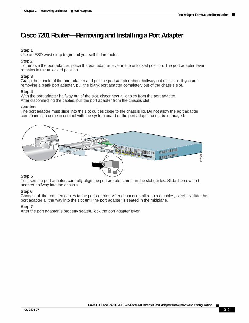
Chapter 3 Removing and Installing Port Adapters Port Adapter Removal and Installation
Cisco 7201 Router—Removing and Installing a Port Adapter
1709
02
ALARM
RJ45 ENLINK
TXRX
GBIC
GIGABIT ETHERNET 0/2
RJ45 ENLINK
TXRX
GBIC
GIGABIT ETHERNET 0/0
RJ45 ENLINK
TXRX
GBIC
GIGABIT ETHERNET 0/1
CISCO 7301
SLOT 1
CONSOLEAUX
COMPACTFLASH STATUS
100-240V, 2A, 50/60 Hz24V=9A, 48 - 60V=5AGE 0/0
GE 0/1GE 0/2
GE 0/3AUX
CONSOLE
MNGMNT USE ONLY
FELINK
0FE 0/0
RJ45SFP
SFPSFP
SFP
LINK/ACTV
ALARM
PWR OK
STATUS
CFACTV
COMPACT FLASH
LINK/ACTV
RXTX
LINK/ACTV
LINK/ACTV
RXTX
EN
RJ45 EN
ENAB
LED
RX CE
LLS
RX CA
RRIER
RX AL
ARM
ATM
Cisco 7201
Step 1Use an ESD wrist strap to ground yourself to the router.
Step 2To remove the port adapter, place the port adapter lever in the unlocked position. The port adapter lever remains in the unlocked position.
Step 3Grasp the handle of the port adapter and pull the port adapter about halfway out of its slot. If you are removing a blank port adapter, pull the blank port adapter completely out of the chassis slot.
Step 4With the port adapter halfway out of the slot, disconnect all cables from the port adapter.After disconnecting the cables, pull the port adapter from the chassis slot.
CautionThe port adapter must slide into the slot guides close to the chassis lid. Do not allow the port adapter components to come in contact with the system board or the port adapter could be damaged.
Step 5To insert the port adapter, carefully align the port adapter carrier in the slot guides. Slide the new port adapter halfway into the chassis.
Step 6Connect all the required cables to the port adapter. After connecting all required cables, carefully slide the port adapter all the way into the slot until the port adapter is seated in the midplane.
Step 7After the port adapter is properly seated, lock the port adapter lever.
3-9PA-2FE-TX and PA-2FE-FX Two-Port Fast Ethernet Port Adapter Installation and Configuration
OL-3474-07
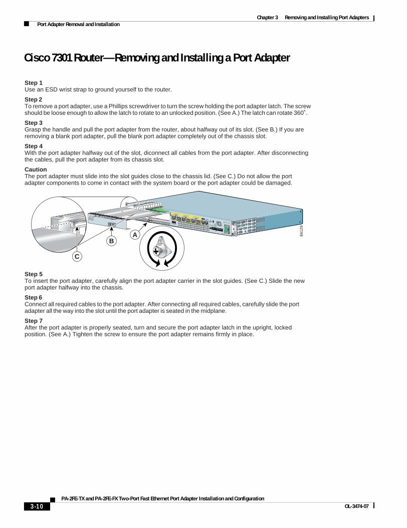
Chapter 3 Removing and Installing Port Adapters Port Adapter Removal and Installation
Cisco 7301 Router—Removing and Installing a Port Adapter
8412
9
ALARM
RJ45 ENLINK
TXRX
GBIC
GIGABIT ETHERNET 0/2
RJ45 ENLINK
TXRX
GBIC
GIGABIT ETHERNET 0/0
RJ45 ENLINK
TXRX
GBIC
GIGABIT ETHERNET 0/1
CISCO 7411
SLOT 1
CONSOLEAUX
COMPACTFLASH STATUS
100-240V, 2A, 50/60 Hz24V=9A, 48 - 60V=5A
A
ENAB
LED
RX CE
LLS
RX CA
RRIER
RX AL
ARM
ATM
BA
Step 1Use an ESD wrist strap to ground yourself to the router.
Step 2To remove a port adapter, use a Phillips screwdriver to turn the screw holding the port adapter latch. The screw should be loose enough to allow the latch to rotate to an unlocked position. (See A.) The latch can rotate 360˚.
Step 3Grasp the handle and pull the port adapter from the router, about halfway out of its slot. (See B.) If you are removing a blank port adapter, pull the blank port adapter completely out of the chassis slot.
Step 4With the port adapter halfway out of the slot, diconnect all cables from the port adapter. After disconnecting the cables, pull the port adapter from its chassis slot.
CautionThe port adapter must slide into the slot guides close to the chassis lid. (See C.) Do not allow the port adapter components to come in contact with the system board or the port adapter could be damaged.
Step 5To insert the port adapter, carefully align the port adapter carrier in the slot guides. (See C.) Slide the new port adapter halfway into the chassis.
Step 6Connect all required cables to the port adapter. After connecting all required cables, carefully slide the port adapter all the way into the slot until the port adapter is seated in the midplane.
Step 7After the port adapter is properly seated, turn and secure the port adapter latch in the upright, locked position. (See A.) Tighten the screw to ensure the port adapter remains firmly in place.
B
C
3-10PA-2FE-TX and PA-2FE-FX Two-Port Fast Ethernet Port Adapter Installation and Configuration
OL-3474-07
Chapter 3 Removing and Installing Port Adapters Port Adapter Removal and Installation
Cisco 7304 PCI Port Adapter Carrier Card—Removing and Installing a Port Adapter
You can install one single-width port adapter in a Cisco 7304 PCI port adapter carrier card. This section provides step-by-step instructions for removing and installing a port adapter in a Cisco 7304 PCI port adapter carrier card.
Caution When performing the following procedures, wear a grounding wrist strap to avoid ESD damage to the Cisco 7304 PCI port adapter carrier card.
Note If the Cisco 7304 PCI port adapter carrier card is still in the router, you must remove the port adapter carrier card before removing a port adapter.
To remove and install a port adapter in a Cisco 7304 PCI port adapter carrier card, refer to Figure 3-2 and do the following:
Step 1 To remove the port adapter from the Cisco 7304 PCI port adapter carrier card, turn the port adapter lock from its locked and horizontal position shown in A of Figure 3-2 to its unlocked and vertical position shown in B of Figure 3-2.
Step 2 Ensure that the cables are disconnected from the port adapter before removing the Cisco 7304 PCI port adapter carrier card from the chassis.
Step 3 Grasp the handle of the port adapter and pull the port adapter from the Cisco 7304 PCI port adapter carrier card.
Step 4 To insert the port adapter in the Cisco 7304 PCI port adapter carrier card, locate the guide rails inside the Cisco 7304 PCI port adapter carrier card that hold the port adapter in place. They are at the top left and top right of the port adapter slot and are recessed about an inch, as shown in C of Figure 3-2.
Step 5 Carefully slide the port adapter in the Cisco 7304 PCI port adapter carrier card until the port adapter makes contact with the port adapter interface connector. When fully seated, the port adapter front panel should be flush with the face of the Cisco 7304 PCI port adapter carrier card.
Step 6 After the port adapter is properly seated, turn the port adapter lock to its locked and horizontal position, as shown in A of Figure 3-2.
3-11PA-2FE-TX and PA-2FE-FX Two-Port Fast Ethernet Port Adapter Installation and Configuration
OL-3474-07

Chapter 3 Removing and Installing Port Adapters Port Adapter Removal and Installation
Figure 3-2 illustrates how to remove and install a port adapter in a Cisco 7304 PCI port adapter carrier card.
Figure 3-2 Cisco 7304 PCI Port Adapter Carrier Card—Port Adapter Removal and Installation
8465
7
7300-CC-PA
OIRSTATUS
7300 PA CARRIER
ENAB
LED
RX CE
LLS
RX CA
RRIER
RX AL
ARM
ATM
A
C
7300-CC-PA
OIRSTATUS
7300 PA CARRIER
B
7300-CC-PA
ENAB
LED
RX CE
LLS
RX CA
RRIER
RX AL
ARM
ATM
3-12PA-2FE-TX and PA-2FE-FX Two-Port Fast Ethernet Port Adapter Installation and Configuration
OL-3474-07
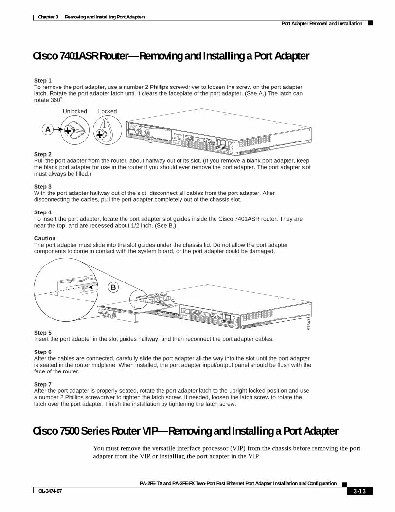
Chapter 3 Removing and Installing Port Adapters Port Adapter Removal and Installation
Cisco 7401ASR Router—Removing and Installing a Port Adapter
Cisco 7500 Series Router VIP—Removing and Installing a Port AdapterYou must remove the versatile interface processor (VIP) from the chassis before removing the port adapter from the VIP or installing the port adapter in the VIP.
5764
3
Step 1To remove the port adapter, use a number 2 Phillips screwdriver to loosen the screw on the port adapter latch. Rotate the port adapter latch until it clears the faceplate of the port adapter. (See A.) The latch can rotate 360˚.
Step 2Pull the port adapter from the router, about halfway out of its slot. (If you remove a blank port adapter, keep the blank port adapter for use in the router if you should ever remove the port adapter. The port adapter slot must always be filled.)
Step 3With the port adapter halfway out of the slot, disconnect all cables from the port adapter. After disconnecting the cables, pull the port adapter completely out of the chassis slot.
Step 4To insert the port adapter, locate the port adapter slot guides inside the Cisco 7401ASR router. They are near the top, and are recessed about 1/2 inch. (See B.)
CautionThe port adapter must slide into the slot guides under the chassis lid. Do not allow the port adapter components to come in contact with the system board, or the port adapter could be damaged.
Step 5Insert the port adapter in the slot guides halfway, and then reconnect the port adapter cables.
Step 6After the cables are connected, carefully slide the port adapter all the way into the slot until the port adapter is seated in the router midplane. When installed, the port adapter input/output panel should be flush with the face of the router.
Step 7After the port adapter is properly seated, rotate the port adapter latch to the upright locked position and use a number 2 Phillips screwdriver to tighten the latch screw. If needed, loosen the latch screw to rotate the latch over the port adapter. Finish the installation by tightening the latch screw.
ENAB
LED
RX CE
LLS
RX CA
RRIER
RX AL
ARM
TX
RX ENHANCED ATM
ENAB
LED
RX CE
LLS
RX CA
RRIER
RX AL
ARM
TX
RX ENHANCED ATM
B
A
LockedUnlocked
3-13PA-2FE-TX and PA-2FE-FX Two-Port Fast Ethernet Port Adapter Installation and Configuration
OL-3474-07

Chapter 3 Removing and Installing Port Adapters Port Adapter Removal and Installation
Removing and Installing a VIP Carrier Card in the Cisco 7500 Series Router
39
39
5
EJECT
SLOT 0SLO
T 1
NORMAL CPU HALT
RESET
AUX.
CONSOLE
ROUTE SWITCH PROCESSOR
CLASS 1 L
ASER PRODUCT
L
ASERPRODUKT DER K
LASSE 1
PRODUIT
LASER D
E CLASSE 1
PRODUCTO L
ASER DE C
LASSE 1
ENHANCED GIGABIT ETHERNET
LINK
ENABLED
TX RX
Captiveinstallationscrew
A
B
C
D
Card carrier guide
Captiveinstallationscrew
Remove a module as follows:
1. Use a screwdriver to loosen the captive installation screws (shown in A and D).
2. Simultaneously pull the ejector levers out to release the module from the backplane connector (shown in B). The levers should snap into their spring retainers.
3. Grasp the module handle with one hand and place your other hand under the carrier to support and guide the module as you pull it out of the slot. Avoid touching the card.
4. Place the removed module on an antistatic mat or antistatic foam, or immediately install it in another slot.
5. Install a new module or a filler (MAS7K-BLANK) to keep dust out of the chassis and to maintain proper airflow through the chassis.
Install a module as follows:
1. Choose a slot for the new module and ensure that there is enough clearance to accommodate any interface equipment that you will connect directly to its ports.
2. Use a screwdriver to loosen the captive installation screws (shown in A) and remove the filler (or the existing module) from the slot to be filled.
3. Hold the module handle with one hand, and place your other hand under the carrier to support the module and guide it into the slot. Avoid touching the card.
4. Place the back of the module in the slot and align the guide on the carrier with the groove in the slot (shown in A).
5. Carefully slide the module into the slot until the faceplate makes contact with the ejector levers (shown in C).
6. Use the thumb and forefinger of each hand to push the ejector lever flat against the module (shown in B).
7. Use a screwdriver to tighten the captive installation screws.
3-14PA-2FE-TX and PA-2FE-FX Two-Port Fast Ethernet Port Adapter Installation and Configuration
OL-3474-07
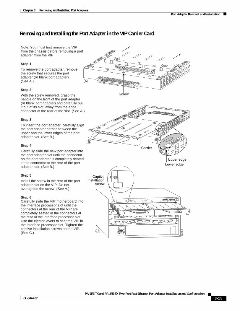
Chapter 3 Removing and Installing Port Adapters Port Adapter Removal and Installation
Removing and Installing the Port Adapter in the VIP Carrier Card
Note: You must first remove the VIP from the chassis before removing a port adapter from the VIP.
Step 1
To remove the port adapter, removethe screw that secures the portadapter (or blank port adapter).(See A.)
Step 2
With the screw removed, grasp the handle on the front of the port adapter (or blank port adapter) and carefully pull it out of its slot, away from the edge connector at the rear of the slot. (See A.)
Step 3
To insert the port adapter, carefully align the port adapter carrier between the upper and the lower edges of the port adapter slot. (See B.)
Step 4
Carefully slide the new port adapter into the port adapter slot until the connector on the port adapter is completely seated in the connector at the rear of the port adapter slot. (See B.)
Step 5
Install the screw in the rear of the port adapter slot on the VIP. Do not overtighten the screw. (See A.)
Step 6Carefully slide the VIP motherboard into the interface processor slot until the connectors at the rear of the VIP are completely seated in the connectors at the rear of the interface processor slot. Use the ejector levers to seat the VIP in the interface processor slot. Tighten the captive installation screws on the VIP. (See C.)
26
52
0
Screw
Lower edge
Carrier
Upper edge
EJECT
SLOT 0SLO
T 1
NORMAL CPU HALT
RESET
AUX.
CONSOLE
ROUTE SWITCH PROCESSOR
A
B
C
Captiveinstallation
screw
3-15PA-2FE-TX and PA-2FE-FX Two-Port Fast Ethernet Port Adapter Installation and Configuration
OL-3474-07
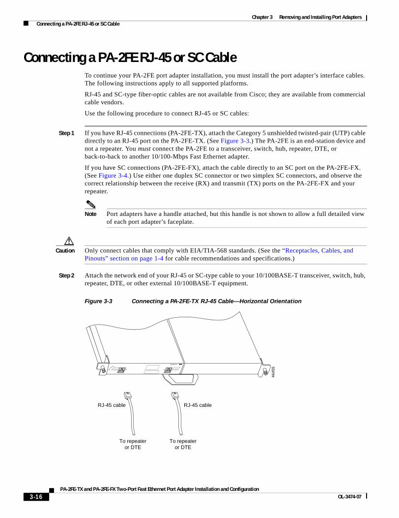
Chapter 3 Removing and Installing Port Adapters Connecting a PA-2FE RJ-45 or SC Cable
Connecting a PA-2FE RJ-45 or SC CableTo continue your PA-2FE port adapter installation, you must install the port adapter’s interface cables. The following instructions apply to all supported platforms.
RJ-45 and SC-type fiber-optic cables are not available from Cisco; they are available from commercial cable vendors.
Use the following procedure to connect RJ-45 or SC cables:
Step 1 If you have RJ-45 connections (PA-2FE-TX), attach the Category 5 unshielded twisted-pair (UTP) cable directly to an RJ-45 port on the PA-2FE-TX. (See Figure 3-3.) The PA-2FE is an end-station device and not a repeater. You must connect the PA-2FE to a transceiver, switch, hub, repeater, DTE, or back-to-back to another 10/100-Mbps Fast Ethernet adapter.
If you have SC connections (PA-2FE-FX), attach the cable directly to an SC port on the PA-2FE-FX. (See Figure 3-4.) Use either one duplex SC connector or two simplex SC connectors, and observe the correct relationship between the receive (RX) and transmit (TX) ports on the PA-2FE-FX and your repeater.
Note Port adapters have a handle attached, but this handle is not shown to allow a full detailed view of each port adapter’s faceplate.
Caution Only connect cables that comply with EIA/TIA-568 standards. (See the “Receptacles, Cables, and Pinouts” section on page 1-4 for cable recommendations and specifications.)
Step 2 Attach the network end of your RJ-45 or SC-type cable to your 10/100BASE-T transceiver, switch, hub, repeater, DTE, or other external 10/100BASE-T equipment.
Figure 3-3 Connecting a PA-2FE-TX RJ-45 Cable—Horizontal Orientation
4645
5ENABLED
LINK0
TX0RX0
RX1LIN
K1
TX1
PA-2FE-TX
0 1
To repeateror DTE
RJ-45 cable
To repeateror DTE
RJ-45 cable
3-16PA-2FE-TX and PA-2FE-FX Two-Port Fast Ethernet Port Adapter Installation and Configuration
OL-3474-07

Chapter 3 Removing and Installing Port Adapters Connecting a PA-2FE RJ-45 or SC Cable
Figure 3-4 Connecting PA-2FE-FX SC Cables—Horizontal Orientation
4645
6RX1LIN
K1
TX1
CLA
SS 1
LED
PRO
DU
CT
P
RO
DU
KT M
IT K
LASSE 1
LED
PRO
DU
IT A
VEC
VOYA
NT D
EL
D
E C
LASSE 1
PRO
DU
CTO
LED
DE C
LASE 1
ENABLED
0LINK0
TX0RX0
TXRX 1 TX
PA-2FE-FX
RX
Simplex (2)To repeater
Duplex (1)To repeater
3-17PA-2FE-TX and PA-2FE-FX Two-Port Fast Ethernet Port Adapter Installation and Configuration
OL-3474-07

Chapter 3 Removing and Installing Port Adapters Connecting a PA-2FE RJ-45 or SC Cable
3-18PA-2FE-TX and PA-2FE-FX Two-Port Fast Ethernet Port Adapter Installation and Configuration
OL-3474-07

PA-2FE-TX and PA-2FE-FX Two-Port Fast EOL-3474-07
C H A P T E R4
Configuring the PA-2FETo continue your PA-2FE port adapter installation, you must configure the Fast Ethernet interfaces. The instructions that follow apply to all supported platforms. Minor differences between the platforms—with Cisco IOS software commands—are noted.
This chapter contains the following sections:
• Using the EXEC Command Interpreter, page 4-1
• Configuring the Interfaces, page 4-2
• Checking the Configuration, page 4-9
Using the EXEC Command Interpreter You modify the configuration of your router through the software command interpreter called the EXEC (also called enable mode). You must enter the privileged level of the EXEC command interpreter with the enable command before you can use the configure command to configure a new interface or change the existing configuration of an interface. The system prompts you for a password if one has been set.
The system prompt for the privileged level ends with a pound sign (#) instead of an angle bracket (>). At the console terminal, use the following procedure to enter the privileged level:
Step 1 At the user-level EXEC prompt, enter the enable command. The EXEC prompts you for a privileged-level password as follows:
Router> enable
Password:
Step 2 Enter the password (the password is case sensitive). For security purposes, the password is not displayed.
When you enter the correct password, the system displays the privileged-level system prompt (#):
Router#
To configure the new interfaces, proceed to the “Configuring the Interfaces” section on page 4-2.
4-1thernet Port Adapter Installation and Configuration
Chapter 4 Configuring the PA-2FE Configuring the Interfaces
Configuring the Interfaces After you verify that the new PA-2FE is installed correctly (the ENABLED LED goes on), use the privileged-level configure command to configure the new interfaces. Have the following information available:
• Protocols you plan to route on each new interface
• IP addresses, if you plan to configure the interfaces for IP routing
• Bridging protocols you plan to use
If you installed a new PA-2FE or if you want to change the configuration of an existing interface, you must enter configuration mode to configure the new interfaces. If you replaced a PA-2FE that was previously configured, the system recognizes the new interfaces and brings each of them up in their existing configurations.
You can configure each of the interfaces on a PA-2FE at:
• 100 Mbps, half duplex, for a maximum aggregate bandwidth of 200 Mbps per pair. Half-duplex operation is the default.
• 200 Mbps, full duplex, for a maximum aggregate bandwidth of 400 Mbps per pair.
You can also configure one PA-2FE interface at 100 Mbps, half duplex, and the second PA-2FE interface at 200 Mbps, full duplex, for a maximum aggregate bandwidth of 300 Mbps per pair.
For a summary of the configuration options available and instructions for configuring interfaces on a PA-2FE, refer to the appropriate configuration publications listed in the “Related Documentation” section on page viii.
You execute configuration commands from the privileged level of the EXEC command interpreter, which usually requires password access. Contact your system administrator, if necessary, to obtain password access. (See the “Using the EXEC Command Interpreter” section on page 4-1 for an explanation of the privileged level of the EXEC.)
This section contains the following subsections:
• Shutting Down an Interface, page 4-2
• Performing a Basic Interface Configuration, page 4-7
Shutting Down an Interface Before you remove an interface that you will not replace, or replace port adapters, use the shutdown command to shut down (disable) the interfaces to prevent anomalies when you reinstall the new or reconfigured port adapter. When you shut down an interface, it is designated administratively down in the show command displays.
Follow these steps to shut down an interface:
Step 1 Enter the privileged level of the EXEC command interpreter (also called enable mode). (See the “Using the EXEC Command Interpreter” section on page 4-1 for instructions.)
Step 2 At the privileged-level prompt, enter configuration mode and specify that the console terminal is the source of the configuration commands, as follows:
Router# configure terminalEnter configuration commands, one per line. End with CNTL/Z.Router(config)#
4-2PA-2FE-TX and PA-2FE-FX Two-Port Fast Ethernet Port Adapter Installation and Configuration
OL-3474-07
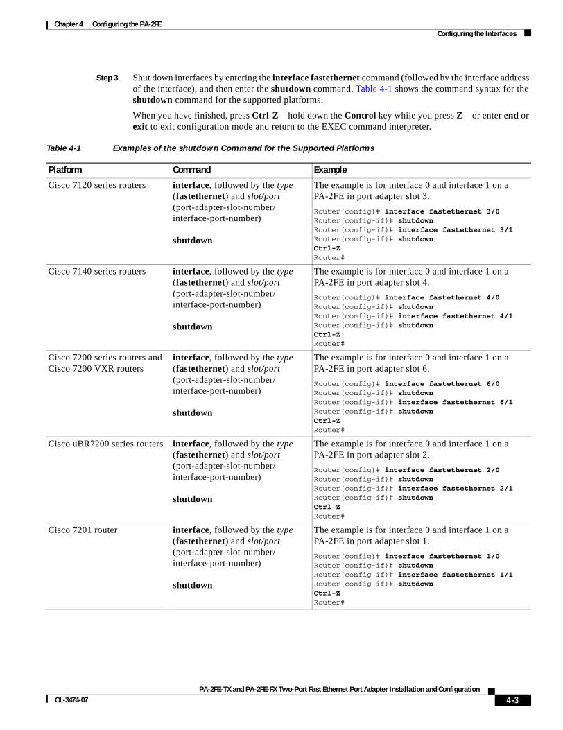
Chapter 4 Configuring the PA-2FE Configuring the Interfaces
Step 3 Shut down interfaces by entering the interface fastethernet command (followed by the interface address of the interface), and then enter the shutdown command. Table 4-1 shows the command syntax for the shutdown command for the supported platforms.
When you have finished, press Ctrl-Z—hold down the Control key while you press Z—or enter end or exit to exit configuration mode and return to the EXEC command interpreter.
Table 4-1 Examples of the shutdown Command for the Supported Platforms
Platform Command Example
Cisco 7120 series routers interface, followed by the type (fastethernet) and slot/port (port-adapter-slot-number/interface-port-number)
shutdown
The example is for interface 0 and interface 1 on a PA-2FE in port adapter slot 3.
Router(config)# interface fastethernet 3/0Router(config-if)# shutdownRouter(config-if)# interface fastethernet 3/1Router(config-if)# shutdownCtrl-ZRouter#
Cisco 7140 series routers interface, followed by the type (fastethernet) and slot/port (port-adapter-slot-number/interface-port-number)
shutdown
The example is for interface 0 and interface 1 on a PA-2FE in port adapter slot 4.
Router(config)# interface fastethernet 4/0Router(config-if)# shutdownRouter(config-if)# interface fastethernet 4/1Router(config-if)# shutdownCtrl-ZRouter#
Cisco 7200 series routers and Cisco 7200 VXR routers
interface, followed by the type (fastethernet) and slot/port (port-adapter-slot-number/interface-port-number)
shutdown
The example is for interface 0 and interface 1 on a PA-2FE in port adapter slot 6.
Router(config)# interface fastethernet 6/0Router(config-if)# shutdownRouter(config-if)# interface fastethernet 6/1Router(config-if)# shutdownCtrl-ZRouter#
Cisco uBR7200 series routers interface, followed by the type (fastethernet) and slot/port (port-adapter-slot-number/interface-port-number)
shutdown
The example is for interface 0 and interface 1 on a PA-2FE in port adapter slot 2.
Router(config)# interface fastethernet 2/0Router(config-if)# shutdownRouter(config-if)# interface fastethernet 2/1Router(config-if)# shutdownCtrl-ZRouter#
Cisco 7201 router interface, followed by the type (fastethernet) and slot/port (port-adapter-slot-number/interface-port-number)
shutdown
The example is for interface 0 and interface 1 on a PA-2FE in port adapter slot 1.
Router(config)# interface fastethernet 1/0Router(config-if)# shutdownRouter(config-if)# interface fastethernet 1/1Router(config-if)# shutdownCtrl-ZRouter#
4-3PA-2FE-TX and PA-2FE-FX Two-Port Fast Ethernet Port Adapter Installation and Configuration
OL-3474-07
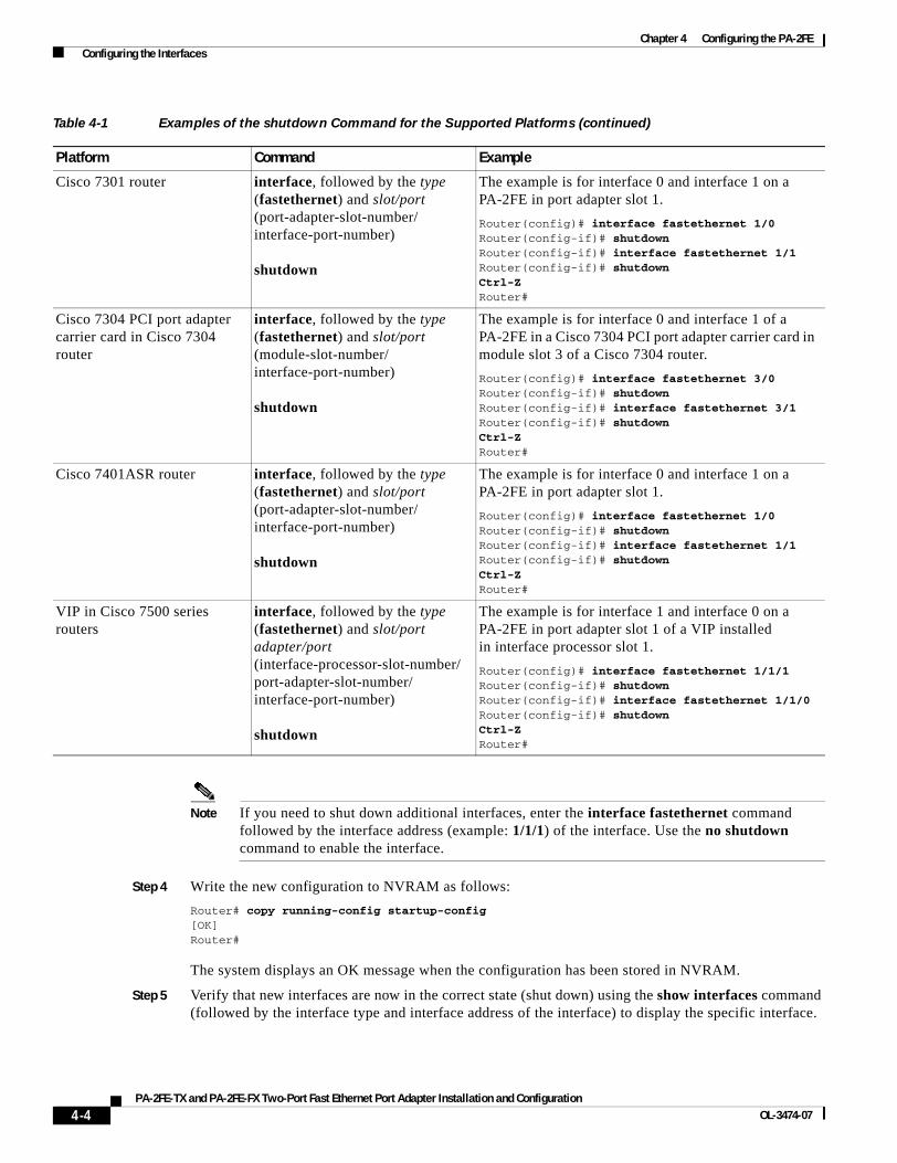
Chapter 4 Configuring the PA-2FE Configuring the Interfaces
Note If you need to shut down additional interfaces, enter the interface fastethernet command followed by the interface address (example: 1/1/1) of the interface. Use the no shutdown command to enable the interface.
Step 4 Write the new configuration to NVRAM as follows:
Router# copy running-config startup-config[OK]Router#
The system displays an OK message when the configuration has been stored in NVRAM.
Step 5 Verify that new interfaces are now in the correct state (shut down) using the show interfaces command (followed by the interface type and interface address of the interface) to display the specific interface.
Cisco 7301 router interface, followed by the type (fastethernet) and slot/port (port-adapter-slot-number/interface-port-number)
shutdown
The example is for interface 0 and interface 1 on a PA-2FE in port adapter slot 1.
Router(config)# interface fastethernet 1/0Router(config-if)# shutdownRouter(config-if)# interface fastethernet 1/1Router(config-if)# shutdownCtrl-ZRouter#
Cisco 7304 PCI port adapter carrier card in Cisco 7304 router
interface, followed by the type (fastethernet) and slot/port (module-slot-number/interface-port-number)
shutdown
The example is for interface 0 and interface 1 of a PA-2FE in a Cisco 7304 PCI port adapter carrier card in module slot 3 of a Cisco 7304 router.
Router(config)# interface fastethernet 3/0Router(config-if)# shutdownRouter(config-if)# interface fastethernet 3/1Router(config-if)# shutdownCtrl-ZRouter#
Cisco 7401ASR router interface, followed by the type (fastethernet) and slot/port (port-adapter-slot-number/interface-port-number)
shutdown
The example is for interface 0 and interface 1 on a PA-2FE in port adapter slot 1.
Router(config)# interface fastethernet 1/0Router(config-if)# shutdownRouter(config-if)# interface fastethernet 1/1Router(config-if)# shutdownCtrl-ZRouter#
VIP in Cisco 7500 series routers
interface, followed by the type (fastethernet) and slot/port adapter/port (interface-processor-slot-number/port-adapter-slot-number/interface-port-number)
shutdown
The example is for interface 1 and interface 0 on a PA-2FE in port adapter slot 1 of a VIP installed in interface processor slot 1.
Router(config)# interface fastethernet 1/1/1Router(config-if)# shutdownRouter(config-if)# interface fastethernet 1/1/0Router(config-if)# shutdownCtrl-ZRouter#
Table 4-1 Examples of the shutdown Command for the Supported Platforms (continued)
Platform Command Example
4-4PA-2FE-TX and PA-2FE-FX Two-Port Fast Ethernet Port Adapter Installation and Configuration
OL-3474-07
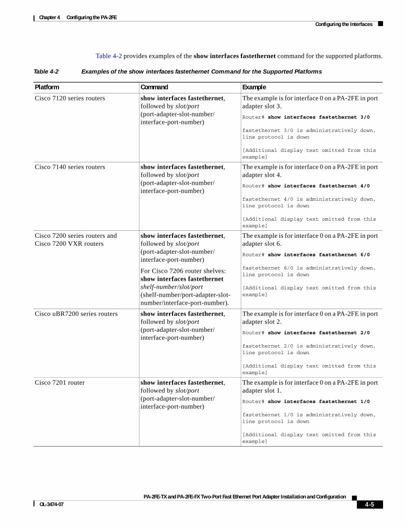
Chapter 4 Configuring the PA-2FE Configuring the Interfaces
Table 4-2 provides examples of the show interfaces fastethernet command for the supported platforms.
Table 4-2 Examples of the show interfaces fastethernet Command for the Supported Platforms
Platform Command Example
Cisco 7120 series routers show interfaces fastethernet, followed by slot/port (port-adapter-slot-number/interface-port-number)
The example is for interface 0 on a PA-2FE in port adapter slot 3.
Router# show interfaces fastethernet 3/0
fastethernet 3/0 is administratively down, line protocol is down
[Additional display text omitted from this example]
Cisco 7140 series routers show interfaces fastethernet, followed by slot/port (port-adapter-slot-number/interface-port-number)
The example is for interface 0 on a PA-2FE in port adapter slot 4.
Router# show interfaces fastethernet 4/0
fastethernet 4/0 is administratively down, line protocol is down
[Additional display text omitted from this example]
Cisco 7200 series routers and Cisco 7200 VXR routers
show interfaces fastethernet, followed by slot/port (port-adapter-slot-number/interface-port-number)
For Cisco 7206 router shelves: show interfaces fastethernet shelf-number/slot/port (shelf-number/port-adapter-slot-number/interface-port-number).
The example is for interface 0 on a PA-2FE in port adapter slot 6.
Router# show interfaces fastethernet 6/0
fastethernet 6/0 is administratively down, line protocol is down
[Additional display text omitted from this example]
Cisco uBR7200 series routers show interfaces fastethernet, followed by slot/port (port-adapter-slot-number/interface-port-number)
The example is for interface 0 on a PA-2FE in port adapter slot 2.
Router# show interfaces fastethernet 2/0
fastethernet 2/0 is administratively down, line protocol is down
[Additional display text omitted from this example]
Cisco 7201 router show interfaces fastethernet, followed by slot/port (port-adapter-slot-number/interface-port-number)
The example is for interface 0 on a PA-2FE in port adapter slot 1.
Router# show interfaces fastethernet 1/0
fastethernet 1/0 is administratively down, line protocol is down
[Additional display text omitted from this example]
4-5PA-2FE-TX and PA-2FE-FX Two-Port Fast Ethernet Port Adapter Installation and Configuration
OL-3474-07
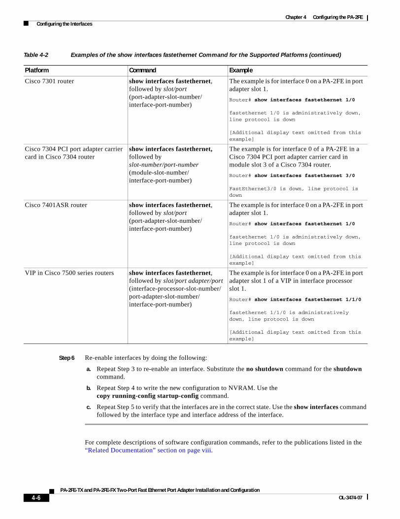
Chapter 4 Configuring the PA-2FE Configuring the Interfaces
Step 6 Re-enable interfaces by doing the following:
a. Repeat Step 3 to re-enable an interface. Substitute the no shutdown command for the shutdown command.
b. Repeat Step 4 to write the new configuration to NVRAM. Use the copy running-config startup-config command.
c. Repeat Step 5 to verify that the interfaces are in the correct state. Use the show interfaces command followed by the interface type and interface address of the interface.
For complete descriptions of software configuration commands, refer to the publications listed in the “Related Documentation” section on page viii.
Cisco 7301 router show interfaces fastethernet, followed by slot/port (port-adapter-slot-number/interface-port-number)
The example is for interface 0 on a PA-2FE in port adapter slot 1.
Router# show interfaces fastethernet 1/0
fastethernet 1/0 is administratively down, line protocol is down
[Additional display text omitted from this example]
Cisco 7304 PCI port adapter carrier card in Cisco 7304 router
show interfaces fastethernet, followed by slot-number/port-number (module-slot-number/interface-port-number)
The example is for interface 0 of a PA-2FE in a Cisco 7304 PCI port adapter carrier card in module slot 3 of a Cisco 7304 router.
Router# show interfaces fastethernet 3/0
FastEthernet3/0 is down, line protocol is down
Cisco 7401ASR router show interfaces fastethernet, followed by slot/port (port-adapter-slot-number/interface-port-number)
The example is for interface 0 on a PA-2FE in port adapter slot 1.
Router# show interfaces fastethernet 1/0
fastethernet 1/0 is administratively down, line protocol is down
[Additional display text omitted from this example]
VIP in Cisco 7500 series routers show interfaces fastethernet, followed by slot/port adapter/port (interface-processor-slot-number/port-adapter-slot-number/interface-port-number)
The example is for interface 0 on a PA-2FE in port adapter slot 1 of a VIP in interface processor slot 1.
Router# show interfaces fastethernet 1/1/0
fastethernet 1/1/0 is administratively down, line protocol is down
[Additional display text omitted from this example]
Table 4-2 Examples of the show interfaces fastethernet Command for the Supported Platforms (continued)
Platform Command Example
4-6PA-2FE-TX and PA-2FE-FX Two-Port Fast Ethernet Port Adapter Installation and Configuration
OL-3474-07
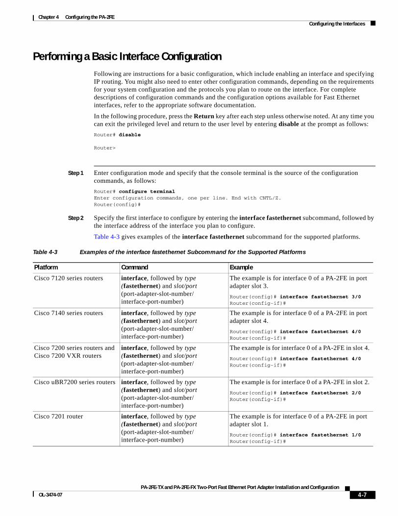
Chapter 4 Configuring the PA-2FE Configuring the Interfaces
Performing a Basic Interface Configuration Following are instructions for a basic configuration, which include enabling an interface and specifying IP routing. You might also need to enter other configuration commands, depending on the requirements for your system configuration and the protocols you plan to route on the interface. For complete descriptions of configuration commands and the configuration options available for Fast Ethernet interfaces, refer to the appropriate software documentation.
In the following procedure, press the Return key after each step unless otherwise noted. At any time you can exit the privileged level and return to the user level by entering disable at the prompt as follows:
Router# disable
Router>
Step 1 Enter configuration mode and specify that the console terminal is the source of the configuration commands, as follows:
Router# configure terminalEnter configuration commands, one per line. End with CNTL/Z.Router(config)#
Step 2 Specify the first interface to configure by entering the interface fastethernet subcommand, followed by the interface address of the interface you plan to configure.
Table 4-3 gives examples of the interface fastethernet subcommand for the supported platforms.
Table 4-3 Examples of the interface fastethernet Subcommand for the Supported Platforms
Platform Command Example
Cisco 7120 series routers interface, followed by type (fastethernet) and slot/port (port-adapter-slot-number/interface-port-number)
The example is for interface 0 of a PA-2FE in port adapter slot 3.
Router(config)# interface fastethernet 3/0Router(config-if)#
Cisco 7140 series routers interface, followed by type (fastethernet) and slot/port (port-adapter-slot-number/interface-port-number)
The example is for interface 0 of a PA-2FE in port adapter slot 4.
Router(config)# interface fastethernet 4/0Router(config-if)#
Cisco 7200 series routers and Cisco 7200 VXR routers
interface, followed by type (fastethernet) and slot/port (port-adapter-slot-number/interface-port-number)
The example is for interface 0 of a PA-2FE in slot 4.
Router(config)# interface fastethernet 4/0Router(config-if)#
Cisco uBR7200 series routers interface, followed by type (fastethernet) and slot/port (port-adapter-slot-number/interface-port-number)
The example is for interface 0 of a PA-2FE in slot 2.
Router(config)# interface fastethernet 2/0Router(config-if)#
Cisco 7201 router interface, followed by type (fastethernet) and slot/port (port-adapter-slot-number/interface-port-number)
The example is for interface 0 of a PA-2FE in port adapter slot 1.
Router(config)# interface fastethernet 1/0Router(config-if)#
4-7PA-2FE-TX and PA-2FE-FX Two-Port Fast Ethernet Port Adapter Installation and Configuration
OL-3474-07
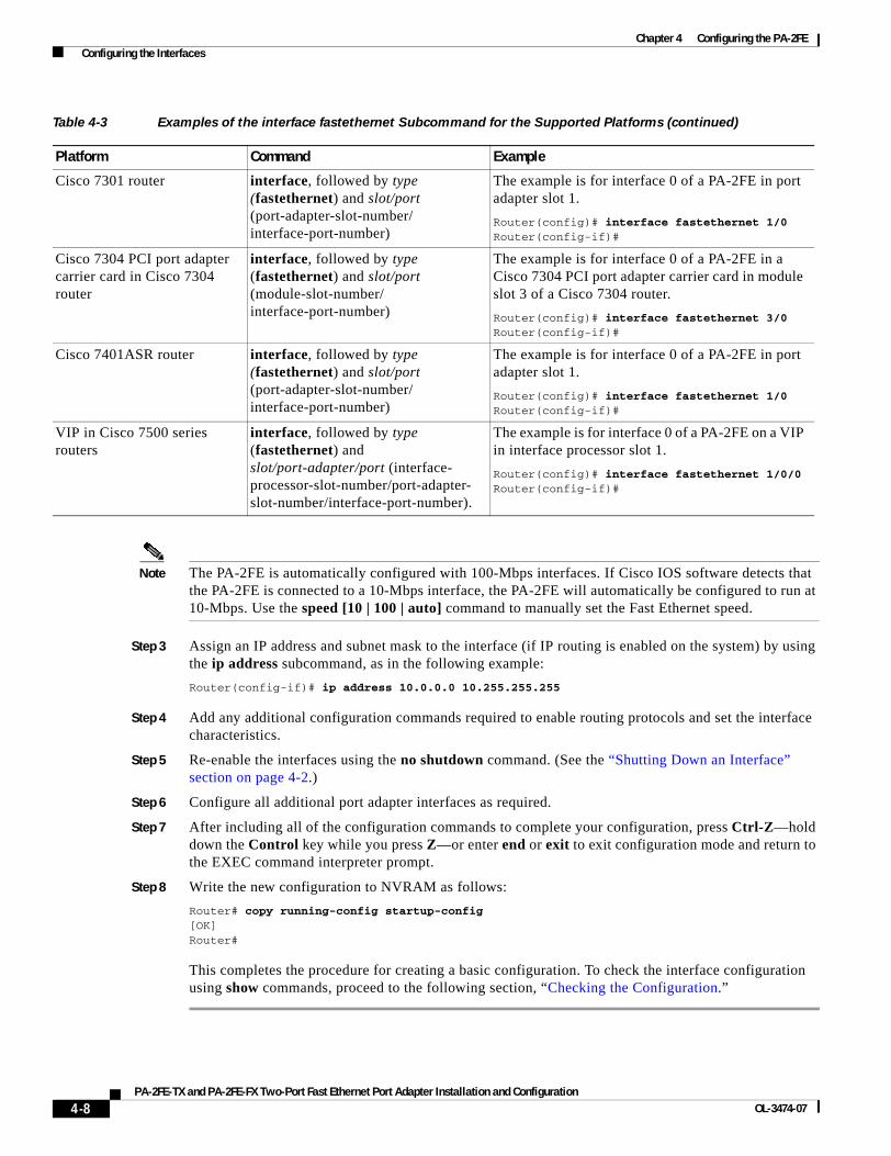
Chapter 4 Configuring the PA-2FE Configuring the Interfaces
Note The PA-2FE is automatically configured with 100-Mbps interfaces. If Cisco IOS software detects that the PA-2FE is connected to a 10-Mbps interface, the PA-2FE will automatically be configured to run at 10-Mbps. Use the speed [10 | 100 | auto] command to manually set the Fast Ethernet speed.
Step 3 Assign an IP address and subnet mask to the interface (if IP routing is enabled on the system) by using the ip address subcommand, as in the following example:
Router(config-if)# ip address 10.0.0.0 10.255.255.255
Step 4 Add any additional configuration commands required to enable routing protocols and set the interface characteristics.
Step 5 Re-enable the interfaces using the no shutdown command. (See the “Shutting Down an Interface” section on page 4-2.)
Step 6 Configure all additional port adapter interfaces as required.
Step 7 After including all of the configuration commands to complete your configuration, press Ctrl-Z—hold down the Control key while you press Z—or enter end or exit to exit configuration mode and return to the EXEC command interpreter prompt.
Step 8 Write the new configuration to NVRAM as follows:
Router# copy running-config startup-config[OK]Router#
This completes the procedure for creating a basic configuration. To check the interface configuration using show commands, proceed to the following section, “Checking the Configuration.”
Cisco 7301 router interface, followed by type (fastethernet) and slot/port (port-adapter-slot-number/interface-port-number)
The example is for interface 0 of a PA-2FE in port adapter slot 1.
Router(config)# interface fastethernet 1/0Router(config-if)#
Cisco 7304 PCI port adapter carrier card in Cisco 7304 router
interface, followed by type (fastethernet) and slot/port (module-slot-number/interface-port-number)
The example is for interface 0 of a PA-2FE in a Cisco 7304 PCI port adapter carrier card in module slot 3 of a Cisco 7304 router.
Router(config)# interface fastethernet 3/0Router(config-if)#
Cisco 7401ASR router interface, followed by type (fastethernet) and slot/port (port-adapter-slot-number/interface-port-number)
The example is for interface 0 of a PA-2FE in port adapter slot 1.
Router(config)# interface fastethernet 1/0Router(config-if)#
VIP in Cisco 7500 series routers
interface, followed by type (fastethernet) and slot/port-adapter/port (interface- processor-slot-number/port-adapter-slot-number/interface-port-number).
The example is for interface 0 of a PA-2FE on a VIP in interface processor slot 1.
Router(config)# interface fastethernet 1/0/0Router(config-if)#
Table 4-3 Examples of the interface fastethernet Subcommand for the Supported Platforms (continued)
Platform Command Example
4-8PA-2FE-TX and PA-2FE-FX Two-Port Fast Ethernet Port Adapter Installation and Configuration
OL-3474-07

Chapter 4 Configuring the PA-2FE Checking the Configuration
Checking the Configuration After configuring the new interface, use the show commands to display the status of the new interface or all interfaces, and use the ping command to check connectivity. This section includes the following subsections:
• Using show Commands to Verify the New Interface Status, page 4-9
• Using the ping Command to Verify Network Connectivity, page 4-21
Using show Commands to Verify the New Interface Status Table 4-4 demonstrates how you can use the show commands to verify that new interfaces are configured and operating correctly and that the PA-2FE appears in them correctly. Sample displays of the output of selected show commands appear in the sections that follow. For complete command descriptions and examples, refer to the publications listed in the “Related Documentation” section on page viii.
Note The outputs that appear in this document may not match the output you receive when running these commands. The outputs in this document are examples only.
Table 4-4 Using show Commands
Command Function Example
show version orshow hardware
Displays system hardware configuration, the number of each interface type installed, Cisco IOS software version, names and sources of configuration files, and boot images
Router# show version
show controllers Displays all the current interface processors and their interfaces
Router# show controllers
show diag slot Displays types of port adapters installed in your system and information about a specific port adapter slot, interface processor slot, or chassis slot
Router# show diag 2
show interfaces type 3/interface-port-number
Displays status information about a specific type of interface (for example, fastethernet) in a Cisco 7120 series router
Router# show interfaces fastethernet 3/1
show interfaces type 4/interface-port-number
Displays status information about a specific type of interface (for example, fastethernet) in a Cisco 7140 series router
Router# show interfaces fastethernet 4/1
4-9PA-2FE-TX and PA-2FE-FX Two-Port Fast Ethernet Port Adapter Installation and Configuration
OL-3474-07
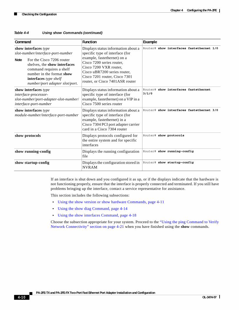
Chapter 4 Configuring the PA-2FE Checking the Configuration
If an interface is shut down and you configured it as up, or if the displays indicate that the hardware is not functioning properly, ensure that the interface is properly connected and terminated. If you still have problems bringing up the interface, contact a service representative for assistance.
This section includes the following subsections:
• Using the show version or show hardware Commands, page 4-11
• Using the show diag Command, page 4-14
• Using the show interfaces Command, page 4-18
Choose the subsection appropriate for your system. Proceed to the “Using the ping Command to Verify Network Connectivity” section on page 4-21 when you have finished using the show commands.
show interfaces type slot-number/interface-port-number
Note For the Cisco 7206 router shelves, the show interfaces command requires a shelf number in the format show interfaces type shelf number/port adapter slot/port.
Displays status information about a specific type of interface (for example, fastethernet) on a Cisco 7200 series router, Cisco 7200 VXR router, Cisco uBR7200 series router, Cisco 7201 router, Cisco 7301 router, or Cisco 7401ASR router
Router# show interfaces fastethernet 1/0
show interfaces type interface-processor-slot-number/port-adapter-slot-number/interface-port-number
Displays status information about a specific type of interface (for example, fastethernet) on a VIP in a Cisco 7500 series router
Router# show interfaces fastethernet 3/1/0
show interfaces type module-number/interface-port-number
Displays status information about a specific type of interface (for example, fastethernet) in a Cisco 7304 PCI port adapter carrier card in a Cisco 7304 router
Router# show interfaces fastethernet 3/0
show protocols Displays protocols configured for the entire system and for specific interfaces
Router# show protocols
show running-config Displays the running configuration file
Router# show running-config
show startup-config Displays the configuration stored in NVRAM
Router# show startup-config
Table 4-4 Using show Commands (continued)
Command Function Example
4-10PA-2FE-TX and PA-2FE-FX Two-Port Fast Ethernet Port Adapter Installation and Configuration
OL-3474-07
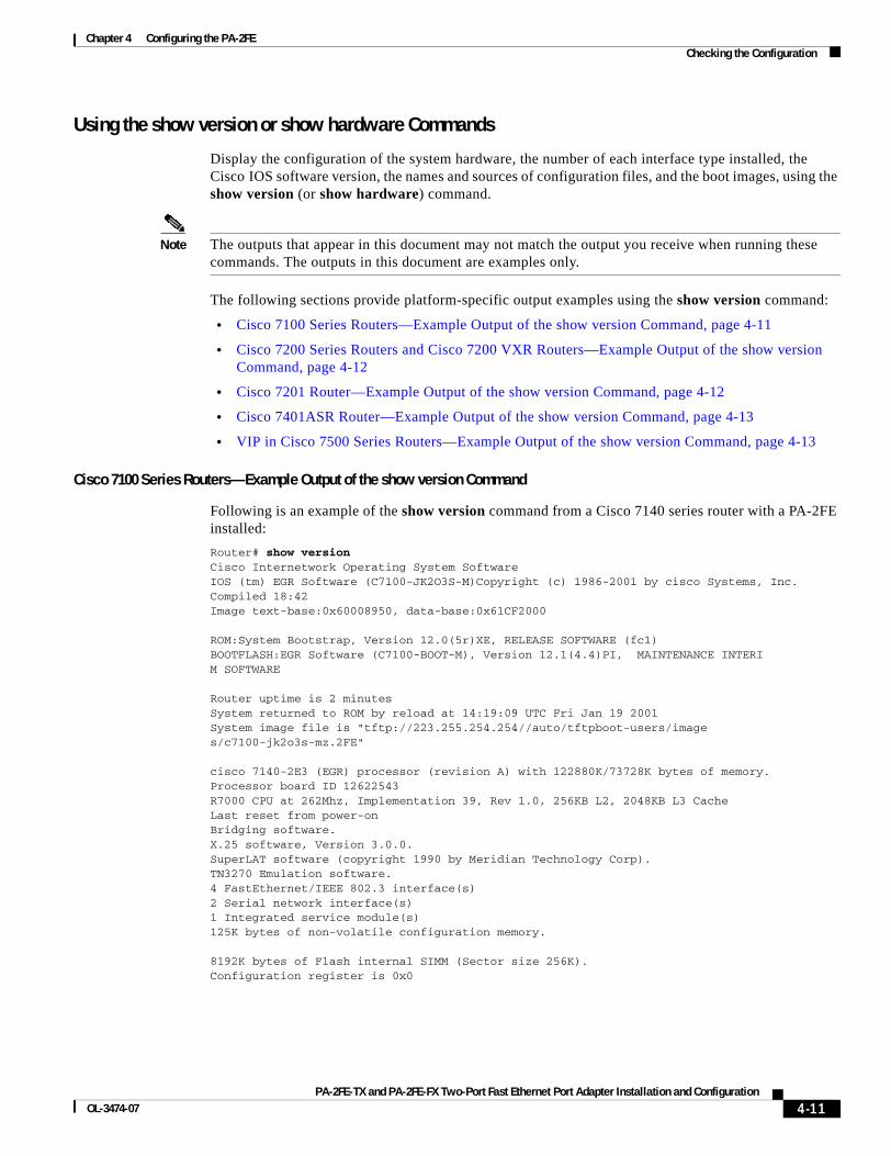
Chapter 4 Configuring the PA-2FE Checking the Configuration
Using the show version or show hardware Commands
Display the configuration of the system hardware, the number of each interface type installed, the Cisco IOS software version, the names and sources of configuration files, and the boot images, using the show version (or show hardware) command.
Note The outputs that appear in this document may not match the output you receive when running these commands. The outputs in this document are examples only.
The following sections provide platform-specific output examples using the show version command:
• Cisco 7100 Series Routers—Example Output of the show version Command, page 4-11
• Cisco 7200 Series Routers and Cisco 7200 VXR Routers—Example Output of the show version Command, page 4-12
• Cisco 7201 Router—Example Output of the show version Command, page 4-12
• Cisco 7401ASR Router—Example Output of the show version Command, page 4-13
• VIP in Cisco 7500 Series Routers—Example Output of the show version Command, page 4-13
Cisco 7100 Series Routers—Example Output of the show version Command
Following is an example of the show version command from a Cisco 7140 series router with a PA-2FE installed:
Router# show versionCisco Internetwork Operating System SoftwareIOS (tm) EGR Software (C7100-JK2O3S-M)Copyright (c) 1986-2001 by cisco Systems, Inc.Compiled 18:42Image text-base:0x60008950, data-base:0x61CF2000
ROM:System Bootstrap, Version 12.0(5r)XE, RELEASE SOFTWARE (fc1)BOOTFLASH:EGR Software (C7100-BOOT-M), Version 12.1(4.4)PI, MAINTENANCE INTERIM SOFTWARE
Router uptime is 2 minutesSystem returned to ROM by reload at 14:19:09 UTC Fri Jan 19 2001System image file is "tftp://223.255.254.254//auto/tftpboot-users/images/c7100-jk2o3s-mz.2FE"
cisco 7140-2E3 (EGR) processor (revision A) with 122880K/73728K bytes of memory.Processor board ID 12622543R7000 CPU at 262Mhz, Implementation 39, Rev 1.0, 256KB L2, 2048KB L3 CacheLast reset from power-onBridging software.X.25 software, Version 3.0.0.SuperLAT software (copyright 1990 by Meridian Technology Corp).TN3270 Emulation software.4 FastEthernet/IEEE 802.3 interface(s)2 Serial network interface(s)1 Integrated service module(s)125K bytes of non-volatile configuration memory.
8192K bytes of Flash internal SIMM (Sector size 256K).Configuration register is 0x0
4-11PA-2FE-TX and PA-2FE-FX Two-Port Fast Ethernet Port Adapter Installation and Configuration
OL-3474-07
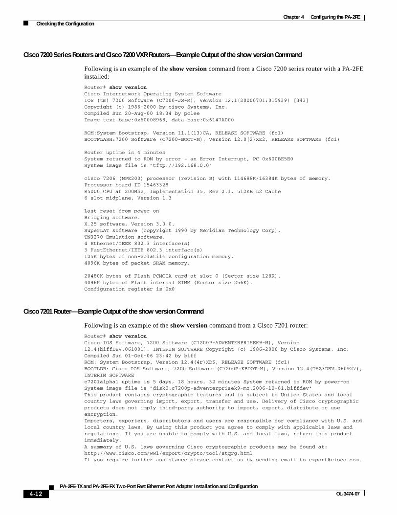
Chapter 4 Configuring the PA-2FE Checking the Configuration
Cisco 7200 Series Routers and Cisco 7200 VXR Routers—Example Output of the show version Command
Following is an example of the show version command from a Cisco 7200 series router with a PA-2FE installed:
Router# show versionCisco Internetwork Operating System Software IOS (tm) 7200 Software (C7200-JS-M), Version 12.1(20000701:015939) [343]Copyright (c) 1986-2000 by cisco Systems, Inc.Compiled Sun 20-Aug-00 18:34 by pcleeImage text-base:0x60008968, data-base:0x6147A000
ROM:System Bootstrap, Version 11.1(13)CA, RELEASE SOFTWARE (fc1)BOOTFLASH:7200 Software (C7200-BOOT-M), Version 12.0(2)XE2, RELEASE SOFTWARE (fc1)
Router uptime is 4 minutesSystem returned to ROM by error - an Error Interrupt, PC 0x600BE5E0System image file is "tftp://192.168.0.0"
cisco 7206 (NPE200) processor (revision B) with 114688K/16384K bytes of memory.Processor board ID 15463328R5000 CPU at 200Mhz, Implementation 35, Rev 2.1, 512KB L2 Cache6 slot midplane, Version 1.3
Last reset from power-onBridging software.X.25 software, Version 3.0.0.SuperLAT software (copyright 1990 by Meridian Technology Corp).TN3270 Emulation software.4 Ethernet/IEEE 802.3 interface(s)3 FastEthernet/IEEE 802.3 interface(s)125K bytes of non-volatile configuration memory.4096K bytes of packet SRAM memory.
20480K bytes of Flash PCMCIA card at slot 0 (Sector size 128K).4096K bytes of Flash internal SIMM (Sector size 256K).Configuration register is 0x0
Cisco 7201 Router—Example Output of the show version Command
Following is an example of the show version command from a Cisco 7201 router:
Router# show version Cisco IOS Software, 7200 Software (C7200P-ADVENTERPRISEK9-M), Version 12.4(biffDEV.061001), INTERIM SOFTWARE Copyright (c) 1986-2006 by Cisco Systems, Inc.Compiled Sun 01-Oct-06 23:42 by biffROM: System Bootstrap, Version 12.4(4r)XD5, RELEASE SOFTWARE (fc1)BOOTLDR: Cisco IOS Software, 7200 Software (C7200P-KBOOT-M), Version 12.4(TAZ3DEV.060927), INTERIM SOFTWAREc7201alpha1 uptime is 5 days, 18 hours, 32 minutes System returned to ROM by power-on System image file is "disk0:c7200p-adventerprisek9-mz.2006-10-01.biffdev"This product contains cryptographic features and is subject to United States and local country laws governing import, export, transfer and use. Delivery of Cisco cryptographic products does not imply third-party authority to import, export, distribute or use encryption.Importers, exporters, distributors and users are responsible for compliance with U.S. and local country laws. By using this product you agree to comply with applicable laws and regulations. If you are unable to comply with U.S. and local laws, return this product immediately.A summary of U.S. laws governing Cisco cryptographic products may be found at:http://www.cisco.com/wwl/export/crypto/tool/stqrg.htmlIf you require further assistance please contact us by sending email to [email protected].
4-12PA-2FE-TX and PA-2FE-FX Two-Port Fast Ethernet Port Adapter Installation and Configuration
OL-3474-07
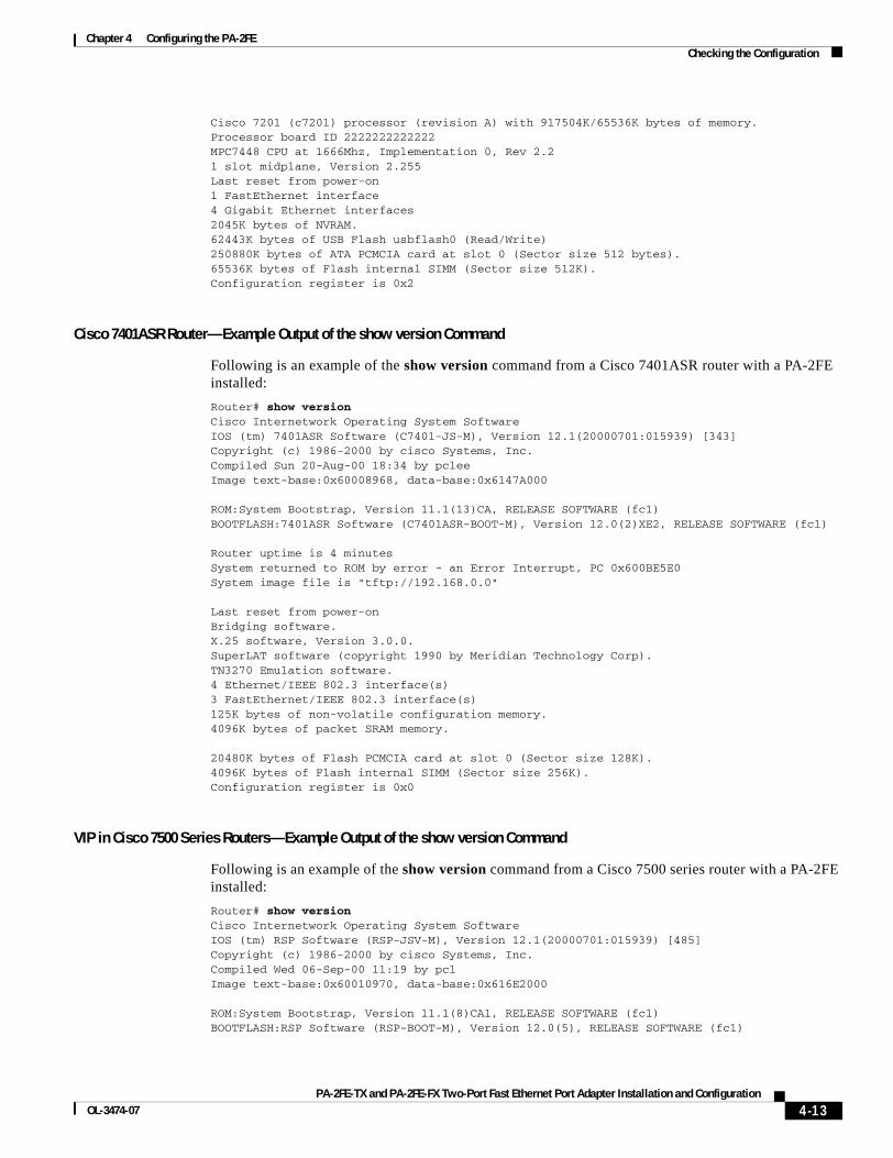
Chapter 4 Configuring the PA-2FE Checking the Configuration
Cisco 7201 (c7201) processor (revision A) with 917504K/65536K bytes of memory.Processor board ID 2222222222222MPC7448 CPU at 1666Mhz, Implementation 0, Rev 2.21 slot midplane, Version 2.255Last reset from power-on1 FastEthernet interface4 Gigabit Ethernet interfaces2045K bytes of NVRAM.62443K bytes of USB Flash usbflash0 (Read/Write)250880K bytes of ATA PCMCIA card at slot 0 (Sector size 512 bytes).65536K bytes of Flash internal SIMM (Sector size 512K).Configuration register is 0x2
Cisco 7401ASR Router—Example Output of the show version Command
Following is an example of the show version command from a Cisco 7401ASR router with a PA-2FE installed:
Router# show versionCisco Internetwork Operating System Software IOS (tm) 7401ASR Software (C7401-JS-M), Version 12.1(20000701:015939) [343]Copyright (c) 1986-2000 by cisco Systems, Inc.Compiled Sun 20-Aug-00 18:34 by pcleeImage text-base:0x60008968, data-base:0x6147A000
ROM:System Bootstrap, Version 11.1(13)CA, RELEASE SOFTWARE (fc1)BOOTFLASH:7401ASR Software (C7401ASR-BOOT-M), Version 12.0(2)XE2, RELEASE SOFTWARE (fc1)
Router uptime is 4 minutesSystem returned to ROM by error - an Error Interrupt, PC 0x600BE5E0System image file is "tftp://192.168.0.0"
Last reset from power-onBridging software.X.25 software, Version 3.0.0.SuperLAT software (copyright 1990 by Meridian Technology Corp).TN3270 Emulation software.4 Ethernet/IEEE 802.3 interface(s)3 FastEthernet/IEEE 802.3 interface(s)125K bytes of non-volatile configuration memory.4096K bytes of packet SRAM memory.
20480K bytes of Flash PCMCIA card at slot 0 (Sector size 128K).4096K bytes of Flash internal SIMM (Sector size 256K).Configuration register is 0x0
VIP in Cisco 7500 Series Routers—Example Output of the show version Command
Following is an example of the show version command from a Cisco 7500 series router with a PA-2FE installed:
Router# show versionCisco Internetwork Operating System Software IOS (tm) RSP Software (RSP-JSV-M), Version 12.1(20000701:015939) [485]Copyright (c) 1986-2000 by cisco Systems, Inc.Compiled Wed 06-Sep-00 11:19 by pclImage text-base:0x60010970, data-base:0x616E2000
ROM:System Bootstrap, Version 11.1(8)CA1, RELEASE SOFTWARE (fc1)BOOTFLASH:RSP Software (RSP-BOOT-M), Version 12.0(5), RELEASE SOFTWARE (fc1)
4-13PA-2FE-TX and PA-2FE-FX Two-Port Fast Ethernet Port Adapter Installation and Configuration
OL-3474-07
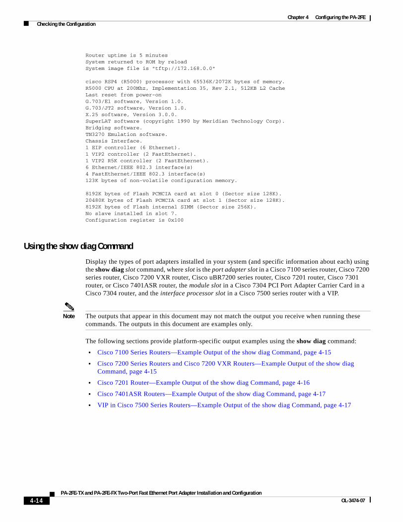
Chapter 4 Configuring the PA-2FE Checking the Configuration
Router uptime is 5 minutesSystem returned to ROM by reloadSystem image file is "tftp://172.168.0.0"
cisco RSP4 (R5000) processor with 65536K/2072K bytes of memory.R5000 CPU at 200Mhz, Implementation 35, Rev 2.1, 512KB L2 CacheLast reset from power-onG.703/E1 software, Version 1.0.G.703/JT2 software, Version 1.0.X.25 software, Version 3.0.0.SuperLAT software (copyright 1990 by Meridian Technology Corp).Bridging software.TN3270 Emulation software.Chassis Interface.1 EIP controller (6 Ethernet).1 VIP2 controller (2 FastEthernet). 1 VIP2 R5K controller (2 FastEthernet).6 Ethernet/IEEE 802.3 interface(s)4 FastEthernet/IEEE 802.3 interface(s)123K bytes of non-volatile configuration memory.
8192K bytes of Flash PCMCIA card at slot 0 (Sector size 128K).20480K bytes of Flash PCMCIA card at slot 1 (Sector size 128K).8192K bytes of Flash internal SIMM (Sector size 256K).No slave installed in slot 7.Configuration register is 0x100
Using the show diag Command
Display the types of port adapters installed in your system (and specific information about each) using the show diag slot command, where slot is the port adapter slot in a Cisco 7100 series router, Cisco 7200 series router, Cisco 7200 VXR router, Cisco uBR7200 series router, Cisco 7201 router, Cisco 7301 router, or Cisco 7401ASR router, the module slot in a Cisco 7304 PCI Port Adapter Carrier Card in a Cisco 7304 router, and the interface processor slot in a Cisco 7500 series router with a VIP.
Note The outputs that appear in this document may not match the output you receive when running these commands. The outputs in this document are examples only.
The following sections provide platform-specific output examples using the show diag command:
• Cisco 7100 Series Routers—Example Output of the show diag Command, page 4-15
• Cisco 7200 Series Routers and Cisco 7200 VXR Routers—Example Output of the show diag Command, page 4-15
• Cisco 7201 Router—Example Output of the show diag Command, page 4-16
• Cisco 7401ASR Routers—Example Output of the show diag Command, page 4-17
• VIP in Cisco 7500 Series Routers—Example Output of the show diag Command, page 4-17
4-14PA-2FE-TX and PA-2FE-FX Two-Port Fast Ethernet Port Adapter Installation and Configuration
OL-3474-07

Chapter 4 Configuring the PA-2FE Checking the Configuration
Cisco 7100 Series Routers—Example Output of the show diag Command
Following is an example of the show diag command from a Cisco 7140 series router:
Router# show diag 4Slot 4: Dual Port FastEthernet (MMF) Port adapter, 2 ports Port adapter is analyzed Port adapter insertion time 00:04:17 ago EEPROM contents at hardware discovery: Hardware Revision :1.0 PCB Serial Number :MIC05022Q6M Part Number :73-5420-04 Board Revision :A0 RMA Test History :00 RMA Number :0-0-0-0 RMA History :00 Deviation Number :0-0 Product Number :PA-2FE-FX Top Assy. Part Number :800-08352-04 EEPROM format version 4 EEPROM contents (hex): 0x00:04 FF 40 02 25 41 01 00 C1 8B 4D 49 43 30 35 30 0x10:32 32 51 36 4D 82 49 15 2C 04 42 41 30 03 00 81 0x20:00 00 00 00 04 00 80 00 00 00 00 CB 94 50 41 2D 0x30:32 46 45 2D 46 58 20 20 20 20 20 20 20 20 20 20 0x40:20 C0 46 03 20 00 20 A0 04 FF FF FF FF FF FF FF 0x50:FF FF FF FF FF FF FF FF FF FF FF FF FF FF FF FF0x60:FF FF FF FF FF FF FF FF FF FF FF FF FF FF FF FF0x70:FF FF FF FF FF FF FF FF FF FF FF FF FF FF FF FF
Cisco 7200 Series Routers and Cisco 7200 VXR Routers—Example Output of the show diag Command
Following is an example of the show diag command from a Cisco 7200 series router with a PA-2FE-FX istalled in port adapter slot 2:
Router# show diag 2Slot 2: Dual Port FastEthernet (RJ45) Port adapter, 2 ports Port adapter is analyzed Port adapter insertion time 00:02:20 ago EEPROM contents at hardware discovery: Hardware Revision :1.0 PCB Serial Number :MIC04291ZUY Part Number :73-5419-01 Number of Slots :1 EEPROM format version 4 EEPROM contents (hex): 0x00:04 FF 40 02 24 41 01 00 C1 8B 4D 49 43 30 34 32 0x10:39 31 5A 55 59 82 49 15 2B 01 01 01 01 01 01 01 0x20:01 01 01 01 01 01 01 01 01 01 01 01 01 01 01 01 0x30:01 01 01 01 01 01 01 01 01 01 01 01 01 01 01 01 0x40:01 01 01 01 01 01 01 01 01 01 01 01 01 01 01 01 0x50:01 01 01 01 01 01 01 01 01 01 01 01 01 01 01 01 0x60:01 01 01 01 01 01 01 01 01 01 01 01 01 01 FF FF 0x70:FF FF FF FF FF FF FF FF FF FF FF FF FF FF FF FF
4-15PA-2FE-TX and PA-2FE-FX Two-Port Fast Ethernet Port Adapter Installation and Configuration
OL-3474-07

Chapter 4 Configuring the PA-2FE Checking the Configuration
The following example shows information about the PA-2FE-FX installed in port adapter slot 3:
Router# show diag 3Slot 3: Dual Port FastEthernet (MMF) Port adapter, 2 ports Port adapter is analyzed Port adapter insertion time 00:00:06 ago EEPROM contents at hardware discovery: Hardware Revision :1.0 PCB Serial Number :MIC04291ZX4 Part Number :73-5419-01 EEPROM format version 4 EEPROM contents (hex): 0x00:04 FF 40 02 25 41 01 00 C1 8B 4D 49 43 30 34 32 0x10:39 31 5A 58 34 82 49 15 2B 01 FF FF FF FF FF FF 0x20:FF FF FF FF FF FF FF FF FF FF FF FF FF FF FF FF 0x30:FF FF FF FF FF FF FF FF FF FF FF FF FF FF FF FF 0x40:FF FF FF FF FF FF FF FF FF FF FF FF FF FF FF FF 0x50:FF FF FF FF FF FF FF FF FF FF FF FF FF FF FF FF 0x60:FF FF FF FF FF FF FF FF FF FF FF FF FF FF FF FF 0x70:FF FF FF FF FF FF FF FF FF FF FF FF FF FF FF FF
Note For complete command descriptions and examples for the Cisco 7200 series routers, refer to the publications listed in the “Related Documentation” section on page viii.
Cisco 7201 Router—Example Output of the show diag Command
Following is an example of the show diag command from a Cisco 7201 router:
Router# show diag 1Slot 1:
Dual OC3 POS Port adapter, 2 portsPort adapter is analyzed Port adapter insertion time 00:02:19 agoEEPROM contents at hardware discovery:Hardware Revision : 1.0PCB Serial Number : JAE07520DYLPart Number : 73-8220-02Board Revision : A0RMA Test History : 00RMA Number : 0-0-0-0RMA History : 00Deviation Number : 0Product (FRU) Number : PA-POS-2OC3Top Assy. Part Number : 800-21857-02EEPROM format version 4EEPROM contents (hex):
0x00: 04 FF 40 03 E3 41 01 00 C1 8B 4A 41 45 30 37 350x10: 32 30 44 59 4C 82 49 20 1C 02 42 41 30 03 00 810x20: 00 00 00 00 04 00 88 00 00 00 00 CB 94 50 41 2D0x30: 50 4F 53 2D 32 4F 43 33 20 20 20 20 20 20 20 200x40: 20 C0 46 03 20 00 55 61 02 FF FF FF FF FF FF FF0x50: FF FF FF FF FF FF FF FF FF FF FF FF FF FF FF FF0x60: FF FF FF FF FF FF FF FF FF FF FF FF FF FF FF FF0x70: FF FF FF FF FF FF FF FF FF FF FF FF FF FF FF FF
4-16PA-2FE-TX and PA-2FE-FX Two-Port Fast Ethernet Port Adapter Installation and Configuration
OL-3474-07

Chapter 4 Configuring the PA-2FE Checking the Configuration
Cisco 7401ASR Routers—Example Output of the show diag Command
Following is an example of the show diag command from a Cisco 7401ASR router:
Router# show diag 1Slot 1: Dual Port FastEthernet (RJ45) Port adapter, 2 ports Port adapter is analyzed Port adapter insertion time 00:02:20 ago EEPROM contents at hardware discovery: Hardware Revision :1.0 PCB Serial Number :MIC04291ZUY Part Number :73-5419-01 Number of Slots :1 EEPROM format version 4 EEPROM contents (hex): 0x00:04 FF 40 02 24 41 01 00 C1 8B 4D 49 43 30 34 32 0x10:39 31 5A 55 59 82 49 15 2B 01 01 01 01 01 01 01 0x20:01 01 01 01 01 01 01 01 01 01 01 01 01 01 01 01 0x30:01 01 01 01 01 01 01 01 01 01 01 01 01 01 01 01 0x40:01 01 01 01 01 01 01 01 01 01 01 01 01 01 01 01 0x50:01 01 01 01 01 01 01 01 01 01 01 01 01 01 01 01 0x60:01 01 01 01 01 01 01 01 01 01 01 01 01 01 FF FF 0x70:FF FF FF FF FF FF FF FF FF FF FF FF FF FF FF FF
VIP in Cisco 7500 Series Routers—Example Output of the show diag Command
Following is an example of the show diag command from a Cisco 7500 series router with a PA-2FE-TX installed in port adapter bay 0 and a PA-2FE-FX installed in port adapter bay 1 of a VIP2 installed in interface processor slot 3:
Router# show diag 3Slot 3: Physical slot 3, ~physical slot 0xC, logical slot 3, CBus 0 Microcode Status 0x4 Master Enable, LED, WCS Loaded Board is analyzed Pending I/O Status:None EEPROM format version 1 VIP2 R5K controller, HW rev 2.02, board revision C0 Serial number:13968891 Part number:73-2167-05 Test history:0x00 RMA number:00-00-00 Flags:cisco 7000 board; 7500 compatible
EEPROM contents (hex): 0x20:01 1E 02 02 00 D5 25 FB 49 08 77 05 00 00 00 00 0x30:60 00 00 01 00 00 00 00 00 00 00 00 00 00 00 00
Slot database information: Flags:0x4 Insertion time:0x2750 (00:06:45 ago)
Controller Memory Size:128 MBytes DRAM, 8192 KBytes SRAM
PA Bay 0 Information:
Dual Port Fast Ethernet (RJ45), 2 ports EEPROM format version 4 HW rev 1.00, Board revision UNKNOWN Serial number:MIC04291ZUY Part number:73-5419-01
PA Bay 1 Information:
4-17PA-2FE-TX and PA-2FE-FX Two-Port Fast Ethernet Port Adapter Installation and Configuration
OL-3474-07
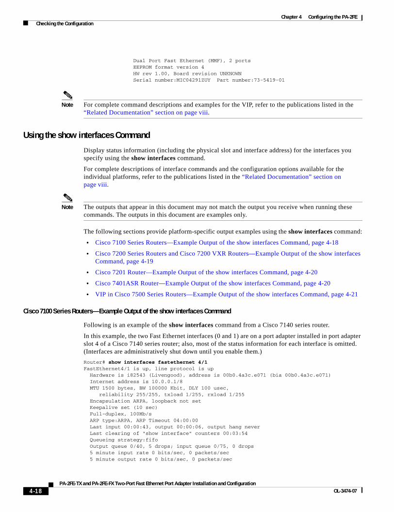
Chapter 4 Configuring the PA-2FE Checking the Configuration
Dual Port Fast Ethernet (MMF), 2 ports EEPROM format version 4 HW rev 1.00, Board revision UNKNOWN Serial number:MIC04291ZUY Part number:73-5419-01
Note For complete command descriptions and examples for the VIP, refer to the publications listed in the “Related Documentation” section on page viii.
Using the show interfaces Command
Display status information (including the physical slot and interface address) for the interfaces you specify using the show interfaces command.
For complete descriptions of interface commands and the configuration options available for the individual platforms, refer to the publications listed in the “Related Documentation” section on page viii.
Note The outputs that appear in this document may not match the output you receive when running these commands. The outputs in this document are examples only.
The following sections provide platform-specific output examples using the show interfaces command:
• Cisco 7100 Series Routers—Example Output of the show interfaces Command, page 4-18
• Cisco 7200 Series Routers and Cisco 7200 VXR Routers—Example Output of the show interfaces Command, page 4-19
• Cisco 7201 Router—Example Output of the show interfaces Command, page 4-20
• Cisco 7401ASR Router—Example Output of the show interfaces Command, page 4-20
• VIP in Cisco 7500 Series Routers—Example Output of the show interfaces Command, page 4-21
Cisco 7100 Series Routers—Example Output of the show interfaces Command
Following is an example of the show interfaces command from a Cisco 7140 series router.
In this example, the two Fast Ethernet interfaces (0 and 1) are on a port adapter installed in port adapter slot 4 of a Cisco 7140 series router; also, most of the status information for each interface is omitted. (Interfaces are administratively shut down until you enable them.)
Router# show interfaces fastethernet 4/1FastEthernet4/1 is up, line protocol is up Hardware is i82543 (Livengood), address is 00b0.4a3c.e071 (bia 00b0.4a3c.e071) Internet address is 10.0.0.1/8 MTU 1500 bytes, BW 100000 Kbit, DLY 100 usec, reliability 255/255, txload 1/255, rxload 1/255 Encapsulation ARPA, loopback not set Keepalive set (10 sec) Full-duplex, 100Mb/s ARP type:ARPA, ARP Timeout 04:00:00 Last input 00:00:43, output 00:00:06, output hang never Last clearing of "show interface" counters 00:03:54 Queueing strategy:fifo Output queue 0/40, 5 drops; input queue 0/75, 0 drops 5 minute input rate 0 bits/sec, 0 packets/sec 5 minute output rate 0 bits/sec, 0 packets/sec
4-18PA-2FE-TX and PA-2FE-FX Two-Port Fast Ethernet Port Adapter Installation and Configuration
OL-3474-07
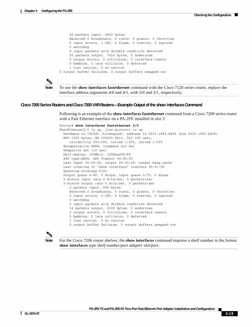
Chapter 4 Configuring the PA-2FE Checking the Configuration
26 packets input, 4922 bytes Received 0 broadcasts, 0 runts, 0 giants, 0 throttles 0 input errors, 1 CRC, 0 frame, 0 overrun, 0 ignored 0 watchdog 0 input packets with dribble condition detected 50 packets output, 7016 bytes, 0 underruns 0 output errors, 0 collisions, 0 interface resets 0 babbles, 0 late collision, 0 deferred 1 lost carrier, 0 no carrier0 output buffer failures, 0 output buffers swapped out
Note To use the show interfaces fastethernet command with the Cisco 7120 series router, replace the interface address arguments 4/0 and 4/1, with 3/0 and 3/1, respectively.
Cisco 7200 Series Routers and Cisco 7200 VXR Routers—Example Output of the show interfaces Command
Following is an example of the show interfaces fastethernet command from a Cisco 7200 series router with a Fast Ethernet interface on a PA-2FE installed in slot 2:
Router# show interfaces fastethernet 2/0FastEthernet2/0 is up, line protocol is up Hardware is i82543 (Livengood), address is 0030.1983.b438 (bia 0030.1983.b438) MTU 1500 bytes, BW 100000 Kbit, DLY 100 usec, reliability 255/255, txload 1/255, rxload 1/255 Encapsulation ARPA, loopback not set Keepalive set (10 sec) Half-duplex, 100Mb/s, 100BaseTX/FX ARP type:ARPA, ARP Timeout 04:00:00 Last input 00:00:06, output 00:00:09, output hang never Last clearing of "show interface" counters 00:01:29 Queueing strategy:fifo Output queue 0/40, 0 drops; input queue 0/75, 0 drops 5 minute input rate 0 bits/sec, 0 packets/sec 5 minute output rate 0 bits/sec, 0 packets/sec 2 packets input, 690 bytes Received 0 broadcasts, 0 runts, 0 giants, 0 throttles 0 input errors, 0 CRC, 0 frame, 0 overrun, 0 ignored 0 watchdog 0 input packets with dribble condition detected 14 packets output, 2220 bytes, 0 underruns 0 output errors, 0 collisions, 0 interface resets 0 babbles, 0 late collision, 0 deferred 1 lost carrier, 0 no carrier 0 output buffer failures, 0 output buffers swapped out
Note For the Cisco 7206 router shelves, the show interfaces command requires a shelf number in the format show interfaces type shelf number/port adapter slot/port.
4-19PA-2FE-TX and PA-2FE-FX Two-Port Fast Ethernet Port Adapter Installation and Configuration
OL-3474-07
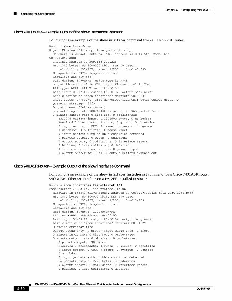
Chapter 4 Configuring the PA-2FE Checking the Configuration
Cisco 7201 Router—Example Output of the show interfaces Command
Following is an example of the show interfaces command from a Cisco 7201 router:
Router# show interfacesGigabitEthernet0/0 is up, line protocol is up Hardware is MV64460 Internal MAC, address is 0019.56c5.2adb (bia0019.56c5.2adb) Internet address is 209.165.200.225 MTU 1500 bytes, BW 1000000 Kbit, DLY 10 usec, reliability 255/255, txload 1/255, rxload 45/255 Encapsulation ARPA, loopback not set Keepalive set (10 sec) Full-duplex, 1000Mb/s, media type is RJ45 output flow-control is XON, input flow-control is XON ARP type: ARPA, ARP Timeout 04:00:00 Last input 00:07:03, output 00:00:07, output hang never Last clearing of "show interface" counters 00:00:04 Input queue: 0/75/0/0 (size/max/drops/flushes); Total output drops: 0 Queueing strategy: fifo Output queue: 0/40 (size/max) 5 minute input rate 180240000 bits/sec, 430965 packets/sec 5 minute output rate 0 bits/sec, 0 packets/sec 2222975 packets input, 133378500 bytes, 0 no buffer Received 0 broadcasts, 0 runts, 0 giants, 0 throttles 0 input errors, 0 CRC, 0 frame, 0 overrun, 0 ignored 0 watchdog, 0 multicast, 0 pause input 0 input packets with dribble condition detected 0 packets output, 0 bytes, 0 underruns 0 output errors, 0 collisions, 0 interface resets 0 babbles, 0 late collision, 0 deferred 0 lost carrier, 0 no carrier, 0 pause output 0 output buffer failures, 0 output buffers swapped out
Cisco 7401ASR Router—Example Output of the show interfaces Command
Following is an example of the show interfaces fastethernet command for a Cisco 7401ASR router with a Fast Ethernet interface on a PA-2FE installed in slot 1:
Router# show interfaces fastethernet 1/0FastEthernet1/0 is up, line protocol is up Hardware is i82543 (Livengood), address is 0030.1983.b438 (bia 0030.1983.b438) MTU 1500 bytes, BW 100000 Kbit, DLY 100 usec, reliability 255/255, txload 1/255, rxload 1/255 Encapsulation ARPA, loopback not set Keepalive set (10 sec) Half-duplex, 100Mb/s, 100BaseTX/FX ARP type:ARPA, ARP Timeout 04:00:00 Last input 00:00:06, output 00:00:09, output hang never Last clearing of "show interface" counters 00:01:29 Queueing strategy:fifo Output queue 0/40, 0 drops; input queue 0/75, 0 drops 5 minute input rate 0 bits/sec, 0 packets/sec 5 minute output rate 0 bits/sec, 0 packets/sec 2 packets input, 690 bytes Received 0 broadcasts, 0 runts, 0 giants, 0 throttles 0 input errors, 0 CRC, 0 frame, 0 overrun, 0 ignored 0 watchdog 0 input packets with dribble condition detected 14 packets output, 2220 bytes, 0 underruns 0 output errors, 0 collisions, 0 interface resets 0 babbles, 0 late collision, 0 deferred
4-20PA-2FE-TX and PA-2FE-FX Two-Port Fast Ethernet Port Adapter Installation and Configuration
OL-3474-07
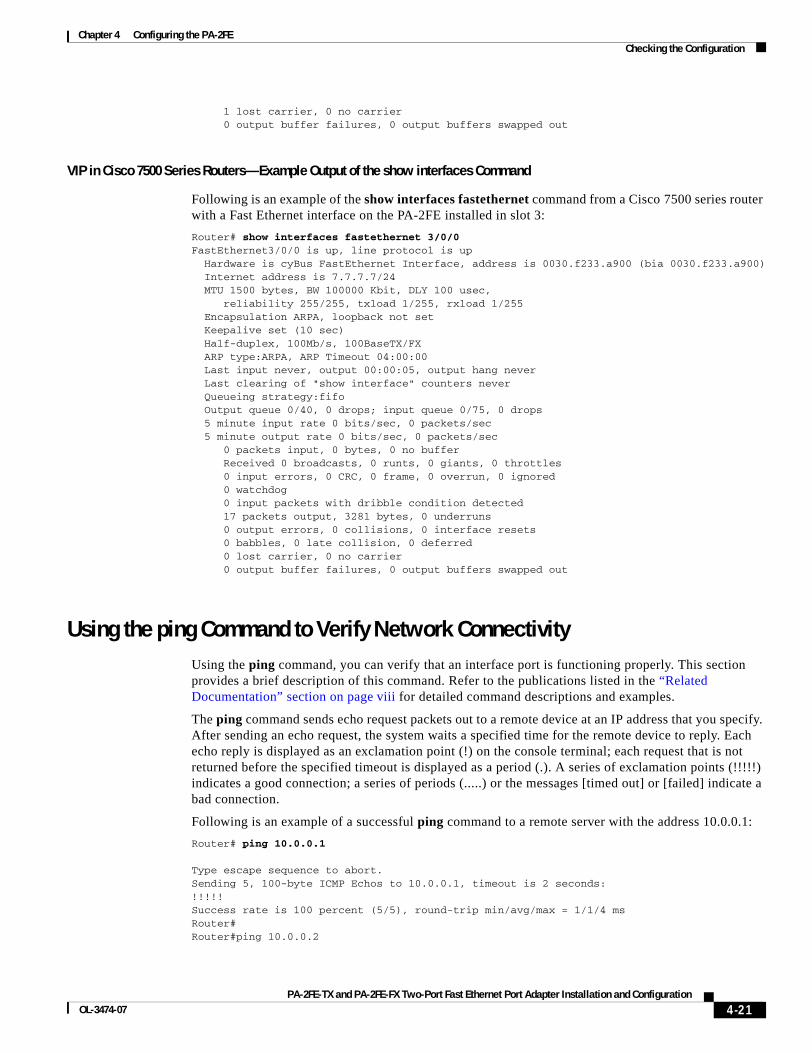
Chapter 4 Configuring the PA-2FE Checking the Configuration
1 lost carrier, 0 no carrier 0 output buffer failures, 0 output buffers swapped out
VIP in Cisco 7500 Series Routers—Example Output of the show interfaces Command
Following is an example of the show interfaces fastethernet command from a Cisco 7500 series router with a Fast Ethernet interface on the PA-2FE installed in slot 3:
Router# show interfaces fastethernet 3/0/0FastEthernet3/0/0 is up, line protocol is up Hardware is cyBus FastEthernet Interface, address is 0030.f233.a900 (bia 0030.f233.a900) Internet address is 7.7.7.7/24 MTU 1500 bytes, BW 100000 Kbit, DLY 100 usec, reliability 255/255, txload 1/255, rxload 1/255 Encapsulation ARPA, loopback not set Keepalive set (10 sec) Half-duplex, 100Mb/s, 100BaseTX/FX ARP type:ARPA, ARP Timeout 04:00:00 Last input never, output 00:00:05, output hang never Last clearing of "show interface" counters never Queueing strategy:fifo Output queue 0/40, 0 drops; input queue 0/75, 0 drops 5 minute input rate 0 bits/sec, 0 packets/sec 5 minute output rate 0 bits/sec, 0 packets/sec 0 packets input, 0 bytes, 0 no buffer Received 0 broadcasts, 0 runts, 0 giants, 0 throttles 0 input errors, 0 CRC, 0 frame, 0 overrun, 0 ignored 0 watchdog 0 input packets with dribble condition detected 17 packets output, 3281 bytes, 0 underruns 0 output errors, 0 collisions, 0 interface resets 0 babbles, 0 late collision, 0 deferred 0 lost carrier, 0 no carrier 0 output buffer failures, 0 output buffers swapped out
Using the ping Command to Verify Network ConnectivityUsing the ping command, you can verify that an interface port is functioning properly. This section provides a brief description of this command. Refer to the publications listed in the “Related Documentation” section on page viii for detailed command descriptions and examples.
The ping command sends echo request packets out to a remote device at an IP address that you specify. After sending an echo request, the system waits a specified time for the remote device to reply. Each echo reply is displayed as an exclamation point (!) on the console terminal; each request that is not returned before the specified timeout is displayed as a period (.). A series of exclamation points (!!!!!) indicates a good connection; a series of periods (.....) or the messages [timed out] or [failed] indicate a bad connection.
Following is an example of a successful ping command to a remote server with the address 10.0.0.1:
Router# ping 10.0.0.1
Type escape sequence to abort.Sending 5, 100-byte ICMP Echos to 10.0.0.1, timeout is 2 seconds:!!!!!Success rate is 100 percent (5/5), round-trip min/avg/max = 1/1/4 msRouter#Router#ping 10.0.0.2
4-21PA-2FE-TX and PA-2FE-FX Two-Port Fast Ethernet Port Adapter Installation and Configuration
OL-3474-07
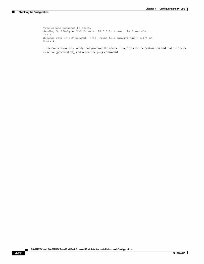
Chapter 4 Configuring the PA-2FE Checking the Configuration
Type escape sequence to abort.Sending 5, 100-byte ICMP Echos to 10.0.0.2, timeout is 2 seconds:!!!!!Success rate is 100 percent (5/5), round-trip min/avg/max = 1/1/4 msRouter#
If the connection fails, verify that you have the correct IP address for the destination and that the device is active (powered on), and repeat the ping command.
4-22PA-2FE-TX and PA-2FE-FX Two-Port Fast Ethernet Port Adapter Installation and Configuration
OL-3474-07