P037-029.pdf - PC & More
305
-
Upload
khangminh22 -
Category
Documents
-
view
1 -
download
0
Transcript of P037-029.pdf - PC & More


© Copyright Brother 1998All rights reserved.No part of this publication may be reproduced in any form or by any means without permission inwriting from the publisher.Specifications are subject to change without notice.
Trademarks:The brother logo is a registered trademark of Brother Industries, Ltd.
Apple, the Apple Logo, and Macintosh are trademarks, registered in the United States and othercountries, and True Type is a trademark of Apple computer, Inc.Epson is a registered trademark and FX-80 and FX-850 are trademarks of Seiko EpsonCorporation.Hewlett Packard is a registered trademark and HP Laser Jet is a trademark of Hewlett PackardCompany.IBM, IBM PC and Proprinter are registered trademarks of International Business MachinesCorporation.Microsoft and MS-DOS are registered trademarks of Microsoft Corporation.Windows is a registered trademark of Microsoft Corporation in the U.S. and other countries.

PREFACEThis service manual contains basic information required for after-sales service of the laser printer(here- in-after referred to as "this machine" or "the printer"). This information is vital to the servicetechnician to maintain the high printing quality and performance of the printers.
This service manual covers the HL-820, 1020, 1040 and 1050 laser printers. (Note that any figuresfor the printer body are based on the HL-1040 printer.)
This manual consists of the following chapters:
CHAPTER I : FEATURES AND SPECIFICATIONS
Features, specifications, etc.
CHAPTER II : THEORY OF OPERATION
Basic operation of the mechanical system, the electrical system and the electricalcircuits, and their timing information.
CHAPTER III : DISASSEMBLY AND REASSEMBLY
Procedures for disassembling and reassembling the mechanical system.
CHAPTER IV : MAINTENANCE AND TROUBLESHOOTING
Reference values and adjustments, troubleshooting image defects, troubleshootingmalfunctions, etc.
APPENDICES :SERIAL NO. DESCRIPTIONS, CONNECTION DIAGRAMS, PCB CIRCUITDIAGRAMS.
Information in this manual is subject to change due to improvement or re-design of the product. Allrelevant information in such cases will be supplied in service information bulletins (TechnicalInformation).
A thorough understanding of this printer, based on information in this service manual and serviceinformation bulletins, is required for maintaining its print quality performance and for improving thepractical ability to find the cause of problems.

i
CONTENTS
CHAPTER I FEATURES AND SPECIFICATIONS..........................................I-1
1. FEATURES.........................................................................................................................I-1
2. SPECIFICATIONS ..............................................................................................................I-3
2.1 Printing....................................................................................................................................... I-3
2.2 Functions ................................................................................................................................... I-3
2.3 Electrical and Mechanical .......................................................................................................... I-4
2.4 Paper Specification .................................................................................................................... I-5
2.5 Print Delivery.............................................................................................................................. I-5
2.6 Paper ......................................................................................................................................... I-6
2.7 Effective Printing Area ............................................................................................................... I-7
3. SAFETY INFORMATION ....................................................................................................I-9
3.1 Laser Safety (110 - 120V Model only) ....................................................................................... I-9
3.2 FDA Regulations (110 - 120V Model only) ................................................................................ I-9
3.3 Caution for Laser Product........................................................................................................ I-10
CHAPTER II THEORY OF OPERATION........................................................ II-1
1. ELECTRONICS..................................................................................................................II-1
1.1 General Block Diagram............................................................................................................. II-1
1.2 Main PCB Block Diagram ......................................................................................................... II-4
1.3 Main PCB.................................................................................................................................. II-7
1.3.1 CPU Core .................................................................................................................... II-7
1.3.2 ASIC ............................................................................................................................ II-9
1.3.3 ROM .......................................................................................................................... II-15
1.3.4 DRAM........................................................................................................................ II-16
1.3.5 Optional RAM ............................................................................................................ II-17
1.3.6 Optional Serial I/O ..................................................................................................... II-18
1.3.7 EEPROM................................................................................................................... II-18
1.3.8 Reset Circuit .............................................................................................................. II-19
1.3.9 CDCC I/O .................................................................................................................. II-19
1.3.10 Engine I/O.................................................................................................................. II-21
1.3.11 Paper Feed Motor Drive Circuit ................................................................................. II-23
1.4 Panel Sensor PCB.................................................................................................................. II-24
1.5 Power Supply.......................................................................................................................... II-24
1.5.1 Low-voltage Power Supply ........................................................................................ II-24
1.5.2 High-voltage Power Supply, SR PCB........................................................................ II-25
2. MECHANICS....................................................................................................................II-26
2.1 Overview of Printing Mechanism ............................................................................................ II-26
2.2 Paper Transfer........................................................................................................................ II-27
2.2.1 Paper Supply ............................................................................................................. II-27
2.2.2 Paper Registration..................................................................................................... II-27
2.2.3 Paper Eject ................................................................................................................ II-28

ii
2.3 Sensors................................................................................................................................... II-29
2.3.1 Cover Sensor............................................................................................................. II-29
2.3.2 Toner Empty Sensor.................................................................................................. II-29
2.4 Drum Unit................................................................................................................................ II-30
2.4.1 Photosensitive Drum ................................................................................................. II-30
2.4.2 Primary Charger ........................................................................................................ II-30
2.4.3 Developer Roller........................................................................................................ II-30
2.4.4 Transfer Roller........................................................................................................... II-30
2.4.5 Cleaner Roller............................................................................................................ II-30
2.4.6 Erase Lamp .............................................................................................................. II-30
2.5 Print Process .......................................................................................................................... II-30
2.5.1 Charging ................................................................................................................... II-30
2.5.2 Exposure Stage......................................................................................................... II-31
2.5.3 Developing................................................................................................................. II-32
2.5.4 Transfer ..................................................................................................................... II-32
2.5.5 Drum Cleaning Stage ................................................................................................ II-33
2.5.6 Erasing Stage ............................................................................................................ II-33
2.5.7 Fixing Stage............................................................................................................... II-33
CHAPTER III DISASSEMBLY AND REASSEMBLY.......................................III-1
1. SAFETY PRECAUTIONS..................................................................................................III-1
2. DISASSEMBLY FLOW......................................................................................................III-2
3. DISASSEMBLY PROCEDURE .........................................................................................III-3
3.1 Output Tray ASSY ................................................................................................................... III-3
3.2 Drum Unit................................................................................................................................. III-3
3.3 Top Cover ................................................................................................................................ III-4
3.4 Rear Cover .............................................................................................................................. III-4
3.5 MP Sheet Feeder ASSY .......................................................................................................... III-5
3.6 Fixing Unit ................................................................................................................................ III-6
3.7 Scanner Unit ............................................................................................................................ III-8
3.8 Main PCB ASSY .................................................................................................................... III-10
3.9 Base Plate ASSY................................................................................................................... III-10
3.10 Panel Sensor PCB ASSY ...................................................................................................... III-11
3.11 Low-voltage Power Supply PCB ASSY ................................................................................. III-12
3.12 High-voltage Power Supply PCB ASSY................................................................................. III-13
3.13 Sub Fan Motor ASSY ............................................................................................................ III-14
3.14 Fan Motor ASSY ................................................................................................................... III-14
3.15 Drive Unit ............................................................................................................................... III-15
3.16 Main Motor ASSY .................................................................................................................. III-16
3.17 Sub Motor ASSY.................................................................................................................... III-16
3.18 Paper Support........................................................................................................................ III-17
3.19 Extension Support Wire ......................................................................................................... III-17
4. PACKING........................................................................................................................III-18

iii
CHAPTER IV MAINTENANCE AND TROUBLESHOOTING.......................... IV-1
1. INTRODUCTION ..............................................................................................................IV-1
1.1 Initial Check........................................................................................................................ IV-1
1.2 Basic Procedure................................................................................................................. IV-2
2. CONSUMABLE PARTS....................................................................................................IV-3
2.1 Drum Unit........................................................................................................................... IV-3
2.2 Toner Cartridge .................................................................................................................. IV-3
2.3 Periodical Replacement Parts............................................................................................. IV-3
3. IMAGE DEFECTS ............................................................................................................IV-4
3.1 Image Defect Examples ..................................................................................................... IV-4
3.2 Troubleshooting Image Defects .......................................................................................... IV-5
3.3 Location of High-voltage Contacts and Grounding Contacts.............................................. IV-19
3.4 Location of Feed Roller Shaft and Grounding Contacts..................................................... IV-20
4. PAPER JAM ...................................................................................................................IV-21
5. TROUBLESHOOTING MALFUNCTIONS.......................................................................IV-22
6. INSPECTION MODE ......................................................................................................IV-27
6.1 Incorporated Inspection Modes......................................................................................... IV-27
6.2 Error Codes...................................................................................................................... IV-29
APPENDICES
1. Serial No. Descriptions ......................................................................................................A-1
2. Connection Diagram, HL-820/1020 ...................................................................................A-2
3. Connection Diagram, HL-1040 ..........................................................................................A-3
4. Connection Diagram, HL-1050 ..........................................................................................A-4
5. Main PCB Circuit Diagram, (HL-820/1020/1040), (1/2)......................................................A-5
6. Main PCB Circuit Diagram, (HL-820/1020/1040), (2/2)......................................................A-6
7. Main PCB Circuit Diagram, (HL-1050), (1/5)......................................................................A-7
8. Main PCB Circuit Diagram, (HL-1050), (2/5)......................................................................A-8
9. Main PCB Circuit Diagram, (HL-1050), (3/5)......................................................................A-9
10.Main PCB Circuit Diagram, (HL-1050), (4/5)....................................................................A-10
11.Main PCB Circuit Diagram, (HL-1050), (5/5)....................................................................A-11
12.Panel Sensor PCB Circuit Diagram .................................................................................A-12
13.Low-voltage Power Supply PCB Circuit Diagram, HL-820/1020/1040 (110 - 120V) ........A-13
14.Low-voltage Power Supply PCB Circuit Diagram, HL-820/1020/1040 (220 - 240V) ........A-14
15.Low-voltage Power Supply PCB Circuit Diagram, HL-1050 (110 - 120V) ........................A-15
16.Low-voltage Power Supply PCB Circuit Diagram, HL-1050 (220 - 240V) ........................A-16
17.High-voltage Power Supply PCB Circuit Diagram............................................................A-17
18.How to Know Drum Unit Life & Page Counter .................................................................A-18
19.Diameter / Circumference of Rollers ................................................................................A-20

I-1
CHAPTER I FEATURES AND SPECIFICATIONS
1. FEATURES
This printer has the following features:
High Resolution and Fast Printing Speed
<HL-820>True 600 dots per inch (dpi) with microfine toner and 8 pages per minute (ppm) printingspeed (A4 or Letter paper).
<HL-1040/1020>True 600 dots per inch (dpi) with microfine toner and 10 pages per minute (ppm) printingspeed (A4 or Letter paper).
<HL-1050>True 600 dots per inch (dpi) and 1200 x 600 dpi for graphics with microfine toner and 10pages per minute (ppm) printing speed (A4 or Letter paper).
Enhanced Printing Performance and User-Friendly Operation for Windows
The dedicated printer driver and TrueTypeTM-compatible fonts for Microsoft® Windows 3.1and Windows 95 are available on the floppy disk and CD-ROM supplied with your printer.You can easily install them into your Windows system using our installer program. Thedriver supports our unique compression mode to enhance printing speed in Windowsapplications and allows you to set various printer settings including toner saving mode,custom paper size, sleep mode, gray scale adjustment, resolution, and so forth. You caneasily setup these print options in the graphic dialog boxes through the Printer Setupmenu within the Windows Control Panel.
Printer Status Monitor with Bi-directional Parallel Interface
The printer driver can monitor your printer’s status using bi-directional parallelcommunications.
The printer status monitor program can show the current status of your printer. Whenprinting, an animated dialog box appears on your computer screen to show the currentprinting process. If an error occurs, a dialog box will appear to let you know what tocorrect. For example: when your printer is out of paper, the dialog box will display “NoPaper” and instructions for the corrective action to take.
Versatile Paper Handling
The printer has a multi-purpose sheet feeder and a straight paper path mechanism.Using this mechanism, you can load A4, letter, legal, B5, A5, A6, and executive sizes ofpaper, and various types of media including envelopes, organizer paper, or your custompaper size. The multi-purpose sheet feeder also allows manual paper loading, so youcan also use labels and transparencies.
Environment-Friendly
�Economy Printing Mode
This feature will cut your printing cost by saving toner. It is useful to obtain draft copiesfor proof-reading. You can select from two economy modes, 25% toner saving and 50%toner saving, through the Windows printer driver supplied with your printer.
�Sleep Mode (Power Save Mode)
Sleep mode automatically reduces power consumption when the printer is not in use.The printer consumes less than 13W when in sleep mode.

I-2
�Low Running Cost
The toner cartridge is separate from the drum unit. You need to replace only the tonercartridge after around 2,400 pages, which is cost effective and ecologically friendly.
The actual number of pages printed with each toner cartridge may vary depending onyour average type of print job.
Enhanced Memory Management
The printer provides its own data compression technology in its printer hardware and thesupplied printer driver software, which can automatically compress graphic data and fontdata efficiently into the printer's memory. You can avoid memory errors and print mostfull page 600dpi graphic and text data, including large fonts, with the standard printermemory.
Remote Printer Console Program for DOS (for HL-1040/1050 only)
The utility program, Remote Printer Console (RPC), is available on the floppy disk andCD-ROM supplied with your printer. When you operate your computer in the DOS (DiskOperating System) environment, this program allows you to easily change the defaultsettings of the printer such as fonts, page setup, emulations and so on.
This program also provides a status monitor program, which is a Terminate-and-StayResident (TSR) program. It can monitor the printer status while running in thebackground and report the current status or errors on your computer screen.
Popular Printer Emulation Support (for HL-1040/1050 only)
These printers support the following printer emulation modes;The HL-1040 supports HP LaserJet IIP, Epson FX-850, and IBM Proprinter XLThe HL-1050 supports HP LaserJet 6P/6L, Epson FX-850 and IBM Proprinter XL.
When you use DOS application software or Windows™ version 3.0 or earlier, you canuse any of these emulations to operate the printer in the 300 dpi resolution mode. Theprinters also support Auto-emulation switching between HP and Epson or HP and IBM. Ifyou want to set the printer emulation, you can do it using the Remote Printer ConsoleProgram.
USB Interface (for HL-1050 only)
The Universal Serial Bus Interface is an interface which allows the printer to connect tomultiple peripheral devices.
High Resolution Control & Advanced Photoscale Technology (for HL-1050 only)
High resolution control (HRC) technology provides clear and crisp printouts. Use thisfunction to get smooth text print quality.Advanced Photoscale Technology enables the printer to print graphics in 256 grayscales,producing nearly photographic quality. Use this function when you want to printphotographic images.
Optional Apple Macintosh® Interface (for HL-1040/1050 only)
An optional Apple Macintosh serial interface is available which allows your printer to beconnected to Apple Macintosh computers. With this option, you can use your printer withboth an IBM PC (or compatible) and an Apple Macintosh at the same time. This optionalinterface board can be used as an RS-422A interface for Macintosh or an RS-232C serialinterface for an IBM PC or compatible.

I-3
2. SPECIFICATIONS
2.1 Printing
Print method Electrophotography by semiconductor laser beam scanning
Laser: Wave length: 780nmOutput: 5mW max
Resolution HL-820/1020: 600 x 600dots/inch (for Windows)HL-1040: 600 x 600dots/inch (for Windows or DOS)
300 x 300dots/inch (under Apple Macintosh, DOS,or other operating system)
HL-1050: 1200(H) x 600(V)dots/inch (for Windows DIBgraphics)600 x 600dots/inch (for Windows or DOS)300 x 300dpi (under Apple Macintosh usingoptional RS-100M)
Print speed HL-820: Up to 8 pages/minuteHL-1020/1040/1050: Up to 10 pages/minute(when loading Letter-size paper from the multipurpose sheet feeder)
Warm-up Max. 30 seconds at 23°C (73.4°F)
First print 15 seconds(when loading Letter-size paper from the multipurpose sheet feeder)
Print media Toner cartridgeLife Expectancy: 2,400 pages/cartridge(when printing A4 or letter-size paper at 5% print coverage)
Developer Drum unit, separated from toner cartridgeLife Expectancy: 20,000 pages/drum unit at 20 pages per job
8,000 pages at 1 page per job
2.2 Functions
CPU HL-820/1020/1040: MC68EC000 16MhzHL-1050: MB86831 66Mhz
Emulation HL-820/1020: Brother Printing Solution for WindowsHL-1040: Brother Printing Solution for Windows
Automatic emulation selection among HP LaserJetIIP (PCL level 4), EPSON FX-850, and IBMProprinter XL
HL-1050: Brother Printing Solution for WindowsAutomatic emulation selection among HP LaserJet6P (PCL level 6), EPSON FX-850, and IBMProprinter XL
Printer driver WindowsTM 3.1/3.11, Windows 95 and Windows NT 4.0 driver,supporting Brother Native Compression mode and bi-directionalcapability.Optional Macintosh driver available for System 6.0.7 or higher (for HL-1040/1050 only)

I-4
Interface Bi-directional parallelUniversal Serial Bus (USB) (HL-1050 only)RS-422A/RS-232C serial (RS-100M) is optionally available. (HL-1040/1050 only)
Memory HL-820/1020/1040: 2.0 MbytesHL-1050: 4.0 Mbytes
Expandable up to 36 Mbytes by installing anindustry standard SIMM
Control panel 1 switch and 4 lamps
Diagnostics Self-diagnostic program
2.3 Electrical and Mechanical
Power source U.S.A. and Canada: AC 110 to 120V, 50Hz/60HzEurope and Australia: AC 220 to 240V, 50Hz/60Hz
Power consumption Printing (peak): 820W or lessPrinting (average): 280W or lessStanding by: 60W or lessSleep: 13W or less
Noise Printing: 49dB A or lessStanding by: 33dB A or less
Temperature Operating: 10 to 32.5°C (50 to 90.5°F)Storage: 0 to 40°C (38 to 104°F)
Humidity Operating: 20 to 80% (non condensing)Storage: 10 to 85% (non condensing)
Dimensions 390 x 365 x 245 mm (15.4 x 14.4 x 9.7 inches)(W x D x H) (when the output tray is closed.)
Weight Approx. 7.2kg (15.7lb.) including the drum unit and toner cartridge
Note:
x The peak figure of power consumption is worked out when the halogen heater lamp isturned ON.
x The peak figure of power consumption is worked out excluding inrush current value.x Be sure that the peak figure of power consumption is reference value and should be
used inside the Brother offices only.
PR99017

I-5
2.4 Paper Loading
(1) Multi-purpose sheet feeder loading
Paper size: A4, Letter, Legal, B5, A5, A6, and Executive. Other sizes of media thatcan be handled by the feed mechanism can be loaded.
69.8 to 229 mm
105 to 356mm (face down)
Feeding direction
Feedable paper weight: 60 (16lb.) to 158 (42lb.) g/m2
Maximum load height : 22mm (200 sheets of 80g/m2 paper) letter or A4 size
Setting method: Pull the MP sheet feeder cover toward you, insert thestack of paper into the feeder, aligning the top edge ofthe sheets, then push the cover back to its originalposition.
(2) Manual slot loading
Paper size: Same as in (1) for the multi-purpose sheet feeder.
Feedable paper weight: Same as in (1) for the multi-purpose sheet feeder.
Setting methods: Place the side of the paper to be printed on face downinto the manual feed slot after selecting orientation. Alignthe paper at the center of the manual feed slot, and besure to insert it fully into the feed slot. Move the paperguide of the manual feed slot to the paper width.
Cautions:� Before loading paper with holes such as organizer sheets, be sure to fan the stack
well.� When printing on the back of pre-printed paper, be sure to straighten the paper as
much as possible.
2.5 Print Delivery
(1) With the output tray openedTray capacity: Maximum 100 sheets (80g/m2), face-down only
(2) With the output tray closedTray capacity: 1 sheet (80g/m2), face-down only
Note:
� Face down: Deliver the printed face of the paper downward.� Environment : 23°C

I-6
2.6 Paper
(1) Paper type
(a) Normal paper (60 to 157g/m2, specified types of high-quality paper)
• A4 size• Letter size• Legal size• B5 (JIS ISO) size• A5 size• A6 size• Executive size
* The recommended types of plain paper are as follows:Letter : Xerox 4200 (75g/m2)A4 : Xerox 80 Premier Paper (80g/m2)
(b) Special paper (specified types)
• Labels• Envelopes (DL, C4, C5, COM10, Monarch)• Organizers (K, L, and J sizes of DAY-TIMERS)
(C) Other detailed specifications
Cut Sheet Envelope
Basis Weight 60 to 158 g/m2 (16 to 42 lb.)75 to 90 g/m2 (20 to 24 lb.)single thickness
Caliper�0.03 to �0.08 in.(0.08 to 0.2 mm)
0.0033 to 0.0058 in.(0.084 to 0.14 mm)single thickness
Moisture Content 4% to 6% by weight 4% to 6% by weight
Smoothness 100 to 250 (Sheffield) 100 to 250 (Sheffield)
Caution:� Although the printer can handle 9 inches (229mm) width paper such as the C4 size
envelope, you may get stains on the paper outside 8.5 inches width or on the back ofthe paper.
� It is recommended to use long-grained paper for the best print quality. If short-grainedpaper is being used, it might be the cause of paper jams.
� Use neutral paper. Do not use acid paper to avoid any damage to the printer drumunit.
(2) Paper feed conditions
Type Name Feeder Manual feed
60 to 80 g/m2 �(200 sheets)
�
Normal paper (cut sheet) 80 g/m2 paper (Legal) �(100 sheets)
�
158 g/m2 �(30 sheets)
�
Labels �(50 sheets)
�
Special paper (cut sheet) Envelopes �(10 sheets)
�
Organizers �(10 sheets)
�
PR98184

I-7
2.7 Effective Printing Area
Printable area
A
E C E
B D
F
F
The effective printing area means the area within which the printing of all the datareceived without any omissions can be guaranteed.

I-8
The table below shows the effective printing areas.
Size A B C D E F
A 4210.0mm8.27”(2,480 dots)
297.0mm11.69”(3,507 dots)
203.2mm8.0”(2,400 dots)
288.5mm11.36”(3,407 dots)
3.4mm0.13”(40 dots)
4.23mm0.17”(50 dots)
Letter215.9mm8.5”(2,550 dots)
279.4mm11.0”(3,300 dots)
203.2mm8.0”(2,400 dots)
270.9mm10.67”(3,200 dots)
6.35mm0.25”(75 dots)
�
Legal215.9mm8.5”(2,550 dots)
355.6mm14.0”(4,200 dots)
203.2mm8.0”(2,400 dots)
347.1mm13.67”(4,100 dots)
� �
B 5 (JIS)182.0mm7.16”(2,149 dots)
257.0mm10.12”(3,035 dots)
173.5mm6.83”(2,007 dots)
248.5mm9.78”(2,935 dots)
6.01mm0.24”(71 dots)
�
B 5 (ISO)176.0mm6.93”(2,078 dots)
250.0mm9.84”(2,952 dots)
164.0mm6.46”(1,936 dots)
241.5mm9.5”(2,852 dots)
� �
Executive184.15mm7.25”(2,175 dots)
266.7mm10.5”(3,150 dots)
175.7mm6.92”(2,025 dots)
258.2mm10.17”(3,050 dots)
6.35mm0.25”(75 dots)
�
A 5148.5mm5.85”(1,754 dots)
210.0mm8.27”(2,480 dots)
136.5mm5.37”(1,612 dots)
201.5mm7.93”(2,380 dots)
6.01mm0.24”(71 dots)
�
A6105.0mm4.13”(1,240 dots)
148.5mm5.85”(1,754 dots)
93.0mm3.66”(1,098 dots)
140.0mm5.51”(1,654 dots)
� �
Organizer(J size)
69.85mm2.75”(825 dots)
127.0mm5.0”(1,500 dots)
56.2mm2.21”(675 dots)
118.5mm4.66”(1,400 dots)
6.35mm0.25”(75 dots)
�
Organizer(K size)
95.25mm3.75”(1,125 dots)
171.45mm6.75”(2,025 dots)
86.78mm3.42”(975 dots)
162.98mm6.42”(1,925 dots)
� �
Organizer(L size)
139.7mm5.5”(1,650 dots)
215.9mm8.5”(2,550 dots)
131.23mm5.17”(1,500 dots)
207.43mm8.17”(2,450 dots)
� �
COM-10104.78mm4.125”(1,237 dots)
241.3mm9.5”(2,850 dots)
92.11mm3.63”(1,087 dots)
232.8mm9.16”(2,750 dots)
� �
MONARCH98.43mm3.875”(1,162 dots)
190.5mm7.5”(2,250 dots)
85.7mm3.37”(1,012 dots)
182.0mm7.16”(2,150 dots)
� �
C 4228.6mm9.0”(2,700 dots)
304.8mm12.0”(3,600 dots)
203.2mm8.0”(2,400 dots)
296.3mm11.66”(3,500 dots)
12.7mm0.5”(150 dots)
�
C 5162mm6.38”(1,913 dots)
229mm9.01”(2,704 dots)
150.0mm5.9”(1,771 dots)
220.5mm8.68”(2,604 dots)
6.01mm0.24”(71 dots)
�
DL110mm4.33”(1,299 dots)
220mm8.66”(2,598 dots)
98.0mm3.86”(1,157 dots)
211.5mm8.33”(2,498 dots)
� �
(Note that the paper sizes indicated here should conform to the nominal dimensionsspecified by JIS.)
� A4 paper must accommodate 80 characters printed in pica pitch (203.2 mm).� The dot size is based on 300 dpi resolution.� Organizer is not supported by any printer emulations (commands).
PR98184

I-9
3. SAFETY INFORMATION
3.1 Laser Safety (110 - 120V Model only)
This printer is certified as a Class 1 laser product under the US Department of Health andHuman Services (DHHS) Radiation Performance Standard according to the RadiationControl for Health and Safety Act of 1968. This means that the printer does not producehazardous laser radiation.
Since radiation emitted inside the printer is completely confined within the protectivehousings and external covers, the laser beam cannot escape from the machine duringany phase of user operation.
3.2 FDA Regulations (110 - 120V Model only)
The US Food and Drug Administration (FDA) has implemented regulations for laserproducts manufactured on and after August 2, 1976. Compliance is mandatory forproducts marketed in the United States. One of the following labels on the back of theprinter indicates compliance with the FDA regulations and must be attached to laserproducts marketed in the United States.
The label for Japanese manufactured products
MANUFACTURED: KBROTHER INDUSTRIES, LTD.
15-1, Naeshiro-cho, Mizuho-ku, Nagoya 467-8561, Japan.This product complies with FDA radiationperformance standards, 21 CFR Subchapter J.
The label for Chinese manufactured products
MANUFACTURED : CBROTHER Corporation (Asia) Ltd.Shenzen Buji Nan Ling FactoryGold Garden Ind., Nan Ling Village, Buji, Rong Gang,Shenzhen, CHINAThis product complies with FDA radiationperformance standards, 21 CFR Subchapter J.

I-10
3.3 Caution for Laser Product (Warnhinweis für Laserdrucker)
CAUTION: When the machine during servicing is operated with the cover open, theregulations of VBG 93 and the performance instructions for VBG 93 arevalid.
CAUTION: In case of any trouble with the laser unit, replace the laser unit itself. Toprevent direct exposure to the laser beam, do not try to open the enclosureof the laser unit.
ACHTUNG: Im Falle von Störungen der Lasereinheit muß diese ersetzt werden. DasGehäuse der Lasereinheit darf nicht geöffnet werden, da sonstLaserstrahlen austreten können.
(1) Location of the laser beam window.
Fig. 1-1
(2) Location of Caution Label for Laser Product. (200V only)
CLASS 1LASER PRODUCTAPPAREIL Å LASER DE CLASSE 1LASER KLASSE 1 PRODUKT
Fig. 1-2
Window

II-1
CHAPTER II THEORY OF OPERATION
1. ELECTRONICS
1.1 General Block Diagram
Fig. 2-1 shows a general block diagram of the HL-820/1020 printer.
Video control blockInterface block
Engine control blockOperation block
(Operation panel)
Control system
Low
-vol
tage
pow
er s
uppl
y bl
ock
Hig
h-vo
ltage
pow
er s
uppl
y bl
ock
Laser scanner unitDrive block
(Stepping motor)
Drum unitTransfer block
Developing block
Drum
Charging block
Cleaner block
Ext
erna
l dev
ice
Paper tray unit
Paper tray
Manual feed
Fixing unit
Paper eject block
Paper feed system
Image generation system
Toner cartridge
Erase lamp
Fig. 2-1
HL-820/1020

II-2
Fig. 2-2 shows a general block diagram of the HL-1040 printer.
Optional I/F board (Mac. RS-232C)
Expansion I/O
Video control blockInterface block
Engine control blockOperation block
(Operation panel)
Control system
Low
-vol
tage
pow
er s
uppl
y bl
ock
Hig
h-vo
ltage
pow
er s
uppl
y bl
ock
Laser scanner unitDrive block
(Stepping motor)
Drum unitTransfer block
Developing block
Drum
Charging block
Cleaner block
Ext
erna
l dev
ice
Ext
erna
l dev
ice
Paper tray unit
Paper tray
Manual feed
Fixing unit
Paper eject block
Paper feed system
Image generation system
Toner cartridge
Erase lamp
Fig. 2-2
HL-1040

II-3
Fig. 2-3 shows a general block diagram of the HL-1050 printer.
Optional RAM (SIMM) (max. 32Mbytes)
Optional I/F board (Mac. RS-232C)
Expansion memory I/O Expansion I/O
Video control blockInterface block
Engine control blockOperation block
(Operation panel)
Control system
Low
-vol
tage
pow
er s
uppl
y bl
ock
Hig
h-vo
ltage
pow
er s
uppl
y bl
ock
Laser scanner unitDrive block
(Stepping motor)
Drum unitTransfer block
Developing block
Drum
Charging block
Cleaner block
Ext
erna
l dev
ice
Ext
erna
l dev
ice
Paper tray unit
Paper tray
Manual feed
Fixing unit
Paper eject block
Paper feed system
Image generation system
Toner cartridge
Erase lamp
Fig. 2-3
HL-1050

II-4
1.2 Main PCB Block Diagram
Fig. 2-4 shows the block diagram of the main PCB.
Reset Circuit
Program + Font ROM
512 Kbytes
RAM
(2.0 Mbytes)
EEPROM (128 8 bits)
CPU Core
(MC68EC000)
A S I C
Oscillator (15.3MHz)
Address Decoder
DRAM Control
Timer
FIFO
DATA EXTENSION
CDCC Parallel I/O
Soft Support
EEPROM I/O
Engine Control I/OMotor Driver
To Panel Sensor PCB
BUS INT
To PC
Fig. 2-4
HL-820/1020

II-5
Fig. 2-5 shows the block diagram of the main PCB.
Reset Circuit
Program + Font ROM
512 Kbytes
RAM
(2.0 Mbytes)
Option Serial I/O
(RS232C & RS422A)
EEPROM (128 8 bits)
CPU Core
(MC68EC000)
A S I C
Oscillator (15.3MHz)
Address Decoder
DRAM Control
Timer
FIFO
DATA EXTENSION
CDCC Parallel I/O
Soft Support
EEPROM I/O
Engine Control I/OMotor Driver
To Panel Sensor PCB
BUS INT
To PC
Fig. 2-5
HL-1040

II-6
Fig. 2-6 shows the block diagram of the main PCB.
Reset Circuit
Program + Font ROM
4.0 Mbytes
RAM
(4.0 Mbytes)
Option RAM (SIMM)
(max. 32Mbytes)
Option Serial I/O
(RS232C & RS422A)
EEPROM (512 x 8 bits)
CPU Core
(MB86831)
A S I C
Oscillator (33.3MHz)
Address Decoder
DRAM Control
Timer
FIFO
CDCC Parallel I/O
Soft Support
EEPROM I/O
Engine Control I/OMotor Driver
To Panel Sensor PCB
BUS INT
To PCUSB I/O
To PC
Fig. 2-6
HL-1050

II-7
1.3 Main PCB
1.3.1 CPU Core
Fig. 2-7 shows the CPU circuit block on the main PCB.
The CPU is a Motorola MC68EC000FN16 which is driven with a clock frequency of15.3MHz. This clock frequency is made by dividing the source clock of 30.67 MHz intotwo.
Fig. 2-7
HL-820/1020/1040

II-8
Fig. 2-8 shows the CPU circuit block on the main PCB.
The CPU is a Motorola MB86831 which is driven with a clock frequency of 33MHz. TheCPU itself runs at 66MHz.
Fig. 2-8
HL-1050

II-9
1.3.2 ASIC
The ASIC is composed of a Cell Based IC that contains the following functional blocks.
(1) Oscillator circuit
Generates the main clock for the CPU by dividing the source clock frequency intotwo.
(2) Address decoder
Generates the CS for each device.
(3) DRAM control
Generates the RAS, CAS, WE, OE and MA signals for the DRAM and controlsrefresh processing (CAS before RAS self-refreshing method).
(4) Interrupt control
Interrupt levels:
Priority High 7 NMI
6 FIFO
5 EXINT(Option Serial I/O)
4 BD / Timer 1
3 SCANINT
2 CDCC / BOISE / DATA EXTENSION
Low 1 Timer 2
(5) Timers
The following timers are incorporated:
Timer 1 16-bit timer
Timer 2 10-bit timer
Timer 3 Watch-dog timer
(6) FIFO
A 5,120-bit FIFO is incorporated. Data for one raster scan is transferred from theRAM to the FIFO by DMA transmission and is output as serial video data. Thedata cycle is 10.22 MHz.
(7) CDCC parallel I/O
<Data receiving>
There are two modes in this unit. One is the CPU receiving mode and the other isthe DMA receiving mode. In the CPU receiving mode the CPU receives thecommand data from the PC, and after the CPU is switched to the DMA mode, itreceives the image data and writes to the DRAM directly.
HL-820/1020/1040

II-10
90 µsec
STROBE
BUSY
ACK
STROBE
BUSY
ACK
0.5 µsec
0.5 µsec1.5 µsec
CPU Receive Mode
DMA Receive Mode
BUSY goes HIGH at the falling edge of STROBE. The data (8 bits) from the PC islatched in the data buffer at the rising edge of STROBE. The pulse width of ACKdiffers according to the speed MODE as shown above. BUSY goes LOW at therising edge of ACK.
<IEEE1284 support>
This supports the IEEE1284 data transfer with the following modes.
Nibble modeByte mode
(8) Data expansion
This circuit expands the compressed image data received from the PC, and writesthe bit map data to the FIFO.
(9) Software support
Supports 16 x 16 rotation, bit expansion, and bit search.
(10) EEPROM I/O
One output port and one I/O port are assigned.

II-11
(11) Engine control I/O
This I/O is used for the connection to the panel sensor PCB. It controls the mainmotor, solenoid, sensors, etc.
Fig. 2-9

II-12
The ASIC is composed of a Cell Based IC that contains the following functional blocks.
(1) Oscillator circuit
Generates the main clock for the CPU.
(2) Address decoder
Generates the CS for each device.
(3) DRAM control
Generates the RAS, CAS, WE, OE and MA signals for the DRAM and controlsrefresh processing (CAS before RAS self-refreshing method).
(4) Interrupt control
Interrupt levels:
Priority High 10 Reserve interrupt 1 (for debug)9 Watch Dog Timer8 LSB EMPTY (for VDO FIFO)7 Timer 16 USB5 XIO interrupt (RS-100M) or MIO interrupt4 BD (for engine check)3 Reserve interrupt 22 CDCC
Low 1 Timer 2
Note:
� All the interrupts can be masked.
� The priority of levels 7, 6, and 5 are changeable from the program.
(5) Timers
The following timers are incorporated:
Timer 1 32-bit timer
Timer 2 32-bit timer
Timer 3 Watch-dog timer
(6) FIFO
A 10Kbit FIFO is included. Data for one raster scan is transferred from the RAM tothe FIFO by DMA transmission and is output as serial video data. The data cycle is10.43MHz.
(7) Parallel I/O
<Data receive Mode>
There are two modes in this unit. One is the CPU receive mode and the other isthe DMA receive mode. In the CPU receive mode the CPU receives the commanddata from the PC, and after the CPU is switched to the DMA mode, it receives theimage data and writes it to the DRAM directly.
HL-1050

II-13
90 µsec
STROBE
BUSY
ACK
STROBE
BUSY
ACK
0.5 µsec
0.5 µsec1.5 µsec
CPU Receive Mode
DMA Receive Mode
BUSY goes HIGH at the falling edge of the STROBE signal. The data (8 bits) fromthe PC is latched into the data buffer at the rising edge of the STROBE signal. Thepulse width of ACK varies according to the speed MODE as shown above. BUSYgoes LOW on the rising edge of ACK.
<IEEE1284 support>
This supports the IEEE1284 data transfer with the following mode.
Nibble modeByte modeECP mode
(8) Data expansion
This circuit expands the compressed image data received from the PC, and writesthe bit map data to the FIFO.
(9) Software support
Supports 16 x 16 rotation, bit expansion, bit search, and decimal point conversion.
(10) EEPROM I/O
One output port and one I/O port are assigned.

II-14
(11) Engine control I/O
This I/O is used for the connection to the panel sensor PCB. It controls the mainmotor, solenoid, sensors, etc.
Fig. 2-10

II-15
1.3.3 ROM
A program file of 512 Kbytes and the font data are stored in the ROM. A 42-pin IC socketis provided: a 16 Mbits ROM (42-pin) is mounted into this socket normally, but a 4 MbitsROM (40-pin) can be mounted by leaving the 1st and 42nd pins of the socket opencircuit.
Fig. 2-11
A program file of 4.0 Mbytes and the font data are stored in the ROM. Two 42-pin ICsockets are provided: two 16 Mbits ROMs (42-pin) can be mounted into these sockets.
Fig. 2-12
HL-1050
HL-820/1020/1040

II-16
1.3.4 DRAM
A 16M-bit DRAM (x 16bits) is used as the RAM.
Fig. 2-13
Two 16M-bit DRAMs (x 16bits) are used as the RAM.
Fig. 2-14
HL-1050
HL-820/1020/1040

II-17
1.3.5 Optional RAM
A 32bit (72 pin) SIMM can be fitted as optional RAM. The main PCB has one slot and thecapacity of SIMM can be from 1 Mbyte to 32 Mbytes.
Fig. 2-15
HL-1050

II-18
1.3.6 Optional Serial I/O
The interrupt of the serial I/O is input to the EXINT terminal of the ASIC, and isrecognized by the CPU. A 32-byte register is provided for this I/O, which is readand written to by the CPU.
Fig. 2-16
1.3.7 EEPROM
The EEPROM is an XL24C01AF type of two-wire method with a 128 x 8 bitsconfiguration.
M62320FP is an IC which transfers the data received from the serial I/O to the parallelI/O.
Fig. 2-17
The EEPROM is XL24C04AF type of two-wire method with a 512 x 8 bits configuration.
Fig. 2-18
HL-1040/1050
HL-1050
HL-820/1020/1040

II-19
1.3.8 Reset Circuit
The reset IC is a PST598DNR. The reset voltage is 4.2V (typ.) and the LOW period ofreset is 200ms (typ).
Fig. 2-19
The reset IC is a PST596DNR. The reset voltage is 4.2V (typ.) and the LOW period ofreset is 50ms (typ).
Fig. 2-20
1.3.9 CDCC I/O
Fig. 2-21 shows the CDCC interface circuit.
Fig. 2-21
HL-1050
HL-820/1020/1040
HL-820/1020/1040

II-20
Fig. 2-22 shows the CDCC interface circuit.
Fig. 2-22
HL-1050

II-21
1.3.10 Engine I/O
Fig. 2-23 shows the engine interface circuit.
Fig. 2-23
HL-820/1020/1040

II-22
Fig. 2-24 shows the engine interface circuit.
Fig. 2-24
HL-1050

II-23
1.3.11 Paper Feed Motor Drive Circuit
The motor driver is a TR array. The excitation method is 2-2 phase excitation with abipolar drive.
Fig. 2-25
The motor driver is a TR array. The excitation method is 2-2 phase excitation with abipolar drive.
Fig. 2-26
HL-1050
HL-820/1020/1040

II-24
1.4 Panel Sensor PCB
The following parts are on the panel sensor.
• Control Panel ...........1 Switch, 4 lamps• Connector ................Low-voltage, high-voltage, solenoid, main motor, toner sensor,
laser, polygon motor, connector for main PCB• Registration sensor
1.5 Power Supply
1.5.1 Low-voltage Power Supply
The power supply uses a switching regulation system to generate the regulated DCpower (+5V and +24V), which are converted from the AC line.
The regulated output and the production code of each power supply vary depending onthe printer model as listed below;
Model Regulated Output Production Code
HL-820/1020/1040 +5V / 0.6 A+24V / 2.0 A
100V: MPW1547200V: MPW1447
HL-1050 +5V / 1.2A+24V / 2.0A
100V: MPW1550200V: MPW1450
Heater
Circuit
ThermalFuseLightning
Surge
Absorber
Feedback
Line
Filter
Fuse
Rectifier Oscillator
24V
Regulation
Circuit
5V
Regulation
Circuit
24V
5V
Lamp
(Heater)
(Panel Sensor Circuit)
Fig. 2-27

II-25
1.5.2 High-voltage Power Supply
This generates and outputs the voltages and currents for the charging, development andtransfer functions.
Transfer Roller
SupplyRoller
PhotosensitiveDrum
DevelopingRoller
CleanerRoller
CoronaUnit
CurrentRegulator
CurrentRegulator
VoltageRegulator
VoltageRegulator
B1
B81 Q81
B101 Q101
VoltageRegulator
Z51 VR51
VoltageRegulator
VR71
VoltageRegulator
VR61
VR22
PC141
PAPERSENSOR
24VI
GND
R1
CurrentRegulator
B121 Q121
Fig. 2-28

II-26
2. MECHANICS
2.1 Overview of Printing Mechanism
Fig. 2-29
Main Motor
Scanner Unit
Main Fan Motor
Solenoid
Main Cotrol PCBPanel Sensor PCB
High-VoltagePowerSupply
Primary Charger (Corona Wire)Primary Charger (Grid)Developer RollerTransfer RollerCleaner Roller
Registration Sensor
TonerEmptySensorPCB
Toner Empty Sensor
Thermistor (for Toner)
Sub Motor
EL PCB
Sub Fan Motor
Thermistor (for Heat roller)
Supply RollerEject Sensor
Fig. 2-30
PapersMulti-purpose Sheet Feeder
Manual Paper Path
MP Feeder Cover
Paper Pick-up Roller
Paper FeedRoller
Pinch Roller
Drum Unit
Blade
Photosensitive Drum
TransferRoller Erase Lamp
Fixing Unit
Pressure Roller
Eject Roller
HopperPlate
Registration Sensor Lever
Toner Cartridge
Polygon Mirror
Laser Scanner
Toner EmptySensor
Supply Roller Scanner Unit
Corona Wire
DevelopmentRoller Cleaning Roller
Eject SensorActuator
Heat Roller
Thermistor

II-27
2.2 Paper Transfer
2.2.1 Paper Supply
The pick-up roller picks up one sheet of paper from the paper feeder every time it isrotated and feeds it to the paper feed roller.
Fig. 2-31
The paper is gripped between the pick-up roller and the separation pad and separatedinto individual sheets.
The pick-up roller is directly connected to the sector gear, whose rotation is forciblystopped by the gear stopper. When the pick-up solenoid is activated, the clutchmechanism is engaged by the solenoid action and the sector gear is driven; when it hascompleted one full turn its rotation is stopped again by the gear stopper. The paperdrawn out by the pick-up roller pushes against the top of form sensor lever and the papertop position/absence of paper is detected by sensing the motion of the lever.
2.2.2 Paper Registration
When paper picked up from the multi-purpose sheet feeder (MPF) pushes against the topof form sensor actuator, the registration sensor lever is caused to turn, and the photosensor detects this motion. When this signal from the sensor is detected the paper feedroller is stopped temporarily by the clutch. The paper is fed to the nip point between thepaper feed roller and the pinch roller in the multi-purpose sheet feeder, and the skew ofthe paper is corrected by pushing the leading edge of the paper against the nip point.When the paper feed roller starts to be rotated again when it is released by the clutch,paper with the leading edge correctly aligned, is fed by the paper feed roller and istransported to the transfer roller.
Clutch mechanism (engaged/released by the solenoid assembly)Released when the solenoid is ON and engaged when the solenoid is OFF.
Fig. 2-32
Hopper plate
p Pick-up roller
Registration sensor lever
Separation pad
Paper Pinch roller
Transfer roller
Drum
Paper feed roller

II-28
2.2.3 Paper Eject
The completion of paper eject is detected in the following manner:
(a) When the leading edge of the paper pushes down the eject sensor actuatorlocated in the fixing unit, the photo sensor (photo interrupter) is opened anddetects the start of paper eject.
(b) When the trailing edge of the paper has passed through the paper eject sensoractuator, the photo sensor is closed and the completion of paper eject isrecognized.
Fig. 2-33
� �
�
�
�
�
�
�
� �
Fig. 2-34
Transfer roller
Pressure roller
Drum
Eject sensor actuator
Eject roller
Heat roller
Eject sensor actuator
High-voltage powersupply PCB
Sensor
Eject sensor actuator
Sensor
Paper

II-29
2.3 Sensors
2.3.1 Cover Sensor
Detects opening and closing of the top cover.
Fig. 2-35
2.3.2 Toner Empty Sensor
Detects if there is toner in the toner cartridge. It also detects whether or not the drum unitis installed. (The toner cartridge is installed in the drum unit).
Fig. 2-36
Toner EmptySensor
Cover Switch
Top Cover

II-30
2.4 Drum Unit
2.4.1 Photosensitive Drum
Generates the latent electrostatic image and develops the image on the drum surface.
2.4.2 Primary Charger
Forms a uniform charge on the drum surface.
(1) Corona wireGenerates the ion charge on the drum.
(2) Grid
Spreads the ion charge evenly over the drum surface.
2.4.3 Development Roller
Develops the latent electrostatic image on the drum surface by the addition of the toner.
2.4.4 Transfer Roller
Transfers the toner image to the paper from the drum surface.
2.4.5 Cleaner Roller
Removes and recycles the toner remaining on the drum surface.
2.4.6 Erase Lamp
Discharges the electrostatic latent image on the drum.
2.5 Print Process
2.5.1 Charging
The drum is charged to approx. +1150V by an ion charge which is generated by theprimary charger. The charge is generated by ionization of the corona wire, which has aDC bias from the high-voltage power supply applied to it. The flow of the ion charge iscontrolled by the grid to ensure it is distributed evenly on the drum surface. The drumsleeve is regulated to approx. 280V by the voltage regulator.
+++
++ + + + +
++
+++
+++
+ + ++
------- - - - -
Fig. 2-37
The primary charge uses a corona wire, but since the drum is positively charged, onlyless than 1/10 of the usual quantity of ozone is generated compared with the negativelycharged drum. The level of ozone expelled from the printer is therefore not harmful to thehuman body. Applicable safety standards have been complied with.
Passive TypeVoltage Regulator
Grid
VoltageRegulator
Corona wire
HVPS
1150V
280V
Aluminum drum sleeve
Organic Photoconductor layerDrum

II-31
2.5.2 Exposure Stage
After the drum is positively charged, it is exposed to the light emitted from the laser unit.
Fig. 2-38
The area exposed to the laser beam is the image to be printed. The surface potential ofthe exposed area is reduced, forming the electrostatic image to be printed.
1 Cycle of drum
Sur
face
Pot
entia
l (V
)
+1150
+700
+400+300
1 2 3 4
(a)
(b)
Time
1
2
3
4
Primary charging
Laser beam exposure and developing(a) Unexposed area ( Non image area )(b) Exposed area ( Image area )
Transfer the image to paper
Erase the residual potential
DrumSleeve
Fig. 2-39
Drum
Paper
Laser beam
f � lens
Polygon mirror
Motor
Lens
Laser diode
Laser detector
Laser Beam

II-32
2.5.3 Developing
Developing causes the toner to be attracted to the electrostatic image on the drum so asto transform it into a visible image.
The developer consists of a non-magnetic toner. The development roller is made ofconductive rubber and the supply roller (which is also made of conductive sponge) rotateagainst each other. The toner is charged and carried from the supply roller to thedevelopment roller. The toner adheres to the development roller and is conveyed to thedrum at an even thickness controlled by the blade. The toner is nipped between thedevelopment roller and the drum and developed onto the latent image on the drum. Theelectrostatic field between the drum and the development roller, which is DC-biased fromthe high-voltage power supply, creates the electrostatic potential to attract toner particlesfrom the development roller to the latent image area on the drum surface.
Fig. 2-40
2.5.4 Transfer(a) Transfer process
After the drum has been charged and exposed, and has received a developedimage, the toner formed is transferred onto the paper by applying a negativecharge to the back of the paper. The negative charge applied to the paper causesthe positively charged toner to leave the drum, and adhere to the paper. As aresult, the image is visible on the paper.
(b) Cleaning process of transfer roller
If the toner is not transferred onto the paper perfectly, it is possible that there maybe residual toner on the drum which will adhere to the transfer roller. The transfervoltage changes to a positive voltage during non-printing rotation of the drum.Therefore the transfer roller is cleaned by returning the positively charged toneradhering to the transfer roller onto the photo-conductive drum.
(a) Transfer process [ON]
(b) Cleaning process [ON]
Drum
Erase lamp
(a) Collecting process
(b) Discharging processCleaning rollerDevelopment
rollerDC-bias
SR-bias
Supply roller
Develop housing
Auger
Separator
BladeTransfer roller
Toner

II-33
2.5.5 Drum Cleaning Stage
In the image transfer stage, not all the toner on the photosensitive drum is transferredonto the paper but some remains on the drum. In the drum cleaning stage, the drumsurface is cleaned by the cleaning roller, so that residual toner on the drum surface isremoved and collected on the cleaning roller itself. The residual toner on the cleaningroller will be discharged to the drum during starting or non-printing time. The toner will becollected by the developing roller and reused (for further developing).
2.5.6 Erasing Stage
Before the cleaning stage, the drum surface is exposed to the light emitted from theerase lamp (LED lamp). This stage prepares the drum by decreasing its surface voltageuniformly, ready to receive a uniform charge in the primary charging stage.
2.5.7 Fixing Stage
The image transferred to the paper by static electricity is fixed by heat and pressure whenpassing through the heat roller and the pressure roller in the fixing unit. The thermistorASSY keeps the surface temperature of the heat roller constant by detecting the surfacetemperature of the heat roller and turning on or off the halogen heater lamp.
�
�
��
��
�
�
�
�
�
�
�
�
��
�
�
�
�
�
�
�
�
�
�
�
�
��
�
�
�
�
�
�
�
�
��
�
�
�
�
�
�
�
�
�
�
�
�
�
�
�
�
�
�
�
�
�
�
�
�
�
�
�
�
�
�
�
�
�
�
�
�
�
�
�
�
�
�
�
�
�
�
�
�
�
�
�
�
�
�
�
�
�
�
�
�
�
�
�
�
�
�
�
�
�
�
�
�
�
�
�
�
�
�
�
�
�
�
�
�
�
�
�
�
�
�
�
�
�
�
�
�
�
�
�
�
�
�
�
�
�
�
�
�
�
�
�
�
�
�
�
�
�
�
�
�
�
�
�
�
�
�
�
�
�
�
�
�
�
�
� �
�
�
�
�
� �
�
�
�
�
�
�
�
�
� �
�
�
�
�
� ��
�
�
�
�
�
�
�
�
�
�
�
�
�
�
�
�
�
���
�
�
�
�
Fig. 2-41
Pressure roller
Thermistor ASSY
Halogen heater lamp
Heat roller
Cleaner ASSY

III-1
CHAPTER III DISASSEMBLY AND REASSEMBLY
1. SAFETY PRECAUTIONS
To avoid creating secondary problems by mishandling, be careful to follow the followingprecautions during maintenance work.
(1) Always turn off the power switch and unplug the power cord from the power outletbefore accessing any parts inside the printer.
(2) Be careful not to lose screws, washers, or other parts removed.
(3) Be sure to apply grease to the gears and applicable positions specified in thischapter.
(4) When using soldering irons or other heat-generating tools, take care not toaccidentally damage parts such as wires, PCBs, and covers.
(5) Before handling any PCBs, touch a metal portion of the equipment to dischargeany static electricity charge on your body, or the electronic parts or componentsmay be damaged.
(6) When transporting PCBs, be sure to wrap them in the correct protective packaging.
(7) Be sure to replace self-tapping screws correctly, if removed. Unless otherwisespecified, tighten screws to the following torque values.
TAPTITE, BIND or CUP BM3 : 7kgf • cmM4 : 10kgf • cm
TAPTITE, CUP SM3 : 8kgf • cm
SCREWM3 : 7kgf • cmM4 : 8kgf • cm
(8) When connecting or disconnecting cable connectors, hold the connector body, notthe cables. If the connector has a lock, release the connector lock first to releaseit.
(9) After a repair, check not only the repaired portion but also all connectors. Alsocheck that other related portions are functioning properly before operationalchecks.

III-2
2. DISASSEMBLY FLOW
DR
UM
UN
IT
MP
SH
EE
T F
EE
DE
R A
SS
Y
TO
P C
OV
ER
FIX
ING
UN
IT
SC
AN
NE
R U
NIT
PA
PE
R S
UP
PO
RT
EX
TE
NS
ION
SU
PP
OR
T W
IRE
A
1 3 6
OU
TP
UT
TR
AY
AS
SY
2 54
18
7
19RE
AR
CO
VE
R
MA
IN P
CB
AS
SY
BA
SE
PLA
TE
AS
SY
PA
NE
L S
EN
SO
R P
CB
AS
SY
LOW
-VO
LTA
GE
PS
PC
B A
SS
Y
B
A
DR
IVE
UN
IT
MA
IN M
OT
OR
AS
SY
15 16 17
8 9 1011
13
MA
IN F
AN
MO
TO
R1412
BOTT
OM
HIG
H-V
OLT
AG
E P
S P
CB
AS
SY
SU
B M
OT
OR
AS
SY
SU
B F
AN
MO
TO
R A
SS
Y
B

III-3
3. DISASSEMBLY PROCEDURE
3.1 Output Tray ASSY
(1) Open the output tray toward you.
(2) Press the hinges at the left and right sides of the output tray inwards to release theoutput tray from the main cover.
Fig. 3.1
3.2 Drum Unit
(1) Open the top cover.
(2) Lift out the drum unit.
Fig. 3.2
Drum Unit
Top Cover
Main Cover
Main Cover
Output Tray
Output Tray

III-4
3.3 Top Cover
(1) Open the top cover.
(2) Press the hinges at the left and right sides of the top cover inwards to release thetop cover from the main cover.
Note:It is recommended for easy removal to press the side of the top cover ( ➀ ) while pullingthe side of the main cover ( ➁ ).
1
2
Fig. 3-3
3.4 Rear Cover
(1) Remove the two M4x12 tapping screws.
(2) Remove the rear cover.
Fig. 3-4
Note:When re-assembling the rear cover, hook the two hooks at the right and left hand side(rear), then secure the two screws.
Main Cover
Top Cover
Top Cover
Main Cover
Main Cover
Rear Cover
Taptite, bind M4x12
Multi-purpose Sheet Feeder
Taptite, bind M4x12

III-5
3.5 MP Sheet Feeder ASSY
Caution:When disassembling the MP sheet feeder ASSY, if you get the grease on your fingers,take care not to touch the separation pad or the paper pick-up roller, the grease spread tothe paper and the drum unit. It might cause black spots to appear on the printed page.
(1) Push the left rib outwards and pull out the MP sheet feeder. It is not necessary torelease the right rib.
��
�
�
Fig. 3-5Note:When re-assembling, apply a suitable amount of grease (2 rice-grain size) between theheat sink of the motor and the ground leaf spring in case of grease shortage. (Refer tothe figure below.)
Fig. 3-6
Multi-purposeSheet Feeder
Rib
Ground leaf spring
Grease: FLOIL GE-676(or FLOIL GE-334C)
Motor heat sink
6.2MM

III-6
3.6 Fixing Unit
(1) Remove the two M4x16 tapping screws.
(2) Lifting the fixing unit, disconnect the thermistor connector on the EL PCB first, thenthe two heater harnesses.
Fig. 3-7
Note:The eject sensor actuator may also be removed when removing the fixing unit. In thiscase be sure to re-assemble the eject sensor actuator when re-assembling the fixing unit.
(3) Remove the two M3x12 tapping screws.
(4) Open the fixing unit cover along the open side of the fixing unit cover.
Fig. 3-8
Taptite, bind M3x12
Fixing unit cover
ShaftFixing unit
v r
Pressure roller
Fixing unit frame
Fixing UnitTaptite, cup M4x16
Thermistor connector
Heater harness (Brown)
Thermistor harness
EL PCB
Taptite, cup M4x16
Heater harness(Blue)

III-7
(5) Release the right side of the paper eject roller shaft.
(6) Remove the four eject pinch rollers and the pinch springs from the fixing unitframe. Then, remove the pinch spring from each pinch roller.
Fig. 3-8a
(7) Remove the M3x10 self tapping screw securing the connector plate.
(8) Remove the connector plate from the fixing unit frame and loosen the other M3x10tapping screw securing the fixing unit cover.
(9) Remove the idle gear 16 from the fixing unit frame to remove the heat roller. Then,remove the halogen heater lamp from the heat roller.
Caution :Never touch the surface of the halogen heater lamp and the heat roller.
Fig. 3-9
Note:� When re-assembling the bearing at the both ends of the heat roller, ensure that the
direction of the bearing is correct referring to the above figure.� The heat roller itself is very similar to the one for HL-1060/1070 printers. The heat
roller for the HL-820/1020/1040/1050 printers can be distinguished by the groove onthe edge of the roller. (Refer to the above figure.)
Halogen heater lamp(Blue 100V, Red 200V)
Heat roller
Taptite, pan M3x10
Connector plateFixing unit frame
Idle gear 16
Taptite, panM3x10
Heat roller gear
Heat Roller Bearing
Heat Roller Washer
Retaining ring
Groove
Heat Roller Bearing
PR98292
Paper eject roller shaft
Pinch Spring
Eject Pinch Roller

III-8
� When replacing the heat roller cleaner with a new one, attach the cleaner referring tothe figure below;
Fig. 3-10
� Follow the instructions below when installing the thermistor in the fixing unit.i) Place the cleaner felt of the cleaner ASSY for the thermistor under the heat roller.ii) Place the end of the thermistor on the heat roller.iii) Insert boss1 of the thermistor into the hole of the fixing unit frame.iv) Do no place the thermistor on boss2 of the fixing unit frame.
��
���
��
���
����
�����
����
��
�������
Fig. 3-11
3.7 Scanner Unit
(1) Remove the three M4x12 tapping screws.
(2) Lift out the scanner unit.
Fig. 3-12
Thermistor
Taptite, bind M4x12
Heat Roller
Fixing unit frame
Scanner Unit
Boss2
Main cover
Boss1
Panel Sensor PCB
Cleaner ASSY for thermistor
Taptite, bind M4x12
-1mm ~ +1mm
4mm ~ 5mm

III-9
Note:When replacing the scanner unit, ensure to assemble the ferrite core using the cablebinder as follows;
Fig. 3-13
(3) Disconnect the three connectors from the panel sensor PCB.
(4) Remove the M3x8 tapping screw, and lift the toner sensor PCB from the scannerunit.
Caution:Never touch the inside of the scanner unit or the mirror when disassembling orreassembling. If there is any dirt or dust on the mirror, blow it off.
Fig. 3-14
Toner Sensor PCB
Scanner Unit
Taptite, cup M3x8
Ferrite Core
Flat cable
Cable binder
LD harness

III-10
3.8 Main PCB ASSY
(1) Remove the three M4x6 screws.
(2) Hold the hooks at the left and right of the mounting frame to pull out the main PCBASSY.
Fig. 3-15
3.9 Base Plate ASSY
Caution:Prior to turning the printer upside-down, ensure that the drum unit has been removedfrom the printer.
(1) Turn the printer upside down.
(2) Remove the eight M4 and five M3 self tapping screws.
Fig. 3-16
Screw, pan M4x6
Hook
Hook
Main PCB ASSY
Taptite, bind M4x12
Taptite, cup M3x6Taptite, bind M4x12
Taptite, bind M4x12
Taptite, bind M4x12
Screw, pan M4x6
Base plate ASSY
Taptite, cup M3x6

III-11
(3) Lift the base plate ASSY and remove the grounding screw.
Fig. 3-17
3.10 Panel Sensor PCB ASSY
(1) Remove the main shield.
(2) Remove the M4x12 screw securing the panel sensor PCB ASSY.
Fig. 3-18
Note:� When re-assembling the main shield, ensure that you fit PCB A to underneath the
main shield.� When re-assembling the panel sensor PCB, ensure that you fit the PCB into hook B
and hook C first. Then, fit the two bosses to the PCB and secure the screw.
Base Plate ASSY
Taptite, bind M4x12
Ground wire
Panel Sensor PCB ASSY
Screw pan(washer),M3.5x6
Main shield
Low-voltage PowerSupply PCB ASSY
Panel Sensor PCB ASSY
A
B
C
Main shield

III-12
(3) Disconnect the eight connectors from the PCB. (Three connectors have alreadybeen disconnected when removing the scanner unit.)
1
23
4 56
7
8
9
10
(Name of the Harnesses)1. Low-voltage harness2. Erase lamp harness3. Toner harness4. Scan motor flat cable5. Laser harness6. Solenoid harness7. Main / sub motor connector8. Fan motor 1 harness9. Fan motor 2 harness10. High-voltage flat cable
Fig. 3-19
Note:� When re-assembling, the cable connectors must be inserted securely into the PCB
connectors and the PCB must not be stressed by the harnesses.� The connectors should be inserted by matching the housing color and the number of
pins.
3.11 Low-voltage Power Supply PCB ASSY
(1) Remove the one M4x12 tapping screw securing the low-voltage power supply PCBASSY.
(2) Disconnect the two connectors for the heater harness and the LV harness from thePCB.
Fig. 3-20
Panel SensorPCB ASSY
Main frame
LV harness
Low-voltage Power Supply ASSY
H r h rn

III-13
(3) Remove the one M4x12 screw to remove the inlet holder. Then, remove the inletand the PCB.
Note:When re-assembling the inlet holder and AC inlet, be sure to insert the part A of theholder into the hole of the ferrite core.
Fig. 3-21
3.12 High-voltage Power Supply PCB ASSY
(1) Remove the one M4x12 screw securing the high-voltage power supply PCB ASSY.
(2) Remove the film covering the PCB.
(2) Disconnect the HV flat cable from the PCB.
Fig. 3-22
Taptite, bindM4x12
Main Cover
HV flat cable
High-voltage PowerSupply PCB ASSY
Inlet Holder
AC Inlet
Main Cover
Insulation Sheet
Ferrite Core
A
III-14
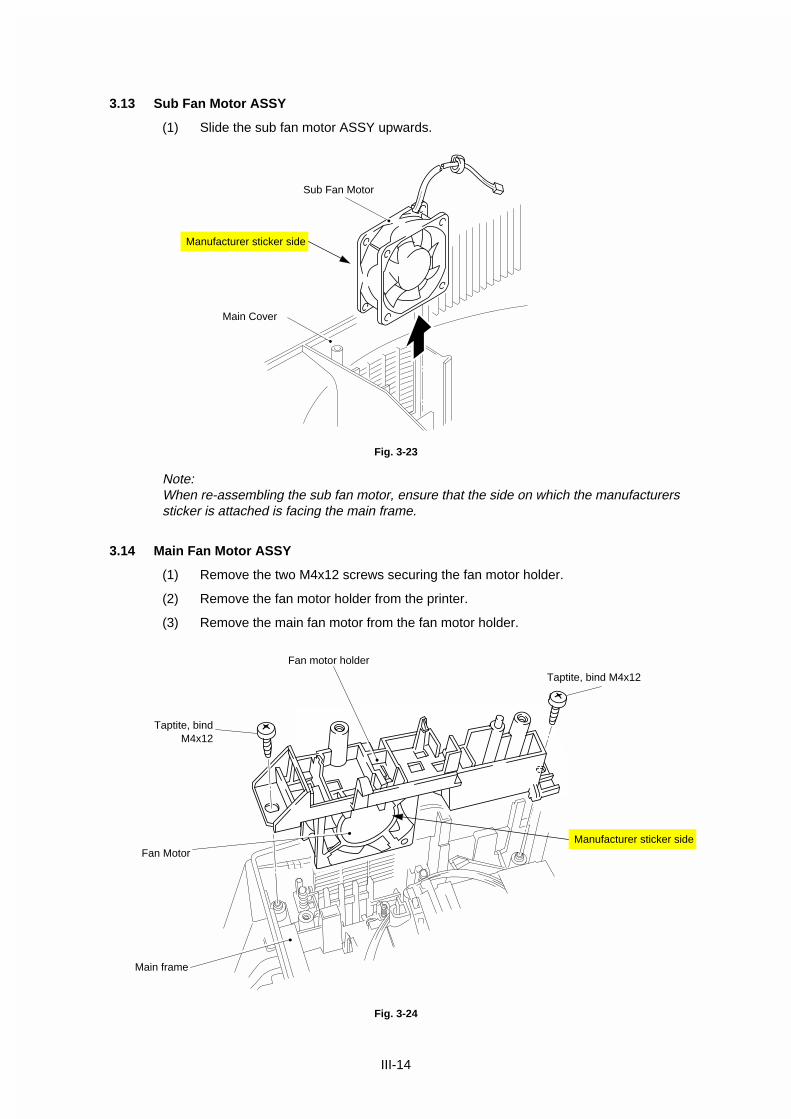
3.13 Sub Fan Motor ASSY
(1) Slide the sub fan motor ASSY upwards.
Fig. 3-23
Note:When re-assembling the sub fan motor, ensure that the side on which the manufacturerssticker is attached is facing the main frame.
3.14 Main Fan Motor ASSY
(1) Remove the two M4x12 screws securing the fan motor holder.
(2) Remove the fan motor holder from the printer.
(3) Remove the main fan motor from the fan motor holder.
Fig. 3-24
Fan motor holder
Fan Motor
Taptite, bind M4x12
Sub Fan Motor
Main Cover
Manufacturer sticker side
Taptite, bindM4x12
Main frame
Manufacturer sticker side

III-15
Note:When re-assembling the fan motorinto the holder, refer to the figure onthe right.
Fig. 3-25
3.15 Drive Unit
(1) Unhook the heater harness from the drive unit.
Fig. 3-26
(2) Remove the three M4x20 and one M4x12 screws securing the drive unit.
Fig. 3-27
Heater harness
Drive Unit
Hook
Taptite, cup M4x20
Fan Motor
Fan motor holder
Electrode DRB1
Taptite, cup M4x12
Ferrite Core(HL-1050 only)
Ferrite Core(HL-1050, 200V only)
Motor harness
Ferrite Core(HL-1050, 100V only)
Ferrite Core(HL-1050 only)
PR980109

III-16
Note:� When re-assembling the drive unit, ensure that you fit the drive unit underneath the
electrode DRB1.� When disassembling the drive unit, be sure to remove the eight ferrite cores of two
types on the heater harness and the motor harness. (Refer to the figures in theprevious page, Fig. 3-26 and Fig. 3-27.) The place where the bigger core should beassembled varies depending on the model.
3.16 Main Motor ASSY
(1) Remove the two M3x6 screws securing the main motor.
(2) Remove the main motor ASSY.
Fig. 3-28
3.17 Sub Motor ASSY
(1) Remove the two M3x6 screws securing the sub motor.
(2) Remove the sub motor ASSY.
Fig. 3-29
Main Motor ASSY
Taptite, bind M3x6
Drive Unit
Sub Motor ASSY
T p i in M x

III-17
3.18 Paper Support
(1) Pull the paper support down toward you and pull both legs outwards to release it.
Fig. 3-30
3.19 Extension Support Wire
(1) Raise the extension support wire toward you and press both legs inward to releaseit.
Fig. 3-31
Paper SupportMP Sheet Feeder
Output Tray
Extension Support Wire

III-18
4. PACKING
Fig. 3-32
Documents
Accessory carton
Pad
Pad
Printer
Bag
Carton

IV-1
CHAPTER IV MAINTENANCE AND TROUBLESHOOTING
1. INTRODUCTION
1.1 Initial Check
(1) Operating environment
Check if :
• The source voltage stays within ±10% from the rated voltage shown on the ratingplate.
• The printer is installed on a solid, level surface.
• The room temperature is maintained between 10°C and 32.5°C. The relativehumidity is maintained between 20% and 80%.
• The printer is not located in a dusty place.
• The printer is not exposed to ammonia fumes or other harmful gases.
• The printer is not located in a hot or humid area (such as near water or ahumidifier).
• The printer is not exposed to direct sunlight.
• The room is well-ventilated.
• The printer is not placed where the ventilation hole of the printer is blocked.
(2) Print paper
Check if :
• A recommended type of print paper is being used. [If the paper is too thick or toothin, or tends to curl, paper jams or paper feed problems may occur, or printedimages may be blurred.]
• The print paper is damped. [If so, use fresh paper, and check whether the printquality improves or not.]
• The print paper is short-grained paper or acid paper. [If so, print quality problemsmay occur. For further information, refer to paper specifications in Chapter II.]
(3) Consumables
Check if :
• The Toner lamp is not lit on the control panel when a toner cartridge is installed inthe printer. [If the lamp is lit, replace the cartridge with a new one. If blank spotsoccur on printouts, take out the drum unit and slowly rock it to redistribute thetoner evenly.]
(4) Others
Condensation:
When the printer is moved from a cold room into a warm room in cold weather,condensation may occur inside the printer, causing various problems as listedbelow:
• Condensation on the optical surfaces such as the scanning mirror, lenses, thereflection mirror and the protection glass may cause the print image to be light.
• If the photosensitive drum is cold, the electrical resistance of the photosensitivelayer is increased, making it impossible to obtain the correct contrast whenprinting.

IV-2
• Condensation on the corona unit may cause corona charge leakage.
• Condensation on the hopper gate and separation pad may cause paper feedtroubles.
If condensation has occurred, wipe the effected units or parts with a dry cloth.
If the drum unit is unpacked soon after it is moved from a cold room to a warm room,condensation may occur inside the unit, which may cause incorrect images. Instruct theuser to allow the unit to come to room temperature before unpacking it. This will take oneor two hours.
1.2 Basic Procedure
If a malfunction or incorrect print appears, make an initial check following the basicprocedure below:
(1) Check the error lamps following the inspection procedure described later inthis section. If no error lamps are lit, see Section 4 for troubleshooting information.
(2) If any defective image output is found, follow the image defect fault descriptions inthis section.

IV-3
2. CONSUMABLE PARTS
2.1 Drum Unit
The Drum lamp is on when the drum unit is nearly at the end of its life.
Life expectancy: 20,000 pages at 20 pages per job8,000 pages at 1 page per job
Note:
There are many factors that determine the actual drum life, such as temperature,humidity, type of paper and toner that you use, the number of pages per print job, etc..
2.2 Toner Cartridge
Toner low: The Data and Alarm lamps blink once every five seconds.
Toner empty: The Data and Alarm lamps blink once every second.
Life expectancy: 2,400 pages/new toner cartridge(when printing A4- or letter-size paper at 5% print coverage)
Note:
Toner life expectancy will vary depending on the type of average print job printed.
2.3 Periodical Replacement Parts
No. Description Part No. Qty service life (number of prints) Remarks
1 Fixing Unit UL8750001 1 (50,000) 120V
Fixing Unit UL8751001 1 (50,000) 230V
2 Scanner Unit UL8748001 1 (50,000 or more)
3 MP sheet feeder ASSY UL8749001 1 (50,000 or more)
Note:
The above table shows only estimated values. They are subject to change without priornotice.

IV-4
3. IMAGE DEFECTS
3.1 Image Defect Examples
I-2 DarkI-1 Light I-2 Dark I-3 Completely blank I-4 All black
I-5 Dirt on back of paper I-6 Black vertical streaks
I-6 Black vertical streaks
I-7 Black horizontal stripes
I-9 White vertical streaks
I-8 Black vertical streaks
I-10 Faulty registration
I-11 Poor fixing
I-12 Image distortion I-13 Faint print I-14 White spots I-15 Black spots
I-17 Gray background I-18 I-19 Downward fogging
of solid black
Hollow print
I-20 Horizontal lines
Print out test print out test print out test Print out test print oPrint out test print out test print out test Print out test print o Print out test print o
Print out test print out test print out test Print out test print oPrint out test print out test print out test Print out test print o Print out test print o
Print out test print out test print out test Print out test print oPrint out test print out test print out test Print out test print o Print out test print o
Print out test print out test print out test Print out test print oPrint out test print out test print out test Print out test print o Print out test print o
Print out test print out test print out test Print out test print oPrint out test print out test print out test Print out test print o Print out test print o
Print out test print out test print out test Print out test print oPrint out test print out test print out test Print out test print o Print out test print o
Print out test print out test print out test Print out test print oPrint out test print out test print out test Print out test print o Print out test print o
Print out test print out test print out test Print out test print oPrint out test print out test print out test Print out test print o Print out test print o
Print out test print out test print out test Print out test print oPrint out test print out test print out test Print out test print o Print out test print o
Print out test print out test print out test Print out test print oPrint out test print out test print out test Print out test print o Print out test print o
Print out test print out test print out test Print out test print oPrint out test print out test print out test Print out test print o Print out test print o
Print out test print out test print out test Print out test print oPrint out test print out test print out test Print out test print o Print out test print o
Print out test print out test print out test Print out test print oPrint out test print out test print out test Print out test print o Print out test print o
Print out test print out test print out test Print out test print oPrint out test print o
Print out test print out test print out test Print out test print oPrint out test print o
Print out test print out test print out test Print out test print oPrint out test print o
Print out test print out test print out test Print out test print oPrint out test print o
Print out test print out test print out test Print out test print oPrint out test print o
Print out test print out test print out test Print out test print oPrint out test print o
Print out test print out test print out test Print out test print oPrint out test print o
Print out test print out test print out test Print out test print oPrint out test print o
Print out test print out test print out test Print out test print oPrint out test print o
Print out test print out test print out test Print out test print oPrint out test print o
Print out test print out test print out test Print out test print oPrint out test print o
Print out test print out test print out test Print out test print oPrint out test print o
Print out test print out test print out test Print out test print oPrint out test print o
I-16 Black band
I-22 GhostI-21 Light rain
Fig. 4.1

IV-5
3.2 Troubleshooting Image Defects
The following procedures should be followed in the event of specific image defects.
See subsection 3.3 for information about the location of the high-voltage contacts andgrounding contacts.
Caution:Print quality can not be guaranteed in the following cases;
� When using the printer for a special job, such as printing of name cards.
� When printing much narrower paper than printable paper width.
� When printing on one area of the paper continuously even though Letter or A4-sizepaper is used.
I-1 Light
Possible cause Step Check Result Remedy HV.GNDcontacts(Fig.4-5)
Toner sensingfailure
(printer side)
1 Can printing be started with thedrum unit removed?
Yes Toner sensor failure.Check if the tonersensor needscleaning and checkthe toner sensorconnection.
Toner sensingfailure
(toner cartridgeside)
2 Is the problem solved when 4or 5 pages are printed after thetoner cartridge is replaced witha full one?
Yes The wiper of thetoner cartridge isdefective.
Replace the tonercartridge.
Drumconnectionfailure
3 Are all the contacts (HV, GND)connected when the drum unitis installed?
No Clean contactelectrodes both in theprinter body and onthe drum unit.
➀
High-voltagepower supplyPCB failure
4 Check the harness connectionbetween the high-voltagepower supply PCB and thepanel sensor PCB.
No If the connection isnormal, replace thehigh-voltage powersupply PCB.
Panel sensorPCB or mainPCB failure
5 Perform the same check asstep 4 above and also betweenthe panel sensor PCB and themain PCB.
No Replace the panelsensor PCB or themain PCB.
Scanner unitfailure
6 Is the problem solved byreplacing the scanner unit?
Yes Replace the scannerunit.

IV-6
I-2 Dark
Possible cause Step Check Result Remedy HV.GNDcontacts(Fig.4-5)
Corona failure(soiled wire)
1 Is the corona wire dirty? Yes Clean the corona wireby using the wirecleaner.
➇
Corona failure(contact failure)
2 Are the corona electrodesbetween the printer body anddrum unit dirty?
No Clean both electrodes.
➅
Drum unit failure 3 Is the problem solved when thedrum unit is replaced?
Yes Replace the drumunit with a new one.
High-voltagepower supplyPCB
4 Are there any disconnectedconnectors?
No Replace the high-voltage power supplyPCB.
Main PCB 5 Are there any disconnectedconnectors?
No Replace the mainPCB.
Panel sensorPCB
6 Are there any disconnectedconnectors?
No Replace the panelsensor PCB.

IV-7
I-3 Completely blank
Possible cause Step Check Result Remedy HV.GNDcontacts(Fig.4-5)
Developing biascontact failure
1 Are the developing biascontacts between the printerbody and drum unit dirty?
Yes Clean the electrodesat both sides. ➆
Drum unit 2 Are the drum shaft and drumelectrode of the printer body
Yes Clean the shaft andthe electrode. ➀
connected correctly? No Check the connectionbetween the shaft andthe electrode.
➀
Drum unit failure 3 Is the problem solved after thedrum unit is replaced?
Yes Replace the drumunit.
Scanner harnessconnection failure
4 Is the scanner harnessconnected securely?
Is there any play in theconnection?
No Reconnect theconnector properly.
Main / Panelsensor PCBconnection failure
5 Are printing signals being inputto the scanner?
Is the problem solved after themain PCB or the panel sensorPCB replaced?
Yes Replace the mainPCB or the panelsensor PCB.
Scanner unitfailure
6 Scanner interlock leverdamaged.
Yes Replace the scannerunit.
Scanner mirror is broken orloose.
No Replace the high-voltage power supplyPCB.

IV-8
I-4 All black
Possible cause Step Check Result Remedy HV.GNDcontacts(Fig.4-5)
Corona failure 1 Is the corona wire of the drumunit broken?
Yes Replace the drumunit.
2 Are the electric terminalsprings in the printer body andthe electrode on the bottomface of the drum unit dirty?
Yes Clean the terminalsin the printer and onthe drum. ➅
Harnessconnection
3 Is the scanner unit connectedwith the panel sensor PCBcorrectly?
No Check the harnessconnection betweenthe scanner unit andthe panel sensorPCB.
High-voltagepower supplyPCB
4 Is the problem solved afterhigh-voltage power supplyPCB replaced?
Yes Replace the high-voltage power supplyPCB.
Ditto 5 Perform the same check as instep 3.
Yes Replace the panelsensor PCB.
Main PCB 6 Is the problem solved aftermain PCB is replaced?
Yes Replace the mainPCB.
Panel sensorPCB
7 Is the problem solved after thepanel sensor PCB is replaced?
Yes Replace the panelsensor PCB.

IV-9
I-5 Dirt on the back of paper
Possible cause Step Check Result Remedy
Fixing unit 1 Is the pressure roller dirty?
Is any other area in the printerdirty?
Yes Clean the pressure roller.
(See the following note.)
Dirt in the drumunit
2 Is the transfer roller dirty?
Is the problem solved after thedrum unit is replaced?
Yes Replace the drum unit
No Replace the high-voltagepower supply PCB.
Note: Clean the pressure roller as follows;
(1) Set three or more sheets of paper in the MP sheet feeder.
(2) Open the top cover.
(3) Turn on the power switch while holding down the switch on the control panel.
(4) Release the panel switch when the Drum lamp is on.
(5) Close the top cover.
(6) Hold down the panel switch until the Ready lamp is on, then release theswitch.
(7) Print three patterns; grid, zip and solid black.
(8) Turn off the power switch with the top cover closed.
(9) Set paper in the manual slot with the solid black side up.
(10) Turn on the power switch while holding down the switch on the control panel.
(11) Release the panel switch when the Drum lamp is on.
(12) Press the panel switch again and release it immediately.
(13) Print a page of test pattern while cleaning the pressure roller.

IV-10
I-6 Black and blurred vertical streaks
Possible cause Step Check Result Remedy HV.GNDcontacts(Fig.4-5)
Corona failure 1 Is the corona wire dirty? Yes Clean the coronawire with the wirecleaner.
➇
Corona failure 2 Is the vertical block streakabout 10mm wide?Is the corona wire cleaner notin its home position?
Yes Return the wirecleaner to its homeposition.
Dirt in the paperfeed system
3 Is the paper tray or feedsystem on the drum unit soiledwith toner?
Yes Clean the toner off.
Scratch on thedrum
4 Is the drum surface scratched? Yes Replace the drumunit.
Cleaning failure 5 Is the drum surface dirty withtoner in streaks?
Yes Replace the drumunit.
Scratch on theheat roller
6 Is the surface of the heat rollerscratched?
Yes Replace the fixingunit.
Note:If you print the same pattern continuously, the drum will be worn and black verticalstreaks will appear on the paper.
I-7 Black and blurred horizontal stripes
Possible cause Step Check Result RemedyScratch on thedrum
1 Are the horizontal stripes at94mm (OPC drum) intervals?
Yes Replace the drum unit.
Toner stuck onthe developerroller
2 Are the horizontal stripes at25mm (developer roller)intervals?
Yes Print several sheet and seewhat happens.The problem will disappearafter a while. If not, replace thedrum unit.
Scratch on thefixing roller
3 Are the horizontal streaks at63mm (heat roller) intervals?
Yes Replace the fixing unit.
High-voltagepower supplyPCB
4 Is the problem solved after thehigh-voltage power supplyPCB is replaced?
Yes Replace the high-voltagepower supply PCB.

IV-11
I-8 Black vertical streaks (in a gray background)
Possible cause Step Check Result Remedy
Translucentstain on thescanner window
1 Are there any stains on thescanner window?
Yes Clean the scanner window.If it is not effective, replace thescanner unit.
I-9 White vertical streaks
Possible cause Step Check Result Remedy
Scanner windowdirty
1 Is the scanner window dirty? Yes Clean the scanner window witha dry tissue.
Transfer failure 2 Is the transfer roller scratched? Yes Replace the drum unit.
I-10 Faulty registration
Possible cause Step Check Result Remedy
Excessive paperload
1 Is the paper loaded in thepaper feeder more than 22mmdeep?
Yes Instruct the user to keep paperloads below 22mm in depth.
Print paper 2 Is the specified weight of therecommended paper beingused?
No Instruct the user to use therecommended types of paper.
Ditto 3 Is the first printing positionwithin ±1mm of the tolerancespecification?
Yes Adjust the Y offset by using theutility software supplied.
Paper resistsensor positionincorrect
4 Is the position of the paperresist sensor normal?
No Reposition the sensor to thecorrect position.

IV-12
I-11 Poor fixing
Possible cause Step Check Result Remedy
Printing paper 1 Is thick paper more than 42lbweight in use?
Yes Instruct the user to use paperof the recommended weightand thickness.
Toner sensingfailure
2 Is the problem solved byreplacing the drum unit or thetoner cartridge?
(When printing is faint.)
Yes Toner is empty.
The toner sensing is defective,clean the toner sensor.
If the wiper in the tonercartridge is broken, replace thetoner cartridge with a new one.
Thermistorfailure
3 Is the thermistor fittedcorrectly?
No Fit the thermistor correctly.
Low-voltagepower supplyPCB failure
4 Is the problem solved byreplacing the low-voltagepower supply PCB?
Yes Replace the low-voltage powersupply PCB.
I-12 Image distortion
Possible cause Step Check Result Remedy
Scanner 1 Is the scanner unit secured tothe frame incorrectly?
Is there any play?
Yes Secure the unit correctly andtighten the screws.
Scanner LDemission failure
Scanner motorrotation failure
2 Is the laser diode or the laserscanner motor defective?
Yes Replace the scanner unit.
Scannerconnectionfailure
3 Is the scanner harnessconnected properly?
Is it coming loose?
Yes Connect the harness correctly.

IV-13
I-13 Faint print
Print out test print out test print out test Print out test print o Print out test print o
Print out test print out test print out test Print out test print o Print out test print o
Print out test print out test print out test Print out test print o Print out test print o
Print out test print out test print out test Print out test print o Print out test print o
Print out test print out test print out test Print out test print o Print out test print o
Print out test print out test print out test Print out test print o Print out test print o
Print out test print out test print out test Print out test print o Print out test print o
Print out test print out test print out test Print out test print o Print out test print o
Print out test print out test print out test Print out test print o Print out test print o
Print out test print out test print out test Print out test print o Print out test print o
Print out test print out test print out test Print out test print o Print out test print o
Print out test print out test print out test Print out test print o Print out test print o
Print out test print out test print out test Print out test print o Print out test print o
Print out test print out test print out test Print out test print oPrint out test print o
Print out test print out test print out test Print out test print oPrint out test print o
Print out test print out test print out test Print out test print oPrint out test print o
Print out test print out test print out test Print out test print oPrint out test print o
Print out test print out test print out test Print out test print oPrint out test print o
Print out test print out test print out test Print out test print oPrint out test print o
Print out test print out test print out test Print out test print oPrint out test print o
Print out test print out test print out test Print out test print oPrint out test print o
Print out test print out test print out test Print out test print oPrint out test print o
Print out test print out test print out test Print out test print oPrint out test print o
Print out test print out test print out test Print out test print oPrint out test print o
Print out test print out test print out test Print out test print oPrint out test print o
Print out test print out test print out test Print out test print oPrint out test print o
Possible cause Step Check Result Remedy
Printer not level 1 Is the printer placedhorizontally?
No Place the printer on a flatsurface.
Drum unit 2 Does the problem happenedimmediately after replacing thedrum unit with a new one?
Yes Remove and carefully shakethe drum unit horizontally.
Scanner windowdirty
3 Is the window of the laserscanner dirty?
Yes Clean the scanner window witha dry tissue.
Scanner unitfailure
4 Is the problem solved byreplacing the scanner unit?
Yes Replace the scanner unit.
I-14 White spots
Possible cause Step Check Result Remedy
Toner cartridge 1 Is the toner in the tonercartridge almost empty?
Yes Shake the drum unithorizontally. Replace the tonercartridge with a new one.
No Replace the drum unit.
Print paper 2 Is the problem solved afterchange to specified freshlyunpacked paper?
Yes Recommend the user tochange the paper.
(Damp (wet) paper might beused.)
Environment 3 Check if the problem stillappears after the printer haswarmed up.
Yes Replace the drum unit.
Advise the user of thespecified print environment.

IV-14
I-15 Black spots
Possible cause Step Check Result Remedy
Drum unit 1 Are the spots at 94mmintervals?The problem is not solved afterprinting a few pages.
Yes If toner remains stuck, wipe itoff gently with a cotton swab.Replace the drum unit if theOPC drum is scratched ordeteriorated (exposed).(Refer to the following note.)
Fixing unit 2 Are the spots at 63mmintervals?The problem is not solved afterprinting a few pages.
Yes Check and clean the heat rollerwith a cloth dampened withalcohol.Replace the fixing unit.
High-voltagepower supplyPCB
3 Is the problem solved after thehigh-voltage power supplyPCB is replaced?
Yes Replace the high-voltagepower supply PCB.
Note: Clean the drum unit as follows:
(1) Place the printing samples in front of the process unit, and find the exactposition of the image defect.
Fig. 4-2
(2) Turn the drum gear by hand while looking at the surface of the OPC drum.
Fig. 4-3
Position of smudge onthe drum
94mm interval

IV-15
(3) Wipe the surface of the photosensitive drum with a cotton swab until the dustor paper powder on the surface comes off.
Fig. 4-4
Caution:
� Do not wipe the surface of the photosensitive drum with something sharp. (ball-pointpen etc.)
� Use the cleaning liquid which is a 50-50 mixture of ethyl alcohol and pure water.
I-16 Black band
Possible cause Step Check Result Remedy
Drum unit 1 Is the wire cleaner positionedat its home position?
No Return the wire cleaner to itshome position.
Ditto 2 Is the corona wire dirty? Yes Clean the corona wire.
If the problem still appearsafter cleaning, replace thedrum unit.
Photo sensitive drumToner cartridgeCleaning roller
Paper pathSeparator

IV-16
I-17 Gray background
Possible cause Step Check Result Remedy
Print paper 1 Does the paper being usedmeet the paper specification(weight, etc.).
No Recommend to change thepaper to a specified type of thepaper.
Yes Recommend to change thepaper to a fresh pack paper.
Drum unit 2 Is the problem solved afterreplacing the drum unit?
Yes Replace the drum unit.
No Replace the high-voltagepower supply PCB.
Note: The following cases increase the possibility of this problem.
1) The drum unit is at the end of its life.
2) There is dust or paper powder.
3) A large amount of paper whose width is narrower than A4 is printed.
4) Acid paper is being used.
I-18 Hollow print
Possible cause Step Check Result Remedy
Print paper 1 Is thick paper of more than42lb being used or extremelyrough surface paper?
Yes Recommend to use thespecified type of paper.
No Refer and compare with I-14.
Note:
This problem may appear on the first 10 to 20 pages immediatelyafter replacing the toner cartridge.

IV-17
I-19 Downward fogging of solid black
Possible cause Step Check Result Remedy
Drum unit 1 Is the problem solved afterreplacing the drum unit?
Yes Replace the drum unit.
High-voltagepower supplyPCB
2 Is the problem solved afterreplacing the high-voltagepower supply PCB?
Yes Replace the high-voltagepower supply PCB.
I-20 Horizontal lines
Possible cause Step Check Result Remedy HV.GNDcontacts(Fig.4-5,4-7)
SR electrode 1 Are the SR electrodesbetween the printer body andthe drum unit dirty?
Yes Clean both electrodes. ➈
SR connectionfailure
2 Are the SR electrodesbetween the printer body andthe drum unit connectedcorrectly?
No Check the SRconnection.
Feed roller 3 Are the feed roller shaft andthe ground contactconnected correctly?
No Check the connectionbetween the shaft andthe ground contact.
➉

IV-18
I-21 Light rain
Possible cause Step Check Result Remedy
Drum unit failure 1 Is the problem solved afterreplacing the drum unit withone that does not contain astarter sheet**?
Yes Replace the drum unit.
High-voltagepower supplyPCB failure
2 Is the problem solved afterreplacing the high-voltagepower supply PCB?
Yes Replace the high-voltagepower supply PCB.
**Note:
Make sure to use a used drum unit which has already ejected the starter sheet. It is notpossible to find the drum unit failure if you use a new drum unit with a starter sheet in it.
I-22 Ghost
Possible cause Step Check Result Remedy
Driver setting 1 Is thin paper such as 64g/m2
used under the thick papermode?
Yes Change the current mode tothe normal mode from thedriver setting.
Print 5 or 6 blank pages if thisproblem occurs.

IV-19
3.3 Location of High-voltage Contacts and Grounding Contacts
Fig. 4-5
Fig. 4-6
Grounding contacts
➁➀
High-voltage contacts
➂ For transferroller
Drum unit
➃ For cleaningroller
➄
➇ Wire cleaner
➅
➆ For developmentroller
For supply roller
For developmentroller
For corona wire
For cleaning roller
For transfer roller
For corona wire
For transferroller For cleaning
rollerFor grid
For developmentroller
➈ pp
For grid
For supply roller

IV-20
3.4 Location of Feed Roller Shaft and Grounding Contacts
Fig. 4-7
Feed shaft roller➉ For feed roller

IV-21
4. PAPER JAM
Problem Type of jam Cause Temp measure
Jam at power on Paper stuck Paper feed sensor orpaper eject sensor isturned on.
Remove the paper insidethe printer. If there is nopaper, check thesuspect sensorsreferring to note andclear the problem.
Top of paper stoppedat 20mm from thefixing unit.
Paper feed rollerrotated twice.
No paper Paper feed sensor isnot turned on.
Check paper feedsensor motion referringto note and clear theproblem.
Top of paper stoppedat 250mm from thefixing unit.
Next paper is not fed.
Jam caused by paperlength detected aslonger than 400mm (16inches).
Paper feed sensor isnot returning properly,and is not turned off.
Check paper feedsensor motion referringto note and clear theproblem.
Top paper stoppedbetween the paperfeed roller and thepick-up roller.
Jam caused by paperlength detected asshorter than 80mm.
Paper feed sensorwas turned off early.Malfunction ofactuator or hardwarenoise.
Check sensors referringto note and clear thecause of the problem.
Paper was fed approx.20mm from the pick-up roller.
Jam caused by a paperfeed delay.
Due to paper dust orrubber of the pick-uproller wear, paper wasnot fed in at theproper timing.
Remove the paper dustattached to the pick-uproller. If the rubber isworn out, replace it withnew one.
Top of paper stoppedat 17mm from thecontact point of theheat roller andpressure roller.
Jam caused by thepaper sensed as notbeing ejected from thepaper eject sensor.
Paper eject sensordoes not workproperly and is notturned off.
(single printing)
Check the sensor motionreferring to note andclear the problem.
Jam occurred afterejecting paper.
Same as above. Same as above.
(continuous printing)
Same as above.
Top of paper stoppedat 20mm from thefixing unit.
1. Cover open
2. Bug
1. Cover is not closedproperly.
2. Bug
1. Check if the drum unitis installed correctly.
2. Please inform BIL.
Note: How to check the sensors
(1) Open the cover.
(2) Power on the printer while pressing the panel switch.
(3) Release the panel switch.
(4) Press and release the panel switch.
Results:
*Alarm Lamp is ON = Paper feed sensor is turned ON
*Drum Lamp is ON = Paper eject sensor is turned ON

IV-22
5. TROUBLESHOOTING MALFUNCTIONS
When carrying out countermeasures for malfunctions as described in this section, checkconnectors for contact failure before measuring the voltage at the specified connectorpins.
M-1 No AC power supplied
Possible cause Step Check Result Remedy
Supply voltage 1 Is the correct voltage presentat the outlet?
No Inform the user that the correctvoltage is not supplied at theoutlet.
Power plug 2 Is the power cord securelyplugged into the outlet?
No Plug the power cord securelyinto the outlet.
Fuse (F1, F2) 3 Is the fuse blown? Yes If the fuse blows againimmediately after replacing thelow-voltage power supply PCB,check that there is not a shortcircuit somewhere in the ACpower supply line.
Wiring 4 Unplug the power supply plug.Is there a broken wire betweenthe AC input connector of thelow-voltage power supply andthe power plug?
Yes Replace the AC power cord.
M-2 No DC power supplied
Possible cause Step Check Result Remedy
AC powersupply
1 Is AC power supplied betweenconnectors CN1-L and CN1-Nwhen the power plug isplugged into the outlet?
No Follow the same checkprocedure of M-1 “No ACpower supplied”.
Wiring, DC load 2 Turn the power switch OFFand disconnect the P13connector (panel sensor PCB).Turn the power switch ONagain. Measure the voltagesbetween the terminals.Do the measured voltagesatisfy the prescribed value inthe table below?
Yes Turn the power switch OFF,reconnect the connector andturn the power switch ONagain.If the protector circuit isactivated, check the connector,the wiring from the connector,and the DC load.
Low-voltagepower supplyPCB
PCB + lead pin - lead pin Voltage
PanelSensor
P8-1 P8-4 Approx. 24V
P8-2 P8-3 Approx. 5V
No Replace the low-voltage powersupply PCB.
Caution:
If you analyze malfunctions with the power plug inserted into the power outlet, specialcaution should be exercised even if the power switch is OFF because it is a single poleswitch.

IV-23
M-3 Main motor unrotated
Possible cause Step Check Result Remedy
Failure ofconnector
1 Is the connection of connectorP9 on the panel sensor PCBcorrect?
No Reconnect the connector.
Main motor (M1) 2 Disconnect connector P9 fromthe panel sensor PCB.Measure the resistancebetween the connector pins ofthe main motor by using acircuit tester.Do the measured resistancessatisfy the prescribed values inthe table below?
P9-5 and P9-6
P9-7 and P9-8 Approx.4.5
Approx.4.5
No Replace the main motor.
Main PCB 3 Is the problem solved byreplacing the main PCB?
Yes Replace the main PCB.
Sub motorunrotated
4 Disconnect connector P9 fromthe panel sensor PCB.Measure the resistancebetween the connector pins ofthe main motor by using acircuit tester.Do the measured resistancessatisfy the prescribed values inthe table below?
P9-1 and P9-2
P9-3 and P9-4 Approx.9.1
Approx.9.1
No Replace the sub motor.
M-4 No paper supplied
Possible cause Step Check Result Remedy
Connectionfailure
1 Is the contact of connector P3on the panel sensor PCBgood?
No Reconnect the connector.
Panel sensorPCB circuit
2 Set paper in the manual paperslot and make a test print bypressing the switch on thecontrol panel.
No Replace the panel sensorPCB.
Paper pick-upclutch solenoid
Does the voltage between pins2 (SOLENOID) and 1 (24V) ofthe P3 connector on the panelsensor PCB change fromapprox. 24V DC to 0V withinthe specified time?
Yes Replace the paper pick-upsolenoid.
MP tray unitfailure
3 Is the surface of the separationpad or the pick up rollerstained or worn out?
Yes Clean the surface or replace.
Main PCB 4 Is the problem solved byreplacing the main PCB?
Yes Replace the main PCB.

IV-24
M-5 Insufficient output from high-voltage power supply unit
Possible cause Step Check Result Remedy
High-voltagecontact
1 Do any of the terminals on thehigh-voltage contacts have dirtor contact burns?
Yes Clean the high-voltage contact.
High-voltagepower supplyPCB
2 Check the connections of theharness between the high-voltage power supply and thepanel sensor PCB are securedcorrectly.
Yes Replace the high-voltagepower supply PCB.
No Reconnect the harnessbetween the high-voltagepower supply and the panelsensor PCB.
M-6 Fixing heater temperature failure
Possible cause Step Check Result Remedy
Poor thermistorharness contact
1 Are the connectors on theerase lamp PCB and the high-voltage power supply PCBsecured correctly?
No Connect the connectorssecurely.
Blown thermalfuse
2 Remove the fixing unit andmeasure the resistancebetween the input connectors.
Is it open circuit?
Yes Replace the fixing unit.
Thermistorfailure
3 Is the thermistor installedproperly?
Yes Replace the fixing unit.
No Reinstall the thermistorproperly.
Halogen heaterlamp failure
4 Remove the fixing unit andmeasure the resistance of thefixing unit lamp. Is it opencircuit?
Yes Replace the halogen heaterlamp.
M-7 BD failure
Possible cause Step Check Result Remedy
Harnessconnectionfailure
1 Is connector P2 on the panelsensor PCB secured correctly?
No Connect it securely.

IV-25
M-8 Scanner failure
Possible cause Step Check Result Remedy
Harnessconnectionfailure
1 Is the connection of thescanner motor connector P5on the panel sensor PCBsecured?
No Reconnect the connectorssecurely.
Power supplyinput
2 Is the voltage between pins 1(+24VDC) and 2 (GND) ofconnector P5 on the panelsensor PCB 24VDC?
No Check if +24VDC is suppliedbetween pins 1 (+24VDC) and4 (+24VRET) of connector P8on the panel sensor PCB. Ifnot, check the power supplyoutput on the low-voltagepower supply PCB.
Yes Replace the scanner unit.

IV-26
F-1 Double feeding
Possible cause Step Check Result Remedy
Paper 1 Is paper of a recommendedtype being used?
No Instruct the user to userecommended types of paper.
Separation pad 2 Is the surface of the separationpad worn out?
Yes Replace the MP sheet feeder.
F-2 Wrinkles
Possible cause Step Check Result Remedy
Paper 1 Is paper of a recommendedtype being used?
No Instruct the user to use therecommended types of paper.
2 Is the wrinkle problem solved ifnew paper is used?
Yes Instruct the user how to storepaper so that it does notabsorb moisture.
Fixing unitentrance guide
3 Is the entrance guide dirty? Yes Clean the entrance guide.
Fixing unit 4 Is the pressure roller dirty? Yes Clean the pressure roller
No Replace the fixing unit.

IV-27
6. INSPECTION MODE
6.1 Incorporated Inspection Modes
The printer incorporates various inspection modes such as the factory inspection modeand the test print mode. The inspection mode varies depending on the model of theprinter.
This printer supports a factory inspection mode, continuous grid pattern print mode, 3patterns print mode and NV-RAM value dump mode.
The operation of the inspection mode is as follows.
(1) Turn off the power switch of the printer.
(2) With the top cover open, turn on the power switch while holding down the switchon the control panel.
When you enter this inspection mode, the Drum lamp is ON. Holding down thepanel switch will cause the lamps to turn ON in the order Drum � Alarm � Ready� Data � Drum. When you release the switch, a mode is selected.
The mode selected is indicated by the lamp which is ON when you release theswitch.
The inspection modes are assigned to the respective lamps as shown below.
Lamp Type of inspection
Drum Factory inspection mode
Alarm Continuous grid pattern print mode
Ready 3 patterns print mode (grid, zip, black)
Data NV-RAM value dump mode
Drum + Alarm * ROM code reprogramming mode (onlywhen flash memory is fitted)
Alarm + Ready * RAM check
Ready + Data * 4% density pattern print mode
* Note: For the HL-1050 printer only.
Details of the factory inspection mode are as follows.
This mode is used to check if the sensors in the printer are functioning correctly. In theprocess of this inspection, the lamps and the switch on the control panel are alsochecked. On entering this mode, the lamps show the status of the respective sensors asfollows;

IV-28
Drum
Alarm
Ready(Paper)
Data(Toner)
Paper eject sensor
Registration sensor
Cover sensor
Toner sensor
Switch
Fig. 4.8
Paper eject ON (Paper is detected.) Drum lamp ON
sensor OFF (No paper is detected.) Drum lamp OFF
Registration ON (Paper is detected.) Alarm lamp ON
sensor OFF (No paper is detected.) Alarm lamp OFF
Cover ON (The top cover is closed.) Ready lamp OFF
sensor OFF (The top cover is open.) Ready lamp ON
Toner ON (The toner cartridge is installed.) Data lamp OFF
sensor OFF (No toner cartridge is installed.) Data lamp ON
The procedure for the factory inspection mode is as follows.
(1) Turn the printer power switch OFF, open the top cover, and remove the drum unit.
(2) Turn the printer power switch ON while holding down the control panel switch. TheDrum lamp comes ON.
(3) Lightly press the panel switch again.
(4) Check that the Drum (paper eject sensor) and Alarm (registration sensor)lamps go OFF after all the lamps have been ON.
If the paper eject sensor is ON at this point, the Drum lamp stays ON (error).
If the registration sensor is ON at this point, the Alarm lamp stays ON (error).
(5) Install the drum unit.
Check that the Data lamp goes OFF.
(6) Lightly touch the registration sensor actuator.
Check that the Alarm lamp comes ON.
(7) Close the top cover.
Check that the Ready lamp goes OFF.
(8) Press the control panel switch.
(9) If all the sensors are correct, the printer goes back to the Ready status. Ifany error is detected, the corresponding lamp stays ON.

IV-29
6.2 Error Codes
In the event of a printer failure, error codes will be indicated as shown below. All thelamps and the specific lamps are turned ON alternately. The specific combination oflamps that are ON indicates the type of the error.
Type of error Data Ready Alarm DrumFuser Malfunction �
Laser BD Malfunction �
Scanner Malfunction � �
ROM Error �
D-RAM Error � �
Service A * � �
Service B * � � �
Service C �
Service D � �
Service E0 � �
Service E1 � � �
Service P � �
NV-RAM Error � � �
CPU Runtime Error * � � � �
* Refer to the further description of these errors as follows;
� Service A: Address Error
� Service B: Bus Error
� CPU Runtime Error: A CPU error other than the above two defects, such as anIllegal Instruction or Operation Overflow
HOW THE LAMPS INDICATE AN ERROR
Drum
Alarm
Ready(Paper)
Data(Toner)
Time delay
: OFF : ON
Fig. 4-9
FUSER MALFUNCTION

A-1
APPENDIX 1. SERIAL NO. DESCRIPTIONS
The descriptions below show how to read labels on each printer and part.
< ID for production month >A: January E: May J: SeptemberB: February F: June K: OctoberC: March G: July L: NovemberD: April H: August M: December
(1) Printer .........................on the main body
X X X X X X L 7 S 1 1 1 1 0 1
(2) Process unit ...............on the package of the process unit (Drum unit with toner cartridge)
6 D 3 0 0 0 0 A N B
(3) Drum unit ....................on the drum unit
6 E B 0 0 0 0 0 1
(4) Toner cartridge ............on the toner cartridge
6 3 3 1. 0 2 8E 0 5. N B. 0
(5) Scanner unit ................on the scanner unit
2 8 0 0 1
YEARMONTH
DATE
SERIAL NO.
LINE NO.
TONER TYPE
YEAR
MONTHASSEMBLY
SERIAL NO.
SERIAL NO.DATE
MONTH(X: OCT., Y: NOV., Z: DEC.)
YEAR
FILLING AMOUNT : 0=100g : 1=110g
TONER TYPE: NB
FILLING DATE
FILLING MONTH
SERIAL NO.ID NO.1:HL-700 SERIES, 8: HL-820/1020/1040/1050, 9:HL-1060
FACTORY ID NO.
MODEL NO.
MONTH
YEARFACTORY NO.
SERIAL NO.
PR99019

Appendix 2. Connection Diagram, HL-820/1020
A - 2
P1 CDCC I/F
MAIN PCB
P2 ENGINE I/FMAIN
MOTOR
SUBMOTOR
FAN1
FAN2
REGISTRATIONSENSOR
COVER SW
PANEL SENSORPCB
SW1
P1 ENGINE
P3 P9
PH2
P8P4
SCANNER UNIT
P1
PH1
CN1
SCANNERMOTOR
ERASE LAMPP1
SR.B T/R DRM.B VCLM GRID DEV
HVPS
PC141 CN1
PAPER SENSOR
THERMISTOR
HEATER
SOLENOID
CN1
LVPS
POWERSW
INLET
AC INPUT
CN
101
LD P
C8
P1
P6
P2
P5
P7
P10
P11
M
SW
2 LE
Ds
TONERSENSOR
(60x60mm)
(80x80mm)

Appendix 3. Connection Diagram, HL-1040
A - 3
RS-100M
SERIAL I/F
P1 CDCC I/F
MAIN PCB
P2 ENGINE I/FMAIN
MOTOR
SUBMOTOR
FAN1
FAN2
REGISTRATIONSENSOR
COVER SW
PANEL SENSORPCB
SW1
P1 ENGINE
P3 P9
PH2
P8P4
SCANNER UNIT
P1
PH1
CN1
SCANNERMOTOR
ERASE LAMPP1
SR.B T/R DRM.B VCLM GRID DEV
HVPS
PC141 CN1
PAPER SENSOR
THERMISTOR
HEATER
SOLENOID
CN1
LVPS
POWERSW
INLET
AC INPUT
P3
OP
I/O
CN
101
LD P
C8
P1
P6
P2
P5
P7
P10
P11
M
SW
2 LE
Ds
TONERSENSOR
(60x60mm)
(80x80mm)

Appendix 4. Connection Diagram, HL-1050
A - 4
RS-100M
SERIAL I/F
P1 CDCC I/F
SLI
OT
SIM
M
MAIN PCB
P2 ENGINE I/FMAIN
MOTOR
SUBMOTOR
FAN1
FAN2
REGISTRATIONSENSOR
COVER SW
PANEL SENSORPCB
SW1
P1 ENGINE
P3 P9
PH2
P8P4
SCANNER UNIT
P1
PH1
CN1
SCANNERMOTOR
ERASE LAMPP1
SR.B T/R DRM.B VCLM GRID DEV
HVPS
PC141 CN1
PAPER SENSOR
THERMISTOR
HEATER
SOLENOID
CN1
LVPS
POWERSW
INLET
AC INPUT
P3
OP
I/O
CN
101
LD P
C8
P1
P6
P2
P5
P7
P10
P11
M
SW
2 LE
Ds
TONERSENSOR
P2 USB I/F
(80x80mm)
(60x60mm)

CO
DE
U
K40
0700
0
B48
K31
2CIR
NA
ME V
- 5
Ap
pen
dix
5.
Mai
n P
CB
Cir
cuit
Dia
gra
m, (
HL
-820
/102
0/10
40),
(1/
2)

Ap
pen
dix
6.
Mai
n P
CB
Cir
cuit
Dia
gra
m, (
HL
-820
/102
0/10
40),
(2/
2)
CO
DE
U
K40
0700
0
B48
K31
2CIR
NA
ME A
- 6

Ap
pen
dix
7.
Mai
n P
CB
Cir
cuit
Dia
gra
m, (
HL
-105
0), (
1/5)
CO
DE
U
K40
4100
0
B51
2001
CIR
NA
ME A
- 7

Ap
pen
dix
8.
Mai
n P
CB
Cir
cuit
Dia
gra
m, (
HL
-105
0), (
2/5)
CO
DE
U
K40
4100
0
B51
2001
CIR
NA
ME A
- 8

Ap
pen
dix
9.
Mai
n P
CB
Cir
cuit
Dia
gra
m, (
HL
-105
0), (
3/5)
CO
DE
U
K40
4100
0
B51
2001
CIR
NA
ME A
- 9

Ap
pen
dix
10.
Mai
n P
CB
Cir
cuit
Dia
gra
m, (
HL
-105
0), (
4/5)
CO
DE
U
K40
4100
0
B51
2001
CIR
NA
ME A
- 1
0

Ap
pen
dix
11.
Mai
n P
CB
Cir
cuit
Dia
gra
m, (
HL
-105
0), (
5/5)
CO
DE
U
K40
4100
0
B51
2001
CIR
NA
ME A
- 1
1

Ap
pen
dix
12.
Pan
el S
enso
r P
CB
Cir
cuit
Dia
gra
m
CO
DE
U
K40
1000
0
B48
K30
3CIR
NA
ME A
- 1
2

Appendix 13. Low-voltage Power Supply PCB Circuit Diagram, HL-820/1020/1040 (110 - 120V)
Low-voltage PS Circuit (110 - 120V)NAME
A - 13
N LF
1P
C2
R22T
RA
1
Z2
CN
1
AB
PC
1
R106
Q101
D101
A
C110
C16
SW
1C1
C22
R23
R20 R21
R101
R102
R103
R105
D110
VR101 R104
Z1L1NTC1
C9
D7
R7
R6
R10
FG
D102
IC101
524V
5V
RE
M
GN
D
412,3
CN
101
PC
2
BQ
2
PC
1
R18
Q1
C15
C7
C5
R2
D4
R11
R13
C13
R9
R8
C10
C11
R5
R17D6
D104
+
+
+
C101
C102
C103
R115
R110
R113
R114
C8BEA1
D14D11
D12D13
FG
+

Appendix 14. Low-voltage Power Supply PCB Circuit Diagram, HL-820/1020/1040 (220 - 240V)
Low-voltage PS Circuit (220 - 240V)NAME
A - 14
N L
F1
PC
2
R22
TR
A1
Z2
CN
1
AB
PC
1
R106
Q101
D101
T1
A
C110
SW
1
C1
C22
R23
R20 R21
R101
R102
R103
R105
D110
VR101 R104
Z1
R1
L1NTC1
C9
D7
R7
R6
R10
EG
D102
IC101
5
24V
5V
RE
M
GN
D
41
2,3
CN
101
PC
2
BQ
2
Q1
PC
1
R18
C7
C5
R2 R3
D4
R11R13
C13
R9
R8
C10
C11
R5
R17D6
D104
+
+
+
C101
C102
C103
R115
R110
R113
R114
C8BEA1
D14D11
D12D13
FG
+

Appendix 15. Low-voltage Power Supply PCB Circuit Diagram, HL-1050 (110 - 120V)
Low-voltage PS Circuit (110 - 120V)NAME
A - 15
N LF
1P
C2
R22T
RA
1
Z2
CN
1
AB
PC
1
R106
Q101
BE
A101
D101
A
C110
C16
SW
1C1
C22
R23
R20 R21
R101
R102
R103
R105
D110
VR101 R104
Z1L1
NTC1
C17
C9
D7
R7
R6
R10
FG
D102
IC101
524V
5V
RE
M
GN
D
412,3
CN
101
PC
2
B
Q2
PC
1
R4D2R18
Q1
C15
C7
C5
R2
D4
R11
R13
C13
R9
R8
C10
C11
R5
R17D6
D104
+
+
+
+
C101
C102
C103
R115
R110
R113
R114
R116
R117
C8BEA1
D14D11
D12D13
FG

Appendix 16. Low-voltage Power Supply PCB Circuit Diagram, HL-1050 (220 - 240V)
Low-voltage PS Circuit (220 - 240V)NAME
A - 16
N L
F1
PC
2
R22
TR
A1
Z2
CN
1
AB
PC
1
R106
Q101
D101
BE
A101
A
C110
SW
1
C1
C22
R23
R20 R21
R101
R102
R103
R105
D110
VR101 R104
Z1
R1
L1NTC1
C9
D7
R7
R6
R10
EG
D102
IC101
5
24V
5V
RE
M
GN
D
41
2,3
CN
101
PC
2
BQ
2
Q1
PC
1
R18
C7
C5
R2 R3
D4
R11R13
C13
R9
R8
C10
C11
R5
R17D6
D104
+
+
+
C101
C102
C103
R115
R110
R113
R116
R117
R114
C8BEA1
D14D11
D12D13
FG
+
T1

Ap
pen
dix
17.
Hig
h-v
olt
age
Po
wer
Su
pp
ly P
CB
Cir
cuit
Dia
gra
m
Hig
h-v
olt
age
PS
Cir
cuit
NA
ME
A -
17
4
3
2
1
6
9
7
8
5
4
1
2
10
3
11
PSENSCN1
SRCN1
TRANSFBCN1
TRANSFFCN1 R81 R87
R89
R108
R128
R126
VR121R127
R141
PC141
R142 R143 R144 R145
R129
IC121
C121
R134
R132
R133
C127
R90
IC81
Q81
D86
D85
Q71
R78R77R76R67
Q61
Q63
Q65
Q62
Q64
R68
R71
Q26Q27
Q25
Q24
Q23
Q22
R72R66R63R62
R26
R28
R17R15
R13
R7
R9R8
R2
R1
Q4Q5Q3
Q1
D82
D81
B1
R81
R56R55R54R53R52R51
R21
VR51C52C51
D52 Z51
D61
D51
D87
DRM . B
GRID
CN6
CN5CN4
VCLN
CN3
DEVCN2
CHG
C27
T / R
D128
CN7SR . B
B81
B101
D88
D101
Q102
Q101
D103
D123
D126
D125B121
Q121
Q12
2
D104
D105
R92
R88
R114
R84
R83
R85
R86
R10
6
R10
4R10
1
R10
2R
103
R10
5V
R10
1
R82
D81
Q82
C81
C82
C62
C
61
Q52
Q51
R24
R
23
R25
R43
VR
23V
R22
VR
21
R34
R33
R82C82
C
81
R27
R16
R12
R11R5
R6
R4
R3
R10
R14
PC
21
R22
Q21
D82
D10
2
D12
4
D12
2
D12
7D12
1
D84
D83
C84
C85
C86 R
91
C83
C10
3
C10
4C
105
C10
2
C12
3
C12
2
C10
1
C10
6
R11
2
R11
3 R
111
R11
0 R
109
R10
7
R13
1
R12
5 R
124
R12
3
R12
2 R
121
R13
5
C10
7
C12
4
C12
8
C12
5C
126
VCLNCN1
DEVCN1
DEVCH1CN1
DEVCH2CN1
0VCN1
CHGCN1
+24VCN1
P1
C25
C
24
C23
C21
C26
D25
D24
D21
PC
22
D22
D23
C28
C22
C4
C1
C3
+
D5
D4
D2
D3
Q2
C5
C2
C72
C73
D72
D62
VR
61
R65
R64
R61
D71
R75
VR
71
R74
R73
D1
Q6
+

A-18
APPENDIX 18. HOW TO KNOW DRUM UNIT LIFE & PAGE COUNTERIf you want to know the drum unit life or the number of printed pages, you shouldprint out the test print page (for HL-820/1020) or the print configuration page(s) (HL-1040/1050).
Print Test Print or Print Configuration
1) Turn on the power switch of the printer while pressing the control panelswitch.
2) Release the panel switch when the Drum lamp comes on.3) Press the panel switch and release it when the Alarm lamp comes on.4) Print the page(s) of Test Print or Print Configuration.
Note:� The design of Test Print and Print Configuration vary depending on the printer
model. Refer to the figures below;� The ** marks in the figures show the page counter. They are not printed in
some countries.
<HL-820/1020> <HL-1040>
<HL-1050>(**)
(**)
(**)

A-19
How to Read the Drum Life
The bar shown below is printed at the bottom of Test Print / PrintConfiguration.
� It initially indicates 100% and gradually decreases.
� It indicates 0% when the Drum lamp is on.
� It stays at 0% even if further printing is done.
Drum Life
00000030303030202
100%0%
How to Read the Page Counter
The page counter is not shown directly for some countries. (Refer to the notein the previous page.)
However, the values printed at the right below of the drum life bar, which areavailable in all countries, indicate the number of the printed pages in a unit of1 and in a unit of 1,000.
� Value in a unit of 1
The hexadecimal value stored in NV-RAM is printed.
Example: 000000E0D0D0D0D0D
0 00 00 0E 0D 0D 0D 0D 0D
60,000 x 0 + 600 x 0 + 14 + 13 + 13 + 13 + 13 + 13 = 79
� Value in units of 1,000
Page counter indicated by units of 1,000 pages.
0 - 99 pages 0 600 - 699 pages 6
100 - 199 pages 1 700 - 799 pages 7
200 - 299 pages 2 800 - 899 pages 8
300 - 399 pages 3 900 - 999 pages 9
400 - 499 pages 4 1,000 - 1,999 pages A
500 - 599 pages 5 2,000 - 2,999 pages B
Value in units of 1,000(Refer to the table below.)
PR98092

A-20
APPENDIX 19. DIAMETER / CIRCUMFERENCE OF ROLLERSThe diameter and circumference of each roller are listed below;
No. Parts Name Diameter (Circumference)
1 Paper Feed Roller � 11.97 mm (37.6 mm)
2 Transfer Roller � 16.90 mm (53.1 mm)
3 OPC Drum � 29.97 mm (94.1 mm)
4 Heat Roller � 19.86 mm (62.4 mm)
5 Pressure Roller � 16.50 mm (51.8 mm)

Apr., '9884U005BE0
PARTS REFERENCE LIST
MODEL:HL-820/1020/1040/1050
R
LASER PRINTER

NOTE FOR USING THIS PARTS REFERENCE LIST
1. In the case of ordering parts, it needs mentioning the following items:
(1) Code
(2) Q'ty
(3) Description
(4) Symbol ( PCB No., Revision , and Parts location mounted on the PCB.)
Note : No orders without Parts Code or Tool No. can be accepted.
< Example >
REF.NO. CODE Q’TY DESCRIPTION SYMBOL REMARK
Revision No.: marked on the printed circuit board.
B48K056 - 201A
2. Design-changed parts :
If the parts are changed, any one of the following symbols is indicated in the REMARKScolumn.
#A : compatible between old and new
#B : replaceable from old to new
#D : incompatible
# : newly established
3. The original of this list was made based on the information available in April, 1998.
4. Parts are subject to change in design without prior notice.
(1) (4)(3)(2)
Design change indicationSpecification No .Pattern alteration No.Circuit board No.

CONTENTS
GENERAL DRAWING .................................................................................. 1
MAIN PCB DRAWING (HL-820/1020/1040) ................................................. 2
MAIN PCB DRAWING (HL-1050) ................................................................. 3
AC CORD / PACKING MATERIAL DRAWING............................................. 4
1. DRIVE UNIT.......................................................................................... 5
2. SCANNER UNIT ................................................................................... 5
3. MP SHEET FEEDER ............................................................................ 6
4. FIXING UNIT......................................................................................... 6
5. COVERS............................................................................................... 7
6-1. MAIN PCB <HL-820/1020>................................................................... 8
6-2. MAIN PCB <HL-1040 OTHERS>.......................................................... 8
6-3. MAIN PCB <HL-1040 ISRAEL> ............................................................ 8
6-4. MAIN PCB <HL-1050 OTHERS>.......................................................... 9
6-5. MAIN PCB <HL-1050 ISRAEL> ............................................................ 9
7. PANEL SENSOR PCB........................................................................ 10
8. POWER SUPPLY PCB ....................................................................... 10
9. HIGH VOLTAGE POWER SUPPLY.................................................... 11
10. AC CORD............................................................................................ 11
11. ACCESSORIES .................................................................................. 12
12. PACKING MATERIALS....................................................................... 12

- 1
-
GE
NE
RA
L D
RA
WIN
G
MO
DE
L
HL-
820/
1020
/104
0/10
50 8
4U82
1/83
1/83
2/86
1/86
2
5-24
5-
23
5-22
5-12
5-14
11-8
5-14
5-16
5-15
7-1
5-2
5-3
5-13
5-9
5-33
5-11
5-11
5-10
5-32
5-33
8-2
5-18
5-19
1-35-
35 (1
00V
onl
y)
1-2
1-2
1-1
1-5
1-6
1-6
1-4
8-1
5-7
5-335-
35(2
00V
onl
y)
5-34
5-8
5-1
5-21
5-25
5-26
5-6
5-5
5-20
5-26
5-31
5-16
5-16
5-15
5-15
2-4
2-3
2-4
2-3
2-2
2-2
2-1
5-27
5-28
2-5
4-1-
1
4-7
4-2
4-6
4-3
4-2
4-3
11-3
11-1
11-2
11-6 11
-7
11-4
3-1
5-29
2-2
11-55-
30
4-1
4-5
4-6
4-4
4-4
4-8
5-179-
1
5-4
5-33
4-1-
11
5-34
5-34
T/I
NO
. PR
9809
6 / P
R98
100
/ PR
9817
6 / P
R98
235
/ PR
9827
1 / P
R98
292
(Leg
end
mod
el o
nly)
11-5
-1
4-9
11
4-10
4-11

1-1
MODEL HL-820/1020 84U-821-101/104
6-1. MAIN PCB <HL-820/1020>
MODEL HL-1040 84U-831-101/103, 84U-832-101
6-2/3. MAIN PCB <HL-1040 OTHERS/ISRAEL>
1-1
1
1
- 2 -

1-1
1
MODEL HL-1050 84U-861-101/103/104, 84U-862-106
6-4/5. MAIN PCB <HL-1050 OTHERS/ISRAEL>
- 3 -

POWER CORDS & PACKING DRAWING
MODEL HL-820/1020/1040/1050 84U-821/831/832/861/862-230/930
1A
10-
1B
1C
1D
1E
1F
1G
1H
1I
1J
12-2
12-2 12-3
12-4
- 4 -
12-1
T/I NO. PR98176

1. DRIVE UNIT REF.NO. CODE Q'TY DESCRIPTION REMARK1 UL8747001 1 DRIVE UNIT ASSY (SP)2 087412016 3 TAPTITE, CUP B M4X203 085411215 1 TAPTITE, BIND B M4X124 UL7964001 1 MAIN MOTOR ASSY5 UL7968001 1 SUB MOTOR ASSY6 085320616 4 TAPTITE, BIND S M3X6
MODEL HL-820/1020/1040/1050 84U-821/831/832/861/862-010
2. SCANNER UNITREF.NO. CODE Q'TY DESCRIPTION SYMBOL REMARK1 UL8748001 1 SCANNER UNIT Y (SP) (B48K226)2 085411215 3 TAPTITE, BIND B M4X123 UL8759001 1 TONER SENSOR PCB ASSY B48K2313 UL8810001 1 TONER SENSOR PCB ASSY (LEGEND) B512028 4 087310815 1 TAPTITE, CUP B M3X8 4 084311015 1 TAPTITE, SARA B M3X10 (LEGEND) 5 UH3064001 1 S SEAL SPONGE 4
MODEL HL-820/1020/1040/1050 84U-821/831/832/861/862-020T/I NO. PR98176
- 5 -

3. MP SHEET FEEDER REF.NO. CODE Q'TY DESCRIPTION REMARK1 UL8749001 1 MP SHEET FEEDER ASSY (SP)1 UL8832001 1 MP SHEET FEEDER ASSY (LEGEND) (SP)
MODEL HL-820/1020/1040/1050 84U-821/831/832/861/862-040T/I NO. PR98176
4. FIXING UNIT REF.NO. CODE Q'TY DESCRIPTION REMARK1-11 UL8750001 1 FIXING UNIT, 120V (SP)1-11 UL8751001 1 FIXING UNIT, 230V (SP)1-11 UL8833001 1 FIXING UNIT (LEGEND) (SP) 1 UH3306001 1 HALOGEN LAMP Y, 120V (SP)1 UH3307001 1 HALOGEN LAMP Y, 230V (SP)2 087411616 2 TAPTITE, CUP B M4X163 085311216 2 TAPTITE, BIND B M3X124 083311017 2 TAPTITE, PAN B M3X105 UL8757001 1 HEAT ROLLER YS (SP) 5 UL8834001 1 HEAT ROLLER (LEGEND) (SP) 6 UH3178000 2 H/R BEARING Y7 UL8758001 1 H/R CLEANER 7 UL8855001 1 H/R CLEANER (LEGEND) 8 UL8754001 1 H/R WASHER9 UH3196001 1 THERMISTOR Y ASSY 10 UH3323001 4 EJECT PINCH ROLLER ASSY 11 UL6682001 4 PINCH SPRING
MODEL HL-820/1020/1040/1050 84U-821/831/861-050/051 84U-832/862-052T/I NO. PR98116 / PR98176 / PR98271 / PR98292
- 6 -

5. COVERS REF.NO. CODE Q'TY DESCRIPTION SYMBOL REMARK1 UL7983001 1 MAIN COVER ASSY2 085411215 1 TAPTITE, BIND B M4X12 3 085411215 1 TAPTITE, BIND B M4X12 4 085411215 1 TAPTITE, BIND B M4X125 002400616 3 SCREW PAN M4X66 087320616 2 TAPTITE, CUP S M3X67 0A5350605 1 SCREW PAN(WASHER), M3.5X6 8 UL8659001 1 EL PCB UNIT B48K3049 UL8753001 1 MAIN FAN MOTOR10 UL8509001 1 SUB FAN MOTOR11 085411215 2 TAPTITE, BIND B M4X12 12 UL8505001 1 BASE PLATE 820/1020/104012 UL8601001 1 BASE PLATE 105013 UL8506001 1 MAIN PCB GUIDE RAIL (820/1020/1040)14 UL8507001 2 RUBBER FOOT15 085411215 8 TAPTITE, BIND B M4X12 16 087320616 5 TAPTITE, CUP S M3X6 17 UL8508001 1 INSULATION SHEET18 UL8512001 1 INLET HOLDER19 085411215 1 TAPTITE, BIND B M4X1220 UL8510001 1 I/F SHIELD ASSY 820/1020/104020 UL8604001 1 I/F SHIELD ASSY 1050 21 UL8518001 1 PANEL COVER, GRAY122722 UL8745001 1 TOP COVER ASSY23 UL8515001 1 OUTPUT TRAY24 UL8516001 1 EXTENSION SUPPORT WIRE25 UL8746001 1 REAR COVER ASSY26 085411215 2 TAPTITE, BIND B M4X12 27 UL6740001 1 LASER CAUTION LABEL27 UL7931001 1 LASER CAUTION LABEL (LEGEND) 28 UL6741001 1 TONER WARNING LABEL29 UL8575001 1 MODEL PLATE, HL-820 29 UL8639001 1 MODEL PLATE, HL-102029 UL8519001 1 MODEL PLATE, HL-1040 29 UL8641001 1 MODEL PLATE, HL-1040DX29 UL8686001 1 MODEL PLATE, HL-1040 (LEGEND) 29 UL8611001 1 MODEL PLATE, HL-1050 29 UL8645001 1 MODEL PLATE, HL-1050DX29 UL8820001 1 MODEL PLATE, HL-1050 (LEGEND) 30 UL8640001 1 MYLAR LABEL, HL-1020 CAN30 UL8650001 1 MYLAR LABEL, HL-820 EUR30 UL8522001 1 MYLAR LABEL, HL-1040 US30 UL8547001 1 MYLAR LABEL, HL-1040 CAN30 UL8642001 1 MYLAR LABEL, HL-1040DX CAN30 UL8651001 1 MYLAR LABEL, HL-1040 EUR30 UL8612001 1 MYLAR LABEL, HL-1050 US30 UL8596001 1 MYLAR LABEL, HL-1050 CAN30 UL8646001 1 MYLAR LABEL, HL-1050DX CAN30 UL8652001 1 MYLAR LABEL, HL-1050 EUR31 UH3297001 1 C-TICK MARK LABEL32 UH0905001 1 US PATENT SEAL HL-1033 UG3005000 4 FERRITE CORE 34 UG3005000 7 FERRITE CORE (HL1050) 35 UK3617000 1 CORE, TFC-16813 (HL1050)
MODEL HL-820/1020/1040/1050 84U-821/831/832/861/862-060T/I NO. PR98096 / PR98110 / PR98176
- 7 -

6-1. MAIN PCB <HL-820/1020> REF.NO. CODE Q'TY DESCRIPTION SYMBOL REMARK1-1 UK4202001 1 MAIN PCB ASSY, HL-820 (SP) B48K312-350E 1-1 UK4229001 1 MAIN PCB ASSY, HL-1020 (SP) B48K312-360E 1 UK4245000 1 MROM HL1040 #3
MODEL HL-820/1020 84U-821-101/104T/I NO. PR98172 / PR98182 6-2. MAIN PCB <HL-1040 OTHERS>REF.NO. CODE Q'TY DESCRIPTION SYMBOL REMARK1-1 UK4200001 1 MAIN PCB ASSY, HL-1040 (SP) B48K312-300F 1-1 UK4165001 1 MAIN PCB ASSY, HL-1040 (LEGEND) (SP) B48K312-303F 1 UK4245000 1 MROM HL1040 #3
MODEL HL-1040 84U-831/832-101T/I NO. PR98172 / PR98176 / PR98182
6-3. MAIN PCB <HL-1040 ISRAEL>REF.NO. CODE Q'TY DESCRIPTION SYMBOL REMARK1-1 UK4201001 1 MAIN PCB ASSY, HL-1040 HEB (SP) B48K312-301B 1 UK3995000 1 MROM HL1040H #3
MODEL HL-1040 84U-831-103T/I NO. PR98172
- 8 -

6-4. MAIN PCB <HL-1050 OTHERS> REF.NO. CODE Q'TY DESCRIPTION SYMBOL REMARK1-1 UK4203001 1 MAIN PCB ASSY, HL-1050 100V (SP) B512001-200C 1-1 UK4167001 1 MAIN PCB ASSY, HL-1050 200V (SP) B512030-140A 1-1 UK4174001 1 MAIN PCB ASSY, HL-1050 LEGEND (SP) B512030-143A 1 UK4168000 1 MROM1050-EVEN #112 UK4169000 1 MROM1050-ODD #7
MODEL HL-1050 84U-861-101/104 84U-862-106T/I NO. PR98109 / PR98176 / PR98177 / PR98183 / PR98186 6-5. MAIN PCB <HL-1050 ISRAEL>REF.NO. CODE Q'TY DESCRIPTION SYMBOL REMARK1-1 UK4204001 1 MAIN PCB ASSY, HL-1050 (SP) B512030-141C 1 UK3998000 1 MROM1050H-EVEN #11 2 UK3999000 1 MROM1050H-ODD #7
MODEL HL-1050 84U-861-103T/I NO. PR98109 / PR98177 / PR98183 / PR98186
- 9 -

7. PANEL SENSOR PCB REF.NO. CODE Q'TY DESCRIPTION SYMBOL REMARK1 UK4205001 1 PANEL SENSOR PCB ASSY (SP) B48K303
MODEL HL-820/1020/1040/1050 84U-821/831/832/861/862-151
8. POWER SUPPLY PCBREF.NO. CODE Q'TY DESCRIPTION SYMBOL REMARK1 UK4118001 1 LOW-VOLTAGE PS ASSY, 115V
HL-820/1020/1040 (SP)REV. B
1 UK4120001 1 LOW-VOLTAGE PS ASSY, 115VHL-1050 (SP)
1 UK4119001 1 LOW-VOLTAGE PS ASSY, 230VHL-820/1020/1040 (SP)
REV. D
1 UK4121001 1 LOW-VOLTAGE PS ASSY, 230VHL-1050 (SP)
2 UK3836001 1 AC INLET ASSY, 115V2 UK3843001 1 AC INLET ASSY, 230V
MODEL HL-820/1020/1040/1050 84U-821/831/861-200/201 84U-832/862-201T/I NO. PR98112 / PR98207 / PR98251
- 10 -

9. HIGH VOLTAGE POWER SUPPLY REF.NO. CODE Q'TY DESCRIPTION REMARK1 UK4122001 1 HIGH-VOLTAGE PS ASSY (SP)
MODEL HL-820/1020/1040/1050 84U-821/831/832/861/862-220
10. AC CORDSREF.NO. CODE Q'TY DESCRIPTION REMARK1A UH1051001 1 AC CORD ASSY, UL/CSA1B UH1054001 1 AC CORD ASSY, BS1C UH1052001 1 AC CORD ASSY, VDE1D UH1055001 1 AC CORD ASSY, SAA1E UH1053001 1 AC CORD ASSY, SEV1F UK4094001 1 AC CORD ASSY, DEMKO1G U34320001 1 AC CORD ASSY, #4 (SAF)1H UK4099001 1 AC CORD ASSY, CHLI1I U34322001 1 AC CORD ASSY, #6 (ISRAEL)1J UK3610001 1 AC CORD ASSY, CHN96
MODEL HL-820/1020/1040/1050 84U-821/831/832/861/862-230T/I NO. PR98176
- 11 -

11. ACCESSORIES REF.NO. CODE Q'TY DESCRIPTION REMARK1 UK4090001 1 PR DRIVER DISK ASSY1, 820 (WINDOWS)1 UK4193001 1 PR DRIVER DISK ASSY1, 1020 (WINDOWS) 1 UK3875001 1 PR DRIVER DISK ASSY1, 1040 (WINDOWS)1 UK4183001 1 PR DRIVER DISK ASSY 1, 1040LEG(WINDOWS) 1 UK3895001 1 PR DRIVER DISK ASSY1, 1050 (WINDOWS) 1 UK4179001 1 PR DRIVER DISK ASSY 1, 1050HEB(WINDOWS) 1 UK4233001 1 PR DRIVER DISK ASSY 1, 1050LEG(WINDOWS) 2 UK4092001 1 PR DRIVER DISK ASSY2, 820 (TRUETYPE)2 UK4195001 1 PR DRIVER DISK ASSY2, 1020 (TRUETYPE)2 UK3877001 1 PR DRIVER DISK ASSY2, 1040 (TRUETYPE)2 UK4185001 1 PR DRIVER DISK ASSY2, 1040LEG(TRUETYPE) 2 UK3897001 1 PR DRIVER DISK ASSY2, 1050 (TRUETYPE)2 UK4181001 1 PR DRIVER DISK ASSY2, 1050HEB(TRUETYPE)2 UK4235001 1 PR DRIVER DISK ASSY2, 1050LEG(TRUETYPE)3 UK4197001 1 PR DRIVER DISK ASSY6, 1050 ARABIC3 UK4339001 1 PR DRIVER DISK ASSY 3, LEG 4 UK4199001 1 CD-ROM ASSY5 UE2188001 1 PAPER SUPPORT ASSY 5-1 UL7158001 1 TE TUBE 6 UL8529001 1 SET GUIDE, US6 UL8550001 1 SET GUIDE, FRA6 UL8534001 1 SET GUIDE, GER6 UL8557001 1 SET GUIDE, NOR6 UL8560001 1 SET GUIDE, NL6 UL8565001 1 SET GUIDE, DEN6 UL8568001 1 SET GUIDE, ITA6 UL8571001 1 SET GUIDE, SWE6 UL8739001 1 SET GUIDE, SPA7 UE2014001 1 BAG, 215X350H8 UK4156001 1 CORE NF-13 ASSY (HL1050)
MODEL HL-820/1020/1040/1050 84U-821/831/832/861/862-920T/I NO. PR98100 / PR98110 / PR98176 / PR98235 / PR98265
- 12 -

12. PACKING MATERIALS REF.NO. CODE Q'TY DESCRIPTION REMARK1 UE2233001 1 CARTON, EUR HL-8201 UE2236001 1 CARTON, CAN HL-10201 UE2239001 1 CARTON, USA HL-10401 UE2240001 1 CARTON, CAN HL-10401 UE2222001 1 CARTON, EUR HL-10401 UE2237001 1 CARTON, CAN HL-1040DX 1 UE2245001 1 CARTON, LEGEND HL-1040 1 UE2241001 1 CARTON, USA HL-10501 UE2230001 1 CARTON, EUR HL-10501 UE2238001 1 CARTON, CAN HL-1050DX1 UE2242001 1 CARTON, CAN HL-10501 UE2248001 1 CARTON, LEGEND HL-1050 2 UE2223001 1 STYROFOAM PAD ASSY3 UE2226001 1 CARTON, ACCESORRIES4 UE2126001 1 BAG, 700X800 (BODY)
MODEL HL-820/1020/1040/1050 84U-821/831/832/861/862-930T/I NO. PR98087 / PR98110 / PR98176
- 13 -

R
Lower Tray Unit for HL-2400CColor Laser Printer
PARTS REFERENCE LIST
MODEL: LT-24CL
Feb., 199954S003BE0

NOTE FOR USING THIS PARTS REFERENCE LIST
1. In the case of ordering parts, it needs mentioning the following items:
(1) Code
(2) Q'ty
(3) Description
Note : No orders without Parts Code can be accepted.
< Example >
REF.NO. CODE Q’TY DESCRIPTION REMARK
2. Design-changed parts :
If the parts are changed, any one of the following symbols is indicated in the REMARKS column.
#A : compatible between old and new
#B : replaceable from old to new
#D : incompatible
# : newly established
3. The original of this list was made based on the information available in Feb., 1999.
4. Parts are subject to change in design without prior notice.
(1) (3)(2)

CONTENTS
LOWER TRAY UNIT
List.................................................................................................................................... 1
Drawing ............................................................................................................................2

LOWER TRAY UNIT REF.NO. CODE Q'TY DESCRIPTION REMARK1 UH1948001 1 PAPER SENSOR2 UH1947001 1 PAPER SIZE SENSOR3 UH1996001 1 OHP SENSOR4 UH3494001 1 PAPER FEEDING CLUTCH5 UH3485001 1 PAPER FEEDING ROLLER6 UH3486001 1 SEPARATOR PAD7 UH3493001 1 PAPER CASSETTE
MODEL LT-24CL 54S-X06
-1-

- 2
-
GE
NE
RA
L D
RA
WIN
G
MO
DE
L
LT-2
4CL
54S
-X06
4
3
1
6
5
2
7

R
Lower Tray Unit for HL-2400CColor Laser Printer
SERVICE MANUAL
MODEL: LT-24CL
Feb., 199954S004BE0

© Copyright Brother 1999
All rights reserved.
No part of this publication may be reproduced in any form or by any means without permission inwriting from the publisher.
Specifications are subject to change without notice.
Trademarks:
The brother logo is a registered trademark of Brother Industries, Ltd.

PREFACE
i
PREFACEThis service manual contains basic information required for after-sales service of the optional lowertray unit for color laser printer (here-in-after referred to as "the unit"). This information is vital to theservice technician to maintain the high quality and performance of the printer and unit.
This service manual covers the LT-24CL lower tray unit.
Information in this manual is subject to change due to improvement or re-design of the product. Allrelevant information in such cases will be supplied in service information bulletins (TechnicalInformation).
A thorough understanding of this unit, based on information in this service manual and serviceinformation bulletins, is required for maintaining its quality performance and for improving the practicalability to find the cause of problems.

CONTENTS
ii
CONTENTS
1. PRODUCT OUTLINE................................ ................................ ..........1
1.1PARTS NAMES & FUNCTIONS.................................................................................1
2. SPECIFICATIONS ................................ ................................ ..............2
3. INSTALLATION................................ ................................ .................. 3
3.1 CONDITIONS REQUIRED FOR INSTALLATION............................................................ 33.1.1 Environmental conditions.................................................................................................3
3.1.2 Basic layout of printer set-up location ..............................................................................3
3.2 UNPACKING.........................................................................................................4
3.3 INSTALLATION PROCEDURES.................................................................................53.3.1 Install the lower tray unit to the printer .............................................................................5
3.3.2 Connect the LT signal connector into the printer .............................................................8
3.3.3 Install the covers ..............................................................................................................9
3.3.4 Relocate the printer / Test print........................................................................................9
4. MAINTENANCE................................ ................................ ................ 10
4.1 DAILY MAINTENANCE .........................................................................................10
4.2 PERIODIC MAINTENANCE ....................................................................................10
5. DISASSEMBLY PROCEDURE................................ ......................... 11
5.1 PAPER SENSOR / OHP SENSOR.........................................................................12
5.2 PAPER SIZE SENSOR .........................................................................................12
5.3 PAPER FEEDING CLUTCH ...................................................................................12
5.4 PAPER FEEDING ROLLER / SEPARATION PAD.......................................................13
6. CLEARING PAPER JAMS ................................ ............................... 14
6.1 PAPER FEEDING JAM .........................................................................................14
6.2 INNER JAM / OUTER JAM ....................................................................................14

REGULATIONS
iii
REGULATIONS
LASER SAFETY (FOR 110-120 V MODEL ONLY)
The printer, HL-2400C is certified as a Class I laser product under the U.S. Department ofHealth and Human Services (DHHS) Radiation Performance Standard according to theRadiation Control for Health and Safety Act of 1968. This means that the printer does notproduce hazardous laser radiation.
Since radiation emitted inside the printer is completely confined within protective housings andexternal covers, the laser beam cannot escape from the machine during any phase of useroperation.
FDA REGULATIONS (FOR 110-120 V MODEL ONLY)
U.S. Food and Drug Administration (FDA) has implemented regulations for laser productsmanufactured on and after August 2, 1976. Compliance is mandatory for products marketed inthe United States. One of the following labels on the back of the printer indicates compliancewith the FDA regulations and must be attached to laser products marketed in the UnitedStates.
Caution
Use of controls, adjustments or performance of procedures other than those specified in thismanual may result in hazardous radiation exposure.

REGULATIONS
iv
IEC 825 SPECIFICATION (FOR 220-240 V MODEL ONLY)
The printer, HL-2400C is a Class 1 laser product as defined in IEC 825 specifications. Thelabel shown below is attached in countries where required.
CLASS 1LASER PRODUCTAPPAREIL Å LASER DE CLASSE 1LASER KLASSE 1 PRODUKT
This printer has a Class 3B Laser Diode which emits invisible laser radiation in the ScannerUnit. The Scanner Unit should not be opened under any circumstances.
Caution
Use of controls, adjustments or performance of procedures other than those specified in thismanual may result in hazardous radiation exposure.
The following caution label is attached near the scanner unit.
5mW7 8 0 n m - 8 0 0 n m
DANGER- INVISIBLE LASER RADIATION WHEN OPEN.AVOID DIRECT EXPOSURE TO BEAM.
VORSICHT- UNSICHTBARE LASERSTRAHLUNG, WENN ABDECKUNGGEÖFFNET UND SICHERHEITSVERRIEGELUNGÜBERBRÜCKT. NICHT DEM STRAHL AUSSETZEN.
DANGER- RAYON LASER INVISIBLE LORS DE L’OUVER TURE.EVITER L’EXPOSITION DIRECTE.
PELIGRO- RADIACION LASER INVISIBLE AL ABRIR. EVITARLA EXPOSICION DIRECTA AL HAZ.
MAS
For Finland and Sweden
LUOKAN 1 LASERLAITE
KLASS 1 LASER APPARAT
Varoitus! Laitteen käyttäminen muulla kuin tässä käyttöohjeessa mainitulla tavalla saattaaaltistaa käyttäjän turvallisuusluokan 1 ylittävälle näkymättömälle lasersäteilylle.
Varning – Om apparaten används på annat sätt än i denna Bruksanvisning specificerats, kananvändaren utsättas för osynlig laserstrålning, som överskrider gränsen för laserklass 1.

SAFETY INSTRUCTIONS
v
SAFETY INSTRUCTIONS
SAFETY PRINCIPLE
1) Before starting any operations, read this manual thoroughly. Especially read the safetyinstructions in this section carefully and ensure that you understand the contents.
2) Perform all the operations by following the procedures described in this manual. Follow allthe cautions and warnings set out in the procedures and on safety labels affixed to themachine. Failure to do so may result in human injury or equipment damage.
3) Perform only the procedures explained in this manual. Refrain from opening or touchingany portions that are not related to your required operation(s).
4) Repair and replacement of parts should be performed by trained and qualified personsonly. Operators should not attempt to do such repair or replacement work.
5) It must be appreciated that the above-mentioned cautions and warnings do not covereverything because it is impossible to evaluate all the circumstances of repair situations.
SPECIAL SAFETY INFORMATION
Introductory Information
Cautions and warnings are made clear by following the ‘Safety Alert Symbols’ or ‘SignalWords’ such as DANGER, WARNING and CAUTION.
<SAFETY ALERT SYMBOL>
This is the safety alert. When you find this symbol placed on the equipment or marked in thismanual, be aware of the potential of human injuries. Follow the recommended precautions andsafety operation practices.
<Understanding Signal Words>
DANGER is used to indicate the presence of a hazard which will cause severe human injuriesor a fatal accident if the warning is ignored.
WARNING is used to indicate the presence of a hazard or unsafe practices which may causesevere human injuries or a fatal accident if the warning is ignored.
CAUTION is used to indicate the presence of a hazard or unsafe practices which may causeminor human injuries if the warning is ignored. CAUTION also calls your attention to safetymessages in this manual.
<Follow Safely Instructions>
Carefully read all the safety messages set out in this manual and also in the safety warningsigns placed on the equipment. In this manual, the safety instructions (safety alert symbols andsignal words) are enclosed in a rectangular enclosure to bring them to your attention. Keep thesafety signs on the equipment in good condition and ensure none are missing or damaged.Replace the safety signs if unreadable or damaged. Learn how to operate the equipment andhow to use the controls properly. Do not let anyone operate this equipment without followingthe instructions. Keep the equipment in proper working condition. Unauthorized modification tothe equipment may impair the function & safety and affect the life of the equipment.
Listed below are the various kinds of “WARNING” messages contained in this manual.

SAFETY INSTRUCTIONS
vi
WARNINGHAZARDOUS VOLTAGE
May cause serious injuries or fatal accidents. Voltage is now being suppliedfrom the power supply of printer. There is a danger of electrical shock if youtouch the active area inside the printer.
Be sure to turn the power supply switch OFF and pull the plug out from thepower outlet before starting maintenance work on the printer.
WARNINGHARMFUL OZONE GAS
Inhalation of an excessive amount of ozone gas may adversely affect therespiratory organs.
An Ozone Filter is fitted to this printer to reduce the exhausted ozone. Thisfilter must be replaced with a new filter periodically in accordance with themanual supplied with the printer.
WARNINGHOT SURFACE
The Fusing Unit reaches a temperature of approx.160°C and adjacent partsare also very hot.
When you need to change the cleaning pad or remove jammed paper, waitabout 20 minutes after opening the paper exit unit to allow the unit to cooldown.
CAUTIONROTATING PARTS
Be aware of the potential danger of various rollers and take care not to getyour fingers or hand caught into the machine, this can cause serious injuries.Note that the exit roller that ejects the printed paper is rotating while printing.
Be careful not to get your hair, fingers, hands, sleeve or necktie caught in themachine while operating the machine.

SAFETY INSTRUCTIONS
vii
CAUTIONHAZARDOUS POWDER
Toner is a fine powder which can cause a powder explosion if disposed of intoa fire. Under no circumstances dispose of toner into a fire.
CAUTIONHAZARDOUS POWDER
Toner is a fine powder which may cause irritation to the eyes and respiratoryorgans if inhaled.
Handle the toner cartridge, waste toner pack and developing unit carefully soas not to spill the toner.
CAUTIONPOWER CORDS & PLUGS
This printer is equipped with a 3-wire power cord fitted with a 3-pronged plugwith an earth connection for the user’s safety.
Use these power cords in conjunction with a properly grounded electricaloutlet to avoid the possibility of an electrical shock.
CAUTIONSAFETY INTERLOCK
The front cover, paper exit unit and transfer unit of this printer have electricalsafety interlocks to turn the power off whenever they are opened. Do notattempt to circumvent these safety interlocks.

SAFETY INSTRUCTIONS
viii
<Label Location>
1
2
3
1. Hot Caution Label AVERTISSEMENTWARNING WARNUNGHot surface.Avoid contact.
Heiße oberfiäche.Bei beseitigung.
Surface chaude.Eviter tout contact.
2. Laser Caution Label
5mW7 8 0 n m - 8 0 0 n m
DANGER- INVISIBLE LASER RADIATION WHEN OPEN.AVOID DIRECT EXPOSURE TO BEAM.
VORSICHT- UNSICHTBARE LASERSTRAHLUNG, WENN ABDECKUNGGEÖFFNET UND SICHERHEITSVERRIEGELUNGÜBERBRÜCKT. NICHT DEM STRAHL AUSSETZEN.
DANGER- RAYON LASER INVISIBLE LORS DE L’OUVER TURE.EVITER L’EXPOSITION DIRECTE.
PELIGRO- RADIACION LASER INVISIBLE AL ABRIR. EVITARLA EXPOSICION DIRECTA AL HAZ.
MAS
3. Rating Label (For US)
NOVEMBER 1997
FCC ID : B3QHLC1
MODEL HL-C1SER. NO.
1 2 0 V ~ 5 0 / 6 0 H z 8 . 0 ABROTHER INDUSTRIES, LTD.
BROTHER PRINTER HL SERIES COVEREDBY ONE OR MORE FOLLOWING PATENTS:
U 5 2 4 9 2 L 7 H 1 1 1 1 0 1
MADE IN JAPAN
CLASS 1 LASER PRODUCT
APPAREIL Å LASER DE CLASSE 1
LASER KLASSE 1 PRODUKT
MANUFACTURED;
BROTHER INDUSTRIES, LTD.15-1, Naeshiro - cho, Mizuho - ku, Nagoya 467, Japan.This product complies with FDA radiationperformance standards, 21 CFR Subchapter J.
This device complies with Part 15 of the FCC Rules. Operation issubject to the following two conditions : (1) This device maynot cause harmful interference, and (2) this device mustaccept any interference received, including interference thatmay cause undesired operation.
HTJ
USP4, 968, 159 USP5, 050, 228 USP5, 068, 805USP5, 086, 481 USP5, 093, 904 USP5, 126, 788
(For Europe)
MODEL HL-C1SER. NO.
2 2 0 V - 2 4 0 V ~ 5 0 / 6 0 H z 4 . 0 ABROTHER INDUSTRIES, LTD.
E 5 2 6 1 9 L 7 H 1 1 1 1 0 1
A C N 0 0 1 3 9 3 8 3 5MADE IN JAPAN
TOVProductSafety CLASS 1 LASER PRODUCT
APPAREIL Å LASER DE CLASSE 1
LASER KLASSE 1 PRODUKT

PRODUCT OUTLINE
- 1 -
1. PRODUCT OUTLINE
1.1 Parts Names & Functions
Fig. 1
No. Parts Name Outline of Function
1 Media Cassette To feed paper automatically
2 Paper Guide (LTU)To guide paper from the media cassette to theprinter.
3 Paper Feeding Clutch To transport paper from the media cassette.
4 Guide PinsGuide pin to correctly locate the printer onto thelower tray unit.
5 LT Signal ConnectorConnection to the printer to control the lower trayunit.
5. LT Signal Connector
3. Paper Feeding Clutch
2. Paper Guide (LTU)
1. Media Cassette
4. Guide Pins

SPECIFICATIONS
- 2 -
2. SPECIFICATIONS
No. Item Specification
1 Applicable Printer Brother Color Laser Printer HL-2400C
2 Cassette CapacityNormal paper: 250 sheetsTransparency: 50 sheets
3 Feedable Paper SizesLetter, Legal, A4, Executive, B5, Transparency,Label
4 Dimensions (W x D x H)500 x 484 x 116 mm(139 x 134.5 x 32.2 inch)
5 Weight Approximately 8.0 kg (17.6 lb.)

INSTALLATION
- 3 -
3. INSTALLATION
3.1 Conditions Required for Installation
Installation conditions for the lower tray unit are the same as for the printer. Any laser beamprinter is likely to be influenced by the environment of the set-up location. If the printer is set-up in an inappropriate location, the printer may not perform as expected. Therefore, thefollowing factors should be taken into consideration before deciding where to set-up theprinter.
3.1.1 Environmental conditions
The printer should not be set up in the locations referred to in the following items 1) through4) which specify inappropriate locations for set-up.
1) Where it is likely to receive direct sunlight or similar light. (For example, next to a window)
2) Where it is likely to suffer a big difference in temperature and humidity between themaximum and minimum levels. (Normal operation environment is within 10°C ∼ 32.5°C,20 ∼ 80%RH and without any condensation.)
3) Where it is likely to be in a draft of cold air from an air-conditioner or warm air from aheater, or to receive direct radiant heat.
4) Where it is likely to be excessively dusty or be subject to corrosive gases such asammonia.
5) Users should select a location with good ventilation and set the printer on a flat surface.
6) Users should check that the maximum angle of the set-up location is horizontal to within±1°.
3.1.2 Basic layout of printer set-up location
Fig.2 shows the basic layout of the printer set-up location that is suitable for smoothoperation and maintenance of the printer.
40cm(16") 70cm(28")
10cm(4")
10cm(4")
Pape
r Exit
Sid
e
Fron
t Sid
e
Fig. 2
• The space in front of the printer (70cm) is necessary to open the front cover.
• The space at back of the printer (40cm) is necessary to open / close the rear accesscover.
• The space on both sides of the printer (10cm) is necessary for general access.
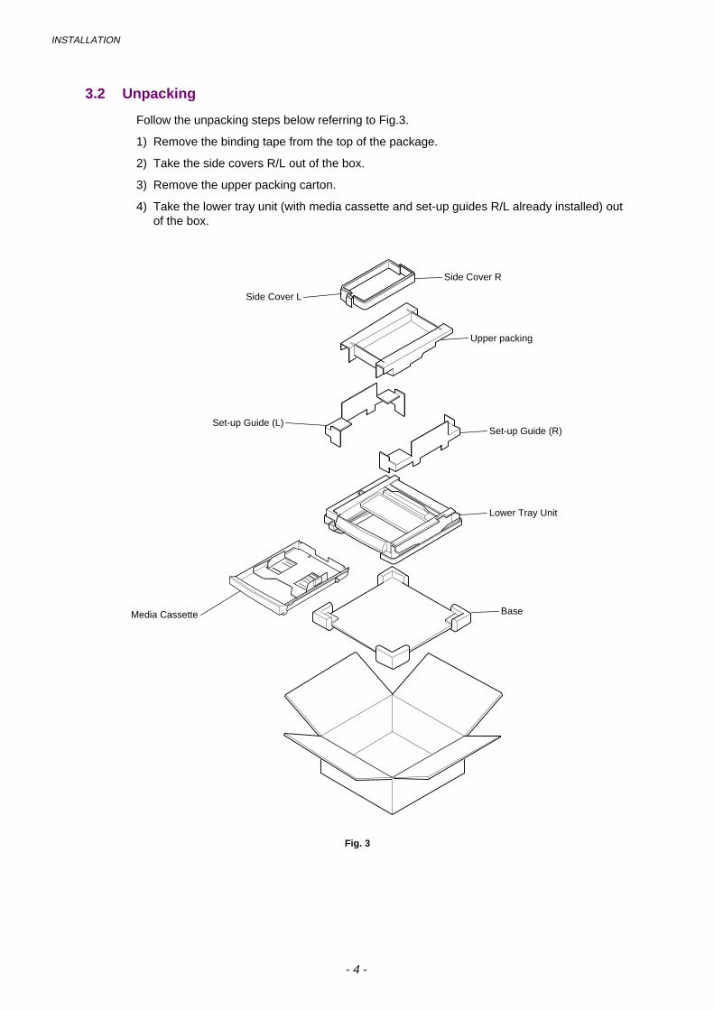
INSTALLATION
- 4 -
3.2 Unpacking
Follow the unpacking steps below referring to Fig.3.
1) Remove the binding tape from the top of the package.
2) Take the side covers R/L out of the box.
3) Remove the upper packing carton.
4) Take the lower tray unit (with media cassette and set-up guides R/L already installed) outof the box.
Fig. 3
Side Cover R
Lower Tray Unit
Set-up Guide (R)
Upper packing
BaseMedia Cassette
Set-up Guide (L)
Side Cover L

INSTALLATION
- 5 -
3.3 Installation Procedures
3.3.1 Install the printer onto the lower tray unit
1) Place the lower tray unit on a solid, flat surface where the printer is to be installedensuring that the conditions in sections 3.1.1 and 3.1.2 are complied with.
2) Check that the set-up guides R/L are fixed onto the lower tray unit.
Fig. 4
3) Pull out the LT signal connector which is located at the rear left side of the unit, andremove the LT connector cover from the lower tray unit.
Fig. 5
LT connector cover
Set-up Guide (R)
Set-up Guide (L)
LT Signal Connector

INSTALLATION
- 6 -
4) Check the three alignment guide pins on the lower tray unit.
Fig. 6
5) Two people should be used to lift up the printer and place it onto the lower tray unit asshown in Figure 7.
WARNINGThe printer weighs approximately 32kg, so it is too heavy for one person to carry. It needstwo adults to move the printer. Since the printer is a precision machine, make sure that it iscarried slowly with care so that no impact occurs to the printer while moving it.
Fig. 7
NOTE:
• Slowly lower the printer along the set-up guides provided at both sides of the unit so thatthe locating holes in the printer align correctly with the guide pins.
• After putting the printer onto the lower tray unit, ensure that the alignment pins are locatedcorrectly into the printer.
Guide pins

INSTALLATION
- 7 -
6) Remove the set-up guides R/L from the unit.
Fig. 8
7) Insert the metal fixtures into both sides of the lower tray unit from above.
8) Tighten the screws to secure the fixtures.
Fig. 9
NOTE:
Check that the two metal fixtures and the two screws were supplied with the lower tray unit.
Lower Tray UnitMetal Fixture
Screw
Printer
Set-up Guide (R)
Set-up Guide (L)

INSTALLATION
- 8 -
3.3.2 Connect the LT signal connector into the printer
1) Remove the LT connector cover (U) from the printer.
2) Connect the LT signal connector into the connector of the printer.
NOTE:
Connect the LT signal connector into the printer connector correctly until it clicks as it locksinto position.
3) Install the LT connector cover onto the printer.
4) Install the LT connector cover (U) onto the lower tray unit.
Fig. 10
LT connector cover (U)
LT connector cover
LT Signal Connector

INSTALLATION
- 9 -
3.3.3 Install the covers
1) Install the side covers R/L onto both sides of the lower tray unit.
Fig. 11
3.3.4 Relocating the printer / Test print
1) If it is necessary to relocate the printer with the lower tray unit installed, hold it under thelower tray unit, it should only be moved by two adults and should be kept level at all times.Care should be taken to not subject the printer to any unnecessary shock during movingthe printer.
Fig. 12
CAUTION• The printer with the lower tray unit installed weighs approximately 40kg, so it is too heavy
for one person to carry. It needs two adults to move the printer.
• If the printer and the lower tray unit are relocated separately, ensure that you disconnectthe LT signal connector from the printer before lifting up the printer from the lower trayunit.
2) After all the installation steps are finished, load paper only into the media cassette of thelower tray unit and implement the test print.
Cover (L)
Cover (R)

MAINTENANCE
- 10 -
4. MAINTENANCE
4.1 Daily Maintenance
You need not daily maintenance for the lower tray unit such as cleaning.
4.2 Periodic Maintenance
You need not to replace any parts periodically. However, it is recommended for highperformance of paper feeding that the following parts are replaced in accordance with theperiodic replacement cycle of printer parts.
Description Part No. Replacement Cycle
Paper Feeding Roller UH3485001 Every 120K print
Separation Pad UH3486001 Every 120K print

DIS
AS
SE
MB
LY
- 11
-
5.
DIS
AS
SE
MB
LY
Whe
n di
sass
embl
ing
the
low
er tr
ay u
nit,
follo
w th
e in
stru
ctio
ns in
the
sect
ions
bel
ow r
efer
ring
to F
igur
e 13
;
Bac
k co
ver
(LT
U)
Pap
er g
uide
(LT
U)
OH
P S
enso
r
Pap
er F
eed
ing
R
olle
r
Pap
er S
enso
r
Pap
er F
eed
ing
Clu
tch
Sep
arat
ion
Pad
Sid
e c
over
(R
)
Bas
e co
ver
LTU
(R
)
Pap
er S
ize
Sen
sor
Med
ia c
asse
tte (
L)
Bas
e co
ver
LTU
(L)
Sid
e co
ver
(L)
Fron
t cov
er (
LTU
)
Cas
sette
gui
de (
L)
Pap
er g
uide
(L)
Pap
er g
uide
(UL)
Fig
. 13

DISASSEMBLY
- 12 -
5.1 Paper Sensor (PEL) / OHP Sensor (OHPL)
1) Remove the BT4x8 screw (1 pc.) to remove the back cover (LTU).
2) Remove the screws (2 pcs.) to remove the paper guide (LTU).
3) Remove the ST4x6 screws (2 pcs.) to remove the paper guide (L).
4) Remove the ST4x6 screws (2 pcs.) to remove the paper guide (UL) assembly.
5) Remove the paper sensor connector.
6) Remove the paper sensor from the paper guide (UL).
7) Remove the BT3x6 screws (2 pcs.) to remove the OHP sensor from the paper guide (UL).
8) Remove the OHP sensor harness connector.
5.2 Paper Size Sensor (PSU)
1) Remove the BT4x8 (2 pcs.) screws to remove the base cover LTU (L).
2) Remove the ST3x6 screws (2 pcs.) to remove the front cover (LTU).
3) Remove the BT3x8 screw of the cassette guide (L) assembly.
4) Pull the cassette guide (L) toward you while pushing the front catch to release the guidefrom the plastic catches.
5) Remove the connector of the paper size sensor.
6) Remove the cassette guide (L) assembly from the frame.
7) Remove the BT3x8 screws (2 pcs.) to remove the paper size sensor from the cassetteguide (L).
5.3 Paper Feeding Clutch
1) Remove the BT4x8 screws (2 pcs.) to remove the base cover LTU (R).
2) Remove the BT4x8 screw (1 pc.) to remove the back cover (LTU).
3) Remove the harness connector of the paper feeding clutch.
4) Remove the ST3x6 screw (1 pc.) to remove the clutch cover.
5) Remove the stopper ring from the paper feeding clutch shaft.
6) Remove the paper feeding clutch from the shaft.
Note:
When removing the clutch cover, the spring installed onto the clutch cover comes off.

DISASSEMBLY
- 13 -
5.4 Paper Feeding Roller / Separation Pad
1) Remove the BT4x8 screw (1 pc.) to remove the back cover (LTU).
2) Remove the screws (2 pcs.) to remove the paper guide (LTU).
3) Remove the ST3x6 screws (2 pcs.) to remove the paper guide (L).
4) Remove the ST3x6 screws (2 pcs.) to remove the paper guide (UL).
5) Disconnect the harness from the paper guide (UL).
6) Remove the paper feeding roller by pushing it to the right viewed from the rear of the unit.
7) Pull up and remove the separation pad.
CAUTIONDo not touch the surface of the paper feeding roller and separation pad.

DISASSEMBLY
- 14 -
6. CLEARING PAPER JAMS
6.1 Paper Feeding Jam
1) Pull out the media cassette (L).
2) Remove the paper remaining inside the printer.
3) Open the rear cover to check no paper remains.
4) Close the rear cover.
6.2 Inner Jam / Outer Jam
Both inner jam and outer jam actually occur inside the printer.
Refer to Section 3.2 & 3.3 in Chapter VIII of the HL-2400C service manual.

- 1 -
GENERAL DRAWING
MODEL HL-84U821/831/832/861/862
5-24 5-23
5-22
5-12
5-14
11-8
5-145-16
5-15
7-1
5-2
5-3
5-13
5-9
5-33
5-11
5-11
5-10
5-325-33
8-2
5-18
5-19
1-3
5-35 (100V only)
1-2
1-2
1-1
1-5
1-6
1-6
1-4
8-1
5-7
5-33
5-35(200V only)
5-345-8
5-1
5-215-255-26
5-6
5-5
5-20
5-26
5-31
5-16
5-16
5-15
5-15
2-42-32-4
2-3 2-22-2
2-15-27
5-28
2-5
4-1-1
4-7
4-2
4-1
4-5
4-6
4-4
4-4
4-6
4-3
4-24-3
11-3
11-1
11-2
11-6
11-7
11-4
3-1
5-29
2-2
4-8
11-5
5-30
5-17
9-1
5-4
5-33
4-1-1
5-34
5-34
PR98235
T/I NO. PR98096 / PR98100 / PR98176 / PR98235
(Legend model only)
11-5-1

11. ACCESSORIES PR98235REF.NO. CODE Q'TY DESCRIPTION REMARK1 UK4090001 1 PR DRIVER DISK ASSY1, 820 (WINDOWS)1 UK4193001 1 PR DRIVER DISK ASSY1, 1020 (WINDOWS) 1 UK3875001 1 PR DRIVER DISK ASSY1, 1040 (WINDOWS)1 UK4183001 1 PR DRIVER DISK ASSY 1, 1040LEG(WINDOWS) 1 UK3895001 1 PR DRIVER DISK ASSY1, 1050 (WINDOWS) 1 UK4179001 1 PR DRIVER DISK ASSY 1, 1050HEB(WINDOWS) 1 UK4233001 1 PR DRIVER DISK ASSY 1, 1050LEG(WINDOWS) 2 UK4092001 1 PR DRIVER DISK ASSY2, 820 (TRUETYPE)2 UK4195001 1 PR DRIVER DISK ASSY2, 1020 (TRUETYPE)2 UK3877001 1 PR DRIVER DISK ASSY2, 1040 (TRUETYPE)2 UK4185001 1 PR DRIVER DISK ASSY2, 1040LEG(TRUETYPE) 2 UK3897001 1 PR DRIVER DISK ASSY2, 1050 (TRUETYPE)2 UK4181001 1 PR DRIVER DISK ASSY2, 1050HEB(TRUETYPE)2 UK4235001 1 PR DRIVER DISK ASSY2, 1050LEG(TRUETYPE)3 UK4197001 1 PR DRIVER DISK ASSY6, 1050 ARABIC4 UK4199001 1 CD-ROM ASSY5 UE2188001 1 PAPER SUPPORT ASSY CHNG5-1 UL7158001 1 TE TUBE ADD6 UL8529001 1 SET GUIDE, US6 UL8550001 1 SET GUIDE, FRA6 UL8534001 1 SET GUIDE, GER6 UL8557001 1 SET GUIDE, NOR6 UL8560001 1 SET GUIDE, NL6 UL8565001 1 SET GUIDE, DEN6 UL8568001 1 SET GUIDE, ITA6 UL8571001 1 SET GUIDE, SWE6 UL8739001 1 SET GUIDE, SPA7 UE2014001 1 BAG, 215X350H8 UK4156001 1 CORE NF-13 ASSY (HL1050)
MODEL HL-820/1020/1040/1050 84U-821/831/832/861/862-920T/I NO. PR98100 / PR98110 / PR98176 / PR98235
- 12 -

5. COVERS PR99041REF.NO. CODE Q'TY DESCRIPTION SYMBOL REMARK1 UL7983001 1 MAIN COVER ASSY2 085411215 1 TAPTITE, BIND B M4X12 3 085411215 1 TAPTITE, BIND B M4X12 4 085411215 1 TAPTITE, BIND B M4X125 002400616 3 SCREW PAN M4X66 087320616 2 TAPTITE, CUP S M3X67 0A5350605 1 SCREW PAN(WASHER), M3.5X6 8 UL8659001 1 EL PCB UNIT B48K3049 UL8753001 1 MAIN FAN MOTOR10 UL8509001 1 SUB FAN MOTOR11 085411215 2 TAPTITE, BIND B M4X12 12 UL8505001 1 BASE PLATE 820/1020/104012 UL8601001 1 BASE PLATE 105013 UL8506001 1 MAIN PCB GUIDE RAIL (820/1020/1040)14 LJ4047001 2 RUBBER FOOT CHNG15 085411215 8 TAPTITE, BIND B M4X12 16 087320616 5 TAPTITE, CUP S M3X6 17 UL8508001 1 INSULATION SHEET18 UL8512001 1 INLET HOLDER19 085411215 1 TAPTITE, BIND B M4X1220 UL8510001 1 I/F SHIELD ASSY 820/1020/104020 UL8604001 1 I/F SHIELD ASSY 1050 21 UL8518001 1 PANEL COVER, GRAY122722 UL8745001 1 TOP COVER ASSY23 UL8515001 1 OUTPUT TRAY24 UL8516001 1 EXTENSION SUPPORT WIRE25 UL8746001 1 REAR COVER ASSY26 085411215 2 TAPTITE, BIND B M4X12 27 UL6740001 1 LASER CAUTION LABEL27 UL7931001 1 LASER CAUTION LABEL (LEGEND) 28 UL6741001 1 TONER WARNING LABEL29 UL8575001 1 MODEL PLATE, HL-820 29 UL8639001 1 MODEL PLATE, HL-102029 UL8519001 1 MODEL PLATE, HL-1040 29 UL8641001 1 MODEL PLATE, HL-1040DX29 UL8686001 1 MODEL PLATE, HL-1040 (LEGEND) 29 UL8611001 1 MODEL PLATE, HL-1050 29 UL8645001 1 MODEL PLATE, HL-1050DX29 UL8820001 1 MODEL PLATE, HL-1050 (LEGEND) 30 UL8640001 1 MYLAR LABEL, HL-1020 CAN30 UL8650001 1 MYLAR LABEL, HL-820 EUR30 UL8522001 1 MYLAR LABEL, HL-1040 US30 UL8547001 1 MYLAR LABEL, HL-1040 CAN30 UL8642001 1 MYLAR LABEL, HL-1040DX CAN30 UL8651001 1 MYLAR LABEL, HL-1040 EUR30 UL8612001 1 MYLAR LABEL, HL-1050 US30 UL8596001 1 MYLAR LABEL, HL-1050 CAN30 UL8646001 1 MYLAR LABEL, HL-1050DX CAN30 UL8652001 1 MYLAR LABEL, HL-1050 EUR31 UH3297001 1 C-TICK MARK LABEL32 UH0905001 1 US PATENT SEAL HL-1033 UG3005000 4 FERRITE CORE 34 UG3005000 7 FERRITE CORE (HL1050) 35 UK3617000 1 CORE, TFC-16813 (HL1050)
MODEL HL-820/1020/1040/1050 84U-821/831/832/861/862-060T/I NO. PR98096 / PR98110 / PR98176 / PR99041
- 7 -

7. COVERS PR99041REF.NO. CODE Q'TY DESCRIPTION SYMBOL REMARK1 UL7983001 1 MAIN COVER ASSY2 085411215 1 TAPTITE, BIND B M4X12 3 085411215 1 TAPTITE, BIND B M4X12 4 085411215 1 TAPTITE, BIND B M4X125 002400616 3 SCREW PAN M4X66 087320616 2 TAPTITE, CUP S M3X67 0A5350605 1 SCREW PAN(WASHER), M3.5X6 8 UL8659001 1 EL PCB UNIT B48K3049 UL8753001 1 MAIN FAN MOTOR10 UL8509001 1 SUB FAN MOTOR11 085411215 2 TAPTITE, BIND B M4X12 12 UL8601001 1 BASE PLATE 13 LJ4047001 2 RUBBER FOOT CHNG14 085411215 8 TAPTITE, BIND B M4X12 15 087320616 5 TAPTITE, CUP S M3X6 16 UL8508001 1 INSULATION SHEET17 UL8512001 1 INLET HOLDER18 085411215 1 TAPTITE, BIND B M4X1219 UL8510001 1 I/F SHIELD ASSY 20 UH3828001 1 SHIELD SHEET, P2000 21 UH3850001 1 PANEL COVER, GRAY122722 UH3852001 1 TOP COVER ASSY23 UH3826001 1 DOCUMENT EXTENSION SUPPORT WIRE24 UH3825001 1 OUTPUT TRAY25 UL8516001 1 EXTENSION SUPPORT WIRE26 UH3801001 1 SCANNER REAR COVER ASSY27 UH3805001 1 REAR COVER ASSY28 085411215 2 TAPTITE, BIND B M4X12 29 UL6740001 1 LASER CAUTION LABEL29 UL7931001 1 LASER CAUTION LABEL, LEG 30 UL6741001 1 TONER WARNING LABEL31 UH3838001 1 MYLAR LABEL, MFC-P2000 (US)31 UH3839001 1 MYLAR LABEL, MFC-P2000 (CANADA)31 UH3840001 1 MYLAR LABEL, HL-P2000 (EUR)32 UG3005000 5 FERRITE CORE33 087320616 1 TAPTITE, CUP S M3X6 34 UH3751001 2 MINI CLAMP35 UH3752001 1 NYLON CLAMP36 085411215 1 TAPTITE, BIND B M4X12
MODEL MFC-P2000/HL-P2000 84U-901/902-060T/I NO. PR98303 / PR99041
- 7 -

HL1060PL
5. FIXING UNITS PR99042REF.NO. CODE Q'TY DESCRIPTION REMARK1-9 UH3164001 1 FIXING UNIT Y, 120V (SP) 1-9 UH3165001 1 FIXING UNIT Y, 230V (SP) 1 UH3306001 1 HALOGEN LAMP Y, 120V (SP)1 UH3307001 1 HALOGEN LAMP Y, 230V (SP)2 087411616 2 TAPTITE, CUP B M4X163 UL6667001 1 THERMISTOR ASSY CHNG4 UH3188001 1 CLEANER ASSY Y5 UH3178000 2 H/R BEARING Y6 UH3419001 1 HEAT ROLLER YS ASSY7 087311415 1 TAPTITE, CUP B 3X148 UH3323001 4 EJECT PINCH ROLLER ASSY 9 UL6682001 4 PINCH SPRING
MODEL HL-1060 54U-S01-051T/I NO. PR98040 / PR98292 / PR99042
7. MAIN PCBREF.NO. CODE Q'TY DESCRIPTION SYMBOL REMARK1 UK3439001 1 MAIN PCB ASSY, PCL5 2M(SP) B48K246-300J
MODEL HL-1060 54U-S01-101T/I No. 97-P028 / 97-P043 / PR97161

5. FIXING UNITS PR99042REF.NO. CODE Q'TY DESCRIPTION REMARK1-9 UH3164001 1 FIXING UNIT Y, 120V (SP) 1-9 UH3165001 1 FIXING UNIT Y, 230V (SP) 1 UH3306001 1 HALOGEN LAMP Y, 120V (SP)1 UH3307001 1 HALOGEN LAMP Y, 230V (SP)2 087411616 2 TAPTITE, CUP B M4X163 UL6667001 1 THERMISTOR ASSY CHNG4 UH3188001 1 CLEANER ASSY Y 5 UH3178000 2 H/R BEARING Y 6 UH3419001 1 HEAT ROLLER YS ASSY (SP)7 087311415 1 TAPTITE, CUP B 3X148 UH3323001 4 EJECT PINCH ROLLER ASSY 9 UL6682001 4 PINCH SPRING
MODEL HL-1070 54U-S03-050/051T/I NO. PR98292 / PR99042
7. MAIN PCBREF.NO. CODE Q'TY DESCRIPTION SYMBOL REMARK1 UK3950001 1 MAIN PCB ASSY B48K302-100C 2 UH3542001 1 CONDUCTIVE TAPE
MODEL HL-1070 54U-S03-101T/I NO. PR98108
- 5 -

3. MP SHEET FEEDER PR99042REF.NO. CODE Q'TY DESCRIPTION REMARK1 UL8749001 1 MP SHEET FEEDER ASSY (SP)1 UL8832001 1 MP SHEET FEEDER ASSY (LEGEND) (SP)
MODEL HL-820/1020/1040/1050 84U-821/831/832/861/862-040T/I NO. PR98176
4. FIXING UNIT REF.NO. CODE Q'TY DESCRIPTION REMARK1-11 UL8750001 1 FIXING UNIT, 120V (SP)1-11 UL8751001 1 FIXING UNIT, 230V (SP)1-11 UL8833001 1 FIXING UNIT (LEGEND) (SP) 1 UH3306001 1 HALOGEN LAMP Y, 120V (SP)1 UH3307001 1 HALOGEN LAMP Y, 230V (SP)2 087411616 2 TAPTITE, CUP B M4X163 085311216 2 TAPTITE, BIND B M3X124 083311017 2 TAPTITE, PAN B M3X105 UL8757001 1 HEAT ROLLER YS (SP) 5 UL8834001 1 HEAT ROLLER (LEGEND) (SP) 6 UH3178000 2 H/R BEARING Y7 UL8758001 1 H/R CLEANER 7 UL8855001 1 H/R CLEANER (LEGEND) 8 UL8754001 1 H/R WASHER9 UL6667001 1 THERMISTOR ASSY CHNG10 UH3323001 4 EJECT PINCH ROLLER ASSY 11 UL6682001 4 PINCH SPRING
MODEL HL-820/1020/1040/1050 84U-821/831/861-050/051 84U-832/862-052T/I NO. PR98116 / PR98176 / PR98271 / PR98292 / PR99042
- 6 -

6. FIXING UNIT PR99042REF.NO. CODE Q'TY DESCRIPTION REMARK1-11 UL8750001 1 FIXING UNIT, 120V (SP)1-11 UL8751001 1 FIXING UNIT, 230V (SP)1-11 UL8833001 1 FIXING UNIT, LEG 230V (SP) 1 UH3306001 1 HALOGEN LAMP Y, 120V (SP)1 UH3307001 1 HALOGEN LAMP Y, 230V (SP)2 087411616 2 TAPTITE, CUP B M4X163 085311216 2 TAPTITE, BIND B M3X124 083311017 2 TAPTITE, PAN B M3X105 UL8757001 1 HEAT ROLLER YS (SP) 5 UL8834001 1 HEAT ROLLER, LEG (SP) 6 UH3178000 2 H/R BEARING Y7 UL8758001 1 H/R CLEANER7 UL8855001 1 H/R CLEANER, LEG 8 UL8754001 1 H/R WASHER9 UL6667001 1 THERMISTOR ASSY CHNG10 UH3323001 4 EJECT PINCH ROLLER ASSY11 UL6682001 4 PINCH SPRING
MODEL MFC-P2000/HL-P2000 84U-901/902-050/051/052T/I NO. PR98271 / PR98292 / PR98303
8. MAIN PCBREF.NO. CODE Q'TY DESCRIPTION SYMBOL REMARK1-1 UK4250001 1 MAIN PCB ASSY, US (SP) B512018-100C 1-1 UK4251001 1 MAIN PCB ASSY, EUR (SP) B512018-101B1-1 UK4252001 1 MAIN PCB ASSY, HEB (SP) B512018-1021 UK4328000 1 MROMP2000, US #4 1 UK4320000 1 MROMP2000, EUR #41 UK4160000 1 MROMP2000, HEB #4
MODEL MFC-P2000/HL-P2000 84U-901/902-101/102/103T/I NO. PR98260
- 9 -

12. PACKING MATERIALS PR99055REF.NO. CODE Q'TY DESCRIPTION REMARK1 UE2233001 1 CARTON, EUR HL-8201 UE2236001 1 CARTON, CAN HL-10201 UE2239001 1 CARTON, USA HL-10401 UE2240001 1 CARTON, CAN HL-10401 UE2222001 1 CARTON, EUR HL-10401 UE2237001 1 CARTON, CAN HL-1040DX 1 UE2245001 1 CARTON, LEGEND HL-1040 1 UE2241001 1 CARTON, USA HL-10501 UE2230001 1 CARTON, EUR HL-10501 UE2238001 1 CARTON, CAN HL-1050DX1 UE2242001 1 CARTON, CAN HL-10501 UE2248001 1 CARTON, LEGEND HL-1050 1 LJ4002001 1 CARTON, TWN&KOR HL-1040R ADD2 UE2223001 1 STYROFOAM PAD ASSY3 UE2226001 1 CARTON, ACCESORRIES4 UE2126001 1 BAG, 700X800 (BODY)
MODEL HL-820/1020/1040/1050 84U-821/831/832/861/862-930T/I NO. PR98087 / PR98110 / PR98176 / PR99055
- 13 -

5. COVERS PR99057REF.NO. CODE Q'TY DESCRIPTION SYMBOL REMARK1 UL7983001 1 MAIN COVER ASSY2 085411215 1 TAPTITE, BIND B M4X12 3 085411215 1 TAPTITE, BIND B M4X12 4 085411215 1 TAPTITE, BIND B M4X125 002400616 3 SCREW PAN M4X66 087320616 2 TAPTITE, CUP S M3X67 0A5350605 1 SCREW PAN(WASHER), M3.5X6 8 UL8659001 1 EL PCB UNIT B48K3049 UL8753001 1 MAIN FAN MOTOR10 UL8509001 1 SUB FAN MOTOR11 085411215 2 TAPTITE, BIND B M4X12 12 UL8505001 1 BASE PLATE 820/1020/104012 UL8601001 1 BASE PLATE 105013 UL8506001 1 MAIN PCB GUIDE RAIL (820/1020/1040)14 UL8507001 2 RUBBER FOOT CHNG15 085411215 8 TAPTITE, BIND B M4X12 16 087320616 5 TAPTITE, CUP S M3X6 17 UL8508001 1 INSULATION SHEET18 UL8512001 1 INLET HOLDER19 085411215 1 TAPTITE, BIND B M4X1220 UL8510001 1 I/F SHIELD ASSY 820/1020/104020 UL8604001 1 I/F SHIELD ASSY 1050 21 UL8518001 1 PANEL COVER, GRAY122722 UL8745001 1 TOP COVER ASSY23 UL8515001 1 OUTPUT TRAY24 UL8516001 1 EXTENSION SUPPORT WIRE25 UL8746001 1 REAR COVER ASSY26 085411215 2 TAPTITE, BIND B M4X12 27 UL6740001 1 LASER CAUTION LABEL27 UL7931001 1 LASER CAUTION LABEL (LEGEND) 28 UL6741001 1 TONER WARNING LABEL29 UL8575001 1 MODEL PLATE, HL-820 29 UL8639001 1 MODEL PLATE, HL-102029 UL8519001 1 MODEL PLATE, HL-1040 29 UL8641001 1 MODEL PLATE, HL-1040DX29 UL8686001 1 MODEL PLATE, HL-1040 (LEGEND) 29 UL8611001 1 MODEL PLATE, HL-1050 29 UL8645001 1 MODEL PLATE, HL-1050DX29 UL8820001 1 MODEL PLATE, HL-1050 (LEGEND) 30 UL8640001 1 MYLAR LABEL, HL-1020 CAN30 UL8650001 1 MYLAR LABEL, HL-820 EUR30 UL8522001 1 MYLAR LABEL, HL-1040 US30 UL8547001 1 MYLAR LABEL, HL-1040 CAN30 UL8642001 1 MYLAR LABEL, HL-1040DX CAN30 UL8651001 1 MYLAR LABEL, HL-1040 EUR30 UL8612001 1 MYLAR LABEL, HL-1050 US30 UL8596001 1 MYLAR LABEL, HL-1050 CAN30 UL8646001 1 MYLAR LABEL, HL-1050DX CAN30 UL8652001 1 MYLAR LABEL, HL-1050 EUR31 UH3297001 1 C-TICK MARK LABEL32 UH0905001 1 US PATENT SEAL HL-1033 UG3005000 4 FERRITE CORE 34 UG3005000 7 FERRITE CORE (HL1050) 35 UK3617000 1 CORE, TFC-16813 (HL1050)
MODEL HL-820/1020/1040/1050 84U-821/831/832/861/862-060T/I NO. PR98096 / PR98110 / PR98176 / PR99041 / PR99057
- 7 -

7. COVERS PR99057REF.NO. CODE Q'TY DESCRIPTION SYMBOL REMARK1 UL7983001 1 MAIN COVER ASSY2 085411215 1 TAPTITE, BIND B M4X12 3 085411215 1 TAPTITE, BIND B M4X12 4 085411215 1 TAPTITE, BIND B M4X125 002400616 3 SCREW PAN M4X66 087320616 2 TAPTITE, CUP S M3X67 0A5350605 1 SCREW PAN(WASHER), M3.5X6 8 UL8659001 1 EL PCB UNIT B48K3049 UL8753001 1 MAIN FAN MOTOR10 UL8509001 1 SUB FAN MOTOR11 085411215 2 TAPTITE, BIND B M4X12 12 UL8601001 1 BASE PLATE 13 UL8507001 2 RUBBER FOOT CHNG14 085411215 8 TAPTITE, BIND B M4X12 15 087320616 5 TAPTITE, CUP S M3X6 16 UL8508001 1 INSULATION SHEET17 UL8512001 1 INLET HOLDER18 085411215 1 TAPTITE, BIND B M4X1219 UL8510001 1 I/F SHIELD ASSY 20 UH3828001 1 SHIELD SHEET, P2000 21 UH3850001 1 PANEL COVER, GRAY122722 UH3852001 1 TOP COVER ASSY23 UH3826001 1 DOCUMENT EXTENSION SUPPORT WIRE24 UH3825001 1 OUTPUT TRAY25 UL8516001 1 EXTENSION SUPPORT WIRE26 UH3801001 1 SCANNER REAR COVER ASSY27 UH3805001 1 REAR COVER ASSY28 085411215 2 TAPTITE, BIND B M4X12 29 UL6740001 1 LASER CAUTION LABEL29 UL7931001 1 LASER CAUTION LABEL, LEG 30 UL6741001 1 TONER WARNING LABEL31 UH3838001 1 MYLAR LABEL, MFC-P2000 (US)31 UH3839001 1 MYLAR LABEL, MFC-P2000 (CANADA)31 UH3840001 1 MYLAR LABEL, HL-P2000 (EUR)32 UG3005000 5 FERRITE CORE33 087320616 1 TAPTITE, CUP S M3X6 34 UH3751001 2 MINI CLAMP35 UH3752001 1 NYLON CLAMP36 085411215 1 TAPTITE, BIND B M4X12
MODEL MFC-P2000/HL-P2000 84U-901/902-060T/I NO. PR98303 / PR99041 / PR99057
- 7 -

Laser Printer HL-800/1000 Series
Quick Setup GuideRead this guidebook first to set up your printer andprepare your computer for the printer.Save all packing materials and outer carton. Theyare useful when shipping the printer.
Keep this manual in a convenient place for quick and easy reference at all times. Referto the On-Line manual by installing the CD-ROM into Windows.The product names in this guidebook are trademarks or registered trade marks of each manufacturer. The specifications aresubject to change without notice.
©1998 Brother Industries Ltd.

(For USA & CANADA Only)
For technical and operational assistance , please call:In USA 1-800-276-7746 (outside California) / 949-859-9700 Ext. 329 (within California)In CANADA 1-800-853-6660 / 514-685-6464 (within Montreal)
If you have comments or suggestions, please write us at:In USA Printer Customer Support - Brother International Corporation
15 Musick, Irvine, CA 92718In CANADA Brother International Corporation (Canada), Ltd. - Marketing Dept.
1, rue Hôtel de Ville Dollard-des-Ormeaux, PQ, Canada H9B 3H6
BBS: For downloading drivers from our Bulletin Board Service, call:In USA: 1-888-298-3616 / In CANADA : 1-514-685-2040Please log on to our BBS with your first name, last name and a four digit number for your password. OurBBS supports modem speeds up to 14,400, 8 bits no parity, 1 stop bit.
Fax-Back System (For USA and Canada only)Brother Customer Service has installed an easy to use Fax-Back System so you can get instant answers tocommon technical questions and product information for all Brother products. This is available 24 hours aday, 7 days a week. You can use the system to send the information to any fax machine, not just the one youare calling from. Please call 1-800-521-2846 (USA) or 1-800-681-9838 (Canada) and follow the voiceprompts to receive faxed instructions on how to use the system and your index of Fax-Back subjects.
DEALERS/SERVICE CENTERS (USA only)For the name of an authorized dealer or service center, call 1-800-284-4357.
SERVICE CENTERS (Canada only)For service center addresses in Canada, call 1-800-853-6660
INTERNET ADDRESSFor technical questions and downloading drivers: http://www.brother.com
Definitions of Warnings, Cautions, and NotesThe following conventions are used in this User’s Guide:
WarningIndicates warnings that must be observedto prevent possible personal injury.
! CautionIndicates cautions that must be observed to use theprinter properly or prevent damage to the printer.
✒✒✒✒ NoteIndicates notes and useful tips to rememberwhen using the printer.
To Use the Printer Safely
WarningAfter you have just used the printer, someinternal parts are extremely hot. When youopen the printer top cover, never touch theshaded parts shown in the followingillustration.
High TemperatureInside the Printer
WarningThere are high voltage electrodes inside theprinter. Before cleaning the printer, make sureyou turn off the power switch and unplug thepower cord from the power outlet.
Turning off the Switch and Unplugging the Printer

1
Table of Contents
Action 1: Check the Supplied items --- 2Action 2: Place the Printer --- 3Action 3: Install the Toner Cartridge/Drum Unit --- 4Action 4: Load Paper into Your Printer --- 5Action 5-1: Connect Your Printer to Your Computers parallel interface --- 7Action 5-2: Connect Your Printer to Your Computers using the USB
interface ( Only for HL-1050 with Windows 98 )--- 8
Action 6: Plug in and Turn on Your Printer --- 11Action 7-1: Installation from CD-ROM --- 13Action 7-2: Prepare Windows 95/98 for the Printer from floppy disks ---14Action 7-3: Prepare Windows 3.1 for the Printer ---15Action 7-4: Prepare DOS for the Printer (Only HL-1040/1050) --- 16Action 7-5: Prepare Macintosh for the Printer (Only HL-1040/1050) --- 20LAMPS AND SWITCH --- 21REPLACING THE TONER CARTRIDGE --- 24REPLACING THE DRUM UNIT --- 27ALARM INDICATIONS AT A GLANCE --- 30ADDITIONAL MEMORY (HL-1050 ONLY) --- 33PRINTER SPECIFICATIONS --- 35REGULATIONS --- 37
Trademarks
The Brother logo is a registered trademark of Brother Industries, Ltd.
Apple, the Apple Logo, and Macintosh are trademarks, registered in the United States and other countries, andTrueType is a trademark of Apple Computer, Inc.Epson is a registered trademark and FX-80 and FX-850 are trademarks of Seiko Epson Corporation.Hewlett Packard is a registered trademark and HP LaserJet 6P, 6L, 5P, 5L, 4, 4L 4P, III, IIIP, II, and IIP aretrademarks of Hewlett-Packard Company.IBM, IBM PC, and Proprinter are registered trademarks of International Business Machines Corporation.Microsoft and MS-DOS are registered trademarks of Microsoft Corporation. Windows is a registered trademarkof Microsoft Corporation in the U.S. and other countries.
All other brand and product names mentioned in this User’s Guide are registered trademarks of their respectivecompanies.
Compilation and Publication Notice
Under the supervision of Brother Industries Ltd., this manual has been compiled and published, covering thelatest product’s descriptions and specifications.
The contents of this manual and the specifications of this product are subject to change without notice.
Brother reserves the right to make changes without notice in the specifications and materials contained hereinand shall not be responsible for any damages (including consequential) caused by reliance on the materialspresented, including but not limited to typographical and other errors relating to the publication.
©1998 Brother Industries Ltd.

- 2 -
Action 1: Check the Supplied Items
After taking the printer out of the carton and removing the packing materials, make sure thatthe following items are not damaged and none are missing:
• Printer • Paper support
• Drum unit assembly (with Toner cartridgeincluded)
• AC Cord
�� 3.5” floppy disks for Windows® printer driver and fonts�� Quick setup guide (this guidebook)�� Plastic Bag�� CD-ROM
✒ NOTEThe 3.5” floppy disks for the Macintosh printer driver may be included for some countries.You will need to purchase an interface cable that matches the bi-directional IEEE 1284compliant interface of your computer. If you do not know what cable you need, consult yourdealer.

-3-
Action 2: Place the printer
Please take note of the following before using the printer.
Power Supply
� Use the printer within the specified power range.AC power: ±10% of the rated power voltage in your countryFrequency: 50 Hz (220 V– 240 V) or 50/60 Hz (110–120 V)
� The power cord, including extensions, should not exceed 5 meters (16.5 feet).� Do not share the same power circuit with other high-power appliances, particularly an air conditioner,
copier, shredder and so on. If it is unavoidable that you must use the printer with these appliances, it isrecommended that you use an isolation transformer or a high-frequency noise filter.
� Use a voltage regulator if the power source is not stable.
Environment
� The printer should be installed near a power outlet, which is easily accessible.� Use the printer only within the following ranges of temperature and humidity.
Ambient temperature: 10°C to 32.5°C (50°F to 90.5°F)Ambient humidity: 20% to 80% (without condensation)
� The printer should be used in a well ventilation room.� Place the printer on a flat, horizontal surface.� Keep the printer clean. Do not place the printer in a dusty place.� Do not place the printer where the ventilation hole of the printer is blocked.� Do not place the printer where it is exposed to direct sunlight. Use a blind or a heavy curtain to protect
the printer from direct sunlight when the printer is unavoidably set up near a window.� Do not place the printer near devices that contain magnets or generate magnetic fields.� Do not subject the printer to strong physical shocks or vibrations.� Do not expose the printer to open flames or salty or corrosive gasses.� Do not place objects on top of the printer.� Do not place the printer near an air conditioner.� Keep the printer horizontal when carrying.� Do not cover the slots in the top cover.
System Requirements for the Brother Printing Solution for Windows
Check the following system requirements to setup and operate the printer in Brother Printing Solution forWindows:
� IBM PC or compatible with 80486 SX or higher microprocessor� Parallel interface (or printer port)� 4 MB or more of memory (8 MB recommended)� 10 MB of space available on your hard disk for the printer driver and all fonts� Microsoft Windows 95/98, 3.1/3.11 or Windows NT 4.0
! CautionThe HL-820/1020 printer has been designed specifically for Windows 95/98, 3.1/3.11 and WindowsNT4.0. It cannot work in a DOS environment such as MS-DOS.

- 4 -
Action 3: Install the Toner Cartridge/Drum Unit
1 Unpack the drum unit assembly with thetoner cartridge included. Gently shake itfrom side to side five or six times.
! CAUTIONDo not expose the drum unit to light forlonger than a few minutes, as this willdamage the drum.
! CAUTIONDo not remove the starter sheet.This sheet will be ejected while the printeris warming-up after installing a new drumunit. (See Action 5 Illustration 4)
2 Open the top cover of the printer by holdingboth sides of it.
3 Holding the drum by its handles, install itinto the printer.
4 Close the top cover.
See “CHAPTER 5 MAINTENANCE” inthe On-line User’s Guide for moreinformation about replacement of the tonercartridge.
Starter Sheet

- 5 -
Action 4: Load Paper into Your Printer
Before loading paper, make sure that the paper meets the specification described in the On-line User’s Guide Chapter 2. Using unsuitable paper might reduce the print quality.
1 Install the paper support onto the multi-purpose sheet feeder.
2 Open the multi-purpose sheet feeder cover.
! CAUTIONBe sure to open the sheet feeder coverwhenever you insert paper into the sheetfeeder otherwise you may get paper mis-feeding or paper jam errors.
3 Load paper in the multi-purpose sheetfeeder.
✒ NOTEThe feeder can hold up to 200 sheets ofplain paper or up to 10 envelopes.Excessive sheets may cause paper jams.Make sure that the paper is stacked belowthe ▲ mark.

- 6 -
4 Hold the tab of the right hand paper guideand press the catch to release the guidelock. Move the paper guide to fit the paperwidth.
! CAUTIONFailure to set the paper guide to the paperwidth may cause paper skew and jam.
5 Close the multi-purpose sheet feeder cover.
6 Open the output tray. ( ① )Extend the extension support wire. ( ② )
The printer can handle paper within the following specifications:
Paper Type Paper SizeCut sheets A4, Letter, Legal, B5(JIS/ISO), A5, A6, 3”x 5”, Executive,
Custom size(70-216 x 127-356 mm)
Envelopes DL, C5, COM-10, Monarch, 9” x 12”Organizer Day-Timer® J, K, L, 70-216 x 127-356 mmLabels and
TransparenciesA4, Letter70-216 x 127-356 mm
See “CHAPTER 2 PAPER HANDLING” in the On-line User’s Guide for moreinformation.

- 7 -
Action 5-1 : Connect Your Printer to Your Computers parallelinterface
You must connect the printer to your computer with a suitable interface cable. In most cases, abi-directional IEEE 1284 compliant parallel cable is used for this connection.
1 Make sure that the printer power switch isoff before connecting or disconnecting theinterface cable.
Also, make sure that the computer is turnedoff.
2 Connect the parallel interface cable to theparallel interface port of the printer. ( ① )
Secure the connection with the wire clips.( ② )
Connect the interface cable to the printerport of the computer.
✒ NOTEThe HL-1040/1050 printer can also operate with an RS-232C/RS-422A serial interface byinstalling the optional serial interface board. In some countries it might be pre-installed. Formore information, see “CHAPTER 4 OPTIONS” in the On-line User’s Guide.
For the location of your computers parallel (or serial, if you are using the optional interfaceboard) printer port, refer to the User’s Guide of your computer.

8
Action 5-2 : Connect Your Printer to Your Computers using the USBinterface ( Only for HL-1050 with Windows 98 )
The Universal Serial Bus is an interface which allows the printer to be connected to multipleperipheral devices. If your PC has a USB port, you can connect the printer to your PC byusing the USB interface as described in the following procedure.
✒ NOTE�� We recommend that you use the USB interface with this printer on Microsoft Windows�
98. Although Microsoft Windows� 95 OSR2.1 supports the USB interface, some PCs donot work correctly with the USB interface.
�� Only one Brother printer can be used in the same chain of the USB connection. If morethan one Brother printer exists in the same chain of the USB connection, only one printercan be used.
�� To obtain the latest driver, refer to the following page on our web site:http://www.brother.com/ [Soft ware]
1 Turn the printer power off.
Connect your PC and HL-1050 with theUSB interface cable.
Turn the printer power on.
The dialog shown above will appear onyour PC.
Click the Next button.
Select “Search for the best driver for yourdevice.”
Click the Next button.
2
3

9
Insert the supplied CD-ROM into thedrive of your PC.
Select “CD-ROM drive.”
Click the Next button
Click the Next button.
The USB driver is installed.
When the dialog shown above appears onyour PC, click the Finish button.
Be sure to restart Windows 98 so thatthe installed USB driver will beeffective.
When the installation of the USB driver is complete, install the printer driver.From CD-ROM: Run the CD-ROM program and go to the ‘Install driver’ menu.From Floppy disk: Refer to the Software Quick Setup Guide.
Set the printer port to USBAfter installing the USB driver and printer driver, the printer port has to be set to ‘USB port’.1. Click the Start button and select Printers in Settings .2. Select the HL-1050 icon in printers so that the HL-1050 icon is highlighted.3. Select Properties from File menu.4. Click Details tab.5. Select BRUSB :(USB Printer Port) in the box for “Print to the following port”.6. Click OK to close the properties dialog box.
4
5
6

10
TroubleshootingIf the printer does not print from the USB port, try reinstalling the USB driver as follows;1. Double-click the file ‘DeinsUSB.exe’ in the USB directory of the CD-ROM.2. Turn the printer off and on again.3. “Add New Hardware Wizard” is launched again, follow the instructions in the Wizard.

-11 -
Action 6: Plug in and Turn on Your Printer
1 Plug the power cord into the AC poweroutlet and the printer power inlet.
✒ NOTEThe shape of the power cord variesaccording to the country of destination.
2 Turn on the power switch that is locatedon the left side of your printer.
3
Drum
Alarm
ReadyPaperDataToner
Make sure that the READY lamp is lit afterthe printer has warmed up (approximately30 seconds).
4 Make sure that the printer automaticallyejects the starter sheet while the printer iswarming-up immediately after installing anew drum unit.
Starter Sheet

12
Printing a Test Sample Page
We recommend that you print a test page. Refer to the instructions below.
✒ NOTE�� The following test page operation will be invalid after the printer has received any data
from your computer.
Press the control panel switch .The printer will start printing a test samplepage.
✒ NOTE�� If you have already sent data from your computer to the printer, you can print a self test
using the following steps.1. Make sure the top cover is closed.2. Hold down the switch and turn on the power switch. Keep the switch depressed until the Drum lamp comes on.3. Press the switch again to execute the test print.The HL-1040/1050 printer can also print settings, fonts, and hexadecimal values ofreceived data. For more information, see “Test Print Mode” in Chapter 3 of the On-lineUser’s Guide.
�� If the printer does not print a test sample page, see “CHAPTER 6 TROUBLESHOOTING,Q & A” of the On-line User’s Guide. If you are still unable to print a test sample page afterreviewing the information in the User’s Guide, consult your dealer or Brotherrepresentative for support.
�� This Setup guide, the User’s Guide and an instructional video are available on theCD-ROM. You can view the On-Line guides with the Adobe Acrobat reader softwareincluded on the CD-ROM.
After printing the test sample page, you are ready to prepare your computer to work with theprinter. The software setup varies depending upon your computer and operating system. Referto the relevant following section:
Action 7-1: Installation from CD-ROMAction 7-2: Prepare Windows 95/98 for the Printer from floppy diskAction 7-3: Prepare Windows 3.1 for the Printer from floppy diskAction 7-4: Prepare DOS for the Printer (Only for HL-1040/1050 Users) from floppy diskAction 7-5: Prepare Macintosh for the Printer (Only for HL-1040/1050 Users)

13
Action 7-1: Installation from CD-ROMThe supplied CD-ROM contains the following materials.
�������� Printer Driver & TrueType fonts -You need to configure your PC for the printer by installing the printer driverand TrueType-compatible fonts. Printer driver & TrueType fonts can be installed eitherfrom the CD-ROM or the floppy disks.
�� Soft PCL 5e ( Only for HL-820/1020/1040 ) -To print the document at 600 dpi from the Windows DOS box you need to install thisutility.
�� Other useful utilities -Several other useful utility software programs are available on the CD-ROM.
�� Documentation -This Setup guide, the User’s Guide and an instructional video are available on the CD-ROM. You can view the On-Line guides with the Adobe Acrobat reader softwareincluded on the CD-ROM. The instruction video shows how to replace theconsumables etc.
If your PC does not have a CD-ROM drive, you can install the printer driver or RPC from thesupplied floppy disks. For the other software that is supplied on the CD-ROM, it is possibleto make disk sets from the CD-ROM if you can get access temporarily to a PC with CD-ROMand Floppy disk drives.
For Windows 95/98/NT 4.0
1. Close all the applications running on your PC.2. Insert the supplied compact disc into the CD-ROM drive.
✒ NOTEDepending on the computer configuration, the installation program may automatically start.In this case, skip the following steps 3 to 5.
3. Click Start .4. Choose Run .5. Type D:\START32 (or the appropriate drive directory letter) in the command line box and
click OK.
After the installer starts, simply follow the instructions that appear on the screen.
For Windows 3.1/3.11
1. Close all the applications running on your PC.2. Insert the supplied compact disc into the CD-ROM drive.3. In the Windows Program Manager screen, click the File menu.4. Choose Run .5. Type D:\START16 (or the appropriate drive directory letter) in the command line box and
click OK.
After the installer starts, simply follow the instructions that appear on the screen.

-14 -
Action 7-2: Prepare Windows 95/98 for the Printer from floppy disksYou need to configure Windows 95/98 for the printer by installing the printer driver andTrueType™-compatible fonts from the supplied disk into Windows 95/98.
1. Insert the supplied floppy disk labeled “disk1” into your floppy disk drive.
2. Click the Start button and select Settings .
3. Select Printers and doubleclick the Add Printer icon.
4. Follow the instructions in Windows� 95/98.

- 15 -
Action 7-3: Prepare Windows 3.1 for the PrinterYou need to configure Windows 3.1 for the printer by installing the printer driver andTrueTypeTM-compatible fonts from the supplied disk into Windows 3.1.
Because the supplied printer driver and fonts are compressed on the disk, be sure to use thesupplied installer program to install them. These instructions assume you will install thedriver and fonts from the disk drive A.
1. Start Windows 3.1.
2. Insert the supplied disk for Windows into your floppy disk drive.
3. Choose Run from the File menu in the Program Manager.
4. Type the drive name where you insertedthe supplied disk and “SETUP” in thebox: for example, A:\SETUP . Click theOK button or press the Enter key.
5. The installer program will begin. Follow the instructions on the computer screen.(Be sure to restart Windows when the installation process is completed.)
✒ NOTE�� The installer automatically updates your SYSTEM.INI Windows file by adding
DEVICE=bi-di.386 under the [386Enh] section. If any bi-directional parallelcommunications device driver has previously been installed, it will be deactivated by thisnew driver. If you want to use the driver that was previously installed, you should re-installyour previous driver. However, re-installing the previous driver will make the HL-800/1000 series driver inactive.
�� The installer makes the installed printer driver the Windows default.�� The installer automatically sets the printer port to the parallel interface, LPT1.�� During this installation, changes have been made to the SYSTEM.INI file. It is necessary
to restart Windows so that the changes become effective and the installed bi-directionalparallel communications device driver can take effect.

- 16 -
Action 7-4: Prepare DOS for the Printe r (Only for HL-1040/1050 Users)
How to Use the Printer in Your DOS Application Soft ware(without using the Windo ws system)Before working with application software that runs in DOS, if you do not already have asuitable driver installed, you will need to install a printer driver that matches one of thefollowing supported emulations:
HL-1040 : HP LaserJet IIP, EPSON FX-850, or IBM Proprinter XL printersHL-1050 : HP LaserJet 6P, EPSON FX-850, or IBM Proprinter XL printers
The following table shows combinations of printer drivers and printer emulation mode. To getthe most out of this printer, you should install an HP printer driver in your applicationsoftware.
Printer Model Printer driver supported inyour application software
Emulation mode to be selected withthe remote printer console program
HL-1040 HP LaserJet IIP™
HP LaserJet II™
HP LaserJet IIP emulation modeAuto emulation selection
HL-1050 HP LaserJet 6L/6P™
HP LaserJet 5L/5P™
HP LaserJet 4/4L/4P™
HP LaserJet III/IIIP™
HP LaserJet 6L/6P emulation modeAuto emulation selection
HL-1040/1050 Epson® FX-850™
Epson FX-80™Epson FX-850 emulation modeAuto emulation selection
HL-1040/1050 IBM ® Proprinter® XL
IBM Proprinter
IBM Proprinter XL emulation modeAuto emulation selection
✒ NOTE�� The best or recommended printer driver is indicated in bold.�� Be sure to choose the correct printer driver in your application software. Failure to do so
may cause poor or inconsistent results.�� Ensure that the printing resolution of the HL-1040 is set to 300 dpi in your DOS
application software.

- 17 -
What Does Remote Printer Console Do?
The Remote Printer Console (RPC) is a utility program which runs in the DOS environmentand comprises the following two programs:
❏ Remote Printer Console Main ProgramThis program allows you to change various printer settings such as emulation, printquality, fonts, page setup and so on from your computer screen. Since most DOSapplications have a printer settings menu which overrides the settings made by the RPC,you may not need to use this utility program. This utility program is useful for applicationsoftware which does not control the printer’s settings and features.
❏ Printer Status Monitor ProgramThis utility program can monitor your printer’s status using bi-directional parallelcommunications. If your printer has no paper, this utility program displays “Paper Empty”error status and instructions for corrective action on your computer screen. This utilityprogram stays resident in your computer memory (Terminate-and-Stay Resident program)and runs in the background.
Installing the Remote Printer Console
Before you install the program, make sure that you have the following hardware and software:
DOS Version 3.3 or laterMonitor EGA/VGA or compatibleOption Mouse; the mouse driver must be installed.
(You can also operate the program with the keyboard.)
Follow these steps to install the remote printer console program:
1. Make sure your printer is connected to your computer and is ready (On-line).
2. Start your computer. If you are in Windows, exit and return to the DOS prompt. You mustbe in the DOS prompt to proceed with installation.
3. Insert the supplied disk into your floppy disk drive (A: or B:).
4. Select drive A or B to be used by typing A: or B: afterthe DOS prompt and pressing the Enter key. C:\>A:
5. Type RPCSETUP and press the Enter key. A:\>RPCSETUP
6. Follow the instructions on the screen.

- 18 -
Using the Remote Printer Console Main Program
Type C:\RPCX>RPCX and press theEnter key to start the Remote PrinterConsole main program.
The Main Screen will appear on yourcomputer screen as shown on the right.
Remote Printer Console
Direct_Access Printer_Setup Console_Config Guide
Current Status
Status Ready
Media Type Regular
Emulation AutoPaper Size LetterOrientation Portrait
Quality NormalCopies 1
Memory Size 1048576 Bytes
[ �/ �] Select [Enter]Setting
[Alt+Character] Menu [F1] Help [Esc] Exit
The RPC gets the current settings information from your printer when it starts if bi-directionalcommunication is enabled between your computer and printer. Otherwise, RPC shows itsdefault settings. If you want to change settings, move the cursor to the desired item and selectthe desired setting by using the Enter and cursor keys. Then, press the Enter key to makethe selected setting valid. If you use a mouse, click the desired item to change the setting.
Additionally, there are four sub-menus as shown in the table below. Select a sub-menu byclicking the desired sub-menu with the mouse, by using the cursor key and the Enter key,or by using the keys shown below to switch the screen to the sub menus.
Menu Press the keys FunctionsDirect Access Alt + D You can directly control printer functions such as Print
Form, Self Print, Reset Printer, Sleep Control.Printer Setup Alt + P You can enter the setting mode to change further printer
settings, such as, margin settings, continue mode,reprint function, font, and sleep mode.
Console Config Alt + C You can change the environment settings for the RPCprogram: color, Status Monitor configuration, etc.
Guide Alt + G You can get into the Guide mode.Help F1 You can get On-Line help about the current highlighted
item by pressing F1.

-19 -
Using the Printer Status Monitor Program
Type C:\RPCX>STMX and press the Enter key to make the Printer Status Monitor Programstay resident in your computer memory. If there are any changes to the printer status, itdisplays a message on your computer screen.
If the printer status monitor program stays resident in your computer, you can monitor theprinter status on your computer screen immediately using the hot-key sequence (Ctrl +Alt +R).
To remove the Printer Status Monitor program from your computer memory, typeC:\RPCX>STMX/R and press the Enter key.
❏ The RPC works in the environment where your printer is directly connected to yourcomputer. If you are using any printer buffer switches which do not support bi-directionalcommunication between the printer and computer, the program works only in the PC toprinter direction and cannot receive printer status information.
❏ The program does not work with printers on a network.
❏ If the RPC conflicts with some application software, exit your application software andthen run the RPC.
❏ The RPC may work in the DOS-compatible box screen mode of Windows, however, it isrecommended that you completely exit from Windows to the DOS prompt before using theRPC.
❏ The Printer Status Monitor and some other Terminate-and-Stay programs cannot coexist inthe computer’s memory. If they do not work properly together, use them one at a time.You can suspend the Printer Status monitor with any of the following methods orcommands.�� Type C:\RPCX>STMX/R and press the Enter key.�� Hold the space bar down while executing the AUTOEXEC.BAT file at DOS startup to
prevent the status monitor being loaded as a TSR program.

- 20 -
Action 7-5: Prepare Macintosh for the Printer (Only for HL-1040/1050 Users)
You need to configure your computer for the printer by installing the printer driver andTrueTypeTM-compatible fonts into the System Folder of your Macintosh computer, and selectyour printer.
✒ NOTEYou must have Macintosh System software version 6.0.7 or above to use this printer driver.This printer driver only supports the 300 dpi mode when used with a Macintosh computer.When setting up the printer to work with your Macintosh computer, you will need to use theRS-422A serial interface. The serial interface board is an option, but comes standard in somecountries. For information on options, consult your dealer or refer to the User’s Guide for thisprinter.
A supplied high density floppy disk contains the printer driver and TrueTypeTM-compatiblefonts necessary for this printer to work with Macintosh computers.
Be sure to follow the steps below to install the printer driver by using the installer software:
1. Start your Macintosh computer.
2. Insert the supplied disk for the Macintosh computer into the disk drive. If your computerdoes not support high density 1.4 MB diskettes, please contact your dealer or BrotherPrinter Support.
3. Double-click the disk icons to open your hard disk and the inserted disk.
4. Double-click the Installer icon.
5. The installer starts running. Follow the instructions on the computer screen.
✒ NOTEAfter you have installed the printer driver, you need to select your printer with the Chooser(which is located under the Apple menu) on the Macintosh computer.

-21 -
LAMPS AND SWITCH
This section refers to the following lamps and switch on the printer control panel.
Drum
Alarm
ReadyPaperDataToner
✒ NoteWhen the power switch is off or the printer is in sleep mode, all lamps including the Readylamp are off.
Ready (Paper) Lamp
The Ready lamp indicates the current status of the printer.
Lamp Printer statusOff ❍ The power switch is off or the printer is in sleep mode. If the printer is
in sleep mode, it will wake up automatically when it receives data oryou press the control panel switch.
Blinking❍↔●
The printer is warming up. (Blinking at 1 second intervals)
Blinking❍↔●
The printer is cooling down and has stopped printing until the printersinternal temperature lowers. (Blinking at 2 seconds intervals)
On ● The printer is ready to print.
This lamp also works as the Paper lamp with the Alarm lamp. They blinksimultaneously to indicate a paper error. See “Operator Calls” section of this manual.
Data (Toner) Lamp
The Data lamp indicates the current status of the print data process.
Lamp Printer statusOff ❍ The printer has no print data.
Blinking❍↔●
The printer is receiving data from the computer or the printer isprocessing data in memory.
On ● Print data remains in the printer memory. If the Data lamp is on for along period of time and nothing has printed, you need to press theswitch to print the remaining data.
This lamp also works as the Toner lamp with the Alarm lamp. They blinksimultaneously to indicate a toner error. See “REPLACING THE TONERCARTRIDGE” and “Operator Calls” section in this manual.

- 22 -
Drum Lamp
The Drum lamp indicates the drum unit is nearly at the end of its life.
Lamp Printer statusOff ❍ The drum unit can be used.On ● The drum unit is nearly at the end of its life. Installing a new drum unit
turns off this lamp. See “REPLACING THE DRUM UNIT”.
Alarm Lamp
The Alarm lamp blinks to indicate a printer error status such as “Cover Open” and“Memory Full.” If any other error occurs, the printer indicates the error by blinking theAlarm lamp with another lamp or by printing an error report.
✒ NoteThe Ready , Data and Drum lamps are used to indicate printer errors with the Alarmlamp. See “ALARM INDICATIONS AT A GLANCE” in this manual and takecorrective action for the error.
Switch
This switch will be used for the following purposes depending on the situation.
Cancel printingIf you press the switch during printing, the printer immediately stops printing andejects the paper.Wake-upIf the printer is in sleep mode, pressing the switch wakes it up into the ready state.Form FeedIf the Data lamp is on, press the switch . The printer prints any data remaining in theprinter memory: this operation is called “Form Feed.”Error RecoveryIf an error occurs, the printer will recover from some errors automatically. If the errordoes not clear automatically, press the switch to clear the error and continue printeroperation.

- 23 -
Other Control Features
Sleep ModeWhen the printer does not receive data for a certain period of time (time-out), it enterssleep mode. Sleep mode acts as though the printer was turned off. The default time-outis 5 minutes. While the printer is in sleep mode, all the lamps are off and it is as if itwas turned off, but the printer can still receive data from the computer. Receiving a printfile or document automatically wakes up the printer to start printing. Pressing the switchalso wakes up the printer.
✒ Note�� When the printer goes into sleep mode, the fan will not stop until the printer engine
has cooled down.�� Sleep mode allows the print engine to cool, so the temperature of your room and how
long the printer has been in sleep mode affects the warm-up time. This warm-up timecan take up to 30 seconds. The Ready lamp blinks to indicate that the printer iswarming up.
�� You can change the time out for the sleep mode with the supplied printer driver (allmodels) or Remote Printer Console program (HL-1040/1050 only). Refer to the Helpsection in the printer driver or RPC program for more information about the sleepmode setting.
Test Print ModeThe printer has the following test print mode. Follow these steps:
1. Make sure that the top cover is closed.2. Hold down the switch and turn on the power switch. Keep the switch depressed
until the Drum lamp comes on.The Drum lamp lights to indicate that the printer is in the test print mode.
3. Press the switch again to execute the test print or hold down the switch to selectanother option and release the switch to execute the selected option.The test print mode varies depending upon the printer model as follows:
Lamp Li t Choice FunctionDrum Test sample
pageThe printer prints a test sample page.The printer returns to the ready status after printing.
Alarm Print Config& Print Fonts I
The printer prints the current configuration of the printerand a list of the internal fonts.The printer returns to the ready status after printing.(HL-1040/1050 only)
Ready Factory Reset The printer is restored to the factory setting and permanentfonts and macros are cleared.The printer returns to the ready status after printing.(HL-1040/1050 only)
Data Hex DumpPrint
The printer can print data as hexadecimal values, so thatyou can check data errors and problems. To exit from thismode, you have to turn off the printer. (HL-1040/1050only)

- 24 -
REPLACING THE TONER CARTRIDGE
The printer can print approximately 2,400 pages (5% coverage: A4/Letter) with one tonercartridge. When the toner cartridge is running low, the Alarm and Data (Toner) lamps blinkonce every 5 seconds to indicate toner low. Initially, some models are supplied with astarter toner cartridge which must be replaced after 1,000 pages.
✒✒✒✒ Note�� Actual page count will vary depending on your average document type. (i.e.:
standard letter, detailed graphics, etc.)�� It is recommended that you always keep a new toner cartridge ready for use for when
you get the toner low warning.�� Discard the used toner cartridge according to local regulations. If you are not sure of
them, consult your local dealer. Be sure to seal up the toner cartridge tightly so thattoner powder does not spill out of the cartridge. Do not discard used toner cartridgestogether with domestic rubbish.
�� It is recommended that you clean the printer when you replace the toner cartridge.
Drum
Alarm
ReadyPaperDataToner
Toner Low and Empty Indication
! Caution�� You may print approximately 100 pages after the first toner low indication. Both
Alarm and Data (Toner) lamps will blink continuously to indicate that the toner isempty. Once this indication appears, your printer cannot resume printing until youhave installed a new toner cartridge.
�������� Keep the drum unit level after removing the toner cartridge, to avoidpossible toner spill or scatter.
Follow these steps to replace the toner cartridge:
1 Open the top cover towards you. Removethe drum unit by holding each side of thedrum and gently lifting the drum forwardstowards you.
✒ NoteIt is recommended to put the drum unit on apiece of disposable paper or cloth in case ofaccidental toner spill or scatter.

-25 -
High Temperature
WarningAfter you have just used the printer,some internal parts of the printer areextremely hot. When you open the topcover of the printer, never touch theshaded parts shown in the followingillustration.
2
Gently turn the lever on the toner cartridgeforward until it stops.
✒ NoteThe toner cartridge cannot be removedunless the shutter is completely closed byturning the lever fully to the front.
3 Remove the old toner cartridge from thedrum unit by pulling it out gently.
! CautionHandle the toner cartridge carefully. If tonerscatters on your hands or clothes, wipe orwash it off with cold water immediately.
4
Unpack the new toner cartridge, gentlyshake it five or six times and then removethe protective part.
! Caution�� Only unpack the toner cartridge
immediately before installing it into theprinter. If toner cartridges are leftunpacked for a long period of time, thetoner life is shortened.
�� You can only use a Brother genuinetoner cartridge (TN-300 series) whichis specially formulated to ensure topprint quality. Using another brand oftoner cartridge could void yourprinter’s warranty.

-26 -
5 Install the new toner cartridge into the righthand side of the drum unit. Make sure thatthe toner cartridge guide bar is exactlyaligned with the guide slot in the drum unitand pushed fully home into the drum unit toensure that the toner cartridge and the drumunit fit together correctly.
6 Gently turn the lever on the toner cartridgebackward until it stops.
7 Turn the drum unit upside down gently.
Clean the primary corona wire inside thedrum unit by gently sliding the blue tab tothe right and left several times.
8 Re-install the drum unit into the printer andclose the top cover.

- 27 -
REPLACING THE DRUM UNIT
The printer uses a drum unit to create the print images on paper. If the Drum lamp is on, itindicates the drum unit is nearly at the end of its life. We recommend you prepare a new drumunit to replace the current one. Even if the Drum lamp is on, you may be able to continue toprint without replacing the drum unit for a while. If there is a noticeable deterioration in theoutput print quality even before the Drum lamp lights, then the drum unit should be replaced.
Drum
Alarm
ReadyPaperDataToner
! Caution�� When removing the drum unit, handle it carefully as it may contain toner.�� You should clean the printer when you replace the drum unit.
✒✒✒✒ NoteThe drum unit is a consumable, and it is necessary to replace it periodically.There are many factors that determine the actual drum life, such as temperature,humidity, type of paper and toner that you use, the number of pages per print job, etc..The drum life is estimated at approximately 20,000 pages at 20 pages per job and 8,000pages at 1 page per job. The actual number of pages that your drum will print may besignificantly less than these estimates. Because we have no control over the manyfactors that determine the actual drum life, we cannot guarantee a minimum number ofpages that will be printed by your drum.
For best performance, use only genuine Brother toner, and the product should only beused in a clean, dust-free environment with adequate ventilation.
Follow these steps to replace the drum unit:
1 Open the top cover towards you. Removethe drum unit by holding each side of thedrum and gently lifting the drum forwardstowards you.
✒ NoteIt is recommended to put the drum unit on apiece of disposable paper or cloth in case ofaccidental toner spill or scatter.

- 28 -
High Temperature
WarningAfter you have just used the printer,some internal parts of the printer areextremely hot. When you open the topcover of the printer, never touch theshaded parts shown in the followingillustration.
2 Remove the toner cartridge from the drumunit and keep it in a safe place.
✒ Note� Discard the used drum unit according to local
regulations. If you are not sure of them, consultyour local dealer/retailer. Be sure to seal up thedrum unit tightly so that toner powder does notspill out of the unit. Do not discard used drumunits together with domestic rubbish.
� It is recommended to put the drum unit on apiece of disposable paper or cloth in case ofaccidental toner spill or scatter.
3
Unpack the drum unit and gently shake itfive or six times horizontally.
! Caution�� Only unpack a drum unit immediately
before installing it into the printer. If anunpacked drum unit is subjected toexcessive direct sunlight or room light,the unit may be damaged.
�� Handle the toner cartridge and the drumunit carefully as it contains toner. Iftoner scatters and your hands or clothesget dirty, wipe or wash it off with coldwater immediately.
! CautionDo not remove the starter sheet.

-29 -
4 Install the toner cartridge into the new drumunit.Install the new drum unit into the printer.
5 Close the top cover.The printer automatically ejects the startersheet. Ejecting this sheet resets the drumlife alarm.

- 30 -
ALARM INDICATIONS AT A GLANCE
Operator Calls
If a recoverable error occurs, the printer indicates an ‘operator call’ by blinking the Alarmlamp and any of the following lamps.
Find the error and take the proper action to correct it. The printer automatically recovers frommost errors, but you may need to reset the printer with the panel switch as described below.
Blinking Lamp Error Action
Paper ❍↔●
Alarm ❍↔●
Paper jam Clear the paper jam referring to the next section “PAPERJAMS” and press the panel switch if the printer does notautomatically resume printing.
Paper empty Load paper in the printer referring to the On-Line user’sguide Chapter 2 and press the panel switch .
Misfeed Reinstall the paper and press the panel switch .
Toner ❍↔●
Alarm ❍↔●(every 5 seconds)
Toner low Indicates that the printer has approximately 100 pages ofprinting left before the toner cartridge is empty. Prepare anew toner cartridge.
Toner ❍↔●
Alarm ❍↔●
(Fast blinking)
Toner Empty Replace the toner cartridge with a new one referring to theOn-line user’s guide Chapter 5.

-31-
For errors shown below, the printer indicates an operator call by blinking the Alarm lamp. Ifyou use the printer with the supplied Windows driver, the status monitor will appear toindicate the error on your computer screen. The HL-1040/1050 printer also prints some errormessages on paper.
Error ActionCover Open Close the top cover of the printer.
Print Overrun �� Press the panel switch to print the data remaining in theprinter.
�� If you use the supplied Windows driver, try again after turningon Error Recovery in the PRINT menu of your applicationsoftware, (Refer to Help section in Windows printer driver forthe details.)
�� (For HL-1050 only)Expand the printer memory with an optional memory board andset page protection to ON by using the supplied Windowsdriver or RPC program.
�� (For HL-1050 only)Change the following settings in the supplied Windows driverand try again. The best combination of the settings below willvary depending on your document.
Graphics ModeTrueType modeUse Printer TrueType Fonts
�� If this does not clear the error, reduce the complexity of yourdocument or reduce the print resolution.
Memory Full(For HL-1040/1050Only)This error can occur onlywhen using DOS orMacintosh.
�� Press the panel switch to print the data remaining in theprinter.
�� Reduce the print resolution or reduce the complexity of yourdocument.
�� (For HL-1050 only)Expand the printer memory by adding a commercially availableSIMM.
Parallel Interface LineError
�� Press the panel switch to resume printing.�� Check that the connection between your computer and printer is
secure and correct, and check the interface cable.Serial Interface FramingError (For HL-1040/1050 Only)
�� Press the panel switch to resume printing.�� Check the communication parameters such as baud rate and
stop bit settings on both your computer and printer.Serial Interface ParityError (For HL-1040/1050 Only)
�� Press the panel switch to resume printing.�� Check the communication parameters such as bit length and
parity settings on both your computer and printer.Serial Interface OverrunError (For HL-1040/1050 Only)
�� Press the panel switch to resume printing.�� The interface hardware may be damaged. Consult your dealer.

- 32 -
Error ActionSerial Interface InputBuffer Overflow (ForHL-1040/1050 Only)
�� Press the panel switch to resume printing.�� Check the communication parameters such as the handshake
protocols on both your computer and printer.�� If the error occurs again, the interface hardware may be
damaged. Consult your dealer.
✒ NOTEIf the printer does not operate as you expect it to, it is recommended that you turn off thepower switch, wait a few seconds and then turn it on again. If you still have problems, consultyour dealer or our authorized service representative.
Service Calls
If an unrecoverable error occurs, the printer indicates the need for a service call by lighting allthe lamps and then the following combination of lamps alternately:
Service Call Fusermalfunction
Laser BDmalfunction
Scannermalfunction
ROMerror
D-RAMerror
Drum ● ❍ ● ❍ ●Alarm ❍ ● ● ❍ ❍Ready ❍ ❍ ❍ ● ●Data ❍ ❍ ❍ ❍ ❍
Service Call Service A Service B Service C Service D Service E0Drum ❍ ● ❍ ● ❍Alarm ● ● ❍ ❍ ●Ready ● ● ❍ ❍ ❍Data ❍ ❍ ● ● ●
Service Call Service E1 Service P NV-RAMerror
CPU runtimeerror
Drum ● ❍ ● ●Alarm ● ❍ ❍ ●Ready ❍ ● ● ● ❍ OFFData ● ● ● ● ● ON
If you see any of these service call indications, turn off the power switch, wait a few secondsand then turn it on again and try to print again.
If you cannot clear the error and see the same service call indication after turning on theprinter, consult your dealer or our authorized service representative. Report the error statusand situation referring to the above table.
✒ NOTEBe sure that the top cover and the main controller board are firmly installed.
✒ NOTEIf you have any problems other than described in this section, see “CHAPTER 6TROUBLESHOOTING, Q & A” of the On-line User’s Guide. If you are still unable to clearthe problem after reviewing the information in the User’s Guide, consult your dealer.

- 33 -
Additional Memory (HL-1050 Only)
The HL-820/1020/1040 printers have 2 Mbytes of standard memory and additional memorycannot be fitted.The HL-1050 printer has 4 Mbytes of standard memory and a slot for optional additionalmemory. The memory can be expanded up to 36 Mbytes total by installing a commerciallyavailable single in-line memory module (SIMM).
✒ NoteThe HL-820/1020/1040 machine memory cannot be expanded.
Additional memory is useful and may be necessary if you are using the Page Protectionfunction.
Minimum Memory Recommendation (including resident memory)
Page Protect = AUTO or Off Page Protect = Letter, A4, or Legal300dpi 600dpi 300dpi 600dpi
Letter/A4 2 MB 2 MB Letter/A4 2MB 6 MBLegal 2 MB 2 MB Legal 3 MB 6 MB
The following types of SIMM are recommended and can be installed:�� 1 Mbyte HITACHI HB56D25632B-6A, -7A�� 2 Mbytes HITACHI HB56D51232B-6A, -7A�� 4 Mbytes HITACHI HB56A132BV-7A, -7AL, -7B, -7BL�� 8 Mbytes HITACHI HB56A232BT-7A, -7AL, -7B, -7BL�� 16 Mbytes HITACHI HB56A432BR-6A, -7A�� 32 Mbytes HITACHI HB56A832BS-6A, -7A
This printer can accept memory SIMMS with the following specifications:Speed 60 nsec - 80 nsecPin Type 72 pinHeight 35.00 mm (1.38”) or lessOutput 32 bit or 36 bit
✒ Note�� The HL-1050 can also support DIB graphics with a resolution of 1200 x 600 dpi under
Windows 95/98/Windows 3.1 with the supplied printer driver. We recommend to expand theprinter memory to avoid any memory full errors.
�� The printer has only one slot for a SIMM upgrade. If you want to increase your printermemory again after you have already installed a SIMM module into the slot, you will needto remove the previously installed SIMM first. For example if you had previouslyincreased the printer memory from the standard 4MB to 12MB by adding an 8MB SIMMand you wish to increase your total memory to 20 MB, you need to remove the installed8MB SIMM and install a new 16MB SIMM into the printer.

34
Installing the SIMM
To install the SIMM, follow these steps:1 Turn off the power switch and unplug the p
cord from the AC outlet. Disconnect the intecable (printer cable) from the printer.
! CautionBe sure to turn off the power switch andunplug the power cord to the printerbefore installing or removing the SIMMto/from the main controller board.
2 Unscrew the screws securing the rearplate of the main controller board to theprinter and pull out the main controllerboard .
Unpack the SIMM and hold it by its edge.
! CautionSIMM boards may be damaged by even a small amount of static electricity. Do not touch thememory chips or the board surface. When handling the board and before installing orremoving it, wear an antistatic wrist strap, or frequently touch the surface of the antistaticpackage or bare metal on the printer.
3 Install the SIMM into the slot and push itgently towards the vertical until it clicksinto place.
4. Install the main controller board into the printer by sliding it into the guide rails.5. Secure the main controller board with the four screws.6. Reconnect the interface cable (printer cable) from your computer. Plug the power cord into
the AC outlet and turn on the power switch.7. To check that the SIMM is installed correctly, you may perform a Test Print “Print
Configuration” which will print the current total memory size.

35
PRINTER SPECIFICATIONS
Printing
Print Method Electrophotography by semiconductor laser beam scanningLaser Wavelength: 780 nm / Output: 5 mW max.Resolution HL-820
/1020600 dots/inch (under Brother Printing Solution for
Windows)HL-1040 600 dots/inch (under Brother Printing Solution for
Windows / under Brother Software PCL5e for DOSbox in Windows )
300 dots/inch (under DOS, Apple Macintosh and otheroperating system)
HL-1050 1200 (H) x 600 (V) dots/inch (for Windows DIB graphics)600 x 600 dots/inch (for Windows and DOS)300 x 300 dots/inch (using Apple Macintosh with the
optional RS-100M)Print Quality Normal printing mode
Economy printing mode (up to 25% and 50% toner saving)Print Speed HL-820 : Up to 8 pages/minutes
HL-1020/1040/1050: Up to 10 pages/minute(when loading A4 or letter-size paper from the multi-purposesheet feeder)
NOTE: Maximum print speed is obtained by printing several copies ofthe same page. Print speed may vary depending on interface type,emulation, processing power of the computer, memory allocated to theprint job, paper size and graphic quality.
Warm-UpMax. 30 seconds at 23°C (73.4°F) (The warm up time depends on theambient temperature and humidity.)
First Print 15 seconds (when loading A4 or letter-size paper from the multi-purposesheet feeder)
Print Media Toner cartridge:Life Expectancy: 2,400 pages/new toner cartridge
1,000 pages/starter toner cartridge(when printing A4- or letter-size paper at 5% print coverage)
NOTE: Toner life expectancy will vary depending on the type ofaverage print job printed.
Drum Unit:Life Expectancy: 20,000 pages at 20 pages per job
8,000 pages at 1 page per job
NOTE: There are many factors that determine the actual drumlife, such as temperature, humidity, type of paper and toner thatyou use, the number of pages per print job, etc..

36
FunctionsTrueType Fontson disks
TrueType-compatible soft-fonts for Windows on the supplied disk
Emulation HL-820/1020:Brother Printing Solution for WindowsHL-1040: Brother Printing Solution for Windows / Automatic
emulation selection among HP LaserJet IIP (PCL level4), EPSON FX-850, or IBM Proprinter XL
HL-1050: Brother Printing Solution for Windows / Automaticemulation selection among HP LaserJet 6P (PCL level 6),EPSON FX-850, or IBM Proprinter XL
Printer Driver Windows 3.1/3.11, Windows 95/98 and Windows NT 4.0 driver,supporting Brother Native Compression mode and bi-directionalcapabilityOptional Macintosh driver available for System 6.0.7 or higher (For HL-1040/1050 Only)
Interface Bi-directional parallelUSB interface (HL-1050 only)RS-422A/RS-232C serial interface (RS-100M) is optionally available.(For HL-1040/1050 only)
Memory HL-820/1020/1040 : 2 MBHL-1050: 4 MB (Expandable up to 36 MB by installing an
industry standard SIMM)Diagnostics Self-diagnostic program
Electrical and Mechanical
Power Source U.S.A. and Canada:AC 110 to 120 V, 50 / 60 HzEurope and Australia:AC 220 to 240 V, 50 /60 Hz
PowerConsumption
Printing: 280 W or lessStand-by: 60 W or lessSleep: 13 W or less
Noise Printing: 49 dB A or lessSleep: 33 dB A or less
Temperature Operating: 10 to 32.5°C (50 to 90.5°F)Storage: 0 to 40°C (38 to 104°F)
Humidity Operating: 20 to 80% (without condensation)Storage: 20 to 80% (without condensation)
Dimensions(W x H x D)
390 x 245 x 365 mm (14.4 x 9.8 x 13.9 inches)(when the output tray is closed.)
Weight Approx. 7.2 kg (14.3 lb.) including the drum unit

REGULATIONS
Federal Communications Commission(FCC)Declaration of Conformity (For USA Only)Responsible Party : Brother International Corporation
100 Somerset Corporate BoulevardBridgewater, NJ 08807-0911, USATEL : (908) 704-1700
declares, that the productsProduct Name :Brother Laser Printer HL-820, HL-1020,
HL-1040, HL-1040DX, HL-1050, HL-1050DXModel Numbers :HL-8L, HL-8hProduct Options :ALL
complies with Part 15 of the FCC Rules. Operation is subject to thefollowing two conditions: (1) This device may not cause harmfulinterference, and (2) this device must accept any interferencereceived, including interference that may cause undesired operation.
This equipment has been tested and found to comply with the limitsfor a Class B digital device, pursuant to Part 15 of the FCC Rules.These limits are designed to provide reasonable protection againstharmful interference in a residential installation. This equipmentgenerates, uses, and can radiate radio frequency energy and, if notinstalled and used in accordance with the instructions, may causeharmful interference to radio communications. However, there is noguarantee that interference will not occur in a particular installation.If this equipment does cause harmful interference to radio ortelevision reception, which can be determined by turning theequipment off and on, the user is encouraged to try to correct theinterference by one or more of the following measures:
-Reorient or relocate the receiving antenna.-Increase the separation between the equipment and receiver.-Connect the equipment into an outlet on a circuit different from thatto which the receiver is connected.-Consult the dealer or an experienced radio/TV technician for help.ImportantA shielded interface cable should be used in order to ensurecompliance with the limits for a Class B digital device.Changes or modifications not expressly approved by BrotherIndustries, Ltd. could void the user’s authority to operate theequipment.
Industry Canada Compliance Statement (ForCanada Only)
This Class B digital apparatus meets all requirements ofthe Canadian Interference-Causing EquipmentRegulations.
Cet appareil numérique de la classe B respecte toutesles exigences du Règlement sur la matériel brouilleur duCanada.
International Energy Star ComplianceStatement
The purpose of the International Energy Star Program isto promote the development and popularization ofenergy-efficient office equipments, which includescomputers, monitors, printers, facsimile receivers andcopy machines world-wide.As an International Energy Star partner, BrotherIndustries, Ltd. has decided that this product meets theguideline of the program.
FDA Regulations (For 110-120 V Model Only)
U.S. Food and Drug Administration (FDA) has implementedregulations for laser products manufactured on and after August 2,1976. Compliance is mandatory for products marketed in the UnitedStates. One of the following labels on the back of the printerindicates compliance with the FDA regulations and must be attachedto laser products marketed in the United States.
MANUFACTURED:Brother Corporation (Asia) Ltd. Brother Buji Nan Ling FactoryGold Garden Ind., Nan Ling Village, Buji, Rong Gang, Shenzhen,CHINAThis product complies with FDA radiation performance standards, 21CFR Subchapter J
MANUFACTURED:BROTHER INDUSTRIES (USA) INC.2950 Brother Blvd., Bartlett, TN 38133, U.S.A.This product complies with FDA radiation performance standards, 21CFR Subchapter J
MANUFACTURED:BROTHER INDUSTRIES LTD.15-1 Naeshiro-cho Mizuho-ku Nagoya, 467 JapanThis product complies with FDA radiation performance standards, 21CFR Subchapter J
Laser Safety (For 110–120 V Model Only)
This printer is certified as a Class I laser product under the U.S.Department of Health and Human Services (DHHS) RadiationPerformance Standard according to the Radiation Control forHealth and Safety Act of 1968. This means that the printer doesnot produce hazardous laser radiation.
Since radiation emitted inside the printer is completely confinedwithin protective housings and external covers, the laser beamcannot escape from the machine during any phase of useroperation.
Radio Interference (220-240 V Model Only)
This printer complies with EN55022(CISPR Publication22)/Class B.
Before this product is used, ensure that you use a double-shielded interface cable with twisted-pair conductors and that itis marked “IEEE 1284 compliant”. The cable must not exceed1.8 metres in length.
CautionUse of controls, adjustments or performance of procedures otherthan those specified in this manual may result in hazardousradiation exposure.

IMPORTANT - For Your SafetyTo ensure safe operation the three-pin electrical plug supplied mustbe inserted only into a standard three-pin power point which isproperly grounded through normal household wiring.
Extension cords used with the equipment must be three-pin plugtype and correctly wired to provide proper grounding. Incorrectlywired extension cords may cause personal injury and equipmentdamage.
The fact that the equipment operates satisfactorily does not implythat the power is grounded and that the installation is completelysafe. For your safety, if in any doubt about the effective groundingof the power, consult a qualified electrician.
Disconnect deviceThis printer must be installed near a power outlet, which is easilyaccessible. In case of emergencies, you must disconnect the powercord from the power outlet in order to shut off power completely.
IMPORTANT - Wiring Information (For U.K. only)If the power cord supplied with this printer is not suitable for yourelectrical outlet, remove the plug from the mains cord and fit anappropriate three pin plug. If the replacement plug is intended totake a fuse then fit the same fuse as the original.
If a moulded plug is severed from the power cord then it should bedestroyed because a plug with cut wires is dangerous if plugged intoa live socket outlet. Do not leave it where a child might find it.
In the event of replacing the plug fuse, fit a fuse approved by ASTAto BS1362 with the same rating as the original fuse.Always replace the fuse cover. Never use a plug with the coveromitted.
WARNING - THIS PRINTER MUST BE PROPERLY EARTHED.The wires in the mains cord are coloured in accordance with thefollowing code:
Green and yellow: GroundBlue: NeutralBrown: Live
The colours of the wiring in the power lead of this printer may notcorrespond with the markings which identify the terminals in yourplug. If you need to fit a different plug, proceed as follows.
Remove a length of the cord outer sheath, taking care not to damagethe coloured insulation of the wires inside.
Cut each of the three wires to the appropriate length. If theconstruction of the plug permits, leave the green and yellow wirelonger than the others so that, in the event that the cord is pulled outof the plug, the green and yellow wire will be the last to disconnect.
Remove a short section of the coloured insulation to expose thewires.
The wire which is coloured green and yellow must be connected tothe terminal in the plug which is marked with the letter “E” or bythe earth symbol or coloured green or green and yellow.
The wire which is coloured blue must be connected to the terminalwhich is marked with the letter “N” or coloured black or blue.
The wire which is coloured brown must be connected to theterminal which is marked with the letter “L” or coloured red orbrown.
The outer sheath of the cord must be secured inside the plug. Thecoloured wires should not hang out of the plug.
This product is designed for use in aprofessional environment.
Declaration of Conformity (For Europe)We, Brother International Europe Ltd., Brother House 1 Tame Street, Guide Bridge,
Audenshaw, Manchester M34 5JE, UK.declare that this product is in conformity with the followingnormative documents.Safety: EN 60950, EN 60825EMC: EN 55022 Class B, EN 50082-1following the provisions of the Low Voltage Directive73/23/EEC and the Electromagnetic Compatibility Directive89/336/EEC (as amended by 91/263/EEC and 92/31/EEC).
Issued by:Brother International Europe Ltd.European Technical Services Division
IEC 825 Specification (For 220–240 V Model Only)This printer is a Class 1 laser product as defined in IEC 825specifications. The label shown below is attached in countrieswhere required.
CLASS 1LASER PRODUCTAPPAREIL Å LASER DE CLASSE 1LASER KLASSE 1 PRODUKT
This printer has a Class 3B Laser Diode which emits invisiblelaser radiation in the Scanner Unit. The Scanner Unit should notbe opened under any circumstances.
CautionUse of controls, adjustments or performance of procedures otherthan those specified in this manual may result in hazardousradiation exposure.
The following caution label is attached near the scanner unit.
CAUTION INVISIBLE LASER RADIATION WHEN OPEN AND INTERLOCK DEFEATED.AVOID DIRECT EXPOSURE TO BEAM. CLASS 3B LASER PRODUCT.
ADVARSEL USYNLIG LASER STRÅLING NÅR KABINETLÅGET STÅR ÅBENT.UNGDÅ DIREKTE UDSÆTTELSE FOR STRÅLING. KLASSE 3B LASER.
VARNING OSYNLIG LASERSTRÅLNING NÄR DENNA DEL ÄR ÖPPNAD OCH SPÄRRARÄR URKOPPLADE. STRÅLEN ÄR FARLIG. KLASS 3B LASER APPARAT.
VARO! AVATTAESSA JA SUOJALUKITUS OHITETTAESSA OLET ALTTIINANÄKYMÄTTÖMÄLLE LASERSÄTEILYLLE. ÄLÄ KATSO SÄTEESEEN. LUOKAN3B LASERLAITE.
ADVARSEL USYNLIG LASERSTRÅLING.UNNGÅ DIREKTE KONTAKT MED LASERENHETENNÅR TOPPDEKSELET ER ÅPENT. KLASSE 3B LASERPRODUKT.
ATTENTION RADIATIONS LASER INVISIBLES QUANDOUVERT ET VERROUILLAGE ENLEVE.EVITER EXPOSITIONS DIRECTES AU FAISCEAU. PRODUIT LASER CLASSE 3B.
VORSICHT UNSICHTBARE LASERSTRAHLUNG WENN ABDECKUNGGEÖFFENT UND SICHERHEITSVERRIEGELUNGÜBERBRÜCKT. NICHT DEM STRAHL AUSSETZEN.SICHERHEITSKLASSE 3B.
ATENCIÓN RADIACIÓN LASER INVISIBLE CUANDO SE ABRELA TAPA Y EL INTERRUPTOR INTERNO ESTÁATASCADO. EVITE LA EXPOSICIÓN DIRECTADE LOS OJOS. PRODUCTO LASER CLASE 3B.
For Finland and Sweden LUOKAN 1 LASERLAITE KLASS 1 LASER APPARATVaroitus! Laitteen käyttäminen muulla kuin tässäkäyttöohjeessa mainitulla tavalla saattaa altistaa käyttäjänturvallisuusluokan 1 ylittävälle näkymättömälle lasersäteilylle.Varning – Om apparaten används på annat sätt än i dennaBruksanvisning specificerats, kan användaren utsättas förosynlig laserstrålning, som överskrider gränsen för laserklass1.
Geräuschemission / Acoustic NoiseEmission (For Germany Only)Lpa < 70 dB (A) DIN 45635-19-01-KL2

Shipment of the Printer
If for any reason you must ship your Printer, carefully package thePrinter to avoid any damage during transit. It is recommended that yousave and use the original packaging. The Printer should also beadequately insured with the carrier.
Warning
When shipping the Printer, the DRUM UNIT assembly including theTONER CARTRIDGE must be removed from the Printer and placed inthe plastic bag. Failure to remove and place it in the plastic bagduring shipping will cause severe damage to the Printer and willVOID THE WARRANTY.
1 Remove the drum unit. 2 Place it in the plastic bag and seal thebag completely.
3 Remove the AC cord and the paper trayextension wire from the printer.Re-pack the printer.


Please read this manual thoroughly before using the printer.
��������������� ������������������ ������������������ ������������������ ���
HL-800/1000 Series
User’s Guide
Keep this manual in a convenient place for quick and easy reference at all times.

TABLE OF CONTENTS
CHAPTER 1 INTRODUCTIO N .................................................................................... 1–1
ABOUT THE GUIDEBOOKS.......................................................................................... 1–1Finding Out How to Use the Printer .............................................................................. 1–1
ABOUT YOUR PRINTER................................................................................................ 1–2Printer Overview............................................................................................................ 1–2System Requirements in Brother Printing Solution for Windows................................. 1–3Features.......................................................................................................................... 1–3
OPERATING AND STORAGE ENVIRONMENT.......................................................... 1–7Power Supply................................................................................................................. 1–7Environment .................................................................................................................. 1–7
CHAPTER 2 PAPER HANDLIN G................................................................................ 2–1
PAPER SPECIFICATIONS.............................................................................................. 2–1MULTI-PURPOSE SHEET FEEDER............................................................................... 2–5
Loading Paper into the Feeder....................................................................................... 2–6Two Side Printing (Manual Duplexing) ........................................................................ 2–8
MANUAL FEED SLOT.................................................................................................... 2–9OUTPUT TRAY AND PAPER SUPPORT WIRE ......................................................... 2–11
CHAPTER 3 CONTROL PANEL ................................................................................. 3–1
LAMPS AND SWITCH .................................................................................................... 3–1Ready (Paper) Lamp...................................................................................................... 3–1Data (Toner) Lamp........................................................................................................ 3–2Drum Lamp.................................................................................................................... 3–2Alarm Lamp................................................................................................................... 3–2Switch......................................................................................................................... ... 3–3Other Control Features .................................................................................................. 3–3
Sleep Mode................................................................................................................ 3–3Test Print Mode......................................................................................................... 3–4
CHAPTER 4 OPTIONS.................................................................................................. 4–1
SERIAL INTERFACE BOARD RS-100M (HL-1040/1050 Only)................................... 4–1Selecting the RS-422A (Apple) or RS-232C (IBM) Serial Interface ............................ 4–1Setting the Serial Interface Parameters.......................................................................... 4–2Connecting the Serial Interface Cable........................................................................... 4–4
ADDITIONAL MEMORY (HL-1050 Only) .................................................................... 4–6

CHAPTER 5 MAINTENANC E ..................................................................................... 5–1
REPLACING THE TONER CARTRIDGE ...................................................................... 5–1REPLACING THE DRUM UNIT..................................................................................... 5–7CLEANING THE PRINTER........................................................................................... 5–11
Cleaning the Printer Exterior ....................................................................................... 5–11Cleaning the Printer Interior and Drum Unit ............................................................... 5–12
RE-PACKING THE PRINTER....................................................................................... 5–15
CHAPTER 6 TROUBLESHOOTIN G........................................................................... 6–1
ALARM INDICATIONS AT A GLANC E....................................................................... 6–1Operator Calls................................................................................................................ 6–1Service Calls.................................................................................................................. 6–4
PAPER JAMS.................................................................................................................... 6–5Q & A ................................................................................................................................ 6–8
Setting Up the Printer Hardware.................................................................................... 6–8Setting Up the Printer for Windows .............................................................................. 6–8Setting Up the Printer for DOS.................................................................................... 6–10Setting Up the Printer for Apple Macintosh Computers ............................................. 6–11Paper Handling ............................................................................................................ 6–11Printing ........................................................................................................................ 6–12Print Quality ................................................................................................................ 6–14
CHAPTER 7 APPENDIX.............................................................................................. A–1
PRINTER SPECIFICATIONS......................................................................................... A–1Printing ......................................................................................................................... A–1Functions ...................................................................................................................... A–2Electrical and Mechanical............................................................................................. A–3
PARALLEL INTERFACE SPECIFICATIONS............................................................... A–4UNIVERSAL SERIAL BUS (USB) INTERFACE (HL-1050 Only) ..................... A–6RESIDENT FONTS......................................................................................................... A–7SYMBOL SETS/CHARACTER SETS............................................................................ A-9
INDEX ......................................................................................................................Index–1

Definitions of Warnings, Cautions, and NotesThe following conventions are used in this User’s Guide:
WarningIndicates warnings that must be observed to prevent possiblepersonal injury.
! Caution
Indicates cautions that must be observed to use the printer properly orprevent damage to the printer.
✒ NoteIndicates notes and useful tips to remember when using the printer.
To Use the Printer Safely
WarningAfter you have just used the printer, some internal parts of theprinter are extremely hot. When you open the top cover of theprinter, never touch the shaded parts shown in the followingillustration.
High TemperatureInside the Printer
WarningThere are high voltage electrodes inside the printer. Before cleaningthe printer, make sure to turn off the power switch and unplug thepower cord from the power outlet.
Turning off the Switch and Unplugging the Printer

Shipment of the Printer
If for any reason you must ship your Printer, carefully package thePrinter to avoid any damage during transit. It is recommended that yousave and use the original packaging. The Printer should also beadequately insured with the carrier.
Warning
When shipping the Printer, the DRUM UNIT assembly including theTONER CARTRIDGE must be removed from the Printer and placed inthe plastic bag. Failure to remove and place it in the plastic bagduring shipping will cause severe damage to the Printer and willVOID THE WARRANTY.
1 Remove the drum unit. 2 Place it in the plastic bag and seal thebag completely.
3 Remove the AC cord and the extentionwire of the paper tray from the printer.Re-pack the printer. See“REPACKING THE PRINTER” inChapter 5.

(For USA & CANADA Only)
For technical and operational assistance, please call:
In USA 1-800-276-7746 (outside California) 714-859-9700 Ext. 329 (within California)
In CANADA 1-800-853-6660 514-685-6464 (within Montreal)
If you have comments or suggestions, please write us at:
In USA Printer Customer SupportBrother International Corporation15 MusickIrvine, CA 92718
In CANADA Brother International Corporation (Canada), Ltd.- Marketing Dept.1, rue Hôtel de VilleDollard-des-Ormeaux, PQ, Canada H9B 3H6
BBSFor downloading drivers from our Bulletin Board Service, call:In USA 1-888-298-3616In CANADA 1-514-685-2040Please log on to our BBS with your first name, last name and a four digitnumber for your password. Our BBS supports modem speeds up to 14,400,8 bits no parity, 1 stop bit.
Fax-Back SystemBrother Customer Service has installed an easy to use Fax-Back System soyou can get instant answers to common technical questions and productinformation for all Brother products. This is available 24 hours a day, 7 daysa week. You can use the system to send the information to any fax machine,not just the one you are calling from.Please call 1-800-521-2846 (USA) or 1-800-681-9838 (Canada) and follow the voice prompts to receive faxed instructions on how to use the system andyour index of Fax-Back subjects.
DEALERS/SERVICE CENTERS (USA only)For the name of an authorized dealer or service center, call 1-800-284-4357.
SERVICE CENTERS (Canada only)For service center addresses in Canada, call 1-800-853-6660
INTERNET ADDRESSFor technical questions and downloading drivers: http://www.brother.com

1-1
CHAPTER 1 INTRODUCTION
ABOUT THE GUIDEBOOKS
Finding Out How to Use the Printer
You have two guidebooks for this printer. Read each guidebook in thefollowing order:
1. Read the Quick Setup Guide to set up your printer and to ensureproper connection with your computer. It also contains informationfor installing the printer driver, fonts and Remote Printer ConsoleProgram. (HL-1040/1050 only)
2. Read this On-line User’s Guide to get information about thefollowing.
• Features and operating environment requirements of your printer –Chapter 1
• Paper Handling – Chapter 2 • Control Panel – Chapter 3 • Options – Chapter 4 • Maintenance – Chapter 5 • Troubleshooting – Chapter 6 • Specifications – Appendices • Index

1-2
ABOUT YOUR PRINTER
Printer Overview
Fig. 1-1 Front View
ON
1 2 3 4 5 6 7 8
Fig. 1-2 Rear View
✒ NoteAn RS-422A/RS-232C Serial Interface Port, containing an RS-422A/RS-232C Slide Switch and DIP Switches for Serial setting is optionallyavailable for the HL-1040/1050 series printers only. Some models mayhave this option pre-installed.
RS-422A/RS-232CSerial Interface Port(HL-1040/1050 only)
Multi-Purpose Sheet Feeder
Control Panel
Output Tray
Extension Support Wire
Paper Support
Paper Guide
Manual Feed SlotTop Cover
Power Cord
Parallel Interface Port
Power Switch
AC InletUSB Port (HL-1050 Only)

1-3
System Requirements in Brother Printing Solution for Windows
Check the following system requirements to setup and operate the printerin Brother Printing Solution for Windows:
� IBM PC or compatible with 80486 SX or higher microprocessor� Parallel interface (or printer port)� 4 MB or more of memory (8 MB recommended)� 10 MB of space available on your hard disk for the printer driver and all
fonts� Microsoft Windows 95/98, 3.1/3.11 or Windows NT 4.0
! CautionThe HL-820/1020 printer has been designed specifically for Windows95/98, 3.1/3.11 and Windows NT 4.0. It cannot work in a DOSenvironment such as MS-DOS.
Features
This printer has the following features:
❏ High Resolution and Fast Printing SpeedHL-820 :
True 600 dots per inch (dpi) with microfine toner and up to 8pages per minute (ppm) printing speed (A4 or Letter paper).
HL-1020 :True 600 dots per inch (dpi) with microfine toner and up to 10pages per minute (ppm) printing speed (A4 or Letter paper).
HL-1040 :True 600 dots per inch (dpi) with microfine toner and up to 10pages per minute (ppm) printing speed (A4 or Letter paper).
HL-1050 :True 600 dots per inch (dpi) and 1200 x 600 dpi for graphics withmicrofine toner and up to 10 pages per minute (ppm) printingspeed (A4 or Letter paper).
❏ Versatile Paper HandlingThe printer has a multi-purpose sheet feeder and straight paper pathmechanism. Using this mechanism, you can load A4, letter, legal, B5,A5, A6 and executive sizes of paper, and various types of paperincluding envelopes, organizer paper, and your custom paper size.The multi-purpose sheet feeder also allows manual paper loading, soyou can also use labels and transparencies.

1-4
❏ Enhanced Printing Performance and User-Friendly Operation forWindows®
The dedicated printer driver and TrueType-compatible fonts forMicrosoft
® Windows 95/98 and Windows 3.1 are available on the floppy
disk and CD-ROM supplied with your printer. You can easily installthem into your Windows system using our installer program. Thedriver supports our unique compression mode to enhance printingspeed in Windows applications and allows you to choose variousprinter settings including toner saving mode, custom paper size, sleepmode, gray scale adjustment, resolution and so forth. You can easilyset these print options through the Printer Setup Menu within theWindows Control Panel.
❏ (For HL-1040/1050 Only)Remote Printer Console Program for DOSThe utility program, Remote Printer Console (RPC), is available on afloppy disk supplied with your printer. When you operate yourcomputer in the DOS (Disk Operating System) environment, thisprogram allows you to easily change the default settings of the printersuch as fonts, page setup, emulations and so on.This program also provides a status monitor program, which is aTerminate-and-Stay Resident (TSR) program. It can monitor theprinter status while running in the background and report the currentstatus or errors on your computer screen.
❏ (For HL-1040/1050 Only)Popular Printer Emulation SupportThese printers support the following popular printer emulation modes.The HL-1040 supports HP LaserJet IIP, Epson FX-850, and IBMProprinter XL.The HL-1050 supports HP LaserJet 6P/6L, Epson FX-850 and IBMProprinter XL. When you use DOS application software or Windowsversion 3.0 or earlier, you can use any of these emulations to operatethe printer. The printer also supports auto-emulation switchingbetween HP and Epson or HP and IBM. If you want to select theprinter emulation, you can do it using the Remote Printer ConsoleProgram.

1-5
❏ Printer Status Monitor with Bi-directional Parallel InterfaceThe printer driver can monitor your printer’s status using bi-directional parallel communications. A high quality bi-directionalparallel printer cable is recommended.
The printer status monitor program can show the current status ofyour printer. When printing, the animated dialog box appears on yourcomputer screen to show the current printing process. If an erroroccurs, a dialog box will appear to let you know what to correct. Forexample: when your printer is out of paper, the dialog box will display“Paper Empty” and instructions for the proper corrective action.
❏ (For HL-1050 Only)USB InterfaceThe Universal Serial Bus Interface is an interface which allows theprinter to connect to multiple peripheral devices.
❏ (For HL-1050 Only)High Resolution Control & Advanced Photoscale TechnologyHigh resolution control (HRC) technology provides clear and crispprintouts. Use this function to get smooth text print quality.Advanced Photoscale Technology enables the printer to print graphicsin 256 grayscales, producing nearly photographic quality. Use thisfunction when you want to print photographic images.
❏ (For HL-1040/1050 Only)Optional Apple Macintosh® InterfaceAn optional Apple Macintosh serial interface is available, whichallows your printer to be connected to Apple Macintosh computers.With this option, you can use your printer with both an IBM PC, orcompatible, and an Apple Macintosh at the same time. This optionalinterface board can be used as an RS-422A interface for Macintosh oran RS-232C serial interface for an IBM PC or compatible.
❏ Enhanced Memory ManagementThe printer provides its own data compression technology in theprinter hardware and the supplied printer driver software, which canautomatically compress graphic data and font data efficiently into theprinter’s memory. You can avoid memory errors and print most fullpage 600 dpi graphic and text data, including larger fonts, with theprinter’s standard memory.

1-6
❏ Environment-FriendlyEconomy Printing ModeThis feature will cut your printing cost by saving toner. It is useful toobtain draft copies for proof-reading. You can select from twoeconomy modes—25% toner saving and 50% toner saving—throughthe Windows printer driver supplied with your printer.
Sleep Mode (Power Save Mode)When the printer is not used for a certain amount of time, sleep modeautomatically reduces power consumption. The printer consumes lessthan 13 W when in sleep mode.
Low Running CostSince the toner cartridge is separate from the drum unit, you need toreplace only the toner cartridge after approximately 2,400 pages,which is cost effective and ecologically friendly. (Some models aresupplied with a starter toner cartridge which must be replacedafter 1,000 pages.)The actual number of pages printed with each toner cartridge mayvary depending on your average type of print job.

1-7
OPERATING AND STORAGE ENVIRONMENT
Please take note of the following before using the printer.
Power Supply
Use the printer within the specified power range.AC power: ±10% of the rated power voltage in your countryFrequency: 50/60 Hz (220 V– 240 V) or 50/60 Hz (110–120 V)
The power cord, including extensions, should not exceed 5 meters (16.5feet).
Do not share the same power circuit with other high-power appliances,particularly an air conditioner, copier, shredder and so on. If it isunavoidable that you must use the printer with these appliances, it isrecommended that you use an isolation transformer or a high-frequencynoise filter.
Use a voltage regulator if the power source is not stable.
Environment
The printer should be installed near a power outlet, which is easilyaccessible.
Use the printer only within the following ranges of temperature andhumidity.
Ambient temperature: 10°C to 32.5°C (50°F to 90.5°F)Ambient humidity: 20% to 80% (without condensation)
The printer should be used in a well ventilation room.
Place the printer on a flat, horizontal surface.
Keep the printer clean. Do not place the printer in a dusty place.
Do not place the printer where the ventilation hole of the printer isblocked.
Do not place the printer where it is exposed to direct sunlight. Use a blindor a heavy curtain to protect the printer from direct sunlight when theprinter is unavoidably set up near a window.
Do not place the printer near devices that contain magnets or generatemagnetic fields.

1-8
Do not subject the printer to strong physical shocks or vibrations.
Do not expose the printer to open flames or salty or corrosive gasses.
Do not place objects on top of the printer.
Do not place the printer near an air conditioner.
Keep the printer horizontal when carrying.
Do not cover the slots in the top cover.

CHAPTER 2 PAPER HANDLING
2-1
CHAPTER 2 PAPER HANDLING
PAPER SPECIFICATIONS
The printer can handle paper that has the following specifications.
Paper Type Paper SizeCut sheet A4, Letter, Legal, B5(JIS/ISO), A5, A6, Executive, Custom
size (70-216 x 127-356 mm, 2.75-8.5 x 5-14 inches)Envelopes DL, C5, COM-10, Monarch, 9” x 12”Organizer Day-Timer® J, K, L
(70-216 x 127-356 mm, 2.75-8.5 x 5-11 inches)Labels andTransparencies
A4, Letter (70-216 x 127-356 mm, 2.75-8.5 x 5-14 inches)
Paper Capacity in FeederMulti-purpose Sheet Feeder:
A4/Letter paper: Up to 22 mm (0.87 inch) in height (up to the mark)Approx. 200 sheets of 75 g/m2 (20 lb.)30 sheets of 157 g/m2 (42 lb.) A4/Letter paper
Legal paper: 100 sheetsEnvelopes, Organizer:10 sheets
Output Tray: Approx. 100 sheets of 75 g/m2 (20 lb.) A4/Letterpaper
Cut Sheet EnvelopeBasis Weight 60 to 157 g/m2
(16 to 42 lb.)75 to 90 g/m2 (20 to 24 lb.)single thickness
Caliper �0.03 to �0.08 in.(0.08 to 0.2 mm)
0.0033 to 0.0058 in.(0.084 to 0.14 mm)single thickness
Moisture Content 4% to 6% by weight 4% to 6% by weight
Recommended paperCut sheet: Xerox 4200
(in USA) / Xerox 80 Premier Paper (in Europe)or equivalent
Label: Avery laser label or equivalentTransparency: 3M CG3300 or equivalent

USER’S GUIDE
2-2
RemarksIt is recommended that you test paper, especially special sizes and typesof paper and heavy paper, on this printer before purchasing largequantities.
Avoid using coated paper, such as vinyl coated paper.
Avoid using preprinted or highly textured paper.
Use a recommended type of paper, especially plain paper andtransparencies, for optimum printing. For more information on paperspecifications, consult your nearest authorized sales representative or theplace you purchased your printer.
If the paper has problems feeding from the multi-purpose sheet feeder,use the manual feed slot and try again.
Use neutral paper. Do not use acid paper to avoid any damage to theprinter drum unit.
You can use recycled paper in this printer.
Make sure to select the appropriate media type in the printer driver foroptimum printing.
The print quality might be degraded or the life of drum unit might beshortened with the following usage.
�� Using paper with narrower width than A4/Letter continuously
�� Using the printer for a special job (i.e. printing of name cards etc.)
Cut Sheet
We recommend you use long-grained paper for the best print quality.If you are using short-grained paper, it could be the cause of paper jams.
Labels / Transparencies
Avoid feeding labels with carrier sheets exposed, or your printer will bedamaged.
We recommend you use label or transparencies which are designed foruse in laser printers.

CHAPTER 2 PAPER HANDLING
2-3
Special Paper
Before using paper with holes such as organizer sheets, you must fan thestack well to avoid paper jams and misfeeds.
Do not use organizer sheets that are stuck together. The paste used mightcause damage to the printer.
Before using any paper, make sure that it is not curled. If it is, you shouldstraighten the paper as much as possible. Feeding curled paper can causepaper jams and misfeeds.
Fig. 2-1 Fan the Paper andStraighten the Paper
The printer can handle 9” width paper. However, you may get stains onthe paper outside 8.5” width or on the back of the paper.
If different types of paper are loaded at the same time in the feeder, itmay cause paper jams or mis-feeds.

USER’S GUIDE
2-4
Envelopes
The following types of envelopes are not recommended for use.� Damaged, curled, wrinkled, or irregularly shaped envelopes� Extremely shiny or highly textured envelopes� Envelopes with clasps� Envelopes with self-adhesive closures� Envelopes of baggy construction� Envelopes not sharply creased� Embossed envelopes� Envelopes already printed by a laser printer� Envelopes pre-printed on the inside� Envelopes that cannot be arranged uniformly when placed in a pile
Fig. 2-2 Envelopes
Printable Area The figure below shows the physically printable area.(Except 9”x12” envelope)
Unprintable areaApproximately 4 mm(0.16 inch) for any sizes of paper
Fig. 2-3 Printable Area

CHAPTER 2 PAPER HANDLING
2-5
MULTI-PURPOSE SHEET FEEDER
The printer has a multi-purpose sheet feeder that can feed plain paper,envelopes, transparencies and organizer paper.
To use the multi-purpose sheet feeder, follow these steps:
1. Make sure that you have selected the proper paper source, paper size,media type and orientation.
✒ Note� You may select the proper paper source, paper size, and orientation in
your application software.� If your application software does not support your custom paper size,
select the next paper size up that is closest but larger than the customsize. Then adjust the print area by changing the right and left marginsin your application software.
2. Make sure that the multi-purpose sheet feeder contains the selectedsize of paper in the selected orientation. If necessary, change the paperin the feeder.
3. Send your file or document to the printer.
When the printer receives data, it begins the print process by loadingpaper from the multi-purpose sheet feeder. If the printer is in sleepmode when it receives data, it will wake up and start the printingprocess automatically.

USER’S GUIDE
2-6
Loading Paper into the Feeder
To load paper into the feeder, follow these steps.
1. Open the multi-purpose sheet feeder by gently pulling the lid forwardtowards you. ( ➀ )
2. Load paper into the multi-purpose sheet feeder with the printingsurface face down. ( ➁ )
! Caution� The feeder can hold up to 200 sheets of plain paper (75 g/m2, 20 lb.).
If you load too many sheets, paper jams could occur.� Make sure that the paper is stacked below the ▼ mark.� If there is still some paper in the feeder, you must first remove it, put
it together with the new paper and then insert the stack in the feeder.
Fig. 2-4 Opening the Feeder andLoading Paper or Envelopes in the Feeder
✒ NoteIf you load envelopes in the feeder, make sure they are inserted in thedirection shown above.

CHAPTER 2 PAPER HANDLING
2-7
3. Move the paper guide to the paper width. ( ➀ )
! CautionFailure to set the paper guide to the paper size may cause paper skew orjams.
4. Close the multi-purpose sheet feeder. ( ➁ )
Fig. 2-5 Moving the Paper Guideand Closing the Feeder
✒ NoteIf the multi-purpose sheet feeder runs out of paper when you try to print,the Alarm and Paper lamps blink to alert you to a paper empty error.You have to load paper in the feeder and push the panel switch to cancelthe alarm and continue printing. If paper jams in the printer, the Alarmand Paper lamps also blink. If the error is a paper jam, clear it referringto “PAPER JAMS” in Chapter 6.

USER’S GUIDE
2-8
Two Side Printing (Manual Duplexing)
The supplied printer driver for Windows 95/98 or Windows 3.1 enablesmanual duplex printing. For more information about settings, see the helptext in the printer driver.
The printer prints all the even numbered pages on one side of the paperfirst, and then prints all the odd pages on the reverse side of the paper.
When you have finished printing the even numbered sides of the paper,the driver instructs you to re-insert the paper by a pop-up message on thecomputer screen. Follow the instructions on how to reinsert the paper.
✒ Note� Before re-inserting the sheets, you have to straighten them, or you will
get paper errors.� The use of very thin or very thick paper is not recommended.� If you encounter a double feeding error, we recommend that you hold
all sheets of paper except the front sheet while the paper is feeding.
Fig. 2-6 Notes for Manual Duplexing
✒ NoteWhen you use the Manual Duplex function, it is possible that paper jamsmay occur or print quality might not be satisfactory.

CHAPTER 2 PAPER HANDLING
2-9
MANUAL FEED SLOT
The multi-purpose sheet feeder also has a manual feed slot. You canmanually load paper sheet by sheet from this slot. You do not need toremove paper from the multi-purpose sheet feeder when using the manualfeed slot.
❏ When you load one sheet of paper manually:You do not need to choose manual feed in the Setup dialog box ofyour printer driver. Holding the selected size of paper in the selectedorientation (Portrait or Landscape), place the side of the paper youwish to print on face down into the manual feed slot. Align the paperat the center of the manual feed slot, and be sure to insert it all theway until the top edge of the paper (or envelope) strikes the bottom ofthe manual feed slot to avoid paper mis-feeding. ( ➀ ) Move thepaper guide of the manual feed slot to the paper width you are using. (➁)
Fig. 2-7 Moving the Paper Guide
❏ When you load more than one sheet of paper manually:Open the Setup dialog box of the supplied Windows printer driver andchoose Manual Feed in the Paper Source section. Follow the aboveinstructions to load the first page. The printer automatically startsprinting. After the first page is printed, the dialog box appears andprompts you to load the next page. Load a sheet and choose OK toresume printing. Repeat these steps until you have finished printing allthe pages.
! CautionIf bi-directional communication is not operational between the printer andthe computer, such as when the printer is shared on a network, the dialogbox will not appear to load the next page. Manual paper feeding is notrecommended when your printer is attached to a network.

USER’S GUIDE
2-10
✒ Note� Insert paper firmly into the manual feed slot.� Be sure to load sheet by sheet when using the manual feed slot.

CHAPTER 2 PAPER HANDLING
2-11
OUTPUT TRAY AND PAPER SUPPORT WIRE
The printer ejects paper with printed surfaces face down into the outputtray at the front of the printer.
When the output tray is closed, the ejected paper comes out sheet by sheetthrough the slit at the front. When you open the tray, sheets can bestacked on the tray.
Follow these steps to open the output tray:
1. Pull the top of the tray down (➀).
2. Extend the extension support wire (➁).
Fig. 2-8 Opening the Output Tray andExtending the Extension Support Wire
You can stack up to 100 sheets in the output tray.
! Caution� When you use transparencies, remove each sheet immediately after
printing. Stacking sheets may cause paper curled or paper jam.� Continuous printing with the output tray closed may cause
condensation inside the output tray.

CHAPTER 3 CONTROL PANEL
3-1
CHAPTER 3CONTROL PANEL
LAMPS AND SWITCH
This section refers to the following lamps and switch on the printercontrol panel.
Drum
Alarm
ReadyPaperDataToner
Fig. 3-1 Lamps and Switch on Control Panel
✒ NoteWhen the power switch is off or the printer is in sleep mode, all lampsincluding the Ready lamp are off.
Ready (Paper) Lamp
The Ready lamp indicates the current status of the printer.
Lamp Printer status
Off
❍
The power switch is off or the printer is in sleepmode. If the printer is in sleep mode, it will wakeup automatically when it receives data or youpress the control panel switch.
Blinking
❍↔●
The printer is warming up.(Blinking at 1 second intervals)
Blinking
❍↔●
The printer is cooling down and stops printinguntil the printers internal temperature lowers.(Blinking at 2 seconds intervals)
On
●
The printer is ready to print.
This lamp also works as the Paper lamp with the Alarm lamp. Theyblink simultaneously to indicate a paper error. See “Operator Calls”Chapter 6.

USER’S GUIDE
3-2
Data (Toner) Lamp
The Data lamp indicates the current status of the print data process.
Lamp Printer status
Off
❍
The printer has no print data.
Blinking
❍↔●
The printer is receiving data from the computer orthe printer is processing data in memory.
On
●
Print data remains in the printer memory. If theData lamp is on for a long period of time andnothing has printed, you need to press the switchto print the remaining data.
This lamp also works as the Toner lamp with the Alarm lamp. Theyblink simultaneously to indicate a toner error. See “REPLACING THETONER CARTRIDGE” in Chapter 5 and “Operator Calls” in Chapter 6.
Drum Lamp
The Drum lamp indicates the drum unit is nearly at the end of its life.
Lamp Printer status
Off
❍
The drum unit can be used.
On
●
The drum unit is nearly at the end of its life.Installing a new drum unit turns off this lamp. See“REPLACING THE DRUM UNIT” in Chapter 5.
Alarm Lamp
The Alarm lamp blinks to indicate a printer error status such as “COVEROPEN” and “MEMORY FULL.” If any other error occurs, the printerindicates the error by blinking the Alarm lamp with another lamp or byprinting an error report.
✒ NoteThe Ready , Data and Drum lamps are used to indicate printer errorswith the Alarm lamp. See “ALARM INDICATIONS AT A GLANCE”in Chapter 6 and take corrective action for the error.

CHAPTER 3 CONTROL PANEL
3-3
Switch
This switch will be used for the following purpose depending on thesituation.
Cancel printingIf you press the switch during printing, the printer immediately stopsprinting and ejects the paper.
Wake-upIf the printer is in sleep mode, pressing the switch wakes it up into theready state.
Form FeedIf the Data lamp is on, press the switch . The printer prints any dataremaining in the printer memory: this operation is called “Form Feed.”
Error RecoveryIf an error occurs, the printer will recover from some errorsautomatically. If the error does not clear automatically, press the switchto clear the error and continue printer operation.
Other Control Features
The printer has the following useful features:
Sleep Mode
When the printer does not receive data for a certain period of time (time-out), it enters sleep mode. Sleep mode acts as though the printer wasturned off. The default time-out is 5 minutes. While the printer is in sleepmode, all the lamps are off and it is as if it was turned off, but the printercan still receive data from the computer. Receiving a print file ordocument automatically wakes up the printer to start printing. Pressingthe switch also wakes up the printer.
✒ Note� When the printer goes into sleep mode, the fan will not stop until the
printer engine has cooled down.� Sleep mode allows the print engine to cool, so the temperature of your
room and how long the printer has been in sleep mode affects thewarm-up time. This warm-up time can take up to 30 seconds. TheReady lamp blinks to indicate that the printer is warming up.
� You can change the time out for the sleep mode with the suppliedprinter driver (all models) or Remote Printer Console program (HL-1040/1050 only). Refer to the Help section in the printer driver orRPC program for more information about the sleep mode setting.

USER’S GUIDE
3-4
Test Print Mode
The printer has the following test print mode. Follow these steps:
1. Make sure that the top cover is closed.
2. Hold down the switch and turn on the power switch. Keep theswitch depressed until the Drum lamp comes on.
The Drum lamp lights to indicate that the printer is in the test printmode.
3. Press the switch again to execute the test print or hold down theswitch to select another option and release the switch to execute theselected option.
The test print mode varies depending upon the printer model asfollows:
Lamp Lit Choice FunctionDrum Test sample page The printer prints a test sample page.
The printer returns to the ready status afterprinting.
Alarm Print Config & PrintFonts I
The printer prints the current configuration ofthe printer and a list of the internal fonts.The printer returns to the ready status afterprinting. (HL-1040/1050 only)
Ready Factory Reset The printer is restored to the factory setting andpermanent fonts and macros are cleared.The printer returns to the ready status afterprinting. (HL-1040/1050 only)
Data Hex Dump Print The printer can print data as hexadecimal values,so that you can check data errors and problems.To exit from this mode, you have to turn off theprinter. (HL-1040/1050 only)

CHAPTER 4 OPTIONS
4-1
CHAPTER 4 OPTIONS
SERIAL INTERFACE BOARD RS-100 M (For HL-1040/1050Only)
To connect the printer to a DOS computer with a serial interface or to anApple Macintosh computer, you need to install the optional serialinterface board. When you have installed the serial interface board, youcan share the printer between two computers (two IBM compatible PCsor one IBM compatible PC and one Apple Macintosh) using the paralleland serial interfaces at the same time. Automatic interface selection is astandard feature.
✒ Note� The serial interface board for this printer is optional, but in some
countries the serial interface board may have been installed by eitherthe factory or dealer.
� The serial interface for Apple Macintosh (RS-422A) will only print at300 dpi.
The serial interface board is installed onto the main controller boardinside the printer. For the details about installation, see the instructionguide which was provided with the serial interface board.
Selecting the RS-422A (Apple) or RS-232C (IBM) Serial Interface
✒ NoteThis section is only for printer models which have had the serial interfaceinstalled.
! CautionBe sure to select the serial interface type to match your computer asfollows:� For Apple Macintosh computers: you should not have to change any
settings because the Apple (RS-422A) setting is factory selected(default).
� For IBM compatible PCs you should move the switch to the IBM(RS-232C) setting.
� If you are using an Apple Macintosh on the RS-422A port and anIBM compatible PC on the parallel port, it is not necessary to makeany changes to the switch setting.
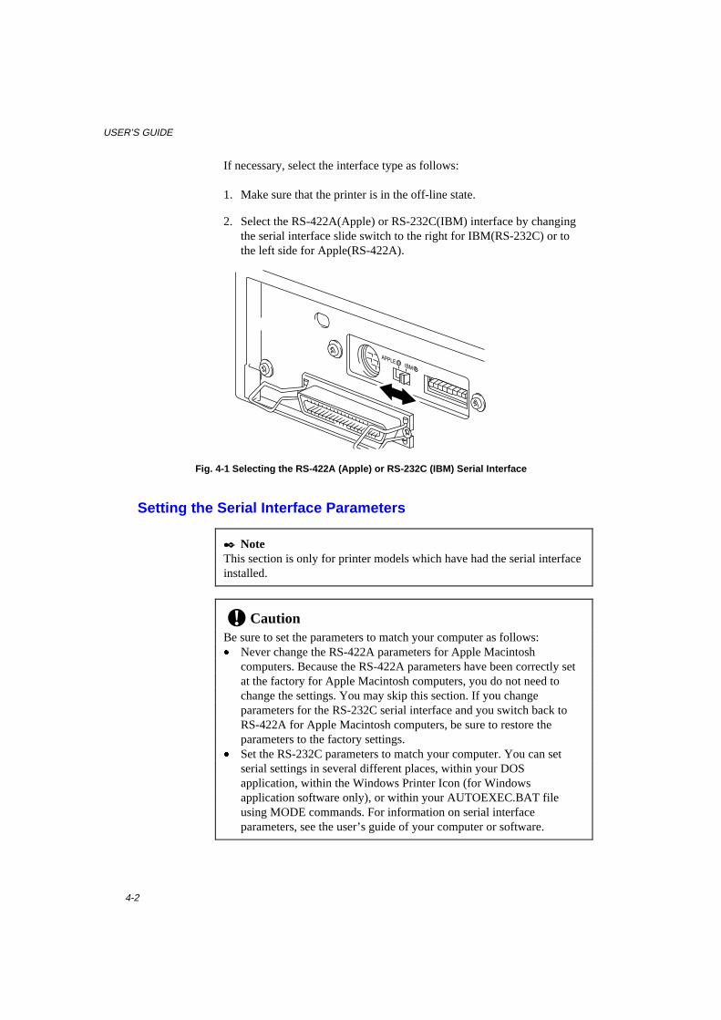
USER’S GUIDE
4-2
If necessary, select the interface type as follows:
1. Make sure that the printer is in the off-line state.
2. Select the RS-422A(Apple) or RS-232C(IBM) interface by changingthe serial interface slide switch to the right for IBM(RS-232C) or tothe left side for Apple(RS-422A).
Fig. 4-1 Selecting the RS-422A (Apple) or RS-232C (IBM) Serial Interface
Setting the Serial Interface Parameters
✒ NoteThis section is only for printer models which have had the serial interfaceinstalled.
! CautionBe sure to set the parameters to match your computer as follows:� Never change the RS-422A parameters for Apple Macintosh
computers. Because the RS-422A parameters have been correctly setat the factory for Apple Macintosh computers, you do not need tochange the settings. You may skip this section. If you changeparameters for the RS-232C serial interface and you switch back toRS-422A for Apple Macintosh computers, be sure to restore theparameters to the factory settings.
� Set the RS-232C parameters to match your computer. You can setserial settings in several different places, within your DOSapplication, within the Windows Printer Icon (for Windowsapplication software only), or within your AUTOEXEC.BAT fileusing MODE commands. For information on serial interfaceparameters, see the user’s guide of your computer or software.

CHAPTER 4 OPTIONS
4-3
If necessary, set the serial interface parameters as follow:
1. Make sure that the printer is in the off-line state.
2. Set the serial interface parameters by moving up (on) or down (off)the selectors of the dual in-line package (DIP) switch.
ON
1 2 3 4 5 6 7 8
Fig. 4-2 Setting the Serial Interface Parameters
Table 1: Serial Interface Parameters Settings
Selector Parameters On (up) Off (down) 1 Baud Rate — See Table 2. — 2 Baud Rate — See Table 2. — 3 Data Length 7 bits 8 bits 4 Stop Bit 2 bits 1 bit 5 Parity — See Table 3. — 6 Parity — See Table 3. — 7 Protocol Xon/Xoff + DTR DTR only 8 Robust Xon On Off
Table 2: Baud Rate Settings
Selector 1 Selector 2 For RS-422A For RS-232C Off Off 57600 9600 On Off 9600 4800 Off On 1200 1200 On On 19200 19200

USER’S GUIDE
4-4
Table 3: Parity Settings
Selector 5 Selector 6 Parity On On Odd On Off Even Off — None
✒ Note� The factory settings are indicated in bold.� If the robust Xon setting is turned on with selector 8, the printer sends
Xon signals at one second intervals to the connected computer until itreceives data. It is effective only if selector 7 is set to the On positionfor the Xon/Xoff plus DTR setting.
Connecting the Serial Interface Cable
✒ NoteThis section is only for printer models which have had the serial interfaceinstalled.
You need a serial interface cable with an 8-pin, DIN-type connector toconnect your printer and computer.
✒ Note� Consult your dealer for a serial interface cable.� If you are a Macintosh user, you can easily find the necessary cable at
a local computer store. Look for Apple serial cables labeled as“Macintosh to ImageWriter II� or “Macintosh to PersonalLaserWriter� 300” or the “Apple System Peripheral 8 Cable”. Do notpurchase a serial cable labeled as “Straight-through” or“LocalTalk.”
� If you are a PC user, you need to purchase a special serial cable fromyour dealer. If you have a 9-pin connector on your computer, look fora cable labeled “IBM AT to ImageWriter II” cable. If you have a 25-pin connector, look for a cable labeled “DB25 to ImageWriter II.”These cables most likely would be found in the Apple Macintoshsection at your computer dealer. For more information about theinterface specification, consult your dealer.

CHAPTER 4 OPTIONS
4-5
You can connect a parallel and a serial interface cable at the same time.The auto interface selection function allows you to share the printer withtwo computers. To do this, connect the parallel interface cable and thenconnect the serial interface cable as follows:
1. Make sure that the power switch is turned off.
! CautionBe sure to turn off the power switch before connecting or disconnectingthe interface cables, or the printer may be damaged.
2. Insert and secure the parallel interface connector into the parallelinterface port of your printer.
3. Insert and secure the serial interface connector into the serial interfaceport of your printer.
4. Turn on the power switch.

USER’S GUIDE
4-6
ADDITIONAL MEMORY (HL-1050 Only)
The HL-820/1020/1040 printers have 2 Mbyte of standard memory andadditional memory cannot be fitted.The HL-1050 printer has 4 Mbyte of standard memory and a slot foroptional additional memory. The memory can be expanded up to 36Mbytes total by installing a commercially available single in-line memorymodule (SIMM).
✒ NoteThe HL-820/1020/1040 machine memory cannot be expanded.
Additional memory is useful and may be necessary if you are using thePage Protection function.
Minimum Memory Recommendation (including resident memory)
Page Protect = AUTO or Off300 dpi 600 dpi
Letter/A4 2 MB 2 MBLegal 2 MB 2 MB
Page Protect = Letter, A4, or Legal300 dpi 600 dpi
Letter/A4 2 MB 6 MBLegal 3 MB 6 MB
The following types of SIMM are recommended and can be installed:� 1 Mbyte HITACHI HB56D25632B-6A, -7A� 2 Mbytes HITACHI HB56D51232B-6A, -7A� 4 Mbytes HITACHI HB56A132BV-7A, -7AL, -7B, -7BL� 8 Mbytes HITACHI HB56A232BT-7A, -7AL, -7B, -7BL� 16 Mbytes HITACHI HB56A432BR-6A, -7A� 32 Mbytes HITACHI HB56A832BS-6A, -7A
This printer can accept memory SIMMS with the followingspecifications:
Speed 60 nsec - 80 nsecPin Type 72 pinHeight 35.00 mm (1.38”) or lessOutput 32 bit or 36 bit

CHAPTER 4 OPTIONS
4-7
✒ NoteThe HL-1050 can also support DIB graphics with a resolution of 1200 x600 dpi under Windows 95/98/3.1 with the supplied printer driver.We recommend to expand the printer memory to avoid any memory fullerror.
✒ NoteThe printer has only one slot for a SIMM upgrade. If you want to increaseyour printer memory again after you have already installed a SIMMmodule into the slot, you will need to remove the previously installedSIMM first. For example if you had previously increased the printermemory from the standard 4MB to 12MB by adding an 8MB SIMM andyou wish to increase your total memory to 36 MB, you need to removethe installed 8MB SIMM and install a new 32MB SIMM into the printer.
Installing the SI MM
To install the SIMM, follow these steps:
1. Turn off the power switch and unplug the AC cord from the ACoutlet. Disconnect the interface cable (printer cable) from the printer.
Fig. 4-3 Unplug the AC Cordand Disconnect the Interface Cable
! CautionBe sure to turn off the power switch and unplug the AC cord to theprinter before installing or removing the SIMM to/from the maincontroller board.

USER’S GUIDE
4-8
2. Unscrew the screws securing the rear plate of the main controllerboard to the printer and pull out the main controller board.
Fig. 4-4 Removing the Main Controller Board
3. Unpack the SIMM and hold it by its edge.
! CautionSIMM boards may be damaged by even a small amount of staticelectricity. Do not touch the memory chips or the board surface. Whenhandling the board and before installing or removing it, wear an antistaticwrist strap, or frequently touch the surface of the antistatic package orbare metal on the printer.
4. Install the SIMM into the slot and push it gently towares the verticaluntil it clicks into place.
Fig. 4-5 Install the SIMM

CHAPTER 4 OPTIONS
4-9
5. Install the main controller board into the printer by sliding it into theguide rails.
6. Secure the main controller board with the four screws.
7. Reconnect the interface cable (printer cable) from your computer.Plug the power cord into the AC outlet and turn on the power switch.
8. To check that the SIMM is installed correctly, you may perform a TestPrint “Print Configuration” which will print the current total memorysize.

CHAPTER 5 MAINTENANCE
5-1
CHAPTER 5 MAINTENANCE
REPLACING THE TONER CARTRIDGE
The printer can print approximately 2,400 pages (5% coverage:A4/Letter) with one toner cartridge. When the toner cartridge is runninglow, the Alarm and Data (Toner) lamps blink once every 5 seconds toindicate toner low. Initially, some models are supplied with a startertoner cartridge which must be replaced after 1,000 pages.
✒ Note� Actual page count will vary depending on your average document
type. (i.e.: standard letter, detailed graphics, etc.)� It is recommended that you always keep a new toner cartridge ready
for use for when you get the toner low warning.� Discard the used toner cartridge according to local regulations. If you
are not sure of them, consult your local dealer. Be sure to seal up thetoner cartridge tightly so that toner powder does not spill out of thecartridge. Do not discard used toner cartridges together with domesticrubbish.
� It is recommended that you clean the printer when you replace thetoner cartridge. See “CLEANING THE PRINTER” in this chapter.
Drum
Alarm
ReadyPaperDataToner
Fig. 5-1 Toner Low and Empty Indication
! CautionYou may print approximately 100 pages after the first toner lowindication. Both Alarm and Data (Toner) lamps will blink continuouslyto indicate that the toner is empty. Once this indication appears, yourprinter cannot resume printing until you have installed a new tonercartridge.

USER’S GUIDE
5-2
! CautionKeep the drum unit level after removing the toner cartridge, to avoid
possible toner spill or scatter.
Follow these steps to replace the toner cartridge:
1. Open the top cover towards you. Remove the drum unit by holdingeach side of the drum and gently lifting the drum forwards towardsyou.
Fig. 5-2 Removing the Drum Unit
✒ NoteIt is recommended to put the drum unit on a piece of disposable paper orcloth in case of accidental toner spill or scatter.

CHAPTER 5 MAINTENANCE
5-3
WarningAfter you have just used the printer, some internal parts of theprinter are extremely hot. When you open the top cover of theprinter, never touch the shaded parts shown in the followingillustration.
High Temperature
Fig. 5-3 Inside the Printer
2. Gently turn the lever on the toner cartridge forward until it stops.
✒ NoteThe toner cartridge cannot be removed unless the shutter is completelyclosed by turning the lever fully to the front.
Fig. 5-4 Turning the Lever to Close the Shutter

USER’S GUIDE
5-4
3. Remove the old toner cartridge from the drum unit by pulling it outgently.
Fig. 5-5 Removing the Old Toner Cartridge
! CautionHandle the toner cartridge carefully. If toner scatters on your hands orclothes, wipe or wash it off with cold water immediately.
4. Unpack the new toner cartridge, gently shake it five or six times andthen remove the protective part.
! Caution� Only unpack the toner cartridge immediately before installing it into
the printer. If toner cartridges are left unpacked for a long period oftime, the toner life is shortened.
� You can only use a Brother genuine toner cartridge (TN-300series) which is specially formulated to ensure top print quality.Using another brand of toner cartridge could void your printer’swarranty.
Fig. 5-6 Shaking the Toner Cartridgeand Remove the Protective Part

CHAPTER 5 MAINTENANCE
5-5
5. Install the new toner cartridge into the right hand side of the drumunit. Make sure that the toner cartridge guide bar is exactly alignedwith the guide slot in the drum unit and pushed fully home into thedrum unit to ensure that the toner cartridge and the drum unit fittogether correctly.
Fig. 5-7 Installing the Toner Cartridgeinto the Drum Unit
6. Gently turn the lever on the toner cartridge backward until it stops.
Fig. 5-8 Turning the Lever to Open the Shutter
7. Turn the drum unit upside down gently.

USER’S GUIDE
5-6
8. Clean the primary corona wire inside the drum unit by gently slidingthe blue tab to the right and left several times.
Fig. 5-9 Cleaning the Primary Corona Wire
9. Re-install the drum unit into the printer and close the top cover.
Fig. 5-10 Close the top cover
Home Position (▲)

CHAPTER 5 MAINTENANCE
5-7
REPLACING THE DRUM UNIT
The printer uses a drum unit to create the print images on paper. If theDrum lamp is on, it indicates the drum unit is nearly at the end of its life.We recommend you prepare a new drum unit to replace the current one.Even if the Drum lamp is on, you may be able to continue to printwithout replacing the drum unit for a while. If there is a noticeabledeterioration in the output print quality even before the Drum lamplights, then the drum unit should be replaced.
Drum
Alarm
ReadyPaperDataToner
Fig. 5-11 Drum Unit Nearly at the End of its Life
! Caution� When removing the drum unit, handle it carefully as it may contain
toner.� You should clean the printer when you replace the drum unit. See
“CLEANING THE PRINTER” in this chapter.
✒ NoteThe drum unit is a consumable, and it is necessary to replace itperiodically.There are many factors that determine the actual drum life, such astemperature, humidity, type of paper and toner that you use, the numberof pages per print job, etc.. The drum life is estimated at approximately20,000 pages at 20 pages per job and 8,000 pages at 1 page per job. Theactual number of pages that your drum will print may be significantly lessthan these estimates. Because we have no control over the many factorsthat determine the actual drum life, we cannot guarantee a minimumnumber of pages that will be printed by your drum.
For best performance, use only genuine Brother toner, and the productshould only be used in a clean, dust-free environment with adequateventilation.

USER’S GUIDE
5-8
Follow these steps to replace the drum unit:
1. Open the top cover towards you. Remove the old drum unit.
Fig. 5-12 Removing the Drum Unit
WarningAfter you have just used the printer, some internal parts of theprinter are extremely hot. When you open the top cover of theprinter, never touch the shaded parts shown in the followingillustration.
High Temperature
Fig. 5-13 Inside the Printer
2. Remove the toner cartridge from the drum unit and keep it in a safeplace. For more information, see “REPLACING THE TONERCARTRIDGE” in this chapter.
✒ Note� Discard the used drum unit according to local regulations. If you are
not sure of them, consult your local dealer/retailer. Be sure to seal upthe drum unit tightly so that toner powder does not spill out of theunit. Do not discard used drum units together with domestic rubbish.
� It is recommended to put the drum unit on a piece of disposable paperor cloth in case of accidental toner spill or scatter.

CHAPTER 5 MAINTENANCE
5-9
Fig. 5-14 Removing the Toner Cartridge
3. Unpack the drum unit and gently shake it five or six timeshorizontally.
Fig. 5-15 Shaking the Drum Unit
! Caution� Do not remove the starter sheet.
Fig. 5-16 Do Not Remove the Starter Sheet� Only unpack a drum unit immediately before installing it into the
printer. If an unpacked drum unit is subjected to excessive directsunlight or room light, the unit may be damaged.
� Handle the toner cartridge and the drum unit carefully as it containstoner. If toner scatters and your hands or clothes get dirty, wipe orwash it off with cold water immediately.
Starter Sheet
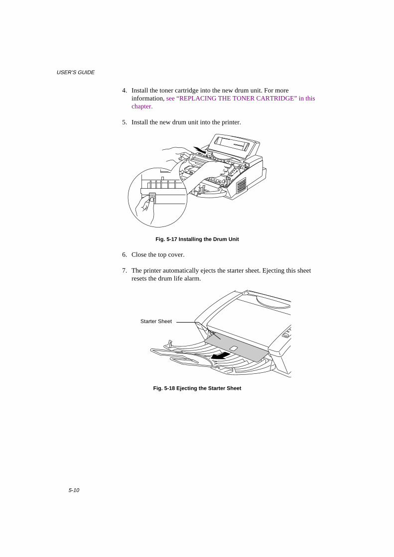
USER’S GUIDE
5-10
4. Install the toner cartridge into the new drum unit. For moreinformation, see “REPLACING THE TONER CARTRIDGE” in thischapter.
5. Install the new drum unit into the printer.
Fig. 5-17 Installing the Drum Unit
6. Close the top cover.
7. The printer automatically ejects the starter sheet. Ejecting this sheetresets the drum life alarm.
Fig. 5-18 Ejecting the Starter Sheet
Starter Sheet

CHAPTER 5 MAINTENANCE
5-11
CLEANING THE PRINTER
Clean the printer exterior and interior periodically. If printed pages getstained with toner, clean the printer interior and drum unit.
Cleaning the Printer Exterior
Clean the printer exterior as follows:
1. Turn off the power switch and unplug the power cord.
WarningThere are high voltage electrodes inside the printer. Before cleaningthe printer, make sure to turn off the power switch and unplug thepower cord from the power outlet
Fig. 5-19 Turning off the Switch and Unplugging
2. Remove the paper in the multi-purpose sheet feeder.
3. Use a damp cloth for cleaning.
! CautionUse water or neutral detergents for cleaning. Cleaning with volatileliquids such as thinners or benzene will damage the surface of the printer.
4. Wipe dirt and dust away from the printer exterior and feeder with acloth.
5. Load paper into the multi-purpose sheet feeder, and plug in the powercord.

USER’S GUIDE
5-12
Cleaning the Printer Interior and Drum Unit
Clean the printer interior and the drum unit as follows:
1. Turn off the power switch and unplug the power cord.
WarningThere are high voltage electrodes inside the printer. Before cleaningthe printer, make sure to turn off the power switch and unplug thepower cord from the outlet.
Fig. 5-20 Turning off the Switch and Unplugging
2. Open the top cover of the printer.
3. Take the drum unit out of the printer and put it aside.
WarningAfter you have just used the printer, some internal parts of theprinter are extremely hot. When you open the top cover of theprinter, never touch the shaded parts shown in the followingillustration.
High Temperature
Fig. 5-21 Inside the Printer

USER’S GUIDE
5-14
4. Gently wipe the scanner window with a soft dry cloth.
Fig. 5-22 Cleaning the Scanner Window
! Caution� Do not touch the scanner window with your fingers.� Do not wipe the scanner window with cleaning alcohol (isopropyl).
5. Turn the drum unit upside down carefully.
! CautionHandle the drum unit carefully as it contains toner. If toner scatters andyour hands or cloths get dirty, wipe or wash it off with cold waterimmediately.
✒ NoteIt is recommended to put the drum unit on a piece of disposable paper orcloth in case of accidental toner spill or scatter.
Scanner Window

USER’S GUIDE
5-14
6. Clean the primary corona wire inside the drum unit by gently slidingthe tab to the right and left several times.
Fig. 5-23 Cleaning the Primary Corona Wire
7. Return the tab to the home position (▲ mark position) beforereinstalling the drum unit.
! CautionBe sure to position the tab at the home position, or printed pages mayhave vertical stripes.
8. Install the drum unit into the printer.See the section “REPLACING THE DRUM UNIT” in Chapter 5.
9. Close the top cover.
10. Plug in the power cord and turn on the power switch.
Home Position (▲)

CHAPTER 5 MAINTENANCE
5-15
RE-PACKING THE PRINTER
! CautionWhenever you transport the printer, use the packing materials which areprovided with your printer. Also, follow the steps below to re-pack theprinter, or the printer may be damaged which will void the printer’swarranty.
1. Turn off the power switch and unplug the printer from the AC outlet.Remove the AC cord and the extention wire of the paper tray from theprinter.
2. Open the top cover.
3. Remove the drum unit assembly, referring to the previous section.
✒ NoteRemove the drum unit assembly with the toner cartridge included.
Fig. 5-24 Removing the Drum Unit Assembly

USER’S GUIDE
5-16
4. Place the drum unit assembly in the plastic bag and seal the bagcompletely.
Fig. 5-25 Placing the Drum Unit in the Plastic Bag
5. Close the top cover, the extension wire, and the output tray.
6. Wrap the printer in the plastic bag and place it in the original cartonbox with the original Styrofoam packing material.
7. Place any documents (manual and any documentation describing thereason for repacking the printer) and the drum unit assembly in thecarton box as shown below.
8. Close the carton box and tape it.
Fig. 5-26 Repacking the Printer
Drum UnitIncluding TonerCartridge
Carton
Printer
Manuals

CHAPTER 6 TROUBLESHOOTING
6-1
CHAPTER 6 TROUBLESHOOTING
ALARM INDICATIONS AT A GLANCE
Operator Calls
If a recoverable error occurs, the printer indicates an ‘operator call’ byblinking the Alarm lamp and any of the following lamps.
Find the error and take the proper action to correct it. The printerautomatically recovers from most errors, but you may need to reset theprinter with the panel switch as described below.
Blinking Lamp Error Action
Paper ❍↔●
Alarm ❍↔●
Paper jam Clear the paper jam referring to the next section“PAPER JAMS” and press the panel switch ifthe printer does not automatically resume printing.
Paper empty Load paper in the printer referring to Chapter 2and press the panel switch .
Misfeed Reinstall the paper and press the panel switch .
Toner ❍↔●
Alarm ❍↔●
(every 5 seconds)
Toner low Indicates that the printer has approximately 100pages of printing left before the toner cartridge isempty. Prepare a new toner cartridge.
Toner ❍↔●
Alarm ❍↔●
(Fast blinking)
Toner Empty Replace the toner cartridge with a new onereferring to Chapter 5.

USER’S GUIDE
6-2
For errors shown below, the printer indicates an operator call by blinkingthe Alarm lamp. If you use the printer with the supplied Windows driver,the status monitor will appear to indicate the error on your computerscreen. The HL-1040/1050 printer also prints some error messages onpaper.
Error Action
COVER OPEN Close the top cover of the printer.
PRINT OVERRUN � Press the panel switch to print the data remaining in theprinter.
� If you use the supplied Windows driver, try again afterturning on Error Recovery in the PRINT menu of yourapplication software, (Refer to Help section in Windowsprinter driver for the details.)
� For HL-1050 onlyExpand the printer memory with an optional memoryboard and set page protection to ON by using the suupliedWindows driver or RPC program.
� For HL-1050 onlyChange the following settings in the supplied Windowsdriver and try again. The best combination of the settngsbelow will vary depending on your document.
Graphics ModeTrueType� modeUse Printer TrueType� Fonts
� If this does not clear the error, reduce the complexity ofyour document or reduce the print resolution.
MEMORY FULL
(For HL-1040/1050 Only)This error can occur onlywhen using DOS orMacintosh.
� Press the panel switch to print the data remaining in theprinter.
� Reduce the print resolution or reduce the complexity ofyour document.
� For HL-1050 onlyExpand the printer memory.by adding a commerciallyavailable SIMM.
Parallel Interface LineError
� Press the panel switch to resume printing.� Check that the connection between your computer and
printer is secure and correct, and check the interface cable.Serial Interface FramingError
(For HL-1040/1050 Only)
� Press the panel switch to resume printing.� Check the communication parameters such as baud rate
and stop bit settingson both your computer and printer.
Serial Interface ParityError
(For HL-1040/1050 Only)
� Press the panel switch to resume printing.� Check the communication parameters such as bit length
and parity settings on both your computer and printer.

CHAPTER 6 TROUBLESHOOTING
6-3
Error Action
Serial Interface OverrunError
(For HL-1040/1050 Only)
� Press the panel switch to resume printing.� The interface hardware may be damaged. Consult your
dealer.
Serial Interface InputBuffer Overflow
(For HL-1040/1050 Only)
� Press the panel switch to resume printing.� Check the communication parameters such as the
handshake protocols on both your computer and printer.� If the error occurs again, the interface hardware may be
damaged. Consult your dealer.
✒ NoteIf the printer does not operate as you expect it to, it is recommended thatyou turn off the power switch, wait a few seconds and then turn it onagain. If you still have problems, consult your dealer or our authorizedservice representative.

USER’S GUIDE
6-4
Service Calls
If an unrecoverable error occurs, the printer indicates the need for aservice call by lighting all the lamps and then the following combinationof lamps alternately:
Service Call Fusermalfunction
Laser BDmalfunction
Scannermalfunction
ROM error
Drum ● ❍ ● ❍Alarm ❍ ● ● ❍Ready ❍ ❍ ❍ ●Data ❍ ❍ ❍ ❍
Service Call D-RAM error Service A Service B Service CDrum ● ❍ ● ❍Alarm ❍ ● ● ❍Ready ● ● ● ❍Data ❍ ❍ ❍ ●
Service Call Service D Service E0 Service E1 Service PDrum ● ❍ ● ❍Alarm ❍ ● ● ❍Ready ❍ ❍ ❍ ●Data ● ● ● ●
Service Call NV-RAMerror
CPU Runtimeerror
Drum ● ●Alarm ❍ ●Ready ● ●Data ● ● ● ON ❍ OFF
If you see any of these service call indications, turn off the powerswitch, wait a few seconds and then turn it on again and try to print again.
If you cannot clear the error and see the same service call indication afterturning on the printer, consult your dealer or our authorized servicerepresentative. Report the error status and situation referring to the abovetable.
✒ NoteBe sure that the top cover and the main controller board are firmlyinstalled.

CHAPTER 6 TROUBLESHOOTING
6-5
PAPER JAMS
Before you can clear a paper jam error, you need to find the location ofthe paper jams. Locate the position referring to the following figure.
Fig. 6-1 Locating Paper Jam Position
After locating the position, clear the jammed paper referring to thefollowing descriptions. If the jammed paper is removed completely andthe top cover is closed, the printer may resume printing automatically. Ifthe printer does not resume printing, press the control panel switch .
WarningAfter you have just used the printer, some internal parts of theprinter are extremely hot. When you open the top cover of theprinter, never touch the shaded parts shown in the followingdiagram.
High Temperature
Fig. 6-2 Inside the Printer
Paper
Multi-PurposeSheet Feeder
Drum Unit
Top Cover

USER’S GUIDE
6-6
! CautionDo not pull jammed paper from the output tray. Be sure to open thetop cover to remove the jam, or the fuser may get dirty with toner powderand may result in toner scatter on the next printed page or pages.
Fig. 6-3 Do Not Pull the Jammed Paper from the Output Tray
❏ Paper Jam in the Multi-Purpose Sheet Feeder
If a paper jam has occurred inside the multi-purpose sheet feeder,open the multi-purpose sheet feeder to pull the jammed paper upwardout of the feeder; then close the multi-purpose sheet feeder. Also,open the top cover and check that a torn piece of paper does notremain inside the printer referring to the next section.
Fig. 6-4 Paper Jam in the Feeder
If the paper cannot be pulled up, see the next section “Paper Jam nearthe Drum Unit.”

CHAPTER 6 TROUBLESHOOTING
6-7
❏ Paper Jam near the Drum Unit or at the Paper Output Tray
If a paper jam has occurred near the drum unit, open the top cover andremove the drum unit. Then, pull the jammed paper upwards and outof the printer. Install the drum unit and close the top cover.
Fig. 6-5 Paper Jam near the Drum Unit
❏ Paper Jam in the Fuser Unit
If a paper jam has occurred in the fuser unit, open the top cover andremove the drum unit. Then, pull the jammed paper out of the fuser.Install the drum unit and close the top cover.
Fig. 6-6 Paper Jam Inside the Printer

USER’S GUIDE
6-8
Q & A
This section contains questions and answers for using your printer. If youhave encountered a problem, find the question relating to your problemand take the steps recommended to correct the problem.
Setting Up the Printer Hardware
Question RecommendationThe printer does not work. Alllamps are off.
The printer may be in sleep mode. Press the panelswitch to wake up the printer. Check to see if theprinter is plugged into a live power source and thepower switch is on.
The printer does not print. Check the following:� The printer is turned on.� All of the protective parts have been removed.� The toner cartridge and drum unit are installed
properly.� The interface cable is securely connected between
the printer and computer.� Check to see if the Alarm lamp is blinking. If the
lamp is blinking, refer to the Operator Call sectionof this manual.
� Check to see if the Ready lamp is blinking. If thelamp is blinking fast, the printer might be coolingdown to lower the printers internal temperature.Open the top cover of the printer to lower thetemperature.
Setting Up the Printer for Windows
Question RecommendationI cannot print from myapplication software.
� Make sure the supplied Windows printer driver isinstalled and selected with your applicationsoftware.
� (For HL-1040/1050)If you use the serial interface, make sure that theserial slide switch of the serial interface is in thecorrect position and the interface settings arecorrectly set up with the DIP switches.

CHAPTER 6 TROUBLESHOOTING
6-9
Question RecommendationSometimes I get the memoryFull message. How can Icorrect this?
� Reduce the print resolution or reduce thecomplexity of your document and try again.
� (For HL-1050)Expand the printer memory by adding acommercially available SIMM.
� (For HL-1050)Change the following settings in the suppliedWindows driver and try again. The bestcombination of the following settings may varydepending on your document.
Graphics ModeTrueType ModeUse Printer TrueType Fonts
Sometimes I get a PrintOverrun error when printingcertain documents fromWindows.
� If you are using the supplied Windows driver, turnerror recovery on in the Setup dialog box and tryagain.
� Reduce the print resolution or reduce thecomplexity of your document and try again.
� (For HL-1050)Expand the printer memory by installing acommercially available SIMM and set the PageProtection ON in the supplied Windows driver.
� (For HL-1050)Change the following settings in the suppliedWindows driver and try again. The bestcombination of the following settings may varydepending on your document.
Graphics ModeTrueType ModeUse Printer TrueType Fonts

USER’S GUIDE
6-10
Setting Up the Printer for DOS (For HL-1040/1050 Only)
Question RecommendationI cannot print from myapplication software.
� Check if the DOS application software interfacesettings match that of your printer: for example, ifyou are using a parallel printer cable, you wouldmost likely set your DOS software printer port toLPT1.
� Check if the printer has any printer alarms active.� Check if the appropriate printer is selected in your
application software.� The HL-820/1020 cannot print from DOS
applications.� If the serial interface is used, make sure that the
RS-232C serial interface is selected with the slideswitch. Make sure that the interface settings arecorrectly set up with the proper DIP switches.Make sure the serial parameters of baud rates,parity and stop bits match between yourapplication software and the printer.
The printer prints, but it printsincorrect information.Sometimes it prints a couple ofcharacters and then ejects thepage, etc.
This is an indication that your application printeremulation setting and the printer’s emulation do notmatch. Check in your application software whichprinter you have selected to make sure the printer isset up correctly. Remember the printer emulates threewidely used printer selections: HL-1040 (HP LaserJetIIP, Epson FX-850, and IBM Proprinter XL) / HL-1050 (HP LaserJet 6L/6P, Epson FX-850 and IBMProprinter XL). Try setting the printer into HPemulation and then select the HP LaserJet IIP (forHL-1040) or HP LaserJet 6P/6L (for HL-1050)printer in your application software.
The printer does not print whenI press the Print Screen Key.(Data lamp On)
Press the panel switch . The data has been sent to theprinter but the printer did not receive the Page Ejectcommand: print screens do not send this command.
The printer prints the first partof my document but does notprint the last page.(Data lamp On)
This was a common problem with database softwareand spreadsheet software when not correctly set up.The data has been sent to the printer but the printerdid not receive the Page Eject command. Press thepanel switch to eject the page. Then check with yoursoftware supplier on how to add a Page Eject (orForm Feed) command to the end of your print job.
How can I change the Usersettings or default settings ofthe printer?
Use the remote printer console (RPC) program.

CHAPTER 6 TROUBLESHOOTING
6-11
Setting Up the Printer for Apple Macintosh Computers When theOptional RS-100M Serial Interface Is Installed into Your Printer(For HL-1040/1050 Only)
Question RecommendationI cannot print from myapplication software.
� Make sure that the supplied Macintosh printerdriver is installed in the System Folder and it isselected with Chooser.
� Check the PORT selection within the Chooser: itshould match the port to which you physicallyattached the printer cable.
� The serial slide switch of the optional interfaceboard should be in the Apple (RS-422A) position.
� Check the printer cable type: you cannot use aLocalTalk or straight-through cable. Refer toChapter 4 for details on printer cable type.
Paper Handling
Question RecommendationThe printer does not loadpaper.
� Check to see if the “PAPER EMPTY” messageappears on your computer screen or the Alarmand Paper lamps are blinking on the printercontrol panel. If so, the multi-purpose sheet feedermay be out of paper or not properly installed. If itis empty, load a new stack of paper into thefeeder.
� If there is paper in the multi-purpose sheet feeder,make sure it is straight. If the paper is curled, youshould straighten it before printing. Sometimes itis helpful to remove the paper, turn the stack overand put it back into the paper tray.
� Reduce the amount of paper in the multi-purposesheet feeder, then try again.
The printer does not load paperfrom the manual feed slot.
Re-insert the paper firmly, one sheet at a time.
How can I load envelopes? You can load envelopes from either the multi-purposesheet feeder or the manual feed slot. Your applicationsoftware must be set up correctly to print on theenvelope size you are using. This is usually done inthe page setup or document setup menu of yoursoftware. Refer to your application manual.
What paper can I use? You can use plain paper, envelopes, transparencies,labels, and organizer paper. For information onloading paper, see “Paper Handling” in Chapter 2.
How can I clear paper jams? See “PAPER JAMS” in this chapter.

USER’S GUIDE
6-12
Printing
Question RecommendationThe printer prints unexpectedlyor it prints garbage.
� Turn the printer off and on again to reset theprinter.
� Make sure your application software is correctlyset up to use this printer by checking the printersettings in your application software.
� (For HL-1040/1050)Check the printer emulation settings. If you canuse the supplied RPC program, use it to changethe settings as required. Also, you can print thecurrent setting list from the RPC program orPrinter Control Panel.
� (For HL-1040/1050)Make sure that the correct interface type andsettings are made to match your computer. Be sureto use the RS-422A serial interface for Macintoshcomputers and the RS-232C serial interface forPCs. Refer to “SERIAL INTERFACE BOARDRS100M” in Chapter 4.
The printer cannot print fullpages of a document. An errormessage “PRINT OVERRUN”occurs.
The printer received a very complex print job andcould not process part of the page. This may besolved by the following ways.� If you are using Windows 95/98 or Windows 3.1
with the supplied printer driver, see the “Settingup the Printer for Windows” section.
� Try to reduce the complexity of your document orreduce the print resolution.
The printer prints the firstcouple of pages correctly, thensome pages have text missing.(For HL-1040/1050 Only)
This is a problem usually relating to serial interfacesettings. Your computer is not recognizing theprinter’s input buffer full signal. Causes could beincorrect serial cable (incorrectly wired or too long)or incorrect setting of your computer serial interface.

CHAPTER 6 TROUBLESHOOTING
6-13
Question RecommendationThe printer cannot print fullpages of a document. A"MEMORY FULL" errormessage occurs.(For HL-1040/1050 Only)
� (For HL-1050)Change the following settings in the suppliedWindows driver and try again. The bestcombination of the following settings may varydepending on your document.
Graphics ModeTrueType ModeUse Printer TrueType Fonts
� Reduce the graphic quality or the number of fontsizes within your application software.
� Reduce the printer resolution.� Reduce the complexity of your document and try
again.� (For HL-1050)
Expand the printer memory by adding acommercially available SIMM and set the PageProtection to ON by using the supplied Windowsdriver.
The printer cannot print fullpages of a document. A"MEMORY FULL" errormessage occurs.(For HL-10-40/1050 Only)
� (For HL-1050)Expand the printer memory by installing acommercially available memorySIMM.
� Reduce the printer resolution.� Reduce the complexity of your document and try
again.� Reduce the graphic quality or the number of font
sizes within your application software.My headers or footers appearwhen I view my document onscreen but do not show upwhen I print them.
Most laser printers have a restricted area that cannotbe printed on. Usually the first two lines and last twolines of text cannot print (leaving 62 printable lines).Adjust the top and bottom margins in your documentto allow for this.

USER’S GUIDE
6-14
Print Quality
! CautionYou will clear a print quality problem by replacing the drum unit with anew one if the Drum lamp is on. The drum unit is at the end of its life.
Question RecommendationPrinted pages contain whitestripes.
Here come Flat-top ,he come. One thing I can tell you is you go to be free. Come together right now, over
me. Here come Flat-top ,he come. One thing I can tell you is you go to be free. Come together right now,
over me. Here come Flat-top ,he come. One thing I can tell you is you go to be free. Come together rightA
now, over me. Here come Flat-top ,he come. One thing I can tell you is you go to be free. Come togetherA
right now, over me. Here come Flat-top ,he come. One thing I can tell you is you go to be free. Come AAA
together right now, over me. Here come Flat-top ,he come. One thing I can tell you is you go to be free. A
Come together right now, over me. Here come Flat-top ,he come. One thing I can tell you is you go to beA
free. Come together right now, over me. Here come Flat-top ,he come. Lucy in the sky with Diamonde. AA
One thing I can tell you is you go to be free. Come together right now, over me. Here come Flat-top ,heAA
come. One thing I can tell you is you go to be free. Come together right now, over me. Here come Flat-top
,he come. One thing I can tell you is you go to be free. Come together right now, over me. Here come Flat-
top ,he come. One thing I can tell you is you go to be free. Come together right now, over me. Lucy in the
sky with Diamonde. Here come Flat-top ,he come. One thing I can tell you is you go to be free. Come AAA
together right now, over me. Here come Flat-top ,he come. One thing I can tell you is you go to be free. A
Come together right now, over me. Here come Flat-top ,he come. One thing I can tell you is you go to be
free. Come together right now, over me. Here come Flat-top ,he come. One thing I can tell you is you goA
to be free. Come together right now, over me. Here come Flat-top ,he come. Lucy in the sky with AAAAA
Diamonde. One thing I can tell you is you go to be free. Come together right now, over me. Here come A
Flat-top ,he come. One thing I can tell you is you go to be free. Come together right now, over me. HereA
come Flat-top ,he come. One thing I can tell you is you go to be free. Come together right now, over me. A
Here come Flat-top ,he come. One thing I can tell you is you go to be free. Come together right now, over
me. Here come Flat-top ,he come. One thing I can tell you is you go to be free. Come together right now,
over me. Here come Flat-top ,he come. Lucy in the sky with Diamonde. One thing I can tell you is you go
to be free. Come together right now, over me. Here come Flat-top ,he come. One thing I can tell you is you
go to be free. Come together right now, over me. Here come Flat-top ,he come. One thing I can tell you is
you go to be free. Come together right now, over me. Here come Flat-top ,he come. One thing I can tell A
you is you go to be free. Come together right now, over me. Here come Flat-top ,he come. One thing I can
tell you is you go to be free. Come together right now, over me. Here come Flat-top ,he come. One thing I
can tell you is you go to be free. Come together right now, over me. Here come Flat-top ,he come. One A
thing I can tell you is you go to be free. Come together right now, over me. Here come Flat-top ,he come.
One thing I can tell you is you go to be free. Come together right now, over me. Here come Flat-top ,he A
come. One thing I can tell you is you go to be free. Come together right now, over me. Here come Flat-top
,he come. One thing I can tell you is you go to be free. Come together right now, over me. Here come Flat-
top ,he come. One thing I can tell you is you go to be free. Come together right now, over me. Here come
Flat-top ,he come. Lucy in the sky with Diamonde. One thing I can tell you is you go to be free. Come AAA
Fig. 6-7 White Stripes or FaintImages
You may clear the problem by wiping the scannerwindows with a soft cloth. (See “Cleaning the printerinterior and Drum unit.” in Chapter 5.)
If the same problem occurs and the Drum lamp isstill on after cleaning, replace the drum unit with anew one.
Printed pages are stained withtoner or have vertical stripes.
Here come Flat-top ,he come. One thing I can tell you is you go to be free. Come together right now, over
me. Here come Flat-top ,he come. One thing I can tell you is you go to be free. Come together right now,
over me. Here come Flat-top ,he come. One thing I can tell you is you go to be free. Come together rightA
now, over me. Here come Flat-top ,he come. One thing I can tell you is you go to be free. Come togetherA
right now, over me. Here come Flat-top ,he come. One thing I can tell you is you go to be free. Come AAA
together right now, over me. Here come Flat-top ,he come. One thing I can tell you is you go to be free. A
Come together right now, over me. Here come Flat-top ,he come. One thing I can tell you is you go to beA
free. Come together right now, over me. Here come Flat-top ,he come. Lucy in the sky with Diamonde. AA
One thing I can tell you is you go to be free. Come together right now, over me. Here come Flat-top ,heAA
come. One thing I can tell you is you go to be free. Come together right now, over me. Here come Flat-top
,he come. One thing I can tell you is you go to be free. Come together right now, over me. Here come Flat-
top ,he come. One thing I can tell you is you go to be free. Come together right now, over me. Lucy in the
sky with Diamonde. Here come Flat-top ,he come. One thing I can tell you is you go to be free. Come AAA
together right now, over me. Here come Flat-top ,he come. One thing I can tell you is you go to be free. A
Come together right now, over me. Here come Flat-top ,he come. One thing I can tell you is you go to be
free. Come together right now, over me. Here come Flat-top ,he come. One thing I can tell you is you goA
to be free. Come together right now, over me. Here come Flat-top ,he come. Lucy in the sky with AAAAA
Diamonde. One thing I can tell you is you go to be free. Come together right now, over me. Here come A
Flat-top ,he come. One thing I can tell you is you go to be free. Come together right now, over me. HereA
come Flat-top ,he come. One thing I can tell you is you go to be free. Come together right now, over me. A
Here come Flat-top ,he come. One thing I can tell you is you go to be free. Come together right now, over
me. Here come Flat-top ,he come. One thing I can tell you is you go to be free. Come together right now,
over me. Here come Flat-top ,he come. Lucy in the sky with Diamonde. One thing I can tell you is you go
to be free. Come together right now, over me. Here come Flat-top ,he come. One thing I can tell you is you
go to be free. Come together right now, over me. Here come Flat-top ,he come. One thing I can tell you is
you go to be free. Come together right now, over me. Here come Flat-top ,he come. One thing I can tell A
you is you go to be free. Come together right now, over me. Here come Flat-top ,he come. One thing I can
tell you is you go to be free. Come together right now, over me. Here come Flat-top ,he come. One thing I
can tell you is you go to be free. Come together right now, over me. Here come Flat-top ,he come. One A
thing I can tell you is you go to be free. Come together right now, over me. Here come Flat-top ,he come.
One thing I can tell you is you go to be free. Come together right now, over me. Here come Flat-top ,he A
come. One thing I can tell you is you go to be free. Come together right now, over me. Here come Flat-top
,he come. One thing I can tell you is you go to be free. Come together right now, over me. Here come Flat-
top ,he come. One thing I can tell you is you go to be free. Come together right now, over me. Here come
Flat-top ,he come. Lucy in the sky with Diamonde. One thing I can tell you is you go to be free. Come AAA
Fig. 6-8 Dark Stripes or TonerStains
� Clean the printer interior and the primary coronawire of the toner cartridge. See “Cleaning thePrinter Interior and Drum Unit” in Chapter 5.
� Make sure that the tab of the corona wire is at thehome position.
If the same print problem occurs and the Drum lampis still on after cleaning, replace the drum unit with anew one.
Printed pages have white spotsin black text and graphics area.
Fig. 6-9 White Spots
Make sure that you use paper that meets thespecifications. Rough surface or thick media cancause the problem.
If you still have the same problem and the Drumlamp is on, replace the drum unit with a new one.

CHAPTER 6 TROUBLESHOOTING
6-15
Question RecommendationToner scatters and stains theprinted page.
Fig. 6-10 Scattering Toner
Clean the printer interior. See “Cleaning the PrinterInterior and Drum Unit” in Chapter 5.
Make sure that you use paper that meetsspecifications.
After the new toner cartridge is installed, the first 10- 20 pages may be stained with toner. This problemwill be cleared after the first 10-20 pages with thenew toner cartridge.
If you still have the same problem and the Drumlamp is on, replace the drum unit with a new one.
The whole page is printed inblack.
Fig. 6-11 Black Page
Wipe the electric terminals referring to “Cleaning thePrinter Interior and Drum Unit” in Chapter 5. Neveruse heat-sensitive paper as it will cause this problem.
If the same problem occurs and the Drum lamp isstill on after cleaning, replace the drum unit with anew one.
Nothing is printed on the page.
Fig. 6-12 White Page
� Make sure that the toner cartridge is not empty.� Wipe the electric terminals referring to “Cleaning
the Printer Interior and Drum Unit” in Chapter 5.� Make sure that a torn piece of paper does not
remain on the scanner window.
Printed pages are marked atregular intervals.
Here come Flat-top ,he come. One thing I can tell you is you go to be free. Come together right now, over
me. Here come Flat-top ,he come. One thing I can tell you is you go to be free. Come together right now,
over me. Here come Flat-top ,he come. One thing I can tell you is you go to be free. Come together rightA
now, over me. Here come Flat-top ,he come. One thing I can tell you is you go to be free. Come togetherA
right now, over me. Here come Flat-top ,he come. One thing I can tell you is you go to be free. Come AAA
together right now, over me. Here come Flat-top ,he come. One thing I can tell you is you go to be free. A
Come together right now, over me. Here come Flat-top ,he come. One thing I can tell you is you go to beA
free. Come together right now, over me. Here come Flat-top ,he come. Lucy in the sky with Diamonde. AA
One thing I can tell you is you go to be free. Come together right now, over me. Here come Flat-top ,heAA
come. One thing I can tell you is you go to be free. Come together right now, over me. Here come Flat-top
,he come. One thing I can tell you is you go to be free. Come together right now, over me. Here come Flat-
top ,he come. One thing I can tell you is you go to be free. Come together right now, over me. Lucy in the
sky with Diamonde. Here come Flat-top ,he come. One thing I can tell you is you go to be free. Come AAA
together right now, over me. Here come Flat-top ,he come. One thing I can tell you is you go to be free. A
Come together right now, over me. Here come Flat-top ,he come. One thing I can tell you is you go to be
free. Come together right now, over me. Here come Flat-top ,he come. One thing I can tell you is you goA
to be free. Come together right now, over me. Here come Flat-top ,he come. Lucy in the sky with AAAAA
Diamonde. One thing I can tell you is you go to be free. Come together right now, over me. Here come A
Flat-top ,he come. One thing I can tell you is you go to be free. Come together right now, over me. HereA
come Flat-top ,he come. One thing I can tell you is you go to be free. Come together right now, over me. A
Here come Flat-top ,he come. One thing I can tell you is you go to be free. Come together right now, over
me. Here come Flat-top ,he come. One thing I can tell you is you go to be free. Come together right now,
over me. Here come Flat-top ,he come. Lucy in the sky with Diamonde. One thing I can tell you is you go
to be free. Come together right now, over me. Here come Flat-top ,he come. One thing I can tell you is you
go to be free. Come together right now, over me. Here come Flat-top ,he come. One thing I can tell you is
you go to be free. Come together right now, over me. Here come Flat-top ,he come. One thing I can tell A
you is you go to be free. Come together right now, over me. Here come Flat-top ,he come. One thing I can
tell you is you go to be free. Come together right now, over me. Here come Flat-top ,he come. One thing I
can tell you is you go to be free. Come together right now, over me. Here come Flat-top ,he come. One A
thing I can tell you is you go to be free. Come together right now, over me. Here come Flat-top ,he come.
One thing I can tell you is you go to be free. Come together right now, over me. Here come Flat-top ,he A
come. One thing I can tell you is you go to be free. Come together right now, over me. Here come Flat-top
,he come. One thing I can tell you is you go to be free. Come together right now, over me. Here come Flat-
top ,he come. One thing I can tell you is you go to be free. Come together right now, over me. Here come
Flat-top ,he come. Lucy in the sky with Diamonde. One thing I can tell you is you go to be free. Come AAA
Here come Flat-top ,he come. One thing I can tell you is you go to be free. Come together right now, over
me. Here come Flat-top ,he come. One thing I can tell you is you go to be free. Come together right now,
over me. Here come Flat-top ,he come. One thing I can tell you is you go to be free. Come together rightA
now, over me. Here come Flat-top ,he come. One thing I can tell you is you go to be free. Come togetherA
right now, over me. Here come Flat-top ,he come. One thing I can tell you is you go to be free. Come AAA
together right now, over me. Here come Flat-top ,he come. One thing I can tell you is you go to be free. A
Come together right now, over me. Here come Flat-top ,he come. One thing I can tell you is you go to beA
free. Come together right now, over me. Here come Flat-top ,he come. Lucy in the sky with Diamonde. AA
One thing I can tell you is you go to be free. Come together right now, over me. Here come Flat-top ,heAA
come. One thing I can tell you is you go to be free. Come together right now, over me. Here come Flat-top
,he come. One thing I can tell you is you go to be free. Come together right now, over me. Here come Flat-
top ,he come. One thing I can tell you is you go to be free. Come together right now, over me. Lucy in the
sky with Diamonde. Here come Flat-top ,he come. One thing I can tell you is you go to be free. Come AAA
together right now, over me. Here come Flat-top ,he come. One thing I can tell you is you go to be free. A
Come together right now, over me. Here come Flat-top ,he come. One thing I can tell you is you go to be
free. Come together right now, over me. Here come Flat-top ,he come. One thing I can tell you is you goA
to be free. Come together right now, over me. Here come Flat-top ,he come. Lucy in the sky with AAAAA
Diamonde. One thing I can tell you is you go to be free. Come together right now, over me. Here come A
Flat-top ,he come. One thing I can tell you is you go to be free. Come together right now, over me. HereA
come Flat-top ,he come. One thing I can tell you is you go to be free. Come together right now, over me. A
Here come Flat-top ,he come. One thing I can tell you is you go to be free. Come together right now, over
me. Here come Flat-top ,he come. One thing I can tell you is you go to be free. Come together right now,
over me. Here come Flat-top ,he come. Lucy in the sky with Diamonde. One thing I can tell you is you go
to be free. Come together right now, over me. Here come Flat-top ,he come. One thing I can tell you is you
go to be free. Come together right now, over me. Here come Flat-top ,he come. One thing I can tell you is
you go to be free. Come together right now, over me. Here come Flat-top ,he come. One thing I can tell A
you is you go to be free. Come together right now, over me. Here come Flat-top ,he come. One thing I can
tell you is you go to be free. Come together right now, over me. Here come Flat-top ,he come. One thing I
can tell you is you go to be free. Come together right now, over me. Here come Flat-top ,he come. One A
thing I can tell you is you go to be free. Come together right now, over me. Here come Flat-top ,he come.
One thing I can tell you is you go to be free. Come together right now, over me. Here come Flat-top ,he A
come. One thing I can tell you is you go to be free. Come together right now, over me. Here come Flat-top
,he come. One thing I can tell you is you go to be free. Come together right now, over me. Here come Flat-
top ,he come. One thing I can tell you is you go to be free. Come together right now, over me. Here come
Flat-top ,he come. Lucy in the sky with Diamonde. One thing I can tell you is you go to be free. Come AAA
Fig. 6-13 Example of RegularMarking
The problem may disappear by itself. Try printingmultiple pages to clear this problem especially if theprinter has not been used for a long time.
If the surface of the drum has been scratched, replacethe drum unit with a new one.
If the problem does not disappear, it may be that thedrum has been marked or damaged due to excessiveexposure to light. In this case, replace the drum unitwith a new one.

USER’S GUIDE
6-16
Question RecommendationPrinted pages are blurred at thecenter or either edge.
Here come Pat-top ,he come. One thing I can tell you is you go to be free. Come together right now, over
me. Here come Pat-top ,he come. One thing I can tell you is you go to be free. Come together right now,
over me. Here come Pat-top ,he come. One thing I can tell you is you go to be free. Come together rightA
now, over me. Here come Pat-top ,he come. One thing I can tell you is you go to be free. Come togetherA
right now, over me. Here come Pat-top ,he come. One thing I can tell you is you go to be free. Come AAA
together right now, over me. Here come Pat-top ,he come. One thing I can tell you is you go to be free. A
Come together right now, over me. Here come Pat-top ,he come. One thing I can tell you is you go to beA
free. Come together right now, over me. Here come Pat-top ,he come. Diamonde the skyLucy in with .
AA One thing I can tell you is you go to be free. Come in the sky right now, over me. Here come Pat-top
,heAA come. One thing I can tell you is you go to be free. Come together right now, over me. Here come
Pat-top ,he come. One thing I can tell you is you go to be free. Come in the sky right now, over me. Here
come Flat-top ,he come. One thing I can tell you is you go to be free. Come tin the sky right now, over me.
in the sky Lucy Diamonde with . Here come Pat-top ,he come. One thing I can tell you is you go to be free.
Come AAA together right now, over me. Here come Pat-top ,he come. One thing I can tell you is you go to
be free. A Come together right now, over me. Here come Pat-top ,he come. One thing I can tell you is you
go to be free. together Comeright now, over me. Here come Pat-top ,he come. One thing I can tell you is
you goA to be free. Come together right now, over me. Here come Pat-top ,he come. Lucy in the sky with
AAAAA Diamonde. One thing I can tell you is you go to be free. Come tin the sky right now, over me. Here
come A Pat-top ,he come. One thing I can tell you is you go to be free. Come in the sky right now, over
me. HereA come Pat-top ,he come. One thing I can tell you is you go to be free. Come tin the sky right
now, over me. A Here come Pat-top ,he come. One thing I can tell you is you go to be free. Come together
right now, over me. Here come Pat-top ,he come. One thing I can tell you is you go to be free. Come
together right now, over me. Here come v ,he come. Lucy Diamonde in the sky with . One thing I can tell
you is you go to be free. Come tin the skyright now, over me. Here come Pat-top ,he come. One thing I
can tell you is you go to be free. Come in the sky right now, over me. Here come Pat-top ,he come. One
thing I can tell you is you go to be free. Come in the sky right now, over me. Here come Pat-top ,he come.
One thing I can tell A you is you go to be free. Come in the sky right now, over me. Here come Pat-top ,he
come. One thing I can tell you is you go to be free. Come in the sky right now, over me. Here come Pat-
top ,he come. One thing I can tell you is you go to be free. Come in the sky right now, over me. Here come
Pat-top ,he come. One A thing I can tell you is you go to be free. Come in the sky right now, over me. Here
come Pat-top ,he come. One thing I can tell you is you go to be free. Come in the sky right now, over me.
Here come Pat-top ,he A come. One thing I can tell you is you go to be free. Come in the sky right now,
over me. Here come Pat-top ,he come. One thing I can tell you is you go to be free. Come together right
now, over me. Here come Flat-top ,he come. One thing I can tell you is you go to be free. Come tin the sky
right now, over me. Here come Pat-top ,he come. Lucy in the sky with Amesist. One thing I can tell you is
Fig. 6-14 Blurred Page
Certain environmental conditions such as humidity,high temperatures, etc. may cause this situation tooccur.� Make sure that the printer is placed on a flat,
horizontal surface.� Remove the drum unit with the toner cartridge
installed. Try shaking them from side to side.� You may clear the problem by wiping the scanner
windows with a soft cloth. (See “Cleaning thePrinter Interior and Drum Unit.”)
If the same problem occurs after cleaning andDrum lamp is still on, replace the drum unit witha new one.
Ghost images show up onprinted pages.
Fig. 6-15 Ghost Ima ges
� Make sure that you use paper that meets thespecifications. Rough surface or thick media cancause the problem.
� Make sure that you select the appropriate mediatype in the pritner driver.
✒ NoteThe drum unit is a consumable, and it is necessary to replace itperiodically.

CHAPTER 7 APPENDIX
A-1
CHAPTER 7APPENDIX
PRINTER SPECIFICATIONS
Printing
Print Method Electrophotography by semiconductor laser beam scanning
Laser Wavelength: 780 nmOutput: 5 mW max
Resolution HL-820/1020: 600 dots/inch(under Brother Printing Solution for Windows)
HL-1040: 600 dots/inch(under Brother Printing Solution for Windows/ under Brother Software PCL5e for DOS boxin Windows )300 dots/inch(under DOS, Apple Macintosh and otheroperating system)
HL-1050: 1200 (H) x 600 (V) dots/inch (for Windows DIB graphics)600 x 600 dots/inch(for Windows and DOS)300 x 300 dots/inch(using Apple Macintosh with the optional RS-100M)
Print Quality Normal printing modeEconomy printing mode (up to 25% and 50% toner saving)
Print Speed HL-820 : Up to 8 pages/minutesHL-1020/1040/1050: Up to 10 pages/minute(when loading A4 or letter-size paper from the multi-purpose sheet feeder)
NOTE: Maximum print speed is obtained by printing severalcopies of the same page. Print speed may vary depending oninterface type, emulation, processing power of the computer,memory allocated to the print job, paper size and graphicquality.
Warm-Up Max. 30 seconds at 23°C (73.4°F)(The warm up time depends on the ambient temperature andhumidity.)

USER’S GUIDE
A-2
First Print 15 seconds (when loading A4 or letter-size paper from themulti-purpose sheet feeder)
Print Media Toner cartridge:Life Expectancy: 2,400 pages/new toner cartridge
1,000 pages/starter toner cartridge(when printing A4- or letter-size paper at 5% print coverage)
NOTE: Toner life expectancy will vary depending on the typeof average print job printed.
Drum Unit:Life Expectancy: 20,000 pages at 20 pages per job
8,000 pages at 1 page per job
NOTE: There are many factors that determine the actual drumlife, such as temperature, humidity, type of paper and toner thatyou use, the number of pages per print job, etc..
Functions
TrueType Fonts on disks TrueType-compatible soft-fonts for Windows on the supplieddisk
Emulation HL-820/1020:Brother Printing Solution for WindowsHL-1040: Brother Printing Solution for Windows
Automatic emulation selection among HP LaserJetIIP (PCL level 4), EPSON FX-850, or IBMProprinter XL
HL-1050: Brother Printing Solution for WindowsAutomatic emulation selection among HP LaserJet6P (PCL level 6), EPSON FX-850, or IBMProprinter XL
Printer Driver Windows 3.1/3.11, Windows 95/98 and Windows� NT 4.0driver, supporting Brother Native Compression mode and bi-directional capabilityOptional Macintosh driver available for System 6.0.7 or higher(For HL-1040/1050 Only)
Interface Bi-directional parallelUSB interface (HL-1050 only)RS-422A/RS-232C serial interface (RS-100M) is optionallyavailable. (For HL-1040/1050 only)

CHAPTER 7 APPENDIX
A-3
Memory HL-820/1020/1040 : 2 MBHL-1050: 4 MB
Expandable up to 36 MB by installing anindustry standard SIMM
Diagnostics Self-diagnostic program
Electrical and Mechanical
Power Source U.S.A. and Canada: AC 110 to 120 V, 50 / 60 HzEurope and Australia: AC 220 to 240 V, 50 /60 Hz
Power Consumption Printing: 280 W or lessStand-by: 60 W or lessSleep: 13 W or less
Noise Printing: 49 dB A or lessSleep: 33 dB A or less
Temperature Operating: 10 to 32.5°C (50 to 90.5°F)Storage: 0 to 40°C (38 to 104°F)
Humidity Operating: 20 to 80% (without condensation)Storage: 20 to 80% (without condensation)
Dimensions (W x H x D) 390 x 245 x 365 mm (14.4 x 9.8 x 13.9 inches)(when the output tray is closed.)
Weight Approx. 7.2 kg (14.3 lb.) including the drum unit

USER’S GUIDE
A-4
PARALLEL INTERFACE SPECIFICATIONS
✒ NoteTo ensure best quality performance use an IEEE 1284 compliant parallelcable between the printer and your computer. Only IEEE 1284 cablessupport all of the advanced printing capabilities, like bi-directionalcommunication. These cables will be clearly marked with “IEEE-1284”.
Interface Connector Printer Side: Amphenol FCN-685J036-L/X or equivalentA shielded cable should be used.
Pin Assignment
Pin No. Signal Direction Pin No. Signal Direction
1 DATA STROBE Input 19 0V (S.G.) –
2 DATA 1 Input 20 0V (S.G.) –3 DATA 2 Input 21 0V (S.G.) –4 DATA 3 Input 22 0V (S.G.) –5 DATA 4 Input 23 0V (S.G.) –6 DATA 5 Input 24 0V (S.G.) –7 DATA 6 Input 25 0V (S.G.) –8 DATA 7 Input 26 0V (S.G.) –9 DATA 8 Input 27 0V (S.G.) –10 ACKNLG Output 28 0V (S.G.) –
11 BUSY Output 29 0V (S.G.) –12 PE Output 30 0V (S.G.) –13 SLCT Output 31 INPUT PRIME Input
14 AUTO FEED Input 32 FAULT Output
15 N.C. – 33 N.C. –16 0V (S.G.) – 34 N.C. –17 0V (S.G.) – 35 N.C. –18 +5V – 36 SLCT IN Input

CHAPTER 7 APPENDIX
A-5
✒ NoteTo use bi-directional communication, an interface cable which has the pinconnections above must be used.
Pin1182193
4205
6217
8229
1024112312
13
142516
15
17
Shield
Pin1
192
203
214
225
236
247
258
269
27102811291217131514303133323436351816
Shield
Fig. A-1 Parallel Interface Cable

USER’S GUIDE
A-6
UNIVERSAL SERIAL BUS (USB) INTERFACE (HL-1050 only)
Interface Connector
Pin Assignment
Pin No. Signal1 Vcc (+5V)2 - Data Serial Data -3 + Data Serial Data +4 Ground
12
34

CHAPTER 7 APPENDIX
A-7
RESIDENT FONTS
The following bitmapped fonts are resident in this printer.
✒ NoteHL-820/1020 printer does not have resident fonts inside the printer.
HL-1040 :Bitmapped Fonts
Brougham 10 (12 point) upright/normal upright/bold italic/normal italic/bold
Brougham 12 (10 point) upright/normal upright/bold italic/normal italic/bold
Letter Gothic 16.66 (8.5 point) upright/normal upright/bold italic/normal italic/bold
(Portrait and Landscape are available for the above.)
HL-1050 :Bitmapped Fonts
This printer has the following bitmapped fonts. They can be used in theHP LaserJet 6P, EPSON FX-850, and IBM Proprinter XL modes. Theyhave the following characteristics.
� Letter Gothic 16.66 Normal, Italic, Bold, BoldItalic (Portrait &Landscape)
� OCR-A(Portrait & Landscape)� OCR-B(Portrait & Landscape)
Scalable Fonts
The following scalable fonts can be used in the HP LaserJet 6P,EPSON FX-850, and IBM Proprinter XL modes.

USER’S GUIDE
A-8
Intellifont Compatible Fonts
� Alaska (Extrabold)� Antique Oakland (Oblique, Bold)� Brougham (Oblique, Bold, BoldOblique)� Cleveland Condensed� Connecticut� Guatemala Antique (Italic, Bold, BoldItalic)� Letter Gothic (Oblique, Bold)� Maryland� Oklahoma (Oblique, Bold, BoldOblique)� PC Tennessee Roman (Italic, Bold, BoldItalic)� PC Brussels Light (Italic, Demi, DemiItalic)� Utah (Oblique, Bold, BoldOblique)� Utah Condensed (Oblique, Bold, BoldOblique)
Microsoft Windows 3.1 TrueType Compatible Fonts
� BR Symbol� Helsinki (Oblique, Bold, BoldOblique)� Tennessee Roman (Italic, Bold, BoldItalic)� W Dingbats

CHAPTER 7 APPENDIX
A-9
SYMBOL SETS/CHARACTER SETS
OCR Symbol Sets (HL-1050 Only)
When the OCR-A or OCR-B font is selected, the corresponding symbol set is alwaysused.
� OCR-A � OCR-B
HP LaserJet IIP Mode ( HL-1040 )
� ISO14 JIS ASCII� ISO57 Chinese� ISO11 Swedish� HP Spanish� ISO17 Spanish� ISO10 Swedish� ISO16 Portuguese� ISO84 Portuguese� ISO85 Spanish� PC-8
� PC-8 D/N� PC-8 Turkish� PC-850� PC-852� PC-860� PC-863� PC-865� Roman 8� ISO Latin 1 (ECMA-94)� ISO60 Norwegian 1
� ISO61 Norwegian 2� ISO4 UK� ISO25 French� ISO69 French� HP German� ISO21 German� ISO15 Italian� ISO6 ASCII� Legal� ISO2 IRV
HP LaserJet 6P Mode ( HL-1050 )
� Roman 8 (8U)� ISO Latin1 (0N)� ISO Latin2 (2N)� ISO Latin5 (5N)� ISO Latin6 (6N)� PC-8 (10U)� PC-8 D/N (11U)� PC-850 (12U)� PC-852 (17U)� PC-775 (26U)� PC-1004 (9J)� PC-8 Turkish (9T)� Windows Latin1 (19U)� Windows Latin2 (9E)� Windows Latin5 (5T)� Windows Baltic (19L)
� Legal (1U)� Ventura Math (6M)� Ventura Intl (13J)� Ventura US (14J)� PS Math (5M)� PS Text (10J)� Math-8 (8M)� Pi Font (15U)� MS Publishing (6J)� Windows 3.0 (9U)� Desktop (7J)� MC Text (12J)� Symbol (19M)� Windings (579L)� ISO2 IRV� ISO4 UK
� ISO6 ASCII� ISO10 Swedish� ISO11 Swedish� ISO14 JIS ASCII� ISO15 Italian� ISO16 Portuguese� ISO17 Spanish� ISO21 German� ISO25 French� ISO57 Chinese� ISO60 Norwegian1� ISO61 Norwegian2� ISO69 French� ISO84 Portuguese� ISO85 Spanish� HP German� HP Spanish

USER’S GUIDE
A-10
EPSON Mode ( HL-1040/1050 )
� US ASCII� PC-8� PC-8 D/N� PC-850� PC-852� PC-860� PC-863� PC-865
� PC-8 Turkish� German� UK ASCII I� French I� Danish I� Italy� Spanish� Swedish
� Japanese� Norwegian� Danish II� UK ASCII II� French II� Dutch� South African
IBM Mode ( HL-1040/1050 )
� PC-8� PC-8 D/N� PC-850
� PC-852� PC-860� PC-863
� PC-865� PC-8 Turkish
✒ NoteIf you want to know what characters are in each symbol/character set,print the CHARSETS.PRN file from the “Print form” option in the DirectAccess Menu of the Remote Printer Console Program.

CHAPTER 7 APPENDIX
A-11
❏ HP LaserJet IIP / HP LaserJet 6P
The following table shows characters available only in the correspondingcharacter set. The numbers at the top of the table are code values withwhich characters are to be replaced in the Roman 8 character set. Forother characters, see the character set of Roman 8.

USER’S GUIDE
A-12
❏ HP LaserJet IIP/6P, EPSON FX-850, IBM Propritner XL
❏ EPSON FX-850

CHAPTER 7 APPENDIX
A-13
The following table shows characters available only in the correspondingcharacter set. The numbers at the top of the table are code values withwhich characters are to be replaced in the US ASCII character set. Forother characters, see the character set of US ASCII.

USER’S GUIDE
A-14
Trademarks
The Brother logo is a registered trademark of Brother Industries, Ltd.
Apple, the Apple Logo, and Macintosh are trademarks, registered in theUnited States and other countries, and TrueType is a trademark of AppleComputer, Inc.Epson is a registered trademark and FX-80 and FX-850 are trademarks ofSeiko Epson Corporation.Hewlett Packard is a registered trademark and PCL, HP LaserJet 6P, 6L, 5P, 5L,4, 4L 4P, III, III P, II, and IIP are trademarks of Hewlett-PackardCompany.IBM, IBM PC, and Proprinter are registered trademarks of InternationalBusiness Machines Corporation.Microsoft and MS-DOS are registered trademarks of MicrosoftCorporation. Windows is a registered trademark of Microsoft Corporationin the U.S. and other countries.
All other brand and product names mentioned in this User’s Guide areregistered trademarks of their respective companies.
Compilation and Publication Notice
Under the supervision of Brother Industries Ltd., this manual has beencompiled and published, covering the latest product’s descriptions andspecifications.
The contents of this manual and the specifications of this product aresubject to change without notice.
Brother reserves the right to make changes without notice in thespecifications and materials contained herein and shall not be responsiblefor any damages (including consequential) caused by reliance on thematerials presented, including but not limited to typographical and othererrors relating to the publication.
©1998 Brother Industries Ltd.

CHAPTER 7 APPENDIX
A-15
REGULATIONS
This product is designed for use in a professional environment.
Federal Communications Commission(FCC) Declaration of Conformity(For USA Only)
Responsible Party : Brother International Corporation100 Somerset Corporate BoulevardBridgewater, NJ 08807-0911, USATEL : (908) 704-1700
declares, that the productsProduct Name : Brother Laser Printer HL-820, HL-1020, HL-1040, HL-1040DX,
HL-1050, HL-1050DXModel Numbers : HL-8L, HL-8hProduct Options : ALL
complies with Part 15 of the FCC Rules. Operation is subject to the following twoconditions: (1) This device may not cause harmful interference, and (2) this device mustaccept any interference received, including interference that may cause undesiredoperation.
This equipment has been tested and found to comply with the limits for a Class B digitaldevice, pursuant to Part 15 of the FCC Rules. These limits are designed to providereasonable protection against harmful interference in a residential installation. Thisequipment generates, uses, and can radiate radio frequency energy and, if not installed andused in accordance with the instructions, may cause harmful interference to radiocommunications. However, there is no guarantee that interference will not occur in aparticular installation. If this equipment does cause harmful interference to radio ortelevision reception, which can be determined by turning the equipment off and on, the useris encouraged to try to correct the interference by one or more of the following measures:
- Reorient or relocate the receiving antenna.- Increase the separation between the equipment and receiver.- Connect the equipment into an outlet on a circuit different from that to which the receiver
is connected.- Consult the dealer or an experienced radio/TV technician for help.
ImportantA shielded interface cable should be used in order to ensure compliance with the limits fora Class B digital device.Changes or modifications not expressly approved by Brother Industries, Ltd. could void theuser’s authority to operate the equipment.
Industry Canada Compliance Statement (For Canada Only)
This Class B digital apparatus meets all requirements of the Canadian Interference-CausingEquipment Regulations.
Cet appareil numérique de la classe B respecte toutes les exigences du Règlement sur lamatériel brouilleur du Canada.
International Energy Star Compliance Statement
The purpose of the International Energy Star Program is to promote the development andpopularization of energy-efficient office equipments, which includes computers, monitors,printers, facsimile receivers and copy machines world-wide.As an International Energy Star partner, Brother Industries, Ltd. has decided that thisproduct meets the guideline of the program.

USER’S GUIDE
A-16
Radio Interference (220-240 V Model Only)
This printer complies with EN55022(CISPR Publication 22)/Class B.
Before this product is used, ensure that you use a double-shielded interface cablewith twisted-pair conductors and that it is marked “IEEE 1284 compliant”. Thecable must not exceed 1.8 metres in length.
Laser Safety (For 110–120 V Model Only)
This printer is certified as a Class I laser product under the U.S. Department of Health andHuman Services (DHHS) Radiation Performance Standard according to the RadiationControl for Health and Safety Act of 1968. This means that the printer does not producehazardous laser radiation.
Since radiation emitted inside the printer is completely confined within protective housingsand external covers, the laser beam cannot escape from the machine during any phase ofuser operation.
FDA Regulations (For 110-120 V Model Only)
U.S. Food and Drug Administration (FDA) has implemented regulations for laser productsmanufactured on and after August 2, 1976. Compliance is mandatory for products marketedin the United States. One of the following labels on the back of the printer indicatescompliance with the FDA regulations and must be attached to laser products marketed inthe United States.
MANUFACTURED:Brother Corporation (Asia) Ltd. Brother Buji Nan Ling FactoryGold Garden Ind., Nan Ling Village, Buji, Rong Gang, Shenzhen, CHINAThis product complies with FDA radiation performance standards, 21 CFR Subchapter J
MANUFACTURED:BROTHER INDUSTRIES (USA) INC.2950 Brother Blvd., Bartlett, TN 38133, U.S.A.This product complies with FDA radiation performance standards, 21 CFR Subchapter J
MANUFACTURED:BROTHER INDUSTRIES LTD.15-1 Naeshiro-cho Mizuho-ku Nagoya, 467 JapanThis product complies with FDA radiation performance standards, 21 CFR Subchapter J
CautionUse of controls, adjustments or performance of procedures other than those specified in thismanual may result in hazardous radiation exposure.

CHAPTER 7 APPENDIX
A-17
Declaration of Conformity (For Europe)
We, Brother International Europe Ltd., Brother House 1 Tame Street, Guide Bridge, Audenshaw, Manchester M34 5JE, UK.
declare that this product is in conformity with the following normative documents.
Safety: EN 60950, EN 60825EMC: EN 55022 Class B, EN 50082-1
following the provisions of the Low Voltage Directive 73/23/EEC and the ElectromagneticCompatibility Directive 89/336/EEC (as amended by 91/263/EEC and 92/31/EEC).
Issued by:Brother International Europe Ltd.European Technical Services Division
IEC 825 Specification (For 220–240 V Model Only)
This printer is a Class 1 laser product as defined in IEC 825 specifications. The label shownbelow is attached in countries where required.
CLASS 1LASER PRODUCTAPPAREIL Å LASER DE CLASSE 1LASER KLASSE 1 PRODUKT
This printer has a Class 3B Laser Diode which emits invisible laser radiation in the ScannerUnit. The Scanner Unit should not be opened under any circumstances.
CautionUse of controls, adjustments or performance of procedures other than those specified in thismanual may result in hazardous radiation exposure.
The following caution label is attached near the scanner unit.
CAUTION INVISIBLE LASER RADIATION WHEN OPEN AND INTERLOCK DEFEATED.AVOID DIRECT EXPOSURE TO BEAM. CLASS 3B LASER PRODUCT.
ADVARSEL USYNLIG LASER STRÅLING NÅR KABINETLÅGET STÅR ÅBENT.UNGDÅ DIREKTE UDSÆTTELSE FOR STRÅLING. KLASSE 3B LASER.
VARNING OSYNLIG LASERSTRÅLNING NÄR DENNA DEL ÄR ÖPPNAD OCH SPÄRRARÄR URKOPPLADE. STRÅLEN ÄR FARLIG. KLASS 3B LASER APPARAT.
VARO! AVATTAESSA JA SUOJALUKITUS OHITETTAESSA OLET ALTTIINANÄKYMÄTTÖMÄLLE LASERSÄTEILYLLE. ÄLÄ KATSO SÄTEESEEN. LUOKAN3B LASERLAITE.
ADVARSEL USYNLIG LASERSTRÅLING.UNNGÅ DIREKTE KONTAKT MED LASERENHETENNÅR TOPPDEKSELET ER ÅPENT. KLASSE 3B LASERPRODUKT.
ATTENTION RADIATIONS LASER INVISIBLES QUANDOUVERT ET VERROUILLAGE ENLEVE.EVITER EXPOSITIONS DIRECTES AU FAISCEAU. PRODUIT LASER CLASSE 3B.
VORSICHT UNSICHTBARE LASERSTRAHLUNG WENN ABDECKUNGGEÖFFENT UND SICHERHEITSVERRIEGELUNGÜBERBRÜCKT. NICHT DEM STRAHL AUSSETZEN.SICHERHEITSKLASSE 3B.
ATENCIÓN RADIACIÓN LASER INVISIBLE CUANDO SE ABRELA TAPA Y EL INTERRUPTOR INTERNO ESTÁATASCADO. EVITE LA EXPOSICIÓN DIRECTADE LOS OJOS. PRODUCTO LASER CLASE 3B.

USER’S GUIDE
A-18
For Finland and Sweden LUOKAN 1 LASERLAITE KLASS 1 LASER APPARAT
Varoitus! Laitteen käyttäminen muulla kuin tässä käyttöohjeessa mainitulla tavalla saattaaaltistaa käyttäjän turvallisuusluokan 1 ylittävälle näkymättömälle lasersäteilylle.
Varning – Om apparaten används på annat sätt än i denna Bruksanvisning specificerats, kananvändaren utsättas för osynlig laserstrålning, som överskrider gränsen för laserklass 1.
IMPORTANT - For Your Safety
To ensure safe operation the three-pin electrical plug supplied must be inserted only into astandard three-pin power point which is properly grounded through normal household wiring.
Extension cords used with the equipment must be three-pin plug type and correctly wired toprovide proper grounding. Incorrectly wired extension cords may cause personal injury andequipment damage.
The fact that the equipment operates satisfactorily does not imply that the power is groundedand that the installation is completely safe. For your safety, if in any doubt about the effectivegrounding of the power, consult a qualified electrician.
Disconnect deviceThis printer must be installed near a power outlet, which is easily accessible. In case ofemergencies, you must disconnect the power cord from the power outlet in order to shut offpower completely.
Geräuschemission / Acoustic Noise Emission (For Germany Only)
Lpa < 70 dB (A) DIN 45635-19-01-KL2

CHAPTER 7 APPENDIX
A-19
IMPORTANT - Wiring Information (For U.K. only)
If the power cord supplied with this printer is not suitable for your electrical outlet, removethe plug from the mains cord and fit an appropriate three pin plug. If the replacement plug isintended to take a fuse then fit the same fuse as the original.
If a moulded plug is severed from the power cord then it should be destroyed because a plugwith cut wires is dangerous if plugged into a live socket outlet. Do not leave it where a childmight find it.
In the event of replacing the plug fuse, fit a fuse approved by ASTA to BS1362 with the samerating as the original fuse.
Always replace the fuse cover. Never use a plug with the cover omitted.
WARNING - THIS PRINTER MUST BE PROPERLY EARTHED.
The wires in the mains cord are coloured in accordance with the following code:
Green and yellow: GroundBlue: NeutralBrown: Live
The colours of the wiring in the power lead of this printer may not correspond with themarkings which identify the terminals in your plug. If you need to fit a different plug, proceedas follows.
Remove a length of the cord outer sheath, taking care not to damage the coloured insulationof the wires inside.
Cut each of the three wires to the appropriate length. If the construction of the plug permits,leave the green and yellow wire longer than the others so that, in the event that the cord ispulled out of the plug, the green and yellow wire will be the last to disconnect.
Remove a short section of the coloured insulation to expose the wires.
The wire which is coloured green and yellow must be connected to the terminal in the plugwhich is marked with the letter “E” or by the earth symbol or coloured green or green andyellow.
The wire which is coloured blue must be connected to the terminal which is marked with theletter “N” or coloured black or blue.
The wire which is coloured brown must be connected to the terminal which is marked withthe letter “L” or coloured red or brown.
The outer sheath of the cord must be secured inside the plug. The coloured wires should nothang out of the plug.

INDEX
A
Alarm lamp ...........................3–2, 6–1auto-emulation switching..............1–4
B
baud rate ......................................4–3bitmapped font............................. A–7
C
character set................................ A–9control panel........................1–2, 3–1cover open....................................6–2cut sheet.......................................2–1
D
data compression technology.......1–5Data lamp .....................................3–2data length....................................4–3DIP switch ............................1–2, 4–3DOS............................................6–10dpi.................................................1–3Drum lamp....................................3–2drum unit ......................................5–7
life ..................................... 5-7, A–2duplex printing ..............................2–8
E
economy mode.............................1–6emulation............................. 1–4, A–2envelope................................2–1, 2-4error
message ...................................6–2recoverable ...............................6–1unrecoverable ...........................6–4
extension wire ..............................1–2
F
Factory Reset ...............................3–4
H
hex dump print..............................3–4
I
interface ...........................A–2, A-4~6error.............................................. 6–2
J
jammed paper ..............................6–5
L
label..............................................2–1
M
Macintosh...........................1–5, 6–11manual feed slot ...................1–2, 2–9memory ................................ 4-6, A–3
full ............................................. 6–2misfeed.........................................6–1multi-purpose sheet feeder ..1–2, 2–5capacity ........................................2–1
O
operator call .............................6–1~3organizer ......................................2–1output tray .......................... 1–2, 2–11
capacity ....................................2–1
P
papercapacity ....................................2–1empty........................................ 6–1jam....................................6–1, 6–5recommended...........................2–1size ........................................... 2–1type........................................... 2–1
paper guide ..................................1–2Paper lamp............................3–1, 6-1paper support ...............................1–2parallel interface
pin assignment .........................A–4port ........................................... 1–2
power cord ................................... 1–2power switch ................................ 1–2ppm .............................................. 1–3

primary corona wire....................5–14print
method..................................... A–1overrun......................................6–2quality ...................................... A–1speed ....................................... A–1
Print Config...................................3–4Print Fonts I ..................................3–4printable area ...............................2–4printer driver ................................ A–2printer status monitor.................... 1–5
R
Ready lamp ..................................3–1Remote Printer Console ...............1–4resident font................................. A–7resolution............................. 1–3, A–1RPC..............................................1–4RS-232C.......................................4–2RS-422A.......................................4–2
S
scanner window..........................5–13serial interface ..............................4–1
cable .........................................4–4parameter .................................4–3RS-422A/RS-232C port ............1–2
service call....................................6–4sleep mode...........................1–6, 3–3slide switch ............................1–2, 4-2starter sheet .................................5–9switch ...........................................3–3symbol set ................................... A–9
T
test print mode..............................3–4time-out ........................................3–3toner
empty ........................................6–1low ............................................6–1
toner cartridge ..............................5–1life ............................................ A–2
Toner lamp ...........................3–2, 6–1top cover.......................................1–2transparency.................................2–1
W
warm-up ...................................... A–1
Windows.......................................6–8