![ER]\d `_ Sfe 4`_X dfcV `W DV_R 8`ge - Daily Pioneer](https://static.fdokumen.com/doc/165x107/631e68b75ff22fc74506ae42/erd-sfe-4x-dfcv-w-dvr-8ge-daily-pioneer.jpg)
P. W. D. HANDBOOK
207
9 9
-
Upload
khangminh22 -
Category
Documents
-
view
5 -
download
0
Transcript of P. W. D. HANDBOOK

GOVERNMENT OF MAHARASHTRA
P. W. D. HANDBOOK
CHAPTER 9
FOUNDATIONS
M.P. GAJAPATHY RAO
1986

P. W. D. HANDBOOK
First Edition 1876
Second Edition .. 1877
Third Edition 1883
Fourth Edition .. 1887
Fifth Edition .. 1896
Sixtlı Edition 1916
Seventh Edition .. .. 1922
Eighth Edition . 1931
Ninth Edition .. 1949
Tenth Edition .. 1986
CHAPTER 9--FOUNDATIONSThis Chapter of the Tenth Edition is edited by the Chief Engineer andDirector, Maharashtra Engineering Research Institute, Nashik 422 004 on behalfof Government of Maharashtra.
Editorial Staff :
1. ShriP. K. Nagarkar, Chief Engineer and Director.2. Shri C. G. Patankar, Superintending Engineer and Joint Director.3. Shri A. P. Jadhav, Assistant Research Ofäcer.

PREFACEThe P.W.D. Handbook was last revised in 1949 as 9th edition
which has been in vogue so far. As most ofthe material in this Hand-book has become outmoded and considerable technological develop-ments have taken place since then, it was decided to bring the matteruptodate and publish in the form of a new Handbook. The workwhich was originally being dealt with by a separate unit headed bya Special Officer was subsequently entrusted to the MaharashtiaEngineering Research Institute, Nashik for co-ordination and publica-tion. The accompanying list shows chapters of the revised editionassigned for writing to different oficers in the Irrigation Departmentand Public Works Department. The Draft chapters are edited byChief Engineer and Director, M.E.R.1.The present Chapter No. 9 on " Foundations " deals with founda-
tions of buildings and bridges. The main aspects covered are SiteInvestigations, Shallow Foundations and Deep Foundations. Underdeep foundations two types namely Pile Foundations and WellFoundations are covered.
AcknowledgementCertain paras, part paras, formulae, tables and figures appsaring
in this publication and listed on pages have been reproduced withthe permission of Indian Standards Institution from Indian standardsto which references are invited for further details. These standardsare available for sale from Indian Standards Institution, New Delhiand its Regional and Branch Offices at Ahmedabad, Bangalore,Bhopal, Bhubaneshwar, Bombay, Calcutta, Chandigarh, Hyderabad,Jaipur, Madras and Trivandrum.Some material appearing in this publication has been reproduced
from References 1 and 2 on pages 178,179 with the prior writtenconsent of McGraw-Hill Book Company. Reference numbers aremarked in brackets against the relevant material in the text.
Some material appeariog in this publication has been reproducedfrom the Indian Roads Congress Standard Specifications and Codesof Practice for Road Bridges with the written consent of the IndianRoads Congress.
M.P. GAJAPATHY RAO, P. K. NAGARKAR,Superintending Engineer, Chief Engineer and Director,Public Works Department. M.E.R.I., Nashik.

ChapterNo.
38
P.W.D. HANDBOOK
(REVISED) (B-TYPE)
List of Chapters (B)
Subject
MaterialsMasonryReinforced Concrete ConstructionPrestressed ConcretePlastering and PointingPreparation of Projects (all types), and Engineering GeologySurveyingExcavationFoundationsBuildingsTown PlanningRoad»C. D. Works and BridgesPorts and HarboursRunways and Air-stripsElectrical Works connected with BuildingsSoil MechanicsHydraulicsHydrology and Water PlanningMasonry and Concrete DamsEarth and Composite DamsInstrumentationPart I---Spillways, Part II--Outlets, Part IIT-Gates and HoistsCanalsIrrigation and Irrigation ManagementSoil Survey of Irrigation Command, Land Drainage and ReclamationHydro Power SchemesConstruction of TunnelsUrban Water SupplyRural Water SupplySanitary EngineeringConstruction MachineryQuality ControlLabour LawsRate AnalysisConstruction PlanningPart I-Land Acquisition, Part Il-ValuationMathematical Data and Miscellaneous Information.
1
2
4
6
8
9
1011
1213
1415
161718
19
2021
22232425262728293031
323334353637


SerialNo,
1.2
1.3
1.4
1.5.
CHAPTER 9
FOUNDATIONS
INDEX
Title PageNo
SECTION 1--GENERAL
Site Investigation
Necessity
Information required
Methods
1 .1
1
2
Programme of subsurface exploration-1.4.1 Scope1.4.2 Extent1.4.2.1 Number of trial pits and borings1.4.2.2 Depth of exploration1.4.3 Stages1.4.3.1 Investigation1.4.3.2 Tests on soil samples
2
2
3
6
6
9
Methods of exploration-1.5.1 Reconnaissance1.5.2 Trial pits1.5.3 Trenches1.5.4 Drifts or Tunnels1.5.5 Auger Borings1.5.6 Percussion Boring1.5.7 Wash Boring1.5.8 Rotary Boring1.5.8.1 Core barrels1.5.8.2 Triple tube core barrel1.5.9 Bore hole size
1.5.10 Drilling observations1.5.1. Recording information of borings
11
12
14
14
15
16
16
17
17
17
19
19
20

INDEX
SerialNo. Title Page
No.
1.6
1.8
1.15
Geophysical Methods-1.6.1 Seismic exploration 201.6.2 Electrical Resistivity Method 23
Soil Sampling-1.7.1 General1.7.2 Disturbed Samples1.7.3 Undisturbed Samples1.7.4 Rock Samples1.7.5 Samplers
1. 7
23
24
25
27
281.7.6 Classifications of rock for engineering purposes .. 28
Handling and labelling of Samples-1.8.1 Disturbed samples1.8.2 Undisturbed samples1.8.3 Rock samples
32
33
33
Field tests
l 10 Standard penetration test
Static cone penetration test
1 12 Dynamic cone penetration test
Vertical load test (Plate bearing test)
I .14 Pressure meter test
Field vane shear test
341 .9
35
371 l
38
t .13 40
41
47
1 16 Ground water table
Appendix I-Log of trial pits
Appendix II-Bore log
SECTION 2-SHALLOW FOUNDATIONSShallow and deep foundations
48
49
50
532 1
Shallow foundations
Depth or foundations
53
54
2.2
2.2

1X
INDEx
SerialNo, Title Page
No
2.4
2.5
2.6
2.7
2.8
3.7
Dimension of footings
Locating footing adjacent to existing footingSettlements
Design
Spread footings-2.8.1 Bending moments2.8.2 Shear
55
56
56
67
2.8.3 Bearing on top of footing2.8.4 Deep beam
75
76
Eccentrically loaded rigid fcotings 762 .9
2. 10 Combined footingsRaft foundations for buildings
78
2. 11 80
2. 12 Beams on elastic foundations 81
Raft foundations for bridges2 13 8
SECTION 3-WELL FOUNDATIONSGeneral
Parts of a well foundation
Terminology
Shape
Factors governing choice of shape
Design-
3.6.1 Loads and forces
99
992
993
3.4 100
3.5 100
1043.6
105
3.6.2 Stability3.6.3 Structural design of cement concrete wells
105
1 15
Construction aspects-3.7.1 Wells sinking3.7.2 Sand blows
3.7.3 Tilts and shifts3.7.4 Grounding well on foundation rock3.7.5 Bottom plug
117
129
1229
132
132

x
Serial
3.8
4.1
4.2
4.3
4.4
4.5
4.6
4.7
4.8
4.9
4.10
4.11
4.12
4.13
4.14
4.15
4.16
4.17
4.18
INDEX
No Title PageNo,
3.7,6 Filling the weil
3.7.7 Top plug3.7.8 Anchoring well in rock
134
134
4
Records and Reports 137
SECTION 4 -PILE FOUNDATIONS
General
Terminology
145
145
Bearing capacity of piles 148
Determination of bearing capacity of piles 152
Pile groups-4.5.1 Bearing capacity of pile groups4.5.2 Lateral resistance of pile groups
160
[6
4.5.3 Distribution of load between vertical and batter piles- 161
approximate methods.
4.5.4 Settlement of pile groups
Structural design of niles
Handling and driving forces
Negative friction
Laterally loaded piles
Raker piles
Spacing of pilesFactor of safety
Increase in safe load for concrete piles
Overloading
Concret; piles
Prestressed concrete piles
Steel piles
Timber piles
1 6
164
165
165
167
169
169
169
170
170
170
186
86
18 8

x
LIST OF TABLES
Table Title Page
SECTION 1
1.1 Methods of sub-soil explorations 71.2 Tesıs on soil samples 91.3 Sub-soil data for deep foundation of bridges 11
1.4 Approximute range of velocities of seismic waves in soils 201.5 Fxtent of weathering ofrock .. 29!.6 Hardness (for Engineering description of rock not to be confused 30
with Mohr's scale for minerals).1.7 Jeint and beding in rock 31
1.8 Rock quality designator (RQD) 31
1.9 Strengih of rock 321.10 Values of 4.D and weight of granular soils based on corrected 36
N
1.11 Empiricaıl values of q,, and cunsistency of cohesive soils 36
SECTION 2
2.1 Maximum and differential settleusents of Buildings and Bridges .. 59Safe beuring caparity (from 18: 1904-1978) 60
SECTION 3
3.1 Valnes Ä factor usually used 1063.2 K-ä arbitrarily chosen for different strata 1163,3 Eguipix nie for well sinking 127
3.4 Wellsinking -Daily field record 1383..5 Wellsinking-Woeekly progress report 140
SECTION 4
4.1 Friction between pile and soil 152
42 Typica ıl values of' Nj,' 169
4.3 Typical values of K for preloaded clays 169
44 Requirements for concrete cxposed to sulphate attack 17945 Cusing and handling of precast piles 182
}

Figure
1.6
xil
LIST OF FIGURES
Title Page
SECTION 1
Depth of preliminary explorationPressure bulbsTimber support for Trial pits ..
Wooden scaffolding for supporting weak zones in driftAugersChisels
Schematic arrangement of wash boringSeismic method of scil explorationElectrica1 resistivity method: Sct up of elecirodes
.10 (x) Thin-walled sampling tube(5) Standard split spoon sampler(c) Spring sample retainer(d) Sample retainer for mud and watery samples.
41 .1
1
131 .3
141 4
151
l€18
2l2?1 .9
25
Method of obtaining hand-cut undisturbed samples .. 261 .1 1
1 12 (a) Pump tyre sampler for sands(b) Schematic illustration of fixed-piston sampler
29
Static cone penetration:; Schematic illustration of measuring coneand friction resistance.
38.1
Cones and adapter for Dynamic con. Penetration testI 14 9
1 .15 (a) Menard pressure meter(b) H/D High pressue probe
4243
1 .16 Stress-strain curve (in situ pressuremeter test) 4
SECTION 2
Thickuess of wall footingThickness of plain concrete pedestalLocation of footings
552
2.2 56
57
(a) Continuous footing(b) Load settlement curve
2.4 6363
Skempton's values of the bearing capacity factor Nc when d 0
Width of section for bending moment
Critical sections for bending moment
Moment reinforcement in footingCritical sections for shear
64
7
2.8 72
739

1
LIST OF FIGURES-.conta.
Figure Title Page
2.10 Footings subjected to axial load and uniaxial moment redistributed 77soil reaction.
Combined footings .. .. 79
2.12 Proportioning the size of footing 802.13 (a) Type design for R.C.C. Raft foundation for bridge .. 83
21
(b) Type design for R.C.C. Raft foundation for bridges (reinforce- 84ment arrangement).
(c) Type design for R.C.C. Raft foundation for bridges 85(Reinforcement arrangement).
(d) Type designs for R.C.C. Raft foundations for bridges (Schedule 87of reinforcement for 2 span bridges).
(e) Type designs for R.C.C. Raft foundations for Bridges (Schedile 88of reinforcement for bridges with more than 2 span bridges).
(f) Type designs for R.C.C. Raft foundations for bridges (Schedule 89of reinforcement for single span bridges).
2.14 Narrow Raft foundation for solid slab bridge (a to d) .. 91-95
SECTION 3
3.1 Parts of well foundation3.2 Plan view of wells of different shapes3,3 Bearing capacity factors ..
3.4 Free Rigid Bulkhead .. .....109
101
103
109
3.5 Pressure Distribution at Base and side of well in non-cohesive soil 110
(from LR.C.: 45-1972).3.6 Ultimate Soil Resistance (from I.R.C. 45-1972) . 123.7 Anchor location (a to h) .. 114
2,8 Double walled sand island in about 6 to 7 m water deptli .. 118
3.9. Steel caisson .. 120
3,10 Floating caissons (a to c) .. 121
2.11 Launching of steel caissons (a and b) BB 122
3,12 Drop chisel fabricated from rails .. 3125
3.13 (a) Air jettingpipe & (b) Air and water jetting arrangement iin 126well curb and steining.
3.14 Schematic representation of methods for correcting tilts (ato d) .. 130
3,15 Recess in well steining for keying bottom plug .....1333.16 Anchoring of will foundation in rock .. 135

LIST OF FIGURES---concld,
TitleFigure age
SECTION 4
Different uses of pilesTypical shapes of pilesPressure bulbs for end bearing pilesPressure bulbs for friction piles
4. 1
4.2 144.3 14:4.4 150
Effect of relation between foundation width and pile Iongth onpressure distribution.
4.5l
Bearing capacity factors No NRCulman's method of determining pile reactions
4.6 44.7 161
An alternative method to establish pile forces, may be rerformedanalytically or graphicaliy.
4.8 162
Simplified computation of soil stresses bencath a pile group4. 10 Negative frietion411 L/d versus np
' for equivalent cantilever lengilı4. 12 L/d versus * K' for equivalent cantilever length4. 13 Typical details cf under-reamed pile4. 14 Splieing of steel piles4. 15 Protection of timber pile heads while driving4 16 Srlieing o\ Timber piles
4.9 16
166
168
168
185
187
190
190

SFCTION 1--GENERAL


CHAPTER 9
FOUNDATIONSSECTION 1--GENERAL
Site Investigations -
1.1. Necessity
Site investigailon. Sonn Ihe for planning, design and construction of strucetures. The servissabiliy and performance of strustures depend on the correctnessand adequacy of t A well planned investigation both in time andcontent leads to economy in Gn construction and safety of structures.For existing structures ru v are of value in identifying causes of distress
and finding remedia measurss,
la the or bridee < fonndations not onlı consfitite major poıtıon ofthe tota, cust, but also gi ser» ndıu> berolsya sand ihe tvge of suf .r-structure. Therefore investigatiosns are essentiaq both from considerations of selectingthe most suitable site and type of bridgzIt is false economy to attempt 10 save on site investigation as desiens based on
assumed or inadeqirate data can lead ta necessity of modification in design duringconstruction.
1.2. Information requiredThe object of site anne 1 th. following nlormatior -
(a) topographical features such surface configuration. watercourses, trees,rock outcrops.
(P) Exssting strustwes PIon* ts Ines access for constinchion schieles vlearancesavaslable under ovorhead such as clecirie lines ete.
(c) locati ı of undeigio na services such as olectric and telephone cables,water supply Ines, drainage lines etc.;
r h
or other causes;
slope failures;
(f) bistor of the ste, for detecis and frılures of existing structures-
(2) spezia frutures such ss varthauakes, Nooding, seasonal swelling and shrink:age, soil erosion:
(I) availability ol cosstruerion materials:
(k) physical and engincering properties of tie soil strata for determining there-
ments etc. susceptibility to lignefication due to vibrations caused by earthquake;Tb 4597-2
N1
N u settle>

2
(I) ground water conditions together with their seasonal! variations71 chemical analysis of soil and ground water for delelerious
(n) scour depths for bridge foundations:
Ü ecis
(p) likely construction difficultiss and ihe probable sinking and driving effrotsrequired for installing well and pile foundations.
1.3. Methods
Surveys, study of topographical, geological and agriculturel soil maps whereavailable, meteorological data and study of all previous investigation reports arecarried out to locate and delineate structures, topographical features, geologicalfeatures, surface soils and for gathering data pertinent io behaviour andperformance of existing structures,
Subsurface investigations are carried out to determine all relevant deiz on sub-surface soils and ground water conditions required for design and construction ofthe foundations.
Subsurface investigations may be carried out by open trial pits, auguring, soundingand probing, boring and geophysical methods. Except in some forms of soundingand when geophysical methods are used, soil samples are taken for visual inspectionand testing. The type of samples, that is, disturbed or undisturbed will depend onthe method of exploration, soil type and facilities available, Relevant aspects arebriefiy set out in later sections. The various methods arc tabulated in Tables 1.1,1.2 and 1.3.
Aerial photography may be useful in soil exploration over large area. This isa specialised branch and is not dealt with here.
1.4. Programme of Subsurface Exploration1.4.1. ‚Scope.-The scope of investigations may range from simple exanıination of
surface soils with a few trial pits to detailed exploration of subsoil to considerabledepth with in-situ and laboratory tests.
1.4.2. Extent.-The extent of subsurface exploration depends on-(a) the nature of soils and complexity of soil profiles,(b) the size and importance of the structure and arrangement of foundations.(c) behaviour of existing structures.
All exploration programme should be carried out in close co-ordination withthe design and construction engineers. A geologist may also be »ssociated.
1.4.2.1. Number of trial pits and borings (See also Table 1.3)(f) General .. The positions, spacings and numbers of trials pitsand
borings should be aderuäte to veveal significant
stiata over fne wiea vccupieu bie structureand ıte vicinity.
(if) Compact Building sites One bore hole or trial pit in each corner and oneinthe centre for an area of 0.4 hectare.
nanges in thıchngss, d of the

3
(iif) Small and ioss One bore hole or trial pit in the centre may sufüce.important buildings.
(iv) Large areas .. The number of bore holes or trial pits will dependon tlie geological nature of the terrain. Conepenetration tests may be performed at 50mintervals ir a grid pattern and on the basis of suchprnetration data the number of bore holes or trialpits can be decidx!. Where cone tenetration testsar. not possible, for instance in sites with boulderystratas, geophysical methads may be used.
(v) Bridges .. The exploraiion should vover the entire length of thebridge plus a distance on either side equal to abouttwice the depth of the last main foundation belowthe bed. Before the stage of framing the bridgeproposal the number of trial pits or boring shouldb3 such that the maximum spacing shouldnormally not exceed 30 m subject to a minimum ofthree trial pits or borings in the river bed, one inthe centre and one each near the banks. Dependingon the profiles obtained from these, the number ofadditional bores and their locations nıay be decidedin order io obiain reliable data regarding the soilstrata and depth of rock, After deeiding thenumber and locations of the piers and abutmentsit may be necessary to take trial pits or borings aseach pier and abutment location, In specific caseıt may be necessary to takc more than one trial pitor boring at each pier and abutment position inorder to determine the transverse (Perpendiculartc the bridge) profile of the soil strata particularlythat of rock. (Fig. 1-).
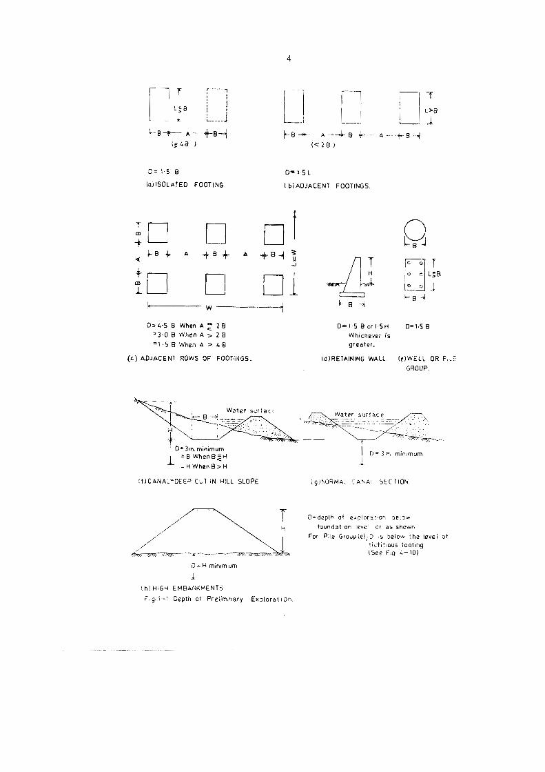
.14.2.2. Depth ofExploration (See Fig. 1-1 and also Table 1.3)--The rule regardingthe depth to which borings should penetrate is derived from the concept of the
pressure bulb in solls. The pressure bulbs are pressure isobars constructed fromequations based on elastic iheories such as those of Boussinesq, Westerguard andotbers. The Boussinesgqg equation is for soil which is elastic, homogeneous, semi-infinite and isotropic and obeys Hook's law. For non-isotropic soil or for soil massconsisting of laycred strata other theorics such as Westerguard's can be used. TypicalFressure bulb is shown in Fig. 1-2. The concept of tbe pressure bulb helps in under-standing the magnitude of stresses, the extent and depth of stressed soil zones beneaththe foundation and tie depth at which the stress becomes inappreciable. In the caseof a number ofloaded areas near one another the pressure bulbs will overlap and thedepth of the appreciably stressed zone will increase.
Depth (See Fig 1-1)-Based on ihe above concept the depth of exploration shouldnormally be onc and a half times the width of Ihe footing in case of a single footinguninfluenced by other foolings and one and a half times ihe width of the group in
Tb 4597-2a
4
A 4 A
(54B ) (<28)
0=15 8 D=15L(aISOLATED FOOTING (bJADJACENT FOOTINGS.
8-4
T
+ 51B A 8 A +84 3„rer + +
+ H © [e} L=B
L oe ©
+
D=45B When A 2 2B o=r5Bor1-5H D=158=30B WhenA» 26 Whichever is=158 When A >4B greater,
(e) ADJACENT ROWS OF FOOTINGS. {O)RETAINING WALL. (e)WELL OR FileGROUP.
ao
Water surtacıB Water surfac e
-
In,minimum_
=B WhenBZHD= 3m minımum
=zHWhen8>H
WICANAL-DEEP CUT IN HILL SLOPE (gJNORMAaL CANnAL SECTION.
D=depth of exploration Delowtoundatıon level or as shown
For Pile Grouple);D ı5 below the levei ottictıtious tooting{See Fıg. 4-10)
D=H minım um
IN)HIGH EMBANKMENTS
r.g. 1-1. Depth ot Preliminary Exploration

&t- + r L/ 43
q,8
26
158& 28 3B
8o
\IB 28
-3 8
46
5B
38(a)
4 3ZAGDRD,
7
(db)
7,
1 2: PRESSURE BULBS (A) PRESSURE ISOBARS BASED ON WESTERGUARDEQUATION FOR SQUARE AND LONG CONTINUOUS> FOOTIINGS B B ORBXL (FROM FOUNDATION ANALYSIS AND DESIGN BY I. F. BOWLES).
FIG
BY STRESSFD ZONES FOR NARROW AND BROAD FOOTINGS SHOWSFALLACY OF BASIC DESIGN OF BROAD FOOTINGS ON VALUES DETER-MINED FROM LATE TESIS USING SMAL SIZT PLATE®S.

6
case of number of loaded areas in close proximity with overlapping bulbs. However,where the geological conditions are not known at least one boring should go toa much greater depth, but noi less than iwiee the widıh of {vorne or uf group offootings. Where the normal depth of exploration ends in any unsuitable so. stratum,the exploration should be carried down 10 firm and suitable soils or to rock.
The depth to which scasonal moisture variaiions affect the soil should be consideredthe minimum depth for explorations.
The depth should also be governed by any industrial process that contaminate thesoil.
In rock the boring should penetrate through the upper weathered zone and about3 m into sound rock.
1.4.3. Stages -The investigations may consist of four stages as follows -
(i) Initial investigations included tlıerein preliminary and detailed investigationsconsisting of trial pits, augering, boring, collecting samples, and testing to theextent required for framing propesals, desiens and construction.
(ii) Supplementary investigations in certain specific areas 6 provide, as necessary,additional information required for designs.
(ii) Verification cf sub-surface coäditions during consiruction io determineconformity with desizns and to enabte modifications as necessary in the desigus.
(iv) Posi-construction monitoring of ıhe siruciure. Stages (f} und {fir) should becarried out in all cases. Stage (if) may or may not arise, Stage (A will providevaluable data for assessing the performance of the structure, formvlating remedialmeasures and [or use in elfecling economy and safety in future projects. Therefore,it is des'rable that this should be carried out on as many projects as possible.
1.4.3.1. Investigation -The initial investigation mentiorıed above as Stage (if) areagain carried out in two stages, namely, Preliminary investigations and Detailedinvestigations
(f) Preliminary Investigation -Preliminary invesligations are carried out 10
establish the types of soils, stratification of the soil, iscalion of rock and sroundwater. This is done by means of a few trial rits or bore holes. Geophysical methodsand cone peneiromester tests besides providing useful data will help in programmingdetailed investigations. Study of ail available data such as various types of maps,previous reports, history and existing struciures wil! be part of this stage.
(ii) Detailed Investigation - Detailed Investigations are initially rlanned on thebasis of the data cbtained from preliminary investigation. This planning may be
reviewed and modified as the investigation proceeds. The purpose of the detziledinvestigation is to determine the pertineni engincering properties such zs shear
strength, compressibility and nermeability for determining bearing capacities,settlement analysis, scour depth calculations and stability calculations. The pro-gramnı. will consisi of boring, sampling, field and laboratory tests. Both, groundwater and sub-soil should be analysed for determining possible harmful effects onfoundation structures,

7
The various methods are summarised in Table 1.1. The tests to be performed onsoil samples are ouilined in Table 1.2.
For bridges, tie IRC 78/1983 Standard Specifieations and Code of Practice forRoad Bridges, Section VIT, Foundations and Sub-struciure, First Revision GeneralFeatures uf Design" divides the sub-surface foundation region into three zones andspecifies the various tests in cach zone. These are given in Table 1.3.
TABLE 1.1
Methods of Sub-Soil Explorations
Method Use Applicability
1. Geophysical : (a) Seismic, Soil and rock profiling. Progressively firmer(b) Electrical resistivity, (l'hickness and depths). stratifications. Firm(c) Sonic. Soil samples are not strata underlying
obtained. Should be sup- mud, water riverplemented with borings and sea beds.for soil indentifications.
2. Soundings :
(a) Standard penstration Relative density and angle Cohesionless soils with-test (See IS : 2131-1963), of internal friction of out boulders.
cohesionless soils. Con-sistencey of cohesive soils(doubtful). Disturbedsamples obtained,
(b) Static Cone penetro- Bearing capacity, skin fric- Soils without boulders.meter test (See IS : 4968- tion, settlement afterPart-itI-1971). correlating with other
field tests. No samplesobtained.
(c) Dynamic Cone penetro- Qualitative relative Soils without boulders.meter test (See IS : 4968- sırengths of sub-soils,Part-!I-1976). should be correlated
with standard penetra-tion test. No samplesobtzined.
3, Trial pits, trenches, drifts, Examination of strata in- Allsoil types.
turbed, undisturbed sam-
ples for testing.4. Borings
(6) Auger boring. .. Soil stratification, Distur- Allsoil types.
shafts. place. Collecting dis
bed samples obtained fortesting.
>
9
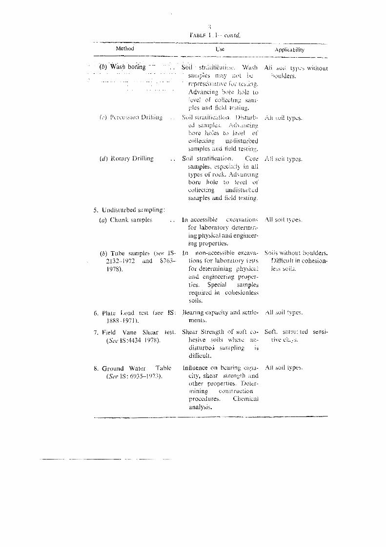
TABLE l contd,
Method Use
(b) Wash boring
(d) Rotary Drilling
5. Undisturbed sampling:(a) Chunk sampies
(b) Tube samples (see IS-2132-1972 and 8763-1978).
6. Plate Load test (see IS:1888-1971).
7. Field Vane Shear(See 15:4434-1978).
lest.
8. Ground Water Table(SeeIS 6935 197%)
sol straifkaten. Washsauupies may not bu
represenuative for Iesung.Advaneing Dore hole to
ples aud d testing.
tsturb-samples.
Issel ofundisturbed
f
bore loles to
Soil stratitieation. Ücresamples. especially in alltypes of rock. Adyancıngbore hole to
volieciing undisturtudsäimples and fieid testing.
In accessible cxcavulionsfor Jaborarory determin-ing physica and engincer-ing properties.
in non-accessible excava-tions for laboratory testsfor determining physicaland engineering pruper-ties. Special samplesrequired in collesionlesssous.
Bearing capacity and settle-ments.
Shear Sireugti of soft co-hesive soils wheic un-
sampling 15
difheuit.
Induence on bearing vana-skear h und
other properties. Dewer-mining vons'ructionprocedures. Cbemicalanalysis.
Ievel of
Applicability
AH sul types withoutDoulders.
el
I soil types.Di\
u
soil types.
All soil tyises.
Soils without boulders.Difheult in cohesion-less solls.
Al soil types.
All soil types.
d sensi-e

Method
9 . Permeability tesi (See IS:5529-Part-1-1969).
TABLE 1.1- -contd,
Use
Inflüenee on si! proper-tes. Deteraiining cons-truction procedures.
Applwabiliiy
All seil types.
10. Pressure meter test Bearing capacıry, seitle- I Rockment, stress-stiainrelationship.
Il. Bore hole deformeter test Bearing capacity, strength. Reck.in rock. stress-strain relationship
in rock.
1432 Tests on Son Samples-ihe test, on soul sarnples are hsted an T 1 ı 2.The tests to be conducted for a particular project wii depend on nature of thatproject. Some of them may not be required. In some cases addition tests or speciatests not listed may be required to be carried out.
1.
2.
TABLE 1.2
Tesıs on Soil Samples
hesionless soils).
Stages ofTests Reference to IS Type of
exploration sample
Reconnaissance Visual Classification. 1S: 1498--1910 138
Preliminary and Liquid and Plastic 15: 2720-Part V-!979 [BIDetailed Explora- limits.tion.
Grain size analysis .. 8: 2720-Pırt IV-1973 DS
Specific gravity 13: 2720-Part IIL-1480 DSNatural moisture IS: 2720-Part 1I-1975 DS,content. UDS
Unit weight 15: 2720-Paxt-Ti-19x0
Compaction 18: 2720-Parts Vi and UNSvIn.
Relative Densiy (Co- 15: 2720-Parı XIV UDS

10
TABLE 1.2-contd
Stages of Type» ofexploration
Tests Reference to 18Sample
Consolidation test 15 :2720-XV-1965 USD(including pre-con-solidation pressure).
Shear Strength-
Unconfined compres- 18: 2720-Part X-1973 UDSsion.
Triaxialcompression IS: 2720-Part XI-1971 UDS
Direct shear IS: 2720-Part XiII- UDS,1972. DS
Permeability IS: 2720-Part XVIl DS,DUS.
Chemical Tests-
Chlorides and 18: 2720-Part XXVI- DSSulphates. 1977.
Calcium carbonate 1S: 2720-Part XXII- DS1976.
Organic matter IS: 2720-Pari XXII- DS1972.
Ground Water-
Chemical analysısand IS: 2620-Part XXVI- DSpH. 1973,
Bacteriological analysis DS(if necessary).
Note.-DS = Disturbed sample; UDS = Undisturbed sample.
‚Rock drilling--
Visual examinationUnit weightWater absorptionPorosity CorePetrograpäic analysis samplesCompressive strengthShear strength.

1i
TABLE 1,3
Sub-soil Data for Deep Foundation of Bridges(3)
Zone Data
1. Bed level to anticipated maximum scour (f) Soil classificationdepth. (ä) Particle size distribution
(fü) Silt factor (every change of strata)(iv) Shear strength(v) Permeability.
2. Maximum anticipated scour level to (i) Soil classificationfoundation. (fi) Shear strength
(ii) Compressibility(iv) Permeability(v) Natural moisiure(vi) Unit weight(vii) Relative density(ri) Rock properties as in Table 1.2,
3. Foundation level to about 11 times the (i) Soil classificationwidth of foundation below it. (ä) Shear strength
{üi) Compressibility(iv) Rocks properties as in Table 1.2,
The appropriate methods and tests listed in Tables I.l and 1.2 should be
performed to obtain the above data.
1.5. Methods of Exploration1.5.1. Reconnaissance-This includes compilation and study of available infor-
mation, site visits and topographical surveys. The following are some of the infor-mation which should be coilecied and studied :-
topographical maps, geological maps, petrological maps, soil survey maps,aerial photographs, previous investigalion reports, history of structures past andexisting, details of the proposed structure such as dimensions, foundationlocations, special requirements for basements, architectural considerations,
By making site visits data on the following should be obtained :-
local topography, vegetation evidence of erosion, landslides, excavalions,quarries, water courses, water levels in wells, stream», fiood marks and the tidelevels, ground water conditions, drainage conditions, lovation of springs, typeand behaviour of existing structures, distress in existing structures, constructionalresiraints such as possible effects of vibration on adjacent structures, eflects ofexcavation and pile driving in the proximity, fill material.
Data obtained from reconnaissance will be useful for planning the preliminaryand detailed investigation.

1.5.2. Trial Pits1.5.2.1. Trial pits are the most satisfactory in revealing the aciual nature of
the strata, Pasturbed and undisterbed samples can be vasily collected. In particularundisturbed sirmples collected from trial pits are compared to any other undisturhedsam les insuu l d ki fo etermming berring capacı\ and compres-ihlityof the strmn are easıty nerformeld.
.527. Trial plts are generally excavated manually and to shallow dCost and groung wawr are iwo of the considerations wlich limit the depıhci trial pits. In diy r d trial pits upto a deptn of about 5m will be econormical.inc anflow ofsun soil water und the resources avatlabie for dewatering will generallv
depih 10 a few meer below the ground water level.t
win. mn size ihe bottom of the pit should be I .2 m x 1.2 m. The dime-sıons on the vop should be such as to ensure safety of the sides. If the sides aresupported by shecting, the bottom dimensions should be suitably increased. Addi-tonal space skonld also be provided for ladder, hoisting arrangement etc. Ifundisturbed soll samples are to be taken by the hand cut method a slightly largerzit will be require for convenient working.
1.5.2.3. Deep pits should be supported by timber, using sheeting or runners.The general method is shown in Fig. 1-3.
Tue runaers are uenally 40 10 50 mm thick and 175 io 200 mm in width. Thepoinis are bevelled to facilitate driving. The runners ars supported against carthpressure by int rnal bracings corsisting of about 23 mm x 75 mn or 150 mm diameterssertlisgs in ihe form ofa frame and placed about 1.2 m centre to centre vertically.
Material om deep pits is removed by buckets operated by a hoist orwindisss. The Jatter snould be provided with a ratchet device for safety.
The material should be stockpiled around the pit and marked withstakes indieatirg d derth from which the material was excavaled. The natural
content ol ike ınaterial sliould be inimediately determined.\W
Disturbed samples should be taken for classification and other tests.
Undistorbed sanıpiıs be 1aken for determining the iu-situ enginc-rng piv-perties They may be taken eitic, [rom the bottom or sides ofthe piis.of the soil layer exceeds ? m a sceond sauaple is taken.
if water is met with the ground, vater level should be recorded.arrangement wonld then be required.
1.5..5. Deep tria pits should be properly ventilated te ıcmuve dead air frointbe pit. This can be done by a simple arrangement consisting of a pipe starting,slighily above the fioor of ihe pit and taken to about one ıneter above the top ofthe pit. Forecd vertilation may be necessary in some sitnations.
1.3.2.6. Open trial pits shall be suitably barıicaded or corcied for safety. Theyshould be filled back as suon as inspection and collection of data are completed.
nz

13
{c)
tting
shectin
gan
dbracıng.
One
settingof
runn
er,(b
)Tu
i2,
&je
=
kn©u%=
{Tb Be a KRY <.
©.
3:0 5 Far] un a:B < x=) Er Si &-, u3
fe LE. Zu &be
n t \ N
har
i
hik IL.
zaI

14
1.5.2.7. The recording information obtained from trial pits should be recordedsystematically and correctly. A recommended proforma for logging trial pits isshown in Appendix I.
1.5.3. Trenckes-Trenches are similar to trial pits except that ihey are continuousover a length.
1.5.4. Drifts or Tunnels--Excavation of drifts or tunnels is slow and cxpensiveand therefore it ıs resorted to only in major projects and when other methods donot yield the required information.
1.5.4.1. The minimum clear dimensions of the section of a drift in rock usuallyadopted are 1.5 m in width and 2 m in height. In soft rock the roof may be archshaped. In weak zones the sides and roofmust be supporied. A method usually adoptedis shown in Fig, 1-4.
1.5.4.2. Drifts should be properly ventilated specially for removing foul airand blast gaseous from explosives. This can be done by forced air from compressoror blower. Drifts should be adequately Hghted to enabie inspection and collectionof data,
Wooden supportsWedges
Wooden sleepers S N AN)
250 X150mm
EKW AN
2100mm
1500m
J
Fig-I-4 Wooden scaffolding for supportingweak zones in dritt
1543 Recording of information for logging and sampling of drifts reference
may be made to IS 4453-1980.

15
1.5.5. Auger Borings-Auger boring is a simple method of soil investigationand sampling The samples obtained are disturbed samples. When undisturbedsamples are required auger boring cannot be used. However they can be used foradvancing a bors hole to a level at which undisturbed sampling or penetrationtest is required.
1.5.5.1. Varieties of augers are (a) helical auger, (7) post hole auger, (c) shellauger, (d) disc auger, (d) bucket auger. Some of these are shown in Fig 1-5.
AO
(a) (b) (c)
Fig.'-5 Augers: (a) Helical (b) post hole ‚(c)shell.Ee
Hand operatedd post-hole auger can be used for expioring upto a depth of about 6 mUsing a tripod holes upto 25 m can be excavated. Portable power-driven helicalaugers are available in diameters ranging from 75mm to 300 mm.
Augers are generally used in soils in which the holes can stand unsupported.However casings can be used,

16
1.5.5.2. Water should not be added when auger boring is performed in softcohesive soils and cohesionless soils above water table. A little water may be requiredto be added in stiff cohesive soils to aid boring and bring up samples. In cohesionlessdeposits below the water table, water in the casing should be maintainsd at or abovethe water table.
1.5.6. Percussion Boring--This ıscthod is not suitable for careful investigation,but it is the only method suitable for drilling in bouldery and gravelly s rata.
The method consists of boring by alternately lifting and dropping heavy drillinghits or chiscle Then 15 pulvcrised e series of blows and ıs removed fromthe bore holes by bailers some varieties of chisels are shown in Fig. -6.
E
(a) (b) (c) (d ) (e)
Fig. 1-6 Chisels:(a)Straight edge,(b)V- edge,(ec) T- edge. (d) Cross - bit. (e)Y-bit.
1.5.7. Wash Boring---The arrangement is illustrated in Fig 1-7. This is probablythe most commonly used method for relatively deeg in soils. It is usually the prelimi-nary to percussion or Rotary boring. It consists of penetrating the soils by displacing

17
and washing up the material by means of water under pressure. Wash boring isineffective when materials like heavy shingle, boulders or rock which cannot bewashed out are encountered. In such situations wash boring must be replaced byPercussion or Rotary boring.The apparatus consists of a wash tube fitted with a chopping bit within a casing pipe
of considerably larger diameter. Water is forced through the wasb tube, emergesthrough small holes in tbe bit and rises up to the surface carrying particles of soilthrougb the casing pipe. The overflow is collected in a through and the water is againpumped back into the wash pipe and recirculated. The hole is advanced by rotatingand raising and dropping the bit on to the soil at the bottom.
1.5.7.1. The type of soil is ascertained from the wash collected in the trough.However the soil from the wash does not represent the true in situ type as the Leavierparticles remain in suspension in casing pipe and soils from different layers get mixedup. Therefore the washed sample canot be used for classification or any other tests.For samrling washing should be stopped at intervals and whenever the washed upslurry indicates change in soil type, then samplers are driven into the soil by jackingor hammering. For undisturbed samples the samplers must be jacked into the soiland not hammered.
1.5.8. Rotary Boring-In this method the ground is penetrated by the abrasiveand grinding action of a revolving cutting tool of hollow section. It is fundamentallydifferent from percussion boring and unlike in the latter method the materials outthrougb is not broken up or pulverised, but solid cores are brought up to the surface.Casing is generally not needed in this type of drilling. If the sides of the hole tend tocollapse a drilling mud is used. The drilling mud is a slurry of a thixotropic clay, suchas bentonite in water. It is forced into the sides of the hole by the rotating drill grovi-ding adequate supporting strength to the soil. If the water testing is to be done, drillingmud should not be used.
Various types of drilling bits and core barrels are used for drilling and recovery ofcores in different soil and rock types. Bits such as diamond bits, sawtooth bits, steelshot bits, clay bits are used. Single tube core barrels and specially designed doubletube core barrels are used for extracting core samples in many types of soils, particu-larly in sands, slits and soft and fractured rock.
Recovery of cores is more important than rapid progress in drilling. A largepercentage of recovery will give a continuous section of the substrata. A small percentage and portions of core lost may denote soft or fractured rock. The cores also-provide information on location, size and nature of joints, seams and fissures.
1.5.8.1. Core barrels-In the single tube core barrel the core in the entire barrellength is exposed to the abrasive action of the drilling fluid and cores of soft rock orweak cemented strata get seriously eroded and broken. Therefore a specially designeddouble tube core barrel is used in such strata. The inner tube which is stationaryprotects the core from the drilling fiuid and reduces the torsional effect transmittedto the core. (See Fig. 1-12).
1.5.8.2. Triple tube core barrel--In addition to the double tube core barrel, tripietube core barrels have also been developed. Currently Messrs. Asia Foundation andConstructions Ltd., (AFCONS), Bombay use such drilling equipment. The tripleTb 4597-3

18
s.
Jet pipe |
Collectingbox
m___ NCasinn pipe
N
6,5 AALL"
Y
r
a
Arrangement of Wash Boring.Nem t7gF

19
tube core barrel assembly consists of the two tubes similar to the double tube corebarrels. In addition a split tube is provided inside the second tube. The cores arecollected in this third tube. It is claimed that the triple tube core barrel assembly canbe successfully used to take out cores without loss or damage from soft and fissuredformations.
1.5.9. Bore hole size-The size of bore hole will depend on the deptli of boring,size of samples required, the tests to be performed and the soil types. For determiningthe shear strength of soil or rock by means of laboratory tests, core sample of diameterto height ratio of 1:1 is required. The diameter of the bore hole should be sufficientto facilitate undisturbed sampling and performing of in-situ tests in the bore holes.Since for laboratory testing a core samıple of 100 mm diamete: is required the diameterof the bore hole should be 150 mm to allow for casing pipe and tube sampler. Forstandard penetration test a smaller bore hole of 100 mm diameter is adequate. Forcompression tests, the sample diameter required is usually 40 mm and the result is
averaged from three such samples. Therefore, the size of the bore hole should bedetermined in advance in conjunction with the soil testing programme.
1.5.10. Drilling observations-During the drilling observations complete observa-tions should be made and recorded. The observations to be made are:
Observation Use
1. Drill Water:
(a) Colour and levels at which changes Provides information on lithology andoecur. general nature of strata. Highly mud
laden water may correlate with poorcore recovery and indicate probablereason for core loss.
(6) Lost, fully returned or partially May indicate existence of open joint orreturned. special geological features like cavities
and faults.
{c) If hot water is encountered, its tem-
perature, depth and amount of flow.
2. Rate ofpenetration .. Indicates comparative physical nature ofstrata. Change or strata existence ofopen seams or cavity or weak or softerzone.
3. Core Loss .. .. Poor recovery may be due to poorly con-solidated rock. presence of highlysheared zones, clay filled seams carelessdrilling.
4. Ground Water level every day beforeand after drilling.
5, Other special conditions:
(i) Depth at which hole was grouted,(ii) Artesian conditions, (ii) Gasdischarge, (iv) Permeability tests.
Tb 4597-3a

20
1.5.11. Recording information ofBorings-All borings should be properly loggedand recorded. A typical proforma is given in Appendix II. A site plan showing thelocations of the borings should be included.
1.6. Geophysical MethodsThs boundaries between layers of different types of soils may be located by geophy-
sical methods. These methods are based on the fact that the gravitational, magnetic,alectrical, radioactive and elastic properties of different scils may be different. Thetwo geophysical methods used in sub-surface exploration for foundations are tbeseismic method and the electrical resistivity method which make use of the elasticproperty and the electrical resistance of soils respectively. To establish thetype of soil,these meihods must be employed in conjunction with borings or other direct methodsof exploration.
1.6.1. Seismic exploration1.6.1.1. Rock profile and the location of dense strata can be obtained by the
seismic method which is fast and reliabie.
1.6.1.2. Outline of Procedure-The method consists of determining the velocityof induced shock waves in different strata. Shock waves are induced into the soil byexploding small charges in the soil or by striking a plate placed on the soil witha hammer. The shock waves are picked up some distance away by means of listening(sensing) devices known as geophones and the velocity determined from the time lapse.As the distance between the geophone and the point ofthe shock increases some oftheshock waves travel downwards into and through underlying strata and up again to tbegeophone thus enabling the computation of velocities in these strata. Velocities ofshock waves are higher in denser materials. Velocities in a few materials are given inTable 14.
TABLE 14
Approximate Range of Velocities of Seismic Waves in Soils (4)
Materials Velocity in m/sec
Sand and top soil ..Sandy clay .. .. 365580Gravel .. 490-790Glacial till .. .. .. 550-2135Rock tallus .. .. .. 400-760Wet loose materials .. 1400-1830Shale .. .. .. 790-3350SandstoneGranite .. 3050-6100
180-365
915-2740
Limestone .. 1830-6100

21
1.6.1.3. Principle-Principally the procedure is as follows :-
(i) The shock is induced at various known distances along a line from thesensing device and the time of shock wave travel and corresponding distance arerecorded.
(ii) A graph of distance vs. time is plotted as shown in Fig. 1-8. Since velocitiesare different in different stratum the plot will be kinked line with different slozes.The velocity is given by-
distanceVelocity = - -
time
pickupsImpulse
DistancesL5 Vtrom Impulse.
I
La3
Top stratum> 1
aDenser stratum
(a) Rock
oO
o©
I
ü©
=tanmo
5
c
59
m!A*tan &]E
tz An
>a
m
t
Ar
L, La Ly L4 Lg
Distance from ıimpulse to pickup-m,'b)
Fig 1-8 Seisrnic method of soit exploratations(alPaths ot shock impuise.ib} - Distance graph,Di

22
A single point or observation will give the velocity. But to obtain an averagevalue a number of points of distance vs. time are plotted.
11 I ) The thickness of euch layer is calculated from :-
(1-12)£ \ V-V,?V,V
-
H, 1
7
H, 3t
\ )73
The variables are illustrated in Fig. 1-9.
Milttammeter I Battery.
Potentiometer&
101
9t
- A -
V
Äc1
Electrodes.d
l For determining lateral changes in soıl Move the Set-un of fourelectrodes to different iocations keeping spacing d constant.
2. For determining vertical changes in soil: Maintain focation and
change spacing d
Fig.1-9 Electrical-resistivity method: Set up of electrodes.
1.6.1.4. Limitations---This method does not give satisfactory results if
(a) the velocity in the underlying stratum is less than that in the stratum aboveit l.e., V, is less than V,(b) the soils change gradually upto rock and there is no marked difference in
ihe wave velocities in the different soils.
(c) tlıe interface of two lavers is irregularIn this method the nature ol the soil through which the wave travels is not revealed.
For deterniining the nature of the strata boring or sounding must be done. But thedepth to rock and the strata changes can be fair!y wel! established by this methods

23
1.6.2. Electrical Resistivity Method
1.6.2.1. This method is based on the different resistivities of different soils.The resistivity of a soil is dependent on ihe water content. density and composition.The resistivity cf saturated silt is low while that of dry gravel and rock is high.
1.6.2.2. Outline of Procedure--Four electrodes are driven into the ground atequal distances along a line (see Fig. 1-9) A battery to supply direct current alongwith an ammeter is connected across the outer electrodes and a potentiometerbetween the two inner electrodes. The resistivity of the soil is determined from thecurrent and,voltage-
V
Where
p = resistivity (ohm-cm)d - distance between the electrodes (cm)
I
V = Voltage between the inner electrodes (V)I = Current across the outer electrodes (A)
To interpret the results it is necessary to determine the resistivity in known forma-tions.
1.6.2.3. Approximate range of resistivity values for some materials are givenbelow (4) :-
Material Resistivity (ohm-M or cm)
Limestone (marble) .. .. 10%
Quartz .. 10"Rock Salt .. 10° to 107
Granite .. 5000 to 10%
Sandstone .. 35 t0 4000
Moraines .. .. to 4000
Limestones .. 120 to 400
Clays .. .. .. Lto 126
1.7. Soil Sampling1.7.1. General--Soil samples are required for conducting tests for classitying
the soil and determining its enginnering properties. Quantity of samples collectedmust be adequate for all the intended tests. Therefore, sampling, like ali otherexploration work, should be carried outin co-ordination with design and constructionengineers,
The prime requirement of the sample ıs that it should be truly representative ofthe stratum. Samples from wash borings are not representative because the fingermaterials tend to separate from the coarser materials. However ihese samples äre

24
useful in locating strata changes and indicating the depths at which representativesamples should be collected. Samples obtained from auger borings are reasonablyrepresentative.
Soil samples obtained from borings are classified as disturbed and undisturbedsamples. While there are no truly undisturbed samples, the degree of disturbancecan be kept to a minimum by using the proper equipment and methods.
Samples of soil and rock should be collected and placed in sealed containers soas to preserve their natural moisture content. For purposes of soil classificationdisturbed samples are adequate.
For determination of engineering properties and stress-strain relationshipsundisturbed samples are required. Obtaining undisturbed samples for cohesionlesssoils is extremely dificult. Therefore in such soils sounding tests, particularly thestandard Penetration Tests are carried out,
1.7.2. Disturbed Samples
1.7.2.1. All the strata upto the depth of the exploration should be sampled.When sampling in accessible pits the sides of exposed surfaces should be examinedand the sequence, thickness and classification of each stratum of soil should berecorded. Care should be exercised to ensure that materials from other strata donot get included.
1.7.2.2. In non-acessible excavations (bore holes and the like) samples are obtainedin bailers and sampling tubes. In certain types of soils. for instance, gravelly sand,samples obtained by wash boring are not representative and therefore relianceshould not be placed on such samples for classification. There are many types ofsampling tubes, some specially designed for use in cohesionless soils. Some areillustrated in Fig. 1-10.
1.7.2.3. Quantity of Sample--The quantity of sample required for various tests
(4) is given below : (See also IS : 2720-Part I 1972).
Tests Soil type Weight of samplek8.
(i) Soil classification, natural moisturen Cohesive 1
content, mechanical analysis andindex properties. Chemical tests. Sand and gravels 3
sands.Gravelly soils 25
(ii) Compaction .7Cohesive soils and 12.5
(iii) Comprehensive examination on Cohesive soils and 25 to 50materials including soil stabilisation. © sands.
J Gravelly soils 50 to 100
Since samples can get damaged during storing or transporating, the quantity ofsample collected should be more than what is considered necessary for testing.

25
tr grülrod
8o m"oh &
N
oO
N ©
€
ventsN N
ImFour screws r1
v(4)
un
un
aa0>
u
0
stiel hr l r )
vN>
NN N
cEN
o>c
(a) b
-walled Sampling tube D} Standard split-spoon sampierFia.3-19 (a) Thing
(c) Spring sampie retainer (d)\Sample retainer for mud and watery sam 25
1 .73. Undistu bcd Samples
1.7.3.1. Undisturbed samples are collected to determine the properties of thesoil in its natural state. The properties required are engineering properties like in-situ
density, consolidation characteristics, shear strength and sensitivity in tie case ofclays.
All the strata encountered upto the depth of exploration must be sampled.
1.7.3.2. Chunk Samples-In accessible excavations such as trial pits, trenches,drifts and sides of cuts, undisturbed samples can be obtained by the hand method.The samples obtained by this method are referred to as "chunk samples or block
samples". The soil must have some cohesion for collection of such samples to be
possible. They are collecied in square wooden boxes or short metal cylinders. Themethod is illustrated in Fig. 1-11.

26
+N(N
2
%warx
c loth„sampleAr
-..
Dhx
All six Sides sealed with wax-clothand wax(a)Cutting block sampk om pi t
(b)Sealing of sampie,
Annular spacebetween boxand sealedsample filledwith moistsawdust
Box
Sealedsample
% xN \
i
ke) Encasing sample in box beforeeutting 1 N block fram bottom.
Steps:Cut away carth from all four stdes as shown In (a),2)Seal sides and top as shown n(b),JhEncase wich box as shown in Ic},
(d)Packing to support sample
#
4)Pack sides and top with moist sawdust as shown in (d),S}Natl lid of box on top.$)Cut away bottom of the block of sample carefully and without disturbing,7)Overturn with box so that bottom and top are inverted.8) Seal the new top surtace of sample. pack and nail lid.
FIG. 1-11. Method of Obtaining Hand- cut Undisturbed Samples
Ihe block of soil must be protected from exposure to direct sun and wind toretain the natural moisture content, The sample is also coated with wax for thesame purpose. However hot wax should not be poured over the sample as it willpenetrate and dry the soil.

27
The size of samples may vary irom 15 em to 30 cm cubes. Cylindrical samplesmay be 15 cm to 20 cm in diameter and 15 cm to 30 cm in length. The latter canbe collected in metallic cylinders. The size and numbers should be adequate for allthe tests.
1.7.3.3. Core samples--In non-accessible excavations like bore holes undisturbedsamples are obtained in cylindrical open ended seamless tubes. The samplers areattached to drill rods and forced into the soil by jacking. Where jacking is not possibledriving is resorted to. The sampler is rotated slightly or a special cutting device isattached to cut ıhe sample off and the sampler is withdrawn, frietion holding thesoil in the tube.
The bore hole must be pre-bored to the depth at which undisturbed sample is
required. There should not be any disturbed soil at that level. Above ground waterlevel the method of boring adopted should be such that the natural water contentof the soil is not affected. Dry augering is one such method.
1.7.3.4. Cohesive soils-In cohesive soils undisturbed samples are quite easilvobtained. In most soil types the ordinary thin walled open ended seamless tube
sample is adequate for obtaining samples. The depth to which the sampling tubesare forced into the soil must be carefully controlled as over driving will compressthe soil and disturb its natural state.The length of drive should be a little less thanthe length available for the sample.
1.7.3.5. Colıesionless soils--It is extremely difficult to obtain undisturbed samplesof cohesionless materials. Special types of samplers, like the compressed air sampler,are required. Field tests, such as the standard penetration test, in conjuction withdisturbed samples are performed for determining engineering properties in suchsoils.
1.7.3.6. Frequency of sampling-Continuous and intermittent sampling aredone. Continuous sampling is required in important investigations such as in thecase of earthen dam foundations.
Intermittent sampling should be done at intervals not exceeding 1.5 m and at
every change of stratum. The size and number of samples required will depend onthe tests to be performed. Usually the soil property is averaged from three tests andtherefore for each type of test three test specimens would be required. If the type oftests are many, continuous sampling may be required in a particular stratum. There-fore, sampling must be done in co-ordination with the design engineer and the testinglaboratory.
1.7.4. Rock samples-In order to be able to distinguish between a boulderand rock formation the depth of boring and sampling should be 3 m in exploratoryborings. IRC : 78-1979 recommends a depth of 3 m in sound rock for bridgefoundation investigations.
1.7.4.1. Information required-Boring and sampling should be performed toobtain the following informatiou --
Profile of Ihe rock stratum both in depth and lateral extent.
(ii) Weathered zones and degree of weathering

28
(fi) Geological formation.
(iv) Lithologic and structural features and physical condition relevant to theinterpretation of subsurface conditions.
(v) Properties of the rock
(vi) Erodibility(vi) Colour of water
1.7.4.2, Observations-The following should be noted:-(1) Joints, seams or fractures: position, direction, size, whether open or filled,
sheared, crushed or faulted; (2) bedding planes, laminations; (3) PhysicalCharacteristics and minerology; colour, grain size and shape, type and extentof ceımenting material
Interpretation of data and examination and description of cores should be doneby a geologist. Microscopic examination and laboratory tests for establishing theminerology is generally required only in special cases. Visual examinations andsingle feld tests would enable an experienced person to establish the rock types.
1.7.4.3. Cores of soft roeck-Double tube core barrels should be used for obtain-ing cores from soft or fractured rock, hard, brittle or partially cemented soils andsoft, partially consolidated or weakly cemented soils. For these materials hard metaldrill bits are used. In the double tube barrel there is an inner stationery barrel whichprotects the core from the abrasive action of the drilling fluid and reduces the torsionalforces on the core.
1.7.4.4. Cores of hard rock--The single tube core barrel is primarily used inhard, solid rock which requires diamond drill bits. In this, the core is exposed overits entire length to the erosion effect of the drilling fluid and is therefore suitableonly for hard, solid rock.
1.7.5. Samplers-A few types of samplers are illstrated in Fig. 1-10 and 1-12,
1.7.6. Classification of rock for engineering purposes-The value of rock forfoundation is assessed from the following characteristics:-
(a) Extent of weathering of rock-Table 1.5.
(b) Hardness (for engineering description of rock-not to be confused withMohr's scale for minerals) Table 1.6.
(c) Joint bedding and foliation spacing in rock-Table 1.7.
(d) Rock quality designator (RQD) : Table 1.8 expresses the length ofcore recovered as percentage of length drilled. It is an indication of the soundnessof rock. ROD is determined only when (#) double tube N size core barrels with
non-rotating inner core barrel are used; (ii) only those rock pieces which are100 mm and longer are measured for their total length; (ii) if core is broken
during handling or drilling the broken pieces are fitted together and the lengthmeasured (this may be determined by examining the fractured surfaces whichwould be fresh and irregular with sharp edges).
(e) Strength of the rock-Table 1.9.

29
TS TIRSS
MR: Samplerhead
T hinwalledsampler
1_Piston rod
Piston
rap valve Fixed[0 N
Pistonh N
{
(a)
Sampler presseddown mto sorl
(b) ti)Fig. 1-12M)Pump type sampler tor sands (b)Schematic ıllustration 01
{iPiston and thin-walled sampler ın posıtıon at bottom ofsampier pressed down into soil and ready for withdrawin
Fıxed-Piston Samplerbore hole ,‚(illThın-walledg with sampter
TABLE 1.5
Extent of Weathering of Rock (3)
Fresh BR .. Rockfresh crystals bright, few joints may show slightstaining. Rock rings under hammer if crystalline.
Very slight .. .. Rock generally fresh, joints stained, some joints mayshow clay ıf open, crystals in broken face show bright.Rock rings under hammer if crystalline.
Slight .. Rock generally fresh-joints stained and discolourationextends into rock upto 25 mm. Open joints containclay. In grainitoid rocks some occasionally felsparerystals are duli and discoulured; Crystalline rocksring under hammer,

30
Moderate .. .. Significant portions of rock shon discolouration andweathering effects. In grantoid rock most felspar aredull and discoloured: same shon clavey. Rock hasdull sound under hammer and shows „enificant lossof strength as compared with fresh rück.
Moderately Severe .. Allrock except quartz discoloured or stained. In granitoidrock all felspars dull and discoloured and majorityshow kaolinization. Rock shows sevcre oss of strengthand can be excavated with geologists pick. Rock goes"clunk" when struck (Saprolite).
Severe .. All rock except quartz discoloure or stained. Rock"Tabric" clear and evident but reduced in strength tostrong soil. In granitoid rocks all felsnars Kaolinizedto some extent. Scme fragments of stroug rock usuallyleft (Seprolite).
Very Severe .. All rock except quartz discolourcd or stained. Rock"fabric" but mass effectively reduced to "soil"with only fragments of strong rock remaining.
Complete ., .. Rock reduced to " soil" Rock " fabric not or discerni-
1
ble only in small scattered locations. Quartz may bepresent as dyke or stringers.
TABLE 1.6
Hardness (for Engineering Description of Rock not to be confused withMohr's Scale for Minerals) (3)
Very Hard .. .. Cannot be scratched with knife of sharp pick. Breakingof hand specimens requires several hard blows ofgeologists pick.
Hard .. Can be scratched with knife or pick only with dithculty.Hard blow of hammer required to detach handspecimen.
Moderately .. Can be scratched with knife or pick. Grooves to 6 mmdeep can be excavated by hard blow of point of geo-logists' pick. Hand specimens can be detached bymoderate blow.
Medium .. .. Can be grooved or gauged 1.5 mm deep by firm pressureon knife or pick point. Can be excavated in smallchips to pieces about 25 mm maximum size by hardblows of the point of a geologists' pick.
Soft .. .. Can be gauged or grooved readily with knife or pickpoint. Can be excavated in chips to pieces of severalcms in size by moderate blows of a pick point. Smallthin pieces can be broken by finger pressure.

31
Very soft .. .. Can be carved with knife. Can be excavated readilywith point of pick. Pieces 2.5 cm or more in thicknesscan be broken by finger pressure. Can be scratchedreadily by finger nail.
Note .. .. For specific projects involving only a limited number ofrock types, subdivision of major groupings may bedesirable. Numerical or alphabetical subscripts maybe used to identify such subdivisions.
TABLE 1.7
Joint and Bedding in Rock (3)
Spacing Joints Bedding Remarks
Less than 50 mm .. Very close Very thin
50 mm to 300 mm Close Thin
300 mmtolm .. Moderately Close... Medium
imto3m .. Wide Thick Massively bedded.
More than3m .. Very wide Very thick Massively bedded.
Note.-Joint spacing refers to the distance normal to the place of the joints of a single system" set "
of joints which are paralalled to each other or nearly so. The spacing ofeach " set " shouldbe described, if possible to establish.
TABLE 1.8
Roek Quality Designator (ROD) (3)
ROD in % = 100 X Length of the core in pieces 100 mm longer length of run
ROD Diagnostic Description
Exceeding 90 per cent Excellent
90-75 .. BR Good
75-50 .. Fair
50-25 .. Poor
Less than 25 .. .. .. Very Poor

32
TABLE 1,9
Strength of Rock
Rock classification Description
Rock of very high strength .. Rock much stronger than concrete withcompresive strength greater than 215N/mm?.
Rock of high strength .. Reck stronger than concrete with acompressive strength between 54 to215 N/mm?.
Rock of medium strength .. Rock comparable io concrete with acompressive strength between 14 to54 N/mm?.
Rock of low strength .. .. Rock comparable to brick masonry witha compressive strength between .5 to14 N/mm'.
Rock of very low strength .. .. Rock weaker than brick masonry with acompressive stregnth between 1.
Note.-Rock with compressive strength less than I N/mm? is treated as soil.
1.8. Handliug and Labelling of Samples (See IS : 1892-1979)Samples should be handled carefully while sampling, packing, transporting and
testing,
1.8.1. Disturbed Samples
1.8.1.1. Samples should be packed in plastic lined bags or closely woven clothbags to prevent loss of fine particles. Wherever necessary care should be taken tomäintain the moisture content till testing.
1 8. 1.2. Wherever possible the natural moisture content should be determinedimmediately at site. Where this is not possible, a small sample should be immediatelypacked in a moisture proof container and sealed for preserving the natural moisturecontent till the test. If possible such samples should be stored in cold roorn.
1.8.1.3. Label-Every sample should be adequately labelled. Two labels should beattached, on inside and the other outside. The inside label should be protected fromthe moisture so that the writing does not get affected. The outside label, also protected .
from getting/shall be fixed to the container and not the cap, as caps are likely to getinterchanged.

33
The labels should give the following information :-
Protect name
Borz hole/trial pit number:
Field sample number:
Location:
Depth at which the sample is taken:
Bao of (if sample is placed in more thanone bag).
I tab tes Tue top and bottom of the inbe ınır containTue. d ı the so of this Being ir. as undist ırbed
2 Sem lorı the (sp andtie space sloult be packed mich noıst saw dı st or
SIALı lt 0 1 Bar paner necessary and loscrs ofpuaffin wax ıo completelvıl attu take the eds morsiure pioof Ihe sımp'e siould bu ci sed wirt u Light
and se " Top " and " Bottom " of the sampler should be marked as per the
sampler.
7
L, tı
t
T 5 Sealing and nackıng hauld be sunnlur to tube sımpleish
tiors end u dmg L N sample Topand Bottom "shauid inaıked
.8.2.3. h Ywo labels should be prepared. One should bu glaced insideand the other fxed seeurelv on the outside. Both tlıe labels should be properly protec-ted u os te tuatihcı de not mi eftacted Tre ıdentifwation mımber ot h sanıpleshould be painted on the container (a label may get detached).
h tdıntifwarion information snould contain
T Itatu
Sammle number
1
Elevauon depth at h samnle ıs taken:4
Kievationdepth af top of sample:
1.8.2.4. Records of samples should be kept in serially numbered sheets bound ınbook form in dunlicate.
1.8.3. Rock Samples--Rock Samples should ve ıdentified in a manner similarto undisturbed samples. In addition Ihe percentage of recovery should also berecorded.
Tb 4597-4

34
1.8.3.1. Small diameter rock cores should be preserved in wooden core boxes.A core box is usually 1.5 mlong and of depth slightly larger than the diameter ofthe core. It contains longitudinal compartments to hold usually 10 rows of cores.The width of the compartment should be such that when the box is closed movementof the cores does not occur. There should be separate boxes for every drill hole.
1.8.3.2. Arranging Cores--While placing the cores in the box care should betaken to see that the core is not changed end to end. The cores should be kept intbe same sequence as obtained in the core barrel. The depth should be written inindelible ink at 1.5 m intervals on wooden blocks inserted at the correct pcsiticnsin the box.
The cores should be arranged as follows :-
(a) start from the left in the compartment next to the hinge (of the lid of the box).{b) proceed to the right end in the order of increasing depth.
(c) arrange similarly in the adjacent compartment and proceed thus alwaysfrom left to right.(d) number all core pieces serially omitting very small pieces.
(e) mark an arrow (>) with paint on every core piece in the direction of increas-ing depth.
(f) pack core pieces of each run lightly against one another to simulate in-situcondition.
(g) separate each run from the next by a wooden partition inserted in a mannerto prevent it from falling off.
(h) Where there is no core recovery (whole or part) insert a wooden block oflength equal to core loss and mark with paint.(i) in cases of poor core recovery collect the settled sludge from the return drill
water, pack in polythene bags and keep in core box between wooden blocksmarked "
Washings".
1.8.3.3. Labels--Identification labels should be aflixed, or identification informa-tion should be directly painted on top of the lid of the core box:
ProjectDrill Hole NoBox No
(For more than one box per drill hole write box no. in the numerator and drillhole no. in the denominator).
Elevation/Depth from to
1.9. Field Tests
1.9.1. General-Field tests are performed to obtain the in-situ engineeringproperiies of the sub-strata, to determine the ground water levels and the in-situpermeability. In cohesionless soils collection of undisturbed samples is difficultand therefore in-situ field tests become essential. Field loading tests properly carriedout and properly interpreted are quite useful, in determining the bearing capacities

35
and settlements of foundatiens. For determining ihe load carrying capacity of pilefoundation, pile load tests are necessary. In tne preliminary stage sounding testswhich may or may not bo supnlemented by geophysical tests and limited boringsmay L2 adequate ın some cases. In extensive areas, sounding tests determine thenumber and locations of borings required.
1.9.2. Field tests include Feld density tests, moisture tests, permeability tests,penetration tests (namely stetic cons penetremeter test, dynamic cone penetrometertest, standard penztration test) field vane shear test, plate loading test, pressure metertest, pile-driving test and pile loading test.
1.10. Standard Penetration Test (See 18: 2131---1963)J.10.1. This test is very extensively used, especially for determining the in-situ
properties of cohesionless strata, undisturbed samples of which are difficult to obtain.It also finds use in cohesive strata, though the correlations should be used withcaution. Pre-boring te the test level is required.
1.10.2. Outline of procedure--A bore hole is drilled upto the level at which thetest is to be made. A standard split spoon sampler (see Fig. 1-10) attached to drillrods is then driven into tho soil by a free falling hammer weighting 65 kg and fallingthrouglı 75 cm The number of blows to cause a penetration of 30 cm is recordedand is designated as the N-valuc. The blow counts are made for each of three 15 cmpenetrations. The number of blows for the last two penetrations totalling 30 cmis the N-value. The penetration of the A frst 15 cnı is not counted as the top soil layeris treated as disturbed.
1.10... Factors affecting the test-A number of factors which are mentionedbelow affect the test results, and therefore, particular attention should be paid tothem -
1. Variations in weisht of hammer.
2. Variations in height of dren and interference in free fall.
3. Eccentric blows.
4. Chatter of drill rods when the derth is large or unsupported length of drillrod is large.
5. Split spoon not seated properly on undisturbed soil.
6. Bore hole not cleaned of loose material.
7. Sufficient hydrostatic pressure not maintained in Ihe bore hole leading to'quick sand ' condition.
0. Damaged drive s.ıoe.o
9. Presence of round nebbles or large gravel in the strata.Tb 4597-4u

36
1.10.4. Soil properties--Based on tests and correlations already established, (heproperties shown in Tables 1.10 and 1.11 are derived from this test :-
TABLE 1.10
Values of ® D and weight ofGranular Soils based on corrected N-Vulne (1)
Description Very Loose Medium Dense veryDense
Relative density (D) 0.15 0.35 0.65 0.85 1.0
Standard Penetration No. (Nı 4 10 30 50
Approximate angle of internal* 25° 27° 32 30° -.35° 35° -.40° 38° -43°friction.cb)
tApproximate range of moist 1.12-1.60 1.44-1.84 1.76--2.08 1.76--2.4 2.09.-2.4unit weight, tım?,
* After Meyerhof; & = 25-40.15 D with more than 5% fines and* =30-.-0.15 D with less than5%.
TABL£ 1.11
Empirical value for T, and Consistency of Cohesive Soils (1)
Consistency Very Soft Medium stiff Very Hardsoft stiff
Au (t/m?) 2.75 5,5 11.0 22.0 44.0N .. 0 2 4 8 16 32
M (sat) t/m3 1.60-1.92 1.76-2.08 1.92-2.24
Where q,, = unconfined compression strength; N = standard penetration resistance
p (sat) = saturated unit weight,
Identification characteristics-
Very Soft Excludes from between fingers when saqueezed in hand.Sott Moulded by light finger pressure.Medium Moulded by strong finger pressure.Ssuff Indented by thumb nail.Hard Dificult to indent by thumb nail.
The correlation between N-value and the shear strengih of cohssive soils is un-reliable. The unconfined compression test should be used.

37
1.10.5 Cmrection for N-value--(F Increase in depth increases the number ofblows in svils of the same relative density. Therefore the uuwber of blows should bevorrevted the overburden pressure. The following expression is by Gibbs andHoltz (1957) (2) and is applicable to dry or wet cohesionless seils:
|
35N == N' .. .. .. 03)
wlbere N corrected value of standard penetration resistance.N' == standard penetration resistance (No. of blows) as actually recorded.P == effective overburden pressure in t/m®;
P $ 28 t/m?
GN) When the N-valve in fine or silty saturated sand exceeds 15, the following correc-uon should be miade (Terzaghi and Peck-1967).
Where N and N' are the same as in the previous expression.
1.11. Stalie Cone Penetration Test (See latest revision of IS: 4968-Part III- 1976)111 tests, ntudz to determine thıe ın sıru penetraton resist ince Li 316,
the bearing capucity of the soil and the skin frietion values uses in designing rilefoundations,
It is most srccessful in soft or loose soils like silty sands loose sands, layereddepcsits of sands, silts and clays. In Europe it is invariabiy used for exploratorystage ol in ssigntions.
The test van be performed with manual operation to depths of 15 to 20 m inadıy, making it ınexpeusive and fast.
11.2. ren ofprocedure-The test consists of pushing into the soil, by meanscf hydraulic jack or any other mechanical method, first a steel cone of standarddimension» connected to drill orsounding rods and then the cone and a frictionjacket which is fitted immedistelv above the cone (See Fig. 1-13). The soil resistanceto the pere.iztion of ihe cone and the cone together with the fiietion jacket are
ad t
Tesıstinces 15d1ıT vrı
frietion ein togeiher are performed in sequence successively.The entu. egsipinent must be securely anchored into the ground for providing
ihe react..,a. The capacity of the driving mechanism is usually 2 to 3 tonnes formanually on>rated and upto 10 tonnes for mechanically operated equipment.The pene:rätion resistance of each step is measured on pressure gauges connected
to the jacks. These values are suitably corrected for the weights ofthe cone, soundingrods, frietivn jacket and the ratio of the ram area to the base area. The differencebetween the two vorrecied Tesistances is a measure of the skin frietion.For dateraining tho bearing capacity, in-situ density and shear strengtli para-
meters of the sırata from the cone resistance data correlations will have to be

ox
N
2Ea©
Fig.1-13 Static Cone Penetration: Schematicillustration of measuring con2 andfriction resistance
established with other tests like standard penetration test, laboratory tests andload tests on piles and shallow foundations,.
1.11.3. Limitations-The test is unsuitable in the following types of soils:-gravelly soils, soils with N-value greater than 50 (standard penetration as perIS: 2131-1963); made up or filled up sosls wäich may contain loose stones, brickbats etc.In dense sands the anchorage arrangement becomes very elaboräte and cxpensive.
In such cases the dynamic cone penetration test may be performed.
1.12. Dynamic Cone Penetration Test (See latest revision of IS: 4968, PartI& II)
1.12.1. This test is made to obtain qualitative indication of the relative sirengthsofsub-soil strata. For obtaining quantitative indications the results must be correlatedwith the results of the standard penetration test.

39
The test is useful in the exploratory stages for planning and indetailed investiga-tions. With experience it can be used to reduce the number of borings in the detailed
investigation stage.
1.12.2. Outline ofprocedure-The test consists of driving a standard cone attachedto drill rods into the ground by blows from a hammer. The number of blows requiredfor every 100 mm penctration is recorded. Two sizes of cones, 50 mm and 62.5 mmare used (See Fig. 1-14).
Threads tosuit drillrod couplings
ox)
|
|
|
I
!
[ ı
\8 o
-50.50
Non-recoverable cone Recoverable cone
Threads to suitdrilt rod ccuplings
S1F
||
e----> 41 g
Cone adapter
Fig-1-14 Cones and adapter for Dynamiccone penetration test.

40
The weıght of the hammer is 65 kgand is made to freely jall ihrough a height or750 mm for each blow.
Thc test ıs carried out with and without the use of bentonite. The use Bemonıtereduc's Irietional resistance which increases enormousiv with depth,
1.123, Correlation--A correlation between ıhe dynanıc Cone penetrationIue De and the N value of standard penetration test is given us: -
va
Ne 1.5 N upto a depth ofd m
Ne 1.75 N tor depths of die Im
The conditions lor the abose correlation arc: -
Jiameter of cone = 62,5 mm
cone driven dry upto a depth of ® m
soil tyre to be medium to fine sand
The correlation should be used with caunion.
After a conelation say with ine standard pencir. tıcnpropertics of tie soil can be determined :-
relative density,
ungle orınterna frielion,moist u weight.
Samples are not obtained and therefure.be definitesy 1 a in bouldeı and graveily strata the ses. his van a a
>
1.13. Vertical Load Test (Plate Bearing Test) (See IS: 1388 -197))
1.13.1. This is a mode test for erototype foundations to determins the allown.ablebearing pressures and settlements of foundations,
1132 Outline of procedwe-The test consı > of lwuding a sie! est niate,vsually by a reaction ioad, and plottng a load t c ve ini theultimate bearing canacity or thu snil and yund.'ıcns aex concretz block cın be used instead ı the steel platz Ihe »z Io usedand the number o1 tesıs perteimed depend on he ol 50,1 Ti pı ofproviding adequate reaction load also places a 1 n t on ihe mastman of Diele,The bottom surface U the plate is vrise-crosscd or chequered > shi iaie h rouelbases of actual foandations. as rough bases carry a Aigher load.
Su
For clayey solls and loose U > medium compacted sinds. MM um square I
used For ders. sards and gravelly soils three tests, each at sut-ciently wat Ho anolllel die Made using cm. Sam q Ipleter size i be 79cm OT
of ENE EAN y seat Dad aluch w be regiumud 1 sarge Files see u 2
IS
L
para. 2.6.8.4 (d)

41
1.13.3. Faetors influencing the test--(i) The test shall be made at the same leveıas the actual foundation level.
(ii) The bearing capacity ol clayey soils. silts, !oose to medium compacted soilsdocs not yary appieciably with size of foundatien. Therefore, the beuring capacityIs deteriuud Dy test on one size ot plate
(vi) The bearıng vapacııy of dense sand und gravelly soil varies Lk sze Tounda-tien. Thereiore, tests niust be made on dilferent sizes platescapacıty for ine actual Vousdatıon size extrapvlaird.
h u
) Tar beiring party as sgnilicaitly d on due Mm hesungeapachy at the ievei ot Ihe watzı table m helfo tu ara H % oe inetable equal to the widih of the foundation. Therefore, if Gre ı jew si is belowthe water iüe west ir De made leundaiion levei joweringwater inbic io that ir tnis is aut practicabie the test be nade a thewater tablc provided the sirata at this level and at the stress-mfluerse zune aresimilar Lo those aı Foundation Icvel.
BERG r
(") The stress-influenced zone (or pressure bulb as expliuner in para. 1.4.2.2)under the iest plate is small as compared to that under the actuaı fourdation andtlieiefore, Ihe tes' cat, does nor ieflecr or re ellecı 0) 0 Yacte stı. "a wıtlanine pressuie halb ofıhe toundauon Tlus ıs a nnutztıou 01 Wie
die test resuli must be interpreied wich the heip of adequately despto include, particularly, the eflect, of weak strata.
10 ıx
(vi) The load-seitlement curves of partly cohesive sotis and lonse zohesionless
jetermined [rora che design (permissibie} settloment of the fousdatich. For a givenfoundation width (Be) te settlement (Sp) of ihe test plate, corresponding to the
design seiileinent ol the Foundation is first determined from:
R >1
S; Br(Bp +30) (1-5)Sp p (Br +30)
Where
Sp- Design setilenient of the foundation.
Br Width of foundation.
Bp Width ol iest plate 60cm
Sp -Setilemeni of iest plate corresponding to SrTlic allowable load on hfoundatıon 15 Ihen load on the load seltisineni curveof the test vortesponding to the settlöment of tie est Biate dereriuimad above,
1.14. Pressure Meier Test1.14.!. The pressure meter test is conducled in a bore hole to determine mainlv
the bearing vapacity Ihe stratum and 1 make seutlemeüt Gi
Tlie inerhod is used types ofsols and wearlcred ock. Soil rock and hard rock.One of the pressure mulers wnich has appleudon a cl types of solls aud Mearheredrock Is the Ye Prossure Meter manufısıured in Frauce.

42
Very recently (1984), M/s. Insitu Geotechniques Pvt. Ltd. have developed therobe in India for use in all soris of soilsH/D (Hughes/Deshpande) high pressure p
including soft rock, weathered rock and hard rock.
The principle of the two pressuremeter(a) and (b), Menard pressure meter in Fig.in Fig. 1-15 (b).
is schematically illustrated in Fig. 1-15-1-15 (a) and the H/D High Pressure probe
Mainpressure yauge
sem
ırgssurevolumeter,
plastic gas bottletubes
soil Greuındunder
Test
Fiy.1-15t@aMenard Pre
vard celiProbe
"Measuring cellNG
Guard cell
ssure Meter,

olıFLöw
BIEED
OFF
1 ı
_VA
LVE
Gruü
LOW
PRETZSYR
Ee
GAU
GE
\
BLE=D
OFF
ITTER
JF
fINSTRU
MEN
T
FIG-1.15b
H/D
HIGH
PRESSU
RE
CorTRO
LBo
rSC
HEM
ATIC
CIRC
UIT
PROBE
1SISh
h.AL
Wise"
ToSU
RFALL
PRESSU
REMOSE
Er
‚TL
uf721r
!
.f d
/!
BIn
{;
aE)
I}
/!
nemsran
eeTTE
DIE
IT(I
Fasn
msm
eet
ähT
rBF
.EBL
EMEM
BRAN
38}
DISPLAC
EMEN
T\
erTR
ANSD
UCE
R\
f
%AE
SSURIZED)
iku
5; B
EN
VALYE
8
PRESSU
RE
SIGNAL
TAL
HEA
THITAG
CROSS
SEC'ION
OFPR
OBE
KELEC
TRZC
ML
CABL
EMmENT
EN
PROBE

44
Menard Pressure Meter1.142. Deseription of the Instrument-The pressure meter consists ot > maın
components:- -
(I) The Probe--This is a cylindrica 1 metal body witlı rubber meinbranes stretchedover It and Attiiched in such a manner as to eflectively form three independent cells.The centra uU measuring cell contains a liquid under gas pressure, ıhe upper andlower cells are pressurised with gas only. The deformatious are measwied by thecentral cell only where conditions of plane strain are deemed to exist due to presenceof the guard cells.
In order to minimize the possibility of the rubber membrane being punctured bysharp aggresates, these are generally protected by a shield of overlapriag losıludinalınetal strips.The probes are available in various diameters to suit the standard borekole dimen-
sions; the most common dimensions are A,, By, Nx.(2) The Volumeter -This is a metal cylindrical, waterfilled reservoir equipped
with. pressure gauges and regı lators. It permits the controlled injection of water andgas into the central and guard cells respectively.
indicating the water level in the reservoir. For high uccuracy reudings, the sight-t:beis isolated aud reading sensitivity increased Lo 50 times.
The volumeter is connected to the probe by what it appears to be» a single, Nexibleplastic tubing which in fact is a combination of tivo tubes, one inside theThe inner tubing carries the water to ihe central vell and the space between {he twotubings al 2as to reach the guaid celis Ti, prevents a nc« ‚bie expansıon ofthe inner tubing which would load to erroneous readings of tne amouul of waterinjected.The pressure is supplied from a small gas bottle (CO>, or for high pressure tests,
compressed air or nitrogen).
r
1.14.3. Test Procedure
1.14.3.1. Placing the probe-The procedure will vary according to the soilcondition»; three main cases are considered :-
(1) Free standing soils: In soils which do not cave in, the borehole Is advancedeither wiıh an auger or by conventional rotary drilling. The probe ıs ihen inse:ısdinto the borehole and tests are verformed for every 1 m.
{2) Loose and soft soils: The borehole is advanced with an auger or bydrilling with a bentonite mud injection to prevent
"caving in" or "sgeezing in"
{0 follow the advancement of the borehole with a casing to cut ofi layers likely tocollapse.
(3) Sands and gravels It is usually impossible to maintain a borehole upenin sands or graveis, parlicularlv below the water table. For this rarlieular applica-tion, prude s enclosed within a special
" siotted casing" whuch can be diiven
into Ihe matesial to be tested without previous drulling. When the desired eievatıonis reached. ine tesı is perforıned normally.
sts Ku dt

45
1.14.3.2. Performing the test--After placing the probe at the required elevation,pressure is applied in increments and the corresponding voltime changes are notedat 15, 30 and 60 seconds. By plotting volume changes at 60 seconds versus pressure,an in-situ STRESS-STRAIN CURVE is obtained, the general appearance of whichis shown in Fig. 1-16.
00
| /
E = Kv
soo $ /N
E 2£© m!
30
m-
2 200 / & 20- m v ! >
100: z 10 oYa Do; or" Ö
1
2 3 b 5 6 7 8 9 10 1Pi Pt Pu
AI
>wi
o400
U
300o
u
piev7
<>
p
1
Pressure P> bars
Fig. 1-16 Stress- Straim curvelin-situ Pressuremeter test)
1.14.4. This curve normally exhibits three phases-
(a) a curved section which reflects a re-compression of the soilsand a nestlingin" of the probe;(b) A near linear ; hase referred to as " psuedo-elastic ", From this section of
the curve tne modulus of deformation E is derived.
(c) after this phase, volume increases very rapidly with the pressure in functionand ideally the curve becomes asymptotic to what is known as the " limit pressurePı- This value directly reflects the ultimate bearing capacity of the material.
(d) By plotting the volume changes between 30 seconds and 60 seconds, the
creep curve" is obtained. It represents the tendency of the material to deformwith time.
The point at which definite upward break occurs is referred to as the ""creep
pressure" Py; it generally corresponds to the upper limit of the pseudo-elastic zone.

46
1.14.5. Bearing Capacity-These apply to piles, caissons, desp strip footingsand shallow foundations.
In a cohesive material, the relationship between cohesion (c), (undrained shearstrength), and the pressure meter test rerults is given by the expression,
+log E«- (Gibson and Anderson 1962) (1-5)
P,-- Po1
e2C
Where E, M are elastic modulus and Poission's ratio of the material respectively.
Experience, indicates (as per the manufacturers) that the denominator has a limitedrange for various soils and in clay the range varies within the limit of 5 to 7, themost common value being 55. Substituting this value, the equation (1--6) becomes
(1-7)where C = cohesion.
oıP
Prandtl uses a very similar equation in his calculation for stip footings, namelyQu =r+3.14C.
Therefore, the limit pressure P, can be used directly for the calculation of the ultimatebearing capacity (Qu) from the formula
Qu=Po +K(P,-P° ) (1-8)
Where K is a factor depending on the shape of foundation, depth of eınbeimentand soil type. For a shallow foundation at a depth of 2 minclay, the value of K is)
Btaken as (' +04 L ) ‚and then equation 1-8 becomes
Qu = Po + 55C (\ +04 (19)BL
1.14.6. Settiements-In a purely elastic media, the diametrical expansion ofa cylindrical cavity is related to the pressure by the equation
1AD= am (1-10)
E = (l+u) AP I a-1)
E
ADWhich, when expressed in function of volume becomes
APE=(1+u) V-- (1-12)AV

47
It should be noted here that the parameter1
measured direct!y during theE
test, is related to the shear modulus G by the relation
2G = E1
The modulus E derived from the slope of the Pressuremeter curve is utilized forthe computation of settlements which is uswaliy expressed as the sum of three com-ponents.
: elastic settlement in relation to micro-deformations.W, : settlement due to shear deformations without volume change.W, : seitlement due to volumetric variations.3
The initial component W, is small and usually negligible The general formula.for W, and W, are:
== PRo ( KgR
)R,1
3E
«PRW3
Wheie U = Poission's ratioP - net bearing pressureR. - Half width of foundation- Theological factor
, Aa - Shape factors.
As seen from the equations, W, is predominant wbere foundations are small butbecomes negligible with respect to W, for large foundations. As the settlementcorresponding to the term Wa results from a field of stresses very closely associatedto the one around the pressuremeter probe, the pressuremeter appears to be welladapted for te computation of settlement ofmost foundations which are ofmoderatedimensions. When unidirectional consolidation is expected such as under largerafts, component W, is predominent.
This test is conducted on!y by one agency in the state under patent rights, whoalso interpret the test results and furnish the required bearing capacity and theestimated settlement of foundations. Detailed procedures, applicable formulae andcalculations can be obtained from this agency.
1.15. (a) Field Vane Shear Test (See IS: 4434-1978 Latest Revision)
1.15. (a) (1) Et is difficult to obtain undisturbed sample of very soft, sensitiveclay strata. In undisturbed samples the pore pressure may undergo change due toloss of hydrostatic pressure. Therefore, tne field vane shear test is performed in suchsoils to obtain the in-situ shear strength.

48
1.15. (a\(2) Outline of Prosedure---The test consists of insertine a four bladedyang, attached 1 drill rud, iuto the soil, rotating it to sheara eyliadrical surface ofthe soil and measuring the torque required for such sheariing, pre-boring to the testlevel is required for tie test to be performed.
1.15. (a)(3) Limitation-The test gives the total shear strength and there is nomeans of separaling the cohesion and friclion components. Therefore, it is notsuitable inc-$ soils.
1.15. (BD) The„Hip High Pressure Probe [Fig. 1-15(b})
.1 5.
©
A)1 Te Probe consists of a hoilow cylindrical >R ı with four displace-
ers nlaced in the middle of tue probe longitudirally in the four direc-tions. These four arms are enveloped by a rubber membrane and the entire jrobe isercascd by 2 stesi strip sheafhing.
1.15. (542) The probe is inserted in a bore hole io the fest elovatior and themembrane is expanded hydraulically stressing the sides the tboe hole.
The prussure and displacements are measured electrunically through an clectroniecontrol Fax at ground level. A typical plot of applied pressure viz., radial dispiace-ment is shown: in Fig. 1.15({).
1.15. 630) Capabilities claimed for the probe are;-(i Range of testing .. Oto 200 kgiem making it useful even in
hard rock,(ii) Kigh accuracy
(Ei) t in :ncasuring radial 0.01%,sireins.
(ir) Independent ineasurement ol deformalion of soü in cach of the four direc-Lions leading to a knowledge of the anisorropy ol the soil.
1.16. Ground Water Table (See 15 : 6935-- 1973)
1.16.1. Ground water aflects many aspects of foundation design and construc-tion. In submerged Lohesionless soils the bearing capacity reduces to about enc halfthe value above water, Similarly scitlements are twice as large when the soil is sub-merged than when it is dry, With lowering of water table the weight of the soildecreases causiaz an increase in the shearing stress which mav not be countcractedby increased shear strengih. This condition may lead to loss of stability and failureof soil mases. Rise ofmoisture in certain (laycy soils causes sweiling and consequentincrease of bearing capacity. It also gives rise to undesirabic upward pressures andsetilement problenis. During excavation Bowof water may loosen the soil andcreate hazards.
1.16.2. Therefore, the location of ground water tabie should be established as
accurately as possible. It is usually determined by measuring the water level in boreholes after a lapse cf suitable time, generally after 24 hours. In higkly permeablesoils a shonier time period is adequaie unless drilling mud has been used for sealingthe bore hole,

APPE
NDIX
1
(Para1.5.2.7)
LOGOFTR
IALPITS
(Attache
dsite
plan
with
TrialPitlocatio
nsmarked)
PıKo
)ec1
TrialPitNo.
Locatio
nSize
ofTrial p
itMetho
dof
excavalion....
Dateofexcavatio
nTrialPitlogged
by
Groun
dLevelR.L.
Rate
ofgrou
ndwater
INÜlOw.....
Groun
dWaterlevelR.L.
Metho
dad
optedforde
watering
Capa
city
ofpu
mps
employed
Classificationof
soil
Sampling
In-situ
tests
Descriptio
n|
Group
Graph
icElevation
Type
ofSize
Test
results
onType
‚
Locatio
nrepresen
tatio
n(m
)sample
sample
i
Tb 4597 un
Dep
than
du
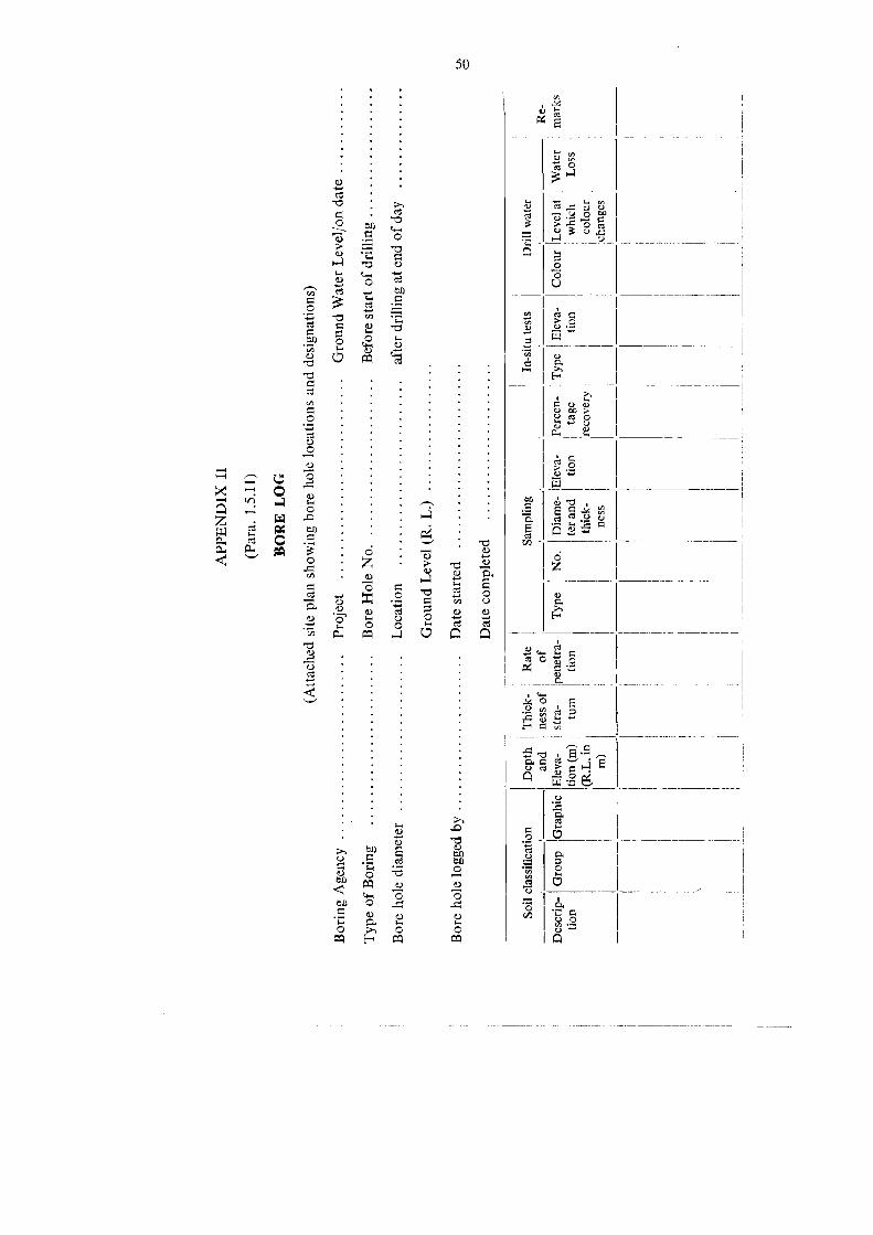
APPE
NDIX
U
(Para.
1.5.11
)
BORE
LOG
(Attache
dsite
plan
show
ingbo
reho
lelocatio
nsan
dde
sign
ations)
ness
j
Boring
Agen
cyProject
Groun
dWater
Leveljonda
te
Type
ofBo
ring
Bore
HoleNo.
Before
startof
drilling
Bore
hole
diam
eter
Locatio
nafterdrillingatend
ofda
y
Groun
dLevel(R.L.)
Bore
hole
logged
byDatestarted
Datecompleted
Soilclassification
Dep
thTh
ick-
Rate
Sampling
In-situ
tests
Drillwater
\an
d‚n
esof
of;
\
Re-
Descrip-
Group
IGraph
icEleva-
stra-
pene
tra-
Type
No.
Diame_
Eleva-
Percen
_Type
|Eleva-
Colour
Levela
tWater
marks
tion
tion(m
)tum
tion
terand
tion
tage
tion
.which
Loss
(R.L.in
\thick-
recovery
!colour
m)
chan
ges
05

SECTION 2-SHALLOW FOUNDATIONS


53
SECTION 2--SHALLOW FOUNDATIONS
2.1. Shallow and Deep Foundations2.1.1. Foundations are broadly classified as shallow foundations and deep
foundations. The shallow foundation is one which is immediately below the struc-ture it supports. The deep foundation is at a considerable depth below tbe structure.It is not possible to draw a sharp dividing line between the twe.
2.1.2. Frequently a shallow footing refers to one whose width is equal to orgreater than the depth of its base below the ground surface. This definition is usedby Terzaghi and his theory of bearing capacity is based on it.
2.1.3. In case of bridge foundations the IRC 78-1983 describes a shallow lounda-tion as one which may be taken down to a comparatively shallow depth below thebed surface provided the foundation is protected against scour. In erodible stratathe depth of all foundations should not be less than 2 metres for piers and abutmentswith arch superstructure and 1.2 meires for those with other types of superstructure.A deep foundation is described as one which is taken down to depths providingadequate embedment, the minimum of which should not be less than one-thirdthe maximum anticipated depth of scour below the high flood level.
2.2. Shallow Foundations
These can be divided into two groups : Spread footings or single foolings andrafts or mats. In between these are combined footings.
2.2.1. Spread footing also called single footing, as the name implies sj.readsthe load from the column to the soil. Such a footing is also sometimes calledan open footing to denote a footing constructed in an open excavated pitDepending onits shape ar the way in which it is designed the lollowing names areused to further sub-divide a spread footing _- _
(1) Stepped or sloped footing---When the column load is large and the bearingarea is required to be increased, the extra cost of formwork required for slopingor stepping should be effected by the saving in material to justify this type.
(2) Tiro way footing refers to a R.C.C. footing reinforced in both directions.
(3) Wall footing ıs a spread Footing under a wall.
(4) Pedestal is a short columner member which transmits the load from thecolumn to the footing when the latter is at a relatively deeper depth below thesurface.
(5) Cantilever footing is a footing on which the column is located eceentrically
2.2.2. Rafts or Mats-A raft or a mat foundation is a single slab supportinga large number of loads. It may be continuous overa partor the whole ofthestructure, [t is used when the bearing capacity ofthe soil is so low that a spreadfooting if used will spread over a large part of the area under the structure or whenIhe soil contains comnresihl ! thatwould be diffieult to control.
Toren! t

54
2.2.3. Combined footing is one which supports more than one column in a line.It may be rectangular or trapezoidal in shape.
2.2.4. Strap or strip footing is a long narrow continuous slab joining footings ina straight line.
2.3. Depth of Foundations
The depth of foundation is governed by-(i) bearing capacity of the soil.
(ii) depth of volume changes in the soil.
(ii) depth of scour.
(iv) ground water level.
(v) existing structures, excavations,
(vi) underground features such as caves, mines,
(vi) depth of frost zone.
(viii) unconsolidated fills like garbage, dumps.
(ix) susceptibility of the soil such as loose sand to liquefaction during carth-quake.
?311 Clayey soils like black cotton soils undergo large volume changes with
change in moisture content. Generally shrinkage movements become small at a depthofabout 1.2 m In case of black cotton soils, the depth of movement may be as deepas 3.5 m.
2.3.1.2. Fluctuations in ground water level affect the bearing capacity of the soil.
?313 Loose sands with standard penetration value of lessthan 10 may undergoliquefaction or excessive total and differential scttlement during an earthquake.
2.3.2. The minimum depth of foundation below the ground surface should be
50 cm except on rock when removal of top soil may be required.
2.3.3. For bridges (See IRC:78-1983)--Tbe depth of foundations in erodibleStrata may be taken to shallow depths below the bed surface provided good bearingstratum is available and the foundation is protected against scour.
2.3.3.1. In erodible strata the minimum depth below scour level should be
2 meters for piers and abutments with arches and 2.1 metres for other types ofSuperstructure.
2.3.3.2. On rock the minimum depth specified is--(a) 0.6 m in bard rocks like igneous, eneissic. granite with ultimate crushing
strength of 100 gm/cm? or more.
(db) 1.5 m in rocks other than in (a) above and having minimum ultimate crush-
ing strength of 20 kg/cm?.
(c) In cases not covered by (a) and (b) the depth should be decided by keepingin view the overall characteristics of the rock formation such as fissures, bedding
planes, cavities, crushing strength, etc.

55
2.3.3. In our State, foundations of piers and abutments were taken, in the past,to 0.15 min hard rock and 0.45 m to 0.6 m in soft rock. In recent years these figureswere modified to 0.5 m in hard rock and 1.5 m in soft rock. There bave been nofoundation failures reported even with depth of 0.15 m and 0.45 m-0.6m. Takingfoundations in rock as deep as 0.6 mand 1.5 m in hard and soft rocks respectivelyis not only costly and seems unnecessary but the operation of excavating to suchdepths will in most cases shatter the rock. Therefore, in the state for states worksthe previous practice of 0.15 m in hard rock and 0.6 m in soft rock could still beconsidered for adoption.
2.4. Dimensions of Footings2.4.1. The size of footings is selected so that the safe bearing capacity of the
soil is not exceeded and the overall settlements and differential settlements are withinthe prescribed values.
2.4.2. In case of walls the minimum width of footing should be:B=2W +30 cm
wbere B == width in cm- W = width of supported wall in cm
2.4.2.1. The minimum thickness should be as shown -
Type tan «
Brick and stone masonry .. *2Lime concrete . xl 5 (Fig. 2-1)Cement concrete Kl
2.4.3. In case of reinforced and plain cement concrete the minimum thicknessat the edge should be 15 cm.
2.4.4. In the case of plain concrete pedestals the thickness shall be governed by:
Wall
Fig. 2-1 Thickness of Wall Footing

56
column
plain concretepedestal
Fig. 2- 2 Thickness of Plain Concretepedestal.
100tan 74 X 0.9 1 +1
where, gg = bearing pressure on soil in N/mm?
fcg - characteristic strength of concrete at 28 days in N/mm.
Iofck
2.5. Location of Footing adjacent to existing Footing2.5.1. An empirical rule is to keep the distance between the old and new footings
not less than the width of the wider footing.
2.5.2, Foundation in sloping ground (See Fig. 2-3).
2,5.3. Some of the relevant Indian Standards which deal with deptb of shallowfoundations are 1S: 1080-1962 Code of Practice for Design and construction ofSimple Spread Foundation, IS: 2950 Part 1-1973 Code of Practice for Design andConstruction of Raft Foundations: Design (first revision) and IS: 1904-1978 CodeofPractice for Structural Safety of Buildings: Shallow Foundations (second revision).These may be referred to.
2.6. Settlements
2.6.1. Settlement of foundations depends on the type of soil, its properties suchas consolidation properties, the state of consolidation at the time of loading, density,moisture content, elastic properties, shear strength, intensity of applied load andsize of footing. Thus a large number. of variables enter into the calculations andtherefore a number of semi-empirical methods and methods based on field testresults are used.
2.6.2. In general settlements comprise two components, one which occursinstantaneously and the other over a long period oftime and is caused by consolida-tion of the soil.

New
footing
x 5 N sLne
ofap
proxim
ate
Ia
gfooting
S+%Xem.
+60cm
Na)
dIspe
rsion
e30
°45
°
8
Rock
Sob)
M
Mmustlie
with
insoil/rock
1 1 Y
:Prop
osed
f otin
g-
PN
-"Overbu
rden
Tonsagqü
ent
Settlemen
ttpressure
lost
|soifh
eave
(e)
Fig2-3
Locatıo
not
footıngs.ta
)adjacen
tto
edge
ofslop
ing
grou
nd,(b)
existin
gfooting‚{c)Loss
oflateral
supp
ort
tosoil
bene
ath
existin
gfooting
‚(d)
capa
city
unde
rfooting.
(cd
&e
from
Ret.-3)
New
footing
located
topreven
toverstressing
ofsofl
unde
rLoss
ofoverbu
rden
pressure
lowering
bearing
LS
-Excavatio
n-
Existing
footıng
Existin
gfooting
Setttemen
tof
footing
x7
N
due
tolateral
disptla
cemen
tof
soil
tNew
footing
«

58
2.6.3. If the clay is saturated, the settlement is computed from consolidationtheory. The widely used equation is;
Po + APlog
H
Po1
where S = settlement= compression index
Po = existing over burden pressureP = pressure increment
Co initial void ratio in-situ.
These properties are determined from laboratory tests and field tests. If the soil ispreconsolidated the effective preconsolidation pressure is used instead of Po. Whetherthe soils is preconsolidated or not is usually determined from the pressure vs. void-ratio curve (p vs ecurve). If it cannot be determined from this curve, the level ofnatural moisture content is used. If it is closer to the plastic limit than to the liquidlimit, the clay is preconsolidated. If it is not closer to or greater than the liquidlimit, the clay is preconsolidated and may be sensitive in which case the computedsettlement will be very low.
2.6.4. In the following soils the consolidation theory does not apply:C- 6 soils
non-saturated clays and silts
granular soils
Settlements in the above soils and the immediate settlement in saturated clays iscalculated from equations based on theory of elastieity or from field tests such asthe static cone penetrometer test, plate bearing tests and standard penetration test.
2.6.5. The IS: 8009 (Part 1)---1976 Code of Practice for calculation of settlementof Shallow Foundations gives procedures and expressions for computing settlementsand should be referred to.
2.6.6. Maximum and Differential Settlements of Builaings2.6.6.1. Differential settlements can be caused by-(a) variations in soil types, presence of organic matter.
(b) unequal bearing pressures under different footings of the structure.
(c) overloading of soil by future adjacent structures.
(d) soils which undergo large volume changes.
2.6.6.2. Tolerable values for settlements and differential settlements of buildingswhich are meant to be used only as a guide are given in Tablc 2-1 taken from IS:1904-1978 Code of Practice for structural safety of Buildings: Shallow Foundations:

TABL
E2.1
Maxim
uman
dDifferen
tialsettle
men
tsof
Build
ing(4)an
dBridges(1)
Isolated
Foun
datio
nRa
ftFoun
datio
n
Serial
Type
ofStructure
Sand
andHardClay
Plastic
Clay
Sand
andHardClay
Plastic
Clay
No.
Maxi-
Differen
-An
gular
Maxi_
Differen
_An
gular
Maxi_
Differen
_
Angu
lar
Maxi_
Differen
_An
gular
mum
tial
Distor-
mum
tial
Distor-
mum
tial
Distor-
mum
tial
Distor-
settle-
settle-
tion
settle-
settle-
tion
settle_
settle
_tio
nsettle-
settle
tion
men
tınen
tmen
tmen
tmen
tmen
tmen
tmen
tmm
mm
mm
mm
mm
mm
mm
mm
(2)
3)(4)
(5)
(6)
02)
(8)
&(10)
(dt)
(12)
(14)
(15)
diForsteelstructure
..50
0033
L1/30
050
.003
311/30
075
.003
3L1/30
010
0.003
31/30
0
(ii)Forreinforced
concrete
..50
0015
L1/66
675
.001
5L1/66
675
.002
L1/50
010
0.002
L1/50
0
(if)For
plain
brick
walls
inmultistoreyedbu
ildings-
(a)For*
60.000
25L
1/40
0080
.000
25L
1/40
00Not
likelyto
beecon
ountered
.
(b)For
60.000
33L
1/30
0080
.000
33L
1/30
00
(iv)Forwater
towersan
dsoils
50.001
5L1/66
675
.001
5L1.66
610
0.002
5L1/40
012
5.002
5L1/40
0
d>
(v)Forbridges
Differen
tialsettlemen
t:.002
5Lforsimplysupp
ortedsupe
rstructure(L
=Sp
an)
Note.--T
hevalues
givenin
thetablemay
betakenon
lyas
agu
idean
dthepe
rmissiblesettlemen
tan
ddifferen
tialsettlemen
tin
each
case
shou
ldbe
decide
das
perrequ
irem
entsofthede
sign
er.
*L
deno
testheleng
thof
defle
cted
partof
wall/raftor
centre-to-centre
distan
cebe
twcencolumns.
Hde
notesthehe
ight
ofwallfrom
foun
datio
nfooting.
65

60
TABLE 2.2
Safe Bearing Capacity (from IS: 1904-1978)
AFE Bearing
No Type of Rock/Soils capacity RemarkskN/m? (kg/cm? )
(2) (4)
(a) Rocks-
Serial
je }
(i) Rocks-hard without lamination and defects, 3240 (33)for example granite, trap and diorite.
(i) Laminated rocks, for example sand stone and 1620 (16.5)lime stone in sound condition.
(ii) Residual deposits of shattered and broken bed 880(9.0)rock and hard shale, cemented material.
(iv) Softrock .. 440 (4.5)
(b) Non-cohesive Soils-(v) Gravel, sand and gravel compact and offering 440 (4.5) (See Note 2).
high resistence to penetration when excavatedby tools.
(vi) Coarse sand, compact and dry .. 440 (4.5) Means that the groundwater levelis at a depthnot less than the widthof foundation belowthe base of the founda-tion.
(vi) Medium sand, compact and dry 245 (2.5)(vi) Fine sand, silt (dry, lumps easily pulvarized by 150 (1.5)
the fingers).
(ix) Loose gravel or sand gravel mixture loose 245 (2.5) (See Note 2).coarse to medium sand, dry.
(x) Fine sand, loose and dry 100 (1.0)(xi) Soft shale, hard or stiff clay in deep beddiy .. 440 (4.5) This group is succeptible
to longterm consolida-tion setllement.
(si) Medium clay, readily indented with a thumb 245 (2,5)nail.
(xiü) Moist clay and sand clay mixture which can be 150 (1.5)indented with strong thumb pressure..
(iv) Soft clay indented with moderate thumb 100 (1.0)pressure.
(xv) Very soft clay which can be penetrated several 50 (0.5)inches with the thumb.
(xvi) Black cotton soil or other shrinkable or expan- See Note 3 to be deter-sive clay in dry condition (50 per cent mined after investiga-(Saturation) tion

6l
TABLE 2.2 -contd.
Serial AFE Bearing
No Type of Rock/Soils capacity RemarkskN/m? (kg/cm? )
(db (2) 8) (4)
(d) Peat-(vi) Peat ‚See Note 3 and Note 4.
To be determined afterinvestigation.
(e) Made Up Grouna-(xviii) Fills or made up ground See Note 2 and Note 4.
To be determined afterinvestigation.
Note I-Values listed in the table are from shear consideration only.
Note 2-Values are very much rough due to the following reasons:-(a) Efiect of characteristics of foundations (i.e. effect of depth, width, shape, roughness etc.),
has not been considered.
(b) Effect of range of soil properties (i.e. angle of frictional resistance, cohesion, water tabledensity etc.) has not been considered.
(c) Effect of eccentricity and indication ofloads has not been considered.
Note 3-For non-cohesive soils, the values listed in the table shall be reduced by 50 per cent if thewater {able is above or near the base of footing.
Note 4-Compactness or looseness of non-cohesive soils may be determined by driving thecone of 65 mm dia. and 60 apex angle by a hammer of 65 kg falling from 75 centimeter if correctNo. of blows (N) (see 15: 6403-1971) for 30 cm penetration are less than 10, the soil is called loose,if N lies between 10 and 30 it is medium, ifmore than 30, the soil is called as dense.
Code of practice for determination of allowable bearing pressure on shallow foundations.
2.6.7. Proportioning Footings for Equal Settlements
2.6.7.1. The conventional method for equalising settlements is given below:-(i) Determine the ratio ofmaximum live load to dead load for each footing.
(ii) Determine the size of the footing for which this ratio is the maximum bydividing the dead load and maximum live load by the permissible soil pressure.(iii) For this footing select the live load that will be most frequently present.
This is called the reduced live load. Generally the reduced live load is taken ashalf the live load.
(iv) For this footing obtain the reduced permissible pressure by dividing thesum of the dead load and reduced live load by the area of the footing determinedin step (ii).(») Use the reduced permissible soil pressure for determining the area of all
the other footings by considering the dead load and reduced live load for these
footings.

62
2.6.8. Permissible Bearing Pressure
2.0.8.1. The permissible bearing pressure may not be the same as the sale bearingcapacity. Tlie safe bearing capacity is geucrally bascd on soil failure and is determinedmore reliably from lield tests, or calculations based on soil properties determinedfrom laboratory test. In the absence of such tests experience, observations andrecords may be made use of. Such bearing capacities may also be called presumptivebearing capacities because it is presumed from performance records of structuresthat the soil can support tkat load.
2.6.8.2. The permissible bearing pressure (or allowable bearing pressure) will bethat which wil keep Ihe setticments and differential settlements within the permissible/limits.
2.6.8.3. Tuerefore, tie permissible bearing pressure is determined as follows:-(D) Determine areas of footing using the safe bearing capacities from field test
results (See section 1) or theoretical calculations based on soil properties (seepara 2.6.8.4.) or from Table 2.2. Use the most reliable of these values.
(if) Caleulate the settlements, differential settlements and angular distortions.
(iii) Compare the calculated settlements with the tolerable settlements givenin Table 2-1.
(iv) If there is a large difference change the safe bearing capacity and repeatall calculations till acceptable correspondence of calculated and tabulated settle-ment values is obtained. Tiıe corresponding safe bearing capacity is treated astie permissible bearing capacity.
2684 Bearing capacity o/ Soils
(a) The ultimate total bearing capacity of a soil is the load required to producefailure of the soil and the ultimate bearing capacity ıs the failure load per unit ofarza. It depends not only on the propertics of the soil but also on the size and shapeofthe loaded area and its location below the surface of the soil.
(b) There are two types of soil failure, namely, general shear failure and local shearfailure.
In general slıear failure, the strain preceding the failure of the soil by plastic flowis very small. In local shear failure, tiıe strain is quite significant.
These two types of failures are better understood with reference to load-settlementcurves obtained from field tests such as a plate load test. In Fig. 2.4a)( (b), twotypes of load settlement curves are shown. Curve dips down abruptly while, curve2 gradually slopes down. Curve 1 obtained for a dense soil represents general shearfailure and curve 2 obtained in a local soil represents local shear failure.
(c) Expression for bearing capacity-Terzaghi gives the following expressionsfor the total ultimate bearing capacity for the two cases of failures. The expressionsare for shallow footings with rough base and it is assumed that the soil is homogene-ous from the surface to a depth far below the base of the footing.

63
Q Load
\
\
Df
Settlernen
t
\
\
\
\
\
2B
Fig24 (a) Continuous footing Fig.2-4(b)Load- settlement curve.
1. Long strip footing as footing of a wall, of width 2BGeneral shear failure: Q, ==2B(CNc + YDFNa + YBN. } "per unit lengthLocal shear failure: Qu, =B(3 CN'o+YDfN'„+ YBN', ) of footing.
2. Circular footing of diameter 2R:Qy = ar? (1.3 CNc + Df q + 0.6 YRN; ) Fans (2-1)
3. For square footing ofsize2B X 2B.
Qu (1.3CNE + YDENg OS NYBN,) Egns. (2-2)
If the soil is loose and very compressible the bearing capacity factors N are replacedby N. In such soils failure will be by local shear failure.
Qn = Total ultimate bearing capacityC Cohesion of the soil
Y
= Unit weight of the soil
Dr depth of the base of footing below the surface [See Fig. 2-4(a)].Ne, Ng Nr = bearing capacity factors dependent on angle of internal friction
of the soil (from Fig. 3-3 section 3).
N'c q NY, == bearing capacity factors dependent on angle of internal frietiou® of the soil.

64
(d) Fromthe above expressions, the following important inferences can be drawn:----
(1) In cohesive soil (6 =) :
(i) the ultimate bearing capacity i.e. the load per unit area causing failure is
independent of tbe size of the footing; its value at depth Drisequalto 5.7c + »D;.(ii) at the surface of the soil Dr 0 the ultimate bearing capacity is equal to
5.7c
It must however, be remembered that a wider footing will stress the soil to greaterdepths.
(2) In soils with &> 0 the ultimate bearing capacity increases with the size olthe footing, thus, in such soils when conducting plate load tests for determiningbearing capacity, the plate size should be rroperly chosen consistent with size ofthe footing.
Bearing capacity in cohesive soils ($ = 0) for different values of Dr/2B and for
rectangular footings.
Skempton's values of Ne for different values of Dr/2B are given in the Fig. 2-5below:
T
(SQUARE c IRCLEg
8
7
STRIPLONG6
B5
4-0 08DfLu
3
2
1 2 3 L 5 6
D+/B
Fig.2-5 Skemptons values of the bearingcapacity factor when d=0

65
The rectangular footings the values of N. is multiplied by the factor (1 +0.2 )
where 2B = width of footing2L = length of footing
BL
When Dy/2B is less than 2.5, the value of Ne is given by : Ne = 5(1+0.2B/L)(1 + 0.2DJB).
In any given case the determination of whether the soil will fail in general shearor local shear will be governed by the denseness of the soil.
&--0 Soils: The degree of denseness of cohesionless soils is assessed from therelative density. Relative density is related to the void ratio. Therefore, the voidratio required to be determined. The relative density can also be assessed from theN values obtained from the Standard Penetration Test as shown in Table 1.10.
The degree of denseness related to the relative density and tbe correspondingexpression for calculating the bearing capacity is given below:-
Degree of Density Index Bearing CapacityDenseness (relative density) Expression
Dense .. Greater than 70 per cent General shear failure.Loose Less than 20 per cent
MediumLocal shear failure
Interpolate between generaland local sbear failures,
20 to 70 per cent
Density Index is defined as:
o
emaro
Where & =o void ratio of cohesionless soil in its loosest state.
e = void ratio in the given state
Emax void ratio in the densest state
+ Soils: Denseness may be determined from the void ratio as shown below :-
Degreeof Void Ratio Bearing capacity expression
Dense
€ss
Less than 0.55 .. General shear failure
Greater than 0.75 Local shear failureBetween 0.55 and 0.75
LooseMedium Interpolate between general and
local shear failures.
Factors influencing Bearing Capacity-The beating capacity of soils is influenced
by the water table, eccentricity of loading and the shape, inclination and depth offooting. Therefore, the bearing capacities if determined from the above expressionsneed to be corrected for these factors.Tb 4597-6

66
Correction factor for water table--The last term in equations 2.1 namely BNshould be multiplied by a factor W whose value is:-
d/2B0.5 0
1.0 1.0
W
between 0.05 and 1.0 Interpolate lincarly between 0 and 1.0.
where d = depth of water table below the level of the base of the footing.2B = width of footing.
Correction factor for eccentric loading:eccentrieity *e' only in one direction \ Substitute 2B - 2e for 2B in
S equations 2.1.
Substitute in equations 2.1
f (2B - 2e5) for 23
eccentrieity in both directions eL and e5 (2L -2 ) for 2Land
Correction factors for shape, inclination and depth offooting:The modified bearing capacity equation is
p = CNcScdeic + YDfNgSadaiq + yBNySydyiywhere,
= ultimate bearing capacity (load per unit area).= Shape factors given below
dc,dg,dy = depth factors given below
ic,ig,iy = inclination factors give below.
Sc.Sq
Shape factor:
Shape ol footing Shape of Forting
Sc Sq Ss YContinuous strip .. 1.0 1.0 10Rectangle 1 +0.2B/L 1 + 0.2 B/L 1--- 0.4 BjLSquare ) 1.30 1.20 0,8Circle 1.30 1.20 06
Depth factor:dc = 1 -+ 0.2 Dy/2B
dq =dy =! for d<10°dq=dy=!-10.1 Dr/2B VN® for &>10°
where N$ = tan? (r/4 + &/2)
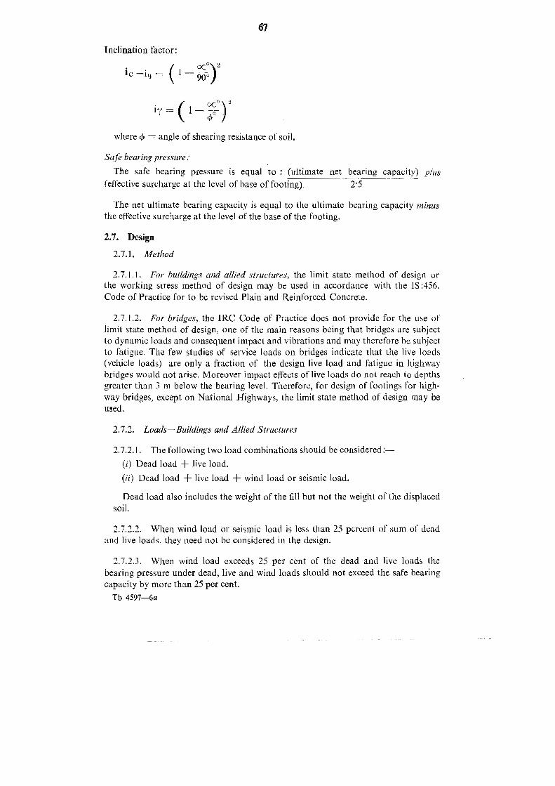
67
Inclination factor:
ic =ig = ( 1
09°)1Y = ( 1 =
where & = angle of shearing resistance of soil.
o
Safe bearing pressure:The safe bearing pressure is equal to: (ultimate net bearing capacity) plus
{effective surcharge at the level of base of footing). 25
The net ultimate bearing capacity is equal to the ultimate bearing capacity minusthe effective surcharge at the level of the base of the footing.
2.7. Design
2.7.1. Method
2.7.1.1. For buildings and allied structures, the limit state method of design orthe working stress method of design may be used in accordance with the IS:456.Code of Practice for to be revised Plain and Reinforced Concrete.
2.7.1.2. For bridges, the IRC Code of Practice does not provide for the use oflimit state method of design, one of the main reasons being that bridges are subjectto dynamic loads and consequent impact and vibrations and may therefore be subjectto fatigue. The few studies of service loads on bridges indicate that (he live loads(vehicle loads) are only a fraction of the design live load and fatigue in highwaybridges would not arise. Moreover impact effects of live loads do not reach io depthsgreater than 3 m below the bearing level. Therefore, for design of footings for high-way bridges, except on National Highways, the limit state method of design may beused.
2.7.2. Loads-Buildings and Allied Structures
2.7.2.1. The following two load combinations should be considered :-
(i) Dead load live load.
(ii) Dead load + live load + wind load or seismic load.
Dead load also includes the weight of the fill but not the weight of the displacedsoil,
2.7.2.2. When wind load or seismic load is less than 25 percent of sum of deadand live loads, they need not be considered in the design.
2.7.2.3. When wind load exceeds 25 per cent of the dead and live loads the
bearing pressure under dead, live and wind loads should not exceed the safe bearingcapacity by more than 25 per cent.Tb 4597-6a
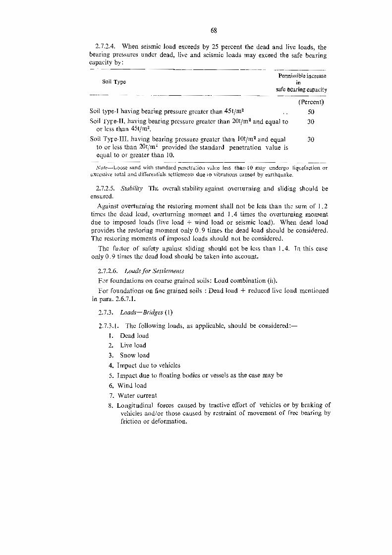
68
2.7.2.4. When seismic load exceeds by 25 percent the dead and live loads, thebearing pressures under dead, live and seismic loads may exceed the safe bearingcapacity by:
Permissible increaseSoil Type in
safe bearing capacity
(Percent)Soil type-I having bearing pressure greater than 45t/m2 50Soil Type-Il, having bearing pressure greater than 20t/m? and equal to 30
or less than 45t/m?,Soil Tyre-Ill, having bearing pressure greater than 10t/m? and equal 30to or less than 20t/m® provided the standard penetration value isequal to or greater than 10.
Note-Loose sand with standard penetration value less than 10 may undergo liquefaction orexcessive total and differentials settlements due io vibrations caused by earthquake.
2.7.2.5. Stability-The overall stability against overturning and sliding should beensured.
Against overturning the restoring moment shall not be less than the sum of 1.2times the dead load, overturning moment and 1.4 times the overturning momentdue to imposed loads (live load + wind load or seismic load). When dead loadprovides the restoring moment only 0.9 times the dead load should be considered.The restoring moments of imposed loads should not be considered.
The factor of safety against sliding should not be less than 1.4. In this caseonly 0.9 times the dead load should be taken into account.
2.7.2.6. Louds for SettlementsFor foundations on coarse grained soils: Load combination (ii).For foundations on fine grained soils : Dead load + reduced live load mentioned
inpara 2671
2.7.3. Loads-Bridges (1)2.7.3.1. The following loads, as applicable, should be considered -
1. Dead loadLive load
Snow load
. Impact due to vehicles
. Wind load
2.
3.
4
5. Impact due to floating bodies or vessels as the case may be
6
7. Water current
8 . Longitudinal forces caused by tractive effort of vehicles or by braking ofvehicles and/or those caused by restraint of movement of free bearing byfriction or deformation.

69
9. Centrifugal force10. Buoyancy11. Earth pressure including live load surcharge, if any.12. Temperature effects
13. Deformation effects
14. Secondary effects15. Erection16. Seismic force
17. Wave pressure18. Grade effects
for evaluation of the loads and forces except seismic forces refer to Chapter onBridges or IRC: 5-1970 and IRC: 6-1966 (Standard Specifications and Code ofPractice for Road Bridges Sections I and IT.
2.7.3.2. Seismic force should be evaluated as given in IRC: 78-1983 StandardSpecifications and Code of Practice for Road Bidges, Section VFI Foundationsand Substructure.
2.7.3.3. Load Combinations-The following are the load combinations for thedesign of members (not for bearing pressures)
Combination (the numbers refer to the load numbers in para 2.7.3.1).I
1I
I M+6+17IV DMD+r16+17V +6VI 1+7+10+11+15+8+6+18VI YD + 16
1+2@0o93+7+8+10+9+11+18D+14+13+1
6
2.7.3.4. Permissible increase in stresses-The permissible increase in stressesin the design of members for the different load combinations is given below:-
Permissible IncreaseinatiLord Compbination in stresses
III .. 15
III .. 33.33
IV . 50
V .. 33.33 (50 as per state practice),VI 33,33
Ni!
vo .. 50

70
2.7.3.5. Load Combinations and Factor ofSafety for Bearing Pressures-The loadcombinations and factors of safety on the ultimate bearing capacity are given below.In earthquake zone loose sand with standard penetration value less than 10 mayundergo liquefaction. This should be investigated.
Factor of SafetyLoad combination
Soil Rock
+7 +8+109 +11 2.3 6-8ı 2 56.5
or
ı+7+10+11+15+8-+6orl6 2 5-6.5
)
)
or(D+5+1 7
As per state practice a 100 per cent increase in the allowable bearing pressure onrock is permitted when impact due to floating bodies or vessels is considered.
2.7.3.6. Factors of Safety for Stability:
(i) Against Overturning-without seismic 2
with seismic 1.5
I ) Against Sliding-without seismic 1.5with seismic 1.25
(iii) Against deep seated failure-without seismic 1.25with seismic 1.15
2.8. Spread Footings
2.8.1. Bending Moments
2.8.1.1. The section for bending moment is taken as the vertical section acrossthe footing (XX,YY in the Fig. 2-6).All the forces acting on one side of the section is considered.
2.8.1.2. The critical sections for bending moment area are shown in Fig. 2-7.
2.8.1.3. The reinforcement required for rcsisting bending moment is distributedacross the section as shown in Fig. 2-8.
2.8.2. Shear
2.8.2.1. For determining the shear strength, the footing is treated as a wide beamor as subject to two way diagonal punching shear and the more severe of the twoconditions is considered. The critical sections for each of these conditions are shownin Fig. 2-9.

Y
x4X
clu
Footing
Y
Fig.2-6:Width of sectionfor Bending Moment.
1
Coiumn ‚pedestalor wall except Minmasonry wall.
Masonry wall
b
r
S/a" ‚Base plate
a ab=critical section
Fig.2-7 Critical sections for bending moment.

l
Reinforzem
ent
parallel
toL
Fig.?-
9Mom
ent
Reinforcem
ent
5&XA
,in
this
strip
2Ss
2B
L+8
X
inthis
inthis,
® >
inFooting.
Reinforcem
ent
parallel
toB
reinforcem
ent
-m
strip
|strip
BB
A=Area
ofn a
o vo> o >
B

ıda
--_-_crıtıcal
Fig-2-%
Critical
2:IT,
d
(a)
\(db)
3
(d)
(e)
section
d=thickness
offooting.
Sections
for
Stear:talto
lt)two
way
diagon
alpu
nching
shear.
(g)wide
wide
beam
shear
beam
snear.
(g)
dyr
wdA
-Id
+(f
)

74
2.8.2.2. Shear Stress for footings of uniform section:
Shear Stress = Tv=d
M
Verying Section tv= dV+ tand
Negative sign applies when M increases in the same direction as d. Positve siguwhen M decreases.
Where V = Shear force
b, = Perimeter of critical section (breadth of section of wide beam)d effective depthM bending moment at the section
tansc= angle between top and bottom edges of the beam.
2.8.2.3. Permissible shear stress (not applicable to Bridges)-Either limit statemethod or working stress method of design may be used:-
(a) Footing treated as wide beam-The permissible shear stress (Te) in concreteis now related to the ratio of the tensile reinforcement to the area of concretesection. The values may be taken from the IS: 456-1978, Tables 13 and 14 forlimit state design and Tables 17 and 18 for working stress design.
Shear reinforcement is provided to carry a shear equal to V - zcbod (whereV, bo and d are as given).
(b) Two way diagonalpunching shear-When shear reinforcement is not provide:tv + Ks Tc
Where Ks = (0.5+1/b)» +1T c shear stress in concrete (limit state design)= 0.25= 0.16 V fox (working stress design)
b = length and breadth of column respectively.
Fck == characteristic compressive strength of concrete.b
when Ss shear stress in section < 1.5 shear reinforcement should be
provided.When shear stress in section > 1.5 T.; the section must be redesigned.
In building design, the shear strength of the concrete is considered and shearreinforcement is provided only for the balance shear. The shear stress carried bythe concrete is assumed to be 0.5 Tc.
The depth of spread footings should be so chosen that shear reinforcement is not
required,

75
2.8.2.4. For Bridges, except on National Highways.-The shear stress in theconerete is calculated from the expressions given above in para 2.8.2.2. but usingthe lever arm (jd) instead of the effective depth.
The permissible shear stress values in concrete are as lollows:-Working stress method Permissible shearConcrete Stress (kgfjcm?)Ordinary concrete-1:2:4 .. 09,51:14 : 3 .. .. 791:1:2 .. 8.0
Controlled concrete-
Fe less than 200 kgf/em? 0.033 FeFo greater than 200 kgf/em? .. 0.02 Fc+ 2.6 kgf/em? subject to a maxi-
mum of 8.5 kgficm?.where Fo= 28-day 150 mm cube crushing strength - works test.
If the shear stress exceeds the permissible values shear reinforcement to carry theentire shear should be provided.
The concrete section should be so chosen that shear reinforcement is not required.
2.8.2.5. Footings on piles.-The critical section for footings on piles is shown inFig. 2-9,
Pile reactions-For design of footing the following pile reactions should beconsidered :-
(i) Reactions of all piles whose centres are located at a distance of half thepile diameter and beyound from the critical section.(ü) Reactions of piles whose centres are located at a distance of half the pile
diameter and more on the inside (towards the column) of the critical section arenot considered.
(üi) Reactions of piles located in between (i) and (ii) are interpolated froma straight line relationship.
2.8.3. Bearing on top of footing-The compressive bearing stress in concreteat the basc of the column should be limited to-
(Permissible bearing stress in direct compression) X AsWhere A,= Supporting area for bearing of footing, which in sloped or stepped
footing may be taken as the area of the lower base of the largestfrustrum of a pyramid or cone contained wholly within the footingand having for its upper base the area actually loaded and side slopeof one vertical to two horizontal.
A,= loaded area at the column base.

76
The permissible bearing stress in concrete is taken as:-0.25 Fck (working stress design)0.45 Fck (limit state design)
2.8.3.1. If the permissible bearing stress in the concrete of either the column orfooting is exceeded, the excess force is provided for by extending the column barsinto the footing or by dowels. The development length in either case should besufficient to transfer the tension or compression. The minimum number of barshould be four and the minimum area 0.5 per cent of cross sectional area of thecolumn. The diameter of the dowel should not exceed the column bar diameter bymore than 3 mm.
2.8.4. Deep Beam-Ihe depth obtained from considerations of moment, shearand development length for column bars or dowels may be such that the footingfalls in the category of deep beam. A deep beam is one which satisfies the followingcriteria :-
(a) the ratio of span to depth is less than 2 for a simply supported beam.
(b) the ratio of span to depth is less than 2.5 for a continuous beam.
For analysis and disposition of reinforcementin deep beams IS:456-1978 may bereferred.
2.9, Eccentrically loaded rigid footings2.9.1]. Eccentric loading on a footirıg may arise due to the column being eccen-
trically located on the footing or due to moments. The eccentricity may be in onedirection or in two directions. The soil bearing pressures under a rigid footingsubject to eccentric loads will vary linearly from a maximum at one extremity toa minimum at the other. When the minimum pressure becomes negative (tension)only a part ofthe area under the footing will be loaded and a redistribution of pres-sures will occur for equilibrium.
2.9.2. Soil pressure-Since the footing is treated as rigid the soil pressures arecalculated from principles of machines :-
+ MA I
I 1M = P.e and for rectangular footings Y zBL? and A = BL
Pq
PTherefore q = SL ( L )
6e
Where P = vertical resultant load,e = eccentricity of P.
B, L = width and length of footing,q = intensity of soil pressure.

77
2.9.3. Moment about one axis e > L/6--When e > L/6 the maximum redistri-buted soil pressure is calculated from considerations of equilibrium. The two equi-librium conditions are : (f) the total soil pressure must be equal to the vertical resul-tant load and (ii) the lines of action of the total soil pressure and the vertical resultantload must coincide.
P
L
Bx
T_ Redistributedpressure
+ intensity
PSol
Fig. 2-10 Footings subjected to axıal load and uniaxıal mısmentredistributed soil reaction
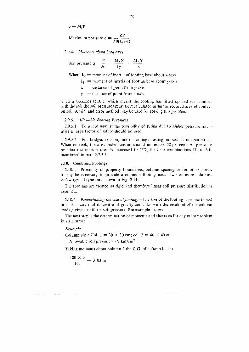
78
e=M/PZPMaximum pressure q =
3B(L/2-e)
2.9.4. Moments about both axes
PSoil pressure q + M,X xM
Iy IxA
Where I, = moment of inertia of footing base about x-axıs
I, = moment of inertia of footing base about y-axisx = distance of point from y-axisy = distance of point from x-axis
when q becomes tensile, which means the footing has lifted up and lost contactwith the soil the soil pressures must be recalculated using the reduced area of contacton soil. A trial and error method may be used for solving this problem.
2.9.5. Allowable Bearing Pressures2.9.5.1. To guard against the possibility of tilting due to higher pressure inten-
sities a jarge factor of safety should be used.
2.9.5.2. For bridges tension, under footings resting on soil, is not permitted.When on rock, the area under tension should not exceed 20 per cent. As per statepractice the tension area is increased to 25% for load combinations II to VIImentioned in para ? 733
2.10. Combined Footings2.10.1. Proximity of property boundaries, column spacing or for other causes
it may be necessary to provide a common footing under two or more columns.A few typical types are shown in Fig. 2-11.The footings are treated as rigid and therefore linear soil pressure distribution is
assumed.
2.10.2. Proportioning the size of footing.-The size of the footing is proportionedin such a way that its centre of gravity coincides with the resultant of the columnloads giving a uniform soil pressure. See example below :-
The next step is the determination of moments and shears as for any other problemin structures:
ExampleColumn size: Col. = 30 x 30 cm; col. 2 -40 X 40cmAllowable soil pressure = 2 kgf/cm?
Taking moments about column I the C.G. of column loads:
100 x -3. 03m5
165

79
Length offooting required = 2(3.03 + 0.3) = 6.66 m
165 x 1000
666 x 21. 24 mB
Footing size = L x B = 6.66 X 1.24Uniform soil pressure == 2 kgf/cm?
N
TIE BEMm
ELEVATION ELEVATION
PLAN PLAN
RECTANGULAR RECTANGULAR WITHTIE BEAM
PLANTRAPEZOIDAL
G 2-11 OMBIıNED FOOTINGS

80
COLUMN-I (Soxzs Cm) COLLIMN2 (40 x40 cm)G5T
sm
lı5 cm
Fig. 2-12 FOR EXAMPLE)(para -2 10 2)
The size of footing can be rounded off and the actual pressure intensity used.In computing the pressure intensity for calculating moments and shears the weightof the footing is not taken.
2.10.3. Width of footing effectjve in short direction-In the short direction theentire length of the footing will obviously not be effective in resisting moment.A narrow strip symmetrical about the column and having a width equal to the widthof the column plus twice the effective depth is taken to resist the bending moment.In the remaining length minimum reinforcement as required by the appropriatecodes is provided.
2.10.4. Critical Section for moment-The critical sections for moment will be
those at which the moments are maximum.
2.10.5. Critical Sectionfor shear--The critical sections for shear are asin the caseof spread footings.
2,11. Raft Foundations for Buildings2.11.1. Rafts are provided when the bearing capacity of the soil is low. A raft
may be provided under the entire building or a part of it. In the latter case it may be
dificult to control differential settlements.
2.11.2. Rigidraft2.11.2.1. Rafts, wherever practicable are proportioned in the same manner as
combined footings and conventionally designed as rigid structures. This is reasonablyvalid in soft compressible soils.
2.11.2.2. The pressures are calculated from the expressions given under eccentric-
ally loaded footings. If the eccentricity is large there is the danger of tilting.
2.11.3. Settlement-A raft foundation is usually provided at some depth belowthe ground level. Therefore the weight of the excavated soil may in very few cases
equal to the weight of the building resulting in negligible settlement. Normally the

81
settlements are calculated for the net increase in pressure, by deducting the weightof the excavated soil from the weight of the building.
2.11.4.. Design-The soil pressures under the raft are determined at variouslocations and the raft is designed as an inverted flat slab. Ribs may be providedbetween columns and the raft analysed like an inverted grid of beams and slab.The slabs between the ribs are designed as one-way or two-way depending upon thesituation.
2.12. Beams on Elastic Foundations2.12.1. Combined and strap footings and raft foundations can be designed by
the application of the theory of beams on elastic foundations. Reference may bemade to Beams on Elastic Foundations by M. Hetenyi for theoretical part.Combined and strap footings can be analysed by using directly the equations
of Heteny which cover different types of loads, moments and end conditions.For analysing raft foundations by the above theory techniques such as the finite
difference method and finite element method can be employed and computerprogramme is prepared.
2.13. Raft Foundations for Bridges2.13.1. Raft foundations are extensively adopted in the State for bridges with
solid slab superstructure. Considerable progress is achieved in design and constructionof raft foundations. More efforts are required to develop practicable techniquesof construction in river beds with higlı water inflow.
2.13.2. Raft foundations are eminently suitable when firm and inerodible founda-tion stratum is deep seated which would normally require well foundations. Withraft foundations it is possible to construct submersible bridges with much lessobstruction to flood discharge than when well foundations are adopted. Bridges withraft foundations take less time for construction and they are far more economical.
2.13.3. The longest raft so far constructed in the State is about 280 m long acrossthe Kobragadi river in Chandrapur district.
2,134. Type Plans-Applying the theory of beams on elastic foundations,Patwardhan, Chonkar and Gajapathy Rao, the authors have developed type plansfor raft foundations for solid slab bridges. See Fig. 2-13. The raft is treated asa Channel section comprising the raft slab and tlıe monolitbic upstream anddownstream cut-off walls.
2.13.5. Type plans for a slab raft with non-monolithic cut-off walls are underpreparation.
2.13.6. Narrow Raft Foundation-A narrow raft foundation has also been
developed by the author and constructed for some solid slab bridges. This type isiltustrated in Fig. (2.14 a, b, c, d). It is more economical than the full width raftFig. (2.13 a,b, c,d, e, f). Since the length of the pier is small, it is necessarily ofeither plain cement concrete or of reinforced concrete.Tb 4597 -7

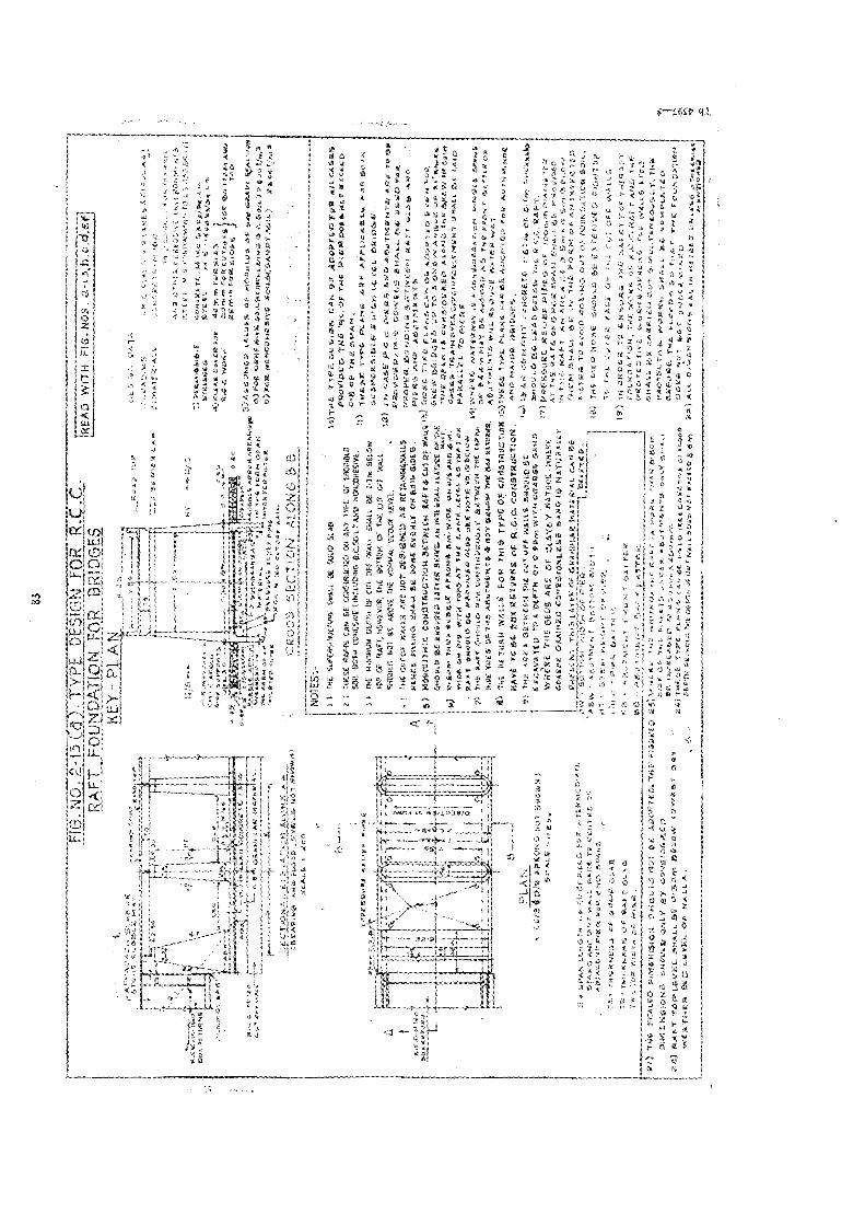
83
x
FIG.N
O. 2
-13
TYPE
DESIGN
FORR.C.C.
BEI
EpRE
ADwiTH
116.N08
.2-12
.bc,d.er
RAFTFO
UNDAT
ION
FOR
BRIDGES
Sen
BRIUGED
KEY
PLAN
.as
3Van
="
ENTER
cmI
Zeur
TIgt
Boman
n=
RdPR
2.aEssriam
an!
Pro
"men
uvrWtih
.De
az
Zra
ES®
$H
;u
SuLS
22rer
DEZEDET
ze23
Kr
BZu
mu
"r„u
n?m
TH"
name
""we
eye
3jr
j£
4TER
BuSO
HFRETEMia
3=»rg
a%
B>ama
avBIRIALER
SER
[2yoaaaaa
nr
‚re
$w®
PER
AJCısAULER
FBSu
mFU
Rmiab
Zune
PERF
2Pi
BETH
eewerne
rMin
eree
REwor:
BOmm
FOREU
TORE
EKo
RBa
slom
auPE
RA
saEEmmromsine
.var
Beech
un59
5Bir
"RR
ISDR
rAP
Rn
»„
IJSe
Weo
psare"
irsan.
6AP
RoaAR
RAHGRSrAu
SumED
eALuEB
ofMEC
uLen
OEBu
het
€RA
on*
rtun
amar
Kunseaer«4
Sora
entk-
minsFO
RMAL
FOR
CONESrE0
urem
doSa)
Bart
eroo
peen
KursexF
RSohE
ArieRE
FAUTEe
VIFO
RNONCO
MTEINGEwon
wa
Pa}
assyo
&8
Bukm
iSITO
EFweis.
2AT
SERO
NR
LEnr
mr
ya]
ern
ElRiN
SONDBL
SCHE
1Nun
are
NOTES
BEIS)TuE
TYP
TuuIGW
DAN
GEAD
ORT
EOFERAL
CASES
FEW
FROVIDED
THE
wiVFTA
RPIE
BRDOkA
NGTMRS
RuD
GB
ORTasspan
TeskktÜ
bBEL.DNG
SL,
YAO
RCON
x*
ae=
SON
BORe
COHESIW
kÜNL.DNG
BEL
FARO
Fass
NM
AmEn
ETYek
Pian
sAU
EAP
Pscan
Kahn
6map
BETe
Feel
BESTE
LECU
TSFTA
San
BEZI
BELO
Eu
BHLAGBr
Sic
KsDROm
-Yanyd
7H
" fr4,
BÜPEh
eIo
DRTE
FFAl
1Mater
akdırTe
onenn
U.
Mal
sncase
Pac
mars
andan
ITman
taan
dvums
f&
BFRoyeeD
MW
IEnihie
Briäl.
BLMies
Ron
+m
TBSTR
Wikia
FREH
OTEB
IGED
AbRE
TANBG
AALLE
PAD
BIRD
SaBi
tWieet
KAEI
ähAU
TF
NEN
TEFRURG
SHAL
BRDONEEH
EMLY
ORBO
THED
ERFIE@
Sare
ABLTMER
TS}
ft
x4)
Möktulln
irSO
NSTRL,TIaH
BETW
ELN
KAFTSCH
TURWA)
etN
vusnnKa
nkeb
Ann
gehe
nFoo
woh
nEm
den
>de
grPr
INTEGRA
L SKAT
ORE
De
YaBrEw
DRDue
HINTER
aER
NVAn
nRE
Banr
%\
mwön
nBE
Enbı
Ena
ATIRE
RETR
EESPAR
ISLU
Hk
WER
ALONGTR
ERVsne
rn
\F
gehu
b3
APBO
NSsBrs
AITC
Kan
ıwSann
wen
uiTR
EEa
NEE
"TA
Trel
DELas
ff
ur€]
wor
anud
WIE
TORI
RTTEEwre
EYEL
ABIRAT
DE
PARA
LLEL
19BIER
E&$
a22Se
1BIOW
rf
£x
RAET
BUSSI
PRDSIDLO
AltonikHari:
soTu
ben
Mnn
uET
WAT
ER18
arn
SRRA
NIUM
winuu
hGran
NNEE
RER
RLEET
BuTW
ELH
THEKa
in.
BEDEA
mMAT
DE
AAHED
AGa
prsnm?BE
TTRO
H99
11Ab
EVO
EBORTH
EAB
UTW
MEN
TSBR
ELOW
THEAczKÜ
TDER
E,AB
UTW
ERIS
WEL
RE&BA
Tway
x
ARE
BITn
ERE
TLAN
FOR
TNIS
TFPT
OFLO
NSTRIGTIORIB)TRE
SETreL
ANAR
Amar
Häve
10BE
BaRE
TURN
EOFN
C.O
Gon
sTkucrıon.
ANGEMAIORDRINES
IEAR
EBE
TWEEN
TIEST
Oft
WALLSE
BHOuLDBa
Vegan
EMEN
TCOMORE
TE63
OFDr
Trun
uahe
%
ctun
se,
EISN
ATEO
TORDRE
HDi0
OnWITHETAR
ERAD
enen
ARE
Rap
Sul
EnDE
vos
misÄrIR
TEN
ouWHER
ETH
EBE
DSAR
EOFCLAY
EYNAT
ort
muine
aa
Ane
SOAK
EEGRA
NT
CHNFEIOHLERS
BANDig
HAT
UIM
ALLT
Mir
BAFT
AnÄA
RLAEI
um"G
saafuh
ePR
ESEN
TJAYIR
SHGRA
NDIARMAT
ERTA
.CA
NBE
THEM
Dyki
BEI
TIMEFO
RMDRan
InIEREI
ıınala
veSins
BERAP
RALT
RUE
TEE
REU
Pier
INTER
TINO
JEOAD
RDAT
Enn
ANWALL
WAC
HSE
Asm
ESMET
&LER
TE13
)Fim
Bose
SNovLh
BERU
EIDEN
Fiuyrup
weR
man
s5)
Ehren
wos
vr&
14Re
HTe
nrtiN
BALL
Ur
AH#T
WEE
Niur
ihA
I.Tem
bArI
{19
°Ra
ceı
£sine
EGSkmufe
IbBä
rı5%
rIB
RaZ
Tmeh
Tren
warten
PRURT
ATION,Th
WöR
K>a
NNAFTA
Inf
%viear
ERBR
neAm
tu
222
FRRO
LETSG
woh
nteAk
ut02
4wa
LIE,
man
n.es
een
eejet
BARR
LLUEEU
Tni
TEAN
EOUYLY
Tri
-T
-
Ayon
eeba
Nrn
atmu
Ede
hLw
esst
Don
yBE
IMRA
ESD
389
»alssirea
KEIESE
Inh
1,00
0»o
Tin
TeBo
lnDation
we)
RafT
TOP.EVEL
0Sem
AbiIM
ELE
TYPE
PLAN
Ean
aIRRLLAK
Tab>
DOER
WMOTSR
TUNDER
Kn.D
WER
THER
BED
EVEL
OPHALL
enBE
PSM
ORC
HDLZ
TUEDER
TSOFT
ABE
STO
TRa
ckieEm
Baal
DmEN
Enmn
aTE
aBE
SHim
kiuiek

FrBe
We
SEae
4uJ
kim
avas
INIW
FINOAN
IEBN
SI9U
S3>6
5NOLVEN
NOS
Ylävy
338
SaNsi
An
KIEETTIR
ERBIN
argAD
a
VEWereWas
TER
SEFR
au
vDa
deB
‚ne
2ON
arsfr
NT
par
avi
%in
aZu
ZeZe
Hrn
N
x
gar
-
uURe
n
2man
tel
ORNEIN
>z
ALP
ZUNee
Er2:3
srda
nwe
mBR
:*
:43
Nx
voMc
IEa.
xEn
ihYin
won
hen
die
FA]
A.ey
xen
dene
nnn
neee
erSr?
£PE
R
®
NvkWr
um „Br
CAFEVe
7
N
+
;Un
Wr
w
are
wenge
RUSS
xIr
imwen
200
a®
wi
soZe
-
ars
Ier
urBd
tv
1"ae
naurg
ZrRE
N
u
Y
Ala
»
an
©
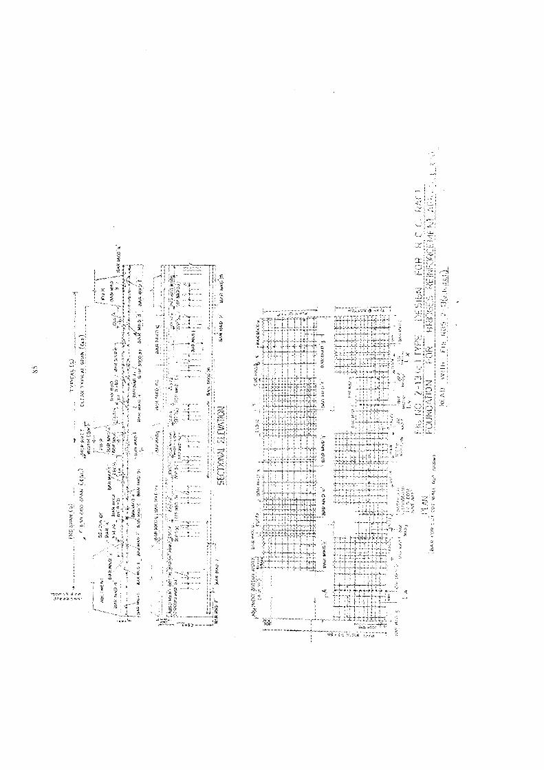
3
RDSEAN
rırsaLie)
-A
Cıarıa
Dee
Bari
UL
PIrtalsheCu
)Pe
-
-.m
i2
mein
run
ik'yı;H
\vak
Brze
ua
ARWr
et\
ba#M
1wan
n2%
Bi.
4FE
en>
NPa
Er27
753
warira"
"xvan
B«
FeZu
ree
De
*B
-.-.r
De
eeEee
.-ua
.DEE
ReGE
ZeFE
era
En\
kubi
E)
Pen:
u%
AHr
BERN
Heche
imze
zu;
DE
SeER
ROR
4l
Res
Heb
iale
206g
BoMia
zaartı
u
1
VPZ
UUIM
zeze
BeFE
"ir
FEI
A..
7a,
BEx
ROmL
EA,
wa
avs
Hr
Pike:,
osr
mon
nen
mzone
®ward
PRanMa}
{$
+F
3
x«
Yası
Een)
s
rr
R52
&Ke
hlAT
iLANKR
FZe
Tun2
gAG
[3[
Le;
„rk
%"keh
eIn
daeı
o.L
y>2
4{
ya*
9,j
Da
ivo:
3*
..»
uBu
;ME
een
grEZ
;-
*H
H"gr
Fe
jiH
19
?R
r«
u;1
ı**+
3A
fi«
Pr
2841
»v
{®
xv4
>Pu
h"
52EEE
€ve
1i
5H
12RiFisıı?
un
ZnZZ
b'.
urD
\A
arYR
Rda
at"0
x-
sFe
#E72
Di.
vor
}os
ft1
DEE
ESe
Ba%
©,oo
,F
vı?
bir
*}R
3wi
!ze
iix
ErUL
",«
®E2
»ah
M
ws
%"
5F
prva
*7%
P%ie:
Eu.
i+
;Pa
aus
Br
3a,
ije
u!
iFi
2ur
En4
3
*%
Ln
av
}i
urUr
21£
I?
ni'
3or
a
aep
Du
BEEBe
BEEEE
Eee
5
BaSE
SrBePre
--
rL
rsur
ter
KOı
pr44
sch
alla
J_
sEU
1BA
R
Ir
#=u

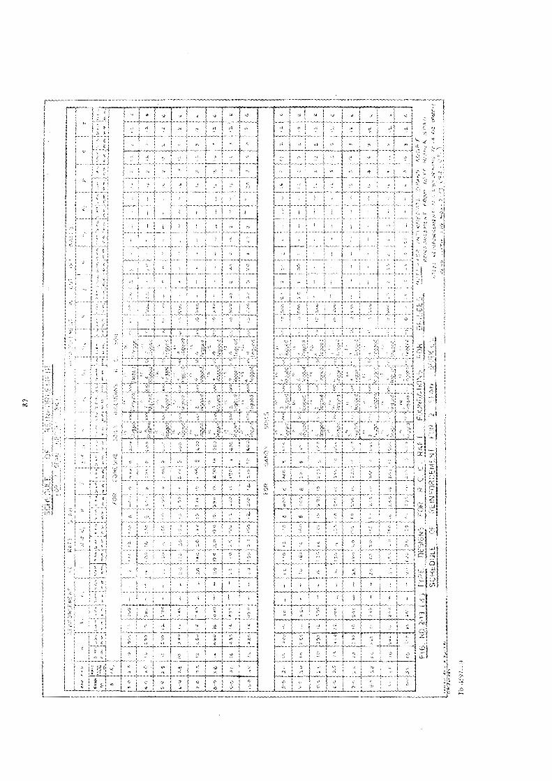

Pan
neu
Fr-
-man
tmme
sent
E\
{MEN
T=1
Nne
een
aCE
ESa
Bae
ZB23
75Ve
urRe
"mind
IPR
..-
17
nnes
}";
CEPr
44
Pr">
mr-
..!
3
»Ei
Y\
\!
\i
2.
!bua
eben
»„ir
PPFR
anlven
Bemiare
EEE
N.
4>
"vr.
+sa
son
voara
oosr.
pnBe
mnsn
ser
mern.
wulaıagasm
s«0
in..
rer
je»vom
Fua
ma
jmmme
jmm
»L
nKim
mw
iRrer
KrSE
SEEEE
-zu
BEa
"or
Au
N1
2e
GeE
EEZr
erBL
anmo.
TVTTT
pevn
gem
B!
{1
1H
\.
|
Fig
I,I.
uni?
"he
r
"huFa
iPu
-&
Nsata
ly2:2
ix%
;a
Eee
DEE
En
a
reP
3%au
nad
Bade
:Ba
ru
..-
inha
l.eh
e!
8°us
vnv
xa
BBTER
SHE
DELETE
EuTu
FÄ
t-x
rneen
F3%
H
«f
F-}
|ef
»Ihe
rin
Inen
PrPR
"ir
7ma
8aun
,vrN
er-:
id44
um+"
4bu
msen
nnan
y.-
IÄ
-Dr
GE
1
Tr®L
>be
nns
erBe
rPo
rnhin
Ian'
3,)
59[er
etEi
xEZ
Br"x
free
nnd
00an
de}
Lii.
anar
EPE
Raf
eru;
;N
_.j
I|
ara
h,aan
iain
Fir
ls
}F
;i,
ieu
„ey
s>4
‚eour
=;N
MB
Bulie
bauulm
au10
im„
:ug
Px
vaHau
se!
ron}
nele
aeeen
Y\
Bas
m.
Es-;
M
$
|
}z
2lıcia
lanjn
nie
I,am
tıen
sjo'.
Paal,"
Dh
ef»
eo,«
jeim
lzm
}Er
ERrg
ee;
we
Nun
heys?
etEine
auPe
s
Eon
1.6
"!"
1ku)
9rils
anlz!
PuE zeur
ww.
*
npnn
dam
aan
1mm
werpm
grn
+B
leo
FRyo"
wi
"ahl
"ha
dm
ein
te"ip
et"
;%
4"oa
s
Rras
Bes)
sage;EIER
Kd.lıl
ıin
aBa
erB3
3'OlL
mg
gu-
rcKLLze
HI
ngm
7777
575%
BEEr
uu
1za?
4j
."
?\!
Iuhı
ie'
%rd
Ioı ik
Ia
10Izsatım
fiyatlın
Italia
fussı
peF3%
%rs
ugrn
aee
m
nnre
Iri
ar‚>
1]in
Fuen
x
Er»
on-.
tn+
3#
«TE
PIE
Pass
Der
wR
3eo
shi
umII.
kun
eeod
19idea
Bm,
xR
fape
tel
arer
here
ng-
-e-
i;
KK"4iz
udZe
Zn1
h=
ra
uLe
zeP}
;
;P
2>
vrwi
wei
Korm
em..
PER
YA'E
Bau
ende
e,aeier
&"elei
ogy
eedl
ten
HI.
ae
Zu"S
nnBr
but,
x
Io.
>Pa
ssSpji
s23
00Foul
lich
ee,
!j
FEBE
Ge
u12
08Ib
en!
4Pe
nvu
RLTS
D
ZuURH
IEEPa
}w
'vw
I5%
PIt
i,x
oc
Id#
-
s'I.
an
BEZu
Zeze
0le
s*
zo)
5%jeoa
Pau})
sozr0
wIsao
,u
Boa
imine
Boge
vuf
SET
laES
IEags
v2
4%
FF
ar%
Fr1
un}
DE
Dr
AZee
N
zu3
1°f
|
..ar
a.ua
m$
in}
enen
-1
u
m17
2"Po
ju
1a"
Pwen
®
Pru
i20
;Een
2%‚8
2.;
Ina‚In
|
DV
3gs
FITe
2io
Lee
FECH
Eau
ehet
{
+um
}-1m
Fyert
nnen
"ierent
ı,»
Pus]
y-BP
Du
21
je3%
chf
esL
Wa
[Eu
Eee
IrPE
R:Lie20
0;
aBe
er
zuES
2322
Fhe
erIeyael
Merk
a
m1.18
8Intense
anE
AuoR
Ti
De
ZZ
FaFb
TER
zeB
Mori
Bere
man
KrRE
REEHT
KREIT
HuX
T3
Sram
VEDan
»STLEL
RIWFO
RELEMEN
TmE
COnFORrmiNe
niN
55-
>IS
m3n
GRA
DE.»
FT7
anne
uRE
Rveitn
RiuN
O327
3ah
ct)
-4,3


91
c
APRON.
n
A Ip AR Nr
5 \ % Na a \
1 ihlı4 i Jean. 1
l
i
PLAN AT RAFT TOP LEVEL
(scale ı90 2
.. Staa) from counter for! Yo be
a
een/ra? vounlerfor/
To be,
as"
7
L..
350 250
from caun'er
a
CROSS SECTION &CC
FIG: NO. 2- 14»NARROW_ RAFT FOUNDATION
Tb 4597-10
FOR SOLID SLAB BRIDGE.READ- WIIH FISNOS 21L tb.cd.)

SECTION 3 WELL FOUNDATIONS
Tb 4597-12

A
7>
>
Nrn
onwir
PR>
FE0%
anag
wir
i
vx
mg"
urvar
ZeN
D#
PiA
EB12
22Z
xEr
snj
mor
zor
5Y
..Y
\PR
Amen
nenn
e..
Fa2er
ZeFEGe
zZap)
RY
enTTS
rnTh
%©
"r>
fs
Znrl
hePo
%3
".2
a®x
Pe
R
[=un
gen
eru
Amsm
$no
n,s
xoR
kaBa
yy®
{4u
Kama,u
BEm
Jrwia
mmun
sEB
gt»
U.
LED
nu,
Brisnctiu
cdtm
BELEGE
SELi)
BAER
-
serie
a
PMae
2230
7mn)
een >
EF2Er
eur
nzDe
®De
,3
»Pr
erg
F
ga.agnıdlenI
GZe
mEi
wo...
A*
Erwo
BEER
aFe
uPr
\
1}
%1
\
Zee 7
2["
a.
2\r
my
5.N
Z-AIZ)HAR
RUW
RAM
enEr
oeFn
4N.
-BJ
MR
V©
eru
ZuFe
erF
una
PR+
yaÄ
33%
men
\
()£
»oo
m
er*
re"r
ah
INDAT
ION
FÜR
SULH
Si.
enin
eem
*WE
en27
>-
a-E
enI.
rnEh
IrNE
"&
\Y
[ee
}
SECT
OR
OFKR
AFT
THRO
UGKR
CUTOFF
WALL
e

1
i
swr
t
a
var
m"/
wen
"Pr
Aee
-A
BrPs
n
e2
24
84a
vrun
1BE
EZeEN
2"
vr«
PKn
Eu*
ErFa
?6
PR44
Paer
-.Pr
Pa\
PEYG
E57
Pau
ort
WP
Zeen
rPe
12
SZen
nr,
j
®
Prnt
Pr.
BRUDER
IPODBE
DE
aZu
orvor
x53
Per
Da
Pe-
war
+a
-
nnhe
UN
vor
wi
__
x
r7
En*
»E
*
aeZe
22
; }er
Pr Wh
wen
t
[avu;
44
-%
WII
y-*
u>
>22
R
wein
huun
nrPa
pe2Ze
€m
xs
FiPE
REr
+
Pu72
u20
?7r
ux
De
Ri
r">
PRZu
5em
ara.
4dr
not
28En
\-
Fr**
Pe%
m!
viv
..xSe
arn
MER
€Pe
er«
e*
Ean
-u;
»*
Eon
rr
£71
Saerh
PrFRE
..
Le)S 5
a
m
Ru

WOTZS
-
rn-
uA D
EED
DEE
uraBr
ne[2
aeee
Zenr
Ju.
ernp
ade
man
ch2.gern
WEN
NS
wel
BatBe
rgen
ste
DA
05Fe
uER
a|wine
2ÜEM
ESEI
RE"695
8Ko
rgYen
2087
7rang
eefAnDre
DEE
tel
GrBe
ngnp
emap
ru.
#8ne
n=
Soyon
una
ClRI
INTEBE
Z52
06EA
MI V
LEFASERa
ua
ErZap
rerer
fen Sara
VeYT
Berg
mBE
REIT
Hree
ee
rorm
maidie
ardhe
ncefe
hllngspatde
done
umuten
eca
ve95
.00de
nts
wirPB
Vade
ryon
arBa
r gufe
reYeermpe
iar
Desßa
ne"7-4.re
nna
men
enA R
ETTEN
ETTEL5
BEE
SBOHT
RTDEEE
REC
Feet!
PER
or"u
'meta
EEWIEDER
SEHEN
eng
Are
Yet
deHaren
Worufe
nmTrau
nhe
yEr
1'fon
eheff
wienof
1 Parde
rss
7°wun
dern
men
ana
ner
arsone
BE
"rd
jair
Des,M
ehrre
nein
irihsreFe
WRerg
OTB
IrESB
enoeErnte
ner
rerl,Erg
rem
wa
A?
""?
.-.-u
reFeckerde
EEE
EROd
15an
tepe
na
RDhs
ern
FEFr
man
na78
"mm
aekndo
ner
wsre
ver
mare
wacßh
ered
bon,
saur
mEn
nehe
nweHa
aSb
aBe
th,
raLe
rate
entar
erea
ren
xPR
EENEEEENe
6
are
\nu
ra,
reRa
ndiefa
anvl
yne
De
Wut
ers
nrmare,Be
rnerKr
eeER
EEE
vie
sa»
MP
FEPÄ
BENEPa
DAS
aBe
IpSfr
men
Ereff.
a pi2a
BTTR
LSegen
wetle
rar
Wem
seärug
zurhem
fen
renm
}er,
;
Don
Bine
AhFurt
Arne
Sp,a
LTTenee
[7L
Sese
wre
mean?
enFO
Ru
Aare
AZrAm
tor:
FEA
REI
aemen
tkan
_Gr
veSR
'om
erAate
sache
Of"EC
Oun
5_a
Zu2
mun
dy.
erut
rder
BeBa
mEEE
GEEB
&,4fr
Bra
rtera2
wgBRut
672
eert
Dem
one
nen
agen
een
arbe
itam
Lues
20ST
mE
arCe
helonw
Aben
vefortan
BL2
Zr
Ära
ehear
enor
werd
Arrrfan
Ha
erde
eeen
>en
grain
Mafarnakafeo
noo
"a
ME70
393
ES,
NEE
MÄR
Beh
TEE
BEWIT
ran
npzuen
nnen
und
>
_JB
eyu
Fezer
FCZr"er,2
FrwarWer
BRgeu„
ai.r
wm
#£*
ePia
ekBE
AGHS
ND2A
)NAH
RVIRAT
TIree
ıne
mfrut
snFemaren
sBepresug
fre
Em|
nur
spalen
met
enAd
aA
wre
geFour
IDAT
JONLF
mÜR
0en
-or
we
#
aDrthe
Amer,rl
eemrw
efrege
engeBR
SLAB
RRB
ROST
5019
760
IETED
Ager
RATE
SIE
u€
uwu
EAPi}
Der
+DIE
EUerg
PsA
£rw
'li
-4:
run
uthe
t-
aen

SECTION 3-WELL FOUNDATIONS
Tb 4597-12

99
SECTION 3-WELL FOUNDATIONS
3.1. General
3.1.1. Well foundations are deep foundations used for transferring load to fmstrata underlying soft strata. They are extensively used for bridges and marine
structures. They find some application in land structures like chimney stacks, talltowers and pylons. Their use in buildings is limited. The famous Taj Mahal in Agraon the banks of Yamuna river is founded on a large number of brick wells.
3.12. Well foundation is constructed in parts or lifts on surface and sunk into
{he ground down to firm foundation stratum by excavating and dredging cut the
soil from the inside.
3.1.3. In India the most preferred deep foundation for bridges across rivers is
the well foundation. The main reasons being the relative ease with wäich it can be
sunk with or without very little special equipment and agencies constructing the
alternative of pile foundations were few. Besides, because of their large size, wells
can carry large loads and the uncertainities which are present in determining the
bearing capacities of pile groups are almost absent in well foundations.
3.2. Parts of a Well FoundationThe main parts of a well foundation, are the cutting edge, the curb, the steining,
the bottom plug, the top plug and the well cap. (Fig. 3-1) shows a typical section of
a well and its parts. These and other terms commonly used in connection with well
foundations are defined in para 3.3.
3.3. TerminologyAnchors_Mechanical aids used to anchor the well down to foundation rock for
ensuring stability. They usually consist of steel rods or rails or prestressed cables
through the bottom plug or the steining.
Blowing-The sudden flow of the soil from the bottom into the well. Generally
occurs in sandy strata and due to differential water pressures inside and outside
the well.
Bottom plug-The base of the well, used to transfer the load to the foundation
soil, constructed inside the well after completion of sinking. It is usually of cement
concrete M 150.
Curb_The lower portion of the well steining provided to facilitate sinking.
Its internal surface is tapered in the form of a frustrum of a cone. Its outside surface is
vertical and is offset by a few centimetres usually 4cm beyond the face of the steining.
This is meant fer reducing frictional resisitance on the steining surface during
sinking.
Cutting edge-The bottom peripheral edge of the well curb which cuts into the
soil during sinking or acts as a penetrating face. It is generally made of steel plate
and angle and anchored into the well curb.
Dewatering-The removal of water from inside of the well.
100
Dredge hole-The hollowy space enclosed by the steining through which dredgingoperation are conducted for sinking the well.
Filling-The material filled inside the well. This is done primarliy for stabilityand in certain cases for strength. The material is usually granular soil. Clays, siltsand expansive soils are not used.
Kentledge-The load placed on the well as an aid to sinking.Shift-The translational movement of the well from its original position.
Steining-!t is the wall of the well which transfers the loads to the base cf ihefoundation. It also acts as a coffer dam during sinking.Tilt--Departure from the vertical position of the well expressed as the tangent
of the angle.
Top plug-A plug for covering the filling. It serves as a base for casting the well
cap. It is usually of cement concrete M 100.
Well cap-It is a structural unit (generally a slab) laid at the tcp io support the
substructure and transmit the load to the steining.
3.4. ShapeThe different shapes of weils which are used are illustrated in Fig. 3-2. They are:--
(a) Single circular well;
(b) Twin circular well;
(c) Dumb-belis shaped well;
(d) Double-D shaped well;
(e) Single square or rectangular well;
(f) Muiti-cell square or rectangular well.
3.5. Factors Governing Choice of ShapeThe principle factors which govern the selection of shape of well are (i) stability
of the well as a foundation, (ii) structural safety of the well and (ii) constructionfactors which include construction for the shape, sinking effort and alignmentcontrol.
3.5.1. Single circular well-For a given area the circular shape has the least
perimeter and therefore both the frictional resistence on the external surface and the
bearing resistance at the cutting edge level during sinking are the least. The sirkingeffort is thus proportionately reduced. The radial earth pressures acting on the well
duiing sinking induce hoop compression which is an advantage. The small flexural
rigidity reduces its stability value and overstresses to a larger degree the soil at one
extreme edge of the base. Added to this the flexural rigidity being same in all direc-
tions, renders it uneconomical for resisting lateral forces applied predominantly in
one direction for example water current forces on a pier and earth pressure on the
abutment of a bridge. In the latter case large eccentric positioning of the abutment
on the well is required necessitating large uneconomical well cap. Even to supportthe pier a well cap with overhang is required. However, large diametet single wells
are more frequently used than other types.

Ku): b
u-BU
nra
N1
1I£
CLEA
RCO
VER
il!Ik
mm
6VERIICAL
BARS
MK
12mr
8INNER
RING
MK
T
67CM
C,c
VERT
Y@
67C
VERT
ICALL
-&mm
4BA
RS69
-00
CMC/C
HORIZO
NTA
LLY
&67
CMC/C
VERT
ICALLY
B
Sk-
Y2mm
$ÖUTER
RINGMK'V
67CM
C/cVERT
ICALLY
A
--
CMCLEA
RCO
VER
75CLEA
RCO
VER
<
A
16mm
6BA
RS@
347
CMC/C
MK
b
ANCH
ORE
DWITH
CUTIING
EDGE
Iamm
6VERT
ICAL
BARS
(102
NOS
IMK'C'
#BA
RSQ
34-7
CMC'CM
Ka
-
ı
SVE
INING
_RE
INFO
RCEM
ENT
WELDED
TO
OUTER
PLAT
E.
ISEN
E
vv
6mm
6SPAC
ERS
6900
CMC/C
HORIZO
NTA
LLY
&67
CMC/C
VERT
ICALLY
MK
X"LSTA
GGER
ED)
EWELL
Rc
co
CIRB
MMm
oni
B12
mm
6LINK
MK
"1°
16mm
ANCH
OR
RODSWED
EDTO
PLA
2mm
6BA
RSMK
S1,52
53
DETAILS
OFWELL
STEINING
NN
na
SCALE
1em
«100
cm
ı6mm
6RING
MK
ny&
}N
RIN
„15mr
oRING
+12
mm.M
.S.
STIFFENER
PLAT
E
2xI
nINFERY
ALS
WELDED
-28
0mm,
NU!S
ICAN
CHOR
230
x18
mm
MSFlat
BARS
b
18mm
0RIVETS
@22
5mm
C/C
x12
mm
+SECT
ION.
MSAN
CLE
SECT
ION
AASC
ALL
m20
cmHEA
VYSTEEL
CUTTING
EDGE
PL&
ATm
CONTINUOUS
WELD
100x10
0
7%
AL65
mWELLCA
PIRC
CTO
PPLUG
CCM10
0G
34
STEININGCC
M10
0CM
REINFO
RCED
uhE
100
x
MS
ANGIF
425
021
8mm
MS
FLaT
Mr
sen
muse
MS
Fial
BoTlom
PLus
SCALE>
Icm
SIcm
CEMEN
TCO
NCR
ETE|
DETAILS
OFCUTTINS
EDGE
NOT
LESS
THAN
M15
0
SCALE
=Icm-!0
Ucm
FOUNDAT
ION
LEVEL
\STEEL
CUTTING
EDGE
-WELL
CURB
R.C.C
DETAILS
OF
CUTIING
EDGE
SECT
ION
B-B'
FIS
NO-3-1-PA
RTS
OF
WELL
FOUNAT
ION
PART
SOFRC
CWELL
FOUNDAT
ION

103
.8 ..
(a) Circular Well. (b) Dumb bell,
..
»
.»
c ) Double D shaped Well, (d) Square Well,
8 &>
»>
» +
&a2
(8) Multi cell Square or rectangular Well,
Fig 3-2 Plan view of wells of different shapes
3.5.2. Twin circular well--Due to the rigid well cap connecting the two weilsthe twin wells are treatcd® as a single foundation unit. Both ti:c wells are sunk simul-taneously. The resistance to lateral load: is large, but under a bridse abulment, tLeunit if placed along the direction of the bridge axis will projeit like a spur into theriver stream and cause disturbed fiow conditions and irwrease bank erosion. Furtherin this position a large overhanging cap will be required to accommodete the abut-ment. If aligned along the river bank its usefulness in resisting earth pressures andother longitudinal forces is greately reduced. Sinking of two independent weils closeto one another is difficult. Shifts and tilts can easily occur in different directiorswhich not only may be extremely difhicult, if not impossible, to rectify but also necessi-tate costiy remedial measures after construction. Because of these diffieulties, thistype has gone out of use in the State.
Tb 4597-14
104
3.5.3. Dumb-bell shape well--Till very recently this type was being used in the Statemore widely than any other type. It has large bearing and lateral capacities and theobstruction caused to flood discharge and consequently the magnitude of normalwater current forces on it are minimum which in effect further increases the lateral
capacity. However for skew water currents (20° variation from the normal is alsorequired to be considered in design) the long side of the well presents a square ended
surface, as a result of which the water force in the direction of the bridge axis will bemuch larger than in a single circular well. Under the abutment the disadvantagesof the twin well hold. Sinking and control of alignment pose no special problems.Shuttering for concreting is more elaborate requiring more skillful craftsmen, and is
therefore, more costly.
3.5.4. Double-D shaped well--It has the advantages of the dumb-bell shapedwell. Structurally its sides are subject to bending requiring lateral reinforeing steel.Water forces will be similar to dumb-bell shape well.
3.5.5. Single square or rectangular well-Compared to a cireular well, morematerial is required for a given bearing area. Side walls are subject to bending underthe action of earth pressures and water forces. The lateral capacity is more comparedto the circular well. However, this may be off-set by the large water current forceson the square upstream face resulting increase in the overturning forces. For this
reason, this type is not considered suitable under piers in the river channel. Becauseof the larger surface area the frictional resistance to sinking is greater.
3.5.6. Multi-cell Square or rectangular well-From structural considerationa large square or rectangular well requires cross diaphragm walls in one or bothdirections dividing the dredge hole into two or more cells. Careful control of dredgingand excavation in each cell is required to prevent tilts. As in the case of single rect-
angular well the frictional resistanct to sinking is larger. Such a well can be propor-tioned to have large bearing and lateralload carrying capacity. It is eminently suitableunder a bridge abutment on bank slopes retaining high embankments and whensubjected to large active earth pressures.
3,6. DesignAlthough well foundations have been and still are the most extensivley used as deep
foundations for bridges in the country there is a great lack of development in their
design. At present there is a lack of test data and performance observations on
prototypes (Except for a few attempts, there have been no laboratory tests or
experiments to aid one in the design of well foundations.) Oversimplified approachesand the application of bearing capacity theoıies developed for shallow foundationsis the current practice which is included here.
The laboratory studies are in progress in the Indian Institute of Technology,Powai, Bombay and the Central Road Research Institute, New Delhi. Their findingsand results, when available, and any other theoretical developments hereafter maybe used in supersession of the practice set out here.
It must be realised that well foundations constitute a major cost component ofa bridge. Therefore results of laboratory studies hemmed with limitations and theories
unrelated to field conditions which lead to costly well design should not be applied

105
indiscriminately. The tendency to adopt oversafe design methods should be
discouraged. Methods based on performance of foundations are to be preferredto these.
3.6.1. Loads and Forces-The loads and forces are the same as given in paras3.7.3.1. and 2.7.3.2. of Section 2 on Shallow Foundations. In addition, the effectsof tilts and shifts of the well should also be considered. The design should initiallycater for the permissible tilt and shift of 1 in 80 and 150 mm respectively.
3.6.2. Stability3.6.2.1. The load combinations andfactors of safety-As given in para 2.7.3.5 apply
them for bearing pressures under well foundations also. When the wells are foundedin soil stratum no tension is permitted under the foundation. When the wells bearon rock tensile bearing stresses are permitted provided the compressive bearingarea is not less than 80 per cent of the total base area and the maximum redistributcd,compressive bearing stress is not greater than the safe bearing capacity of tlie rock.As per state practice the compressive bearing area may be 75%, of the total basearea for load combination IIT to VII (see para 2.7.3.2)
The stability of the well should also be checked for the following constructionstages and scour conditions :-
(i) Pier well rested on rock but unplugged, that is without bottom plug and
subject to full design water current forces under design scour condition.
(ii) Abutment wellcompleted upto abutment cap level but without superstructureand subject to full design active and passive earth pressures.(iii) Abutment well in service condition, with solid earth retaining wall type
abutment, subject to all design forces with (a) maximum design scour that is1.27 times normal scour, in front on the water side on approach embankmentintact and (5) scour upto twice normal scour all around.
(iv) When the abutment is of the spill-through type (in which the earth back-Ail!
spills through in front on the water side) and the sloping fill in front is well protectedfrom scour, condition (ii) (a) may be checked assuming that the 1.27 times normalscour occurs at the toe of the spill. No passive earth pressure should be assumedin the sloping spill portion. Only its surcharge effect may be considered.
For the construction stages (i) and (ii) seismic forces should not be considered.Suitable stabilising measures should be taken, as necessary.
3.6.2.2. Scour Depth
(1) Mean scour scour depth in natural channels flowing in non-coherentalluvium may be calculated by the formula 3-1. Till further developments take placethis formula may also be used for rivers with bed material consisting of boulders.
1
l 34 (7 (3 1d
Where d - mean scour depth below the highest flood level - (m)
Q = design discharge per meter width corresponding to the highest floodlevel - (cumec)
f = Silt factorTb 4597-14a

106
Calculation of Q--This is taken as the maximum of the following:
(f) the total design discharge divided by the effective linear waterway betweenabutments or guide bunds.
(ii) concentrated flow through a portion of the waterway.(iii) actual observations.
the effective lincar waterway is the total width of the waterway of the bridge minusthe effective width of obstruction due to the piers only which is taken as the meanof the widths at flood level and at mean scour level. In the case of natural channelswith undefined banks in alluvial beds the effective linear waterway should not be
greater than that obtained by any accepted rational formula e.g.W = CVQ where W = regime width in metres;
Q = the design maximum discharge in cumecs; and
C = a constant varying from 4.5 to 6.3, usually taken as 4.8 for regimechannels,
For submersible bridges, q may be calculated as follows :-
(Q,) (Q )v
Lq
Where Q, = discharge flowing over the bridge in the bridge portion,
Q, = discharge through the vents which is calculated frem the submergedweir formula.
L = Length of the bridge.
y = effective linear waterway as calculated above.
Silt factor f-The silt factor is calculated for representative samples of the bedmaterial upto the level of the deepest anticipated scour from :-
f=1.76VnWhere m - Mean size of particle in mm.
TABLE 3.1
Values of silt factor usually used
DinType of bed material
(mm) ffine silt .. .. 0.081 0.50
0.120 0.600.158 0.70
medium silt .. Bu .. Be 0.233 0.85standard silt .. .. 0.323 1.00medium sand .. 0.505 1.25coarse sand .. .. 0.725 1.50fine bajri and sand .. 0.988 1.75heavy sand 1.290 2.00

107
(2) Maximum depth of scour-The maximum depth of scour below the highestflood level may be estimated as-
In straight river reach:
(i) at piers
(if) at abutments
2d1. 27d
For floor protection works for shallow foundation the following scour valuesmay be adopted-
(i) in a straight reach ...1.27d(ii) at a moderate bend .. 1.5d(iii) at a severe bend .. 1.75d(iv) at a right angled bend
(») at upstream noses of guidebanks .. 2.75d2d
For cut-off walls of raft foundation the scour depth adopted in the State is " d "obtained from formula 3-1.
(3) Scour in abnormal conditions- Special studies and observations should beconducted for determining scour in abnormal conditions.
3.6.2.3. Depth of Well Foundation-Deep foundations, to which category of welland pile foundations belong, should be taken in erodible strata to a depth adequateto provide tlıe required embedment for stability as calculated from raticna formulae.The embedment below the anticipated maximum scour level should not be less than
1 of the anticipated maximum scour depth.
3.6.2.3. Factors of safety for stability-The factors of safety against overturning,sliding and deep seated failure are as given in para 2.7.3.6. Factors of safety are alsomentioned in the paras that follow.
3.6.2.4. Well Foundations on Rock
(1) Vertical load carrying capacity. The vertical load carrying capacity is takenas due only to bearing on rock assuming that there is no contribution of frictionalresistance.
(2) Lateral Soil Support-(lateral stability of well)There are many uncertainities in the determination of lateral soil suppert to wells
subject to lateral loads. Therefore, widely differing practices are in use.
The one which is widely used in the State is given below. It is based on the theoryapplied to free rigid bulk heads acted upon by lateral loads (which is also recommendedby Terzaghi for application to foundations of cable towers).
(a) Non-cohesive soils-The lateral soil support is taken at equal t0-Intensity of earth pressure = yYH (Kp - KA) (3-2)Where K, = Coeflcient of passive earth pressure
Kı = Coefficient of active earth pressure
Y = unit weight of soilH = depth below the design scour level

108
A factor of safety of 2 should be used for Kp. When wind or seismic forces are
considered the factor of safety may be reduced to 1.6.
The angle of wall friction $ may be used but should be limited to a maximum
value of #/2, where $ is the angle of internal friction.
The maximum lateral earth support that can be developed is limited to the appliedlateral force.
The moment transmitted to the well base is the resultant of the moments due to the
applied load and the lateral earth support as calculated above. When the depth H
required or developing lateral earth support equal to the applied loads is less than
the depth to base of well only vertical loads will be transmitted to the bearingstratum at well base level. The bearing pressures will therefore be vertical loads
divided by the base area.
Bearing Pressure-The maximum bearing pressure should not exceed the sale
bearing capacity of the rock. For bridges the IRC: 78-1983 (Section VII, Part-I)
specifies that the theoritical tensile area should not exceed 20 per cent of the total
base area. As per state praotice 25 per cent is permitted for load combinations{ILto VII mentioned in para 2.7.3.2.
(b) Cohesive soils The same method as used „o non-cohesive soils may be
adopted except for the following changes which are recommended in view of the
presence ot uncertainties and lack ot adequate data:
(i) In the active earth pressure the cohesion term,
2 onamely | -2. tan? (45 - ) ] may bc ommitted.
r
=
(ii) A factor ot safety ot 3.0 may be used for Kp in the case of soils with $ less
than 15°. When wind or seismic forces are considered a factor of safety of -2.4
may be used.
3.6.2.6. Well Foundations on Soil Stratum
(1) Vertical load carrying capacity-The ultimate vertical load carrying capacity
may be taken as given by Eq. 3-3 (Ref. 3)
Qu R?(l.3c Ne + YDfNg + 0.6Y RNY) 2 r Rf«Df (3-3)
Where F R == radius of well, cm (use the appropriate base area, perimeter and
(0.8 X width of well) for non-circular wells in place of =R?, 2rRand 0.6R in (Eg. 3-3.)
= unit weight of soil in kgf/cm?.c == cohesion in kgf/cm?
Dr = depth below scour level in em
fs = side friction between soil and well in kgf/cm?; for guidance see
Table 4-1 and para 4.2.2.2. of Section 4; for cohesive soils use ocin place of fg where has the values given in para 4.2.2.2; the value
of should not generally exceed 0.5.
NcNq,N, bearing capacity factors from Fig. 3-3;

10°
40N: rq
N
U 5
\ueo 50 20 30 % 10 0 20 40 co
N and N
cN
o
0 4&.N,= 780N, 260
80
Nrqc
N tor local shear.N N tor general shear, N N'N 0, F
Fig.3 3 Bearing- capacity tactors. (From ref-&)
rc + qc
A minimum factor of safety of 2 .5 should be used for arriving at the safe load.
In using Eg. 3-3 the values of fs and c should be established from laboratoryand in-situ tests. They should be cross-checked with values obtained during actualwell sinking operations. The design values should not exceed these latter values.
(2) Lateral Soil Support-(a) One of the methods used to evaluate the lateral soil
support is the one applied to free rigid bulk heads.
q (per unit length)
H
D
_ - _ -_ _-
D,
> PDD
Fig.3-4 Free Rigid Bulkhead.

110
Umax =P, 6GD-D) 3-4Gmax(H +D)=P, (4D? - ;D7) 3-5Where P, = Yo (Kp - Ku)Kp,Kı = Passive and active earth pressure coefficients. For non-
cohesive soils a factor of safety of 2 without wind orseismic and 1.6 with wind or seismic forcer should beused for Kp. In cohesive soils the limitations mentioredin para 3.6.2.3. (2)(b) should apply.
(b) The method recommended by IRC: 45-1972 is given belcw. It is applicableonly to (i) wells bearing on and embeded below maximum scour level by non-cohesivesoil and (ii) the depth of embedment is not less than 0.5 times the width of 1he
foundation.
Non-cohesive oil The soil resistance should be calculated both by the elastictheory and ultimate soil resistance.
Elastie theory
scaur level H
Y(DY)O 1%Iot' 8
EiBAN Deflection Pressure
evation of we profile distributionr at sideL
Plan of well Soil is non-cohesive
\o and perfectly elastic
P=K 2
Deflection at base 5
D+0-5B
H
K proportional to depth
Pressure atbase.-.
Fig.3-5 Pressure Distribution at Baseand Side of Well in Nen- cohesive soil.(from IR C: 45-197?)

111
M.B \
a +3, (3-6)
+ M.Ba A 21
P4W
(3-7)W
0, should not exceed the allowable pressure on the soil.
s, should not be tensile.
H should lie within the following limits:-MH>3(l un') - uW (3-8)(a)
MH< I (1- un) + WW (3-8)(b)
mM > (3-9)I
Where A = area of well base.B = width of base parallel to the direction of the external horizontal
force.
H = external horizontal force at scour level.
I, = Moment of inertia of base about the centroidal axis normal todirection of horizontal forces.
)I
= moment of inertia of the projected area in elevation of the soilmass off ring resistance = LD®/12.
yL = Projected width of the soil mass offering resistance multiplied by
appropriate value of shape factor : for circular wells = 0.9
for square or rectangular wells where the resultant horizontal force acts
parallel to the principal axis, a suitable value based on experimentalresults shall be used
D = depth of well below scour level.
m = Kp/K - may be taken as unity when experimental values of KHand K are not available.
Kn = horizontal subgrade reaction.
K = vertical subgrade reaction.
M = total applied external moment at the base.
Kp Coulombls active and passive earth pressure co-eflicient;the angle of wallfriction is taken as 3 & but limited to 223° 0,where & is angle of internal friction.

112
MW = Vertical load at well base.
coeflicient of friction between base and the soil= coefficient of friction between well side and Soil.
for rectangular well.21 gular
diameter, ,for circular well
ı
TD
unit weight of soilli
Ulimate Resistance
IH, |
h Scour_tevel A/
D Point of /rotation
//
/D
\/ \
/iL
P AKK )
pP
B = (b)Lateral ultimate resistance (Ms)
Applied load W/B+ + NE+
1 dAUpward basepressure W/B
4
(a)Base Resistance (M,) Fig. 3-6 Ultimate Soil Resistance.(from R € 45-1972)
The total ultimate resistance of soil is comprised of (a) frictional soil resistancealong base, (bh) lateral soil resistance to deformation and (c) frictional soil resistancealong the front and back faces of the well.
= 0.7(Mb + + Mp) (3-10)

113
Where M = ultimate applied external moment including also due to tilts and
shifts about the plane of rotation of the well, which is assumedto be at a height of 0.2D above the well base.
M, = Total resisting moment.
Mt + M (3-1)
A Sul, (3-2)W
Where Mh = QWB tan &, for square or rectangular well = 0.6 QWB tan $,for circular well. base resisting moments
M,; = 0.1 pP-
= 0.181 (Kp - K,) LBD? sin= 0.11Y (Kp - K,) B?D? sin= Side resisting moment
Q = a constant dependent on D/B and is given below:
D/B 0.5 1.0 1.5 2.0 2.5Q 0.41 0.45 0.5 0.56 0.64
ö for rectangular well.--$ for circular well.
Note--Interpolate linearly for intermediate values of D/B' su = ultimate bearingcapacity of the soil.
Load factors load factors for ultimate M are: -
1.1D1.1D+B+t.4W. +Ep + WorS)1.1D+1.6L1.1D+B+1.4(L+ Wo + Ep)1.1D+B+125(L+Wo+Ep+WorS)
Where D dead load
L = live load including braking etc.
B == buoyancy
W.= water current force
Ep = earth pressureW = Wind force
S == seismic force
Note-Effect of deformation due to temperature, shrinkage and creep may be
neglected for normal structures.
(3) Allowable pressures-The allowable bearing pressure, as discussed in the case
of shallow foundations in Section 2, are determined both from considerations of
bearing capacity of the soil as well as the permissible settlement for the structure.
Therefore when wells bear on soil the load carrying capacity should not be greaterthan that obtained from the allowable bearing pressure. When wells are subject to
lateral loads and moments, no tension is permissible under tlıe well base.

114
(4) Permissible Settlements-When the superstructure is structurally determinatethe differential settlement between adjacent piers should not produce a change ingrade ofmore than 1:400. For indeterminate superstructures the total and differentialsettlements will depend on the secondary moments and shear forces for which theyare designed and the values will have to be specified in each case by the designengineer. When the superstructure contains hinges settlements can impair theirfunction.In some bridges with simply supported superstructure and well foundations on
soil maximum settlement of about 18 cm has been calculated. In such cases specialarrangements to enable jacking the structure are required to be built in.
(5) Settlement Analysis-The analysis for settlements will generally be as outlinedin Section 2. In the case of clay, consolidation is also considered. The soil pressuresfor settlement analysis may be obtained approximately by assuming a 2:1 (2 hori-zontal to 1 vertical) load dispersion from the level of the well base.
3.6.2.7. Anchors for stability of wells(1) Methods-Abutment wells which are subject to large unbalanced lateral loads
arising for instance from active earth pressure and surcharge can be stabilised byback to anchor blocks, friction slabs or raker piles. For efficacy the anchors shouldbe located as shown in Fig. 3-7. Anchoring down the well base into the underlyingstrata is dealt with separately in para 3.7.8.
Y / I1
Active / Passive zone Passive 1tfor block /tailure zene tor block 51failure we tor 4
51 wallKg"edge1
0
(a3 (b) (c) (d)
bhaha
Passive resistance: Frictional resistance 1TTr
AA (zwh,) Pile in bending Raker piles.Zin-K,)Kw
(e} (t) (g) (h)
Fig.3-7 Anchor Locations ‚(a)ineftective ‚(b)partialy ineffective as the two failurewedges overlap,(c)completeiy effective ‚(d}anchorage pile fully effective,(e}passive resistance of anchor block, (f)resistance by friction tor anchor,{glresistance by plle n bending (h)raker pile are subjet tooniy axial torces

115
3.6.3. Structural Design of Cement Concrete Wells3.6.3.1. Cutting Edge-The steel cutting edge should be sturdy enough to enable
cutting and penetration through the various types of sub-soil met with at the site.A typical and most commonly used steel cutting edge comprising angle and plate isshown in Fig. 3.1. The weight of structural steel in this cutting edge is 53 kg/m andit has been found to be adequate for the wells sunk so far in the State.A very heavy and sturdy type of cutting edge consisting of steel plates welded to
form a V shape is also illustrated in Fig. 3.1. It would find application in situationswhere the external pressures on the cutting edge are very considerable, as would bethe case when the depth of sinking is large and also when sinking is to be done throughgravelly and bouldery which are likely to cause damage to the angle and plate typeand also to the bottom portion of the well curb. The weight of such a cutting edgecould be about 110 kg per meter length.
3.6.3.2. Curb-The curb has a vertical outer surface and a tapered inner surfaceterminating in a short vertical surface at the top for the obvious reason of ofleringthe minimum resistance to sinking. Its width cn top, that is at the juncticn withthe steining is equal to the thickness of the steining plus the offset, which is usually4 cm provided on the outside to reduce frictional resistance to sinking. The taperangle usually varies from 30° to 40° to the vertical. Structurally it would be designedfor the bursting radial forces exerted by the thrust of the bottom plug.
An empirical rule is to provide about 70 kg ofreinforcing steel per cubic metre ofconcrete. The grade of concrete usually is M 150. A typical curb is shown in Fig. 3.1.
3.6.3.2. Steel Strakes-When blasting is employed for sinking the wellthe R.C.C.curb and lower part of the steining will require protection from damage by the blastand flying debris. Such protection is given by encasing the curb and the steiningwith a steel shell called strake. The specification for Steel Strakes as given in theIRC : 78-1983 is as follows:
The curb and steining should be protected with steel plates of thickness not lessthan 6 mm. on the outer face of the curb upto half its height and on the inner facenot less than 10 mm Thickness upto thetop of the curb, suitably reduced to 6 mmto a height of 3 3m bove the top of the curb. The steel plates should be anchored tothe curb and steining, additional hoop reinforcement of 10 mm. dia M. S. or deformedbars at 150 mm centres should be provided in the curb and in the steining uptoa height of3 m above the curb. The concrete mix in this portion ofthe steining shouldnot be less than 1:1.5:3
3.6.3.3. Steining---The structural design of steining is like that of any hollowcolumn subject to direct load and bending. Local deformation of the section is causedby hydrostatic and earth pressures, particularty under conditions of sand blows andcomplete dewatering. The well should also be structurally adequate to absorb possibletilts and shifts during sinking. One consideration, is to assume that only the topone-third height of the well is supported at any time during sinking and the remainingtwo-third hangs unsupported. The section and reinforcement should be adequate forthis condition. Besides structural considerations, the thickness of the steining isdecided also from the constructional requirement. Normally it should be possible

116
to sink the well under its own weight and without any kentledge. The past practicein the State till to the publication of the IRC Codal provisions in 1966 was to providea steining thickness of 0.6 m in C. C. 1:3:6 for the circular and dumb-bell shapedwells with dredge hole diameters of 2.44 and 3.05 m respectively.The first publication of the IRC code was in 1966. The provisions made therein
underwant revision and modifications are periodically reviewed. The most recentIRC Code is the SRC:78-1983 standard specification and code of practice in RoadBridges-Section-III foundations and substructure.
Ceiment grade ol' concrete may normally be M-100. If from struc-tural considerations the well is required to be designed as a R.C.C. column, then theconcrete grade should not be less than M150. When the stresses in the steining are
wholly compressive or tensile within the specified permissible values for the concretethe concrete grade in all the three exposure zones of marine environments (sub-merged, splash and atmospheric zones-see Section 4 for definitions) may be M100.The clear cover to any reinforcement bar in such cases should not be less than 75 mm.When the steining is designed as an R.C.C. member, the specifications for concretein marine environments given in para 4.15.7 of Section 4 should be followed.
Thickness of Steinin It is given by the equation:t=KD
Wheret = thickness, minimum 0.5 m.
D = external diameter or width.H = depth below ground level or water level whichever is higher.K = a constant arbitrarily chosen for different strata-as given in the
VH
foilowing tables:
TABLE 3.2.
K-a Constant arbitrarily chosen for different strata
KSoit Type Coneree
(a) Single circular or dumb-bell: shaped well
Sand 0.03 0.047
Clay .. .. 0.033 0.052
(b) Double-D well-Sand .. 0.039 0.062
Clay .. 0.043 0.068
Brick
Reinforcement-See Fig. 3-1 for typical detailling).
Longitudinal steel--The minimum area of longitudinal steel either mild steelordeformed bar is usually 0.12 per cent of gross cross sectional area of the steining.The steel is equally distributed along the inner and outer faces.
Transverse hoop steel-The minimum volume of transverse steel (hoop rings inthe case of circular wells and closed links in other cases) is generally about 80%, of

117
the longitudinal steel. In addition transverse links are provided to tie cach pair oflongitudinal bars on the opposite faces. These ties are usually 6 mm diameter tyingalternate pairs and staggered at about 70 cm vertical ecntre to centre.
The cross sectional area of cement concrete steining of the commonly used wellsis usually larger than that required to carry the direct vertical loads. "Therefore, unlessrequired by structural design, provision of more than the above specified minimumsteel may not be considered necessary.
3.6.3.4. Bottom plug-The bottom plug transfers the load to the foundationsoil. It is of concrete of M150 grade. It is usually cast to a height of 0.3 m into the
dredge hole above the top of the inclined surface of the curb. The total thickness ofthe plug is thus quite large. Therefore, no design as such is required, except to checkthat the bearing pressures are within permissible limits for the concrete.
36.3.5. Well cap-The well cap is a structural member which bears and transfersthe loads from the structure above to the well steining. It is designed either for thefixed edge condition or partially restrained edge condition. The thickness is usually0.6 m t0o.9 m and for the common well of size 5m to 6 min diameter or side of thecap should be treated as a thick plate for designing, It is not uncommon for thetransverse length of the pier base supported by the well cap to extend over the wellsteining or over the entire diameter or length of the dredge hole. In such case it isreasonable to assume that a part of the lower portion of the pier acts along with thewell cap to resist the loads.
3.7. Construction Aspects
3.7.1. Well Sinking
3.7.1.1. Seating the Cutting Edge-The first operation in well sinking is layingand scating the cutting edge horizontally on the ground in its true position at the
specified elevation. The cutting edge should be complete with anchor bars weldedor bolted to it for anchoring into the curb and steining concrete.
In dry river beds open excavation is done upto a depth of about 30 cm above thesub-soil water level for seating the cutting edge.
Before seating the cutting edge of an abutment well the rising ground on the riverbank side should be excavated and levelled over a sufficiently wide area because
surcharge loading will cause the well to tilt while it is sunk.
In wet sites, a sand island is constructed to a height of about 30 cm above thewater level, and the cutting edge is seated on top of it. Alternately the well mayconsist of an annular steel shell, when it is more usual to call it a caisson floatedand towed to site and sunk below water on to the bed by filling the annular spacewith concrete. Thereafter sinking beneath the bed proceeds in the usual manner.
3.7.1.2. Sand Island (Fig. 3-8)-An artificial island is constructed at locationso that the well can be built on top ofit and sunk as if on dry land. The island ısbuilt of earth to a sufficient height above the water level usually not less than 30 cmabove, and of a size to allow of safe working space around the well. A minimumof 1.5 m space all round is usually considered necessary.

8
D u! 15
SABAMEOI Reis,
-BAMECO "ES,
FILLINSD
smAr|A
1
.. von Kr \
/ \-
ul 79
f 4Enno In
EuBaMBüU
PLANINCLINEO-SUPPO 5cmg BULLIES
Im
m
t
9m \1
x
„u
SECTION
FIG.3-8:DOUBLE WALLED SANDISLAND IN ABOUT 6 to/mWATER DEPIH,
The sides of the island are made stable by giving them adequate slope and furtherprotected by rip-rap or sand bags.
In desp water the earth can be retained within a circumferential wall consistingof a single or double of bamboo or wooden bully piles driven into the bed and lashiedtogether with ropes. Bamboo matting can be placed on the inside of this wall of pilesto prevent the earth from slipping through gaps in the wall. In the cas2 of a wallot two rows of piles the annular space is filled with earth. The wall where necessarycan be laterally supported on the outside by rip-rap or sand bags.

119
Sand islands by the above methods can usually be constructed in water depthsupto about 5 m. In deep water stronger cofferdams of steel sheet piling will berequired with specialised pile driving equipment. This is a very costly method and thealternative of floating caisson stakes should be preferable.
3713 Floating Caisson : Steel Caisson (See Fig. 3-9, 3-10 & 3-11)-A floatingcaisson is generally fabricated from M. S. plates. The inner and outer walls consistof skin plates welded on to a framework of vertieal and circumferential angles. Thetwo walls are braced to one another with angles. Only welded connections are usedto ensure water tightness,
Floating Cement Concrete walls can also be cast, towed to location and sunk.Floatation is achieved by means of hollow water tight steel containers fixed to theouter surface.
Composite Caisson.-Messıs. Gammon India have also fabricated and used
composite caisson of R.C.C. and structural steel. The outer wall is made of R.C.C.about 23 cm thick and the inner wall M. S. plate. The two walls are connected andbraced by angles. The advantages claims for this type are:-
(i) optimum use of the compressive strength of concrete, the outer wall beingsubject to hydrostatic hoop compression.
(üä) the outer R.C.C. wall ultimately forms part of the steining thickness.
The caissons are fabricated on an island, tilting platform or slipway near the wateredge, launched and towed to location. In special cases, in harbour works for instancewhere conditions are suitable the caissons can be fabricated in dry docks.
The weight of the caisson and the height to which it is initially fabricated will begoverned by the required depth of submergence and its stability as a floating vessel.
Sinking ihe caisson and seating it on the bed is carried out affected by a varietyof methods. Some of the methods are:-
(a) filling the annulus with water;(5) filling the annulus with concrete;(c) combination of (a) and (5); in this case the lower portion is filled with
concrete ;
(d) lowering from a floating gantry ;
(e) controlled filling of the floats attached to cement concrete well with water. ;
Filling the annulus with water or partly with concrete and partly with water givesgreater control over the sinking operation particularly at the stage when the bottomof the caisson near the river bed. With this method it is also possible to refloat thecaisson in the case of an exigency or for correcting a tilt which may occur if the riverbed beneath the caisson is not level and only a part of the cutting edge strikes the bedon rounding, or the bed beneath consists of dipping firm strata.
The sinking for grounding on the bed is done in stages ensuring adequate heightof the caisson above the water level. At the end of each stage, additional height ofcaisson is added.Tb 4597-15

120
A
M.S
plate
frameAngleb
Angle_
NWas
MS.cuffing edge
SECTION
MS.pat e
NAngle TFAME
Angle braceskin plaf e
PLAN
Fıg-3-9, STEEL CAISSON

121
Water LeveiBarge or
Caisson Gantry
Water LeveBarge or
anchoranchor Bed eve!
{q)
Water Leve Woter Level
Anchor rope
River bed / Sand bags Caisson
Anchor
b) "Gravel
steel float
Tb 4597-150
River bedccwell
(c) Fig 3-10
Floating Caissons a) Sinking byfloating gantny (b)methad ofpreventing scouring of bed beforegrounding ofcaissons r
(d)cc.well with f loats,

122
CaıssonN
N x
NNN
No NN
NNNN
NN
NNNNN
7YN N
N
N
N
Na
r
Tilting Platform
(a)>
caisson
Fıg-3-11. Launching of steel caissons : (a) Tilting piatform ;Ib} Stip-way

123
In flowing water, there is the possibility of the bed material getting scoured when
the caisson stands suspended just above the bed. This can be guarded against by
depositing a layer of small size boulders, yravel or coarse aggregate on the bed
beneath the caisson. Sand filled bags can also be deposited on the bed around the
outer periphery sufficiently clear of the outer wall.
It is important to ensure that the caisson is grounded truly vertical and in its
exact position.
3.7.1.4. Well Curb-The grade of concrete should not be less than M 150. Thishas always been still, is the practice in the state IRC: 78-1983 though specifies a mix
not leaner than M 200. Steel forms should be used. The inside form work supportingthe inclined face should not be removed earlier than 7 days of casting the concrete.
It follows that sinking should not start till the curb concrete has attained an age of
7days. The concreting ofthe entire curb should be done in one continuous operation.
3.7.1.5. Well Steining-The well steining is casted only after the supporting forms
of the curb have been removed and the curb is sunk partially. This is to safeguard
against the possibility of the well tilting during the concreting of the steining. Thefirst and second lifts of the steining are restricted to 2 m and 2.5 m respectively.The heights of subsequent lift should not be more than the external diameter of thewall. Concreting should be done evenly in layers of uniform height to prevent unequaland eccentric loading, The side forms should be removed only after 48 hours.
The lifts should be cast in one continuous line which would not be vertical fora titled well. Shuttering for the new lift should be erected against a portion of the
already cast lift and continued above in the same line. It is important to realise that
the well from bottom to top is one member in a continuous straight line.
3.7.1.6. Sinking-Sinking the well is done by excavating and removing the
material from under the cutting edge and inside the dredge hole. As the material
is removed, the well sinks under its own weight. Casting of steining lifts and sinkingoperations proceed successively.
(a) Dredging-Initially dredging is done manually, dewatering the inside by
pumping where necessary. By annual dredging it is possible to control carefully the
uniformity of excavation all along the periphery of the cutting edge and ensure that
the well sinks vertically without tilting. Common excavation equipments such as
pickages, crow bars, hammers and chisels and pneumatic breakers are used. Thismethod should be employed to the maximum depth possible so as to secure adequateembedment in plumb. Thus the possibility of tilting is reduced when mechanical
grabbing is employed for deeper sinking, thereafter. If the well tilts in the initial
stages of sinking, it will tilt more as it is sunk further.
Grabs of the clam shell type operated manually slung from derricks or by cranes
are used for levelled. Excavating and dredging at the bottom is done in the form ofa bowl shapped pit usually referred to as a sump. The depth of the pit varies from
1 mto2 m. In sandy strata a sump of this type is not practicable as the sand will
flow in. In cohesive soils a deeper pit may cause sudden sinking of the well. In the
case ol two adjacent wells, the depth of the sump below the cutting edge should not
be more than half the clear distance between the wells. This is to ensure that the

124
soil between the two wells does not cave in towards the dredge hole of the wells.Sinking of such wells should be done alternately in stages, each well to a depth ofabout half its diameter.
Dredging in dumb-bell shaped and multi-celled wells should proceed simulta-neously. This may not always be practicable, in the latter type specially when thewell is large and is divided into a number of cells. In such cases advance dredgingin any one cell should be done to shallow depths, always keeping in view that excessivedredging in one cell could lead to tilting of the well.
(b) Dewatering and sinking in the dry has the advantages of the insitu soil conditionsbeing visible to inspection and controlled excavation being possible.However, dewatering and lowering the water table below a certain depth may not
be possible either because of heavy inflow or danger of sand blows, which occurdue to the differential hydrostatic pressure. In such cases mechanical grabbingunderwater or excavation by divers is employed.In impervious soils sinking is sometimes aided by dewatering the well and reducing
its buoyancy.Capacities of pumps used for dewatering wells on two works are given in Table
3.1. Low head pumps must be located inside the well on platforms at differentelevations as the water level is lowered.
(c) Use of Drop Chisels-Hard strata below water level can be loosened andbroken up by dropping steel chisels from a height. The chisels are made by weldingtogether lengths of rails or rolled steel I-beams and providing a tapered chisel end.Separate chiselling points may also be attached by welding or bolting. A typicalchisel fabricated of rails is shown in Fig. 3.12. The weight of the chisels may varyfrom light 1 tonne to heavy 3.5 tonnes depending on the material to be broken up.Chiselling and removal of the chiselled material is done successively. Continuouschiselling is usually done for half of a working shift (i.e. for a period of 4 hours)followed by removal of the chiselled material. This type of chiselling can be doneonly within the area bounded by the steining. The chisel cannot be operated forcutting material under the cutting edge. The material within the area bounded bythe steining is first chiselled and removed to any workable depth say 0.5 mto 1 metreand then divers employed to cut and remove the hard strata under the cutting edge.Divers break up hard material under water employing hand tools such as chiselsand hammers and pneumatic breakers.
(d) Blasting--When high frictional resistance prevents sinking either light blastingor kentledge is used. Blasting may damage the well and should not be resorted withoutpermission of the engineer in-charge. A light blast of a half stick of gelignite explodedat the bottom under water sets up vibrations and loosens the grip of the surroundingsoil enabling the well to sink. Dynamite in proportion of 30 gm to 120 gm in weighthave been variously used for hard clay. Light blasting is also cmployed to loosenand fracture hard strata before divers go down and break up and removethe material. The blast holes are usually located at deptis of I m to1.5 m below tlıe cutting edge, and at 0.75 m to I m horizontally centreto centre. Where necessary, inclined holes are drillel so that the bottom

125
HE
T
Fig.3- 12 Drop Chisel tabricated from rails.
of the hole is vertically below the cutting edge. Not more than four holes are chargedand blasted at a time. Each hole is charged with a half stick of gelignite (one stickis about 25 mm diameter and about 150 m long and of about 0.5 kg weight). Chargeslarger than 0.7 kg should not be used except under expert guidance.All parts of the well should be carefully examined after a blast for possible damages
and rectification carried out immediately.
(e) Kentledge-Kentledge is also employed to overcome frietional resistanceto sinking. Kentledge as defined earlier is the name given to the external verticalload placed on the well steining to promote sinking or to correct tilts. The loadusually consists of sand bags placed on a platform of rolled steel joists and steel
plates or wooden sleepers and planks, the former being preferable as it contributessubstantially to the weight. The platform for the load should be erected in sucha manner as to leave adequate opening over the well dredge hole for working, thatis for carrying out without obstruction all the operations connected with sinking.Stability and safety should be of primary importance in deciding the size and shapeof the platform and the height of the load. Kentledge is usually a costly method.
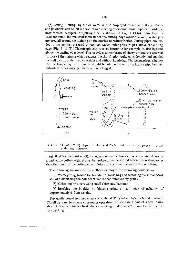
126
(f) Jetting--Jetting by air or water is also employed to aid in sinking. Ductsand jet outlets can be left in the curb and steining or external hose pipes with suitablenozzles used. A typical air jetting pipe is shown, in Fig. 3.13 (a). This type isused for removing material from under the cutting edge inside the well. Water jetsare used all around the steining on the outside to reduce friction, Jetting pipes embed-ded in the steinin ; are used to conduct water under pressure just above the cuttingedge [Fig. 3° 13 (b)] Thixotropic clay sluries, bentonite for example, is also injectedabove the cutting edge level. This provides a membrane of slurry around the externalsurface of the steining which reduces the skin friction quite considerably and enablesthe well to sink under its own weight and without kentledge. The jetting pipes, whetherfor injecting slurry, air or water should be interconnected by a header pipe becauseindividual pipes may get damaged or clogged.
Aır.jetOutletN;
well.e Omm dia. air
steining, header pipe.
3mm dia. waterheader pipe.
25mm dia.jet t ° r
75mm long pipe
ä(a} (b)
or o
coupling+
valveD
4
Jet ie tt gn zzies
o
ig 3-13 (alAir jetting pipe (b}Air and Water jetting arrangement in wellb and steininn.
(g) Boulders and other Obstructions-When a boulder is encountered undera part of the cutting edge, it must be broken up and removed before excavating underthe other parts of the cutting edge. Unless this is done, the well will start tilting.
The following are some of the methods employed for removing boulders :-
(a) Water jetting around the boulder for loosening and removing the surroundingsoil and displacing the boulder which is then removed by grabs.
(b) Chiselling by divers using small chisel and hammer.
(c) Breaking the boulder by blasting using a half stick of gelignite ofapproximately 0.5 kg weight.
Frequently buried tree trunks are encountered, They are cut by chisels and removed.
Chiselling can be a time consuming operation. In one case a part ofa tree trunkabout 1.5 min diameter took divers working under about 6 months to remove
by chiselling.

127
(h) Uniform Dredging-Excavation and dredging inside the well should be done
uniformly all along the cutting edge to prevent or minimise chance of tilting.
(i) Dredged Material-The dredged material should be dumped as far away as
possible from the well and spreed out evenly all around. It should not be depositedin a heap on one side because unequal pressures will lead to tilting of the well.
(j) Precautions before floods-Sinking of wells should be planned and executed
in such a manner that every well that is commenced is sunk to its foundation level,
plugged, filled and capped before the onset of monsoons of the first floods which
in many parts of the State occur in the last week of May. If for any uncontrollablereason this is not possible, the well should be sunk well below the scour level to secure
safe embedment and filled to ensure stability during floods. Well steining should
not be left projecting above the bed level or the low water level. In navigable channels
the wells should be protected from impact of vessels even during the working season.
3.7.1.7. Equipments for well sinking-Equipments used for open sinking of well
foundations of two bridge projects in river beds is listed in Table 3.1.
TABLE 3.3
Equipments For Well Sinking
PROJECT I--BRIDGE ACROSS BHAWANTADI RIVER IN BHANDARADISTRICT
Salient features(1) Length of bridge-398 m,
(2) No. of well foundations-7,
(3) Total depth of well sinking below bed-80 n
(4) Size of well-4.5 m internal dia., 0.75 m steining thickness
(5) Programme--Well sinking to be-completed in 2 working seasons
(6) Substrata--sand, black clay soil, stiff, plastic soil with lime content ("ohisa"),rock.
Equipment Nos.
1. Derricks (wooden log) .. .. ....2 Nos.
2. Cast iron pipe derrick and boom; swivel type rotating 360°; 1 No.
boom reach 5 m.
Steel wire rope, 12-16 mm diameter .. .. 500 m
4. Pulley blocks, 2.5-3 t capacity .. .. 16 Nos.
Winches (diesel), 3t capacity .. .. .. 2 Nos.
6. Pumps: low head, self priming, centrifuga 5-15 H.P. .. 4 Ni IS
7. Air compressors, 8.5 kg/cm? .. .. 1No.
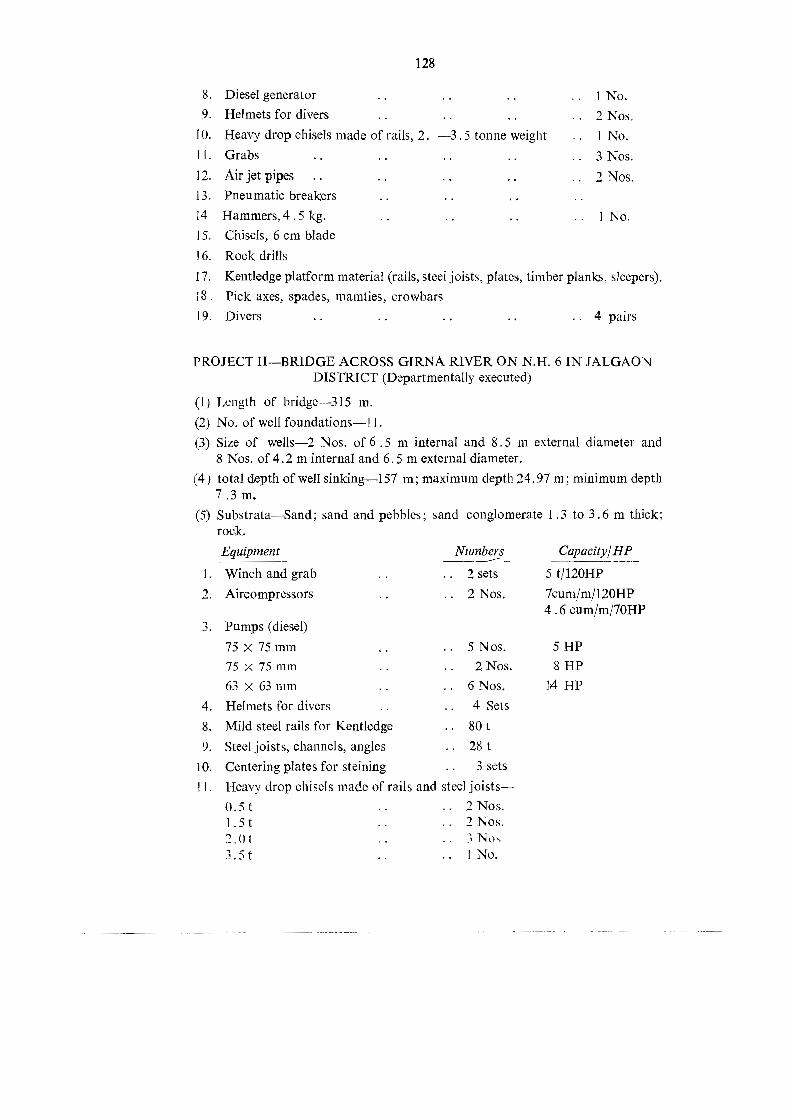
128
8. Diesel generator .. .. .. 1No.9. Helmets for divers .. 2 Nos.
10. Heavy drop chisels made of rails, 2. -3.5 tonne weight .. I No.tl. Grabs .. .. Nos.12. Airjetpipes .. .. .. Nos.13. Pneumatic breakers .. BA ..
14 Hammers,4.5 kg. .. INo.15. Chisels, 6 cm blade
16. Rock drills17. Kentledge platform material (rails, steel joists, plates, timber planks, sleepers).iS, Pick axes, spades, mamties, crowbars19. Divers .. .. .. .. 4 pairs
PROJECT II-BRIDGE ACROSS GIRNA RIVER ON N.H. 6 IN JALGAONDISTRICT (Departmentally executed)
(!) Length of bridge--315 m.
(2) No. of well foundations- .
(3) Size of wells-2 Nos. of 6.5 m internal and 8.5 m external diameter and8 Nos. of 4.2 m internal and 6.5 m external diameter.
(4) total depth of well sinking-157 m; maximum depth 24.97 m; minimum depth7.3 m,
(5) Substrata-Sand; sand and pebbles; sand conglomerate 1.3 to 3.6 m thick;rock.
Equipment Numbers Capacity/HP1. Winch and grab .. 2 sets 5 t/120HP2. Aircompressors .. 2 Nos. 7cum/m/120HP
4.6 cum/m/70HP3. Pumps (diesel)
75x 75mm 5 Nos 5HP75x 75mm 2 Nos &HP63x 63mm ...6Nos. 14 HPHelmets for divers .. 4 SetsMild steel rails for Kentledge .. 80t
9. Steel joists, channels, angles .. 28t10. Centering plates for steining .. 3 sets
11. Heavy drop chisels made of rails and steel joists-0.5t .. 2 Nos.1.5t .. 2 Nos.2.01 ...3 Nos.
4.
8.
3,5t .. No,

129
12. Welding equipment .. 1 Set 3 Phase/0-150 Amps13. Crane RB-22 .. 1 No. 5 t/60 HP14. Steel Wire ropes of various diameters .. 600 m
15. Pneumatic breakers, chisels, hammers, crow bars, pick axes etc.
3.7.2. Sand Blows.-The following are some of the methods usually adopted forarresting sand blows-
(a) Stopping dewatering and equalising thc water level inside and outside the well,
(b) Increasing the inside water level above the outside level,
(c) Sinking down the well by kentledge,
(d) Packing grass bundles or sand bags around the well on the outside.
When sand blows are expected men and equipment inside the well should be broughtout.
During sinking the well through sand, the ground surface around the well shouldbe watched for subsidence which may lead to sand blow.
3.7.3. Tüts and Shifts
3.7.3.1. Tilting and shifting of wells is of quite common occurrence despite
precautions. A well can tilt for a variety of causes such as non-uniform removalof material from under the cutting edge, boulders and other obstructions underlyingthe cutting edge, deeply inclined surface of rock stratum, excessive surcharge loadson one side of the wells (e.g. caused by dumping dredged material on one side,)rising ground surface, excessive height of steining cast above the ground level whichraises the centre of gravity of the well, blasting inside the well, unsymmetrical kent-
ledge, sand blows, variations in sub-strata across the well.
The methods adopted for correcting tilts are:-(a) dredging on the higher side.
(b) removal of obstructions before further sinking operations.
(c) eccentric kentledge.
(d) mechanically pulling or pushing the well (see Fig. 3-14).
(e) reducing surcharge effect on the higher side by levelling, excavating and
removing material (See Fig. 3-14).(f) strutting on the tilted side to prevent further tilting (See Fig. 3-14).
(g) jetting, water, air or bentonite on the external surface of the steining on the
higher side to reduce skin friction.
(h) in tidal creeks, attaching a buoyancy weight (e.g. a hollow steel box) to the
steining well on the lower side, against which a rising tide will exert an upwardforce (See Fig. 3-14).
mufled blasting inside the well at the bottom combined with niwasuresq
(d) and (f}.

Tiite
dwen
Reactio
nweigh
tTrun
ion
chain
vWire
ropg
pull
block
(g)
Fig
Sche
mat
Sreekz
teprasen
:BEN
Eecentrie
„geilercavatad
sfor
Correctin
g
kentiedg
ean
dSu
rcha
rge,
{d}Mecha
nical
Pushing
witn
jacks
Fram
e
oa
Floa
tLow
tide
teyeı
RZ{b}
S
Nkentiedg
e
Surcha
r
solexcavated
Block
saba
gsN
>5
lc)
/
Ar

131
3.7.3.2. In sharply titled. wells the grab will dredge either on the lower side or inthe centre and not on the higher side which is actually required. Therefore, in such
cases, the grab should be guided down to the required position at the well bottom.A simple guide is a taught steel wire rope, one end of which is fixed to the curb justabove the cutting edge on the required side (the high side) and the other end to anyconvenient point above the well such as on the derrick. The drop chisel can alsobe guided by a similar device.
3.7.3.3. Measurement of Tilt-Vertical scales with 25 cm graduations are paintedon the outer surface of the well at the four quadrant points coineiding witl the bridgeaxis and the axis perpendicular to it. The width of the painted scale may be about10 cm. For easy visibility and readability the scale is painted with alternate blackand white strips each 25 cm long. The zero of the scale should be at the top of the
cutting edge. The scales are extended and continuously graduated as each successive
steining lift is built. An exclusive steel tape should be used for marking the
graduations.
The tilt is measured by taking readings with a level on a staff held against anyconvenient graduation of all the four scales. Tilt measurements are taken as frequentlyas necessary, the minimum being once a day. In the early stages of sinking when
tilting of the well is more likely, tilt measurements should be taken quite frequentlyso that timely corrective measures could be taken.
3.7.3.4. Measures to counteract excessive tilts and shifts-As stated in para 3.6.1
the design of well foundation should account for a tilt of I in 80 andashift of150 mm.
When the actual tilt and shift exceed these permissible values or other values which
adversely affect the stability of the well, measures to counteract these effects need to
be devised. Measures will necessarily depend on each individual case. However some
of the commonly adopted measures are:
(i) Filling the well entirely or to part depth with cement concrete, a lean mix of1:3:6 would do in most cases. Cement concrete fill being denser than sand fill, willincrease the vertical pressure intensity on the foundation stratum and reduce the
overturning effect of excessive tilt.
(ii) Where, however, a fill of sand or concrete aggravates the effect of tilt, the
well is filled only with water.
(ii) The pier or abutment is located eccentrically on the well cap to producea restoring moment. If necessary the well cap is cantilevered out beyond the well
steining to accommodate the pier or abutment.
(iv) Providing unequal spans on either side.
(») An abutment well can also be stabilised by-(a) tying back to a frietion slab, block or anclıor piles.
(b) providing fiy-back returns.

132
3.7.4. Grounding well on Foundation Rock
3.7.4.1. The IRC Code No. 78-1979 stipulates that the well should be evenlyseated all around the periphery on sound rock (i.e. devoid of fissures, cavities,weathered zone, likely extent of erosion etc.) by providing adequate embedment andthat the extent of seating and embedment in each case should be decided by theengineer-in-charge.
3.7.4.2. For wells founded on soil the deeiding factor is the safe bearing capacityof the foundation stratum and the allowable bearing pressure. A similar approachmay be adopted in the case of rock stratum. The bearing capacity of the rock maybe determined from laboratory unconfined compression tests on rock cores or in situtests like the plate beaiing test or the pressure meter test described in Section 1.
Laboratory tests on rock cores may not reflect the true strength of the rock in situbecause the in situ conditions e.g. lateral confinement, fissures, fractures, inclinedbedding planes are not simulated.
The plate bearing test is more reliable, if it is feasible and the various limitationsmentioned in section l are accounted for while interpreting the results.
The pressure meter test is perhaps the most reliable, but it requires a boring plantfor boring the hole for introdueing the pressure meter. When the well is requiredto be anchored down by means of anchor rods for stability, a boring plant is requiredand the pressure meter test can be conducted in such cases without diffculty.
3.7.4.3. If this approach of deciding the foundation level, i.e. on the basis ofsafe/allowable bearing pressure, is adopted, the need for unnecessary embedment inhard strata and rock would be eliminated in most cases. In this approach it must beremembered that the stressed zone extends to some depth below the foundation level(see Section 1). The strata in this zone should be properly determined and the stressintensities computed. Cases are known where wells have been sunk at great costand with great difficulty and loss of time through very thick stratum of tough sandconglomerate, thickness of almost that of the well diameter. In such cases bearingpressures at various depths should be computed to determine the possibility offounding the well on the top of such stratum.
3.7.5. Bottom Plug3.7.5.1. The thickness of the bottom plug should be such that it rises at least
300 mm into the vertical portion of the dredge hole (See Fig. 3-15). Usually a shallowsump, about 0°5 m deep at centre, is excavated below the cutting edge level beforecasting the bottom plug. When seating is on rock, the plug must be cast only afterthoroughly cleaning and removing all loose material from the rock surface. When therock surface is inclined and a part of the cutting edge is unsupported measures shouldbe taken to ensure that the bottom plug fills this gap completely. The concrete (stonesin the case of colcrete) can be manually spread and packed at intervals, by diverswhen under water, while concreting is in progress. Nominal anchors are sometimesprovided to sterilise the bottom plug and the well on dipping rock stratum lengthsof rolled steel joists and steel rails are also used as inserts between the dipping rocksurface and the overhanging cutting edge to support the well.

133
6
Weilsteinmg
a
30cm&
- -7.5cm1
. Weil„curb
[2
"s
Fig. 3-15 Recess ın Well Steining for KeyingBottom Pflug.
3.7.5.2. Anchoring of wells into foundation rock for stability is usually doneby means of anchor rods through the bottom plug. To ensure positive action betweenthe well steining and the bottom plug, without which the anchors will not be stressed,it is preferable to provide a thicker bottom plug so that the central vertical portionabove the curb is greater than 300 mm. Such positive action can also be ensured byproviding a key in the inside surface of the steining as shown in Fig. 3.12.
3.7.5.3. The bottom plug may be of cement concrete or colcrete. When of cementconcrete the nominal mix should not be leaner than 1:2:4 with 1 0 y extra cementand slump of about 150 mm. Concreting should be done by means of a tremie pipeor skip box and in still water condition. The specifications for underwater concretingand tremie concreting prescribed in IS:456-1978 should be tollowed. Concreting ofthe plug should be done in one continuous operation. Dewatering of the well shouldnot be done at the time of concreting.3.7.5.4. When colcrete is used the sizes of stones are usually 100 mm to 200 mm
grouted with cement-sand grout of 1:2 proportion and water cement ratio of 066.The stones are first dumped and at intervals should be spread out and packed, bydivers where necessary, particularly in gaps between the cutting edge and rocksurface. Grouting under pressure is done through a series of uniformly spaced groutpipes of 40 mm to 50 mm diameter starting from the bottom and rising up. Thepipes are gradually withdrawn as the grout rises, the bottom ends always beingabout 150 mm below the level of the grout.

134
3.7.5.5. The quantity ofgrount thatis required to beinjected should be determinedin advance from tests. The test can be conducted in a container sufficiently largeso that the test can be treated as representative.
3.7.5.6. After the colerete hardens a recuperative test is performed to test its
permeability. A differential water head of 3 m is created by lowering the water levelinside the well by 3 m and observing the rate of rise in water level. The rate of riseshould not be more than 0°3 m per hour.
3.7.6. Filling the well
3.7.6.1. Generally, from considerations of stability, all wells are filled in with soil,between the bottom and top plugs. The type of soils should be non-cohesive or oflow plastivity and non-organic. Excavated material satisfying these requirementscan be used.
3.7.6.2. The fill increases the vertical loads thereby reducing the adverse effects oflateral loads and moments on the bearing soil. It provides the increased mass useful
against impact of floating bodies.
When increased vertical load is a disadvantage the fill is omitted. Leaving the well
empty is one of the expedients sometimes adopted for restoring the stability ofa tilted well, or when loss of stability occurs from any other cause.
3.7.7. Top Plug---The top plug is ol cement concrete of nominal mix 1:3:6 of300 mm thick.
3.7.8. Anchoring well in rock3781 To increase the stability of the well against overturning and sliding and
if tensile area at well base is within permissible limits the well can be anchored down
by tension anchors into foundation rock. These tension anchors may be steel rods
or high tensile prestressed cables.
The factors which determine the tensile resistance of the anchors are:-(1) strength of the anchor rod which depends on the tensile strength of the steel
and the cross sectional arca of the rod or cable.
(2) stength of the cement grout bonding the anchor into the hole.
(3) bond strength between the rod and the grout and the grout and the side ofthe hole.
(4) disposition of the anchor rods which determines the magnitude of the resistingforce couple.
(5) shear strength of the rock.(6) the ability of the weil steining and bottom plug to act together to transmit
forces to the anchor rods (See para 3.7.5).
3.7.8.2. Anchor rods through the bottom plug-The most commonly used method
is to install anchor rods circumferentially through the bottom plug (Fig. 3.16). Forhigher strength as well as increased bond resistance deformed bars (could twisted
or hot rolled-IS:1786 or IS:1139) are used. Sometimes plain round bars manuallydeformed and with lugs welded on are used (Fig. 3.16). Any mechanical device such
as bolts and nuts. welded helical coil which will increase the bond resistance may be
used (Fig. 3.16).

91
aNEN
\‚C
LOSED
LINKS
xMS.or
HY.S.D.}
f
+
Aya
STEINING
STEEL
{REINFO
RCEM
ENT
IN
/STEINING
NOTFU
LLY
/SH
OWN
ı48
®
PLAN
WELL
STEINING
Tom
£r
BOrToM
UG
OFWELL
|
IHI
T
ROCK
LEVEL
=> --A
NCH
OR
ROD--
=m
BOREHOLE
GRO
UTED
N-B
SECT
ION-AA
gor
weu
ANCH
OR
THRO
UGH
STEN
ING
ANCH
OR
THRO
UGH
"BOTTOM
PLUS
FIG.NO.3-16:
ANCH
ORING
OFW
ELL
FOUNDAT
ION
INRO
CK.
BEFO
REPD
DS
\
rock
ever
ASS
LFORT
ION
OF
BOTTOM
PLUG
CAST
NS
1)45
Kg/m
{90Lb/YAR
D)M
.S.RAIL
[
WELDED
STEINING
©®
PLAN
&mm
ıOF
ANCH
OR
RODS.
FORT
ION
BOTTOM
CAST
AFTER
ON
&m
SROUTING
SSr
FOR
ANCH
OR
(NGRa
UP
©F3NOS
X SD.BAR
S7R
mmHN
FFRe
itDIFFERE
_

136
From practical considerations of drilling holes the anchor rods are necessarilyto be positioned some distance inside from the steining. This severely limits themaximum resultant tensile resistance of the group of anchor rods as the momentarm is considerably reduced.
3.7.8.3. Anchor rods through the steining-Installing anchors through the steiningis statically more advantageous (See Fig. 3-16). Vertical duct holes of at least 100.mm.diameter are left in the steining or steel pipes are embedded in it. The duct bolesare sources of weakness in the steining and adequate reinforcement should be providedaround them to prevent possible vertical cracking of the steining along them partic-ularly when explosives are detonated inside the well. Steel pipes increase the cost.Another disadvantage is that holes in the rock below must be drilled through thesenarrow holes in the steining which can prove to be a difficult and damaging operationwhen the depth is great.
3.7.8.4. Prestressed Anchors-Prestressed anchors may also be uscd but theyare expensive and call for special quality control and protective measures againstcorrosion. Prestressed anchors are positive in that, as such a permanent compressivebearing pressure develops at the base and can be advantageously used to reduce thesize of well which may balance the increased cost of the prestressed anchors.
3.7.8.5. Anchor depth-The anchor depth depends both on the bond strengthbetween the cement grout and the rod and also that between the grout and the borehole wall.
The bond resistance is given by:-T=xrdl+bd
Where T pullin the rod
d - diameter of the rod
1 = length of the rod embedded
7 bd= permissible bond stress between rod and grout or between
grout and rock surface.
Field pull out tests on anchor rods fixed with cement slurry and cement mortargrout indicate development of ultimate bond strengths of 15 to 20 kg/cm?. For designthe permissible bond strength when cement slurry with water-cement rario of 0.4 to0.6 is used may be taken as 6 kg/cm?. Higher values may be used if established bytests.
3.7.8.6. Cement mixes for grouting.-Cement mix for grouting may be cenmient
slurry with water/cement ratio of 0.4 to 0.6. To prevent shrinkage and to cause
slight expansion 4 gm of alumina powder per 50 kg of cement may be added and
thoroughly mixed.
3.7.8.7. Grouting.-The bore hole must be first thoroughly cleaned of all loosematerial using air jets, under water this is done by divers. The bore hole is then filledwith the cement slurry and then anchor rod is inserted. If a delay occurs between
grouting and inserting the rod the cement slurry may start setting. Which must be

137
guarded against. The anchor rod can be fitted to a long pipe for lowering into the
bore hole.
The hole is grouted with cement slurry under a pressure of 5 kg/cm? using a grout
pump. The grout is conveyed by means of a casing pipe which is progressivelyextracted as the grout rises in the whole.
The diameter of the bore hole must be at least 40 mm larger than that of the anchorrod. The bore hole is drilled through the bottom plug after it is cast and sufficientlyhardened.
Dewatering the well for drilling the holes must be done with caution and should
commence only after ensuring that it will not affect the bottom plug or the well in
any manner. If any sand is trapped anywhere between the plug and the rock surface
or if there is any gap or crack giving access to sand from outside, sand or water will
blow in through the bore holes foreing out the grout and possibly the anchor rod also.
If this goes undetected the anchor rod will remain ineffective. If this occurs, it is
an indication that sufficient care had not been taken in casting the bottom plug and
the same is not fully effective. The more serious consequence is that the well will be
subject to uplift pressures resulting in unstability of the well.
3,8. Records and Reports
3.8.1. Continuous records of well sinking should be maintained and reported at
least once a week to the Executive Engineer. Continuous recording and reporting are
essential not only for the obvious purposes of recording work andmonitoring progress,but also to check on design assumptions and to modify the designs and construction
methods and stages as necessary.
3,8.2. Since, as stated earlier, much development work yet remains to be done
on well foundations, maximum amount of field data must be collected on every work,so that in addition to serving as checks and records of work they can also be used
for research and development.
3.83. Data recorded should give, among other things, complete and detailed
information on well sinking, methods employed, blasting, obstacles and difficulties
encountered during sinking and methods employed to overcome them, sub-strata
actually met with, sand blows and dewatering. Tilts and shifts must also be recorded
and reported.
3.8.4. Recommended proforma for daily and weekly reports is given in Table
3.4 and 3.5 respectively.
3.8.5. Inaddition to well sinking, record of well seating on the foundation stratum
and bottom plugging should be maintained. This report should contain data on
foundation stratum (classification, physical condition, variation and test results),measures adopted to support overhanging portions of the cutting edge (i.e. portionsnot resting on rock) method and stages of plugging, details of anchoring, dewateringand recuperation tests.Tb 4597--160

TABL
ENo.
3.4
Well Sinking
-Daily
FieldRe
cord
Project
WellNo.
andLocatio
nFron
tElevation
Design
Foun
datio
nR.
L.
Steining
Strata
Classificationard
Kentledg
eWeigh
tconstructio
nWell S
inking
Dep
thMetho
dWater
Physical
cond
ition
Eccentricity
Date
Sunk
oflevel
From
ToFrom
Tosinking
RL.
Aspe
rAs
(Ton
nes)
X-axis
Y-axis
(R.L.m
)(R.Lm)
(R.Lm)
(R.L.m
)m
Bore
Log
actually
(cm)
(cm)
met
sel

Remarks
(Inad
ditio
nto
othe
r
Obstacles
Special
Tilt
Shift
Measures
Sinking
remarks
give
descriptions
of
encoun
tered
Sand
blow
spe
cie
takenfor
effortsin
the
blastin
g,chisellin
gwith
weigh
t>
metho
dsin
sinking
(cau
sean
dused
for
Alon
gAlon
gAlon
gAlon
gcorrectin
gstratum
anddrop
ofchisel,p
umping
out
(Typean
dmagnitude
)X-axis
Y-axis
X-axis
Y-axis
tilt/shift
(/sq.m
rwater
with
duratio
n,H.P.
ofsinking
description)
(cm)
(cm)
pumps,de
pthof
water
lowered
,distress
tocuttinged
ge,steining)
Copy
subm
itted
totheExecutiveEn
gine
er,P.W.Division,
Sub-Divisiona
l Eng
ineer,
Copy
toSh
ri‚Junior
Engine
er.
Public
Works
Sub-Division,
(Tab
leforDailyFieldRe
cord
ofWell Sinking
)

140
TABLE
Weekly Progress Report
Project
Serial No.of Date of Steining Steining Total Initial Present R.L.ofNo, weil sinking constructed withcurb Steining R.L.of iR. L.of cutting
began uptodate reported constructed cutting cutting edgeincluding previous sincelast edge edge reported
curb weck report m m previousiym m week m
ı 2 3 4 5 6 7 8 9
PiP2
P3
P4
PS
P6
P7
Copy submitted to the Executive Engineer, Public Works Division,
Copy to Shri Junior Engineer.
TABLE 3.5.--Proforma for Weekly Progress Report of Well Sinking.

No. 3.5
of Well Sinking
141
Week ending on 198
Total Sinking Depthtosinking done Designdone sincelast founda-m report tion
(week) R.L. m.m
10 11
Strata met Obstacleswith during Tilt Tilt met duringperiod of Shift sinking Remarksonxx onyyreport cm Typeand
(classificationem em Descrip-
and physical tion
condition)13 14 15 16 17 1812
Sub-Divisional Engineer,Public Works Sub-Division,


SECTION 4-PILE FOUNDATION


145
SECTION 4--PILE FOUNDATION
Geueral41. A pile is a structural foundation member which transfers the load to deep
seated strata. A pile foundation may consist of either a single pile or a group ofpiles. Piles are very widely used for multistoried buildings and marine structureslike jetties and wharvers, Their use for bridges has been rather limited in our countryprobably because of the extensive use and subsequent development of wellfoundations. However, the use of piles for major bridges in the State is picking up.Piles are also used (Fig. 41) for (#) compaction of soils, (if) stabilising slopes, (iii) 10
serve as anchors to resist uplift forces and moments, (iv) as batter piles for resistinglateral loads, (r) as fenders to absorb berthing forces of vessels and (vi) as sheetingfor retaining earth. (Fig. 4-1).
4.1.1. Load Transfer-The load bearing pile may transfer the load by end-bearing with the toe bearing on firm stratum by friction along the surface or bya combination of both. If the load is transferred primarily by end bearing the pile is
known as an end bearing pile and if by friction as friction pile. When a pile isinstalled to resist axial pull it may be termed as fension pile. If itis installed at anangle to the vertical it is known as raker pile or batter pile.
4.1.2. Type-A pile may be of concrete, timber or steel. Timber piles wereused widely in the past. At present however, concrete piles are used in most situations.
Typical shapes of timber, steel and conerete piles are shown in Fig. 4-2.
4.1.3. The selection of a pile-type depends on a variety ol factors such as cost,availability, soil characteristics, underground conditions, type of structure andloading, depth and proximity to existing structures.
42. TerminologySome of the common terms used in pile foundations are:
Batter pile or Raker pile (5)-A pile which is installed at an angle to the vertical.
Bored Cast in-situ Concrete pile--A concrete pile formed in the ground by boringa hole and subsequentiy üilling it with concrete. While boring a hole a casing may be
used. If the casing is left permanently the pile is called cased pile. If it is removedthe pile is called an uncased pile.
Bored Compaction Pile-A bored pile wherein immediately after placing ofconcrete, the concrete and surrounding ground are compacted by driving a ram
through the concrete or by any other means.
Composite Pile---A pile whose length is made up of more Ihan one material.
Cut-off Lerel-The level at which the pile is cut-off to support the pile cap orbeam or any other structural member at that level.
Dolly-A block of hardwood or some suitable material placed on top of tlıehelmet to receive the blows of the hammer.

"vn
n I Fend
eran
dba
tter
piles
Pliestor
stab
ilising
slop
ean
oba
nks.
Fig-4-)
Y
4
1
Anchor
piles
SheetpileI
We
1 4F
Sheet
pile
retaining
earth
tied
back
toAn
chor
piles.
Piles
for
compa
cting
soil
Differen
tuses
otpiles
vum
End-be
aring
pile
Pite
!stratum
Frictio
npile
torup
fift
force

tt
uptol2
6
uH-Pile
7
jWBD
N+ 0-6
06Cross
section
Pipe
pile
Steelpile
sections
N
6
Tip
06
0
Dim
ension
sin
meter:
are
indicative
only.
Concrete
precast
Oa
concrete
piies-cross
sections
8Timbe
rpile
Sing
leun
der-ream
edconcreie
pie.
Fig
4-2
Typical
shap
esof
piles

148
Driven Cast in-Situ Concreie Pile-A concreie pile formed in the ground by
driving a casing and subsequently filling the hole so formed with concrete. When the
casing is left permanently it is called a cased pile--When the casing is taken out itis called uncased pile.Driven Precasit Concrete Pile-A concrete pile constructed in casting yard, cured,
and subsequently driven into the ground.Driving Cap--A steel cap placed temporarily on top of a pile to distribute the
blow over the cross section and to prevent the head being damaged during driving.
Drop or Stroke-The distance through which the driving weight is allowed to
fall before hitting the helmet of the pile.
Drop Hammer--A hammer, ram of "monkey" raised by a winch and allowedto fall under gravity.
End Bearing Pile-Pile which transmits the load primarily by resistance developedat ıts toe.
Factor of Safety--The ratio of the ultimate load capacity of pile to the safe loadofa pile.Follower or Long Dolly--A removable extension which transmits the hammer
blows to the pile when the pile head has been driven down below the pile fromleaders and is out of reach of the hammer.
Friction Pile--Pile which transmits the load by frietion developed along. its
surface.
Hammer, Double Acting-A hammer operated by steam, compressed air or
internal combustion, the energy of its blows being derived mainly from the source
of motive power and not from gravity alone.
Hammer, Single-Actin-A hammer raised by steam, compressed air or internal
combustion, and allowed to fall under gravity.Helmet-The upper portion of the driving cap which holds the packing in
position.Packing---A pad of resistent material contained between the helmet and the top of
a pile to prevent the head from being damaged du ting driving.Pedestal Concrete Pile-A pile with a pedestal formed at its base to increase the
bearing area.
Test Pile-A pile which is load tested. It may form part of the pile foundation.
Trial Pile-A pile installed to determine the carrying capacity of a pile. It does
not form part of the pile foundation.
Ultimate Load Capacity or Bearing Capacity of Pile-The maximum load whicha pile can carry before failure of ground in shear.
Under-Reamed Pile-A bored pile, usually concrete, with enlarged bulb made
by cutting or scooping out the soil.
4.3. Bearing Capacity of Piles
4.3.1. The load carrying capacity of a pile foundation cannot be greater than.
that of the soil to which the load is transmitted. The load is trnansmitted both byend bearing and friction. Therefore, the bearing capacity of the soil at and beneath

149
the tip of the pile and the frictional resistance of the soil surrounding the pile governits load carrying capacity. A variety of factors such as method of installing the pile,characteristics of the pile, spacing of piles, and future changes have a bearing on thesoil strength. When the soil surrounding the pile is soft or has low frictional resis-tance and the pile is bearing on hard stratum (say, rock) the pile derives its capacityfrom end bearing.
4.3.2. Pressure Distribution4.3.2.1. End Bearin-The pressure distribution beneath the tip of the pile ıs
assumed to be similar to the pressure bulb derived from the Boussinesq equation.Th: general pattern is illustrated in Fig. 4-3
P
SOFTSTRaTa - STRATA
MARDIo ooa
oooo uo oo
A _ TR GA,SOFTSTRATUM_7 GE
Ao
oo
onoooo
o
Bulb ot pressure forSingle Pile Separatıon of Bulbs of Press
ca)
ure
PPpPPr
SOFTSTRA- STRATA
o! o %° ov
a STRATUM CH HARDo HARD
o oi TRATUMooo
vo
o &oo
Pa
o 4oo8
DEEooAo
0 b
BD)Overlapping Bulbs ofOl Pressure for EEE EEEAdjacent es CEEEEEEE
D EEEo>oo
ooqo
<a)Merging of adjaceni Bulbs ofPressure into nsle Buın
Fig,4-3. Pressure bulbs for end bearina n:tion Engineering by G.A .Leonards)m Founda,
from which it should be noted that (i) it is important to investigate the soil stratato adequate depth below the level of the pile end and ensure that there is no soft orweak stratum in the stressed zone, (ii) the overlapping pressure bulbs increase in thestress in certain zones.

150
Friction Piles.--Pressure bulbs are also drawn to indicate the pressuredistribution to the soil around frietion piles. The pressure bulbs for a single pile anda pile group are illustrated in Fig. 4-4.
4
PFr
7
11
NTOP OF HARD STRAT
Cd)vertical e y al Pıla Separation of Bulbs of Pressure
TıpFORCE?
WERE TREEWIESN NUIZZEZLET! un7744Z / \ WILLNZZ,4
14 f A
1 \ 2
TOP OF HARD STRATUM TOR or Hann 7(b) ce)
Buib of Pressure for Merging of Adjacent Bu!bsSingle Pile of Pressure into Single Prulb
»
I,
A
1,
Fig.4-4: Pressure bulbs for friction piles (From Founda-tion Engineering by G. A.Leonards)
In the case ol'a group of piles the pressure bulbs overlap. The pressure distributionis different for single piles and group of piles. It also varies with the shape of thestructure and its width in relation to the length of the pile (1).
In the case of narrow structures there is a real advantage in friction piles trans-
mitting the loads to lower depth as compared to a footing. However there is no
significant advantage in the case of a wide structure. This is illustrated in Fig. 4-5.In this case the pile foundation is as good as a raft foundation (Fig. 4-5).

WIDE BUILDING BNARROW A
N
N
Nx
PRESSURF DISTRIBUTIONN NIN PERCENT OF LAG
PER UNIT OF AREAN
BEER ABavE 757,
Below 251,
Fig.4-5 Effect of relation between foundation width andpile length on pressure distribution (From foundationEngineering by G.A.Leonards)
4.3.3. Frictional resistance-Values of frictional resistance are determined fromfield and laboratory tests on sub-soil, laboratory tests on soil samples and pile loadtests and pull out tests. The static cone penetro-meter test correlated with the
standard penetration test described in Section 1 can be used to get a continuousrecord of frictional resistance. Laboratory shear tests on undisturbed samples are
reliable. From loading and pull out tests and driving resistances on piles of differentlengths, the friction in the different strata can be determined.
Friction values of some types of soils are given in Table 4.1. These are for guidanceonly. Reliable values must be obtained from pile load tests.
Tb 4597-17

152
TABLE 4.i
Friction between Pile and Soil
Soil Friction t/m
Fine grained soils-Very soft clay .. .. . 01.2Mud .. .. .. 0.24-- 2
Soft clay .. . 1-3Silt .. .. 0.5-2,5Silty clay .. .. .. 24Sandy clay .. 24Medium Clay ..2.54.5Sandy Silt .. ..
Firm clay .. ..3.4-5.4Stiff clay .. .. .. 5.5-9.5Dense silty clay .. .. .. 4.4-7.3Very stiff clay .. .. 10-20
Hard clay .. .. .. Over 20
Coarse grained soils-Sand .. .. .. 3.5-8.5 (b)Sand and gravel .. 5-15Gravel ...7.5--17.5
3 -5
43.3.1. Factors Affecting Friction-Friction depends on the type of soil its
moisture content the degree of consolidation, degree of compaction, the shape of
pile, the time interval between driving and testing and the magnitute of imposedload relative to the failure load.
Friction increases with compaction and decreases with increasing moisture.
Friction is more for round piles than square piles of side equal to the diameter
of round pile. In sand tapered piles will develop more resistance than vertical sided
piles.In soft clay friction may increase after a few days of driving the pile. In saturate
coarse-grained soil the resistance may decrease after 24 hours. Therefore sufäcient
time interval must be allowed between driving and testing the pile.
4.4. Determination of Bearing Capacity of Piles
4.4.1. The bearing capacity (i.e. the load carrying capacity) of piles is determined
from formulas and load tests. The formulae are of three types: static, dynamic and
wave equation. The last is not dealt with here as it is rather complex and is best
solved on computer.

153
4.4.2. Static static formula is applicable to all types of piles.For piles driven by vibration the dynamic formula is not applicable and the staticformula must be used. There are a number of static formulae for estimating the pilecapacity. They are all basically of the form:
Qu=-pr 07; (41)Where Qu ultimate bearing capacity.
Qp = load carried by the pile in end bearing,
Qr = load carried by frietion along the pile surface.
The method of calculating the components carried in end bearing and by frictiondiffer in different formulae. Typical formulae in use for granular soils and cohesivesoils are given below (5, 6, 7). A factor of safety of 2.5 should be used for arrivingat the allowable load on the pile when these formulae are used.
4.4.2.1. Piles in granular soils
n
Qu = Ap (Ry Nr + PDNg) + % KPpitan 8 Asi (4-2)
Where Qu = ultimate bearing capacity of pile in Kg.Ap = cross sectional area of pile toe in cm?R = pile radius in cm.
y effective unit weight of soil at pile toe in kg/cm?P - eflective overburden pressure at pile toe kgf/cm?
11
D
Na, Nr bearing capacity factors depending on the angle of internal frictiongat toe.
n2 summation of layers in which pile is installed.
1 =
K = coeflicient of earth pressure.
Ppi = effective overburden pressure in Kg.f/cm? for the ilhlayer where i
varies from I ton.8 = angle of wall friction between pile and soil, in degrees (may be
taken equal to &, the angle of internal friction).Ası - Surface area of pile stem in cm? in the ith layer.
The earth pressure coeflicient K depends on nature of soil, type of pile and itsmethod of construction. In loose to medium sands K values of 1 to 3 should beused.
The maximum effective overburden pressure at the pile tip for piles longer than15 to 20 times pile diameter should correspond to pile lengths 15 to 20 timesdiameter.
Values of N, and N, may be taken from Fig. 4-6 which is based on recommenda-tions of Vesic.Tb 4597- 17a

154
500
100
VA50
10 NY20 25 30 35 &D 45
ANSLE OF INTERNAL FRICTIONGFIG-4-6 BEARING CAPACITY FACTORS NQ, NR
( FROMIS: 2911 PARTI/SECAL- 1979 AND
IS 8403-1971)
4.4.2.2. Piles in Cohesive Soils
Qu = ApNcCp + CAsWhere A, = cross sectional area of pile toe in cm?
N. = bearing capacity factor usually taken as 9
C» = average cohesion at pile tip in kgf/cm?x = reduction factor
C = average cohesion throughout the length of the pile in kgf/cm?
As = surface area of pile shaft in cm?.

155
values of «
___Consisteney |nvale
Soft to very soft .. <A 1.0Medium .. .. .. 4t08 0.7Stiff BR BR BR 8t0 15 0.4Stiffto hard .. .. >15 0.3
ax
oc may be taken to vary from 0.5 to 0.3 depending on the consistency ofthe soil.
Higher values upto 1 may be used for softer soils, provided the soil is not sensitive.
Note.-Static formula may be used as a guide only. Better reliance may be puton load test of piles.
Frictional resistance from Static Cone penetrometer Test-When full penetrationdata are available for the entire depth the following correlation may be used for
determining the friction along tke pile.Soil Side friction (f,)
Clays and peats (q. < 10) .. ..- gc/10
Clays .. .. .. .. ge125
Silty clays and silty sands .. .. gc[100 - gc/25Sand .. .. .. .. gc/100Coarse sands and gravels .. .. .. <qc/150Where g. = static point resistance
For non-homogeneous soils the ultimate point bearing capacity may be calculated
using the following relationships.
Au ( Ico + Gel )Go} (4-4)2
where Qu = ultimate point beäring capacity
dco = average static cone resistance over a depth of 2d below the pile tip.
Gc, = minimum static cone resistance over the depth 2d below pile tip.
gc, = average of the minimum cone resistance valuss over a heightof 8d above the pile tip.
d = diameter of pile tip or equivalent diameter for non-circular piles.
Correlation between the static cons resistance qc and the N value of standard
penetration test may be taken as :
Soil
Clays .. .. .. ..
Silts, Sandy Silts and slightly cohesive silt sand mixtures 2
Clean fine to medium sands and slightiy silty sands .. 34Coarse sands and sands with little gravel ..
ge/N
2
5-6Sandy gravels and graveis .. 8-10

156
4.4.2.3. End Bearing Piles-When the pile is bearing on hard stratum and the
surrounding soil is soft or has low frictional resistance the pile derives its capacityfrom end bearing. Even in the case of a pile in soil of appreciable side resistancebut resting on rock, it is usual to assume end bearing the reason being that for sidefrictional resistance to develop the pile tip must undergo displacement:
In such case the ultimate capacity (Qu) of the pile is determined from:
Qu = 4r Ap (4-5)
where qr == ultimate bearing resistance of rock
Ap = area of pile tip
The above formula needs to be reviewed by tests, Some tests tend to show that thepile capacity is under estimated by omitting the friction component. Such tests willin the long run lead to economy in the design of piles.
4.4.2.4. Terzaghi-Peck formula.-One other static formula presented by Terzaghiand peck (4) for the ultimate bearing capacity (Qu) is:-
Qu = TR'p(1.3CNe + YDpNgq + 0.6 yRpNr-)+ 2rRpD'f, - for round piles (4-6a)
Qu = 4R?, (1.36Ng +Y + 0.8 ar
+ 8RpfsD'r- for square piles (4-6b)
Where R, == radius of round pile or half of side of square pile
ce == cohesion
= effective weight of soil
P
Dr = depth of tip below ground surface/deepest scour level
q Nr = bearing capacity factors depending only onö (from Fig. 3.3/Section III)
fs - skin friction.
D'r = friction length in load-Carrying Strata
4.4.3. Dynamic Formulae
4.4.3.1. The dynamic pile-driving formulae are based on the theory that theultimate bearing capacity of the pile is the same as the ultimate resistance to driving.The energy of the blows is equated to the work done in overcoming the resistance to
penetration. Allowances are made for various factors such as elastic compressionsof pile and ground. There are many formulae in use. one widely used is the Hileyformula. Tbe dynamic formulae are not applicable to piles which are driven byvibrator driving methods.
Hiley Formula-The modified Hiley formula is: (from Ref. 7)
WhnR= -- 4-7ens+C

157
Where R = Ultimate driving resistance-tonnesW = Weisht of the ram-tonnesh height of free fall (cm) of ram taken as:
100 % for trigger operated drop hammers
80%, for which operated drop hammers90% of stroke for single actıng hammers
Wh = 90% of rated energy of blow (tonne-cum) when using Mckiernan- Terry double acting hammer.
n = efficiency of blow to be obtained from the expressions given below.
S final set per blow
s =C+G+Gc ı > temporary compression of dolly and packing
= 1.77 R/A without dolly or helmet, but with 2.5 cm thickcushion
= 9,05 R/A with dolly upto 60 cm long and helmet and cushion
upto 7.5 cm thick
C, = temporary compression of pile= 0.0657 RL/A
C, = temporary compression of ground-3,55 R/A
L = length of pile inmA = area ofpile in cm?
Expressions for efficiency of blow n:() When W >Pe:
W P -e(4-8a)W+P
(ü) When W<P.e:W+P.eW+P W+P
Where P = Weight of pile, anvil, helmet and follower:When the pile finds refusal in rockuse P/2 instead of P
e coefficient of restitution; values are given below:
(4-86)P.e2
n
e Condition
0.5 Steelram of double acting hammer on steel anvil over R.C.C. pile0.4 Cast iron ram of single acting or drop hammer on R.C.C. pile0.25 Single acting or drop hammer on driving cap and helmet with hard wood
dolly on R.C.C. pile or directly on timber pile.0 Deteriorated condition of pile head or dolly.

158
4.4.4. Bearing Capacity ofRaker Piles (driven by single acting or drop hammer)-Multiply bearing capacity of vertical piles by K given below for different anglesof rake
Rake K1 :12 0.991 :19 0.985
0.980.970.960.9450.9150.86
1 : 8
1 6
1 : 5
1 4
1 : 3
:.
4.4.5. Pile Load Test (See IS: 2911-Part IV- Load Test on Piles)-The mostreliable method of determining the bearing capacity of a pile is to carry out loadtests on a test pile. Tests are performed for determining the bearing capacity incompression and uplift and the lateral bearing capacity. Tests are performed eitheron single piles, or on groups. The point of application of test load and test conditionsshould be similar to the prototype. Differences should be suitably accounted for ininterpretation and use of results.
4.4.5.1. Time Interval between driving and testing-For friction piles in granularsoils the test should be conducted 24 hours after driving. In clays sufficient time mustbe allowed for the disturbed and remoulded soil around the piles to attain a stablecondition. This may take a few days or more than a month.
4.4.5.2. Classification-The tests are classified as /nitial test and Routine test.The initial test is carried out on a test pile, while the routine test on a working pile.The initial test is for determining safe loads and to estimate settlements at workingloads. The routine test is a check test on a working pile.
4.4.5.3. Compression or Vertical Load Test-This is performed in one of threeways depending on the information required -
(a) Load Test with incremental application of loads(b) Continuous Rate of Penetration (CRP) test(c) Cyclic load test.
The test with loads applied incrementally, each increment being applied onlyafter the settlement rate over a period of one hour becomes negligible or after a periodof 2 hours, is performed for determining the safe loads and settlements.
For determining the ultimate bearing capacity the constant Rate of Penetration(CRP) test is performed.
For separating out the friction and end bearing components of the bearing capacitythe Cyclic Load Test is performed.

159
4.4.5.4. Lateral Load Test-This test is performed for determining the lateral
load carrying capacity.
The Pull-Out Test is performed to determine the capacity of the pile to resist upliftforces.
4.4.5.5. Age of concrete at test-Concrete piles should be tested after the concrete
has attained its full specified design strength, that is after 28 days,unless rapid hard-
ening cement has been used.
4.4.5.6. Number of Tests-The IS: 2911 (Part IV)-1979 stipulates the followingnumbers of test:-
Initial tests: Minimum 2% tests for work ofmore than2 00 piles when specificinformation about strata and guiding past experience are not available.
Routine tests: Minimum half percent. In case of largely varying strata 2 percent,or more. In case of important structures upto 2 per cent. However, number oftests may be varied.
4.4.5.7. Safe Loads and Test Loads
Vertical Load Test (Compression)-The safe Load on single pile is taken as smaller
of-(a) two-thirds of final load causing 12 mm settlement or actual permissible
settlement prescribed for the structure.
(b) half the final load causing settlement equal to 10° of pile diameter or 75%of bulb diameter in case of under-reamed piles.
The safe load on groups is smaller of-
o
(a) final load causing 25 mm settlement or actual permissible settlement
prescribed for the structure.
(b) two-thirds of load causing 40 mm settlement.
The tests load for initial test should be twice the safe load calculated by static
formula or the load at which the specified settlement is reached, whichever is earlier.
The test load for routine test should be one-half times the safe load or load at which
total settlement attained is 12 mm and 40 mm for single pile and group of pilesrespectively.
Lateral Load Test.-The safe load on the pile is taken as least 0f-(a) half the final load at which displacement increases to 12 mm
(b) final load at which displacement corresponds to 5 mm
(c) load corresponding to any other specified displacement based on performancerequirement.The displacement is at cut-off level of the pile.
Pull-out-Test-The safe load is taken as smaller of-(a) two-thirds of the load causing total displacement of 12 mm or specified
permissble displacement.
(b) half the load at which the load-displacement curve shows a clear break.

160
The test load for initial test should be twice the estimated safe load or unit theload-displacement curve shows a break.The test load for routine test should be one-and-half the allowable load or 12 mm
pull whichever is earlier.
4.4.5.8. Procedure and Analysis-For detailed procedures for conducting the testand recording and analysis of results reference should be made to IS 2911 (Part IV)-1979 " Load Test on Piles ".
4.4.5.9. Effect ofSoil Type-When a single pile is tested the effect of overlappingof pressures of adjacent piles in the group is not reflected. Therefore if such testresult is extended to a pile group the bearing capacity of the group may be overestim-ated. If a single pileof a group is tested, the unloaded piles surrounding it may actas reinforcement for the soil and give incorrect results. The settlement of a pile loadedin a group will be more than the pile single loaded.
4.5. Pile Groups4.5.1. Bearing Capacity of Pile Groups-In a pile group the stress zones overlap.
The behaviour of a pile group is dependent on many complex factors which make itdificult to estimate the bearing capacity of the group. The bearing capacity of thegroup may or may not be equal to the sum of the bearing capacities of the individualpiles. One approach by Terzaghi and Peck is given below.
4.5.1.1. Cylindrical Pier method. of Terzaghi and Peck-The capacity of the groupis taken as equal to that of a column of soil enclosed by the piles. The capa:ity ofthis soil column will consist of an end bearing part and a side friction part. (4-9)
Where Q,, - ultimate bearing capacity of the soil column
Q, = ultimate bearing capacity of the base of the column
Qr = ultimate frietional resistance of the surface of the column
Q, is same as equations 4-6 with R denoting the radius or half sideof the soil column
Q is limited to a maximum value equal to the sum ofthe individual pile capacities.
A factor of safety ot 3 is recommended for obtaining the allowable load.
4.5.1.2. In homogeneous sand-In homogeneous sand the ultimate bearingcapacity of group of driven piles with centre to centre spacing of 2 to 4 pile diametersmay be taken as the sum of the ultimate bearing capacity of single piles. For boredpile group it may be taken as two thirds the single pile capacity.If the firm stratum, in which the pile group bears, is underlain by a weak deposit
the group capacity is taken as the smaller of the sum of the single pile capacitiesor that given by the cylindrical pier method of Terzaghi and peck.
4.5.1.3. For a group of driven or bored piles with the cap resting on the claythe group capacity is taken as that given by the cylindrical pier method.
If the pile cap is not resting on the soil the group capacity may be only two thirdsof the sum of single pile capacities.

161
4.5.1.4. End bearing piles-In the case of a group of end bearing piles bearingon rock the group capacity is equal to the sum of the single pile capacities.
4.5.2. Lateral Resistance of Pile Groups-The lateral resistance of pile groups ofvertical and batter piles in homogeneous soil is generally governed by block failureof an equivalent pier consisting of the pile group and enclosed soil mass.
If a pile group is located in sloping ground as may happen in the case of a bridgeabutment the laterial resistance on the slope side will be much smaller than in the
case of level ground. In addition, the surcharge loading from the opposite side willcause large active earth pressure on the pile group.4.5.3. Distribution of load between Vertical and Batter Piles: Approximate Methods
4.5.3.1. One ofthe approximate methods of distributing the load between verticaland batter piles is the Culmann's method (Fig. 4-7).
A
P1
B
32ıa
Pı
PR
2c
03
Fig-4--7 Culmans method of determining pile reactions.
Bach pile group is replaced by a force line P,, P,, P,,. Let P, and P, meet at A,and the resultant applied force R meet P, at B. Then the resultant of the pile forces
P should pass through A and B. Thus a force polygon can be drawn as in Fig.4-8 c, and P,, P, and P, determined.

162
4.5.3.2. Another graphical method (2) is shown in Fig. 4-8. The procedure, isas follows :-
VexvEX/\4 3 2 1
Actual system
Hau Errer of clesurePr4
+
Pr,3Adjust batlers until errorclosure (He) is zero or withinsatisfactery limits.
Y
Force polygan forplle system given
An alternative method to establish pile forcss;may be performed analylically or graphically as shown.From faundation analysis & Design by
B
1. Resolve applied force into vertical and horizontal components:--V & H.
n x
Y + Ve2
2. Vertical pile load P, = X
3. Plot force polygon asshown. % P,==O but ZH, maynot be equal to zero,
n4. Pu=xP,tan , Therefore by adjusting the slope of the forces, Hp can
1
be made equal to H or to any acceptable value close to H.
The above two methods assume hinged joints at the pile cap.
4.5.3.3. Since the pile cap is rigidly connected to the pile heads, the momentsand shears in the piles should be calculated treating the system as a rigid frame.

163
4.5.4 Settlement of Pile Groups4.5.4.1. The settlement of a pile group is larger than that of a single pile. The
setilement calculations can be made in the same way as for a rigid foundation afterthe stresses on the strata are calculated. Consolidation and negative friction effectsmust also be considered in addition to the stresses due to loads.
4.5.4.2. The stress on the strata are depend on factors wbich are dificult toestimate such as distribution of friction along the pile, overlap of stresses, effect ofdriving and time-dependent effects such as consolidation, tkixotropy, etc.
Therefore a simplified approach (2) is usually adopted for computing tbe stress onthe strata (Fig. 4.9).
v
locatedZone Lf on &o
N fe #77 tstrata
ne cafor KAT "A77. Pre
Ap >O Az Firm stratae 2:1 8=30o
H=L£ for Hp= 0 (c)(a) H= for He#o
Layer of9fi
Feor
4
Y por
3(b)
Fig.4-3 SIMPLIFIED COMPUTATION OF SOlL STRESSESBENEATH A P! GROUP. (a) FRICTION PILES ‚(b) ALTERNATIVEMETHOD FÜR STRESS COMPUTATIONS FOR FRICTION PILES,(<) POINT-BEARINS PILES.( FROM FOUNDATION ANALYSIS & DESIGNBY J.E.BOWLES)
For friction piles two cases are considered:
Case 1 (Fig. 4-9) The load is placed on a fictitious rigid footing on top of the layerwhich provides frictional resistance and the load is assumed to disperse at a slope of2:1 (2 verticall horizontal) from this.
Case 2 (Fig. 4-9) The load is placed on a fictitious rigid footing at a height of L/3above the bottom of the piles and a load dispersion of 2:1 is assumed.
The soil at and below the levels of the fictitious footings should be able to carrythe stresses without excessive deformation, or the load must be transmitted to deeperstrata, that is, the piles should be taken to deeper depths.
4.5.4.3. Simple Expressions (related to standard penetration test)
The results of the standard penetration test can be used for estimating settlementsin sands and silty sands.

164
The following simple but conservative expressions are suggested by Meyerhoffor a pile group in a sand deposit which is not underlain by a more compressiblesoil at greater depth:
In sand:
IN (4.10)
Where S = settlement of pile group (cm)
P = net foundation pressure (kg/cm?)
I influence factor (1-D'.B) > 0.5
D'= effective depth in sand bearing stratum (m)
B = width of pile group (m)
N = average standard penetration resistance (blows/0.3 m) within
group width below pile points.
In silty sand:
Settlement = 25
In clay or above a clay stratum-Determine settlement for initial deformationconsolidation properties of the clay and treating the foundation as a column ofsoil enclosed by the pile group.
Rate of settlement is dificult to estimate because of uncertainity of local drainageconditions.
4.6 Structural Design of Piles
For structural design, the pile is treated as a column and is designed for verticaland horizontal (lateral) loads and moments.
In addition to the usual loads the special loading conditions imposed by Slopingfills, unequal surface loadings and lateral and vertical soil movements must be consi-dered,
In slopes, as at bridge abutments, the soil resistance offered to lateral forces willbe much less. Further the active earth pressure will impose large lateral loads.
4.6.1 Effective length.-The structural capacity of piles which are wholly em-
bedded in soils ofundrained shear strength not less than 0. 1 kgf/ cm? is not restricted
by the slenderness ratio, that, is the pile will behave as a short column irrespectiveof the slenderness ratio. If the soil is very weak, that is, the undrained shear strengthis less than 0.1 kgf/cm?, then special analysis should be made to determine whether
the pile will behave as a long column. Liquid mud should be treated like water.

165
The effective length of pile projecting above the ground and not adequately bracedis dependent on the nature of the soil and the structure the pile supports. It may bedetermined as follows from the point of contraflexure below the ground surface.
Soil Depth of point of contraflexurePelowihegroundievel
Good soil .. .. imX 3d
Weak soil .. Halfthe depth of penetration in the stratum(undrained shear strength but:< 0.1 Kg.t/em? >3m
or > 10d ?Whichever is less
(d is pile diameter)
4.7, Handling and Driving Force4.7.1. Handling--Precast piles may be picked up at two or three points. For
hoisting and erection they will be picked up at one point near the head with the tipon the ground. Approximate pick up points to give minimum bending moments are
given below:-
No. of pick up points Location Bending moment
One .293L 0.043 wL?Two .. .. .20TL: :.207L 0.021 wL?Three .. .134L: :.355L :.145L 0.011 wL?
w == weight per unit lengthL = length of pile
Axial tensile stresses due to the full weight of the pile should also be calculatedand provided for.
4.7.2. Driving stress-The driving stress on the pile is estimated from (7).
Driving resistance
[2
1 ]x 4-11).Cross sectional area of pile Vn (4-11)
Where n = efliciency of the blow (same as in Dynamic Formula 4-7).
4.8. Negative Friction4.8.1. Negative side friction acts on the pile surface in a direction to increase the
load on it, In compression piles it acts downwards increasing the compressive loadas well as dragging the pile down which may result in excessive settlements.
It occurs in the situation of a pile installed through a fill overlying soft stratum orwhen consolidation or cohesive strata is still continuing. It may also occur whenthe ground water is lowered and the resulting increase in effective stress causesconsolidation of the soil. (Fig. 4-10).

earth/
cohe
sion
less
pressure
illcoha
sive
till
>ft
% Fig-4-10
Negative
Frictio
n
P=2iL+B)
AzLxB
997
++P
fP
TU
oao
P-TD
D
oo
o

167
The negative frietion Pr acts on the surface of the pile and tho maximum valuewill depend on the coefficient of friction. Neglecting the drag of the weak stratumthe general form of the expression will be:
Pr= ple (4-12)In cohesive soils the frietion between the pile and the soil will be equal to the
cohesion of the soil. Therefore, the negative friction force will be:Pr=pif (4-13)
Where c = cohesion of the soil kg/cm?pP= perimeter of pile.1= depth of fill.
In cohesionless soils the frietion will be:f> X (earth pressure).= u(G4Krl)
Therefore: Pr= 1 Ky, ypl? (4-14)
The upper limit of „ may be taken as tan &. The value of K will be betweenKa and K,, the coeflcients of active and passive carth pressures.
4.8.2. For pile groups, the total negative friction on the group may be equal tothe sum of the values on individual piles or, analagous to the bearing, that acting onthe perimeter on a soil column enclosed by the piles. In the latter case the weight ofthe soil enclosed by the piles is also considered to act on the pile group.
= n-pf (4-15)
or Prg = ( >)? + ylA
Where Prg = negative friction on the pile groupn = number of pilesp' perimeter of soil column bounded by the pile group.A = area of the soil column.
The higher of the two values from equation 4-15 should be used.
4.8.3. Measures to reduce negative friction-When the negative friction is anti-cipated to cause undesirable effects such as excessive load on the pile or excessivesettlements measures should be taken to reduce or eliminate it. The measure consistsof providing a slipping surface around the pile in the zone. It may consist of a coatingof bitumen or bitumen compound whose recommended thickness varies from [ mmto 6 mm.
4.9. Laterally Loaded PilesThe capacity of piles to resist lateral loads is also dependent on the horizontal
subgrade modulus of the soil.
One of the methods of design of such a pile is to treat it as a cantilever, fixed atsome depth below the ground level and which gives the same deflection at the groundlevel at the actual pile.Tb 4597-18

168
The equivalent length of such a cantilever is determined as follows (7) :-
(i) From Table 4-2 or 4-3 determine the value of modulus of horizontal sub-
grade reaction 'np' or the modulus of subgrade reaction K.
(ii) From Fig. 4-1! or 4-12 determine the equivalent length 'L' correspondingto the particular value ot 'np' or 'K'.
SANDFree h ad20
10
50
Fix&d head-t2
1
02 05 1.2 51°.2 5
n, (kg/cm?)
L= Equivalent length of cantilever giving the samedeflection at ground level as the actual pile,
d =Diameter of the pile.
Fig.4-11 L/d versus N for equivalent cantilever length.N (From IS: 2911, Part 1/Sec .1- 1979).
ee head} CLAY
10
L/d 5
Fixedha
ad2
> 10 20 50 100 200 500
Kiky/cm)L,d sama as in Fig. 4-11.
Fig. 4=12.L/d versusK for equivalent cantilever length.( From IS:2911 Part I/Sec.1-1979).
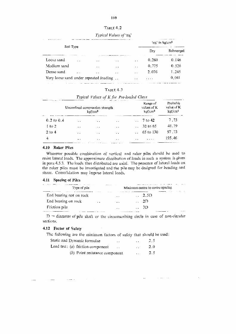
169
TABLE 4.2
Typical Values of 'np'
'ah in kg/cm3Soil Type
Dry Submerged
Looss sand 0.260 0.146Medium sand 0.775 0.526Dense sand 2.076 1.245
Very loose sand under repsated loading .. 0.041
TABLE 4.3
Typical Values of K or Pre-loaded Clays
Range of ProbableUnconfined compression strength valuesofK value ofK
kgf/cm? kgf/cm? kgf/cm?
0.210 0.4 7t042 7.731to2 32 to 65 48.792t04 65 to 130 97.734 BR Bu 195.46
4.10 Raker PilesWherever possible combination of vertical and raker piles should be used to
resist lateral loads. The approximate distribution of loads in such a system is givenin para 4.5.3. The loads thus distributed are axial. The presence of lateral loads onthe raker piles must be invostigated and the pile may be designed for bending andshear. Consolidation may impose lateral loads.
4.11 Spacing of Piles
Minimum centre to centre spacing_
Type of pile
End bearing not on rock . . 2.5DEnd bearing on rock .. .. .. 2DFrietion pile .. 3D
D = diameter of pile shaft or the circumscribing circle in case of non-eircularsections.
4.12 Factor of SafetyThe following are the minimum factors of safety that should be used:Static and Dynamic formulae .. .. 2.5Load test: (a) friction component .. .. 2.0
(b) Point resistance component .. 2.5

170
Factor of safety in the case of load test should be increased, under unfavourableconditions where:-
(a) settlement is to be limited or unequal settlement avoided.
(b) Large impact or vibration expected.
(c) soil properties deteriorate with time.
(d) time load on a structure on a friction pile forms a considerable portion ofthe total load and approximates the dead load.
4.13 Increase in safe Loads for Concrete PilesLoad .. Maximum permissible increases in safe load.Wind .. 25 per cent.
Farthquake .. As per IS: 1893-1975 (Criteria for Earthquake Resis-tant Structures).
4.14 OverloadngIf after construction it is found that the safe load is just short of the load
required to be carried then the following overloads may be permitted.
(i) Single pile inagroup .. 10 per cent of pile capacity on each pile subjectto (2).
(2) On group .. 10 per cent of capacity of group, but not morethan 40 per cent of allowable load on singlepile.
4.15. Concrete Piles4.15.1. Concrete piles are fall in thıe following broad categories :-
(i) Driven precast piles (IS:2911-Part-I/Section 3-1979)(fi) Driven cast in-situ piles (IS:2911-Part I/Section-1979)(iii) Bored cast in-situ piles (IS:2911-Part 1/Section-2 1979)
(iv) Bored precast piles
(v) Under-reamed piles (IS:2911-Part II-1973)
The first three types are defined in para 4.15.2 Bored precast piles as the nameindicates are precast piles installed in prebored holes.
4.15.2. Method of Installation.-The basic operations are as follows:-Driven precast pile-The precast pile is driven into the ground with or without
jetting or other techniques.
Driven cast in-situ pile.--A casing with a plug or shoe is driven into the grounddisplacing the soil. The reinforcement cage is lowered and the hole is ülled withconcrete and during this operation the casing is progressively withdrawn. Theconcrete may be rammed or vibrated. When the casing is withdrawn the concretecomes into direct contact with the soil. The casing may, in some situations, beleft permanently.

171
Bored cast in-situ piles--Initial boring of about 1.2t0 Sm is done using a bailerand a temporary casing is lowered in the bore hole. Further boring to the requireddepth is done using chisels of cutting tools, Bentonite slurry is filled in the borehole tor stabilising the walls of the bore hole. After lowering the reinforcementcage the hole is filled with concrete with a tremie.
Bored precast pile--Casing or pre-tube is sunk into the ground by specialequipment and grabbing the soil from within. The precast pile is installed withintie tube. The tube is progressively withdrawn and the annular space between thopile and h boro hole is filled v 2} ı cement sand grout. Benoto and the Hochastras-sor-Weise systems of piling fall in this group.
Under-reamed piles-Under rcamed pile is a bored cast in situ pile havingone or more bulbs. The depths of these piles usually range from 3.5 to 5, m andbecause of this short depth boring is done by augers, either manually operatedor power operated. The bore hole is first augered to the required depth. Then theenlarged space for the bulb is cut in the bore hole at tlıe specified depth witha special under-reaming tool. For double and multi-under-reams boring is doneupto the first bulb from top, bulb cut, boring done upto the second bulb, the secondbulb formed and so on till the bottom of the pile. Below water table and in softsoils bentonite is used for stabilising the sides of the bore hole. In very soft soilsor in permeable stratum normal casing and boring is done and bulb enlarge-ments cut by the under-reaming tool. The bore hole is then concreted.
4.15.3. Selection of Pile Type-The selection of a pile type depends on a varietyof factors such as cost, availability, soil characteristics, underground conditions,depth, type of structure, loading and proximity to structures. Some applications are
given below. It must be remembered that cach pile type has its own special appli-cations and in given situation more than one pile type may be equally suitable.
Driven precast pile-From Considerations of handling and head room precastpiles are of small diameter generally not exceeding 35 cm and of relatively shortlength to overcome the difüculty of weight of large diameter, piles, annular sectionscan be used.
The quality of the precast pile, both as regards material and dimensional controlsuch as cross section, alignment of reinforcument and cover to reinforcement canbe ensured,. It is particularly suitable in corrosive soils as protective measures canbe taken before installation. In fact it is the automatic choice in such soils. In sandthe soil near the piles gets compacted and the point resistance and friction resistanceis more than in bored pile. This also holds for the pile group. In saturated clays thesoils near the piie is displaced and remoulded and the frictional resistance is morethan in bored pile.
It is wasteful and sometimes dificult to make good the difference in pile lengthas actually required and as precast. When lengthening with additional precast piecesvertical aligninont may get disturbed. The efücacy of splices particularly in bendingand in resisting horizontal loads is uncertain. It is not suitable in stiff layers andboalder sirata, and in the proximity of existing structures as vibrations caused bydriving may be harmful. Heaving of adjacent ground may also be caused. It is difficultTb 4597-19

172
to key such piles in rock. This in some situations could be overcome by using pilesof annular section and chiselling the rock from inside the hollow.
Bored cast in-situ piles--They are suitable in all soil types including stiff materialand boulder strata and in the proximity of structures. Large diameters are possibleand keying them in rock can be achieved. There are a number of variations of this
type of pile, some patented. Under-reamed piles, micro-piles, pressure-piles fall inthis category. They find application also in underpinning structures.
In long pile of small diameter it is difieult to ensure verticality of the reinforcement
cage and cover to reinforcement. It is not suitable in corrosive soils. In sand the soil
near the pile gets loosened and the point resistence and friction resistance is less than
in bored pile. Close control of the bentonite slurry is required. When it gets mixed
with soil and deteriorates in quality the sides of the bore hole may collapse. The
possibility of necking, hollows, and discontinuity of concrete is reported to exist.
Driven cast in-situ piles-These piles can be driven to great depths without much
difficulty.In soft soils as the casing is withdrawn while concreting the soil may get mixed
with the concrete. Doubts are also expressed regarding the soundness and continuityof concrete in the shaft. This is overcome in some methods by ranıming the concrete.
These are not suitable in corrosive soils.
Bored precast piles-These are reported to combine the advantages of driven
precast piles and bored piles.More data would appear to be required regarding the efficacy of the grout in
providng adhesion.
Under-reamedpiles.-These piles find wide application for foundations in expansive
soils, like B. C. soil, where it is required to take the foundations below the surface
which is unaffected by seasonal moisture variations. They are also used for reachingfirm strata and also to resist upward and lateral loads.
The IS code rates safe bearing capacities upto 42 tonnes for single under-reamed
and upto 63 tonnes for double under-reamed. The safe uplift capacity is half the safe
bearing capacity. The safe lateral loads which they can resist varies from about 12
percent to 8 percent of the safe bearing loads, the lower percentage being applicable to
larger diameter piles.
There is the possibility of the enlarged bulb space not being completely concreted.
If this happens the result will be a simple shaft without bulbs and a pile with a capacitymuch less than that which will be imposed on it. Since there is no direct means of
determining whether the bulbs have been effectively concreted (this is deduced only
indirectly from the volume of concrete used) the reduced pile capacity remains
unknown and serious consequences may result.
4.15.4. Materials4.15.4.1. Specifications for Bentonite-Bentonite is a particular form of the clay
mineral montomorillonite. It derives its name from the Fort Benton rock depositsin Wyoming. It is the name given to natural sodium montomorillonite mineral clay or
base-exchanged sodium montomorillonite clays with impurities upto about 10 percent.

173
Bentonite is used for stabilising the sides of bore holes.
The specifications for bentonite suspension (6) used in piling work are :
(a) The liquid limit should be between 300 and 450 per cent.
(b) The sand content of bentonite powder should not be greater than 7 percent.
(c) Fresh water should be used formaking bentonite solution.
(d) The specific gravity ofthe bentonite solution should be about 1.12.
(e) The Marsh funnel viscosity should be about 37 seconds.
(f) The swelled volume after 12 hours in abundant quantity of water should beat least two time its dry volume.
(g) The PH of the slurry should be less than 11.5.
4.15.4.2 Concrete
Type of pile Slump Grade Cement content
Driven precast ..
Driven cast in-situ.
Bored cast insitu
Minimum 100 mm whenconcrete in pile is notcompacted. Maximum180 mm.
Concrete poured in waterfree unlined bore hole.
X 100 mm 180 mmConcrete under water/drilling mud withtremie:& 150 mm
>> 180 mm.
+ M20 when drivingstress.
> 100 kgf/cm?+ MI15 when driving
stress. < 100 kgf/cm?< M20 for bridges.xMIS< M20 for bridges.
For design grade is takenas equivalent to M15and M20 when using350 kg/m? and 400kg/m? cement res-pectively for bridges.
+300 kg/cm?/ when notexposed to sulphateattack. For concretingunder water or drillingmud additional 10%over that for the con-crete grade with speci-fied slump but »370 kg/M?.
+ 350 kg/m? for smalldiameter piles upto10 m depth.
X 400 kg/m? for largediameter/deeper piles.
4.15.5. Permissible stresses-The permissible stresses in concrete shall be as
per IS 456-1978 (latest revision) code ofpractice in plane reinforeed concrete and for
bridges as per IRC : 21-1972. For cast insitu piles the average compressive stressshould be calculated on the total cross sectional area of the pile. Ifcasing of adequatethickness and proper shape is left permanently in driven cast in situ piles the permissiblecompressive stress may be increased. When concerting is done by termie in boredcast insitu piles the permissible compressive stress may be 33.33 percent or the
specificied 28-day cube strength. In this case the maximum size ot aggregate shall be20 mm.

174
4.15.6. Under Water Concreting (See IS 456-1978):Cement Coutent as mentioned aboveCoarse aggregate (by volume) 1% (volume of fine aggregate)
> 2 (volume of fine aggregate)
Concrete placed under water shall be treated as nominal mix and not as design mix.
4.15.7. Concrete in Sea Water-Requirements for concrete in marine environ-ments have been laid down by the P.W.D. in Circular No. PBN. 2276/999/CR-35-/Dsk-4, dated 14th June 1977. Relevant extracts are reproduced below Reference
may also be made to IS: 456-1978.
4.15.7.1. Principally marine environments attack tlıe concrete structures in three
ways.
(i) Physical damage to conerete. caused by physical attrition due to wind blown
sand, wave carried sand and shingle and cracking due to thermal variation, alternate
drying and wetting and due to forination of salt crystals in the pores.
(if) Chemical action. of cement with salts in the sea water and breeze. Maindamage is due to magnesium sulphate and carbon dioxide, the latter being parti-cularly active in stagnant and polluted backwaters.
(iii) Accelerated corrossion of steel reinforcement causing loss of effective areaof steel and cracking and spalling of concrete due to the increased veiume of rust
so formed. Chlorides in sea water and aggregate are the main culprits in this respect.(The chloride content of concrete as a whole should be less than 50 ppm andthe sulphate content less than 3000 ppm.
A cracked, inadequately compacted, porous concrete will allow the above ceflects
to reach deep inside the structural member while a sound, denso and impermicableconcrete will restrict the effects to the thin layer near the surface.
4.15.72. Zones of Exposure-For durability of a structure in marine environ-
ment, three zones of exposure which are defined as under should be vsnsidered:
(a) Submerged Zone.-That part of the structure below the splaslı zone.
(b) Splash Zone.-Thatt part of the structure subject to repeatcd wetting by sea
water and drying. This zone may be taken as that between the highest and lowestwater levels reached by the wave.
(c) Atmospheric Zone. -That part of the structure above the splash zone.
4.15.73. MaterialsCement-Cement should be ordinary, rapid-hardening, blastfurance slag cement
or sulphate-resisting portland cement complying with the provisions of the relevantI. S. standards. In the submerged and less exposed atmospheric zones, crdinaryportland cement will normally prove satisfactory. Experience has shown that, in the
splash and more exposed atmospheric zones, good quality concrete made with prot-land cement havinga tricaleium aluminate (C,A) content of less than 8 per cent will
give satisfactory long term performance. The soluble chloride present in the portland

175
coments produced in various factories of India may lie in the range of 4 ppm to500 ppm Similar!y soluble sulphate may lie in the range 420 t0 800 ppm. itıs advanta-geous to use cement with chloride contents less than 100 ppm since the overallchloride content including that from water should not exceed 50 ppm in the concrete,
aggregates should not be used in concrete unless they arethoroughly washed in fresh water and have a sufliciently low shale and chloridecontent.
IS : 2386 (Part VII) gives standard test methods for alkali aggregätes reactivitywhich can be used when dealing with suspicious aggregates.
Water--Water should be clean and free from harmful matter. Wherever possible,it should be obtained from a public supply. Sea Water should not be used in
reinforced, prestressed or other structural concrete. As per IS:456 the water for
mixing concrete should not contain more than 1000 ppm alkali chloride and 500
ppm of sulphate. It is considered safer to use water containing not more than 560
pom of chloride to ensure that overall chloride content in concrete is well within the
permissible limits.
Admixiures-Calcium chloride or admixtures or pigments containing calciumchloride should not be used. Air entraining agents, workability aids and retardingagents may be used provided that suitable precautions are taken and it can be shown
by tests that the product to be added will produce the required effect witlıout in anyway changing the other qualities required in the concrete or damaging the steel.
Reinforcing steel-All reinforcement shall be clean and free from locse mill scale,dust, loose rust coats of paints, oil or other coatings which may destroy or reducebond. During storage the reinforcing steel should be protected by a watering ofcoment wash. Slight rust may be removed by rubbing the rods with gunny cloth orwire brushes. In case of heavy rusting of reinforcement, the rust may be removed bypickling or by use of rust removing jelly and phosphate coating given by tank
phosphating or application of phosphating jelly. Zinc coated reinforcements whenused reduce the risk of corrosion as long term tests have shown that initial attack onzinc by the alkalies released during hydration of the cement is not progressive and thatthe coating can be expected to have good durability. Hot dip galvanizing to give the
thickness of zinc plus zinc alloy layer from 0.02 to 0.13 mm is found to be a reliableand economic of providing satisfactory zinc coated surface.
Prestressing tendons-During and after the installation of prestressing tendonsthe precautions to be taken consist of producing the best possible tendon environment
during the period between installation and the provision of final protection and ofkeeping this period to a minimum. Corrosion is likely to occur only in the presenceof water which should therefore be excluded as far as possible. If the period before
provision of final protection is long, precautions should be taken to prevent or reducethe extent by which any remaining water, or subsequently ingressing water couldcombine in reaction with thessteel. Grouting should be carried out as soon as possibleafter stressing. When it is necessary to leave one side of form work of girders cpenfor sometime for tying reinforcement or any other purpose, the open side should be
ieeward with reference to sea.

176
Sheathing-Rigid or semi-rigid water tight metal sheathing should be used. Itshould be spliced with tightly fitting, sleeves and the joints bound with waterprooftape.
Grout-Materials for grout should comply with the following requiremenis:-(a) Cement normally should be ordinary Portland cement.
(b) Aggregates, if used in large ducts, should consist of siliceous granules,finely ground limestone, trass, pozzolana or fine sand.
(c) Admixtures may be used if tests have shown that they improve the propertiesof the grout, e.g. by increasing workability, reducing bleeding, entraining air orexpanding the grout. Admixtures should be free from chlorides, nitrates, sulphides,sulphites, and any other material liable to affect the steel or grout. If aluminiumpowder is used, the total expansion of the grout should not exceed 10 per cent.
(d) Water should be clean and free from harmful matter. Wherever possible,it should be obtained from a public supply. Sea water should not be used in grout.
Concrete
Precautions to ensure durability-One of the main characteristics influencing thedurability of concrete is its permeability. With strong, dense aggregates, a suitablylow psrmeability is achieved by having a sufüciently low water/sement ratio, byensuring complete compaction ofthe concrete and by using proper curing methods toensure complete hydration of the cement. The cement content should be sufäcient to
provide adequate workability with a low water/cement ratio so that the concrete canbe completely compacted with means available. It is essential that the concrete shouldbe as dense as possible, so all design and detailing should be such as to make it easyfor concrete to be compacted around reinforcement and into corners of mouldsand forms. Shutter vibrators will be preferable to ensure good compaction in areassheltered from pin vibrators reinforcing bars, for parts of structures subjects to sea
spray, the removal of side forms should be delayed to protect green concrete fromsea water. Construction and supervision must be such as to ensure a consistentlyhigh standard of workmanship. The chloride content should not exceed 50 ppm andthe Sulphate content should not exceed 3000 ppm.
Cement Content-For reinforced concrete structural members the minimumcontent shall be as follows :-
(a) In the splash zone-(i) Minimum 360 kg/m? (20.4 bags/100 cft)
(b) In the atmospheric zone-(i) Minimum 320 kg/m? where the maximum sizeof aggregate is 40 mm (18.12 bags/100 cft)
(ii) Minimum 360 kg/m? where the maximum size of aggregate is 20 mm
(20.4 bags/100 cft)
(iii) Minimum 410 kg/m? where the maximum size of aggregate is 10 mm
(23.22 bags/100 cft)
(©) In the submerged zone-(i) Minimum 300 kg/m? (17.00 bags/100 cft)
Water/cement ratio-For high-quality concrete of low permeability, the watercement ratio should not be more than 0.45 and preferably 0.40 or less subject to the
attainment of adequate workability.

177
Strength-All concrete in marine environments shall be controlled concrete.For reinforcement concrete structural members the minimum concrete cube strength
(28 days work tests) shall be 200 kg/cm?.
Abrasion--If severe scouring action due to pebbles, sand or silt is expected, the
coarse aggregates used in the concrete should be at least as hard as the material
causing abrasion and the sand content of the mix should be kept as low as possible.
4.15.7.4. Curing of concrete-Special attention should be paid to curing ofconcrete in order to ensure maximum durability and to minimise cracking. Concreteshould be cured with fresh water. The concrete surface should be kept wet despitewind etc. Care should be taken to avoid rapid lowering of concrete temperaturescaused by applying cold water, to hot concrete surface (thermal shock). Sea water
should not be used for curing reinforced concrete or prestressed concrete. Wherethere is doubt about the ability to keep concrete surface permanently wet for the
whole of the curing period, a heavy duty membrance curing compound should be
used. In any case green concrete must not come into contract with sea water.
4.15.7.5. Concrete cover to ıforcement The concrete cover must be of the
same quality, impermeability and strength as the rest of the concrete. Particular caremust be taken to ensure this specially in beam and slab soffits.
reın
The concrete cover must develop sufficient alkalinity, and protect the steel. The
alkalinity developsd should not be less than 0.04 N and should not be more than
0.08N.The cover by its quality must keep the diffusion of harmful salts and permeation
of water as low as possible. A good quality 13 mm cover is better than porous 50
mm cover.
The cover must be uniform throughout and its thickness should be exclusive of
plaster or other decorative finishes.
The concrete cover shall be as per the relevant clauses of I. R. C. Codes and I.S.S.
4.15.7.6. Detailing of Miscellaneous Items
Binding Wires-All ends of binding wires shall be carefully turned inwards so
that they do not project out of concrete to start rusting action, stainless steel or gal-vanised wires are preferable. where possible polythene binding strengths and polythenebar grips should be used after making sure that these do not result in loss of bond or
chemical reaction with concrete.
Bar diameter-Smaller number of large diameter bars shall be used to keep more
space between the bars and smaller surface area of bars available for corrosion. In
general there should be no congestion ofreinforcement any where.
Cover Blocks-Good eircular shaped concrete cover blocks of the same strengthas the main concrete shall invariably be used both at bottom as well as sides,
4.15.7.7. Protective coatings and corrosion inhibitors.-As yet there is not much
information available of indigeneous products which are suitable for use as " Protec-tive Coatings " on concrete structures in marine environments. For portions whichare above water and in splash zone and easy for access, ordinary bituminous pain-tings on the surface would be economical. They can be renewed periodically.
178
The addition ot liners to the substructure columns on outside would be particularlyadyantageous for jetties where weak concrete cover is also subjected tc accidentalimpast of floating crafts despite provision of fenders.The Central Elestro Chemical Research Institute (CECRI) Karaikudi, Tamilnadu
has developed certain special processes for prevention of corrosion like [6 liquidconcentrate to be added to water used for mixing concrete (if) cement coating forstee1 (ii) coating of external surface of concrete. Although the products are not availa-ble commercially, the licence for the processes can be obtained from the NationalRessarch Development Corporation of India, New Delhi for manufacturing theproducts ar site. Perhaps small quantities for application in special cases couldbs obtained, directly from C. E.C. R. I. A detailed note by the CECRI, Karaikudiis availabe as Annexture-I to the Special Publication No. 2-1876" " Corrosion ofReinforced and Prestressed Concrete Highway Structures located in Coastal Areas "published by the Indian National Groups of the I. A. B. S. E., New Delhi. (Thispublication can be obtained from the Secretary, Indian Roads Congress, New Delhi).
4.15.7.8. Quality Control
General--Reinforced concrete and prestressed concrete structures in marineenvironments ar© most prone to corrosion and decay, as such special attention shouldbe paid to the quality control in order to achieve high standards both in materialsand workmanship.
Tests All the tests on materials specified for high quality works should carried,out in case of concrete structures in marine environment. Special attention is drawnto the following items:-
(i) Cement .. Chemical tests including chloride and sulpkate contents-
(ii) Aggregate .. Alkali aggregate reaction tests and abrasion tests.
(ii) Water .. Chloride and sulphate contents
(iv) Concrete .. (a) Estimation of alkalinity(b) Estimation of total chlorides
(c) Estimation of total sulphate.
For an indication of rusting of steel reinforcement, the surface of concrete could betested with an indicator such as phenolphthalin which when turning red indicatesrusting.
Non-destructive tests-There are a number of non-destructive tests in vogue forpetermining and ensuring the quality of concrete such as Schmidt Hammer, UltrasonicPulse Transmission techniques, Radiometer techniques, etc. Except the first the other
techniques require equipmentwhich are not still easily available. The Schmidt Hammeris easily available and simple to use. It is useful for detecting variations in the concreteproperties to a small depth between different parts of a structure. This test should be
extensively used during and after construction particularly to check the quality ofconcrete cover in beam soffits and similar locations. For performing this test theconcrete surface should be smooth. Twenty readings will have to be taken overan area of 250 -250 mm for averaging after discarding particularly high and lowreadings.

179
TABLE 4.4
Requirements for Concrete Exposed to Sulphate Attack
Concentration of Sulphate expressed as SO,Type of Minimum Water/
In Soil In Ground Cement cement Cement
Total SO, in 2:1 water content Ratio
SO; (%) water (Parts/100000) kg/m?extract g/l
Less than- Less than-0.2 30 OPC PPC 280 0.55
Portland Slagcement.
0.2t0 30 to 120 Do. 330 0.500.5 Supersulphated 310 0.50
cement,
0.5t01.9t0 120 to 250 Supersulphated 330 0.50cement.
OPC = Ordinary portland cement; PPC = Portland pozzolana cement.
Above table is applicable to concrete made with 20 mm aggregate and for groundwaters of pH 6 to 9 containing naturally occuring sulphates but not contaminates
such as ammonium salts. For 40 mm aggregate the value may be reduced by about
15% and for 12.5 mm aggregate increased by about 15%.
OPC concrete is not recommended in acidic conditions (pH 6 or less) and in
aggressive environment containing ammonium sulphate.
OPC with C,A more than 5 per cent and 2c,A + C,AF (or its solid solution4 CaO, Al,O,Fe,0O, + CaO, Fe,O,) not more than 20 per cent may be used in
place of supersulphated cement.
Portland slag cement conforming to IS : 455-1976 with slag content more than
50 per cent exhibits better sulphate resisting properties.
Minimising effect of harmful chemical salts.-In order to minimise the changes ofdeterioration of concrete from harmful chemical salts the total chloride (Cl) and
sulphate (SO,) contents in concrete should not be greater than 0.15 per cent and4 per cent by mass of cement respectively.
4,15.8. Protection of Concrete against Deterioration
4.15.8.1. Aggressive Chemicals. -Protection of concrete in sca water and marino
atmosphere is given in para 4.15.7. Concrete is also attacked by sulphates and
sulphuric acid oceuring naturally in soils, by corrosive chemicals present in industrial
water which may be present in fill materials or permeated into previous soils and by
organic acids and carbondioxide resulting from decay of vegetable matter.
Sulphate attack is a disruptive process. Attack by organic acids and dissolved
carbondioxide takes the form of teaching and attack by sulphuric acid takes both
these forms.Tb 459720 (13,004-3-87)

180
The naturally occurring sulphates in soils are those of calcium, magnesium, sodiumand potassium. Of these magnesium sulphate is the most aggressive. Ammoniumsulphate does not occur naturally in soil but since it is used in the manufacture offertilizers it can occur in cultivated soils and farm lands where fertilisers are used.
Ammonium Sulphate attacks ordinary portland cement very severely.
4.15.8.2. Protective treatment-(l) Dense impermeable concrete affords the best
protection. For this reason high strength precast concrete piles are the most suitable.
Table 4.4 gives recommendations for type of cement, cement content and wafer-cement ratio for concrete exposed to sulphate attack. This table gives recommend-ations for concrete in general. For piles when ordinary Portland cement or PozzolanaPortland cement is prescribed use the maximum of the minimum cement contents
specified in Table 4.4 and para 4.15.4.2.
Concrete exposed to attack by organic acids-The degree of aggressive action byorganic acids is very roughly assessed by the pH value of the ground water or thesub-soil. Some recommendations are:-
pH value Protection
greater than 6 .. None required
Ordinary Portland Cement is satisfactory610 3.5 Supersulphated cement in dense concrete with water-
(mineral acids only) cement ratio not greater than 0.4.
(2) Coatings-(a) Metal sheathing
(b) Tar or bitumen. Those coatings are likely to be stripped while driving resultingin total loss of or inadequate protection,
(c) Resins. High cost ofsuch coatings may be prohibitive factor.
(d) Glass fibre wrapping infregnated with bitumen. When driving in gravelly soils
or rocky soils the wrapping is likely to get torn.
(e) Pile caps and capping beams bearing on ground can be protected if cast on
heavy gauge polytheline sheets laid on a sand mat or lean bed concrete. The sides
can be protected by a spray of hot bitumen or bituminous paint or a layer of mastic
asphalt. Adhesive plastic sheathings can also be used.
(f) Plastic Sheath. For cast-in-situ piles, the concrete can be placed in plasticsheaths.
4.15.9. Reinforcement-The pile section and reinforcement should be adequately
designed for vertical and lateral loads and moments imposed by handling and
driving oporations by the structure and by the soil movements both vertical and
lateral.
Handling and driving stresses arise in driven precast piles. Vertical soil movements
may arise due to consolidation and create down drag forces on pile by negativefriction. Cohesive slopes and unequal surface loadings on compressible soil can
cause large lateral soil movements which are transmitted to the pile group setting upmoments in both vertical and batter piles. This condition would arise in pile groupsunder bridge abutments.

181
Reinforcement required for the design loads may be stopped at the section beyondwhich it is not required. However the minimum reinforcement given below shouldbe provided in the entire length of the pile.
Driven Precast PilesMinimum main reinforcement-The minimum area of main longitudinal reinforce-
ment shall be the following percentages of the cross-sectional area of the pile:-(a) Pile length less than 30 times its least width ..
(b) Pile length 30 to 40 times its least width .. .. 1.50%(c) Pile length greater than 40 times its least width ..
1.25°o
2.00%o
Minimum lateral reinforcement--Lateral reinforcement is important in resistingdriving stresses. They should be in the form of hoops or links and should not be
less than 6 mm diameter. The minimum volume shall be:
(a) at each end of pile for a distance of about 3times 0.6 per cent of grossthe ieast width. volume of pile.
(b) in the body of the pile .. .. 0.2 per cent of grossvolume of pile.
Cover-The clear cover to any reinforcement including binding wire shall not be
less than 40 mm. When exposed to sea-water or other corrosive environment theclear cover should not be less than 50 mm.
Driven and Bored Cast in-situ PilesMinimum longitudinal reinforcement-The Minimum area of longitudinal rein-
forcement in the full length of the pile shall be 0.4 per cent of the sectional areacalculated on the basis of the outside area of the casing of the shaft.
Adeyuate dowels with minimum bond length below cut-off level and with adequate
projection into pile cap should be provided.
Minimum lateral reinforcement-The minimum lateral reinforcement shall be
6 mm diameter links or spirals at 150 mm centres.
Cover-The clear cover to main reinforcement shall not be less than 50 mm.
4.15.10. Pile CapsLoad dispersion-The dispersion of loads and reactions from the columns and
piles may be assumed to be at 45° upto mid-depth of the cap. The moments and
shears are calculated as for footings. Any other rational method may also be uscd.
The depth of pile cap should be adequate for anchorage of column and pilereinforcement.
The effect of differential settlement of piles under the same cap must be properlyconsidered in the design.The pile cap should be rigid enough to distribute the pile reactions.
The clear overhang of the pile cap beyond the outermost pile should be 100 to
150 mm.
The pile should project 50 mm into the pile cap concrete.
Tb 4597--200

182
The cap should generally be cast over a 75 mm thick levelling course concrete.
The clear cover to main reinforcement shall not be less than 60 mm.
4.15.11. Construction Aspects4.15.11.1. Control of Alignment-Piles should be installed with the greatest
possible accuracy as per the drawings. The following tolerances may be used as
a guide. For special cases the tolerances may be closer :-
Deviation from vertical .. .. .. 1.5 per cent
Deviation from raked angle (in case of raker pile) .. 4.0 per cent
Positional deviation at working level of piling rig. .. 75mm
Positional deviation in case of single pile foundation .. 50mm
Greater tolerances may be prescribed for piles driven over water and or raker piles.In case of deviations greater than {he above which cannot be taken care of by
redesign of pile cap or pile ties the pile should be replaced or supplemented.
4.15.11.2. Piling sequence--Normaily piling should proceed outward from the
centre of the group or from one extreme to the other. Possibility of heaving of theadjacent pile or disturbance to the setting or hardening of concrete of the adjacentpile should be kept in view. This possibility is greater in compact soils than in loosesoils. In loose sands driving will tend to compact the soil and make further drivingof piles difficult. In very soft cohesive soils driving may cause the soil to fow out,in which case the sequence should be from outside to inside.
4.15.11.3. Precast Piles
Casting yard--The bed of the casting yard should be firm and well drained to
guard against upheavals and damaging the piles. It should be sufliciently away to
prevent the vibratory effects of pile driving affecting the setting and hardening offreshly concreted piles.
Castnig of piles should be continuous from end to end. The faces should be partic-ularly dense. The top face should be finished level.
Curing-Wet curing for 7 days should be done. See Table 4.5, through curingand hardening are essential. Between wet curing and driving the pile should be
protected from drying from wind and direct sun.
TABLE 4.5
Curing and Handling ofPrecast Piles
Minimum Time
Release Wet Lift fromType of cement side Curing
Shutters Bed Drive(hours) (days) (days) (days)
Ordinary Portland cement .. . 24 7 10 28
Rapid-hardening Portland Cement .. 12 7 7 10
183
Stering-Piles shouid be stacked on level wooden supports at predeterminedpoints so that bending stresses are not exceeded. The ground should be firm enoughto bear the weight of the stack without settlements. The piles should be so stackedthat order piles can be removed first. Piles should be picked up at the design pickup points.
Pile driving-The pile head should be protected by packing, helmet and dolly.The dolly should not be thicker than the width of the pile.
The heaviest hammer and softest packing should be used for obtaining the maximumset for a given stress.
The packing hardens with use and should be replaced periodically.
A light hammer and hard packing will cause hammer rebound and create tensilestresses in the pile.
Piles should be properly held in position and restrained otherwise a non-axialhammer blow will set up transverse vibrations.
The stroke of a single acting or drop hammer should be limited to 1.2 m. In softsolid penetration per blow will be large. If rock is suddenly reached the hammerblow may damage the pile. In such conditions a shorter stroke should be used.
Continuous driving after the pile has reached refusal should be avoided.
Sudden changes in penetration rates should be noted and causes determined ifpossible before continuing driving.
Jetting is effective in cohesionless and may be used. About 27,000 litres of water
per hour at a pressure of 8.5 kgf/cm? would be required in silts and sands. Muchmore water at higher pressure will be required in dense soils. Jetting may impairthe bearing capacity of piles already driven and may affect existing structures in the
vieinity. Jetting should be stopped before completing by driving and the final penet-ration should be achieved by the ordinary method of driving.
Pile heads.--The conerete should be stripped to a level 50 mm above that of the
cap bottom and reinforcement left projecting for adequate bond in the cap concrete.
Risen piles.-While driving a pile the levels of the tops of the already driven pilesshould be noted to determine whether any of them rise up dus to heaving ground.Such piles may be driven back to their original depth unless redriving tests indicate
that this is not necessary.
4.15.11.4. Cast in-situ piles-An initial temporary casing of minimum lengthot one meter should be installed while boring for a bored pile. It is usual to install
lengths of 1.5mto2m.When drilling mud is used its consistency must be carefully controlled. Concreting
should not be done when the specific gravity of the drilling mud is more than 1.2.The slurry should be maintained at 1.5 m above the ground water level.
The bottom of the bore hole should be carefully cleaned before concreting. Thisis best done by flushing with fresh drilling mud.

184
Tremie-concreting-Conereting under water should be done with tremie or speciallydesigned under water buckets. The following should be particularlyobserved :-
(a) the minimum cement content should be 370 kg/m? and the slump not lessthan 150 mm.
(b) Temporary casing should be used to prevent soil from the sides falling inand contaminating the concrete.
(c) the tremie pipe should be of adequate diameters; for 20 mn aggregate thediameter should be 200 mm.
(d) the tremie pipe should always be embedded in the concrete adequately sothat neither water nor drilling mud can enter into the concrete.
Concreting should be continuous and uninterrupted. In the case of an exceptionalinterruption upto 2 hours the tremie pipe should be left in the concrete and periodi-cally moved up and down to prevent concrete setting around it. Concreting shouldbe restarted with a quantity of richer concrete with a slump of about 200 mm. Iffinal set takes place before resumption of concrete the unfinished pile should be
rejected.
Concreting above cut-off level-Concrete should be cast to a minimum of onemeter above the cut-off level when the latter is less than 1.5 m, below the workinglevel. If it is deeper an additional height of 50 mm for every additional 0.3 m depthshould be cast. It the cut-off level is below ground water the height of concrete castabove it should be not less than required for producing a pressure on the unsetconcrete at cut off level equal to the water pressure.
4.15.11.5. Under Reamed Piles (See IS:2911-Part III-1973)
Typical Details-Typical details of under-reamed pile are shown in Fig. 4-13.
Length-Since under-reamed piles are specially useful for foundations in expansivesoils, the piles should be taken to a depth where ground movements due to seasonalmoisture variations become negligible. This depth in deep expansive soils is generally3.5 m. In other situations, that is, shallow depths of expansive soils and other poorsoils the pile may be taken to depth of at least 50 cm in the zone unaffected by soilmovements,
Bulb diameter-The diameter of the under-reamed bulb varies from 2D to 3D.It is generally 2.5D; (D is the diameter of stem of pile)
Bearing Capacity-The pile is treated as a short column and therefore, the lateraldimensions and embedment in soil should meet the requirements of a short column.
The load carrying capacity is determined from a load test conducted as prescribedin IS: 2911 (Part IV)-1979.
In the absence of a load test the safe loads are given in the above IS., as per whichthe diameters vary from 20 to 50 cm and loads from 8 to 42 tonnes and from 12 to63 tonnes for single and double under-reamed piles.

185
+2D
ulin
expa
nsive
1Au gap oO
o
‚= 45' approx.
1 4approx.
e,= 30 approx. 8 5,
Er
Single Under -Reamed Pile Multi -Under-Reamed Pile
Au
-2 5 D
Wallw .Wallwidthwidthw d h
+150 | a +150
+20 80 »80 a
Interior beam Exterior beamBeam in Expansive Soils Beam in Non- Expansive Soil
SECTION X-X
1,x <
Fig-4-13 Typical Details of Under-Reamed Pile
186
4.16. Prestressed Concrete PilesIn prestressed concrete piles tensile stresses are resisted without cracking and
therefore, they may be more durable in aggressive environments.
The design of these piles will be like any other prestressed concrete structuralmember.
Some special provisions relating to piles are given below:-
(a) The maximum axial stress in a pile acting as a short strut should be limitedto 25 per cent of the 28-day works cube strength less the prestress after losses.
(b) To allow for impact the tensile stresses due to handling without impactshould not exceed one third the permissible stresses for handling loads.
(c) Prestress after losses should satisfy the following conditions :-
(i) To estimate stresses while handling, it may be assumed that 75 per centoi «osses will have occured within two months.
(ii) Prestress in N/mm? should not be less than 007 times the ratio of length ofpile to its least lateral dimensions.
(ii) Minimum prestress related to ratio of weight of hammer to weight ofpile should be as follows :-
Ratio of hammer weight to pile weight 0°9 08 07 07Minimum prestress for normal driving 20 35 50 60(kg.f/cm?).
(iv) For diesel hammers the minimum prestress should be 50 kgf/cm?.
(d) Mild steel stirrups-The diameter or mild steel stirrups should not beless than 6 mm and pitch not more than side dimension less 50 mm. At the pileends the volume of stirrups over a length equal to three times the side dimensionshould not be less than 06 per cent of the volume of the pile.
(e) Transfer of prestress-Ihe minimum cube strength of concrete at transfershould be 2°5 times the stress in concrete at transfer or 280 kg/cm? for strandor crimped wire or 350 kgf/cm? for plain or indented wire whichever is greater.
(f) Driving--There is some evidence to show that a larger ratio of hammer
weight to pile weight is required to avoid damage to the pile. A careful check fortension cracks should be made while driving the first pile and if cracks are noticedthe drop should be reduced or heavier hammer used.
4.17. Steel Piles4.17.1. Steel piles may be H-piles, pipe piles or piles formed by welding rails or
sheet piles. Wide fange I[-beams may also be used. Some typical sections are shownin Fig. 4-14.
Steel piles can be driven to greater depth, are lengthened easily and quickly at site
by field welding, can as early be cut off and are relatively light for their capacity.The displacements caused in driving are small. They can be driven in strata withsmall boulders and socketed in rock.

187
H-Piles-H-Piles can take quite large loads and can be driven through hardstrata to reach rock. Small boulders are broken up or displaced by these piles. Splicingis done by flange and web plates which are either welded, bolted or rivetted
(Fig. 4-14). Splice plates on the inside wall avoid possible loss of soil support.
Splice plateswelded rivetedor bolted.
inside seeve
weldin](c)
weld
outs
weld
(d)
{b)
Fig.g-14. Splicing of steel piles :{aJand (b),H-piles (c}and(d) Pipe pites.(c & a fron Ref 2)
The driving points may require strengthening for hard driving.
Capping ot H-piles is done by welding on a flat plate of pieces of rolled joists.However, research conducted by the Department of Highways, Ohio State (USA),indicate that caps are unnecessary. For transferring pile loads a concrete cap may be
used with suitable embedment.
Pipe piles-Pipe piles may be close ended or open ended. Pipes may be welded orseamless tubes. Displacement of soil with closed end will be greater. Driving pointsmay be conical or flat. In open ended pipe piles the material is removed by jettingwith air or water or by bailing. Small boulders can be broken up by chisel bits or
by blasting and the fragments removed from inside the pipe.
Splicing of pipe lengths is done by internal or external sleeves (Fig. 4-14).
4.17.2. Corrosion-Steel piles will corrode in corrosive soils marine, environ-ments and near water surface. Bacterial corrosion can also occur.

188
4.17.3. Protection.-Protection of steel piles consists of coatings, encasements,increase in section or cathodic protection.Surface coatings consist of paint, coal-tars, bitumastic coatings and epoxy based
paints.Encasements may consist of in-situ concrete, precast concrete Jackets or gunite
or membrane wrappings.
4.18. Timber Piles (See IS : 2911-Part II-1965)4.18.1. Classification-Timber piles are classified into two classes namely class
A and Class B.
Class A-Piles for railway and highway bridges, trestles, docks and sharves.The butt diameter should not be less than 30 cm.
Class B-Piles for foundations of structures other than those of Class A andTemporary work. Piles used compacting soils should be of diameter not less than10 cm.
4.18.2. Advantages-Timber piles are cheap, light and easy to handle. perma-nently submerged piles are resistent to decay. They have been used in the past infoundations for many causeways in the state.
Compaction of soils with timber piles may be cheaper than deep concrete orsteel pile foundations.
4.18.3. Timber species-Only timber of high durability should be used. Highdurability is defined as average life of 120 months and more based on the" Graveyard " test. Species of high durability are:
Botanical name Trade name
Acacia Catechu Willd KhairAlbizia odoratissima Benth Kala-sirisHopea parviflora Bedd hopeaMesua ferrea Linn mesua
munisops Littoralis bullet WoodShorea robusta Quertn.f: Sal (UP)Vitex altissima Lin.F. millaAlbizia lebbek Benth KokkoBassia butyracea Hill MahuaDysoxylum malbaricum Bedd While cedar
Eucalyptus engenioides eucalyptusGhuta travancorica Bedd ghutaHardwickia pinnata Roxb pineyLagerstroemia lanceollota benteakPterocarpus dalbergioides Robx padaukPterocarpus marsupium Robx bijasalShorea robusta Gaertn. f. sal (MP)Soymida febrifuga A. Juss rohiniTectona grandis Linn. f. teak

189
Botanical name Trade name
Xylia Zylocarpa Tanb .. Jrul
Artocarpus intogrifolius auct. non dinnf. .. kathalBassia latifolia Roxb. (Syn. Madhuca Sppl.) .. mahuaCarea arborea Roxb .. kumbiCedras deodara D. Don .. DeodarCupressus torulosa D. Don .. CypressDalbergia latifolia Roxb .. rosewoodGnelina arborea Linn .. gamariHardwickia binata Roxb .. AnjanOugeinia dalbergioides Benth .. Sandan
4.18.4. General requirements-The ratio of heart-wood diameter to pile butt-diameter should not be less than 0.8.Piles which are used without treatment should have as little sapwood as possible.
Defects-The permissible defects shall be as specified in IS : 883-1970 and IS:3629.
Tolerance in length-The tolerance in length of piles should be -30 cm for
piles less than 12 m long and + 50 cm for piles of 12 m and longer length.
Handling-Treated piles should be handled in such a way as not to damage the
surface of the wood. Sharp pointed tools should not be used. Breaking of fibres or
brushing the surface should not be permitted. Minor abrasions of the surface oftreated piles in the portion which will be permanently under water may be permitted.
4.18.5. Bearing capacity-Provisions mentioned under concrete piles will applyhere also.
If load test data are not available the bearing capacity is determined from the
engineering news formula:
For piles driven with drop hammer
16 WHP= 4-16S+2.5For piles driven with single-acting steam hammer
16 WH4-16bP
S + 0.25( )
(
Where P = safe load on pile in kgW = weight of monkey in kgH free fall of monkey in kgS = penetration of pile in cm to be taken as average of 3 blows.
4.18.6. Permissible stresses in timber-The permissible stresses shall be as givenin IS : 883-1970 and IS : 3629.
4.18.7. Driving-The tips of piles should be pointed to a tip area of 25 to 40 cm?
the tapering to be done over a length equal to 1.5 to 2 times the diameter of the pile

190
In soft strata pointing is not required. In hard materials steel shoes should be provided.To prevent brooming the head should be hooped with a suitable ring. The headshould also be protected by a cushion block (see Fig. 4-15).
Metal cap etal barsfor driving snug fit.snug fit
Fig. 4-15 Protection of timber pile heads while driving.(from Ref. 2)
Lengthening-Lengthening is illustrated in Fig. 4-16.
Metal Splice platsleeve snug |!
Bearing enBearing
endsN
|
cut squarecut square
f rt rends
Wood surface shouldbe trimmed
square so that thesplice platebears squarely for its full widthand length
Fig- 4-16 Splicing of timber piles
(from Ref. 2)

191
Pile Hammer-The weight of the hammer should be such that an efficiency ofnot less than 30 per cent is developed (See eq.' 4-8). The weight ofthe hammer should
preferably be not less than that of the pile.
4.18.8. Protection
4.18.8.1. Timber piles are subject to decay and deterioration by fungus, insects,marine borers and mechanical wear Piles permanently below ground water seem tohave infinite life.
Piles protected only against fungus, decay and insect attack will not stand againstmarine borer attack.
The most effective form of treatment is by creosote treatment under pressure.The treatment should be as per IS : 401.
4.18.8.2. Treatment offield cuts-Surfaces of treated piles should not be damagedin any way nor should any holes bored or nails driven or cuts made for braces. Anycuts should be painted with two coats of hot creosote. Holes should be plugged with
creosoted plugs. Bolt holes drilled in the field should be filled with hot creosote
preferably under pressure. Bolts should be coated with sealing compound. One typeof sealing compound consists of coal-tar-pitch and creosote-plastic mixture.
Exposed tops of piles should be painted with two coats of hot creosote and sealed
with scaling compound. A waterproof cap of three layers of tar-impregnated canvas
should be used over the sealing compound.
For protecting the piles from abrasion in the zone of fluctuating water levels,
gunite, encasement with treated wooden battens and concrete have been used.

192
REFERENCES
SECTION I
l. Foundation Analysis and Design by J. E. Bowles, Mc Graw Hill Book Co.,New York.
2. H.J. Gibbs & W. J. Holtz: Research on Determining the Density of Sandsby Spoon Penetration Testing, Proceedings Fourth International Conference onSoil Mech. & Foundation Engineering, London 1957.
3. IRC: 78-1983, Standard Specifications and Code of Practice for Road Bridges,Section VII, Foundations & Sub-structure, Part I : General Features of Design.
4. 15: 1892-1979 Code of Practice for Sub-Surface Investigation for Foundations(First Revision).
5. IS:2131-1639-Method for Standard Penetration Test for soils.
6. 18: 4968-Part III-1976 Method for Sub-Surface Sounding for Soils: StaticCone Penetration Test.
7. 15:4968-1976 Method for Sub-Surface Sounding for soils: Part I-DynamicMethod using 50 mm Cone Without Bentonite Slurry-Part II-Dynamic Methodusing Cone and Bentonite Slurry.
8. 18:1888-1971 Method of Load Test on Soils (First Revision).
9. 18:6935-1973 Method of Determination of water level in Borehole.
10. 18:5313-1980 Guide for Core Drilling Observations,.
ll. 18:4078-1980 Code of Practice for Indexing and Storage of Drill Cores.
12. 18:2132-1972 Code of Practice for Thin Walled Tube Sampling of Soils.
13. 15:4453-1980: Code of Practice for Sub-Surface Exploration by Pits,Trenches, Drifts and Shafts (First Revision).
REFERENCES
SECTION HU
1. IRC:78-1983: Standard specifications and Code of Practice for Road Bridges,Section VII, Foundations of Sub-Structure, Part-I, General Fealuris of Design.
2. Foundation Engineering by G. A. Leonards; Mc Graw Hill Book Co. NewYork, 1962,
3. Foundation Analysis of Design by J. E. Bowles, Mc Graw Hill Book Co.,New York, 1968.
4. 18:1904-1978: Code of Practice for Structural Safety of Buildings: ShallowFoundations (Second Revision).
5. IS: 1080-1962: Code of Practice for Design and Construction of SimpleSpread Foundations.

193
6. IS: 2950-Part I-1973: Code of Practice for Design of Construction of RaftFoundations-Design (First Revision).
7. IS: 8009--Part I--1976: Code of Practice for Calculation of Settlement ofshallow Foundations.
8. IS: 456--1978 Code of Practice for Plain Reinforced Concrete.
REFERENCES
SECTION III
1. IRC: 45-1972: Recommendations for Estimating the Resistance of soilbelow the maximum Scour Level in the Design of Well Foundations of Bridges.
2. IRC: 78-1983: Standard Specifications and Code of Practice for RoadBridges-Section VII Foundations and Sub-Structure, Part-I: General features ofDesign.
3, Soil Mechanics in Engineering Practice by Karl Terzaghi of R. B. Peck, JohnWiley & Sons Inc, New York.
REFERENCES
SECTION IV
1. Foundation Engineering by G. A. Leonards; Mc Graw Hill Book Co., NewYork 1962.
2. Foundation Analysis and Design by Joseph E. Bowles; Mc Graw Hill BookCo., New York.
3. Foundation Engineering by R. B. Peck, W. E. Hanson, T. H. Thornburn,John Wiley & Sons Inc., New York.
4. Soil Mechanics in Engineering Practice by Karl Terzaghi and R. B. Peck,John Wiley & Sons, Inc., New York.
5, 6, 7. IS: 2911 Part I/Sections 1, 2, 3 1979: Code of Practice for Design &Construction of Pile Foundations, Part I-Concrete Piles; Section 1. Driven cast-insitu Concrete Piles, Section 2. Bored cast-in-situ piles, Section 3-Driven Precastconcrete Piles.
8. IS: 2911 Part II-1980 Code of practice for Design & Construction of PileFoundations under Reamed Pile Foundations.
9. IS: 2911 Part ITV-1979 Code of Practice for Design & Construction of PileFoundation: Load Test on Piles.
10. 18:2911 Part II-1980 Timber Piles (First Revision)
11. IS: 2911 Code of practice for design and construction of pile Foundation.
12. Concrete in Marine environment-Published by American Concrete Institute.
BOMBAY : PRINTED AT THE GOVERNMENT CENTRAL PRESS


![`UZ TR]]d W`c UZa]`^RTj eR]\d e` V_U F\cRZ_V hRc](https://static.fdokumen.com/doc/165x107/6335ecd98502b620dc09098c/uz-trd-wc-uzartj-erd-e-vu-fcrzv-hrc.jpg)


