Otari MX-5050 Professional Recorder (manual) - Museum of ...
61
-
Upload
khangminh22 -
Category
Documents
-
view
4 -
download
0
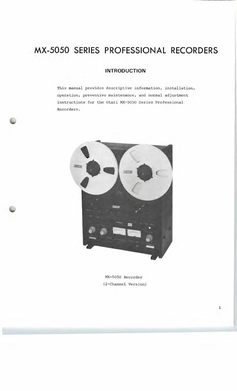
Transcript of Otari MX-5050 Professional Recorder (manual) - Museum of ...


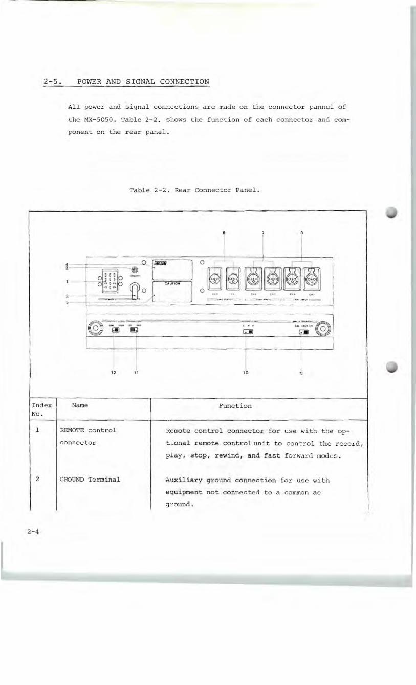

Index No.
I
2
3
4
5
6
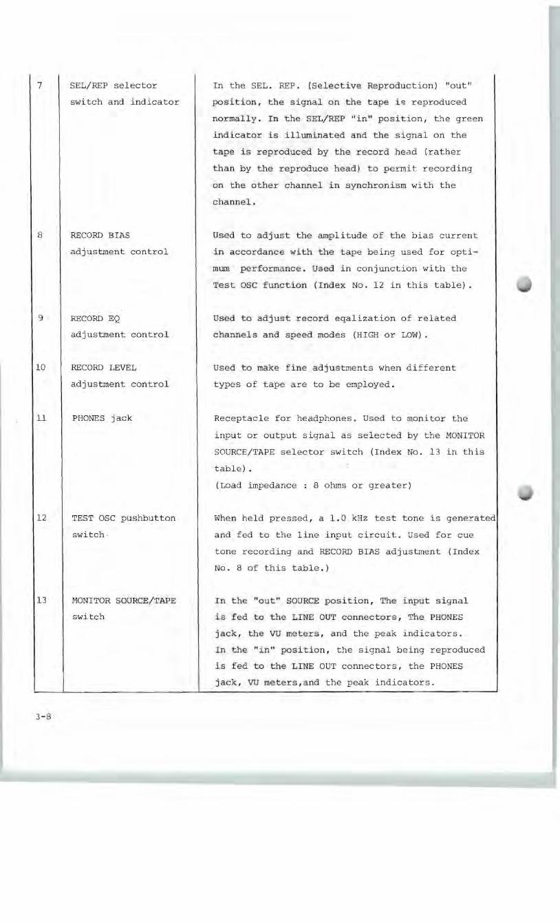
7
8
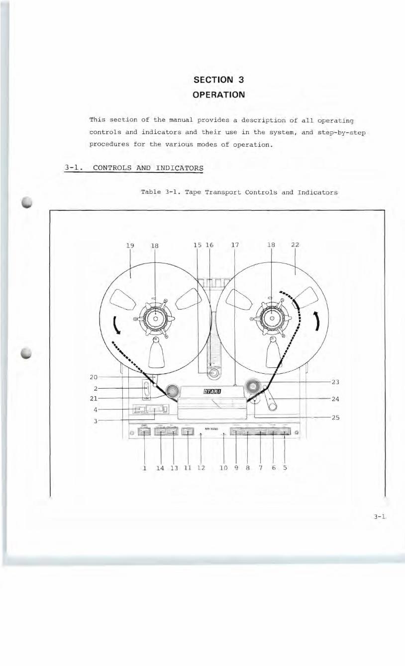
Name
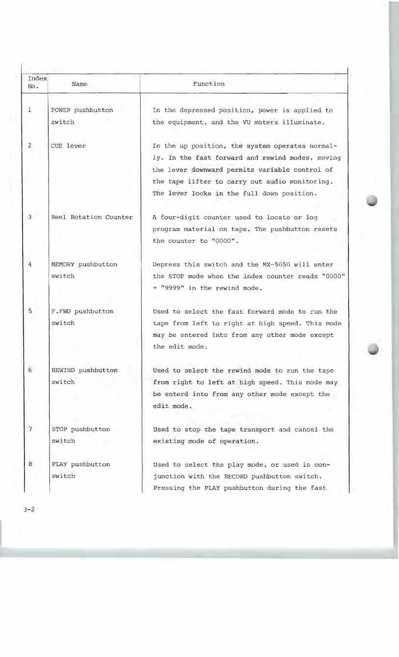
POWER pushbutton
switch
CUE lever
Reel Rotation Counter
MEMORY pushbutton
switch
F.FWD pushbutton
switch
REWIND pushbutton
switch
STOP pushbutton
switch
PLAY pushbutton
switch
Function
In the depressed position, power is applied to
the equipment, and the VU meters illuminate.
In the up position, the system operates normal
ly. In the fast forward and rewind modes, moving
the lever downward permits variable control of
the tape lifter to carry out audio monitoring.
The lever locks in the full down position.
A four-digit counter used to locate or log
program material on tape. The pushbutton resets
the counter to "0000".
Depress this switch and the MX-5050 will enter
the STOP mode when the index counter reads "0000"
-+ "9999" in the rewind mode.
Used to select the fast forward mode to run the
tape from left to right at high speed. This mode
may be entered into from any other mode except
the edit mode.
Used to select the rewind mode to run the tape
from right to left at high speed. This mode may
be enterd into from any other mode except the
edit mode.
Used to stop the tape transport and cancel the
existing mode of operation.
Used to select the play mode, or used in con
junction with the RECORD pushbutton switch.
Pressing the PLAY pushbutton during the fast
3-2

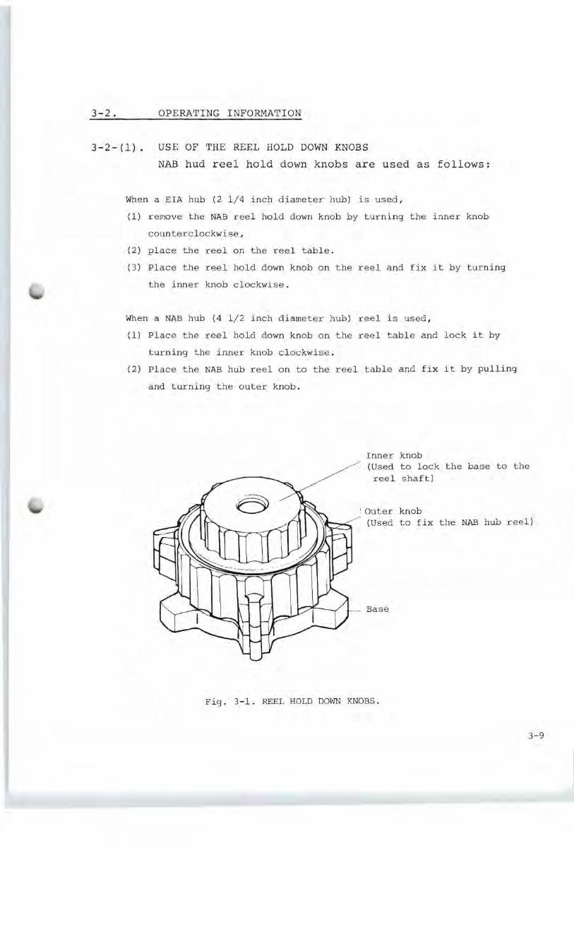
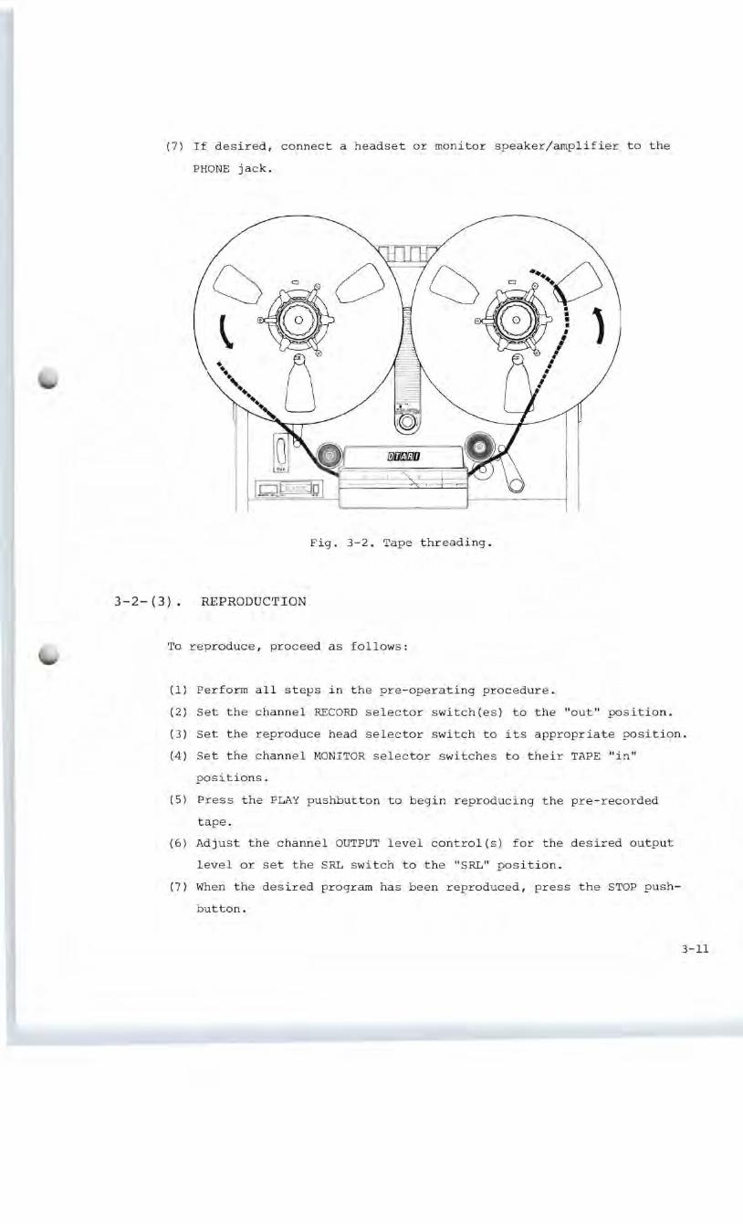
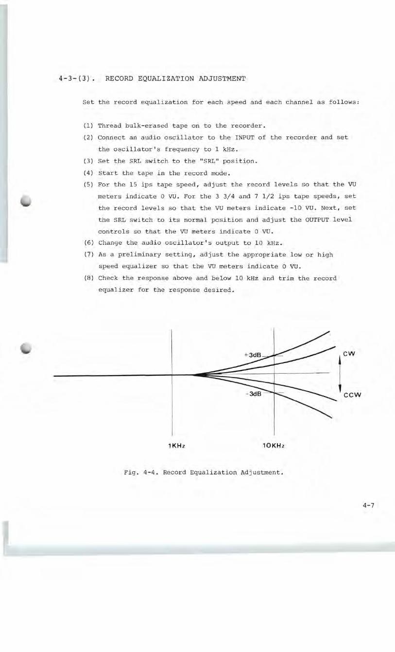
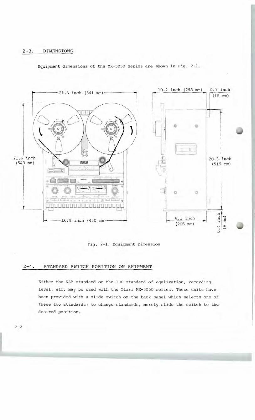
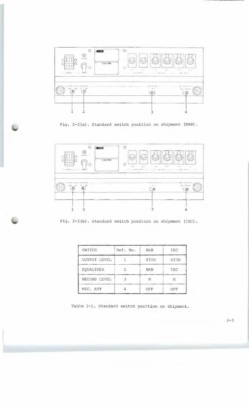
3-2- (4) • NORMAL RECORDING
To record normally, proceed as follows:
(1) Perform all steps in the pre-operating procedure.
(2) Set the desired RECORD selector switches to the "in" position for
the channel(s) selected for recording. The associated red indicator(s)
will illuminate to indicate the selected channel(s). Simultaneously
the tape transport RECORD indicator begins to blink.
(3) Set the desired MONITOR SOURCE/TAPE switch to the "out" SOURCE
position.
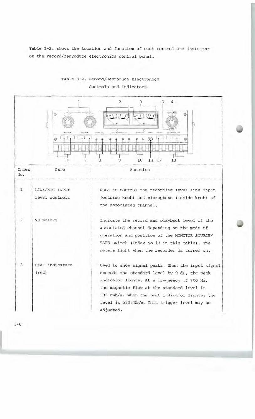
(4) Adjust the desired LINE/MIC INPUT level control(s) so that the VU
meter(s) indicates 0 for most audio peaks. (It is advisable to adjust
the channel input levels so that the peak indicator lamps, located
in the VU meter housings, blink occasionally.)
(5) Push the reel rotation counter pushbutton to reset the counter to
"0000".
(6) Press the PLAY and RECORD pushbuttons simultaneously to start recording
on the selected channel(s). The tape transport RECORD indicator will
cease blinking and instead will light continuously.
(7) While recording, the input signal of each channel can be compared
with the signal reproduced on each channel by pressing the MONITOR
switch to the "in" TAPE position.
(8) After recording is complete, but while still in the record mode,
once again press the PLAY pushbutton to enter directly into the
play mode without stopping the tape transport (punch out) .
After punching outs, if desired, press the RECORD pushbutton to
enter directly into the record mode without stopping the tape
transport (punch in). If further recording is not necessary, press
the STOP pushbutton to stop tape motion and deactivate the record
mode.
(9) This unit has the following three record mode capabilities.
i) Microphon conne ction(s).
Note: Set the MIC. ATT. switch on the rear panel to either the
"0 dB" or "-20 dB" position in accordance with the micro
phone input level.
3-12
li) Line connection(s).
Note: Check that the MIC. ATT. switch is set to the "OFF"
position to avoid noise from the microphone amplifier.
lli)Microphone(s) and line(s) connection
Note: Mic and line mixing recording may be carried out.
3-2- (5) . RECORDING WITH SELECTIVE REPRODUCTION
The selective reproduction function causes the reproduced audio to be
taken from the record head rather than from the reproduce head. This
permits a recording to be made on another channel synchronized ( in
phase ) with the channel being reproduced. To record with selective
reproduction, proceed as follows.
(1) Perform all steps in the pre-operating procedure.
(2) Perform all steps in the normal recording procedure for the channel
to be prerecorded.
(3) Rewind the tape to the point where selective reproduction is to
begin.
(4) Set the selective reproduction (SEL/REP) switch to the "in" position
corresponding to the channel to be monitored while the recording is
being made.
(5) Set the RECORD selector switch to the "in" position corresponding
to the channel to be recorded.
(6) Set the MONITOR selector switch to the TAPE "in" position correspond
ing to the channel being monitored.
(7) Set the MONITOR selector switch to the SOURCE "out" position corre
sponding to the channel to be recorded.
(8) Adjust the LINE/MIC INPUT level control so that the VU meter indicates
o for most audio peaks. (It is advisable to adjust the channel out
put levels so that the peak indicator lamps, located in the VU meter
housings, blink occasionally.)
(9) Press the PLAY pus hbutton to start tape motion. At the point where
overdub is desired press the RECORD pushbuttons to start recording
on the selected channel(s).
3-13
(lO)When recording is complete, press the STOP pushbutton to stop tape
motion and deactivate the record mode, or punch-out by pressing the
PLAY pushbutton.
Notes:
(1) If this unit is a full-track model, the SEL.REP. function is not
included.
(2) The pitch control is used to finely adjust one track with another
track(s). It can be used in both the Record and Reproduce modes.
(3) The SEL. REP. mode has priority over the Record mode in this unit.
(While the SEL. REP. pushbutton(s) is (are) pushed, the associated
channel(s) can not enter the record mode.)
3-14
3-2-(6). FAST WINDING
For fast-winding operations, and for editing or cueing, press the F.FWD
or REWIND pushbutton as appropriate. These pushbuttons can be pressed
alternately without having to press the STOP pushbutton between rast
winding operations. These modes may be entered into from any other mode
except the edit mode. Pressing PLAY during a fast-winding mode causes
the tape to automatically come to a stop and then enter into the play
mode. In a fast-winding mode, the tape lifters are automatically actu
ated and lift the tape away from the heads. To monitor the tape in a
fast-winding mode, the position of the tape-lifters can be varied by
operation of the CUE lever. Thus the distance of the tape from the heads
may be varied to control the signal level from the tape.
3-2-(7). EDITING AND SPLICING TAPE
For editing and splicing operations, the CUE lever can be used in fast
winding modes to quickly locate the desired program material. In addition,
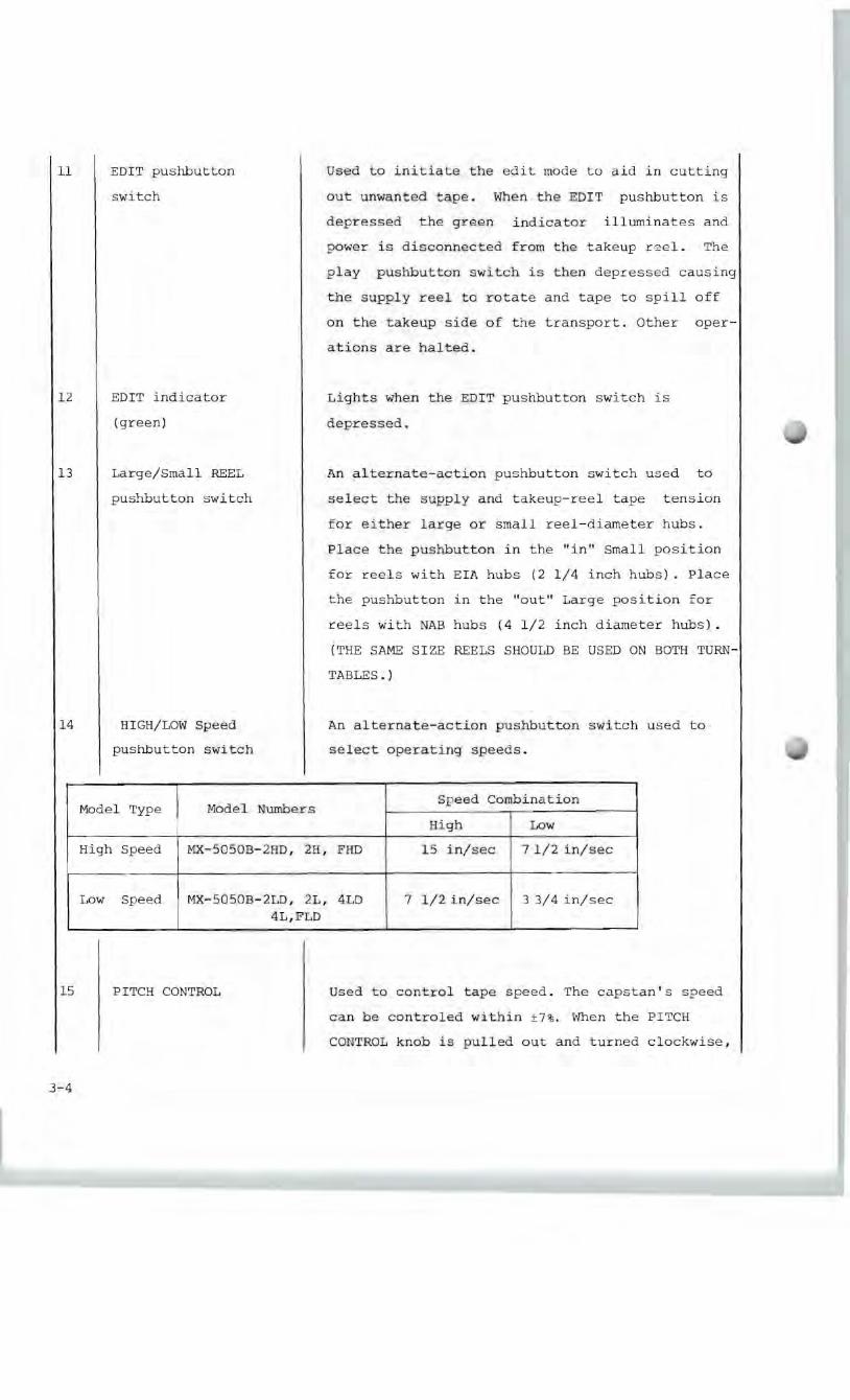
there is a EDIT mode of operation, used as follows:
Depressing the EDIT pushbutton while in the play mode removes power
from the takeup reel and causes the tape to be spilled off on the
take up side of the transport. This mode is used to fasilitate cutting
out unwanted tape. The edit mode can also be entered into from the
stop mode by pressing the PLAY pushbutton while the EDIT pushbutton
is in its depressed position.
The tape-splicing block (Fig. 3-3.) mounted on the head cover can be used
to hold the tape for ease in cutting the tape with a single-edged razor
blade and applying splicing tape. Use 7/32-inch splicing tape wide (3M
Co., No.4l) and never use collophane tape.
3-15
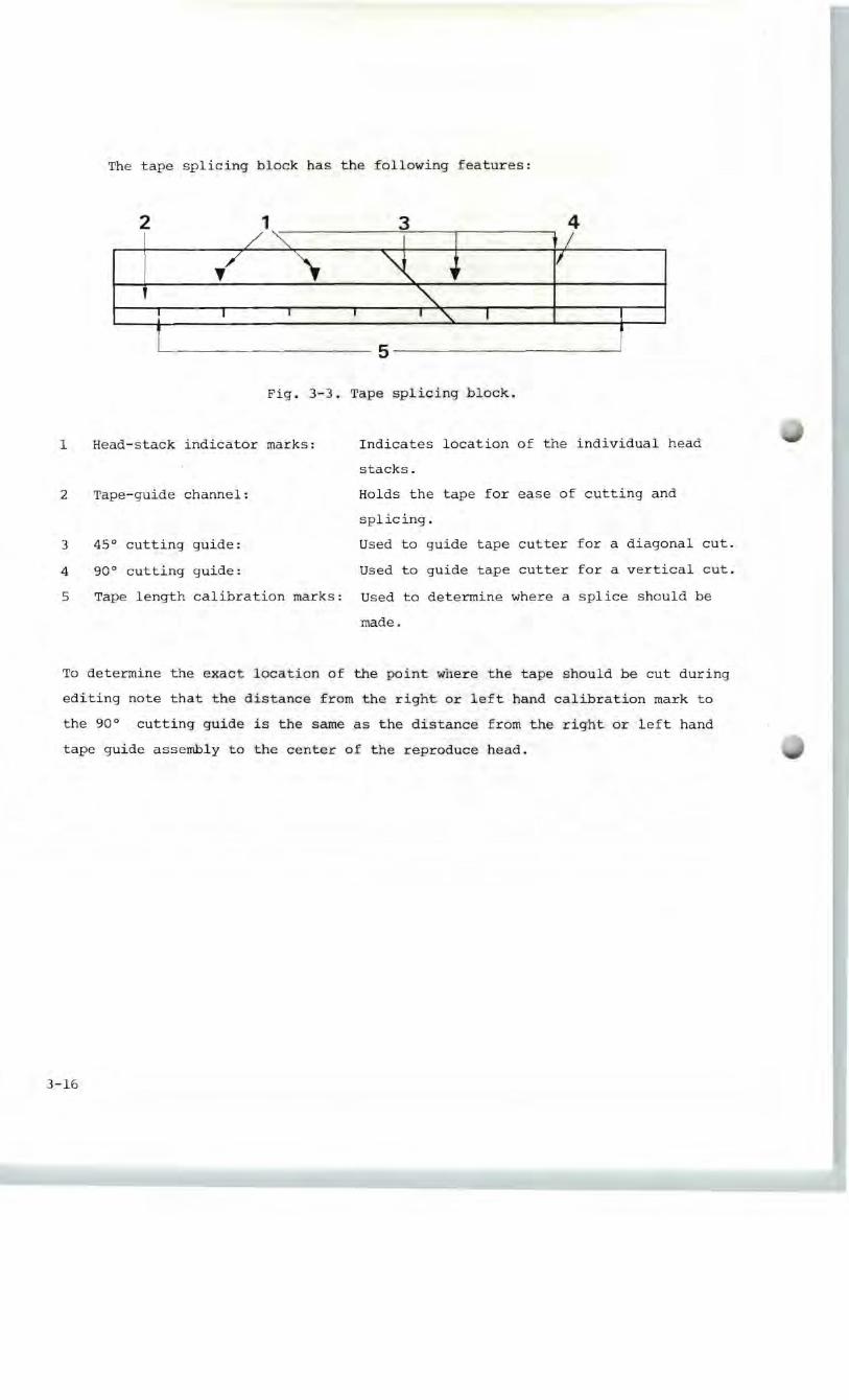

Table 4-1. Test and Maintenance Items
Item Suggested Model Used for
Head cleaner Ampex 087-007 Cleaning the heads
Isopropyl Any (Otari Cleaning Cleaning the tape guides,
alcohol Kit Ty-502 contains
the above cleaning
materials. )
capstan, and capstan pitch
roller
Head demag
netizer
Any Demagnetizing the heads and
tape guides
Lubricating
oil
Mobil DTE Heavy
Medium
Anderol #456
Lublicating the capstan of
the hysteresis synchronous
motor
Lubricating the capstan of the
dc servo control motor.
Reproduction
alignment tape
NAB
3 3/4 ips:
MRL 21F10l
7 1/2 ips:
MRL 21T204
15 ips:
MRL 21J205
lEC
7 1/2 ips:
MRL 21T302
15 ips:
MRL 21J303
Setting the operating standard
reference levels.
Audio Oscillator
20 to 20 kHz
Hewlett-Packard 204C
or 209D
Setting record equalization
Ac volt meter Hewlett-packard 400L
or 400FL
Setting record and playback
frequency Response
4-2
4-3. ELECTRONIC ALIGNMENT
Electronic alignment consists of setting the record bias, and setting
the record equalization and record level. Note that the reproduction
adjustments must be performed before making the recording adjustments.
These electronic adjustments should be performed at regularly scheduled
intervals, and when changing from one type of recording tape to another.
4-3- (1) • RECORD BIAS ADJUSTMENT
For optimum performance, biasing should be done using the type of tape
that will normally be used. To set the bias level, carry out the follow
ing procedure for each channel.
(1) Thread bulk-erased tape on to the recorder.
(2) Set the SRL calibration switch to the SRL position. Set the SPEED
switch to the "7 1/2" position.
(3) Start the tape in the record mode.
(4) Press the TEST OSC pushbutton and set the record level control for
a 0 reading on the VU meters.
(5) Adjust the RECORD BIAS adjustment trim pot for a maximum reading
on the VU meters.
4-3-(2). RECORD LEVEL ADJUSTMENT
(1) Set the Record level switch to the "H","M",or"L" position according
to the tape being used or the equalization standard.
(2) Thread bulk-erased tape on to the recorder.
(3) Set the SRL. calibration switch to the "SRL" position and the
Monitor switch to the "SOURCE" position.
(4) Pushing the TEST OSC pushbutton, adjust the line input levels so
that the VU meters indicate 0 VU.
(5) Change the mode of the Monitor switch from "SOURCE" to "TAPE".
(6) Start the tape in the record mode, and adjust the appropriate
RECORD LEVEL adjustment trim pot so that the VU meter indicates
o VU.
4-6