
An Energy Security Strategy for Romania: Promoting Energy Efficiency and Renewable Energy Sources

Optimization of Hybrid Systems with Renewable Energy Sources : Trends for Research
Gilles Notton Vladimir Lazarov Zahari Zarkov Ludmil Stoyanov
Renewable Energy Team - SPE Laboratory University of Corsica – UMR CNRS 6134
Scientific Centre of Vignola Route des Sanguinaires- F20000 Ajaccio
FRANCE
Faculty of Electrical Engineering Technical University of Sofia
8, Kl. Ochridski Blvd 1000 Sofia,
BULGARIA [email protected] [email protected] [email protected] [email protected]
Abstract – The paper deals with the sizing and optimization of the hybrid systems with renewable energy sources. The classification according to different criteria has been made. The examples of optimization linked with different case studies are shown. Flexible hybrid system of renewable energy sources for validation of the optimization procedures and results is also shown. On the bases of the discussions future trends for research are shown.
I. INTRODUCTION
The development of new ideas for energy production namely the conception of distributed generation increases the interest linked with renewable energy sources and the hybrid systems.
The following definition of a hybrid system with renewable energy sources (HSRES) can be suggested. This is a power system, using one renewable and one conventional energy source or more than one renewable with or without conventional energy sources, that works in “stand alone” or “grid connected” mode [1], [2], [3]. The National electrical energy system is a hybrid system.
HSRES are used for energy production for distant, not connected to the common electrical distribution system objects, e.g. distribution systems for small islands, villages, hotels, houses [4], [5], [6], as well as the supply of telecommunication, meteorological and other stations, research laboratories, etc. In connection with the distributed generation, these systems are being more widely used as grid-connected systems. Their undisputed advantage is the more efficient way of use of the disposable renewable energy resources.
II. CLASSIFICATION OF OPTIMIZATION TASKS
The classification of the optimizations tasks should be
done according different criterions: - According to the system components:
• Each component separately; • The system as whole (comprising two or
more components); • Optimal energy control;
- According to different parameters: • Investment cost, output energy cost; • System sustainability; • Consumption of primary energy resources
including fuel;
III. OPTIMIZING AND MODELLING
To find an optimal configuration and control of HSRES
an analysis of the multifactor target functions should be conducted. Some of those functions are:
A. Cost of energy
,...),,,,,,,( iiiiii PTREQFCOFnCULfCOE = (1) where L – Energy consumption, CUi – Overall cost of each
unit, ni – Number of the units of the same type, COFi – Cost of the fuel, QFi – Fuel consumption of the units €/kWh, RE – Available renewable energy, Ti – Life of the unit, Pi – Rated power of the units.
The return on investment is inversely proportional to the cost of energy, i.e. minimizing the energy cost leads to maximizing the yield upon investment.
B. System sustainability
The objective is to find a configuration with maximum
stability, i.e. minimum number of supply interruptions. ,...),,,,( maxmin SESEPRELfErr ii= (2)
where Err– Number of supply interruptions, Li – Load with its own priority, RE – Renewable energy, Pi – Power of the unit, SEmin, SEmax – Minimum/ maximum stored energy. C. Fuel consumption / Use of RES
The objective is to find a configuration with maximum use
of renewable energy and minimum fuel consumption. ,...)),,,,(max( maxmin SESEPRELfREU i= (3)
,...)),,,,(min( maxmin SESEPRELfFC i= (4)
Optimisation done according to this criterion increases the ecological conformity of the system, but at the same time reduces its stability and leads to a rise of the overall cost.
It is possible to combine different optimisation criteria – for example (1) and (2). In this case the target function is:
opt(min(COE),min(Err)) (5) It is also possible to charge different importance to every
criterion, which will lend variety to the operation modes of the hybrid system.
The above-mentioned arguments considering target functions are the most important factors, which those
1441-4244-0232-8/06/$20.00 ©2006 IEEE
functions depend on. Modelling of a hybrid system means creating a computer
model of its components, as well as of the factors that influence it [10]. The modelling and simulation of an already designed or still being designed system allow its behaviour to be examined for a given period of time under different circumstances.
Some simulations can be performed by specialized software. Several products that simulate and optimize hybrid systems are listed below:
- Hybrid2 - Hybrid2 is designed to study a variety of hybrid power systems with different components. The program also includes economic analysis tool. The results are provided in two levels of output, a summary and a detailed time step by time step description of power flows [10].
- HOMER (Hybrid Optimization Model for Electric Renewables) - It is a computer modelling software, that models the operation of both off-grid and grid-connected power systems for remote, stand-alone, and distributed generation. The package models both conventional and renewable energy technologies. It performs optimisation and sensitivity algorithms that allow choosing a better configuration of the designed system.
- RAPSIM (Remote Area Power Supply Simulator) - A computer modelling product, designed to simulate alternative power supply options. The program helps sizing PV, wind, diesel stand-alone and hybrid systems.
The control strategies and techniques are also subject of study. In general they should be combined with the sizing optimization.
When controlling the energy systems with RES, it should be taken into account that a part of the input indicators cannot be controlled. This imposes some limits and determines the introduction of feedbacks in order to increase the system stability. The control can be centralised, scattered on the units or combined.
Batteries, generator with conventional fuel and their joint work are more often subject to control. However, the control system can be even more complicated.
According to their course of action, control systems are determined as passive or active.
Passive systems are used with the simple HSRES. Most of the existing systems are passive; they work on the “on/off” principle.
Active systems are used with HSRES consisting of a large number of components. They measure and calculate the input data (meteorological, energy flows). These systems are flexible and can work in different modes.
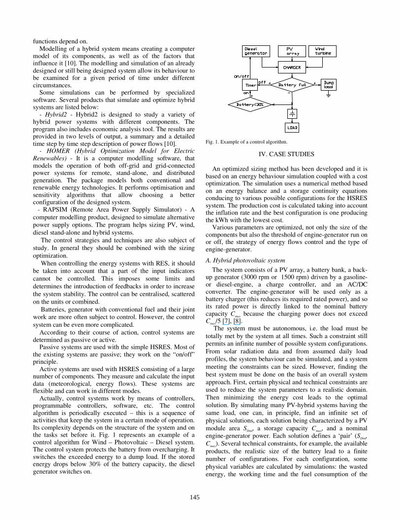
Actually, control systems work by means of controllers, programmable controllers, software, etc. The control algorithm is periodically executed – this is a sequence of activities that keep the system in a certain mode of operation. Its complexity depends on the structure of the system and on the tasks set before it. Fig. 1 represents an example of a control algorithm for Wind – Photovoltaic – Diesel system. The control system protects the battery from overcharging. It switches the exceeded energy to a dump load. If the stored energy drops below 30% of the battery capacity, the diesel generator switches on.
Fig. 1. Example of a control algorithm.
IV. CASE STUDIES
An optimized sizing method has been developed and it is based on an energy behaviour simulation coupled with a cost optimization. The simulation uses a numerical method based on an energy balance and a storage continuity equations conducing to various possible configurations for the HSRES system. The production cost is calculated taking into account the inflation rate and the best configuration is one producing the kWh with the lowest cost.
Various parameters are optimized, not only the size of the components but also the threshold of engine-generator run on or off, the strategy of energy flows control and the type of engine-generator.
A. Hybrid photovoltaic system
The system consists of a PV array, a battery bank, a back-up generator (3000 rpm or 1500 rpm) driven by a gasoline- or diesel-engine, a charge controller, and an AC/DC converter. The engine-generator will be used only as a battery charger (this reduces its required rated power), and so its rated power is directly linked to the nominal battery capacity Cmax because the charging power does not exceed Cmax/5 [7], [8].
The system must be autonomous, i.e. the load must be totally met by the system at all times. Such a constraint still permits an infinite number of possible system configurations. From solar radiation data and from assumed daily load profiles, the system behaviour can be simulated, and a system meeting the constraints can be sized. However, finding the best system must be done on the basis of an overall system approach. First, certain physical and technical constraints are used to reduce the system parameters to a realistic domain. Then minimizing the energy cost leads to the optimal solution. By simulating many PV-hybrid systems having the same load, one can, in principle, find an infinite set of physical solutions, each solution being characterized by a PV module area SDim, a storage capacity Cmax, and a nominal engine-generator power. Each solution defines a ‘pair’ (SDim, Cmax). Several technical constraints, for example, the available products, the realistic size of the battery lead to a finite number of configurations. For each configuration, some physical variables are calculated by simulations: the wasted energy, the working time and the fuel consumption of the
145
engine-generator, and the times when certain subsystems need replacement. The wasted energy is defined as:
( ) ( ) ( )[ ]∑ −=
>>
Max
LPV
CCPP
LPV dttPtPTWE (6)
It is the energy produced by the PV array when the battery capacity C has reached its maximal capacity Cmax and the power of the load PL does not need the total power of the photovoltaic PPV.
The working time and the fuel consumption QV of the engine-generator are determined by:
−+
=
0
0
00
0
01
vvgrvvgrv
v
QPCIP
PP
QPCIP
Q
Q
ηη (7)
where P0 and Q0 are respectively the rated power and the fuel consumption at this rated power, PCIV is heating value of fuel (kWh/l) which has a value equal to respectively 10.081 kWh/l and 9.432 kWh/l for diesel and gasoline. ηgr is engine efficiency equal to 41.6%.
The times when certain subsystems need replacement are sometimes constant (as for the electronic devices), sometimes depending on the running time (as for the engine generator). The energy cost is then computed for each pair, and the minimization of this parameter yields the optimal operating configuration.
To illustrate the battery energy state evolution as a function of the engine-generator running thresholds Fig. 2 shows the stored energy as a function of time, over five days. Assumed parameter settings for the figures are as follows: C = 2 days, the initial charge on the battery is 100% of the capacity, dimensionless PV module surface is 0.94, starting threshold SDM=30% and stopping threshold SAR=50%, 70% and 100%. Also, the ‘Low Consumption’ load profile (provided by ‘adapted’ or ‘high efficiency’ appliances) was used, and a gasoline engine was assumed.
Fig. 2. Evolution of the battery state of charge for several values of the thresholds SDM and SAR governing the operation of the engine-generator.
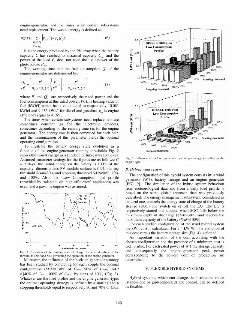
Moreover, the influence of the back-up generator strategy has been studied by computing for each couple the optimal configuration (SDM∈[30% of Cmax, 90% of Cmax], SAR ∈[40% of Cmax, 100% of Cmax] by steps of 10%) (Fig. 3). Whatever are the load profile and the engine generator type, the optimal operating strategy is defined by a starting and a stopping thresholds equal to respectively 30 and 70% of Cmax.
Fig. 3. Influence of back-up generator operating strategy according to the engine type. B. Hybrid wind system
The configuration of this hybrid system consists in: a wind generator (WT), battery storage and an engine generator (EG) [9]. The simulation of the hybrid system behaviour from meteorological data and from a daily load profile is based on the same global approach than was previously described. The energy management subsystem, considered as an ideal one, controls the energy state of charge of the battery storage (SOC) and switch on or off the EG. The EG is respectively started and stopped when SOC falls below the maximum depth of discharge (SDM=30%) and reaches the maximum capacity of the battery (SAR=100%).
For each studied configuration of the wind hybrid system the kWh cost is calculated. For a 4 kW WT the evolution of this cost versus the battery storage size (Fig. 4) is plotted.
An important variation of the cost according with the chosen configuration and the presence of a minimum cost is well visible. For each rated power of WT the storage capacity and consequently the engine-generator peak power corresponding to the lowest cost of production are determined.
V. FLEXIBLE HYBRID SYSTEMS
Hybrid systems, which can change their structure, mode
(stand-alone or grid-connected) and control, can be defined as flexible.
146

The Laboratory of Renewable Energy Sources in the Technical University of Sofia, Bulgaria, was created within the framework of Project TEMPUS 09704-94. Its main purpose is education and research. It disposes of an experimental flexible hybrid power system (Fig. 5), that comprises the following elements: digital meteorological station, wind generator, photovoltaic, lead-acid battery, inverter-rectifier, solar thermal collector with vacuum tubes, monitoring system based on hardware from National Instruments.
The system is flexible, because the disposal units can work in a different combination. Moreover, monitoring system has been developed [2]; it allows monitoring the operation of the hybrid system, as well as the meteorological conditions for a long period of time. The measured indicators (current, voltage, power, meteorological data, etc.) are kept in a database [3].
The collected information allows analyzing the system work under different weather conditions and operation modes, as well as choosing suitable control strategy.
A lot of experiments with the described hybrid system have been done. As example, the results for a period of 24 hours are presented thereinafter. It has to be mentioned that in order to increase the possibilities of the hybrid system the wind generator is simulated by a motor-generator group with an asynchronous generator of the same rated power. In that way is used the capability to explore the system behaviour having preliminary defined wind energy potential.
Fig. 6 shows the graphs of the powers produced by the wind generator Pwg, the photovoltaic Ppv and the total power Ptot:
pvwgtot PPP += (8)
Fig. 7 shows the results for the produced energy respectively from the wind generator Ewg and from the photovoltaic Epv. Under the existing conditions the total produced energy from all the sources is Eprod = 3.615 kWh and the consumed energy is Econs = 4.86 kWh. The difference Eprod – Econs is Etot = -1.245 kWh (Fig. 8). This result is negative because the produced energy is smaller than the consumed one. This means that the battery has lost 1.245 kWh of its energy during the period in order to supply the loads.
The flexibility of the described hybrid system allows research of different unit combinations and development of methods for design and control under different conditions, as well as validation of the results.
1.561.48
1.741.77
1.61
1.83
1,4
1,6
1,8
2
2,2
2,4
2,6
2,8
3
3,2
0 1 2 3 4 5 6 7 8Storage capacity (days of autonomy)
kWh
cost
(€)
Gasoline generator
Diesel 3000 rpm generator
Diesel 1500 rpm generator
black : WT type 1white : WT type 2
Fig. 4. kWh cost versus storage capacity for a 4 kW WT.
147

time,h 04:00 08:00 12:00 16:00 20:00
Pwg,W
0
500
1000
1500
time,h 04:00 08:00 12:00 16:00 20:00
Ptot,W
0
500
1000
1500
time,h 04:00 08:00 12:00 16:00 20:00
Ppv,W
050
100150200250
Fig. 6. Produced power from the wind generator Pwg, photovoltaic Ppv and total Ptot.
Ewg2,342kWh
65%
Epv 1,273kWh
35%
Fig. 7. Produced energy from the wind generator Ewg and the photovoltaic Epv.
Etot -1,245kWh
Econs 4,86kWh
Eprod 3,615kWh
-2
-1
0
1
2
3
4
5
1 2 3
E,kWh
Fig. 8. Produced energy Eprod, consumed energy Econs and total Etot.
VI. CONCLUSION
In this paper, the problem of optimization of hybrid systems with renewable energy sources is considered. The
Wind turbine
Rectifier
Inverter
Battery Storage
PV array
Three-phaseAC loads
Charge controller
DC loads
AC loads
Thermal collector
Boiler
Convector
Pump 2Pump 1
Monitoring andcontrol system
Synopticstation
Meteorological data
Control signals
Measurements fromthe hybrid system
Fuel cells
SMES
DC bus 24V
AC bus 220V
Fig. 5. Flexible experimental hybrid system of a mixed type.
148

classification of the optimization approaches is presented. In recent years, a trend to a decrease in the cost of
renewable energy technologies has been observed, which comes together with the arisen tendency towards distributed generation of energy. Those two factors provide the opportunity that many solutions to be reconsidered with the increasing of the complicity of the hybrid systems. One of them is the global energy approach combining the electrical ant thermal energy consideration.
The main conclusions of the discussed topics is the need of further research on the RES hybrid systems and the creation of optimization tools for complex hybrid systems, from where solution for different more simple may be deduced. The optimization procedure may combine the control strategies also.
The creation of flexible experimental systems increases the possibility to validate the obtained results.
VII. ACKNOWLEDGMENT
The authors want to thank the French Agency for Energy
Management ADEME and the French Foreign Affair Ministry for their financial contribution by the means of the Renewable Energy Research Network ADEME for European Central and Oriental Countries. This research network allowed to develop a fruitful and strong collaboration between Bulgarian and French teams.
VIII. REFERENCES
[1] V. D. Lazarov, G. Notton, Z. Zarkov, and I. Bochev,
"Hybrid power systems with renewable energy sources – types, structures, trends for research and development," in Proc. of Int. Conf. ELMA2005, Sofia, Bulgaria, 2005, pp. 515-520.
[2] V. D. Lazarov and Z. Zarkov, "Monitoring of renewable energy sources hybrid system," in Proc. of Int. Conf. ICATE’2002, Craiova/Baile Herculane, Romania, pp. 224-229, 2002.
[3] Z. Zarkov and V. D. Lazarov, "Energy balance of a hybrid renewable energy sources system," in Proc. of Int. Conf. ICATE’2004, Baile Herculane, Romania, pp. 291-296, 2004.
[4] M. Landau and R. Geipel, "Modulare PV-Hybridsysteme für netzferne Gebiete - Pilotanlagen Kythnos und Starkenburger Hütte," presented at the Kasseler Symposium Energie–Systemtechnik, Germany, 2004.
[5] S. Drouilhet and M. Shirazi, "Wales, Alaska high-penetration wind-diesel hybrid power system," NREL, Tech. Rep., May. 2002.
[6] Ph. Strauss and A. Engler, "AC coupled PV hybrid systems and microgrids – state of the art and future trends," in Proc. of 3-rd World Conference on Photovoltaic Energy Conversion, Osaka, Japan, May. 2003.
[7] M. Muselli, G. Notton, and A. Louche, "Design of hybrid-photovoltaic power generator, with optimization of energy management," Solar Energy, vol. 65, No. 3, pp. 143-157, 1999.
[8] M. Muselli, G. Notton, P. Poggi, and A. Louche, "PV-hybrid power systems sizing incorporating r\battery storage: an analysis via simulation calculations," Renewable Energy, 20, pp. 1-7, 2000.
[9] G. Notton, C. Cristofari, P. Poggi, M. Muselli, “Wind electrical supply system: behaviour simulation and sizing optimization,” Wind Energy, 4-2, 43-59, 2001.
[10] J. Manwell, A. Rogers et al., Hybrid 2 – a hybrid system simulation model. Theory manual, NREL, 1998.
149
Copyright © 2022 FDOKUMEN