Optimal parameters for final position of teeth in space closure ...
12
RESEARCH Open Access Optimal parameters for final position of teeth in space closure in case of a missing upper lateral incisor Luca Lombardo * , Antonio D′Ercole, Michele Carmelo Latini and Giuseppe Siciliani Abstract Background: The aim of this study was to provide clinical indications for the correct management of appliances in space closure treatment of patients with agenesis of the upper lateral incisors. Methods: Virtual setup for space closure was performed in 30 patients with upper lateral incisor agenesis. Tip, torque and in-out values were measured and compared with those of previous authors. Results: In the upper dentition, the tip values were comparable to those described by Andrews (Am J Orthod 62 (3):296-309, 1972), except for at the first premolars, which require a greater tip, and the first molars, a lesser tip. The torque values showed no differences except for at the canines, where it was greater, and the in-out values were between those reported by Andrews and those by Watanabe et al. (The Shikwa Gakuho 96:209-222, 1996) (except for U3 and U4). Conclusions: The following prescriptions are advisable: tip 5°, torque 8° and in-out 2.5 for U1; tip 9°, torque 3° and in-out 3.25 for U3; tip 10°, torque -8° and in-out 3.75 for U4; and tip 5°, torque -8° and in-out 4 for U5. Andrews' prescription is suitable for the lower jaw, except for at L6. It is also advisable to execute selective grinding (1.33 ± 0.5 mm) and extrusion (0.68 ± 0.23 mm) on the upper canine during treatment, and the first premolar requires some intrusion (0.56 ± 0.30 mm). Keywords: Set up; Missing lateral; Space closure Background Agenesis of the upper lateral incisor occurs in roughly 2% of the population [1-4] and comprises 20% of all cases of agenesis [5]. The choice of treatment is influ- enced by a series of parameters linked to the patient's profile, the type of malocclusion, the shape and size of the teeth and the periodontal biotype [6-9]. There are two major treatment options for upper lateral incisor pa- tients, namely space closure and canine substitution of the missing lateral incisor, or space opening and filling with a prosthetic implant. However, in the anterior sector, the prosthetic option may not be the best solu- tion and cannot be considered a permanent treatment. Indeed, although single implants have relatively long lifespan, they may give rise to biological complications in the long term, for instance, an increase in infraocclu- sion progression rate [10-14], blue colouring of the labial gingiva [15], abutment exposure [12] and distal papilla recession [15,16]. Hence, space closure is the pre- ferred option for many dentists. Nevertheless, this solution does present some prob- lems, predominantly in clinical management of the an- terior sector. In particular, issues may arise in terms of correct levelling of the marginal gingival contours, as well as achieving the right degree of angulation and in- clination on the crowns [8,17-20]. In an ideal upper gin- gival line, the gingival margins of the central incisors and canines are at the same level [18], with the gingival contours at the lateral incisors being roughly 1 mm lower than the line between these. To prevent an un- sightly gingival line, therefore, it is necessary to extrude the canine and, at the same time, intrude the first * Correspondence: [email protected] Postgraduate School of Orthodontics, Ferrara University, Via Montebello, 31, Ferrara 44121, Italy © 2014 Lombardo et al.; licensee Springer. This is an Open Access article distributed under the terms of the Creative Commons Attribution License (http://creativecommons.org/licenses/by/4.0), which permits unrestricted use, distribution, and reproduction in any medium, provided the original work is properly cited. Lombardo et al. Progress in Orthodontics 2014, 15:63 http://www.progressinorthodontics.com/content/15/1/63
-
Upload
khangminh22 -
Category
Documents
-
view
2 -
download
0
Transcript of Optimal parameters for final position of teeth in space closure ...

Lombardo et al. Progress in Orthodontics 2014, 15:63http://www.progressinorthodontics.com/content/15/1/63
RESEARCH Open Access
Optimal parameters for final position of teeth inspace closure in case of a missing upper lateralincisorLuca Lombardo*, Antonio D′Ercole, Michele Carmelo Latini and Giuseppe Siciliani
Abstract
Background: The aim of this study was to provide clinical indications for the correct management of appliances inspace closure treatment of patients with agenesis of the upper lateral incisors.
Methods: Virtual setup for space closure was performed in 30 patients with upper lateral incisor agenesis. Tip,torque and in-out values were measured and compared with those of previous authors.
Results: In the upper dentition, the tip values were comparable to those described by Andrews (Am J Orthod 62(3):296-309, 1972), except for at the first premolars, which require a greater tip, and the first molars, a lesser tip. Thetorque values showed no differences except for at the canines, where it was greater, and the in-out values werebetween those reported by Andrews and those by Watanabe et al. (The Shikwa Gakuho 96:209-222, 1996) (exceptfor U3 and U4).
Conclusions: The following prescriptions are advisable: tip 5°, torque 8° and in-out 2.5 for U1; tip 9°, torque 3° andin-out 3.25 for U3; tip 10°, torque −8° and in-out 3.75 for U4; and tip 5°, torque −8° and in-out 4 for U5. Andrews'prescription is suitable for the lower jaw, except for at L6. It is also advisable to execute selective grinding (1.33 ± 0.5 mm)and extrusion (0.68 ± 0.23 mm) on the upper canine during treatment, and the first premolar requires some intrusion(0.56 ± 0.30 mm).
Keywords: Set up; Missing lateral; Space closure
BackgroundAgenesis of the upper lateral incisor occurs in roughly2% of the population [1-4] and comprises 20% of allcases of agenesis [5]. The choice of treatment is influ-enced by a series of parameters linked to the patient'sprofile, the type of malocclusion, the shape and size ofthe teeth and the periodontal biotype [6-9]. There aretwo major treatment options for upper lateral incisor pa-tients, namely space closure and canine substitution ofthe missing lateral incisor, or space opening and fillingwith a prosthetic implant. However, in the anteriorsector, the prosthetic option may not be the best solu-tion and cannot be considered a permanent treatment.Indeed, although single implants have relatively long
* Correspondence: [email protected] School of Orthodontics, Ferrara University, Via Montebello, 31,Ferrara 44121, Italy
© 2014 Lombardo et al.; licensee Springer. ThisAttribution License (http://creativecommons.orin any medium, provided the original work is p
lifespan, they may give rise to biological complicationsin the long term, for instance, an increase in infraocclu-sion progression rate [10-14], blue colouring of thelabial gingiva [15], abutment exposure [12] and distalpapilla recession [15,16]. Hence, space closure is the pre-ferred option for many dentists.Nevertheless, this solution does present some prob-
lems, predominantly in clinical management of the an-terior sector. In particular, issues may arise in terms ofcorrect levelling of the marginal gingival contours, aswell as achieving the right degree of angulation and in-clination on the crowns [8,17-20]. In an ideal upper gin-gival line, the gingival margins of the central incisorsand canines are at the same level [18], with the gingivalcontours at the lateral incisors being roughly 1 mmlower than the line between these. To prevent an un-sightly gingival line, therefore, it is necessary to extrudethe canine and, at the same time, intrude the first
is an Open Access article distributed under the terms of the Creative Commonsg/licenses/by/4.0), which permits unrestricted use, distribution, and reproductionroperly cited.

Figure 1 Determination of the occlusal plane and medianraphe (upper jaw).
Table 1 Arch form
Upper (mm) Lower (mm)
Inter-canine diameter 39 29
Canine depth 9.1 5.1
Inter-molar diameter 55 51
Molar depth 31.4 26.6
Lombardo et al. Progress in Orthodontics 2014, 15:63 Page 2 of 12http://www.progressinorthodontics.com/content/15/1/63
premolar [19]. In practical terms, this means either thatfirst-, second- and third-order bends will need to be ap-plied to the wire or that the brackets will have to berepositioned several times.Although in the past many researchers have addressed
the various methods of treatment used in lateral incisoragenesis [6-9,21], the literature published to date con-tains no study using digital setup software to evaluatethe optimal parameters for space closure. We have con-ducted this study with the aim of providing evidence-based clinical indications for good clinical managementof these cases. The idea was to exploit digital setup
Figure 2 Determination of the occlusal plane and medianraphe (lower jaw).
technology to calculate such parameters in patients withlateral incisor agenesis treated by means of space clos-ure, calculating the optimal tip, torque and in-out foreach tooth in both arches, as well as the amount of se-lective grinding to be performed on the palatal surfaceof the canine after extrusion, the inter-premolar andinter-molar distances of the treated arches - controllingthe change in arch shape after setup - and, finally, theamount of canine extrusion and premolar intrusion ne-cessary to create an optimal gingival line.
MethodsSample characteristicsThirty Caucasian patients with lateral incisor agenesiswere selected. The sample comprised 16 males and 14females of mean age 19.6 (SD 4.8). Initial plaster modelsand bite wafers were collected for each patient, and se-lection was performed according to the following cri-teria: unilateral or bilateral agenesis of the upper lateralincisor, presence of all other teeth except for the second(lost prematurely in some patient) and third molars,absence of other agenetic teeth, complete eruption,absence of bridges or implants, ectopic teeth andsupernumerary teeth. In our sample, the mean overjetwas 2.11 mm (SD 2.15) and the mean overbite2.12 mm (SD 2.31).The plaster models of each patient were scanned using
an optical 3D scanner (reVeng Orthodontic, Vision USADentrex Company, Cherry Hill, NJ, USA) to obtain
Figure 3 Placement of FA point and FACC axis.

Figure 4 Final setup (in different views).
Lombardo et al. Progress in Orthodontics 2014, 15:63 Page 3 of 12http://www.progressinorthodontics.com/content/15/1/63
three-dimensional virtual models in STL. Numerous stud-ies have confirmed the reliability and precision of today'sdigital methods of handling virtual models [22-26].NemoCast 3D software (Nemotec, Madrid, Spain)
was used to prepare the models and their setups. Themodels were oriented in 3D Cartesian space (x, y and z) sothat the ideal occlusal plane was in the frontal view,parallel to the x and y axes and orthogonal to the zaxis. In the occlusal view, the ideal plane of themedian raphe is parallel to the z and y axes and or-thogonal to the x axis.
Figure 5 Occlusal interferences. The selected teeth are represented in gr
Three landmarks were identified and used to correctlyposition the occlusal plane:
� The most occlusal tip of the cusp of the most distaltooth on the right
� The most occlusal tip of the cusp of the most distaltooth on the left
� The incisal margin of the central incisors
Once the occlusal plane was correctly positioned, weidentified the median raphe plane perpendicular to the
ey.

Figure 6 Measurement of the inter-canine and inter-molardiameters before setup.
Lombardo et al. Progress in Orthodontics 2014, 15:63 Page 4 of 12http://www.progressinorthodontics.com/content/15/1/63
upper occlusal plane, passing through the retro-incisivepapilla and the most distal point of the palatine medianraphe (Figures 1 and 2).When creating a setup, the arch form has a key role.
We opted for one most similar to that described as idealby Lombardo and Fattori [27]. Reference points basedon the inter-canine and inter-molar distances and thecanine and molar depths were used to plot the curve.A millimetric grid was then positioned on the occlusal
plane with the z axis coinciding with the palatine medianraphe and the point (0;0) which coincides with the inci-sal margin of the incisors. The arch form curve was thentraced through the following five points (Table 1):
� Point (0;0) on the grid� Inter-canine diameter point/2 (x); right and left
canine depths (y)� Inter-molar diameter point/2 (x); right and left
molar depths (y)
Figure 7 Measurement of the inter-canine and inter-molardiameters after setup.
The last step in the preparation phase involved seg-mentation of the models. This was performed by iden-tifying the most mesial and distal points of each toothin the occlusal view and allowing the software to cre-ate the corresponding tooth axis automatically. Thecrowns were then segmented from the gingiva at thegingival sulcus.Subsequently, as described by Andrews [28], the facial
axis (FA) points and their respective facial axes of theclinical crowns (FACC) were identified using both thefrontal and occlusal views for each tooth (Figure 3).The digital setup was then constructed using the fol-
lowing steps (Figure 4):
� Alignment of the lower arch according to thepre-established arch form
� Flattening of the lower curve of Spee� Programming the tip and torque values suggested by
Andrews for the lower teeth� Alignment of the upper arch according to the
identified arch form and space closure� Flattening of the upper curve of Spee� Programming the tip and torque values suggested by
Andrews for the upper teeth� Individual adjustment to create correct overbite and
overjet (between 1.5 and 2 mm) of anterior andposterior sectors and correct inter-cuspidation ofthe molars
� Positioning of the canines and first premolarsaccording to the indications suggested by Zachrissonand Rosa [8,19], i.e. extrusion of the canine andintrusion of the first premolar to create the idealgingival architecture, and canine torque most similarto that of a lateral incisor to eliminate the canineeminence, which would instead be re-created at thefirst premolar, increasing the negative torque
Finally, by means of the ‘occlusogram’ function (allow-ing to calculate the amount of superimposition betweenthe upper and lower arches), all intra- and inter-archcollisions were eliminated. The software then providedthe tip and torque values for each tooth on the finalsetup, reading the FACC values with respect to the oc-clusal plane. The in-out values were then calculated bymeans of the software's ‘linear measures’ function, usinga method similar to that described by Andrews [28].Each model was sectioned in the occlusal view on thehorizontal plane up to the areas of contact between theteeth. On this image, the segments uniting the most ves-tibular mesial and distal points with respect to the areaof contact of each tooth were identified. Another linearmeasurement was used to connect the FA point withthe respective segment identified previously. Once eachsetup was complete, the ‘occlusogram’ function was used
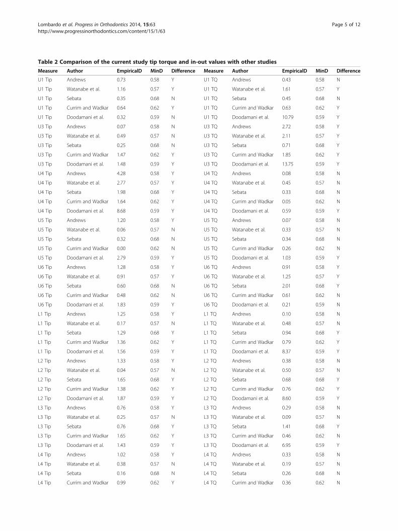
Table 2 Comparison of the current study tip torque and in-out values with other studies
Measure Author EmpiricalD MinD Difference Measure Author EmpiricalD MinD Difference
U1 Tip Andrews 0.73 0.58 Y U1 TQ Andrews 0.43 0.58 N
U1 Tip Watanabe et al. 1.16 0.57 Y U1 TQ Watanabe et al. 1.61 0.57 Y
U1 Tip Sebata 0.35 0.68 N U1 TQ Sebata 0.45 0.68 N
U1 Tip Currim and Wadkar 0.64 0.62 Y U1 TQ Currim and Wadkar 0.63 0.62 Y
U1 Tip Doodamani et al. 0.32 0.59 N U1 TQ Doodamani et al. 10.79 0.59 Y
U3 Tip Andrews 0.07 0.58 N U3 TQ Andrews 2.72 0.58 Y
U3 Tip Watanabe et al. 0.49 0.57 N U3 TQ Watanabe et al. 2.11 0.57 Y
U3 Tip Sebata 0.25 0.68 N U3 TQ Sebata 0.71 0.68 Y
U3 Tip Currim and Wadkar 1.47 0.62 Y U3 TQ Currim and Wadkar 1.85 0.62 Y
U3 Tip Doodamani et al. 1.48 0.59 Y U3 TQ Doodamani et al. 13.75 0.59 Y
U4 Tip Andrews 4.28 0.58 Y U4 TQ Andrews 0.08 0.58 N
U4 Tip Watanabe et al. 2.77 0.57 Y U4 TQ Watanabe et al. 0.45 0.57 N
U4 Tip Sebata 1.98 0.68 Y U4 TQ Sebata 0.33 0.68 N
U4 Tip Currim and Wadkar 1.64 0.62 Y U4 TQ Currim and Wadkar 0.05 0.62 N
U4 Tip Doodamani et al. 8.68 0.59 Y U4 TQ Doodamani et al. 0.59 0.59 Y
U5 Tip Andrews 1.20 0.58 Y U5 TQ Andrews 0.07 0.58 N
U5 Tip Watanabe et al. 0.06 0.57 N U5 TQ Watanabe et al. 0.33 0.57 N
U5 Tip Sebata 0.32 0.68 N U5 TQ Sebata 0.34 0.68 N
U5 Tip Currim and Wadkar 0.00 0.62 N U5 TQ Currim and Wadkar 0.26 0.62 N
U5 Tip Doodamani et al. 2.79 0.59 Y U5 TQ Doodamani et al. 1.03 0.59 Y
U6 Tip Andrews 1.28 0.58 Y U6 TQ Andrews 0.91 0.58 Y
U6 Tip Watanabe et al. 0.91 0.57 Y U6 TQ Watanabe et al. 1.25 0.57 Y
U6 Tip Sebata 0.60 0.68 N U6 TQ Sebata 2.01 0.68 Y
U6 Tip Currim and Wadkar 0.48 0.62 N U6 TQ Currim and Wadkar 0.61 0.62 N
U6 Tip Doodamani et al. 1.83 0.59 Y U6 TQ Doodamani et al. 0.21 0.59 N
L1 Tip Andrews 1.25 0.58 Y L1 TQ Andrews 0.10 0.58 N
L1 Tip Watanabe et al. 0.17 0.57 N L1 TQ Watanabe et al. 0.48 0.57 N
L1 Tip Sebata 1.29 0.68 Y L1 TQ Sebata 0.94 0.68 Y
L1 Tip Currim and Wadkar 1.36 0.62 Y L1 TQ Currim and Wadkar 0.79 0.62 Y
L1 Tip Doodamani et al. 1.56 0.59 Y L1 TQ Doodamani et al. 8.37 0.59 Y
L2 Tip Andrews 1.33 0.58 Y L2 TQ Andrews 0.38 0.58 N
L2 Tip Watanabe et al. 0.04 0.57 N L2 TQ Watanabe et al. 0.50 0.57 N
L2 Tip Sebata 1.65 0.68 Y L2 TQ Sebata 0.68 0.68 Y
L2 Tip Currim and Wadkar 1.38 0.62 Y L2 TQ Currim and Wadkar 0.76 0.62 Y
L2 Tip Doodamani et al. 1.87 0.59 Y L2 TQ Doodamani et al. 8.60 0.59 Y
L3 Tip Andrews 0.76 0.58 Y L3 TQ Andrews 0.29 0.58 N
L3 Tip Watanabe et al. 0.25 0.57 N L3 TQ Watanabe et al. 0.09 0.57 N
L3 Tip Sebata 0.76 0.68 Y L3 TQ Sebata 1.41 0.68 Y
L3 Tip Currim and Wadkar 1.65 0.62 Y L3 TQ Currim and Wadkar 0.46 0.62 N
L3 Tip Doodamani et al. 1.43 0.59 Y L3 TQ Doodamani et al. 6.95 0.59 Y
L4 Tip Andrews 1.02 0.58 Y L4 TQ Andrews 0.33 0.58 N
L4 Tip Watanabe et al. 0.38 0.57 N L4 TQ Watanabe et al. 0.19 0.57 N
L4 Tip Sebata 0.16 0.68 N L4 TQ Sebata 0.26 0.68 N
L4 Tip Currim and Wadkar 0.99 0.62 Y L4 TQ Currim and Wadkar 0.36 0.62 N
Lombardo et al. Progress in Orthodontics 2014, 15:63 Page 5 of 12http://www.progressinorthodontics.com/content/15/1/63

Table 2 Comparison of the current study tip torque and in-out values with other studies (Continued)
L4 Tip Doodamani et al. 1.29 0.59 Y L4 TQ Doodamani et al. 5.92 0.59 Y
L5 Tip Andrews 1.52 0.58 Y L5 TQ Andrews 0.25 0.58 N
L5 Tip Watanabe et al. 0.06 0.57 N L5 TQ Watanabe et al. 0.13 0.57 N
L5 Tip Sebata 0.77 0.68 Y L5 TQ Sebata 0.04 0.68 N
L5 Tip Currim and Wadkar 0.77 0.62 Y L5 TQ Currim and Wadkar 0.35 0.62 N
L5 Tip Doodamani et al. 1.61 0.59 Y L5 TQ Doodamani et al. 5.42 0.59 Y
L6 Tip Andrews 1.96 0.58 Y L6 TQ Andrews 0.27 0.58 N
L6 Tip Watanabe et al. 0.84 0.57 Y L6 TQ Watanabe et al. 0.23 0.57 N
L6 Tip Sebata 0.11 0.68 N L6 TQ Sebata 1.14 0.68 Y
L6 Tip Currim and Wadkar 1.09 0.62 Y L6 TQ Currim and Wadkar 0.38 0.62 N
L6 Tip Doodamani et al. 2.22 0.59 Y L6 TQ Doodamani et al. 6.76 0.59 Y
In out U1 Andrews 1.19 0.58 Y In out L1 Andrews 0.36 0.58 N
In out U1 Watanabe et al. 0.58 0.57 Y In out L1 Watanabe et al. 1.74 0.57 Y
In out U1 Currim and Wadkar 0.30 0.62 N In out L1 Currim and Wadkar 0.93 0.62 Y
In out U3 Andrews 1.25 0.58 Y In out L2 Andrews 0.81 0.58 Y
In out U3 Watanabe et al. 1.82 0.57 Y In out L2 Watanabe et al. 0.34 0.57 N
In out U3 Currim and Wadkar 0.39 0.62 N In out L2 Currim and Wadkar 0.29 0.62 N
In out U4 Andrews 3.07 0.58 Y In out L3 Andrews 1.00 0.58 Y
In out U4 Watanabe et al. 2.43 0.57 Y In out L3 Watanabe et al. 1.58 0.57 Y
In out U4 Currim and Wadkar 0.91 0.62 Y In out L3 Currim and Wadkar 0.66 0.62 Y
In out U5 Andrews 3.46 0.58 Y In out L4 Andrews 1.45 0.58 Y
In out U5 Watanabe et al. 1.47 0.57 Y In out L4 Watanabe et al. 2.15 0.57 Y
In out U5 Currim and Wadkar 1.14 0.62 Y In out L4 Currim and Wadkar 0.81 0.62 Y
In out U6 Andrews 3.85 0.58 Y In out L5 Andrews 2.71 0.58 Y
In out U6 Watanabe et al. 0.59 0.57 Y In out L5 Watanabe et al. 1.54 0.57 Y
In out U6 Currim and Wadkar 1.41 0.62 Y In out L5 Currim and Wadkar 1.22 0.62 Y
In out L6 Andrews 3.42 0.58 Y
In out L6 Watanabe et al. 1.13 0.57 Y
In out L6 Currim and Wadkar 1.90 0.62 Y
TQ, torque; Y, yes; N, no.
Table 3 Mean tip values
Mean (mm) SD (mm)
Tip U1 4.78 1.11
Tip U3 8.60 2.04
Tip U4 10.20 1.99
Tip U5 5.08 2.88
Tip U6 3.12 2.46
Tip L1 2.13 1.19
Tip L2 2.32 1.35
Tip L3 4.90 2.52
Tip L4 3.18 1.66
Tip L5 4.03 2.44
Tip L6 5.32 2.95
Table 4 Mean torque values
Mean (degree) SD (degree)
Torque U1 7.68 1.33
Torque U3 3.15 1.19
Torque U4 −8.18 2.31
Torque U5 −8.50 2.10
Torque U6 −15.30 4.94
Torque L1 −1.18 0.79
Torque L2 −1.40 0.81
Torque L3 −11.52 1.07
Torque L4 −17.45 1.33
Torque L5 −22.37 1.71
Torque L6 −32.15 3.41
Lombardo et al. Progress in Orthodontics 2014, 15:63 Page 6 of 12http://www.progressinorthodontics.com/content/15/1/63

Table 5 Mean in-out values
Mean (mm) SD (mm)
In-out U1 2.41 0.42
In-out U3 3.17 0.43
In-out U4 3.73 0.50
In-out U5 3.90 0.56
In-out U6 4.71 0.69
In-out L1 1.49 0.29
In-out L2 1.90 0.31
In-out L3 2.79 0.48
In-out L4 3.39 0.56
In-out L5 3.73 0.63
In-out L6 4.70 0.74
Table 7 Standard confidence intervals for tip, torque andin-out values
Measure L95 Mean (°) U95
U1 Tip 4.37 4.78 5.19
U2 Tip NA NA NA
U3 Tip 7.84 8.60 9.36
U4 Tip 9.46 10.20 10.94
U5 Tip 4.00 5.08 6.16
U6 Tip 2.20 3.12 4.04
L1 Tip 1.69 2.13 2.57
L2 Tip 1.82 2.32 2.82
L3 Tip 3.96 4.90 5.84
L4 Tip 2.56 3.18 3.80
L5 Tip 3.12 4.03 4.94
L6 Tip 4.22 5.32 6.42
U1 TQ 7.18 7.68 8.18
U2 TQ NA NA NA
U3 TQ 2.71 3.15 3.59
U4 TQ −9.04 −8.18 −7.32
U5 TQ −9.28 −8.50 −7.72
U6 TQ −17.14 −15.30 −13.46
L1 TQ −1.47 −1.18 −0.89
L2 TQ −1.70 −1.40 −1.10
L3 TQ −11.92 −11.52 −11.12
L4 TQ −17.95 −17.45 −16.95
L5 TQ −23.01 −22.37 −21.73
L6 TQ −33.42 −32.15 −30.88
In-out U1 2.26 2.42 (mm) 2.58
In-out U2 NA NA NA
In-out U3 3.01 3.17 3.33
In-out U4 3.54 3.73 3.92
In-out U5 3.69 3.90 4.11
In-out U6 4.45 4.71 4.97
In-out L1 1.38 1.49 1.60
In-out L2 1.78 1.90 2.02
In-out L3 2.61 2.79 2.97
In-out L4 3.18 3.39 3.60
In-out L5 3.49 3.73 3.97
In-out L6 4.42 4.70 4.98
Lombardo et al. Progress in Orthodontics 2014, 15:63 Page 7 of 12http://www.progressinorthodontics.com/content/15/1/63
to calculate the amount of grinding in millimetres re-quired at the inevitable pre-contacts between the palatalsurface of the upper canines and the lower lateral inci-sors and canines (Figure 5).Evaluation of the difference in transversal width at
both the canines and molars before and after setup wasthen performed using the ‘linear measures’ function, cal-culating the inter-canine and inter-molar diameters ofthe upper arch. The pre-setup measurements were takenbetween the cusps of the canines and the mesiovestibu-lar cusps of the molars, respectively. The post-setupinter-canine distance was calculated by measuring thedistance between the vestibular cusps of the first premo-lars and the inter-molar distance between their mesio-vestibular cusps (Figures 6 and 7). The ‘linear measures’function was then used to measure the amount of canineextrusion and first premolar intrusion by analysing thepre- and post-setup FA point positions. The same func-tion was used to calculate the post-setup Bolton index.
Statistical analysisStatistical analysis of the following values was performedusing the R program [29] and the pwr R package [30]:
� Tip� Torque� In-out� Quantity of selective grinding on upper canine� Inter-canine and inter-molar diameters
Table 6 Inter-canine and inter-molar diameters beforeand after setup
Mean (mm) SD (mm)
Inter-canine distance Pre-setup 29.34 3.78
Post-setup 34.95 1.50
Inter-molar distance Pre-setup 49.15 2.69
Post-setup 47.50 1.19
TQ, torque; NA, not applicable.
� Amount of canine extrusion and first premolarintrusion
� Post-setup Bolton index
A standard confidence interval was calculated for tip,torque and in-out values using t-test statistics. Theseconfidence intervals enabled us to assess the uncertainty

Table 8 Anterior and total Bolton index
Mean SD
Sum mandibular ‘anterior’ 33.41 mm 1.99 mm
Sum maxillary ‘anterior’ 42.06 mm 2.37 mm
Anterior Bolton index 79.49 3.71
Sum mandibular ‘total’ 79.86 mm 4.06 mm
Sum maxillary ‘total’ 91.12 mm 5.09 mm
Total Bolton index 87.76 4.15
Lombardo et al. Progress in Orthodontics 2014, 15:63 Page 8 of 12http://www.progressinorthodontics.com/content/15/1/63
of our estimated values. We then used power analysis tocompare our tip, torque and in-out values with those ofother studies. In essence, power analysis enabled us toassess the minimum effect size that can be detectedgiven an α level of confidence of 95% and a β power anda specific sample size. Usually, a β power parameter of80% is used as a threshold. As a rule of thumb, d effectsize of around 0.25 is deemed small, around 0.5 isdeemed moderate and over 0.8 is deemed large. To per-form the pairwise study comparison required to com-pare the estimates of pairs of studies, and therefore apower analysis on two independent samples, we usedthe t-test (Table 2). This table includes the column‘empiricalD’ that reports empirical effect size betweenthe two comparing studies. ‘MinD’ shows the minimumeffect size that our sample size could assess within. Thelast column ‘difference’ assesses whether the differencesbetween the current value and those of other authorscan be statistically significant using stated significanceand power level.
ResultsTables 3 and 4 show the means and standard deviations ofthe inclination and angulation values of the crowns follow-ing setup. The angulation of the teeth in the upper jawswas positive in all cases. The first premolar displayed the
Figure 8 Comparison with literature values for tip on upper teeth.
highest degree of tip, followed by the canine. The lowesttip value was measured at the first molar. Torque valuesin the upper jaw were only positive at the central incisorand the canine, while the other teeth presented progres-sively diminishing inclination up to the first molar. In thelower jaw, all tip values were positive, with the first molar,followed by the canine, displaying the greatest tip and thecentral, preceded by the lateral incisor, the smallest. Asregards the torque, all values were negative, and a growingtrend from the central incisor to the first molar was noted.Table 5 shows the in-out values of each tooth in the
upper and lower arches. In both arches, the in-outvalues tended to increase progressively from the centralincisor to the first molar. The mean value of selective ca-nine grinding identified on the setups was 1.33 mm (SD0.54). Comparison of the pre- and post-setup inter-canine transversal measurements (Table 6) revealed atendency for the inter-canine diameter to increase andthe inter-molar diameter to decrease during the (virtual)treatment. Standard confidence intervals for tip, torqueand in-out values are shown in Table 7 (L95 and U95represent 95% confidence interval).Table 2 show the statistical comparison of current
study tip, torque and in-out values with other studiedvalues. The mean value of canine extrusion was found tobe 0.68 mm (SD 0.23 mm), whereas the mean intrusionof the first premolar was 0.56 mm (SD 0.30 mm). Fi-nally, the mean anterior Bolton index of our sample isreported in Table 8.
DiscussionThe first consideration regards the choice of the sample.Dental casts of patients with unilateral or bilateral agen-esis of the upper lateral incisors were selected. The se-lection of casts of patients with full dentition and theremoval of the lateral incisors would not have produced

Figure 9 Comparison with literature values for tip on lower teeth.
Figure 10 Comparison with literature values for torque on upper teeth.
Figure 11 Comparison with literature values for torque on lower teeth.
Lombardo et al. Progress in Orthodontics 2014, 15:63 Page 9 of 12http://www.progressinorthodontics.com/content/15/1/63

Figure 12 Comparison with literature values for in-out on upper teeth.
Lombardo et al. Progress in Orthodontics 2014, 15:63 Page 10 of 12http://www.progressinorthodontics.com/content/15/1/63
setups corresponding to the real-world clinical situation,because the mesio-distal diameters of crowns in patientswith both unilateral and bilateral upper lateral agene-sis were significantly reduced (except for the uppersixth) [31]. Therefore, since there is no difference inthe amount of mesio-distal width reduction betweenpatients with unilateral and bilateral agenesis [31], theprescriptions proposed in this study can be consideredvalid for both cases.We wanted to reproduce Andrews' method of analysis
using NemoCast 3D software, exploiting the greater pre-cision of the digital system. Comparing our values withthose obtained by Andrews [28], Watanabe et al. [32],Sebata [33], Currim and Wadkar [34] and Doodamaniet al. [35] (Table 2), we can see that the prescriptionvalues at U1 and U3 are very similar, especially accord-ing with Sebata’s values. However, the U4 tip is fargreater than those reported by all the other authors, asthe premolar has been used to replace the canine, whichusually has a greater tip. The second premolar, U5,had a mean value comparable to those reported byWatanabe et al., Sebata and Currim and Wadkar, butgreater than those measured by Andrews and Doodamani
Table 9 In-out values (upper arch)
In-out values Delta (mm)
Andrews' in-out values
U1 2.01 U3 2.67 0.66
U3 2.67 U4 2.54 - 0.13
U4 2.54 U5 2.48 - 0.06
Current study in-out values
U1 2.41 U3 3.17 0.76
U3 3.17 U4 3.73 0.56
U4 3.73 U5 3.90 0.17
et al. Conversely, the tip on U6 was lower than that de-scribed by Andrews, Watanabe et al. and Doodamani et al.as, considering class II malocclusion, we had to reduce thetip on this tooth in order to achieve correct inter-cuspidation (Figure 8).As regards the tip in the lower arch, our mean values
were all (except for L6) comparable to those recorded byWatanabe et al., showing the same trend as those mea-sured by Andrews and Doodamani et al. but with slightlyhigher values (Figure 9), a discrepancy presumably dueto our different measurement method. Sebata andCurrim and Wadkar showed different trends. However,these differences were not found to be clinically signifi-cant, as a difference in prescription of 2° to 3° would beunlikely to create significant clinical implications. Theexception to this rule was the L6, which, due to the classII malocclusion, requires a far greater tip than the valuesreported by the other authors (except for Sebata).As for torque (Figure 10), our upper arch values were
comparable to those of Andrews, Sebata and Currimand Wadkar, except for U3, whose torque was markedlygreater in our measurements. However, this is likely tobe related to the fact that in the position of the lateralincisor, the canine must have a positive rather than anegative torque. Our lower arch values were all compar-able to those reported in the literature (Figure 11).Our in-out values in the upper arch fell between
those reported by Andrews and those by Watanabeet al. (Figure 12). The canine in place of the lateral in-cisor displays higher values with respect to the missingtooth due to its greater labiolingual dimensions, butthe difference observed between our U1 and U3 wascomparable to that described by Andrews. In contrast, U4in-out was greater than that reported by Andrews andCurrim and Wadkar, as it was used to create the canineeminence. Hence, the difference in in-out between U3 and

Figure 13 Comparison with literature values for in-out on lower teeth.
Lombardo et al. Progress in Orthodontics 2014, 15:63 Page 11 of 12http://www.progressinorthodontics.com/content/15/1/63
U4 (Δ U3 −U4) was greater than that calculated byAndrews. The main differences found are summarized inTable 9. In terms of lower arch in-out, once again, ourvalues fell between those of Andrews and Watanabe et al.,displaying a comparable trend (Figure 13).The other objective of our study was to determine the
amount of selective grinding to be performed on the pal-atal surface of the upper canine. This investigationyielded clear results that were very similar on the leftand right, namely that 1.33 mm of selective grinding issufficient to prevent pre-contacts with the lower archduring the course of treatment.Analysis of the inter-arch diameters showed that the
mean final U3 inter-canine diameter was comparablewith that reported by Lombardo et al. [36], while the U6diameter was statistically smaller. This discrepancy isundoubtedly ascribable to the mesialization of the pos-terior sector, meaning that, overall, the inter-arch diame-ters are as expected.Regarding canine extrusion and first premolar intru-
sion, to achieve an ideal gumline and prevent gingivaldisplacement of the canine gingival zenith [17], the ca-nine must be extruded by 0.68 mm and the first pre-molar intruded by 0.56 mm.We also calculated the total and anterior Bolton indices
[37]. We analysed both monolateral and bilateral agenesis,finding that the mesio-distal widths of teeth in agenesispatients are reduced (except for U6). Hence, the meantotal ratio in our sample was 87.76 (SD 4.15), less thanthat proposed by Bolton (91.3, SD 1.91) and indicating thepresence of a maxillary excess. This discrepancy could becaused by the fact that while calculating the maxillarysum, we replaced U2, which has a mesio-distal diameterof 6.5 mm, with U7, whose mesio-distal diameter is 9 mm[38]. Furthermore, according to our findings, the U6 isthe only tooth whose mesio-distal diameter is not reduced
in agenesis patients, which could also help explainthe total maxillary excess we found. In contrast, wemeasured a mean anterior Bolton ratio of 79.49 (SD3.71), which compared to the Bolton index (77.2, SD1.65) lets us assume an upper anterior deficiency. In bi-lateral agenesis cases, the anterior maxillary sum is gen-erally calculated using U4 instead of the missing U2,whose mesio-distal widths are almost equal in normalconditions [38] (7 mm U4, 6.5 mm U2). However, incases of monolateral agenesis (48% of our sample), thecontralateral incisor is often microdontic [31] (meanwidth of our sample U2 is 4.54 mm, SD 0.79) consider-ably reducing the maxillary sum, which is likely to ex-plain the mean anterior maxillary defect.
ConclusionsAccording to our findings, the following positioning pre-scriptions are indicated in the upper arch (for both uni-lateral and bilateral agenesis):
– Central incisor: tip 5°, torque 8° and in-out 2.5 mm.– Canine: tip 9°, torque 3° and in-out 3.25 mm
(0.75 mm greater with respect to U1).– First premolar: tip 10°, torque −8° and in-out
3.75 mm (0.50 mm greater with respect to U3).– Second premolar: tip 5°, torque −8° and in-out
4 mm (0.25 mm greater with respect to U4).– First molar: a tube with −15° of torque can be used.– In the lower arch, Andrews' prescriptions can be
used on all teeth except for the first molar, whichinstead requires a tip of 5°.
During treatment, it is advisable to selectively grind thepalatal surface of the upper canine by 1.33 ± 0.5 mm inorder to prevent pre-contacts, which may slow treatmentdown. We also suggest extruding the canine by 0.68 ±

Lombardo et al. Progress in Orthodontics 2014, 15:63 Page 12 of 12http://www.progressinorthodontics.com/content/15/1/63
0.23 mm and intruding the first premolar by 0.56 ±0.30 mm in order to obtain ideal gingival architecture.
Competing interestsThe authors declare that they have no competing interests.
Authors’ contributionsLL and GS initiated the study idea, designed the study and revised the text.AD'E did the sample selection and measurement. MCL revised the text. Allauthors read and approved the final manuscript.
Authors’ informationLuca Lombardo is Research coordinator.Antonio D’Ercole and Michele Latini are Resident.Giuseppe Siciliani is chairman.
AcknowledgementsWe thank Dr. Giorgio Alfredo Spedicato, PhD, for his statistical advices.
Received: 29 September 2014 Accepted: 31 October 2014
References1. Goodman JR, Jones SP, Hobkirk JA, King PA. Hypodontia: clinical features
and the management of mild to moderate hypodontia. Dent Update.1994; 21:381–84.
2. Larmour CJ, Mossey PA, Thind BS, Forgie AH, Stirrups DR. Hypodontia - aretrospective review of prevalence and etiology. Part I. Quintessence Int.2005; 36:263–70.
3. Rakhshan V. Meta-analysis and systematic review of factors biasing theobserved prevalence of congenitally missing teeth in permanentdentition excluding third molars. Prog Orthod. 2013; 14:33.
4. Robertsson S, Mohlin B. The congenitally missing upper lateral incisor.A retrospective study of orthodontic space closure versus restorativetreatment. Eur J Orthod. 2000; 22:697–710.
5. Stamatiou J, Symons AL. Agenesis of the permanent lateral incisor:distribution, number and sites. J Clin Pediatr Dent. 1991; 15:244–6.
6. Kokich VO Jr, Kinzer GA. Managing congenitally missing lateral incisors.Part I: canine substitution. J Esthet Restor Dent. 2005; 17(1):5–10.
7. Sabri R. Management of missing maxillary lateral incisors. J Am DentAssoc. 1999; 130(1):80–4.
8. Zachrisson BU. Improving the esthetic outcome of canine substitution formissing maxillary lateral incisors. World J Orthod. 2007; 8(1):72–9.
9. Johal A, Katsaros C, Kuijpers-Jagtman AM, Angle Society of Europemembership. State of the science on controversial topics: missingmaxillary lateral incisors - a report of the Angle Society of Europe 2012meeting. Prog Orthod. 2013; 14:20.
10. Jung RE, Pjetursson BE, Glauser R, Zembic A, Zwahlen M, Lang NP. A systematicreview of the 5-year survival and complication rates of implant-supportedsingle crowns. Clin Oral Implants Res. 2008; 19(2):119–30.
11. Thilander B, Odman J, Lekholm U. Orthodontic aspects of the use of oralimplants in adolescents: a 10-year follow-up study. Eur J Orthod. 2001;23(6):715–31.
12. Jemt T. Measurements of tooth movements in relation to single-implantrestorations during 16 years: a case report. Clin Implant Dent Relat Res.2005; 7(4):200–8.
13. Jemt T, Ahlberg G, Henriksson K, Bondevik O. Changes of anterior clinicalcrown height in patients provided with single-implant restorations aftermore than 15 years of follow-up. Int J Prosthodont. 2006; 19(5):455–61.
14. Jemt T. Single implants in the anterior maxilla after 15 years offollow-up: comparison with central implants in the edentulousmaxilla. Int J Prosthodont. 2008; 21(5):400–8.
15. Dueled E, Gotfredsen K, Trab Damsgaard M, Hede B. Professional andpatient-based evaluation of oral rehabilitation in patients with toothagenesis. Clin Oral Implants Res. 2009; 20(7):729–3.
16. Chang M, Wennström JL, Odman P, Andersson B. Implant supportedsingle-tooth replacements compared to contralateral natural teeth.Crown and soft tissue dimensions. Clin Oral Implants Res. 1999;10(3):185–94.
17. Pini NP, De-Marchi LM, Gribel BF, Pascotto RC. Digital analysis of anteriordental esthetic parameters in patients with bilateral maxillary lateralincisor agenesis. J Esthet Restor Dent. 2013; 25(3):189–200.
18. Kokich VG, Nappen DL, Shapiro PA. Gingival contour and clinical crownlength: their effect on the esthetic appearance of maxillary anteriorteeth. Am J Orthod. 1984; 86(2):89–94.
19. Rosa M, Zachrisson BU. Integrating esthetic dentistry and spaceclosure in patients with missing maxillary lateral incisors. J ClinOrthod. 2001; 35(4):221–34.
20. Rosa M, Olimpo A, Fastuca R, Caprioglio A. Perceptions of dentalprofessionals and laypeople to altered dental esthetics in cases withcongenitally missing maxillary lateral incisors. Prog Orthod. 2013; 14:34.
21. McNeill RW, Joondeph DR. Congenitally absent maxillary lateral incisors:treatment planning considerations. Angle Orthod. 1973; 43(1):24–9.
22. Stevens DR, Flores-Mir C, Nebbe B, Raboud DW, Heo G, Major PW. Validity,reliability, and reproducibility of plaster vs digital study models: comparisonof peer assessment rating and Bolton analysis and their constituentmeasurements. Am J Orthod Dentofacial Orthop. 2006; 129(6):794–803.
23. Kasparova M, Grafova L, Dvorak P, Dostalova T, Prochazka A, Eliasova H,Prusa J, Kakawand S. Possibility of reconstruction of dental plaster castfrom 3D digital study models. Biomed Eng Online. 2013; 12:49.
24. Gracco A, Buranello M, Cozzani M, Siciliani G. Digital and plaster models:a comparison of measurements and times. Prog Orthod. 2007; 8(2):252–9.
25. Fleming PS, Marinho V, Johal A. Orthodontic measurements on digitalstudy models compared with plaster models: a systematic review.Orthod Craniofac Res. 2011; 14(1):1–16.
26. Luu NS, Nikolcheva LG, Retrouvey JM, Flores-Mir C, El-Bialy T, Carey JP, MajorPW. Linear measurements using virtual study models. Angle Orthod. 2012;82(6):1098–106.
27. Lombardo L, Fattori L. Normal dental and alveolar arch forms in a Caucasianpopulation compared with commercially available arch wires. Int Orthod. In press.
28. Andrews LF. The six keys to normal occlusion. Am J Orthod. 1972;62(3):296–309.
29. Core Team R. R: A Language and Environment for Statistical Computing.Vienna: R Foundation for Statistical Computing; 2014. http://www.R-project.org/.
30. Champely S. pwr: Basic Functions for Power Analysis. Vienna: TheComprehensive R Archive Network; 2012. http://CRAN.R-project.org/package=pwr.
31. Mirabella AD, Kokich VG, Rosa M. Analysis of crown widths in subjectswith congenitally missing maxillary lateral incisors. Eur J Orthod. 2012;34(6):783–7.
32. Watanabe K, Koga M, Yatabe K, Motegi E, Isshiki Y. A morphometric studyon setup models of Japanese malocclusions. Shikwa Gakuho. 1996;96:209–22.
33. Sebata E. An orthodontic study of teeth and dental arch form on theJapanese normal occlusions. Shikwa Gakuho. 1980; 80:945–69.
34. Currim S, Wadkar PV. Objective assessment of occlusal and coronalcharacteristics of untreated normals: a measurement study. Am J OrthodDentofacial Orthop. 2004; 125(5):582–8.
35. Doodamani GM, Khala AS, Manohar M, Umashankar. Assessment of crownangulations, crown inclinations, and tooth size discrepancies in a SouthIndian population. Contemp Clin Dent. 2011; 2(3):176–81.
36. Lombardo L, Setti S, Molinari C, Siciliani G. Intra-arch widths: a meta-analysis.Int Orthod. 2013; 11:172–92.
37. Bolton WA. Disharmony in tooth size and its relation to the analysis andtreatment of malocclusion. Angle Orthod. 1958; 28:11–130.
38. Ash M. Physiologic form of the teeth and the periodontium. In: Ash M,editor. Wheeler's Dental Anatomy, Physiology and Occlusion. 7th ed.Philadelphia: WB Saunders; 1992: p. 102–27.
doi:10.1186/s40510-014-0063-8Cite this article as: Lombardo et al.: Optimal parameters for finalposition of teeth in space closure in case of a missing upper lateralincisor. Progress in Orthodontics 2014 15:63.