Operating Instructions Wheel Loader TL80 - Lease Maskin
102
Operating Instructions Wheel Loader TL80 Keep behind driver's seat for later use! AUSGABE • EDITION 2006-10 GÜLTIG AB FZ-ID.NR. • VALID FROM SERIAL NO. • A PARTIR DU NO. DE SERIE TL00800101 > TL00801180 TEREX GMBH • D-74595 LANGENBURG
-
Upload
khangminh22 -
Category
Documents
-
view
0 -
download
0
Transcript of Operating Instructions Wheel Loader TL80 - Lease Maskin

Operating Instructions
Wheel Loader TL80
Keep behind driver's seat for later use!
AUSGABE • EDITION
2006-10 GÜLTIG AB FZ-ID.NR. • VALID FROM SERIAL NO. • A PARTIR DU NO. DE SERIE
TL00800101 > TL00801180 TEREX GMBH • D-74595 LANGENBURG
Hauptverwaltung/Verkauf Direction générale/Vente Central administration/Sales
Kundendienst Service après-vente Service department
Ersatzteile Pièces de rechange Spare parts
Terex GmbH Postfach 61 • D-74595 Langenburg Schaeffstr. 8 • D-74595 Langenburg Phone 07905/58-0 Fax 07905/58-114
Terex GmbH Postfach 12 64 • D-91534 Rothenburg Erlbacher Str. 115 • D-91541 Rothenburg Phone 09861/972-451 Fax 09861/972-460
Terex | Ersatzteile GmbH Postfach 12 64 • D-91534 Rothenburg Erlbacher Str. 115 • D-91541 Rothenburg Phone 09861/972-0 Fax 09861/972-410
Order no.: 5 780 200 303 englisch

Table of Contents
TL80
1 Introduction.....................................................................................................................1 1.1 Warranty and Maintenance.......................................................................................................2 1.2 Notes on using the instruction book..........................................................................................2 1.3 Environmental requirements.....................................................................................................3 1.4 Copyright ..................................................................................................................................3 1.5 Pictograms................................................................................................................................3
2 Safety and Prevention of Accidents..............................................................................5 2.1 Introductory remarks.................................................................................................................5 2.2 Proper use ................................................................................................................................5 2.3 General safety notes.................................................................................................................6 2.4 Operation ..................................................................................................................................6 2.5 Danger zone .............................................................................................................................7 2.6 Transport of persons.................................................................................................................7 2.7 Stability .....................................................................................................................................7 2.8 Travel operation........................................................................................................................8 2.9 Operation ..................................................................................................................................8 2.10 Guides ....................................................................................................................................9 2.11 Danger of falling objects .........................................................................................................9 2.12 Working in the vicinity of underground power lines ................................................................9 2.13 Working in the vicinity of overhead power lines....................................................................10 2.14 Operation in closed rooms....................................................................................................10 2.15 Work stoppages....................................................................................................................10 2.16 Change of work attachments, maintenance, repair ..............................................................11 2.17 Recovery, loading, transportation .........................................................................................12 2.18 Monitoring and inspections ...................................................................................................12 2.19 Fire protection.......................................................................................................................13 2.20 Emergency exit .....................................................................................................................13 2.21 Other dangers.......................................................................................................................13
3 Technical data...............................................................................................................15 3.1 Views ......................................................................................................................................15 3.2 Diesel engine ..........................................................................................................................21 3.3 Electrical system.....................................................................................................................21 3.4 Travel drive .............................................................................................................................21 3.5 Brakes.....................................................................................................................................22 3.6 Hydraulic system ....................................................................................................................22 3.7 Axles .......................................................................................................................................23 3.8 Tires........................................................................................................................................23 3.9 Fuels, lubricants and coolants ................................................................................................24
3.9.1 Filling quantities:...............................................................................................................24 3.9.2 Fuel, lubricant and coolant specifications.........................................................................25
3.10 Permissible loads in compliance with German Regulations (StVZO) ...................................26 3.11 Sound level values, vibration ................................................................................................26 3.12 Dimensions and weights.......................................................................................................26 3.13 Front loader installation ........................................................................................................27 3.14 Loading bucket .....................................................................................................................27 3.15 Fork lift attachment ...............................................................................................................28 3.16 Optional accessories ............................................................................................................29
Table of Contents
TL80
4 Operation.......................................................................................................................31 4.1 First commissioning ................................................................................................................31 4.2 Operator controls and display elements .................................................................................32 4.3 Engine.....................................................................................................................................36
4.3.1 Starting the engine ...........................................................................................................36 4.3.2 Monitoring during operation..............................................................................................37 4.3.3 Switching off the engine ...................................................................................................37
4.4 Driver's seat / Steering wheel tilt adjustment ..........................................................................38 4.5 Heating / Ventilation................................................................................................................39 4.6 Light switch in compliance with StVZO...................................................................................39 4.7 Hydroinflation of tires ..............................................................................................................40 4.8 Driving, steering and braking ..................................................................................................41
4.8.1 Driving ..............................................................................................................................41 4.8.2 Steering ............................................................................................................................43 4.8.3 Braking .............................................................................................................................43 4.8.4 Road travel .......................................................................................................................44 4.8.5 Parking the machine.........................................................................................................45
5. Loading Operation.......................................................................................................47 5.1 General ...................................................................................................................................47 5.2 Loader operation.....................................................................................................................47 5.3 Changing work attachments ...................................................................................................49
5.3.1 General.............................................................................................................................49 5.3.2 Assembly of work attachments.........................................................................................50
5.4 Notes on how to work with the machine .................................................................................52 5.4.1 Loading.............................................................................................................................52 5.4.2 Scraping, grading .............................................................................................................52 5.4.3 Excavation work ...............................................................................................................52
6 Recovery and Transport of the Machine.....................................................................53 6.1 Recovery of the machine ........................................................................................................53 6.2 Loading the machine using a crane........................................................................................54 6.3 Transporting the machine .......................................................................................................54
7 Care and Maintenance..................................................................................................55 7.1 General notes .........................................................................................................................55 7.2 Intervals ..................................................................................................................................55 7.3 Regular oil analyses ...............................................................................................................56 7.4 Warranty .................................................................................................................................56 7.5 Inspection parts and aids........................................................................................................57 7.6 Care and cleaning...................................................................................................................58 7.7 Notes for winter operation.......................................................................................................58 7.8 Checking, maintenance and inspection plans ........................................................................61
7.8.1 Initial inspection (delivery/ handing-over inspection) ........................................................61 7.8.2 Daily and weekly tasks .....................................................................................................62 7.8.3 Overview of lubricating points...........................................................................................64 7.8.4 Inspection plan .................................................................................................................66

Table of Contents
TL80
7.9 Inspection and maintenance work ..........................................................................................68 7.9.1 Engine oil..........................................................................................................................68 7.9.2 Engine oil filter ..................................................................................................................69 7.9.3 Engine oil cooler ...............................................................................................................69 7.9.4 Fuel system ......................................................................................................................70 7.9.5 Air filter, air intake.............................................................................................................72 7.9.6 V-belts ..............................................................................................................................75 7.9.7 Checking the valve lash....................................................................................................76 7.9.8 Brakes ..............................................................................................................................77 7.9.9 Hydraulic oil ......................................................................................................................78 7.9.10 Hydraulic oil cooler .........................................................................................................79 7.9.11 Hydraulic oil filter ............................................................................................................80 7.9.12 Breather..........................................................................................................................81 7.9.13 Axles...............................................................................................................................82 7.9.14 Wheels............................................................................................................................84 7.9.15 Injection valves ...............................................................................................................85 7.9.16 Toothed belt for engine...................................................................................................85 7.9.17 Electrical equipment .......................................................................................................85 7.9.18 Cab ventilation dust filter ................................................................................................86 7.9.19 Windshield washer system.............................................................................................86
7.10 Shutdown..............................................................................................................................87 7.10.1 Preservation (temporary shutdown) ...............................................................................87 7.10.2 During shutdown.............................................................................................................87 7.10.3 After shutdown................................................................................................................87
8 Trouble-Shooting..........................................................................................................89 8.1 General ...................................................................................................................................89 8.2 Engine.....................................................................................................................................89 8.3 No steering movement............................................................................................................89 8.4 Insufficient performance of service brake ...............................................................................89 8.5 Insufficient performance of parking brake...............................................................................89 8.6 Hydrostatic drive has no neutral position................................................................................89 8.7 Hydraulic oil exceeds max. admissible temperature...............................................................90 8.8 Sluggish acceleration and deceleration, too little propulsive power .......................................90 8.9 Transmission works in one direction only ...............................................................................91 8.10 Transmission works in neither direction................................................................................91 8.11 Loader installation is not working..........................................................................................91 8.12 Decrease in machine’s performance (loader installation).....................................................92 8.13 Working cylinders are not working satisfactorily ...................................................................92 8.14 Trouble in the electrical system ............................................................................................92
9 Appendix .......................................................................................................................93 9.1 Electrical system.....................................................................................................................93

Table of Contents
TL80

Introduction 1
TL80 1
1 Introduction You decided to buy a Terex TL80 Wheel Loader.
The confidence placed in this model will be rewarded by the efficient and economical performance of the machine.
These operating instructions contain all information necessary for the correct use of the machine.
Please read them carefully before putting the machine into operation and make sure that they are kept at hand at all times.
Should you need further explanations or should anything be unclear, please contact your dealer immediately.
Special equipment and attachments are not included in these operating instructions.
We reserve the right to make improvements on the machine within the scope of impending technical developments, without incurring any obligation to change these operating instructions.
Any modifications of Terex products and their equipment using extras and work attachments which are not included in our product range require our written approval. If our approval is not sought, our warranty expires, as does our product liability for any resulting consequential damage.
Please state the vehicle type and the vehicle identification number when making inquiries or orders, and in all written correspondence.
The vehicle identification number of the machine is stamped on the identification plate (1/1).
1L824-001
Fig. 1-Identification plate

1 Introduction
2 TL80
1.1 Warranty and Maintenance The warranty period covers 12 (twelve) months, beginning with the day the machine is handed over or put into operation.
Safe working conditions and good working order of the machine are prerequisites for efficient work. Your Terex Wheel Loader fulfills these requirements when correctly handled and when serviced and maintained as specified.
Careful observation of the machine whilst in function and the use of the specified fuels, lubricants and coolants will prevent malfunction.
Trained specialist personnel are responsible for any servicing of the machine which requires expert knowledge. Inspections and repairs must therefore be carried out by your dealer’s customer service.
In respect of possible claims for damages during the warranty period, all work specified in the maintenance and inspection plan must be carried out at the specified intervals.
After the warranty period, too, regular maintenance must be performed to ensure that the machine is constantly in good working order and enjoys a reasonable service life.
Insist that only original Terex spare parts are used in the event of any repair work. In this way, you will have a product of lasting high quality, thereby ensuring that your machine maintains its original condition.
1.2 Notes on using the instruction book
References to pictures and items The references to pictures and items contained in the text, such as "Figure 12/4" or "12/4" mean Figure 12, Item 4 (Bild = Figure).
The figures shown in this list partly contain additional equipment.
“DANGER” Symbol
This symbol is employed for a high risk of injury to persons. It is essential that the safety notes are observed.
“WARNING” Symbol
This symbol is employed for information whose non-compliance may lead to severe material damage. It is essential that the safety notes are observed.
“ATTENTION” Symbol
This symbol is employed for information containing important notes about the correct use and / or how to proceed. Non-compliance may lead to malfunction.

Introduction 1
TL80 3
1.3 Environmental requirements Applicable environmental requirements must be observed for all tasks performed on and with the machine.
During installation, repair and maintenance tasks, particular care must be taken that substances that would damage the environment such as
• Lubricating grease and oil
• Hydraulic oil
• Fuel
• Coolants
• Cleaning fluids containing solvents
are not allowed to come in contact with the soil or the water system.
These substances must be stored in suitable containers and must be properly transported, collected and disposed of.
If the substances listed above do reach the soil, the leak or outlet must be stopped immediately and the fluid must be cleaned up with a suitable absorbent material. If necessary, the soil involved must be removed. Absorbent materials and removed soil must be disposed of properly. Applicable environmental requirements must be observed.
1.4 Copyright This instruction book is intended for use by personnel responsible for operation, maintenance, repair and supervision of the machine.
These operating instructions are copyrighted and shall not, either in whole or in part, be reproduced, transmitted or used for the purpose of competition without our prior written permission.
1.5 Pictograms The following table explains the meaning of the pictograms which may be attached to your machine.
Symbol Description
Danger
In Operating Instructions: Warning On machine: Caution
Attention
Battery charge indicator
Pre-heating
Engine oil pressure
Engine oil temperature
Engine oil level
Coolant temperature
Coolant level
Air filter
Hydraulic oil Hydraulic oil level
Hydraulic oil temperature
Hydraulic oil filter clogging indicator

1 Introduction
4 TL80
Symbol Description
Horn
Fuel Fuel level
Fan Heater / Ventilation
Windshield wash/ wipe system
Parking brake
Direction indicator, left/ right
Working floodlight(s)
High beam indicator
Rotating beacon
V
R
Direction of travel, forward/ reverse
Travel speed, fast
Travel speed, slow
Working hydraulics cut-off
Unlocked
Locked
Float position
Symbol Description
Hazard warning system
Operating hour meter Operating hours
Lashing points
Suspension points for loading by crane
First-aid kit
Fire extinguisher
On machine: Safety distance
Danger of crushing
Danger of injury
Observe notes in the Operating Instructions
Grease gun
Lubricating point

Safety and Prevention of Accidents 2
TL80 5
2 Safety and Prevention of Accidents 2.1 Introductory remarks
Certificate of Conformity The machine complies with the fundamental requirements stipulated in the applicable European guidelines.
Conformity has been proven. The respective documents and the original of the Certificate of Conformity are deposited with the manufacturer.
A copy of the Certificate of Conformity is attached to the sales documents.
Before putting the earth-moving machine into operation, read these operating instructions carefully and strictly observe the indicated references for safe operation.
National safety regulations - e.g. the Accident Prevention Regulations, “Earth-Moving Machinery” (BGR 500, 2.12) and “Vehicles” (BGV D29) in the Federal Republic of Germany - must also be complied with when operating the earth-moving machine.
In addition to the operating instructions, legal regulations governing road traffic and road safety measures must also be observed. Such requirements could also apply in respect of handling hazardous goods or the wearing of personal safety gear, for example.
Furthermore, safety laws governing work in particular locations (tunnels, adits, quarries, pontoons, contaminated areas, etc.) must likewise be observed.
2.2 Proper use The earth-moving machine with standard loader bucket equipment is intended solely for work which is suitable for the function of the machine and its work implements.
Such work involves loosening, taking up, transporting and dumping soil, rock or other materials as well as loading these materials on trucks, conveyor belts or other means of transport, when the transport of the material is normally done by positioning the earth-moving machine.
The mounting of special work implements such as multi-purpose buckets, side-dump buckets, sweepers, fork lift attachments, etc. allows the machine to perform above mentioned work.
Any usage above and beyond that specified here, e.g. the transport of persons or the usage of the lift equipment as work platform, and any non-compliance with the manufacturer’s instructions is regarded as improper use. The manufacturer shall not be liable for damage resulting from improper use. This risk is borne solely by the plant operator.
Compliance with the operating and maintenance instructions, the performance of maintenance work as specified and adherence to replacement intervals all form part of the concept of proper use.

2 Safety and Prevention of Accidents
6 TL80
2.3 General safety notes It is important to refrain from any working methods which impair safety.
The earth-moving machine is only to be used if it is in a safe, operational condition.
The manufacturer’s instructions must be complied with for operation, maintenance, repair, assembly and transportation.
The plant operator must provide additional special safety instructions, wherever necessary, for specific local conditions.
The operating instructions and any information pertaining to safety must be carefully kept in the driver’s cab.
The operating instructions and safety notes must be complete and fully readable.
Safety devices on earth-moving machines shall not be deactivated or removed.
Protective work clothing must be worn during operation. Rings, scarves and unbuttoned jackets are to be avoided. Protective goggles, protective boots, helmets, gloves, reflecting jackets, ear-muffs, etc. may be required.
Before commencing work, information must be obtained on first aid and possible means of rescue (ambulance, fire brigade, helicopters).
A check must be carried out to ensure that the first aid box is at hand and that its contents comply with regulations.
Personnel must be aware of the location and method of operation of the fire extinguishers on the earth-moving machine as well as on-site fire-warning and fire-fighting equipment.
Loose parts such as tools or other accessories must be secured to the earth-moving machine.
Open doors, windows, covers, flaps, etc. must be closed or secured so that they cannot slam shut.
2.4 Operation Earth-moving machines are only to be independently operated and serviced by persons who
• are physically and mentally suitable
• have been instructed in the operation or maintenance of earth-moving machines and have demonstrated this ability to the plant operator
• can be expected to perform their allocated duties reliably
All such persons must be of the legal minimum age.
They must be designated by the plant operator to operate or service the earth-moving machine.
Operating equipment is only to be operated from the driver’s seat.
The earth-moving machine is only to be ascended and entered using the entrances and surfaces intended for this purpose.
It is the driver’s responsibility to ensure that the operator’s stand, entrances and other surfaces of the earth-moving machine which have to be stepped on are free of dirt, grease, oil, ice and snow.

Safety and Prevention of Accidents 2
TL80 7
2.5 Danger zone
• No one is to enter the danger zone of earth-moving machines.
• The danger zone encompasses the area around the earth-moving machine in which persons may be injured by movements of the earth-moving machine during operation, its work implements and attachments, or by swinging out or falling loads.
• The machine operator is only to work the earth-moving machine if the danger zone is free of personnel.
• The machine operator must give a warning signal to persons who may be in danger.
• The machine operator shall stop work with the earth-moving machine if anyone remains in the danger zone despite the warning.
• To ensure no danger of crushing, a sufficient safety distance (min. 0.5 m) must be kept from solid objects, e.g. buildings, excavation slopes, scaffolding, other machines, etc.
• If the above safety distance cannot be maintained, the area between solid objects and the working zone of the earth-moving machine must be blocked off.
• If conditions are such that the machine operator’s view of the driving and working zone is restricted, he must be guided or the driving and working zone must be marked by a solid barricade.
2.6 Transport of persons The transport of persons on the machine is forbidden.
2.7 Stability
• The earth-moving machine must be used, driven and operated in such a manner that its stability against overturning is ensured at all times.
• The machine operator must drive at speeds which are suitable for local conditions.
• The permitted payload of the earth-moving machine shall not be exceeded.
• The earth-moving machine must remain at a sufficient distance from the edges of quarries, pits, mounds and slopes to ensure there is no risk of falling.
• Earth-moving machines must be secured so that they cannot roll or slip when in the vicinity of excavations, shafts, ditches, pits and slopes.

2 Safety and Prevention of Accidents
8 TL80
2.8 Travel operation Before putting the earth-moving machine into operation, the driver's seat, mirrors and operator's controls must be adjusted so as to ensure safe working.
A safety belt (seat belt), if installed, must always be fastened.
The windows must be clean and free of ice.
Driving tracks must be designed so as to ensure smooth, safe operation, i.e. they must be sufficiently wide, on ground which has as few slopes as possible and sufficient carrying capacity.
Downhill tracks must be set out in such a way that earth-moving machines can be safely braked.
Before driving downhill, the appropriate transmission mode for the terrain must be selected and the gear lever shall not be moved during downhill travel (high gear or low gear).
On steep drops and uphill gradients, the load must be carried on the uphill side, if possible, to increase stability.
The carrying capacity of bridges, cellar roofs, vaults, etc. must be verified before the earth-moving machine can drive over them.
The internal dimensions of constructions must be noted before entering underground passages, tunnels, etc.
It is the plant operator's responsibility to ensure that equipment such as first-aid box, warning triangle, hazard lights are kept with the machine in compliance with the traffic regulations valid in the user’s country (e.g. in Germany "StVZO") and that the driver has the appropriate license as required by the national traffic laws of the country in question.
Outside areas covered by general traffic regulations, e.g. on construction sites, traffic regulations should be applied in the proper manner. This should also apply with regard to drivers’ licenses.
2.9 Operation Daily before commencing work and after every change of work attachments, the machine operator must check the correct fastening of the work attachments as well as the correct lock of the quick-mount hitch. Work attachments are to be carefully moved at low height. During this check the danger zones of earth-moving machines have to be free of personnel.
The machine operator is only to swing the work equipment over occupied driver’s seats, operator consoles and workplaces of other machines if these are protected by canopies (FOPS).
If a cab does not have the required protection, the driver of this vehicle must leave the driver’s stand when equipment has to be slewed overhead.
The vehicles must be loaded in such a manner as to ensure that there is no overloading and no material can be lost during travel. The vehicle must be loaded from the lowest possible height.
At dumping points, earth-moving machines are only to be operated if suitable measures have been taken to prevent rolling or falling.

Safety and Prevention of Accidents 2
TL80 9
2.10 Guides Guides must be easily recognizable, e.g. by means of reflective clothing. They must remain within the machine operator’s field of sight.
While guiding the machine, guides shall not be given other jobs which may distract them from their task.
2.11 Danger of falling objects Earth-moving machines are only to be used where there is a danger of falling objects if the driver’s stand has a canopy (FOPS). A front guard must be employed if there is a risk of materials breaking into the cab.
In front of walls e.g. of stacked materials, earth-moving machines must be positioned and operated in such a way that the driver’s seat and entry to the driver’s seat are not situated on the side facing the wall.
Demolition work is only to be performed by earth-moving machines where there is no danger to persons and if the machine is equipped with canopy, cab-mounted front guard and the appropriate work implement.
See regulations book "Demolition work" (ZH 1/614) published by the Tiefbau-Berufsgenossenschaft (the employer’s liability insurance association).
2.12 Working in the vicinity of underground power lines Before commencing excavating work using earth-moving machines, it must be determined whether any underground power lines are present in the intended working zone which may present a danger to persons. If underground power lines are present, their exact position and course must be determined in consultation with the proprietor or operator of the lines, and the necessary safety precautions decided and implemented. The course of power lines in the work area must be clearly marked, under supervision, before commencing any earth-moving work. If the position of lines cannot be determined, search ditches must be dug - manually, if needed. If underground power lines are encountered unexpectedly or they or their protective covers are damaged, the machine operator must discontinue work immediately and notify the supervisor.

2 Safety and Prevention of Accidents
10 TL80
2.13 Working in the vicinity of overhead power lines When the earth-moving machine is being used in the vicinity of overhead power lines and trolley wires, a safety distance which varies depending upon the nominal voltage of the overhead line must be maintained between the lines and the earth-moving machine and its work equipment, to prevent current overspill. This also applies to the distance between these lines and attached implements or loads.
The safety distances specified below must be complied with
Nominal voltage in Volt
Safety distance in meters
- 1000 V 1.0 m over 1 kV - 110 kV 3.0 m
over 110 kV - 220 kV 4.0 m over 220 kV - 380 kV 5.0 m
nom. voltage unknown
5.0 m
In the observation of safety distances, all working movements of earth-moving machines, e.g. positions of the work equipment and the dimensions of attached loads must be taken into consideration. Uneven ground which would cause the earth-moving machine to be inclined and thus nearer to overhead lines must also be taken into account.
During work in windy conditions, both overhead lines and work equipment may swing out, thus reducing the safety distance.
If it is impossible to maintain sufficient distance from overhead power lines and trolley wires, the plant operator must consult with the proprietor or operator of the overhead lines to find other safety precautions to prevent current overspill. Such measures could be, e.g. • Switching off the current • Re-routing the overhead line • Cabling, or • Limiting the work zone of earth-moving
machines.
2.14 Operation in closed rooms If earth-moving machines are to be used in closed rooms, these areas must be sufficiently ventilated and the special regulations observed.
2.15 Work stoppages Before rest periods and at the end of the working day, the driver of the earth-moving machine must park the machine on ground which has sufficient carrying capacity and is as level as possible, and must secure it against unintended movement.
Before rest periods and at the end of the working day, the driver must lower the work equipment onto the ground or secure it so that it cannot move.
The driver shall not leave the earth-moving machine when the work equipment has not been lowered to the ground or secured.
Earth-moving machines are only to be parked in places where they do not present an obstacle, e.g. on the construction site or to plant traffic. Warning devices, e.g. triangles, warning cordons, flashing or hazard lights are to be used if necessary.
Before leaving the operator stand, the driver must bring all operating equipment into home position, switch off the working hydraulics and apply the brakes.
If the driver is leaving the earth-moving machine unattended, he must first turn off the engine and ensure that it cannot be started up by unauthorized persons (e.g. removing ignition keys).

Safety and Prevention of Accidents 2
TL80 11
2.16 Change of work attachments, maintenance, repair Earth-moving machines are only to be converted, maintained or serviced under the guidance of a suitable person designated by the plant operator and following the manufacturer’s operating instructions.
After every change of work attachments, the driver must convince himself that the quick-mount hitch is correctly fastened and locked.
Work on e.g.
• braking,
• steering,
• hydraulic and
• electric systems
of the machine is only to be carried out by expert personnel specially trained in these areas. Stability must be ensured during all type of work on the machine at all times. The work equipment must be secured against movement by lowering it to the ground or equivalent measures, e.g. cylinder supports, trestles. With the engine running, the unprotected articulation range of articulated loaders shall not be entered. When jacking up earth-moving machines, jacking devices must be positioned so that they cannot slip. Jacks must be positioned and applied absolutely straight, without tilting. Raised earth-moving machines must be supported by suitable structures such as crosswise stacks of planks, square timbers or steel trusses. Earth-moving machines which are raised with work equipment must be stabilized by a supporting structure immediately after lifting. Work under raised machines which are only supported by their hydraulics is forbidden.
The engine/motor(s) must be turned off prior to all maintenance and repair work. These requirements are only to be ignored in the case of maintenance or repair work which cannot be performed without the engine/motor(s) running. When performing maintenance and repair work on the hydraulic system, it must be relieved of pressure. With the engine turned off, lower the work equipment to the ground and actuate all hydraulic control levers until there is no pressure in the hydraulic system. Before working on the electrics or when performing arc-welding on the machine, the connection to the battery must be disconnected. When disconnecting the battery, first the negative pole then the positive pole must be disconnected. The battery must be re-connected in reverse order.
During repair work around the battery, the battery must be covered with insulating material; tools should never be placed on or near the battery.
Protective devices of moving machine parts are only to be opened or removed if the drive has been switched off and cannot be switched on again by unauthorized persons.
Protective devices are e.g. engine/motor covers, doors, protective grating, trim. Upon completion of assembly, maintenance or repair work, all protective devices must once more be attached in the proper manner. Load-bearing parts of earth-moving machines are only to be welded following consultation with the manufacturer and in accordance with recognized welding principles.
Protective structures (ROPS; FOPS) shall not be welded or drilled in any way.

2 Safety and Prevention of Accidents
12 TL80
Before commencing work on the hydraulic system, the operating pressure, pilot pressure, back pressure and pressure inside the tank must be let off. Alterations, such as welding of the hydraulic system, are only to be undertaken with the manufacturer’s permission. Swallowing lubricants, or long and repeated skin contact, can be hazardous to health. When used properly, there is no particular danger to health. The safety specification sheets from the mineral companies must be observed. Only the hoses specified by the manufacturer are to be used. Hydraulic hoses must be routed and assembled by expert personnel.
In the vicinity of fuel or batteries, smoking and naked flames are prohibited.
2.17 Recovery, loading, transportation Earth-moving machines are only to be loaded onto recovery vehicles if adequate towing vehicles are used.
The tow fixing points specified by the manufacturer must be employed.
For loading and transportation, earth-moving machines and all necessary auxiliary equipment must be secured against unwanted movement.
The traveling gear and track-laying gear of earth-moving machines must be sufficiently cleaned of mud, snow and ice to ensure that ramps can be driven up without risk of slipping.
When transporting the earth-moving machine on trucks, flatbed trailers, or by rail, it must be sufficiently secured with chocks and by attachment to the lashing points.
Before setting off, the route to be taken must be examined to determine whether the roads are wide enough, entrances and passages under bridges are large enough and that roads and bridges have sufficient carrying capacity.
2.18 Monitoring and inspections The machine must be submitted to a general inspection in compliance with the existing UVV-regulations (Accident Prevention Regulations). This inspection must be carried out by an expert (e.g. machine engineer or machine foreman): • before the machine is put into operation for
the first time and before the machine is again put into operation after essential modifications have been made
• at least once a year • in the meantime, in compliance with
operating conditions and local environments
The results of this inspection have to be recorded in writing and this record has to be kept until the next inspection takes place. Prior to every work shift, the machine operator must check the earth-moving machine in compliance with the inspection and maintenance plan. Hydraulic hoses must be replaced as soon as the following damage is recognized: • Damage to the outer layer which reaches
the intermediate layer • Embrittled patches on the outer layer • Deformations when under pressure or
without pressure which differ from the original shape of the installed hose
• Leaks • Damage to hose fittings or to the
connection between the fitting and the hose The coolant level is only to be checked after the engine has cooled down; the cap must be turned carefully to let off excess pressure. Prior to operations, the machine operator must check the function of the safety devices. The machine operator must advise the supervisor immediately - and his replacement, if there is a change of operator - with regard to any shortcomings. In the event of shortcomings which jeopardize the operating safety of the earth-moving machine, it shall not be used until these have been eliminated.

Safety and Prevention of Accidents 2
TL80 13
2.19 Fire protection • Before refueling the tank of the machine,
the engine must be stopped. Exercise special caution as long as the engine is hot.
• Never smoke or handle open flames whilst refueling the tank of the machine.
The fire extinguisher must be kept in the cab and the fire extinguisher symbol be attached.
2.20 Emergency exit The right-hand cab door acts as an emergency exit.
2.21 Other dangers Failure of hydraulic system If the hydraulic system fails because the diesel engine is not running, the hydraulic pump is damaged or hydraulic oil has been lost, only the EMERGENCY functions
• manual steering (without power assistance) and
• lower work equipment (only if ignition is switched on)
can still be performed.
MTK115002

2 Safety and Prevention of Accidents
14 TL80
Technical Data 3
TL80 15
3 Technical data
3.1 Views
435
40°
4135
1980
1780
13801850
80°
40°
4955
3200
2550
45° 700
50°
100
112°11752100
2670
L834-003
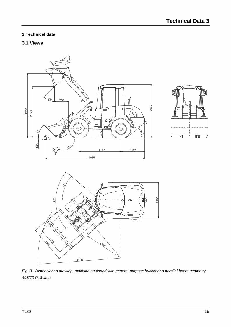
Fig. 3 - Dimensioned drawing, machine equipped with general-purpose bucket and parallel-boom geometry
405/70 R18 tires

3 Technical Data
16 TL80
1980
4140
18501380
80°
40°
4970
3200
25252820
45° 715
Maulw
eite 1010 50°
100
112°
1780
435
40°
11752100
2670
L834-004
Fig. 4 - Dimensioned drawing, machine equipped with multi-purpose bucket and parallel-boom geometry
405/70 R18 tires

Technical Data 3
TL80 17
4080
max.1078
2670
1380
1980
80°
40°
1780
435
40°
11752100
5540
3020
1350
135
1250
630
500
430
L834-005
Fig. 5 - Dimensioned drawing, machine equipped with fork lift attachment and parallel-boom geometry
405/70 R18 tires

3 Technical Data
18 TL80
435
11752100
2670
13801850
40°
2550
3220
710
110
4995
1780
90°
L834Z-003
Fig. 6 Dimensioned drawing with general-purpose bucket and Z-bar linkage 405/70 R18 tires

Technical Data 3
TL80 19
435
11752100
2670
13801850
40°
3220
1780
905
5050
720
2525
2750
180 94°
L834Z-004
Fig. 7 Dimensioned drawing with multi-purpose bucket and Z-bar linkage 405/70 R 18 tires

3 Technical Data
20 TL80
435 40°
11752100
2670
R1980
1780
R4115
700
1300
460
13513
50
3030
5600
500
L834Z-005
Fig. 8 Dimensioned drawing with fork lift attachment and Z-bar linkage 405/70 R 18 tires

Technical Data 3
TL80 21
3.2 Diesel engine Make: ............................................................... Deutz Type:................................................................ F4M2011 Design:............................................................. 4 cylinders in line
Four-stroke diesel engine with direct injection optimized for emissions reduction (COM II/EPA II)
Displacement: .................................................. 3,100 cm³ Power to DIN 70020: ....................................... 44.0 kW at n = 2,400 rpm Max. torque: ..................................................... 195 Nm / 1,700 rpm Specific fuel consumption at nominal engine speed: ..............................................................
218 g/kWh
Cooling:............................................................ Engine oil / air with external oil cooler Heating: ........................................................... Fresh air with heat exchanger connected to
engine oil circuit
3.3 Electrical system Operating voltage:............................................ 12 V Battery:............................................................. 12 V / 74 Ah / 680 A (EN) / 400 A (DIN) Generator:........................................................ 14 V 55 A Starter: ............................................................. 2.3 kW Cold-start aid:................................................... Heater plug Lighting system: ............................................... to German Regulations Authorizing the Use of
Vehicles for Road Traffic (StVZO)
3.4 Travel drive Travel drive: ..................................................... Variable displacement pump, flange-mounted
directly onto diesel engine, two-stage variable displacement motor with power shift on rear axle reduction gear.
High-speed version featuring rear axle manual transmission shiftable in standstill position.
Suction return filter in the form of a tank insert filter.
Travel speeds: ................................................. Forward — reverse TL80 TL80 S Transmission
range I Transmission
range II
Gear range "Work":
0 – 7 km/h 0 – 7.0 km/h 0 – 14 km/h
Gear range "Road":
0 – 20 km/h 0 – 18 km/h 0 – 36 km/h

3 Technical Data
22 TL80
Power transmission:......................................... Hydrostatic transmission with advanced driving automatics. Automatic adjustment of propulsive force and speed.
Continuous speed regulation forward and in reverse.
Four-wheel drive via propeller shaft connection.
Max. operating pressure — travel: ................... 440 bar
3.5 Brakes Service brake: .................................................. Hydraulically actuated center-mounted drum
brake, combined with hydrostatic brake of travel drive. The brake acts on all four wheels via four-wheel drive.
Parking brake:.................................................. Mechanically actuated center-mounted drum brake on front axle.
Auxiliary brake: ................................................ The hydrostatic travel drive in the closed circuit acts as an additional non-wearing brake.
3.6 Hydraulic system Hydraulic pump:............................................... Gear pump on the throughdrive of the variable
displacement pump.
Max. pump capacity: 64 l/min
Operating pressure, steering: 175 bar
Operating pressure, loading: 250 bar
Priority valve: ................................................... Priority supply of hydraulic oil to steering through load-sensing system, ensuring that all the available oil can be provided if necessary. Rapid steering movements are possible even at low engine revs.
Steering: .......................................................... Fully hydraulic, proportionally acting articulated steering.
One double-acting steering cylinder.
Total steering angle: ........................................ 80°
Technical Data 3
TL80 23
Loader installation:........................................... Parallel-boom geometry
Double-acting work cylinders, one lift cylinder and one tilt cylinder.
Z-bar linkage
Double-acting work cylinders, two lift cylinders and one tilt cylinder. Control valve with 3 control circuits. Electro-hydraulically operated float position for “Lower” work function. Single, four-way control lever (joystick) with integrated direction-of-travel switch, float position switch and a switch for additional control circuit.
Additional control circuit: .................................. Max. oil flow......................................... 64 l/min Max. operating pressure...................... 230 bar
Hydraulic oil cooler: ......................................... Thermostatically controlled.
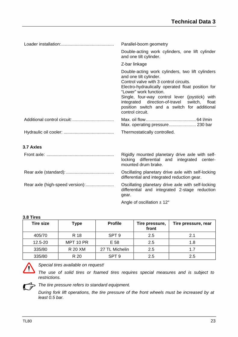
3.7 Axles Front axle: ....................................................... Rigidly mounted planetary drive axle with self-
locking differential and integrated center-mounted drum brake.
Rear axle (standard): ....................................... Oscillating planetary drive axle with self-locking differential and integrated reduction gear.
Rear axle (high-speed version):....................... Oscillating planetary drive axle with self-locking differential and integrated 2-stage reduction gear.
Angle of oscillation ± 12°
3.8 Tires Tire size Type Profile Tire pressure,
front Tire pressure, rear
405/70 R 18 SPT 9 2.5 2.1 12.5-20 MPT 10 PR E 58 2.5 1.8 335/80 R 20 XM 27 TL Michelin 2.5 1.7 335/80 R 20 SPT 9 2.5 2.5
Special tires available on request!
The use of solid tires or foamed tires requires special measures and is subject to restrictions.
The tire pressure refers to standard equipment.
During fork lift operations, the tire pressure of the front wheels must be increased by at least 0.5 bar.
3 Technical Data
24 TL80
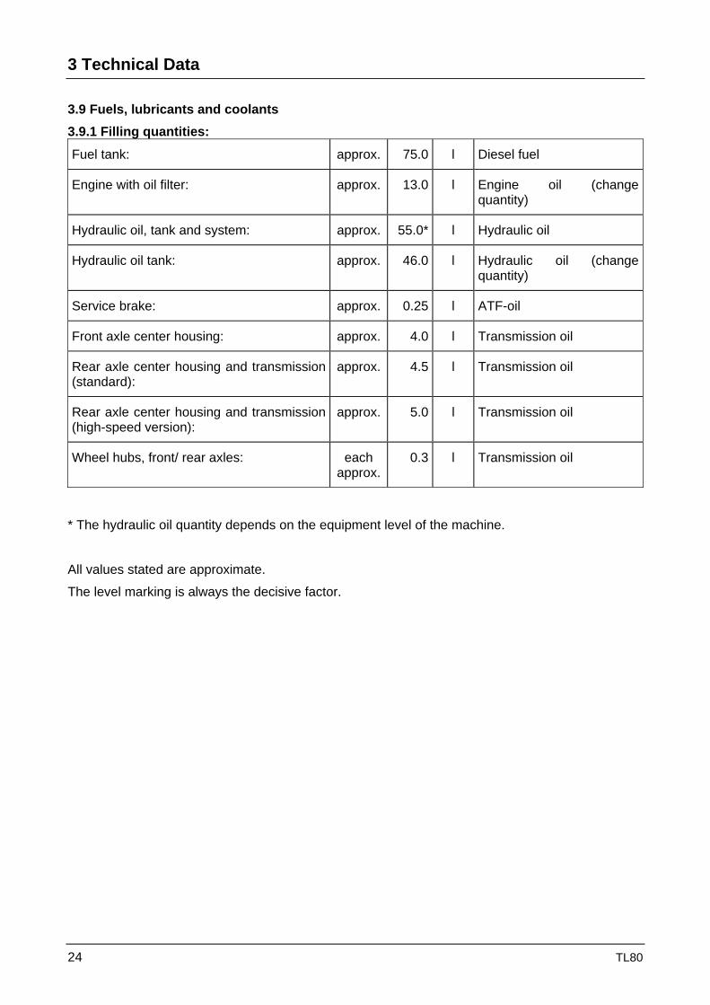
3.9 Fuels, lubricants and coolants 3.9.1 Filling quantities:
Fuel tank: approx. 75.0 l Diesel fuel
Engine with oil filter: approx. 13.0 l Engine oil (change quantity)
Hydraulic oil, tank and system: approx. 55.0* l Hydraulic oil
Hydraulic oil tank: approx. 46.0 l Hydraulic oil (change quantity)
Service brake: approx. 0.25 l ATF-oil
Front axle center housing: approx. 4.0 l Transmission oil
Rear axle center housing and transmission (standard):
approx. 4.5 l Transmission oil
Rear axle center housing and transmission (high-speed version):
approx. 5.0 l Transmission oil
Wheel hubs, front/ rear axles: each approx.
0.3 l Transmission oil
* The hydraulic oil quantity depends on the equipment level of the machine.
All values stated are approximate.
The level marking is always the decisive factor.

Technical Data 3
TL80 25
3.9.2 Fuel, lubricant and coolant specifications Prescribed fuels, lubricants and
coolants for Central Europe
Application Code designation in compliance
with Bi 1)
Designation Specification, Standards, Quality
Remarks
Engine -- Diesel fuel EN 590 ASTM D975 1-D / 2-D Before using RME-fuels
(rape oil methyl ester), it is essential to consult your responsible Terex dealer for further details.
Engine EO 1540 A Engine oil SAE 15W-40 API CF4 ACEA E3 or E2
See also engine manufacturer’s instructions
Hydraulic system
HYD 1040 Hydraulic oil or multi-grade engine oil
HVLP 46 or SAE 10W-40
The following viscosity limit values must be kept (in compliance with ASTM 445) at 100 °C min. 8 mm 2/s (cSt)at –10 °C approx. 1,500 mm 2/s (cSt)
BIO-E-HYD-HEES Biodegradable hydraulic oil on synthetic ester base
Filling in compliance with customer specifications. Brand label on machine.
Do not mix biodegradable oils of different suppliers.
The same viscosity specifications apply as for mineral hydraulic oils.
When changing from mineral to biodegradable hydraulic oils, the tank and hydraulic system must be completely drained, cleaned and flushed. For further details before changing oils, please consult your responsible Terex dealer.
Axles GO 90 LS Transmission oil
SAE 85W-90LS API-GL 5
Alternative recommendations SAE 90LS SAE 80W-90LS
Lubricating points MPG-A Multi-purpose, lithium-soap based grease
K2K-30 DIN 51825
Brake ATF Brake oil ATF Type A Suffix A Dexron-IID
1) In conformity with the regulation lubricants of the Main Association of the German Building Industry e.V.
Alternative recommendation for other temperature ranges Engine oil in compliance with API CG 4 or CF 4 and in compliance with ACEA E3 or E2
Hydraulic oil in compliance with DIN 51524.T3 HVLP
-30-22
-20-4
-1014
032
1050
2068
3088
°C°F
Umgebungstemperatur/Ambient temperature/Température ambiante
0W-300W-405W-30
5W-4010W-3010W-40
15W-4020W-50Viskode

3 Technical Data
26 TL80
3.10 Permissible loads in compliance with German Regulations (StVZO) Permissible gross weight: ................................ see identification plate
Permissible axle load, front:............................. or
Permissible axle load, rear: ............................. General Operating License
3.11 Sound level values, vibration Sound level values in compliance with directive 2000/14/EC and EN 474
Guaranteed sound power level: ....................... LW(A) = 101 dB (A)
Sound pressure level (at driver's ear): ............. LP(A) = 76 dB (A)
Vibration values in compliance with directive 98/37/EEC and EN 474
Weighted r.m.s. value of acceleration is below .................... 0.5 m/s2 for entire body
and ........................................................................................ 2.5 m/s2 for upper limbs
3.12 Dimensions and weights Values refer to general-purpose bucket and 405/70 R18 tires Parallel-
boom geometry
Z-bar linkage
Operating weight, standard equipment approx. kg 4,800 4,800
Total length on ground mm 4,955 4,995
Total width mm 1,850 1,850
Height over cab mm 2,670 2,670
Wheel base mm 2,100 2,100
Tread width, front and rear mm 1,380 1,380
Rear overhang angle ° 40 40
Ground clearance beneath propeller shaft mm 435 435
Turning radius at outside edge of bucket in transport position
mm 4,135 4,150
Turning radius at outside edge of tires mm 3,780 3,780
Turning radius at inside edge of tires mm 1,980 1,980

Technical Data 3
TL80 27
3.13 Front loader installation Values based on general-purpose bucket and 405/70 R18 tires Parallel-
boom geometry
Z-bar linkage
Width of bucket mm 1,850 1,850
Capacity in compliance with DIN/ISO 7546 (max. density = 1.8 t/m³)
approx. m³ 0.8 0.8
Payload in bucket kg 1,440 1,440
Dumping height at 45° dumping angle approx. mm 2,550 2,550
Dumping reach at max. dumping height approx. mm 700 710
Max. bucket hinge pin height approx. mm 3,200 3,220
Tilt-back angle ° 50 50
Dumping angle at max. dumping height ° 45 45
Digging depth, horizontal bucket approx. mm 100 110
Lift capacity at ground level approx. N 48,000 48,400
Ripping force at cutting edge of bucket approx. N 45,000 47,300
Tipping load, straight approx. kg 3,500 3,500
Tipping load, articulated approx. kg 3,150 3,150
Work cycle times, ..................................................... lift: sec 4.7 4.9
............................................................................. lower: sec 3.2 3.4
Dumping in uppermost position, in/ out sec 1.1 1.1
* in compliance with ISO 8313
Stability in conformity with DIN 24094
3.14 Loading bucket
Width
mm
Capacity, heaped
m3
Max. density (γ)
per t/m3
General-purpose bucket 1,850 0.8 1.8
Multi-purpose bucket 1,850 0.75 1.6
Earth bucket 1,850 0.9 1.6
Light-material bucket 1,850 1.0 1.2
Super light-material bucket 1,950 1.2 0.8
Side-dump bucket 1,850 0.7 1.8
High-tip bucket 1,850 0.7 1.2

3 Technical Data
28 TL80
3.15 Fork lift attachment Fork connection to ISO/FEM Class 2 Form B DIN 15 173 and ISO 2328 respectively
Width of fork carrier: mm 1,240
Length of forks: mm 1,120
Fork cross section: mm 100 x 45
Max. stacking height: mm 3,020
The stated carrying capacity is based on the machine traveling over level ground, with a stability factor of 1.25 or 80% of the tipping load.
The payloads are valid for the machine fitted with 405/70 R 18 SPT 9 tires and the equipment condition as described in compliance with ISO 6016.
Total lift range S=2.0 S=1.25
kg 1,250 2,000
lbs 2,750 4,400
kglbs
kg 1,380 2,200
500mm19,7inch
+0,5bar+7,3psi + kg
lbs kglbs
lbs 3,030 4,840
Transport position S=1.67 S=1.25
kg 1,720 2,300
lbs 3,790 5,060
kglbs
kg 1,870 2,500
500mm19,7inch
+0,5bar+7,3psi + kg
lbs kglbs
lbs 4,120 5,500
kglbs
When screw-on rear axle weights or rear tires with hydroinflation are used.
During fork lift operations, the tire pressure of the front wheels must be increased by at least 0.5 bar.

Technical Data 3
TL80 29
3.16 Optional accessories
• Orthopedic air-cushioned driver’s seat
• Fire extinguisher
• Height and tilt-adjustable steering wheel
• Pressurized cab
• Air conditioning
• Engine-independent diesel heater with timer
• Diverse electrical accessories such as working floodlights, rotating beacon, radio, etc.
• FOPS-roof guard
• Sliding window, right-hand door
• Diesel exhaust cleaner
• Catalytic converter
• High-speed version
• Anti-theft device
• Back-up alarm system
• Electric tank refueling pump
• Quick-attach system, hydraulically actuated
• Snow blade
• Sweeper
• Load hook for attaching to forks
• Rear axle weights
• Outlet for hydraulic hand hammer
• Filling with biodegradable hydraulic oil (ester-based BIO-E-HYD-HEES)
- Further optional equipment available on request! -
Any modifications of TEREX products and their equipment using extras and work attachments which are not included in our product range require our written approval. If our approval is not sought, our warranty expires, as does our product liability for any resulting consequential damage.

3 Technical Data
30 TL80

Operation 4
TL80 31
4 Operation
4.1 First commissioning
The machine must be entered from the left-hand side as seen in the direction of travel. The right-hand cab door acts as an emergency exit.
If the cab is entered by the right-hand door, the joystick may be operated unintentionally.
If you are not familiar with the operator controls and display elements of this machine, read this Chapter carefully before operating the machine.
This Chapter deals with all functions.
Before driving and working with the machine it is necessary to thoroughly familiarize yourself with the operator controls and display elements.
Each time before putting the machine into operation it must be subjected to a thorough visual inspection. Ensure that there is no damage, loose or missing screws, oil accumulation, oil or fuel leakage. Faults must be remedied immediately. In the event of shortcomings which jeopardize the operating safety, the machine is not to be put into operation until these have been eliminated.
Each time before putting the machine into operation, the inspections in compliance with Chapter 7.8 must be carried out.

4 Operation
32 TL80
4.2 Operator controls and display elements
The following list includes non-standard equipment!
L824-010
1 2 3 4
5
6
7
8
9
10
11
12
13
15
14
Fig. 10.1-Operator controls

Operation 4
TL80 33
1 Direction indicator — horn — low/high beam (steering column mounted switch)
2 Brake inching pedal
3 Accelerator pedal
4 Tilt adjustment of steering wheel (option: height adjustment)
5 Actuation of additional control circuit
6 Control lever — loader installation
7 Direction-of-travel pre-selection (without function if working hydraulics are disabled)
8 Impulse mode — float position
9 Parking brake
10 Socket
11 Fuse carrier
12 Fan: fresh air/ re-circulating air
13 Radio
14 Control rod for mechanical quick-attach system
15 Washer tank

4 Operation
34 TL80
P
I
N
II
II
0I
L824-010-1
20
21
22
23
24 25 26 27 28
29
30
31
32
33 34 35 36 37 38 39 40 41 42
43
44
45
46
4748
49
51
50
5253
54
5556
57
61
58
59
60
Option“S”-Version
Fig. 10.2-Instrument panel

Operation 4
TL80 35
20 not assigned *
21 ORANGE — pre-heating monitor
22 RED — battery charge indicator
23 RED — parking brake
24 GREEN — travel direction, forward
25 Coolant temperature
26 Operating hour meter
27 Fuel gauge
28 GREEN — travel direction, reverse
29 GREEN — direction indicator
30 BLUE — high beam
31 RED — engine oil pressure
32 RED — air filter indicator
33 Travel speed — fast/slow
34 Change-over switch for high gear
Only press if machine is at standstill!
35 Multi-function switch with lock for work equipment cut-off and change-over of the direction-of-travel pre-selection switches from Pos. 07 to Pos. 36
Only press if machine is at standstill!
36 Pre-selection of travel direction — Function only active if working hydraulics are disabled
37 not assigned *
38 not assigned *
39 not assigned *
40 Windshield wash function front/rear
41 Windshield wiper, front
42 Windshield wiper, rear
43 Switch for air conditioning and temperature control
44 Fan switch – heater
45 not assigned * 46 not assigned *
47 Pre-selection switch for actuation of additional control circuit (Pos. 5)
48 Pre-selection switch for float position — OFF/Impulse/Continuous mode
49 not assigned *
50 Glow plug and starter switch
51 Hazard warning switch
52 Working floodlight, front
53 Working floodlight, rear
54 not assigned *
55 not assigned *
56 not assigned *
57 Heater control
58 Monitor — manual transmission indicator range I
59 Monitor — manual transmission indicator range II
60 Monitor — manual transmission indicator range — disabled
If this symbol comes up, the manual transmission is in an intermediate position. The machine is not ready for operation! This can be remedied by performing brief steering movements until the manual transmission engages.
61 Speed indicator
* for non-standard equipment

4 Operation
36 TL80
4.3 Engine 4.3.1 Starting the engine
Each time before putting the machine into operation, the inspections in compliance with Chapter 7.8 must be carried out.
Before switching on the engine, ensure that no one is in the immediate vicinity of the machine or in the danger zone.
• All shift levers must be put into neutral position.
• Parking brake (11/9) applied, direction-of-travel pre-selectors (11/7; 11/36) in “O” position.
• Insert ignition key in glow plug and starter switch (11/50).
• Turn clockwise to “1”, the indicator lamps (11/22; 11/31) light up.
• Pre-ignition starts; the indicator lamp (11/21) lights up.
• Press the accelerator pedal (11/3) completely down for normal start and to the quarter-open position for hot start.
• After the indicator lamp (11/21) has gone out, turn the glow plug and starter switch to "Start". As soon as the engine is running, turn the ignition key to “1” and decrease the revs to low idle speed. The indicator lamps should go out.
• If the engine has not started after max. 20 seconds, turn the ignition key to “1” or “0”, and pause for at least 1 minute before trying again. Repeat the start-up procedure.
Do not drive the engine at full throttle straight away. Drive with restraint until the operating temperature of the engine has been reached.
3
7
9
2231
36
50
L824-011
21
0I
Fig. 11-Operation

Operation 4
TL80 37
4.3.2 Monitoring during operation
If the engine and the machine are put into operation without prior remedy of the fault, severe damage to the engine may result!
• If the battery charge (12/22) or engine oil pressure indicator lamp lights up (12/31), switch off the engine immediately and determine the cause, or call for service personnel.
• If the permitted engine oil temperature (12/25) is exceeded, stop work, open the engine hood and keep the engine running at low idle to allow it to cool down.
Once the engine has cooled down, turn it off and determine the cause of overheating, or call for service personnel.
• If the air filter indicator lamp (12/32) lights up, perform the necessary air filter maintenance.
4.3.3 Switching off the engine
Do not switch the engine off when running at full throttle, but allow it to run for a short time without load at low idle-running speed.
• Turn the ignition key to "0".
• The engine stops automatically.
22
25
3132
L824-012 Fig. 12-Operation

4 Operation
38 TL80
4.4 Driver's seat / Steering wheel tilt adjustment Driver's seat
• The comfort seat is spring-mounted with oil-pressure operated shock absorbers.
• The seat meets international quality and safety standards in compliance with ISO 7096 and ISO 6683 (Fig. 13).
1. Horizontal adjustment
2. Weight adjustment
3. Seat back adjustment
4. Vertical adjustment
Raising seat: Raise seat until it clicks audibly into place.
Lowering seat: Raise seat as far as the stop; it then sinks to its lowest position.
Tilt adjustment of steering wheel
• Press lever (14/4) downward.
• Adjust steering wheel tilt-wise.
• Release lever.
Height adjustment of steering wheel (option)
• Draw lever (14/4) upward.
• Adjust steering wheel height-wise.
• Release lever.
Fig. 13-Driver's seat
4
L824-014 Fig. 14-Operation

Operation 4
TL80 39
4.5 Heating / Ventilation
Heating
• The heater is connected to the engine oil circuit.
• The fan is operated using the switch (15/44). Temperature is adjusted using the switch (15/57) and can be operated with fresh air and re-circulating air.
• Open aspirating hole (15/12) for re-circulating air mode.
• The air is distributed and aimed as desired by adjusting the air vents.
Ventilation
• In ventilation mode, the valve towards the engine oil circuit remains closed.
• The fan is operated using the switch (15/44).
• The air is distributed and aimed as desired by adjusting the air vents.
Air conditioning (option)
• Operate the air conditioning system using the switch (15/43).
4.6 Light switch in compliance with StVZO The loader’s lighting is switched on and off by turning the steering column mounted switch (15/1).
Setting 0 Light off
Setting 1 Parking light
Setting 2 Headlamps
(low/high beam)
Switch from one to another by lifting the steering column mounted switch (15/1).
Blue indicator lamp (15/30) lights up for high beam.
1
12
30
43
44
57
L824-015
0I
Fig. 15 Operation

4 Operation
40 TL80
4.7 Hydroinflation of tires
• When the loader is used with a fork lift attachment, the rear wheels may be filled with a water/ antifreeze mixture to increase the lifting capacity.
• Prepare the mixture in an appropriately sized container. Allow it to cool and stir until there are no more lumps.
Always pour magnesium chloride into the water, not the other way round! Do not allow the solution to come into contact with eyes, skin or clothing - caustic substance!
Recommendation when filled to 75% with antifreeze protection to –30 °C. Values per wheel:
Type of tire MgCl2
ca. kg
H2O
l
Total
kg
405/70 SPT 55 70 125
12.5-20 MPT 57 74 131
335/80 XM 59 73 132
335/80 SPT 51 66 117
MgCl2 = magnesium chloride
H2O = water

Operation 4
TL80 41
4.8 Driving, steering and braking 4.8.1 Driving
When driving on public roads, the wheel loader, as a self-propelled work machine, is subject to legal regulations valid in the user's country (e.g. in the Federal Republic of Germany, StVZO and StVO).
The vehicle has two pre-selection switches for the travel direction which are alternately active.
Change-over by means of the multi-function switch (16/35).
One pre-selection switch for the travel direction (16/36) is located on the instrument panel and another such switch on the joystick (16/7) for the working hydraulics.
The multi-function switch (16/35) is only to be pressed if the machine is at a standstill and when both travel direction pre-selection switches are in neutral position. If the two direction-of-travel pre-selection switches are pressed in a contradictory manner, the machine stops.
When driving on roads, the joystick (16/7) for the work equipment must be deactivated by operating the multi-function switch (16/35).
By doing so, the travel direction pre-selection switch on the joystick (16/7) is without function, too.
The direction of travel is pre-selected using the switch (16/36) on the instrument panel.
In working mode, the joystick (16/7) for the work equipment must be activated using the multi-function switch (16/35).
By doing so, the switch (16/36) on the instrument panel is without function.
The direction of travel is pre-selected using the travel direction pre-selection switch on the joystick (16/7).
7
3536
L824-016 Fig. 16-Operation

4 Operation
42 TL80
Driving off
• Set the travel direction pre-selection rocker switch located on the joystick (17/7) and the instrument panel (17/36) to “O” (neutral position).
• The indicator lamps (17/24 & 17/28) must not light up.
• Start the engine.
• Raise the lift frame as far as the “Travel” height mark (18/1).
• Select “fast” or “slow” range (17/33) as required.
• High-speed version (option) — Select gear range I or II.
Observe the indicator lamp (17/58-60).
• Release the parking brake (17/9).
• Set the desired travel direction using the pre-selection switches for the travel direction (17/7 or 17/36).
• The indicator lamp (17/24 or 17/28) lights up.
• Press the accelerator pedal (17/3). The machine only drives off once a certain engine speed is reached.
• Travel speed is increased and decreased using the accelerator pedal. Travel speed directly depends on engine speed.
• The direction of travel may be changed quickly by operating the pre-selectors (17/7; 17/36).
Coming to a halt
• Travel speed is reduced by releasing the accelerator pedal. The hydrostatic drive acts as a non-wearing auxiliary brake.
• Operate the braking inching pedal (17/2) as required.
• See also Chapter 4.8.3, “Brakes”.
2 3
7
9
I
N
II
24 28
33 36
58
59
60
Option“S”-Version
L824-017 Fig. 17-Operation
L824-018
1
Fig. 18-Height mark

Operation 4
TL80 43
4.8.2 Steering
• The wheel loader has fully hydraulic, proportionally acting articulated steering.
• Priority supply of hydraulic oil to steering through load-sensing system.
In the event of steering malfunctions, determine the cause immediately (see trouble-shooting table) and call for service personnel if necessary.
4.8.3 Braking Service brake and auxiliary brake
• To bring the machine to a halt, release the accelerator pedal (19/3). The hydrostatic drive then acts as an auxiliary brake.
• Press the brake inching pedal (19/2) as required.
Parking brake
• Only apply the parking brake (19/9) if the machine is stationary.
With the parking brake (19/9) applied, the transmission is disabled.
Brake inching mechanism
• The machine features a brake inching mechanism altering the relationship between travel speed and engine speed.
• When the brake inching pedal (19/2) is pressed, travel speed is reduced - irrespective of engine speed - until the machine comes to a stop.
This permits sensitive driving at maximum engine speed, e.g. when loading a truck, where fast working cycles are required.
2 3
9
L824-019 Fig. 19-Operation

4 Operation
44 TL80
4.8.4 Road travel Before driving on open roads, the following points have to be observed:
The wheel loader must be equipped as stipulated by the regulations authorizing the use of vehicles for road traffic in the user's country.
• Empty the bucket and tilt back completely.
• Attach the protective device on the front bucket edge.
• Secure the side-dump bucket with socket pins.
• Completely retract the high-tip bucket.
• Fold the forks of the fork lift attachment upward, lock in place and secure against lateral shifting.
Rigid forks must be dismounted!
• Raise the lift frame as far as the height color mark (18/1) until sufficient ground clearance is secured.
• Set the direction-of-travel pre-selection switches on the joystick (20/7) and the instrument panel (20/36) to “0” (neutral position).
• Switch off the working hydraulics (20/35).
Only press if machine is stationary!
• Check the function of the direction indicators, hazard warning lights, horn, low/high beam.
• Close the cab door.
L824-018
1
Fig. 18 Height color mark
7
3536
L824-020 Fig. 20 Operation

Operation 4
TL80 45
4.8.5 Parking the machine
• Set the direction-of-travel pre-selection rocker switches (21/7 and 21/36) to “0”.
• Lower the work equipment to the ground.
• Switch off working hydraulics (21/35).
• Apply the parking brake (21/9).
• Switch off the engine and remove the ignition key.
• Lock the cab after finishing work to keep unauthorized persons from getting in.
If necessary, secure the machine with chocks so that it cannot roll away.
7
3536
L824-021
9
Fig. 21-Operation

4 Operation
46 TL80

Loading Operation 5
TL80 47
5. Loading Operation 5.1 General
Every day before commencing work, and after each change of equipment, a check must be carried out to ensure that the work attachment is correctly fastened, and the quick-mount hitch is properly locked.
The bucket must be moved carefully at a low height.
• Before commencing loading work, memorize the lever controls well.
• During loading work, driving and work movements should flow in smooth succession.
• Drive slowly when familiarizing yourself with the controls.
5.2 Loader operation
• Switch on the work equipment (22/35).
Operation — Bucket
• With joystick (22/6)
Operation — Additional control circuit
• Switch on additional control circuit (22/47) — Step 1.
• Press right-hand / left-hand push-button switch (22/5), e.g. open/ close multi-purpose bucket.
The additional control circuit must always be switched off unless additional equipment is actuated.
Continuous operation of additional control circuit
• Set the additional control circuit (22/47) to step 2. The red indicator lamp lights up.
Observe the operating direction of the attachment (e.g. direction of rotation of sweeper).
The additional control circuit must always be switched off unless additional equipment is actuated.
56
35
L824-022
0I
47
Fig. 22 Operation

5 Loading Operation
48 TL80
Operation of float position
The float position must always be switched off unless actuated.
Set switch (23/48) to “O”.
Impulse mode
• Set float position switch (23/48) to “1”.
• Place bucket on ground.
• Press switch (23/8). Float position is activated.
Continuous mode
• Place bucket on ground.
• Set switch (23/48) to “2”. The green indicator lamp lights up.
Fig. 23-Operation

Loading Operation 5
TL80 49
5.3 Changing work attachments 5.3.1 General To achieve maximum utilization of the machine for a variety of applications, a great number of work attachments and accessories are available.
The machine is equipped with a quick-attach system, to shorten the time it takes to change attachments.
When mounting a multi-purpose bucket, front sweeper, etc., an additional control circuit is required.
It is possible to use, under certain circumstances, the work attachments of predecessor models for our machines. When mounting the work attachments of predecessor models they may have to be adjusted and/ or are subject to utilization restrictions. The mounting of work attachments which are not included in our product range requires our written approval. It is essential to consult your dealer before mounting such a work attachment.
When attachments have been removed, they must be secured against overturning to avoid possible injury to persons.

5 Loading Operation
50 TL80
5.3.2 Assembly of work attachments
The bearings of the lift frame, the work attachment and the quick-mount hitch must be free from dirt.
Before disconnecting hydraulic connections, the system must be released from pressure.
Procedure for changing directly mounted work attachments
In the event of a hydraulically actuated attachment, first of all the hydraulic connection must be disconnected (system must be without pressure).
• Rest the attachment on the ground so that it cannot overturn.
• Remove the pin of the linkage and the pin of the lift frame.
• Move the lift frame out of the work attachment and insert a new one.
Procedure for changing work attachments with mechanical quick-attach system
In the event of a hydraulically actuated attachment, first of all the hydraulic connection must be disconnected (system must be without pressure).
• Lower the work attachment to the ground so that it cannot overturn.
• Raise pin (24/2) and open the quick-mount hitch using the control rod (24/1) until the locking bolts are completely retracted.
• Check the function of the quick-mount hitch lock and lubricate the pins if required.
• Attach another work attachment and close the quick-mount hitch until the locking bolts are completely extended and the pin clicks in.
• Ensure that the work tool and the lock are properly seated.
• The control rod is kept in the left-hand storage box in the driver’s cab.
L823B22
12
Fig. 24-Quick-mount hitch

Loading Operation 5
TL80 51
Procedure for changing work attachments with hydraulic quick-attach system
• Lower the work attachment to the ground so that it cannot overturn.
• Switch off the diesel engine.
• Operate the push-button switches (25/5) for pressure relief.
• In the case of a hydraulically actuated work attachment, the hydraulic connections on both manifold blocks must be disconnected.
• Set ball valve (26/1) to “Unlock quick-mount hitch” position.
• Start the diesel engine.
• Unlock the quick-mount hitch (25/5) and move out of the work attachment.
• Take up new work attachment and lock by pressing the push-button switch (25/5).
Visual check to ensure that the quick-mount hitch is correctly locked.
• Switch off diesel engine.
• Operate push-button switches (25/5) for pressure relief.
• Set ball valve (26/1) to “Quick-mount hitch locked”.
• Connect hydraulically actuated work attachment to connection of additional control circuit.
The additional control circuit (25/47) must be switched off unless a hydraulically actuated additional attachment is connected.
5
L824-025
0I
47
Fig. 25-Operation
Fig. 26-Hydraulic quick-attach system
5 Loading Operation
52 TL80
5.4 Notes on how to work with the machine 5.4.1 Loading
• During transport, the bucket - either filled or empty - must be kept as close to the ground as possible.
• If possible, avoid long transport distances!
For loading, lower the bucket and position the cutting edge parallel to the ground. Reduce speed by inching as required.
Penetrate the bucket in the material to be loaded.
As soon as the bucket is filling, slightly raise the lift frame and tilt back the bucket.
For dumping, raise the bucket until it is above the location where to unload the material and then start to unload.
5.4.2 Scraping, grading
• Lower the lift frame and move the cutting edge in the ground with flat angle of inclination. Do not penetrate too deeply to ensure jolt-free removal of earth.
• During this work, the depth is only to be leveled by moving the bucket in and out.
5.4.3 Excavation work
• To excavate the ditch for the foundation, attempt to dig layers which are as regular as possible.
• Plan the excavation in such a way as to enable the machine to leave the ditch for the foundation forward with the full bucket.
• Attempt to keep the outward run of the ditch for the foundation as flat as possible.

Recovery and Transport 6
TL80 53
6 Recovery and Transport of the Machine
6.1 Recovery of the machine Towing of the wheel loader must be restricted to clearing a junction or a road, to prevent damage to the hydrostatic drive.
If possible, let the diesel engine run at low idle during towing.
Towing lugs: Front: right and left on the axle plates
Rear: right and left, bottom, side plates of the rear end
Max. load capacity of towing lugs approx. 5,300 kg.
• Whenever the wheel loader has to be towed, for whatever reason, the “Travel” oil circuit must be opened so that the hydrostatic transmission no longer acts as an auxiliary brake.
• At the two high-pressure relief valves (27/1) with bypass (in the connecting plate of the hydraulic pump), loosen the nut (28/1) and screw in screw (28/2) until it is level with the nut.
• Tighten the nut (28/1).
• After towing, screw back screw (28/2) until the stop.
• Re-tighten the nut (28/1).
Absolute cleanliness is essential when working on the hydraulic system. Always secure the machine with chocks and relieve the hydraulic system of pressure before carrying out maintenance and repair work.
1
L824-027
1
Fig. 27 Hydraulic pump
Fig. 28-HP-relief valve

6 Recovery and Transport
54 TL80
6.2 Loading the machine using a crane
Use a crane harness and a crane with sufficient lifting capacity!
To load the machine by use of a crane, the following steps must be taken:
• Empty the bucket and tip back.
• Move the lift frame to travel position.
• Apply the pin of the articulation lock (29/1).
• Turn off the engine.
• Dismount from the machine and close the doors.
• Attach the loader to the hoisting appliance at the specified, marked points (Fig. 29) in the correct manner.
6.3 Transporting the machine To transport the machine onto a flat bed trailer, railway goods wagon, etc. the following steps must be taken:
• Empty and fold in the bucket.
• Move the machine onto the flat bed trailer, goods wagon, etc., or lift by crane if required.
• Apply the articulation lock (30/1).
• Place the work equipment on the ground.
• Stop the engine.
• Dismount from the machine and close the doors.
• Attach the machine at the points illustrated (Fig. 30) in the correct manner.
Be aware of the total transport height.
Risk of accident when driving in tunnels, under bridges, etc.!
L824-029
1
Fig. 29-Loading the machine using a crane
L824-0301
Fig. 30-Lashing for transport

Care and Maintenance 7
TL80 55
7 Care and Maintenance
7.1 General notes The good operating condition and life expectancy of machines are largely influenced by care and maintenance.
For this reason, it is in every machine owner’s interest to perform the specified maintenance work and comply with the service intervals. This Chapter deals in detail with periodic maintenance, inspection and lubricating tasks.
The type-specific maintenance and inspection plan lists all work to be performed on the machine at regular intervals. Maintenance and inspection plans for this purpose are contained in every instruction book.
It is essential that the recommendations in Chapter 2, “Safety and Prevention of Accidents” are observed.
7.2 Intervals First inspection once before first putting into operation Chapter 7.8.1
Daily jobs every 10 operating hours or every work shift 1) Chapter 7.8.2
Weekly jobs weekly or after 50 operating hours 1) Chapter 7.8.2
100 operating hours once after first putting into operation 2) Chapter 7.8.4
Every 500 operating hours after every 500 operating hours or 6 months Chapter 7.8.4
Every 1,000 operating hours after every 1,000 operating hours or 12 months Chapter 7.8.4
Every 2,000 operating hours after every 2,000 operating hours or 2 years Chapter 7.8.4 1) whichever comes first 2) also applicable when new or overhauled diesel engines are put into operation

7 Care and Maintenance
56 TL80
7.3 Regular oil analyses Oil analyses are not intended as a substitute for the oil change intervals but – apart from a possible reduction of maintenance costs and as a form of preventive maintenance – they take into account the increasing environmental awareness.
Advantages of an oil analysis
• Extension of the oil change intervals under standard or light-duty operating conditions.
• Minimum wear of high-quality components with optimum use of the lubricants.
• Periodic laboratory analyses enable an early detection of imminent damage.
• Repairs performed before they actually become absolutely necessary help prevent serious and unexpected damage.
• Sequential damage can be avoided.
Oil analysis intervals Periodic oil analyses reveal trends in the condition of the oil and the machine.
When the scheduled oil change intervals have been reached, the oils should be analyzed in the following intervals to check their quality and thus extend the oil change intervals:
• Hydraulic oil: 1,000 operating hours
• Transmission oil: 500 operating hours
• Engine oil: 100 operating hours
Based on the first results, the laboratory recommends the interval for the next sampling.
Ask your Terex dealer for an information booklet detailing the scope and procedures of the oil analysis.
7.4 Warranty During the warranty period thorough inspections are stipulated which are obligatory and which must be carried out by trained specialist dealer personnel.
The inspections are obligatory and must be paid for.
The performance of the obligatory inspections must be confirmed on the inspection cards in the warranty / handing over certificate.
If they are omitted, the warranty may be subject to restrictions.
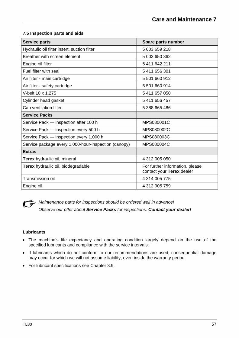
Care and Maintenance 7
TL80 57
7.5 Inspection parts and aids
Service parts Spare parts number Hydraulic oil filter insert, suction filter 5 003 659 218 Breather with screen element 5 003 650 362 Engine oil filter 5 411 642 211 Fuel filter with seal 5 411 656 301 Air filter - main cartridge 5 501 660 912 Air filter - safety cartridge 5 501 660 914 V-belt 10 x 1,275 5 411 657 050 Cylinder head gasket 5 411 656 457 Cab ventilation filter 5 388 665 486
Service Packs Service Pack — inspection after 100 h MPS080001C Service Pack — inspection every 500 h MPS080002C Service Pack — inspection every 1,000 h MPS080003C Service package every 1,000-hour-inspection (canopy) MPS080004C Extras Terex hydraulic oil, mineral 4 312 005 050 Terex hydraulic oil, biodegradable For further information, please
contact your Terex dealer Transmission oil 4 314 005 775 Engine oil 4 312 905 759
Maintenance parts for inspections should be ordered well in advance!
Observe our offer about Service Packs for inspections. Contact your dealer!
Lubricants
• The machine’s life expectancy and operating condition largely depend on the use of the specified lubricants and compliance with the service intervals.
• If lubricants which do not conform to our recommendations are used, consequential damage may occur for which we will not assume liability, even inside the warranty period.
• For lubricant specifications see Chapter 3.9.

7 Care and Maintenance
58 TL80
7.6 Care and cleaning
The machine must be cleaned on a suitable surface with an oil separator.
• Neither a steam-jet appliance nor a high-pressure cleaning apparatus are to be used for cleaning during the first two months after the machine is used for the first time or when newly painted to avoid damage to the paint.
• Do not use aggressive detergents for cleaning the machine. We recommend using commercially available cleaning agents for passenger cars.
• When cleaning with a steam-jet appliance, the hot water jet is not to exceed 80 °C and a spray pressure of 70 bar.
• Linings (insulating materials, etc.) are not to be exposed directly to water, steam or high-pressure jets.
• When cleaning with water or steam jets, take care not to spray exhaust-gas and air filter openings.
• If cleaning the engine with water or steam jets, do not expose sensitive engine parts, such as generator, cabling, oil pressure switch, etc. directly to the jet.
• After each wet clean, the machine must be lubricated in accordance with the lubricating plan and a test of all work cycles, steering and driving functions carried out.
7.7 Notes for winter operation The following points - and the relevant notes in the engine instruction book - should be observed during winter operation.
Hydraulic oil
• If the machine is not used for longer periods at temperatures around and below freezing, warm up the engine by running at medium revs for approx. 3-5 min.
Engine oil
• The oil viscosity (SAE class) should be selected in compliance with the ambient temperature at the machine’s place of operation.
Battery charge
• A good cold start performance requires a well-charged battery. By warming the battery to approx. +20° (remove the battery after the engine has been turned off and store it in a warm room), the minimum starting temperatures can be lowered by 4-5 °C.
• When installing the battery, ensure good contact of terminal connections.
• Only tighten terminal screws so that they are “hand-tight”, to prevent deformation of the terminal posts!

Care and Maintenance 7
TL80 59
Fuel
• Only use commercially available brand-name diesel fuel with a sulfur content of less than 0.5 %.
• In winter, only use winter diesel fuel to prevent clogging of the fuel system due to paraffin separation. Even if winter diesel fuel is used, disturbing paraffin separations (jelling) can occur at very low temperatures.
• If only summer diesel is available, or if winter diesel must be used at very low temperatures, we recommend the addition of petroleum (Fig. 36) or additives.
• These mixtures should only be used temporarily, not for longer periods.
Only mix the components in the tank. First fill in the necessary quantity of petroleum, then add the diesel.
Additives should be chosen in compliance with the recommendations of your fuel supplier.
Petrol is not to be added.
Danger of explosion!
HM23-052
0 10 20 30 40 50 60%
0
- 5
-10
-15
-20
-25
-30
+32
+23
+14
+ 5
- 4
-13
-22
°F °C
A
B
CDD2011D2012 Fig. 36 - Table for the addition of petroleum or additives
A = Summer diesel
B = Winter diesel
C = Added proportion of petroleum
D = Outside temperature

7 Care and Maintenance
60 TL80

Care and Maintenance 7
TL80 61
7.8 Checking, maintenance and inspection plans 7.8.1 Initial inspection (delivery/ handing-over inspection)
L824-031
5 6 4 6 5 9 3 78 2
Fig. 31 Initial inspection
Jobs to be carried out by trained dealer service personnel. Chapter
1 Check whether machine-specific instruction book is in the machine --
2 Check engine oil level 7.9.1
3 Hydraulic oil level 7.9.9
4 Check fuel level 7.9.4
5 Oil level check: differential and axle hubs 7.9.13
6 Check tire pressure and tightness of wheel nuts 7.9.14
7 Check brake oil level 7.9.8
8 Battery: electrolyte level and charge condition 7.9.17
9 Top up windshield washer system 7.9.19
10 Grease machine (all lubricating points) 7.8.3
11 Test run, hydraulic function check and test work --
12 Visual inspection for tightness of all hoses, pipes, cylinders, etc. --
13 Check function of electrical indicating and warning elements, and the lighting system
--
14 Initial delivery/ handing-over certificate and return to manufacturer --

7 Care and Maintenance
62 TL80
7.8.2 Daily and weekly tasks Inspection and maintenance jobs to be performed by operating personnel:
L824-032
14 15 3 13 15 4 1 20 182216 14 217 1112 19
Fig. 32 Inspection and maintenance plan

Care and Maintenance 7
TL80 63
Daily Chapter
1 Check hydraulic oil level 7.9.9
2 Check engine oil level 7.9.1
3 Check fuel level (fuel gauge on instrument panel) 7.9.4
4 Check water level for windshield wiper 7.9.19
5 General visual inspection for material cracks, external damage, completeness, etc.
--
6 Check for leaks in:
pipes, hoses, control valve, hydraulic pumps, cylinders, etc.
--
When tightening hoses or pipeline connections, counterlock fittings to prevent turning.
7 Check electrical indicating and warning elements, and the lighting system --
8 Check smooth running of operator controls --
Weekly Chapter
11 Clean cooling fins of the hydraulic oil cooler 7.9.10
In case of extreme exposure to dust, shorten cleaning intervals.
12 Clean cooling fins of the engine oil cooler 7.9.3
In case of extreme exposure to dust, shorten cleaning intervals.
13 Check that door catches function perfectly --
14 Check tire pressure and tightness of wheel nuts 7.9.14
15 Check fastening of axles and propeller shaft --
16 Check bushings and bolts of the work equipment --
17 Check bolts, bushings and the linkage of the articulated steering --
18 Check that pneumatic springs of engine hood function perfectly --
19 Drain fuel filter 7.9.4
20 Check brake oil level 7.9.8
21 Check function of brakes --
22 Check if the dust filter for cab ventilation is dirty and clean if required 7.9.18
In case of extreme exposure to dust, shorten cleaning intervals.
23 Check function, condition and completeness of safety devices --
24 Grease machine in compliance with overview of lubricating points 7.8.3

7 Care and Maintenance
64 TL80
7.8.3 Overview of lubricating points
Replace damaged grease nipples immediately and check if grease passes through!
L824-033
12
16 17
13 14117
10 8 2 1 9 63 4 5 15
Fig. 33 Lubrication chart

Care and Maintenance 7
TL80 65
Grease all lubricating points with multi-purpose grease. The intervals stated are valid for one-shift operation
Item Lubricating point Qty. daily weekly Chapter
1 Tilt cylinder - Tilt lever 1 X --
2 Lift frame - Tilt lever 1 X --
3 Lift cylinder - Lift frame 1 (2)* X --
4 Tilt cylinder - Front end 1 X --
5 Lift frame - Front end 2 X --
6 Lift cylinder - Front end 1 (2)* X --
7 Lift frame - Quick-mount hitch 2 X --
8 Linkage - Quick-attach system 1 X --
9 Tilt lever - Linkage 1 X --
10 Quick-mount hitch, mechanical
Quick-mount hitch, hydraulic
3 2
X X
--
11 Steering cylinder - Front end 1 X --
12 Pivot point 3 X --
13 Steering cylinder - Rear end 1 X --
14 Rear axle bearing 1 X --
15 Door hinges 4 X --
16 Multi-purpose bucket 2 X --
17 Multi-purpose bucket cylinder 4 X --
* () Z-bar linkage
We recommend that for special operations, e.g. on sandy ground, the lubrication intervals are shortened. Increased frequency of lubrication helps self-cleaning of bearing points.

7 Care and Maintenance
66 TL80
7.8.4 Inspection plan To be carried out by trained specialist dealer personnel
O = Checking, Maintenance
X = Replace Operating hours 2x
min.
1x
min.
Perform work with machine at operating temperature
after
100
every
500
every
1,000
every
2,000
yearly
yearly
Chapter
1 Check whether machine-specific instruction book is in the machine
O O --
2 Change engine oil X X 7.9.1
3 Change engine oil filter X X 7.9.2
4 Drain water from fuel tank O O O 7.9.4 5 Change fuel filter X X 7.9.4 6 Clean fuel pump and screen filter O 7.9.4
7 Check air intake O O 7.9.5 8 Change air filter - main cartridge to service indicator X 7.9.5 9 Change air filter - safety cartridge as required 1) 7.9.5 10 Clean cooling fins of hydraulic oil cooler. O O O 7.9.10
In case of high exposure to dust, shorten the cleaning intervals.
11 Clean cooling fins of engine oil cooler O O O 7.9.3
In case of high exposure to dust, shorten the cleaning intervals.
12 Check V-belt tension O O 7.9.6 13 Check engine mounts and pump attachments O O -- 14 Check engine speed adjustment, top-end and
low idle speed O O --
15 Check valve lash of engine and adjust if necessary
O 7.9.7
16 Check injection valves O 7.9.15 17 Check fuel leak oil pipe and replace if
necessary O X1) 7.9.4
18 Replace toothed belt 3) 7.9.16
19 Check crankcase breather in valve cover O --
20 Check acid level and battery connections O O 7.9.17 21 Check condition of tires, tire pressure and
tightness of wheel nuts O O 7.9.14
22 Check secure fastening of axles and propeller shaft
O O --
23 Check bearing bushings and bolts of work equipment and replace if necessary
O O --
24 Check bushings and bolts of the articulation and the articulated steering and replace if necessary.
O O --

Care and Maintenance 7
TL80 67
O = Checking, Maintenance
X = Replace Operating hours 2x
min.
1x
min.
Perform work with machine at operating temperature
after
100
every
500
every
1,000
every
2,000
yearly
yearly
Chapter
25 Check that door catches function perfectly, and replace if necessary
O O --
26 Clean or replace the dust filter for cab ventilation
O X X 7.9.18
27 Check electrical indicating and warning elements, and lighting system
O O --
28 Check smooth running of operator controls and adjust if necessary
O O --
29 Check tightness of all pipes, hoses, control valve, hydraulic pumps, cylinders, etc.
O O --
When tightening hose and pipe connections, screw-in couplings must be locked to prevent rotation.
30 Check or change hydraulic oil O O X 2) X 7.9.9
31 Replace insert of hydraulic oil return suction filter
X X X 7.9.11
32 Replace breather X X 7.9.12
33 Check function of brakes and replace brake oil O O X X 7.9.8 34 Bleed brake O O 7.9.8 35 Rear axle differential with transmission / option:
manual transmission: oil check or oil change X O X X 7.9.13
36 Front axle differential - oil check or oil change X O X X 7.9.13 37 Wheel hubs of front and rear axles: oil check or
oil change X O X X 7.9.13
38 Grease machine in compliance with overview of lubricating points
O O 7.8.3
39 Check function, condition and completeness of safety equipment
O O --
40 Hydraulic function check with pressure function test
O O --
41 Test run and test work O O --
42 Initial inspection cards and return to manufacturer
O O 4) 7.4
1) at least every 2 years 2) Extension of oil change intervals in compliance with oil sample analysis and lab report. For further information see Chapter 7.3 3) Every 5 years or 5,000 operating hours respectively 4) within warranty
Observe our offer about Service Packs for inspections. Contact your dealer!

7 Care and Maintenance
68 TL80
7.9 Inspection and maintenance work 7.9.1 Engine oil
Checking the engine oil level
• Check the oil level daily before starting, with the machine parked on level ground.
• The notches on the oil dipstick (35/1) indicate the min. and max. oil levels.
• If necessary, top up engine oil. Unscrew the cap (35/2) and top up oil using a clean container.
Changing engine oil
Collect the waste oil, do not allow it to seep into the ground.
Dispose of in compliance with regulations!
• Run the engine until it reaches operating temperature, engine oil temperature approx. 80 °C.
• Park the machine on a level surface. • Stop the engine. • Remove the cover on the bottom of the
rear end. • Place suitable oil drip pans below the
opening. • Screw the oil drain hose onto the oil-
change valve (35/3).
Danger of scalding when hot oil is drained!
• Open the drain plug (35/5) on the oil cooler.
• Remove the oil drain hose and screw the protective cap onto the valve.
• Carefully close the drain plug on the oil cooler.
• Close the service opening with the cover. • To change the engine oil filter (35/4), see
Chapter 7.9.2.
• Top engine oil up to the “MAX” mark on the oil dipstick (35/1) using the filler hole (35/2).
• Start the engine and run at low idle speed for approx. 2 min.
• Open the vent valve (35/6) to eliminate the air from the oil cooler.
• Switch off the engine. • Check the oil level and top up oil if
necessary (empty cooler has filled with oil).
• Start the engine and run at low idle speed for approx. 2 minutes.
• Switch off the engine. • Check the oil level and top up oil if
required.
2
L824-03514 3
6
5
Fig. 35 Engine oil

Care and Maintenance 7
TL80 69
7.9.2 Engine oil filter The engine oil filter must be replaced with every engine oil change.
• Place oil drip pan below the engine oil filter.
• Clean the outside of the engine oil filter.
• Unscrew the filter cartridge (36/4) using a commercially available tool and check that the fastening stud is firmly secured in the filter head.
• Dispose of the filter cartridge in compliance with regulations.
• Check filter head condition and clean.
• Fill the new filter with oil, wet the sealing ring with oil and tighten firmly by hand
• After a test run, check the tightness of the engine oil filter cartridge.
7.9.3 Engine oil cooler
Only clean the cooler with the engine switched off and cooled down!
• Clean the engine oil cooler (37/1) from the outlet side with compressed air.
If necessary, clean with cold detergent or steam jet on a suitable surface with an oil separator.
Do not expose the generator directly to the water or steam jet.
Bring engine to operating temperature to prevent corrosion.
L824-0364
Fig. 36 Engine oil filter
L824-037
1
Fig. 37 Engine oil cooler
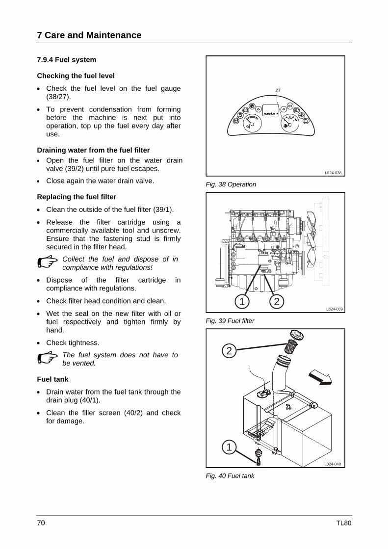
7 Care and Maintenance
70 TL80
7.9.4 Fuel system
Checking the fuel level
• Check the fuel level on the fuel gauge (38/27).
• To prevent condensation from forming before the machine is next put into operation, top up the fuel every day after use.
Draining water from the fuel filter • Open the fuel filter on the water drain
valve (39/2) until pure fuel escapes.
• Close again the water drain valve.
Replacing the fuel filter
• Clean the outside of the fuel filter (39/1).
• Release the filter cartridge using a commercially available tool and unscrew. Ensure that the fastening stud is firmly secured in the filter head.
Collect the fuel and dispose of in compliance with regulations!
• Dispose of the filter cartridge in compliance with regulations.
• Check filter head condition and clean.
• Wet the seal on the new filter with oil or fuel respectively and tighten firmly by hand.
• Check tightness.
The fuel system does not have to be vented.
Fuel tank
• Drain water from the fuel tank through the drain plug (40/1).
• Clean the filler screen (40/2) and check for damage.
27
L824-038 Fig. 38 Operation
L824-0391 2
Fig. 39 Fuel filter
1
2
L824-040 Fig. 40 Fuel tank
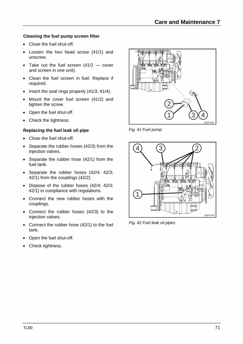
Care and Maintenance 7
TL80 71
Cleaning the fuel pump screen filter
• Close the fuel shut-off.
• Loosen the hex head screw (41/1) and unscrew.
• Take out the fuel screen (41/2 — cover and screen in one unit).
• Clean the fuel screen in fuel. Replace if required.
• Insert the seal rings properly (41/3; 41/4).
• Mount the cover fuel screen (41/2) and tighten the screw.
• Open the fuel shut-off.
• Check the tightness.
Replacing the fuel leak oil pipe
• Close the fuel shut-off.
• Separate the rubber hoses (42/3) from the injection valves.
• Separate the rubber hose (42/1) from the fuel tank.
• Separate the rubber hoses (42/4; 42/3; 42/1) from the couplings (42/2).
• Dispose of the rubber hoses (42/4; 42/3; 42/1) in compliance with regulations.
• Connect the new rubber hoses with the couplings.
• Connect the rubber hoses (42/3) to the injection valves.
• Connect the rubber hose (42/1) to the fuel tank.
• Open the fuel shut-off.
• Check tightness.
L824-041
1
2
43
Fig. 41 Fuel pump
L824-042
4 3
1
2
Fig. 42 Fuel leak oil pipes

7 Care and Maintenance
72 TL80
7.9.5 Air filter, air intake
All maintenance work on the air intake system must be carried out with the engine off.
Do not start the engine while the filter cartridge is removed.
7.9.5.1 Dust extraction valve
• Dust extraction valves (43/1) are largely maintenance-free.
• Any baked-on dust can be removed by squeezing the valve together.
7.9.5.2 Air intake
• Check the air filter attachment and retaining straps for damage.
• Check the tightness of the air intake between the air filter and the engine.
• Examine rubber parts for damage.
Replace damaged parts immediately.
7.9.5.3 Cartridge maintenance interval
Air filter — Main cartridge
• The air filter main cartridge must be replaced as soon as the filter maintenance indicator lamp (44/32) on the instrument panel lights up during operation.
• Brief delay in maintenance does not result in lower filter efficiency.
Air filter — Safety cartridge The air filter safety cartridge must be replaced in the following cases:
• After the fifth maintenance of the main cartridge
• After 2 years of operation at the latest
• If the service indicator switches on after the main cartridge has just been serviced
• If the main cartridge is damaged
• If the safety cartridge is damaged
1S515-41
Fig. 43-Air filter
32
L824-044 Fig. 44-Operation

Care and Maintenance 7
TL80 73
7.9.5.4 Replacing cartridges
Main cartridge
• Release the wire fasteners (45/1) and remove the bottom of the housing (45/4).
• Withdraw the main cartridge (45/2) by twisting slightly to and fro.
• Check whether the safety cartridge (45/3) must be replaced.
Remove safety cartridge only in the case of necessary maintenance work. Only open the seal (45/5) of the safety cartridge for the purpose of replacement.
• Note down the date of maintenance in the appropriate sections of the safety cartridge (45/3).
• Insert the new or cleaned main cartridge carefully into the filter housing starting with the open side and check that it is correctly positioned.
• Fit the lower part of the housing. (Pay attention to the position of the dust extraction valve).
• Place the wire fasteners in the groove of the flange on the filter housing and tighten.
Safety cartridge
• Remove the main cartridge.
Do not clean the safety cartridge and, once it has been removed, do not use it again.
• Using a suitable tool (e.g. screwdriver), pierce the seal (45/5) of the safety cartridge (45/3) from the inside, then lift up the two clips (45/6).
• Grasp the safety cartridge (45/3) by the two clips (45/6), withdraw by twisting slightly to and fro, and dispose of it.
• Insert a new safety cartridge and check that it is correctly positioned.
• Install the main cartridge.
3
2
1
4
5
6
HR32-053
3.
2.1.
Fig. 45-Air filter cartridge replacement

7 Care and Maintenance
74 TL80
7.9.5.5 Cleaning the main cartridge
Never wash or brush out the main cartridge.
When blowing out, ensure that dust does not land on the inside of the main cartridge.
• The main cartridge can be cleaned up to five times if necessary. It must be replaced once it reaches its maximum service life of two years, at the latest. The number of times it is cleaned must be marked.
• For cleaning (46/1), a pipe the end of which is bent at 90° should be attached to a compressed-air pistol. It must be sufficiently long to reach the floor of the cartridge. Blow out the main cartridge from the inside to the outside with dry compressed air (max. 5 bar) by moving the pipe up and down in the cartridge. Continue until no more dust escapes.
• Check the clean main cartridge for damage to the paper bellows and rubber seals (46/2). Tears and perforations in the paper bellows can be determined using a torch.
Never continue to use damaged main cartridges. If in doubt, use a new one.
S515-45
max. 5 bar
1
2
Fig. 46 Cleaning the main cartridge

Care and Maintenance 7
TL80 75
7.9.6 V-belts
Checking the condition of V-belts
Only check and tension V-belts with the engine off!
Danger of injury!
• Visual check of the complete V-belts.
Replace worn or damaged V-belts immediately.
Checking the V-belt tension
To check the V-belt tension, a tension gauge is recommended. Check the tension in compliance with the manufacturer’s operating instructions.
Checking the V-belt tension without a tension gauge
• To check the tension, press the V-belt with your thumb in the middle of the greatest free length, and measure the sag.
• Using medium thumb pressure of approx. 45 N, the V-belt sag (A) should equal 10 – 15 mm.
Tensioning V-belts
• Slacken the fastening screws (47/1).
• Rotate the generator (47/2) until the tension is correct.
• Re-tighten the fastening screws.
• Check the tension once more.
Replacing V-belts
• Slacken the fastening screws (47/1).
• Swivel the generator against the direction of tensioning.
• Remove the used V-belt and fit a new one.
• Swivel the generator (47/2) in the direction of the arrow until the V-belt tension is correct.
• Re-tighten fastening screws.
• Check tension once again.
When new V-belts are fitted, their tension must be checked and adjusted if necessary after the first 15 min.
L824-047
2
1
A
Fig. 47 V-belts

7 Care and Maintenance
76 TL80
7.9.7 Checking the valve lash
• The valve lash (48/1) is tested by means of a reed gauge placed between the upper part of the valve stem (48/3) and the rocker arm (48/2) on the cold engine.
• The correct valve lash is
0.30 mm for the inlet valve and
0.50 mm for the exhaust valve.
Valve setting
• Remove the cylinder head cover.
Crankshaft position 1:
• Turn the crankshaft until both valves intersect at the 1st cylinder (exhaust valve not yet closed, inlet valve begins to open).
• The valves marked black can be adjusted. To check the completed adjustment, mark the respective rocker arm with chalk.
If required, adjust valve lash. To do so, proceed as follows:
⇒ Slacken the lock nut (48/4).
⇒ Using a screwdriver, adjust the setting screw (48/5) in such a manner that the correct valve lash (48/1) is obtained when the lock nut is tightened.
Crankshaft position 2:
• Turn the crankshaft further by one full turn (360°).
• The valves marked black can now be adjusted.
• Re-mount the cylinder head cover with the new seal.
1
2
3
4
5
S515-47
2
2
3
3
4
4
1
1
Kurbelwellenstellung 1
Kurbelwellenstellung 2
Fig. 48 Valve setting
Crankshaft position 1
Crankshaft position 2

Care and Maintenance 7
TL80 77
7.9.8 Brakes
Checking the brake oil level
• Visual inspection (49/1) of the brake oil level.
Only top up with ATF-oil!
Changing brake oil and bleeding the brake
Collect the waste oil, do not allow it to seep into the ground. Dispose of in compliance with regulations!
A bleeding device must be employed when changing brake oil and bleeding brakes.
• Remove the cover up front above the axle.
• Release the bleeder screw (50/1), connect the bleeder hose and insert it into collecting bottle.
• Connect the bleeding device on the brake oil container (49/1).
• Change brake oil and bleed the brake in compliance with the bleeding device instruction book.
• Remove the bleeder hose and re-tighten the bleeder screw.
• Release the bleeder screw (50/2) on the inch valve of the "travel" hydraulic pump; connect the bleeder hose and insert it in the collecting bottle.
• Start to bleed.
• Remove the bleeder hose and tighten the bleeder screw.
• Dismount the bleeding device and close the brake oil container with its original cover.
• Re-fit the cover up front.
1L824-049
Fig. 49 Brake oil
L834-050
1
2
Fig. 50 Bleeding the brake

7 Care and Maintenance
78 TL80
7.9.9 Hydraulic oil
Checking the hydraulic oil level
• Check the oil level using the oil dipstick (51/1). Top up hydraulic oil if required.
Hydraulic oil change
Danger of scalding from hot oil!
• Retract all hydraulic cylinders.
• Stop the engine.
• Unscrew the oil dipstick (51/1).
• Remove the drain plug (51/4) from the hydraulic oil tank and drain oil into a clean container.
Collect the waste oil, do not allow it to seep into the ground. Dispose of in compliance with regulations!
• Flush and clean the hydraulic oil tank as required (to do so, remove the complete suction filter, 51/2).
• Screw back on the drain plug carefully.
• Fill up with clean hydraulic oil via the breather. To do so, remove filter head (51/3).
• Screw back on the breather head.
• Screw back in the oil dipstick.
L834-051
3 1 2
4
Fig. 51 Hydraulic oil tank

Care and Maintenance 7
TL80 79
7.9.10 Hydraulic oil cooler
Dirt accumulation in coolers causes the hydraulic oil to overheat. Only clean coolers with the engine turned off and cooled down.
• The hydraulic oil cooler (52/1) is cleaned from the outlet side with compressed air.
If necessary, clean the machine using cold detergent or a steam jet device on a suitable surface with an oil separator. Do not expose the generator to direct water or steam jet.
After cleaning, bring the engine to operating temperature to prevent corrosion.
L824-037
1
Fig. 52 Hydraulic oil cooler

7 Care and Maintenance
80 TL80
7.9.11 Hydraulic oil filter
After a larger repair job, following the test run the filter cartridge of the hydraulic oil filter must be renewed as well.
Replacing the filter insert
• Unscrew the oil dipstick (51/1). • With the aid of a tool, remove the filter
cover (53/1). • Remove the filter element (53/5) along
with the inlet connection (53/3) by pulling and turning at the same time.
• Remove the filter element from the inlet connection and dispose of in compliance with regulations.
• Ensure that the seal (53/2) in the cover and the O-ring (53/4) on the inlet connection are in faultless condition and replace any damaged parts.
• Insert a new filter element on the inlet connection and insert together in filter.
• Screw on the filter cover (53/1) and tighten (20 Nm).
• Screw back in the oil dipstick. • Check the tightness of the filter by means
of a test run.
L834-051-1
3 1 2
4
Fig. 51 Hydraulic oil tank
1234
5
L834-053 Fig. 53 Hydraulic oil filter

Care and Maintenance 7
TL80 81
7.9.12 Breather
Replace the breather if it is dirty, e.g. due to hydraulic oil vapor.
• Unscrew the oil dipstick (54/1).
• Remove the breather (54/2) and dispose of in compliance with regulations.
• Clean the screen (54/4) and check for damage. Replace if required.
• Screw in new breather (54/2) with O-ring (54/3) and tighten by hand.
• Screw back in the oil dipstick.
L834-054
1
2
4
3
Fig. 54 Breather
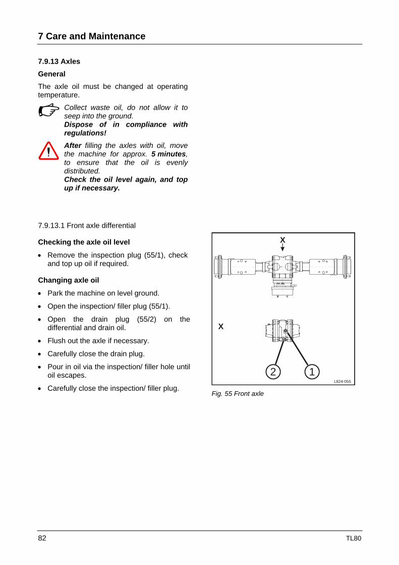
7 Care and Maintenance
82 TL80
7.9.13 Axles General The axle oil must be changed at operating temperature.
Collect waste oil, do not allow it to seep into the ground. Dispose of in compliance with regulations!
After filling the axles with oil, move the machine for approx. 5 minutes, to ensure that the oil is evenly distributed. Check the oil level again, and top up if necessary.
7.9.13.1 Front axle differential
Checking the axle oil level
• Remove the inspection plug (55/1), check and top up oil if required.
Changing axle oil
• Park the machine on level ground.
• Open the inspection/ filler plug (55/1).
• Open the drain plug (55/2) on the differential and drain oil.
• Flush out the axle if necessary.
• Carefully close the drain plug.
• Pour in oil via the inspection/ filler hole until oil escapes.
• Carefully close the inspection/ filler plug.
L824-055
1
X
X
2
Fig. 55 Front axle

Care and Maintenance 7
TL80 83
7.9.13.2 Differential of rear axle with transmission
Checking the axle oil level
• Remove the inspection plug (56/1), check and top up oil if required.
Changing axle oil
The rear axle differential and the transmission have combined oil filling.
• Park the machine on level ground.
• Open the inspection/ filler plug (56/1).
• Open the drain plugs on the differential (56/2) and the transmission (56/3) and drain the oil.
• Flush out the axle if necessary.
• Carefully close both drain plugs.
• Pour in oil via the inspection/ filler hole (56/1) until oil escapes.
• Carefully close the inspection/ filler plug.
L834-0561
X
X
2
3
Fig. 56 Rear axle

7 Care and Maintenance
84 TL80
7.9.13.3 Wheel hub
Checking the axle oil level
• Remove the inspection plug (57/1), check and top up oil if required.
Changing axle oil
The wheel hub has a combined inspection, filler and drain plug!
• Turn the wheel until the screw plug (57/1) on the hub is at the bottom.
• Open the screw plug and catch the escaping oil.
• Flush out if necessary.
• Turn the wheel to the filling and inspection position: The inspection mark must be horizontal.
• Fill in oil up to the lower edge of the hole.
• Carefully close the screw plug.
7.9.14 Wheels
Checking the tire pressure
• Check the tire pressure in accordance with the pressure chart, Chapter 3.8.
Tightness of wheel nuts
• During the first 50 operating hours, check the tightness of the wheel nuts (M 20 x 1.5) daily, and subsequently every week, and tighten to the correct torque if necessary.
Tightening torque: 460 Nm
• When fitting a wheel, tighten the nuts to the correct torque crosswise in several stages.
ÖlstandLevel
1
L834-057Ablaßstellung/Drain Fig. 57 Wheel hub

Care and Maintenance 7
TL80 85
7.9.15 Injection valves
• Injection valves must be checked by your service specialist.
7.9.16 Toothed belt for engine
• The toothed belt must be replaced by your service specialist.
7.9.17 Electrical equipment
Battery
The instructions of the battery manufacturer must be observed when using the battery for the first time.
• The acid level should be approx. 10 mm above the edges of the plates. If necessary, top up with pure distilled water.
• Only check the battery with the engine off.
With maintenance-free batteries, this check can be omitted.
Removing the battery
• Disconnect first the battery ground cable (-), then the positive cable (+).
• Detach the clamping bracket (59/1).
• Lift out the battery.
Installing the battery
• Lay the battery in the machine and secure with the clamping bracket.
• First connect the positive cable (+), then the battery ground cable (-).
Ensure that the negative terminal is connected to the negative pole (-) and the positive terminal to the positive pole (+).
In winter, in particular, the battery charge should be closely monitored.
Lighting and warning equipment
• Check the correct function of the lighting equipment.
• Check the correct function of the indicator lamps.
• Check the correct function of the warning equipment.
L824-059
1
Fig. 59 Battery

7 Care and Maintenance
86 TL80
7.9.18 Cab ventilation dust filter
• The air intake for the heating and the fresh air supply of the cab features a dust filter or optionally a charcoal/ pollen filter.
Removal
• Remove the ventilation grid (60/1).
• Remove the angle bracket (60/2).
• Take out the dust filter (60/3).
• Clean the filter or replace it.
Cleaning the dust filter
Never wash or brush out the filter!
• Knock the filter with the intake side (side covered by expanded metal) several times on a flat and hard surface.
• Using dry compressed air (max. 5 bar), blow against the direction of flow.
• Check the filter for damage to the paper bellows and seals.
Never continue to use damaged dust filters!
Re-installation
• Re-insert new or cleaned dust filter until the stop.
Observe the mounting position! The air flow arrows must point towards the cab.
• Fasten the dust filter with the angle bracket.
• Re-fit the ventilation grid.
7.9.19 Windshield washer system
• Top up the washer tank (61/1) as required.
• Add antifreeze when temperatures are around or below freezing.
L824-060
1 2
3
Fig. 60-Dust filter for cab ventilation
L824-061
1
Fig. 61 Windshield washer tank

Care and Maintenance 7
TL80 87
7.10 Shutdown 7.10.1 Preservation (temporary shutdown) To prevent damage (corrosion, etc.) from storage during shutdown periods over three months, certain preservation measures must be taken:
• We recommend keeping the machine in a dry, dust-free room during the storage period.
• Clean the inside and outside of the machine thoroughly, including the engine.
• Lubricate the machine in compliance with the lubrication plan.
• Check the oil levels of all assemblies, such as axles, transmission(s), etc. and top up if necessary.
• Check the hydraulic oil level and top up if necessary.
• Repair paint damage.
• Fill the diesel tank completely, to prevent corrosion of the tank walls.
• Check the antifreeze level in the coolant and adjust if necessary.
• Perform all the preservation measures contained in the diesel engine operating instructions.
• Check the tire pressure in compliance with the prescribed value and protect the tires from direct sunlight.
• Treat bare piston rods with a commercially available anti-corrosion agent.
• Remove and clean the battery and keep it in compliance with regulations in a dry - in winter, frost-proof - room. Coat connections with a little pole grease.
• Seal off the air intake opening of the air filter system and the exhaust pipe opening.
7.10.2 During shutdown • When the machine is out of use for
6 months, after this time all assemblies must be brought to operating temperature and maneuvered for approx. 15 minutes.
• Beforehand, the anti-corrosion coat must be removed from the piston rods, and the openings of the air filter system and the exhaust pipe freed.
• After the maneuvering cycle, preserve the machine once more as previously described.
7.10.3 After shutdown Before putting the machine into operation once more, the following measures must be carried out: • Anti-corrosion coat must be cleaned from
the piston rods. • Seal off the air intake opening of the air
filter and the exhaust pipe opening. • Remove the air filter insert, check its
condition and replace if necessary. • Check the condition of the air filter main
cartridge / safety cartridge and replace if required.
• Clean the machine with a neutral detergent.
• Check and - if required - re-charge and re-install the battery.
• Carry out all measures for putting the diesel engine back into operation stated in the engine operating instructions.
• If the machine has been out of use for more than 6 months, the oil in the assemblies such as axles, transmission(s), etc. must be changed.
• If hydraulic oil filters such as suction and return filters as well as breathers have been out of use for more than 6 months, they must be replaced.
• Lubricate the machine in compliance with the lubrication plan.

7 Care and Maintenance
88 TL80

Trouble-Shooting 8
TL80 89
8 Trouble-Shooting 8.1 General Operating problems are often the result of incorrect handling of the machine, the use of unsuitable materials or irregular maintenance.
The following table presents a summary of a range of problems and their probable causes.
If a problem can only be eliminated through repair, then the responsible Service Agent must be called in.
8.2 Engine All faults in the diesel engine must be examined as described in their specific engine operating instructions.
During the warranty period, malfunctions must be dealt with by the responsible Service Agent or a specialist workshop.
Fault Possible cause Remedy 8.3 No steering movement
1 Oil supply to pump interrupted Check and repair suction line
2 Hydraulic pump damaged Repair or replace
3 Priority valve damaged Remedy fault (call Service Agent)
4 Steering control unit damaged Remedy fault (call Service Agent)
5 Steering cylinders damaged Repair
6 Mechanical fault Repair
8.4 Insufficient performance of service brake
1 Wear of drum brake Adjust or repair (call Service Agent)
2 Master brake cylinder damaged Repair or replace (call Service Agent)
3 Mechanical fault Repair (call Service Agent)
8.5 Insufficient performance of parking brake
1 Wear of drum brake Adjust or repair
2 Mechanical fault in brake actuation Repair and/ or re-adjust
8.6 Hydrostatic drive has no neutral position
1 Switch for direction of travel damaged Repair or replace
2 Solenoids of valve damaged Repair or replace
3 Neutral position has shifted Check, re-calibrate (call Service Agent)
4 Internal damage to travel pump Replace travel pump
5 Excessive engine idling Adjust

8 Trouble-Shooting
90 TL80
Fault Possible cause Remedy 8.7 Hydraulic oil exceeds max. admissible temperature
1 Thermo switch damaged Replace
2 Oil level too low Top up oil to mark on dipstick
3 Oil cooler clogged or faulty Clean, check, replace if necessary
4 Suction filter clogged Replace
5 High-pressure valves do not respond all the time or too early
Check high-pressure valves, re-adjust or replace if necessary
6 Flushing circulation does not function Check pressure of flushing and filling pump, possible back pressure in cooling circuit, check housing pressure
7 Travel pump or travel motor damaged (worn)
Replace
8 Charge pump worn Replace
9 Main relief valve damaged Replace
8.8 Sluggish acceleration and deceleration, too little propulsive power 1 Insufficient engine power Check diesel engine
2 A brake has got stuck Check, remedy damage
3 No tank pressurization Check breathers and breathers, replace
4 Suction filter clogged Replace filter
5 Fast/ slow-gear does not shift electrically or mechanically
Check power supply and solenoid valve, repair and replace if necessary. Check travel motor
6 Fault in brake inching device Check, adjust, replace
7 Filling pump sucks up air Check, eliminate leakage
8 Travel pump mis-adjusted Re-adjust travel pump
9 Filling or supply pressure too low Check pressure, adjust
10 Pressure relief valve of filling circuit clogged or faulty
Check, re-adjust or replace
11 High-pressure too low Check high-pressure (pressure cut-off), and re-adjust high-pressure valves or replace if necessary
12 Travel pump does not open fully, pilot pressure too low
Nozzles clogged, check, repair
13 Internal damage to travel pump or travel motor
Replace units
14 Travel motor mis-adjusted Re-adjust travel motor

Trouble-Shooting 8
TL80 91
Fault Possible cause Remedy 8.9 Transmission works in one direction only
1 Switch for direction of travel damaged Repair or replace if necessary
2 Solenoid valve sticks or is damaged Repair or replace if necessary
3 Power supply towards switch for direction of travel or solenoid valve interrupted
Check and repair (incl. ground connection)
4 Pilot pressure too low on one side Nozzles clogged, check, clean
5 High-pressure relief valve is faulty or incorrectly set
Swap valves around. If machine now travels in the other direction, examine valve, clean and replace if necessary
8.10 Transmission works in neither direction
1 Too little hydraulic oil in tank Top up to mark on dipstick
2 Mechanical connection to diesel engine faulty
Check, repair
3 Filling pump damaged, no filling pressure
Remove pump and examine, install new pump if necessary
4 Switch for direction of travel damaged Repair and replace if necessary
5 Solenoid valve for direction of travel damaged
Repair and replace if necessary
6 Suction filter clogged Replace filter
7 Suction line between tank and pump kinked
Check and eliminate kink
8 Power supply to switch for direction of travel and solenoid valve interrupted
Remedy cause of interruption
9 Internal damage to travel pump or travel motor
Replace units completely
10 Mechanical connection between travel motor and axle interrupted
Check, repair
8.11 Loader installation is not working
1 Oil supply to pump interrupted Check suction line and repair if necessary
2 Main relief valve damaged Check and replace if necessary
3 Hydraulic pump damaged Check, repair or replace
4 Hydraulic pump drive mechanically interrupted
Check and repair

8 Trouble-Shooting
92 TL80
Fault Possible cause Remedy 8.12 Decrease in machine’s performance (loader installation)
1 Insufficient engine power Check diesel engine and adjust if necessary
2 Hydraulic oil level too low Top up hydraulic oil to the mark on the dipstick
3 Pump is sucking up air Tighten hose connections. Replace O-ring or seals
4 Insufficient operating pressure Re-adjust main relief valve, replace if necessary
5 Wear of pump Replace pump
6 Incorrect hydraulic oil Quality of hydraulic oil must conform to our recommendation
8.13 Working cylinders are not working satisfactorily
1 Seals in cylinders worn Re-seal cylinders
2 Secondary valves faulty Check secondary valves and replace completely if necessary
8.14 Trouble in the electrical system
1 Outside and/or internal lighting damaged
Check cables, connections, bulbs and fuses
2 Windshield wiper does not work Check cables, connections and fuses.
Examine windshield wiper for mechanical damage.
Replace complete wiper if necessary
3 Horn does not work Check cables, connections and fuses. Replace complete horn
4 Control organs are imprecise Determine the fault or source of the problem, call Service Agent if necessary
5 Starting system does not work satisfactorily
Check charge capacity of battery.
Test starter function.
Check connection and condition of power and battery ground cables.
Check function of ignition lock, replace if necessary.

Appendix 9
TL80 93
9 Appendix 9.1 Electrical system
Fuse box - Assignment diagram
L824-E0102-10-15
5
6
7
8
1
2
3
4
9
10
11
A B
A B
C
D
C
F01F02F03
K2 K1
5
6
7
8
1
2
3
4
9
10
11
D = K3 (turn-signal flasher relay) below instrument panel
A B Position Ampere assigned to Position Ampere assigned to
F 1 15 Heater fan F 1 15 Working floodlight, front
F 2 15 Wash/wipe, front F 2 15 Working floodlight, rear
F 3 15 Wash/wipe, rear F 3 10 Turn signal
F 4 10 Rotating beacon; interior light F 4 10 Hazard warning switch
F 5 15 Travel, forward/reverse F 5 15 Socket; radio
F 6 10 Reserve F 6 15 Reserve
F 7 10 Reserve F 7 10 Horn
F 8 10 E-module inputs F 8 10 High beam
F 9 10 Instruments F 9 15 Low beam
F 10 10 Radio F 10 10 Side marker light, left
F 11 15 Reserve F 11 10 Side marker light, right
C / D F 01 50 Fuse K 1 Start relay
F 02 80 Starting system K 2 Pre-heat relay
F 03 30 Control module power supply K 3 Turn-signal flasher relay
Colors of fuses
10 A red 15 A blue 30 A rose 50 A red 80 A white
Cable and Plug colors
bg beige dgr dark gray hbr light brown rt red bl blue ge yellow hgr light gray sw black br brown gn green hr light red vi violet dbl dark blue gr gray nt nature ws white dbr dark brown hbl light blue or orange

9 Appendix
94 TL80
DELIVERY AND HANDING-OVER INSTRUCTIONS The following checklist is to be followed when handing over the machine to the customer:
1. Operating instructions The operating instructions should be read side by side, and be explained in detail through practical training on the machine. The following items are essential: • Accident Prevention Regulations published by the employer’s liability
insurance associations in the user’s country • Technical data • Operator controls, indicating and warning elements • Checks before putting the machine into operation • Specifications for diesel engine start-up • Starting and switching off the diesel engine • Explanation of hydrostatic drive • Driving, speed ranges and notes for driving on roads • Recovery and transport of the machine • Operation of all functions • Actuation of the quick-attach system • Explanation of maintenance and inspection intervals in compliance with
Maintenance and Inspection Plan by demonstrating maintenance points on machine
• Lubrication intervals and points of lubrication in compliance with lubrication chart and demonstration of these points on the machine
• Handing over the diesel engine operating instructions 2. Spare parts list • Structure of spare parts list, of Figure s and the respective descriptions • Instructions for ordering spare parts: always state the type of machine, the
vehicle identity number (Fz-Id.Nr.), parts designation, complete spare part number, piece number, delivery address, etc.
3. Warranty • Explanation of warranty covered by manufacturer • Explanation of inspection cards and note on maintenance and inspection
plan • The warranty/ handing-over card must be filled out correctly and returned
Wheel Loader TL80
Maintenance and Inspection Plan The careful performance of all prescribed inspections is the best prerequisite for the machine’s continuous readiness for operation.
All maintenance work mentioned should therefore be performed in the prescribed sequence with the machine being in warm condition.
The inspections are obligatory.
If omitted, this may affect the warranty covered by us.
The machine must be thoroughly cleaned before inspection takes place.

I n s p e c t i o n T a b l e T o b e c a r r i e d o u t b y t r a i n e d d e a l e r / s e r v i c e t e c h n i c i a n
O = Checking, maintenance X = Replacement
Operating hours min. 2x
min. 1x
Perform work with machine at operating temperature
after 100
every 500
every 1000
every 2000
yearly yearly
1 Check whether machine-specific instruction book is in the machine
O O
2 Change engine oil X X 3 Change engine oil filter X X 4 Drain water from fuel tank O O O 5 Change fuel filter X X 6 Clean fuel pump and screen filter O 7 Check air intake O O 8 Change air filter - main cartridge to service indicator X 9 Change air filter - safety cartridge as required 1) 10 Clean cooling fins of hydraulic oil cooler. O O O
In case of high exposure to dust, shorten the cleaning intervals.
11 Clean cooling fins of engine oil cooler O O O
In case of high exposure to dust, shorten the cleaning intervals.
12 Check V-belt tension O O 13 Check engine mounts and pump attachments O O 14 Check engine speed adjustment, top-end and
low idle speed O O
15 Check valve lash of engine and adjust if necessary
O
16 Check injection valves O 17 Check fuel leak oil pipe and replace if
necessary O X1)
18 Replace toothed belt 3) 19 Check crankcase breather in valve cover O 20 Check acid level and battery connections O O 21 Check condition of tires, tire pressure and
tightness of wheel nuts O O
22 Check secure fastening of axles and propeller shaft
O O
23 Check bearing bushings and bolts of work equipment and replace if necessary
O O
24 Check bushings and bolts of the articulation and the articulated steering and replace if necessary.
O O
O = Checking, maintenance X = Replacement
Operating hours
min. 2x
min. 1x
Perform work with machine at operating temperature
after 100
every 500
every 1000
every 2000
yearly yearly
25 Check that door catches function perfectly, and replace if necessary
O O
26 Clean or replace the dust filter for cab ventilation
O X X
27 Check electrical indicating and warning elements, and lighting system
O O
28 Check smooth running of operator controls and adjust if necessary
O O
29 Check tightness of all pipes, hoses, control valve, hydraulic pumps, cylinders, etc.
O O
When tightening hose and pipe
connections, screw-in couplings must be locked to prevent rotation.
30 Check or change hydraulic oil O O X 2) X 31 Replace insert of hydr. oil return suction filter X X X 32 Replace breather X X 33 Check function of brakes and replace brake
oil O O X X
34 Bleed brake O O 35 Rear axle differential with transmission /
option: transmission: oil check or oil change X O X X
36 Front axle differential - oil check or oil change X O X X 37 Wheel hubs of front and rear axles: oil check
or oil change X O X X
38 Grease machine in compliance with overview of lubricating points
O O
39 Check function, condition and completeness of safety equipment
O O
40 Hydraulic function check with pressure function test
O O
41 Test run and test work O O 42 Initial inspection cards and return to
manufacturer O O 4)
1) at least every 2 years 2) Extension of oil change intervals in compliance with oil sample analysis and lab report. For further information see Chapter 7.3 3) Every 5 years or 5,000 operating hours respectively 4) within warranty