OP Pictures by Radio
52
July 1934 Edited by obert Hertzberg and Louis Martin IN THIS ISSUE : he Ten Best Foreign S. W. Stations By J. B. L. Hinds OP Pictures by Radio New World List of Stations in Handy Form The Truth About "Noise Reducing" Aerials Amateurs Rescue Flood Victims By Lewis Winner The Method 1 Making Superhets Work By Robert S Kruse Clifford E. Denton's Latest Receiver _ _ =s= = = = - _ - =_ _ <. z _ =- =
-
Upload
khangminh22 -
Category
Documents
-
view
0 -
download
0
Transcript of OP Pictures by Radio

July 1934
Edited by
obert Hertzberg and Louis Martin
IN THIS ISSUE :
he Ten Best Foreign S. W. Stations
By J. B. L. Hinds
OP Pictures by Radio
New World List of Stations in Handy Form
The Truth About "Noise Reducing" Aerials
Amateurs Rescue Flood Victims
By Lewis Winner
The Method 1
Making Superhets Work By Robert S Kruse
Clifford E. Denton's Latest Receiver
_ _ =s= = = =
- _ - =_ _ <. z _
=-
=

BOOKS FOR THE RADIO MAN Many of the questions asked daily by radio experimenters, constructors and listeners all over the country are answered completely and clearly in vari- ous books. To assist radio men in buying books best suited for their own particular needs, we have made a selection of representative works that we can recommend very highly. These books are all up -to -date and
will prove very valuable.
-ihe RADIO QMQTEUR%' H4NDDCO1< .4...,,...,.. °.:...,.,a.
"The Radio Amateur's Handbook" The RADIO AMATEUR'S HANDBOOK was first published in the fall of 1926. It was in response to a growing demand upon the American Radio Relay League for some sort of a manual of operation for short -wave experi- mental radio work. The first edition met with great favor and two reprint - ings were necessary to supply the demand. Since that time ten subsequent editions have been published and more than 215.000 copies have been sold. The latest edition ( 11th edition, published January, 1934) is approximately 15'; larger than the first edition, and represents probably the most compre- hensive revision yet attempted. New receiver circuits and designs are pre- sented. together with a thorough treatment of the recently -developed "single - signal" sets. A completely re- written 36 -page chapter is devoted to all that is new in the world of transmitters. New circuits and layouts are given, all problems which face the transmitting amateur being discussed in a lucid and comprehensive manner. The radio telephony chapter represents all new material. New designs for Class B modulators and speech amplifiers are fea- tured. Still another new chapter is that on
antennas. 238 pages. many illustrations. Price $1.00 postpaid
"The Outlook for Television" How far has television advanced? How far is it
from commercial application? What form will this application take? ow will it affect broadcasting, advertising, home and theatre entertainment? How will it be used in education. politics, war, and religion'
Mr. Orrin E. Dunlap, the author, tells in detail how television has been developed to date. He ex- plains in clear, simple language the technical and scientific principles on which it rests, the obstacles which must be overcome. the probable future de- velopments of the industry. It is a book not only of facts but of personalities. The author takes us into the television laboratories of such men as Alex -
anderson, Zworykin, Jenkins, Hammond, Baird, and others- explains the work they are doing. and pre- sents their opinions on the future of television. The book is authoritative.
Price $4.00 Postage extra
"How to Become a Radio Amateur"
Completely done over in 1934 style, telling all about amateur radio and describing the latest equipment- push-pm!! transmitter-- bandspread pentode receiver- simplest of monitors.
l'he third edition of "How to Become a Radio Ama. teur" marks another milestone in amateur develop- ment. Still the standard elementary guide for the would -be amateur, the simple, inexpensive station de- scribed incorporates features which in the past have been confined to the more advanced layouts. The de- signs have been made flexible. so that parts out of the junk box can be readily substituted. The performance of the completed station is such that any amateur can own and operate it with satisfaction and pleasure. It's a real amateur station, with con- struction and operation described 5.25 price in clear. understandable language. Postpaid
"flints and kinks for the Amateur For years hams have said that one of
the most practical and valuable features of all radio magazines is the experi- menter's section. But -try to recall when it was you saw that swell (but, alas, only dimly remembered) suggestion for band -spreading, or a key click elimi- nator. What was needed was a compilation of all the best ideas, brought under one cover, segregated by subjects, and in- dexed. And here it is -an intensely practical book, filled out with selected additional material, with dozens of valu- able and workable ideas gleaned from the practical station experience of suc- cessful amateurs. Chapters on workshop ideas, receivers, transmitters, amateur, phone QRM elimination, keying, power supply, and so on.
An ever- present help in time of trou- ble, and worth its weight in crystals when you are des- perate for an idea. Price $.50 80 pages in aurae- Postpaid tive paper covers.
II1.\TN 6: kl \ Iti N
r.. lb. Ydl.
,.. ...,...
"Radio A ma tour's License Manual" Before you can operate an amateur
transmitter, you must have a government license and an officially assigned call. These cost nothing -but you must be able to pass the examination. The License Manual tells how to do that -tells what you must do and how to do it. It makes a simple and comparatively easy task of what otherwise might seem a difficult task. In addition to a large amount of general information, it contains 198 typical ques- tions and answers such as are asked in the government examinations. If you know the answers to the questions in this book, you can pass the examination without trouble
Price 5.25. Postpaid.
The Rail. AwwteMrY
LICENSE nIA1UAL
The safest way to remit money is by post office or express money order. Hold your receipt until your books arrive. Do not send coins through the mail. Write or print your name and address clearly. Prompt deliveries of
all orders guaranteed. No books sent on approval or C. O. D.
Standard Publications, Inc., 1123 Broadway, New York, N.Y.

.1. E. Smith. l'nxldcnl, N Clonal Radio bolt flute. The roan who has direeted the Home -Study training or more men for the Radio Induxtry than any other man in .. ,.tom
E A RADIO EXPERT Many Make $ 75
s40 su a Week 1/1 train you at home ormany Good
Spare Time and Full Time Radio Jobs
..-c.. - t r ÿ
' Spare time set servi- ing pays many N.R.I. men $5, $10, $15 a
week extra. Full time men make as much as
?40, $60, $75 a week.
i ,
...a {
tl
. ' ß
rift r l i t -., (
t. i. -
j
',
Y,
Broadcasting Stations
Employ managers, engineers, operators, installation and maintenance men f jobs paying up h f Y g P
$5,000 a year.
' ,
1'101
f f
r" `is: I I
+`r k ¡ ;,e,.y, 'Nxr., `,
Radio Factories
Employ testers, inspectors, fore -
serrvicemen e for jobs paying up to
$7,500 a year.
Aircraft Radio
Radio is making flying safer. Radio operators employed through Civil Ser- vice Commission earn $1,620 to
$2,800 a year.
Loud Speaker Appara tus
Installation and service work is an
ther growing money- making field 1.r trained Radio
men.
Television The coining field of many great oppor- tunities is covered
by my Course.
I YOU are dissatisfied with your present job; if you are
struggling along in a rut with little or no prospect of anything better than a skinny pay envelope -clip the
coupon NOW. Get my big FREE hook on the opportunities in Radio. Read how quickly you can learn at home in your spare time to he a Radio Expert -what good jobs my gradu- ates have been getting -real jobs with real futures.
Many Radio Experts Make $40, 860, $75 a Week In about tin years the Radio Industry has grown from a
few million dollars to hundreds of millions annually. Over .00,000 jobs have been created by this growth, and thousands more will be created by its continued development. Many men :Ind young men with the right training -the kind of training I give you in the N. R. I. Course -have stepped into Radio at two and three times their former salaries. Real Opportunities Ahead in Radio for Trained Men
It's had to Lind a field with more opportunity awaiting the trained man. Why in 1933 -one of the worst depression years -the Radio Industry sold $213,000,000 worth of sets and parts!
Radio set sales increased 45% -tube sales increased 25 %! Over .tí10,000 people worked in the industry. Its a gigantic business, even in the worst business years: And look what's ahead! Mil- lions of sets are becoming obsolete annually. 16,000,000 sets are in operation on which over $200,000,000 are spent each year for repairs, servicing, new tubes, etc. Broadcasting sta- tions pay their employees (exclusive of artists) approximately S23,000,000 a year. Advertisers pay 600 great broadcasting stations over $75,000,000 a year for radio time and talent. "These figures are so big that they're hard to grasp! Yet they're all true! Here is a new industry that has grown to a commercial iant! No wonder great business leaders predict a brilliant future for this great and growing business!
Get into This Field With a Future There's opportunity for you in Radio. Its future is
certain. Television, short wave, police Radio, automobile Radio, midget sets, loud speaker systems, aircraft Radio -in
FREE Radio Servicing Tips
Let me PROVE that my Course is clear, easy to un- derstand, and fascinating to study. Send the coupon for
a free lesson, "Trouble Shoot - ing in D.C., A.C. and Battery Sets." This interesting lesson gives 132 ways to correct com- mon Radio troubles. I am will- ing to send this book to prove that you too can master Radio -just as thousands of other fellows have done. Many of them, without even a grammar school education, and no Radio or technical experience, have become Radio experts and now earn two or three times their former pay. Mail coupon now.
every branch, developments and improvements are taking place. Here is a real future for thousands and thousands of men who really know Radio. Get the training that opens the road to good pay and success! Send the coupon now and get full particulars on how easy and interesting I make learning at home. Read the letters from graduates who are today earning good money in this fascinating industry.
Many Make SS, Sie, SIS a Week Extra in Spare Time Almost at Once
My book also tells how many of my students made $5, $10, and $15 a week extra servicing sets in spare time, soon after they enrolled. I give you plans and ideas that have made good spare time money- -$200 to $1,000 a year -for hundreds of fellows. My Course is famous as "the one that pays for itself."
Money Back If You Are Not Satisfied I am so sure that N. R. I. can train you it home satisfac-
torily that I will agree in writing to refund every penny of your tuition if you are not satisfied with my Lesson and Instruction Service upon completion. You'll get a copy of this Agreement with my hook.
64-page Book of Information Free Get your ropy today. It- it r, to soy
ambitious fellow over 15 years old. It tells you about Radio's spare time and full time job opportunities; it tells you all about my Course; what others who have taken it are doing and making. Find out what Radio offers YOU without the slightest obligation. MAIL. THE COUPON in an envelope. or paste it on a le post card NOW.
J. E. Smith, President, NationalRadio Institute Dept. 4GSS,
Washington, D. C.
J. E. SMITH, President, National Radio Institute, Dept. 4GSS Washington, D. C.
Dear Mr. Smith: I want to take advantage of your Special Offer. Send me your two books, "Trouble Shoot- ing in D.C., A.C. and Battery Sets" and "Rich Rewards in Radio." I understand this request does not obligate me. (Please print plainly.)
Name Age
Address
City State "M"
July, 1934 Vol. 1, No. 9
SHORT WAVE RADIO devoted to short -wave transmission and reception in all their phases
Robert Hertzberg, Editor Louis Martin, B. S., Techmcal Director
IN THIS ISSUE
Of General Interest:
Pictures by Radio 4
Beware of the Fake Noise Eliminator! 5
Progress of the Short -Wave Art by P. C. Sowersby 6
Amateur Radio to the Rescue in the Northwest by Lewis Winner 8
Radio Row Goes Short Wave 9
J. B. L. Hinds Picks the Ten Best Short -Wave Stations 10
Best Short -Wave Stations I3
Reception Reports from Readers 14
New World List of Stations 16
International Call Letter Assignments 19
Bock Review 19
Short -Wave Receiver Review 20
Before Breakfast Short Wave Club 42
Of Explanatory Nature:
Some Questions and Answers on Noise Reduc- ing Aerial Systems- Answers by Arthur H. Lynch
The Double Doublet
Must Supers be Noisy?
Some Suggestions for Using the New Multi - Element Tubes
Some Applications of New Type Electrolytic
Condensers
Making the Super Work .. by Robert S. Kruse
Converting Operating Conditions
For the Constructor: The Mascot 2
The AC -DC Air Scout Set.. by Harold Mitchell
The Denton 1934 Discoverer
The Double Duplex by Louis Martin
22
24
26
27
28
30
43
32
33
34
36
2
IN FUTURE ISSUES:
LOUDSPEAKERS FOR S.W. USE -Although it is an ex- tremely important part of every short -wave receiver, the loudspeaker has received comparatively little attention from users of these popular receivers. Our Technical Director has prepared an excellent article on the subject, dealing par- ticularly with the proper methods of field excitation.
PORTABLE RECEIVERS -At least one portable receiver of excellent design and construction will be described in the forthcoming August issue. We had expected to run this set in the current number. but a number of little "bugs" developed in it and we decided to exterminate them before presenting the set to our readers.
ADVANCE DATA ON THE NEW SETS -Without revealing any confidences, we are able to say at this time that a number of new and different ideas will appear in forth- coming short -wave and all-wave receivers that will appear this Fall. We can state definitely that the superheterodyne circuit is here to stay and that it will be o whole lot quieter than heretofore. Multi -stage pre -selectors, improved automatic volume control, freedom from acoustic feedback and extremely high ratio tuning controls will be among the dishes served to the buying public.
The entire contents of SHORT WAVE RADIO are copy- righted by Standard Publications, Inc., and must not be reproduced without permission of the copyright owners.
SHORT WAVE RADIO -Monthly. Entered os second -class matter September 15, 1933, at the post office at Chicago, Illinois, under the Act of March 3, 1879.
SHORT WAVE RADIO is published on the first of every month preceding date of issue. Subscription price is $2.50 a year in the United States and possessions; Canada and foreign countries $3.00 a year. Individual copies, $.25 in the United States and possessions; Canada and foreign countries, $.30. Published by Standard Publications, Inc., 4600 Diversey Avenue, Chicago, Illinois. Editorial and ad- vertising offices, 1123 Broadway, New York, N. Y. Louis Martin, President; Robert Hertzberg, Secretary -Treasurer; Charles H. Farrell, Advertising Manager.
SHORT WAVE RADIO is distributed by Pictorial Dis- tributing Corp., 222 West 39th Street, New York, N. Y.
Articles on short -wave subjects are desired, and are paid for on publication. The editors will be glad to discuss con- tributions with authors. Unused or unsolicited manuscripts will not be returned unless full postage is furnished by the contributor.
Address oll correspondence of editorial or advertising nature to SHORT WAVE RADIO, 1123 Broadway, New York, N. Y. Telephone: CHelsea 2 -6620 and 6621.
IIIIIIIIIIIIIIII
re
READY TO
IIIIIIIII IIIIIIIIIIIIIIIIIIIIIIIIIIIIIIIIIIIIIIIIIIIIIIIIIIIIIIIIIIIIIIIIIIIIIIIIIIIIIIIIIIIIIIIIIIN
o places" THE INSTANT IT'S INSTALLED
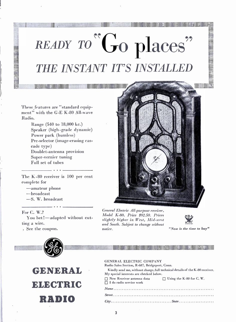
These features are "standard equip- ment" with the G -E K -80 All -wave Radio.
Range (540 to 18,000 kc.) Speaker (high -grade dynamic) Power pack (humless) Pre -selector (image- erasing cas- cade type) Doublet- antenna provision Super- vernier tuning Full set of tubes
The K -80 receiver is 100 per cent complete for
-amateur phone -broadcast -S. W. broadcast
.. For C. W.?
You bet !-adapted without cut- ting a wire. . See the coupon.
11111111111111111111111111111111111111111111111111111111111
111111 I IIIIIIIIIl1011L_,
General Electric All-purpose receiver, Model K -80. Price $92.50. Prices slightly higher in West, Mid -west and South. Subject to change without notice.
o
.VOu ia the I tu buy"
11111111111111111111111111111111111010 111111110111110101111011111 11111111111000111111111111111111111 11 111111111111111111111111111 III IIIIIIIIIIIIIIIIIIIIIIIIIIIIIIilllllli
.,, 111ÍÍÍü..ilüilÍÍIÍIIIiIiIIllÍÜil.,,.', .
GENERAL ELECTRIC
RADIO
GENERAL ELECTRIC COMPANY Radio Sales Section, R -687, Bridgeport, Conn.
Kindly send me, without charge, full technical details of the K-80 receiver. My special interests are checked below.
New Receiver antenna data Using the K -80 for C. W. I do radio service work
Name
Street
City State
3

Pictures by Radio WHILE television continues to lurk around that hidden corner, much research ef- fort is being spent on fac-
simile transmission. Transmission of this kind does not possess the popular romantic appeal of tele- vision, which has been plagued by ex- cessive and premature publicity, but it nevertheless holds some very in- teresting possibilities. Realizing this, Mr. John V. L. Hogan, well - known radio engineer and inventor, who is responsible for single dial tuning, has been busy developing what now appears to be the simplest facsimile system so far presented to the radio art.
Demonstrations of the Hogan sys- tem given recently in New York and Milwaukee, Wis., leave little doubt as to its practicability. At the trans- mitting end, images in the form of black and white drawings, typewrit- ten matter, maps, sketches, etc., or clear, contrasty photographs, are scanned by a simple viewing mech- anism. The sketches or other subject matter to be transmitted are printed or sketched by hand on a continuous paper roll about 4" wide. This feeds through the transmitter and the images are scanned continu- ously. Scenes may also be photo- graphed on regular 35 millimeter cinema film and scanned for easy transmission.
Narrow Frequency Range
In the New York experiments, Mr. Hogan's experimental transmitter, W2XAR on 1594 kilocycles, was used. In Milwaukee the experimental stations W9XAG on 1652 kilocycles and W9XAF between 40 and 60 megacycles will be used for regular experimental service. This facsimile transmission presents no particular problems insofar as the radio trans- mitter itself is concerned, as the sig- nal frequency is only about 2400 or 2500 cycles -only half the width of an ordinary broadcast signal.
At the receiving end, any high - grade receiver equipped with a suitable coupling device for the transcriber may be used. The actual picture producing machine is about half the size of a midget receiver. The images are produced on a con- tinuous roll of paper by means of a vibrating needle or stylus fed with ink. The images produced are thus immediately available for observa- tion or cutting, no chemical or photographic processing being in- volved. In fact, the user of the equipment can watch the image as it is reproduced line by line. The received record is permanent, dry and easily handled.
At the present time, detail in the reception is limited to 40 lines per inch. While this does not permit any fine gradations of tone, the
4
At the radio -pic- ture transmitting station: how hand drawn images on o continuous pa- per tape are pre- sented to t h e
"scanning" mech- anism for broad- casting. To the right is a cinema - film scanning ar- rangement, with a short loop of film in place. The sim- plicity and com- pactness of the a p p a r a t u s a r e
evident.
reproduction of cartoons, maps, stock quotations and the like is really excellent and more than fulfills the requirements of many special ser- vices.
No details of the actual transmit- ting and receiving mechanisms have as yet been released, but SHORT WAVE RADIO expects to publish fur- ther information on the apparatus in future issues.
The paper tape at the receiving end is four inches wide, and the image is reproduced on it at the linear paper speed of two and one - half inches per minute.
The Hogan apparatus is not avail- able commercially at the present time, although even now Mr. Hogan believes that machines can be built in mass production for as little as $10. Mr. Hogan himself is not in the manufacturing business, but the likelihood is that radio manufac- turers will be licensed by him and
that the radio "pens" will appear on the market as soon as a number of transmitting stations install suit- able transmitting equipment.
Short -wave set owners and ex- perimenters will undoubtedly find the Hogan facsimile apparatus a source of considerable interest. The possi- bilities of the system are obvious, and many uses can easily be devised for it.
The Milwaukee experiments are sponsored by the Milwaukee Journal, a daily newspaper, which also op- erates station WTMJ on the regular broadcast band. The Hogan ap- paratus will be installed in the Hotel Schroeder of that city. The test pro- grams will run about three hours daily, according to Walter Damm, manager of the Milwaukee Journal's stations and chairman of the Tele- vision and Facsimile Committee of the National Association of Broad- casters.
Foreign Station By Robert W. Mitchell
132 Forest Street Winchester, Mass.
A letter from Oslo states the fol- lowing: "The short -wave station LCL, Jeloy, is an experimental sta- tion erected in order to find a high frequency channel suited for relay transmission to the new Finnmark broadcasting transmitter. The time of operation is in the near future likely to be irregular, and probably the wavelength will be altered from 42.9 to 48.9 m. or more. Presently the station is transmitting the com- plete ordinary evening program from Oslo."
The summer schedule of the Deutschen Kurzwellensender (Ger- man short -wave station) to North America will be on DJC (49.83 m.)
Notes of Interest
and on DJD (25.51 m.) from 9:30 P.M. to 12:00 M. Eastern Daylight Saving Time.
The Radio Club of Tenerife sends the following: " -Most probably we will stop working with our station EA8AB for some time (former EAR58) as we intend building it up again with more power. If it closes down it will be for about 4 to 5 months.
"Nevertheless we will continue to broadcast with our station EAJ4% (201 m. 1492 kc.) , 200 w. power."
Station CJRO, 6150 kc., at Winne - peg, Man., is again working in syn- chronization with CJRX, 11,720 kc., also of Winnepeg, using the Canadian Radio Commission pro- grams from 9 P.M. to midnight E. D. T. CJRO was revamped during the winter months.
SHORT WAVE RADIO
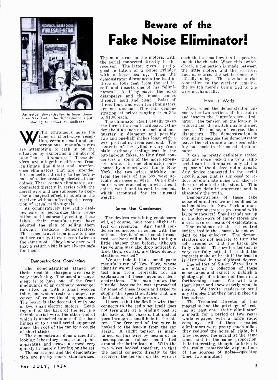
An actual demonstration in lower down- town New York. The demonstrator is just
starting to collect an audience
WITH extraneous noise the bane of short -wave recep- tion, certain small and un- scrupulous manufacturers
are attempting to cash in on the situation by exploiting a number of fake "noise eliminators." These de- vices are altogether different from legitimate line filters and interfer- ence eliminators that are intended for connection directly to the termi- nals of noise -creating electrical ma- chines. These pseudo eliminators are connected directly in series with the aerial wire and are supposed to exer- cise a magical effect in quieting the receiver without affecting the recep- tion of actual radio signals.
As comparatively few radio deal- ers care to jeopardize their repu- tation and business by selling these fakes, their manufacturers have adopted the plan of selling them through roadside demonstrators. These men travel from place to place and are rarely, if ever, seen twice in the same spot. They know darn well that a return visit is not always safe for them!
Demonstrations Convincing
The demonstrations staged by these roadside sharpers are really very convincing. The usual arrange- ment is to have one of the front mudguards of an ordinary passenger car fitted up with a small wooden table, on which rests a midget re- ceiver of conventional appearance. The board is also decorated with one or two small electric motors. Lead- ing out of the back of the set is a flexible aerial wire, the other end of which is attached to one of the door hinges or to a small aerial supported above the roof of the car by a couple of short sticks.
The demonstrator dons a scientific looking laboratory coat, sets up his apparatus, and draws a crowd very quickly by merely turning on the set.
The sales spiel and the demonstra- tion are pretty much standardized.
for JULY, 1934
Beware of the
Fake Noise Eliminator! The man turns on the motors, with the aerial connected directly to the receiver. The latter gives a pretty good imitation of a coffee grinder with a loose bearing. Then the demonstrator disconnects the lead -in three or four feet from the set it- self, and inserts one of his "elimi- nators." As if by magic, the noise disappears and the music comes through loud and clear. Sales of three, four, and even ten eliminators are not unusual after this demon- stration, at prices ranging from 35c to $1.00 each.
The eliminator itself usually takes the form of a small cardboard cylin- der about an inch or an inch and one - quarter in diameter and possibly two and one -half inches long, with a wire protruding from each end. The contents of the cylinder vary from plain, ordinary sealing wax in the out -and -out fakes, to tiny fixed con- densers in some of the more expen- sive units. In one eliminator pur- chased by a short -wave fan in New York, the two wires sticking out from the ends of the box were ac- tually one piece of wire! One elimi- nator, when cracked open with a cold chisel, was found to contain cement, which accounted for its unusual weight.
Some Use Condensers
The devices containing condensers will, of course, have some slight ef- fect on reception. Any small con- denser connected in series with the antenna circuit of most small broad- cast receivers will make the tuning a little sharper than before, although the volume may also drop noticeably. How then, you ask, are these demon- strations worked?
We are indebted to a small parts manufacturer of New York, whose identity we will keep a secret to pro- tect him from reprisals, for an explanation of these ingenious dem- onstrations. This man knows the "inside" because he was approached by some of these fakers and asked to supply the special switches that are the basis of the whole stunt.
It seems that the flexible wire that connects to the radio set itself does not terminate at a binding post at the back of the chassis, but instead goes through a small hole in the lat- ter. The free end of the wire is hooked to the lead -in from the car aerial. A slight tension is main- tained on this wire by means of an inconspicuous rubber band tied around the latter lead -in. With the two wires hooked together, so that the aerial connects directly to the receiver, the tension on the wire is
such that a small switch is operated inside the chassis. When this switch closes, a connection is made between the little motors and the receiver, and, of course, the set becomes ter- rifically noisy. The regular aerial connection to the receiver remains, the switch merely being tied to the wire mechanically.
How It Works
Now, when the demonstrator un- hooks the two sections of the lead -in and inserts the "interference elimi- nator," the tension on the lead -in is reduced and the switch inside the set opens. The noise, of course, then disappears. The demonstration is convincing because the demonstrator leaves the set running and does noth- ing but hook in the so- called elimi- nator.
It can be pretty definitely stated that any noise picked up by a radio aerial can be eliminated only at the expense of the desired radio signals. Any device connected in the aerial circuit alone that is supposed to re- duce or eliminate noise will also re- duce or eliminate the signal. This is a very definite statement and is absolutely the truth.
Demonstrations of these fake noise eliminators are not confined to automobiles -in New York a num- ber of demonstrators go around with large pushcarts! Small stands set up in the doorways of empty stores are also a favored means of exploitation.
The existence of the set control switch inside the chassis is not evi- dent to the onlooker. The demon- strators do not hesitate to turn the sets around so that the backs are fully visible. The switch tension is very carefully adjusted so that the contacts make or break if the lead -in is disturbed in the slightest degree.
The editors of SHORT WAVE RADIO are making a collection of these noise fakes and expect to publish a photograph of a bunch of them in a forthcoming issue. We will take them apart and show exactly what is inside. We invite readers to send any samples that they have picked up themselves.
The Technical Director of this magazine had the privilege of test- ing at least one "static eliminator" a month for a period of two years while engaged with a large radio company. All of these so- called eliminators were pretty much alike :
they reduced the noise all right, but they reduced the signal at the same time, and in the same proportion. It is interesting, though, to listen to the really remarkable explanations of the sources of noise -speaking time, two minutes !
5
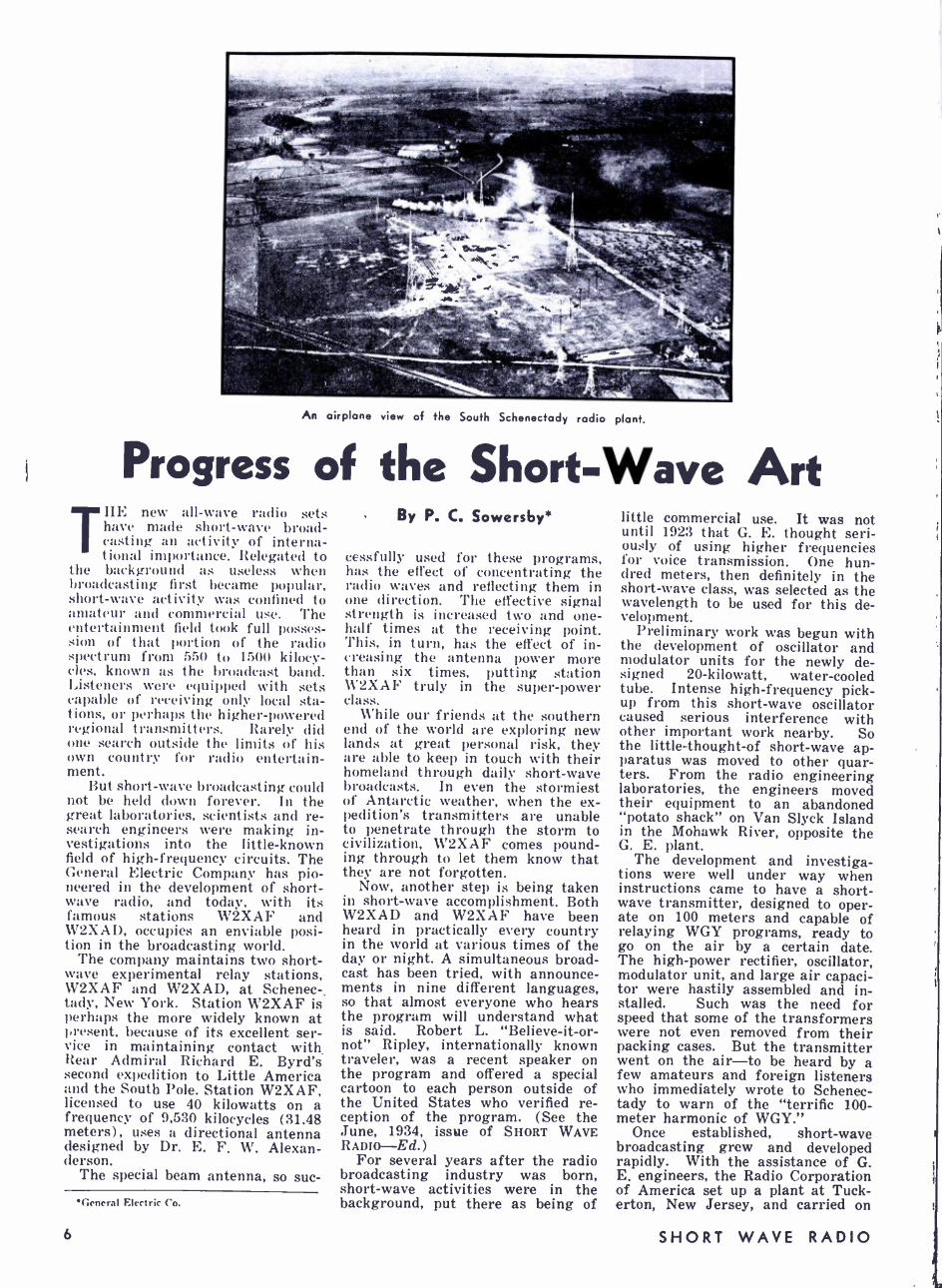
An airplane view of the South Schenectady radio plant.
Progress of the Short -Wave Art THE new all -wave radio sets
have made short -wave broad - casting an activity of interna- tional importance. Relegated to
the background as useless when broadcasting first became popular, short -wave activity was confined to amateur and commercial rise. The entertainment field took full posses - sion of that portion of the radio spectrum from 550 to 1 500 kilocy- cles, known as the broadcast band. Listeners were equipped with sets capable of receiving only local sta- tions, or perhaps the higher -powered regional transmitters. Rarely did one search outside the limits of his own country for radio entertain- ment.
But short -wave broadcasting could not be held down forever. In the great laboratories, scientists and re- search engineers were making in- vestigations into the little -known field of high -frequency circuits. The General Electric Company has pio- neered in the development of short- wave radio, and today, with its famous stations W2XAF and W2XAD, occupies an enviable posi- tion in the broadcasting world.
The company maintains two short- wave experimental relay stations, W2XAF and W2XAD, at Schenec -. tidy, New York. Station W2XAF is perhaps the more widely known at present, because of its excellent ser- vice in maintaining contact with. Rear Admiral Richard E. Byrd's second expedition to Little America and the South Pole. Station W2XAF, licensed to use 40 kilowatts on a frequency of 9,530 kilocycles (31.48 meters), uses a directional antenna designed by Dr. E. F. W. Alexan- derson.
The special beam antenna, so suc-
General Electric Co.
By P. C. Sowersby*
cessfully used for these programs, has the effect of concentrating the radio waves and reflecting them in one direction. The effective signal strength is increased two and one - half times at the receiving point. This, in turn, has the effect of in- creasing the antenna power more than six times, putting station W2XAF truly in the super -power class.
While our friends at the southern end of the world are exploring new lands at great personal risk, they are able to keep in touch with their homeland through daily short -wave broadcasts. In even the stormiest of Antarctic weather, when the ex- pedition's transmitters are unable to penetrate through the storm to civilization, W2XAF comes pound- ing through to let them know that they are not forgotten.
Now, another step is being taken in short -wave accomplishment. Both W2XAD and W2XAF have been heard in practically every country in the world at various times of the day or night. A simultaneous broad- cast has been tried, with announce- ments in nine different languages, so that almost everyone who hears the program will understand what is said. Robert L. "Believe- it -or- not" Ripley, internationally known traveler, was -a recent speaker on the program and offered a special cartoon to each person outside of the United States who verified re- ception of the program. (See the June, 1934, issue of SHORT WAVE RADIO-Ed.)
For several years after the radio broadcasting industry was born, short -wave activities were in the background, put there as being of
little commercial use. It was not until 1923 that G. E. thought seri- ously of using higher frequencies for voice transmission. One hun- dred meters, then definitely in the short -wave class, was selected as the wavelength to be used for this de- velopment.
Preliminary work was begun with the development of oscillator and modulator units for the newly de- signed 20- kilowatt, water -cooled tube. Intense high -frequency pick- up from this short -wave oscillator caused serious interference with other important work nearby. So the little -thought -of short -wave ap- paratus was moved to other quar- ters. From the radio engineering laboratories, the engineers moved their equipment to an abandoned "potato shack" on Van Slyck Island in the Mohawk River, opposite the G. E. plant.
The development and investiga- tions were well under way when instructions came to have a short- wave transmitter, designed to oper- ate on 100 meters and capable of relaying WGY programs, ready to go on the air by a certain date. The high -power rectifier, oscillator, modulator unit, and large air capaci- tor were hastily assembled and in- stalled. Such was the need for speed that some of the transformers were not even removed from their packing cases. But the transmitter went on the air -to be heard by a few amateurs and foreign listeners who immediately wrote to Schenec- tady to warn of the "terrific 100 - meter harmonic of WGY."
Once established, short -wave broadcasting grew and developed rapidly. With the assistance of G. E. engineers, the Radio Corporation of America set up a plant at Tuck - erton, New Jersey, and carried on
6 SHORT WAVE RADIO
conversations with England on short -waves. Other nations were beginning to take notice of the pos- sibilities of higher frequencies.
Spring floods in the Mohawk River made broadcasting from Van Slyck Island difficult. Programs were continued nightly, but high water marooned the operators and engineers on more than one occa- sion ; . escue was effected by row- boat and canoe.
Necessity for facilities for expan- sion, as well as the need for more commercial quarters, resulted in the establishment of the radio experi- mental laboratory at South Sche- nectady. Under new licenses issued by the Department of Commerce, the projects grew rapidly. Develop- mental work, which had begun in the 100- to 109 -meter band, pro - gressed until the frequencies of 4610 kc. (65 meters), 7140 kc. (42 meters) , 9150 kc. (32.77 meters) ,
11,550 kc. (26 meters), and 13,660 kc. (21.96 - meters) were used.
Problems of Frequency Shift
Many difficult problems were en- countered as the power was in- creased in short -wave circuits. In the original self- excited oscillator circuits, large shifts in frequency resulted from the natural vibrations of capacitors, from body capacity effects when operators moved near the transmitters, and from various mechanical vibrations. Such fre- quency fluctuations made the carrier wave unsuitable for speech modula- tion. Vibration was minimized by rigid construction, and later the use of harmonic amplifiers made possi- ble a much steadier carrier through the use of temperature -regulated crystal control.
Vacuum -tube construction became an increasingly difficult problem with the introduction of high -fre- quency circuits. Greater power at high frequency resulted in failure of grid leads within the tubes. Con- tinued difficulties of this nature finally brought about the develop- ment of new tubes having low grid capacities, capable of withstanding high frequencies.
Short -waves also resulted in new methods of radio insulation. Porce- lain, bakelite, and other similar insulating materials were unsatis- factory. Glass had to be used in many cases, and, finally, an entirely new insulating material- Mycalex- was developed.
Valuable information was ob- tained as the short -wave tests progressed, by simultaneous trans- missions on several frequencies. The coöperation of the American Radio Relay League, and many amateurs, in addition to the company's own observers, made it possible to de- termine the more favorable frequen- cies for short -wave broadcasting. Reports from Europe, Africa, South America, and Australia, represent- ing widely different time zones,
were of great assistance in determ- ining the success of the tests.
Accordingly, two frequencies were selected to give the greatest possi- ble coverage from Schenectady, and early in 1927, W2XAF and W2XAD began operating on alternate nights, transmitting the regular programs of WGY. W2XAF used a frequency of 9,150 kc. (32.77 meters), and K2XAD used 13,660 kc. (21.96 meters).
The advent of broadcasting net- works brought many events of national and international impor- tance within the reach of short -wave audiences. Through these short- wave stations, many historical hap- penings were broadcast. Among them were:
New York's reception to Colonel Lindbergh.
The Prince of Wales' speech at the opening of the Peace Bridge in Buffalo.
The Pan -American Conference at Havana.
President Coolidge's address to the Pan -American Conference at Washington.
New York's reception to the crew of the "Bremen."
Time signals and messages to the Gow -Smith expedition in Brazil.
Important American football games.
World's Series baseball games. Heavyweight- championship box-
ing matches. King George's speech to the Arms
Conference. The inaugurations of Presidents
Hoover and Roosevelt. Opening of Congress and impor-
tant Congressional legislation. To make the coverage more nearly
complete, programs of W2XAF and W2XAD have been rebroadcast from such distant points as England, South Africa, Spain, France, Aus- tralia, New Zealand, Mexico, Cuba, Argentine, Brazil, and Chile. So much interest has been shown by
foreign listeners in American short- wave schedules that many of the pro- grams of W2XAF and W2XAD have been listed in foreign periodicals. The present use of all -wave sets has made the interchange of program material of great real value.
Not only has short -wave broad- casting been of value internation- ally, but it has brought increasing response from listeners in many southern states of the United States, indicating a large field of reception. High static levels in the summer months make long -wave reception difficult, and, in many cases, impos- sible. Short -wave transmissions necessarily have been used in tropi- cal and semi -tropical countries, where electric disturbances are par- ticularly severe in the middle and lower frequencies.
Success Recognized
The success of American short- wave broadcasting, we believe, has done much to popularize it in other lands. The British Broadcasting Corporation, after a series of tests on station G5SW at Chelmsford (which included many two -way con- versations with W2XAD and other American stations interested in long- distance transmission s), adopted it for Empire communica- tion. Today, the Corporation trans- mits to remote parts of the Empire through regular short -wave sched- ules.
Schenectady transmissions have become so popular that many daily newspapers in England, in Central and South America, and in Australia carry the 19- and 31 -meter sched- ules. BBC's "World Radio Maga- zine" syndicates the G. E. short- wave programs to both English and continental newspapers. Continental reports of Schenectady programs prove that the stations have regular listeners on the far side of the At- lantic.
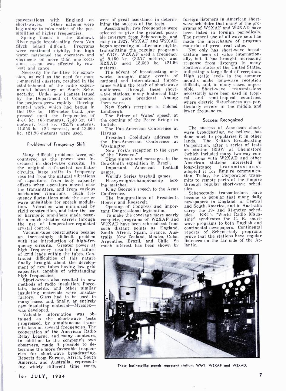
These business -like panels represent staticns WGY, W2XAF and W2XAD.
for JULY, 1934 7

Three of the operators of W7BEV one of the key stations in the rescue work. The operators, horn left to right, are Nelson Colett, Roland Smith and Wilbur Miller.
Amateur Radio to the Rescue in the Northwest By Lewis Winner STREWN shreds of clothing
over hullos battered by .,-wirl- ing, woolen waters ; countless disheveled, hottleless, %Vander -
ing children and adults. shrieking, sobbing, staring at their treasured symbols of life suddenly s%%ept away. A !Piercing tragedy. :ut(1 this but briefly prtrays the scene of a piti- ful tloo(1- stricken area.
A sudden roar, an airplane, and almost magically, :ti(1 is at hand. A few dots and dashes from this iso- lated section torn apart by a prank of nature. and the world begins to ht,Ili.
¿ r11o1e stirring scene could not be painted. Short -wave radio and the zealousness which radio ama- teurs have shown in this work are the answer. Operating a perfectly harmonious keyed system, they dem- onstrated the vital value of this means of communication in the re I ent floods in the Coeur I)' Alenes :urea, %which cut otl' the toWns of \ \'a!lace and Kellogg, Idaho.
Every means of communication suddenly impaired, the entire flooded district was shrouded in walls of silence. Swift radio messages, how - ever, soon cracked through the ether, Fringing prompt assistance.
Without compensation, working t relessly day and night. repairing transmitting antennas in darkness :old storm, tramping hip deep in mud, currying heavy equipment into the storm ridden district. these sol- diers Of short -wave radio stood by for one hundred and twenty con - secutive hours.
\\'hen the first report of condi-
8
tions at Wallace and Kellogg reached station \1'7A tA, Spokane, Washington, owned by Henry Stur- t(vant, his transmitting antenna was out of order. The area was bitched in darkness and a high wind was blowing. Sturtevant, however, realized that an emergency existed. With only a single flashlight to guide hint. he climbed two fifty -foot trees on which the antenna was suspended, untangled the wires. brought them down to earth. and made the proper repairs. Almost immediately, he and station \ \'7BI:\' contacted \V7i I)X at Wallace, and \\'7AQK at Kellogg. Operators were thereafter on the air practically every minute. Tired, and so worn that he could not possibly keep awake, Dunkin McLean, operator of station \ \' 7 BDX, was finally relieved by Carl Johnson. a short -wave operator who flew to the Osborn Flying Field near \Wallace with Major R. G. Breen in an Army plane.
Johnson and his assistant were obliged to carry the heavy transmit- ting and receiving equipment, which they had brought along for a second short -wave station at Wallace, from the flying field to town.
They walked four miles in mud and water to Wallace, where a sta- tion was set up in a garage, with the call letters W7BUZ. Several other amateurs in Kellogg and Wallace soon came in on the scene with per- tinent messages. These were sta- tions W7AQK and W7BCU.
More than a thousand messages were handled by the Spokane short- wave operators. They consisted of
personal, business, and emergency messages. Even such special mes- sages as required by stock brokers and telegraph companies were flashed through the air. Airway traffic was also handled. Associated Press news and press dispatches ad- dressed to the newspapers, totalling over 11,000 words, were sent through.
News regarding the United States Mail was handled. Weather reports were given to the North -West Air- ways every morning. Food, clothing, even furniture, was ordered by way of short -wave radio and transported by plane and boat.
So accurate were the weather re- ports from these amateur stations that many planes flying in to the stricken area were prevented from serious injury by proper landing condition warnings.
The key stations, W7AMA and \\'7I,, at Spokane, operating on 1,976 kc. and 3,956 kc., employed specially constructed transmitting equipment and a professional short- wave receiver, the Hammerlund Comet "Pro."
The equipment was kept going continuously. Consequently, excep- tional consistency of transmission and reception was an important fac- tor. The success with which this work was done is evident. The newspapers of this vicinity lauded the remarkable work of these ama- teurs and their steadfast instru- ments.
Without the heroic, ceaseless, vigil Of these "hams," as they are popu- larly known, thousands would not have been saved, and millions of dol- lars would have been also lost. Even after the actual flood had receded, constant watch was kept by these amateurs until all indications pointed to safety. These watches had to be kept since the water - soaked earth, which had frozen, pre- sented new hazards to the stricken residents.
Amateurs went about the town keeping close watch and sending word to those at the transmitter, "warning information." Although communication was established at some points, those living at the lower part of the country or in the valley were still without assistance. Fuel, fruits, vegetables, fresh foods, had to be sent them. Rapid mes- sages swept through describing
((inn/bitted on page 47)
One of the floating derelicts resulting from the storm. Amateur radio played a
big part in the rescue work.
SHORT WAVE RADIO
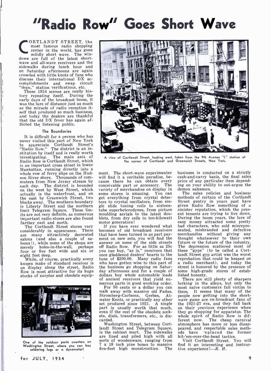
"Radio Row" Goes Short Wave CORTLANDT STREET, the
most famous radio shopping center in the world, has gone solidly short wave. The win-
dows are full of the latest short- wave and all -wave receivers and the sidewalks during lunch hour and on Saturday afternoons are again crowded with little knots of fans who discuss their international DX ac- complishments and swap circuit "dope," station verifications, etc.
These 1934 scenes are really his- tory repeating itself. During the early days of the broadcast boom, it was the lure of distance just as much as the miracle of radio reception it- self that produced so much business, and today the dealers are thankful that the old DX fever has again af- flicted the listening public.
The Boundaries It is difficult for a person who has
never visited this part of New York to appreciate Cortlandt Street's "Radio Row." The district is an in- stitution by itself and is really worth investigating. The main axis of Radio Row is Cortlandt Street, which is an important cross street in lower Manhattan, running directly into a whole row of ferry slips on the Hud- son River shore. Thousands of com- muters from New Jersey stream by each day. The district is bounded on the west by West Street, which actually is the waterfront, and on the east by Greenwich Street, two blocks away. The southern boundary is Liberty Street and the northern limit Telegram Square. These lim- its are not very definite, as numerous important radio stores are also found farther east and north.
The Cortlandt Street stores vary considerably in appearance. There are many attractively decorated salons (and also a couple of sa- loons !) , while some of the shops are merely holes -in- the -wall, perhaps four or five feet wide and six or eight feet deep.
While, of course, practically every known make of standard receiver is on display along the street, Radio Row is most attractive for its huge stocks of surplus and obsolete equip-
One of the outdoor parts counters on
Washington Street, where you can buy soldering lugs or a dynamotor!
for JULY, 1934
wAt!lif r `-
í411611'4Í EuQn ,
11 6
A view of Cortlandt Street, looking west, taken from the 9th Avenue "L" station at the corner of Cortlandt and Greenwich Streets, New York.
ment. The short -wave experimenter will find it a veritable paradise, be- cause there he can obtain every conceivable part or accessory. The variety of merchandise on display in some stores is amazing. You can get everything from crystal detec- tors to crystal oscillators, from sin- gle slide tuning coils to sixteen - tube superheterodynes, from picture moulding aerials to the latest dou- blets, from dry cells to ten -kilowatt motor generators!
If you have ever wondered what becomes of old broadcast receivers that have been turned in as part pay- ment on new sets, you will find the answer on some of the side streets off Radio Row. For as little as 25c you can buy, "as is," receivers that once gladdened dealers' hearts to the tune of $200.00. Many radio fans who have gotten wise to this part of the business go shopping on Satur- day afternoons and for a couple of dollars buy whole automobile loads of ancient receivers that yield nu- merous parts in good working order.
For 50 cents or a dollar you can walk away with massive old Fadas, Stromberg- Carlsons, Grebes, At- water Kents, or practically any other set produced since 1921. A single part is usually worth that much, even if the rest of the obsolete sock- ets, dials, transformers, etc., is dis- carded.
Washington Street, between Cort- landt Street and Telegram Square, is the cabinet mart. The sidewalks are lined and piled high with all sorts of woodenware, ranging from 7 x 18 inch pine boxes to massive five -feet high monstrosities. The
business is conducted on a strictly cash -and -carry basis, the final sales price of any particular item depend- ing on your ability to out -argue the demon salesmen.
The sales policies and business methods of certain of the Cortlandt Street gentry in years past have given Radio Row something of a sinister reputation, which the pres- ent tenants are trying to live down. During the boom years, the lure of easy money attracted some pretty bad characters, who sold misrepre- sented, misbranded and defective merchandise without giving any thought whatsoever to their own future or the future of the industry. The depression scattered most of these "gyps" (to be called a Cort- landt Street gyp artist was the worst reprobation that could be heaped on a radio merchant), and today the street is honored by the presence of some high -grade stores of estab- lished honesty.
There are still plenty of sharpers lurking in the alleys, but only the most naïve customers fall victim to them. It seems that many of the people now getting into the short- wave game are ex- broadcast fans of the 1921 -27 era, and they fall back on their previous experience when they go shopping for apparatus. The whole spirit of Radio Row is dif- ferent now. The cheap carnival atmosphere has more or less disap- peared, and respectable sales meth- ods have eplaced the former hit -'em- over -the -head tactics.
Visit Cortlandt Street. You will find it an interesting and instruc- tive experience ! -R. H.
9

J. B. L. Hinds S an experienced listener of
radio prof, rams from all parts of the world, 1 have been asked to game the ten
best foreign stations now on the air and broadcasting regular programs.
In making such a selection, con- sideration must be given to many things, such as class of programs presented, strength and evenness of signal, consistency of output, whether enjoyable and understand- able to the majority of listeners, etc.
In the opinion of the writer the stations listed below will furnish the greatest enjoyment and entertain- ment, as a varied class of enter- tainment, consisting of concert and symphony orchestras, typical native music and songs will emanate from them and their programs will also furnish considerable information on the current topics of the day.
Where time of day or night is given, Lastern Standard time is in- tended, as all reliable radio pro- grams published in the U. S. of foreign broadcast stations show that time.
For convenience, the ten stations %vill he listed in alphabetical order according to the countries in which they are operating, it being impos- sible to list the order in which they come on the air, as some operate the majority of the time, while others operate on certain days only. It is not the intention of the writer to indicate which stations are superior to others, and the assignment made should have no bearing on the selec- tions made.
Australia
VK2ME, Sydney, Australia, trans- mits programs only on Sunday of each week on 31.28 meters and is on the air from 1 to 3, 4:30 to 8:30 and 9:00 to 11 A.M. and is known as the "Voice of Australia." Electrical recordings are mostly used, but many news items of interest are given and each broadcast contains a very instructive fifteen -minute talk on some section of Australia, which covers an area of 2.974,581 square miles and has a population of 6,600,- 000. The laughing notes of the Aus- tralian Kookaburra bird open and close the programs as a rule, and they also precede and follow the fifteen- minute talk mentioned. The time of day is given over this sta- tion, as are the chimes from the clock atop to G.P.O. building in Sydney.
Its sister station, VK3ME, Mel- bourne, Australia, broadcasts on Wednesday from 5 to 6:30 A.M. and on Saturday from 5:00 to 7:00 A.M. on 31.55 meters, and is a welcome visitor in many American homes with its varied program of record- ings, news items, etc.
I recently had the pleasure of lis- tening to our own Eddie Cantor
10
Picks the Ten Best
J. B. L. Hinds
whom we take pleasure in introducing to our readers as the new conductor of our Short Wave Station Department, is an experienced and conservative radio fan who never counts o station as heard until he receives a verification from it. He does not merely guess at the identity of stations, but listens very carefully, kelps a complete and very accurate record of his results, and double checks on each new catch by attempting to duplicate the reception at least a second time. We feel that his advice and sug- gestions will be interesting and helpful because he spends only a nominal amount of time at his receivers, and therefore, he is in the same position as most other short -wave listeners. By profession an accountant with the New York Central Railroad in its New York office, he is at his regular job during the day and listens to the short waves after he gets home. He does not have to stay up all day and all night and have relief operators for his receivers in order to build up an impressive log of stations. We believe his understanding of the average short -wave fan's prob- lems and habits will do much to make his articles valuable.
Mr. Hinds acquired his first short- wave receiver, on a.c. Super -Wasp, in the Spring of 1930. Late last year, be- fore entering the Denton Trophy Con-
test, he acquired a more modern re- ceiver, a Hammarlund Pro. He has received phone or broadcast stations from more than 40 countries and has a really marvelous and highly prized collection of almost 200 verification cards, letters and certificates.
Mr. Hinds lives in Yonkers, N. Y., a suburb bordering on the northern end of New York City. He will be very glad to correspond with readers of SHORT WAVE RADIO and to receive their reports on their own receiving ex- periences. Reports from other sections of the country are especially desired and will be studied and abstracted by Mr. Hinds in these columns for the bene- fit of other listeners. Letters should be addressed to Mr. J. B. L. Hinds, c/o SHORT WAVE RADIO, 1123 Broadway, New York, N. Y. If you want a personal reply, be sure to enclose a stamped and self -addressed envelope.
Mr. Hinds is not a radio technician, being interested primarily in interna- tional DX reception. You can ask him all the questions you want about foreign stations, but if you want technical advice on receivers, circuits, parts, etc., address your letter to Mr. Louis Martin, techni- cal director of this magazine.
Do not hesitate to write to Mr. Hinds regularly. A steady exchange of station "dope" will be to everybody's benefit.
singing "Look What You Got" from this station; to me, his voice sounded as real as when singing the song in a New York studio on Sun- day night. Both Australian stations have pleasant voiced English an- nouncers who often tell you the exact time of night in Melbourne or Sydney and inform you promptly before and after rendition the title of the selection played or sang. If you happen to be listening to VK3ME on Saturday morning, when the announcer gives the time in Mel- bourne as 10 P.M. Saturday night, you may note from your watch be- side you that it is exactly 7:00 o'clock Saturday morning Eastern
Standard time, and you may go to your breakfast table as Melbourne says "Goodnight everybody" and plays "God Save the King" and closes down.
The signals of VK2ME and VK3ME come into America strong, steady and clear. The first station broadcasts with 2 kw. and the lat- ter with 20 kw. of power. Both stations are owned and operated by the Amalgamated Wireless (Aus- tralasia), Limited, and both are used for overseas broadcasting and also beam wireless services to Great Britain, the continents of Europe, North and South America as well as coastal stations and ship wireless.
SHORT WAVE RADIO
Foreign Short Wave Stations VK2ME is the largest broadcasting station in the Southern Hemisphere. The transmitting plant for both stations is located at A.W.A. Radio Center, Pennant Hills, near Sydney, Australia.
Ir the listeners of these stations will bear in mind that, in Australia, spring is September, October and November; summer is December, January, February ; autumn is March, April, May; and winter is June, July, and August, they may account for the changes in signal volume from this part of the world.
Colombia
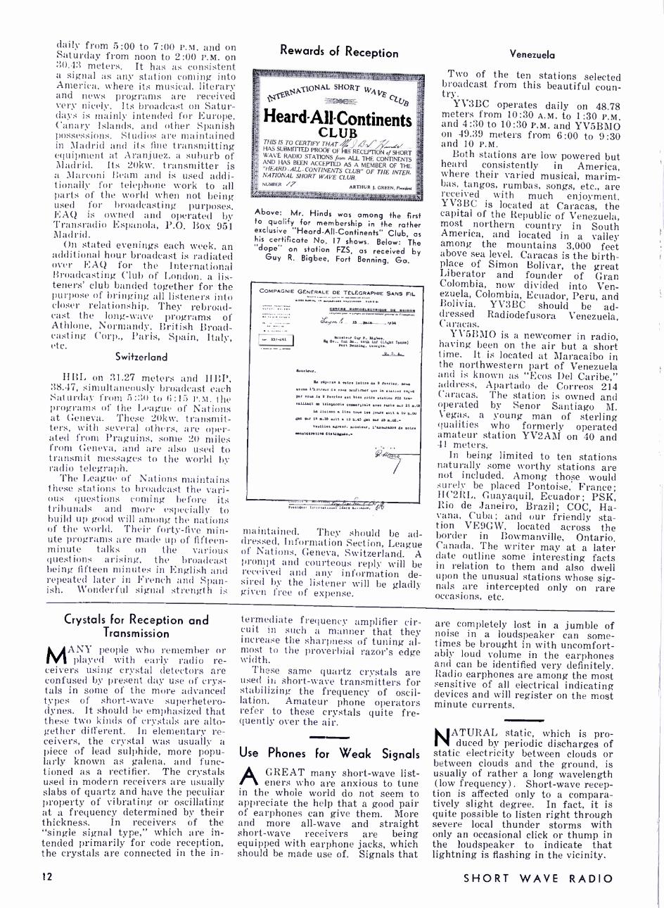
HJIABB, which you find regularly on 46.51 meters, is operated from Barranquilla, that quaint city on the northern coast of Colombia, situated just off the Caribbean Sea. This sta- tion operates with 300 watts of power and transmits each week day from 7:00 P.M. to 9:30 P.M. and on Sunday from 4:00 to 6:00 P.M. Its typical Spanish numbers are much enjoyed by many listeners. The sta- tion is operated by Mr. Elias J. Pellet, who is the proud owner and operator. Mr. Pellet was educated in the United States and is well equipped with a knowledge of elec- tricity and radio. He first began broadcasting over a 7 -watt home- made transmitter under the call letters of HKD. Mr. Pellet makes his announcements both in Spanish and English and his programs are greatly enjoyed in the United States, where he has many warm friends.
England
The British Broadcasting Cor- poration broadcasts with eight trans- mitters GSA, GSB, GSC, GSD, GSE, GSF, GSG, and GSH, seven of the eight being used usually in the daily broadcast. Two transmitters are used simultaneously on each broad- cast. Thus, if reception is poor from one, it may be good from the other.
The striking of Big Ben and the Westminster Chimes is radiated often over the network from the Parliament building in London. Big Ben is one of the important land- marks in London. It was built in 1858 and is considered the most powerful striking clock in the world.
--LA VOZ DE BARRANQUILLA" n O w 715
BARRANQUILLA --COLOMBIA -- B A
we vt11m .oun 11cvnon or ou tTÜarv ON 00% 6th u4.-._
u4 .. .fm
(FORMELV H K D)
55 .t, 0.7 15
ru:o L
roua n
ntAft 11V07 ¡CM, ow11a
E. J. r6LLRT , 00711.,011
Dully:lltar, -1 pm. and 5 t0 lOpm
This simple but werl prepared card veri- fies reception very specifically.
for JULY, 1934
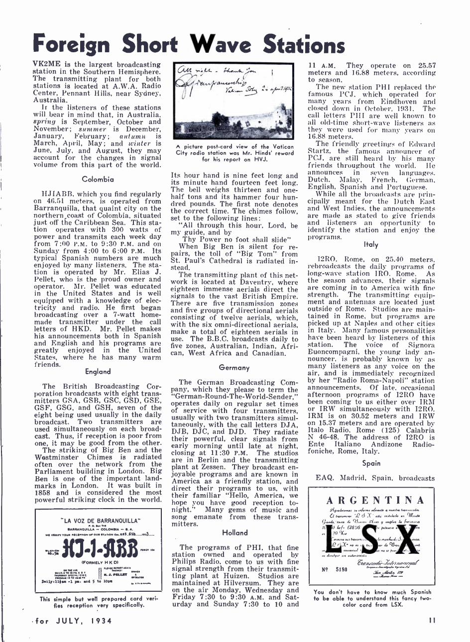
A picture post -card view of the Vatican City radio station was Mr. Hinds' reward
for his report on HVJ.
Its hour hand is nine feet long and its minute hand fourteen feet long. The bell weighs thirteen and one - half tons and its hammer four hun- dred pounds. The first note denotes the correct time. The chimes follow, set to the following lines:
"All through this hour, Lord, be my guide, and by
Thy Power no foot shall slide" When Big Ben is silent for re-
pairs, the toll of "Big Tom" from St. Paul's Cathedral is radiated in- stead.
The transmitting plant of this net- work is located at Daventry, where eighteen immense aerials direct the signals to the vast British Empire. There are five transmission zones and five groups of directional aerials consisting of twelve aerials, which, with the six omni -directional aerials, make a total of eighteen aerials in use. The B.B.C. broadcasts daily to five zones, Australian, Indian, Afri- can, West Africa and Canadian.
Germany
The German Broadcasting Com- pany, which they please to term the " German -Round -The -World- Sender," operates daily on regular set times of service with four transmitters, usually with two transmitters simul- taneously, with the call letters DJA, DJB, DJC, and DJD. They radiate their powerful, clear signals from early morning until late at night, closing at 11:30 P.M. The studios are in Berlin and the transmitting plant at Zessen. They broadcast en- joyable programs and are known in America as a friendly station, and direct their programs to us, with their familiar "Hello, America, we hope you have good reception to- night." Many gems of music and song emanate from these trans- mitters.
Holland
The programs of PHI, that fine station owned and operated by Philips Radio, come to us with fine signal strength from their transmit- ting plant at Huizen. Studios are maintained at Hilversum. They are on the air Monday, Wednesday and Friday 7:30 to 9:30 A.M. and Sat- urday and Sunday 7:30 to 10 and
11 A.M. They operate on 25.57 meters and 16.88 meters, according to season.
The new station PHI replaced the famous PCJ, which operated for many years from Eindhoven and closed down in October, 1931. The call letters PHI are well known to all old -time short -wave listeners as they were used for many years on 16.88 meters.
The friendly greetings of Edward Startz, the famous announcer of PCJ, are still heard by his many friends throughout the world. He announces in seven languages. Dutch, Malay, French, German, English, Spanish and Portuguese.
While all the broadcasts are prin- cipally meant for the Dutch East and West Indies, the announcements are made as stated to give friends and listeners an opportunity to identify the station and enjoy the programs.
Italy
I2R0, Rome, on 25.40 meters, rebroadcasts the daily programs of long -wave station IRO, Rome. As the season advances, their signals are coming in to America with fine strength. The transmitting equip- ment and antennas are located just outside of Rome. Studios are main- tained in Rome, but programs are picked up at Naples and other cities in Italy. Many famous personalities have been heard by listeners of this station. The voice of Signora Buoncompagni, the young lady an- nouncer, is probably known by as many listeners as any voice on the air, and is immediately recognized by her "Radio Roma -Napoli" station announcements. Of late, occasional afternoon programs of I2R0 have been coming to us either over IRM or IRW simultaneously with I2R0. IRM is on 30.52 meters and IRW on 15.37 meters and are operated by Italo Radio, Rome (125) Calabria N 46 -48. The address of I2R0 is Ente Italiano Andizone Radio - foniche, Rome, Italy.
Spain
EAQ, Madrid, Spain, broadcasts
ARGENTINA y,y,aJ .ma, (n/0. a nunfo banunúlón.
fonm.o . ci X nf1: ,n,fÍla.lo n 'Woad /¡anAr. a.<a Av 43ÍrÍa. nlp/m in / 1Í.Í,.a
I( 0 4/. (36J6 paana ( `'n eX1
Aalborg ,nlW
.
mmr.n.d . ., Í.0 ,. PM.
p an
laii.iln/I -//Jy/ifPP!!C ;-,,..... .
./r, ,,cw .z+ _ N? 5180
You don't have to know much Spanish to be able to understand this fancy two -
color card from LSX.
daily from 5:00 to 7:00 P.M. and on Saturday from noon to 2:00 P.M. on 30.43 meters. It has as consistent a signal as any station coming into America, where its musical. literary and news programs are received very nicely. Its broadcast on Satur- days is mainly intended for Europe, Canary Islands. and other Spanish possessions. Studios are maintained in Madrid and its fine transmitting equipment at Aranjuez, a suburb of Madrid. Its 20kw. transmitter is a Marconi Beam and is used addi- tionally for telephone work to all parts of the world when not being used for broadcasting purposes. EAQ is owned and operated by Transradio Espanola, P.O. Box 951 Madrid.
On stated evenings each week, an additional hour broadcast is radiated over EAQ for the International Broadcasting Club of London. a lis- teners' club banded together for the purpose of bringing all listeners into closer relationship. They rebroad- cast the long -wave programs of Athlone, Normandy, British Broad- casting Corp., Paris, Spain, Italy, etc.
Switzerland
HBL on 31.27 meters and HBP, 38.47, simultaneously broadcast each Saturday from 5:3(1 to 6:15 r''.M. the programs of the League of Nations at Geneva. These 20kw. transmit- ters, with several others, are oper- ated from Praguins, some 20 miles from Geneva, and are also used to transmit messages to the world by radio telegraph.
The League of Nations maintains these stations to broadcast the vari- ous questions coming before its tribunals and more especially to build up good will among the nations of the world. Their forty -five min- ute programs are made up of fifteen - minute talks on the various questions arising, the broadcast being fifteen minutes in English and repeated later in French and Span- ish. Wonderful signal strength is
Rewards of Reception
i :r T'-¡Tj _ , a..n .:IiiY +fado q... ir(iili.}n.
p1 ONAL SHORT w
°e11
Heard- All -Continents
ToT^
CLUB THIS IS TO CERTIFY l I i, ! -/í ., , /,Ìv/'',, t/ FIAS SUBMITTED PROOF OF HIS RECEPTION of SHORT WAVE RADIO STATIONS from ALL 114E CONTINEN I s AND HAS BEEN ACCEPTED AS A MEMBER OF Till 41 "HEARD. ALL - CONTINENTS CLUB" OF THE INTLR. Ti NATIONAL SHORT WAVE CLUB. NUMBER /7 ARTHUR T. GREEN. Aad.r
.71
Above: Mr. Hinds was among the first to qualify for membership in the rather exclusive "Heard -All- Continents" Club, as his certificate No. 17 shows. Below: The "dope" on station FZS, as received by
Guy R. Bigbee, Fort Benning, Ga.
COMPAGNIE GENERALE DE TELEGRAPHIE SANS FIL.
s..... ,...;0..I
ss000tv
pra.. - la_-yy._
-..- I3S
..w
tloo.ur 0W P. MO.. y oa.. Z. w,.. beta lnr u..wt roam) flit DVmlu¡ ooarµV.
..y. sy 11.010.0.
L rayon.. a quo t.ttto Y 9 r' . Von.
S.ano 1.9ohneut . vs. wads..: Gw L .tattoo n/w per oaV 10 9 I..rl.r .t Moo notre ..110V ILA tnn.
r.11Lnt So t.l.yauata .. 09.11x1 awes rut V wr il 6.01 L. 11ntIOV 1109 told 104 Jour. 0o11 tu 3.99
..t Y. 16 .ls Satt 13 11.43 at war as ..111:
xSUl13Sa Sin n. .a.St.ur, 1VVUrVVa. 4S Votre 0o011163.t1a 6tS40696..
maintained. They should be ad- dressed, Information Section, League of Nations, Geneva, Switzerland. A prompt and courteous reply will be received and any information de- sired by the listener will be gladly given free of expense.
Venezuela
Two of the ten stations selected broadcast from this beautiful coun- try.
V3BC operates daily on 48.78 meters from 10:30 A.M. to 1:30 P.M. and 4:30 to 10:30 P.M. and YV5BMO on 49.39 meters from 6:00 to 9:30 and 10 P.M.
Both stations are low powered but heard consistently in America, where their varied musical, marim- bas, tangos, rumbas, songs, etc., are received with much enjoyment. YV3BC is located at Caracas, the capital of the Republic of Venezuela, most northern country in South America, and located in a valley among the mountains 3,000 feet above sea level. Caracas is the birth- place of Simon Bolivar, the great Liberator and founder of Gran Colombia, now divided into Ven- ezuela, Colombia, Ecuador, Peru, and Bolivia. YV3BC should be ad- dressed Radiodefusora Venezuela, Caracas.
YV5BMO is a newcomer in radio, having been on the air but a short time. It is located at Maracaibo in the northwestern part of Venezuela and is known as "Ecos Del Caribe," address, Apartado de Correos 214 Caracas. The station is owned and operated by Senor Santiago M. Vegas, a young man of sterling qualities who formerly operated amateur station YV2AM on 40 and 41 meters.
In being limited to ten stations naturally some worthy stations are not included. Among those would surely be placed Pontoise, France; HC2RL, Guayaquil, Ecuador; PSK, Rio de Janeiro, Brazil; COC, Ha- vana, Cuba; and our friendly sta- tion VE9GW, located across the border in Bowmanville, Ontario, Canada. The writer may at a later date outline some interesting facts in relation to them and also dwell upon the unusual stations whose sig- nals are intercepted only on rare occasions, etc.
Crystals for Reception and Transmission
MANY people who remember or
played with early radio re- ceivers using crystal detectors are confused by present day use of crys- tals in some of the more advanced types of short -wave superhetero- dynes. It should be emphasized that these two kinds of crystals are alto- gether different. In elementary re- ceivers, the crystal was usually a piece of lead sulphide, more popu- larly known as galena, and func- tioned as a rectifier. The crystals used in modern receivers are usually slabs of quartz and have the peculiar property of vibrating or oscillating at a frequency determined by their thickness. In receivers of the "single signal type," which are in- tended primarily for code reception, the crystals are connected in the in-
12
termediate frequency amplifier cir- cuit in such a manner that they increase the sharpness of tuning al- most to the proverbial razor's edge width.
These same quartz crystals are used in short -wave transmitters for stabilizing the frequency of oscil- lation. Amateur phone operators refer to these crystals quite fre- quently over the air.
Use Phones for Weak Signals
A GREAT many short -wave list - eners who are anxious to tune
in the whole world do not seem to appreciate the help that a good pair of earphones can give them. More and more all -wave and straight short -wave receivers are being equipped with earphone jacks, which should be made use of. Signals that
are completely lost in a jumble of noise in a loudspeaker can some- times be brought in with uncomfort- ably loud volume in the earphones and can be identified very definitely. Radio earphones are among the most sensitive of all electrical indicating devices and will register on the most minute currents.
NATURAL static, which is pro- duced by periodic discharges of
static electricity between clouds or between clouds and the ground, is usually of rather a long wavelength (low frequency). Short -wave recep- tion is affected only to a compara- tively slight degree. In fact, it is quite possible to listen right through severe local thunder storms with only an occasional click or thump in the loudspeaker to indicate that lightning is flashing in the vicinity.
SHORT WAVE RADIO
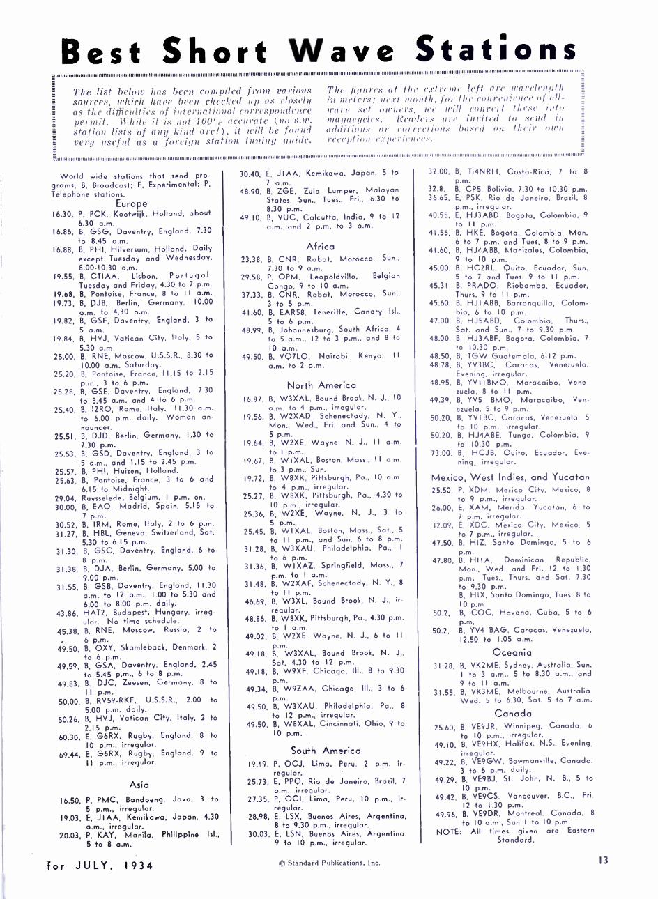
Best Short Wave Stations uuuuuuuuouuununmunnuaunnnuuuuuununuuuuuuunnnunuuanuuuuununnuuunuuuuuunmm11uununnunuuuunnunnunuuunuuuunmmllnn,n,,,,,....,,,
The list below has been. compiled from radon. sources, which hare been checked up as closely as the difficulties of international correspondence permit. While it is not 100(, accurate (no s.rc. station lists Of any kind are!), it will be found t'eri, useful as a foreign station tuning guide.
The figures at the cxtrenc left are wavelength in meters; nest month, for the con yen ¡rue(' of (M-
ira re set nnneI's, rte Will con rent these into ma nor ttele.'. Readers are in rited to send in additions or Corrections based on their own reception experiences.
uuumuumuuumumaunuununuuunnmwunuuuunnunmumuunnuunnwuuuunnunmunumuununnnuuuuuuun,unuuununnnuuunr.
World wide stations that send pro- grams, B, Broadcast; E, Experimental; P,
Telephone stations. Europe
16.30, P, PCK, Kootwiik, Holland, about 6.30 a.m.
16.86, B, GSG, Daventry, England, 7.30
to 8.45 a.m. 16.88, B, PHI, Hilversum, Holland. Daily
except Tuesday and Wednesday, 8.00 -10.30 a.m.
19.55, B, CTIAA, Lisbon, Portugal. Tuesday and Friday, 4.30 to 7 p.m.
19.68, B, Pontoise, France, 8 +o I I a.m.
19.73, B, DJB, Berlin, Germany, 10.00
a.m. to 4.30 p.m. 19.82, B, GSF, Daventry, England, 3 to
5 a.m. 19.84, B, HVJ, Vatican City, Italy, 5 to
5.30 a.m. 25.00, B, RNE, Moscow, U.S.S.R., 8.30 to
10.00 a.m. Saturday. 25.20, B, Pontoise, France, 11.15 to 2.15
p.m., 3 to 6 p.m. 25.28, B, GSE, Daventry, England, 7 30
to 8.45 a.m. and 4 to 6 p.m.
25.40, B, 12R0, Rome, Italy. 11.30 a.m. to 6.00 p.m. daily. Woman an- nouncer.
25.51, B, DJD, Berlin, Germany, I.30 to 7.30 p.m.
25.53, B, GSD, Daventry, England, 3 to 5 a.m., and 1.15 to 2.45 p.m.
25.57, B, PHI, Huizen, Holland. 25.63, B, Pontoise, France, 3 to 6 and
6.15 to Midnight. 29.04, Ruysselede, Belgium, I p.m. on.
30.00, B, EAQ, Madrid, Spain, 5.15 to 7 p.m.
30.52, B, IRM, Rome, Italy, 2 to 6 p.m.
31.27, B, HBL, Geneva, Switzerland, Sat. 5.30 to 6.15 p.m.
31.30, B, GSC, Daventry, England, 6 to 8 p.m.
31.38, B, DJA, Berlin, Germany, 5.00 to 9.00 p.m.
31.55, B, GSB, Daventry, England, II.30 a.m. to 12 p.m., 1.00 to 5.30 and 6.00 to 8.00 p.m. daily.
43.86, HAT2, Budapest, Hungary, irreg- ular. No time schedule.
45.38, B, RNE, Moscow, Russia, 2 to 6 p.m.
49.50, B, OXY, Skamleback, Denmark, 2
to 6 p.m. 49.59, B, GSA, Daventry, England, 2.45
to 5.45 p.m., 6 to 8 p.m.
49.83, B. DJC, Zeesen, Germany, 8 to II p.m.
50.00, B, RV59 -RKF, U.S.S.R., 2.00 to 5.00 p.m. daily.
50.26, B, HVJ, Vatican City, Italy, 2 to 2.15 p.m.
60.30, E, G6RX, Rugby, England, 8 to IO p.m., irregular.
69.44, E, G6RX, Rugby, England, 9 to I I p.m., irregular.
Asia
16.50, P, PMC, Bandoeng, Java. 3 to 5 p.m., irregular.
19.03, E, JIAA, Kemikawa, Japan, 4.30 a.m., irregular.
20.03, P, KAY, Manila, Philippine Isl.,
5 to 8 a.m.
Tor JULY, 1934
30.40, E, JIAA, Kemikawa, Japan, 5 to 7 a.m.
48.90, B, ZGE, Zula Lumper, Malayan States, Sun., Tues., Fri.. 6.30 to
8.30 p.m. 49.10, B, VUC, Calcutta, India, 9 to 12
a.m. and 2 p.m. to 3 a.m.
Africa 23.38, B, CNR, Rabat, Morocco, Sun..
7.30 to 9 a.m. 29.58, P, OPM, Leopoldville, Belgian
Congo, 9 to IO a.m. 37.33, B. CNR, Rabat, Morocco, Sun.,
3 to 5 p.m. 41.60, B, EAR58, Teneriffe, Canary Isl.,
5 to 6 p.m. 48.99, B, Johannesburg, South Africa. 4
to 5 a.m., 12 to 3 p.m.. and 8 to IO a.m.
49.50, B, VQ7LO, Nairobi, Kenya, II a.m. to 2 p.m.
North America 16.87, B, W3XAL, Bound Brook, N. J., 10
a.m. to 4 p.m., irregular. 19.56, B, W2XAD, Schenectady, N. Y.,
Mon., Wed.. Fri. and Sun., 4 to 5 p.m.
19.64, B, W2XE, Wayne, N. J., II a.m. to I p.m.
19.67, B, WI XAL, Boston, Mass., II a.m. to 3 p.m.. Sun.
19.72, B, W8XK, Pittsburgh, Pa., 10 a.m to 4 p.m., irregular.
25.27, B, W8XK, Pittsburgh, Pa.. 4.30 to 10 p.m., irregular.
25.36, B, W2XE, Wayne, N. J., 3 to 5 p.m.
25.45, B, WI XAL, Boston, Mass., Sat., 5
to I I p.m., and Sun. 6 to 8 p.m.
31.28, B, W3XAU, Philadelphia, Pa., I
to 6 p.m. 31.36, B, WIXAZ, Springfield, Mass., 7
p.m. to I a.m. 31.48, B, W2XAF, Schenectady, N. Y., 8
to I I p.m. 46.69, B, W3XL, Bound Brook, N. J., ir-
regular. 48.86, B, W8XK, Pittsburgh, Pa., 4.30 p.m.
to I a.m. 49.02, B. W2XE, Wayne, N. J., 6 to II
p.m. 49.18, B, W3XAL, Bound Brook, N. J.,
Sat. 4.30 to 12 p.m. 49.18, B, W9XF, Chicago, III., 8 to 9.30
p.m. 49.34, B, W9ZAA, Chicago, Ill., 3 to 6
p.m. 49.50, B, W3XAU, Philadelphia, Pa., 8
to 12 p.m., irregular. 49.50, B, W8XAL, Cincinnati, Ohio, 9 to
IO p.m.
South America 19.19, P, OCJ, Lima, Peru, 2 p.m. ir-
regular. 25.73, E, PPQ, Rio de Janeiro, Brazil, 7
p.m.. irregular. 27.35, P, OCI, Lima, Peru, IO p.m., ir-
regular. 28.98, E, LSX, Buenos Aires, Argentina.
8 to 9.30 p.m., irregular. 30.03, E, LSN, Buenos Aires, Argentino.
9 to IO p.m.. irregular.
© Standard Publications. Inc.
32.00, B, Ti4NRH, Costa -Rica, 7 to 8
p.m. 32.8, B, CPS, Bolivia, 7.30 to 10.30 p.m. 36.65. E, PSK, Rio de Janeiro, Brazil, 8
p.m., irregular. 40.55. E, HJ3ABD, Bogota, Colombia. 9
to II p.m. 41.55, B, HKE, Bogota, Colombia, Mon.
6 to 7 p.m. and Tues. 8 to 9 p.m. 41.60, B, HPABB, Manizales, Colombia.
9 to 10 p.m. 45.00, B, HC2RL, Quito, Ecuador, Sun.
5 to 7 and Tues. 9 to 11 p.m. 45.31, B, PRADO, Riobamba, Ecuador,
Thurs. 9 to II p.m. 45.60, B, HJ I ABB, Barranquilla, Colom-
bia, 6 to 10 p.m. 47.00, B, HJSABD, Colombia, Thurs.,
Sat. and Sun., 7 to 9.30 p.m. 48.00, B. HJ3ABF, Bogota, Colombia, 7
to 10.30 p.m. 48.50, B, TGW Guatemala, 6 -12 p.m. 48.78, B, YV3BC, Caracas. Venezuela.
Evening, irregular. 48.95. B, YV I I BMO, Maracaibo, Vene-
zuela, 8 to II p.m. 49.39. B, YV5 BMO, Maracaibo, Ven-
ezuela. 5 to 9 p.m. 50.20, B, YV I BC, Caracas, Venezuela, 5
to 10 p.m., irregular. 50.20. B. HJ4ABE, Tunga, Colombia. 9
to 10.30 p.m. 73.00, B, HCJB, Quito, Ecuador, Eve-
ning, irregular.
Mexico, West Indies, and Yucatan 25.50, P, XDM, Mexico City, Mexico, 8
to 9 p.m., irregular. 26.00, E, XAM, Merida, Yucatan. 6 to
7 p.m. irregular. 32.09, E, XDC, Mexico City. Mexico, 5
to 7 p.m., irregular. 47.50, B, HIZ, Santo Domingo, S to 6
p.m. 47.80, B. HIIA, Dominican Republic,
Mon., Wed. and Fri. 12 to 1.30 p.m. Tues., Thurs. and Sat. 7.30 to 9.30 p.m. B. HIX, Santo Domingo, Tues. 8 to 10 p.m
50.2, B, COC, Havana, Cuba, 5 to 6
p.m. 50.2, B. YV4 BAG, Caracas, Venezuela,
12.50 to 1.05 a.m.
Oceania 31.28, B, VK2ME, Sydney, Australia, Sun.
I to 3 a.m., 5 to 8.30 a.m., and 9 to II a.m.
31.55. B, VK3ME, Melbourne, Australia Wed. 5 to 6.30, Sat. 5 to 7 a.m.
Canada 25.60, B, VE4JR, Winnipeg, Canada, 6
to IO p.m., irregular. 49.10, B, VE9HX, Halifax, N.S., Evening,
irregular. 49.22, B, VE9GW, Bowmanville, Canada.
3 to 6 p.m. daily. 49.29, B. VE9BJ, St. John, N. B., 5 to
IO p.m. 49.42, B, VE9CS, Vancouver, B.C., Fri.
12 to 1.30 p.m. 49.96, B, VE9DR, Montreal, Canada. 8
to 10 a.m., Sun I to 10 p.m. NOTE: All tames given are Eastern
Standard.
13

Reception Reports From Readers BECAUSE the United States is
a big country, reception con- ditions on the short waves are bound to be different in
different sections. For this reason, we ask readers to send in detailed re- ports of their experiences. Extremely interesting data have been brought to light in some of the letters we have published. This department has caused Wooly short -wave listen- ers to start corresponding with each other, and some fine friend- ships have been built up.
If you have been keeping a log of your results and every listener should) , by all means send us a sort of review of it for a period of, say, a month. Don't fail to men- tion your receiver and to describe your aerial. Use a typewriter if you have one; otherwise, please write clearly in ink on one side of the paper.
Oklahoma Editor. SIIURT WAVE: RADIO:
Some of the stations I receive reg- ularly are the Daventry stations. all Berlin stations, 1280, EAQ, VK3111E, VK2.11E, VK3LR, PII1. (71A A, ,11AA, VE9GW, VE9JR, VE9DN, IIC2R14, COC, YV3BC, YVIBC, 11,14A BE, HJSABD, HJ1 ABB, PIZA 1)O, Pontoise, IIJ3A BF, YV5BMO, CP5, IIJ2ABA, KNRA, KFZ, etc.
KFZ has been coming in lately with fairly good volume on number 9 with best reception on Number 5, (near 34 meters) . KNRA has also been coming in on this frequency during the last part of the week during the tests preceeding the Sun- day night broadcasts.
J1AA, 38.07 meters, is received here every morning between 3:30 and 6 :35 A.M. C.S.T. The signals are usually received with fair vol- ume. News reports are given in English during part of the first hour of broadcasting. Oriental music and speaking in Japanese take up the remainder of the program. The sign - ofr at 6 :3 5 is preceded at 6 :30 by a system of gongs and bells. Some mornings they use 4, 3, 1 gong strokes and one chime. Other morn- ings they vary the number of strokes on the gong.
VK3LR, 31.3 meters. is received from about 1:30 to 6:45 A.M., C.S.T. every morning except Sunday. They broadcast the programs of some long wave station in Australia and carry the programs of the national net- work. Their signal comes through fairly well with some distortion, making announcements hard to un- derstand.
The two Daventry stations on 31 meters, GSB and GSC, have been coming in extra well during the past two months. At times their signals are better than any others on the band.
14
DJB, 19.73 meters, comes in every morning with excellent volume be- tween 6:45 and 8 A.M., C.S.T. This station is also used irregularly to transmit programs for rebroadcast- ing over the NBC.
EAQ, 30.43 meters, has dropped the IBC programs except on Satur- days and Sundays from 6 to 6:30 P.M., C.S.T.
XETE, 31.25 meters, is on the air daily now, rebroadcasting the pro- grams of XEAL, long wave station of the Pan -American Radio Co. XETE sends a phonograph record verification to all reporting recep- tion of their station. The record is of typical Mexican selections.
HJ 1Aßß will send a set of photo- graphs of the city of Barranquilla to any one sending in ten reports of reception from their station.
I recently received a verification from JYT, 15.76 megacycles, which tests occasionally with San Fran- cisco. On the occasion I heard them they were testing in preparation for a rebroadcast over the NBC.
Although the transmission was for commercial purposes, I wrote for, and received, a verification from Toshitada Matsuyuki at the .Jap- anese station, who enclosed a photo- graph of the station. The verifica- tion is written in English on a multigraph form. The surface of the paper is covered with a light purple ink which makes it very attractive.
My receivers are an 11 -Tube I'hilco 16B All -Wave. and a Pilot A.C. Super -Wasp short -wave re- ceiver.
Hoping this information might be of some use to you, I am,
Sincerely yours, ROBERT WOODS,
14 West Broadway, Sand Springs, Oklahoma.
Colorado Editor, SHORT WAVE RADIO:
I am writing in response to your call for listeners from the West to send in reports.
I use an RCA -Victor eight tube all -wave and a three -tuber that I built myself. Both of my sets are downtown and, therefore, I have a lot of QRM, but I have made some catches which I consider pretty good.
I haven't done much above 49 meters, except for hams and police calls, although the first night I had the set I got the police station in N.Y.C. I have received hams all over the States and one from Can- ada.
The only Canadian broadcast sta- tion which I have received is VE9GW, Bowmanville, this on the three -tuber.
The 49 -meter band is not very good here except for locals, such as W8XAL, W9XF, W2XE, and W8XK.
Likewise the 31 -meter band is not very good. I have pulled in W2XAF, WIXAZ, W3XAU and for my for - eigns 1 have heard GSC, Daventry, but they weren't very good ; also XETE, Mexico City and VK2ME, sydney. I get HJ1ABB, Barran - quilla, South America, just like a local every night between 5 and 6 P.M. mountain time. But the funny part is I don't receive them on the frequency that everyone lists them. I get them on about 46 meters.
The 25 -meter band is really the best band out here. I have tuned in FYA, Paris; GSD, Daventry; 2R0, Rome; W2XE, N. Y. C.; and W8XK, Pittsburgh. On the 19 -meter band, I have heard GSF, DJB, FYA, and W8XK.
I have gotten only one station in the 16 -meter band and that is W3XAL. I have done all this during the day. Most of the DX is in the morning about eight o'clock, moun- tain time. Then European stations
come through again about noon. South Americans from five on, and VK2ME was at one A.M. I am working right now to get
my ham ticket and my only draw- back is code receiving. I expect to take my exam in a few months, and then it's the air for me.
Better DX and 73, F. L. HOPPER,
Lamar, Colo.
Montreal, Canada Editor, SHORT WAVE RADIO:
In reference to your recent letter, we are listing below full particulars with regard to our short -wave sta- tion VE9DR.
Call Letters -VE9DR Wavelength -49.96 meters, 6005
kilocycles. Power -50 watts. Schedule -Daily except Sunday,
8 A.M. to 12:00 Midnight; Sundays, 12:30 P.M. -11:00 P.M.
We would advise, however, that VE9DR has not been on the air for some time, and we do not expect to go into commission again before two or three months. As soon as we are on the air again regularly we will be glad to advise you.
Yours very truly, CANADIAN MARCONI COMPANY,
Montreal, Canada,
Allegheny Mt. Foothills Editor, SHORT WAVE RADIO:
Here is my report from twenty miles north of Pittsburgh, Pa., (New Kensington) on the Allegheny River, known as the Allegheny Mts. Foothills. Built a two -tube receiver in February and heard HJ1ABB testing at 1:30 A.M. and got the "bug" bad. Built a four -tube outfit and listened in about March 1st and
SHORT WAVE RADIO
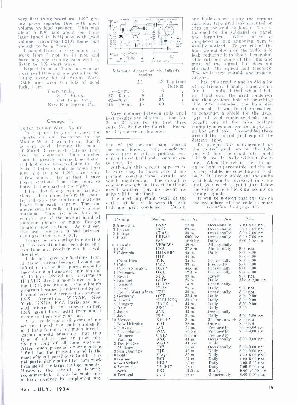
very firnt thing heard was GSC giv- ing press reports, this with good volume on loud speaker. This was about 5 P.M. and about one hour later tuned in i;At:1 also with wood volume. Have heard 2R0 Rome loud enough to be a "local."
i cannot listen in very much as I
work from 3 P.M. to 11 P.H. and have only one evening each week to list "n to DX short wave.
Expect to he a "ham" as soon as I can read iO w.p.m. and get a license. Enjoy every bit of SHORT WAVE RADIO and wish you lots of good luck, I am
Yours truly, S. .I. FLICK, 534 Ridge Ave.,
New Kensington, Pa.
Chicago, III.
Editor, SHORT WAVE: RADIO: In response to your request for
reports on s.w. reception in the Middle West, I wish to say that it is very good. During the month of March I received stations from over 40 countries. This number could be greatly enlarged. no doubt, if i had more time to listen in. As it is, i listen in only between 1:00 P.M. and IO P.M. ('.S.T., and only a few hours a day at that. I have heard stations from the countries listed in the chart at the right.
I have listed only commercial sta- tions. The number before the coun- try indicates the number of stations heard from each country. The star above certain calls indicates phone stations. This list also does not contain any of the several hundred amateur phoney or many foreign amateur s.w. stations. As you see, the Test reception is had between 4; :1111 and D:00 A.M. C.S.T.
It may be interesting to note that all this reception has been done on a two tube a.c. receiver which i will describe.
i do not have verifications from all these stations because I could not afford it in the first place, secondly t hey do not all answer ; only ten out of 15 have QSLed me. I wrote to II.1 t A RB about a month ago enclos- ing I.R.C. and giving a whole hour's program because i understand Span- ish and have not received an answer. LSX. Argentina, W2XAF, New York; KNRA, FYA Paris, and sev- eral others do not. answer either. i,SX hasn't been heard from and I
wrote to them one year ago. I am enclosing a diagram of my
set and I wish you could publish it. as I have found after much investi- gation among amateurs that this type of set. is used in practically 98 per cent of all ham stations. After much personal experimenting I find that the present model is the most efficient possible to build. it is
not particularly suited for ham work because of the large tuning capacity. however, the circuit is heartily recommended. It can be made into a hum receiver by employing any
for JULY, I 9 3 4
12
s.M;s i S7 4C, U-.. 0 S5-01,6 . / /56
.. .... S'D 05
1 .f
a-?-
Qs 25C 39'
Schematic diagrom of Mr. Talbert's receiver.
1:>-28 m.
L1
3
L2 Tap from Bottom
6 27-4:', m. 6 11 1
42-86 m. 10 25 2 110-200 m. 15 60 3
Vary distance between coils until best results are obtained. Use No. 20 or 24 wire for the first three coils, No. 24 for the fourth. Forms are 11.4 inches in diameter.
one of the several band spread methods known, viz; condenser across part of coil, a padding con- denser to set band and a smaller one to tune, etc.
Although this circuit appears to be very easy to build, several im- portant constructional details are worth mentioning. The circuit is common enough but if certain things aren't watched for, no decent re- sults will be obtained.
The most important detail of the entire set has to do with the grid leak and grid condenser. Usually
one builds a set using the regular cartridge type grid leak mounted on clips on the grid condenser. This is fastened to the subpanel or panel, and forgotten. When the set is completed a loud annoying hum is usually noticed. To get rid of the hum we cut down on the audio grid leak. reducing it to about .1 megohm. This cuts out some of the hum and most of the signal. but does not eliminate the squeal and feedback. The set is very unstable and unsatis- factory.
I had this trouble and so did a lot of my friends. I finally found a cure for it. I noticed that when I held my hand near the grid condenser and then grabbed hold of something that was grounded. the hum dis- appeared. It was found impractical to construct a shield for the usual type of grid condenser -leak. so I bought one of the mica postage stamp type condensers and a pig -tail midget grid leak. I assembled these around the control grid cap of the detector tube.
By placing this arrangement on the control grid cap on the tube you will find the usual tube shield will fit over it easily without short- ing. When the set is then turned on no hum is perceptible and the set is very stable, no squealing or feed- back. It is very stable and the audio grid leak can be increased in value until you reach a point just below the value where blocking occurs on strong signals.
It will be noticed that the tap on the secondary of the coils is much
(Continued on page 45)
Country .Stations M. or Kc. How often Time
9 Argentina LSX 28 m. Occasionally 7.00-8.00 P.M. 3 Belgium ORK 29 m. Occasionally 6.00-7.00 P.M. 2 Bolivia CPAY 38 m. Occasionally 6.00-7.00 P.M. 6 Brazil PRBA 6900 kc. Occasionally 6.00-7.00 P.M.
PSY 6900 kc. Daily 8.00-9.00 P.M. 10 Canada VE9GW 49 m. All day daily
1 Chile CEA 37.8 m. Almost daily 9.00 P.M. 5 Colombia HJIABB 45 m. Daily 8.00 -9.00
HJP 44 m. 8.00 -9.00 2 Costa Rica TIR 35 m. Occasionally 8.00 -9.00 5 Cuba CMA 33 m. Frequently 8.00 -9.00 3 Czecho -Slovakia OKH 44.6 m. Occasionally 8.00 -9.00 1 Denmark OXL 52.4 m. Occasionally 8.00 -9.00 l Egypt SUX 39 m. Rarely 9.00 P.m. 8 England GSD' 25 m. Daily About 2.00 P.M. 1 Ecuador HCJB 73 m. Occasionally 5 France FYA 25 m. Daily 2.00 P.M. 1 French West Africa FZH 30 m. Occasionally 3.00 P.M. 8 Germany OFT 38.4 m. Daily 8.00-9.00 5 Hawaii KE.J-KEQ 30-40 m. Daily 8.00-9.00 3 Hungary HATZ 44 m. Daily 8.00-9.00 4 Italy 2R0 25 m. Daily 2.00 3 Japan JAN 43 m. Occasionally 1 .Java PLV 31 m. Daily 5.00-6.00 P.M.
10 Mexico XF.TE 31 m. 3 Times a week 8.00 P.M. 1 New Hebrides YHL 38 m. Once at 8.00 P.M. 3 Norway LCI Si m. Frequently 8.00-9.00 P.M. 4 Netherlands PGA 30.5 m. Frequently 8.00-9.00 P.M. 1 Morocco CNR* 37.3 m. Frequently 1 Panama RXC 44 m. Occasionally 8.00-9.00 P.M. 3 Puerto Rico WGU 44.6 m. Daily 1 Madagascar FTZ 60 m. Occasionally 8.00-9.00 P.M. 3 San Domingo HIR 40 m. Daily 8.00-9.00 P.M.
10 Spain EAQ 30 m. Daily 4.30-6.00 P.M. 3 Surinam P2B 31 m. Daily 4.00-5.00 P.M. 6 Switzerland HBL' 32 m. Daily 3.00-5.00 P.M. 6 Venezuela Y V3BC 48 m. Daily 7.00-9.00 P.M. 1 Syria FXC 37.5 m. Rarely 9.00-10.00 P.M. 2 Portugal CUT 38 m. Occasionally 8.00-9.00 P.M.
15
New World List of Stations WE are presenting this
month another station list, which, together with the lists previously published
in SHORT WAVE RADIO, gives readers what is probably the most complete compilation of station data available. This new list is arranged numeri- cally according to frequency in rm gacvcles an(1 wavelength in me- ter, With only the call letters and lo( Aim) included. No operating h(, lrs are given, as short -wave sta- t 'on schedules are notoriously un- (lel,:'ndable. However, space is left for dial readings, so the list will be found very useful as a record of reception, and as a means of draw - ing up calibration curves.
The frequencies are given in megacycles rather than in kilocycles because the present trend is toward the use of the former unit. Readers accustomed to working with kilo- cycles can readily swing from kilo- cycles to megacycles, or vice versa, as the difference between the two units is merely a matter of the decimal point's position. Thus, 15.12 megacycles is the same as 15,120 kilocycles. The corresponding wave- lengths in meters are given in all cases, as there are still many people, particularly "old timers" just get- ting back into the short -wave game, who still find it easier to think in terms of meters than in kilocycles or megacycles.
Mera- cycles Meters Call Location Dial Dial Mega-
cycles Meters Call
For the benefit of new readers, we might mention that the follow- ing lists appeared in past issues of SHORT WAVE RADIO:
New Police Frequencies, arranged alphabetically by names of cities, page 11, June, 1934 issue. World List of S. W. Broadcast Stations, arranged numerically ac- cording to frequency, page 12, May, 1934 issue. Grand List of the S. W. Stations of the World, arranged alphabeti-
cally according to call letters, page 12, April, 1934 issue.
Back copies of these issues are ob- tainable directly from SHORT WAVE RADIO at the regular price of 25 cents each, in stamps or coin.
Location t u 20 I ',r W3XAY Philadelphia. l'a. to (HI ;.1 W3XE Philadelphia, l'a.
W6XAO Los Angeles, Calif. W8XAN Jackson, Mich. W8XF Pontiac, Mich. W8XL Cuyahoga fits., Ohio W9XE Marion, Incl. W1XW Milton, Ma -s. W2XAK New York, N. V. W2XF New York, N. V. W2XR Rocky Point, N. V. W3XAD Camden, N. J. W6XAQ Phoenix, Ariz.
I.20 5.53 W3XAY Philadelphia, l'a. ;; r.(1 5.57 W3XAY Philadelphia, l'a. -,I.40 5.83 W6XAQ Phoenix, Ariz.
W6XC San Francisco. ('al. W8XAC Lincoln Park, ?Mich. W1XW Milton, Mass. 4, 50 6.18 W3XE Philadelphia, Pa. W6XAO Los Angeles, Cal. W8XAN Jackson, Nlich. W8XF Pontiac, :Vieh. W8XL ('uyaluna Hts., Mich W9XE Marion, Ind. W2XAK New Vork. N. V. W2XF New Vork, N. V. W2XR Rocky Point, N. V. W3XAD Camden. N. J. 45.2( 6.22 W3XAY Philadelphia, Pa. 47.80 6.27 W3XAY Philadelphia, l'a.
43.00 6.97 W3XE Philadelphia, l'a. W6XAO IA,- Angeles, Calif. W8XAN la, k -on, Mich. W8XF Pontiac, Mich. W8XL Cuyahoga Fits., Ohio W9XE Marion. Ind. WIXG Boston, Mass. W2XAK New Vork, N. Y. W2XF New Vork, N. V. W2XR Rocky Point. N. Y. W3XAD Camden, N. J.
42.20 7.10 W3XAY Philadelphia, Pa. 41.50 7.17 W3XAY Philadelphia, Pa. 41 00 7.32 WIXW Milton, Mass.
W2XV Clifton, N. J. W6XC San Francisco. Cal. W8XAC Lincoln Park, Mich.
40.6(1 7.38 W2XV Clifton, N. J. 40 to 7.48 W2XV Clifton, N. J. .3,;.c 0 7.77 W2XV Clifton, N. J. 37 u 7.98 W2XV Clifton, N. J. 3; 1 tl') W2XV Clifton, N. J. 3` `" ` ` W3XAY Philadelphia, Pa. 35 (II ` .1 ; W2XV Clifton, N. J. 34.60 )'' ; W2XV Clifton, N. J.
33.10 9.06 31.611 9.49 31.10 0.65 to 20 9.93
30 10 9.97 27 50 10.79 15 70 11 67 24 011 12.50 22.30 13.45 )1 54 13.93
16
W3XAR Haverford. Pa. W2XAC Lincoln Park. Mich. W2XES Englewood, N. J. W2XV Clifton, N. J. W2XV Clifton, N. J. W2XV Clifton, N. J. W3XAY Philadelphia, Pa. W2XV Clifton, N. J. W6XD Palo Alto. Cal. W2XBC New Brunswick, N. J. W6XQ San Francisco, Cal. GBU Rugby, England W8XK Pittsburgh, Pa.
Dial Dial 21.4 21.46 21.42 21.41 21.40 21.11, 21.1.; 21.0s 21.06
21.02 21.00
;.')7 1;.95 14.0 14.01 14.(2 14.17 14.19 14.23 14.24
14.2; 14.28
GSH Daventry, England W I XAL Boston. Mass. W2XDJ Deal. N. J. WKK Lawrenceville, N. J. WLO Lawrenceville. N. J. LSL Buenos Aire., Argen. LSM Buenos Aires, Argen. PSA Rio de Janeiro, Brazil KWN Dixon, Cal. WKA Lawrenceville, N. J. LSN Buenos Aires, Argen. OKO Podebradv,
Czechoslavakia Buenos Aires, Argen. Paris, France Buenos Aires, Argen. Bandoeng. Java Rugby. England Leopuldsville,
Belgian Congo DHO Nauen, Germany
5.03 LSG Buenos Aires, Argen. DIH Nauen, Germany
5.07 LSG Buenos Aires, Argen. 5.11 WMI Deal, N. J. 5.12 FTD St. Assise, France 5.24 CEC Santiago. Chile 5.25 IRW Rome, Italy 5.48 WOP Ocean Gate. N. J.
WKN Lawrenceville, N. J. PPU Rio de Janeiro, Brazil WKF Lawrenceville, N. J. DFA Nauen, Germany ORG Brussels, Belgium WNC Deal, N. J. WKW Rocky Point. N. Y. GAG Rugby, England LSR Buenos Aires, Argen. HBF Pragins, Switzerland OCI Lima, Peru GBU Rugby, England GAU Rugby, England GBJ Bodmin, England VWY Poona, India DFB Nauen, Germany HJY Bogota, Colombia GAS Rugby. England PCK Kootwijk, Holland PMC Bandoeng, Java WLA Lawrenceville, N. J. FZS Saigon, Indo -China GBS Rugby, England YVR Maracay, Venezuela FRE St. Assise, France FRO St. Assise. France PLE Bandoeng, Java CGA Quebec, Canada LSY Buenos Aires, Argen. KQJ Bolinas, Cal. W2XAO Long Island City,N.Y. PLF Bandoeng, Java PCV Kootwijk, Holland W3XAL Bound Brook, N. J. W8XK E. Pittsburgh, Pa. W9XAA Chicago, Ill. W9XF Chicago, Ill. PHI Huizen, Holland GSG Daventry, England DJE Zeesen, Germany
20.73 14.47 LSY 20.65 14.5 FSR
LSN 10.67 14.54 PMB 2(1.35 14.72 GAA 20.04 14.97 OPL
19.95
19.90 l').85 19.83 19.69 19.54 19..;5
19.27 19.22 19.24 19.21 19.20 19.02 18.97 15.06 is 90 15.68 15.62
15.54 15.52 18.46 18.41 15.40
1 5.37 18.35 18.31
15.57 15.61 15.59 15.61 15.62 15.77 15.81 15.82 15.78 16.06 16.11
16.18 16.19 16.25 16.29 16.30 16.33 16.35 16.38
18.30 16.39 18.24 16.44
18.20 18.17 18.13 18.05 17.85
16.48 16.51 16.55 16.62 16.80
17.83 16.82 17.78 16.87
17.77 16.88
17 76 16.89
SHORT WAVE RADIO
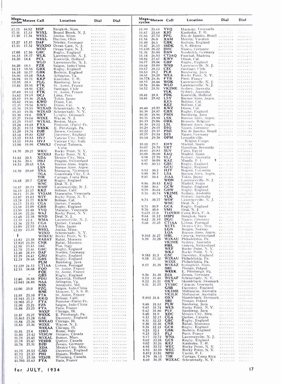
Mega- cycles Meters Call Location Dial Dial
17.75 16.92 HSP Bangkok, Siam 17.31 17.33 W3XL Bound Brook, N. J. 17.30 17.34 W9XL Anoka. Minn.
W8XL Dayton, Ohio 17.27 17.37 DAF Norden, Germany 17.11 17.52 W2XDO Ocean Gate, N. J.
WOO Ocean Gate. N. J. 17.08 17.56 GBC Rugby, England 16.33 18.37 WLK Lawrenceville. N. J. 16.30 18.4 PCL Kootwijk, Holland
WLO Lawrenceville. N. J. 16.20 18.5 FZR Saigon, Indo -China 16.15 18.56 GBX Rugby, England 16.10 16.57 GBK Bodmin, England 16.06 18.68 NAA Arlington, Va. 16.04 18.71 KKP Kauhuku, T. H. 15.95 18.8 PLG Bandoeng, Java 15.86 18.91 FTK St. Assise, France
18.91 CEC Santiago. Chile 15.69 19.12 FTK St. Assise, France 15.62 19.19 OCJ Lima, Peru 15.49 19.36 J 1 AA Tokio, Japan 15.42 19.46 KWO Dixon, Cal. 15.35 19.54 KWU Dixon, Cal. 15.34 19.55 W2XAD Schenectady, N. Y. 15.33 19.56 W2XAD Schenectady. N. Y. 15.30 19.6 OXY Lynghy, Denmark 15.27 19.64 W2XE \ \'ayne, N. J. 15.25 19.67 WIXAL Boston, Mass. 15.24 19.68 FYA Pontoise, (Paris) Fr. 15.21 19.72 W8XK E. Pittsburgh, Pa. 15.20 19.74 DJ-B Zeesen, Germany 15.14 19.81 GSF Daventry, England 15.12 19.83 HVJ Vatican City, Italy 15.11 19.84 HVJ Vatican City, Italy 15.00 19.99 CM6XJ Central Tuinucu,
Cuba 14.70 20.27 WKU Rocky Point, N. Y.
W2XBJ Rocky Point, N. Y. 14.62 20.5 XDA Mexico City, Mex. 14.56 20.6 HBJ Pragins, Switzerland 14.53 20.65 LSA Buenos Aires, Argen.
LSN Buenos Aires, Argen. 14.50 20.69 YNA Managua. Nicaragua
TGA Guatemala City, C.A. TIR Cartago, Costa Rica
14.48 20.7 GBW Rugby. England WNC Deal, N. J.
14.47 20.73 WMF Lawrenceville. N. J. 14.15 21.17 KKZ Bolinas, Calif. 14.11 21.26 YV2AM Maracaibo, Venezuela 13.87 21.63 WIY Rocky Point, N. Y. 13.78 21.77 KKW Bolinas, Cal. 13.75 21.82 CGA Quebec, Canada 13.58 22.09 GBB Rugby, England 13.50 22.48 YVQ Maracay, Venezuela 13.48 22.26 WAJ Rocky Point, N. Y. 13.40 22.38 WND Deal, N. J. 13.39 22.4 WMA Lawrenceville, N. J. 13.34 22.55 CGA Quebec, Canada 13.09 22.93 J 1 AA Tokio, Japan 12.85 23.35 W9XL Anoka, Minn.
W2XO Schenectady, N. V. I W2XCU Rocky Point, N. Y.
12.83 23.38 RABAT Rabat, Morocco 12.825 23.39 CNR Rabat, Morocco 12.80 23.45 1AC Pisa, Italy 12.78 23.46 GBC Rugby. England 12.40 24.19 DAF Norden, Germany 12.29 24.41 GBU Rugby, England 12.25 24.46 GBS Rugby, England
PLM Bandoeng, Java 12.229 24.53 CTIAA Lisbon, Portugal 12.15 24.68 FQO St. Assise, France
FQE St. Assise. France GBS Rugby, England
12.06 24.88 PDU Koot vijk, Holland 12.045 24.89 NAA Arlington, Va.
NSS Annapolis, Md. 12.00 25.0 FZG Saigon, Indo -China
RNE Moscow, U. S. S. R. 11.95 25.10 FTA St. Assise, France 11.945 25.13 KKQ Bolinas, Calif. 11.905 25.2 FYA Pontoise (Paris) Fr. 11.90 25.21 FZS Saigon, Indo -China 11.88 25.25 FYA Paris, France
W9XF Chicago, Ill. 11.87 25.27 W8XK E. Pittsburgh. Pa. 11.865 25.28 GSE Daventry, England 11.84 25.34 W9XAO Chicago, Ill. 11.83 25.36 W2XE Wayne, N. J.
W9XAA Chicago, Ill. 11.81 25.4 12R0 Rome, Italy 11.80 25.42 VE9GW Ontario, Canada 11.79 25.45 W1XAL Boston, Mass. 11.78 25.47 VE9DR Quebec, Canada 11.76 25.51 DJD Zeesen, Germany
XDA Mexico City, Mex. 11.75 25.53 GSD Daventry, England 11.73 25.57 PHI Huizen, Holland 11.72 25.58 VE9JR Winnipeg, Canada 11.705 25.63 FYA Paris, France
Mega -Meters cycles Call Location Dial Dial
11.69 25.65 YVQ Maracay, X'enezucla 11.67 25.68 KIO Kauhuku, T. H. 11.66 27.73 PPG Rio de Janeiro, Brazil 11.54 26.0 XAM Merida. Yucatan 11.49 26.1 GBK Bodmin, England 11.47 26.15 IBDK S. S. Elettra 11.435 26.22 DHC Nauen, Germany 11.34 26.44 DAN Nordreich, Germany 11.18 26.83 CT3AQ Funchal, Madeira 10.84 27.67 KWV Dixon, Cal. 10.77 28.04 GBP Rugby, England 10.68 28.09 WNB Lawrenceville, N. J. 10.67 28.12 CEC Santiago. Chile 10.63 28.2 PLR Bandoeng, Java 10.61 28.28 WEA Rocky Point. N. Y. 10.578 28.36 FYB Paris, France 10.55 28.44 WOK Lawrenceville. N. J. 10.54 28.46 WLO Lawrenceville, N. J. 10.52 28.51 VK2ME Sydney, Australia
VLK Sydney, Australia 10.41 28.8 PDK Kootwijk, Holland 10.41 28.82 LSY Buenos Aires. Argen.
KES Bolinas, Cal. KEZ Bolinas, Cal.
10.40 28.85 KWZ Dixon, Cal. 10.39 28.87 GBX Rugby, England 10.36 28.96 PMN Bandoeng. Java 10.35 28.98 LSX Buenos Aires. Argen. 10.33 29.04 ORK Brussels. Belgium 10.30 29.12 LSL Buenos Aires, Argen. 10.29 29.15 DIQ Nauen, Germany 10.22 29.35 PSH Rio de Janeiro, Brazil 10.15 29.54 DIS Nauen, Germany 10.14 29.58 OPM Leopoldeville,
Belgian Congo 10.10 29.7 EHY Madrid, Spain 10.07 29.79 VRT Hamilton, Bermuda 10.05 29.83 SUV Cairo, Egypt 10.00 30.00 EAQ Madrid. Spain 9.98 27.59 VLJ Sydney, Australia 9.97 30.09 KAZ Manila. P. I. J 9.95 30.15 GBU Rugby, England
GCU Rugby, England 9.93 30.2 HJY Bogota, Colombia 9.89 30.3 LSA Buenos Aires. Argen. 9.87 30.4 JIAA Tokio, Japan
WON Lawrenceville, N. J. 9.86 30.43 EAQ Madrid. Spain 9.80 30.6 GCW Rugby, England 9.79 30.64 GBW Rugby, England 9.76 30.74 VK2ME Sydney, Australia
VLK Sydney, Australia 9.75 30.77 WOF Lawrenceville, N. J.
WNC Deal, N. J. 9.71 30.9 GCA Rugby. England 9.70 30.9 VMI Deal, N. J.. 9.675 31.0 TI4NRH Costa Rica. C. A. 9.64 31.12 HSP2 Bangkok. Siam 9.62 31.19 DGU Nauen, Germany 9.60 31.25 CTIAA Lisbon. Portugal
XETE Mexico City. Mex. LGN Bergen, Norway LQA Buenos Aires, Argen.
9.595 31.27 HBL Geneva, Switzerland 9.59 31.28 W3XAU Philadelphia. Pa.
VK2ME Sydney, Australia HBL Geneva. Switzerland WEF Rocky Point, N. Y. WKJ Rocky Point, N.
9.585 31.3 GSC Daventry, England 9.58 31.32 W3XAU Philadelphia, Pa.
W3XE Philadelphia, Pa. 9.57 31.35 W1XAZ Springfield, Mass.
SRI Poznan. Poland W8XK E. Pittsburgh, Pa.
9.56 31.38 DJA Zeesen, Germany 9.53 31.48 W2XAF Schenectady, N. Y. 9.52 31.51 OXY Skamlebaek. Denmark 9.51 31.55 YV3BC Caracas, Venezuela
GSB Daventry, England VK3ME Melbourne, Australia VK3LR Melbourne, Australia
9.493 31.6 OXY Skamlebaek, Denmark SRI Posnan, Poland
9.48 31.63 PLW Bandoeng, Java 9.45 31.74 WES Rocky Point, N. Y. 9.42 31.86 PLV Bandoeng, Java 9.40 31.9 XDC Mexico City, Mex. 9.33 32.15 CGA Quebec, Canada 9.31 32.22 GBC Rugby, England 9.30 32.26 CNR Rabat, Morrocco 9.28 32.33 GCB Rugby. England 9.25 32.4 GBK Bodmin, England 9.23 32.5 FL -1 Paris. France 9.17 32.72 WNA Lawrenceville, N. J. 9.02 33.26 GCS Rugby. England 9.02 33.26 KEJ Kaukuku, T. H. 8.95 33.52 WEC Rocky Point, N. Y. 8.93 33.59 WEC Rocky Point, N. Y. 8.872 33.81 NPO Cavite, P. I. 8.79 34.13 TIR Cartago, Costa Rica 8.69 34.35 W2XAC Schenectady, N. Y.
for JULY, 1934 17
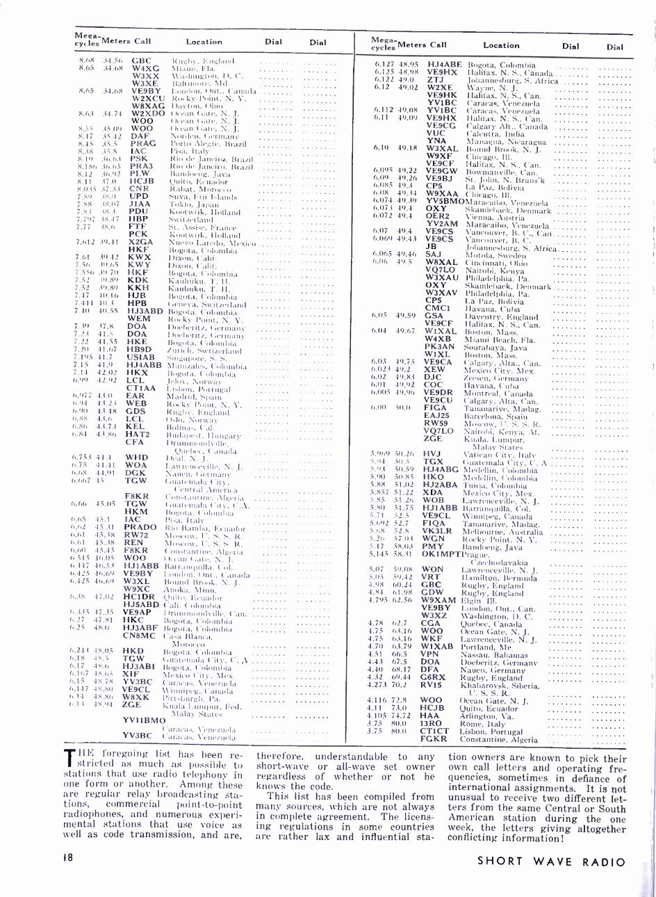
Me¢a- cyc les Meters Call Location ion Dial Dial Mega-
cycles Meters Call Location Dial Dial 8.68 34.56 GBC Itu.;I.t. I u;l,utd 8.65 34.68 W4XG \I nni. I I.t.
W3XX \\ In11:;i.01. D. C. W3XE I .í(í5ín tt, \Id.
8.65 34.68 VE9BY I om I. ut, ( mt.. Canada W2XCU I:. ,. k l'oint, N. Y. W8XAG I ).t. tUut, ( )hio
8.63 34.74 W2XDO ( ), can ( :ate, N. J. WOO t ), tan (:ate.
8.55 35.(19 WOO ( can ( :ate. N. J. 8.47 35.42 DAF \orílen. (:erntanv 8.45 35.5 PRAG l'orto Alegre, Brazil 8.38 35.8 IAC Pisa, Italy 8.19 36.6.i PSK Rio dc Janeiro, Brazil 8.186 36.65 PRA3 Rio de Janeiro, Brazil 8.12 36.92 PLW Bandoeng, Java 8.11 37.0 HCJB Quito. Ecuador 8.1135 37.33 CNR Rabat, Moro,, o 7.89 38.0 UPD Suva, Fi pi klands 7.88 38.07 JIAA Tokio, Jalau 7.83 38.3 PDU Kootwi ¡k. Rolland 7.797 38.47 HBP Switzerland 7.77 38.6 FTF St. Assise, France
PCK Kootwijk. Holland 7.612 39.41 X2GA Nuevo vo Laredo, Mexico
HKF I ;..gota, Colombia KWX I >ixon, Calif. KWY Dixon, Calif. HKF Bogota. Colombia KDK kauhuku, 'I'. 11. KKH K.uthuku, 7'. II. HJB llogota, Colombia HPB t:eneva, Switzerland HJ3ABD Bogota, Colouthia WEM Rocky ('oint, N. V.
7.39 37.8 DOA I)oeheritz, ( :ermany 7.23 41.5 DOA 1 )utheriti, ( :ermany 7.22 41.55 HKE Bogota, ('(ím,5:í 7.2(1 41.67 HB9D /mi, h. Síí555í thou( 7.195 41.7 USIAB Sntal,otc S . 7.15 41.9 HJ4ABB :I:utizales, (olonihia 7.14 42.02 HKX Bogota, ('oluuthi.t 6.99 42.92 LCL Jelin-, Norway
CTIAA Lisbon, Portugal 6.977 43.0 EAR Madrid. Spain 6.94 43.23 WEB Rocky l'oint, N. V. 6.911 43.48 GDS Rugby. England 6.88 43.6 LCL Oslo, Norway 6.86 43.73 KEL Bolina.,, ('al. 6.84 43.86 HAT2 Budapest. Hungary
CFA Drummondville, Quebec. Canada
6.753 44.4 WHD Deal. N. J. 6.75 44.41 WOA I.awrent (Ville. N. J. 6.68 44.91 DGK N,tu, n. t:ernta>tt 6.667 45 TGW t u:Uetnala Pity.
Central . \nu'rica F8KR ('on ..tantine. Algeria
6.66 45.05 TGW luatemala ('ity. ('.A HKM ling )t a, Columbia
6.65 45.1 IAC Pi it, Italy 6.62 45.31 PRADO Itiu Baumb,a, Ecuador 6.M 45.38 RW72 :Moscow, l' ' R 6.61 45.38 REN Moscow, C. S. S. R. 6.611 45.4.5 F8KR Constantine, Algeria 6.515 46.05 WOO Ocean (:ate, N. I. 6.447 46.53 HJIABB Barranquilla. Col. 6..125 46.69 VE9BY London. ( )nt.. Canada 6.425 46.69 W3XL Bound Br)ok. N. J.
W9XC Anoka, Minn. 6.38 47.02 HC1DR Quito. Ecuador
HJ5ABD ('ali. Colombia 6.335 47.35 VE9AP Drummondville. ('an. 6.27 47.81 HKC Bogota. Colombia 6.25 48,0 HJ3ABF Bogota. Colombia
CN8MC Casa Blanca, Morocco
6.243 48.05 I-IKD Bogota, Colombia 6.18 48.5 TGW ( :uatentala City, C. ,A 6.17 48.6 HJ3AB1 Bogota, Colombia 6.167 48.65 XIF Mexico ('itv. Mex. 6.15 48.78 YV3BC Caracas. Venezuela 6.117 48.80 VE9CL Winnipeg. Canada 6.14 48.86 W8XK Pittsburgh, Pa. t 1 i 48.94 ZGE Kuala Lumpur, Fed.
Malay States YVI1BMO
Caracas, Venezuela YV3BC Caracas, Venezuela
7.61 39.42 7.56 ;9.65 7.556 39.70 7.52 39.89 7.52 39.89 7.47 40.16 7.444 40.3 7.40 40.55
6.127 48.95 HJ4ABE Bogota, Colombia 6.125 48.98 VE9HX Ilalifax, N. S., Canada 6.122 49.0 ZTJ Johannesburg. S. Africa 6.12 49.02 W2XE Wayne, N. J.
VE9HK Halifax, N. S., Can. YVIBC Caracas, Venezuela
6.112 49.08 YVIBC Caracas. Venezuela 6.11 49.09 VE9HX Halifax. N. S., Can.
VE9CG Calgary Alt., Canada VUC Calcutta, India YNA Managua, Nicaragua
6.10 49.18 W3XAL Bound Brook, N. J. W9XF Chicago, Ill. VE9CF Halifax, N. S., Can. 6.095 49.22 VE9GW Bowmanville, Can. 6.09 49.26 VE9BJ St. John, N. Bruns'k 6.085 49.3 CPS La Paz, Bolivia 6.08 49.34 W9XAA Chicago, Ill. 6.074 49.39 YV5BMOMaracaibo, Venezuela 6.073 49.4 OXY Skamlebaek, Denmark 6.072 49.4 OER2 Vienna. Austria YV2AM Maracaibo, Venezuela
6.07 49.4 VE9CS Vancouver, B. C., Can 6.069 49.43 VE9CS Vancouver. B. C. JB Johannesburg, S. Africa 6.065 49.46 SAJ Motola, Sweden
6.06 49.5 W8XAL Cincinnati. Ohio VQ7LO Nairobi, Kenya W3XAU Philadelphia, Pa. OXY Skamlebaek, Denmark W3XAV Philadelphia, I'a. CP5 La Paz. Bolivia CMC( (Havana, Cuba
6.05 49.59 GSA Daventry, England VE9CF Ilalifax, N. S., Can.
6.04 49.67 WIXAL Boston, Mass. W4XB Miami Beach, Fla. PK3AN Sourabaya, Java W1XL Boston, Mass.
6.03 49.75 VE9CA Calgary, Alta.. Can. 6.023 49.2 XEW Mexico City, Mex. 6.02 49.83 DJC Zeesen, Germany 6.01 49.92 COC Ilavana, Cuba 6.005 49.96 VE9DR Montreal. Canada
VE9CU Calgary. Alta, Can. 6.00 50,(1 FIGA Tananarive. Madag.
EAJ25 Barcelona, Spain RW59 Moscow, U S S R . VQ7LO Nairobi, Kenya, Af. ZGE Kuala, Lumpur,
Malay States 5.969 50.26 HVJ Vatican City, Italy 5.94 50.5 TGX Guatemala City, ('. A 5.93 50.59 HJ4ABG Medellin, Colombia 5.90 5(1.85 HKO Medellin, Colombia 5.88 51.02 HJ2ABA Tunia, Colombia 5.857 51.22 XDA Mexico City, Mex. 5.85 51.26 WOB Lawrenceville, N. J. 5.80 51.75 HJ1ABB Barranquilla, Col. 5.71 52.5 VE9CL Winnipeg, Canada 5.692 52.7 FIQA Tananarive, Madag. 5.68 52.8 VK3LR Melbourne, Australia 5.26 57.0.3 WGN Rocky Point, N. Y. 5.17 58.03 PMY Bandoeng, Java 5.145 58.31 OKIMPTPrague,
Czechoslavakia 5.07 59.08 WON Lawrenceville, N. J. 5.05 59.42 VRT Hamilton, Bermuda 4.98 60.24 GBC Rugby, England 4.84 61.98 GDW Rugby, England 4.795 62.56 W9XAM Elgin Ill.
VE9BY London, Ont.. Can. W3XZ Washington, D. C.
4.78 62.7 CGA Quebec, Canada 4.75 63.16 WOO Ocean Gate, N. J. 4.75 63.16 WKF Lawrenceville, N. J. 4.70 63.79 W1XAB Portland, Me. 4.51 66.5 VPN Nassau, Bahamas 4.43 67.5 DOA Doeberitz, Germany 4.40 68.17 DFA Nauen, Germany 4.32 69.44 G6RX Rugby, England 4.273 70.2 RV15 Khabarovsk, Siberia,
U. S. S. R. 4.116 72.8 WOO Ocean Gate, N. J. 4.11 73.0 HCJB Quito, Ecuador 4.105 74.72 HAA Arlington, Va. 3.75 80.0 13R0 Rome, Italy 3.75 80.0 CTICT Lisbon, Portugal
FGKR Constantine, Algeria
lilt. foregoing list has been re- / stricted as much as possible to
stations that use radio telephony in one form or another. Among these are regular relay broadcasting sta- tions, commerc ial point -to -point radiophones, and numerous experi- mental stations that use voice as well as code transmission, and are,
18
therefore, understandable to any short -wave or all -wave set owner regardless of whether or not he knows the code.
This list has been compiled from many sources, which are not always in complete agreement. The licens- ing regulations in some countries are rather lax and influential sta-
tion owners are known to pick their own call letters and operating fre- quencies, sometimes in defiance of international assignments. It is not unusual to receive two different let- ters from the same Central or South American station during the one week, the letters giving altogether conflicting information!
SHORT WAVE RADIO

List of The international call letter assignments under- went some extensive changes early this year, when the acts of the Madrid Radio Conven- tion of 1932 went into effect. For the most part the changes affect the smaller countries. but one really important shift gives all the R and U calls to the Union of the Socialist Soviet Republics, ( "Russia "). The list as given below incorporates the official changes.
Block of Calls Country Amateur
Prefix
CAA -CEZ Chile CE CFA -CKZ Canada VE CLA -CMZ Cuba CM CNA -CNZ Morocco CN COA -COZ Cuba CPA -CPZ Bolivia CP t-QA -CRZ Portuguese colonies:
Cape Verde Ids. CR4 Portuguese Guinea CR5 Angola CR6 Mozambique CR7 Portuguese India CR8 Macao CR9 Timor CR10
CSA -CUZ Portugal: Portugal proper CTI Azores CT2 Madeira CT3
CVA -CXZ Uruguay CX CYA -CZZ Canada ll Germany D EAA -EHZ Spain EAR EIA -EIZ Irish Free State EI ELA -ELZ Liberia EL EPA -EQZ Persia ESA -ESL Esthonia ES ETA -ETZ Ethiopia (Abyssinia) ET EZA -EZZ Sarre Territory F France (including colonies):
France proper F French Indo-China FI Tunis FM4 Algeria FM8
G United Kingdom: Great Britain except Ireland G Northern Ireland GI
HAA -HAZ Hungary HA ITBA -HBZ Switzerland HB HCA -HCZ Ecuador HC
International Call Assignments Amateur
Block of Calls Country Prefix Amateur
Block of Calls Country Prefix
HHA -HHZ Haiti HH VIIA -VMZ Australia VK HIA -HIZ Dominican Republic HI VOA -VOZ Newfoundland VO HJA -HKZ Colombia IIJ VPA -VSZ British colonies and protectorates HPA -HPZ Republic of Panama British Guiana VP HRA -HRZ honduras IIR Fiji. Ellice Ids., Zanzibar VPI HSA -HSZ Siam HS Bahamas, Barbados. HVA -HVZ Vatican City State Jamaica VP2 HZA -HZZ Hedjaz Bermuda VP9 I Italy and colonies Fanning Id. VQI J Japan J Northern Rhodesia VQ2 K United States of America: Tanganyika VQ3
Continental United States \V Kenya Colony VQ4 Philippine Ids. KA Uganda VQ5 Porto Rico and Virgin Ids. K4 Malaya (including Straits Territory of Hawaii KG Settlements) VSI -2 -3 Territory of Alaska K7 Hongkong VS6
LAA -LNZ Norway LA Ceylon VS7 LOA -LWZ Argentine Republic LU VTA -V \VZ British India VU LXA -LXZ Luxemburg VXA -VVZ Canada LYA -LYZ Lithuania United States of America: LZA -LZZ Bulgaria LZ Continental United States W 11f Great Britain G (for others. see under K.) N United States of America \V XAA -XFZ Mexico X OAA -OCZ Peru OA XGA -XIJZ China AC OEA -OEZ Austria XYA -XZZ British India OFA -OHZ Finland OH VAA-VAZ Afghanistan YA OKA -OKZ Czechoslovakia OK YBA -VHZ Dutch East Indies ONA -OTZ Belgium and colonies ON VIA -VIZ Iraq YI OUA -OZZ Denmark OZ YJA -VJZ New Hebrides PAA -PIZ The Netherlands PA VLA -VLZ Latvia Y1. PJA -PJZ Curacao PJ YMA -V1117, Danzig YM PKA -POZ Dutch East Indies PK YNA -\'NZ Nicaragua YN PPA -PYZ Brazil PY YOA -YRZ Rumania PZA -PZZ Surinam PZ VSA -VSZ Republic of El Salvador YS R Union of the Socialist Soviet YTA -VUZ Yugoslavia
Republics V VA- 1'\VL Venezuela YV SAA -SMZ Sweden SM ZAA -ZAZ Albania ZA SOA -SRZ Poland SP ZBA -ZJL British colonies and protectorates STA -SUZ Egypt: Transjordania ZC1
Sudan ST Palestine ZC6 Egypt proper SU Nigeria Zll
SVA -SZZ Greece SV Southern Rhodesia ZE1 TAA -TCZ Turkey TA ZKA -ZMZ New Zealand: TFA -TFZ Iceland TF Cook Ids. ZK TGA -TGZ Guatemala TG New Zealand proper ZL TIA -TIZ Costa Rica TI British Samoa ZM TKA -TZZ France and Colonies and ZPA -ZPZ Paraguay Z I'
Protectorates ZS U U.S.S.R. ZSA -ZUZ Union of South Africa Z'I' VAA -VGZ Canada VE ZU
PHYSICS OF ELECTRON TUBES, by L. R. Koller, published by the McGraw -Hill Book Co., Inc., New York, N. Y., 6 by 9 inches; 200 pages; well illustrated. Price $3.00. With the appearance of so many
books on vacuum tubes, it is a bit refreshing to read one that does not repeat the wealth of stereotyped information so common in many texts on the subject. Physics of Electron Tubes is exactly what the name implies : a treatment of vacuum tubes from the standpoint of the physicist. You need know nothing about the operation of vac- uum tubes to be able to read and appreciate this book. The chapters deal with the characteristics of dif- ferent types of filaments, the calcula- tion of the emission current obtain- able therefrom, the advantages and disadvantages of the different types of filaments, etc.
A chapter on the effect of gas is very well presented in a manner somewhat unusual to a radio en- gineer. The calculation of the mean free path, thickness of ion sheaths, etc., is clearly indicated.
The last half of the book is devoted to photoelectricity and allied fields,
an important and well- deserved set of chapters.
The style of the book is very pleasing. Written by a man who knows his work thoroughly, the top- ics are presented in a very concise manner, the only formulas shown being those which are actually used in the determination of tube con- stants. Not a single mention is made of the operation of the tube, this part of the theory being left to other books on the subject.
A very valuable feature of the book is the numerical problems at the end of each chapter, together with the answers. Your reviewer feels that more texts on radio should incorporate problems, as they afford one of the few means whereby the reader can check his knowledge of a particular chapter.
Only a few typographical errors were found, and they were of negli- gible importance. Also, discrepancies exist between several of the answers given in the text and those cal- culated by your reviewer. However, most of the discrepancies occur in the location of the decimal point, and so should not be detrimental in any respect to those who wish to do the problems.
This is a much needed treatment of what takes place inside the much used vacuum tube.
-L. M.. * * *
ELEMENTS OF RADIO COM- MUNICATION, by John H. More - croft, published by John Wiley and Sons, New York, N. Y., 6 by 9 inches, 286 pages, well illustrated. Price, $3.00. This is the second edition of the
now famous Elements of Morecroft, and it is just as difficult to outline the virtues of this book as it is to properly treat the more detailed Principles.
In brief, this book takes the reader from the very fundamentals of radio communication to the more detailed treatment of vacuum -tube theory and operation. It really con- tains much more information than its modest name implies, and the subject is treated in a manner that can only be attained by a teacher of long standing. It is lucid, accurate and profusely illustrated with nu- merical problems -an important combination to the man with a mass of un- corelated facts about radio.
(Continued on page 41)
for JULY, 1934 19
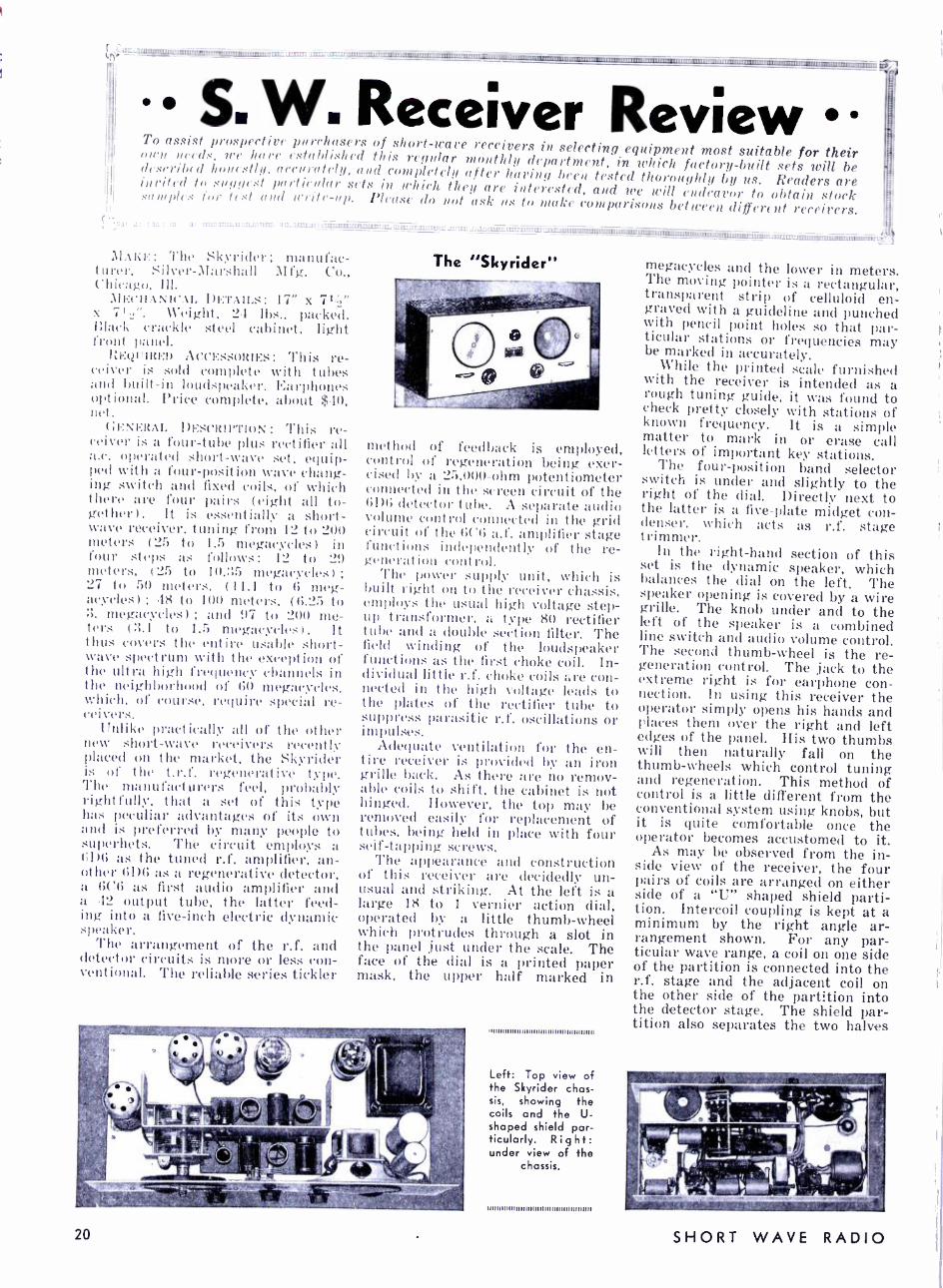
) q4'ü:;;:::. ummmm' I "rmmm nmm W.IW:®R::ü1m1:Iü:ülDüüllIIlID11IW' _ ._ 1r14f117 - ____-- ___- - ___ -- _-
S:
S. W. Receiver Review To assist prospective purchasers of short -wave receivers in selecting equipment most suitable for their own needs, we have established this regular monthly department, in which factory -built sets will be described honest!! /, accurately, and completely after having been tested thoroughly by us. Readers are invited to suggest particular sets in which they are interested, and we will endeavor to obtain stock samples for test and write -up. Please do not ask us to make comparisons between different receivers.
.. 1
- II:WL.'üüüC:. IDLL 'II:IIW::^".I:lül :JJ.SWWüp1;;,11WMWWW61'WIIIIDWWüWfüIDü.'IWIL'WIIm1.l0ü.11W1';WW(!¡! - - - . _üüüWW;üllWWIDW7®m r nrml ml n -.;;üyylp,.IllIWllCIIülmnnityl!,rnunmmmmmn mül;.
í11A1:1'.: The Skyrider; manufac- turer, Silver- Marshall 1\I fg. Co., Chicago, Ill.
.11ECHAN1('.L DETAILS: 17" x x 7 Weight, 24 lbs., packed. Black- crackle steel cabinet, light front panel.
REQUIRED ACCESSORIES: This re- ceiver is sold complete with tubes and built -in loudspeaker. Earphones optional. Price complete, about $40, net.
(il' :NI :RAI. I)EscItll "'loN : This re- ceiver is a four -tube plus rectifier all a.c. operated short -wave set, equip- ped with a four- position wave chang- ing switch and fixed coils, of which there are four pairs (eight all to- gether). It is essentially a short- wave receiver, tuning from 12 to 200 meters (25) to 1.5 megacycles) in four steps as follO \' : 12 to 29 meters, (25) to 10.35 megacycles) ;
27 to 50 meters, (11.1 to 6 meg- acycles) ; 48 to 100 meters, (6.25 to :1. megacycles) ; and 97 to 200 me- ters ( :;.1 to 1.5 megacycles) . It thus covers the entire usable short - wave spectrum with the exception of the ultra high frequency channels in the neighborhood of (i0 megacycles. which, of course, require special re- ceivers.
Unlike practically all of the other new short -wave receivers recently placed on the market, the Skyrider is of the t.r.f. regenerative type. The manufacturers feel, probably right fully, that a set of this type has peculiar advantages of its own and is preferred by many people to superhets. The circuit employs a (;l)6 as the tuned r.f. amplifier, an- other 6I)6 as a regenerative detector, a 6C6 as first audio amplifier and a 42 output tube, the latter feed- ing into a five -inch electric dynamic speaker.
The arrangement of the r.f. and detector circuits is more or less con- ventional. The reliable series tickler
The "Skyrider"
method of feedback is employed, control of regeneration being exer- cised by a 25,000 -ohm potentiometer connected hi the screen circuit of the 61)6 detector tuba'. A separate audio volume control cl lnnecte(I in the grid circuit of the (i('(i a.f. amplifier stage functions independently of the re- generation control.
The power supply unit, which is built right on to the receiver chassis, employs the usual high voltage step - up transformer, a type 80 rectifier tube and a double section filter. The field winding of the loudspeaker functions as the first choke coil. In- dividual little r.f. choke coils are con- nected in the high voltage leads to the plates of the rectifier tube to suppress parasitic r.f. oscillations or impulses.
Adequate ventilation for the en- tire receiver is provided by an iron grille back. As there are no remov- able coils to shift, the cabinet is not hinged. However, the top may be removed easily for replacement of tubes, being held in place with four self- tapping screws.
The appearance and construction of this receiver are decidedly un- usual and striking. At the left is a large 18 to 1 vernier action dial, operated by a little thumb -wheel which protrudes through a slot in the panel just under the scale. The face of the dial is a printed paper mask, the upper half marked in
20
I I I I I I I III lllll 111I I I I 11111111111111111111111
Left: Top view of the Skyrider chas- sis, showing the coils and the U- shaped shield par- ticularly. Right: under view of the
chassis.
11111111111111111I I11111111I I I I I I I 1111111111
megacycles and the lower in meters. The moving pointer is a rectangular, transparent strip of celluloid en- graved with a guideline and punched with pencil point holes so that par- ticular stations or frequencies may be marked in accurately.
While the printed scale furnished with the receiver is intended as a rough tuning guide, it was found to check pretty closely with stations of known frequency. It is a simple matter to mark in or erase call letters of important key stations.
The four- position band selector switch is under and slightly to the right of the dial. Directly next to the latter is a five -plate midget con- denser, which acts as r.f. stage trimmer.
In the right -hand section of this set is the dynamic speaker, which balances the dial on the left. The speaker opening is covered by a wire grille. The knob under and to the left of the speaker is a combined line switch and audio volume control. The second thumb -wheel is the re- generation control. The jack to the extreme right is for earphone con- nection. In using this receiver the operator simply opens his hands and places them over the right and left edges of the panel. His two thumbs will then naturally fall on the thumb -wheels which control tuning and regeneration. This method of control is a little different from the conventional system using knobs, but it is quite comfortable once the operator becomes accustomed to it.
As may be observed from the in- side view of the receiver, the four pairs of coils are arranged on either side of a "U" shaped shield parti- tion. Intercoil coupling is kept at a minimum by the right angle ar- rangement shown. For any par- ticular wave range, a coil on one side of the partition is connected into the r.f. stage and the adjacent coil on the other side of the partition into the detector stage. The shield par- tition also separates the two halves
SHORT WAVE RADIO

b
9 R'LATe . r.f//'1/yE4
ro"
6D6 i 300 -e-, O./n.5 1
/nr
A/OTE APES/STANCE OF AIL R. F C/fO.rR.f /J JO ONMS.
ON0. FFEDF.P w/4fS 04 AE.P/AL
/,0 V A C
.73 /'JF1 PFC.
500,000 OHM ear rr _ i 1 /OLUrIf CO.VIloL)
_ _
/00, 000 ON/YS
.0005 = Ó//MF. MF.,1 ----- %1L REC
.25 MF. c
S .tiFG 606
tSOOo OHMS
30,o00
,0 /MF,
6C6
\I _ S h1F,
3000 O//11S
/00,000 O/+MS
REGENF4AT/ON 1-CONI,ML tt5,000
ONMS
III
4
.SMF
250,000 0NMS
20 0///1.5 p --/C TI F/LAMENT C74CU/T
2S, 000 Or/MS
606 F
.Sw/rCN OM VOLUME CONTROL
r:-'
r
11 RFC
RFC
80
606 6 C6 A F
.SPEAA!'EQ F/E[
1 X 42
F
T`-aMF --T 1 1
PEONE .TACA"
of the dual tuning condenser and the two sections of the wave changing switch.
Provisions are made for the con- nection of a transposed or twisted wire transmission line for use with a doublet antenna.
OPERATION : The general opera- tion of the Skyrider was found to be very satisfactory, the regenerative action being especially smooth and gradual. This is an important fea- ture from the standpoint of voice and music reception. In the sample tested by the editors of SHORT WAVE RADIO, there was a suspicion of a dead spot in two of the tuning ranges, due probably, to coil absorp- tion, but otherwise the set proved extremely sensitive and quite selec- tive. The volume control could not be opened up full on such foreign stations as London, Berlin, Rome and Madrid. At high volume levels the set tends to become microphonic and breaks into a howl due to acous- tic feedback between the loudspeaker and the circuit components. This is not serious or objectionable, as the signals become too loud for comfort
Correct method of operating the thumb wheels of the Skyrider receiver.
for JULY, 1934
Complete schematic diagram of the Skyriders.
before this point is reached and the operator will naturally reduce the volume anyway.
The Skyrider should appeal to short -wave DX fans. It makes an ideal supplementary set for the man who already has an excellent broad- cast receiver and who therefore does
not care to buy one of the new all - wave sets.
A special model for amateur com- munication purposes is also avail- able. This is identical in appear- ance with the set illustrated but has complete band spreading to open up the crowded amateur channels.
Names of Antenna Parts Clarified
AGOOD many short -wave set owners seem to be confused
over the names of the various parts of the now popular types of noise reducing antennas. The general term "doublet" is being applied to the entire installation, whereas actu- ally a "doublet" is a specific kind of aerial and has nothing to do with the transposed wire or twisted wire lead -in, which is actually the part of the system that rejects both noise and radio impulses along its own length. Contrary to the general be- lief, the aerial itself does not reject the noise. It must continue to pick up all radio impulses that strike it if it is to function as an antenna at all.
A "doublet" is merely a split an- tenna with an insulator at the exact center, its maximum operating effectiveness taking place on a wave - length double the overall length in meters ; hence the name doublet. The wires that connect this antenna with the receiver are known as the transmission line or feeders. Ex- actly the same transmission lines or feeders may be connected to one ex- treme end of an aerial wire. The best operating wavelength of an end-
fed antenna of this kind is again double its length in meters, so the name doublet may be applied to an end -fed aerial just as well as to a center -fed aerial.
AUTOMATIC volume control, as now employed very success-
fully in many short -wave super - heterodynes, overcomes fading of short -wave stations to a large de- gree. However, the a.v.c. action can- not do the impossible; it will not restore or create a signal if fading is so bad that the impulses die out of the receiving antenna altogether. If a station is tuned in and heard quite loudly and then starts to dis- appear, there is nothing the listener can do about it, except wait for the signals to reappear. Of course, in some sets "fading" is not signal fad- ing at all, but is due to drift in the tuning circuits. This can be over- come only by a very slight readjust- ment of the dial. Frequency shift at the transmitter may also take place if the latter is not of the crys- tal controlled type. In this case, any receiver will require slight retuning.
21
Some Questions and Answers on Noise Reducing Aerial Systems
THE problem of antennas seems to be universal among all short- wave set owners, regardless of the class they fall in. They may
be set constructors or merely set operators, but they all have to use aerials. Fully 75 of all the ques- tions asked at the Winter meetings of the Short Wave Club of New York were on this subject. There evidently is a great deal of wrong information floating around, for some of the people attending these meetings expressed some queer no- tions about antennas.
In order to clarify the situation a little, we have asked DIr. Arthur II. Lynch, well known exponent of short -wave. noise reducing antennas, to answer a number of typical ques- tions asked by short -wave set own- ers. The questions and the answers follow and contain a great deal of useful information. If you have any further questions that you want answered, do not hesitate to send them in to us. We feel that the subject of short -wave antennas is extremely important and we want to make certain that every reader un- derstands the characteristics and limitations of the popular types now available.
(1) In what direct ion is an ordi- nary straight end -fed aerial direc- t ional ?
(1) A straight end -fed antenna is directional in the direction op- posite the free end ; that is, if the antenna runs North and South and the lead is taken off the North end. the receiver will receive best from stations to the North. If the lead is taken off the South end, the re- ceiver will perform best with sta- tions to the south.
The directional properties of such an antenna are not very marked, when used in the broadcast band or when the length of the antenna is rather short. The directional prop- erties of such an aerial depend, to a degree, upon the length of the flat portion of the antenna as com- pared to the length of the lead -in itself. When a transposed trans- mission line replaces the ordinary lead -in, the directional effect of the antenna is slightly improved.
Directional Effect
(2) In what direction is the popu- lar doublet i renter -fed) aerial di- rectional?
(2) Just the opposite directional properties are noted, in connection with the so- called "doublet" antenna. An antenna running North and South will receive best in the direc- tions East and West. The direc- tional properties of the doublet are more marked than those of the
22
single wire type of antenna. (3) Why does transposing the wires of the lead -in prevent the lead -in itself from picking up noise or radio energy, or rather why does
not this energy get down into the radio receiver by way of the lead -in?
(3) The reason that a transposed line does not pick up interference is rather simple to understand. Con- sider that a transposed line is pass- ing in a vertical plane from any antenna to any receiver. At some distance below the antenna and before the line reaches the re- ceiver, consider that we have a source of interference. The inter- ference strikes the two wires of the transposed transmission line with equal intensity. The transposition in the line makes the two sides of the line 180 degrees out of phase. Therefore the interference striking the line is neutralized because it strikes one wire and creates a vol- tage in that wire with the same in- tensity that it strikes the other wire and creates a voltage in it.
(4) Is a transposed wire feeder of any appreciable advantage, enough advantage to warrant its cost, in lo- cations altogether free from extrane- ous noise?
(4) Yes. In some locations, even where no noise exists, there is a no- ticeable fading on regular broad- cast stations from 20 to 100 miles distant. This results from the out of phase mixing of the ground and the air waves. Using the doublet antenna with a transposed transmis- sion line eliminates the ground wave altogether. This results, in many instances, in the reception of very satisfactory programs, which, under other conditions, would not be worth hearing. This is a comparatively new application of the doublet an- tenna and one which is becoming in- creasingly popular with broadcast listeners who desire to receive over long distances, especially at night.
(5) A transposed lead -in termi- nates at the outside of a window. The radio receiver is several rooms removed inside the house. What is the best method of connecting the lead -in to the receiver?
(5) The easiest way to run a transmission line from the point where the transposed line enters the house to the radio receiver itself is by using ordinary No. 14 -2 wire BX cable. This is the same wire used for electric house wiring. Wire of this nature is looked upon by many ex- perts to be entirely unsuitable for transmission -line work. However, we have run lines of this character several hundred feet without any noticeable loss in signal strength.
Lines of this nature are very de- sirable for running the leads from
an antenna to the receiver when the receiver is located in an apartment house, where the use of a regular transposed transmission line would be difficult. The ideal arrangement on apartment houses is to run the transposed transmission line to the level of the roof and BX from the roof level to the receiver. In su- burban locations, it is desirable to run the transposed transmission line to the window nearest the loca- tion of the receiver, and a short length of BX from there.
Length of Wire (6) How critical or important is
the length of an end -fed aerial? A doublet aerial?
(6) The answer to this question depends to a large degree upon whether the antenna is to be used for reception on all waves or on a particular frequency. If the antenna is to be used on a particular fre- quency, such as for communication purposes on 20, 40, 80 or 160 meters, as used by amateurs, the choice of the length of the antenna is rather important. In most instances the most suitable length is one half of the actual wavelength on which the amateur desires to transmit and re- ceive.
For use in connection with all - wave receivers, the most desirable procedure is the use of an antenna one -half the length of the shortest wavelength we desire to receive. This holds true whether the antenna be a singlet or doublet type. In the latter case, the two wires form doublet, one half the wavelength of the shortest wave received, while, with the single type of antenna, the single wire is one half the wave- length.
The determination of this length of antenna wire has been determined on the following basis. The average all -wave receiver has a sensitivity of approximately 20 microvolts per meter at 15 meters, and a sensitivity of 2 microvolts at 550 meters. There- fore, the best procedure is to make the antenna most efficient where the receiver is least efficient. As we go up in wavelength, the antenna be- comes less efficient and therefore, the improved efficiency of the re- ceiver itself more than compensates for the lack of efficiency of the an- tenna, and we have a desirable bal- ance.
The above holds true whether we are considering a single wire a half wavelength in length, or a doublet which has a total length of one half the shortest wavelength we desire to receive.
(7) What are the limits on the length of the transposed wire feeder itself?
SHORT WAVE RADIO
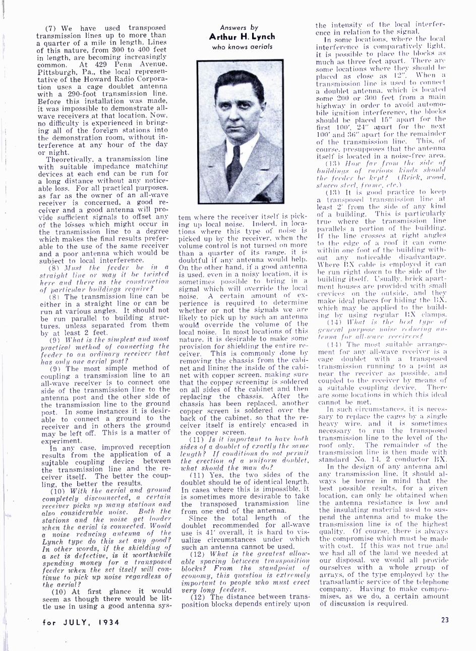
(7) We have used transposed transmission lines up to more than a quarter of a mile in length. Lines of this nature, from 300 to 400 feet in length, are becoming increasingly common. At 429 Penn Avenue. Pittsburgh, Pa., the local represen- tative of the Howard Radio Corpora- tion uses a cage doublet antenna with a 290 -foot transmission line. Before this installation was made. it was impossible to demonstrate all - wave receivers at that location. Now, no difficulty is experienced in bring- ing all of the foreign stations into the demonstration room, without in- terference at any hour of the day or night.
Theoretically, a transmission line with suitable impedance matching devices at each end can be run for a long distance without any notice- able loss. For all practical purposes. as far as the owner of an all -wave receiver is concerned, a good re- ceiver and a good antenna will pro- vide sufficient signals to offset any of the lósses which might occur in the transmission line to a degree which makes the final results prefer- able to the use of the same receiver and a poor antenna which would be subject to local interference.
(8) Must the feeder be in a straight line or may it be twisted here and there as the construction of particular buildings require?
(8) The transmission line can be either in a straight line or can be run at various angles. It should not be run parallel to building struc- tures, unless separated from them by at least 2 feet.
(9) What is the simplest and most practical method of connecting the feeder to an ordinary receiver that has only one aerial post?
(9) The most simple method of coupling a transmission line to an all -wave receiver is to connect one side of the transmission line to the antenna post and the other side of the transmission line to the ground post. In some instances it is desir- able to connect a ground to the receiver and in others the ground may be left off. This is a matter of experiment.
In any case, improved reception results from the application of a suitable coupling device between the transmission line and the re- ceiver itself. The better the coup- ling, the better the results.
(10) With the aerial and ground completely disconnected, a certain receiver picks up many stations and also considerable noise. Both the stations and the noise get louder when the aerial is connected. Would a noise reducing antenna of the Lynch type do this set any good? In other words, if the shielding of a set is defective, is it worthwhile spending money for a transposed feeder when the set itself will con- tinue to pick up noise regardless of the aerial?
(10) At first glance it would seem as though there would be lit- tle use in using a good antenna sys-
for JULY, 1934
Answers by
Arthur H. Lynch who knows aerials
tern where the receiver itself is pick- ing up local noise. Indeed, in loca- tions where this type of noise is picked up by the receiver, when the volume control is not turned on more than a quarter of its range, it is doubtful if any antenna would help. On the other hand, if a good antenna is used, even in a noisy location, it is sometimes possible to bring in a signal which will override the local noise. A certain amount of ex- perience is required to determine whether or not the signals we are likely to pick up by such an antenna would override the volume of the local noise. In most locations of this nature, it is desirable to make some provision for shielding the entire re- ceiver. This is commonly done by removing the chassis from the cabi- net and lining the inside of the cabi- net with copper screen, making sure that the copper screening is soldered on all sides of the cabinet and then replacing the chassis. After the chassis has been replaced, another copper screen is soldered over the back of the cabinet, so that the re- ceiver itself is entirely encased in the copper screen.
(11) Is it important to have both sides of a doublet of exactly the same length? If conditions do not permit the erection of a uniform doublet, what should the man do?
(11) Yes, the two sides of the doublet should be of identical length. In cases where this is impossible, it is sometimes more desirable to take the transposed transmission line from one end of the antenna.
Since the total length of the doublet recommended for all -wave use is 41' overall, it is hard to vis- ualize circumstances under which such an antenna cannot be used.
(12) What is the greatest allow- able spacing between transposition blocks? From the standpoint of economy, this question is extremely important to people who must erect very long feeders.
(12) The distance between trans- position blocks depends entirely upon
the intensity of the local interfer- ence in relation to the signal.
In some locations, where the local interference is comparatively light, it is possible to place the blocks as much as three feet apart. There are some locations where they should 1w
placed as close as 12 ". When a transmission line is used to connect a doublet antenna, which is located some 200 or 300 feet from a main highway in order to avoid automo- bile ignition interference, the blocks should be placed 15" apart for t he first 100', 24" apart for the next 100' and 36" apart for the remainder of the transmission line. This, of course, presupposes that the antenna itself is located in a noise -free area.
(13) Hour far from the side of buildings of rnriHrr.' kinds 5110111(1
the feeder be kept? (Brick, mood, stucco steel, frame, etc.)
(13) It is good practice to keep a transposed transmission line at least 2' from the side of any kind of a building. This is particularly true where the transmission line parallels a portion of the building. If the line crosses at right angles to the edge of a roof it can come within one foot of the building with- out any noticeable disadvantage. Where BX cable is employed it can be run right down to the side of the building itself. Usually. brick apart- ment houses are provided with small crevices on the outside. and they make ideal places for hiding the BX, which may be applied to the build- ing by using regular BX clamps.
(14) What is the best tape of ,general purpose noise rrdueinq an- tenna for all-wore rerrirers?
(14) The most suitable arrange- ment for any all -wave receiver is a cage doublet with a transposed transmission running to a point as near the receiver as possible, and coupled to the receiver by means of a suitable coupling device. There are some locations in which this ideal cannot be met.
In such circumstances, it is neces- sary to replace the cages by a single heavy wire, and it is sometimes necessary to run the transposed transmission line to the level of the roof only. The remainder of the transmission line is then made with standard No. 14. 2 conductor BX.
In the design of any antenna and any transmission line, it should al- ways be borne in mind that the best possible results, for a given location, can only be obtained when the antenna resistance is low and the insulating material used to sus- pend the antenna and to make the transmission line is of the highest quality. Of course, there is always the compromise which must be made with cost. If this was not true and we had all of the lanci we needed at our disposal, we would all provide ourselves with a whole group of arrays, of the type employed by the transatlantic service of the telephone company. Having to make compro- mises, as we do, a certain amount of discussion is required.
23
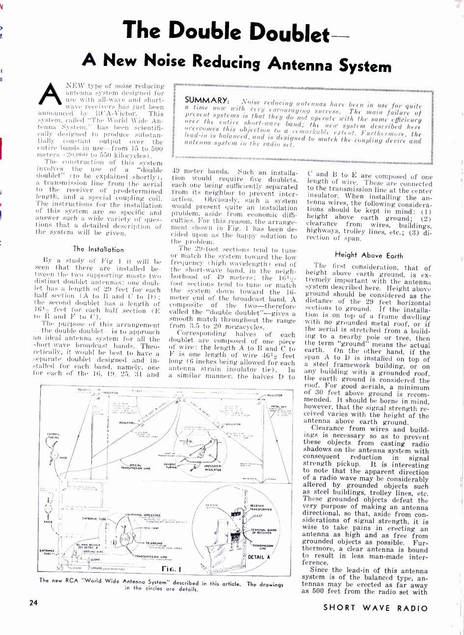
The Double Doublet- A New Noise Reducing Antenna System
ANEW type of noise reducing antenna system designed for use with all -wave and short - wave receivers has just been
announced by RCA- Victor. This system. called 'The World Wide An- tenna System," has been scientifi- cally designed to produce substan- tially constant output over the entire bands in use -from 15 to 500 meters (20,000 to 550 kilocycles).
The construction of this system involves the use of a "double doublet" (to be explained shortly), a transmission line from the aerial to the receiver of predetermined length, and a special coupling coil. l'he instructions for the installation of this system are so specific and answer such a wide variety of ques- tions that a detailed description of the system will be given.
The Installation By a study of Fig 1 it will be
seen that there are installed be- tween the two supporting masts two distinct doublet antennas: one doub- let has a length of 29 feet for each half section (A to B and C to I)) ;
the second doublet has a length of 161/4 feet for each half section ( E toB and FtoC).
The purpose of this arrangement - -the double doublet is to approach an ideal antenna system for all the short -wave broadcast bands. Theo- retically, it would be best to have a separate doublet designed and in- stalled for each band, namely, one for each of the 16, 19, 25, 31 and
nNI1EEElIIIIIITIIIIIIIIIIIIIITII1111111111111111111111111111111111111111111111111111111111111111111uuulUUUUUUnuu
SUMMARY: Noise reducing antennas hare been in use for quite a time now with very encouraging success. The main failure of present systems is that they do not operate with the same efficiency over the entire short -wave band; the new system described here overcomes this objection to a remarkable extent. Furthermore, the lead -in is balanced, and is designed to match the coupling device and antenna system in the radio set.
49 meter bands. Such an installa- tion would require five doublets, each one being sufficiently separated from its neighbor to prevent inter- action. Obviously, such a system would present quite an installation problem, aside from economic diffi- culties. For this reason, the arrange- ment shown in Fig. 1 has been de- cided upon as the happy solution to the problem.
The 29 -foot sections tend to tune or match the system toward the low frequency (high wavelength) end of the short -wave band, in the neigh- borhood of 49 meters; the 161/4- foot sections tend to tune or match the system down toward the 16- meter end of the broadcast band. A composite of the two -therefore called the "double doublet" -gives a smooth match throughout the range from 3.5 to 20 megacycles.
Corresponding halves of each doublet are composed of one piece of wire: the length A to B and C to F is one length of wire 461/4 feet long (6 inches being allowed for each antenna strain insulator tie). In a similar manner, the halves D to
CAMBRIC TueING
ll A.D.
.yl,,,_ ... . ,. -INUTA,UN
A
\ ... .
!\ -INSULATOR
^' ! ,7
ENTRANCE TORE
SPECIAL TRANSMISSION LINE
LIGMINING ARRISTORS
'
(V. ' , . .._.. .
I All WAN REGENTS ? w'f SEE DETAIL A .
ENI.AnCI , GROUND .vIRE
URL-_.G LLLlll .
TO GROUND
.i...... tw..tlt tons)
TRANSMüswN' IN(N.
Fi G. I `
I/1 GROUNDItctRw.,u.rtl
INSU,ATDR
O \ KúA .W T
.tt.
sRwcR TRANS[[EPORMCR
/EAT
4eD
DETAIL A \ r TERMINAL BOARD
CO RECEIVER
`TRAM 01 LINE
The new RCA ''World Wide Antenna System" described in this article. The drawings in the circles are details.
24
C and B to E are composed of one length of wire. These are connected to the transmission line at the center insulator. When installing the an- tenna wires, the following considera- tions should be kept in mind: (1) height above earth ground; (2) clearance from wires, buildings, highways, trolley lines, etc.; (3) di- rection of span.
Height Above Earth The first consideration, that of height above earth ground, is ex- tremely important with the antenna system described here. Height above ground should be considered as the distance of the 29 feet horizontal
sections to ground. If the installa- tion is on top of a frame dwelling with no grounded metal roof, or if the aerial is stretched from a build- ing to a nearby pole or tree, then the term "ground" means the actual earth. On the other hand, if the span A to D is installed on top of a steel framework building, or on any building with a grounded roof, the earth ground is considered the roof. For good aerials, a minimum of 30 feet above ground is recom- mended. It should be borne in mind, however, that the signal strength re- ceived varies with the height of the antenna above earth ground.
Clearance from wires and build- ings is necessary so as to prevent these objects from casting radio shadows on the antenna system with consequent reduction in signal strength pickup. It is interesting to note that the apparent direction of a radio wave may be considerably altered by grounded objects such as steel buildings, trolley lines, etc. These grounded objects defeat the very purpose of making an antenna directional, so that, aside from con- siderations of signal strength, it is wise to take pains in erecting an antenna as high and as free from grounded objects as possible. Fur- thermore, a clear antenna is bound to result in less man -made inter- ference.
Since the lead -in of this antenna system is of the balanced type, an- tennas may be erected as far away as 500 feet from the radio set with
SHORT WAVE RADIO

negligible loss of power. However, a minimum length must be maintained. This point will be discussed a little later. The direction of the span, for best results, is that direction having the double doublet placed broadside to the direction from which it is desired to receive. This direction is indicated in Fig. 2. If the antenna is placed in an E -W direction, then reception will be best when signals originate from either the north or the south.
In localities with a noise level that is extremely high, it might be wise to install the antenna so that it points to the interference. The an- tenna may then not be placed in the best position as far as signal strength is concerned, but in these locations sacrificing signal strength for decreased noise is well worth while.
Horizontal Doublet
Theoretically, the doublet should be stretched out fully -each half making an angle of 180 degrees with the other as shown in Figs. 2 and 3. If this angle is reduced because of constructional difficulties, let us say, to 90 degrees, as shown in Fig. 3, the signal strength will he re- duced about 30 per cent from the signal received when the doublets are in a straight line. The diagram of Fig. 3 is a top view of the antenna system. Hence, the insulators for both the 161/2 foot doublet and the 29 -foot doublet are shown, since they are both in the same plane.
The total length of lead -in supply must always be used regardless of the distance of the receiver from the double doublet. If, for instance, this distance is 60 feet, the balance of 50 feet (the minimum lead -in supply must always be used regard- less of the distance of the receiver from the double doublet.) If, for in- stance, this distance is 60 feet, the balance of 50 feet (the minimum lead -in length is 110 feet) may be coiled up at the receiver end. This precaution must be taken because the entire system is matched as far as impedances are concerned for maximum output, and any lead -in lengths shorter than the minimum of 110 feet will unbalance the system.
For distances between the receiver and double doublets greater than 110 feet, additional length of line must be added in multiples up to two times, or up to 220 feet. After this distance, additional lengths can be added up to 500 feet and can be cut anywhere convenient for connec- tion to the receiver. The following table will clarify this condition.
Line Run to Deceiver from Line Length Number of Length to be
Doublet Used Lengths of Coiled In Feet In Feet II11 Feet In Feet
95 110 1 15 150 220 2 70 210 220 2 10
300 300 3 \o coil necee- sarp. Cut off
500 500 5 unused portion if desired.
The matching transformer used is
mounted on the receiver proper as shown by detail A of Fig. 1. The purpose of this coupling unit is to couple the transmission line to the receiver and balance out the trans- mission line with respect to ground. It is important to note that the length of the ground connection from the transformer to the post on the receiver is critical to insure maxi- mum noise reduction this distance should be as short as possible -not over one inch from the chassis ground.
The transmission line is twisted flexible rubber covered wire, almost identical with ordinary lamp cord. The length of the antenna connec- tion of the transformer is not as critical as that of the ground inso- far as noise reduction is concerned. However, it is wise to keep it as short as possible.
It should be noted that because of constructional difficulties, it may not be possible to secure the full span of 60 feet required for best recep- tion without decreasing the angle from 180 degrees. This situation may be taken care of by the use of specially developed loading coils to permit a reduction of the antenna span from 60 feet to about 34 feet. The connection of these loading coils is indicated in Fig 4.
Vertical Doublet
The non -directional properties of the vertical doublet are preferred, by some people, to the horizontal doublet illustrated previously. This is offset, on the other hand, by the better signal -to -noise ratio obtained by the horizontal doublets. For those
who wish a non -directional antenna, therefore, with the dimensions given in Fig. 1, a wooden pole or frame house at least 60 feet above the ground is recommended. Such a sup- port is not readily found and is ex- pensive to construct. For those who have some vertical facilities, how- ever, the sketches of Fig. 5 are in- tended. Note the use of the loading coils in order to effectively reduce the vertical height required from about 60 feet to about 34 feet. Two constructions are shown in this figure : that at A being suitable when a 34 -foot pole is available, and that at B when a 20 -foot pole is available. Either type of construction will give about the same results.
Due to a most efficient match of the double doublet to the receiver for the shorter waves, there is an inevitable loss introduced for the frequencies assigned to broadcast- ing, police calls, etc., in the range from 550 to 3500 kilocycles (545 to 85.7 meters). To compensate for this antenna loss, a switch is pro- vided on the coupler for improving the reception of signals in this range. Of course, good signal strength can still be obtained in most cases with the switch in the short -wave receiving position.
It is interesting to note that this is the first antenna system of the noise reducing type that attempts to compensate for the changing effi- ciency of the system with changes in frequency. It is also interesting to note that the system depends upon the variation in sensitivity of the receiver to compensate for the varia- tion in the efficiency of the antenna system.
NAM b."[Y/.e xC110N
I ii:wáMn`Fi éïw+i`c P oiu,c\P
Fo. l:.<ói ï«cñ éino. 1
1°só°úió 1
TOP VIEW OF DOUBLE DOUBLETS
T4.LNOIOI. u.0
FiG.2 VT[MNA MA \T
ARTENNA I.SULLTOA FoR LP TOOT STTTION /ANTENNA oclotA10. FOR 16 FOOT 61NCx SCC,ION
-o- -90
TOP VIEW OF
000(iIt DOUBLETS
Fi G.3
\o
C.FUIOR
`RECOMENOED ANGLI FOR F,3T awl,5
LOADING COLS FOR DETAILS SEE FIG_4.
eFE CT-. WOOD CROSS-ARM SUPPORT
ANTENNA STRAIN INSULATORS
USC NOTE FOR SECUR:NG TRANSMISSION LINE
TARE OR STRAP CROSSOVER INSULATOR TO POLE
ROOF OR WOODEN GROUND DOLE
TRANSMISSION LINE
W000 DOSE SUPPORT
(GUT POLES WITH ROPr ONLY)
ti SECURE DY COILINGANTENNA WIRE A FEW TURNS ó SOLDERING ON ITSELF' (EACH ANTENNA WIRE I6 -6 LONG)
I7 LOADINO COILS FOR DETAILS GEEF.G4
w u
jilivieg I.
F - 9
iilli 7 OOP OR ORWNO
RAMBOO POLES 16 FEET LONG
W000CN POLE
TRANSMISSION LINE
ANTENNA STRAIN INSULATORS
wool) RASE SUPPORT
FiG. 5
Several diagrams illustrating the oper- ation of the new antenna system. The effect of keeping the antenna at less than 180" is shown. Vertical doublets
are shown in Fig. 5.
for JULY, 1934 25
Must Supers Be Noisy 1111111111111111111111 l l l l l l l l l l l l l l l l l l l l l l l l l l l l l l l l l l l l t 111 l l l l l l l l l l l l l l l l l l l l l l l l l minim l l l l l l l l l l l l l l l l l l l l l l l 11111111111 l l l l l 111111111111111111111111111111 l l l l l 111111111111111011111111 l l l l 11..
SUMMARY: Even a good super is noisy -but not any more so than it should be. The noise level output depends upon the gain Of the set: the more sensitive the set, the more noise you will hear-- t.r.f. or super. This article gives you the "low - down" on the whole situation. If you want a quiet set, get an insensitive one; if you want sensitivity, get a good super.
ItAPEVINE telegraphy is a very efficient means of com- munication. Once it gets under way, it can seldom be
checked until long after it has taken its toll. Some years ago, someone started the notion that superhetero- dynes- especially short -wave super - heterodynes -are noisy, and that they are noisy simply because they are supers. Furthermore, no distinc- tion was made as to the type of noise, probably because the one who started the fool idea had a brain- storm, which spent itself before any qualifications to the original state- ment could be made.
Now, s.w. supers are not nearly as noisy as some people lead themselves to believe. Of course, poor design. bad alignment and cheap parts are bad enough ; but, when they are com- bined into a mess that is colloquially known as a "receiver," it's a wonder the contraption works at all. In fact, many "receivers" function in spite of their parts rather than because of them.
Classification of Noises
We can eliminate, first of all, noises picked up from external sources such as power lines, aerial. etc.; for, regardless of what kind of a set you have, they will be heard. The only other kind of noise is that generated in the receiver itself, and it is with this phase of the problem that Nye will confine ourselves.
Leaky condensers, rosin joints, poor insulation and defective tubes are the major causes of noise; but, even these can be eliminated by the application of some elbow grease on a hot iron and by the use of high quality parts. When all this has been taken care of, receivers -espe- cially supers -are said to be noisy. If so, then where does the noise come from?
It may be news for some people to know that the limit of amplification that is obtainable from any receiver using vacuum tubes is determined by the permissible noise level. In other words, as more and more amplifica- tion is added to a receiver, the noise level increases and increases until the noise may become louder than the signal to be heard. This noise -the selfsame noise that causes all the trouble -is generated in the tube it- self, and cannot be eliminated by any
26
amount of elbow grease and money when standard parts are used. (It may not be amiss to mention, in passing, that the General Electric Company has designed a special "low noise" tube that resembles the OlA in appearance, but which costs much more!)
It is beyond the scope of this dis- cussion to give the theory of noise generation, although the reader is referred to the March, 1934, issue of this magazine for additional infor- mation on tube noises. However, suffice it to say that the noise voltage is a function of the materials used in the construction of the tube, the plate current, gas content, etc. Fur- thermore, the greater portion of this noise arises from the fact that the electrons from the filament or cath- ode are not emitted in a smooth, uni- form motion; rather, their motions are random, and the plate current as measured by a milliammeter is a measure of the average of the ran- dom velocities. It is the motions that deviate from the average that generate the tube noise voltage.
This voltage appears in the plate circuit of any particular tube, is am- plified in exactly the same manner that a signal is amplified, and is heard in the output as hisses, scratches, rasps, etc.. the exact noun depending upon the vocabulary of the individual.
T.R.F. vs. Super Noise
Here, then, is the crux of the whole situation. If a good super seems more noisy than a t.r.f. set, then the additional noise is present simply because the amplification of the super is many more times that of the t.r.f. set. A little reflection will clear up this point. We all know -or should know -that the amount of amplification obtainable from a tube varies with the frequency of the voltage to be amplified; the higher the frequency, the less the amplifi- cation. That is why supers are used in the first place. Because of the comparatively low frequency of the i.f., a great deal more amplification can be obtained from a single i.f. stage than could be obtained from a t.r.f. stage. The tuned r.f. stage or stages is used merely for the pur- pose of developing enough signal to work the first detector properly and to give the receiver some selectivity.
Stage for stage, then, the super is better, and since it has more amplifi- cation, the noise is amplified more. This is a general statement and therefore should be qualified a bit. If we have high gain in the preselec- tor stage of a super, then the point of linearity of the second detector is reached at a corresponding lower value of noise voltage, so that the set will be quieter than with a low -gain preselector stage. This point is more fully discussed in the article re- ferred to previously.
This situation may be summed up in a simple statement: take any t.r.f. set and add stages of amplification to it until the gain of the receiver equals that of a good superhetero- dyne. Under these conditions, the amount of noise heard in the output will be about the same for the two receivers.
Possibility of Noise
We do not mean to infer from these statements that the possibility of noise generation is the same in the super as in any t.r.f. set. On the contrary, there are more places where noise can be generated in a super than in, perhaps, any other type of receiver. With the proper precautions, though, this noise can be eliminated.
First of all, too many supers use oscillators that work too violently. Some of them are so bad that the grid of the first detector goes posi- tive with no signal. A positive volt- age on the grid of some of the tubes used for first detectors gives rise to electron emission from the grid, with the result that operation is erratic and the super is noisy. As pointed out in the April issue, page 44, there is no need for the oscillator voltage at the grid of the first detector to be greater than the signal voltage, as too much oscillator voltage can start more trouble than a convention of old maids.
The plate circuit of the mixer tube (first detector) is a hotbed of differ- ent frequencies. Besides the signal carrier, oscillator carrier, and the sum and difference of the two, there exist sums and differences of the modulation frequency (audio signal) and oscillator and signal, alone and in combination ! All the i.f. ampli- fier cares about is the difference fre-
(Continued on page 40)
SHORT WAVE RADIO

6F1 /- PFN7OOF SC.KlN 8-r.ArNODF s rlro0e GP/0 7-TRroDF /AA/F
CON7A7i GRro -ro CAPON rueF.
LAG, 73 6S. SS / PrArFOroDF
3-CATNOOl 6-PLA,FOro01r
/9 I- GR/D- rn00F2 J PA,F-rNrooF I 6-Gl/o-re/o0F 2 - Pl .1 -r4/00lt
GAND N24 ro CAP
ON ru0! 2A7-4A7
l-GeON!JS3 3-cArNOO: 4-6/7/0 N: l 7- GRVO N2.7
687287 r- 1C4FFN 3-CArNOOF 6 - D/OOF PLATF 7-0/005 ALAI,
CONrror / \O O seal CwPMAI ruse
.T3 r- GR/0'wooer S- A,F. /WOOF / 6- GR/O re/00l 7-CAr OOF 2- P Are - re/ODf 2
606, 6C6, 77 70, 1 Se I- SCefFN J-CAi o0f 6 - SVPPff55OR
NOPF PG/7'0N /FI' OF ruse .5ecrer3 1OWN PNF POAAOW NG TERM /NA( PFAlrAYr,J AR, Pee w 71/855:- 8- A[Arf, J - 1-A,FR1
Ge/D NW/ ,O CAP oN rv5f
79 I- G.C/Drero0f7 J- P475-rRro051 6 - CA7NOOF 2- Pr Are rR005
VACUUM tubes designed for broadcast -band receivers have been adapted to work in con- junction with a great variety
of circuits. Broadcast -band design engineers have provided for every possible use of the characteristics of vacuum tubes, while, for some unaccountable reason, short -wave engineers have been content with the old standard modes of connec- tion which have been exploited time and time again.
Of course, there are many reasons for this apparent lack of originality. For one thing, the requirements for short -wave operation are different from those for broadcast band operation, so that many of the unique broadcast circuit arrange- ments employed are not justified in short -wave practice. Then again, the number of short -wave receivers sold at this writing is considerably less than the number of straight broadcast -band sets, so that it would be natural for the engineering de- partment of set manufacturers to concentrate on that phase of radio which has the greatest pecuniary remuneration.
This commercial viewpoint should not prevent the dyed -in- the -wool ex- perirpenter from trying a few cir- cuits of his own, all of which leads us to the purpose of this article -to give, concisely, a few pointers on the "trick" circuits which may be employed with some of the complex tubes available today.
The 2A7 Pentagrid Converter
This tube is one of the latest that has puzzled the non -technical radio man. It consists of a heater, cathode, five grids and a plate ; its socket connections and internal ar- rangement are shown in the diagram. The primary purpose of this tube is. to act as a combination first - detector and oscillator in superhet- erodyne circuits. The first two grids, in combination with the com-
Some Suggestions
for Using the New Multi -element Tubes
111111111111111111111111111 111111111111111111111111
Symbols and socket connections for some of the new multi - element tubes now available in the market. Some good suggestions for their use are given in this
article.
11111111I1111I11 11111 111111111111I11111111111111111
mon cathode, serve as a triode oscillator, while the remaining three grids and output plate serve as a first detector. A unique character- istic of this tube is that no external coupling between the oscillator and first detector coils is required -the variation in plate current in the out- put section depends upon the signal voltage and the oscillator voltage, the coupling taking place in the tube itself.
Although this is the primary function of this tube, there is no reason why it cannot be adapted to other purposes. For instance, in a superheterodyne, the pentode sec- tion may be used as one of the i.f. amplifiers, and the triode portion as the beat -frequency oscillator ; al- though the characteristic of the tube changes slightly when the os- cillator is shut off, nevertheless, the change in characteristics is not very great, and is certainly warranted, especially in view of the fact that a tube is saved.
The 6A7 is the 6.3 volt equivalent of the 2A7.
The 6F7 Triode Pentode
The socket connections for this tube are identical with those of the 2A7 shown in the diagram, although the tube construction and applica- tion are different. For one thing, the triode and pentode sections are entirely isolated. The triode sec- tion may, theoretically, be worked independently of the pentode part of the tube -in short, this is really two separate and distinct tubes in one envelope; the only thing that is com- mon is the cathode.
The original purpose of this tube, which was announced at about the same time that the 2A7 was an- nounced, is to serve as a combina- tion first detector and oscillator. Although this is also the primary purpose of the 2A7, nevertheless the fact that the coupling between the mixer and oscillator circuits must
be made external to the tube itself allows it to be used in more numer- ous circuit arrangements.
For instance, the November, 1933 issue of SHORT WAVE RADIO con- tained a description of the "Triflex," which is a one -tube receiver acting as an r.f. amplifier, regenerative de- tector and a.f. amplifier connected in a reflex arrangement. In this re- ceiver, the r.f. from the antenna feeds into the pentode section, which, in turn, is coupled into the triode portion, where it is detected and regenerated ; finally, the audio from this triode portion is reflexed back into the pentode part of the tube. The audio is removed and fed into a pair of earphones.
This three -in -one combination, al- though economical from a circuit standpoint, may be a bit tricky for the inexperienced experimenter, so we would recommend, as a starter, the use of this tube as merely an r.f. amplifier- detector or as a de- tector -audio amplifier. In any case, a tube would be saved, inasmuch as the 6F7 actually consists of two tubes in one envelope.
There is one point here that should be cleared up. The fact that this single tube is used for two pur- poses does not detract from the ef- ficiency of any one of the purposes. In other words, the .pentode section acts as if a separate pentode were used and the triode section acts with the same efficiency as if a sep- arate triode were used.
Of course, this tube may also be used as a combination i.f. amplifier and beat oscillator in exactly the same manner as would two separate and distinct tubes. The main diffi- culty here is to keep the triode sec- tion from oscillating too strongly and so overload the pentode section.
The 6F7 is a very stable tube, has a rather low noise level, and should be an excellent starter for the ex- perimenter. When the pentode is used as a regenerative detector, then control of regeneration may easily be effected by variation of the screen voltage. This method of re- generation control, as is well known, produces a minimum change in tun- ing with change in regeneration.
Miscellaneous Diode Detector Tubes
There is almost an infinite variety of combination of diode- triode- pentode tubes such as the 75, 2A6, 85, 2B7, etc., which may be applied in circuit arrangements that are slightly different from conventional arrangements. The usual procedure
(Continued on page 38)
for JULY, 1934 27
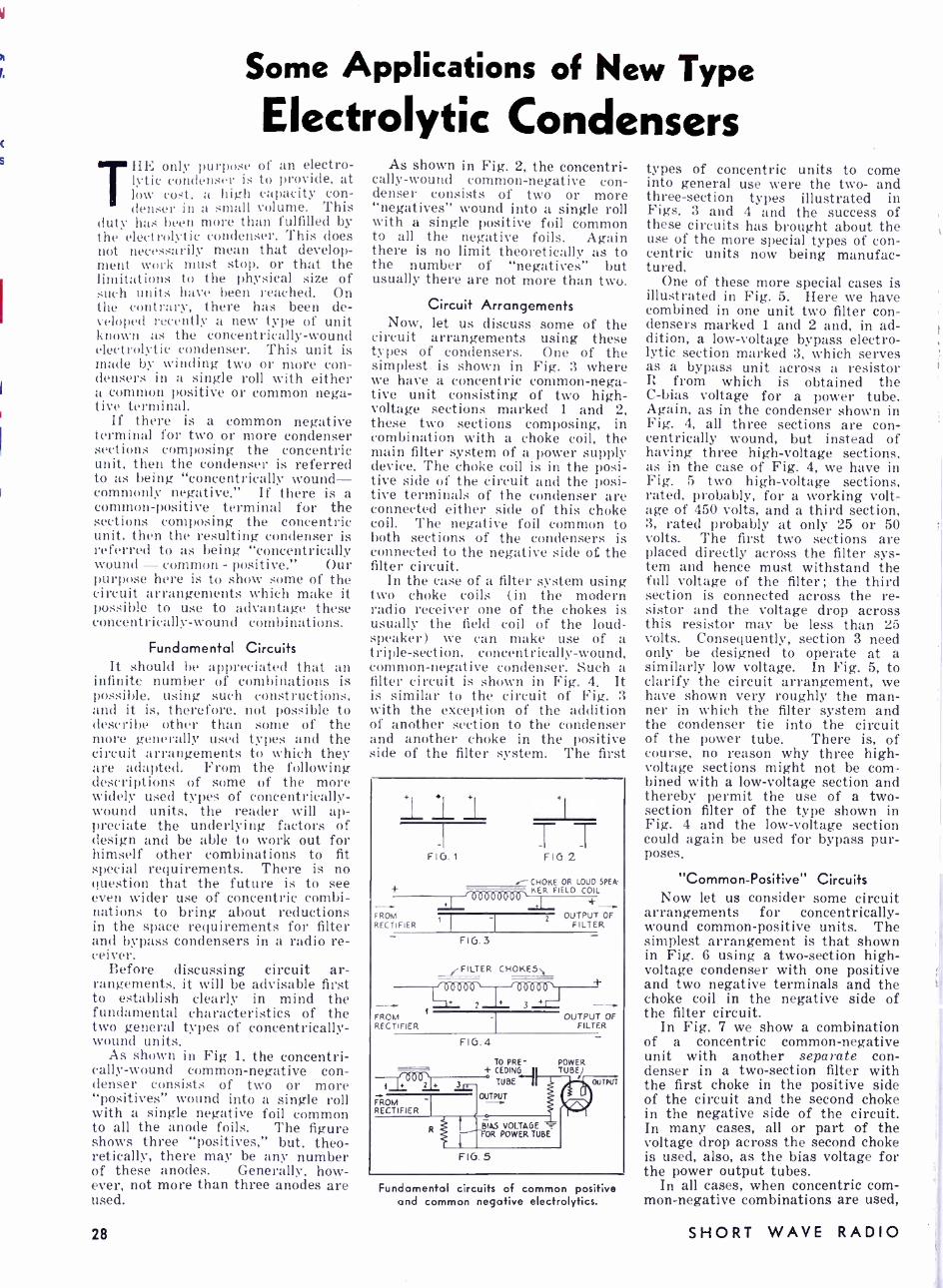
Some Applications of New Type
Electrolytic Condensers THE only purpose of an electro-
lytic condenser is to provide, at lo. ow cost, a high capacity con- denser in a small volume. This
duty has been more than fulfilled by the electrolytic condenser. This does not necessarily mean that develop- ment work must stop, or that the limitations to the physical size of such units have been reached. On the contrary, there has been de- veloped recently a new type of unit known as the concentrically -wound electrolytic condenser. This unit is made by winding two or more con- densers in a single roll with either a common positive or common nega- tive terminal.
If there is a common negative terminal for two or more condenser sections composing the concentric unit, then the condenser is referred to as being "concentrically wound - commonly negative." If there is a common- positive terminal for the sections composing the concentric unit, then the resulting condenser is referred to as being "concentrically wound - common - positive." Our purpose here is to show some of the circuit arrangements which make it possible to use to advantage these concentrically -wound combinations.
Fundamental Circuits It should be appreciated that an
infinite number of combinations is possible, using such constructions, and it is, therefore, not possible to describe other than some of the more generally used types and the circuit arrangements to which they are adapted. From the following descriptions of some of the more widely used types of concentrically - wound units, the reader will ap- preciate the underlying factors of design and be able to work out for himself other combinations to fit special requirements. There is no question that the future is to see even wider use of concentric combi- nations to bring about reductions in the space requirements for filter and bypass condensers in a radio re- ceiver.
Before discussing circuit ar- rangements, it will be advisable first to establish clearly in mind the fundamental characteristics of the two general types of concentrically - wound units.
As shown in Fig 1, the concentri- cally -wound common -negative con- denser consists of two or more "positives" wound into a single roll with a single negative foil common to all the anode foils. The figure shows three "positives," but, theo- retically, there may be any number of these anodes. Generally, how- ever, not more than three anodes are used.
28
As shown in Fig. 2, the concentri- cally -wound common- negative con- denser consists of two or more "negatives" wound into a single roll with a single positive foil common to all the negative foils. Again there is no limit theoretically as to the number of "negatives" but usually there are not more than two.
Circuit Arrangements Now, let us discuss some of the
circuit arrangements using these types of condensers. One of the simplest is shown in Fig. 3 where we have a concentric common -nega- tive unit consisting of two high - voltage sections marked 1 and 2, these two sections composing, in combination with a choke coil, the main filter system of a power supply device. The choke coil is in the posi- tive side of the circuit and the posi- tive terminals of the condenser are connected either side of this choke coil. The negative foil common to both sections of the condensers is connected to the negative side oî the filter circuit.
In the case of a filter system using two choke coils (in the modern radio receiver one of the chokes is usually the field coil of the loud- speaker) we can make use of a triple- section, concentrically- wound, common- negative condenser. Such a filter circuit is shown in Fig. 4. It is similar to the circuit of Fig. 3 with the exception of the addition of another section to the condenser and another choke in the positive side of the filter system. The first
FIG .1
FROM RECTIFIER
TT FIG.2
.--CHOKE OR LOUD SPEk
6Ò0600
1
KER FIELD COIL
z OUTPUT OF FILTER
F10.3
FILTER CHOKES\
FROM RECTIFIER
OUTPUT OF FILTER
FIG 4
TO
. TUBE
PRE-
O01) + 'j FROM
OUTPUT
RECTIFIER
FIG 5
Fundamental circuits of common positive and common negative electrolytics.
types of concentric units to come into general use were the two- and three -section types illustrated in Figs. 3 and 4 and the success of these circuits has brought about the use of the more special types of con- centric units now being manufac- tured.
One of these more special cases is illustrated in Fig. 5. Here we have combined in one unit two filter con- densers marked 1 and 2 and, in ad- dition, a low- voltage bypass electro- lytic section marked 3, which serves as a bypass unit across a resistor R from which is obtained the C -bias voltage for a power tube. Again, as in the condenser shown in Fig. 4, all three sections are con- centrically wound, but instead of having three high- voltage sections, as in the case of Fig. 4, we have in Fig. 5 two high -voltage sections, rated, probably, for a working volt- age of 450 volts, and a third section, 3, rated probably at only 25 or 50 volts. The first two sections are placed directly across the filter sys- tem and hence must withstand the full voltage of the filter; the third section is connected across the re- sistor and the voltage drop across this resistor may be less than 25 volts. Consequently, section 3 need only be designed to operate at a similarly low voltage. In Fig. 5, to clarify the circuit arrangement, we have shown very roughly the man- ner in which the filter system and the condenser tie into the circuit of the power tube. There is, of course, no reason why three high - voltage sections might not be com- bined with a low- voltage section and thereby permit the use of a two - section filter of the type shown in Fig. 4 and the low- voltage section could again be used for bypass pur- poses.
"Common- Positive" Circuits Now let us consider some circuit
arrangements for concentrically - wound common -positive units. The simplest arrangement is that shown in Fig. 6 using a two- section high - voltage condenser with one positive and two negative terminals and the choke coil in the negative side of the filter circuit.
In Fig. 7 we show a combination of a concentric common -negative unit with another separate con- denser in a two -section filter with the first choke in the positive side of the circuit and the second choke in the negative side of the circuit. In many cases, all or part of the voltage drop across the second choke is used, also, as the bias voltage for the power output tubes.
In all cases, when concentric com- mon- negative combinations are used,
SHORT WAVE RADIO

consideration must be given to the voltage between the two "negatives" due to the voltage drop across the choke or other apparatus connected between the two "negatives." The polarity of this voltage drop is shown in Figs. 6 and 7 by the small polarity marks (plus and minus) near the chokes connected in the negative sides of the circuits. This voltage drop is due to the current flowing through the choke coil and the direction of this current is such that the polarity of the side of the choke nearest the output of the filter is positive and the polarity of the side of the choke nearest the input to the filter is negative. The amount of voltage drop across the chokes (and hence the voltage drop between the two "negatives ") will be de- termined by the resistance of the choke and the current, and will be equal to the product of the resistance in ohms and the current in amperes.
Leakage in "Negatives" This voltage drop between the
two "negatives" will cause a high leakage current to flow between the two "negatives," and very adversely affect the effectiveness of the entire filter system unless one of the "negatives" of the condenser has a film formed on it to limit the cur- rent flow. In the case of Fig. 6 the "negative" of section 2 will be of positive polarity with respect to the "negative" of section 1 by the amount of the voltage drop across the filter choke. Hence the negative foil of section 2 must have a film on it capable of limiting the current flowing between the "negatives" to a very small value. If the voltage drop is 100 volts, then the film must be such as to limit the current to a small value at 100 volts. If we were to use a condenser in this circuit which did not have such a film on one of the "negatives," the receiver would hum very badly due to excess leakage current across the choke coil.
Similarly in the case of Fig. 7, the "negative" of section 3 is of positive polarity with respect to the "negative" of section 2. Again the "negative" of section 3 must have a film on its surface such as to limit the current flow.
Design Factors In the case of common- positive
concentric units all the positive foils have a film on their surfaces, and we therefore do not have to con- sider leakage paths between "posi- tives." In the case of common - negative concentric units, leakage must be considered and failure to take this factor into account un- doubtedly will result in unsatisfac- tory operation of the receiver. The importance of this point cannot be overemphasized.
In many circuits use is made of a combination of common -positive and common -negative constructions in a single unit. Such combinations may bring about some reduction in the
'IIIIIII1111111111111111111I11111111111IIIIIIIII1111111111111111111111111!1111111111111111111111111111111P_
SUMMARY: Electrolytic condensers have undergone many changes since they were first made available to the general public. One of the latest changes involves the combination of two or more units in a single container, with either a common -positive or a common -negative term- inal.
The purpose of this article is to explain, in a practical manner, the connections of these condensers and to out- line some of the precautions to follow in using them. This article should be of value to every user of electrolytic con- densers.
111111111111111111111111111 11111111111111111 H1111111111111111111 lllllllllll 111111111 llllll llllllllll 111,
physical size of the unit, but there is frequently no advantage from a cost standpoint, and, naturally, the more complicated the arrangement the greater are the possibilities of field trouble.
For example, instead of using a single- section condenser and a two - section, common -negative condenser, we can combine them into one unit, as shown in Fig. 7, with, as indi- cated above, a slight reduction in physical size. This latter arrange- ment is shown in Fig. 8. From the standpoint of sections 1 and 2 we have a concentric common -negative because both of the sections are con- nected to a common -negative foil, A. However, from the standpoint of sections 2 and 3 we have a common - positive construction because both sections have a common -positive foil, B. The complete unit is there- fore a mixture of common "posi- tives" and the common "negatives," but the resulting arrangement is electrically equivalent, at least, to
FROM RECTIFIER
+
- 00000000.
FIG.6
0-0 0-0 FROM + RECTF FIER T
FIG.7
OUTPU T OF -
FILTER
+ + OUTPUT
2 OF d FILTER
0 oQ9
+ -+ 00006ö00 2
FROM RECTIFIER
FIG. 8
1
FROM RECTIFIER
+ a ^ OUTPUT OF -
FILTER .Q00004 r---
4Qli9J FIG.9
3 OUTPUT OF FILTER
Some additional uses to which the new electrolytics may be put.
the filter circuit of Fig. 7. The following points may fur-
thermore serve to indicate the desirability of giving serious con- sideration to the filter circuit ar- rangement. In both Figs. 7 and 8 there is present a common -positive concentric unit and hence formation of one of the negative foils will have to be resorted to in order that there shall not be excessive leakage be- tween "negatives." By slightly re- arranging the circuit of Fig. 7 this disadvantage can be eliminated.
In Fig. 9 we show the same filter circuit but we have combined sec- tions 1 and 2, thereby making them a concentric common -negative and section 3 is a separate unit. In other words, by simply rearranging the connections we can change from the common -positive, plus one sepa- rate section arrangement of Fig. 7 to the common -negative, plus one separate section arrangement of Fig. 9 -and it is always preferable to use a common -negative unit if this can be accomplished without unwarranted increase in cost of the complete radio receiver.
Conclusion It will be obvious to the reader
that, although we have only covered in this article concentric combina- tions with respect to their applica- cation to filter systems, similar concentric combinations can also be applied generally to the bypass cir- cuits of radio receivers. There are many points in the receiver, for ex- ample, where two 5 or 10 mf. low voltage sections (25 or 50 volts) can be wound concentrically and used to bypass certain audio circuits. Al- most invariably, where low voltage bypass condensers are wound con- centrically, they are of the common - negative type ; it is seldom that such condensers are wound with common - positives.
The preceding discussion will serve to indicate some of the funda- mental factors underlying the de- sign and use of concentrically wound electrolytic condensers of various types. It has, of course, been im- possible to cover all phases of the subject, but the essential point will, we hope, be apparent from the fore- going. There is no question but that the general use of concentri- cally wound units in radio receivers of today has somewhat complicated the problem of design and servicing in the sense that reasonable care must be exercised to make certain that all factors have been consid- ered.- Aerovox Corporation.
Readers familiar with the design 1,f standard broadcast receivers will recall the time when all electrolytics were of the wet type. They were bulky, had to be handled carefully, and, in general, were a nuisance. The clean -cut units now available are a pleasure to use -once installed, you can forget about them. It will be interesting to watch the develop- ment of the electrolytic condenser art. -Tech. Dir.)
for JULY, 1934 29
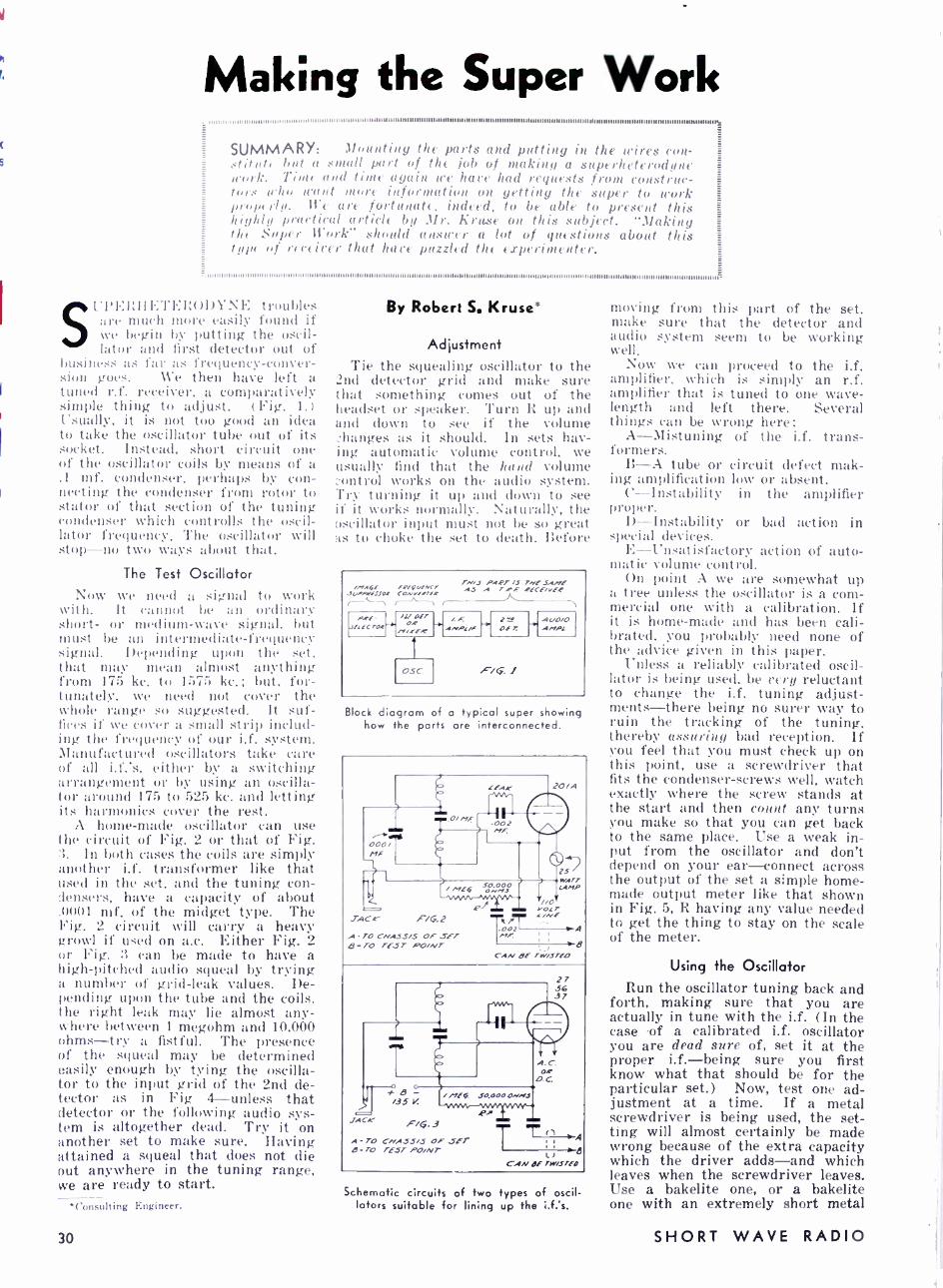
Making the Super Work ""II II I111111111I I I Il l l l tl l l l l l l I I I I II III II I II I I I
SUMMARY: 1lounting the parts and putting in the wires con - stitnt( but a small part of the job of retaking a superheterodyne work. Tim( and time again we have had requests from construc- tors who want more information on getting the super to work prop( rly. We are fortunate. indeed, to be able to present this highly practical article by 11r. Kruse on this subject. ":flaking the Super Work" should answer a lot of questions about this type of reeeicer that have puzzled the experimenter.
1111111111111 11111, 111111111111111111111111111111 III IIIIIIIIII 1111111111111111111111111I1111I1111111111 11111111 1111111111 11111111111111 11111111111111111111111111111111111 11111 111111 III 1111111111 III 111I111111I11111110
SU1'1 Uh1E'l'EI'.ODYNE troubles are much more easily found if we begin by putting the oscil- lator and first detector out of
business as far as frequency- conver- sion goes. We then have left a tuned r.f. receiver, a comparatively simple thing to adjust. (Fig. 1.) Usually, it is not too good an idea to take the oscillator tube out of its socket. Instead, short circuit one of the oscillator coils by means of a .1 mf. condenser, perhaps by con- necting the condenser from rotor to stator of that section of the tuning condenser which controlls the oscil- lator frequency. The oscillator will stop -no two ways about that.
The Test Oscillator Now we need a signal to work
with. It cannot be an ordinary short- or medium -wave signal. but must be an intermediate -frequency signal. Depending upon the set, that may mean almost anything from 175 kc. to 1575 kc. ; but, for- tunately, we need not cover the whole range so suggested. It suf- fices if we cover a small strip includ- ing the frequency of our i.f. system. Manufactured oscillators take care of all i.f.'s, either by a switching arrangement or by using an oscilla- tor around 175 to 525 kc. and letting its harmonics cover the rest.
A home -made oscillator can use the circuit of Fig. 2 or that of Fig. 3. In both cases the coils are simply another i.f. transformer like that used in the set, and the tuning con - lensers, have a capacity of about .0001 mf. of the midget type. The Fig. 2 circuit will carry a heavy growl if used on a.c. Either Fig. 2 or Fig. 3 can be made to have a high -pitched audio squeal by trying a number of grid -leak values. De- pending upon the tube and the coils, the right leak may lie almost any - where between 1 megohm and 10,000 ohms -try a fistful. The presence of the squeal may be determined easily enough by tying the oscilla- tor to the input grid of the 2nd de- tector as in Fig 4- unless that detector or the following audio sys- tem is altogether dead. Try it on another set to make sure. Having attained a squeal that does not die out anywhere in the tuning range, we are ready to start.
`Consulting Engineer.
30
By Robert S. Kruse*
Adjustment Tie the squealing oscillator to the
2nd detector grid and make sure that something comes out of the headset or speaker. Turn R up and and down to see if the volume -2hanges as it should. In sets hav- ing automatic volume control, we usually find that the hand volume control works on the audio system. Try turning it up and down to see if it works normally. Naturally, the oscillator input must not be so great as to choke the set to death. Before
irowó! Plpl/I.KT T.viJ PA?rLS TAIL, .5.4414, AS A T.Pf .PECE/vfP JUd44P111J0! CON ., - r- _J
PRE- JFLFCTO.f
/i oFT r- OR /'1/.rER
OSC
ANPL/f z _a
OE T.
FiG:
A(l0/O ANOL
Block diagram of a typical super showing how the parts are interconnected.
Schematic circuits of two types of oscil- lators suitable for lining up the i.f.'s.
moving from this part of the set, make sure that the detector and audio system seem to be working well.
Now we can proceed to the i.f. amplifier, which is simply an r.f. amplifier that is tuned to one wave- length and left there. Several things can be wrong here: A- Mistuning of the i.f. trans- formers.
B -A tube or ing amplification
C- Instability proper.
D- Instability special devices. E- Unsatisfactory action of auto- matic volume control.
On point A we are somewhat up a tree unless the oscillator is a com- mercial one with a calibration. If it is home -made and has been cali- brated, you probably need none of the advice given in this paper.
Unless a reliably calibrated oscil- lator is being used, be very reluctant to change the i.f. tuning adjust- ments -there being no surer way to ruin the tracking of the tuning, thereby assuring bad reception. If you feel that you must check up on this point, use a screwdriver that fits the condenser -screws well, watch exactly where the screw stands at the start and then count any turns you make so that you can get back to the same place. Use a weak in- put from the oscillator and don't depend on your ear -connect across the output of the set a simple home- made output meter like that shown in Fig. 5, R having any value needed to get the thing to stay on the scale of the meter.
circuit defect mak- low or absent. in the amplifier
or bad action in
Using the Oscillator Run the oscillator tuning back and
forth, making sure that you are actually in tune with the i.f. (In the case of a calibrated i.f. oscillator you are dead sure of, set it at the proper i.f. -being sure you first know what that should be for the particular set.) Now, test one ad- justment at a time. If a metal screwdriver is being used, the set- ting will almost certainly be made wrong because of the extra capacity which the driver adds -and which leaves when the screwdriver leaves. Use a bakelite one, or a bakelite one with an extremely short metal
SHORT WAVE RADIO
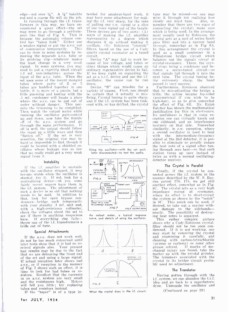
edge -not over 4 ". A f4" bakelite rod and a coarse file will do the job.
In running through the i.f. trans- formers in this way, we have en- countered a queer effect -the set may seem to go through a perform- ance like that of Fig. 6. This is because the automatic volume con- trol has "taken hold." Either use a weaker signal or put the a.v.c. out of commission temporarily. This can he done in some systems by re- moving the separate a.v.c. tube or its grid -cap clip- whatever makes the least change in a very weak signal. In some systems, you may need to put a capacity short circuit (.1 mf. non -inductive) across the input of the a.v.c. tube. When the set uses some of the recent mongrel tubes where parts of 2 or 3 tubes are huddled together in one bottle, it is more of a puzzle, but a little guessing and testing with the .1 mf. condenser will locate a place where the a.v.c. can be put out of order without danger. This per- mits the trimming to be completed. Then watch the output meter while running the oscillator gain -control up and down, now take the muzzle off of the a.v.c. system and go through the same performance. If all is well, the output should follow the input up a little ways and then "flatten off." If the set is very sensitive, the original rise may be hard or impossible to find, though it could be located with a shielded os- cillator whose leakage was so low that we really could get a very weak signal from it.
Instability
If the i.f. amplifier is unstable with the oscillator stopped, it may become stable when the oscillator is started- -try it. If not, look for a neutralizing device -oh yes, some fairly recent supers have them in the i.f. system. The adjustment of such a device is so old that nothing needs to be said. In addition to that, look for open bypass con- densers- bridge each temporarily with your standby .1 mf. unit and, with a high -resistance voltmeter, check the voltages about the set to see if there is anything suspicious here. If everything else fails - throw one of the i.f. transformers a trifle out of tune.
Special Attachments
If the a.v.c. does not work well, do not be too much concerned until later tests show that it is had on re- ceived signals also. Your present bad results may be due to the fact that we are detouring the front end of the set and using a large signal. If actual reception later shows bad a.v.c., or if reception in the manner of Fig. 7 shows such an effect, it is time to look for bad tubes or re- sistors. Recollect that the currents in an a.v.c. system are very small and the resistances high. Meters will tell you little ; try replacing tubes and resistors instead.
If the "super" is of a type in-
for JULY, 1934
tended for amateur -band work, it may have some attachment for mak- ing the i.f. very sharp, for the sake of pulling one c.w. signal or a slice of one voice signal out of the tangle. These devices are of two sorts: (A) ways of making the i.f. amplifier regenerative to a degree which sharpens it up without making it oscillate, (B) Robinson "stenode" filters, based on the use of a Cady quartz crystal resonator as a tuned circuit.
Device "A" may fail to work be- cause of low voltage, and tubes or other things which would cause an ordinary regenerative device to fail. If we keep right on regarding the set as a t.r.f. device and use the i.f. oscillator, the cause can be run down.
Device "B" can mis -fire for a variety of causes. First, one should be certain that it actually is mis- firing. Crystal tuning is quite sharp, and if the i.f. system has been tink- ered with, or has drifted, the crystal
Using the oscillator -with the set oscil- lator disconnected -to test the audio.
RESONANCE or/rPUr
O-/ MA. F70.5 12.4Av6E -i F.PEQ UENC Y
F/aG
An output meter, a typical response curve, and details of using the oscillator.
1 A
CPYSrAL ..vo/-r-re
8
NORMAL /.F. 4FSONgNCE
F/G 8 C
What the crystal does in the i.f. circuit.
tune may be missed -or one may miss it through not realizing how closely one must tune. Also, re- member that there are two ways of connecting the crystal; make sure which is being used. In the arrange- ment usually used by Robinson, the crystal acts as a sort of series band - pass filter and lets a narrow band through, somewhat as in Fig 8A. In this arrangement the crystal is used as a small condenser in a Wheatstone bridge circuit which balances out the signals except at crystal- resonance. There, the crys- tal stops being a condenser and be- comes a series -tuned circuit -so that signals fall through it into the next tube. The crystal tuning be- ing extremely sharp, the band passed is very narrow.
Furthermore, Robinson observed that by mis- adjusting the bridge a trifle, the action became lop -sided (assymetrical if you wish to be high -hat), so as to give somewhat the effect of Fig. 8B. Mr. Ralph Batcher has shown the mathematical justification for this in electronics. Its usefulness is that in voice re- ception one can virtually knock out one sideband, and an interference beatnote on that side. Somewhat similarily, in c.w. reception, where a second oscillator is used to beat with the intermediate -frequency signal at the 2nd detector, it is pos- sible to eliminate or greatly reduce the beat note of a signal after tun- ing through zero beat -so that each station turns up once instead of twice as with a normal oscillating - detector receiver.
The Crystal in Parallel
Finally, if the crystal be con- nected across the i.f. system in the manner described by the W. S. Bar- den patent 376, 175, we get still another effect, somewhat as in Fig. 8C. The crystal acts as a very high impedance except at resonance, where its effect is to short -circuit the system as shown by the "notch" in 8C. This notch can be used, if desired, to take out a carrier with- out damage to the sidebands- nearly. The possibility of destroy- ing beat notes is apparent.
This rather complex picture shows why a Cady -Robinson crystal - filter should not be too soon con- demned. If it is not working, one may start by removing the crystal and examining it carefully, and cleaning with carbon -tetrachloride (pyrene or carbona) or some other grease solvent. If marks of me- chancal injury are found, take the matter up with the crystal grinder. The trimmers associated with the crystal in its bridge circuit proba- bly need no adjustment.
The Translator
Having gotten through with the i.f. system, we can abandon the t.r.f. idea and go back to a superhetero- dyne. Unmuzzle the oscillator and
(Continued on page 39)
31
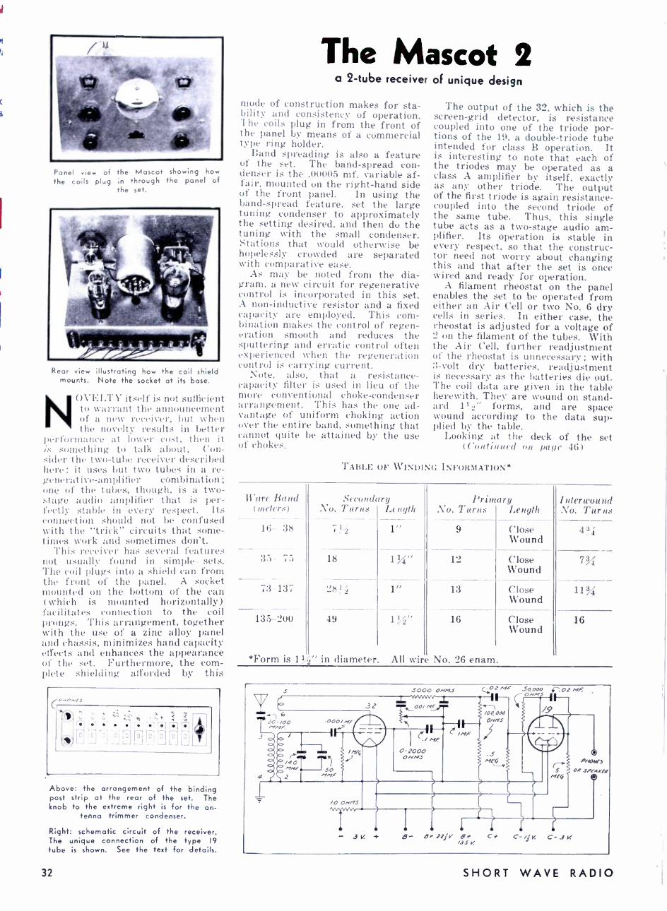
Panel view of the Mascot showing how the coils plug in through the panel of
the set.
Rear view illustrating how the coil shield mounts. Note the socket at its base.
N(WELTY itself is not sufficient to warrant the announcement of a new receiver, but when the novelty results in better
performance at lower cost, then it is something to talk about. Con- sider the two -tube receiver described here: it uses but two tubes in a re- generative- amplifier combination; one of the tubes, though, is a two - stage audio amplifier that is per - fectly stable in every respect. Its connection should not be confused with the "trick" circuits that some- times work and sometimes don't.
This receiver has several features not usually found in simple sets. The coil plugs into a shield can from the front of the panel. A socket mounted on the bottom of the can ( which is mounted horizontally) facilitates connection to the coil prongs. This arrangement, together with the use of a zinc alloy panel and chassis, minimizes hand capacity effects and enhances the appearance of the set. Furthermore, the com- plete shielding afforded by this
CAHO nee .f
,
ri i, . 1. . .
;31
ö. Ó . I1 ¡-3-
n -61 ó a 0
Above: the arrangement of the binding post strip at the rear of the set. The knob to the extreme right is for the an-
tenna trimmer condenser.
Right: schematic circuit of the receiver. The unique connection of the type 19 tube is shown. See the text for details.
32
The Mascot 2 a 2 -tube receiver of unique design
mode of construction makes for sta- bility and consistency of operation. The coils plug in from the front of the panel by means of a commercial type ring holder.
Band spreading is also a feature of the set. The band -spread con- denser is the .00005 mf. variable af- fair, mounted on the right -hand side of the front panel. In using the band -spread feature, set the large tuning condenser to approximately the setting desired, and then do the tuning with the small condenser. Stations that would otherwise be hopelessly crowded are separated with comparative ease.
As may be noted from the dia- gram, a new circuit for regenerative control is incorporated in this set. A non -inductive resistor and a fixed capacity are employed. This com- bination makes the control of regen- eration smooth and reduces the sputtering and erratic control often experienced when the regeneration control is carrying current.
Note, also, that a resistance - capacity filter is used in lieu of the more conventional choke -condenser arrangement. This has the one ad- vantage of uniform choking action over the entire band, something that cannot quite be attained by the use of chokes.
The output of the 32, which is the screen -grid detector, is resistance coupled into one of the triode por- tions of the 19, a double- triode tube intended for class B operation. It is interesting to note that each of the triodes may be operated as a class A amplifier by itself, exactly as any other triode. The output of the first triode is again resistance - coupled into the second triode of the same tube. Thus, this single tube acts as a two -stage audio am- plifier. Its operation is stable in every respect, so that the construc- tor need not worry about changing this and that after the set is once wired and ready for operation.
A filament rheostat on the panel enables the set to be operated from either an Air Cell or two No. 6 dry cells in series. In either case, the rheostat is adjusted for a voltage of 2 on the filament of the tubes. With the Air Cell, further readjustment of the rheostat is unnecessary ; with
-volt dry batteries, readjustment is necessary as the batteries die out. The coil data are given in the table herewith. They are wound on stand- ard 1', /_" forms, and are space wound according to the data sup- plied by the table.
Looking at the deck of the set (Continued on page 46)
TABLE OF WINDING INFORMATION*
Ware Band (meters)
Secondary .No. Turns Length
Primary No. Turns Length
Interwound No. Turns
16- 38 7t2 1 9 Close 4;t.í Wound
35- 75 18 %" 12 Close 7% Wound
î3-13; 1" 13 Close 11% Wound
135-20o 49 1 16 Close 16 Wound
*Form is 11," in diameter. All wire No. 26 enam.
000/Nf
4 fsl
1
wo"
32
S000 Or/MJ
¡`00/ tiff=
. /MF 0 -1000
/O ON/IS
401 MF SO 000 j1 01 Mf. / ONMS
/00,000 ONMS
.5 MEG
/9
S MEG
- 3V. + B- I1JY so- /35 . Ct C-/jV. C-3K
SHORT WAVE RADIO
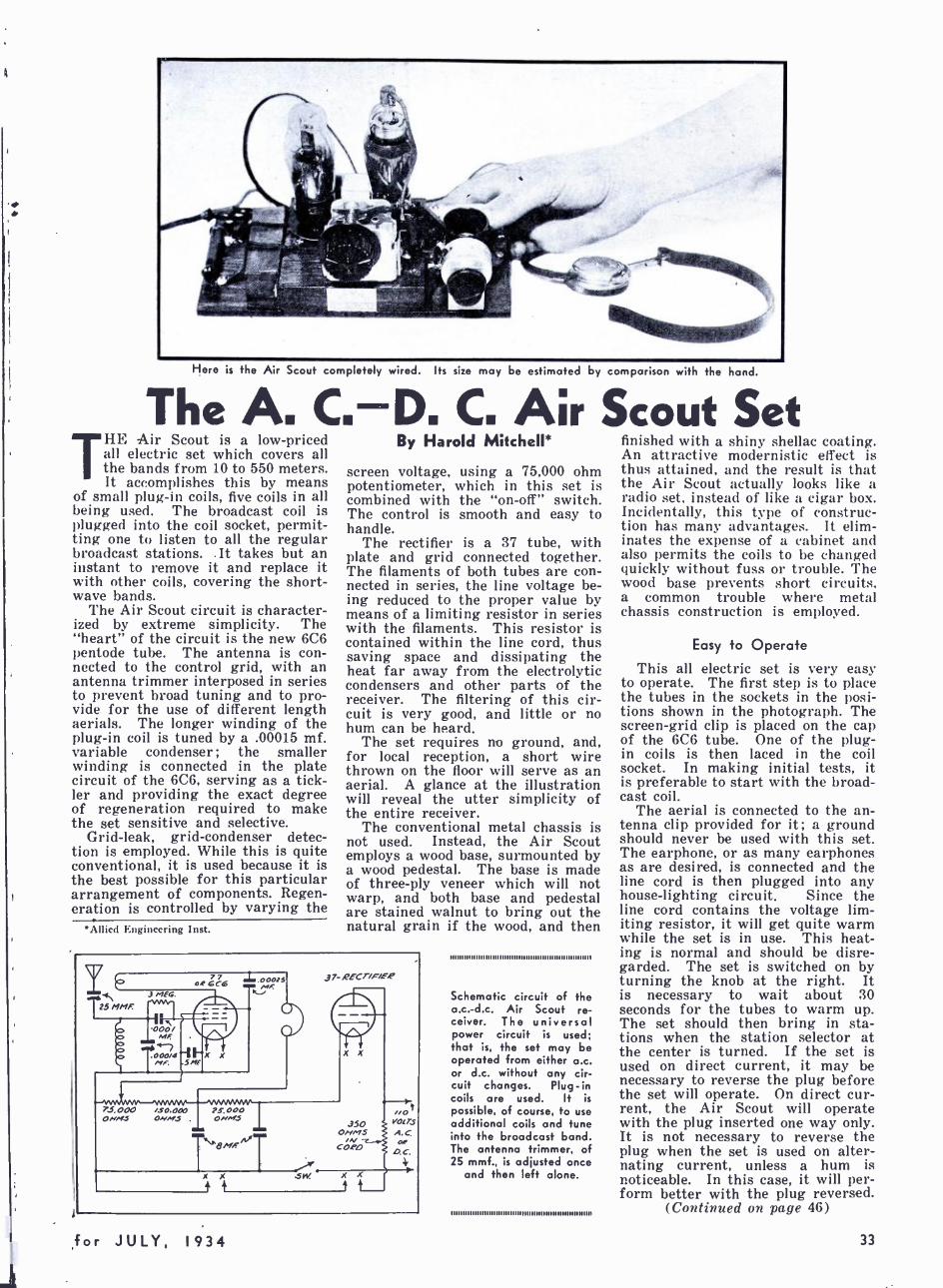
Here is the Air Scout completely wired. Its size may be estimated by comparison with the hand.
The A. C.D. C. Air Scout Set HE Air Scout is a low- priced all electric set which covers all the bands from 10 to 550 meters. It accomplishes this by means
of small plug -in coils, five coils in all being used. The broadcast coil is plugged into the coil socket, permit- ting one to listen to all the regular broadcast stations. .It takes but an instant to remove it and replace it with other coils, covering the short- wave bands.
The Air Scout circuit is character- ized by extreme simplicity. The "heart" of the circuit is the new 6C6 pentode tube. The antenna is con- nected to the control grid, with an antenna trimmer interposed in series to prevent broad tuning and to pro- vide for the use of different length aerials. The longer winding of the plug -in coil is tuned by a .00015 mf. variable condenser ; the smaller winding is connected in the plate circuit of the 6C6, serving as a tick- ler and providing the exact degree of regeneration required to make the set sensitive and selective.
Grid -leak, grid- condenser detec- tion is employed. While this is quite conventional, it is used because it is the best possible for this particular arrangement of components. Regen- eration is controlled by varying the
*Allied Engineering Inst.
By Harold Mitchell*
screen voltage, using a 75,000 ohm potentiometer, which in this set is combined with the "on -off" switch. The control is smooth and easy to handle.
The rectifier is a 37 tube, with plate and grid connected together. The filaments of both tubes are con- nected in series, the line voltage be- ing reduced to the proper value by means of a limiting resistor in series with the filaments. This resistor is contained within the line cord, thus saving space and dissipating the heat far away from the electrolytic condensers and other parts of the receiver. The filtering of this cir- cuit is very good, and little or no hum can be heard.
The set requires no ground, and, for local reception, a short wire thrown on the floor will serve as an aerial. A glance at the illustration will reveal the utter simplicity of the entire receiver.
The conventional metal chassis is not used. Instead, the Air Scout employs a wood base, surmounted by a wood pedestal. The base is made of three -ply veneer which will not warp, and both base and pedestal are stained walnut to bring out the natural grain if the wood, and then
77 64 cc"
óa
7.5 OOO ,5-0,O00 ONMS ONMS
00075
23-,000 ONS
X X .5W
J 7- RECT/FiE.P
Schematic circuit of the a.c. -d.c. Air Scout re- ceiver. The universal power circuit is used; that is, the set may be operated from either a.c. or d.c. without any cir- cuit changes. Plug -in coils are used. It is
possible, of course, to use additional coils and tune into the broadcast band. The antenna trimmer, of 25 mmf., is adjusted once
and then left alone.
11111111111111111111111111111111 11111n1111 ll ll llI ll llllll1l
finished with a shiny shellac coating. An attractive modernistic effect is thus attained, and the result is that the Air Scout actually looks like a radio set, instead of like a cigar box. Incidentally, this type of construc- tion has many advantages. It elim- inates the expense of a cabinet and also permits the coils to be changed quickly without fuss or trouble. The wood base prevents short circuits, a common trouble where metal chassis construction is employed.
Easy to Operate
This all electric set is very easy to operate. The first step is to place the tubes in the sockets in the posi- tions shown in the photograph. The screen -grid clip is placed on the cap of the 6C6 tube. One of the plug - in coils is then laced in the coil socket. In making initial tests, it is preferable to start with the broad- cast coil.
The aerial is connected to the an- tenna clip provided for it; a ground should never be used with this set. The earphone, or as many earphones as are desired, is connected and the line cord is then plugged into any house -lighting circuit. Since the line cord contains the voltage lim- iting resistor, it will get quite warm while the set is in use. This heat- ing is normal and should be disre- garded. The set is switched on by turning the knob at the right. It is necessary to wait about 30 seconds for the tubes to warm up. The set should then bring in sta- tions when the station selector at the center is turned. If the set is used on direct current, it may be necessary to reverse the plug before the set will operate. On direct cur- rent, the Air Scout will operate with the plug inserted one way only. It is not necessary to reverse the plug when the set is used on alter- nating current, unless a hum is noticeable. In this case, it will per- form better with the plug reversed.
(Continued on page 46)
for JULY, 1934 33
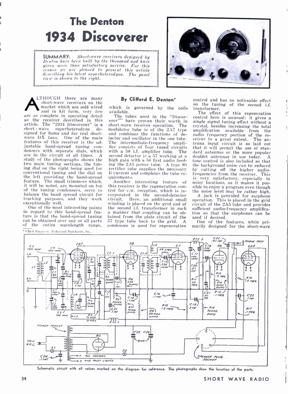
The Denton
1934 Discoverer SUMMARY: Short -wave receivers designed by DI11t bare been built by the thousand and have gie r / 1 1 than satisfactory service. For this reason nl are pleased to present this article describing Iris latest superheterodyne. The panel view is shown to the right.
111111111111111111 1
LTHOUGH there are many short -wave receivers on the market which are sold wired and in kit form, very few
are as complete in operating detail as the receiver described in this article. The "1934 Discoverer" is a short - wave superheterodyne de- signed for hams and for real short- wave DX fans. One of the main features of this receiver is the ad- justable band -spread tuning con- densers with separate dials, which are in the circuit at all times. A study of the photographs shows the two main tuning sections, the tun- ing dial on the right being used for conventional tuning and the dial on the left providing the band- spread feature. 'l'he small trimmers which, it will be noted, are mounted on top of the tuning condensers, serve to balance the band spread circuit for tracking purposes, and they work exceptionally well.
One of the most interesting points in regard to this band -spread fea- ture is that the band- spread tuning can be obtained over any or all parts of the entire wavelength range, ('hilf I(ncin . r I:l lIrratrd l'urch.urr, In:.
By Clifford E. Denton*
which is governed by the coils available.
The tubes used in the "Discov- erer' have proven their worth in short -wave receiver operation. The modulator tube is of the 2A7 type and combines the functions of de- tector and oscillator in the one tube. The intermediate -frequency ampli- fier consists of four tuned circuits with a 58 i.f. amplifier tube. The second detector is a 57 working at a high gain with a 56 first audio feed- ing the 2A5 power tube. A type 80 rectifier tube supplies the necessary B current and completes the tube re- quirements.
Another interesting feature of this receiver is the regeneration con- trol for c.w. reception, which is in- corporated in the second- detector circuit. Here, an additional small winding is placed on the grid end of the second i.f. transformer in such a manner that coupling can be ob- tained from the plate circuit of the 57 type tube back to the grid. A condenser is used for regeneration
control and has no noticeable effect on the tuning of the second i.f. transformer.
The effect of this regeneration control here is unusual: it gives a single signal tuning effect without a crystal, besides increasing the total amplification available from the radio frequency portion of the re- ceiver to a great extent. The an- tenna input circuit is so laid out that it will permit the use of stan- dard antennas or the more popular doublet antennas in use today. A tone control is also included so that the background noise can be reduced by cutting off the higher audio - frequencies from the receiver. This is very satisfactory, especially in noisy locations, as it makes it pos- sible to enjoy a program even though the noise level may be rather high.
A jack is provided for earphone operation. This is placed in the grid circuit of the 2A5 tube and provides sufficient audio- frequency amplifica- tion so that the earphones can be used if desired.
One of the features, while pri- marily designed for the short -wave
C3 /00 AI MF' C 4
MMF LA
!/
5A
L1
taayn C/ /10 Inc
C6, '40 nns
1.4 7
,P 1 230 y
OHyJ
X
C8) / MF
C9 / MF
C/ / et,
L
/F /
0 o o
R2 2S0Y10-1 QNMS
58
/j /
P1F,
X X
-e6 250 Oi!/S
if -2
L
JLS S7 0 #9 IMF-6
1 '
iii
250 MMF
2 FC 2
1
C22 .O/ /if-a
C/B SFi T -_
250 ' I.MF
C /) l /O0 F MMF 1 / C20 .0/ nF
,P // 25 MEG
//O V
C7 MMr
, oar IL1
/40 7 ern/
CS /00 MMF
OWfQ F',PANSF
C24 /MF
S/
La
C/O / MF
e3 25,000 OMnCf
L R4
73.000
C/2 / MF
O .e.'iFS
L$0,000 OMM,s
C27 //IX
!FC /
e7J 7JOOO .4 ONM1
C /6 ./MF
.P/O /5 7f
.PB do oo0 0N/YS
Tt C2/ 0/ Mf
R/2 /0000 OHNJ
PNONÌ
24 5
4 /6 SA/EG
F. C23 It -/MF \
.P /7 / .rJfG
6p
S2
X ALL hFA7ERS
X ANp P/LOT L/Gn'7-S
SPEA.eLE.e PLUG .TOC!"ET
Schematic circuit with all values marked on the diagram
34
for reference. The photographs show the location of the parts.
SHORT WAVE RADIO
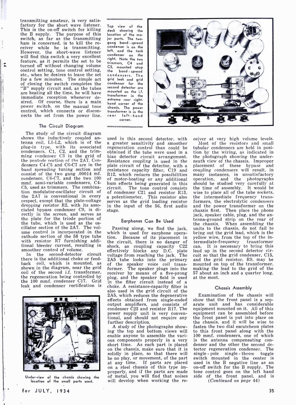
transmitting amateur, is very satis- factory for the short wave listener. This is the on -off switch for killing the B supply. The purpose of this switch, as far as the transmitting ham is concerned, is to kill the re- ceiver while he is transmitting. However, the short -wave listener will find this switch a very excellent feature, as it permits the set to be turned off without changing volume control setting, tone control setting, etc., when he desires to leave the set for a few minutes. The simple act of closing the switch completes the "B" supply circuit and, as the tubes are heating all the time, he will have immediate reception whenever de- sired. Of course, there is a main power switch. on the manual tone control, which connects or discon- nects the set from the power line.
The Circuit Diagram
The study of the circuit diagram shows the inductively coupled an- tenna coil, LI -L2, which is of the plug -in type. with its associated condensers, Cl, C2, and the trim- ming condenser C3 in the grid of the pentode portion of the 2A7. Con- densers C4 -05 and C6 -C7 are in the band spreading tuning section and consist of the two gang .00014 mf. condenser, C6 -C7, and the two 100 mmf. semi- variable condensers, C4- 05, used as trimmers. The combina- tion modulator -oscillator circuit of the 2A7 is conventional in every respect, except that the plate- voltage dropping resistor R2, with its asso- ciated bypass condenser C9, is di- rectly in the screen, and serves as the plate for the triode portion of the tube, which is used as the os- cillator section of the 2A7. The vol- ume control is incorporated in the cathode section of the 58 type tube with resistor R7 furnishing addi- tional bleeder current, resulting in smoother control of volume.
In the second- detector circuit there is the additional choke or feed- back coil, which is mounted, as shown in the diagram, near the grid coil of the second i.f. transformer, the regeneration being controlled by the 100 mmf. condenser C17. Grid leak and condenser rectification is
Under -view of the chassis showing the location of the small parts used.
aunnnnuuuuuuunununnuuunu
Top view of the deck showing the location of the ma- jor parts. The two - gang band - spread condenser is on the left, and the tank condenser on the right. Note the two trimmers, C4 and C5, mounted atop the band -spread condensers. The grid leak and grid condenser for the second detector are mounted on the i.f. transformer in the extreme rear right - hand corner of the chassis. The power transformer is in the rear left -hand
corner.
11111111111 1I11n11111111111 1IIIIIIII lllllllllll
used in this second detector, with a greater sensitivity and smoother regeneration control than could be obtained if the tube were used in a bias detector circuit arrangement. Resistance coupling is used in the plate circuit of the detector, with a resistance capacity filter, C19 and R12, which reduces the possibilities of motor -boating or any additional hum effects being generated in this circuit. The tone control consists of condenser C21 and resistor R13, a potentiometer. This resistor also serves as the grid loading resistor in the input of the 56, first audio stage.
Earphones Can Be Used
Passing along, we find the jack. which is used for earphone opera- tion. Because of its placement in the circuit, there is no danger of shock, as coupling capacity C22 effectively blocks any D.C. plate voltage from reaching the jack. The 2A5 tube looks into the primary of the speaker voice coil trans- former. The speaker plugs into the receiver by means of a five -prong plug, and the speaker field is used in the filter circuit instead of a choke. A resistance -capacity filter is also used in the grid circuit of the 2A5, which reduces the degenerative effects obtained from single -ended output amplifiers, and consists of condenser C23 and resistor R17. The power supply unit is very conven- tional, and should not require any further description.
A study of the photographs show- ing the top and bottom views will enable anyone to assemble the vari- ous components properly in a very short time. As each part is placed on the chassis, make sure that it is solidly in place, so that there will be no play, or movement, of the part at any time. If parts are placed on a steel chassis of this type im- properly, and if the parts are made of metal, you will find that noises will develop when working the re-
ceiver at very high volume levels. Most of the resistors and small
tubular condensers are held in posi- tion by the wiring, as indicated in the photograph showing the under- neath view of the chassis. Improper placement of these bypass and coupling condensers will result, in many instances, in unsatisfactory operation, and the photographs should be studied very carefully at the time of assembly. It would be wise to place all of the tube sockets, the intermediate frequency trans- formers, the electrolytic condensers and the power transformer on the chassis first. Then place the phone jack, speaker cable, plug, and the an- tenna- ground strip on the rear of the chassis. When assembling the units to the chassis, do not fail to bring out the grid lead, which is the yellow wire, from the top of the in- termediate- frequency transformer can. It is necessary to bring this lead up in the second detector cir- cuit so that the grid condenser, C15, and the grid resistor, R9, may be mounted on top of the transformer, making the lead to the grid of the 57 about an inch and a quarter long, at the most.
Chassis Assembly
Examination of the chassis will show that the front panel is a sep- arate unit and has considerable equipment mounted on it. All of this equipment can be assembled before the front panel is put into place on the chassis, and it will be wise to fasten the two dial escutcheon plates to this front panel along with the 100 mmf. condensers, one of which is the antenna compensating con- denser and the other the second de- tector regeneration condenser. The single - pole single - throw toggle switch mounted in the center is used in the B negative line as an on -off switch for the B supply. The tone control goes on the left hand side of the front panel, and is
(Continued on page 44)
for JULY, 1934 35
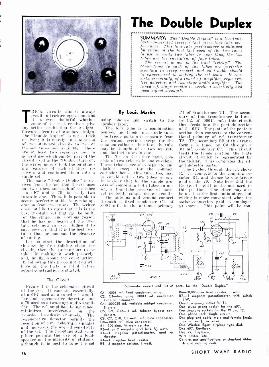
TRICK circuits almost always result in trickier operation, and it is even doubtful whether some of the trick receivers give
any better results that the straight - forward circuits of standard design. The "Double Duplex" is not a trick receiver; it is merely an adaptation of two standard circuits to two of the new tubes now available. 'There are at least two receivers now in general use which employ part of the circuit used in the "Double Duplex "; the writer merely took the outstand- ing features of each of these re- ceivers and combined them into a single set.
'l'he name "Double Duplex" is de- rived from the fact that the set uses but two tubes, and each of the tubes -a 6F7 and a 79 -is really two tubes in one. Thus, it is possible to secure perfectly stable four -tube op- eration from two tubes. The writer does not like to state that this is the best two -tube set that can be built. for the simple and obvious reason that he has not heard all the two - tube sets now in use. Suffice it to say, however, that it is the best two - tuber that he has had the pleasure of tuning.
Let us start the description of this set by first talking about the circuit, then the precautions to be taken in making it work properly, and, finally, about the construction. By following this procedure, you will have all the facts in mind before actual construction is started.
The Circuit Figure 1 is the schematic circuit
of the set. It consists, essentially, of a (;F7 used as a tuned r.f. ampli- fier and regenerative detector, and a 79 used as a two -stage audio ampli- fier. 'l'he r.f. amplifier, being tuned, minimizes interference on the crowded broadcast channels. The regenerative detector permits the reception of c.w. (telegraph signals) and increases the overall sensitivity of the set. The two -stage audio am- plifier permits the use of a loud- speaker on the majority of stations, although it is best to tune the set
36
The Double Duplex SUMMARY: The "Double Duplex is a two -tube, battery- operated receiver that gives four -tube per- formance. This four -tube performance is obtained by virtue of the fact that each of the two tubes in use is really two tubes in one; thus, the two tubes are the equivalent of four tubes.
The circuit is not in the least "tricky." The connections to each of the tubes are perfectly standard in every respect, and no trouble should be experienced in making the set work. It con- sists, essentially, of a tuned r.f. amplifier, regenera- tive detector, and two -stage audio amplifier. The tuned r.f. stage results in excellent selectivity and good signal strength.
By Louis Martin using phones and switch to the speaker later.
The 617 tube is a combination pentode and triode in a single tube. 'l'he triode portion is separate from the pentode section except for the common cathode; therefore, the tube may be thought of as two separate and distinct tubes in one.
The 79, on the other hand, con- sists of two triodes in one envelope. 'l'hese triodes are also separate and distinct except for the common cathode; hence, this tube, too, may be considered as two tubes in one. It is clear that by the simple pro- cess of combining both tubes in one set, a four -tube receiver of novel yet perfectly simple design results.
'I'he antenna and ground connect through a fixed condenser Cl, of .00111 mf., to the antenna primary
Pl of transformer Ti. The secon- dary of this transformer is tuned by C2, of .00014 mf.; this circuit then feeds into the pentode section of the 6F7. The plate of the pentode section then connects to the conven- tional primary of r.f. transformer T2. The secondary S2 of this trans- former is tuned by C3 through a .01 mf. condenser C7. This circuit feeds the triode portion, the plate circuit of which is regenerated by the tickler. This completes the r.f. and detector parts.
The tickler, through the r.f. choke P.F.C., connects to the coupling re- sistor R4, and thence to one triode grid of the 79. Note here that the Gr (grid right) is the one used in this position. The other may also be used as the first audio stage, but wiring is more convenient when the socket -connection grid is employed as shown. This point will be con-
CII,
l/1 6F7
r s 1 --- -- 1cI `', i I..L. ..
1,í+C2 CS
Ti
- Bf
22 5 v
F XVI
Q2 Ca
C9
r- si /
T2
CIl V2
CIO 79
) 1
aa
Q6
.ciG I
R3
BF' /35 V
C/2
x x
( 6. 3 ) VOL r5
cB- C
Sw
C- 1.5 V
Schematic circuit and list of parts for the "Double Duplex."
CI -.0001 mf. fixed condenser, mica. C2, C3 -two gang .00014 mf. condenser,
Federal Instrument. C4- .000025 mf. variable midget condenser,
5 plate. C5, C'?, C12-.1 mf. tubular bypass con-
densers. C6, C7, CIO, CII -.01 mf. mica condensers. C8 -.0001 mf. mica condenser. R I -300 -ohm, I/2 -watt resistor. R2 -1 or 2 megohm grid leak, 1/2 watt. R3 -.l megohm potentiometer, used as
rheostat. R4 -.I megohm fixed resistor. R5 -.5 megohm resistor, I watt.
R6- 50,000 -ohm fixed resistor, I watt. R7 -.5 megohm potentiometer, with switch
S.W. One four -prong socket for TI. One seven prong socket for the 6F7. Two six -prong sockets for the 79 and T2. One phone jack, single circuit. One plug and cable, male and female (ma''e
on set end, six wires. One Wireless Egert airplane type dial. One 6F7, Raytheon. One 79, Raytheon. Wire solder, etc. Coils as per specifications, or standard Alden
4- and 6 -prong coils.
SHORT WAVE RADIO
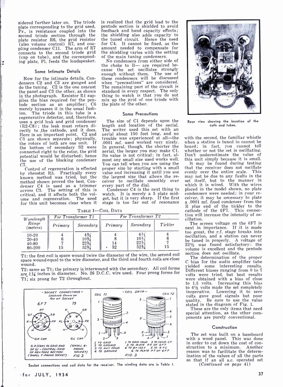
sidered further later on. The triode plate corresponding to the grid used, Pr., is resistance coupled into the second triode section through the plate resistor R6, the grid resistor (also volume control) R7, and cou- pling condenser Cll. The arm of R7 connects to the second triode grid (cap on tube), and the correspond- ing plate, Pl, feeds the loudspeaker.
Some Intimate Details
Now for the intimate details. Con- densers C2 and C3 are ganged and do the tuning. C2 is the one nearest the panel and C3 the other, as shown in the photograph. Resistor R1 sup- plies the bias required for the pen- tode section as an amplifier; C6 merely bypasses it in the usual fash- ion. The triode in this tube is a regenerative detector, and, therefore, uses a grid leak and grid condenser (R2 -C8) ; the leak must return di- rectly to the cathode, and it does. Here is an important point. C2 and C3 are shown separate ; physically, the rotors of both are one unit. If the bottom of secondary S2 were connected right to the rotor, the grid potential would be disturbed ; hence the use of the blocking condenser C7.
Control of regeneration is effected by rheostat R3. Practically every known method was tried, but the method shown proved the best. Con- denser C4 is used as a trimmer across C3. The setting of this is critical, and it affects both the vol- ume and regeneration. The need for this unit becomes clear when it
is realized that the grid lead to the pentode section is shielded to avoid feedback and hand capacity effects; the shielding also adds capacity to the tuned circuit. Hence the need for C4. It cannot be fixed, as the amount needed to compensate for the shielding varies with the setting of the main tuning condensers.
No condensers from either side of the choke to B- are required be- cause the set oscillates strongly enough without them. The use of these condensers will be discussed when "precautions" are considered. The remaining part of the circuit is standard in every respect. The only thing to watch is that you do not mix up the grid of one triode with the plate of the other.
Some Precautions
The size of Cl depends upon the length and location of the aerial. The writer used this set with an aerial about 150 feet long, and no trouble was experienced at all -the .0001 mf. used worked very nicely. In general, though, the shorter the aerial, the larger you may make Cl. Its value is not critical ; in fact, al- most any small size used works well. You can tell when you are using the proper size by starting with a small value and increasing it until you use the largest size that allows the re- ceiver to oscillate smoothly over every part of the dial.
Condenser C4 is the next thing to watch. It is merely a 5 plate mid- get, but it is very sharp. If the first stage is too far out of resonance
TABLE I -COIL DATA
Wavelength Range
(meters)
For Transformer T1 For Transformer T2
Primary Secondary Primary Secondary Tickler
10 -20 4 43 4 434" 4
20 -40 6 10% 8 10,s 6 40 -80 7 223% 14 223 7
80 -200 15 523% 32 523. 15
Ti: the first coil is space wound twice the diameter of the wire, the second coil space wound equal to the wire diameter, and the third and fourth coils are close wound. T2: same as Ti; the primary is interwound with the secondary. All coil forms are 1% inches in diameter. No. 26 D.C.C. wire used. Four prong forms for
Tl; six prong for T2 throughout.
- SOCKET CONNECT IONS - LOok /NG DowN ON TOO of SOCKET
79
GR
G P (CAP) TO GR /D ENO OF Si - CONTROL -GR /D OF PEN TODE SECT/ON
( SMALL 7-PRONG SOCKET)
GL CAP
(SMALL 6- PRONG SOCKET) F /`j 2
COIL Ti -CO/L DarA-
2-' ! ro GRID 2 TO GROOWO .3 TO ANT CONO 4 TO GROUND
3 -
COIL T2
S---l rr 116á1--2 3
4 6 \ ! ! 7ö GR/0 CONO 2 TO CONO C7 .3 TO PLATE RP OF 6F7
4TO EN- 135V STO RcC 6 TO PLATE P T OF 6F7
FiG 3
Socket connections and coil data for the receiver. The winding data are in Tab! I
Rear view showing the location of the coils and tubes.
with the second, the familiar whistle when a station is tuned in cannot be heard ; in fact, you cannot tell whether or not the set is oscillating. Don't underestimate the value of this unit simply because it is small.
It may be found during testing that the receiver does not oscillate evenly over the entire scale. This may not be due to any faults in the set itself, but to the manner in which it is wired. With the wires placed in the model shown, no plate condensers were needed ; in your re- ceiver, it may be necessary to plate a .0001 mf. fixed condenser from the B plus end of the tickler to the cathode of the 6F7. This connec- tion will increase the intensity of os- cillation.
The screen voltage on the 6F7 is next in importance. If it is made too great, the r.f. stage breaks into oscillation, and a station can never be tuned in properly. A voltage of 221/2 was found satisfactory : the volume is excellent and the pentode section does not oscillate.
The determination of the proper C bias for the audio amplifier tube yielded some interesting results. Different biases ranging from 0 to 7 volts were tried, but best results were obtained with a bias of close to 1.5 volts. Increasing this bias to 41/2 volts made the set completely inoperative. Lowering it to zero volts gave good signals but poor quality. Be sure to use the value stated in the diagram of Fig. 1.
These are the only items that need special attention, as the other com- ponents are purely conventional.
Construction
The set was built on a baseboard with a wood panel. This was done in order to cut down the cost of con- struction to a minimum. Another reason was to facilitate the determ- ination of the values of all the parts so that if an all a.c. operated set
(Continued on page 41)
for JULY, 1934 37
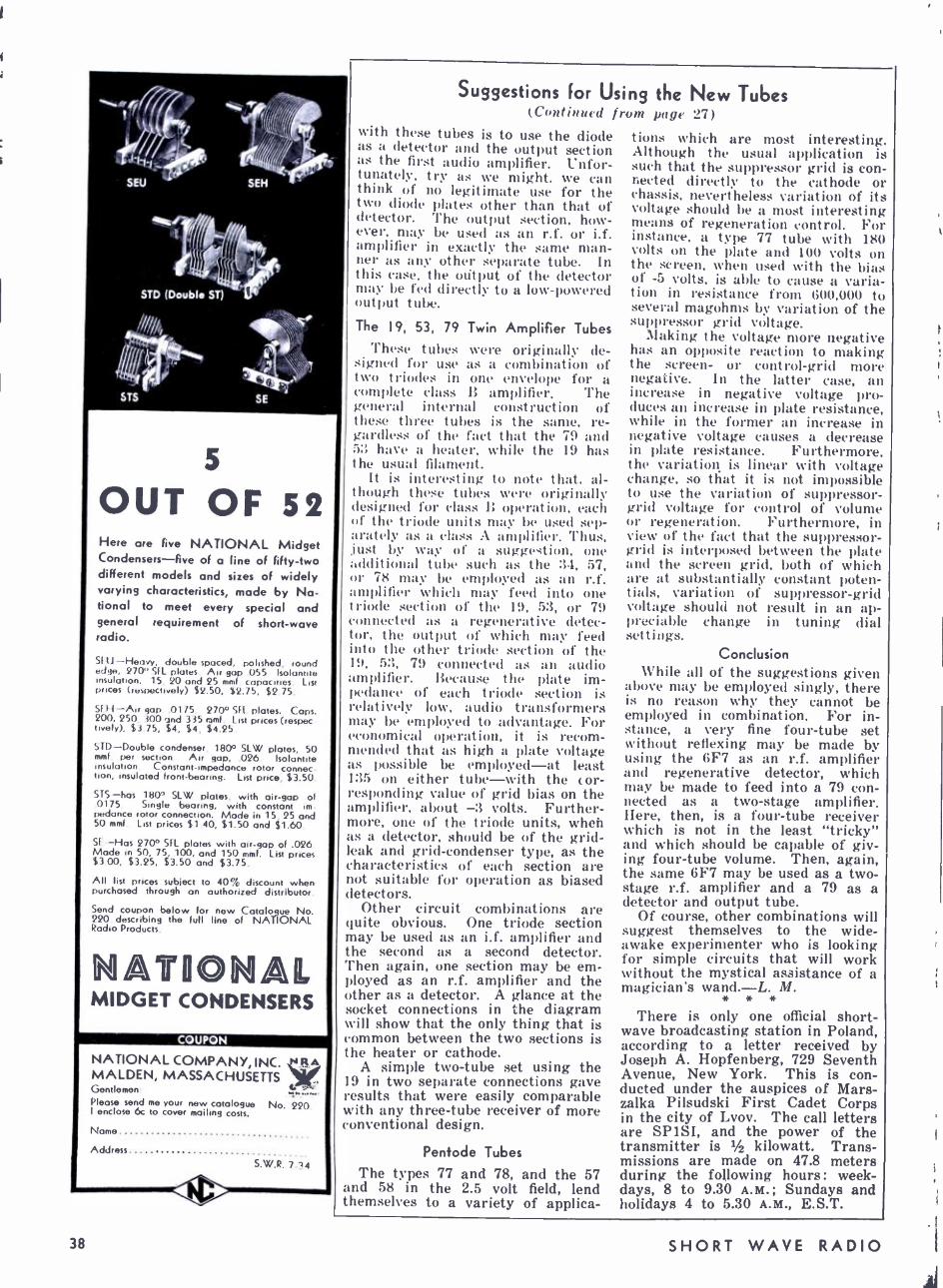
11(
í f
:r I STD (Double ST)
5
OUT OF SZ Here are five NATIONAL Midget Condensers -five of a line of fifty -two different models and sizes of widely varying characteristics, made by Na- tional to meet every special and general requirement of short -wave radio.
(AU doublespaced, polished, round edge, 27() '.I L plates. Air gap .055 Isolanote insulation. 15, 20 and 25 mmf. capacities. List Prices (repectively) $2.50, $2.75, $2.75.
Sf H --An gap .0175. 270° SFL plates. Cops. 200, 250, 300 and 335 rtmf. List prices (respec -
tively), $3.75, $4, $4, $4.25.
STD- Double condenser, 180° SLW plates, 50 mmf. per section. Air gap, .026. Isolantite insulation. Constant - impedance rotor connec- tion, insulated front -bearing. List price, $3.50.
STS -has 180° SLW plates, with air -gap of .0175. Single bearing, with constant im- pedance rotor connection. Mode in 15 25 and 50 mmf. List prices $1.40, $1.50 and $1.60.
SE -Has 270° SFL plates with air-gap of .026. Made in 50, 75, 100, and 150 mmf. List price $3 00, $3.25, $3.50 and $3.75.
All list prices subject to 40% discount when purchased through an authorized distributor.
Send coupon below for new Catolo_gue No. 220 describing the full line of NATIONAL Radio Products.
a MIDGET CONDENSERS
COUPON
NATIONAL COMPANY, INC. RA MALDEN, MASSACHUSETTS f Gentlemen 6 Please send me your new catalogue No. 220. I enclose 6c to cover mailing costs.
Name
Address
S.W.R.7 4
Suggestions For Using the New Tubes (Continued from page 27)
with these tubes is to use the diode as a detector and the output section as the first audio amplifier. Unfor- tunately, try as we might, we can think of no legitimate use for the two diode plates other than that of detector. The output section, how- ever, may be used as an r.f. or i.f. amplifier in exactly the same man- ner as any other separate tube. In this case, the output of the detector may be fed directly to a low- powered output tube.
The 19, 53, 79 Twin Amplifier Tubes These tubes N',re originally de-
signed for use a: a combination of two triodes in one envelope for a complete class B amplifier. The general internal construction of these three tubes is the same, re- gardless of the fact that the 79 and 5 have a heater, while the 19 has the usual filament.
It is interesting to note that, al- though these tubes were originally designed for class B operation, each of the triode units may be used sep- arately as a class A amplifier. 'Thus, lust by way of a suggestion, one additional tube such as the :34, 57, or 78 may be employed as an r.f. amplifier which may feed into one triode section of the 19, 53, or 79 connected as a regenerative detec- tor, the output of which may feed into the other triode section of the 19, 5:3, 79 connected as an audio amplifier. Because the plate im- pedance of each triode section is relatively low, audio transformers may be employed to advantage. For economical operation, it is recom- mended that as high a plate voltage as possible be employed -at least 135 on either tube -with the cor- responding value of grid bias on the amplifier, about 3 volts. Further- more, one of the triode units, when as a detector, should be of the grid - leak and grid- condenser type, as the characteristics of each section are not suitable for operation as biased detectors.
Other circuit combinations are quite obvious. One triode section may be used as an i.f. amplifier and the second as a second detector. Then again, one section may be em- ployed as an r.f. amplifier and the other as a detector. A glance at the socket connections in the diagram will show that the only thing that is common between the two sections is the heater or cathode.
A simple two -tube set using the 19 in two separate connections gave results that were easily comparable with any three -tube receiver of more conventional design.
Pentode Tubes The types 77 and 78, and the 57
and 58 in the 2.5 volt field, lend themselves to a variety of applica-
tions which are most interesting. Although the usual application is such that the suppressor grid is con- nected directly to the cathode or chassis, nevertheless variation of its voltage should be a most interesting means of regeneration control. For instance, a type 77 tube with 180 volts on the plate and 100 volts on the screen, when used with the bias of -5 volts, is able to cause a varia- tion in resistance from 600,000 to several magohms by variation of the suppressor grid voltage.
Making the voltage more negative has an opposite reaction to making the screen- or control -grid more negative. In the latter case, an increase in negative voltage pro- duces an increase in plate resistance, while in the former an increase in negative voltage causes a decrease in plate resistance. Furthermore, the variation is linear with voltage change, so that it is not impossible to use the variation of suppressor - grid voltage for control of volume or regeneration. Furthermore, in view of the fact that the suppressor - grid is interposed between the plate and the screen grid, both of which are at substantially constant poten- tials, variation of suppressor -grid voltage should not result in an ap- preciable change in tuning dial settings.
Conclusion While all of the suggestions given
above may be employed singly, there is no reason why they cannot be employed in combination. For in- stance, a very fine four -tube set without reflexing may be made by using the 6F7 as an r.f. amplifier and regenerative detector, which may be made to feed into a 79 con- nected as a two -stage amplifier. Here, then, is a four -tube receiver which is not in the least "tricky" and which should be capable of giv- ing four -tube volume. Then, again, the same 6F7 may be used as a two - stage r.f. amplifier and a 79 as a detector and output tube.
Of course, other combinations will suggest themselves to the wide - awake experimenter who is looking for simple circuits that will work without the mystical assistance of a magician's wand. -L. M.
* * *
There is only one official short- wave broadcasting station in Poland, according to a letter received by Joseph A. Hopfenberg, 729 Seventh Avenue, New York. This is con- ducted under the auspices of Mars - zalka Pilsudski First Cadet Corps in the city of Lvov. The call letters are SP1SI, and the power of the transmitter is 1/2 kilowatt. Trans- missions are made on 47.8 meters during the following hours: week- days, 8 to 9.30 A.M.; Sundays and holidays 4 to 5.30 A.M., E.S.T.
38 SHORT WAVE RADIO

Making the Super Work (Continued from page 31)
the pre -amplifiers (if any), and use a harmonic of the i.f. oscillator as a signal to work with. Tune it in, align the r.f. tuned circuits with the precautions customary to that job, and somewhat suggested in connec- tion with i.f. alignment, and check back on the a.v.c. action. Probably any direct connection from the oscil- lator will now give far too much signal. The battery- driven oscilla- tor is best for this job, as it can be carried to and from the set to ad- just the input. It should be possible again to make the output meter - and the output noise -climb a little ways and then flatten off. Set the audio gain control at some place which will avoid blowing meters and eardrums.
"Shush" The perennial curse of superhet-
erodynes is "shush" or "superhet- erodyne hiss." It seems to have several sources, but one might as well start out by suspecting the first detector- especially in sets so un- fortunate as to have no preselector. Other things being equal, there ap- pears to be more of this in sets which concentrate their amplifica- tion in the i.f. system -a statement likely to bring the roof down on me, since sets have been designed which used such a combination and gave good performance. Certainly, move number 1 is to get the "shush" down in the first detector by adjusting the oscillator input voltage, which can be done (among other ways) by changing the plate voltage of the oscillator. If the set has several tuning ranges, it would be an acci- dent if this worked out in all of them. It then depends on the oscil- lator coils and the pickup coils (if any) whether one can get a good combination in all. Our present no- tion is that the r.f. voltage fed into the detector from the oscillator should be about a volt less than the detector bias -and notice that the detector (so- called) is not biased in the customary detector manner. The data book will show proper values and had better be checked if a set is noisy.
Watch the I.F.
In some sets "shush" seems to start in the i.f. system and can be toned down a great deal by de- coupling and bypassing -probably because it was microphonic- regen- erative noise in the first place. By "decoupling" we mean placing 2000 ohms or so in the plate supply leads, perhaps 100,000 in the bias -supply leads, and bypassing between the re- sistors and the tube -or rather on the "tube side" of the resistors. Where a.v.c. is concerned, we must be careful lest this slows down the a.v.c. too much or causes motor - boating.
THE WHOLE WORLD 44 na.iire
PHY WINNER"3"
Here is a really superior Short Wave Receiver. Its performance is the kind you usually associate with only the most expensivesets. Yet the cost is low ... just a few cents more than most 2- tube kits. No wonder it has been acclaimed editorially by Short Wave Craft, Short Wave Radio Magazine and the N. Y. Sun! And how easy it is to build! All parts are so placed that a minimum of soldering and wiring is re- quired. Such design cuts down the chances for error in wiring,
SPECIAL POWER PACK KIT The Trophy Winner "3" comes with power supply kit including chassis, power transformer; employs 3 mfd. filter condensers; two 30 henry filter chokes . all over size. Output: 250 v. at MA. Operates from any AC house current and is free from hum.
CN 13905- Trophy Winner "3" A. C. kit of parts complete with wiring dia- 1.V3 gram less coils, tubes, power supply
CN 13906 -Power supply kit of pads, less tube S4 95
CN 13907 -Special coils, 16 to 200 meters S2 25
CN 13908 -Kit of matched tubes for receiver and power supply 84.30
CN 13985 -Complete kit of parts. Set, power supply, coils and tubes $18.45
WHOLESALE RADIO SERVICE (O: 100 Sixth Avenue,^ New York, N.Y.
219 Central Avenue. Newark. N.J.
Truly a Who's Who of Short Wave Royalty: National, Hammarlund, Lafayette, Lynch, etc. Every lead-
ing manufacturer is listed here. Every conceivable Short Wave accessory may be found at Lowest Wholesale P.ires! Never before has such an amazing array of Short Wave been packed between the covers of a single catalog. This NEW Bargain Book lists everything in- cluding sets and kits From 2 -6 tubes, all -wave receivers, condensers, coils, converters, chokes, crystals and holders, transmitting tubes and equipment, antenna systems, etc.... all at LOWEST WHOLESALE PRICES.
r Wholesale Radio Service Co. 100 Sixth Avenue, Dept. SWR -74, New York City
L Send me your New Short Wave Catalog 55D
C Send me the items I have listed in attached letter.
I enclose S to cover cost.
Name
Address
City State J
Then again, "shush" may origi- nate in a tube ahead of the mixer. Variable -mu tubes have reduced this difficulty a good bit. One has not much choice with the older tubes, as the range of operating voltages is such that silence and good gain do not run together. It is worth while to consider grafting a vari -mu tube into the set as a preselector; but not if it previously had a.v.c., as the control -range will suffer.
External Pickup
Maybe it isn't genuine "shush" anyway, but just plain noise from the antenna. In a set with a resist- ance- coupling at the input, every- thing from groans to megacycles gets into the first tube, and a lot of it overloads the poor thing. But anyone in 1934 who uses a set with- out tuned input deserves trouble.
In some of the recent combina- tion- tubes, representing an oscillator electron- coupled to a "mixer" -but all in the same bottle -one may en- counter a tendency to mis -fire if the voltage is a little low, especially if the set is attempting to work at a wavelength below 40 meters. Not all makes of these tubes were suffi- ciently uniform at first either. Bet- ter check voltage and trade tubes. Some also become noisy after short use, though quiet at first. Some- times the noise stops or becomes less if the tube is temporarily turned off. New tube!
New DX Club Radio set owners interested in
long- distance reception should know about the KDKA -W8XK DX Club, which was started last December. Its purpose is to inform DX'ers of news and tips over the air. No formal membership is involved ; individual listeners simply send in reports and suggestions which are read over the air through the powerful Westing- house stations in East Pittsburgh. Joe Stokes has charge of the broad- cast band and Edward C. Lips the short -wave bands.
The Club is on the air every Mon- day morning at 12:30 A.M. over KDKA on 980 kilocycles and W8XK on 6140 kilocycles and sometimes 11870 kilocycles. Suggestions and comments from listeners everywhere are welcome. So far, reports have been received from listeners in Can- ada, England and New Zealand.
Attention Clubs I
SHORT WAVE RADIO is interested in obtaining descriptions of short -wave clubs for write -up. We particularly desire pictures of the club rooms (if any) and some idea of the discus- sions that take place during the meetings. Do not fail to include the names and addresses of the officers, especially the secretary. Address all letters to SHORT WAVE RADIO, 1123 Broadway, New York, N. Y.
for JULY, 1934 39
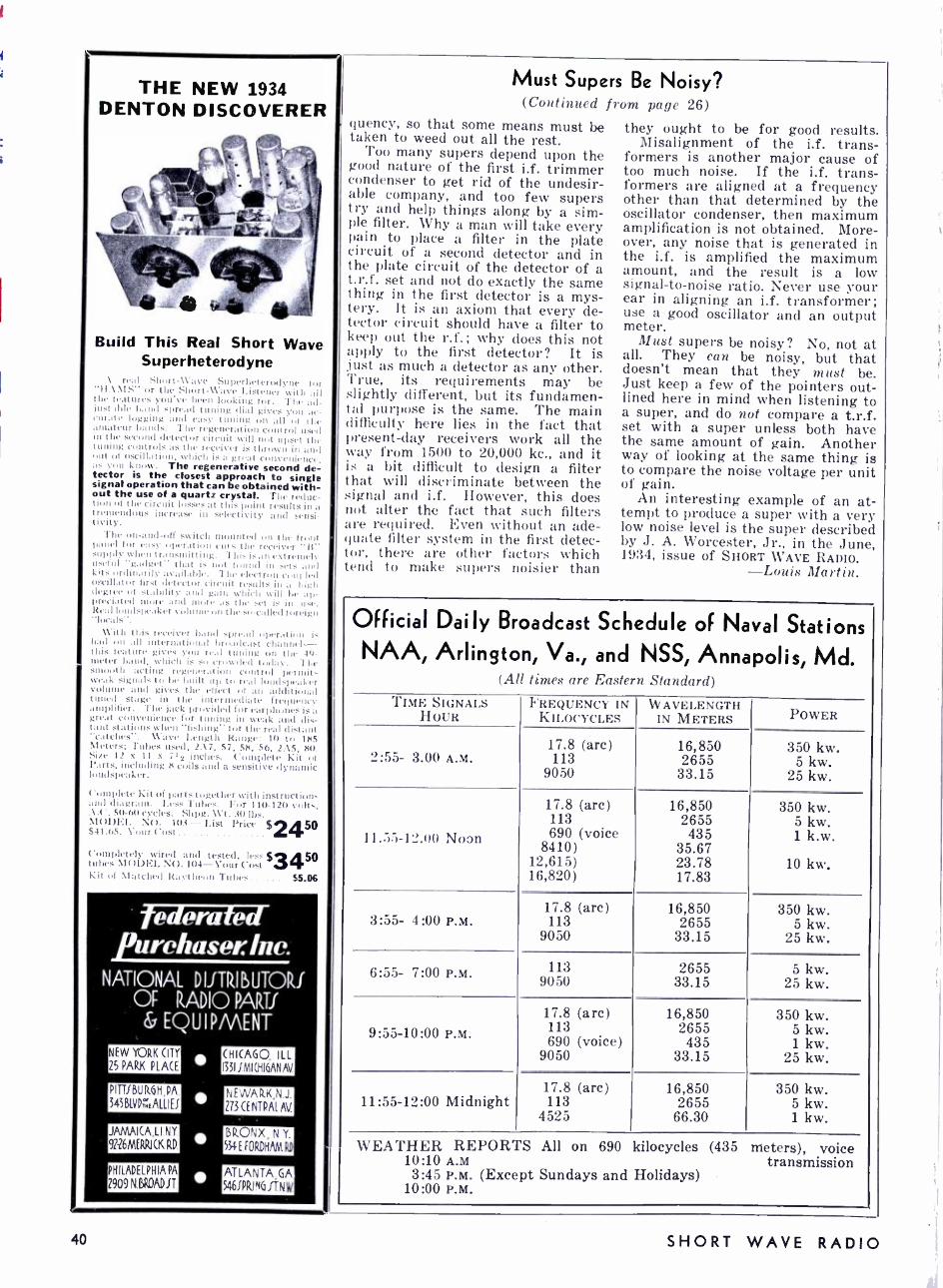
THE NEW 1934 DENTON DISCOVERER
Build This Real Short Wave Superheterodyne
\ real Shur(- \1ave Superheterodyne for II \\IS" or the Short-Wave Listener with all i..tures you've been looking tor, The ad- le band spread tuning dial gives you ac- logging :u d easy tuning on all of the amateur bands - The regeneration control used in the second detector cireuit will nut upset the tuning controls as the receiver is thrown in amii out of oscillation, which is a great cotivelrielia
tent know. The regenerative second de- tector is the closest approach to single signal operation that can be obtained with- out the use of a quartz crystal. "I he redac- t t the circuit I .it the- point results in a t rem ndous increase ill selectivity and sensi- tivit)'.
fhe on- and -off switch mounted on the front panel for easy operation cuts the receiver "Ii' supply when transmitting. 7 Iiis is an extremely useful "gadget" that is not found in sets and kits ordinarily available. The electron con' led cill:tur first detector circuit results in a high degree of stability and gain which will be al preciated more and more as the set is in le-. Real loudspeaker 'olunreon the so- called foreign
11'itli this receiver band spread operation is had on all international broadcast channels- this feature gives you real tuning on the 49- meter band, which is so crowded today. The smooth acting regeneration control permits weak signals to be built up to read loudspeaker volume and gives the effect of an additional tuned stage in the intermediate frequency amplifier. The jack provided for earphones is a great convenience for tuning in weak and dis- tant stations when "fishing" for the real distant "catches ". \lave Length Range: 10 to 185 Meters; Tubes used, 2.17, 57, 58, 56, 2.15, 80. Size 12 x II 7 1 2 s inches. Complete Kit of Parts. including 8 coils and a sensitive dynamic loudspeaker.
Complete Kit of parts together with instructu i
and di. graun. Less Tubes. For I10 -120 volt -. \.l'. 61) -60 cycles. Sltpg. 11't. 30 lbs. MOD1ì1. NO. 103 -List Price $2450 341.65. \'our Cost F Completely wired and tested, If 53 450 tubes MODEL NO. 104-Vour ( Kit of \ latched Itattheain Tupi 55.06
federated p urehase,. /ne.
NATIONAL D IJTRI ß UTORI OF RADIO PARTI
EQUIPMENT
NEW YORK CITY
25 PARK PLACE
PITTIBURGHPA
343BLVP ZrALLIEI
JAMAICALI NY
92-26MERRICK RD
PHILADELPHIA PA
2909 N.BROADIT
CHICAGO, ILL 13511 MI (HIGANAV
NEWARK,N J
273 CENTPAI AV
BRONX, N Y
534E FORDHAM RD
ATLANTA, GA 5461PRING ITNW
I
Must Supers Be Noisy? (Continued from page 26)
fluency, so that some means must be taken to weed out all the rest. Too many supers depend upon the
good nature of the first i.f. trimmer condenser to get rid of the undesir- able company, and too few supers try and help things along by a sim- ple filter. Why a man will take every pain to place a filter in the plate circuit of a second detector and in the plate circuit of the detector of a t.r.f. set and not do exactly the same thing in the first detector is a mys- tery. It is an axiom that every de- tector circuit should have a filter to keep out the r.f.; why does this not apply to the first detector? It is just as much a detector as any other. True, its requirements may be slightly different, but its fundamen- tal purpose is the same. The main difficulty here lies in the fact that present -day receivers work all the way from 1500 to 20,000 kc., and it is a bit difficult to design a filter that will discriminate between the signal and i.f. However, this does not alter the fact that such filters are required. Even without an ade- quate filter system in the first detec- tor, there are other factors which tend to make supers noisier than
they ought to be for good results. Misalignment of the i.f. trans-
formers is another major cause of too much noise. If the i.f. trans- formers are aligned at a frequency other than that determined by the oscillator condenser, then maximum amplification is not obtained. More- over, any noise that is generated in the i.f. is amplified the maximum amount, and the result is a low signal -to -noise ratio. Never use your ear in aligning an i.f, transformer; use a good oscillator and an output meter.
Must supers be noisy? No, not at all. They can be noisy, but that doesn't mean that they must be. Just keep a few of the pointers out- lined here in mind when listening to a super, and do not compare a t.r.f. set with a super unless both have the same amount of gain. Another way of looking at the same thing is to compare the noise voltage per unit of gain.
An interesting example of an at- tempt to produce a super with a very low noise level is the super described by J. A. Worcester, Jr., in the June, 1934, issue of SHORT WAVE RADIO.
-Louis Martin.
Official Daily Broadcast Schedule of Naval Stations NAA, Arlington, Va., and NSS, Annapolis, Md.
(All times are Eastern Standard) TIME SIGNALS
HOUR FREQUENCY IN
KILOCYCLES WAVELENGTH
IN METERS POWER
`':55- 3.00 A.M. 17.8 (arc) 113
9050
16,850 2655
33.15
350 kw. 5 kw.
25 kw.
17.8 (arc) 16,850 350 kw. 113 2655 5 kw.
1 l.:r:>-l''.(tt Noan 690 (voice 435 1 k.w. 8410) 35.67
12,615) 23.78 10 kw. 16,820) 17.83
17.8 (arc) 16,850 350 kw. 3:55- 4:00 P.M. 113 2655 5 kw.
9050 33.15 25 kw.
6:55- 7:00 P.M. 113 2655 5 kw. 9050 33.15 25 kw.
17.8 (arc) 16,850 350 kw. 9:55-10:00 P.M. 113
690 (voice) 2655 435
5 kw. 1 kw.
9050 33.15 25 kw.
17.8 (arc) 16,850 350 kw. 11:55-12:00 Midnight 113 2655 5 kw.
4525 66.30 1 kw.
WEATHER REPORTS All on 690 kilocycles (435 meters), voice 10:10 A.M transmission 3:45 P.M. (Except Sundays and Holidays)
10:00 P.M.
40 SHORT WAVE RADIO
The Double Duplex (Continued from page 37)
is constructed, the details of the circuit will be final.
A good dial is as essential as care- ful tuning. An airplane type was finally selected, not only because it enhances the appearance of the re- ceiver, but because the graduations on these dials are spread sufficiently to permit easy reading.
As may be seen from the front view of the set, the panel contains four knobs and a phone jack. The lower center knob is the main tun- ing control ; the knob immediately to the right varies the trimmer C4; the upper right -hand knob controls the regeneration ; and the upper left -hand knob controls the off -on switch and volume control.
The rear view of the set show the layout of the parts. Looking to- ward the panel from the rear, the 6F7 is seen directly in front of the antenna coil Ti. Immediately to the tight of the 6F7 is the r.f. trans- former T2. The 79 is located at the extreme right, in front of the phone jack. The six -prong socket for the 79 is so placed that the heater prongs (large holes) are to t he rear ; the six -prong socket for T2 is placed so that the large holes are to the right; the seven -prong socket for the 6F7 has its heater holes to the left, although slightly more to the front than to the rear; the antenna coil has its large holes facing the panel.
The gang condenser C2 -C3 is not mounted directly on the baseboard. 'l'he construction of the dial is such that C2 -C3 must be raised sufficiently to permit the shaft of the condenser to line up with the hole in the dial. The correct height is easily deter- mined by experiment. The face of the dial takes a hole 31/8 inches in diameter. If a fly cutter is not available, then a series of small holes drilled close to the circumfer- ence of a circle of the correct diame- ter will do the trick. A half -round file to finish off is all that is needed.
Several leads are shielded : the lead to the cap of the 6F7, the lead to the cap of the 79, and the lead fróm R7 to C11. They are also placed high above the chassis to pre- vent any feedback from one triode section to the other. All heater leads, the two leads from R3, and the two leads from the switch SW are twisted to neutralize any field they may generate.
A plug and cable arrangement is used to facilitate connection to the batteries. It so happens that the phono jack, antenna -ground posts, and the plug and cable were all ob- tained from an old Brunswick phonograph combination cable. These cables may be obtained in the market for practically nothing. The connections from the cable to the receiver proper were made directly to the points involved -no special
strip to which cables usually termi- nate was used. All coil data are given in Table I and in Fig. 3.
Results The proof of the pudding is in the
eating, and the proof of a radio set is in the hearing. The writer is not given to exaggerated or ambigu- ous claims. All he wishes to empha- size is that this little receiver will give about the same results that any reasonably good four -tube receiver will give -and at a small cost. The tuned stage preceding the first de- tector minimizes interference and adds to the gain of the receiver. Regeneration also adds its bit.
As stated previously, a loudspeak- er may be used, and when the writer says that a loudspeaker may be used, he does not mean that a soundproof room and holding of the breath are necessary in order to hear a station. Although opinions differ as to what. exactly, a "loudspeaker set" consists of, the writer feels that this Double Duplex easily falls into that class.
Book Review (Continued from page 19)
Much of the material, especially the illustrations, has been taken di- rectly from his Principles, and has been rewritten in a style suitable for the beginner. All mathematics, with rare exceptions, has been reduced to simple algebra; comprehensive discussions as to the relative merits of this and that cannot be found - only the results of the discussions are presented.
-R. H. O. * * *
HANDBOOK OF CHEMISTRY AND PHYSICS, edited by Charles D. Hodgman, published by The Chemical Rubber Co., Cleveland, Ohio, 41/2 by 7 inches, 1818 pages. Price, $6.00. Nearly two thousand pages of
tables with practically no explana- tory material ! Every conceivable type of table, logarithms, resistance, temperature corrections, electron constants, radio vacuum -tube char- acteristics, etc., etc., is printed in this book.
To be able to turn to a certain page and find the constant you want without wading through a mass of undesirable explanatory material is a pleasurable feeling that can only be appreciated after it has been done. Explanatory material is for text books, and a handbook should have facts, and nothing but facts.
Anyone interested in radio, pho- tography, astronomy, chemistry, physics, and other scientific hobbies will be able to keep this book on the work table, not in the library.
It is the eighteenth edition, and represents the cumulative effort of twenty years of compilation.
Summer Specials CRYSTAL Prices Reduced
LEEDS precision ground Crystals 1" square, in the 160 or 80 meter bands, within .1 of 1% of the specified fre- quency. Y cut $2.25 X cut $3.25 X cut 40 meter crystals ground $4.95 to the same degree of accuracy Ouartz is Quartz -The usual Leed, guarantee of 100% satisfaction is back of our crystals. Can you ask for more?
In Line With the New Crystal Prices
A new moulded bakelite crystal holder that fits a standard UY tube socket. Will accommodate crystals slightly larger than 1" square, furnished with light brass plates accurately lapped. Pressure crystal may be readily adjusted. Dust proof of course. Price
Summertime is portable the WING Transceiver amateurs ore getting a 1
this unit. Price with The MALLORY type for B supply for Price
time. May we recommend for automotive use. Many 5 mile range with
S .25 tubes 18 11 power supply is ideal
the transceiver. si 1.50
V.T.E. 203A tubes carrying our regular guarantee Special $9.75 Heavy Glass Insulators 5" long, Special 10c
The new Sprague line of 600 v. working tubular paper condensers-- all standard capacities fr.,rr, .0001 to. 01 ... 15c .02 18c
400 v. working .05 18c .1 21c .25 ...... 27c 5 36c
Flechtheim Condensers at new low prices
Type Cap Working v D.C. Price Tc 100 1 mfd 1000 v $1.75 Tc 200 2 mfd 1000 v 2.75 T 100 1 mfd 1500 v 2.25 T 200 2 mfd 1500 v 3.75 Th 100 1 mfd 2000 v 4.25 Th 200 2 mfd 2000 v 6.75 HP 100 1 mfd. . 3000 v 9.00 HP 200 2 mfd. 1,000 v 12.25 VM 100 1 mfd 5000 v 13.50
AT LAST ! ! Antenna wire that's not like rubber. Just cut it to the proper length and forget it. It won't stretch No. 12 hard drown tinned copper wire, 100 ft 55c No. 10 hard drown tinned copper wire, 100 ft 85c No 12 hard drown phosphor bronze wire. 100 ft 75c No. 10 hard drown phosphor bronze wire, 100 ft. $1.25
Other lengths in proportion
RESISTOR SPECIAL ! The product of one of the country's largest manu- facturers. 200 -watt Vitreous enamel resistors 81,2" long, furnished with slider.
1000 ohm $ B5 25,000 ohm . $1.10 2500 ohm 95 35,000 ohm ... 1.15 5000 ohm 95 50,000 ohm ... 1.20
10,000 ohm .... 1 00 60,000 ohm 15,000 ohm .... 1 05 80,000 ohm .. 1.25
100,000 ohm
The Radio Amateur has found it convenient to shop at LEEDS. Only quality merchandise at wholesale prices. We do not publish a catalog, quotations on all short wave equipment furnished by return mail.
ORS-I RADro
45 -G Vesey Street, New York City New York Headquarters for Short Wave and
Experimental Apparatus
for JULY, 1934 41
World-Wide SW Receivers I:1-2005i. Hone./ salu4.-F4ereign Ite4eption /:uatr:tntPPd
MILES 0X2
Wired and tested, extra. S1 25
1.15
-3 tube performance from 2 tubes; uses 6F7-37 tubes as ItF amplifier, re- generative detector, and audio amplifier: filaments run directly from 110 v. AC or DC; requires 135 v. B battery or power pack; extremely sensitive; ex- rllent volume: free from crud spots; heavy black
crackle finish chassis and panel; coils and diagrams included S 95 Kit, assembled
-Uses 6F7 -1 V tubes in special circuit as screen grid regenera- tive detector, audio amplifier, rectifier and complete built -in power supply; operates from 110 v. AC or DC; un- usually compact and neat appearance: heavy black crackle finish chassis and panel: coils and diagrams included.
Kit. assembled .5595 Wired and tested, extra Tubes....
ALL -ELECTRIC 2
51.25
1.80
EILEN RADIO LABORATORIES, 24 West 20th St., New York, N.Y.
THE SET YOU HAVE
ALWAYS WANTED
t-:- ..4
the
for the truly critical 1111 There is no finer all -wave receiver
II 'rite Jor t)etanls
PIONEER SOUND LABORATORY 135 Liberty St. New York, N. Y.
11NIVI;Ittit1[, 2- Iillttl on
IIaIIdi-Mike An exceptionally clear. highly damped hand microphone. For announcing. transmitting or home recording. Maximum volume. Minimum hiss. Truly natural in tone. No delicate parts to he damaged if dropped. tarred or roughly handled. A typical UNIVERSAL Value at $S.tt2 Dealer's Net Price
UNIVERSAL MICROPHONE CO., Ltd. 424 Warren Lane, Inglewood, Calif.
U. S. A.
42
THE
"WIZADD" a Short -Wave Converter
of STERLING Quality
Self -powered. Universal A.C. -D.C.. this converter employs two tubes, one oA7 as oscillator and R.F. stage, and the 37 Rectifier. Has two plug -in
roils, and tunes from 20 to 20(1 meters.
Encased in an Ebony Bakelite cabinet of modernistic design this compact job (61/2" x 5" x 21/2") is priced at
$8.25 (completely as- sembled,includ- ing tubes ; and coils)
STERLING LABORATORIES 135 Liberty St., New York, N. Y.
READ Like an SEND Expert!
Learn Quickly at Home; Get Real Speed
It's easy, fascinating, to l,ecome a good up witl the New MASTER TELEI'LEX Code Teacher to help you. Only instrument ever produced which records your sending in visible dots am dashes -then seeds back to you. Also sends practice work, recorded by an expert, at any speed you want. Thousands agree this method is surest, quickest -has taught more ops in pas few years than all other "systems" combined Used by L'. S. Army. Navy, A.T.S. T., R.C.A. and others. We furnish Complete Course, lend you Master Teleplex, give you personal in struction wltlt a MOSEY - ß:\t'K Gt'AIL%NTRE. Low cost. Send today for booklet S.R. 19, ne obligation; post card will dn. Teleplex Company
76 Cortlandt St. New York, N. Y.
FREE BOOK
The B. B. S.W. C. THE E Before Breakfast Short Wave I Club, which was first described in
the November, 1933, issue of SHORT WAVE RADIO, is a unique organiza- tion open to all short -wave listeners. There are no dues, meetings, minutes or other parliamentary nuisances. It is merely a friendly, fraternal and not too serious organization of early birds who believe in the old adage about catching the worm. The only requirement for membership is two verifications from short -wave phone stations one thousands miles or more from the applicant's location, re- ceived any time after 5 :00 A.M. and before 9 :00 A.M. any day of the week,
Verifications sent in to the B. B. S. W. C., are returned promptly to their senders along with a certificate of membership suitable for framing. This certificate measures 81/2 in. by 111 /_ in. and is printed on high grade paper.
We do not make any distinction between short -wave relay broad- casting stations, commercial radio- phones, amateur phones, experimen- tal stations, and ship stations. Any station that operates below 200 meters and uses voice transmission is a legitimate catch for the short- wave listener, who is interested only in the feat of reception itself and not in the musical programs, political propaganda and private conversa- tions that fill the air. It is really much more of an accomplishment to bring in an amateur station using perhaps only ten or fifteen watts of power than a powerful broadcasting station using ten or fifteen kw.
Address your verifications and ap- plications for membership to the Be- fore Breakfast S. W. Club, care of SHORT WAVE RADIO, 1123 Broadway, New York, N. Y., and be sure to en- close a large stamped and addressed envelope for their safe return.
ç:ç;ÇW! B1`l' "1IiIjiJ. horl Ut1v . ; ; Q:ltib
tt9 t9 to certify that
has qualilìetl for ?llembership in the
"lielore lireakftut tihort /Vane flub" by satisfying the requirements as publishtt in :Stunt /Dave 31a6io'
MeN VORN ,u.,u ..u., w..,..wo
A reduced reproduction of the diploma issued, free of all charges, to all those
who can qualify. See text.
SHORT WAVE RADIO

McMurdo Silver
MASTERPIECE II
10 -570 METERS
proclaimed greatest all -wave receiver by engineering uni- versities, broadcast executives
and explorers.
Admiral Byrd is using Masterpiece II ir. the Antarctic . the Engineer of a Great Eastern University writes, "Mas- terpiece 11-is my ideal come true" . . .
Broadcast Executives prefer Master- piece II for their own use, because of its lower noise level and consequent bet- ter reception of far distant stations. Many unique features such as band spread tuning, built in beat note oscil- lator. Write for complete details and particulars of 10 -day trial, money -back guarantee offer.
McMURDO SILVER, INC. Dent. 1 751
3360 N. Paulina Street, Chicago, U S. A.
Correcting Operating Conditions
LTHOUGH vacuum tubes are generally operated with the "typical" electrode voltages recommended by the manu-
facturer, special circumstances some- times make it necessary to use tubes at other voltages. In such cases. new operating conditions which will give the best results must be ob- tained. The new conditions can be readily obtained for pentodes by means of the accompanying chart.
If, for example, the 89 with pen- tode connection is to be used with a plate voltage of 200 volts, what will be the correct operating conditions? Thé "typical" values given by the manufacturers are for plate voltages of 250, 180, 135, and 100 volts, none of which quite fits the case. The ratio of the new plate voltage to a known voltage (250 volts) is 200 - 250 = 0.8. This is called the vo11 -tage conversion factor and is
Plate Volts Screen Volts Control Grid Volts Plate Milliamperes Screen Milliamperes Mutual Conductance (Micromhos) 1800 Load Resistance (Ohms) 6750 Power Output (Watts) ' 3.4
identified as Fe. Multiplying all voltages by Fe gives the new voltages shown in Table I.
By means of the accompanying curves and the voltage conversion factor (Fe) , the new values of the screen and the control grid voltage, the plate and the screen current, mutual conductance, power output, and load resistance can readily be determined. The factors Fr, Fp, Fr and F,,,,1 are the ordinates read from the curves at the abscissa value of 0.8. The following table gives the calculated values for a plate voltage of 200 volts.
In the same manner, operating conditions can be determined for other voltage ratios. This method is particularly adaptable to output pentodes where the plate and the screen current are fairly high and vary according to the 3/2 power law, and where the voltage conversion factor is not over two to three or less than one -half to one -third.
-RCA -Radiotron Co., Inc. (This article is particularly perti-
nent to short -wave receiver con- structors because of the fact that many of the tubes available are rated for voltages which differ con- siderably from those used by short- wave constructors. This article tells
CONVERSION FACTORS FOR PENTODES
These curves especial , aseidl for po.er rentoaea calculating a h l..r ac drat, from panitehed pendttions, otlrtr eperat ng conditions meet late voltage reyatreeen s . Ftrat, aet.r. ne
of the n . plate veltage to the published plate eeeeeee the desired gondl¡ions . This rtio age Con e n Factor '(r. , then used to
screen new and the new co trel grid voltage. aedtOdetere.ne fro. the (actora for
he oto et.n( con l.t. on. .
O 4 a 4
operating special
t m voltage
t,e
t
the
in
ratio
Volt-
also other
e r
i ° w.::: :'C a MEE ®i11i_
i1En® MI Ill E 11
---1 -
...' --n,II Aim I
qill
t99t
F 1111 _
2 r,.1.r, ..., MIMI . sr.mwl - BNtU®11/I/__ ,; t®®irRr il/%ffi \ _gltliá7l® i
Ui Yolilln ii villiéé iMIiIá
o
°i''1iú'i go lc, ó
:: ::
ri .1 ïl®®EI 111111®1i111111
W
a.
i so.i
}: -, /- 1: ® 1 lill III : 111111
I _ asai.lsmt.al. l.s I.ia .....i nos ---4-
--- -- 1 Y__OgIN/r//i .i f or rts rp cIt a rane. goers:' ®
I o ruTt Q
rto
.-
A
/1®I r
l_. __
....
.
_
..
I 1 I
I
rar.ci. i, a r rcs To
g IP CM i .rr us ro r I'CUrs TO
i a ruts CO iiii --o .anc-
na I COMP /n To 1$g (IT
at oorrur tos: Irsnuect IMO if II We t C:-oaTa it 11I il.11
O.1 O.2 04 O6 r 2 ] 4 a a 10 VOLTAGE CONVEFStON FACTOR (re)
The conversion chart referred to in this article.
TABLE I Condition 250 -Volt
250 250 - 25
32 5.5
Factor Fe = 0.80 Fe = 0.80 Fe = 0.80 F/ = 0.71 F( = 0.71 Fg,n = 0.90 Fr = 1.12 Fp = 0.58
200 -Volt Condition
200 200 - 20
22.7 3.9
1620 7550 1.98
NEW S.W. RECEIVER ea4 G
1'bls newly designed S.W. 2 -tube receiver is so
far ahead In circuit design and layout that it IS the world's easiest to
build. In performance it is as efficient as most -tube sets. This Is because the 'Mascot N utilizes one 19
[flee dual Triode tube and a 32 screen grid tube In a re- ;:eneratIvc resistance coupled audio amplifier combination. Its simplicity of design and layout Plus easy Point It' point assembly and wiring instructions make It )x,ssib'e for even a novice tt build it. In operation it is no longer necessary to reach behind the panel to change plug -In coils, for the 'la -rot 2 employs front panel plug -in coils such as are found in only high priced sets. The 'Mascot 2 is licensed under R('.% and Hazeltine patents and employs other features usually found ht the most expensive receiver::. such as complete shielding, hand spreading, smooth regeneration, stable control and very low battery drain. Foreign stations with loud 'I taker reception Is an actuality with this new, two tube Universal \Mascot which Iisty at only $17.50
DEALERS ! AMATEURS !
EXPERIMENTERS !
Your discount is 40'; off or. net S 10.50
1 -onr jobber or favorite M. (1. House can supply you I( not write us and the will sec that you are supplied.
INSULINE CORP. OF AMERICA 23-25 PARK PLACE NEW YORK, N.Y. I).partment S -74
Q Send nie additional information on the Mascot -3.
O Send me nahe of nearest jobber.
Name
Address
City State
\Ii I H. It ietzke, President of Isla. former chief instructor of Naval ,
Research Laboratory and today an out- -landing ft'ure in the Itadi prof,'shoi
CREI ONE YEAR RESIDENCE COURSE IN PRAC- TICAL RADIO ENGINEERING SAVES TIME AND MONEY FOR THOSE ENTERING RADIO
My Residence School. located in Wash- ington. offers the ambitious young man the quickest and most thorough way to enter the higher fields of Radio as a TRAINED ENGINEER! Complete laboratories with modern working equipment. Same course is offered for home study or combination of Home Study and Residence.
lf', ;te lie for Our Free 40 -Page Booklet CAPITOL RADIO ENGINEERING INSTITUTE
14th and Park Road, Washington, D. C. Dept. SW -7
FREE New Short Wave and Auto Radio Catalog
Radio Replacement Parts, Sets. Tubes and Electrical Appliances at great savings. WHOLESALE MERCHANDISERS, Inc. 628 Broadway, - New York City
for JULY, 1934
Subscribe?
See Page 48.
43

the kallicralter's SKY RIDER
-a remarkable new
Short.Wave Receiver Now reception of foreign short -wave stations as depend- able as American programs. A super -performing short- wave receiver designed for those who want dependable reception at a cost far less thon that of all -wave receivers. Designed for short -wave reception alone. Finest high - frequency construction with the results in an entirely new standard of short -wave performance. Complete with built -in power -pack and dynamic speaker. Write for FREE booklet.
Get this FREE hallicrafter's
booklet! I SILVER -MARSHALL MFG. CO.,
417 N. State St., Chicago, U. S. A. Send new FREE HALLICRAFTERS
SKY -RIDER booklet. I Name
I Address De -t. F
J SUMMER PERFORMANCE
4, 141$
New S. W. Sets suitable for Summer Camps, Va- cations and short trips.
PRIZEWINNER 15 to 200 Meters)
('or, phoely self powrred. latest type 77-43 wad 2.:Z.1 Tubes Provision for Ilead l'honcr and Speaker. (' tete, leas tubes. in rich eraekle- finish cabinet. Assembled wired tested, ready to plug in, including four roils.... $12.95 Kit of RCA or Arcturus Tubes to match 3.75 Complete Rit of pari,,, including 4 coils 10.55
'THE BYRD 2 -TUBE KIT NOTHING EXTRA TO BUY: 34 Dehntor. 33 Pentode t in po t . Mw ro-Vernier dial. black crackled finish hinged top cabinet. Set 4 coils. 1.1-200 m. l' Tete apeci- Invrtions, blueprints. hard - ware. wire Net of Arcturus tubes ____.. _ _51.95
The Byrd is also available for 6 -v tubes
$5.75
YANKEE CLIPPER
One Tutu, I10 V. AC -DC short wave. using 12 -A multi- purpose tube. Quiet built in Power Supply. Portable. for use wherever electric power is available. Price for $6.75 complete kit of parts including black crystal t0 finish metal cabinet. Hardware. instructions, etc. 12 -A -7 Guaranteed Tube 1.25 Wired. Complete e't rn 1.60
FREE BOOK ALAN RADIO CORPORATION avine complete het
sent short
repueeL aliaos
83 Cortland) SI. Dept. I RN N. Y. City
The 1934 Discoverer (Continued frum page 35)
equipped with the line switch. The control on the right -hand side, fac- ing the front panel, is the manual volume control, which is, of course, in the cathode circuit of the 58 i. f. stage. There is one shielded lead used in this receiver, and that lead runs from the plate of the second detector to condenser C17, which is mounted on the front panel. This condenser, as previously mentioned, is the regeneration- control unit for the second detector circuit, and, un- less this wire is shielded, it will be difficult to keep this circuit out of oscillation because of feedback through other portions of the wiring.
The first thing to be done after the receiver has been completely wired is to check the wiring against the circuit diagram before placing any of the tubes in the sockets. If this check is satisfactory, place the tubes in their respective sock- ets and plug the receiver into the a. c. line. Allow time for the tubes to heat, and you are now ready to tune the two intermediate frequency transformers to 465 kilocycles. If a local oscillator is obtainable, set the oscillator to 465 kc. and adjust the small tuning screws on top of the i. f. transformers for a max- imum response in the loud -speaker or in the output meter, if the latter is available. After this alignment is accomplished, connect the antenna and ground and short circuit post SA to ground if the standard an- tenna is used. Slowly rotate the main tuning dial and condenser C3, which is the antenna compensating condenser, until a signal is heard. The establishment of resonance be- tween condenser Cl in the mod- ulator circuit and C2 in the oscil- lator circuit will manifest itself by a rushing sound, and in many cases a mushy signal will be picked up immediately, which can be cleared up by readjustment of C3.
Be sure and have the volume con- trol, R5, moved to the full -on posi- tion when making the first test on this receiver, and have condenser C17, the regeneration control, at zero setting - minimum feedback. After a signal has been tuned in, check the action of the volume con- trol R5 and advance the regenera- tion control C17 until the maximum signal strength is obtained. If it is desired, of course, to tune in c. w. signals, it will be necessary to ad- vance C17 until the 57 tube is in oscillation. In general, the most satisfactory and most sensitive con- ditions will be obtained just at the point below oscillation for phone re- ception.
Set the moving arm of the poten- tiometer R13, the tone control, for the most pleasing tone value; in most cases this unit can be adjusted once and left alone. However, there
When Seeking a Radio School Consider RCA Institutes . . . 25 years old . . . an institution recognized as an important factor in the radio industry.
The beginner who seeks instruction in any branch of radio will find courses designed tor hire ... either at the Resident Schools in New York and Chicago or the RCA Institutes Home Study courses. Students attending our Chicago School this Sum- mer have an added advantage in combining a study of the scientific wonders of the World's Fair.
FEATURES OF RCA INSTITUTES HOME STUDY COURSES
Extension reursr; for home ,turfy on convenient '.no obligation" plan. Examination and tech- nical advisory services. Free post- graduate practical training at resident school with mod- ern ertulpment under Instructing engineers.
Write for Catalog
RCA Institutes, Inc. Dept. SR -31
75 Yariek Street, New York
1154 Merchandise Marl. Chicago
FR FF CA A
NF; iV TA
RADIO LOG
Packed with new-model radio VALUES at rock- bottom wholesale prices! Money-bark guarantee and 30 -DAY FREI: TRIAL IN YOUR lltt nn every set. All types. Send for big new, lit(,. I5 free eataing TODAY. frises e II
P F4/1t1/141Y RADIO Inc.
Dept. 7 -41, Oakman Bldg.. Detroit. Mich.
SHORT WAVE EXCHANGE
Have you some apparatus to sell or swap, or some special service to offer to other short -wave fans? Take advantage of the low rates of this department to reach other "hams ". Only 5 cents per word for amateurs, 8 cents per word for manu- facturers or dealers. Name, initial and address each count as one word. Not less than 10 words accepted. Cash, money order or U. S. postage stamps must accompany all advertisements. Please write clearly.
a,ea
in nuul a aeill Ilelaa ul aa aa 111111 1111111111111 11111 111 aaalipaalal Ileon laalnelaallel ulllllpaluue aeieuae.
5 COILS, DOLLAR. Andraud, 42 Morton Street, New York, N. Y.
THE ANSWER FACTORY has unsnarled many puzzles of amateur and commer- cial operators. Prompt quotations, rea- sonable prices. Robert S. Kruse, RFD No. 2, Guilford, Connecticut.
are times when it will be necessary to cut out more of the higher fre- quencies; a readjustment of the tone control is then necessary.
When it comes to using the band - spread section, set the main tuning dial, C1 -C2, to approximately the band desired and adjust the con- densers C4 and C5 until resonance is obtained over that portion of the band desired; then tune the con- densers C6 -C7.
Sufficient resistance -capacity filter- ing has been included in all the im- portant circuits of this receiver to insure smooth operation, and there should be no real difficulty in obtain- ing results in a receiver of this kind. So many features which are usable and practical have been incorporated in this receiver that it will surely prove of interest to all short -wave hams and listeners. A speaker hav- ing a field coil of 1800 ohms tapped at 300 ohms provides the plate sup- ply filtering and the bias voltage for the 2A5, second audio stage.
44 SHORT WAVE RADIO

Reception Reports from Readers
(Continued from page' 15) lower than that recommended by C. E. Denton in his Handbook. I have found that if a larger amount of coil is tapped, the set oscillates too easily and a drop in signal strength is noted. As it is, the set oscillates very easily and the sen- sitivity is very high.
The antenna is coupled to the set through an antenna coil. This is su- perior to condenser coupling because no dead spots are noticeable, and the antenna capacity has little or no effect on the tuning of the signal, adding more to the stability of the set.
Electron coupling is used because it is the most stable form of oscil- lator known. Variations of supply voltage have no effect on the re- ceiver whatsoever. A station can be tuned in just on the edge of oscil- lation and it will stay that way, no matter how many irons, toasters, etc., are plugged in on the same line.
The r.f. choke in the detector plate lead is very important. Make sure it is of the best obtainable. If you can't afford the best, construct one from a piece of 1/2 -inch rubber tub- ing. Wind 600 turns total in four sections about 1/2 inch apart.
The detector plate choke consists of the primary and secondary of a 5 -1 audio transformer in series. This method of coupling gives from two to three times as much volume as resistance coupling.
Sincerely, ROBERT J. TALBERT,
7823 Colfax Ave., Chicago, Ill.
R.M.A. Identifies New Sets T0 inform the radio buying public as well as the trade, means to
establish identification of "all wave" and other receiving sets have been adopted by the Radio Manufactur- ers' Association. The object is to definitely classify the new and im- proved receivers, to avoid misrepre- sentation and to facilitate merchan- dising of sets.
Nomenclature and frequency ranges for a standard broadcast receiving set, the "all wave" re- ceiver and the "standard and short wave," or "dual wave" receiver, were adopted by the Radio Manufacturers' Association board of directors April 18 at Chicago, following recommen- dations from the Association's En- gineering Division.
The "Standard Broadcast" re- ceiver is defined to include sets hav- ing the regular frequency range from 540 to 1500 kilocycles.
The definition of the "all wave" receiver applies to sets with fre- quency ranges from 540 kilocycles to at least 18,000 kilocycles.
The "standard" and "short wave"
You're I1 ere, There, Everywh ere ilei //i an
AC -DC. Self -powered Kit, «h built -in speaker, coils to cover 15 to 200 meters rs and blue print
56.75 (tubes us,d -I -78. 1 -37 and 1 -38).
Custom built and laboratory tested.(extra) .. . 51.25
THE INTERNATIONAL 3A KIT 58.25 "Die 3A uses one 121.3 one 38 and one 6F7 Custom built and laboratory tested, (extra)... 51.75
THE INTERNATIONAL 3B KIT 58.00 (The 3B is same as above sots, out battery olé. 1. pli ,l. Can be had for 2 or 6 volt operation.) Custom built and laboratory tested. (extra) ... 51.50
Broadcast coil for either model .75 Complete kit of matched tubes Model 3 $2.25 Model 3A 2.75
Model 38-2 volts 2.65
Model 3B -6 volts 2.25
EXPERIMENTAL RADIO LABS. 80E Cortlandt St. New York, N. Y. WORLD WIDE RECEIVER
INTERNATIONAL THREE
tee Or rQrl'Çt
rzuthi lve Amp asoUrashialttta nenn as attoTdinorijj ratiiD curia
Whether you have a broadcast, short outomobit or all -wav re-
ceiver, t ver, you con per clearer, more realistic, noise-bee radio recption
by the use of the
471ATie 1¡ R a l.g-r RIC frill A A iii
ANTENNA SYSTEM
Unconditionally guaranteed to out- perform any other kind of aerial or so-caned erial eliminator. or money
nefunó.d without question.
Write TODAY for Full D.fapa
Remember - No Radio Can Be Better Than Its Aerial
ARTHUR H. LYNCH, Inc. - 227 Fulton St., New York, N. Y.
ALUMINUM BOX SHIELDS 6" x 5' /sex 6 "$1.15
16 Gauge Aluminum Panels 7x1l..25e 7 12..29e 7 14..33c 7-hose panels are a .grelot lot at the above prices. I .ngar an d
wider at correspondingly low prices. Add postage on I lb. fro ocr We have no catalogue. Please do not ask for one.
BLAN THE RADIO MAN, INC. 177 Greenwich St.,Dept.HM,New York,N.Y.
Genuine Alcoa"
Stock
f 1
1
1
1
1
1
IM No - -- ALL ELECTRIC
ALL -WAVE AIR SCOUT ONLY SET OF ITS KIND IN THE WORLD
42
nrn,l ty II. r. ii u. t S. Sr. , .to. a"r,.io,
This powerful little set operates di- reetly from any house lighting circuit. 1
either a.e. or d.e. It brings in all standard broad- cast stations and also police calls, forrif/n stations. rode nd trans -At hintir phone conversations. foes live Plug -in coils to rover band from la to 550 meters. Compact and light -slakes an ideal portable.
IWill operate several headsets simultaneously and ,% ill stork on ashort indoor aerial. COMPLETE SET. with two tubes. earphone, two II
toil. covering band farm 70 to 550 Meters, ready to plug in and use Postpaid 58.50
Same a: above, less earphone Postpaid $8.00 Three extra plug -In coils to cover band from 10 to 71P meters -- oe each.
Battery0perated All -Wave Air Scout complete' with tube. earphone, two coils ready to use (less In- expensive batteries) $5 95 postpaid SPECIAL OF'F'ER: Valuable data on ill-Ware 7te- reirrra sent upon reef ipt of foe to rarer handling roots. Fret circulars alyo arailablt-
ALLIED ENGINEERING INSTITUTE ' I r. 19t1
98 Park Place Dept. CF - New York,'N. Y. Phone BArclay 7 -9540
1
1
1
1
1
1
1
1
1
1
Complete KIT with set of 4 coils 56.25 Wired - $7.50 Tubes - $1.50
As the name implies thé "JIFFY 3" is a short-wave kit that practically assembles itself. This remarkable re- ceiver has a moulded Bakelite hase- RESISTANCE COUPLED through- out. Merely connect a few wires - take a few turns with a screwdriver, and in a jiffy you will be pulling in foreign stations -police calls -aircraft signals. Has two 30's and a 32. Battery operated -light weight -world. wide reception -low current drain.
LEOTONE RADIO CO. 65A Dey St. New York, N. Y.
45 for JULY, 1934
i
24 Years of
CONDENSE R LEADERSHIP
THE basic refinements which made Hammarlund Condensers the first
choice of radio pioneers still make the new models the unchallenged preference of to- day's leaders. There is a Hammarlund Condenser for every receiving and transmitting need - single, dual, double- spaced and "hand - spread" tuning -all so moderately priced there is no excuse for "economizing" on condensers of lesser prestige.
Write Dept. SR -7 for Complete 1934 Catalog
i
HAMMAR L U N D MFG. CO. 424 438 West 33rd Street New York
3ot,8ct2e', Tdnriiry
ll-ammarIund larc,S,ON PRODUCTS u
seal for our new 1 Itl :I. l'uhdu %kith the complete í41I(11(1' WAVE listing. Build our famous 2 tube "I)X -er" described In the leading radio magazines. Complete kit of quality tarts costs only 36.73, Includ-
iuc coils. our 4 'l'ube Band -spread Islt Is a world- beater also. Ally-
n 11.11i,l on..,. m,de. ae.e ..f. 1 het.
thrilling súoit l
sell SI it II Equipment during these sumo., '. months for big profits. There's u w..uderful opportunity In uurslugle miltcornpact Af obileSould Systems for complete operation from a ti volt storage battery. They're described In our new catalog along wit Ii Re plete line of A.C. Amplifiers and Sound Sys- tems ranging from 4 to SII watts In output. If you sell Sr )l' I I. you aced our book.
our new catalog, which is yours FRI;I. for the asking, lists the 1114 complete line "i SHORT WAVE Transmitting and Receiving equipment you could ask for ... priced right and available quickly. Every AMATEUR needs this valuable new ALLIED book. Send for it today. It is packed with AMATEUR equip- ment representing every single famous standard line. Yon will find our prices consistently lower.
tor llc \'nIUnblo nee' I.I.lI Ii (OA,.. It's F'Itl'l. lo addi-
to e pleto Siltlit'l' WAVE. SOUND, and A tiA'l'I. tlIt tisijaas, you will find radin's 111081 e lets stork of standard replacement parts. test equipment. sod it sew Mitt pro11,11e line of World-Wide reeek, r.. Write Dept. I. today for your FREE ropy.
AIIíedRadío CORPO AT ION
833 W. JACKSON BLVD.,CHICAGO,ILL.
46
or "dual wave" receiver as defined by the R. M. A. will apply to sets having frequencies between 4,000 and 20,000 kilocycles, with a short wave range covering a ratio of max- imum to minimum frequencies of at least two and one -half to one.
The definitions outlined above were adopted by the R. M. A. board as the simplest possible to correctly advise the buying public and the trade. Detailed standards defining the nomenclature and frequency l'anges of the three types of receiv- ers will be issued soon by the R. M. A. Engineering Division.
The Mascot 2 (Continued from page 32)
from the rear, the tube to the right is the 32, screen -grid detector, that to the left is the double triode type 19 tube. The tuning condenser to the right is the main .00014 mf. tank, and the other, smaller unit at the extreme left is the band -spread unit. The large shield can in the center houses the plug -in coil, which is further illustrated in the front - panel view. The grid leak and the grid condenser are mounted above the deck, at the extreme right, to keep the leads as short as possible.
The chassis is 10" wide, 7" high, and 6" deep; it weighs but 31/2 pounds, complete with tubes and coil, less batteries.
The entire set may be obtained in kit form, ready for assembly and wiring with two additional coils for the broadcast band and an additional coil for the 9.3 to 21 meter band.
The Air Scout (Continued from page 33)
The Air Scout can be used not only on 105 to 120 volt lines, but also on any 220 volt source of power, either a.c. or d.c., through the use of a voltage reducing resistor.
There ai-e three controls availa- ble. At the right is the combined switch and regeneration control. Turning this knob in a clockwise direction turns the switch to the "on" position. As the knob is turned further, it operates the re- generation control. The knob at the center turns the station selector. The third control is the one on the trimmer condenser at the right rear.
No special directions are re- quired for tuning in broadcast sta- tions on the orange -colored coil. If the set tunes too broadly, a shorter aerial should be used or else the adjusting screw on the antenna trimmer condenser should be loos- ened. In many locations, the Air Scout will operate with a short indoor aerial if local stations only are desired. Tune in the station wanted by means of the station se- lector knob at the center. Then turn the knob on the regeneration con- trol until satisfactory volume is ob- tained.
A little practice will soon make
Twice as Big as
Iasi Edo....,
KRUSE'S .
RADIOPHONE GUIDE
.11.10- ,.,..c10- AN. MOW ,.a o.so
BATCHER'S RADIOGRAPHS
50f
Before!
is the new
2nd edition
of
KRUSE'S RADIOPHONE GUIDE
and just as full of operating and construc- tional information which isn't printed else- where.
And furthermore Theré s a complete set of
Batchers "Radiografs" the simplest problem- solvers we ever saw.
IN STOCK AT- I 'I'I pson Iloltmes, Su ii Francisco \VaIter Ashe Radio Co., St. Louis G. M. & (7. Radio Sup. CO., Oakland Zack Radio Sup. Co., San Francisco Radio Specialties Co., Detroit Warner Bros., San Francisco E. C. Wenger Co., Oakland Leeds. New York Often! ,aeh Elect. Co., San Francisco I. S. Cohen's Suns, S71t1 Francisco Neisner Bros., Inc., Roston 3. C. I Iobrecht Co., Sacramento Portland Radio Sup. Co., Portland tlrifilth Sales Co., Tacoma, Wash. Wedel Co., Inc., Portland \Vedei ('o., Inc., Seattle Seattle Radio Sup. Inc., Seattle Lou Bunn Co., St. Paul I lii.ago Radio Apparatus Co., Chicago Spokane Radio Co., Inc., Spokane Midwest Radio Mart, Chicago Gross Radio, Inc., New York Intercity Radio Stores. Long Beach A Sales Co., New York Burstein- Applebee Co., Kansas City Abbott's Sweet Shop, Berwyn, Ill. T. F. Cushing, Springfield, Mass. Ports Mfg. Co., Fresno Radio Inspection Service, liartford Radio Supply Co., Los Angeles Ilatry & Young, Hartford Kruusou Service Co., Buffalo I'ierson's Radio Laboratory, Sacramento Itlau the Radio Blau, New York Wilmington (Delaware) Elec. Specialties Co. Kladug Radio Laboratories, Kent, Ohio Maurice Schwartz & Son, Schenectady Harry's Radio Land. Lung Beach Radio Service Laboratory, JLinchester, N. H. Thompson Battery and Radio Service,
Zanesville Radio Laboratories, Kansas City ltadiu Electric Service Co., Philadelphia Chicago Radio Apparatus Co., Chicago ('ameradio, Pittsburgh Natick Book Store, Los Angeles Radio Distributing Co., South Bend, Ind. Radio Television Sup. Co., Los Angeles, Cal. Neisner Bros., Rochester, N. Y. Electric Supply Co., Oakland, Cal. Coast Electric Co., San Diego, Cal. McGills, Melbourne, Australia Radio Supply Co., Oakland, Cal.
50 cents from your dealer (75 cents in Canada) or direct from
Robert S. Kruse Guilford, Conn.
(P.S. The 1st edition sold Out in 90 days)
SHORT WAVE RADIO
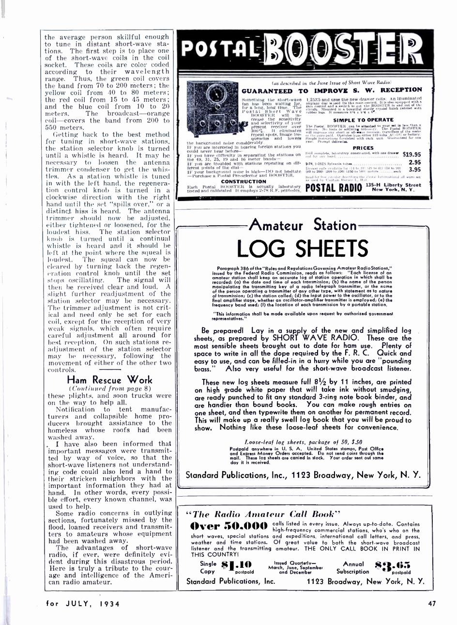
the average person skillful enough to tune in distant short -wave sta- tions. The first step is to place one of the short -wave coils in the coil socket. These coils are color coded according to their wavelength range. Thus, the green coil covers the band from 70 to 200 meters; the yellow coil from 40 to 80 meters; the red coil from 15 to 45 meters; and the blue coil from 10 to 20 meters. The broadcast-orange coil- covers the band from 200 to 550 meters.
Getting back to the best method for tuning in short -wave stations, the station selector knob is turned until a whistle is heard. It may be necessary to loosen the antenna trimmer condenser to get the whis- tles. As a station whistle is tuned in with the left hand, the regenera- tion control knob is turned in a clockwise direction with the right hand until the set "spills over," or a distinct hiss is heard. The antenna trimmer should now be adjusted, either tightened or loosened, for the loudest hiss. The station selector knob is turned until a continual whistle is heard and it should be haft at the point where the squeal is loudest. The squeal can now be cleared by turning back the regen- eration control knob until the set stops oscillating. The signal will then be received clear and loud. A slight further readjustment of the station selector may be necessary. The trimmer adjustment is not crit- ical and need only be set for each coil, except for the reception of very weak signals, which often require careful adjustment all around for best reception. On such stations re- adjustment of the station selector may be necessary, following the movement of either of the other two controls.
Ham Rescue Work (Continued from page 8)
these plights, and soon trucks were on the way to help all.
Notification to tent manufac- turers and collapsible home pro- ducers brought assistance to the homeless whose roofs had been washed away.
. I have also been informed that important messages were transmit- ted by way of voice, so that the short -wave listeners not understand - ing. code could also lend a hand to their stricken neighbors with the important information they had at hand. In other words, every possi- ble effort, every known channel, was used to help.
Some radio concerns in outlying sections, fortunately missed by the flood, loaned receivers and transmit- ters to amateurs whose equipment had been washed away.
The advantages of short -wave radio, if ever, were definitely evi- dent during this disastrous period. Here is truly a tribute to the cour- age and intelligence of the Ameri- can radio amateur.
p o i TA 1100STER (as described in the June Issue of Short Wave Radio
GUARANTEED TO IMPROVE S. W. RECEPTION SanctIting the Short -wave fan haft been waiting for, for a long. long time Tbe Postal Short Wave
I« )STEM will in- crease the sensitivity and selectivity of your pre4ent receiver over 300''ó. It eliminates repeat spots. image fre- quencies and lowers
the background noise considerably. IF you are interested in hearing foreign stations you could never hear before - IF you have difficulty In separating the stations on the 49, 31. 25, 19 and 16 meter bands- IF you are troubled with stations repeating on dif- ferent paints of the dial - IF your background noise is high -DO not hesitate -Purchase a Postal Pre- ,eleetor and BOOSTER.
CONSTRUCTION Each Postal 1st i r;.: t t l( Is actually laboratory tested and callbratrol It employs 2 -78 Il.l. pentode.
I.25Z5 and uses the new drawer coils An Illuminated airplane dud u used for the main control. It is den equipped with a
Gain control and a switch to cut the BOOSTER in and out of th, circuit 5lounid in a beautiful sturdy crystal finish cabinet with rubber legs. It measure. 8% z 10..
SIMPLE TO OPERATE The Postal ROOSTER ran he attaehd to yo or t it t. thon minnt,.. No tool. or soldering neee..:.rv. The !'eta! BOOSTER will
the price any short or as a -wave rere..or. reaardle of the make
or Frire paid. Operate. fruin either 110 volta Ar -I)(; or battery. Simple instructions furnished with each unit. Uurnrouteed for one Yser. !'rompt deliveries.
PRICES Sold complete. laboratory con.trnrtod. with sue drawee $19.95 ,oil for :my bond
2-7g, 1- 257,5 Sylvania tubes 2.95 Drawer roils a vailnhie for Ile to 111) 129 to 01) (59 to 90) (90 to 200) (200 to 350) (350 to 540) meter. sash
POSTAL RADIO
3.95
135 -H Liberty Street New York, N. Y.
Amateur Station
LOG SHEETS Paragraph 386 of the "Rules and Regulations Governing Amateur Radio Stations,"
issued by the Federal Radio Commission, reads as follows: "Each license of an amateur station shall keep an accurate log of station operation in which shall be recorded! (a) the date and time of each transmission; (b) the name of the person manipulating the transmitting key of a radio telegraph transmitter, or the name of the person operating a transmitter of any other type, with statement as to nature of transmission; (c) the station called; (d) the input power to the oscillator, or to the final amplifier stage, whether an oscillator -amplifier transmitter is employed; (e) the frequency band used; (f) the location of each transmission by a portable station.
"This information shall be made available upon request by authorised government representatives."
Be prepared! Lay in a supply of the new and simplified log sheets, as prepared by SHORT WAVE RADIO. These are the most sensible sheets brought out to date for ham use. Plenty of space to write in all the dope required by the F. R. C. Quick and easy to use, and can be filled -in in a hurry while you are ''pounding brass." Also very useful for the short -wave broadcast listener.
These new log sheets measure full 81/2 by 11 inches, are printed on high grade white paper that will take ink without smudging, are ready punched to fit any standard 3 -ring note book binder, and are handier than bound books. You can make rough entries on one sheet, and then typewrite them on another for permanent record. This will make up a really swell log book that you will be proud to show. Nothing Tike these loose -leaf sheets for convenience.
Loose-leaf lo {' she'e'ts, paekaçe of SO, S.50 Postpaid anywhere in U. S. A. United States stamps, Post Office and Express Money Orders accepted. Do not send coins through the mail. These log sheets are carried in stock. Your order sent out same day it is received.
Standard Publications, Inc., 1123 Broadway, New York, N. Y.
'The Radio .1 itater Book"' Over ill.11lll/ short waves, special stations weather and time stations. listener and the transmitting THIS COUNTRY!
Single ;Mj' "' Issued Quarterly - March, June, September
Copy postpaid and December
Standard Publications, Inc.
calls listed in every issue. Always up -to -date. Contains high- frequency commercial stations, who's who on the and expeditions, international call letters, and press, Of great value to both the short -wave broadcast amateur. THE ONLY CALL BOOK IN PRINT IN
Annual Subscription
$3. 6 1 postpaid
1123 Broadway, New York, N. Y.
47 for JULY, 1934
have
SHORT WAVE RADIO
sent directly
to your home
If your local newsdealer does not carry a large stock of national magazines, you will find it much more convenient - and a little cheaper, too - to have SHORT WAVE RADIO sent directly to your home or office. A year's subscrip- tion costs only $2.50 ($3.00 in Canada and foreign countries), and your copies will reach you with- out delay. Use the handy coupon below. Post office or express money orders, bank checks and U.S. stamps accepted. Do not send coins through the mail.
Twelve issues of SHORT WAVE RADIO will bring you information and enjoyment worth many times the slight price of the magazine. Among the contributors you will find the best -known men in the short- wave field: Denton, Kruse, Worces- ter, Lynch, Cisin, Hinds, Brennan and Shortt.
STANDARD PUBLICATIONS, INC. 1 123 Broadway, New York, N. Y.
Enclosed is $ Send me SHORT WAVE RADIO for one year, starting with the issue.
Name
No. and Street
City
State
l'leitsC c rilt rlrvn l
1818 pages of information!
"TIME IIANDBOOH OF
CIIEMISTf Y and PHYSICS" 20th year of publication
FOR twenty years the Handbook of Chemistry and Physics has been giving a unique service to those in need of
accurate tables, formulas and scientific data in a single convenient volume. The Eighteenth Edition represents a 20- year accumulation of necessary data for the busy scientist, engineer and experimenter, that is not only acceptable but highly essential in the commercial, educational, research and home laboratory.
Constant revision, year by year, brings you, in this 20th Anniversary Edition, 1818 pages of the most up -to -date data procurable. With the Eighteenth Edition available, you do not need to rely upon obsolete reference works, incomplete data or original papers which are often hard to locate. Of particular interest to the radio experimenter are the greatly enlarged table of characteristics of Thermionic tubes, dozens of valuable tables of mathematical functions and formulas and numerous chapters on sound, electricity and light.
This handbook is generally regarded as the most complete single reference book for the scientific worker. It is the kind of book that you will keep on your desk or work -table, not in the bookcase.
Price `011
postpaid
(Special price to students, write for details)
order from
STANDARD PUB., INC., 11_'3 lirua(lway New York, N. Y.
INDEX TO ADVERTISERS
Alan Radio Corporation 44
Allied Engineering Institute 45
Allied Radio Corporation. 46 Bean the Radio Man, Incorporated 45
Books 2nd, 3rd and 4th Covers Capitol Radio Engineering Institute 43
Eilen Rad :o Laboratories 42
Experimental Radio Laboratories 45
Federated Purchaser, Incorporated 40
Fordson Radio, Incorporated .. 44
General Electric Company 3
Hammarlund Manufacturing Company 46
Insuline Corporation of America 43
Kruse, Robert S. 46
Leeds Radio 41
Lootone Radio Company 45
Lynch, Arthur H., Incorporated 45
McMurdo Silver, Incorporated 43
National Company, Inc. 38
National Radio Institute I
Pioneer Sound Laboratory 42
Postal Radio 47
Radio & Technical Publishing Company 3rd Cover RCA Institutes, Incorporated 44
Short -Wave Exchange 44
Silver -Marshall Manufacturing Company 44
Sterling Laboratories 42
Teleplex Company 42
Universal Microphone Company, Ltd. 42
Wholesale Merchandisers, Incorporated 43
Wholesale Radio Service Company, Inc. 39
48

SPECIMEN PAGE, FRO11 GIIIRARI)l'.S " RADIO PHYSICS COI-RSI;"
SHORT WAVE RECEPTION 817
less some further movement of the band is desired at a later date. In other words, the trimmer condenser permits the operator to select the par- ticular portion of the band to be included within the tuning range.
One consideration involved in shunting a tuning condenser across only a part of a coil is that when the condenser is adjusted for minimum capacity, the coil is tuned close to its natural period. Unfortunately, the circuit resistance increases rapidly as
ai
(Al (g) C3
c (C)
Fig. 428 -Band -spread coil arrangement. (Left) The conventional detector circuit with grid - leak and condenser at the top of the coil between it and the grid of the tube. (Center) Here the grid -leak is located in the grid- return to filament line, providing the same results as at the left. (Right) The band -spread circuit showing the grid - leak and condenser in a new position.
the frequency approaches the natural period of the spread coils the shunt capacity furnished by the trig of the tube itself keeps the circuit well below the ntl
Inside the band -spread type coil is a small grit' as an adjustable low- capacity trimmer condenser. 'I rangement, let us refer to Fig. 423. At (A) is shod for a detector stage. Here, a coil is shunted by a v end of the coil connecting to the grid of the tube thr
Fgi. 424 -A band- spread type s.w. coil is shown at the shown at its center, are the grid -condenser typical s.w. receiver with the band- spread coil
by a grid condenser, while the lower end of the coil A variation of this circuit is shown at (B) where the netted in the grid -filament return lead. (C) shows the regular variable tuning condenser of about .00( of the total inductance, while the grid leak Ri, and
Mail Coupon Today
GHIRARDI'S
DX DOPE Here's just one page from Ghirardi's "monu- mental" RADIO PHYSICS COURSE, a refer- ence book of nearly 1000 pages with 508 diagrams and illustrations. Short -wave fans say it is invaluable to them not only for Ghirardi's authoritative handling of difficult short-wave questions, but also for the background it gives them :n general radio ani electricity. Do you want to know more about S. W. receiver construction, "band - spreading", "dead- spots ", "waveband- switch- ing" and other DX problems? Then Ghirardi's book is just what will help you most. It's clear, concise, up -to -date and easy for anybody to understand. Your short -wave reception will improve just as soon as you apply the practical principles Ghirardi gives you.
Many say this course should sell for $50 to $100. Our price is only $3.85 (plus 15c for handling charges). If it isn't just what you've been look- ing for, return it within 10 days and we'll gladly refund your money. Mail the coupon today or send postcard for further information.
FREE CIRCULAR Send Coupon or Postcard
To: Radio & Technical Publishing Co. 45 Astor Place, Dept. S -7, New York
EEnclosed find $4 for 1 copy of Ghirardi's RADIO PHYSICS COURSE postpaid, with your trial guar- antee.
ElPlease send me the free circular.
D Enclosed find $1.75 for 1 copy of Ghirardi and Freed's RADIO SERVICING postpaid (198 pages, 121 illus- trations).
Name
Address
City State
Occupation

vvvvvvvvvvvvvvvvvvvvvvvvvvvvvvvv vvvVVvvvvvvvVVvvYvvvvvvvvvvvvvvvvvvvvvvvm
And Now -
ft HANDiÍIo - -YOU!
We had to "hand it to Denton" at first for writing the greatest short -wave book in print; now, WE HAND IT TO YOU for accepting it so enthusiastically and for your appreciation of its excellent contents.
Vi'e make no bones about this book. It was written for you, at your request. It contains the type of information you want -and need. Coil data, circuits galore, construction material and
short -wave tube information to the 128th page.
We made it presentable, too. The paper is one of the finest grades obtainable. It will not turn yellow after a few months. The make -up is clean -cut, conservative, easy -to -read. There is no need to cover up this book when you glance over it in the train!
We made the HANDBOOK so modern that it will not become obsolete for ninny years. It can't -it's so funda. mentally sound and useful. It is, without doubt, the greatest dollar's worth the receiving amateur can obtain.
Order direct from your dealer or from us
Standard Publication., Inc. 1123 Broadway, New York. N. Y.
Gentlemen: Enclosed please find $1.1)11 (U. S. stamps, bunk cheek, postal or express y order ncwpled) for which please send nie one copy of I)enton's SIIOItT WAVE RADIO HANDBOOK. (If u dollar bill is sent. wrap it up in several layers of paper.)
Name
Street nntl number
tit, and Statte Please print cleargy
J
List of National Distributors AMERICAN NEWS CO.
New York AMERICAN SALES
New York BLAN THE RADIO MAN
New York BRENTANO'S
Chicago BRENTANO'S
New York CENTRAL DE
PUBLICACIONES S. A., Mexico City
DIAMOND NEWS CO.
GROSS RADIO New York
CO. HARVEY'S RADIO New York
LEEDS RADIO New York
OFFENBACH ELF.C. CO., Ltd San Francisco
RADIO 'l't'I'LY CO. Los Angeles
SPOKANE RADIO CO. Spokane, %'ash.
SUN RADIO CO. New York
TREMONT N:I.EC. SUPPLY CO.
Boston WEDEL CO.
Seattle, Wash.
Havana, Cuba EATON CO. T.
New York FEDERATED PURCHASER,
Inc., New York
READY FOR DELIVERY Your Copy Mailed Same Day Order Is Received
Standard Publications, Inc. 1123 Broadway New York, N. Y.
&AAAAWAAAAAAAAAAAAAAAAAAAAAAAAAAAJALAAAAAAAAAAAAAAAAAAAAAA Printed in the U. S. A. by W. F. Hall Printing Company. Chicago. III.