On the Edge of Secure Connectivity via Software-Defined ...
174
Tampere University Dissertations 347 On the Edge of Secure Connectivity via Software-Defined Networking MARKKU VAJARANTA
-
Upload
khangminh22 -
Category
Documents
-
view
4 -
download
0
Transcript of On the Edge of Secure Connectivity via Software-Defined ...

Tampere University Dissertations 347
On the Edge of Secure Connectivity
via Software-Defined Networking
MARKKU VAJARANTA


Tampere University Dissertations 347
MARKKU VAJARANTA
On the Edge of Secure Connectivity via Software-Defined Networking
ACADEMIC DISSERTATION
To be presented, with the permission of
the Faculty of Information Technology and Communication Sciences
of Tampere University,
for public discussion at Tampere University
on 27 November 2020, at 12 o’clock.

ACADEMIC DISSERTATION Tampere University, Faculty of Information Technology and Communication Sciences Finland
Responsible supervisor and Custos
Associate Professor Billy Brumley Tampere University Finland
Pre-examiners Professor Antonio Lioy Politecnico di Torino Italy
Dr. David Arroyo Guardeño Spanish National Research Council Spain
Opponent Dr. Diego R. Lopez Telefónica Research and Development Spain
The originality of this thesis has been checked using the Turnitin OriginalityCheck service. Copyright ©2020 author Cover design: Roihu Inc. ISBN 978-952-03-1778-2 (print) ISBN 978-952-03-1779-9 (pdf) ISSN 2489-9860 (print) ISSN 2490-0028 (pdf) http://urn.fi/URN:ISBN:978-952-03-1779-9 PunaMusta Oy – Yliopistopaino Vantaa 2020

PREFACE
The research for this thesis was conducted in Tampere University of Technology
(TUT) Laboratory of Pervasive Computing during years 2015-2018. I had the
opportunity to build a complete cyberlab (TUTCyberLabs) environment on the
TUT premises to support both this research and many other similar projects.
It has been a rewarding journey from my �rst day as a Ph.D. student to
writing the �nal words of this thesis. It has included numerous hours working
in the laboratory, a lot of brainstorming sessions and gallons of co�ee. Working
in several projects, including the EIT Digital ACTIVE, has o�ered me a great
opportunity to conduct cutting-edge research while simultaneously meeting and
working with inspiring people.
I want to express my deepest gratitude to Prof. Jarmo Harju for his guidance
and collaboration over the years, including several publications. The years
moving from working as a laboratory assistant to a M.Sc degree programme to
further conducting joint research with Prof. Harju on the doctoral programme
have been fruitful and extremely rewarding.
Prof. Billy Bob Brumley is to be thanked for supervising my thesis and help-
ing me �nish my doctoral studies. Our cooperation has been straightforward
and �uent, so I realize I've been privileged to have worked with Billy.
I am grateful to Prof. Antonio Lioy and Dr. David Arroyo Guardeño for
pre-examination of my thesis and all their sharp-minded comments regarding
the manuscript. Also I'd like to extend a very special thank you to Dr. Diego R.
Lopez, Telefónica, for having such interest in my topic and for his willingness
to act as an opponent.
Special thanks go to my colleague, Joona Kannisto, for his enlightening con-
versations on a broad range of topics, and for his support for my research over
the years. Furthermore, I'd like to thank all the co-authors who have writ-
ten publications with me including Prof. Timo D. Hämäläinen, Arto Oinonen,
iii

Ph.D. Ari Kulmala, Jouni Markunmäki, Vili Viitamäki, Antti Kolehmainen
and Bilhanan Silverajan.
I'd also like to thank my family for their support during my road to a Ph.D.
It has been a much easier path throughout the years of studying and doing
research while having such a supportive family as you.
I've heard a story that once upon a time, a distinguished researcher started
a conference speech by stating:
�If you think I will reveal any secrets here, you're all wrong�.
This applies at some level to this thesis as well. The topics covered in this
publication are relatively straightforward and any presented innovations could
have been discovered by other researches working with secure networking.
Regardless, I contentedly publish this thesis addressing presented topics and
their purpose in this �eld of technology. Especially the combination of VPN and
SDN is highly e�cient to be utilized more in modern networks with high-speed
and low latency requirements. Hopefully, my �ndings will accelerate research
in this �eld and will eventually lead to ever more sophisticated security designs.
�All design involves con�icting objectives and hence compromise,
and the best designs will always be those that come up with the best
compromise�
Invention by Design, Henry Petroski.
Markku Vajaranta
21.8.2019 Tampere
iv

ABSTRACT
Securing communication in computer networks has been an essential feature
ever since the Internet, as we know it today, was started. One of the best known
and most common methods for secure communication is to use a Virtual Private
Network (VPN) solution, mainly operating with an IP security (IPsec) protocol
suite originally published in 1995 (RFC1825). It is clear that the Internet, and
networks in general, have changed dramatically since then. In particular, the
onset of the Cloud and the Internet-of-Things (IoT) have placed new demands
on secure networking. Even though the IPsec suite has been updated over the
years, it is starting to reach the limits of its capabilities in its present form.
Recent advances in networking have thrown up Software-De�ned Networking
(SDN), which decouples the control and data planes, and thus centralizes the
network control. SDN provides arbitrary network topologies and elastic packet
forwarding that have enabled useful innovations at the network level.
This thesis studies SDN-powered VPN networking and explains the bene�ts
of this combination. Even though the main context is the Cloud, the approaches
described here are also valid for non-Cloud operation and are thus suitable for
a variety of other use cases for both SMEs and large corporations.
In addition to IPsec, open source TLS-based VPN (e.g. OpenVPN) solutions
are often used to establish secure tunnels. Research shows that a full-mesh
VPN network between multiple sites can be provided using OpenVPN and it
can be utilized by SDN to create a seamless, resilient layer-2 overlay for multiple
purposes, including the Cloud. However, such a VPN tunnel su�ers from re-
siliency problems and cannot meet the increasing availability requirements. The
network setup proposed here is similar to Software-De�ned WAN (SD-WAN)
solutions and is extremely useful for applications with strict requirements for
resiliency and security, even if best-e�ort ISP is used.
IPsec is still preferred over OpenVPN for some use cases, especially by
v
smaller enterprises. Therefore, this research also examines the possibilities for
high availability, load balancing, and faster operational speeds for IPsec. We
present a novel approach involving the separation of the Internet Key Exchange
(IKE) and the Encapsulation Security Payload (ESP) in SDN fashion to oper-
ate from separate devices. This allows central management for the IKE while
several separate ESP devices can concentrate on the heavy processing.
Initially, our research relied on software solutions for ESP processing. De-
spite the ingenuity of the architectural concept, and although it provided high
availability and good load balancing, there was no anti-replay protection. Since
anti-replay protection is vital for secure communication, another approach was
required. It thus became clear that the ideal solution for such large IPsec tun-
neling would be to have a pool of fast ESP devices, but to con�ne the IKE
operation to a single centralized device. This would obviate the need for load
balancing but still allow high availability via the device pool.
The focus of this research thus turned to the study of pure hardware so-
lutions on an FPGA, and their feasibility and production readiness for appli-
cation in the Cloud context. Our research shows that FPGA works �uently
in an SDN network as a standalone IPsec accelerator for ESP packets. The
proposed architecture has 10 Gbps throughput, yet the latency is less than 10
µs, meaning that this architecture is especially e�cient for data center use and
o�ers increased performance and latency requirements.
The high demands of the network packet processing can be met using several
di�erent approaches, so this approach is not just limited to the topics presented
in this thesis. Global network tra�c is growing all the time, so the development
of more e�cient methods and devices is inevitable. The increasing number of
IoT devices will result in a lot of network tra�c utilising the Cloud infrastruc-
tures in the near future. Based on the latest research, once SDN and hardware
acceleration have become fully integrated into the Cloud, the future for secure
networking looks promising. SDN technology will open up a wide range of
new possibilities for data forwarding, while hardware acceleration will satisfy
the increased performance requirements. Although it still remains to be seen
whether SDN can answer all the requirements for performance, high availability
and resiliency, this thesis shows that it is a very competent technology, even
though we have explored only a minor fraction of its capabilities.
vi
CONTENTS
1 Introduction . . . . . . . . . . . . . . . . . . . . . . . . . . . . . . . . 15
1.1 The research question, the methodology and the original contri-
bution of the thesis . . . . . . . . . . . . . . . . . . . . . . . . . 15
1.2 The storyline . . . . . . . . . . . . . . . . . . . . . . . . . . . . 17
1.3 Scope and restrictions . . . . . . . . . . . . . . . . . . . . . . . 19
1.4 The author's contribution to the publications . . . . . . . . . . 20
1.5 Acknowledgments . . . . . . . . . . . . . . . . . . . . . . . . . . 21
2 Background . . . . . . . . . . . . . . . . . . . . . . . . . . . . . . . . 23
2.1 Conventional networking . . . . . . . . . . . . . . . . . . . . . . 23
2.2 SDN networking . . . . . . . . . . . . . . . . . . . . . . . . . . 27
2.2.1 A short history of SDN . . . . . . . . . . . . . . . . . . 27
2.2.2 SDN in a nutshell . . . . . . . . . . . . . . . . . . . . . . 29
2.2.3 SDN: a worthy endeavor or a waste of e�ort? . . . . . . 33
2.3 VPN technologies . . . . . . . . . . . . . . . . . . . . . . . . . . 36
2.3.1 Encryption algorithms and modes for IPsec and OpenVPN 39
2.3.2 IPsec . . . . . . . . . . . . . . . . . . . . . . . . . . . . . 41
2.3.3 OpenVPN . . . . . . . . . . . . . . . . . . . . . . . . . . 44
2.3.4 Speed, security and high availability considerations for
IPsec and OpenVPN . . . . . . . . . . . . . . . . . . . . 45
2.4 Time to make tasks faster: Hardware acceleration . . . . . . . . 48
3 Answers to questions: publications get tied up . . . . . . . . . . . . . 51
3.1 Resilient VPN connections with an IP zero con�guration . . . . 51
vii

3.2 Tunneling enhancements for large enterprise VPNs . . . . . . . 60
4 Re�ections and lessons learned of the conducted research . . . . . . . 75
4.1 Real world SDN stu� . . . . . . . . . . . . . . . . . . . . . . . . 75
4.1.1 One controller to rule them all . . . . . . . . . . . . . . 75
4.1.2 Future prospects for the control plane and the controllers 77
4.1.3 The future for the data plane . . . . . . . . . . . . . . . 80
4.1.4 (Security) applications for the SDN . . . . . . . . . . . . 83
4.1.5 Does the designed IPsec setup work in the real world? . 85
4.2 Hardware backed IaaS Cloud . . . . . . . . . . . . . . . . . . . 88
4.3 An orchestrator to glue it all together . . . . . . . . . . . . . . 90
5 Conclusion . . . . . . . . . . . . . . . . . . . . . . . . . . . . . . . . 95
References . . . . . . . . . . . . . . . . . . . . . . . . . . . . . . . . . . . 99
Publication I . . . . . . . . . . . . . . . . . . . . . . . . . . . . . . . . . 121
Publication II . . . . . . . . . . . . . . . . . . . . . . . . . . . . . . . . . 131
Publication III . . . . . . . . . . . . . . . . . . . . . . . . . . . . . . . . 141
Publication IV . . . . . . . . . . . . . . . . . . . . . . . . . . . . . . . . 153
Publication V . . . . . . . . . . . . . . . . . . . . . . . . . . . . . . . . . 159
viii

ABBREVIATIONS
AES Advanced Encryption Standard
AES-NI Advanced Encryption Standard New Instruction
AH Authentication Header
API Application Programming Interface
ARP Address Resolution Protocol
AS Autonomous System
ASIC Application-Speci�c Integrated Circuit
BSDRP BSD Router Project
BYOD Bring Your Own Device
CAM Content Address Memory
CBC Cipher Block Chaining
CCM Counter with CBC-Message Authentication Code
CFB Cipher Feedback
COTS Commercial O�-the-Shelf
CPU Central Processing Unit
CTR Counter mode
CUDA Computer Unied Device Architecture
DES Data Encryption Standard
DHCP Dynamic Host Con�guration Protocol
DHCPv6-PD DHCPv6 Pre�x Delegation
DNS Domain Name System
ix

DoS denial-of-service
DPDK Data Path Development Kit
DPI Deep Packet Inspection
DSA Digital Signature Algorithm
DSS Digital Signature Standard
DTLS Datagram Transport Layer Security
ECDSA Elliptic Curve Digital Signature Algorithm
ECMP Equal-Cost Multi-Path
ESP Encapsulated Security Payload
ForCES Forwarding and Control Element Separation
FPGA Field Programmable Gateway Array
GCM Galois Counter Mode
Geneve Generic Network Virtualization Encapsulation
GPGPU General Purpose GPU
GPU Graphics Processing Unit
HA High Availability
HMAC Hashed Message Authentication Code
HNCP Home Networking Control Protocol
HW Hardware
IaaS Infrastructure-as-a-Service
ICS Industrial Control System
IDS Intrusion Detection System
IHU I-Hear-U
IKE Internet Key Exchange
IMIX Internet MIX
IoT Internet of Things
IP Internet Protocol
x

ISC Internet Systems Consortium
ISP Internet Service Provider
IV initialization vector
LAN Local Area Network
LTE Long-Term Evolution
LUT Lookup table
MAC Media Access Control
MitM Man-in-the-Middle
MPLS Multiprotocol Label Switching
MTU Maximum Transfer Unit
NAPT Network Address Port Translation
NAT Network Address Translation
NAT-T NAT Traversal
NFV Network Function Virtualization
NIC network interface card
NIST National Institute of Standards and Technology
NVGRE Network Virtualization using Generic Routing Encapsula-
tion
OFB Output Feedback
OMP Overlay Management Protocol
OSI Open Systems Interconnection
OTV Overlay Transport Virtualization
OVS Open vSwitch
PC Personal Computer
PDR Port Down Reconciliation
PISA Protocol Independent Switch Architecture
PPTP Point-to-Point Tunneling Protocol
PRP Parallel Redundancy Protocol
xi

QAT QuickAssist Technology
REST Representational State Transfer
RFC Request For Comments
RSA Rivest�Shamir�Adleman
SA Security Association
SAD Security Association Database
SD-WAN Software-De�ned WAN
SDN Software-De�ned Networking
SME Small and medium-sized enterprises
SNMP Simple Network Management Protocol
SoC System on a Chip
SOHO Small o�ce / Home o�ce
SPI Security Parameter Index
SSH Secure SHell
SSL Secure Sockets Layer
STP Spanning Tree Protocol
TCP Transmission Control Protocol
TLS Transport Layer Security
Trill Transparent Interconnection of Lots of Links
TUT Tampere University of Technology
UDP User Datagram Protocol
USB Universal Serial Bus
VM Virtual Machine
VPN Virtual Private Networking
VXLAN Virtual eXtensible LAN
WWAN Wireless WAN
XML eXtensive Markup Language
xii

ORIGINAL PUBLICATIONS
Publication I B. Silverajan, M. Vajaranta and A. Kolehmainen. Home Net-
work Security: Modelling Power Consumption to Detect and
Prevent Attacks on Homenet Routers. 11th Asia Joint Con-
ference on Information Security, AsiaJCIS 2016, Fukuoka,
Japan, August 4-5, 2016. IEEE Computer Society, 2016, 9�
16. doi: 10.1109/AsiaJCIS.2016.10.
Publication II M. Vajaranta, J. Kannisto and J. Harju. Implementation Ex-
periences and Design Challenges for Resilient SDN Based
Secure WAN Overlays. 11th Asia Joint Conference on In-
formation Security, AsiaJCIS 2016, Fukuoka, Japan, August
4-5, 2016. IEEE Computer Society, 2016, 17�23. doi: 10.
1109/AsiaJCIS.2016.25.
Publication III M. Vajaranta, J. Kannisto and J. Harju. IPsec and IKE
as Functions in SDN Controlled Network. Network and
System Security - 11th International Conference, NSS 2017,
Helsinki, Finland, August 21-23, 2017, Proceedings. Ed. by
Z. Yan, R. Molva, W. Mazurczyk and R. Kantola. Vol. 10394.
Lecture Notes in Computer Science. Springer, 2017, 521�530.
doi: 10.1007/978-3-319-64701-2_39.
Publication IV M. Vajaranta, V. Viitamaki, A. Oinonen, T. D. Hämäläi-
nen, A. Kulmala and J. Markunmäki. Feasibility of FPGA
Accelerated IPsec on Cloud. 21st Euromicro Conference on
Digital System Design, DSD 2018, Prague, Czech Republic,
August 29-31, 2018. Ed. by M. Novotný, N. Konofaos and
A. Skavhaug. IEEE Computer Society, 2018, 569�572. doi:
10.1109/DSD.2018.00099.
xiii

Publication V M. Vajaranta, A. Oinonen, T. D. Hämäläinen, V. Viitamäki,
J. Markunmäki and A. Kulmala. Feasibility of FPGA accel-
erated IPsec on cloud. Microprocessors and Microsystems -
Embedded Hardware Design. Ed. by P. Kitsos. Vol. 71. Else-
vier, 2019, 102861. doi: 10.1016/j.micpro.2019.102861.
xiv

1 INTRODUCTION
Secure networking is a highly desirable security feature nowadays. Both do-
mestic and commercial users demand technology that can maintain security for
their data as it goes through the Internet. There are several di�erent methods
for achieving this, including Virtual Private Networking (VPN), which is often
the choice for many large enterprises. However, probably the most interesting
new networking technology to have appeared in a long time is Software-De�ned
Networking (SDN). Vendors and Cloud operators are touting beguiling images
of automated networks that are the answer to all networking problems. In
this context, device manufacturers are presenting SDN as a technology which
can meet all the requirements for these networks. Nevertheless, even the most
ardent of these vendors will concede that there are still some question marks
about the supposed bene�ts of SDN.
Therefore, this thesis aims to study what this new technology, SDN, can do
for secure communication, particularly with regard to its utilization for VPN
networks such as those used to link multiple sites within a single enterprise. Is it
all just sales hype, or can SDN really provide added value for the Internet users
by o�ering outstanding solutions to the challenges faced by VPN technology?
1.1 The research question, the methodology andthe original contribution of the thesis
When the Forwarding and Control Element Separation (ForCES) Framework
was introduced in 2004 by [178], the whole network paradigm underwent a
wave of innovative change. This led to the inception of the latest SDN concept,
which has opened up yet more new possibilities for ingenious solutions. SDN
can not only be utilized by the largest of corporate organizations, but it can also
15

be used to improve and refresh the networks of even small and medium-sized
enterprises (SMEs).
The importance of secure communication channels over untrusted networks
cannot be emphasized enough. It is a de facto requirement when a company's
operations are spread over several di�erent physical locations. Although this
might only appear to be a concern for large multi-site companies, the current
trend for outsourcing servers to Cloud providers is very common. Many small,
kickstart technology companies use servers in the public Cloud, and thus they
have to communicate with them through the Internet.
This thesis answers the following research questions about networking tech-
nology in general, and SDN in particular. The focus is on their ability to
provide secure communication for both SMEs and large businesses:
1. What cost-e�ective solution can provide SMEs with a secure and resilient
VPN using best-e�ort ISPs, either with or without SDN?
2. How secure and resilient is an SDN-supported VPN given the additional
rigorous performance requirements of large corporations and the Cloud?
This thesis contributes to the debate by providing fresh thinking and novel
approaches to these questions. The methodology utilized to accomplish this is
the result of practice-driven experiments.
More precisely, the same three-step approach was used for every published
article. The �rst step was to conduct research on the web to identify and
evaluate any related work on best practice in the �eld. The second step was to
examine the latest research not only in terms of its relation to previous research,
but also to apply novel approaches to the topics. Finally, experiments were
conducted to obtain empirical data which would show up any limitations of the
studies, along with any possible problems with the designs of the networking
solutions under study.
As the research for this thesis progressed, it threw up still more unanswered
questions, so what follows is the story behind each stage of the articles produced
for this thesis, including a brief introduction to each topic.
16
1.2 The storyline
The search for answers to the �rst question presented in section 1.1 began with
a study of the Small o�ce/Home o�ce (SOHO) approach to networking. This
work was actually conducted over a much larger environment than was pre-
sented in the Publication I. The research in Publication I focuses on modeling
power consumption to detect attacks on wireless routers designed for home
use. The results of this research successfully illustrate how a router's power
consumption changes signi�cantly when it undergoes Wi�-based attacks.
The power consumption modeling and attacks may only play a minor part in
the bigger picture of researching SDN-based VPN solutions. The work is based
on a setup that depicts a SOHO network. It includes four wireless routers, one
of which acts as a gateway to the Internet. The network setup used for the
experiments in Publication I was in fact a smaller part of a larger entity, as
explained later in section 3.1. After the experiments on Wi� attacks had been
conducted, the setup was extended to include both another SOHO network and
a Cloud connection as well. As this was beyond the scope of Publication I this
work was not included in that publication.
The network presented in Publication I was a fully functional routed VPN
setup for which the routing and IP distribution were done with a Zero-con�gura-
tion networking (zeroconf) [68] approach. The question then arose, �What
would happen with a non-routed setup?� Especially one in which the sites
could communicate with each other using a best-e�ort Internet Service Provider
(ISP)? How resilient and fault-tolerant could it be made to be using open source
tools?
This led to Publication II, for which the research question was immediately
obvious, i.e. �What solution ful�lls the needs for a secure and resilient layer-
2 Wide Area Network (WAN) overlay?� Our solution utilized an OpenVPN
carrying Virtual eXtensible Local Area Network (VXLAN) packets which made
forwarding decisions for network packets between virtual Open vSwitch (OVS)
switches. The SDN controller handled all the virtual switches, thus providing
elastic packet-forwarding in the network.
The test network in Publication II had two virtualization platforms and an
o�ce network with two gateways, each using two ISPs for the Internet connec-
17

tion. The experiments conducted on this network showed it to be relatively
resilient and fault-tolerant.
This kind of virtualization platform was a good example of a Cloud infras-
tructure setup where multiple sites host a number of Virtual Machines (VMs),
and this is just what is needed in the head o�ce of many commercial organi-
zations. Although the current trend for many companies is to outsource their
servers and thus to buy virtualization capacity from a Cloud provider, such
companies still need fast connectivity to their Cloud VMs, especially in terms
of throughput and latency. Furthermore, as commercial enterprises tend to
stick with proprietary solutions instead of open source ones, any connection to
the Cloud is often built using IPsec.
This fact highlighted the need to dig deeper into IPsec, and into methods
for speeding up tunneling. This also entailed research into the high-availability
and fault-tolerance options for IPsec, which resulted in Publication III.
The novel approach taken here was to use an SDN network to separate the
Internet Key Exchange (IKE) and IPsec Encapsulated Security Payload (ESP)
tra�c from each other, and to terminate them on di�erent servers. In this
way, a single device was able to handle a vast number of key negotiations using
IKE. Keys were distributed to a set of servers that were dedicated for ESP
encapsulation.
This work includes a thorough description of the network architecture and
the message exchange description for the SDN and IPsec, all of which were
orchestrated with an Application Programming Interface (API). The results
of the experiments described in Publication III con�rmed that the proposed
architecture is functional and ESP encapsulation works �uently on the separate
devices in the network. However, the predicted problem with IPsec sequence
numbers was detected and thus it was not feasible to share tra�c related to a
single Security Association (SA) with other ESP servers. The di�erent SAs, on
the other hand, worked well and packets were distributed e�ciently throughout
the network.
Since it was cumbersome, in fact nearly impossible, to share a single SA
on separate devices, a question arose: How to make IPsec packet encryption
faster? The answer was to accelerate it, e.g. on a Field Programmable Gateway
Array (FPGA) device.
18

This topic was thus investigated more carefully in Publication IV and in the
extended journal version of that study published as Publication V. Hereinafter,
Publication V will be the research referred to regarding this topic. The aim of
this study was to evaluate the feasibility of IPsec FPGA acceleration in Cloud
environments with the help of the SDN solution presented in Publication III.
The results were astonishingly good. A single FPGA can host a vast number of
tunnels and provide 10 Gbps packet throughput rate with only 10 µs latency.
The FPGA appears to be an extremely e�cient device for this purpose. The
utilization of a separate IKE in a dedicated server relieves the FPGA from a
lot of complex algorithms and processes, leaving it with more room for the
all-important encryption process.
1.3 Scope and restrictions
The �eld of internet security could include so many aspects of networking that
is is necessary to de�ne the scope of any research in the �eld. The following
topics have been excluded from this thesis in order to focus on other, more
desired topics.
• Wireless communication
• Digital design
• Cloud (limited scope)
As this thesis focuses heavily on networking, while Publication I is about
wireless networking, it is necessary to state clearly that wireless communica-
tion itself is beyond the scope of this thesis. The methods presented here rely
on wired communication, usually with Ethernet networking. The high-speed
links are mostly wired, and the ISPs o�er wired connectivity for their clients.
Although the internal network in some companies might include a wireless net-
work for clients, the backbone of the company network and its server networks
are mostly wired.
This thesis only touches on the topic of digital design described in Publica-
tion V. The FPGA described in that article provides a platform for the desired
functionality. Even though some factors concerning the design of the FPGA
are explained, the digital design itself is beyond the scope of this work.
19

The term 'the Cloud' also needs to be de�ned within the context of this the-
sis. Here, the Cloud is considered to be an Infrastructure-as-a-Service (IaaS)
Cloud, one which o�ers VMs to its customers. Virtualization platforms provide
the same service, but here the Cloud is regarded as a relatively large environ-
ment hosting a vast number of VMs on several hypervisors. Furthermore, the
IaaS Cloud is often built to be easily expandable and the surrounding infras-
tructure has to be able to adapt to this feature. Such modularity and elasticity
is not covered in more traditional server virtualizations.
1.4 The author’s contribution to the publications
Publication I describes how power measurements can reveal network attacks
on home network routers. The author set up the network for the experiments,
which included a Wi� mesh, OpenWRT �rmware deployment to routers, a
custom-built Babel routing protocol daemon and an ISP providing IPv6 pre-
�xes. The network packets used for the attacks against the Wi� network were
also designed by the author. The energy measurements and related data anal-
ysis were covered by the co-authors.
Most of the work described in Publication II on resilient, secure, SDN-based
WAN overlay networks was carried out by the author, who also wrote the
corresponding sections and designed both the network and the experiments
conducted to verify its performance. The topics of redundancy and link watch
script in the architecture were covered by the co-authors.
Publication III describes how SDN is utilized to operate the IKE and ESP
processes from the IPsec on individual devices in a network. Although it was
the coauthor of the article who came up with the original idea for including a
separate ESP processing server in the network, nearly all of the research was
carried out by the author. This included the SDN setup, the ESP crypto en-
gine setp, the IKE service and their orchestration, as well as the veri�cation
experiments. All the relevant sections corresponding to these topics in Publi-
cation III were written up by the author. The orchestration of the IPsec and
the speci�cation of the API speci�cation were done in collaboration with the
co-authors.
Finally, the author's major contribution to Publication V was in providing
20

the overall architectural vision of how the FPGA accelerator can be �tted to
the IPsec with SDN paradigm. The author was responsible for several ele-
ments of this article including the system model for the complete design, the
feasibility considerations for using an IPsec on an FPGA, the speci�cation of
the IPsec accelerator logic for the FPGA, and the physical network setup for
the experiments. The corresponding sections in Publication V were written by
the author. However, the author did not contribute to the FPGA internal de-
velopment, the Advanced Encryption Standard (AES) block development, the
FPGA measurement hardware, the packet client or the application logic for the
experiments. Neither did the author contribute to the FPGA resource, or the
performance and latency evaluations.
1.5 Acknowledgments
Supported in part by the European Research Council (ERC) under the Euro-
pean Union's Horizon 2020 research and innovation programme (grant agree-
ment No 804476 �SCARE�).
21

22

2 BACKGROUND
Sending messages has a long history encompassing the ingenious use of a variety
of media including smoke signals, �ags, carrier and even carrier pigeons. More
modern inventions include the telegraph, the phone and, nowadays, the packets
of digital data carried by the Internet. Since the 1980s, however, there has been
surprisingly little development in communication networking.
Now, changes are being wrought by the idea of detaching the control and
forwarding planes in the form of an SDN. It is hypothesized that such an
approach would be a perfect match for the Cloud technologies currently being
developed all around the globe.
One of the principal requirements of cloud-related technologies is that the
communication to the Cloud should be secure, and one of the best ways of
ensuring this is through the use of VPNs. This means that current performance
requirements for VPNs are extremely high, so new innovations such as hardware
acceleration are required as soon as possible.
2.1 Conventional networking
For the vast majority of people around the world, computer networks are now
an indispensable part of everyday life. Besides gaming and watching videos,
many people rely on computer networks for their news feeds, for the majority of
their long-distance communication, and of course for their banking and business
a�airs. The Internet, that global network which interconnects an incalculably
vast number of electronic devices, is the core communication network for our
world. However, in reality the Internet consists of numerous smaller networks,
each of which may contain any manageable number of devices. Arguably, the
most common type of these smaller networks is the Local Area Network (LAN),
which is usually dedicated to one single network area, such as a company o�ce,
23
or increasingly nowadays, someone's private home.
Any device connecting to the Internet will require an exact addressing scheme
for establishing connectivity with other devices connected to the net and ex-
changing messages. Currently, networking relies on two main types of addresses:
a Media Access Control (MAC) address and an Internet Protocol (IP) address.
The MAC address was standardized by IEEE 802.3 and is the address in the
Ethernet II frame �eld of a network packet [93]. Its purpose is to point out the
next recipient for a packet. A MAC address is 48 bits long and is considered to
be globally unique. It is also called the hardware address since it is hard-coded
to the Ethernet chip.
Within networks, the Ethernet packet carries the IP packet in its payload.
The IP address was speci�ed as long ago as 1981 [136]. There are currently two
di�erent versions in use: version 4 [136] which speci�es a 32-bit long address
format, and version 6 [33] which has a 128-bit address. The purpose of the IP
address is to specify the actual source and destination devices of each network
packet in any packet transmission.
The Ethernet frame carries the IP frame in its payload. The IP frame
further carries a transport layer protocol, the most common of which are the
Transmission Control Protocol (TCP) [137] or the User Datagram Protocol
(UDP) [134]. It is the transport layer protocol that usually carries the real
information that is being transmitted in its application data.
The TCP is a stateful protocol ensuring that the communicating devices
can keep track of all the packets sent and received and verify that every single
packet gets transmitted between the two ends of the connection [137]. While
the TCP provides a reliable communication channel for its peers, the UDP,
being a stateless protocol, does not o�er the same level of reliability by itself
[134]. For that reason, UDP is often used for packet transmissions which do
not su�er from a number of lost packets, such as audio or video transmission.
In networking, there are two types of devices that are mostly concerned with
packet forwarding: switches and routers. The switch is the basic building block
of any network. It may have a relatively large number of ports (e.g. 4-48) and
its purpose is to connect all the devices e.g. in a LAN, for example, together.
The basic function for a switch is to receive a packet in one of its ports and
forward it to one of its other ports for transmission in the LAN. A switch uses
24

PC A
SW A
PC B
SW B
SW X
ROUTER A ROUTER B
MAC ADDR:AA:AA:AA:AA:AA:AA IP ADDR: 1.1.1.2
MAC ADDR: 11:11:11:AA:AA:AA IP ADDR: 1.1.1.1
MAC ADDR:C0:FF:EE:B1:B1:B1 IP ADDR: 3.3.3.2
MAC ADDR:BB:BB:BB:BB:BB:BB IP ADDR: 2.2.2.2
MAC ADDR: 11:11:11:A1:A1:A1 IP ADDR: 3.3.3.1
MAC ADDR:C0:FF:EE:BB:BB:BB IP ADDR: 3.3.3.2
MAC SRC:AA:AA:AA:AA:AA:AA MAC DST: 11:11:11:AA:AA:AA IP SRC: 1.1.1.2 IP DST: 2.2.2.2
MAC SRC: 11:11:11:A1:A1:A1 MAC DST: C0:FF:EE:B1:B1:B1 IP SRC: 1.1.1.2 IP DST: 2.2.2.2
MAC SRC: C0:FF:EE:BB:BB:BB MAC DST: BB:BB:BB:BB:BB:BB IP SRC: 1.1.1.2 IP DST: 2.2.2.2
Figure 2.1 Packet forwarding when PC A sends a packet to PC B.
MAC addresses for this purpose and thus holds a table of seen addresses that
is constantly updated whenever necessary.
The router, on the other hand, connects whole networks together. It usually
has a relatively small number of ports compared to a switch, but of course
there are exceptions. When a router receives a packet, it reads the IP address
to �nd out which destination network the packet is going to, and re-sends the
packet either directly to the �nal destination or to another router for further
delivery. The router makes the routing decision based on its routing table,
which contains information related to known IP networks. The information in
this table can be gathered using both static and dynamic methods, although
further analysis of these methods is beyond the scope of this thesis.
Figure 2.1 shows a very basic scenario for a network with two PCs, two
routers and three switches (SW). PC A in the �gure sends a network packet
to PC B, which is in an entirely di�erent network. To reach its destination,
this packet needs to travel through routers A and B. The solid black lines show
the physical connections between devices whereas the green arrows depict the
packet forwarding through the devices holding a MAC or IP address.
As illustrated in Figure 2.1, the router manipulates the Ethernet header by
replacing the source and destination MAC address �elds. The switches A, X
and B only read the MAC address and forward the packet to the port where
the destination MAC address is supposed to be. It is notable that in this
con�guration the IP address of the packet stays the same from end to end.
However, this is not always the case since sometimes the network utilizes a
technology called Network Address Translation (NAT) [36]. NAT's Purpose is
to translate a public IPv4 address into a private IPv4 address. An even more
25

useful technology is Network Address Port Translation (NAPT), which trans-
lates a single public IPv4 address and its TCP/UDP port numbers into multiple
IPv4 private addresses and their corresponding TCP/UDP port numbers. In
this thesis, the term NAT will be used to refer to both NAT and NAPT. This
is an established practice in the literature as, in the end, there is not much
di�erence in the two technologies.
The case in Figure 2.1 changes quite dramatically when NAT is deployed on
router A. The packet is sent as before, but the router also replaces the SRC
IP address before sending it on to router B. In this scenario, router B, and
eventually PC B, receives a packet with a source IP of 3.3.3.1.
Commonly, the IP addresses in networks like the one shown in Figure 2.1
are distributed to the clients using a Dynamic Host Con�guration Protocol
(DHCP). The DHCP greatly reduces the network management burden and is
thus recommended, especially for IPv6, due to its much larger address space.
In addition, DHCPv6 can also assign complete network blocks from ISP to
customers using DHCPv6 Pre�x Delegation (DHCPv6-PD) [170].
The objective of the IETF Zeroconf Working Group is to facilitate network
management by making speci�cations for a zeroconf approach using IPv4 and
IPv6 addressing [68]. The Homenet working group has the same ambition
according to [131, 160]. The Homenet [61] project is in turn making imple-
mentations based on these RFCs. These rely on the Home Networking Control
Protocol (HNCP) [160] in order to achieve �zeroconf IPv6 (and IPv4) routing,
pre�x assignment and service discovery� for networks with multiple wireless
routers, as stated in [61] . The HNCP uses the pre�x-assignment algorithm of
[131] with its own message structure, as presented in [160]. Periodic update
messages take place every 20 seconds, verifying the router's continued existence
in the network. The Homenet project relies on the Babel routing protocol [21].
This works by sending periodic HELLO messages to the network every 4 sec-
onds with reciprocal IHU (I-Hear-U) messages. These messages identify neigh-
bouring routers and are followed with the UPDATE messages that update the
routing table information regarding IP networks behind these neighbors.
Networks and devices are often benchmarked in order to ascertain their ac-
tual performance and throughput rate. It is important to understand the e�ect
that the size of the network packet may have when carrying out such experi-
26

ments. For instance, IPFire has benchmarked IPsec in [169] with a wide range
of di�erent-size packets. Their results clearly indicate the need for a relatively
large packet size (in the range of 64 B to 1500 B) before line rate operation
can be achieved. Their results [169] started to approach the theoretical maxi-
mum when a packet size of 800 B was used. Operation with small packet sizes
requires a lot of performance just for the packet generation part, let alone the
packet handling itself. Thus, these benchmarks often tend to favor large packet
sizes in their experiments in order to ensure good results and demonstrate a
network's peak performance, rather than its actual performance.
De�ning the real throughput of a network is not a simple topic due to the
di�culties of accurate benchmarking caused by the large variation in packet
sizes handled by the Internet. The Internet MIX (IMIX) speci�cation explains
the situation in [96] by de�ning the methods used to �nd �repeatable test con-
ditions�, though the authors are careful to state that one test set might not
work in a di�erent con�guration. Benson, Akella and Maltz [12] measured the
typical packet size in networks, or IMIX, as varying between 200 B and 1400
B. In this thesis we assume that the Maximum Transfer Unit (MTU) of 1500 B
is used if the packet size for the benchmarks is not de�ned. These MTU-sized
packets may skew the results slightly, since it shows the maximum throughput
for the easiest-to-handle packet size. Smaller packets are more di�cult to han-
dle, and would result in a lower value for maximum throughput. This has been
veri�ed, for instance, Park et al. [128] for IPsec processing.
2.2 SDN networking
2.2.1 A short history of SDN
The earliest reference to SDN is from 1987 by Cummings, Hickey and Kinney
[31] in an AT&T document discussing the evolution of telecommunication at
that time. Their document has only a sketchy reference to SDN, and only
informs the reader that the network is managed using software. The current
SDN concept was �rst presented in [178] which described the separation of the
forwarding and control planes. The migration from hardware to software had
already reached networking a while ago, but the really rapid development in
27

this research �eld has only occurred since 2009 based on Nunes et al. [103].
Since that time, researchers' views on the potential capabilities of SDN have
broadened considerably.
However, this kind of network management via software is de�nitely not a
new invention. The well-known Simple Network Management Protocol (SNMP)
performed such a task from the time it was developed in 1988 [18]. The idea
behind SNMP is that agent software on an administrator machine sends com-
mands to the network devices. This allows a single machine to manage multiple
network devices.
Going back even further, in-house built custom management script setups
have been used ever since the Telnet protocol was speci�ed in 1983 [138]. These
scripts usually tend to deploy some feature or con�guration parameter centrally
to a large set of network devices with relative ease. Telnet has since been
replaced by Secure Shell (SSH) [179], but the main idea of script collection has
stayed the same.
Netconf [39] is an even more sophisticated method compared to custom
script collection. It uses eXtensive Markup Language (XML) [177] to represent
the con�guration on network devices and thus is very �exible, allowing di�erent
con�guration schemes for various devices. The only requirement is to have a
Netconf agent running on the device software, which should be connected to a
Netconf manager.
All of the aforementioned methods ful�ll the SDN paradigm for a software
programmable network [55, 178]. Essentially, it means that devices are con�g-
ured centrally with user-friendly software involving minimal e�ort. The de�ni-
tion of SDN is still �nding its form among the stakeholders.
The SDX Central which is a �news and resource site for software-de�ned
everything� has de�ned SDN as follows [151]: �The goal of Software-De�ned
Networking (SDN) is to enable cloud computing and network engineers and
administrators to respond quickly to changing business requirements via a cen-
tralized control console.�
If Cloud technology is to be closely associated with SDN, then it is also nec-
essary to have a de�nition for the Cloud. The National Institute of Standards
and Technology (NIST) has speci�ed [91] the Cloud as follows: �Cloud comput-
ing is a model for enabling ubiquitous, convenient, on-demand network access
28

to a shared pool of con�gurable computing resources . . . that can be rapidly
provisioned and released with minimal management e�ort or service provider
interaction.� Thus the cloud can be considered as a large virtualization platform
providing VM hosting services using several servers (hypervisors). Cloud com-
puting can be supported by edge computing, a technique which moves some of
the data processing from the Cloud core to the edge of the network [156]. This
o�oading reduces the network tra�c and therefore any latency for applications
that utilize the Cloud.
Nunes et al. [103] de�ned SDN to be �a new networking paradigm in which
the forwarding hardware is decoupled from control decision.� A similar de�ni-
tion underlies Raghavan et al. [141] who state that: �SDN e�ectively separates
the control plane from the data plane, much like earlier e�orts such as . . . and
provides a programmatic interface so that new control plane functionality re-
quires only writing code for the network controllers.�
Perhaps the simplest and best explanation is found from a non-pro�t con-
sortium, the Open Network Foundation, which is now playing a signi�cant role
in the standardization of SDN-related technologies. Their explanation [109] for
SDN states that it is: �The physical separation of the network control plane
from the forwarding plane, and where a control plane controls several devices.�
2.2.2 SDN in a nutshell
To summarize subsection 2.2.1: the SDN is about having separate control and
data planes. This helps administrators to make required network changes e�-
ciently even in complex networks such as Clouds. Figure 2.2 depicts a conven-
tional network approach on the left and an SDN approach on the right. Usually,
as in this �gure, the SDN is speci�cally designed to utilize switches, but the
SDN concept can be extended to all network equipment. Traditional network
switches make forwarding decisions on their own since every single switch can
be considered to have its own control plane, i.e. its �brains�. In an SDN net-
work, this control plane is transferred to a server called the SDN controller,
which has connectivity to the switches. This way, the �brains� of the network
are centralized.
Thus, the SDN controller has a complete understanding of the network struc-
29

SW 1
SW 2 SW 3
SDN Controller
SW 1
SW 2 SW 3
Control plane
Data plane
Data plane, Programmable switch
Control plane
Figure 2.2 Conventional network with combined control and data plane on the leftand corresponding SDN solution with a separate controller device on theright [17].
SW 1 SW 2
SW 3 SW 4
PC A
PC B
Middlebox X
SDN Controller
Figure 2.3 SDN network with four switches, two PCs, single random middlebox andan SDN controller.
ture and is in an impeccable location for creating �ows, which de�ne network
packet paths in the switch plane. A �ow can be regarded as the rule set for
how a packet gets forwarded in the switch plane. Every switch in the packet
path gets an entry in its packet forwarding table. Figure 2.3 depicts an SDN
network with an SDN controller, four switches, two PCs and a single random
middlebox that can be any network device or a server holding an application
of any kind related to network packet handling.
In traditional networking, the network presented in Figure 2.3 is considered
to have a loop. Traditionally, the Spanning Tree Protocol (STP) [167] modi�es
the network structure by disabling links it �nds best to prevent loops [23].
Assume the STP has disabled the link between SW 3 and SW 4, and a packet
transfer from PC A to PC B occurs. The SW 1 uses the path via SW 2 since
that is the only possibility.
SDN changes the situation dramatically as it obviates the need for STP. All
the links between the switches are active. When a packet from PC A to PC B
30

Figure 2.4 Different SDN layers and their corresponding API interfaces [152].
enters SW 1, the switch asks the controller for the desired path. The controller
knows the structure of the network precisely, so it creates a �ow for the packet
through the network from SW 1, either via SW 2 or SW 3. The topology in SDN
is always completely loop-free, because �ows are created centrally on-demand.
Flows can be created either directly, as the SDN controller �nds best, or with
rules from third-party software deployed along with the controller. Figure 2.4
shows the di�erent layers in the SDN stack and their corresponding APIs [152].
The control layer in the middle holds the SDN controller, which communi-
cates with the applications and switches. Two popular open-source controller
projects are, for instance, OpenDaylight and Floodlight [88]. The Floodlight
SDN controller contains a number of inbuilt applications, or modules, (e.g. net-
work services) like Learning switch [47]. The Learning switch is a basic layer
two-level switch component that makes packet forwarding decisions, unless this
has been done previously by some other Floodlight module. In Floodlight, the
modules are run sequentially as shown in Figure 2.5, where the modules can
decide whether to allow further packet processing or not. For instance, the
Firewall module can decide not to allow the Learning switch to participate in
the �nal �ow generation.
The SDN controller o�ers a northbound API that connects the applications
and the control-layer software together. The Representational State Transfer
31

Incoming OpenFlow message
Firewallmodule
Learning switch module
Push flows to switches
Figure 2.5 Example of possible Floodlight module pipeline [49].
(REST) API [142] approach is usually used to provide an easy method for
applications to communicate with the SDN controller [153]. The Application
layer holds third-party applications that the network administrators have de-
ployed alongside the SDN controller. These applications might provide e.g.
precise instructions how some speci�c packets are forwarded in the network, or
a statistical analysis of network usage. Thus the applications are a method to
automate various task related to network and packet forwarding.
Finally, the infrastructure layer contains the network devices, such as switch-
es. Messaging between the controller and the switches uses a southbound API.
OpenFlow is a communication protocol especially designed for this purpose
[107]. OpenFlow de�nes a message's structure and how the switches and con-
troller should interact. It o�ers various options as to how the packet-forwarding
rules in the switches can be con�gured [154]. At the time of writing, the newest
version of OpenFlow, 1.5.1, o�ers the richest feature-set yet for packet handling.
For example, usually packets are forwarded based on their source and destina-
tion IP addresses. However, there are yet more advanced forwarding policies.
For instance, OpenFlow version 1.5 includes egress port packet-processing, in
which a packet is processed after determining its outgoing port [107].
Even though the communication from the SDN controller to the switches
tends to use the OpenFlow protocol, it is not essential. Cisco has speci�ed the
Cisco OpFlex protocol [27] as an alternative to OpenFlow, while the OpenDay-
light SDN controller speci�es the use of Netconf instead of OpenFlow.
Thus, there are a range of implementation combinations for SDN. Neverthe-
less, they all utilize the underlying approach of separating the control and data
planes in the network. This all replies on automation, so the next section will
consider the pros and cons of this new networking approach in that context.
32
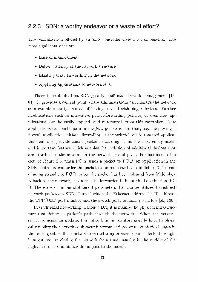
2.2.3 SDN: a worthy endeavor or a waste of effort?
The centralization o�ered by an SDN controller gives a lot of bene�ts. The
most signi�cant ones are:
• Ease of management
• Better visibility of the network structure
• Elastic packet forwarding in the network
• Applying applications to network level
There is no doubt that SDN greatly facilitates network management [42,
81]. It provides a central point where administrators can manage the network
as a complete entity, instead of having to deal with single devices. Further
modi�cations such as innovative packet-forwarding policies, or even new ap-
plications, can be easily applied, and automated, from this controller. New
applications can participate in the �ow generation so that, e.g., deploying a
�rewall application initiates �rewalling at the switch level Automated applica-
tions can also provide elastic packet forwarding. This is an extremely useful
and important feature which enables the inclusion of additional devices that
are attached to the network in the network packet path. For instance,in the
case of Figure 2.3, when PC A sends a packet to PC B, an application in the
SDN controller can order the packet to be redirected to Middlebox X, instead
of going straight to PC B. After the packet has been released from Middlebox
X back to the network, it can then be forwarded to its original destination, PC
B. There are a number of di�erent parameters that can be utilized to redirect
network packets in SDN. These include the Ethernet address,the IP address,
the TCP/UDP port number and the switch port, to name just a few [50, 106].
In traditional networking without SDN, it is mainly the physical infrastruc-
ture that de�nes a packet's path through the network. When the network
structure needs an update, the network administrators usually have to physi-
cally modify the network equipment interconnections, or make static changes in
the routing table. If the network restructuring process is particularly thorough,
it might require closing the network for a time (usually in the middle of the
night in order to minimize the impact to the users).
33
In SDN, the physical infrastructure of the network does not play such a
signi�cant role. Once the packet path is de�ned by SDN, only the necessary
network devices are included in the path. New devices can be added to the
network at any time, and once they are in place they can participate in the
packet processing by changing the way the �ows are generated. Added devices
can be tested beforehand with a small set of end devices, and the network
operation can be expanded step by step. This is an especially useful feature in
situations when a problem occurs, as most of the network is still using the old
packet path. So, if a modi�ed network encounters a problem, �ow generation
can be reverted back to the old functional path until the problem has been
solved, with as little disruption as possible to the network users. Most of these
tasks can be done during normal working hours, and at worst the network
modi�cation will just cut out the existing TCP connections.
Therefore the infrastructure in SDN can be considered to have a virtual
topology [126]. This, in turn, makes tracing network packets much more chal-
lenging than it is in traditional networks. The physical topology of the network
remains the same. Thus, debugging in operational networks might get very
complex. However, the situation in research and development networks is al-
most the opposite: SDN o�ers great debugging capabilities for development
purposes since the packets can be freely redirected in the network. This would
be risky in an operational network since the debugging redirections could create
huge problems which could have a devastating impact on vital network tra�c.
The importance of the virtual topology is even more marked when software
switches are added to the picture. A software switch, for instance OpenvSwitch
[110], is often deployed to a hypervisor in order for the VMs to have network
connectivity. When these switches are added to the SDN architecture, the
visibility of the SDN controller is extended to include the VMs. This is highly
bene�cial, especially in a Cloud environment. In such an environment, the
networks tend to be highly complex, but since the network is managed centrally
via an SDN controller, individual VMs can be identi�ed from the network.
Furthermore,VMs can provide a number of useful network functions, such as
a �rewall, Deep Packet Inspection (DPI) or a Dynamic Host Con�guration Pro-
tocol (DHCP) server, to name but a few. This concept is called Network Func-
tion Virtualization (NFV) [40]. Its purpose is to reduce costs by using Com-
34

mercial O�-the-Shelf (COTS) solutions, instead of using highly-customized,
dedicated devices to run the services in the network, which can be very ex-
pensive [13]. SDN and NFV together are a powerful combination, enabling
the possibility to run a great number of network functions in the servers and
provide such functions to the whole network automatically using SDN �ows.
Inevitably, automated network management has its downsides. One of the
greatest drawbacks to SDN is that unless the network is designed and built
carefully, it might end up having a single point of failure: the controller. An in-
accessible controller might cause very severe damage to the network, especially
if the switches have not been carefully con�gured to tolerate faulty situations.
Packets could easily be directed to the wrong parts of the network, and the
network could become unusable. Once it is accepted that the controller holds
the virtual topology of the network, then it is clear that if the controller goes
wrong, so will the network.
Another important issue with the SDN controller security is the trustworthi-
ness especially in regard to third party applications and in the control plane as
stated by Scott-Hayward, O'Callaghan and Sezer [150]. A compromised SDN
controller will place the network at the mercy of an attacker. Malicious appli-
cations may take over packet forwarding, or impair the network in some other
way. In this context, the control plane is very fragile as it o�ers a great place
for an attacker to cause harm for instance by modifying network con�gurations,
by causing denial-of-service (DoS) attack against the controller itself or sni�-
ing packets to steal information, to name just a few possibilities. The SDN
controller access control mechanisms are still weak and should receive more
attention from the research community [83, 125].
Missing security in access control is not the only problem SDN faces. In a
2013 workshop, Metzler [94] pointed out some politico-economic problems with
SDN. According to him, because consumers are not really aware of the poten-
tial bene�ts of SDN technology, businesses are not investing heavily enough in
SDN technology. This is re�ected in the lack of use cases and vendor strategies,
and the immaturity of many of the commercial products on o�er, as Metzler
also points out. Another problem is that vendors tend to sell old devices as
new innovation-enablers once the SDN logo has been printed on the packaging.
Metzler calls this �SDN-washing� and de�nes it as when: �a vendor re-labels
35

its legacy products and services with SDN-based vocabulary.� Despite these
problems, however, Metzler sees the future of SDN as bright, and thinks that
it o�ers the possibility to reduce provisioning work by 95 % compared to tra-
ditional networks.
SDN has many attractive features. It is easy to automate, easy to man-
age and it is cloud-ready. However, its greatest vulnerability lies in its greatest
strength. Centralized control means that it will always contain a possible single-
point-of-failure device, one that would also be extremely vulnerable to hostile
attack from an adversary. The security of the SDN controller cannot be em-
phasized enough: whoever controls the controller, controls the network. These
negative points could well be just the initial friction which accompanies the
commercial development of any new product on the market. It seems reason-
able to hope that they will disappear as SDN technology becomes more mature
and �nds its own niche in the �eld of modern networking.
2.3 VPN technologies
VPN in technology vise is aimed at securing connectivity for two or more net-
works, or computers, through an untrusted network such as the Internet. VPNs
are especially useful in cases where a lot of di�erent style network tra�c takes
place and the protocol used for communication does not, in itself, provide any
con�dentiality, integrity or authenticity. These are provided by the VPN solu-
tions since VPNs are in fact protocol suites that include for instance encryption
primitives as a part of the provided set of services.
Most common VPN technologies can be categorized into three di�erent
classes based on their implementation mechanism [122]:
1. PPTP
2. TLS
3. IPsec
The Point-to-Point Tunneling Protocol (PPTP) [56] is a rather old-fashioned
approach to VPN connection that, as Schneier [148] points out, is vulnerable
to relatively poor levels of security. It still has its uses, especially because of
36

its support for legacy devices, but it is not highly-recommended and is thus
omitted from further discussion in this thesis.
IPsec stands for Internet Protocol Security and is a complete suite consisting
of di�erent protocols for building secure communication channels. Even though
the RFCs for IPsec can be traced back to 1995, it is still very widely used and
is considered to be an e�cient method for building VPN connections [7, 8].
Transport Layer Security (TLS) protocol can also be used for creating VPN
connections [122]. In practice, TLS VPN is often con�ated with OpenVPN
[118], which is a very popular open-source VPN solution. Vendors such as
Barracuda [10] and Cisco [29] have their own commercially-available imple-
mentations for TLS-based VPN solutions. Some of these solutions might be
attached with Secure Sockets Layer (SSL) term instead of TLS. The reason
is that the SSL is the old version of the TLS protocol and therefore the SSL
term still exists as a colloquial name even though the SSL should not be used
anymore. Further, for instance in Cisco products, the VPN can even operate
using the Datagram Transport Layer Security (DTLS) protocol [22, 143, 144].
The DTLS is based on TLS, but uses the UDP protocol instead of the TCP.
This thesis mainly focuses on OpenVPN due to its wide variety of features and
its open-source implementation.
Although IPsec is very e�cient when connecting complete networks together,
the advantages of an OpenVPN are particularly apparent when connecting sin-
gle devices to a corporate internal network. Of course, both systems have their
own advantages, and there are cases where one technology has clear advantages
over the other.
Figure 2.6 depicts the two most common VPN setups: site-to-site [172],
which in this case is built using IPsec, and remote access [171], here built using
OpenVPN. In the diagram, the headquarters (HQ) network has a server, a
PC C, and a �rewall to host IPsec and OpenVPN tunnels. The Company o�ce
network contains two PCs: A and B, and a �rewall. The home network consists
of a laptop and a NAT-enabled �rewall.
Site-to-site means that there is a connection between the Company o�ce
and the HQ networks. IPsec would be the typical VPN technology for this
usage. It enables �uent communication between the networks. The PCs A,
B and C and the Server do not require any special client software since the
37

Home network
Company office Company headquarters network
Internet
PC A Server
Laptop
Firewall
IPsec tunnel
Firewall
FirewallOpenVPN tunnel
NAT
PC BPC C
Figure 2.6 An illustration of Site-to-Site and remote access VPN setups.
Firewalls handle all the required packet-encapsulation procedures.
The Laptop in the Home network is a good example of a remote access
setup. The connection to the HQ network is built through a Firewall with
NAT. The laptop has an OpenVPN client software and negotiates the tunnel
with the Firewall of the HQ network, which is running an OpenVPN server.
Therefore, at least the Server and PC C can communicate securely with the
laptop. The connectivity can be further extended with appropriate routing and
forwarding decisions taken in the Firewall in order to connect to the Company
o�ce devices as well. These two di�erent VPN technologies are explained in
more depth in the following sections.
Secure networking is a broad concept. Even though they are not pure VPN
solutions, it is worth pausing here to include MACsec [145] as it is a very
attractive and much-discussed technology. MACsec is a layer-2 protocol aimed
at providing con�dentiality and integrity in LAN networks, and as such it is not
directly usable over WAN networks. Nevertheless, it can be used with IPsec
or TLS VPN to achieve end-to-end security [73]. MACsec is mainly used in
point-to-point links between switches or from a switch to a host. It can prevent
both security threats like Man-in-the-Middle (MitM), and playback attacks,
[73] since any tra�c which fails the integrity check is dropped.
Three indispensable requirements in the VPN networking can be address.
38

First is con�dentiality that is achieved by using encryption. Second and third
are integrity and authenticity which both are provided by message authentica-
tion. Thus, before discussing IPsec and the OpenVPN in more detail, some of
the most common encryption algorithms and their operational modes need to
be explained.
2.3.1 Encryption algorithms and modes for IPsec andOpenVPN
Tra�c in VPN can be encrypted using several di�erent cipher suites. Even
though other ciphers surely can be used, the following list contains the most
common ones and their equivalent modes for VPN use. The list is gathered
from [161, 162] and from a Linux server running OpenVPN via the command
openvpn --show-ciphers.
• AES-CBC/CTR/CCM/GCM
• Blow�sh-CBC
• Camellia-CBC/CTR/CCM
• ChaCha20/Poly1305
The most popular of these is arguably the AES -suite, which was published
in 2001 by the NIST [139]. It uses three di�erent key sizes: 128, 192 and 256
bits. Strongswan IPsec [163] can use AES with multiple modes: Cipher Block
Chaining (CBC) [34, 51], Counter (CTR) [62], Counter with CBC-Message
Authentication Code (CCM) [63] and Galois Counter Mode (GCM) [35, 174].
OpenVPN, on the other hand, only supports the AES modes of CBC, Cipher
Feedback (CFB) [34], Output Feedback (OFB) [34] and GCM in version 2.4.5.
Another cipher is Blow�sh (1993), which uses variable key lengths between
40-448 bits with IPsec and OpenVPN as speci�ed in RFC2451 [130]. However,
the RFC has reported that weak keys have been detected for Blow�sh, raising
doubts about its security. Blow�sh does have a successor, Two�sh, but this can
be used with IKE version 1 only in the Strongswan suite [161].
Camellia, published in 2000, is regarded as being equivalently safe to the
AES suite, but it is not as popular [90]. It supports 128, 192 and 256 bit key
39

sizes and is integrated in OpenSSL 1.1.1c and OpenVPN 2.4.7. Camellia is also
supported for IPsec ESP packet encryption based on [75, 162].
All of the aforementioned suites work on the block cipher principle and uses
Hashed Message Authentication Code (HMAC) for authentication [84]. The
ChaCha20/Poly1305 is a stream cipher suite in which the Chacha20 handles
the encryption and the Poly1305, the authentication. Support for ChaCha20/
Poly1305 in IPsec is from 2015 and is speci�ed in [101]. It uses 256-bit keys
and is limited to IKEv2 in IPsec. The combination of ChaCha20/Poly1305 can
be found in OpenSSL 1.1.0, released in 2016. The OpenVPN also has support
for it from Version 2.5 onwards.
The AES, Blow�sh and Camellia suites have di�erent block cipher modes
that specify how the blocks are encrypted using the desired cipher method. The
mode a�ects the security level and performance of the speci�ed cryptographic
algorithm and each have their own pros and cons.
The Cipher Block Chaining (CBC) mode originated in 1976 and is the oldest
mode still in use [37]. It is known to have a number of vulnerabilities [129].
and is relatively slow in operation because it uses an initialization vector (IV)
value from the previous encrypted block for the next one, i.e its operation is
sequential. Its greatest advantage is its legacy �tness as the CBC mode has
been built into virtually every IPsec-supporting device in the past, which makes
it compatible with a lot of old devices.
The Cipher Feedback (CFB) mode is similar to CBC, but the plaintext is
added into an encrypted IV value using the XOR operation. The IV for the
next block is then fetched from this ciphertext. The Output Feedback (OFB)
mode is, in turn, very similar to the CFB mode. The only di�erence is that
the IV for the next block is fetched before the XOR operation of the plaintext
value and the encrypted IV [34].
Counter mode (CTR) uses a completely di�erent approach in which an IV
and a counter value are concatenated and encrypted. The XOR operation takes
place afterwards with the plaintext to generate the ciphertext. CTR mode is
signi�cantly faster than CBC because its operations can be parallelized, as
explained in [38].
CCM is a combination of the CTR mode with CBC-MAC (CBC-Message
Authentication Code (MAC)). It uses the output from the AES-CBC-MAC as
40

the MAC input for the CTR process as explained in [3]. Crypto++ benchmark
[30] found CCM to be slower than CBC.
GCM combines the CTR mode with Galois �eld multiplication. It is no-
table that GCM tends to use its own TAG value instead of HMAC for the
authentication code [35]. The basic operation of GCM relies on IV, which is
combined with a counter that increases along the blocks to be encrypted. An
XOR operation with encrypted value and plain text generates the ciphertext.
The GCM mode is gradually replacing many of the other modes. For instance,
Cisco recommends AES-GCM highly and predicts it will be valid until at least
2035 [26].
2.3.2 IPsec
IPsec is a protocol suite that provides a secure communication channel by
encrypting the desired tra�c. It is located in layer 3 of the Open Systems
Interconnection (OSI) model and thus can easily carry the upper level protocols
such as TCP and UDP through the Internet. As presented in Figure 2.6, it
is an e�cient method to securely connect networks together. The IPsec suite
has two major protocols to use: Internet Key Exchange (IKE) [76, 133] and
Encapsulation Secure Payload (ESP) [79].
IKE's purpose is to use public key cryptography to securely create keys for
the ESP protocol. The ESP protocol carries the real payload from the end de-
vices and encrypts the packets using symmetric cryptography. The symmetric
encryption is much faster than with a public key, and therefore it facilitates the
demanding ESP process.
IKE has two versions: IKEv1 [57] and IKEv2 [77]. IKEv2 has many advan-
tages over IKEv1. For example, it uses fewer messages, it simpli�es negotiation,
it decreases latency and it �xes weaknesses to name but a few [77]. So, only
IKEv2 is considered in this thesis.
The message sequence in Figure 2.7 describes how IPsec builds a tunnel. It
de�nes which processes handle which part of the tunneling when there have not
been any prior packets between the IPsec endpoints [11]. Signaling in Figure 2.7
illustrates the IPsec setup presented in Figure 2.6.
In this example, the PC in O�ce 1 needs to communicate with a Server in
41

Packet to Server (Plaintext)
PC
IKE SA INIT Request
Deliver CHILD SA info
IKEv2
Encrypted packet to Office 2
Response to PC (Plaintext)
ESP
Response to PC (Plaintext)
Server
Packet to Server (Plaintext)
Encrypted packet to Office 1
ESP
IKE SA INIT Response
IKEv2
IKE AUTH Request
IKE AUTH Response
Create CHILD SA Request
Create CHILD SA Response
Deliver CHILD SA info
Office 1 IPsec endpoint Office 2 IPsec endpoint
Figure 2.7 IPsec tunnel from zero to up with separate processes for IKE and ESPpackets [11].
O�ce 2. This initiates the IPsec tunnel negotiation between the IPsec endpoints
using the IKEv2 module. The IKE in O�ce 1 sends an SA initialization (INIT)
request message to the IPsec endpoint in O�ce 2. After a successful response,
this is followed by authentication (AUTH). Finally a CHILD SA setup take
place. This CHILD SA holds the information that the ESP process needs, so
it is delivered to the ESP process. Every IPsec endpoint actually holds two
separate Security Associations (SAs): one for the IKE and another for the ESP
(or IPsec as it is often called).
Finally, the ESP process encrypts the plaintext packet received from the PC
and delivers it to the IPsec endpoint in O�ce 2, where the packet is decrypted
and delivered to the Server. The Server responds to the PC and sends the
packet to the IPsec endpoint for encryption in the ESP process. This ESP
packet is sent to O�ce 1 IPsec endpoint for decryption and delivery to the PC.
In the example shown in Figure 2.7, all the ESP packets were encrypted. It
is also possible to use only authenticated messages by using an Authentication
Header (AH) and not to use encryption at all with the payload [78]. However,
because ESP provides authenticity as well, AH mode is regarded as a legacy
method since encryption is a must for a VPN.
IPsec has two di�erent communication modes at the network level: the
42

transport, and the tunnel mode [79]. The transport mode is mainly used for
two machines that require data encryption between them, using IPsec. Tunnel
mode, on the other hand, is for much broader use as it connects whole networks
together. Tunnel mode is also a valid method to connect networks that use a
private IP addressing range since the non-routable IP addresses are hidden in
the ESP packets and only the tunnel endpoint IP addresses are visible.
The example in Figure 2.6 uses tunnel mode since there is an external IPsec
endpoint that conducts cryptographic operations for the whole network. In
Transport mode the generated ESP packet retains the original IP addresses
and only the payload of the received IP datagram is encrypted.
Unfortunately, IPsec struggles with the NAT described in section 2.1. Since
the NAT modi�es the IP address header of the network packets, it breaks the
IPsec tunnels traveling through the NAT in several ways, as described in [2].
This is especially problematic in one speci�c use case: a remote access setup.
Connections are often made from a home network, or from public networks as
found in hotels, all of which use NAT. So, a connection is thus established
between e.g. an IPsec router with a public IP address and a laptop having
a private IP address. The IPsec tunnels are usually required to have static
endpoint IPs and in this case the client IP is being translated from a private to
a public one in the NAT. Therefore IPsec is not usable as is for this purpose.
The use of NAT Traversal (NAT-T) can help the situation by allowing IKE
operation through the NAT [82]. The ESP packets in tunnel mode should pass
the NAT (and �rewall) with small modi�cations including disabled address val-
idation as described in [2]. Still more workarounds like the UDP encapsulation
of IPsec ESP packets presented in [67] have been developed to counter the
problems of NAT.
Thus it is very tricky to build IPsec tunnels through NAT and one solution
described in RFC3715 well illustrates the problem width: It recommends to use
6to4 tunneling and to build IPsec on top of that tunnel, which is to say that it
tunnels the tunneling to achieve the desired tunneling.
These aforementioned problems in IPsec are probably one of the reasons
why the open source community started to work with a VPN solution called
OpenVPN. This technology uses a completely di�erent technical approach as
described in subsection 2.3.3.
43

2.3.3 OpenVPN
OpenVPN is commercial open source software for virtual private networking.
The initial release is from 2001 and it is heavily community-supported software
[118]. The OpenVPN software works on several platforms including Linux,
Windows and Android, and it has been included in �rewall/router distributions
such as pfSense [132], IPFire [71] and OpenWRT [123].
OpenVPN operates in layer 4 of OSI and therefore requires some extra work
to carry the TCP and UDP messages compared to IPsec. The principle is still
the same as in IPsec: a received plaintext network packet gets encrypted and
encapsulated in the carrier protocol, in this case UDP or TCP [140].
The use of UDP or TCP is in fact the key to successful operation through
the NAT, which is where IPsec struggles. From the NAT viewpoint, OpenVPN
tra�c is like any UDP- or TCP-related tra�c, such as browser tra�c. This is
the main reason why OpenVPN is so popular for remote access setups. [122]
OpenVPN is a valid technology for site-to-site setups as well [121]. An
especially handy feature is that it can create secure tunnels between routers
and the tunnel interfaces to have IP addresses. The bene�t of IPs is that they
can be used in routing decisions. This is not possible in the IPsec case since
IPsec does not have tunnel IPs.
Figure 2.8 shows the message exchange when a PC connects to an OpenVPN
server and sends messages with a Server in the company's internal network
[140]. The client starts by resetting the tunnel parameters to request a new
session from the OpenVPN server, and this is followed by an acknowledgement
(ACK) message. Next, a Transport Layer Security (TLS) handshake take place
with the required exchange of secrets. Finally the CONTROL message is sent
containing key lengths and any other possible options which the OpenVPN
server needs to inform the client about. Finally, the client sends an ACK
message to con�rm negotiation completion.
After the PC has negotiated the OpenVPN tunnel with the OpenVPN server,
the PC sends an encrypted packet to the Server in the company network. This
packet gets decrypted in the OpenVPN server and is delivered to the Server.
The response from the Server is sent to the OpenVPN server for encryption
and delivery to the PC, as shown in Figure 2.8.
44

Company networkInternet
Plaintext Packet to Server
PC
P_CONTROL_HARD_RESET_CLIENT
Encrypted packet to Server
Plaintext Response to PC
Server
Encrypted response to PC
P_CONTROL_HARD_RESET_SERVER
OpenVPN server
P_ACK
P_CONTROLTLS handshake, secret exchange
P_ACK
Figure 2.8 OpenVPN tunnel from zero to up [140].
As with IPsec, OpenVPN creates two SAs for a connection and uses TLS for
tunnel setup negotiation and, usually, a block cipher like AES for the real pay-
load delivery. OpenVPN supports several ciphers for tunnel negotiation since it
leverages TLS. It is possible to use various Digital Signature Algorithms (DSAs)
[45] including Digital Signature Standard (DSS) [45], Rivest�Shamir�Adleman
(RSA) [74] and Elliptic Curve Digital Signature Algorithm (ECDSA) [46]. Var-
ious versions of block ciphers like AES-CBC/GCM are also supported. The
newer versions of OpenVPN limit the use of cipher suites to enhance security
[117]. This might cause connection problems in older clients. This mainly con-
cerns platforms which do not receive frequent VPN client software updates,
such as Android.
2.3.4 Speed, security and high availability considerationsfor IPsec and OpenVPN
The cipher and its encryption mode strongly a�ect the performance of a VPN.
A number of groups have measured the throughput in open source IPsec so-
lutions. Libreswan is reported to have reached 5.25 Gbps throughput using
AES-GCM-128 and 1.39 Gbps using AES-128-CBC in [87]. In turn, [169] has
measured Strongswan as reaching 9.6 Gbps using AES-GCM in New Instruc-
tion (AES-NI) mode. The Wireguard project has measured the performance of
45

an unspeci�ed IPsec solution as reaching 881 Mbps with the AES-256-GCM-
128 cipher using AES-NI [176]. The choice of hardware has a signi�cant e�ect
and thus explains the wide range of di�erent results. In order to determine the
maximum throughput, it is even more important to see whether they were all
using GCM mode rather than CBC or some other mode. This clearly indicates
that the use of GCM mode is preferred to gain higher throughput for VPN
solutions.
OpenVPN is not regarded as the fastest VPN tunneling solution based on
benchmarks like [176] and [16]. The Wireguard project [176] has benchmarked
OpenVPN reaching 258 Mbps with their setup using some 256-bit AES cipher.
OpenVPN was also benchmarked by the BSD Router Project (BSDRP) [16].
They achieved 550 Mbps throughput using AES-GCM-128 mode in their test
setup.
OpenVPN has a number of known vulnerabilities as reported in, for instance,
[120] and [116]. Some of these vulnerabilities are not speci�c to OpenVPN but
a�ect a wide range of services through a common library like OpenSSL instead.
OpenVPN often utilizes OpenSSL as well, but alternative TLS libraries can be
used. Furthermore, OpenVPN is vulnerable to DoS attacks, as is almost any
public service.
The IPsec suite has been heavily criticized by Ferguson and Schneier [44] be-
cause of its very complex structure, which can even decrease the overall security.
There have been actual attacks against IPsec, as in Felsch et al. [43], for exam-
ple, who found that it is possible to break into the IKE protocol and achieve
authentication bypasses. In addition to these protocol weaknesses, software
projects providing IPsec suites often su�er from a number of vulnerabilities.
For instance, Strongswan has been reported as having remote denial of service
up to version 5.6.0 [102].
In addition to targeted attacks, devices running VPNs are also susceptible
to possible hardware or software failures, which can cause the service to be
temporarily unreachable. To mitigate these problems, a High Availability (HA)
[66] feature has been added to the picture. Its purpose is to run another instance
of the service on another device. Although HA does not guarantee 100% uptime,
it does guarantee 99.999% , which means that only minimal service breaks of
a few seconds need occur in an error situation [53]. HA can also be extended
46

to include load balancing [66]. The main di�erence here is that HA provides
a service to stay up even if some part of the infrastructure running the service
crashes. The load balancing ensures that the workload will be shared among
the available resources.
HA and load balancing are quite cumbersome in IPsec cases, as stated in
[100]. Document scopes the problem of an IPsec cluster o�ering both fea-
tures. First of all, the SAs of an IPsec should be synchronized between the
cluster nodes to ensure seamless operation. That is still only a minor prob-
lem compared to the di�culty of synchronizing the ESP packet SA counters.
These counters are incrementally numbered, making the packets unique and
thus adding an anti-replay feature to the protocol. However, their exact syn-
chronization requires a lot of overhead from the servers, even if it is possible at
all [100].
Instead of counter synchronization after every ESP packet, Nir [100] suggests
synchronizing the outbound SA counters after every 10,000 packets or so, and
learning the counter value from the packets going to the incoming SA counter.
So, the anti-replay feature makes load balancing cumbersome, or even impos-
sible. The other cluster members cannot process the packets �uently without
updated SA counter values. It is possible to disable the anti-replay feature as
permitted in [80] but this is very risky due to the security vulnerabilities that
this exposes.
While acknowledging that IPsec �ts poorly into an HA setup, the Strongswan
project has nevertheless looked at HA deployment in [164]. Their solution re-
lies on having one virtual IP throughout the cluster servers to run the IPsec.
A customized high-availability plug-in is used to to share state information
and the SA of IKE with the IPsec SAs throughout the cluster. The outgoing
ESP packets are kept on one node to enable sequential numbering. When this
node goes down, the number is lost and in the re-join phase new IPsec SA (or
CHILD_SA) re-keying takes place. The incoming SA counters on the clus-
ter nodes are updated from the incoming packets every now and then, which
provides adequate counter information and therefore the essential anti-replay
security feature [100].
The OpenVPN community edition presents a load balancing and failover
con�guration in [119]. The principle is to have multiple remote server ad-
47

dresses for the client con�guration, and the client picks one from the list to
connect to. However, this kind of approach is not regarded as true load balanc-
ing since the clients randomly pick a server without knowing its load status.
Such a mechanism creates an uneven distribution of clients to the pool of Open-
VPN servers. Furthermore, the server software is unaware of the other possible
servers in the cluster and thus cannot make client hand overs in order to share
the load equally. Although the failover feature is present, if a server goes down
the OpenVPN tunnel must be re-negotiated with some other server.
2.4 Time to make tasks faster: Hardwareacceleration
Hardware (HW) acceleration is a method to speed up the processing of any task
that would require a lot of computation from a typical Central Processing Unit
(CPU) in a workstation or a server. Such tasks can be o�oaded to a speci�c
processing unit, an accelerator, that has been specially developed for the given
task.
Hardware acceleration can take place in either a Graphics Processing Unit
(GPU), a special section in the CPU, a Field Programmable Gate Array (FPGA)
or in an Application-Speci�c Integrated Circuit (ASIC). Usually though, a GPU
or some instruction set in a CPU are used because they are relatively easy to
set up. Although the FPGA and ASIC solutions are very e�cient, they often
require a lot of work.
In fact, a GPU is a very good example of a HW accelerator, as its main
purpose is to help the PC's CPU generate an image on the screen. Image-
processing tasks are o�oaded from the CPU to the GPU. Additionally, the
GPU may aid the CPU with, for instance, video encoding/decoding tasks [4].
Task acceleration with a General Purpose GPU (GPGPU) [52] means that
the GPU is not just con�ned to video. For instance Nvidia has developed a
�parallel computing platform�, which is a Compute Uni�ed Device Architec-
ture (CUDA), that can run a vast number of computationally heavy processes
concurrently in their GPUs [104]. The CUDA can be used with machine learn-
ing, for example with the TensorFlow neural network [166] or with a network
48

Intrusion Detection System (IDS) [173].
Even though a CPU is generally regarded as a non-accelerated device, it
might have some special logic section that can be regarded as an accelerator.
The AES-NI presented in 2.3.4 is actually a HW accelerated version of the AES
suite, e.g. in Intel CPUs [69]. AES-NI was used in a case study by Intel and
was proved to have signi�cant performance gain as compared to traditional
AES usage [70]. The QuickAssist Technology (QAT) HW accelerator block
is another CPU-integrated HW accelerator. It was developed by Intel and
used, for instance, in their Xeon D-1600 series [149]. The QAT o�ers a set of
accelerators for [97] for cryptographic and data-compression operations. The
use of a CPU-integrated HW accelerator is ingenious since the CPU can o�oad
data to it whenever possible. The data stays inside the CPU, which not only
decreases the time spent on data transfer but also reduces the risk of data leaks
compared to an external HW accelerator.
FPGA is an integrated circuits device that holds a number of con�gurable
blocks and input/output (I/O) ports [159]. With these blocks and ports, it
is possible to con�gure the FPGA to work on a particular task, such as a
calculation. An FPGA runs on a relatively low clock frequency compared to a
PC, but its e�ciency stems from the highly parallel hardware operation of the
task [159].
The ASIC is another integrated circuit, although unlike an FPGA, it is
not recon�gurable. ASIC chips are built to perform their own function, and
nothing else. However, their performance is much better than an FPGA's and
they consume much less power [157]. Probably the best-known standalone
ASIC accelerators are the ones that have been created for Bitcoin mining [175].
A System on a Chip (SoC) is an ASIC design that holds a number of
smaller elements including processors, memory, and also sometimes accelera-
tors. Mathew et al. [89] has presented an AES HW accelerator called nanoAES
that is especially targeted for mobile SoC platforms with only 13 mW total
power consumption. The nanoAES is capable of AES-128 encryption of 432
Mbps. This kind of low-power solution is especially important in relation to
the Internet of Things (IoT), as IoT devices can vary greatly, from large, high-
performance devices to hand-held, ultra-low-power constrained devices.
In summary, there are several choices as to where to run accelerators. The
49
FPGA solution outdoes the GPU solution due to its combination of recon�g-
urability and performance [20]. A GPU su�ers from its static architecture, such
as the CPU, whereas an FPGA can freely be edited. On the other hand, build-
ing an accelerator for a GPU is a much simpler task than it is for an FPGA. An
FPGA solution requires a lot of extra work from the developer team [20]. The
drawback with ASICs is that they are extremely expensive unless the produc-
tion numbers are huge. For these reasons, the FPGA suits most purposes and
is an almost universal accelerator in that it can be freely con�gured to perform
almost any desired task. For instance, Salman, Rogawski and Kaps [147] have
used FPGAs for IPsec cryptographic operations and Sjovall et al. [158] for 4K
video encoding.
FPGA accelerators usually use either a Universal Serial Bus (USB), a PCI
express (PCIe) or the Ethernet network to transfer data from, e.g. a PC to
an FPGA. Neil and Liu [99] presented a neural network FPGA accelerator
and implemented it in a USB-attached FPGA development board. In contrast,
Sjovall et al. [158] used a PCIe interface in their video accelerator to insert
the FPGA accelerator into a rack-installable server. A much more ambitious
approach aimed at providing FPGA acceleration for a whole network in one
go was considered by Caul�eld et al. [19]. They installed FPGA accelerator
boards between the servers and switches in a Cloud platform. This provided
direct, dedicated, accelerators for every single bare-metal server in the cloud.
It seems that in the long run it is better to run accelerators directly in
the network. The SDN then becomes an e�cient method for redirecting the
network packets, as stated earlier in subsection 2.2.3. As an FPGA is a freely
con�gurable platform, Naous et al. [98] has implemented an OpenFlow switch
on one. Their solution is capable of line-rate switching and the writers found
their solution to be very feasible due to its relatively low area consumption of
34% in a netFPGA platform [98].
50

3 ANSWERS TO QUESTIONS:PUBLICATIONS GET TIED UP
This chapter will establish the links between the publications for this thesis.
Publication I and Publication II discuss the SME business and thus answer the
�rst research question, the approach to which is explained in section 3.1.
The second research question is more about enterprise VPN solutions, which
are discussed in section 3.2 and are based on Publication III and Publication V.
3.1 Resilient VPN connections with an IP zeroconfiguration
Using VPN to provide secure networking between company o�ces is now fairly
standard practice. Although Publication I might not appear to be directly re-
lated to VPN networking, the network structure for the experiments was part
of a much larger setup. Publication I presented the results of the detection of
network attacks on the home portion of this large network structure. Detection
was based on measuring the power consumption of the Wi� router. Two dif-
ferent kinds of attacks were performed against the network. The �rst of these
was a Wi� de-authentication attack against a Wi� based mesh network. The
second was a route injection attack against a Babel routing protocol that was
running on the routers. The results clearly showed that these attacks caused
medium to heavy loads on the wireless router and can be recognized using an
external sensor measuring the power consumption level of the wireless router.
Even though the scope of Publication I was limited to these power con-
sumption measurements, a comprehensive testbed network had to be set up to
obtain the results. After expanding the testbed to its full scale, it was then used
51
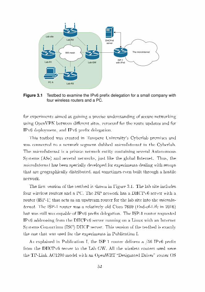
The microInternet
Lab-R2
Lab-R3
Lab-R1 Lab-GW
PC A
Lab site
Wifi mesh
ISP-1with IPv6
DHCPv6server
Figure 3.1 Testbed to examine the IPv6 prefix delegation for a small company withfour wireless routers and a PC.
for experiments aimed at gaining a precise understanding of secure networking
using OpenVPN between di�erent sites, zeroconf for the route updates and for
IPv6 deployment, and IPv6 pre�x delegation.
This testbed was created in Tampere University's Cyberlab premises and
was connected to a network segment dubbed microInternet in the Cyberlab.
The microInternet is a private network entity containing several Autonomous
Systems (ASs) and several networks, just like the global Internet. Thus, the
microInternet has been specially developed for experiments dealing with setups
that are geographically distributed, and sometimes even built through a hostile
network.
The �rst version of the testbed is shown in Figure 3.1. The lab site includes
four wireless routers and a PC. The ISP network has a DHCPv6 server with a
router (ISP-1) that acts as an upstream router for the lab site into the microIn-
ternet. The ISP-1 router was a relatively old Cisco 7600 (End-of-Life in 2016)
but was still was capable of IPv6 pre�x delegation. The ISP-1 router requested
IPv6 addressing from the DHCPv6 server running on a Linux with an Internet
Systems Consortium (ISC) DHCP server. This version of the testbed is exactly
the one that was used for the experiments in Publication I.
As explained in Publication I, the ISP-1 router delivers a /56 IPv6 pre�x
from the DHCPv6 server to the Lab-GW. All the wireless routers used were
the TP-Link AC1200 model with an OpenWRT �Designated Driver� router OS
52

distribution using Linux kernel 4.1.16.
Publication I required a Wi�, ad-hoc, mesh-based, IPv6-enabled routing
network that could be targeted using Wi�-based attacks. The project Homenet
which combined HNCP and Babel was chosen as the network. This package
provided a zeroconf approach for the wireless ad-hoc network and IPv4/IPv6
address distribution.
The testbed network operation relies heavily on the Homenet package. On
the WAN side, with the Homenet the upstream ISP connection is automatically
identi�ed as being on the Lab-GW router. DHCPv6-PD request messages are
exchanged with the ISP-1 to obtain the IPv6 pre�x. The Homenet distributes
the received pre�x throughout the testbed networks so that they all have an /64
IPv6 network. The Wi� routers joining the mesh network triggers the HNCP
protocol to act on the wireless interface of the router and exchange information
regarding addressing space for the newly-joined device. It is important to note
that with the Homenet package, none of the wireless routers in this setup had
static IP addresses assigned. Instead, all the addressing was negotiated by the
HNCP. The Babel routing protocol handled the proper routing information for
the network.
The combination of HNCP and Babel was extremely e�cient, only requiring
that the corresponding software packages be installed on the OpenWRT routers
and the interfaces be con�gured for the hnet protocol. Thus, the network
combination used in Publication I is a perfect solution for a single o�ce's need
for a wireless multi-router network that supports IPv4 and IPv6.
The next task was to extend this network over multiple sites. This exceeds
the scope of Publication I, so to better elaborate the possibilities, the testbed
was expanded as depicted in Figure 3.2. The Home site is completely identical
to the Lab site in terms of structure and the devices and software that were used.
The Lab-GW no longer receives IPv6 addressing or pre�xes from the upstream
router. Instead the Lab-GW and Home-GW only have IPv4 addressing in their
microInternet WAN links through ISP-2 and ISP-3. IPv6 ISP is transferred
to the host Master-GW router which becomes a new root router for the whole
site and is located in a Server room. The Master-GW does not have any other
devices in its LAN network. Thus the Server room site represents the case where
a single router device is operating in a Cloud with public IPv6 addressing and
53

The microInternet
Lab-GW
Lab-R3
Lab-R1 Lab-R2
PC A
Lab site
Wifi mesh
ISP-2
DHCPv6server
Home-GW
Home-R3
Home-R2Home-R1
PC B
Home site
Wifi mesh
ISP-3
ISP-1with IPv6
Master-GW
Public IPv4Public /58 IPv6 network
Server roomsite
OpenVPNtunnel
OpenVPNtunnel
OpenVPNtunnel
Figure 3.2 Two geographically separated Wifi mesh networks and a central gatewaythat redistributes IPv6 addressing through OpenVPN tunnels to Lab andHome sites.
IPv6 pre�x available.
The Lab and Home sites are connected to the Server room site and each
other using OpenVPN tunnels. The OpenVPN was con�gured to use virtual
routing (tun) interfaces on which the Homenet stack was enabled. The /56
IPv6 pre�x received by the Master-GW is shared among the networks in all the
sites through the OpenVPN tunnels. Experiments conducted in this network
revealed that the Homenet worked �awlessly through the tunneling and to
provide public IPv6 addressing from the Master-GW to both the Lab and Home
sites. The Babel routing protocol was able to manage this complex routing
scenario between the di�erent sites.
Naturally, in this scenario the IPv6 packets cannot be directly released from,
e.g. Lab-GW to the microInternet. The packets need to be delivered through an
OpenVPN tunnel to the Master-GW, which is responsible for the IPv6 network
for the all sites. The relatively small overhead and increase in latency for the
IPv6 packets can be recognized since the packets from the Lab and Home sites
must always be routed through the Master-GW.
The complete network described in Publication I is especially targeted at
54

constrained devices such as smart consumer devices, sensors or practically any
IoT device that needs global IP addressing. These devices often tend to be new
enough to have IPv6 support in their software. The network presented in Fig-
ure 3.2 is e�cient for this purpose but also proved to work during experiments
for regular small o�ce / home o�ce tra�c. No performance measurements
were conducted since the target was not to �nd a high performance and low
latency solution, but instead to develop a highly practical setup that requires
minimal e�ort from an administrative point of view.
Because the �rst network did not always answer the need for a tunneling
solution over the WAN, Publication II proposes a completely di�erent tunneling
option that utilizes a layer 2 overlay. The publication speci�es three di�erent
use cases that might require this kind of L2 connectivity: a LAN-connected
water pump, a traveling salesman and an ambulance. There are many other
cases in which the L2 WAN overlay may be useful, such as for Industrial Control
System (ICS) networks where it is mandatory for some devices to be located
in the same LAN. A uniform LAN for these kind of ICS devices, i.e. those that
are geographically distributed, can be built using the L2 overlay solution. As
the current trend is to push services into a Cloud, many existing critical ICS
devices might suddenly need a seamless connection to the Cloud as well. In such
cases, changes to the network are inevitable. However, changing the structure
of an ICS network might be very cumbersome, costly and even dangerous for
the process the ICS devices are responsible for. The VPN setup presented in
Publication I is not viable for these use cases since it is based on routing, but
the overlay VPN setup presented in Publication II is �t for such a purpose.
Publication II de�nes a layer 2 WAN overlay solution that is resilient and
can cope with several of the problems that may occur in any best-e�ort ISP
connections, such as link loss, NAT and ISP outage. In essence, the entire solu-
tion consists of the overlay solution itself, securing it, and creating a redundant
loop-free datapath.
Once it was clear that an L2 overlay networking solution was required, the
following technologies, as explained in Publication II, were considered.
• Transparent Interconnection of Lots of Links (Trill)
• Virtual eXtensible LAN (VXLAN)
• Generic Network Virtualization Encapsulation (Geneve)
55

• Overlay Transport Virtualization (OTV)
• Network Virtualization using Generic Routing Encapsulation (NVGRE)
In the end, the VXLAN was selected due to its maturity and good support
in virtual Open vSwitch. VXLAN works by encapsulating an L2 frame in an
L4 UDP frame. It is perfectly feasible to carry such a frame over a WAN link
and easy to use with secure tunneling mechanism.
In Publication II, OpenVPN, IPsec and Datagram Transport Layer Security
(DTLS) were brie�y discussed as candidates for the secure tunneling mecha-
nism. The DTLS and IPsec are more lightweight solutions than OpenVPN,
but they su�er from the NAT incompatibility problem. As the connections
are designed to work through any best-e�ort ISP, it soon became clear that
OpenVPN was the only feasible choice, and thus it was selected.
In a complex network with an arbitrary topology SDN is a key technology
for enabling comprehensive packet forwarding control. The topology in our
overlay network is expected to have multiple loops caused by the redundant
paths between sites. Therefore, our proposal utilizes OVS for the datapath
because it has good support in both SDN and many other platforms. The
packet forwarding in all OVS switches is controlled by an SDN controller, in
this case, Floodlight. The SDN controller has perfect visibility over the whole
network and thus can e�ectively forward network packets between di�erent
sites.
Figure 3.3 shows the proposed datapath in Publication II between three dif-
ferent locations. Two of those are Cloud platforms, Hypervisor-1 and Hypervi-
sor-2, running VMs. The LAN (192.168.xx.x/24) network depicts the company
network that has two gateways (GW-1, GW-2) to the Internet both using two
separate ISPs: ISP1 and ISP2. The Wireless WAN (WWAN) connections be-
tween the GWs and the ISPs are established using 4G cellular modems. The
gateways are the same TP-Link devices with OpenWRT that were used for the
experiments in Publication I.
Both gateways establish one OpenVPN tunnel to each Cloud using di�er-
ent ISPs. The tunnels bind to the correct WWAN interface using a more
speci�c route and are terminated to tun interfaces which have routable IP ad-
dresses. The VXLAN connections are in turn built between the OVS bridges
(br0,CustBr0) with the tun interface endpoint IPs, as can be seen in Figure 3.3.
56
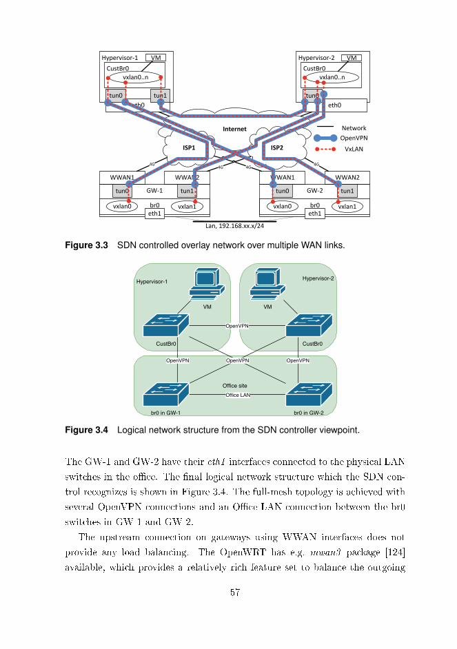
Internet
Hypervisor-1
CustBr0
vxlan0..n
eth0
tun1
VM
tun0
Hypervisor-2
CustBr0
vxlan0..n
eth0
tun0
VM
ISP1 ISP2
GW-1
br0eth1
vxlan0 vxlan1
WWAN2WWAN1
tun1tun0 GW-2
br0eth1
vxlan0 vxlan1
WWAN2WWAN1
tun1tun0
Lan, 192.168.xx.x/24
4G 4G
4G 4G
OpenVPN
VxLAN
Network
Figure 3.3 SDN controlled overlay network over multiple WAN links.
Office site
Hypervisor-2 Hypervisor-1
CustBr0
VM
OpenVPN
OpenVPN
CustBr0
VM
OpenVPN
Office LAN
br0 in GW-1
OpenVPN
br0 in GW-2
Figure 3.4 Logical network structure from the SDN controller viewpoint.
The GW-1 and GW-2 have their eth1 interfaces connected to the physical LAN
switches in the o�ce. The �nal logical network structure which the SDN con-
trol recognizes is shown in Figure 3.4. The full-mesh topology is achieved with
several OpenVPN connections and an O�ce LAN connection between the br0
switches in GW-1 and GW-2.
The upstream connection on gateways using WWAN interfaces does not
provide any load balancing. The OpenWRT has e.g. mwan3 package [124]
available, which provides a relatively rich feature set to balance the outgoing
57

packets over several WAN interfaces simultaneously. However, our proposal did
not use that but instead relied solely on the route metric value. The WWAN2
interface has a higher metric for the default route and thus it is not used actively.
When WWAN1 connectivity drops, the route with the higher metric is taken
into use.
The resiliency of this network was veri�ed by conducting a set of ISP connec-
tion breaks and glitches for the VPN tunnel. The L2 overlay network could not
recover by itself as desired in the �rst case. The OVS seemed to lack the link
status information for the VXLAN interfaces, as is described in Publication II.
The problem was especially noticeable because of missing PORT_DOWN mes-
sages in the OVS. The Port Down Reconciliation (PDR) module in Floodlight
should be aware of any network changes but it malfunctioned with the VXLAN
interfaces in the OVS.
The solution was to build a customized watchdog script as described in
Publication II. This script watches the tunnel endpoint IPs every two seconds
using ICMP Echo messages [135]. Once a faulty connection between OVS
switches is recognized, its VXLAN interface gets removed from the OVS and
the related �ows are �ushed away. After the tunnel has been re-negotiated,
the corresponding VXLAN interfaces are added to the OVS once again. The
Floodlight controller responds rapidly to the interface removal as expected.
With the given script, re-convergence time for the network turned out to be
between 4-6 seconds. The time is not as good as it could be, still we have to
remember that this kind of re-convergence is required only when a large scale
error, such as router or ISP breakdown, occurs. Therefore the error occurrence
probability is relatively low making the 4-6 seconds tolerable re-convergence
time.
During the experiments it was noticed that somehow the network packets
with a near-MTU value did not pass through the tunnel. The reason was that
OpenVPN was incapable of dealing with the 36 B overhead caused by the extra
IP+UDP+VXLAN headers. This was solved by setting the OpenVPN tunnel
MTU to 2000 B. The OpenVPN copes well with the fragmentation of network
packets exceeding the underlying network MTU of 1500 B.
The control plane has several problems in the presented setup. First of all,
stunnel [165] had to be used to achieve secure connectivity between the OVS
58

switches and the SDN controller. Incoming connections from the switch to
the controller are caught by the stunnel server and redirected unencrypted to
the SDN controller. The SDN controller, Floodlight, includes TLS support as
stated in [112], but at the time of writing Publication II, the documentation
lacked a clear approach to mutual TLS con�guration, which was the reason for
using stunnel.
The second problem lies with the connection between the OVS and the
controller itself through the stunnel since the connection is established between
the OVS and the Floodlight controller using best-e�ort ISP without any active
redundancy. In the IP level, all the OVS switches use TLS to connect to a
public IP address of a VM running a Floodlight daemon that is hosted in a
Cloud (e.g. Hypervisor-1). Link-loss occurring on an active WAN link causes
the OVS switch to lose connectivity with the controller. The connection is cut
after the TCP timeout and another is established through the active secondary
ISP. A faster control-plane link renegotiation process can be implemented to the
developed watchdog script to speed up the process. Furthermore, the lost WAN
link will be reconnected at some point and then the egress packets will again
choose the WAN link that has the smaller route metric value. If the stunnel
packets are then changed to use the newly repaired WAN link, the OVS loses
connectivity to the Floodlight again since the source IP changes. Therefore,
the developed watchdog script should include a comprehensive and exact route
table update mechanism for stunnel in order to use the existing path to the
Floodlight controller. Added static routing ensures that the stunnel will use a
functional ISP connection and thus prevents unnecessary link changes for the
existing connection.
The third, and �nal, problem in the control plane is the single instance of
the SDN controller. This produces a single-point-of-failure that could have dev-
astating results for the whole network being out-of-order when the controller
is lost. Therefore, having a redundant controller pair in a Cloud would greatly
enhance the reliability of the network. As stated in Publication II, the Flood-
light controller did not have high availability support at the time of writing. As
the controller side was not the main goal of the work for that publication, the
SDN controller was not changed, although this missing feature in Floodlight
is reported. Notable is that in some other SDN controllers, like Faucet, high
59

availability support is available [41].
The complete protocol structure for this network is quite complex. The
routed OpenVPN solution presented earlier with Publication I is much more
lightweight since only OpenVPN is used. As explained in Publication II, us-
ing IPsec or DTLS instead of OpenVPN would reduce the protocol overhead.
In fact, using technology like MACsec to carry the VXLAN, as was brie�y
discussed in Publication II, would reduce the overhead even more.
In summary: Publication I presented a routed VPN setup with zeroconf
routing and IP deployment, while Publication II focused on VPN resiliency be-
tween multiple sites. The approaches ranged from a routed scenario to layer 2
overlay technology. Both have their use cases, which can vary from an IoT net-
work to an ICS network, and even to a regular SME company network. The L2
overlay in Publication II bene�ts from the addressing approach of Publication I
. The zeroconf, which enables automatic IPv6 networking, would facilitate a
combination of these two approaches. Whereas the L2 overlay using VXLAN,
SDN and OpenVPN provides the same LAN over multiple sites for devices that
are sensitive to the network structure, the Homenet package provides zeroconf
addressing and routing for the rest of the network, including the L2 overlay
network.
3.2 Tunneling enhancements for large enterpriseVPNs
Publication I and Publication II were largely targeted at examining network so-
lutions for small and medium-sized companies, (SMEs). Large companies tend
to go for more mature and reliable solutions for their VPN connections, such as
IPsec rather than OpenVPN. As the elastic SDN �ow creation in Publication II
turned out to be very e�cient, even though it only utilized a fraction of the
SDN capabilities, What might be achieved if SDN were to be used with IPsec?
So, the next step was to examine IPsec and SDN together to better under-
stand the possibilities of such a combination. It soon became clear that the IKE
and ESP process separation looked like a promising enhancement for IPsec, as
was explained in Publication III. The IPsec process could be made faster using
60
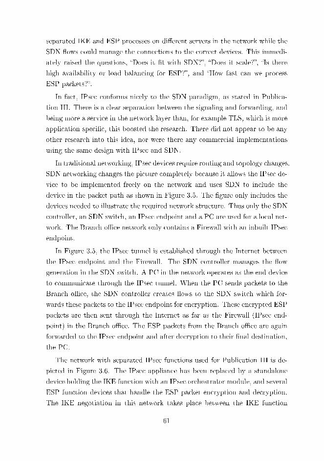
separated IKE and ESP processes on di�erent servers in the network while the
SDN �ows could manage the connections to the correct devices. This immedi-
ately raised the questions, �Does it �t with SDN?�, �Does it scale?�, �Is there
high availability or load balancing for ESP?�, and �How fast can we process
ESP packets?�.
In fact, IPsec conforms nicely to the SDN paradigm, as stated in Publica-
tion III. There is a clear separation between the signaling and forwarding, and
being more a service in the network layer than, for example TLS, which is more
application speci�c, this boosted the research. There did not appear to be any
other research into this idea, nor were there any commercial implementations
using the same design with IPsec and SDN.
In traditional networking, IPsec devices require routing and topology changes.
SDN networking changes the picture completely because it allows the IPsec de-
vice to be implemented freely on the network and uses SDN to include the
device in the packet path as shown in Figure 3.5. The �gure only includes the
devices needed to illustrate the required network structure. Thus only the SDN
controller, an SDN switch, an IPsec endpoint and a PC are used for a local net-
work. The Branch o�ce network only contains a Firewall with an inbuilt IPsec
endpoint.
In Figure 3.5, the IPsec tunnel is established through the Internet between
the IPsec endpoint and the Firewall. The SDN controller manages the �ow
generation in the SDN switch. A PC in the network operates as the end device
to communicate through the IPsec tunnel. When the PC sends packets to the
Branch o�ce, the SDN controller creates �ows to the SDN switch which for-
wards these packets to the IPsec endpoint for encryption. These encrypted ESP
packets are then sent through the Internet as far as the Firewall (IPsec end-
point) in the Branch o�ce. The ESP packets from the Branch o�ce are again
forwarded to the IPsec endpoint and after decryption to their �nal destination,
the PC.
The network with separated IPsec functions used for Publication III is de-
picted in Figure 3.6. The IPsec appliance has been replaced by a standalone
device holding the IKE function with an IPsec orchestrator module, and several
ESP function devices that handle the ESP packet encryption and decryption.
The IKE negotiation in this network takes place between the IKE function
61

Internet
SDN SwitchPC
IPsec Endpoint
Branch office
SDN Controller
Firewall,IPsec endpoint
ESP Traffic
Unencrypted traffic
IKE negotiation
Figure 3.5 Traditional placement for IPsec appliance in SDN network.
Internet
SDN SwitchPCs
ESP function
Branch office
SDN Controller
Firewall,IPsec appliance
ESP function
IKE function andIPsec orchestrator
ESP Traffic
Unencrypted traffic
IKE negotiation
Figure 3.6 IPsec with distributed IKE module and two ESP functions for ESP packetprocessing in an SDN network.
server and the Branch o�ce Firewall.
The IPsec orchestrator plays a major role in this setup. First, the orches-
trator orders SDN �ow creation for the UDP port 500 tra�c to reach the IKE
function. Second, the orchestrator needs to deliver the negotiated IKE CHILD
SA values to the ESP device(s). Third, all the ESP tra�c has to be forwarded
to ESP devices. Fourth, the orchestrator must handle a re-keying process when
required. The CHILD SA value is considered extremely sensitive information
and for this reason the orchestrator is placed on the same server as the one
on which the IKE daemon is running. To be more precise, the orchestrator
only needs to know the lifetime of an IPsec CHILD SA. Therefore all the other
62

information, except the lifetime, can be delivered from the IKE daemon up to
the ESP devices in encrypted form. Whether the SA information is encrypted
or not, the packet transmission between the ESP devices and the orchestrator
should take place on a closed network using TLS authentication and encryption
to prevent any possible information leaks.
The network is ready for real packet transmission after the IKE negotiation,
the delivery of the CHILD SA value and the SDN �ow generation is complete.
When the PC sends a network packet heading for the Branch o�ce network,
the SDN controller creates �ows to the network based on the IPsec orchestrator
instructions to include one of the ESP devices in the packet path. The encrypted
packet is forwarded to the Internet towards the Branch o�ce. Returning packets
from the branch o�ce are redirected to the ESP devices for decryption and then
back to its �nal destination.
Given the IPsec SDN network structure presented in Publication III, the
implementation is next discussed based on the original combination of devices
and software listed below that was planned to be used for the experiments in
Publication III.
• HP 5900 series SDN switch
• Floodlight SDN controller [48]
• Strongswan for IKE daemon [163]
• DPDK IPsec-secgw as ESP process [32]
• DPDK process virtualized in NFV style
• Open vSwitch for NFV instances [110]
The HP 5900 switch was used as an SDN switch for the experiments because
of its OpenFlow support. Floodlight turned out to be an extremely unviable
controller for the HP 5900 and HP 3800 switches with which the CyberLab was
equipped. Floodlight was unable to write even simple �ows to the switch �ow
table. The reason for this was that Floodlight was trying to use wrong �ow
table ID. As the main objective in Publication III only required the basic SDN
function of redirecting network packets with �ows, the HP VAN SDN controller
that supported HP switches was selected, instead of Floodlight.
63

The Strongswan IPsec daemon was used for the IKE negotiations. The
security parameters for the CHILD SA can easily be extracted from the IKE
and delivered for the orchestrators as described in Publication III.
ESP functionality was designed to work on the Intel Data Path Development
Kit (DPDK) IPsec-secgw [32] application in a virtualization platform. This way,
more ESP processes could be launched on-demand in an NFV style. However,
a search of the DPDK documentation revealed that it would not work. The
DPDK relies on o�oading the IP header checksum generation from the software
application to the network interface card (NIC). DPDK does not support this
feature for any virtual NIC as speci�ed in [32]. For this reason the IPsec-secgw
was moved to operate on a physical Intel Atom C2000-based platform.
Two of these Atom platforms using IPsec-secgw were attached to the net-
work. The results listed in Publication III are clear: adding more ESP devices
to the network really does speed up the total packet processing. Network tra�c
that needs to be encrypted can be redirected as wished to the ESP device with
smallest load. If an ESP device crashes, it can be just dropped from the pool of
available devices until it has recovered. The experiments also showed the gen-
erally acknowledged fact that the AES-GCM mode outperforms the AES-CBC
mode. In the experiments, the AES-GCM used the Intel IPsec crypto software
library that optimizes the CPU AES routines [54]. The raw 64-byte packet
transfer rate for this setup with single ESP function and one PC is 600 Mbps,
rising to 1300 using two ESP functions and two PCs. Even though the perfor-
mance numbers were relatively good for such poor hardware, that comes at a
cost: we encountered several obstacles which made the parallel ESP processing
device architecture unsuitable for use in a real network.
The load balancing turned out to be too complicated and cumbersome for
a single IPsec tunnel. As explained in Publication III, the proposed structure
provides HA, but not full load balancing. The load balancing is path-based,
i.e. it relies on IP addresses. Therefore, network packets from one PC cannot
be shared between multiple ESP processes in, for example, a round-robin style.
Another solution such as combining multiple ESP devices using link aggregation
was required.
Path-based load balancing also poses problems for the incoming connections.
A single tunnel is always redirected to the same ESP device since the tunnel
64

endpoints are constant. Equal-Cost Multi-Path (ECMP) with SDN can change
this since it uses the least congested available port. Multiple IPsec tunnels, each
with their own source and destination IP addressing can of course be shared
among multiple ESP devices. Free IPsec tunnel distribution from IP addresses
could be done using the Security Parameter Index (SPI) value, but at the time
of writing, the Open�ow still does not have this feature. Heydari Fami Tafreshi
et al. [60] also pointed out the importance of this feature for Open�ow SDN.
The load balancing also caused problems for the replay-attack protection.
Every ESP device has its own sequence number counter for network packets.
Thus, the receiving end of a tunnel will receive duplicated sequence numbers
when parallel ESP devices are used. The packets with duplicated numbers will
be regarded as replayed, and therefore are discarded. The sequence numbering
could be �xed by synchronizing the packet counters on all the ESP devices that
work in parallel. However, as is also stated in Publication III, this is not a feasi-
ble solution because the ESP operation is often very dense and synchronization
would signi�cantly slow the process down. The replay-attack protection can
still be disabled, but this is de�nitely not recommended [80].
So, if this kind of networking architecture with separated IKE and ESP
functions is to be used, some other workaround is needed to balance the load
of the incoming packets.
To be more precise, the problem is not just the load balancing. What is
needed is a platform which can meet the rigorous performance requirements
for the IPsec ESP. Furthermore, high availability is more important than load
balancing. Without active load balancing, the platform could still provide the
necessary replay-attack protection.
The �nal conclusion to be drawn from the work in Publication III is that
the network structure and separated IPsec IKE and ESP processes were unique
and novel at the time of writing Publication III. The architecture used does
have a number of bene�ts: the management of the IPsec tunnels is in a single
point, the pool of ESP devices o�ers passive redundancy, and SDN removes the
need for network layer modi�cations when an IPsec device is attached to the
network.
Regarding the original question presented at the beginning of section 3.2 as
to whether IPsec and SDN can work together, there are a number of positive
65

Internet
Network Director server
FPGA
Data plane
Control plane
Enddevices
SDN Switch
Switch
Router / Firewall
Figure 3.7 Complete network architecture for FPGA accelerated IPsec with FPGAfor ESP processing and Network Director server for IKE.
points. IPsec �ts nicely into the SDN paradigm and it can be scaled by adding
more ESP devices. There is some degree of high availability, but this is achieved
without load balancing. However, the performance numbers with the test setup
were not su�cient. As a point of comparison, the Libreswan IPsec project
measured 5.25 Gbps ESP packet throughput on AES-GCM [87]. Still, a more
important objective in Publication III was to carefully examine and verify the
SDN network structure and any possible HA and load balancing features rather
than to develop a high-speed implementation.
In the �related work� section of Publication III, the performance numbers,
especially those with a dedicated IPsec accelerator device, were signi�cantly
higher than they were for the presented design. In fact, there has been a con-
siderable amount of research into using IPsec on an FPGA. Still, as the �related
work� section in Publication V indicates, the approaches in these studies vary,
but they often do not consider production readiness and complete system mod-
els. Therefore, Publication V is particularly aimed at �nding the answers to
such points. The target, which was successfully achieved, was to replace the
software solution presented in Publication III with an FPGA ESP accelerator
device to host 1000 concurrent tunnels providing 10 Gbps throughput with only
10 µs latency.
So, Publication V utilizes the network structure presented in Publication III.
and investigates the feasibility of an FPGA-based, dedicated IPsec processing
device for ESP packets. The solution relies on a separate software-based IKE
solution as in Publication III, thus saving a valuable FPGA area for ESP pro-
cessing. The main di�erence is the use of the FPGA instead of the software
66

IPsec ESP function. The architecture is shown in Figure 3.7. It contains end
devices, such as PCs, whose network connectivity is through SDN switches and
a Router/Firewall to the Internet. The SDN switch is managed by an SDN
controller in the Network Director server which also hosts the IKE service. All
tra�c between the Network Director server, the FPGA and the SDN switch
takes place on a Control plane network that uses traditional switches. Precisely
the same network packet forwarding occurs in Figure 3.7 as it did for the net-
work presented in Publication III and the end device tra�c which requires ESP
processing is forwarded to the FPGA using SDN �ows.
Figure 3.8 presents the FPGA architecture proposed for Publication V. This
has three main parts: a Control plane, a Data plane and IPsec Accelerator logic.
The purpose of the Control plane is to have a dedicated interface for updating
the Security Association Database (SAD) in the IPsec Accelerator. The Control
plane has an Ethernet interface and a User logic control block containing the
TCP/IP stack with TLS support. It is implemented on a soft core processor.
The ESP tra�c takes place in the Data plane. The Data plane has a Fiber
optics module that physically connects it to the network. The Packet client is a
protocol parser which processes the Ethernet headers and pushes the Ethernet
payload to the IPsec Manager in the IPsec Accelerator Logic. The IPsec man-
ager chooses which Encryption or Decryption block to use. Every block has
its own AES-GCM + AES block which encrypts or decrypts the given data.
furthermore, the Encryption and Decryption blocks read and write data to the
IPsec Enc & Dec SADs that store all the information needed for an IPsec tun-
nel. Even though Figure 3.8 only shows two Encryption and Decryption blocks,
there can be more parallel blocks as long as they �t to the FPGA.
Replacing the software ESP device used in Publication III with the FPGA
presented in Publication V might seem straightforward. Nevertheless, build-
ing such an accelerator needs a lot of attention to detail in order to produce
a properly working solution where all the di�erent parts including the FPGA,
SDN controller and the IKE daemon cooperate properly. Therefore, the fea-
sibility for, and details of, an FPGA based IPsec accelerator as presented in
Publication V are explained below.
At the network architecture level, some modi�cations are �rst required to
�t the FPGA into the network. Publication V describes these modi�cations in
67

Data plane
Control plane
Ethernet
Fiber optics
SDN / User logic control
Packet client
IPsec Accelerator logic
Encrypt #1
IPsec Manager
AES-GCM + AES
IPsec Enc & Dec
SADs
Decrypt #1
AES-GCM + AES
AES-GCM + AES
AES-GCM + AES
Encrypt #2
Decrypt #2
Figure 3.8 Architecture of the proposed IPsec FPGA implementation.
Sections 4.2 and 4.3 therein. The proposal in Publication V did not contain
an Address Resolution Protocol (ARP) or a MAC address in the FPGA. This
was because the ARP implementation would require more logic and area on
the FPGA and it was desirable to reserve area as much as possible for the ESP
processing. Therefore the FPGA does not modify the original source MAC
address �eld, and the SDN switch learns a load of MAC addresses behind the
FPGA switch, even though they are not there. Our suggestion is to disable the
MAC address learning feature in the SDN switch port to which the FPGA is
connected. This way the network packets can freely be forwarded to the FPGA
using SDN �ows.
On the other hand, without the ARP implementation the FPGA may en-
counter problems since it cannot identify the destination device's MAC address
once ESP packet decryption has taken place, as described in Publication V.
The solution is to have a Lookup table (LUT) on the FPGA to store the MAC
and IP address pairs so that the correct MAC address can be written for the
leaving packets. Having a LUT for /16 network with approximately 65,000 IP
addresses would require 400 kB of memory, which can be done with the FPGA
on-chip memory. The on-chip memory is crucial since it can be read in every
clock cycle, thus signi�cantly reducing the latency for any outgoing packets.
Another way to tackle the destination MAC address problem is to rewrite the
false addresses using proper SDN �ows in the SDN switch.
Both of the above solutions are more e�cient than having an ARP imple-
mentation on the FPGA. The reason is the long and unpredictable ARP request
time, and the consequent need for packet bu�ering while waiting for someone in
68
the network to respond to an ARP request. The platform must operate �uently
even when it has to deal with data with a line-rate speed and the destination
MAC address is missing. We estimate that e.g. an ARP request which takes 2
seconds will need a bu�er of 2 Gb if the line-rate is only 1 Gbps. Therefore,
the bu�ering can not be scaled to an FPGA with limited memory.
Publication II described the fragmentation issues at the network level. Frag-
mentation also occurs in this scenario for network packets of 1445 B or more
due to the ESP overhead. Thus, the FPGA-based ESP device needs to han-
dle proper fragmentation for MTU-sized network packets on encryption. Our
suggestion is that when the local network MTU is set to 1500 B, any pack-
ets requiring fragmentation should be split in two. It would be su�cient to
have a �rst packet containing 1024 B and then another packet with the rest of
the data bytes. On the receiving side, packet reassembly would only require
500 Mb memory for 41k packets with a size of 1500 B. DDR RAM from the
FPGA is to be used because it has a large capacity and its operation is non
time-critical. The ring bu�er method would be useful since it automatically
overwrites any possible missing fragments. Packets with missing fragments can
be discarded, even though no retransmission is provided by the ESP. The upper
level protocols should be able to �x this problem.
The anti-replay feature is a must for IPsec and thus a desirable feature for
an FPGA-based ESP device. An anti-replay algorithm like the one presented
in [180] can be used. Publication V discusses this topic in Section 4.5 and
presents a simple anti-replay mechanism. The FPGA has to store the sequence
numbers for already-seen packets within a sliding window time frame. The
sliding window mechanism reduces the need for memory to store the sequence
numbers. An e�cient window size is as low as 1024, which would only require
10 bits of memory. It should be noted that in [174] for instance, a window size
of only 64 is recommended. However, this is too small for high speed operation
so a larger value should be used, as stated in [25].
The sequence number synchronization problem described in [79] is also ad-
dressed in Publication V. When large packet loss occurs, the sequence number
counter can get out of sync with the tunnel endpoints. Building a mechanism
directly onto an FPGA to detect this kind of desynchronization would require
more area and would be quite complicated. Whenever such a large packet loss
69

occurs, the ESP process is halted anyway. The time consumed in the IKE
re-negotiation process is a fraction of the total service timeout, so the most
cost-e�ective solution would be to request re-negotiation from the IKE.
In normal operation, the IKE daemon needs to establish a CHILD SA and
deliver the keys to the FPGA prior to the start of the packet transfer in the data
plane. In a re-negotiation phase the CHILD SA information must be delivered
to the decryption SAD �rst, before changing the encryption SAD parameters.
This ensures the receiving end will be ready when new keys are applied to the
encryption SAD and taken into use.
Indeed, the CHILD SA negotiation is non time-critical and thus can be done
using software in a server. Another such process is the initialization vector (IV)
generation. Generating random numbers on an FPGA is quite cumbersome due
to the lack of an entropy source. For these reasons, IV generation is extremely
feasible in the Network Director server using, say, OpenSSL.
The SAD in the FPGA stores all the sensitive information for ESP process.
Our calculations in Publication V show that only 69 kB of memory is required
for the encryption SAD and 109 kB for the decryption SAD in order to host
1000 concurrent IPsec tunnels. The decryption SAD is much larger than the
encryption SAD since it stores duplicate information for every SA. This ensures
that in the re-key phase it is possible to store the newly negotiated key to the
SAD while maintaining the functionality of the old key (and the whole SA).
Thus, when the encryption process updates its keys, the receiving end is ready
for action.
The SAD memory is a problem area, especially with the latency. The re-
quired 178 kB can �t in to the on-chip memory, but even though the reading
only takes one clock cycle per line it is still too slow. Even in its simplest form,
with 1000 concurrent entries it could take 1000 clock cycles to read the correct
SA value. Having a 1000-cycle latency in this kind of IPsec accelerator would
be too much. The solution presented in Publication V is to use a Content Ad-
dress Memory (CAM). Although using CAM on an FPGA is quite complicated
and costly, it is still the only feasible solution for SAD. In fact, our proposal
does not cover the CAM implementation as it is a whole research topic in itself,
and thus beyond the scope of this thesis.
Table 3.1 gives a clear illustration of the distribution of the IPsec functions
70

Table 3.1 Function distribution between hardware (HW) and software (SW) and anyrequirements they need regarding the architecture.
Function Run in Requirements
IKE SW Prior operation
IV generation SW Prior operation
AES HW -
Fragmentation HW Bu�er size > 500 Mb
SAD HW Response time critical
memory required 178 kB
parallel access needed
Integrity check HW -
Anti-replay HW -
Anti-replay SW Use IKE to re-negotiate
resync
Ethernet stack HW 400 kB of fast response memory
SDN / User HW < 2 MB of instruction
logic control and data memory
between the hardware and the software. Based on Publication V, the ESP
is a feasible and e�cient function to be accelerated on an FPGA. Still, as
Table 3.1 shows, there are a number of details that need to be taken care of.
Some of them, such as the anti-replay feature, would just require a few hours
of implementation but the SAD would need careful planning and a good deal
of background work.
The security of the FPGA-based IPsec ESP device itself is essential. Most
potential attacks against the ESP device would occur on the data plane since
that is accessible from the Internet. Therefore it is vital to ensure the data
plane does not leak any sensitive information. The IPsec Accelerator logic
should do this by default due to its design, since SAD is not directly accessible
from the data plane. The CAM SAD can be considered as safe enough in terms
of data leakage. Attacks against it would require physical access and are thus
unlikely. Still attacks against the whole ESP device, such as denial of service,
might cause some damage.
71
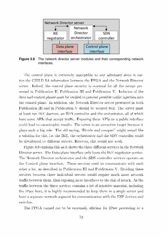
Network Director server
IKE negotiator
SDN controller
Network Director
orchestrator
Data plane interface
Control plane interface
Figure 3.9 The network director server modules and their corresponding networkinterfaces.
The control plane is extremely susceptible to any adversary since it car-
ries the CHILD SA information between the FPGA and the Network Director
server. Indeed, the control plane security is essential for all the setups pre-
sented in Publication II, Publication III and Publication V. Isolation of the
data and control planes must be veri�ed to prevent possible tra�c injection into
the control plane. In addition, the Network Director server presented in both
Publication III and in Publication V should be secured well. The server must
at least run IKE daemon, an SDN controller and the orchestrator, all of which
have some APIs that accept tra�c. Exposing these APIs on a public interface
could lead to catastrophic results. The server is an attractive target because it
plays such a big role. The old saying, �Divide and conquer� might sound like
a solution for this, i.e. the IKE, the orchestrator and the SDN controller could
be distributed to di�erent servers. However, this would not work.
Figure 3.9 explains this as it shows the three di�erent services in the Network
Director server. The Data plane interface only hosts the IKE negotiator service.
The Network Director orchestrator and the SDN controller services operate on
the Control plane interface. These services need to communicate with each
other a lot, as described in Publication III and Publication V. Dividing these
services between three individual servers would require much more network
tra�c between them, thus exposing more interfaces to the risk of attack. As the
tra�c between the three services contains a lot of sensitive material, including
the IPsec keys, it is highly recommended to keep them in a single server and
have a separate network segment for communication with the ESP devices and
switches.
The FPGA turned out to be extremely e�cient for IPsec processing as a
72

standalone device in the network. As the calculations in the evaluation section
of Publication V show, a single encryption or decryption block on an Intel Arria
10 FPGA reaches 2 Gbps throughput rate on any network packet size. There-
fore the proposed FPGA architecture with parallel encryption or decryption
blocks can reach 10 Gbps throughput rate while keeping the latency below 10
µs. The network packet size signi�cantly a�ects throughput, so if MTU sized
packets are used a single block can achieve a throughput rate of 15.6 Gbps.
The SDN is the key function to run IKE separately on a software, and ESP
on an FPGA. Even though load balancing with a single IPsec tunnel between
multiple FPGAs was not feasible, one device can handle a considerable amount
of tra�c and meet the high speed performance goal.
73

74

4 REFLECTIONS AND LESSONSLEARNED OF THE CONDUCTEDRESEARCH
The purpose of this section is to evaluate the signi�cance of the research and
see what can be learned from it. We begin with a discussion of the real world
status of the SDN. Then we assess the implications of being able to have a
single network controller and two separate planes in networking. We move
on to consider hardware acceleration in the Cloud context, and the issues of
orchestration.
4.1 Real world SDN stuff
Even though the virtues of SDN are well publicised, its real power lies in its
applications. Therefore, this chapter �nishes with an assessment of some (se-
curity) applications based on the research.
4.1.1 One controller to rule them all
A single controller watching over the whole network and making forwarding
decisions is a signi�cant bene�t to be gained through SDN networking. Cen-
tralized packet handling enables accurate packet forwarding in networks with
loops.
The network setup presented in section 3.1 and shown in Figure 3.4 has
a single SDN controller which manages several geographically isolated SDN
switches and the packet �ows between them. Although not explicitly de�ned
as such, the overlay network presented in Publication II also clearly �ts the
75

SDN Controller
SD-WANrouter
SD-WANrouter
The Internet
MPLS
LTE
Broadband
Fiber
Ethernet
Branch Office Headquarters
Broadband
Fiber
Ethernet
Figure 4.1 SD-WAN network architecture with two sites both using SD-WAN routerthat is being managed centrally using an SDN controller [168].
description of an SD-WAN, and turned out to be a very e�cient method of
connecting several sites together, including a Cloud. The presented architecture
creates a single broadcast domain over several locations, in addition to this,
the network can easily be modi�ed with additional paths between the sites
as desired. It is almost impossible to discuss SDN nowadays without coming
across the term software-de�ned WAN, or SD-WAN. So, what exactly is an
SD-WAN?
One of the best presentations of an SD-WAN is given in Thompson and
Hollar [168]. In this work, an SD-WAN is de�ned as a network that provides
high redundancy by securely connecting di�erent company sites through mul-
tiple connections. In its simplest form, the SD-WAN router creates an overlay
networking layer between di�erent sites and balances the load using software-
managed �ows with a central controller.
Figure 4.1 shows such a network scenario with two sites, i.e a Branch o�ce
and a Headquarters. The Branch o�ce has an SD-WAN router with Long-
Term Evolution (LTE) and Fiber and Broadband Internet ISP connections.
The Headquarters is equipped with a similar SD-WAN router and also uses
Fiber and Broadband for Internet connectivity. These two sites have also been
connected together using a Multiprotocol Label Switching (MPLS) network.
The SD-WAN routers in both networks are managed by a central SDN con-
troller. The SDN controller manages the network tra�c using �ows between
the sites in order to select the best available path for the packets. Paths going
through the Internet can be encrypted as explained in [155] using, for example,
IPsec VPN.
One of the greatest bene�ts of SD-WAN networking is that it opens up the
76

possibility of adding network-level applications to all the o�ces simultaneously.
When an application is installed on the SDN controller, it is also enabled on all
the SD-WAN routers. A good example of such an application is policy-based
routing between the sites. All end user applications requiring low-latency op-
eration can be directed to use the path with the lowest latency, not LTE. It
is worth noting that with SD-WAN, and our solution presented in Publica-
tion II, only the tra�c between sites can be a�ected; not the tra�c towards
the Internet.
It has been clearly demonstrated that IPsec tunneling can be used for the
tra�c between sites. The IPsec acceleration described in section 3.2 can speed
up the packet processing and ease the management for such SD-WAN scenarios.
Instead of pushing the SD-WAN router to its limits with a heavy IPsec encryp-
tion load, another device in the network can do the required ESP processing.
It is almost axiomatic in the computing to make the most common case the
fastest. ESP processing is a very common case for an SD-WAN.
Since the ESP devices in an SD-WAN are managed centrally from a single
SDN controller, there is some dispute about the use of the IKE. It is possible
to build an IKE-less IPsec, as was shown in [58]. The controller generates the
required SA material, such as the SPI and the keys, and delivers them to the
selected ESP devices. This eliminates the need for one of the services of the
network, i.e. the IKE.
The use of SDN in this kind of distributed network environment pushes the
control plane to its limits. Therefore, the whole issue of SDN networking is
discussed in terms of the control plane, based on the lessons learned during this
research.
4.1.2 Future prospects for the control plane and thecontrollers
For researchers and developers in the �eld, the separate control plane and cen-
tral management is a refreshing wind of change. The use of a control plane and
a centrally managed controller o�ers a completely new level of visibility to the
network.
The work presented in Publication II, Publication III and Publication V
77

used the OpenFlow protocol. However, as explained in subsection 2.2.2, the
control protocol in SDN is not limited to OpenFlow, and SDN does not nec-
essarily mean OpenFlow, (although perhaps it should). The control protocol
will need to be standardized. At present there are numerous groups of network
developers, both open source groups and vendors, who are all working away in
their own little segment of the secure networking �eld. Until they can all agree
on the controlling protocol, regardless of whether or not it is OpenFlow, the
whole networking �eld will su�er.
Interoperability is the key. There is a good example of this in section 3.2.
Our Cyberlab was already equipped with OpenFlow-enabled HP switches. It
was easiest to use some popular open source SDN controller and thus Flood-
light was chosen. Even though the OpenFlow protocol was used, the Floodlight
and the HP switches did not work together as expected. Without proper inter-
operability between the open source projects and the vendors, the companies
who build SDN networks are forced to reinvent some of the basic functions that
should be there by default.
During the experiments conducted in the Cyberlab, OpenFlow performed
the basic operations well. Still, it is less reliable in cases like the one discussed
in section 3.1 where an SDN controller manages switches over WAN links. If
resilient operation cannot be guaranteed, this will hinder the usability of central
management. Although in this work the topic is discussed using OpenFlow as
an example, the same principles apply to all SDN management protocols over
WAN links.
Although SDN was developed especially for LAN networks, its use might
well expand over WANs as well, if it has not done so already. This has changed
the original assumption of having reliable network connectivity between the
controller and the network equipment. The OpenFlow protocol should thus
be �tted into these use cases as well. Building a completely new protocol for
SD-WAN makes no sense, as OpenFlow serves it purpose well and its basic
operation is functional over WANs. In fact, separating SDN and SD-WAN at
the protocol level would result in a more fragmented SDN �eld.
Possible connectivity problems between the SDN controller and the switches
require some extra features, such as active parallel redundancy as provided by
the Parallel Redundancy Protocol (PRP) [127]. As explained for the data
78

plane in Publication II, the PRP can be used to �x control plane connectivity
problems for multiple WAN locations. Implementing such a redundancy feature
directly into OpenFlow could solve some of the connectivity problems. The
PRP would create several connections between the SDN controller and the
switches, o�ering more resilient connectivity. One challenge with this is that
the endpoints should be aware of duplicate packets, and thus a unique identi�er
for every OpenFlow packet is needed. Therefore, implementing such a feature
in OpenFlow would mean adding it to the core structure of the protocol. The
only solution would be to add this feature to future OpenFlow versions, which
would make all the older versions obsolete for SD-WAN purposes. Although
this would not be ideal, some solution is nonetheless required since, for instance,
when a fault occurs those SD-WAN routers without an active connection to the
controller would not be able to make any new �ow modi�cations, and would
have to wait for the connection to be repaired. Cisco has approached the
problem using an Overlay Management Protocol (OMP) [28] in their Viptela
based SD-WAN solutions. Even though the exact technical details of the OMP
resiliency are not available, their use of an OMP here indicates that Cisco
(and Viptela) are also addressing the problem of the SD-WAN routers losing
connectivity with the controller.
The use of TLS for the management protocol is mandatory. As described in
3.1, TLS was used for control plane connectivity with stunnel, which ensured the
con�dentiality of the connection. As the OpenFlow protocol already supports
TLS, there is, in fact, no need for the stunnel. Still, as long as vendors and
open source projects do not implement TLS support in devices and controllers,
or provide the necessary documentation for them, solutions like stunnel will
continue to be used.
In addition to smoother operation over WAN links, some solution is required
to better �t the SA management to the SDN paradigm. The IKE-less opera-
tion of IPsec was brie�y mentioned in Figure 4.1.1. There is little doubt that
OpenFlow does need better IPsec support. It should be able to carry the re-
quired SA information from the SDN controller to the ESP devices. This would
mean that the SDN controller could use OpenFlow directly to manage the ESP
devices [60].
Our research in Publication III and Publication V, highlighted the need for
79

a �ow-matching rule for the ESP SPI values. If that were achieved, it would
be possible to direct ESP packets in the network with SPI instead of relying
on the tunnel endpoint IPs. Therefore it would allow the use of several tunnels
(CHILD SAs) between the same public IPs but terminate them on separate ESP
devices. Incoming ESP packets could thus be shared among several ESP devices
which would enhance the ESP packet processing rate with parallel processing.
Meanwhile, the outgoing packets could instead use the least-congested FPGA
for the destination, either with ECMP or with some other method as described
in Publication III.
The future for the control plane looks very promising and it seems certain
that centralized management is a step in the right direction. However, un-
til the industry can reach some mutual agreement on its structure, and the
technologies to use, the control plane will continue to be rather complex and
cumbersome. Nevertheless, networks with central management will save money,
o�er new features and be more reliable with SDN.
4.1.3 The future for the data plane
The future for the data plane looks even more promising than for the control
plane. Arbitrary network topology is no longer bound to physical infrastructure
while the �ows can be freely created to the network. Flows can include various
network devices in a packet's path, such as �rewalls, IDS:s or VPN endpoints, as
long as they are connected to some switch in the network. We have shown that
the use of SDN removes the need for ARP implementation from the FPGA
in Publication V, thus showing how SDN is also very e�cient for research
purposes.
Publication II drew attention to the link recovery issue, and the problem
of recreating a �ow in the data plane as described in section 3.1. Although
in that case we used a custom script as a �x, a parallel redundancy protocol
would be a much better approach, especially in terms of high availability. Fixing
the missing PORT_DOWN information messages in the OVS is not the best
solution from a speed perspective as the SDN controller is required to change
the �ows. If the original breakdown occurred on a link where there is an active
connection between the SDN controller and the OVS, it can take quite a long
80
time to �x a malfunctioning �ow. Merling, Braun and Menth [92] presented
a solution for this in which the �ows are changed to operational links directly
in the switches, without the need for any SDN controller intervention. This
approach can signi�cantly improve the quality and reliability of such an OVS-
based L2 overlay without active redundancy �ows. Thus stakeholders, e.g. Open
Network Foundation, should carefully consider implementing such features into
the OpenFlow and SD-WAN-related technologies of the future.
Despite the issue of the missing PORT_DOWN status information, the
OVS turned out to be an extremely �exible solution and worked well for all
the experiments conducted for Publication II. It not only has a wide range of
di�erent features, as listed in [111], but it also o�ers support for a variety of
virtualization platforms.
A search of the Internet for examples of SDN controllers or SDN applications
for Publication II revealed that Mininet [95] is often regarded as being the main
topic for any �rst tutorial. For instance, Mininet is used to create the test
network in the ONOS SDN controller tutorial [105]. The same phenomenon
has been acknowledged by Lantz, Heller and McKeown [85] as well.
As a �rst step, this kind of testing with a software-based network is ideal:
the Mininet leans against the OVS and con�gures the links for it automatically.
This removes the need for any expensive hardware, and thus makes research
into SDN networking much more accessible to the wider networking community.
Still, it is questionable that many projects, including purely scienti�c research
ones, solely rely on a software data plane utilising Mininet and OVS.
The OVS is very tolerant of di�erent SDN controllers, applications and
packet processing features. However, do the currently used physical switches
provide the same features as OVS? Judging by the earlier example section 3.2
where the open source SDN controller could not communicate properly with
the HP switches, the answer has to be �no, they do not�.
Support for the packet processing features the in physical switches was eval-
uated from the documentation and with a few quick and simple experiments.
Publication V explained the case where the MAC address destination �eld can
be overwritten using SDN �ows. Based on the documentation [64] at least, this
feature is supported. Interestingly, rewriting the IP address �eld for HP/Aruba
switches is not speci�cally explained [6, 64]. In fact, experiments conducted in
81

the Cyberlab revealed that the IP address could not be rewritten using REST
API [65], at least not for the devices used for Publication III and Publication V.
And, according to [86], the Lenovo RackSwitch G8272 does not support IP ad-
dress rewriting either. Furthermore, the Juniper Junos OpenFlow feature guide
[72] does not even include the MAC address rewriting �ow action feature. On
the other hand, a combination of OVS and the Floodlight SDN controller was
proved to be able to o�er the IP rewriting feature. This indicates that the
device vendors do not necessarily provide all the features in their devices that
the OpenFlow protocol allows. So, it is possible that the example networks
built using OVS cannot be directly converted to the physical infrastructure.
Bosshart et al. [15] approach the problem of the missing packet processing
feature by specifying a P4 programming language to describe how switches
should process network packets. This was later taken under the Open Network
Foundation umbrella [108]. One of the main goals in P4 is to make the data
plane programmable and recon�gurable by the network administrators. This
would allow new feature like �rewalls, IDS etc. to be implemented directly onto
the switches. Barefoot Networks has taken up the concept by releasing prod-
ucts that support Protocol Independent Switch Architecture (PISA) and P4 [9],
which are mandatory features for data plane programmability. Versatile hard-
ware blocks in the switches will mean more applications can be implemented
there directly, and this will reduce the need for external, dedicated network
devices.
Even though switches are becoming more programmable, external devices
still have their place in a network. Publication V presented a dedicated FPGA-
based IPsec ESP device for the network. The FPGA was con�gured to act as
one device in the data plane and our estimates showed that the performance
was su�cient for even such a heavy process as ESP. This kind of approach
accords with the idea of having a programmable data plane, even if it is in the
form of an FPGA. While P4 allows the switch hardware to be used directly
instead of an external FPGA, it is important to remember that devices get
faster over increasingly short timespans. As new and more powerful devices
such as switches or FPGAs come to the market, they will be installed into the
network. Changing a single FPGA for a more powerful one is a much easier
operation than using a 48-port switch to achieve faster packet processing for
82

an application like IPsec. Basic functions that are not immediately in need of
performance enhancement should be pushed directly to the switch plane. Ad-
vanced applications with rigorous performance requirements will bene�t from
their own con�gurable hardware platform in SDN networks. The combination
of two device families is going to be extremely e�cient: the switches handle the
core functions while the FPGAs (or similar) can deal with the heavy processing.
Together, they provide the desired level of recon�gurability.
There might already be performance problems in the OpenFlow switches
in its basic operation. The reason is that the �ows generated in the switches
cannot be executed in the switch hardware. Instead, they are provided in the
software mode as explained in [6]. However, using software �ows in switches
is relatively slow, as shown in [146]. This study benchmarked the HP 3500yl
switch throughput for hardware �ow at 1 Gbps, while the software �ow was
measured at 80 Mbps. It is uncertain whether this only applies to HP switches
as neither the Lenovo RackSwitch application guide [86] nor the Junos Open-
Flow feature guide [72] have anything to say about the software/hardware �ow
implementation. This kind of performance evaluation needs further clari�cation
since an SDN network with low throughput is virtually useless.
4.1.4 (Security) applications for the SDN
The value of SDN lies in the breadth and variety of applications that it can o�er.
Publication III and Publication V presented an IPsec ESP application. This
kind of approach, combining IKE and ESP, is especially practical for enterprises
hosting a vast number of tunnels due to the central management of tunnels. A
software solution would be relatively easy to set up, while an FPGA solution
would o�er higher bandwidth. Whatever the case, IPsec is de�nitely a good
application to be implemented with SDN.
Hauser et al. [58] were clearly well aware of this as they �rst implemented
IPsec directly onto a switch data plane using P4 language, and then onto an
external server similar to the one used in Publication III. The reason they
changed from the switch to an external server was that a bandwidth of only
1.4 Gbps could be implemented directly on a switch. This was due to fact
that the switch lacked any hardware acceleration for the AES processing. The
83
concept itself is inspired: IPsec is directly implemented on a switch which
allows immediate encryption for incoming packets from the end devices. High
speed operation can be achieved by attaching an FPGA solution directly to
the switches as in Publication V. Unfortunately, this solution cannot be not
scaled since every switch would require its own external FPGA. Any really
scalable solution would require switches that either have an integrated hardware
accelerator, or full FPGA, such as Arista 7130 [5].
Still the encryption in local networks can be done using other protocols
like MACsec. Hauser et al. [59] implemented MACsec using P4 and centrally
deployed the MACsec to the SDN network using an SDN controller. Their
application �ts well into the SDN paradigm. This emphasizes the importance of
having programmable physical SDN switches. In Publication II the L2 overlay
network used OpenVPN for the connections between SDN switches. In that
study, MACsec was brie�y discussed as being a viable alternative to OpenVPN.
Although the authors of [52] did not cover the use of MACsec over a WAN link,
but instead focused on the implementation for local networks, this kind of SDN-
controlled integrated security mechanism clearly demonstrates the power and
versatility of SDN and points in the right direction for future research.
There are also a number of proprietary SDN applications, such as the one
presented in [14]. In this product, the SDN network forwards all the Domain
Name System (DNS) requests to the company's internal DNS server regardless
of their original destination. This ensures that only company internal DNS
servers are used, even if the users wanted to use some other, global, DNS server.
SDN is thus a good application directly at the network level. As the Bring Your
Own Device (BYOD) ideology continues to spread, the SDN network can repel
some of the possible adversaries that these random devices could bring in.
In summary, SDN networking o�ers a versatile platform on which to deploy
security applications and should be closely considered for any network requir-
ing a high level of security. Traditionally, the switch plane (or the broadcast
domain) have been the sweet spot for malware to spread because of the free
packet transaction between devices. With SDN, it is possible to add the de-
sired security layer directly onto the broadcast domain. This would allow the
implementation of an application directly on the SDN controller, which would
be able to permit or deny some speci�ed network tra�c. Thus an SDN network
84

can be used to e�ectively prevent anomalies spreading throughout the whole
network via a single application in the controller.
4.1.5 Does the designed IPsec setup work in the realworld?
While the example networks in Publication III and Publication V present a
basic setup which veri�es the network structure, a real-world setup might look
di�erent due to IPv4 NAT. In subsection 4.1.3 we discuss the possibility of
rewriting the IP addresses directly in the SDN switches, using proper �ows.
This allows more customized network setups to be used. Figure 4.2 shows an
advanced example of a network with the ESP and IKE services located outside
the inner �rewall. The internal network contains several PCs and a Server
connected to SDN switches and is managed by an internal SDN Controller.
This kind of internal network frequently uses private IPv4 addressing space.
The inner �rewall performs a NAT to this network from one public IPv4 address
that is located in a �Middle network� depicted in Figure 4.2. This middle
network is protected by an outer �rewall to reduce tra�c noise and can operate
either in transparent or routed mode.
The setup presented in Figure 4.2 assumes that the ISP dedicates only one
usable IPv4 address to the company and that this needs to be allocated at the
inner �rewall to achieve NAT functionality and Internet connectivity to the
devices in the internal network. The ESP devices can be either DPDK-based
ones as in Publication III or FPGAs as in Publication V. They o�er the ESP
encryption and decryption function for the network packets that they receive.
Forwarding tra�c to the ESP devices is managed from the SDN controller EXT.
The ESP functionality uses the public IPv4 address from the inner �rewall in
its processing. This can be done since the SW 4 forwards all the incoming ESP
tra�c to the ESP devices based on the protocol. Outgoing packets requiring
ESP processing are forwarded based on the destination IP address.
However, this approach slightly violates best practice, as illustrated in the
following example of a packet transaction. PC A (10.3.3.7) is communicating
to branch o�ce server (192.168.1.2) through the VPN. The network packets
enter the inner �rewall with IP SRC: 10.3.3.7 and IP DST: 192.168.1.2. Since
85
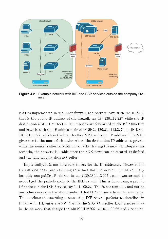
Public IPv4 addressing
Private IPv4 addressingusing NAT
e.g. 10.3.0.0/16
PC A
Openflow
SDN Controller INT
PC B
SW 1
SW 2
SW 3
Firewallinner
Server X
SW 4
SDN Controller EXT
Firewallouter
The Internet
ESP devices
SAs
IKE Service
OpenFlow
Public server
Internal network Middle network
Figure 4.2 Example network with IKE and ESP services outside the company fire-wall.
NAT is implemented in the inner �rewall, the packets leave with the IP SRC
that is the public IP address of the �rewall, say 130.230.112.227 while the IP
destination is still 192.168.1.2. The packets are forwarded to the ESP function
and leave it with the IP address pair of IP SRC: 130.230.112.227 and IP DST:
130.230.113.2, which is the branch o�ce VPN endpoint IP address. The NAT
gives rise to the unusual situation where the destination IP address is private
while the source is already public for a packet leaving the network. Despite this
scenario, the network is usable since the SDN �ows can be created as desired
and the functionality does not su�er.
Importantly, it is not necessary to rewrite the IP addresses. However, the
IKE service does need rewriting to ensure �uent operation. If the company
has only one public IP address in use (130.230.112.227), some workaround is
needed get the packets going to the IKE as well. This is done using a private
IP address in the IKE Service, say 10.1.100.22. This is not routable, and nor do
any other devices in the Middle network hold IP addresses from the same area.
This is where the rewriting occurs. Any IKE-related packets, as described in
Publication III, enter the SW 4 while the SDN Controller EXT creates �ows
in the network that change the 130.230.112.227 to 10.1.100.22 and vice versa.
86

This then pushes the packets to the IKE Service or to the outer Firewall.
In this way, a single public IP address can be used concurrently in several
devices. Furthermore, the Public server can host, e.g., SSH service and use the
same public IP address with a similar SDN �ow setup. Even without several
public IP addresses, NAT functionality can be achieved at the switch level,
outside the inner �rewall, thus enhancing the security in the core network. This
kind of address modi�cation is highly transparent and might cause di�culty
in debugging but simultaneously, could complicate possible adversary reverse-
engineering attempts on the network.
There are, of course, alternatives to the network setup depicted in Figure 4.2.
Another option is to use two interfaces from the ESP device and connect them
to the SDN switch planes in the internal network (e.g. SW 1) and in the middle
network. This way the ESP device starts to act as a gateway, but one that only
transfers the IPsec VPN tra�c. It might be thought that this would require
some complicated routing setup, but that's not the case when the SDN con-
troller makes packet-forwarding decisions in the networks. As for any security
concerns arising from having another gateway device in the internal network,
security is still good since only the tra�c related to the IPsec is forwarded to
the ESP device. The use of AES-CBC or AES-GCM provides the all-important
con�dentiality and authenticity [174] for the ESP packets. Therefore only traf-
�c which is veri�ed as coming from the VPN peer is processed, decrypted and
sent on to the internal network. Network packets using another protocol should
not even reach the gateway because the SDN �ows will push them to the inner
�rewall. Some broadcast messages may be the exception, and these must be
terminated in the ESP device via e.g. a white list that only allows ESP packets.
In summary, in a real-world network, any external ESP device would require
careful planning and implementation because of the problems that might be
caused by the addressing limitations. Achieving the desired level of security
also requires careful planning. Some workarounds will certainly be needed, and
there is as yet no best practice available. The best solution is to approach the
implementation with security as a priority, and then to compromise with the
needs of the network design administrators.
87
4.2 Hardware backed IaaS Cloud
Publication V presented an FPGA-accelerated ESP device that was ten times
faster than the one in Publication III. Therefore, our research strongly indi-
cates that it would make sense to extend the hardware accelerator in SDN to
include other heavy processes as well. Che et al. [20] researched the bene�ts
of hardware acceleration using three di�erent applications: Gaussian Elimina-
tion, Data Encryption Standard (DES), and Needleman-Wunsch. Their results
show that while some applications, like DES, �t well to FPGAs, others, such
as Gaussian Elimination, are better handled on a GPU.
The importance of hardware acceleration has been acknowledged by many
groups. Abadi et al. [1] state that the machine learning platform, TensorFlow,
bene�ts greatly from accelerators. The famous cloud operating system Open-
stack [113] has launched a project called Cyborg [114] to address the need for
acceleration. Cyborg provides a management framework for software accelera-
tors like DPDK and hardware accelerators like GPUs and FPGAs [114]. One
FPGA accelerator installation by Caul�eld et al. [19] resulted in performance
gains for Bing search rankings and data encryption. These �ndings clearly
indicate that Cloud networks, be they public or private, are moving towards
accelerated services.
As described in subsection 4.1.3, accelerators �t well with an SDN. Only one
single FPGA was used in Publication V. If it were to be scaled up for the Cloud,
it would incorporate any number of accelerators that could be inserted into the
Cloud SDN network to serve the VMs. There are three di�erent options for
such a layout.
The �rst of these options is to install a rack full of accelerator devices onto
the network and use SDN �ows to utilize these accelerators for all the machines
around the data center requesting HW acceleration. This mean a lot of east-
west tra�c between racks, which could mean an increase in latency. On the
other hand, the centralized location of the HW accelerators might help with
their management and installation of them to the network.
The second option is to distribute the accelerators through the data center
racks so that any servers in a single rack would try to use their nearest accel-
erator, preferably from their own rack. This, however, requires an orchestrator
88

on the SDN network and precise information regarding the nearest accelerator.
The SDN controller and the accelerator orchestrator would then control the
available resources together.
The third option is to implement the accelerators as Caul�eld et al. [19] did.
Their approach did not need any intelligence from the network since the FPGA
was just a �Bump-in-a-Wire�. The authors noted in their conclusions that �The
most important problem to solve is the design of scalable accelerators� and go
on to mention that the physical location and interface in the infrastructure is
one pressing challenge.
Scalability is indeed an important feature. Using the �rst or second of the
above options to distribute the accelerators in the infrastructure seems more
likely to provide the required scalability as more accelerators can be attached
to the network when required. The network interface is one of the best choices
for accelerators to be connected into the Cloud infrastructure. Compared to
local access such as that o�ered by PCI-E, the network-attached accelerators
can be made usable for all devices in the data center, rather than just to a local
server. Furthermore, if the accelerators are attached to the network, a pipeline
can be built in which data �ows from one accelerator to another.
Publication V investigated using the Cloud for the IPsec accelerator. One
use-case for the presented platform is to host tunnels for a vast number of IoT
devices. According to [24] the amount of data that �ows between IoT devices
and the Cloud is growing fast. Thus in Cloud environments, a single software
IPsec or even an FPGA cannot handle all the incoming IPsec tra�c, so a pool
of IPsec tunnel endpoints is needed. The architecture in Publication V allows
central management for numerous IoT devices from a single server (orchestra-
tor) while the ESP tra�c is processed in other devices. However, some legacy
IoT devices might only support the AES-CBC encryption mode, which would
make the proposed FPGA solution in Publication V unusable. Interestingly,
the DPDK-based approach presented in Publication III could be used since it
supports several di�erent encryption modes, including AES-CBC.
A closer look at IoT devices reveals they also might be creating new chal-
lenges for Cloud platforms. Cloud data centers are constantly receiving in-
creasing amounts of tra�c causing extremely heavy loads to the network, not
to mention the CPUs and storages. Edge (or fog) computing can reduce the
89

load from the data centers by moving the processing closer to the edge of the
network and thus closer to the end devices, as described in [156]. Our proposed
FPGA accelerator architecture is suitable to be implemented on the edge as
well. It can provide the necessary connectivity between the edge and the Cloud,
or the edge and the IoT device. Another bene�t of FPGAs is their relatively
small physical size, and their standalone function without any host server. This
makes their physical installation on the edge site relatively easy. In this location
they are also less likely to increase the heat dissipation or energy consumption
compared to a rack-installable server. Other accelerator applications can pro-
vide data modi�cation functions for desired IoT origin data on-the-�y, which is
bene�cial because, as stated in [156], it reduces the bandwidth and load from
the Cloud platform itself.
A good SDN controller and orchestrator combination can make the use of
accelerators transparent. The orchestrator should be aware of the physical
locations of the accelerators and their capabilities. Furthermore, utilising only
the SDN �ows in the network, several parallel or concurrent accelerators could
be used. For enterprises doing heavy data processing this means that their
work can be made faster either in their own data centers, or in public Clouds
via accelerator architecture. Accelerators will not supersede high-performance
CPU servers, but they can support them by providing a platform to run heavy
processes, thereby freeing up more computational power on the servers, all of
which is possible with good orchestration.
4.3 An orchestrator to glue it all together
Even though the original research questions were not speci�cally about orches-
tration, it is an unavoidable topic with this kind of research. The orchestrator
is a management tool, the conductor for a complex computerised entity and its
job is to make sure every part of that entity works together in harmony. All
the network setups presented in Publications II-V relied on orchestration, at
least to a certain extent.
In Publication II, the setup especially bene�ted from an orchestrator as the
number of sites increased. Multi-tunnel OpenVPN-based setups can use central
management for the OpenVPN tunnels. The number of these tunnels rapidly
90

rises (quadratically), as in the setup the full-mesh topology was needed, which
made the management work heavy. The number of required tunnels can be
calculated with Equation 4.1 where n is the number of tunnels.
Ntunnels =n(n− 1)
2(4.1)
This means, for example, that while only three tunnels are required for
three sites, 15 tunnels would be required for six sites. Setting up the tunnels
can be time-consuming, while proper orchestration may reduce the time and
con�guration errors signi�cantly. This kind of orchestration could just be a
few scripts. These are used to build the necessary con�guration, including
keys between sites, and to deploy the keys to the OpenVPN endpoints, even
for routed scenarios like in Publication I. The Homenet solution presented
in Publication I handles all the necessary IP address assignments, and routes
them between the sites, which greatly reduces the amount of con�guration.
The drawback with using Homenet between many sites is that it can lead to
overlapping IP ranges, especially in IPv4 which uses the 10.0.0.0/8 range [61],
since the addresses are managed independently in every site. Thus, central IP
address management through an orchestrator is bene�cial, even crucial, as the
number of di�erent sites increases.
As with the VPN solutions presented in Publication III and in Publica-
tion V, orchestration is often related to the Cloud. In Publication III, an IPsec
orchestrator with its own sub-orchestrators worked as a central information
exchange point for the IPsec process. Its main purpose is to make sure the
process operates as needed: IKE provides CHILD SA, keys that are distributed
to ESP devices and generate �ows in the network. Therefore, the orchestrator
can be regarded as having security associations with all the ESP devices in the
network, as well as with the IKE daemon and the SDN controller. All the de-
vices and the orchestrator must trust each other and keep their communication
secure to prevent possible anomalies. For example, sensitive information such
as the IPsec SA keys �ows through the orchestrator, although the orchestrator
does not need to know their values.
The IPsec orchestrator in Publication III can be considered as the main
building block which oversees all the sub-level orchestrators. It would have
been desirable in Publication III to launch the ESP processes in NFV fashion.
91
Having this additional feature would have required a new sub-orchestrator to
manage the automatic VM launching in the NFV platform. The NFV platform,
or a Cloud, usually has its own orchestrator with one or more APIs already.
Does it manage the virtual network inside the Cloud as well? If yes, it should be
manageable from the orchestrator, which is responsible for IPsec �ow generation
in the rest of the network as well. These VMs are in fact ESP devices and need
management from the IPsec orchestrator. As any scenario is developed, the
role of the orchestrator expands heavily and generates highly-complex, nested
orchestration.
If one adds the hardware acceleration from Publication V to the design, the
packet crypto function (or ESP device) orchestrator from Publication III should
also oversee these HW accelerators. The orchestrator also has to understand
the function and location of any HW accelerator in the network in order to give
the best service to the customers.
Furthermore, when technologies like P4-MACsec [59] are implemented to the
network, this places more demands on it. What sort of orchestrator can support
all of these features? It is either a proprietary one from a company who o�er
all the desired services in their product portfolio, or it is a nested orchestrator,
where the main orchestrator has several sub-orchestrators. The problem with
the former is that it is very likely only to work with other products from the
same vendor, while the problem with the latter is that because it is highly
complex with several orchestrators the APIs must be carefully standardized to
ensure interoperability between all the di�erent parts.
A promising direction for orchestration is to rely on a single open source
platform which allows the use of middleware software to �t with di�erent en-
tities under the orchestrator. One example of such a platform is ManageIQ,
which has providers e.g. for Clouds, containers, networking and storage, to
name but a few. Openstack has also approached orchestration by having one
central service, Heat, and several sub-services each responsible for one segment,
such as clustering [115].
The complete orchestrator setup would already be complex, even without
IaaS Cloud. Building such �uently working orchestration, even for a sim-
ple network-attached accelerator, will almost certainly require a great deal of
knowledge and expertise from the designers, but on the other hand, in the
92

end it would provide all the desired features. However, there can be no doubt
that orchestration at some level will be required when accelerators like the ones
presented in Publication V are attached to the network.
93

94

5 CONCLUSION
VPN technologies o�ers companies, and individuals, secure communication be-
tween their desktop machines, servers, handheld devices and other devices. If
implemented well, VPN provides con�dentiality, integrity and authenticity for
network packets over untrusted networks, such as the Internet. The spread of
Cloud computing means that more and more services are pushed to work from
Cloud VMs. This emphasizes the need for secure communication to the Cloud,
and often the most practical way to achieve this is by using a VPN solution.
Much of the time, there are no special requirements for a VPN tunnel and
thus practically any software solution is su�cient. Still, at some point the
basic setup is no longer adequate, so a more sophisticated VPN solution is
required providing, perhaps, better resiliency or high speed operation. Recent
advances in networking include SDN, which provides comprehensive visibility
to the network and thus precise packet forwarding capabilities. As our research
indicates, more advanced VPN tunneling solutions can be achieved using SDN
technology.
The work done for Publication I did not cover the use of SDN, but the main
structure of the network setup provided IPv4 and IPv6 networking over multiple
sites using the zeroconf approach. The routed setup presented in section 3.1
has an adequate tunneling setup for the use of SOHO and SME, as these do
not require any higher resiliency than the always-available best-e�ort.
A more resilient VPN network setup was achieved using L2 overlay technol-
ogy in Publication II. This research was also targeted at the use of SOHO and
SME. This tunneling solution relied on a dedicated SDN controller to build net-
work �ows through multiple tunnels between sites. This provided more reliable
packet transfer than the setup in Publication I, even though only best-e�ort
ISP connections were used. The setup is usable, for instance, in connecting ICS
networks together, and also for connecting to Cloud VMs. However, this solu-
95
tion did su�er from a fragile control plane and from problems in reallocating
�ows when errors occur in the underlying network.
While the former publications relied on OpenVPN tunneling technology,
larger enterprises tend to opt for IPsec because of its maturity, reputation and
higher performance. In Publication III we presented a novel approach to IPsec
where the IKE and ESP functionality is separated and operated from di�erent
boxes in the network. This functionality was achieved using proper SDN �ow
con�guration that redirects tra�c directly in the switch plane. It even allows
the use of several high-speed ESP devices, albeit under certain conditions and
with some limitations, while the IPsec IKE is managed from a single endpoint.
The distributed IPsec is e�cient enough, for instance, for Cloud providers to
run IPsec endpoints to a vast number of customers. The design su�ers from
a missing anti-replay feature which is the trade-o� for parallel operation for a
single IPsec tunnel. By assigning a single tunnel to a dedicated ESP device, the
anti-replay feature would be enabled. The high availability goal could then be
reached through several ESP devices in the network by distributing the IPsec
tunnels between them and moving the ESP processing from any faulty ones
using SDN �ows to the operational devices. Thus, the ESP device needs to be
extremely powerful and able to host a great number of concurrent tunnels.
Publication V discusses the IPsec tunnel from this viewpoint. It explains
the feasibility of FPGA-accelerated IPsec on the Cloud. It utilises the same
network design as in Publication III, while the ESP processing is done on an
FPGA platform. That work indicated that an FPGA can provide exactly the
right platform for such a high speed IPsec ESP device. An FPGA such as
the Intel Arria 10 can host roughly 1000 concurrent tunnels and o�er 10 Gbps
throughput with any packet size while keeping the latency below 10 µs. This
is achieved using a purely hardware approach on the FPGA and by removing
any function from the FPGA that could possibly operate on commodity server
software. There are a wide variety of use cases for this kind of solution due to
its great design performance: Cloud operators, audio/video transfer, endpoints
for IoT devices and edge computing to name but a few.
SDN still divides opinion as to whether it really is a useful new technology,
or just another marketing trick. Traditional networking solutions like in Pub-
lication I are often su�cient, in which case SDN is not needed. However, our
96

research shows that SDN comes into its own when elastic packet forwarding is
required. With SDN it is possible to implement highly complex setups and even
transparently obfuscate the network tra�c from the end devices. Even though
Publication I and Publication II targeted the SME level, larger enterprises
might require more use cases than the presented SDN and IPsec combination
before they will be persuaded to use SDN. These could include, for instance,
avoiding downtime for maintenance by using a virtual topology.
Corporations running a great number of virtual machines, e.g. Cloud op-
erators, bene�t greatly from SDN since the visibility of the physical network
infrastructure can be extended inside the hypervisors. This provides rich control
for the network packets using SDN �ows all the way up to the VMs. Services
can thus be provided in an NFV style as desired in Publication III. Further-
more, a number of hardware accelerators like the ones used in Publication V
can be attached to the network and the network packets from the VMs pushed
to use them via SDN �ows.
Besides the research on secure networking with SDN, it turns out that SDN
is in fact an e�ective �shortcut� tool for researchers, too. In Publication V the
intention was not to run ARP on the FPGA. Removing the implementation
need from the hardware provided savings for the FPGA area, and simultane-
ously conferred elasticity on the network. Thus it is highly probable that other
research projects dealing with network and non-standard devices will bene�t
from conducting their experiments using an SDN platform.
It is to be hoped that the future will hold much more research related to
improving secure networking in the SDN �eld. Another topic for future research
is hardware acceleration techniques, especially for use at the enterprise level,
but also for smaller companies that run heavy data processing. Innovative
and highly e�cient solutions could be achieved with combinations of SDN and
FPGAs, especially if some open source projects look in that direction.
Here is my thesis in a nutshell. SDN-based approach can improve the relia-
bility, resiliency and performance of VPN connections. There are surely other
equally convenient options for VPNs. Research shows that companies can build
complicated, fast, IPsec scenarios or self-managed SD-WANs using open source
tools. The work presented here clearly shows that SDN has its place in net-
working. How quickly that will spread and what the networks will look like in
97

the future is up to the vendors. For researchers, SDN will continue to provide
a rich and interesting �eld to be harvested for the variety of new, sweet topics
it may yield. This researcher, for one, strongly encourages others to carry on
the good work with SDN.
98

REFERENCES
[1] M. Abadi, P. Barham, J. Chen, Z. Chen, A. Davis, J. Dean, M. Devin, S.
Ghemawat, G. Irving, M. Isard, M. Kudlur, J. Levenberg, R. Monga,
S. Moore, D. G. Murray, B. Steiner, P. A. Tucker, V. Vasudevan, P.
Warden, M. Wicke, Y. Yu and X. Zheng. TensorFlow: A System for
Large-Scale Machine Learning. 12th USENIX Symposium on Operating
Systems Design and Implementation, OSDI 2016, Savannah, GA, USA,
November 2-4, 2016. Ed. by K. Keeton and T. Roscoe. USENIX Asso-
ciation, 2016, 265�283. url: https://www.usenix.org/conference/
osdi16/technical-sessions/presentation/abadi.
[2] B. Aboba and W. Dixon. IPsec-Network Address Translation (NAT)
Compatibility Requirements. RFC 3715 (2004), 1�18. doi: 10.17487/
RFC3715.
[3] I. Algredo-Badillo, C. F. Uribe, R. Cumplido and M. Morales-Sandoval.
FPGA Implementation and Performance Evaluation of AES-CCMCores
for Wireless Networks. ReConFig'08: 2008 International Conference
on Recon�gurable Computing and FPGAs, 3-5 December 2008, Can-
cun, Mexico, Proceedings. IEEE Computer Society, 2008, 421�426. doi:
10.1109/ReConFig.2008.54.
[4] Archlinux wiki. Hardware Video Acceleration. https://wiki.archlinu
x.org/index.php/Hardware_video_acceleration. Online; accessed
12 December 2019.
[5] Arista. 7130 FPGA-enabled Network Switches. Quick Look.
https : / / www . arista . com / en / products / 7130 - fpga - enabled -
network-switches-quick-look. Online; accessed 12 December 2019.
[6] ArubaOS-Switch OpenFlow v1.3 Administrator Guide for 16.04. 2017.
99

[7] R. J. Atkinson. IP Encapsulating Security Payload (ESP). RFC 1827
(1995), 1�12. doi: 10.17487/RFC1827.
[8] R. J. Atkinson. Security Architecture for the Internet Protocol. RFC
1825 (1995), 1�22. doi: 10.17487/RFC1825.
[9] Barefoot networks. Technology. https://www.barefootnetworks.com/
technology/. Online; accessed 12 December 2019.
[10] Barracuda networks. Barracuda SSL VPN & Remote Access. https:
//www.barracuda.com/products/sslvpn/models. Online; accessed
12 December 2019.
[11] A. Basu and J. Young. Cisco Document ID:115936. IKEv2 Packet Ex-
change and Protocol Level Debugging. https://www.cisco.com/c/
en/us/support/docs/security- vpn/ipsec- negotiation- ike-
protocols/115936- understanding- ikev2- packet- exch- debug.
html. Online; accessed 12 December 2019. 2013.
[12] T. Benson, A. Akella and D. A. Maltz. Network tra�c characteristics
of data centers in the wild. Proceedings of the 10th ACM SIGCOMM
Internet Measurement Conference, IMC 2010, Melbourne, Australia -
November 1-3, 2010. Ed. by M. Allman. ACM, 2010, 267�280. doi:
10.1145/1879141.1879175.
[13] C. J. Bernardos, A. Rahman, J. C. Zúñiga, L. M. Contreras, P. Aranda
and P. Lynch. Network Virtualization Research Challenges. RFC 8568
(2019), 1�42. doi: 10.17487/RFC8568.
[14] Bluecat. Making the Case for SDN: A Real-World Example. https:
//www.bluecatnetworks.com/blog/making-case-sdn-real-world-
example/. Online; accessed 12 December 2019.
[15] P. Bosshart, D. Daly, G. Gibb, M. Izzard, N. McKeown, J. Rexford,
C. Schlesinger, D. Talayco, A. Vahdat, G. Varghese and D. Walker.
P4: programming protocol-independent packet processors. Computer
Communication Review 44.3 (2014), 87�95. doi: 10.1145/2656877.
2656890.
100

[16] BSD Router Project OpenVPN benchmark.
https://bsdrp.net/documentation/examples/openvpn_performanc
e_lab_of_an_ibm_system_x3550_m3_with_intel_82580. Online;
accessed 12 December 2019.
[17] M. Casado, N. Foster and A. Guha. Abstractions for software-de�ned
networks. Commun. ACM 57.10 (2014), 86�95. doi: 10.1145/2661061.
2661063.
[18] J. D. Case, M. S. Fedor, M. L. Scho�stall and J. R. Davin. Simple Net-
work Management Protocol. RFC 1067 (1988), 1�33. doi: 10.17487/
RFC1067.
[19] A. M. Caul�eld, E. S. Chung, A. Putnam, H. Angepat, D. Firestone, J.
Fowers, M. Haselman, S. Heil, M. Humphrey, P. Kaur, J. Kim, D. Lo,
T. Massengill, K. Ovtcharov, M. Papamichael, L. Woods, S. Lanka, D.
Chiou and D. Burger. Con�gurable Clouds. IEEE Micro 37.3 (2017),
52�61. doi: 10.1109/MM.2017.51.
[20] S. Che, J. Li, J. W. Shea�er, K. Skadron and J. Lach. Accelerating
Compute-Intensive Applications with GPUs and FPGAs. Proceedings
of the IEEE Symposium on Application Speci�c Processors, SASP 2008,
held in conjunction with the DAC 2008, June 8-9, 2008, Anaheim, Cal-
ifornia, USA. IEEE Computer Society, 2008, 101�107. doi: 10.1109/
SASP.2008.4570793.
[21] J. Chroboczek. The Babel Routing Protocol. RFC 6126 (2011), 1�45.
doi: 10.17487/RFC6126.
[22] Cisco ASA 5500 Series Con�guration Guide using the CLI, 8.4 and 8.6.
https://www.cisco.com/c/en/us/td/docs/security/asa/asa84/
configuration/guide/asa_84_cli_config/vpn_anyconnect.html.
Online; accessed 12 December 2019. 2019.
[23] Cisco Document ID:5234. Understanding and Con�guring Spanning
Tree Protocol (STP) on Catalyst Switches. https://www.cisco.com/
c/en/us/support/docs/lan-switching/spanning-tree-protocol/
5234-5.html. Online; accessed 12 December 2019. 2006.
101

[24] Cisco Global Cloud Index: Forecast and Methodology, 2016�2021. White
Paper. Document ID: 1513879861264127. https://www.cisco.com/c/
en/us/solutions/collateral/service-provider/global-cloud-
index- gci/white- paper- c11- 738085.html. Online; accessed 12
December 2019. 2018.
[25] Cisco. IPSec Anti-Replay Check Failures. Document ID:116858. https:
//www.cisco.com/c/en/us/support/docs/ip/internet- key-
exchange-ike/116858-problem-replay-00.html. Online; accessed
12 December 2019. 2016.
[26] Cisco. Next Generation Encryption. https://www.cisco.com/c/en/
us/about/security-center/next-generation-cryptography.html.
Online; accessed 12 December 2019. 2015.
[27] Cisco OpFlex: An Open Policy Protocol. Declarative Control. White
paper. https://www.cisco.com/c/en/us/solutions/collateral/
data-center-virtualization/application-centric-infrastructu
re/white- paper- c11- 731302.pdf. Online; accessed 12 December
2019. 2015.
[28] Cisco SD-WAN. Product Documentation. Viptela Overlay Management
Protocol. https://sdwan-docs.cisco.com/Product_Documentation/
vManage_Help/Release_18.3/Configuration/Templates/OMP. On-
line; accessed 12 December 2019. 2019.
[29] Cisco. SSL VPN Security. https://www.cisco.com/c/en/us/about/
security-center/ssl-vpn-security.html. Online; accessed 12 De-
cember 2019. 2019.
[30] Crypto++ benchmark. https://www.cryptopp.com/benchmarks.
html. Online; accessed 12 December 2019. 2009.
[31] J. L. Cummings, K. R. Hickey and B. D. Kinney. AT&T network ar-
chitecture evolution. AT&T technical journal 66.3 (1987), 2�12.
[32] Data Plane Development Kit. Documentation. Version 19.08.0-rc0.
https://doc.dpdk.org/guides/. Online; accessed 12 December 2019.
[33] S. E. Deering and R. M. Hinden. Internet Protocol, Version 6 (IPv6)
Speci�cation. RFC 2460 (1998), 1�39. doi: 10.17487/RFC2460.
102

[34] M. Dworkin. SP 800-38A. Recommendation for Block Cipher Modes of
Operation: Methods and Techniques. Federal Information Processing
Standards Publication 197 (2001), 1�51. doi: 10.6028/NIST.SP.800-
38A.
[35] M. Dworkin. SP 800-38D. Recommendation for Block Cipher Modes of
Operation: Galois/Counter Mode (GCM) and GMAC. Federal Infor-
mation Processing Standards Publication (2007), 1�37. doi: 10.6028/
NIST.SP.800-38D.
[36] K. B. Egevang and P. Francis. The IP Network Address Translator
(NAT). RFC 1631 (1994), 1�10. doi: 10.17487/RFC1631.
[37] W. F. Ehrsam, C. H. Meyer, J. L. Smith and W. L. Tuchman. Mes-
sage veri�cation and transmission error detection by block chaining. US
Patent 4,074,066. 1976.
[38] A. M. El-Semary, M. M. A. Azim and H. Diab. SPCBC: A Secure
Parallel Cipher Block Chaining Mode of Operation based on logistic
Chaotic Map. TIIS 11.7 (2017), 3608�3628. doi: 10.3837/tiis.2017.
07.017.
[39] R. Enns. NETCONF Con�guration Protocol. RFC 4741 (2006), 1�95.
doi: 10.17487/RFC4741.
[40] ETSI Network Function Virtualization (NFV) introduction.
https://www.etsi.org/technologies/689-network-functions-
virtualisation. Online; accessed 12 December 2019.
[41] Faucet SDN controller. https://faucet.nz. Online; accessed 12 De-
cember 2019.
[42] N. Feamster, J. Rexford and E. W. Zegura. The road to SDN: an intel-
lectual history of programmable networks. Computer Communication
Review 44.2 (2014), 87�98. doi: 10.1145/2602204.2602219.
[43] D. Felsch, M. Grothe, J. Schwenk, A. Czubak and M. Szymanek. The
Dangers of Key Reuse: Practical Attacks on IPsec IKE. 27th USENIX
Security Symposium, USENIX Security 2018, Baltimore, MD, USA,
August 15-17, 2018. Ed. by W. Enck and A. P. Felt. USENIX Associ-
103

ation, 2018, 567�583. url: https://www.usenix.org/conference/
usenixsecurity18/presentation/felsch.
[44] N. Ferguson and B. Schneier. A cryptographic evaluation of IPsec.
Counterpane Internet Security, Inc 3031 (2000), 14. url: https://
www.schneier.com/academic/paperfiles/paper-ipsec.pdf.
[45] N. FIPS. 186 digital signature standard. 1994.
[46] N. FIPS. 186-3 digital signature standard. 2009.
[47] Floodlight controller modules. https://floodlight.atlassian.net/
wiki/spaces/floodlightcontroller/pages/1343528/Applications.
Online; accessed 12 December 2019.
[48] Floodlight SDN controller.
http://www.projectfloodlight.org/floodlight/. Online; accessed
12 December 2019.
[49] Floodlight SDN controller. Developers. How to Write a Module. https:
//floodlight.atlassian.net/wiki/spaces/floodlightcontroller/
pages/1343513/How+to+Write+a+Module. Online; accessed 12 Decem-
ber 2019.
[50] Flowgrammable. OpenFlow classi�er �elds. http://flowgrammable.
org/sdn/openflow/classifiers. Online; accessed 12 December 2019.
[51] S. Frankel, R. Glenn and S. G. Kelly. The AES-CBC Cipher Algo-
rithm and Its Use with IPsec. RFC 3602 (2003), 1�15. doi: 10.17487/
RFC3602.
[52] J. Ghorpade, J. Parande, M. Kulkarni and A. Bawaskar. GPGPU Pro-
cessing in CUDA Architecture. CoRR abs/1202.4347 (2012). arXiv:
1202.4347. url: http://arxiv.org/abs/1202.4347.
[53] J. Gray and D. P. Siewiorek. High-Availability Computer Systems.
IEEE Computer 24.9 (1991), 39�48. doi: 10.1109/2.84898.
[54] J. Guilford, S. Gulley, E. Ozturk, K. Yap, V. Gopal and W. Feghali.
Intel White Paper: Fast Multi-bu�er IPsec Implementations on Intel
Architecture Processors. https://www.intel.com/content/dam/www/
public/us/en/documents/white- papers/fast- multi- buffer-
104
ipsec- implementations- ia- processors- paper.pdf. Online; ac-
cessed 12 December 2019. 2012.
[55] E. Haleplidis, K. Pentikousis, S. G. Denazis, J. H. Salim, D. Meyer and
O. G. Koufopavlou. Software-De�ned Networking (SDN): Layers and
Architecture Terminology. RFC 7426 (2015), 1�35. doi: 10.17487/
RFC7426.
[56] K. Hamzeh, G. S. Pall, W. Verthein, J. Taarud, W. A. Little and G.
Zorn. Point-to-Point Tunneling Protocol (PPTP). RFC 2637 (1999),
1�57. doi: 10.17487/RFC2637.
[57] D. Harkins and D. Carrel. The Internet Key Exchange (IKE). RFC
2409 (1998), 1�41. doi: 10.17487/RFC2409.
[58] F. Hauser, M. Häberle, M. Schmidt and M. Menth. P4-IPsec: Imple-
mentation of IPsec Gateways in P4 with SDN Control for Host-to-
Site Scenarios. CoRR abs/1907.03593 (2019). arXiv: 1907.03593. url:
http://arxiv.org/abs/1907.03593.
[59] F. Hauser, M. Schmidt, M. Häberle and M. Menth. P4-MACsec: Dy-
namic Topology Monitoring and Data Layer Protection with MACsec
in P4-SDN. CoRR abs/1904.07088 (2019). arXiv: 1904.07088. url:
http://arxiv.org/abs/1904.07088.
[60] V. Heydari Fami Tafreshi, E. Ghazisaeedi, H. Cruickshank and Z. Sun.
Integrating IPsec within OpenFlow architecture for secure group com-
munication. ZTE COMMUNICATIONS JOURNAL 12.2 (2014), 41�
49.
[61] Homenet Project homepage. http://www.homewrt.org. Online; ac-
cessed 12 December 2019. 2017.
[62] R. Housley. Using Advanced Encryption Standard (AES) Counter Mode
With IPsec Encapsulating Security Payload (ESP). RFC 3686 (2004),
1�19. doi: 10.17487/RFC3686.
[63] R. Housley. Using Advanced Encryption Standard (AES) CCM Mode
with IPsec Encapsulating Security Payload (ESP). RFC 4309 (2005),
1�13. doi: 10.17487/RFC4309.
105

[64] HP OpenFlow 1.3 Administrator Guide. Wired Switches K/KA/KB/WB
15.15. 2014.
[65] HPE VAN SDN Controller 2.7 REST API Reference. 2016.
[66] J. Hudgens. Crondose. Code Interview Question: Load Balancing vs
High Availability. https : / / www . crondose . com / 2016 / 08 / load -
balancing-vs-high-availability/. Online; accessed 12 December
2019. 2016.
[67] A. Huttunen, B. Swander, V. Volpe, L. DiBurro and M. Stenberg. UDP
Encapsulation of IPsec ESP Packets. RFC 3948 (2005), 1�15. doi:
10.17487/RFC3948.
[68] IETF Zeroconf Working Group. http://www.zeroconf.org. Online;
accessed 12 December 2019.
[69] Intel. AES-NI. https : / / www . intel . com / content / www / us / en /
architecture-and-technology/advanced-encryption-standard-
aes/data-protection-aes-general-technology.html. Online; ac-
cessed 12 December 2019.
[70] Intel. Case study. Intel AES-NI hardware-accelerated encryption boosts
security and performance of GenoSpace Population Analytics applica-
tion. https : / / www . intel . com / content / dam / www / public / us /
en / documents / case - studies / aes - ni - boosts - security - and -
performance-genospace-study.pdf. Online; accessed 12 December
2019.
[71] IPFire, a Linux based �rewall distribution. https://www.ipfire.org.
Online; accessed 12 December 2019.
[72] Juniper networks. Junos OS. OpenFlow Feature Guide. https://www.
juniper.net/documentation/en_US/junos/information-products/
pathway-pages/junos-sdn/junos-sdn-openflow.pdf. Online; ac-
cessed 12 December 2019.
[73] Juniper networks. Techlibrary. Understanding MACsec Bene�ts. https:
//www.juniper.net/documentation/en_US/release-independent/
nce/topics/concept/macsec-benefits-understanding.html. On-
line; accessed 12 December 2019. 2014.
106

[74] B. Kaliski. PKCS #1: RSA Encryption Version 1.5. RFC 2313 (1998),
1�19. doi: 10.17487/RFC2313.
[75] A. Kato, S. Moriai and M. Kanda. The Camellia Cipher Algorithm and
Its Use With IPsec. RFC 4312 (2005), 1�8. doi: 10.17487/RFC4312.
[76] C. Kaufman. Internet Key Exchange (IKEv2) Protocol. RFC 4306
(2005), 1�99. doi: 10.17487/RFC4306.
[77] C. Kaufman, P. E. Ho�man, Y. Nir, P. Eronen and T. Kivinen. Internet
Key Exchange Protocol Version 2 (IKEv2). RFC 7296 (2014), 1�142.
doi: 10.17487/RFC7296.
[78] S. T. Kent. IP Authentication Header. RFC 4302 (2005), 1�34. doi:
10.17487/RFC4302.
[79] S. T. Kent. IP Encapsulating Security Payload (ESP). RFC 4303 (2005),
1�44. doi: 10.17487/RFC4303.
[80] S. T. Kent and K. Seo. Security Architecture for the Internet Protocol.
RFC 4301 (2005), 1�101. doi: 10.17487/RFC4301.
[81] H. Kim and N. Feamster. Improving network management with soft-
ware de�ned networking. IEEE Communications Magazine 51.2 (2013),
114�119. doi: 10.1109/MCOM.2013.6461195.
[82] T. Kivinen, B. Swander, A. Huttunen and V. Volpe. Negotiation of
NAT-Traversal in the IKE. RFC 3947 (2005), 1�16. doi: 10.17487/
RFC3947.
[83] F. Klaedtke, G. O. Karame, R. Bifulco and H. Cui. Access control
for SDN controllers. Proceedings of the third workshop on Hot topics
in software de�ned networking, HotSDN '14, Chicago, Illinois, USA,
August 22, 2014. Ed. by A. Akella and A. G. Greenberg. ACM, 2014,
219�220. doi: 10.1145/2620728.2620773.
[84] H. Krawczyk, M. Bellare and R. Canetti. HMAC: Keyed-Hashing for
Message Authentication. RFC 2104 (1997), 1�11. doi: 10 . 17487 /
RFC2104.
107

[85] B. Lantz, B. Heller and N. McKeown. A network in a laptop: rapid
prototyping for software-de�ned networks. Proceedings of the 9th ACM
Workshop on Hot Topics in Networks. HotNets 2010, Monterey, CA,
USA - October 20 - 21, 2010. Ed. by G. G. Xie, R. Beverly, R. T. Morris
and B. Davie. ACM, 2010, 19. doi: 10.1145/1868447.1868466.
[86] Lenovo. Lenovo RackSwitch G8272 Application Guide For Networking
OS 8.2. https : / / systemx . lenovofiles . com / help / topic / com .
lenovo.rackswitch.g8272.doc/G8272_AG_8-2.pdf. Online; accessed
12 December 2019. 2015.
[87] Libreswan IPSec benchmarking and performance testing.
https://libreswan.org/wiki/Benchmarking_and_Performance_
testing. Online; accessed 12 December 2019. 2016.
[88] L. Mamushiane, A. Lysko and S. Dlamini. A comparative evaluation
of the performance of popular SDN controllers. 2018 Wireless Days,
WD 2018, Dubai, United Arab Emirates, April 3-5, 2018. IEEE, 2018,
54�59. doi: 10.1109/WD.2018.8361694.
[89] S. Mathew, S. Satpathy, V. Suresh, H. Kaul, M. Anders, G. K. Chen,
A. Agarwal, S. Hsu and R. Krishnamurthy. 340mV-1.1V, 289Gbps/W,
2090-gate NanoAES hardware accelerator with area-optimized encryp-
t/decrypt GF(24)2 polynomials in 22nm tri-gate CMOS. Symposium
on VLSI Circuits, VLSIC 2014, Digest of Technical Papers, Honolulu,
HI, USA, June 10-13, 2014. IEEE, 2014, 1�2. doi: 10.1109/VLSIC.
2014.6858420.
[90] M. Matsui, J. Nakajima and S. Moriai. A Description of the Camel-
lia Encryption Algorithm. RFC 3713 (2004), 1�15. doi: 10.17487/
RFC3713.
[91] P. Mell, T. Grance et al. The NIST de�nition of cloud computing.
(2011).
[92] D. Merling, W. Braun and M. Menth. E�cient Data Plane Protection
for SDN. 4th IEEE Conference on Network Softwarization and Work-
shops, NetSoft 2018, Montreal, QC, Canada, June 25-29, 2018. IEEE,
2018, 10�18. doi: 10.1109/NETSOFT.2018.8459923.
108

[93] R. Metcalfe and D. Boggs. Ethernet: Distributed Packet Switching for
Local Computer Networks (Reprint). Commun. ACM 26.1 (1983), 90�
95. doi: 10.1145/357980.358015.
[94] J. Metzler. Five SDN problems aired by analyst Jim Metzler. https:
/ / searchnetworking . techtarget . com / news / 2240183823 / Five -
SDN-problems-aired-by-analyst-Jim-Metzler. Online; accessed 12
December 2019. 2013.
[95] Mininet. An Instant Virtual Network on your Laptop (or other PC).
http://mininet.org. Online; accessed 12 December 2019.
[96] A. Morton. IMIX Genome: Speci�cation of Variable Packet Sizes for
Additional Testing. RFC 6985 (2013), 1�10. doi: 10.17487/RFC6985.
[97] D. Mulnix. Intel. QuickAssist Technology use cases. https://software.
intel.com/en-us/articles/how-intel-quickassist-technology-
accelerates- nfv- use- cases. Online; accessed 12 December 2019.
2017.
[98] J. Naous, D. Erickson, G. A. Covington, G. Appenzeller and N. McK-
eown. Implementing an OpenFlow switch on the NetFPGA platform.
Proceedings of the 2008 ACM/IEEE Symposium on Architecture for
Networking and Communications Systems, ANCS 2008, San Jose, Cal-
ifornia, USA, November 6-7, 2008. Ed. by M. A. Franklin, D. K. Panda
and D. Stiliadis. ACM, 2008, 1�9. doi: 10.1145/1477942.1477944.
[99] D. Neil and S. Liu. Minitaur, an Event-Driven FPGA-Based Spiking
Network Accelerator. IEEE Trans. VLSI Syst. 22.12 (2014), 2621�2628.
doi: 10.1109/TVLSI.2013.2294916.
[100] Y. Nir. IPsec Cluster Problem Statement. RFC 6027 (2010), 1�12. doi:
10.17487/RFC6027.
[101] Y. Nir. ChaCha20, Poly1305, and Their Use in the Internet Key Ex-
change Protocol (IKE) and IPsec. RFC 7634 (2015), 1�13. doi: 10.
17487/RFC7634.
[102] NIST. National Vulnerability Database. CVE-2018-10811. Strongswan
Remote Denial of Service. https://nvd.nist.gov/vuln/detail/CVE-
2018-10811. Online; accessed 12 December 2019. 2018.
109
https://software.intel.com/en-us/articles/how-intel-quickassist-technology-accelerates-nfv-use-cases
https://software.intel.com/en-us/articles/how-intel-quickassist-technology-accelerates-nfv-use-cases

[103] B. A. A. Nunes, M. Mendonca, X. N. Nguyen, K. Obraczka and T.
Turletti. A Survey of Software-De�ned Networking: Past, Present, and
Future of Programmable Networks. IEEE Communications Surveys and
Tutorials 16.3 (2014), 1617�1634. doi: 10.1109/SURV.2014.012214.
00180.
[104] Nvidia Cuda-zone. https : / / developer . nvidia . com / cuda - zone.
Online; accessed 12 December 2019.
[105] Open Network Foundation. Basic ONOS Tutorial.
https : / / wiki . onosproject . org / display / ONOS / Basic + ONOS +
Tutorial. Online; accessed 12 December 2019.
[106] Open Networking Foundation, OpenFlow 1.5.1 protocol speci�cation.
https://www.opennetworking.org/wp-content/uploads/2014/10/
openflow-switch-v1.5.1.pdf. Online; accessed 12 December 2019.
2018.
[107] Open Networking Foundation, OpenFlow standards.
https://www.opennetworking.org/software-defined-standards/
specifications/. Online; accessed 12 December 2019. 2018.
[108] Open Networking Foundation. P4 language.
https://www.opennetworking.org/p4/. Online; accessed 12 Decem-
ber 2019.
[109] Open Networking Foundation, SDN De�nition.
https://www.opennetworking.org/sdn-definition/. Online; ac-
cessed 12 December 2019.
[110] Open Virtual Switch (OpenvSwitch) project. https://www.openvswitch.
org. Online; accessed 12 December 2019.
[111] Open Virtual Switch (OpenvSwitch) project. Features. https://www.
openvswitch.org//features/. Online; accessed 12 December 2019.
[112] OpenFlow and REST API Security. https://floodlight.atlassian.
net/wiki/spaces/floodlightcontroller/pages/5636115/OpenFlow+
and+REST+API+Security+Configuration. Online; accessed 12 Decem-
ber 2019.
110
[113] Openstack cloud operating system. https://www.openstack.org. On-
line; accessed 12 December 2019.
[114] Openstack cloud operating system. Cyborg project.
https://docs.openstack.org/cyborg/latest. Online; accessed 12
December 2019.
[115] Openstack. Components. https://www.openstack.org/software/
project-navigator/openstack-components. Online; accessed 12 De-
cember 2019.
[116] OpenVPN Community.OpenVPN and SWEET32. https://community.
openvpn.net/openvpn/wiki/SWEET32. Online; accessed 12 December
2019.
[117] OpenVPN, hardening. https://community.openvpn.net/openvpn/
wiki/Hardening. Online; accessed 12 December 2019.
[118] OpenVPN home page. https : / / openvpn . net. Online; accessed 12
December 2019.
[119] OpenVPN. Implementing a load-balancing/failover con�guration.
https://openvpn.net/community- resources/implementing- a-
load-balancing-failover-configuration/. Online; accessed 12 De-
cember 2019.
[120] OpenVPN, Security Advisories. https://openvpn.net/security-
advisories/. Online; accessed 12 December 2019.
[121] OpenVPN. Site-to-site VPN routing explained in detail.
https://openvpn.net/vpn- server- resources/site- to- site-
routing-explained-in-detail/. Online; accessed 12 December 2019.
[122] OpenVPN. Why SSL VPN? https://openvpn.net/faq/why-ssl-
vpn/. Online; accessed 12 December 2019.
[123] OpenWRT, a Linux based wireless router distribution. https://www.
openwrt.org. Online; accessed 12 December 2019.
[124] OpenWRT documentation, Mwan3 (use multiple WAN connections to-
gether). https://openwrt.org/docs/guide- user/network/wan/
multiwan/mwan3. Online; accessed 12 December 2019.
111

[125] N. Paladi and C. Gehrmann. SDN Access Control for the Masses. Com-
puters & Security 80 (2019), 155�172. doi: 10.1016/j.cose.2018.10.
003.
[126] C. A. Papagianni, G. Androulidakis and S. Papavassiliou. Virtual Topol-
ogy Mapping in SDN-Enabled Clouds. IEEE 3rd Symposium on Net-
work Cloud Computing and Applications, NCCA 2014, Rome, Italy,
February 5-7, 2014. Ed. by F. Quaglia, B. Ciciani and D. R. Avresky.
IEEE Computer Society, 2014, 62�67. doi: 10.1109/NCCA.2014.18.
[127] Parallel redundancy protocol (PRP). International Standard IEC 62439-
3. (2016).
[128] J. Park, W. Jung, G. Jo, I. Lee and J. Lee. PIPSEA: A Practical IPsec
Gateway on Embedded APUs. Proceedings of the 2016 ACM SIGSAC
Conference on Computer and Communications Security, Vienna, Aus-
tria, October 24-28, 2016. Ed. by E. R. Weippl, S. Katzenbeisser, C.
Kruegel, A. C. Myers and S. Halevi. ACM, 2016, 1255�1267. doi: 10.
1145/2976749.2978329.
[129] K. G. Paterson and A. K. L. Yau. Padding Oracle Attacks on the
ISO CBC Mode Encryption Standard. Topics in Cryptology - CT-
RSA 2004, The Cryptographers' Track at the RSA Conference 2004,
San Francisco, CA, USA, February 23-27, 2004, Proceedings. Ed. by
T. Okamoto. Vol. 2964. Lecture Notes in Computer Science. Springer,
2004, 305�323. doi: 10.1007/978-3-540-24660-2_24.
[130] R. Pereira and R. Adams. The ESP CBC-Mode Cipher Algorithms.
RFC 2451 (1998), 1�14. doi: 10.17487/RFC2451.
[131] P. P�ster, B. Paterson and J. Arkko. Distributed Pre�x Assignment
Algorithm. RFC 7695 (2015), 1�20. doi: 10.17487/RFC7695.
[132] pfSense, a FreeBSD based �rewall distribution. https://www.pfsense.
org. Online; accessed 12 December 2019.
[133] D. Piper. The Internet IP Security Domain of Interpretation for ISA-
KMP. RFC 2407 (1998), 1�32. doi: 10.17487/RFC2407.
[134] J. Postel. User Datagram Protocol. RFC 768 (1980), 1�3. doi: 10.
17487/RFC0768.
112

[135] J. Postel. Internet Control Message Protocol. RFC 792 (1981), 1�21.
doi: 10.17487/RFC0792.
[136] J. Postel. Internet Protocol. RFC 791 (1981), 1�51. doi: 10.17487/
RFC0791.
[137] J. Postel. Transmission Control Protocol. RFC 793 (1981), 1�91. doi:
10.17487/RFC0793.
[138] J. Postel and J. K. Reynolds. Telnet Protocol Speci�cation. RFC 854
(1983), 1�15. doi: 10.17487/RFC0854.
[139] N. F. Pub. Announcing the advanced encryption standard (AES). Fed-
eral Information Processing Standards Publication 197 (2001), 1�51.
[140] Quarkslab, OpenVPN 2.4.0 Security Assessment. Technical report.
https://ostif.org/wp- content/uploads/2017/05/OpenVPN1.
2final.pdf. Online; accessed 12 December 2019. 2017.
[141] B. Raghavan, M. Casado, T. Koponen, S. Ratnasamy, A. Ghodsi and
S. Shenker. Software-de�ned internet architecture: decoupling architec-
ture from infrastructure. 11th ACM Workshop on Hot Topics in Net-
works, HotNets-XI, Redmond, WA, USA - October 29 - 30, 2012. Ed.
by S. Kandula, J. Padhye, E. G. Sirer and R. Govindan. ACM, 2012,
43�48. doi: 10.1145/2390231.2390239.
[142] V. Redka. MLSDEV. A Beginner's Tutorial for Understanding REST-
ful API. https://mlsdev.com/blog/81-a-beginner-s-tutorial-
for - understanding - restful - api. Online; accessed 12 December
2019. 2016.
[143] E. Rescorla and N. Modadugu. Datagram Transport Layer Security.
RFC 4347 (2006), 1�25. doi: 10.17487/RFC4347.
[144] E. Rescorla and N. Modadugu. Datagram Transport Layer Security
Version 1.2. RFC 6347 (2012), 1�32. doi: 10.17487/RFC6347.
[145] A. Romanow. Media Access Control (MAC) Security IEEE 802.1 ae.
IEEE, 2006.
113

[146] P. Rygielski, M. Seliuchenko, S. Kounev and M. Klymash. Performance
Analysis of SDN Switches with Hardware and Software Flow Tables.
10th EAI International Conference on Performance Evaluation Method-
ologies and Tools, VALUETOOLS 2016, Taormina, Italy, 25th-28th
Oct 2016. Ed. by A. Pulia�to, K. S. Trivedi, B. Tu�n, M. Scarpa,
F. Machida and J. Alonso. ACM, 2016. doi: 10.4108/eai.25-10-
2016.2266540.
[147] A. Salman, M. Rogawski and J. Kaps. E�cient Hardware Accelerator
for IPSec Based on Partial Recon�guration on Xilinx FPGAs. 2011
International Conference on Recon�gurable Computing and FPGAs,
ReConFig 2011, Cancun, Mexico, November 30 - December 2, 2011.
Ed. by P. M. Athanas, J. Becker and R. Cumplido. IEEE Computer
Society, 2011, 242�248. doi: 10.1109/ReConFig.2011.33.
[148] B. Schneier. Schneier on security. Analysis of Microsoft PPTP Version
2. https://www.schneier.com/academic/pptp/. Online; accessed 12
December 2019.
[149] D. Schor. WikiChip. Intel Rolls Out Next-Gen Data Center Portfolio.
https://fuse.wikichip.org/news/2130/intel-rolls-out-next-
gen-data-center-portfolio-100-gigabit-ethernet-optane-dc-
hewitt-lake-and-cascade-lake-with-up-to-56-cores/6/. Online;
accessed 12 December 2019.
[150] S. Scott-Hayward, G. O'Callaghan and S. Sezer. Sdn Security: A Sur-
vey. IEEE SDN for Future Networks and Services, SDN4FNS 2013,
Trento, Italy, November 11-13, 2013. IEEE, 2013, 1�7. doi: 10.1109/
SDN4FNS.2013.6702553.
[151] SDX Central de�nition of Software-De�ned Networking (SDN). https:
//www.sdxcentral.com/networking/sdn/definitions/what-the-
definition-of-software-defined-networking-sdn/. Online; ac-
cessed 12 December 2019. 2018.
[152] SDX Central, Understanding the SDN Architecture - SDN Control Plane
& SDN Data Plane. https://www.sdxcentral.com/networking/sdn/
definitions/inside-sdn-architecture/. Online; accessed 12 De-
cember 2019. 2018.
114

[153] SDX Central. What are SDN Northbound APIs (and SDN Rest APIs)?
https : / / www . sdxcentral . com / networking / sdn / definitions /
north-bound-interfaces-api/. Online; accessed 12 December 2019.
[154] SDX Central. What are SDN Southbound APIs?
https : / / www . sdxcentral . com / networking / sdn / definitions /
southbound-interface-api/. Online; accessed 12 December 2019.
[155] SDX Central. What is Software-De�ned WAN (or SD-WAN)? https:
//www.sdxcentral.com/networking/sd-wan/definitions/software-
defined-sdn-wan/. Online; accessed 12 December 2019.
[156] W. Shi, J. Cao, Q. Zhang, Y. Li and L. Xu. Edge Computing: Vision
and Challenges. IEEE Internet of Things Journal 3.5 (2016), 637�646.
doi: 10.1109/JIOT.2016.2579198.
[157] R. Singh. Numato Lab. FPGA Vs ASIC: Di�erences Between Them
And Which One To Use? https://numato.com/blog/differences-
between-fpga-and-asics/. Online; accessed 12 December 2019. 2018.
[158] P. Sjovall, V. Viitamaki, A. Oinonen, J. Vanne, T. D. Hämäläinen and
A. Kulmala. Kvazaar 4K HEVC intra encoder on FPGA accelerated air-
frame server. 2017 IEEE International Workshop on Signal Processing
Systems, SiPS 2017, Lorient, France, October 3-5, 2017. IEEE, 2017,
1�6. doi: 10.1109/SiPS.2017.8109999.
[159] Stemmer Imaging. Introduction to FPGA acceleration. https://www.
stemmer-imaging.com/en-fi/technical-tips/introduction-to-
fpga-acceleration/. Online; accessed 12 December 2019.
[160] M. Stenberg, S. Barth and P. P�ster. Home Networking Control Pro-
tocol. RFC 7788 (2016), 1�40. doi: 10.17487/RFC7788.
[161] StrongSwan IKEv1 Cipher Suites. https://wiki.strongswan.org/
projects/strongswan/wiki/IKEv1CipherSuites. Online; accessed
12 December 2019. 2018.
[162] StrongSwan IKEv2 Cipher Suites. https://wiki.strongswan.org/
projects/strongswan/wiki/IKEv2CipherSuites. Online; accessed
12 December 2019. 2018.
115

[163] StrongSwan, the OpenSource IPsec-based VPN Solution. https://www.
strongswan.org. Online; accessed 12 December 2019. 2018.
[164] StrongSwan. User documentation. High Availability. http://wiki.
strongswan.org/projects/strongswan/wiki/HighAvailability.
Online; accessed 12 December 2019. 2018.
[165] Stunnel. TLS encryption wrapper proxy software.
https://www.stunnel.org. Online; accessed 12 December 2019.
[166] TensorFlow machine learning project. https://www.tensorflow.org/.
Online; accessed 12 December 2019.
[167] The IEEE 802.1D standard. 1990.
[168] B. Thompson and S. Hollar. World Wide Technology. Software De-
�ned Revolution: A Look at Cisco SD-WAN O�erings. https://www.
youtube.com/watch?v=9345AqJ6oTA. Online; accessed 12 December
2019. 2018.
[169] M. Tremer. IPFire IPsec benchmark. https://blog.ipfire.org/
post/feature-spotlight-galois-counter-mode-ipsec-with-10g.
Online; accessed 12 December 2019. 2018.
[170] O. Troan and R. E. Droms. IPv6 Pre�x Options for Dynamic Host
Con�guration Protocol (DHCP) version 6. RFC 3633 (2003), 1�19.
doi: 10.17487/RFC3633.
[171] J. Tyson and S. Crawford. Howstu�works. How VPNs Work. Remote
access VPN. https://computer.howstuffworks.com/vpn3.htm. On-
line; accessed 12 December 2019. 2018.
[172] J. Tyson and S. Crawford. Howstu�works. How VPNs Work. Site-to-
site VPN. https://computer.howstuffworks.com/vpn4.htm. Online;
accessed 12 December 2019. 2018.
[173] G. Vasiliadis, S. Antonatos, M. Polychronakis, E. P. Markatos and S.
Ioannidis. Gnort: High Performance Network Intrusion Detection Using
Graphics Processors. Recent Advances in Intrusion Detection, 11th In-
ternational Symposium, RAID 2008, Cambridge, MA, USA, September
15-17, 2008. Proceedings. Ed. by R. Lippmann, E. Kirda and A. Tracht-
116

enberg. Vol. 5230. Lecture Notes in Computer Science. Springer, 2008,
116�134. doi: 10.1007/978-3-540-87403-4_7.
[174] J. Viega and D. A. McGrew. The Use of Galois/Counter Mode (GCM)
in IPsec Encapsulating Security Payload (ESP). RFC 4106 (2005), 1�
11. doi: 10.17487/RFC4106.
[175] Wikipedia. Bitcoin. https://en.wikipedia.org/wiki/Bitcoin. On-
line; accessed 12 December 2019.
[176] Wireguard. Performance analysis of Wireguard VPN compared to Open-
VPN and IPsec. https://www.wireguard.com/performance/. Online;
accessed 12 December 2019. 2018.
[177] World Wide Web Consortium. Extensible Markup Language (XML) 1.0
(Fifth Edition). https://www.w3.org/TR/REC-xml/. Online; accessed
12 December 2019.
[178] L. Yang, R. Dantu, T. A. Anderson and R. Gopal. Forwarding and
Control Element Separation (ForCES) Framework. RFC 3746 (2004),
1�40. doi: 10.17487/RFC3746.
[179] T. Ylönen and C. Lonvick. The Secure Shell (SSH) Connection Proto-
col. RFC 4254 (2006), 1�24. doi: 10.17487/RFC4254.
[180] X. Zhang and T. Tsou. IPsec Anti-Replay Algorithm without Bit Shift-
ing. RFC 6479 (2012), 1�9. doi: 10.17487/RFC6479.
117

118

PUBLICATIONS
119


PUBLICATIONI
Home Network Security: Modelling Power Consumption to Detect
and Prevent Attacks on Homenet Routers
B. Silverajan, M. Vajaranta and A. Kolehmainen
11th Asia Joint Conference on Information Security, AsiaJCIS 2016, Fukuoka,
Japan, August 4-5, 2016. 2016, 9�16
doi: 10.1109/AsiaJCIS.2016.10
Publication reprinted with the permission of the copyright holders


Home Network Security: Modelling PowerConsumption to Detect and Prevent Attacks on
Homenet RoutersBilhanan Silverajan, Markku Vajaranta, Antti Kolehmainen
Tampere University of Technology, FinlandEmail: [email protected]
Abstract—Future home networks are expected to becomeextremely sophisticated, yet only the most technically adeptpersons are equipped with skills to secure them. In this paper, weprovide a novel solution to detect and prevent attacks on homerouters based on anomalous power consumption. We developeda means of measuring power consumption that could be used ina wide variety of home networks, although our primary focuson is on profiling Homenet-based residential routers, specificallyto detect attacks against homenet routing infrastructure. Severalexperimental results are presented when the infrastructure isexposed to various types of attacks, which show strong evidenceof the feasibility of our approach.
Index Terms—IETF Homenet, Home Network Security, PowerConsumption.
I. INTRODUCTION
Networks in the home today consist of relatively simplesetups. In the majority of homes, a broadband router or cellulargateway delivers connectivity to devices in the home, eitherwirelessly over Wi-Fi, or using an Ethernet cable. In all theseinstances, a single subnet is offered, usually behind a NATwith private IPv4 addresses. Additional gateways are rarelyused, except as repeaters.
In recent years however, the home has rapidly emerged asa natural convergence point for technological developmentsand innovations. It is not only commonplace to have con-nected homes contain smart consumer devices, sensors, remotesurveillance systems and home automation, but increasinglyhaving mobile devices and even vehicular networks joininginto a home network when needed. Additionally, better con-nectivity options and more advanced networking possibilities,such as support for IPv6 that provides end-to-end communi-cation without the need for NATs, are now also made possiblefrom service providers and network operators.
The Home Networking Working Group (Homenet WG)was subsequently chartered by the Internet Engineering TaskForce (IETF) as a response to the rapidly increasing arrays ofdevices, computers, sensors and gateways that are constantlybeing added into residential networks, as well as a means tosimplify end-to-end communication, service integration andnetwork management by the home network owner, networkoperators and service providers. Among others, the HomenetWG proposed that home networks need to adopt an architec-ture that allows them to scale and evolve organically as thecomplexity of the services and devices grow.
One of the most significant recommendations made isthat, with the introduction of IPv6 for home networking, aHomenet-compliant residential network (simply referred tofrom now on as “homenet”), should support multiple networksand subnets. A homenet can therefore consist of multiplerouters forming a proper routing infrastructure complete withits own routing protocol. The other is that, as the owners of ahomenet do not normally comprise technically adept persons,minimal (and ideally zero) configuration of addressing andnetworking needs to be performed: Users simply connect theirdevices to their home subnet of choice, and the homenet in-frastructure should automatically handle all the intrinsic detailsfor addressing, routing, service discovery and reachability.
In terms of home network security, several aspects ofprotecting home networks and devices, such as data pri-vacy, access control and end device protection have beeninvestigated in current research publications. However, apartfrom well-known administrative practices such as ensuringthe use of good passphrases and passwords for wirelessconnectivity, employing firewalls and access control lists inthe gateway, little if any security research on home gatewaysecurity actually exists. For example, Geon Woo Kim etal. [1] discuss the need to protect home networks from avariety of malware, Distributed Denial-of-Service (DDoS) andeavesdropping attacks through the introduction of a frameworkproviding guarantees of authentication, authorisation and arule-based security policy engine for undertaking actions whensecurity infractions occur. Mohamed Abid [2] studies the useof biometric authentication to enable and personalise useraccess into a home network. Also, Shaojun Qu [3] discussesremote authentication and authorisation to provide secureaccess into the home environment.
On the other hand, Lucas Dicioccio et al. [4] reveals that,while on the whole, even if the number of connected devicesin four out of five home networks amount to less than adozen, home gateways in particular are always active at anygiven time. This is exacerbated in homenet-based residentialnetworks, when a proper routing infrastructure having multiplerouters remains active at any given time. Therefore, even ifthe idea of an automatically configured routed network inthe home provides convenience and significant advantages tovarious kinds of users and smart devices, the homenet routersthemselves can become highly susceptible to malicious activity
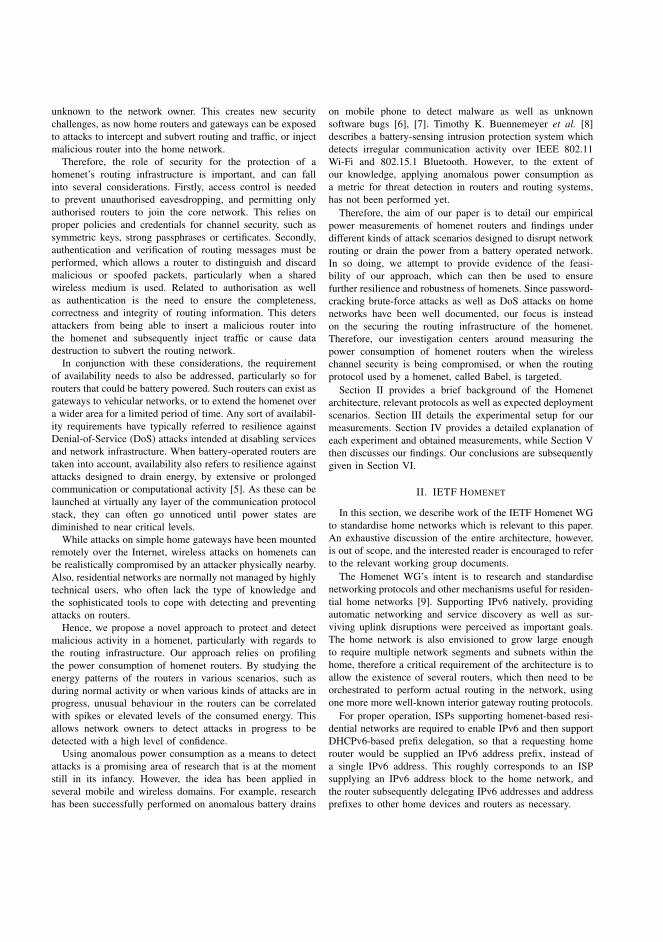
unknown to the network owner. This creates new securitychallenges, as now home routers and gateways can be exposedto attacks to intercept and subvert routing and traffic, or injectmalicious router into the home network.
Therefore, the role of security for the protection of ahomenet’s routing infrastructure is important, and can fallinto several considerations. Firstly, access control is neededto prevent unauthorised eavesdropping, and permitting onlyauthorised routers to join the core network. This relies onproper policies and credentials for channel security, such assymmetric keys, strong passphrases or certificates. Secondly,authentication and verification of routing messages must beperformed, which allows a router to distinguish and discardmalicious or spoofed packets, particularly when a sharedwireless medium is used. Related to authorisation as wellas authentication is the need to ensure the completeness,correctness and integrity of routing information. This detersattackers from being able to insert a malicious router intothe homenet and subsequently inject traffic or cause datadestruction to subvert the routing network.
In conjunction with these considerations, the requirementof availability needs to also be addressed, particularly so forrouters that could be battery powered. Such routers can exist asgateways to vehicular networks, or to extend the homenet overa wider area for a limited period of time. Any sort of availabil-ity requirements have typically referred to resilience againstDenial-of-Service (DoS) attacks intended at disabling servicesand network infrastructure. When battery-operated routers aretaken into account, availability also refers to resilience againstattacks designed to drain energy, by extensive or prolongedcommunication or computational activity [5]. As these can belaunched at virtually any layer of the communication protocolstack, they can often go unnoticed until power states arediminished to near critical levels.
While attacks on simple home gateways have been mountedremotely over the Internet, wireless attacks on homenets canbe realistically compromised by an attacker physically nearby.Also, residential networks are normally not managed by highlytechnical users, who often lack the type of knowledge andthe sophisticated tools to cope with detecting and preventingattacks on routers.
Hence, we propose a novel approach to protect and detectmalicious activity in a homenet, particularly with regards tothe routing infrastructure. Our approach relies on profilingthe power consumption of homenet routers. By studying theenergy patterns of the routers in various scenarios, such asduring normal activity or when various kinds of attacks are inprogress, unusual behaviour in the routers can be correlatedwith spikes or elevated levels of the consumed energy. Thisallows network owners to detect attacks in progress to bedetected with a high level of confidence.
Using anomalous power consumption as a means to detectattacks is a promising area of research that is at the momentstill in its infancy. However, the idea has been applied inseveral mobile and wireless domains. For example, researchhas been successfully performed on anomalous battery drains
on mobile phone to detect malware as well as unknownsoftware bugs [6], [7]. Timothy K. Buennemeyer et al. [8]describes a battery-sensing intrusion protection system whichdetects irregular communication activity over IEEE 802.11Wi-Fi and 802.15.1 Bluetooth. However, to the extent ofour knowledge, applying anomalous power consumption asa metric for threat detection in routers and routing systems,has not been performed yet.
Therefore, the aim of our paper is to detail our empiricalpower measurements of homenet routers and findings underdifferent kinds of attack scenarios designed to disrupt networkrouting or drain the power from a battery operated network.In so doing, we attempt to provide evidence of the feasi-bility of our approach, which can then be used to ensurefurther resilience and robustness of homenets. Since password-cracking brute-force attacks as well as DoS attacks on homenetworks have been well documented, our focus is insteadon the securing the routing infrastructure of the homenet.Therefore, our investigation centers around measuring thepower consumption of homenet routers when the wirelesschannel security is being compromised, or when the routingprotocol used by a homenet, called Babel, is targeted.
Section II provides a brief background of the Homenetarchitecture, relevant protocols as well as expected deploymentscenarios. Section III details the experimental setup for ourmeasurements. Section IV provides a detailed explanation ofeach experiment and obtained measurements, while Section Vthen discusses our findings. Our conclusions are subsequentlygiven in Section VI.
II. IETF HOMENET
In this section, we describe work of the IETF Homenet WGto standardise home networks which is relevant to this paper.An exhaustive discussion of the entire architecture, however,is out of scope, and the interested reader is encouraged to referto the relevant working group documents.
The Homenet WG’s intent is to research and standardisenetworking protocols and other mechanisms useful for residen-tial home networks [9]. Supporting IPv6 natively, providingautomatic networking and service discovery as well as sur-viving uplink disruptions were perceived as important goals.The home network is also envisioned to grow large enoughto require multiple network segments and subnets within thehome, therefore a critical requirement of the architecture is toallow the existence of several routers, which then need to beorchestrated to perform actual routing in the network, usingone more more well-known interior gateway routing protocols.
For proper operation, ISPs supporting homenet-based resi-dential networks are required to enable IPv6 and then supportDHCPv6-based prefix delegation, so that a requesting homerouter would be supplied an IPv6 address prefix, instead ofa single IPv6 address. This roughly corresponds to an ISPsupplying an IPv6 address block to the home network, andthe router subsequently delegating IPv6 addresses and addressprefixes to other home devices and routers as necessary.
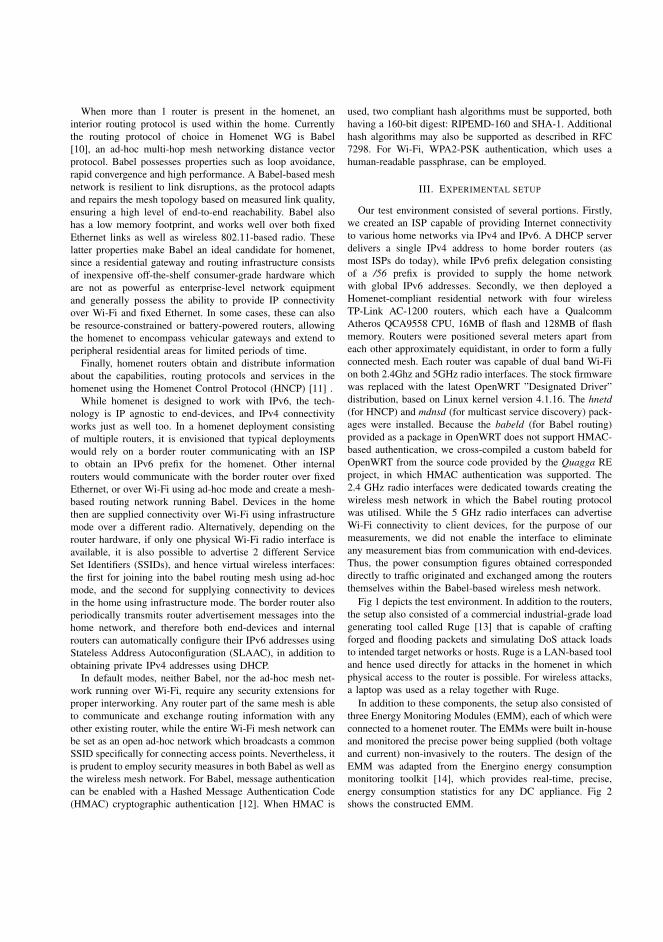
When more than 1 router is present in the homenet, aninterior routing protocol is used within the home. Currentlythe routing protocol of choice in Homenet WG is Babel[10], an ad-hoc multi-hop mesh networking distance vectorprotocol. Babel possesses properties such as loop avoidance,rapid convergence and high performance. A Babel-based meshnetwork is resilient to link disruptions, as the protocol adaptsand repairs the mesh topology based on measured link quality,ensuring a high level of end-to-end reachability. Babel alsohas a low memory footprint, and works well over both fixedEthernet links as well as wireless 802.11-based radio. Theselatter properties make Babel an ideal candidate for homenet,since a residential gateway and routing infrastructure consistsof inexpensive off-the-shelf consumer-grade hardware whichare not as powerful as enterprise-level network equipmentand generally possess the ability to provide IP connectivityover Wi-Fi and fixed Ethernet. In some cases, these can alsobe resource-constrained or battery-powered routers, allowingthe homenet to encompass vehicular gateways and extend toperipheral residential areas for limited periods of time.
Finally, homenet routers obtain and distribute informationabout the capabilities, routing protocols and services in thehomenet using the Homenet Control Protocol (HNCP) [11] .
While homenet is designed to work with IPv6, the tech-nology is IP agnostic to end-devices, and IPv4 connectivityworks just as well too. In a homenet deployment consistingof multiple routers, it is envisioned that typical deploymentswould rely on a border router communicating with an ISPto obtain an IPv6 prefix for the homenet. Other internalrouters would communicate with the border router over fixedEthernet, or over Wi-Fi using ad-hoc mode and create a mesh-based routing network running Babel. Devices in the homethen are supplied connectivity over Wi-Fi using infrastructuremode over a different radio. Alternatively, depending on therouter hardware, if only one physical Wi-Fi radio interface isavailable, it is also possible to advertise 2 different ServiceSet Identifiers (SSIDs), and hence virtual wireless interfaces:the first for joining into the babel routing mesh using ad-hocmode, and the second for supplying connectivity to devicesin the home using infrastructure mode. The border router alsoperiodically transmits router advertisement messages into thehome network, and therefore both end-devices and internalrouters can automatically configure their IPv6 addresses usingStateless Address Autoconfiguration (SLAAC), in addition toobtaining private IPv4 addresses using DHCP.
In default modes, neither Babel, nor the ad-hoc mesh net-work running over Wi-Fi, require any security extensions forproper interworking. Any router part of the same mesh is ableto communicate and exchange routing information with anyother existing router, while the entire Wi-Fi mesh network canbe set as an open ad-hoc network which broadcasts a commonSSID specifically for connecting access points. Nevertheless, itis prudent to employ security measures in both Babel as well asthe wireless mesh network. For Babel, message authenticationcan be enabled with a Hashed Message Authentication Code(HMAC) cryptographic authentication [12]. When HMAC is
used, two compliant hash algorithms must be supported, bothhaving a 160-bit digest: RIPEMD-160 and SHA-1. Additionalhash algorithms may also be supported as described in RFC7298. For Wi-Fi, WPA2-PSK authentication, which uses ahuman-readable passphrase, can be employed.
III. EXPERIMENTAL SETUP
Our test environment consisted of several portions. Firstly,we created an ISP capable of providing Internet connectivityto various home networks via IPv4 and IPv6. A DHCP serverdelivers a single IPv4 address to home border routers (asmost ISPs do today), while IPv6 prefix delegation consistingof a /56 prefix is provided to supply the home networkwith global IPv6 addresses. Secondly, we then deployed aHomenet-compliant residential network with four wirelessTP-Link AC-1200 routers, which each have a QualcommAtheros QCA9558 CPU, 16MB of flash and 128MB of flashmemory. Routers were positioned several meters apart fromeach other approximately equidistant, in order to form a fullyconnected mesh. Each router was capable of dual band Wi-Fion both 2.4Ghz and 5GHz radio interfaces. The stock firmwarewas replaced with the latest OpenWRT ”Designated Driver”distribution, based on Linux kernel version 4.1.16. The hnetd(for HNCP) and mdnsd (for multicast service discovery) pack-ages were installed. Because the babeld (for Babel routing)provided as a package in OpenWRT does not support HMAC-based authentication, we cross-compiled a custom babeld forOpenWRT from the source code provided by the Quagga REproject, in which HMAC authentication was supported. The2.4 GHz radio interfaces were dedicated towards creating thewireless mesh network in which the Babel routing protocolwas utilised. While the 5 GHz radio interfaces can advertiseWi-Fi connectivity to client devices, for the purpose of ourmeasurements, we did not enable the interface to eliminateany measurement bias from communication with end-devices.Thus, the power consumption figures obtained correspondeddirectly to traffic originated and exchanged among the routersthemselves within the Babel-based wireless mesh network.
Fig 1 depicts the test environment. In addition to the routers,the setup also consisted of a commercial industrial-grade loadgenerating tool called Ruge [13] that is capable of craftingforged and flooding packets and simulating DoS attack loadsto intended target networks or hosts. Ruge is a LAN-based tooland hence used directly for attacks in the homenet in whichphysical access to the router is possible. For wireless attacks,a laptop was used as a relay together with Ruge.
In addition to these components, the setup also consisted ofthree Energy Monitoring Modules (EMM), each of which wereconnected to a homenet router. The EMMs were built in-houseand monitored the precise power being supplied (both voltageand current) non-invasively to the routers. The design of theEMM was adapted from the Energino energy consumptionmonitoring toolkit [14], which provides real-time, precise,energy consumption statistics for any DC appliance. Fig 2shows the constructed EMM.

HOMENET
EMM
EMM
EMM
ISP
Figure 1: Setup for measuring power consumption. Routers areinterconnected in a full mesh topology. Blue arrows indicateauthentic Babel traffic. Red arrows depict forged traffic.
Figure 2: Energy Monitoring Module.
IV. MEASUREMENTS
This section presents our methodology and measurementsper experiment. Various kinds of attacks were targetted atthe homenet. In some cases, power measurements were takenwhen Babel was used without HMAC authentication. In theothers, HMAC authentication was enabled, using the SHA1algorithm. In IETF protocol design, HMAC-SHA-1 is thepreferred keyed-hash algorithm [15].
For each experiment, several sets of measurements weretaken to ensure data correlation. Each run was conducted oncethe routers were in steady-state both before and after attacks,
and measurements were taken approximately for an hour.Additionally, datasets for the three access points were verifiedto ensure correct calibration of the EMMs. For each readingtaken from the serial interface of the EMM, the data consistedof the average voltage, average current, an approximate samplesize of 800 voltage/current samples in the averaging windowof a single reading, each for an approximate time of 200msin the averaging window.
For each set, we start by describing the acquisition of ourdataset and then follow with an initial analysis of the results.A deeper discussion of these results is presented in the nextsection V.
A. Baseline Measurements
Wireshark IO Graphs: jemma
60 120 180 240 300 360 420
Time (s)
18
24
30
36
42
48
54
60
Pack
ets
/s
60 120 180 240 300 360 420
18
24
30
36
42
2
2.2
2.4
2.6
2.8
3
0 40 80 120 160 200 240 280
Power (W
)
Time (s)
2
2.2
2.4
2.6
2.8
3
0 40 80 120 160 200 240 280
Power (W
)
Time (s)
Figure 3: Baseline graphs from top-down. a) Power consump-tion with Babel, HMAC enabled. b) Power consumption withBabel, no HMAC. c) mDNS traffic triggering peaks in energyconsumption. y-axis shows packet count, x-axis shows elapsedtime in seconds.
In this experiment, we took detailed power measurementsof access points in which no malicious traffic was introduced.By default, Wi-Fi channel security was achieved by the use ofWPA2-PSK. Two types of power measurements were taken. Inthe first instance, the energy was monitored when Babel wasused with HMAC authentication enabled, while in the second
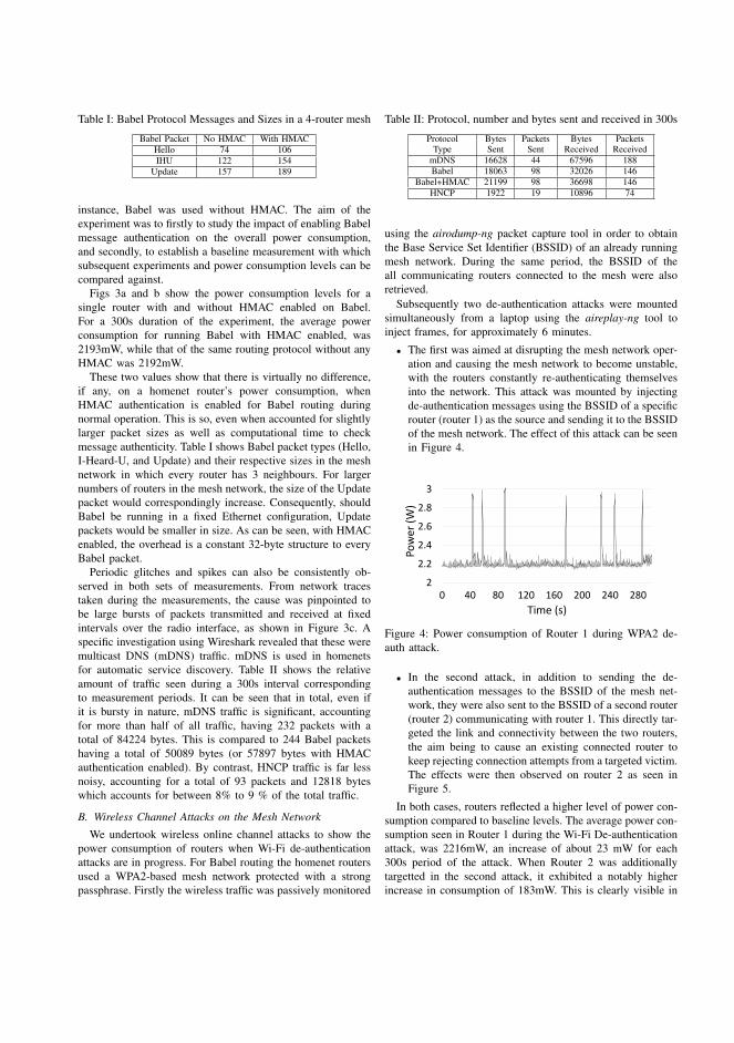
Table I: Babel Protocol Messages and Sizes in a 4-router mesh
Babel Packet No HMAC With HMACHello 74 106IHU 122 154
Update 157 189
instance, Babel was used without HMAC. The aim of theexperiment was to firstly to study the impact of enabling Babelmessage authentication on the overall power consumption,and secondly, to establish a baseline measurement with whichsubsequent experiments and power consumption levels can becompared against.
Figs 3a and b show the power consumption levels for asingle router with and without HMAC enabled on Babel.For a 300s duration of the experiment, the average powerconsumption for running Babel with HMAC enabled, was2193mW, while that of the same routing protocol without anyHMAC was 2192mW.
These two values show that there is virtually no difference,if any, on a homenet router’s power consumption, whenHMAC authentication is enabled for Babel routing duringnormal operation. This is so, even when accounted for slightlylarger packet sizes as well as computational time to checkmessage authenticity. Table I shows Babel packet types (Hello,I-Heard-U, and Update) and their respective sizes in the meshnetwork in which every router has 3 neighbours. For largernumbers of routers in the mesh network, the size of the Updatepacket would correspondingly increase. Consequently, shouldBabel be running in a fixed Ethernet configuration, Updatepackets would be smaller in size. As can be seen, with HMACenabled, the overhead is a constant 32-byte structure to everyBabel packet.
Periodic glitches and spikes can also be consistently ob-served in both sets of measurements. From network tracestaken during the measurements, the cause was pinpointed tobe large bursts of packets transmitted and received at fixedintervals over the radio interface, as shown in Figure 3c. Aspecific investigation using Wireshark revealed that these weremulticast DNS (mDNS) traffic. mDNS is used in homenetsfor automatic service discovery. Table II shows the relativeamount of traffic seen during a 300s interval correspondingto measurement periods. It can be seen that in total, even ifit is bursty in nature, mDNS traffic is significant, accountingfor more than half of all traffic, having 232 packets with atotal of 84224 bytes. This is compared to 244 Babel packetshaving a total of 50089 bytes (or 57897 bytes with HMACauthentication enabled). By contrast, HNCP traffic is far lessnoisy, accounting for a total of 93 packets and 12818 byteswhich accounts for between 8% to 9 % of the total traffic.
B. Wireless Channel Attacks on the Mesh Network
We undertook wireless online channel attacks to show thepower consumption of routers when Wi-Fi de-authenticationattacks are in progress. For Babel routing the homenet routersused a WPA2-based mesh network protected with a strongpassphrase. Firstly the wireless traffic was passively monitored
Table II: Protocol, number and bytes sent and received in 300s
ProtocolType
BytesSent
PacketsSent
BytesReceived
PacketsReceived
mDNS 16628 44 67596 188Babel 18063 98 32026 146
Babel+HMAC 21199 98 36698 146HNCP 1922 19 10896 74
using the airodump-ng packet capture tool in order to obtainthe Base Service Set Identifier (BSSID) of an already runningmesh network. During the same period, the BSSID of theall communicating routers connected to the mesh were alsoretrieved.
Subsequently two de-authentication attacks were mountedsimultaneously from a laptop using the aireplay-ng tool toinject frames, for approximately 6 minutes.
• The first was aimed at disrupting the mesh network oper-ation and causing the mesh network to become unstable,with the routers constantly re-authenticating themselvesinto the network. This attack was mounted by injectingde-authentication messages using the BSSID of a specificrouter (router 1) as the source and sending it to the BSSIDof the mesh network. The effect of this attack can be seenin Figure 4.
2
2.2
2.4
2.6
2.8
3
0 40 80 120 160 200 240 280
Pow
er (
W)
Time (s)
Figure 4: Power consumption of Router 1 during WPA2 de-auth attack.
• In the second attack, in addition to sending the de-authentication messages to the BSSID of the mesh net-work, they were also sent to the BSSID of a second router(router 2) communicating with router 1. This directly tar-geted the link and connectivity between the two routers,the aim being to cause an existing connected router tokeep rejecting connection attempts from a targeted victim.The effects were then observed on router 2 as seen inFigure 5.
In both cases, routers reflected a higher level of power con-sumption compared to baseline levels. The average power con-sumption seen in Router 1 during the Wi-Fi De-authenticationattack, was 2216mW, an increase of about 23 mW for each300s period of the attack. When Router 2 was additionallytargetted in the second attack, it exhibited a notably higherincrease in consumption of 183mW. This is clearly visible in
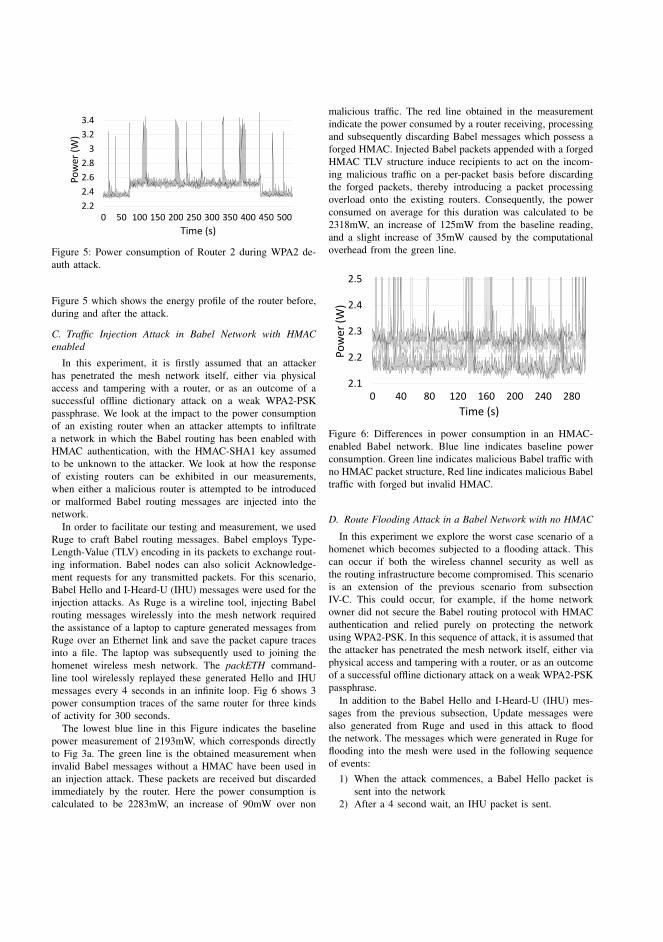
2.2
2.4
2.6
2.8
3
3.2
3.4
0 50 100 150 200 250 300 350 400 450 500
Pow
er (
W)
Time (s)
Figure 5: Power consumption of Router 2 during WPA2 de-auth attack.
Figure 5 which shows the energy profile of the router before,during and after the attack.
C. Traffic Injection Attack in Babel Network with HMACenabled
In this experiment, it is firstly assumed that an attackerhas penetrated the mesh network itself, either via physicalaccess and tampering with a router, or as an outcome of asuccessful offline dictionary attack on a weak WPA2-PSKpassphrase. We look at the impact to the power consumptionof an existing router when an attacker attempts to infiltratea network in which the Babel routing has been enabled withHMAC authentication, with the HMAC-SHA1 key assumedto be unknown to the attacker. We look at how the responseof existing routers can be exhibited in our measurements,when either a malicious router is attempted to be introducedor malformed Babel routing messages are injected into thenetwork.
In order to facilitate our testing and measurement, we usedRuge to craft Babel routing messages. Babel employs Type-Length-Value (TLV) encoding in its packets to exchange rout-ing information. Babel nodes can also solicit Acknowledge-ment requests for any transmitted packets. For this scenario,Babel Hello and I-Heard-U (IHU) messages were used for theinjection attacks. As Ruge is a wireline tool, injecting Babelrouting messages wirelessly into the mesh network requiredthe assistance of a laptop to capture generated messages fromRuge over an Ethernet link and save the packet capure tracesinto a file. The laptop was subsequently used to joining thehomenet wireless mesh network. The packETH command-line tool wirelessly replayed these generated Hello and IHUmessages every 4 seconds in an infinite loop. Fig 6 shows 3power consumption traces of the same router for three kindsof activity for 300 seconds.
The lowest blue line in this Figure indicates the baselinepower measurement of 2193mW, which corresponds directlyto Fig 3a. The green line is the obtained measurement wheninvalid Babel messages without a HMAC have been used inan injection attack. These packets are received but discardedimmediately by the router. Here the power consumption iscalculated to be 2283mW, an increase of 90mW over non
malicious traffic. The red line obtained in the measurementindicate the power consumed by a router receiving, processingand subsequently discarding Babel messages which possess aforged HMAC. Injected Babel packets appended with a forgedHMAC TLV structure induce recipients to act on the incom-ing malicious traffic on a per-packet basis before discardingthe forged packets, thereby introducing a packet processingoverload onto the existing routers. Consequently, the powerconsumed on average for this duration was calculated to be2318mW, an increase of 125mW from the baseline reading,and a slight increase of 35mW caused by the computationaloverhead from the green line.
2.1
2.2
2.3
2.4
2.5
0 40 80 120 160 200 240 280
Pow
er (
W)
Time (s)
Figure 6: Differences in power consumption in an HMAC-enabled Babel network. Blue line indicates baseline powerconsumption. Green line indicates malicious Babel traffic withno HMAC packet structure, Red line indicates malicious Babeltraffic with forged but invalid HMAC.
D. Route Flooding Attack in a Babel Network with no HMAC
In this experiment we explore the worst case scenario of ahomenet which becomes subjected to a flooding attack. Thiscan occur if both the wireless channel security as well asthe routing infrastructure become compromised. This scenariois an extension of the previous scenario from subsectionIV-C. This could occur, for example, if the home networkowner did not secure the Babel routing protocol with HMACauthentication and relied purely on protecting the networkusing WPA2-PSK. In this sequence of attack, it is assumed thatthe attacker has penetrated the mesh network itself, either viaphysical access and tampering with a router, or as an outcomeof a successful offline dictionary attack on a weak WPA2-PSKpassphrase.
In addition to the Babel Hello and I-Heard-U (IHU) mes-sages from the previous subsection, Update messages werealso generated from Ruge and used in this attack to floodthe network. The messages which were generated in Ruge forflooding into the mesh were used in the following sequenceof events:
1) When the attack commences, a Babel Hello packet issent into the network
2) After a 4 second wait, an IHU packet is sent.

3) After a 1 second wait, steps 1 and 2 are repeated in anendless loop.
4) After an initial 12 second wait from step 1, Updatemessages are constantly flooded into the network every 3ms. Each message updates current routes for the IPv4 /24network by increasing the network address by a singlebit for each transmission. Updates start at 10.0.0.0/24.One network advertisement is done every 3ms.
5) Sending route update messages for the entire /24 IPv4network takes 15 seconds after which sending Updatesstarts anew.
With the above steps, routing tables and information forthe entire homenet mesh was updated constantly, inducinga heavy stress and CPU load onto the routers.This forcesrouters to consider between 200 and 650 routes, dependingon the router load status. As before, a laptop was used asa wireless relay injecting malicious traffic into the network.Hello and IHU messages were transmitted using packETHwhile Update messages were wirelessly replayed using thetcpreplay tool. Because the malicious Babel traffic was in-jected into the homenet where routing was not secured usingHMAC authentication, all the existing homenet routers wereunaware that the traffic was forged. Fig 7 graphically depictsthe resulting router’s energy consumption profile. From itsbaseline power consumption of 2192 mW, the router beginsconsuming an average of 2802 mW during the attack. Thegraph also shows an interval during the sequence of eventswhere there is a momentary pause before the flooding attackreplay loop resumes, and reaches a similarly consistent state ofhigh power consumption for a second time during the attack.
2
2.5
3
3.5
4
4.5
01
63
32
54
88
65
18
13
97
61
13
81
30
11
46
41
62
61
78
91
95
12
11
42
27
72
43
9
Pow
er (
W)
Time (s)
Figure 7: Power consumption during route injection attack, noHMAC enabled
V. FINDINGS
Based on our measurements and observations, the obtainedresults remained consistent across all our experimental runs.The experiments conducted focused solely on the power con-sumption profiles of the routers working with Babel in wirelessad-hoc mode. However, we wanted to ensure that mandatoryfeatures of the Homenet Architecture, and the componentswhich implemented them were not disabled at any stage of ourexperiments. One such component was mDNS, which imple-ments service discovery. From our findings, mDNS consumed
a significant portion of energy, even when minimal servicesexisted in the homenet.
Additionally, because all homenet routers participate inmulticast-based packet transmission and reception, it is highlylikely that as more routers are added to a mesh-based homenet,the increase of multicast traffic could be in the order of O(n).Implementation optimisations, protocol improvements, tuningof mDNS advertisements and broadcast intervals may yieldbetter energy efficiency. However, investigation of such aspectsare out of scope of this paper.
The approach of using power consumption as a metric forattack detection in homenet appeared promising and feasible. Itcan be seen that various kinds of attacks had a definite impacton the energy consumed by a homenet router. With floodingattacks, significant differences were seen, compared to the baselevel measured. However, even for Wi-Fi based authenticationattacks, while the measured levels of additional power con-sumed were relatively small, it was noticeable that becauseof the nature of the mesh topology, the power consumptionpattern of more than 1 router was normally affected by attackstargetting even a single homenet router. Consequently, it wouldbe possible to observe the power consumption patterns andperform correlation across several routers to detect an attackin progress, even if individual power consumption levels bythemselves may not give a clear indication. Particularly forcovert attacks, using power consumption anamolies can bequite effective. On the other hand, our findings note that ahomenet cannot only rely on homenet routers enabling HMACauthentication for Babel routing, without having a properwireless channel security, for example by having a WPA2-PSKwireless network with a weak passphrase. When energy is anasset that needs to be conserved, then such a practice would becounter-productive and exposes an additional attack surface, asin addition to injecting malicious Babel traffic, an adversarycan append a forged HMAC to each injected packet, forcing arouter to both process the injected message as well as performcomputations on the forged HMAC. An additional point ofinput is that homenet-based configurations are also suitable fordeploying ad-hoc mesh and wireless sensor networks wheregateways are more resource constrained in terms of com-putational ability as well as power. Using energy footprints,power draining attacks, which force a battery-operated routerinto consuming significantly more energy thereby reducing itsviable performance and lifetime, can be similarly detected.
For the EMMs, we saw several advantages in develop-ing our own implementations based on low-cost but highlyaccurate current and voltage sensors. For example, our ap-proach allowed the ability to non-invasively monitor the powerconsumption of the routers without having to install anyspecial hardware or software on the router itself. Additionally,EMMs can be colocated in multiple locations without beingphysically encumbered in a specific location, as each setup isportable and can be easily powered using an external batterysupply. However, significant amount of time was necessaryfor sensor calibration, and ensuring consistency by double-checking measurements across the several homenet routers
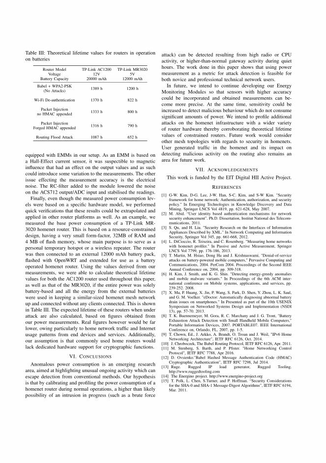
Table III: Theoretical lifetime values for routers in operationon batteries
Router ModelVoltage
Battery Capacity
TP-Link AC120012V
20000 mAh
TP-Link MR30205V
12000 mAh
Babel + WPA2-PSK(No Attacks) 1389 h 1200 h
Wi-Fi De-authentication 1370 h 822 h
Packet Injectionno HMAC appended 1333 h 800 h
Packet InjectionForged HMAC appended 1316 h 790 h
Routing Flood Attack 1087 h 652 h
equipped with EMMs in our setup. As an EMM is based ona Hall-Effect current sensor, it was suspectible to magneticinfluence that had an effect on the output values and as suchcould introduce some variation to the measurements. The otherissue effecting the measurement accuracy is the electricalnoise. The RC-filter added to the module lowered the noiseon the ACS712 output/ADC input and stabilised the readings.
Finally, even though the measured power consumption lev-els were based on a specific hardware model, we performedquick verifications that these results could be extrapolated andapplied in other router platforms as well. As an example, wemeasured the base power consumption of a TP-Link MR-3020 homenet router. This is based on a resource-constraineddesign, having a very small form-factor, 32MB of RAM and4 MB of flash memory, whose main purpose is to serve as apersonal temporary hotspot or a wireless repeater. The routerwas then connected to an external 12000 mAh battery pack,flashed with OpenWRT and extended for use as a batteryoperated homenet router. Using the values derived from ourmeasurements, we were able to calculate theoretical lifetimevalues for both the AC1200 router used throughout this paper,as well as that of the MR3020, if the entire power was solelybattery-based and all the energy from the external batterieswere used in keeping a similar-sized homenet mesh networkup and connected without any clients connected. This is shownin Table III. The expected lifetime of these routers when underattack are also calculated, based on figures obtained fromour power measurements. Real figures however would be farlower, owing particularly to home network traffic and Internetusage patterns from end devices and services. Additionally,our assumption is that commonly used home routers wouldlack dedicated hardware support for cryptographic functions.
VI. CONCLUSIONS
Anomalous power consumption is an emerging researcharea, aimed at highlighting unusual ongoing activity which canescape detection from conventional methods. Our hypothesisis that by calibrating and profiling the power consumption of ahomenet router during normal operations, a higher than likelypossibility of an intrusion in progress (such as a brute force
attack) can be detected resulting from high radio or CPUactivity, or higher-than-normal gateway activity during quiethours. The work done in this paper shows that using powermeasurement as a metric for attack detection is feasible forboth novice and professional technical network users.
In future, we intend to continue developing our EnergyMonitoring Modules so that sensors with higher accuracycould be incorporated and obtained measurements can be-come more precise. At the same time, sensitivity could beincreased to detect malicious behaviour which do not consumesignificant amounts of power. We intend to profile additionalattacks on the homenet infrastructure with a wider varietyof router hardware thereby corroborating theoretical lifetimevalues of constrained routers. Future work would considerother mesh topologies with regards to security in homenets.User generated traffic in the homenet and its impact ondetecting malicious activity on the routing also remains anarea for future work.
VII. ACKNOWLEDGEMENTS
This work is funded by the EIT Digital HII Active Project.
REFERENCES
[1] G-W. Kim, D-G. Lee, J-W. Han, S-C. Kim, and S-W Kim. "Securityframework for home network: Authentication, authorization, and securitypolicy." In Emerging Technologies in Knowledge Discovery and DataMining, Springer LNCS Vol 4819, pp. 621-628, May 2007.
[2] M. Abid. “User identity based authentication mechanisms for networksecurity enhancement”. Ph.D. Dissertation, Institut National des Telecom-munications, 2011.
[3] S. Qu, and H. Liu. "Security Research on the Interfaces of InformationAppliances Described by XML." In Network Computing and InformationSecurity, Springer Vol 345, pp. 661-668, 2012.
[4] L. DiCioccio, R. Teixeira, and C. Rosenberg. "Measuring home networkswith homenet profiler." In Passive and Active Measurement, SpringerLNCS Vol 7799, pp. 176-186, 2013.
[5] T. Martin, M. Hsiao, Dong Ha and J. Krishnaswami, "Denial-of-serviceattacks on battery-powered mobile computers," Pervasive Computing andCommunications, 2004. PerCom 2004. Proceedings of the Second IEEEAnnual Conference on, 2004, pp. 309-318.
[6] H. Kim, J. Smith, and K. G. Shin. "Detecting energy-greedy anomaliesand mobile malware variants." In Proceedings of the 6th ACM inter-national conference on Mobile systems, applications, and services, pp.239-252. 2008.
[7] X. Ma, P. Huang, X. Jin, P. Wang, S. Park, D. Shen, Y. Zhou, L. K. Saul,and G. M. Voelker. "eDoctor: Automatically diagnosing abnormal batterydrain issues on smartphones." In Presented as part of the 10th USENIXSymposium on Networked Systems Design and Implementation (NSDI13), pp. 57-70. 2013.
[8] T. K. Buennemeyer, M. Gora, R. C. Marchany and J. G. Tront, "BatteryExhaustion Attack Detection with Small Handheld Mobile Computers,"Portable Information Devices, 2007. PORTABLE07. IEEE InternationalConference on, Orlando, FL, 2007, pp. 1-5.
[9] T. Chown, Ed., J. Arkko, A. Brandt, O. Troan and J. Weil, "IPv6 HomeNetworking Architecture", IETF RFC 6126, Oct. 2014.
[10] J. Chroboczek, The Babel Routing Protocol, IETF RFC 6126, Apr. 2011.[11] M. Stenberg, S. Barth, and P. Pfister. "Home Networking Control
Protocol", IETF RFC 7788, Apr 2016.[12] D. Ovsienko.”Babel Hashed Message Authentication Code (HMAC)
Cryptographic Authentication”, IETF RFC 7298, Jul 2014.[13] Ruge. Rugged IP load generator, Rugged Tooling.
http://www.ruggedtooling.com[14] The Energino project. http://www.energino-project.org[15] T. Polk, L. Chen, S.Turner, and P. Hoffman. “Security Considerations
for the SHA-0 and SHA-1 Message-Digest Algorithms”, IETF RFC 6194,Mar. 2011.
PUBLICATIONII
Implementation Experiences and Design Challenges for Resilient
SDN Based Secure WAN Overlays
M. Vajaranta, J. Kannisto and J. Harju
11th Asia Joint Conference on Information Security, AsiaJCIS 2016, Fukuoka,
Japan, August 4-5, 2016. 2016, 17�23
doi: 10.1109/AsiaJCIS.2016.25
Publication reprinted with the permission of the copyright holders


Implementation Experiences and Design Challenges for Resilient SDNBased Secure WAN Overlays
Markku Vajaranta, Joona Kannisto and Jarmo HarjuTampere University of TechnologyEmail: [email protected]
Abstract— Mobile computing devices, industrial control sys-tems, and service provider clouds often need to be connectedto each other over wide area networks. However, reliability,quality of services and confidentiality are challenging in suchsetups. Moreover, isolated appliances and physical equipmentface harsh environment conditions. In this paper we exploredesigning secure layer 2 overlay networks using SoftwareDefined Networking (SDN), and challenges in implementingthem with open source tools.
I. INTRODUCTION
Information technology and pervasive computing bringsnew waves of innovation [1]. Every object becomes pro-grammable, data driven, and the physical realm gets weavedwith the digital world. Mobile computing and networking arehuge drivers for this progression, as systems become morevaluable the more connections they have [2].
The proliferation of network connected devices bringsalong challenges with security [3]. Many Internet of Thingsdevices use unsecured connections, protocols and vulnerablesoftware [3], [4]. The risks materialize when the devices areinstalled to networks that do not have strict firewalls. Thisis not a threat that concerns only future. Many vulnerableconnected devices are continuously exploited today [4].
Another enabler for pervasive services is the cloud com-puting. The definition of cloud computing calls for servicesthat are elastic, independent of location, controllable andmeasurable by the operator, and can be accessed by het-erogeneous devices over standard protocols [5]. The cloudis further divided to private, community, public and hybridclouds, which exhibit different security properties and needdifferent security services [5].
Cloud paradigm requires new thinking from the networkside. For instance, tenant VM (Virtual Machine) isolationinto their own networks is a must-have requirement for allshared cloud operators already. To allow efficient resourcedistribution, the logical network topology may differ a lotfrom the actual physical topology. Cloud computing reliesheavily on virtual networking, which is required as thetraditional traffic patterns no longer apply [6]. Moreover,the requirements are ever increasing and cloud networksand VM’s are about to be directly connected to companynetworks, home networks, and even to mobile personalclouds.
Seamless layer 2 clouds are mostly needed for legacyapplications, and such applications which expect to maintain
stable connection. For example, separate ICSs (IndustrialControl Systems) may reside in the same LAN, and it wouldbe very costly or even impossible to make changes to them.
Yet, connecting networks is not a simple task. Layer 2WAN overlay network techniques exist and some of themare secure when speaking about data privacy, e.g. VPN’s[7]. On the other hand, resilient overlay networks are usuallyoperating on layer 3 and they are done with BGP (BorderGateway Protocol) [8]. The combination of these factorsrequires new aspects to resilient L2 networking.
When designing such overlay network, the characteristicsmust take into account the underlaying network structure andits properties. The quality of Internet connections is typicallybest effort and Internet Service Providers (ISPs) do not wishto guarantee any latency or maximum packet loss. Thismakes Internet connections cheap (even ubiquitous). Furtherthe cloud providers typically run their operations in multiplelocations which needs interconnection between them. Theseinterconnects need to scale to many data centers since virtualmachines could even move between the locations. Thus,redundancy has to be built on top of the upper layers.
The usage of Software Defined Networking (SDN) tech-nology allows to organize networks freely using also othercriteria besides basic forwarding related decisions. Pathscan be influenced by the need of redundancy or by thesecurity services in the network [9]. For example, inter-VMcommunication can go through a firewall even when themachines reside logically in the same broadcast domain.
The paper is structured as follows. In the second sectionwe present use cases and requirements for a WAN SDNsolution. In the third section we review related work andpresent potential technologies that could satisfy the require-ments. In the fourth section we present a network designinspired by the existing solutions. The fifth section discussesthe experiences and gives ideas for future work. Finally,conclusions are drawn.
II. USE CASE AND REQUIREMENTS
The security of an overlay network should be carefullyconsidered. The basic security guideline for the design isgained from the CIA triad (confidentiality, integrity, avail-ability) [10].
The resiliency of the designed network is also important,since the network must be able to operate in distant locations,but as well in cloud environments. We have selected three

use cases to highlight the importance of the security andresiliency requirements.
CLOUD
Salesman Ambulance
Water treatment plant
Fig. 1. Use cases
Water pump Water supply station resides usually in remotelocation which requires an Internet connection for con-trolling the water pump speed. Without connectivitythe pump operates at a designated constant power.The water network can tolerate excess or insufficientpressure/flow, but it operates with less energy whenthe pressure is optimal. The controlling system, i.e.the optimization engine server is running in a cloud,and thus has real-time measurements from all pumpingstations to achieve the best efficiency for supplyingwater.
Traveling salesman While traveling, also globally, the net-work connections should be terminated to the nearestdatacenter to ensure best quality of service. Security isof topmost priority. In addition, the operating systemshould not reach for local services in unknown LANs[11].
Ambulance The personnel needs the patient records withoutany delay. Hospital equipment, for instance, heart rateanalyzers, EKGs or automatic morphine pumps need tobe in connection with the hospital’s cloud. The vehiclemoves at 180km/h, so mobile connections may breakfrom time to time.
The L2 connections between locations are built throughuntrusted networks. Common for every use case is theusage of 4G mobile connections. The mobile network isoften implemented with carrier grade IPv4 NAT (NetworkAddress Translation), which causes end-to-end connectivityproblems. Direct connections can, however, be built usingIPv6 protocol if the mobile network allows it. Unfortunatelyoften legacy applications do not support IPv6 and thus IPv4is needed. This leads to the requirement to use a secure IPv4tunneling method which is immune to NAT. In addition, someISPs might have implemented firewalls to restricting certaintraffic. This extends the need for tunnel to be also as firewallimmune as possible.
Sometimes nodes in the public IP network can act as ex-change points. Based on the needs of the use case, resiliencywill however suffer, if an alternative path (if it exists) wouldnot be available in a few seconds. This increases the need for
good packet integrity and emphasizes fast convergence time.Such features are thus required for this implementation.
The use cases define as well the need for good cloudintegration. Provisioning new VMs to these networks shouldbe effortless and reliable, which is only possible if software-based switching is available for every location the networkis extended to.
III. RELATED WORK
In order to have security in a untrusted WAN, a securetunneling mechanism is needed. One of the most famoussecure tunneling methods is IPsec (Internet Protocol SecuritySuite). It works in both transport and tunneling modesoffering the required security features for L3 VPN. TheIPsec, however, often faces problems in NAT connections[12]. Thus, the reliability does not meet the required level inchanging network conditions, and cheap commodity Internetconnections may not work.
With TLS based VPN (such as OpenVPN) these interop-erability requirements can be solved. OpenVPN tunnels thetraffic inside encrypted UDP or TCP packets, and thus inthe vast number of scenarios firewalls and NAT applianceslet it through. The L2 tunnel driver for OpenVPN is calledTAP. However, the TAP uses a simple local Ethernet controlplane causing it to be intolerant for topologies with redundantlinks, which create loops.
Despite being integral for the development of future ser-vices, secure seamless cloud WAN networking is not a muchresearched problem. Solutions for various sub-problems ofthe issue exist, however. Some of them cover simple roadwarrior cases that support only a single access concentratorand are thus not scalable or do not integrate well withcloud systems. Data center interconnection has gatheredattention, but most solutions are presented for networks thatare controlled fully by the data center operator. Resiliencyof these network environments may not fulfill the needs ofcritical cyber physical solutions. A mesh topology is oftenused to provide required resiliency but simultaneously itbrings the problem for possible loops. Since the current trendis to have data centers geographically distributed, securetunneling is required between the sites. When it comes downto ICS, requirements for network stability and reliability playa big role.
SDN is a key feature when building complex networks.It allows arbitrary topologies based on different criteria likesecurity [9], redundancy [13], [14] or efficiency [15]. SDNis commonly used for cloud networking[15] as it makestopology changes much faster than traditional networkingapproaches. SDN uses separate control plane which offerscentralized controller to have total awareness of the network.
Different industry-driven approaches to L2 virtualizationtechniques exist, but some of them are cumbersome ormissing essential features. One technique for DCI (Data Cen-ter Interconnectivity) is overlay networking, which typicallyuses an underlying IP based network, and forms its owntopology over that by using a tunneling protocol (examplesTRILL, MPLS and VXLAN) [6].

TRILL (Transparent Interconnection of Lots of Links)[16] is a technology to create a L2 cloud which forwardspackets efficiently and can recover from link breaks. TRILL,like many others is an overlay solution, which means thatit encapsulates the Ethernet frames. MPLS (MultiprotocolLabel Switching) was one of the first popular overlay net-working solutions. It has labels that are used for identifyingtraffic flows. The forwarding decisions are configured eitherstatically or dynamically [17]. The label switching nodes areconnected over IP, and thus IPsec can be used. Typically, thetechnology requires time consuming provisioning from bothISP and company requesting this feature.
VXLAN is a stand-alone overlay networking protocolwhich extends the VLAN identifier space to 16 millionunique different networks. It works by encapsulating the L2data to L4 UDP frame. VXLAN includes a multicast controlplane, which is used by the distributed switch entities todistribute unknown unicast packets and broadcast packetsto all switches that form the virtual network. The switcheskeep a table of switch identifiers and IP addresses associatedwith previously seen MAC addresses, which they utilize inunicast traffic forwarding. The protocol does not considersecurity features and thus should be used only in trustedenvironments. The VXLAN however is widely supported, inphysical and in virtual switches as well. VMware platformshave native VXLAN support since it has been one of themain developers. [18]
Geneve (Generic Network Virtualization Encapsulation) isa similar protocol to VXLAN presented in an IETF draft[19]. Where VXLAN offers its own multicast based controlplane, Geneve aims to be a control plane agnostic tunnelingprotocol. The Geneve header includes Virtual Network IDfield to ensure corresponding data transmission through thetunnel. Unfortunately, the support for Geneve is very poorand the security features are similar to VXLAN.
OTV (overlay transport virtualization) [20] is a technologyto extend the L2 network directly through the IP network.Strength of OTV is the ability to stretch the network of adatacenter to cover several separate data centers together.OTV by itself does not offer security features, but IPseccan be added on the links. Neither does VPLS (Virtualprivate LAN Service) [21] which uses BGP (Border GatewayProtocol) or LDP (Label Distribution Protocol) to form fullmesh. Both of these can be operated over IP or MPLSnetworks.
Microsoft has introduced the NVGRE [22] (Network Vir-tualization using Generic Routing Encapsulation) protocolfor network virtualization. The protocol is designed to tunnellayer 2 packets over layer 3 networks using GRE. This makesthe protocol very simple and lightweight. It does not containany security features and thus should not be used over theInternet.
Traditional method to provide redundancy to Ethernetnetworks have been to construct redundant topology and touse Spanning Tree Protocol (STP). The STP prevents loopsby shutting down ports that do not belong to a tree graphformed from a chosen root node. The default convergence
time for STP is 30-50 seconds, which is too much forcritical applications [23]. In addition, the STP makes thenetwork inefficient as the parallel usage of network links isnot possible. For instance, east-west links, which are neededfor inter-VM communication, are typically disabled.
PRP (Parallel Redundancy Protocol) [24] is one optionto create redundant networks with zero recovery time. Thisactive redundancy protocol offers parallel transmission for asingle packet from source to destination by duplicating thepacket. Delivery paths have no distinction and thus receivingnode discards the duplicates. [25] The challenge for PRP isto build a topology that can carry the duplicated packets ondistinct paths. Common topology that is used with PRP isthe ring topology. The required topology can be achievedusing SDN [13], [26], [14].
IV. PROPOSED DESIGN TO EVALUATE SECURE WANSDN
In order to get implementation experience of a SecureWAN SDN concept we built a network on virtualized in-frastructure and OpenWRT based base stations connectedwith 4G. The setup is depicted in Figure 2 where GW-1 andGW-2 are OpenWRT routers. Hypervisor-1 and Hypervisor-2 in Figure 2 reside in two common rack servers runninga hypervisor to host virtual machines. The used design is alayered one, which has SDN control plane, encrypted links,and virtual switching provided with Open vSwitch.
A. Link Layer Encryption
Link layer encryption method had several possibilities.The method must however answer the given requirementsand consider the VXLAN usage as well. Different consideredprotocol stacks are shown in the Figure 3.
VXLAN over OpenVPN was chosen because it worksthrough firewalls and is tolerant of NAT. OpenVPN alsosupports larger MTU than its underlay network. OpenVPNis a tunneling solution, and creates a network, which allowsbidirectional communication inside single connection.
VXLAN over DTLS (Datagram Transport Layer Security)would be more light-weight, but as VXLAN needs twoseparate connections, it cannot function with NAT that doesnot allow incoming connections. Even without NAT firewallpermissions may as well restrict the traffic making the DTLSunusable for this matter.
IPsec-VXLAN would have been another alternative. How-ever, it suffers from the same problems with NAT as DTLS-VXLAN. IPsec host policy is independent from routing, andpackets going to IPsec protected destinations do not travelin clear text if they are handed to a wrong interface.
B. SDN Control Plane
Open-source module-based controller [27] written in Javacalled Floodlight operates as the SDN controller. It usesOpenFlow protocol for communication between the switchesand the controller. OpenFlow works on top of TCP and manyOpenFlow implementations also support TLS with or withoutmutual authentication.
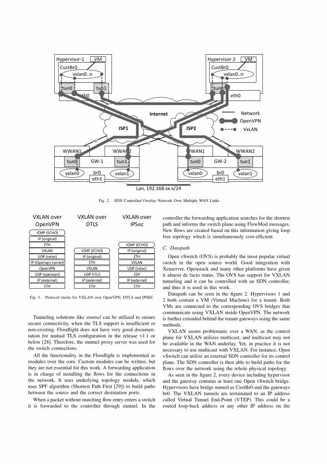
Internet
Hypervisor-1
CustBr0
vxlan0..n
eth0
tun1
VM
tun0
Hypervisor-2
CustBr0
vxlan0..n
eth0
tun0
VM
ISP1 ISP2
GW-1
br0eth1
vxlan0 vxlan1
WWAN2WWAN1
tun1tun0 GW-2
br0eth1
vxlan0 vxlan1
WWAN2WWAN1
tun1tun0
Lan, 192.168.xx.x/24
4G 4G
4G 4G
OpenVPN
VxLAN
Network
Fig. 2. SDN Controlled Overlay Network Over Multiple WAN Links
VXLAN overOpenVPN
IP (original)
ICMP (ECHO)
ETH
VXLAN
UDP (vxlan)
IP (Openvpn tunnel)
UDP (openvpn)
IP (external)
ETH
OpenVPN
VXLAN overDTLS
IP (original)
ICMP (ECHO)
ETH
VXLAN
UDP DTLS
IP (external)
ETH
VXLAN overIPSec
IP (original)
ICMP (ECHO)
ETH
VXLAN
UDP (vxlan)
ESP
IP (external)
ETH
Fig. 3. Protocol stacks for VXLAN over OpenVPN, DTLS and IPSEC
Tunneling solutions like stunnel can be utilized to ensuresecure connectivity, when the TLS support is insufficient ornon-existing. Floodlight does not have very good documen-tation for mutual TLS configuration in the release v1.1 orbelow [28]. Therefore, the stunnel proxy server was used forthe switch connections.
All the functionality in the Floodlight is implemented asmodules over the core. Custom modules can be written, butthey are not essential for this work. A forwarding applicationis in charge of installing the flows for the connections inthe network. It uses underlying topology module, whichuses SPF algorithm (Shortest Path First [29]) to build pathsbetween the source and the correct destination ports.
When a packet without matching flow entry enters a switchit is forwarded to the controller through stunnel. In the
controller the forwarding application searches for the shortestpath and informs the switch plane using FlowMod messages.New flows are created based on this information giving loopfree topology which is simultaneously cost-efficient.
C. Datapath
Open vSwitch (OVS) is probably the most popular virtualswitch in the open source world. Good integration withXenserver, Openstack and many other platforms have givenit almost de facto status. The OVS has support for VXLANtunneling and it can be controlled with an SDN controller,and thus it is used in this work.
Datapath can be seen in the figure 2. Hypervisors 1 and2 both contain a VM (Virtual Machine) for a tenant. BothVMs are connected to the corresponding OVS bridges thatcommunicate using VXLAN inside OpenVPN. The networkis further extended behind the tenant gateways using the samemethods.
VXLAN seems problematic over a WAN, as the controlplane for VXLAN utilizes multicast, and multicast may notbe available in the WAN underlay. Yet, in practice it is notnecessary to use multicast with VXLAN. For instance, OpenvSwitch can utilize an external SDN controller for its controlplane. The SDN controller is then able to build paths for theflows over the network using the whole physical topology.
As seen in the figure 2, every device including hypervisorand the gateway contains at least one Open vSwitch bridge.Hypervisors have bridge named as CustBr0 and the gatewaysbr0. The VXLAN tunnels are terminated to an IP addresscalled Virtual Tunnel End-Point (VTEP). This could be arouted loop-back address or any other IP address on the

bridge4
PRPeth
bridge1
vxlan0
vxlan1
Rewrite mac
vi0
vi1
eth
vi0
vi1
bridge2
vxlan1
vxlan0
bridge3
vxlan1
vxlan0
vxlan0
vxlan1
Fig. 4. PRP Ethernet over WAN SDN
machine. The important point is that the sending VTEPs canreach the other VTEP interface over the Layer-3 network.VXLAN is designed so that the L3 network provides theresiliency through routing. However, as we are unable toinfluence the routing of the actual IP underlay, we can makeredundant paths using VXLAN and let the controller handlethe redundancy. This is guaranteed because the VPN tunnelIP addresses are used as VXLAN VTEP termination points.
The figure 2 presents as well how the VXLAN tunnelsare built via OpenVPN tunnel interfaces. Tagged traffic isforwarded to the corresponding TUN interface and pushedto the destination where e.g. virtual machines are directlyconnected to the OVS bridge. Through the Internet a singlepacket is thus encapsulated inside VXLAN protocol whichis further encrypted using OpenVPN tunnel.
D. Active Redundancy
Active redundancy environment can be created using aprotocol called PRP (Parallell redundancy protocol). Prac-tical implementation requires adding two virtual Ethernetinterfaces to Open vSwitch and connecting them to a PRPtap which removes duplicate packets [24].
PRP operation in the implemented network is explainedin the figure 4. It works by making the Ethernet addresstranslation rule for the second PRP interface, so that thenetwork can make independent forwarding decisions for thepackets. For instance, if the paths share some links thesubsequent links can still be on different paths. Another flowrule in the chain duplicates the packet and the vendor partof the Ethernet MAC address is changed to a special PRPprefix. The end destination is PRP aware, so it can rewritethe packets coming with the special MAC address to thecorrect one.
If the controller, or the script that is making the flows, isnot PRP aware, the end switch needs to also send some ofthe packets with the PRP source address. Also IP addressesmay need to be rewritten if the controller does not permit thatthe same address is used in multiple ports and with differentMAC addresses. Furthermore, when the active redundancy ismade using an external script to control the SDN controllernorthbound interface, the configuring software needs to knowthe network topology at least partially. For example, if thereare two independent links leaving from the edge node, thepacket can be copied to both of them, and the controller canmake the rest of the path for the flows. However, the paths arenot guaranteed to be different from each other. If the paths
share links, the redundancy is not increased accordingly andsome resources are wasted for carrying duplicated packets.
In contrast, PRP implementation as an SDN controllerapplication is much simpler. The only thing that the SDNcontroller needs to be aware of is that the destination forthe packet is a PRP destination. Then, it can choose pathsoptimally using either Loop Free Alternatives [30] or someother mechanism. MAC address rewriting or adding someother flow identifier can be used if the redundant paths needto share links.
Cases where the secondary PRP transit MAC addressesuse a known prefix, forwarding application can find alter-native path in stateless manner. Thus the application selectsamong possible paths the one that shares the least amount oflinks with the most optimal one. The same rule can furtherbe applied if some other flow identifier is used.
E. Control Layer Redundancy
As our topology has multiple paths between the sourceand the destination, the controller can change the forwardingrules in the case of reachability issues. However, due tothe way Open vSwitch tunnel interfaces are exposed to thecontroller, it was needed to develop a custom watchdogapplication [31].
Open vSwitch lacks the link status information forVXLAN links. VXLAN is built on the assumption that theL3 network underneath is resilient. It does not natively havethe concept of multihop forwarding either, which can fix theL3 reachability issues. For end to end reachability detectionBFD (Bidirectional Forwarding Detection) protocol is avail-able in OVS, but it does not generate a PORT DOWN status.The controller should know if a VXLAN link is unableto communicate. These communication problems cover alltunnels and physical problems. OVS should inform the SDNcontroller about broken VXLAN links, but it does not. Basedon the information, the PDR (Port Down Reconciliation)module in Floodlight should change the path for the existingflows based on the network changes [27]. This does notoccur, and even the new flows are built to non-workinginterfaces.
To fix the issue we developed a watchdog script [31]to notice dead links and flows. The used watchdog scriptchecks reachability for tunnel endpoint every two secondswith ICMP echo (ping). Changing the current jammed flowsto backup link is done by removing the interface and clearingthe associated flows. Floodlight controller then rebuilds nec-essary flow tables to switches using other interfaces, whichhopefully will be up. The script configures the interfaceback up once the endpoint is reachable again. Using thecustom watchdog application the convergence time will be4-6 seconds.
V. DISCUSSION
As the security of the proposed setup relies heavily onthe OpenVPN tunnel, it can be vulnerable to the tunneldisappearing, and packets may get routed through wronginterface in clear text. For example, if the tunnel interface

goes down, without proper firewall settings the VXLANpackets are transmitted to the ISP’s network unencryptedbased on the default route information.
Moreover, the security is not end to end when there aremultiple links. Therefore, a secure variant of VXLAN typeof tunneling protocol would be useful. In SDN environmentthe controller should take care of the security associations.
The usage of VXLAN requires the underlay technique toaccept MTU value above 1500 bytes. This was faced withseveral experiments where ping and other smaller packagesgo well through the network, but any larger messages didnot. VXLAN encapsulated packet consists of IPv4 and UDPheaders which make 28 bytes and in addition the VXLANheader is 8 bytes more, total 36 bytes. The underlay net-work’s MTU should thus be adjusted to consider this extraoverhead.
For instance, the OpenVPN tunnel MTU must be raised ifsome parts of the bridged network do not support MTU lessthan 1500. The tunnel interface can be set to much higherMTU, e.g. 2000 bytes since the OpenVPN takes care ofthe fragmentation. This creates an overhead, which couldbe a problem for scalability. Yet, any tunneling solution willexperience MTU issues.
Practical option would be MACsec [32] under VXLANor any other tunnel, provisioned using an extension toOpenFlow or with MACsec key exchange protocols. MAC-sec is supported in some traditional switches. An SDNcontroller could implement the necessary key exchanges tobe compatible with them, so the security domain could beextended outside of SDN domain as well. Overall encryptionat the network edge would be desirable. In addition, MACsecactually implements PRP-like duplicate packet filtering asa side effect of avoiding replay attacks. OpenFlow keymanagement for MACsec would be one issue. This couldbe solved by storing the public keys on the controller for allthe switches. The receiving switch gets flow rules that usekey wrapping.
Switches are unable to exchange keys between each other,as the sending switch is unaware for the final destinationswitch of the packet. This knowledge is at the controller.Key derivation could create problems which are not as severewith key wrapping or key distribution. For instance, when aswitch for a destination VM changes all the flow rules needto be reinstalled.
Control layer based redundancy is combined with activeredundancy to have the best sides of each. Active redundancyhas potentially zero convergence time. Yet, active redun-dancy loses capacity, potentially increasing latency as wellas packet loss due to congestion. Thus capacity problemsmight occur if the packets would be copied to any possiblealternative path. In addition, PRP does not handle more thantwo interfaces [33]. Quality of Service (QoS) is partiallyimproved by the PRP. At any given moment, PRP uses theinterface that can provide the packets faster.
Control layer based redundancy is too slow for someof the applications. On the other hand, faster convergencetime could cause continuous topology changes in mobile
conditions. However, topology change is necessary eventu-ally since the backup paths could be constructed very sub-optimally.
The SDN controller is the centralized brain for the overlaynetwork. Therefore, redundant controller design is requiredfor increased reliability. Currently if the controller is notreachable the old flows continue to operate, but no newconnections can be made. OVS supports using multiplecontrollers, but high-availability features are missing in theFloodlight controller v1.1 [28]. Floodlight though has plansto support synchronization but the support is not ready fullyintegrated nor tested [34], [35].
VI. CONCLUSIONS
This paper describes a method for building a secureoverlay network over WAN connections. The used protocolsand technologies offer a resilient and secure communicationmethod for ICS, DCI and other use cases. Presented examplesystem has been built using commodity hardware and best-effort 4G mobile wireless WAN connections. The use ofthese components further increase the need for reliablecommunication protocol stack.
The security in this context is not pervasive security whichprevents everything and creates an isolated network. Themain aspect is to have a safe mechanism to move databetween two locations without a possibility to be seen bya 3rd party. It answers the need for confidentiality, integrityand availability. Still the security features in this network donot totally prevent DDoS attacks, MitM attacks and manyothers.
As presented, VXLAN and OpenVPN transporting meth-ods combined with SDN offer a powerful tool for secureseamless WAN. SDN is the key function that allows pre-sented network to operate seamlessly.
The used SDN components, Open vSwitch, and theFloodlight controller presented minor issues, and some re-quired components were still missing. For instance, the OVSVXLAN implementation does not inform the SDN controllerabout broken links, which had to be compensated usingcustom watchdog script. Also, control plane redundancy ismissing since the Floodlight does not support it yet. Thiscreates a single point of failure and hopefully problemis fixed within the incoming versions of the Floodlightcontroller.
Data plane redundancy is provided by PRP protocol. Itensures the data transmission between endpoints using twodifferent paths through the overlay network. Yet, it cannotfunction in complex networks without an SDN componentthat can build logical ring topologies for it.
The built stack causes quite large overhead, which isnot ideal, although much of this is due to interoperability.This overhead issue could be answered with e.g. VXLANover DTLS, but the resiliency and availability would suffergreatly. Also, resiliency can always be improved, and evenprovided as a service.
Data center and industrial control system networks willneed to consider overlay network security eventually. This

paper offers one solution to cover some use cases usingopen-source tools. Set requirements were answered and thenecessary resiliency and security level was reached. SDNtechnology proofed its power and elasticity in this rathercomplex network setup.
ACKNOWLEDGMENT
The research was conducted in the Cyber Trust program ofDIGILE (Finnish Strategic Centre for Science, Technologyand Innovation in the field of ICT), funded by Tekes.
REFERENCES
[1] M. Satyanarayanan, “Pervasive computing: Vision and challenges,”Personal Communications, IEEE, vol. 8, no. 4, pp. 10–17, 2001.
[2] J. Hendler and J. Golbeck, “Metcalfe’s law, web 2.0, and the semanticweb,” Web Semantics: Science, Services and Agents on the World WideWeb, vol. 6, no. 1, pp. 14–20, 2008.
[3] Z.-K. Zhang, M. C. Y. Cho, C.-W. Wang, C.-W. Hsu, C.-K. Chen, andS. Shieh, “IoT security: ongoing challenges and research opportuni-ties,” in 2014 IEEE 7th International Conference on Service-OrientedComputing and Applications (SOCA). IEEE, 2014, pp. 230–234.
[4] Y. M. P. Pa, S. Suzuki, K. Yoshioka, T. Matsumoto, T. Kasama, andC. Rossow, “IoTPOT: analysing the rise of IoT compromises,” in 9thUSENIX Workshop on Offensive Technologies (WOOT 15), 2015.
[5] P. Mell and T. Grance, “The NIST definition of cloud computing,”Communications of the ACM, vol. 53, no. 6, p. 50, 2010.
[6] A. Scarfo, “The evolution of data center networking technologies,”in Data Compression, Communications and Processing (CCP), 2011First International Conference on. IEEE, 2011, pp. 172–176.
[7] N. M. K. Chowdhury and R. Boutaba, “A survey of network virtual-ization,” Computer Networks, vol. 54, no. 5, pp. 862–876, 2010.
[8] D. Andersen, H. Balakrishnan, F. Kaashoek, and R. Morris, Resilientoverlay networks. ACM, 2001, vol. 35, no. 5.
[9] C. DeCusatis and P. Mueller, “Virtual firewall performance as awaypoint on a software defined overlay network,” in High PerformanceComputing and Communications, 2014 IEEE 6th Intl Symp on Cy-berspace Safety and Security, 2014 IEEE 11th Intl Conf on EmbeddedSoftware and Syst (HPCC, CSS, ICESS), 2014 IEEE Intl Conf on.IEEE, 2014, pp. 819–822.
[10] S. S. Greene, Security policies and procedures. New Jersey: PearsonEducation, 2006.
[11] M. Wuergler. The evolution of wireless penetration testing.[Online]. Available: http://immunityservices.blogspot.fi/2016/01/the-evolution-of-wireless-penetration.html
[12] B. Aboba and W. Dixon, “Ipsec-network address translation (NAT)compatibility requirements,” Internet Requests for Comments, RFCEditor, RFC 3715, March 2004.
[13] E. Molina, E. Jacob, J. Matias, N. Moreira, and A. Astarloa, “Avail-ability improvement of layer 2 seamless networks using OpenFlow,”The Scientific World Journal, 2015.
[14] J. Zhang, B.-C. Seet, T.-T. Lie, and C. H. Foh, “Opportunities forsoftware-defined networking in smart grid,” in Information, Com-munications and Signal Processing (ICICS) 2013 9th InternationalConference on. IEEE, 2013, pp. 1–5.
[15] S. Azodolmolky, P. Wieder, and R. Yahyapour, “SDN-based cloudcomputing networking,” in Transparent Optical Networks (ICTON),2013 15th International Conference on. IEEE, 2013, pp. 1–4.
[16] D. Eastlake, A. Banerjee, D. Dutt, R. Perlman, and A. Ghanwani,“Transparent interconnection of lots of links (TRILL) use of IS-IS,”Internet Requests for Comments, RFC Editor, RFC 6326, July 2011.
[17] D. Awduche, L. Berger, D. Gan, T. Li, V. Srinivasan, and G. Swallow,“RSVP-TE: Extensions to RSVP for LSP tunnels,” Internet Requestsfor Comments, RFC Editor, RFC 3209, December 2001.
[18] M. Mahalingam, D. Dutt, K. Duda, P. Agarwal, L. Kreeger,T. Sridhar, M. Bursell, and C. Wright, “Virtual extensible localarea network (VXLAN): A framework for overlaying virtualizedlayer 2 networks over layer 3 networks,” Internet Requests forComments, RFC Editor, RFC 7348, August 2014. [Online]. Available:http://www.rfc-editor.org/rfc/rfc7348.txt
[19] J. Gross, T. Sridhar, P. Garg, C. Wright, I. Ganga, P. Agarwal, K. Duda,D. Dutt, and J. Hudson, “Geneve: Generic network virtualizationencapsulation,” Internet Engineering Task Force, Internet Draft, 2014.
[20] H. Grover, D. Rao, D. Farinacci, and V. Moreno, “Overlaytransport virtualization,” Working Draft, IETF Secretariat, Internet-Draft draft-hasmit-otv-04, February 2013. [Online]. Available:https://tools.ietf.org/html/draft-hasmit-otv-04
[21] K. Kompella and Y. Rekhter, “Virtual private lan service (VPLS)using BGP for auto-discovery and signaling,” Internet Requests forComments, RFC Editor, RFC 4761, January 2007.
[22] P. Garg and Y. Wang, “NVGRE: Network virtualization using genericrouting encapsulation,” Internet Requests for Comments, RFC Editor,RFC 7637, September 2015.
[23] A. Myers, E. Ng, and H. Zhang, “Rethinking the service model:Scaling ethernet to a million nodes,” in Proc. HotNets. Citeseer,2004.
[24] H. Weibel, “Tutorial on parallel redundancy protocol (PRP),” ZurichUniversity of Applied Sciences, 2011.
[25] H. Kirrmann, M. Hansson, and P. Muri, “IEC 62439 PRP: Bumplessrecovery for highly available, hard real-time industrial networks,” inEmerging Technologies and Factory Automation, 2007. ETFA. IEEEConference on. IEEE, 2007, pp. 1396–1399.
[26] X. Dong, H. Lin, R. Tan, R. K. Iyer, and Z. Kalbarczyk,“Software-defined networking for smart grid resilience: Opportunitiesand challenges,” in Proceedings of the 1st ACM Workshop onCyber-Physical System Security, ser. CPSS ’15. New York,NY, USA: ACM, 2015, pp. 61–68. [Online]. Available: http://doi.acm.org/10.1145/2732198.2732203
[27] R. Izard. Controller modules. [Online]. Available: https://floodlight.atlassian.net/wiki/display/floodlightcontroller/Controller+Modules
[28] Floodlight releases and roadmap. [Online]. Avail-able: https://floodlight.atlassian.net/wiki/display/floodlightcontroller/Releases+and+Roadmap
[29] E. W. Dijkstra, “A note on two problems in connexion with graphs,”Numerische mathematik, vol. 1, no. 1, pp. 269–271, 1959.
[30] A. Atlas and A. Zinin, “Basic specification for IP fast reroute: Loop-free alternates,” Internet Requests for Comments, RFC Editor, RFC5286, September 2008.
[31] M. Vajaranta and J. Kannisto. Link watching script for open vswitch.[Online]. Available: https://github.com/joonakannisto/himmeli
[32] A. Romanow, Media Access Control (MAC) Security IEEE 802.1 ae,IEEE Std., 2006.
[33] Parallel redundancy protocol (PRP) software implementation.[Online]. Available: https://github.engineering.zhaw.ch/Team1588/sw stack prp1
[34] T. A. Ribeiro. How to add fault toler-ance to the control plane. [Online]. Avail-able: https://floodlight.atlassian.net/wiki/display/floodlightcontroller/How+to+Add+Fault+Tolerance+to+the+Control+Plane
[35] R. Izard. We want you to add cool features to floodlight. [Online].Available: https://floodlight.atlassian.net/wiki/pages/viewpage.action?pageId=24805405

140

PUBLICATIONIII
IPsec and IKE as Functions in SDN Controlled Network
M. Vajaranta, J. Kannisto and J. Harju
Network and System Security - 11th International Conference, NSS 2017, Helsinki,
Finland, August 21-23, 2017, Proceedings. Ed. by Z. Yan, R. Molva, W. Mazurczyk
and R. Kantola. 2017, 521�530
doi: 10.1007/978-3-319-64701-2_39
Publication reprinted with the permission of the copyright holders

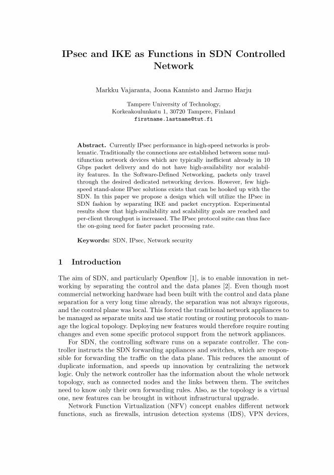
IPsec and IKE as Functions in SDN ControlledNetwork
Markku Vajaranta, Joona Kannisto and Jarmo Harju
Tampere University of Technology,Korkeakoulunkatu 1, 30720 Tampere, Finland
Abstract. Currently IPsec performance in high-speed networks is prob-lematic. Traditionally the connections are established between some mul-tifunction network devices which are typically inefficient already in 10Gbps packet delivery and do not have high-availability nor scalabil-ity features. In the Software-Defined Networking, packets only travelthrough the desired dedicated networking devices. However, few high-speed stand-alone IPsec solutions exists that can be hooked up with theSDN. In this paper we propose a design which will utilize the IPsec inSDN fashion by separating IKE and packet encryption. Experimentalresults show that high-availability and scalability goals are reached andper-client throughput is increased. The IPsec protocol suite can thus facethe on-going need for faster packet processing rate.
Keywords: SDN, IPsec, Network security
1 Introduction
The aim of SDN, and particularly Openflow [1], is to enable innovation in net-working by separating the control and the data planes [2]. Even though mostcommercial networking hardware had been built with the control and data planeseparation for a very long time already, the separation was not always rigorous,and the control plane was local. This forced the traditional network appliances tobe managed as separate units and use static routing or routing protocols to man-age the logical topology. Deploying new features would therefore require routingchanges and even some specific protocol support from the network appliances.
For SDN, the controlling software runs on a separate controller. The con-troller instructs the SDN forwarding appliances and switches, which are respon-sible for forwarding the traffic on the data plane. This reduces the amount ofduplicate information, and speeds up innovation by centralizing the networklogic. Only the network controller has the information about the whole networktopology, such as connected nodes and the links between them. The switchesneed to know only their own forwarding rules. Also, as the topology is a virtualone, new features can be brought in without infrastructural upgrade.
Network Function Virtualization (NFV) concept enables different networkfunctions, such as firewalls, intrusion detection systems (IDS), VPN devices,

just to name few, to run virtualized. This allows service aggregation to a singleserver and simultaneously offers possibility to add functions as on-demand tothe network. The NFV and SDN together is a powerful combination to provideelastic services and use them without major network reconfigurations. [3]
IPsec is an example of a protocol that has a clear signaling and forwardingseparation [4, 5]. The Internet Key Exchange (IKE) protocol [5] is used to ne-gotiate the security associations (SAs), which are then used for the actual dataplane of the IPsec. This makes IPsec conform nicely to the SDN paradigm. IPsecis also a service of the network layer, unlike, for example, TLS, which is moretied to the actual application.
Some common IPsec clustering problems have been discussed in [6]. The RFChowever ignores the IPsec function distribution, which this paper describes. IPseccan be distributed into multiple SDN enabled functions, that can be effectivelyparallelized and freely organized based on the available resources. Furthermore,we concentrate on presenting the communication between the modules, and hopethat our contribution would incite discussion on open APIs to provision securityfunctions to SDN networks, such as the IPsec and IKE functions presented here.
This paper is structured as follows: Section 2 contains the related work.Section 3 describes the proposed solution of IPsec functionality distribution andSDN paradigm. Section 4 evaluates the performance of the proposed solutionwhile Section 5 contains future work and discussion. Finally Section 6 draws theconclusions.
2 Related work
Inserting security appliances into SDN networks has already been discussed in[7–11] showing that the security needs guide the networking topology. One ofthe conclusions being that SDN allows to forget the physical topology altogether[12].
Yet, freedom from the physical constraints may require advanced flow bal-ancing. Scott-Hayward et al. added that traffic redirection may cause link con-gestions which results to performance problems [12].
Tafreshi et al. [13] argue that Openflow needs to support IPsec, in order to beaware of the flows and to route the traffic more efficiently. The usage of SecurityParameter Index (SPI) parameter in flow identification would enhance networkoperation in High Availability (HA) enabled IPsec setups.
Recently, Li et. al. have proposed having IPsec concentrator as an integralpart of the SDN network [14]. Their work, however, differs from ours, as theydo not implement a modular design of independent services orchestrated by theSDN controller.
SDN network is enhanceable by NFV services. While SDN controller changesflows to insert some middle-box functions, the NFV concept introduces servicesproviding these functions using virtualization. [15, 16]
The presented solution is tailored to use IPsec, but it is not limited to it.The same methodology applies whether MACsec or OpenVPN is used in the

middlebox [17, 18]. Dedicated IPsec processing appliances are required to providefast IPsec functionality to the network. Solutions such as DPDK [19], PIPSEA[20] or Cavium Octeon based devices [21] have been proposed. Meng et al. alsoincluded measurements for the throughput on different packet size [21]. Theirsolution struggled with large amount of small packets which is a commonlyknown problem in VPN tunneling.
3 Scalable IPsec architecture description
From this point we use the following terminology:
IPsec appliance handles the whole IKE and IPsec functionality autonomously.IKE function handles only the IKE negotiation.Packet crypto function (PCF) handles only IPsec for network packets.
3.1 Traditional IPsec Appliance in an SDN Network
Figure 1 presents how a stand-alone IPsec appliance can be applied to an SDNnetwork. The appliance maintains the tunnel connection and performs data en-cryption/decryption operations between the headquarter and the branch officenetwork. The SDN controller in the network does not have visibility to the IPsecappliance status. The controller is only for modifying the flows and forwardingthe packets to the IPsec appliance when necessary.
The traditional design does not achieve scalability nor availability needs with-out vendor specific redundancy protocols and ad-hoc management of resources.More IPsec appliances can be added to the network, but they suffer from beingseparate devices in that they cannot take over each other’s flows.
3.2 Distributed IPsec functionality
Network design where the IPsec functionality is distributed to an IKE functionand two PCFs is described in Figure 2. This design meets the high availability
Internet
SDN SwitchPC
IPsec Appliance
Branch office
SDN Controller
Firewall,IPsec appliance
ESP Traffic
Unencrypted traffic
IKE negotiation
Fig. 1. Traditional placement for IPsec appliance in SDN network.

Internet
SDN SwitchPCs
Packet crypto function
Branch office
SDN Controller
Firewall,IPsec appliance
Packet crypto function
IKE function andIPsec orchestrator
ESP Traffic
Unencrypted traffic
IKE negotiation
Fig. 2. IPsec with distributed IKE module and two packet crypto functions in an SDNnetwork
and scalability needs for IPsec because every function can have several multipli-cations. IKE function is required to negotiate SA values with the branch officeIPsec appliance. These SA values need to be transferred from IKE function toall PCFs.
The IPsec orchestrator module acts between the PCFs and the IKE functionto store and deliver necessary information such as SPI and key values. Deliverycan occur in a separate network from the main SDN control network, if sodesired. The IPsec orchestrator also selects the PCF for one specific networkflow. The PCF operates on the data plane and is responsible for encryption anddecryption operations. The SDN network allow to use virtually any number ofthese functions to reach the required IPsec packet processing rate.
3.3 Message exchange
Figure 3 describes message exchange between the different actuators in the net-work. It reflects a situation where a PC in the local network is the first to senda packet going to the branch office. The SDN controller checks its table for ex-isting IPsec SAs, and consults the network policy on whether the packet shouldbe protected, dropped or forwarded as is. This matching is done by a controllermodule responsible for security associations. If the packet needs a new SA, theIPsec orchestrator needs to be informed and a new IKE negotiation is initiated.
The IKE negotiation requires the SDN controller to redirect all packets withUDP port 500 to the IKE function (there can also be a static flow rule). Thisallows the IKE negotiation to occur between the IKE function and the branchoffice IPsec VPN appliance. The resulting SA with the traffic policies, are addedto the IPsec SA table in the IPsec orchestrator. SPI, KEY, lifetime and IPinformation are distributed to the PCFs.

PC A SDN SW SDN CTRLPacket crypto
function #1Packet crypto function #N
Branch office VPN
P
P
IPsec Orch., IKE func.
P from A to VPN
UDP:500 flow
SPI,KEY,IP,Lifetime
SPI,KEY,IP,Lifetime
OK
IKEv2 negotiation
FlowSetup. (A to Encr,
Encr to OUT,Out to Decr,
Decr to A)
OK
Release P to SW
Fig. 3. Signaling and message transfer between different actuators when PC A sendsa packet (P) to Branch office.
3.4 Technical details of IPsec orchestration
The IPsec orchestrator is the central information exchange point for the IKEorchestrator and the packet crypto function orchestrator as shown in Figure 4.The communication is done using API layers. When a packet related to new IPseccommunication is received, it is forwarded to IPsec orchestrator for verificationand decision making. If the packet is valid, second level orchestrators are called.
The IKE orchestrator is responsible for verifying incoming new IKE connec-tions. If connection is valid, the IKE function establishes new IKE SAs. The IKEorchestrator also orders the SDN controller to create flows for capturing the IKEinitiation traffic to the device responsible for IKE function.
The Packet crypto function orchestrator is responsible for monitoring theload of PCFs and sharing traffic equally between them. Orchestrator makes thedecision which PCF is used for which flow in the network and thus it gives flowinstructions directly to the SDN controller.
The IPsec, IKE and packet crypto function orchestrators share a lot of sen-sitive information. They need to know the SPI, key and the lifetime informa-tion that the IKE function negotiates. All the communication between differentorchestrators and functions is done over a separate control network. The com-munication can use TLS, physical separation or preferably both. None of theIPsec orchestrators needs the keys themselves, so the keys could be transmittedin encrypted form.

IPsec orchestrator Receive
packets
IKE orchestrator
IKE function
Packet crypto function orchestrator
Packet crypto function
SDN Controller Manage
switches
API
API
API
API
Flows
Flows
Fig. 4. IPsec orchestrator and its sub-orchestrators: IKE and packet crypto functionorchestrator, different functions and SDN controller communication.
3.5 IPsec orchestration API
The IPsec orchestrator needs to get the keys from the IKE orchestrator to bedelivered to the PCFs. The simplest way is to use API. In our example, the IKEorchestrator launches the IKE function which negotiates IKE parameters. TheIKE function returns the child SA keys to the IKE orchestrator which sends thekeys to IPsec orchestrator. It makes a POST request to initiate a dataplane PCF.The function returns a resource identifier that can be later queried for statisticsand removed. The response also includes a description of the ports provisionedfor the operation. The packet crypto function’s API is a JSON REST API withthe syntax described in the following listing:
{"mode": [" tunnel","transport "],
"spi": "0 x512256",
"operation ": [" encrypt","decrypt"],
"details ": {
"enc -mode" : "aes -cbc",
"mac" : "sha -1",
"ck": "deadbeef",
"ik": "caffeebaba",
[" tunnel"," transport "]: {
"out_dst ": "10.0.0.1" ,
"out_src ": "192.168.0.1" ,
"in_block ": "10.33.7.0/24" ,
"out_block ": "192.168.13.0/24"
}}}
At minimum, the PCF device needs the integrity (ik) and cryptography (ck)keys, and SPI (defaults to transport mode, and AES-CBC with SHA-1 HMAC).For the tunnel mode, the outer IP addresses, as well as allowed inner addressesare required.
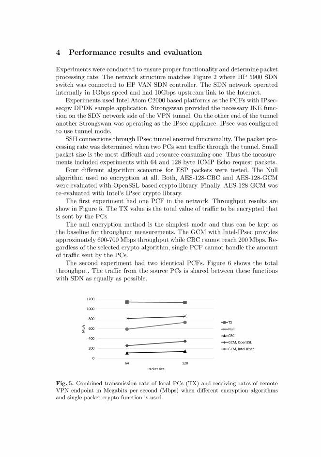
4 Performance results and evaluation
Experiments were conducted to ensure proper functionality and determine packetprocessing rate. The network structure matches Figure 2 where HP 5900 SDNswitch was connected to HP VAN SDN controller. The SDN network operatedinternally in 1Gbps speed and had 10Gbps upstream link to the Internet.
Experiments used Intel Atom C2000 based platforms as the PCFs with IPsec-secgw DPDK sample application. Strongswan provided the necessary IKE func-tion on the SDN network side of the VPN tunnel. On the other end of the tunnelanother Strongswan was operating as the IPsec appliance. IPsec was configuredto use tunnel mode.
SSH connections through IPsec tunnel ensured functionality. The packet pro-cessing rate was determined when two PCs sent traffic through the tunnel. Smallpacket size is the most difficult and resource consuming one. Thus the measure-ments included experiments with 64 and 128 byte ICMP Echo request packets.
Four different algorithm scenarios for ESP packets were tested. The Nullalgorithm used no encryption at all. Both, AES-128-CBC and AES-128-GCMwere evaluated with OpenSSL based crypto library. Finally, AES-128-GCM wasre-evaluated with Intel’s IPsec crypto library.
The first experiment had one PCF in the network. Throughput results areshow in Figure 5. The TX value is the total value of traffic to be encrypted thatis sent by the PCs.
The null encryption method is the simplest mode and thus can be kept asthe baseline for throughput measurements. The GCM with Intel-IPsec providesapproximately 600-700 Mbps throughput while CBC cannot reach 200 Mbps. Re-gardless of the selected crypto algorithm, single PCF cannot handle the amountof traffic sent by the PCs.
The second experiment had two identical PCFs. Figure 6 shows the totalthroughput. The traffic from the source PCs is shared between these functionswith SDN as equally as possible.
0
200
400
600
800
1000
1200
64 128
Mb
/s
Packet size
TX
Null
CBC
GCM, OpenSSL
GCM, Intel-IPsec
Fig. 5. Combined transmission rate of local PCs (TX) and receiving rates of remoteVPN endpoint in Megabits per second (Mbps) when different encryption algorithmsand single packet crypto function is used.

0
200
400
600
800
1000
1200
1400
1600
1800
64 128
Mb
/s
Packet size
TX
Null
CBC
GCM, OpenSSL
GCM, Intel-IPsec
Fig. 6. Combined transmission rate of local PCs (TX) and receiving rates of remoteVPN endpoint in Megabits per second (Mbps) when different encryption algorithmsand two packet crypto functions are used.
The results show that 1.5 Gbps throughput is reached in 128 byte packet size.The TX Mbps value is smaller than the Mbps value of the received encrypteddata, since every null encrypted packet enlarges the original packet with 32 bytesand GCM with 56 bytes. Thus the GCM line should be higher than the null line,but with 64 byte packet size the PCFs still choked.
All the experiments used DPDK based IPsec-secgw as the PCF. Through-put using one PCF with 64 byte packet size was best with GCM (Intel-IPsec),approximately 600Mbps. In comparison, the authors in [20] were able to useIntel Quick Assist Tool (QAT) with DPDK and achieved 1Gbps throughput.Their own embedded APU environment, PIPSEA, reached 3Gbps. Even fasterpacket processing rate, 4Gbps, have been achieved in [21] using Cavium Octeonplatform.
5 Future work and discussion
The described model proves that SDN and distributed IPsec operate well to-gether. Multiple PCFs serve in the network to provide the required HA feature,but they only guarantee partial load balancing. In this concept the load balanc-ing is path based meaning that a client uses one PCF at a time. Simultaneoususe is doable, but would require a proper link aggregation mechanism leading tomultiple PCFs being presented to the SDN network as one. This method needsmultipath labeling to identify individual packets, which is a future research topic.
Outgoing packets are well load balanced, but incoming packets are redirectedalways to a certain PCF for decryption in the tunnel mode. This is caused bythe source and destination IPs being the same for each packet in the tunnelmode, meaning that the transport mode is unaffected. A solution for betterload balancing in the tunnel mode is to use Equal-Cost Multi-Path (ECMP) inOpenflow SDN which chooses the least congested ports if possible.
The presented design of this paper is vulnerable to replay attacks becausethe sequence number verification in the tunnel mode needs to be disabled as

permitted in [4]. This is because each PCF allocates sequence numbers to theirpackets independently, and in the receiving end the packets from different PCFs(but belonging to the same SA) may appear as duplicates. The problem could beeliminated by synchronizing the packet counters between all PCFs, which wouldrequire shared state table between the functions. This is virtually impossible inhigh speed operation.
A replay attack may occur even when the sequence number verification isenabled. If an attacker has two packet injection points to the data plane, thecontroller can construct flows through different PCFs, causing the duplicatepacket to reach the destination. An answer is to use deterministic link selection,which in turn makes ECMP unsuitable. A platform-independent solution wouldbe to run multiple flows through the network and balance these flows by usingencrypted payload bits with a bitmask.
The original model can be extended to include automatic PCF launchingin NFV fashion. The used DPDK ipsec-secgw sample application relies on IPheader TX checksum offloading while the virtual interfaces do not support thisfeature. For this reason experiments were not conducted in virtual environment.
An existing IKE negotiator was used for experiments. Our approach requiredcomplicated dataplane arrangements for the IKE messages and could likely havebeen avoided with a pure IKE component as an SDN application. Althoughin these pilots the IPsec orchestrator has access to all the secrets, we can alsosupport key wrapping in the orchestrator mediated messaging to the data planePCFs. In most environments this would have only minor security benefit for alot of added complexity.
6 Conclusions
We present a modern approach utilizing SDN to enhance the IPsec availabilityand performance on commodity hardware. The model distributes IPsec mainoperations to individual functional modules. The IKE module provides necessaryinformation to the data plane devices for ESP operation.
The results of our performance tests show that IPsec throughput increasesfrom 750Mbps to 1.5Gbps when the number of packet crypto functions is dou-bled. While this performance increase was to be expected, it also emphasizes thebenefit of distributed design of SDN networks.
This kind of an SDN network which includes the presented IPsec model worksfor both small and enterprise networks. However, great benefit can be achievedwhen a lot of clients use IPsec.The work presented in this article illustrates thepossibilities that SDN brings to the legacy techniques which have difficulties tomeet the current scalability needs.
References
1. McKeown, N., Anderson, T., Balakrishnan, H., Parulkar, G., Peterson, L., Rexford,J., Shenker, S., Turner, J.: Openflow: enabling innovation in campus networks.ACM SIGCOMM Computer Communication Review 38(2) (2008) 69–74

2. Nunes, B.A.A., Mendonca, M., Nguyen, X.N., Obraczka, K., Turletti, T.: A sur-vey of software-defined networking: Past, present, and future of programmablenetworks. IEEE Communications Surveys & Tutorials 16(3) (2014) 1617–1634
3. Mijumbi, R., Serrat, J., Gorricho, J.L., Bouten, N., De Turck, F., Boutaba, R.:Network function virtualization: State-of-the-art and research challenges. IEEECommunications Surveys & Tutorials 18(1) (2016) 236–262
4. Kent, S., Seo, K.: Security architecture for the internet protocol. RFC 4301, RFCEditor (December 2005) http://www.rfc-editor.org/rfc/rfc4301.txt.
5. Kaufman, C., Hoffman, P., Nir, Y., Eronen, P.: Internet key exchange protocolversion 2 (ikev2). RFC 5996, RFC Editor (September 2010)
6. Nir, Y.: Ipsec cluster problem statement. RFC 6027, RFC Editor (October 2010)7. Fayazbakhsh, S.K., Chiang, L., Sekar, V., Yu, M., Mogul, J.C.: Enforcing network-
wide policies in the presence of dynamic middlebox actions using flowtags. In:NSDI. Volume 14. (2014) 533–546
8. Qazi, Z.A., Tu, C.C., Chiang, L., Miao, R., Sekar, V., Yu, M.: SIMPLE-fying mid-dlebox policy enforcement using sdn. ACM SIGCOMM computer communicationreview 43(4) (2013) 27–38
9. Qazi, Z., Tu, C.C., Miao, R., Chiang, L., Sekar, V., Yu, M.: Practical and incre-mental convergence between sdn and middleboxes. Open Network Summit, SantaClara, CA (2013)
10. Gember, A., Prabhu, P., Ghadiyali, Z., Akella, A.: Toward software-defined mid-dlebox networking. In: Proceedings of the 11th ACM Workshop on Hot Topics inNetworks, ACM (2012) 7–12
11. Bremler-Barr, A., Harchol, Y., Hay, D., Koral, Y.: Deep packet inspection as aservice. In: Proceedings of the 10th ACM International on Conference on emergingNetworking Experiments and Technologies, ACM (2014) 271–282
12. Scott-Hayward, S., O’Callaghan, G., Sezer, S.: Sdn security: A survey. In: FutureNetworks and Services (SDN4FNS), 2013 IEEE SDN For, IEEE (2013) 1–7
13. Tafreshi, V.H.F., Ghazisaeedi, E., Cruickshank, H., Sun, Z.: Integrating ipsecwithin openflow architecture for secure group communication. ZTECOMMUNI-CATIONS (2014) 41
14. Li, W., Lin, F., Sun, G.: Sdig: Toward software-defined ipsec gateway. In: NetworkProtocols (ICNP), 2016 IEEE 24th International Conference on, IEEE (2016) 1–8
15. Wood, T., Ramakrishnan, K., Hwang, J., Liu, G., Zhang, W.: Toward a software-based network: integrating software defined networking and network function vir-tualization. IEEE Network 29(3) (2015) 36–41
16. Han, B., Gopalakrishnan, V., Ji, L., Lee, S.: Network function virtualization:Challenges and opportunities for innovations. IEEE Communications Magazine53(2) (2015) 90–97
17. Hutchison, G.T., Nemat, A.B.: Macsec implementation (October 12 2010) USPatent 7,814,329.
18. Feilner, M.: OpenVPN: Building and integrating virtual private networks. PacktPublishing Ltd (2006)
19. Divyesh Darde, Vidhya Sankaran, H.W.H.W.: Cs5413 project final report. analysisof performance of intel dpdk on physical and virtual machines
20. Park, J., Jung, W., Jo, G., Lee, I., Lee, J.: Pipsea: A practical ipsec gatewayon embedded apus. In: Proceedings of the 2016 ACM SIGSAC Conference onComputer and Communications Security, ACM (2016) 1255–1267
21. Meng, J., Chen, X., Chen, Z., Lin, C., Mu, B., Ruan, L.: Towards high-performanceipsec on cavium octeon platform. In: International Conference on Trusted Systems,Springer (2010) 37–46

PUBLICATIONIV
Feasibility of FPGA Accelerated IPsec on Cloud
M. Vajaranta, V. Viitamaki, A. Oinonen, T. D. Hämäläinen, A. Kulmala and
J. Markunmäki
21st Euromicro Conference on Digital System Design, DSD 2018, Prague, Czech
Republic, August 29-31, 2018. Ed. by M. Novotný, N. Konofaos and A. Skavhaug.
2018, 569�572
doi: 10.1109/DSD.2018.00099
Publication reprinted with the permission of the copyright holders
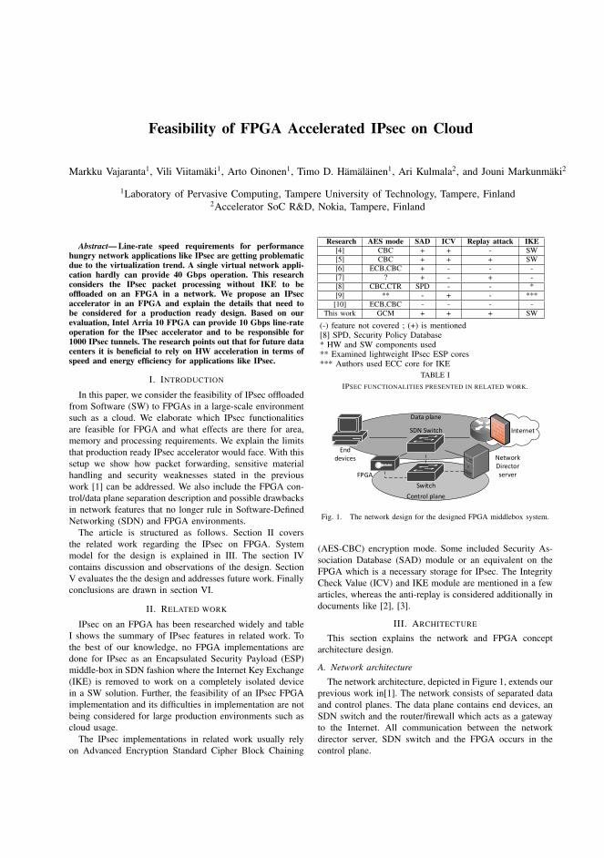
Feasibility of FPGA Accelerated IPsec on Cloud
Markku Vajaranta1, Vili Viitamaki1, Arto Oinonen1, Timo D. Hamalainen1, Ari Kulmala2, and Jouni Markunmaki2
1Laboratory of Pervasive Computing, Tampere University of Technology, Tampere, Finland2Accelerator SoC R&D, Nokia, Tampere, Finland
Abstract— Line-rate speed requirements for performancehungry network applications like IPsec are getting problematicdue to the virtualization trend. A single virtual network appli-cation hardly can provide 40 Gbps operation. This researchconsiders the IPsec packet processing without IKE to beoffloaded on an FPGA in a network. We propose an IPsecaccelerator in an FPGA and explain the details that need tobe considered for a production ready design. Based on ourevaluation, Intel Arria 10 FPGA can provide 10 Gbps line-rateoperation for the IPsec accelerator and to be responsible for1000 IPsec tunnels. The research points out that for future datacenters it is beneficial to rely on HW acceleration in terms ofspeed and energy efficiency for applications like IPsec.
I. INTRODUCTION
In this paper, we consider the feasibility of IPsec offloadedfrom Software (SW) to FPGAs in a large-scale environmentsuch as a cloud. We elaborate which IPsec functionalitiesare feasible for FPGA and what effects are there for area,memory and processing requirements. We explain the limitsthat production ready IPsec accelerator would face. With thissetup we show how packet forwarding, sensitive materialhandling and security weaknesses stated in the previouswork [1] can be addressed. We also include the FPGA con-trol/data plane separation description and possible drawbacksin network features that no longer rule in Software-DefinedNetworking (SDN) and FPGA environments.
The article is structured as follows. Section II coversthe related work regarding the IPsec on FPGA. Systemmodel for the design is explained in III. The section IVcontains discussion and observations of the design. SectionV evaluates the the design and addresses future work. Finallyconclusions are drawn in section VI.
II. RELATED WORK
IPsec on an FPGA has been researched widely and tableI shows the summary of IPsec features in related work. Tothe best of our knowledge, no FPGA implementations aredone for IPsec as an Encapsulated Security Payload (ESP)middle-box in SDN fashion where the Internet Key Exchange(IKE) is removed to work on a completely isolated devicein a SW solution. Further, the feasibility of an IPsec FPGAimplementation and its difficulties in implementation are notbeing considered for large production environments such ascloud usage.
The IPsec implementations in related work usually relyon Advanced Encryption Standard Cipher Block Chaining
Research AES mode SAD ICV Replay attack IKE[4] CBC + + - SW[5] CBC + + + SW[6] ECB,CBC + - - -[7] ? + - + -[8] CBC,CTR SPD - - *[9] ** - + - ***
[10] ECB,CBC - - - -This work GCM + + + SW
(-) feature not covered ; (+) is mentioned[8] SPD, Security Policy Database* HW and SW components used** Examined lightweight IPsec ESP cores*** Authors used ECC core for IKE
TABLE IIPSEC FUNCTIONALITIES PRESENTED IN RELATED WORK.
Internet
Network Director serverFPGA
Data plane
Control plane
Enddevices
SDN Switch
Switch
Fig. 1. The network design for the designed FPGA middlebox system.
(AES-CBC) encryption mode. Some included Security As-sociation Database (SAD) module or an equivalent on theFPGA which is a necessary storage for IPsec. The IntegrityCheck Value (ICV) and IKE module are mentioned in a fewarticles, whereas the anti-replay is considered additionally indocuments like [2], [3].
III. ARCHITECTURE
This section explains the network and FPGA conceptarchitecture design.
A. Network architecture
The network architecture, depicted in Figure 1, extends ourprevious work in[1]. The network consists of separated dataand control planes. The data plane contains end devices, anSDN switch and the router/firewall which acts as a gatewayto the Internet. All communication between the networkdirector server, SDN switch and the FPGA occurs in thecontrol plane.

Network Director server
IKE negotiator
SDN controller
Network Director
orchestrator
Data plane interface
Control plane interface
Fig. 2. The network director server modules and their correspondingnetwork interfaces.
IKE negotiator
SDN controller
Orchestrator SDN Switch FPGA
Flows: IKE forwardings
OK
OK
Establish SA
OK
SA information
Flows: Packet forwarding forencryption/decryption
OK
Fig. 3. The initial message sequence required in startup phase.
The network director server depicted in Figure 2 imple-ments three software modules: an IKE negotiator, a networkdirector orchestrator and an SDN controller. The IKE ne-gotiator SW establishes the necessary Security Association(SA) with the other endpoint of the IPsec tunnel throughthe data plane. The SDN controller SW uses the controlplane interface for pushing flow rules to the SDN switch. Thenetwork director orchestrator SW is the binding componentbetween the IKE negotiator, the SDN controller, and also theFPGA(s). Thus the network director orchestrator controls thewhole process by giving instructions to other SW modulesand the FPGA.
The messages sent between different modules in IPsectunnel setup phase are shown in Figure 3. The orchestratorinstructs the SDN controller to push flows into the SDNswitch which forwards the IKE messages coming fromthe Internet to the network director. When finished, theorchestrator instructs the IKE negotiator to start establishingthe SA. Once the SA phase is done, the orchestrator pushesIKE SA information to the FPGA using the control plane.Finally more flows are pushed to the SDN switch that containinformation which packets need to be sent to FPGA forencryption or decryption.
B. FPGA architecture
Figure 4 shows an example block diagram for an IPsecaccelerator in an FPGA in figure 1. The HW architecturecontains three different logical components: the IPsec ac-celerator logic, SDN fashion data, and control planes. Eventhough the data and the control planes both communicatewith the accelerator logic, any traffic entering the FPGA isunable to jump from one plane to another.
The control plane subsystem is only for updating the SAD
Data plane
Control plane
Ethernet
40G QSFP+
SDN / User logic control
Ethernet Packet client
IPsec Accelerator logic
Encrypt #1
IPsec Manager
AES-GCM + AES
IPsec Enc & Dec
SADs
Decrypt #1
AES-GCM + AES
AES-GCM + AES
AES-GCM + AES
Encrypt #2
Decrypt #2
Fig. 4. Internal block diagram of an IPsec FPGA implementation whereIPsec accelerator operates as user logic with a separate data and controlplane networks.
table whereas the accelerator subsystem holds the desiredfunctionality for the FPGA, in this case the IPsec. The IPsecmanager receives data from the packet client and selectsbetween the encrypt and decrypt modules. All modulesare dependent on their corresponding SAD registries thatcontain the tunnel information. Both modules are requiredto do checks on the traffic to verify the integrity of data. Ifeverything matches, the AES-GCM + AES block is beingqueried with given data.
IV. FEASIBILITY OF AN FPGA ACCELERATION
Below we consider the following issues affecting the feasi-bility of FPGA acceleration: the network director, modifica-tions required to the network, information in IPsec operationand security considerations of the design.
A. Network Director orchestrator responsibilities
The orchestrator SW is responsible for setting up andremoving the IPsec tunnel operation in the network. Itinitiates new connections using IKE an negotiator, pushesflows using SDN controller and updates the SAD entries onthe FPGAs. The orchestrator needs to set up all of thesebefore the actual packet transmission starts. This ensures theminimal latency in the network level.
The high-speed requirement makes it impossible for theFPGA to request the orchestrator to do IKE negotiation whena packet with non-existing SA information enters the FPGA.The negotiation is virtually too late in that case. The SWmodules will not create latency if beforehand all tunnelsare negotiated, keys are stored in the FPGA SADs, andthe necessary flow rules exist in the SDN switch. Similarly,latency can be avoided by doing the re-key and key deliveryoperations prior to key timeout.
B. Network layer considerations
A standalone FPGA in a network does not require a MediaAccess Control (MAC) address at all since the forwardingdecisions in the switch plane are made by the SDN. Thepackets may enter and leave the FPGA with any MACaddress pair. This is adverse since the switch learns falselysome MAC addresses to be behind the FPGAs switch porteven though they are not there. For this reason the MACaddress learning feature should be off at the switch portwhere the FPGA is connected to.

Quite many different kinds of broadcast/multicast mes-sages are seen in the network. Thus it’s a good practice tohave a white list in the Ethernet packet client module toallow only desired traffic to bypass it and to be delivered tothe IPsec accelerator logic.
One major issue faced by the design is the incomingpacket forwarding after the packets are decrypted in theFPGA. These decrypted packets contain wrong destinationMAC address which need to be updated to match the realdestination specified in the Internet Protocol (IP) header.This can be easily achieved by keeping track of the seen IPand MAC address pairs and rewriting the false destinationMAC address in the Ethernet packet client. Another approachwould be to use flow rule in the SDN switch which rewritesthe MAC addresses in the switch level. Both approaches havetheir benefits and should be chosen on occasion.
C. SPI, Sequence number and IV
The Security Parameter Index (SPI) value that is negoti-ated by IKE must be unique for the IPsec tunneling deploy-ment. SW IKE solutions running in e.g. Linux consider thisproperty by default and thus the uniqueness can be trusted.
The Sequence Number (SN) identifies a single packetand works as an anti-replay mechanism which should beimplemented as described in [11], [12]. The usage of Ex-tended Sequence Number (ESN) is mandatory in IKEv2making the ESN 64 bits long. When considering the 40 Gbpslink, the maximum amount of packets per second (pps) is59,523,808. A practical viewpoint is that even though thepackets with consecutive SNs should be close to each other,they will arrive in mixed order. For this reason, effectivesliding window mechanism is required to have a workinganti-replay mechanism. The design for such a mechanism ishowever out of the scope in this paper.
The Initialization Vector (IV) for encryption is a valuethat must never repeat [11]. Usually after the depletion ofIV numbers, the key is renegotiated. The value however is64 bits long. If every single value is used, the 64-bit IV willlast for approximately 9827 years making the IV to be uniquefor the key lifetime even if used carelessly. Thus the FPGAdoes not need to worry about IV depletion and its signalingto the network director.
D. IPsec SAD
The SAD contains the items described in table II. Thedestination network information is not required because it isused only for identification when choosing correct SA foroutgoing packets. Similarly not required is the IV since it isread from the incoming packet.
This results in 552 bits of data per connection in encryp-tion SAD. The decryption SAD is required to store doublethe amount of information specified in the table to ensureseamless operation in the re-key phase. Thus the decryptionSAD size is 1008 bits per connection.
We can approximate that in a larger environment with1000 IPsec tunnels the amount for on-chip memory on anFPGA is 68 kB for the encryption SAD and 124 kB for the
TABLE IISAD REGISTRY ENTITIES ON THE FPGA
Item Size (bits) Enc. SAD Dec. SADDestination network 32+32 yes no
SPI 32 yes yeskey 256 yes yes
key size 8 yes yesIV 64 yes no
SEQ # 64 yes yesTunnel SRC IP 32 yes yesTunnel DST IP 32 yes yes
decryption SAD. Thus the SADs fit to the on-chip memoryeasily which speeds up operation. The advantage is that theon-chip memory can be read every cycle compared to theexternal memory which requires multiple cycles.
E. Packet processing inside an IPsec accelerator
The presented IPsec accelerator design in the Figure 4is functional as is. The IPsec manager is responsible forsharing incoming packets to the right function (decryp-tion/encryption), and the desired module (encryption #1,encryption #2...). The selection between encryption anddecryption function can be based on the Protocol field inthe IP header. All ESP packets are sent to decrypt functionand all plain text packets to the encryption.
Contrary to Figure 4, the number of function modules isnot limited to two. Having more parallel modules speeds upthe packet processing since consecutive packets belonging tothe same SA can use same module. This action saves timesince AES does not need to be reconfigured. The mechanismis however complicated since functionality should be ablein some cases to utilize all modules for a single SA andsometimes every module for a different SA. To guaranteefair and correct module selection, the utilization level of asingle module is needed. This algorithm can be built usingsliding window approach, but is not covered in this article.
F. Concept security and possible attack vectors
The most vulnerable spot is the control plane where themessages for the FPGA and the SDN switch configurationstake place. It is vital to ensure the physical security of thecontrol plane network in addition to securing the deviceswhich have access to it. As long as data goes in plain text,they can be easily obtained from the control plane. ThusTransport Layer Security (TLS) protocol suite should beimplemented to it for security. The Openflow protocol thatis often used for communication between switches and theSDN controller supports TLS as well. If used, it can providethe necessary confidentiality, integrity and authentication forthat specific traffic as well.
The on-chip memory on an FPGA for SAD ensures thatprivate material cannot be leaked from the external memoryof the FPGA by bus snooping. However, side-channel attackcan still be executed on the system-on-a-chip (SoC) itselfwhich would be successful even though the process iscomplicated and time consuming one.
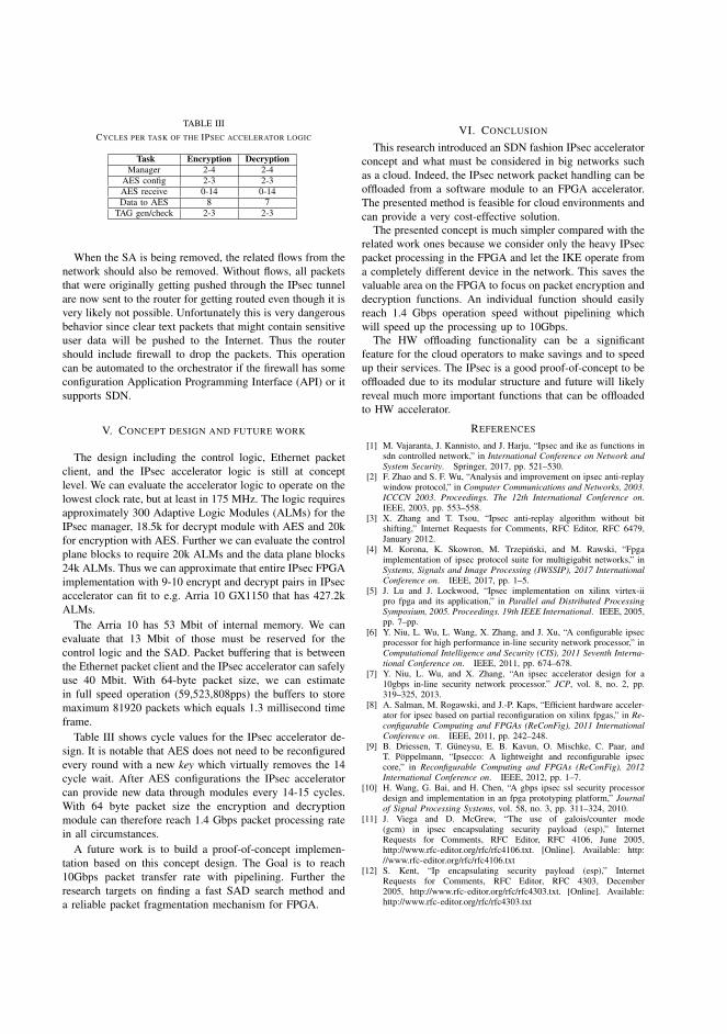
TABLE IIICYCLES PER TASK OF THE IPSEC ACCELERATOR LOGIC
Task Encryption DecryptionManager 2-4 2-4
AES config 2-3 2-3AES receive 0-14 0-14Data to AES 8 7
TAG gen/check 2-3 2-3
When the SA is being removed, the related flows from thenetwork should also be removed. Without flows, all packetsthat were originally getting pushed through the IPsec tunnelare now sent to the router for getting routed even though it isvery likely not possible. Unfortunately this is very dangerousbehavior since clear text packets that might contain sensitiveuser data will be pushed to the Internet. Thus the routershould include firewall to drop the packets. This operationcan be automated to the orchestrator if the firewall has someconfiguration Application Programming Interface (API) or itsupports SDN.
V. CONCEPT DESIGN AND FUTURE WORK
The design including the control logic, Ethernet packetclient, and the IPsec accelerator logic is still at conceptlevel. We can evaluate the accelerator logic to operate on thelowest clock rate, but at least in 175 MHz. The logic requiresapproximately 300 Adaptive Logic Modules (ALMs) for theIPsec manager, 18.5k for decrypt module with AES and 20kfor encryption with AES. Further we can evaluate the controlplane blocks to require 20k ALMs and the data plane blocks24k ALMs. Thus we can approximate that entire IPsec FPGAimplementation with 9-10 encrypt and decrypt pairs in IPsecaccelerator can fit to e.g. Arria 10 GX1150 that has 427.2kALMs.
The Arria 10 has 53 Mbit of internal memory. We canevaluate that 13 Mbit of those must be reserved for thecontrol logic and the SAD. Packet buffering that is betweenthe Ethernet packet client and the IPsec accelerator can safelyuse 40 Mbit. With 64-byte packet size, we can estimatein full speed operation (59,523,808pps) the buffers to storemaximum 81920 packets which equals 1.3 millisecond timeframe.
Table III shows cycle values for the IPsec accelerator de-sign. It is notable that AES does not need to be reconfiguredevery round with a new key which virtually removes the 14cycle wait. After AES configurations the IPsec acceleratorcan provide new data through modules every 14-15 cycles.With 64 byte packet size the encryption and decryptionmodule can therefore reach 1.4 Gbps packet processing ratein all circumstances.
A future work is to build a proof-of-concept implemen-tation based on this concept design. The Goal is to reach10Gbps packet transfer rate with pipelining. Further theresearch targets on finding a fast SAD search method anda reliable packet fragmentation mechanism for FPGA.
VI. CONCLUSION
This research introduced an SDN fashion IPsec acceleratorconcept and what must be considered in big networks suchas a cloud. Indeed, the IPsec network packet handling can beoffloaded from a software module to an FPGA accelerator.The presented method is feasible for cloud environments andcan provide a very cost-effective solution.
The presented concept is much simpler compared with therelated work ones because we consider only the heavy IPsecpacket processing in the FPGA and let the IKE operate froma completely different device in the network. This saves thevaluable area on the FPGA to focus on packet encryption anddecryption functions. An individual function should easilyreach 1.4 Gbps operation speed without pipelining whichwill speed up the processing up to 10Gbps.
The HW offloading functionality can be a significantfeature for the cloud operators to make savings and to speedup their services. The IPsec is a good proof-of-concept to beoffloaded due to its modular structure and future will likelyreveal much more important functions that can be offloadedto HW accelerator.
REFERENCES
[1] M. Vajaranta, J. Kannisto, and J. Harju, “Ipsec and ike as functions insdn controlled network,” in International Conference on Network andSystem Security. Springer, 2017, pp. 521–530.
[2] F. Zhao and S. F. Wu, “Analysis and improvement on ipsec anti-replaywindow protocol,” in Computer Communications and Networks, 2003.ICCCN 2003. Proceedings. The 12th International Conference on.IEEE, 2003, pp. 553–558.
[3] X. Zhang and T. Tsou, “Ipsec anti-replay algorithm without bitshifting,” Internet Requests for Comments, RFC Editor, RFC 6479,January 2012.
[4] M. Korona, K. Skowron, M. Trzepinski, and M. Rawski, “Fpgaimplementation of ipsec protocol suite for multigigabit networks,” inSystems, Signals and Image Processing (IWSSIP), 2017 InternationalConference on. IEEE, 2017, pp. 1–5.
[5] J. Lu and J. Lockwood, “Ipsec implementation on xilinx virtex-iipro fpga and its application,” in Parallel and Distributed ProcessingSymposium, 2005. Proceedings. 19th IEEE International. IEEE, 2005,pp. 7–pp.
[6] Y. Niu, L. Wu, L. Wang, X. Zhang, and J. Xu, “A configurable ipsecprocessor for high performance in-line security network processor,” inComputational Intelligence and Security (CIS), 2011 Seventh Interna-tional Conference on. IEEE, 2011, pp. 674–678.
[7] Y. Niu, L. Wu, and X. Zhang, “An ipsec accelerator design for a10gbps in-line security network processor.” JCP, vol. 8, no. 2, pp.319–325, 2013.
[8] A. Salman, M. Rogawski, and J.-P. Kaps, “Efficient hardware acceler-ator for ipsec based on partial reconfiguration on xilinx fpgas,” in Re-configurable Computing and FPGAs (ReConFig), 2011 InternationalConference on. IEEE, 2011, pp. 242–248.
[9] B. Driessen, T. Guneysu, E. B. Kavun, O. Mischke, C. Paar, andT. Poppelmann, “Ipsecco: A lightweight and reconfigurable ipseccore,” in Reconfigurable Computing and FPGAs (ReConFig), 2012International Conference on. IEEE, 2012, pp. 1–7.
[10] H. Wang, G. Bai, and H. Chen, “A gbps ipsec ssl security processordesign and implementation in an fpga prototyping platform,” Journalof Signal Processing Systems, vol. 58, no. 3, pp. 311–324, 2010.
[11] J. Viega and D. McGrew, “The use of galois/counter mode(gcm) in ipsec encapsulating security payload (esp),” InternetRequests for Comments, RFC Editor, RFC 4106, June 2005,http://www.rfc-editor.org/rfc/rfc4106.txt. [Online]. Available: http://www.rfc-editor.org/rfc/rfc4106.txt
[12] S. Kent, “Ip encapsulating security payload (esp),” InternetRequests for Comments, RFC Editor, RFC 4303, December2005, http://www.rfc-editor.org/rfc/rfc4303.txt. [Online]. Available:http://www.rfc-editor.org/rfc/rfc4303.txt

PUBLICATIONV
Feasibility of FPGA accelerated IPsec on cloud
M. Vajaranta, A. Oinonen, T. D. Hämäläinen, V. Viitamäki, J. Markunmäki
and A. Kulmala
Microprocessors and Microsystems - Embedded Hardware Design. Ed. by P. Kitsos.
2019, 102861
doi: 10.1016/j.micpro.2019.102861
Publication reprinted with the permission of the copyright holders

Microprocessors and Microsystems 71 (2019) 102861
Contents lists available at ScienceDirect
Microprocessors and Microsystems
journal homepage: www.elsevier.com/locate/micpro
Feasibility of FPGA accelerated IPsec on cloud
Markku Vajaranta a , ∗, Arto Oinonen a , Timo D. Hämäläinen
a , Vili Viitamäki b , Jouni Markunmäki b , Ari Kulmala b
a Computing Sciences, Tampere University, Tampere, Finland b Baseband ASIC R&D, Nokia Networks, Tampere, Finland
a r t i c l e i n f o
Article history:
Received 30 November 2018
Revised 12 June 2019
Accepted 4 August 2019
Available online 5 August 2019
Keywords:
IPsec
Offloading
SDN
Accelerator
a b s t r a c t
Hardware acceleration for famous VPN solution, IPsec, has been widely researched already. Still it is not
fully covered and the increasing latency, throughput, and feature requirements need further evaluation.
We propose an IPsec accelerator architecture in an FPGA and explain the details that need to be consid-
ered for a production ready design. This research considers the IPsec packet processing without IKE to
be offloaded on an FPGA in an SDN network. Related work performance rates in 64 byte packet size for
throughput is 1–2 Gbps with 0.2 ms latency in software, and 1–4 Gbps with unknown latencies for hard-
ware solutions. Our proposed architecture is capable to host 10 0 0 concurrent tunnels and have 10 Gbps
throughput with only 10 μs latency in our test network. Therefore the proposed design is efficient even
with voice or video encryption. The architecture is especially designed for data centers and locations with
vast number of concurrent IPsec tunnels. The research confirms that FPGA based hardware acceleration
increases performance and is feasible to integrate with the other server infrastructure.
© 2019 Elsevier B.V. All rights reserved.
1. Introduction
The IPsec Virtual Private Network (VPN) tunnel is a commonly
used protocol suite to build secure end to end connections through
the Internet. It provides confidentiality, integrity and authentic-
ity, but also introduces performance overhead affecting the latency
and throughput of the transmission. IPsec requires both packet
protocol processing and cryptographic computations, and a net-
work must support a massive number of IPsec tunnels simultane-
ously. At the same time, the network functions, including IPsec, are
being virtualized. Thus we need to find both high-performance and
flexible solutions.
The IPsec leans to Internet Key Exchange (IKE) to ensure se-
cure key exchange between endpoints and uses Encapsulated Se-
cure Payload (ESP) to encrypt network packets. Our previous work
in [1] presented a design where the IKE and ESP processes are dis-
tributed in a local network using Software-defined Network (SDN)
to improve performance. In this paper, we consider hardware ac-
celeration on FPGA for ESP processing and extend the context to a
very large-scale cloud environment.
∗ Corresponding author.
E-mail addresses: [email protected] (M. Vajaranta),
[email protected] (A. Oinonen), [email protected] (T.D. Hämäläinen),
[email protected] (J. Markunmäki), [email protected] (A. Kul-
mala).
The work in [1] tried to speed up IPsec processing by run-
ning ESP processes parallel in multiple SW servers. This approach
was not feasible due to problems with incoming packet forward-
ing and cumbersome anti-replay protection. The research however
described SDN to precisely control the IPsec flows, and separation
of IKE and ESP execution in different devices in the network.
In [1] the IPsec packet processing throughput was 100 Mbps us-
ing AES-128-CBC cipher and 600 Mbps on AES-GCM with 64 byte
packet size. It showed the packet processing to be relatively slow
operation on SW depending on used crypto algorithm. The Li-
breswan open source IPsec project has measured with unspeci-
fied packet size 5.25 Gbps throughput on SW using AES-GCM and
1.39 Gbps using AES128-SHA1 crypto ciphers [2] . The benchmarked
system performed 9.78 Gbps link throughput without crypto. In Li-
breswans’ results it is possible that the network packet size was
set to relatively large resulting higher total throughput in every
test. Even though these aforementioned numbers were decent, our
goal is 10 Gbps throughput and 10 μs packet latency which is hard
to achieve without using HW acceleration. These numbers clearly
indicated that SW solution in long run is not performant enough.
This justifies the usage of fast IPsec middle-box in SDN fashion for
IPsec packet processing.
In [3] we shortly explained the architecture where an FPGA
would consider the ESP processing when used in such network ar-
chitecture presented in [1] . The work indicated that much larger
research is needed just for the architecture to be elaborated and
https://doi.org/10.1016/j.micpro.2019.102861
0141-9331/© 2019 Elsevier B.V. All rights reserved.

2 M. Vajaranta, A. Oinonen and T.D. Hämäläinen et al. / Microprocessors and Microsystems 71 (2019) 102861
Internet
IPsecFPGA
Enddevices
SDN Switch
Router / FirewallIPsec
SW server
Fig. 1. Simplified system model with separate IPsec devices for ESP on FPGA and
IKE on SW server.
all the limits and constraints the FPGA will face with a production
ready solution that can host vast number of concurrent tunnels.
Some number of studies concerning FPGA IPsec solutions exist as
the related work section will reveal, but they do not consider the
production readiness and features the IPsec endpoint requires. This
was a strong motivation for our research.
When considering the IPsec FPGA accelerator architecture, the
challenge is how to partition the IPsec functions on HW, in which
we need to trade-off between memory consumption, computing
power and area. A major contribution is to draw a clear picture of
the requirements and limits for the IPsec HW accelerator besides
the proposed architecture. We elaborate the whole architecture to
find non-time-critical parts and move them to run on software to
achieve more area on an FPGA for performance hungry functions.
Our proposed system model is depicted in Fig. 1 . End devices
can be considered as user PCs connected to the Internet via a Fire-
wall. IPsec processing take place collaboratively in IPsec FPGA and
in IPsec SW server. The SDN Switch connects these different de-
vices together. The IPsec tunnel is negotiated by IKE using IPsec
SW on a server with another IPsec endpoint somewhere in the In-
ternet. These negotiated Security Association (SA) values are trans-
ferred to the IPsec FPGA which covers the ESP packet processing.
When the End devices communicate through the IPsec tunnel, the
SDN switch forwards the traffic to the IPsec FPGA for packet re-
packaging. This approach uses the FPGA to accelerate only the traf-
fic related to End devices and do not consider key negotiations at
all.
This paper is structured as follows. Section 2 presents the re-
lated work regarding the IPsec on FPGA. Our proposed system ar-
chitecture is explained in Section 3 . Section 4 points out critical
issues of IPsec functionality and their consequences to FPGA im-
plementation. Our proposal for the HW accelerator architecture is
presented in Section 5 . Section 6 evaluates the design. The conclu-
sions are given in Section 7 .
2. Related work
Several FPGA based implementations have been presented for
IPsec acceleration. For instance, Heliontech already provides a com-
mercial IPsec ESP core [4] which can reach 3.7 Gbps throughput
rate, and there are several research proposals listed in Table 1 .
Most of the works propose encryption acceleration on FPGA.
Most use Advanced Encryption Standard Cipher Block Chaining
(AES-CBC) or Electronic Code Book (ECB) instead of Galois Counter
Mode (AES-GCM), despite that AES-GCM is described in RFC4106
already in 2005 [5] . In addition, the Security Association Database
(SAD) module or an equivalent is often considered on the FPGA
which is the necessary storage for IPsec. The Integrity Check Value
(ICV) and anti-replay are mentioned in few works and the purpose
is well explained. The anti-replay feature for FPGA is a research
topic itself and considered additionally e.g. in [6,7] . Quite many
works left IKE out of scope and discussed the efficiency and cost-
effectiveness of their solution instead. Our architecture uses IKE as
described in [1] where it is working in its own SW solution.
Table 1
IPsec functionalities presented in related work. Throughput rate for 64 byte
packet length in CBC mode if not otherwise specified.
Research AES SAD ICV Replay IKE Throughput
mode attack rate
[8] CBC + + − SW 2.1 Gbps
[9] CBC + + + SW 1.2 Gbps !
[10] ECB,CBC + − − − 1.5 Gbps !
[11] ? + − + − 11.28 Gbps
with 512 B
[12] CBC,CTR SPD − − ∗ 600 Mbps !
[13] ∗∗ − + − ∗∗∗ Unknown
[14] ECB,CBC − − − − 742 Mbps
with 1500 B
[15] CBC + − − − 3.08 Gbps
[16] CBC SPD + + - − 4 Gbps
[17] only SHA − + − − −[18] CBC − − − − 577 Mbps !
This work GCM + + + SW 2x5 Gbps
( −) feature not covered; ( + ) is mentioned + − Covered, but implementation
unknown SPD: Security Policy Database instead of SAD ∗ HW and SW com-
ponents used ∗∗ Examined lightweight IPsec ESP cores ∗∗∗ Authors used ECC
core for IKE ! Throughput rate not specified with network packet length This
work uses 5 parallel 2 Gbps blocks for both decryption and encryption
Korona et al. [8] proposed to use encryption modules in parallel
for a single task using round-robin style. Parallel access to SAD in
this solution was done using an arbiter system in its own clock do-
main for the best performance. They reached 2.1 Gbps throughput
for 64 B, and 5.5 Gbps for 1500 B packet length.
Lu et al. built their solution on top of Xilinx Virtex-II Pro-FPGA.
They separated the data and control paths to move the data pro-
cessing on top of HW and leave the SW to maintain only control
traffic. The work includes the SAD, ICV and anti-replay features and
the design was built using reconfigurable and extensible network
service platform with IBM PowerPC processor for SW operations.
Synthesis shows maximum of 1197 Mbps throughput rate in AES-
128 mode [9] .
Virtex 5 family device was used by Niu et al. for IPsec ac-
celerators in [10,11] . The design used key engine instead of IKE.
The research addresses that crypto processing is the most time
consuming operation and thus the design is utilizing several AES
cores simultaneously through a crossbar bus. The SAD is placed
in the SRAM and specified to hold 256 security associations. The
proposal in [10] reached 1.5 Gbps processing rate with unknown
packet length. However, they reached 11.89 Gbps throughput rate
for 512 B packets in [11] .
Partial reconfiguration is playing the key role in [12] . Their con-
tribution includes mixing HW and SW solution in FPGA to gain
flexibility in its operation. The design utilizes external memory to
load either AES, SHA256 or MODEXP to IPsec co-processor using
partial reconfiguration. The design reached slightly over 600 Mbps
throughput with undocumented network packet length.
The research in [13] focused as well on the crypto core instead
of IPsec features. Driessen et al. presented a core called IPSecco
that is designed for reconfigurable and lightweight HW. They used
PRESENT instead of AES, GROSTL and PHOTON instead of Secure
Hash Algorithm (SHA) and the ECC core instead of IKE which made
the core very energy and cost-efficient.
Wang et al. [14] used Network Security Processor system to ac-
celerate the IPsec and SSL operations on FPGA. The research fo-
cused on cryptographic processing and its optimization. The de-
sign is planned to work with a PC through PCI-X interface instead
of standalone device in a network. The implementation reached
0.742 Gbps AES-256-CBC with HMAC-SHA-1-96 when tested with
1500 B network data packet. This particular research addresses the
problem of data packets exceeding the MTU of 1500 B. Their solu-
tion uses packet size of 576 B for the network fragments generated.
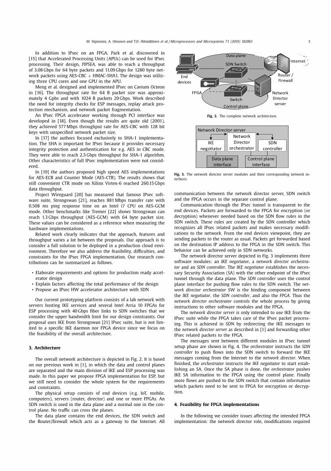
M. Vajaranta, A. Oinonen and T.D. Hämäläinen et al. / Microprocessors and Microsystems 71 (2019) 102861 3
In addition to IPsec on an FPGA, Park et al. discovered in
[15] that Accelerated Processing Units (APUs) can be used for IPsec
processing. Their design, PIPSEA , was able to reach a throughput
of 3.08 Gbps for 64 byte packets and 11.09 Gbps for 1280 byte net-
work packets using AES-CBC + HMAC-SHA1. The design was utiliz-
ing three CPU cores and one GPU in the APU.
Meng et al. designed and implemented IPsec on Cavium Octeon
in [16] . The throughput rate for 64 B packet size was approxi-
mately 4 Gpbs and with 1024 B packets 20 Gbps. Work described
the need for integrity checks for ESP messages, replay attack pro-
tection mechanism, and network packet fragmentation.
An IPsec FPGA accelerator working through PCI interface was
developed in [18] . Even though the results are quite old (2001),
they achieved 577 Mbps throughput rate for AES-CBC with 128 bit
keys with unspecified network packet size.
In [17] the authors focused exclusively to SHA-1 implementa-
tion. The SHA is important for IPsec because it provides necessary
integrity protection and authentication for e.g. AES in CBC mode.
They were able to reach 2.5 Gbps throughput for SHA-1 algorithm.
Other characteristics of full IPsec implementation were not consid-
ered.
In [19] the authors proposed high speed AES implementations
for AES-ECB and Counter Mode (AES-CTR). The results shows that
still convenient CTR mode on Xilinx Virtex-6 reached 260.15 Gbps
data throughput.
Project Wireguard [20] has measured that famous IPsec soft-
ware suite, Strongswan [21] , reaches 881 Mbps transfer rate with
0.508 ms ping response time on an Intel i7 CPU on AES-GCM
mode. Other benchmarks like Tremer [22] shows Strongswan can
reach 1.3 Gbps throughput (AES-GCM) with 64 byte packet size.
These values can be considered as a reference when measuring the
hardware implementations.
Related work clearly indicates that the approach, features and
throughput varies a lot between the proposals. Our approach is to
consider a full solution to be deployed in a production cloud envi-
ronment. Therefore we also address the feasibility, difficulties, and
constraints for the IPsec FPGA implementation. Our research con-
tributions can be summarized as follows.
• Elaborate requirements and options for production ready accel-
erator design
• Explain factors affecting the total performance of the design
• Propose an IPsec HW accelerator architecture with SDN
Our current prototyping platform consists of a lab network with
servers hosting IKE services and several Intel Arria 10 FPGAs for
ESP processing with 40 Gbps fiber links to SDN switches that we
consider the upper bandwidth limit for our design constraints. Our
proposal uses IKE from Strongswan [21] IPsec suite, but is not lim-
ited to a specific IKE daemon nor FPGA device since we focus on
the feasibility of the overall architecture.
3. Architecture
The overall network architecture is depicted in Fig. 2 . It is based
on our previous work in [1] , in which the data and control planes
are separated and the main division of IKE and ESP processing was
made. In this paper we propose FPGA implementation for ESP, but
we still need to consider the whole system for the requirements
and constraints.
The physical setup consists of end devices (e.g. IoT, mobile,
computers), servers (router, director) and one or more FPGAs. An
SDN switch is used in the data plane and a normal one in the con-
trol plane. No traffic can cross the planes.
The data plane contains the end devices, the SDN switch and
the Router/firewall which acts as a gateway to the Internet. All
Internet
NetworkDirectorserver
FPGA
Data plane
Control plane
Enddevices
SDN Switch
Switch
Router / Firewall
Fig. 2. The complete network architecture.
Network Director server
IKE nego�ator
SDN controller
Network Director
orchestrator
Data plane interface
Control plane interface
Fig. 3. The network director server modules and their corresponding network in-
terfaces.
communication between the network director server, SDN switch
and the FPGA occurs in the separate control plane.
Communication through the IPsec tunnel is transparent to the
end devices. Packets are forwarded to the FPGA for encryption (or
decryption) whenever needed based on the SDN flow rules in the
SDN switch. These rules are created by the SDN controller which
recognizes all IPsec related packets and makes necessary modifi-
cations to the network. From the end devices viewpoint, they are
sending packets to the router as usual. Packets get forwarded based
on the destination IP address to the FPGA in the SDN switch. This
behavior can be achieved only in SDN networks.
The network director server depicted in Fig. 3 implements three
software modules: an IKE negotiator , a network director orchestra-
tor and an SDN controller . The IKE negotiator establishes the neces-
sary Security Association (SA) with the other endpoint of the IPsec
tunnel through the data plane. The SDN controller uses the control
plane interface for pushing flow rules to the SDN switch. The net-
work director orchestrator SW is the binding component between
the IKE negotiator , the SDN controller , and also the FPGA . Thus the
network director orchestrator controls the whole process by giving
instructions to other software modules and the FPGA.
The network director server is only intended to use IKE from the
IPsec suite while the FPGA takes care of the IPsec packet process-
ing. This is achieved in SDN by redirecting the IKE messages to
the network director server as described in [1] and forwarding other
IPsec related packets to the FPGA.
The messages sent between different modules in IPsec tunnel
setup phase are shown in Fig. 4 . The orchestrator instructs the SDN
controller to push flows into the SDN switch to forward the IKE
messages coming from the Internet to the network director . When
finished, the orchestrator instructs the IKE negotiator to start estab-
lishing an SA. Once the SA phase is done, the orchestrator pushes
IKE SA information to the FPGA using the control plane. Finally
more flows are pushed to the SDN switch that contain information
which packets need to be sent to FPGA for encryption or decryp-
tion.
4. Feasibility for FPGA implementations
In the following we consider issues affecting the intended FPGA
implementation: the network director role, modifications required

4 M. Vajaranta, A. Oinonen and T.D. Hämäläinen et al. / Microprocessors and Microsystems 71 (2019) 102861
IKE nego�ator
SDN controllerOrchestrator SDN Switch FPGA
Flows: IKE forwardings
OK
OK
Establish SA
OK
SA informa�on
Flows: Packet forwarding forencryp�on/decryp�on
OK
Fig. 4. The initial message sequence required in startup phase.
to the network, packet fragmentation problem, IPsec related vari-
ables, anti-replay feature and security considerations. All of these
contribute to the HW/SW partitioning decisions.
4.1. Network director orchestrator responsibilities
The orchestrator is responsible for setting up and removing the
IPsec tunnels in the network. It initiates new connections using IKE
as the negotiator, pushes flows using SDN controller and updates
the SAD entries on the FPGAs.
The orchestrator needs to set all of these up before the actual
packet transmission starts. If a packet with non-existing SA infor-
mation enters the FPGA, it must pause its operation and request
the orchestrator to perform the IKE negotiation. Since the FPGA
does not have much packet buffer space, such a delay may cause
even loss of data. Thus, all IPsec tunnels should be negotiated be-
forehand, keys stored in the FPGA SADs, and the necessary flow
rules set in the SDN switch. Similarly, latency can be minimized
by doing the re-key and key delivery operations from IKE to the
FPGA prior to key timeout. This motivates our decision to run non
time-critical tasks like IKE in SW and the rest in FPGA.
4.2. Network layer memory requirements
As desired and explained in (3) , the IPsec packet processing in
FPGA is transparent to the end devices. We assume that all FPGAs
are directly connected to the SDN switch so that all data forward-
ing to the FPGA is based in IP addresses instead of typical Me-
dia Access Control (MAC) address. Thus the packets may enter and
leave the FPGA with any MAC address pair, or no MAC at all. De-
spite easy control, there are some drawbacks.
The first is that the switch learns falsely some MAC addresses
in the FPGAs’ switch port even though the FPGAs have none. For
this reason the MAC address learning feature should be off at the
switch port where the FPGA is physically connected.
The second is the incoming packet forwarding after the pack-
ets are decrypted in FPGA. These decrypted packets contain wrong
destination MAC address, which needs to be updated to match the
real destination specified in the Internet Protocol (IP) header. There
are practically four different solutions for this:
1. ARP protocol on FPGA data plane
2. Store learned IP & MAC address pairs on FPGA
3. Use router’s MAC address as destination
4. Let SDN switch to rewrite destination MAC field
The most efficient and easiest is to use a look-up-table (LUT) to
keep track of the seen IP and MAC address pairs in the FPGA and
rewrite the false destination MAC address in the FPGA. The down-
side is that unseen addresses are not yet present in the LUT and
on the other hand, the size of the LUT would exceed the FPGA ca-
pacity if all the possible IP addresses should be tracked. In simple
networks with under hundred clients the size of the LUT will not
cause problems. Still in larger networks some Address Resolution
Cache (ARP) cache mechanism like one in [23] should be consid-
ered. A sufficient method is to bind IP address to LUT addresses as
presented in the following.
1. IP address 192.168.0.24 = LUT address 0.24
2. IP address 192.168.1.24 = LUT address 1.24
3. IP address 192.168.112.87 = LUT address 112.87
The LUT memory address thus is calculated from the lowest
8 + 8 bits. Single LUT will then contain /24 network where each ad-
dress holds the a MAC address for the IP address. Addresses for /16
network in such LUT would consume 400 kB of memory, which in
turn should fit to the on-chip memory. The usage of on-chip mem-
ory is crucial since it can be read every clock cycle.
Another feasible approach would be to use flow rule in the SDN
switch to rewrite the MAC addresses in the switch level. In long
run this however causes overhead to the SDN controller since it
will receive every now and then requests to do also MAC address
rewrite. Using a combination of second and fourth solution would
be the best where the FPGA takes care of packet process in long
run and the SDN network backs up when necessary.
Another issue is that many different broadcast/multicast mes-
sages in the network might reach the FPGA. Thus it is necessary
to have white lists to allow only desired traffic to enter the FPGA.
Without such white list all e.g. ARP and Dynamic Host Configura-
tion Protocol (DHCP) packets, just to name few, will be delivered to
the IPsec encryption process and pushed through tunnel. Allowing
only IP protocol traffic that has no multicast address in the IP des-
tination field or broadcast addresses in the MAC destination field
will solve this problem. The white list can be implemented in a
register file to be configured when needed at runtime.
4.3. Network packet fragmentation
Network packets close to the Maximum Transmission Unit
(MTU) size of 1500 B cause a lot of problems in IPsec implemen-
tation. The main reason is the overhead of 54–57 B in the IPsec
AES-GCM mode. The header includes tunneling IP header (TNL IP)
(20 B), SPI (4 B), Sequence number (4 B), IV (8 B), Padding (max
3 B), pad length (1 B), Next header (1 B) and authentication tag
(max 16 B).
When a network packet with a size of 1445 B or larger gets
encrypted in IPsec, it exceeds the MTU limit and requires fragmen-
tation. The fragmentation can occur on IPsec device or on a router
[24] in which case the packets must be reassembled prior to ESP
packet processing. Thus packet fragmentation must be considered
in the FPGA as well.
To simplify the FPGA design, the fragmentation issue may be
handled by limiting the MTU on the local network to 1400 B. This
guarantees that no fragmentation is needed. However, this is not
very robust and permanent solution.
Usually the local networks have MTU of 1500 B and in these
cases the fragmentation can be done by splitting the incoming
packet in two: e.g. first 1024 bytes and the rest of the packet.
This is an efficient and lightweight method which uses always the
constant packet size. It is irrelevant in this case whether the first
packet is full but not the second, because the two fragments will
be generated in any case.
Slightly more intelligent algorithm is required since the net-
work MTU in local networks can be fixed to 90 0 0 B when the
jumbo frame support is enabled. That will create seven 1500 B
fragments because of the header overhead. The algorithm needs to
take as many 14 4 4 B data chunks as possible, resulting to packets
of n times 14 4 4 B and a packet containing the rest of the data. For

M. Vajaranta, A. Oinonen and T.D. Hämäläinen et al. / Microprocessors and Microsystems 71 (2019) 102861 5
IncomingPacket P
Is SN(P) greater than X
No
Does SN(P) fall to the an�-replay window ?
No
Is SN(P) seen before ?
Yes Yes
Integrity Check: Is AES-GCM TAG Valid?
Yes
No
Yes
No
Update informa�on regarding seen SNs
If SN(P) greater than X, update X to SN(P)
Allow packet forward to decryp�on
Discard (P)
Fig. 5. Block diagram for simple anti-replay mechanism. SN(P) represents the Sequence number for received packet whereas X presents the SN counter current value.
instance a packet of 2890 B will be fragmented to two where each
contains 14 4 4 B of data and a packet of 2 B of data.
Even though the splitting can be done efficiently, RFC4459
[25] addresses the next three problems:
1. Overhead of headers caused by fragmentation
2. Computation required by the fragmentation
3. Difficulties in packet reassembly in the receiving end
The first one will occur in any case, and the computation prob-
lem can be solved with FPGA. The last, however, is the most severe
for the FPGA. As we know, the network packets rarely arrive in or-
der and thus some buffering method is required.
A recommendation is to use external DDR memory as a buffer
to store all incoming network packet fragments. The FPGA needs
to wait for all pieces to arrive, reassemble the whole packet and
then push to the IPsec decryption module. Surely this is problem-
atic when some fragment is lost or long latencies faced during
the transmission. Thus the FPGA fragmentation buffer needs to be
ready to clear out the oldest fragment pieces in order to receive
new ones. The solution is a ring buffer that works well accord-
ing to our experience. The ring buffer size does not have any strict
minimum requirement. We can calculate that 500 Mb buffer will
hold slightly over 41,0 0 0 packets of 1500 B which can be consid-
ered sufficient for this application.
4.4. SPI and IV
The Security Parameter Index (SPI) value identifies the IPsec
connection and thus must be unique for the IPsec tunneling de-
ployment. The SPI negotiated by IKE protocol in a SW solution like
Strongswan should verify the SA uniqueness for the best of the au-
thors knowledge. The SPI value is 32 bits that minimizes the colli-
sion possibility.
The Initialization Vector (IV) is a random number used in cryp-
tography and an essential part of AES-GCM process. The generation
of a true random number in FPGA is complicated due to missing
entropy source, but a pseudo-random number [26] is often suf-
ficient. Our proposal is to benefit from the separate orchestrator
server and create the random numbers there with a desired crypto
library in advance and deliver the IV to the SAD for the usage.
The IV value also must never repeat as stated in [5] . If the IV
numbers deplete during the key lifetime, re-key operation should
follow. The IV value must be 64 bits long in the IPsec using AES-
GCM, that is quite a large set of unique numbers. Thus the IV can
be considered unique for the key lifetime of few hours. Our con-
clusion is that the FPGA does not need to carry out IV depletion
case and its signaling to the network director.
4.5. Anti-replay feature, integrity check value and sequence number
The Integrity Check Value (ICV) and Sequence Number (SN) are
both included in the anti-replay feature described in RFCs [5,24] .
The SN verifies that a packet has not yet been received and is
adequate new. The ICV, in our case the AES-GCM TAG, verifies
the integrity and therefore trustworthiness of packet and its SN.
Fig. 5 shows a simple anti-replay mechanism proposal for FPGA ar-
chitecture.
In optimal case, incoming packets come in order making the
verification simple: next packet SN(t + 1) would be the previous
packet SN(t) + 1. Unfortunately this is not the case since packets
will likely arrive in mixed order within certain timespan if they
ever arrive due to packet loss. Unseen packets will go through the
integrity check for verification and when passing, the process will
continue to update the necessary anti-replay information prior the
next packet handling.
The SN counter update occurs only when the received packet
SN exceeds the current SN value. When so, the counter is updated
with the SN value from the received packet. The next step is to up-
date the information regarding the seen packets. The SN is 64 bits
long due to the usage of Extended Sequence Number (ESN) manda-
tory in IKEv2. Therefore it is virtually impossible to store informa-
tion whether every single packet is already received or not. Luckily
this is not necessary and a sliding window method such as one
presented in [7] can be used. Still a register with a size of win-
dow size is required to store received packet numbers. This does
not cause any great memory requirements since e.g. register of 10
bits is needed with anti-replay window of 1024 packets.
Packets falling out of the anti-replay window can be silently
discarded. In these cases the upper level protocol probably fixes
the situation by requesting re-send from the original source when
necessary. Discarding packets also occurs when they have already
been received. Notable is that some implementations increase the
SN counter when such discard occurs [27] .
The [5] specifies anti-replay window size of 64, but for exam-
ple Cisco presents windows size of 512 in the enhancement re-
quests CSCva65805 and CSCva65836 512 [27] . When considering
a high speed link, the window size of 64 is relatively small and
some greater number in power of two like 512/1024/2048 should
be considered.
The anti-replay feature still might drift to problems when a
significant packet loss of more than 2 32 packets is encountered
[24] . The high bits of the ESN loses synchronization resulting to
state where the anti-replay will fail all the time. This requires trig-
ger and re-synchronization mechanisms as stated and described in
[24] . The probability of such packet loss increases with higher link
speeds. With 1 Gbit throughput rate we can estimate that packet

6 M. Vajaranta, A. Oinonen and T.D. Hämäläinen et al. / Microprocessors and Microsystems 71 (2019) 102861
loss needs to last approximately for 2880 s. In 10 Gbps it is only
tenth resulting 288 s. Therefore with faster links already in few
Gbps it is a necessity to have this mechanism.
A replay attack might occur when an attacker delays a network
packet or resends it to the IPsec endpoint that it has already re-
ceived. This kind of an attack is very severe because it can affect
any device communicating through a VPN tunnel. Consequences
vary from slowing down and cutting connections to having server
software to receive duplicate entries or even possible denial-of-
service (DoS) attacks. Thus the anti-replay feature is vital for an
IPsec gateway even though the RFC 4303 [24] permits disabling it.
4.6. Security association database
The SAD contains the items described in Table 2 . The destination
network information is not required in decryption SAD because it is
used only for identification when choosing correct SA for outgoing
packets. The IV on the other hand is missing since it is read from
the incoming packet. The decryption SAD instead needs space to
store sequence numbers (SNs) that have already been received.
This results in 552 bits of data per connection in encryption
SAD. The decryption SAD size is at least 868 bits per connection
because it is required to store double the amount of information
specified in the table to ensure seamless operation in the re-key
phase.
Thus we can approximate that in a larger environment with
10 0 0 IPsec tunnels the amount of memory on an FPGA is 69 kB for
the encryption SAD and 109 kB for the decryption SAD. The size of
SAD does not seem to be a problem, but the response time is. Any
external memory is slow compared to the on-chip one, which can
be read every cycle. Still in the worst case finding a correct SA in-
formation from the database takes 10 0 0 clock cycles which is way
too long. The response must come from the SAD within few clock
cycles, say 1–5, otherwise the whole accelerator speed is signifi-
cantly reduced.
There are two practical approaches: some small cache in the
on-chip memory to store few previous (e.g. less than 20) SA in-
formation, or the usage of Content Addressable Memory (CAM) or
Ternary CAM (TCAM). The cache is fast to implement and offers a
reasonably good response time. The downside is that it works well
only when the FPGA processes a lot of packets with a very minimal
set of SAs. When the number of SAs rise, the only feasible solution
is CAM/TCAM, which returns the queried information in one clock
cycle.
For example Jiang and co-workers [28,29] presents good
CAM/TCAM implementations, and a white paper from eSilicon pro-
vides a good overview and arguments for TCAMs in Cloud [30] .
In addition to CAM, we need to consider how to manage mul-
tiple encryption and decryption modules accessing the SAD (CAM
or equivalent) in parallel [8] . This occurs when workload is shared
amongst more than one encryption or decryption modules. Luckily
only the IV, SN and Seen SN values are affected. Thus a semaphore
is required to ensure that only one process handles the variable at
Table 2
SAD registry entities on the FPGA.
Item Size (bits) Enc. SAD Dec. SAD
Destination network 32 + 32 yes no
SPI 32 yes yes
key 256 yes yes
key size 8 yes yes
IV 64 yes no
SN 64 yes yes
Seen SNs x no yes
Tunnel SRC IP 32 yes yes
Tunnel DST IP 32 yes yes
a time. Extra latency of 3–5 clock cycles is expected, but can be
reduced out via proper pipelining.
As a conclusion, a memory solution that can return correct val-
ues from a large table in few clock cycles is required. We cannot
give any estimates of the required area before implementation and
thus such CAM might even slow down the overall performance
by limiting the number of maximum parallel modules. Unfortu-
nately the CAM implementations are very expensive on FGPA leav-
ing room for research on lightweight and fast memory solution.
4.7. Security and attack vectors
The most vulnerable spot is the control plane where the mes-
sages for the FPGA and the SDN switch configurations take place.
It is vital to ensure the physical security in addition to securing
the devices’ software. Thus Transport Layer Security (TLS) protocol
suite should be implemented to control plane, including the FPGA.
The most straightforward solution is to use soft core processor for
its implementation on FPGA. The Openflow [31] protocol we use
for communication between switches and the SDN controller sup-
ports TLS as well.
The on-chip memory on an FPGA for SAD ensures that private
material cannot be leaked from the external memory of the FPGA
by bus snooping. However, side-channel attack can still be exe-
cuted on the chip itself, but this is out of scope of this paper. We
require that any control traffic to FPGA is never plain text.
When an SA is being removed, the related flows from the net-
work should also be removed. Without flows, all packets that were
originally getting pushed through the IPsec tunnel are now sent to
the router for routing to the destination network even though it
is unreachable. Unfortunately this is very dangerous behavior since
clear text packets that might contain sensitive user data will be
pushed to the Internet. Thus the router or another network device
should drop these packets.
This operation can be automated from the orchestrator if Ap-
plication Programming Interface (API) or SDN is present in devices
participating the packet delivery in data plane. Our solution relies
on an SDN flows which create STOP rules for removed SAs. This
might however cause a small overhead to the SDN controller and
the orchestrator but is non-significant when everything is working
properly.
4.8. Summary of requirements
Based on above considerations we conclude the requirements
for the FPGA implementation in Table 3 . The IKE and IV genera-
tion must be done prior to operation and necessary information
delivered to the SAD in the HW. The fragmentation buffer size may
vary, our architecture uses 500 Mb to reach sufficient buffering.
Table 3
Function distribution between hardware (HW) and software (SW) and any
requirements they need regarding the architecture.
Function Run in Requirements
IKE SW Prior operation
IV generation SW Prior operation
AES HW –
Fragmentation HW Buffer size > 500 Mb
SAD HW Response time critical, memory
required 178 kB, parallel access needed
Integrity check HW –
Anti-replay HW –
Anti-replay HW –
resync
Ethernet stack HW 400 kB of fast response memory
AES control HW < 2 MB of instruction and data memory

M. Vajaranta, A. Oinonen and T.D. Hämäläinen et al. / Microprocessors and Microsystems 71 (2019) 102861 7
Data plane
Control plane
Ethernet
Fiber
SDN / User logic control
Packet client
IPsec Accelerator logic
Encrypt#1
IPsec Manager
AES-GCM + AES
IPsec Enc &Dec
SADs
Decrypt#1
AES-GCM + AES
AES-GCM + AES
AES-GCM + AES
Encrypt#2
Decrypt#2
Fig. 6. Architecture of the proposed IPsec FPGA implementation.
SAD has the strictest requirements with a response time of 1–5
clock cycles, 178 kB of memory even though it might need to be
on-chip memory, and also parallel access from the different mod-
ules. The Ethernet protocol stack requires 400 kB memory which
can return information rapidly, preferably on-chip.
In the following we present the FPGA architecture that fulfills
the above requirements.
5. Proposed FPGA architecture
Fig. 6 depicts the proposed IPsec accelerator architecture on
FPGA. The main subsystems are the IPsec accelerator logic, control
and data planes. Any traffic entering the FPGA is unable to cross
the planes.
The control subsystem contains a copper Ethernet interface and
controller logic that terminates the incoming connections from the
network director to this interface. The logic is implemented on a
soft core processor with a lightweight TCP/IP stack and TLS im-
plementation. The main task of the control plane is to update the
SAD table in the IPsec accelerator. It has also register access to the
other subsystems like packet client for configuring and monitoring
the system.
The data plane consists of Fiber optics block and a Packet client
block, shown on the left in Fig. 6 . The Fiber optics block provides
Physical Transport (PHY) and MAC functions. The packet client is
a configurable protocol parser that is configured only to process
Ethernet headers because the IP and ESP headers are processed in
the IPsec accelerator logic. The packet client also includes the ARP
cache and fragmentation handling.
When the Fiber optics module receives data from network, it
forwards Ethernet frames to the packet client which removes Eth-
ernet header information and writes the payload data to the IPsec
accelerator logic. When sending accelerator data to the network,
packet client packs the data in an Ethernet frame and writes it for-
ward to the Fiber optics module, which transmits the frame to the
network.
The IPsec accelerator logic consists of IPsec manager , a number
of modules implementing the Encrypt/Decrypt functions and AES-
GCM + AES blocks, one for each function module. The AES-GCM +
AES blocks perform the actual AES algorithm.
IPsec manager receives data from the packet client and delivers it
to the desired module (Encrypt #1, Encrypt #2, Decrypt #1...). The
IPsec manager only makes decision where a received packet will
be pushed next and thus all modules are required to inform the
IPsec manager whenever they are ready to receive new packet. This
function is only concerning forwarding decision inside the IPsec
accelerator logic and thus kept as lightweight as possible leaving
the anti-replay and integrity check verification to take place in the
modules.
The modules directly communicate with the SAD to find and
update corresponding SA entries whenever needed. They work on
their own either to encrypt or decrypt the given packet. Each of
SDN SW 1
SDN SW 2
SDN SW 3
SDN SW 4
FPGA 1 FPGA 2 FPGA 3
10 G
10 G
10 G
10 G
40 G
G 04G 04G 04
20 x PCs 2x 10G10 G10 G
Server 1
Server 2
Server 3
Server 4
1 G
1 G
1 G
1 G
SDN SW 5
SDN SW 6
2x 10G
SDN control plane switch
Fig. 7. Physical network setup for the experiments. SDN control links drawn in
dashed line.
Data plane
Control plane
Ethernet
Fiber
Control
Packet client
MUX
Frame generator
TX FIFO
RX FIFO Loop
TP 5
TP 1 TP 2
TP 4 TP 3
TX Counter
RX Counter
RX Counter
TX Counter
Fig. 8. FPGA measurement hardware. Control links are drawn in dashed line and
latency measurement locations marked as testpoints TP1-TP5.
these modules have dedicated AES-GCM + AES blocks to ensure fast
cryptographic processing.
The number of functional modules is not limited to two as in
Fig. 6 . Having more modules in parallel speeds up the packet pro-
cessing since consecutive packets belonging to the same SA can use
the same module. This action saves time since AES does not need
to be reconfigured. However, in some cases all modules should be
used for a single SA and sometimes every module for a different
SA. To guarantee fair and correct module selection, probing the
loading of a single module is needed. This algorithm can be built
using the sliding window approach, but this is out of scope of this
paper.
6. Evaluation
We will evaluate the FPGA logic area and speed as well as
bandwidth and latency of the IPsec acceleration in the following.
Our target platform is Arria 10 connected via 1 Gbps link to the
control plane and 40 Gbps fiber link to the data plane. Laboratory
setup for the evaluation is shown in Fig. 7 . It includes of six SDN
switches, separate control plane switch, three Intel Arria 10 FPGAs,
four servers and 20 PCs.
Latency of the overall lab setup and SW solution was experi-
mented. The proposed FPGA architecture was modified for mea-
surements so that the IPsec accelerator logic is replaced with mea-
surement logic shown in Fig. 8 . The measurement logic includes a
loop that connects RX input directly to TX output, and an Ethernet
frame generator that is capable of producing raw Ethernet frames of
different sizes at stable 40 G bandwidth. The Control block selects
the source of TX path between the two options and configures the
frame generator. The control block can also inject packets to the
Packet client TX output, when raw Ethernet frames are not suffi-
cient for testing. Test points TP1-TP5 are probes that are used for
latency calculations. Counters in Application logic and Fiber optics

8 M. Vajaranta, A. Oinonen and T.D. Hämäläinen et al. / Microprocessors and Microsystems 71 (2019) 102861
blocks keep track of frames and bytes sent, and the values are used
for bandwidth calculations.
6.1. Software IPsec performance
Experiments of latency and throughput on Strongswan IPsec in
tunnel mode between Server 3 and Server 4 was conducted. Both
had a virtual machine (VM) as a client for the VPN tunnel. Servers
included Intel E5-2680 v4 CPU with Centos 6.9 and Strongswan
5.7.1 in aes256gcm16 mode. In the experiment, FPGA 3 operated
as an additional client for a network behind Server 4 sending ping
packets to the VM in Server 3. To reach the VM, the packet re-
quired IPsec encryption on Server 4 and decryption on Server 3.
The packet, however, was hijacked right after encryption using an
SDN flow back to the FPGA 3. The time difference measured on
FPGA between sent and received packets in test points TP5 and TP1
was the latency of Strongswan for encryption plus latency caused
by the switch.
Strongswan packet encryption for a single IPsec tunnel was
measured to require 172 μs on average. Having 200 concurrent
IPsec tunnels up without traffic did not cause any more latency.
Increment in latency to 192 μs was noticed when 64 B ping traf-
fic of approximately 10,0 0 0 packets per second (pps) in total was
pushed through the tunnels.
The raw packet throughput was measured with sending file
with netcat directly between Server 3 and Server 4. Results showed
4.7 Gbps transfer speed without IPsec encryption and 630 Mbps
with it. Our expectation is that after offloading the IPsec process to
HW acceleration on FPGAs 2 and 3, the same 4.7 Gbps is reachable
with only 10 μs latency increment. There might be several reasons
why the test setup did not reach 10 Gbps throughput already with-
out IPsec, but this is irrelevant. Instead, significant is the decelera-
tion in transfer speed when IPsec is used.
6.2. FPGA resource and performance evaluation
We can evaluate the accelerator logic to operate on at least
175 MHz clock rate. The fiber optics module uses two separate
312,5 MHz clocks for the RX and TX data paths. To allow the ac-
celerator to run on a lower clock frequency, dual-clock FIFOS are
used for crossing the clock domains between packet client and ac-
celerator logic in each direction. The fiber optics module on FPGA
transfers data every two cycles on a 256-bit Avalon-ST bus. As the
accelerator reads from the FIFO every clock cycle, its frequency has
to be at least 156,25 MHz for 40 Gbps bandwidth.
The accelerator logic requires approximately 300 Adaptive Logic
Modules (ALMs) for the IPsec manager, 18.5k for decrypt module
with AES and 20k for encryption with AES. Further we can eval-
uate the control plane blocks to require 20k ALMs and the data
plane blocks 24k ALMs. Thus we can summarize that the entire
IPsec FPGA implementation with 9–10 encrypt and decrypt pairs
in IPsec accelerator fits to Arria 10 GX1150 that has 427.2k ALMs.
The Arria 10 has 53 Mbit of internal M20K memory. We can
evaluate that 10 Mbit of those must be reserved for the control
logic and the SAD. 3 Mbit is reserved for the ARP cache. Packet
buffering that is between the packet client and the IPsec accelera-
tor can safely use the remaining 40 Mbit. With 64 byte packets en-
tering the FPGA in 40 Gbps (59,523,808 pps), the buffers will store
the maximum of 81,920 packets, which equals 1.3 ms time frame.
Fig. 9 shows the process of encrypting one 64 B packet on
FPGA. The IPsec manager reads the incoming packet and forwards
it to Encrypt block 1. The Encrypt block configures the AES-GCM
block using the information stored in the SAD and delivers the
packet to be encrypted. After the AES-GCM encryption, the encrypt
block finishes the packet to output. During the finishing task, the
Table 4
Impact to maximum allowed process-
ing time in the implementation with
different packet sizes when theoretical
maximun packets per second rate for
40 Gbps link is reached.
Packet Packets per Maximum
size (B) second time (ns)
64 59,523,808 16.8
128 33,783,783 29.6
256 18,115,942 55.2
512 9,398,496 106.4
1024 4,789,272 208.8
1500 3,289,473 304
Table 5
FPGA packet client buffering latency with
different packet sizes.
Packet RX path TX path
size (B) latency (ns) latency (ns)
64 50 62
128 50 78
256 50 100
512 50 154
1024 50 263
1500 50 353
9000 50 1854
block generates the ESP trailer, updates the SAD and finishes the IP
header. Decryption follows a similar procedure.
In Fig. 9 , a new SA configuration is needed for the AES-GCM
block. The new configuration causes a 14 clock cycle delay, before
the AES-GCM block can start encrypting the data. When the AES-
GCM block is reused for the same SA and already configured, the
14 cycle wait is removed, because only IV and SN values have to
be updated in the AES configuration phase.
When encrypting a larger packet than 64 bytes, every 16 byte
transfer cycle in the packet increases the processing time by 1
clock cycle. Therefore, a 14 4 4 B packet can be encrypted in 131
cycles.
The processing rate of the implementation is critical in high-
speed networks, because packets have to be handled in a cer-
tain time to prevent buffer overflow. The Table 4 illustrates how
packet size affects the maximum number of packets per second
and therefore the processing rate requirement. Single decryption
or encryption process can reach 2 Gbps packet processing rate at
64 B packet size and 15.6 Gbps with MTU size. With pipelining and
parallel processes, the throughput in 64 B reaches easily 10 Gbps.
6.3. FPGA latency evaluation
The total latency of the HW acceleration consists of packet pro-
cessing and data plane latencies on the FPGA, and port latencies
produced by the network switches. The data plane latency on the
FPGA is the sum of fiber optics module, packet client and buffering
latencies. Various test setups were used for measuring the band-
width and latency in the network and inside the FPGA. FPGA data
plane latencies were measured with an SDN flow that routed all
IP traffic between Server 1 and Server 2 through FPGA 1, that was
configured as loop. When Server 1 sent ICMP packets to Server 2,
the RX path latency was measured on FPGA 1 between test points
TP1 and TP3, and TX path latency between TP3 and TP5.
Table 5 shows the combined latency of the packet client and
FIFO buffers. The latency of RX path was constant 50 nanoseconds,
but the TX path latency depended on the packet size. The reason
for the difference is, that the TX FIFO is configured in store-and-
forward manner to wait for a complete frame to be stored before

M. Vajaranta, A. Oinonen and T.D. Hämäläinen et al. / Microprocessors and Microsystems 71 (2019) 102861 9
256
Manager
Encrypt #1
AES-GCM
SAD
0 1 32 54 7 8 9 34 3635 37 38 39 40 41 42 43
Packet in
Encrypted packetOut
Finish
4410 11 12
Update
0 1 2 3
2624 27 28 29 30 31 3332
Read
Configuration
Configure AES
Encrypt
Packet to AES
Fig. 9. Cycles per task of the IPsec accelerator logic.
sending it to the network. A store-and-forward FIFO relaxes the
clock speed requirements for the application logic, as the Ethernet
standard does not allow the transaction of a started frame to be
paused if the application is not able to produce data fast enough.
For the FPGA transceiver and switch port latency measure-
ments, FPGA 3 was configured as frame generator. The roundtrip
latency of the transceivers was measured from test points TP5 to
TP1, when a loop adapter was connected to the data plane inter-
face. When FPGA 3 was connected through the switch to FPGA
2, which looped packets back to FPGA 3, the switch port latency
could be calculated by subtracting the previously measured laten-
cies from the total latency between TP5 and TP1. Frame and byte
counters in the Fiber optics block on FPGA 3 were used in the test
for bandwidth calculation.
The measured switch port and FPGA transceiver latencies were
1 μs and 250 ns per direction, respectively. Measurements also re-
vealed that the full 40 Gbps link could be utilized on all packet
sizes between 60–1500 B. Therefore, one 14 4 4 B MTU-sized packet
can be encrypted or decrypted by the FPGA with an approximated
total latency of 10 μs, including the port latency in the network
switch.
6.4. Summary of evaluation
A single FPGA can reach 10 Gbps operating speed in any packet
size. When put to Cloud Data Center (DC) context the real world
efficiency is depicted in the following. The network traffic in DC
varies a lot depending the DC purpose and traffic measuring point.
According to our experiences, common traffic in the DC back-
bone is around 100 Gbps whereas closer to edge 10 Gbps. Common
packet size according to Benson et al. [32] is between 200 Bytes
and 1400 Bytes. Supposed DC in this case with 100 Gbps traffic us-
ing e.g. 400 B IMIX [33] packets handle more than 25 Mpps. There-
fore the Cloud DC requires approximately 10 IPsec FPGA accelerator
devices that each have their own tunnels to handle.
We have listed two different open source IPsec projects that
we can easily compare to our IPsec FPGA based proposal. First
is the Libreswan with throughput of 5.25 Gbps using AES-GCM
with unspecified packet size [2] . Second SW solution is the
Strongswan measured in Section 6.1 reaching 630 Mbps throughput
even though in [22] reported to reach 1.3 Gbps packet rate with 64
B packets. Thus our proposed IPsec FPGA architecture has speed up
of 1.9 to Libreswan and 7.7–15.9 to Strongswan. The HW solutions
presented in related work are mainly slower compared to our solu-
tion. Still in [11,15,16] the throughput outperformed our presented
architecture when large network packet size was used.
Latency measurements in turn shows 172–192 μs latency for
the Strongswan. The most difficult network packet in terms of la-
tency for our architecture is 14 4 4 B since it produces MTU-sized
ESP packet. Evaluation indicates the proposed solution to han-
dle these MTU-sized packets in approximately 10 μs resulting to
speed-up of 17 in latency to SW solution.
The throughput of the presented architecture is limited by the
data processing rate in the accelerator logic. The most expensive
operations on FPGA are AES-GCM encryption/decryption and AES
configuration. Multiple AES-GCM blocks can operate in parallel for
increased throughput. If the AES-GCM block is already configured
for the correct SA, reconfiguration is not needed. Therefore, the ac-
celerator logic should prefer forwarding packets of one tunnel to
the same AES-GCM block to avoid unnecessary reconfigurations.
7. Conclusion
This research introduced an SDN fashion IPsec accelerator ar-
chitecture and what must be considered in a production ready de-
sign. The IPsec is a good proof-of-concept to be offloaded due to
its modular structure.
Presented concept considers only the heavy IPsec packet pro-
cessing in the FPGA and leaves the IKE to operate on a completely
different device in the network. This saves the valuable area on
the FPGA to focus on packet encryption and decryption functions.
An individual function reaches 2 Gbps operation speed at 64 B, and
15.6 Gbps with MTU sized network packets without pipelining. The
presented architecture meets the target and is capable of hosting
10 0 0 tunnels, and with parallel processing 10 Gbps packet through-
put is expected in all packet sizes while the latency stays below
10 μs.
The presented IPsec HW accelerator meets our goal and pro-
vides all the necessary features for production ready design. The
IPsec HW solutions are widely researched as shown in the related
work, but the overall architecture and production readiness is often
quite vague. Even though it is easy to discuss the throughput and
latency, more important is to include all necessary features and
functions since they affect the performance. Designed architecture
covers the necessary anti-replay and fragmentation features which
are mandatory. This accelerator is feasible for voice and audio ap-
plications due to its low latency, and simultaneously it also serves
the IoT world that needs vast amount of concurrent tunnels.
Declaration of Competing Interest
None.
References
[1] M. Vajaranta , J. Kannisto , J. Harju , Ipsec and ike as functions in sdn con-
trolled network, in: International Conference on Network and System Security, Springer, 2017, pp. 521–530 .
[2] Libreswan ipsec benchmarking and performance testing. www-site: https:// libreswan.org/wiki/benchmarking _ and _ performance _ testing , 2016.
[3] M. Vajaranta , V. Viitamaki , A. Oinonen , T.D. Hamalainen , A. Kulmala , J. Markun- maki , Feasibility of fpga accelerated ipsec on cloud, in: 2018 21st Euromicro
Conference on Digital System Design (DSD), IEEE, 2018, pp. 569–572 . [4] Helion ipsec esp engine. helion technology limited. www-site: https://www.
heliontech.com/ipsec.htm , 2006,
[5] J. Viega , D.A. McGrew , The use of galois/counter mode (GCM) in ipsec encap- sulating security payload (ESP), RFC 4106 (2005) 1–11 .
[6] F. Zhao , S.F. Wu , Analysis and improvement on ipsec anti-replay window pro- tocol, in: Computer Communications and Networks, 2003. ICCCN 2003. Pro-
ceedings. The 12th International Conference on, IEEE, 2003, pp. 553–558 .

10 M. Vajaranta, A. Oinonen and T.D. Hämäläinen et al. / Microprocessors and Microsystems 71 (2019) 102861
[7] X. Zhang , T. Tsou , IPsec Anti-Replay Algorithm without Bit Shifting, RFC 6479, RFC Editor, 2012 .
[8] M. Korona , K. Skowron , M. Trzepi nski , M. Rawski , Fpga implementation of ipsec protocol suite for multigigabit networks, in: Systems, Signals and Image
Processing (IWSSIP), 2017 International Conference on, IEEE, 2017, pp. 1–5 . [9] J. Lu , J. Lockwood , Ipsec implementation on xilinx virtex-ii pro fpga and its
application, in: Parallel and Distributed Processing Symposium, 2005. Proceed- ings. 19th IEEE International, IEEE, 2005, pp. 7–pp .
[10] Y. Niu , L. Wu , L. Wang , X. Zhang , J. Xu , A configurable ipsec processor for
high performance in-line security network processor, in: Computational Intelli- gence and Security (CIS), 2011 Seventh International Conference on, IEEE, 2011,
pp. 674–678 . [11] Y. Niu , L. Wu , X. Zhang , An ipsec accelerator design for a 10gbps in-line secu-
rity network processor., JCP 8 (2) (2013) 319–325 . [12] A. Salman , M. Rogawski , J.-P. Kaps , Efficient hardware accelerator for ipsec
based on partial reconfiguration on xilinx fpgas, in: Reconfigurable Com-
puting and FPGAs (ReConFig), 2011 International Conference on, IEEE, 2011, pp. 242–248 .
[13] B. Driessen , T. Güneysu , E.B. Kavun , O. Mischke , C. Paar , T. Pöppelmann , Ipsecco: a lightweight and reconfigurable ipsec core, in: Reconfigurable Com-
puting and FPGAs (ReConFig), 2012 International Conference on, IEEE, 2012, pp. 1–7 .
[14] H. Wang , G. Bai , H. Chen , A gbps ipsec ssl security processor design and im-
plementation in an fpga prototyping platform, J. Signal Process. Syst. 58 (3) (2010) 311–324 .
[15] J. Park , W. Jung , G. Jo , I. Lee , J. Lee , Pipsea: a practical ipsec gateway on embed- ded apus, in: Proceedings of the 2016 ACM SIGSAC Conference on Computer
and Communications Security, ACM, 2016, pp. 1255–1267 . [16] J. Meng , X. Chen , Z. Chen , C. Lin , B. Mu , L. Ruan , Towards high-performance
ipsec on cavium octeon platform, in: International Conference on Trusted Sys-
tems, Springer, 2010, pp. 37–46 . [17] A.P. Kakarountas , H. Michail , A. Milidonis , C.E. Goutis , G. Theodoridis , High-
-speed fpga implementation of secure hash algorithm for ipsec and vpn appli- cations, J. Supercomput. 37 (2) (2006) 179–195 .
[18] P. Chodowiec , K. Gaj , P. Bellows , B. Schott , Experimental testing of the giga- bit ipsec-compliant implementations of rijndael and triple des using slaac-1v
fpga accelerator board, in: International Conference on Information Security,
Springer, 2001, pp. 220–234 . [19] A. Soltani , S. Sharifian , An ultra-high throughput and fully pipelined imple-
mentation of aes algorithm on fpga, Microprocess. Microsyst. 39 (7) (2015) 4 80–4 93 .
[20] Wireguard performance analysis. www-site: https://www.wireguard.com/ performance/ , 2018.
[21] Stronswan, the opensource ipsec-based vpn solution. www-site: https://www.
strongswan.org , 2018. [22] M. Tremer, Ipfire ipsec benchmark. www-site: https://blog.ipfire.org/post/
feature- spotlight- galois- counter- mode- ipsec- with- 10g , 2018. [23] M. Parelkar , D. Jetly , High performance udp/ip 40gb ethernet stack for fpgas,
in: Applied Reconfigurable Computing. Architectures, Tools, and Applications: 14th International Symposium, ARC 2018, Santorini, Greece, May 2–4, 2018,
Proceedings 14, Springer International Publishing, 2018, pp. 255–268 . [24] S. Kent , IP Encapsulating Security Payload (ESP), RFC 4303, RFC Editor, 2005 .
[25] P. Savola , MTU and Fragmentation Issues with In-the-Network Tunneling, RFC
4459, RFC Editor, 2006 . [26] M. Majzoobi , F. Koushanfar , S. Devadas , Fpga-based true random number gen-
eration using circuit metastability with adaptive feedback control, in: Interna- tional Workshop on Cryptographic Hardware and Embedded Systems, Springer,
2011, pp. 17–32 . [27] Cisco. ipsec anti-replay check failures. document id:116858. www-site:
https://www.cisco.com/c/en/us/support/docs/ip/internet-key-exchange-ike/
116858- problem- replay- 00.html , 2016. [28] W. Jiang , Scalable ternary content addressable memory implementation using
fpgas, in: Proceedings of the Ninth ACM/IEEE Symposium on Architectures for Networking and Communications Systems, IEEE Press, 2013, pp. 71–82 .
[29] Z. Ullah , M.K. Jaiswal , Y. Chan , R.C. Cheung , Fpga implementation of sram-based ternary content addressable memory, in: 2012 IEEE 26th Interna-
tional Parallel and Distributed Processing Symposium Workshops & Ph.D. Fo-
rum, IEEE, 2012, pp. 383–389 . [30] D. Dudeck , L. Minwell , Why is TCAM Essential for the Cloud? Whitepaper, eS-
ilicon, 2017 . [31] Open networking foundation, openflow. www-site: https://www.
opennetworking.org/technical-communities/areas/specification/open- datapath/ , 2018.
[32] T. Benson , A. Akella , D.A. Maltz , Network traffic characteristics of data centers
in the wild, in: M. Allman (Ed.), Proceedings of the 10th ACM SIGCOMM In- ternet Measurement Conference, IMC 2010, Melbourne, Australia - November
1–3, 2010, ACM, 2010, pp. 267–280 . [33] A. Morton , IMIX Genome: specification of variable packet sizes for additional
testing, RFC 6985 (2013) 1–10 .
Markku Vajaranta received the M.S. degree in commu-
nication engineering from Tampere University of Technol- ogy (TUT), Tampere, Finland, in 2014. From 2014 he con-
tinued as a project researcher and in 2015 started Ph.D. studies in the Laboratory of Pervasive Computing, TUT. He
has worked in several projects including Digile IoT, Dig-
ile Cybertrust and EIT Digital ACTIVE, and also developed TUTCyberLabs’ TIECyberLab segment. His research inter-
ests include secure tunneling, softwaredefined network- ing (SDN) and hardware accelerator solutions.
Arto Oinonen received the M.Sc. degree in electrical en- gineering from Tampere University of Technology (TUT),
Tampere, Finland, in 2017. He is currently pursuing the Doctoral degree with the Computing Sciences Unit at
Tampere University. He was a Research Assistant with the
Department of Pervasive Computing, TUT, from 2015 to 2017, and briefly a Project Researcher in 2017 before start-
ing Ph.D. studies in the Laboratory of Pervasive Comput- ing, TUT, in 2018. His current research interests include
hardware and system-on-a-chip design, cloud FPGA accel- eration platforms and high-level synthesis.
Timo D. Hämäläinen has been full professor at Tampere
University since 2001. His research and teaching activities include model based system design, HW/SW co-design
and System-on-Chip tools and methodologies, for exam-
ple the open source IP-XACT tool Kactus2. He is author of over 60 journal articles, 200 conference publications, and
has 10 patents.
Vili Viitamäki received the M.S. degree in embedded sys- tems from Tampere University of Technology (TUT), Tam-
pere, Finland, in 2018. From 2017 onwards he has worked
in the industry as a hardware engineer developing both wired and wireless networking devices. His previous re-
search includes hardware accelerators for networking and video applications.
Jouni Markunmäki received the M.Sc. degree in the de-
gree program of Information Technology with Software
Systems as a main subject and Telecommunications as a subsidiary from Tampere University of Technology (TUT),
Tampere, Finland, in 1999. He has been working in the Telecommunications industry from 1997 in various tech-
nical roles including transport area system specification and working as a technical lead within Telco Cloud ac-
celeration area. Current position is in the Nokia Mobile
Networks SoC (System on a Chip) product management following the categories of generic compute, Cloud accel-
eration and Machine Learning from the silicon solutions view.
Ari Kulmala received his Ph.D. degree in 2009 from the Tampere University of Technology (TUT). Currently he
heads Baseband ASIC unit in Nokia System on chip orga- nization focusing on developing ASIC and FPGA soutions
for wireless infrastructure. He has experience on many ASIC and FPGA products from requirements to implemen-
tation using various silicon technology nodes. From the
beginning of 2009, he worked in Wireless Modem unit of Devices R & D in Nokia as technical digital ASIC project
manager. After Renesas Electronics acquired the unit he worked in Renesas Mobile from 2010 to 2013. Dr. Kulmala
is author or co-author of around twenty international ref- ereed publications. From 2003 to 2009 he worked as a
Researcher in the Department of the Computer Systems of TUT.