On the design of scalable, self-configuring virtual networks
12
On the Design of Scalable, Self-Configuring Virtual Networks David Isaac Wolinsky, Yonggang Liu, Pierre St. Juste, Girish Venkatasubramanian, Renato Figueiredo University of Florida {davidiw, yonggang, ptony82, girish, renato}@acis.ufl.edu ABSTRACT Virtual networks (VNs) provide methods that simplify re- source management, deal with connectivity constraints, and support legacy applications in distributed systems, by enabling global addressability of VN-connected machines through either a common layer 2 Ethernet or a NAT-free layer 3 IP network. This paper presents a novel VN design that supports dynamic, seamless addition of new resources with emphasis on scalability in a unified private IP address space. Key features of this system are: (1) Scalable con- nectivity via a P2P overlay with the ability to bypass over- lay routing in LAN communications, (2) support for static and dynamic address allocation in conjunction with virtual nameservers through a distributed data store, and (3) sup- port for transparent migration of IP endpoints across wide- area networks. The approach is validated by a prototype implementation which has been deployed in grid and cloud environments. We present both a quantitative and qualitative discussion of our findings. 1. INTRODUCTION The implementation and use of overlay networks (ONs 1 ) as Virtual Private Networks (VPNs) for distributed comput- ing has been explored in previous research [11, 30, 15, 29, 17, 18]. ONs enable users to easily merge resources into a homogeneous network system, providing connectivity across nodes distributed over multiple domains as if they belonged to a LAN. ONs also make the process of configuring the se- curity of network environments significantly easier. By de- coupling the public and private networks, the administrator of an ON need not be the same as the administrator of the physical network where the ON runs. This allows different 1 Throughout this paper, the terms overlay network (ON), virtual network (VN), and virtual private network (VPN) will be used interchangeably. In this context a VPN/VN runs on top of an ON providing features such as IP and Ethernet to the ON. Permission to make digital or hard copies of all or part of this work for personal or classroom use is granted without fee provided that copies are not made or distributed for profit or commercial advantage and that copies bear this notice and the full citation on the first page. To copy otherwise, to republish, to post on servers or to redistribute to lists, requires prior specific permission and/or a fee. SC09 November 14-20, 2009, Portland, Oregon, USA (c) 2009 ACM 978-1-60558-744-8/09/11 $10.00. security policies for the differing networks. For example, a public connection may be accessible by anyone but limit cer- tain types of traffic, whereas an ON can be made accessible to only those with proper credentials and allow all forms of traffic. However, current ON approaches lack the ability to auto- nomically configure a system consisting of both clusters and workstations in a scalable manner. Previous work on this topic [11, 13], analyzed the use of Peer-to-Peer (P2P) VN interfaces and the prospects of using dynamic host configu- ration protocol (DHCP) and address lookup through the use of a distributed hash table (DHT). However, a limitation of this approach was the need to incur ON routing overhead for all VN packets, including those destined to LAN hosts. The contributions made in this paper extend upon P2P-based overlay techniques [11, 13, 32] to support a unified frame- work where WAN ON routing can be reconciled with direct point-to-point LAN communication without sacrificing the self-configuration, scalability and fault tolerance properties of a P2P overlay. Specifically, we present a P2P-based VN which is novel in its ability to integrate the following fea- tures: • Integrated support for three self-configuring methods to connect to the VN: (1) local-host ON router for a single VN endpoint, (2) single ON router for a cluster of VN end- points, and (3) a novel hybrid model with a local-host ON router which can be bypassed for intra-LAN communica- tions • A single layer 3 subnet across multiple domains using an Ethernet layer gateway instead of IP layer gateway • Machine addresses can be either automatically or statically configured • Scalable address and name resolution • Transparent, self-configuring WAN migration of VN end- points Specifically, the contributions that separate this paper from our previous work include the architectures of ON router and hybrid models allowing machines on a LAN to talk directly with each other avoiding VN software over- heads, integration with standard networking protocols (ARP, DHCP, DNS) that provide a portable VN solution, and sup- port for IP migration between VPN routers. Figure 1 depicts how the three deployment models considered in this paper relate to the P2P overlay architecture. Furthermore, we evaluate an implementation of the proposed approach quali- tatively and quantitatively in environments that include dis- tributed cloud resources. An interesting new opportunity for virtual networking de- ployment exists in the realm of cloud computing, specifically infrastructure as a service (IaaS). IaaS provides an avenue
Transcript of On the design of scalable, self-configuring virtual networks

On the Design of Scalable, Self-ConfiguringVirtual Networks
David Isaac Wolinsky, Yonggang Liu, Pierre St. Juste,Girish Venkatasubramanian, Renato Figueiredo
University of Florida{davidiw, yonggang, ptony82, girish, renato}@acis.ufl.edu
ABSTRACTVirtual networks (VNs) provide methods that simplify re-source management, deal with connectivity constraints,and support legacy applications in distributed systems, byenabling global addressability of VN-connected machinesthrough either a common layer 2 Ethernet or a NAT-freelayer 3 IP network. This paper presents a novel VN designthat supports dynamic, seamless addition of new resourceswith emphasis on scalability in a unified private IP addressspace. Key features of this system are: (1) Scalable con-nectivity via a P2P overlay with the ability to bypass over-lay routing in LAN communications, (2) support for staticand dynamic address allocation in conjunction with virtualnameservers through a distributed data store, and (3) sup-port for transparent migration of IP endpoints across wide-area networks.
The approach is validated by a prototype implementationwhich has been deployed in grid and cloud environments.We present both a quantitative and qualitative discussion ofour findings.
1. INTRODUCTIONThe implementation and use of overlay networks (ONs1 )
as Virtual Private Networks (VPNs) for distributed comput-ing has been explored in previous research [11, 30, 15, 29,17, 18]. ONs enable users to easily merge resources into ahomogeneous network system, providing connectivity acrossnodes distributed over multiple domains as if they belongedto a LAN. ONs also make the process of configuring the se-curity of network environments significantly easier. By de-coupling the public and private networks, the administratorof an ON need not be the same as the administrator of thephysical network where the ON runs. This allows different
1Throughout this paper, the terms overlay network (ON),virtual network (VN), and virtual private network (VPN)will be used interchangeably. In this context a VPN/VNruns on top of an ON providing features such as IP andEthernet to the ON.
Permission to make digital or hard copies of all or part of this work forpersonal or classroom use is granted without fee provided that copies arenot made or distributed for profit or commercial advantage and that copiesbear this notice and the full citation on the first page. To copy otherwise, torepublish, to post on servers or to redistribute to lists, requires prior specificpermission and/or a fee.SC09 November 14-20, 2009, Portland, Oregon, USA(c) 2009 ACM 978-1-60558-744-8/09/11 $10.00.
security policies for the differing networks. For example, apublic connection may be accessible by anyone but limit cer-tain types of traffic, whereas an ON can be made accessibleto only those with proper credentials and allow all forms oftraffic.
However, current ON approaches lack the ability to auto-nomically configure a system consisting of both clusters andworkstations in a scalable manner. Previous work on thistopic [11, 13], analyzed the use of Peer-to-Peer (P2P) VNinterfaces and the prospects of using dynamic host configu-ration protocol (DHCP) and address lookup through the useof a distributed hash table (DHT). However, a limitation ofthis approach was the need to incur ON routing overhead forall VN packets, including those destined to LAN hosts. Thecontributions made in this paper extend upon P2P-basedoverlay techniques [11, 13, 32] to support a unified frame-work where WAN ON routing can be reconciled with directpoint-to-point LAN communication without sacrificing theself-configuration, scalability and fault tolerance propertiesof a P2P overlay. Specifically, we present a P2P-based VNwhich is novel in its ability to integrate the following fea-tures:
• Integrated support for three self-configuring methods toconnect to the VN: (1) local-host ON router for a singleVN endpoint, (2) single ON router for a cluster of VN end-points, and (3) a novel hybrid model with a local-host ONrouter which can be bypassed for intra-LAN communica-tions
• A single layer 3 subnet across multiple domains using anEthernet layer gateway instead of IP layer gateway
• Machine addresses can be either automatically or staticallyconfigured
• Scalable address and name resolution• Transparent, self-configuring WAN migration of VN end-
points
Specifically, the contributions that separate this paperfrom our previous work include the architectures of ONrouter and hybrid models allowing machines on a LAN totalk directly with each other avoiding VN software over-heads, integration with standard networking protocols (ARP,DHCP, DNS) that provide a portable VN solution, and sup-port for IP migration between VPN routers. Figure 1 depictshow the three deployment models considered in this paperrelate to the P2P overlay architecture. Furthermore, weevaluate an implementation of the proposed approach quali-tatively and quantitatively in environments that include dis-tributed cloud resources.
An interesting new opportunity for virtual networking de-ployment exists in the realm of cloud computing, specificallyinfrastructure as a service (IaaS). IaaS provides an avenue

Figure 1: Illustration of the three different deployment
models considered in this paper. In VN interface mode
(1), each node has an overlay ID and communicates to all
other nodes through VN tunneling. In VN router mode
(2), only the router has an overlay ID and routes for a set
of resources; LAN communication does not require VN
tunneling. In hybrid mode (3), each host has an overlay
ID; LAN communication does not require VN tunneling.
for users to instantiate systems on demand using remotelymanaged resources. This allows the user to focus on soft-ware in the system, thereby reducing or removing the cost ofmanaging hardware infrastructures. In cloud environments,VNs provide a single private network that allows the distri-bution of resources amongst multiple cloud vendors, as wellas seamless connection to local machines. The ability to de-ploy a VN across multiple providers, with the potential forsupporting transparent migration, helps avoid vendor anddata lock-in, which have been recognized as key challengesto the adoption of the cloud model [3]. In this context, wequalitatively evaluate the ability of our overlay to integratewith two of today’s leading cloud providers (Amazon andGoGrid), demonstrating the ability to create a VN span-ning two remote cloud infrastructures, local resources, andan overlay bootstrap deployed over hundreds of nodes dis-tributed over PlanetLab [24].
This paper’s organization follows. Section 2 provides thenecessary background to understand the framework for ourcontributions by reviewing related and previous work. Sec-tion 3 introduces our VN models from a high level systemspoint of view. Section 4 describes the networking conceptsused to implement a VN router, interface, and hybrid. Sec-tion 5 presents and evaluates our migration strategy. Sec-tion 6 qualitatively describes deployment and quantitativelyevaluates VN routers and interfaces in cloud environments.Section 7 concludes the paper.
2. BACKGROUNDThree important areas that concern distributed systems
are connectivity, security, and growth. In the field of gridsystems, traditional environments consist of aggregate clus-ters, where each cluster has a head node that provides accessand enforces security. However, the details of implementingand maintaining this environment, specifically the connec-tivity between resources and the head node as well as growthare left to the system administrator. To allow different clus-
ters to merge into a unified system, administrators wouldhave to place all resources on mutually accessible networksor create complex pathways between the two domains, creat-ing potential security issues, limiting growth, and reducingthe independence of that cluster. A popular solution to thisproblem involves the use of middleware brokering agents,such as Globus [10], which provide secure connections be-tween clusters by requiring that each participating cluster’shead node has a signed certificate and be publicly accessibleto the brokering agent. This approach allows many smallclusters to be aggregated together to form a distributed gridprovided that the used cluster management software [2, 22,6, 28] supports communicating with the brokering agent.
Cloud computing [3, 19], namely Infrastructure as a Ser-vice (IaaS), offers a new opportunity for distributed com-puting. IaaS allows users to focus on software and rele-gate the maintenance of hardware to cloud providers. Cloudproviders offer features such as wide-area distribution of re-sources for fault tolerance, persistent storage, back-end pri-vate networking, and public network interfaces. Unlike gridenvironments, there has not been much discussion on cloudinteroperability and user resources interacting with clouds,but interoperability is recognized as a hindrance to adop-tion. Efforts towards defining open clouds are beginning toappear with initiatives like the Open Cloud Manifesto [1].In the context of our work and in its first revision, the Man-ifesto does not define the networking expectations of a cloudinfrastructure.
In grids, not all scenarios require a layering approach tosupport multiple administrative domains provided by host-ing one’s own cluster. A scenario that is mutually benefi-cial for clouds exists in an environment where all-to-all con-nectivity is available for distinct and distributed resources.Virtual networking provides a framework enabling all-to-allnetwork connectivity while retaining isolation from the phys-ical network to facilitate the enforcement of security policies.This form of virtual networking is similar to Virtual PrivateNetworking (VPN) services (e.g. OpenVPN [33] and Cis-coVPN [5]) where all participants are in the same layer 3 net-work and thus have all-to-all connectivity. Bandwidth con-straints, complex configuration/management, latency, andreliance on a single site are issues presented by traditionalVPN configurations and led to the desire for better commu-nication pathways provided by distributed overlay networksto support such infrastructures.
2.1 Related WorkRelated work in the field of virtual networking on top
of overlay networks for distributed computing includes Vi-olin [15], VNET [29], ViNe [30], SoftUDC VNET [18],OCALA [17], N2N [8], and IPOP [11]. The primary featurefound in all virtual networking software is the support forall-to-all native IP communication amongst peers in the vir-tual network, though their mechanisms for supporting thisare different. Table 1 summarizes key differences amongstthese approaches, which have been motivated by differentassumptions about the target environment and use. Thecontributions of this paper largely stem from and extendinitial work done in the IPOP overlay as described in [11,13], which is detailed in the following subsection.
2.2 IPOP: P2P Virtual Networking

Overlay Routing Configuration Miscellaneous
IPOP Structured P2P overlaywith O(Log N) routinghops, where N is the sizeof P2P network. Self-optimizing shortcuts andSTUN-based NAT traver-sal.
Mapping stored in DHTresolves virtual IP addressto P2P address. Virtualnetwork packets are routedto corresponding P2P ad-dress.
Each machine runs P2PVPN software with a dy-namic IP address in acommon subnet. Com-mon configuration sharedamongst all hosts.
Supports encrypted P2Plinks and end-to-end VPNtunnels (unpublishedwork). Migration possi-ble; routes self-configurewithout user interven-tion, product of the P2Poverlay.
N2N Unstructured P2P net-work, super nodes providecontrol paths, forms directconnections for data.
Broadcast for discoveryand overlay for control. Noorganization, no guaran-tees about routing time.
Requires N2N software ateach host, must connect toa super node. Supportslayer 2 Ethernet network.
Supports shared secrets tocreate private tunnels be-tween edges. Migrationnot discussed, but poten-tially free due to layer 2 ap-proach.
OCALA Not tied to any specificoverlay, layer 3 middle-ware.
Based upon chosen overlay. Requires OCALA stack,overlay configuration, andIP to overlay mapping.
Security is overlay basedor SSH tunnels. Migrationnot mentioned.
SoftUDCVNET
Decentralized with ex-plicitly configured overlayroutes.
Broadcast for discovery. Requires software on eachhost and one proxy persite. Layer 2 networking.
Security is not discussednor is wide-area migration.
ViNe ViNe authority configuresglobal network descriptortable (GNDT) explicitlyat each router. Supportsproxying to one locationthrough another and NATtraversal.
GNDT provides overlayroutes for all routers inoverlay.
Each subnet is allocated asingle router. Each hostmust be configured for reg-ular and ViNe networks,but no VN software neededon host.
Supports encryptedtunnels between ViNErouters, migration notdiscussed.
Violin Decentralized networkwith statically configuredoverlay routes.
Broadcast discovery forEthernet, static routes forIP subnet.
Virtual hosts connect VMsto the VN. Hosts connectto virtual switches or prox-ies (gateways). Switchesconnect to proxies. Sitesare typically allocated anIP address space.
Security potentiallythrough the use of SSHTunnels. Migrationpossible; requires reconfig-uration of switches.
VirtuosoVNET
Decentralized with ex-plicitly configured overlayroutes.
Broadcast for discovery.Bridging learns paths afterinitial discovery. Virtualnetwork packets are routedbetween VNET proxies.Can be configured manu-ally.
Each site runs a proxy pro-viding Ethernet bridge toother proxies. VM hostsforward packets to localproxy. Proxies configuredto connect to other prox-ies.
Security through the useof SSL and SSH Tunnels.Layer 3 migration, productof layer 2 virtualization.
Table 1: Virtual Network Comparison
IPOP uniquely differentiates itself from related virtualnetwork techniques in how it builds upon a Peer-to-Peer(P2P) overlay for virtual IP packet routing and for dis-tributed hash table (DHT)-based object storage/lookup. Indoing so, it removes the requirement of having any central-ized hosting mechanism. Furthermore, a P2P system canprovide features that allow two private-addressed machinesconstrained by distinct NATs (Network Address Translationdevices) to communicate with each other through traversaltechniques as well as through the P2P overlay without con-figuring any routing rules, similar to the proxying techniquesused in other VNs. This section discusses the features of P2Pin IPOP that reduce the complexity in configuring a VN.
In a P2P system, each node has two ways to be addressed:via the lower layer network, e.g. an IP address, and throughthe overlay via a P2P address. The machine’s IP address isonly used to help bootstrap overlay connections; the P2P ad-dress is then used when communicating through the overlay.As described previously [13], IPOP introduced two conceptsthat allowed namespaces and multiple virtual IP networksto share the same P2P system, and the use of a methodfor dynamic allocation of IP addresses. In this method, the
namespace and the virtual IP are hashed to create a key forlookup of the P2P address.
Supporting distributed address allocation and lookup re-quires access to a distributed data share that supports atomicand idempotent writes. To this end, IPOP uses a DHT pro-vided by the underlying P2P system. A DHT is similar to ahash table: a database where data is stored in a (key, value)format. During address allocation, a machine attempts toperform an atomic write where the DHT key is the names-pace and requested IP address and the value is its P2P ad-dress. The DHT is also used to store information about thenamespaces that is used during DHCP configuration, suchas the valid address range, lease time, and reserved IP ad-dresses.
Furthermore, because IPOP uses the P2P address for mes-sage routing, which is decoupled from the physical networkaddress of a host, virtual IP address migration happenstransparently to applications (even across domains), andconnectivity can be established as quickly as it takes forP2P links to be reestablished.
As mentioned in Table 1, IPOP handles only layer 3 virtu-alization and has limited interaction with layer 2. As such,

prior to the techniques described in this paper, IPOP couldonly support a one-to-one mapping of IPOP instance to host.
3. VIRTUAL NETWORK MODELSTraditionally, VNs provide either an interface model, where
there exists one VN software stack per host, or the routermodel, where there exists one VN software stack per somesubset of machines in a LAN. In this section, we present acomparison of qualitative advantages and disadvantages ofthe two approaches. We also present a new model, hybrid,that bridges the gap between the two models by taking asubset of features from both. Graphical representations ofthe models can be found in Figures 2, 3, 4. In this section,we focus on the basic architecture of the VNs leaving thesystem independent networking features for the followingsection.
Figure 2: A VN deployed as an interface for single ma-
chine usage. The user of the machine is presented two in-
terfaces on two different IP subnets. All non-VN subnet
based traffic is routed normally via the default interface.
Figure 3: A VN deployed as a router providing vir-
tual network access for an entire layer 2 network. Each
machine in the network only has a VN-based address,
though they can communicate directly with each other
(and with proper routing rules and NAT setup the In-
ternet as well). The machine hosting the VN can also
have an IP address in the network by assigning one to
the bridge.
The prime factor which the three designs share is theTAP [21] device, a Virtual Ethernet device that is available
Figure 4: A VN deployed in a hybrid mode providing
virtual network access for a single machine but bypassing
the VN when a VN peer is local. This model is similar to
having two network cards from a single machine going to
one switch. The key feature is that this model allows a
machine to be in multiple IP address space subnets and
have layer 2 traffic as well.
for almost all modern operating systems, including Win-dows, Linux, Mac OS/X, BSD, and Solaris. The TAP de-vice functions by letting software write incoming packets tothe device which are treated as packets that came from overthe network. Packets that are written to the TAP device byO/S sockets are available by reading the TAP device. TheVN receives incoming packets from the overlay and writesthem to the TAP device, and receives outgoing packets fromthe TAP device and sends them through the overlay.
The added feature of the router model (Figure 3) is thatthe TAP device is now bridged to the entire network. Inother words, the TAP device virtualizes a bridge to otherphysical networks. Thus packets can be routed to it and sentthrough the overlay. Packets received by the VN can be writ-ten to the TAP device with the destination being a machinephysically connected to the machine hosting the VN router.This approach eliminates overhead between two machinesin the same physical network as they can talk directly witheach other without any VN middleware. Furthermore, therouter can easily be deployed in existing systems, simplify-ing the migration to virtual networking. This model suffersfrom having a single point of failure for a LAN (namely, theVN router). This is a situation that does not occur in theinterface mode. Nonetheless, depending on deployment sce-narios, this VN model reduces overall resource utilization,since each machine using the VN router would not have todeal with network virtualization as that is dedicated to aspecific VM.
Finally, we present the VN hybrid model (Figure 4) whichtakes from the VN router the ability to allow machines onthe same LAN to communicate directly with each otherwithout VN overhead while still providing the fault toler-ance that the VN interface provides. Assuming that thereis no overhead in the O/S’ pseudo-drivers, the performanceshould be identical in the LAN to the VN router and to theVN interface for WAN. From a high level point of view, thepiece that makes this possible is the VETH pseudo device

that provides a virtual Ethernet pair. This allows users toadd additional network cards to a bridge and thus allow mul-tiple IP addresses in this environment. The reason for thislies in the nature of the state of the interfaces connected tothe bridge. Devices directly connected to the bridge go intopromiscuous mode, that is, all packets sent to them are for-warded on as if they are a wire. In non-promiscuous mode,the network card will drop packets that are not destined forthat network card. So in that case, it is not possible to as-sign more than one IP address to a bridge, because it andall devices connected to it are viewed as one big networkinterface. By connecting the VETH device, we are able touniquely identify Ethernet addresses and thus additional IPaddresses. In contrast, aliasing a Ethernet card only pro-vide additional IP addresses and services that rely on layer2 networking. In this case, some services may not work, forexample, DHCP does not work on aliased network cards.
To summarize, Table 2 presents a qualitative comparisonof the three deployment models.
4. IMPLEMENTATIONA self-configuring system must be transparent to the en-
vironment where it resides and require no interaction fromthe administrator besides starting the system. For VNs, itmeans the ability to join a network without explicitly addingnetwork rules or routing tables. In this section, we presentthe methods used in layer 2 and layer 3 networking thatallow the deployment of self-configuring VNs alongside anexisting system. Specifically, we dissect Figure 5 and de-scribe the sections in terms of the networking protocols andfeatures, namely:
• ARP, Address Resolution Protocol, to allow communicationin a LAN
• DHCP, Dynamic Host Configuration Protocol, for dynamicaddress allocation
• IP, Internet Protocol, for static addresses• DNS, Domain Name Servers, for virtualized name services
4.1 Layer 3 Communication in a LANIP is a layer 3 protocol. Layer 2 devices such as switches,
bridges, and hubs are not aware of IP addresses. When alayer 3 packet is being sent on a layer 2 network, the ad-dress resolution protocol (ARP) is used to determine thelayer 2 address. This process, as shown in Figure 6, beginsby the sending of a layer 2 broadcast message which con-tains an ARP request, requesting that a node owning thetarget IP address respond to the sender of this packet. If anode owns the target IP address, they respond with an ARPreply, making themselves the sender and the original senderis the message recipient. The Ethernet header consists ofthe source address being the sender and the target beingthe destination. By listening to these requests, layer 2 de-vices such as a switch can autonomously learn the location ofnodes holding Ethernet addresses are and can forward pack-ets through appropriate ports as opposed to broadcasting ordropping them.
In a typical IP subnet, all machines talk directly witheach other through switches. As such, they must learn eachother’s Ethernet address. In our virtual network model, weaim to provide a large, flat subnet spanning across all nodesconnected to the VN. To accomplish this, the VN providesthe ability to virtualize a bridge, similar to proxy ARPs [25]used to implement a transparent subnet gateway [4]. In this
Figure 6: ARP Request/Reply Interaction.
scenario, the VN would need to respond to the ARP packetswith a fake layer 2 address. Layer 2 devices in the systemwould then route all packets destined for that layer 2 addressto the VN.
In our model (Figure 5), ARPs are only responded to if(a) they are inquiring about a VN IP address, (b) the VNaddress is not locally allocated, and (c) there is a P2P:IPmapping. If all those are true, then an ARP response is sentback to the sender. ARPs are occasionally sent out duringthe course of communication and thus if a machine migratesto a VN router, the VN router will no longer respond withARPs. An ARP response sent by the VN requires a sourceEthernet address, bridges and switches will see the responseand will forward all traffic towards the TAP device for thatEthernet address. A VN device can use the same Ethernetaddress for remote entities.
Prior to the introduction of the VN hybrid, our systemsused the Ethernet address FE:FD:00:00:00:00 to refer to re-mote entities. If each VN hybrid used this address, therewould be layer 2 collision causing a single hybrid to have alltraffic sent to it. In hybrid mode, each VN must generatea unique “remote” Ethernet address at run time. Our ex-perience and research has led us to the following solution:(1) use FE:FD for the first two bytes as they tend to be un-allocated and (2) assign random values to the 4 remainingbytes. Applying the birthday problem in this context, theexpected probability of address collisions is small for typicalLAN environments (less than 50% if the average number ofVN hybrid nodes on the same L2 network is 65,000).
4.2 Allocating AddressesIf a packet is an IP packet, the VN has a new decision to
make: whether or not it should attempt to route the packet.This decision is made by checking 1) does the VN own theaddress and 2) can the VN route the packet. So we begin bydiscussing methods of how a VN may own an address andthen discuss how to determine IP packet routing.
IP addresses are traditionally allocated in one of threeways: 1) statically, 2) dynamically through DHCP, or 3)through pseudo-random link-local addressing. In our model,we focus on static and dynamic addressing.
DHCP as defined in the RFCs [9, 27] enables dynamicconfiguration of addresses, routing, and other networkingrelated features. While many different client and serversexist, they all tend to support the basic features of allowingthe server to specify to a client and IP address, a gatewayaddress, and domain name servers. As shown in Figure 7,the steps in DHCP are:
1. Client sends Discover packet requesting address.2. Server receives the packet, allocates an address, and sends
an Offer of the address and other network configuration.3. Client receives and acknowledges the Offer by sending a
Request message to accept the Offer.

Interface Router Hybrid
Host LAN No assumption Ideally, VLAN No assumption, though mayhave duplicate address alloca-tion in the same subnet for dif-ferent namespaces.2
Host software IPOP, tap End node: none. Router:IPOP, tap, bridge
IPOP, tap, veth, bridge
Host overhead CPU, memory End node: none. Router:CPU, memory
CPU, memory
LAN traffic Through IPOP Bypasses IPOPMigration Handled by node Involves source and target
routersHandled by node
Tolerance tofaults
Nodes are independent Router fault affects all LANnodes
Nodes are independent
Table 2: Qualitative comparison of the three deployment models
Figure 7: DHCP Client/Server Interaction.
4. Server receives Request message and returns an Ack mes-sage containing the same details as the Offer.
During the DHCP phase, the VN will communicate withthe overlay and allocate an address for the requester. Sim-ilarly, a VN model can review packets coming into the VN,review the sender IP address, and request from the overlaythat the address be allocated to the VN. Thus to the overlay,static addressing is identical to dynamic addressing. Thereis one caveat with static addressing: it is difficult to handleaddress conflicts. In our model, this is done by the overlaydropping address allocation requests made for a previouslyallocated address. DHCP does support requesting an ad-dress and thus one could argue that this method is superiorto using static addresses. Another key feature of DHCP isthat it provides network information, namely in our case,DNS server addresses.
If an overlay allocates an address to the VN, then theVN owns it. The other address that the VN owns is the nulladdress, 0.0.0.0, which is sent during DHCP to indicate thatthe machine has no address prior to the request.
Routing is contingent on the ability of the overlay to anaddress and whether or not it supports broadcast and multi-cast packets. In our models, we implemented broadcast andmulticast by having all members of a subnet associate onthe DHT a value (the overlay address) to a specific key, i.e.,namespace:broadcast. Then when such a packet is received,it is sent to all addresses associated with that key. Thenit is up to the VN at each site to filter the packet. This is
2A namespace provides a unique global address space insidea VN. The filtering for namespace occurs in the VN softwareand bypassing that software, as in the case of the hybrid, canresult in undesirable behavior.
sufficient to support deployments where multicast or broad-cast is not relied upon extensively; we consider support forscalable multicast as a topic for future work.
4.3 Domain Name Servers and ServicesName services allow machines to be addressed with names
that are more meaningful to users than numeric addresses.Certain applications and services require domain name check-ing, such as Condor. To support DNS, this requires that theOS be programmed with the VN’s DNS servers IP, which wetake generically to be the lowest available IP address in asubnet. In static configuration, this process requires the userto manually add this address, though through DHCP this isset automatically.
In the state representation of the VN (Figure 5), the VNchecks the IP packet to ensure that the destination IP andport match that of the virtual DNS server and the well-known DNS port, 53. In the event of a match, the packetis passed to the VN’s handler for domain names. From ourexperience, there are two common uses for names, 1) be-cause applications require it, and 2) to assist users in find-ing resources. For 1), we have implemented a system thattakes in an IP address and maps it directly to a name, suchas, 10.250.5.5 maps to C250005005. For 2), we take ad-vantage of the DHT and perform a Put in the key names-pace:hostname with the value being the mapped IP address.
4.4 Hybrid ConfigurationThe key difference from the hybrid and router models is
that the hybrid model routes for only a single network de-vice, say A, and thus must ignore messages that do not origi-nate from A. This has other ramifications, strictly speaking,the hybrid model does not know about the existence of allmachines in a local area network, because it does not ownthem. So when an ARP request of some remote machine,say B, is sent by A, the hybrid interface must receive theresult. For this, we suggest sending a similar message toB requesting the local Ethernet address with the requesterbeing the same pseudo-entity used for the transparent sub-net gateway. If no message is returned after a set amountof time (we use 2 seconds) then the original ARP can beresponded to with the pseudo-entity being the target.
To determine which Ethernet the hybrid routes, it can begiven the name of the device at startup and query the op-erating system for the Ethernet address. Other potentiallyinteresting approach involve the use of a few hybrid nodes toroute for many LAN machines, akin to the topic discussed

Figure 5: The state diagram of our proposed VN. In this model, a VN interface is identical to a VN router with the
caveat that the TAP device is not bridged, thus isolating the VN traffic. The “Should Handle” with dashed lines is a
feature that is specific to the VN hybrid; that is, a VN hybrid must be configured to communicate for a single network
device.
in [32] regarding a few routers for many machines, thoughthis is left as future work.
5. SUPPORTING MIGRATIONApart from advantages like performance isolation, secu-
rity, and portability, one of the significant advantages of us-ing VMs is the capability to migrate the VM with its entiresoftware stack from one physical host to another. This mi-gration may be performed in a stop-restart manner, wherethe VM is paused, migrated to another host and restarted,or in a live mode, which attempts to minimize down time toreduce interruption of services running on the VM.
VMs including Xen [20], VMware ESX [23] and KVM [26]support migration with two critical requirements: (1) filesystems (disk images) must be on a shared storage system(i.e. network file systems or storage area networks) and (2)to maintain network connectivity, the migration must occurwithin an IP subnet. In order to retain network connectivityafter migration, the VMM must notify the LAN of the VM’snew location. The new VMM host generates an unsolicitedARP reply which broadcasts to the entire network the VM’snew location.
The VN interface and hybrid models support migrationof the virtual address using techniques previously describedin [11]. This is a product of the decentralized, isolated over-lay approach where each overlay end point has a one-to-onemapping to VN end point, e.g., P2P to IP. When a VN in-terface or hybrid model migrates, the overlay software mustreconnect to the overlay, at which point, packets will beginto be routed to the VN endpoint again, completing migra-tion.
Unlike interface and hybrid models, the VN router doesnot support a one-to-one mapping. In fact, a VN routertends to have one P2P address for many IP addresses. Whena machine with a VN IP wants to migrate, it cannot also takeits P2P address with it otherwise it would end connectivityfor the rest of the members of the VN router shared overlayend point. A solution to this problems requires the abilityto delete IP-to-P2P mappings in the DHT, detect new ad-dresses on the network, and inform senders that an IP is nolonger located at that overlay end point. With these capa-bilities, transparent migration can be achieved for the VNrouter model as follows.
The VMM initiates a migration on a source node. Untilthe migration completes, the VN router at the source contin-ues to route virtual IP packets for the VM. Upon completion

of migration, the VN router at the target learns about thepresence of the migrated VM by either receipt of an un-solicited ARP or by proactively issuing periodic broadcastICMP messages on its LAN. The VN router attempts tostore (Put) the IP:P2P address mapping in the DHT, andqueries for the existence of other IP:P2P mapping(s). If noprevious mappings are found, the VN router assumes re-sponsibility for the IP address. Otherwise, the VN routersends a migration request to each P2P address returned bythe DHT. The VN router receiving a migration request con-firms the existence of the IP address in its routing table andthat if there is that there is no response to ARP requestssent to the IP address. If these conditions hold, it deletesits IP:P2P mapping from the DHT and returns true to themigration request; otherwise, it returns false. If the migra-tion request returns true, the VN router at the target LANstarts routing for the virtual IP address; if it returns, false,the VN router does not route for the virtual IP address untilthe previous IP:P2P mapping expires from the DHT.
In addition to VN routers synchronizing ownership of themigrated virtual IP address, any host that is connected tothat machine must be informed of the new P2P host. Overtime, this will happen naturally as ARP cache entries expireand the IP:P2P mapping is looked up from the DHT. Addi-tionally, the VN router at the source may keep forwardingrules for the migrated IP address for a certain period of time,akin to mobile IP but not on a permanent basis. A moredirect approach, as implemented in our prototype, involvesthe VN router notifying the connected host of a change inownership, resulting in the host querying the DHT for theupdated P2P end point. An evaluation of tradeoffs in themigration design, while interesting, is outside the scope ofthis paper.
6. EVALUATIONIn this section, we present an evaluation of the different
VN models, using prototype implementations built uponIPOP. In the Grid evaluation, we simulate a client/serverenvironment and investigate CPU / networking overheadsrelated with each approach. We also present results withcloud deployments: an evaluation of a proof of concept inter-networking of multiple clouds and local resources, and eval-uation of the overhead of the different approaches in WANand LAN environments. In all WAN experiments, a wide-area IPOP overlay network with approximately 500 overlaynodes distributed across the world on PlanetLab resourcesis used to bootstrap VN connections and to support DHT-based storage and P2P messaging.
6.1 ToolsThe proposed VN models place varying demands on the
resources of the systems involved. We chose to focus onCPU as our experience suggests that this is the most sig-nificant limiting factor. As we will present, the CPU loadoffered by these models depends on the bandwidth of theunderlying network link, since a larger bandwidth requiresmore processing of packets.
To evaluate these VN models, we employed Netperf [16]and SPECjbb [7]. These tools were used as follows:
Netperf is used to estimate the latency and bandwidth ofthe different VN models. The latency is measured by de-ploying Netperf in the TCP RR mode, which measures thenumber of 1-byte request-receive transactions that can be
completed in a second. The bandwidh is estimated by run-ning Netperf in the TCP STREAM mode, which is a bulktransfer mode. It should be noted that in situations wherethe link bandwidths were asymetric, we deployed Netperf inboth directions. Since both the latency and bandwidth aredependent on the CPU available, we ran Netperf in situa-tions where it was the only active workload (referred as “nospec” in Figures), and in situations where there was a CPUintensive benchmark running on the system.
SPECjbb simulates a three-tier web application with allthe clients, the middle tier, and the database running on asingle system in a single address space (inside a JVM). Oncompletion, the benchmark provides the metric in terms ofbusiness of operations per second (bops). The bops scoreof the system under test depends on both the CPU and thememory in the system, as the entire database for the bench-mark is held in memory. This benchmark generates negligi-ble disk activity and no network activity. Thus, by compar-ing the bops value when SPECjbb is run with and withoutthe Netperf (with different VN models), we get an insightinto the CPU load offered by the VN model. SPECjbb wasconfigured to run for 4 minutes with 1 warehouse and a JVMheap size of 256 MB. The running time of Netperf was alsoset at 4 minutes.
6.2 On the GridOur initial evaluation involves testing a client-server en-
vironment. Our baseline hardware consisted of quad-core2.3GHz 5140 Xeon with 5 GB memory and Gigabit networkconnectivity. Each VM was allocated 512 MB of RAM andran Debian 4.0 using a Linux 2.6.25 kernel. The client sideconsisted of 4 VMs on 5 machines. The server side consistedof 5 VMs on one machine with 4 acting as servers and 1 act-ing as a gateway, which was necessary to control bandwidthinto the system, done through the Linux utility tc [14], traf-fic control. In this environment, each server had 5 clientscommunicating with it. The setup is shown in Figure 8.
Figure 8: The system setup for our grid experiments.
The VM “Servers” ran SPECjbb and were also the site
for the collection of the netperf benchmarks. All the
VM “Servers” were connected through the TC Gateway
through host-only networking to the VM “Clients”. All
traffic for the VM“Servers”passes through the TC Gate-
way, which also doubled as the Router in the Router
experiments.
The evaluation results are presented in Figure 9 and 10.The maximum bandwidth of 600 Mbps is achieved whenneither virtual network nor traffic shaping are enabled (“nospec.phys” at 1000 Mbps limit in Figure 9(a)), which is only60% of the theoretical maximum. We attribute this limit
0
100
200
300
400
500
600
1 10 100 1000
Bandwidth Limit, Mbps
Me
as
ure
d B
an
dw
idth
, M
bp
s
no spec.interface no spec.phys no spec.router
spec.interface spec.phys spec.router
(a) TCP Stream bandwidth, SPECJbb load
0
5000
10000
15000
20000
25000
30000
1 2 5 10 20 25
Bandwidth Limit in Mbps
Tra
nsacti
on
s/s
no spec.interface no spec.phys no spec.router
spec.interface spec.phys spec.router
(b) TCP RR latency, SPECJbb load
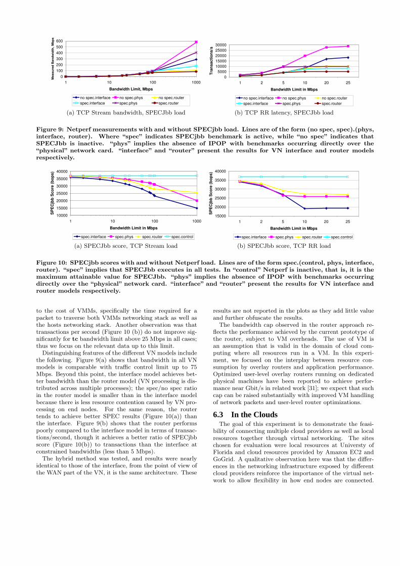
Figure 9: Netperf measurements with and without SPECjbb load. Lines are of the form (no spec, spec).(phys,interface, router). Where “spec” indicates SPECjbb benchmark is active, while “no spec” indicates thatSPECJbb is inactive. “phys” implies the absence of IPOP with benchmarks occurring directly over the“physical” network card. “interface” and “router” present the results for VN interface and router modelsrespectively.
10000
15000
20000
25000
30000
35000
40000
1 10 100 1000
Bandwidth Limit in Mbps
SP
EC
jbb
Sc
ore
(b
op
s)
spec.interface spec.phys spec.router spec.control
(a) SPECJbb score, TCP Stream load
15000
20000
25000
30000
35000
40000
1 2 5 10 20 25
Bandwidth Limit in Mbps
SP
EC
jbb
Sc
ore
(b
op
s)
spec.interface spec.phys spec.router spec.control
(b) SPECJbb score, TCP RR load
Figure 10: SPECjbb scores with and without Netperf load. Lines are of the form spec.(control, phys, interface,router). “spec” implies that SPECJbb executes in all tests. In “control” Netperf is inactive, that is, it is themaximum attainable value for SPECJbb. “phys” implies the absence of IPOP with benchmarks occurringdirectly over the “physical” network card. “interface” and “router” present the results for VN interface androuter models respectively.
to the cost of VMMs, specifically the time required for apacket to traverse both VMMs networking stack as well asthe hosts networking stack. Another observation was thattransactions per second (Figure 10 (b)) do not improve sig-nificantly for tc bandwidth limit above 25 Mbps in all cases;thus we focus on the relevant data up to this limit.
Distinguishing features of the different VN models includethe following. Figure 9(a) shows that bandwidth in all VNmodels is comparable with traffic control limit up to 75Mbps. Beyond this point, the interface model achieves bet-ter bandwidth than the router model (VN processing is dis-tributed across multiple processes); the spec/no spec ratioin the router model is smaller than in the interface modelbecause there is less resource contention caused by VN pro-cessing on end nodes. For the same reason, the routertends to achieve better SPEC results (Figure 10(a)) thanthe interface. Figure 9(b) shows that the router performspoorly compared to the interface model in terms of transac-tions/second, though it achieves a better ratio of SPECjbbscore (Figure 10(b)) to transactions than the interface atconstrained bandwidths (less than 5 Mbps).
The hybrid method was tested, and results were nearlyidentical to those of the interface, from the point of view ofthe WAN part of the VN, it is the same architecture. These
results are not reported in the plots as they add little valueand further obfuscate the results.
The bandwidth cap observed in the router approach re-flects the performance achieved by the current prototype ofthe router, subject to VM overheads. The use of VM isan assumption that is valid in the domain of cloud com-puting where all resources run in a VM. In this experi-ment, we focused on the interplay between resource con-sumption by overlay routers and application performance.Optimized user-level overlay routers running on dedicatedphysical machines have been reported to achieve perfor-mance near Gbit/s in related work [31]; we expect that suchcap can be raised substantially with improved VM handlingof network packets and user-level router optimizations.
6.3 In the CloudsThe goal of this experiment is to demonstrate the feasi-
bility of connecting multiple cloud providers as well as localresources together through virtual networking. The siteschosen for evaluation were local resources at Universty ofFlorida and cloud resources provided by Amazon EC2 andGoGrid. A qualitative observation here was that the differ-ences in the networking infrastructure exposed by differentcloud providers reinforce the importance of the virtual net-work to allow flexibility in how end nodes are connected.

EC2 / UF EC2 / GoGrid UF / GoGridStream Phys 89.21 35.93 30.17Stream VN 75.31 19.21 25.65RR Phys 13.35 11.09 9.97RR VN 13.33 10.69 9.76
Table 3: WAN Results for inter-cloud networking.Stream is in Mbs and RR is in trans/s (The inverseof trans/s would be equal to the average latency).
VN Interface VN Router VN Hybrid PhysicalStream 109 325 324 327RR 1863 2277 2253 3121
Table 4: LAN results performed at GoGrid. Streamis in Mbs and RR is in trans/s. Interface and Phys-ical used the eth0 NIC, while Router and Hybridused eth1. Different VLANs may give different re-sults.
Specific network configurations for the clouds were as fol-lows:
• Amazon EC2 provides static IP networking (public and pri-vate), no Ethernet connectivity, and no ability to recon-figure IP addresses for network. Currently, only the VNinterface model is supported.
• GoGrid provides 3 interfaces (one public, statically config-ured, and two private, which can be configured in any man-ner); the 2 private interfaces are on separate VLANs sup-porting Ethernet connectivity. The VN interface, router,and hybrid models are supported.
In this experiment, we have narrowed down the perfor-mance evaluation to focus on WAN and LAN performanceof VNs in cloud environments and consider Netperf singleclient-server interactions only. Because Amazon only sup-ports Interface mode, we only evaluate it in the WAN ex-periment. We have observed that, within Amazon, the VNis able to self-organize direct overlay connections [12]. Eachtest was run 5 times for 30 seconds, the standard deviationfor all results was less than 1. Because of this, we onlypresent the average in Table 3.
It can be seen in Table 3 that the VN adds little overheadin the Netperf-RR experiment. Between UF and GoGridas well as between UF and Amazon EC2, the overhead forthe Stream experiment was about 15%. This may be at-tributed to the additional per-packet overhead of the VNand the small MTU set for the VN interface (1200). TheMTU, or maximum transmission unit, is the larget packetthat is sent from an interface. IPOP conservatively limitsthe VN MTU to 1200 down from the default 1500 to al-low for overlay headers and to work properly with poorlyconfigured routers, which we have encountered in practicaldeployments. A more dynamic MTU, which will improveperformance, is left as future work. The EC2 / GoGridexperiment had greater overhead which could possibly beattributed to by the VM encapsulation of cloud resources.
Table 4 shows that some of our performance expectationsfor the different models in a LAN were accurately predictedwhile others were not so clear. Stream results match the ex-pectation that VN models hybrid and router bypass virtual-ization and get near physical speeds, whereas interface doesnot. Interestingly, RR had rather poor results for Routerand Hybrid though further testing seems to indicate that
this is an issue of using the VLAN connected network inter-faces as opposed to the public network connected interface.
6.4 VN Router Migration EvaluationFor the analysis of our implementation, we setup two Xen-
based VMware VMs co-located on the same quad-core Xeon5335 2 GHz machine each with 1 GB memory allocated run-ning only a minimal configuration with a SSH server. Thegoal of the evaluation was to determine overlay overheadsand attempt to minimize the cost of the VM migration. Theexperiment, as shown in Figure 11, involved migrating a Xenguest VM between two Xen host VMMs running in VMware.Although they are hosted in the same infrastructure, thetwo domains are connected to two separate VLANs, andthus isolated. As mentioned earlier, resource information isstored in a DHT running on top of our ON which is deployedon PlanetLab. Thus the migration overheads in the experi-ment capture the cost of wide-area messaging in a realisticenvironment. During the course of the experiment, we triedover 50 different IP addresses migrating them about 10 timeseach in attempt to gain some insights in the cost of usingthe DHT with support for deletes and VN router messagesas a means to implement migration. The result, presentedin Figure 12 gathered from the experiment was how longthe VN IP was offline, measured by means of ICMP pingpackets. On average, the overhead of VN migration was 20seconds. This overhead is in addition to the time taken tomigrate a VM, since the VN routers begin to communicateonly after migration finishes.
Figure 11: The VN operations that occur after a guest
(VM) has been migrated. (1) The destination retrieves
the P2P information of the source from the DHT and
optimistically places its information into the Dht. (2)
The destination requests that the source delete its infor-
mation from the DHT. (3) The source confirms that the
VM is no longer present and performs the delete. (4)
The source notifies the destination that its request has
finished successfully.
7. CONCLUSIONSA key aspect of our contribution is the use of common
network protocols as the building blocks for self-configuring,
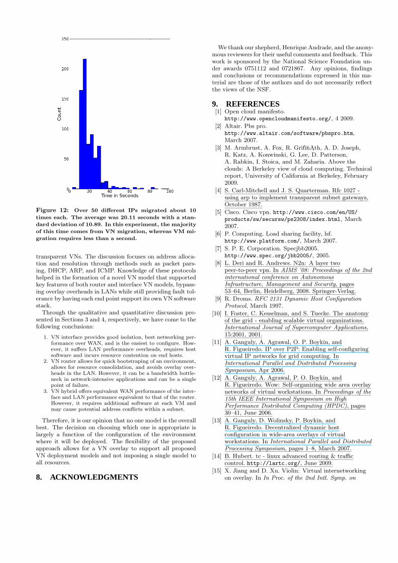
Figure 12: Over 50 different IPs migrated about 10
times each. The average was 20.11 seconds with a stan-
dard deviation of 10.89. In this experiment, the majority
of this time comes from VN migration, whereas VM mi-
gration requires less than a second.
transparent VNs. The discussion focuses on address alloca-tion and resolution through methods such as packet pars-ing, DHCP, ARP, and ICMP. Knowledge of these protocolshelped in the formation of a novel VN model that supportedkey features of both router and interface VN models, bypass-ing overlay overheads in LANs while still providing fault tol-erance by having each end point support its own VN softwarestack.
Through the qualitative and quantitative discussion pre-sented in Sections 3 and 4, respectively, we have come to thefollowing conclusions:
1. VN interface provides good isolation, best networking per-formance over WAN, and is the easiest to configure. How-ever, it suffers LAN performance overheads, requires hostsoftware and incurs resource contention on end hosts.
2. VN router allows for quick bootstraping of an environment,allows for resource consolidation, and avoids overlay over-heads in the LAN. However, it can be a bandwidth bottle-neck in network-intensive applications and can be a singlepoint of failure.
3. VN hybrid offers equivalent WAN performance of the inter-face and LAN performance equivalent to that of the router.However, it requires additional software at each VM andmay cause potential address conflicts within a subnet.
Therefore, it is our opinion that no one model is the overallbest. The decision on choosing which one is appropriate islargely a function of the configuration of the environmentwhere it will be deployed. The flexibility of the proposedapproach allows for a VN overlay to support all proposedVN deployment models and not imposing a single model toall resources.
8. ACKNOWLEDGMENTS
We thank our shepherd, Henrique Andrade, and the anony-mous reviewers for their useful comments and feedback. Thiswork is sponsored by the National Science Foundation un-der awards 0751112 and 0721867. Any opinions, findingsand conclusions or recommendations expressed in this ma-terial are those of the authors and do not necessarily reflectthe views of the NSF.
9. REFERENCES[1] Open cloud manifesto.
http://www.opencloudmanifesto.org/, 4 2009.
[2] Altair. Pbs pro.http://www.altair.com/software/pbspro.htm,March 2007.
[3] M. Armbrust, A. Fox, R. GrifınAth, A. D. Joseph,R. Katz, A. Konwinski, G. Lee, D. Patterson,A. Rabkin, I. Stoica, and M. Zaharia. Above theclouds: A Berkeley view of cloud computing. Technicalreport, University of California at Berkeley, February2009.
[4] S. Carl-Mitchell and J. S. Quarterman. Rfc 1027 -using arp to implement transparent subnet gateways,October 1987.
[5] Cisco. Cisco vpn. http://www.cisco.com/en/US/products/sw/secursw/ps2308/index.html, March2007.
[6] P. Computing. Load sharing facility, lsf.http://www.platform.com/, March 2007.
[7] S. P. E. Corporation. Specjbb2005.http://www.spec.org/jbb2005/, 2005.
[8] L. Deri and R. Andrews. N2n: A layer twopeer-to-peer vpn. In AIMS ’08: Proceedings of the 2ndinternational conference on AutonomousInfrastructure, Management and Security, pages53–64, Berlin, Heidelberg, 2008. Springer-Verlag.
[9] R. Droms. RFC 2131 Dynamic Host ConfigurationProtocol, March 1997.
[10] I. Foster, C. Kesselman, and S. Tuecke. The anatomyof the grid - enabling scalable virtual organizations.International Journal of Supercomputer Applications,15:2001, 2001.
[11] A. Ganguly, A. Agrawal, O. P. Boykin, andR. Figueiredo. IP over P2P: Enabling self-configuringvirtual IP networks for grid computing. InInternational Parallel and Distributed ProcessingSymposium, Apr 2006.
[12] A. Ganguly, A. Agrawal, P. O. Boykin, andR. Figueiredo. Wow: Self-organizing wide area overlaynetworks of virtual workstations. In Proceedings of the15th IEEE International Symposium on HighPerformance Distributed Computing (HPDC), pages30–41, June 2006.
[13] A. Ganguly, D. Wolinsky, P. Boykin, andR. Figueiredo. Decentralized dynamic hostconfiguration in wide-area overlays of virtualworkstations. In International Parallel and DistributedProcessing Symposium, pages 1–8, March 2007.
[14] B. Hubert. tc - linux advanced routing & trafficcontrol. http://lartc.org/, June 2009.
[15] X. Jiang and D. Xu. Violin: Virtual internetworkingon overlay. In In Proc. of the 2nd Intl. Symp. on

Parallel and Distributed Processing and Applications,pages 937–946, 2003.
[16] R. Jones. Netperf: A network performance monitoringtool. http://www.netperf.org/netperf/NetperfPage.html, 42009.
[17] D. Joseph, J. Kannan, A. Kubota,K. Lakshminarayanan, I. Stoica, and K. Wehrle.Ocala: an architecture for supporting legacyapplications over overlays. In NSDI’06: Proceedings ofthe 3rd conference on Networked Systems Design &Implementation, pages 20–20, Berkeley, CA, USA,2006. USENIX Association.
[18] M. Kallahalla, M. Uysal, R. Swaminathan, D. E.Lowell, M. Wray, T. Christian, N. Edwards, C. I.Dalton, and F. Gittler. SoftUDC: A software-baseddata center for utility computing. Computer,37(11):38–46, 2004.
[19] K. Keahey and T. Freeman. Contextualization:Providing one-click virtual clusters. IEEEInternational Conference on eScience, pages 301–308,2008.
[20] C. C. Keir, C. Clark, K. Fraser, S. H, J. G. Hansen,E. Jul, C. Limpach, I. Pratt, and A. Warfield. Livemigration of virtual machines. In In Proceedings of the2nd ACM/USENIX Symposium on Networked SystemsDesign and Implementation, pages 273–286, 2005.
[21] M. Krasnyansky. Universal tun/tap device driver.http://www.kernel.org/pub/linux/kernel/people/
marcelo/linux-2.4/Documentation/networking/
tuntap.txt, March 2007.
[22] M. Livny, J. Basney, R. Raman, and T. Tannenbaum.Mechanisms for high throughput computing.SPEEDUP Journal, 11(1), June 1997.
[23] M. Nelson, B.-H. Lim, and G. Hutchins. Fasttransparent migration for virtual machines. In ATEC’05: Proceedings of the annual conference on USENIXAnnual Technical Conference, pages 25–25, Berkeley,CA, USA, 2005. USENIX Association.
[24] L. Peterson and D. Culler. Planet-lab.http://www.planet-lab.org, March 2007.
[25] J. Postel. Rfc 0925 - multi-lan address resolution,1984.
[26] Qumranet. Kernel-based virtual machine for linux.http://kvm.qumranet.com/kvmwiki, March 2007.
[27] R. D. S. Alexander. RFC 2132 DHCP Options andBOOTP Vendor Extensions.
[28] Sun. gridengine.http://gridengine.sunsource.net/, March 2007.
[29] A. I. Sundararaj and P. A. Dinda. Towards virtualnetworks for virtual machine grid computing. InVM’04: Proceedings of the 3rd conference on VirtualMachine Research And Technology Symposium, pages14–14, Berkeley, CA, USA, 2004. USENIXAssociation.
[30] M. Tsugawa and J. Fortes. A virtual network (vine)architecture for grid computing. International Paralleland Distributed Processing Symposium, 0:123, 2006.
[31] M. Tsugawa and J. Fortes. Characterizing user-levelnetwork virtualization: Performance, overheads and
limits. In IEEE International Conference on eScience,pages 206–213, Dec. 2008.
[32] D. I. Wolinsky, Y. Liu, and R. Figueiredo. Towards auniform self-configuring virtual private network forworkstations and clusters in grid computing. In VTDC’09: Proceedings of the 3rd international workshop onVirtualization technologies in distributed computing,pages 19–26, New York, NY, USA, 2009. ACM.
[33] J. Yonan. Openvpn. http://openvpn.net/, March2007.