On the base stations antenna system design for mobile communications
7
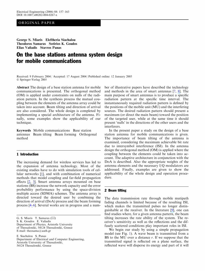
ORIGINAL PAPER George S. Miaris Eleftheria Siachalou Theodoros Samaras Sotirios K. Goudos Elias Vafiadis Stavros Panas On the base stations antenna system design for mobile communications Received: 9 February 2004 / Accepted: 17 August 2004 / Published online: 12 January 2005 Ó Springer-Verlag 2005 Abstract The design of a base station antenna for mobile communications is presented. The orthogonal method (OM) is applied under constraints on nulls of the radi- ation pattern. In the synthesis process the mutual cou- pling between the elements of the antenna array could be taken into account. Beam tilting and direction of arrival are also considered. The whole design is completed by implementing a special architecture of the antenna. Fi- nally, some examples show the applicability of our technique. Keywords Mobile communications Base station antennas Beam tilting Beam forming Orthogonal method 1 Introduction The increasing demand for wireless services has led to the expansion of antenna technology. Most of the existing studies have to do with simulation tools of cel- lular networks [1], and with combination of numerical methods that model coupling and far-field propagation effects [2, 3]. Smart antenna arrays mounted on base stations (BS) increase the network capacity and the error probability performance by using the space-division multiple access (SDMA) schemes. The antenna array is directed toward the desired user by combining the direction of arrival (DoA) process and the beam forming process [4–6]. Several works are in progress and a num- ber of illustrative papers have described the technology and methods in the area of smart antennas [7, 8]. The main purpose of smart antennas is to produce a specific radiation pattern at the specific time interval. The instantaneously required radiation pattern is defined by the positions of the mobile unit (MU) and the interfering sources. The desired radiation pattern should present a maximum (or direct the main beam) toward the position of the targeted user, while at the same time it should present ‘nulls’ in the directions of the other users and the interferers. In the present paper a study on the design of a base station antenna for mobile communications is given. The importance of beam tilting of the antenna is examined, considering the maximum achievable bit rate due to intersymbol interference (ISI). In the antenna design the orthogonal method (OM) is applied where the coupling between the elements could be taken into ac- count. The adaptive architecture in conjunction with the DoA is described. Also the appropriate weights of the antenna elements and the necessary I/Q modulators are addressed. Finally, examples are given to show the applicability of the whole design and operation proce- dure. 2 Beam tilting The data transmission rate through mobile mutipath fading channels is limited because of the resulting ISI, which makes the transmitted pulses no longer distin- guishable at the receiver. In the literature [9], one can find studies where, for a given antenna pattern, the beam tilting increases the rate ability of the system. The re- ceiver’s sensitivity as well as the reflections and the dif- fusely scattered conditions play important roles in ISI. We begin our study by using a simple propagation model (see Fig. 1). A wave beam is transmitted from a BS to the MU over a distance r. If we suppose that the transmitted signal is reflected on a plane surface, the reflected wave will disperse its energy and part of it will G. S. Miaris T. Samaras (&) S. K. Goudos E. Vafiadis Department of Physics, Aristotle University of Thessaloniki, 54124 Thessaloniki, Greece E-mail: [email protected] E. Siachalou S. Panas Department of Electrical and Computer Engineering, Aristotle University of Thessaloniki, 54124 Thessaloniki, Greece Electrical Engineering (2006) 88: 157–163 DOI 10.1007/s00202-004-0267-x
Transcript of On the base stations antenna system design for mobile communications
ORIGINAL PAPER
George S. Miaris Æ Eleftheria Siachalou
Theodoros Samaras Æ Sotirios K. Goudos
Elias Vafiadis Æ Stavros Panas
On the base stations antenna system designfor mobile communications
Received: 9 February 2004 / Accepted: 17 August 2004 / Published online: 12 January 2005� Springer-Verlag 2005
Abstract The design of a base station antenna for mobilecommunications is presented. The orthogonal method(OM) is applied under constraints on nulls of the radi-ation pattern. In the synthesis process the mutual cou-pling between the elements of the antenna array could betaken into account. Beam tilting and direction of arrivalare also considered. The whole design is completed byimplementing a special architecture of the antenna. Fi-nally, some examples show the applicability of ourtechnique.
Keywords Mobile communications Æ Base stationantennas Æ Beam tilting Æ Beam forming Æ Orthogonalmethod
1 Introduction
The increasing demand for wireless services has led tothe expansion of antenna technology. Most of theexisting studies have to do with simulation tools of cel-lular networks [1], and with combination of numericalmethods that model coupling and far-field propagationeffects [2, 3]. Smart antenna arrays mounted on basestations (BS) increase the network capacity and the errorprobability performance by using the space-divisionmultiple access (SDMA) schemes. The antenna array isdirected toward the desired user by combining thedirection of arrival (DoA) process and the beam formingprocess [4–6]. Several works are in progress and a num-
ber of illustrative papers have described the technologyand methods in the area of smart antennas [7, 8]. Themain purpose of smart antennas is to produce a specificradiation pattern at the specific time interval. Theinstantaneously required radiation pattern is defined bythe positions of the mobile unit (MU) and the interferingsources. The desired radiation pattern should present amaximum (or direct the main beam) toward the positionof the targeted user, while at the same time it shouldpresent ‘nulls’ in the directions of the other users and theinterferers.
In the present paper a study on the design of a basestation antenna for mobile communications is given.The importance of beam tilting of the antenna isexamined, considering the maximum achievable bit ratedue to intersymbol interference (ISI). In the antennadesign the orthogonal method (OM) is applied where thecoupling between the elements could be taken into ac-count. The adaptive architecture in conjunction with theDoA is described. Also the appropriate weights of theantenna elements and the necessary I/Q modulators areaddressed. Finally, examples are given to show theapplicability of the whole design and operation proce-dure.
2 Beam tilting
The data transmission rate through mobile mutipathfading channels is limited because of the resulting ISI,which makes the transmitted pulses no longer distin-guishable at the receiver. In the literature [9], one canfind studies where, for a given antenna pattern, the beamtilting increases the rate ability of the system. The re-ceiver’s sensitivity as well as the reflections and the dif-fusely scattered conditions play important roles in ISI.
We begin our study by using a simple propagationmodel (see Fig. 1). A wave beam is transmitted from aBS to the MU over a distance r. If we suppose that thetransmitted signal is reflected on a plane surface, thereflected wave will disperse its energy and part of it will
G. S. Miaris Æ T. Samaras (&)S. K. Goudos Æ E. VafiadisDepartment of Physics, Aristotle Universityof Thessaloniki, 54124 Thessaloniki, GreeceE-mail: [email protected]
E. Siachalou Æ S. PanasDepartment of Electrical and Computer Engineering,Aristotle University of Thessaloniki,54124 Thessaloniki, Greece
Electrical Engineering (2006) 88: 157–163DOI 10.1007/s00202-004-0267-x
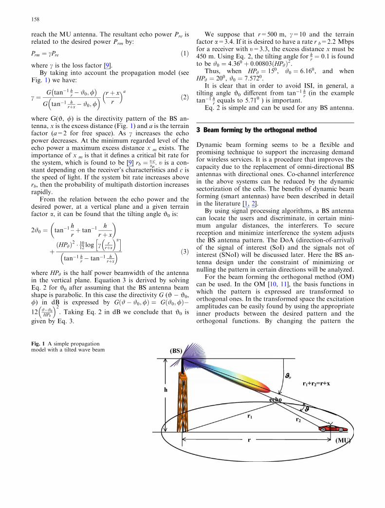
reach the MU antenna. The resultant echo power Pre isrelated to the desired power Prm by:
Prm ¼ cPre ð1Þ
where c is the loss factor [9].By taking into account the propagation model (see
Fig. 1) we have:
c ¼G tan�1 h
r � #0;/� �
G tan�1 hrþx� #0;/
� � r þ xr
� �að2Þ
where G(J, /) is the directivity pattern of the BS an-tenna, x is the excess distance (Fig. 1) and a is the terrainfactor (a=2 for free space). As c increases the echopower decreases. At the minimum regarded level of theecho power a maximum excess distance x m exists. Theimportance of x m is that it defines a critical bit rate forthe system, which is found to be [9] rb ¼ t�c
xm. t is a con-
stant depending on the receiver’s characteristics and c isthe speed of light. If the system bit rate increases aboverb, then the probability of multipath distortion increasesrapidly.
From the relation between the echo power and thedesired power, at a vertical plane and a given terrainfactor a, it can be found that the tilting angle J0 is:
2#0 ¼ tan�1hrþ tan�1
hr þ x
� �
þHP#ð Þ2 � 1012 log c r
rþx
� �ah i
tan�1 hr � tan�1 h
rþx
� � ð3Þ
where HP# is the half power beamwidth of the antennain the vertical plane. Equation 3 is derived by solvingEq. 2 for J0 after assuming that the BS antenna beamshape is parabolic. In this case the directivity G (J � J0,/) in dB is expressed by G #� #0;/ð Þ ¼ G #0;/ð Þ�12 #�#0
HPh
� �2. Taking Eq. 2 in dB we conclude that J0 is
given by Eq. 3.
We suppose that r=500 m, c=10 and the terrainfactor a=3.4. If it is desired to have a rate r b=2.2 Mbpsfor a receiver with t=3.3, the excess distance x must be450 m. Using Eq. 2, the tilting angle for h
r ¼ 0:1 is foundto be #0 ¼ 4:360 þ 0:00803 HP#ð Þ2.
Thus, when HP# ¼ 150, #0 ¼ 6:160, and whenHP# ¼ 200, #0 ¼ 7:5720.
It is clear that in order to avoid ISI, in general, atilting angle J0 different from tan�1 h
r (in the exampletan�1 h
r equals to 5.710 ) is important.Eq. 2 is simple and can be used for any BS antenna.
3 Beam forming by the orthogonal method
Dynamic beam forming seems to be a flexible andpromising technique to support the increasing demandfor wireless services. It is a procedure that improves thecapacity due to the replacement of omni-directional BSantennas with directional ones. Co-channel interferencein the above systems can be reduced by the dynamicsectorization of the cells. The benefits of dynamic beamforming (smart antennas) have been described in detailin the literature [1, 2].
By using signal processing algorithms, a BS antennacan locate the users and discriminate, in certain mini-mum angular distances, the interferers. To securereception and minimize interference the system adjuststhe BS antenna pattern. The DoA (direction-of-arrival)of the signal of interest (SoI) and the signals not ofinterest (SNoI) will be discussed later. Here the BS an-tenna design under the constraint of minimizing ornulling the pattern in certain directions will be analyzed.
For the beam forming the orthogonal method (OM)can be used. In the OM [10, 11], the basis functions inwhich the pattern is expressed are transformed toorthogonal ones. In the transformed space the excitationamplitudes can be easily found by using the appropriateinner products between the desired pattern and theorthogonal functions. By changing the pattern the
Fig. 1 A simple propagationmodel with a tilted wave beam
158
corresponding weights are changed as well. To null thepattern in certain directions the orthogonal method canbe modified. It is noticed that the above constraints arelinear; therefore, beam forming by the OM is possible.
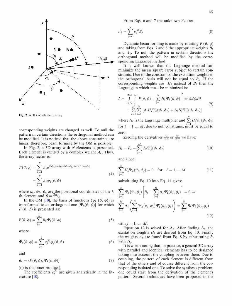
In Fig. 2, a 3D array with N elements is presented.Each element is excited by a complex weight Ak. Thus,the array factor is:
F #;/ð Þ ¼XN
k¼1Akeibdk sin# cosð/�/kÞþcos # cos #k½ �
¼XN
k¼1Ak/k #;/ð Þ
ð4Þ
where dk, /k, Jk are the positional coordinates of the kth element and b ¼ 2p=k.
In the OM [10], the basis of functions {/k (J, /)} istransformed to an orthogonal one {Yk(J, /)} for whichF (J, /) is presented as:
F #;/ð Þ ¼XN
k¼1BkWk #;/ð Þ ð5Þ
where
Wk #;/ð Þ ¼Xk
j¼1cðkÞj /j #;/ð Þ ð6Þ
and
Bk ¼ F #;/ð Þ;Wk #;/ð Þh i ð7Þ
(Æ,æ is the inner product).The coefficients c kð Þ
j are given analytically in the lit-erature [10].
From Eqs. 6 and 7 the unknown Ak are:
Ak ¼XN
j¼k
c jð Þk Bj ð8Þ
Dynamic beam forming is made by rotating F (J, /)and taking from Eqs. 7 and 8 the appropriate weights Bk
and Ak. To null the pattern in certain directions theorthogonal method will be modified by the corre-sponding Lagrange method.
It is well known that the Lagrange method canminimize the mean square error subject to certain con-straints. Due to the constraints, the excitation weights inthe orthogonal basis will not be equal to Bk. If thecorresponding weights are Hk instead of Bk then theLagrangian which must be minimized is:
L ¼Rp=2
�p=2
R2p
0
F #;/ð Þ �PN
k¼1HkWk #;/ð Þ
����
����
2
sin#d/d#
+PM
‘¼1
PN
k¼1K‘HkWk #‘;/‘ð Þ þ K‘H�k W�k #‘;/‘ð Þ�
ð9Þ
where K‘ is the Lagrange multiplier andPN
k¼1HkWk #‘;/‘ð Þ
for ‘ ¼ 1; :::;M , due to null constrains, must be equal to
zero.
Zeroing the derivatives @L@Hk
or @L@H�k
we have:
Hk ¼ Bk �XM
‘¼1K‘W
�k #‘;/‘ð Þ ð10Þ
and since,
XN
k¼1HkWkð#‘;/‘Þ ¼ 0 for ‘ ¼ 1; :::;M ð11Þ
substituting Eq. 10 into Eq. 11 gives:
XN
k¼1Wk #j;/j
� �Bk �
XM
‘¼1K‘W
�k #‘;/‘ð Þ
" #
¼ 0)
XM
‘¼1K‘
XN
k¼1Wk #j;/j
� �W�k #‘;/‘ð Þ
!
¼XN
k¼1BkWk #j;/j
� �
ð12Þ
with j =1,…, M.Equation 12 is solved for K‘. After finding K‘, the
excitation weights Hk are derived from Eq. 10. Finallythe weights Ak are found from Eq. 8 by substituting Bj
with Hj.It is worth noting that, in practice, a general 3D array
with parallel and identical elements has to be designedtaking into account the coupling between them. Due tocoupling, the pattern of each element is different fromthat of the others and of course different from the cor-responding isolated one. To solve the synthesis problem,one could start from the derivation of the element’spattern. Several techniques have been proposed in the
Fig. 2 A 3D N -element array
159
past. One such technique has to do with the applicationof the method of moments (MoM) [10]. Another makesuse of the over-sampling of the pattern of each element[12]. The OM in conjunction with measurements of theelement pattern is an alternative technique. The wholeprocedure is based on the fact that the element pattern isactually obtained through the array pattern by excitingonly a single element while the rest are short-circuited.
4 Architecture of the antenna and directions of arrival
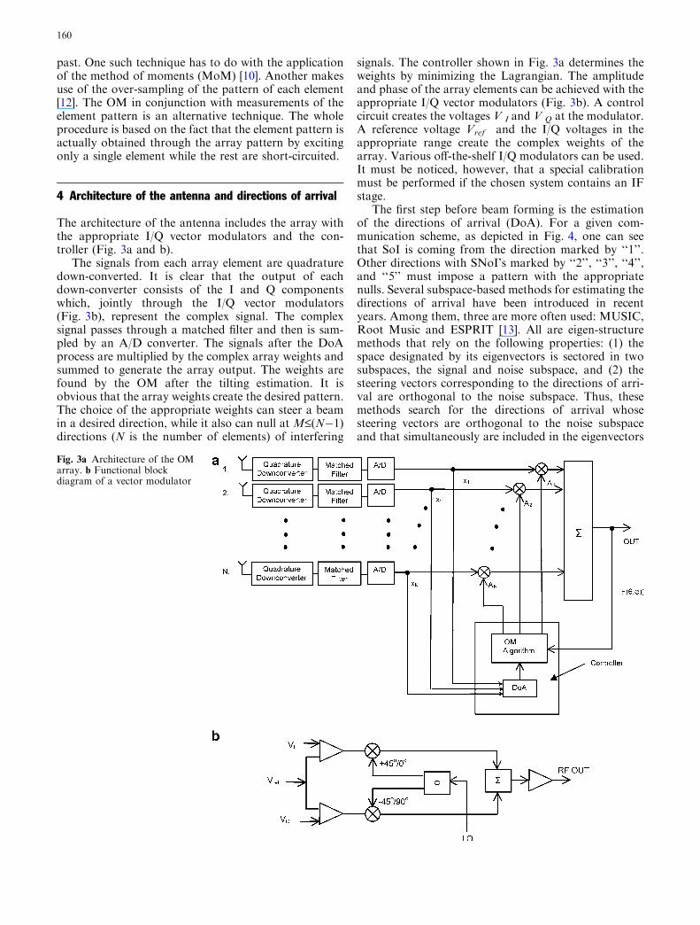
The architecture of the antenna includes the array withthe appropriate I/Q vector modulators and the con-troller (Fig. 3a and b).
The signals from each array element are quadraturedown-converted. It is clear that the output of eachdown-converter consists of the I and Q componentswhich, jointly through the I/Q vector modulators(Fig. 3b), represent the complex signal. The complexsignal passes through a matched filter and then is sam-pled by an A/D converter. The signals after the DoAprocess are multiplied by the complex array weights andsummed to generate the array output. The weights arefound by the OM after the tilting estimation. It isobvious that the array weights create the desired pattern.The choice of the appropriate weights can steer a beamin a desired direction, while it also can null at M£(N�1)directions (N is the number of elements) of interfering
signals. The controller shown in Fig. 3a determines theweights by minimizing the Lagrangian. The amplitudeand phase of the array elements can be achieved with theappropriate I/Q vector modulators (Fig. 3b). A controlcircuit creates the voltages V I and V Q at the modulator.A reference voltage Vref and the I/Q voltages in theappropriate range create the complex weights of thearray. Various off-the-shelf I/Q modulators can be used.It must be noticed, however, that a special calibrationmust be performed if the chosen system contains an IFstage.
The first step before beam forming is the estimationof the directions of arrival (DoA). For a given com-munication scheme, as depicted in Fig. 4, one can seethat SoI is coming from the direction marked by ‘‘1’’.Other directions with SNoI’s marked by ‘‘2’’, ‘‘3’’, ‘‘4’’,and ‘‘5’’ must impose a pattern with the appropriatenulls. Several subspace-based methods for estimating thedirections of arrival have been introduced in recentyears. Among them, three are more often used: MUSIC,Root Music and ESPRIT [13]. All are eigen-structuremethods that rely on the following properties: (1) thespace designated by its eigenvectors is sectored in twosubspaces, the signal and noise subspace, and (2) thesteering vectors corresponding to the directions of arri-val are orthogonal to the noise subspace. Thus, thesemethods search for the directions of arrival whosesteering vectors are orthogonal to the noise subspaceand that simultaneously are included in the eigenvectors
Fig. 3a Architecture of the OMarray. b Functional blockdiagram of a vector modulator
160
defining the signal subspace. The above algorithms offera good balance between statistical performance andsimplicity.
MUSIC, Root-MUSIC and ESPRIT can be imple-mented for BS antennas. The simulation results arebased on a large number of samples. Also, a spatiallydistributed correlated noise can be added to producenoisy signals. MUSIC algorithm with the techniquecalled ‘spatial smoothing’ [2], is an alternative tool forthe DoA. It must be noticed that to increase the per-formance of the system the beam tilting in the directiongiven by Eq. 2 is important. This direction, in general,differs slightly from the corresponding one of the SoI.
5 Numerical examples
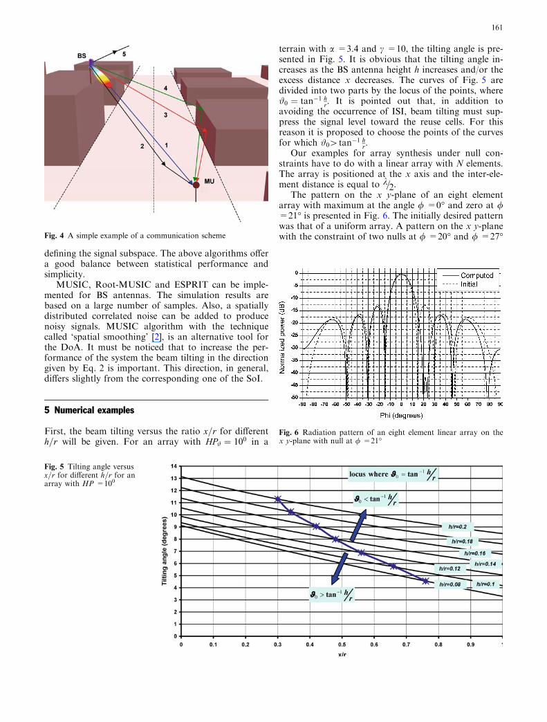
First, the beam tilting versus the ratio x=r for differenth=r will be given. For an array with HP# ¼ 100 in a
terrain with a =3.4 and c =10, the tilting angle is pre-sented in Fig. 5. It is obvious that the tilting angle in-creases as the BS antenna height h increases and/or theexcess distance x decreases. The curves of Fig. 5 aredivided into two parts by the locus of the points, where#0 ¼ tan�1 h
r. It is pointed out that, in addition toavoiding the occurrence of ISI, beam tilting must sup-press the signal level toward the reuse cells. For thisreason it is proposed to choose the points of the curvesfor which #0[tan�1 h
r.Our examples for array synthesis under null con-
straints have to do with a linear array with N elements.The array is positioned at the x axis and the inter-ele-ment distance is equal to k=2.
The pattern on the x y-plane of an eight elementarray with maximum at the angle / =0� and zero at /=21� is presented in Fig. 6. The initially desired patternwas that of a uniform array. A pattern on the x y-planewith the constraint of two nulls at / =20� and / =27�
Fig. 5 Tilting angle versusx=r for different h=r for anarray with HP =100
Fig. 4 A simple example of a communication scheme
Fig. 6 Radiation pattern of an eight element linear array on thex y-plane with null at / =21�
161
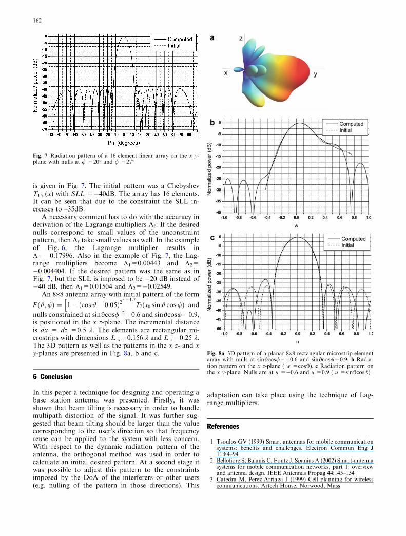
is given in Fig. 7. The initial pattern was a ChebyshevT15 (x) with SLL =�40dB. The array has 16 elements.It can be seen that due to the constraint the SLL in-creases to –35dB.
A necessary comment has to do with the accuracy inderivation of the Lagrange multipliers K‘: If the desirednulls correspond to small values of the unconstraintpattern, then K‘ take small values as well. In the exampleof Fig. 6, the Lagrange multiplier results inL=�0.17996. Also in the example of Fig. 7, the Lag-range multipliers become L1=0.00443 and L2=�0.004404. If the desired pattern was the same as inFig. 7, but the SLL is imposed to be �20 dB instead of�40 dB, then L1=0.01504 and L2=�0.02549.
An 8·8 antenna array with initial pattern of the form
F #;/ð Þ ¼ 1� cos#� 0:05ð Þ2h i�1:7
T7 x0 sin# cos/ð Þ and
nulls constrained at sinJcos/=�0.6 and sinJcos/=0.9,is positioned in the x z-plane. The incremental distanceis dx = dz =0.5 k. The elements are rectangular mi-crostrips with dimensions L x=0.156 k and L z=0.25 k.The 3D pattern as well as the patterns in the x z- and xy-planes are presented in Fig. 8a, b and c.
6 Conclusion
In this paper a technique for designing and operating abase station antenna was presented. Firstly, it wasshown that beam tilting is necessary in order to handlemultipath distortion of the signal. It was further sug-gested that beam tilting should be larger than the valuecorresponding to the user’s direction so that frequencyreuse can be applied to the system with less concern.With respect to the dynamic radiation pattern of theantenna, the orthogonal method was used in order tocalculate an initial desired pattern. At a second stage itwas possible to adjust this pattern to the constraintsimposed by the DoA of the interferers or other users(e.g. nulling of the pattern in those directions). This
adaptation can take place using the technique of Lag-range multipliers.
References
1. Tsoulos GV (1999) Smart antennas for mobile communicationsystems: benefits and challenges. Electron Commun Eng J11:84–94
2. Bellofiore S, Balanis C, Foutz J, Spanias A (2002) Smart-antennasystems for mobile communication networks, part 1: overviewand antenna design. IEEE Antennas Propag 44:145–154
3. Catedra M, Perez-Arriaga J (1999) Cell planning for wirelesscommunications. Artech House, Norwood, Mass
Fig. 7 Radiation pattern of a 16 element linear array on the x y-plane with nulls at / =20� and / =27�
Fig. 8a 3D pattern of a planar 8·8 rectangular microstrip elementarray with nulls at sinJcos/=�0.6 and sinJcos/=0.9. b Radia-tion pattern on the x z-plane ( w =cosJ). c Radiation pattern onthe x y-plane. Nulls are at u =�0.6 and u =0.9 ( u =sinJcos/)
162

4. Sarkar TK, Wicks MC, Salazar-Palma M, Bonneau RJ(2003) Smart antennas. Wiley-Interscience and IEEE Press,New York
5. Tsoulos GV (ed) (2001) Adaptive antennas for wireless com-munications. IEEE Press, New York
6. Godara LC (ed) (2001) Handbook of antennas in wirelesscommunications. CRC Press, Boca Raton
7. Chryssomallis M (2000) Smart antennas. IEEE AntennasPropag 42:129–136
8. Sarkar T, Ji Z, Kim K, Medouri A, Salazar-Palma M (2003) Asurvey of various propagation models for mobile communica-tion. IEEE Antennas Propag 45:51–82
9. Tong F, Akaiwa Y (1997) Effects of beam tilting on bit-rateselection in mobile multipath channel. IEEE T Veh Technol46:257–261
10. Sahalos JN (2002) Antenna arrays. In: Proakis JG (ed) TheWiley encyclopedia of telecommunications. Wiley-Interscience,New York
11. Sahalos JN (2000) Antenna synthesis by orthogonal Mo-M(OM3). In: Uzunoglou NK, Nikita KS, Kaklamani DI (eds)Applied computational electromagnetics—state of the art andfuture trends. Springer, Berlin Heidelberg New York
12. Steyskal H, Herd JS (1990) Mutual coupling compensation insmall array antennas. IEEE T Antenn Propag 38:1971–1975
13. Godara LC (1997) Applications on antenna arrays to mobilecommunications, part II: beam-forming and direction-of-arri-val considerations. Proc IEEE 85:1195–1245
163