olympus-pm-10-a-instructions.pdf - Alan Wood
34
oLy"'-' L -- - - - PHom ICROGRPPHIC SYSTEM CAMERA = MODEL I
-
Upload
khangminh22 -
Category
Documents
-
view
0 -
download
0
Transcript of olympus-pm-10-a-instructions.pdf - Alan Wood

oLy"'-' L
-- - - -
P H o m ICROGRPPHIC SYSTEM CAMERA =
MODEL I
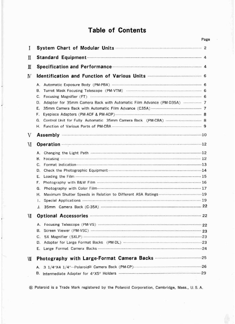
Table of Contents Page
A . Automatic Exposure Body (PM-PEA) ........................................................................... 6
B . Turret Mask Focusing f elescape ('M-Vf M) ............... ......-. ................................... 6
C . Focusing Magnifier (FT) ............................................................................................. 6
D . Adapter for 35mm Camera Back with Automatic Film Advance (PM-Q35A) ............... 7 E . 35mm Camera Back with Automatic Film Advance (C35A) .......................................... 7 F . Eyepiece Adapters (PM-ADF & PM-ADP) ........................................................................ 8
G . Control Unit for Fdly Automatic 35mm Camera Rack (PM-CBA) .............................. 8 51 . Function of Various parts of RM-CBA ........................................................................... 9
A a Changing the Light Path ............................................................................................. 12 ..................................................................................................................... El Focustng 12
C . Format Indication ........................................................................................................ 13 Q . Check the Photographic Equipment .............................................................................. 14
E+ Loading the Film ......................................................................................................... 15 F . 'Photography with B&W Film ....................................................................................... 16
G . photography with Color Film .................... ................................................................. 17
W . Maximum Shutter Speeds in Relation to Different ASA Ratings..... ............................... 19
I . Special Applications ................................................................................................... 19 J . 35mm Camera Back (C.35A) ............~.......~........................................................... . . 22
@I Polaroid is a Trade Mark registered by the Polaroid Corporation. Cambridge. Mass., 'U . S. A .

I System Chart of Modular Camera Units The photomicrographic camera system listed below is based on a modular concept of
interchangeable accessories for a wide range of applications. The entire camera system is
called PM-10.
The model PM-LO-A features fully automatic exposure and film advance facilities and
can be furnished with the standard components linked by bold lines, as well as with
optional accessories linked by dotted lines, as outlined in the chart below.
PM-CP I3 1/4*X4 114' Polar016 Back) t * 1 L ~ ~ ~ - - l . l l - - - - - - - - - - - - - ~ ~ - . ~
C"
-111
I I
! PM-VS (Focusing Telescope)
I
-
I PM - VTM I
I (Turret Mask Focusing I Telescope)
1 I I 0
r- 1111-
I 1 I I I PM YSC (Screen Vmr)
FT (Focusing Magnifier)
7
C-35 A (Em Camera Back with C-35 (35s C m s a Back
I Automatic Fi lm Advance) I ~ i t h Manual I!
I Yilm Advmcel I V
PM-D35A (Adapter for 35m Camera Back PM -P35 (Adapter for w i t h Automatic F i l m Advance)
3r BG;era with Manual
I-) f i l m ~d\drmm)
Exposure C L Body) -
PM -PBA (Automatic hposure Body) BM-ADF (Eyepiece Adapter
for FK Eyepieces)
I I
Ll (Photographic Eyepieces)

$ GK (4' x 5' Graphmatic Film Holder) Y
: GP (4'xS' Graphic Fib Pack Holder) I n
" GR (4' X5' Graphic Sheet F~lm Holder) Llrlr-r"..r-rr-rq
I
'1 PM - C4XS (4' X 5' Intermediate Adapter for PH, GH, GP, rind GR)
BM -DL (Adapter with Relay Lens for Large
Format Backs1
PM-CRA (Conhol Unit for Fully Automatic 3511 Camera Back)
* aA -AD? (Eyepiece Adspter for P Eyepieces)

Standard Equipment Before assembly. please check your standard outfit PM-16-A, which
following items:
Automat ie Exposure Body PM-PBA
Turret Mask Focusing Tetescope PM-VTM
Focusing Magnifier FT
Adapter for 35mm Camera Back with Automatic
Film Advance PM-D35A 35mm Camera Back with Automatic Film Advance C-35A
Data Inserts
Control Unit for FulFy Autcrnatic 35mm Camera Rack PM-CBA Eyepiece Adapter for FK Eyepieces PM-ADF
Eyepiece Adapter for P Eyepieces PM- ADP
Color Temperature Compensation Filter LB 45
LED
Neutral Density Filters ND 6 ND 12
NO 50
Storage Case
Optional Accessories
Focusing Telescope PM-VS Screen Viewer PM-VSC
5 X Magnifier 5XLP Adapter with Relay tens for Large Format Back PM-DL
3 1/4%4 P/4" Polaroid Back , PM-CP
4"X5" Intermediate Adapter PM-'24x5 (for 4"X5'! Polaroid film pack, Graphmatic
film holder, Graphic film pack holder, Graphic sheet film holder)
Photo Eyepieces FK (2.5XP3.3X,5X,6.7X)
Orthochromatic Filter Green II N Yellow
II Specification and Performance '
comprises the
* Automatic exwvure range: 32 min. to 1/100 sec. With pilot lamp indicating correct
exposure and pilot lamp indicating open shutter.
The light measuring device is calibrated to read within a
central circular area comprising approx. 30% of the field
photographed with 35mm film.

* Automatic shutter release system with push-button switch
and v ibration-proof electric shutter.
* ASA rating : B & W and color : 6-3,200.
Fine adjustment, graduated in 5 steps(0.75,0.85,1,1.2,1.5) * Color temperature adjustment unit:
Adjustment range: Color temp regulation scale is divided
into two parts ; One for tungsten type film, and the other for daylight type film. Color temperature indicating
meter, zero method of indication. * Reciprocity law failure compensation unit:
Reproduceable color rendition can be obtained by adjusting
for constant exposure time with a check button, a check area within the meter and a combination of ND filters.
* Automatic exposure body: A sliding prism incorporated into the Automatic Exposure
Body PM-PBA permits selective deviation of the light to
either the focusing telescope (loo%), the film plane, the focusing telescope and the photocell (64%/ 16%/20%),or
the color temperature rneter(IOO%). A built-in electronic
lock permits shutter release onl y when the sliding prism is
in camera/focusing position (CVE). * 35mm camera back with automatic f i lm advance;
Mounting: bayonet type. With electric cclntacts and self-
operating, fight excluding shutter. Film sire 24X36mm.
Provided with data imprinting device. * Magnification at film plane:
Wi th FK eyepiece: Objective magnification X FK eyepiece
magnification
With P eyepiece: Objective magnification X P eyepiece
magnification X 0.5 From the foregoing, the magnifications as tabulated 'below may be obtained by combining the objectives and eyepieces available. --- -:I FK2.5X FK6.7X Ob jectve
Bio- logical Appli- cations
P7X 1 P l O X ( P15X
4.6X 7 X
14X
35X 7 0 X
140X 350X
4.6X &.BX
1J.SX 21X 35X 70X
140X 1 7 5 X 35OX
1 .3X 2X 4X
10X 20X
40X l o O X
1.3X 2.5X
I 5 X Metallo- I ' 6 X
10X
cations 20X 4 0 X 50X
l O O X
10X 30X 75X
LOOX l5QX
200X JDOX 5 0 0 X 750X
6.5X 12.5X
25X 30X
8.7X 13.4X
27X 67X
l 3 4 X
270X 670X
3.3X 5 X
1 0 X 25X 50X
9.8X 1 8 . 8 X 37.5X
45X l6.5X 25X 33.5X I
40X 25X 33X 67X 50X
l O O X 200X 250X
500X
l O O X 1 3 Z X I 200X 2 5 0 X I 330X 1 500X
----
4.3X 6.6X
13.2X
33X
3 . 3 X ) 4.3X 6.3X 1 8 . 3 X
50X 1 66X
6.5X 10X
20X 50X
6 . 5 X I 8.7X 16.8X
I O O X 135X lOOX , 125X 250X
6 6 X l O O X
200X 250X
500X
1 3 2 X 1 6 5 X 330X
270X 335X
670X

IV Identification and Function of Various Units A. Automatic Exposure Body (PWPBA)
Locating Groove f o r Camera Adapter Contacts f o r 3 5 m Camera Back with Auturnatic
Fi I m Advance position the adapter on the automatic exposure body.
6. tur re t Mark Focusing Telescope (PM-VTM)
Knurled Clamping Ring
Mask Selector Lever
Biopter - \ Adjustment
C. Focusing Magnifier (FT)
Mounting Ring Fits on the front
lens portion of focusing te1escop~-
permit focusing on the frame reticles of the focusing telescope.

P. Adapter for 35mm Camera Back with Automatic Film Advance (PM-Q35A)
Camera Lock i ng Pin
Camera Attachment Pin Automatical ly opens the Iight exclutling s h u t t e r i n he 35mm camera back. A
lever causes
and permlts removal of the camera back.
Red Arrow Indicates the direct ion of
Index Dot 1 'I'o be aligned with dot on the
\ Electrical Contacts- For Fi lm Advance Motor .
35mm caiera hack prior ta camera back engagement.
1 j i /
/ Knurled Clamping
trical Contacts r : 1 - A J ha otor.
Locating Pin T n properly position the adapter
v on the automatic exposure Lady.
E. 35mn1 Camera Back with Automatic Film Advance CC-35A)
Film Counter Rewind knob esetting type. \ \ Index Dot Film l n ~ ~ r a t nr \ \ -
Srpar aLr n..,n >Laic
f o r B & W and
,,.,, 0 0 ,","..a,",
A c A A,' T o bt aligned w i t h dot on 3 5 m m camera back
adapter p r ~ o r to camera back engagement.
T l ~ e l a n ~ l ) l i g h t s up during f i lm advance.
and closes when the camcra back is removed.
Electricalcontacts For Film Advance Motor.
/
Rewind Button Back Cover Locking Lever
en the hinged cover.
-- --I--
\ Slit Data insert
I
i - Slide the ins;: i n t o the s l i t .
I
Put in information here ( 4X24.5mm) 7

IF. Eyepiece Adapters (PM-ADF & RM-ADP)
1. PM-ADF
Clarnpi ng Screw
7
2. PM-ADP
Clamping S c r e w
-7
Cocat i nc I ndex
Control Unit for Fully Automatic 35mm Camera Back (PM-CBA)
Ascertain that the line voltage selector switch at the bottom of the control unit (PM-
CBA) is set to conform with the local mains voltage.

H. Function of Various Parts of PM-CBA
(1) Selector Switch
"OFF'Lpower turns o f f , "AUTO & CTR" -power turns on; automatic exposure and
color temperature measurement are available.
"TIME" -automatic exposure c i r r ~ ~ i t is hy-passed, manual exposure is available.
"X" -synchronized flash phatography is available: Fixed shutter speed of approximately
1/30 sec.
(2) ASA Speed Selector Dial (ASA SPEED)
Un the dial, "35" denotes 35mm camera back and "L" large-tormat camera backs.
(3) ASA Flne Regulation Dial (ASA REG)
Permits fine regulation of the ASA rating. For details, consult subsequent paragraphs.
(4) Color Temperature Regulation Dial (COLOR TEMP REG) Permits selection of daylight or tungsten type film and sets to the desired color temper-
ature o f the f~Bm used.
(5) Color Temperature Meter (serves also as check meter)
The meter permits light balancing to obtain correct coFar temperature by means of zero
point alignment. Also, photography using the same shutter speed can be made by means
of the check meter.
(6) Safety Light (SAFETY EXP.)
Green pi lo l l ight , indicating safe light IevtIs, when on. The shuttcr con be released with
the green light off, but the f i lm wil l be overexposed.
( 7 ) Working Light (WORK)
Orange Pilot Light. Lights only while the shutter is open.
(8) Warning Light (WARN)
Red pilot light. Comes on after the Cast frame of the 35mm f i lm is exposed.
(9) Shutter Release Button (RELEASE)
Activates the shutter.
(10) Time Of f Buttan (TIME OFF) Closes the shutter, Used either t o interrupt ai~tnrnntir: exposure or for manual exposure
(TlME).
(1 1) Film Advance Button (WINDING)
Permits advancing the f i lm one frame each t ime the button i s pushed.
(12) Check Button (CHtCKS
Activates the check meter.
(13) Input Receptacle
Receives the line cord.
(14) Fuse Holders One holder contains a 0.5A fuse for the power source protection, and the other contalns a 2A fuse for the circuit protection; screw-in type and easy t o replace.
(15) Out put Receptacle
Receives the connection cord from the automatic exposure body.
(16) "X" Contact
For Synchronized flash photography.
(17) Grounding 'terminal

V Assembly 1. Attaching The Turret Mask Focusing Telescope
Attach to the automatic exposure body b y aligning locating pin with locating groove, and clamp with the knurled ring. (Sip.1) This procedure applies also for the focusing tele- scope (FM-VS) and screen viewer (PM-VSC).
2. Attaching the Adapter for 35mm Camera Backs
Attach to the automatic exposure body by aligning the locating pin with t h e locating groove, and cIamping the adapter wi th the knurled clamping ring. (Fig.2) This procedure applies also for the adapter for large-format camera backs.
3. Mounting the 35mm Back with Automatic Fitm Advance
Attach by first aligning the index dots on both camera back and camera adapter and rotating the camera back i r ~ t t ~ e direction of t h e red arrow urltil the camera locking pin engages with an audible click. (Fig.3) A t the sdrrle tirrle the light excluding shutter in the camera back automatically opens. * Removing the Camera Back Rotate the camera back in the direction opposite t o the red arrow while pressing the release lever at the back of the camera adapter. The camera back can be removed when the two index dots are aligned (Fig.4). Prior to removal, the l ight exclud- ing shutter closes to prevent light from reaching the film.
* The FK eyepiece adapter (PM-ADF) is used in combination with the FK photo eyepieces. Place the adapter over the straight photo tube of the microscope and clamp it, with the red index dot facing forward. Insert the FK eyepiece, place the automatic exposurc body on the eyepiece adapter,
with i ts index dot in line with the one of the eyepiece adapter, and clamp. (Fig. 5,6,7)
(Fig. 1)
tad ' a m , , , -- -- . t-.z 2JgP-
4. Mounting the Eyepiece Adapters
(Fig. 51 (Fig.6)

To replace the eyepiece, remove only the automatic exposure body by loosening the
clamping screw and lifting the body. The adapter need not be detached.
* The P eyepiece adapter (PM-ADP) is used in combination wi th the P photo eyepieces.
1) Insert the P eyepiece @ o f your choice into the eyepiece adapter and clamp the
assembly on the automatic exposure body @. (Fig,8,9)
. . 7 .-
CFig.8) (Fig.9)
2) Slide the entire camera unit: over the photo tube of the microscope and cIarnp.
5, Connect the Cord 1) Insert the multiple prong plug of the connecting . ,
cord from the exposure body into the receptacle a t the back of the control unit. Clarrip wi th lhe knurled clamping ring. (Fig.10)
2) Insert the round plug of the line cord into the receptacle at the back of the control unit and clamp it with the knurled clamping ring. Con- nect the line cord to a suitable mains outlet
C l O O V AC, 1 l O V AC. 120V AC, 220V AC, or 240V AC).
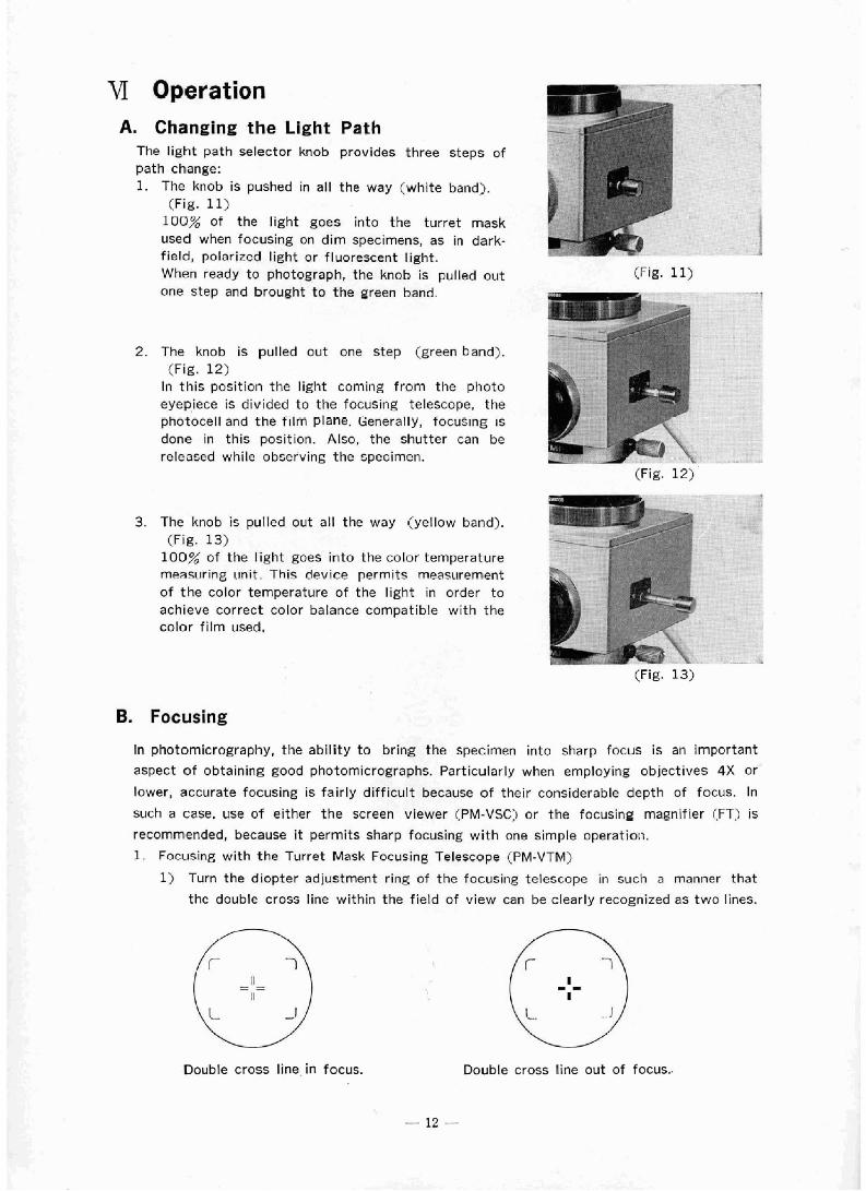
VI Operation A. Changing the Light Path
The right path selector knab provides three steps of path change: 1. The knob is pushed in all the way (white band}.
(Fig. 11) 100% of the light goes into the turret mask used when focusing on dim specimens, as in dark- field, polorircd light or fluorescent light. When ready to photograph, the knob is pulled out one step and brought to the green band.
(Fig. 11)
2. The knab is pulled out one step (green band). (Fig. 12)
In this position the light coming f rom the photo eyepiece is divided to the focuslng telescope, the phototell and the f ~ l m plane. Generally, focusing is done in this position. Also, the shutter can be released while observing the specimen.
(Fig. 12)
T-+
3. The knob is pulled out all the way (yellow band). (Fig. 13) .
100% of the light goes into the color temperature t
sn~sqr~ring unit. Thiq device permits measilrernent I
of the color temperature o f the light in order t o $ E +'4L
achieve correct color balance compatible with the -3 I color fi lm used.
, , '
1, .
(Fig. 133
B. Focusing
In photomicrography, the ability to bring the specimen into sharp focus is an important
aspect of obtaining good photomicrographs. Particularly when employing objectives 4 X or
lower, accurate focusing is fairly difficult because o f their considerable depth of focus. In
such a case. use of either the screen viewer (PM-VSC) or the focusing magnifier (FT) is
recommended, because it permits sharp focusing wi th one simple operatioti.
1. Focusing with the Turret Mask Focusing Telescope (PM-VTM)
1) Turn the diopter adjustment ring of the focusing telescope in w c h a manner that
thc doublc cross line within the f ietd of view can be clearly recognized as two lines.
'Double cross line in focus. Double cross line out of focus..

Since the focusing telescope wi th the double cross h e in focus, and the fi lm plane are in precise alignment, the image focused through the focusing telescope and the image on the f ilrn plane are in focus at the same time. Therefore. unless the adjustment just described is perfect, blurred pictures will result no matter how well the specimen may be brought in focus. + The reticles in the field of view indicate the different camera formats. Far details, please refer t o the next paragraph.
Use the coarse and fine adjustment controls of the microscope t o bring the specimen in focus. Check again if both the double cross l i re and the specimen are equally sharp in focus.
2. Focusing with the Screen Viewer (PM-VSC)
Using the screen viewer wil l considerably help in sharply focusing when using objectives 4 X or lower.
1) Detach the focusing telescope and attach the screen viewer instead.
2) Place the 5X magnifier, an accessory, on the frosted glass and slide i ts frnnt Tens assembly back and forth to focus on the cross hairs on the frosted glass of the
screen viewer.
3. Focusing with the Focusing Magnifier (FT)
More accurate specimen focus is achieved by using the FT in conjunction with the focusing telescopes. To make it compatible with all Olyrnpus attachment cameras three interchangeable mounting rings are available. These mounting rings are engraved on the inside in accordance with the following table:
Engraving I Photographic Apparatus
I / PM-10, VANOX
7 I PM-7, PMS-I!
6 1 PM-6
Slide-in frcmt lens assembly
Engraving Mounting ring /
The mounting ring f i ts exactly over the butside diameter of the focusing telescope. The front lens assembly can be moved laterally for focusing on the double cross Line.
Focusing Procedure 1) A t first use the diapter adjustment ring of f he f ocvsing telescope te focus on the double
crass line. Then operate the coarse and fine adjustment knobs of the microscope to bring the specimen in focus.
2) Place the FT over the focusing telescope and move the front lens assembly o f the FT in or out t o focus on the double cross line in the field of view.
3) Lastly, use the fine adjustment control of the micrascope to again focus sharply on the specimen. Specimen and double cross line should be in focus a t the same time.
C. Format Indication
Four frame reticles can be seen when looking through the turret mask focusing telescope or on the frosted glass of the screen viewer. These reticles indicate the frame sires for the different camera backs and represent approximately 90% of the actual picture area.

Select the frame reticle inside the turret mask focusing telescope by. means of the
mask selector lever, in accordance with the camera back in use, a s per the following
illustrations.
Please note, that the reticle indicating the 4ItX5" frame is fixed in the focusing telescope
and cannot be rotated with the mask selector lever.
/95mm Rsticl o Reticle far
Polaraid Eiack
As illustrated above, moving the lever ta the respective positions engraved an the
focusing telescope rotates the corresponding reticles into horizontal position in the field
of view.
D. Check the Photographic Equipment
Before actual photomicrography familiarize yourself thoroughly with the operation of all
components.
It is particularly important t o check the proper operation of the control unit once the light
path selector knob is pulled out one step (green band) and the selector switch of the control
unit moved to the "AUTO & CTR" position:
The following points should be checked.
1. The safety light (SAFETY EXP) is on.
2. The workirg light (WCRK) illuminates when the shutter release button is pressed. (The light will go on only during the time the shutter is open.)
3. The meter needle should move to the right when the check button (CHECK) is pressed.
The following steps are recommended in case one or more points as iisted above cannot be
satisfied : r
Rernedi es. Malfunction Possible Causes
I Points 1-3
cannot be met.
Safety light does
not go on.
Cards improperly connected. connect ions.
Blown fuse. Replace fuse.
Illumination is taa bright.
Bulb defectibe.
Reduce intensity.
Replace bu!b.

4. The f ~ l m is advanced one frame immediately after the shutter closes. The red pilot light on the camera back lights up during the filrn advance process. A t this time, a slight
Working light does
humming sound caused by the f i lm advance motor can be heard. Instruction on Photographic Equipment
x When using the 35mm camera back with automatic f i lm advance, the warning light (WARN) lights up after completion of the last exposure. At this time, the fclm advance pilot light on the camera back lights up for several seconds, until the warnlng light goes on. Then the red pilot light on the camera back goes off. The shutter does not operate while the f i lm advance pilot lip,ht is on even if the release button is pressed. * Never release the shutter when the working light (WORK) goeson. The shutter can be released when the work~ng light goesoff, and the safety light (SAFETY EXP) is on. + Sometimes, when a camera back Is removed, reloaded and attached again, it Is possible that the warning light wil l remain on. Pushing the t i lm advance button once wil l cause the warning light t o go out. a The warning light is always on when large format camera backs are in use. Disregard it in this case. I t operates onIy when the 35mm czrnera back wi th automatic filrn advance (C-35A) is attached. * The safety light (SAFETY EXP) may occasionally wink on and off during the shutter release process or film advance. This does not affect the proper operation of the PM-10. s The bulbs for the pilot light (SAFETY EXP, WORK, WARN) are interchangeable. Bulb rating, 6 V 60mA.
Difficult to see if
illumination is too
E. Loading the Film
Reduce intensity. not go on.
Meter needle does
not move.
Loading the camera back with a 35mm cartridge can be done with the back removed or attached t o the PM-10-A, w~thout outside light hitt ing the film. I t 1s advisable to keep the back on the camera attachment, however, because this way the motorized fi lm advance can be used to wind the film onto the take-up spool.
1) Pull the back cover operating lever @j and open the cover (hinged cover). (Fig. 14)
2) Li f t up the crank @# folded into the rewind knob and pull the knob all the way out. (Fig. 141
3) Put the cartridge (3-1 in the f ~ l m chamber and push the rewind knob back into position. (Fig. 15) If the rewind knob does not slide home, it wi l l enter easily i f pushed in while rotating it t o the right and le f t slightly.
4) Insert the filrn end into a groove on the take-up spool @;. Any groove may be used. Because of
bright and shutter
speed too fast.
the easy loading system, you cnly have to insert the end portion of the film.
H! If the fi lm was loaded with the camera back
Bulb defective.
l l luminat i~n is too
dark.
detached, attach the camera back t o the adapter at this stage.
Replace bulb.
Increase intensity.
(Fig. 15)

5) Press.the film advance button (WINDING) of t h e
control unit and advance the film until the film
perforations @ engage the sprockets on both
sides. (Fig. 16)
The film advance pilot light (red) is on while the
film is advanced.
The film is advanced by one frame each time
the advance button is pressed. (Fig. 16)
6 ) Close the back cover securely.
7) Press the film advance button again t o advance the film (2 to 3 frames) until the number 1 appears in the film counter.
8) Set the film indicatot (ASA scale) of the camera back to the ASA rating of the film used.
W"1 - . ^ - A -
AUTO & C T S T I K E
F. Photography with &&W Film
1) Make sure that the selector switch of the control box is in the "AUTO & CTR" position. (Fig. 17)
Make sure that the safety lamp (green) is on. JT --- * _ I - 1
2) Set the ASA dial. 1 ,*
Set the mark "35" on the ASA dial to the (Fig. 171 ASA rating of the f i l rn used. (Fig. 18)
Fig. 18 represents the use of ASA 50 film.
r The mark "L" is used for large-format camera - , .----
work.
3) Check the specimen focus.
4) Make sure that the light path selector knob on the body is positioned to the green band.
5) Make sure again. that the green safety light
(SAFETY EXP) is on. If it is off, reduce
illumination intensity.
6) Release the shutter by. depressing the release
button (RELEASE) of the control box. (Fig. 19)
After release. the "WORK" tight (orange) will go
on while the shutter is open. After the exposure
is completed [closing of the shutter), the
"WORK" Iight goes out and immediately afterwards
the film advances automatically by one frame.
* While the film is being transported, the film
advance pilot light on the camera back l ights up
and the humming of the filrn advance motor can be heard.
T I M E OFF
*.>a ' Z *
(Fig. 18)
I
SAFETY EXP.
(Fig. 19)

* Indication and operation after completion of the film roll
(1) As soon as the last frame is exposed the film advance motor stops and the pilot light on the camera back lights up. The *WARNINGn light on the control unit also
goes on several seconds later. At this moment, the camera pilot light will go out.
(23 Press the black rewind button a t the bottom of the camera back and rewind the
film w i th the rewind crank.
This operation can be performed with the camera back still on the PM-10 or removed
from the assembly.
.r The "WARNING" light indicates cnrrectly only when the 35mm camera back with
automatic f i'[m advance (C-35A) is used.
The "WARNING" light goes on onry when the film cannot be advanced, i. e., when all
frames have been exposed, or if the fnrc~! necpssary to advance the film becomes
excessive due to film jamming. In the latter case the motor circuits are automatically
interrupted ta prevent burning out of the motor and the "WARNING" light will go on
several seconds later. A look at the film counter will verify i f the "WARNING"
i light is or1 because the filrrl roll is erpused or because it is jarrirned.
G. Photography with Color Film
For photography with color film, the color temperature of the light source should be the
same as the color temperature for which the specific film was manufactured, in order t o obtain best color reproduction. This operation is known a s color temperature regulation. It
Is indispensable whenever color film is used.
Mow t o Effect Color Temperature Regulation
1) First focus on the specimen and then move the specimen slide until a portion of the slide without any specimen covers the field of view.
* Accurate regulation of the color temperature is impossible when the specimen covers
the field of view, therefore bring into the field the area circled in Fig. 20,
2) Pull out the light path selector knob of the body a l l the way, as far as the yellow band
(Fig. 21). In this position all the light impinges an the color temperature measuring unit.
(Fig. 204 (Fig. 21)

- -- -- . - ----- *-9-
3) Move the selector switch of the control unit t o . the 'AUTO Br T T R " position.
OR TEMP. R
4) Set the "COLOR TEMP REG" (CTR) dial to the orange zone (far the tungsten type film) or t o c
the blue zone (for the daylight type firm), according to the type of film used.
* The large dot in the center o f the scale each zone assures the nominal color temperature of CQL
the film used, white the small dots are provided t o render fine adjustment of the color (Fig.22) temperature of the light source for constant color reproduction with different types of emulsion used on the film, or to your preference -0-
for particular color reproduction effect. Fig. 22 illustrates that in a atandard method the CTR
*G. dEaT is aligned with the large dot for the nominal color temperature o f a daylight film.
- * I f a lower color temperature of the light source
is required, turn the CTR dial to the small dots on the l e f t slde of the large one. In reverse, if a higher color temperature is required, turn (Fig.23)
the dial to the right side. 5$ Place only the LBD filter in the filter holder a t the microscope base for a tungsten film,
or place the LED and LB45 filters together for a daylight film, and regulate the voltage of the light source so that the meter on the control unit will read zero. (Fig.23)
*When the color temperature of the light source is lower than the color temperature designated by the CTR dial, the meter needle moves to the left side (red arrow). When the color ternperature of illumination is higher, the needle moves t e the right side (blue arrow). When the color temperature of the light source is lower, raise the voltage, until the meter reads zero. Proceed in reverse if the color ternperature is higher.
* If the meter fails to read zero even at the maximum voltage, due to the voltage variations from the AC power supply; age of bulb, bulb errors, etc., or although the meter reads zero, if it is necessary to avoid-high voltage or subdue glare of light, insert one more LB45 into the light path t o lower the voltage properly, without deviating the mete rfrom 0.
61 Push the light path selector knob all the way in.
* An electrical interlock prevents the shutter from being released with the knab pulled out all the way.
7 ) The following steps are identical to the ones described for photography with black-and- white film.
* After the color temperature has been regulated, do not change the LBD and LB filters
and the voltage of the light source anymore.
Use neutral density fi lter (NO) ta regulate the light intensity, i f necessary.
OTransmission and Number of ND Filters.
COLOR TEMPERATURE AND REPRODUCTION OF COLOR FILM In color photomicrography, a color f i lm requires a specific color temperature under the different conditions from the general color photography. since in mast cases of color photomicrography, a color temperature cornpensat ion fi lter is inevitably used with the microscope light source to give the color temperature required dy the film, and at the same time, the light emitted from the light source directly impinges on the emulsion of the color film. Considering these conditions peculiar to color photomicrography, the Model PM-1'0-A is provided with the LB45 and LBD f i l ters for color temperature compensation. The LBD fi lter is a neutral interference f i l ter tha t particularly excels in color conversion facilities. The PM-10-A also incorporates a CTR dial graduated with a barge dot and smaEl dots on the scale as metnioned in PARA. 4). The large dot denotes the dial-setting position for the nominal color temperature of the color f i lm in use. It i s recommended, however, for a photographer t o determine an optimum color temperature for each film in use by test
shots, finely adjusting by means of the small dot indexes, for a color f i lm has its own characteristics in color reproduction.
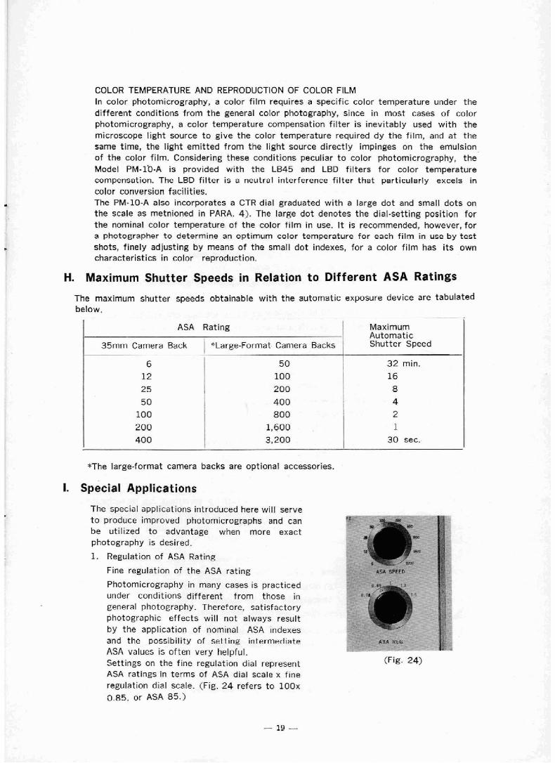
H. Maximum Shutter Speeds in Relation to Different ASA Ratings
The maximum shutter speeds abtaFnable with the automatic exposure device are tabulated belaw.
"The large-format camera backs are optional accessories.
--
ASA Rating ! Maximum Automatic
I. Special Applications
35mm Camera Back , $Large-Format Camera Backs
The special applications introduced here will serve t o produce improved photomicrographs and can be utilized to advantage when more exact photography i s desired.
1. Regulation of ASA Rating
Fine regulation of the ASA rating ASA SPFE
Shutter Speed
Photomicrography in many cases is practiced under conditions different from those in general photography. Therefore, satisfactory photographic effects wil l not always result by the apprication of nominal ASA ~ndexes and the possibility of setting intermediate A3A values is often very helpful. Settings on the fine regulation dlal represent ASA ratings Fn terms of ASA dial scale x fine regulation dial scale. (Fig. 24 refers to lOOx o ~ 5 , or ASA 85.3
(Fig. 24)
6 t 50 I 32 rnin. 12 100 I 16 25 I 200 8
50 ! 400 4 100 i 800 2
200
400 1,600 1 3,200 30 stc.

(Example) . .
When ASA Index of Film is 100
Fine regulation of the ASA speed with the fine regulation dial is recommended in the following instances.
Position of I Position of Ratings ASA Dial Scale Regulation Dial Scale
a. If the ASA speed af the film used is not engraved an the ASR dial scale.
b. If over- or underexposure is intentionally desired.
c. If overexposure of the specimen will result due to excessive brightness of the background.
. . -
For example ;
a A- -
If the specimen area in the field of view is very small, the f i lm should be overexposed.
If there is on cxtrcmc brightness difference over the specimen area in the field of view,
the film should be underexposed.
If there is even density of the specimen over the entire field of view, the fi lm should be
exposed normally.
* With the PM-10 and a 35mm camera back light covering about 30% of the film area
is measured in the center of the frame.
(Example) If the specimen occupies about 70% of this portion and the remaining 30%
is empty when photographed at ASA 100, then the fine regulation dial should be set ta
0.75 t o compensate for underexposure which could be caused by the empty area.
ASA 100 X 0.75 = ASA 75
Checking for Correct Exposure
Consistent color reproductions are obtained.
Extremely short or long exposures lead to film sensitivity variations due to reciprocity
taw failure. In order to obtain consistently satisfactory color reproductions. it is
VarFat ion
suggested to avoid using a wide range of exposure times and photograph with the same shutter speed whenever possible.
With increasing magnification of the microscope, the amount of light on the film surface
decreases and the exposure time lengthens. Particularly when photographing on a single
rolf of fi lm from very low to high rnagnif ications, different color reproductions sometimes
Over
Slightly over
Standard
Slightly under
Under
100
result even though the color temperature may be constant. This phenomenon is known
as reciprocity law failure of the film.
In such an event it is necessary t o work with a constant exposure time to obtain uniform
0.75
0.85
1
1.2
1.5
color reproductions. The check mechanism can be used t o provide such a constant
exposure time.
75
85
100
120
150
For that purpose, the volume of light is reduced by neutral density filters (ND), supplied
in the standatd equipment, with which the light level on the fi lm surface can be kept constant for aF1 magnifications.

* How t o Check
This is done by the "CHECK" button and by the check scale area (black scale) of the
color temperature meter.
The check scale area consists of five steps, any one of which may be used. Choose that
scale position which is deemed most suitabie for the condition of the specimen, the
illumination, etc. For the first check, it is suggested to choose the highest of the
objective magnifications t o be used for photography. If an initial check is made wi th a
law+magnification o'bjective, the light intensity may not be sufficient to maintain
constant exposure time with higher power objectives.
Examples of Application
I) If the CHECK button is pressed after the
specimen detail has been selected and made
ready for photography, the meter needle
moves to a certain point on the check scale
area.
Fig.25 shows the needle moved just t o the
third line from the right.
* If the needle goes beyond the scale
(Fig.261, put an ND fitter in the filter holder Fig. 25 Fig. 26
t o reduce the volume of light 50 that the
needle returns into the check area.
With high density specimens, the needle sometimes moves t o t he l e f t of 'rile check
area. In this case, photography is sti l l poss~ble and correct exposure times will be
computed unless the specimen is so dark that observation becomes impossible.
2) When changing objectives, place different density ND f~l ters into the f ~ l t e r holder to
. keep the meter needle on the point determined initially. (Fig.25) - Thus, photography with the shutter speed kept constant on a single roll of fi lm will
produce uniform color reproduction.
3. Manual Exposure with Timer Mechanism
In this method, photomicrographs are made
manually, at certain exposure times, without -. 1 - + - *-Tv"g + - _ ,w"~"x .-
, " recourse to rhe automatic exposure mechanism. AUTO & CTR
1) Move the selector dial of the control unit to pos~tion "'TIME" (Fig. 27). This means that the
automatic exposure circuit is by-passed.
2) Release the shutter. The "WORK" light (orange)
goes and the shutter opens. - ' 7 , I
Q 3) After the desired exposure time, press the "TIME ~ ~ A ~ ~ C ~ ~ p ~ . f ~ ~ b ; 2 - ~ , ~ * ~ ~ + - - *-.-\ -a I.
?"\ >
OFF" button. (Fig.27 j
This terminates the exposure and the "WORK" light
goes out.
* Pressing the "TIME OFF" button always causes the shutter to close. This is of
advantage, for instance, i f an automatic exposure is to be interrupted deliberately.

S 35mm Camera Back (C935A)
Tha camera back is provided with data imprinting.
facilities.
11 To imprint in a picture simultaneously with
shutter release, use an insert provided, on K I ~ which necessary information is written with a
soft-point pen. Y ' n
2) Slide the insert into the slit at the bottom [ \ of the camera back, with the written informa- I
tian facing the film plane.
3) Data Imprinting Position
Data may be imprinted in the picture as illustrated below. Data imprinting area
Other Points To Remember
I) When you imprint data, it is recommended to frame and trim your picture, so that
the data may b e imprinted against the white or transparent background.
2) The insert can be used repeatedly after wiping off written data with ether-xy lene mixture.
3) Do not leave in a bright room the camera back with the insert slid. En the slit for hours.
Optional Accessories * The focusing telescope and screen viewer are as illustrated below.
A. Focusing Telescope (PM-VSI
Clamping Ring T h e r inz clamvs the \ telescope tv the B
raposurc body.
Locating Pin The locatmg pin z d with the
Diopter Adjustment Ri ng
/ The ring parrnrts focusing on t h e frame
reticles and the dmble cross1 ine.
tocating growe on the b d v .
Select the reticte compatible with the camera back in use. Camera backs other than
the 35mm camera back are optional accessories.
4" X5' Holder
f- 3 1/4" X 4 t/4" Polaroi d
35mm Camera

B. Screen Viewer (PM-VSC)
Clampig Ring
Screen -. ,- -l-he image is projected on tht scrrcn.
- -
I The rine clamps the vlerver to the automatic
expowre body.
Locati & Pin \
. . . . . , a i t h t h r locating prouve
cn he body.
C. 5X Magnifier {5XLP)
Facusing Front Lens Assembly
can be moved In and out,
to focus on the crossline on the frosted glass of thc scrccn viewer.
D. Adapter for Large-Format Camera Backs (PM-DL)
Clamping Ring
automatic exposure body.
The adapter is required for a l l types of large-format camera backs.

E. PargemFarmat Camera Backs For individual applications, refer to t h e subsequent section on "Photography with Large- Format Camera Backs".
1. Polaroid 334" X 4 X f r Back (PM-CPj
Back Cover
Yellow Tab
hz Slide .-
2. Intermediate Adapter for 4'' X 5" Holders (PM-C 4 X 5)
G l am ping Device Seat for holders.
-*
\clamping Flange,

MI Photography with Large-Format Camera Backs
you 'have only to remove the 35mm camera adapter. attach the large-format adapter instead and mount the large format camera back on it.
The the
picture size varies with the type of camera back used, but the magnification at firm surface remains the same for all, as follows : If FK eyepiece is used : Magnification of objective x magnification of FK eyepiece x 3
* If P eyepiece is 'used : Magnificat ion of objective x magnification of P eyepiece x about 1.5
From the foregoing, the rnagnifica%ions as tabulated below may be obtained by combining the objectives and eyepieces available.
The subsequent sections will describe standard applications based on automatic exposure. Special applications also are possible as in the case of 35mm camera (see Section 1, page 19).
Eyepleee '1 Objective
Bio- logical Appli- cations
1-3x 2X 4X 1 OX
20X 40X
l O O X
FK6.7X
2SX
P7X
13.7X 21X I
42X 105X 2 1 0 X 420X
1050X
Metallo- graphical Appli- cations
FK2.5X 1 F K 3 . 3 I FK5X
9.8X 15X 30X 75X
1 5 0 X 300X 750X
2 1 X 5 6 X
112.5X li5X 225X
45QX 900X
1125X 2250X
P l O X I P 1 5 X
13.7X I 19.5X
12.9X 19.5X 3QX 60X
150X 3 0 0 X 600X
1500X
1.3X 2.5X
5 X 6 X 1 OX 2 0 X 40X 5 0 X
l O O X
26X 52.5X
19.5X 20X 40X
l O O X 200X 400X
lOOOX
12.9X 25X 5QX 6 O X
lQOX 200X 400X 500X lOOOX
29X 4 5 X 90X
225X 450X 900X
2250X
9.8X 18.8X 37.5X
4 5 X 75X
150X 300X 375X J50X
37.5X 75X
30X 6 0 X
150X 3 0 0 X 6 0 0 X
1500X
19.5X 37.5X
7SX 9DX l50X 300X
6 0 0 X 750X
P500X
63X YOX 105X 150X 210X , 300X
40X 80X
200X 4 0 0 X 800X
2 0 0 0 X
26X i 50X
l O O X 1201 200X 400X 800X lOOOX 2000X
4 2 0 X 525X
1 0 5 0 X
600X 750X
1 5 0 0 X

A. 3 1/4" X 4 1/4'! Polaroid Camera Back (PM-CP)
Picture size : 3 1/4'! X 4 1/4" C83mm X 108mmJ
Film used : Polaroid Type 108 (color, ASA 75) Polaroid Type 107 (B&W, ASA 3000)
1. Attaching the Camera Back At tach the adapter for large format camera backs (PM-DL) to the top of the exposure body by aligning the locating pin of the adapter with the locating groove on the exposure body and clamping the adapter with i t s clamping ring. Pull the clamping device on the Earge format adapter towards you all the way. SIide the 3 1/4" X 4 lj4'! Polaroid back with the cover Pocking latch facing you. onto the seat of the adapter, from right to left. Push back the clamping device until it firmly clamps the Polaroid back.
2. Loading the Camera Back with Polaroid Film a Read the instructions inserted in the f llm pacX f i r ~ t arlrj then take the f611owing stebs :
1) Open the fi lm case and take out the film pack. 2) Push the Covet Locking Latch @ upwards
with both ,hands. (Fig. 28) 3 ) Open the camera back cover all the way.
(Handle with care not to break the cover.) .
(Fig. 28:
It is essential to keep the roller clean, for. a dirty roller will produce irregularities on the picture.
1) To clean the roller, lift the roller unit @ up- wards and remove. (Fig- 295
2) Wipe the roller first with a wet 'cloth and then with a dry cloth.
3) After cleaning, place the roller unit in its original position.
(Fig. 29) ----- 41 Next, holding the film pack only by i ts edges, ,,, < . A . L , - - - , * . .
so t h a t the safety cover, bearing the SAFETY COVER....-.THIS SIDE FACES LENS, faces into the camera, and insert the pack (c against the spring 'beneath the back cover.(Fig. 30,:
\ - -4
I '/
5) Push the pack into the camera until i t comes to a stop. You will feel it snap into place. Make sure that the white tabs are not trapped between the pack and the camera body. (FIE. 30
6) Close the camera back cower by pressing both sides of the cover tightly. A t this time, the black tab of the safety cover should be emerging from the small slot; ~f not, open the back cover once again and make sure the black tab is sticking out.
7) Hold the black cover removed, the white tab should come out frome the slot. Do not yet pull out this white tab.

This concludes the preparation for photography. @if the white tab is not visible;
If the white tab does not come out when the safety cover is pulled out, darken the room as much as possible and proceed as follows:
1) Open the camera back cover just slightly and :,- , take the end of the white tabs outside without moving the film pack. (Fig. 31)
2) With the white tab emerging from the slot, close the back cover by pressing it tightly an both sides.
3. Focusing Fig. 31
1) Use the focusing telescope to focus accurately, in the same manner as with the 35mm camera back.
2) For framing, refer t o the Polaroid reticle in the focusing telescope. Move the specimen detail t o be photographed into this area.
4. Photography
1) Make sure that the selector switch of the Retic1 e for 3 1/4' X 4 1/4" control unit is in position "AUTO & CTR". Polaroid Bask
2) Set the ASA dial. Align with the "L" mark. 3) Check the specimen focus once again. 4) Make sure that the light path selector knob
of the exposure body is in the green band posit ion. ,'-
5) Make sure that the "SAFETY" light (green) L~ J 1
is on. L 3 6) Pull out the light slide of the camera back
slowly all t h e way. Ef not pulled out completely, part of the picture may be obscured.
7) Use the release button (RELEASE) of the controi unit to release the shutter. The "WORK" light (orange) lights up only while exposure is in progress. The "WARNING" light also lights up but ignore this since it does not affect large-format camera photography.
8) When the exposure is finished, push the light slide into the camera back.
5. Film Development
Develop the film in the following manner: 1. Hold the white tab emerging from the camera with thumb and index finger of the
right hand and pull it out completely in one motion. 2. After the white tab is pulled out, a yellow tab emerges. If the yellow tab does
not come out after the white tab is pulled out, do as mentioned on the next page: do not pull another white tab.
* If the yellow tab is in sight, do not pull the white tab. Pulling out the white tab does not mean commencement of development ; i t is a preparatory step for pulling the yellow tab.
3. Hold the center of the yellow tab and pull i t out from the camera quickly in one motion. This is the beginning of development. It starts trom the point where the yellow tab has been pulEed out all the way. The speed of pulling out is about equal to the time of saying "pull out". If countless white spots appear in the picture, pull out a l i t t le more slowly.

4. The f i lm can be developed in the following lengths of time (strict compliance with these time limits is recommended) :
- . Type 107 Type 108
5. A t the end of the specified development time, strip the picture from the brown paper, starting the corner nearest ta the letters "PULL". Avoid touchillg t h e surface sf the color picture for several minutes, and after drying, paste the picture on a color print mount. Also avoid touching thz surface of the black and white picture and apply o cootcr to the picture to prevent fading and other changes. (Refer to the next sectian.)
6. Treatment after Development
1) In the case of black and white pictures; be sure t o spply a &ter to all prints, w~th ln 2 hours i f possible. The picture begins t o fade within a few hours unless the coater i s applied. Hold one corner of the print, turn the surface up, put on a f lat place, and give 6-8 coats evenly all over the picture.
* Be careful not to damage the picture with the coater edge. Also avoid stacking prints which were just coated. They will stick together,
23 Do not apply a coater t o color pictures. Instead, when the surface has dried, mount the prints on the mounts supplied.
* If the yellow tab does not appear when the white tab is pulled out, take the following steps :
1) Darken the room as much as possible, open the camera back cover just wide enough t o receive a finger, and hold down the f i lm pack with the finger tip. (Fig.32)
2) While holding down the f i lm pzck, open the back cover fully and pull out the top yellow tab. (F ig .33) Pulling out that one tab, discard it. It is no use trying to save it. While the back cover is open, check whether the roller is dirty.
3) After making sure that the next white t a b is our from the slot, close the camera back cover.
----. -- - . - - *- 7 - - - - . , < - - - - - 7 - 7
-
Development i s available 1 Temperature in 10-15 sec. Suitable time for development is 13-15 see. 27'C--32 OC
when ambient temperature I
21QCh.27QC is low, and about 30 sec. i when it is below 10 deg. Cm
Time
55--45 '''a
65-55 see.
90-70 Set.
Long time tends t o produce
strong contrast.
Short time gives reddish and
long time bluish color.

B. Intermediate Adaper for 4" X 5" Holders
Use of this unit permits photography with 4" X Sf' film holders. The film holders available are : Polaroid film holder, Graphmatic film holder, Graphic pack adapter, Graphic film holder (Rita Way), Linhof film holder. The above mentioned film holders are not dlympus products. They can be obtained either from our authorized distributors or from reputable camera dealers.
1. Atta~hing Large Format Adapter
Attach in the same manner as for the 3 1/4" X 4 1J4" Polaroid back. {See page 26)
2. Attach the Film Holder
L 1) Slide the lock buttons (bath sides) of the intermediate adapter in the direction
opposite to locking. bt the end of the~r travel press the buttons. (Fig.34)
The clamping device will lift up
2) Insert the film holder all the way. (Fig.35) This will engage a projection on the
film holder with a rnat~ng groove on the Intermediate adapter.
In case of the graphmatic film holder, insert the holder into position without
lift in^ up the clamping device. (Fig.36)
15 Clamp t h e film holder down with the lock buttons.
- - ... ? - - - -
To detach the holder :
1) Sl~de the lock buttons on both sides in
the d~rection oppos~te to locking
2) Pull the holder out while lifting it I~ghtly.
IFig.37) This way, it will slide out easily.

3. Focusing
1) Use the focusing telescope t o focus an the specimen, in the same manner as.
with the 35mm camera.
2) For the film area indication, refer to the
411 X 5" frame reticle in the focusing
telescope. Move the specimen detail into
the atca covered by the 4" X 5" reticle.
4. Photography
I) Make sure that the selector switch of the control unit is in the "AUTO & CTR"
position.
2) Set the ASA dial. Align with the "L" mark.
3) Check t t ~ e specimen focus again.
4) Make sure that the light path selector of the exposure body is in the green band position.
5) Make sure that the "SAFETY" light (green) is on.
6 ) After pulling out the light slide (or its equivalent) of the film holder, use the
release button to release the shutter.
The "WORK" light (orange) goes on only while exposure is in progress.
The "WARNING" light also lights up, but ignore this since it does not affect
large-format camera photography.
For instructions pertaining to the use of the different film holders, please refer
t o the literature supplied by the individual manufacturers.

MEMO