![4YZ_R UVa]`jZ_X ^`cV ec``ad R]`_X =24+ 2c^j - Daily Pioneer](https://static.fdokumen.com/doc/165x107/631afdf5c51d6b41aa050cf4/4yzr-uvajzx-cv-ecad-rx-24-2cj-daily-pioneer.jpg)
Offshore Pedestal-mounted Cranes API SPECIFICATION 2C SEVENTH EDITION, MARCH 2012 EFFECTIVE DATE:...
136
Offshore Pedestal-mounted Cranes API SPECIFICATION 2C SEVENTH EDITION, MARCH 2012 EFFECTIVE DATE: OCTOBER 2012 AMERICAN PETROLEUM INSTITUTE
-
Upload
independent -
Category
Documents
-
view
0 -
download
0
Transcript of Offshore Pedestal-mounted Cranes API SPECIFICATION 2C SEVENTH EDITION, MARCH 2012 EFFECTIVE DATE:...
Offshore Pedestal-mounted Cranes
API SPECIFICATION 2C SEVENTH EDITION, MARCH 2012
EFFECTIVE DATE: OCTOBER 2012
AMERICAN PETROLEUM INSTITUTE

CO
PY
righted ma
ter-ia
llicen
sed
to Yik C
he
n S
un on 27
-Jul-2
01
2 for lice
nse
e&
#3
9:s u
se only.
No fu
rthe
r rep
rod
uctio
n o
r networK
ing :s pe
rmitte
d.
Distrib
ute
d by T
ho
mso
n

Offshore Pedestal-mounted Cranes
Upstream Segment
API SPECIFICATION 2C SEVENTH EDITION, MARCH 2012
EFFECTIVE DATE: OCTOBER 2012
AMERICAN PETROLEUM INSTITUTE
z o

Special Notes
API publications necessarily address problems of a general nature. With respect to particular circumstances, local, state, and federal laws and regulations should be reviewed.
Neither API nor any of API's employees, subcontractors, consultants, committees, or other assignees make any warranty or representation, either express or implied, with respect to the accuracy, completeness, or usefulness of the information contained herein, or assume any liability or responsibility for any use, or the results of such use, of any information or process disclosed in this publication. Neither API nor any of API's employees, subcontractors, consultants, or other assignees represent that use of this publication would not infringe upon privately owned rights.
API publications may be used by anyone desiring to do so. Every effort has been made by the Institute to assure the accuracy and reliability of the data contained in them; however, the Institute makes no representation, warranty, or guarantee in connection with this publication and hereby expressly disclaims any liability or responsibility for loss or damage resulting from its use or for the violation of any authorities having jurisdiction with which this publication may conflict.
API publications are published to facilitate the broad availability of proven, sound engineering and operating practices. These publications are not intended to obviate the need for applying sound engineering judgment regarding when and where these publications should be utilized. The formulation and publication of API publications is not intended in any way to inhibit anyone from using any other practices.
Any manufacturer marking equipment or materials in conformance with the marking requirements of an API standard is solely responsible for complying with all the applicable requirements of that standard. API does not represent, warrant, or guarantee that such products do in fact conform to the applicable API standard.
Users of this Specification should not rely exclusively on the information contained in this document. Sound business, scientific, engineering, and safety judgment should be used in employing the information contained herein.
All rights reserved. No part of this work may be reproduced, translated, stored in a retrieval system, or transmitted by any means, electronic, mechanical, photocopying, recording, or otherwise, without prior written permission from the publisher. Contact the
Publisher, API Publishing Services, 1220 L Street, NW, Washington, DC 20005.
Copyright © 2012 American Petroleum Institute
z o

Foreword
Nothing contained in any API publication is to be construed as granting any right, by implication or otherwise, for the manufacture, sale, or use of any method, apparatus, or product covered by letters patent. Neither should anything contained in the publication be construed as insuring anyone against liability for infringement of letters patent.
Shall: As used in a standard, "shall" denotes a minimum requirement in order to conform to the specification.
Should: As used in a standard, "should" denotes a recommendation or that which is advised but not required in order to conform to the specification.
This document was produced under API standardization procedures that ensure appropriate notification and participation in the developmental process and is designated as an API standard. Questions concerning the interpretation of the content of this publication or comments and questions concerning the procedures under which this publication was developed should be directed in writing to the Director of Standards, American Petroleum Institute, 1220 L Street, NW, Washington, DC 20005. Requests for permission to reproduce or translate all or any part of the material published herein should also be addressed to the director.
Generally, API standards are reviewed and revised, reaffirmed, or withdrawn at least every five years. A one-time extension of up to two years may be added to this review cycle. Status of the publication can be ascertained from the API Standards Department, telephone (202) 682-8000. A catalog of API publications and materials is published annually by API, 1220 L Street, NW, Washington, DC 20005.
Suggested revisions are invited and should be submitted to the Standards Department, API, 1220 L Street, NW, Washington, DC 20005, [email protected].
iii
() ocr ro ::J (J) C ::J o ::J N
~ 'c ;z:; o N
ill 0.,
(j) c
~

Co
pyrig
hte
d rn
ate
riallice
nse
d to Y
ik Ch
en
Su
n on 2
7-Ju
l-20
12
for lice
nse
e&
#3
9;s u
se only.
No
furtrler rep
rod
uctio
n o
r ne
two
rking
IS D
errnitted. D
istributed by ThD
mson S
cien
llf'c.

Contents
Page
1 Scope ...................... '" ......................................................... 1
2 Normative References ..................................................................... 1
3 Terms, Definitions and Abbreviations ........................................................ 4 3.1 Terms and Definitions ..................................................................... 4 3.2 Abbreviations ........................................................................... 17 3.3 Units .................................................................................. 18
4 Documentation .......................................................................... 21 4.1 Manufacturer-supplied Documentation upon Purchase ........................................ 21 4.2 Purchaser-supplied Information prior to Purchase ............................................ 22 4.3 Record Retention ........................................................................ 22
5 Loads ....................... " ........................................................ 22 5.1 Safe Working Limits ..................................................................... 22 5.2 Critical Components ..................................................................... 23 5.3 Forces and Loadings .................................................................... 23 5.4 In-service Loads ........................................................................ 23 5.5 Out-of-service Loads ..................................................................... 32 5.6 Wind, Ice, and Seismic Loads ............................................................. 33
6 Structure ............................................................................... 34 6.1 General ................................................................................ 34 6.2 Pedestal, Kingpost, and Crane Supporting Foundation ........................................ 35 6.3 Exceptions to use of AISC ................................................................ 35 6.4 Structural Fatigue ....................................................................... 35
7 Mechanical ............................................................................. 36 7.1 Machinery and Wire Rope Duty Cycles ...................................................... 36 7.2 Critical Rigging Components ............................. " ............................... 39 7.3 Boom Hoist, Load Hoist, Telescoping, and Folding Boom Mechanisms .......................... 46 7.4 Swing Mechanism ....................................................................... 52 7.5 Power Plant ............................................................................ 56
8 Ratings ................................................................................ 57 8.1 General ................................................................................ 57 8.2 Load Rating and Information Charts ........................................................ 59
9 Gross Overload Conditions ............................................................... 61 9.1 General ................................................................................ 61 9.2 Failure Mode Calculations ................................................................ 62 9.3 Calculation Methods ..................................................................... 62 9.4 Failure Mode Charts ..................................................................... 62 9.5 Gross Overload Protection System (GOPS) .................................................. 62
10 Human Factors-Health, Safety, and Environment. ............................................ 63 10.1 Controls ............................................................................... 63 10.2 Cabs and Enclosures .................................................................... 65 10.3 Miscellaneous Requirements and Equipment ................................................ 68
11 Manufacturing Requirements .............................................................. 72 11.1 Material Requirements of Critical Components ............................................... 72 11.2 Welding of Critically Stressed Components ................................................. 76
v

Contents
Page
11.3 Nondestructive Examination of Critical Components .......................................... 77
12 Design Validation by Testing .............................................................. 77 12.1 Design Validation ........................................................................ 77 12.2 Certification ............................................................................ 79 12.3 Operational Tests ........................................................................ 79
13 Marking ................................................................................ 80
Annex A (informative) Example List of Critical Components ......................................... 81
Annex B (informative) Commentary .............................................................. 83
Annex C (informative) API Monogram Program ................................................... 100
Annex 0 (normative) Cylinder Calculation Methods ............................................... 104
Annex E (informative) Example Calculations ..................................................... 107
Annex F (informative) Additional Purchaser Supplied Information ................................... 122
Bibliography ............................................................................... 124
Figures 1 Crane Illustrations ........................................................................ 2 2 Offboard Loadings ...................................................................... 25 3 Onboard Loadings ....................................................................... 26 4 Out-of-service Loadings .................................................................. 27 5 Some Methods of Securing Dead End of Rope when using Conventional Wedge Sockets .......... 42 6 Sheave Dimensions ...................................................................... 43 7 Hoist Drum ............................................................................. 48 8 Plots of Rated Loads for Various Operating Conditions ....................................... 61 9 Basic Four-lever Crane Control Diagram .................................................... 65 10 Basic Two-Lever Crane Control Diagram (Option 1) ........................................... 66 11 Basic Two-Lever Crane Control Diagram (Option 2) ........................................... 67 B.1 Variable Pedestal Factor .................................................................. 88 C.1 API Monogram Nameplate ......................................................... , ..... 103 0.1 Cylinder Configuration .................................................................. 106 E.1 Swing Bearing Ultimate Strengths ........................................................ 120
Tables 1 Description of Symbols .................................................................. 18 2 Summary of Design Parameter ............................................................ 24 3 Vertical Velocity for Dynamic Coefficient Calculations ......................................... 27 4 Crane Vertical Acceleration ............................................................... 28 5 Crane Base Inclinations and Accelerations .................................................. 28 6 Recommended Shape Coefficients ......................................................... 33 7 Classification of Offshore Crane Applications ............................................... 37 8 Auxiliary Hoist - 5 Year TBO .............................................................. 37 9 Main Hoist - 5 Year TBO .................................................................. 37 10 Boom Hoist - 5 Year TBO ................................................................. 37 11 Slew Mechanism - 5 Year TBO ............................................................ 38 12 Prime Mover and Pump Drive - 5 Year TBO ........................................... , ...... 38
z o
§: ~ ro co 3 Cl
~ is ::l
Q
ZD 0,

Contents
Page
13 Wire Rope TBR by Typical Offshore Crane Classification ...................................... 38 14 Auxiliary Wire Rope ...................................................................... 38 15 Main Wire Rope ......................................................................... 39 16 Boom Wire Rope ........................................................................ 39 17 Sheave Groove Radius, Metallic Rim ....................................................... 44 18 Sheave Groove Radius, Cast Nylon Rim .................................................... 45 19 Four-lever Crane Control Function ......................................................... 65 20 Two-Lever Crane Control Function (Option 1) ................................................ 66 21 Two-Lever Crane Control Function (Option 2) ................................................ 67 22 Indicators, Alarms, and Limits ............................................................. 69 23 Boom and Load Indicators ................................................................ 70 24 Level 1 Fracture Toughness ............................................................... 73 25 Casting Acceptance Criteria Based on ASTM Radiographic Standards .......................... 74 26 Level 2 Fracture Toughness ............................................................... 74 27 Bearing Ring Steel Cleanliness Limits ...................................................... 75 28 Workmanship Standard Examples ......................................................... 78 B.1 General Method-Vessel Information ........................................................ 84 B.2 General Method Sample Design Value Calculations TLP and Spar .............................. 85 B.3 Minimum Required Hook Speeds at Supply Boat Deck vs. Significant Wave Height ................ 86 B.4 Crane Structures ........................................................................ 89 B.5 Auxiliary Hoist - Five Year TBO ............................................................ 90 B.6 Main Hoist - Five Year TBO ............................................................... 90 B.7 Boom Hoist - Five Year TBO .............................................................. 90 B.8 Slew Mechanism - Five Year TBO .......................................................... 90 B.9 Prime Mover and Pump Drive - Five Year TBO ............................................... 91 B.10 Main Hoist Wire Rope .................................................................... 91 B.11 Auxiliary Hoist Wire Rope ................................................................. 91 B.12 800m Hoist - Wire Rope ................................................................. 92 8.13 Calculated Noise Exposures .............................................................. 94
N C' 'c ;S o N
Q
z o 2' ;+
~
ro o.

N

Offshore Pedestal-mounted Cranes
1 Scope
This specification provides requirements for design, construction, and testing of new offshore pedestal-mounted cranes, For the purposes of this specification, offshore cranes are defined as pedestal-mounted elevating and rotating lift devices for transfer of materials or personnel to or from marine vessels, barges and structures,
Typical applications can include:
a) offshore oil exploration and production applications; these cranes are typically mounted on a fixed (bottomsupported) structure, floating platform structure, or ship-hulled vessel used in drilling and production operations;
b) shipboard applications; these cranes are mounted on surface-type vessels and are used to move cargo, containers, and other materials while the crane is within a harbor or sheltered area; and
c) heavy-lift applications; cranes for heavy-lift applications are mounted on barges, self-elevating vessels or other vessels, and are used in construction and salvage operations within a harbor or sheltered area or in limited (mild) environmental conditions,
Figure 1 illustrates some (but not all) of the types of cranes covered under this specification, While there are many configurations of pedestal-mounted cranes covered in the scope of this specification, it is not intended to be used for the deSign, fabrication, and testing of davits or emergency escape devices, Additionally, this specification does not cover the use of cranes for subsea lifting and lowering operations or constant-tension systems,
2 Normative References
The following referenced documents are indispensable for the application of this specification, For dated references, only the edition cited applies, For undated references, the latest edition of the referenced document (including any addenda) applies,
API Recommended Practice 2A-WSO, Planning, Designing and Constructing Fixed Offshore Platforms-Working Stress Design, 21 st Edition
API Recommended Practice 20, Recommended Practice for Operation and Maintenance of Offshore Cranes
API Specification 2H, Specification for Carbon Manganese Steel Plate for Offshore Platform Tubular Joints
API Recommended Practice 2X, Recommended Practice for Ultrasonic Examination of Offshore Structural Fabrication and Guidelines for Qualifications of Technicians
API Specification 9A, Specification for Wire Rope
API Recommended Practice 14F, Recommended Design and Installation for Unclassified and Class I, Division 1 and Division 2 Locations
API Recommended Practice 500, Classification of Locations for Electrical Installations at Petroleum Facilities Classified as Class I, Division 1 and Division 2
API Recommended Practice 505, Classification of Locations for Electrical Installations at Petroleum Facilities Classified as Class I, Zone 0, Zone 1 and Zone 2
o ::;,(\) :::> (J) c :::> o :J
N -;" 'c ;S o N
Q
c (f> (\)
o co -< z o 2 ~
~ (i3 u (3 0.. C g o :0
0) D ..
c:r '<
(j) c
~

2
3
King post mounted lattice boom wire luffed crane
Key
1 boom chord 2 boom extension 3 boom heel pin 4 boom hoist mechanism 5 boom hoist wire rope or
boomline 6 boom lacing 7 boom luffing cylinder 8 boom point sheave
assembly or boom head
9 10
11
12 13 14
API SPECIFICATION 2C
Telescopic box boom cylinder luffed crane
Swing bearing mounted lattice boom wire luffed crane
boom section, insert 15 cab boom section, lower, 16 bridle base or butt 17 gantry, mast, or A-frame boom section, upper, 18 hook block point or tip 19 king post or center post boom splice 20 main hoist drum boom stop 21 main hoist rope or boom tip extension load line or jib 22 overhaul ball
Figure 1-Crane Illustrations
Pedestal mounted folding boom crane
23 24 25 26
27
28
14
.~ , ~~ If ~ ! I f181 ~ ~
pedestal or base pendant line swing-circle assembly whip line or auxiliary hoist drum whip line or auxiliary hoist rope folding boom articulating cylinder
(j) C ::l
o :;;)
z o

OFFSHORE PEDESTAL-MOUNTED CRANES 3
ABMA Standard 9 1, Load Ratings and Fatigue Life for Ball Bearings
ABMA Standard 11, Load Ratings and Fatigue Life for Roller Bearings
AISC 335-89 2, Specification for Structural Steel Buildings-Allowable Stress Design and Plastic Design
NOTE Also available as the specification section in AISC 325-05, Manual of Steel Construction-Allowable Stress Design, 9th Edition.
ALI A 14.3 3, American National Standards for Ladders-Fixed-Safety Requirements
ASNT SNT-TC-1A 4, Personnel Qualification and Certification in Nondestructive Testing
ASSE A1264.1 5, Safety Requirements for Workplace Floor and Wall Openings, Stairs, and Railing Systems
ASTM A295 6, Standard Specification for High-Carbon Anti-Friction Bearing Steel
ASTM A320/A320M, Standard Specification for Alloy/Steel Bolting Materials for Low-Temperature Service
ASTM M85, Standard Specification for High Hardenability Antifriction Bearing Steel
ASTM A578/A578M, Standard Specification for Straight-Beam Ultrasonic Examination of Plain and Clad Steel Plates for Special Applications
ASTM A770/A770M, Standard Specification for Through-Thickness Tension Testing of Steel Plates for Special Applications
ASTM E23, Standard Test Methods for Notched Bar Impact Testing of Metallic Materials
ASTM E45, Standard Method for Determining the Inclusion Content of Steel
ASTM E 165, Standard Practice for Liquid Penetrant Examination
ASTM E709, Standard Guide for Magnetic Particle Testing
AWS 01.1 :2010 7 , Structural Welding Code-Steel
ISO 148-1 8, Metallic materials-Charpy pendulum impact test-Part 1: Test method
ISO 281, Roller Bearings-Dynamic Load Ratings and Rating Life
ISO 683-17, Heat-treated steels, alloy steels and free-cutting steels-Part 17: Ball and roller bearing steels
ISO 4967, Determination of content of nonmetallic inclusions-Micrographic method using standard diagrams
1 American Bearing Manufacturers Association, 2025 M Street, NW, Suite 800, Washington, DC 20036, www.abma-dc.org. 2 American Institute of Steel Construction, One East Wacker Drive, Suite 700, Chicago, Illinois 60601, www.aisc.org. 3 American Ladder Institute, 401 North Michigan Avenue, Chicago, IL 60611, www.americanladderinstitute.org. 4 American SOciety for Nondestructive Testing, 1711 Arlingate Lane, P.O. Box 28518, Columbus, Ohio 43228, www.asnt.org. 5 American Society of Safety Engineers, 1800 East Oakton Street, Des Plaines, Illinois 60018, www.asse.org. 6 ASTM International, 100 Barr Harbor Drive, West Conshohocken, Pennsylvania 19428, www.astm.org. 7 American Welding Society, 550 NW Lejeune Road, Miami, Florida 33126, www.aws.org. 8 International Organization for Standardization, 1, ch. de la Voie-Creuse, Case postale 56, CH-1211, Geneva 20,
Switzerland, www.iso.org.
o ::0-(]) :::;
(j) c :::;
o :J N ';' 'c ~ o N
~ () (]) :J 0' (]) (])
"" 'it GO ill u; C (J> (])
o ::J ~-
z o

4 API SPECIFICATION 2C
3 Terms, Definitions and Abbreviations
3.1 Terms and Definitions
For the purposes of this document, the following definitions apply.
3.1.1 A-frame gantry mast A structural frame extending above the upper structure to which the boom support ropes are reeved.
NOTE 1 See Figure 1, Item 17.
NOTE 2 The head of the mast is usually supported and raised or lowered by the boom hoist ropes.
3.1.2 auxiliary hoist whip line A secondary rope system, usually of lighter load capacity than provided by the main rope system. Also known as auxiliary.
NOTE See Figure 1, Item 26 and Item 27.
3.1.3 auxiliary tip An extension attached to the boom point to provide added boom length for the auxiliary hoist.
NOTE See Figure 1, Item 14.
3.1.4 axial load A load applied in line with an object.
3.1.5 axis of rotation The vertical axis around which the crane upper structure rotates.
3.1.6 base (mounting) pedestal (base) The supporting substructure on which the revolving upper structure is mounted.
NOTE See Figure 1, Item 23.
3.1.7 bearing raceway The surface of the bearing rings which contact the rolling element (balls or rollers) of the swing-bearing assembly.
3.1.8 bearing ring The rotating and stationary rings that house the rolling elements (balls or rollers) of the swing-bearing assembly.
3.1.9 bearing stress Stress caused by contact between two members (e.g. pin in a hole).
(j) Q

3.1.10 boom
OFFSHORE PEDESTAL-MOUNTED CRANES
A member hinged to the revolving upper structure and used for supporting the hoist tackle.
3.1.11 boom angle The angle above or below horizontal of the longitudinal axis of the base boom section.
3.1.12 boom angle indicator An accessory which measures the angle of the boom above horizontal.
3.1.13 boom chord A main corner member of a lattice type boom.
NOTE See Figure 1, Item 1.
3.1.14 boom extension Intermediate section of a telescoping boom.
NOTE See Figure 1, Item 2.
3.1.15 boom insert Intermediate section of a lattice type boom.
NOTE See Figure 1, Item 9.
3.1.16 boom heel-pin heel pin The boom pivot point on the upper structure.
NOTE See Figure 1, Item 3.
3.1.17 boom hoist boom hoist mechanism The mechanism responsible for raising and lowering the boom.
NOTE See Figure 1, Item 4 and Section 7.3
3.1.18 boom hoist wire rope Wire rope that operates on a drum controlling the angle positioning of the boom.
NOTE See Figure 1, Item 5.
3.1.19 boom lacing lacing Structural truss members at angles to and supporting the boom chords of a lattice-type boom.
NOTE See Figure 1, Item 6.
0 0 'Q ~~
<£ CD D..
:3 5
ill
~ ~ G (j) ::J if; (j) 0..
0 -< ~
0 :;y (j) ::J
(j) C :J 0 ::J
N -;" '-c ;S 0
N
~ G (j) ::J if; (j) (j) QO 'it W \.0 (j)
~ (j)
0 ::J ,< Z 0
C :J :y
~ m '0 (3 0..
2 o· ::J
'< ::J (j)
~ '< A-
S (0
en

6 API SPECIFICATION 2C
3.1.20 boom length The straight-line distance from the centerline of the boom heel-pin to the centerline of the boom-point load hoist sheave pin, measured along the longitudinal axis of the boom.
3.1.21 boomline Boom hoist rope that reels on drums or passes over sheaves.
NOTE See definition of boom hoist wire rope.
3.1.22 boom luffing cylinder Means for supporting the boom and controlling the boom angle.
NOTE See Figure 1, Item 7.
3.1.23 boom-point sheave assembly An assembly of sheaves and a pin built as an integral part of the boom-point.
NOTE See Figure 1, Item 8.
3.1.24 boom splices Splicing connections for sections of a basic crane boom and additional sections; usually of the splice plate type, pin type or butt type.
NOTE See Figure 1, Item 12.
3.1.25 boom stop A device used to prevent the boom from falling backwards in the case of high winds or a sudden release of load.
NOTE See Figure 1, Item 13.
3.1.26 bottom-supported structure A fixed, stationary structure without significant movement in response to waves and currents in normal operating conditions.
EXAMPLE Fixed offshore platforms (e.g. gravity base or jacket and pile supported), jackup rigs (once in position and bottom supported) and submersible bottom-supported rigs.
3.1.27 boom-tip extension jib An extension attached to the boom point to provide added boom length for lifting specified loads.
NOTE See Figure 1, Item 14.
3.1.28 brake A device used for retarding or stopping motion or holding.
N -;' 'c ~ o N
9 ~. ~: <D Q.

3.1.29 bridle
OFFSHORE PEDESTAL-MOUNTED CRANES
A frame equipped with sheaves and connected to the boom by stationary ropes that are usually called pendants.
NOTE See Figure 1, Item 16.
3.1.30 cab An enclosure for the operator and the machine operation controls.
NOTE See Figure 1, Item 15.
3.1.31 check valve A mechanical device that normally allows fluid to flow through it in only one direction.
3.1.32 clutch A means for engagement or disengagement of power.
3.1.33 critical Of essential importance; indispensable.
3.1.34 critical component
7
Any component of the crane assembly devoid of redundancy and auxiliary restraining devices whose failure shall result in an uncontrolled descent of the load or uncontrolled rotation of the upper structure.
NOTE See examples in Annex A of this specification.
3.1.35 cyclic load A load applied repeatedly.
3.1.36 davit A fixed radius structure with a relatively small capacity used for lifting.
3.1.37 deck appurtenance response spectrum The way in which objects on the deck of a platform or vessel respond to seismic activity.
3.1.38 designated representative A person selected or assigned by the employer or the employer's representative as being qualified to perform specific duties.
3.1.39 design requirements The requirements set forth by the manufacturer's engineering authority for materials, manufacturing, fabrication, and inspection procedures to be employed in the production of the crane.
3.1.40 design service temperature The lowest average temperature for the coldest 24 hours in one year.
o ::J

8
3.1.41 drill ship
API SPECIFICATION 2C
A floating vessel fitted with a drilling apparatus used mainly for oil exploration.
3.1.42 dynamic friction brake A means of slowing and stopping a rotating object by a mechanical means accomplished by modulating friction.
3.1.43 dynamic loading Loads introduced into the machine or its components due to accelerating or decelerating loads.
3.1.44 emergency escape device A means of evacuation in extreme circumstances where normal evacuation means are not possible.
3.1.45 enclosure A structure that may provide environmental protection for the machine.
3.1.46 factored load FL Equal to the SWLH times the vertical dynamic coefficient (C).
NOTE 1 This load is the load acting on the boom tip for calculation purposes.
NOTE 2 Other loads considered include: offload, sideload, environmental loads, loads due to crane base motion, and other loads as defined herein.
3.1.47 fitness-for-purpose The manufacture or fabrication of an assembly or component to the quality level required (but not necessarily the highest level attainable) to assure material properties, environmental interactions, and any imperfections present in the assembly or connection are compatible with the intended purpose.
3.1.48 flange An internal or external rib or rim used for strength or containment.
3.1.49 fleet angle The maximum angle at which the wire rope enters a drum or a sheave.
3.1.50 flexible splines A means of transmitting torque through a joint containing a series of parallel keys on a shaft and corresponding grooves in a hub or fitting.
3.1.51 floating platform and vessel A moving structure that the crane is mounted on.
EXAMPLE TLPs, spars, semi-submersibles, drill ships, and FPSOs.
n o "0
~ (0
~ O.
9 5'. 0-r: ill o.

3.1.52 floating production storage offloader FPSO
OFFSHORE PEDESTAL-MOUNTED CRANES 9
A floating vessel used for processing and storing oil and gas that is produced by a separate platform or subsea template.
3.1.53 folding and articulating boom A type of box boom where the boom tip can change its angle relative to the base section of the boom.
NOTE See Figure 1 example.
3.1.54 foundation bolts Bolts used to connect a swing bearing to the upper structure and pedestal.
3.1.55 fracture control plan The consideration of material properties, environmental exposure conditions, potential material and fabrication imperfections, and methods of inspection for the purpose of eliminating conditions which may result in failure under the design requirements for the projected life of the crane.
3.1.56 gross overload protection system GOPS A system or device used to protect the crane operator's cabin in the event of an unbounded overload applied to the crane hook.
3.1.57 hoisting The process of lifting.
3.1.58 hoist mechanism A hoist drum and rope reeving system used for lifting and lowering loads.
3.1.59 hoist rope Wire rope involved in the process of lifting.
3.1.60 hoist tackle Assembly of ropes and sheaves arranged for pulling.
3.1.61 hook block Block with a hook attached used in lifting service.
NOTE 1 A hook block can have a single sheave for double or triple line or multiple sheaves for four or more parts of line.
NOTE 2 See Figure 1, Item 18.
3.1.62 hook rollers A means to connect the upper structure to the foundation or pedestal by using rollers to prevent the revolving upper structure from toppling.
z o 2' ;::1-
~

10 API SPECIFICATION 2C
3.1.63 horizontal acceleration Acceleration acting horizontally on the crane components or load due to vessel motions.
3.1.64 hydraulic cylinder A mechanical actuator that translates fluid pressure into linear force and motion.
3.1.65 in-service A crane is in service when the operator is in control of the crane.
3.1.66 keying An arrangement for connecting a shaft and hub or collar using a rectangular piece that fits into notches on both pieces.
3.1.67 kingpost A fixed tubular member that acts as a centerline of rotation for the revolving upper structure and as the connective member to the platform.
NOTE See Figure 1, Item 19.
3.1.68 lattice boom Boom of open construction with lacing between main corner members (chords) in the form of a truss.
3.1.69 legacy rating A simplified method of calculating an offboard SWL based on a constant fixed dynamic coefficient of 2.
NOTE 1 This method was first used in the third edition of this standard and has been superseded by the "general" and "vessel-specific" methods.
NOTE 2 See 5.4.4 for the specific circumstances when use of the legacy method is allowed.
3.1.70 lifting geometry The arrangement of the load to the crane and all supporting elements.
3.1.71 live-load-side The side of a wedge socket where the wire rope that is to support a load enters the socket.
3.1.72 list The static angle of a vessel about its longitudinal axis.
3.1.73 load An applied force.
3.1.74 load block The assembly of hook or shackle, swivel, sheaves, pins, and frame suspended by the hoisting ropes.
v '<
3.1.75 load chart
OFFSHORE PEDESTAL-MOUNTED CRANES 11
A document at the operator's station that contains SWLs at multiple radii along with other crane specific information.
3.1.76 load indicator system LIS A device that tells the operator the load on the hook.
3.1.77 loadline hoist line The main hoist rope, usually multiple part reeving.
NOTE 1 See Figure 1, Item 21.
NOTE 2 The secondary hoist rope is referred to as a whip line or auxiliary line (see Figure 1, Item 27).
3.1.78 load-moment indicator system LMIS A device that tells the operator the load on the hook, the distance from the axis of rotation to the center of the load, and the SWL at that distance.
3.1.79 load ratings Crane ratings established by the manufacturer in accordance with Section 8.
3.1.80 lock valve A valve that holds pressure and requires positive pressure from the power source to release.
NOTE 1 A lock valve actuates automatically to bring the mechanism to a stop in the event of a control or motive power loss.
NOTE 2 Includes valves (i.e counter-balance valves, over-center valves, pilot-to-open check valves, load-lock valves, and loadhold valves).
3.1.81 luffing The operation of changing boom angle in a vertical plane (in effect changing the working radius).
3.1.82 luffing cylinder A hydraulic actuator used to change the boom angle. See Figure 1, Item 7.
3.1.83 magnetic particle A non-destructive test method that detects defects in ferrous metals using magnetic fields or electrical currents.
3.1.84 major structural revision A change to the structure that reduces the load-carrying capability of any structural component or for which a revised load chart has been established.
3.1.85 mounting flatness The extent to which a mating surface is free of distortion.
o (j) :0 W (j) CL
o
o OJ' (j) :0
(j) c :0
o :J
z o
co,<

12 API SPECIFICATION 2C
3.1.86 mounting stiffness The extent to which a mating surface shall resist deflection.
3.1.87 nominal breaking load The minimum static load required to fail a component.
3.1.88 not stowed The crane is out-of-service, but the crane relies solely on its own structure for support from environmental conditions.
3.1.89 offboard lift A crane lifting a load from or to anywhere not on the platform or vessel that the crane is mounted on.
EXAMPLE Lifting from or to a supply boat.
3.1.90 offlead angle The angle to vertical in the same plane as the boom caused by a load not directly underneath the load sheave. See Figure 2.
3.1.91 offload A radial load applied in the plane of the boom at the boom tip.
3.1.92 offload force A load applied to the boom tip perpendicular to the vertical load and in the same plane as the boom. See Figure 2 and Figure 3.
3.1.93 offloading loads Loads lifted while unloading a vessel.
3.1.94 onboard lift A crane lifting a load from and to the deck of the platform or vessel that the crane is mounted on.
3.1.95 operator's station The designated location for the operator to operate the machine.
3.1.96 out-of-service A situation when the operator is not controlling the crane and no load is suspended from the hook.
3.1.97 overhaul Ability of a weight on the end of the hoist line to unwind rope from the drum when the brake is released.
3.1.98 overhaul ball The weight on a single part line used to pull the wire rope off of the drum. See Figure 1, Item 22.
z o
(:;,.<:::

OFFSHORE PEDESTAL-MOUNTED CRANES
3.1.99 overturning moment The product of force and distance:
a) in plane-overturning moment in the same plane as the boom, and
b) side plane-overturning moment in the plane perpendicular to the boom.
3.1.100 pendant line A standing (not running) rope of specified length with fixed end connections. See Figure 1, Item 24.
3.1.101 pitch diameter Root diameter of a drum, lagging, or sheave, plus the diameter of the rope.
NOTE See 7.2.4.2, 7.3.1.5, Figure 6, and Figure 7.
3.1.102 prototype An initial manufactured component or unit of a specific design.
3.1.103 qualified
13
A person who, by possession of a recognized degree, certificate of professional standing, or by extensive knowledge, training and experience, has successfully demonstrated the ability to solve problems relating to the subject matter and work.
3.1.104 rack and pinion mechanism A set of gears that translate rotational motion and torque into linear motion and force.
3.1.105 radial load A load applied perpendicular to an object.
3.1.106 radiographic A non-destructive test method for detecting flaws by using electromagnetic radiation.
3.1.107 rated capacity The rated load or SWL at specified radii as established by the manufacturer, which are the maximum loads at those radii covered by the manufacturer's warranty for the conditions specified.
3.1.108 reeving A rope system where the rope travels around drums and sheaves.
3.1.109 revolving upper structure The rotating upper frame structure where the operating machinery is mounted.

14
3.1.110 roller path swing-circle
API SPECIFICATION 2C
The surfaces contacting the rollers that support the revolving upper structure. It may accommodate cone rollers, cylindrical rollers, or live rollers.
3.1.111 rolling element The balls or rollers contained between the rings of the swing bearing.
3.1.112 rope Wire rope, unless otherwise specified.
NOTE This has the effect of counteracting torque by reducing the tendency of the finished rope to rotate.
3.1.113 running block A frame that is not rigidly connected to the structure containing sheaves.
EXAMPLE Bridle and load blocks.
3.1.114 safe working load SWL rated capacity The maximum rated load within crane-rated capacity for the given operating conditions.
3.1.115 safe working load hook SWLH The safe working load plus the weight of the hook and load block.
3.1.116 seismic load A load induced by an earthquake.
3.1.117 semi-submersible A floating vessel that can range its draft depth using water ballasts.
3.1.118 shear stress Stress caused by a load either parallel or tangential to the surface of a member.
3.1.119 sheave A round object with a groove to retain wire rope that is used to change the direction of the rope.
3.1.120 sheave bearing A plain or roller bearing that allows the sheave to spin freely on a shaft.
z o

OFFSHORE PEDESTAL-MOUNTED CRANES
3.1.121 sheave groove A cutout in a sheave used to retain the wire rope.
3.1.122 sheave guard A device to prevent the rope from leaving the groove in a sheave.
3.1.123 sidelead angle
15
The angle to vertical in the plane perpendicular to the boom caused by a load being not directly underneath the load sheave.
NOTE See Figure 2.
3.1.124 sideload A load applied at the boom tip perpendicular to the boom and parallel to the horizontal plane.
3.1.125 sideload force A load applied to the boom tip perpendicular to the vertical load and in the plane perpendicular to the boom.
NOTE See Figure 2 and Figure 3.
3.1.126 significant wave height Hsig The existing sea wave height that is associated with the load chart, rating or other condition.
3.1.127 single degree-of-freedom A model where only one parameter is allowed to vary while all others remain constant.
3.1.128 sling An assembly that connects the load to the material-handling equipment.
3.1.129 spar A particular configuration of a floating offshore facility.
3.1.130 standing wire rope A supporting, non-operating wire rope that maintains a constant distance between the points of attachment to the two components connected by the wire rope.
3.1.131 static inclinations The constant angle (list and trim) of a platform or vessel from level.
3.1.132 stowed The boom is placed in a boom rest or other similar arrangement in extreme environmental conditions.
ill Cl.

16
3.1.133 stress
API SPECIFICATION 2C
The average amount of force per unit area of an object.
3.1.134 swing slewing Rotation of the upper structure about the axis of rotation.
3.1.135 swing bearing swing-circle A combination of rings with balls or rollers capable of sustaining radial, axial, and moment loads of the revolving upper structure with boom and load.
NOTE Common types include roller, ball, and hook roller bearings.
3.1.136 swing-circle assembly The connecting component between the crane revolving upper structure and the pedestal for some cranes.
NOTE 1 The swing-circle assembly allows crane rotation and sustains the moment, axial, and radial loads imposed by crane operation.
NOTE 2 See Figure 1, Item 25.
3.1.137 swing mechanism The machinery involved in rotating the revolving upper structure about the axis of rotation in both directions.
3.1.138 swivel A load-carrying member with thrust bearings that allows the load to rotate.
3.1.139 telescoping boom Consists of a base boom from which one or more boom sections are moved axially in relation to each other to increase the boom length.
NOTE 1 See Figure 1, Item 2, Item 10, and Item 11.
3.1.140 tensile stress Stress caused by a load perpendicular to the face of a member.
3.1.141 tension leg platform TLP A floating production facility that is tethered to permanent moorings.
3.1.142 torque A rotational tendency caused by a moment or a force-couple acting at a radius.
NOTE Cyclic torque is a torque that is applied repeatedly.
z o
3.1.143 trim
OFFSHORE PEDESTAL-MOUNTED CRANES
The static angle of a vessel about its latitudinal axis.
3.1.144 two-block
17
The condition when the lower load block or hook assembly contacts the upper load block or boom-point sheave assembly.
3.1.145 ultrasonic A non-destructive form of testing that detects flaws in materials using ultrasonic pulse waves.
3.1.146 vertical boom tip dynamic acceleration The change in velocity of the boom tip caused by vessel motions.
3.1.147 vertical dynamic coefficient Cv A coefficient that is multiplied by the safe working load (SWLH) to provide the vertical factored load.
3.1.148 vertical load A load applied perpendicular to the horizontal plane.
3.1.149 vessel response amplitude operators RAO The response amplitude operators or a set of statistics that model a ship's behavior at sea.
3.1.150 wind load A load applied by air at a certain velocity passing over the crane structure.
3.1.151 wire rope A flexible, multi-wired member usually consisting of a core member around which a number of multi-wired strands are "laid" or helically wound.
3.1.152 working load The external load in pounds (kilonewtons) applied to the crane including the weight of load-attaching equipment (i.e. load block, shackles and slings).
NOTE The maximum allowable working load for a given condition is the SWL.
3.2 Abbreviations
For the purposes of this document, the following definitions apply.
ABMA
AISC
ANSI
American Bearing Manufacturers Association
American Institute of Steel Construction
American National Standards Institute

18
API
ASME
ASNT
ASTM
AWS
BS
OOF
IEEE
ISO
MOOU
SAE
3.3 Units
API SPECIFICATION 2C
American Petroleum Institute
American Society of Mechanical Engineers
American Society of Nondestructive Testing
American Society of Testing and Materials
American Welding Society
British Standard
degree of freedom
Institute of Electrical and Electronics Engineers
International Organization for Standardization
mobile offshore drilling unit
Society of Automotive Engineers
Many of the formulae in this publication depend on the input quantities having the proper units to calculate the correct result. The formulae given in this publication are given in the U.S. Customary System (USC) of units. Primary units used are ft (length), Ib (force), s (time), and degrees (angles). These results may be converted to the International System of Units (SI) metric equivalents, if desired. Since some of the formulae are "unit-dependent", the U.S. units shall be input in the formulae and U.S, unit results obtained; results may then be converted to SI units. Conversion factors from USC to SI units are given as follows. For additional conversions, refer to ASTM SI10 or IEEE Standard 268.
1 meter = 3.2808 ft
1 kilogram = 2.2046 Ib force
1 Newton = 0,2248 Ib force
1 Joule = 0.737557 ft-Ib force
1 Mega Pascal (MPa) = 145.0377 Ib/in 2 (psi)
o Celsius = 5/9 x (0 Fahrenheit -32)
Table 1-Description of Symbols
Symbol Units Equation or Section i • Used I
Description
I D,1 : Internal thread shear area ,
D,1 External thread shear area ~--------~-------~--------------~----------------------------------------------------
E,5 Tensile stress area of threaded fastener ---------------------------------~--------------------------------------------------------
g Equation (7) Boom tip vertical acceleration
BL Ib Equation (31) Minimum nominal breaking load for wire rope -------------------------------------- -------------------_ .. _-
CI D.2 Substitution variable for Per equation
D.2 Substitution variable for Per equation ------------------------------------------------------------------------------~--.------
D,1 Factor for flat head attachment on cylinder 1--------------------------------_._---.. _--._------------------ ------.-----.----------------------------------------
en hr Equation (37) Hours of exposure to a specific noise level --~----------
C s Equation (23) Member shape coefficient for wind loading
z o
m Cl.

Symbol Units
OFFSHORE PEDESTAL-MOUNTED CRANES
Table i-Description of Symbols (Continued)
Equation or Section Used Description
Cv 5.4.5 Vertical dynamic coefficient
D ft E.5 Pitch circle diameter of swing-bearing elements
Dr, ft Equation (34) Pitch circle diameter of swing-bearing fasteners
19
--------r-----------------------------------------------------1 Dr ft Equation (35) Pitch circle diameter of weakest swing-bearing element
deyl in. 0.1 Inside diameter of cylinder tube
0.1, Equations (26), DF (27), (28), (29), (32),
(33)
Oesign factor for rigging, load blocks, and cylinders (may be different for each component)
~.-.------~------~--------------~-----------------------------------------------------~
Ds in. 0.1 Minimum major diameter of external thread
Dsh in. 7.2.4.2 Pitch diameter of sheave wheel
d in. 7.2.4.2 Nominal diameter of wire rope ~----------~------~---------------+--------------------------------------------------------
El Ib/in.2 0.2 Elastic modulus of cylinder body material
E2 Ib/in.2 0.2 Elastic modulus of cylinder rod material
En in. 0.1 Maximum pitch diameter of internal thread ----------- ------+--------------- +-----------------._----------_._----_ .. __ ._ ... __ ._-------_ ... _---
Ers Equation (31) Efficiency of reeving system for running rigging
in. 0.1 Minimum pitch diameter of external thread 1----._---._ .... - --------+------------------l-------- . __ .--. __ .---------_ .. ---
Eweld 0.1 Tube joint weld efficiency for cylinder
FL Ib Vertical factored load
g 32.2 ftls2 Equation (2) Acceleration due to gravity
H Ib I Equation (34) Axial load on swing bearing 1------. Hsig I ft I .... ---------1--
1
S-i-g-ni-fi-ca-n-t-w-a-v-e-h-e-ig-h-t---------------------
fItip I ft Equation (10) ---1 Vertical distance from boom tip to supply boat deck
11 I in4 0.2 ___ .. 1~~.:.ond moment of area of cylinder body ___ _ . -. ---t------.-t-----.--.-----.- .... --- .... --.-.. ---.. --
12 in4 0.2 Second moment of area of cylinder rod
K Ib/ft Equation (2) Vertical spring rate of crane -------. - ..... -... -----~---------------_+-------.--.-- .. - .. ----.--.-.--.----.-.-- ·_-·_-----------------------1
B.5.1 Effective length factor for elastic buckling
Equation (30) Bearing constant for reeving system efficiency
I,
in. 0.1 Maximum minor diameter of internal thread
I ft I E5 f-·------
L-1 ------1II----in-. ----11-0-.-2------··---·-··-+-Le-n-g-t-h-O-f-Cy-l-in-d-e-r -b-Od-y-------------------·-·-------·------------l
L2 in. I 0.2 ! Length of piston extension r--·----L------I--I ---in-. ---11--0-.-1------------·-1-L--e-n-g-th-o--f-t-hr-e·-a-d-e-n-g-a-g-em'-e-n-t -----------.----.--------... --.-----
_. ___ ~~ _____ I ft-lbmIEq~~;;;~-(-34)--------lo~erturning moment reaction at swing bearing , ~-.. --.-+--- --_._---"-_._ .. - ---~-.-"."--.------.. ---.-- .--~---~--
j-11i~-- : :~~~tiOn(~O) i ~~:::: :~~~:s of linei~r~(3vl~_system ~----'\-b------I--i -. -----i~ Eq-uation (34) ~ umb~~f-;~~-g-bea~~g-fast~-n-e-r-s-o-r-e-Ie--m-e--nt-s------·-----------------
.\
11
Length of moment arm
z o 2' ~

20 API SPECIFICATION 2C
Table 1-Description of Symbols (Continued)
Symbol I
Units Equation or Section :
i Used Description !
NE I dB(A) Equation (36) I Permissible noise exposure I I
OL i Equation (10) Substitution variable for Equation (9)
i Ib/in2 i D1 I Pressure in cylinder ! I
Pb I Ib E.5, Equation (34) Load on individual swing-bearing fastener or element i
Per !
I Ib D.2 Elastic buckling force for cylinder
PF i
Equation (25) Factor applied to vertical and horizontal loads on the pedestal in addition to the factored load
Pn i Ib E.5, Equation (35) • Ultimate capacity of load element of swing circle assembly
PbNb ! Ib E.5 Maximum swing-bearing load times number of load elements !
~- -- .~~ .. ~.~-.-~ .. "- .~ ._------_._-,
· PnNb Ib i E5 Ultimate capacity of swing-bearing load elements -
I ! Equation (23) Pwind Ib/ft2 : Wind pressure acting on the projected area ! .. ----.-.--~" -" ---.~~ .-!
p in. iD1 Screw thread pitch --
ql in. D.2 I Substitution variable for Per equation
q2 in. • D.2 I Substitution variable for Pcr equation
S i Equation (30) ! Number of sheave wheels in reeving system
Sa Ib/in2 I D.1 I Maximum allowable tensile stress in cylinder !
SF ! E.3.2, EAA I Factor relating load in the boom suspension to a load on the hook
St Ib/in2 I D1 ! Maximum allowable thread shear stress in cylinder --
! • D.2 SI i Substitution variable for Per equation
S2 D.2 Substitution variable for Per equation -- ------------. -.------------ ----------~----------------
T hr ! Equation (36) Duration of noise exposure --
Tn hr , Equation (37) Total permitted hours of exposure to a specific noise level
T s , Ib/in 2 D.1, E.5 Ultimate tensile stress of material
{ in. i E5 Height/thickness of swing-bearing geometry ---
(wail in. i D.1 • Minimum cylinder tube wall thickness
thead in. i D1 . 'Minimum cylinder head thickness -
U ,
knot i Equation (23) Wind velocity -------~-. . - --- -- .---.. ---~
I' e ftls i Equation (5) Crane boom tip vertical velocity
I'd ftls Equation (5) Supply boat deck vertical velocity - -- --- --------- --- _I.-
I h ftls Equation (5) Maximum possible steady hOisting velocity -- --
r~h1l1in ftls Equation (6) Required minimum steady hoisting velocity ---------------- 0.. -- -- - ----~--------------------------------------- ---
I; ftls Equation (2) Relative velocity between hook and supply boat -~-----~-
_ .. _--_. -----------------_._--_._-_._-
I/" Ib Equation (31) Total applied load in a wire rope system ---~-------.-----------~-- ----------- . ~- .-.-.-.--------.--.~--.-.-.~.~-------.----.--------.--.-.-~- .... -~ .. ".---~--".~.-~
II'horizolltaIC\l Ib Equation (16) Horizontal load acting on suspended load due to crane base motion _ ... _-_. __ ... . _____ .. ~ __ .>. ___ ~ ________ ~ _____ . ___ ~._. ____ .. _~ __ ._. __ .M ___ •• ___ • _________ •• _____ •• ___ ••• ___ • __ •• ____ -
I+~mwilld) Ib Equation (21) Horizontal offlead load acting on crane due to wind
o
U '<

OFFSHORE PEDESTAL-MOUNTED CRANES 21
Table i-Description of Symbols (Continued)
Symbol Units Equation or Section Description Used
WoffC~ Ib Equation (17) Horizontal offlead load acting on crane components due to crane base motion
--_ .. _--_.-.-.-"-~ ---_._--- -------
Woffdyn Ib Equation (20) Total induced horizontal dynamic offlead load due to crane base and supply boat motions
WoffSB Ib Equation (9) Offload force on boom tip due to supply boat motion ------ ._- .. ,- _ .. - ----
Wp Ib EAA Load in boom hoist wire rope due to boom weight
Wsidc(wind) Ib Equation (22) Horizontal side lead load acting on crane due to wind ~- ------~-.-.-"--.- " ----
WsideCI Ib Equation (14) Static side lead load acting at the boom tip by the factored load (FL) due to static crane base inclination
WsideCtvl Ib Equation (18) Horizontal side lead load acting on crane components due to crane base motion
Wsidedyn Ib Equation (19) Total induced horizontal dynamic side lead load due to crane base and supply boat motions
._-
rVsideSB Ib Equation (13) Side load force on boom tip due to supply boat motion
Wsus Ib E.3.2 Total load in boom hoist wire rope
a Equation (3) Substitution variable for Equation (4)
4 Documentation
4.1 Manufacturer-supplied Documentation upon Purchase
The manufacturer shall supply to the purchaser certain documentation for each crane manufactured. The documentation shall include:
a) load and information charts according to 8.2;
b) information for crane foundation support structure design including:
king post or pedestal-mounting dimensions at the crane and supporting structure interface;
maximum overturning moment with corresponding axial and radial load, and torque and side moments at the crane and supporting structure interface in accordance with 6.2;
maximum axial load with corresponding overturning moment and radial load, and torque and side moments at the crane and supporting structure interface in accordance with 6.2; and
fatigue design moment and corresponding other loads to be used to design supporting structure for 1,000,000 cycles in accordance with 6.4;
c) list of all critical components in accordance with 5.2 and certification that these components meet the API 2C material, traceability, welding (as applicable), and nondestructive examination requirements;
d) operations, parts, and maintenance manual(s); and
e) failure-mode assessment results for unintended gross overloads according to Section 9.
o o "0 '-:~

22 API SPECIFICATION 2C
The purchaser shall have confidential access to manufacturer's design calculations, associated drawings, and other pertinent information necessary to assure compliance with this specification. The manufacturer shall certify that the crane furnished to this specification meets the material and dimensional specifications used in the calculations.
4.2 Purchaser-supplied Information prior to Purchase
Unlike land based cranes, offshore cranes have a fixed location on a structure and are not capable of moving relative to the load. The capacity of all offshore cranes depends on the structure the crane is mounted on, the environmental conditions, and the location of the load relative to the structure. For these reasons it is not possible to define a crane using a single parameter or load (i.e. a 50-ton crane). To define a crane's capability, many parameters are provided to the crane manufacturer. The purchaser shall supply the crane manufacturer with the minimum information listed below for each crane required to be purchased. This data shall be used to correctly size the requested crane. Annex F lists added information the purchaser may want to supply to further define his requirements to the manufacturer to include the following:
a) safe working load (SWL) at desired lifting radius;
b) type of lift-onboard and offboard lifts;
c) boom length and configuration-fixed length, minimum and maximum for telescopic or folding and articulating boom crane;
d) type of vessel the crane is installed on-bottom-supported structure, ship and barge in calm water, tension leg platform, spar, semi-submersible, drill ship, or FPSO in accordance with Table 3, Table 4, and Table 5;
e) crane elevation from heel pin to mounting deck and from mounting deck to mean sea level (MSL);
f) significant wave height(s) for crane operation;
g) wind speed(s) for crane operation;
h) crane calculation and ratings method-General Method, Vessel-specific Method or Legacy Dynamic Method in accordance with Section 5 loads and all associated design parameters specific to the chosen method of calculation; and
i) crane duty cycle classification-in accordance with Section 7;
j) hazardous area classification for crane and crane boom in accordance with 7.5.4.
4.3 Record Retention
The manufacturer shall maintain all inspection and testing records for 20 years. These records shall be employed in a quality audit program of assessing malfunctions and failures for the purpose of correcting or eliminating design, manufacturing, or inspection functions that may have contributed to the malfunction or failure.
5 Loads
5.1 Safe Working Limits
The intent of this specification is to establish safe working limits for the crane in anticipated operations and conditions. This is accomplished by establishing safe working loads (SWLs) based on allowable unit stresses, factored loads, and design factors. Operation of the crane outside of the limits established by the manufacturer in accordance with the guidelines set forth in this document can result in catastrophic failure up to and including separating the entire crane and operator from the foundation. Compliance with allowable stresses and design factors set forth in this specification does not guarantee that the crane shall stay mounted on its foundation in the event of a gross overload which may occur in the event of snagging the supply boat. Protection for the crane operator in the event of a gross overload is also required as defined in Section 9.
o o v ~ ~CD 0 ..
z o

OFFSHORE PEDESTAL-MOUNTED CRANES 23
5.2 Critical Components
A critical component is any component of the crane assembly devoid of redundancy and auxiliary restraining devices whose failure shall result in an uncontrolled descent of the load or uncontrolled rotation of the upper structure. Due to their critical nature, these components are required to have stringent design, material, traceability, and inspection requirements. The manufacturer shall prepare a list of all critical components for each crane. Annex A contains an example list of critical components.
5.3 Forces and Loadings
Offshore pedestal-mounted cranes are subjected to forces and loadings due to many factors. These vary significantly depending on whether the crane is in service or out of service (and whether the boom is stowed in the boom rest in this condition). These applied forces also vary significantly depending on whether the crane is performing an onboard or calm water lift (no relative motion between the load and the crane boom tip) or if it is performing an offboard lift from a supply boat in rough sea conditions. Also, whether the crane is mounted on a bottom-supported structure ("fixed") or a floating structure significantly changes the conditions affecting the crane.
Section 5.4, Section 5.5, and Section 5.6 define forces and loads that are applied to the crane during various operations and conditions. These shall be considered in the evaluation of the crane to determine safe working envelopes for each condition. Applied forces and loads shall not cause stresses or component loadings that exceed the allowables specified throughout the rest of this specification (i.e. allowable stresses, loadline pulls, and pedestal overturning moments).
Table 2 summarizes the forces and loadings that apply for various operating conditions. As an aid in understanding these parameters, Figure 2, Figure 3, and Figure 4 show these forces and loadings acting on a crane for various operating conditions.
5.4 In-service Loads
5.4.1 General
5.4.1.1 During use, the crane is subjected to loads due to its own weight, the lifted load, environment, motions of the platform and vessel, dynamic forces caused by movements (i.e. hoisting) and, for offboard lifts, motions of the supply vessel the load is being lifted from.
5.4.1.2 Dynamic forces acting on the safe working load (SWL) are assumed to also act on the crane hook block or overhaul ball used during the lift. The dynamic load factors used herein are applied to the SWLH, defined as the SWL plus the weight of the hook block or overhaul ball in use.
The crane vertical factored load (FL) shall equal the SWLH multiplied by the dynamic coefficient Cv determined in 5.4.5. Offlead and side lead loads, loads due to supply boat motion, and the static inclination and motion of the crane base on floating installations shall be considered as defined in 5.4.6 and 5.4.7. Wind, ice, and other environmental loads acting on the crane shall be considered as defined in 5.6. For the specified lift conditions, the SWLH shall satisfy the requirements of 8.1.1 when the worst combination of all loads defined herein is applied to the crane.
5.4.1.3 Three methods are given for calculating the dynamic forces acting on a crane in a specified sea state. These methods and their limitations are discussed in the following paragraphs. The methods are the
Vessel-specific Method,
General Method, and
Legacy Dynamic Method (for offboard lifts on bottom-supporied structures only).
c 0' (\)
o ::J ~'
[J ,<

24 API SPECIFICATION 2C
Table 2-Summary of Design Parameter
Design Condition
ID Design Parameter In-service In-service Out-ot-service I Out-ot-service Offboard Lift Onboard Lift (Boom Not Stowed) i (Stowed)
A Supply boat deck velocity Purchaser specified or N/A N/A I N/A
Vd Table 3
B Crane boom tip velocity Vc Purchaser specified or
N/A N/A N/A Table 3 ----'"-~-.~ .. -.~-
I
Hoist velocity I'h used for Maximum available-
C shall exceed or equal N/A N/A N/A load calculations Equation (6) value
Equations (1) and (2) Table 4 and I D Vertical Factored load FL Equation (7) and N/A N/A
Cy xSWLH Equation (8) •
Minimum required hoist Section 5.4.5.3 E velocity for lifting Equation (6) value N/A N/A
conditions (~luniIl) (2 ftlmin minimum) :
F Supply boat offload force
Equation (9) N/A N/A N/A WoflS13
Supply boat side load I I
G force WsideSB
Equation (11) N/A N/A I N/A I ,
Purchaser specified or Purchaser specified Purchaser specified or Purchaser specified or
H Crane inclination side load Table 5/Equation (14) or Table 5/Equation Table 5/Equation (14) Table 5/Equation (14)
Value (14) Value for non-stowed for extreme vessel conditions I case
Crane base horizontal I Purchaser specified or Purchaser specified ,
I acceleration loads acting I Table 5/Equations (16) or Table 5/Equation N/A N/A on vertical factored load through (18) (16) through (18)
•
Crane base vertical and Purchaser specified or Purchaser specified ,Purchaser specified or Purchaser specified or
horizontal acceleration J loads acting on boom and
Table 4 and Table 5 ~r Tabl~ 4 fnd Table i :~~~~e~~~dnJ~~~en~n_ ':~~~~e~a~~~J~~~e 5 other crane parts
accelerations acce era Ions stowed conditions ; extreme vessel case - ---
Environmental loads due lin accordance with 5.6 In accordance with
In accordance with 5.6 In accordance with 5.6 K
to wind and ice or snow 5.6 for non-stowed for extreme vessel conditions case
NOTE N/A means not applicable.
5.4.1.4 Floating platform and vessel crane ratings shall be determined by either the vessel-specific method or general method. Bottom-supported crane ratings shall be determined by either the General Method or with special restrictions, the Legacy Dynamic Method.
5.4.2 Vessel-specific Method
The Vessel-specific Method is the preferred method for floating platform and vessel crane installations. For the vessel-specific method, the purchaser shall supply the velocity r 'c used in Equation (1) through Equation (5) to calculate the dynamic coefficient CY' The "( shall be the boom tip velocity for a given operating condition and may be calculated by investigating the motion behavior of the crane and the vessel to which it is mounted. The accuracy of this method depends on how well the motions of the crane boom tip can be calculated. The "d for the supply vessel shall be taken from Table 3 or it may be specified by the purchaser. For the vessel-specific method, the purchaser shall specify the!y instead of using Table 4 and shall specify the platform and vessel static inclinations and the crane dynamic horizontal accelerations instead of using Table 5. The Ay shall be determined for the boom tip at a typical
() o D
"" cO
o ::J -<

OFFSHORE PEDESTAL-MOUNTED CRANES
CD , CD
/
\0 \
/ /
// //
// / / ~..,.".--
0--(3) /\ (0 ~
/ \ 0) / fn\\
~ / I
/
Key
1 centerline of crane 5 F 2 vertical axis 6 G & H
9 0 10 offead
3 crane inclination 7 crane weight 11 side lead 4 K & I (in any direction) 8 J
NOTE See first column in Table 2 for definition of variables
Figure 2-0ffboard Loadings
25
lifting position and this shall be used for the entire crane, Required information for the vessel-specific method is discussed in Annex B,
5.4.3 General Method
For the general method, the velocity I'd and r'e shall be taken from Table 3 for offboard lifts, These velocities were based on estimates of motions derived for representative platform and vessels of various types, Annex B discusses the basis for the values given in Table 3, For the general method, the platform and vessel values from Table 4 and Table 5 shall also be used,
5.4.4 Legacy Dynamic Method
For some offboard lifts from bottom-supported installations, the Legacy Dynamic Method may be used instead of the General or Vessel-specific Method, This alternate method is only allowed for bottom-supported structures in areas with very mild sea and wind conditions (i.e, the Gulf of Mexico) and shall only be used in situations where the supply vessel position is maintained constant relative to the platform (i,e, for a platform·tethered supply vessel), In these
0 0
TO '=; cO ::y
ill CL
=j OJ ~-
~-() (j) ::l if, (j) Q
0 -< T 0 ::y (j) :J fJ) C :J 0 :J
N ';" '-c ;S S' N
Q 0-(j) OJ if; ill ill 90 'let W ill OJ C if; ill 0 :J ,< Z 0
~ ~ (D u 3 D-C 2-is :J
~
CD :if ~ 2' ::J
Ci."1
:; o :3 (j)
Q

26 API SPECIFICATION 2C
Key
1 centerline of crane 2 vertical axis 3 crane inclination
/
4 K & I (in any direction)
o \0 \
/ /
// //
// / / ----==-
5 F 6 G&H 7 crane weight 8 J 9 0
NOTE See first column in Table 2 for definition of variables.
Figure 3-0nboard Loadings
special conditions, a dynamic coefficient of 2.0 may be used, offJead and wind forces may be taken as zero, and side load shall be taken as 2 % of the vertical factored load (sideload force = 0.02 x FL). If this method is used, the minimum hook speed (i'hmill) shall not be less than 0.67 ftls (40 ft/min).
5.4.5 Vertical Factored Loads
5.4.5.1 General
The vertical factored load FL acting on the crane boom tip shall be the SWLH multiplied by the vertical dynamic coefficient C v'
(1 )
5.4.5.2 Offboard Lifts
For offboard lifts, the vertical dynamic coefficient Cy shall be determined from the following expression:
C = 1 -;-1' x J K y r, gxSIt'UI
(2)
ii CD ::l if, CD CD S)c
'" GO ill Vi C if; CD
z o

Key
OFFSHORE PEDESTAL-MOUNTED CRANES
/
CD \0 \
/ //,
// //
// / / ------===--
1 centerline of crane 5 H 2 vertical axis 6 crane weight 3 crane inclination 7 J 4 K (in any direction)
NOTE See first column in Table 2 for definition of variables.
Figure 4-Out-of-service Loadings
Table 3-Vertical Velocity for Dynamic Coefficient Calculations
Supply Boat Velocity Vd (for Vessel-specific and General Methods)
Load being lifted from or placed on: rd (ft/s) -----,---.- --.~-
Bottom-supported structure 0.0 --
--_._---------
Moving vessel (supply boat), Hsig < 9.8 ft I'd = 0.6 x Hsig
Moving vessel (supply boat), H sig ;;: 9.8 ft I'd = 5.9 + 0.3 x (Hsig - 9.8)
Crane Boom Tip Velocity Vc (for General Method)
Crane mounted on: Vc (ft/s) --- - ----------------- ----_. __ . _._-_ ... -
Bottom-supported structure 0.0
Ship and barge in calm water 0.0 -
Tension leg platform (TLP) 0.05 x H sig
Spar 0.05 x HS1g
Semi-submersible 0.025 x Hsig x Isig
Drill ship 0.05 x Hsig x ffsig
Floating production storage offloader (FPSO) 0.05 x II,,;; x Hsig
NOTE 1 See Annex B for a discussion of how these values were developed
NOTE 2 Iis1g shall be In it when used with the above formulae
Cl 0
--c "i ~ 2D c" '3
27 ill
~ ~-0" I1J
i1, I1J Il
0' -< x Cl :;-I1J :0
(fJ C ::l
0 ::l N -;--' '-c ;S s: N
Q o· I1J ::l (f> I1J I1J i<'> "t W <D Ui
~ I1J 0 ;2. '<
Z 0
2' ::+ ~-
ro u (3 Q. C
~-is :J
<:; ij; ~ S;; :;;.:..-
:0 <D (,~'
D
~ j Zf Cl.
CJ 5 ;2" n;-D.
CY '<

28 API SPECIFICATION 2C
Table 4-Crane Vertical Acceleration
Crane Mounted on Vertical Acceleration Av 9
Bottom-supported structure 0.0
Ship/barge in calm water 0.0
Tension leg platform (TLP) 0.003 x H sig 2: 0.07
Spar 0.003 x Hsig 2: 0.07
Semi-submersible 0.0007 x Hsig x Hsig 2: 0.07
Drill ship 0.0012 x lsig x Hsig 2: 0.07
Floating production storage offloader (FPSO) 0.0012 x Hsig x Hsig 2: 0.07
NOTE 1 Hsig shall be in It when used with the above formulae.
NOTE 2 1 9 = 32.2 ftls2
Table 5-Crane Base Inclinations and Accelerations
Crane Static Inclination Crane Dynamic Horizontal Angle (deg) Crane Mounted on Acceleration
i List I
Trim 9
Bottom-supported structure ! 0.5 10.5 0.0
Ship/barge in calm water i 50 ! 3.0 0.0 I
! 05 I
Tension leg platform (TLP) ! 0.5 0.007 x Hsig 2: 0.03
Spar i 0.5 : 0.5 0.007 x Hsig 2: 0.03
Semi-submersible : 15 11.5 0.007 x Hsig 2: 0.03
Drill ship I
0.01 x (Hsio)l1 2: 0.03 : 25 . 1 I <0
-~
Floating production storage offloader (FPSO) 2.5 1 10.01 X (Hsio)ll 2: 0.03 , b
NOTE 1 Hsig shall be in ft when used with the above formulae.
NOTE 2 1 9 = 32.2 ftls2
Equation (1) and Equation (2) shall be satisfied simultaneously. Alternately, when SWLH is not known, the factored load FL may be used in the following expression:
ry
i'r- xK (X = ---
gxFL
where
K is the vertical spring rate of the crane at the hook expressed in Ib/tt;
SIf'Uf is the safe working load plus hook block or overhaul ball in use expressed in Ib;
FL is the factored load (SIf'Lf-f x ('v) expressed in Ib;
(3)
(4)
-< x o it ::J (fJ C ::J
o ::J

OFFSHORE PEDESTAL-MOUNTED CRANES 29
is a substitution variable in the Cyequation;
g is acceleration due to gravity expressed as 32.2 ftls2; and
r~ is the relative velocity expressed in ftls.
(5)
r'h is the maximum actual steady hoisting velocity for the SWLH to be lifted expressed in ftls;
I'd is the vertical velocity of the supply boat deck supporting the load expressed in ftls; and
Vc is the vertical velocity of the crane boom tip due to crane base motion expressed in ftls.
However, Cy shall not be less than the onboard dynamic coefficient.
Crane stiffness K shall be calculated taking into account all elements from the hook through the pedestal structure. Annex B discusses calculation of crane stiffness to be used in this formula.
During offboard lifts, hoisting velocity at the elevation where the lift is initiated (i.e. supply boat deck level) shall be fast enough to avoid re-contact after the load is lifted. The minimum hoisting velocity (Vhmin) for any particular hook load to be lifted shall be:
Vhmin = 0.033 + 0.098 x H sig' for Hsig S 6ft (6)
Vhmin = 0.067 x (Hsig + 3.3), for Hsig > 6 ft
where
ffsig is the significant wave height for the load chart in question in ft; and
Vhmin is the minimum required steady hoisting velocity in ftls.
The /'h used in Equation (5) to calculate Cy shall be the actual maximum available steady hook speed attainable (when the hook is at the waterline) and shall be equal to or larger than /'hmin'
5.4.5.3 Onboard Lifts
For onboard lifts, the velocities I'd and /'c shall be taken as zero. For on board lifts, Vhmin shall not be less than 0.033 ft S (2 ftlmin). For the vessel-specific and general methods, Cy shall be obtained from the following equations where vertical boom tip dynamic acceleration (Av) is determined from the vessel motion analysis for the specific operating conditions. For the general method, this value is found in Table 4.
C 1 373- SWLJ-J + A v" 1.173\913 v
(7)
Equation (1) and Equation (7) shall be satisfied simultaneously or alternately when SWLH (lb) is not known, the following may be used.
C \'
r ') ) _ ,A" I( 1.373 + .1"f FL
0.686) T 2 + ~,! '-4:---'-_ L 173.913 (8)
Q ['1.
v ,<

30 API SPECIFICATION 2C
However, Cy shall not be less than 1.1 + Ay or greater than 1.33 + Ay.
where
Cy is the dynamic coefficient;
Ay is the vertical boom tip acceleration expressed in g's; and
FL is the factored load expressed in lb.
5.4.6 Horizontal Loads
5.4.6.1 General
Horizontal loadings shall be taken into consideration in establishing the crane ratings. If more specific data is not available from the purchaser, the effect of offlead, sidelead, crane base static inclination, and crane base motions shall be calculated in accordance with this section and shall be applied concurrently with vertical loads in crane rating calculations.
5.4.6.2 Offlead and Sidelead Due to Supply Boat Motion (SB Forces)
All offboard lifts shall include the horizontal loads induced by supply boat motion. The radial offlead load, WoffSB,
applied at the boom tip due to supply boat motion shall be:
WoffSB = FL x OL (9)
where
(10)
Htip is the vertical distance from boom tip to supply boat deck expressed in ft; and
FL is the factored load expressed in Ib
The horizontal side load (expressed in Ib) applied at the boom tip due to supply boat motion shall be:
I = WoffSB VI sideSB 2 (11 )
When the purchaser supplies specific offlead and side lead angles (Vessel-specific Method), the offlead and sidelead forces shall be a function of the specified angles as:
IFoffSB = F L x tan (offlead angle) (12)
If'(offSidc)SB = FL x tan (sidclead angle) (13)
5.4.6.3 Loads Due to Crane Inclinations (CI Forces) and Crane Motions (CM Forces)
All onboard and offboard lifts shall include the loads induced by crane base static inclination (list or trim) and crane base motions. For the vessel-specific method, the boom tip motions resulting from the platform and vessel crane
CJ o
D
~ (0
-;0-
20" o~
-e ::y o 3 (f)
~

OFFSHORE PEDESTAL-MOUNTED CRANES 31
motions shall be determined. The boom tip motions shall be defined for the in-service operating conditions and for the worst non-stowed out-of-service conditions. For the general method in the absence of any specific data for the vessel, the values in Table 5 may be used. Annex B provides information on the size and type of vessels for which the Table 5 values are valid. The Table 5 values are not valid for different types of vessels or smaller vessels than those in Annex B.
Platform and vessel static inclinations (list and trim) cause offlead and sidelead depending on the crane operating direction relative to the inclination. Static offlead results in a static change in position of the hook compared to level lifting conditions. To account for this, the crane boom angle should be adjusted to bring the hook back to the correct radius and the ratings determined for this configuration. Static sidelead results in a sideload at the boom tip due to the vertical factored load equal to:
WsideCI = F L x sin (static sidelead angle) (14)
The static sidelead angle is defined as:
static sidelead angle = J(list)2 + (Irim)2 x sin (crane swing angle) (15)
The assumed crane swing angle shall be evaluated at several angles including at a minimum 0 0 and 900 (maximum offlead and sidelead). The lowest SWLH resulting from these angle variations shall be selected for a given lifting condition.
The crane static sidelead also causes sideloads to be imparted due to the boom and crane weights. These sideloads shall be calculated in a similar manner and applied to the crane boom and other crane components.
Crane base motions cause offloads and sideloads to be imparted to the boom tip similar to those from supply boat motions. Crane base motions also cause vertical loads, offloads, and sideloads to be imparted due to the boom and crane weights. These loads shall be applied to the crane along the boom and on other affected components. The horizontal accelerations determined for the crane boom tip (purchaser specified for the vessel-specific method or from Table 5) shall be applied to the boom and other crane components along with the boom tip horizontal load due to this acceleration times the vertical factored load. The horizontal loads from crane base motions (CM forces) acting on the suspended load can be written as:
WhorizontalCM = FL x horizontal acceleration (16)
Similar horizontal forces result from the boom and other crane components due to platform and vessel static inclinations and horizontal accelerations. These added horizontal loads shall be calculated for the various crane components and applied to the various crane components. The horizontal loads due to crane motions shall be applied in the direction of crane base motion. This results in sidelead and offlead forces due to WhorizontalCM of:
TFoffCM = IFhorizontalCM x cos(crane base angle) (17)
H7sideCM = IFhorizontalCM x sin (cranc base angle) (18)
where
crane base angle is the angle of crane base motions from the direction of boom (0° for only offlead, 90° for only sidelead)
o ::J
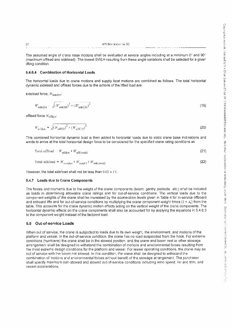
32 API SPECIFICATION 2C
The assumed angle of crane base motions shall be evaluated at several angles including at a minimum 0° and 90° (maximum offlead and sidelead). The lowest SWLH resulting from these angle variations shall be selected for a given lifting condition.
5.4.6.4 Combination of Horizontal Loads
The horizontal loads due to crane motions and supply boat motions are combined as follows. The total horizontal dynamic sidelead and offlead forces due to the actions of the lifted load are:
sidelead force, Wsidcdyn:
(19)
offlead force Woffdyn:
(20)
This combined horizontal dynamic load is then added to horizontal loads due to static crane base inclinations and winds to arrive at the total horizontal design force to be considered for the specified crane rating conditions as:
Total offload = Woffdyn + Woff(wind) (21 )
Total sideload = Wsidedyn + WsideCI + Wsidc(wind) (22)
However, the total sideload shall not be less than 0.02 x FL.
5.4.7 Loads due to Crane Components
The forces and moments due to the weight of the crane components (boom, gantry, pedestal, etc.) shall be included as loads in determining allowable crane ratings and for out-of-service conditions. The vertical loads due to the component weights of the crane shall be increased by the acceleration levels given in Table 4 for in-service offboard and onboard lifts and for out-of-service conditions by multiplying the crane component weight times (I + Ay) from the table. This accounts for the crane dynamic motion effects acting on the vertical weight of the crane components. The horizontal dynamic effects on the crane components shall also be accounted for by applying the equations in 5.4.6.3 to the component weight instead of the factored load.
5.5 Out-of-service Loads
When out of service, the crane is subjected to loads due to its own weight, the environment, and motions of the platform and vessel. In the out-of-service condition, the crane has no load suspended from the hook. For extreme conditions (hurricane) the crane shall be in the stowed position, and the crane and boom rest or other stowage arrangement shall be designed to withstand the combination of motions and environmental forces resulting from the most extreme design conditions for the platform and vessel. For lesser operating conditions, the crane may be out of service with the boom not stowed. In this condition, the crane shall be designed to withstand the combination of motions and environmental forces without benefit of the stowage arrangement. The purchaser shall specify maximum non-stowed and stowed out-of-service conditions including wind speed, list and trim, and vessel accelerations.
o :0
tv -;' 'c ;:s o tv

OFFSHORE PEDESTAL-MOUNTED CRANES 33
5.6 Wind, Ice, and Seismic Loads
5.6.1 Wind
The purchaser may specify desired wind speeds for each lift condition for which ratings shall be determined as well as for out-of-service conditions. In the absence of purchaser-specified information, the wind speed shall be:
for onboard lifts, 20 knots;
for offboard lifts, 7.16 x Ji1:s (but not less than 20 knots);
for the legacy rating method, see 5AA for wind speed;
for out-of-service unstowed conditions, 61 knots; and
for out-of-service stowed conditions,122 knots.
These wind velocities include the effects of elevation and gust loads for the crane location.
The wind pressure acting on the projected area of the crane components and lifted load shall be calculated as:
~
P wind = 0.00339 x Cs X if
where
U is the wind velocity expressed in knots (1 knot = 1.1508 mile/h = 0.5144 m/s);
Cs is the member shape coefficient; and
Pwind is the wind pressure expressed in Ib/ft2
In the absence of other information, shape coefficients, Cs, are recommended as shown in Table 6:
Table 6-Recommended Shape Coefficients
Member Type Cs
I-beams, angles, channels 2.0 --
Square tube 1.5
Round pipe 0.8
Flat sides of enclosures 1.5
. (1.33 x SH'L11\,2/3 Load projected area = 200-)
(23)
(24)
Wind directions may be assumed to act in the direction of crane base motions. Wind forces acting on the faces of the lifted load shall be added to the other horizontal side loads and offloads applied at the boom tip. Wind forces acting on the boom and other crane components shall be applied to the boom in the appropriate plane in a direction to be
(f) c :l
o :l
") ~
'-c ;:s o N

34 API SPECIFICATION 2C
additive to the other horizontal boom loads. Wind forces acting on the boom and other crane components shall be additive to the other horizontal loads.
5.6.2 Ice
For cranes where ice or snow accumulation is expected to occur, refer to API 2N for methodology with purchaser supplied information.
5.6.3 Seismic
On bottom-supported structures subject to seismic loading, cranes shall be designed to meet deck seismic criteria in accordance with API 2A-WSD, 21 st Edition, Section 2.3.6.e.2. Specific crane seismic design guidelines are as follows.
a) Cranes and their pedestals shall be designed in accordance with methodologies applied to other significant topside equipment (e.g. drilling rig and flare boom). Most typically, deck equipment is designed on the basis of a strength level event (SLE) deck appurtenance response spectrum.
b) Consideration shall be given to the uncertainty of the natural period calculations. This is typically handled by broadening or shifting the design spectra.
c) Due to the very low probability of simultaneous occurrence of a design seismic event at the time of the crane being used for a maximum rated lift, a reduced crane load may be considered simultaneous with the design seismic event. General guidance is that a crane study should be conducted to identify typical offloading loads that shall regularly occur during the life of the platform. A load equal to 90 % non-exceedingly may be used, but should not be less than 1/3 of the rated capacity. In the absence of such a study, a load producing 2/3 of the rated crane overturning moment capacity shall be considered.
d) Seismic analyses shall also consider the no-hook load case. Such analyses help identify components governed by uplift.
e) Seismic analyses shall also consider a design case with the boom in its stowed condition.
f) For SLE analyses, an increase of 1/3 in. allowable stresses is permitted.
g) For operational use of a crane in a seismically active area, it is recommended that the crane be stowed when it is not being used.
6 Structure
6.1 General
All critical structural components (except as noted in 6.3) shall be designed to conform with the allowable unit stresses specified in the AISC "Specification for Structural Steel Buildings-Allowable Stress Design and Plastic Design," dated June 1, 1989 (see note) when subjected to the loads described in Section 5. For in-service load conditions described in 8.2, the basic allowable unit stresses in the AISC specification shall be used without benefit of the 1/3 stress increase. For extreme conditions of seismic loads (in-service or out-of-service) or extreme winds (outof-service only), the 1/3 allowable stress increase in the AISC specification may be used.
NOTE This specification is available from the AISC website (www.aisc.org)asadownload.ltis also the specification section in the 9th edition of the AISC Manual of Steel Construction: Allowable Stress Design, which also may be available for sale.
For structural steels other than those listed in AISC, compatibility with the AISC allowable unit stresses should be established and documented by the crane manufacturer.
N ';-' 'c ~ o N
z o
:J (Q
Q o.
9 ~. 0' C
it Q.
C5' ,<

OFFSHORE PEDESTAL-MOUNTED CRANES 35
Critical field assembly connecting joints (pinned or bolted) (Le. boom splice and heel connections and gantry and mast tension leg members) shall be designed to develop 100 % of the strength of the connected members. Box boom section field assembly splices shall be designed to develop 100 % of the strength of the box boom sections adjacent to the splice location. Non-critical connecting joints (welded, pinned or bolted) shall develop either the load carried by the connected members or the strength of the connected members based on AISC allowables, but in no case less than 50 % of the tensile strength of the controlling member. Allowable shear stresses and width-to-thickness ratios shall be in accordance with the applicable provisions of AISC.
6.2 Pedestal, Kingpost, and Crane Supporting Foundation
Pedestals, kingposts, and the crane-support structure shall be designed for the loads defined in Section 5 with an additional factor, the pedestal load factor (PF), that applies to the vertical and horizontal loads due to the factored load. The PF is applied to vertical factored load and to offlead and sidelead forces due to the vertical factored load. The PF is derived as follows:
SWLH P F = 1.56 - 900, 000
but not less than 1.2 or greater than 1.5.
These components shall satisfy AISC without a 1/3 increase in stress (see 6.1).
(25)
For tall kingposts and pedestals, additional stiffness may be required to prevent excessive motion of the crane and operator. Excessive motion may cause operator discomfort even if the stress level requirements given above are satisfied.
6.3 Exceptions to use of AISC
Swing bearings, their bolt connections, and foundation bolts in general are not to be analyzed in accordance with AISC. Specific design requirements for swing bearings and bolting are presented in 74.
6.4 Structural Fatigue
The crane structure shall be designed for a fatigue life exceeding the expected crane service life. In the absence of data on projected frequency and magnitude of lifted loads during the expected life of the crane, every critical structural component of the crane shall be designed to withstand a minimum of 1,000,000 cycles at 50 % of its onboard lift SWLH and associated horizontal loads (offload and sideload) as defined in Section 5 at the most adverse radius for each component. The stress range used should be the difference between the stress caused by the above loading and stress with the boom in the same position but unloaded.
The fatigue design criteria shall be based on established fatigue design life guidelines such as are found in AWS 01.1, BS7608 or Appendix K of the AISC specification (see 6.1). Annex B includes a discussion of the structural fatigue approach and the source of the fatigue curves.
The design engineer shall consider hot-spot stresses in the base metal adjacent to the toe of welds, especially those welds which constitute the main load path in transferring load and which rely on the weld rather than cross-section (i.e. a "bottleneck" in stress flow). This hot-spot stress may be defined as that which should be measured by a straingauge element adjacent to the toe of the weld after stable cycles are achieved (or shakedown) during prototype testing. Finite-element analysis compatible with this definition may be used to calculate this stress. Appropriate fatigue curves may be taken from AWS 01.1 or BS7608, or other documents to obtain a fatigue-life estimate compatible with this definition.
z o C d
-i :::; o c, oJ o

36 API SPECIFICATION 2C
If the purchaser supplies information on expected frequency and magnitude of lifted loads, the design engineer may use the fatigue curves mentioned above to:
a) size structural components to meet fatigue requirements during the design phase, or
b) perform a fatigue analysis to estimate the expected fatigue life of an existing design based on the cyclic information supplied by the purchaser.
7 Mechanical
7.1 Machinery and Wire Rope Duty Cycles
7.1.1 General
The theoretical design life of the structural, machinery, and wire-rope components of the crane shall be considered separately. Requirements for the structural components are intended to provide a structure that meets or exceeds the life expectancy of the facility on which the crane is installed. Machinery and wire rope design life should be based on reasonable repair or replacement intervals, consistent with the duty cycle, or specific frequency and magnitude of lifted loads during the expected life of the crane.
The preferred basis of the duty cycle analysis of the crane components is to use purchaser-projected information. In the absence of this information, default duty cycle parameters are provided for typical pedestal-mounted offshore crane classifications. Manufacturers may also provide predetermined life cycle ratings.
The theoretical design life guidelines herein cannot encompass all operational, environmental, and maintenance variables affecting the life of crane components, and cannot be considered as guaranteed. These guidelines are intended to provide a reasonable basis for the design of structural, machinery and wire rope components of the crane which are consistent with the intended usage.
7.1.2 Machinery Duty Cycles
When the purchaser does not provide specific duty cycle data, the expected duty cycle or time between overhaul (TBO) of the primary machinery components is determined from frequency of use in hours during the TBO in years. The expected magnitude of lifted loads is expressed as a percentage of the maximum load of the individual component that corresponds with the frequency during the TBO. The duty cycle life of the individual components are determined from the maximum allowable load on each crane component based on the component rating without regard to the capacity of the crane as a whole. Operating speeds are based on a percentage of maximum speed, and the machinery is considered to be in use whether the crane is loaded or unloaded, but only if it is in motion.
7.1.2.1 Classification of Typical Offshore Crane Applications
In the absence of information from the purchaser, the operating frequency may be classified by typical offshore crane application as shown in Table 7 for the overall crane, and in Table 8, Table 9, Table 10, Table 11, and Table 12 for the major crane mechanical components.
7.1.2.2 Machinery Duty Cycles by Crane Classification
If typical offshore-crane classifications are used, the theoretical TBO cycle life for the primary machinery components may be determined from the corresponding magnitude of loading and operating speeds as shown in the Table 8, Table 9, Table 10, Table 11, and Table 12. The commentary discusses the basis of the classifications and TBO information.
()
.g j (Q
u o

OFFSHORE PEDESTAL-MOUNTED CRANES 37
Table 7-Classification of Offshore Crane Applications
Crane Duty-Cycle Annual Operating Typical Applications Classification (Prime Mover)
Production duty 200 hr Offshore cranes on bottom-supported production platforms
---,,"-" ""~" ... ~
Offshore cranes on bottom-
Intermediate duty 2000 hr supported or floating platforms with temporary rigs or intermittent periods of intensive use
~----------- ---_.----_.-- ._-
Offshore cranes on MODUs or Drilling duty 5000 hr floating production facilities with full-
time drilling operations
Construction duty 1000 hr Offshore cranes on construction barges or vessels heavy-lift cranes
Table 8-Auxiliary Hoist - 5 Year T80
Crane Duty Cycle Theoretical % Maximum ! % Maximum Classification Design Life Torque Speed
Production duty 60 hr 45 % 70 %
Intermediate duty 825 hr 45 % 70 % ~.--~- -... -.--------~-
Drilling duty 2,100 hr 55 % 70 %
Construction duty 250 hr 45% 70 %
Table 9-Main Hoist - 5 Year T80
Crane Duty-Cycle Theoretical % Maximum % Maximum Classification Design Life Torque Speed
I
Production duty I 70 hr 45 % 70 % ---- ---_ .. " .. "---'" -- --------
Intermediate duty 225 hr 45 % 70 %
Drilling duty I
500 hr 55 % 70 %
Construction duty ! 250 hr 45 % 70 %
Table 10-8oom Hoist - 5 Year T80
Crane Duty-Cycle Theoretical % Maximum % Maximum Classification ! Design Life Torque Speed
Production duty ! 70 hr 45 % 70 %
Intermediate duty 1250 hr 45 % 70 %
Drilling duty 3750 hr 55 % 70 % 1-----_ .. _-_. __ ._-
Construction duty 900 hr 45 % 70 %
7.1.3 Wire Rope Duty Cycles
The duty cycle approach for wire ropes is similar to that of the machinery components, although the time between replacement (TBR) for wire ropes is expected to be less than that of the machinery. The crane designer should consider factors (i.e. the magnitude and frequency of loading, fleet angles, f) d ratios of drums and sheaves commensurate with the duty cycle),
() 0 D
'3 co ::r CD C'~
:3 '" ~ ~ (') CD S; CD D-
o :S :x-() ::r CD :J
UJ C ::0
0 :J N ';-' '-c ~ 0
N
Q o· CD :J if; m (j)
SIC ::;-t. GO ill Ui C if; CD 0 2. '<
Z 0
~ J
~ ro
D
a 0. c ~ 6 :0
<;; i(; ~ <;; x ~-:;
I.e:::
if 1:J
~ ~2 (l) G,
0
~ s-ill C2.
G' '<
~ 0
~ Q
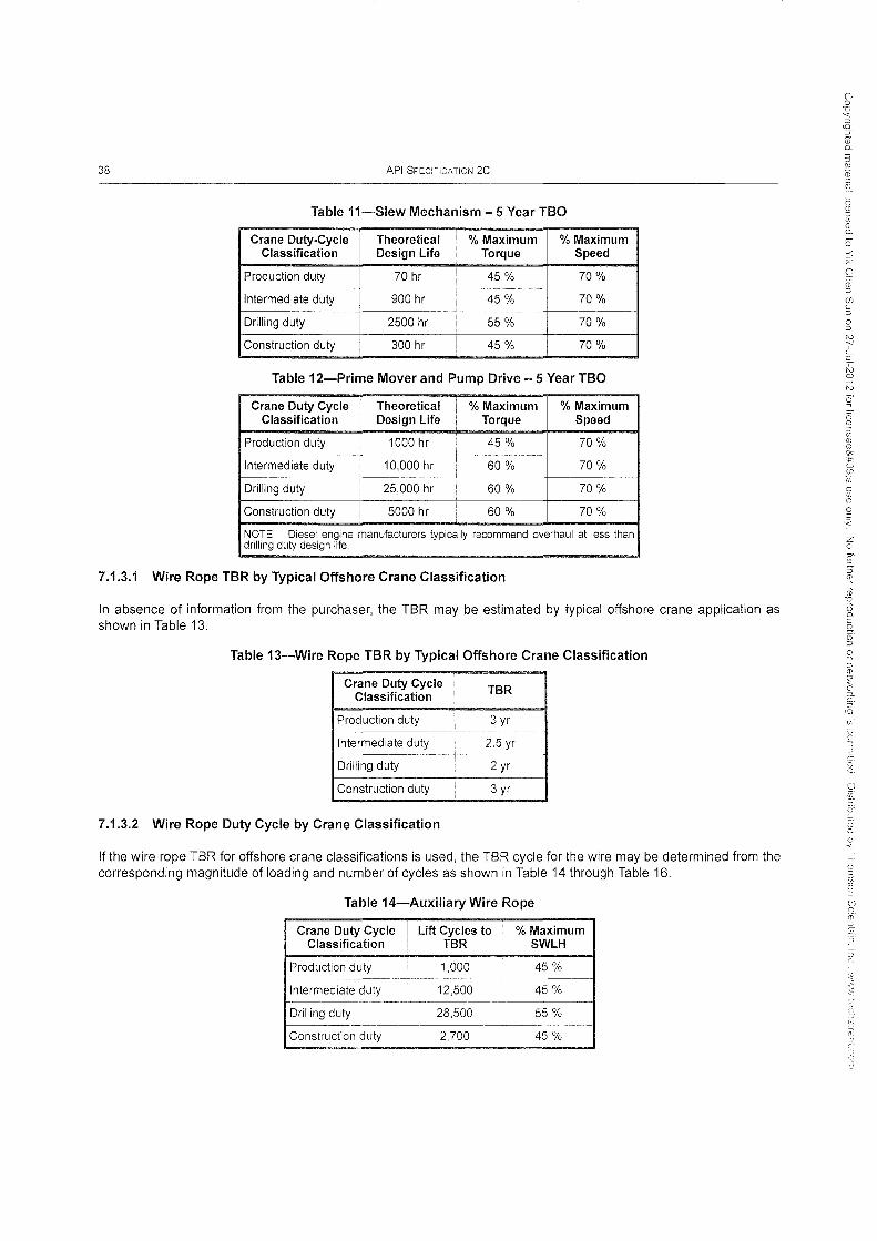
38 API SPECIFICATION 2C
Table ii-Slew Mechanism - 5 Year TBO
Crane Duty-Cycle Theoretical ,
% Maximum % Maximum Classification Design Life Torque Speed
Production duty 70 hr ! 45 % 70 %
Intermediate duty 900 hr 45% 70 %
Drilling duty 2500 hr 55 % 70 %
Construction duty 300 hr 45 % 70 %
Table 12-Prime Mover and Pump Drive - 5 Year TBO
Crane Duty Cycle Theoretical % Maximum % Maximum Classification Design Life Torque Speed
Production duty 1000 hr 45 % 70 %
Intermediate duty 10,000 hr 60 % 70 % r----- --- r-------- ---
Drilling duty 25,000 hr 60 % 70 %
Construction duty 5000 hr , 60 % 70 %
NOTE Diesel engine manufacturers typically recommend overhaul at less than drilling duty design life.
7.1.3.1 Wire Rope TBR by Typical Offshore Crane Classification
In absence of information from the purchaser, the TBR may be estimated by typical offshore crane application as shown in Table 13.
Table 13-Wire Rope TBR by Typical Offshore Crane Classification
Crane Duty Cycle TBR Classification
Production duty 3 yr --
Intermediate duty 2.5 yr
Drilling duty , 2 yr
Construction duty ! 3 yr
7.1.3.2 Wire Rope Duty Cycle by Crane Classification
If the wire rope TBR for offshore crane classifications is used, the TBR cycle for the wire may be determined from the corresponding magnitude of loading and number of cycles as shown in Table 14 through Table 16.
Table 14-Auxiliary Wire Rope
Crane Duty Cycle Lift Cycles to I % Maximum Classification TBR ! SWLH
Production duty 1,000 45 %
Intermediate duty 12,500 45 %
Drilling duty 28,500 ! 55 %
Construction duty 2,700 45 %
o :J N ~ 'c ;;::; o N
Q
o ::J ~.
z o
(;<'

OFFSHORE PEDESTAL-MOUNTED CRANES 39
Table 15-Main Wire Rope
Crane Duty Cycle Lift Cycles to % Maximum Classification TBR SWLH
Production duty 250 45 %
Intermediate duty 650 45 %
Drilling duty 1500 55 %
Construction duty 350 45 %
Table i6-Boom Wire Rope
Crane Duty Cycle I Lift Cycles %SWLH Classification toTBR
Production duty 1200 45 %
Intermediate duty 12,500 45 % " -... ~-
Drilling duty 30,000 55 %
Construction duty 3000 45 %
7.2 Critical Rigging Components
7.2.1 General
Suspension (boom hoist ropes and pendant lines) and hoist systems are comprised of certain rigging equipment. Components of rigging equipment that meet the critical component definition shall be considered critical rigging components and shall comply with the requirements of this section.
7.2.2 Wire Rope
7.2.2.1 General
All wire rope used in hoist and suspension systems shall comply with the requirements set out below.
7.2.2.2 Construction
The crane manufacturer shall specify the wire rope construction to be used for each application (boomlines or loadlines). The requirements of API 9A shall be the minimum specification for wire rope used on offshore cranes. The ropes shall be suitable for the intended purpose and service life.
7.2.2.3 Inspection, Maintenance and Replacement (IMR)
The crane manufacturer shall provide IMR procedures for all wire rope used in the crane. The procedures shall comply with the minimum criteria given in API 20.
7.2.2.4 Design Factors
Minimum design factors for running and standing wire ropes shall be calculated from the following formulas.
7.2.2.4.1 Running Rigging (Ioadline and boomline hoisting systems)
lJF but need not be greater than 5.0 (26)
o -< x= o :y (1) :J
(j) C :J
o ::J N -;" 'c ~ o N
([) 0..

40 API SPECIFICATION 2C
or regardless of SWLH:
DF = 2.25 xCv (27)
whichever is greater, but shall not be less than 3.0.
SWLH is as determined from 8.1.1 for each radius and Cy is the corresponding vertical dynamic coefficient as determined from Equation (2) in 5.4.5.2. Equation (4) shall not be used.
7.2.2.4.2 Standing Rigging (Pendant Line Suspension Systems)
10,000 DF = 0.0025 x SWLH + 2444' but need not be greater than 4.0 (28)
or
DF = 2.0xCy (29)
whichever is greater, but shall not be less than 3.0.
SWLH is as determined from 8.1.1 for each radius and Cy is the corresponding vertical dynamic coefficient as determined from Equation (2) in 5.4.5.2. Equation (4) shall not be used.
7.2.2.5 Reeving System Efficiency
The efficiency of reeving systems for running rigging shall be calculated from the following formula:
K'v -1 En = ~~._--,b,--__
KbxNx(Kb-l) (30)
where
Ers is the reeving system efficiency;
Kb is the bearing constant: 1.045 for bronze bushings or 1.02 for roller bearings;
N is the number of line parts; and
S is the total number of sheaves in reeving system.
For standing rigging, Ers equals 1.0.
7.2.2.6 Wire Rope Load
Wire rope load (W) is defined as the maximum total force generated in the load lines or boom suspension systems by the effects of applied loads. For loadlines, the applied load is SWLH. For boomlines and pendant lines, the applied loads include SWLH, dead weight (with accelerations from crane base motions), offiead, wind and lifting geometry.
o Q

OFFSHORE PEDESTAL-MOUNTED CRANES
7.2.2.7 Minimum Wire Rope Breaking Strength
7.2.2.7.1 General
The minimum required breaking strength for a wire rope shall be calculated from the following formula:
BL = WxDF NxErs
where
BL is the required minimum nominal breaking load for a single wire rope in Ib;
W is the wire rope load from 7.2.2.6 in Ib;
DF is the design factor from 7.2.2.4;
N is the number of parts of line; and
Ers is the reeving system efficiency from 7.2.2.5.
7.2.3 Wire Rope End Terminations
7.2.3.1 U-bolt and Fist Grip Clips
41
(31 )
Extreme care should be exercised to assure proper orientation of U-bolt clips. The U-bolt segment shall be in contact with the wire rope dead-end. The orientation, spacing, torquing, and number of all clips shall be in accordance with the crane manufacture's specifications.
7.2.3.2 Eye Splice
Eye splices shall have a minimum of three full tucks. Other details of eye splicing shall be specified by the crane manufacturer.
7.2.3.3 Wedge Sockets
Wedge sockets shall be installed with the live-load-side of the wire rope in line with the wedge socket pin. Wire rope clips used in conjunction with wedge sockets shall be attached to the unloaded (dead) end of the rope as shown in Figure 5 (other options are provided by various vendors). Wedge socket assemblies shall withstand wire rope failure.
7.2.3.4 Termination Efficiency
Wire rope end terminations shall not reduce wire rope strength below 80 % of the wire rope nominal breaking load. If the efficiency of the end termination is below 80 %, breaking strength of the wire rope used to determine rated loads shall be reduced until the loss is compensated up to a minimum of 80 % efficiency.
7.2.3.5 Installation Procedure
Detailed installation procedures for wire rope end terminations shall be specified by the crane manufacturer.
7.2.4 Sheaves
7.2.4.1 All sheaves that are part of any crane hoist system shall comply with this specification.
o ::J" <D OJ
(j) C ::J
o :J
z o
-·1 CY o :3 (n o ::J

42
Key
1 extra piece of same rope is clipped to main rope
2 loopback method 3 secure loop loadline
loosely with wire
API SPECIFICATION 2C
4 seven times rope diameter minimum
5 three times rope diameter maximum
Figure 5-Some Methods of Securing Dead End of Rope when using Conventional Wedge Sockets
7.2.4.2 Sheave pitch diameter (Dsh) to nominal wire rope diameter (d) ratio (Dshld) shall not be less than 18 (Figure 6). For cranes with higher duty cycles (as described in 7.1), a higher Dsi/d ratio results in a longer fatigue life of the wire rope.
7.2.4.3 Sheave groove contour shall be smooth and free from defects harmful to the wire rope.
7.2.4.4 Sheave groove angle shall taper outward and shall not be less than a 30° included angle. Groove flange corners shall be rounded. The rim concentricity and perpendicularity about the rotation axis shall be within tolerances specified by the crane manufacturer.
7.2.4.5 Sheave groove radius for wire rope support shall be sized for the specified wire rope diameter in accordance with Table 17 for sheaves having metallic rims and in accordance with Table 18 for sheaves having cast nylon rims. Sheave groove size and tolerance for other rim materials shall be specified by the crane manufacturer.
7.2.4.6 Material selection and arrangement of materials for sheaves shall be such that the potential for galvanic corrosion of the sheave body or the rope wire is minimized.
7.2.4.7 Materials that display a tendency to fracture in a brittle mode at any temperature within the design range should not be used for the production of sheaves. Sheaves are exempt from impact testing.
7.2.4.8 Sheaves shall be capable of resisting all applicable structural loadings described in Section 5 without exceeding allowable stresses. For polymer materials known collectively as Type 6 cast nylons, allowable flexural, tensile, shear, and bearing stresses shall be limited to a maximum of 30 % of the corresponding flexural, tensile, and compressive strengths.
7.2.4.9 Joints between metallic and polymer material shall incorporate some positive means to prevent separation.
N -;-' 'c ~ o N

OFFSHORE PEDESTAL··MOUNTED CRANES
Key
1D 2 d 3 sheave pin
CD
Figure 6-Sheave Dimensions
43
7.2.4.10 Selection of radial and thrust bushings or bearings for sheaves shall be made with regard to all suspended and side load forces.
7.2.4.11 Sheave bearings shall be individually lubricated through a separate passage. Permanently lubricated bearings are exempt from this requirement.
7.2.4.12 Sheave guards-All sheaves including running blocks shall be provided with guards or other suitable devices to prevent the rope from unintentionally coming out of the sheave groove.
7.2.5 Load Block Assemblies
7.2.5.1 Hook Block
The hook block is the main hoist system load block used in main boom lifting operations.
Sheave bearings shall be sized to be suitable for the intended service.
The weight of the hook block shall be sufficient for the boom length and parts of line specified to prevent slack wire rope when the main hoist drum is unwinding at maximum speed.
Cast-iron material shall not be used to provide additional weight in load block assemblies. The hook block assembly shall meet the material requirements of 11.1.7.
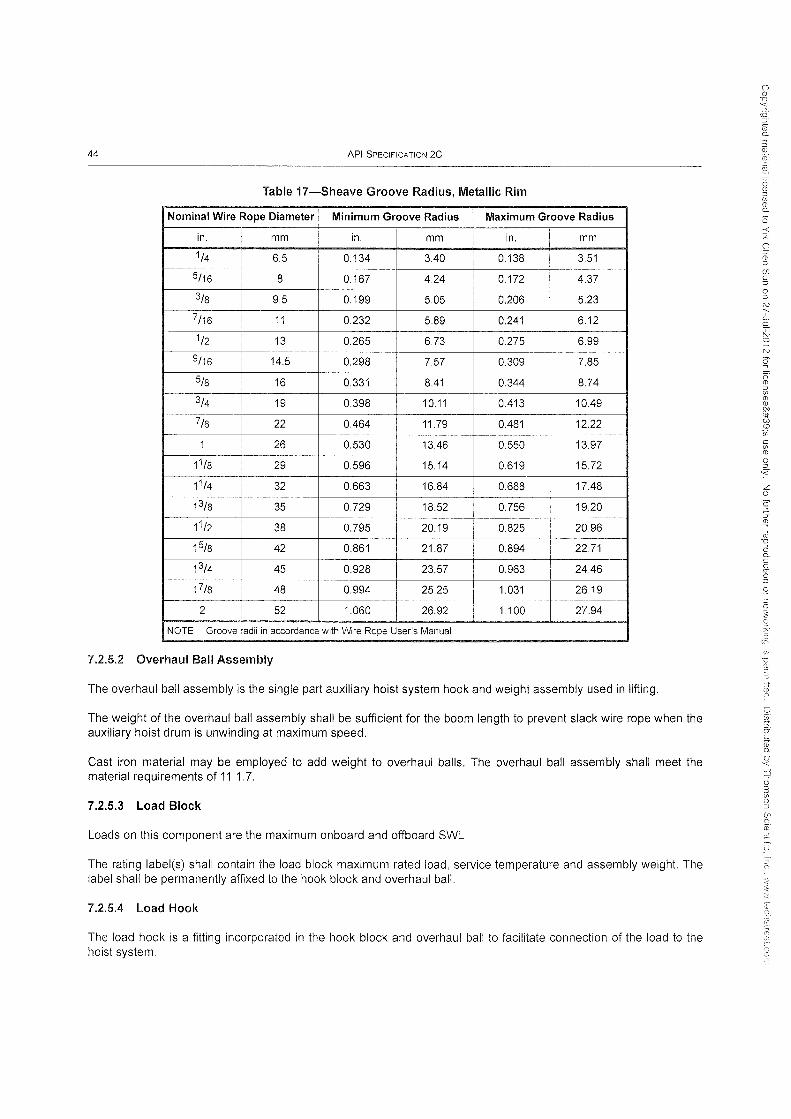
44 API SPECIFICATION 2C
Table 17-Sheave Groove Radius, Metallic Rim
Nominal Wire Rope Diameter Minimum Groove Radius Maximum Groove Radius
in. I mm in. mm in. mm
1/4 6.5 0.134 340 0.138 3.51 _._ ... 1-----5/16 8 0.167 4.24 0.172 4.37
3/8 9.5 0.199 505 0.206 5.23
7/16 ! 11 0.232 5.89 0.241 6.12
1/2 ,
13 0.265 6.73 0.275 6.99
9/16 : 14.5 0.298 7.57 0.309 7.85
5/8 : 16 0.331 841 0.344 8.74 _.
3/4 19 0.398 10.11 0413 1049
7/8 22 0464 11.79 0481 12.22
1 26 0.530 1346 0.550 13.97
11/8 i 29 0.596 15.14 0.619 15.72
11/4 32 0.663 16.84 0.688 1748
13/8 I 35 0.729 18.52 0.756 19.20 I
11/2 38 0.795 20.19 0.825 20.96
15/8 I 42 0.861 21.87 0.894 22.71 I
13/4 45 0.928 23.57 0.963 2446
17/8 48 0.994 25.25 1.031 26.19
2 ,
52 1.060 26.92 1.100 27.94
NOTE Groove radii in accordance with Wrre Rope User's Manual
7.2.5.2 Overhaul Ball Assembly
The overhaul ball assembly is the single part auxiliary hoist system hook and weight assembly used in lifting.
The weight of the overhaul ball assembly shall be sufficient for the boom length to prevent slack wire rope when the auxiliary hoist drum is unwinding at maximum speed.
Cast iron material may be employed to add weight to overhaul balls. The overhaul ball assembly shall meet the material requirements of 11.1.7.
7.2.5.3 Load Block
Loads on this component are the maximum onboard and offboard SWL.
The rating label(s) shall contain the load block maximum rated load, service temperature and assembly weight. The label shall be permanently affixed to the hook block and overhaul ball.
7.2.5.4 Load Hook
The load hook is a fitting incorporated in the hook block and overhaul ball to facilitate connection of the load to the hoist system.
o (j) OJ if; ill O.
o -< 7' o :y (j) OJ
(j) C :J
o OJ
N ';' 'c ;:s o N
cr
ro o.

OFFSHORE PEDESTAL-MOUNTED CRANES 45
Table i8-Sheave Groove Radius, Cast Nylon Rim
Nominal Wire Rope Diameter I Minimum Groove Radius Maximum Groove Radius
in. I mm I in. mm in. mm I 1
1/4 6.5 I 0.131 3.33 0.163 4.13 I
I----~ ._-_. ! --~ .. --1---
5/16 8 i 0.164 4.17 0.195 4.96
3/8 9.5 i
0.197 5.00 0.228 5.79
7/16 11 I 0.230 5.83 0.261 6.63 !
1/2 13 I
0.263 6.67 0.294 746
9/16 14.5 j 0.295 7.50 0.327 8.29
5/8 16 : 0.328 8.33 0.359 9.13 f-----
3/4 1
19 0.394 10.00 0425 10.80
7/8 22 I
0459 11.67 0.506 12.86
1 26 I
0.525 13.34 0.572 14.53
11/8 29 !
0.591 15.00 0.638 16.19
11/4 32 i
0.656 16.67 0.906 23.02
13/8 35 !
0.722 18.34 0.972 24.69
11/2 38 I 0.788 20.00 1038 26.35 !
15/8 42 I 0.853 21.67 1.103 2802 I
13/4 45 I
0.919 23.34 1.169 29.69 I
--17/8 48 I 0.984 25.00 1.234 31.35
2 52 I 1.050 26.67 1.300 33.02
The hook material shall be alloy steel and produced as a forging or casting.
The load hook shall meet the material requirements of 11.1.7.
Hooks shall be equipped with a latch to retain loose lifting gear under non-lifting conditions. There shall be a positive locking means if the hook is to be used for transporting personnel. The latch is not intended to support the lifted load.
7.2.5.5 Load Block Design Factors
Design factors shall be determined by dividing the load block minimum plastic failure load by the corresponding load block loads. The basic rating design factor shall be:
DF- 10,000 b db' 'h 40 - 0.0025 xSWLH+ 2444' utnee not egreatert an . (32)
or
DF= 3.0Xlv (33)
whichever is greater.

46 API SPECIFICATION 2C
SWLH is as determined from 8.1.1 for each radius, and Cy is the corresponding vertical dynamic coefficient as determined from Equation (2) in 5.4.5.2. Equation (4) shall not be used.
7.2.5.6 Prototype Design Verification
7.2.5.6.1 A prototype design shall be tested to establish the validity of underlying design concepts, assumptions and analytical methods.
7.2.5.6.2 A proof load of 2.0 times the maximum rating shall be applied without permanent deformation to the prototype.
7.2.5.6.3 A plastic failure load shall be confirmed by destructive testing. Differences between actual and minimum material properties shall be taken into account.
7.3 Boom Hoist, Load Hoist, Telescoping, and Folding Boom Mechanisms
7.3.1 Hoist
7.3.1.1 General
Boom, main, and auxiliary hoists shall be approved by the manufacturer for personnel handling and shall be indicated as such on their nameplate. Hoists shall also conform to standards of performance and serviceability as set out below.
7.3.1.2 Performance
The line pull for boom and load hoists shall meet the following requirements.
a) The required line pull for boom and load hoists shall account for reeving system efficiency in accordance with 7.2.2.5.
b) Load hoist line pull shall be based on maximum SWLH positioned at the boom tip.
c) Boom hoist line pull shall be based on the force induced by the factored loads specified in Section 5.
7.3.1.3 Brake Requirements
The brakes shall meet the following requirements.
a) Brakes shall be of a fail-safe design. The brakes shall apply automatically when the control lever is returned to the neutral position or in the event of power loss.
b) Two braking systems shall be provided for each hoist, a dynamic brake and a parking brake.
c) Parking brakes shall be mechanical and act directly on the drum or through a continuous mechanical path.
d) When power-operated brakes having no continuous mechanical linkage between the actuating and braking means are used for controlling loads, an automatic mechanical means shall be provided to set the brake to prevent the load from falling in the event of loss of brake actuating power.
e) Controlling fluid from a drive motor directly attached to the hoist is considered a dynamic brake when:
- the control device is connected directly to the outlet port without the use of hoses;
CJ o
1:0
~. ({) -:y ffi o.
z o
UJ o ,::;::

OFFSHORE PEDESTAL-MOUNTED CRANES 47
the control device requires positive pressure from the power source to release, and it actuates automatically to bring the hoist to a stop in the event of a control or motive power loss; and
the braking system is effective throughout the operating temperature range of the working fluid.
f) Brakes and clutches shall be provided with adjustments (where necessary) to compensate for wear and to maintain adequate force on springs where used.
g) Parking brakes shall prevent the drum from rotating in the lowering direction and shall be capable of holding the rated load indefinitely without attention from the operator.
h) During normal operations, the boom and all loads shall be lowered only by connection of the hoist to the power train. These hoists shall not be capable of free fall operation, except when employed as part of a gross overload protection system in accordance with 9.5.
i) In addition to brakes, boom hoists shall have a means of locking the drum for maintenance purposes. This lock shall support the maximum torque of the hoist.
7.3.1.4 Brake Performance
Brake performance shall meet the following requirements.
a) Dynamic brakes shall have adequate capacity to stop 110 % of the line pull (see 7.3.1.2) from the maximum line speed in the lowering mode.
b) Parking brakes, when applied to a stopped drum, shall have sufficient capacity to hold 1.5 times the maximum torque induced by the line pull calculated in accordance with 7.3.1.2.
c) The lowest coefficient of friction for the brake lining with due consideration of service conditions (humidity and grease) is to be applied in the design calculation of braking torque capacity, but this coefficient of friction shall not be higher than 0.3.
d) Dynamic brakes shall be able to operate continuously for one hour, raising and lowering the rated load at maximum design speed over a height of 50 ft (15 m). Dwell time between raising and lowering operations shall not exceed 3 seconds. Coolant flow, if applicable, shall be maintained within limits specified by the hoist manufacturer. At the end of this operation, the brake shall have adequate capacity to stop 110% of the line pull (see 7.3.1.2) from the maximum design speed in the lowering mode while lowering.
e) Boom hoists shall be capable of elevating the boom from a minimum luffing angle of 0° to the maximum recommended luffing angle for all boom configurations.
7.3.1.5 Drums
The wire rope drums shall meet the following requirements.
a) All drums shall provide a first layer rope pitch diameter of not less than 18 times the nominal rope diameter (Figure 7).
b) The flange shall extend a minimum distance of 2.5 times the wire rope diameter over the top layer of the rope unless an additional means of keeping the rope on the drum is supplied.
c) Drum(s) shall have sufficient rope capacity with recommended rope size(s) to operate within the range of boom lengths, operating radii and vertical lifts as agreed to between the manufacturer and the purchaser.
(") (!) ::l if> (!) D-
o -< X o ;;y (!) ::J
(j) C :::J o ::J
N
-:-' 'c ~ o N
2:
C U) (!)
o ::J .:z
(f)
o

48 API SPECIFICATION 2C
d) No less than five full wraps of rope shall remain on the drum(s) in any operating condition. The drum end of the rope shall be anchored to the drum by a suitable means.
e) To ensure correct spooling, flange spacers may be used to account for rope tolerances.
NOTE The flange shall extend a minimum distance of 2.5 times the wire rope diameter over the top layer of rope unless an additional means of keeping the rope on the drum is supplied.
7.3.1.6 Components
Key
1 D 2 d 3 Minimum 2.5 d 4 drum 5 flange
Figure 7-Hoist Drum
.'fl)
t CD _t
Components shall be designed to minimize the likelihood of incorrect use or assembly as follows.
a) All critical drive components shall have unique spline, keying, or other arrangements to prevent improper installation or interchange of parts.
b) Where the above provisions cannot be met, parts in question shall be clearly marked and specific warning on interchangeability included in the operating and maintenance manuals.

OFFSHORE PEDESTAL-MOUNTED CRANES 49
7.3.1.7 Mounting
Mounting of machinery components shall meet the following requirements.
a) To prevent premature deterioration of internal machinery components due to distortion under service loads, the hoist manufacturer shall provide recommendations for mounting stiffness and mounting flatness.
b) Where means of alignment may be disturbed by disassembly, means for field alignment shall be provided.
c) The attachment of the hoist to the structure shall be sized to resist at least the greater of:
2.0 times the maximum reactions induced by the maximum attainable line pull of the hoist.
The maximum line pull caused by the highest dynamic loads. For load hoists, this equals Cy multiplied by SWLH. For boom hoists; this is the boom line load at the boom hoist due to boom weight, crane dynamics and Cy multiplied by SWLH.
d) The crane manufacturer is responsible for the design and testing of the hoist foundation and mounting. Mounting and distortion under load shall be in accordance with the hoist manufacturer's recommendations.
7.3.1.8 Lubrication and Cooling
Hoist Lubrication and cooling shall meet the following requirements.
a) All hoists shall be equipped with means to check lubricant and coolant levels. The means shall be readily accessible with wire rope in place. Maximum and minimum levels shall be clearly indicated.
b) Hoists that use a circulating fluid for lubrication or cooling shall be provided with means to check fluid level while in operation (see 10.3.4).
c) Hoists that use a closed lubrication system shall have a fluid capacity of at least 120 % of the manufacturer's minimum recommended operating level.
7.3.1.9 Flexible Splines and other Coupling Arrangement Ratings
Flexible splines and other coupling arrangements shall have a design life that is greater than the gear train and bearing at rated load and maximum rated speed when operating within alignment limits of 7.3.1.7.
7.3.2 Luffing
Two methods for supporting the boom and luffing or changing the boom angle are wire-rope suspension and hydraulic-cylinder support.
7.3.2.1 Wire-Rope Suspension
When wire rope suspension is used, all components of the system shall be designed in accordance with their individual section in the code as follows:
a) for wire rope design, see 7.2.2,
b) for sheave design, see 7.2.4, and
c) for hoist design, see 7.3.1.
N ';-J <c ~ o N

50 API SPECIFICATION 2C
7.3.2.2 Cylinder Support
7.3.2.2.1 Performance
Cylinders shall meet the following performance requirements.
a) Luffing cylinders shall be capable of elevating the boom from a minimum angle of 0° to a maximum luffing angle while supporting dead weight only.
b) Luffing cylinders shall be capable of elevating the boom in all recommended boom configurations when the forces induced by the factored loads specified in Section 5 are applied.
c) Each luffing cylinder shall have an integrally mounted lock valve that holds 1.5 times the pressure induced by the loads specified in Section 5.
d) Lock valves shall close automatically when the control lever is returned to the neutral position.
e) Lock valves shall be directly mounted to boom control cylinders without the use of hoses.
7.3.2.2.2 Design
Cylinders shall meet the following design requirements.
a) Cylinders shall be designed using the force induced by the loads specified in Section 5.
b) For pressure containment, a minimum design factor of 3.0 shall be maintained for burst. Burst shall be calculated using the method given in 0,1, or alternatively using ASME BPVC, Section 8, Division 2.
c) For structural resistance, a minimum design factor of 2.0 shall be maintained for yield and elastic buckling. Elastic rod buckling of simply supported cylinders shall be calculated using the method given in 0.2.
7.3.3 Telescoping and Folding Mechanisms
Other boom control functions include telescoping and folding. Telescoping is customarily accomplished using either hydraulic cylinders or by a rack-and-pinion mechanism, Folding is accomplished using hydraulic cylinders,
7.3.3.1 Performance
Telescoping and folding mechanisms shall meet the following performance requirements,
a) Telescoping mechanisms are not necessarily required to extend or retract with self-weight or under load in all boom configurations.
b) Folding mechanisms shall be capable of full articulation for all recommended boom configurations while supporting dead weight.
c) Telescoping and folding mechanisms shall be designed using the force induced by the loads specified in Section 5,

OFFSHORE PEDESTAL-MOUNTED CRANES 51
7.3.3.2 Cylinders
Telescoping and folding cylinders shall meet the following requirements:
a) cylinders shall meet the same design requirements as luffing cylinders in 7.3.2.2; for telescoping cylinders, the combined buckling resistance of the boom sections and cylinder(s) may be considered;
b) each cylinder shall have an integrally mounted lock valve that holds 1.5 times the pressure induced by the loads specified in Section 5;
c) lock valves shall close automatically when the control lever is returned to the neutral position; and
d) lock valves shall be directly mounted to boom-control cylinders without the use of hoses.
7.3.3.3 Rack and Pinion Mechanisms
7.3.3.3.1 Performance
Rack and pinion mechanisms shall be designed using the loading induced by the loads on the crane specified in Section 5.
7.3.3.3.2 Brakes
Rack and pinion mechanisms shall meet the following requirements.
a) Brakes shall be of a fail-safe design. The brakes shall apply automatically when the control lever is returned to the neutral position or in the event of power loss.
b) Both a dynamic brake and a parking brake shall be provided.
c) Parking brakes shall be mechanical and act through a continuous mechanical path.
d) Controlling fluid from a drive motor is considered to be a dynamic brake when
the control device is connected directly to the outlet port without the use of hoses,
the control device requires positive pressure from the power source to release, and it actuates automatically to bring the mechanism to a stop in the event of a control or power loss, and
the braking system is effective throughout the operating temperature range of the working fluid.
e) Parking brakes shall have sufficient capacity to hold 1.5 times the required induced load.
f) Dynamic brakes shall be capable of stopping 1.1 times the required induced load.
g) Gearbox efficiency may be used when calculating braking capacity.
7.3.3.3.3 Design
A minimum design factor of 3.0 on ultimate strength shall be used for the design of mechanical components.
(") ::r m :J
(j) C :::J
o :J
N -;--' ~ c ~ o N
Q o (D ::J Ul m m 90
"" w (S)
1) c Ul m o ::J -<

52 API SPECIFICATION 2C
7.4 Swing Mechanism
7.4.1 Swing Rotation Mechanism
7.4.1.1 General
The swing mechanism is the means to rotate the upper structure of the machine. The swing mechanism shall be capable of smooth starts and stops with controllable rates of acceleration and deceleration.
7.4.1.2 Swing Holding Strength
The swing mechanism shall be designed with sufficient strength and capacity to hold the crane and SWLH in position for all radii and boom lengths under the most severe combination of dynamic loadings (FL), support structure motions, tilt, and wind conditions as defined in Section 5 for all planned in-service and out-of-service non-stowed conditions.
7.4.1.3 Swing Rotating
The swing mechanism shall be designed to rotate the crane and SWLH with support structure motions, tilt and wind conditions as defined in Section 5 (without Cy and dynamics from the supply boat). The swing mechanism shall also be designed to rotate the crane in the worst non-stowed out-of-service conditions. The swing may be a limiting factor in establishing crane SWLH as described in 8.1.1.
7.4.1.4 Parking Brake
7.4.1.4.1 A brake(s) with holding power in both directions shall be provided to restrain movement of the upper structure under the most severe combination of support structure motions with the SWLH loads defined in 7.4.1.2 and for the worst non-stowed out-of-service conditions as listed in Section 5, but shall not retard the rotation of the upper structure during operation.
7.4.1.4.2 This brake shall be controllable by the operator at the operator's station and shall be capable of remaining in the engaged position without the attention of the operator.
7.4.1.4.3 If the swing brake is of the automatic type, return of the swing control lever to neutral shall not engage the brake in a manner that abruptly arrests the swing motion. An automatic swing brake that is incapable of controlled deceleration shall not be used.
7.4.1.5 Dynamic Friction Brake
A dynamic friction brake to stop, hold, or retard the rotation motion of the upper structure may be provided. When provided, it shall be controllable by the operator at the operator's station. It shall also satisfy the holding power requirements of 7.4.1.3. The parking brake and dynamic friction brake can be the same brake with two methods of actuation.
7.4.1.6 Optional Swing Parking Mechanism
If specified by purchaser, a device to restrain the movement of the upper structure of an out-of-service crane in one or more fixed positions (determined by purchaser) shall be provided.
The purpose of the device is to act as a secondary, redundant method of preventing crane rotation under mild environmental and deck motion conditions, and is not intended to be used during crane operations or to secure the crane during storm conditions. It shall be designed using the design parameters in Table 2 for an out-of-service, nonstowed crane.

OFFSHORE PEDESTAL-MOUNTED CRANES 53
7.4.2 Swing-Circle Assembly
The swing-circle assembly is the connecting component between the crane revolving upper structure and the pedestal. This component allows crane rotation and sustains the moment, axial, and radial reactions imposed by crane operation. The swing-circle assembly may be a roller bearing, ball bearing or hook roller design. The swingcircle assembly shall conform to the specifications set out in the following paragraphs.
7.4.2.1 Design
7.4.2.1.1 General
The factors described in 7.4.2.1.2 through 7.4.2.1.6 shall be used in determining the adequacy of the swing-circle assembly.
7.4.2.1.2 Swing Circle Service Loads
The combination of the following simultaneous raceway reactions shall be calculated using the loads induced by the crane Factored Load (FL), crane dead weights, crane motions, crane tilt, offiead, sidelead, and environmental conditions as defined in Section 5:
overturning moment (combined side plane and in the plane of the boom), and
axial force.
Under the above simultaneous reactions, the raceway static capacity shall not be exceeded. This is to ensure that permanent depressions of rolling elements into the bearing raceway do not form while in service.
These loads may occur simultaneously and result in the maximum stress in the swing-circle assembly and shall be used by the bearing manufacturer in calculating bearing service life and fatigue.
7.4.2.1.3 Swing-Circle Life
Members subjected to repeated stress cycles shall be designed for adequate resistance to structural fatigue degradation. The calculated fatigue life of the assembly shall be substantially in excess of the rolling contact wear life as defined by ABMA 9 for ball bearings; ABMA 11 for roller bearings; or ISO 281, as applicable.
7.4.2.1.4 Working Environment
Anti-friction bearings shall be sealed from foreign and marine environmental contamination.
7.4.2.1.5 Ultimate Strength Criteria for Swing Circle Assembly Fasteners
The design criteria of the swing-circle assembly fasteners employed as the sole means of restraining separation of the pedestal and the crane shall be as follows: The maximum calculated stress shall be equal to or less than the minimum specified ultimate tensile strength of the material. Calculated stresses shall be due to the reactions induced by 3.75 times FL, with crane dead weights, crane motions, crane tilt, offiead, sidelead, and environmental conditions as defined in Section 5. Annex E.5 provides sample calculation methods for typical bearing configurations and their fasteners.

54 API SPECIFICATION 2C
The load (lb) due to external loading on the most heavily loaded swing-circle assembly fastener shall be calculated by:
(34)
where
M is the overturning moment reaction expressed in ft-Ib;
H is the axial reaction expressed in Ib;
Dt is the pitch circle diameter of fasteners expressed in ft; and
Nb is the number of fasteners
The load Pb shall not exceed the bolt tensile stress area times bolt tensile strength. Both sets of fasteners (inner race and outer race) shall satisfy this requirement.
Equation (34) is an approximation of the load on the most heavily loaded fastener that can be affected by crane structure and bearing design. It assumes the crane structure deflection does not induce additional load on the bolt, that the bolt mounting surfaces are parallel to each other, that the bolts are uniformly preloaded to manufacturer's specifications and that the bolt circle diameters are relatively close to the bailor roller path diameter. It is the responsibility of the crane manufacturer to verify that the above formula is adequate for the specific crane and bearing design.
7.4.2.1.6 Ultimate Strength Criteria for Swing Circle Assembly Rings, Roller Elements, Hook Roller Assemblies
The design criteria of the swing-circle assembly rings, roller elements and hook roller elements employed as the sole means of restraining separation of the pedestal and the crane shall be as follows: the maximum calculated stress shall be equal to or less than the minimum specified ultimate tensile strength of the material. Calculated stresses shall be due to the reactions induced by 3.75 times FL, with crane dead weights, crane motions, crane tilt, offlead, sidelead, and environmental conditions as defined in Section 5.
The ultimate strength Pn (Ib) of the weakest element of the swing circle assembly shall satisfy:
(35)
where
M is the overturning moment reaction (ft-Ib);
H is the axial force reaction (lb); and
Dr is the element diameter corresponding to Pn (ft).
The swing circle manufacturer shall provide the ultimate strength parameter Pn as well as the diameter Dr for the weakest element. Annex E.5 provides sample calculation methods for typical bearing configurations and their fasteners.

OFFSHORE PEDESTAL-MOUNTED CRANES 55
7.4.2.2 Material Properties
7.4.2.2.1 General
Swing circle assembly materials shall meet the requirements of 11,1,8,
7.4.2.2.2 Welding
Welding for the attachment of slew ring bearings that are employed as the sole means of restraining separation of the pedestal and the crane shall meet the requirements of 11,2,5.
7.4.2.3 Mounting
7.4.2.3.1 Surface Flatness and Finish
The flatness and surface finish requirements specified by the swing-circle assembly manufacturer shall be maintained for both the revolving upper structure and bearing mating surfaces, and pedestal and bearing mating surfaces,
7.4.2.3.2 Pedestal Deflection
The maximum deflection of loaded conditions shall be within the limits specified by the swing-bearing manufacturer.
7.4.2.3.3 Swing-Circle Assembly Clearance
If the swing-circle assembly is a ball or roller bearing, clearances permitted before the bearing shall be replaced and an approved method of measuring such clearances shall be specified in the crane manual.
7.4.2.3.4 Roller Path Deflection
If the swing-bearing assembly is a hook roller arrangement, the assembly shall be adjustable to take up clearance. Allowable clearances and method of adjustment shall be specified in the crane manual.
7.4.2.4 Threaded Fasteners
Threaded fasteners used to connect the swing-circle assembly to the pedestal or upper structure shall conform to the requirements as set out below.
7.4.2.4.1 Bolt Spacing
Connecting bolts shall be equally spaced over the 360 0 mounting circumference. One bolt may be omitted for assembly of the swing bearing. The crane manufacturer may use unequal bolt spacing if structural analysis or prototype crane strain gauge instrumented testing is performed to ensure the integrity of the bolted connection.
7.4.2.4.2 Fatigue Life
Fatigue life of threaded connections shall be determined by calculation. Calculations shall be made available to the swing-circle assembly purchaser.
7.4.2.4.3 Material Properties
Material used in threaded fasteners shall meet requirements of 11.1,6,
(') o u ~. CD
o· (0 ::J if, (0 Cl
o -< :x: (') ':::T (0 :::J (j) C :::l
o :::l
N ';-' 'c ~ o N
Q
z o C ::l-~.

56 API SPECIFICATION 2C
7.4.2.4.4 Pre-stress Levels
Fasteners shall be pre-stressed to a level that shall preclude relief of pre-load in the most heavily loaded fastener with the maximum SWLH x Cy condition. The level of permanent preload is to be determined by the crane manufacturer, but is not to exceed 80 % of the bolt material yield strength.
7.4.2.4.5 Fastener Markings
Only fasteners permanently marked with the fastener manufacturer's identification mark and SAE, ASTM, or ISO grade-identifying markings shall be used.
7.4.2.4.6 Rotation Restraints
Fasteners that are not accessible for inspection shall be positively restrained from rotation by nonpermanent means.
7.5 Power Plant
7.5.1 General
The power plant is comprised of the prime mover and its auxiliary systems, including the power take-off means and the starting system.
7.5.1.1 Power Plant Sizing
The power plant minimum output requirements shall be established such that the minimum required hook velocity I'hmin (see 5.4 and 5.4.5.2) may be achieved when lifting the corresponding rated load. Plant sizing can be significantly influenced by simultaneous operation (hoist, luff, swing) requirements specified by the purchaser. In addition to simultaneous operations, power plant and hydraulic component efficiencies shall be considered when determining the required power output.
7.5.1.2 Gasoline Engines
Gasoline engines are not permitted as prime movers.
7.5.1.3 Pneumatic Prime Movers
Pneumatic prime movers or auxiliary systems that use flammable gas as the fluid power medium are not permitted.
7.5.2 Exhaust Systems of Internal Combustion Prime Movers
7.5.2.1 Spark-arresting Silencer
Engine exhausts shall be equipped with a spark-arresting-type silencer.
7.5.2.2 Exhaust Piping
Exhaust gases shall be piped to the outside of the engine enclosure and discharged in a direction away from the operator.
7.5.2.3 Exhaust Guards
All exhaust systems shall be guarded in areas where contact by personnel in the performance of their normal duties is possible.
ill Cl
C.7
~. ~-
ro c.

OFFSHORE PEDESTAL-MOUNTED CRANES 57
7.5.3 Fuel Tanks
7.5.3.1 Neck and Filler Caps
Fuel tanks shall be equipped with filler necks and caps designed to prevent fuel contamination from external sources. Removable caps (where fitted) shall be securely tethered to the filler.
7.5.3.2 Fuel Tank Drains
Drains shall be provided on all fuel tanks. Drains shall be located to drain the tank below the level of the fuel pick-up.
7.5.4 Hazardous Area Classification
The purchaser shall specify to the manufacturer the classification of the area in which the crane is to be installed. The classification shall consider the crane boom separately. The classification shall consider temporary uses of the area as well as permanently installed equipment. API 500 or API 505 shall be used to determine a hazardous area classification.
7.5.5 Isolation of Ignition Sources and Heated Surfaces
7.5.5.1 Electrical Equipment
In hazardous areas, electrical systems shall be in accordance with a recognized code as it pertains to the elimination of ignition sources. Recognized codes include NFPA 70, API 14F, IEEE 45, and lEG 61892.
7.5.5.2 Diesel Engines and Mechanical Equipment
Heated surfaces >400 of (i.e. engine exhaust systems) shall be protected from exposure to hydrocarbon liquid (fuel and oil) spillage or leaks.
Heated surfaces >725 of (i.e. engine exhaust manifold and turbo) shall be protected from accumulation of hydrocarbon gas.
In hazardous areas, heated surfaces> 725 of shall be insulated, cooled or protected by other means.
7.5.6 Diesel Air Intake Shut-Off
Diesel engines shall be equipped with a device to shut the engine intake air in the event of diesel engine runaway.
8 Ratings
8.1 General
Ratings shall be established for onboard lifts (crane lifts to and from the deck of the platform and vessel that the crane is mounted on) and for offboard lifts (crane lifts from or to supply vessels). When there is no relative motion between the load and the crane, the offboard capacity may be the same as the onboard capacity. Offshore cranes are subjected to a variety of loadings due to the environment they operate in, including vertical loads, offload, sideload, wind loads, and others. This is true of bottom-supported structure cranes for offboard lifts, but even more so for onboard and offboard lifts for cranes on floating platforms and vessels. The guidelines herein for rating cranes cannot cover all conditions and crane installations, particularly for cranes mounted on floating platforms and vessels. The purchaser and the supplier should determine the conditions that apply to the specific application and determine safe crane rated loads and operating limits accordingly.
z o

58 API SPECIFICATION 2C
For cranes on floating platforms and vessels, it is strongly recommended that crane rated loads be developed that consider the motions of that particular vessel and the crane's location on the vessel. This Vessel-specific Method of establishing crane ratings is preferred because it should provide the best evaluation of the floating platform and vessel effects on rated load for a given operating condition. The Vessel-specific Method requires the platform and vessel owner to provide sufficient information to determine crane motions and accelerations for the specific operating conditions desired. The required information is discussed in Annex B. In the absence of this information, the general method design motions and accelerations provided in Section 5 were developed to be representative for various types of floating platforms and vessels.
The Legacy Dynamic rating method for offshore applications is an approach taken from older editions of this standard. It uses a fixed dynamic coefficient of 2.0 for all supply boat lifts with no consideration of offiead, sidelead or wind. The original intent of the legacy ratings method was to establish ratings for bottom-supported structure cranes in calm conditions (i.e. the Gulf of Mexico) in which the movement of the supply boat relative to the platform was restrained by tethering or other means. Since the use of the legacy rating method does not consider support structure motions, tilt, specific supply boat motions, or wind conditions, it is not recommended for worldwide use, and the legacy method shall not be used for cranes on floating platform and vessels under any circumstances.
8.1.1 Crane Rated Loads
It is the intent of this specification that all load rating charts present to the operator the safe working loads (SWL) that can actually be lifted and swung (slewed) on the specific installation, and under the specific conditions for which the charts are applicable. If the minimum hook velocity specified in 5.4.5.2 cannot be met, a rating shall not be given for that particular significant wave height. Therefore, the SWL shown on these charts shall be the least of the following:
a) maximum load based on all structural components (except kingpost and pedestal) that does not cause the allowable stresses in 6.1 to be exceeded on any component when the crane is Simultaneously subjected to vertical factored load plus all loads due to supply boat motion, platform and vessel motion, platform and vessel static inclination, and environmental loads as defined in Section 5;
b) maximum load based on kingpost or pedestal or crane foundation structure that does not cause the allowable stresses of 6.1 to be exceeded with the same loads as Item (a) but with the added pedestal factor given in 6.2;
c) maximum load based on loadline reeving and wire rope design factors in accordance with 7.2.2;
d) maximum load based on load hoist line pull available, considering line reeving losses with manufacturer's design reeving for a load at the boom tip calculated in accordance with 7.3.1 or 5.4.4 when the Legacy Dynamic Method is used;
e) maximum load based on boomline reeving and wire-rope design factors in accordance with 7.2.2;
f) maximum load based on boom pendant wire rope in accordance with 7.2.2;
g) maximum SWL based on boom hoist line pull available, considering line reeving losses with manufacturer's design reeving for boomline calculated in accordance with 7.3.1;
h) maximum load based on swing-circle assembly capability (where applicable) as defined in 7.4.2.1;
i) maximum load based on swing-mechanism capability as defined in Section 7.4.1.2 and Section 7.4.1.3; and
j) maximum SWL based on telescopic, folding, and luffing cylinder force available calculated in accordance with 7.3.3.
The published "load chari" rated load SWL shall equal SWLH minus the weight of the hook block.
o ill OJ 'fi ill ill Ro 'It w 1O iii c: 'fi ill o :J
-:-:
IT '< "1 ::;y o J vo ::;

OFFSHORE PEDESTAL-MOUNTED CRANES 59
8.1.2 Personnel Rated Loads
For onboard lifts, the personnel capacity shall not exceed 50 % of SWL at each radius.
For offboard lifts, the personnel capacity shall not exceed 50 % of SWL at each radius and wave height.
The personnel net shall be considered part of the load.
8.1.3 Crane Out-of-service Conditions
Section 5.5 defines loads the crane is typically subjected to when it is out of service. The crane shall be designed to accept these loads without exceeding the allowable stress levels and safety factors defined in the other sections of this specification.
8.2 Load Rating and Information Charts
8.2.1 Load Rating Chart(s)
8.2.1.1 Content of Chart
Substantial and durable load charts with clearly legible letters and figures shall be provided with each crane and be securely fixed to the crane in a location easily visible to the operator. The charts shall provide the following information.
a) The manufacturer's approved load ratings at operating radii, not exceeding 5 ft (2 m) increments, and corresponding boom angles down to horizontal for the specified boom length and jib length (where applicable).
b) The basis of ratings shall be plainly stated and shall be in compliance with all applicable sections of this specification. This shall include definition of conditions for which the chart is applicable (i.e. onboard or offboard lifts, or wave height). The chart shall state which of the three methods were used to determine the ratings (Vesselspecific, General, or Legacy Dynamic methods) as defined in 5.4.
c) Reeving diagrams or charts (shown either on the load chart or by chart reference to the specific crane's operating manual) recommending the number of parts of line for each rope used on the crane.
d) API minimum recommended hook speed at the supply boat elevation according to 5.4.5 [see Equation (6)], or in accordance with 5.4.4 when the Legacy Dynamic Method is used.
e) The name of the platform or vessel to which the crane rating chart applies.
f) Crane manufacturer and crane serial number.
g) There shall be load charts defining SWL for specific lift conditions. The load chart shall provide numerical values for SWL versus all working radii. The crane shall not be operated outside of the specified lift conditions. More than one load chart may be developed to define crane SWL for different environmental conditions. Figure 8 shows an example plot of SWL versus lift radius for various conditions for a crane.
h) The rated personnel capacity of the crane shall be supplied on the load chart for all working radii.
8.2.1.2 Chart Review
The crane load rating chart shall be reviewed and revised if any of the following occurs:
a) the crane is moved to another location, which includes relocation on the existing platform or moving to another platform or vessel;
(f)
:::::
'" :J

60 API SPECIFICATION 2C
b) the boom or jib length is changed;
c) any of the wire rope components are replaced with a wire rope with a lower breaking strength, or if the load block or overhaul ball are exchanged for heavier components;
d) the number of "parts of line" change for any of the wire rope components or the boom, hoist, or auxiliary reeving systems are altered;
e) any of the critical components listed in Annex A are altered in any way that reduces their strength or functionality;
f) the electrical, hydraulic or power plant components of the prime mover system are altered in any way that reduces available line speed or line pull; and
g) the crane is de-rated.
8.2.2 Information Chart
In addition to the load chart, an information chart with clearly legible letters and figures shall be provided with each crane and be securely fixed to the crane in a location easily visible to the operator. The information chart shall provide information that is common to the use of all of the charts referenced in 8.2.1 including, but not limited to the following:
a) precautionary or warning notes relative to limitations on equipment and operating procedures;
b) description of the main hoist cable, including length, type of construction, and breaking strength;
c) description of the auxiliary (whip) hoist cable (where applicable) including length, type of construction, and breaking strength;
d) description of the boom (luffing) hoist cable (where applicable) including length, type of construction, number of parts of line, and breaking strength;
e) description of the boom pendant lines (where applicable) including length, type of construction, number of parts of line, and breaking strength;
f) maximum hook travel for the main hook for all rigging configurations (parts of line);
g) maximum hook travel for the auxiliary (whip) hook as rigged;
h) maximum and minimum hook radii for the main hook with limits set as recommended;
i) maximum and minimum hook radii for the auxiliary (whip) hook with limits set as recommended;
j) maximum available hook speed for the main hook with the hook positioned at the supply boat elevation and the platform and vessel at operational conditions for all rigging configurations (parts of line);
k) maximum available hook speed for the auxiliary (whip) hook (where applicable) with the hook positioned at the supply boat elevation and the platform and vessel at operational conditions;
I) notes or instructions regarding the use of any emergency load-release devices (where applicable); and
m) notes or instructions regarding the operation of any overload protection devices (where applicable).
c (f>
<D o ::J
-<
ro G.
CY ,< .-; :::5" o ::; u, o ::J
(j) ()
CD .0

OFFSHORE PEDESTAL-MOUNTED CRANES 61
100,000
90,000
80,000 CJ)
:9 70,000
"0 (1j
.2 60,000 OJ c
50,000 :.:;2 ..... 0 3: 40,000 ~ (1j 30,000 (f)
20,000
10,000
~ ..... onboard
" ...... offboard, H sig = 2 m
~~ ~ offboard, H sig = 4 m
~ ~ ~ ~ ......, '.... ~
'" ~ r--...... ~ ........... ~
~ , ~ "--. ~ " ~ ~ "'lI--,
~ ........, ~ """"'I ~ ..... II. ~ ~ ~ ~ ~ ~
° 20 25 30 35 40 45 50 55 60 65 70 75 80 85 90 95 100 Load radius, ft
Fixed platform crane
80,000
70,000
CJ) 60,000 :9 "0 (1j 50,000 .2 OJ c 40,000 :g 0 3: 30,000 ~ (1j (f)
20,000
10,000
~~ ..... onboard, H sig = 2 m
~ ~"" ~ ...... onboard, H'ig = 4 m
~ ,......, ~ ~ ~ offboard, H'ig = 2 m
~
~ ~
........, ~ ~ '"
~ offboard, H sig = 4 m
--------. """'I
~ ~ ~ ~ ~ r--,
'"--.. ~
....., ~ ~ ~ ~ ~ "-""""'I "- ~ ~ ~ ~ ~ ~ ~ ~ r--: t--...;
"--':
° 20 25 30 35 40 45 50 55 60 65 70 75 80 85 90 95 100 Load radius, ft
Floating platform/vessel crane
Figure 8-Plots of Rated Loads for Various Operating Conditions
9 Gross Overload Conditions
9.1 General
The allowable unit stresses and design factors used in this specification to establish safe working loads for normal conditions shall not prevent a catastrophic failure in the event of a gross overload condition (i.e. the crane hooking a supply boat or some other unintended event). Damage to equipment is a preferred outcome over injury to personnel. It is the intent of this specification that the crane operator's control station shall remain attached to the facility on which the crane is mounted.
0 0 v ~~
co ::J"
it Q.
:3 ill
~ ill
0" CD ::> if; CD Cl
0 -< x 0 :r ill ::> (j) c ::> 0 ::> N ~ '-~ N s: N
~ 0 m ::> (f> CD m )Ie '1-1, w ill if, C Vi CD 0 ::>
CZ
Z 0
2' ;:l
~ ill u 3 (l c S. i5 ::>
S; -, iii ~ S; " 5
(C:
'C,
~ :3 (j) 0_
9 S· ~-
(j) Q
0-'< :.:;:! § U; Q

62 API SPECIFICATION 2C
9.2 Failure Mode Calculations
The crane manufacturer shall perform failure-mode calculations of the principal load-carrying components of the crane (i.e. boom, loadlines, load block, boom lines, pendants, boom-lifting cylinder, gantry, kingpost and pedestal, swing-bearing assembly, and all critical fasteners). The crane manufacturer shall verify that in the event of an unbounded gross overload applied to the load block by a moving load (e.g. supply boat entanglement), the applicable components supporting the crane operator's control station shall not be the first to fail. The following shall also apply:
a) these calculations shall assume that wire rope is not paid out from the hoist drum(s);
b) the sequence of failure shall be such that the first component to fail shall cause the crane to enter a less critical situation with respect to the safety of the crane operator;
c) if the operator's station is supported by the crane, the ratio between the calculated failure load of any component supporting the crane operator's control station and the first component to fail shall not be less than 1.3 for any radius; and
d) the load conditions used for these calculations (i.e. wind, offlead, side lead, crane base inclinations and accelerations) shall be the same as those used to calculate the offboard load rating chart(s).
Actual lift conditions and equipment condition can differ substantially from the ideal theoretical conditions assumed in failure-mode calculations. Under no circumstances should the calculated failure loads be used to justify operating the crane outside of the normal rated load chart limits.
9.3 Calculation Methods
The failure-mode calculations shall consider failure based on the following:
a) the failure load for all wire-rope reeving systems shall be calculated by multiplying the nominal breaking load by the number of supporting ropes (parts of line); the end connector or reeving system efficiencies shall not be considered;
b) the failure load for all structural steel components shall be calculated using the lesser of the minimum yield stress· or the critical buckling stress (where applicable) with respect to the appropriate axial cross-sectional area and "plastic" bending section properties;
c) the failure load for threaded fasteners under tension shall be calculated by multiplying the specified material minimum tensile stress by the minimum tensile stress area; and
d) the failure load for hooks shall be calculated by multiplying the safe working load for the hook by the hook design factor.
9.4 Failure Mode Charts
The crane manufacturer shall provide to the purchaser charts that summarize the calculated failure loads for each of the major components in 9.2, for all reeving configurations, and operating radii for each offboard rating chart. These charts may be presented in the form of tabular data or graphical curves.
9.5 Gross Overload Protection System (GOPS)
Cranes which cannot demonstrate compliance with 9.2b) and 9.2c) shall be equipped with a system or device which shall provide equivalent protection for the components supporting the crane operator's control station. This device
z o

OFFSHORE PEDESTAL-MOUNTED CRANES 63
may be manual or automatic. If automatic, the ratio between the activation load for the GOPS and the onboard rated load shall not be less than 1.5 for any radius.
10 Human Factors-Health, Safety, and Environment
10.1 Controls
10.1.1 General
10.1.1.1 Location
All controls used during the normal crane operating cycle shall be located within easy reach of the operator while at the operator's station. The operator's station is typically on the rotating crane structure (often in a cab enclosure), but can also be provided by means of a remote or portable console.
10.1.1.2 Automatic Return
Control levers for boom hoist, load hoist, swing, and boom telescope (when applicable) shall return automatically to their center (neutral) positions on release.
10.1.1.3 Marking and Diagrams
Control operations and functions shall be clearly marked and easily visible by the operator at the operator's control station. This can be either by marking each control or by a control-arrangement diagram.
10.1.1.4 Emergency Stop
Provisions shall be made for emergency stop of the crane operations by the operator at the operator's control station.
10.1.1.5 Foot-operated Controls
Foot-operated pedals (where provided) shall be constructed so the operator's feet shall not readily slip off.
10.1.1.6 Control Forces and Movements
When controls and corresponding controlled elements are properly maintained, adjusted, and operated within the manufacturer's recommendations, the forces and movements required to operate the crane within its rated limits shall not exceed the following:
a) hand levers-20 Ib (89 N) and 28 in. (350 mm) total travel;
b) foot pedals-25lb (111 N) and 10 in. (250 mm) total travel.
(fJ C :J
o :J N
C' '-~ N o N
Q
(fJ
o

64 API SPECIFICATION 2C
10.1.2 Power Plant Controls
10.1.2.1 Power on Board
Controls for normally operating power plants mounted on the crane revolving structure shall be within easy reach of the operator and shall include means to
a) start and stop,
b) control speed of internal combustion engines,
c) stop prime mover under emergency conditions, and
d) shift selective transmissions.
10.1.2.2 Remote Power
Controls for operating the power plant shall be conveniently located on the remote power package and shall include the same provisions as 10.1.2.1.
10.1.3 Engine Clutch
All cranes with a direct mechanical drive to any crane function shall be provided with a clutch or other effective means for disengaging power. The clutch control shall be within easy reach of the operator at the operator's station.
10.1.4 Crane Controls-Basic Lever Operating Arrangements
10.1.4.1 Basic Single-axis (Four-lever) Operating Arrangement
10.1.4.1.1 This section applies to conventional four-lever operating crane controls. It should not be construed to limit the use of, or apply to, combination controls, automatic controls, or any other special operating control equipment.
10.1.4.1.2 Basic controls shall be arranged as shown in Figure 9. Controls shown are levers for hand operation.
10.1.4.1.3 Controls for all other functions (i.e. auxiliary drums and throttles) shall be positioned to avoid operator confusion and physical interference. Nothing in this specification precludes the use of additional controls subject to the foregoing requirements.
10.1.4.1.4 All basic controls shall operate as specified in Figure 9 and the function chart as shown in Table 19.
10.1.4.2 Basic Dual-axis (Two-Lever) Operating Arrangement
10.1.4.2.1 This section applies to conventional two-lever operating crane controls. It should not be construed to limit the use of or apply to combination controls, automatic controls, or any other special operating control equipment.
10.1.4.2.2 Basic controls shall be arranged as shown in Figure 10 or Figure 11. Controls shown are levers for hand operation.
10.1.4.2.3 Controls for all other functions (i.e auxiliary drums and throttles) shall be positioned to avoid operator confusion and physical interference. Nothing in this specification precludes the use of additional controls subject to the foregoing requirements.
10.1.4.2.4 Basic controls shall operate as specified in Figure 10 or Figure 11 and the function charts as shown in Table 20 or Table 21.
-< ~
o c::J" (\l ::J
OJ C ::J
o ::J
N ~ 'c ;S o N
Q
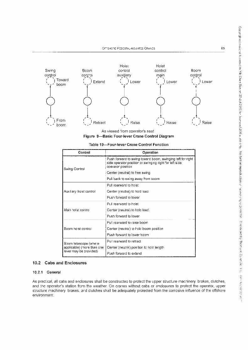
OFFSHORE PEDESTAL-MOUNTED CRANES 65
Hoist Hoist Swing Boom control control Boom control control au;ili~ry main control (' -'I Toward
,-, ,-, ,-, I
) Extend I
) Lower I
) Lower I
) Lower \ \ \ \ 'r boom '-
, '-
, '-
, '-
,
r r r I 0 0 0 0 0 J J J J J
: ) From I
) Retract I
) Raise I
) Raise I
) Raise '-" boom '- '- '- ,-
As viewed from operator's seat Figure 9-Basic Four-lever Crane Control Diagram
Table 19-Four-lever Crane Control Function
Control Operation
Push forward to swing toward boom, swinging left for right side operator position or swinging right for left side
Swing Control operator position
Center (neutral) to free swing
Pull back to swing away from boom
Pull rearward to hoist
Auxiliary hoist control Center (neutral) to hold load
Push forward to lower --
Pull rearward to hoist
Main hoist control Center (neutral) to hold load.
Push forward to lower
Pull rearward to raise boom
Boom hoist control Center (neutral) to hold boom position
Push forward to lower boom
Boom telescope (where Pull rearward to retract
applicable) (more than one Center (neutral) position to hold length lever may be provided)
Push forward to extend
10.2 Cabs and Enclosures
10.2.1 General
As practical, all cabs and enclosures shall be constructed to protect the upper structure machinery, brakes, clutches, and the operator's station from the weather. On cranes without cabs or enclosures to protect the operator, upper structure machinery, brakes, and clutches shall be adequately protected from the corrosive influence of the offshore environment.
0 0 D
~. (0 ::y
ro Q.
:3 ill
~. llJ. 0' (!) ::0 (f) (!) C>-
o ::; A
0 :::r' ill :::J (j) C :::J 0 :::J N -:" '--~ N 0
N
Q (") ill ::0 (f) (\) (\)
90
"" w (0
Ui c (f) (\)
0 ::0
-< Z 0
2' ;:::c :;:,-0; ro u 0 D-C
s:. is :::l
Q ::J (\)
~ Q E. :::J (0
V! D CD
~ m' Q
9 ~ 0" c ro Q.
CY '< --1 ::y 0 :3 (fJ 0 ::J
(f) Q
~ =c, ,::;i

66 API SPECIFICATION 2C
Table 20-Two-Lever Crane Control Function (Option 1)
Control Operation
Push to the left to swing left
Swing control Center (neutral) to free swing
Push to the right to reverse action or to swing right --
Boom telescope (where applicable) Pull rearward to retract
(more than one lever may be Center (neutral) to hold length
Boom control ,,-,
provided)
Auxiliary hoist
Boom control
Main hoist
: ) Extend
T o J
Swing control
: ) Retract ,_/
Swing left
Push forward to extend
Pull rearward to hoist
Center (neutral) to hold load
Push forward to lower
Pull rearward to raise boom
Center (neutral) to hold boom position
Push forward to lower boom
Push to the left to hoist
Center (neutral) to hold load
Push to the right to lower
Auxiliary hoist control
lower
Raise
Swing right Raise
As viewed from operator's seat
Boom control lower
Raise
Figure 10-Basic Two-Lever Crane Control Diagram (Option 1)
10.2.2 Windows
10.2.2.1 General
Main Lower hoist
control
All windows shall be of safety glass or equivalent. Windows shall be provided in the front and both sides of the operator's cab for visibility forward and to either side. Visibility forward shall include a vertical range adequate to cover the boom point and load at all times. The front window may have a section that can be readily removed or held open if desired. If the section is removable, storage space shall be provided. If the section is of the type held in the open position, it shall be secured to prevent inadvertent closure. The lower portion of the front window shall have a grating or other means to prevent the operator from falling through. If the cab is equipped with an overhead window, a grating or other protection should be placed over the window to prevent debris from falling on the operator.
z o
(D CL
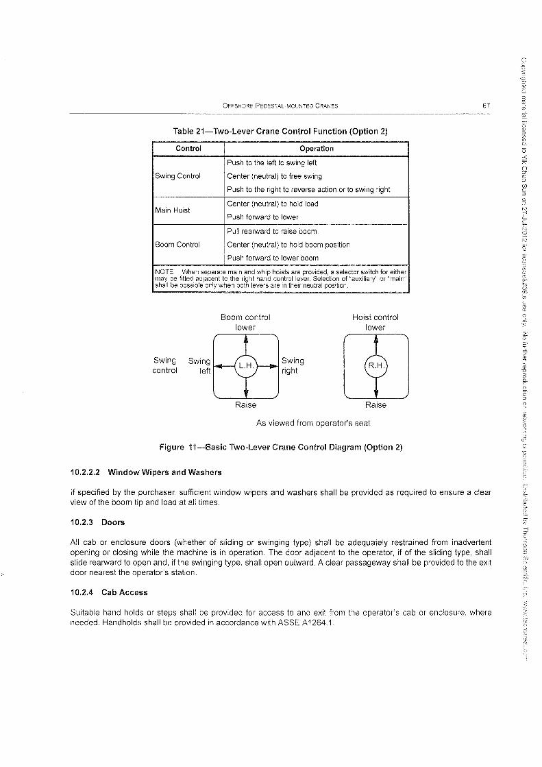
OFFSHORE PEDESTAL-MOUNTED CRANES
Table 21-Two-Lever Crane Control Function (Option 2)
Control Operation
Push to the left to swing left
Swing Control Center (neutral) to free swing
Push to the right to reverse action or to swing right
Main Hoist Center (neutral) to hold load
Push forward to lower
Pull rearward to raise boom.
Boom Control Center (neutral) to hold boom position
Push forward to lower boom
NOTE When separate main and whip hoists are provided, a selector switch for either may be fitted adjacent to the right hand control lever. Selection of "auxiliary" or "main" shall be possible only when both levers are in their neutral position.
Swing control
Swing left
Boom control lower
Raise
Swing right
Hoist control lower
Raise
As viewed from operator's seat
Figure ii-Basic Two-Lever Crane Control Diagram (Option 2)
10.2.2.2 Window Wipers and Washers
67
If specified by the purchaser, sufficient window wipers and washers shall be provided as required to ensure a clear view of the boom tip and load at all times.
10.2.3 Doors
All cab or enclosure doors (whether of sliding or swinging type) shall be adequately restrained from inadvertent opening or closing while the machine is in operation. The door adjacent to the operator, if of the sliding type, shall slide rearward to open and, if the swinging type, shall open outward. A clear passageway shall be provided to the exit door nearest the operator's station.
10.2.4 Cab Access
Suitable hand holds or steps shall be provided for access to and exit from the operator's cab or enclosure, where needed. Handholds shall be provided in accordance with ASSE A 1264.1.
N ';' 'c: ~ o N

68 API SPECIFICATION 2C
10.2.5 Platforms and Walkways
Principle walking surfaces shall be an anti-skid type, Outside platforms (if furnished) shall be provided with guardrails in accordance with ASSE A 1264.1. Two intermediate railings shall be provided in locations where toe boards are not required. All walkways and platforms used to reach operator's station shall have a minimum width of 30 in. (760 mm), unless otherwise specified by the purchaser.
10.2.6 Rigging Access
Where necessary for rigging or service requirements, a ladder or steps shall be provided for access and shall conform to the requirements of ALI A 14.3. Where necessary, areas of cab roof or enclosure shall be capable of supporting the weight of a 200-lb (90-kg) person without permanent deformation.
10.2.7 Noise Level
The permissible noise exposure to the crane operator at the crane operator station is:
T NE = 90 - 16.61 loglOg
where
NE is the permissible noise exposure, slow response dB(A), 95 dB maximum; and
T is the duration of exposure in hours or day, 4 hour minimum.
(36)
When the daily noise exposure is composed of two or more periods of noise exposure of different levels, their combined effect is limited by:
(37)
where
en is the total hours of exposure at a specified noise level; and
Tn is the total hours of exposure permitted at that level.
10.3 Miscellaneous Requirements and Equipment
10.3.1 Indicators, Alarms, and Limits
Table 22 provides definition of crane indicators, alarms, and limits. Some are mandatory; some are at the option of the purchaser.

OFFSHORE PEDESTAL-MOUNTED CRANES 69
Table 22-lndicators, Alarms, and Limits
Indicators, Alarms & Limits Ind ! Trip I
AA VA
Hydraulic system pump pressure X ! PO PO PO
Hydraulic oil temperature X PO PO PO
Hydraulic control system pressure (if applicable) X PO PO PO
Engine start system pressure (if applicable) X PO PO PO
Hydraulic fluid level (required on reservoir) PO ! PO PO PO
Engine lube oil pressure (if applicable) X PO PO PO
Engine coolant temperature (if applicable) X PO PO PO
Engine tachometer (if applicable) PO i PO PO PO I
Engine overspeed (if applicable) PO X PO PO
Fuel level (required on reservoir) (if applicable) PO PO PO PO -_._----_ .. -._"" '"~-- "-~~,,~-~--- ----
Hoist slack rope PO I PO PO PO
Hoist low hook limit PO PO PO PO
Wind speed PO PO PO PO
Hook speed and direction PO PO PO PO
Engine fire and smoke PO PO PO PO •• _-__ ._ •• 0"_ ••
Crane slew limits PO ! PO PO PO
Key
Ind = indicator, AA = audible alarm, X = mandatory, Trip = function limit, VA = visual alarm, PO = purchaser option
10.3.2 Boom Equipment
The following criteria apply to the boom.
10.3.2.1 Boom Angle Limiters and Shut-Off Devices
A boom hoist limiter or shut-off shall be provided to automatically stop the boom hoist when the boom reaches a predetermined high angle. An optional low-angle limiter or shut-off may also be provided.
10.3.2.2 Resistance to Falling Backward
Boom stops shall be provided to resist the boom falling backwards in a high wind or at sudden release of the load. Designs for boom stops include:
a) a fixed or telescoping bumper,
b) a shock-absorbing bumper, and
c) hydraulic boom elevation cylinder(s).
Auxiliary tips shall be restrained from overturning backward.
10.3.2.3 Marking and Labeling
Booms, boom sections, and auxiliary tips shall be permanently identified.
o o .'C
'3 (0 :::J"
ro n.
3
'" ~.
~ n (j) OJ if, (j) 0..
o -< T o ::0-(j) :J
(j) C :J o :0

70 API SPECIFICATION 2C
10.3.2.4 Boom and Load Indicators
Indicators shall be provided as specified in the following:
a) a boom-angle or radius indicator, readable from the operator's station shall be provided;
b) a boom-length indicator, readable from the operator's station shall be provided for telescoping booms, unless the load rating is independent of the load radius; and
c) a load indicator system (LIS) or load-moment indicator system (LMIS) shall be provided as shown in Table 23.
Table 23-Boom and Load Indicators
Crane Duty Cycle Classification Main Hook Auxiliary Hook
Production-unmanned platform Optional Optional
LIS or LMIS LIS or LMIS
Production-manned platform Required Optional
LIS or LMIS LIS or LMIS
Intermediate Required Optional
LIS or LMIS LIS or LMIS . ~---.. -~~.~ .. ~----~ ._- ------~ ... --.---"
Drilling Required Optional
LMIS LIS or LMIS .. _---_ ..... _-_. __ ... - 1--... _ .. . ---
Construction Required Optional
LMIS LIS or LMIS
Load Indicator Types:
LIS-Load Indicator System-provides crane operator with load indication only.
LMIS-Load·Moment Indicator System-provides crane operator an indication of hook load, load radius and crane SWL. System has audible and visual alarms. LMIS shall be programmed with all crane ratings (onboard, offboard, and personnel) that are presented on the Load Rating Charts located in the operator's cab for the hooks they monitor.
10.3.3 Guards for Moving Parts
10.3.3.1 General
Guards shall be provided in accordance with the requirements in 10.3.3.2 through 10.3.3.4.
10.3.3.2 Components to Guard
Exposed moving parts (i.e. gears, set screws, projecting keys, chains, chain sprockets, and reciprocating or rotating parts) that may constitute a hazard under normal operating conditions shall be guarded.
10.3.3.3 Guard Fasteners and Strength
Guards shall be securely fastened and shall be capable of supporting without permanent deformation, the weight of a 200 Ib (90 kg) person unless the guard is located where it is impossible to step on it.
(')
CD :::l
'" (1) 0.
0' -< "" o :y (1) :::J
(j)
§ o :::J N -;-' 'c ;::; o N
z o c
'4 :5 o 3 o o ::; (j) Q CD ;~.
fi

OFFSHORE PEDESTAL-MOUNTED CRANES 71
10.3.3.4 Warning Signs Instead of Guards
If a guard is impractical, it is the responsibility of the manufacturer to warn by means of an appropriate sign. This sign should be designed and installed in accordance with SAE J 115 or other appropriate standard specified by the purchaser, consistent with physical limitations on size and location.
10.3.4 Lubricating Points and Fluid Fills
10.3.4.1 General
Lubricating pOints on all parts shall be accessible without the necessity for removing guards or other parts.
10.3.4.2 Fluid Level Indicators
Fluid level indicators should follow the guidelines set forth in SAE J48.
10.3.4.3 Lubrication Charts, Symbols, and Codes
Lubrication charts shall be furnished by the manufacturer.
10.3.5 Hydraulic and Pneumatic Line Protection
Exposed lines subject to damage shall be protected as far as practical.
10.3.6 Anti Two-block
Means shall be provided to protect hoist ropes, structural components and machinery from damage that may occur when two sheave groups (e.g. load block and boom tip) come into contact as the hoist cable is drawn in. A control override device or proximity-warning device may be used. Stalling of the hoist drum is acceptable where damage or loss of control shall not result.
10.3.7 Emergency Load Lowering
Unless otherwise specified by the purchaser, load hoist drums shall be provided with a means of lowering in the event of power failure or control-system failures. Means shall provide controlled lowering and stopping of the drum under all load conditions. Boom luffing mechanisms do not require emergency load lowering capacity.
The controls shall be arranged in a manner that shall prevent inadvertent engagement. An alternate power source independent of the crane may be used. An instruction plate giving detailed instructions shall be provided at the operator's station for all procedures.
10.3.8 Miscellaneous Equipment
10.3.8.1 Toolbox
A toolbox may be provided for storing tools and lubricating equipment. If provided, it shall be secured permanently to the crane.
10.3.8.2 Hydraulic Circuit Pressures
Means shall be provided for checking the manufacturer's specified pressure settings in each hydraulic circuit.
N ';' '-c ;C o N
Q

72 API SPECIFICATION 2C
10.3.8.3 Hazardous Area Classification
10.3.8.3.1 Electrical components on the crane or remote power plants used in areas classified hazardous shall comply with the criteria in 7.5.4.
10.3.8.3.2 Components on the boom shall be rated for the most hazardous area that can be accessed by the boom.
10.3.8.3.3 The purchaser shall specify to the manufacturer the classification of the area in which the crane shall be installed.
10.3.8.3.4 The classification shall consider temporary uses of the area as well as permanently installed equipment.
10.3.8.4 Audible Warning Device
When specified by the purchaser, an audible signal device (horn) shall be provided for use as needed by the operator. The control(s) for the device shall be within easy reach of the operator at the operator's station.
10.3.8.5 Spillage Containment
To the extent that is practical, all machinery areas that are subject to liquid leakage shall be provided with a containment system. The containment area (well) shall have a minimum lip height of 2.0 in. (50 mm) and be provided with a means for draining. Government regulations should be reviewed for applicability.
11 Manufacturing Requirements
11.1 Material Requirements of Critical Components
11.1.1 General
To the extent possible, materials shall be purchased to specifications of recognized standardization organizations such as those listed in Section 2.
Materials used in the manufacture and fabrication of critical components of the crane shall comply with the manufacturer's design requirement specifications. The design requirement specifications shall define the following properties of metallic materials:
a) chemical composition limits;
b) heat treatment condition;
c) appropriate mechanical property limits (i.e. yield strength, tensile strength, elongation, fracture toughness and ductility).
Design requirement specifications shall detail the methods of testing to verify the specified properties are present in the as-manufactured or as-fabricated condition.
11.1.2 Traceability
Critical structural components shall only be produced from materials which have supporting documentation to verify the properties are as specified in the design and manufacturing requirements. Documentation of material origins shall be that of the basic producer in lieu of certifications prepared by third-party material suppliers. In the absence of supporting documentation, materials shall not be employed in fabrication until the manufacturer conducts or has conducted tests and examinations to verify compliance with design requirements.
(j) C ::l
o :0

OFFSHORE PEDESTAL-MOUNTED CRANES 73
Traceability of materials for critical components and parts shall be achieved through a systematic program of serialization and identification, indexed to process, inspection, and test records of controlled manufacturing procedures. The manufacturing procedures shall be in sufficiently written detail to permit duplication of the original processing at any time within the record retention period specified in 4.3.
11.1.3 Fracture Toughness
Unless explicitly set forth in this specification, materials for machinery (i.e. hoists, cylinders and sheaves) do not require fracture toughness testing.
Where specified, fracture toughness testing shall be conducted in accordance with ASTM E23, ASTM A370 or ISO 148-1.
11.1.4 Wire Rope
Refer to 7.2.2 and its sub-sections for wire rope requirements.
11.1.5 Structural Steels, Castings and Forgings
11.1.5.1 Fracture Toughness of Critical Compounds
The fracture toughness of primary elements of critical structural components shall meet the requirements of Table 24.
Alternately, fracture control plans considering toughness, allowable flaw size, and inspection requirements may be employed. If such fitness-for-purpose criteria are employed, details of the analysis shall be documented for examination on request by the purchaser.
Table 24-Level 1 Fracture Toughness
Mini.mum Specified I ~i~~~~~~~~. Maximum Test
Yield Strength I from three tests Temperature
0; 44 ksi I 20 ft-Ib 10 ° F below the lowest design
I service temperature
--
> 44 and 0; 60 ksi I 25 ft-Ib 10°F below the lowest design service temperature
> 60 ksi 25 ft-Ib 10°F below the lowest design service temperature
NOTE Minimum single value shall not be less than 2/3 of the required minimum average (based on longitudinal Charpy V-notch tests).
11.1.5.2 Lamellar Tearing Resistance of Plate
Critical structural elements fabricated from steel plate that transfer loads through the thickness or the short transverse dimension of the plate shall be ultrasonically inspected in accordance with ASTM A578/A578M, Acceptance Standard Level B. They shall be tested for resistance to lamellar tearing in accordance with the procedures and requirements of API 2H, Supplementary Requirement S-4, or ASTM A770/A770M.
11.1.5.3 Additional Requirements for Castings
11.1.5.3.1 Prototype Castings
The validity of the casting procedure for all critical component castings shall be verified by conducting examinations and tests on the first lot cast and each change in pattern design or pouring practice Destructive testing and
z o C ;::l
~
(j)

74 API SPECIFICATION 2C
radiographic examinations supplemented by other non-destructive examinations are considered appropriate for this purpose. If radiography is employed, the source of radiation for examination of casting sections less than 2.0 in. (50 mm) in thickness shall be from an x-ray generator or from Iridium 192 isotopes. The prototype evaluation shall demonstrate the ability of the casting procedure to consistently produce critical component casting soundness not less than the radiography standards of Table 25.
Table 25-Casting Acceptance Criteria Based on ASTM Radiographic Standards
ASTM Standard Type of Discontinuity
ASTM E446 ASTM E186 ASTM E280
Category A (gas porosity) Severity Level 3 Severity Level 2 Severity Level 2
Category B (sand and slag) Severity Level 2 Severity Level 2 Severity Level 2
Type CA, Level 2 Type 1, Level 1 Type 1, Level 1
Category C (shrinkage) Type CB, Level 2
Type 2, Level 2 Type 2, Level 1 Type CC, Level 1
Type 3, Level 1 Type 3, Level 1 Type CD, Level 1
NOTE All discontinuities in Categories D, E, F, and G are unacoeptable.
11.1.5.3.2 Production Castings
The method of nondestructive examination and the acceptance criteria for examination of the critical component production castings shall be established by the manufacturer. The manufacturer shall consider material properties, environmental exposure, and stress level(s) in critical areas of the casting. The extent of the examination shall be adequate to assure castings possess soundness adequate for the intended purpose (i.e. examine all critically stressed areas).
11.1.5.3.3 Thermal Treatment
All castings for critical components shall be subjected to a normalize and temper, quench and temper, or stress relief heat treatment after shake-out and cooling to ambient temperature. The tempering and stress relief temperatures employed shall be appropriate to the alloy content and strength level required of the component, but shall not be less than 1,100 of (593 °e).
11.1.6 Bolt Materials
The specific grade of material shall be selected to meet strength requirements and corrosion resistance of the service environment.
Fracture toughness of bolts joining critical structural components of the crane which are subject to tensile loading (other than pre-load) shall meet either ASTM A320 or Table 26.
Table 26-Level 2 Fracture Toughness
Minimum Avg. Energy Value
from three tests
30 ft-Ib
Maximum Test Temperature
Lesser of -4 of or 10°F below the lowest design service temperature
INOTE Minimum single value shall not be less than 2/3 of the required ~imum average (based on longitudinal Charpy V-notch tests).

OFFSHORE PEDESTAL-MOUNTED CRANES 75
11.1.7 Hook Block and Overhaul Ball
11.1.7.1 Load Hook Material
The hook material shall be alloy steel and produced as a forging or casting.
Fracture toughness of load hooks shall meet the requirements of Table 24.
11.1.7.2 Structural Steel
Structural steel members of hook block and overhaul ball assemblies shall meet the requirements for structural steel in Section 6 and Table 24.
11.1.7.3 Material for Added Weight
Cast iron material may be employed to add weight in overhaul balls, but not in load block assemblies.
11.1.8 Slew Ring Bearing Material
This section applies to swing circle bearings which are employed as the sole means of restraining separation of the pedestal and the crane. Steels for such swing circle rings shall be selected, tested, and verified as adequate to support the design loads of the crane.
11.1.8.1 Rolling Elements
Steels for rolling elements shall be produced to the minimum requirements of ASTM A295, ASTM A485 or ISO 683-17.
11.1.8.2 Cleanliness of Surface Hardened, Heat Treated Raceways
Cleanliness of swing circle ring steels shall conform to the requirements of ASTM E45, Method A, and to the limits in Table 27 or to DIN 50602 to the limit of K4 of 40 maximum. Alternately, where cleanliness does not meet the requirement, calculation methods shall account for an appropriate loss of service life due to anticipated inclusions.
Table 27-Bearing Ring Steel Cleanliness Limits
Inclusion Category
Series Type IJm
A B C D
Thin series 2.5 2.5 2.5 2.0
Thick series 1.5 1.5 2.0 1.5
11.1.8.3 Fracture Toughness of Raceways
Fracture toughness of raceways for swing circle bearings shall meet the requirements of Table 26.
Tests shall be conducted on a sample of the same cross sectional dimensions as the actual ring after heat treatment and shall exhibit the core hardness required of the finished part. Tests shall be conducted on a sample with the same degree offorming reduction and heat treatment as the ring forging. The length of the test bar shall be oriented parallel to the circumference of the ring. The test specimen shall be removed from the sample at a depth as near as possible to the area of the final ring configuration subjected to maximum calculated stress.
CT ,< -I J C ::J if; o ::J
(f) c

76 API SPECIFICATION 2C
11.1.8.4 Mechanical Properties of Raceways
The manufacturer of the swing circle bearing shall verify adequacy of the mechanical properties of the case and core of the raceways by either performing destructive testing of a representative sample for each prototype design or by performing non-destructive testing of the ring hardness and raceway case hardness depth on each production part.
The manufacturer of the swing circle bearing shall provide a report indicating the material properties required by the design analysis comparing the corresponding measured values for each production part and, where destructive testing of prototype design is employed, for each prototype test. The crane manufacturer shall review the bearing manufacturer's reports to assure each bearing to be employed on a crane complies with these requirements.
11.2 Welding of Critically Stressed Components
11.2.1 Standards
All welding procedures for joining structural load-bearing or load-transfer members of the crane and the performance of welders employing these procedures shall be qualified in accordance with a recognized standard (i.e. AWS 01.1).
11.2.2 Welding Procedures
A written procedure specification shall be prepared for all welding. Pre-qualified procedures as defined in AWS 01.1 are acceptable only for joining materials using the consumables, joint configurations, and procedure limits specified therein. Welding of materials or use of procedures other than those defined by the AWS specifications shall be qualified by testing a sample weld produced in accordance with a written procedure and tested in accordance with the standard used in 11.2.1.
11.2.3 Welder Performance
Performance of welders shall be verified by destructive testing or by radiographic examination. Radiographic examination shall be limited to groove welds using the shielded metal-arc, submerged-arc, gas tungsten-arc, gas metal-arc (globular arc, spray arc, or pulsating arc only) and flux-cored arc processes. Performance of welders employing short-circuiting (short-arc) gas metal arc welding processing shall be qualified by destructive testing only.
11.2.4 Welding Properties
The strength of welds in critical components shall meet the minimum specified design requirements of the materials being joined. Mechanical testing including Charpy testing shall be conducted during procedure qualification to verify that the required properties of the weld and heat-affected zones are attained by the controls outlined in the welding procedure specification.
11.2.5 Welding of Hardenable Swing Circle Raceways
This section applies to slew ring bearings which are employed as the sole means of restraining separation of the pedestal and the crane.
Where welding is performed on the ring after finished machining, the affect of distortion on the bearing service life shall be considered. Alternately, a transition piece of weldable steel may be provided in order to inhibit distortion and provide a weldable interface.
All welding on hardenable bearing rings for the attachment of the bearing to the pedestal, upper structure, or transition piece shall be performed in accordance with the bearing manufacturer's weld procedures. The weld procedures shall be qualified by testing in accordance with 11.2.4 and shall exhibit fracture toughness equivalent to the race base metal (see 11.1.8).
o -< ~:
Cl :0-CD
'" (j) C ::J
o '" tv ." L c: ;Z; o tv
~
z o
9 5 a c 2D Q.

OFFSHORE PEDESTAL-MOUNTED CRANES 77
Where welding is performed after heat treating of the bearing raceway, the weld between the hardenable steel and the weldable (structural) steel shall be subjected to stress relief heat treatment at a temperature not to exceed the tempering temperature employed in the heat treatment of the race.
The welds and transition piece shall be designed to meet the amplified load and strength requirements of the pedestal, 6.2, and the fatigue requirements of 6.4 considering the local stresses occurring due to load path and stress concentrations.
11.3 Nondestructive Examination of Critical Components
11.3.1 Nondestructive Examination Procedures
The manufacturer shall use written nondestructive examination procedures for the examination of critical components of the crane. The procedures shall consider the stage of manufacture in which the examination is to be performed, the accessibility to examination methods, and the configuration of the component to be examined. For ultrasonic examination of tubular members, the validity of the procedures shall be verified in accordance with API 2X or AWS01.1.
11.3.2 Nondestructive Examination Personnel Qualifications
All nondestructive examination personnel employed or contracted for by the manufacturer shall be qualified in accordance with ASNT SNT-TC-1A at Level II proficiency. For ultrasonic examination of tubular members, competency of personnel shall be verified in accordance with API 2X or AWS 01.1.
11.3.3 Minimum Extent of Nondestructive Examination
The manufacturer shall identify all critical components of the crane. These components shall be subjected to nondestructive examinations in accordance with a recognized workmanship standard or, at the option of the manufacturer, by a written examination procedure and acceptance criteria developed in a fitness-for-purpose fracture control plan. The extent of nondestructive examination of non-critical components is also the responsibility of the manufacturer.
11.3.4 Examples of Workmanship Standards
Table 28 provides examples of some recognized procedures for conducting nondestructive examinations and acceptance criteria representing workmanship standards. The manufacturer shall be responsible for developing a similar scheme (with appropriate acceptance criteria) from consideration of the specific crane design, criticality of the component, and applicable nondestructive examination methods. Acceptance criteria based on fitness-for-purpose evaluations shall consider applied and residual stresses, material properties, environmental exposure, and the limitations of the selected nondestructive examination method for detection and evaluation of imperfections.
12 Design Validation by Testing
12.1 Design Validation
12.1.1 General
The manufacturer shall certify that a prototype, design, or major structural revision to a design has been tested in accordance with either sections 12.1.2 or 12.1.3.
Testing shall be used to validate the design method. The intent is to validate the overall design calculation procedure's accuracy and completeness. This shall be accomplished either by performing a strain-gauged load test to the onboard factored load (FL) or by performing a "heavy lift" test to 2.0 times the onboard SWLH. The test loads to
(") (l) ::J
'" (l) (l)
"" 'let w CD if, C
'" (l)
o ::J
~ z o
9 S u c (i) 0.
U '< -I ::r '2 a o :J

78 API SPECIFICATION 2C
Table 28-Workmanship Standard Examples
Inspection Method I
Detectable I Acceptance Criteria I Applies to Applications
and Standard ! Discontinuities
(VT) Visual AWS 01.12010
P, SI, UC, CR, lAM
AWS 01.1:2010 Surface and marginally for: All surfaces Table 6.1
I IF, IJP, Ol Section 6.9
(PT) Liquid penetrant AWS 01.1:2010 i Surface P, SI, UC, Ol, CR,
Nonferrous metals ASTM E165 Table 6.1 (Visual) LAM
(MT) Magnetic particle lAWS 01.12010 Ol, CR, LAM
Surface and near and marginally for: Fillet welds, welds less than
ASTM E709 Table 6.1 (Visual) surface 3/8 in.
I I P, SI, IF, IJP, UC
(RT) Radiographic iAWS 01.1:2010 i Tubular
P, SI, IJP, UC, i Section 6.12.1 i connection Full penetration connections
i where accessible and where AWS 01.12010
I
I Non-tubular and marginally for: a permanent record is
Inspection Part E lAWS 01.1 :2010
IF, CR desired. ! Section 6.12.2 : connections
I
lAWS 01.1:2010 i
(UT) Ultrasonic ! Non-tubular
IF, IJP, CR, LAM ! Section 6.13.2 ! connections Full and partial penetration
AWS 01.12010 I and marginally for: connections 3/8 in. and
Inspection Part F lAWS 01.1:2010 I Tubular P, SI, UC, Ol
greater. i
I connections I Section 6.13.3 1-- I -- -_ .. __ ._--------_._--
! : ------~ .... ~----
LAM (UT) Ultrasonic
i ASTM A578 level B i lamellar
Rolled plates loaded in
i discontinuities and marginally for: tension in the through
ASTM A578 thickness direction. I P, SI,
Key
P = porosity, SI =slag inclusion, IF = incomplete fusion, IJP = incomplete joint penetration, UC = undercut, OL = overlap, CR = cracks, LAM = laminations
NOTE See Table 26 for castings.
provide maximum conditions shall be chosen to test maximum axial thrust condition (maximum rated load at largest associated radius) and maximum overturning moment condition (maximum live overturning moment). Test loads shall be lifted on the main block and the auxiliary line (if provided). The results of the test shall prove the design adequacy either by review of measured stresses in the gauged test or by absence of measurable deformation, cracking, or damage in the heavy lift test.
12.1.2 Resistance-type Strain Gauge Test
This test shall be performed with the crane subjected to the onboard factored load FL conditions with a side load equal to 2 % of the FL load lifted. Strain gauges shall be placed in locations to verify that the uniform stress levels in the crane major components are as established in the deSign calculations. Strain gauges shall also be placed in areas of peak stresses (transitions and connections) to verify that peak stress levels are acceptable. Deflection of the boom due to sideload shall be measured and limited to 24 in.l100 ft of boom length. Test loads and boom lengths shall be selected to produce maximum stress levels in all critical structural components.
Care shall be taken to obtain the zero reference reading for the strain gauges with near zero stress levels in the components. This is particularly critical in long boom lengths and other components where dead weight loading is significant. For long boom lengths, multiple support points shall be provided to minimize boom dead weight effects
-< x o :::r (lJ :J
UJ C ::J
o ::J
N ~ '-c ~ o N
~

OFFSHORE PEDESTAL-MOUNTED CRANES 79
while zeroing the strain gauges. The crane should be exercised by lifting loads prior to strain gauging to allow breakin of the components.
Stresses in different parts of the crane structure shall be measured and evaluated to the following criteria:
a) Uniform stress regions are areas of near-uniform stress where exceeding the yield strength shall produce permanent deformation of the member as a whole. In uniform stress regions, a minimum strength margin of 1.5 is required, where a strength margin is computed as the minimum specified member yield strength divided by the measured gauge stress.
b) Groups of gauges shall be placed in uniform stress regions of main members such that their stresses may be combined to determine the member primary axial and bending stress. These shall then be compared to design calculations to verify member stress levels are as predicted. Groups of gauges shall typically be placed to verify boom primary axial and bending stress, gantry leg axial stress, and in any other region where primary axial and bending stress were calculated during design.
c) Peak stress regions are small areas of high stress surrounded by larger areas of considerably lower stress where exceeding the yield strength shall not produce permanent deformation of the member as a whole. Strain gauges in the peak stress location should have a minimum strength margin (minimum specified yield strength divided by measured gauge stress) of 1.1.
12.1.3 Heavy Lift Load Test
This test shall consist of lifting 2.0 times the onboard SWLH with a corresponding sideload equal to 4 % of the SWLH load. Test loads and boom lengths shall be selected to produce maximum stress levels in all critical structural components. Following the lifts, the crane shall be completely disassembled, including the swing-circle assembly, and subjected to a complete fitness-for-purpose evaluation using an appropriate method of inspection (depending on the component) chosen from the following:
dye penetrant;
magnetic particle;
radiographic;
ultrasonic.
The acceptability criteria for this test shall be that no critical components exhibit any yielding, buckling, indentations, or surface cracks. Special attention shall be given to bolted and welded connections. Measurements and inspections shall be completed before and after the test to determine any differences in condition of critical components. An accompanying requirement of the test shall be that computed stresses under the test loads specified above shall not exceed the AISC allowable unit stresses increased by one-third (referenced in 6.1).
12.2 Certification
The purchaser shall have confidential access to the manufacturer's documentation of the results of the selected method of testing. The manufacturer shall certify that the design of the crane furnished has been validated in accordance with this specification.
12.3 Operational Tests
In addition to the prototype test and quality control measures established by this specification, each new production crane (at the option of the purchaser) shall be tested by the manufacturer. The purchaser (or his designated
o =>
o (j;"
u c CD (l
o '<

80 API SPECIFICATION 2C
representative) may witness the test. This test procedure, as agreed upon between purchaser and manufacturer, is intended to verify safety systems as well as operational systems at rated capacity and full speed.
13 Marking
Offshore cranes that meet all the requirements of this specification shall have a permanent nameplate of stainless steel or other metallic material of equal corrosion resistance in a marine environment affixed to the structure in a conspicuous location protected from damage and disfigurement. The nameplate shall provide the date manufactured, manufacturer's model number, design service temperature, manufacturer's serial number, and manufacturer's identification. The nameplate shall also identify the quality program used during the crane manufacture as "Produced under quality program." The required information shall be imprinted in legible raised or stamped lettering not less than 1/8 in. (4 mm) high.
Manufacturers holding a Monogram License from API may apply the API Monogram to the nameplate as shown in Annex C. In order for a crane to receive the API monogram, it shall meet all the requirements of this specification. For information on the API Monogram, see Annex C.
o o
D
'=i <E
o :J -<

Annex A (informative)
Example List of Critical Components 9
A.1 General
Annex A contains an example list of some, but not all components of a crane that may be classified as "critical" by the definition in 3.1. The designer and manufacturer of each crane shall be responsible for developing a complete list of critical components for each individual design. See Figure 1 and Table 1 for nomenclature.
A.2 Critical Mechanical Components
All linkage between the brake control element and the component to be controlled.
Hoist and slewing brake systems.
Drums, shafts, and gears of hoisting and slewing systems.
Swing circle assembly.
A.3 Critical Structural Components
Fasteners in the critical load path of all critical components.
Boom chord members.
Boom section connection components.
Boom heel pins.
Boom jib section and connection components.
Primary load members of gantries, masts, and A-frames.
Load transfer members of the rotating upper structure including fasteners.
Kingposts.
Pedestals and swing-circle transition pieces.
A.4 Critical Rigging Components
All running wire ropes in hoist systems.
All standing wire ropes in load restraint and support systems.
9 This Annex is merely examples for illustration purposes only. Each company should develop its own approach. They are not to be considered exclusive or exhaustive in nature. API makes no warranties, express or implied for reliance on or any omissions from the information contained in this document
81
9 ~.
f m o. o· .< ..{ :::; o ::; U) o .J

82
Hook block assembly.
Overhaul ball or weight assembly.
Wire rope dead-end connection devices.
Bridle assemblies.
Wire line sheaves and sheave shafts.
API SPECIFICATION 2C
N
~ 'c N o N
Q

Annex B (informative)
Commentary
NOTE The paragraph numbering of Annex B corresponds to the text of this specification. For example, B.5.4, titled "In-service Loads," corresponds to 5.4 of this specification, titled "In-service Loads."
B.1 Scope
API 2C is to be used to provide a consistent basis for ratings of new pedestal cranes that are to be purchased to the requirements of the specification. Figure 1 shows some of the common crane configurations developed under this specification; but Figure 1 is not intended to limit or define development of any other pedestal-mounted crane configuration satisfying the requirements of this document.
B.4.2 Purchaser-supplied Information
As the variety of types of offshore installations and vessels increases, more and more information is required from the purchaser in order to define the crane's intended service conditions and allow the manufacturer to establish safe working loads for the crane. Is the crane to be installed on a floating platform or vessel, and if so, which type (to determine the potential crane motions)? Is the crane to be used on an unmanned production platform with sporadic use or for drilling with heavy continuous service? Careful answers to these questions and others help the purchaser to obtain a crane that suits his needs and one that shall have acceptable maintenance and downtime levels for the duty cycle at which the crane is operated.
B.5.4 In-service Loads
The load rating system for pedestal-mounted cranes addresses the unique problems of these machines. Because they are attached to a rigid base, pedestal cranes are susceptible to operational overloads during on-platform use (instead of tipping when overloaded like mobile land cranes). In addition, the high-speed hoisting capabilities required for offboard operations increase the impact potential during onboard lifts.
The minimum vertical dynamic factor of 1.1 to 1.33 as defined in this specification is intended to apply to onboard lifts with a crane mounted to a bottom-supported structure and to ship and barge lifts in calm water (construction type lifts under controlled conditions). The equation for onboard lift Cy's provides a 1.33 factor for lifts of 50,000 pounds and smaller. This provides similar factors to those specified in the past for bottom-supported structures and normal working loads « 50,000 Ib). For larger loads (i.e. occasional construction lifts or heavy lifts), the factor is reduced in recognition that these lifts shall be done in calm conditions with more attention than the smaller everyday onboard lifts. Somewhat higher minimum vertical dynamic factors are defined for floating structures depending on their size and tendency to exhibit significant listing or wave-induced motion. Ratings for cranes on floating platforms and vessels shall include the effects of crane vessel dynamic motion and vessel static angles (list or trim). These effects shall affect the Cy vertical design factor as well as offlead and sidelead forces.
Treatment of dynamic effects in this specification represents the committee's efforts to establish crane ratings that minimize the probability of failure in a dynamic environment. The committee carefully studied the state of the art in structural dynamics analysis and found that sophisticated theoretical modeling techniques exist in the literature. However, it is obvious that dynamic load charts produced from the most sophisticated computational methods available shall be of no mOl"e value to an offshore crane operator than one generated from simplified assumptions, since the operator shall react to rapidly changing environmental conditions. For this reason and others, the single degree-of-freedom (OOF) mathematical model was adopted. Although the rating method adopted here shall make offshore crane lifts safer, it has no provisions for dealing with extreme dynamic overloads (i.e. accidental connection to a supply vessel or stopping a falling load). Such overloads can be unbounded and cannot be computationally
83

84 API SPECIFICATION 2C
incorporated into a rating chart. The possibility of these overloads exist and shall be addressed in accordance with Section 9.
In-service loads include vertical design loads (SWLH times a design factor), horizontal loads (offiead and sidelead), and environmental loads (typically wind). Three methods are given to determine the loads acting on a crane.
B.5.4.2 Vessel-specific Method
For floating crane installations, the vessel-specific method is the preferred method. It includes the effects of boom tip motions for the specific vessel the crane is installed on. Vessel motions analysis should be used by the purchaser or his representative to predict boom tip motions, velocities, and accelerations with the boom at typical offboard lift location(s). These motions may then be used to develop Vc and horizontal boom tip accelerations for specific seastates.
B.5.4.3 General Method
The general method is used for both bottom-supported structures and floating crane installations. For bottomsupported structures, it results in similar design factors as in the previous editions of this specification. For floating crane installations where vessel-specific motions and loadings are not known, it provides the best alternative method. The dynamic accelerations and loads presented for floating crane installations in the general method were determined based on studies of crane motions on various representative vessels of each type (TLPs, spars, and drillships). Table B.1 summarizes the general sizes and types of vessels from which the motions were developed. The resulting floating crane vessel design accelerations in the specification provide representative levels of loading for the various types of vessels. However, there is no guarantee that these loadings are appropriate or adequate for a given floating crane installation. The best crane ratings for a given installation shall be determined using the vessel-specific approach with motions and information for the crane locations on that particular vessel.
Table B.1-General Method-Vessel Information
Type of Floating Crane Length by Width of Approximate Vessel
Installation Representative Installations Displacement ft tons
Tension leg platforms 150 x 150 to 300 x 300 12,000 - 27,000 --- -. ~- ~--.--- -------------.- - . - .. ~--- - ---~----.~---.-~.---------
Spars 90 to 130 120,000 - 240,000 ..
Semi-submersibles 200 x 260 to 280 x 400 30,000 - 65,000 .~.--.~------_.
Drillships & FPSOs 75 x 500 to 200 x 900 70,000 - 220,000
NOTE 1 ton = 2000 lb.
Table B.2 provides sample calculations of the various design values for the general method versus significant wave height.
B.5.4.4 Legacy Dynamic Method
The third method for establishing a dynamic coefficient (as described in 5A) is adoption of a uniform factor for all offboard lifts. This provides substantial operational advantages in simplifying rating charts and their use. The dynamic coefficient shall be large enough to account for the most severe operating sea conditions, yet not substantially hamper crane capabilities in normal use. Therefore, this method is reasonable only in areas where mild sea conditions predominate (i.e. the Gulf of Mexico). A rating system of this type using a dynamic coefficient of 2.0 with zero offiead, 2 % sidelead, and zero wind speed has been used in the Gulf of Mexico with good results for bottomsupported platform cranes using tethered boat conditions. This legacy method is only for bottom-supported structures in areas with mild sea and wind conditions. It is not to be used for a crane mounted on a floating structure.
N -;--' '-c ;C; o N
z o
(?5
~J
S a c CD Q.

OFFSHORE PEDESTAL-MOUNTED CRANES 85
Table B.2-General Method Sample Design Value Calculations TLP and Spar
Table 2 Table 4 Dynamic
Hsig H sig Offboard Vc Table 2 Av Equation 7 Horizontal
m ft ftls Onboard Cv Acceleration 9
0.00 0.00 0.00 0.D7 1.38 0.03
1.00 3.28 0.16 0.D7 1.38 0.03
2.00 6.56 0.33 0.07 1.38 0.05
3.00 9.84 0.49 0.07 1.38 0.07
4.00 13.12 0.66 0.07 1.38 0.09
5.00 16.40 0.82 0.07 1.38 0.11
6.00 19.69 0.98 om 1.38 0.14
Semi-submersible
0.00 0.00 0.00 0.07 1.38 0.03
1.00 3.28 0.27 0.D7 1.38 0.03
2.00 6.56 1.08 0.07 1.38 0.05
3.00 9.84 2.42 0.07 1.38 0.07
4.00 13.12 4.31 0.12 1.43 0.09
5.00 16.40 6.73 0.19 1.50 0.11
6.00 19.69 9.69 0.27 1.58 0.14
Drillship, FPSO
0.00 0.00 0.00 0.07 1.38 0.03
1.00 3.28 0.54 0.07 1.38 0.04
2.00 6.56 2.15 0.07 1.38 0.08
3.00 9.84 4.84 0.12 1.43 0.12
4.00 13.12 8.61 0.21 1.52 0.17
5.00 16.40 13.45 0.32 1.63 0.22
6.00 19.69 19.38 0.47 1.77 0.27
NOTE Assumes SWLH = 75,000 Ib (affects onboard C v calculation).
B.5.4.5 Vertical Factored Loads
General
Calculation of the vertical dynamic coefficient Cv is based on a single degree of freedom (OOF) mathematical model. Although multiple OOF models have demonstrated enhanced ability to predict stresses in crane components, the single OOF model should adequately predict effects on the crane foundation. While stresses in the boom and other components are important for establishing service life, the primary safety concern lies in foundation stresses that may lead to a separation failure. Thus, a simple single OOF model has been chosen. The formula for tv works for platform mounted cranes as well as floating cranes. The r 'c term provides the motion of the crane boom tip to be combined with that caused by the supply boat (given by r'd)' Since these two velocities occur randomly with respect to each other, they are combined by means of the square root of the sum of the squares.
Cl 0 'U
3. t§-ill 0.
'3 ill
~ 91.. ('; ((J OJ if> rv 0.
0 -< T Cl ::J' <1l ::J
(j) C ::J
0 OJ
N -.; L c ;S ':: N
~ ('; (l) ::J if, (l) (l)
90 'It GO co Oi c '" (l)
0 ::J
~ Z 0
c' S. '.t; ro u (3 o. c g. 0 ::J
Q ::J ((J
:'; Q x 5
I.D
if, 'C
§ g. (D" 0,
C;:J
5 v c roO II 0' '< -I ::J' 0
~ Q

86 API SPECIFICATION 2C
The dynamic load on the crane is definitely a function of the crane stiffness. The stiffer the crane; the larger the dynamic loading. The stiffness value K in Equation 2 is meant to describe the amount of vertical displacement of the hook block that shall occur for a given load application (Ib/ft). It is calculated by accounting for the combined flexibility of the loadline, boomline, pendants, boom, and kingpost or pedestal. It should be calculated with the hook block at sea level where the supply boat lift shall be made. The crane stiffness may vary considerably with radius.
Wire rope stiffness is typically the major contributor to crane flexibility. In the absence of wire rope manufacturer's information, the wire rope modulus of elasticity may be taken as 75,000 N/mm2 (10.9 million psi) based on a crosssectional area equal to 0.48 times the nominal rope diameter squared. This is reasonable for most independent core wire rope types commonly used for offshore cranes, but should not take the place of more accurate manufacturer's information.
Minimum Hoist Velocity
The minimum hoist velocity specified by Equation 6 is intended to keep the load from re-contacting the supply vessel on the next wave crest. Table B.3 summarizes these velocities for various significant wave heights. This is the hoist velocity that should be available at water level where the supply boat lift is being made, accounting for number of layers of wire rope on the winch. Offboard load charts should not be made for conditions where the available hoisting velocity is less than that calculated by Equation 6.
Table B.3-Minimum Required Hook Speeds at Supply Boat Deck vs. Significant Wave Height
Hsig J.J,min Hsig Vhmin ft ftlmin m m/min
0 2.0 0 0.6
0.5 6.5 0.15 2.0
1 11.0 0.30 3.3
2 20.0 0.61 6.1 ~~ -.-.. -~--~------------- -_._ ... ... .....
3 29.0 0.91 8.8
4 38.0 I 1.22 11.6
5 47.0 1.52 I 14.3
6 55.8 1.83 I 17.0
9 73.8 2.74 22.5
12 91.8 3.66 28.0
15 109.8 4.57 33.5
18 127.8 5A9 39.0
B.5.4.6.2 Offlead and Sidelead Due to Supply Boat Motion (SB Forces)
The code is being expanded to include applications (i.e. shipboard cranes and folding or articulating booms). Although the format has been changed, the radial offiead load is the same as the previous edition with the exception that a limiting value has been added. Previously, for cases where the boom tip elevation approaches the work boat deck, the value shall become unbounded. It is expected that in such cases (i.e. tethering of the work boat, dynamic positioning, or careful control by boat skippers) precautions shall prevent excessive offiead. Additionally, it is presumed that, should extreme offiead angles occur, it is expected to be limited to the friction associated with the load sliding on the workboat deck.
It continues to be assumed that the sidelead force is half the offlead force.
o -< T () :;;;(1)
OJ
(j) C ::J
o :0
'" -;-' <.... C
~ o
'"
--, :.:y o :3 >." o :J

OFFSHORE PEDESTAL-MOUNTED CRANES 87
8.5.4.6.3 Loads Due to Crane Inclinations
The crane static inclination angles given in Table 5 represent reasonable operating limits for the various types of installations. In the past, some references have given static angles well past these and well past any reasonable operating condition. The intent was to strengthen the crane against unspecified dynamic loads by means of overdesigning for the static inclinations. With the addition in this specification of reasonable crane vessel dynamic load specifications, the previous conservatism in static inclination angles is not required.
8.5.6.1 Wind
The wind velocity is calculated from the Pierson-Moskowitz spectrum based on a fully developed sea at a height of 10m (32.8 ft) above the surface of the sea.
8.6.1 General
The 1989 version of the AISC specification (AISC 335-89) is specifically chosen for use as an allowable stress design specification. This can be downloaded from the AISC website (www.aisc.org). Research is being conducted by API to incorporate the strength provisions of the new AISC LRFD code into future offshore design practices.
In applying the AISC specification to cranes specifically, the design engineer is faced with making certain interpretations regarding functional differences of certain structural members on cranes compared to their counterpart in a building. This is particularly true for the boom in regard to allowable compressive stresses, which AISC expresses in terms of effective length factor (Keb) for elastic buckling.
The numerical value of Keb is appropriately left to the design engineer, but, not without a sound engineering basis. For cranes with boom lines attached at the boom tip, the factor for buckling in the vertical plane is Keb = 1.0. For buckling out of the vertical plane, the conservative assumption is Keb = 2.0 (for a "flagpole"). However, an assumed value of Keb
= 2.0 for out-of-plane buckling can be overly conservative, especially for long booms. The correct effective length factor can be computed, but not in a simple or direct manner, as it is a function of resistance to side load from the high-tension lines (pendants and boomlines), and this resistance increases with increasing load lifted. The procedure is generally implemented with the aid of a computer; and as a result, design curves are not readily available. Also required in the calculation of Keb for the overall boom, is the calculation of an average moment of inertia required in arriving at a radius of gyration for use in AISC. Methods for calculating average moment of inertia of a laced column are available in the literature. Effective length factors of individual boom components (i.e. unbraced portions of chords and lacing members) shall also be considered. Here again the design engineer can choose conservative values or he can perform buckling analyses (using finite element models) of the chord and lacing structural system. This type of analysis (finite element) is necessary to properly employ AISC for booms with lacing not meeting the requirements of AISC E.4 which reads as follows:
"Lacing, including flat bars, angles, channels, or other shapes employed as lacing, shall be so spaced that the ratio IIr of the flange included between their connections shall not exceed 3/4 times the governing ratio for the member as a whole. Lacing shall be proportioned to resist a shearing stress normal to the axis of the member equal to 2 % of the total compressive stress in the member. The ratio Ilr for lacing bars arranged in single systems shall not exceed 140. For double lacing, this ratio shall not exceed 200. Double lacing bars shall be joined at their intersections. For lacing bars in compression, the unsupported length of the lacing bar shall be taken as the distance between fasteners or welds connecting it to the components of the built-up member for single lacing, and 70 % of that distance for double lacing. The inclination of lacing bars to the axis of the member preferably shall be no less than 60° for single lacing and 45° for double lacing. When the distance between the lines of fasteners or welds in the flanges is more than 15 in., the lacing preferably shall be double or be made of angles."
Gantries and A-frames should also be analyzed with regard to bending moments occurring at the braces. This is generally achieved with the use of finite element models.
o ({) :J (f) ({) ({)
'" 'l-Io w co Ui c '" ({)
o :J
-<
(j)
"

88 API SPECIFICATION 2C
8.6.2 Pedestal, Kingpost, and Crane Supporting Foundation
The scope of this edition of API 2C has been expanded to include heavy lift crane applications in addition to traditional offshore oil exploration and production applications. With the inclusion of heavy lift applications, it became necessary to include provisions for lower pedestal design factors historically associated with heavy lift cranes.
Therefore, the API 2C task group adopted a sliding scale method to determine pedestal design factors. At lower loads to 50,000 Ib, pedestal factors are the same as in previous editions of API 2C. At higher loads greater than about 320,000 Ib, pedestal design factors are similar to that used by DNV, ABS, and LR for heavy lift applications. The sliding pedestal factor scale is used for loads between 50,000 Ib and 320,000 Ib as shown in Figure B.1.
1.6
1.5
E\:1.4 s-o U ~ 1.3
ro (j) (!)
a5 1.2 Cl.
1.1
1.0
f--.
o
"' ~ '" ~ ........ '" ......... 50,000 100,000 150,000 200,000 250,000 300,000 350,000 400,000
SWLH (Ibs)
Figure B.1-Variable Pedestal Factor
8.6.4 Structural Fatigue
The API 2C editions prior to the 7th edition required fatigue life calculations to be assessed based on 25,000 cycles of the onboard factored design load (1.33 times SWLH). Compared to heavy usage cranes (i.e. defined by the drilling duty cycle herein), this number of design cycles was extremely low. However, the high load (1.33 past the maximum that should be lifted in service) effectively made up for the low number of cycles that were chosen. Based in part on the duty cycle data obtained by the committee and in an effort to clear up the confusion, the requirement was changed to 1,000,000 cycles of 50 % of the onboard rated load. This new requirement should result in approximately similar fatigue design requirements due to the nature of fatigue damage. Most structural fatigue curves decrease the number of allowable cycles based on increasing stress raised to an exponent of between 3 and 4. If a fatigue curve exponent of about 3.7 is assumed, the accumulated damage from 25,000 cycles of 133 % rated load should be the same as the accumulated fatigue damage from 1,000,000 cycles of 50 % rated load.
This fatigue requirement, chosen as a minimum, is not to be construed as representative for all offshore cranes, but rather as the lowest acceptable number of cycles to be used for design. Therefor'e, it remains the responsibility of each crane manufacturer to design their product in accordance with its expected usage, and of each crane purchaser to inform the manufacturer of any special requirements regarding duty cycle.
(f) C ::J
o ::J
N co 'c ;:s o
'"

OFFSHORE PEDESTAL-MOUNTED CRANES 89
B.7.1 Machinery and Wire Rope Duty Cycles
B.7.1.1 General
Historically, most offshore cranes designed in accordance with API 2C outlive the platforms on which they are placed. Often they are reconditioned and re-used on a different facility, and their machinery components are typically overhauled and wire rope changed a number of times during the life of the crane. The frequency of the periodic machinery overhauls and wire rope replacements depends on the magnitude of loading, the hours of usage, and harshness of the operating environment.
Therefore, the theoretical design life of the structure is considerably longer than that of the machinery and wire rope. Machinery and wire rope design life should be based on reasonable repair or replacement intervals, consistent with the duty cycle, or specific frequency and magnitude of lifted loads during the expected life of the crane.
B.7.1.2 Machinery Duty Cycles
The preferred basis of the theoretical design life analysis of the crane components is to use a purchaser-projected duty-cycle.
Since many purchasers do not have projected duty cycle information to provide to the crane manufacturer, the API 2C task group collected statistical usage data from actual cranes from a wide variety of end user and facility types. Because of significantly different magnitudes of usage for offshore pedestal-mounted cranes in the petroleum industry, it became readily apparent that a categorical approach was necessary to differentiate the various types of usage. The Production, Intermediate, Drilling, and Construction Duty Classification categories are representative of the statistical data collected. The purchaser should choose which classification applies based on that closest to the anticipated level of annual usage.
A five-year time between overhaul (TBO) for the machinery was selected to provide a favorable balance between cost, maintenance, and life of machinery in relation to the crane structure.
The expected duty cycle life (TBO) of the primary machinery components is determined from the frequency of use in hours (class of utilization) and the magnitude of loading (load spectrum) during the TBO in years. The duty cycle life of the individual components is determined from the maximum allowable load on each crane component based on the component rating without regard to the capacity of the crane as a whole.
For example, to check duty cycle life of a 30,000 Ib rated auxiliary hoist on an intermediate duty crane, Table 8 indicates that the auxiliary hoist machinery shall have a calculated life of at least 825 hr at 45 % maximum torque when operating at 70 % of maximum speed. The correct procedure is to check the auxiliary hoist component life based on the maximum torque produced at 45 % of the auxiliary rating (13,500 Ib), not the overall crane SWLH.
ISO Equivalents - Regardless of API 2C duty cycle classification, the minimum requirement for all API 2C cranes is that the overall crane structure as a whole be designed for a utilization of 1,000,000 cycles with a load spectrum corresponding to 50 % of maximum SWLH. The equivalent ISO 4301-1 class of utilization, load spectrum and group classification is provided in Table BA.
Table BA-Crane Structures
Crane Duty- Cycle Theoretical I % Max Class of I
Load
i Group I
Classification Design Cycles I
SWLH Utilization I Spectrum Classification I All API2C I I
I I
crane duty
I
1,000,000
I
50 % U6 I Q1 A5 classifications I I
I I
(j) C :l
o :l
tv ~ 'c !:; o tv
~
(i) o.

90 API SPECIFICATION 2C
The API 2C duty cycle classifications provide guidance for the hours of utilization and the load spectrum for the selection or design of the primary machinery components based on a five-year overhaul period. The equivalent ISO 4301-1 class of utilization, load spectrum and group classifications for the various API 2C duty cycle classes are provided in Table B.5 through Table B.9.
Table B.S-Auxiliary Hoist - Five Year TBO
Crane Duty Cycle Theoretical % Max Class of Load Group Classification Design Life Torque Utilization Spectrum Classification
Production duty 60 hr 45% TO L1 < M1
Intermediate duty 825 hr 45% T3 L1 M2
Drilling duty 2,100 hr 55% T4 L2 M4
Construction duty 250 hr 45 % T1 L1 I
M1
Table B.6-Main Hoist - Five Year TBO
Crane Duty Cycle I Theoretical % Max Class of Load Group Classification Design Life Torque Utilization Spectrum Classification
Production duty 70 hr 45 % TO L1 < M1 --
Intermediate duty 225 hr 45% T1 L1 M1
Drilling duty 500 hr 55% T2 L2 M2
Construction duty 250 hr 45% T1 L1 M1
Table B.7-Boom Hoist - Five Year TBO
Crane Duty Cycle Theoretical % Max Class of Load I Group Classification Design Life Torque Utilization Spectrum Classification
I I Production duty
I 70 hr 45 % I TO L1 < M1
I I
Intermediate duty 1,250 hr 45% T3 L1 M2 1--- --f--Drilling duty 3,750 hr 55 % T5 L2 M5
-- ---------
Construction duty 900 hr 45% T3 L1 M2
Table B.S-Slew Mechanism - Five Year TBO
Crane Duty Cycle Theoretical % Max Class of I Load Group Classification Design Life Torque Utilization I Spectrum Classification
Production duty 70 hr 45 % TO L1 < M1 f-- -~----- .~-"
Intermediate duty 900 hr 45 % T3 L1 M2
Drilling duty 2,500 hr L2 M4 ------ ,----
Construction duty 300 hr I
45% T1 L1 M1
(/.'
en Q.
~

OFFSHORE PEDESTAL-MOUNTED CRANES 91
Table B.9-Prime Mover and Pump Drive - Five Year TBO
Crane Duty Cycle Theoretical %Max Class of Load Group Classification Design Life HP Utilization Spectrum Classification
Production duty 1,000 hr 45 % T3 L1 M2
Intermediate duty 10,000hr 60% T6 L2 M6
Drilling duty 25,000 hr 60 % T7 L2 M7
Construction duty 5,000 hr 60 % T5 L2 M5
B.7.1.3 Wire Rope Duty Cycle by Crane Classification
Wire ropes are considered to be expendable items and should be replaced many times over the service life of the crane. Times between replacement (TBRs) in years for the duty classifications defined in 7.1.2.1 are shown in 7.1.3.1, Table 13 and are representative of the statistical data collected. The duty cycles derived from these (TBRs) are shown in 7.1.3.2, Table 14, Table 15, and Table 16.
For example, to check duty cycle life of a 30,000 Ib rated auxiliary hoist wire rope used on an intermediate duty crane, Table 14 indicates that the auxiliary hoist wire rope shall have a calculated life of at least 12,500 lifts at 45 % of the maximum SWLH permitted for the diameter and type of construction of the auxiliary hoist wire rope employed. In this case, 12,500 lifts at a load of 13,500 lb.
The equivalent ISO 4301-1 class of utilization, load spectrum and group classification is provided in Table B.10 through Table B.12.
Table B.10-Main Hoist Wire Rope
Crane Duty Cycle Theoretical I % Max Class of Load Group Classification Design Life I SWLH Utilization Spectrum Classification
Production duty i 250 lifts 45 % TO L1 < M1 --------------- I -----+------ -- - ------- ----. r ----- ----
45 % i Intermediate duty I 650 lifts TO L1 < M1 I" ..... . ..... _______ .L __ .. ____ . __ . ___ ... --,-- ,--- --"-----"- .........
Drilling duty 1,500 lifts 55 % TO L1 < M1 ... _---------_. __ .- --------- --------------- - -- ----- --"------ - --- ------------
I Construction duty 250 lifts
I 45 % TO
I L1 < M1
Table B.11-Auxiliary Hoist Wire Rope
Crane Duty Cycle Theoretical %Max Class of
I Load Group
Classification Design Life SWLH Utilization Spectrum Classification
Production duty 1,000 lifts 45 % I
TO ~_L1_I' <M1
Intermediate duty 12,500 lifts 45 % I TO L1 ..l <M1
T L2 I .-
Drilling duty 28,500 lifts 55 % T1 M1 ._._L I .. -
! I
Construction duty 2,700 lifts 45 % TO I L1 I <M1 I
UJ c :::> o :::> N -;-' 'c ;G o N
sr

92 API SPECIFICATION 2C
Table B.12-Boom Hoist - Wire Rope
Crane Duty Cycle Theoretical % Max Class of Load Group Classification Design Life Torque Utilization Spectrum Classification
Production duty 1,200 lifts 45 % TO L1 < M1
Intermediate duty 12,500 lifts 45 % TO L1 <M1
Drilling duty 30,000 lifts 55 % T2 L2 M2
Construction duty 3,000 lifts 45 % TO L1 < M1
8.7.2 Critical Rigging Components
B.7.2.2.4 Design Factors
The scope of the previous editions of API 2C pertained only to offshore oil exploration and production applications. Since the scope of API 2C has been expanded to include heavy lift applications, it became necessary to include provisions for the lower wire rope design factors historically associated with Heavy Lift crane applications.
Therefore, the API 2C task group adopted a sliding scale method to determine wire rope design factors similar to that used by DNV. As part of this approach, reeving efficiency is used to calculate wire rope design factors where in previous editions of API 2C it was not.
The sliding scale utilizes relatively higher wire rope design factors at lower loads, and these design factors incrementally decrease as the magnitude of load increases. For conventional offshore applications with lighter loads, wire rope design factors remain largely unchanged from previous editions of this specification. The change mainly occurs at higher loads associated with heavy lift applications using wire rope design factors that have been used successfully for many years.
B.7.2.3.4 Termination Efficiency
The termination or dead end of the wire rope is not subject to bending over sheaves and drums; thus, the termination is treated as standing rigging. The design factor for standing rigging is approximately 80 % of the design factor for running rigging. Therefore, the termination shall only have an 80 % efficiency with respect to the nominal breaking strength of the wire rope.
Wire rope manufacturers publish catalogue (minimum) breaking strength ratings for their wire ropes, and these published ratings are usually set low enough to assure that the wire rope actually breaks at a higher load when tested. The published catalog ratings are typically used by the crane manufacturers for the crane ratings. It is the intent of this specification that the published catalog breaking strength ratings be used for determining the termination efficiency, not the actual tested breaking strength.
B.7.2.4 Sheaves
The Dshd ratio continues to use pitch diameter, as opposed to root or tread diameter. A Dshd ratio of 18 was chosen as sufficient for most offshore crane applications. Purchasers of cranes with heavier duty cycles or severe usage should consider the potential benefits of increasing the DShd ratio. Such an increase may result in longer rope life and reduced maintenance costs.

OFFSHORE PEDESTAL-MOUNTED CRANES 93
8.7.2.5.5 Load 810ck Design Factors
To maintain consistency with the wire rope design factors (see B.7.2.2.4), the load block design factors also use the sliding scale approach. As with the wire rope, the load block design factors decrease as the magnitude of load increases.
B.7.3 Boom Hoist, Load Hoist, Telescoping, and Folding Boom Mechanisms
8.7.3.2.2 Cylinder Support
Boom control has been expanded to address folding booms and rack-and-pinion telescoping mechanisms. The intent continues to be that boom control mechanisms be capable of reducing the radius of SWL times Cy . This shall allow the operator to reduce the load-moment when exposed to some degree of overload condition.
Design factors for boom control cylinders have been changed to include dynamic effects (Cy ).
All boom control cylinder lock valves are now required to be directly mounted to cylinders without the use of hoses. Boom control cylinder lock valves are now required to hold 1.5 times the cylinder design pressure, much as hoist brakes do. This increases the degree of protection against loss of control of the boom and the associated ever increasing crane moment.
B.7.4 Swing Mechanism
8.7.2.4 Swing-circle Assembly
Pedestal-mounted offshore cranes are not limited by tipping and are necessarily subject to impact loading. For swing circle assemblies employed as the means of restraining separation of the pedestal and the crane, it continues to be the intent that large design factors (3.75 times Cy ) be employed in order to ensure that cranes are not separated from their foundations.
For clarity, ultimate strength criteria of fasteners and raceway rings are now addressed separately.
It continues to be intended that the swing circle assembly manufacturer provide the crane manufacturer with a simple and clear ability to ensure that the material properties used in design have been achieved in manufacturing.
Welding of (hardenable) slewing rings no longer requires a transition piece. Welding requirements are moved to 11.2.5. Designers are cautioned to pay particular attention to stress concentration and load path (prying action) to ensure that strength and especially fatigue requirements are satisfied. Manufacturers are cautioned to take care in welding such a critical and hardenable interface.
B.8 Critical Rigging Components
8.8.1.2 Personnel Rated Loads
Personnel ratings are now simply 50 % of the corresponding cargo ratings, whether offboard or onboard. These new ratings are aligned well with those of OSHA CFR 1926.550 (g) (3) (i) (E) as well as the European standard EN 13852-1. The new ratings are somewhat less conservative than past editions for the crane "structure" for the onboard lift case, but now explicitly address offboard lifts and sea state and now include limits for the hoisting winch. Since personnel lifts are typically light, design factors for rope remain much the same as in prior editions, and those for the hook (although less) are still quite high.

94 API SPECIFICATION 2C
B.9 Gross Overload Conditions
Considerations for Gross Overload Conditions (i.e, from supply boat entanglement) were optional in the previous edition of API2C, In this edition, it is mandatory that the calculated failure load of the principal components supporting the crane operators cabin are not the first to fail in any condition, and failure mode assessment and failure mode charts described in Section 9 are required, In addition, the ratio between the calculated failure load of any component supporting the crane operator's control station and the first component to fail shall not be less than 1,3 for any radius to allow for a reasonable margin of error in the theoretical failure calcUlations, This ratio does not apply to those cranes where the operator's control station is not supported by the crane.
The API 2C task group also evaluated the implementation of gross overload protection systems (GOPS) or automatic overload protection systems (AOPS), which are devices that release the load when an overload is detected. Supply boat entanglement is an extremely rare event, but has a high risk to the crane operator. However, current systems to provide overload protection have their own inherent risks to supply boat personnel if an unintended activation occurs when the hook is at or over the supply boat deck. Therefore, the API 2C task group believes a safe failure mode assessment as required in 9.2 without the GOPS provides the most balanced management of risk considering the personnel on the supply boat as well as the crane operator.
B.1 0.2.7 Noise Level
Permissible noise exposure is derived from OSHA 1910.95. Table B.13 shows values calculated using Equation (36) for example exposure times in hours. The 4 hour minimum specified time results in the maximum allowable noise exposure of 95 dB (no matter if the time is less than 4 hours). Equation (36) calculates the limit of exposure for personnel per day. Therefore, as shown in Table B.13, if a person is exposed to 95 dB for 4 hours, he has reached the allowable daily limit of exposure for noises past 80 dB. For exposure at different levels during a day, Equation (37) provides a limit based on the combined exposures.
Table B.13-Calculated Noise Exposures
T I Calculated NE hr I dB
4 95
8 90
12 i 87
B.10.3.2.4 Boom and Load Indicators
There is much debate as to whether an LIS (load indicator system) or an LMIS (load-moment indicator system) is beneficial to the safety of offshore cranes. Both sides of the debate can be summarized as:
FOR:
The operator needs to know what he or she has on the hook and at what radius.
AGAINST
1, LIS or LMIS must always be maintained and recalibrated to work properly, If they provide an erroneous reading, one can argue that this situation is worse than not having a reading at all.
2, The operator needs to know the weight of the lift BEFORE he or she makes the lift. Once the load is lifted, the crane may be overloaded before the operator can do anything about it.
(j C
D
~. ~

OFFSHORE PEDESTAL-MOUNTED CRANES 95
Overall, it is believed that requiring the use of these systems for the main hook lift on heavily used cranes makes sense. This is because they should have sufficient maintenance to keep them in working order. It is not believed that these systems add to the safety of unmanned platform cranes that are rarely used. This is strictly due to the lack of maintenance the system shall receive on such a facility.
B.11 Manufacturing Requirements
B.11.1 Material Requirements of Critical Components
8.11.1.1 General
Material requirements are specified herein to minimize failures of critical components whose fracture shall result in loss of load or structural instability. It is intended that crane designers consider the significance of individual components and establish the criticality of each. These requirements are not intended to apply to components whose fracture shall be considered a nuisance or inconvenience (e.g. hand rails, cab enclosures, or deck plating), but only components of the load transfer system.
The requirements of this paragraph are for the purpose of assuring consideration of the material properties to be used in critical components and the development of material specifications based on those considerations.
8.11.1.2 Traceability
Traceability requirements minimize the inadvertent use of unintended or inappropriate materials for manufacture of critical components. Insistence on traceability to the producer further minimizes errors in material usage resulting from clerical errors and unscrupulous certifications by third-party material suppliers. When material traceability or identification is lacking, the crane manufacturer may elect to determine the properties of such materials by conducting tests within its own laboratories or in an outside facility. If the tests conducted by the crane manufacturer prove that the materials of unknown origin conform to the manufacturer's design criteria, the test reports provide the documentation to justify use of the materials.
8.11.1.3 Fracture Toughness
Sudden or catastrophic failure of critical components is minimized by employing materials with sufficient fracture toughness to tolerate any inherent imperfections resulting from manufacturing or fabrication.
A more regimented and practical approach has been adopted for material fracture toughness. Charpy impact energy is specified and indexed to material strength levels. For pragmatic considerations, machinery (i.e. gear drives, hoists, rams, and sheaves) are generally exempt from requiring evidence of conformity to fracture toughness requirements.
For service exposures with frequent recurrence at or near the minimum design service temperature, toughness requirements should be increased, the critical components protected from the low temperature exposure, or the design service temperature lowered to provide an extra margin against brittle fracture.
Brittle fracture occurs when the interdependent parameters of tensile stress, fracture toughness, and material imperfection exist in a critical combination. Of the three, fracture toughness is the parameter determined with greatest reliability. Determination of imperfection size by available nondestructive inspection techniques and assessment of actual stresses resulting from concentration factors and fabrication residuals is accomplished with less precision. Materials subjected to controlled thermal stress relief treatments are excluded from the small flaw fracture initiation category if the design considerations have accounted for stress concentration factors (i.e. the actual applied stresses are within commercial design codes).
For non-redundant components exposed to corrosive environments and cyclic stresses, design and manufacture of critical components using materials of known fracture resistance is the responsible engineering approach.
z o
iii o.

96 API SPECIFICATION 2C
B.11.1.5 Structural Steels, including Castings and Forgings
Plate - Lamellar tearing of rolled plate was first documented as a failure mechanism shortly after the development of arc welding as a fabrication tool. The potential for failure by lamellar tearing became more widely recognized following several instances of failure in North Sea structures.
Research by British investigators related the mechanism of lamellar tearing to nonmetallic inclusions retained from the steel-making process. Laboratory investigations and mill test procedures were correlated to define a mechanical property that may be employed as an acceptance tool for procurement of plate resistant to lamellar tearing. The tool was found in a simple tensile test conducted on specimens removed from the through-thickness direction of the plate.
Steel makers have developed methods to reduce the density, size, and shape of residual nonmetallic inclusions which permit loading of the plate in the through-thickness direction without significant hazards of lamellar tearing.
Specification of the through-thickness tensile test requirement on procurement of plate, together with ultrasonic examinations, provide assurance that the material has a low level of nonmetallic inclusions as well as freedom from large laminations resulting from ingestion of other contaminants or from rolling practice.
Crane design engineers should evaluate all design details which result in loading in the through-thickness direction and either modify the detail to eliminate through-thickness loading or prepare a procurement specification employing the additional performance requirements detailed in this paragraph.
Castings - Structural components of complex shape are more readily produced by casting the part to final shape rather than machining from wrought shapes or by forging to the approximate final form. Sound steel castings exhibit properties comparable to their wrought counterparts. The soundness of castings depends largely on the foundry practice, particularly the initial procedures to feed the flask with hot metal. The validity of the pouring procedure is verified either by destructive sectioning of a prototype casting to reveal potential shrinkage, porosity, and sand and dross entrapment, or by nondestructive examinations capable of disclosure and definition of imperfections in all critical areas of the casting. Radiography is the traditional technique for this purpose and graded standards of acceptance have been developed by the American Society for Testing and Materials for use in selecting the quality level compatible with the design criteria.
Prototype examinations indicating sound casting practices are not an assurance all castings produced by the procedure shall exhibit equal quality; therefore, the prototype procedures should be developed to assure acceptable soundness under routine foundry practice. The acceptance criteria specified in Table 27 is for that purpose. Specification of these quality levels does not result in delivery of castings free of all imperfections, nor does it impose requirements beyond the capabilities of commercial foundries. The crane designer is encouraged to become thoroughly familiar with the imperfections permitted by these requirements and to assess the significance on the individual design reliability.
Resistance of castings to brittle fracture is improved by the absence of residual solidification and cooling stresses. Controlled cooling of castings following the solidification results in significant reductions in residual stresses; however, castings removed from the mold at temperatures above the steel's transformation temperature and cooled rapidly to enhance strength properties can result in significant residual stress levels. Shakeout procedures for control of properties and residual stresses are often poorly controlled at the foundry necessitating a subsequent thermal treatment under controlled conditions.
B.11.1.6 Bolt Materials
Fasteners subjected to high tensile and dynamic loading are potential brittle fracture candidates due to inherent notch effects of thread geometry. Crane designers should assess the criticality of all bolted connections and consider the advantages of specifying round-bottom or rolled-thread profiles.
o -< x o ::y CD :J
(j) C :J
o :J
N -;' c_ c ;::; o N

OFFSHORE PEDESTAL-MOUNTED CRANES 97
Fasteners of critical classification are required herein to possess a minimum strength level and adequate fracture toughness to minimize fracture initiating at fatigue cracks resulting from cyclic loading and corrosion pitting from exposure to the marine environment. When fasteners of higher strength than attainable from the specification of ASTM A320/A320M are employed, selections shall be justified by design considerations and testing to assure compliance with the design requirements.
For service design temperatures below -4 of (-20 DC), the crane designer should consider more stringent fracture toughness requirements as compensation for the thread stress-concentration factors and the inherent propensity for brittle fracture in high-strength steels.
For all critical fasteners, the designer should consider the provisions of 7.4.2.4 imposed on swing-circle fasteners and develop assembly specifications to assure proper installation and makeup of the fastener.
8.11.2 Welding of Critically Stressed Components
Performance of critical welded components of the crane is contingent on welding procedures that develop the strength and fracture toughness of the materials joined by the welding. The ability of the welders to apply the provisions of the procedures is assured by examination and performance tests outlined by the referenced welding standards organizations.
B.11.2.2 Welding Procedures
Written welding procedures are essential to control fabrication of critical members. Procedures should be in sufficient detail and clarity to be readily interpreted by shop fabrication personnel. The pre-qualified procedures described in the American Welding Society specifications are reliable for joining steels of known weldability and those listed in the specifications. These procedures shall generally yield acceptable results on the tabulated materials and need not be proven by actual laboratory testing. Performance of these procedures for welding alloy steels and others unlisted in the specifications is uncertain. For these steels, laboratory testing is specified to assure the procedures employed shall yield satisfactory results.
B.11.2.3 Welding Performance
The manipulative skills of welders can be ascertained by radiography or by destructive bend testing when welding processes are employed with known characteristics devoid of a propensity to produce non-fusion and other planartype defects. When welders are to be qualified on short-circuiting (short-arc) gas metal arc welding, destructive bend testing is employed to detect the presence of planar imperfections which may be inherent in the process.
B.11.2.4 Welding Properties
The AWS specifications provide minimum guidance for assessment of procedures for welding fracture-resistant materials. When developing procedures for the joining of fracture-resistant materials, requirements of the ASTM should be employed with fracture toughness testing imposed on the weld and heat-affected zones. Charpy impact testing is the traditional sampling technique; however, the crane manufacturer using a fitness-for-purpose design philosophy may wish to substitute crack-opening displacement or plane strain fracture toughness testing for Charpy tests.
8.11.3 Nondestructive Examination of Critical Components
Nondestructive examinations provide some added assurance that critically stressed components and fabrications are free of imperfections capable of initiating fractures. The extent of examination and the imperfection acceptance limit are considerations dependent on material properties, design stress levels, structural redundancy, and criticality of the component. These considerations are an integral part of the design process and form the basis on which control
ill Cl.

98 API SPECIFICATION 2C
personnel develop the operating procedures for inspections and examinations to be conducted during the course of manufacturing and fabrication.
8.11.3.1 Nondestructive Examination Procedures
The applicability of method and extent of inspection are essential factors in the validity of any nondestructive examination program. Radiographic examinations are effective in the detection of internal three-dimensional imperfections in castings and butt welds. The method is less effective in the detection of planar imperfections (i.e. cracks and lack of fusion) or in the examination of tee butt configurations that limit optimum orientation of the radiation beam and film placements. Ultrasonic examination techniques yield more reliable results in the detection of planar imperfections provided the procedure employed results in a perpendicular interception of the sound beam and imperfection. Magnetic-particle examinations are equally sensitive to the orientation of the magnetic field with respect to the imperfection orientation and, for practical purposes, can be relied upon only for detection of surface or near surface defects. The reliability of liquid penetrant techniques (also limited to surface defect detection) is influenced strongly by surface contaminants (i.e. oil and grease). Inadequate cleaning, insufficient penetrant dwell time, poor excess penetrant removal, and improper developing techniques all influence the reliability of the technique.
These factors should be considered by the crane manufacturer's engineering and quality-control personnel in the development of non-destructive examination procedures to obtain the optimum results possible from the attributes of each available method. The procedures and specification requirements of the ASME BPVC, Section V, provide an excellent source of information for development of nondestructive examination procedures.
Conducting the examinations immediately following processing that can introduce new material imperfections eliminates potential entry of imperfect materials into the manufacturing system and minimizes waste of available manpower expended on work later to be discarded.
8.11.3.2 Nondestructive Examination Personnel Qualifications
Present commercial practice for nondestructive examination personnel competency verification places responsibility for verification on the manufacturer. The commercial practice is contained in ASNT SNT TC-1A, which details requirements for personnel education, training, and certification. In addition to verification of employees, these recommendations are equally applicable to personnel employed on a contract basis. Regardless, the manufacturer retains responsibility for the contractor's competency.
The unique features of tubular member truss structures require the use of corrections and procedures not common in the ultrasonic examination of plate and rolled shape welding. API recognized these added requirements and developed a recommended practice to qualify personnel using these techniques. When the ultrasonic technique is used for this purpose, the API recommendations for personnel verification are appropriate.
8.11.3.3 Minimum Extent of Nondestructive Examination
When nondestructive examinations are based on fitness-for-purpose design philosophies, the choice of examination methods and acceptance criteria are functions of materials properties, magnitude and direction of stress, and the anticipated accuracy in flaw size measurement. These factors are to be determined by documented testing of materials and appropriate calculations of acceptable flaw sizes based on recognized fracture mechanics methodology.
8.11.3.4 Examples of Workmanship Standards
Section 11.3.4 discusses applicable methods of examinations and appropriate acceptance criteria. Each crane manufacturer should assess its designs for application of these examinations. Consideration of load applications (tension, shear, compression) is pertinent to the decision to use these examinations and acceptance criteria. The basis of the decisions should be documented and available for review by the purchaser.

OFFSHORE PEDESTAL-MOUNTED CRANES 99
8.12 Design Validation by Testing
B.12.1.1 General
The manufacturer shall ensure that the design method does not change between models or cranes without reperforming design validation testing. In that regard, it is recommended that the design procedure be well documented and complete. Many factors influence the strength of crane structures including material properties, weld strengths, lacing size and angle, and transition details in areas of stress concentrations. Any modification to a crane critical structural component should be documented by the manufacturer as meeting the standard design method or should be re-tested for design validation.
B.12.1.2 Resistance-type Strain Gauge Test
An example procedure for crane strain gauge testing is given in SAE J987 for lattice boom cranes. An example procedure for box boom cranes is given in SAE J1063. These procedures discuss test measurements, gauge readings, procedures, and loading conditions typical for crane structures. They provide a good reference for typical crane test procedures.
B.12.1.3 Heavy Lift Load Test
The heavy lift test approach may not be appropriate for all cranes since stresses are kept within the one-third increase in basic stress levels allowed by AISC (see 6.1). Also, the test shall include detailed inspection of the crane critical components before and after completion of testing to determine if any components exhibited any yielding, buckling, indentations, or surface cracks.
9 (j)

C.1 Scope
Annex C (informative)
API Monogram Program
The API Monogram Program allows an API Licensee to apply the API Monogram to products. The API Monogram Program delivers significant value to the international oil and gas industry by linking the verification of an organization's quality management system with the demonstrated ability to meet specific product specification requirements. The use of the Monogram on products constitutes a representation and warranty by the Licensee to purchasers of the products that, on the date indicated, the products were produced in accordance with a verified quality management system and in accordance with an API product specification.
When used in conjunction with the requirements of the API License Agreement, API 01, in its entirety, defines the requirements for those organizations who wish to voluntarily obtain an API license to provide API monogrammed products in accordance with an API product specification.
API Monogram Program licenses are issued only after an on-site audit has verified that the Licensee conforms to the requirements described in API 01 in total, and the requirements of an API product specification. Customers and users are requested to report to API all problems with API monogrammed products. The effectiveness of the API Monogram Program can be strengthened by customers and users reporting problems encountered with API monogrammed products. A nonconformance may be reported using the API Nonconformance Reporting System available at http:// compositelisLapi.org/ncr.asp. API solicits information on new product that is found to be nonconforming with APIspecified requirements, as well as field failures (or malfunctions) that are judged to be caused by either specification deficiencies or non-conformities with API-specified requirements.
Annex C sets forth the API Monogram Program requirements necessary for a supplier to consistently produce products in accordance with API-specified requirements. For information on becoming an API Monogram Licensee, please contact API, Certification Programs, 1220 L Street, NW, Washington, DC 20005 or call 202-962-4791 or by email at [email protected].
C.2 References
In addition to the referenced standards listed earlier in this document, Annex C references the following standard:
API Specification 01.
For Licensees under the Monogram Program, the latest version of this document shall be used. The requirements identified therein are mandatory.
C.3 API Monogram Program: Licensee Responsibilities
C.3.1 Maintaining a License to Use the API Monogram
For all organizations desiring to acquire and maintain a license to use the API Monogram, conformance with the following shall be required at all times:
a) the quality management system requirements of API 01;
b) the API Monogram Program requirements of API 01, Annex A;
100
o :0

OFFSHORE PEDESTAL-MOUNTED CRANES 101
c) the requirements contained in the API product specification(s) for which the organization desires to be licensed; and
d) the requirements contained in the API Monogram Program License Agreement.
C.3.2 Monogrammed Product Conformance with API 01
When an API-licensed organization is providing an API monogrammed product, conformance with API-specified requirements described in API 01 (including Annex A) is required.
C.3.3 Application of the API Monogram
Each Licensee shall control the application of the API Monogram in accordance with the following:
a) Each Licensee shall develop and maintain an API Monogram marking procedure that documents the marking and monogramming requirements specified by the API product specification to be used for application of the API Monogram by the Licensee. The marking procedure shall define the location(s) where the Licensee shall apply the API Monogram and require that the Licensee's license number and date of manufacture be marked on monogrammed products in conjunction with the API Monogram. At a minimum, the date of manufacture shall be two digits representing the month and two digits representing the year (e.g. 05-07 for May 2007) unless otherwise stipulated in the applicable API product specification. Where there are no API product specification marking requirements, the Licensee shall define the location(s) where this information is applied.
b) The API Monogram may be applied at any time appropriate during the production process, but shall be removed in accordance with the Licensee's API Monogram marking procedure if the product is subsequently found to be nonconforming with API-specified requirements. Products that do not conform to API-specified requirements shall not bear the API Monogram.
c) Only an API Licensee may apply the API Monogram and its license number to API monogrammable products. For certain manufacturing processes or types of products, alternative API Monogram marking procedures may be acceptable. The current API requirements for Monogram marking are detailed in the API Policy Document, Monogram Marking Requirements, available on the API Monogram Program website at http://www.api.org/ certifications/monogram/.
d) The API Monogram shall be applied at the licensed facility.
e) The authority responsible for applying and removing the API Monogram shall be defined in the Licensee's API Monogram marking procedure.
C.3.4 Records
Records required by API product specifications shall be retained for a minimum of five years or for the period of time specified within the product specification if greater than five years. Records specified to demonstrate achievement of the effective operation of the quality system shall be maintained for a minimum of five years.
C.3.5 Quality Program Changes
Any proposed change to the Licensee's quality program to a degree requiring changes to the quality manual shall be submitted to API for acceptance prior to incorporation into the Licensee's quality program.
z o 2'
~

102 API SPECIFICATION 2C
C.3.6 Use of the API Monogram in Advertising
Licensee shall not use the API Monogram on letterheads or in any advertising (including company-sponsored web sites) without an express statement of fact describing the scope of Licensee's authorization (license number). The Licensee should contact API for guidance on the use of the API Monogram other than on products.
C.4 Marking Requirements for Products
C.4.1 General
These marking requirements apply only to those API Licensees wishing to mark their products with the API Monogram.
C.4.2 Product Specification Identification
Manufacturers shall mark equipment on the nameplate with the information identified in Section 13, as a minimum.
C.4.3 Units
Equipment shall be marked with U.S. customary (USC) units, SI units, or both.
C.4.4 Nameplates
Nameplates shall be made of a corrosion-resistant material and shall be located as indicated in Section 13.
When applied to the nameplate, the API Monogram (including the manufacturer's license number) shall not be less than 1/2 in. (12.7 mm) high and shall appear in the position shown in Figure C.1. The required information shall be imprinted in legible raised or stamped lettering not less than 1/8 in. (4 mm) high.
Nameplates may be attached at the point of manufacture or, at the option of the manufacturer, at the time of field erection.
The API Monogram shall be marked on the nameplate, in addition to the marking requirements of this specification.
C.4.5 License Number
The API Monogram license number shall not be used unless it is marked in conjunction with the API Monogram.
C.5 API Monogram Program: API Responsibilities
The API shall maintain records of reported problems encountered with API monogrammed products. Documented cases of nonconformity with API-specified requirements may be reason for an audit of the Licensee involved (also known as audit for "cause").
Documented cases of specification deficiencies shall be reported without reference to Licensees, customers or users to API Subcommittee 18 (Quality) and to the applicable API Standards Subcommittee for corrective actions.
(J) C :J
o :J N ~ 'c ;S o

0 0. U 'Si <.0 :0-
(i) 0.
3 OFFSHORE PEDESTAL-MOUNTED CRANES 103
ill
~ i!!. 0 (j) OJ if> (j) a 0 -< 7-0 ::r (]) ::J (j) C ::J
0. :J
N
API SPEC 2C ~ SEVENTH EDITION 2012 -;' '--DATE ~4ANUFACTUREO c ;::; L I 0
N
Q 0
PRODUCED UNDER I I QUALITY PROGRAM
1\1ANUFACTURER'S MODEL NO. I J (j)
iii ill ill XC 'It
DESIGN SERVICE TEMPERATURE MIN. I I IvIAX.1
_fEGF.
w CD Ui MANUFACTURER SERIAL NUMBER I in (j)
0. :0 -<
fv1ANUFAC-
I I TUREDBY
Z 0. ADDRESS I I C' ;+ ::y
"; ill D (3 D-C
U Figure C.1-API Monogram Nameplate
(5 OJ
S;
~. :;: 0. ?So
Li-"S
co ~ :; (D 0
9 S· ~ (D Q
C" ,<
::;! § ~ 0 :J

Annex D (normative)
Cylinder Calculation Methods
D.1 Cylinder Pressure Containment and Strength Calculation Methods
Pressure containment:
Minimum cylinder tube wall thickness:
_ PXdcy/2 {wall - S E 06P
a X weld - .
Minimum cylinder head thickness (flat head):
Maximum allowable tensile stress:
Ts S =
a DF
Maximum allowable thread shear stress:
Based on external thread shear area of:
Based on internal thread shear area of:
where
7~ is the ultimate tensile stress of material in question;
Dr is the design factor;
E\\eld is the tube joint efficiency depending upon weld and NDE (1.0 maximum);
d",1 is the tube inside diameter;
104
c; (1)
:0 en (1) (1)
QO 0;; W <D Ui C (f> (1)
o :0 .:z

0 0 "0 ~ t6" :r iD 0.
:3 OFFSHORE PEDESTAL-MOUNTED CRANES 105
Q)
~ ill
0 P is the pressure with force induced from Section 5;
(l)
~ (l) 0.
Sa is the maximum allowable tensile stress; <5 -< x
C[ is the factor for flat head attachment (from ASME VIII UG-34) (0.33 minimum); 0 "::J" (l) ::J (fJ
p is the screw thread pitch (length); C :5
0 ::J
n is the threads per unit of length, 1 /p; N -;-" '-s..
Le is the length of thread engagement (along axis of screw); N 0
'" Kn is the maximum minor diameter of internal thread; ~
0 (l) ::J
Es is the minimum pitch diameter of external thread; (f> (l) (l)
Ro ~
En is the maximum pitch diameter of internal thread; and W ill iii c (f>
Ds is the minimum major diameter of external thread. (l)
0 ::J '<"
D.2 Cylinder Buckling Calculation Methods Z 0
2 The elastic buckling force Pcr for the pin ended cylinder shown below is the lowest-order solution of: ::1-
~-
ill u 0 0. C
S'.
where: 6 ::J
r;; ::J
E1 is the elastic modulus of the cylinder body; (l)
~ r;; x
E2 is the elastic modulus of the rod; :5 CD
0i -c
h is the second moment of the area of cylinder body; and ~ ?
h is the second moment of the area of the rod. ill D~
9 ~. C" c ill D.
IT '<
".., ::J"
1 Pcr qj E2/2
C :3 (jO C ::J
UJ ()
it
51 = sin(q1 L1l :::::
0
C 1

106 API SPECIFICATION 2C
1-1' ---8---+°11
-----0-o
Figure D.1-Cylinder Configuration
See ISO TS 13725 for other cylinder configurations.
N -;" 'c ;Z; o N
z o
(f)
G

Annex E (informative)
Example Calculations
E.1 Calculation of Crane Design Loads for a Typical Load Condition
E.1.1 General
A crane is lifting a load (SWL) of 18,000 Ib from a supply boat at a radius of 100 ft. The load block weighs 2,000 lb. The lift is being made in a 6.6 ft (2 m) significant wave height from a drill ship. Using the general method (no vesselspecific motions supplied), calculate the factored load acting on the crane. For this simplified example, no wind loads shall be considered.
E.1.2 Crane Details
Maximum hoist speed on the load line hoist is 200 ftlmin and the crane is rigged with two-part load line. The crane boom length is 140 ft. At the 100 ft radius, the crane boom angle is 47° from horizontal. Stiffness of the crane was calculated as 24,000 Iblft for the main hoist at the 100 ft radius. The boom heel pin is 30 ft above the main deck which is 70 ft above sea level. The lift is being made with the crane pointed directly off the port side of the drill ship.
E.1.3 Vertical Design Load
To determine the vertical factored load, Cy shall be calculated for offboard lifts in accordance with Equation 2.
Cy = I + Vr x J K . but not less than the onboard dynamic coefficient gXSWLH
where
K is the vertical spring rate of the crane at the hook expressed in Iblft;
SVVLH is the safe working load or rated load expressed in Ib;
g is the acceleration due to gravity, 32.2, expressed in ft/s2; and
T~ is the relative velocity expressed in ftls.
/" = V + rv+v r h";' d . 'c
where
/"h is the maximum actual steady hoisting velocity for the SWL to be lifted expressed in ft/s;
/"d is the vertical velocity of the supply boat deck supporting the load expressed in ftls; and
/"c is the vertical velocity of the crane boom tip due to crane base motion expressed in ftls.
To calculate ('y, we shall know the significant wave height Hsig (6.6 ft), crane stiffness K (given as 24,000 Iblft) , S/VUI, /"h, I'd, and /"e· The SWLH is the SWL (18,000 Ib) plus the weight of the hook block (2,000 Ib) resulting in a SWLH of 20,000 lb. The hoist velocity /'h ,~ 200 Ct/min divided by 2 line parts = 100 fi/min. The supply boat deck
107
(i rc :J if> (l) Q
o -< ;;c o "J (l) :J
(fJ
§ o :J
N -;-' ,c ~ o N
Q
z o
:J (0

108 API SPECIFICATION 2C
velocity I'd = 0.6 x 6.6 = 3.96 fils from Table 3. Vc = 0.05 x H,sig x Hsig in accordance with Table 3 or Vc = 0.05 x 6.6 x
6.6 = 2.18 fils. The combined T'r = /'h + F~ + f~ = 6.19 ft/s = 371.4 film in. So Cv = I + [6.19 x (24.000/(32.2 x
20,000))1/2] = 2.194 according to Equation 2. This shall be greater than the onboard dynamic coefficient which is calculated using Equation 7.
SWLH Cv = 1.373 - I, 173,913 + Avo but not less than 1.1 + Ay or greater than 1.33 + Ay
where:
Cy is the dynamic coefficient;
Ay is the vertical boom tip acceleration expressed in g's; and
FL is the factored load expressed in lb.
The vertical boom tip acceleration is found in Table 4 for the general method and is 0.07 g. Therefore, Cy 1.373 -20,000/1.173,913 + 0.07 = 1.426. This is above the high limit so the onboard Cy is 1.33 + Av = 104.
The offboard Cy is greater than the onboard so it is used. Equation (1) calculates the vertical factored load as shown FL = SWLH xC, = 20,000 x 2.194 = 43,884 lb. For normal rating calculations where SWLH is not known, see E.4.
E.1.4 Minimum Hook Speed
In the range of significant wave heights considered, the minimum required hook speed is calculated using Equation (6): Vhmin = 0.1 (Hsia + 3.3) = 0.99 ftlsec = 5904 fi/min. The actual hook speed is 100 ftimin, so the hook velocity meets the requirements. The"actual hook velocity shall be used in Equation (5) to calculate the dynamic coefficient.
E.1.5 Offlead and Sidelead Due to Supply Boat Motion
In accordance with Equation 9, the offlead force is:
2.5 + (00457 x H .,) W = FL X Sib s: 0 3 FL
offSB 0 305 x H . . . tiP
where
Htip is the vertical distance from boom tip to supply boat deck expressed in ft; and
FL is the factored load expressed in lb.
The distance Htip can be calculated for a lattice boom or non-folding box boom by adding the distance from the water to the boom heel pin to the length of the boom times the sine of the boom angle. Htip = (30+70) + 140 x sine 47°) = 202 ft. The factored load from above is 43,884 lb.
If' '. = 43 884 x 2.5 + (0.457 x 6.6) ~. ' 9')1 It olfSB' 0.305 x 202 .), -~ )

OFFSHORE PEDESTAL-MOUNTED CRANES 109
The horizontal sideload applied at the boom tip due to supply boat motion is calculated using Equation (11).
I ~ WOffSB U sideSB ~ -2-
WsideSB = 1961 Ib
E.1.6 Horizontal Loads Due to Static Crane Inclinations
According to Table 5 for a drill ship, the static inclinations shall be 2.5 0 list and 10 trim for the general method. Since the crane boom is pointing in the port direction (as described above), the 2.50 list shall cause offlead and the 10 trim shall cause sidelead. The offlead shall be accounted for by the operator adjusting his boom angle to get back to the 100 ft radius prior to making the lift. The side lead shall be as given by Equation (14):
H/sideCI = F L x sin (static sidelead angle)
or WsideCI = F Lx sin(l 0) = 43,844 x (0.01745) = 766 lb. The 10 trim angle shall also cause similar side loads due to the boom and other crane components equal to their weight times sin(1°). These side loads should be applied to the boom and other crane components.
E.1.7 Horizontal Loads Due to Crane Motions
According to Table 5 for a drill ship, the horizontal acceleration in g's = 0.0 I x (Hsig) 11 but not less than 0.03. For H"g =
6.6 ft, horizontal acceleration = 0.08 g. This acceleration should be applied as either a side acceleration on the crane or an offlead acceleration on the crane, whichever creates the worst condition for the controlling component. For this example, let us assume that the crane is oriented such that this load causes offlead. Since the boom is pointed in the port direction, this means we are assuming the real crane horizontal accelerations are occurring in the port to starboard direction, resulting in an applied static body force in the starboard to port direction in our model. From Equation 16 through Equation (18):
TYhorizontalCM =, F L x horizontal acceleration
or
rVhorizontalCM = FL x 43,884 x 0.08 = 3498 lb
and
WoffCM = WhorizontalCM x cos(crane base angle)
WsidcCM = WhorizontalCM x sin (crane base angle)
where
erane base angle is the angle of crane base motions from the direction of boom (0° for only offlead, 90° for only sidelead)

110 API SPECIFICATION 2C
For this example:
Crane Base Angle = 0°
WoffCM = 3498 lb
WsideCM = 0 lb
Similar horizontal forces result from the boom and other crane components due to crane vessel horizontal accelerations. These added horizontal loads shall be calculated for the various crane components and applied to the various crane components.
E.1.8 Combination of Horizontal Design Loads
The combined horizontal loads for this example due to the SWL according to Equation (19) through Equation (22) are:
sidelead force Wsidedyn:
offlead force Woffdyn:
This combined dynamic horizontal load is then added to horizontal loads due to static crane base inclinations and winds to arrive at the total horizontal design force to be considered for the specified crane rating conditions as:
Total offload = IYoffdyn + If/off (from wind)
Total sidcload = IYsidedyn + WsideCI + Wside (from wind)
or for this example
Woffdyn = J(3922)2 + (3498)2 = 5255 Ib
and
Total oflload = 5255 + 0 = 5255 Ib
Total sidt:load = 1961 + 766 + 0 = 2727 Ib
z o

OFFSHORE PEDESTAL-MOUNTED CRANES 111
E.1.9 Loads Due to Boom Weight
The vertical loads due to boom weight are increased by the value in I + Ay (found in Table 4) to account for crane motions on floating crane platforms, For the 6.6 ft llsig on a drill ship, the actual weight of the boom is increased by a multiplier equal to 0.0012 x llsig x llsig;:: 0.07 plus 1. For llsig = 6.6, this multiplier equals 1.07 because the formula gives 0.052, which is smaller than the minimum 0.07 specified, and then 1 is added. The boom weights (as well as the other crane components) should be increased by this multiplier in the crane rating calculations.
The horizontal loads due to the boom are determined by applying Equation (14) through Equation (1S) (see 5.4.6.3) to the boom weight instead of FL. For this example
BOOl1lsideCl = Boom weight x sin (1°) = Boom weight x 0.01745
BOOl11horizontalCM = (Boom weight) x (horizontal acceleration)
or
BOOlllhorizontalCM = (Boom weight) x 0.08
and
BOOll1offCM = BOOl11horizontalCM x cos (cranc base angle)
BOOlJ1sideCM = BoomhorizontalCM x sine crane base angle)
In addition to the above loads, the vertical and horizontal loads shall be computed due to the same effects acting on the other crane components.
E.2 Calculation of Overturning Moment and Other Loads at Platform/Crane Interlace
E.2.1 General
The overturning moments, axial load, and radial load acting at the platform and pedestal interface shall be calculated for the example given in E.1. These loads shall include the additional pedestal factor calculated by Equation (25).
SWLll _ P F = 1.56 - 900, 000' but not less than 1.2 or greater than I.)
where:
PF is the pedestal load factor; and
FI~ is the factored load expressed in Ib,
SWLH from above is 20,000 lb. Using the equation above, PF = 1.56 - 20.000/900.000 = 1.53. This is outside of the 1,2 to 1,5 range, so the PF = 1.5,
E.2.2 Additional Crane Details
In addition to the information given in E,1, the following information is provided, The 140 ft boom weighs 25,000 Ib and the CG of the boom is SO ft from the heel pin. The heel pin is mounted 4,5 ft horizontally from the center of the

112 API SPECIFICATION 2C
pedestal (center of rotation). The crane CG (without the boom) is 2 ft behind the center of rotation (opposite the boom direction) and 7 ft above the boom heel pin. The crane weighs 100,000 Ib without the boom. Again, wind loads are neglected for this simplified example.
E.2.3 Pedestal Force and Moment Due to Hook Load with Pedestal Factor
The loads due to the vertical factored load (including the pedestal factor from 6.2) are:
Vertical load = FL x PF= 43.884 x 1.5 = 65.8261b
In-plane moment = (Vertical load) x (Radius) = 65.826 x 100 = 6.582.621 ft-Ib
E.2.4 Pedestal Force and Moment Due to Hook Offload
The total offload resulting from the presence of the SWLH was given in Equation (21). For this example, total offload was 5255 lb.
Offload = (Total offload) x P F = 5255 x 1.5 = 7882 Ib
In-plane moment = (Offload) x (Boom tip height above pedestal base)
= 7882 x [30 + 140 sin(47°)]
= 7882 x 132.4 = 1.043.540 Ib
E.2.5 Pedestal Force and Moment Due to Hook Sideload
The total sideload resulting from the presence of the SWLH was given in Equation (22). For this example, it was 2727 lb.
Sideload = (Total sideload) x PF= 2727 x 1.5 = 4090 Ib
Sideplane moment = (Sideload) x (Boom tip height above pedestal base)
= 4090 x 132.4 = 541.473 ft-Ib
Torque = (Sidcload) x (Radius) = 4090 x 100 = 409,000 ft-Ib
E.2.6 Loads Due to Boom Weight
The loads due to boom weight (and other crane components) are not subject to the PF factor in 6.2. Crane and boom weights result in vertical, offload, and sideloads due to floating crane motions (and wind). For this example, these are:
Boom vertical load = (Boom weight) x (1 + liv) = 25.000 x 1.07 = 26,750 Ib
Boom ofl1oad = (Boom weight) x (Omead horizontal acceleration)
= 25.000 x 0.08 = 1993 Ib [See calculations above using Table 5]
In-plane moment = (Vcrtical boom load) x (Horizontal distance li'om pedestal center to boom CG)
-I- (Boom ollload) x (Boom CO height above pedestal base) + (Wind effects)
o ::J" ro :::> (j) c ::J
o :oJ N -;--' '-c ~ o N

OFFSHORE PEDESTAL-MOUNTED CRANES 113
= 26,750 x [70 x cos(47°) + 4.5) + 2000 x [30 + 70 x sin(47°) = 1,559212 fl-Ib
Boom Sideload = Boom Weight x Static Sidelead Angle + Boom Acceleration+ Wind effects
25,000 x sine 1 0) + 0 + 0 = 436 lb
Sideplane moment = (Boom sideload) x (Boom CG height above pedestal base) + (Wind effects)
= 436 x [30 +70 x sin(47°») = 35,426 ft-Ib
Torque = (Boom sideload) x (Horizontal distance from pedestal center to boom CG)
= 4090 x [70 x cos(4T) + 4.5) = 25,809 ft-Ib
E.2.7 Loads Due to Crane Weight (other than boom)
The loads due to crane weight are not subject to the PF factor in 6.2. Crane weights result in vertical, offload, and sideloads due to floating crane motions (and wind). For this example, these are:
Crane veliicalload = (Crane weight) x (l +Ay) = 100,000 x 1.07 = 107,000 lb
Crane offload = (Crane weight) x (Off1ead horizontal acceleration)
= 100,000 x 0.08 = 7971lb [see Table 4]
In-plane moment = (Veliical crane load) x (Horizontal distance from pedestal center to CG)
+ (Crane off1oad) x (CG height above pedestal base) + (Wind effects)
= 107,000 x (-2) + 7971 x (30 + 7) = 80,917 ft-Ib
Cranc sideload = (Cranc wcight x [sin(Static sidelead angle) + Sidelead horizontal acceleration]) + (Wind effects)
= 100.000 x [sinWl + OJ + 0 = 1745 ft-Ib
Sideplane moment = (Crane sideload) x (CG height above pedestal base) + (Wind effects)
= 1745 x (30 + 7) = 64,573 ft-Ib
Torque = (Crane sideload) x (Horizontal distance from pedestal center to CG)
= 1745 x (-2) = -3490 ft-Ib
For the pedestal in this example:
lotal axial load = 65,826 + 26.750 + 107.000 = 199.576:
tOlal otT1oad = 7882 + 1993 + 7971 = 17.846 Ib:
total side load 4090 + 437+ 1745 = 6272 Ib:
total inplanc moment = 6.582.621 + 1.043.540 + 1.559212 + 80.917 = 9.266.291 tT-lb:

114 API SPECIFICATION 2C
total sideplane moment = 541,473 + 35,426 + 64,574 = 641,473 ft-lb; and
total torque = 409,000 + 22,793 - 3490 = 428,303 ft-lb,
The in plane and sideplane components may be combined by square root of the sum of the squares to yield combined maximum loads of:
total axial load = 199,576 Ib;
total radial load = 18,9161b;
total overturning moment = 9,288,468 ft-Ib; and
total torque = 428,303 ft-lb.
E.3 Calculation of Wire Rope Design Factors
E.3.1 Load Hoist Rope
The design factor for the main hoist wire rope is calculated using Equation (26) and Equation (27) for running rigging:
DF = 3 < 10,000 < 5 ., 'dl . f'SWLI-! -0.004xSWLH+ 1910- ,01 legal esso
DF = 2.25 xCv
whichever is greater.
From above SWLH = 20,000 Ib and Cy = 2.194, so:
D F = 0.004 x ~~', ~~~ + 1910 = 5.03. which is greater than 5.0. so D F = 5
DF= 2.25 x 2.195 = 4.94
The DF based on the SWLH is the larger of the two so the DF for the rope is 5.
Bearing efficiencies in the rope are calculated using Equation 30:
KN 1 E = __ ....:b:..--__ _
K~xlv·x(Kb-l)
where:
E is the reeving system efficiency;
Kb is the bearing constant: 1.045 for bronze bushings or 1.02 for roller bearings;
\ is the number of line parts; and
S is the total number of sheaves in reeving system.
(j) c :::J
o OJ
N -;' 'c ;S o N
z o

OFFSHORE PEDESTAL-MOUNTED CRANES 115
The main hoist has N = 2 parts of line; therefore, it has S = 2 sheaves. Assuming it has roller bearings (Kb = 1.02), the efficiency can be calculated as:
E= 1.022
- 1 ') = 0.971
1.02~ x 2 x (1.02 - I)
The minimum wire rope breaking strength for the main hoist is calculated using Equation (31):
BL = WxDF NxE
where:
BL is the required minimum nominal breaking load for a single wire rope in Ib; and
HI is the wire rope load in lb.
The wire rope load in this case is the SWLH = 20,000 Ib, so the required minimum breaking strength is:
BL = 20,000x5 = 51 5051b 2xO.971 '
E.3.2 Boom Hoist Rope
Assuming the crane has a cable suspended boom, the running rigging of the boom suspension uses the same OF as the main hoist. For simplicity, this example excludes the effects of wind, offload, and sideload. The boom suspension has N = 8 parts of line and S = 8 sheaves. Using the geometry of the specific crane and working radius, a factor that relates the load at the boom tip (i.e. on the hook) to a load in the suspension system can be calculated. For this crane, this suspension factor (SF) is 2.6.
The reeving system efficiency is calculated as:
E' -, - 1.028-1 =0916
8 . 1.02 x8x(1.02-1)
The load in the suspension system is a combination of the weight of the boom and the SWLH. The vertical load at the boom point required to support the 25,000 Ib boom is 13,700 lb. The load in the suspension is the Wsus= (SWU-I + vertical boom weight) x SF = (20,000 + 13.700) x 2.6 = 87.620 lb. The required wire rope breaking strength for the boom hoist rope is:
BL = 87,620x5 = 59 80-lb 8xO.916 ,)
(j) C ::l
o ::J
N -;" 'c ;S o N
-< -, ::f o '3 u, o ::::i

116 API SPECIFICATION 2C
E.3.3 Pendant Lines
This crane also has two static pendant lines that connect the bridle to the boom point. The load in these is the same as the boom suspension (87,620 Ib). The design factor is calculated using Equation (28) and Equation (29).
D F = 3 < 10, 000 < 4 - 0.0025 x SWLH + 2444 -
or
DF= 2.0xCy
whichever is greater.
From above, SWLH = 20,000 Ib and C y = 2.195, so:
DF = 0.0025 xl~o,Oggo + 2444 = 4.01, which is greater than 4, so DF = 4
DF = 2.0 x 2.195 = 4.39
The design factor based on Cy is larger, so the OF is 4.39. The load in each pendant is 87,620/2 = 43,810 lb. The minimum breaking strength is 43,810 x 4.39 = 192,325 lb.
E.4 Calculating SWL for a known crane configuration
The same example crane described above is used in this example. An offboard SWL is not known and shall be calculated based on different known components.
E.4.1 Calculating Cv and a SWL based on crane structure
The structure (not including pedestal) of the crane described above has been designed to support a factored load of 50,000 lb. When calculating this factored load, the sideload, offload, and sidelead have been taken into consideration. These are calculated using the same method shown in E.2. An offboard SWL shall be calculated.
The offboard dynamic coefficient is calculated using Equation (3) and Equation (4).
)
T~xK a=--
gxFL
but not less than the onboard dynamic coefficient.
From E.1.3, I ~ ~. 6.19 fils, K = 24000 h/lb, and g = 32.2 It/s2. Using Equation (3), (X= (6.192 x 24.000)/(32.2 x 50.000) =
0.570. Now the Cy is calculated as
2 -1- 0.571 + J4 x 0.571 + 0.5712
----~-:------- = 2.09 2
(I) '0
2 DC 0-is :::;

OFFSHORE PEDESTAL-MOUNTED CRANES 117
This shall not be less than the onboard dynamic coefficient which is calculated using Equation (8):
1
C = 0.6865+ Ay+ (-1.373- Ayf FL y 2 4 1173913
but not less than 1.1 + Ay or greater than 1.33 + Ay.
Ay is calculated using Table 4 for a drill ship. 0.0012 x Hsjg x Hsjo = 0.0012 x 6.6 x 6.6 = 0.052, which is less than 0.07, so Ay = 0.07. The on board Cy is calculated as: - b
1
C = 06865 + 0.07 + (-1.373 -0.07f _ 50,000 = 141 y' 2 4 1173913'
The offboard Cy (2.09) is greater than the onboard Cy (1.41), so the offboard Cy remains 2.09.
The SWLH equals FLlC'y = 50,000/2.09 = 23,894 lb. The SWL for the crane is the SWLH minus the weight of the block (2,000 Ib), so the SWL is 21,894 Ib based on the crane structure only.
E.4.2 Calculating Cy and a SWL based on the Pedestal
When a SWL is required based solely on the pedestal of a crane, an iterative process shall be used to determine both the pedestal factor and Cy . The Cy is calculated using Equation (2) or Equation (7). The pedestal factor is calculated using Equation (25).
E.4.3 Calculating Cy and a SWL based on the main hoist wire rope
The main hoist cable has a breaking strength of 52,000 lb. To find the SWLH based on the wire rope minimum breaking strength, both Equation (26) and Equation (27) shall be used to calculate a OF and the higher of the two shall be chosen.
The reeving system efficiency shall be calculated. This was done in E.3.2 using Equation (30) and was found to be 0.971.
The mechanical advantage of the two parts of line is equal to the reeving efficiency multiplied by the number of lines. The mechanical advantage of this example is 0.971 x 2 = 1.94. The equivalent breaking load (BL) of the main hoist rigging is the breaking strength of the rope times the mechanical advantage. This is BL = 52,000 x 1.94 = 100,961 lb.
By combining the equivalent breaking strength [BL SWLH x DF, by reference to Equation (31)] and Equation (26), which is one of the branches of the OF equation, a trial solution for SWLH is determined based on BL. This equation is shown below.
S W LH = _-,-1_9_1 O-:,x-,-B-,-L---,:-:-10,000 - 0.004 x BL
.,-,---:-1 ,-9 1_0-,-x-:-l 0,-0-,-, 9-,-6:-:1---,--,- = 2 0, 095 I b 10,000 -0.004 x 100,961
This is not necessarily the actual SWLH. It is a starting point and now shall be checked. This SWLH is plugged into Equation (26) to get a OF.
D F = _,.-.,-_1:-0 ,,--o_o_o_~ 0.004 x SWUl -+- 1910
10, 000 = _ ()? ). -
0.004 x 20, 095 + 1910
U) o
~
118 API SPECIFICATION 2C
This is larger then the maximum value of 5 for Equation (26), so the OF based on Equation (26) is 5. The corresponding SWLH = BLlDF = 100,961/5 = 20,192 lb.
Now, using this SWLH, a corresponding Cy is calculated using Equation 2:
C = I + V x J K = 1+ 6.19 x 24,000 = 2.19 y r gxSWLH 32.2x20,192
This value shall be checked to make sure that it is larger than the onboard Cy using Equation (8). This was done in EA.1, so it shall not be shown again.
Using Equation (27), a OF based on the C\ is calculated.
DF= 2.25xC y = 2.25x2.19 = 4.93
This is less than the OF based on SWLH, so the OF of 5 based on Equation (26) is used. The corresponding SWLH is 20,192 Ib, so the SWL based solely on the main hoist wire rope is 18,160 lb.
If the OF calculated using Equation (27) and the Cy corresponding to the OF based on Equation (26) is the larger of the two, neither OF is used. A OF shall be calculated using only Equation (27), Equation 2, and the equation SWLH= BLlDF This can be done either mathematically or by the use of iteration.
E.4.4 Calculating Cy and a SWL Based on the Boom Hoist Wire Rope
The process for calculating the SWL based on the boom hoist wire rope is similar to the load hoist rope except the suspension factor and the weight of the boom shall be accounted for. The boom suspension wire rope has a breaking strength of 62,000 lb. As stated in E.3.2, the boom suspension has 8 parts of line and a suspension factor of 2.6. Wp =
13,700 Ib of vertical force is required to support the weight of the boom. The reeving system efficiency was calculated as 0.916.
The mechanical advantage is 0.916 x 8 = 7.33. The equivalent breaking strength of the boom suspension is 62.000 x 7.33 = 454.000 lb. The actual load in the suspension system is BL = (SWLI 1+ IVp) x SF x DF This equation is combined with Equation (29) to create the following equation.
, _ 1910xBL-10,000xWp xSF SI+ LH - 10,000 x SF- 0.004 x BL
1910 x 454,000 10,000 x 13, 700 x 2.6 = 21. 100 Ib 10,000 x 2.6 - 0.004 x 454, 000
This is not necessarily the SWLH. It is a starting point and now shall be checked. This SWLH is plugged into Equation (26) to get a OF.
D F = ___ 1_0"-, O __ O __ O-..,.~ 0.004xSvVLH+ 1910
10,000 = 5.01 0.004 x 21, 100 + 1910
This is larger than the maximum value of 5 for Equation (26), so the OF based on Equation (26) is 5. The corresponding SIVLJ-I = (BL DF)/SF- Wp = (454.000/5).
SWLH = BLlDF_w = 454,000/5_ 13 700 = 21200 Ib SF p 2.6 . .
N -;-' 'c ~ o N
z o
CD D..
cy .<

OFFSHORE PEDESTAL-MOUNTED CRANES 119
Now using this SWLH a corresponding Cy is calculated using Equation (2).
C=I+VX! K =1+6.19x 24,000 =2.16 y r 'IgxSrYLH 32.2x21,200
This value shall be checked to make sure that it is larger than the onboard Cy using Equation (8). This was done in EA.1 so it shall not be shown again.
Using Equation (27), a OF based on the Cy is calculated.
DF= 2.25xCy = 2.25x2.16 = 4.86
This is less than the OF based on SWLH, so the OF of 5 based on Equation (26) is used. The corresponding SWLH is 21,200 Ib, so the SWL based solely on the boom hoist wire rope is 19,200 lb.
If the OF is calculated using Equation (27) and the Cy corresponding to the OF based on Equation (26) is the larger of the two, neither OF is used. A OF shall be calculated using only Equation (27), Equation (2), and the equation BL =
(SWLH + Wp) x SFx DF This can be done either mathematically or by the use of iteration.
E.4.5 Calculating Cy and a SWL Based on the Boom Suspension Pendant Lines
The method for calculating the SWL based on the boom suspension pendant lines follows the same method as EAA for boom suspension wire rope. Equation (26) is replaced by Equation (28), and Equation (27) is replaced by Equation (29).
E.5 Calculation Methods for Swing Bearing Ultimate Strengths
The following methods are based on a history of successful applications; however, they do not guarantee that the calculated ultimate strength shall be attained should the assumed severe overload of 3.75 x Flo be applied. Actual strength may be reduced due to distortion of the rings and supporting structure which cause changes in the load distribution on the fasteners, rolling elements and rings. The combined stiffness due to interaction of the slew rings and supporting structure is important.
Some simplifying assumptions are: through-hardened material strength is used (not surface-hardened strength); sufficient bolting and mounting structure stiffness is present to resist significant out of plane and out of round twisting; edge loading, stress concentrations and prying action are neglected and sufficient ductility is present to preclude brittle fracture.
For the bearing design to be suitable, the capacity or strength shall be greater than or equal to the applied force: Pn1\'b
~ Pn·1I/b or as applicable PlnNb ~ PlbNb.
Assumed loading on a segment of slew ring.
(See 7A.2.1.6)
P;\' = 4J/_H b' b D
p \' = 4;\/ + H Ib' b D
c
" CD
z o

120
I I
--1=0-I
I
'----'--t---,-----,I CD Key
1 P1 2 P2 3 45' 40D
50D1 60D2 7 H 8 H1
9 H2 10 L1 11 L2 12 L3
API SPECIFICATION 2C
Figure E.1-Swing Bearing Ultimate Strengths
P nlv'b Capacity (strength) for the corresponding illustration.
where
f-I is the axial thrust load;
@
ill CL
,-,1 :y o :3 Vi o ":.'

(') 0 -0
~ ~ ro' o.
:3 OFFSHORE PEDESTAL-MOUNTED CRANES 121 ill
iff ~ ()
At is the tensile stress area of bolt; (j)
iii (j) d.
D is the diameter of bolt circle or raceway center; 0 -<
"" is the height and thickness (per diagram); (') ::y (j) ::0
(j)
L is the bending arm load length; C :J
0 OJ
Nb is the number of bolts; N
"" L S.
Pb is the load on maximum loaded element; '-' 0
N
Pn is the ultimate capacity of loaded element; §' () (j) OJ
PbNb is the maximum load times the number of load elements; If> (j) (j)
\?o ~-t;
PnNb is the ultimate capacity of load elements times the number of load elements; and w co (;,
iii Ts is the material ultimate stress (final through hardened ring condition). (j)
0 ~. '<
Z 0
2' ::\
~ ro u (3 o. c Q. is ::0
Q ::0 (j)
~ Q A :3
CD (fj
D
~~ ? OS-D_
C]
~f}' S (j) 0.
,~
::;1 0 OJ
~ =.

Annex F (informative)
Additional Purchaser Supplied Information
In addition to the required information listed in 4.2, the following is additional information the purchaser may wish to supply to define crane options, configuration, and rating methodology.
a) Crane type:
lattice boom crane,
box boom crane-fixed boom length,
box boom crane-telescopic boom, and
box boom crane-folding and articulating boom.
b) Required crane lifts and hook speed (if greater than API 2C minimum speed):
onboard lifts at radii and hook speed (if greater than API 2C minimum speed),
offboard lifts at radii and hook speed (if greater than API 2C minimum speed), and
(optional) personnel lifts at radii and hook speed (if greater than API 2C minimum speed).
c) Crane rating method-fixed platform cranes:
General method;
1) significant wave height required, and
2) operating wind velocity,
Legacy Dynamic Method; and
other methods may be specified by purchaser (i.e. significant wave height provided with special offlead and sidelead).
d) Crane Rating Method-floating support cranes:
Vessel-specific Method;
1) significant wave height required,
2) operating wind velocity,
3) vessel static list and trim,
4) boom tip vertical acceleration,
5) crane horizontal acceleration, and
122

() 0 -0
'-3. (Q :J'
iii o. =]
OFFSHORE PEDESTAL-MOUNTED CRANES 123 OJ
~ ~
o· 6) vessel RAO's and crane location on vessel (alternative to accelerations above), (1)
::0 (j) (1) Cl.
General Method; 6' ~
'" significant wave height required;
() :J' (1) ::0
(j)
vessel list and trim if different from defaults; C :::> 0 ::0
operating wind velocity; and N ';" c-c
Legacy Dynamic Method is NOT to be used for floating platform and vessel installations. ;S 0
N
e) Crane options that affect SWL of the crane: Q 0 (1)
::0
boom maintenance walkway, and (j) (1) (1)
9C 1'10
excessive limits on pedestal reactions. w ill Ui C (j) (1)
0 ::0
'< Z 0
2' ;+ :J'
~ ro '0 (3 Cl. c 2.. 0 :::>
~ :::> (1)
:! ~ '" :0
(Q
iii '0
~ :3 ;=,..
ID Cl.
0 ~.' 6 c ID Cl.
rr '< ...., :J' 0 =] (j) 0 ::0
(j) (')
iii ~~.
?J ::J
"

Bibliography
[1] API Recommended Practice 2N, Recommended Practice for Planning, Designing, and Constructing Structures and Pipelines for Arctic Conditions
[2] AGMA 2001-C95, Fundamental Rating Factors and Calculation Methods for Involute Spur and Helical Gear Teeth
[3] AGMA 601 0-F97, Standard for Spur, Helical, Herringbone and Bevel Enclosed Drives
[4] AGMA 908-B89, Information Sheet - Geometl}' Factors for Determining the Pitting Resistance and Bending Strength of Spur, Helical, and Heningbone Gear Teeth
[5] ANSI 10, American National Standard for Use of the International System of Units (S/): The Modem Metric System
[6] ASME, Boiler and Pressure Vessel Code, Section V - Nondestructive Examination
[7] AWS D14.3/D 14.3M, Specification for Welding Earthmoving and Construction Equipment
[8] BS 7608, Code of Practice for Fatigue Design and Assessment for Steel Structures, 1993
[9] EN 13852-1, Offshore cranes - General-purpose offshore cranes
[10] IEC 61892 (all parts), Mobile and fixed offshore units - Electrical installations
[11] I EEE Standard 45, Recommended Practice for Electrical Installation on Shipboard
[12] IEEE Standard 268, American National Standard for Metric Practice
[13] ISO 281, Roller Bearings - Dynamic Load Ratings and Rating Life
[14] ISO TS 13725, Hydraulic fluid power - Cylinders - Method for determining the buckling load
[15] NFPA 70, National Electric Code
[16] SAE J48, Guidelines for Fluid Level Indicators
[17] SAE J115, Safety Signs
[18] SAE J987, Rope Supported Lattice-Type Boom Crane Structures - Method of Test
[19] SAE J1 063, Cantilevered Boom Crane Structure - Method of Test
[20] Turner, J. Ward, Effenberger, Michael, Irick, Jack, Seismic Assessment Procedures for Drilling Structures on Offshore Platforms, SPE 74454, 2002
124
o ~.
rr c iii Q
v '< -1 OJ o :3 (fl
o :::;

THERE. MORE WHERE THIS CAME FROM API Monogram® licensing Program Sales: 877-562-5187
(Toll-free U.S. and Canada) (+ 1) 202-682-8041 (Local and International)
Email: [email protected] Web: www.api.org/monogram
API Quality Registrar (APIQR®) • ISO 9001 • ISOITS 29001 • ISO 14001 • OHSAS 18001 • API Spec 01® • API Spec 02® • API OualityPfuS® • Dual Registration Sales: 877-562-5187
(Toll-free U.S. and Canada) (+ 1) 202-682-8041 (Local and International)
Email: certification@apLorg Web: www.api.org/apiqr
API Training Provider Certification Program (TPCJl®) Sales: 877-562-5187
(Toll-free U.S. and Canada) (+ 1) 202-682-8041 (Local and International)
Email: [email protected] Web: www.api.org/tpcp
API Individual Certification Programs (ICP®) Sales: 877-562-5187
(Toll-free U.S. and Canada) (+ 1) 202-682-8041 (Local and International)
Email: [email protected] Web: www.api.org/icp
API Engine Oil licensing and Certification System (EOlCS) Sales: 877-562-5187
(Toll-free U.S. and Canada) (+ 1) 202-682-8041 (Local and International)
Email: [email protected] Web: www.api.org/eolcs
Motor Oil Matters Sales: 877-562-5187
(Toll-free U.S. and Canada) (+ 1) 202-682-8041 (Local and International)
Email: [email protected] Web: www.motoroilmatters.org
API Diesel Exhaust Fluid Certification Program Sales: 877-562-5187
(Toll-free U.S. and Canada) (+ 1) 202-682-8041 (Local and International)
Email: [email protected] Web: www.apidef.org
API Perforator Design Registration Program Sales: 877-562-5187
(Toll-free U.S. and Canada) (+ 1) 202-682-8041 (Local and International)
Email: [email protected] Web: www.api.org/perforators
API WorkSafe® Sales: 877-562-5187
(Toll-free U.S. and Canada) (+ 1) 202-682-8041 (Local and International)
Email: [email protected] Web www.api.org/worksafe
API-UTI' Sales: 877-562-5187
(Toll-free U.S. and Canada) (+ 1) 202-682-8041 (Local and International)
Email: [email protected] Web: www.api-u.org
API Data® Sales: 877 -562-5187
(Toll-free U.S. and Canada) (+ 1) 202-682-8041 (Local and International)
Service: (+1) 202-682-8042 Email: [email protected] Web: www.APlDataNow.org
API Publications Phone: 1-800-854-7179
(Toll-free U.S. and Canada) (+ 1) 303-397-7956 (Local and International)
Fax: (+ 1) 303-397-2740 Web: www.api.org/pubs
global.ihs.com
API Standards Sales: 877-562-5187
(Toll-free U.S. and Canada) (+ 1) 202-682-8041 (Local and International)
Email: [email protected] Web: www.api.org/standards
AMERICAN PETROLEUM INSTITUTE
o ~ rr c ill 0.
rr '< -1 ~ o 3 if> o ::;

1220 L Street, NW Washington, DC 20005-4070 USA
202,682.8000
Additional copies are available through Techstreet Phone Orders 1-800-699-9277 (Toll-free in the U.S. and Canada)
Fax Orders: Online Ol'ders:
734-780-8000 (Local and International) 734-780-2046 www.techstreet.com
Information about API Publications, Programs and Services is available on the web at www.api.org Product No, G02C07
(") (j) ::l (f> (j) 0.
o -< ~ () -::J" (j) ::l
(j) c ::l
o ::l
N ";' 'C
;:G o N
~
z o