of high speed metal cutting - University of Strathclyde
117
1 Advancements in material removal mechanism and surface integrity 1 of high speed metal cutting: A review 2 Bing Wang 1,2,* , Zhanqiang Liu 1,2,** , Yukui Cai 1,2 , Xichun Luo 3 , Haifeng Ma 1,2 , Qinghua Song 1,2 , 3 Zhenhua Xiong 4 4 ( 1 School of Mechanical Engineering, Shandong University, Jinan 250061, China 5 2 Key Laboratory of High Efficiency and Clean Mechanical Manufacture of MOE/Key 6 National Demonstration Center for Experimental Mechanical Engineering Education, Jinan 7 250061, China) 8 3 Centre for Precision Manufacturing, DMEM, University of Strathclyde, Glasgow, UK 9 4 State Key Laboratory of Mechanical System and Vibration, School of Mechanical 10 Engineering, Shanghai Jiao Tong University, Shanghai 200240, China 11 *Corresponding author, Telephone: +86-15275134008, Email: [email protected] 12 **Corresponding author, Telephone: +86-531-88393206, Email: [email protected] 13 14 15 Abstract 16 The research and application of high speed metal cutting (HSMC) is aimed at 17 achieving higher productivity and improved surface quality. This paper reviews the 18 advancements in HSMC with a focus on the material removal mechanism and 19 machined surface integrity without considering the effect of cutting dynamics on the 20 machining process. In addition, the variation of cutting force and cutting temperature 21 as well as the tool wear behavior during HSMC are summarized. Through 22 comparing with conventional machining (or called as normal speed machining), the 23
-
Upload
khangminh22 -
Category
Documents
-
view
0 -
download
0
Transcript of of high speed metal cutting - University of Strathclyde
1
Advancements in material removal mechanism and surface integrity 1
of high speed metal cutting: A review 2
Bing Wang1,2,*, Zhanqiang Liu1,2,**, Yukui Cai1,2, Xichun Luo3, Haifeng Ma1,2, Qinghua Song1,2, 3
Zhenhua Xiong4 4
(1 School of Mechanical Engineering, Shandong University, Jinan 250061, China 5
2 Key Laboratory of High Efficiency and Clean Mechanical Manufacture of MOE/Key 6
National Demonstration Center for Experimental Mechanical Engineering Education, Jinan 7
250061, China) 8
3 Centre for Precision Manufacturing, DMEM, University of Strathclyde, Glasgow, UK 9
4 State Key Laboratory of Mechanical System and Vibration, School of Mechanical 10
Engineering, Shanghai Jiao Tong University, Shanghai 200240, China 11
*Corresponding author, Telephone: +86-15275134008, Email: [email protected] 12
**Corresponding author, Telephone: +86-531-88393206, Email: [email protected] 13
14
15
Abstract 16
The research and application of high speed metal cutting (HSMC) is aimed at 17
achieving higher productivity and improved surface quality. This paper reviews the 18
advancements in HSMC with a focus on the material removal mechanism and 19
machined surface integrity without considering the effect of cutting dynamics on the 20
machining process. In addition, the variation of cutting force and cutting temperature 21
as well as the tool wear behavior during HSMC are summarized. Through 22
comparing with conventional machining (or called as normal speed machining), the 23
2
advantages of HSMC are elaborated from the aspects of high material removal rate, 1
good finished surface quality (except surface residual stress), low cutting force, and 2
low cutting temperature. Meanwhile, the shortcomings of HSMC are presented from 3
the aspects of high tool wear rate and tensile residual stress on finished surface. The 4
variation of material dynamic properties at high cutting speeds is the underlying 5
mechanism responsible for the transition of chip morphology and material removal 6
mechanism. Less surface defects and lower surface roughness can be obtained at a 7
specific range of high cutting speeds, which depends on the workpiece material and 8
cutting conditions. The thorough review on pros and cons of HSMC can help to 9
effectively utilize its advantages and circumvent its shortcomings. Furthermore, the 10
challenges for advancing and future research directions of HSMC are highlighted. 11
Particularly, to reveal the relationships among inherent attributes of workpiece 12
materials, processing parameters during HSMC, and evolution of machined surface 13
properties will be a potential breakthrough direction. Although the influence of 14
cutting speed on the material removal mechanism and surface integrity has been 15
studied extensively, it still requires more detailed investigations in the future with 16
continuous increase in cutting speed and emergence of new engineering materials in 17
industries. 18
Keywords: High speed metal cutting; Material deformation; Material removal 19
mechanism; Surface integrity; Cutting force and temperature; Cutting tools 20
21
1. Introduction 22
3
Mechanical machining, as a subtractive manufacturing operation, is one of the 1
most widely used manufacturing processes. Although some emerging manufacturing 2
processes, such as additive manufacturing, have advanced beyond rapid prototyping 3
to the manufacture of structural and functional components, the dominant role of 4
machining is still irreplaceable owing to its flexibility [1], good surface quality [2], 5
high material removal rate [3], and the capability to machine nearly all types of 6
materials [4].The global machining market is estimated to be worth over $400 billion 7
by the year 2022 with an annual growth rate of 6-7% [5], which indicates the large 8
demand for machining and the necessity to reduce the machining cost. 9
The development of machining process is generally aimed at improvements in 10
production efficiency and product quality and at cost reduction. To achieve these 11
goals, high performance machining has been pursued by both academia and 12
industries. Extensive research involving experiments [6], analytical modeling [7], 13
and numerical simulation [8] of machining process has been conducted to understand 14
the interaction between cutting tools and workpiece materials. In particular, 15
comparing with the experimental research, analytical modeling and simulation of 16
machining processes are important in the present digital manufacturing era, due to 17
their low cost and capability to serve as a basis for digital twins. The machining 18
performance has been progressing steadily through the optimization of process 19
parameters and advancement of cutting tools and machining equipment [9]. 20
High speed machining (HSM), which was first proposed by Salomon on 1931 21
[10], has been promoting the development of machining processes at a faster pace. 22
4
Owing to its unique technical advantages, it has been one of the most popular 1
research topics in the field of metal cutting. The most prominent benefit of HSMC is 2
the significantly higher processing efficiency induced by the high cutting speed [11]. 3
In recent decades, a substantial number of studies reported that machined surface 4
quality can be improved using HSMC when appropriate process parameters are 5
selected [12-14]. With the development of ultra-hard cutting tools and HSMC 6
equipment, the cutting speed has been increased by several times [2]. 7
HSMC has great potentials in the manufacture of high-value added products 8
such as aviation components, where large quantities of difficult-to-machine materials 9
are widely used. For example, titanium and nickel-based alloys are dominant 10
materials used in aviation engines owing to their good physical and mechanical 11
properties. However, their machinability is pretty poor leading to deteriorated 12
surface quality and low production rate [15]. Thin-walled complex structures with 13
light weight are commonly employed in aviation industries, for which high material 14
removal rate is extremely necessary [16]. The advantages of HSMC, including the 15
low cutting force and high machining efficiency, can satisfy the requirements for 16
manufacturing such aviation components. 17
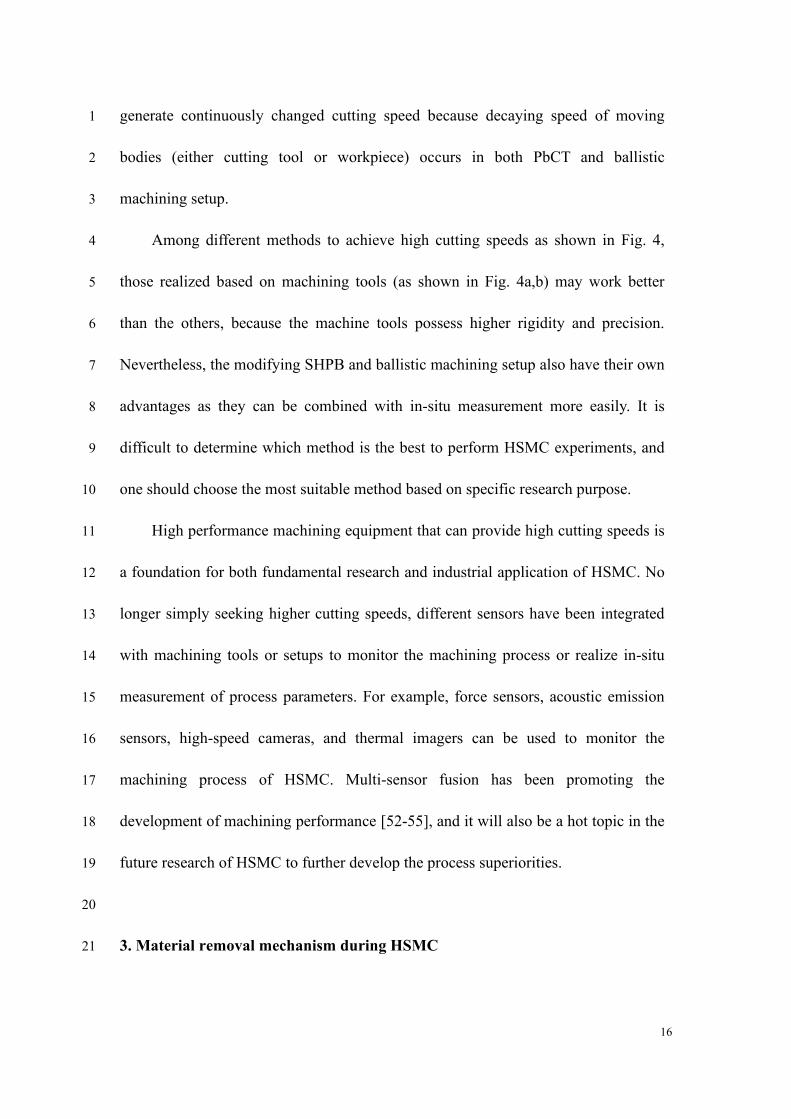
Fig. 1 presents the evolution and application of HSMC from the perspectives of 18
machining tool, spindle speed, cutting speed, material removal rate, industrial 19
application, and the division of cutting speed range. With the development of 20
machine tools, starting from the earliest and manual ones (i.e., the first and second 21
generations as shown in Fig. 1) to the CNC machine tools (i.e., the third and fourth 22
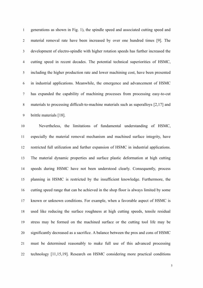
5
generations as shown in Fig. 1), the spindle speed and associated cutting speed and 1
material removal rate have been increased by over one hundred times [9]. The 2
development of electro-spindle with higher rotation speeds has further increased the 3
cutting speed in recent decades. The potential technical superiorities of HSMC, 4
including the higher production rate and lower machining cost, have been presented 5
in industrial applications. Meanwhile, the emergence and advancement of HSMC 6
has expanded the capability of machining processes from processing easy-to-cut 7
materials to processing difficult-to-machine materials such as superalloys [2,17] and 8
brittle materials [18]. 9
Nevertheless, the limitations of fundamental understanding of HSMC, 10
especially the material removal mechanism and machined surface integrity, have 11
restricted full utilization and further expansion of HSMC in industrial applications. 12
The material dynamic properties and surface plastic deformation at high cutting 13
speeds during HSMC have not been understood clearly. Consequently, process 14
planning in HSMC is restricted by the insufficient knowledge. Furthermore, the 15
cutting speed range that can be achieved in the shop floor is always limited by some 16
known or unknown conditions. For example, when a favorable aspect of HSMC is 17
used like reducing the surface roughness at high cutting speeds, tensile residual 18
stress may be formed on the machined surface or the cutting tool life may be 19
significantly decreased as a sacrifice. A balance between the pros and cons of HSMC 20
must be determined reasonably to make full use of this advanced processing 21
technology [11,15,19]. Research on HSMC considering more practical conditions 22
6
that used in industries is a prerequisite to make such as a balance. 1
1st-First milling
machine
RPM (r/min) ~102 <2000 < 104 104 ~ 105
CS (m/min) <10 30~50 50~80 102 ~ 103
MRR (cc/min) <10 10~20 30~50 102 ~ 103
APPNonmetallic
material
Soft metallic and non-
metallic materials
Most metallic and
non-metallic materials
Hard materials and large
material removal volume
RangeLow speed
machining
Conventional speed
machiningHigh speed machining
Ultra-high speed
machining
2nd-Manual machine
tool
3rd-CNC machine
tool 4th-CNC + high speed electro-
spindle
(1820)
(1920)(1980)
(2010)
➢ Low speed
➢ Poor quality
➢ High cost
➢ High speed
➢ High quality
➢ Low cost
2
Fig. 1. Evolution and application of high speed metal cutting. (Note: CNC- computer 3
numerical control, RPM-revolutions per minute, CS-cutting speed, MRR-material removal rate, 4
APP-application) 5
In addition, the evaluation on the machined surface quality has evolved from 6
macro parameters, such as the surface roughness and surface defects, to micro or 7
nano levels such as the crystalline features and phase transformations. Advanced 8
material characterization tools, including Transmission Electron Microscopy (TEM) 9
and Electron Back-Scattered Diffraction (EBSD), make it possible to get deeper 10
insights into the underlying mechanisms of material removal and machined surface 11
formation during HSMC. 12
We acknowledge at the outset that there have been several noteworthy review 13
papers on HSMC in recent decades [2,3,20], and they were mainly focused on the 14

7
experimental results and process modeling while lacked micro-mechanism analysis 1
due to the limitation of microscopic observation tools at that time. The relationships 2
among material removal mechanism, machined surface integrity, and processing 3
parameters have also not been understood clearly. To address the research gap that 4
still occurs, this article is aimed at reviewing the state-of-the-art of HSMC to 5
elaborate its pros and cons for the first time, and at highlighting the challenges in its 6
practical application. In particular, the material removal mechanism and machined 7
surface integrity of HSMC are addressed. The dynamic deformation behavior of 8
workpiece material, microstructural evolution of machined surface, and 9
thermal-mechanical loading characteristics in HSMC, are systematically reviewed 10
and correlated to understand the technical advantages and current research 11
limitations of HSMC. Although there have been some prominent achievements until 12
now, a few potential research directions are recommended, which demonstrate the 13
urgent need to continue the development of HSMC for both academia and industries. 14
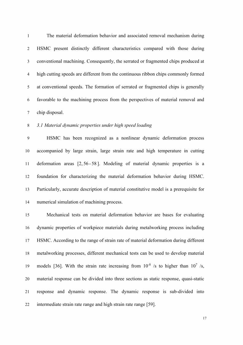
The paper is organized in six sections (Sections 2-7) followed by future 15
research directions and conclusions. Section 2 outlines the definition and history of 16
HSMC, and some technical methods to achieve high cutting speeds. Section 3 and 17
Section 4 present the material removal mechanism and machined surface integrity 18
during HSMC, respectively. The cutting force and cutting temperature, in addition to 19
the tool wear behavior and mechanism are discussed in Section 5 and Section 6, 20
respectively. The pros and cons of HSMC are elaborated from the above aspects. 21
Several typical application cases of HSMC in industries are presented in Section 7. 22
8
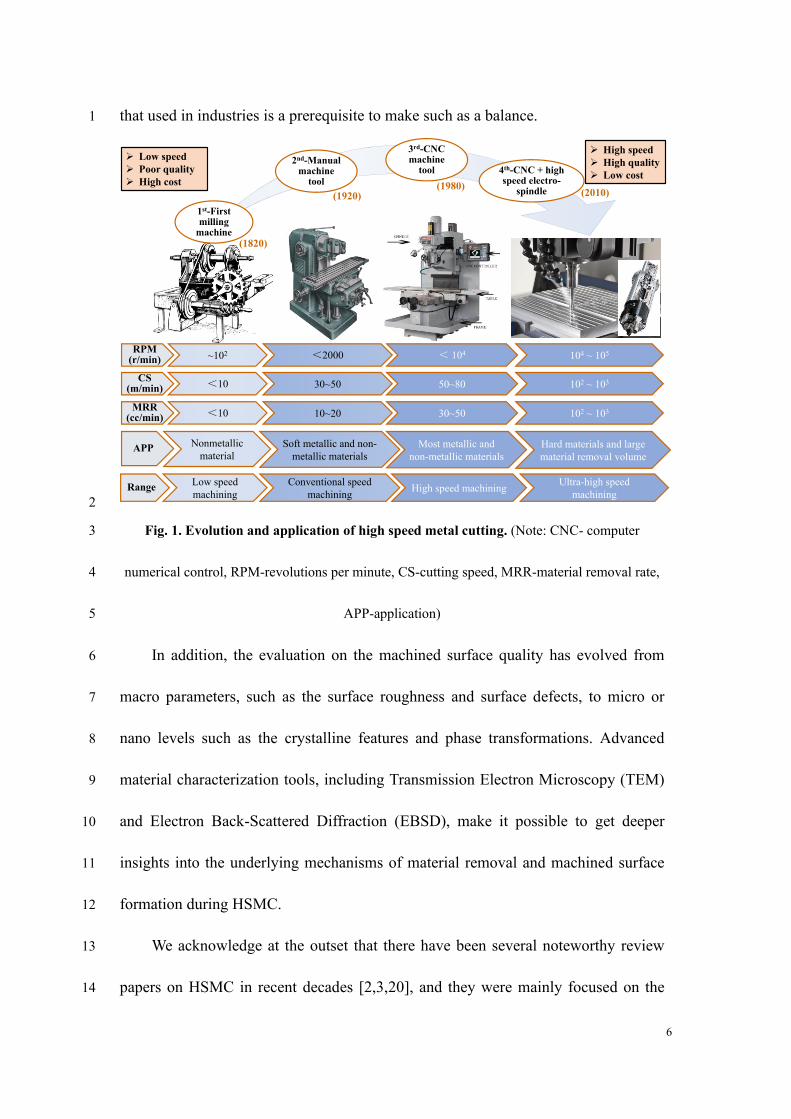
At last, the future research directions on HSMC are discussed and the conclusions 1
are drawn highlighting still-to-be-tackled challenges. Fig. 2 shows the framework of 2
this review paper. 3
It needs to be noted that the “HSMC” involved in this review paper is limited to 4
high speed metal cutting while excluding the abrasive machining, and the effect of 5
cutting dynamics (i.e., vibration of the cutting tool and workpiece) on the machining 6
process is also excluded. To keep the review scope in a focus, HSMC that achieved 7
in the machining modes of orthogonal cutting, turning, and milling are reviewed in 8
this paper. The main content of this paper, especially the material removal 9
mechanism and machined surface integrity of HSMC, is put on the research progress 10
made after the publication of the handbook of high-speed machining technology in 11
the year 2013 [21]. 12
Material removal
mechanism
(Section 3)
• Material dynamic property
• Chip morphology variation
• Mechanical conditions of
chip formation
High speed
machining(Section 2: Definition
and development)
Industrial application
(Section 7)
• Structural components made
by light alloys
• Aero engine components
• Thin-walled components
Tool wear behavior
and mechanism
(Section 6)
• Tool wear behavior
• Tool wear mechanism
• High speed cutting tools
Machined surface
integrity
(Section 4)
• Topographical features and
surface defects
• Metallurgical alterations
• Mechanical properties
Cutting force and
cutting temperature
(Section 5)
• Modeling and variation of
cutting force and cutting
temperature
• Salomon's temperature curve
13
Fig. 2. The framework of this review paper. 14
15
9
2. Definition and development of HSMC 1
2.1 Definition 2
Dr. C. Salomon was granted a German Patent about HSMC in 1931 and first 3
proposed the hypothesis based on a series of experiments that cutting temperatures 4
begin decreasing above a certain cutting speed [10]. Salomon’s cutting temperature 5
curve indicated that there is a cutting speed range (also called death valley) where 6
machining cannot be performed owing to the excessively high temperatures and 7
associated severe cutting tool wear. Initially, HSMC was defined as machining at 8
cutting speeds higher than the death valley. Nevertheless, the existence of Salomon’s 9
curve and its occurrence condition are still being debated in the metal cutting field as 10
open questions [22]. Detailed discussion about the research progress on Salomon’s 11
curve will be discussed in Section 5.2. 12
The cutting speed range in HSMC is a relative concept, and it depends on the 13
cutting processes, workpiece materials and cutting tools used [23]. It was once 14
recommended that machining within a speed range of 500 m/min-7,000 m/min [11] 15
or machining with a spindle rotation speed higher than 8,000 r/min [24] belongs to 16
HSMC. Schulz and Moriwaki [3] defined HSMC as machining whereby cutting 17
speeds are five to ten times higher than conventional cutting speeds. Nevertheless, 18
the above division of cutting speed range for HSMC does not consider specific 19
cutting conditions and workpiece materials. 20
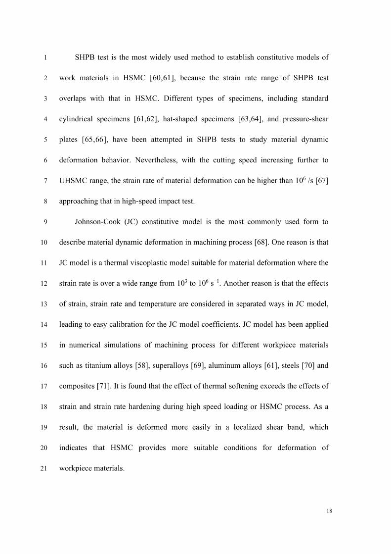
Fig. 3 shows the milestones of development for HSMC, covering several 21
typical findings contributed to advancement of HSMC at different eras. Since 22

10
Salomon proposed the concept of HSMC, its development was slow due to limited 1
performance of available machining equipment for nearly half century. Through 2
considering inertia effect of material deformation at ultra-high cutting speeds, Arndt 3
[25] proposed a new cutting force model adaptable for ultra-high speed machining 4
(UHSMC). After that, based on HSMC experiments, Icks [26,27] suggested that the 5
cutting speed range between 1000 m/min and 10,000 m/min belongs to HSMC and it 6
depends on the machining process. 7
The consistent increase in spindle rotation speed resulted in a prosperous 8
development of HSMC in the 1990s. Schulz [23,28] verified that precipitation 9
hardening plays an important role in the transformation of chip formation from 10
continuous to segmented and the associated cutting speed range of HSMC. A fixed 11
classification into three ranges of cutting speeds was once suggested as conventional 12
machining (0-500 m/min), HSMC (500 m/min-10,000 m/min), and UHSMC 13
(>10,000 m/min) [11]. Tönshoff et al. [29,30] recommended that HSMC be defined 14
as machining at cutting speeds with an essential overstepping of conventional speeds. 15
They proposed that a substantial decrease of production costs caused by increase in 16
cutting speed is an important characteristic entering the range of HSMC. 17
Nevertheless, there was no clarity on what can be considered as a substantial 18
decrease in production costs. 19
11
1925
Salomon, 1931
The patent of high speed
machining with cutting
speeds higher than 720
m/min.
Icks, 1981
A speed range between
1000 m/min and 10,000
m/min dependent on the
manufacturing process.
First experiment
2020
Schulz, 1994
Proposing different
high speed ranges for
machining of several
kinds of materials.
Schneider, 1996
Fixed classification in three areas of cutting
speeds:
➢Conventional machining: 0-500 m/min
➢High speed machining: 500-10,000 m/min
➢Ultra-fast machining: >10,000 m/min
Arndt, 1973Proposing a new cutting force
model adaptable for ultra high
speed machining, through
considering the inertia effect at
ultra high cutting speeds.
Tönshoff et al., 1998High speed machining can
be seen as essential
overstepping of
conventional speed
machining.
Liu and Wang, 2015
Division of machining phases
based on chip morphology and
proposing the scientific essence
of ultra high speed machining.
Denkena et al., 2007Proposing material specific
definition of high speed
cutting range considering
material physical and
mechanical properties.
Molinari et al., 2002
Systematically modelling
adiabatic shear banding
in high speed machining.
1
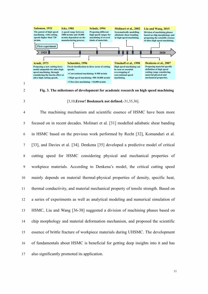
Fig. 3. The milestones of development for academic research on high speed machining 2
[3,10,Error! Bookmark not defined.-31,35,36]. 3
The machining mechanism and scientific essence of HSMC have been more 4
focused on in recent decades. Molinari et al. [31] modelled adiabatic shear banding 5
in HSMC based on the previous work performed by Recht [32], Komanduri et al. 6
[33], and Davies et al. [34]. Denkena [35] developed a predictive model of critical 7
cutting speed for HSMC considering physical and mechanical properties of 8
workpiece materials. According to Denkena’s model, the critical cutting speed 9
mainly depends on material thermal-physical properties of density, specific heat, 10
thermal conductivity, and material mechanical property of tensile strength. Based on 11
a series of experiments as well as analytical modeling and numerical simulation of 12
HSMC, Liu and Wang [36-38] suggested a division of machining phases based on 13
chip morphology and material deformation mechanism, and proposed the scientific 14
essence of brittle fracture of workpiece materials during UHSMC. The development 15
of fundamentals about HSMC is beneficial for getting deep insights into it and has 16
also significantly promoted its application. 17

12
Besides the above achievements, the handbook of high-speed machining 1
technology edited by King [21] systematically summarized HSMC from the aspects 2
of general theory and industrial application. Some other researchers, including 3
Tlusty [39], Smith and Tlusty [40], Schmitz and Donalson [41], Movahhedy and 4
Mosaddegh [42] focused on the characteristics of cutting dynamics during HSMC of 5
different workpiece materials to maximize the machining performance. 6
New definitions of HSMC have been formulated in compliance with advanced 7
knowledge. The machining process enters a new regime only when the deformation 8
behavior of workpiece material undergoes a significant transformation. The material 9
localized deformation behavior within adiabatic shear bands (ASBs) is distinctly 10
different from the uniform plastic deformation of continuous chips [31,34]. 11
Consequently, the existence of ASBs and associated formation of serrated chips have 12
been identified as an indication of HSMC and gradually accepted by academia 13
[43,44]. It needs to be noted that although the critical cutting speed for adiabatic 14
shear is relatively low for certain workpiece materials such as titanium alloys owing 15
to their poor thermal properties, it can still be regarded as HSMC once the cutting 16
speed is higher than that for ASB formation. With a constant increase in the cutting 17
speed, workpiece materials undergo ductile to brittle transition due to the 18
embrittlement effect of the high strain rate. Consequently, the material deformation 19
mechanism transforms from adiabatic shear to brittle fracture, which can be regarded 20
as the indication of UHSMC [36,37]. Therefore, HSMC can be defined as machining 21
with a cutting speed higher than that for ASB formation, whereas UHSMC can be 22
13
defined as machining with a cutting speed higher than that for fragmented chip 1
formation induced by workpiece material embrittlement. 2
A consensus has been reached that the high speed in HSMC is preferably 3
referred to a combined economic and performance target, rather than merely a 4
technical parameter [11]. It is difficult to define HSMC by a specific cutting speed 5
range, which is always varied for different cutting conditions. Consequently, high 6
performance machining is put forward [11] to get the maximum output from 7
machining processes by adjusting machining parameters. 8
9
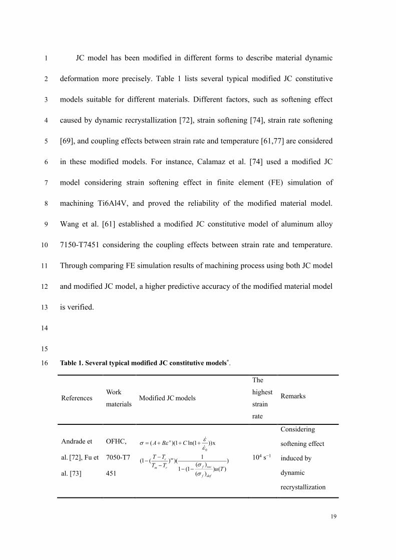
2.2 Test methods to achieve high cutting speeds 10
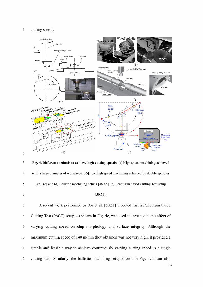
Besides using a high-speed spindle directly, high cutting speeds can be achieved 11
by different methods as seen in Fig. 4. A large diameter of cutting tool or workpiece 12
can help to increase linear cutting speeds if a high-speed spindle is not available. 13
Wang et al. [36] installed a disk workpiece with 130 mm in diameter to the spindle of 14
a machine tool through a tool shaft as shown in Fig. 4a. This method can achieve high 15
cutting speeds at relatively low spindle speeds. A cutting speed range of 50 m/min to 16
8,000 m/min was obtained by Wang et al. during machining of different workpiece 17
materials such as Inconel 718 and aluminum alloy 7050-T7451. 18
Simultaneous rotations of spindle and workpiece in an opposite direction can 19
increase the linear cutting speed effectively. Zhou et al. [45] adopted a machining tool 20
with double spindles rotating oppositely to achieve a maximum cutting speed of 21
30,000 m/min, as seen in Fig. 4b. The finished surface quality of pure aluminum 22
14
A1199 and aluminum alloy A5056 were studied at this high cutting speed. 1
Modifying Split Hopkinson Pressure Bars (SHPB) or Taylor Bar is common 2
method to realize high cutting speeds, as high-pressure gas can generate very high 3
impact speeds. Either cutting tool or specimen can be set as a moving element, and 4
the cutting depth can be adjusted precisely through fixing the relative position 5
between workpiece and cutting tool. HSMC generated by high-pressure gas is also 6
called as ballistic machining. Sutter et al. [46], Sutter and List [47] developed a 7
ballistic machining setup shown in Fig. 4c, and performed HSMC experiments of 8
titanium alloy Ti6Al4V over a wide speed range from 300 m/min to 4,400 m/min. 9
Considering that the ballistic machining is realized by a linear movement between 10
the cutting tool and workpiece, in-situ measurement or observation of machining 11
process with a high-speed camera can be conveniently conducted, and this is a 12
prominent advantage compared with other HSMC methods. Ye et al. [ 48 ] 13
established a ballistic machining setup using a light-gas gun shown in Fig. 4d that 14
can provide cutting speeds up to 12,000 m/min, and carried out HSMC experiments 15
on AISI 1045 steel. The highest cutting speed was achieved by Arndt [25] as 8,000 16
ft/s (equivalent to 146,304 m/min) using the ballistic machining method, whereby 17
the inertia effect of material deformation caused by the ultra-high cutting speed was 18
revealed. Wuertemberger [49] reported an ultra-high speed test setup based on a 19
rocket propulsion, which can achieve ultra-high speeds up to 10,000 m/s. Although 20
the setup was applied to study the wear behavior of high-speed rocket sleds, it can 21
still provide some inspiration for designing new HSMC setups to obtain higher 22
15
cutting speeds. 1
Y
X
Z
X
Spindle
Workpiece specimen
Insert
ScrewsDynanometer
FixtureTool shank
Feed direction
Rotation
Shaft
Machining
deformation
area
(a)(c)
(b)
(d) (e) 2
Fig. 4. Different methods to achieve high cutting speeds. (a) High speed machining achieved 3
with a large diameter of workpiece [36]. (b) High speed machining achieved by double spindles 4
[45]. (c) and (d) Ballistic machining setups [46-48]. (e) Pendulum based Cutting Test setup 5
[50,51]. 6
A recent work performed by Xu et al. [50,51] reported that a Pendulum based 7
Cutting Test (PbCT) setup, as shown in Fig. 4e, was used to investigate the effect of 8
varying cutting speed on chip morphology and surface integrity. Although the 9
maximum cutting speed of 140 m/min they obtained was not very high, it provided a 10
simple and feasible way to achieve continuously varying cutting speed in a single 11
cutting step. Similarly, the ballistic machining setup shown in Fig. 4c,d can also 12
16
generate continuously changed cutting speed because decaying speed of moving 1
bodies (either cutting tool or workpiece) occurs in both PbCT and ballistic 2
machining setup. 3
Among different methods to achieve high cutting speeds as shown in Fig. 4, 4
those realized based on machining tools (as shown in Fig. 4a,b) may work better 5
than the others, because the machine tools possess higher rigidity and precision. 6
Nevertheless, the modifying SHPB and ballistic machining setup also have their own 7
advantages as they can be combined with in-situ measurement more easily. It is 8
difficult to determine which method is the best to perform HSMC experiments, and 9
one should choose the most suitable method based on specific research purpose. 10
High performance machining equipment that can provide high cutting speeds is 11
a foundation for both fundamental research and industrial application of HSMC. No 12
longer simply seeking higher cutting speeds, different sensors have been integrated 13
with machining tools or setups to monitor the machining process or realize in-situ 14
measurement of process parameters. For example, force sensors, acoustic emission 15
sensors, high-speed cameras, and thermal imagers can be used to monitor the 16
machining process of HSMC. Multi-sensor fusion has been promoting the 17
development of machining performance [52-55], and it will also be a hot topic in the 18
future research of HSMC to further develop the process superiorities. 19
20
3. Material removal mechanism during HSMC 21
17
The material deformation behavior and associated removal mechanism during 1
HSMC present distinctly different characteristics compared with those during 2
conventional machining. Consequently, the serrated or fragmented chips produced at 3
high cutting speeds are different from the continuous ribbon chips commonly formed 4
at conventional speeds. The formation of serrated or fragmented chips is generally 5
favorable to the machining process from the perspectives of material removal and 6
chip disposal. 7
3.1 Material dynamic properties under high speed loading 8
HSMC has been recognized as a nonlinear dynamic deformation process 9
accompanied by large strain, large strain rate and high temperature in cutting 10
deformation areas [2, 56 - 58 ]. Modeling of material dynamic properties is a 11
foundation for characterizing the material deformation behavior during HSMC. 12
Particularly, accurate description of material constitutive model is a prerequisite for 13
numerical simulation of machining process. 14
Mechanical tests on material deformation behavior are bases for evaluating 15
dynamic properties of workpiece materials during metalworking process including 16
HSMC. According to the range of strain rate of material deformation during different 17
metalworking processes, different mechanical tests can be used to develop material 18
models [36]. With the strain rate increasing from 10-8 /s to higher than 107 /s, 19
material response can be divided into three sections as static response, quasi-static 20
response and dynamic response. The dynamic response is sub-divided into 21
intermediate strain rate range and high strain rate range [59]. 22
18
SHPB test is the most widely used method to establish constitutive models of 1
work materials in HSMC [60,61], because the strain rate range of SHPB test 2
overlaps with that in HSMC. Different types of specimens, including standard 3
cylindrical specimens [61,62], hat-shaped specimens [63,64], and pressure-shear 4
plates [65,66], have been attempted in SHPB tests to study material dynamic 5
deformation behavior. Nevertheless, with the cutting speed increasing further to 6
UHSMC range, the strain rate of material deformation can be higher than 106 /s [67] 7
approaching that in high-speed impact test. 8
Johnson-Cook (JC) constitutive model is the most commonly used form to 9
describe material dynamic deformation in machining process [68]. One reason is that 10
JC model is a thermal viscoplastic model suitable for material deformation where the 11
strain rate is over a wide range from 103 to 106 s−1. Another reason is that the effects 12
of strain, strain rate and temperature are considered in separated ways in JC model, 13
leading to easy calibration for the JC model coefficients. JC model has been applied 14
in numerical simulations of machining process for different workpiece materials 15
such as titanium alloys [58], superalloys [69], aluminum alloys [61], steels [70] and 16
composites [71]. It is found that the effect of thermal softening exceeds the effects of 17
strain and strain rate hardening during high speed loading or HSMC process. As a 18
result, the material is deformed more easily in a localized shear band, which 19
indicates that HSMC provides more suitable conditions for deformation of 20
workpiece materials. 21
19
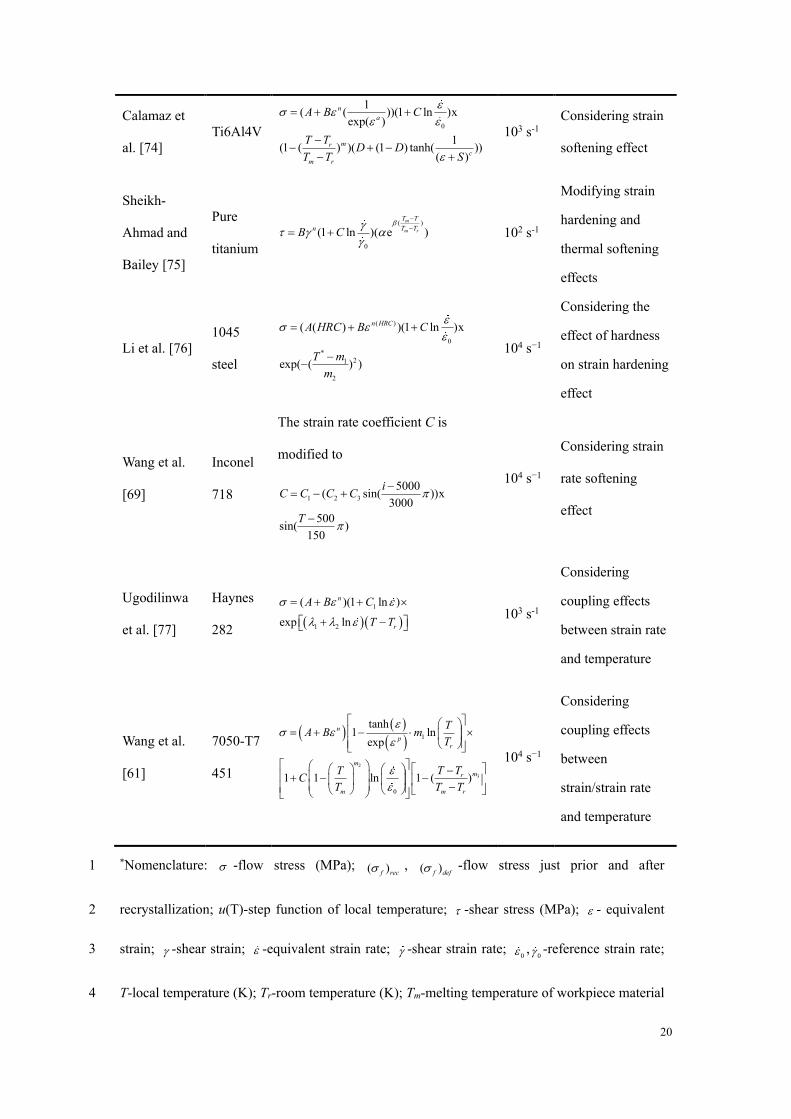
JC model has been modified in different forms to describe material dynamic 1
deformation more precisely. Table 1 lists several typical modified JC constitutive 2
models suitable for different materials. Different factors, such as softening effect 3
caused by dynamic recrystallization [72], strain softening [74], strain rate softening 4
[69], and coupling effects between strain rate and temperature [61,77] are considered 5
in these modified models. For instance, Calamaz et al. [74] used a modified JC 6
model considering strain softening effect in finite element (FE) simulation of 7
machining Ti6Al4V, and proved the reliability of the modified material model. 8
Wang et al. [61] established a modified JC constitutive model of aluminum alloy 9
7150-T7451 considering the coupling effects between strain rate and temperature. 10
Through comparing FE simulation results of machining process using both JC model 11
and modified JC model, a higher predictive accuracy of the modified material model 12
is verified. 13
14
15
Table 1. Several typical modified JC constitutive models*. 16
References Work
materials Modified JC models
The
highest
strain
rate
Remarks
Andrade et
al. [72], Fu et
al. [73]
OFHC,
7050-T7
451
0
( )(1 ln(1 ))x
1(1 ( ) )( )
( )1 (1 ) ( )
( )
n
mr
f recm r
f def
A B C
T T
T Tu T
= + + +
−−
−− −
104 s−1
Considering
softening effect
induced by
dynamic
recrystallization
20
Calamaz et
al. [74]
Ti6Al4V 0
1( ( ))(1 ln )x
exp( )
1(1 ( ) )( (1 ) tanh( ))
( )
n
a
mr
c
m r
A B C
T TD D
T T S
= + +
−− + −
− +
103 s-1
Considering strain
softening effect
Sheikh-
Ahmad and
Bailey [75]
Pure
titanium
( )
0
(1 ln )( e )
m
m r
T T
T TnB C
−
−= + 102 s-1
Modifying strain
hardening and
thermal softening
effects
Li et al. [76]
1045
steel
( )
0
*21
2
( ( ) )(1 ln )x
exp( ( ) )
n HRCA HRC B C
T m
m
= + +
−−
104 s−1
Considering the
effect of hardness
on strain hardening
effect
Wang et al.
[69]
Inconel
718
The strain rate coefficient C is
modified to
1 2 3
5000( sin( ))x
3000
500sin( )
150
iC C C C
T
−= − +
−
104 s−1
Considering strain
rate softening
effect
Ugodilinwa
et al. [77]
Haynes
282 ( )( )
1
1 2
( )(1 ln )
exp ln
n
r
A B C
T T
= + +
+ −
103 s-1
Considering
coupling effects
between strain rate
and temperature
Wang et al.
[61]
7050-T7
451
( )( )
( )2
3
1
0
tanh1 ln
exp
1 1 ln 1 ( )
n
pr
m
mr
m m r
TA B m
T
T TTC
T T T
= + −
− + − − −
104 s−1
Considering
coupling effects
between
strain/strain rate
and temperature
*Nomenclature: -flow stress (MPa); ( )f rec , ( )f def -flow stress just prior and after 1
recrystallization; u(T)-step function of local temperature; -shear stress (MPa); - equivalent 2
strain; -shear strain; -equivalent strain rate; -shear strain rate; 0 ,
0 -reference strain rate; 3
T-local temperature (K); Tr-room temperature (K); Tm-melting temperature of workpiece material 4
21
(K); A, B, n, C, m, m1, m2, m3- JC constitutive parameters; D, S, λ, α, β-material constants. 1
Note: The specific parameter values can be tracked in corresponding references. 2
Based on the viewpoint from Astakhov [3,9], mechanical machining can be 3
regarded as purposeful fracture between the removed layer material and bulk 4
workpiece. Machining conditions that are favorable to material fracture can help 5
improve the machining efficiency. Material fracture is determined by the combined 6
influences of the stress state, strain rate, and temperature. The effect of the stress 7
state on material fracture that occurs during mechanical tests [78] or machining 8
processes [ 79-81] has been studied, whereby material fracture strain models 9
considering the stress state effect have been developed. The effects of the strain rate 10
and temperature on material dynamic fracture and corresponding fracture strain 11
models have been focused on in recent years through SHPB tests. It has been 12
acknowledged that material fracture strain decreases with either increasing the strain 13
rate or decreasing the temperature [82]. An increase in the strain rate promotes the 14
ductile to brittle transition of ductile materials. Through investigating the effects of 15
the strain rate and stress triaxiality on the equivalent fracture strain of Ti6Al4V, 16
Wang et al. [64] proposed a fracture strain model with an exponential expression of 17
the strain rate as Eq. (1). 18
2.764 0.125
0
(0.097 0.118e )(1 0.217 ln )f
− −= + + (1) 19
where η is the stress triaxiality, and 0 are the loading strain rate and the 20
reference strain rate, respectively. 21
22
Micro-mechanism analysis of material fracture at high speed loading can help 1
understand the material failure behavior during HSMC. The cross-sectional 2
microstructures of the fracture surface for Ti6Al4V tested from 0.001 /s (i.e., 3
quasi-static loading) to 16,000 /s revealed that the dominant material fracture 4
mechanism transforms from transgranular fracture to mixed intergranular fracture 5
and transgranular fracture, and then to intergranular fracture [83]. It indicates that 6
ductile to brittle transition occurs for metal with increasing the strain rate. 7
8
3.2 Material deformation behavior and material removal mechanism 9
As the cutting speed increases, the chip morphology evolves from continuous to 10
serrated and then to fragmented. From the perspectives of material removal rate, chip 11
disposal, and machining automation, serrated and fragmented chips are preferable to 12
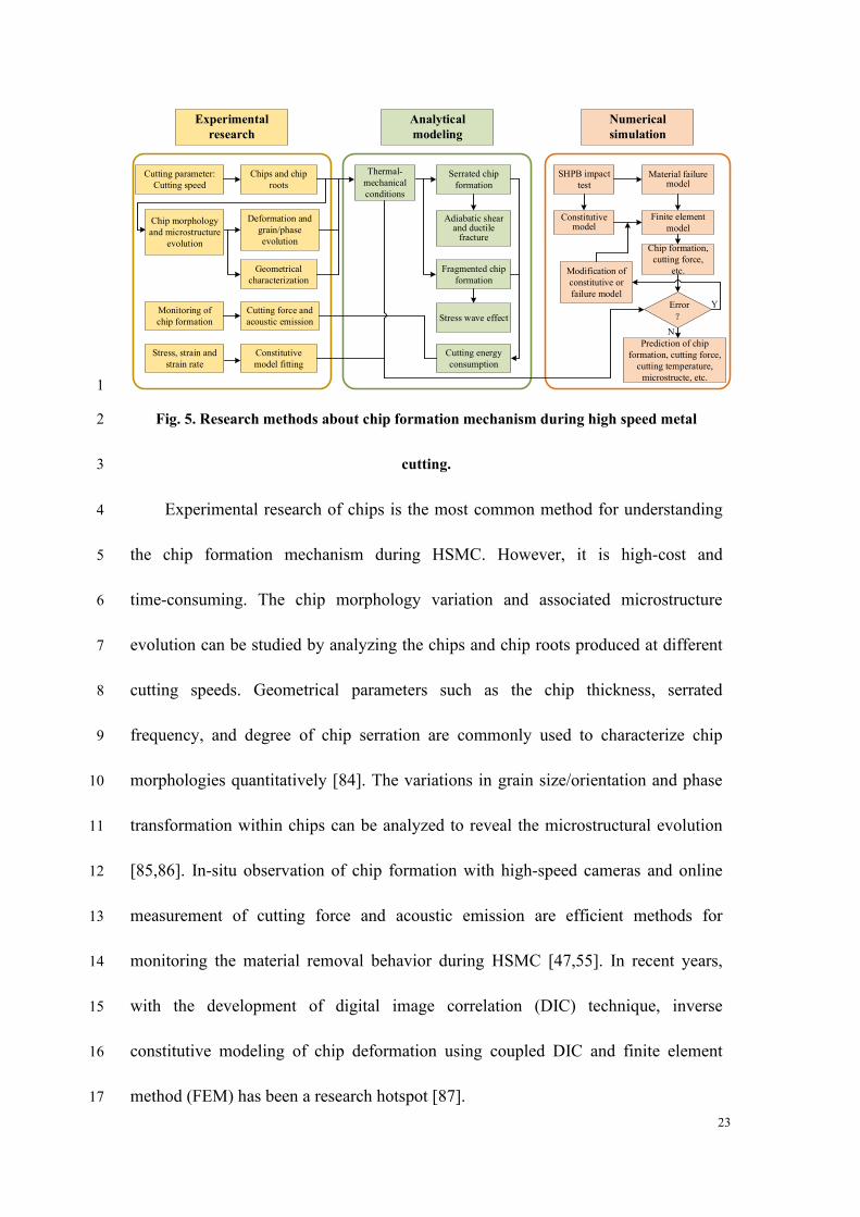
continuous chips. This is one of the technical superiorities of HSMC. Fig. 5 presents 13
the main research methods for identifying the chip formation mechanism in HSMC 14
including experimental research, analytical modeling, and numerical simulation. 15
23
Experimental
research
Cutting parameter:
Cutting speed
Chips and chip
roots
Chip morphology
and microstructure
evolution
Deformation and
grain/phase
evolution
Stress, strain and
strain rate
Cutting force and
acoustic emission
Geometrical
characterization
Constitutive
model fitting
Monitoring of
chip formation
Analytical
modeling
Thermal-
mechanical
conditions
Serrated chip
formation
Adiabatic shear and ductile
fracture
Cutting energy
consumption
Fragmented chip
formation
Stress wave effect
Numerical
simulation
SHPB impact
test
Material failure model
Finite element
model
Prediction of chip
formation, cutting force,
cutting temperature,
microstructe, etc.
Chip formation,
cutting force,
etc.
Constitutive model
Error
?
Y
Modification of
constitutive or
failure model
N
1
Fig. 5. Research methods about chip formation mechanism during high speed metal 2
cutting. 3
Experimental research of chips is the most common method for understanding 4
the chip formation mechanism during HSMC. However, it is high-cost and 5
time-consuming. The chip morphology variation and associated microstructure 6
evolution can be studied by analyzing the chips and chip roots produced at different 7
cutting speeds. Geometrical parameters such as the chip thickness, serrated 8
frequency, and degree of chip serration are commonly used to characterize chip 9
morphologies quantitatively [84]. The variations in grain size/orientation and phase 10
transformation within chips can be analyzed to reveal the microstructural evolution 11
[85,86]. In-situ observation of chip formation with high-speed cameras and online 12
measurement of cutting force and acoustic emission are efficient methods for 13
monitoring the material removal behavior during HSMC [47,55]. In recent years, 14
with the development of digital image correlation (DIC) technique, inverse 15
constitutive modeling of chip deformation using coupled DIC and finite element 16
method (FEM) has been a research hotspot [87]. 17
24
Analytical modeling and numerical simulation are effective for obtaining 1
deeper insights into the scientific essence of chip formation and are more 2
cost-efficient than experimental methods. The modeling of thermal-mechanical 3
conditions for serrated and fragmented chip formation provides a basis for the 4
theoretical research of chip formation mechanism. The adiabatic shear and ductile 5
fracture theory [88-90] and the stress wave effect [36,91] have been acknowledged 6
as efficient theories to explain the formation mechanisms of serrated chips and 7
fragmented chips, respectively. The cutting energy consumption for chip formation 8
can also be theoretically modeled as a function of process parameters. 9
FEM is the main tool for numerical simulation of HSMC due to its suitability of 10
analyzing severe plastic deformation process and high computational efficiency. 11
Accurate material models, including constitutive model [59,92,93] and friction 12
model [94], are important to guarantee the reliability of simulation results. With 13
numerical simulation, the parameters of cutting force, cutting temperature, and 14
microstructural evolution can also be predicted along with chip formation process. 15
The relationships among experimental research, analytical modeling, and numerical 16
simulation of chip formation in HSMC are illustrated in Fig. 5. 17
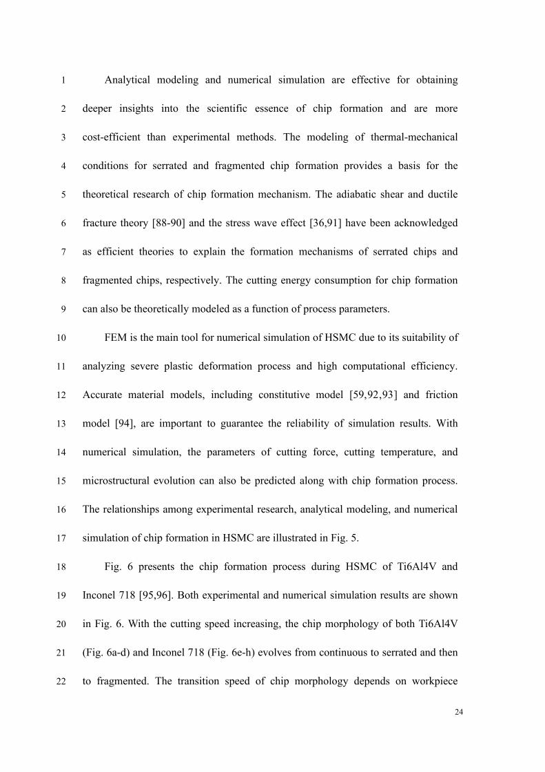
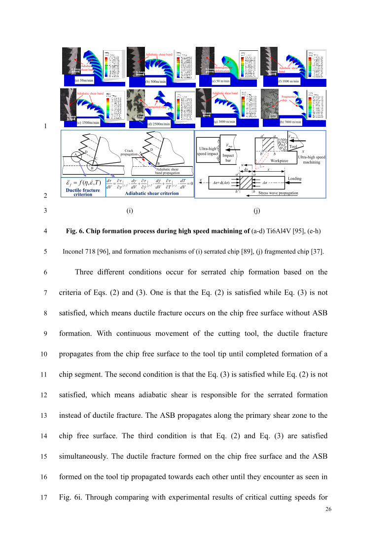
Fig. 6 presents the chip formation process during HSMC of Ti6Al4V and 18
Inconel 718 [95,96]. Both experimental and numerical simulation results are shown 19
in Fig. 6. With the cutting speed increasing, the chip morphology of both Ti6Al4V 20
(Fig. 6a-d) and Inconel 718 (Fig. 6e-h) evolves from continuous to serrated and then 21
to fragmented. The transition speed of chip morphology depends on workpiece 22

25
materials. Adiabatic shear theory and periodic fracture were popular perspectives to 1
explain serrated chip formation mechanism. Through analyzing the mechanical 2
conditions on chip free surface and tool tip region, Wang and Liu [89] proposed a 3
mixed mechanism of adiabatic shear and ductile fracture (Fig. 6i) and successfully 4
solve the dispute of the above two famous theories. For the material on chip free 5
surface located at Point A shown in Fig. 6i, positive stress triaxiality occurs and 6
ductile fracture criterion expressed by Eq. (2) is suitable for evaluating material 7
failure. Regarding the material within the tool tip area located at Point B shown in 8
Fig. 6i, negative stress triaxiality occurs and adiabatic shear is apt to be initiated. 9
Adiabatic shear criterion expressed by Eq. (3) is adaptable to evaluate the occurrence 10
of plastic deformation instability. 11
( , , )f f T = (2) 12
where T is the deformation temperature which is not considered in Eq. (1). The 13
ductile fracture criterion considering all the effects of strain rate, stress state and 14
temperature was presented in [80]. 15
,, ,
0T T
d d d dT
dV dV dV T dV
= + + =
(3) 16
where τ is the shear flow stress, γ is the shear strain, is the shear strain rate, and 17
dτ/dV implies the total differential calculation of shear flow stress over the cutting 18
speed. 19
26
(b) 500m/min
0.1mm
(a) 50m/min
0.1mm
(c) 1500m/min
0.1mm
(d) 2500m/min
0.1mm
Adiabatic
shear band
Adiabatic shear band
Adiabatic shear band
Fragmented chip
(f) 1000 m/min (e) 50 m/min
(h) 7000 m/min
Homogeneous
deformation Adiabatic shear
band
Fragmented
chip
0.1mm
0.1mm 0.1mm
0.1mm
2mm
0.1mm
Adiabatic shear band
0.1mm
0.1mm
(g) 3000 m/min
1
Impact
bar
VimpUltra-high
speed impactx
Tool
Vimp_c
Ultra-high speed
machining
a' a
b' b
Workpiece
aa'
bb'
xdxu
Stress wave propagation
x LoadingAσAσ+d(Aσ)
2
(i) (j) 3
Fig. 6. Chip formation process during high speed machining of (a-d) Ti6Al4V [95], (e-h) 4
Inconel 718 [96], and formation mechanisms of (i) serrated chip [89], (j) fragmented chip [37]. 5
Three different conditions occur for serrated chip formation based on the 6
criteria of Eqs. (2) and (3). One is that the Eq. (2) is satisfied while Eq. (3) is not 7
satisfied, which means ductile fracture occurs on the chip free surface without ASB 8
formation. With continuous movement of the cutting tool, the ductile fracture 9
propagates from the chip free surface to the tool tip until completed formation of a 10
chip segment. The second condition is that the Eq. (3) is satisfied while Eq. (2) is not 11
satisfied, which means adiabatic shear is responsible for the serrated formation 12
instead of ductile fracture. The ASB propagates along the primary shear zone to the 13
chip free surface. The third condition is that Eq. (2) and Eq. (3) are satisfied 14
simultaneously. The ductile fracture formed on the chip free surface and the ASB 15
formed on the tool tip propagated towards each other until they encounter as seen in 16
Fig. 6i. Through comparing with experimental results of critical cutting speeds for 17
A
B
C
D Crack propagation
Adiabatic shear band propagation
A
B
C
D
0,,, =
+
+
=
dV
dT
TdV
d
dV
d
dV
dTT
),,( Tff =
Adiabatic shear criterionDuctile fracture
criterion
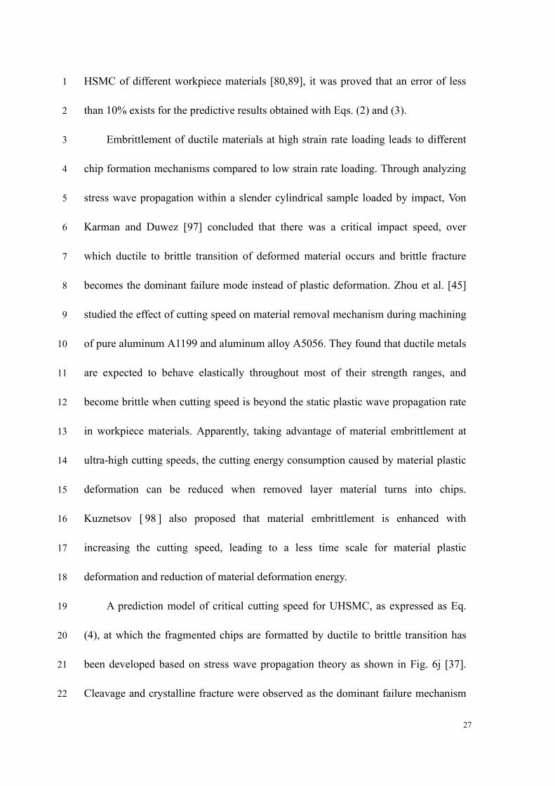
27
HSMC of different workpiece materials [80,89], it was proved that an error of less 1
than 10% exists for the predictive results obtained with Eqs. (2) and (3). 2
Embrittlement of ductile materials at high strain rate loading leads to different 3
chip formation mechanisms compared to low strain rate loading. Through analyzing 4
stress wave propagation within a slender cylindrical sample loaded by impact, Von 5
Karman and Duwez [97] concluded that there was a critical impact speed, over 6
which ductile to brittle transition of deformed material occurs and brittle fracture 7
becomes the dominant failure mode instead of plastic deformation. Zhou et al. [45] 8
studied the effect of cutting speed on material removal mechanism during machining 9
of pure aluminum A1199 and aluminum alloy A5056. They found that ductile metals 10
are expected to behave elastically throughout most of their strength ranges, and 11
become brittle when cutting speed is beyond the static plastic wave propagation rate 12
in workpiece materials. Apparently, taking advantage of material embrittlement at 13
ultra-high cutting speeds, the cutting energy consumption caused by material plastic 14
deformation can be reduced when removed layer material turns into chips. 15
Kuznetsov [ 98 ] also proposed that material embrittlement is enhanced with 16
increasing the cutting speed, leading to a less time scale for material plastic 17
deformation and reduction of material deformation energy. 18
A prediction model of critical cutting speed for UHSMC, as expressed as Eq. 19
(4), at which the fragmented chips are formatted by ductile to brittle transition has 20
been developed based on stress wave propagation theory as shown in Fig. 6j [37]. 21
Cleavage and crystalline fracture were observed as the dominant failure mechanism 22
28
for chip formation during UHSMC, and all these features are typical brittle fracture 1
characteristics [37,67]. 2
0
0
ue
UHSM
d deV de
= (4) 3
where VUHSMC is the critical cutting speed of UHSMC, dσ0/de is the slope of the 4
tangent line corresponding to the point of stress σ0 on the engineering stress-strain 5
curve of workpiece material, eu is the strain corresponding to the tensile strength of 6
workpiece material, and ρ is the workpiece material density. 7
Based on the model of Eq. (4), the predictive results of VUHSMC for three 8
workpiece materials (i.e., Ti6Al4V, Inconel 718, and 7050-T7451 aluminum alloy) 9
have an error of 4.8%, 6.0%, and 16% compared with experimental results. 10
Nevertheless, the model of Eq. (4) is limited to the prediction of critical cutting 11
speed for orthogonal cutting mode, and the stress wave propagation is assumed to be 12
within a one-dimensional removed material layer. A general model adaptable to more 13
complicated machining processes and considering more practical cutting conditions 14
is still needed. 15
Wang et al. [37,99] developed cutting energy consumption models for serrated 16
and fragmented chip formation during HSMC and UHSMC, as shown in Fig. 7a. As 17
expressed by Eq. (5), the cutting energy consumption for serrated chip formation 18
mainly includes the plastic deformation energy in the primary shear zone, friction 19
energy of the tool-chip interface, and chip kinetic work. Comparatively, the cutting 20
energy consumption for fragmented chip formation mainly includes the local kinetic 21
energy of chip fragments and the fracture surface energy expressed by Eq. (6). The 22

29
variation in cutting energy consumptions for several typical ductile metals such as 1
aluminum 7050-T7451, Inconel 718, and Ti6Al4V are presented in Fig. 7b-d, 2
respectively. The predicted results of cutting energy consumption for both serrated 3
and fragmented chips present good agreement with experimental results as shown in 4
Fig. 7. The errors between the predicted and experimental results are less than 10% 5
for the above three workpiece materials. 6
)(cos2
sin
)cos(
sin),,(
0
2
22
00
−+
−++=
V
Vaa
VAdTE
wc
css (5) 7
where s is the average shear stress in the primary shear zone, As is the sectional 8
area of the primary shear zone along the cutting edge, Vc is the chip sliding speed, aw 9
is the cutting width, and β is the friction angle. 10
AA
E +
=
2
2 (6) 11
where A' is the ratio of the fragment chip surface area to its volume which can be 12
obtained by Eq. (7), χ is the specific surface energy for the workpiece material. 13
3/12
)2
(
=A (7) 14
The cutting energy consumption for brittle regime machining in UHSMC is 15
significantly lower than that for ductile regime machining in HSMC. This indicates 16
the advantage of UHSMC in terms of energy savings. For example, the cutting 17
energy consumption for chip formation during machining of 7050-T7451 at a speed 18
of 8,000 m/min decreases by 19% compared to that at 4,000 m/min, whereas the 19
machining efficiency increases to two times. Meanwhile, the cutting energy 20
consumption for chip formation during machining of Inconel 718 at a speed of 8,000 21
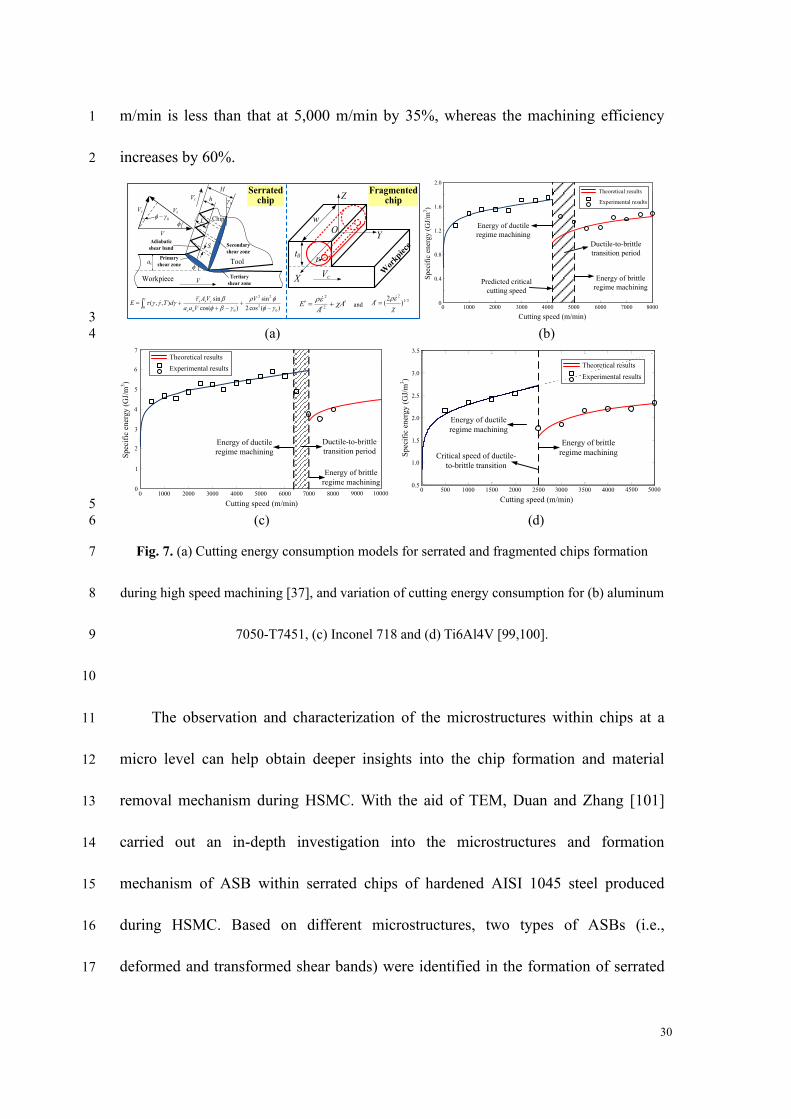
30
m/min is less than that at 5,000 m/min by 35%, whereas the machining efficiency 1
increases by 60%. 2
rt0
VcX
Y
Z
Ow
Tool
Chip
Workpiece
Primary
shear zone
Secondary
shear zone
Tertiary
shear zone
0 −L
ac
h
H
Vc
S
Vc
V
0
Vs
V
Adiabatic
shear band
)(cos2
sin
)cos(
sin),,(
0
2
22
00
−+
−++=
V
Vaa
VAdTE
wc
css
AA
E +
=
2
2 3/1
2
)2
(
=Aand
Serrated chip
Fragmented chip
0
0.4
0.8
1.2
1.6
2.0
0 1000 2000 3000 4000 5000 6000 7000 8000
Cutting speed (m/min)
Sp
ecif
ic e
ner
gy
(G
J/m
3)
Energy of brittle
regime machining Predicted critical
cutting speed
Energy of ductile
regime machining
Theoretical results
Experimental results
Ductile-to-brittle
transition period
3
(a) (b) 4
0
1
2
3
6
7
0 1000 2000 3000 4000 5000 6000 7000 8000
Cutting speed (m/min)
Spec
ific
ener
gy (
GJ/
m3)
Energy of brittle
regime machining
Energy of ductile
regime machining
Ductile-to-brittle
transition period
9000 10000
5
4
Theoretical results
Experimental results
0 500 1000 1500 2000 2500 3000 3500 4000 4500 50000.5
1
1.5
2
2.5
3
3.5x 10
9
0.5
1.0
1.5
2.0
3.5
0 500 1000 1500 2000 2500 3000 3500 4000
Cutting speed (m/min)
Spec
ific
ener
gy (
GJ/
m3)
Energy of brittle
regime machining
Energy of ductile
regime machining
4500 5000
3.0
2.5
Critical speed of ductile-
to-brittle transition
Theoretical results
Experimental results
5
(c) (d) 6
Fig. 7. (a) Cutting energy consumption models for serrated and fragmented chips formation 7
during high speed machining [37], and variation of cutting energy consumption for (b) aluminum 8
7050-T7451, (c) Inconel 718 and (d) Ti6Al4V [99,100]. 9
10
The observation and characterization of the microstructures within chips at a 11
micro level can help obtain deeper insights into the chip formation and material 12
removal mechanism during HSMC. With the aid of TEM, Duan and Zhang [101] 13
carried out an in-depth investigation into the microstructures and formation 14
mechanism of ASB within serrated chips of hardened AISI 1045 steel produced 15
during HSMC. Based on different microstructures, two types of ASBs (i.e., 16
deformed and transformed shear bands) were identified in the formation of serrated 17
31
chips. The deformed ASBs are generated by purely severe plastic shear, while the 1
transformed ASBs are produced by recrystallization process. 2
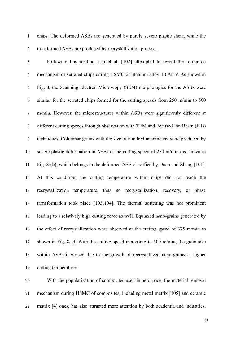
Following this method, Liu et al. [102] attempted to reveal the formation 3
mechanism of serrated chips during HSMC of titanium alloy Ti6Al4V. As shown in 4
Fig. 8, the Scanning Electron Microscopy (SEM) morphologies for the ASBs were 5
similar for the serrated chips formed for the cutting speeds from 250 m/min to 500 6
m/min. However, the microstructures within ASBs were significantly different at 7
different cutting speeds through observation with TEM and Focused Ion Beam (FIB) 8
techniques. Columnar grains with the size of hundred nanometers were produced by 9
severe plastic deformation in ASBs at the cutting speed of 250 m/min (as shown in 10
Fig. 8a,b), which belongs to the deformed ASB classified by Duan and Zhang [101]. 11
At this condition, the cutting temperature within chips did not reach the 12
recrystallization temperature, thus no recrystallization, recovery, or phase 13
transformation took place [103,104]. The thermal softening was not prominent 14
leading to a relatively high cutting force as well. Equiaxed nano-grains generated by 15
the effect of recrystallization were observed at the cutting speed of 375 m/min as 16
shown in Fig. 8c,d. With the cutting speed increasing to 500 m/min, the grain size 17
within ASBs increased due to the growth of recrystallized nano-grains at higher 18
cutting temperatures. 19
With the popularization of composites used in aerospace, the material removal 20
mechanism during HSMC of composites, including metal matrix [105] and ceramic 21
matrix [4] ones, has also attracted more attention by both academia and industries. 22
32
Bejjani et al. [106] studied the microstructural evolution within ASBs of serrated 1
chips formed during HSMC of titanium metal matrix composite (Ti-MMC). They 2
reported that the microstructure inside the ASBs was composed of elongated and 3
equiaxed nano-sized grains attributed to rotational dynamic recrystallization, which 4
is similar with the phenomenon in HSMC of titanium alloy. 5
Columnar grainsColumnar grains
Equiaxed nano-grains
Equiaxed nano-grains
Increase of grain sizeIncrease of grain size
6
Fig. 8. Microstructural evolution in ASBs of serrated chips formed during HSMC of 7
Ti6Al4V at different cutting speeds. (a) Bright field and (b) dark field images at 250 m/min. (c) 8
Bright field and (d) dark field images at 375 m/min. (e) Bright field and (f) dark field images at 9
500 m/min [102]. 10
33
Although the above research is beneficial for understanding the formation 1
mechanism of serrated chips during HSMC of different workpiece materials, some 2
limitations or research gaps still occur implying potential research directions in this 3
field. For instance, the relationship or mapping is still not clear among the specific 4
microstructures formed in chips, deformation conditions such as the strain, strain 5
rate, and state of stress, in addition to the cutting conditions. Furthermore, it has not 6
been focused enough on the dependence of material removal mechanism and 7
associated microstructural evolution on inherent attributes of workpiece material. 8
Original specific microstructures, thermal-physical-mechanical properties and 9
isotropy/anisotropy of workpiece materials may result in different removal 10
mechanism during HSMC process. 11
Effective numerical simulation of the microstructure within chips can help to 12
predict material removal behavior and achieve distributions of microstructure field 13
prior practical machining process. Through developing a Mechanical Threshold Stress 14
(MTS) based internal state variable (ISV) constitutive model, the grain size 15
distributions within ASBs and segments of serrated chips were successfully predicted 16
during HSMC of commercially pure titanium [107] and nickel-based Waspaloy [108], 17
as shown in Fig. 9. In their model, the flow stress depends on the microstructure 18
including the dislocation density and mean grain size. The influences of dislocation 19
drag, dynamic recovery, and dynamic recrystallization are also taken into 20
consideration. When the grain size is smaller than a critical value, an inverse 21
Hall-Petch effect caused by grain boundary sliding is included in the model to 22
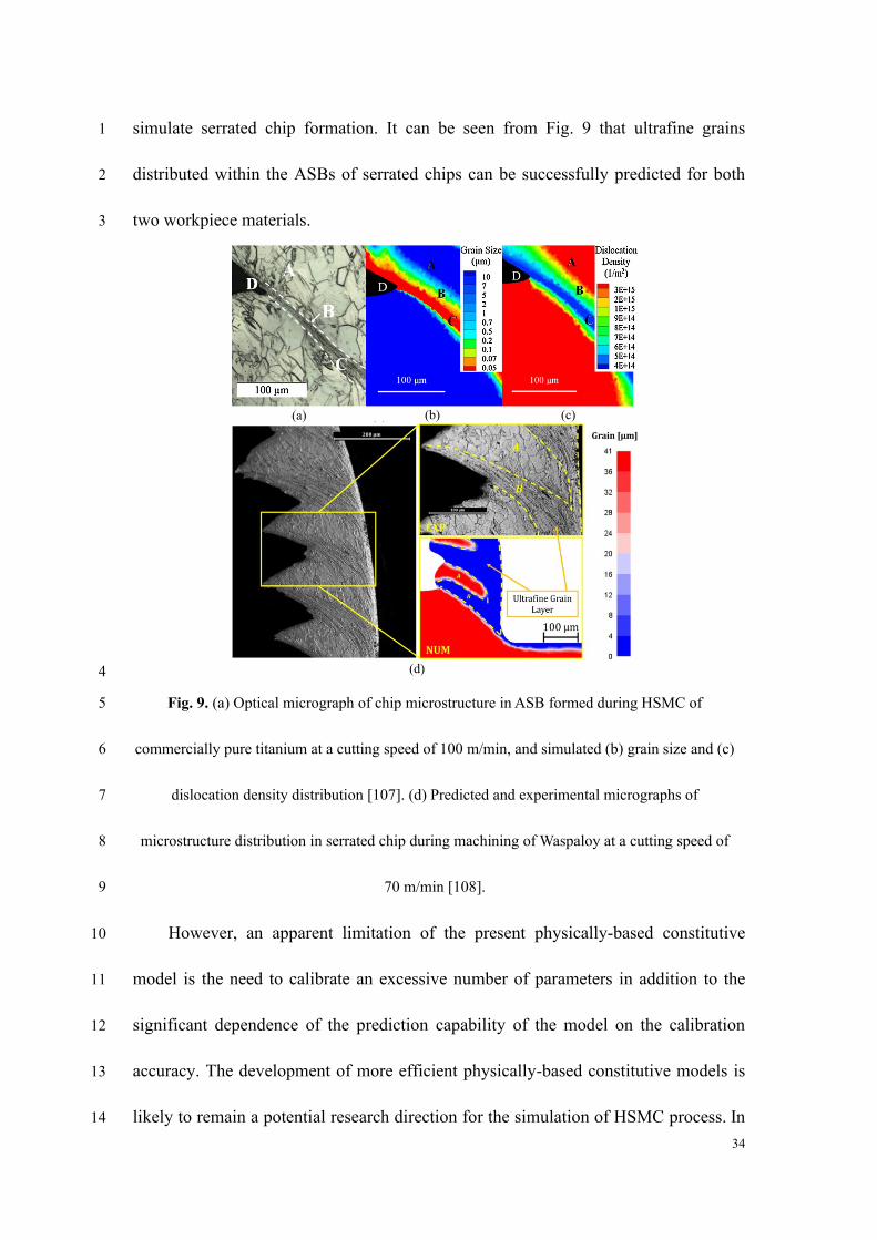
34
simulate serrated chip formation. It can be seen from Fig. 9 that ultrafine grains 1
distributed within the ASBs of serrated chips can be successfully predicted for both 2
two workpiece materials. 3
(b)(a) (b) (c)
(d) 4
Fig. 9. (a) Optical micrograph of chip microstructure in ASB formed during HSMC of 5
commercially pure titanium at a cutting speed of 100 m/min, and simulated (b) grain size and (c) 6
dislocation density distribution [107]. (d) Predicted and experimental micrographs of 7
microstructure distribution in serrated chip during machining of Waspaloy at a cutting speed of 8
70 m/min [108]. 9
However, an apparent limitation of the present physically-based constitutive 10
model is the need to calibrate an excessive number of parameters in addition to the 11
significant dependence of the prediction capability of the model on the calibration 12
accuracy. The development of more efficient physically-based constitutive models is 13
likely to remain a potential research direction for the simulation of HSMC process. In 14
35
addition, the present research about material removal behavior and associated 1
mechanism in HSMC is mainly limited to two-dimensional cutting. Material removal 2
mechanism in three-dimensional cutting that is widely used in practical applications 3
needs further study. 4
5
4. Machined surface integrity in HSMC 6
The excellent surface integrity of the final machined component is a main 7
superiority of HSMC. Surface integrity is commonly used to characterize machined 8
surface quality. It mainly includes surface topography, metallurgical alteration, and 9
mechanical property [15]. In general, surface topography primarily affects the 10
contact condition and stress concentration of machined components, while the 11
metallurgical alteration within the machining-affected area determines the surface 12
mechanical properties, which will further affect the component service performance 13
[109,110]. 14
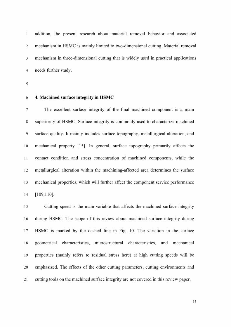
Cutting speed is the main variable that affects the machined surface integrity 15
during HSMC. The scope of this review about machined surface integrity during 16
HSMC is marked by the dashed line in Fig. 10. The variation in the surface 17
geometrical characteristics, microstructural characteristics, and mechanical 18
properties (mainly refers to residual stress here) at high cutting speeds will be 19
emphasized. The effects of the other cutting parameters, cutting environments and 20
cutting tools on the machined surface integrity are not covered in this review paper. 21
36
Machined surface
integrity
Cutting parameters
• Cutting speed
• Feed rate
• Depth of cut, etc.
Influence factors Surface quality
Machining
affected
layer
Bulk
material
Evaluation parameters
Physical property and service performance of machined surface
Cutting environments
• Dry cutting
• Wet cutting
• Cryogenic cutting, etc.
Cutting tools
• Tool structure
• Tool material
• Tool wear, etc.
Geometrical characteristics
• Geometrical morphology
• Surface roughness
• Surface defects, etc.
Microstructural characteristics
• Plastic deformation layer
• Grain size and deformation
• Phase transformation, etc.
Mechanical properties
• Residual stress
• Micro hardness, etc.Review scope
Outcome
1
Fig. 10. Review scope of machined surface integrity in HSMC. 2
3
4.1 Machined surface topography and surface defects generated during HSMC 4
4.1.1 Machined surface topography 5
Surface roughness is the most widely used parameter to characterize the 6
geometrical characteristics of machined surfaces. Regarding assembled machined 7
surfaces, an excessively high surface roughness is likely to induce extreme friction 8
and wear. For load bearing components, a rough surface may induce more severe 9
stress concentrations at asperities, which then result in micro-cracks more easily 10
under external loadings [111]. A smoother surface with lower surface roughness is 11
generally preferred in most mechanical components. The cutting speed is an 12
important process parameter that determines the finished surface roughness by 13
37
affecting the material deformation behavior and the contact conditions between the 1
cutting tool and finished surface. 2
Su et al. [112] performed high speed orthogonal cutting experiments over a 3
speed range from 120 m/min to 1,200 m/min on a high strength alloy steel 4
Aermet100. They revealed an underlying reason for the variation in the 5
micro-topography of machined surface by correlating the chip morphology and 6
machined surface micrograph at different cutting speeds. As shown in Fig. 11, the 7
results indicate that although the machined surface roughness increases as the cutting 8
speed increases from 120 m/min to 200 m/min, it then decreases consistently when 9
the cutting speed increases from 200 m/min to 1,200 m/min. The variation in 10
machined surface roughness is recognized as being induced by micro-waves formed 11
on the surface, which is determined mainly by the degree of chip serration. Complete 12
chip serration at a cutting speed of 1,200 m/min generates the lowest surface 13
roughness, which implies the applicability of HSMC in practical production. 14
An experimental research on HSMC of Ti6Al4V also concluded that the 15
machined surface roughness decreased with increasing of the cutting speed over a 16
range of 420 m/min-1,020 m/min [113]. Decrease of cutting force and serrated chip 17
thickness are two main reasons contributed to the decrease of machined surface 18
roughness at high cutting speeds. Zhou et al. [114] studied the machined surface 19
roughness in high speed turning of Inconel 718 at different cutting speeds, and 20
presented that the variation of machined surface roughness also depends on the 21
cutting tools used. CBN tools coated with titanium nitride (TiN) can induce a 22
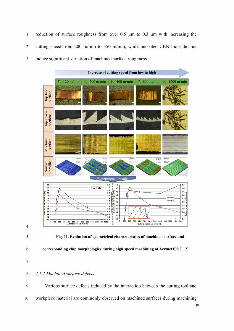
38
reduction of surface roughness from over 0.5 μm to 0.3 μm with increasing the 1
cutting speed from 200 m/min to 350 m/min, while uncoated CBN tools did not 2
induce significant variation of machined surface roughness. 3
Ch
ip f
ree
surf
ace
Ch
ip c
ross
-se
ctio
ns
Mac
hin
ed
surf
ace
Su
rfac
e p
rofi
le
Vc=600 m/minVc=400 m/minVc=200 m/minVc=120 m/min Vc=1200 m/min
Experimental results
4
Fig. 11. Evolution of geometrical characteristics of machined surface and 5
corresponding chip morphologies during high speed machining of Aermet100 [112]. 6
7
4.1.2 Machined surface defects 8
Various surface defects induced by the interaction between the cutting tool and 9
workpiece material are commonly observed on machined surfaces during machining 10

39
processes. These defects will function as weakening locations that cause the 1
initiation and propagation of cracks and premature failure of machined components 2
[115]. Thus, a clear understanding of the types of surface defects and the prevention 3
of their formation through selecting appropriate cutting parameters can effectively 4
use the technical advantages of HSMC. 5
The surface defects formed during HSMC of different workpiece materials such 6
as steels [48], nickel-based alloys [116,117], titanium alloys [118,119], and 7
aluminum alloys [67] have been studied. Fig. 12 presents the typical surface defects 8
formed on machined surfaces during HSMC of two types of nickel-based 9
superalloys (AD 730™ [117] and Inconel 718 [36,120]) under different cutting 10
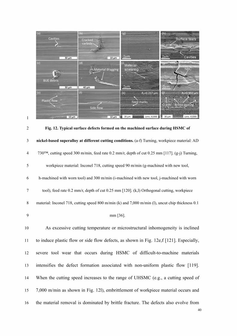
conditions. Cavities and carbide cracking are two main types of surface defects for 11
the two workpiece materials, as shown in Fig. 12a,b,h,j). The cavities are generally 12
formed because of the pull-out of hard precipitates and carbides from the surface or 13
developed in association with tool wear, e.g., irregular wear near the tool nose or 14
adhesion of workpiece material on the cutting edge [117]. Cracked carbides that 15
remain on machined surfaces tend to induce the formation of micro-cracks and 16
deteriorate the machined surface quality. Built-up-edge (BUE) debris detached from 17
the cutting edge is easily re-deposited on the machined surface and induces debris 18
defects. Meanwhile, surface tears and material dragging are likely to occur when 19
detached cracked carbides or BUE are re-deposited and dragged on the machined 20
surface in the subsequent cutting steps. 21
40
30 μm Lens: X1000
Ra=0.237 μm
30 μm Lens: X1000
Brittle tearing Cracks
Ra=0.902 μm
Feed marks
(a) (b)
(g) (h)
(i) (j)
(k) (l)
Cavities Cracked carbide
BUE debris
Material dragging
Plastic flow
Side flow
1
Fig. 12. Typical surface defects formed on the machined surface during HSMC of 2
nickel-based superalloy at different cutting conditions. (a-f) Turning, workpiece material: AD 3
730™, cutting speed 300 m/min, feed rate 0.2 mm/r, depth of cut 0.25 mm [117]. (g-j) Turning, 4
workpiece material: Inconel 718, cutting speed 90 m/min (g-machined with new tool, 5
h-machined with worn tool) and 300 m/min (i-machined with new tool, j-machined with worn 6
tool), feed rate 0.2 mm/r, depth of cut 0.25 mm [120]. (k,l) Orthogonal cutting, workpiece 7
material: Inconel 718, cutting speed 800 m/min (k) and 7,000 m/min (l), uncut chip thickness 0.1 8
mm [36]. 9
As excessive cutting temperature or microstructural inhomogeneity is inclined 10
to induce plastic flow or side flow defects, as shown in Fig. 12e,f [121]. Especially, 11
severe tool wear that occurs during HSMC of difficult-to-machine materials 12
intensifies the defect formation associated with non-uniform plastic flow [119]. 13
When the cutting speed increases to the range of UHSMC (e.g., a cutting speed of 14
7,000 m/min as shown in Fig. 12l), embrittlement of workpiece material occurs and 15
the material removal is dominated by brittle fracture. The defects also evolve from 16
41
plastic deformation types to brittle fracture. Owing to the brittle fracture, the surface 1
roughness generated at the cutting speed of 7,000 m/min is significantly higher than 2
that at 800 m/min. 3
It is noteworthy that the optimum cutting conditions for the inhibition of surface 4
defects differ across different studies even for the same workpiece material. For 5
example, M'Saoubi reported that a good surface finish was obtained during 6
machining of Inconel 718 at a relatively low cutting speed of 90 m/min (as shown in 7
Fig. 12g) due to the lower cutting temperature, whereas Wang et al. [36] observed 8
that a high cutting speed of 800 m/min produced machined surface with less defects 9
as shown in Fig. 12k. Ye et al. [48] also reported that a high cutting speed of 4,000 10
m/min produced a smoother surface than that at a speed of 1,800 m/min during 11
HSMC of 1045 steel. This is attributed to the fact that higher cutting speeds result in 12
a shorter time for the plastic deformation of machined surface, whereby the plastic 13
flow becomes limited resulting in a higher quality of surface integrity [122]. 14
It can be concluded that the cutting speeds at which lower cutting temperatures 15
and less plastic deformation are generated can help suppress the formation of surface 16
defects during ductile regime machining. Meanwhile, when the cutting speed 17
exceeds the critical value of UHSMC, brittle regime machining occurs and the 18
surface quality deteriorates. It is recommended that UHSMC be applied in the rough 19
and semi-finish machining processes rather than in the final finish process. 20
Nevertheless, the means to achieve effective trade-offs between machining 21
42
efficiency and surface defects with proper process planning for different workpiece 1
materials is still under debate. 2
3
4.2 Metallurgical alterations of machined surface 4
4.2.1 Microstructural alteration 5
Metallurgical alterations of machined surfaces have attracted more attention in 6
recent decades and been gradually recognized as a significant surface integrity 7
parameter that determines surface properties and performance. Ultrafine grains are 8
prone to be generated by severe plastic deformation during machining processes. 9
The higher plastic strain and plastic strain rate generated in HSMC provide a 10
favorable condition for the formation of ultrafine grains on the machined surface. 11
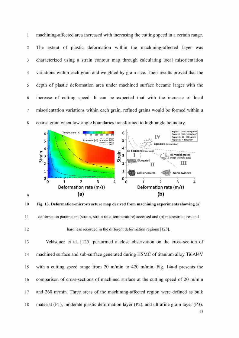
Guo et al. [123] mapped the relationships among deformation rate, strain, and 12
temperature in machining processes (Fig. 13). They summarized the dependence of 13
microstructural alteration and microhardness on the deformation parameters, i.e., 14
strain and deformation rate. It is evident that the range of deformation rate and strain 15
in HSMC can help produce ultrafine grains and micro/nano-sized cell structures. 16
Different research on several kinds of workpiece materials 17
[50,51,104,108,124,125] has demonstrated that high cutting speeds can generate 18
ultrafine grains on the machined surface and subsurface. Xu et al. [50] investigated 19
the microstructural alterations on the machined surface of nickel-based superalloy 20
Inconel 718 over a speed range from 50 m/min to 140 m/min using the PbCT setup as 21
seen in Fig. 4e. It was reported that the severe deformation depth within the 22
43
machining-affected area increased with increasing the cutting speed in a certain range. 1
The extent of plastic deformation within the machining-affected layer was 2
characterized using a strain contour map through calculating local misorientation 3
variations within each grain and weighted by grain size. Their results proved that the 4
depth of plastic deformation area under machined surface became larger with the 5
increase of cutting speed. It can be expected that with the increase of local 6
misorientation variations within each grain, refined grains would be formed within a 7
coarse grain when low-angle boundaries transformed to high-angle boundary. 8
9
Fig. 13. Deformation-microstructure map derived from machining experiments showing (a) 10
deformation parameters (strain, strain rate, temperature) accessed and (b) microstructures and 11
hardness recorded in the different deformation regions [123]. 12
Velásquez et al. [125] performed a close observation on the cross-section of 13
machined surface and sub-surface generated during HSMC of titanium alloy Ti6Al4V 14
with a cutting speed range from 20 m/min to 420 m/min. Fig. 14a-d presents the 15
comparison of cross-sections of machined surface at the cutting speed of 20 m/min 16
and 260 m/min. Three areas of the machining-affected region were defined as bulk 17
material (P1), moderate plastic deformation layer (P2), and ultrafine grain layer (P3). 18
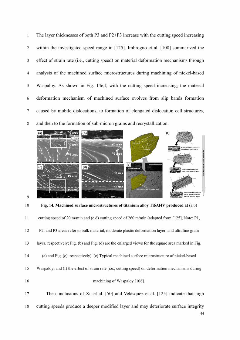
44
The layer thicknesses of both P3 and P2+P3 increase with the cutting speed increasing 1
within the investigated speed range in [125]. Imbrogno et al. [108] summarized the 2
effect of strain rate (i.e., cutting speed) on material deformation mechanisms through 3
analysis of the machined surface microstructures during machining of nickel-based 4
Waspaloy. As shown in Fig. 14e,f, with the cutting speed increasing, the material 5
deformation mechanism of machined surface evolves from slip bands formation 6
caused by mobile dislocations, to formation of elongated dislocation cell structures, 7
and then to the formation of sub-micron grains and recrystallization. 8
(e)
(a) (b)
(c) (d)
(f)
9
Fig. 14. Machined surface microstructures of titanium alloy Ti6Al4V produced at (a,b) 10
cutting speed of 20 m/min and (c,d) cutting speed of 260 m/min (adapted from [125], Note: P1, 11
P2, and P3 areas refer to bulk material, moderate plastic deformation layer, and ultrafine grain 12
layer, respectively; Fig. (b) and Fig. (d) are the enlarged views for the square area marked in Fig. 13
(a) and Fig. (c), respectively). (e) Typical machined surface microstructure of nickel-based 14
Waspaloy, and (f) the effect of strain rate (i.e., cutting speed) on deformation mechanisms during 15
machining of Waspaloy [108]. 16
The conclusions of Xu et al. [50] and Velásquez et al. [125] indicate that high 17
cutting speeds produce a deeper modified layer and may deteriorate surface integrity 18
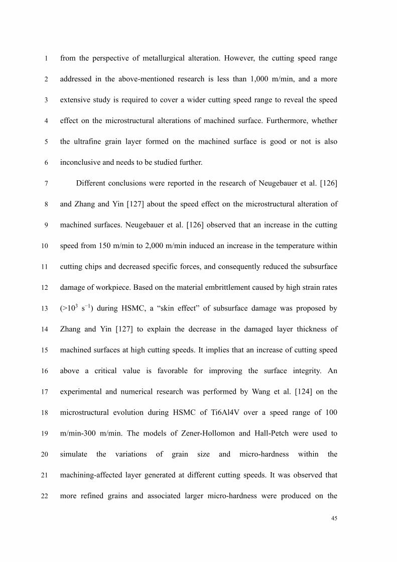
45
from the perspective of metallurgical alteration. However, the cutting speed range 1
addressed in the above-mentioned research is less than 1,000 m/min, and a more 2
extensive study is required to cover a wider cutting speed range to reveal the speed 3
effect on the microstructural alterations of machined surface. Furthermore, whether 4
the ultrafine grain layer formed on the machined surface is good or not is also 5
inconclusive and needs to be studied further. 6
Different conclusions were reported in the research of Neugebauer et al. [126] 7
and Zhang and Yin [127] about the speed effect on the microstructural alteration of 8
machined surfaces. Neugebauer et al. [126] observed that an increase in the cutting 9
speed from 150 m/min to 2,000 m/min induced an increase in the temperature within 10
cutting chips and decreased specific forces, and consequently reduced the subsurface 11
damage of workpiece. Based on the material embrittlement caused by high strain rates 12
(>103 s−1) during HSMC, a “skin effect” of subsurface damage was proposed by 13
Zhang and Yin [127] to explain the decrease in the damaged layer thickness of 14
machined surfaces at high cutting speeds. It implies that an increase of cutting speed 15
above a critical value is favorable for improving the surface integrity. An 16
experimental and numerical research was performed by Wang et al. [124] on the 17
microstructural evolution during HSMC of Ti6Al4V over a speed range of 100 18
m/min-300 m/min. The models of Zener-Hollomon and Hall-Petch were used to 19
simulate the variations of grain size and micro-hardness within the 20
machining-affected layer generated at different cutting speeds. It was observed that 21
more refined grains and associated larger micro-hardness were produced on the 22
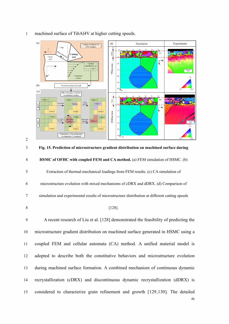
46
machined surface of Ti6Al4V at higher cutting speeds. 1
(a)
(b)
(c)
(d)
2
Fig. 15. Prediction of microstructure gradient distribution on machined surface during 3
HSMC of OFHC with coupled FEM and CA method. (a) FEM simulation of HSMC. (b) 4
Extraction of thermal-mechanical loadings from FEM results. (c) CA simulation of 5
microstructure evolution with mixed mechanisms of cDRX and dDRX. (d) Comparison of 6
simulation and experimental results of microstructure distribution at different cutting speeds 7
[128]. 8
A recent research of Liu et al. [128] demonstrated the feasibility of predicting the 9
microstructure gradient distribution on machined surface generated in HSMC using a 10
coupled FEM and cellular automata (CA) method. A unified material model is 11
adopted to describe both the constitutive behaviors and microstructure evolution 12
during machined surface formation. A combined mechanism of continuous dynamic 13
recrystallization (cDRX) and discontinuous dynamic recrystallization (dDRX) is 14
considered to characterize grain refinement and growth [129,130]. The detailed 15
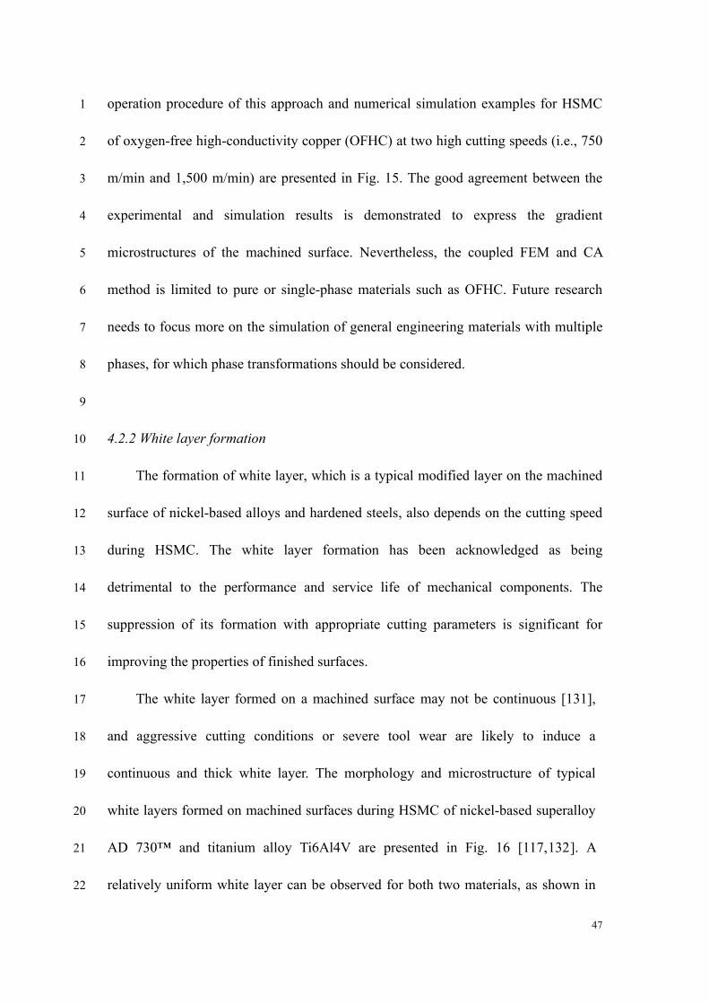
47
operation procedure of this approach and numerical simulation examples for HSMC 1
of oxygen-free high-conductivity copper (OFHC) at two high cutting speeds (i.e., 750 2
m/min and 1,500 m/min) are presented in Fig. 15. The good agreement between the 3
experimental and simulation results is demonstrated to express the gradient 4
microstructures of the machined surface. Nevertheless, the coupled FEM and CA 5
method is limited to pure or single-phase materials such as OFHC. Future research 6
needs to focus more on the simulation of general engineering materials with multiple 7
phases, for which phase transformations should be considered. 8
9
4.2.2 White layer formation 10
The formation of white layer, which is a typical modified layer on the machined 11
surface of nickel-based alloys and hardened steels, also depends on the cutting speed 12
during HSMC. The white layer formation has been acknowledged as being 13
detrimental to the performance and service life of mechanical components. The 14
suppression of its formation with appropriate cutting parameters is significant for 15
improving the properties of finished surfaces. 16
The white layer formed on a machined surface may not be continuous [131], 17
and aggressive cutting conditions or severe tool wear are likely to induce a 18
continuous and thick white layer. The morphology and microstructure of typical 19
white layers formed on machined surfaces during HSMC of nickel-based superalloy 20
AD 730™ and titanium alloy Ti6Al4V are presented in Fig. 16 [117,132]. A 21
relatively uniform white layer can be observed for both two materials, as shown in 22
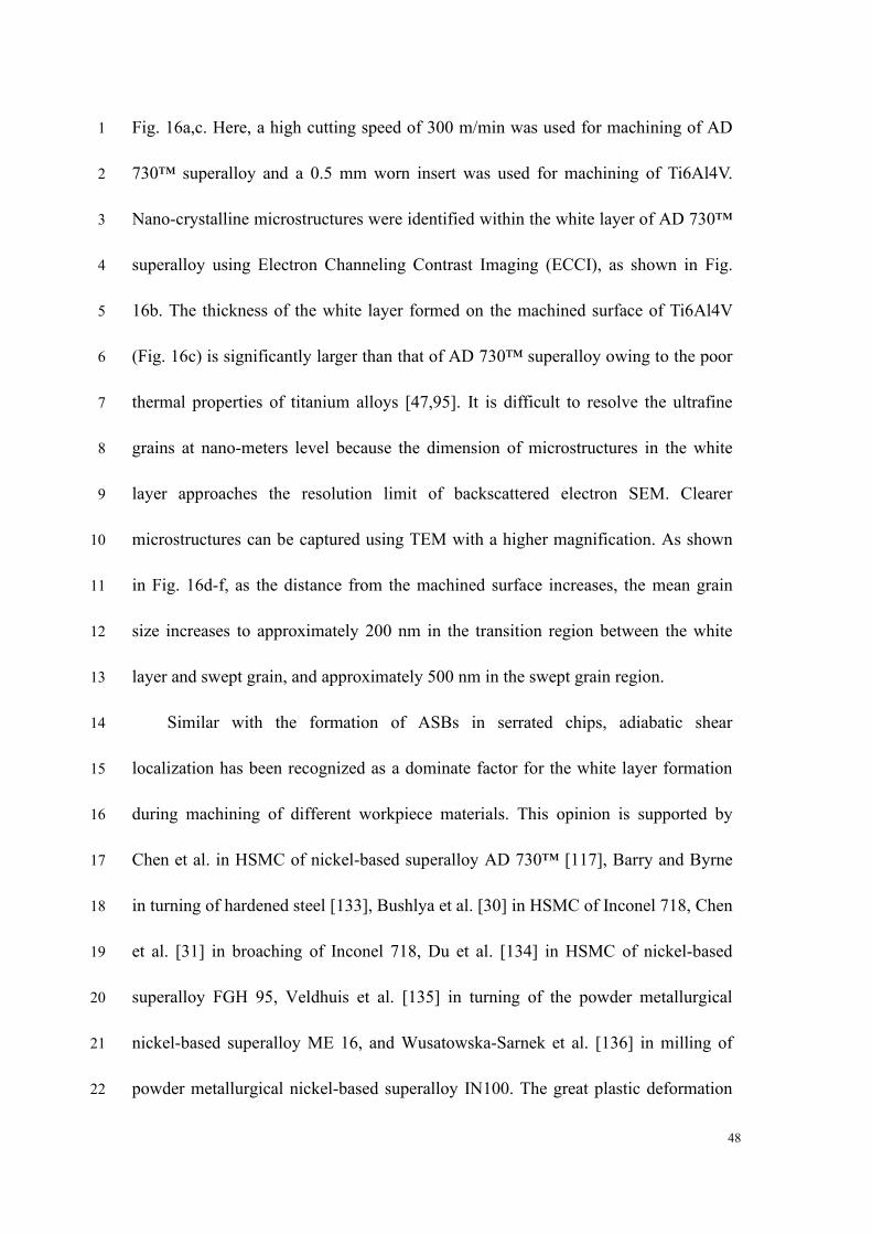
48
Fig. 16a,c. Here, a high cutting speed of 300 m/min was used for machining of AD 1
730™ superalloy and a 0.5 mm worn insert was used for machining of Ti6Al4V. 2
Nano-crystalline microstructures were identified within the white layer of AD 730™ 3
superalloy using Electron Channeling Contrast Imaging (ECCI), as shown in Fig. 4
16b. The thickness of the white layer formed on the machined surface of Ti6Al4V 5
(Fig. 16c) is significantly larger than that of AD 730™ superalloy owing to the poor 6
thermal properties of titanium alloys [47,95]. It is difficult to resolve the ultrafine 7
grains at nano-meters level because the dimension of microstructures in the white 8
layer approaches the resolution limit of backscattered electron SEM. Clearer 9
microstructures can be captured using TEM with a higher magnification. As shown 10
in Fig. 16d-f, as the distance from the machined surface increases, the mean grain 11
size increases to approximately 200 nm in the transition region between the white 12
layer and swept grain, and approximately 500 nm in the swept grain region. 13
Similar with the formation of ASBs in serrated chips, adiabatic shear 14
localization has been recognized as a dominate factor for the white layer formation 15
during machining of different workpiece materials. This opinion is supported by 16
Chen et al. in HSMC of nickel-based superalloy AD 730™ [117], Barry and Byrne 17
in turning of hardened steel [133], Bushlya et al. [30] in HSMC of Inconel 718, Chen 18
et al. [31] in broaching of Inconel 718, Du et al. [134] in HSMC of nickel-based 19
superalloy FGH 95, Veldhuis et al. [135] in turning of the powder metallurgical 20
nickel-based superalloy ME 16, and Wusatowska-Sarnek et al. [136] in milling of 21
powder metallurgical nickel-based superalloy IN100. The great plastic deformation 22
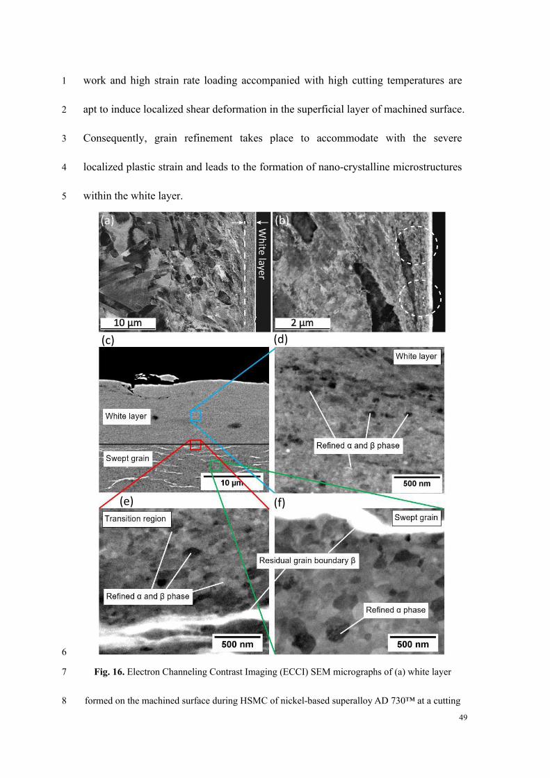
49
work and high strain rate loading accompanied with high cutting temperatures are 1
apt to induce localized shear deformation in the superficial layer of machined surface. 2
Consequently, grain refinement takes place to accommodate with the severe 3
localized plastic strain and leads to the formation of nano-crystalline microstructures 4
within the white layer. 5
(c) (d)
(e) (f)
6
Fig. 16. Electron Channeling Contrast Imaging (ECCI) SEM micrographs of (a) white layer 7
formed on the machined surface during HSMC of nickel-based superalloy AD 730™ at a cutting 8
50
speed of 300 m/min, and (b) nano-crystalline microstructure as marked by dash lines within the 1
white layer [117]; (c) Cross-sectional Backscattered Electron SEM images of the white layer and 2
deformed region on the machined surface during HSMC of titanium alloy Ti6Al4V. Higher 3
magnification images of (d) the white layer, (e) the transition region between white layer and 4
swept grain and (f) the swept grain [132]. 5
Liao et al. [137] investigated the formation mechanism of white layer for a 6
nickel-based superalloy S135H under severe plastic deformation induced by 7
machining process. Their results show that the white layer was composed of a graded 8
microstructure, which includes a dynamic recrystallized layer formed by 9
nano-crystallized grains and a dynamic recovery layer formed by sub-grain 10
microstructures. Although grain refinement occurred within the superficial surface of 11
white layer, γ' phase dissolution also occurred leading to distinctly different properties 12
of white layer from bulk material. Based on cyclic compression tests using 13
micropillars, it was found that the white layer has lower strength and increased 14
ductility compared to the bulk material. As a result, the white layer formation 15
weakens the mechanical properties of machined surface and is expected to be avoided 16
in machining process. However, the influence of cutting speed on the white layer 17
formation of S135H was not covered in [137] and needs to be further studied. 18
The effect of cutting speed on the white layer formation of another typical 19
nickel-based superalloy FGH95 was reported in [134]. Through a close examination 20
on the cross-sections of white layer formed on the machined surface, a thin white 21
layer with about several micros in thickness was formed on the machined surface 22
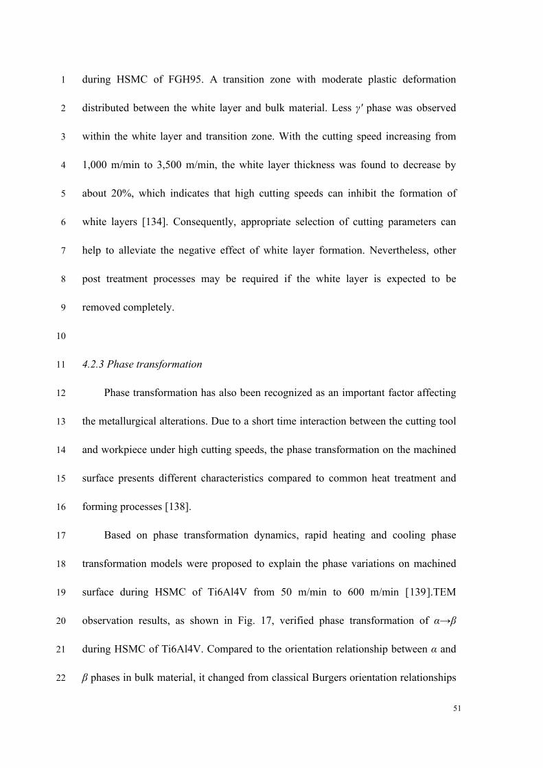
51
during HSMC of FGH95. A transition zone with moderate plastic deformation 1
distributed between the white layer and bulk material. Less γ' phase was observed 2
within the white layer and transition zone. With the cutting speed increasing from 3
1,000 m/min to 3,500 m/min, the white layer thickness was found to decrease by 4
about 20%, which indicates that high cutting speeds can inhibit the formation of 5
white layers [134]. Consequently, appropriate selection of cutting parameters can 6
help to alleviate the negative effect of white layer formation. Nevertheless, other 7
post treatment processes may be required if the white layer is expected to be 8
removed completely. 9
10
4.2.3 Phase transformation 11
Phase transformation has also been recognized as an important factor affecting 12
the metallurgical alterations. Due to a short time interaction between the cutting tool 13
and workpiece under high cutting speeds, the phase transformation on the machined 14
surface presents different characteristics compared to common heat treatment and 15
forming processes [138]. 16
Based on phase transformation dynamics, rapid heating and cooling phase 17
transformation models were proposed to explain the phase variations on machined 18
surface during HSMC of Ti6Al4V from 50 m/min to 600 m/min [139].TEM 19
observation results, as shown in Fig. 17, verified phase transformation of α→β 20
during HSMC of Ti6Al4V. Compared to the orientation relationship between α and 21
β phases in bulk material, it changed from classical Burgers orientation relationships 22
52
of (0001)α//(110)β and [11-20]α//[111]β to new orientation relationships of 1
(01−10)α//(110)β, [0001]α//[111]β. The phase transformations occurred in both ASB 2
and tool-chip interface of serrated chips, and machined surfaces are shown in Fig. 19. 3
It was reported that the β phase ratio increased from 8% to 90% in the machined 4
surface layer generated over the high cutting speed range of 50 – 600 m/min. 5
Nevertheless, the current research on the phase transformation behavior of 6
machined surface during HSMC is still limited, and which kind phase is better for 7
the service performance of machined surface is also unclear. Effective prediction and 8
control of phase transformations will be important and needs further research. 9
10
Fig. 17. Phase transformations during HSMC of Ti6Al4V. (a), (c), (e) and (g) are the bright 11
field TEM images of bulk material, tool-chip interface of serrated chip produced at 200 m/min, 12
ASBs of serrated chip produced at 500 m/min, and machined surface formed at 600 m/min, 13
respectively. (b), (d), (f) and (h) are the SAED patterns of corresponding regions, respectively 14
[139]. 15
53
It is clear from the preceding discussion that researchers are trying to get deeper 1
insights into the microstructural alterations of machined surface generated in HSMC, 2
as the microstructure determines final physical and mechanical properties of 3
machined components. With the advancement of material observation and 4
characterization tools, evaluation of machined surface integrity has been expanded 5
from macro level to micro and nano levels. Application of new engineering materials, 6
such as powder metallurgy superalloys, metal matrix and ceramic matrix composites, 7
also raises urgent needs for effective assessment of machined surface integrity of 8
such new materials. It is anticipated that this research direction will still be popular 9
in the near future driven by the machining requirements of industrial sectors. 10
11
4.3 Residual stress distribution within machined surface layer 12
Residual stress has significant influence on the mechanical behavior, 13
particularly the fatigue performance, of machined components [140,141]. For 14
thin-walled components, residual stress also impacts the dimensional accuracy and 15
determines the subsequent assembly quality [ 142 ]. Fractographic analysis of 16
mechanical components demonstrates that fatigue failures are generally nucleated on 17
the surface or subsurface of components. As a result, the residual stress generated 18
within the machining-affected layer is critical for assuring the service performance 19
of finished components. 20
Compressive residual stress is preferred on the finished surface during 21
machining process. A compressive residual stress can increase the threshold values 22
54
of allowed alternating stress for a specific fatigue life. Comparatively, a tensile 1
residual stress indicates a reduction of allowed alternating stress during working 2
[143,144]. Too high tensile residual stress generated on the machined surface will be 3
detrimental to the fatigue performance and lead to a premature failure of mechanical 4
components and even disasters. Furthermore, the effect of residual stress is 5
particularly prominent for high cycle fatigue regime because the working stress is 6
too low to substantially relax the residual stress generated during machining process 7
[145]. 8
The plastic deformation of machined surface and cutting heat that propagates 9
into the workpiece are the main causes of residual stress generation. In general, the 10
cutting heat and associated thermal effect are apt to induce tensile residual stress, 11
whereas plastic deformation and associated mechanical loading tend to generate 12
compressive residual stress [19]. Jacobson et al. [146] observed that an increase in 13
the strain rate at high cutting speeds can generate more mechanical work, which 14
would result in compressive residual stresses. Meanwhile, more severe plastic 15
deformation at high cutting speeds generates more heat leading to tensile residual 16
stress formation. The final state of the residual stress on the machined surface would 17
be determined by the above two competing factors. 18
The residual stress profiles within machining-affected layers of Inconel 718 19
during a turning process at different cutting speeds were investigated by Schlauer et 20
al [147]. Low residual stress and small distribution depth of the residual stress were 21
generated at a low cutting speed of 10 m/min. With increasing the cutting speed to 22
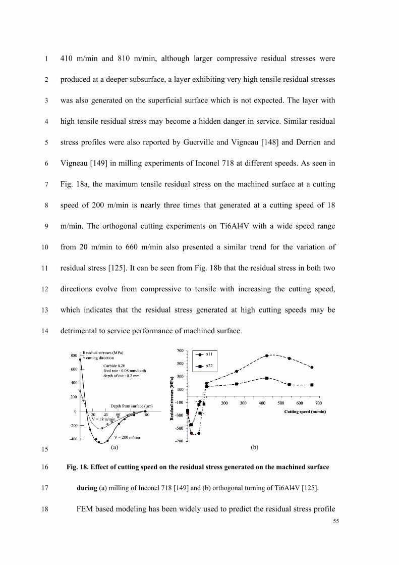
55
410 m/min and 810 m/min, although larger compressive residual stresses were 1
produced at a deeper subsurface, a layer exhibiting very high tensile residual stresses 2
was also generated on the superficial surface which is not expected. The layer with 3
high tensile residual stress may become a hidden danger in service. Similar residual 4
stress profiles were also reported by Guerville and Vigneau [148] and Derrien and 5
Vigneau [149] in milling experiments of Inconel 718 at different speeds. As seen in 6
Fig. 18a, the maximum tensile residual stress on the machined surface at a cutting 7
speed of 200 m/min is nearly three times that generated at a cutting speed of 18 8
m/min. The orthogonal cutting experiments on Ti6Al4V with a wide speed range 9
from 20 m/min to 660 m/min also presented a similar trend for the variation of 10
residual stress [125]. It can be seen from Fig. 18b that the residual stress in both two 11
directions evolve from compressive to tensile with increasing the cutting speed, 12
which indicates that the residual stress generated at high cutting speeds may be 13
detrimental to service performance of machined surface. 14
(a) (b) 15
Fig. 18. Effect of cutting speed on the residual stress generated on the machined surface 16
during (a) milling of Inconel 718 [149] and (b) orthogonal turning of Ti6Al4V [125]. 17
FEM based modeling has been widely used to predict the residual stress profile 18
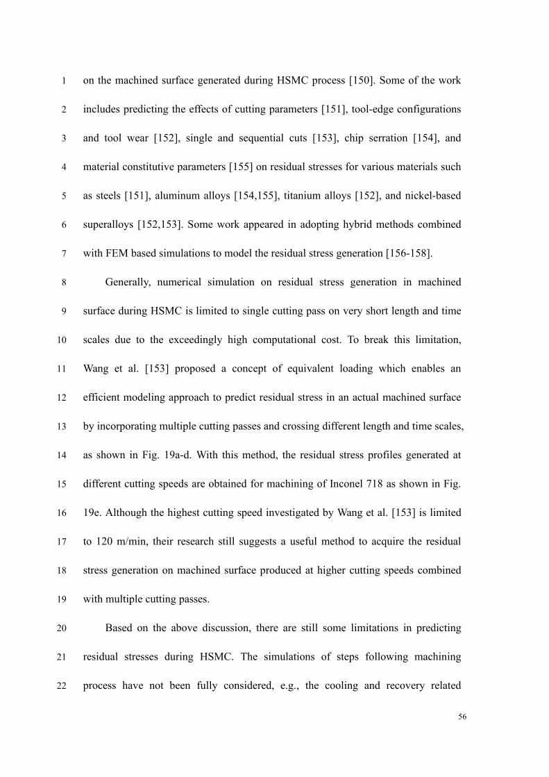
56
on the machined surface generated during HSMC process [150]. Some of the work 1
includes predicting the effects of cutting parameters [151], tool-edge configurations 2
and tool wear [152], single and sequential cuts [153], chip serration [154], and 3
material constitutive parameters [155] on residual stresses for various materials such 4
as steels [151], aluminum alloys [154,155], titanium alloys [152], and nickel-based 5
superalloys [152,153]. Some work appeared in adopting hybrid methods combined 6
with FEM based simulations to model the residual stress generation [156-158]. 7
Generally, numerical simulation on residual stress generation in machined 8
surface during HSMC is limited to single cutting pass on very short length and time 9
scales due to the exceedingly high computational cost. To break this limitation, 10
Wang et al. [153] proposed a concept of equivalent loading which enables an 11
efficient modeling approach to predict residual stress in an actual machined surface 12
by incorporating multiple cutting passes and crossing different length and time scales, 13
as shown in Fig. 19a-d. With this method, the residual stress profiles generated at 14
different cutting speeds are obtained for machining of Inconel 718 as shown in Fig. 15
19e. Although the highest cutting speed investigated by Wang et al. [153] is limited 16
to 120 m/min, their research still suggests a useful method to acquire the residual 17
stress generation on machined surface produced at higher cutting speeds combined 18
with multiple cutting passes. 19
Based on the above discussion, there are still some limitations in predicting 20
residual stresses during HSMC. The simulations of steps following machining 21
process have not been fully considered, e.g., the cooling and recovery related 22
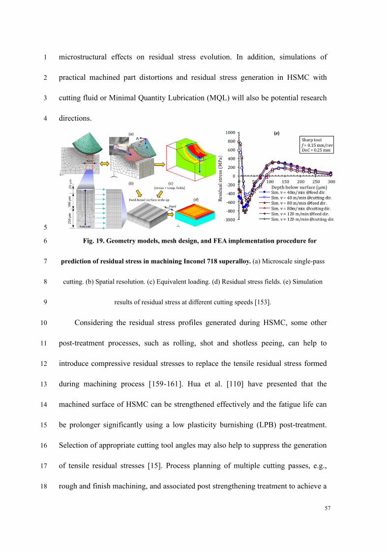
57
microstructural effects on residual stress evolution. In addition, simulations of 1
practical machined part distortions and residual stress generation in HSMC with 2
cutting fluid or Minimal Quantity Lubrication (MQL) will also be potential research 3
directions. 4
(e)
5
Fig. 19. Geometry models, mesh design, and FEA implementation procedure for 6
prediction of residual stress in machining Inconel 718 superalloy. (a) Microscale single-pass 7
cutting. (b) Spatial resolution. (c) Equivalent loading. (d) Residual stress fields. (e) Simulation 8
results of residual stress at different cutting speeds [153]. 9
Considering the residual stress profiles generated during HSMC, some other 10
post-treatment processes, such as rolling, shot and shotless peeing, can help to 11
introduce compressive residual stresses to replace the tensile residual stress formed 12
during machining process [159-161]. Hua et al. [110] have presented that the 13
machined surface of HSMC can be strengthened effectively and the fatigue life can 14
be prolonger significantly using a low plasticity burnishing (LPB) post-treatment. 15
Selection of appropriate cutting tool angles may also help to suppress the generation 16
of tensile residual stresses [15]. Process planning of multiple cutting passes, e.g., 17
rough and finish machining, and associated post strengthening treatment to achieve a 18
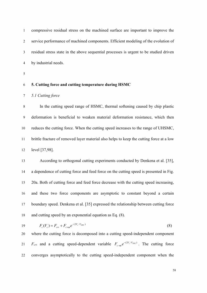
58
compressive residual stress on the machined surface are important to improve the 1
service performance of machined components. Efficient modeling of the evolution of 2
residual stress state in the above sequential processes is urgent to be studied driven 3
by industrial needs. 4
5
5. Cutting force and cutting temperature during HSMC 6
5.1 Cutting force 7
In the cutting speed range of HSMC, thermal softening caused by chip plastic 8
deformation is beneficial to weaken material deformation resistance, which then 9
reduces the cutting force. When the cutting speed increases to the range of UHSMC, 10
brittle fracture of removed layer material also helps to keep the cutting force at a low 11
level [37,98]. 12
According to orthogonal cutting experiments conducted by Denkena et al. [35], 13
a dependence of cutting force and feed force on the cutting speed is presented in Fig. 14
20a. Both of cutting force and feed force decrease with the cutting speed increasing, 15
and these two force components are asymptotic to constant beyond a certain 16
boundary speed. Denkena et al. [35] expressed the relationship between cutting force 17
and cutting speed by an exponential equation as Eq. (8). 18
(2 / )
var( ) c HSCV V
c c c cF V F F e−
= + (8) 19
where the cutting force is decomposed into a cutting speed-independent component 20
Fc∞ and a cutting speed-dependent variable )/2(
varHSCc VV
c eF−
. The cutting force 21
converges asymptotically to the cutting speed-independent component when the 22
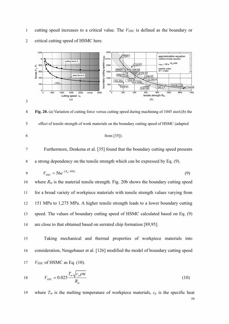
59
cutting speed increases to a critical value. The VHSC is defined as the boundary or 1
critical cutting speed of HSMC here. 2
(a) (b) 3
Fig. 20. (a) Variation of cutting force versus cutting speed during machining of 1045 steel;(b) the 4
effect of tensile strength of work materials on the boundary cutting speed of HSMC (adapted 5
from [35]). 6
Furthermore, Denkena et al. [35] found that the boundary cutting speed presents 7
a strong dependency on the tensile strength which can be expressed by Eq. (9). 8
( )/40056 mR
HSCV e−
= (9) 9
where Rm is the material tensile strength. Fig. 20b shows the boundary cutting speed 10
for a broad variety of workpiece materials with tensile strength values varying from 11
151 MPa to 1,275 MPa. A higher tensile strength leads to a lower boundary cutting 12
speed. The values of boundary cutting speed of HSMC calculated based on Eq. (9) 13
are close to that obtained based on serrated chip formation [89,95]. 14
Taking mechanical and thermal properties of workpiece materials into 15
consideration, Neugebauer et al. [126] modified the model of boundary cutting speed 16
VHSC of HSMC as Eq. (10). 17
0.025m p
HSC
m
T cV
R
= (10) 18
where Tm is the melting temperature of workpiece materials, cp is the specific heat 19
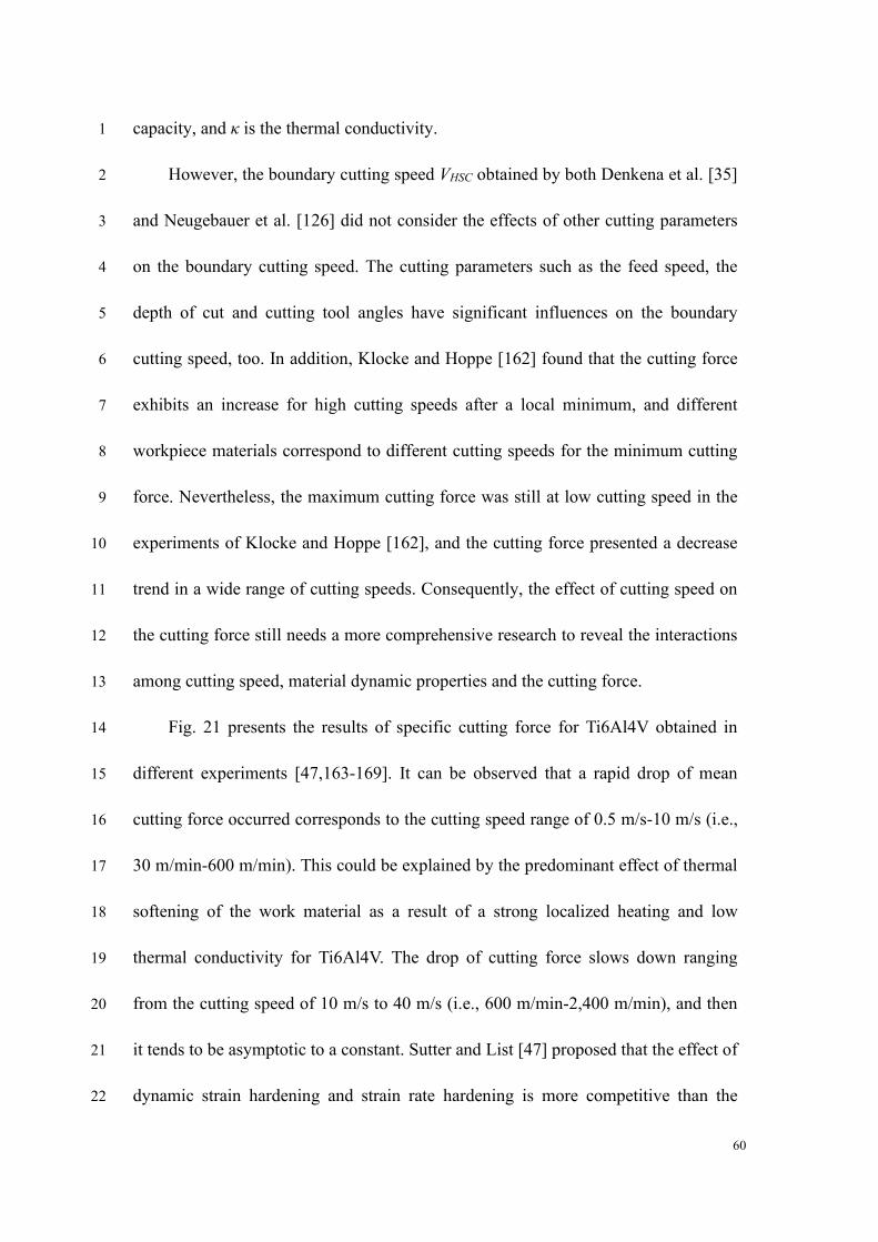
60
capacity, and κ is the thermal conductivity. 1
However, the boundary cutting speed VHSC obtained by both Denkena et al. [35] 2
and Neugebauer et al. [126] did not consider the effects of other cutting parameters 3
on the boundary cutting speed. The cutting parameters such as the feed speed, the 4
depth of cut and cutting tool angles have significant influences on the boundary 5
cutting speed, too. In addition, Klocke and Hoppe [162] found that the cutting force 6
exhibits an increase for high cutting speeds after a local minimum, and different 7
workpiece materials correspond to different cutting speeds for the minimum cutting 8
force. Nevertheless, the maximum cutting force was still at low cutting speed in the 9
experiments of Klocke and Hoppe [162], and the cutting force presented a decrease 10
trend in a wide range of cutting speeds. Consequently, the effect of cutting speed on 11
the cutting force still needs a more comprehensive research to reveal the interactions 12
among cutting speed, material dynamic properties and the cutting force. 13
Fig. 21 presents the results of specific cutting force for Ti6Al4V obtained in 14
different experiments [47,163-169]. It can be observed that a rapid drop of mean 15
cutting force occurred corresponds to the cutting speed range of 0.5 m/s-10 m/s (i.e., 16
30 m/min-600 m/min). This could be explained by the predominant effect of thermal 17
softening of the work material as a result of a strong localized heating and low 18
thermal conductivity for Ti6Al4V. The drop of cutting force slows down ranging 19
from the cutting speed of 10 m/s to 40 m/s (i.e., 600 m/min-2,400 m/min), and then 20
it tends to be asymptotic to a constant. Sutter and List [47] proposed that the effect of 21
dynamic strain hardening and strain rate hardening is more competitive than the 22
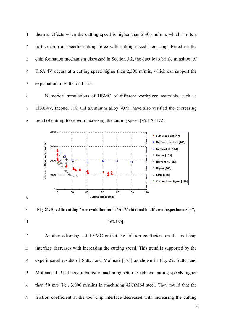
61
thermal effects when the cutting speed is higher than 2,400 m/min, which limits a 1
further drop of specific cutting force with cutting speed increasing. Based on the 2
chip formation mechanism discussed in Section 3.2, the ductile to brittle transition of 3
Ti6Al4V occurs at a cutting speed higher than 2,500 m/min, which can support the 4
explanation of Sutter and List. 5
Numerical simulations of HSMC of different workpiece materials, such as 6
Ti6Al4V, Inconel 718 and aluminum alloy 7075, have also verified the decreasing 7
trend of cutting force with increasing the cutting speed [95,170-172]. 8
Sutter and List [47]
Hoffmeister et al. [163]
Gente et al. [164]
Hoppe [165]
Barry et al. [166]
Illgner [167]
Larbi [168]
Cotterell and Byrne [169]
9
Fig. 21. Specific cutting force evolution for Ti6Al4V obtained in different experiments [47, 10
163-169]. 11
Another advantage of HSMC is that the friction coefficient on the tool-chip 12
interface decreases with increasing the cutting speed. This trend is supported by the 13
experimental results of Sutter and Molinari [173] as shown in Fig. 22. Sutter and 14
Molinari [173] utilized a ballistic machining setup to achieve cutting speeds higher 15
than 50 m/s (i.e., 3,000 m/min) in machining 42CrMo4 steel. They found that the 16
friction coefficient at the tool-chip interface decreased with increasing the cutting 17
62
speed at both cutting depths of 0.2 mm and 0.5 mm. Other researchers also found the 1
decrease of friction coefficient at high cutting speeds, such as Findley and Reed [174] 2
for lead-antimony alloy (the friction coefficient decreases from 0.85 to 0.3 with 3
cutting speed from near zero to 780 m/min), Tanaka et al. [175] for steel (the friction 4
coefficient decreases from 0.6 to 0.18 with cutting speed from near zero to 8,000 5
m/min) and Recht [176] for 4340 steel (the friction coefficient decreases from 0.6 to 6
0.26 with cutting speed from 240 m/min to 2,160 m/min). 7
8
Fig. 22. Experimental evolution of friction coefficient at the tool-chip interface for a wide 9
range of cutting speeds [173]. 10
Recht [176] explained the reduction of friction coefficient as being due to 11
melting at the asperities between tool-chip interface. Neugebauer et al. [126] 12
proposed that at very high cutting speeds and normal forces, the sliding surfaces 13
between tool and chip are separated by a lubricating film of molten workpiece 14
material, which may help reduce the friction coefficient to very low values. However, 15
considering the embrittlement of work materials at very high cutting speeds, the 16
above postulations seem to be inapplicable for UHSMC. The decreasing adhesion 17
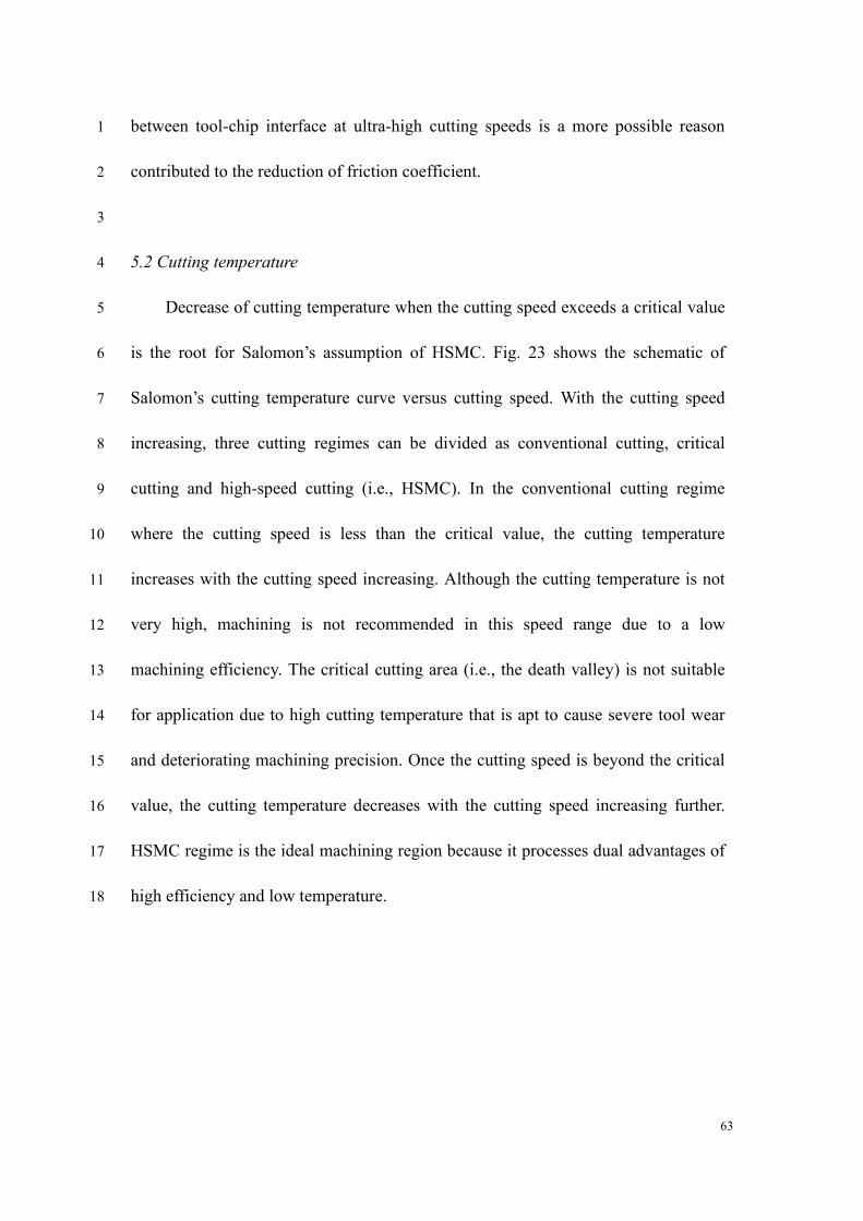
63
between tool-chip interface at ultra-high cutting speeds is a more possible reason 1
contributed to the reduction of friction coefficient. 2
3
5.2 Cutting temperature 4
Decrease of cutting temperature when the cutting speed exceeds a critical value 5
is the root for Salomon’s assumption of HSMC. Fig. 23 shows the schematic of 6
Salomon’s cutting temperature curve versus cutting speed. With the cutting speed 7
increasing, three cutting regimes can be divided as conventional cutting, critical 8
cutting and high-speed cutting (i.e., HSMC). In the conventional cutting regime 9
where the cutting speed is less than the critical value, the cutting temperature 10
increases with the cutting speed increasing. Although the cutting temperature is not 11
very high, machining is not recommended in this speed range due to a low 12
machining efficiency. The critical cutting area (i.e., the death valley) is not suitable 13
for application due to high cutting temperature that is apt to cause severe tool wear 14
and deteriorating machining precision. Once the cutting speed is beyond the critical 15
value, the cutting temperature decreases with the cutting speed increasing further. 16
HSMC regime is the ideal machining region because it processes dual advantages of 17
high efficiency and low temperature. 18
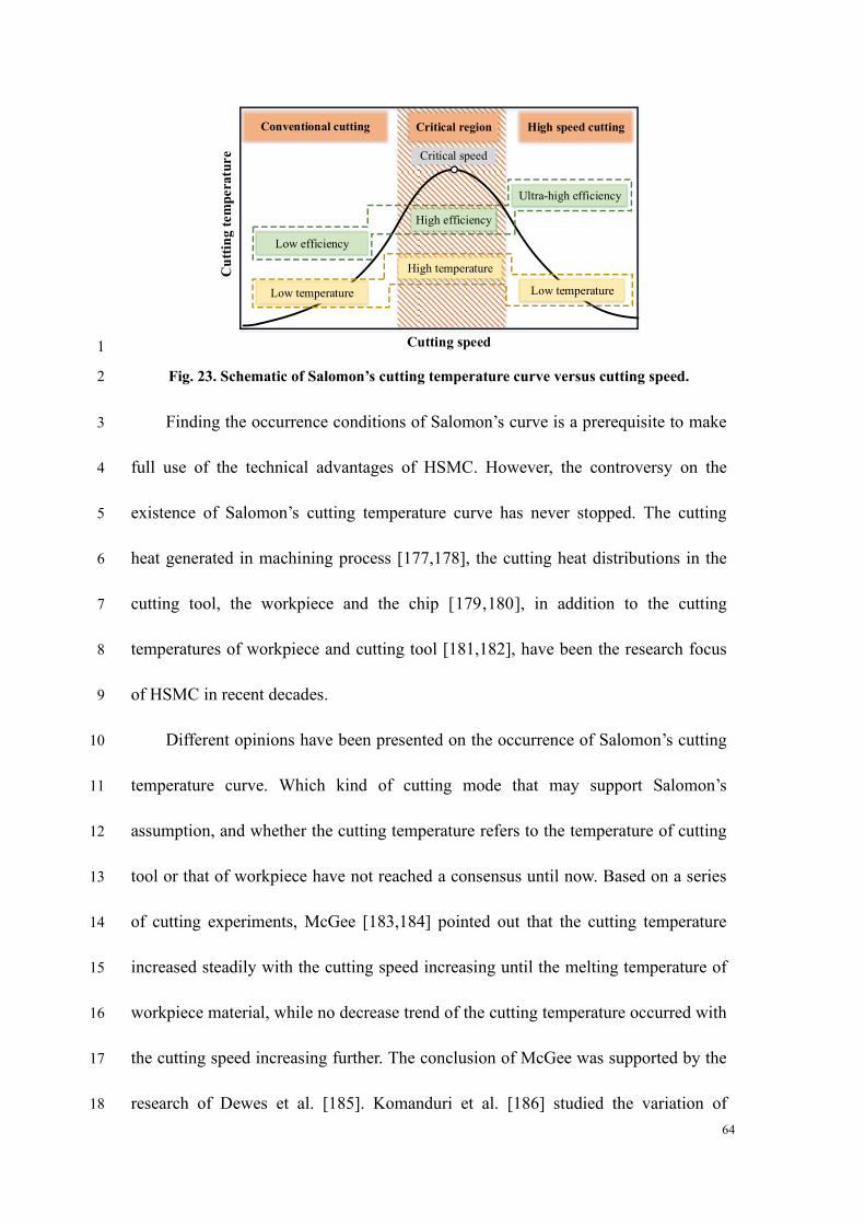
64
Low temperature
High temperature
Low temperature
Low efficiency
High efficiency
Ultra-high efficiency
Critical speed
Conventional cutting Critical region High speed cutting
Cutting speed
Cu
ttin
g t
em
pera
ture
1
Fig. 23. Schematic of Salomon’s cutting temperature curve versus cutting speed. 2
Finding the occurrence conditions of Salomon’s curve is a prerequisite to make 3
full use of the technical advantages of HSMC. However, the controversy on the 4
existence of Salomon’s cutting temperature curve has never stopped. The cutting 5
heat generated in machining process [177,178], the cutting heat distributions in the 6
cutting tool, the workpiece and the chip [179,180], in addition to the cutting 7
temperatures of workpiece and cutting tool [181,182], have been the research focus 8
of HSMC in recent decades. 9
Different opinions have been presented on the occurrence of Salomon’s cutting 10
temperature curve. Which kind of cutting mode that may support Salomon’s 11
assumption, and whether the cutting temperature refers to the temperature of cutting 12
tool or that of workpiece have not reached a consensus until now. Based on a series 13
of cutting experiments, McGee [183,184] pointed out that the cutting temperature 14
increased steadily with the cutting speed increasing until the melting temperature of 15
workpiece material, while no decrease trend of the cutting temperature occurred with 16
the cutting speed increasing further. The conclusion of McGee was supported by the 17
research of Dewes et al. [185]. Komanduri et al. [186] studied the variation of 18
65
cutting temperature on the tool-chip interface, and concluded that the cutting 1
temperature increased with the cutting speed increasing without any decrease. 2
Radulescu and Kapoor [187] proposed that the cutting temperature on the tool-chip 3
interface has positive correlation with the cutting speed, and this correlation is 4
suitable to both continuous and interrupted cutting modes. Longbottom and Lanham 5
[22] made a comprehensive review on relevant research about Salomon’s assumption 6
about cutting temperature, and suggested that Salomon’s assumption may not be 7
suitable for the tool-chip interface temperature, while it may be adaptable for the 8
variation of temperature on workpiece surface. 9
The interrupted machining may be a necessary condition for the tenability of 10
Salomon’s assumption about cutting temperature. Through high speed milling 11
experiments of aluminum alloy, Schultz [188] found that a large amount of cutting 12
heat is dissipated by the fast-moving chips, leading to a low temperature on the 13
machined surface at high milling speeds. Dagiloke et al. [189] and Chen et al. [190] 14
reported that high milling speeds lead to a decrease of heat transfer time from heat 15
sources into workpiece, which then results in low temperatures on the workpiece 16
surface in HSMC. O’Sullivan and Cotterell [191] found that the temperature on 17
workpiece surface could be decreased at a not very high speed as about 220 m/min 18
during machining of aluminum. Palmai [192] proposed that Salomon’s assumption is 19
valid for the variation of cutting temperature during interrupted machining such as 20
milling, and developed an empirical cutting temperature model which is consistent 21
with Salomon’s results, but the underlying reason for the cutting conditions that 22
66
support Salomon’s assumption was not given. 1
A decrease of cutting heat distribution proportion may also lead to decrease of 2
cutting temperature in either workpiece surface or cutting tool. Richardson et al. 3
[193] performed milling experiments on aluminum alloy 7449 with a wide cutting 4
speed ranging from 300 m/min to 3,000 m/min, and revealed that the workpiece 5
surface temperature decreased substantially due to a reduction of 83% for the heat 6
distribution into the workpiece. The distribution proportions of cutting heat within 7
cutting deformation zones are also different in different literatures. Shaw [194] 8
proposed that 90% of the total cutting heat flows into cutting chips, while the rest 9
10% of the cutting heat flows into the workpiece and cutting tool equally. Another 10
research reported that 80% percent of the total cutting heat is taken away by cutting 11
chips, while the rest 20% flows into workpiece and cutting tool [195]. 12
Astakhov [9,196] suggested that Péclet criterion, which is defined as the ratio of 13
the product of cutting speed and cutting depth to thermal diffusivity of work material, 14
can be used to understand the cutting heat distribution in metal cutting process. The 15
Péclet number Pe is a similarity number and it characterizes the relative influence of 16
the cutting parameters with respect to the thermal properties of work material on 17
cutting heat distribution. Astakhov [196] found that the Péclet number Pe is much 18
larger than 10 for commonly used cutting parameters, indicating that over 95% of 19
the cutting heat was dissipated by cutting chips. Nevertheless, only the cutting heat 20
source of primary deformation zone was considered in the Péclet criterion. The 21
effects of cutting heat generated on the tool-chip interface and tool-workpiece 22
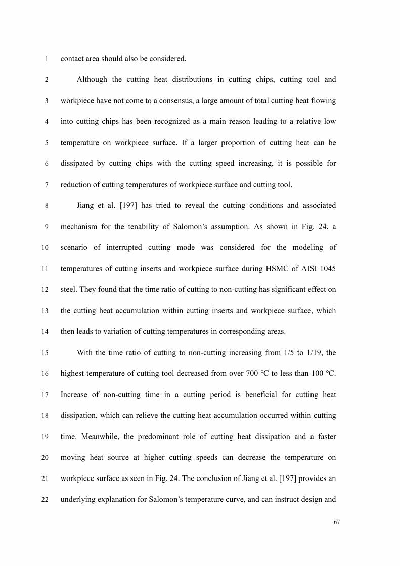
67
contact area should also be considered. 1
Although the cutting heat distributions in cutting chips, cutting tool and 2
workpiece have not come to a consensus, a large amount of total cutting heat flowing 3
into cutting chips has been recognized as a main reason leading to a relative low 4
temperature on workpiece surface. If a larger proportion of cutting heat can be 5
dissipated by cutting chips with the cutting speed increasing, it is possible for 6
reduction of cutting temperatures of workpiece surface and cutting tool. 7
Jiang et al. [197] has tried to reveal the cutting conditions and associated 8
mechanism for the tenability of Salomon’s assumption. As shown in Fig. 24, a 9
scenario of interrupted cutting mode was considered for the modeling of 10
temperatures of cutting inserts and workpiece surface during HSMC of AISI 1045 11
steel. They found that the time ratio of cutting to non-cutting has significant effect on 12
the cutting heat accumulation within cutting inserts and workpiece surface, which 13
then leads to variation of cutting temperatures in corresponding areas. 14
With the time ratio of cutting to non-cutting increasing from 1/5 to 1/19, the 15
highest temperature of cutting tool decreased from over 700 ℃ to less than 100 ℃. 16
Increase of non-cutting time in a cutting period is beneficial for cutting heat 17
dissipation, which can relieve the cutting heat accumulation occurred within cutting 18
time. Meanwhile, the predominant role of cutting heat dissipation and a faster 19
moving heat source at higher cutting speeds can decrease the temperature on 20
workpiece surface as seen in Fig. 24. The conclusion of Jiang et al. [197] provides an 21
underlying explanation for Salomon’s temperature curve, and can instruct design and 22
68
manufacture of cutting tools and optimization of cutting parameters. 1
Hea
t fl
ux
(W
/m2)
x10
5
Interrupted cutting model
Effect of cutting/non-cutting ratio on cutting tool temperature
Effect of cutting/non-cutting ratio
Effect of cutting speed on workpiece surface temperature
Heating Heating HeatingCoolingCooling
Prediction results
2
Fig. 24. Heat flux, measured and calculated temperatures of cutting tool and workpiece 3
surface during high speed machining [197]. 4
Based on the above discussion, the cutting heat generation and distribution, as 5
well as the cutting temperatures of workpiece and cutting tool during HSMC process, 6
need to be theoretically modelled and predicted more precisely. Meanwhile, accurate 7
measurement of the cutting temperature within a tiny deformation zone at ultra-high 8
cutting speeds is still a great challenge. 9
10
6. Tool wear behavior and mechanism in HSMC 11
Regarding the cons of HSMC or the most critical challenge for application of 12
HSMC in industries, one can think of the severe tool wear under extreme 13
thermal-mechanical loading conditions, especially during machining of 14
difficult-to-machine materials. Inappropriate selection of cutting tools may restrict 15
69
the other advantages of HSMC. Understanding tool wear behavior and associated 1
wear mechanism can instruct design and fabrication of cutting tools adaptable for 2
HSMC, and recommend suitable tools for machining of specific work material. The 3
tool wear behavior and mechanism in HSMC of difficult-to-machine materials such 4
as titanium and nickel-based alloys are emphasized here. 5
Rahman et al. [198] summarized the wear behavior of different cutting tools in 6
a review on HSMC of titanium alloys. It was found that the tool wear rate progress 7
rapidly during machining titanium alloys with conventional cutting tools, and it is 8
difficult to perform machining at cutting speeds higher than 60 m/min. Due to 9
chemical reaction with the elements in titanium alloys at high temperatures, some 10
tool materials, such as ceramic, diamond and cubic boron nitride (CBN) with binder 11
material, are also not suitable for HSMC of titanium alloys. Comparatively, 12
binder-less CBN tools present a prominently long tool life than other tools especially 13
at high cutting speeds. 14
A research on high-speed milling of titanium alloy TA15 using diamond (PCD) 15
and PCBN tools demonstrated a dramatic reduction of cutting tool life when the 16
cutting speed just increased from 250 m/min to 350 m/min [199]. Shalaby and 17
Veldhuis [200] compared the wear and tribological performance of four different 18
ceramic tools in HSMC of nickel-based superalloy Inconel 100, and found that the 19
tool life of all investigated tools decreased by up to 90% as seen in Fig. 25a-d. 20
Meanwhile, their results indicate that SiAlON ceramic outperformed other ceramic 21
70
tool materials and can be used in machining of nickel-based superalloys at relatively 1
high cutting speeds. 2
The tool wear mechanism during HSMC has also been widely focused on, and 3
proved to rely on the tool material, machining mode, and cutting parameters 4
[201-203]. Based on high speed milling experiments of an aerospace titanium alloy 5
Ti-6242S using uncoated cemented carbide tools [204], flank wear and excessive 6
chipping on the flank edge were reported as the main tool failure modes. Attrition, 7
adhesion and diffusion were found as the main wear mechanisms of PCD and PCBN 8
tools in high speed milling of titanium alloys [199,205]. Regarding a near-beta 9
titanium alloy Ti5553, abrasive and adhesive wear mainly contribute to the severe 10
tool wear at high cutting speed, and built-up-edge formation is also a common 11
problem [206]. During HSMC of aluminum alloys, tungsten carbide with cobalt 12
binder (WC-Co) tools are apt to appear unexpected chipping followed by 13
catastrophic failure due to the chemical reaction between aluminum and cobalt at 14
high cutting temperatures [207]. Coatings are recommended to be applied on tool 15
materials containing cobalt for HSMC of aluminum alloys. When machining of 16
nickel-based superalloys, adhesive wear and coating peeling are the main 17
mechanisms for tool wear and premature failure at high cutting speeds [201,208]. 18
To improve the performance of cutting tools at high cutting speeds, developing 19
new tool materials and applying cooling assistance are still important. As seen in Fig. 20
25e, a high-pressure cooling jet can achieve over seven times longer tool life while 21
the cutting speed doubles [209]. Meanwhile, chips are fractured more easily due to 22
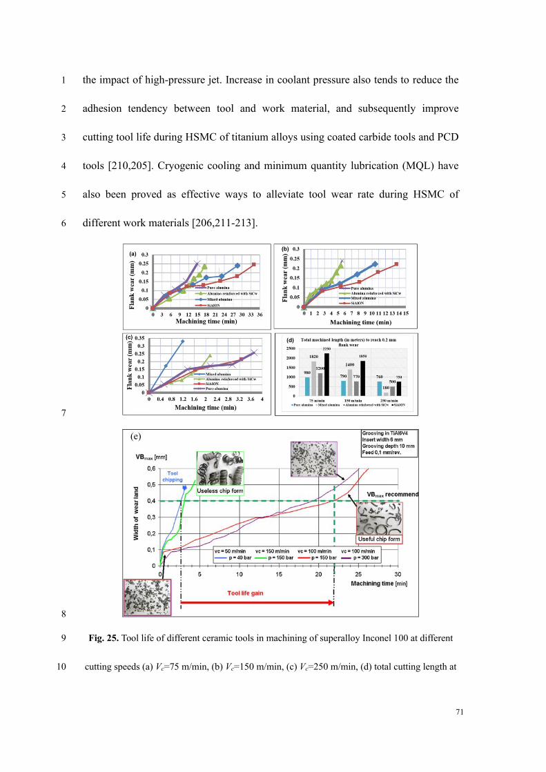
71
the impact of high-pressure jet. Increase in coolant pressure also tends to reduce the 1
adhesion tendency between tool and work material, and subsequently improve 2
cutting tool life during HSMC of titanium alloys using coated carbide tools and PCD 3
tools [210,205]. Cryogenic cooling and minimum quantity lubrication (MQL) have 4
also been proved as effective ways to alleviate tool wear rate during HSMC of 5
different work materials [206,211-213]. 6
7
8
Fig. 25. Tool life of different ceramic tools in machining of superalloy Inconel 100 at different 9
cutting speeds (a) Vc=75 m/min, (b) Vc=150 m/min, (c) Vc=250 m/min, (d) total cutting length at 10
(e)
72
different cutting speeds to reach 0.2 mm flank wear [200]; and (e) effect of cutting speed and 1
flushing conditions on tool wear in machining Ti6Al4V [209]. 2
Under the demand of eco-friendly manufacturing, high speed dry machining is 3
recommended in recent decades. Advanced tool coatings can help to achieve higher 4
cutting speeds without coolants. Similar with the review on tool wear behavior and 5
mechanism in HSMC, the tool coatings that are adaptable for HSMC of titanium and 6
nickel-based alloys are particularly commented. The coatings suitable for HSMC 7
should be helpful for reducing the friction which can decrease the heat generation on 8
the tool-chip interface. They also need to have excellent thermal barrier performance 9
which can prevent the heat diffusion into cutting tools to guarantee high wear 10
resistance of cutting tools at high temperatures. Compared to other coatings, 11
(Ti,Al)N possesses a lower thermal conduction coefficient and a considerably 12
enhanced oxidation stability, which makes it be one of the best coating materials for 13
HSMC tools used in machining of difficult-to-machine materials such as titanium 14
and nickel-based alloys [2,214]. Through adding oxygen to (Ti,Al)N coatings to 15
form TiAlON, it can enhance the cutting tool performance further [215], because 16
TiAlON offers a higher abrasion resistance due to the formation of Al2O3 during 17
HSMC. 18
Generally, oxide PVD coatings have combined advantages of a reduction of 19
friction at elevated temperatures and excellent wear resistance, so the heat generation 20
can be decreased and the adherence of workpiece materials on the tool rake face can 21
be suppressed at high cutting speeds [216-218]. In addition, soft tool coatings that 22
73
are made of solid lubricants, such as MoS2 and tungsten carbide/carbon (WC/C) 1
coatings, are useful to reduce the friction coefficient between tool-chip interface and 2
then to lower the cutting forces and temperatures [219,220]. Consequently, the tool 3
wear rate is decreased and higher cutting speeds can be achieved. 4
With the emergence of advanced cutting tools and new engineering materials, 5
the tool wear behavior and mechanism during HSMC under different combinations 6
of cutting tool and workpiece materials needs further study. To develop new 7
advanced cutting tool materials and structures as well as tool coatings, that can 8
achieve high cutting speeds without coolant, will always be important for 9
production. 10
11
7. Application of HSMC in industries 12
Typical cases for the application of HSMC in industries are presented in this 13
section to show the feasibility of HSMC in practical manufacturing. One of the 14
advantages of HSMC is high material removal volume in manufacturing of 15
components. Under the requirements of safety and economic efficiency, the 16
application of light-weight components has been increased dramatically, which 17
makes HSMC play a more significant role in the industries. Furthermore, with the 18
development of advanced materials with higher strength and toughness, 19
high-efficient machining of mechanical component made of such materials raise 20
more challenges for HSMC. Thin-walled components with light weight and high 21
74
strength are particularly popular in high value-added products such as those of 1
aviation industries. 2
A typical application of HSMC in manufacturing of multi-frame monolithic 3
component used in aircraft is shown in Fig. 26a,b [221]. The aircraft frame was 4
made of aluminum alloy 7075 in an oversaturated state, and it was fabricated from a 5
block workpiece with dimensions of 60 mm x1,190 mm x 1,215 mm. The weight of 6
the finished frame was 3.15 kg while that of the initial workpiece was 243 kg, 7
meaning that the weight of the final product was 1.3% of the initial workpiece and 8
98.7% of the workpiece material was removed as chips. The basic criteria for 9
assessing the manufacturing precision included the wall thickness tolerance of +/- 10
0.2 mm on the largest machined surface with dimensions of 300 mm x 300 mm, and 11
the surface roughness Ra less than 0.6 μm. Using HSMC process with a spindle 12
rotational speed of 15,000 rpm, excessive material on the workpiece was removed 13
with high efficiency, while the dimensional accuracy (the wall thickness tolerance 14
less than 0.2 mm), the surface roughness (Ra=0.272 μm) and waviness of the 15
machined surface were successfully guaranteed [221]. 16
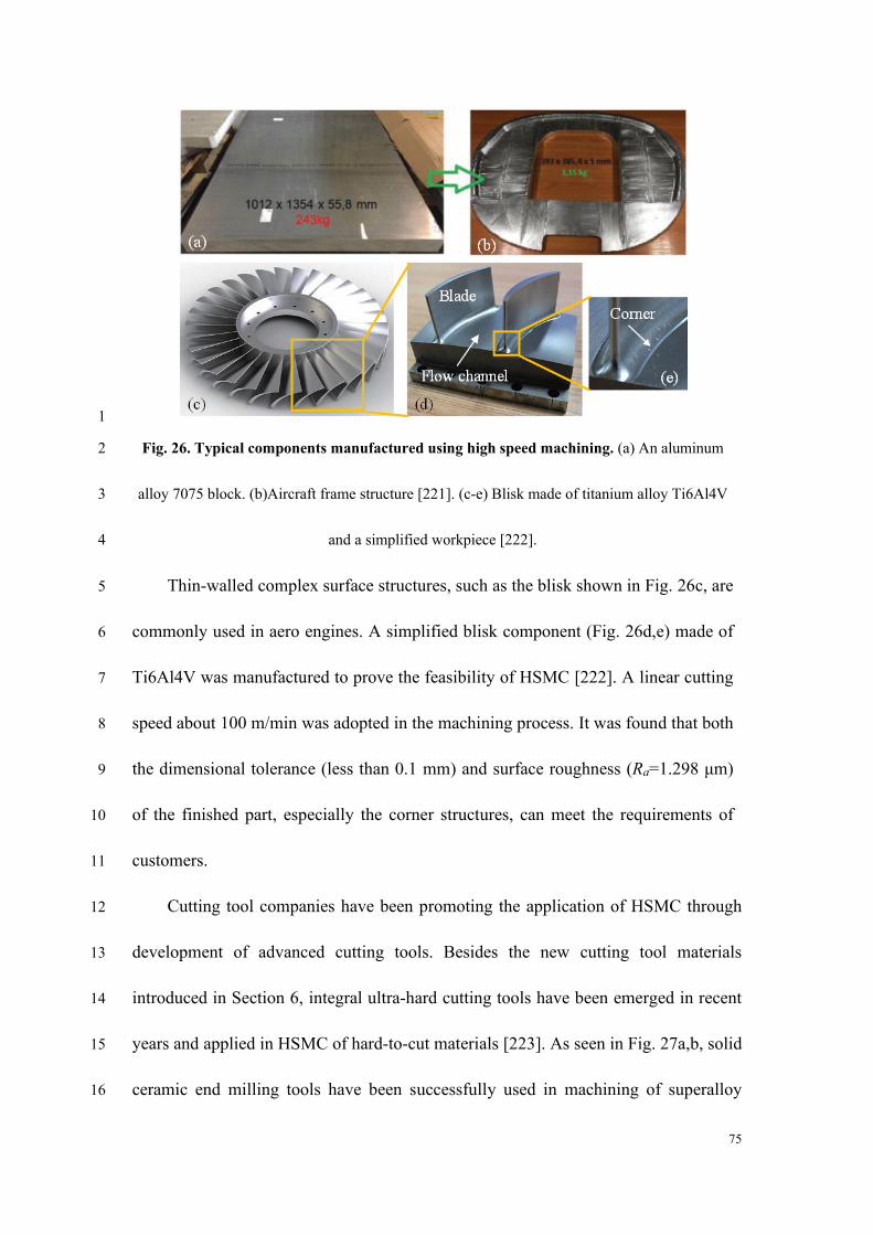
75
1
Fig. 26. Typical components manufactured using high speed machining. (a) An aluminum 2
alloy 7075 block. (b)Aircraft frame structure [221]. (c-e) Blisk made of titanium alloy Ti6Al4V 3
and a simplified workpiece [222]. 4
Thin-walled complex surface structures, such as the blisk shown in Fig. 26c, are 5
commonly used in aero engines. A simplified blisk component (Fig. 26d,e) made of 6
Ti6Al4V was manufactured to prove the feasibility of HSMC [222]. A linear cutting 7
speed about 100 m/min was adopted in the machining process. It was found that both 8
the dimensional tolerance (less than 0.1 mm) and surface roughness (Ra=1.298 μm) 9
of the finished part, especially the corner structures, can meet the requirements of 10
customers. 11
Cutting tool companies have been promoting the application of HSMC through 12
development of advanced cutting tools. Besides the new cutting tool materials 13
introduced in Section 6, integral ultra-hard cutting tools have been emerged in recent 14
years and applied in HSMC of hard-to-cut materials [223]. As seen in Fig. 27a,b, solid 15
ceramic end milling tools have been successfully used in machining of superalloy 16
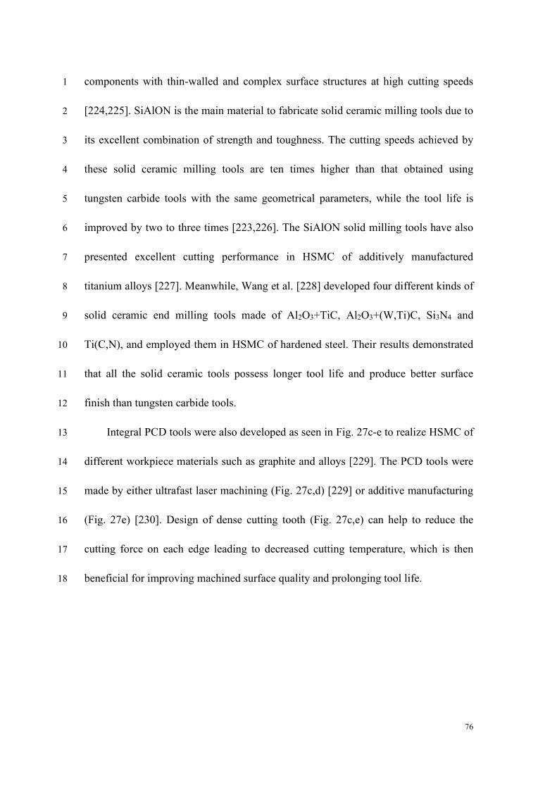
76
components with thin-walled and complex surface structures at high cutting speeds 1
[224,225]. SiAlON is the main material to fabricate solid ceramic milling tools due to 2
its excellent combination of strength and toughness. The cutting speeds achieved by 3
these solid ceramic milling tools are ten times higher than that obtained using 4
tungsten carbide tools with the same geometrical parameters, while the tool life is 5
improved by two to three times [223,226]. The SiAlON solid milling tools have also 6
presented excellent cutting performance in HSMC of additively manufactured 7
titanium alloys [227]. Meanwhile, Wang et al. [228] developed four different kinds of 8
solid ceramic end milling tools made of Al2O3+TiC, Al2O3+(W,Ti)C, Si3N4 and 9
Ti(C,N), and employed them in HSMC of hardened steel. Their results demonstrated 10
that all the solid ceramic tools possess longer tool life and produce better surface 11
finish than tungsten carbide tools. 12
Integral PCD tools were also developed as seen in Fig. 27c-e to realize HSMC of 13
different workpiece materials such as graphite and alloys [229]. The PCD tools were 14
made by either ultrafast laser machining (Fig. 27c,d) [229] or additive manufacturing 15
(Fig. 27e) [230]. Design of dense cutting tooth (Fig. 27c,e) can help to reduce the 16
cutting force on each edge leading to decreased cutting temperature, which is then 17
beneficial for improving machined surface quality and prolonging tool life. 18
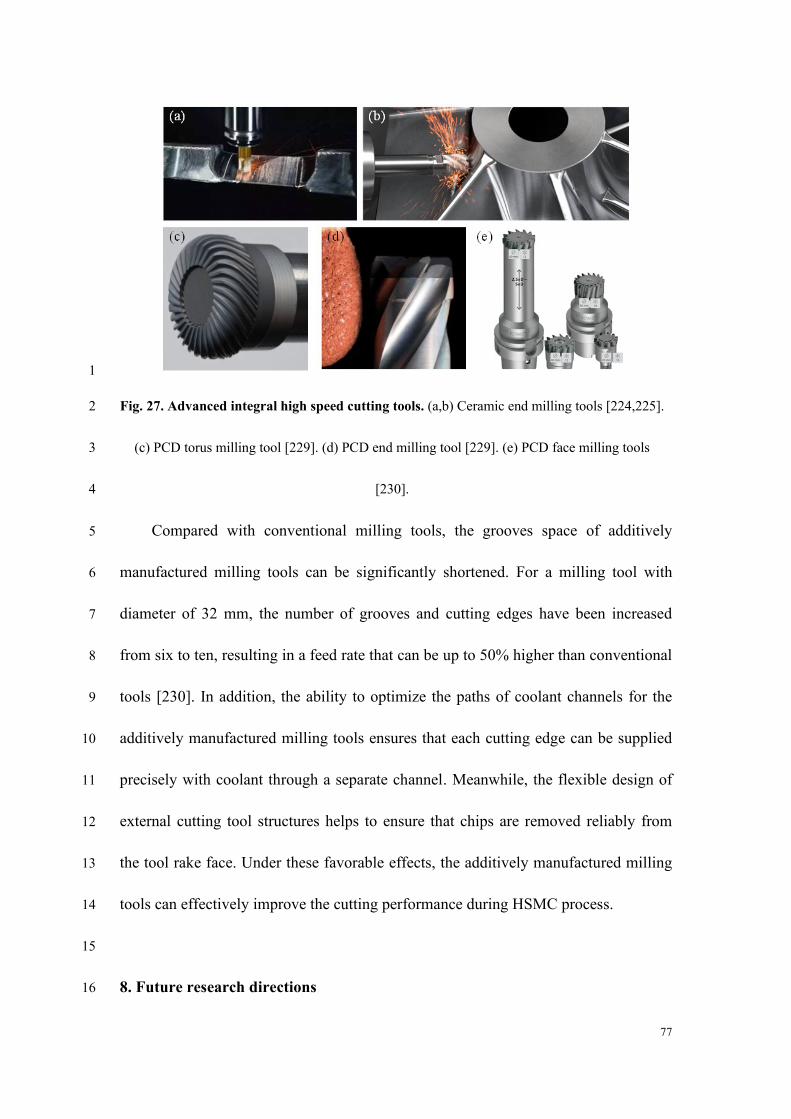
77
1
Fig. 27. Advanced integral high speed cutting tools. (a,b) Ceramic end milling tools [224,225]. 2
(c) PCD torus milling tool [229]. (d) PCD end milling tool [229]. (e) PCD face milling tools 3
[230]. 4
Compared with conventional milling tools, the grooves space of additively 5
manufactured milling tools can be significantly shortened. For a milling tool with 6
diameter of 32 mm, the number of grooves and cutting edges have been increased 7
from six to ten, resulting in a feed rate that can be up to 50% higher than conventional 8
tools [230]. In addition, the ability to optimize the paths of coolant channels for the 9
additively manufactured milling tools ensures that each cutting edge can be supplied 10
precisely with coolant through a separate channel. Meanwhile, the flexible design of 11
external cutting tool structures helps to ensure that chips are removed reliably from 12
the tool rake face. Under these favorable effects, the additively manufactured milling 13
tools can effectively improve the cutting performance during HSMC process. 14
15
8. Future research directions 16
78
The relevant research on HSMC in such aspects as material removal mechanism, 1
machined surface integrity, cutting force and cutting temperature, cutting tool, and 2
workpiece material are summarized in Fig. 28. To provide more detailed information 3
about the recent research progress on this topic, only literatures published after the 4
1990s are addressed here. The increasing number of studies reported in recent years 5
indicates that the research on HSMC is still attracting significant attention 6
worldwide. In particular, since the 2000s, a higher focus has been placed on the 7
study of machined surface integrity and material removal mechanism during 8
machining of different workpiece materials (four typical metals are presented in Fig. 9
28) at high cutting speeds. Meanwhile, high speed cutting tools have attracted more 10
attention because they constitute an important factor for promoting the increase in 11
cutting speed. Studies on the cutting force and cutting temperature of HSMC are also 12
being conducted to answer the fundamental questions discussed in the above 13
sections. It can be asserted that HSMC is yet to be an established technology, and 14
that the research on HSMC would also be impelled by the fast development of 15
processing equipment and broad industrial demand. 16
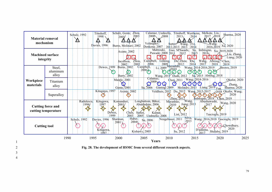
79
Material removal
mechanism
Machined surface
integrity
Workpiece
materials
Cutting force and
cutting temperature
Cutting tool
Steel, aluminum
alloy
Titanium
alloy
Superalloy
1990 1995 2000 2005 2010 2015 2020 2025
Maranhão, 2010
Maranhão, 2010
Wertheim, 2014
Mabrouki, Pawade; 2008
M'Saoubi, 2012
Du, 2012
Mantle, 2001
Wang; 2016,2018
Okafor, 2020
Okafor, Wang; 2020
Axinte, 2002
Longbottom, Bäker, Abukhshim; 2006
Schulz, Gente;
2001Schulz, 1992
Schulz, 1992
Tönshoff, 1998
Tönshoff, 2013
Burns, Molinari; 2002Davies, 1996
Davies, 1996
Velásquez,Denkena; 2007
Wang, 2015-2017
Wang; 2014-2016
Wang, 2013
Wang, Jiang; 2013
Sharma, 2020
Zhang, Sharma; 2020
Ye, 2014
Zhou, 2003
Zhou, 2003
Sutter; 2012,2013 Xu, 2020
Xu; 2019,2020
Haber, 2004
Umbrello, 2008
Karpat, Umbrello; 2008
Chen, 2011
Melkote, 2017
Wang; 2016,2019
Calamaz, 2008
Calamaz, 2008
Wang; 2014-2016,2019Li, 2009
Abushawashi, 2017
Campbell, 2006
Campbell, 2006
Molinari; 2013
Burns, 2002
Chen, 2019
Wang, 2020
Duan, 2012
Liu, 2018
Liu, Zhang, Liang; 2020
Imbrogno, 2018
Imbrogno, 2018
Su, 2015
Su, 2015
Zhou, 2012
Du, Zhou; 2012
Abroug, 2018
Abroug, 2018
Chen, 2019
Ginting, 2009
Ginting, 2009
Guo, 2011
Wang, 2011
Neugebauer, 2011
Brown, 2019
Barry, 2002
Du, 2014
Veldhuis, 2012Axinte, 2002
Wang, 2017
Jacobson, 2002
Fan, 2018
Gente, 2001
Sutter, 2005
Komanduri, 2001
List, 2012
Kitagawa, 1997
Kitagawa, 1997
Kitagawa, 1997
Dewes, 1999
Dewes, 1999
Radulescu, 1994
Chen, 2003
Su, 2012 Shalaby, 2019
Sharman, 2001
Kishawy, 2005
Silva, 2013
Tascioglu, 2019
Tascioglu, 2019
D'addona, 2017
Liang; 2019
Su, 2006
Su, 2006
Chowdhury, 2020
Years1
Fig. 28. The development of HSMC from several different research aspects. 2
3
4
80
Based on the review and above summary, the potential research directions of 1
HSMC to be focused on are as follows. 2
(1) Material removal mechanism during HSMC 3
The cutting speed used in manufacturing processes is growing at an increasing 4
pace. Similar to Moore's law, the cutting speed and associated material removal rate 5
increase by approximately 100% every two years (as indicated by the data shown in 6
Fig. 1) with the development of high speed machine tools and ultra-hard cutting 7
tools [9,231,232]. Meanwhile, new advanced engineering materials such as metal 8
matrix and ceramic matrix composite materials have emerged and are being 9
gradually applied in industries. The continuous increase in cutting speed and the new 10
engineering materials may generate different mechanisms (e.g., ductile-to-brittle 11
transition) of material removal behavior, which deserves more research efforts in the 12
future. 13
The present research on the material removal mechanism during HSMC is 14
mainly limited to two-dimensional cutting mode. The material removal behavior 15
during three-dimensional cutting that is widely used in practical applications lacks 16
enough research. Correspondingly, dynamic deformation and fracture behavior of 17
workpiece materials under the coupled loadings of high strain rate and more 18
complicated stress state need to be studied. More general material models adaptable 19
for three-dimensional HSMC are urgent to be developed. In addition, in-situ 20
observation and measurement of material deformation with the aid of digital image 21
correlation techniques would also be a research focus, as they can provide the most 22
81
direct evidence and data basis for material deformation modeling compared with 1
speculation and postmortem examination. 2
(2) Machined surface integrity generated at high cutting speeds 3
The evaluation of machined surface integrity has evolved from traditional 4
macro parameters, such as the surface roughness and surface defects, to micro and 5
nano level parameters such as crystalline features and phase transformations. 6
Advanced material characterization tools, including TEM and EBSD, enable us to 7
obtain deeper insights into the mechanisms underlying the material removal and 8
machined surface formation during HSMC. To reveal the relationships among 9
inherent attributes of workpiece materials, processing parameters during HSMC, and 10
evolution of machined surface properties will be a potential breakthrough direction. 11
Furthermore, the present evaluation system of machined surface integrity 12
generated by HSMC is aimed mainly at isotropic metallic materials. A more general 13
evaluation system is required to assess the machined surface integrity of a wider 14
range of materials, particularly anisotropic composite materials [71,105,106]. 15
(3) Process modeling of HSMC 16
The present studies on the cutting force and cutting temperature during HSMC 17
are based mainly on experiments and empirical modeling, while theoretical process 18
modeling is still limited. Some issues have not been understood clearly, such as (i) 19
conditions for the existence of Salomon’s curve during HSMC, (ii) dependence of 20
process modeling on the thermal-physical-mechanical properties of workpiece 21
materials, and (iii) relationships among the cutting conditions, process parameters 22
82
(i.e., cutting force and cutting temperature), and material deformation behavior. 1
Especially, the generation and distribution of cutting heat during HSMC and the 2
cutting temperatures of workpiece and cutting tool need to be theoretically modeled 3
and predicted more precisely. The accurate measurement of the cutting temperature 4
and deformation fields within an extremely small deformation zone at ultra-high 5
cutting speeds is also a great challenge to be tackled. 6
(4) High speed cutting tools 7
Under the demand of eco-friendly manufacturing, the development of new 8
advanced cutting tool materials and structures as well as tool coatings that can 9
achieve high cutting speeds without coolant is being pursued by both academia and 10
industries. Ultrafast laser machining [229] and additive manufacturing [230] provide 11
new solutions for fabricating ultra-hard cutting tools with dense tooth structures that 12
can effectively improve the cutting speed. Integral ultra-hard cutting tools such as 13
solid ceramic cutting tools or PCD tools adaptable for HSMC has attracted more 14
attention and would be a research hotspot in the near future. 15
(5) Application and performance evaluation of HSMC 16
Considering that different evaluation parameters for the performance of HSMC 17
may not be in favorable conditions simultaneously, a trade-off between the pros and 18
cons of HSMC must be determined reasonably in practical applications. Research on 19
HSMC considering practical service conditions of machined components is a 20
prerequisite to make such as a balance. 21
Furthermore, developing more adaptable hybrid/combined processes, such as 22
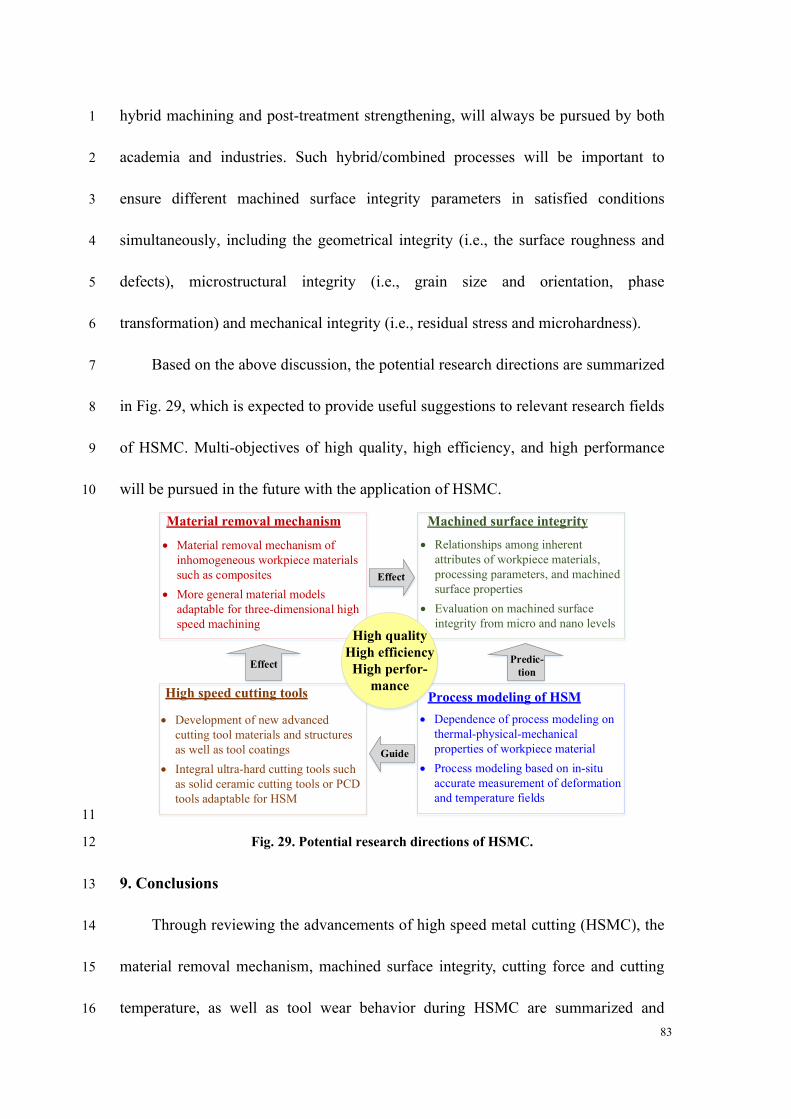
83
hybrid machining and post-treatment strengthening, will always be pursued by both 1
academia and industries. Such hybrid/combined processes will be important to 2
ensure different machined surface integrity parameters in satisfied conditions 3
simultaneously, including the geometrical integrity (i.e., the surface roughness and 4
defects), microstructural integrity (i.e., grain size and orientation, phase 5
transformation) and mechanical integrity (i.e., residual stress and microhardness). 6
Based on the above discussion, the potential research directions are summarized 7
in Fig. 29, which is expected to provide useful suggestions to relevant research fields 8
of HSMC. Multi-objectives of high quality, high efficiency, and high performance 9
will be pursued in the future with the application of HSMC. 10
Material removal mechanism Machined surface integrity
High speed cutting tools Process modeling of HSM
Effect
Effect
• Material removal mechanism of
inhomogeneous workpiece materials
such as composites
• More general material models
adaptable for three-dimensional high
speed machining
• Relationships among inherent
attributes of workpiece materials,
processing parameters, and machined
surface properties
• Evaluation on machined surface
integrity from micro and nano levelsHigh quality
High efficiency
High perfor-
mance
Predic-
tion
• Dependence of process modeling on
thermal-physical-mechanical
properties of workpiece material
• Process modeling based on in-situ
accurate measurement of deformation
and temperature fields
Guide
• Development of new advanced
cutting tool materials and structures
as well as tool coatings
• Integral ultra-hard cutting tools such
as solid ceramic cutting tools or PCD
tools adaptable for HSM
11
Fig. 29. Potential research directions of HSMC. 12
9. Conclusions 13
Through reviewing the advancements of high speed metal cutting (HSMC), the 14
material removal mechanism, machined surface integrity, cutting force and cutting 15
temperature, as well as tool wear behavior during HSMC are summarized and 16
84
discussed. The pros and cons of HSMC are elaborated based on the above aspects. 1
The deficiencies in the present research on HSMC and the challenges for application 2
of HSMC in industries are highlighted. Certain potential future directions for 3
research on HSMC are discussed. The main conclusions drawn are as following. 4
⚫ HSMC can be defined as machining with a cutting speed higher than that 5
for ASB formation, whereas UHSMC can be defined as machining with a 6
cutting speed higher than that for fragmented chip formation induced by 7
workpiece material embrittlement. A consensus has been reached that the 8
“high speed” in HSMC is preferably referred to a combined economic and 9
performance target rather than merely a technical parameter. Different 10
setups to achieve high cutting speeds have been developed, and they have 11
played an important role in both fundamental research and industrial 12
application of HSMC. 13
⚫ Workpiece materials present distinctly different dynamic behaviors during 14
HSMC compared to their static properties, owing to the high loading rate 15
applied by the cutting tool. Different material models that consider the 16
combined effects of strain, strain rate, and temperature have been 17
established to describe the material deformation and fracture behavior at 18
high cutting speeds. With the increase in cutting speed, chip morphology 19
generally evolves from continuous to serrated and then to fragmented. 20
Different prediction models have been developed for serrated and 21
fragmented chips formation. The variation of material dynamic properties 22
85
at high cutting speeds is the underlying mechanism responsible for the 1
transition of chip morphologies. The cutting energy consumption of brittle 2
regime machining in UHSMC can be decreased by more than 19% 3
compared with ductile regime machining in HSMC, which indicates the 4
advantage of UHSMC in terms of energy savings. 5
⚫ Various surface defects and different surface topographies on the machined 6
surface are generated in HSMC compared to low-speed machining. Less 7
surface defects and lower surface roughness can be obtained at a specific 8
range of high cutting speeds, and the speed range depends on the workpiece 9
material, cutting mode, and cutting tool used. Ultrafine grain layer and 10
phase transformation are produced by severe plastic deformation on the 11
machined surface during HSMC of different workpiece materials. 12
⚫ With increasing the cutting speed, although larger compressive residual 13
stresses are generated at a deeper subsurface due to severer plastic 14
deformation, a thin layer exhibiting very high tensile residual stresses is 15
generally induced on the superficial surface, which may become a hidden 16
danger in service. The high cutting speeds may not improve all surface 17
integrity parameters (e.g., the residual stress, the surface topography, and 18
the microstructural alteration, etc.) simultaneously. Optimized cutting 19
speed need to be determined based on a balanced surface quality. 20
⚫ The cutting force can be reduced in the cutting speed range of HSMC due to 21
thermal softening caused by chip plastic deformation that is beneficial for 22
86
weakening material deformation resistance. Brittle fracture of removed 1
layer material can also help to keep the cutting force at a low level when 2
the cutting speed increases to the range of UHSMC. The friction coefficient 3
at the tool-chip interface presents a decreasing trend with increasing the 4
cutting speed. Different opinions have been proposed about the existence of 5
Salomon’s cutting temperature curve. It indicates that interrupted 6
machining may be a necessary condition for the tenability of Salomon’s 7
assumption, and the time ratio of cutting to non-cutting is a significant 8
parameter that affect the variation of cutting temperature. 9
⚫ Severe tool wear under extreme thermal-mechanical loading conditions is 10
one of the most critical challenges for application of HSMC in industries. 11
Understanding tool wear behavior and associated wear mechanism can 12
instruct design and fabrication of cutting tools adaptable for HSMC, and 13
recommend suitable tools for machining of specific work materials. 14
⚫ HSMC has been applied successfully in industrial manufacture of different 15
mechanical components. It has presented prominent advantages in the 16
fabrication of components that require the removal of a high volume of 17
material. The speed range used in industries has been improved 18
significantly by the advancements in ultra-hard cutting tools that can 19
achieve higher cutting speeds. Meanwhile, with the development of 20
advanced engineering materials that display higher strength and toughness, 21
87
the high-efficient machining of mechanical components made of these 1
materials presents further challenges for HSMC. 2
3
References 4
[1] A. Yadav, S.C. Jayswal, Modelling of flexible manufacturing system: a review,
Int. J. Prod. Res. 56(7) (2018) 2464-2487.
[2] D. Dudzinski, A. Devillez, A. Moufki, D. Larrouquere, V. Zerrouki, J. Vigneau, A
review of developments towards dry and high speed machining of Inconel 718
alloy, Int. J. Mach. Tools Manuf. 44(4) (2004) 439-456.
[3] H. Schulz, T. Moriwaki, High-speed machining, CIRP Ann. 41(2) (1992)
637-643.
[4] K. Gupta, J.P. Davim, (Eds.) High-Speed Machining, Academic Press (2020).
[ 5 ]Machining Market to Reach $414.17 Billion by 2022, Says Beroe Inc.
https://www.prnewswire.com/news-releases/machining-market-to-reach-414-17
-billion-by-2022--says-beroe-inc-300939464.html.
[6] T.G. Molnar, S. Berezvai, A.K. Kiss, D. Bachrathy, G. Stepan, Experimental
investigation of dynamic chip formation in orthogonal cutting, Int. J. Mach.
Tools Manuf. 145 (2019) 103429.
[7] C.A. Van Luttervelt, T.H.C. Childs, I.S. Jawahir, F. Klocke, P.K. Venuvinod, Y.
Altintas, E. Armarego, D. Dornfeld, I. Grabec, J. Leopold, B. Lindstrom, D.
Lucca, T. Obikawa, T. Shirakashi, H. Sato, Present situation and future trends in
88
modelling of machining operations progress report of the CIRP Working Group
‘Modelling of Machining Operations’, CIRP Ann. 47(2) (1998) 587-626.
[8] C. Maranhão, J.P. Davim, Finite element modelling of machining of AISI 316
steel: numerical simulation and experimental validation, Simul. Model. Pract.
Th. 18(2) (2010) 139-156.
[9] V.P. Astakhov, Tribology of Metal Cutting. Elsevier, 2006.
[10] C.J. Salomon, Process for machining metals of similar acting materials when
being worked by cutting tools, German Patent No. 523594, 1931.
[ 11 ] R. Wertheim, High-speed cutting, CIRP Encyclopedia of Production
Engineering (2014) 632-654.
[12] R.S. Pawade, S.S. Joshi, P.K. Brahmankar, Effect of machining parameters and
cutting edge geometry on surface integrity of high-speed turned Inconel 718, Int.
J. Mach. Tools Manuf. 48(1) (2008) 15-28.
[13] J. Du, Z. Liu, Effect of cutting speed on surface integrity and chip morphology
in high-speed machining of PM nickel-based superalloy FGH95, Int. J. Adv.
Manuf. Technol. 60(9-12) (2012) 893-899.
[14] A.L. Mantle, D.K. Aspinwall, Surface integrity of a high speed milled gamma
titanium aluminide, J. Mater. Process. Technol. 118(1-3) (2001) 143-150.
[15] B. Wang, Z. Liu, Influences of tool structure, tool material and tool wear on
machined surface integrity during turning and milling of titanium and nickel
alloys: a review, Int. J. Adv. Manuf. Technol. 98(5-8) (2018) 1925-1975.
89
[16] V. Thévenot, L. Arnaud, G. Dessein, G. Cazenave-Larroche, Influence of
material removal on the dynamic behavior of thin-walled structures in
peripheral milling, Mach. Sci. Technol. 10(3) (2006) 275-287.
[17] A.C. Okafor, Cooling and machining strategies for high speed milling of
titanium and nickel super alloys, In High Speed Machining. Elsevier, Academic
Press (2020) 127-161.
[18] B. Wang, S.N. Melkote, S. Saraogi, P. Wang, Effect of scratching speed on
phase transformations in high-speed scratching of monocrystalline silicon,
Mater. Sci. Eng. A 772 (2020) 138836.
[19] D.A. Axinte, R.C. Dewes, Surface integrity of hot work tool steel after high
speed milling-experimental data and empirical models, J. Mater. Process.
Technol. 127(3) (2002) 325-335.
[20] M. Rahman, Z.G. Wang, Y.S. Wong, A review on high-speed machining of
titanium alloys, JSME Int. J. Series C, Mech. Syst. Mach. Element. Manuf.
49(1) (2006) 11-20.
[21] R. King, Handbook of High-Speed Machining Technology. Springer Science &
Business Media, 2013.
[22] J.M. Longbottom, J.D. Lanham, A review of research related to Salomon's
hypothesis on cutting speeds and temperatures, Int. J. Mach. Tools Manuf.
46(14) (2006) 1740-1747.
[23] H. Schulz, E. Abele, A. Sahm, Material aspects of chip formation in HSC
machining, CIRP Ann. 50(1) (2001) 45-48.
90
[24] ISO 1940/1, Mechanical vibration - Balance quality requirements for rotors in a
constant (rigid) state, 2003.
[25] G. Arndt, Ultra-high-speed machining: a review and an analysis of cutting
forces, Proc. Inst. Mech. Eng. 187(1) (1973) 625-634.
[26] G. Icks, Machine dependent limits of high speed turning, Dr.-Ing. Diss.,
University Stuttgart, 1981.
[27] K. Tuffentsammer, G. Icks, Lathe criteria for the turning at ultra-high cutting
speeds, Proceed. 10th NAMRC. (1982) 374.
[28] H. Schulz, High speed cutting - A technology with future, Werkstatt und Betrieb,
127(7-8) (1994) 539-541.
[ 29 ] H.K. Tönshoff, B. Karpuschewski, C. Lapp, P. Andrae, New machine
techniques for high-speed machining, In International Seminar on improving
Machine Tool Performance, 1 (1998) 65-76.
[30] H.K. Tönshoff, B. Denkena, Basics of Cutting and Abrasive Processes. Springer,
Berlin, Heidelberg, 2013.
[31] A. Molinari, C. Musquar, G. Sutter, Adiabatic shear banding in high speed
machining of Ti-6Al-4V: experiments and modeling, Int. J. Plast. 18(4) (2002)
443-459.
[32] R.F. Recht, Catastrophic thermoplastic shear, ASME J. Appl. Mech. 86 (1964)
186-193.
[33] R. Komanduri, T. Schroeder, J. Hazra, B.F. Von Turkovich, D.G. Flom, On the
91
catastrophic shear instability in high-speed machining of an AISI 4340 steel,
ASME J. Eng. Ind. 104(2) (1982) 121-131.
[34] M.A. Davies, Y. Chou, C.J. Evans, On chip morphology, tool wear and cutting
mechanics in finish hard turning, CIRP Ann. 45(1) (1996) 77-82.
[35] B. Denkena, R. Ben Amor, L. De Leon-Garcia, J. Dege, Material specific
definition of the high speed cutting range, Int. J. Mach. Mach. Mater. 2(2)
(2007) 176-185.
[36] B. Wang, Z. Liu, G. Su, X. Ai, Brittle removal mechanism of ductile materials
with ultrahigh-speed machining. ASME J. Manuf. Sci. Eng. 137(6) (2015)
061002.
[37] B. Wang, Z. Liu, G. Su, Q. Song, X. Ai, Investigations of critical cutting speed
and ductile-to-brittle transition mechanism for workpiece material in ultra-high
speed machining, Int. J. Mech. Sci. 104 (2015) 44-59.
[38] B. Wang, Z. Liu, Q. Yang, Investigations of yield stress, fracture toughness, and
energy distribution in high speed orthogonal cutting, Int. J. Mach. Tools Manuf.
73 (2013) 1-8.
[39] J. Tlusty, High-speed machining, CIRP Ann. 42(2) (1993) 733-738.
[40] S. Smith, J. Tlusty, Current trends in high-speed machining, ASME J. Manuf.
Sci. Eng. 119(4B) (1997) 664-666.
[41] T.L. Schmitz, R.R. Donalson, Predicting high-speed machining dynamics by
substructure analysis, CIRP Ann. 49(1) (2000) 303-308.
92
[42] M.R. Movahhedy, P. Mosaddegh, Prediction of chatter in high speed milling
including gyroscopic effects, Int. J. Mach. Tools Manuf. 46(9) (2006) 996-1001.
[43] S. Sharma, A. Meena, Microstructure induced shear instability criterion during
high-speed machining of Ti-6Al-4V, ASME J. Manuf. Sci. Eng. 143(6) (2020)
061001.
[44] G.G. Ye, Y. Chen, S.F. Xue, L.H. Dai, Critical cutting speed for onset of serrated
chip flow in high speed machining, Int. J. Mach. Tools Manuf. 86 (2014) 18-33.
[45] L.B. Zhou, J. Shimizu, A. Muroya, E. Hiroshi, Material removal mechanism
beyond plastic wave propagation rate, Precis. Eng. 27(2) (2003) 109-116.
[46] G. Sutter, A. Molinari, G. List, X. Bi, Chip flow and scaling laws in high speed
metal cutting, ASME J. Manuf. Sci. Eng. 134(2) (2012) 021005.
[47] G. Sutter, G. List, Very high speed cutting of Ti-6Al-4V titanium alloy-change
in morphology and mechanism of chip formation, Int. J. Mach. Tools Manuf. 66
(2013) 37-43.
[48] G.G. Ye, S.F. Xue, W. Ma, M.Q. Jiang, Z. Ling, X.H. Tong, L.H. Dai, Cutting
AISI 1045 steel at very high speeds, Int. J. Mach. Tools Manuf. 56 (2012) 1-9.
[49] L.B. Wuertemberger, Predicting the Wear of High Speed Rocket Sleds. Air
Force Institute of Technology, (2012) No. AFIT-ENY-12-D-02.
[50] D. Xu, Z. Liao, D. Axinte, M. Hardy, A novel method to continuously map the
surface integrity and cutting mechanism transition in various cutting conditions,
Int. J. Mach. Tools Manuf. 151 (2020) 103529.
93
[51] D. Xu, Z. Liao, D. Axinte, M. Hardy, R. M’Saoubi, A quick method for
evaluating the thresholds of workpiece surface damage in machining, CIRP Ann.
68(1) (2019) 61-64.
[52] V. Nguyen, S. Melkote, A. Deshamudre, M. Khanna, D. Walker, PVDF sensor
based monitoring of single-point cutting, J. Manuf. Process. 24 (2016) 328-337.
[53] M.C. Kang, J.S. Kim, J.H. Kim, A monitoring technique using a multi-sensor in
high speed machining, J. Mater. Process. Technol. 113(1-3) (2001) 331-336.
[54] R.E. Haber, J.E. Jiménez, C.R. Peres, J.R. Alique, An investigation of tool-wear
monitoring in a high-speed machining process, Sensor. Actuat. A: Phys. 116(3)
(2004) 539-545.
[55] B. Wang, Z. Liu, Acoustic emission signal analysis during chip formation
process in high speed machining of 7050-T7451 aluminum alloy and Inconel
718 superalloy, J. Manuf. Process. 27 (2017) 114-125.
[56] T.D. Marusich, M. Ortiz, Modelling and simulation of high-speed machining.
Int. J. Numer. Meth. Eng. 38(21) (1995) 3675-3694.
[57] D. Umbrello, Finite element simulation of conventional and high speed
machining of Ti6Al4V alloy, J. Mater. Process. Technol. 196(1-3) (2008) 79-87.
[58] G. Chen, C. Ren, X. Yang, X. Jin, T. Guo, Finite element simulation of
high-speed machining of titanium alloy (Ti-6Al-4V) based on ductile failure
model, Int. J. Adv. Manuf. Technol. 56(9-12) (2011) 1027-1038.
[59] S.N. Melkote, W. Grzesik, J. Outeiro, J. Rech, V. Schulze, H. Attia, P.J. Arrazola,
94
R. M’Saoubi, C. Saldana, Advances in material and friction data for modelling
of metal machining, CIRP Ann. 66(2) (2017) 731-754.
[60] G.T. Gray III, High-strain-rate testing of materials: The Split-Hopkinson
Pressure Bar. Charact. Mater. (2002) 1-15.
[61] B. Wang, Z. Liu, Q. Song, Y. Wan, X. Ren, A modified Johnson-Cook
constitutive model and its application to high speed machining of 7050-T7451
aluminum alloy, ASME J. Manuf. Sci. Eng. 141(1) (2019) 011012.
[62] O.S. Lee, M.S. Kim, Dynamic material property characterization by using split
Hopkinson pressure bar (SHPB) technique, Nucl. Eng. Des. 226(2) (2003)
119-125.
[63] J. Peirs, P. Verleysen, J. Degrieck, F. Coghe, The use of hat-shaped specimens to
study the high strain rate shear behaviour of Ti-6Al-4V, Int. J. Impact Eng. 37(6)
(2010) 703-714.
[64] B. Wang, X. Xiao, V.P. Astakhov, Z. Liu, The effects of stress triaxiality and
strain rate on the fracture strain of Ti6Al4V, Eng. Fract. Mech. 219 (2019)
106627.
[65] D. Rittel, S. Lee, G. Ravichandran, A shear-compression specimen for large
strain testing, Exp. Mech. 42(1) (2002) 58-64.
[66] A. Dorogoy, D. Rittel, A. Godinger, Modification of the shear-compression
specimen for large strain testing, Exp. Mech. 55(9) (2015) 1627–1639.
[67] B. Wang, Z. Liu, Investigations on deformation and fracture behavior of
95
workpiece material during high speed machining of 7050-T7451 aluminum
alloy, CIRP J. Manuf. Sci. Technol. 14 (2016) 43-54.
[68] G.R. Johnson, W.H. Cook, A constitutive model and data for metals subjected to
large strains, high strain rates and high temperatures, In: Proceedings of the
seventh international symposium on ballistics, Hague, Netherlands. (1983)
541-547.
[69] X. Wang, C. Huang, B. Zou, H. Liu, H. Zhu, J. Wang, Dynamic behavior and a
modified Johnson-Cook constitutive model of Inconel 718 at high strain rate
and elevated temperature, Mater. Sci. Eng. A 580 (2013) 385-390.
[70] A. Banerjee, S. Dhar, S. Acharyya, D. Datta, N. Nayak, Determination of
Johnson Cook material and failure model constants and numerical modelling of
Charpy impact test of armour steel, Mater. Sc. Eng. A 640 (2015) 200-209.
[71] Q. Wu, W. Xu, L. Zhang, Machining of particulate-reinforced metal matrix
composites: An investigation into the chip formation and subsurface damage, J.
Mater. Processing Technol. 274 (2019) 116315.
[ 72 ] U. Andrade, M.A. Meyers, K.S. Vecchio, A.H. Chokshi, Dynamic
recrystallization in high-strain, high-strain-rate plastic deformation of copper,
Acta Metall. Mater. 42 (1994) 3183-3195.
[73] X.L. Fu, X. Ai, S. Zhang, Y. Wan, Constitutive equation for 7050 aluminum
alloy at high temperatures, Mater. Sci. Forum 532 (2006) 125-128.
[74] M. Calamaz, D. Coupard, F. Girot, A new material model for 2D numerical
96
simulation of serrated chip formation when machining titanium alloy Ti-6Al-4V,
Int. J. Mach. Tools Manuf. 48 (2008) 275-288.
[75] J.Y. Sheikh-Ahmad, J.A. Bailey, A constitutive model for commercially pure
titanium, ASME J. Eng. Mater. Tech. 117 (1995) 139-144.
[76] G. Li, M. Wang, C. Duan, Adiabatic shear critical condition in the high-speed
cutting, J. Mater. Process. Technol. 209(3) (2009) 1362-1367.
[77] N.E. Ugodilinwa, M. Khoshdarregi, O.A. Ojo, Analysis and constitutive
modeling of high strain rate deformation behavior of Haynes 282 aerospace
superalloy, Mater. Today Commun. 20 (2019) 100545.
[78] Y.B. Bao, T. Wierzbicki, On fracture locus in the equivalent strain and stress
triaxiality space, Int. J. Mech. Sci. 46 (2004) 81-98.
[ 79 ] Y. Abushawashi, X. Xiao, V. Astakhov, Practical applications of the
“energy-triaxiality” state relationship in metal cutting, Mach. Sci. Technol. 21(1)
(2017) 1-18.
[80] B. Wang, Z. Liu, Evaluation on fracture locus of serrated chip generation with
stress triaxiality in high speed machining of Ti6Al4V, Mater. Des. 98 (2016)
68-78.
[81] S. Buchkremer, F. Klocke, D. Veselovac, 3D FEM simulation of chip breakage
in metal cutting, Int. J. Adv. Manuf. Technol. 82(1-4) (2016) 645-661.
[82] V.P. Astakhov, Mechanical properties of engineering materials: relevance in
design and manufacturing, In Introduction to Mechanical Engineering, Springer,
97
Cham, (2018) 3-41.
[83] B. Wang, X. Xiao, V.P. Astakhov, Z. Liu, A quantitative analysis of the
transition of fracture mechanisms of Ti6Al4V over a wide range of stress
triaxiality and strain rate, Eng. Fract. Mech. 231 (2020) 107020.
[84] B. Wang, Z. Liu, Investigations on the chip formation mechanism and shear
localization sensitivity of high-speed machining Ti6Al4V, Int. J. Adv. Manuf.
Technol. 75(5-8) (2014) 1065-1076.
[85] C.E. Campbell, L.A. Bendersky, W.J. Boettinger, R. Ivester, Microstructural
characterization of Al-7075-T651 chips and work pieces produced by
high-speed machining, Mater. Sci. Eng. A, 430(1-2) (2006) 15-26.
[86] J.P. Velásquez, B. Bolle, P. Chevrier, G. Geandier, A. Tidu, Metallurgical study
on chips obtained by high speed machining of a Ti-6 wt.% Al-4 wt.% V alloy,
Mater. Sci. Eng. A, 452 (2007) 469-474.
[ 87 ] X.M. Zhang, K. Zhang, D. Zhang, J. Outeiro, H. Ding, New in situ
imaging-based methodology to identify the material constitutive model
coefficients in metal cutting process, ASME J. Manuf. Sci. Eng. 141(10) (2019)
101007.
[88] A. Molinari, X. Soldani, M.H. Miguélez, Adiabatic shear banding and scaling
laws in chip formation with application to cutting of Ti-6Al-4V, J. Mech. Phys.
Solid. 61(11) (2013) 2331-2359.
[89] B. Wang, Z. Liu, Serrated chip formation mechanism based on mixed mode of
98
ductile fracture and adiabatic shear, Proc. Inst. Mech. Eng. Part B: J. Eng.
Manuf. 228(2) (2014) 181-190.
[90] T.J. Burns, M.A. Davies, On repeated adiabatic shear band formation during
high-speed machining, Int. J. Plast. 18(4) (2002) 487-506.
[91] X. Yang, B. Zhang, Material embrittlement in high strain-rate loading, Int. J.
Extreme Manuf. 1(2) (2019) 022003.
[92] E. Ceretti, M. Lucchi, T. Altan, FEM simulation of orthogonal cutting: serrated
chip formation, J. Mater. Process. Technol. 95(1-3) (1999) 17-26.
[93] Y.B. Guo, D.W. Yen, A FEM study on mechanisms of discontinuous chip
formation in hard machining, J. Mater. Process. Technol. 155 (2004)
1350-1356.
[94] T. Özel, The influence of friction models on finite element simulations of
machining, Int. J. Mach. Tools Manuf. 46(5) (2006) 518-530.
[95] B. Wang, Z. Liu, Shear localization sensitivity analysis for Johnson-Cook
constitutive parameters on serrated chips in high speed machining of Ti6Al4V,
Simul. Model. Pract. Th. 55 (2015) 63-76.
[96] B. Wang, Z. Liu, X. Hou, J. Zhao, Influences of cutting speed and material
mechanical properties on chip deformation and fracture during high-speed
cutting of Inconel 718, Materials 11(4) (2018) 461.
[97] T. Von Karman, P. Duwez, The propagation of plastic deformation in solids, J.
Appl. Phys. 21(10) (1950) 987-994.
99
[98] V.D. Kuznetsov, Super-high-speed cutting of metals, Iron Age 155 (1945)
66-69.
[99] B. Wang, Z. Liu, Q. Song, Y. Wan, Z. Shi, Proper selection of cutting
parameters and cutting tool angle to lower the specific cutting energy during
high speed machining of 7050-T7451 aluminum alloy, J. Clean. Prod. 129
(2016) 292-304.
[100] B. Wang, Z. Liu, Q. Song, Y. Wan, X. Ren, An approach for reducing cutting
energy consumption with ultra-high speed machining of Super Alloy Inconel
718, Int. J. Precis. Eng. Manuf. - Green Technol. 7(1) (2020) 35-51.
[101] C.Z. Duan, L.C. Zhang, Adiabatic shear banding in AISI 1045 steel during
high speed machining: mechanisms of microstructural evolution, Mater. Sci.
Eng. A 532 (2012) 111-119.
[102] H. Liu, J. Zhang, X. Xu, W. Zhao, Experimental study on fracture mechanism
transformation in chip segmentation of Ti-6Al-4V alloys during high-speed
machining, J. Mater. Process. Technol. 257 (2018) 132-140.
[103] Y. Idell, J. Wiezorek, G. Facco, A. Kulovits, M.R. Shankar, Geometric
dynamic recrystallization of austenitic stainless steel through linear plane-strain
machining, Philos. Mag. 100(9) (2020) 1102-1128.
[104] X. Liang, Z. Liu, B. Wang, Dynamic recrystallization characterization in
Ti-6Al-4V machined surface layer with process-microstructure-property
correlations, Appl. Surf. Sci. 530 (2020) 147184.
100
[105] Z. Liao, A. Abdelhafeez, H. Li, Y. Yang, O.G. Diaz, D. Axinte, State-of-the-art
of surface integrity in machining of metal matrix composites, Int. J. Mach.
Tools Manuf. 143 (2019) 63-91.
[106] R. Bejjani, M. Balazinski, H. Attia, P. Plamondon, G. L'Éspérance, Chip
formation and microstructure evolution in the adiabatic shear band when
machining titanium metal matrix composites, Int. J. Mach. Tools Manuf. 109
(2016) 137-146.
[107] S.N. Melkote, R. Liu, P. Fernandez-Zelaia, T. Marusich, A physically based
constitutive model for simulation of segmented chip formation in orthogonal
cutting of commercially pure titanium, CIRP Ann. 64(1) (2015) 65-68.
[108] S. Imbrogno, S. Rinaldi, D. Umbrello, L. Filice, R. Franchi, A. Del Prete, A
physically based constitutive model for predicting the surface integrity in
machining of Waspaloy, Mater. Des. 152 (2018) 140-155.
[109] D. Kumar, S. Idapalapati, W. Wang, S. Narasimalu, Effect of surface
mechanical treatments on the microstructure-property-performance of
engineering alloys, Materials 12(16) (2019) 2503.
[110] Y. Hua, Z. Liu, B. Wang, X. Hou, Surface modification through combination
of finish turning with low plasticity burnishing and its effect on fatigue
performance for Inconel 718, Surf. Coat. Technol. 375 (2019) 508-517.
[111] M. Suraratchai, J. Limido, C. Mabru, R. Chieragatti, Modelling the influence
of machined surface roughness on the fatigue life of aluminium alloy, Int. J.
101
Fatigue 30(12) (2008) 2119-2126.
[ 112 ] G. Su, Z. Liu, L. Li, B. Wang, Influences of chip serration on
micro-topography of machined surface in high-speed cutting, Int. J. Mach.
Tools Manuf. 89 (2015) 202-207.
[113] Z. Zhang, Z. Wang, W. Wang, R. Jiang, Y. Xiong, Investigation on surface
quality of high-speed cutting titanium alloy Ti6Al4V based on Split-Hopkinson
pressure bar. Proc. Inst. Mech. Eng. Part B: J. Eng. Manuf. 234(10) (2020)
1293-1301.
[114] J. Zhou, V. Bushlya, P. Avdovic, J.E. Ståhl, Study of surface quality in high
speed turning of Inconel 718 with uncoated and coated CBN tools, Int. J. Adv.
Manuf. Technol. 58(1-4) (2012) 141-151.
[115] F. Abroug, E. Pessard, G. Germain, F. Morel, A probabilistic approach to study
the effect of machined surface states on HCF behavior of a AA7050 alloy, Int. J.
Fatigue 116 (2018) 473-489.
[116] J.M. Zhou, V. Bushlya, J.E. Stahl, An investigation of surface damage in the
high speed turning of Inconel 718 with use of whisker reinforced ceramic tools,
J. Mater. Process. Technol. 212(2) (2012) 372-384.
[117] Z. Chen, R.L. Peng, J. Zhou, R. M'Saoubi, D. Gustafsson, J. Moverare, Effect
of machining parameters on cutting force and surface integrity when high-speed
turning AD 730™ with PCBN tools, Int. J. Adv. Manuf. Technol. 100(9) (2019)
2601-2615.
102
[118] A. Ginting, M. Nouari, Surface integrity of dry machined titanium alloys, Int. J.
Mach. Tools Manuf. 49(3-4) (2009) 325-332.
[119] X. Liang, Z. Liu, Tool wear behaviors and corresponding machined surface
topography during high-speed machining of Ti-6Al-4V with fine grain tools,
Trib. Int. 121 (2018) 321-332.
[120] R. M'Saoubi, T. Larsson, J. Outeiro, Y. Guo, S. Suslov, C. Saldana, S.
Chandrasekar, Surface integrity analysis of machined Inconel 718 over multiple
length scales, CIRP Ann. 61(1) (2012) 99-102.
[121] H.A. Kishawy, M.A. Elbestawi, Effects of process parameters on material side
flow during hard turning, Int. J. Mach. Tools Manuf. 39 (1999) 1017-1030.
[122] B. Shiari, R.E. Miller, D.D. Klug, Multiscale simulation of material removal
processes at the nanoscale, J. Mech. Phys. Solids 55 (2007) 2384-2405.
[123] Y. Guo, C. Saldana, W.D. Compton, S. Chandrasekar, Controlling deformation
and microstructure on machined surfaces, Acta Mater. 59(11) (2011)
4538-4547.
[124] Q. Wang, Z. Liu, B. Wang, Q. Song, Y. Wan, Evolutions of grain size and
micro-hardness during chip formation and machined surface generation for
Ti-6Al-4V in high-speed machining, Int. J. Adv. Manuf. Technol. 82(9-12)
(2016) 1725-1736.
[125] J.P. Velásquez, A. Tidu, B. Bolle, P. Chevrier, J.J. Fundenberger, Sub-surface
and surface analysis of high speed machined Ti-6Al-4V alloy, Mater. Sci. Eng.
103
A 527(10-11) (2010) 2572-2578.
[126] R. Neugebauer, K.D. Bouzakis, B. Denkena, F. Klocke, A. Sterzing, A.E.
Tekkaya, R. Wertheim, Velocity effects in metal forming and machining
processes, CIRP Ann. 60(2) (2011) 627-650.
[127] B. Zhang, J. Yin, The ‘skin effect’of subsurface damage distribution in
materials subjected to high-speed machining, Int. J. Extreme Manuf. 1(1) (2019)
012007.
[128] H. Liu, J. Zhang, B. Xu, X. Xu, W. Zhao, Prediction of microstructure gradient
distribution in machined surface induced by high speed machining through a
coupled FE and CA approach, Mater. Des. 196 (2020) 109133.
[129] L.S. Tóth, Y. Estrin, R. Lapovok, C. Gu, A model of grain fragmentation based
on lattice curvature, Acta Mater. 58 (2010) 1782-1794.
[130] R. Ding, Z.X. Guo, Microstructural evolution of a Ti-6Al-4V alloy during
β-phase processing: experimental and simulative investigations, Mater. Sci. Eng.
A 365 (2004) 172-179.
[131] D.A. Axinte, P. Andrews, W. Li, N. Gindy, P.J. Withers, T.H.C. Childs, Turning
of advanced Ni based alloys obtained via powder metallurgy route, CIRP Ann.
55(1) (2006) 117-120.
[132] M. Brown, P. Crawforth, R. M'Saoubi, T. Larsson, B. Wynne, A. Mantle, H.
Ghadbeigi, Quantitative characterization of machining-induced white layers in
Ti-6Al-4V, Mater. Sci. Eng. A 764 (2019) 138220.
104
[133] J. Barry, G. Byrne, TEM study on the surface white layer in two turned
hardened steels, Mater. Sci. Eng. A 325(1-2) (2002) 356-364.
[134] J. Du, Z. Liu, S. Lv, Deformation-phase transformation coupling mechanism of
white layer formation in high speed machining of FGH95 Ni-based superalloy,
Appl. Surf. Sci. 292 (2014) 197-203.
[135] S.C. Veldhuis, G.K. Dosbaeva, A. Elfizy, G.S. Fox-Rabinovich, T. Wagg,
Investigations of white layer formation during machining of powder
metallurgical Ni-based ME 16 superalloy, J. Mater. Eng. Perform. 19(7) (2010)
1031-1036.
[136] A. Wusatowska-Sarnek, B. Dubiel, A. Czyrska-Filemonowicz, P. Bhowal, N.B.
Salah, J. Klemberg-Sapieha, Microstructural characterization of the white
etching layer in nickel-based superalloy, Metall. Mater. Trans. A 42(12) (2011)
3813-3825.
[137] Z. Liao, M. Polyakov, O.G. Diaz, D. Axinte, G. Mohanty, X. Maeder, J.
Michler, M. Hardy, Grain refinement mechanism of nickel-based superalloy by
severe plastic deformation-Mechanical machining case, Acta Mater. 180 (2019)
2-14.
[138] X. Yan, S. Yin, C. Chen, C. Huang, R. Bolot, R. Lupoi, M. Kuang, We. Ma, C.
Coddet, H. Liao, M. Liu, Effect of heat treatment on the phase transformation
and mechanical properties of Ti6Al4V fabricated by selective laser melting, J.
Alloy. Compd. 764 (2018) 1056-1071.
105
[139] Q. Wang, Z. Liu, D. Yang, A.U.H. Mohsan, Metallurgical-based prediction of
stress-temperature induced rapid heating and cooling phase transformations for
high speed machining Ti-6Al-4V alloy, Mater. Des. 119 (2017) 208-218.
[140] M.A.S. Torres, H.J.C. Voorwald, An evaluation of shot peening, residual stress
and stress relaxation on the fatigue life of AISI 4340 steel, Int. J. Fatigue 24(8)
(2002) 877-886.
[141] Y.B. Guo, A.W. Warren, F. Hashimoto, The basic relationships between
residual stress, white layer, and fatigue life of hard turned and ground surfaces
in rolling contact, CIRP J. Manuf. Sci. Technol. 2(2) (2010) 129-134.
[142] J.G. Li, S.Q. Wang, Distortion caused by residual stresses in machining
aeronautical aluminum alloy parts: recent advances, Int. J. Adv. Manuf. Technol.
89(1-4) (2017) 997-1012.
[143] R.M.N. Fleury, E. Salvati, D. Nowell, A.M. Korsunsky, F. Silva, Y.H. Tai, The
effect of surface damage and residual stresses on the fatigue life of nickel
superalloys at high temperature, Int. J. Fatigue 119 (2019) 34-42.
[144] Y. Hua, Z. Liu, B. Wang, J. Jiang, Residual stress regenerated on low plasticity
burnished Inconel 718 surface after initial turning process, ASME J. Manuf. Sci.
Eng. 141(12) (2019) 121004.
[145] A. Weidner, T. Lippmann, H. Biermann, Crack initiation in the very high cycle
fatigue regime of nitrided 42CrMo4 steel, J. Mater. Res. 32(23) (2017)
4305-4316.
106
[146] M. Jacobson, P. Dahlman, F. Gunnberg, Cutting speed influence on surface
integrity of hard turned bainite steel, J. Mater. Process. Technol. 128 (2002)
318-323.
[147] C. Schlauer, R.L. Peng, M. Odén, Residual stresses in a nickel-based
superalloy introduced by turning, Mater. Sci. Forum 404-407 (2002) 173-178.
[148] L. Guerville, J. Vigneau, Influence of machining conditions on residual
stresses, in: D. Dudzinski, A. Molinari, H. Schulz (Eds.), Metal Cutting and
High Speed Machining, Kluwer Academic Plenum Publishers (2002) 201-210.
[149] S. Derrien, J. Vigneau, High speed milling of difficult to machine alloys, in: A.
Molinari, H. Schulz, H. Schulz (Eds.), Proceedings of the First French and
German Conference on High Speed Machining, University of Metz, France,
1997.
[150] I.S. Jawahir, E. Brinksmeier, R. M’Saoubi, D.K. Aspinwall, J.C. Outeiro, D.
Meyer, D. Umbrello, A.D. Jayal, Surface integrity in material removal
processes: recent advances, CIRP Ann. 60(2) (2011) 603-626.
[151] M. Mohammadpour, M.R. Razfar, R.J. Saffar, Numerical investigating the
effect of machining parameters on residual stresses in orthogonal cutting, Simul.
Model. Pract. Th. 18(3) (2010) 378-389.
[152] T. Özel, D. Ulutan, Prediction of machining induced residual stresses in
turning of titanium and nickel based alloys with experiments and finite element
simulations, CIRP Ann. 61(1) (2012) 547-550.
107
[153] F. Wang, Z.Y. Liu, Y.B. Guo, J. Zhao, Z.Q. Liu, Efficient multiscale modeling
and validation of residual stress field in cutting, ASME J. Manuf. Sci. Eng.
139(9) (2017) 091004.
[154] T. Mabrouki, F. Girardin, M. Asad, J.F. Rigal, Numerical and experimental
study of dry cutting for an aeronautic aluminium alloy (A2024-T351), Int. J.
Mach. Tools Manuf. 48(11) (2008) 1187-1197.
[155] M. Daoud, J.F. Chatelain, A. Bouzid, Effect of rake angle-based Johnson-Cook
material constants on the prediction of residual stresses and temperatures
induced in Al2024-T3 machining, Int. J. Mech. Sci. 122 (2017) 392-404.
[156] F. Valiorgue, J. Rech, H. Hamdi, P. Gilles, J.M. Bergheau, 3D modelling of
residual stresses induced in finish turning of an AISI 304L stainless steel, Int.
J. Mach. Tools Manuf. 53 (2012) 77-90.
[157] Y. Fan, T. Wang, Z. Hao, X. Liu, S. Gao, R. Li, Surface residual stress in high
speed cutting of superalloy Inconel718 based on multiscale simulation, J.
Manuf. Process. 31 (2018) 480-493.
[158] D. Yang, Z. Liu, X. Ren, P. Zhuang, Hybrid modeling with finite element and
statistical methods for residual stress prediction in peripheral milling of
titanium alloy Ti-6Al-4V, Int. J. Mech. Sci. 108 (2016) 29-38.
[159] P.A. Colegrove, H.E. Coules, J. Fairman, F. Martina, T. Kashoob, H. Mamash,
L.D. Cozzolino, Microstructure and residual stress improvement in wire and arc
additively manufactured parts through high-pressure rolling, J. Mater. Process.
108
Technol. 213(10) (2013) 1782-1791.
[160] A.H. Mahmoudi, A. Ghasemi, G.H. Farrahi, K. Sherafatnia, A comprehensive
experimental and numerical study on redistribution of residual stresses by shot
peening, Mater. Des. 90 (2016) 478-487.
[161] A. Marcon, S.N. Melkote, M. Yoda, Effect of nozzle size scaling in co-flow
water cavitation jet peening, J. Manuf. Process. 31 (2018) 372-381.
[162] F. Klocke, S. Hoppe, Mechanisms of chip formation in high speed cutting. Sci.
Fundament. HSC 1 (2001) 1-10.
[163] H.W. Hoffmeister, A. Gente, T.H. Weber, Chip formation at titanium alloys
under cutting speed of up to 100 m/s, in: 2nd International Conference on High
Speed Machining, PTW Darmstadt University, (1999) 21-28.
[164] A. Gente, H.W. Hoffmeister, C.J. Evans, Chip formation in machining
Ti6Al4V at extremely high cutting speeds, CIRP Ann. Manuf. Technol. 50
(2001) 49-52.
[165] S. Hoppe, Experimental and numerical analysis of chip formation in metal
cutting, Ph.D. Thesis, Fakultät für Maschinenwesen der Rheinisch-
Westfälischen Technischen Hochschule Aachen, 2003.
[166] J. Barry, G. Byrne, D. Lennon, Observations on chip formation and acoustic
emission in machining Ti-6Al-4V alloy, Int. J. Mach. Tools Manuf. 41 (2001)
1055-1070.
[167] H.J. Illgner, Hochgeschwindigkeitsfräsen schwer zerspanbarer Legierungen,
109
Ph.D. Thesis, TH Darmstadt, Carl Hanser Verlag, 1990.
[168] S. Larbi, Contribution à l'étude de l'usinage à grandes vitesses de matériaux
métalliques par simulation sur un banc d'essai à base de barres de Hopkinson,
Ph.D. Thesis, Université de Nantes, 1990.
[169] M. Cotterell, G. Byrne, Characterisation of chip formation during orthogonal
cutting of titanium alloy Ti-6Al-4V, CIRP J. Manuf. Sci. Technol. 1 (2008)
81-85.
[170] E. Uhlmann, M.G. Von Der Schulenburg, R. Zettier, Finite element modeling
and cutting simulation of Inconel 718, CIRP Ann. 56(1) (2007) 61-64.
[171] M. Bäker, Finite element simulation of high-speed cutting forces, J. Mater.
Process. Technol. 176(1-3) (2006) 117-126.
[172] B. Rao, Y.C. Shin, Analysis on high-speed face-milling of 7075-T6 aluminum
using carbide and diamond cutters, Int. J. Mach. Tools Manuf. 41(12) (2001)
1763-1781.
[173] G. Sutter, A. Molinari, Analysis of the cutting force components and friction in
high speed machining, ASME J. Manuf. Sci. Eng. 127 (2005) 245-250.
[174] W.N. Findley, R.M. Reed, The influence of extreme speeds and rake angles in
metal cutting, ASME J. Eng. Ind. 85(2) (1963) 49-67.
[175] Y. Tanaka, H. Tsuwa, M. Kitano, Cutting mechanism in ultra-high-speed
machining, Trans. ASME (1967) paper No 67-PROD-14.
[176] R.F. Recht, A dynamic analysis of high speed machining, High Speed
110
Machining, edited by R. Komanduri, et al., ASME, New York, (1984) 83-93.
[ 177 ] N.A. Abukhshim, P.T. Mativenga, M.A. Sheikh, Heat generation and
temperature prediction in metal cutting: A review and implications for high
speed machining, Int. J. Mach. Tools Manuf. 46(7-8) (2006) 782-800.
[178] R. Komanduri, Z.B. Hou, Thermal modeling of the metal cutting process-Part
II: temperature rise distribution due to frictional heat source at the tool-chip
interface, Int. J. Mech. Sci. 43(1) (2001) 57-88.
[179] Y. Karpat, T. Özel, Analytical and thermal modeling of high-speed machining
with chamfered tools, ASME J. Manuf. Sci. Eng. 130(1) (2008) 011001.
[180] N.A. Abukhshim, P.T. Mativenga, M.A. Sheikh, Investigation of heat partition
in high speed turning of high strength alloy steel, Int. J. Mach. Tools Manuf.
45(15) (2005) 1687-1695.
[181] G. List, G. Sutter, A. Bouthiche, Cutting temperature prediction in high speed
machining by numerical modelling of chip formation and its dependence with
crater wear, Int. J. Mach. Tools Manuf. 54 (2012) 1-9.
[182] T. Kitagawa, A. Kubo, K. Maekawa, Temperature and wear of cutting tools in
high-speed machining of Inconel 718 and Ti-6Al-6V-2Sn, Wear 202(2) (1997)
142-148.
[183] F.J. McGee, An assessment of high-speed machining, SME Tech., MR 78-648
(1978) 22.
[184] F.J. McGee, High speed machining study: methods for aluminum workpieces,
111
Amer. Mach. 123(3) (1979) 121-126.
[185] R.C. Dewes, E. Ng, K.S. Chua, P.G. Newton, D.K. Aspinwall, Temperature
measurement when high speed machining hardened mould/die steel, J. Mater.
Process. Technol. 92 (1999) 293-301.
[186] R. Komanduri, D.G. Flom, M. Lee. Highlights of the DARPA advanced
machining research program, ASME J. Eng. Ind. 107(4) (1985) 325-335.
[187] R. Radulescu, S.G. Kapoor, An analytical model for prediction of tool
temperature fields during continuous and interrupted cutting, ASME J. Eng. Ind.
116(2) (1994) 135-143.
[188] H. Schultz, High speed milling of aluminium alloys, In Proceedings of the
Winter Annual Meeting of the ASME, High Speed Machining, New Orleans,
(1984) 241-244.
[189] I.F. Dagiloke, A. Kaldos, S. Douglas, B. Mills, High-speed machining: an
approach to process analysis, J. Mater. Process. Technol. 54(1-4) (1995) 82-87.
[190] M. Chen, F. Sun, H. Wang, R. Yuan, Z. Qu, S. Zhang, Experimental research
on the dynamic characteristics of the cutting temperature in the process of
high-speed milling, J. Mater. Process. Technol. 138(1-3) (2003) 468-471.
[191] D. O’sullivan, M. Cotterell, Temperature measurement in single point turning,
J. Mater. Process. Technol. 118(1-3) (2001) 301-308.
[192] Z. Palmai, Cutting temperature in intermittent cutting, Period. Polytech. Mech.
Eng. 31(1) (1987) 61-78.
112
[193] D.J. Richardson, M.A. Keavey, F. Dailami, Modelling of cutting induced
workpiece temperatures for dry milling, Int. J. Mach. Tools Manuf. 46(10)
(2006) 1139-1145.
[194] M.C. Shaw, Energy conversion in cutting and grinding, CIRP Ann. 45(1) (1996)
101-104.
[195] Sandviken Cormorant, Modem metal cutting-A practical handbook, 1994.
[196] V.P. Astakhov, A treatise on material characterization in the metal cutting
process, Part 1: A novel approach and experimental verification, J. Mater.
Process. Technol. 96(1-3) (1999) 22-33.
[197] F. Jiang, Z. Liu, Y. Wan, Z. Shi, Analytical modeling and experimental
investigation of tool and workpiece temperatures for interrupted cutting 1045
steel by inverse heat conduction method, J. Mater. Process. Technol. 213(6)
(2013) 887-894.
[198] M. Rahman, Z.G. Wang, Y.S. Wong, A review on high-speed machining of
titanium alloys, JSME Int. J. Series C, Mech. Syst. Mach. Element. Manuf.
49(1) (2006) 11-20.
[199] H. Su, P. Liu, Y. Fu, J. Xu, Tool life and surface integrity in high-speed milling
of titanium alloy TA15 with PCD/PCBN tools, Chin. J. Aeronaut. 25(5) (2012)
784-790.
[200] M.A. Shalaby, S.C. Veldhuis, Wear and tribological performance of different
ceramic tools in dry high speed machining of Ni-Co-Cr precipitation hardenable
113
aerospace superalloy, Trib. Trans. 62(1) (2019) 62-77.
[201] A. Sharman, R.C. Dewes, D.K. Aspinwall, Tool life when high speed ball nose
end milling Inconel 718™, J. Mater. Process. Technol. 118(1-3) (2001) 29-35.
[202] Z.Q. Liu, X. Ai, H. Zhang, Z.T. Wang, Y. Wan, Wear patterns and mechanisms
of cutting tools in high-speed face milling, J. Mater. Process. Technol. 129(1-3)
(2002) 222-226.
[203] H.A. Kishawy, M. Dumitrescu, E.G. Ng, M.A. Elbestawi, Effect of coolant
strategy on tool performance, chip morphology and surface quality during
high-speed machining of A356 aluminum alloy, Int. J. Mach. Tools Manuf. 45(2)
(2005) 219-227.
[ 204 ] A. Ginting, M. Nouari, Experimental and numerical studies on the
performance of alloyed carbide tool in dry milling of aerospace material, Int. J.
Mach. Tools Manuf. 46(7-8) (2006) 758-768.
[205] R.B. da Silva, Á.R. Machado, E.O. Ezugwu, J. Bonney, W.F. Sales, Tool life
and wear mechanisms in high speed machining of Ti-6Al-4V alloy with PCD
tools under various coolant pressures, J. Mater. Process. Technol. 213(8) (2013)
1459-1464.
[206] E. Tascioglu, A. Gharibi, Y. Kaynak, High speed machining of near-beta
titanium Ti-5553 alloy under various cooling and lubrication conditions, Int. J.
Adv. Manuf. Technol. 102(9-12) (2019) 4257-4271.
[207] V.D. Calatoru, M. Balazinski, J.R.R. Mayer, H. Paris, G. L’Espérance,
114
Diffusion wear mechanism during high-speed machining of 7475-T7351
aluminum alloy with carbide end mills, Wear 265(11-12) (2008) 1793-1800.
[208] D.M. D’addona, S.J. Raykar, M.M. Narke, High speed machining of Inconel
718: tool wear and surface roughness analysis, Procedia CIRP 62 (2017)
269-274.
[209] K.H. Arnold, A. Stoll, Economic and energy-efficient cutting assisted by
high-pressure cooling, Using the Example of Titanium Alloys, Sustainable
Production for Resource Efficiency and Ecomobility, ICMC, Proceedings,
(2010) 231-246.
[210] X. Liang, Z. Liu, W. Liu, B. Wang, G. Yao, Surface integrity analysis for
high-pressure jet assisted machined Ti-6Al-4V considering cooling pressures
and injection positions, J. Manuf. Process. 40 (2019) 149-159.
[211] Y. Su, N. He, L. Li, X.L. Li, An experimental investigation of effects of
cooling/lubrication conditions on tool wear in high-speed end milling of
Ti-6Al-4V, Wear 261(7-8) (2006) 760-766.
[212] Y. Kaynak, H.E. Karaca, R.D. Noebe, I.S. Jawahir, Tool-wear analysis in
cryogenic machining of NiTi shape memory alloys: A comparison of tool-wear
performance with dry and MQL machining, Wear 306(1-2) (2013) 51-63.
[213] N. Tapoglou, M.I.A. Lopez, I. Cook, C.M. Taylor, Investigation of the
influence of CO2 cryogenic coolant application on tool wear, Procedia CIRP 63
(2017) 745-749.
115
[214] P.C. Jindal, A.T. Santhanam, U. Schleinkofer, A.F. Shuster, Performance of
PVD TiN, TiCN, and TiAlN coated cemented carbide tools in turning, Int. J.
Refract. Metal. Hard Mater. 17(1-3) (1999) 163-170.
[215] K. Tönshoff, B. Karpuschewski, A. Mohfeld, T. Leyendecker, G. Erkens, H.G.
Fuss, R. Wenke, Performance of oxygen-rich TiAlON coatings in dry cuttings
applications, Surf. Coat. Technol. 108-109 (1998) 535-542.
[216] H. Schulz, J. Dörr, I.J. Rass, M. Schulze, T. Leyendecker, G. Erkens,
Performance of oxide PVD-coatings in dry cutting operations, Surf. Coat.
Technol. 146 (2001) 480-485.
[217] K. Bobzin, High-performance coatings for cutting tools, CIRP J. Manuf. Sci.
Technol. 18 (2017) 1-9.
[218] M.S.I. Chowdhury, B. Bose, K. Yamamoto, L.S. Shuster, J. Paiva, G.S.
Fox-Rabinovich, S.C. Veldhuis, Wear performance investigation of PVD coated
and uncoated carbide tools during high-speed machining of TiAl6V4 aerospace
alloy, Wear 446 (2020) 203168.
[219] B. Navinsek, P. Panjan, M. Cekada, D.T. Quinto, Interface characterization of
combination hard/solid lubricant coatings by specific methods, Surf. Coat.
Technol. 154 (2002) 194-203.
[220] K.K. Gajrani, S. Suresh, M.R. Sankar, Environmental friendly hard machining
performance of uncoated and MoS2 coated mechanical micro-textured tungsten
carbide cutting tools, Trib. Int. 125 (2018) 141-155.
116
[221] P. Bałon, J. Szostak, B. Kiełbasa, E. Rejman, R. Smusz, Application of high
speed machining technology in aviation, In AIP Conference Proceedings,
1960(1) (2018) 070003.
[222] W. Zhao, Q. Shen, B. Wang, Z. Liu, CNC programming and machining
technology for 5-axis milling of turbine blisk, Aeronaut. Manuf. Technol. 60(15)
(2017) 58-63.
[223] D. Grguraš, M. Kern, F. Pušavec, Cutting performance of solid ceramic and
carbide end milling tools in machining of nickel based alloy Inconel 718 and
stainless steel 316L, Adv. Prod. Eng. Manag. 14(1) (2019) 27-38.
[224]https://www.kennametal.com/us/en/site-search.html?query=:relevance:allCateg
ories.
[225]https://www.sandvik.coromant.com/en-gb/products/coromill_316/pages/default
.aspx.
[226] D. Grguraš, M. Kern, F. Pušavec, Suitability of the full body ceramic end
milling tools for high speed machining of nickel based alloy Inconel 718,
Procedia CIRP 77 (2018) 630-633.
[227] H. Zhang, J. Dang, W. Ming, X. Xu, M. Chen, Q. An, Cutting responses of
additive manufactured Ti6Al4V with solid ceramic tool under dry high-speed
milling processes, Ceram. Int. 46(10) (2020) 14536-14547
[228] B. Wang, Z. Liu, Cutting performance of solid ceramic end milling tools in
machining hardened AISI H13 steel, Int. J. Refract. Metal. Hard Mater. 55
117
(2016) 24-32.
[229] C.A. Dold, G. Eberle, C. Heger, Digitization for highly accurate 3D laser
processing of customer‐specific tools: digital generation of micro tools in
coatable carbide and ultra‐hard materials and aspects of autonomous production,
Photon. Views 17(2) (2020) 38-42.
[230]https://www.renishaw.com/en/komet-group-innovates-cutting-tools-using-metal
-3d-printing-technology--42311.
[ 231 ] B. Carlsson, The development and use of machine tools in historical
perspective, J. Econ. Behav. Organiz. 5(1) (1984) 91-114.
[232] K. De Decker, How sustainable is digital fabrication, Low-Tech Magaz. (2014)
March 25.