OF 1624L/1624 Bus Chassis – Bodybuilding Guidelines
188
OF 1624L/1624 Bus Chassis – Bodybuilding Guidelines
-
Upload
khangminh22 -
Category
Documents
-
view
3 -
download
0
Transcript of OF 1624L/1624 Bus Chassis – Bodybuilding Guidelines

OF 1624L/1624 Bus Chassis – Bodybuilding Guidelines

19
04
GL
01
H
1904GL01H
Guidelines and Precautions
Daimler India Commercial Vehicles Pvt. Ltd.,as the manufacturer of BharatBenz vehicles, publishes this body/equipment mounting directive to
provide body manufacturers with important technical information about the basic vehicle. This information must be observed by the body
manufacturer in the production of bodies and equipment, fittings and modifications for BharatBenz vehicles. Due to the large number of body
manufacturers and body types, Daimler India Commercial Vehicles Pvt. Ltd., cannot take into account all the possible modifications to the vehicle,
e.g. performance, stability, load distribution, center of gravity and handling characteristics, that may result from the design of attachments, bodies,
equipment or modifications. For this reason, Daimler India Commercial Vehicles Pvt. Ltd., can accept no body manufacturer liability for accidents or
injuries sustained as a result of such modifications to the vehicles if such modifications have a negative impact on the overall vehicle. Accordingly,
Daimler India Commercial Vehicles Pvt. Ltd., will only assume liability as vehicle manufacturer within the scope of the design, production and
instruction services which it has performed itself. The body manufacturer is bound to ensure that its bodies and equipment, fittings and
modifications are themselves not defective, nor capable of causing defects or hazards to the overall vehicle. If this obligation is violated in any way,
the body manufacturer shall assume full product liability.
Daimler India Commercial Vehicles Pvt. Ltd., does not issue body/equipment approval certificates for bodies not manufactured by BharatBenz.
These directives only supply important information and technical specifications to body manufacturers explaining how to handle the product. These
body/equipment mounting directives are primarily intended for the professional manufacturers of bodies, equipment, fittings and modifications for
our vehicles. As a result, these body/equipment mounting directives assume that the body manufacturer has suitable background knowledge. If you
intend to mount attachments, bodies and equipment on or carry out modifications to our vehicles, please be aware that certain type of work (e.g.
welding work on chassis components) may only be carried out by qualified personnel. This will avoid the risk of injury while also ensuring that the
degree of quality required for the attachments, bodies, equipment and modifications is given.
Illustrations and schematic drawings are examples only and serve to explain the texts and tables. References to regulations, standards, directives
etc. are given in keywords and serve for information only. Additional information is available from any of the Daimler India commercial Vehicles Pvt
Ltd authorized Dealers or Service Centers.
2
OF 1624/1624L Bus Bodybuilding Guidelines

19
04
GL
01
H
1904GL01H
Mechanical part
3OF 1624/1624L Bus Bodybuilding Guidelines

19
04
GL
01
H
1904GL01HContents
4
• Weights & dimensions
• Permissible loads
• Chassis frame
• Chassis modifications/adjustments
• Chassis alignmen & levelling
• Body/Chassis interface
• Cooling system
• Air Intake system
• Steering system
• Pnuematic system
• Brake system
• Exhaust system
• Fuel system
• Gearbox & shifting system
• Suspensions system
• Climate control
• Maintenance & access
• Ergonomics
• Miscellaneous
OF 1624/1624L Bus Bodybuilding Guidelines

19
04
GL
01
H
1904GL01H
For the approval of the body dimensioning (length, wheelbase and overhangs), it is necessary that the technical and legal limits of
total and per axle load capacity of the chassis must not exceeded, considering all operating and loading conditions (dynamic and
static). Refer to the chapter “Admissible Load per Axle” page 08.
These chassis has been developed to meet several body building conditions, making possible the best relations between the weights
and the body dimensions. However, if it is necessary to change the dimensions of the wheelbase, it is mandatory to present a
technical proposal for Daimler Buses India. approval in advance.
For the OF chassis, the rear overhang dimension is technically limited by 60% of the wheelbase value to ensure the vehicle drivability
according to an adequate weight distribution.
Important:
As a safety measure, the technical limitations of the chassis always prevail over local legal values for the application of ready-made vehicles.
(mm) OF 1624/OF 1624L
Wheelbase 5950
Front overhang 2305
Rear overhang 3510
Overall length 11765
For the dimensioning of the bodies, the following basic dimensions must be taken into account (values only for initial reference):
Tab1- Basic dimensions
1.Official approval
1.1 Dimensions
5
OF 1624/1624L Bus Bodybuilding Guidelines
19
04
GL
01
H
1904GL01H
1.Official approval
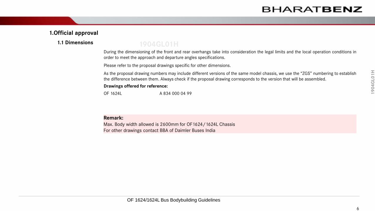
During the dimensioning of the front and rear overhangs take into consideration the legal limits and the local operation conditions in
order to meet the approach and departure angles specifications.
Please refer to the proposal drawings specific for other dimensions.
As the proposal drawing numbers may include different versions of the same model chassis, we use the “ZGS” numbering to establish
the difference between them. Always check if the proposal drawing corresponds to the version that will be assembled.
Drawings offered for reference:
OF 1624L A 834 000 04 99
1.1 Dimensions
Remark:
Max. Body width allowed is 2600mm for OF1624/1624L Chassis
For other drawings contact BBA of Daimler Buses India
6
OF 1624/1624L Bus Bodybuilding Guidelines

19
04
GL
01
H
1904GL01H
The “BharatBenz Logo”, and the written expression “BharatBenz” are Daimler Buses India trademarks. The following notes, referring
to the use of these trademarks, embrace a worldwide level for body builders that install a body not made by Daimler on a
BharatBenz chassis:
• The BharatBenz logo is to be attached only on the front of the body, centered at body height for the identification of the chassis.
The name of the body maker has to be attached at a distance from the BharatBenz, referring to the body maker, and according to
the drawings in the following pages.
• The written “BharatBenz letterings” has to be used for the identification of the chassis at the front & rear part, The name of the
body maker has to be always attached at a distance from the written “BhararBenz expression” (see drawings).
Therefore, the BharatBenz chassis are always supplied with the chrome plated BharatBenz Logo and the chrome finish BharatBenz
written expression for the identification of the chassis. This chrome finish logo is attached by the body maker, to the body front end
at chassis height, in name of Daimler Buses or its affiliated companies. The same applies to the attachment of the written
BharatBenz expression to the rear body end at a height below the rear glass. (see drawings)
The BharatBenz trademarks cant be used to identify the chassis, if the complete vehicle does not comply with the quality
specifications contained in the Daimler Buses guidelines, for body makers.
• Specific Daimler buses names, as Mercedes-Benz, CITARO, TRAVEGO, SHD etc., for example, cant be attached to the body. The
body maker can only use his own type designation, which should not permit any confusion with the specific Daimler Buses names.
• The BharatBenz key, Fuel caps and steering wheel are marked with the BharatBenz by the manufacturer and are part of the
chassis delivery scope. Interior elements (for ex., seats, ashtrays, roof interior, etc.), which are not integrated by the chassis
manufacturer, are forbidden to be marked with BharatBenz trademarks.
1.2 Use of BharatBenz trademarks
Official approval
OF 1624/1624L Bus Bodybuilding Guidelines 7

19
04
GL
01
H
1904GL01HThe bodybuilders not authorized to use the original design for the body, or to copy the original design or elements of the original
design. The body maker will have to create an independent design, whose appearance cant be confused with the original Daimler
design. The use of original BharatBenz parts, with significant design, such as mirrors, headlights and other elements, require,
therefore, the express approval from Daimler Buses or from its affiliated companies.
• The bodybuilder commits himself to permit the necessary monitoring of the product and process of the bus body quality, by a
consultant of the Daimler Buses body builder/Affiliated company. The acceptance of the body by the body maker consultant is not
to be considered, under any circumstances, as a reduction of responsibility of the body maker on the product/ legislation/liability
on the body. The maker of the body will also be made responsible for the chassis, under the aspects of responsibility on the
product, should he not attain himself to the Daimler body building guidelines and, thus, compromising the performance of the
chassis.
Any and all markings of bus bodies, with BharatBenz trademarks, that exceed these marking guidelines, require a
separate trademark licensing agreement with Daimler Buses and a written authorization from Daimler Buses.
Official approval
OF 1624/1624L Bus Bodybuilding Guidelines 8

19
04
GL
01
H
1904GL01H
Pink colored area: Protected area for BharatBenz trademark.
This space is not to be used for the attachment of any other designations.
1- Recommended position for the BharatBenz Logo.
2- Recommended position for the BharatBenz Letters.
3- Recommended position for the Bodybuilder trademarks.
Blue colored area: The space other than protected areas (pink color) can be used by the body builder for Body Manufacturer
logo/ trademark within the scope of the brand directives.
Front View Rear View
1
2
2
3
3
Official approval
OF 1624/1624L Bus Bodybuilding Guidelines 9

19
04
GL
01
H
1904GL01H
2 Chassis weight
The weight values presented below are only for reference. For the adequate dimensioning of the body, the correct weight
values must be established according to the chassis composition.
FA RAFrame weightB00.01-0142-10
FA - Front axle
RA - Rear axle
Tab2- Weight reference values BSVI chassis
Chassis Front axle (kg) Rear axle (kg)
OF 1624L (Non-Retarder) 3225 2425
OF 1624L (Retarder) 3375 2525
Remark:
Reference values: may vary due to the installed accessories or to the chassis composition
OF1624/1624L: Without body, with full 380ltr. fuel reservoir, with G86 SAEIII gearbox, without driver, without spare wheel, without
fire extinguisher and toolbox, with "AdBlue®" 51ltr. tank (holding capacity of tank is 35 liters).
10
OF 1624/1624L Bus Bodybuilding Guidelines

19
04
GL
01
H
1904GL01H
3 Loads allowed per axle
3.1 Loads allowed per axle
The OF chassis frames are dimensioned to form a "single" structural set together with the body. The joining points between the
body and the chassis must be distributed to avoid concentration of tensions, and that duly absorbs all the strains applied on the
set.
The Body Builder must ensure that all the interface points and those that are subject to strains are built duly embedded pursuant
to the guidelines issued by Daimler Buses India
The admissible technical loads per axle for the chassis are as follows:
Tab3- Allowed technical loads
[kg] OF 1624 OF 1624L
Front axle 6500 6500
Rear axle 10200 10200
Total 16700 16700
For the use of other types of tires, please check the Chassis manufacturer's specifications with regard to the load capacity limit and
inflation pressure.
The Body Builder must also observe the weight specifications mentioned in the corresponding law. When the technically admissible
values and the legal admissible values differ, the one that presents the smallest value must prevail.
iGross Vehicle Weight Rating (GVWR) = Chassis + Body + Load (passengers + luggage)
11
OF 1624/1624L Bus Bodybuilding Guidelines
19
04
GL
01
H
1904GL01H
3 Loads allowed per axle
3.2 Admissible loads per axle
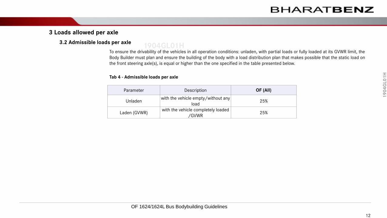
To ensure the drivability of the vehicles in all operation conditions: unladen, with partial loads or fully loaded at its GVWR limit, the
Body Builder must plan and ensure the building of the body with a load distribution plan that makes possible that the static load on
the front steering axle(s), is equal or higher than the one specified in the table presented below.
Tab 4 - Admissible loads per axle
Parameter Description OF (All)
Unladenwith the vehicle empty/without any
load25%
Laden (GVWR)with the vehicle completely loaded
/GVWR25%
12
OF 1624/1624L Bus Bodybuilding Guidelines

19
04
GL
01
H
1904GL01H
4 Chassis frame
4.1 Arrangement
The OF chassis have a single frame concept, of the "ladder type" and with cross members fastened by rivets or bolts.
Chassis frame B31.00-0999-22
13
OF 1624/1624L Bus Bodybuilding Guidelines
19
04
GL
01
H
1904GL01H
4 Chassis frame
4.2 Chassis material
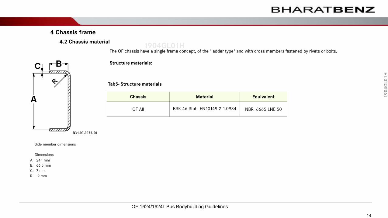
The OF chassis have a single frame concept, of the "ladder type" and with cross members fastened by rivets or bolts.
Side member dimensions
Dimensions
A. 241 mm
B. 66,5 mm
C. 7 mm
R 9 mm
Structure materials:
Tab5- Structure materials
Chassis Material Equivalent
OF All BSK 46 Stahl EN10149-2 1.0984 NBR 6665 LNE 50
14
OF 1624/1624L Bus Bodybuilding Guidelines

19
04
GL
01
H
1904GL01H
5 Chassis modifications and adjustments
5.1 First cross member adjustment
iNo changes or repositioning are possible for the first cross member of the OF chassis.
Remark:
The first crossmember was not designed to attach towing hitch/hook
15
OF 1624/1624L Bus Bodybuilding Guidelines

19
04
GL
01
H
1904GL01H
Driver cockpit
5 Chassis modifications and adjustments
5.2 Driver’s Cockpit
iThe OF chassis do not make possible alterations in the driver ergonomics or its position.
Remark:
Integrate the front panel (B) and the floor (A) of the podest to the body structure:
Arrow - Direction of travel
The red area - May be modified or replaced by the Body Builder
The blue area - Must not be modified or replaced by the Body Builder
B
A
16
OF 1624/1624L Bus Bodybuilding Guidelines

19
04
GL
01
H
1904GL01H
5 Chassis modifications and adjustments
5.3 Vertical adjustment of front overhang
!The longitudinal members are fixed and cannot be adjusted.
17
OF 1624/1624L Bus Bodybuilding Guidelines

19
04
GL
01
H
1904GL01H
5 Chassis modifications and adjustments
5.4 Wheelbase modification
!Wheelbase modifications are not allowed for OF 1624L/1624 chassis.
Remark:
Regarding OF chassis, the removal of the central part of the vehicle frame is not allowed to install the feed-through type luggage
compartment in the wheelbase region.
18
OF 1624/1624L Bus Bodybuilding Guidelines

19
04
GL
01
H
1904GL01H
5 Chassis modifications and adjustments
5.5 Rear overhang extension
Remark:
A cross member must be mounted at the rear end, even if the frame extension and/or towing coupling have not been planned..
The extension of the rear overhang of the OF chassis is allowed within the admissible weight limits are observed (legal and
technical) and the constructive limits for the rear overhang. Take into consideration that the departure angle must be kept within
the established limits.
The extension of the vehicle frame must be done according to the following technical prescriptions:
• In the preparation of the extension, the Body Builder must provide the addition of cross members, in adequate quantity and
distribution to keep unchanged the vehicle frame rigidity.
• The material used for the frame extension and for the preparation of the new cross members, fastening plates and
reinforcement pieces, must have thickness and quality equivalent to those of the original vehicle frame, as described in the
chapter “Chassis Material” page ***.
• The welding must be carried out as recommended in the chapter 3.13 - Welding techniques/welding methods - of the manual
Guidelines for Body Building - “General Manual".
• After welding the vehicle frame longitudinal members, apply reinforcements symmetrically in both sides of the frame. To avoid
cracks in the spot weld and to preserve the longitudinal members elasticity, weld or bolt the reinforcement pieces to the frame
in the shape of beveled corner plates and, at the ends, forming a common face with the upper or lower tabs of the longitudinal
member. Keep enough distance between the longitudinal member web and the upper and lower reinforcement corner plates.
19
OF 1624/1624L Bus Bodybuilding Guidelines

19
04
GL
01
H
1904GL01H
6 Chassis alignment and leveling
6.1 Chassis Levelling:
The OF chassis must be supported on a flat horizontal floor, duly with chokes and supported on racks as per the figure below.
They must not be subject to strains and stresses caused by the weight of the engine and the transmission.
The figure below is illustrative.
The necessary quantity and the arrangement of the devices must be established by the Body Builder, in such a manner that the
chassis alignment conforms the respective proposal drawings.
Chassis alignment and leveling
During the leveling process the chassis must be leveled with reference to the corresponding proposal drawing.
The devices must be supported exclusively on the vehicle frame longitudinal members. The use of mechanic components such as
those is not allowed: engine, transmission, axles, articulations, etc. Cross members and wings must not be used as support points.
The devices used in the leveling process must be rigid enough to ensure that the movements of people on the chassis or
dimensional variations due to its own weight, transport and storage do not compromise the process. These devices must not be
removed until the complete fastening of the body structure on the vehicle frame.
The chassis leveling must be ensured in other directions, the longitudinal and the transverse direction.
20
OF 1624/1624L Bus Bodybuilding Guidelines

19
04
GL
01
H
1904GL01H
6 Chassis alignment and leveling
6.2 Chassis Alignment:
The Body Builder must ensure the frame alignment.
For complete vehicles, it must be ensured that the misalignment between the axles does not exceed the maximum values indicated
below:
Chassis alignment:
(A - B) = 10mm maximum
(C - D) = 15mm maximum
Frame alignment
A
B
C
D
!It is the manufacturer's responsibility to prevent that the misalignment of the axles does not exceed the specified maximum values,
to ensure the perfect driveability and stability conditions.
21
OF 1624/1624L Bus Bodybuilding Guidelines
19
04
GL
01
H
1904GL01H
7 Interface Between the Body & Chassis
7.1 Areas for body fastening
All OF chassis are not self-supporting. The assurance of its integrity is shared with the body structure.
The correct fastening of the body to the chassis is extremely important to keep the structural stability of the set, avoiding
concentration of tensions.
The body structure must be designed and assembled in such a way that they ensure the structural stability of the bus set (chassis
+ body) consistent with the dimension values specified in the proposal drawings of the focused chassis, and/or other technical
information made available by Daimler Buses India.
During the development of the body, the Body Builder must pay attention to the correct applications and to the legal and technical
limits of the final bus set (chassis + body).
“L” shaped supports bolted to the longitudinal member are available to facilitate the fastening of the body during the body building
process to the OF chassis equipped with air suspension.
* Use of U-type Contraction is not recommended for OF 1624 Air suspension chassis.
!Welding or drilling holes in the longitudinal member and frame cross members are not allowed.
Important:
Daimler Buses India does not interfere in the structural project of the body, which is sole responsibility of itsmanufacturer. Daimler Buses India makes available fastening locations and relevant guidance to make possible theinterface between the body and the chassis.
The Daimler Bus chassis have been designed, tested and produced to meet the requirements of the relevantapplications.
22
OF 1624/1624L Bus Bodybuilding Guidelines

19
04
GL
01
H
1904GL01H
7 Interface Between the Body & Chassis
7.1 Areas for body fastening
In order to make the body building process easier, interface bolted “L” shaped brackets are available in the frame for
this purpose.
The fastening of the body structure have to be carried out directly onto these brackets with the utilization of welding
processes. If, for some reason, these “L” shaped brackets are rendered useless, the fastening of the body have to be
mandatorily bolted on the frame rails.
New brackets may be added to the chassis frame for body fastening, provided that they are assembled according to the
Body Building Directives.
In the rear axle region, it is not allowed to insert fixed supports directly to the longitudinal members.
Body attachment plates- Front
The fastening of the body structure must be made directly on these supports by using welding processes. If the “L”
shaped supports are scrapped, the body fastening should be compulsorily bolted to the longitudinal members.
For the adaptation of the body drawing, new supports can be inserted in the vehicle frame, following the other
instructions available in the body building guidelines, specific for each chassis model.
!Further to the essential points (indicated in “orange”), for the body structuring and body support, the Body Builder must
evaluate the needs of his project, and add the necessary quantity of fastening points to the chassis.
Body attachment plates-Rear
23
OF 1624/1624L Bus Bodybuilding Guidelines

19
04
GL
01
H
1904GL01H
7 Interface Between the Body & Chassis
7.1 Areas for body fastening
It is essential that the whole available area on the support, highlighted in blue color in the figure, is used to avoid deformation of
the interface supports and consequently of the longitudinal members ("spring" effect) and to provide an adequate interface
between the body structure and the vehicle frame
On these supports, the cross members (or extensions) of the body base structure must be welded to the upper part, associated to
the "wings" that join the body lateral parts (side cross members or their supplementary components).
The supports assembled at the front of the rear suspension, together with the internal reinforcements of the longitudinal members,
must not be eliminated. If the new supports must be changed to adapt them to the body structure drawing, they must be produced
in a single plate (without splicing) with the same material (steel NBR6656 LNE500) and minimum thickness of 6mm. For the
fastening, use 06 (six) M14x1.5x40 – 10.9 bolts (MBB N 000000 005514) and M14x1.5 – 10 nuts (MBB N 000000 005662), all
flanged. Use a tightening torque of 172 ± 13 Nm for the fastening and carry out the control and recording in the internal
documentation. If the supports thickness is changed by more than 6mm, the bolts length must be increased to meet the
requirements of this installation.
Body attachment ‘L’ plate Body attachment plates at Front
24
OF 1624/1624L Bus Bodybuilding Guidelines

19
04
GL
01
H
1904GL01H
7 Interface Between the Body & Chassis
7.2 Inadequate Regions for the Body Fastening
The chassis numbering, during the entire body building process must be properly protected.
When a supporting base and/or additional fastenings are necessary due to concentration of loads or additional strains, in order to
supplement the fastening of the body structure to the vehicle frame, remember that some areas of the vehicle frame are not
appropriate for welded fastenings. If such areas are used and this damages the vehicle frame, such damages are not covered by
the warranty granted by Daimler Buses India. Under no circumstances may the Body Builder use such areas for directly welded
fastenings. Any undue use of welding in these regions may cause the loss of the rights to the warranty and transfer of the liability.
In some areas, the fastenings may be bolted to the vehicle frame.
!Welding or drilling holes in the longitudinal members tabs and mobile frame cross members are not allowed.
25
OF 1624/1624L Bus Bodybuilding Guidelines

19
04
GL
01
H
1904GL01H
7 Interface Between the Body & Chassis
7.2 Inadequate Regions for the Body Fastening
Below follows the indication of chassis locations where the fastening of supports is not permissible by means of welding, being
mandatory the utilization of bolts to attach supports to side members.
!Modifications to the frame are not permitted in the highlighted areas. Welding operation is not permitted throughout the frame.
Critical areas on frame:
• Steering box bracket
• Spring bracket
• Stabilizer
• Bump Stop
• Shock absorber
• Cross member
• Engine mount
OF1624 chassis Unsuitable areas for fastening
26
OF 1624/1624L Bus Bodybuilding Guidelines

19
04
GL
01
H
1904GL01H
7 Interface Between the Body & Chassis
7.3 Frame ends
Due to the arrangement of the power train set at the front part of the OF chassis, changes of the front overhang are not allowed.
The rear overhang may be altered as explained in chapter 5.5 “Rear Overhang Extension” page 16.
Frame ends
27
OF 1624/1624L Bus Bodybuilding Guidelines
19
04
GL
01
H
1904GL01H
7 Interface Between the Body & Chassis
7.4 Wheelhouses
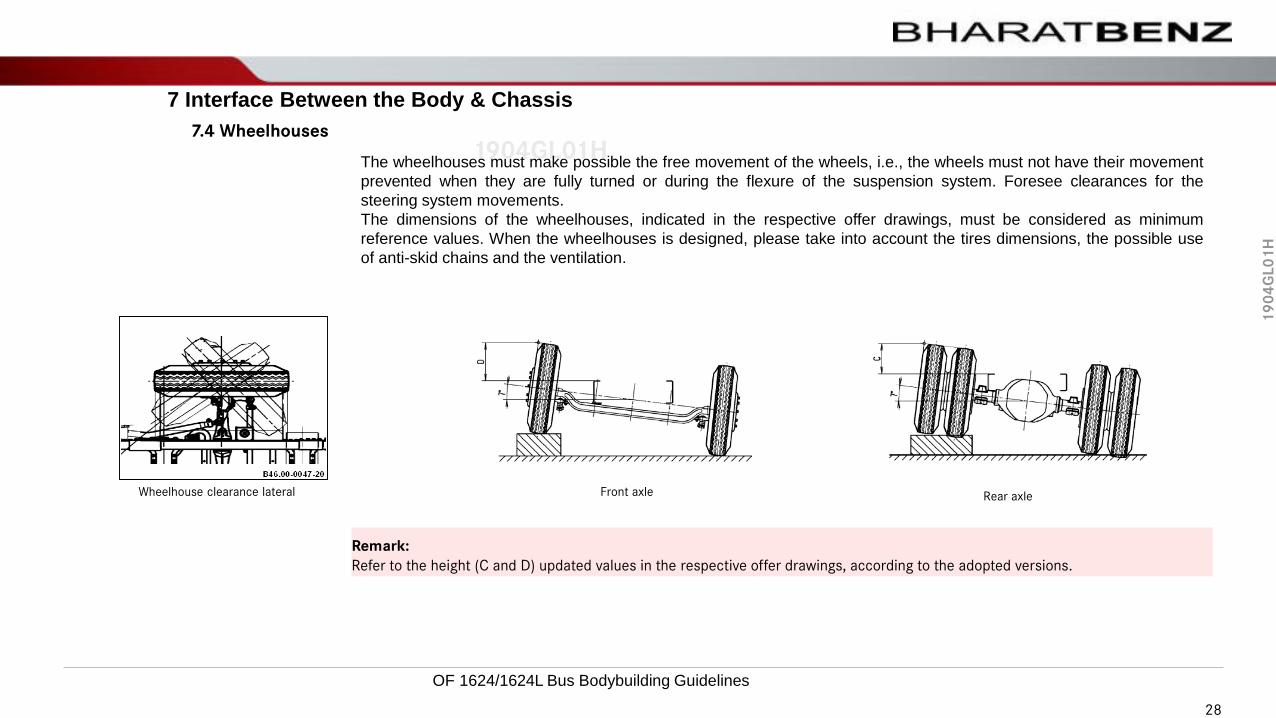
The wheelhouses must make possible the free movement of the wheels, i.e., the wheels must not have their movement
prevented when they are fully turned or during the flexure of the suspension system. Foresee clearances for the
steering system movements.
The dimensions of the wheelhouses, indicated in the respective offer drawings, must be considered as minimum
reference values. When the wheelhouses is designed, please take into account the tires dimensions, the possible use
of anti-skid chains and the ventilation.
Remark:
Refer to the height (C and D) updated values in the respective offer drawings, according to the adopted versions.
Front axle Rear axleWheelhouse clearance lateral
28
OF 1624/1624L Bus Bodybuilding Guidelines

19
04
GL
01
H
1904GL01H
7 Interface Between the Body & Chassis
7.5 Central Unit Structure
!Not applicable.
Remark:
Regarding OF chassis, the removal of the central part of the vehicle frame is not allowed to install the luggage compartment in the
wheelbase.
29
OF 1624/1624L Bus Bodybuilding Guidelines
19
04
GL
01
H
1904GL01H
8 Cooling system
The radiators must be kept in their original positions, so that their attachment cushions can work freely. The radiators shall be
properly protected before carrying out any service in order to prevent damages to the fins. Do not paint the radiator.
To ensure enough air flow for the coolers, do not put stickers, plates or other adornment pieces.
!The coolers must be kept in their initial position, in such a manner that the fastening mounts may operate freely. The air cooler must
be protected before the execution of any services, to avoid damages to the fins. The cooler must not be painted.
Remark:
The support structure of the cooling system is self-standing, i.e, they do not need to be tied to the body. Drilling holes, trimming and
welding are not allowed to be done in this structure and also in their support points.
30
OF 1624/1624L Bus Bodybuilding Guidelines

19
04
GL
01
H
1904GL01H8.1 Radiator fixation structure
8 Cooling system
To assure enough air passage to the radiator, do not put labels, plates and adornment pieces.
!The support structure of the cooling system doesn’t need attaching to the body, in other words, it is self-supporting. Drillings, cuts and
welding are not allowed on this structure and on its fixing points.
Sustaining structure of the radiators
31
OF 1624/1624L Bus Bodybuilding Guidelines

19
04
GL
01
H
1904GL01H8.1 Radiator fixation structure
8 Cooling system
Foresee a clearance higher than 50 mm between the radiator’s support structure (cooling cage and all components) and body
(front panel/structure, engine cover, side panels, etc.) to attend possible variations in manufacturing.
A flap with enough size has to be provided in the body to allow maintenance access to the cooling system, including the radiators
replacement. The body must permit the engine and radiators removal through the vehicle front part. Any reinforcements of the
body that may exist in this area should be removable.
50mm
32
OF 1624/1624L Bus Bodybuilding Guidelines

19
04
GL
01
H
1904GL01H8.2 Radiator compartment
8 Cooling system
Due to the original configuration used in the cooling system of the OF chassis the Body Builder does not have to install additional
deflectors between the coolers set and the engine, however, the body must have front openings for the coolers, as described in the
chapter “Cooling System Openings” page 35.
The baffle plates have as purpose to prevent the recirculation of hot air that comes from the engine compartment.
If this requirement is not complied with, the effectiveness of the engine cooling system may be compromised.
Not satisfying this requirement results in the compromising of the engine cooling system performance.
During the production of air baffle plates, the following points must be taken into consideration:
Due to the movements of the cooling system, it is important to use rubber profiles and/or similar pieces to carry out the sealing
and avoid damages to the coolers.
• The plates must be detachable and the access for the maintenance of the periodical maintenance items must be ensured.
• Linings or rubber elements must not be supported directly on the cooler honeycomb to avoid damages.
• Do not carry out rework services in the cooler support structure.
!Ensure the sealing between the coolers compartment and the engine to avoid the recirculation of hot air. Linings or rubber elements
must not be supported directly on the cooler lines, to avoid damaging them. Hot air from the engine compartment must not flow into
the cold air environment where the coolers are located.
Remark:
During the manufacturing of the bodies for the OF chassis, the Body Builder can install air baffle plates at the upper and lower part
of the cooling unit, in order not to affect the cooling system performance.
The baffle plates purpose is to avoid the recirculation of hot air in the engine compartment.
Deflecting plates
33
OF 1624/1624L Bus Bodybuilding Guidelines

19
04
GL
01
H
1904GL01H8.3 Radiator fan and air deflector
8 Cooling system
A clearance larger than 20 mm must be kept between the surface of the coolers set support structure (“cage”, including its
components) and the body parts (engine cover, side panel, etc.), to meet the requirements of possible manufacturing variations .
The body must be equipped with an access cover to the cooling system, big enough to make possible the maintenance of the
coolers (including replacement works).
When the body has cross members in this region that make it impossible or difficult to carry out the maintenance services, they
must be produced in a manner that renders them removable.
Fan blade positioning
Deflector
1 Fan blade
Minimum clearance, A = 25 mm
34
OF 1624/1624L Bus Bodybuilding Guidelines

19
04
GL
01
H
1904GL01H8.4 Expansion tank (Coolant reservoir)
8 Cooling system
The expansion reservoir filler neck must allow free access for the refuel with a watering can, and/or automatic equipment (gun
with flow control).
In case extension to filling neck, the proposal must be pre-evaluated & authorized by Daimler Buses India.
Expansion tank
Pressure valve
1 Filler neck
!The expansion tank (coolant reservoir) must be kept in the original position.
!The pressure valve of the expansion reservoir must not be modified or removed. Its seal must remain unbroken and the refuel must
be made through the reservoir filler neck.
35
OF 1624/1624L Bus Bodybuilding Guidelines

19
04
GL
01
H
1904GL01H8.5 Cooling system openings
8 Cooling system
Free area of air pickup
The unobstructed air intake area must be positioned immediately in front of the radiators.
The illustration beside shows the radiator air pick-up grille for chassis with front engine.
Tab6- Free area of air pickup
Cooling system Openings
Chassis BSVI Minimum area (dm²)
OF1624/OF1624L 30*
* Free openings shall be maintained relative to radiator position of the chassis.
36
OF 1624/1624L Bus Bodybuilding Guidelines
19
04
GL
01
H
1904GL01H9.1 Engine air intake system
9 Engine air intake system
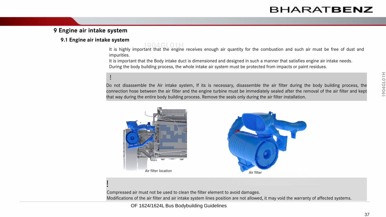
It is highly important that the engine receives enough air quantity for the combustion and such air must be free of dust and
impurities.
It is important that the Body intake duct is dimensioned and designed in such a manner that satisfies engine air intake needs.
During the body building process, the whole intake air system must be protected from impacts or paint residues.
!Do not disassemble the Air intake system, If its is necessary, disassemble the air filter during the body building process, the
connection hose between the air filter and the engine turbine must be immediately sealed after the removal of the air filter and kept
that way during the entire body building process. Remove the seals only during the air filter installation.
!Compressed air must not be used to clean the filter element to avoid damages.
Modifications of the air filter and air intake system lines position are not allowed, it may void the warranty of affected systems.
Air filter location Air filter
37
OF 1624/1624L Bus Bodybuilding Guidelines

19
04
GL
01
H
1904GL01H9.2 Air Intake Box
9 Engine air intake system
For the OF chassis (right-hand drive vehicle), the air intake box must be produced as per guidance described in the
chapter “Air intake position” page 36.
Seal the air intake box opening with the lateral of the body to ensure the air flow.
The air intake box may be disassembled to avoid damages during the chassis and body coupling process. The air filter
intake must be sealed to avoid the penetration of residues.
9.3 Air intake opening
The body opening for air intake to the engine must have a minimum area :
Tab7- Minimum area for air intake
Chassis Air intake box Minimum area (dm²)
OF1624/1624L RHD 4.0
The body opening for engine air intake shall be located in front of the filter air intake and allow free of dust or dirt air
inlet in a satisfactory amount for combustion, as well as ensure longer filter element durability.
38
OF 1624/1624L Bus Bodybuilding Guidelines
19
04
GL
01
H
1904GL01H9.4 Air intake position
9 Engine air intake system
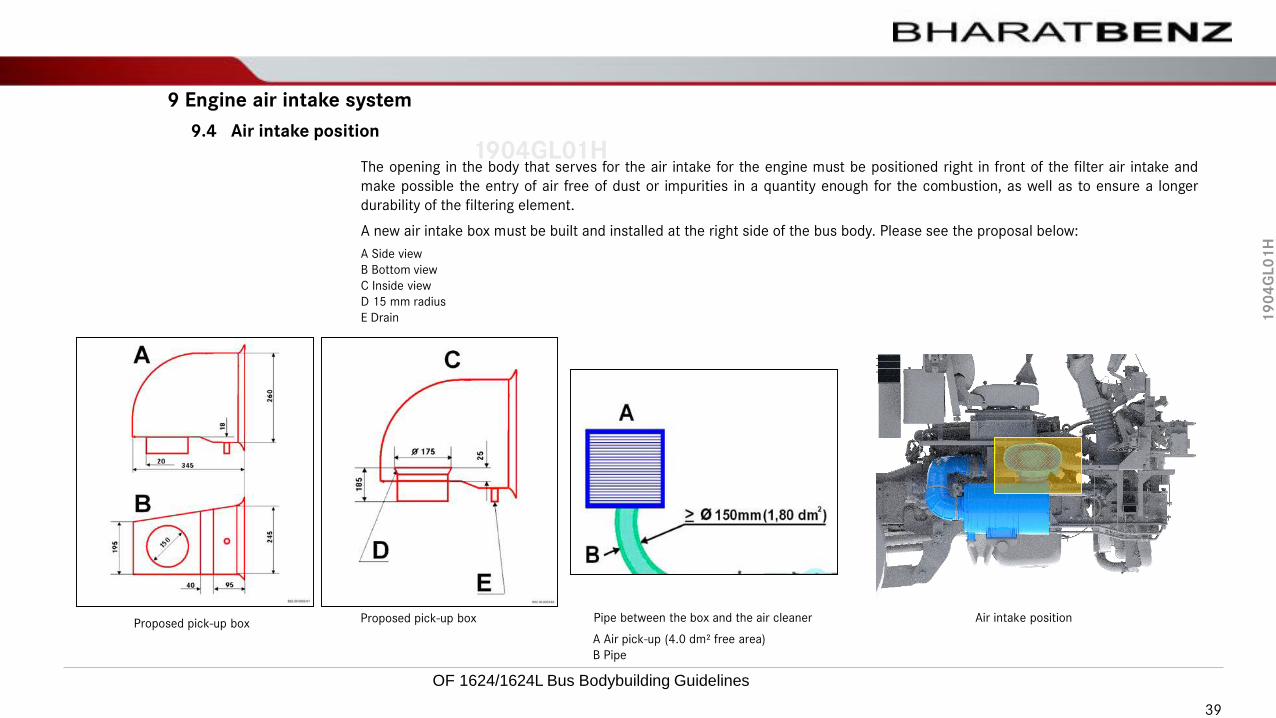
The opening in the body that serves for the air intake for the engine must be positioned right in front of the filter air intake and
make possible the entry of air free of dust or impurities in a quantity enough for the combustion, as well as to ensure a longer
durability of the filtering element.
A new air intake box must be built and installed at the right side of the bus body. Please see the proposal below:
Air intake position
A Side view
B Bottom view
C Inside view
D 15 mm radius
E Drain
A Air pick-up (4.0 dm² free area)
B Pipe
Pipe between the box and the air cleaner Proposed pick-up box Proposed pick-up box
39
OF 1624/1624L Bus Bodybuilding Guidelines

19
04
GL
01
H
1904GL01H9.5 Air filter restriction level sensor
9 Engine air intake system
The chassis are equipped with an electric sensor that indicates the restriction of the air intake system (dirty filter) with indication at
the instrument cluster.
OF chassis are equipped with an electronic sensor for the indication of the air filter restriction level.
During the body building process, it is necessary to protect it against impacts and paint residues to avoid the air intake occurs
without filtering.
Instrument cluster BS VI
• For BS VI vehicles the indication is given as a pop up notification on the LED screen
Air filter restriction sensor
40
OF 1624/1624L Bus Bodybuilding Guidelines
19
04
GL
01
H
1904GL01H10.1 Steering system
10 Steering system
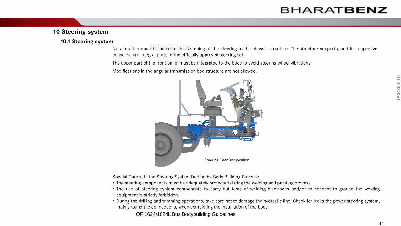
No alteration must be made to the fastening of the steering to the chassis structure. The structure supports, and its respective
consoles, are integral parts of the officially approved steering set.
The upper part of the front panel must be integrated to the body to avoid steering wheel vibrations.
Modifications in the angular transmission box structure are not allowed.
Steering Gear Box position
Special Care with the Steering System During the Body Building Process:
• The steering components must be adequately protected during the welding and painting process.
• The use of steering system components to carry out tests of welding electrodes and/or to connect to ground the welding
equipment is strictly forbidden.
• During the drilling and trimming operations, take care not to damage the hydraulic line. Check for leaks the power steering system,
mainly round the connections, when completing the installation of the body.
41
OF 1624/1624L Bus Bodybuilding Guidelines

19
04
GL
01
H
1904GL01H10.2 Power steering oil tank
10 Steering system
Do not reposition the power steering oil reservoir as changing the original engine supports is not allowed.
It is not allowed to change the positioning and fastening of the power steering oil reservoir & its hoses, their routing as it is installed
in its final position.
If It is necessary to ensure the refueling access through the front cover/lid of the vehicle.
Power steering oil tank Steering Oils reservoir position
42
OF 1624/1624L Bus Bodybuilding Guidelines
19
04
GL
01
H
1904GL01H10.3 Adjustable Steering Column
10 Steering system
!Check the updated values in the respective proposal drawings, according to the adopted versions.
The OF 1624/1624L chassis are equipped with adjustable steering column, aiming and adjusting it to the driver cockpit.
When the chassis has this feature, the Body Builder must plan the layout of the dashboard at an appropriate distance from the
steering column to make all the adjustment positions possible.
The body panel must have a minimum clearance of 5 mm with regard to all the steering column adjustment positions.
The adjustment dimensions of the steering wheel are indicated in the respective proposal drawings, and must be considered as
minimum reference values.
43
OF 1624/1624L Bus Bodybuilding Guidelines

19
04
GL
01
H
1904GL01H11.1 Pneumatic outlet for auxiliary services
11 Pneumatic system
The body accessories that are pneumatically actuated such as the horn, the doors actuation and other pneumatic devices, must
not be connected directly to the service or parking brake circuits, or their air reservoirs.
The location of the Auxiliary compressed air tank for the accessories is highlighted in below picture for OF1624 chassis.
Bodybuilder must assemble the multiport connector or suitable adapter while taking air supply to auxiliary devices.
Positioning of the Auxiliary tank on chassis
44
OF 1624/1624L Bus Bodybuilding Guidelines

19
04
GL
01
H
1904GL01H11.2 Pneumatic hosing (connection plates)
11 Pneumatic system
!Not applicable.
45
OF 1624/1624L Bus Bodybuilding Guidelines

19
04
GL
01
H
1904GL01H11.3 APU (Air Processing Unit)
11 Pneumatic system
The position of the APU (Air Pressure Unit) set is the definitive one, and must not be altered. Prepare access for the removal, to
facilitate the maintenance.
Provide an “A” clearance of 30mm on the APU set to make its removal possible
!Do not start the engine while the APU (Air Pressure Unit) control pipe is removed.
Clearance over APU
A Clearance of 30mm
A
46
OF 1624/1624L Bus Bodybuilding Guidelines

19
04
GL
01
H
1904GL01H11.4 Compressors
11 Pneumatic system
The chassis compressors are actuated by gears and are coupled to the engine.
In the production of the engine cover/hood, it is necessary to provide access to the upper part of the compressor.
Air compressor
47
OF 1624/1624L Bus Bodybuilding Guidelines

19
04
GL
01
H
1904GL01H12.1 Brake system
12 Brake system
The chassis brake system must not be changed.
During the body building processes, the systems must be duly protected.
Do not insert derivations in the brake circuits, as the use of the connections previously made available in the chassis for the
actuation of the pneumatic components as described in the chapter “Pneumatic Connection for auxiliary service” page 44 is
compulsory.
The Body Builder must carry out inspections to identify possible leakage and/or damages in the components after the completion
of the body installation process.
Before the dynamic assessments are carried out, all the systems must be duly reviewed and corrected as a safety measure. If
doubts arise, contact Daimler Buses India.
Parking Brake Adjuster Lever
The parking brake actuation lever is supplied in the chassis in a provisional position. The Body Builder must provide for its fastening
in a visible and practical place, of easy access to the driver, foreseeing also the need to use it in emergency cases.
It must also be positioned in a place that makes impossible its accidental or undue access. The complete travel of the lever must
be free from interferences.
Service Brake Pedal
The service brake pedal is assembled in its definitive position in the chassis, however the Body Builder must ensure its free travel,
without interferences such as from wiring harnesses, lines, trim parts, floor, etc.
Parking brake lever
1. Actuated brake
2. Released brake
Parking brake lever position
48
OF 1624/1624L Bus Bodybuilding Guidelines

19
04
GL
01
H
1904GL01H12.2 Retarder
12 Brake systemThe chassis may be equipped with Electromagnetic retarder (Telma) as a special variant.
It is an aggregate particularly suitable for vehicles that operate in hilly regions or places that have mixed topographic conditions.
Its application will result in a significant increase in the durability of the brakes system (mainly the brake pads and linings) and
mechanical components in general.
During the installation of the instrument cluster of chassis equipped with retarder, the position of the actuation controls must be
planned taking into consideration in such a manner that the driver is able to reach them easily avoiding ergonomic problems and
interferences.
It’s operation must not interfere with the Body dashboard or any component near by.
RetarderActuation of the retarder
In the assembly of Tourist coaches, the luggage compartment structure or Sheet metal panels or Body floor (Plywood) must be at
least 100mm above the Chassis longitudinal members.
Thermal isolation materials must also be added to the Right, Left and Top sides and on the retarder.
49
OF 1624/1624L Bus Bodybuilding Guidelines

19
04
GL
01
H
1904GL01H
12 Brake system
!Add thermal isolation to the wiring harnesses, lines, and other components of the body that are susceptible to high temperatures.
!The fuel lines must not be positioned in the inner part of the vehicle frame in the retarder region. Ensure that the fuel lines routes
are kept at the external part of the frame as installed in the original chassis keeping them at a safe distance from the heat sources.
!Information related to the fastening of the electronic control unit and other instructions related to the electric part, are included in
the manual “Body Building Guidelines” – Specific electric/electronic Part, in the chapter 17 – “Telma Retarder”.
!The batteries compartment must be placed behind the front axle.
50
OF 1624/1624L Bus Bodybuilding Guidelines

19
04
GL
01
H
1904GL01H13.1 Exhaust system
13 Exhaust system
The genuine part of the chassis, from the engine until to the muffler/catalytic converter (including), must not be changed.
13.2 Exhaust System counter Pressure
Carry out the counter-pressure measurement, in the case the original exhaust pipes length is extended, and the values obtained
must be smaller than:
• 280 mbar for chassis with BSVI engines.
!Further information is described in the Body Building Directives - General Part, in chapter 3.23 - Exhaust System.
Exhaust system
51
OF 1624/1624L Bus Bodybuilding Guidelines

19
04
GL
01
H
1904GL01H
13 Exhaust system
13.3 Exhaust outlet position
OF 1624L BSVI chassis exhaust system does not requires any tail pipe extension by Bodybuilder until unless local legislation
demands or situation prevails.
In the case of exhaust pipe extension, the pipe added by the Body Builder must have a diameter equal or greater than the one of
the genuine component.
The fastening of such extension to the body must be made by means of elastic elements identical to the original ones supplied with
the chassis.
When extending the pipes, it is necessary to take care to prevent that the exhaust gases back pressure does not exceed the
established limit, according to “Exhaust System”.
For the assembly of Exhaust outlet, the body project must foresee an orifice for the exhaust pipes, with minimum clearance of 20
mm to avoid interferences. According to the material used in the production of the body structure, it is necessary to study the
necessity of adopting protections to avoid damages caused by heat.
In the production of line extension, the movements of some components must be taken into account, such as: axles, transmission
shafts, etc.
!Do not reposition or rotate the exhaust tail pipe orientation.
Exhaust outlet pipe
52
OF 1624/1624L Bus Bodybuilding Guidelines

19
04
GL
01
H
1904GL01H
13 Exhaust system
13.4 Exhaust gas treatment system
13.4.1 AdBlue®" Tank
The Euro 5/ BS 6 chassis are equipped with an "AdBlue®" tank plus a pump, necessary to meet the legislation requirements.
When necessary, the "AdBlue®" line and pump may be removed during the body building process and must be properly stored
and identified.
13.4.2 Protection of "AdBlue®" Tank
To avoid system contamination, it is mandatory that contaminants do not come in contact with the solution. It is necessary to
carefully preserve the after treatment system and related components during the installation of the implements and bodies to
avoid contact with contaminants.
During the installation of bodies, the system should remain closed (including breathers) to preserve covers, nozzles, and
connections. Protective plugs (rubber) can be used on genuine covers, improving security against damages to system
components.
During the handling of after treatment system components, they should remain closed and protected (with genuine covers and
other protections).Besides, they should be kept away from contaminants such as fuel, oil, grease, dust, dirt, metal residues and
detergents.
!The catalytic converter must not be removed during the body building process.
During the body building the catalytic converter must be protected from mechanical impacts to avoid damaging the sensors etc.
After treatment systems are extremely sensitive to potential impurities contained in "AdBlue®" solution.
To avoid the contamination during the vehicles' refuel or utilization, properly protect the "AdBlue®" tank fitting to avoid residue
built-up by installing access covers on the side and on the mud flap.
BS 6 chassis are equipped with an "AdBlue®" tank
53
OF 1624/1624L Bus Bodybuilding Guidelines

19
04
GL
01
H
1904GL01H
13 Exhaust system
13.4 Exhaust gas treatment system
13.4.3 “AdBlue ®” Pump
The "AdBlue®" pump must not be removed from its original position, even if changes in the "AdBlue®" tank position occur.
The connection hoses between the tank, the pump and the metering valve have been defined with specific lengths for this purpose
and their replacement is not necessary.
Arrangement of the AdBlue ® Pump
!The "AdBlue®" pump must not be changed from its initial position, If damages occur during the body building process, the line must
be replaced, and the same original material characteristics must be kept.
"AdBlue®" lines must not have joints
54
OF 1624/1624L Bus Bodybuilding Guidelines

19
04
GL
01
H
1904GL01H
13 Exhaust system
13.4 Exhaust gas treatment system
!The "AdBlue®" pump must not be changed from its initial position, If damages occur during the body building process, the line must
be replaced, and the same original material characteristics must be kept.
"AdBlue®" lines must not have joints
!In Brazil, the chemical product (urea diluted with water) is called Arla 32 (NOx Liquid Automotive Reducing Agent), in European
countries it is called "AdBlue®", and in the USA, DEF..
!When the "AdBlue®" reservoir line and pump connections are disassembled, it is necessary to protect them from damages and
contaminations.
!The "AdBlue®" is a chemical product (urea diluted in water) of synthetic origin, used to reduce the pollutant emissions of heavy
vehicles that use the SCR (Selective Catalytic Reduction) system.
The "AdBlue®" fluid is produced by synthetic means, and is a transparent, basic, colorless and odorless product and is not toxic.
It is not a dangerous substance and fits into the 1 category of danger, i.e., the lowest risk category. however, it is very corrosive
when in contact with some metals, including the carbon steel and presents high capillarity.
55
OF 1624/1624L Bus Bodybuilding Guidelines

19
04
GL
01
H
1904GL01H
BSIV Exhaust System
13 Exhaust system
13.4 Exhaust gases treatment system BS6
13.4.4 “After treatment system”- OF 1624L/BS 6
OF1624L chassis are equipped with "SCR“ system component, required to comply with the legislation BSVI.
The position for OF1624L BS VI Fuel tank, exhaust muffler and Ad-Blue system are positioned based on ATS packaging and should
not be disturbed by bodybuilder.
13.4.5 Exhaust treatment system openings-
A minimum opening of 25dm2 to be provided in the Body for efficient cooling of the Exhaust system, The Perforations to be given
on the body skirt panel/flap, its position must be exactly on the side of the muffler.
To avoid heat & Noise transfer to Body or its components Thermal insulation to be provided.
Minimum of 300mm to be available between the exhaust system and body structure/ floor.
1020
640
850
Exhaust system-Front view
Exhaust system-Side view
Exhaust system- Complete view
Removable
shield
56
OF 1624/1624L Bus Bodybuilding Guidelines

19
04
GL
01
H
1904GL01H
13 Exhaust system
13.5 Exhaust gases treatment system BS6
13.4.6 Catalyst
SCR system
!The catalyst/SCR system should not be removed in the body building process. During the body assembling process, the catalyst must
be protected against mechanical impacts in order to prevent damages to the sensors, etc.
13.4.7 Turbocharger heat shield
On the OF chassis with OM926 engine it is necessary to ensure a minimum clearance of 70mm at the engine cover to permit the
removal of the turbocharger's heat shield.
3.NOX Reducing SCR
2.Oxidation catalyst
3.ATS Mixing pipe
5.Exhaust pipe
1.Engine to ATS
57
OF 1624/1624L Bus Bodybuilding Guidelines

19
04
GL
01
H
1904GL01H
• The ATS unit and Exhaust pipe should not be relocated from the original position
• The body components near BS6 exhaust unit should be well insulated, There must be a gap between the top of
the ATS and Body (A), as shown.
• Similarly, There should be a minimum gap of 100mm from the muffler and body in the lateral direction (B);
• The body skirt panel on ATS should have an perforations of minimum 20dm2 opening positioned exactly in front
of the ATS to allow free flow air for cooling of the ATS.
A – 400 mm min.
B – 100 mm
Fig. ATS View from front
Plywood
Body support structure
Skirt panel
Insulation: Superwool plus 1200 with AL foil
Density : 128 Kg/m3
Source; (Murugappa Morgan Thermal Ceramics
Ltd. )
ATS Body side panel with 20 dm2 Openings
13.3 Exhaust unit insulation Exhaust system
A
B
OF 1624/1624L Bus Bodybuilding Guidelines 58

19
04
GL
01
H
1904GL01H
14 Fuel system
14.1 Fuel reservoir
The chassis are supplied with the fuel tanks in their permanent position.
It’s repositioning is not permitted. In exempted cases prior evaluation & approval of the repositioning is necessary from Body
Building Advisory, Daimler buses India.
The fuel reservoirs installed by the body builders must follow the building norms and safety tests established for the purpose, in
force in the respective countries, as well as the prescriptions contained in this chapter.
For the all the OF 16T chassis, we recommend the utilization of the original Daimler (A 400 470 1101) fuel reservoirs of 380L
holding capacity.
Fuel Tank
59
OF 1624/1624L Bus Bodybuilding Guidelines

19
04
GL
01
H
1904GL01H
14 Fuel system
14.1 Fuel reservoir
Fuelreservoir/Chassis 380L
OF 1624/1624L 4130 mm
Tab8- Original fuel reservoir position
OF 1624L Position of the reservoirs
D
14.1.1 Fuel reservoir position
60
OF 1624/1624L Bus Bodybuilding Guidelines

19
04
GL
01
H
1904GL01H
14 Fuel system
14.1 Water Separator
14.1.2 Water separator filter
The fuel system has a water separator filter, which has as function to improve the quality of the fuel, making possible a better
performance and increasing the durability of the engine.
The body manufacturer must foresee in the Body Development project an easy access for the view and maintenance.
If the repositioning of the separator filter is necessary during Bodybuilding process, Kindly contact Daimler Buses India with
relocation proposal.
This new location must not make possible oil spillage on components such as the belts, exhaust pipe, cooler and other peripheral
components, during the removal for cleaning.
The maintenance services must be carried out according to the "Mercedes-Benz Maintenance Plan” or whenever a high
concentration of water in the fuel is present.
14.1.3 Fuel System Bleeding
It is not necessary to release or disconnect the connections and lines to bleed the fuel system. If the lines between the nozzle and
the diesel injection unit is removed, replace them with new lines to avoid leaks.
The incorrect installation of the lines in the nozzles and/or injector units may cause diesel leakage, and consequently, the risk of
fires.
Water separator filter
Water separator filter
!Bodybuilder must keep easy access for viewing its condition and maintenance access, side cover or flap must be openable type.
Do Not combine Water separator and Battery Box, they must be separated & drain hole to be provided in its compartment.
61
OF 1624/1624L Bus Bodybuilding Guidelines

19
04
GL
01
H
1904GL01H
14 Fuel system
14.1 Water Separator
14.1.4 Bleeding Procedure
• Pump the fuel, using the manual pump handle 1, until you notice a strong resistance caused by the increase of the system
pressure.
• Actuate the starter motor, without accelerating. If the engine does not start within 20 seconds, interrupt the starter motor
actuation and wait for at least a minute before trying again. If the engine does not start to operate, repeat the bleeding process.
• Let the engine continue to operate for approximately 1 minute to eliminate completely the air from the system by the self-bleeding
process.
Water separator filter
62
OF 1624/1624L Bus Bodybuilding Guidelines
19
04
GL
01
H
1904GL01H
14 Fuel system
14.2 Central fuel tank
!Not applicable.
63
OF 1624/1624L Bus Bodybuilding Guidelines
19
04
GL
01
H
1904GL01H
15 Manual gearbox
15.1 Care with the Transmission Control System
The chassis are delivered with the final configuration of the gear shifting system, no changes are allowed.
Change sin original position may cause hard gear shifting, more efforts to driver & other ergonomics issues.
During development of engine hood and front panel, lever and gear shifting assembly movements shall be foreseen, taking into
consideration all gear shifts, as well as the cushioning system clearances of powertrain unit, thus avoiding interference.
In the shifting lever area, the assembly of the finishing pieces must be foreseen, in order to avoid the noise, heat and impurities
penetration.
64
OF 1624/1624L Bus Bodybuilding Guidelines

19
04
GL
01
H
1904GL01H
15 Manual gearbox
15.2 Gear shifting system cables length
The gear shifting system cables are delivered in definitive length, and must not be changed.
The Body Builder must also ensure to keep a minimum distance of 50 mm between the powertrain set (engine and transmission)
and the body all over its perimeter.
Transmission control system movements must be foreseen in the development of the body floor structure including all possible
gear shifts, as well as the clearance of the power train mount systems to avoid interferences.
Cable shifting system
65
OF 1624/1624L Bus Bodybuilding Guidelines

19
04
GL
01
H
1904GL01H
15 Manual gearbox
15.3 Gearshift cables - disassembly and assembly
The gear shifting system cables must not be disassembled during body assembly process.
15.4 Gearbox linkage cable adjustment
!Not applicable.
15.5 Positioning of shifting lever support
The shift gate frame is supplied already in its definitive position, there are no adjustment options.
The repositioning is not allowed.
15.5 Positioning of shifting lever support
The propeller shaft must not be painted or covered with anti-resonance material.
Changes in the propeller shaft are not allowed.
66
OF 1624/1624L Bus Bodybuilding Guidelines
19
04
GL
01
H
1904GL01H
16 Automatic gearbox
!Not applicable.
67
OF 1624/1624L Bus Bodybuilding Guidelines

19
04
GL
01
H
1904GL01H
17 Suspension system
Take the due precautions with the suspension when you carry out body installation works to avoid damaging the
suspension components. During the painting and eventual welding processes, the wiring harnesses, springs, air
bellows, lines, and pneumatic valves must be protected.
The use of suspension components (such as springs, bellows, shock absorbers and its supports) in the welding
equipment electrodes tests is not allowed.
Take the due precautions with the compressed-air line of the suspension while cutting or drilling to avoid damaging
them.
Check whether there are leaks at the compressed-air line of the suspension, mainly at the connection region, after
completing the body building.
Front Air Suspension
Rear Air Suspension
!Do not disable the air suspension level regulating valve rods during the transport.
!The body must make possible the removal and installation of the leaf spring of the front and rear suspension.
17.1 Care with suspension system
68
OF 1624/1624L Bus Bodybuilding Guidelines

19
04
GL
01
H
1904GL01H
17 Suspension system
To determine the height of the first step of the body and the height of the floor with regard to the ground, it is necessary to check
the height of the chassis with regard to the ground for the several foreseen loads.
In the offer drawings the heights “A” and “B” of the chassis in the unladen condition (series version – without optional items) and
loaded condition (GVWR).
17.2 Suspension height
Chassis height
17.2.1 Steel springs suspension
A Chassis height to ground level-front axle
B Chassis height to ground level-rear axle
69
OF 1624/1624L Bus Bodybuilding Guidelines

19
04
GL
01
H
1904GL01H
17 Suspension system
For chassis equipped with air suspension, the height from the ground with regard to the structure (frame) varies according to the
pressure at the bellows (air bellows) and also according to the tires' diameter. The level adjustment valves pressurize and de-
pressurize the bellows automatically during the vehicle operation. The valves level and increase the smooth operation in irregular
ground or irregular surface roads. Therefore, it is necessary to establish a standard height to serve as standard reference height for
the level adjustment valves.
The height adjustments are carried out by changing the length of the suspension level control valves actuation stems:
To increase the vehicle height, increase the rod length. Conversely, to lower the vehicle, the length of the rod should be reduced.
At the front part, only a valve controls the air suspension bellows of the front axle.
At the rear part, one or two valves control the bellows of the rear drive axle set.
17.2 Suspension height
Actuation rod
Remarks:
A peculiarity of the level regulating valves is that each of them has its own established position, number and side.
Do not change the leveling stem height without consent from Daimler Buses technical team, it can greatly affects the ride &
handling of the Bus.
17.2.2 Pneumatic springs suspension
70
OF 1624/1624L Bus Bodybuilding Guidelines

19
04
GL
01
H
1904GL01H
17 Suspension system
17.2 Suspension height
Suspension’s H1 distance (Front axle) Suspension’s H1 distance
H1 = 295 mm (distance between the side rail bottom face and the front axle beam top face).
H2 = 96 mm (distance between the side rail bottom face and the clamps of the bellows bottom base).
Remarks:
The “H1” and “H2” heights does not change by the tires' diameters. The overall distance from the
ground up to the chassis structure varies according to the tires, without interfering in the suspension
adjustment height.
17.2.2 Pneumatic springs suspension
Suspension’s H2 distance (Rear Axle)
71
OF 1624/1624L Bus Bodybuilding Guidelines

19
04
GL
01
H
1904GL01H
17 Suspension system
17.2 Suspension height
Height adjustment of the conventional pneumatic suspension
• Adjustment of the Conventional Air Suspension Height
• Reference height for the adjustment of the front and rear suspensions.
• With the vehicle on a leveled ground, the level control valves remain inoperative with their levers in neutral. Upwards, the lever
pressurizes the bellows and, down, it depressurizes.
Preliminary conditions:
• Vehicle positioned on a flat and leveled ground, preferably over a ditch.
• Parking brake activated and wedge-type shims under the wheels.
• Tires calibrated at the working pressure recommended by the manufacturer.
• Level control valves and tight pneumatic system (no leakage).
• Front and rear air suspensions normally pressurized.
• If the vehicle is equipped with a lifting system, the system must be inactivated.
• Ball heads of the lever rods must be in good conditions.
72
OF 1624/1624L Bus Bodybuilding Guidelines

19
04
GL
01
H
1904GL01H
17 Suspension system
17.2 Suspension height
A Leveling valve
B Leveling lever
C Adjustable rod
D Articulation ball joints
Rear suspension leveling valve
Front suspension leveling valve
Important:
At the front suspension, only a single valve controls the two bellows.
The level control valve (A) with its lever (B) released remain in the “neutral” position.
After 6 mm of the lever travel to each side, the valve starts to operate (175 mm lever).
Note:
By actuating the lever (B) up, the pressure in the bellows increases and the structure goes up.
By actuating the lever (B) down, the pressure in the bellows decreases and the structure goes down.
• Adjusting procedures
• Disconnect the actuation rod (C) at the ball head (D) leaving the lever of the level control valve (B) free and in the neutral position.
• Pressurize the air system fully.
• Establish clearly the H1 height measurement point for the front suspension or H2 for the rear suspension.
• Actuate the lever (B) of the level control valve and establish the H1 (front) or H2 (rear) adjustment dimension. Do not exceed
during the lifting, as the lever will be without Control
• Adjust the actuation rod (C) until it matches with the “neutral” point of the level control valve lever (B). At this point, connect the
rod to the ball head, taking care to tighten the rod adjustment nut.
• To confirm the adjustment, it is recommended to disconnect the lever from the rod again, de-pressurize manually the bellows,
connect the lever, pressurize the vehicle system and wait until the H1 or H2 height get automatically established.
• If the front and rear suspensions are already regulated, we suggest that a test drive is done preferably in a place where the paving
is irregular and uneven. Later, put the vehicle over a ditch and confirm the adjustment heights H1 in the front, and H2 in the rear
73
OF 1624/1624L Bus Bodybuilding Guidelines

19
04
GL
01
H
1904GL01H
17 Suspension system
17.2 Suspension height
During the body building of vehicles with NR, the suspension height adjustment is not necessary because all chassis are supplied
for bodybuilding with pre-established calibration by Daimler Buses, which takes into consideration the body weight.
Deactivate the sensors during the transport to the body manufacturer to avoid reading errors that could block the system
operation.
After the body building, follow this procedure to activate the sensors to enable the system to operate normally:
• Connect the height sensor rod to the axle.
• The system operation keys must be installed in such a manner that the driver is able to access them easily.
• Only after the installation of the other components, the system control unit must be connected to the main harness.
Body Building Process
Note:
As the system is calibrated after its installation on the chassis, the components are not exchangeable. Therefore, the exchange of
control units among the vehicles without recalibration is not allowed.
74
OF 1624/1624L Bus Bodybuilding Guidelines

19
04
GL
01
H
1904GL01H
17 Suspension system
17.2 Suspension height
The control unit must only be connected after body building conclusion of the chassis and the installation of the other system
components.
The system does not make possible to carry out settings without the use of adequate equipment, and must not, therefore, be
changed during the body building process.
Suspension Levels Variation for Chassis Equipped with the "NR" Suspension Electronic Control System.
Reference values for the project, considering a body width of 2,600 mm.
Lowering of the body to the left side - boarding platform
The actuation of the electronic suspension control system makes possible to lower the vehicle at the left side, approximately 28mm
(considering a body width of 2,600 mm).
Body lowering to the left side
75
OF 1624/1624L Bus Bodybuilding Guidelines

19
04
GL
01
H
1904GL01H
17 Suspension system
17.2 Suspension height
Lowering of the body to the right side - boarding steps
The actuation of the electronic suspension control system makes possible to lower the vehicle at the right side, approximately 66
mm (considering a body width of 2,600 mm).
Body lowering to the right side
76
OF 1624/1624L Bus Bodybuilding Guidelines

19
04
GL
01
H
1904GL01H
18 Climate control
18.1 Air conditioner
The chassis are equipped from the plant with a special version (SA) “Preparation for the installation of air conditioning” which is
formed by the installation of the additional pulley A9042340212 for the actuation of the air conditioning system compressor, duly
approved in agreement with Daimler Buses India.
This pulley has a 250 mm diameter with double "V" channel, with a B profile, assembled between the front end of the crankshaft
and the fan.
The air conditioning compressor base and additional alternator must be fastened to the vehicle frame (longitudinal members). The
fastening of these components to the engine is not allowed.
Compressor drive pulley
77
OF 1624/1624L Bus Bodybuilding Guidelines

19
04
GL
01
H
1904GL01H
1
2
3
B
18 Climate control
18.1 Air conditionerThe correct operation and durability of the air conditioning installations on the Daimler bus chassis are the Body Builders'
responsibility or their Implementers', as the processes adopted are not controlled by Daimler Buses India.
The air conditioning belts tensioning system must foresee the relative movements of the engine, by adopting systems with
shock absorbers (for example, by using pneumatic or hydraulic cylinders).
The rigidity of the tensioning system may cause vibrations inside the vehicle compromising the comfort of the bus passengers
as well as reducing the durability of the set.
The whole set must be properly equipped with mounts to minimize the problems due to vibrations.
The Body Builder or the Implementer responsible for the air conditioning installation must install pulleys of the "tensioning
roll" type to avoid the belts flotation. We suggest to “divide the space between the pulleys in two parts” by the insertion of
tensioning rolls.
Drive arrangement seen in (A), direct drive layout can interfere with cooling and steering system pipes hence modifications to
any of the chassis components and hydraulic pipes are not allowed.
We emphasis that compressor installation must be carried at higher position with the support of idler pulley shown beside (B)
which connects AC compressor belt drive to main engine pulley without disturbing chassis hydraulic pipes.
Compressor drive pulley
Compressor fixation on top side
1
2
Engine Pulley
Idle Pulley
1
2
A
3 compressor Pulley
78
OF 1624/1624L Bus Bodybuilding Guidelines

19
04
GL
01
H
1904GL01H
18 Climate control
18.1 Air conditioner
We highlight that the air conditioner installation without idle pulley can also be possible on lower side
of the frame connecting direct drive for AC compressor pulley to engine pulley.
The base of the air conditioning compressor and additional alternator can be to fastened to the chassis
frame (side rails). The fastening of these components to the engine is not allowed.
For the air conditioner compressor system sizing, it should be considered the customer operation
characteristics, complying with the engine sizing limits:
Compressor drive direct arrangement
(TM 65)
Tab9- Speed Specifications of OM 906 Engine
Engine OM926 240hp BS 6
Idle speed 650 rpm
Maximum torque rotation 1200 – 1600 rpm
Maximum power rotation 2200 rpm
Maximum rotation 2750 rpm
Maximum free rotation 2750 rpm
79
OF 1624/1624L Bus Bodybuilding Guidelines

19
04
GL
01
H
1904GL01H
18 Climate control
18.2 Heating systemThe chassis can be equipped from the factory with a special version (SA) “Preparation for the installation of the heating system”,
since the programming is done at Daimler Buses India plant.
Below you can see the arrangement of outlet points and heater water return of the engine for the heating system:
Arrangement of the space heating tap
WARNING!
OF 1624L chassis is compatible with heating system for driver compartment and windshield de-mister only, use for entire
passenger salon heating system is not permitted,
Un-authorized implementation of passenger saloon heating system may cause void warranty of Engine, cooling system & related
systems.
80
OF 1624/1624L Bus Bodybuilding Guidelines

19
04
GL
01
H
1904GL01H
18 Climate control
18.2 Heating system
The chassis have in the engine front end a coolant outlet for the space heating system. For vehicles that will have heating, the hot
water intake should derivate exclusively from this connection.
1. For the tapping of hot coolant for space heating, it will be necessary the body builder's action in
2. the replacement of the hollow bolt (A000 997 56 01) for the space heating connection (A904 997 00 72) and the sealing rings
(N000 000 00 10 72) that will have to be procured in the Daimler Buses authorized Dealership.
3. Apply 40±4Nm tightening torque on the heating connection after the final assembly.
4. Follow the heating system assembling according to project specific of each body builder.
Tab10- Components for the hot water heater outlet
Component Part no Quantity
Hollow bolt(Replace) A000 997 56 01 1 Part
Sealing ring(Replace) N000 000 00 10 72 2 Part
Engine Deceleration eyelet(Keep) A001 990 86 88 1 Part
Heating connection(include) A904 997 00 72 1 Part
Hollow bolt
Connecting Plug
81
OF 1624/1624L Bus Bodybuilding Guidelines

19
04
GL
01
H
1904GL01H
18 Climate control
18.2 Heating system
The coolant will have to be replenished following instructions in 3.22.2 Regulation of the coolant - A – in Body building Directives
General Part.
To eliminate air from the system, the following procedure should be adopted:
1 After refueling the system, let the engine operate for approximately 10 minutes.
2 Check the coolant level and refuel if necessary.
Return of the heating coolant
82
OF 1624/1624L Bus Bodybuilding Guidelines
19
04
GL
01
H
1904GL01H
19 Maintenance accesses
19.1 Maintenance accesses
The Body Builder must foresee in the projects, the free access for the maintenance services (lubrication, repairs, adjustments,
etc.), as well as making possible the removal and installation of any component of the vehicle, such as: engine, transmission, etc.
Bodybuilder must foresee also easy access to check refuel level of the coolant expansion reservoir, power steering fluid reservoir
and clutch operation system.
Whenever necessary, the Body Builder should install removable covers and/or lids that make possible the easy execution of the
several maintenance and repair services in the vehicle (for example: access cover to the upper part of the transmission).
Arrangement of the Inspection and Maintenance Covers
In the figures below, we give examples of the external and internal covers for the focused chassis. The dimensions must ensure
easy access for the inspection and maintenance of the vehicle.
The Body Builder must install means of access to the Radiators, expansion tank, fuel filter, steering system reservoir, clutch fluid
reservoir and other reservoirs, as well as making easy to see the air filter restriction indicator. If it is not possible the access from
the front part, provide internal access covers.
Note:
The vehicles equipped with optional items (for example, retarder, automatic transmission, and fuel tank) must have covers that enable easy access for maintenance.
83
OF 1624/1624L Bus Bodybuilding Guidelines

19
04
GL
01
H
1904GL01H
19 Maintenance accesses
19.1 Maintenance accesses
1
2345
Inspection and maintenance covers
1 Air filter (800X450)
2 ATS system
3 AdBlue® Tank filler neck
4 Fuel reservoir
5 Fuel reservoir filler neck
1200 X 700400 X 7001600 X
700
850 X
500
200 X
200
84
OF 1624/1624L Bus Bodybuilding Guidelines

19
04
GL
01
H
1904GL01H
19 Maintenance accesses
19.1 Maintenance accesses
Inspection and maintenance covers min. dimensions
#All dimensions are in mm (Length X Width)
Expansion tank/reservoirs/engine filters - Reservoirs such as clutch fluid, coolant, steering oil, windscreen washer fluid etc. must have proper
access to visually inspect the levels (Max and Min marks must be properly visible).
The cut-outs/ flaps must have adequate space for filling and draining.
1. Radiator tank
2. Power steering oil reservoir
3. Engine
4. Gearbox
5. Water separator/Fuel filter
6. APU
7. Ad-Blue reservoir float
8. Fuel reservoir float - Provision for removal of fuel gauge float unit must be provided.
9. Rear axle (Cut out must be positioned at the center of the V-rod fixation)
1
2 3
4 6
5
7 8 9
500 X 450
650 X 450900 X
800
200 X
200200 X
200
FA RA
250
85
OF 1624/1624L Bus Bodybuilding Guidelines

19
04
GL
01
H
1904GL01H
19 Maintenance accesses
19.1 Maintenance accesses
Accesses for inspection and maintenance
Access to pedals, clutch fluid reservoir - Adequate space for access to all the three pedals for play adjustments must be
provided
1.Access to Clutch fluid reservoir
2.Access to Power steering reservoir
3.Access to radiators
Access covers exclusive for the leaf spring eyelets, pneumatic system valves set, fuel filters and engine lubricating oil, etc. are not
necessary however, the access for the maintenance of these components and other mechanic and electric components of the
chassis must be foreseen.
86
OF 1624/1624L Bus Bodybuilding Guidelines

19
04
GL
01
H
1904GL01H
19 Maintenance accesses
19.1 Maintenance accesses
Access to chassis components
Access must be preserved for the mechanical springs, dampers , greasing points and other chassis components
1
Access to valves and filters
1. Access to the pneumatic valves assembly
2. Access to the engine filters (engine oil and fuel)
1. Front axle
2. Rear axle
87
OF 1624/1624L Bus Bodybuilding Guidelines

19
04
GL
01
H
1904GL01H
19 Maintenance accesses
19.1 Maintenance accesses
Poles, connectors and/or cables of the batteries and supports must not contact the body and/or its components during the
installation and assembly to avoid possible short circuits, and consequently the risk of fire. It is necessary to isolate the poles,
connectors and cables of the batteries.
• Access cover for spare tire – Tire compartment and a top hinged hatch should be provided by the bodybuilder to facilitate
easy removal and refitting of the tire from the exterior.
Foresee access to the batteries, according to the body arrangement.
88
OF 1624/1624L Bus Bodybuilding Guidelines

19
04
GL
01
H
1904GL01H
20 Thermal acoustic insulation
20.1 Thermal acoustic insulation
!There are no specific information related to the subject for these chassis.
For general information on the correct execution of the body building, refer to the manual Guidelines for Body Building - “General
Manual" Chapter 3.17 Thermal acoustic isolation.
89
OF 1624/1624L Bus Bodybuilding Guidelines

19
04
GL
01
H
1904GL01H
21 Ergonomics
21.1 Driver's seat
For the correct positioning of any seat model, the Body Builder must use as reference the x and z distances between the OHC
(accelerator foot heel point) and the H point (driver's hip articulation), as established in the ergonomic requirements of vehicles
standards (ISO/DIS 16121-1 Standard: Road vehicles – Ergonomic requirements for driver’s workplace in line-service buses).
The figure indicates the horizontal and vertical distances recommended for the driver's seat, using as reference the center of the
accelerator pedal and the H point of the seat.
The seat suppliers must inform in the technical drawings the x and z coordinates of the H point in relation to the fastening points of
the seats, as well as the seat travel settings.
It is important to emphasize that the ISO/DIS 16121-1 standard establishes as minimum seat travel settings, 200mm for the
horizontal and 100mm for the vertical travel setting.
The positioning shown below is valid only for seats with settings equal or greater than these.
OHC - accelerator foot heel point
H - driver hip articulation point
Xac - distance from the accelerator center/OHC
Zac - accelerator center height
Driver's seat Ergonomics
90
OF 1624/1624L Bus Bodybuilding Guidelines

19
04
GL
01
H
1904GL01H
21 Ergonomics
21.1 Driver's seatOHC : Vehicle floor point measured 220 mm far from the accelerator center.
H : The seat suppliers must inform the Body Builders the correct H point positioning.
Zac : Accelerator height.
Zac : Varies according to the body floor between 100 and 120 mm, and this is why the Xac dimension may also vary.
OHC - accelerator foot heel point
H - driver hip articulation point
Xac - distance from the accelerator center/OHC
Zac - accelerator center height
Driver's seat
Zac Xac
100 173
120 160
91
OF 1624/1624L Bus Bodybuilding Guidelines

19
04
GL
01
H
1904GL01H
21 Ergonomics
21.2 Instruments cluster
The instrument cluster is supplied in the chassis in an ergonomically adequate position and the Body Builder must use definitive
supports to install the instrument cluster in the body.
The Body Builder should observe the following items when positioning the instrument cluster in the vehicles according to the
geometry:
The Body Builder must ensure that the adopted positioning makes possible to see adequately, in all the steering wheel adjustment
conditions, all the instrument cluster elements, including the indicator lamps. The line of sight cannot be cut by the rim or by the
central region of the steering wheel.
The inclination of the panel should be 62.5° to eliminate the possibility of reflections due to the curvature of the front lens.
If it is necessary for the Body Builder to reposition the instrument cluster, its displacement must be carried out exclusively in the
center line of the average height driver's view point, keeping its 62.5° inclination.
As a suggestion, the instrument cluster may be embedded in the trim piece. The instrument cluster painting is recommended to be
made in black color to avoid reflection. Align the centers between the instrument cluster, steering wheel and driver's seat.
Instrument cluster
92
OF 1624/1624L Bus Bodybuilding Guidelines

19
04
GL
01
H
1904GL01H
21 Ergonomics
21.2 Instruments cluster
The inclination of the instrument cluster will have to be of 62.5° to eliminate the possibility of reflexes from the front lens curvature.
Instrument cluster inclination Instrument cluster inclination
93
OF 1624/1624L Bus Bodybuilding Guidelines

19
04
GL
01
H
1904GL01H
21 Ergonomics
21.3 Gearshift lever
The chassis are supplied with the gearshift lever installed in the definitive place, without available adjustment settings.
94
OF 1624/1624L Bus Bodybuilding Guidelines

19
04
GL
01
H
1904GL01H
22 Articulation
!Not applicable.
95
OF 1624/1624L Bus Bodybuilding Guidelines
19
04
GL
01
H
1904GL01H
23 Procedures for the chassis transport
OF Chassis are prepared for normal road traffic and with the necessary equipment according to urban and road traffic regulations,
The max. speed of driving should not be exceeded 40kmph.
Important:
When perform loading and unloading maneuvering in semi-trailers, the vehicle must not exceed the speed of 20 km/h.
Chassis Towing
The first and last cross members of the chassis are not prepared aiming at being used in direct towing operations. The Body
Builder must assemble a mechanism appropriate for this purpose, according to its operational needs, foreseeing the adaptation to
the body.
Important:
For towing a chassis with automatic gearbox, the drive shaft must be disconnected. See chapter “Automatic gearbox” page 64.
!The chassis must be parked in a flat floor place, avoiding possible twists that may cause permanent deformations in its structure.
The chassis have plastic covers for the protection of the instrument cluster, electrical center, batteries, and other electric and
electronic components.
If such covers are removed during the transfer of the vehicle, take care for them to be put again and be correctly fastened to avoid
damages to the mentioned electric and electronic components.
For further information, refer to the manual Guidelines for Body Building - “General Manual", chapter 3.6 Chassis transportation.
96
OF 1624/1624L Bus Bodybuilding Guidelines

19
04
GL
01
H
1904GL01H
Electric and Electronic part
97OF 1624/1624L Bus Bodybuilding Guidelines

19
04
GL
01
H
1904GL01HContents
98
• Introduction
• Body building process –Disassembly & assembly of WH
• Podest & surrounding EE systems
• Combined instrument panel
• Electric centre (ECU, Fuse, Relays…)
• Diagnostic plug
• Connector main board
• Body-chassis interface
• Ground point, battery compartment
• MR control unit/alternator
OF 1624/1624L Bus Bodybuilding Guidelines

19
04
GL
01
H
1904GL01H
Standard
Model 1624L 1624
Nominal
voltage24 volts
Battery 2 x 12 Volts, 200 Ah
Alternator 1 x 100 A 1 x 100 A 1 x 100 A 1 x 100 A
Starter Motor 5,5 kW 5,5 kW 5,5 kW 5,5 kW
Fuses Safety fuses
Horn 335 Hz
Tab1- OF technical data – Standard (Non-Retarder chassis)
Optional
Model 1624 1624L
Battery 2 x 12 Volts, 200 Ah
Alternator 2 x 100 A 2 x 100 A 2 x 100 A 2 x 100 A
Fuses Safety fuses
Tab1- OF technical data – Optional (Retarder chassis)
1.Official approval
1.1 Dimensions
OF 1624/1624L Bus Bodybuilding Guidelines 99

19
04
GL
01
H
1904GL01H
Fixing point on cross member
2.Body building Process
2.1 Disassembly of modules and wiring harnesses
2.1.1 Preventing damage to electrical systems (General)
• All electronic modules are to be removed before starting the process of bodybuilding.
• All electronic modules must be placed away from, and protected against dust, soldering work (high temperatures, high electric
current), paint and anti-corrosive agents.
• Because of the specific parametrization per chassis FZ, the electronic modules must not be swapped.
• Wiring harness must be protected against Welding splash, cutting or drilling operations.
• No electric wiring harness is to be cut, because it has been designed with enough length for the bodybuilding, if it become
necessary to increase its length, it must be consulted prior with BBA, Daimler Buses India.
• Use wire gauges that are compatible with the loads to be installed.
• In the case of complementation or maintenance, do not modify the original vehicle wiring. Maintain the same wire gage in the
case of a repair. Do not make direct connections by eliminating relays or other components, because these procedures may
jeopardize the vehicle's complete installation
• In the process of bodybuilding care needs to be exercised in the protection of the electric wiring harnesses, from welding and
high temperature, in order not to be damaged and causing short circuit.
• The new routing of the wire sets should be carefully executed in order to avoid their passage through areas with sharp edges or
high-temperature regions so that their insulation is not damaged.
• Wire harnesses have “fixing points” along their length. These fixing points are colored marks to indicate the areas through which
the wiring is to be directed. This feature is helpful during assembly and for standardizing wire lengths.
OF 1624/1624L Bus Bodybuilding Guidelines 100
19
04
GL
01
H
1904GL01H
Preventing damage to electrical systems
• The earth of electrical consumers does not return via the vehicle frame (current- free frame), but via the earthing points on the
frame connected by wires.
• Incorrect supply voltage polarization can destroy the control units.
• Never start the engine unless the battery is securely connected (battery terminals tightened).
• The engine can be jumpstarted from another vehicle’s battery, if the battery is flat. Observe vehicle Operating Instructions. Do not
use quick-chargers for jump-starting.
• Only tow-start the vehicle when the battery is connected.
• Quick charge batteries only after disconnecting them from the bus electrical system. Both positive and negative terminals must
be disconnected. Observe vehicle operating Instructions.
• Do not remove or connect control unit connectors while batteries are connected.
• Cables which are routed near the exhaust system must have fire-resistant sheathing.
• Route cables avoiding chafing points, particularly at joints and sharp edges. If necessary, use wiring ducts or conduit.
• The body-building support department must be contacted if the retrofitting of a battery isolating switch is needed.
• To take measurements in the electrical system use suitable test lines.
• The chassis wiring can not be enlarged without permission of the body-building support(BBS) department.
Electromagnetic compatibility (EMC)
• Electrical interference occurs in vehicle electrical circuits because of the various consumers. Electrical and electronic devices
built in to the bus must demonstrate or guarantee electromagnetic compatibility and resistance to interference between
themselves and also in respect of devices located outside the vehicle. Non-observance of this requirement may result in the
vehicle’s operating permit being invalidated (EUDirective2004/104/EC).
• The electromagnetic compatibility of electrical and electronic systems being retrofitted must have been granted type approval in
accordance with EC Directive95/54/EEC and must bear the “e”mark.
OF 1624/1624L Bus Bodybuilding Guidelines 101

19
04
GL
01
H
1904GL01H
2.Body building Process
2.2 Fuel system
Fuel tank and filler must be designed so as to prevent electrostatic energy on their entire surface (EU Directive 70/221 EEC). Make
sure the filler is connected to the metal chassis structure by means of an appropriate ground connection rod.
For OF chassis it is not necessary to any alterations for electrostatic discharge.
2.3 Fuel sensor
!Not applicable.
OF 1624/1624L Bus Bodybuilding Guidelines 102

19
04
GL
01
H
1904GL01H
!Protect electric electronics equipment with protective covers. Never remove the protection covers before body building.
3.Podest
3.1 Combined instrument
Consists of the combined instrument, tachograph which is an independent instrument is applicable only for Euro3/4/5 variants,
main light switch and press button switches.
The components are secured to a support bracket so their transportation can be safely carried out preventing mechanical damage
and/or short-circuits.
To inhibit weather action (water, dust and sunshine), the dashboard is protected with a cover that has to be kept in place from the
final Daimler Buses India.. inspection up to the beginning of the bodybuilding.
It is extremely important that the cover continues to be used to protect the instruments, switches, accelerator pedal and steering
wheel against water and dust infiltration during the period the vehicle is being transported or while it is parked in the yard.
OF 1624/1624L Bus Bodybuilding Guidelines 103

19
04
GL
01
H
1904GL01HThe instrument panel is a device combination of display and control systems, mounted on the dashboard.
The new combined instrument comprises the speedometer, rev counter, fuel gage, engine temperature gage, air pressure gage of the
brake circuits, warning lights, diagnosis display and odometer display.
The information coming from the IES-CAN is translated and displayed. The displays can be graphics, icons, shown individually or in
combinations.
Furthermore, the audible signals (buzzers) in the instrument panel, the indicator lamps in the light panel and the function lighting for
various switches are controlled from here.
Every fault in the electronic system is displayed with a message on the display. Depending on the priority of the fault, it can be
displayed as yellow or red. An "On-Board“. Diagnosis can be done via the OBD button.
Before the bodybuilding process, the combined instrument will have to be removed from the dashboard, and be placed in a location
protected from dust, welding (high temperature, high current), enamel and anti-corrosive substances.
There must be a tracking system control, in the bodybuilding process, by means of the use of some identification label, as the same is
parameterized with specific data of the vehicle, and it cannot be installed in another vehicle.
Instrument Cluster terminology
3.Podest3.1 Instrument cluster for BS-VI
Instrument Cluster
OF 1624/1624L Bus Bodybuilding Guidelines 104

19
04
GL
01
H
1904GL01H3.2 Combined Instrument Cluster
• Loosen the connectors, especially taking care with the dashboard's inner connector.
• Loosen the 4 screws from the instrument cluster.
• Keep the instrument cluster in a protected location until the body building is finished.
• Do not interchange the Instrument cluster because they have different configurations for each type of vehicle. It will cause the vehicle speed
error
Disassemble the dashboard carefully and do not switch with other chassis VIN because it changes the calibration of the revolution meter and the
speedometer.
3.Podest
OF 1624/1624L Bus Bodybuilding Guidelines 105

19
04
GL
01
H
1904GL01H3.3 Illumination Main Switch
3.Podest
Headlight main switch
OF 1624/1624L Bus Bodybuilding Guidelines 106

19
04
GL
01
H
1904GL01HThe OF1624L Chassis uses a new Combination switch is mounted on the steering column, for activation of various lighting &
wiping controls also the retarder.
The switch can control the following accessories
LH side combination switch functions:
1 Turn Indicator RH
2 Turn Indicator LH
3 High Beam
4 Low beam
5 Pass Beam
6 Horn
7 Wiper intermittent
8 Wiper low speed
9 Wiper high speed
10 Wiper washer
RH side combination lamps functions:
1. Retarder activation
Note:
The pass by beam activates as long as the combination switch is held In the position .
Combination switch LH
Combination switch RH
3.4 Combination switch for Chassis
3.Podest
OF 1624/1624L Bus Bodybuilding Guidelines 107
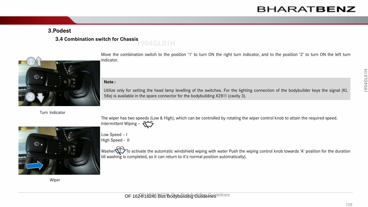
19
04
GL
01
H
1904GL01H
OF 1624/1624L Bus Bodybuilding Guildeines
The wiper has two speeds (Low & High), which can be controlled by rotating the wiper control knob to attain the required speed.
Intermittent Wiping –
Low Speed – I
High Speed - II
Washer (To activate the automatic windshield wiping with water Push the wiping control knob towards ‘A’ position for the duration
till washing is completed, so it can return to it’s normal position automatically).
Turn Indicator
Wiper
3.4 Combination switch for Chassis
3.Podest
Move the combination switch to the position ‘1’ to turn ON the right turn indicator, and to the position ‘2’ to turn ON the left turn
indicator.
Note :
Utilize only for setting the head lamp levelling of the switches. For the lighting connection of the bodybuilder keys the signal (KL
58a) is available in the spare connector for the bodybuilding X2811 (cavity 3).
1
2
OF 1624/1624L Bus Bodybuilding Guidelines
108

19
04
GL
01
H
1904GL01H
Electronic accelerator pedal
!The ignition must not be turned ON before connecting the accelerator pedal, otherwise an electronic module malfunction will be
indicated by the instrument panel. To solve the problem, an authorized dealer or service station must be consulted.
!Do not swap pedals, every pedal is calibrated in accordance with each chassis. A defective pedal must be replaced by a new one which
has to be calibrated by means of the vehicle's instruments or by “Star Diagnosis” (diagnose equipment for Daimler vehicles).
3.5 Accelerator Pedal
3.Podest
The OF 1624 chassis are equipped with an electronic accelerator pedal. Its fastening is designed according to the driver's ergonomics,
should be kept at original orientation.
Disconnect the electronic accelerator pedal during Welding work on the chassis to protect the electronic accelerator circuit.
OF 1624/1624L Bus Bodybuilding Guidelines 109

19
04
GL
01
H
1904GL01H
OF 1624/1624L Bus Bodybuilding Guildeines
!Not applicable.
3.5 Tachograph
3.Podest
OF 1624/1624L Bus Bodybuilding Guidelines
110

19
04
GL
01
H
1904GL01H
OF 1624/1624L Bus Bodybuilding Guildeines
3.6 Star Point (CAN)
This is a CAN interconnection center between all electronic control units. This component is necessary to allow the electronic control
units to share data.
It must be installed in a place of easy access for maintenance and must be protected from water, dust, welding (high temperatures),
enamel and anti-corrosive substances.
Neutral point
3.Podest
OF 1624/1624L Bus Bodybuilding Guidelines
111
19
04
GL
01
H
1904GL01H3.6.1 CAN System
The CAN system is defined as a data communication digital interface between electronic control units. It is a communication
“network” that handles and distributes information and data control in real-time.
The CAN communication speed is “High speed” and with 5V tension. In order not to have loss of information between the modules,
their distance to the “star point” is restricted to 2.5m.In case of welding jobs on the vehicle, all modules must be disconnected to
avoid damage to the circuits.
The purpose of the CAN system is to intelligently enhance data handling and acquisition, also reducing the number of connections and
wires between the systems.
The CAN system permits the reduction of wires and increases the safety of the whole system.
The bodybuilder cannot manipulate the CAN. There are special pins, where the bodybuilder can obtain some specific signals.
The faults of the electronic system are displayed in the instrument cluster via the CAN. These faults are also saved. The faults that
arise during the bodybuilding are to be removed from the memory. They can be erased on the instrument panel display. Enter the
“Diagnosis” menu and click “Clear all events”.
Note:
The branching of the electric wiring harnesses are no to be spliced under any circumstances.
3.6 Star point (CAN)
3.Podest
OF 1624/1624L Bus Bodybuilding Guidelines 112

19
04
GL
01
H
1904GL01H
OF 1624/1624L Bus Bodybuilding Guildeines
!Not applicable.
3.7 NR system
3.Podest
OF 1624/1624L Bus Bodybuilding Guidelines
113

19
04
GL
01
H
1904GL01H
!Not applicable.
3.8 Converter
3.Podest
OF 1624/1624L Bus Bodybuilding Guidelines 114

19
04
GL
01
H
1904GL01H
OF 1624/1624L Bus Bodybuilding Guildeines
!Not applicable.
3.9 Flame start system
3.Podest
OF 1624/1624L Bus Bodybuilding Guidelines
115

19
04
GL
01
H
1904GL01HLocation of the electric horn:
The final location of the horn is the bodybuilder's responsibility and has to ensure the spread of the sound, complying with the law
in force in the country and protected from floods.
1 Electric horn
1
3.10 Horn
3.Podest
OF 1624/1624L Bus Bodybuilding Guidelines 116

19
04
GL
01
H
1904GL01H
Ambient air temperature sensor Location
3.11 Outside air temperature sensor
3.Podest
Temporary location :
The outside air temperature sensor is located near driver podest temporarily located at the first cross member with additional
length of wire to reposition during bodybuilding process.
Final mounting location :
The Ambient Air temperature sensor will have to be relocated in the vehicle front where it is adequately exposed to ambient air and
is easy to access during maintenance.
Ambient air temperature sensor
OF 1624/1624L Bus Bodybuilding Guidelines 117
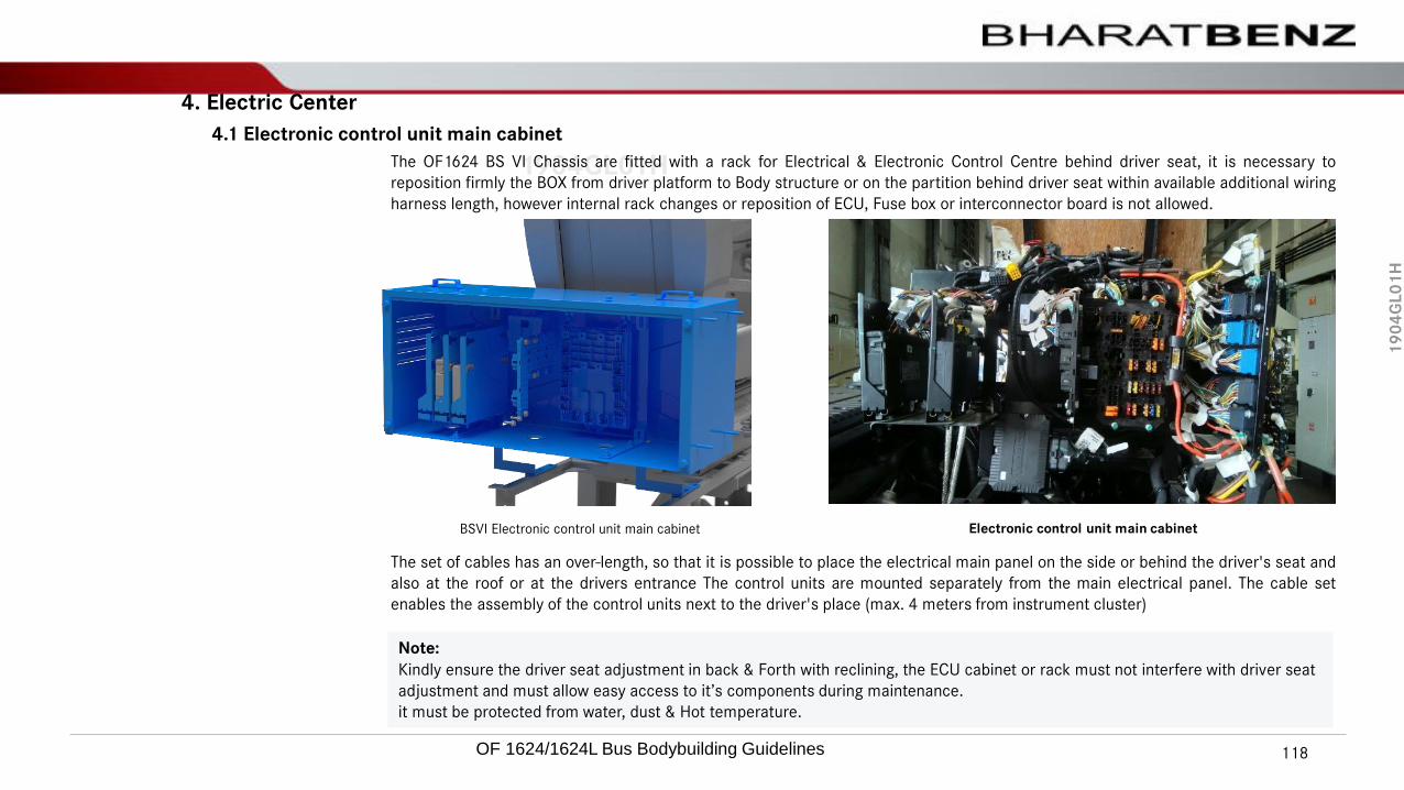
19
04
GL
01
H
1904GL01HThe OF1624 BS VI Chassis are fitted with a rack for Electrical & Electronic Control Centre behind driver seat, it is necessary to
reposition firmly the BOX from driver platform to Body structure or on the partition behind driver seat within available additional wiring
harness length, however internal rack changes or reposition of ECU, Fuse box or interconnector board is not allowed.
The set of cables has an over-length, so that it is possible to place the electrical main panel on the side or behind the driver's seat and
also at the roof or at the drivers entrance The control units are mounted separately from the main electrical panel. The cable set
enables the assembly of the control units next to the driver's place (max. 4 meters from instrument cluster)
Note:
Kindly ensure the driver seat adjustment in back & Forth with reclining, the ECU cabinet or rack must not interfere with driver seat
adjustment and must allow easy access to it’s components during maintenance.
it must be protected from water, dust & Hot temperature.
4.1 Electronic control unit main cabinet
4. Electric Center
BSVI Electronic control unit main cabinet Electronic control unit main cabinet
OF 1624/1624L Bus Bodybuilding Guidelines 118

19
04
GL
01
H
1904GL01H
OF 1624/1624L Bus Bodybuilding Guildeines
!
The CPC5 module is factory fitted on the chassis electrical rack
12456 3The Electronic Cabinet consist of
1. CPC ECU
2. ABS ECU
3. CGW
4. Fuse mounting
5. ASAM ECU
6. Interconnector assembly
4.1 Electronic control unit main cabinet
4. Electric Center
OF 1624/1624L Bus Bodybuilding Guidelines
119

19
04
GL
01
H
1904GL01H4.1 Electronic control unit main cabinet
4. Electric Center
4.1.1 CPC5 module
!The modules are to be installed in a place of easy access for maintenance.
Note:
• Never assemble or disassemble any connection if they are powered. Switch off the vehicle to disconnect or connect the module.
• Never measure the connections when they are on by using probes or cables ends. Never remove the connectors pulling them by the
wires. After unlatching them, lift them out pulling at the same connector body.
• To remove the connector from the module, press the side latch and remove it. Never install additional equipment on the chassis
“fuse-box” switch cabinet. The bodybuilder must install a second switch cabinet for the body.
The CPC5 module is unique for BSVI variants has been developed to establish the communication between the MR (PLD) engine
management module and the several vehicle equipment.
The basic function of drive control (CPC) is to calculate and transmit the relevant engine target torque to the engine control unit
(MCM). The control process is transmitted via the
"single-wire" engine CAN bus. The engine target torque is calculated according to the position of the electronic accelerator pedal
sensor. Other required data or control intervention activities are sent by all authorized systems to the CPC via the vehicle IES-CAN.
Speed controllers, e.g. idle speed limiter or torque limiters can be configured in the drive control unit. The statutory speed limiter and
convenience features for controlling the speed are integrated into the CPC. Various physical variable (e.g. outside temperature) are
recorded for other systems (e.g. INS) and placed on the vehicle CAN bus.”CPC” ECU
OF 1624/1624L Bus Bodybuilding Guidelines 120

19
04
GL
01
H
1904GL01H4.1 Electronic control unit main cabinet
4. Electric Center
4.1.2 ABS Module
ABS Module
All OF chassis are equipped with ABS systems.
!The modules are to be installed in a place of easy access for maintenance.
Note:
• Never assemble or disassemble any connection if they are powered. Switch off the vehicle to disconnect or connect the module.
• Never measure the connections when they are on by using probes or cables ends. Never remove the connectors pulling them by the
wires. After unlatching them, lift them out pulling at the same connector body.
• To remove the connector from the module, press the side latch and remove it. Never install additional equipment on the chassis
“fuse-box” switch cabinet. The bodybuilder must install a second switch cabinet for the body.
OF 1624/1624L Bus Bodybuilding Guidelines 121

19
04
GL
01
H
1904GL01H4.1 Electronic control unit main cabinet
4. Electric Center
4.1.3 CGW Module
!The modules are to be installed in a place of easy access for maintenance.
CGW Module
CGW(Central Gate way) Is the ECU will centralize the different CAN network in the vehicle.
In this vehicle Different EUCs are connected together in different network, All the network centralized through CGW to share the CAN
information's.
Note:
• Never assemble or disassemble any connection if they are powered, Switch off the vehicle to disconnect or connect the module.
• CGW ECU is configured all information about vehicle configuration, During body building Don’t uninstall the ECU from the RACK,
instated of that complete RACK assembly can be uninstall and reinstall from the vehicle only if necessary.
OF 1624/1624L Bus Bodybuilding Guidelines 122

19
04
GL
01
H
1904GL01H
Cabin fuse box
4.1 Electronic control unit main cabinet
4. Electric Center
4.1.4 Fuse box Cabin fuse box
“Fuse box” is a cabinet containing relays, protection fuses, diodes and resistors.
Arrangement and characteristics of these components are shown on the label A 831 584 0308 which is supplied together with the
tool box.
The label should be placed near the bus switch cabinet to allow the identification of the components during a possible maintenance
job. Once removed, the “Fuse Box” must be stored in a safe place protected from dust, welding splashes (high temperature), paint
and anti-corrosives.
For OF1624/1624L vehicles, optional automatic circuit breakers are available.
Note:
• Never assemble or disassemble any connection if they are powered. Switch off the vehicle to disconnect or connect the module.
• Never install additional equipment on the chassis “fuse-box” switch cabinet. The bodybuilder must install a second switch cabinet
for the body.
!The modules are to be installed in a place of easy access for maintenance.
123
OF 1624/1624L Bus Bodybuilding Guidelines

19
04
GL
01
H
1904GL01H
Electric Center
The fuses which are part of the electric center fuse box for all Daimler vehicles are distinguished in their ratings by means of colors:
For a successful bodybuilding we recommend to follow these instructions in order to avoid any inconveniences in the vehicle's
electric wiring.
The electric center is located in a provisional position, the final location will be defined at the bodybuilding.
All the components which supply these vehicles are dimensioned to attend the electric loads for their original equipment.
Color Rating Color Rating
Violet 3 A Light Blue 15A
Light Brown 5A Yellow 20A
Brown 7.5A Natural 25A
Red 10A Green 30A
Fuse identification
Tab8- Fuse identification
4.1 Electronic control unit main cabinet
4. Electric Center
4.1.4.1 Fuse box Cabin fuse box
OF 1624/1624L Bus Bodybuilding Guidelines 124

19
04
GL
01
H
1904GL01H
Note:
• Never assemble or disassemble any connection if they are powered, Switch off the vehicle to disconnect or connect the module.
• All the input and output characteristics are configured in the ASAM ECU, always body builders has to refer the bus body electrical
connector interface detail to connect the inputs and output loads.
• Excessive load will create the Error in the ECU and Continues excessive load may damage the ECU.
• During body building Don’t uninstall the ECU from the RACK, instated of that complete RACK assembly can be uninstall and reinstall
from the vehicle only if necessary,
• Never install additional equipment on to this ECU, The bodybuilder must install a second switches for the body loads.
• Use only bus body builder interface and through Hardwire and CAN interface.ASAM Module
4.1 Electronic control unit main cabinet
4. Electric Center
4.1.5 ASAM Module
ASAM(Advanced sensor Actuator module) receive the inputs from switches, sensors and CAN signals from other vehicle ECUs and
control the vehicle actuators.
ASAM transmit and receive the CAN signals to other bus body ECUs.
!The modules are to be installed in a place of easy access for maintenance.
125
OF 1624/1624L Bus Bodybuilding Guidelines

19
04
GL
01
H
1904GL01H
Interconnector Board
4.1 Electronic control unit main cabinet
4. Electric Center
4.1.6 Interconnector Module
!The modules to be placed in a place of easy access for maintenance.
X2-1
X1-2 X1-3 X1-4
X2-2 X2-3 X2-4 X2-5
X3-1 X3-2 X3-3 X3-4 X3-5
X4-1 X4-2 X4-3 X4-4 X4-5
X4-2 X4-3 X4-4
Connector main board
Function Coordinate Color Cavity Description
X0202 X1-1(KL30) Terminal 30 Distribution
X0210 X1-2 Gray 21 Chassis Interface connection
X0221 X1-3 21 Not connected
X0214 X1-4 White 21 Chassis Interface connection
X1-5
X2811 X2-1 Gray 21 Spare Connector for Bodybuilder
X0232 X2-2 Not connected
X0222 X2-3 21 Not connected
X0215 X2-4 Gray 21 Chassis Interface connection
X0211 X2-5 Blue 21 Chassis Interface connection
X2812 X3-1 Blue 21 Spare Connector for Body builder
X0231 X3-2 21 Not connected
X0223 X3-3 21 Not connected
X0216 X3-4 Blue 21 Chassis Interface connection
X0212 X3-5 White 21 Chassis Interface connection
X0229 X4-1 Not Connected
X0228 X4-2 Not connected
X0224 X4-3 Blue 21 Chassis Interface connection
X0220 X4-4 White 21 Chassis Interface connection
X0213 X4-5 Gray 21 Chassis Interface connection
X0204 X5-1(KL15) Kl15 Main distribution
X0227 X5-2 Not connected
X0226 X5-3 Gray Chassis Interface connection
X0225 X5-4 Blue ABS Interface connection
W0201 X4-5(KL-31) Ground main control panel
Interconnector Board
connectors position
Interconnector Board connectors description
126
OF 1624/1624L Bus Bodybuilding Guidelines
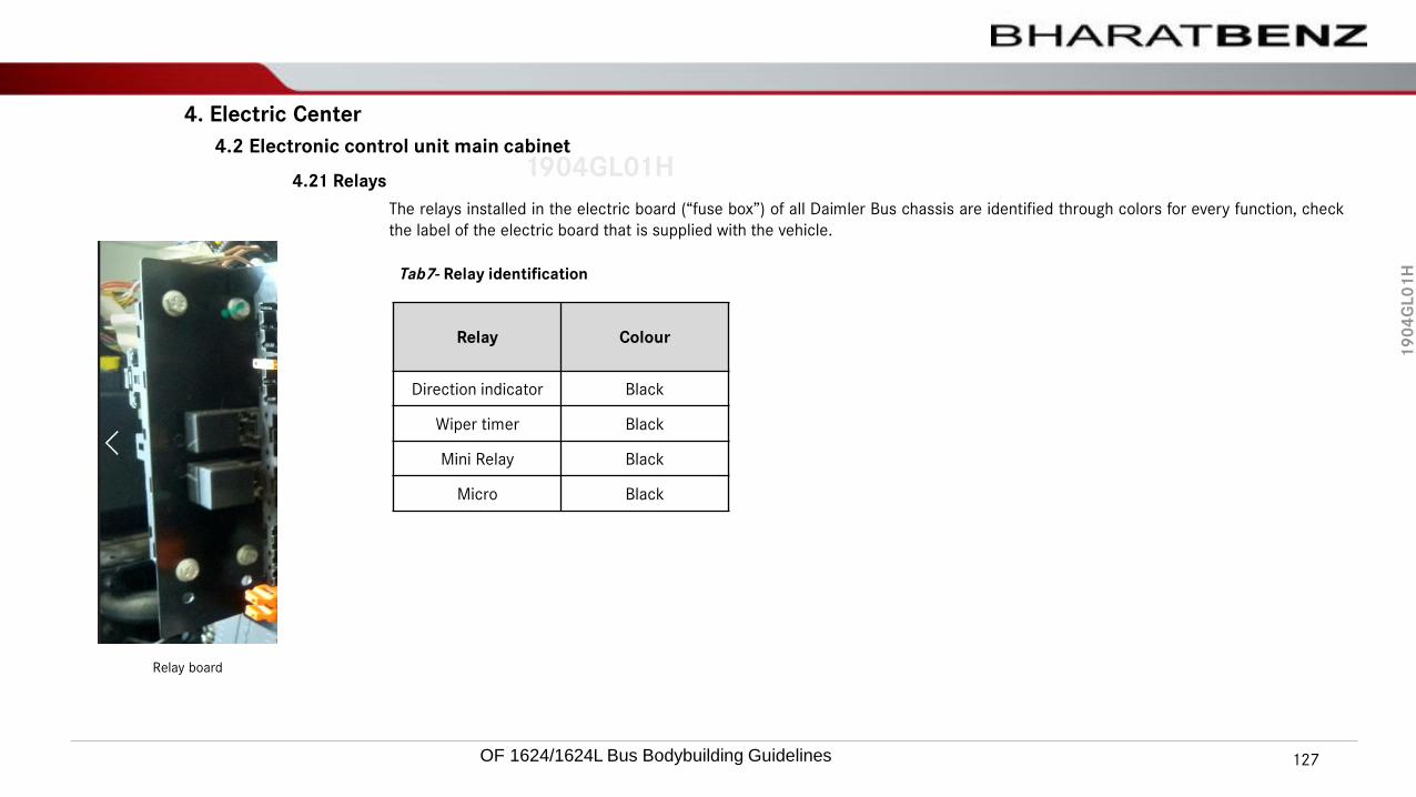
19
04
GL
01
H
1904GL01H
4. Electric Center
4.2 Electronic control unit main cabinet
The relays installed in the electric board (“fuse box”) of all Daimler Bus chassis are identified through colors for every function, check
the label of the electric board that is supplied with the vehicle.
Relay Colour
Direction indicator Black
Wiper timer Black
Mini Relay Black
Micro Black
Tab7- Relay identification
4.21 Relays
Relay board
OF 1624/1624L Bus Bodybuilding Guidelines 127

19
04
GL
01
H
1904GL01HAlways refer to the chassis wiring diagram before any repair or change of components. Always use auxiliary relays to activate any
equipment to be installed, mainly if it is via ignition or start key.
Always install fuses on the systems according to the need of the equipment. Only the auxiliary relay coil must be actuated by the
ignition key.
The electric center (All ECU‘s , Fuses, and Relays and it’s components) final location in the bus body must be protected against water
infiltration and impurities.
The Electric center must be mounted in vertical or horizontal position to avoid accumulation of water, dust or any other impurities.
In case any complementation or maintenance is required, do not change the vehicle original electrical wiring. Keep the same cable
gauge if a repair is needed. Do not make direct connections eliminating relays or other components. These procedures will put into
risk the whole vehicle electrical wiring.
Make sure that electrical wiring does not rub against cutting edges on the vehicle's metal structure, because this is one of the main
short-circuit and fire risk factors.
Damaged fuses must be replaced with others with the same rating. If there is frequent fuse burn out, detect the cause. Never replace
a fuse with a different rating, and never insert clamps or other objects into the fuse holders with the purpose of replacing them under
an emergency condition and/or temporarily.
All electronic modules must be installed in an easily accessible place for maintenance, protected against water infiltration and
impurities. They must never be repaired but, instead, they must be replaced by new parts because they are safety items.
4. Electric Center
4.3 Overall comments
OF 1624/1624L Bus Bodybuilding Guidelines 128

19
04
GL
01
H
1904GL01H
OF 1624/1624L Bus Bodybuilding Guildeines
!Not applicable.
4. Electric Center
4.4 Capacity of the Diodes
OF 1624/1624L Bus Bodybuilding Guidelines
129

19
04
GL
01
H
1904GL01H4.5.1 Main cabinet
Electronic control units (ECU) are the processors that manages the running of the engine & brake system. This module receives the
signals from all engine and vehicle sensors and identifies the operation regimen. It is installed in such a way that it remains in vertical
position at all times during vehicle operation.
Before the body mounting process, the ECU should be removed from the main cabinet and kept in cover, protected from dust, water,
welding splashes (high temperature), paints and anticorrosive. A traceability control must be available since the units are
parameterized with vehicle specific data so as to prevent interchange. Never use high-pressure washing equipment on the
connectors.
ECUs should be disconnected at all times during welding. It should be connected only after connecting all sensors, actuators, entire
cabin/chassis wiring harness, engine and vehicle connector before battery connection. After ensuring all the connections, vehicle
should be cranked and checked for any fault codes.
Never assemble or disassemble any connection if they are powered.
Switch off the vehicle to disconnect or connect the ECUs.
Never make any measurements on powered connections using test leads or cable ends. Use appropriate test leads. Never remove
the connectors pulling them by the wires.
ECU Cabinet BS VI variants
4. Electric Center
4.5 Electronic control unit
OF 1624/1624L Bus Bodybuilding Guidelines 130

19
04
GL
01
H
1904GL01H4.6.2 ECU location
For chassis delivery condition, ECUs are fixed with the plastic bracket, it must be protected against the following environmental
conditions are to be followed:
• Water and dust, especially the wiring harnesses that were routed through the top.
• Mechanical damage, especially the pressure compensation element and the male pins in the connector.
• In case of paintwork on the remaining vehicle, avoid paint on the ECU and its terminals.
• Electrostatic discharge.
• Contamination with the media’s whose tubes are beside the ECU.
• The protection should be executed with a plastic foil which protects the ECU and, in parallel, the wiring harness. Material of the
foil: polypropylene conductible plastic.
While transporting the chassis or shifting in a container (for approx. 1-2 months duration) protection against the following must be
ensured:
• Environmental conditions: heat, water and dust.
• Mechanical damage, especially on the pressure compensation element and the male pins in the connector.
• In case of paintwork on the remaining vehicle, avoid paint on the ECU and its terminals.
• Electrostatic discharge.
• Contamination with the media’s whose tubes are beside the ECU.
• Relative humidity higher than 60% could cause corrosion.
• The protection is recommended with a plastic foil which protects the ECU and, in parallel, the wiring harness. Material of the foil:
polypropylene conductible plastic which has some additional VCI corrosion protection. Example see link:
http://www.excor.de/vci/index.html
ECU Cabinet for BS VI variants
4. Electric Center
4.6 Electronic control unit
OF 1624/1624L Bus Bodybuilding Guidelines 131

19
04
GL
01
H
1904GL01H5.1 Diagnostics plug
This plug is located in the switch cabinet and its function is to allow “off board” diagnostics, or diagnostics with external test
equipment. When removed for bodybuilding, attention is to be given in order not to permit the infiltration of impurities (dust), welding(high temperature), enamel and anti-corrosive substances, as this could impair its utilization.
After the bodybuilding, the diagnosis socket has to be attached to a sheet metal surface, so the connector can be firm, and avoidshort-circuit or damages to the same, besides facilitating the connection of the diagnosis equipment “plug”, as “Star Diagnosis” for
example.
5.Diagnostic Plug
Diagnosis socket 16-way - diagnosis for:
• INS – Instrument cluster
• ABS/ASR
• Telma retarder
• MR – Engine management
• FR/CPC - Engine / vehicle interface
Diagnostic plug
OF 1624/1624L Bus Bodybuilding Guidelines 132
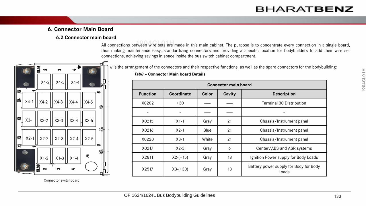
19
04
GL
01
H
1904GL01HAll connections between wire sets are made in this main cabinet. The purpose is to concentrate every connection in a single board,
thus making maintenance easy, standardizing connectors and providing a specific location for bodybuilders to add their wire set
connections, achieving savings in space inside the bus switch cabinet compartment.
Below is the arrangement of the connectors and their respective functions, as well as the spare connectors for the bodybuilding:
Connector switchboard
6.2 Connector main board
6. Connector Main Board
X2-1
X1-2 X1-3 X1-4
X2-2 X2-3 X2-4 X2-5
X3-1 X3-2 X3-3 X3-4 X3-5
X4-1 X4-2 X4-3 X4-4 X4-5
X4-2 X4-3 X4-4Connector main board
Function Coordinate Color Cavity Description
X0202 +30 ----- ----- Terminal 30 Distribution
- - ----- ----- -
X0215 X1-1 Gray 21 Chassis/Instrument panel
X0216 X2-1 Blue 21 Chassis/Instrument panel
X0220 X3-1 White 21 Chassis/Instrument panel
X0217 X2-3 Gray 6 Center/ABS and ASR systems
X2811 X2-(+15) Gray 18 Ignition Power supply for Body Loads
X2517 X3-(+30) Gray 18Battery power supply for Body for Body
Loads
Tab8 – Connector Main board Details
OF 1624/1624L Bus Bodybuilding Guidelines 133

19
04
GL
01
H
1904GL01H
Location of the Interface connections – OF 1624L BS6
X0106 and 33M01
X2504 and X2505
X2508
X2509
X2506
X2507X2811
X2812
7.1 Interface chassis and body OF 1624L BS6 Chassis
7. Interface chassis and body
Location of connectors
X2811 = Body builder interface
X2812 = Body builder interface
X0106 = Windshield wiper stand connector
33M01 = Windshield wiper pump standby connector
X2504 = Front Headlamp/Indicator connector left
X2505 = Front Headlamp/Indicator connector Right
X2508 = Side marker connector Left
X2509 = Side marker connector Right
X2506 = Taillights connector left
X2507 = Taillights connector Right
OF 1624/1624L Bus Bodybuilding Guidelines 134

19
04
GL
01
H
1904GL01H7.2 Color codes of wires
For wire colors, please refer to the table below:
Color code Color description
B Black
Br Brown
Ch Chocolate
Dg Dark green
G Green
L Blue
Lg Light green
O Orange
P Pink
R Red
Sb Sky blue
V Violet
W White
Y Yellow
Gr Gray
7. Interface chassis and body
Tab9 - Color code
OF 1624/1624L Bus Bodybuilding Guidelines 135

19
04
GL
01
H
1904GL01H
The standby connector functions for body mounting located in the switch cabinet, as well as the Daimler and AMP connector
number to be used by the bodybuilder, are listed in the table below.
Tab10- Bus body interconnector Connection X2811
Bus Body Interconnector
Chassis side Connector Bus Body builder side connector
MB Part no: A 036 545 31 28 MB Part no: A 013 545 65 26
Secondary lock: A 000 542 16 73 NA
TYCO 21 POLES: 1-967630-2 TYCO 21 POLES: 8-968975-2
Tyco lock : 967635-1 NA
Color: Glay Brawn Color: Glay Brawn
Coding : "A" Coding : "A"
Latching mechanism = 'B-C' Latching mechanism = 'B-C'
Electric center - X2811 CONNECTOR Color-
code
Wire
N.
Circuit
N.
Gau
ge
(mm
²)
pi
n
pi
n
Inpu
t/
Outp
ut
Potenti
al
Max
Curre
nt
Min
Curre
nt
Function Symbol Description
GN/RT 191 6107 0.8 1 1 Input (-ve) - -Open door luggage
compartment signal
Displays a telltale in the instrument cluster when
signal is active
GR/GE 192 4117 0.8 2 2 Input (-ve) - - Stop request signalDisplays a telltale in the instrument cluster when
signal is active
GR/BL 193 4119 0.8 3 3 Input (-ve) - -Open door signal Passenger/
Emergency
Displays a telltale in the instrument cluster when
signal is active
GN/BL 194 4632 0.8 4 4 Input (-ve) - - Hazard lights activation NoThe hazard lights will start to flash when this pin is
active
GN/GR 195 1223 0.8 5 5 Input (-ve) - - A/C RPM (High-idle RPM) signal
The engine speed will be increased to a fixed value
and the symbol a telltale will be displayed in the
instrument cluster
GR 196 3021 0.8 6 6Outp
ut
24V
(+ve)1A -
Distribution KL.58.1(Parking
illumination)No Signal informing if parking illumination is on
BR/WS 197 1218 0.8 7 7Outp
ut
24V
(+ve)0.7A -
Start auxiliary (KL.50) Cranking
signalNo Signal is active when the vehicle is cranking
GE/RT 198 3043 0.8 8 8Outp
ut
24V
(+ve)2A - Backup lights signal No Signal is active when the reverse gear is engaged
RT/GN 232 3335 0.8 9 9Outp
ut
24V
(+ve)2A - Lighting Signal No Signal is deactivate when the vehicle is cranking
GN/BR 200 3194 0.8 10 10Outp
ut
24V
(+ve)0.7A - Safety System Activated
Not
AvailableNot Available
GN/WS 201 3242 0.8 11 11 Input (-ve) - - Washer Fluid Level Provide information of shortage washer fluid
GE/GR 187 8167 0.8 12 12 Input (-ve) - - Seat Belt DriverNot
AvailableNot Available
VI/GN 188 6229 0.8 13 13 - - - - NA NA NA
14 14 - - - - NA NA NA
RT 153 0033 0.8 15 15Outp
ut
24V
(+ve)1A -
KL 30 Signal(Battery unstitched
+ve)No Positive signal from the battery
GN 288 6016 0.8 16 16Outp
ut
24V
(+ve)1A -
KL 15 Signal(Battery switched
+ve)No
Positive signal from first position of the ignition
switch
GE 314 1127 0.8 17 17Outp
ut
24V
(+ve)5A -
D+ Signal (In engine running
condition)No Provide signal in engine running condition
WS/BL 260 0002 0.8 18 18Outp
ut
24V
(+ve)0.01A - W Signal No Signal providing the alternator speed (W)
VI/WS 189 6098 0.8 19 19Outp
utPWM - Speed signal C3 output No Available only in vehicles with tachograph
BL/WS 190 6012 0.8 20 20 - - - - NA
WS/BL 155 6030 0.8 21 21 - - - - NA
X2811
7.3 Bus body interconnector
OF 1624/1624L Bus Bodybuilding Guidelines 136

19
04
GL
01
H
1904GL01H
Bus Body Interconnector
The standby connector functions for body mounting located in the switch cabinet, as well as the Mercedes-Benz and AMP connector
number to be used by the bodybuilder, are listed in the table below.
Tab11- Bus body interconnector Connection X2812
Chassis side Connector Bus Body builder side connector
MB Part no: A 053 545 07 28 MB Part no: A 020 545 47 26
Secondary lock: A 000 542 16 73 NA
TYCO 21 POLES: 3-967630-1 TYCO 21 POLES: 6-968975-1
Tyco lock : 967635-1 NA
Color: Light Blue Color: Light Blue
Coding : "C" Coding : "C"
Latching mechanism = 'B-D' Latching mechanism = 'B-D'
Electric center - X2812 CONNECTOR
Color-
code
Wire
N.
Circuit
N.
Gaug
e
(mm
²)
pi
n
pi
n
Input
/
Outp
ut
Potent
ial
Max
Current
Min
CurrentFunction
Sym
bolDescription
VI/WS 250 4232 0.75 1 1 Input (-ve) - - Bus Stop Brake
In parallel to the doors status, this pin brakes the
vehicle when active and displays the telltale in
the instrument cluster
BR/GR 267 0.75 2 2 CAN - - BodyBuilder CAN GND No Only for Bodybuilder interface with CAN
GE/RT 252 4394 0.75 3 3Outp
ut
24V(+v
e) 0.75A - Signal >5Km/h No This pin is active when the vehicle is over 5km/h
WS/GE 253 4395 0.75 4 4Outp
ut
24V(+v
e) 0.5A - Parking Brake Status No
This pin is active when the park brake lever is
engaged
BL 254 0.5 5 5 CAN - - BodyBuilder CAN H No Only for Bodybuilder interface with CAN
GE 255 0.5 6 6 CAN - - BodyBuilder CAN L No Only for Bodybuilder interface with CAN
BL/WS 256 8165 0.75 7 7 - - NA
WS/GE 257 8164 0.75 8 8 - - NA
WS/RT 246 6074 0.75 9 9 - - NA
RT/BL 247 6199 0.75 10 10 - - NA
RT 78 0.5 11 11 - - NA
GW/SW 79 0.5 12 12 - - NA
BL 76 0.5 13 13 - - NA
BR 77 0.5 14 14 - - NA
15 15 - - NA
GR/RT 221 3037 0.75 16 16Outp
ut
24V(+v
e) 1A -
Front Position lamp left & right(LEDs
Possible)No Exterior Lighting
GR/WS 343 3049 0.75 17 17Outp
ut
24V(+v
e) 1A -
Rear Position lamp left & Right(LEDs
Possible)No Exterior Lighting
GE/GN 199 3055 0.75 18 18Outp
ut
24V(+v
e) 2A - Upper brake lamp left & right No Exterior Lighting
GE/WS 294 3053 0.75 19 19Outp
ut
24V(+v
e) 3.5A -
Upper left rear indicator lamp (LED
possible)No Exterior Lighting
GE/WS 347 3054 0.75 20 20Outp
ut
24V(+v
e) 1A -
Upper right rear indicator lamp (LED
possible)No Exterior Lighting
RT/GN 344 6229 0.75 21 21Outp
ut
24V(+v
e) 3A - 5th stop lamp(LED) No Exterior Lighting
X2812
7.3 Bus body interconnector
OF 1624/1624L Bus Bodybuilding Guidelines 137

19
04
GL
01
H
1904GL01HBelow are the connection details for Front left side headlight, located in the first cross member of the module 1.
Tab12- Front left lamp interface connector X2504(X1)
Chassis side Connector Bus Body builder side connector
MB Part no: A 693 545 39 26 MB Part no: A 693 545 40 26
TYCO 6 POLES: 282090-1 TYCO 6 POLES: 282108--1
Color: Black Color: Black
Front Left Lamp Interconnector X2504(X1)
Color-code Wire N. Circuit N.
Gauge
(mm²) pin pin
Input/
Output Potential Max Current Min Current Function
GR/BL 262 3039 0.75 1 1 Output 24V(+ve) 3.0A 0,2A Low Beam, left, LED or Xenon possible
WS 264 3101 0.75 2 2 Output 24V(+ve) 3.0A 0,5A High Beam, left, LED or Xenon possible
GR/VI 327 3039 0.75 3 3 Output 24V(+ve) 1.0A 50mA Turn Left Front Headlamp(LED Possible)
WS 270 3026 0.75 4 4 Output 24V(+ve) 1.0A - Front Side Position Light
BR 352 1.5 5 5 Output (-ve) - - Ground
BL/GE 268 3475 0.75 6 6 Output 24V(+ve) 3.0A - DRL (Daytime Running Light), left
Front Left Lamp Interconnector X2504(X1)
7.4 Headlight and other front light connections LH
OF 1624/1624L Bus Bodybuilding Guidelines 138

19
04
GL
01
H
1904GL01HBelow are the connection details for front left Fog lamp connector
Tab13- Front left lamp interface connector X2504(X2)
Chassis side Connector Bus Body builder side connector
MB Part no: A 015 545 55 26 MB Part no: A 693 545 33 26
TYCO 2 POLES: 282080-1 TYCO 6 POLES: 282104--1
Color: Black Color: Black
Front Left Lamp Interconnector X2504(X2)
Color-code Wire N. Circuit N.
Gauge
(mm²) pin pin
Input/
Output Potential Max Current Min Current Function
WS/GN 266 3035 0.75 1 1 Output 24V(+ve) 3.0A - Fog Lamp, front left (LED possible)
BR 353 1.5 2 2 Output (-ve) - - Ground
Front Left Lamp Interconnector X2504(X2)
7.4 Front Fog light connection LH
OF 1624/1624L Bus Bodybuilding Guidelines 139

19
04
GL
01
H
1904GL01HBelow are the connection details for Front right side headlight, located in the first cross member of the module 1.
Tab14- Front Right lamp interface connector X2505(X1)
Chassis side Connector Bus Body builder side connector
MB Part no: A 693 545 40 26 MB Part no: A 693 545 39 26
TYCO 6 POLES: 282108--1 TYCO 6 POLES: 282090-1
Color: Black Color: Black
Front Right Lamp Interconnector X2505(X1)
Color-code Wire N. Circuit N.
Gauge
(mm²) pin pin
Input/
Output Potential Max Current Min Current Function
BL/RT 261 3034 0.75 1 1 Output 24V(+ve) 3.0A 0,2A Low Beam, Right, LED or Xenon possible
BL/SW 263 3102
0.75
2 2 Output 24V(+ve) 3.0A 0,5A High Beam, Right, LED or Xenon possible
WS/BL 326 3040 0.75 3 3 Output 24V(+ve) 1.0A 50mA
Turn Right Front Headlamp (LED Possible)
GR/GN 271 3025 0.75 4 4 Output 24V(+ve) 0.5A - Front Side Position Light
BR 354 1.5 5 5 Output (-ve) - - Ground
BL/GN 267 3476 0.75 6 6 Output 24V(+ve) 1.0A - DRL (Daytime Running Light), right
Front Right Lamp Interconnector X2505(X1)
7.4 Headlight and other front light connections RH
OF 1624/1624L Bus Bodybuilding Guidelines 140

19
04
GL
01
H
1904GL01H
Below are the connection details for front right Fog lamp connector
Tab15- Front left lamp interface connector X2505(X2)
Chassis side Connector Bus Body builder side connector
MB Part no: A 693 545 33 26 MB Part no: A 015 545 55 26
TYCO 6 POLES: 282104--1 TYCO 2 POLES: 282080-1
Color: Black Color: Black
Front Right Lamp Interconnector X2505(X2)
Color-code Wire N. Circuit N.
Gauge
(mm²) pin pin
Input/
Output Potential Max Current Min Current Function
WS/GN 266 3035 0.75 1 1 Output 24V(+ve) 3.0A - Fog Lamp, front right (LED possible)
BR 353 1.5 2 2 Output (-ve) - - Ground
Front Right Lamp Interconnector X2505(X2)
7.4 Front Fog light connection RH
OF 1624/1624L Bus Bodybuilding Guidelines 141

19
04
GL
01
H
1904GL01HBelow are the connection details for the LH side marker & LH side indicator connectors
Chassis side Connector Bus Body builder side connector
MB Part no: A 693 545 39 26 MB Part no: A 693 545 40 26
TYCO 6 POLES: 282090-1 TYCO 6 POLES: 282108--1
Color: Black Color: Black
Left side Lighting Interconnector X2508
Color-code Wire N. Circuit N.
Gauge
(mm²) pin pin
Input/
Output Potential Max Current Min Current Function
BL/WS 329 3101 0.75 1 1 Output 24V(+ve) 1.0A (21W) Single Bulb or Intelligent LED - Left front side direction indicator lamp
GE/GN 314 3430 0.75 2 2 Output 24V(+ve) 2.0A (7*5W) Bulb or Intelligent LED - Side marker lamp left
BR 356 1.5 3 3 Output GND - - Ground
GN 330 3421 0.75 4 4 Output 24V(+ve) 3.0A (21W) Single Bulb or Intelligent LED - Left rear side direction indicator lamp
5 5 -
6 6 -
Left side Lighting Interconnector X2508
Tab16- Side left lamp interface connector X2508
7.5 Side marker & side Indicator connections LH
OF 1624/1624L Bus Bodybuilding Guidelines 142

19
04
GL
01
H
1904GL01H
OF 1624/1624L Bus Bodybuilding Guildeines
Tab17- Side Right lamp interface connector X2509
Below are the connection details for the RH side marker & RH side indicator connectors
Color-code Wire N. Circuit N.
Gauge
(mm²) pin pin
Input/
Output Potential Max Current Min Current Function
BL/GE 328 3102 0.75 1 1 Output 24V(+ve) 1A (21W) Single Bulb or Intelligent LED - Right front side direction indicator lamp
GE/GN 313 3074 0.75 2 2 Output 24V(+ve) 1A (7*5W Bulb or Intelligent LED - Side marker lamp Right
BR 356 1.5 3 3 Output GND - Ground
GN/VI 331 3422 0.75 4 4 Output 24V(+ve) 3A (21W) Single Bulb or Intelligent LED - Right rear side direction indicator lamp
5 5 -
6 6 -
Right side Lighting Interconnector X2509
Chassis side Connector Bus Body builder side connector
MB Part no: A 693 545 40 26 MB Part no: A 693 545 39 26
TYCO 6 POLES: 282108--1 TYCO 6 POLES: 282090-1
Color: Black Color: Black
Side right Lamp Interconnector X2509
7.5 Side marker & side Indicator connections RH
OF 1624/1624L Bus Bodybuilding Guidelines
143

19
04
GL
01
H
1904GL01H
Below are the connection details for LH tail light connectors
Tab18 - Left rear light assembly interface connector X2506(X1)
Color-code Wire N. Circuit N.
Gauge
(mm²) pin pin
Input/
Output Potential Max Current Min Current Function
GN 350 3051 0.75 1 1 Output 24V(+ve) 3.0A - Stop Lamp, rear left lower
WS/GN 255 3132 0.75 2 2 Output 24V(+ve) 1.0A 50mA Turn signal rear, left
GE/RT 324 3043 0.75 3 3 Output 24V(+ve) 1.5A - Backup lamp
BL 316 3041 0.75 4 4 Output 24V(+ve) 3.0A - Tail lamp left
GR/GE 309 3047 0.75 5 5 Output 24V(+ve) 1.0A - License Plate Lamp (First/Second)
BR 346 1.5 6 6 - Ground
Left rear light assembly interface connector X2506(X1)
Chassis side Connector Bus Body builder side connector
MB Part no: A 693 545 39 26 MB Part no: A 693 545 40 26
TYCO 6 POLES: 282090-1 TYCO 6 POLES: 282108--1
Color: Black Color: Black
Left rear light assembly interface connector X2506(X1)
7.6 Rear lamp connections LH
OF 1624/1624L Bus Bodybuilding Guidelines 144

19
04
GL
01
H
1904GL01HBelow are the connection details for LH Fog lamp connectors
Tab19- Left rear Fog light assembly interface connector X2506(X2)
Chassis side Connector Bus Body builder side connector
MB Part no: A 015 545 55 26 MB Part no: A 693 545 33 26
TYCO 2 POLES: 282080-1 TYCO 6 POLES: 282104--1
Color: Black Color: Black
Left rear Fog light assembly interface connector X2506(X2)
Color-code Wire N. Circuit N.
Gauge
(mm²) pin pin
Input/
Output Potential Max Current Min Current Function
GE 338 3045 0.75 1 1 Output 24V(+ve) 1.0A - Fog Lamp, rear left
BR 348 0.75 2 2 Output (-ve) - - Ground
Left rear Fog light assembly interface connector X2506(X2)
7.6 Rear Fog lamp connections LH
OF 1624/1624L Bus Bodybuilding Guidelines 145

19
04
GL
01
H
1904GL01HBelow are the connection details for RH tail light connectors
Tab20- Right rear light assembly interface connector X2507(X1)
Color-code Wire N. Circuit N.
Gauge
(mm²) pin pin
Input/
Output Potential Max CurrentMin Current
Function
GN/BL 351 3052 0.75 1 1 Output 24V(+ve) 3.0A - Stop Lamp, rear right lower
WS/GE 169 3131 0.75 2 2 Output 24V(+ve) 1.0A 50mA Turn signal rear, right
GE/RT 325 3043 0.75 3 3 Output 24V(+ve) 1.5A - Backup lamp
BL/GN 318 3042 0.75 4 4 Output 24V(+ve) 3.0A - Tail lamp right
5 5 -
BR 347 1.5 6 6 Output (-ve) - Ground
Right rear light assembly interface connectorX2507(X1)
Chassis side Connector Bus Body builder side connector
MB Part no: A 693 545 40 26 MB Part no: A 693 545 39 26
TYCO 6 POLES: 282108--1 TYCO 6 POLES: 282090-1
Color: Black Color: Black
Right rear light assembly interface connector X2507(X1)
7.6 Rear lamp connections RH
OF 1624/1624L Bus Bodybuilding Guidelines 146

19
04
GL
01
H
1904GL01HBelow are the connection details for RH Fog lamp connectors
Tab21- Right rear Fog light assembly interface connector X2507(X2)
Chassis side Connector Bus Body builder side connector
MB Part no: A 693 545 33 26 MB Part no: A 015 545 55 26
TYCO 6 POLES: 282104--1 TYCO 2 POLES: 282080-1
Color: Black Color: Black
Right rear Fog light assembly interface connector X2507(X2)
Color-code Wire N. Circuit N.
Gauge
(mm²) pin pin
Input/
Output Potential Max CurrentMin Current
Function
GE 339 3045 0.75 1 1 Output 24V(+ve) 1.0A - Fog Lamp, rear right
BR 349 0.75 2 2 Output (-ve) - Ground
Right rear Fog light assembly interface connector X2507(X2)
7.6 Rear Fog lamp connections RH
OF 1624/1624L Bus Bodybuilding Guidelines 147

19
04
GL
01
H
1904GL01H
OF 1624/1624L Bus Bodybuilding Guildeines
Interface chassis and body
The Wiper system connectors for front windshield is located at the FIRST CROSSBEAM, original connector must be retained for body
adaptation connector details to be used by the bodybuilder is listed in the table below.
!Should the power of the windshield wiper motor, to be installed by the body maker be higher than specified, in order not to
damage the chassis combined switch, auxiliary relays are to be installed in the circuits of stages 1 and 2 of the windshield wiper
system. See below the spare connector table for the body maker X0106.
Color-code Wire N. Circuit N.
Gauge
(mm²) pin pin
Input/
Output Potential Max Current Function
WS 276 3082 0.75 1 1
Input/
Output Gnd Active low Wiper Autostop input
BL 277 3405 2.5 2 2 Output 24V(+ve) Active High(12A Max) Wiper low speed
3 3
GE/BL 279 3404 2.5 4 4 Output 24V(+ve) Active High(12A Max) Wiper High speed
5 5
BR 278 2.5 6 6 Output Gnd Gnd Gnd
Windshield Wiper Motor – X0106
Tab22- M4 washer motor Connection X0106
MB Part No Supplier part No MB Part No Supplier part No
Connector: A 384 545 73 26 926330-3(Tyco) 171433-1(Tyco)
Terminal1: A 384 545 85 26 927852-3(Tyco)
Terminal2 : A 384 545 82 26 880645-6(Tyco)
Color: White
Windshild Wiper motor-X0106
Chassis side Connector Bus Body builder side connector
Color: White
928962-2(Tyco)
7.7 Wiper motor connections
OF 1624/1624L Bus Bodybuilding Guidelines
148

19
04
GL
01
H
1904GL01H
Tab 23- Windshield Wiper Pump Motor – 33M01
Color-code Wire N. Circuit N.
Gauge
(mm²) pin pin
Input/
Output Potential Max Current Function
BR 280 1.5 1 1
Input/
Output Gnd Gnd Gnd
GE/GR 281 3079 1.5 2 2 Output 24V(+ve) 6A Max Wiper washer pump motor
Windshield Wiper Pump Motor – 33M01
The Washer system connector for front windshield is located on the FIRST CROSSBEAM, the Daimler and AMP connector number
to be used by the bodybuilder are listed in the table below.
MB Part No Supplier part No MB Part No Supplier part No
Connector: A 384 545 80 26 926522-1(Tyco) 1-180908-0
Terminal : A 384 545 82 26 880645-6(Tyco) 928962-2(Tyco)
Color: White
Windshield Wiper Pump Motor – 33M01
Chassis side Connector Bus Body builder side connector
Color: White
7.8 Wiper pump connections
OF 1624/1624L Bus Bodybuilding Guidelines 149

19
04
GL
01
H
1904GL01HTwo Body- chassis interface connectors (X2811 and X2812) positioning in the Rack.
7.9 Body builder inter Connectors
X2
-1
X1
-2X
1-3
X1
-4
X2
-2X
2-3
X2
-4X
2-5
X3
-1X
3-2
X3
-3X
3-4
X3
-5
X4
-1X
4-2
X4
-3X
4-4
X4
-5
X4
-2X
4-3
X4
-4
OF 1624/1624L Bus Bodybuilding Guidelines 150
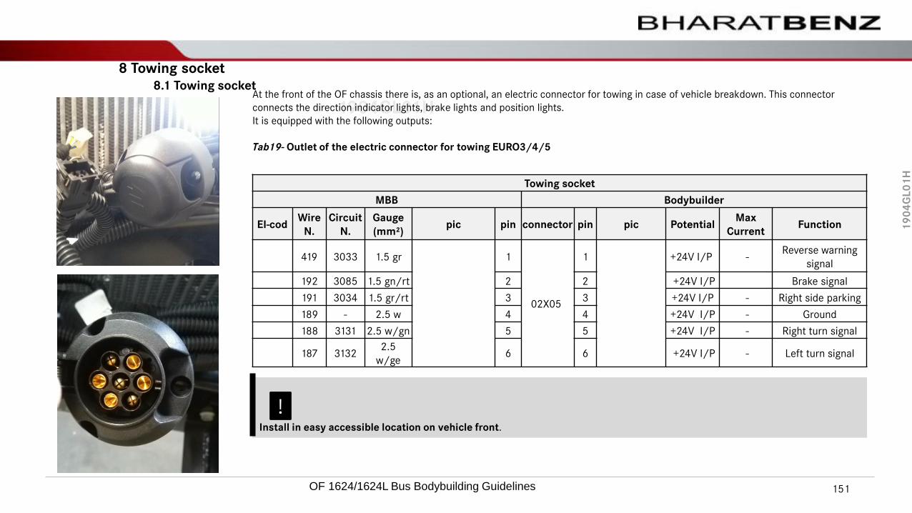
19
04
GL
01
H
1904GL01H
8 Towing socket8.1 Towing socket
At the front of the OF chassis there is, as an optional, an electric connector for towing in case of vehicle breakdown. This connector
connects the direction indicator lights, brake lights and position lights.
It is equipped with the following outputs:
Tab19- Outlet of the electric connector for towing EURO3/4/5
Towing socket
MBB Bodybuilder
EI-codWire
N.
Circuit
N.
Gauge
(mm²)pic pin connector pin pic Potential
Max
CurrentFunction
419 3033 1.5 gr 1
02X05
1 +24V I/P -Reverse warning
signal
192 3085 1.5 gn/rt 2 2 +24V I/P Brake signal
191 3034 1.5 gr/rt 3 3 +24V I/P - Right side parking
189 - 2.5 w 4 4 +24V I/P - Ground
188 3131 2.5 w/gn 5 5 +24V I/P - Right turn signal
187 31322.5
w/ge6 6 +24V I/P - Left turn signal
Install in easy accessible location on vehicle front.
!
OF 1624/1624L Bus Bodybuilding Guidelines 151

19
04
GL
01
H
1904GL01HEarthing points
The chassis is delivered with 4 interconnected earthing points (driver's place, electrical main panel, engine and batteries).
Earthing point W1001 must be placed next to the batteries (existing earthing point at the central part of the chassis is only valid for
transport). This earthing point must have electrical connection to the body-structure and an adequate size to conduct the earth
current.
Avoid the connection of many cables to an earthing point, create an extra earthing point connected by wire to an existing earthing
point.
The battery earthing point must be connected to other earthing points (engine and electrical main panel...) with the cables supplied
with the chassis.
The cables at the earthing point must be well-tightened to avoid to get loose with the vehicle's vibrations. Poor contact at the earthing
point can cause malfunction or damages in electric components.
9 Ground point9.1 Ground point
Location on starter motor
Isolated ground termination
Image
Image
WARNING
Poor contact at earthing points or missing earth cables can cause malfunction or damages electric/electronic components (risk of
fire).
In All earthing points must be connected jointly by means of wires to conduct properly the electrical current.
No current should be conducted through the vehicle frame can cause Routing the earth return conductor via the vehicle frame
damage to engine and transmission components and to the earth line.
OF 1624/1624L Bus Bodybuilding Guidelines 152

19
04
GL
01
H
1904GL01H
9 Ground point9.2 Grounding point located in the connections center
1 Grounding point
2 Signal KL30
Ground point Location on Electric center
Daimler bus chassis with electronic engine have a particularity concerning the body grounding. Countless problems will occur in the
case the body grounding interferes in the grounding of the chassis, such as: The engine may shutdown without any previous notice in
the instrument cluster, defects without coherent explanations, random operation of other systems, etc.
The structure of the body is not to be utilized as grounding, i.e, the body will need to have its grounding project similar to the project
developed in the vehicle chassis. For the chassis area, the specific point in the side rail has to be utilized, which we denominate:
“Unified ground connection point”.
The grounding point which will be used by the body has to be derived from the unified grounding points because these points are
interconnected to the battery's negative pole by means of electrical cables.
In the area of the instrument cluster there is a specific point to connect any grounding point, where practically only exist electrical
signals, and not power wires.
This detail is because the EMC (Electrical Magnetic Compatibility) effect affects on the electronic equipment.
The grounding points are located in the chassis, at the left side close to the starter motor and in the connections center, they are
directly derived from the negative battery post.
Grounding point on the starter motor.
OF 1624/1624L Bus Bodybuilding Guidelines 153

19
04
GL
01
H
1904GL01HOF chassis are delivered with two 12V-135Ah maintenance free batteries (24V system) or optionally, two 12V-170Ah batteries (24Vsystem), placed on a metal bracket attached to the chassis frame. Never install 12V equipment connected to one of the batteriesonly. If necessary, utilize a 24V to 12V converter.
!Do not remove the cover before the bodybuilding.
Battery compartment B54.10-0009-02
Electronic relays (arrows)
1 Plastic cover for battery protection
2 Protection removed from batteries
1 2
10 Battery compartment10.1 Battery
OF 1624/1624L Bus Bodybuilding Guidelines 154

19
04
GL
01
H
1904GL01H
Battery Handling & Precautions
Observe vehicle Operating Instructions. Remove and check the batteries on receipt of the chassis.
If the acid density is below 1.20g/ml or open-circuit voltage is below 12,2 volts, recharge the batteries. The charging time is 24
hours. Batteries removed temporarily must be stored in a cool, dry place. Daimler Buses recommends to store the batteries in a
suitable charging station.
The acid density or the open-circuit voltage must be checked every 3 months. If necessary, recharge the batteries using a suitable
device. The charging time is 24 hours.
Check the batteries before delivering the vehicle. If necessary, recharge or replace the batteries. Protect the batteries from UV
radiation. Provide a cover, Never place any metal objects or tools on the batteries.
There is a risk of short circuit if the positive terminal clamp on the connected battery comes into contact with vehicle parts. This
could cause highly explosive gas mixture to ignite. You and others could be seriously injured as a result. When disconnecting the
batteries, always disconnect the negative terminal clamp first and then the positive terminal.
Do not disconnect or remove the battery terminals while the engine is running.
Following safety precautions must be taken to ensure that electronic components are protected from overvoltage during welding
work:
Disconnect the positive and negative battery terminals and cover them. Remove batteries. The main electrical panel and the
battery electrical panel, as well as all electronic control units, must be removed before starting to work on the body structure. They
may only be installed once all welding work and work on the shell has been completed,
All remaining electrical systems and lines must be protected from damage, e.g. from welding sparks, by taking the appropriate
precautions (e.g. welding covers).
As the electronic control units are unique for every chassis, they must be marked with the vehicle identification number before
removing them from the chassis. The storage place must be free of dust, heat, water and other environmental/industrial
influences.
OF 1624/1624L Bus Bodybuilding Guidelines 155

19
04
GL
01
H
1904GL01HThe batteries compartment must be designed to be water and/or impurities proof. It should also be, well ventilated, where the section
for gas ventilation / exhaust is not to be conveyed to the passengers cabin and to the baggage compartment, it should be located in
an easily accessible compartment from the outside, and, for safety, at the opposite side of the driver, with sufficient room for battery
removal without damaging the leads and the support.
The internal battery compartment temperature has to have a maximum limit of 50C°, as batteries are damaged if this limit is
exceeded.
Never splice battery cables. Install and fasten them firmly.
Protect the electric wires from abrasion / mechanical rubbing against each other and other vehicle parts, besides protecting them
from excessive heat, thus avoiding starting a fire. If there is damage risk from mechanical rubbing along its way, passing by beams or
plates, these passages are to be protected with grommets. If necessary, utilize wiring ducts or conduits. However, it is better to attach
the wires in this passage with a bracket to assure that no friction occurs.
The positive lead and the negative lead connecting the batteries to the starter and grounding point, have lengths and gauges
according to the location of the batteries in the chassis and have been designed aiming at the chassis ferrying to the bodybuilder, with
the batteries fastened onto a wooden board. The bodybuilder has to evaluate the need to change the leads, adapting them to the new
length and gauge needs, without causing substantial voltage drop. In this case, the specifications of the following norms are to be
observed:
– For the leads - MBN 22.004-B;
– For the terminals - DIN 46.234 (Crimped, without the utilization of solder).
The purpose of these norms is to use flexible wire with crimped terminal and flexible insulation tape between the cable ends and
terminals (do not use solder on the terminals). Always keep the terminals clean and tightened.
The lengths of the battery leads are not to be changed without previous authorization of the Electric and Electronic Engineering
Department of Daimler Buses India..
Cable support
10 Battery compartment10.1 Battery compartment
OF 1624/1624L Bus Bodybuilding Guidelines 156

19
04
GL
01
H
1904GL01HFor testing and investigations, never cause short circuit between battery poles, alternator and starter terminals and other systems, to check the
presence of electric tension or for other reason, as besides damaging the same components, with the large scale utilization of on-board electronics in
the vehicles, this practice will cause irreparable damages.
Be careful with electric current leakage (it is the existing electrical consumption when the engine
and all electrical consumers are in switched-off condition. Ex.: radio memory, clock, GPS. etc) The smaller this consumption, the better.
We consider acceptable:
– 300mA for vehicles with 100Ah batteries;
– 500mA for vehicles with 135/170 or 220Ah batteries.
Recharge batteries only after disconnecting them from the electrical system of the bus, following the instructions of the battery manufacturer and
those of the battery charger manufacturer. For battery recharging, considering a 60% charge state (between 12.35V and 12.45V),
Re recommend to apply a maximum of 02 recharges to each battery and that the respective recording is carried out in the bodybuilding check list.
The recharged batteries should not remain stored for over 60 days.
Model Recharging time current Maximum constant tension
100Ah
6 Hours
100A
14 Volts135Ah 13.5A
170Ah 17.0A
220Ah 22.0A
The values vary according to the battery charge state
10 Battery compartment10.1 Battery compartment
Tab20- Battery recharging
OF 1624/1624L Bus Bodybuilding Guidelines 157

19
04
GL
01
H
1904GL01HShould there be any trace of corrosion on the battery or battery terminals, detach the leads and clean with a wire
brush. The acid can be neutralized with soda ash and water solution. Reattach the battery leads after having cleaned
them.
As the original batteries are of the maintenance free type, it is not necessary to apply petroleum jelly / grease on the
battery terminals / posts.
If the electrical tension of the batteries, measured in open circuit, is below 12.4 V, recharge the batteries. The
recharging time varies according to the battery state of charge.
The batteries provisionally removed form the vehicles, are to be stored in a ventilated, dry and fresh location. We
recommend to store batteries in an appropriate recharging station.
The electrical tension of the batteries (minimum value of 12.4 V) is to be checked every 2 months
If necessary, recharge them.
Protect the batteries against UV radiation. Utilize the protection cover whenever necessary. In emergency, if the charge
of the vehicle batteries is not sufficient to crank the engine, auxiliary batteries, connected in parallel, can be utilized.
Do not utilize fast chargers for auxiliary starting.
The chassis are fitted with a master mechanical switch on the positive battery lead. It must be installed in a place of
easy access. The mechanical master switch comes attached to a provisional support bracket. We recommend the
support to be adequately used and attached to avoid shakings and/or short circuit risk.
!
For more details, ask for help referring to the battery manufacturer or the Electric and Electronic Engineering
Department of Daimler India commercial vehicle.
10 Battery compartment10.1 Battery compartment
OF 1624/1624L Bus Bodybuilding Guidelines 158

19
04
GL
01
H
1904GL01HEvery cable harness must be disconnected from the electronic modules before carrying out any welding work in the chassis. No cable
harness must be cut and/or stretched.
For chassis transport, the battery negative and positive cables up to the starter motor feature lengths and sizes according to the
battery location in the chassis. These cables were designed only for the chassis transport with the batteries on the wood board, and
the bodybuilder is in charge of evaluating these cables change to adapt them to the sizes.
The negative pole must be connected to the starter motor negative end. Never use the chassis frame or any other chassis or body
metallic part as a conductor element (mass and/or grounding).
Adblue metering unit Warning LED must be always positioned near main Battery cut-off Switch
Warning !
Turn off the MASTER SWITCH before starting the body building process, however, never with the engine running.
Parts of the exhaust treatment system are cooled with Adblue flow after the engine has been turned off. As long as the Adblue
pump is working the LED is lit.
Do not open the battery isolator switch when the LED is lit. otherwise the Adblue metering unit could be damaged.
Battery cutoff Switch
10 Battery compartment10.1 Battery compartment
Ad-Blue system Warning LED
OF 1624/1624L Bus Bodybuilding Guidelines 159

19
04
GL
01
H
1904GL01H
Battery panel (Power Distribution Board, PDB)
The battery panel contains the main fuses and ignition relay.
This panel must be mounted separately from the battery compartment, but as close as possible. The cables from +battery to motor
starter through battery panel and battery isolator switch must be routed with special care (without tension, without rubbing),
The chassis main fuse has a 100 Amps capacity (for the terminal 15-optional signals and terminal 30 from the main switch cabinet) and
another with a 300 Amps capacity (for the starter motor terminal 30 signal). In case of need, both 100 Amp fuses may be replaced by
others with nominal current which is compatible with the complete bus design, keeping in mind the main feed wire gauge.
!Position the batteries so that the MAIN SWITCH rod does not touch the battery negative and positive poles, when it is switched
off.
Main fuse box (1X 150A)
10 Battery compartment10.2 Main fuse
Power Distribution Board
OF 1624/1624L Bus Bodybuilding Guidelines 160

19
04
GL
01
H
1904GL01H
Main fuse (1x300A)
10 Battery compartment10.2 Main fuse
Power supply fuses
Retarder Power supply fuse (1x150A)
OF 1624/1624L Bus Bodybuilding Guidelines 161

19
04
GL
01
H
1904GL01HThe chassis are supplied with protective covers on the battery poles, we recommend their utilization to prevent short circuit.
!Position the batteries so that the MAIN SWITCH rod does not touch the battery negative and positive poles, when it is switched off.
Battery connector protection cover B54.00-0008-02
10 Battery compartment10.3 Terminal Protective cover
OF 1624/1624L Bus Bodybuilding Guidelines 162

19
04
GL
01
H
1904GL01H
!Fuses are to be located in easily accessible places for maintenance.
10 Battery compartment10.4 Power supply fuse
OF 1624/1624L Bus Bodybuilding Guidelines 163

19
04
GL
01
H
1904GL01HThe MCM control unit is mounted directly on the engine block and is programmed according the characteristics of the engine
mounted on.
The MCM module(“PLD” engine management) is the processor that manages the running of the engine. The module has this name
due to its association with the fuel system (pump/pipe/ nozzle).
This module receives the signals from all engine and vehicle sensors, identifies the operation regimen, determines the instantaneous
need of fuel and controls the injection time in the injection units. This module is attached to the engine side. Connection to all the
sensors installed in the engine is carried out by means of a 120-way connector. Connection to the vehicle is carried out by means of a
21-way connector. This module also has an atmospheric air pressure sensor installed over the electronic board, and for this reason,
there is an air inlet in the module's rear part.
Never use high-pressure washing equipment on the connectors or on the air inlet.
MR (PLD) module rear part B54.21-0001-10
A-Atmospheric pressure sensor detail
MR (PLD) module B15.00-0001-20
Located on the engine block side
• 1 MR (PLD) module
• 2 21-wire connector.
• 3 120-wire connector.
11 MCM Electronic control unit
11.1 MCM Electronic control unit
1
2
3
OF 1624/1624L Bus Bodybuilding Guidelines 164

19
04
GL
01
H
1904GL01HMCM (PLD) module connectors are weatherproof.
They are waterproof (high-pressure water jets are not advisable), they withstand diesel oil, dust, abrasion, engine compartment
temperature, low temperatures (-40°C) and are not flammable, however, assembly and disassembly of the 55-wire and 16-wire
connectors require a careful although simple and easy procedure, because otherwise the damage caused may be very expensive.
Follow these proceedings to connect and disconnect the 120-wire and 21-wire connectors
21-wire connector - Information connection (CAN) with the vehicle.
1 Push the yellow lock upwards, the connector will slide out.
2 Pull the connector away and protect the terminals until its reconnection.
21-wire connector
11 MCM Electronic control unit11.1 MCM Electronic control unit
OF 1624/1624L Bus Bodybuilding Guidelines 165

19
04
GL
01
H
1904GL01H120-wire connector - Engine information connection.
1 Pull front lock upwards to make connector slide out.
2 Pull the connector away and protect the terminals until its reconnection.
120-wire connector
11.1 MCM Electronic control unit
OF 1624/1624L Bus Bodybuilding Guidelines 166

19
04
GL
01
H
1904GL01H
OF vehicles are fitted with a 28V 100A alternator (2 No’s for retarder chassis)
The above mentioned alternators are equipped with rectified regulators with Zener diodes to avoid current noise harmful to
electronic modules.
Vehicles equipped with TWO alternator 28V 100A
12 Alternator
12.1 Alternator
!It is not permitted to install alternators without being connected to the vehicle's batteries, as it causes electric over-tension that
damages the electronic modules and, consequently the loss of warranty of the alternators and electronic modules.
!The association of different capacity and different make alternators (parallel connection) is not permissible, as it causes imbalance
in the electric power generation system and, consequently the loss of the alternators guarantee.
OF 1624/1624L Bus Bodybuilding Guidelines 167

19
04
GL
01
H
1904GL01H!Not applicable.
13 Rear start system
OF 1624/1624L Bus Bodybuilding Guidelines 168

19
04
GL
01
H
1904GL01H
14 Starter blocker
!Not applicable.
OF 1624/1624L Bus Bodybuilding Guidelines 169

19
04
GL
01
H
1904GL01HIn order to fulfill the BSVI emissions requirements, the engine exhaust smoke is being treated inside the silencer before being
released to the atmosphere. The silencer includes DOC (Diesel Oxidation Catalyst), DPF (Diesel Particle Filter) and SCR Catalyst.
The diesel particulate filter must be accessible for maintenance.
Do not assemble body-structure profiles in front of the DPF cover. If the profile is necessary it must be dismountable.
15 ATS system
15.1 Exhaust treatment system
Note• Do not open the DPF cover. This can be executed only by authorized personal.
• Avoid as far as possible during body-work the engine running at idle speed. At idle speed the diesel particulate filter gets
clogged faster and in worst case a manual filter regeneration could be necessary (see following pages).
OF 1624/1624L Bus Bodybuilding Guidelines 170

19
04
GL
01
H
1904GL01H15.1 Electric center of the “ATS” system
15 ATS system
The ACM2 ECU controls all the devices and sensors that are part of the exhaust after-treatment system. Following
components are part of this system.
Note• Never assemble or disassemble any connection if they are powered, Switch off the vehicle to disconnect or connect the module.
• ACM ECU is parameterized with vehicle characteristics,
• During body builder this EUC must not to be uninstall from vehicle.
WARNING !
Exhaust fumes can be very hot. Do not park the vehicle with running engine over dry scraps (leaves, paper,.) (Risk of fire)
OF 1624/1624L Bus Bodybuilding Guidelines 171
19
04
GL
01
H
1904GL01H15.2 Diesel Particulate Filter
15 ATS system
Under normal circumstances, automatic regeneration of the diesel particle filter is sufficient to avoid heavy soot loading
of the filter. However, if the bus is predominantly driven short distances or with the engine under low load, it might not
be possible for automatic regeneration to finish successfully.
An indicator lamp in the instrument cluster warns that the diesel particle filter is nearing a high load state and indicates
that appropriate action needs to be taken. The on-board computer gives prompt warnings of emission-relevant
malfunctions or user errors and displays their respective priority by means of yellow or red alerts.
If these messages are disregarded, there is a risk of engine power output being reduced and a need to exchange the
diesel particulate filter prematurely.
WARNING !
If the yellow event window and its message are disregarded, there is a risk of engine power output being reduced and a need to
exchange the diesel particulate filter prematurely).
OF 1624/1624L Bus Bodybuilding Guidelines 172

19
04
GL
01
H
1904GL01H15.2 DPF Regeneration
15 ATS system
Automatic diesel particulate filter regeneration
Whenever the green "Particle filter" indicator lamp in the instrument cluster lights up, this means that the
diesel particle filter is undergoing automatic regeneration.
Automatic regeneration does not start unless all necessary operating conditions have been fulfilled, e.g. engine oil or
exhaust gas temperatures sufficiently high and engine running.
In addition, automatic regeneration is not possible with the engine idling or running at an elevated idling speed. The
regeneration cannot be finished without a good period of driving because this is the only time in which the necessary
temperatures are reached in the exhaust system.
If regeneration is in progress and one of the operating conditions is no longer fulfilled, the green indicator lamp goes out
prematurely and regeneration is aborted.
It restarts automatically when all necessary operating conditions are fulfilled again.
Inhibiting automatic regeneration of diesel particle filter
If the elevated exhaust gas temperatures associated with regeneration may present a danger, e.g. where the heat
produced may jeopardize safety, it is possible to inhibit the regeneration process. Neither automatic nor manual
regeneration can then be initiated and regeneration is stopped if it is already in progress.
• Press the lower section of pushbutton (1) to inhibit automatic regeneration of the diesel particle filter.
• To deactivate, press the lower section of inhibit pushbutton (1) again.
Note
If possible, avoid interrupting a journey while the green "Particle filter" indicator lamp is lit. This will prolong the period of
regeneration.1
Note
Indicator lamp lights up in the instrument cluster and no generation can be started
Regeneration control switch
Inhibiting & Deactivation of
Regeneration
OF 1624/1624L Bus Bodybuilding Guidelines 173

19
04
GL
01
H
1904GL01H
Manual diesel particulate filter regeneration
Under normal circumstances, automatic regeneration of the diesel particle filter is sufficient to avoid heavy soot loading
of the filter. However, if the bus is predominantly driven short distances or with the engine under low load, it might not
be possible for automatic regeneration to finish successfully.
If the diesel particle filter load state becomes critical, an indicator lamp lights up in the instrument cluster.
This informs the driver that a manual regeneration must be started. The manual regeneration process lasts
approximately 30 to no more than 60 minutes, depending on the temperature of the exhaust system.
Starting regeneration of diesel particle filter manually Pull over safely with regard for other traffic and leave the engine
running. Park well clear of other vehicles, objects and all flammable materials.
• Apply the parking brake Shift the transmission to neutral N
• Take your foot off the accelerator pedal. If active, deactivate the regeneration inhibitor.
• Press and hold the upper section of "Manual regeneration"
• pushbutton (1) for approximately 4 seconds.
• The green indicator lamp in the instrument cluster comes on and engine speed is increased.
• When regeneration has finished, the green indicator lamp in the instrument cluster goes out and engine speed drops
to idling speed.
WARNING!
Leave the regeneration inhibitor activated only as long as the danger exists. Whenever you activate the regeneration inhibitor,
regeneration will continue to be inhibited even after the next engine start.
15.2 DPF Regeneration
15 ATS system
1
Activation of
Regeneration
OF 1624/1624L Bus Bodybuilding Guidelines 174

19
04
GL
01
H
1904GL01H15.2 DPF Regeneration
15 ATS system
Note
Manual regeneration cannot be started unless the engine oil and exhaust gas temperatures are sufficiently high, the AdBlue® is
not frozen and the system is functioning normally).
WARNING!
Regeneration will be aborted automatically if you engage a gear, release the parking brake or activate the regeneration inhibitor by
pressing the lower section of the "Regeneration inhibitor" pushbutton.
OF 1624/1624L Bus Bodybuilding Guidelines 175

19
04
GL
01
H
1904GL01H
16 Fire sensor in engine compartment
!Not applicable.
OF 1624/1624L Bus Bodybuilding Guidelines 176

19
04
GL
01
H
1904GL01HThe OF Chassis are fitted with the (optional ) Electro-Magnetic Telma retarder. In this case, some instructions should be observed.
Factory-supplied Telma Retarder with plastic protection for the electronics.
The retarder main fuse has 150 Amps capacity (for the Battery + ve supply from the main switch to Retarder ECU ). In case of need,
150 Amp fuses may be replaced by others with nominal current which is compatible with the complete bus design, keeping in mind
the main feed wire gauge.
Telma Retarder
17 Retarder
17.1Retarder Telma
OF 1624/1624L Bus Bodybuilding Guidelines 177

19
04
GL
01
H
1904GL01HIn the assembly of the instrument cluster of the bodies of chassis fitted with retarder, foresee the positioning of the
actuation controls, according to version, that enable easy and practical reach by the driver, avoiding ergonomic and
interference problems.
Retarder brake actuation
1 Retarder brake operating position
17 Retarder
17.2 Assembly of the Telma Retarder actuation lever in the vehicle's dashboard.
OF 1624/1624L Bus Bodybuilding Guidelines 178

19
04
GL
01
H
1904GL01H18.1 Body electrical system
The cable sets for the body electrical system shall be manufactured by the body manufacturer.
The following must be observed during connection and installation:
Connection to the chassis electrical system may only take place via the adapter connector in the central electrical compartment. The
wires must be attached to the bus such that they cannot be damaged by kinking or vibration. Route cables in such way that scuffing
can not occur, particularly at crossover points and sharp edges. If necessary, use cable ducts or guide pipes.
Data lines (CAN-wires) shall be laid in isolation from other current-carrying cables to prevent interference from electromagnetic
effects.
IES-CAN data lines may not be extended (max. line length 2.5 m) since this can lead to faulty control unit signals.
In general, the cables routed to electronic components must not be modified.
Lines must be protected from heat by means of insulation. Route cables without tension.
OF chassis has designed considering Body Electrical loads. The Electrical load termination has to be taken from electrical center
panel.
The Electrical Loads has to be used using relay for switching and fuse protection.
OF Chassis without retarder model : allowed max current for body builder : 50A
OF Chassis with retarder model : allowed max current for body builder : 50A
18 Body load
OF 1624/1624L Bus Bodybuilding Guidelines 179

19
04
GL
01
H
1904GL01H18.2 Electricity consumption - auxiliary Loads
Please note the following when retrofitting electrical consumers:
Higher-capacity batteries and an additional alternator are available from the factory as optional equipment.
Before starting work on the electrical system switch off all consumers and disconnect the negative terminals (-) from the batteries.
Reconnect batteries only when all loosened cables are connected.
Do not connect additional consumers to fuses already assigned.
Do not connect additional wires (e.g with insulation piercing devices) to existing ones Ensure that retrofitted consumers have
sufficient additional fuse protection. The size of the fuse must protect the cable and not the connected system. The sufficient
protection against every malfunction without influencing the whole system.
For the supply of 12V devices only use 24V-12V converters. Power tapping directly at the battery or at the terminal clamps of the
battery is not permitted.
Auxiliary consumers may only be electrically connected to the parts specified by Daimler AG, the central body manufacturer box
and the positive power distribution board.
None of the existing electrical connections may be separated in order to connect auxiliary consumers.
An energy balance estimation of the whole vehicle's electrical system must be done by the bodybuilder to guarantee the expected
lifetime of the batteries and alternators. Persistent overloaded electrical system must be avoided. Use engine running signal (D+) to
prevent battery discharge while engine is stopped.
18 Body load
OF 1624/1624L Bus Bodybuilding Guidelines 180

19
04
GL
01
H
1904GL01H18.3 Interface connectors
Following interface connectors in the main electrical compartment are used to control indicators and icons, and to activate
previously prepared chassis functions. The interface also provides signals to the body electrical system.
X2-1
X1-2
X1-3
X1-4
X2-2
X2-3
X2-4
X2-5
X3-1
X3-2
X3-3
X3-4
X3-5
X4-1
X4-2
X4-3
X4-4
X4-5
X4-2
X4-3
X4-4
18 Body load
OF 1624/1624L Bus Bodybuilding Guidelines 181

19
04
GL
01
H
1904GL01H
18.4 Power tapping for body loads
18.4.1 Electricity consumption - auxiliary Loads
Electrical consumers up to 50A (Terminal 30 and Terminal 15) can be tapped from main distributors terminal at the main electrical
panel.
WARNING!
The current draw of all body consumers connected to the distributors terminals must not exceed the given value. If this cannot be
guaranteed, refer to following paragraph “Electrical consumers over 50A”
WARNING!
“Ignition on (Terminal15)“ power supply can be taken only from distributor X0204 or from the power distribution board. It is not
allowed to take this signal directly from ignition switch, this can affect the electronic systems.KL30
KL15
Ground
OF 1624/1624L Bus Bodybuilding Guidelines 182

19
04
GL
01
H
1904GL01H
18.5 Electrical consumers over 50A
The power distribution board in the battery compartment is designated for the supply of power electrical consumers with a high
current draw. There are empty fuse slots (see drawing below) where the body electrical consumers can draw the necessary current.
Define fuse's properties according to the protected wire specification.
WARNING!
• There is a risk of fire if the cables are overloaded.
• Define fuse’s properties according to wire specification.
• Ensure that cable and fuse connections are tightened properly to prevent malfunction and fire.
Daimler Buses recommends that big consumers are connected in accordance with following circuit diagram.
Use engine running signal (D+) to prevent battery discharge while engine is stopped.
1 Main electrical panel plug X2811 (pin assignment according consumer, Term.15, D+..., max 500mA)
3 Power distribution board (free slots)
9 Additional fuse, power distribution board
10 Ground terminal
OF 1624/1624L Bus Bodybuilding Guidelines 183

19
04
GL
01
H
1904GL01H
19 Articulation
!Not applicable.
OF 1624/1624L Bus Bodybuilding Guidelines 184

19
04
GL
01
H
1904GL01H20.1 Chassis transport procedures
Chassis Towing
The first and last cross members of the chassis are not prepared aiming at being used in direct towing operations. The Body Builder
must assemble a mechanism appropriate for this purpose, according to its operational needs, foreseeing the adaptation to the body.
Important:
Chassis should not be driven in streets or highways until unless transportation pack fitted to chassis, the vehicle speed should not
exceed 40 km/h..
During maneuvers while loading and unloading on semi-trailers, the vehicle speed should not exceed 5 km/h..
Important:
It is necessary to remove the propeller shaft to tow the chassis with automatic transmission. For more information, refer to
chapter “Automatic Transmission.” page 91.
!
The chassis must be parked in a flat floor place, avoiding possible twists that may cause permanent deformations in its structure.
20 Appendix
For non transportation pack chassis, it is compulsory to use semi-trailers to transport the chassis that have the appropriate
standard devices required for the transportation in urban lanes and highways.
OF 1624/1624L Bus Bodybuilding Guidelines 185

19
04
GL
01
H
1904GL01H
20 Appendix
The chassis have plastic covers for the protection of the instrument cluster, electrical center, batteries, and other electric and
electronic components.
If such covers are removed during the transfer of the vehicle, take care for them to be put again and be correctly fastened to avoid
damages to the mentioned electric and electronic components.
For further information, refer to the manual Guidelines for Body Building - "General Manual", chapter 3.6 Chassis transportation.
OF 1624/1624L Bus Bodybuilding Guidelines 186

19
04
GL
01
H
1904GL01H
187OF 1624/1624L Bus Bodybuilding Guidelines
19
04
GL
01
H
1904GL01HBBA- Body Building Advisory,
Daimler Buses India
Helpline:
+91 44 4969 5342
Internet
www.bharatbenz.com/
www.daimler.com
Edition version 1.0
Writing finished on: 14.07.2021
21 Contact
188
OF 1624/1624L Bus Bodybuilding Guidelines