
october 2018 - Army Publishing Directorate
524
*TC 3-21.220 (TC 3-21.220/MCWP 3-15.7/ AFMAN 11-420/NAVSEA SS400-AF-MMO-010) Static Line Parachuting echniques and Training Headquarters, Department of the Army DISTRIBUTION RESTRICTION.T This publication is approved for public elease. Distribution is unlimited.
-
Upload
khangminh22 -
Category
Documents
-
view
2 -
download
0
Transcript of october 2018 - Army Publishing Directorate

*TC 3-21.220 (TC 3-21.220/MCWP 3-15.7/AFMAN 11-420/NAVSEA SS400-AF-MMO-010)
Static Line Parachuting echniques and Training
Headquarters, Department of the Army
DISTRIBUTION RESTRICTION. TThis publication is approved for public elease. Distribution is unlimited.


TC 3-21.220, C1
Change 1 Headquarters Department of the Army
Washington, DC, 2020
Static Line Parachuting Techniques and Training
1. Change TC 3-21.220, 24 October 2018, as follows:
Remove old pages: Insert new pages: i through xi i through xi
1 1-219 through 2-2411 3-12
1 1-219 through 2-211 3-12
3-23 3-245-1 5-2
3-23 3-245-1 5-25-7 5-8 5-7 5-8
1 through 7-513 8-14
1 through 7-513 8-14
199 9-10
199 9-10
9-15 through 9- 9-15 through 9-20
10-41 10-42 10-41 10-42
1 15-223
1 15-223 through 16-26
9 18-103 19-4
9 18-103 19-4
22-7 22-825-7 through 25-10
22-7 22-825-7 through 25-10
3 through E-11 through F-3
3 through E-11 through F-3
2. A bar ( ) marks new or changed material.
3. File this transmittal sheet in front of the publication.
DISTRIBUTION RESTRICTION: Approved for public release; distribution is unlimited.

This page intentionally left blank.

DISTRIBUTION:Active Army, Army National Guard, and United States Army Reserve: istributed in

This page intentionally left blank.

*TC 3-21.220 (TC 3-21.220/MCWP 3-15.7/AFMAN 11-420/NAVSEA SS400-AF-MMO-010
DISTRIBUTION RESTRICTION: This publication is approved for public release. Distribution is unlimited.
*This publication supersedes TC 3-21.220/MCWP 3-15.7/AFMAN 11-420/NAVSEA SS400-AF-MMO-010, StaticLine Parachuting Techniques and Tactics, 18 September 2018.
TC 3-21.220, C1 i
Training Circular No. 3-21.220
Headquarters Department of the Army
Washington, DC, 24 October 2018
Static Line Parachuting Techniques and Training
Contents Page
PREFACE.................................................................................................................. xiii
PART ONE BASIC TECHNIQUES Chapter 1 OVERVIEW ............................................................................................................... 1-1
Standards and Phases .............................................................................................. 1-1 Physical Readiness Training ..................................................................................... 1-1 Jump Phase ............................................................................................................... 1-2
Chapter 2 PERSONAL EQUIPMENT ........................................................................................ 2-1 T-11 and MC-6 Personnel Parachute Systems ......................................................... 2-1 Ground and Tower Phase ......................................................................................... 2-1 T-11 Reserve Parachute ......................................................................................... 2-11 Care of the Parachute Before and After Jumping ................................................... 2-18 Donning Parachutes ................................................................................................ 2-20
Chapter 3 FIVE POINTS OF PERFORMANCE ......................................................................... 3-1 T-11 Point 1. Proper Exit, Check Body Position, and Count ..................................... 3-1 Point 2. Check Canopy and Gain Canopy Controls .................................................. 3-1 Point 3. Sharp Lookout at all Times, Constantly Compare Rate of Descent ............ 3-2 Point 4. Prepare to land ............................................................................................. 3-6 Point 5. Land ........................................................................................................... 3-13 MC-6 Point 1. Proper Exit, Body Check Position, and Count .................................. 3-15 Point 2. Check Canopy and Gain Canopy Control .................................................. 3-15 Point 3. Sharp Lookout at all Times, Constantly Compare Rate of Descent .......... 3-16 Point 4. Prepare to land ........................................................................................... 3-20 MC-6 Parachute Key Points .................................................................................... 3-21 Point 5. Land ........................................................................................................... 3-27
Chapter 4 TRAINING APPARATUSES ..................................................................................... 4-1 Parachute Landing Fall Devices ................................................................................ 4-1 Mock Door Training ................................................................................................... 4-7 Suspended Harness Training .................................................................................. 4-12 Thirty-Four Foot Mock Tower .................................................................................. 4-14 Methods of Recovery ............................................................................................... 4-17

Contents
ii TC 3-21.220/MCWP 3-15.7/AFMAN 11-420/NAVSEA SS400-AF-MMO-010, C1
Chapter 5 C-130/C-17/C-27J EXITING PROCEDURES ........................................................... 5-1 Alternate Door Exiting Procedures for Training ........................................................ 5-1 C-130/C-17 Adept Option 1 Exciting Procedures ..................................................... 5-2 C-27J Adept Option 1 Exiting Procedures ................................................................ 5-4 C-130/ C-17 Adept Option 2 Exiting Procedures ...................................................... 5-6 C-27J Adept Option 2 Exiting Procedures ................................................................ 5-7 Mass Exit Procedures ............................................................................................. 5-10
Chapter 6 T-11R ACTIVATION AND PARACHUTE MALFUNCTIONS................................... 6-1 T-11R Activation (Pull Drop Method) ........................................................................ 6-1 Parachute Malfunctions and Incidents ...................................................................... 6-1 Total Malfunctions ..................................................................................................... 6-2 Partial Malfunctions ................................................................................................... 6-3
PART TWO ADVANCED TECHNIQUES Chapter 7 KEY PERSONNEL ................................................................................................... 7-1
Commander’s Responsibilities .................................................................................. 7-1 Key Personnel Prerequisites ..................................................................................... 7-2 Rotary-Wing Aircraft/Nonstandard Aircraft Personnel .............................................. 7-3
Chapter 8 JUMPMASTER AND SAFETY DUTIES................................................................... 8-1 Essential Information................................................................................................. 8-1 Sustained Airborne Training ..................................................................................... 8-4 T-11 ATPS Sustained Airborne Training Requirements ........................................... 8-7
Chapter 9 JUMPMASTER AND SAFETY DUTIES AT DEPARTURE AIRFIELD ................... 9-1 Departure Airfield ...................................................................................................... 9-1 Advanced Emergency Bailout Parachute ................................................................. 9-4 Jumpmaster Personnel Inspection, T-11 and MC-6 ................................................. 9-9 Technical Inspection and Hang of Combat Equipment ........................................... 9-27
Chapter10 JUMPMASTER AND SAFETY DUTIES IN FLIGHT .............................................. 10-1 Primary and Assistant Jumpmaster and Safety Duties ........................................... 10-1 C-130, Practical Work Inside the Aircraft ................................................................ 10-2 C-17A Globemaster III (PWAC) ............................................................................ 10-19 C-27J Spartan (PWAC) ......................................................................................... 10-28 Army Emergency Bailout Parachute ..................................................................... 10-35 BA-18 Back Automatic Parachute ......................................................................... 10-41
Chapter 11 DEPARTURE AIRFIELD CONTROL OFFICER .................................................... 11-1 DACO Initial Coordination ....................................................................................... 11-1 DZSO and DZSTL Coordination ............................................................................. 11-2
Chapter 12 INDIVIDUAL COMBAT EQUIPMENT JUMP LOADS ........................................... 12-1 Jumper’s Load ......................................................................................................... 12-1 Protective Gear ....................................................................................................... 12-2 Jumpable Packs .................................................................................................... 12-20 Individual Weapon’s and Weapon Cases ............................................................. 12-35 Weapons and Equipment Container System ........................................................ 12-42 Life Preservers ...................................................................................................... 12-44
Chapter 13 ARTIC RIGGING ..................................................................................................... 13-1 Arctic Space Considerations ................................................................................... 13-1 Mountain Safety Research Snowshoes .................................................................. 13-2 Skis and MOLLE/ALICE Pack with AIRPAC Side-Mount Container ...................... 13-5 AIRPAC Side-Mount Container Technical Inspection Procedures ....................... 13-12
Chapter 14 A-SERIES CONTAINERS ...................................................................................... 14-1
Contents
TC 3-21.220/MCWP 3-15.7/AFMAN 11-420/NAVSEA SS400-AF-MMO-010, C1 iii
Rigging Procedures ................................................................................................. 14-1 A-7A Airdrop Cargo Sling Assembly ....................................................................... 14-2 A-21 Cargo Bag Assembly ...................................................................................... 14-8
PART THREE AIRCRAFT Chapter 15 AIRCRAFT TYPES AND JUMP ALTITUDES ........................................................ 15-1
Aircraft Types .......................................................................................................... 15-1 Jump Altitudes ......................................................................................................... 15-1 High Elevation Jumping ........................................................................................... 15-3
Chapter 16 HIGH PERFORMANCE AIRCRAFT ....................................................................... 16-1 C-130E/H/J Configurations ...................................................................................... 16-2 C-130J-30 Configurations........................................................................................ 16-3 MC-130J/H/P ......................................................................................................... 16-13 C-17A Globemaster III ........................................................................................... 16-14 C-27J Spartan ....................................................................................................... 16-19 C-27J Static Line Over-the-Ramp Operations....................................................... 16-23
Chapter 17 ROTARY-WING AIRCRAFT ................................................................................... 17-1 Requirements and Safety Considerations ............................................................... 17-1 UH-60-Series Blackhawk ......................................................................................... 17-2 CH-47 Chinook ...................................................................................................... 17-12 UH-1 Iroquois ........................................................................................................ 17-17 UH-72A Lakota Light Utility Helicopter .................................................................. 17-22
Chapter 18 SISTER SERVICE AIRCRAFT ............................................................................... 18-1 CH 53 Sea Stallion .................................................................................................. 18-1 CH/HH-3 Jolly Green Giant ..................................................................................... 18-5 V-22 Osprey Aircraft ................................................................................................ 18-7 UH-1N/Y Iroquois .................................................................................................. 18-14
Chapter 19 NONSTANDARD AIRCRAFT ................................................................................. 19-1 Procedure Modifications In Nonstandard Aircraft .................................................... 19-1 C-7A CARIBOU ....................................................................................................... 19-2 C-23B/B+ Sherpa .................................................................................................... 19-5 C-212 (CASA 212) ................................................................................................. 19-10
Chapter 20 AIRDROP PROCEDURES ...................................................................................... 20-1 Drop Altitudes and Airdrop Procedures ................................................................... 20-1 Types and Methods of Airdrops .............................................................................. 20-4 Drop Zones .............................................................................................................. 20-5 Airdrop Release Methods and Personnel ................................................................ 20-9
Chapter 21 FORMULAS AND COMPUTATIONS ..................................................................... 21-1 Ground Marking and Verbally Initiated Release Systems ....................................... 21-1 Wind Drift ................................................................................................................. 21-2 Wind Velocity ........................................................................................................... 21-4 Forward Throw ........................................................................................................ 21-6 Drop Headings, Point Of Impact, Wind Drift Compensation, and Forward Throw Compensation ......................................................................................................... 21-7
Chapter 22 DROP ZONE ESTABLISHMENT AND OPERATION ............................................ 22-1 Computed Air Release Point ................................................................................... 22-1 Markings .................................................................................................................. 22-2 Ground Marking Release System ........................................................................... 22-3 Guidance Procedures .............................................................................................. 22-6 Postmission Requirements .................................................................................... 22-10 Surveys .................................................................................................................. 22-12

Contents
iv TC 3-21.220/MCWP 3-15.7/AFMAN 11-420/NAVSEA SS400-AF-MMO-010, C1
Chapter 23 MALFUNCTION OFFICER ..................................................................................... 23-1 Multiservice MO Qualifications and Duties ............................................................. 23-1 Investigating Malfunctions ....................................................................................... 23-3 Reporting Malfunctions and Incidents ..................................................................... 23-6 Investigations by the Malfunction Officer ................................................................ 23-6 General Reporting Requirements ........................................................................... 23-7
Chapter 24 ADVERSE WEATHER AERIAL DELIVERY SYSTEM AND INSTRUMENT METEROROLOGICAL CONDITIONS ............................................................................................. 24-1
Multiple Mission Support ......................................................................................... 24-1 T-11 Series Points of Performance ......................................................................... 24-2 MC-6 Series Points of Performance ....................................................................... 24-2
Chapter 25 DELIBERATE WATER DROP ZONE OPERATIONS ........................................... 25-1 Jump (Safe) Conditions .......................................................................................... 25-1 Personnel and Equipment ....................................................................................... 25-2 Jumper Requirements ............................................................................................. 25-3 Organization and Equipment of Drop Zone Detail .................................................. 25-4 Jump Recovery Procedures .................................................................................... 25-5 Water Drop Zone Prejump Training ........................................................................ 25-6 Procedures for Water Landings With a Life Preserver ........................................... 25-7
Appendix A BASIC AIRBORNE REFRESHER TRAINING ......................................................... A-1 Appendix B JUMPMASTER TRAINING COURSE ...................................................................... B-1 Appendix C JUMPMASTER REFRESHER COURSE ................................................................. C-1 Appendix D DROP ZONE RISK ASSESSMENT ANALYSIS ...................................................... D-1 Appendix E SUSTAINED AIRBORNE TRAINING ....................................................................... E-1 Appendix F COLLISIONS, ENTANGLEMENT, AND CENTER PANEL STRIKE ....................... F-1
GLOSSARY ................................................................................................ Glossary-1 REFERENCES ........................................................................................ References-1 INDEX ............................................................................................................... Index-1
Figures
Figure 2-1. T-11 harness assembly ............................................................................................... 2-3 Figure 2-2. T-11 riser assembly ..................................................................................................... 2-4 Figure 2-3. MC-6 riser assembly ................................................................................................... 2-5 Figure 2-4. T-11/MC-6 universal static line modified and universal static line snap hook ............. 2-6 Figure 2-5. MC-6 main canopy pack tray and nomenclature ......................................................... 2-7 Figure 2-6. T-11 main canopy diagram .......................................................................................... 2-9 Figure 2-7. MC-6 main canopy diagram ...................................................................................... 2-11 Figure 2-8. Extractor parachute ................................................................................................... 2-12 Figure 2-9. T-11 ejector spring and related components ............................................................. 2-12 Figure 2-10. T-11 reserve canopy ............................................................................................... 2-13 Figure 2-11. Reserve riser assembly ........................................................................................... 2-15 Figure 2-12. T-11 reserve pack tray ............................................................................................ 2-16 Figure 2-13. T-11R rip cord handle assembly ............................................................................. 2-17

Contents
TC 3-21.220/MCWP 3-15.7/AFMAN 11-420/NAVSEA SS400-AF-MMO-010, C1 v
Figure 2-14. T-11R inserts ........................................................................................................... 2-18 Figure 2-15. Executing figure-eight folds with arms ..................................................................... 2-19 Figure 3-1. Landing attitude ........................................................................................................... 3-6 Figure 3-2. Tree landing attitude .................................................................................................... 3-8 Figure 3-3. Landing without a life preserver ................................................................................. 3-10 Figure 3-4. Landing with a life preserver ...................................................................................... 3-11 Figure 3-5. Wire landing attitude .................................................................................................. 3-12 Figure 3-6. Landing attitude ......................................................................................................... 3-21 Figure 3-7. Water landing without a life preserver ....................................................................... 3-24 Figure 3-8. Water landing with a life preserver ............................................................................ 3-25 Figure 3-9. Wire landing attitude .................................................................................................. 3-26 Figure 4-1. Parachute landing fall sequence .................................................................................. 4-2 Figure 4-2. Lateral drift apparatus .................................................................................................. 4-4 Figure 4-3. Mock door apparatus ................................................................................................... 4-7 Figure 4-4. Controlled movement technique .................................................................................. 4-9 Figure 4-5. Static line bight ........................................................................................................... 4-10 Figure 4-6. Suspended harness apparatus .................................................................................. 4-12 Figure 4-7. Thirty-four foot mock tower ........................................................................................ 4-14 Figure 4-8. Thirty-four foot mock tower personnel positions ........................................................ 4-16 Figure 4-9. Hand-towed drag pad ................................................................................................ 4-18 Figure 4-10. Canopy release assembly ....................................................................................... 4-19 Figure 8-1. Wire landing attitude .................................................................................................. 8-12 Figure 8-2. Wire landing attitude .................................................................................................. 8-18 Figure 9-1. AEBP parts identification ............................................................................................. 9-5 Figure 9-2. Inspect the tuck flaps ................................................................................................... 9-5 Figure 9-3. Inspect the rip cord pin................................................................................................. 9-6 Figure 9-4. Inspect the right links ................................................................................................... 9-6 Figure 9-5. Inspect front rip cord housing tacking .......................................................................... 9-7 Figure 9-6. Inspect left links ........................................................................................................... 9-8 Figure 9-7. Quarter-inch yellow pressure-sensitive tape ............................................................. 9-19 Figure 9-8. T-11R insert is flush with the binding tape ................................................................. 9-20 Figure 9-9. T-11R bottom insert is flush with the binding tape ..................................................... 9-20 Figure 10-1. GET READY ............................................................................................................ 10-4 Figure 10-2. OUTBOARD PERSONNEL, STAND UP ................................................................. 10-5 Figure 10-3. INBOARD PERSONNEL, STAND UP ..................................................................... 10-6 Figure 10-4. HOOK UP ................................................................................................................ 10-7 Figure 10-5. CHECK STATIC LINES ........................................................................................... 10-8 Figure 10-6. CHECK EQUIPMENT .............................................................................................. 10-9 Figure 10-7. SOUND OFF FOR EQUIPMENT CHECK ............................................................... 10-9 Figure 10-8. Jumpmaster safety check, right door position ....................................................... 10-11 Figure 10-9. Jumpmaster safety check, left door position ......................................................... 10-12

Contents
vi TC 3-21.220/MCWP 3-15.7/AFMAN 11-420/NAVSEA SS400-AF-MMO-010, C1
Figure 10-10. STAND BY........................................................................................................... 10-15 Figure 10-11. AEPB components .............................................................................................. 10-36 Figure 10-12. Cover flaps .......................................................................................................... 10-36 Figure 10-13. Rip cord pin ......................................................................................................... 10-37 Figure 10-14. Right link .............................................................................................................. 10-37 Figure 10-15. Rip cord housing tacking ..................................................................................... 10-38 Figure 10-16. Left link ................................................................................................................ 10-39 Figure 12-1. Advanced combat helmet ........................................................................................ 12-2 Figure 12-2. ACH pads ................................................................................................................ 12-3 Figure 12-3. ACH rear trapezoidal pad ........................................................................................ 12-3 Figure 12-4. ACH adjustable straps ............................................................................................. 12-4 Figure 12-5. ACH held in place for initial adjustments ................................................................. 12-5 Figure 12-6. Back strap adjustment ............................................................................................. 12-5 Figure 12-7. Adjust two front straps ............................................................................................. 12-6 Figure 12-8. Front and back adjustable straps ............................................................................ 12-6 Figure 12-9. Position nape pad .................................................................................................... 12-7 Figure 12-10. Replacement hardware and taping the mounting bracket .................................... 12-8 Figure 12-11. Universal shroud ................................................................................................... 12-9 Figure 12-12. High cut ballistic helmet ......................................................................................... 12-9 Figure 12-13. Impact pads and liner .......................................................................................... 12-10 Figure 12-14 Universal parachutist recovery bag ...................................................................... 12-11 Figure 12-15. Universal parachutist recovery bag handles ....................................................... 12-12 Figure 12-16. UPRB folds .......................................................................................................... 12-12 Figure 12-17. Proper wear of the UPRB .................................................................................... 12-13 Figure 12-18. Folded aviator kit bag .......................................................................................... 12-13 Figure 12-19. Properly routed and secured leg strap ................................................................ 12-14 Figure 12-20. Placement of the M50 inside the MAWC ............................................................ 12-14 Figure 12-21. IOTV worn under T-11 parachute harness .......................................................... 12-15 Figure 12-22. Waistband extension ........................................................................................... 12-16 Figure 12-23. Harness, single-point release .............................................................................. 12-17 Figure 12-24. Hook-pile tape lowering line instructions ............................................................. 12-19 Figure 12-25. Hook-pile tape lowering line ................................................................................ 12-19 Figure 12-26. Modified hook-pile tape lowering line .................................................................. 12-20 Figure 12-27. Routing equipment retainer straps ...................................................................... 12-21 Figure 12-28. Friction adapter routing using GEN III MOLLE.................................................... 12-21 Figure 12-29. Attachment of HPTLL to the GEN III MOLLE ...................................................... 12-21 Figure 12-30. Position of outer accessory pouch on the GEN III MOLLE ................................. 12-22 Figure 12-31. HSPR under envelope cushion portion ............................................................... 12-23 Figure 12-32. Routed over shoulder carrying straps ................................................................. 12-24 Figure 12-33. Placement of retainer band ................................................................................. 12-24 Figure 12-34. ALICE pack with HSPR ....................................................................................... 12-25

Contents
TC 3-21.220/MCWP 3-15.7/AFMAN 11-420/NAVSEA SS400-AF-MMO-010, C1 vii
Figure 12-35. Sternum strap secured on MAP ........................................................................... 12-27 Figure 12-36. Routing of compression straps over release handle cross strap ......................... 12-27 Figure 12-37. Securing HSPR with quarter-inch cotton webbing to MAP .................................. 12-27 Figure 12-38. Routing of equipment retainer straps using M-MOLLE ....................................... 12-28 Figure 12-39. Routing of friction adapters using M-MOLLE ....................................................... 12-28 Figure 12-40. Sternum strap secured on M7 ............................................................................. 12-29 Figure 12-41. Routing of compression straps over release handle cross strap ......................... 12-29 Figure 12-42. Securing HSPR with quarter-inch cotton webbing to M7..................................... 12-30 Figure 12-43. Surgeon’s pack .................................................................................................... 12-30 Figure 12-44. Mystery Ranch RATS CAB medical aid bag ....................................................... 12-31 Figure 12-45. Securing the waistband/external sustainment pouch .......................................... 12-31 Figure 12-46. Assembled integrated-harness, single point release using the adjustable D-ring
attaching straps ....................................................................................................... 12-31 Figure 12-47. Assembled integrated-harness, single point release ........................................... 12-32 Figure 12-48. Utilize quarter-inch cotton webbing as the point of attachment ........................... 12-32 Figure 12-49. J51 Warhammer backpack .................................................................................. 12-33 Figure 12-50. Shoulder carrying strap routing on hydration pack .............................................. 12-33 Figure 12-51. Attachment of D-ring attaching straps to hydration pack ..................................... 12-34 Figure 12-52. Attachment of HPTLL to hydration pack .............................................................. 12-34 Figure 12-53. Padding, taping the M16 rifle or M4 carbine configured for jumping exposed .... 12-35 Figure 12-54. M16 rifle or M4 carbine rigged to be jumped exposed ........................................ 12-36 Figure 12-55. Routing the upper tie-down tape .......................................................................... 12-39 Figure 12-56. Attachment of HPTLL to the MAWC .................................................................... 12-40 Figure 12-60. Place M122 tripod under closing flap of MOLLE pack......................................... 12-40 Figure 12-61. Place M192 LWGM in main compartment of MOLLE .......................................... 12-41 Figure 12-62. M170A1 components and M170A1 and M4 inside the large MAWC .................. 12-42 Figure 12-63. TFSS 5326 fastened to a Soldier’s waist belt ...................................................... 12-45 Figure 12-64. Left and right TFSS 5326 pouches ...................................................................... 12-46 Figure 12-65. Inflated chamber to support the person under the arms...................................... 12-47 Figure 13-1. Types of authorized gloves ...................................................................................... 13-2 Figure 13-2. Rigged snowshoes................................................................................................... 13-3 Figure 13-3. Snowshoes under the closing flap or placed on the inside of the MOLLE I ............ 13-3 Figure 13-4. Snowshoes under the closing flap or placed on the inside of the ALICE ................ 13-4 Figure 13-5. MOLLE I rigged with snowshoes ............................................................................. 13-5 Figure 13-6. Placement of friction adaptors ................................................................................. 13-6 Figure 13-7. Ski placement when jumping ................................................................................... 13-7 Figure 13-8. Placement of internal securing strap ....................................................................... 13-8 Figure 13-9. Folding excess weapons container material ............................................................ 13-9 Figure 13-10. Placement of weapon in container ....................................................................... 13-10 Figure 13-11. Container with a quick-release knot ..................................................................... 13-11 Figure 13-12. Jumper with side-mount container and tandem load ........................................... 13-12

Contents
viii TC 3-21.220/MCWP 3-15.7/AFMAN 11-420/NAVSEA SS400-AF-MMO-010, C1
Figure 14-1. A-7A straps .............................................................................................................. 14-3 Figure 14-2. Two-strap load positioned and secured .................................................................. 14-4 Figure 14-3. Three-strap load positioned and secured ................................................................ 14-5 Figure 14-4. Four-strap load positioned and secured .................................................................. 14-6 Figure 14-5. Typical four-strap load rigged for low velocity paratroop door airdrop .................... 14-7 Figure 14-6. Container and load positioned................................................................................. 14-8 Figure 14-7. Container rigged ...................................................................................................... 14-9 Figure 14-8. Container rigged (continued) ................................................................................. 14-10 Figure 14-9. Container load rigged for low-velocity paratroop door airdrop .............................. 14-11 Figure 16-1. C-130E/H/J TAP-1/A*TAP-1 .................................................................................... 16-2 Figure 16-2. C-130J-30 configurations ........................................................................................ 16-3 Figure 16-3. C-130E/H/J TAP-2/A*TAP-2 configuration .............................................................. 16-4 Figure 16-4. C-130 J-130 TAP-2/A*TAP-2 configuration ............................................................. 16-5 Figure 16-5. C-130E/H/J TAP-3/A*TAP-3 configuration .............................................................. 16-7 Figure 16-6. C-130 /J-30 TAP-3/A*TAP-3 configuration .............................................................. 16-8 Figure 16-7. Personnel locations ................................................................................................. 16-9 Figure 16-8. Static line grasped with reverse bight ................................................................... 16-10 Figure 16-9. Crash worthiness seat with Type III nylon cord ..................................................... 16-11 Figure 16-10. C-17A ADP-1 seating configuration, sidewall seats only .................................... 16-15 Figure 16-11. C-17A ADP-2 seating configuration, sidewall and center seats .......................... 16-15 Figure 16-12. C-17A ADP-3 seating configuration, sidewall and center seats .......................... 16-16 Figure 16-13. C-27J sidewall seats (only) configuration ............................................................ 16-20 Figure 16-14. C-27J sidewall and center seats configuration .................................................... 16-20 Figure 16-15. C-27J in-flight rigging seating configuration ........................................................ 16-21 Figure 17-1. UH-60 series Blackhawk ......................................................................................... 17-3 Figure 17-2. UH-60 RF antenna padded and taped .................................................................... 17-3 Figure 17-3. UH-60 series door edge padded and taped ............................................................ 17-4 Figure 17-4. UH-60 series anchor line ......................................................................................... 17-5 Figure 17-5. UH-60 series anchor line secured to the floor ......................................................... 17-5 Figure 17-6. UH-60 series jumpmaster’s intercom stowed overhead.......................................... 17-7 Figure 17-7. UH-60 series loading ............................................................................................... 17-8 Figure 17-8. UH-60 series hook up of USL snap hook and excess USLM routed ...................... 17-9 Figure 17-9. UH-60 series seating and static line routing ............................................................ 17-9 Figure 17-10. Sound off for equipment check............................................................................ 17-10 Figure 17-11. Modified C-3A troop safety belts ......................................................................... 17-12 Figure 17-12. CH-47 Chinook .................................................................................................... 17-13 Figure 17-13. CH-47 anchor line cable attachment ................................................................... 17-13 Figure 17-14. CH-47 seating configuration ................................................................................ 17-14 Figure 17-15. CH-47 USLM routing ........................................................................................... 17-14 Figure 17-16. CH-47 exiting and position of static JM or safety ................................................ 17-16 Figure 17-17. UH-1 series Iroquois ............................................................................................ 17-17

Contents
TC 3-21.220/MCWP 3-15.7/AFMAN 11-420/NAVSEA SS400-AF-MMO-010, C1 ix
Figure 17-18. UH-1 exposed fixtures padded ............................................................................ 17-18 Figure 17-19. UH-1 series floor mounted anchor line systems .................................................. 17-18 Figure 17-20. UH-1 seating configuration, overhead expedient ALS ......................................... 17-20 Figure 17-21. UH-1 seating configuration, ALS ......................................................................... 17-20 Figure 17-22. UH-72A Lakota .................................................................................................... 17-22 Figure 17-23. Right side of UH-72A Lakota shown with tape .................................................... 17-23 Figure 17-24. Left UH-72A Lakota exterior shown with tape ..................................................... 17-24 Figure 17-25. Left UH-72A Lakota exterior shown with tape and skid pad cover ...................... 17-24 Figure 17-26. Location of aft static line anchor device ............................................................... 17-25 Figure 17-27. Location of forward static line anchor device ....................................................... 17-25 Figure 17-28. O-rings of each anchor device facing each other ................................................ 17-26 Figure 17-29. Installation of safety roll pins on each anchor device .......................................... 17-26 Figure 17-30. Aft and forward anchor devices with tape after installation of safety roll pin ....... 17-27 Figure 17-31. Anchor line system shown with running end of strap oriented toward front of aircraft
and D-rings toward skin of aircraft .......................................................................... 17-27 Figure 17-32. Safety wire installed through snap hook of anchor line system ........................... 17-28 Figure 17-33. End of safety wire around snap hook of anchor line system ............................... 17-28 Figure 17-34. Safety wire and snap hook taped ........................................................................ 17-29 Figure 17-35. Excess webbing taped in place ........................................................................... 17-29 Figure 17-36. Static line personnel safety straps ....................................................................... 17-30 Figure 17-37. Seating configuration for static line personnel without combat equipment and crew
chief 17-30 Figure 17-38. Seating configuration for static line personnel without combat equipment and crew
chief 17-31 Figure 17-39. Seating configuration for static line personnel with combat equipment and crew
chief 17-31 Figure 17-40. USL snap hook faced toward aircraft skin ........................................................... 17-32 Figure 17-41. Slack retainer stowed properly ............................................................................ 17-32 Figure 17-42. Safety strap shown across jumper No. 1 ............................................................. 17-33 Figure 18-1. CH-53 Sea Stallion .................................................................................................. 18-1 Figure 18-2. CH-53 anchor line installation .................................................................................. 18-2 Figure 18-3. CH-53 seating configuration .................................................................................... 18-3 Figure 18-4. CH/HH Jolly Green Giant ......................................................................................... 18-5 Figure 18-5. CH/HH anchor line cable ......................................................................................... 18-6 Figure 18-6. V-22 Osprey ............................................................................................................. 18-7 Figure 18-7. V-22 Osprey helicopter mode .................................................................................. 18-8 Figure 18-8. V-22 Osprey conversion mode ................................................................................ 18-8 Figure 18-9. V-22 Osprey aircraft mode ....................................................................................... 18-9 Figure 18-10. Troop seat with seating back webbing................................................................. 18-10 Figure 18-11. Seating configuration (noncombat-equipped jumpers) ........................................ 18-11 Figure 18-12. UH-1N/Y ............................................................................................................... 18-14 Figure 18-13. UH-1 exposed fixtures padded ............................................................................ 18-15

Contents
x TC 3-21.220/MCWP 3-15.7/AFMAN 11-420/NAVSEA SS400-AF-MMO-010, C1
Figure 18-14. UH-1 series anchor line systems......................................................................... 18-16 Figure 18-15. UH-1 modified anchor line ................................................................................... 18-16 Figure 18-16. UH-1 series modified anchor line ........................................................................ 18-17 Figure 18-17. UH-1 seating configuration expedient anchor line system .................................. 18-18 Figure 18-18. UH-1 seating configuration, overhead anchor line system ................................. 18-19 Figure 19-1. C-7A Caribou ........................................................................................................... 19-2 Figure 19-2. C-7A configuration for jumping from the ramp ........................................................ 19-3 Figure 19-3. C-7A configuration for jumping from the doors ....................................................... 19-4 Figure 19-4. C-23B/B+ Sherpa .................................................................................................... 19-5 Figure 19-5. Seating configuration ............................................................................................... 19-6 Figure 19-6. C-212 (Casa 212) .................................................................................................. 19-10 Figure 19-7. C-212 seating configuration .................................................................................. 19-11 Figure 21-1. Determination of the release point by WSVC .......................................................... 21-3 Figure 21-2. Release point location for VIRS and GMRS ........................................................... 21-8 Figure 22-1. Day CARP DZ markings (left) and night CARP DZ markings (right) ...................... 22-2 Figure 22-2. Marking placement for inverted L and 15:1 mask clearance ratio .......................... 22-4 Figure 22-3. GMRS panel emplacement for T pattern ................................................................ 22-5 Figure 22-4. GMRS panel emplacement for H pattern ................................................................ 22-5 Figure 22-5. Army VIRS offset ..................................................................................................... 22-6 Figure 22-6. Release point location for JSJR .............................................................................. 22-9 Figure 22-7. AF IMT Form 4304, Drop Zone/Landing Zone Control Log .................................. 22-11 Figure 22-8. Sample of a suggested format for incident reporting ............................................ 22-12 Figure 22-9. Sample of a completed AF-IMT Form 3823 (front) ............................................... 22-14 Figure 22-10. Sample of a completed AF-IMT Form 3823 (back) ............................................. 22-15 Figure 25-1. Landing with the B-7 life preserver .......................................................................... 25-8
Tables
Table 1-1. APFT standards for the 17- to 21-year-old level .......................................................... 1-2 Table 1-2. Typical jump week schedule ......................................................................................... 1-3 Table 4-1. Common parachute landing fall errors ......................................................................... 4-3 Table 12-1. Weapon orientation and packing material required for side mount container ........ 12-43 Table 14-1. Example for how to determine minimum allowable weight ...................................... 14-2 Table 14-2. Equipment required for rigging four-strap A-7A load for low velocity paratroop door
airdrop ...................................................................................................................... 14-7 Table 14-3. Equipment required for rigging the A-21 container load for low velocity paratroop door
airdrop .................................................................................................................... 14-11 Table 15-1. Minimum jump altitudes for all aircraft ...................................................................... 15-2 Table 15-2. Time available to activate reserve parachute ........................................................... 15-3 Table 16-1. C-130 E/H/J .............................................................................................................. 16-1 Table 16-2. C-130-J-30 (stretch) ................................................................................................. 16-1

Contents
TC 3-21.220/MCWP 3-15.7/AFMAN 11-420/NAVSEA SS400-AF-MMO-010, C1 xi
Table 16-3. MC-130H configurations ......................................................................................... 16-13 Table 16-4. MC-130J configurations .......................................................................................... 16-13 Table 16-5. MC-130P configurations ......................................................................................... 16-14 Table 16-6. C-17A airdrop passenger configuration .................................................................. 16-14 Table 16-7. C-27J configuration ................................................................................................. 16-19 Table 20-1. Example calculation of drop altitude in feet .............................................................. 20-1 Table 20-2. Airdrop altitude for rotary-wing and fixed-wing aircraft ............................................. 20-2 Table 20-3. Minimum aerial delivery altitudes (in feet) ................................................................ 20-2 Table 20-4. Computed air release point chart .............................................................................. 20-5 Table 21-1. Conversion chart for 10 gram helium (pilot) balloons ............................................... 21-5 Table 21-2. Conversion chart for 30 gram helium (pilot) balloons ............................................... 21-6 Table 21-3. Fixed-wing forward throw data .................................................................................. 21-7 Table A-1. Minimum requirements for basic Airborne refresher training .......................................A-2 Table B-1. Course training events ..................................................................................................B-1 Table C-1. Training events ............................................................................................................ C-1 Table D-1. Drop zone risk assessment decision matrix ................................................................ D-7 Table D-2. Leader’s checklist for possible water landings ............................................................ D-7 Table D-3 Leader’s checklist for possible wire landings ............................................................... D-8 Table D-4. Leader’s checklist for possible tree landings ............................................................... D-9


TC 3-21.220/MCWP 3-15.7/AFMAN 11-420/NAVSEA -AF-MMO-010 xiii
Preface
Recommended Changes to Publications and Blank Forms


TC 3-21.220/MCWP 3-15.7/AFMAN 11-420/NAVSEA SS400-AF-MMO-010, C1 1-1
PART ONE
Basic Techniques This part provides all the information the instructor needs to prepare students to participate safely in static line Airborne operations.
Chapter 1
Overview
The purpose of Airborne training is to qualify personnel in the use of the parachute as a means of combat deployment. This training also develops leadership, self- confidence, and an aggressive spirit through tough mental and physical conditioning. This chapter discusses the purpose, standards, and phases of static line parachute training. It also provides the instructor with a list of prejump orientation topics.
STANDARDS AND PHASES 1-1. Airborne training initiates and sustains a high standard of proficiency through repetition and time- proven techniques. Valid results are obtained when the following training standards are employed:
Strict discipline.High standards of proficiency on each training apparatus and during each phase of training.Vigorous physical conditioning programs to ensure paratroopers are capable of jumping with aminimum risk of injury.A strong sense of esprit de corps and camaraderie among paratroopers.Emphasis on developing mental alertness, instantaneous execution of commands, self-confidence,and confidence in the equipment.
1-2. The three-week Airborne course is divided into two training phases. Weeks one and two form theground and tower training phase. Week three is the jump training phase.
PHYSICAL READINESS TRAINING 1-3. Volunteers must achieve Army Physical Fitness Test (APFT) standards for the 17- to 21-year-old levelprior to reporting for Airborne training and must weigh 110 pounds in duty uniform. Volunteers must havethe ability to reach (vertically) 80 inches with combat equipment rigged and both feet remaining in contactwith aircraft deck. (See table 1-1 on page 1-2.) Students who cannot progress in daily physical readinesstraining are referred to a board that decides to recycle them or return them to their unit.
1-4. Daily exercises condition the muscle groups that play a significant part in jumping. Volunteers mustexecute a flexed arm hang for twenty seconds. The APFT and flexed arm hang are two separate eventsexecuted consecutively, with the APFT being administered first and then the flexed arm hang on day one ofAirborne School.

Chapter 1
1-2 TC 3-21.220/MCWP 3-15.7/AFMAN 11-420/NAVSEA SS400-AF-MMO-010 24 October 2014
1-5. Students who pass the APFT and fail the flexed arm hang are evaluated using the Slip Pull Simulator. Failure to successfully meet the standard of the APFT and or the flexed arm hang will result in the student being dropped from the Basic Airborne Course.
1-6. The Slip Pull Simulator is a mechanical device used to determine if an incoming Airborne School student has sufficient upper body strength to pull a riser slip on a simulated T-11 parachute system. The apparatus matches the actual effort (within a very close tolerance) required of a paratrooper pulling a slip while under a T-11 canopy with combat equipment, during the last 200 feet above ground level (AGL).
Table 1-1. APFT standards for the 17- to 21-year-old level
EVENT REPETITIONS TIME LIMIT MALE FEMALE Push-ups 42 19 2 minutes Sit-ups 53 53 2 minutes
Two-mile run Male Female
15:54 minutes 18:54 minutes
*Flexed Arm Hang Male Female 20 seconds
*Soldier who fails the Flexed Arm Hang on the Slip Pull Simulator
Male Female 20 seconds
JUMP PHASE 1-7. Students who meet training proficiency in the basic jump techniques and the physical fitness requirements during ground and tower week training, advance to the jump training phase. During jump training phase, the student makes five qualifying jumps from aircraft at an altitude of 1250 feet AGL. (See table 1-2.)
1-8. Students are thoroughly briefed before performing their qualification jumps. The topics include— A review of the five points of performance, collisions and entanglements, center panel strike
emergency procedures, towed jumper procedures, malfunctions, activation of the reserve, and emergency landings.
A summary on the maintenance of the T-11 Advanced Tactical Parachute System (ATPS) or the MC-6 series Personnel Parachute System, including shakeout and storage after landing. (Refer to TM 10-1670-327-23&P for more information.)
How to don the parachute “by the numbers” on the first jump. Additional instructors are available for close supervision and jumpmaster personnel inspection (JMPI).
Aircraft orientation, including enplaning and jump procedures. Drop zone and approximate point of impact (PI) information. The rigging, donning, and proper lowering procedures of individual combat equipment.

Overview
1-3
Table 1-2. Typical jump week schedule
JUMP NUMBER EQUIPMENT TYPE EXIT
1 Helmet ADEPT option 2
2 HelmetMass exitHollywood
3(night)
Helmet, combat equipment (medium MOLLE and MAWC)
Combat equipmentMass exit
4 HelmetMass exitHollywood
5(night)
Helmet, combat equipment (medium MOLLE and MAWC)
Combat equipmentMass exit
LEGENDADEPT - alternate door exit procedures for training; MAWC –modular Airborne weapon’s case; MOLLE - modular lightweight load-carrying equipment

2-1
Chapter 2
Personal Equipment
Note

Chapter 2
2-2

2-3
Figure 2-1. T-11 harness assembly
Note
Chapter 2
2-4
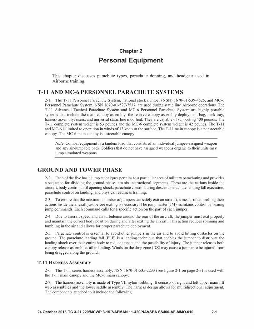
Figure 2-2. T-11 riser assembly
Note

2-5
Figure 2-3. MC-6 riser assembly

Chapter 2
2-6
Figure 2-4. T-11/MC-6 universal static line modified and universal static line snap hook

2-7
Figure 2-5. MC-6 main canopy pack tray and nomenclature

Chapter 2
2-8
2-9
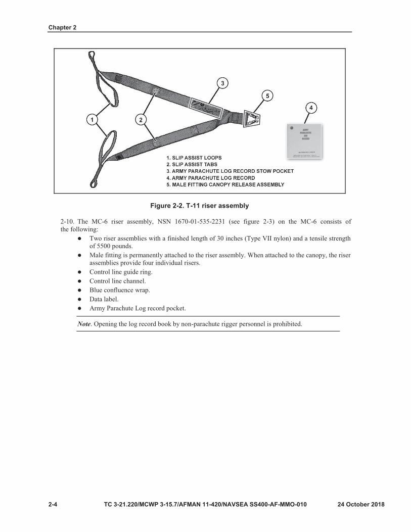
Figure 2-6. T-11 main canopy diagram

Chapter 2
2-10

2-11
Figure 2-7. MC-6 main canopy diagram

Chapter 2
2-12
Figure 2-8. Extractor parachute
Figure 2-9. T-11 ejector spring and related components
2-13
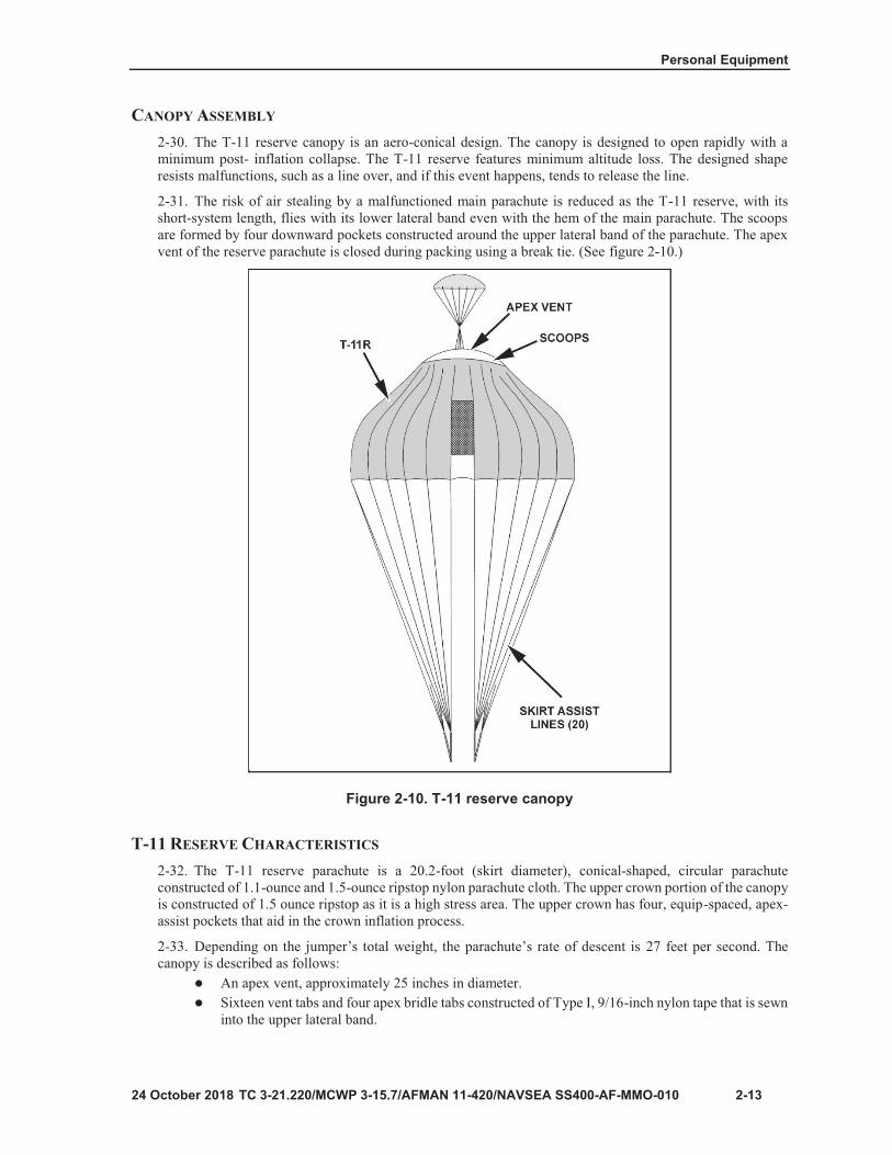
Figure 2-10. T-11 reserve canopy

Chapter 2
2-14
2-15
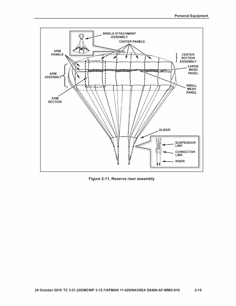
Figure 2-11. Reserve riser assembly

Chapter 2
2-16
Figure 2-12. T-11 reserve pack tray

2-17
Figure 2-13. T-11R rip cord handle assembly

Chapter 2
2-18
Figure 2-14. T-11R inserts

2-19
Note
Figure 2-15. Executing figure-eight folds with arms

Chapter 2
TC 3-21.220/MCWP 3-15.7/AFMAN 11-420/NAVSEA SS400-AF-MMO-010, C1
Step 2. The No. 1 jumper grasps two adjacent suspension lines at the lower lateral band, one ineach hand, and vigorously shakes the gore, making certain no grass, twigs, insects, or other foreignmatter are left on the fabric.Step 3. The No. 1 jumper then transfers both suspension lines to their left hand, grasps thesuspension lines of the next gore with the right hand, and continues as in step 2, workingcounterclockwise until each gore has been shaken and all suspension lines are in the left hand. Pay close attention to ensure no foreign material remains in the canopy.Step 4. The No. 2 jumper begins to slowly pull the canopy up, elongating the suspension lines(group separation must be accomplished). The No. 1 jumper shakes the suspension lines and duststhem by hand. The No. 1 jumper then turns the kit bag (recovery bag) inside out and cleans itthoroughly to ensure no debris is in the kit bag.Step 5. The No. 1 jumper puts the harness in the kit bag (recovery bag).Step 6. The No. 2 jumper then slowly lowers the parachute while the No. 1 jumper folds thesuspension lines on top of the harness and places the canopy inside the kit bag (recovery bag).
Reserve Parachute and Wet Parachute Procedures 2-46. The shakeout procedure for the reserve parachute (if used) is the same as that for the main canopy. Dothe shakeout as soon after jumping as practicable.
2-47. Parachutes used in wet weather or exposed to moisture will be hung to dry within 24 hours of the jump.Once dry, shakeout procedures will then occur.
DONNING PARACHUTES 2-48. Two personnel are required when donning parachutes. Using the buddy system to properly don andadjust the troop parachute harness provides an additional safety check, prevents delays during JM personnelinspection, and provides minimum discomfort to the jumper while aboard the aircraft and when receiving theopening shock of the parachute.
2-49. The buddy-system method provides the best combination of speed and accuracy for jumpers to adjustand check each other’s parachutes. One jumper assumes the role as No. 1 jumper and the other jumperassumes the role as No. 2 jumper.
Note. During the initial periods of Airborne training, students will receive thorough training in the nomenclature, fitting, and wearing of the parachute assemblies. Demonstration, followed by student participation, is the key to the success of this instruction. Instructors constantly check to ensure students know the proper nomenclature as well as the proper methods of wearing and fitting the parachutes.
T-11 AND MC-6 HARNESS
2-50. When donning the T-11 or MC-6 parachutes, jumpers must complete the following steps:Step 1. Inspect the parachute assembly for visible defects. The main parachute harness requirespre-adjustment prior to fitting.Step 2. Place the parachute on the ground. Ensure the harness assembly is up and the risers arefacing away. This includes—
Activating the quick release in the waistband and pulling up each of the activating levers onthe leg strap ejector snaps, which releases the leg straps. The jumper then activates the quickrelease in the chest strap.
TC 3-21.220/MCWP 3-15.7/AFMAN 11-420/NAVSEA SS400-AF-MMO-010, C1
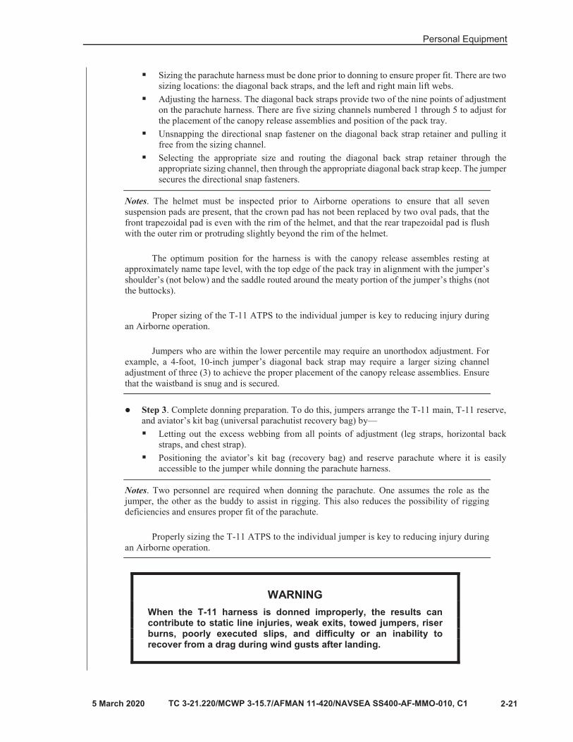
Sizing the parachute harness must be done prior to donning to ensure proper fit. There are twosizing locations: the diagonal back straps, and the left and right main lift webs.Adjusting the harness. The diagonal back straps provide two of the nine points of adjustmenton the parachute harness. There are five sizing channels numbered 1 through 5 to adjust forthe placement of the canopy release assemblies and position of the pack tray.Unsnapping the directional snap fastener on the diagonal back strap retainer and pulling itfree from the sizing channel.Selecting the appropriate size and routing the diagonal back strap retainer through theappropriate sizing channel, then through the appropriate diagonal back strap keep. The jumper secures the directional snap fasteners.
Notes. The helmet must be inspected prior to Airborne operations to ensure that all seven suspension pads are present, that the crown pad has not been replaced by two oval pads, that the front trapezoidal pad is even with the rim of the helmet, and that the rear trapezoidal pad is flush with the outer rim or protruding slightly beyond the rim of the helmet.
The optimum position for the harness is with the canopy release assembles resting at approximately name tape level, with the top edge of the pack tray in alignment with the jumper’s shoulder’s (not below) and the saddle routed around the meaty portion of the jumper’s thighs (not the buttocks).
Proper sizing of the T-11 ATPS to the individual jumper is key to reducing injury during an Airborne operation.
Jumpers who are within the lower percentile may require an unorthodox adjustment. For example, a 4-foot, 10-inch jumper’s diagonal back strap may require a larger sizing channel adjustment of three (3) to achieve the proper placement of the canopy release assemblies. Ensure that the waistband is snug and is secured.
Step 3. Complete donning preparation. To do this, jumpers arrange the T-11 main, T-11 reserve,and aviator’s kit bag (universal parachutist recovery bag) by—
Letting out the excess webbing from all points of adjustment (leg straps, horizontal backstraps, and chest strap).Positioning the aviator’s kit bag (recovery bag) and reserve parachute where it is easilyaccessible to the jumper while donning the parachute harness.
Notes. Two personnel are required when donning the parachute. One assumes the role as the jumper, the other as the buddy to assist in rigging. This also reduces the possibility of rigging deficiencies and ensures proper fit of the parachute.
Properly sizing the T-11 ATPS to the individual jumper is key to reducing injury during an Airborne operation.
WARNING When the T-11 harness is donned improperly, the results can contribute to static line injuries, weak exits, towed jumpers, riser burns, poorly executed slips, and difficulty or an inability to recover from a drag during wind gusts after landing.

Chapter 2
2-22 TC 3-21.220/MCWP 3-15.7/AFMAN 11-420/NAVSEA SS400-AF-MMO-010
Notes. The main lift webs provide two of the nine points of adjustment. There are three size settings: small, medium, and large.
To make main lift web size changes, unsnap the snap fastener and expose the tuck tab. Select the appropriate size setting. If selecting small or medium, insert the tuck tab into the appropriate tuck pocket and remove any slack from the main lift web adjustment strap. If selecting the large setting, the main lift web adjustment strap will be fully extended with the tuck tab folded in towards the main lift web. Secure the snap fastener again. Conduct the same size change on the opposite main lift web.
The tuck pocket for the small setting is located above the chest strap on each main lift web. The tuck pocket for the medium setting is located below the chest strap on each main lift web. For the large setting, there is no tuck pocket; the main lift web adjustment strap will be fully extended with slack removed.
Although the main lift webs provide the capability to increase their length to accommodate jumpers at the higher percentiles and permit essential items to be worn under the parachute harness.
Jumpers should only adjust the main lift webs after all attempts to size using the maximum adjustments on the diagonal back straps have been exhausted
Step 4. Don the main parachute harness. Both jumpers perform the following steps:The No. 1 jumper dons the helmet and assumes a modified “high jumper” position.The No. 2 jumper places the parachute harness over the jumper’s arms with the diagonal backstraps resting on the jumper's shoulders and hold the pack tray high on the jumper’s back.
Step 5. Secure the chest strap. The No. 1 jumper performs step 5, which includes the followingactions:
Ensuring that the quick-release webbing retainer is the width of two to three fingers.Completing an “S” fold or accordion fold and securing the excess webbing in its webbingretainer. This ensures that the tabbed ending points towards the chest strap friction adapter.Pulling the ejector snaps and L-shaped ejector snap pads as far forward as possible towardsthe center of the groin while ensuring that the saddle is routed underneath the hamstrings (notthe buttocks).
Note. Maintain a modified “high jumper position.”
Secure the aviator kit bag (AKB) or universal parachutist recovery bag (UPRB).Secure the leg straps with the AKB or UPRB.Aviator’s kit bag: ensures that the left leg strap is properly routed through the exposedcarrying handle, over the bottom and under the top. Then, complete an “S” fold, accordionfold, or roll the free running ends of the leg straps into the webbing retainers.Universal parachutist recovery bag: ensure the left leg strap is properly routed through theleft leg strap retainer and the right leg strap is properly routed through the right leg strapretainer. Then, complete an “S” fold, accordion fold, or roll the free running ends of the legstraps into the webbing retainers.
Step 6. Adjust the parachute to the individual jumper. Both jumpers perform step 6, whichincludes the following actions:
The No. 1 jumper secures the D-rings with the thumbs of each hand, then pulls downward,pressing against the body, and stands erect.After the No. 2 jumper is standing erect, remove all slack from the horizontal back strap bysimultaneously pulling up on both sides of the horizontal back straps where they emerge fromthe main lift web.

Personal Equipment
TC 3-21.220/MCWP 3-15.7/AFMAN 11-420/NAVSEA SS400-AF-MMO-010 2-23
Step 7. Continue adjusting parachute to the individual jumper. Both jumpers perform step 7, which includes the following actions:
The No. 1 jumper remains standing erect, releases the D-rings and applies pressure to thehorizontal back strap just above the leg strap ejector snaps until a tight but not uncomfortableadjustment has been made.The No. 2 jumper removes all slack on each side by placing the palm of one hand on top of adiagonal back strap and pressing while tightening down the free running end with the other.The jumper “S” folds, accordion folds, or rolls the free running ends and secures them intothe webbing retainers.
Step 8. Next jumper dons a parachute. The No. 1 and 2 jumpers then change positions and repeatsteps 1 through 6. When both jumpers have donned their parachute harnesses, they face each otherand make a visual inspection. They correct any discrepancies before securing the reserveparachute. All excess webbing is stowed in webbing retainers.
Note. After donning the T-11 harness, the pack tray’s top edge should be in alignment with the jumper’s shoulder blades for optimum position of the harness. The center point of the leg strap ejector snaps and quick-fit V-ring should rest in the jumper’s hip socket.
T-11 RESERVE DONNING
2-51. The jumper attaches the reserve parachute by cradling the parachute in his or her left arm with theconnector snaps up and the rip cord handle in the palm of the left hand. If the jumper is part of the jumpmasterteam or pushing a door bundle the jumper must have the T-11R marked with yellow pressure sensitive tapeon the top carrying handle. If any other jumper has a T-11R marked for jumpmaster, that reserve must not beused and another must be obtained from Control and Issue.
2-52. The jumpers performs the following steps when donning the T-11 reserve parachute:Step 1: No. 1 and No. 2 jumpers take the following actions:
The No. 1 jumper cradles the reserve parachute in the crook of their left arm with the rip cordhandle in the palm of the left hand.The No. 2 jumper removes all twists from the waistband and hands the free running end tothe No. 1 jumper, being careful not to reintroduce a twist in the waistband.
Step 2:Jumpers No. 1 and 2 perform step 2 by taking the following actions:The No. 1 jumper passes the waistband through the waistband retainers on the rear of thereserve parachute from right to left. Then attaches the right connector snap to the right D-ringon the harness, the left connector snap to the left D-ring, and ensures that the waistband isbelow the D-rings.The No. 2 jumper attaches the waistband to the waistband-adjuster panel and grasps therunning end of the jumper’s waistband in his or her right hand, placing the left hand on theend of the reserve for leverage. The jumper pulls the slack from the waistband and secures itto the waistband adjuster panel, forming a quick release.
Step 3: The No. 1 and 2 jumpers change positions and repeat steps 1 through 3. When both jumpershave donned their parachute harnesses and reserve, they face each other and make a visualinspection. They correct any discrepancies. After doing so, they are now ready to jump; however,before jumping from an aircraft, they will receive a detailed safety inspection from a JM.
Note. When moving with the parachute harness on, the jumper will keep their hand on the rip cord handle at all times to prevent accidental activation of the reserve parachute.

Chapter 2
2-24
Note

3-1
Chapter 3
Five Points of Performance
WARNINGS Hands must remain over the ends of the reserve parachute withfingers naturally spread. Failure to do so may cause unintentional activation of the reserve parachute while standing in the door or during exit from the aircraft. If no opening shock is felt by the jumper at the end of the 6000 count, he or she must activate the reserve parachute for a total malfunction.

Chapter 3
3-2
WARNING During descent, the jumper must watch to avoid collisions and entanglements with other jumpers and to avoid obstacles on the DZ. Jumpers must stay 25 feet away from other jumpers.

Five Points of Performance
3-3

Chapter 3
3-4
WARNING Attempting to roll off the canopy could wrap the suspension line around the higher jumper’s body, preventing the main canopy from re-inflating and preventing them from deploying the reserve.
WARNING When slipping away from fellow jumpers, always use a diagonal slip. If the higher jumper should fall through a corner vent, they should remain where they are and be prepared to conduct a parachute landing fall.
Five Points of Performance
3-5

Chapter 3
3-6
WARNING DO NOT change slips or make any more turns with the parachute unless it is to avoid other jumpers in the air or obstacles on the ground.
Figure 3-1. Landing attitude

Five Points of Performance
3-7

Chapter 3
3-8
Figure 3-2. Tree landing attitude

Five Points of Performance
3-9
WARNING Make sure the reserve reaches the ground or is close to it before continuing with the following actions.
WARNING Extreme care must be taken when climbing down the T-11 reserve parachute suspension lines because of the slippery coating applied to the suspension lines. Remember, when in doubt, stay where you are and wait for assistance.

Chapter 3
3-10
Figure 3-3. Landing without a life preserver

TC 3-21.220/MCWP 3-15.7/AFMAN 11-420/NAVSEA SS400-AF-MMO-010, C1 3-11
Water Landing with a Life Preserver 3-29. When wearing a T-11 parachute harness and jumping with a life preserver (see figure 3-4), the jumperdoes the following in addition to the actions mentioned under water landing:
While still in the air, the jumper activates the life preserver prior to assuming a landing attitude.If the life preserver fails to inflate, the jumper inflates the life preserver manually by blowing airinto the inflation valve hose.The jumper will jettison any combat equipment.Looks below to ensure there are no fellow jumpers below, lowers their equipment, and jettisonstheir equipment.Assumes a landing attitude and prepares to do a PLF in the event the water is shallow.Once in the water, the jumper activates both canopy release assemblies by using the hand-to-shouldermethod or the hand-to-assist method as described previously in the procedures for recovering from the drag.The jumper does not remove the harness since the life preserver will support the jumper.
Note. For more information on life preservers, refer to chapter 12 of this publication.
Figure 3-4. Landing with a life preserver

Chapter 3
TC 3-21.220/MCWP 3-15.7/AFMAN 11-420/NAVSEA SS400-AF-MMO-010
HIGH-TENSION WIRE LANDING 3-30. The jumper does the following if unable to avoid high tension lines when landing (see figure 3-5):
If the jumper is drifting towards wires, he or she immediately tries to slip away.If the jumper cannot slip away, he or she looks below to ensure there are no fellow jumpers belowand jettisons their equipment, making a mental note of where it lands.Ensures that the jumper e maintains their helmet.Assumes a landing attitude by keeping feet and knees together and exaggerating the bend in hisor her knees. The jumper keeps eyes open, chin on chest, and their back arched.Places the palms of their hands high on the inside of the front set of risers.When the jumper makes contact with the wires, he or she begins a hard rocking motion andattempts to pass through the wires.Prepares to do a PLF in the event the jumper passes through the wires.If the jumper gets hung up in the wires, he or she does not attempt to lower them self to the ground.The jumper stays where they are and waits for assistance.
Figure 3-5. Wire landing attitude

Five Points of Performance
3-13
Note
Note

Chapter 3
3-14

Five Points of Performance
3-15
WARNINGS Hand must remain over the ends of the reserve parachute with fingers naturally spread. Failure to do so may cause unintentional activation of the reserve parachute while standing in the door or during exit from the aircraft. If no opening shock is felt by the jumper at the end of the 4000 count, the jumper must activate the reserve parachute for a total malfunction.

Chapter 3
3-16
WARNINGS During descent, the jumper must watch to avoid collisions and entanglements with other jumpers and to avoid obstacles on the DZ. Jumpers stay 50 feet away from other jumpers. Due to the canopy’s steerability and maneuverability, jumpers should stay at least 50 feet apart in the air to prevent collisions and entanglements.

Five Points of Performance
3-17
WARNING Before attempting any maneuvers, the jumper must check around them self to prevent collisions with other jumpers.

Chapter 3
3-18
Notes.
WARNING Running with the wind just prior to landing can cause injury and must be avoided below 100 feet above the ground.

Five Points of Performance
3-19
WARNINGS Continuing to utilize one steering line during the fifth point of performance “LAND” will cause the canopy to remain in a turn and NOT slow the jumper’s lateral ground speed. All riser slips during the last 200 feet should be gentle and smooth enough to adjust direction only as needed. Pulling down 12 inches or more on both rear risers smoothly and quickly will reduce forward speed, then increase the jumper’s rate of descent in less than two seconds.
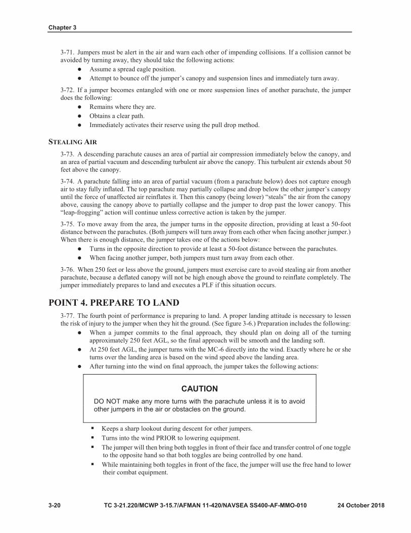
Chapter 3
3-20
CAUTION DO NOT make any more turns with the parachute unless it is to avoid other jumpers in the air or obstacles on the ground.

Five Points of Performance
3-21
Figure 3-6. Landing attitude

Chapter 3
3-22
WARNING Make sure the reserve reaches the ground or is close to it before continuing with the following actions.

Five Points of Performance
24 October 2018 TC 3-21.220/MCWP 3-15.7/AFMAN 11-420/NAVSEA SS400-AF-MMO-010 3-23
CAUTION Extreme care must be taken when climbing down the T-11 reserve parachute suspension lines because of the slippery coating applied to the suspension lines. Remember, when in doubt, stay where you are and wait for assistance.
WATER LANDING 3-81. As soon as the jumper realizes he or she is going to land in water, they take the following actions:
Immediately tries to turn away if the jumper is drifting towards a body of water.If the jumper cannot turn away, looks below to ensure there are no fellow jumpers underneath,and lowers the equipment.Jettisons the helmet, making a mental note of where it lands.Activates the quick release in the waistband, disconnects the left connector snap, and rotates thereserve parachute to the right.Seats them self well into the saddle and activates the quick release in the chest strap, completelyremoving the chest strap from the chest strap friction adapter.Regains canopy control.Prior to entering the water, the jumper assumes a landing attitude by keeping feet and kneestogether, knees slightly bent, and places hands on the leg strap ejector snaps.When the balls of the feet make contact with the water, the jumper activates both ejector snaps forthe leg straps, arches back, throws arms above the head, and slides out of the parachute harness.Swims upwind or upstream away from the canopy.Is prepared to execute a PLF if the water is shallow (two feet or less in depth).
Without a Life Preserver 3-82. The jumper does the following (in addition to the actions under water landing) when wearing the MC-6 parachute harness and executing a water landing without a life preserver is imminent (see figure 3-7 onpage 3-24):
Looks below to ensure there are no follow jumpers and lowers the equipment.Jettisons his or her helmet, making a mental note of where it lands.Activates the quick release in the waistband, disconnects the left connector snap, and rotates thereserve parachute to the right.Seats them self well into the saddle and activates the quick release in the chest strap, completelyremoving the chest strap from the chest strap friction adapter.Regains canopy control.Prior to entering the water, the jumper assumes a landing attitude by keeping feet and kneestogether, knees slightly bent and places hands on the ejector snaps for the leg straps.When the balls of the feet make contact with the water, the jumper activates both ejector snaps forthe leg straps, arches the back, throws arms above the head, and slides out of the parachute harness.Swims upwind or upstream away from the canopy.If the canopy comes down on top of you, locate a seam, and follow it to the skirt of the canopy.Is prepared to execute a PLF if the water is shallow (two feet or less in depth).
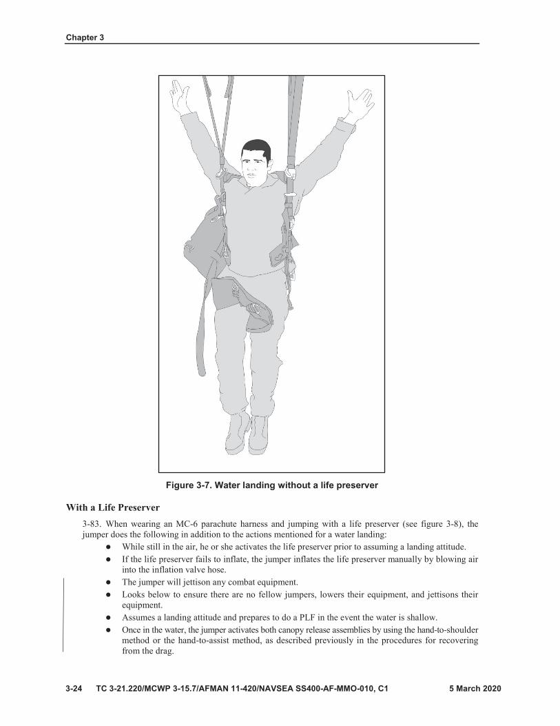
Chapter 3
TC 3-21.220/MCWP 3-15.7/AFMAN 11-420/NAVSEA SS400-AF-MMO-010, C1
Figure 3-7. Water landing without a life preserver
With a Life Preserver 3-83. When wearing an MC-6 parachute harness and jumping with a life preserver (see figure 3-8), thejumper does the following in addition to the actions mentioned for a water landing:
While still in the air, he or she activates the life preserver prior to assuming a landing attitude.If the life preserver fails to inflate, the jumper inflates the life preserver manually by blowing airinto the inflation valve hose.The jumper will jettison any combat equipment.Looks below to ensure there are no fellow jumpers, lowers their equipment, and jettisons theirequipment.Assumes a landing attitude and prepares to do a PLF in the event the water is shallow.Once in the water, the jumper activates both canopy release assemblies by using the hand-to-shouldermethod or the hand-to-assist method, as described previously in the procedures for recoveringfrom the drag.

Five Points of Performance
3-25
Note
Figure 3-8. Water landing with a life preserver

Chapter 3
3-26
Figure 3-9. Wire landing attitude
Note

Five Points of Performance
3-27
Note

Chapter 3
3-28

4-1
Chapter 4
Training Apparatuses

Chapter 4
4-2
Figure 4-1. Parachute landing fall sequence

4-3
Table 4-1. Common parachute landing fall errors
ERROR CAUSE CORRECTION
Feet apart. Anticipation of landing.Keep moderate muscle tension in the legs. Keep feet and knees together.
Drawing the legs up under the buttocks.
Anticipation of landing. Relaxing the knees. Exaggeration of the bend in the knees. Pulling feet up upon landing.
Keep moderate muscle tension in legs. Maintain aproper prepare-to-land attitude, naturally exposing the balls of the feet to the ground.
Missing the second (calf) and third (thigh) points of contact.
Feet and knees apart. Straightening the legs. Failure to shift the knees.
Bend the knees slightly. Keep feet and knees together. Shift and bend the knees throughout the fall.
Knees into the ground.
Hesitation upon landing. Pushing knees forward toward ground. Excessive bend in knees. Turning the feet toward the direction of drift.
Do not hesitate upon landing. Shift knees to the side. Keep moderate muscle tension in legs. Maintain the proper prepare-to-land attitude.
Elbows hit the ground.
Leaning forward toward ground. Failure to rotate upper body away from ground. Breaking fall with elbows.
Rotate upper body away from the ground with elbows up and in front of face.
Head strikes the ground.
Relaxing the neck. Arching the back during the prepare-to-land attitude. Rotating the upper body into the ground. Missing the points of contact.
Keep chin on chest. Tense neck muscles throughout the PLF. Assume proper prepare-to-land attitude. Rotate upper body away from the ground.

Chapter 4
4-4
Figure 4-2. Lateral drift apparatus

4-5
Note
Note

Chapter 4
4-6

4-7
Figure 4-3. Mock door apparatus

Chapter 4
4-8

4-9
Figure 4-4. Controlled movement technique

Chapter 4
4-10
Figure 4-5. Static line bight

4-11

Chapter 4
4-12
Figure 4-6. Suspended harness apparatus

4-13

Chapter 4
4-14
Figure 4-7. Thirty-four foot mock tower

4-15

Chapter 4
4-16
Figure 4-8. Thirty-four foot mock tower personnel positions

4-17

Chapter 4
4-18
Figure 4-9. Hand-towed drag pad

4-19
Figure 4-10. Canopy release assembly

Chapter 4
4-20

24 October 2018 TC 3-21.220/MCWP 3-115.7/AFMAN 11-420/NAVSEA SS400-AF-MMO-010 5-1
Chapter 5
C-130/C-17/C-27J Exiting Procedures
This chapter discusses the three exiting procedures, alternate door exit procedures (ADEPT) option 1, ADEPT option 2, mass exit, and the proper method for jumpers to exit the C-130, C-17, and the C-27J aircraft safely. All units must strictly enforce proper exiting procedures from fixed-wing aircraft. Exiting procedures are perishable skills, therefore, be well briefed and rehearsed prior to any Airborne operation. (See chapter 10 for jumpmaster practical work inside the aircraft [PWAC].)
ALTERNATE DOOR EXITING PROCEDURES FOR TRAINING
WARNINGS Only one series of parachute will be suspended in the air at any one given time and on one given pass over the drop zone. Mixing parachutes that have different opening performance characteristics may lead to hazardous conditions incidents. Do not sacrifice safety for time, complete the full inspection of each jumper’s USLM down to the main curved pin protector flap. If the inspection cannot be completed in time, the pass will be aborted. An improperly routed USLM can cause death or serious injury.
CAUTION Any member of the JM team can call a NO DROP anytime it is determined something is wrong or unsafe.
5-1. The alternate door exit procedures for training options are used when jumping the T-11 ATPS and MC-6 series parachutes. This training safety measure allows the maximum number of jumpers to exit the aircraft with a minimum risk of high altitude entanglements. ADEPT options are as follows:
ADEPT option 1: during a single pass, only one stick of jumpers on one side of the aircraft exit their paratroop door prior to any jumpers exiting from the opposite paratroop door.
ADEPT option 2: during a single pass, one stick of jumpers exit from the PJMs door, followed by a stick of jumpers from the AJMs door.
Mass exit: this exit procedure is used only when jumping the T-11 ATPS. During this type of exit, jumpers will exit from both doors at the same time with one second intervals between jumpers and a half second between paratroop doors.

Chapter 5
5-2 TC 3-21.220/MCWP 3-115.7/AFMAN 11-420/NAVSEA SS400-AF-MMO-010M, C1
CAUTION No more than 20 jumpers per anchor line cable for a C-130H, no more than 31 per anchor line cable on a C-130-J30(C-130J), and no more than 27 per anchor line cable (outboard) and 24 per anchor line cable (inboard) for a C-17 Globemaster III. No more than 13 jumpers per anchor line cable for a C-27J.
C-130/C-17 ADEPT OPTION 1 EXCITING PROCEDURES5-2. During a single pass over the drop zone, only one stick of jumpers on one side of the aircraft jumps.After issuing the jump command of “STAND UP” (see chapter 10 for JM PWAC) the following jumperactions will occur:
Only the jumpers for that pass will stand up; on a C-130 series aircraft, the jumpers sitting in theforward outboard portion may stand up on their seats if required, in order to allow the inboardpersonnel to stand up, raise seats, and secure them. (In the C-17, standing on seats is not required.)Once the inboard seating is raised and secured, the outboard personnel in the forward portion ofthe aircraft will raise and secure their seats.Immediately after putting the seats up, the jumper must tighten down their appropriate adjustableleg straps and secure the excess webbing in the webbing retainer when jumping withcombat equipment.The first three jumpers should be positioned one behind the other, with the rest of the stickstaggered inboard and outboard.When the command of HOOK UP is given, the jumpers will detach USL snap hook from the topcarrying handle of the reserve parachute. Hook up to the appropriate anchor line cable with theopening gate towards the skin of the aircraft. Jumpers will form a bight (four in the hand, twobelow); jumpers will not touch the double sewn portion of the USLM. The first three jumpers willextend their static line arms to obtain the proper distance between jumpers, all others will holdtheir (static line) elbow high.The nonstatic line hand will protect the rip cord handle and the jumper’s feet will be staggeredwith the outboard foot forward.When the command of “CHECK STATIC LINES” is given, jumpers will check the USLM fromthe point of attachment to where it disappears over the top of the shoulder. The jumper behind willtrace the USLM past the static line slack retainer band and down to the first stow. If the static lineslack retainer band that is holding the USLM breaks, the jumper will then stow any excess staticline in the other static line slack retainer band. The last two jumpers turn towards the skin of theaircraft and the second to last jumper will check the last jumper’s USLM.On the command of “CHECK EQUIPMENT,” each jumper will:
Trace the rim of the helmet.Trace the chinstrap.Touch and visually inspect the chest strap, both left and right leg straps.Touch and visually inspect to ensure the hook-pile tape lowering line is secured to the lefttriangle link and all excess webbing is properly secured in its appropriate webbing retainerswhen jumping combat equipment.
After the JM completes the door checks, 1-minute, 30-second time warnings (jumpers will relayannouncements), and gives the command of “STAND BY,” the JM will escort the No. 1 jumperinto door position and the JM will be positioned close enough to the lead edge of the paratroopdoor to control the flow of jumpers, but far enough back as to not impede the jumpers’ movementto the paratroop door.
Note. On a C-17, the JM will not issue the command of “STAND BY” until the amber light is on

C-130/C-17/C-27 Exiting Procedures
5-3
Note.
Note.
WARNING In order to maximize dispersion and minimize simultaneous exits, JMs must control the flow of jumpers ensuring a one-second interval between jumpers at his or her paratrooper door.

Chapter 5
5-4
CAUTIONS Jumpmasters must be prepared to initiate red light procedures at any time after the green light has been illuminated.
Jumpers will grasp their universal static lines approximately six inches from the point of attachment; generally below the double-sewn portion, with their corresponding static line elbow perpendicular to shoulder level in order to reduce misrouted static lines.
CAUTION Mass exit is not authorized for the C-27J. It is recommended that all first-time jumpers be briefed planeside regarding the narrow size of the paratroop door and the undisturbed high-velocity airflow immediately outside of the paratroop door prior to their first jump on this aircraft.

C-130/C-17/C-27 Exiting Procedures
5-5
WARNING In order to maximize dispersion and minimize simultaneous exits, JMs must control the flow of jumpers ensuring a one-second interval between jumpers at the paratrooper door.

Chapter 5
5-6
CAUTIONS Jumpmasters must be prepared to initiate red light procedures at any time after the green light has been illuminated.
Jumpers will grasp their universal static lines approximately six inches from the point of attachment; generally below the double sewn portion, with their corresponding static line elbow perpendicular to shoulder level in order to reduce misrouted static lines.
Note.

C-130/C-17/C-27J Exiting Procedures
24 October 2018 TC 3-21.220/MCWP 3-115.7/AFMAN 11-420/NAVSEA SS400-AF-MMO-010 5-7
The No. 1 jumper will hand the USLM to the safety and should be positioned about two feet fromthe center of the jump platform. The jumper keeps their feet spread and legs slightly flexed so thattheir weight is equally distributed over both feet to maintain balance.Follow-on jumpers close up behind the preceding jumper and keep a position with feet spread andlegs slightly flexed so that their weight is equally distributed over both feet to maintain balance.The JM can control the No. 1 jumper by grasping one of the jumper’s diagonal back straps oraccording to the unit SOP.At the command, “GO,” the No. 1 jumper moves toward the door and onto the jump platform,focusing on the horizon. The jumper pushes off with either foot and vigorously jumps up 6 inchesand out 36 inches away from the jump platform, immediately snapping into a good, tightbody position.
Note. On a C-17, the jumper will take one or two additional steps on the jump platform before pushing off with either foot.
As each jumper begins to move, they will utilize a controlled movement technique (slow deliberate walk) and assume an elbow locked position with the arm that is controlling the USLM. They placethe static line control hand so that it is nearly touching the back of the pack tray of the jumper infront of him, which establishes the proper interval between jumpers. They do not place the staticline control hand in a position so that it extends past the pack tray of the jumper in front of them.When the jumper is perpendicular to the paratroop door, each jumper takes one more step, makeseye-to-eye contact with the safety, and the safety takes control of the USLM.The jumper will immediately return the static line hand to the end of the reserve parachute, withoutswimming the USLM.Places the palms of their hands (fingers naturally spread) on the ends of the reserve parachute withthe elbows tight into the sides.The jumper will execute a left or right face to the open paratroop door only when the safety haspositive control of the USLM.The jumper utilizes the controlled movement technique towards the paratroop door and onto thejump platform, focusing on the horizon. The jumper pushes off with either foot, vigorously jumpsup 6 inches and out 36 inches away from the aircraft, immediately snapping into a good, tightbody position.
5-9. The AJM observes the actions in the PJMs door. When the AJM spots the last three jumpers in thevicinity of the paratroop door of the PJMs stick, he or she faces the jumpers and issues the jump commandof “STAND BY.” When the AJM sees the last jumper clear the jump platform in the PJMs door, they turnand recheck the jump caution lights. (The PJM is now observing the actions in the AJMs paratroop door.)
5-10. If the jump caution lights are still green, the AJM orally and physically issues the command, “GO,” tothe No. 1 jumper. All jumpers will follow the exiting procedures as explained earlier in this chapter.
5-11. When the last jumper exits from the AJMs side of the aircraft (last pass), the AJM gives his or herUSLM to the safety, checks the jump caution lights, and if they are green, exits. The PJM, seeing the AJMexit, passes his or her USLM to the safety, checks the jump caution lights, and if they are green, exits.
5-12. Safety personnel visually clear to the rear of the aircraft and give each other a thumbs up signal. Theyhelp the loadmaster recover deployment bags.
C-27J ADEPT OPTION 2 EXITING PROCEDURES
WARNING Mass exit is not authorized for this aircraft.

5-13. During a single pass over the drop zone, one stick of jumpers exit from the PJMs paratroop door,followed by a stick of jumpers from the AJMs paratroop door. After issuing the jump command of “PORTSIDE AND STARBOARD SIDE PERSONNEL STAND UP” (see chapter 10 for JM PWAC) the followingjumper actions will occur:
Only the jumpers for that pass will stand up. Securing seats is optional based upon the unit SOPand mission:
Raise seats and secure them.Seats can be left secured emplace (down), this causes all jumpers to execute a 90 degree turnaround the last cargo seat at the paratroop door. (This method of exiting must be rehearsed.)A 90-degree exit is vital due to the absence of an air deflector.
Immediately after putting the seats up (if applicable), the jumpers must tighten down theirappropriate adjustable leg straps and secure the excess webbing in the webbing retainer whenjumping combat equipment.When the command of “HOOK UP” is given, the jumpers will detach USL snap hook from thetop carrying handle of the reserve parachute. Hook up to the anchor line cable with the openinggate towards the skin of the aircraft. Jumpers will form a bight (four in the hand, two below).Jumpers will not touch the double-sewn portion of the USLM. The first three jumpers will extendtheir static line arms to obtain the proper distance between jumpers. All others will hold their staticline elbow high.
CAUTION No more than 13 jumpers per anchor line cable on a C-27J.
The nonstatic line hand will protect the rip cord handle and the jumper’s feet will be staggeredwith the outboard foot forward.When the command of “CHECK STATIC LINES” is given, jumpers will check the USLM fromthe point of attachment to where it disappears over the top of the shoulder. The jumper behind willtrace the USLM past the static line slack retainer band and down to the first stow. If the static lineslack retainer band that is holding the USLM breaks, the jumper will then stow any excess staticline in the other static line slack retainer band. The last two jumpers will turn towards the skin ofthe aircraft and the second to last jumper will check the last jumper’s USLM.On the command of “CHECK EQUIPMENT,” each jumper will:
Trace the rim of the helmet.Trace the chinstrap.Touch and visually inspect the chest strap, both left and right leg straps.Touch and visually inspect to ensure the HPT lowering is secured to the left triangle link andall excess webbing is properly secured in its appropriate webbing retainers when jumpingcombat equipment.
After the JM completes the door checks, 1-minute, 30-second time warnings (jumpers will relayannouncements), and gives the command of “STAND BY,” the JM will escort the No. 1 jumperinto door position and the JM will be positioned close enough to the lead edge of the paratroopdoor to control the flow of jumpers, but far enough back as to not impede the jumpers’ movementto the paratroop door.The No. 1 jumper will hand the USLM to the safety and should be positioned about two feet fromthe center of the jump platform. The jumper keeps his or her feet spread and legs slightly flexedso that their weight is equally distributed over both feet to maintain balance.Follow-on jumpers close up behind the preceding jumper and keep a position with feet spread andlegs slightly flexed so that their weight is equally distributed over both feet to maintain balance.The JM can control the No. 1 jumper by grasping one of the jumper’s diagonal back straps oraccording to the unit SOP.

C-130/C-17/C-27 Exiting Procedures
5-9
WARNING The aircraft does not have an air deflector to disrupt the high-velocity airflow immediately outside the paratroop door. Therefore, jumpers must make a vigorous exit and have a tight body position to avoid making contact with the aircraft. Additionally, jumpmasters and safeties may experience turbulent air in the immediate workspace around the paratroop door.

Chapter 5
5-10
WARNING In order to maximize dispersion and minimize simultaneous exits, JMs must control the flow of jumpers ensuring a one-second interval between jumpers at the paratrooper door.
CAUTIONS Jumpmasters must be prepared to initiate red light procedures at any time after the green light has been illuminated.
Jumpers will grasp their universal static lines approximately six inches from the point of attachment; generally below the double-sewn portion, with their corresponding static line elbow perpendicular to shoulder level in order to reduce misrouted static lines.

C-130/C-17/C-27 Exiting Procedures
5-11
Note.
Note.

Chapter 5
5-12
Note.
WARNINGS Only one series of parachute will be suspended in the air at any one given time and on one given pass over the drop zone. Mixing parachutes that have different opening performance characteristics can cause high altitude incidents during ADEPT option 2 or mass exit operations.
Do not sacrifice safety for time, complete the full inspection of each jumper’s USLM down to the main curved pin protector flap. If the inspection cannot be completed in time, the pass will be aborted. An improperly routed USLM can cause death or serious injury.
CAUTION Any member of the JM team can call a “NO DROP” anytime they determine something is wrong or unsafe.

6-1
Chapter 6
T-11R Activation and Parachute Malfunctions

Chapter 6
6-2
WARNING The towed jumper must remain in a good, tight body position and protect the rip cord handle with both hands. Accidental activation of the reserve while being towed could be fatal.

6-3
CAUTION The most important action of a towed jumper is to protect therip cord handle.

Chapter 6
6-4

24 October 2018 TC 3-21.220/MCWP 3-115.7/AFMAN 11-420/NAVSEA SS400-AF-MMO-010 7-1
PART TWO
Advanced Techniques This part discusses key personnel, jumpmaster, safety actions, and the departure airfield control officer
Chapter 7
Key Personnel
This chapter discusses responsibilities of key personnel, prerequisites, and currency. The initial training and follow-on refresher training of key personnel are of major concern to commanders. Proper training and supervision ensures that these key personnel follow the correct procedures and operational safety measures during Airborne operations.
A jumpmaster may remain current after a permanent change of station if they performed JM or AJM duty on a high-performance aircraft within the preceding 180 days of signing into a gaining unit. A jumpmaster should ensure that upon arrival to their gaining unit and completing reception and integration training, that their next duty is still within 180 days of the last duty they performed prior to permanently changing their station. A Memorandum for Record signed by the first colonel (O-6) in the Soldier’s chain of command stating that the JM performed above stated duty within 90 days is required. This Memorandum of Record and DA Form 1307, Individual Jump Record, reflecting the same information must go forward with the JM to their next duty station.
Basic Airborne refresher training is conducted to validate that newly assigned jumpers can properly rig their individual equipment, properly fit their parachute harness, safely perform their individual tasks inside the aircraft, and conduct a proper parachute landing fall. Jumpmaster Refresher training is conducted to validate newly assigned JM-qualified personnel on new equipment training for all unit-specific equipment and newly fielded equipment, jumpmaster personnel inspection, prejump training, drop zone control and support criteria, mock door training, and PWAC. This training also ensures that unit-specific items of equipment and unit SOPs are covered and the Soldier is familiar with the equipment and SOPs.
COMMANDER’S RESPONSIBILITIES 7-1. The Airborne commander designates the key personnel for each Airborne operation. These keypersonnel are the primary and assistant jumpmasters, safety personnel, departure airfield control officer(DACO), drop zone support team leader (DZSTL), drop zone safety officer (DZSO), and malfunction officer

Chapter 7
7-2 TC 3-21.220/MCWP 3-115.7/AFMAN 11-420/NAVSEA SS400-AF-MMO-010M, C1
(MO). The JM, DACO, DZSTL, or DZSO can delegate their authority to subordinates, but they cannot delegate their responsibilities.
Airborne commander. The Airborne commander should be a jumper, but will not be a memberof any jumpmaster team, or serve as DACO, DZSO, or DZSTL. The Airborne commander mustbe assigned to the command that approved the DD Form 2977, Deliberate Risk AssessmentWorksheet, for the Airborne operation being conducted.PJM, AJM, and safety personnel. Each aircraft has a designated PJM, AJM, and safetypersonnel. The Airborne commander gives the designated PJM responsibility for and commandauthority over all personnel onboard a jump aircraft. PJM, AJM, and safety personnel duties aredescribed in chapters 8, 9, and 10 of this publication.DACO. The DACO is located at the departure airfield and has coordination responsibilitywith the ground liaison officer and airlift control element (ALCE) or aircrew for the loadingof personnel, equipment, and supplies into the aircraft. Also, the DACO provides the JMwith changes to station time and the overall operational plan, current DZ weather, airfield crossingprocedures, and the aircraft parking plan. Complete DACO duties are discussed in chapter 11of this publication.DZSO or DZSTL. Each DZ has a DZSO or DZSTL. The DZSO or DZSTL has commandauthority over the actions and safety of all personnel on the drop zone. The DZSO and DZSTLprocedures for DZ operations are described in chapters 20, 21, and 22 of this publication.Malfunction officer. As a member of the drop zone support team (DZST), the MO is located onthe DZ where they can best view the airdrop. It is the responsibility of the MO to promptly andaccurately investigate malfunctions and may enlist as many personnel as needed to watch formalfunctions and assist during the investigation process. AR 59-4 will be in possession of themalfunctions officer during jump operations. It describes in detail the duties and responsibilitiesof the MO during any investigation resulting in the partial or total malfunction of personnelairdrops.
KEY PERSONNEL PREREQUISITES 7-2. The following minimum standards must be met before personnel will be allowed to perform PJM,AJM, safety, DACO, DZSO, DZSTL, or MO duties for personnel and heavy equipment airdrop operations.Individuals who are appointed as PJMs, AJMs, or safety personnel, must have the prerequisites describedbelow. The following qualifications apply to JMs who are commissioned officers, warrant officers, or NCOs:
U.S. Army and U.S. Navy: E-5 or above.U.S. Marine Corps and U.S. Air Force: E-4 or above.
7-3. To be JM qualified, the JM must be a graduate from an authorized and accredited JM course and havebeen issued the additional skill identifier of 5W. (Refer to appendix B for plan of instruction requirements.)Authorized JM courses can be found at Fort Benning, Georgia; with a mobile training team at Fort Bragg,North Carolina; or at a special operations forces’ JM course. Jumpmaster qualified must go throughjumpmaster refresher training prior to conducting any jumpmaster duties. (Refer to appendix C for receptionand integration requirements.) This training must be if the jumpmaster is outside of the reception andintegration requirements.
7-4. To be JM current, the JM must have either performed JM or AJM duties within the preceding 180days; or if a senior-rated or master-rated parachutist, performed duty as a safety on military, high- performance fixed-wing aircraft utilizing a door or ramp exit within the preceding 180 days; or completed aJM refresher course (refer to appendix C) in the preceding 180 days and be a current jumper. A jumpmastermust be a current and qualified T-11, or MC-6 (or both) jumper in order to perform jumpmaster duties.
Notes. JMs must perform duties every 180 days to maintain currency on T-11 or MC-6 parachutes.
For U.S. Navy and U.S. Marine Corps only: if fixed-wing high-performance aircraft are not available, the JM, AJM, and safety may meet currency requirements using organic rotary-wing or nonstandard aircraft.

Key Personnel
TC 3-21.220/MCWP 3-115.7/AFMAN 11-420/NAVSEA SS400-AF-MMO-010 7-3
7-5. A new graduate of a recognized JM course must perform safety duties twice before performing AJMduties and perform AJM duties twice before performing PJM duties. This is referred to as “jumpmasterbaseline currency.” Once a jumpmaster has performed baseline requirements after graduating a recognizedcourse, no further baseline requirements are needed after jumpmaster refresher training.
ROTARY-WING AIRCRAFT/NONSTANDARD AIRCRAFT PERSONNEL
7-6. To perform the duties of the PJM on a rotary-wing aircraft or nonstandard aircraft, the JM must firstmeet the performance duty requirements of the PJM on a fixed-wing. A jumpmaster may conduct JMduties and maintain currency from a rotary-winged or nonstandard aircraft with the exception of aircraftthat utilize exits from a seated position during a 180-day period. However, the next JM duty counted towardscurrency must be from a fixed-wing, high-performance craft within the next 180 days. A jumpmaster cannotmaintain currency with two consecutive JM duties from a rotary-winged nonstandard aircraft, as statedin this paragraph.
Note. This allows all jumpmasters one year to execute JM duties from a fixed-wing, high- performance aircraft.
7-7. JM must observe a current JM in the performance of their duties for a rotary-wing or nonstandardaircraft operation (prejump training, mock door training, aircraft inspection, rigging procedures, and theactual airdrop operation). The qualifying JM must then be observed during the performance oftheir duties by a current rotary-wing, aircraft-qualified PJM before being allowed to perform the above listedduties unsupervised.
7-8. In addition to meeting the qualifications listed previously in this chapter, the assistant jumpmaster musthave performed the duties a safety officer at least twice. Safety personnel must also meet the listed previouslyin this chapter, and also be a current and qualified JM to be appointed as a safety.
7-9. To be appointed a departure airfield control officer, individuals must meet the prerequisiteslisted previously in this chapter, be a current and qualified JM and have performed the duties as an assistantDACO at least once.
7-10. Drop zone safety officers must meet the qualifications listed previously in this chapter, are a currentand qualified JM or a combat crew trainer or special tactics squadron (STS) certified. For Ground MarkingRelease System (GMRS) or Verbally Initiated Release System (VIRS) drops, the DZSO must be a qualifiedJM in the type of jump being conducted, and have assisted a current and qualified DZSO performing theirduties during an airdrop operation involving personnel or heavy equipment.
7-11. For U.S. Navy and U.S. Marine Corps operations, the DZSO is an E-4 or above, or DOD civilianequivalent. U.S. Navy and U.S. Marine Corps DZSOs are also:
Parachutist qualified and current in the operation being conducted (static line or free fall).Have completed a DZSO course of instruction using Naval Special Warfare/Explosive OrdnanceDisposal (EOD) Lesson Training Guide DZSO administered by a current JM.Designated in writing by the commander as a DZSO. To be DZSO current, the DZSO must haveperformed the duties of a DZSO within the preceding 180 days. If noncurrent, received refreshertraining from a current JM or DZSO and run a drop zone while under instruction.
Note. For combination airdrop operations, the DZSO and DZSTL must follow the procedures for heavy drop operations, but observe the jumpers as they exit the aircraft.
7-12. A DZSO refresher course can be conducted by an individual that is a current and qualified JM andDZSO. Noncurrent DZSOs need only complete the DZSO requirements of the Jumpmaster Refresher training curriculum found in appendix C. In addition:
The individual being refreshed on the duties of the DZSO must be a current JM.

Chapter 7
7-4 TC 3-21.220/MCWP 3-115.7/AFMAN 11-420/NAVSEA SS400-AF-MMO-010M, C1
At the completion of DZSO Refresher the JM must perform duties of the DZSO within 180 daysin order to be a current DZSO, and perform one DZSO duty every 180 days from the initialduty to remain current.If the individual has never performed the duties of DZSO they must assist once before performingthe duties of the DZSO.
7-13. Individuals must meet the following prerequisites to be appointed as an assistant drop zone safetyofficer (ADZSO):
Be a commissioned officer, warrant officer, or NCO (U.S. Army and U.S. Navy: E-5s or above;U.S. Marine Corps and U.S. Air Force: E-4s or above).Be a current and qualified JM for personnel or heavy equipment drop.Be certified as an ADZSO by having attended one of the following:
U.S. Army Infantry School (USAIS) Jumpmaster Course (for computed air release point[CARP] DZs only).The U.S. Army Advanced Airborne School JM Course (for CARP DZs only).U.S. Army Special Operations Command (USASOC) Jumpmaster Course.Must have the ASI 5W.
To be ADZSO current, the ADZSO must have performed the duties of a DZSO or assistant DZSOwithin the preceding 180 days, graduated jumpmaster school within the last 180 days, orcompleted a jumpmaster refresher course within the preceding 180 days.
Note. For combination airdrop operations, the DZSO and ADZSO must follow the procedures for heavy drop operations, but observe the jumpers as they exit the aircraft.
7-14. Individuals must meet the following prerequisites to be appointed as a DZSTL:Be a commissioned officer, warrant officer, or NCO (U.S. Army and U.S. Navy: E-5s or above;U.S. Marine Corps and U.S. Air Force: E-4s or above).Be a current and qualified JM for personnel or heavy equipment.Be certified as a DZSTL by having attended one of the following:
USAIS Pathfinder Course.USAIS Jumpmaster Course (for CARP DZs only).The U.S. Army Advanced Airborne School JM Course (for CARP DZs only).USASOC Jumpmaster Course.Must have the ASI 5W.
Have observed and assisted a current and qualified DZSTL performing their duties during anairdrop operation involving personnel or heavy equipment.To be DZSTL current, the DZSTL must have performed the duties of a DZSTL or assistantDZSTL within the preceding 180 days or completed a DZSTL refresher course taught by currentDZSTL personnel within the preceding 180 days.
Note. DZSTLs and ADZSOs in support of CDS airdrops are not required to be Airborne qualified, on jump status, or JM qualified and current, but they must have attended an authorized pathfinder course. For combination airdrop operations the DZSO and DZSTL must follow the procedures for heavy drop operations, but observe the jumpers as they exit the aircraft.
7-15. Individuals must meet the following prerequisites to be appointed as a MO:Be a commissioned officer, warrant officer, or NCO (U.S. Army and U.S. Navy: E-5 or above;U.S. Marine Corps and U.S. Air Force: E-4 or above).The individual must be a qualified parachute rigger from the unit providing the air items usedduring the operation according to AR 59-4.

Key Personnel
TC 3-21.220/MCWP 3-115.7/AFMAN 11-420/NAVSEA SS400-AF-MMO-010 7-5
For the U.S. Marine Corps only: a U.S. Marine Corps MO will be a parachute rigger NCO,E-4 or above, or JM qualified, E–5 or above, and must be appointed in writing by the commandingofficer and must receive unit-level refresher training annually. The MO will be from theorganization that provides the air items.For the U.S. Navy only: malfunctions officers will meet qualification, training, currency, andequipment familiarity requirements according to AR 59-4. The malfunction officer does not haveto be from the organization providing the air items but must be maintenance or operationallyqualified on all equipment used during the operation.For the U.S. Air Force only: DZC and DCSO will fill the duties as the MO and be designated inwriting as an MO. They will have a thorough understanding of the parachute equipment used forthe operation. U.S. Air Force combat control personnel are authorized to perform the duties of anMO during unilateral operations.


8-1
Chapter 8
Jumpmaster and Safety Duties
Note

Chapter 8
8-2
Note
Statement of Jump and Loading Manifest
Note

Jumpmaster and Safety Duties
8-3

Chapter 8
8-4
Note
Note
Note

Jumpmaster and Safety Duties
8-5

Chapter 8
8-6
Note

Jumpmaster and Safety Duties
8-7
Note
Chapter 8
8-8

Jumpmaster and Safety Duties
8-9
Note
Chapter 8
8-10
Jumpmaster and Safety Duties
8-11
WARNING The higher jumper does not attempt to roll off the canopy as this could wrap the canopy or suspension lines around their body, preventing the main canopy from reinflating or preventing the higher jumper from deploying the reserve parachute.
CAUTION When slipping away from fellow jumpers, always use a diagonal slip. If the higher jumper should fall through a corner vent, they should remain where they are and be prepared to conduct a parachute landing fall.

Chapter 8
8-12
Figure 8-1. Wire landing attitude

Jumpmaster and Safety Duties
TC 3-21.220/MCWP 3-115.7/AFMAN 11-420/NAVSEA SS400-AF-MMO-010, C1 8-13
WARNING Tree and wire landings only: do not remove the outer tactical vest, if worn.
Note. If the jumper becomes entangled in the wires, they make no attempt to climb down, but waits to be rescued by a recovery team.
WATER LANDING 8-56. Water landings can be dangerous and should be avoided. Immediately look and slip away utilizing aone riser or diagonal slip when beginning to drift towards a water obstacle. If a water landing is imminent,and the jumper does not have a life preserver, they should perform the following:
Looks below to ensure there are no fellow jumpers and lowers their equipment.Jettisons his or her helmet, making a mental note of where it lands.Activates the quick release in the waistband, disconnects the left connector snap and rotates thereserve parachute to the right.Seats them self well into the saddle and activates the quick release in the chest strap, completelyremoving the chest strap from the chest strap friction adapter.Regains canopy control.Prior to entering the water the jumper assumes a landing attitude by keeping feet and kneestogether, knees slightly bent and places their hands on the ejector snaps for the leg straps.When the balls of their feet make contact with the water, the jumper activates both ejector snapsfor the leg straps, arches his or her back, throws their arms above their head and slides out of theparachute harness.Is prepared to execute a PLF if the water is shallow.Swims upwind or upstream away from the canopy.If the canopy comes down on top of the jumper, they locate a seam, and follow it to the skirtof the canopy.
8-57. Sometimes, life preservers are provided for specific missions or training events. The following areinstances when life preservers may be provided and the actions that should be taken:
Emergency water landings could occur on a tactical training mission where the route to the DZ isover a large body of water. On such flights, life preservers are issued to jumpers. If the aircraftmalfunctions, the jumpers may need to jump over the water.Emergency water landings require jumpers to leave any combat equipment onboard the aircraft sothey do not become entangled with the equipment in the water.A jumper may find themself over water with attached combat equipment due to drifting off a DZbordered by water, or during emergency bailout after being hooked up onboard the aircraft. If thisoccurs, the jumper must lower their combat equipment and jettison their equipment.Deliberate water landings are executed for training in selected water drop zones (WDZs). Jumpersmay wear combat equipment only after it has been waterproofed and float checked.The jumper wears the inflatable life preserver under their harness with the inflatable portions underthe armpits. Jumpers wearing an underwater demolition team (UDT) vest will route the chest strapunder the UDT vest to prevent crushing the chest if inflated.While still in the air, the jumper activates the life preserver prior to assuming a landing attitude.If the life preserver fails to inflate, the jumper inflates the life preserver manually by blowing airinto the inflation valve hose.The jumper will jettison any or all of their equipment including their helmet.

Chapter 8
8-14 TC 3-21.220/MCWP 3-115.7/AFMAN 11-420/NAVSEA SS400-AF-MMO-010M 24 October 2018
Looks below to ensure there are no fellow jumpers below and lowers the equipment. Assumes a landing attitude and prepares to do a PLF in the event the water is shallow. Once in the water, the jumper activates both canopy release assemblies by using the hand-to-
shoulder method or the hand-to-assist method, as described previously in the procedures for recovering from the drag.
The jumper does not remove the harness and equipment, since the life preserver will support a fully combat-equipped jumper.
Note. For more information on life preservers, refer to chapter 12 of this publication.
8-58. All first time MC-6 jumpers must watch the MC-6 instructional video and when mandated by the Airborne commander or unit SOP. All personnel must attend SAT. Jumpers must be positioned so their actions can be viewed by the JM team and so they can hear them. Sustained Airborne training is performance- oriented training and should be tailored to fit the mission. All JMs and leaders must make aggressive and positive on-the-spot corrections. SAT must be taught proficiently.
Note. JM version of mock door training and prejump for the T-11 ATPS and MC-6 series parachute can be found in appendix E of this publication.
8-59. Training on the five points of performance must be attended by all jumpers and JMs. The following are the five points of performance:
Proper exit, check body position, and count. Check canopy and gain canopy control. Keep a sharp look out at all times and constantly compare the rate of descent. Prepare to land. Land.
8-60. The first point of performance is proper exit, check body position, and count. Jumpers must perform the following actions:
Keep chin on chest. Keep eyes open. Keep elbows into sides. Keep hands over the ends of the reserve parachute and fingers naturally spread. Bend body forward at the waist. Keep feet and knees together. Lock knees to the rear. Count to 4000 with the MC-6 parachute (fixed-wing aircraft). Count to 6000 with the MC-6 parachute (rotary-winged aircraft). Immediately activate the reserve parachute using the pull drop method, if opening shock
is not felt.
8-61. Immediately after the 4000 or 6000 count, the jumper will conduct the second point of performance of check canopy and gain canopy control. Jumpers must perform the following actions:
Reaches up to the elbow locked position and secures one toggle in each hand located on the inside of the rear set of risers and pulls the toggles down to approximately eye level.
Make a 360-degree check of the canopy. If the jumper has twists, they will compare the rate of descent with fellow jumpers; if they are
falling faster than fellow jumpers or cannot compare the rate of descent, they activate the reserve parachute using the pull drop method. If they are not falling faster than fellow jumpers, then they will remove the twists.

Jumpmaster and Safety Duties
8-15

Chapter 8
8-16

Jumpmaster and Safety Duties
8-17

Chapter 8
8-18
Figure 8-2. Wire landing attitude
WARNING Tree and wire landings only: do not remove the outer tactical vest, if worn.
Note

Jumpmaster and Safety Duties
TC 3-21.220/MCWP 3-115.7/AFMAN 11-420/NAVSEA SS400-AF-MMO-010, C1 8-19
WATER LANDING 8-77. Water landings can be dangerous and should be avoided. If drifting towards water, they immediatelytry to turn away. If a water landing is imminent, the jumper should perform the following:
Look below them self to ensure there are no follow jumpers and lowers their equipment.Jettisons their helmet, making a mental note of where it lands.Activates the quick release in the waistband, disconnects the left connector snap and rotates thereserve parachute to the right.Seats them self well into the saddle and activates the quick release in the chest strap, completelyremoving the chest strap from the chest strap friction adapter.Regains canopy control.Prior to entering the water they assume a landing attitude by keeping feet and knees together,knees slightly bent, and places their hands on the ejector snaps for the leg straps.When the balls of their feet make contact with the water, they activate both ejector snaps for theleg straps, arch their backs, throw arms above their head and slide out of the parachute harness.Is prepared to execute a PLF, if the water is shallow.Swims upwind or upstream, away from the canopy.If the canopy comes down on top of the jumper, locate a seam and follow it to the skirtof the canopy.
8-78. Sometimes, life preservers are provided for specific missions or training events. The following areinstances when life preservers may be provided and the actions that should be taken:
Emergency water landings could occur on a tactical training mission where the route to the DZ isover a large body of water. On such flights, life preservers are issued to jumpers. If the aircraftmalfunctions, the jumpers may need to jump over the water.Emergency water landings require jumpers to leave any combat equipment onboard the aircraft sothey do not become entangled with the equipment in the water.A jumper may find themself over water with attached combat equipment due to their drifting offa DZ bordered by water, or during an emergency bailout after being hooked up onboard theaircraft. If this occurs, the jumper must lower and jettison their combat equipment.Deliberate water landings are executed for training in selected WDZs. Jumpers may wear combatequipment only after it has been waterproofed and float checked.The jumper wears the inflatable life preserver under the harness with the inflatable portions undertheir armpits. Jumpers wearing a UDT vest will route the chest strap under the UDT vest to preventcrushing the chest if inflated.While still in the air, the jumper activates the life preserver prior to assuming a landing attitude.If the life preserver fails to inflate, the jumper inflates the life preserver manually by blowing airinto the inflation valve hose.The jumper will jettison any or all of their equipment including their helmet.The jumper looks below to ensure there are no fellow jumpers below, lowers and jettisons their equipment.Assumes a landing attitude and prepares to do a PLF in the event the water is shallow.Once in the water, the jumper activates both canopy release assemblies by using the hand-to-shouldermethod or the hand-to-assist method as described previously in the procedures for recovering from the drag.Jumpers do not remove their harness since the life preserver will support the jumper.
Note. Refer to chapter 12 for more information about life preservers.


9-1
Chapter 9
Jumpmaster and Safety Duties at Departure Airfield

Chapter 9
9-2
Note

Jumpmaster and Safety Duties at Departure Airfield
9-3

Chapter 9
9-4
Note

Jumpmaster and Safety Duties at Departure Airfield
9-5
Figure 9-1. AEBP parts identification
Figure 9-2. Inspect the tuck flaps

Chapter 9
9-6
Figure 9-3. Inspect the rip cord pin
Figure 9-4. Inspect the right links

Jumpmaster and Safety Duties at Departure Airfield
9-7
Figure 9-5. Inspect front rip cord housing tacking

Chapter 9
9-8
Figure 9-6. Inspect left links

Jumpmaster and Safety Duties at Departure Airfield
TC 3-21.220/MCWP 3-115.7/AFMAN 11-420/NAVSEA SS400-AF-MMO-010, C1 9-9
Note. If vacuum loss occurs, the AEBP is still serviceable for the mission. After the completion of the mission, the AEBP must be repacked.
Conduct an overall visual inspection of the container for seam separation, holes, cuts, tears, frays,burns, and the presence of the Army Parachute Log Record.
JUMPMASTER PERSONNEL INSPECTION, T-11 AND MC-6 9-14. The PJM is responsible for the inspection of the jumpers on the aircraft before an Airborne operation.Only by a complete and systematic equipment inspection of each jumper can the PJM ensure that personnelaboard their aircraft are safe to jump. Jumpmasters must observe all jumpers don the equipment, and makecorrections as needed to prevent deficiencies. Buddy rigging is used:
The buddy system is a systematic method of donning and adjusting the main and reserveparachutes. It provides an additional safety check, prevents unnecessary delays during JMPI, andprovides the jumper with the maximum amount of comfort while wearing the parachute harness.To increase efficiency and reduce risks, jumpmasters are encouraged to gather the chalk andprovide a demonstration of the buddy system prior to donning parachutes. This is especiallybeneficial during reintegration jumps.If a jumpmaster rigs a jumper, it is acceptable for the jumpmaster to JMPI that jumper. The riggingprocedures and the JMPI sequence are two different systematic checks. However, if another JMis available, then that JM should not inspect the jumper that they rigged.
Note. ALL PERSONNEL must utilize the buddy system to don the main and reserve parachute, INCLUDING THE JUMPMASTERS upon their completion of JMPI.
9-15. Prior to inspecting the jumper, the JM will conduct an overall inspection of the jumper prior toplacing the jumper into JMPI configuration. The JM will conduct an overall inspection of the jumper toensure the following:
Boots: inspect the jumper’s boots for open lacing hooks. If the jumper is wearing open lacinghooks, they must be taped prior to the JM placing the jumper into JMPI configuration.Combat equipment: inspect the MAWC to ensure the bottom of the adjustable nose cone is at leastsix inches above the ground and the top of the MAWC rests between the top of the D-ring and thebase of the left canopy release assembly.The JM will look at the canopy release assemblies to ensure they are seated in the hollows of thejumper’s shoulders, below the collar bone at approximately the name tape level. They look at theriser assemblies to ensure that the type of parachute being inspected either has or does not haveblue confluence wrap.
9-16. The only person authorized to place the jumper into JMPI configuration is the jumpmaster who willinspect that jumper. In order to place the jumper into JMPI configuration, the following will occur:
Move behind the jumper and open the main, curved, pin protector flap from the tuck flap.Disconnect the universal static line snap hook from the right outer static line stow bar and ensurethe spring opening gate has spring tension. Remove all excess universal static line modified fromthe static line slack retainer band on the static line slack retainer loop, remove all twists, route theuniversal static line snap hook through the static line slack retainer band and over the jumper’sshoulder corresponding with the paratroop door the jumper is to exit.The JM will secure the universal static line snap hook to the carrying handle of the T-11 reserveparachute, with the spring opening gate facing the jumper. Remove the top and bottom tuck tabs,taking care to ensure that both side tuck tabs remain secure. If the side tuck tabs become unsecurethe jumpmaster will notify a rigger.
Chapter 9
9-10 TC 3-21.220/MCWP 3-115.7/AFMAN 11-420/NAVSEA SS400-AF-MMO-010 24 October 2018
WARNING Boots fitted with lacing hooks must have the hooks taped prior to placing the jumper into JMPI configuration. Taping hooked eyelets is an individual responsibility that must be verified and checked by the jumpmaster.
The JM may now begin their inspection. The general principle during JMPI is that the JMs head and eyes will always be looking where their hands are working. After the JM has completed the JMPI, the JM will place the jumper into jump configuration.
Note. If jumping the MC-6 parachute or any other steerable, military, static line parachute, the JM will identify blue confluence wrap on both riser assemblies. Steerable and nonsteerable canopies cannot be dropped onto the same drop zone during the same pass.
FIVE-FOOT UNIVERSAL STATIC LINE EXTENSION 9-17. For jumps from C-17 aircraft, the universal static line modified will be configured with the five-foot universal static line extension. JMs must supervise during parachute issue to ensure their jumpers do not draw incorrectly configured parachutes for the aircraft that they will be jumping.
9-18. The T-11 series parachutes are easily identifiable when configured with five-foot universal static line extensions by one additional stow on the left and right inner static line stow bars, and the girth hitch formed by the upper looped portion of the universal static line modified and the cotton buffer of the five-foot universal static line extension, which will be centered between the top two stows.
9-19. JMs must inspect this prior to detaching the universal static line snap hook from the right outer static line stow bar. Push in on the girth hitch at the upper looped portion of the universal static line modified and the cotton buffer of the five-foot universal static line extension and visually inspect both of them for any burns, cuts, or frays. Ensure that the girth hitch is centered between the first stow on the left and right inner static line stow bars or the ninth and 10th stows. Once complete, redress the girth hitch. Then, remove the universal static line snap hook from the right outer static line stow bar and remove all twists in the universal static line modified, but do not break the first stow (top left inner) when using the five-foot universal static line extension. Then, route the universal static line snap hook over the jumper’s appropriate shoulder and connect it to the carrying handle of the reserve parachute with the spring opening gate facing towards the jumper.
9-20. During JMPI, the jumpmaster will trace between the top two stows as normal, bypassing the girth hitch of the upper looped portion of the universal static line modified and the cotton buffer of the five-foot universal static line extension that has already been inspected, while still keeping constant contact with the thumb or index finger of their working hand.
ADVANCED COMBAT HELMET (FRONT) 9-21. To inspect the front of the advanced combat helmet, the JM will place both hands, fingers and thumbs extended and joined, fingertips pointing skyward, palms facing the jumper, on the right side of the advanced combat helmet. The right hand is the working hand; the left hand is the control hand. With the working hand, trace across the rim of the advanced combat helmet feeling for any sharp or protruding edges that may cut or damage the jumper’s universal static line modified upon exiting the aircraft. Once both hands are parallel, place the thumbs on the rim of the advanced combat helmet and tilt the jumpers head to the rear. Conduct a visual inspection to ensure the three suspension pads are present, are flush with the outer rim, and the oval pads are covering the bolt ends.
9-22. The JM will place the right index finger on the front left adjustable buckle, to ensure it is free of all cracked components, is serviceable, the front left adjustable strap is properly routed through it, and the free

Jumpmaster and Safety Duties at Departure Airfield
9-11
Note

Chapter 9
9-12

Jumpmaster and Safety Duties at Departure Airfield
9-13
Note

Chapter 9
9-14

TC 3-21.220/MCWP 3-115.7/AFMAN 11-420/NAVSEA SS400-AF-MMO-010, C1 9-15
Conduct a visual inspection to ensure the universal parachutist recovery bag is present, neitherleg strap retainer is cut or frayed more than 50 percent, and the folded portions are facing skyward. The direction of the trapezoid sewn portion has no bearing on how the UPRB is wornon the jumper.Once satisfied with the inspection, stand up in front of the jumper, and issue the commandof “RECOVER.”
UNIVERSAL STATIC LINE MODIFIED 9-30. Inspect the universal static line modified by taking the following actions:
With the right hand grasp the universal static line snap hook, ensuring the spring opening gate isfacing towards the jumper. Open the right hand and let the universal static line snap hookrest in the palm.Place the index finger of the left hand on the girth hitch of the universal static line modified. Ensurethe green identification marking thread is present and the girth hitch has not been reversed. Placethe index finger of the left hand in the vicinity of the rivet pin (do not cover the rivet pin), to ensureit is present and free of rust and corrosion.With the right hand, regrasp the universal static line snap hook and hold it perpendicular to thereserve parachute with the spring opening gate facing towards the jumper.With the index finger and thumb of the left hand, index finger on top, thumb on bottom, palmfacing the jumper, grasp the universal static line modified at the end of the double sewn portion.Rotate the universal static line modified down and to the jumper’s right, and push it toward theuniversal static line snap hook. Visually inspect inside the girth hitch to ensure it is free of allcuts, frays, and burns.With the index finger or thumb of the right hand, push the girth hitch back towards the universalstatic line snap hook and again visually inspect inside the girth hitch for any cuts, frays, or burns.Redress the girth hitch down around the narrow portion of the universal static line snap hook andrelease the universal static line modified with the left hand.Since the universal static line modified is routed over the right shoulder; with the index finger andthumb of the right hand, form an “O” around the universal static line modified just above theuniversal static line snap hook. The jumpmaster should see metal through the “O”.Raise the right hand up, simultaneously inspecting the universal static line modified as it passesthrough the “O” to ensure it is free of all cuts, frays, or burns.Raise the right hand as high as it can go or until resistance is felt, and issue the jumper thecommand, “TURN.” Once the jumper has completed the turn, the right hand should be raised highenough to keep the universal static line modified tight between the control hand and the first stow.Place the index finger or index and middle finger of the left hand behind the universal static linemodified below the right hand, making skin-to-skin contact. Trace the universal static linemodified down, ensuring it is free of all cuts, frays, and burns, and it has not been misrouted underor through either riser assembly to the static line slack retainer band. Withdraw the index fingeror index and middle finger and place below the static line slack retainer band and continue to tracethe universal static line modified to the first stow.With either hand, form a bite in the universal static line modified and look at the static lineslack retainer loop. Ensure it is present, serviceable, and two serviceable static line slack retainerbands are attached.Place the bite on top of the pack tray and control it with either hand. This hand becomes the control hand. The opposite hand becomes the working hand.With the index finger and thumb of the working hand, pinch off the first stow and pull it one totwo inches towards the center of the pack tray. Look behind the first stow, and ensure the universalstatic line modified is free of cuts, frays, or burns, and has not been misrouted around the staticline stow bar. Release the first stow and let it pop back into place.

Chapter 9
9-16 TC 3-21.220/MCWP 3-115.7/AFMAN 11-420/NAVSEA SS400-AF-MMO-010M, C1
Note. When the jumpmaster traces the universal static line modified towards them self, only the index finger will be used. When tracing away, only the thumb may be used.
Insert the index finger or thumb of the working hand from bottom to top behind the first strand ofuniversal static line modified, as close as possible to the first stow. Trace the first strand ofuniversal static line modified, ensure that it is free of all cuts, frays, or burns to the second stow.With the index finger and thumb of the working hand, pinch it off and pull one to two inchestowards the center of the pack tray, and conduct the same inspection. Place the index finger orthumb of the working hand from bottom to top behind the second strand of universal static linemodified and trace it to ensure it is not cut, frayed, or burned.Continue to inspect the universal static line modified in the same manner to the main curved pincover. Ensure the last strand of universal static line modified is routed from the right outerstatic line stow bar.With the index finger of the working hand, gently lift up on the main curved pin cover. Inspect themain curved pin attaching loop to ensure that it is properly attached to both the universal staticline modified and the main curved pin.Visually inspect the main curved pin from its point of attachment to ensure it is not bent, cracked,or corroded, and is properly routed from left to right through the main closing loop. Visuallyinspect to ensure the main curved pin securing tie is present and made of only one turn of “Orangeticket 3” thread, and that it is secured by a surgeons knot locking knot with the ends trimmed toapproximately one inch..Visually inspect the main closing loop to ensure it is not cut, frayed, or burned, and the maincurved pin is not puncturing it in any manner. Conduct a visual inspection of the grommet toensure it is not bent, cracked, or corroded.With the index finger and thumb of the working hand, gently lift up on the main curved pinprotector flap and conduct a visual inspection of the main closing loop, ensuring it is not cut,frayed, or burned, and the grommet is not bent, cracked, or corroded. Stand up behind the jumper.With the index finger and thumb of the working hand, gently lift up on the main curved pinprotector flap and conduct a visual inspection of the main closing loop, ensuring it is not twisted,cut, frayed, or burned, and the grommet is not bent, cracked, or corroded.Stand behind the jumper.
Notes. Broken securing ties: if a tie breaks any time after the original packer makes the tie, prior to getting on the aircraft, it can be replaced by another qualified parachute rigger skill level 1 or higher, after a routine inspection is conducted on the parachute. If the parachute passes the routine inspection, the tie can be replaced and the parachute returned to service without being repacked. Once the tie is made, a qualified parachute rigger inspector skill level 2 or higher must inspect the tie. Both the individual replacing the tie and the inspector must sign the DA Form 3912, Army Parachute Log Record. If the parachute does not pass the routine inspection, it must be returned to the parachute pack facility for repack.
If a securing tie breaks on the aircraft and the main curved pin is still seated in the closing loop, the parachute is still serviceable and can be jumped.
ADVANCED COMBAT HELMET (BACK) 9-31. The jumpmaster inspects the rear of the advanced combat helmet by taking the following actions:
Places both hands, fingers and thumbs extended and joined, fingertips pointing skyward, palmsfacing towards the jumper, on the left side of the advanced combat helmet. The left hand is thecontrol hand and the right hand is the working hand. With the working hand, traces across the rimof the advanced combat helmet feeling for any sharp or protruding edges that may cut or damagethe jumper’s universal static line modified upon exiting the aircraft.

TC 3-21.220/MCWP 3-115.7/AFMAN 11-420/NAVSEA SS400-AF-MMO-010, C1 9-17
Once both hands are parallel, places the thumbs on the rim of the advanced combat helmet andgently tilts the jumper’s head forward. Conducts a visual inspection to ensure the oval pads arecovering the bolt ends, they are flush with the rim of the advanced combat helmet, and the reartrapezoid pad is flush or protruding slightly past the rim of the advanced combat helmet, no morethan one-half inch.Places the right index finger on the rear right adjustable buckle. Ensures it is free of all crackedcomponents and is serviceable, the rear right adjustable strap is properly routed through it, and thefree running end is secured in the webbing retainer.Traces the rear right adjustable strap down, ensuring it is not twisted, cut, or frayed until contactis made with the long portion chin strap. Leaves the right index finger in place.Places the left index finger on the rear left adjustable buckle and conducts the same inspection allthe way down to the chinstrap fastener. Leaves the left index finger in place.Conducts a visual inspection of the nape pad to ensure it is present, secure, serviceable, and hasnot been reversed.
Notes. Ensure there is a minimum of seven suspension pads inside the advanced combat helmet, one crown pad, two trapezoid pads and four oval pads that are covering the bolt ends.
All four oval pads and the front trapezoid pad must be flush with the rim of the advanced combat helmet. The rear trapezoid pad must be flush with the rim of the advanced combat helmet or may extend past the rim of the advanced combat helmet, no more than half an inch.
INSPECTING RISER ASSEMBLIES AND PACK TRAYS 9-32. The jumpmaster performs the inspection of the riser assemblies by taking the following actions:
Reaches over the jumper’s shoulders and grasps a riser assembly in each hand, thumbs down,knuckles pointing skyward, just above the canopy release assemblies. Since these are like itemsof equipment, either riser assembly can be inspected first. For this example, begin the inspectionwith the left riser assembly.Gives the left riser assembly a sharp tug to the rear. Opens the left hand to form a distinguishable“L.” Applies upward pressure with the left thumb and traces the riser assembly rearward,conducting a physical and visual inspection to ensure that an Army Parachute Log Record ispresent, and that the riser assembly is not twisted, cut, or frayed to where it disappears into themain pack tray. Leave the left hand in placeWith the right hand, conducts the same inspection on the right riser assembly. The jumpmastermust ensure that only one riser assembly contains an Army Parachute Log Record.
9-33. An overall inspection of the pack tray is conducted to ensure the pack tray is free of grease, oil, dirt,mud, or tears. The jumpmaster performs the inspection of the pack tray by taking the following actions:
Places both hands, fingers and thumbs extended and joined palms facing towards the pack tray,on the top left corner of the pack tray. The left hand is the control hand and the righthand is the working hand.With the head and eyes six to eight inches away from the working hand, traces across the top packclosing flap, down the right pack closing flap. The jumpmaster bends over to see what they aredoing and traces across the bottom pack closing flap.Turns the working hand over so the pinkie finger leads the way and traces up the left pack closingflap until skin-to-skin contact is made with the control hand. Raises the control hand up out of theway and traces where the control hand had been.The JM forms knife-edges with both hands, palms facing towards them self, and issues thecommand, “ARCH YOUR BACK.”

Chapter 9
9-18 TC 3-21.220/MCWP 3-115.7/AFMAN 11-420/NAVSEA SS400-AF-MMO-010M, C1
DIAGONAL AND HORIZONTAL BACK STRAPS 9-34. The jumpmaster inspects the diagonal or horizontal back straps by taking the following actions:
Inserts both hands behind the diagonal back straps where the natural pocket is formed. Ensuresthat thumbs rest just below the “X” formed by the diagonal back strap retainers. Looks at thediagonal back straps to ensure they are properly routed over the appropriate shoulder, and the topdiagonal back strap has one more row of exposed stitching than the bottom. Looks at the diagonalback strap retainers to ensure they are routed through the sizing channels on the diagonal backstraps, the diagonal back strap retainers are routed around the diagonal back strap keepers, and thedirectional snap fasteners are secure.To further ensure the directional snap fasteners are secure, with both thumbs, The JM plucks thetab portion of the diagonal back strap retainers upward from bottom to top. The JM looks at theleft hand and with that hand, traces down the diagonal back strap to ensure it is not twisted, cut,or frayed to the back strap adjuster.Grasps the back strap adjuster with the left hand and looks at the right hand and the right diagonalback strap. With the right hand traces down the diagonal back strap, ensuring it is nottwisted, cut, or frayed.Bypasses the back strap adjuster and picks up the inspection of the horizontal back strap. Tracesdown, ensuring it is not twisted, cut, or frayed, and the free running end is secured in the webbingretainer until it disappears into the right main lift web.Withdraws the right hand from under the horizontal back strap, and reinserts it, fingers and thumbextended and joined, fingertips pointing skyward, palm facing towards them self. Then traces from bottom to top behind the horizontal back strap where it reemerges from the right main lift web.Issues the jumper the command, “BEND”.Places the left shoulder on the bottom pack closing flap and pushes up on the bottom ofthe pack tray. Simultaneously, with the left hand, pulls down on the back strap adjuster. With headand eyes approximately six to eight inches away, traces the horizontal back strap across thesmall of the jumper’s back until the right pinkie finger makes contact with the main liftweb on the jumper’s left side.Inspects the horizontal back strap is to ensure it is not twisted, cut, or frayed, that the horizontalback strap retainers are properly routed over the horizontal back strap, then under and back overthe horizontal back strap keepers, and secured with directional snap fasteners. Nothing ismisrouted behind the horizontal back strap.Withdraws the right hand from behind the horizontal back strap, and reinserts it from top tobottom behind the horizontal back strap and behind the waistband adjuster panel, whereit re-emerges from the left main lift web. Traces up until making skin-to-skin contact with theleft hand, ensuring that it is not twisted, cut, frayed, the free running end is secured in thewebbing retainer, and nothing has been misrouted behind it. Removes the right hand and gets lefthip to head with the jumper.
SADDLE 9-35. The jumpmaster inspects the saddle by taking the following actions:
Places the fingertips of the right hand, fingers and thumb extended and joined, palm facing towards the jumper, on the lower portion of the left main lift web adjuster. Traces down the lower portionof the main lift web, transitioning to the saddle to ensure it is not twisted, cut, frayed, or beeninverted, and neither leg strap has been misrouted around the saddle. Continues to trace untilmaking contact with the lower portion of the right main lift web adjuster.Reaches back and gets a handful of air and issue the jumper the good seal of approval by tappingthe jumper on the buttocks while issuing the command, “RECOVER”.
Note. Once the jumpmaster has completed the inspection, they will place the jumper into jump configuration.

TC 3-21.220/MCWP 3-115.7/AFMAN 11-420/NAVSEA SS400-AF-MMO-010, C1 9-19
9-36. After the JM has completed their JMPI, they will place the jumper into jump configuration and takethe following actions:
The JM traces the universal static line modified from the universal static line snap hookto ensure that the universal static line modified is routed over the shoulder correspondingwith the door the jumper is to exit.Once behind the jumper, the JM removes all slack from the universal static line modified andstows it in the static line slack retainer band.The JM reinserts the main curved pin protector flap into the tuck flap, ensuring that the maincurved pin cover is the only item of equipment behind it.The JM places either hand on the rip cord assembly, applies steady inward pressure, and reinsertsthe top and bottom tuck tabs, taking care to ensure that both side tuck tabs remain secure.If the side tuck tabs become unsecure the JM notifies a rigger.
9-37. If the jumper requires the T-11R inserts, ensure that the T-11 reserve parachute is marked on thecarrying handle with quarter-inch yellow pressure-sensitive tape. (See figure 9-7.) The jumpmaster:
Places a T-11R insert in the top tuck pocket.Ensures that the top edge of the T-11R insert is flush with the binding tape on the tuck pocket andthe yellow tab is visible. (See figure 9-8 on page 9-20.)Places a T-11R insert in the bottom tuck pocket.Ensures that the bottom of the T-11R insert is flush with the binding tape on the tuck pocket andthe yellow tab is visible. (See figure 9-9 on page 9-20.)Verifies that the side tuck tabs have not been removed from their tuck pockets. If the side tucktabs become unsecure, immediately notify a rigger.
Figure 9-7. Quarter-inch yellow pressure-sensitive tape

Chapter 9
9-20 TC 3-21.220/MCWP 3-115.7/AFMAN 11-420/NAVSEA SS400-AF-MMO-010 24 October 2018
Figure 9-8. T-11R insert is flush with the binding tape
Figure 9-9. T-11R bottom insert is flush with the binding tape
Notes. At a minimum, the PJM and AJM will have the T-11R inserts. If the NUMBER ONE JUMPER is assisting in pushing a door bundle, that jumper is required to have the T-11R inserts.
While conducting rotary-winged operations it is recommended that jumpers exposed to winds that cross the front of the reserve parachute have the T-11R inserts emplaced. (UH-60 and UH-1.)

Jumpmaster and Safety Duties at Departure Airfield
9-21
Chapter 9
9-22
Note

24 October 2018 TC 3-21.220/MCWP 3-115.7/AFMAN 11-420/NAVSEA SS400-AF-MMO-010 9-23
Simultaneously, with both hands form fists with index fingers exposed. Place index fingers on thesnap hooks of the adjustable D-ring attaching straps. Focus attention to the left hand. Conduct avisual inspection to ensure that the snap hook is not bent, cracked, corroded, or distorted out ofshape, and that the opening gate is facing towards the jumper.With the index finger of the left hand, finger the opening gate one time to ensure that it is properlysecured to the right equipment ring, and it has spring tension and has not been reversed. With theleft thumb, flip the free running end of the right adjustable D-ring attaching strap out of the way.Place the left index finger on the black intermittent stitching on the front of the right adjustable D- ring attaching strap just below the snap hook. Trace down the right adjustable D-ring attachingstrap ensuring that it is not twisted, cut, or frayed until contact is made with the triangle link.Bypass the triangle link and pick up the inspection of the attaching loops, ensuring that the whiteattaching loop is routed from bottom to top through the triangle link, the green attaching loop isrouted from bottom to top through the white attaching loop, the red attaching loop is routed frombottom to top through the green attaching loop, and also routed from bottom to top through thegrommet in the female portion leg strap release assembly. Place the index finger of the left handon the single box “X” stitch on the release handle cross strap.Look at the release handle cable where it emerges from the release handle cross strap. Ensure therelease handle cable is properly routed through the red attaching loop and secured by the cableloop retainer. Leave the left index finger in place and with the right hand, conduct thesame inspection on the left adjustable D-ring attaching strap until the right index finger restson the single box “X” stitch.Focus attention on the release handle. With the right index finger and thumb, index finger on top,thumb on the bottom, lift up gently on the release handle. Ensure the release handle and releasehandle cable is properly routed between the two plies of the release handle cross strap, and therelease handle is secured by the hook-pile tabs.Now form a hook with the right index finger and insert it from outside to inside and lift upon the release handle lanyard to ensure it is not twisted, cut, frayed, or misrouted aroundthe equipment retainer strap or the release handle cross strap. Place the right index finger backon the single box “X” stitch.Trace the equipment retainer straps down the outside of the pouch on the MOLLE rucksack untilmaking contact with the box “X” stitches on either side of the adjustable cross strap.Leave the left index finger in place and with the index finger and thumb of the right hand,grasp the free running end of the adjustable cross strap and give it a tug to the jumper’sleft, ensuring that all the slack has been removed from the adjustable cross strap. Place the rightindex finger back on the single box “X” stitch and continue to trace the equipment retainer strapsdown until fingers fall off.Secure the sides of the MOLLE rucksack and raise it to eye level. Look at the equipment retainerstraps to ensure they are routed through the slots at the top corners of the MOLLE rucksackframe and have not been twisted, cut, or frayed. Raise the MOLLE rucksack to the jumper andissue the command, “HOLD.”
Note. Jumpers will secure the top of the MOLLE rucksack and hold it up high.
Continue the inspection of the equipment retainer straps as they route through the adjustableshoulder carrying straps from outside to inside. Ensure the equipment retainer straps are routedover the comfort pad and form an “X” configuration on the rear of the MOLLE rucksack and arenot twisted, cut or frayed. Bypass the girth hitch of the hook-pile tape lowering line and continuethe inspection until fingers rest on the friction adaptors and behind the two to three finger quickreleases in the equipment retainer straps.Simultaneously, inspect the two to three finger quick releases by placing the index andmiddle finger of each hand, palms toward the face, on the outside of the quick releases. Visuallyinspect the free running ends of the equipment retainer straps to ensure they are S-foldedor accordion folded, never rolled, and secured with either one turn of masking tape or twoturns of retainer bands (one or the other, never both) and not secured to the quick releases. Conduct

Chapter 9
9-24 TC 3-21.220/MCWP 3-115.7/AFMAN 11-420/NAVSEA SS400-AF-MMO-010, C1
a visual inspection of the friction adapters to ensure they are routed through the oval cutouts at the base of the MOLLE rucksack frame. With the index finger of each hand, lightly tap them to ensure they are secure. With the thumb and index fingers of each hand, form an “O” around the base of the adjustableshoulder carrying straps. Whenever possible, the free running ends should be on top of both hands. Simultaneously, pull out to ensure they are properly secured to the MOLLE rucksack frame.Visually inspect the free running ends of the adjustable shoulder carrying straps to ensure theyare S-folded or accordion folded, never rolled, and secured with either one turn of maskingtape or two turns of retainer bands (one or the other, never both). With the index fingers ofeach hand, lightly tap the free running ends of the adjustable shoulder carrying straps to ensurethey are secure.
ALICE PACK 9-41. After completing the overall inspection of the reserve parachute, the JM then inspects the all-purpose,lightweight, individual, carrying equipment (ALICE) pack. To inspect this pack:
The inspection of the harness single point release begins with the adjustable D-ring attachingstraps. These are like items of equipment, so either one can be inspected first. However, for thepurpose of this talk through, begin with the right adjustable D-ring attaching strap.Simultaneously, with both hands form fists with your index fingers exposed. Place index fingerson the snap hooks of the adjustable D-ring attaching straps. Now, focus attention to the left hand.Conduct a visual inspection to ensure that the snap hook is not bent, cracked, corroded, distorted,or out of shape, and that the opening gate is facing towards the jumper.With the index finger of the left hand, finger the opening gate one time to ensure that it is properlysecured to the right equipment ring, that it has spring tension, and has not been reversed. With theleft thumb, flip the free running end of the right adjustable D-ring attaching strap out of the way.Place the index finger of the left hand on the black intermittent stitching on the front of the rightadjustable D-ring attaching strap just below the snap hook. Trace down the right adjustable D-ringattaching strap, ensuring that it is not twisted, cut, or frayed until contact is made with the trianglelink.Bypass the triangle link and pick up the inspection of the attaching loops and ensure that the whiteattaching loop is routed from bottom to top through the triangle link, the green attaching loop isrouted from bottom to top through the white attaching loop, the red attaching loop is routed frombottom to top through the green attaching loop, and routed from bottom to top through thegrommet in the female portion leg strap release assembly. Place the index finger of the left handon the single box “X” stitch on the release handle cross strap.Look at the release handle cable where it emerges from the release handle cross strap. Ensure therelease handle cable is properly routed through the red attaching loop and secured by the cableloop retainer. Leave the left index finger in place and with the right hand, conduct the sameinspection on the left adjustable D-ring attaching strap until the right index finger rests on thesingle box “X” stitch.Focus attention on the release handle. With the right index finger and thumb, index finger on top,thumb on the bottom lift up gently on the release handle. Ensure the release handle and releasehandle cable is properly routed between the two plies of the release handle cross strap and therelease handle is secured by the hook-pile tabs.Now form a hook with the right index finger and insert it from outside to inside and lift up on therelease handle lanyard to ensure it is not twisted, cut, frayed, or misrouted around the equipmentretainer strap or the release handle cross strap. Place the right index finger back on the single box“X” stitch.Trace the equipment retainer straps down between the external cargo compartments of the ALICEpack until making contact with the adjustable cross strap. Leave the left index finger in place andwith the index finger and thumb of the right hand, grasp the free running end of the adjustablecross strap and give it a tug to the jumper’s left, insuring that all the slack has been removed fro

TC 3-21.220/MCWP 3-115.7/AFMAN 11-420/NAVSEA SS400-AF-MMO-010, C1 9-25
the adjustable cross strap. Now, place the right index finger back on the single box “X” stitch andcontinue to trace the equipment retainer straps down until all fingers fall off.Secure the sides of the ALICE pack and raise it to eye level and look at the equipment retainerstraps to ensure they are routed behind the envelope cushion and have not been twisted. Raise theALICE pack to the jumper and issue the command, “HOLD.”
Note. Jumpers will secure the top of the ALICE pack and hold it up high.
Continue the inspection of the equipment retainer straps as they route through the envelopecushion. Ensure the equipment retainer straps form an “X” configuration on the rear of the ALICEpack and are not twisted, cut, or frayed. Continue inspection until all fingers rest on the frictionadapters and behind the two-to-three finger quick releases in the equipment retainer straps.Simultaneously, inspect the two-to-three finger quick release by placing the index and middlefinger of each hand, palm facing toward the body, on the outside of the quick release. Now,visually inspect the free running ends of the equipment retainer straps to ensure they are S-foldedor accordion folded, never rolled, and secured with either one turn of masking tape or two turnsof retainer bands (one or the other, never both) and not secured to the quick releases. With theindex finger of each hand, lightly tap them to ensure they are secure.With the thumb and index fingers of each hand, form an “O” around the lower portion of theadjustable shoulder carrying straps. Simultaneously, pull out to ensure they are properly securedto the ALICE pack frame. Visually inspect the free running ends of the adjustable shouldercarrying straps to ensure they are S-folded or accordion folded, never rolled, and secured witheither one turn of masking tape or two turns of retainer bands (one or the other, never both). Withthe index fingers of each hand, lightly tap the free running ends of the adjustable shoulder carryingstraps to ensure the S-folds are secure.
HOOK-PILE TAPE LOWERING LINE (MAWC) 9-42. Inspect the hook-pile tape lowering line, when rigged with a MAWC, by taking the following actions:
With the index finger of the right hand, place it on the hook-pile tape lowering line (HPTLL) justto the left of the girth hitch. Visually inspect to ensure the girth hitch is properly routed north tosouth, south to north, but never east to west.With the right index finger, trace the HPTLL, ensuring that the HPTLL is properly routed over theleft adjustable shoulder carrying strap until making contact with the first set of hook-pile tabs.Visually inspect to ensure the hook-pile tabs are present, secured, and there are no S-foldsprotruding from the end of the retainer flap.Continue to inspect down the retainer flap ensuring that it is secured to the MOLLE rucksackframe by two sets of girth hitched retainer bands on either end of the retainer flap.Continue to trace down until making contact with the second set of hook-pile tabs. Once againensure they are present, secured, and there are no S-folds protruding from the end of the retainerflap.Continue to trace the HPTLL until the index finger disappears behind the modular Airborneweapon’s case. Visually inspect to ensure the HPTLL is properly routed between the mainbody of the modular Airborne weapon’s case and the attachment strap. Leave the right indexfinger in place.Route the left hand over the right forearm and secure the trail edge of the MAWC and pull itforward. Make a mental note of where the right index finger is, remove the right index finger andplace it back on the HPTLL where it just was. Continue to trace up until making contact with theejector snap, ensuring the HPTLL is not routed through the carrying handle.With the right thumb press in on the activating lever to ensure that it is properly seated over theball detent, free of all foreign matter that will keep it from seating completely, the opening gate isfacing the jumper, and is secured to the triangle link. Turn the ejector snap one-quarter turn awayfrom the jumper to ensure the small tooth is present.

Chapter 9
9-26 TC 3-21.220/MCWP 3-115.7/AFMAN 11-420/NAVSEA SS400-AF-MMO-010, C1
Visually inspect the yellow safety lanyard to ensure that it is serviceable and it has not been wired,tied, or taped down. Drop both hands and move back to the front of the jumper and issue thecommand, “SQUAT.”
UNIVERSAL PARACHUTIST RECOVERY BAG AND AVIATOR’S KIT BAG 9-43. Inspect the UPRB by taking the following actions:
Insert the index and middle finger of each hand, from outside to inside, behind the leg straps,below the universal parachutist recovery bag where the natural pocket is formed. Simultaneously,slide both hands back towards the saddle to ensure the leg straps are not crossed. Leave the righthand in place.With the left hand trace the right leg strap up, ensure it is not twisted, cut, or frayed, until contactis made with the right leg strap retainer. Now remove the index finger and middle finger of theleft hand and reinsert them just above the right leg strap retainer and trace up the right leg strap toensure it is not twisted, cut, or frayed, the excess webbing is properly routed behind the leg strapretainer, and is secured in the webbing retainer until contact is made with the quick-fit V-ring.With the thumb, press in on the activating lever of the ejector snap to ensure it is properly seatedover the ball detent and is free of foreign matter that would keep it from seating completely. Leavethe left hand and thumb in place and look at the left leg strap.With the right hand conduct the same inspection of the left leg strap. Once skin to metal contactis made, remove the right hand and use the right forearm to lift up and out on the modular Airborneweapon’s case. With the right thumb, press down on the activating lever to ensure it is properlyseated over the ball detent and that it is free of any foreign material that will keep it from seatingcompletely. Now leave both hands and thumbs in place.Rock back on heels and conduct a visual inspection to ensure the universal parachutist recoverybag is present, neither leg strap retainer is cut or frayed more than 50 percent, and the foldedportions are facing skyward. Once satisfied with the inspection, stand up in front of the jumper.Secure the sides of the MOLLE rucksack and issue the command of “RECOVER.”
Note. Jumpers pick up on the reserve parachute and jumpmasters simply allow the MOLLE rucksack or ALICE pack to rotate between the jumpmaster’s body and the jumper’s body.
9-44. Inspect the AKB, by taking the following actions:Insert the index and middle fingers of both hands, from outside to inside, behind the leg strapsbelow the aviator’s kit bag where the natural pocket is formed. Simultaneously, slide both handsback towards the saddle, to ensure the legs straps are not crossed. Leave the right hand in place.With the left hand trace the right leg strap up, ensure that it is not twisted, cut, or frayed, the excesswebbing is secured in its webbing retainer until there is skin-to-metal contact with the quick-fitV-ring. Rotate the left thumb up and press down on activating lever to ensure it is properly seatedover the ball detent, and that it is free of any foreign material that will keep it from seatingcompletely. Leave the left hand and thumb in place and look at the left leg strap.With the right hand, trace the left leg strap up to ensure it is not twisted, cut, or frayed, it is properly routed through the exposed carrying handle of the aviator’s kit bag, over the bottom and under thetop, and the free running end is secured in the webbing retainer, until contact is made with thequick-fit V-ring. Once skin to metal contact is made, remove the right hand, and use the rightforearm to lift up and out on the MAWC. With the right thumb, press down on activating lever toensure it is properly seated over the ball detent and that it is free of any foreign material that willkeep it from seating completely. Leave both hands and thumbs in place.Rock back on heels and conduct a visual inspection to ensure the aviator’s kit bag is present, hasnot been reversed, and the re-enforced sewn portion is facing away from the jumper. Secure thesides of the MOLLE rucksack and issue the command of “RECOVER.”

TC 3-21.220/MCWP 3-115.7/AFMAN 11-420/NAVSEA SS400-AF-MMO-010, C1 9-27
Note. Jumpers pick up on the reserve parachute and jumpmasters simply allow the MOLLE rucksack or ALICE pack to rotate between the jumpmaster’s body and the jumper’s body.
TECHNICAL INSPECTION AND HANG OF COMBAT EQUIPMENT 9-45. The JM is responsible for inspecting each jumper and item of equipment. Long flights, heavy loads,extreme heat, tactical updates, and special items of equipment (AT4JP, SMJP, and other items) may warrantdelaying the attachment of equipment until a predesignated time later in the mission timeline. Under suchconditions, the Airborne commander may decide to conduct the JMPI without equipment. The commandermust consider individual and unit proficiency when conducting the command risk assessment.
9-46. There are two methods to attach equipment after JMPI is complete: technical inspection (T.I.) and hang of combat equipment, and late hang and JMPI of combat equipment. When the commander has decided to“T.I. AND HANG” after JMPI has been conducted, the T.I. is conducted on the MOLLE rucksack, ALICEpack, MAWC (rigged for a tandem load), the hook-pile tape lowering line (MAWC), and leg strap assemblies.
MOLLE RUCKSACK 9-47. First, conduct an overall inspection of the equipment to ensure it is free of loose or excess webbing,and the adjustable D-ring attaching straps and HPTLL is hanging free. Stand in front of the MOLLE with theadjustable shoulder straps facing away and the base of the MOLLE skyward.
9-48. Begin the inspection of the MOLLE with its point of attachment, the adjustable D-ring attaching straps.These are like items of equipment so either can be inspected first. However, for the purpose of this talkthough, begin with the right adjustable D-ring attaching strap. With both hands secure the snap hooks of theadjustable D-ring attaching straps in each hand, the right snap hook in the left hand, and the left snap hookin the right hand. Place the index fingers on the opening gate of the snap hooks. Focus attention to the lefthand and the right adjustable D-ring attaching strap. Conduct a visual inspection to ensure that the snap hookis not bent, cracked, or corroded and that the opening gate is facing away. With the left index finger, functionthe opening gate one time, ensuring it has spring tension and has not been reversed. With the left thumb, flipthe excess webbing of the adjustable D-ring attaching strap out of the way and place the left index finger onthe black intermittent stitching just below the snap hook. Trace the adjustable D-ring attaching strap, ensuringthat it is not cut or frayed until making contact with the triangle link. Bypass the triangle link and pick up theinspection of the attaching loops, and ensure that the white attaching loop is routed from bottom to topthrough the triangle link, the green attaching loop is routed from bottom to top through the white attachingloop, the red attaching loop is routed from bottom to top through the green attaching loop, and routed frombottom to top through the grommet in the female portion leg strap release assembly.
9-49. Continue tracing until the index finger of the left hand rests on the single box “X” stitch on the releasehandle cross strap. Look at the release handle cable where it emerges from the release handle cross strap.Ensure the release handle cable is properly routed through the red attaching loop and secured by the cableloop retainer. Leave the left index finger in place and with the right hand; conduct the same inspection on theleft adjustable D-ring attaching strap until the right index finger rests on the single box “X” stitch on therelease handle cross strap.
9-50. With the right index finger and thumb (index finger on top, thumb on the bottom) lift up gently on therelease handle. Ensure the release handle and release handle cable is properly routed between the two pliesof the release handle cross strap, and the release handle is secured by the hook-pile tabs. Now form a hookwith the right index finger, insert it from outside to inside and gently lift up on the release handle lanyard toensure it is not twisted, cut, frayed, or misrouted around the equipment retainer strap or the release handlecross strap. Place the right index finger back on the single box “X” stitch on the release handle cross strap.Now grasp the sides of the MOLLE and lay it down flat on the frame.
9-51. Place both index fingers back on the corresponding box “X” stitch on either side of the release handlecross strap. Simultaneously, with both index fingers trace the equipment retainer straps down the outside ofthe pouch of the MOLLE. Continue to trace until making contact with the box “X” stitches on either side ofthe adjustable cross strap. Leave the left index finger in place and with the index finger and thumb of the

Chapter 9
9-28 TC 3-21.220/MCWP 3-115.7/AFMAN 11-420/NAVSEA SS400-AF-MMO-010, C1
right hand grasp the free running end of the adjustable cross strap and give it a tug to the right, ensuring that all the slack has been removed from the adjustable cross strap. Place the right index finger back on the single box “X” stitch and continue to trace the equipment retainer straps down until all fingers fall off.
9-52. Now grasp the sides of the MOLLE and rotate it up so that the top of the MOLLE is facing skyward.Look at the equipment retainer straps to ensure they are routed through the slots at the top corners of theMOLLE frame and have not been twisted, cut, or frayed. Continue to rotate the MOLLE until the pack bodyis facing down and the frame is facing skyward.
9-53. Now place the index fingers of both hands inside the adjustable shoulder carrying straps on top of theequipment retainer straps where they reemerge from slots of the MOLLE frame. Ensure they are routed fromoutside to inside, under the adjustable shoulder carrying straps. Begin tracing down the equipment retainerstraps to ensure the equipment retainer straps are routed over the comfort pad and form an “X” configurationon the rear of the MOLLE, and the straps are not twisted, cut, or frayed. Bypass the girth hitch of the HPTLLand continue your inspection until all fingers rest on the friction adaptors and behind the two-to-three fingerquick releases of the equipment retainer straps. Simultaneously, inspect the two-to-three finger quick releaseby placing the index and middle finger of each hand, palm on the outside of the quick releases.
9-54. Conduct a visual inspection of the friction adapters to ensure they are routed through the oval cutoutsat the base of the MOLLE frame. Visually inspect the free running ends of the equipment retainer straps toensure they are S-folded or accordion folded, never rolled, and secured with either one turn of masking tapeor two turns of retainer bands (one or the other, never both) and not secured to the quick releases. With theindex finger of each hand, lightly tap the free running ends of the equipment retainer straps to ensure theyare secure.
9-55. With the thumb and index fingers of each hand, form an “O” around the base of the adjustable shouldercarrying straps. Whenever possible, the free running ends should be on top of both hands. Simultaneously,pull out to ensure they are properly secured to the MOLLE frame. Visually inspect the free running ends ofthe adjustable shoulder carrying straps to ensure they are S-folded or accordion folded, never rolled, andsecured with either one turn of masking tape or two turns of retainer bands (one or the other, never both).With the index fingers of each hand, lightly tap the free running ends of the adjustable shoulder carryingstraps to ensure they are secure.
9-56. Place the index finger of the right hand on the HPTLL just to the right of the girth hitch as thejumpmaster sees it. Visually inspect to ensure the girth hitch is properly routed north to south, south to north,but never east to west. With the right index finger, trace the HPTLL ensuring that the HPTLL is properlyrouted over the left adjustable shoulder carrying strap until making contact with the first set of hook-pile tabs.Visually inspect to ensure the hook-pile tabs are present and secured, and there are no S-folds protrudingfrom the end of the retainer flap.
9-57. Continue to inspect down the retainer flap, ensuring that it is secured to the MOLLE frame by two setsof girth hitched retainer bands on either end of the retainer flap. Continue to trace down until making contactwith the second set of hook-pile tabs and ensure they are present and secured, and there are no S-foldsprotruding from the end of the retainer flap. With the right hand, palm facing up, fingers pointing away,continue to trace the HPTLL with the palm to the ejector snap.
9-58. Press down with the right thumb on the activating lever, ensuring it is properly seated over the balldetent and is free of all matter which could prevent it from seating completely. Rotate the ejector snap so theball detent is visible from the side and ensure it is seated properly in the activating lever. Visually inspect theopening gate in order to ensure it is closed properly and the small tooth is present and serviceable. Visuallyinspect the yellow safety lanyard to ensure that it is serviceable and it has not been wired, tied, or taped down.This concludes the T.I. of the MOLLE.
9-59. HANG: First ensure that the equipment rings on the jumper’s harness are properly routed over thewaistband for easy accessibility. Next, grasp the snap hooks of the adjustable D-ring attaching straps,ensuring that they are not twisted and the opening gates are facing away from the jumpmaster. The jumperwill lift up their reserve parachute as the jumpmaster attaches each snap hook to the corresponding equipmentring. Next, assist the jumper in taking out any additional excess in the adjustable D-ring attaching straps toget the MOLLE high enough so it touches the bottom of the reserve parachute.

TC 3-21.220/MCWP 3-115.7/AFMAN 11-420/NAVSEA SS400-AF-MMO-010, C1 9-29
ALICE PACK 9-60. First, conduct an overall inspection of the equipment to ensure it is free of loose or excess webbing,and the adjustable D-ring attaching straps and HPTLL is hanging free. Stand in front of the ALICE pack withthe adjustable shoulder straps facing away and the base of the ALICE pack skyward.
9-61. Begin the inspection of the ALICE pack with its point of attachment, the adjustable D-ring attachingstraps. These are like items of equipment so either can be inspected first. However, for the purpose of thistalk though begin with the right adjustable D-ring attaching strap. With both hands secure the snap hooks ofthe adjustable D-ring attaching straps in each hand, the right snap hook in the left hand, and the left snaphook in the right hand. Place index fingers on the opening gate of the snap hooks. Focus attention to the lefthand and the right adjustable D-ring attaching strap. Conduct a visual inspection to ensure that the snap hookis not bent, cracked, or corroded, and that the opening gate is facing away. With the left index finger, functionthe opening gate one time, ensuring it has spring tension and has not been reversed. With the left thumb flipthe excess webbing of the adjustable D-ring attaching strap out of the way and place the left index finger onthe black intermittent stitching just below the snap hook. Trace the adjustable D-ring attaching strap ensuringthat it is not cut or frayed until making contact with the triangle link. Bypass the triangle link and pick up theinspection of the attaching loops, ensuring that the white attaching loop is routed from bottom to top throughthe triangle link, the green attaching loop is routed from bottom to top through the white attaching loop, thered attaching loop is routed from bottom to top through the green attaching loop and routed from bottom totop through the grommet in the female portion leg strap release assembly.
9-62. Continue tracing until the index finger of the left hand rests on the single box “X” stitch on the releasehandle cross strap. Look at the release handle cable where it emerges from the release handle cross strap.Ensure the release handle cable is properly routed through the red attaching loop and secured by the cableloop retainer. Leave the left index finger in place and with the right hand; conduct the same inspection on theleft adjustable D-ring attaching strap until the right index finger rests on the single box “X” stitch on therelease handle cross strap.
9-63. With the right index finger and thumb (index finger on top, thumb on the bottom) lift up gently on therelease handle. Ensure the release handle and release handle cable is properly routed between the two pliesof the release handle cross strap, and the release handle is secured by the hook-pile tabs. Now form a hookwith the right index finger and insert it from outside to inside and gently lift up on the release handle lanyardto ensure it is not twisted, cut, frayed, or misrouted around the equipment retainer strap or the release handlecross strap. Place the right index finger back on the single box “X” stitch on the release handle cross strap.Now grasp the sides of the ALICE pack and lay it down flat on the frame.
9-64. Place both index fingers back on the corresponding box “X” stitch on either side of the release handlecross strap. Simultaneously, with both index fingers, trace the equipment retainer straps down between theexternal cargo compartments of the ALICE pack. Continue to trace until making contact with the box “X”stitches on either side of the adjustable cross strap. Leave the left index finger in place and with the indexfinger and thumb of the right hand, grasp the free running end of the adjustable cross strap and give it a tugto the right, ensuring that all the slack has been removed from the adjustable cross strap. Place the right indexfinger back on the single box “X” stitch and continue to trace the equipment retainer straps down until thefingers fall off.
9-65. Now grasp the sides of the ALICE pack and rotate it up so that the top of the ALICE pack is facingskyward. Look at the equipment retainer straps to ensure they are routed through the envelope cushion andhave not been twisted, cut, or frayed. Continue to rotate the ALICE pack until the pack body is facing downand the frame is facing skyward.
9-66. Now place the index fingers of both hands inside the adjustable shoulder carrying straps on top of theequipment retainer straps where they reemerge from the envelope cushion. Begin tracing down the equipmentretainer straps to ensure the equipment retainer straps form an “X” configuration on the rear of the ALICEpack and are not twisted, cut, or frayed. Bypass the girth hitch of the HPTLL and continue the inspectionuntil the fingers rest on the friction adaptors and behind the two-to-three finger quick releases of theequipment retainer straps. Simultaneously, inspect the two-to-three finger quick release by placing the indexand middle finger of each hand, palm on the outside, of the quick releases.

Chapter 9
9-30 TC 3-21.220/MCWP 3-115.7/AFMAN 11-420/NAVSEA SS400-AF-MMO-010, C1
9-67. Visually inspect the free running ends of the equipment retainer straps to ensure they are S-folded oraccordion folded, never rolled, and secured with either one turn of masking tape or two turns of retainerbands (one or the other, never both) and not secured to the quick releases. With the index finger of each hand,lightly tap the free running ends of the equipment retainer straps to ensure they are secure.
9-68. With the thumb and index fingers of each hand, form an “O” around the base of the adjustable shouldercarrying straps, whenever possible the free running ends should be on top of both hands. Simultaneously,pull out to ensure they are properly secured to the ALICE pack frame. Visually inspect the free running endsof the adjustable shoulder carrying straps to ensure they are S-folded or accordion folded, never rolled, andsecured with either one turn of masking tape or two turns of retainer bands (one or the other never both).With the index fingers of each hand, lightly tap the free running ends of the adjustable shoulder carryingstraps to ensure they are secure.
9-69. Place the index finger of the right hand on the HPTLL just to the right of the girth hitch as thejumpmaster sees it. Visually inspect to ensure the girth hitch is properly routed north to south, south to north,but never east to west. With the right index finger, trace the hook-pile tape lowering line ensuring that theHPTLL is properly routed over the left adjustable shoulder carrying strap until making contact with the firstset of hook-pile tabs. Visually inspect to ensure the hook-pile tabs are present and secured and there are noS-folds protruding from the end of the retainer flap.
9-70. Continue to inspect down the retainer flap, ensuring that it is secured to the ALICE pack frameby two girth hitched retainer bands on either end of the retainer flap; one above and one below thehorizontal frame support.
9-71. Continue to trace down until making contact with the second set of hook-pile tabs, once again ensurethey are present and secured and there are no S-folds protruding from the end of the retainer flap. With theright hand, palm facing up, fingers pointing away, continue to trace the HPTLL with the palm to the ejectorsnap.
9-72. Press down with the right thumb on the activating lever, ensuring it is properly seated over the balldetent, and is free of all matter which could prevent it from seating completely. Rotate the ejector snap so theball detent is visible from the side and ensure it is seated properly in the activating lever. Visually inspect theopening gate in order to ensure it is closed properly, and the small tooth is present and serviceable. Visuallyinspect the yellow safety lanyard to ensure that it is serviceable and it has not been wired, tied, or taped down.This concludes the T.I. of the ALICE pack.
9-73. HANG: First ensure that the equipment rings on the jumper’s harness are properly routed over thewaistband for easy accessibility. Next, grasp the snap hooks of the adjustable D-ring attaching straps,ensuring that they are not twisted and the opening gates are facing away from the jumpmaster. The jumperwill lift up their reserve parachute as each snap hook is attached to the corresponding equipment ring. Next,assist the jumper in taking out any additional excess in the adjustable D-ring attaching straps to get the ALICEpack high enough so it touches the bottom of the reserve parachute.
MODULAR AIRBORNE WEAPON’S CASE RIGGED FOR A TANDEM LOAD 9-74. Before beginning the inspection of the MAWC, ensure it is organized in transport configuration. Thismeans the upper tie down tape is properly routed through the tabbed thong portion of the slide fastener andtabbed thong, and secured to the lead edge with a bow knot. The snap shackle has been adjusted to fit theheight of the jumper, and the opening gate is closed with the yellow safety lanyard secured to the appropriatesnap fastener.
9-75. With the left hand grasp the top of the modular Airborne weapon’s case with the backside of theMAWC facing towards the jumpmaster and the closing flap facing away. The left hand is the control handand the right hand is the working hand.
9-76. The inspection of the modular Airborne weapon’s case begins with its point of attachment; the snapshackle. With the thumb and index finger of the working hand, rotate the snap shackle one quarter of a turnso the opening gate is facing towards the jumpmaster, and conduct a visual inspection of the locking pin toensure it is fully seated. Conduct a visual inspection to ensure the yellow safety lanyard is present and issecured to the appropriate snap fastener. Now, with the right hand form a fist leaving the index finger exposed
TC 3-21.220/MCWP 3-115.7/AFMAN 11-420/NAVSEA SS400-AF-MMO-010, C1 9-31
and trace down the adjusting strap ensuring that it is properly routed through all of the pouch attachment ladder system webbing until coming into contact with the friction adapter. Leave the right index finger in place and visually inspect for proper routing, ensuring the adjusting strap is routed through the friction adapter from top to bottom, then routed up over the bottom and under the top to keep the adjusting strap from slipping. Visually inspect to ensure as much of the excess webbing of the adjusting strap is stowed under the pouch attachment ladder system webbing as possible. If the free running end of the adjusting strap reaches the snap shackle, it must be S-folded or rolled and secured in a retainer band that is girth hitched to the first rung of the pouch attachment ladder system webbing above the friction adapter.
9-77. Once satisfied with the inspection, flip the MAWC 180 degrees so the adjustable nose cone is facingup. Conduct a visual inspection to ensure the muzzle of the weapon is not protruding. Grab the adjustablenose cone with your working hand and attempt to push in and pull out, ensuring the adjustable nose cone isproperly sized to the weapon and the hook-pile tabs are secure.
9-78. Next, flip the modular Airborne weapon’s case back over 180 degrees, with the back of the MAWCstill facing the jumpmaster. With the left hand, grasp the top left side of the MAWC below the upper tie downtape and rotate the modular Airborne weapon’s case so the backside rests on the left forearm. With the righthand, form a fist with the index finger exposed and place the index finger on the quick release buckle at thebottom of the closing flap, and visually inspect to insure it is free of all cracked components and properlysecured. Then, visually inspect to ensure the free running end of the compression strap has been secured inthe webbing retainer. Trace up the slide fastener to ensure it is secured with all teeth engaged until makingcontact with the second set of quick release buckles. Conduct the same visual inspection. Then, visuallyinspect to ensure the free running end of the compression strap has been secured in the webbing retainer.Continue tracing the slide fastener until making contact with the slide fastener and tabbed thong.
9-79. Leave the index finger in place and conduct a visual inspection of the upper spring stop to ensure thespring portion is present and serviceable.
9-80. With the index finger of the right hand, form a hook and insert it from back to front into the windowcreated in the tabbed thong portion of the slide fastener and tabbed thong, and gently pull up on the slidefastener and tabbed thong to ensure it is secured by the snap fastener and the upper tie down tape is properlyrouted through it. Now, with the right hand form a knife-cutting edge, fingers and thumb extended and joined, palm facing the modular Airborne weapon’s case, and trace down approximately 10 to 12 inches from thetop of the modular Airborne weapon’s case, and give it a sharp slap, feeling for the forward assist of theM4/M16 series rifle or the charging handle of the M249 SAW.
9-81. With the index finger and thumb of the right hand, pinch off the bowknot of the upper tie down tapeon the lead edge of the MAWC. Visually inspect the upper tie down tape to ensure it is properly routed behindthe modular Airborne weapon’s case and is secured by a single or double loop bowknot. This concludes theT.I. for the modular Airborne weapon’s case.
9-82. Hang: Secure the modular Airborne weapon’s case and open the snap shackle. Secure the snap shackleto the left equipment ring, ensure it is the outer most item on the equipment ring and the opening gate isfacing the jumper. Conduct a visual inspection to ensure the locking pin is fully seated and the yellow safetylanyard is still secured in the appropriate snap fastener.
9-83. Next, untie the upper tie down tape and route the long end from back to front through the smallrectangular cut-out portion of the left equipment ring. Retie the double or single loop bow knot to the leadedge of the MAWC.
9-84. Finally, route the hook-pile tape lowering line from front to back, between the attachment strap andthe main body of the modular airborne weapons case, ensure it is not misrouted through the carrying handleof the modular airborne weapons case. Secure the ejector snap to the triangle link on the jumpers left side.Ensure the opening gate is facing the jumper and the activating lever is fully seated over the ball detent. (Thisis the tandem load configuration.)
If the MAWC has been rigged to be jumped as one of two single items of equipment, attach theejector snap of the hook-pile tape lowering line as the outermost item of equipment on the leftequipment ring, with the opening gate facing towards the jumper.

Chapter 9
9-32 TC 3-21.220/MCWP 3-115.7/AFMAN 11-420/NAVSEA SS400-AF-MMO-010, C1
If the MAWC has been rigged to be jumped as the only item of equipment, attach the ejector snapof the hook-pile tape lowering line to the left triangle link, with the opening gate facing towardsthe jumper.
HOOK-PILE TAPE LOWERING LINE (MWAC) 9-85. The JM will then grasp the ejector snap of the hook-pile tape lowering line and route it from front toback through the attachment strap (and attachment strap only) on the modular airborne weapons case. TheJM will then attach the ejector snap to the triangle link on the jumpers left side with the opening gate facingtoward the jumper’s body. (This is the tandem load configuration.)
POST-HANG INSPECTION 9-86. Once the JM has completed hanging the equipment on the jumper, they complete a post-hanginspection to verify all of the attachments are properly attached and secured. At a minimum, the following isconducted:
The snap hooks of the adjustable D-ring attaching straps are properly attached to the equipmentrings with the opening gates facing towards the jumper, and the adjustable D-ring attaching strapis not twisted.(MAWC) The snap shackle is the outermost item of equipment on the left equipment ring, if riggedas part of a tandem load. Ensure that the locking pin is fully seated and the yellow safety lanyardis secured to the appropriate snap fastener (whichever creates the least amount of tension).(MAWC) Ensure that the upper tie-down tape is properly routed through the window on the slidefastener and tab thong, around the body of the MAWC, from back to front through the smallcutaway portion of the equipment ring, is secured with a single or double loop bowknot on thelead edge of the MAWC, and is easily accessible to the jumper.(MAWC) Ensure that the HPTLL is properly routed through the attachment strap, its ejector snapis attached to the left triangle link with the opening gate facing towards the jumper, and theactivating lever is fully seated.Ensure that the leg strap release assemblies are routed appropriately.If the jumper is exiting from the left paratroop door, the right adjustable leg strap will be routedaround the right leg, and the left adjustable leg strap is placed around the modular Airborneweapon’s case on the jumper’s left side.If the jumper is exiting from the right paratroop door, the left adjustable leg strap will be routedaround the jumper’s left leg and modular Airborne weapon’s case, and the right adjustable legstrap will not be used.
LATE HANG AND JMPI OF COMBAT EQUIPMENT 9-87. When the Airborne commander has decided to conduct late hang and JMPI, jumpers will attachequipment using the buddy system. After the equipment is properly attached, it must be inspected using thelate hang JMPI sequence.
9-88. The only items to be inspected are the MAWC and the jumpable pack. The late hang JMPI sequencebegins with the snap shackle of the modular Airborne weapon’s case and ends with the ejector snap ofthe HPTLL.
MODULAR AIRBORNE WEAPON’S CASE RIGGED AS A TANDEM LOAD 9-89. The JM will first grasp the left pack closing flap of the reserve parachute with their left hand, palmfacing the reserve parachute, with the thumb pointed down. The JM pushes out on the lead edge of theMAWC with their right forearm.
9-90. The inspection of the modular Airborne weapon’s case begins with its point of attachment; the snapshackle. With the right thumb and index finger, rotate the snap shackle one quarter of a turn to the inside andconduct a visual inspection of the locking pin to ensure it is seated. Conduct a visual inspection to ensure theyellow safety lanyard is present and secured to the appropriate snap fastener. Now with the right hand, form

TC 3-21.220/MCWP 3-115.7/AFMAN 11-420/NAVSEA SS400-AF-MMO-010, C1 9-33
a fist leaving the index finger exposed and trace down the adjusting strap, ensuring that it is properly routed through all of the pouch attachment ladder system webbing until coming into contact with the friction adapter. Keep the right index finger in place and visually inspect for proper routing, ensuring the adjusting strap is routed through the buckle from top to bottom, then routed up over the bottom bar and under the top bar to keep the adjusting strap from slipping. Visually inspect to ensure all excess webbing is stowed under the pouch attachment ladder system webbing, with the tabbed portion of the adjusting strap secured above one of the pouch attachment ladder system webbing. If the free running end of the adjusting strap reaches the snap shackle, it must be S-folded or rolled, and secured in a retainer band that is girth hitched to the first rung of the pouch attachment ladder system webbing above the friction adapter.
9-91. With the right hand, form a knife-cutting edge, fingers and thumb extended and joined, palm facingskyward, and trace from front to rear along the bottom of the modular Airborne weapon’s case to ensure themuzzle of the weapon is not protruding. The JM then lifts on the adjustable nose cone approximately three- to-four inches to ensure the pile tape of the adjustable nose cone is properly secured to the hook tape on theinside of the MAWC main pack body, and the nose cone securing straps are tightened.
9-92. Place the index finger of the right hand on the quick release buckle at the bottom of the closing flap.Trace up the slide fastener, when bypassing the compression straps and quick release buckles, visually inspectto ensure the free running ends have been S-folded, accordion folded, or rolled, and secured in their webbingretainers. The quick release buckles should be free of all cracked components. Secure. Continue to trace upthe slide fastener ensuring it is secured with all teeth engaged, until making contact with the slide fastenerand tabbed thong.
9-93. Leave the index finger in place and conduct a visual inspection of the upper spring stop to ensure thespring portion is present and serviceable.
9-94. With the index finger of the right hand, form a hook and insert it from back to front into the windowcreated in the tabbed thong portion of the slide fastener and tabbed thong, and gently pull up on the slidefastener and tabbed thong to ensure it is secured by the snap fastener and the upper tie down tape is properlyrouted through it. Now, with the right hand form a knife-cutting edge, fingers and thumb extended and joined, palm facing the MAWC, trace down approximately 10-to-12 inches from the top of the modular Airborneweapon’s case and give it a sharp slap, feeling for the forward assist of the M4/M16 series rifle or the charginghandle of the M249 SAW.
9-95. With the index finger and thumb, pinch the upper tie down tape on the lead edge of the MAWC.Conduct a visual inspection to ensure the upper tie down tape is routed around the main body of the MAWC,through the small cutaway portion of the left equipment ring from rear to front, and secured on the lead edgeof the MAWC with a single loop or double loop bow knot.
9-96. Lift up on the bottom of the reserve parachute and issue the jumper the command of “HOLD.”
MOLLE 9-97. The JM will form fists with index fingers exposed and place both index fingers on the snap hooks ofthe adjustable D-ring attaching straps.
9-98. Since these are like items of equipment, either one can be inspected first. For the purpose of this talk-through, begin with the right adjustable D-ring attaching strap. Focus attention to the left hand. Conduct avisual inspection to ensure that the snap hook is not bent, cracked, corroded, or distorted out of shape, andthe opening gate is facing away. With the index finger of the left hand, finger the opening gate one time toensure that it has spring tension. With the left thumb, flip the free running end of the right adjustable D-ringattaching strap out of the way. Trace down the right adjustable D-ring attaching strap, ensuring that it is notcut, frayed, or burned until making contact with the triangle link. Bypass the triangle link and pick up theinspection of the attaching loops, ensuring that the white attaching loop is routed from bottom to top throughthe triangle link, the green attaching loop is routed from bottom to top through the white attaching loop, thered attaching loop is routed from bottom to top through the green attaching loop, and routed from bottom totop through the grommet in the female portion leg strap release assembly.
9-99. Place the index finger of the left hand on the single box “X” stitch on the release handle cross strap.Look at the release handle cable where it emerges from the release handle cross strap. Ensure the release

Chapter 9
9-34 TC 3-21.220/MCWP 3-115.7/AFMAN 11-420/NAVSEA SS400-AF-MMO-010, C1
handle cable is properly routed through the red attaching loop and secured by the cable loop retainer. Leave the left index finger in place and with the right hand, conduct the same inspection on the left adjustable D- ring attaching strap until the right index finger rests on the single box “X” stitch.
9-100. Focus attention on the release handle. With the right index finger and thumb (index finger on top,thumb on the bottom) lift up gently on the release handle. Ensure the release handle and release handle cableis properly routed between the two plies of the release handle cross strap and the release handle is secured bythe hook-pile tabs. Now form a hook with the right index finger and lift up on the release handle lanyard toensure it is not twisted, cut, frayed, or misrouted around the equipment retainer strap or the release handlecross strap. Place the right index finger back on the single box “X” stitch. Now grasp the sides of the MOLLEand lay it down flat on the frame.
9-101. Place both index fingers back on the corresponding box “X” stitch on either side of the release handlecross strap. With both index fingers, simultaneously trace the equipment retainer straps down the outside ofthe pouch on the MOLLE until making contact with the box “X” stitches on either side of the adjustable crossstrap. Leave the left index finger in place and with the index finger and thumb of the right hand, grasp thefree running end of the adjustable cross strap and give it a tug to the right of the jumpmaster, ensuring thatall the slack has been removed from the adjustable cross strap. Place the right index finger back on the singlebox “X” stitch and continue to trace the equipment retainer straps down until all fingers fall off.
9-102. Now grasp the sides of the MOLLE and rotate it up to approximately eye level. Inspect theequipment retainer straps to ensure they are routed through the slots at the top corners of the MOLLE frameand have not been twisted. Continue to rotate the MOLLE skyward and issue the jumper the command of“HOLD.
9-103. With both hands form fists, leaving the index finger exposed and route them from inside to outsideunder the adjustable shoulder carrying straps. Place the index fingers on the equipment retainer straps wherethey re-emerge from the slots at the top corners of the MOLLE. Continue the inspection of the equipmentretainer straps as they route through the adjustable shoulder carrying straps from outside to inside. Ensurethe equipment retainer straps are routed over the comfort pad and form an “X” configuration on the rear ofthe MOLLE and are not twisted, cut, or frayed. Bypass the girth hitch of the HPTLL and continue theinspection until all fingers rest on the friction adaptors and behind the two-to-three finger quick releases inthe equipment retainer straps. Simultaneously, inspect the two-to-three finger quick releases by placing theindex and middle finger of each hand, palms on the outside of the quick releases.
9-104. Visually inspect the free running ends of the equipment retainer straps to ensure they are S-foldedor accordion folded, never rolled, and secured with either one turn of masking tape or two turns of retainerbands (one or the other, never both) and not secured to the quick releases. Conduct a visual inspection of thefriction adapters to ensure they are routed through the oval cutouts at the base of the MOLLE frame. Withthe index finger of each hand, lightly tap them to ensure they are secure.
9-105. With the thumb and index fingers of each hand, form an “O” around the base of the adjustableshoulder carrying straps. Simultaneously pull out to ensure they are properly secured to the MOLLE frame.Visually inspect the free running ends of the adjustable shoulder carrying straps to ensure they are S-foldedor accordion folded, never rolled, and secured with either one turn of masking tape or two turns of retainerbands (one or the other never both). With the index fingers of each hand, lightly tap the free running ends ofthe adjustable shoulder carrying straps to ensure they are secure.
9-106. With the index finger of the right hand, place it just to the right of the girth hitch (as displayed to thejumpmaster) of the hook-pile tape lowering line. Visually inspect to ensure the girth hitch is properly routednorth to south, south to north, but never east to west. With the right index finger trace the HPTLL, ensuringthat the hook-pile tape lowering line is properly routed over the left adjustable shoulder carrying strap untilmaking contact with the first set of hook-pile tabs. Visually inspect to ensure the hook-pile tabs are presentand secured, and there are no S-folds protruding from the end of the retainer flap.
9-107. Continue to inspect down the retainer flap, ensuring that it is secured to the MOLLE frame by twosets of girth hitched retainer bands on either end of the retainer flap.
9-108. Continue to trace down until making contact with the second set of hook-pile tabs, once again ensurethey are present and secured, and there are no S-folds protruding from the end of the retainer flap.
TC 3-21.220/MCWP 3-115.7/AFMAN 11-420/NAVSEA SS400-AF-MMO-010, C1 9-35
Continue to trace the HPTLL until the index finger protrudes between the attachment strap and the main body of the MAWC.
9-109. With the left hand, reach over the right forearm and grasp the trail edge of the MAWC and pull itforward. Inspect to ensure the HPTLL has been routed from front to rear through the attachment strap, andthe attachment strap only. Remove the right index finger and place it on the hook-pile tape lowering linewhere it reemerges on the back of the MWAC. Trace the HPTLL until reaching the ejector snap. With theright hand, form a fist around the ejector snap.
9-110. With the right thumb, press in on the activating lever to ensure that it is properly seated over the balldetent, free of all foreign matter that will keep it from seating completely. Tug on the ejector snap to ensureit is properly secured. Turn the ejector snap one-quarter turn out to ensure the small tooth is present. Visuallyinspect the yellow safety lanyard to ensure that it is serviceable and it has not been wired, tied, or taped down.
9-111. Move back to the front of the jumper and issue the command of “RECOVER.”
ALICE PACK 9-112. The JM will form fists with index fingers exposed and place both index fingers on the snap hooksof the adjustable D-ring attaching straps.
9-113. Since these are like items of equipment, either one can be inspected first. For the purpose of thistalk-through, begin with the right adjustable D-ring attaching strap. Focus attention to the left hand. Conducta visual inspection to ensure that the snap hook is not bent, cracked, corroded, or distorted out of shape, andthe opening gate is facing away. With the index finger of the left hand, finger the opening gate one time toensure that it has spring tension. With the left thumb, flip the free running end of the right adjustable D-ringattaching strap out of the way. Trace down the right adjustable D-ring attaching strap, ensuring that it is notcut, frayed, or burned, until making contact with the triangle link. Bypass the triangle link and pick up theinspection of the attaching loops and ensure that the white attaching loop is routed from bottom to top throughthe triangle link, the green attaching loop is routed from bottom to top through the white attaching loop, thered attaching loop is routed from bottom to top through the green attaching loop, and routed from bottom totop through the grommet in the female portion leg strap release assembly. Place the index finger of the lefthand on the single box “X” stitch on the release handle cross strap. Look at the release handle cable where itemerges from the release handle cross strap. Ensure the release handle cable is properly routed through thered attaching loop and secured by the cable loop retainer. Leave the left index finger in place and with theright hand, conduct the same inspection on the left adjustable D-ring attaching strap until the right indexfinger rests on the single box “X” stitch.
9-114. Focus attention on the release handle. With the right index finger and thumb (index finger on top,thumb on the bottom) lift up gently on the release handle. Ensure the release handle and release handle cableis properly routed between the two plies of the release handle cross strap, and the release handle is securedby the hook-pile tabs. Now form a hook with the right index finger and lift up on the release handle lanyardto ensure it is not twisted, cut, frayed, or misrouted around the equipment retainer strap or the release handlecross strap. Place the right index finger back on the single box “X” stitch. Grasp the sides of the ALICE packand lay it down flat on the frame.
9-115. Place both index fingers back on the corresponding box “X” stitch on either side of the release handlecross strap. With both index fingers, simultaneously trace the equipment retainer straps down the outside ofthe external cargo compartment on the ALICE pack until making contact with the box “X” stitches on eitherside of the adjustable cross strap. Leave the left index finger in place and with the index finger and thumb ofthe right hand, grasp the free running end of the adjustable cross strap and give it a tug to the right of thejumpmaster, ensuring that all the slack has been removed from the adjustable cross strap. Place the rightindex finger back on the single box “X” stitch and continue to trace the equipment retainer straps down untilall fingers fall off.
9-116. Now, grasp the sides of the ALICE pack and rotate it up to about eye level. Look at the equipmentretainer straps to ensure they are routed under the cushion portion and have not been twisted. Continue torotate the ALICE pack skyward and issue the jumper the command of “HOLD.”

Chapter 9
9-36 TC 3-21.220/MCWP 3-115.7/AFMAN 11-420/NAVSEA SS400-AF-MMO-010, C1
9-117. Continue the inspection of the equipment retainer straps as they route through the envelope cushion.Ensure the equipment retainer straps form an “X” configuration on the rear of the ALICE pack and are nottwisted, cut, or frayed. Bypass the girth hitch of the HPTLL and continue the inspection until all fingers reston the friction adaptors and behind the two-to three-finger quick releases in the equipment retainer straps.Simultaneously, inspect the two-to-three finger quick releases by placing the index and middle finger of eachhand, palms on the outside of the quick releases. Visually inspect the free running ends of the equipmentretainer straps to ensure they are S-folded or accordion folded, never rolled, and secured with either one turnof masking tape or two turns of retainer bands (one or the other, never both) and not secured to the quickreleases. With the index finger of each hand, lightly tap them to ensure they are secure.
9-118. With the thumb and index fingers of each hand form an “O” around the base of the adjustableshoulder carrying straps, ensure the free running ends are on top of both hands. Simultaneously pull out toensure they are properly secured to the ALICE pack frame. Visually inspect the free running ends of theadjustable shoulder carrying straps to ensure they are S-folded or accordion folded, never rolled, and securedwith either one turn of masking tape or two turns of retainer bands (one or the other, never both). With theindex fingers of each hand, lightly tap the free running ends of the adjustable shoulder carrying straps toensure they are secure.
9-119. With the index finger of the right hand, place it just to the right of the girth hitch (as displayed to thejumpmaster) of the hook-pile tape lowering line. Visually inspect to ensure the girth hitch is properly routednorth to south, south to north, but never east to west. With the right index finger, trace the HPTLL, ensuringthat the hook-pile tape lowering line is properly routed over the left adjustable shoulder carrying strap untilmaking contact with the first set of hook-pile tabs. Visually inspect to ensure the hook-pile tabs are presentand secured, and there are no S-folds protruding from the end of the retainer flap.
9-120. Continue to inspect down the retainer flap, ensuring that it is secured to the ALICE pack frame bytwo girth hitched retainer bands on either end of the retainer flap; one above and one below the horizontalframe support.
9-121. Continue to trace down until making contact with the second set of hook-pile tabs. Once againensure they are present and secured, and there are no S-folds protruding from the end of the retainerflap. Continue to trace the HPTLL until the index finger protrudes between the attachment strap and themain body of the MAWC.
9-122. With the left hand, reach over the right forearm and grasp the trail edge of the MAWC and pull itforward. Inspect to ensure the HPTLL has been routed from front to rear through the attachment strap, andthe attachment strap only. Remove the right index finger and place it on the HPTLL where it reemerges onthe back of the MWAC. Trace the hook-pile tape lowering line until reaching the ejector snap. With the righthand, form a fist around the ejector snap.
9-123. With the right thumb, press in on the activating lever to ensure that it is properly seated over the balldetent, free of all foreign matter that will keep it from seating completely. Tug on the ejector snap to ensureit is properly secured. Turn the ejector snap one-quarter turn out to ensure the small tooth is present. Visuallyinspect the yellow safety lanyard to ensure that it is serviceable and it has not been wired, tied, or taped down.
9-124. Move back to the front of the jumper and issue the command of “RECOVER.”
ADJUSTABLE LEG STRAPS 9-125. After the jumper is fully rigged, the JM routes the male portion leg strap release assemblies aroundthe jumper’s appropriate leg and attaches it to the female portion leg strap release assembly.
9-126. If the jumper is exiting from the left paratroop door, the right adjustable leg strap will be routedaround the right leg, and the left adjustable leg strap is placed around the MAWC on the jumper’s left side.
9-127. If the jumper is exiting from the right paratroop door, the left adjustable leg strap will routed aroundthe jumper’s left leg and MAWC, and the right adjustable leg strap will not be used.

TC 3-21.220/MCWP 3-115.7/AFMAN 11-420/NAVSEA SS400-AF-MMO-010, C1 9-37
JMPI SEQUENCE FOR AIRPAC
Note. This JMPI sequence is for the front-mounted AIRPAC when jumped with a MAWC.
9-128. The JM inspects the AIRPAC as follows:Place the left hand on the snap hook for the right D-ring attaching strap and the right hand on thesnap hook for the left D-ring attaching strap. Leave the right hand in place and focus attention onthe left hand and the right D-ring attaching strap.With the index finger of the left hand, finger the opening gate to ensure it has spring tension andis properly attached to the right D-ring to the outside of the connector snap. Place the index andmiddle finger of the left hand from outside to inside behind the nylon portion of the D-ringattaching strap and trace down until the middle finger makes contact with the circular ring,ensuring the strap is not twisted, cut, or frayed.Bypass the circular ring and place the index finger on the red attaching loop. Visually inspect thecircular release ring to ensure it has been routed through the circular ring and folded back againstthe nylon portion of the D-ring attaching strap. Ensure the red attaching loop has been routedbottom to top through the circular release ring and then through the grommet on the female portion of the leg strap release assembly. With the thumb and index finger, peel back on either the top orbottom corner of the female portion of the leg strap release assembly to further ensure the redattaching loop has been properly routed.Place the left index finger on the single “X” boxed stitch just below the circular ring. Conduct avisual inspection of the release handle cable to ensure it is properly routed under both plies of therelease handle cross strap and through the red attaching loop. Conduct the same inspection on theleft D-ring attaching strap.Leave the left index finger in place, and with the right hand gently lift up on the release handle toensure it has been properly routed under both plies of the release handle cross strap and has beensecured by the hook-pile tabs.Form a knife-edge with both hands, palms facing each other, and place them on the outer edge ofthe equipment retainer straps. Simultaneously trace down the equipment retainer straps untilcontact is made with the friction adapters. Leaving both hands in place, look at the frictionadapters, ensuring the equipment retainer straps have been properly routed through them and thefree running ends are secured by means of the webbing retainers.With either hand, carefully open the circular closing flap and hold it up and out of the way. Thishand is now the control hand. Place the index finger of the working hand on the single “X” boxedstitch on the 6 o’clock set of equipment retainer straps. Visually inspect both friction adapters toensure the free running ends of the equipment retainer straps are properly routed through them andare secured by means of the webbing retainers.Conduct the same inspection for the 9 o’clock and 3 o’clock set of friction adapters. Place theindex finger of the working hand on the eyelet of the cotter pin.Ensure the white grommet securing loop has been routed through all three grommets, is not cut orfrayed, and has been secured by the cotter pin.Close the circular closing flap, lift the AIRPAC to the jumper and issue the command, HOLD.With the left hand, grasp the hook-pile tape lowering line, palm facing the JM. Pull up if the shortbridal is attached horizontally, or to the jumper’s left if it is attached vertically.Insert the index finger and middle finger of the right hand, from the jumper’s left to right, behindthe locking D-ring. Ensure that it is properly attached to the triangle link and is locked into place.Trace up the short bridal, ensuring it is not twisted, cut, or frayed, until contact is made with thegirth hitch of the hook-pile-tape lowering line.Place the right index finger on the girth hitch, ensuring the cotton buffer is present.Place the index finger and middle finger of the right hand from the jumper’s left, to just behindthe short bridal on the opposite side of the girth hitch. Trace the short bridal until contact is made

Chapter 9
9-38 TC 3-21.220/MCWP 3-115.7/AFMAN 11-420/NAVSEA SS400-AF-MMO-010, C1
with the triangle link, ensuring it is not twisted, cut, or frayed, paying special attention to the point of attachment at the triangle link. Leave the left hand in place and put the index finger of the right hand on the hook-pile tapelowering line where it emerges from the lowering line stow pocket. Ensure no excess of the hook- pile tape lowering line is protruding from the retainer flap. Trace the hook-pile tape lowering lineuntil the index finger disappears behind the nylon chaff portion of the MAWC, ensuring it is notcut, frayed, or burned.Leave the right index finger in place and with the left hand grasp the trail edge of the MAWC andpull it toward the JM. Remove the right index finger and rotate it around to the backside of theMAWC and continue the inspection of the hook-pile tape lowering line where it emerges from thenylon chaffing.Trace the hook-pile tape lowering line to its point of attachment.With the thumb of the right hand, push in on the activating lever of the ejector snap to ensure it isproperly seated over the ball detent. Ensure it is free of any foreign matter, and the opening gateis facing the jumper’s body.With the thumb and index finger of the right hand, pinch off the yellow safety lanyard and trace ituntil fingers fall off the end, ensuring it is not wired, tied, or taped.Move to the front of the jumper and issue the command, SQUAT.
TECHNICAL INSPECTION FOR SIDE-MOUNT AIRPAC 9-129. The side-mount container is technically inspected and attached at the 20-minute time warning, andincludes the following tasks:
Note. Five to six finger quick releases will depend on the item of equipment inside the side-mount AIRPAC.
Ensure all visible container retaining straps are properly secured to their appropriate frictionadapter. (All visible container retaining straps have a five-to-six finger quick release.)Ensure the free running ends of the container retaining straps are S-folded and secured to thequick- release loop by two turns of a retainer band.Ensure the slide fastener is secure.Ensure there is no excess in the fabric flap.Ensure packing material is present, if required, for the particular weapon system.
Jumpmaster and Safety Duties at Departure Airfield
9-39
Note

Chapter 9
9-40
Note

Jumpmaster and Safety Duties at Departure Airfield
9-41

Chapter 9
9-42

Jumpmaster and Safety Duties at Departure Airfield
9-43

Chapter 9
9-44
Note

Jumpmaster and Safety Duties at Departure Airfield
9-45

Chapter 9
9-46
Note

Jumpmaster and Safety Duties at Departure Airfield
9-47

Chapter 9
9-48

Jumpmaster and Safety Duties at Departure Airfield
9-49


10-1
Chapter 10
Jumpmaster and Safety Duties in Flight
Chapter 10
10-2

Jumpmaster and Safety Duties In Flight
10-3
Note

Chapter 10
10-4
Figure 10-1. GET READY

Jumpmaster and Safety Duties In Flight
10-5
Figure 10-2. OUTBOARD PERSONNEL, STAND UP

Chapter 10
10-6
WARNING If jumping combat equipment, at this time the jumper must tighten down all appropriate adjustable leg straps and secure any excess webbing in the appropriate webbing retainer.
Figure 10-3. INBOARD PERSONNEL, STAND UP

Jumpmaster and Safety Duties In Flight
10-7
CAUTION All jumpers on the aircraft must enforce rip cord handle awareness at all times. Once the USLM is hooked up to the anchor line cable, the nonstatic line hand will protect or cover the rip cord handle.
Figure 10-4. HOOK UP

Chapter 10
10-8
Figure 10-5. CHECK STATIC LINES

Jumpmaster and Safety Duties In Flight
10-9
Figure 10-6. CHECK EQUIPMENT
Figure 10-7. SOUND OFF FOR EQUIPMENT CHECK
Note

Chapter 10
10-10
WARNING Do not sacrifice safety for time. Complete the full inspection of each jumper’s USLM. If the inspection cannot be completed in time, the pass will be aborted. An improperly routed USLM can cause death or serious injury.
CAUTION All jumpers on the aircraft must enforce rip cord handle awareness at all times. Once the USLM is hooked up to the anchor line cable the nonstatic line hand will protect or cover the rip cord handle.
Note

Jumpmaster and Safety Duties In Flight
10-11
Note
Figure 10-8. Jumpmaster safety check, right door position

Chapter 10
10-12
Figure 10-9. Jumpmaster safety check, left door position
CAUTION All jumpmasters performing duties on a C-130 aircraft must be able to conduct a paratroop door check while maintaining three points of contact with the airframe. This check requires the jumpmaster to attain an 80-inch reach. Jumpmasters must be evaluated by their unit prior to performing any duties on this airframe.

Jumpmaster and Safety Duties in Flight
TC 3-21.220/MCWP 3-115.7/AFMAN 11-420/NAVSEA SS400-AF-MMO-010 10-13
INITIAL OUTSIDE SAFETY CHECK 10-28. The JM must make outside air safety checks to ensure there are no unsafe conditions outside theaircraft, including trail aircraft in the formation that are below drop altitude or other low-flying aircraft. Fromthe same stable door position, the JM leans forward to the elbow locked position while keeping both heelsflat on the floor of the cargo compartment and visually conducts a down and behind air-safety check.
Note. JMs are encouraged to conduct checks in all cardinal directions to maintain the best situational awareness, but at a minimum will check below and behind the aircraft.
10-29. The JM then comes to the door in a relaxed position, continues observing outside the aircraft spottingfor reference points en route to the DZ. In the absence of reference points and checkpoints, they use additionaltime advisories from the air crew, which was identified during the air mission briefing. The JM relays timewarnings to the jumpers by leaning back inside the aircraft, keeping his or her foot centered on the platform,facing the jumpers, and calls off the one-minute and 30-second time warning, As well as giving the properarm-and-hand signal for each time warning.
10-30. Once the doors are open and the JMs are conducting their door checks, safeties will have all thejumpers close in tight, reducing the interval between the No. 1 jumper and the paratroop door. Jumpers willmaintain the proper interval.
10-31. The JM will lock out their elbows to properly conduct outside air safety checks. The safety will alsolock their elbows while checking for towed jumpers after each pass.
10-32. The loadmaster should relay time warnings to the JM or safety by using hand signals. The exacthand signals must be coordinated between the JM and loadmaster during the aircrew brief.
One-minute time warning—with the elbow locked out, the index finger extended vertically.30-second time warning—with the elbow locked out, the index finger and thumb heldclosely together.
ONE-MINUTE WARNING 10-33. Once the JM spots their one-minute reference point and is about one minute from the green light orthe safety passes along the loadmaster time warning to the JM:
The JM relays the one-minute warning to the jumpers by leaning back, keeping their foot centeredon the platform, facing the jumpers, and extending the index finger of their lead hand, andannounces, “ONE MINUTE.”The jumpers relay the time warning by looking over their shoulder closest to the skin of the aircraftand shouting, “ONE MINUTE.”The JM continues observing outside for the 30-second reference point, or until the 30-second timewarning is relayed from the loadmaster.
THIRTY-SECOND TIME WARNING AND FINAL CLEAR TO THE REAR 10-34. Once the JM spots the 30-second reference point and is about 30 seconds from the green light, orthe safety passes along the loadmaster time warning to the JM:
The JM relays the “THIRTY SECONDS” warning to the jumpers by leaning back, keeping theirfoot centered on the platform, facing the jumpers, and extending the index finger of their lead handand announces, “THIRTY SECONDS.”The jumpers relay the time warning by looking over their shoulder closest to the skin of the aircraftand shouting, “THIRTY SECONDS.”
10-35. After the JM has called off the 30-second reference point, they immediately conduct their final clearto the rear outside safety check. The JM leans forward to the elbow locked position while keeping both heelsflat on the floor of the cargo compartment and visually conducts a down and behind air-safety check.

Chapter 10
Note. For a CARP VIRS DZ, the JM is not responsible for positively identifying the DZ, code letter, or color of smoke. The U.S. Air Force and other service aircraft personnel are responsible for positively identifying the DZ, code letter, or color of smoke.
10-36. If the JM observes any unsafe conditions outside the aircraft, they notify the loadmaster by apreplanned arm-and-hand signal (for example, a cutting motion across the throat) that a NO DROP situationexists for this pass.
CAUTION The JM or safety can call a NO DROP anytime he or she determines something is wrong or unsafe.
10-37. Once the JM makes their final clear to the rear air safety check:The JM removes the trail foot from the jump platform and plants the foot inside the cargocompartment. The JM will then release the paratroop door with the lead hand.Rotates into the aircraft facing the jumpers.The PJM and AJM will make eye-to-eye contact and give each other a thumbs up signal indicatingthere are no unsafe conditions outside the aircraft and they are ready to exit personnel. The JMwill stay in place and issue the eighth jump command of “STAND BY.”
Note. If the first suspended object is an A-series container or door bundle, see door bundle procedures in this chapter.
EIGHTH JUMP COMMAND 10-38. Once the JMs give the thumbs up signal to each other, they will immediately issue the eighth jumpcommand of “STAND BY.” (See figure 10-10.) Starting at the shoulders with the elbows bent, the JMextends and joins their index and middle fingers, curling the remaining fingers and thumb of each handtoward the palm. As they give the command “STAND BY,” they extend their arms up and out to their sides,ending at a 45-degree angle.
10-39. The JM then takes a step forward with the inboard foot and rotates their body so that both JMs arefacing the skin of the aircraft, with the body bisecting the lead edge of the paratroop door. JMs must ensurethey are not impeding either anchor line cable. Each JM will then reach out with the trail hand and secure aproper bight in their USLM. The safety will return control of the JMs USLM to the JM by forming it into asmall bight, then assume a position bisecting the trail edge of the paratroop door ensuring the flow of jumpersare not impeded.
10-40. Whenever possible the JM should protect their rip cord handle with the nonstatic line hand. TheAJM must ensure they have eyes on the PJM and No. 1 jumper by looking over or under either shoulder. Thesafety receives the first jumper’s USLM with their lead hand and secures it with their trail hand by pinningit against the intermediate anchor line support bracket and prepares to control the next jumper’s USLM withthe lead hand.

Jumpmaster and Safety Duties In Flight
10-15
Figure 10-10. STAND BY
CAUTION Both the jumpmaster and the safety must be prepared to initiate red light procedures at any time after the green light has been illuminated.
Chapter 10
10-16
Note
Note

Jumpmaster and Safety Duties In Flight
10-17
Note

Chapter 10
10-18
WARNING The TPRS shall not be used during parachutist retrieval through the ramp and door.
Note
WARNING The last five feet are the most crucial for the towed parachutist. An oscillating parachutist usually strikes the aircraft head first. If the parachutist is oscillating violently, stop the retrieval momentarily to allow stabilization, and then continue with retrieval. Repeat these steps as required.
Note

Jumpmaster and Safety Duties In Flight
10-19
WARNING The towed jumper must remain in a tight body position and protect the rip cord handle with both hands. Inadvertent activation of the reserve while being towed may be fatal or cause serious injury to the jumper.
Note
Note
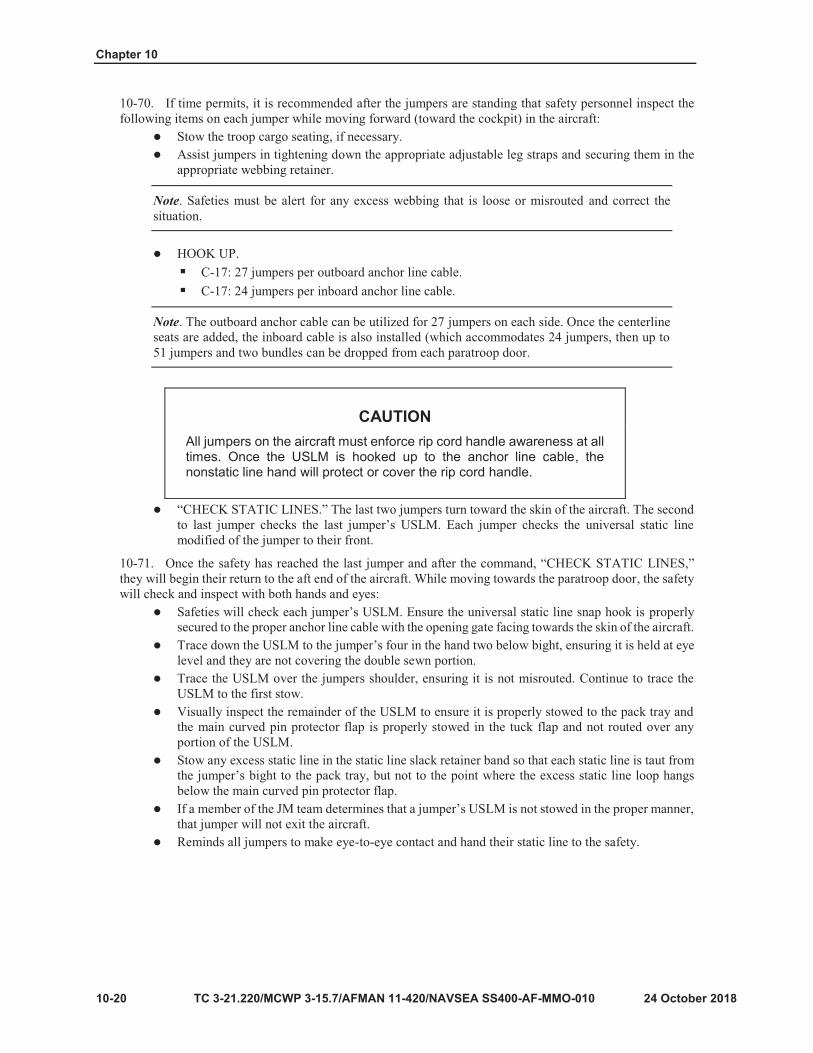
Chapter 10
10-20
Note
Note
CAUTION All jumpers on the aircraft must enforce rip cord handle awareness at all times. Once the USLM is hooked up to the anchor line cable, the nonstatic line hand will protect or cover the rip cord handle.

Jumpmaster and Safety Duties In Flight
10-21
CAUTION All jumpers on the aircraft must enforce rip cord handle awareness at all times. Once the USLM is hooked up to the anchor line cable, the nonstatic line hand will protect or cover the rip cord handle.
Note

Chapter 10
10-22
Note
CAUTIONS All jumpmasters performing duties on a C-17A Globemaster III aircraft must be able to conduct a paratroop door check while maintaining three points of contact with the airframe. This check requires the jumpmaster to attain an 84-inch reach. Jumpmasters must be evaluated by their unit prior to performing any duties on this airframe.
All jumpers on the aircraft must enforce rip cord handle awareness at all times. Once the USLM is hooked up to the anchor line cable, the nonstatic line hand will protect or cover the rip cord handle.
Note

Jumpmaster and Safety Duties In Flight
10-23
Note
WARNING Do not sacrifice safety for time. Complete the full inspection of each jumper’s USLM. If the inspection cannot be completed in time, the pass will be aborted. An improperly routed USLM can cause death or serious injury.
CAUTION The JM or the safety can call a NO DROP anytime they determine something is wrong or unsafe.
Note

Chapter 10
10-24
Note

Jumpmaster and Safety Duties In Flight
10-25
WARNING At no time during Airborne operations should the cargo ramp door be open when the troop doors are open. If this situation exists, all jumpers, including JMs and safety personnel must be seated and strapped in, guarding the rip cord handle of their reserve parachutes. If Army personnel must work around the open troop doors, caution must be taken to prevent personnel from being swept out of the aircraft. Inadvertent reserve activation with troop doors and the cargo door open can cause serious injury or death.
CAUTION Jumpmasters must be prepared to initiate red light procedures at any time after the green light has been illuminated.
Note

Chapter 10
10-26

Jumpmaster and Safety Duties In Flight
10-27
Note
Note

Chapter 10
10-28
Note
Notes
Note
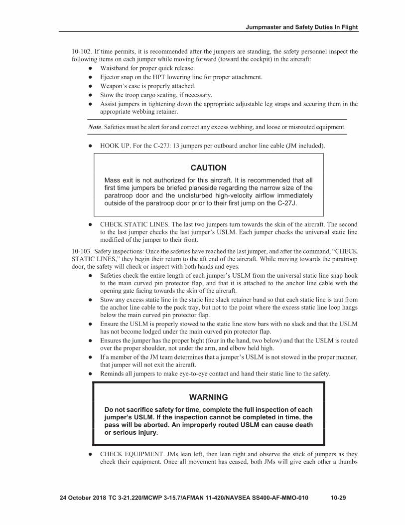
Jumpmaster and Safety Duties In Flight
10-29
Note
CAUTION Mass exit is not authorized for this aircraft. It is recommended that all first time jumpers be briefed planeside regarding the narrow size of the paratroop door and the undisturbed high-velocity airflow immediately outside of the paratroop door prior to their first jump on the C-27J.
WARNING Do not sacrifice safety for time, complete the full inspection of each jumper’s USLM. If the inspection cannot be completed in time, the pass will be aborted. An improperly routed USLM can cause death or serious injury.

Chapter 10
10-30
Note
CAUTION The anchor line cable stop is in line with the trail edge of the jump door. This is different from the C-130, in which the anchor line cable runs further to the aft of the aircraft. The placement of the anchor line cable stop decreases the amount of workspace for the jumpmaster, safety, and jumper.

Jumpmaster and Safety Duties In Flight
TC 3-21.220/MCWP 3-15.7/AFMAN 11-420/NAVSEA-AF-MMO-010 10-31
CAUTION All jumpers on the aircraft must enforce rip cord handle awareness at all times. Once the USLM is hooked up to the anchor line cable, the nonstatic line hand will protect or cover the rip cord handle.
Notes
CAUTION All jumpmasters performing duties on a C-27J Spartan aircraft must be able to conduct a paratroop door check while maintaining three points of contact with the airframe. This check requires the jumpmaster to attain an 80-inch reach. Jumpmasters must be evaluated by their unit prior to performing any duties on this airframe.

Chapter 10
10-32
CAUTION The jumpmaster must be aware that without a wind deflector, the T-11R rip cord handle will be exposed to higher winds than with other fixed-wing aircraft and could cause inadvertent reserve parachute deployment. Minimize unnecessarily exposure of the reserve parachute to relative wind for extended lengths of time.
WARNING At no time will the jumpmaster lock their elbows out during the outside air safety check. Doing so could cause an inadvertent reserve parachute deployment.

Jumpmaster and Safety Duties In Flight
10-33
WARNING Door bundles are not authorized to exit the paratroop doors on a C-27J.
CAUTION The JM or the safety can call a NO DROP anytime they determine something is wrong or unsafe.
Note
Note

Chapter 10
10-34
CAUTIONS Both the jumpmaster and the safety must be prepared to initiate red light procedures at any time after the green light has been illuminated.
Mass exit is not authorized for this aircraft. It is recommended that all first time jumpers be briefed planeside regarding the narrow size of the paratroop door and the undisturbed high-velocity airflow immediately outside of the paratroop door prior to their first jump on the C-27J.

Jumpmaster and Safety Duties In Flight
10-35
Note
.

Chapter 10
10-36
Figure 10-11. AEPB components
Figure 10-12. Cover flaps

Jumpmaster and Safety Duties In Flight
10-37
Figure 10-13. Rip cord pin
Figure 10-14. Right link

Chapter 10
10-38
Figure 10-15. Rip cord housing tacking

Jumpmaster and Safety Duties In Flight
10-39
Figure 10-16. Left link

Chapter 10
10-40
Note
Note

Jumpmaster and Safety Duties in Flight
24 October 2018 TC 3-21.220/MCWP 3-115.7/AFMAN 11-420/NAVSEA SS400-AF-MMO-010 10-41
10-132. During descent, the jumper can use the steering handles located on the back side of the rear risers tomaneuver the parachute in the desired direction of travel to maneuver the canopy and avoid obstacles andother jumpers in the air. Jumpers scheduled to wear the AEBP should rehearse actions under canopy duringSAT. After exiting the aircraft, complete the remaining four points of performance:
Check canopy and gain canopy control.Keep a sharp lookout at all times and constantly compare rates of descent.Prepare to land.Land. Upon landing, the jumper doffs the AEBP system by releasing the three quick-ejector snaps(chest and two leg straps).
10-133. Jumpers must always attempt to avoid mid-air contact by slipping or turning away from fellowjumpers. If unable to avoid a collision, the higher jumper should use the spread-eagle method to bounce offthe lower jumper’s canopy or suspension lines. If an AEBP-equipped jumper enters another jumper’ssuspension lines, the AEBP-equipped jumper immediately assumes the position of attention in hope that theirexit will be the same location without becoming entangled. If not, the AEBP-equipped jumper should followthe emergency procedures for entanglement.
10-134. The AEBP is a steerable canopy with a forward velocity. The AEBP has no reserve canopy. Ifjumpers become entangled, the actions required to correct the problem depend upon the condition of theirmain canopies. If one jumper has a completely inflated canopy, they will hold their positions until they reachthe ground. If both parachutes lose lift capabilities, the jumper with a reserve will use the pull drop methodto activate their reserve parachute. Neither jumper should attempt to climb to the other jumper. Additionally,the higher jumper should avoid the lower jumper when landing. Parachutists scheduled to wear the AEBPshould rehearse collision and entanglement procedures during SAT prejump training.
10-135. If the pilot chute deploys from the pack tray, the JM or safety will immediately attempt to containthe pilot chute. If contained, the AEBP-equipped jumper should remove the parachute and place it inside itskitbag. Jump operations will be on hold until the affected nonjumping JM or safety don a replacementparachute or safety harness. If a replacement parachute or safety harness is not available, the affectedpersonnel should take a seat near the front of the aircraft and the Airborne operation should only be conductedfrom the door with a fully equipped JM team. If the AEBP-equipped jumper is aft of the wheel well, and thejump doors (or ramp) are open and the pilot chute is in or going out the door (or ramp), the jumper shouldimmediately exit the aircraft. Airborne operations will cease if the nonjumping JM or safety conducts anunplanned exit. Jumpers scheduled to wear the AEBP should rehearse canopy activation inside the aircraftduring SAT or at mock door rehearsal.
BA-18 BACK AUTOMATIC PARACHUTE 10-136. The BA-18 U.S. Air Force emergency back automatic parachute is used by nonjumping jumpmastersand safety personnel onboard U.S. Air Force high performance aircraft only. This parachute has a repackcycle of 180 days and must pass a routine inspection at the home unit every 30 days. Once the parachute isactivated, it must be destroyed.
10-137. The BA-18 is equipped with either an FXC Model 7000 or FXC Model 11000 automatic releasesystem (ARS). The owning U.S. Air Force unit’s life support department sets the time-delay release (fromone to 13 seconds) and then attaches a small white tag on the back of the BA-18 to indicate what delay timehas been set (three seconds, four seconds, five seconds, and so on). To employ the BA-18, the jumper eitherpulls the red arming cable knob to activate the time-delay feature, or overrides the ARS by pulling the T- shaped blast handle. Personnel scheduled to wear the BA-18 must inspect it before each use. If they note anydiscrepancies during the inspection, they must not use the parachute. FXC Models 7000 and 11000 cannotbe set on a timer. The U.S. Air Force’s automatic release is a time-delay release.
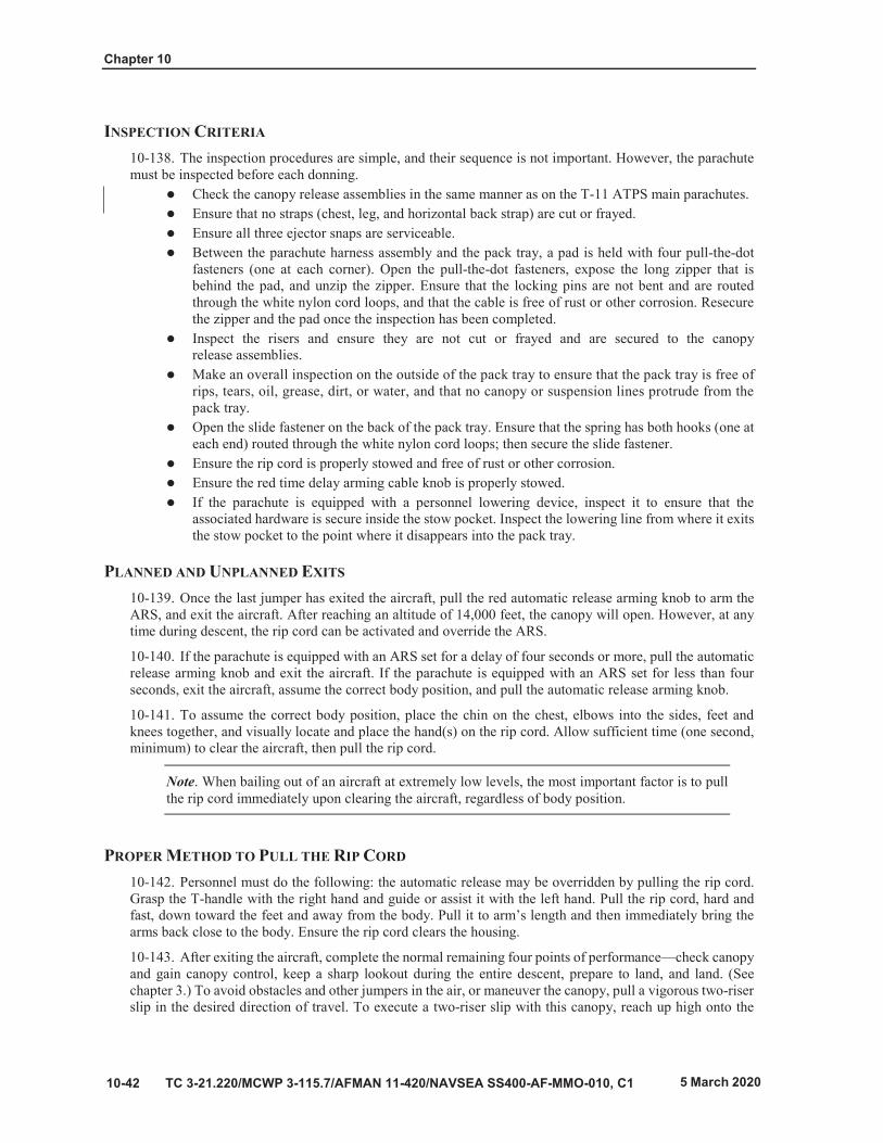
Chapter 10
C 3-21.220/MCWP 3-115.7/AFMAN 11-420/NAVSEA SS400-AF-MMO-010, C1
INSPECTION CRITERIA 10-138. The inspection procedures are simple, and their sequence is not important. However, the parachutemust be inspected before each donning.
Check the canopy release assemblies in the same manner as on the T-11 ATPS main parachutes.Ensure that no straps (chest, leg, and horizontal back strap) are cut or frayed.Ensure all three ejector snaps are serviceable.Between the parachute harness assembly and the pack tray, a pad is held with four pull-the-dotfasteners (one at each corner). Open the pull-the-dot fasteners, expose the long zipper that isbehind the pad, and unzip the zipper. Ensure that the locking pins are not bent and are routedthrough the white nylon cord loops, and that the cable is free of rust or other corrosion. Resecurethe zipper and the pad once the inspection has been completed.Inspect the risers and ensure they are not cut or frayed and are secured to the canopyrelease assemblies.Make an overall inspection on the outside of the pack tray to ensure that the pack tray is free ofrips, tears, oil, grease, dirt, or water, and that no canopy or suspension lines protrude from thepack tray.Open the slide fastener on the back of the pack tray. Ensure that the spring has both hooks (one ateach end) routed through the white nylon cord loops; then secure the slide fastener.Ensure the rip cord is properly stowed and free of rust or other corrosion.Ensure the red time delay arming cable knob is properly stowed.If the parachute is equipped with a personnel lowering device, inspect it to ensure that theassociated hardware is secure inside the stow pocket. Inspect the lowering line from where it exitsthe stow pocket to the point where it disappears into the pack tray.
PLANNED AND UNPLANNED EXITS 10-139. Once the last jumper has exited the aircraft, pull the red automatic release arming knob to arm theARS, and exit the aircraft. After reaching an altitude of 14,000 feet, the canopy will open. However, at anytime during descent, the rip cord can be activated and override the ARS.
10-140. If the parachute is equipped with an ARS set for a delay of four seconds or more, pull the automaticrelease arming knob and exit the aircraft. If the parachute is equipped with an ARS set for less than fourseconds, exit the aircraft, assume the correct body position, and pull the automatic release arming knob.
10-141. To assume the correct body position, place the chin on the chest, elbows into the sides, feet andknees together, and visually locate and place the hand(s) on the rip cord. Allow sufficient time (one second,minimum) to clear the aircraft, then pull the rip cord.
Note. When bailing out of an aircraft at extremely low levels, the most important factor is to pull the rip cord immediately upon clearing the aircraft, regardless of body position.
PROPER METHOD TO PULL THE RIP CORD 10-142. Personnel must do the following: the automatic release may be overridden by pulling the rip cord.Grasp the T-handle with the right hand and guide or assist it with the left hand. Pull the rip cord, hard andfast, down toward the feet and away from the body. Pull it to arm’s length and then immediately bring thearms back close to the body. Ensure the rip cord clears the housing.
10-143. After exiting the aircraft, complete the normal remaining four points of performance—check canopy and gain canopy control, keep a sharp lookout during the entire descent, prepare to land, and land. (Seechapter 3.) To avoid obstacles and other jumpers in the air, or maneuver the canopy, pull a vigorous two-riserslip in the desired direction of travel. To execute a two-riser slip with this canopy, reach up high onto the

Jumpmaster and Safety Duties In Flight
10-43

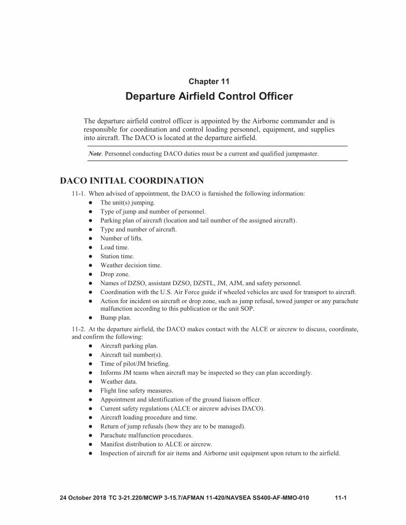
11-1
Chapter 11
Departure Airfield Control Officer
Note

Chapter 11
11-2

12-1
Chapter 12
Individual Combat Equipment Jump Loads
Note

Chapter 12
12-2
Figure 12-1. Advanced combat helmet

12-3
Figure 12-2. ACH pads
Figure 12-3. ACH rear trapezoidal pad
Notes

Chapter 12
12-4
WARNING Seven suspension pads must be present for an Airborne operation. The helmet must be worn with a crown pad to meet the impact protection requirement.
Figure 12-4. ACH adjustable straps

12-5
Figure 12-5. ACH held in place for initial adjustments
Figure 12-6. Back strap adjustment

Chapter 12
12-6
Figure 12-7. Adjust two front straps
Note
Figure 12-8. Front and back adjustable straps
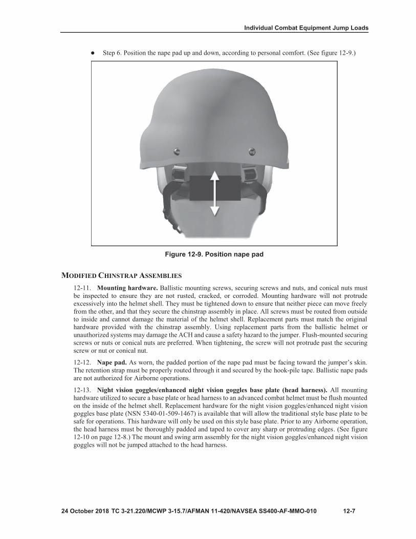
12-7
Figure 12-9. Position nape pad

Chapter 12
12-8
Figure 12-10. Replacement hardware and taping the mounting bracket
WARNING Do not over-tighten the mounting screw on the front bracket. It may break.

12-9
Figure 12-11. Universal shroud
WARNING Individuals are not authorized to drill holes in their helmets.
Figure 12-12. High cut ballistic helmet

Chapter 12
12-10
Figure 12-13. Impact pads and liner
WARNING Do not mix the liner comfort pads with the impact pad system.

12-11
Figure 12-14 Universal parachutist recovery bag

Chapter 12
12-12
Figure 12-15. Universal parachutist recovery bag handles
Figure 12-16. UPRB folds

12-13
Figure 12-17. Proper wear of the UPRB
Figure 12-18. Folded aviator kit bag

Chapter 12
12-14
Figure 12-19. Properly routed and secured leg strap
Figure 12-20. Placement of the M50 inside the MAWC

Individual Combat Equipment Jump Loads
TC 3-21.220/MCWP 3-115.7/AFMAN 11-420/NAVSEA SS400-AF-MMO-010, C1 12-15
IMPROVED OUTER TACTICAL VEST 12-29. The improved outer tactical vest (IOTV) (NSN 8470-01-551-7648 Large) has a side opening thatincreases soft ballistic coverage and adjusts for better comfort. It also has a quick-release handle for Soldiersto instantly remove the vest in emergency situations.12-30. Body armor is bulky, heavy, and can limit the jumper’s flexibility and mobility. Jumpmasters mustsupervise their jumpers when donning parachutes to ensure that IOTV is worn properly, reducing furtherstrain and fatigue. Jumpers may need to adjust their parachute harnesses to a size larger than they commonlywear to accommodate for the size of the body armor.
Note. All IOTV attachments must be removed prior to donning (throat and groin protector, deltoid protectors, upper arm protectors). These components must be placed inside of the ALICE pack or MOLLE. (See figure 12-21.)
CAUTION Airborne commanders must assess risk due to a jumper’s inability to have freedom of maneuver and increased risk of injury during PLF, or when conducting emergency procedures and landings.
12-31. The IOTV can be jumped under the parachute harness of the T-11 with the front and back armorplates installed in the vest. The plates must be properly secured in the carrier pockets to ensure they do notshift and injure the jumper at the chin or back of the head.
Figure 12-21. IOTV worn under T-11 parachute harness 12-32. Some jumpers may require a waistband extension when jumping with the IOTV. This should beconsidered when planning for required air items. To properly secure the waistband extension:
Route the waistband through the metal adjuster on the waistband extension.Route the free running end of the waistband extension through the metal adjuster on the waistbandadjuster panel.Incorporate a two or three finger quick release as normal only into the waistband, not the waistbandextension.Take the free running end of the waistband extension, ensuring it is only routed once through bothmetal bars, and back through the first metal bar forming a non-slip hitch. Jumper will excess handunder hand back against the waistband adjuster panel.

Chapter 12
12-16 TC 3-21.220/MCWP 3-115.7/AFMAN 11-420/NAVSEA SS400-AF-MMO-010M, C1
Finally, use a retainer band to secure the rolled excess along with the waistband adjuster panel.(See figure 12-22.)
Figure 12-22. Waistband extension
JMPI SEQUENCE FOR THE WAISTBAND EXTENSION 12-33. The jumper removes their left hand from behind the reserve and inserts their left index finger andmiddle finger from top to bottom into the quick release formed by the waistband, ensuring it is no more thanthree fingers and no less than two fingers tight, and it is not a false quick release. With their left index fingerand thumb, pinch off the free running end of the waistband where it emerges from the metal adjuster. Tracethe free running end of the waistband until the fingers fall off the end to ensure the waistband is not cut, torn,or frayed, and is easily accessible to the jumper. Continue to trace the waistband extension until makingcontact with the metal adjuster to make certain the waistband extension is not twisted, cut, or frayed, and isnot misrouted.
12-34. The jumpmaster ensures the waistband extension is threaded back through both sides of the metaladjuster, ensuring a positive locking action. The JM also makes sure that any excess webbing is secured witha retainer band. The jumpmaster uses their left hand to grasp the carrying handle of the reserve with theirpalm facing the reserve, and focuses their attention on their right hand and the waistband adjuster panel. Withtheir right hand, the jumpmaster traces the waistband adjuster panel back to where it is sewn into the packtray to ensure that it is not twisted, cut, or frayed. While tracing the waistband adjuster panel, the JM makescertain that the waistband is not misrouted behind the horizontal back strap and that it is properly secured tothe pack tray by a single X box stitch with at least 50 percent of the stitching present. The jumpmaster returnsto the normal JMPI sequence.
TACTICAL ASSAULT PANEL 12-35. The tactical assault panel (TAP) (NSN 8465-01-580-0689) has been fielded to replace the currentMOLLE fighting load carrier. Jumpmasters ensure the TAP system does not interfere with the jumperreacting to any type of emergency. There are two basic rules. First, the reserve parachute rests parallel withthe jumper’s torso. Second, when the TAP system is worn, the items of equipment on the side of the TAPsystem are not resting in front of the horizontal back strap. To properly wear the TAP for Airborne operationsthe jumper must:
Attach the load carrying harness portion of the TAP to the ammunition pouch portion.Don the TAP system ensuring there are no twists in the harnesses webbing and the adjustingbuckles are not cracked or broken, then secure them together.
Note. Any item of equipment or pouch attached to the front of the TAP system that will interfere with the reserve parachute lying parallel to the jumper’s body must be removed.
Remove enough slack from the horizontal back straps of the TAP system so the TAP rests eitherhigh on the jumper’s chest or low enough so it does not interfere with the reserve parachute restingflat against the jumper’s body.Secure the free running ends inside their appropriate webbing retainers.

12-17
Figure 12-23. Harness, single-point release

Chapter 12
12-18
Note

12-19
Figure 12-24. Hook-pile tape lowering line instructions
Figure 12-25. Hook-pile tape lowering line

Chapter 12
12-20
Figure 12-26. Modified hook-pile tape lowering line

12-21
Figure 12-27. Routing equipment retainer straps
Figure 12-28. Friction adapter routing using GEN III MOLLE
Figure 12-29. Attachment of HPTLL to the GEN III MOLLE
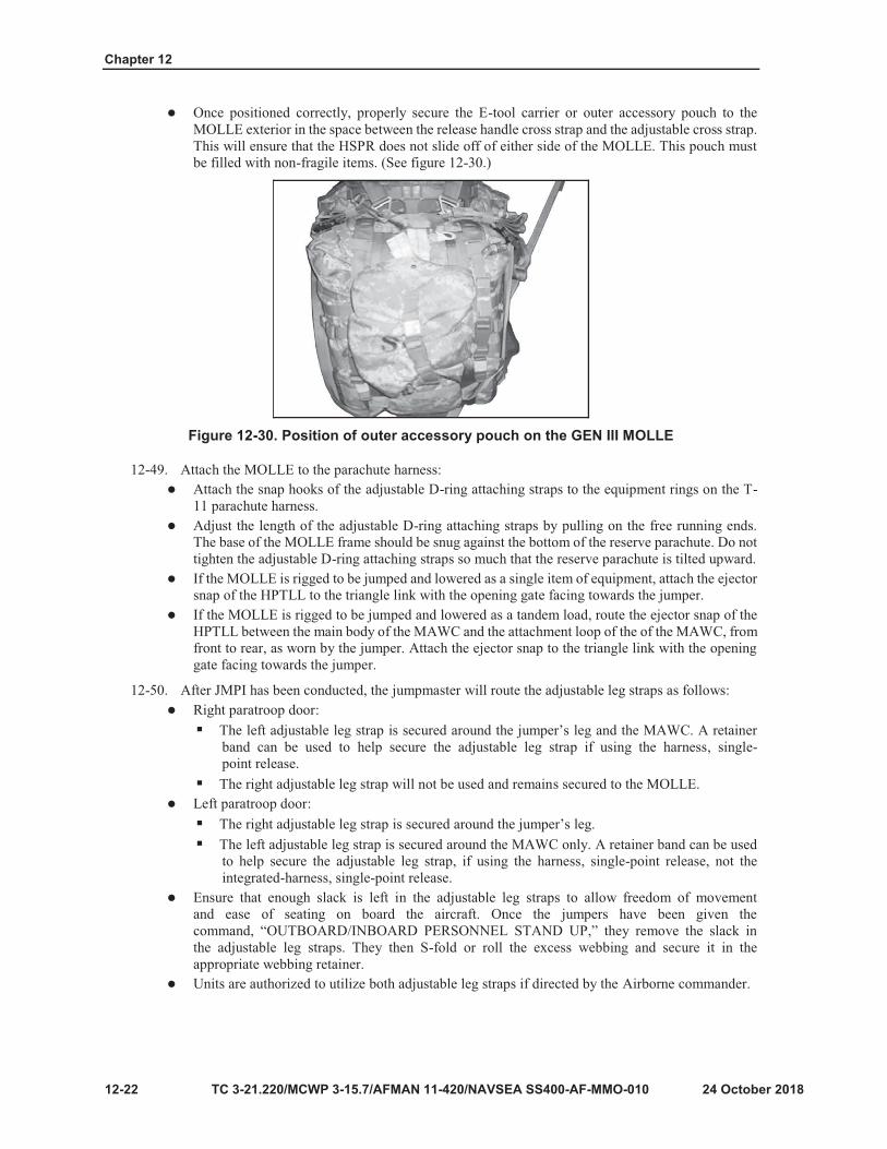
Chapter 12
12-22
Figure 12-30. Position of outer accessory pouch on the GEN III MOLLE

12-23
Figure 12-31. HSPR under envelope cushion portion

Chapter 12
12-24
Figure 12-32. Routed over shoulder carrying straps
Figure 12-33. Placement of retainer band

12-25
Figure 12-34. ALICE pack with HSPR

Chapter 12
12-26

Individual Combat Equipment Jump Loads
24 October 2018 TC 3-21.220/MCWP 3-115.7/AFMAN 11-420/NAVSEA SS400-AF-MMO-010 12-27
Secure the sternum strap in front of the quick releases to hold the shoulder carrying straps in place.(See Figure 12-35.)
Figure 12-35. Sternum strap secured on MAP Readjust the HSPR, if necessary, so the release handle cross strap is directly above the bottom ofthe convenience pouch. Route the compression straps of the convenience pouch over the releasehandle cross strap, but under the release handle cable and not through the release handle lanyard.(See figure 12-36.) Then secure the buckles of the compression straps. This ensures that the HSPRwill not shift along the surface of the MAP.
Figure 12-36. Routing of compression straps over release handle cross strap Cut two pieces of quarter-inch cotton webbing that are approximately 12 inches long. Girth hitchthe quarter-inch cotton webbing to the horizontal nylon equipment hangers on the bottom of theMAP. Use the ones that are closer to the waist strap, not the ones closer to the convenience pouch.Tie the lengths of quarter-inch cotton webbing in a single or double loop bow knot around theHSPR just below the single “X” box stitch. (See figure 12-37.)
Figure 12-37. Securing HSPR with quarter-inch cotton webbing to MAP

Chapter 12
Route the male portion leg strap release assemblies from the point where they are sewn to theequipment retainer straps by the most direct route along the side of the MAP and attach them tothe female portion leg strap release assemblies. Remove the slack and S-fold or roll the excesswebbing and secure it in the webbing retainer. The MAP is attached to the jumper in the samemanner as the ALICE pack and the MOLLE.
MEDIUM MOLLE RUCKSACK (M-MOLLE) 12-60. The M-MOLLE (NSN 8465-01-585-1512) is authorized to be jumped using a HSPR and a HPTLL.Rigging procedures deviate only slightly from the procedures currently used for the MOLLE and HSPR.Anything not mentioned should be rigged according to established procedures for MOLLE. There is norequirement to add an outer accessory pouch, E-tool carrier, or any other similar item to the rear of the M-MOLLE. The rigging procedures for the M-MOLLE are as follows:
Equipment retainer straps will be routed through the carrying handle located at the top of the M-MOLLE and then behind the shoulder carrying straps. (See figure 12-38.)
Figure 12-38. Routing of equipment retainer straps using M-MOLLE Route the friction adapters through oval slots at the base of the MOLLE frame. (See figure 12-39.)Continue rigging the harness, single-point release to the MOLLE as previously described.Reduce and stow the excess webbing of the shoulder carrying straps.Attach the HPTLL as previously described. (See figure 12-39.)
Figure 12-39. Routing of friction adapters using M-MOLLE M7 AND M9 AID BAGS, AND SURGEONS PACK
12-61. The M7 and M9 aid bags are authorized to be jumped using a HSPR and a HPTLL. The M7 and M9can sustain loads ranging from a minimum of 35 pounds to a maximum of 50 pounds. The M7 or the M9cannot be jumped in conjunction with the M50 JSGPM. If the M50 JSGPM must be jumped, it should beplaced inside of the M7. Prior to rigging, all excess webbing must be secured with masking tape, retainerbands, or appropriate webbing retainers. Rigging procedures for the M7 and M9 aid bag are as follows:
Lay out a properly assembled HSPR with the opening gates of the snap hooks facing skyward andremove all twists from the equipment retainer straps.Place the M7 or M9 on top of the HSPR, with the bottom of the M7 or M9 facing towards thefriction adapters.Route the equipment retainer straps under the top carrying handle and then cross them at the backof the M7 or M9 forming an “X” configuration.
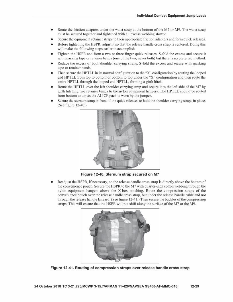
12-29
Figure 12-40. Sternum strap secured on M7
Figure 12-41. Routing of compression straps over release handle cross strap

Chapter 12
12-30
Figure 12-42. Securing HSPR with quarter-inch cotton webbing to M7
Figure 12-43. Surgeon’s pack

12-31
Figure 12-44. Mystery Ranch RATS CAB medical aid bag
Figure 12-45. Securing the waistband/external sustainment pouch
Figure 12-46. Assembled integrated-harness, single point release using the adjustable D-ring attaching straps
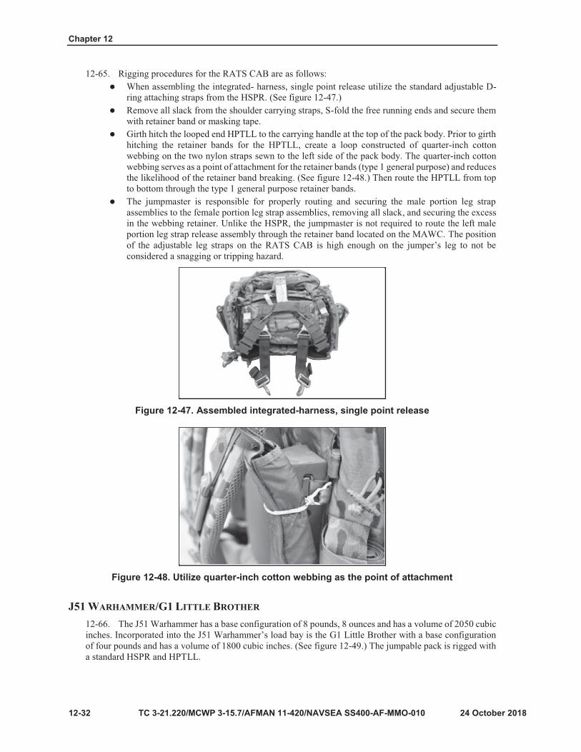
Chapter 12
12-32
Figure 12-47. Assembled integrated-harness, single point release
Figure 12-48. Utilize quarter-inch cotton webbing as the point of attachment

12-33
Figure 12-49. J51 Warhammer backpack
Figure 12-50. Shoulder carrying strap routing on hydration pack

Chapter 12
12-34
Figure 12-51. Attachment of D-ring attaching straps to hydration pack
Figure 12-52. Attachment of HPTLL to hydration pack

12-35
Note
CAUTION Ensure that a round is not chambered and the weapon remains on safe.
Figure 12-53. Padding, taping the M16 rifle or M4 carbine configured for jumping exposed

Chapter 12
12-36
Figure 12-54. M16 rifle or M4 carbine rigged to be jumped exposed

12-37
Note

Chapter 12
12-38
Note
Note

Individual Combat Equipment Jump Loads
24 2018 TC 3-21.220/MCWP 3-115.7/AFMAN 11-420/NAVSEA SS400-AF-MMO-010 12-39
12-84. Adjusting the MAWC to the height of the jumper involves utilizing the adjusting strap:Do not remove the free running end of the adjusting strap from the friction adapter to make anyadjustments to its length.Ensure that after the adjustments are made, the adjusting strap is secured inside the horizontalnylon equipment hangers, leaving enough free for the snap shackle to reach the left equipmentring (approximately one-to-two inches).The free running end is secured in one of two ways: secured underneath the horizontal nylonequipment hangers (not preferred) or a retainer band can be girth hitched to the horizontal nylonequipment hanger located just above the friction adapter.The free running end can then be rolled or S-folded and secured with the retainer band. This is thepreferred method for securing the excess.
Note. Prior to rigging the MAWC, a retainer band can be girth hitched to the horizontal nylon equipment hanger just above the friction adapter of the adjusting strap. A retainer band can also be girth hitched to the vertical nylon equipment hanger below the lower tie-down strap stow pocket to secure the adjustable leg strap.
12-85. After the MAWC has been properly adjusted to the height of the jumper resecure the snap shackleto the left equipment ring:
Secure the yellow safety lanyard to one of the three male portion snap fasteners.Using the top snap fastener is not recommended in order to ensure proper placement of theMAWC.The top of the MAWC must rest between the chest strap and below the jumper’s arm pit andthe base of the nose cone will rest no less than six inches from the ground.
Utilize the snap fastener that will provide the most slack in the yellow safety lanyard.Secure the tab thong by both the snap fastener and the upper tie-down tape. Route the upper tie- down tape through the tab thong, then around the pack body, and secure it to the lead edge with asingle or double loop bow knot.When worn by the jumper, route the upper tie-down tape through the small cut away portion ofthe left equipment ring from rear to front or bottom to top, then secure it to the lead edge of theMAWC with a single or double loop bow knot. Regardless of how the tab thong is being secured,the upper tie-down tape is routed and secured in this manner. (See figure 12-55.)
Figure 12-55. Routing the upper tie-down tape The ejector snap of the HPTLL is routed from front to rear as worn by the jumper, through theattachment loop, and secured to the triangle link or the equipment ring as the outer-most item ofequipment.

Chapter 12
12-86. When the MAWC is rigged to be jumped as a single item of equipment, do the following:Secure an HPTLL in its normal configuration.Girth hitch the looped end HPTLL to the attachment loop.Girth hitch two retainer bands to the horizontal nylon equipment hangers located beside thecarrying handle so they are evenly spaced along the retainer flap.Route the HPTLL from bottom to top through the retainer bands. (See figure 12-56.)
Figure 12-56. Attachment of HPTLL to the MAWC
CREW-SERVED WEAPONS/M3 MAAWS 12-87. The M240B or M240L, M192 LWGM, spare barrel bag, and M3 MAAWS fit into the large MAWCand the M240B can be rigged inside the large MAWC when assembled. Place the barrel underneath the foampadded internal divider, under the nose cone divider, and near the slider fastener. Secure the barrel by girthhitching quarter-inch cotton webbing to the PALs in two places and secure it using a bow knot. The M3MAAWS can be rigged in large MAWC or AT-4JP. Also:
M240L can be rigged in the MAWC with short barrel attached.Spare barrel bag and M4 should be rigged inside the MAWC together.Place the spare barrel bag under the foam padded internal divider and separate the M4 with thefoam padded internal divider.
12-88. Rigging of machine gun tripods and spare barrel bag under the closing flap of a jumpable pack.Rigging the M122 tripod Includes:
Detach the flex mount and traverse and elevation (T&E) mechanism.Pad and tape these items with bubble wrap and masking tape.The flex mount and T&E mechanism must be placed inside the main compartment of the jumpablepack.Fold the M122 tripod’s short leg down and secure it with a sufficient length of quarter-inch cottonwebbing in a single or double looped bow knot. If jumping the M122 tripod inside the spare barrelbag, the short leg does not need to be tied off. (See figure 12-60.)
Figure 12-60. Place M122 tripod under closing flap of MOLLE pack

Individual Combat Equipment Jump Loads
TC 3-21.220/MCWP 3-115.7/AFMAN 11-420/NAVSEA SS400-AF-MMO-010, C1 12-41
12-89. To rig the M122 in a jumpable pack, place the M122 tripod directly beneath the closing flap withthe short leg facing down into the main compartment of the jumpable pack.
12-90. The M192 LWGM can be jumped under the closing flap of a jumpable pack or the MAWC. To do this:Place the M192 LWGM into its collapsed carrying configuration and tie the legs together with asufficient length of quarter-inch cotton webbing in a non-slip knot.Tape all retaining pin pull rings using one turn of masking tape.Pad the incorporated T&E mechanism with two turns of bubble wrap and secure with maskingtape.Pad the entire hinge portion in the same manner as the T&E mechanism. By doing this, the leg- locking stud will be protected from impact, allowing the M192 LWGM to extend into its full firingposition.Place the M192 LWGM directly under the closing flap of the jumpable pack with the bulk of theT&E facing down towards the main compartment.Secure the closing flap, removing all slack. (See figure 12-61.)Secure the exposed portion of the legs to the horizontal equipment hangars on the side of thejumpable pack with a sufficient length of quarter-inch cotton webbing using a single or doublelooped bow knot.
Figure 12-61. Place M192 LWGM in main compartment of MOLLE 12-91. To rig the spare barrel bag:
Place the spare barrel bag directly under the closing flap of the jumpable pack.Then secure the closing flap, removing all slack.
12-92. The 60-mm mortar weapon system (M225 and the M225A1 cannon) are rigged inside the MAWC.The M4 and M225 cannon are also rigged inside the MAWC. The M170 bipod (older model) is rigged insidethe MAWC with the M4 secured in the locking collar.
Pad and tape the points where there is metal-to-metal contact.Ensure the muzzle of the weapon and the long legs of the bipod are inside the nose cone.The M170A1 bipod assembly must be rigged inside the large MAWC with the M4 following thesame rigging procedures as the M170 bipod (See figure 12-62, page 12-42.)

Chapter 12
12-42 TC 3-21.220/MCWP 3-115.7/AFMAN 11-420/NAVSEA SS400-AF-MMO-010M, C1
Figure 12-62. M170A1 components and M170A1 and M4 inside the large MAWC
WEAPONS AND EQUIPMENT CONTAINER SYSTEM 12-93. The AIRPAC (NSN 1670-01-414-2757) is a lightweight nylon equipment pack system used toenclose a jump load. The AIRPAC front-mount container can accommodate all size packs, radios, and 60-mm mortar with base plate or bipod. The side-mount container can hold one AT4, M4, M24, M249, M240Bmachine gun, and other ancillary equipment.
12-94. The AIRPAC consists of the front-mount container, the side-mount container, and the parachutist'sindividual equipment rapid release (PIE/R2) mechanism. Loads in the front-mount container are riggedaccording to the equipment used.
RIGGING JUMPABLE PACKS 12-95. Jumpable packs are rigged in the following manner:
Extend all retaining straps outward to their limits. (The retainer strap with the circular closing flapis the top of the container.)Place the container so that the retaining straps face the ground and the parachute recovery bagfaces up.Fold the parachute recovery bag so that no portions protrude outside the container limits.Place the pack on the parachute recovery bag and ensure the circular release rings on the bottomof the container are not constrained by the pack. The jumpable pack is jumped upside down, withthe waist pad against the front of the thighs.Bring the right side of the container material up first, then the left side and the bottom flap, andthen the top flap.Place the circular closing flap on top of the pack and open the circular closing flap by pulling thetab.Bring the left, right, and bottom retaining straps to the center of the circular closing flap and routethe white grommet securing loop through each grommet of the retaining straps. No specific orderis required. Bring the top flap material up last. Place the cotter pin through the white grommetsecuring loop.Tighten all retaining straps, ensuring that the circular closing flap remains centered on thejumpable pack. Adjust the protective flaps to stow excess fabric. Close the circular closing flapusing three hook-pile tabs.Underhand fold the free running ends of the retaining straps toward the friction adapters and secure them under the webbing retainers.
Note. The circular release rings should be exposed on the top flap of the front-mount container. If the rigged pack is above the rings and restricts movement of the rings, the load must be adjusted.

Individual Combat Equipment Jump Loads
TC 3-21.220/MCWP 3-115.7/AFMAN 11-420/NAVSEA SS400-AF-MMO-010, C1 12-43
RIGGING RELEASE MECHANISM OF FRONT-MOUNTED CONTAINER 12-96. To rig the front-mount container release mechanism, use these procedures:
Stand the rigged pack in an upright position with the bottom of the AIRPAC facing the jumper.Route release handle cables through the cross strap on top of the container and secure the HPT.With the attaching strap snap hook facing down and towards the jumper, route the circular ring ofthe attaching strap from bottom to top through the circular release ring on top of the container.Fold the circular ring of the attaching strap back over and route the red attaching loop through theattaching ring on the attaching strap.With the cable loop retainer on the female portion of the leg strap release assembly facing up,route the red attaching loop from bottom to top through the grommet on the female portion of theleg strap release assembly. Route the release handle cable through the red attaching loop and thenthrough the cable loop retainer. Repeat this sequence for the other strap.
RIGGING HOOK-PILE TAPE LOWERING LINE 12-97. The HPTLL is rigged by taking the following actions:
Select the desired landing orientation of the front-mount container (horizontally or vertically) andattach the short bridle to the appropriate triangle link.Route the looped end of the HPTLL through the unsewn portion of the short bridle and form agirth hitch. Place a retainer band around the nylon tab located inside the closure flaps. Route theHPTLL through the retainer band and stow in the retention pocket. Secure the HPT.For transportation, attach the ejector snap to the primary short bridle triangle link.
RIGGING LOAD FOR SIDE-MOUNT CONTAINER Place the side-mount container on the ground with the friction adapters facing down and the freerunning ends of the internal securing strap to the right.Then position packing material flush with the bottom edge of the fabric flaps and place the weapon on the container in the following orientation. (See table 12-1.)
Table 12-1. Weapon orientation and packing material required for side mount container
WEAPON PACKED ORIENTATION PACKING MATERIAL
M240B MG/SAW Muzzle up None required
AT4 Muzzle up One piece honeycomb on bottom
60-mm mortar Muzzle down One piece of six by six-inch honeycomb on bottom
LEGEND MG – machine gun; mm – millimeter; SAW – squad automatic weapon
Tape and pad exposed or protruding parts (such as sight posts, grip stocks, or bipods) with a softmaterial such as bubble wrap or an adequate substitute.Center load on the internal securing strap and pull the lower fabric flap over packing material.Route free running end of the internal securing strap through the friction adapter on the lowerfabric cap. Place floating V-ring of internal securing strap on the top-center of the load. Form afive-to six-inch quick release in the strap and tighten. From the top, fold excess weapon’s container material downward until flush with the top of the load.Wrap unpadded fabric flap over weapon. Bring padded fabric flap over load and loosely securecontainer retaining straps to friction adapters; form a five-to six-inch quick release in the strap. Donot tighten the strap.

Chapter 12
12-44 TC 3-21.220/MCWP 3-115.7/AFMAN 11-420/NAVSEA SS400-AF-MMO-010M, C1
Note. If jumping an individual weapon, place the weapon muzzle down in the container slide fastener compartment. Secure the slide fastener.
Tighten the container retaining straps (with quick releases). S-fold excess webbing and secure tothe quick-release loop with two turns of a retainer band, leaving a three-inch tail. Securedrawstring on top of the container with a quick-release knot, if necessary.
RIGGING AIRPAC AS TANDEM LOAD HOOK-PILE TAPE LOWERING LINE 12-98. The AIRPAC is rigged as a tandem load with HPTLL by taking the following actions:
If the HPTLL is attached to the front-mount container, detach and place to the side. Using theextended bridle, place the looped end through unsewn portion of short bridle and secure with agirth hitch. Route looped end of HPTLL through the floating V-ring of the extended bridle andform a girth hitch.Stow the HPTLL in the retention pocket. Stow extended bridle excess in the retention pocket,allowing for a two-foot running end. Secure the retention pocket and attach the ejector snap of theHPTLL to the triangle link.After the side-mount container is attached to the jumper, the extended bridle snap hook is attachedto the V-ring on the top of the side-mount container.
AIRPAC ATTACHED TO JUMPER 12-99. The AIRPAC is attached to jumper using the PIE/R2 mechanism as follows:
Place the front-mount container attaching straps under the reserve parachute and attach the front- mount container snap hooks to the equipment-rings (same as a single-point release system).Attach the HPTLL ejector snap to the left triangle link on the jumper’s harness.
Note. When using the PIE/R2 mechanism, ensure the harness has a lowering line adapter web or new harness triangle link.
Attach the PIE/R2 mechanism to the side-mount container located on jumper’s left side by placingthe hook portion of the snap shackle with the hook through the quick-release link from top tobottom. The spring-loaded gate should face away from the container. Remember to hook the gatetoward jumper’s groin muscle.Open the snap shackle with hook, attach to the equipment ring on the outside of the attaching strapsnap hook from back to front, and close the snap shackle.Take the extended bridle snap hook and attach to the floating V-ring on top of the side container.Secure extended bridle under the retention flap on container.On the PIE/R2 mechanism, route the upper tie-down tape around the side-mount container. Routethe upper tie-down tape through the D-ring from bottom to top. Tie the upper tie-down tapeutilizing a bow knot on the lead edge of the side-mount container. With the orange release handlefacing forward on the side-mount container, route the grommet tab through the looped end of theupper attachment strap, over the red attaching loop, and secure with cable. Tighten the upper strap,ensuring that the orange release handle stays on the front portion of the side-mount container.Connect the white release lanyard snap hook to the short bridle, attaching the V-ring on the top ofthe front-mount container. Listen for a metallic click and pull to ensure the snap hook is secure.Attach the leg straps, ensuring the left leg strap is also routed around the side container. Tightenand secure. Stow excess webbing under webbing retainers.
LIFE PRESERVERS 12-100. Jumpers wear life preservers whenever a flight is conducted over water, a water obstacle is on theDZ, or the intended DZ is close to a water obstacle (refer to appendix D). A water obstacle is any body of

Individual Combat Equipment Jump Loads
TC 3-21.220/MCWP 3-115.7/AFMAN 11-420/NAVSEA SS400-AF-MMO-010, C1 12-45
water (for example, a lake, pond, river, stream, or canal) that has a depth of four feet or more, is 40 feet wide or wider, and is located within 1000 meters of any edge of the surveyed or tactically assessed DZ. The tactical flotation support system (TFSS), B-7, B-5, life preserver unit (LPU) 10/P, and life preserver inflatable (NSN 4220 00 6892 9050) are currently certified for use by jumpers. Other life preservers may be used if approved by the individual service components. When jumping life preservers, all jumpers must review rigging and activating procedures prior to executing the Airborne operation.
12-101. The TFSS-5326 (NSN 4220-01-524-5318) is a life-saving product designed to be fastened to anindividual’s waist belt. This product uses two separate flotation bladders located in two separate pouches.Each pouch contains a manually-operated firing mechanism and a carbon dioxide (CO2) gas cylinder thatinflates the flotation bladders. (See figure 12-63.) The TFSS-5326 is intended for use with the T-11 and MC-6 personnel parachute systems.
Figure 12-63. TFSS 5326 fastened to a Soldier’s waist belt

Chapter 12
12-46 TC 3-21.220/MCWP 3-115.7/AFMAN 11-420/NAVSEA SS400-AF-MMO-010M, C1
WARNING The jumper must ensure they do not wear the TFSS-5326 flotation packets between the parachute harness and their body. Serious injury may result if inflated when worn incorrectly.
CAUTION The CO2 cartridge cover does not extend the entire length of the CO2 cartridge cylinder, posing a potential for a cold burn to unprotected skin (frost bite burn) when the cartridge is activated. To mitigate this risk, jumpers must ensure the TFSS-5326 mounting belt is worn tightly around their waist to limit CO2 cartridge movement, and ensure there is a layer of clothing between the CO2 cartridge and the parachutist’s skin.
12-102. A secondary method of inflation for the TFSS-5326 is provided by left and right oral inflation tubes.A “red” bead (see figure 12-64) identifies the right side pouch as worn by the jumper.
Figure 12-64. Left and right TFSS 5326 pouches 12-103. The flotation bladder’s shape allows the inflated chamber to support the person under the arms.Both chambers are intended to inflate to provide buoyancy in the water. (See figure 12-65.) The pouches aremade of durable canvas weave fabric with nylon tape and a grommet, loop, and pin closure system. Theflotation bladders are welded black (covert) or yellow (overt) with 200 denier nylon-coated polyurethanereflective tape.

Individual Combat Equipment Jump Loads
TC 3-21.220/MCWP 3-115.7/AFMAN 11-420/NAVSEA SS400-AF-MMO-010, C1 12-47
Figure 12-65. Inflated chamber to support the person under the arms
LIFE PRESERVER UNIT 10/P 12-104. The life preserver unit 10/P (NSN 4220-00-850-8655) is a standard U.S. Air Force CO2 cartridge- activated life preserver assembly worn during flights over water, or during airdrops when water obstacles arenear (or on) the intended DZ. The LPU 10/P has an adjustable harness and underarm inflation bladders. It isdesigned to keep the wearer’s head above water at weights up to 250 pounds for up to 10 minutes. The LPU10/P must be maintained in compliance with the U.S. Air Force.
12-105. The LPU 10/P is worn under the parachute harness. The harness is worn so that the inflatable pocketsare under the jumper’s arms. The manual inflating valves should be completely closed when donning the lifevest. The shoulder and waist straps are then adjusted to ensure the inflation container is one hand widthbeneath the armpit and not constrained by the parachute harness.
WARNING The inflation wings must be one hand width beneath the jumper’s armpits and clear of the harness straps. If the inflation pockets are too snug under the armpit, or if they are between the harness and the jumper’s body, the jumper can experience severe pain or crushed ribs during inflation.
12-106. The jumper inflates the LPU 10/P flotation bladders by pulling two toggle cords (at the bottom ofthe vest) which activate the CO2 cartridges that fill the bladders with gas. An alternate provision for inflatingthe vest is by blowing into the manual inflation valve rubber hoses located on the bottom side of the wings.Manual inflation should be used only if the CO2 inflation valves fail to operate.
B-7 LIFE PRESERVER
12-107. The B-7 LPU (NSN 4220-00-657-2197) is worn under the parachute harness. To fit the B-7 lifepreserver, the jumper places one flotation packet under each arm so the packet flaps face out, and the togglecords hang down and to the front. The shoulder strap should run from front to rear over the left shoulder,under the back strap, then from rear to front over the right shoulder, and be attached to the ring on the rightflotation packet. Then adjust the shoulder strap so the flotation packets fit snugly against the armpits.The jumper then attaches the chest strap to the attachment rings on the left flotation packet, forminga quick release.

Chapter 12
12-48 TC 3-21.220/MCWP 3-115.7/AFMAN 11-420/NAVSEA SS400-AF-MMO-010M, C1
WARNING Ensure that the B-7 life preserver is worn so that the inflatable portion is not between the parachute harness and the body. Serious injury may result if it is in this position when inflated.

12-49
Figure 12-63. TFSS 5326 fastened to a Soldier’s waist belt
WARNING The jumper must ensure they do not wear the TFSS-5326 flotation packets between the parachute harness and their body. Serious injury may result if inflated when worn incorrectly.
CAUTION The CO2 cartridge cover does not extend the entire length of the CO2 cartridge cylinder, posing a potential for a cold burn to unprotected skin (frost bite burn) when the cartridge is activated. To mitigate this risk, jumpers must ensure the TFSS-5326 mounting belt is worn tightly around their waist to limit CO2 cartridge movement, and ensure there is a layer of clothing between the CO2 cartridge and the parachutist’s skin.

Chapter 12
12-50
Figure 12-64. Left and right TFSS 5326 pouches
Figure 12-65. Inflated chamber to support the person under the arms

12-51
WARNING The inflation wings must be one hand width beneath the jumper’s armpits and clear of the harness straps. If the inflation pockets are too snug under the armpit, or if they are between the harness and the jumper’s body, the jumper can experience severe pain or crushed ribs during inflation.
WARNING Ensure that the B-7 life preserver is worn so that the inflatable portion is not between the parachute harness and the body. Serious injury may result if it is in this position when inflated.


13-1
Chapter 13
Arctic Rigging

Chapter 13
13-2
Figure 13-1. Types of authorized gloves
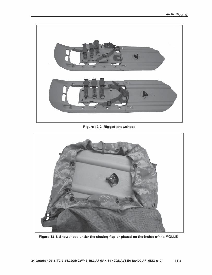
Arctic Rigging
13-3
Figure 13-2. Rigged snowshoes
Figure 13-3. Snowshoes under the closing flap or placed on the inside of the MOLLE I

Chapter 13
13-4
Figure 13-4. Snowshoes under the closing flap or placed on the inside of the ALICE
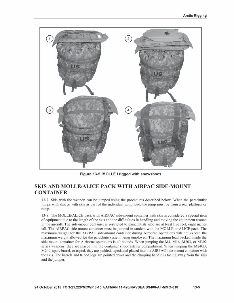
Arctic Rigging
13-5
Figure 13-5. MOLLE I rigged with snowshoes

Chapter 13
13-6
Figure 13-6. Placement of friction adaptors

Arctic Rigging
13-7
Figure 13-7. Ski placement when jumping

Chapter 13
13-8
Figure 13-8. Placement of internal securing strap

Arctic Rigging
13-9
Figure 13-9. Folding excess weapons container material

Chapter 13
13-10
Figure 13-10. Placement of weapon in container

Arctic Rigging
13-11
Figure 13-11. Container with a quick-release knot

Chapter 13
13-12
Figure 13-12. Jumper with side-mount container and tandem load
Note

Arctic Rigging
13-13
Note


14-1
Chapter 14
A-Series Containers

Chapter 14
14-2
Note
Table 14-1. Example for how to determine minimum allowable weight
EXAMPLE:Height (without parachute) 27 inchesLength 44 inchesWidth 21 inches
44 inches X 27 inches = 1188 square inches1188 ÷ 144 = 8.25 square feet
RAMP8.25 X 28 = 231 pounds231 pounds (without parachute) for ramp operations
DOOR8.25 X 11 = 90.75 poundsThe minimum allowable weight for this container is90.75 pounds (without parachute) for door operations.

14-3
WARNING The A-series container with a T-10 modified cargo parachute can support 500 pounds. It is recommended a thorough assessment is conducted before configuring the A-series container at maximum capacity.
Figure 14-1. A-7A straps

Chapter 14
14-4
Figure 14-2. Two-strap load positioned and secured

14-5
Figure 14-3. Three-strap load positioned and secured
Note

Chapter 14
14-6
Figure 14-4. Four-strap load positioned and secured
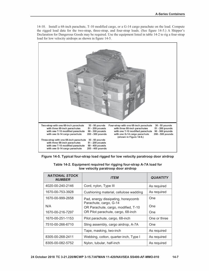
14-7
Figure 14-5. Typical four-strap load rigged for low velocity paratroop door airdrop
Table 14-2. Equipment required for rigging four-strap A-7A load for low velocity paratroop door airdrop
NATIONAL STOCK NUMBER ITEM QUANTITY
4020-00-240-2146 Cord, nylon, Type III As required
1670-00-753-3928 Cushioning material, cellulose wadding As required
1670-00-999-2658
N/A
1670-00-216-7297
Pad, energy dissipating, honeycomb Parachute, cargo, G-14OR Parachute, cargo, modified, T-10OR Pilot parachute, cargo, 68-inch
One
One
One
1670-00-251-1153 Pilot parachute, cargo, 68-inch One or three
7510-00-266-6710 Sling assembly, cargo airdrop, A-7A One
Tape, masking, two-inch As required
8305-00-268-2411 Webbing, cotton, quarter-inch, Type I As required
8305-00-082-5752 Nylon, tubular, half-inch As required

Chapter 14
14-8
Note
Figure 14-6. Container and load positioned

14-9
Note
Figure 14-7. Container rigged
Note

Chapter 14
14-10
Figure 14-8. Container rigged (continued)

14-11
Figure 14-9. Container load rigged for low-velocity paratroop door airdrop
RIGGING LOAD DATA (WITHOUT PARACHUTE)G-14 cargo parachute……………………200 to 500 pounds
T-10 modified cargo parachute…………200 to 500 pounds
Table 14-3. Equipment required for rigging the A-21 container load for low velocity paratroop door airdrop
NATIONAL STOCK NUMBER ITEM QUANTITY
1670-00-242-9173 Bag, cargo, A-2 One
8135-00-664-6958 Cushioning material, packaging, cellulose wadding As required
1670-00-753-3928 Pad, energy-dissipation material, honeycomb As required
1670-00-999-2658
N/A
Parachute, cargo, high-velocity, G-14
OR Parachute, cargo, modified, T-10
One
One
8305-00-268-2411 Webbing, cotton, quarter-inch, Type I As required

Chapter 14
14-12
CAUTION During mock door training, if door bundles are to be exited, the No. 1 jumper must also be present along with a replica of the container to simulate the required procedures.

TC 3-21.220/MCWP 3-115.7/AFMAN 11-420/NAVSEA SS400-AF-MMO-010, C1 15-1
PART THREE
Aircraft A proficient jumpmaster must first be familiar with the aircraft being utilized. Each aircraft has its own characteristics, and all JMs must become familiar with each of the characteristics of those aircraft.
Chapter 15
Aircraft Types and Jump Altitudes
This chapter contains general aircraft descriptions and aircraft drop altitudes. These are critical elements of Airborne. Aircraft are service-tested and approved for troop jumping. Minimum jump altitudes and considerations that apply to Basic Airborne School, tactical, and combat jumps are discussed in the material that follows.
AIRCRAFT TYPES 15-1. High-performance aircraft and utility rotary-wing aircraft are the most commonly-used types ofaircraft for Airborne operations. Characteristics of these aircraft are:
High-performance aircraft are defined as a fixed-wing aircraft with a drop speed of 125 knots orgreater. They have the ability to determine the airdrop release point (CARP) by a member of theaircrew (navigator) and must be able to exit paratroopers out of a troop door using either ADEPToption two or Mass Exit procedures. (Refer to chapter 19 for nonstandard jump aircraft.)The UH-1 series, UH-60 series, CH-47, CH-53 (USMC) are the most commonly-used rotary-wingaircraft for troop airdrops.
JUMP ALTITUDES 15-2. The minimum criteria discussed below include a 125-foot aircraft altimeter error and a 100-foot canopycontrol requirement for the MC-6. The minimum jump altitudes for all aircraft are described below and intable 15-1 on page 15-2.
15-3. Refer to table 15-1 on page 15-2 for peacetime training. The jump altitudes for basic Airborne trainingare as follows:
1250 feet AGL (T-11).1000 feet AGL with a waiver from the Airborne Ranger Training Brigade commander.
15-4. For tactical training, it is 800 feet AGL for the MC-6 and T-11. Aircraft with a drop speed of less than90 knots it is 1500 feet AGL.

Chapter 15
15-2 TC 3-21.220/MCWP 3-115.7/AFMAN 11-420/NAVSEA SS400-AF-MMO-010 24 October 2018
CAUTION The T-11 parachute should not be jumped above 1250 feet AGL for high performance aircraft. Due to the drift characteristics of the parachute, the jumper may drift off of the surveyed drop zone.
15-5. Combat (wartime) drop speeds are restricted to rotary-winged aircraft with a minimum drop speed of90 knots per hour, For drop speeds above 90 knots, the following applies:
600-feet AGL – T-11.600-feet AGL – MC-6.
CAUTION T-11 may be used for rotary-winged operations if justified by a commanddeliberate risk assessment worksheet.
15-6. . For fixed-wing aircraft with a drop speed greater than 125 knots per hour, the following applies forthe T-11 and MC-6:
550 feet AGL (C-130) and 525 feet AGL (C-17) – T-11 (fixed-wing only).475 feet AGL – MC-6.Minimum airspeed is 125 knots.Reserve parachute is optional (combat operations).
Table 15-1. Minimum jump altitudes for all aircraft
TACTICAL STATUS
AIRCRAFT TYPE APPLICATION
FEET AGL
T-11 MC-6
Peacetime Fixed wing Basic Airborne training 1250 N/A
Fixed wing1 Tactical training 8001 8001
Rotary wing Aircraft with a drop speed less than 90 knots 15003 1500
Rotary wing Aircraft with a drop speed more than 90 knots 12503 1250
Combat (Wartime) Rotary wing Aircraft with a drop speed more
than 90 knots 6003 600
Fixed wing2 Aircraft with a drop speed more than 125 knots
550 C-130 525 C-17 475
LEGEND 1 - 800 feet AGL drop altitude may raise the risk level based on jumper’s proficiency and command experience. 2 - Reserve parachute optional. 3 - T-11 may be used for rotary-wing operations if justified by a command deliberate risk assessment worksheet. Due to the drift characteristics of the parachute, the jumper may drift off of the surveyed drop zone. AGL – above ground level; N/A – not applicable

15-3
Table 15-2. Time available to activate reserve parachute
PLANNED ALTITUDE
(FEET AGL)
POSSIBLE AIRCRAFT
ALTIMETER ERROR (FEET)
ACTUAL JUMP ALTITUDE
FEET (AGL)
TOTAL TIME AVAILABLE TO
ACTIVATE RESERVE
(SECONDS)
TIME AVAILABLE MINUS 6000-
COUNT (SECONDS)
1250 +/-125
137512501125
9.48.88.2
5.44.84.2
1000 +/-125
11251000875
8.27.66.9
4.23.62.9
800 +/-125
925800675
7.16.45.6
3.12.41.6
LEGEND+/- - plus or minus; AGL - above ground level
CAUTION The T-11 ATPS meets the operational requirements for use at altitudes of 7500 feet MSL and below. The T-11 ATPS has not been tested above 7500 feet MSL, therefore a deliberate risk assessment must reflect using the T-11 ATPS at altitudes above 7500 feet MSL. Jumpers will experience increased opening shocks and faster rates of descent.


16-1
Chapter 16
High-Performance Aircraft
Table 16-1. C-130 E/H/J
CONFIGURATION JUMPER LOAD
TAP-1 mass drop 62 + two safeties
A*TAP-1 with aircraft armor 48 + two safeties
TAP-2 in-flight rigging 52 + two safeties
A*TAP-2 with aircraft armor 38 + two safeties
TAP-3 over the ramp operations 40 + two safeties
A*TAP-3 with aircraft armor 30 + two safeties
LEGENDA*TAP – tactical airdrop paratroop with armor; TAP – tactical airdrop paratroop
Table 16-2. C-130-J-30 (stretch)
CONFIGURATION JUMPER LOAD
TAP-1 mass drop 74 + two safeties
A*TAP-1 with aircraft armor 68 + two safeties
TAP-2 in-flight rigging 74 + two safeties
A*TAP-2 with aircraft armor 64 + two safeties
TAP-3 over the ramp operations 54 + two safeties
A*TAP-3 with aircraft armor 44 + two safeties
LEGENDA*TAP – tactical airdrop paratroop with armor; TAP – tactical airdrop paratroop
Note
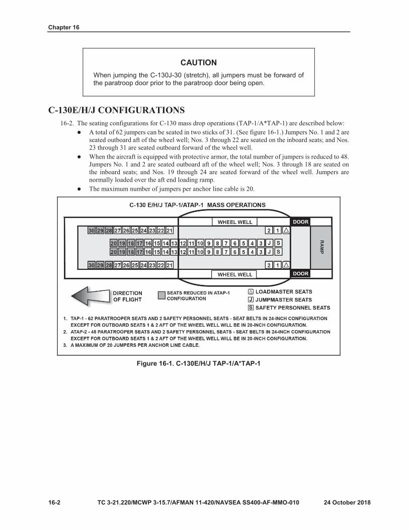
Chapter 16
16-2
CAUTION When jumping the C-130J-30 (stretch), all jumpers must be forward of the paratroop door prior to the paratroop door being open.
Figure 16-1. C-130E/H/J TAP-1/A*TAP-1

High Performance Aircraft
16-3
Figure 16-2. C-130J-30 configurations
Note
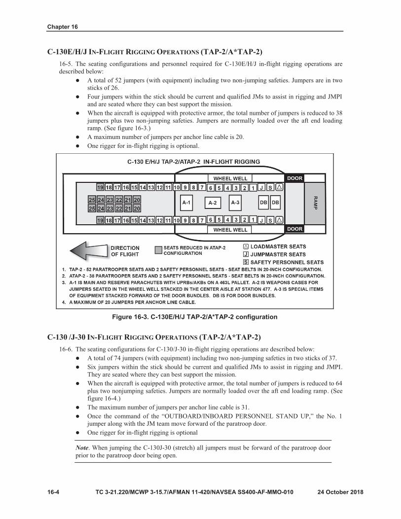
Chapter 16
16-4
Figure 16-3. C-130E/H/J TAP-2/A*TAP-2 configuration
Note

High Performance Aircraft
16-5
Figure 16-4. C-130 J-130 TAP-2/A*TAP-2 configuration

Chapter 16
16-6
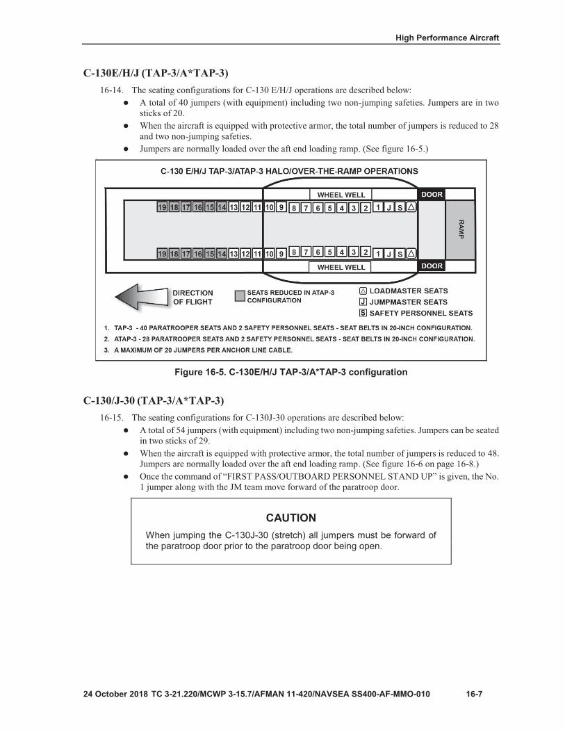
High Performance Aircraft
16-7
Figure 16-5. C-130E/H/J TAP-3/A*TAP-3 configuration
CAUTION When jumping the C-130J-30 (stretch) all jumpers must be forward of the paratroop door prior to the paratroop door being open.
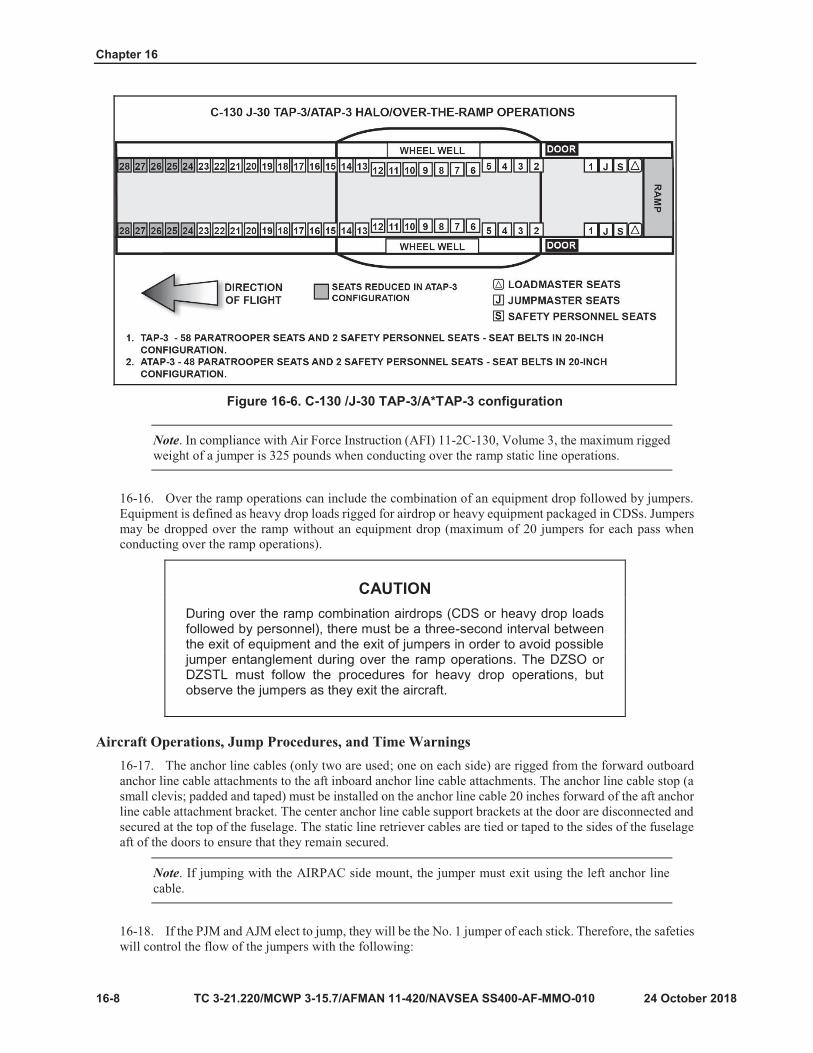
Chapter 16
16-8
Figure 16-6. C-130 /J-30 TAP-3/A*TAP-3 configuration
Note
CAUTION During over the ramp combination airdrops (CDS or heavy drop loads followed by personnel), there must be a three-second interval between the exit of equipment and the exit of jumpers in order to avoid possible jumper entanglement during over the ramp operations. The DZSO or DZSTL must follow the procedures for heavy drop operations, but observe the jumpers as they exit the aircraft.
Note

High Performance Aircraft
16-9
Note
Figure 16-7. Personnel locations

Chapter 16
16-10
Figure 16-8. Static line grasped with reverse bight
Note

High Performance Aircraft
16-11
Figure 16-9. Crash worthiness seat with Type III nylon cord

Chapter 16
16-12
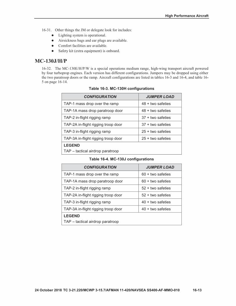
High Performance Aircraft
16-13
Table 16-3. MC-130H configurations
CONFIGURATION JUMPER LOAD
TAP-1 mass drop over the ramp 48 + two safeties
TAP-1A mass drop paratroop door 48 + two safeties
TAP-2 in-flight rigging ramp 37 + two safeties
TAP-2A in-flight rigging troop door 37 + two safeties
TAP-3 in-flight rigging ramp 25 + two safeties
TAP-3A in-flight rigging troop door 25 + two safeties
LEGENDTAP – tactical airdrop paratroop
Table 16-4. MC-130J configurations
CONFIGURATION JUMPER LOAD
TAP-1 mass drop over the ramp 60 + two safeties
TAP-1A mass drop paratroop door 60 + two safeties
TAP-2 in-flight rigging ramp 52 + two safeties
TAP-2A in-flight rigging troop door 52 + two safeties
TAP-3 in-flight rigging ramp 40 + two safeties
TAP-3A in-flight rigging troop door 40 + two safeties
LEGENDTAP – tactical airdrop paratroop

Chapter 16
16-14
Table 16-5. MC-130P configurations
CONFIGURATION JUMPER LOAD
TAP-1 mass drop over the ramp 28 + two safeties
TAP-1A mass drop paratroop door 28 + two safeties
TAP-2 in-flight rigging ramp 16 + two safeties
TAP-2A in-flight rigging troop door 16 + two safeties
LEGENDTAP – tactical airdrop paratroop
Table 16-6. C-17A airdrop passenger configuration
CONFIGURATION JUMPER LOAD
ADP-1, sidewall seats only 52 + two safeties
ADP-2, sidewall and center seats 100 + two safeties
ADP-3, sidewall and center seats/ATGL 100 + two safeties
LEGENDADP – airdrop passenger; ATGL – anti-tank guided launcher

High Performance Aircraft
16-15
Figure 16-10. C-17A ADP-1 seating configuration, sidewall seats only
Figure 16-11. C-17A ADP-2 seating configuration, sidewall and center seats

Chapter 16
16-16
Figure 16-12. C-17A ADP-3 seating configuration, sidewall and center seats

High Performance Aircraft
16-17
Chapter 16
16-18

High Performance Aircraft
16-19
Table 16-7. C-27J configuration
CONFIGURATION JUMPER LOAD
Sidewall seats only 26
Sidewall and center row seats *36
Sidewall seats only in-flight rigging 22
* A/NT without combat equipment
LEGENDA/NT – administrative/nontactical

Chapter 16
16-20
Figure 16-13. C-27J sidewall seats (only) configuration
Figure 16-14. C-27J sidewall and center seats configuration

High Performance Aircraft
16-21
Figure 16-15. C-27J in-flight rigging seating configuration
WARNING Aerial delivery of A–7A or A–21 containers through the side exits (paratroop doors) is prohibited.

Chapter 16
16-22

TC 3-21.220/MCWP 3-115.7/AFMAN 11-420/NAVSEA SS400-AF-MMO-010, C1 16-23
Airsickness bags and earplugs are available.100-mph tape is available to secure the platform locking lever.If jump platforms are not installed in the doors, they must be secured to the upper ramp.All equipment and crew baggage is secured to the floor.During the jump briefing, the jumpers are warned to avoid striking or grabbing the doorplatform locking lever on the leading edge of the door.
C-27J STATIC LINE OVER-THE-RAMP OPERATIONS16-56. In July 2015, the C-27J was approved for safe airdrop operations from both sides of the ramp tosupport static line airborne operations. During a static line over-the-ramp airborne operations test, operationalparatroopers successfully conducted 229 static line airdrops from the ramp of the C-27J without combatequipment. This test demonstrated a 0.99 reliability rating at the 90 percent lower confidence level. TheC-27J is fully capable of conducting static line over-the-ramp airborne operations without combat equipment.Jumpmasters must review the physical characteristics of the aircraft and establish safety parameters formovement of parachutists aboard the aircraft prior to any airdrop operations. All parachutists are required toconduct mock ramp rehearsals, actions inside the aircraft, and proper exit procedures when using over-the-rampexit of the C-27J.
WARNING Due to turbulent airflow outside of the aircraft ramp and the erratic behavior of the D-bags, the flight engineer must use the retrieval system when retrieving D-bags during all over-the-ramp static line airborne operations. If the retrieval system is not used, the turbulent winds are enough to pull the flight engineer and safety outside of the aircraft and may cause catastrophic safety hazards to personnel and equipment.
WARNING When the C-27J is in flight, the ramp and paratroop (rear exit) doors are prohibited from being open at the same time.
CAUTION Jumpers will not jump with combat equipment (rucksack and weapons case) for over-the-ramp operations. Ramp exits with combat equipment cause excessive twists and jumpers flipping through their risers due to the airflow aft of the aircraft and may cause catastrophic safety hazards to personnel and equipment.
Note. When conducting over-the-ramp operations, a five-foot extension must be added to the USL modified.

Chapter 16
16-24 TC 3-21.220/MCWP 3-115.7/AFMAN 11-420/NAVSEA SS400-AF-MMO-010M, C1
Note. Static line bumper stop must be positioned at Station 610 for over-the-ramp operations.
EQUIPMENT DROP 16-57. Container delivery system bundles can be pushed off the ramp. Cargo rollers can be installed on theramp to aid in handling larger bundles.
JOINT PREFLIGHT INSPECTION 16-58. The JM coordinates the exact time sequence of pre-jump procedures with the pilot in command andthe flight engineer. Following preliminary orientation, and before loading personnel onboard the aircraft, theJM and flight engineer should make a joint inspection of the aircraft. The purpose of the joint inspection isto verify the readiness of the aircraft for the conduct of the mission and to take actions necessary to achievethis readiness.
SUPERVISORY PERSONNEL REQUIRED 16-59. To ensure command and control when jumping over-the-ramp, one JM, two non-jumping safeties,and two flight engineers are required. If using a static JM, only one safety is required. When using twosafeties, the aft safety will wear an approved safety harness and the forward safety may wear an approvedbailout parachute.
CAUTION Safety harness length must be checked prior to conducting flight and/or jump operations to ensure the length does not extend beyond the aircraft ramp in the level position.
JUMP COMMANDS 16-60. The following eight jump commands are used for over-the-ramp operations:
GET READY: Jumpers respond in the same manner as for other fixed-wing aircraft.STAND UP: Jumpers stand up and face the ramp of the aircraft.HOOK UP: The jumpers detach the USL snap hook from the top carrying handle of the reserveparachute and hook up to the anchor line cable with the open portion of the snap hook facingoutboard, ensuring that the snap hook seats properly. The jumpers will maintain a reverse bite onthe static line.CHECK STATIC-LINES, CHECK EQUIPMENT, and SOUND OFF FOR EQUIPMENTCHECK. These commands are executed in the same manner as with other fixed-wing aircraft.STAND BY:
If the JM is jumping, he moves to the hinge of the ramp.If a static-line JM, the Number 1 jumper moves to the hinge of the ramp.
GO:If the JM is jumping, at the command of GO, the JM looks at the Number 2 jumper and givesthe command, FOLLOW ME, then exits the aircraft off the center of the ramp. The safetycontrols the flow of the jumpers.If a static JM, at the command of GO, the Number 1 jumper walks off the center of the ramp.

High Performance Aircraft
TC 3-21.220/MCWP 3-115.7/AFMAN 11-420/NAVSEA SS400-AF-MMO-010, C1 16-25
CAUTION Do not sacrifice the safety of the jumpers by rushing the inspection of the static lines. If the safety cannot finish the inspection of the static lines prior to the command stand-by, do not put any jumpers out and make another pass.
CAUTION All jumpers exit the ramp by walking off the center of the ramp. Exits from the left or right side of the ramp result in a poor exit and may cause serious injury or death.
Note. The drop speed of the aircraft is approximately 130 knots and flaps 2 are used when conducting static line over-the-ramp operations.
OVER-THE-RAMP SPECIFIC CHECKLIST 16-61. Ensure that the flight engineer installs the stops on both sides of the ramp so that it is level with theaircraft floor when open. Disengage the support bracket near the door for bundle drops that use the retrievalsystem to pull in the static line. Secure the retrieval cable against the anchor line with breakaway ties startingat the rear of the cable and ending at the ramp hinge. This prevents the ramp from cutting the retrieval cableduring operation.
16-62. Ensure a CGU1 B cargo strap is available and in the appropriate position in the event of a towedparachutist. The cargo strap is prepositioned at Station 700 just aft of the ramp storage bins and on the sameside of the aircraft as the anchor line cable being used. The other end of the cargo strap is secured on thesame side near the observation window where it does not interfere with jump procedures and be readilyaccessible for towed jumper retrieval.
TOWED JUMPER PROCEDURES FOR RAMP EXIT 16-63. Crews should suspect they have a towed jumper if the static line is not positioned high and to theleft or right upper corner of the ramp. The JM or safety is responsible for identifying how the jumper is beingtowed. If being towed by anything other than the static line, the JM or safety shall attempt to free the jumper.If the JM or safety is unable to free the jumper, the jumper will be retrieved whether conscious orunconscious. However, if the jumper cannot be retrieved and indicates consciousness, cut the jumper freeover the DZ or a safe area.
Note. Towed parachutists indicate consciousness and that the reserve parachute is ready by maintaining a tight-body position with both hands on the reserve parachute. This indicates the jumper is prepared to be cut away.
Note. If the parachutist is towed following a ramp exit, it will be necessary to partially rewind the static line retriever to reach the static line for cutting.

Chapter 16
16-26 TC 3-21.220/MCWP 3-115.7/AFMAN 11-420/NAVSEA SS400-AF-MMO-010M, C1
16-64. If a parachutist is to be cut free, the flight engineer retrieves the static line far enough inside theaircraft to allow the JM to reach the static line to cut the towed parachutist's static line.
16-65. If the parachutist is to be retrieved, the flight engineer secures the CGU1 B cargo strap (from whereit is stowed by the observation window) under the static line and relocates it to the tie-down ring located onthe opposite side of the cabin at Station 590. After securing the CGU1 B cargo strap, the flight engineer usesthe static line retrieval winch to pull the towed parachutist in. The static line is retrieved over the CGU1 Bstrap. As the parachutist is retrieved to the ramp area, the flight engineer and safety personnel gain physicalcontrol of the jumper. The parachutist is pulled into the aircraft (under the strap) as the flight engineer relievestension from the static line retrieval winch.
CAUTION Non-jumping personnel do not proceed aft of the paratroop doors unless wearing approved safety harness and with approval from the flight engineer. Safety harness length must be checked prior to conducting flight and/or jump operations to ensure the length does not extend beyond the aircraft ramp in the level position.
Note. During ramp retrieval, the aircrew begins a gradual climb of 500 feet and should not make any unnecessary turns. This assists in keeping the towed jumper in the center of the cargo and/or ramp opening for better control, reducing the possibility of injury during retrieval.

17-1
Chapter 17
Rotary-Wing Aircraft

Chapter 17
17-2

17-3
Note
Figure 17-1. UH-60 series Blackhawk
Figure 17-2. UH-60 RF antenna padded and taped

Chapter 17
17-4
Notes
Figure 17-3. UH-60 series door edge padded and taped
Note

17-5
Figure 17-4. UH-60 series anchor line
Figure 17-5. UH-60 series anchor line secured to the floor

Chapter 17
17-6
Note
WARNING Movement in the cargo compartment must be minimized to preclude inadvertent parachute activation. Maintain rip cord handle awareness at all times.
Note

17-7
Figure 17-6. UH-60 series jumpmaster’s intercom stowed overhead

Chapter 17
17-8
Figure 17-7. UH-60 series loading
WARNING Do not approach the aircraft directly from the front because the lowest arc of the turning rotor blades occurs at that point.

17-9
Figure 17-8. UH-60 series hook up of USL snap hook and excess USLM routed
Note
Figure 17-9. UH-60 series seating and static line routing

Chapter 17
17-10
Note
Figure 17-10. Sound off for equipment check

17-11
Note
Note
Note

Chapter 17
17-12
Figure 17-11. Modified C-3A troop safety belts

17-13
Figure 17-12. CH-47 Chinook
Figure 17-13. CH-47 anchor line cable attachment
Note

Chapter 17
17-14
Figure 17-14. CH-47 seating configuration
Figure 17-15. CH-47 USLM routing
17-15
Note
Note

Chapter 17
17-16
Figure 17-16. CH-47 exiting and position of static JM or safety
WARNING The ramp must not be lowered unless all jumpers are either hooked up or seated in their seats with seat belts fastened.
CAUTION When the ramp is lowered, it must be lowered to three degrees below horizontal prior to exiting jumpers.

17-17
Figure 17-17. UH-1 series Iroquois

Chapter 17
17-18
Figure 17-18. UH-1 exposed fixtures padded
Note
Figure 17-19. UH-1 series floor mounted anchor line systems

17-19
Note
Note

Chapter 17
17-20
Figure 17-20. UH-1 seating configuration, overhead expedient ALS
Figure 17-21. UH-1 seating configuration, ALS

17-21

Chapter 17
17-22
WARNING The parachutist jump pack, AT4JP, or SMJP may not be jumped from aircraft that require jumpers to exit from a seated position. It is highly recommended that unit leadership take a deliberate approach to training individuals who have never executed a T-11 ATPS jump and develop a progression plan for individuals who have less than 10 jumps with the T-11 ATPS. These jumpers are statistically at the highest risk for a parachute incident.
Figure 17-22. UH-72A Lakota

17-23
Figure 17-23. Right side of UH-72A Lakota shown with tape

Chapter 17
17-24
Figure 17-24. Left UH-72A Lakota exterior shown with tape
Figure 17-25. Left UH-72A Lakota exterior shown with tape and skid pad cover

17-25
Figure 17-26. Location of aft static line anchor device
Note
Figure 17-27. Location of forward static line anchor device

Chapter 17
17-26
Figure 17-28. O-rings of each anchor device facing each other
Figure 17-29. Installation of safety roll pins on each anchor device

17-27
Figure 17-30. Aft and forward anchor devices with tape after installation of safety roll pin
Figure 17-31. Anchor line system shown with running end of strap oriented toward front of aircraft and D-rings toward skin of aircraft

Chapter 17
17-28
Figure 17-32. Safety wire installed through snap hook of anchor line system
Figure 17-33. End of safety wire around snap hook of anchor line system

17-29
Figure 17-34. Safety wire and snap hook taped
Figure 17-35. Excess webbing taped in place

Chapter 17
17-30
Figure 17-36. Static line personnel safety straps
Figure 17-37. Seating configuration for static line personnel without combat equipment and crew chief

17-31
Figure 17-38. Seating configuration for static line personnel without combat equipment and crew chief
Figure 17-39. Seating configuration for static line personnel with combat equipment and crew chief

Chapter 17
17-32
Figure 17-40. USL snap hook faced toward aircraft skin
Figure 17-41. Slack retainer stowed properly

17-33
Figure 17-42. Safety strap shown across jumper No. 1
Chapter 17
17-34
WARNING The parachutist jump pack, AT4JP, or SMJP may not be jumped from aircraft that require jumpers to exit from a seated position. It is highly recommended that unit leadership take a deliberate approach to training individuals who have never executed a T-11 ATPS jump and develop a progression plan for individuals who have less than 10 jumps with the T-11 ATPS. These jumpers are statistically at the highest risk for a parachute incident.

18-1
Chapter 18
Sister Service Aircraft
Figure 18-1. CH-53 Sea Stallion

Chapter 18
18-2
WARNING The JM must ensure the tail skid is in the UP position prior to releasing parachutists. Failure to ensure tail skids in the UP position can cause a towed jumper or severe injury situation.
CAUTION Do not use a clevis assembly (G-13) to attach the anchor line cable to the aircraft. If the cable is loose, the clevis may rotate sideways and drastically reduce the strength of the anchor line cable.
Figure 18-2. CH-53 anchor line installation

18-3
Figure 18-3. CH-53 seating configuration

Chapter 18
18-4
WARNINGS The JM must ensure the jumper has T-11R inserts in place and a five-foot universal static line extension attached to the USLM. Failure to use a universal static line extension may cause personal injury from deployment bag strikes. The JM must ensure the jumper has a proper reverse bight. If an improper reverse bight is taken, the USLM could become misrouted under the arm and cause a towed jumper or severe injury.
WARNING Jumpers will deliberately walk off the ramp, which is lowered a minimum of 11 degrees below centerline gauge. Jumpers WILL NOT make a vigorous exit by jumping off the ramp. Less than a one-second interval between jumpers may result in entanglement of jumpers and USLMs.

18-5
Figure 18-4. CH/HH Jolly Green Giant
Serviceable Tag – Materiel,

Chapter 18
18-6
Figure 18-5. CH/HH anchor line cable
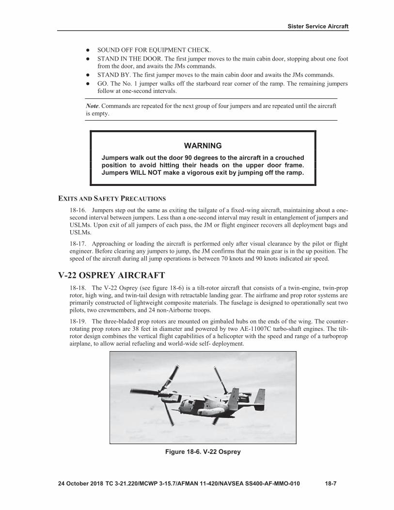
18-7
Note
WARNING Jumpers walk out the door 90 degrees to the aircraft in a crouched position to avoid hitting their heads on the upper door frame. Jumpers WILL NOT make a vigorous exit by jumping off the ramp.
Figure 18-6. V-22 Osprey

Chapter 18
18-8
Note
Figure 18-7. V-22 Osprey helicopter mode
Figure 18-8. V-22 Osprey conversion mode

Sister Service Aircraft
24 October 2018 TC 3-21.220/MCWP 3-115.7/AFMAN 11-420/NAVSEA SS400-AF-MMO-010 18-9
Figure 18-9. V-22 Osprey aircraft mode 18-22. For static line operations the V-22 is limited to airplane mode only, with a maximum drop speed of125 knots (+/- 5 knots) with a minimum drop altitude of 1000 feet AGL. A total of 24 passengers can betransported to conduct parachute operations. All jump operations are over the ramp operations, which is theonly egress point available to the jumper. A staggered offset file exit formation is used for static lineoperations with combat equipment.
18-23. Ensure that the pilot is briefed to expect rapid shifts in the aircraft’s center of gravity during standup, hook up, and exit of jumpers. PJM ensures that all jumpers have T-11R inserts in place. Crowdedconditions inside the cargo compartment could allow for the accidental activation of a reserve parachute,creating an extremely hazardous situation. During movement within the aircraft, the rip cord grip of thereserve parachute is protected by placing the right hand and forearm over the front of the reserve. This methodallows the jumper to control the pilot chute and canopy in case of accidental activation.
SPACE LIMITATIONS 18-24. The space limitations for the V-22 Osprey aircraft are described below. A total of 24 passengers canbe transported to conduct parachute operations.
18-25. Multiple container delivery systems maximum gross weight is 4950 pounds. Individual CDSmaximum rigged weight will not exceed 2328 pounds gross rigged weight. Container footprint is limited todouble A-22 or smaller. A single A-22-sized container height is limited to 60 inches as measured from bottom of the platform to the highest point on the load, including the parachutes. Double A-22-sized container heightis limited to 50 inches as measured from the bottom of the platform to the highest point on the load includingthe parachutes. Ensure ramp is level and upper ramp door is completely open to maintain adequate clearancebetween the load and aircraft when load exits.
18-26. When the MV-22 Cargo Release System releases the cargo load, the Cargo Release System falls tothe deck of the aircraft, presenting a tripping hazard to follow on jumpers as they move towards the ramp toexit the aircraft. When conducting combination personnel and cargo airdrops in which the personnel followthe cargo out of the aircraft, unit commanders are required to implement controls designed specifically tomitigate the risks associated with this hazard.
18-27. USLMs and deployment bags are manually retrieved by the crew chief with assistance from the JMimmediately after the last jumper is clear. The USLMs and deployment bags are secured as soon as they areretrieved inside the aircraft. If the ramp is up, the USLMs can be removed from the anchor cable; otherwise,the static lines are not detached until the aircraft is on the ground.
18-28. Crowded conditions inside the aircraft dictate that caution be used to prevent entanglement ormisrouting of USLMs during the jumper’s exit. Each jumper is cautioned to watch the USLM of thepreceding jumper and to observe all the USLMs trailing from the upper corner of the ramp opening. Thisprecaution ensures that succeeding jumpers do not jump until the parachute of the preceding jumper hasdeployed, and that the deployment bag has trailed to the rear of the aircraft.

Chapter 18
TOWED JUMPER PROCEDURES 18-29. In the event of a towed jumper, the JM prevents any other jumpers from exiting and notifies thepilot. The jumper stays in a tight body position and protects the rip cord handle. The JM will ensure thejumper is securely attached to the aircraft and will not break free during descent. If the jumper is not securelyattached, the JM will attempt to shake or cut them free.
18-30. If the jumper cannot be safely freed from the aircraft, the aircraft will convert to helicopter modeand slowly descend to the DZ. A jumper can safely be lowered and landed on the ground while suspendedfrom the MV-22. In the event the jumper cannot be lowered to the ground, once the hung jumper is at 10 feetor less above the ground, the JM will cut the jumper free.
STATIC LINE OPERATIONS AND SEATING CONFIGURATION 18-31. The aircraft speed is 125 +/- 5 knots for static line operations. The JM will control the ramp level,but it is recommended to be placed at the seventh light setting, which is controlled by the aircrew. Whenutilizing the MC-6, jumpers use a four-second count when conducting the first point of performance.
Note. Airplane and conversion modes can only be used for military free-fall operations.
18-32. Jumpers in troop seats should have the seat back webbing in the lower position (see figure 18-10)and use only the lap belt. Jumpers may also be floor loaded. (See figure 18-11.) Inflight rigging ofparatroopers is authorized. Safety and mission-essential equipment will dictate the number of paratroopersto be airdropped in compliance with MV-22 and AFTTP 3-3.CV-22. Jumpers can be seated on the floorfacing the rear of the aircraft at a 45-degree angle with the jumpers split between the port and starboard sidesof the aircraft. The jumpers are restrained by individual safety belts routed around each jumper.
Figure 18-10. Troop seat with seating back webbing

18-11
Figure 18-11. Seating configuration (noncombat-equipped jumpers)

Chapter 18
18-12
WARNING To ensure safety of jumpers, the aircraft ramp will remain closed until all jumpers have sounded off for equipment check.
Note
WARNING The JM must ensure the jumper T-11R inserts are in place, and has a proper reverse bight. If an improper reverse bight is taken, the static line could become misrouted under the arm and cause a towed jumper or severe injury.

18-13
Note

Chapter 18
18-14
Figure 18-12. UH-1N/Y

18-15
Figure 18-13. UH-1 exposed fixtures padded
Note

Chapter 18
18-16
Figure 18-14. UH-1 series anchor line systems
Figure 18-15. UH-1 modified anchor line

18-17
Figure 18-16. UH-1 series modified anchor line
Notes

Chapter 18
18-18
Figure 18-17. UH-1 seating configuration expedient anchor line system

18-19
Figure 18-18. UH-1 seating configuration, overhead anchor line system

Chapter 18
18-20
CAUTION The AT4JMP/SMJP may not be jumped from aircraft that require jumpers to sit on the floor.

19-1
Chapter 19
Nonstandard Aircraft

Chapter 19
19-2
Figure 19-1. C-7A Caribou

Nonstandard Aircraft
24 October 2018 TC 3-21.220/MCWP 3-115.7/AFMAN 11-420/NAVSEA SS400-AF-MMO-010 19-3
carrying handle of the reserve parachute and hook up to the anchor line cable with the open portion of the snap hook facing outboard, ensuring that the snap hook locks properly. The universal static line is controlled by each jumper in a reverse bight at waist level in the left hand. CHECK STATIC LINES, CHECK EQUIPMENT, and SOUND OFF FOR EQUIPMENTCHECK. (These are executed in the same manner as with other fixed-wing aircraft.).STAND BY/STAND IN THE DOOR.
STAND BY. The No. 1 jumper, upon receiving the command, STAND BY, assumes astanding position near the starboard side of the ramp hinge. The No. 2 jumper stands on theport side of the aircraft slightly to the right of jumper 1. The remaining personnel close up theinterval behind the No. 1 jumper.STAND IN THE DOOR. The proper door position is taken by the jumpers in both doors, withthe appropriate foot resting on the elevated doorsill. There is no jump platform.
GO. Personnel exit the aircraft at one-second intervals.
19-13. The No. 1 jumper, upon receiving the command of “GO,” walks off the port side rear corner of theramp. The remaining jumpers follow at a one-second interval. After the command GO, each jumper will walkoff the ramp and snap into a good, tight body position and began the 4000 count for the MC-6 or 6000 countfor the T-11 ATPS. (See figure 19-2 for C-7A.)
Figure 19-2. C-7A configuration for jumping from the ramp 19-14. When the troop doors are used, simultaneous exits must not be made. The No. 1 jumper exits thestarboard door and No. 2 exits the port door one second after No. 1. The remaining jumpers alternate innumerical order at one-second intervals. (See figure 19-3 on page 19-4.)

Chapter 19
Figure 19-3. C-7A configuration for jumping from the doors
SAFETY PRECAUTIONS 19-15. Jumpers ensure that all seats are secured in the raised position when they stand to hook up. Duringextreme air turbulence, jumpers take a short bight on the static line and use the center anchor line to steadythemselves.
19-16. All jumpers remain off the ramp while it is being lowered to the 15-degree incline for aft endjumping. Jumpers walk down the ramp with feet spread wide to prevent striking the side of the aircraft.
19-17. Upon exit from the aircraft, the jumper brings feet and knees together to form a tight body position.When following heavy equipment loads, jumpers exit between the roller conveyers of the aerial unloadingkit.
19-18. The JM or safety ensures personnel are hooked up in an alternating manner to the same anchor linecable and form one continuous stick of jumpers. For door jumping, the JM or safety taps out the jumpersalternately to preclude a simultaneous exit from both sides of the aircraft. If the JM jumps last, they musthook up to the center anchor line cable and exercise caution to control their own USLM and ensure it doesnot become fouled.
Note. The left troop door may be removed before the operation to allow the JM to look for the DZ. If worn, the restraint harness is attached to the centerline anchor cable as a safety measure.
19-19. When the modular Airborne weapons’ cases are jumped from the paratroop doors, they must bereduced to 36 inches in length. When accompanying supplies and equipment are dropped from the paratroopdoors, the bundles must be standard air delivery containers no larger than 40 36 inches.
19-20. When ramp bundles are dropped, the 15-foot static line with drogue or the breakaway static line maybe used. When door bundles are dropped, the 15-foot static lines with drogues are used with cargo parachutes.The ramp roller conveyor section for the air unloading kit is installed on the port side of the ramp and is usedto assist in ejecting the bundles from the ramp. Jumpers Nos. 1 and 2 push the bundles and are current andqualified jumpmasters.
19-21. The speed of the aircraft during the jump is not less than 90 or more than 120 knots. When jumpingfrom the paratroop doors, the crew chief removes the paratroop doors and tapes the rear portion of the door

Nonstandard Aircraft
19-5
Note
Figure 19-4. C-23B/B+ Sherpa
Note

Chapter 19
19-6
Figure 19-5. Seating configuration

Nonstandard Aircraft
19-7
CAUTION When loading, jumpers must immediately move forward in the aircraft cabin to prevent the aircraft’s tail from striking the ground.
WARNING Hot loading aircraft is dangerous. Special control measures should be implemented to ensure jumpers and ground personnel remain clear of the propellers.

Chapter 19
19-8

Nonstandard Aircraft
19-9
CAUTION Low overhead clearance may require jumpers to duck their heads while exiting the ramp door.
Jumpers must walk STRAIGHT off the ramp and along the port side fuselage and NOT at a 45-degree angle towards the center of the ramp.
Safety must remain clear of the ramp door and against the starboard side fuselage while jumpers exit.
Note

Chapter 19
19-10
CAUTION No more than four jumpers are authorized aft of the port side jump door prior to exit.
Excessive weight load and cargo shift in the ramp door area prior to exit should be avoided.
Figure 19-6. C-212 (Casa 212)

Nonstandard Aircraft
19-11
Figure 19-7. C-212 seating configuration

Chapter 19
19-12
Note
Note
CAUTION Over the ramp Airborne operations are authorized only when the retrieval system is operational.

Nonstandard Aircraft
19-13

Chapter 19
19-14
Note

20-1
Chapter 20
Airdrop Procedures
Table 20-1. Example calculation of drop altitude in feet
A.Distance from highest field elevation in drop zone to desired altitude of aircraft, in feet. 800 feet AGL
B.Highest field elevation in feet above sea level, rounded up to next 50 (for example, round 505 up to 550).
+550 feet fieldelevation
C. Drop altitude in feet indicated. 1350 feet MSL
LEGENDAGL – above ground level; MSL – mean sea level
Note

Chapter 20
20-2
Table 20-2. Airdrop altitude for rotary-wing and fixed-wing aircraft
AIRCRAFT DAY OR NIGHT AGL (IN FEET)
Rotary Wing (All Services, Rotary Wing)
Personnel>90 KTs (N/A for UH aircraft)
Door bundles
15001250 minimum
300 (day)500 (night)
Fixed Wing (Troop Carrier)
PersonnelBasic Airborne trainingTrainingTactical
Door bundlesHeavy equipment
1250 maximum12501000800
300 minimum
1100
IMC/SKE. Drop altitude is 500 feet above highest obstaclethat falls within three miles either side of DZ run-in. CDSusing G-13 or any other parachute, minimum drop altitudeis 400 feet AGL. CDS using G-14 parachute can drop from 300 feet AGL.
LEGENDAGL – above ground level; CDS – container delivery system; DZ – drop zone; IMC/SKE – instrument meteorological conditions/station keeping equipment;KTs - knots; N/A – not applicable; UH – utility helicopter
Table 20-3. Minimum aerial delivery altitudes (in feet)
PERSONNEL FEET
Tactical trainingBasic Airborne traineesSATBTTB (use standard drop altitude of simulated load)Door bundles, G-14 or T-10 (C-17)Door bundles, G-14 (C-130)Door bundles, T-10 (C-17)Door bundles, LCLA (C-130)
8001250500500300300400150

Airdrop Procedures
20-3
Table 20-3. Minimum aerial delivery altitudes (in feet) (continued)
CONTAINER DELIVERY SYSTEM FEET
G-12D: One to six bundles, single parachuteSeven or more bundles, single
parachuteCluster of two parachutes
G-12E: Single parachuteCluster of two
G-13: Single parachute or cluster of twoCluster of three
G-14: Single parachute or cluster of twoCluster of three
12-foot high velocity26-foot high velocityLCLA single parachuteSATB-C/TTB (see parachute load to be simulated)
400600600400550400500300400400500150
HEAVY EQUIPMENT FEET
G-12EG-11B: Single parachute
Cluster of two to sevenCluster of eight
G-11C: Cluster of eightSATB-H/TTB (see parachute load to be simulated)
550900110013001300
ROTARY-WING AERIAL DELIVERY FEET
Personnel: Day or nightBelow 90 KIAS90 KIAS or greater (CH aircraft)
minimumMaximum altitude for static line jump
Bundles: DayNight
150012502999300500
LEGENDCH – cargo helicopter; C/TTB – clustered/tactical training bundle; H/TTB – heavy/tactical training bundle;KIAS - knots indicated airspeed; LCLA – low cost low altitude; SATB – simulated airdrop training bundle; TTB – tactical training bundle

Chapter 20
20-4
CAUTION During over the ramp combination airdrops (CDS and/or high explosive followed by personnel), there must be a three-second interval between the exit of equipment and the exit of jumpers in order to avoid possible jumper entanglement during over the ramp operations. The DZSO or DZSTL must follow the procedures for heavy drop operations, but observe the jumpers as they exit the aircraft.

Airdrop Procedures
20-5
Note
Note
Table 20-4. Computed air release point chart
ALTITUDE(FEET AGL)
WIDTH(NOTES 1, 2, AND 4)
LENGTH(NOTES 3 AND 4)
C-130 CDS/CRS/CRL/LCADS-LV
Single containers
Double containers
To 600 feet 400 yards/366 meters
1
2
3
4
5-8
9-12
1-2
3-4
5-6
7-8
9-16
17-24
400 yards/355 meters
450 yards/412 meters
500 yards/457 meters
550 yards/503 meters
700 yards/640 meters
850 yards/777 meters
Above 600 feet
Add 40 yards/36 meters to width and length for each 100 feet above 600 feet.
Add 20 yards/18 meters to each side and end of the DZ.

Chapter 20
20-6
Table 20-4. Computed air release point chart (continued)
ALTITUDE(FEET AGL)
WIDTH(NOTES 1, 2, AND 4)
LENGTH(NOTES 3 AND 4)
CDS/LCADS-LV (C-17)
Single containers
Double containers
To 600 feet 450 yards/412 meters
1
2
3
4-8
9-14
15-20
1-2
3-4
5-6
7-16
17-28
29-40
590 yards/540 meters
615 yards/562 meters
665 yards/608 meters
765 yards/700 meters
915 yards/837 meters
1065 yards/974 meters
Above 600 feet
Add 40 yards/23 meters to width and length for each 100 feet above 600 feet.
Add 20 yards/18 meters to each side and end of the DZ.
High Velocity CDS/HV-LCADS (using 12-foot, 22-foot, or 26-foot ring slot parachutes)
To 3000 feet 580 yards/530 meters660 yards/604 meters
Add 50 yards/46 meters to trailing edge for each additional row of containers.
Above 3000 feet
Add 25 yards/23 meters to each side and 100 yards/91 meters to each end for every 1000-foot increase in drop altitude.
High Altitude Airdrop Resupply System CDS
To 3000 feet 500 yards/457 meters
1-8containers
9 or more containers
1200 yards/1098 meters
1900 yards/1739 meters
Above 3000 feet
Add 25 yards/23 meters to each side and 50 yards/46 meters to each end for every 1000-foot increase in drop altitude.
High Speed Low Level Aerial Delivery System
300 yards/274 meters 600 yards/549 meters
Personnel (Static Line)
To 1000 feet 600 yards/549 meters
One jumper 600 yards/549 meters
Additional jumpers
Add 75 yards/69 meters to trailing edge for each additional jumper (PI for special tactics, para-rescue, and RQS assigned or supporting SERE personnel) Include safety zone, if required.
Above 1000 feet
Add 30 yards/28 meters to width and length for each 100 feet above 1000 feet. Add 15 yards/14 meters to each side of the DZ, and 15 yards/14 meters to each end.

Airdrop Procedures
20-7
Table 20-4. Computed air release point chart (continued)
ALTITUDE(FEET AGL)
WIDTH(NOTES 1, 2, AND 4)
LENGTH(NOTES 3 AND 4)
Heavy Equipment
To 1100 feet 600 yards/549 meters
One platform 1000 yards/915 meters
Additional platforms
(C-130) add 400 yards/366 meters and (C-17) 500 yards/457 meters to the trailing edge for each additional platform.
Above 1100 feet
Add 30 yards/28 meters to width and length for each 100 feet above 1100 feet. Add 15 yards/14 meters to each side and end of the DZ.
C-17 Dual Row Airdrop System
To 1200 feet 600 yards/549 meters
One platform 1000 yards/915 meters
Additional platforms
(C-130) add yards/ 366 meters and (C-17) 500 yards/457 meters to the trailing edge for each additional platform.
Above 1200 feet
Add 30 yards/28 meters to the width and length for each 100 feet above 1200 feet. Add 15 yards/14 meters to each side and end of the DZ.
NOTE:
18-foot platforms: the number of platforms used to calculate the minimum sizedrop zone is determined by platform placement, and the number of platformsactually onboard the aircraft. The number of empty positions aft of an actualplatform or pallet being dropped must be added to the overall number ofpallets. For example, one platform in position 1L and one platform in position4R would require calculations based on five platforms.
463L or eight-foot training platforms: minimum drop zone is 1600 yards long by 600 yards wide for the two or three pallet or platform training configuration.
C-130E, H, J/C-17 JPADS Guided Systems (Note 5)
Minimum DZ Size (Radius)
Airdrop Altitude (AGL) Yards Meters
Less than 9000 feet
9000 to 15,000 feet
15,000 to 25,000 feet
More than 25,000 feet
328
546
765
No data
300
500
700
No data

Chapter 20
20-8
Table 20-4. Computed air release point chart (continued)
Note 1. C-130 DZ width adjustments (N/A for combat search and rescue assigned/gained aircraft, or Air Force Special Operations Command assigned/gained aircraft operational control to U.S. Special Operations Command or a theater special operations command):
Day visual formations; increase width by 100 yards/92 meters (50 yards/46 meterson each side).Night visual single ship; increase width by 100 yards/92 meters (50 yards/46meters on each side). (N/A for C-130J GPS drops.)Night visual formation; increase width by 200 yards/184 meters (100 yards/92meters on each side).Station keeping equipment formation; increase width by 400 yards/366 meters(200 yards/184 meters on each side).
Note 2. C-17 DZ width adjustments (more than one may be required):Day/night visual formation; increase width by 100 yards/92 meters (50 yards/46meters on each side).Night pilot directed airdrops; increase width by 100 yards/92 meters (50 yards/46meters on each side). (N/A for C-17 GPS drops.)Station keeping equipment formation (heavy equipment or CDS); increase widthby 400 yards/366 meters (200 yards/183 meters on each side).Personnel formation; minimum DZ basic width using center PIs is 1240 yards fortwo-ship elements and 1800 yards for three-ship elements. When using offset PIs,minimum basic width is 1050 yards for two-ship elements and 1300 yards for three-ship elements. Drop altitude adjustments from chart still apply.
Note 3. Length adjustments (N/A for AFSOC assigned or gained, aircraft OPCON to USSOCOM, or a theater special operations command:
Night visual airdrops; increase length by 100 yards/92 meters (50 yards/46 meterson each end).
Note 4. I-CDS DZ length and width requirements will be in compliance with AFI 13-217.
Note 5. Normal training minimum JPADS DZ size requirements:These minimum DZ size requirements are for normal JPADS training outside ofYuma Proving Grounds. The DZ size requirements at YPG are at the discretionAMC/A3D, Natick Soldier Systems Center and YPG as necessary for testing,development and evaluation of JPADS. JPADS upgrade training for aircrews mayoccur at YPG or DZ sizes smaller than stated above with the concurrence ofAMC/A3 D.During contingency use, recommended minimum JPADS DZ size is 200-300meters (218-328 yards) radius circular. Ultimately, minimum JPADS DZ size restswith the user and the joint force commander (or director of mobility forces is sodelegated).
LEGENDAFSOC – Air Force Special Operations Command; AGL – above ground level; AMC/A3 D –Air Mobility Command Director of Operations; CDS - container delivery system; CRL -container ramp load; CRS - Cargo Release System; DZ – drop zone; GPS – Global Positioning System; HV – high velocity; I-CDS – Improved Container Delivery System; JPADS - Joint Precision Airdrop System; LCADS-LV - low cost aerial delivery system-low velocity; N/A – not applicable; OPCON – operational control; PI – point of impact; RQS – rescue squadron; SERE - survival evasion resistance escape (specialists); USSOCOM – U.S. Special OperationsCommand; YPG – Yuma Proving Grounds

Airdrop Procedures
20-9
Note
Note
Chapter 20
20-10
Airdrop Malfunction Report(Personnel-Cargo); Drop Zone Landing Zone Control Log
CAUTION Both the DZSO and the STS have the authority and responsibility to declare a no drop if they believe an unsafe condition exists. A no drop decision by either one will be acted upon by the other without fail. It cannot be overruled.
Note

Airdrop Procedures
20-11

Chapter 20
20-12
Note

Airdrop Procedures
20-13
CAUTION Any personnel climbing trees with pole climbing equipment should be familiar or trained with the equipment prior to execution of the tree recovery. Personnel operating with unfamiliar pole climbing equipment can seriously injure themselves from a fall, or unsecured equipment or tree limbs falling on personnel on the ground.
Note

Chapter 20
20-14
Note

Airdrop Procedures
20-15
Note
Note


21-1
Chapter 21
Formulas and Computations

Chapter 21
21-2
Note
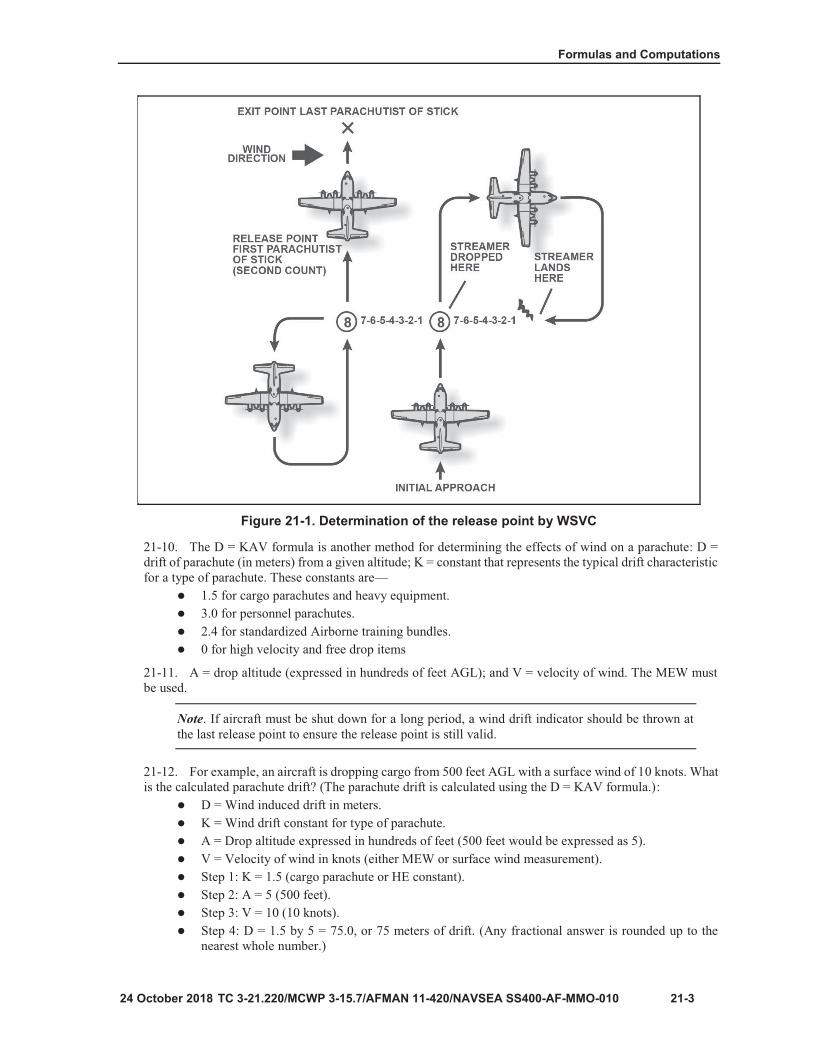
21-3
Figure 21-1. Determination of the release point by WSVC
Note

Chapter 21
21-4

21-5
Table 21-1. Conversion chart for 10 gram helium (pilot) balloons
WIND SPEED IN KNOTS, 10 GRAM HELIUM BALLOONSInflate balloon to 57 inches for day and 74 inches for night
DROP ALTITUDE IN FEET
LEGENDALT – altitude; FT - feet

Chapter 21
21-6
Table 21-2. Conversion chart for 30 gram helium (pilot) balloons
WIND SPEED IN KNOTS, 30 GRAM HELIUM BALLOONSInflate balloon to 75 inches for day and 94 inches for night
DROP ALTITUDE IN FEET
LEGENDALT – altitude; FT - feet

21-7
Table 21-3. Fixed-wing forward throw data
C-130 C-17 C-5
Personnel/door bundles 229 meters/ 250 yards
229 meters/ 250 yards N/A
Heavy equipment 458 meters/ 550 yards
640 meters/ 700 yards
668 meters/ 730 yards
Container delivery systems
503 meters/550 yards
663 meters/725 yards N/A
Note: To convert yards to meters, multiply yards by .9144. To convert meters to yards, divide meters by .9144.
LEGENDN/A – not applicable
Note
Note

Chapter 21
21-8
Figure 21-2. Release point location for VIRS and GMRS

22-1
Chapter 22
Drop Zone Establishment and Operation
Note
Note

Chapter 22
22-2
Figure 22-1. Day CARP DZ markings (left) and night CARP DZ markings (right)

Drop Zone Establishment and Operation
22-3
Note

Chapter 22
22-4
Figure 22-2. Marking placement for inverted L and 15:1 mask clearance ratio

Drop Zone Establishment and Operation
22-5
Figure 22-3. GMRS panel emplacement for T pattern
Figure 22-4. GMRS panel emplacement for H pattern

Chapter 22
22-6
Figure 22-5. Army VIRS offset
Drop Zone Establishment and Operation
24 October 2018 TC 3-21.220/MCWP 3-115.7/AFMAN 11-420/NAVSEA SS400-AF-MMO-010 22-7
22-17. Once the jumpers have exited the aircraft, the GTA then clears the aircraft from the control zone.The following is an example of how the aircraft is cleared:
Pilot: “C3D36, this is A2A22, over.”GTA: A2A22, this is C3D36, over.Pilot: “D36, this is A22, CCP inbound for a personnel parachute drop, over.”GTA: “A22, this is D36, state type and number, over.Pilot: “D36, A22 is a single UH-1H, over.GTA: “A22, this is D36,
“Heading [180] distance (from communications check point).“Drop heading [180].“Drop altitude [1500] (feet indicated).“Drop speed.“Number jumpers/bundles that can be accepted.”
GTA controller reads entire ATC block to the pilot and ends the transmission with: “Continueapproach for visual identification, over.”Pilot: “Wilco.”Upon sighting aircraft, the GTA tells the pilot: “A22, this is D36, I am at your 11 o’clock, 500meters, signal out, can you identify, over?”Pilot: “D36, A22 identifies orange panel, over.”GTA: “A22, D36 has visual contact, turn to drop heading, over.”Pilot: “D36, A22 turning drop heading, over.”GTA: “A22, this is D36, steer left/right, over.”Pilot: “D36, A22 roger.”GTA: “A22, this is D36, on course, over.”Pilot: “D36, A22 roger.”When aircraft is eight to 10 seconds out from release point: GTA: “A22, this is D36, with sixjumpers, stand by, over.”PILOT: “D36, this is A22, standing by, over.”When aircraft is directly over the release point: GTA: “A22, this is D36, with six jumpers,EXECUTE, EXECUTE, EXECUTE.” (GTA must say EXECUTE or NO DROP at least threetimes, or until the first load exits.”At completion of operation, the GTA tells the pilot: “A22, this is D36, I observe six jumpers awayand clear, state intention and report when clear of my control zone,” (include issuing anyadvisories), “over.” (GTA must place aircraft into a closed traffic pattern with a reporting point ifmore than one pass is required.)
JUMPMASTER SPOTTED AND JUMPMASTER RELEASE 22-18. Jumpmaster spotted and jumpmaster release is used by U.S. Marine Corps, U.S. Navy, and U.S.Special Operations Command units. The JSJR release point computation or “spotting” may be used from alltypes of aircraft. It is the same concept as the calculations used for VIRS and GMRS however; it is used bythe JM for spotting and determining the release point from the aircraft. A map of the drop zone 1:50,000 or1:25,000, protractor, pencil, and calculator are required. Plot the impact point, canopy drift, forward throw,RP, terrain feature, and wind direction on the map using the procedures below.
Step 1.Determine what effect the wind will have on the canopy using the wind drift formulaD=KAV, as outlined in chapter 21.Step 2.Using a protractor, plot the impact point on the map. Starting from the impact point, plotthe canopy drift into the direction of the wind on a map.Step 3.Determine the forward throw of the aircraft as outlined in chapter 21.Step 4.Starting at the canopy drift, plot the forward throw opposite the direction of flight and markthis on the map. This is called the release point.

Chapter 22
Note. Continue with steps 5 and 6 if the RP is not identifiable from the aircraft.
Step 5. Locate a terrain feature that is on the inbound aircraft track and is as close as possible tothe RP. For example a road, hilltop, buildings, trees, river, bridge, or something identifiable fromthe air. Mark the terrain feature reference point on the map.Step 6. Determine the count (time in seconds), from the terrain feature reference point to therelease point on the ground. The time/distance formula T = D/R is used.Step 7. The JM starts “spotting” by guiding the aircraft to the intended release point by giving thepilot flight corrections. The JM gives the “GO” when the aircraft is over the RP. If a terrain featurereference point is used, the JM guides the aircraft to the terrain feature and starts their count. Theaircraft maintains heading and the JM gives the “GO” at the end of the count RP. The jumpers exitthe aircraft at the RP and forward throw to the canopy drift. The canopy drift will take effect, andthe first jumper will land on the impact point.
22-19. For example, to determine the count in seconds and RP for a UH-60 flying at 270 degrees, droppingfour jumpers equipped with MC-6 parachutes from an altitude of 1500 feet AGL in 10 knot winds from 060degrees with a drop speed of 80 knots indicated airspeed and the nearest terrain feature on the aircraft trackis 165 meters away, compute the following:
Step 1. D = KAV.D = 3.0 by 15 by 10.D = 450 meters.
Step 2. Plot on the map.Step 3 Forward throw, aircraft speed is 80 knots (80 by 0.51 = 40.8 or 41 meters per second).Step 4. Plot on the map.Step 5. Locate a terrain feature reference point.Step 6. Determine the count from terrain feature to the RP use T = D/R.
The terrain feature is a road 165 meters from the RP.T= 165/41.T = four seconds past the terrain feature.
Step 7. Check to ensure everything is properly calculated and plotted on the map. Using all theinformation from the example, the jumpers will exit and land as shown in figure 22-6.

Drop Zone Establishment and Operation
22-9
Figure 22-6. Release point location for JSJR

Chapter 22
22-10
Note

Drop Zone Establishment and Operation
22-11
Figure 22-7. AF Form 4304, Drop Zone/Landing Zone Control Log

Chapter 22
22-12
Figure 22-8. Sample of a suggested format for incident reporting

Drop Zone Establishment and Operation
22-13

Chapter 22
22-14
Figure 22-9. Sample of a completed AF-IMT Form 3823 (front)

Drop Zone Establishment and Operation
22-15
Figure 22-10. Sample of a completed AF-IMT Form 3823 (back)

23-1
Chapter 23
Malfunction Officer
Note

Chapter 23
23-2
Note
Note
Note
Note
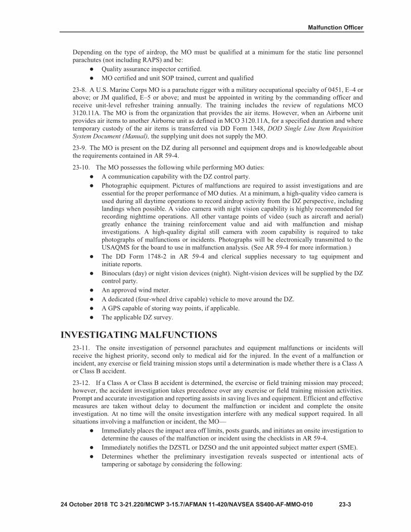
Malfunction Officer
23-3
DOD Single Line Item RequisitionSystem Document (Manual),

Chapter 23
23-4
Evidence/Property Custody Document

Malfunction Officer
23-5
Note
Note

Chapter 23
23-6
Note

Malfunction Officer
23-7
Note


24-1
Chapter 24
Adverse Weather Aerial Delivery System and Instrument Meteorological Conditions
Notes

Chapter 24
24-2

25-1
Chapter 25
Deliberate Water Drop Zone Operations

Chapter 25
25-2
WARNING All jumpers conducting a deliberate water landing must be prepared to conduct a PLF in the event the jumper fails to land inside the surveyed DZ or during emergency bailout procedures.
Note
WARNING The MC-6 should be used, if available. Care must be taken, when using the MC-6 as the porosity of the canopy is extremely limited and may create a suffocation hazard if the jumper is trapped under the canopy.

25-3

Chapter 25
25-4
WARNING When conducting a deliberate water drop zone operation, wet silk training is mandatory. The porosity of the T-11 and MC-6 is extremely limited and may create a suffocation hazard if the jumper is trapped under the canopy.
Note
WARNING Ensure that all personnel are clear of the platform and equipment and not fouled in any lines before cutting the equipment loose from the platform. Failure to do so may cause serious injury or death if the platform sinks.

25-5
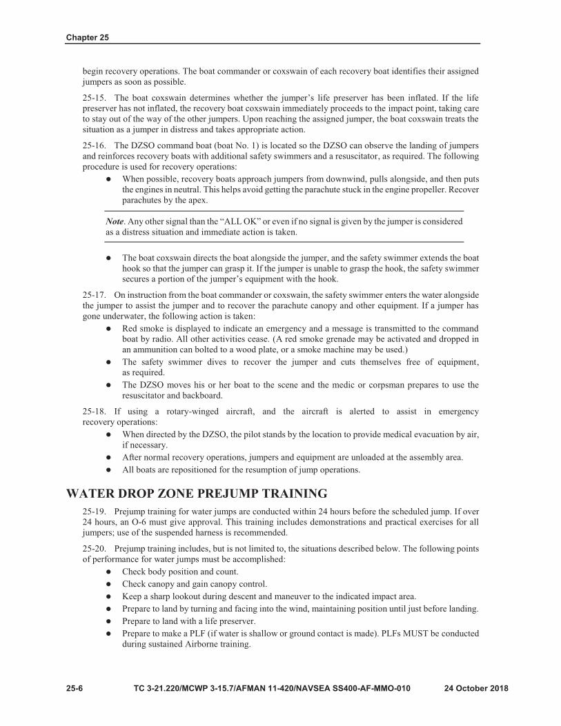
Chapter 25
25-6
Note

TC 3-21.220/MCWP 3-115.7/AFMAN 11-420/NAVSEA SS400-AF-MMO-010, C1 25-7
Emergencies in the air.Emergencies in the water include the following actions:
Ensure the life preserver is fully inflated.If trapped under the canopy, the jumper finds a radial seam and follows it to the edge.If trapped under the canopy, the jumper lifts their hand slowly and creates an air pocket tobreath, then cuts a hole in the canopy material. (If the jumper lifts their hand too quickly, theywill create a suction and the canopy will stick to their face and arm.)Wet silk training is completed and documented within six months prior to the jump (12months for U.S. Navy personnel).
25-21. The following recovery procedures must be performed:Recover parachutes by pulling them in the boat by the apex.Ensure the boat is kept free of gasoline and oil, which would ruin the parachutes.Orientation at the WDZ for the WDZ crew.Any special instructions.
PROCEDURES FOR WATER LANDINGS WITH A LIFE PRESERVER
WARNING All jumpers conducting a deliberate water landing must be prepared to conduct a PLF in the event the jumper fails to land inside the surveyed DZ or during emergency bailout procedures.
25-22. Additional information on approved life preservers can be found in chapter 12. The procedures fordeliberate water landings with a life preserver are:
Jumpers may wear combat equipment only after it has been waterproofed and float-checked.To waterproof equipment, use bags and rigger tape inside equipment containers. Float check bysubmerging in a tank of water until saturated and ensure the equipment is neutral or positivebuoyant (floats).Jumpers wear service approved life preservers.Jumpers wear the approved waterborne operations helmet or a service approved helmet duringWDZ operations.Jumpers jumping in cold water (60 degrees or below) wear wetsuits or dry suits and may wear awetsuit or dry suit hood under the ballistic helmet.Jumpers may wear wetsuit booties, coral booties, or tennis shoes, these shoes WILL BE closedtoe shoes.Jumpers may follow equipment such as door bundles and combat rubber raiding craft on a singleship operation. There are three seconds between the cargo exit and the first jumper’s exit to ensurethe jumpers do not become entangled with the cargo.The cargo and jumpers are hooked to the same anchor line cable on the same side when jumpingthe ramp.
B-7 LIFE PRESERVER
25-23. The B-7 life preserver is worn under the parachute harness with the inflatable portions under thejumper’s armpits. (See figure 25-1, page 25-8.) At 200 feet AGL, the jumper releases all equipment tie-downsand lowers and jettisons their equipment.
25-24. During the descent, the jumper inflates the life preserver by discharging the attached CO2 cartridges.If necessary, the life preserver can be inflated by blowing air into the inflation valve hose. As their feet touchthe water, in case of drag, the jumper activates one canopy release assembly by pulling out on the safety clip

Chapter 25
25-8 TC 3-21.220/MCWP 3-115.7/AFMAN 11-420/NAVSEA SS400-AF-MMO-010M, C1
exposing the cable loops. ENSURE the jumper sounds off with “RISER” when activating the canopy release assembly using one of the two methods, hand-to-shoulder or hand assist. The jumper prepares to execute a PLF if the water is shallow.
25-25. Since the B-7 life preserver provides 500 pounds of positive buoyancy, the jumper does not removethe harness. The jumper swims upstream or upwind away from the parachute to avoid becoming entangledand signals “ALL OK” to the recovery boat.
DANGER Jumpers do not release the canopy release assemblies unless they are being dragged under water. Altitude is hard to judge over the water. If the jumper activates their canopy releases at even moderately high altitude (for example, 50 feet), serious injury or death may result.
CAUTION The jumper must stay clear of the suspension lines to avoid entanglement. If the parachute and equipment are too heavy and hard to hold on to, the jumper lets go of the equipment to avoid being pulled under.
If the jumper signals anything but the “ALL OK” or does not signal, the boat crew will proceed to assist the jumper from the water.
Figure 25-1. Landing with the B-7 life preserver

Deliberate Water Drop Zone Operations
TC 3-21.220/MCWP 3-115.7/AFMAN 11-420/NAVSEA SS400-AF-MMO-010, C1 25-9
UDT LIFE PRESERVER 25-26. Jumpers wearing a UDT vest route the chest strap under the UDT vest so that the chest is not crushedif the UDT is inflated.
25-27. Upon exiting the aircraft, the jumper checks the canopy and steers away from other jumpers. Ataltitude, the jumper releases all equipment tie-downs and lowers and jettisons their equipment. The jumperactivates the quick release on the waistband and unsnaps the left connector snap on the reserve parachute.The jumper rotates the reserve to the right side of the parachute harness and seat themself well into the saddle.
25-28. The jumper activates the quick release on the chest strap and inflates their life preserver with air byblowing into the inflation tube or activating the CO2 cartridge. Sitting back in the harness and using the righthand to hold onto the left main lift web, the jumper steers with their left hand. Just before entering the water,they place their hands on the ejector snaps on the leg straps. The jumper activates the ejector snaps on the legstraps, throws their arms up, and arches out of the harness when entering the water. They prepare to executea PLF if the water is shallow.
25-29. The jumper swims upstream or upwind away from the parachute to avoid becoming entangled, andsignals “ALL OK” to the recovery boat.
CAUTION The jumper must stay clear of the suspension lines to avoid entanglement. If the parachute and equipment are too heavy to hold on to, the jumper lets go of the equipment to avoid being pulled under.
LIFE PRESERVER UNIT 10/P 25-30. The LPU 10/P (NSN 4220-00-850-8655) is a standard U.S. Air Force CO2 cartridge-activated lifepreserver assembly worn during flights over water, or during airdrops when water obstacles are near or onthe intended DZ. The LPU 10/P has an adjustable harness and underarm inflation bladders. It is designed tokeep the wearer’s head above water at weights up to 250 pounds for up to 10 minutes. The LPU 10/P mustbe maintained according to U.S. Air Force standards.
25-31. During the descent, the jumper inflates the life preserver by discharging the attached CO2 cartridges.If necessary, the life preserver can be inflated by blowing air into the inflation valve hose. As their feet touchthe water, in case of drag, the jumper activates one canopy release assembly by pulling out on the safety clipexposing the cable loops. The jumper sounds off with “RISER” when activating the canopy release assemblyusing one of the two methods, hand to shoulder or hand assist. They prepare to execute a PLF if the water isshallow. The jumper swims upstream or upwind away from the parachute to avoid becoming entangled andsignals “ALL OK” to the recovery boat.
CAUTION If the jumper signals anything but the “ALL OK” or does not signal, the boat crew will proceed to assist the jumper from the water.
25-32. The LPU 10/P is worn under the parachute harness. The harness is worn so that the inflatable pocketsare under the jumper’s arms. The manual inflating valves should be completely closed when donning the lifevest. The shoulder and waist straps are then adjusted to ensure the inflation container is one hand widthbeneath the armpit and not constrained by the parachute harness

Chapter 25
25-10 TC 3-21.220/MCWP 3-115.7/AFMAN 11-420/NAVSEA SS400-AF-MMO-010M, C1
WARNING The inflation wings must be one hand width beneath the jumper’s armpits and clear of the harness scraps. If the inflation pockets are too snug under the armpit, or if they are between the harness and the jumper’s body, the jumper can experience severe pain or crushed ribs during inflation.
TFSS-5326 LIFE PRESERVER 25-33. The TFSS-5326 is worn under the parachute harness with the inflatable portions fastened to anindividual’s waist belt. At 200 feet AGL, the jumper releases all equipment tie-downs and lowers andjettisons their equipment.
25-34. The jumper activates the quick release on the waistband and unsnaps the left connector snap on thereserve parachute. The jumper rotates the reserve to the right side of the parachute harness, seats them selfwell into the saddle, and inflates the life preservers by activating the CO2 cartridge. (In the event of CO2cartridge failure, blow air into the inflation tubes.) The jumper activates the quick release on the chest strap.
25-35. After activating the quick release of the chest strap, the jumper immediately regains control of thecanopy. Just before entering the water, they place their hands on the ejector snaps on the leg straps. Thejumper activates the ejector snaps on the leg straps, throws their arms up, and arches out of the harness whenentering the water. They prepare to execute a PLF if the water is shallow.
25-36. The jumper swims upstream or upwind away from the parachute to avoid becoming entangled andsignals “All OK” to the recovery boat by extending one stationary arm overhead.
WARNING The jumper must ensure he does not wear the TFSS-5326 flotation packets between the parachute harness and their body. Serious injury may result if inflated when worn incorrectly.
CAUTIONS The jumper must stay clear of the suspension lines to avoid entanglement. If the parachute and equipment are too heavy and hard to hold on to, the jumper lets go of the equipment to avoid being pulled under.
If the jumper signals anything but the “ALL OK” or does not signal, the boat crew will proceed to assist the jumper from the water.

A-1
Appendix A
Basic Airborne Refresher Training
Notes
WARNING It is highly recommended that unit leadership take a deliberate approach to training individuals who have never executed a T-11 ATPS jump and develop a progression plan for individuals who have less than 10 jumps with the T-11 ATPS. These jumpers are statistically at the highest risk for a parachute incident.

Appendix A
A-2
Table A-1. Minimum requirements for basic Airborne refresher training
PERIOD EVENT LESSONSTRAINING AIDS
ANDEQUIPMENT
1 Ground training
•Identification card and tags,helmet check.•Sizing, donning, and fitting theT-11 and MC-6 parachutes.•RIGGEX:
Demonstration of thecorrect rigging, attaching, andlowering procedures forcombat equipment currentlyused by the unit.
MAWC (sizing andrigging).
Special items ofequipment.
UPRB folding andrigging.
•Fitting and wearing lifepreservers, if required for unitmission.•Activation of the reserveparachute using the pull dropmethod, and methods ofrecovery.
T-11 and MC-6parachute withharness,approved combatequipmentcurrently used bythe unit, lifepreservers, andany other trainingaid equipmentneeded toconduct period 1.
2 Mock door training
•SERJ-TE briefing:Actions in the aircraft, includingjump commands.Proper exiting procedures,control movement technique.•Execute the first two points ofperformance for high-performance aircraft and bothdoors.
High performance aircraft mock door structure or expedient equivalent with USLs.
3 Suspended harness
•Let up position:Two riser slips, one riser slips.•Prepare to land attitude,entanglements, emergencylandings, and center panel strikeemergency procedure.•(MC-6) let up position and toggle control, turning, crabbing, braking, prepare to land attitude, entanglements, and emergency landings.
Suspended harness apparatus (if personnel conducting training and apparatus are available) and improved swing landing trainer (if personnel conducting and apparatus are available).

Basic Airborne Refresher Training
A-3
Table A-1. Minimum requirements for Basic Airborne Refresher Training (continued)
PERIOD EVENT LESSONSTRAINING AIDS
ANDEQUIPMENT
4 Prejump •Prejump includes PLFs (front,sides, and rear).
Two-foot PLF platform and PLF pit.
•Execute a parachute jumpaccording to the unit’sprogression plan for individuals.
Aircraft, parachutes, DZ, unit equipment. (Must be executed within 60 days, or 90 days with waiver, reference note below.)
LEGENDDZ – drop zone; MAWC – modular Airborne weapons case; PLF – parachute landing fall; SERJ-TE – static line control, exiting procedures, red light procedures, jump refusals, towed jumper procedures, emergency procedures;UPRB - universal parachutist recovery bag; USL – universal static line
Note


B-1
Appendix B
Jumpmaster Training Course
Table B-1. Course training events
SUBJECT SCOPE
In-Processing Administrative in-processing of class. Ensure all JMs meet the prerequisite defined in the Army Training Requirements and Resources System.
Orientation and Administration
Orientation on the course requirements that the students must meet are provided. This includes student handouts, questionnaires, the entire training schedule, and the grading system used to evaluate students.
Duties and Responsibilities
of the Jumpmaster and Safety
Discussion consists of the duties and responsibilities of the jumpmaster and safety personnel from the time of notification until completion of the Airborne operation.
Individual Equipment Containers
Discussion consists of the characteristics and nomenclature of individual equipment containers, and includes a demonstration on the correct rigging, attachment, and lowering procedures for the ALICE pack, MOLLE pack, and MAWC.
Army Aircraft Orientation
Students are familiarized with the preparation, inspection, and jump procedures for the UH-1 series, UH-60 series, and CH-47 series rotary-wing aircraft.
Jumpmaster Personnel Inspection
Students receive a demonstration on the correct method for inspecting a parachutist and the attached combat equipment. Remaining hours are spent on practical exercises using two-man buddy teams where the students conduct personnel inspections to find and report major and minor rigging deficiencies that have been placed in the parachute assembly and attached equipment. Students change duties and swap over often to ensure all receive the same amount of inspection time.
U.S. Air ForceAircraft
General aircraft descriptions, jumpmaster procedures, and aircraft preparations are discussed, such as critical elements of Airborne operations including the aircraft and drop altitudes. These aircraft are service-tested and approved for troop drops. Other topics covered include minimum jump altitude and considerations that apply to basic Airborne jumps, tactical training jumps, and combat jumps.
Prejump Training
Discussion consists of the five points of performance and methods of activating the reserve parachute, recovery of equipment, towed parachutist procedures, collisions, entanglements, and the three types of emergency landings.

Appendix B
B-2
Table B-1. Course training events (continued)
SUBJECT SCOPE
A-SeriesContainers
Discussion includes the characteristics, capabilities, and methods of packing, rigging, and inspecting the A-7A cargo sling and A-21 cargo bag,and how to attach and inspect the cargo parachute.
Duties and Responsibilitiesof the DZSO and
DZSTL
Discussion includes the prerequisites to perform duties as the DZSTL, DZSO, and ADZSO. Other topics include tactical DZ assessment and composition of the team for different airdrop scenarios, and scoring procedures using AF 4304 are included.
Jump Commands,
Door Procedures, and
Door Bundle Ejection
Procedures
Discussion includes a demonstration and practical exercise on the proper sequence of jump commands and time warnings with proper arm and hand signals; the door procedures used by a jumpmaster; and door bundle inspection and ejection procedures using aircraft mock-ups. Remaining time is used for practical exercises in the mock-ups (or actual aircraft).
CARP Drop Zones
Additional discussion includes drop zone surveys, methods of marking drop zones for CARP, and drop zone selection factors. Practical exercise on determining the mean effective wind and use of authorized anemometers. Students are familiarized with drop zone marking requirements for day and night Airborne operations. Discussion of ADEPT options (1, 2, and mass exits are also discussed).
Nomenclature Examination Written nomenclature examination is conducted.
Review and Critique
Brief review is conducted of the previous week’s instruction to ensure all questions and tasks are clear.
Nomenclature Examination
RetestPersonnel who failed the initial test are retested.
Written Examination
Written comprehensive examination covering all instruction that has been presented is conducted.
Jumpmaster Personnel
Inspection Pre-Examination
Each student inspects three parachutists: two with no combat equipment and one with combat-equipped parachutist (five-minute time limit).
Jumpmaster Personnel Inspection
Examination
Each student inspects three parachutists: two with no combat equipment and one with combat-equipped parachutist (five-minute time limit).
Jumpmaster Personnel Inspection
RetestPersonnel who failed the initial test are retested.
Prejump Training
ExaminationAll students give oral presentations to determine their ability to effectively conduct prejump training.
Jumpmaster Briefing A briefing on all Airborne operations and grading procedures is conducted.

Jumpmaster Training Course
B-3
Table B-1. Course training events (continued)
SUBJECT SCOPEAircraft Inspection
ClassPractical exercise on aircraft inspection procedures using the C-130 or C-17 is conducted.
Written Examination Retest Personnel who failed the initial test are retested.
Day Practical Work in Aircraft Examination
Graded practical exercise jumpmaster-qualifying personnel with attached equipment on jump commands, time warnings, and hand-and-arm signals.
Out-Processing Students are administratively out-processed in the class.
Graduation Students receive their certifications during an official ceremony in front of their families, colleagues, and friends.
LEGENDADEPT – alternate door exit procedures; ADSO - assistant drop zone safety officer; ALICE –all-purpose, lightweight individual carrying equipment; ATRRS - Army Training Requirements and Recourses System; CARP – computed air release point; DZ – drop zone; DZSO – drop zone safety officer; DZSTL – drop zone support team leader; MOLLE - modular lightweight load-carrying equipment


C-1
Appendix C
Jumpmaster Refresher Course
Table C-1. Training events
SUBJECT SCOPE
Individual Equipment
Provide students are trained on new equipment for jumpmaster certification so they can execute their jumpmaster duties. Training for all unit specific equipment and newly fielded equipment, Jumpmasters must be certified on in order to execute Jumpmaster duties. This will includes but is not limited to weapon cases, jumpable packs, and helmets.
Jumpmaster Personnel Inspection
Each student is talked through the JMPI sequence for noncombat-equipped and combat-equipped jumpers. Adequate time must be provided for conducting a JMPI practical exercise for both noncombat-equipped and combat equipped jumpers. Ensure each student receives the same amount of practice. Each student will be evaluated on his or her ability to identify deficiencies rigged into the equipment as well as their sequence of inspection.
Prejump TrainingIn a classroom environment, the following will be discussed: the five points of performance and methods of activating the reserve parachute, recovery of equipment, towed jumper procedures, collisions, entanglements, and the three types of emergency landings.

Appendix C
C-2
Table C-1. Training events (continued)
SUBJECT SCOPEDrop Zone
Control and Support Criteria
This will include discussion and familiarization of the duties as the DZSO, ADZSO; and composition of the team for different airdrop scenarios.
Duties of the JM, SERJET/E
Briefing, Mock Door Training, and Practical
Work Inside the Aircraft (PWAC)
In a classroom environment, the execution of the duties of the JM and the safety throughout an airborne operation will be discussed.Students will receive a SERJET/E briefing as well as complete the remainder of mock door training; and they will receive a period of instruction about the time warnings, jump commands and actions in the aircraft of both the JM and the safety.Practical exercise will require each student to be evaluated conducting PWAC as a JM and as a safety
LEGENDADZSO – assistant drop zone safety officer; DZSO – drop zone safety officer; JM –jumpmaster; PWAC – practical work inside the aircraft; SARJETE - static line control, exiting procedures, red light procedures, jump refusals, towed jumper procedures, emergency procedures

Jumpmaster Refresher Course
C-3

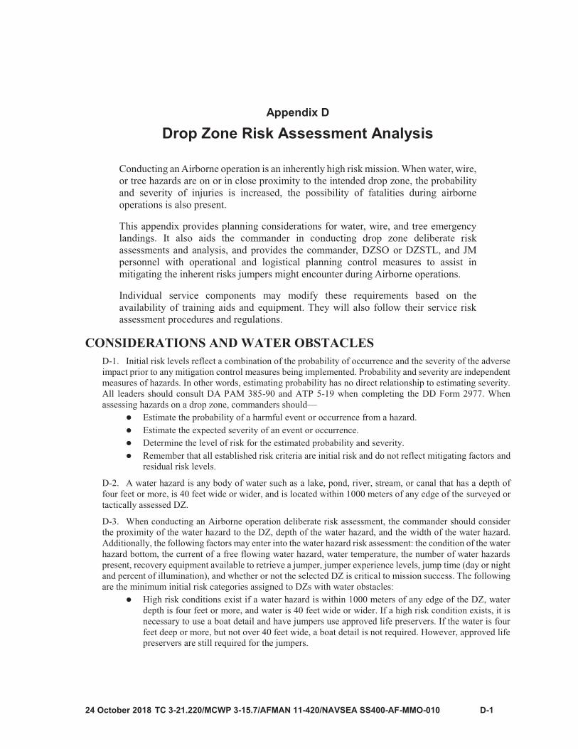
D-1
Appendix D
Drop Zone Risk Assessment Analysis

Appendix D
D-2

Drop Zone Risk Assessment Analysis
D-3
CAUTION Regardless of voltage or current carrying capacity, if a power line is located within 1000 meters of any edge of the surveyed or tactically assessed DZ, the power should be cut off before using the DZ, if possible.

Appendix D
D-4

Drop Zone Risk Assessment Analysis
D-5

Appendix D
D-6

Drop Zone Risk Assessment Analysis
D-7
Table D-1. Drop zone risk assessment decision matrix
HIGH RISK MEDIUM RISK LOW RISK
Water
Within 1000 meters of any edge of a DZ, more than four feet deep, and more than 40 feet wide.
More than 1000 meters but less than 1500 meters from any edge of DZ, more than four feet deep, and more than 40 feet wide.
More than 1500 meters from any edge of DZ, more than four feet deep, and more than 40 feet wide.
Wire Within 1000 meters of any edge of DZ.
More than 1000 meters but less than 1500 meters from any edge of DZ.
More than 1500 meters from any edge of DZ.
Tree(s)Within 1000 meters of any edge of DZ and 35 feet tall or taller.
Within 1000 meters of any edge of DZ and 20 to 35 feet.
Within 1000 meters of any edge of DZ, but less than 20 feet tall.
Obstacle Training and Equipment Required.
Within 1000 meters of any edge of DZ, but less than 20 feet tall.
Not required.
LEGENDDZ – drop zone
Table D-2. Leader’s checklist for possible water landings
COMMANDERDeliberate risk assessment and follow-on assessment have been conducted and approved at the appropriate level.Key leaders, jumpmaster personnel, and jumpers have been informed of water obstacle risks and the risk level (high, medium, or low).AF 3823 is current and available. The DZSO or DZSTL and JM have read it andcompletely understand the unintentional water landing risk level and the safety measures that are to be used. The DZSO or DZSTL and OIC and NCOIC of the boat detail have been briefed and understand their mission.Life preservers are coordinated for if needed.The DZSO or DZSTL, JM personnel, and jumpers have been informed of all water obstacle risks.The DZSTL or DZSO and JM personnel have completed their duties.
DZSO or DZSTLRisk assessment analysis has been conducted and approved at the appropriate level. .If a boat detail is used, the OIC or NCOIC of the boat detail is fully briefed on the plan.All boat detail personnel have been trained and have all necessary equipment available to conduct the mission.All applicable regulations, field manuals, and SOPs have been read.The boat detail maintains communications throughout the mission. Communications are established one hour prior to drop time and checked 15 minutes prior to drop time.

Appendix D
D-8
Table D-2. Leader’s checklist for possible water landings (continued)
JUMPMASTERAll personnel have been briefed on the water hazards.All jumpers have been trained on wear, fit, and use (to include manual inflation) of life preservers.All personnel receive prejump training no earlier than 24 hours prior to take-off, with special emphasis on unintentional water landings. If the prejump is over 24 hours, an O-6 must give approval.LEGENDO-6 – colonel or U.S. Navy captain; DZSO - drop zone safety officer; DZSTL - drop zone supportteam leader; FM – Field Manual; OIC – officer in charge; NCOIC - noncommissioned officer incharge; SOP - standard operating procedure
Table D-3 Leader’s checklist for possible wire landings
COMMANDERDeliberate risk assessment and follow-on assessment has been conducted and approved at the appropriate level.Key leaders, jumpmaster personnel, and jumpers have been informed of wire obstacle risks and the risk level (high, medium, or low).AF 3823 is current and available. The DZSO or DZSTL and JM have read itand completely understand the unintentional wire landing risk level and the safety measures that are to be used. The DZSO or DZSTL and the OIC and NCOIC of the recovery detail have been briefed and understand their mission.The DZSO or DZSTL, JM personnel, and jumpers have been informed of all wire obstacle risks.The DZSTL or DZSO and JM personnel have completed their duties.
DZSO or DZSTLRisk assessment analysis has been conducted and approved at the appropriate level. .If a recovery detail is used, the OIC and NCOIC of the recovery detail is fully briefed on the plan.All detail personnel have been trained and have all necessary equipment available to conduct the mission.All applicable regulations, field manuals, and SOPs have been read.The recovery detail maintains communications throughout the mission. Communications are established one hour prior to drop time and checked 15 minutes prior to drop time.The DZSO or DZSTL has direct contact with who will turn off the power in the event a jumper is drifting towards or becomes entangled in energized electrical lines
JUMPMASTERAll personnel have been briefed on the wire obstacles.All personnel receive prejump training no earlier than 24 hours prior to take-off, with special emphasis on unintentional wire landings. If the prejump is over 24 hours, an O-6 must give approval.
LEGENDO-6 – colonel or U.S. Navy captain; DZSO - drop zone safety officer; DZSTL - drop zone supportteam leader; FM – Field Manual; OIC – officer in charge; NCOIC - noncommissioned officer incharge; SOP - standard operating procedure

Drop Zone Risk Assessment Analysis
D-9
Table D-4. Leader’s checklist for possible tree landings
COMMANDERDeliberate risk assessment and follow-on assessment have been conducted and approved at the appropriate level.Key leaders, jumpmaster personnel, and jumpers have been informed of tree obstacle risks and the risk level (high, medium, or low).AF 3823 is current and available. The DZSO or DZSTL and JM have read itand completely understand the tree landing risk level and the safety measures that are to be used. The DZSO or DZSTL and the OIC and NCOIC of the recovery detail have been briefed and understand their mission.The DZSO or DZSTL, JM personnel, and jumpers have been informed of all tree obstacle risks.The DZSTL or DZSO and JM personnel have completed their duties.
DZSO or DZSTLRisk assessment analysis has been conducted and approved at the appropriate level.If a recovery detail is used, the OIC and NCOIC of the recovery detail is fully briefed on theplan.All recovery personnel have been trained and have all necessary equipment available to conduct the mission.All applicable regulations, field manuals, and SOPs have been read.The recovery detail maintains communications throughout the mission. Communications are established one hour prior to drop time and checked 15 minutes prior to drop time.
JUMPMASTER
All personnel have been briefed on the tree obstacles.All personnel receive pre-jump training no earlier than 24 hours prior to take-off, with special emphasis on unintentional wire landings. If the prejump is over 24 hours, an O-6 must give approval.
LEGENDO-6 – colonel or U.S. Navy captain; DZSO - drop zone safety officer; DZSTL - drop zone supportteam leader; FM – Field Manual; OIC – officer in charge; NCOIC - noncommissioned officer incharge; SOP - standard operating procedure


E-1
Appendix E
Sustained Airborne Training

Appendix E
E-2
Note
Note

TC 3-21.220/MCWP 3-115.7/AFMAN 11-420/NAVSEA SS400-AF-MMO-010, C1 E-3
RED LIGHT PROCEDURES AND JUMP REFUSALS E-6. There are multiple reasons for a red light during flight. These reasons include out of drop zone,obstacles on the drop zone, low flying aircraft, rotary-wing aircraft, and other situations. If a red light occursduring exit, the jumpmaster places their hand in the jumpers face, gives the command, “RED LIGHT, REDLIGHT, RED LIGHT,” and informs the stick to move back away from the paratroop door. If jumpers havealready bisected the paratroop door, they will proceed to exit out of the aircraft.
E-7. If jumpers refuse to jump, the jumpmaster will give the following command three times both physicallyand verbally: “GREEN LIGHT GO.” If the jumper fails to exit after the third command, the safety securesthe jumper by the pack tray, and states, “YOU ARE A JUMP REFUSAL, I AM REMOVING YOU FROMTHE PARATROOP DOOR.” The safety then removes the jumper from the paratroop door. The jumpmastersecures the open paratrooper door. The safety seats the jumper out of the way (ramp or inboard seat) andgives the jumper a lawful order to not touch any equipment.
E-8. The jumpmaster team then continues to exit jumpers if green light permits. Once the paratroop doorsare closed, the safety unhooks the universal static line of any jump refusals and moves them toward theforward portion of the aircraft. The safety tells the jump refusals to sit down and again states, “DO NOTTOUCH YOUR EQUIPMENT.” Upon landing, the safety takes positive control of the jump refusals andtransfers them to the DACO. The jump refusals receive a JMPI from the DACO and a technical inspection isconducted of their equipment by a parachute rigger. If something is found wrong with the jumper’sequipment, no action against the jumper is taken. If no deficiencies are found, the jumper is turned over tothe chain of command for appropriate actions according to the unit SOP.
TOWED JUMPER E-9. All towed jumpers who are unconscious and are being towed by their universal static line modifiedare retrieved and placed inside the aircraft. Towed jumpers who are conscious should maintain a good tight bodyposition with both hands covering their rip cord handles and an attempt is made to retrieve them and placethem inside the aircraft. As the conscious towed jumpers near the paratroop door, they do not reach forpersonnel, but should continue to protect their rip cord handles.
E-10. If the jumper cannot be retrieved, their universal static lines modified are cut. Once the jumper feelsthemself falling free from the aircraft, they count to 6000 and activate their reserve parachute using the pulldrop method. If the jumper is being towed by their equipment, regardless of whether they are conscious orunconscious, that item of equipment will be cut or jogged free, and the jumper’s main canopy will deploy.
EMERGENCY PROCEDURES E-11. In emergencies, the following is conducted by the JM team with the jumpers inside the mock door.The JM team should explain the actions for each type of emergency and then have jumpers demonstrate theemergency actions. If there is:
Ground evacuation or continuous ringing of the alarm bell: if jumpers inside the aircraft hear onecontinuous ring of the alarm bell, there is a crash landing during takeoff. Jumpers should remainseated, extend their legs to a 45-degree angle, wrap their arms around their legs, and place theirheads on their knees until the aircraft stops. Jumpers then exit under the direction of thejumpmasters or loadmaster.Crash landing, ditching, six short rings of the alarm bell, or oral warning: if jumpers inside theaircraft hear six short rings of the alarm bell or an oral warning, there is a crash landing duringflight. Jumpers should remain seated, rotate their legs to a 45 degree angle, wrap their arms aroundtheir legs, and place their heads on their knees until the aircraft stops. Jumpers then exit under thedirection of the jumpmasters or loadmaster.Accidental activation of the reserve inside the aircraft with doors closed: if a reserve is activatedwhen jumpers are inside the aircraft and the doors are closed, jumpers sound off with “RESERVE,RESERVE, RESERVE.” Once the parachute is contained, one of the jumpers alerts thejumpmasters’ by placing their hand or arm over an anchor line cable. The jumpmaster thenreplaces that reserve with a new one and the Airborne operation continues.

Appendix E
TC 3-21.220/MCWP 3-115.7/AFMAN 11-420/NAVSEA SS400-AF-MMO-010
Accidental activation of the reserve inside aircraft with doors open: if a reserve is activated whenjumpers are inside the aircraft and the doors are open, jumpers who are forward of the wheel well(towards the pilots compartment) sound off, “RESERVE, RESERVE, RESERVE.” Once theparachute is contained, one of the jumpers alerts the jumpmasters by placing their hand or armover the anchor line cable. The jumpmasters close the jump doors, then replace that reserve witha new one, and jumpers will exit the aircraft on the next pass. If jumpers are aft of the wheel well(toward jump doors) or center mass aft towards the paratroop door on a C-17, every attempt ismade to contain the parachute. If the reserve starts to snake towards the jump door, the jumperexits the aircraft immediately. Jumpers in front of the activated reserve clear a path for the jumperby either exiting the aircraft, standing on their seat, or moving onto the ramp.Fire during flight: if jumpers are inside the aircraft and hear an oral warning of a fire while inflight, they move from the area, and the loadmasters attempt to extinguish the fire. Jumpers shouldbe prepared to execute bailout procedures if instructed to do so.Bailout, or three short rings of alarm bell, or oral warning: if jumpers are inside the aircraft andthey hear three short rings of the alarm bell or an oral warning, there is an emergency bailout. Thejumpmasters issue shortened jump commands “STAND UP, HOOK UP” on the continuous ring;jumpers will exit the aircraft under the direction of the PJM.
E-12. Jumpers must make a minimum of two exits with the last exit as planned for the Airborne operation.All topics must be covered and tailored to the aircraft used for the operation.
PREJUMP TRAINING E-13. Prior to prejump training, place the jumpers into a formation that allows the jumpmaster to easilycontrol them and make on-the-spot corrections. The extended rectangular formation and the horseshoeformation are the two preferred configurations. It is recommended that the jumpers be placed at double-armintervals to allow the jumpmasters to easily move through the formation.
E-14. Prior to placing the jumpers into formation, ensure the jumpmaster team inspects the helmets,identification cards, and tags. The jumpmasters or the safeties can accomplish this inspection.
E-15. Although prejump can be given by anyone on the jumpmaster team, the primary jumpmaster candelegate authority, but not responsibility. Holding, running, and other information can be inserted intoprejump as the Airborne commander sees fit.
E-16. Although prejump training should be tailored to fit the mission, emergency landings are alwayscovered due to the many variables involved in emergency situations, such as jumpers having to conduct anemergency bailout over unfamiliar terrain.
E-17. Prejump training is performance-oriented training, and the jumpmaster team ensures that the jumpersare performing the actions as they are being covered. During prejump training, use the “HIT IT”exercise as often as needed to keep the jumpers actively involved. Jumpmasters will refer to their unit SOPsfor additional guidance.
T-11 PREJUMPE-18. The five points of performance are performance-oriented training and individual actions that areessential on every parachute jump. Each of the points, specific to the T-11 ATPS, are described in this section.Failure to perform any one point correctly could result in a jump injury. The following instructions are issuedfrom the jumpmaster’s point of view.
E-19. “The first point of performance is PROPER EXIT, CHECK BODY POSITION, and COUNT.JUMPERS HIT IT. Upon exiting the aircraft, snap into a good tight body position. Keep your eyes open, chinon your chest, elbows tight into your sides, hands on the end of the reserve, with your fingers spread. Bendforward at the waist, keeping your feet and knees together, knees locked to the rear, and count to 6000.”
E-20. “At the end of your 6000 count, immediately go into your second point of performance, CHECKCANOPY AND GAIN CANOPY CONTROL. Reach up to the elbow-locked position and secure the frontset of risers in each hand, simultaneously conducting a 360-degree check of your canopy. Your slider will be

TC 3-21.220/MCWP 3-115.7/AFMAN 11-420/NAVSEA SS400-AF-MMO-010, C1 E-5
fully extended and begin to slide down the suspension lines. If, during your second point of performance, you find that you have twists, you must compare your rate of descent with your fellow jumpers. If you are falling faster than your fellow jumpers or you cannot compare your rate of descent with fellow jumpers, immediately activate your reserve parachutes using the pull drop method. If you are not falling faster than fellow jumpers, reach up and grasp a set of risers in each hand, thumbs down, knuckles to the rear. Pull the risers apart and begin a vigorous bicycling motion. When the last twist comes out, immediately check canopy and gain canopy control.”
E-21. “Your third point of performance is KEEP A SHARP LOOKOUT AT ALL TIMES andCONSTANTLY COMPARE YOUR RATE OF DESCENT. Remember the three rules of the air and repeatthem after me. ALWAYS LOOK BEFORE YOU SLIP, ALWAYS SLIP IN THE OPPOSITE DIRECTIONTO AVOID COLLISION, and THE LOWER JUMPER ALWAYS HAS THE RIGHT OF WAY. Avoidfellow jumpers all the way to the ground by maintaining a 25-foot separation and continue to compare yourrate of descent with fellow jumpers. During your third point of performance, release all appropriateequipment tie-downs.”
E-22. “This brings you to your fourth point of performance, which is PREPARE TO LAND. Atapproximately 100 feet above ground level or treetop level, look below you to ensure there are no fellowjumpers and lower your equipment, then slip into the wind. Attempt to utilize the slip assist loops or slipassist tabs and execute a one-riser slip opposite your direction of drift. You will execute a one-riser slip bygrabbing 1-3 arm lengths depending on the wind. If the wind is blowing from your left, reach up with yourleft hand and grab either riser on the left side and pull a 1-3, arm length slip deep into your chest. If the windis blowing from your front, reach up with either hand and grab either riser on the front side and pull a 1-3, armlength slip deep into your chest. If the wind is blowing from your right, reach up with your right hand andgrab either riser on the right side and pull a 1-3, arm length slip deep into your chest. If the wind is blowingfrom your rear, reach up with either hand and grab either riser on the rear side and pull a 1-3, arm length slipdeep into your chest. If you decide to pull a two-riser slip, secure the risers opposite your direction of driftand hold them deep into your chest. After you have slipped into the wind, you will assume a landing attitudeby keeping your feet and knees together, knees slightly bent, elbows tight into your sides, with your head andeyes on the horizon. When the balls of your feet make contact with the ground, put your chin down to yourchest and execute a proper parachute landing fall.”
E-23. “The fifth point of performance is LAND. You will make a proper parachute landing fall by hittingall five points of contact. Touch them, and repeat them after me. One, BALLS OF YOUR FEET; two, CALF;three, THIGH; four, BUTTOCKS; and five, PULL UP MUSCLE. You will never attempt to make a standinglanding.”
E-24. “Remain on the ground and activate both of your canopy release assemblies using either the “hand toshoulder” method or the “hand assist” method. To activate your canopy release assembly using the “hand toshoulder” method, reach up with either hand and grasp the corresponding safety clip. Pull out and down onthe safety clip, exposing the cable loop. Insert the thumb, from bottom to top, through the cable loop. Turnyour head in the opposite direction, and pull out and down on the cable loop. To activate your canopy releaseassembly using the “hand assist” method, reach up and grasp the corresponding safety clip. Pull out and downon the safety clip, exposing the cable loop. Insert the thumb, from bottom to top, through the cable loop.Reinforce that hand with the other. Turn your head in the opposite direction, and pull out and down on thecable loop. Place your weapon into operation and remove the parachute harness.”
E-25. “The next item I will cover is RECOVERY OF EQUIPMENT. Once you are out of the parachuteharness, remove all air items from the equipment rings. Unzip and turn the universal parachutist recoverybag right side out. Place the parachute harness inside the universal parachutist recovery bag with the smoothside facing up. Secure the risers and place them under the parachute harness.”
E-26. Nontactical: “Elongate the suspension lines and canopy, removing all debris. Once you reach the bridle line, secure the drogue parachute and deployment sleeve in one hand and begin to figure-eight roll yourcanopy and suspension lines all the way to the UPRB, leaving the drogue parachute, deployment sleeve, andbridle assembly on top of the main canopy.”
E-27. Tactical: “Remain on a knee at the universal parachutist recovery bag. Begin pulling the suspensionlines and canopy towards the universal parachutist recovery bag, stuffing them in as you go. Place the drogue

Appendix E
E-6 TC 3-21.220/MCWP 3-115.7/AFMAN 11-420/NAVSEA SS400-AF-MMO-010, C1
parachute, deployment sleeve, and bridle assembly on top of the main canopy. Snap, do not zip, the universal parachutist recovery bag. Place the reserve parachute in the reserve parachute stowage pocket. Secure all of your equipment, conduct a 360-degree check of your area, and move out to your assembly area.”
E-28. “The next item I will cover is the ACTIVATION OF THE T-11 RESERVE PARACHUTE. Toactivate the T-11 reserve parachute, you will use the pull drop method. JUMPERS HIT IT, maintain a good,tight body position. Grasp the rip cord handle with either hand. Throw your head back and to the rear, pullout on the rip cord handle, and drop it. Your reserve parachute will activate. Ensure neither hand is in frontof the reserve parachute as it deploys. After you activate your T-11 reserve parachute, secure the reserverisers. At approximately 200 feet above ground level, slip into the wind, and prepare to land.”
E-29. “The next item I will cover is TOWED JUMPER PROCEDURES. JUMPERS HIT IT. If you becomea towed jumper, and are being towed by your universal static line modified and are unconscious; you will beretrieved back inside the aircraft. If you are conscious, maintain a good tight body position with both handscovering your rip cord handle and an attempt will be made to retrieve you inside the aircraft. As you near theparatroop door, DO NOT REACH FOR US, continue to protect your rip cord handle. If you cannot beretrieved, your universal static line modified will be cut. Once you feel yourself falling free from the aircraft,count to 600 and activate your reserve parachute using the pull drop method. If you are being towed by yourequipment, regardless of whether you are conscious or unconscious, that item of equipment will be cut orjogged free, and your main canopy will deploy.”
E-30. “The next item I will cover is MALFUNCTIONS. Remember to continue to check your canopy forany damage or irregularities and compare your rate of descent throughout your entire jump. If at any timeyou cannot compare your rate of descent or you are falling faster than your fellow jumpers, immediatelyactivate your reserve parachute using the pull drop method.”
E-31. “The next item I will cover is COLLISIONS AND ENTANGLEMENTS. JUMPERS HIT IT. CHECKCANOPY AND GAIN CANOPY CONTROL. If you see another jumper approaching, immediately look,and then slip away. If you cannot avoid the collision, assume a spread eagle body position and attempt tobounce off the jumper’s canopy or suspension lines and immediately look, and then slip away. If you passthrough the suspension lines, snap into a modified position of attention. With either hand protect your ripcord handle. With the opposite hand attempt to weave your way out of the suspension lines the same wayyou entered. Once clear, immediately look then slip away. If you become entangled, the higher jumper willclimb down to the lower jumper using the hand under hand method. Once both jumpers are even, they willface each other and grasp each other’s left main lift web. Both jumpers will discuss which PLF they willexecute. Both jumpers will conduct the same PLF. Neither jumper will execute a front PLF. Both jumperswill continue to observe their canopies all the way to the ground. If one canopy collapses both jumpers willride the one good canopy all the way to the ground. If both canopies collapse, both jumpers will immediatelyturn away, in order to create a clear path, and activate their reserve parachute using the pull drop method.Should you find yourself on another jumper’s canopy, without rolling, use whatever means necessary to getoff of the canopy and immediately activate your reserve parachute. Attempt to avoid the four corner vents onthe canopy. Should you fall through a corner vent, stay where you are and be prepared to conduct a PLF. Ifyou have another jumper on top of your canopy, continually compare your rate of descent. If you are fallingfaster than fellow jumpers, immediately activate your reserve parachute using the pull drop method.”
E-32. “The next item I will cover is EMERGENCY LANDINGS. The first emergency landing I will coveris the TREE LANDING. If you are drifting toward the trees, immediately look then slip away. If you cannotavoid the trees and have lowered your equipment, look below you to ensure there are no fellow jumpers, andjettison your equipment making a mental note of where it lands. If you have not lowered your equipment,keep it on you to provide extra protection while passing through the trees. At approximately 200 feet aboveground level, assume a good landing attitude by keeping your feet and knees together, knees slightly bent,and chin on your chest. When you make contact with the trees, rotate your hands in front of your face withyour elbows high. Be prepared to execute a proper PLF if you pass through the trees. If you get hung up inthe trees and you do not feel you can safely lower yourself to the ground, stay where you are and wait forassistance.”
E-33. “If you decide to climb down, jettison all unneeded equipment. Ensure that you maintain your helmet.Activate the quick release in your waistband. With either hand, apply inward pressure on the rip cordassembly. With the opposite hand remove the top tuck tab. Maintain steady inward pressure and with the

Sustained Airborne Training
TC 3-21.220/MCWP 3-115.7/AFMAN 11-420/NAVSEA SS400-AF-MMO-010, C1 E-7
opposite hand insert it behind the rip cord assembly and apply inward pressure. Grasp the rip cord handle with the opposite hand, pull it and drop it. With both hands, control the activation of the reserve parachute to the ground ensuring that all suspension lines and risers are completely deployed. Disconnect the left connector snap and rotate the reserve to the right. Attach the left connector snap to the triangle link on your right side. Seat yourself well into the saddle. Activate the quick release in the chest strap and completely remove the chest strap from the chest strap friction adapter. Grasp the right main lift web with either hand below the canopy release assembly and with the other hand activate the leg strap ejector snaps and climb down the outside of the reserve parachute. Caution must be taken when climbing down the T-11 reserve suspension lines because of the slippery coating applied to the suspension lines. Remember, when in doubt, stay where you are and wait for assistance.” E-34. “The next emergency landing I will cover is the WIRE LANDING. If you are drifting towards wires,immediately look and try to slip away. If you cannot avoid the wires, look below you to ensure there are nofellow jumpers and jettison your equipment, making a mental note of where it lands. Ensure that you maintain your helmet. Assume a landing attitude by keeping your feet and knees together, exaggerating the bend inyour knees, eyes open, chin on your chest with your back arched. Place the palms of your hands high on theinside of the front set of risers with the elbows locked. When you make contact with the wires, begin avigorous rocking motion in an attempt to pass through the wires. Be prepared to execute a proper PLF in theevent you pass through the wires. If you get hung up in the wires, do not attempt to lower yourself to theground. Stay where you are and wait for assistance.”E-35. “The next emergency landing I will cover is the WATER LANDING. If you are drifting towards abody of water, immediately look then slip away. If you cannot avoid the water, look below you to ensurethere are no fellow jumpers and lower your equipment. Next, jettison your helmet, making a mental note ofwhere it lands. Activate the quick release in the waistband. Disconnect the left connector snap and rotate thereserve parachute to the right. Seat yourself well into the saddle and activate the quick release in the cheststrap, completely removing the chest strap from the chest strap friction adapter. Regain canopy control. Priorto entering the water, assume a landing attitude by keeping your feet and knees together, knees slightly bent,and place your hands on both leg strap ejector snaps. When the balls of your feet make contact with the water,activate both leg strap ejector snaps, arch your back, throw your arms above your head, and slide out of theparachute harness. Be prepared to execute a proper PLF if the water is shallow. Swim upwind, or upstream,away from the canopy. If the canopy comes down on top of you, locate a seam, and follow it to the skirt ofthe canopy.”E-36. “The next item I will cover is LIFE PRESERVERS. When jumping a life preserver and you are unableto slip away from the water, lower your combat equipment, activate your life preserver, then jettison yourcombat equipment prior to making contact with the water. Be prepared to execute a proper PLF if the wateris shallow. Once in the water, activate both canopy release assemblies.”E-37. “The next item I will cover is NIGHT JUMPS. When conducting night jumps, be sure to give yourcanopy an extra look if you have any reason to believe you are falling faster than fellow jumpers immediatelyactivate your reserve parachute. Maintain noise discipline and a good interval between fellow jumpers. Beprepared to conduct a PLF because you will hit the ground approximately five to 10 seconds before you thinkyou will.”E-38. “The next item I will cover is instrument meteorological conditions. When jumping under IMC, donot lower your equipment until you have passed through the clouds. Do not slip unless you have to avoid acollision. If you have any type of malfunction or any reason to believe you are falling faster than fellowjumpers, immediately activate your reserve parachute using the pull drop method because you cannotcompare your rate of descent with fellow jumpers. Ensure you recheck your canopy once you pass throughthe clouds.”E-39. “The final item I will cover is PARACHUTE LANDING FALLS. We will now move to the PLFplatform and conduct one satisfactory PLF in each of the four directions.”

Appendix E
E-8 TC 3-21.220/MCWP 3-115.7/AFMAN 11-420/NAVSEA SS400-AF-MMO-010, C1
MC-6 PREJUMPE-40. The five points of performance are performance oriented training and individual actions that areessential on every parachute jump. Each of the points specific to the MC-6 series parachute are described inthis section. Failure to perform any one point correctly could result in a jump injury. The followinginstructions are issued from the jumpmaster’s point of view.
E-41. “The first point of performance is PROPER EXIT, CHECK BODY POSITION, and COUNT.JUMPERS HIT IT. Upon exiting the aircraft, snap into a good tight body position. Keep your eyes open, chinon your chest, elbows tight into your sides, hands on the end of the reserve, with your fingers spread. Bendforward at the waist keeping your feet and knees together, knees locked to the rear, and count to 4000.”
E-42. “At the end of your 4000 count, immediately go into your second point of performance, CHECKCANOPY and GAIN CANOPY CONTROL. When jumping the MC-6 series parachute, secure a toggle ineach hand and pull them down to eye level, simultaneously conducting a 360-degree check of your canopy.If during your second point of performance you find that you have twists, you must compare your rate ofdecent with your fellow jumpers. If you are falling faster than your fellow jumpers or you cannot compareyour rate of descent with fellow jumpers, immediately activate your reserve parachute using the pull dropmethod. If you are not falling faster than fellow jumpers, then reach up and grasp a set of risers in each hand,thumbs down, knuckles to the rear. Pull the risers apart and begin a vigorous bicycling motion. When the lasttwist comes out, immediately check canopy and gain canopy control.”
E-43. “Your third point of performance is KEEP A SHARP LOOKOUT AT ALL TIMES andCONSTANTLY COMPARE YOUR RATE OF DESCENT. Remember the three rules of the air and repeatthem after me. ALWAYS LOOK BEFORE YOU TURN, ALWAYS TURN IN THE OPPOSITEDIRECTION TO AVOID COLLISIONS, and THE LOWER JUMPER ALWAYS HAS THE RIGHT OFWAY. Avoid fellow jumpers all the way to the ground by maintaining a 50-foot separation and continue tocompare your rate of descent with fellow jumpers.”
E-44. “This brings you to your fourth point of performance which is PREPARE TO LAND. Atapproximately 250 feet above ground level, determine your direction of drift. If the wind is blowing fromyour left, pull your left toggle down to the elbow locked position. One you are facing into the wind, let upslowly to prevent oscillation. If the wind is blowing from your right, pull your right toggle down to the elbowlocked position. Once you are facing into the wind, let up slowly to prevent oscillation. If the wind is blowingfrom your rear, pull either toggle down to the elbow locked position. Once you are facing into the wind, letup slowly to prevent oscillation. If the wind is blowing from your front, make minor corrections to remainfacing into the wind. Look below you to ensure there are no fellow jumpers. Transfer control of one toggleto the opposite hand, so that the other hand is controlling both toggles in front of your face. With the freehand, release all appropriate equipment tie-downs, and lower your combat equipment. Now regain canopycontrol with both hands. Assume a proper prepare to land attitude by pulling the toggles to the appropriatebreak position. After you have turned into the wind, you will assume a landing attitude by keeping your feetand knees together, knees slightly bent, elbows tight into your sides, with your head and eyes on the horizon.When the balls of your feet make contact with the ground, put your chin down to your chest and execute aproper parachute landing fall.”
E-45. “The fifth point of performance is LAND. You will make a proper parachute landing fall by hitting allfive points of contact. Touch them and repeat them after me. One, BALLS OF YOUR FEET; two, CALF;three, THIGH; four, BUTTOCKS; and five, PULL UP MUSCLE. You will never attempt to make a standinglanding.”
E-46. “Remain on the ground, and activate one of your canopy release assemblies using either the hand toshoulder method, or the hand assist method. To activate your canopy release assembly using the hand toshoulder method, reach up with either hand and grasp the corresponding safety clip. Pull out and down onthe safety clip exposing the cable loop. Insert your thumb, from bottom to top, through the cable loop. Turnyour head in the opposite direction and pull out and down on the cable loop. To activate your canopy releaseassembly using the hand assist method, reach up and grasp the corresponding safety clip. Pull out and downon the safety clip exposing the cable loop. Insert your thumb, from bottom to top, through the cable loop.Reinforce that hand with the other. Turn your head in the opposite direction and pull out and down on the
Sustained Airborne Training
TC 3-21.220/MCWP 3-115.7/AFMAN 11-420/NAVSEA SS400-AF-MMO-010, C1 E-9
cable loop. If your canopy fails to deflate, activate the other canopy release assembly. Place your weapon into operation and remove the parachute harness.”
E-47. “The next item I will cover is RECOVERY OF EQUIPMENT. Once you are out of the parachuteharness, remove all air items from the equipment rings. Unzip and turn the universal parachutist recoverybag right side out. Place the parachute harness inside the universal parachutist recovery bag with the smoothside facing up and leave the waistband exposed. Secure the risers and place them under the parachuteharness.”
E-48. Nontactical: “Elongate the suspension lines and canopy removing all debris. Once you reach the bridleloop, insert your thumb in the bridle loop and begin to figure-eight roll your canopy and suspension lines allthe way to the universal parachutist recovery bag. Route the waistband through the bridle loop, leaving sixto eight inches of the waistband exposed.”
E-49. Tactical: “Remain on a knee at the universal parachutist recovery bag. Begin pulling the suspensionlines and canopy towards the universal parachutist recovery bag, stuffing them in as you go. Route thewaistband through the bridle loop leaving six to eight inches of the waistband exposed.”
E-50. “Snap, do not zip, the universal parachutist recovery bag. Place the reserve parachute in the reserveparachute stowage pocket. Secure all of your equipment, conduct a 360-degree check of your area, and moveout to your assembly area.”
E-51. “The next item I will cover is the ACTIVATION OF THE T-11 RESERVE PARACHUTE.” Toactivate the T-11 reserve parachute, you will use the pull drop method. JUMPERS HIT IT. Maintain a good,tight body position. Grasp the rip cord handle with either hand. Throw your head back and to the rear, pullout on the rip cord handle, and drop it. Your reserve parachute will activate. Ensure neither hand is in frontof the reserve parachute as it deploys. After you activate your T-11 reserve parachute, secure the reserverisers. At approximately 200 feet above ground level, slip into the wind, and prepare to land.”
E-52. “The next item I will cover is TOWED JUMPER PROCEDURES.” JUMPERS HIT IT. If you arebeing towed by your universal static line modified and are unconscious you will be retrieved back inside theaircraft. If you are conscious, maintain a good, tight body position with both hands covering your rip cordhandle. An attempt will be made to retrieve you inside the aircraft. As you near the paratroop door, do notreach for us, but continue to protect your rip cord handle. If you cannot be retrieved, your universal staticline modified will be cut. Once you feel yourself falling free from the aircraft, count to 4000 and activateyour reserve parachute using the pull drop method. If you are being towed by your equipment, regardless ofwhether you are conscious or unconscious, that item of equipment will be cut or jogged free, and your maincanopy will deploy.”
E-53. “The next item I will cover is MALFUNCTIONS. Remember to continue to check your canopy forany damage or irregularities and compare your rate of descent throughout your entire jump. If at any timeyou cannot compare your rate of descent or you are falling faster than your fellow jumpers, immediatelyactivate your reserve parachute using the pull drop method. If the MC-6 canopy becomes inverted, pulling atoggle will turn you in the opposite direction. Do not activate your reserve parachute unless the canopy wasdamaged during inversion. If you have broken control lines, you must use your rear risers to turn.”
E-54. “The next item I will cover is COLLISIONS AND ENTANGLEMENTS. JUMPERS HIT IT. CHECKCANOPY and GAIN CANOPY CONTROL. If you see another jumper approaching, immediately look, andthen turn away. If you cannot avoid the collision, assume a spread eagle body position and attempt to bounceoff the jumper’s canopy or suspension lines, then immediately look, and then turn away. If you pass throughthe suspension lines and you do become entangled, snap into a modified position of attention. With eitherhand protect your rip cord handle. With the opposite hand, attempt to weave your way out of the suspensionlines the same way you entered. Once clear, immediately look then turn away. If you become hopelesslyentangled, both jumpers will remain where they are, obtain a clear path, and immediately activate theirreserve parachutes using the pull drop method.”
E-55. “The next item I will cover is EMERGENCY LANDINGS. The first emergency landing I willcover is the TREE LANDING. If you are drifting towards the trees, immediately look, then turn away. Ifyou cannot avoid the trees, and have lowered your equipment, look below you to ensure there are no fellowjumpers and jettison your equipment, making a mental note of where it lands. If you have not lowered your

Appendix E
E-10 TC 3-21.220/MCWP 3-115.7/AFMAN 11-420/NAVSEA SS400-AF-MMO-010, C1
equipment, keep it on you to provide extra protection while passing through the trees. At approximately 200 feet above ground level, assume a good landing attitude by keeping your feet and knees together, knees slightly bent, and chin on your chest. When you make contact with the trees, rotate your hands in front of your face with your elbows high. Be prepared to execute a proper PLF if you pass through the trees. If you get hung up in the trees and you do not feel you can safely lower yourself to the ground, stay where you are and wait for assistance.”
E-56. “If you decide to climb down, jettison all unneeded equipment. Ensure that you maintain your helmet.Activate the quick release in your waistband. With either hand, apply inward pressure on the rip cordassembly. With the opposite hand, remove the top tuck tab. Maintain steady inward pressure and with theopposite hand insert it behind the rip cord assembly and apply inward pressure. Grasp the rip cord handlewith the opposite hand, pull it and drop it. With both hands, control the activation of the reserve parachute tothe ground, ensuring that all suspension lines and risers are completely deployed. Disconnect the leftconnector snap and rotate the reserve to the right. Attach the left connector snap to the triangle link on yourright side. Seat yourself well into the saddle. Activate the quick release in the chest strap and completelyremove the chest strap from the chest strap friction adapter. Grasp the right main lift web with either handbelow the canopy release assembly, and with the other hand activate the leg strap ejector snaps and climbdown the outside of the reserve parachute. Caution must be taken when climbing down the T-11 reservesuspension lines because of the slippery coating applied to the suspension lines. Remember, when in doubt,stay where you are and wait for assistance.”
E-57. “The next emergency landing I will cover is the WIRE LANDING. If you are drifting towards wires,immediately look, then turn away. If you cannot avoid the wires, look below you to ensure there are no fellowjumpers and jettison your equipment, making a mental note of where it lands. Ensure that you maintain yourhelmet. Assume a landing attitude by keeping your feet and knees together, exaggerating the bend in yourknees, eyes open, chin on your chest, with your back arched. Place the palms of your hands high on the insideof the front set of risers with the elbows locked. When you make contact with the wires, begin a vigorousrocking motion in an attempt to pass through the wires. Be prepared to execute a proper PLF in the event youpass through the wires. If you get hung up in the wires, do not attempt to lower yourself to the ground. Staywhere you are, and wait for assistance.”
E-58. “The next emergency landing I will cover is the WATER LANDING. If you are drifting towards abody of water, immediately look, then turn away. If you cannot avoid the water, look below you toensure there are no fellow jumpers and lower your equipment. Next, jettison your helmet, making a mentalnote of where it lands. Activate the quick release in the waistband. Disconnect the left connector snap androtate the reserve parachute to the right. Seat yourself well into the saddle. Activate the quick release in thechest strap, completely removing the chest strap from the chest strap friction adapter. Regain canopy control.Prior to entering the water, assume a landing attitude by keeping your feet and knees together, knees slightlybent, and place your hands on both leg strap ejector snaps. When the balls of your feet make contact with thewater, activate both leg strap ejector snaps, arch your back, throw your arms above your head, and slide outof the parachute harness. Be prepared to execute a proper PLF if the water is shallow. Swim upwind, orupstream, away from the canopy. If the canopy comes down on top of you, locate a seam, and follow it tothe skirt of the canopy.”
E-59. “The next item I will cover is LIFE PRESERVERS. When jumping a life preserver and you are unableto slip away from the water, lower your combat equipment, activate your life preserver, then jettison yourcombat equipment prior to making contact with the water. Be prepared to execute a proper PLF if the wateris shallow. Once in the water, activate both canopy release assemblies.”
E-60. “The next item I will cover is NIGHT JUMPS. When conducting night jumps, be sure to give yourcanopy an extra look. ”If you have any reason to believe you are falling faster than fellow jumpers,immediately activate your reserve parachute. Maintain noise discipline and a good interval between fellowjumpers. Be prepared to conduct a PLF because you will hit the ground approximately five to 10 secondsbefore you think you will.”
E-61. “The next item I will cover is INSTRUMENT METEOROLOGICAL CONDITIONS. When jumpingunder IMC, do not lower your equipment until you have passed through the clouds. Do not turn unless youhave to avoid a collision. If you have any type of malfunction, or any reason to believe you are falling fasterthan fellow jumpers, you must immediately activate your reserve parachute using the pull drop method

Sustained Airborne Training
TC 3-21.220/MCWP 3-115.7/AFMAN 11-420/NAVSEA SS400-AF-MMO-010, C1 E-11
because you cannot compare your rate of descent with fellow jumpers. Ensure you recheck your canopy once you pass through the clouds.”
E-62. “The final item I will cover is PARACHUTE LANDING FALLS. We will now move to the PLFplatform and conduct one satisfactory PLF in each of the four directions.”

This page intentionally left blank.

TC 3-21.220/MCWP 3-115.7/AFMAN 11-420/NAVSEA SS400-AF-MMO-010, C1 F-1
Appendix F
Collisions, Entanglements, and Center Panel Strike
Leaders at all levels must stress the importance of prevention in regards to collisions, entanglements, and the center panel strike (T-11 ATPS only); this is key to avoiding situations where emergency procedures are executed. Leaders ensure that all jumpers know the proper emergency procedures discussed in this appendix before executing any static line personnel operations.
Jumpmaster teams control jumper spacing and the flow of jumpers during exiting procedures to avoid simultaneous exits. This leads to acceptable jumper dispersion in the air and aids jumpers in avoidance measures.
All jumpers must maintain a 25-foot separation between jumpers when jumping the T- 11 ATPS and use a one riser or diagonal slip to avoid other jumpers in the air and obstacles on the ground. Jumpers maintain a 50-foot separation when jumping the MC-6 parachute and use good toggle control to avoid other jumpers in the air and obstacles on the ground. In some situations, collisions and entanglements and a center panel strike cannot be avoided. This appendix covers the following emergency procedures:
Collisions and entanglements with the T-11 and MC-6 parachutes.Center panel strike with the T-11 parachute.
COLLISIONS AND ENTANGLEMENTS F-1. A collision is the physical impact or contact, however slight, of one jumper or jumper’s equipmentwith that of another jumper, but both jumpers separate prior to making contact with the ground. Anentanglement is the entwining or attachment of a jumper or jumper’s equipment with that of another jumperduring descent, whether or not the entanglement lasts until the jumpers contact the ground.
F-2. Jumpers must be alert in the air and warn each other of impending collisions. If a collision cannot beavoided by slipping or turning, jumpers attempt to bounce off the other jumpers’ suspension lines or canopiesby spreading their arms and legs just before making contact.
F-3. If a jumper becomes entangled with one or more suspension lines of another parachute, the jumperdoes one of the following, depending on the type of parachute being used and the incident altitudes:
High altitude occurs from aircraft exit throughout full canopy deployment (first point ofperformance).Mid altitude occurs after full canopy deployment throughout descent to the preparation for landingaltitude designated for the type of parachute used (second and third points of performance).Low altitude occurs from the preparation for landing altitude throughout descent to landing (fourthpoint of performance).
T-11 PARACHUTE EMERGENCY PROCEDURESF-4. In the event of an entanglement, the following actions should be taken:
If a jumper is jumping with the T-11 parachute and becomes entangled, the higher jumper climbsdown to the lower jumper using the hand-under-hand method. The jumper must stay away fromthe corner vents located on all four corners of the canopy, and the bridle line on top of the canopy.

Appendix F
F-2 TC 3-21.220/MCWP 3-115.7/AFMAN 11-420/NAVSEA SS400-AF-MMO-010 24 October 2018
Should the jumper fall through a vent or become entangled in the bridle line, the jumper should stay in place and be prepared to execute a proper PLF. Once both jumpers are even, they face each other and grasp each other’s left main lift web. Bothjumpers continue to observe both canopies and take one of the following actions:
If one canopy collapses, neither jumper will activate their reserve parachute because oneT-11 series parachute can safely deliver two combat-equipped jumpers to the ground.If both canopies should collapse, both jumpers immediately turn away from each other tocreate a clear path, and activate their reserve parachute using the pull drop method.
Both jumpers discuss which PLF to execute.Both jumpers conduct the same PLF.Neither jumper executes a front PLF.A jumper who finds them self on another jumper’s canopy, without rolling, uses whatever meansnecessary to get off of the canopy and immediately activate the reserve parachute using the pulldrop method. If a lower jumper has another jumper on top of their canopy, continually comparethe rate of descent of both jumpers. If the lower jumper is falling faster than fellow jumpers, thelower jumper immediately activates the reserve parachute using the pull drop method.Remember to stay away from the four corner vents located at the corners of the canopy.A jumpers who falls through the vent should stay in place and be prepared to execute a properPLF.
CENTER PANEL STRIKE F-5. A center panel strike occurs when a jumper finds them self on top of another jumper’s canopy at anytime during their second, third, and fourth point of performance. The two jumpers handle the situation byfollowing these procedures:
Actions of the higher jumper:If the higher jumper is drifting toward a fellow jumper, the higher jumper should look andimmediately slip away in the opposite direction of the lower jumper using a one riser diagonalslip.If a higher jumper is drifting over a lower jumper's canopy and may land on top of it; prior tomaking contact with the canopy, the higher jumper begins a vigorous running motion in thedirection of their slip, attempting to stay on their feet, until the higher jumper is off the lowerjumper's canopy. The higher jumper continues to slip away until a minimum of 25 feet ofseparation has been achieved.If the higher jumper lands on the lower jumper's canopy and cannot run off, it is vital tomaintain momentum. This should allow the higher jumper to remain on their feet and attemptto get off the closest edge of the canopy, as momentum allows. If the higher jumper cannotstay on their feet, the higher jumper should employ a crawling technique by reaching as faras possible in the direction of the closest edge of the canopy. The higher jumper should graspthe canopy and continue to pull using the hand-over-hand method until free from the lowerjumper's canopy. Once the higher jumper is falling free, they create a clear and unobstructedpath, then activate the reserve parachute using the pull drop method. Keep the feet and kneestogether and be prepared to execute a parachute landing fall.
WARNING Jumpers should not attempt to roll off the canopy as this could wrap the suspension line around their bodies, preventing the main canopy from re-inflating and preventing the deployment of the reserve.

Collisions, Entanglements, and Center Panel Strike
TC 3-21.220/MCWP 3-115.7/AFMAN 11-420/NAVSEA SS400-AF-MMO-010, C1 F-3
Actions of the lower jumper:At the end of the lower jumpers’ 6000 count, they immediately begin the second point ofperformance, check canopy and gain canopy control.They then conduct a 360-degree check of their canopy to ensure the canopy is free of anydamage or fellow jumpers, and the slider is descending.If there is damage to the canopy or a jumper on top, the lower jumpers compares their rate ofdescent with their fellow jumpers. If lower jumpers are falling faster than their fellow jumpers, they immediately activate the reserve parachute using the pull drop method.If the lower jumper has a jumper on top of their canopy and the lower jumper is not fallingfaster than their fellow jumpers, they continue to observe their canopy. If at any time thelower jumpers’ main parachutes begin to deflate, they immediately activate the reserveparachutes using the pull drop method.If the higher jumper slides off of the lower jumper’s canopy, the lower jumper uses a one riserdiagonal slip in the opposite direction to avoid fellow jumpers.
WARNING When slipping away from fellow jumpers, always use a diagonal slip. If the higher jumper should fall through a corner vent, they should remain where they are and be prepared to conduct a parachute landing fall.
MC-6 PARACHUTE EMERGENCY PROCEDURESF-6. A collision is the physical impact or contact, however slight, of one jumper or jumpers’ equipmentwith that of another jumper, but both jumpers separate prior to making contact with the ground. Anentanglement is the entwining or attachment of a jumper or jumper’s equipment with that of another jumperduring descent, whether or not the entanglement lasts until the jumpers make contact with the ground.
F-7. Jumpers must be alert in the air and warn each other of impending collisions. If a collision cannot beavoided by turning away, the jumper should take the following actions:
Assume a spread eagle position.Attempt to bounce off the other jumper’s canopy and suspension lines and immediately turn awayto regain the 50-foot separation.
F-8. If a jumper becomes entangled with one or more suspension lines of another parachute, BOTH jumperstake the following actions:
Remain where they are.Obtain a clear path.Immediately activate their reserve parachute using the pull drop method


TC 3-21.220/MCWP 3-15.7/AFMAN 11-420/NAVSEA-AF-MMO-010 Glossary-1
Glossary
SECTION I – ACRONYMS AND ABBREVIATIONS

Glossary
Glossary-2 TC 3-21.220/MCWP 3-15.7/AFMAN 11-420/NAVSEA-AF-MMO-010

Glossary
TC 3-21.220/MCWP 3-15.7/AFMAN 11-420/NAVSEA-AF-MMO-010 Glossary-3

Glossary
Glossary-4 TC 3-21.220/MCWP 3-15.7/AFMAN 11-420/NAVSEA-AF-MMO-010
SECTION II – TERMS

TC 3-21.220/MCWP 3-15.7/AFMAN 11-420/NAVSEA-AF-MMO-010
References
Terms and Military Symbols, DODDictionary of Military and Associated Terms,
C-130 Operations Procedures,Drop Zone and Landing Zone Operations,Safety Investigations and Reporting,
Joint Airdrop Inspection Records,Malfunction/Incident Investigations, and Activity Reporting {OPNAVINST 4630.24D; AFJ 13-210(I); MCO13480.1C},
Evidence ProceduresThe Army Safety Program,
Property Accountability Policies,Airdrop, Parachute Recovery, and Aircraft Personnel Escape Systems
Special Forces Military Free-Fall Operations,
Risk Management,Army Aviation Accident Prevention Program,
Mishap Notification, Investigation, Reporting, and Record Keeping,
Pathfinder Operations, The Law of Land Warfare,
Manual of the Judge Advocate General (JAGMAN),
Marine Corps Parachuting Policy and Program Administration,
Navy & Marine Corps Mishap and Safety Investigation, Reporting,and Record Keeping Manual,
Water Survival TrainingAirdrop of Supplies and Equipment: Rigging Containers,
Airdrop ofSupplies and Equipment: Rigging Loads for Special Operations

Appendix F
TC 3-21.220/MCWP 3-15.7/AFMAN 11-420/NAVSEA-AF-MMO-010
Field Maintenance Manual Including Repair Parts and Special Tools List for35-Foot Diameter, MC1-1E Troop Back Parachute Assembly P/N 11-1-900-4 (NSN 1670-01-499-6573,
Field Maintenance Manual Including Repair Parts and Special Tools List forT-11Personnel Parachute System (NSN 1670-01-539-4525)
Field Maintenance Manual Including Repair Parts and Special Tools List forMC-6 Personnel Parachute System (NSN 1670-01-527-7537)
Field Maintenance Manual Including Repair Parts and Special Tools List forAdvanced Emergency Bailout Parachute (AEBP) System NSN 1670-01-598-1318,
Operators Manual for Modular Lightweight Load-Carrying Equipment(MOLLE) II,
Preparing HazardousMaterials for Military Air Shipments

Collisions, Entanglements, and Center Panel Strike
3-21.220/MCWP 3-15.7/AFMAN 11-420/NAVSEA-AF-MMO-010
Statement of Jump and Loading ManifestIndividual Jump Record.Recommended Changes to Publications and Blank FormsArmy Parachute Log Record.Evidence/Property Custody DocumentDOD Single Line Item Requisition System Document (Manual).Serviceable Tag – Materiel
Airdrop Malfunction Report (Personnel-Cargo)
Deliberate Risk Assessment Worksheet.


TC 3-21.220/MCWP 3-15.7/AFMAN 11-420/NAVSEA-AF-MMO-010 Index-1
Index
A A-21 cargo bag assembly. 14-
11A-7A airdrop cargo sling
assembly. 14-5advanced combat helmet. 12-6
assembly. 12-8 back. 9-31front. 9-150, 9-21rear. 9-161
ADZSO requirements. 7-13
Airborne commander. 7-1 airdrop operation personnel.
9-1boat detail. 20-31door bundle procedures.
10-89lowering M1950 weapon's
case. 12-93marshalling area control
officer briefing. 8-6 MC-6 video. 8-58risk assessment. 15-8tree recovery detail. 20-32water DZ. 25-3wire obstacles. D-13, D-11
airfield and runway safety. 11-4 AIRPAC. 12-104
attached to jumper. 12-110 JMPI sequence. 9-146 tandem load rigging. 12-109 technical inspection. 13-16,
9-147AKB. 12-23, 8-5
equipment recovery. 8-66, 8-37, 4-56
inspection. 9-45storing USLMs. 10-96
ALICE pack, 8-3, 12-51, 9-130, 9-61, 8-6attaching to parachute
harness. 12-55definition. 9-42
ALICE pack without a frame rigging procedures. 12-57
alternate door exit procedures. 5-1
anemometer. 22-21DIC-3. 20-28Turbometer. 20-29
aviator kit bag how to fold. 12-23
B blown canopy section. 6-15boat detail. 20-31broken control lines. 6-18broken suspension lines. 6-16buddy system
attaching equipment. 9-105 definition. 9-14donning parachutes. 2-46
C C-130 mass drop operations.
16-2’C-130/C-17
option one exitingprocedures. 5-2
option two exiting procedures. 5-10
C-130/J-30 in-flight riggingoperations. 16-6
C-130E/H/J in-flight riggingoperations. 16-5
C-130J mass drop operations.16-3
C-130J-30 operations. 116-15C-17A Globemaster III. 16-36C-212. 19-48C-23B/B+ Sherpa. 19-22C-27J
option one exitingprocedures. 5-6
option two exiting procedures. 5-15
C–27J fixed-wing aircraft. 16-50
C-7A. 19-8
canopy release assemblies. 9-38, 9-23, 4-51, 3-37, 3-34, 2-39, 1-6 activation and methods. 4-
54T-11 and MC-6 parachutes.
4-53center panel strike. F-5 CH/HH-3. 18-10CH-47 Chinook. 17-27CH-53 Sea Stallion. 18-1 chinstrap assembly. 12-11collision. F-1 container loads. 17-6 controlled movement
technique. 4-21corner crossover inversion. 6-
12
D DACO, 9-1, 7-1
iniitial coordination. 11-1 jump refusal. E-8, 8-20responsibilities. 11-3 runway safety. 11-4 update briefing. 9-2 with ALCE. 11-2
delayed canopy opening. 6-17distribution of the load. 12-3 door bundle procedures. 10-89door bundle procedures.
method one. 10-91method two. 10-92
door bundles rigging procedures. 14-1
drop zones. Z, 20-9 DZ
risk assessment decision matrix. D-24
DZSO. 7-1 additional duties. 20-34command boat. 25-16duties. 20-25equipment requirements.
20-27

Index
Entries are by paragraph number.
Index-2 TC 3-21.220/MCWP 3-15.7/AFMAN 11-420/NAVSEA-AF-MMO-010
local power coordination. 20-7
malfunction duties. 23-12personnel requirements. 20-
23refresher course. 7-12required information. 20-24requirements. 7-11tree obstacles. D_19 water briefing. 25-13water obstacles. D-4 water operations. D-5, 25-1 wire obstacles. D-14
DZST. 20-1 malfunction officer. 7-1 mission briefing checklist.
20-38responsibilities. 20-35
DZSTL. 20-35, 7-1 basic equipment. 20-39determining drop altitude.
20-1malfunction duties. 23-12personnel prerequisites. 7-2 post mission requirements.
22-27requirements. 7-14 tree obstacles. D-19water obstacles. D-4 water operations. D-5 wire obstacles. D-14
E ejector spring. 2-24entanglement. F-4, F-3
F front-mount container release
mechanism. 12-107
H high-elevation jumping. 15-9 hook-pile tape lowering line.
12-43hung slider. 6-13hydration jump packs. 12-67
I improved outer tactical vest.
12-29improved swing landing trainer.
4-7detail personnel. 4-10instructor duties. 4-11safety considerations. 4-12
inspection ACH. 9-21aircraft. 9-6 AIRPAC. 9-146
AKB. 9-45ALICE pack. 9-130, 9-61, 9-
42canopy release assemblies.
9-23combat equipment. 9-181combat equipment
(MAWC). 9-39, 9-38exposed weapon. 9-195fixed-wing aircraft. 9-7 JM team. 9-14 jump refusal. 8-20leg straps. 9-143, 9-29, 9-
28M1950 weapon’s case. 9-87M1950 weapon's case. 9-41MAWC rigged for a tandem
load. 9-108 MAWC rigged for tandem
load. 9-75MOLLE rucksack. 9-115, 9-
48, 9-40parachute. 9-13post-hang. 9-104 riser assemblies and pack
trays. 9-32safety kits. 8-5 T-11 reserve parachute. 2-
37UPRB. 9-44USLM. 9-30
instructor PLF critiques. 4-3
J J51 Warhammer. 12-66JM
C-130 checklist. 16-20currency and transferability.
C-2door safety check. 10-105,
10-73, 10-24duties. 10-4 ground marking release
system. 10-49jump commands. 10-38, 10-
17jump platform. 10-25jump refusal. 10-51outside safety check. 10-
109, 10-77, 10-28time warnings. 10-9
hand signals. 10-80towed jumper procedures.
10-63unsafe conditions. 10-113
JM team. 10-1, 9-6, 9-3, 8-9 aircraft inspection. 9-7
C-17A checklist. 16-49C-27J checklist. 16-55
door bundle procedures
method one. 10-91method two. 10-92
emergency procedures. E-11
general duties. 10-3 incidents on aircraft or DZ.
10-95jumping duties. 10-116, 10-
83, 10-44mock door training. E-3 parachute issue tasks. 9-10T-11 and MC-6 parachute
inspection. 9-14towed jumper procedures.
10-55jump commands. 16-19jump configuration. 9-197 jumpable packs. 12-106
K key personnel. 7-1
prerequisites. 7-2 rotary-wing aircraft. 7-6
L lateral drift apparatus. 4-5 life preservers. 12-111
B-7 LPU. 25-23, 12-118LPU 10/P. 25-30, 12-115TFSS-5326. 25-35, 12-112UDT vest. 25-26
loadmaster aircraft inspection. 9-6 fire during flight. 8-27jump commands. 10-23retrieving USLMs. 10-96time warnings. 10-32
hand signals. 10-80towed jumper procedures.
10-63, 10-55
M M1950 weapon’s case. 12-87M50 joint service general
purpose mask. 12-25M7 and M9 aid bags. 12-61malfunction reports. 23-25
U.S. Army and U.S. Air Force. 23-26
U.S. Navy and U.S. Marine Corps. 23-27
mass exit procedure. 5-20MC-130E/H/P/W. 16-32MC-6 Personnel Parachute
System, 2-1, 2-17canopy manipulation. 3-66canopy operating principles.
3-48

Index
Entries are by paragraph number.
TC 3-21.220/MCWP 3-15.7/AFMAN 11-420/NAVSEA-AF-MMO-010 Index-3
emergency procedures. F-6 five points of performance.
3-39harness. 2-48jump altitudes. 15-2 key points. 3-78load distribution. 12-3 main canopy. 2-17obstacles and tree landings.
3-79pack tray assembly. 2-12parachute care. 2-39points of performance. 24-7 prejump. E-40riser assembly. 2-6 water landing procedures.
3-83, 3-82with T-11 harness
assembly. 2-2 with T-11 reserve
parachute. 2-20MC-7 Personnel Parachute
System. 2-44emergency procedures. F-6jumpmaster personnel
inspection. 9-149prejump. E-63reserve parachute. 9-156seating configuration. 18-32static line operations. 18-31
methods of recovery training. 4-50
mission briefing checklist. 20-38
M-MOLLEmedium rucksack. 12-60
MO. 7-1 DD Form 1748-2. 23-17duties. 23-22equipment. 23-10prerequisites. 7-15responsibilities. 23-12U.S. Air Force. 23-6 U.S. Army. 23-1 U.S. Marine Corps. 23-8 U.S. Navy. 23-7
mock door. E-2, 4-13basic phase. 4-15HIT IT exercise. 4-19terms. 4-20
modular Airborne weapon’s case. 12-75
MOLLE technical inspection. 9-47
MOLLE assault pack. 12-58MOLLE rucksack. 9-48, 9-40
attach to parachute harness. 12-49
large rucksack rigging procedures. 12-48
mystery ranch rapid access trauma system. 12-63
O optic sights and lasers. 12-73over the ramp operations. 16-
13
P parachute landing fall. 8-40, 1-
6 devices. 4-1 entanglements. 3-17front PLF. 3-89, 3-35rear PLF. 3-90, 3-36side PLF. 3-88, 3-34tree landings. 8-75water drop zone landing.
25-20water landings. 8-76wire landings. 8-76with weapons. 12-70
parachute malfunctions. 6-4 partial malfunctions. 6-11total malfunctions. 6-7
parachute shakeout procedures. 2-41main canopy. 2-41reserve parachute. 2-42wet or exposed to moisture.
2-43personnel lowering device. 10-
144PJ. 8-1
assistant's briefing. 8-4 over the ramp operations.
10-62pull drop method. 6-1
with T-11 reserve parachute, 6-1
R Ram Air Personnel Parachute
Systems. 23-6 recovery boats. 25-11red light. E-6 reserve extractor parachute. 2-
22rip cord. 10-142 rip cord assembly. 2-34
S safety belt
cargo floor fittings. 17-25fastening. 17-19installation. 17-12
safety clip. 4-55safety investigations. 23-16safety kit. 16-10safety officer
68-inch pilot parachute. 10-14
aircraft inspection. 9-6 C-212 checklist. 19-62drop zone. 25-2, 7-10equipment. 10-2exiting procedures. 8-16in-flight duties. 19-18, 18-8,
17-35, 10-96, 10-87, 10-71, 10-70, 10-7
inside C-130/C-17 aircraft duties. 5-3
inside C27J aircraft duties. 5-6
jump duties. 16-18, 10-19, 10-18
jump procedures. 17-31jump refusals. E-7, 10-52,
8-19jumper inspection. 10-102 lateral drift apparatus. 4-5 paratroop door check. 10-
23time warnings
hand signals. 10-80towed jumper procedures.
10-53safety straps. 17-57safety swimmer
duties. 25-17equipment. 25-6 water jumps. 25-9
side-mount container. 12-108skis. 13-7 sleeve corner vent
entanglement. 6-14snowshoes. 13-4 Soldier Plate Carrier System.
12-37static line
exstension. 9-17storage. 9-10
stealing air. 3-18surface wind. 22-20suspended harness apparatus.
4-28personnel and equipment.
4-31sequence of commands. 4-
32

Index
Entries are by paragraph number.
Index-4 TC 3-21.220/MCWP 3-15.7/AFMAN 11-420/NAVSEA-AF-MMO-010
T T-11 Personnel Parachute
System. 2-1donning the reserve
parachute. 2-49emergency procedures. F-1entanglement procedures.
3-17five points of performance.
3-1harness. 2-48harness assmbly. 2-2load distribution. 12-4main canopy. 2-14, 2-13main pack tray. 2-12parachute care. 2-39prejump. E-18reserve canopy. 2-26reserve pack tray. 2-32reserve parachute. 8-42, 2-
20reserve parachute
activation. 8-71reserve parachute
characteristics. 2-28reserve parachute control.
8-69reserve parachute inserts.
2-36reserve riser assembly. 2-
30riser assembly. 2-5 tree landing procedures. 3-
25universal static line
modified. 2-7
water landing procedures. 3-29, 3-28
tactical assault panel. 12-35thirty-four foot mock tower. 4-
33advanced phase. 4-46basic phase. 4-35personnel and equipment.
4-38safety, 4-15
towed jumper. E-9 aircraft commander. 10-61JM team. 10-55procedure modifications.
10-66procedures. 8-21, 6-9 rotary-wing aircraft
procedures. 17-8 training. E-73
tree climbing down. 3-26landing. 8-54, 3-25
checklist. D-25obstacles, D-5 recovery detail. D-22, 20-32
two-foot high platform. 4-4 types of airdrops. 20-4
U UH-1. 17-36UH-1N/Y. 18-44UH-60A. 17-9 UH-72A. 17-53universal parachutist recovery
bag
how to fold. 12-21universal static line
control. 8-14modified
inspection. 9-30snap hook. 2-10with curved pin. 2-7
unplanned aircraft exit. 10-127 UPRB. 12-20, 8-5
equipment recovery. 8-66, 8-37, 4-56
V V-22 Osprey. 18-18
W water
drop zone. 25-1 hazard. D-2
boat detail. D-7 risk conditions. D-3
landing. 8-77, 8-56, 3-81, 3-27
checklist. D-25with life preserver. 3-29without life preserver. 3-
28obstacle. 12-111
wind drift. 21-9 wire
around snap hook. 17-56landing, 8-11, 8-76, 3-30
checklist. D-25obstacles. D-10radio switch. 17-37

DISTRIBUTION:Active Army, Army National Guard, and United States Army Reserve: istributed in


PIN:103934-000