
O6D/E APPLICATION GUIDE - HOS BV
72
O6D/E APPLICATION GUIDE
-
Upload
khangminh22 -
Category
Documents
-
view
0 -
download
0
Transcript of O6D/E APPLICATION GUIDE - HOS BV
O 6 D / E A P P L I C A T I O N G U I D E
TABLE OF CONTENTS
1
General Information................................................2Features of Carlyle 06D/E Compressors...........................................206D/E Model Number Significance .................................................406D/E Compressor Specification Tables ..........................................5
06D/E Refrigeration Compressor Specifications........................506D/E Compressor Specifications (60 Hz Units) .......................606D/E Compressor Specifications (50 Hz Units) .......................7
1.0 System Design Considerations...........................81.1 General Application Information...........................................81.2 Compressor Rating Notes........................................................81.3 Refrigerant Piping ................................................................101.4 Vibration Isolation ................................................................101.5 Refrigerant Migration and Floodback..................................101.6 Proper Compressor Control and Protection .........................111.7 Clean and Dry System...........................................................111.8 Prevent Excessive Discharge Temperatures..........................111.9 Compressor Interconnection ................................................121.10 Motor-Compressor Selection .................................................141.11 Outdoor Use...........................................................................141.12 Code Approvals ......................................................................141.13 Compressor Wiring Procedures ............................................14
2.0 Compressor Lubrication System ......................152.1 Compressor Lubrication .......................................................152.2 The Oil Pump........................................................................162.3 Recommended Oils ...............................................................162.4 06D/E Oil Pressure History ...................................................17
3.0 Capacity Control ..............................................183.1 Suction Cut-Off Capacity Control.........................................183.2 Design for Proper Oil Return................................................183.3 Capacity Control Application Ranges...................................183.4 Pump-Down Control.............................................................193.5 Unloader Differential Setting................................................193.6 Part Load Performance Factors............................................203.7 Location and Size of Capacity Control Heat Assembly ........203.8 Pressure Differential Required to Load Compressor............213.9 Electric Solenoid Capacity Control Operation .....................213.10 Suction Pressure Capacity Control Operation......................223.11 Pressure Actuated Capacity Control Adjustment..................243.12 Variable Frequency Drives.....................................................24
4.0 Compressor Features and Accessories.............254.1 06D Compressor Motor Protection .......................................254.2 06E Compressor Motor Protection........................................264.3 Rated Load Amperes (RLA) and
Maximum Continuous Current (MCC) ...............................304.4 06D Compressor MCC Values................................................314.5 06E Compressor MCC Values ................................................314.6 06D Compressor Contactor Selection...................................314.7 06D Compressors: Wire Sizing..............................................314.8 06E Compressors: Contactor Sizing and Wire Sizing ..........324.9 Compressor Nameplate Data ................................................32
5.0 Compressor Features and Accessories.............335.1 Safety Relief Valves................................................................335.2 Suction Strainers...................................................................335.3 Oil Safety Switch ...................................................................335.4 Crankcase Heaters .................................................................345.5 Mufflers .................................................................................345.6 Baffle Plates...........................................................................355.7 Discharge Line Check Valves ................................................365.8 Suction Cut-Off Capacity Control.........................................365.9 Cylinder Head Cooling Fans .................................................365.10 Spring Mounting...................................................................375.11 Solid Mounting .....................................................................375.12 Electrical Terminal Parts......................................................375.13 Conduit Adapter Plates..........................................................375.14 SAE Adapter Fitting ...............................................................375.15 Service Valves.........................................................................38
Appendix A: Compressor Outline Drawings...........3906D Outline Drawings ..............................................................40-5206E Outline Drawings...............................................................53-70
General Information
2
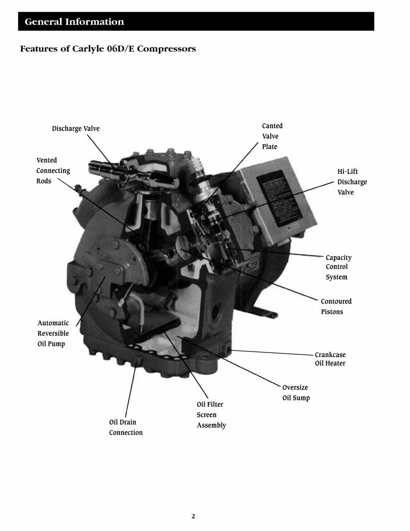
Features of Carlyle 06D/E Compressors
Discharge Valve
Vented
Connecting
Rods
Automatic
Reversible
Oil Pump
Oil Drain
Connection
Oil Filter
Screen
Assembly
Oversize
Oil Sump
Contoured
Pistons
CapacityControl
System
Hi-Lift
Discharge
Valve
Canted
Valve
Plate
CrankcaseOil Heater
3
Carlyle 06D/E semi-hermetic compressors are ideally suited for commercial refrigeration, air conditioning, process cool-ing, and environmental chambers. They are extremely flexible and may be used with many of the new HFC refrigerants such asR-507, R-404A, R-407C and R-134a, in addition to the conventional refrigerants (R-12, R-22, and R-502). The compressorsmay be operated at 50 or 60 hertz and are UL (Underwriters’ Laboratories), CSA (Canadian Standards Association), and ISO9002 approved. Many of the prominent features of the 06D/E compressors are listed below. 06D and 06E compressors complywith the CE Mark requirements and will have the CE Mark logo added to the appropriate compressor nameplates.High Efficiency Valving System
The valving system utilizes low lift valves and high flow ports to reduce valve losses, maximize efficiency, and reduce valuestress. Carlyle’s valves are made of Swedish steel, the finest material available for this application. Valve design has been quali-fied for HFC/POE applications and redesigned to avoid affects of “stiction”.Contoured Pistons and Vented Connecting Rods
The pistons are contoured allowing the suction valves to mate up with the recess in the pistons, resulting in reduced clear-ances which increases both capacity and efficiency. The connecting rods are also vented to provide premium bearing lubrica-tion and longer life.Automatic Reversible High Flow Oil Pump
The positive displacement vane type oil pump is extremely durable and produces a high volume of oil flow. With the newHFC refrigerants and POE (polyolester) oils (which are more soluble), the 06D/E oil pump will produce oil pressure quickly,reducing the potential for nuisance oil pressure trips.Oversize Oil Sump
On start-up, oil level can temporarily drop too low, causing unnecessary wear in other compressor designs when on shut-down, the oil is diluted by refrigerant. The Carlyle oversize oil sump holds extra oil in crankcase to prevent normal oil migra-tion from dropping the oil level below the safe lubrication range.High Efficiency Heavy Duty Motors
These motors have the latest insulation systems which helps to prevent motor burnouts, especially during hot weather peri-ods, when operating pressures, temperatures, and currents (amps) are high.Suction Inlet Screen
The suction inlet screen prevents installation scale or abrasives from entering the compressor and shortening the life of themotor and compressor.Oversize Suction Gas Passages
The oversize suction gas passages generate less turbulence, lower pressure drops and more efficient motor cooling by suc-tion gas, thereby producing a cooler motor that has a more economical operation and longer life.Main Bearings and Running Surface of Aluminum or Steel Backed Babbitt
Aluminum or tin based babbitt material is used on bearing surfaces to provide greater load carrying ability than other typesof materials and are also less susceptible to damage from overheating or liquid refrigerant.Crankcase Oil Heater
This optional accessory warms crankcase oil to reduce refrigerant migration which occurs during shutdown periods.Capacity Control System
Suction cut-off unloading is an option on all four and six cylinder Carlyle 06D/E compressors. Suction cut-off unloading isan efficient method of capacity control that literally blocks off the suction of two cylinders at a time. This method is not onlyefficient, but results in much cooler operating temperatures than hot gas bypass style designs.ISO 9002 Registration
Carlyle Compressor has ISO 9002 Registration by Underwriters’ Laboratories, Inc. to manufacture 06D/E semi-hermeticreciprocating compressors ranging in size from 2 to 40 tons of refrigeration capacity. That means we have a top quality systemin place and will be continually working to improve it. So you can be assured you will always be getting the highest qualitycompressors with Carlyle.
4
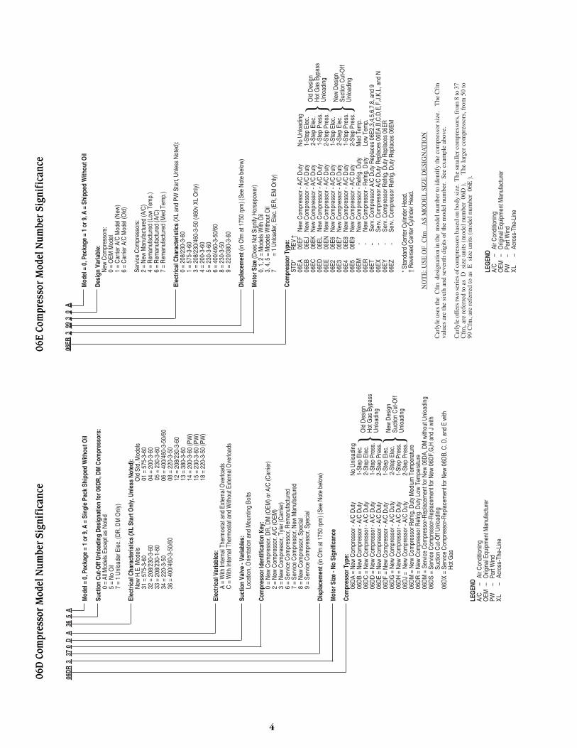
06ER
3 9
9 3
0 A
Mod
el =
0, P
acka
ge =
1 o
r 9, A
= S
hipp
ed W
ithou
t Oil
Desi
gn V
aria
ble:
New
Com
pres
sors
:0
= O
EM M
odel
1 =
Car
rier A
/C M
odel
(New
)6
= C
arrie
r A/C
Mod
el (O
ld)
Serv
ice
Com
pres
sors
:2
= N
ew M
anuf
actu
red
(A/C
)4
= R
eman
ufac
ture
d (L
ow T
emp.
)6
= R
eman
ufac
ture
d (A
/C)
7 =
Rem
anuf
actu
red
(Med
Tem
p.)
Elec
trica
l Cha
ract
eris
tics
(XL
and
PW S
tart,
Unl
ess
Not
ed):
0 =
208/
230-
3-60
1 =
575-
3-60
3 =
208/
230/
460-
3-50
(460
v XL
Onl
y)4
= 20
0-3-
605
= 23
0-3-
606
= 40
0/46
0-3-
50/6
08
= 23
0-3-
509
= 22
0/38
0-3-
60
Disp
lace
men
t (in
Cfm
at 1
750
rpm
) (Se
e N
ote
belo
w)
Mot
or S
ize
(Doe
s N
ot S
igni
fy H
orse
pow
er)
0, 1
, 2 =
Mod
els
With
Oil
3, 4
, 5 =
Mod
els
With
out O
il7
= 1
Unl
oade
r, El
ec. (
ER, E
M O
nly)
Com
pres
sor T
ype:
STD
*R
EV†
06EA
06EF
New
Com
pres
sor -
A/C
Dut
yN
o U
nloa
ding
06EB
06EJ
New
Com
pres
sor -
A/C
Dut
y1-
Step
Ele
c.06
EC06
EKN
ew C
ompr
esso
r - A
/C D
uty
2-St
ep E
lec.
06ED
06EL
New
Com
pres
sor -
A/C
Dut
y1-
Step
Pre
ss.
06EE
06EN
New
Com
pres
sor -
A/C
Dut
y2-
Step
Pre
ss.
06E2
06E6
New
Com
pres
sor -
A/C
Dut
y1-
Step
Ele
c.06
E306
E7N
ew C
ompr
esso
r - A
/C D
uty
2-St
ep E
lec.
06E4
06E8
New
Com
pres
sor -
A/C
Dut
y1-
Step
Pre
ss.
06E5
06E9
New
Com
pres
sor -
A/C
Dut
y2-
Step
Pre
ss.
06EM
-
New
Com
pres
sor -
Ref
rig. D
uty
Med
Tem
p.06
ER
-N
ew C
ompr
esso
r - R
efrig
. Dut
yLo
w T
emp.
06ET
- -
Serv
. Com
pres
sor A
/C D
uty
Rep
lace
s 06
E2,3
,4,5
,6,7
,8, a
nd 9
06EX
-
Serv
. Com
pres
sor A
/C D
uty
Rep
lace
s 06
EA,B
,C,D
,E,F
,J,K
,L, a
nd N
06EY
-
Serv
. Com
pres
sor R
efrig
. Dut
y R
epla
ces
06ER
06EZ
-
Serv
. Com
pres
sor R
efrig
. Dut
y R
epla
ces
06EM
* Sta
ndar
d C
ente
r Cyl
inde
r Hea
d.†
Rev
erse
d C
ente
r Cyl
inde
r Hea
d.
NO
TE
: USE
OF
Cfm
A
S M
OD
EL
SIZ
E D
ESI
GN
AT
ION
Car
lyle
use
s th
e C
fm d
esig
natio
n in
the
mod
el n
umbe
r to
iden
tify
the
com
pres
sor s
ize.
T
he C
fmva
lues
are
the
sixt
h an
d se
vent
h di
gits
of
the
mod
el n
umbe
r. S
ee e
xam
ple
abov
e.
Car
lyle
off
ers
two
seri
es o
f com
pres
sors
bas
ed o
n bo
dy s
ize.
The
sm
alle
r com
pres
sors
, fro
m 8
to 3
7C
fm, a
re r
efer
red
to a
s D
siz
e un
its (
mod
el n
umbe
r 06
D).
T
he la
rger
com
pres
sors
, fro
m 5
0 to
99 C
fm, a
re r
efer
red
to a
s E
siz
e un
its (
mod
el n
umbe
r 06
E).
LEG
END
A/C
–Ai
r Con
ditio
ning
OEM
–O
rigin
al E
quip
men
t Man
ufac
ture
rPW
–Pa
rt W
ind
XL
–Ac
ross
-The
-Lin
e
} }Old
Des
ign
Hot
Gas
Byp
ass
Unl
oadi
ng
New
Des
ign
Suct
ion
Cut
-Off
Unl
oadi
ng
06
D C
omp
ress
or M
odel
Nu
mb
er S
ign
ific
ance
06
E C
omp
ress
or M
odel
Nu
mb
er S
ign
ific
ance
06DR
3
37 0
D A
36 A
Mod
el =
0, P
acka
ge =
1 o
r 9, A
= S
ingl
e Pa
ck S
hipp
ed W
ithou
t Oil
Suct
ion
Cut-O
ff Un
load
ing
Desi
gnat
ion
for 0
6DR,
DM
Com
pres
sors
:0
= Al
l Mod
els
Exce
pt a
s N
oted
5 =
No
Oil
7 =
1 U
nloa
der E
lec.
(DR
, DM
Onl
y)
Elec
trica
l Cha
ract
eris
tics
(XL
Star
t Onl
y, U
nles
s No
ted)
:N
ew H
.E. M
odel
sO
ld S
td. M
odel
s31
= 5
75-3
-60
01 =
575
-3-6
032
= 2
08/2
30-3
-60
04 =
200
-3-6
033
= 2
08/2
30-1
-60
05 =
230
-3-6
034
= 2
20-3
-50
06 =
400
/460
-3-5
0/60
36 =
400
/460
-3-5
0/60
08 =
220
-3-5
012
= 2
08/2
30-3
-60
13 =
380
-3-6
014
= 2
00-3
-60
(PW
)15
= 2
30-3
-60
(PW
)18
= 2
20-3
-50
(PW
)
Elec
trica
l Var
iabl
es:
A =
With
Inte
rnal
The
rmos
tat a
nd E
xter
nal O
verlo
ads
C =
With
Inte
rnal
The
rmos
tat a
nd W
ithou
t Ext
erna
l Ove
rload
s
Suct
ion
Valv
e - V
aria
bles
:Lo
catio
n, O
rient
atio
n an
d M
ount
ing
Bolts
Com
pres
sor I
dent
ifica
tion
Key:
0 =
New
Com
pres
sor,
DR
, DM
(OEM
) or A
/C (C
arrie
r)2
= N
ew C
ompr
esso
r, A/
C (O
EM)
3 =
New
Com
pres
sor,
Tyle
r (C
arrie
r)6
= Se
rvic
e C
ompr
esso
r, R
eman
ufac
ture
d7
= Se
rvic
e C
ompr
esso
r, N
ew M
anuf
actu
red
8 =
New
Com
pres
sor,
Spec
ial
9 =
Serv
ice
Com
pres
sor,
Spec
ial
Disp
lace
men
t (in
Cfm
at 1
750
rpm
) (Se
e N
ote
belo
w)
Mot
or S
ize
- No
Sign
ifica
nce
Com
pres
sor T
ype:
06D
A =
New
Com
pres
sor -
A/C
Dut
yN
o U
nloa
ding
06D
B =
New
Com
pres
sor -
A/C
Dut
y1-
Step
Ele
c.06
DC
= N
ew C
ompr
esso
r - A
/C D
uty
2-St
ep E
lec.
06D
D =
New
Com
pres
sor -
A/C
Dut
y1-
Step
Pre
ss.
06D
E =
New
Com
pres
sor -
A/C
Dut
y2-
Step
Pre
ss.
06D
F =
New
Com
pres
sor -
A/C
Dut
y1-
Step
Ele
c.06
DG
= N
ew C
ompr
esso
r - A
/C D
uty
2-St
ep E
lec.
06D
H =
New
Com
pres
sor -
A/C
Dut
y1-
Step
Pre
ss.
06D
J =
New
Com
pres
sor -
A/C
Dut
y2-
Step
Pre
ss.
06D
M =
New
Com
pres
sor R
efrig
. Dut
y M
ediu
m T
empe
ratu
re06
DR
= N
ew C
ompr
esso
r Ref
rig. D
uty
Low
Tem
pera
ture
06D
M =
Ser
vice
Com
pres
sor-R
epla
cem
ent f
or N
ew 0
6DA,
DM
with
out U
nloa
ding
06D
S =
Serv
ice
Com
pres
sor-R
epla
cem
ent f
or N
ew 0
6DF,
G,H
and
J w
ith
S
uctio
n C
ut-O
ff U
nloa
ding
06D
X =
Serv
ice
Com
pres
sor-R
epla
cem
ent f
or N
ew 0
6DB,
C, D
, and
E w
ith
H
ot G
as
LEG
END
A/C
–Ai
r Con
ditio
ning
OEM
–O
rigin
al E
quip
men
t Man
ufac
ture
rPW
–Pa
rt W
ind
XL
–Ac
ross
-The
-Lin
e
} }Old
Des
ign
Hot
Gas
Byp
ass
Unl
oadi
ng
New
Des
ign
Suct
ion
Cut
-Off
Unl
oadi
ng
5

5
06D
M80
818
.53
(47.
07)
10.0
0(2
5.40
)15
.00
(38.
10)
8.88
x 1
2.88
(22
.55
x 32
.71)
7/8
5/8
17.4
11.2
718.
75.
635
.506
DR
109
18.5
3(4
7.07
)10
.00
(25.
40)
15.0
0(3
8.10
)8.
88 x
12.
88 (
22.5
5 x
32.7
1)7/
85/
812
.17.
653
.35.
53.
526
.306
DM
313
22.1
7(5
6.31
)14
.78
(37.
54)
15.1
0(3
8.35
)8.
88 x
14.
88 (
22.5
5 x
37.7
9)7/
85/
827
.017
.310
013
.58.
650
06D
R01
322
.17
(56.
31)
14.7
8(3
7.54
)15
.10
(38.
35)
8.88
x 1
4.88
(22
.55
x 37
.79)
1-1/
85/
817
.411
.271
8.7
5.6
35.5
06D
M31
622
.17
(56.
31)
14.7
8(3
7.54
)15
.10
(38.
35)
8.88
x 1
4.88
(22
.55
x 37
.79)
1-1/
85/
827
.017
.310
013
.58.
650
06D
R31
622
.17
(56.
31)
14.7
8(3
7.54
)15
.10
(38.
35)
8.88
x 1
4.88
(22
.55
x 37
.79)
1-1/
85/
827
.017
.310
013
.58.
650
06D
A81
822
.17
(56.
31)
14.7
8(3
7.54
)16
.72
(42.
47)
8.25
x 1
3.88
(20
.96
x 3
5.26
)1-
1/8
7/8
44.0
28.2
160
22.0
14.1
8006
DR
718
23.6
2(5
9.99
)14
.78
(37.
54)
16.7
2(4
2.47
)8.
25 x
13.
88 (
20.9
6 x
35.
26)
1-3/
87/
827
.017
.310
013
.58.
650
06D
R82
023
.62
(59.
99)
14.7
8(3
7.54
)16
.72
(42.
47)
8.25
x 1
3.88
(20
.96
x 3
5.26
)1-
3/8
7/8
44.0
28.2
160
22.0
14.1
8006
DA
824
23.6
0(5
9.94
)16
.46
(41.
81)
15.4
9(3
9.34
)8.
88 x
12.
78 (
22.5
x 3
2.46
)1-
3/8
1-1/
855
.535
.619
827
.817
.899
06D
A82
524
.30
(61.
72)
17.5
0(4
4.45
)16
.08
(40.
84)
8.88
x 1
2.78
(22
.5 x
32.
46)
1-3/
81-
1/8
55.5
35.6
198
27.8
17.8
9906
DR
725
24.3
0(6
1.72
)17
.50
(44.
45)
16.0
8(4
0.84
)8.
88/1
1.38
x 1
2.78
(22
.5/2
8.90
x 3
2.46
)1-
3/8
7/8
44.0
28.2
160
22.0
14.1
8006
DR
724
23.6
0(5
9.94
)16
.46
(41.
81)
15.4
9(3
9.34
)8.
88/1
1.38
x 1
2.78
(22
.5/2
8.90
x 3
2.46
)1-
3/8
7/8
44.0
28.2
160
22.0
14.1
8006
DA
328
24.3
0(6
1.72
)17
.50
(44.
45)
16.0
8(4
0.84
)8.
88 x
12.
78 (
22.5
x 3
2.46
)1-
3/8
1-1/
862
.039
.722
831
.019
.911
406
DR
228
24.3
0(6
1.72
)17
.50
(44.
45)
16.0
8(4
0.84
)8.
88/1
1.38
x 1
2.78
(22
.5/2
8.90
x 3
2.46
)1-
5/8
7/8
55.5
35.6
198
27.8
17.8
9906
DA
537
24.3
0(6
1.72
)17
.50
(44.
45)
16.0
8(4
0.84
)8.
88 x
12.
78 (
22.5
x 3
2.46
)1-
5/8
1-1/
889
.057
.126
640
.025
.612
006
DM
337
24.3
0(6
1.72
)17
.50
(44.
45)
16.0
8(4
0.84
)8.
88/1
1.38
x 1
2.78
(22
.5/2
8.90
x 3
2.46
)1-
5/8
1-1/
862
.039
.722
831
.019
.911
406
DR
337
24.3
0(6
1.72
)17
.50
(44.
45)
16.0
8(4
0.84
)8.
88/1
1.38
x 1
2.78
(22
.5/2
8.90
x 3
2.46
)1-
5/8
1-1/
862
.039
.722
831
.019
.911
406
DR
541
24.3
0(6
1.72
)17
.50
(44.
45)
16.0
8(4
0.84
)8.
88/1
1.38
x 1
2.78
(22
.5/2
8.90
x 3
2.46
)1-
5/8
1-1/
889
.057
.126
640
.025
.612
006
EA
550
31.2
2(7
9.30
)21
.49
(54.
58)
21.1
4(5
3.70
)8.
88/1
1.38
x 1
5.31
(22
.5/2
8.9
x 38
.88)
1-5/
81-
1/8
104.
074
.334
549
.035
.017
306
EM
450
31.2
2(7
9.30
)21
.49
(54.
58)
21.1
4(5
3.70
)8.
88/1
1.38
x 1
5.31
(22
.5/2
8.9
x 38
.88)
2-1/
81-
1/8
90.0
64.3
283
46.0
33.9
142
06E
R45
031
.22
(79.
30)
21.4
9(5
4.58
)21
.14
(53.
70)
8.88
/11.
38 x
15.
31 (
22.5
/28.
9 x
38.8
8)2-
1/8
1-1/
890
.064
.328
346
.033
.914
206
EA
565
33.3
8(8
4.79
)23
.68
(60.
15)
20.3
2(5
1.61
)8.
88/1
1.38
x 1
7.44
(22
.5/2
8.9
x 44
.15)
1-5/
81-
3/8
127.
090
.744
664
.045
.722
306
ER
465
33.3
8(8
4.79
)23
.68
(60.
15)
20.3
2(5
1.61
)8.
88/1
1.38
x 1
7.44
(22
.5/2
8.9
x 44
.15)
2-1/
81-
3/8
104.
074
.334
549
.035
.017
306
EA
575
33.3
8(8
4.79
)23
.68
(60.
15)
20.3
2(5
1.61
)8.
88/1
1.38
x 1
7.44
(22
.5/2
8.9
x 44
.15)
2-1/
81-
3/8
163.
011
6.4
506
76.0
54.3
253
06E
M47
533
.38
(84.
79)
23.6
8(6
0.15
)20
.32
(51.
61)
8.88
/11.
38 x
17.
44 (
22.5
/28.
9 x
44.1
5)2-
1/8
1-3/
812
7.0
90.7
446
64.0
45.7
223
06E
R47
533
.38
(84.
79)
23.6
8(6
0.15
)20
.32
(51.
61)
8.88
/11.
38 x
17.
44 (
22.5
/28.
9 x
44.1
5)2-
1/8
1-3/
810
4.0
74.3
345
49.0
35.0
173
06E
A59
933
.38
(84.
79)
23.6
8(6
0.15
)20
.32
(51.
61)
8.88
/11.
38 x
17.
44 (
22.5
/28.
9 x
44.1
5)2-
1/8
1-5/
821
5.0
153.
669
010
6.0
75.7
345
06E
M49
933
.38
(84.
79)
23.6
8(6
0.15
)20
.32
(51.
61)
8.88
/11.
38 x
17.
44 (
22.5
/28.
9 x
44.1
5)2-
1/8
1-5/
818
2.0
130.
061
088
.062
.930
506
ER
399
33.3
8(8
4.79
)23
.68
(60.
15)
20.3
2(5
1.61
)8.
88/1
1.38
x 1
7.44
(22
.5/2
8.9
x 44
.15)
2-1/
81-
3/8
163.
011
6.4
506
76.0
54.3
253
MO
DE
LN
UM
BE
RD
IME
NS
ION
S IN
CH
ES
(C
M)
LE
NG
TH
WID
TH
HE
IGH
T
MO
UN
TIN
G C
EN
TE
RS
SUCT
ION
CONN
. (IN
)SW
EAT
DISC
H.CO
NN. (
IN)
SWEA
T
SERV
ICE
VALV
ES2
MC
C*R
LA
LR
AM
CC
*RL
AL
RA
208/
230-
3-60
400-
3-50
, 460
-3-6
0
EL
EC
TR
ICA
LD
ATA
1
06D/E Refrigeration Compressor Specifications
1 Elec
tric
al C
hara
cter
istic
s:M
odel
s lis
ted
are
avai
labl
e fo
r th
e fo
llow
ing
pow
er s
uppl
ies:
208
/230
-3-6
0, 4
60/4
00-3
-60/
50, 5
75-3
-60
* RL
A ba
sed
on M
CC ÷
1.56
for
06D
*
RLA
base
d on
Mus
t Tri
p of
Rec
omm
ende
d Ci
rcui
t Bre
aker
÷1.
40 fo
r 06
E
2 Alte
rnat
ive
serv
ice
valv
e m
odel
ava
ilabl
e in
mos
t cas
es.
LE
GE
ND
LRA
- Lo
cked
Rot
or A
mps
RLA
- R
ates
Loa
d A
mps
MC
C -
Max
imum
Con
tinuo
us C
urre
nt
6
06D
R10
92.
08.
7-4
00
-10
55-3
50
22.
001-
3/8
3.00
160
06D
M80
83.
08.
00
50–
–0
552
2.00
1-1/
43.
0016
006
DR
013
3.0
13.1
-40
0-1
055
-35
04
2.00
14.
5023
006
DM
313
5.0
13.1
050
––
055
42.
001
4.50
235
06D
R31
65.
015
.9-4
025
-10
55-3
525
42.
001-
1/4
4.50
235
06D
M31
65.
015
.90
25–
–0
454
2.00
1-1/
44.
5023
506
DR
718
5.0
18.3
-40
0-1
055
-35
04
2.00
1-7/
165.
5025
006
DA
818
6.5
18.3
050
––
055
42.
001-
7/16
5.50
250
06D
R82
06.
520
.0-4
040
-10
55-3
545
42.
001-
9/16
5.50
260
06D
R72
46.
523
.9-4
025
-10
55-3
545
62.
001-
1/4
8.00
310
06D
R72
56.
523
.9-4
025
-10
55-3
545
62.
001-
1/4
8.00
310
06D
A82
57.
523
.90
50–
–0
556
2.00
1-1/
48.
0031
506
DA
824
7.5
23.9
050
––
055
62.
001-
1/4
8.00
310
06D
R22
87.
528
.0-4
025
-10
55-3
545
62.
001-
15/3
28.
0031
506
DA
328
10.0
28.0
050
––
055
62.
001-
15/3
28.
0031
506
DR
337
10.0
37.1
-40
25-1
055
-35
456
2.00
1-15
/16
8.00
325
06D
M33
710
.037
.10
25–
–0
456
2.00
1-15
/16
8.00
325
06D
A53
715
.037
.10
50–
–0
556
2.00
1-15
/16
8.00
325
06D
R54
115
.041
.0-4
025
-10
55-3
525
62.
002.
158.
0032
506
ER
450
15.0
50.3
-40
0–
–-3
50
42-
11/1
62-
3/16
14.0
043
006
EM
450
15.0
50.3
025
-10
550
454
2-11
/16
2-3/
1614
.00
430
06E
A55
020
.050
.30
50–
–0
504
2-11
/16
2-3/
1614
.00
430
06E
R46
520
.068
.3-4
00
––
-35
06
2-11
/16
1-63
/64
19.0
048
006
EA
565
25.0
68.3
050
-10
550
506
2-11
/16
1-63
/64
19.0
048
506
ER
475
20.0
75.4
-40
0–
–-3
50
62-
11/1
62-
3/16
19.0
049
006
EM
475
25.0
75.4
040
-10
550
456
2-11
/16
2-3/
1619
.00
490
06E
A57
530
.075
.40
50–
–0
506
2-11
/16
2-3/
1619
.00
490
06E
R39
930
.099
.0-4
00
––
-35
06
2-11
/16
2-7/
819
.00
500
06E
M49
935
.099
.00
40-1
055
045
62-
11/1
62-
7/8
19.0
050
506
EA
599
40.0
99.0
050
––
050
62-
11/1
62-
7/8
19.0
052
0
MO
DE
LN
UM
BE
RH
PR
-502
, 404
A/5
07R
-12,
R-1
34a
R-2
2M
INM
AX
MIN
MA
XM
INM
AX
SU
CT
ION
TE
MP
ER
AT
UR
E R
AN
GE
(D
EG
RE
ES
F)
NU
MB
ER
OF
CY
LIN
DE
RS
NE
TW
EIG
HT
(LB
S)
CF
M@
1750
RP
M
OIL
CH
AR
GE
(PIN
TS
)S
TR
OK
E(I
NC
HE
S)
BO
RE
(IN
CH
ES
)
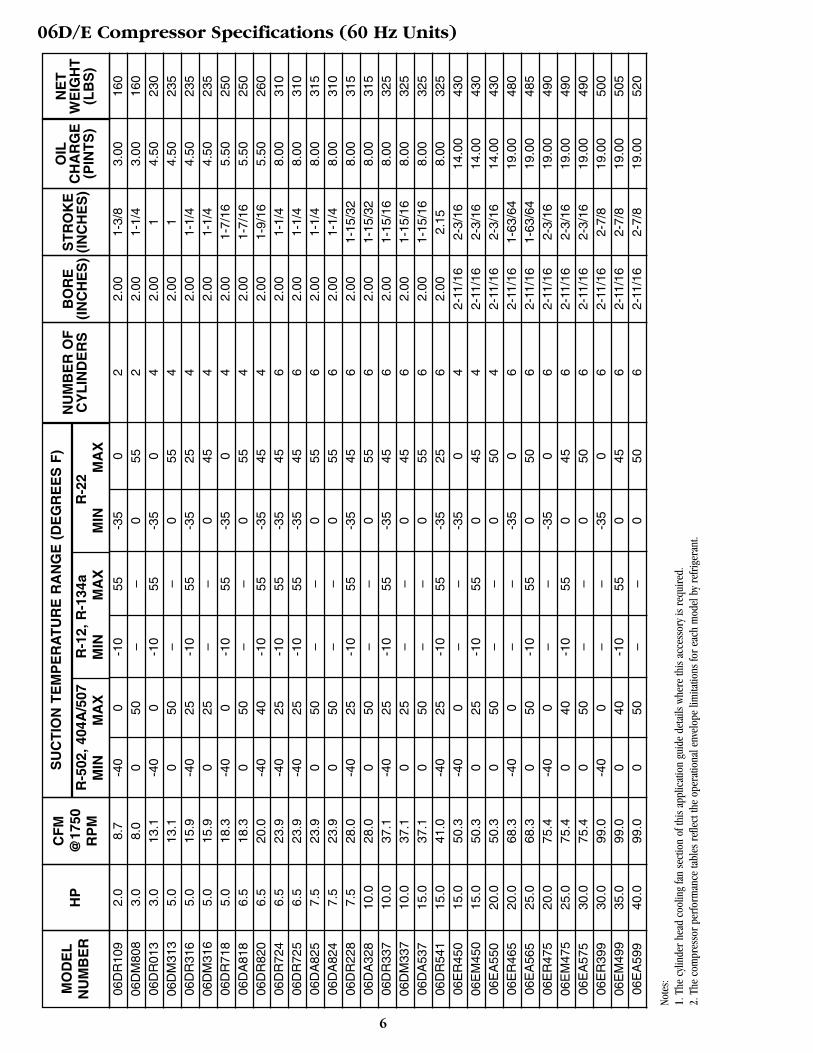
06D/E Compressor Specifications (60 Hz Units)
Note
s:1.
The
cyl
inde
r he
ad c
oolin
g fa
n se
ctio
n of
this
app
licat
ion
guid
e de
tails
whe
re th
is a
cces
sory
is r
equi
red.
2. T
he c
ompr
esso
r pe
rfor
man
ce ta
bles
ref
lect
the
oper
atio
nal e
nvel
ope
limita
tions
for
each
mod
el b
y re
frig
eran
t.
7
06D
R10
92.
00.
21-4
0-1
8-2
312
-37
-18
25.
083.
491.
4273
06D
M80
83.
00.
19-1
810
––
-18
122
5.08
3.18
1.42
7306
DR
013
3.0
0.31
-40
-18
-23
12-3
7-1
84
5.08
2.54
2.13
104
06D
M31
35.
00.
31-1
810
––
-18
74
5.08
2.54
2.13
107
06D
R31
65.
00.
38-4
0-4
-23
12-3
7-4
45.
083.
182.
1310
706
DM
316
5.0
0.38
-18
-4–
–-1
87
45.
083.
182.
1310
706
DR
718
5.0
0.43
-40
-18
-23
12-3
7-1
84
5.08
3.65
2.60
113
06D
A81
86.
50.
43-1
810
––
-18
124
5.08
3.65
2.60
113
06D
R82
06.
50.
47-4
04
-23
12-3
77
45.
083.
972.
6011
806
DR
724
6.5
0.56
-40
-4-2
312
-37
76
5.08
3.18
3.79
141
06D
R72
56.
50.
56-4
0-4
-23
12-3
77
65.
083.
183.
7914
106
DA
825
7.5
0.56
-18
10–
–-1
812
65.
083.
183.
7914
306
DA
824
7.5
0.56
-18
10–
–-1
812
65.
083.
183.
7914
106
DR
228
7.5
0.66
-40
-4-2
312
-37
76
5.08
3.73
3.79
143
06D
A32
810
.00.
66-1
810
––
-18
126
5.08
3.73
3.79
143
06D
R33
710
.00.
88-4
0-4
-23
12-3
77
65.
084.
923.
7914
706
DM
337
10.0
0.88
-18
-4–
–-1
87
65.
084.
923.
7914
706
DA
537
15.0
0.88
-18
10–
–-1
812
65.
084.
923.
7914
706
DR
541
15.0
0.97
-18
-4-2
312
-37
-46
5.08
5.46
3.79
147
06E
R45
015
.01.
19-4
0-1
8–
–-3
7-1
84
6.83
5.56
6.62
195
06E
M45
015
.01.
19-1
8-4
-23
12-1
87
46.
835.
566.
6219
506
EA
550
20.0
1.19
-18
10–
–-1
810
46.
835.
566.
6219
506
ER
465
20.0
1.61
-40
-18
––
-37
-18
66.
835.
048.
9921
806
EA
565
25.0
1.61
-18
10-2
312
-18
106
6.83
5.04
8.99
220
06E
R47
520
.01.
78-4
0-1
8–
–-3
7-1
86
6.83
5.56
8.99
222
06E
M47
525
.01.
78-1
84
-23
12-1
87
66.
835.
568.
9922
206
EA
575
30.0
1.78
-18
10–
–-1
810
66.
835.
568.
9922
206
ER
399
30.0
2.34
-40
-18
––
-37
-18
66.
837.
308.
9922
706
EM
499
35.0
2.34
-18
4-2
312
-18
76
6.83
7.30
8.99
229
06E
A59
940
.02.
34-1
810
––
-18
106
6.83
7.30
8.99
236
MO
DE
LN
UM
BE
RH
PR
-502
, 404
A/5
07R
-12,
R-1
34a
R-2
2M
INM
AX
MIN
MA
XM
INM
AX
SU
CT
ION
TE
MP
ER
AT
UR
E R
AN
GE
(D
EG
RE
ES
F)
NU
MB
ER
OF
CY
LIN
DE
RS
NE
TW
EIG
HT
(KG
)
CF
M@
1450
RP
M
OIL
CH
AR
GE
(LIT
ER
S)
ST
RO
KE
(CM
)B
OR
E(C
M)
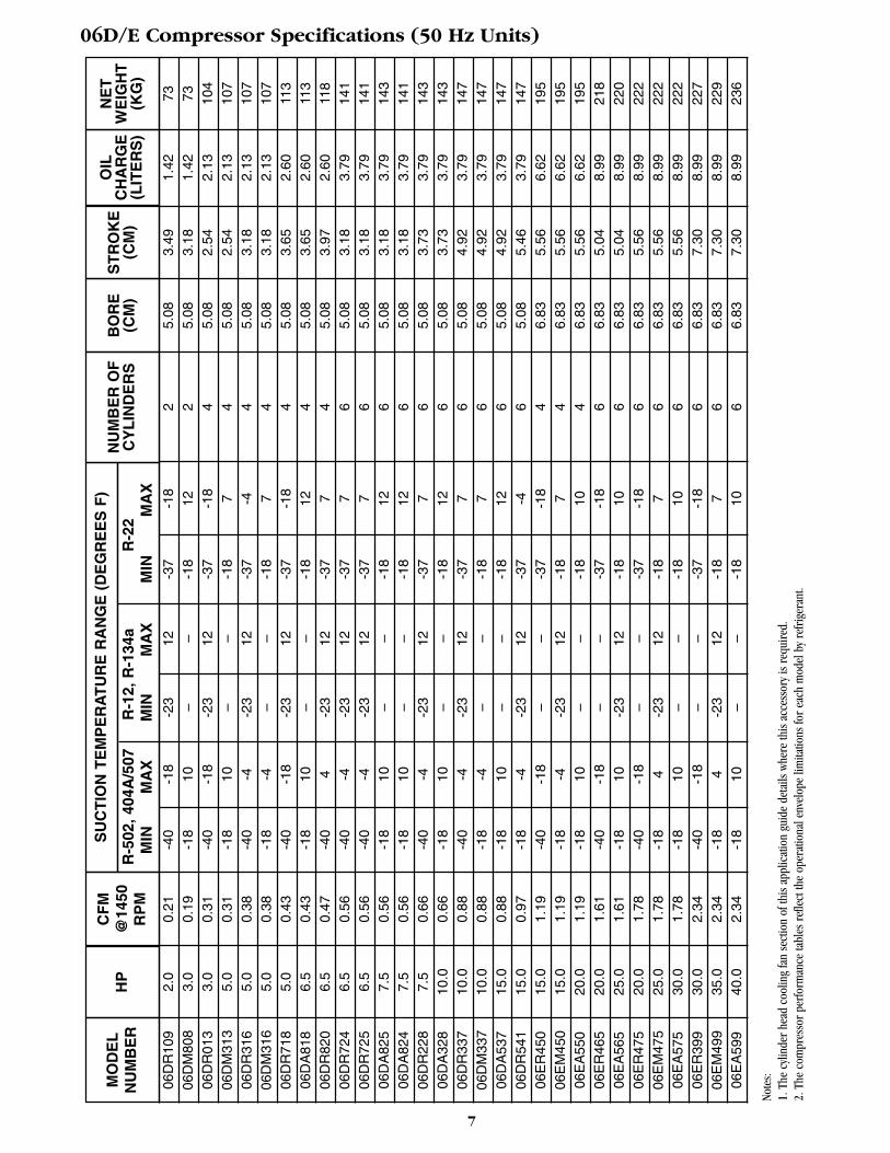
06D/E Compressor Specifications (50 Hz Units)
Note
s:1.
The
cyl
inde
r he
ad c
oolin
g fa
n se
ctio
n of
this
app
licat
ion
guid
e de
tails
whe
re th
is a
cces
sory
is r
equi
red.
2. T
he c
ompr
esso
r pe
rfor
man
ce ta
bles
ref
lect
the
oper
atio
nal e
nvel
ope
limita
tions
for
each
mod
el b
y re
frig
eran
t.
1.0 System Design Considerations
8
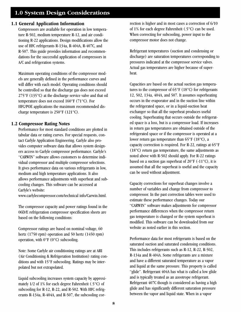
1.1 General Application InformationCompressors are available for operation in low tempera-ture R-502, medium temperature R-12, and air condi-tioning R-22 applications. Design modifications allow theuse of HFC refrigerants R-134a, R-404A, R-407C, andR-507. This guide provides information and recommen-dations for the successful application of compressors inA/C and refrigeration systems.
Maximum operating conditions of the compressor mod-els are generally defined in the performance curves andwill differ with each model. Operating conditions shouldbe controlled so that the discharge gas does not exceed275°F (135°C) at the discharge service valve and that oiltemperature does not exceed 160°F (71°C). ForHFC/POE applications the maximum recommended dis-charge temperature is 250°F (121°C).
1.2 Compressor Rating NotesPerformance for most standard conditions are plotted intabular data or rating curves. For special requests, con-tact Carlyle Application Engineering. Carlyle also pro-vides computer software data that allows system design-ers access to Carlyle compressor performance. Carlyle’s“CARWIN” software allows customers to determine indi-vidual compressor and multiple compressor selections.It gives performance data on various refrigerants in low,medium and high temperature applications. It alsoallows performance adjustments with superheat and sub-cooling changes. This software can be accessed atCarlyle’s website: www.carlylecompressor.com/technical info/Carwin.html.
The compressor capacity and power ratings found in the06D/E refrigeration compressor specification sheets arebased on the following conditions:
Compressor ratings are based on nominal voltage, 60hertz (1750 rpm) operation and 50 hertz (1450 rpm)operation, with 0°F (0°C) subcooling.
Note: Some Carlyle air conditioning ratings are at ARI(Air Conditioning & Refrigeration Institution) rating con-ditions and with 15°F subcooling. Ratings may be inter-polated but not extrapolated.
Liquid subcooling increases system capacity by approxi-mately 1/2 of 1% for each degree Fahrenheit (.5°C) ofsubcooling for R-12, R-22, and R-502. With HFC refrig-erants R-134a, R-404A, and R-507, the subcooling cor-
rection is higher and in most cases a correction of 6/10of 1% for each degree Fahrenheit (.5°C) can be used.When correcting for subcooling, power input to thecompressor motor does not change.
Refrigerant temperatures (suction and condensing ordischarge) are saturation temperatures corresponding topressures indicated at the compressor service valves.Actual gas temperatures are higher because of super-heat.
Capacities are based on the actual suction gas tempera-tures to the compressor of 65°F (18°C) for refrigerants12, 502, 134a, 404A, and 507. It assumes superheatingoccurs in the evaporator and in the suction line withinthe refrigerated space, or in a liquid-suction heatexchanger so that all the superheat produces usefulcooling. Superheating that occurs outside the refrigerat-ed space is a loss, but is a compressor load. If increasesin return gas temperatures are obtained outside of therefrigerated space or if the compressor is operated at alower return gas temperature than 65°F (18°C), acapacity correction is required. For R-22, ratings at 65°F(18°C) return gas temperature, the same adjustments asnoted above with R-502 should apply. For R-22 ratingsbased on a suction gas superheat of 20°F (-11°C), it isassumed that all the superheat is useful and the capacitycan be used without adjustment.
Capacity corrections for superheat changes involve anumber of variables and change from compressor tocompressor. In the past correction tables were used toestimate these performance changes. Today our“CARWIN” software makes adjustments for compressorperformance differences when the compressor returngas temperature is changed or the system superheat ismodified. This software can be downloaded from ourwebsite as noted earlier in this section.
Performance data for most refrigerants is based on thesaturated suction and saturated condensing conditions.This includes refrigerants such as R-12, R-22, R-502,R-134a and R-404A. Some refrigerants are a mixtureand have a different saturated temperature as a vaporand liquid at the same pressure. This property is called“glide”. Refrigerant 404A has what is called a low glideand is typically treated as an azeotrope refrigerant.Refrigerant 407C though is considered as having a highglide and has significantly different saturation pressurebetween the vapor and liquid state. When in a vapor
state the refrigerant is referred to as the saturated dewtemperature. When in the liquid state the refrigerant isreferred to as the saturated bubble temperature. Carlyle’s06D and 06E compressor performance data with R-407Cis based on the compressor suction and discharge at thesaturated dew pressures. Because the compressor suc-tion and discharge pressures will be at saturated dewconditions this is our preferred method of presentingthis data. Compressor performance will be lower thancalculations based on “mean coil temperatures” whichmay be used by other compressor manufacturers.
All R-502 capacity ratings, except for the 06DR109 com-pressor, are based on the use of cylinder head coolingfans at saturated suction temperatures of -20°F (-29°C)or below, and -25°F (-32°C) or below for R-404A andR-507. All low temperature (-30°F to 0°F, -34°C to-18°C) R-22 capacity ratings are based on the use of acylinder head cooling fan. When the compressor is oper-ated at higher return gas temperatures (for example65°F, 18°C), the use of an external desuperheating valveis also required to maintain discharge temperaturesbelow 275°F (135°C) and 250°F (121°C) for HFC/POEapplications. For R-22 low temperature applications,bulletin 02T-3 should be carefully reviewed.
Total heat of rejection (THR) in tons from the compres-sor equals adjusted compressor capacity (in tons) +.285 x kW input (of the compressor motor), or the THRin kilowatts equals the compressor’s capacity in kilowatts+ kW input (of the compressor motor). This heat rejec-tion calculation gives the maximum value possible forcondenser selection. Because of heat losses at the com-pressor (especially is a cooling fan is moving air acrossit) and at the discharge line, the actual heat of rejectionwill be lower.
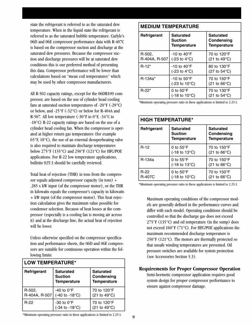
Unless otherwise specified on the compressor specifica-tion and performance sheets, the 06D and 06E compres-sors are suitable for continuous operation within the fol-lowing limits:
Maximum operating conditions of the compressor mod-els are generally defined in the performance curves anddiffer with each model. Operating conditions should becontrolled so that the discharge gas does not exceed275°F (135°C) and oil temperature (in the sump) doesnot exceed 160°F (71°C). For HFC/POE applications themaximum recommended discharge temperature is250°F (121°C). The motors are thermally protected sothat unsafe winding temperatures are prevented. Oilpressure switches are available for system protection(see Accessories Section 5.3).
Requirements for Proper Compressor OperationSemi-hermetic compressor application requires goodsystem design for proper compressor performance toensure against compressor damage.
LOW TEMPERATURE*
Refrigerant SaturatedSuctionTemperature
SaturatedCondensingTemperature
R-502,R-404A, R-507
-40 to 0°F(-40 to -18°C)
70 to 120°F(21 to 49°C)
R-22 -30 to 0°F(-34 to -18°C)
70 to 120°F(21 to 49°C)
*Minimum operating pressure ratio in these applications is limited to 2.25:1.
MEDIUM TEMPERATURE
Refrigerant SaturatedSuctionTemperature
SaturatedCondensingTemperature
R-502,R-404A, R-507
-10 to 40°F(-23 to 4°C)
70 to 120°F(21 to 49°C)
R-12* -10 to 40°F(-23 to 4°C)
80 to 130°F(27 to 54°C)
*Minimum operating pressure ratio in these applications is limited to 2.25:1.
R-134a* -10 to 50°F(-23 to 10°C)
70 to 150°F(21 to 66°C)
R-22* 0 to 50°F(-18 to 10°C)
70 to 130°F(21 to 54°C)
HIGH TEMPERATURE*
Refrigerant SaturatedSuctionTemperature
SaturatedCondensingTemperature
R-12 0 to 55°F(-18 to 13°C)
70 to 150°F(21 to 66°C)
R-134a 0 to 55°F(-18 to 13°C)
70 to 150°F(21 to 66°C)
*Minimum operating pressure ratio in these applications is limited to 2.25:1.
R-22R-407C
0 to 50°F(-18 to 10°C)
70 to 150°F(21 to 66°C)
9
10
1.3 Refrigerant PipingGood system piping designs will minimize the possibilityof lubrication failure, flooded starts, and refrigerantfloodback problems. Refrigerant piping systems musttherefore be designed to protect the compressor by:
1. Preventing excessive lubricating oil from being trappedin the system. Refrigerant piping must be sized for prop-er velocity, especially in suction lines, to return oil underall conditions. If capacity control is utilized, piping mustbe sized for full and part load conditions. With theincreased use of mechanical subcooling in refrigerationconditions, the system designer must also consider thelower refrigerant mass flow that results in systems thatare designed to operate with large amounts of subcool-ing (30°F to 70°F, 16°C to 39°C). With the new HFCrefrigerants, this is especially important in low tempera-ture applications using large amounts of subcooling (forexample liquid subcooled from 110°F to 40°F, (43°C to4°C). This can result in a 40% reduction in mass flowover a system without subcooling. The lower mass flowwill result in lower refrigerant velocities and can resultin inadequate oil return if not considered during the sys-tem piping design.
2. Minimizing the loss of lubricating oil from the compres-sor at all times.
3. Preventing liquid refrigerant from entering the compres-sor during operation and shut down.
To properly cover the subject of piping design would betoo lengthy to treat here, especially since many excellentguides to piping design are presently available. For com-plete details of good system piping practices, the CarrierSystem Design Manual (Part 3 Piping Design) isrecommended.
1.4 Vibration IsolationOn installations where noise and vibration must be keptto a minimum, it is desirable to use vibration mountsunder the compressor unit, even though the compres-sors may be spring mounted. Proper precautions mustbe taken to prevent the transmission of compressorvibration through the piping system. It is also recom-mended to design the suction line with sufficient“spring” so the suction service valve can be moved asidefor access to the suction strainer. Compressors appliedin spring-mounted systems should also have adequateflexibility in the suction and discharge piping to avoid
the excessive stresses caused by the start and stop “kick”of the compressor. These excessive stresses can typicallybe avoided by adding bends in the piping in differentdirections. Many systems have been designed with com-pressors mounted to the bases. In these cases, it isimportant that the compressors be properly torqued tothe base or the compressor may produce a “rattle” ortransmit excessive vibration to the base.
For a more complete review of the system vibration andpiping recommendations, see Carlyle OEM Bulletin#118.
1.5 Refrigerant Migration and FloodbackLiquid refrigerant, or even excessive amounts ofentrained liquid particles in the suction gas, must bekept out of the compressor by proper system design andcompressor control. Under running conditions, the pres-ence of liquid refrigerant in the compressor tends tobreak down the oil film on the cylinder walls, resultingin increased wear to the cylinder walls and piston rings,and possible compressor damage. Furthermore, exces-sive liquid in the cylinders causes hydraulic compres-sion, which can create cylinder pressures as high as1500 psi (103 bar). This hydraulic loading can causesuction and discharge valve and gasket failures to occurwhile also subjecting the connecting rod, piston, andmain bearings to excessive loading. Although laboratorytesting of 06D and 06E compressors has shown that theycan withstand substantial flooded starts and floodback,prolonged excessive flooding will eventually cause anycompressor to fail.
Therefore, special care should be taken to ensure thatliquid refrigerant is kept out of the compressor especial-ly in systems where large quantities of refrigerants areoften used. During compressor operation, the expansionvalve must be properly adjusted to prevent liquid fromentering the compressor.
During compressor shutdown, gravity, thermal actionand refrigerant absorption will result in a refrigerant andoil mixture in the compressor crankcase. Gravity flowcan be prevented by the use of recommended loops inthe piping, but thermal action and the absorption ofrefrigerant by lubricating oil cannot be prevented by pip-ing design. To minimize the absorption of refrigerantinto the oil, the use of crankcase heaters is strongly rec-ommended. Because oil dilution is more critical withHFC refrigerants and POE lubricants, Carlyle requires the
11
use of crankcase heaters in these applications. It isimportant, however, to never energize the crankcaseheater while the compressor is running because this mayoverheat the compressor oil. (See Accessory Section 5.4for applicable heaters.) Carlyle’s experience indicatesthat many compressor failures occur during the first sev-eral months of operation. Many of these failuresoccurred during the initial start-up of the unit, andinspection reports indicate flooding was the probablecause of failure in many of these compressor returns. Itis believed that many of these failures could have beenavoided by using more care during the initial start-up ofthe compressors. Refer to the recommended start-upprocedure in Carlyle’s Refrigeration Compressor ServiceGuide (Lit. No. 020-611).
1.6 Proper Compressor Control and ProtectionAn important consideration to maintain good compres-sor reliability is a proper control and protection strategy.It is extremely important that the compressor controlsdo not allow operation outside the compressor’sapproved application envelope. This may require theaddition of low-pressure switches to avoid too low of asuction pressure and a high-pressure switch to limit theallowable discharge pressure. In many refrigerationapplications an oil safety switch is required to avoid aloss of lubrication.
It is also important to limit compressor start and stops.Each time a compressor motor is energized a highinrush current is reached, if only for a fraction of a sec-ond. In addition the compressor bearing system isstressed, and Carlyle has found a direct correlationbetween excessive starts and higher failure rates. Forthat reason Carlyle does not recommend more than 12starts per hour for these semi-hermetic compressors.In addition in refrigeration rack systems Carlyle hasfound that compressors properly applied will typically belimited to less than 75 cycles per day in low temperaturesystems and 150 cycles per day in medium temperaturesystems. Applications with much higher cycles per dayhave typically been related to poorly adjusted controls.Where possible it is recommended to add cycle countersthat will allow monitoring of the cycles per day.
1.7 Clean and Dry SystemClean and dry systems are essential for long compressorand motor life, and satisfactory operation. This cannotbe over-emphasized. It is even more critical with theintroduction of new HFC refrigerants and POE lubricants.
The new POE lubricants are excellent cleaning agentsthat will deposit system contaminants into the system orcompressor filters and screens, causing excessive pres-sure drop or clogging, if the system is not kept clean.The moisture levels of all systems must be kept withinacceptable limits. Excessive moisture when combinedwith heat and refrigerant can form damaging acids. Onecomponent that requires special attention is the com-pressor lubricant. With compressors applied with miner-al oil (MO) or alkaline-benzene (AB) lubricants, therecommended limit for moisture is maintaining levelsless than 50 PPM. With Polyol-Ester lubricants (POE) theallowable moisture level is higher at 100 PPM but it ismuch more difficult to maintain because of the very highaffinity for moisture. Special care must be taken withPOE oils to avoid moisture getting into the oil.Compressors with POE should only be opened for veryshort periods. POE oil containers should be maintainedwith a dry nitrogen holding charge to keep out moisture.
Liquid line refrigerant filter-driers maintain low moisturecontent, and in the event of a motor burnout, preventcontamination of the evaporator and other parts of therefrigeration system. These filter-driers should be com-patible with the new HFC refrigerants and POE oils ifused.
Liquid line moisture indicators are recommended in allsystems that use semi-hermetic compressors becausethey provide a continuous check on the system’s mois-ture content. Excessive moisture in combination with ahigh operating temperature can lead to motor windingbreakdown and burnout. When moisture is indicated,prompt corrective action, such as changing the filter-drier core or dehydrating the system, can prevent seri-ous compressor damage.
1.8 Prevent Excessive Discharge TemperaturesThe actual discharge gas temperature at the compressordischarge service valve must not exceed 275°F (135°C).For HFC/POE applications the maximum recommendeddischarge temperature is 250°F (121°C). For a givenrefrigerant, this discharge temperature depends uponthe compression ratio as well as the temperature of thesuperheated suction gas. Since an increase in either thecompression ratio or suction gas temperature causes thedischarge temperature to increase, both must be keptwithin allowable limits. In low temperature R-22 applica-tions, external desuperheating is required. See Bulletin02T-3 for these application recommendations.
12
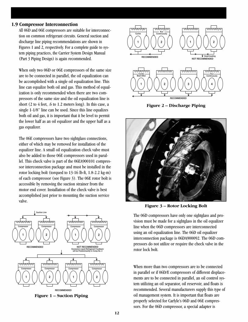
1.9 Compressor InterconnectionAll 06D and 06E compressors are suitable for interconnec-tion on common refrigerant circuits. General suction anddischarge line piping recommendations are shown inFigures 1 and 2, respectively. For a complete guide to sys-tem piping practices, the Carrier System Design Manual(Part 3 Piping Design) is again recommended.
When only two 06D or 06E compressors of the same sizeare to be connected in parallel, the oil equalization canbe accomplished with a single oil equalization line. Thisline can equalize both oil and gas. This method of equal-ization is only recommended when there are two com-pressors of the same size and the oil equalization line isshort (2 to 4 feet, .6 to 1.2 meters long). In this case, asingle 1-1/8” line can be used. Since this line equalizesboth oil and gas, it is important that it be level to permitthe lower half as an oil equalizer and the upper half as agas equalizer.
The 06E compressors have two sightglass connections,either of which may be removed for installation of theequalizer line. A small oil equalization check valve mustalso be added to those 06E compressors used in paral-lel. This check valve is part of the 06EA900101 compres-sor interconnection package and must be installed in therotor locking bolt (torqued to 13-16 lb-ft, 1.8-2.2 kg-m)of each compressor (see Figure 3). The 06E rotor bolt isaccessible by removing the suction strainer from themotor end cover. Installation of the check valve is bestaccomplished just prior to mounting the suction servicevalve.
The 06D compressors have only one sightglass and pro-vision must be made for a sightglass in the oil equalizerline when the 06D compressors are interconnectedusing an oil equalization line. The 06D oil equalizerinterconnection package is 06DA900092. The 06D com-pressors do not utilize or require the check valve in therotor lock bolt.
When more than two compressors are to be connectedin parallel or if 06D/E compressors of different displace-ments are to be connected in parallel, an oil control sys-tem utilizing an oil separator, oil reservoir, and floats isrecommended. Several manufacturers supply this type ofoil management system. It is important that floats areproperly selected for Carlyle’s 06D and 06E compres-sors. For the 06D compressor, a special adapter is
RECOMMENDED
Compressor
2
Compressor
1
Suction Line
Compressor
2
Compressor
1
Compressor
2
Compressor
1
Compressor
2
Compressor
1
RECOMMENDED
NOT RECOMMENDEDExcessive Liquid Refrigerant Foodback
will be Predominantly in Comp No. 2
Figure 1 – Suction Piping
RECOMMENDED
RECOMMENDED
Cycles
1
21 43
21
NOT RECOMMENDED
2
RunContinuously
CyclesMost Often
RunContinuously
Dead-heading
Figure 2 – Discharge Piping
Figure 3 – Rotor Locking Bolt
13
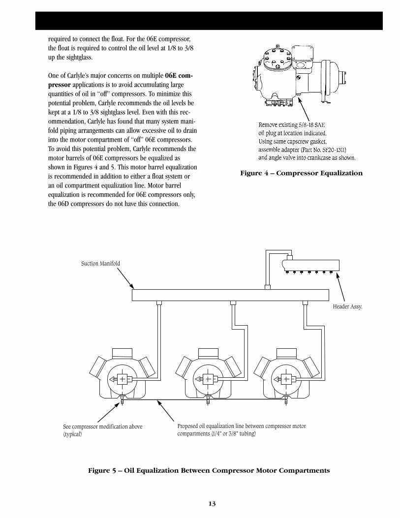
Figure 4 – Compressor Equalization
Suction Manifold
See compressor modification above
(typical)
Header Assy.
Proposed oil equalization line between compressor motor
compartments (1/4” or 3/8” tubing)
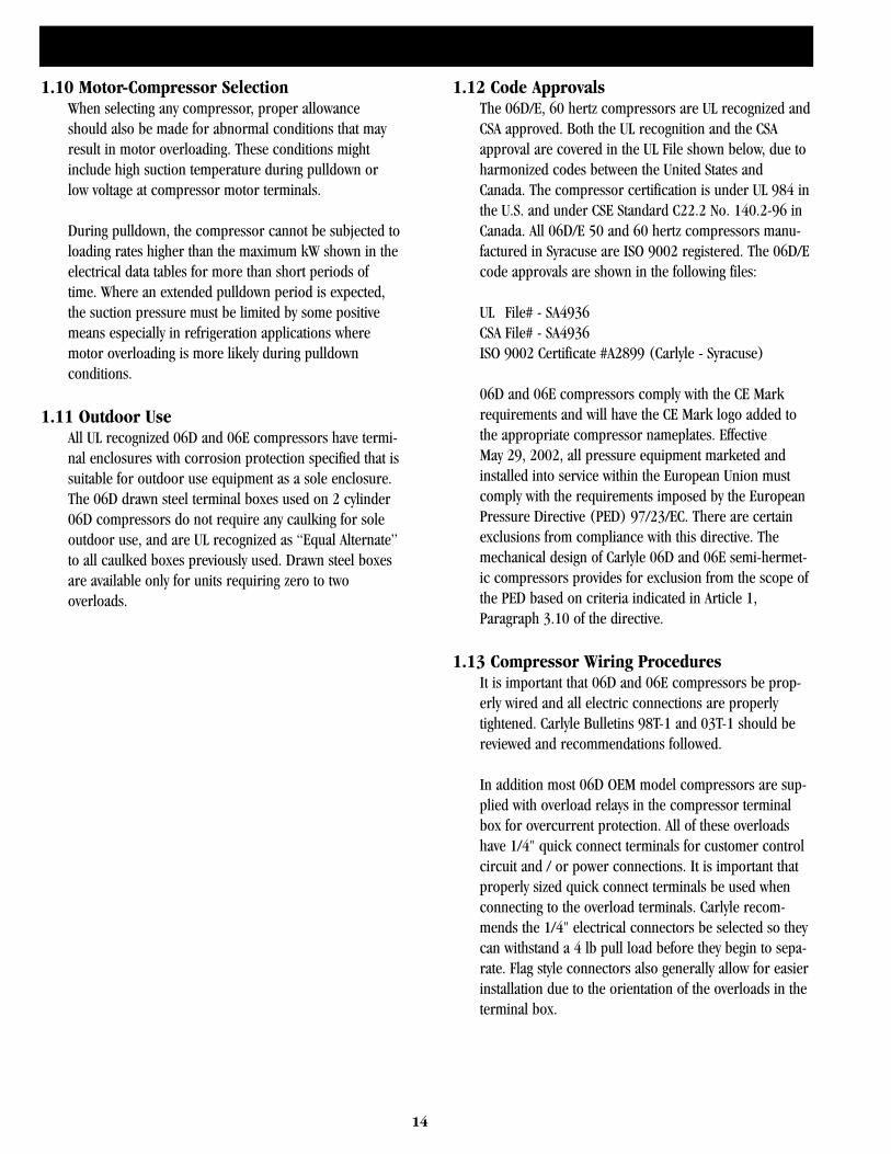
Figure 5 – Oil Equalization Between Compressor Motor Compartments
required to connect the float. For the 06E compressor,the float is required to control the oil level at 1/8 to 3/8up the sightglass.
One of Carlyle’s major concerns on multiple 06E com-pressor applications is to avoid accumulating largequantities of oil in “off” compressors. To minimize thispotential problem, Carlyle recommends the oil levels bekept at a 1/8 to 3/8 sightglass level. Even with this rec-ommendation, Carlyle has found that many system mani-fold piping arrangements can allow excessive oil to draininto the motor compartment of “off” 06E compressors.To avoid this potential problem, Carlyle recommends themotor barrels of 06E compressors be equalized asshown in Figures 4 and 5. This motor barrel equalizationis recommended in addition to either a float system oran oil compartment equalization line. Motor barrelequalization is recommended for 06E compressors only,the 06D compressors do not have this connection.
14
1.10 Motor-Compressor SelectionWhen selecting any compressor, proper allowanceshould also be made for abnormal conditions that mayresult in motor overloading. These conditions mightinclude high suction temperature during pulldown orlow voltage at compressor motor terminals.
During pulldown, the compressor cannot be subjected toloading rates higher than the maximum kW shown in theelectrical data tables for more than short periods oftime. Where an extended pulldown period is expected,the suction pressure must be limited by some positivemeans especially in refrigeration applications wheremotor overloading is more likely during pulldownconditions.
1.11 Outdoor UseAll UL recognized 06D and 06E compressors have termi-nal enclosures with corrosion protection specified that issuitable for outdoor use equipment as a sole enclosure.The 06D drawn steel terminal boxes used on 2 cylinder06D compressors do not require any caulking for soleoutdoor use, and are UL recognized as “Equal Alternate”to all caulked boxes previously used. Drawn steel boxesare available only for units requiring zero to twooverloads.
1.12 Code ApprovalsThe 06D/E, 60 hertz compressors are UL recognized andCSA approved. Both the UL recognition and the CSAapproval are covered in the UL File shown below, due toharmonized codes between the United States andCanada. The compressor certification is under UL 984 inthe U.S. and under CSE Standard C22.2 No. 140.2-96 inCanada. All 06D/E 50 and 60 hertz compressors manu-factured in Syracuse are ISO 9002 registered. The 06D/Ecode approvals are shown in the following files:
UL File# - SA4936CSA File# - SA4936ISO 9002 Certificate #A2899 (Carlyle - Syracuse)
06D and 06E compressors comply with the CE Markrequirements and will have the CE Mark logo added tothe appropriate compressor nameplates. EffectiveMay 29, 2002, all pressure equipment marketed andinstalled into service within the European Union mustcomply with the requirements imposed by the EuropeanPressure Directive (PED) 97/23/EC. There are certainexclusions from compliance with this directive. Themechanical design of Carlyle 06D and 06E semi-hermet-ic compressors provides for exclusion from the scope ofthe PED based on criteria indicated in Article 1,Paragraph 3.10 of the directive.
1.13 Compressor Wiring ProceduresIt is important that 06D and 06E compressors be prop-erly wired and all electric connections are properlytightened. Carlyle Bulletins 98T-1 and 03T-1 should bereviewed and recommendations followed.
In addition most 06D OEM model compressors are sup-plied with overload relays in the compressor terminalbox for overcurrent protection. All of these overloadshave 1/4" quick connect terminals for customer controlcircuit and / or power connections. It is important thatproperly sized quick connect terminals be used whenconnecting to the overload terminals. Carlyle recom-mends the 1/4" electrical connectors be selected so theycan withstand a 4 lb pull load before they begin to sepa-rate. Flag style connectors also generally allow for easierinstallation due to the orientation of the overloads in theterminal box.
2.0 Compressor Lubrication System
15
2.1 Compressor LubricationAll refrigeration compressors must have adequate lubri-cation to ensure trouble-free operation and a long life.When starting up any new system, some oil will be lost tocoat the inside of the piping, some oil will be lodged inlow velocity areas of the system, and some will be keptin circulation. This loss must be made up by adding oilto the system after the initial start-up. Very low compres-sor oil levels can cause complete loss of lubrication andmay result in an immediate compressor failure if notprotected against.
The loss of oil can also be caused by flooded starts orrefrigerant migrating into the oil during an off periodand pulling the oil out of its sump during the suddenpressure drop of a start-up.
While it has always been apparent that very low oil levelscan cause compressor damage, it has also becomeapparent that excessive oil charges can shorten the com-pressor’s life. Oil levels above the center of the 06E com-pressor sightglass cause elevated crankcase and oil tem-peratures, increased power consumption, and possiblevalve plate gasket failures. This problem of excessive oilcharges has been mainly evident on 06E multiple com-pressor applications and does not appear to have causedany difficulties with the application of 06D compressors.
The oil level should be observed in the sightglass imme-diately after the compressor shutdown, while it is stillwarm. The level observed when the compressor is notrunning for a long period may be a mixture of oil andrefrigerant which would not be a true indication of theoil level when the compressor is running.
If the oil level in the sightglass of an 06E compressor isless than one-eighth (1/8) up from the bottom of theglass, this indicates a low oil level. If the oil level is upmore than one-half (1/2) from the bottom, this indicatesa high oil level. Therefore, the oil level should be 1/8 to1/2 up the sightglass when the compressor is runningfor 06E compressors.
Figures 6, 7, and 8 show different oil levels when a sin-gle 06E compressor is running. The photos in each fig-ure show the right and left sightglass of the same com-pressor (only one sightglass is factory supplied). If thelevel is not the same in each glass, consider the true oillevel to be the lower level. The difference in levels is dueto the rotation of the crankshaft. The crankshaft and
running gear are producing the windage required topush the oil down on one side while raising it on theother. Reversing the direction of rotation of the motorwill reverse this relationship.
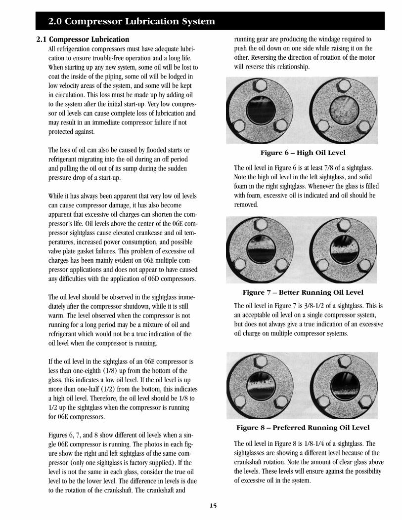
The oil level in Figure 6 is at least 7/8 of a sightglass.Note the high oil level in the left sightglass, and solidfoam in the right sightglass. Whenever the glass is filledwith foam, excessive oil is indicated and oil should beremoved.
The oil level in Figure 7 is 3/8-1/2 of a sightglass. This isan acceptable oil level on a single compressor system,but does not always give a true indication of an excessiveoil charge on multiple compressor systems.
The oil level in Figure 8 is 1/8-1/4 of a sightglass. Thesightglasses are showing a different level because of thecrankshaft rotation. Note the amount of clear glass abovethe levels. These levels will ensure against the possibilityof excessive oil in the system.
Figure 6 – High Oil Level
Figure 7 – Better Running Oil Level
Figure 8 – Preferred Running Oil Level
16
Another effect which has been noted, especially in multi-ple compressor systems, is the increased probability ofblown valve plate gaskets when excessive oil is in thesystem. When the system is grossly overcharged (severalgallons too much), the oil levels in the compressorsumps will only rise 1/2 to 3/4 level in the sightglass of06E compressors. The remainder of the oil will be keptin circulation or will accumulate somewhere in the sys-tem. A likely point is in the suction manifold (dependingon the method of returning oil), and in the compressormotor compartment. This is especially troublesome in anidle compressor in a multiple compressor system thathas an opportunity to accumulate oil in the motor com-partment; but excessive oil in the motor compartment atstart-up will not alone fail gaskets. Some liquid refriger-ant must also be present which will bring enough oilwith it into the cylinders on a start-up to cause gasketfailures. These circumstances have apparently occurredin a number of installations, and their relationship togasket failures has been well confirmed by test.
To check for excessive system oil charges in 06E com-pressors, it is recommended that the oil levels of thecompressors in the system be brought down to approxi-mately 1/4 of the sightglass. If the system is overcharged,the oil levels will rise to a 1/2 sightglass level within ashort time (usually within an hour). Continue removingoil until the oil level does not rise after removal. It isalso recommended that the oil levels be kept at this 1/4level, or between the levels shown in Figure 8. This isespecially true if any compressors have experienced anyrepeated gasket failures. To summarize the advantages ofkeeping the oil at this level:
1. It ensure that excessive oil is not being lodged in the sys-tem. This will eliminate gasket, valve, and running gearfailures.
2. The compressor, oil, and motor run cooler, approxi-mately 20°F (11°C) or more in many cases.
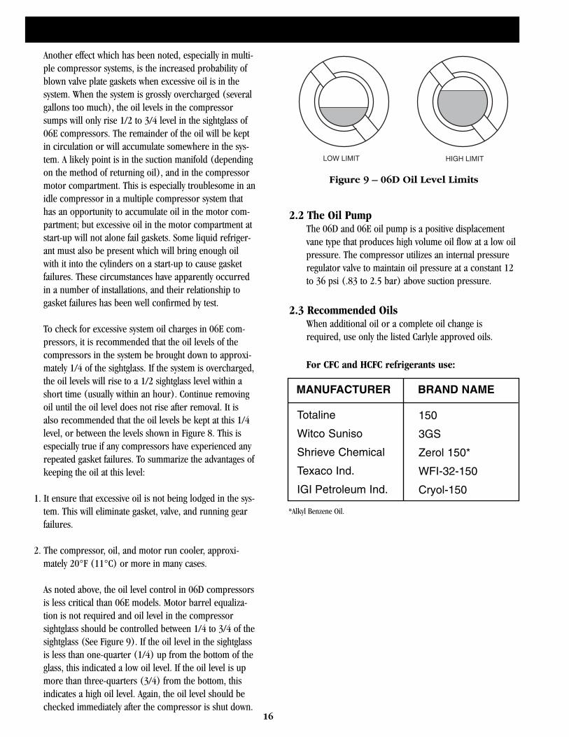
As noted above, the oil level control in 06D compressorsis less critical than 06E models. Motor barrel equaliza-tion is not required and oil level in the compressorsightglass should be controlled between 1/4 to 3/4 of thesightglass (See Figure 9). If the oil level in the sightglassis less than one-quarter (1/4) up from the bottom of theglass, this indicated a low oil level. If the oil level is upmore than three-quarters (3/4) from the bottom, thisindicates a high oil level. Again, the oil level should bechecked immediately after the compressor is shut down.
2.2 The Oil PumpThe 06D and 06E oil pump is a positive displacementvane type that produces high volume oil flow at a low oilpressure. The compressor utilizes an internal pressureregulator valve to maintain oil pressure at a constant 12to 36 psi (.83 to 2.5 bar) above suction pressure.
2.3 Recommended OilsWhen additional oil or a complete oil change isrequired, use only the listed Carlyle approved oils.
For CFC and HCFC refrigerants use:
LOW LIMIT HIGH LIMIT
Figure 9 – 06D Oil Level Limits
MANUFACTURER BRAND NAME
Totaline
Witco Suniso
Shrieve Chemical
Texaco Ind.
IGI Petroleum Ind.
150
3GS
Zerol 150*
WFI-32-150
Cryol-150
*Alkyl Benzene Oil.

Use of oil adhesives is not allowed without writtenapproval from the Carlyle Engineering Department.
For application with HFC refrigerants R-134a, R-507,and R-404A, Carlyle recommends an ISO 68 cST viscosi-ty polyolester oil.
Shown below are POE-68 oils that are approvedfor use in Carlyle compressors.
2.4 06D/E Oil Pressure HistoryAll current 06D/E compressors are provided with theconnections for an oil safety switch. The 06D/E com-pressors use the same basic oil pump design, howeverrecent changes in the oil pressure regulator design haveresulted in slightly different operating oil pressures.Shown below in Table 2 is a brief history of the 06D/Eoperating oil pressure.
While Table 2 can be used as a guide there are a numberof variables that can affect the oil pressure in compres-sors. They include:
1. The CFC and HCFC MO or AB lubricants have lowerviscosities then the heavier POE lubricants recommend-ed. The lower viscosities will result in lower oil pres-sures then POE lubricants in the same compressor oper-ated at identical conditions.
2. Oil temperature will also affect oil pressure. Hot oilwill result in lower viscosities and lower oil pressures.Some of the variables that will result in higher oil tem-perature are: refrigerant type – especially R-22, highcompression ratio that result in higher overall compres-sor temperatures and if the compressor is operatedunloaded for long periods.
3. Carlyle 06DA and 06DF air conditioning models use adifferent oil pressure regulator then refrigeration duty06DR or 06DM models. In 50 or 60 hertz applicationsthe A/C models oil pressure will be equal or higher thenthe refrigeration duty models. This 06D A/C regulatorthough can result in lower oil pressure in variable speedapplications. The regulator may require replacement in06D A/C models if applied with variable speed. ReviewCarlyle Bulletin 95T-8 for modification recommenda-tions. Note: the same oil pressure regulator is used in all06E A/C and refrigeration models.
17
MANUFACTURER BRAND NAME
Castrol
ICI EMKARATE
CPI
Mobil Artic†
Castrol†
E68
RL68H
Solest 68
EAL 68
SW 68
†Medium temperature applications only.
Carlyle does not recommend the use of POE lubricants with R-22.
06D MODELS PSI (Bar) 06E MODELS PSI (Bar)
Before May 1984(Prior S/N 2084J...)
May 1984 to March 1994(Between S/N 2084J & 1094J)
Starting March 1994*(Starting S/N 1094J...)
12 to 18(.83 to 1.24)
16 to 22(1.1 to 1.52)
18 to 26(1.24 to 1.8)
12 to 18(.83 to 1.24)
16 to 22(1.1 to 1.52)
18 to 34(1.24 to 2.3)
*06D/E refrigeration duty service models started using new high flow oil pumps in June 1994 (starting S/N 2994M (D/E) 5315).
Table 2 – Oil Pressure History
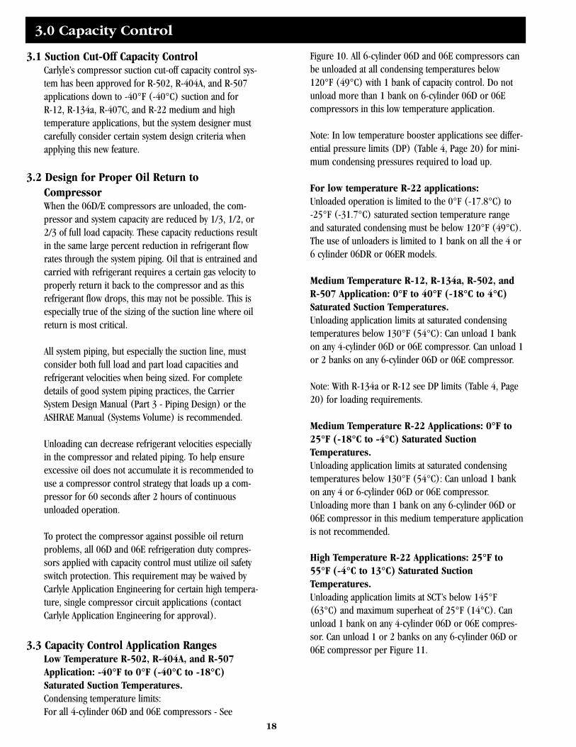
3.0 Capacity Control
18
3.1 Suction Cut-Off Capacity ControlCarlyle’s compressor suction cut-off capacity control sys-tem has been approved for R-502, R-404A, and R-507applications down to -40°F (-40°C) suction and forR-12, R-134a, R-407C, and R-22 medium and hightemperature applications, but the system designer mustcarefully consider certain system design criteria whenapplying this new feature.
3.2 Design for Proper Oil Return toCompressorWhen the 06D/E compressors are unloaded, the com-pressor and system capacity are reduced by 1/3, 1/2, or2/3 of full load capacity. These capacity reductions resultin the same large percent reduction in refrigerant flowrates through the system piping. Oil that is entrained andcarried with refrigerant requires a certain gas velocity toproperly return it back to the compressor and as thisrefrigerant flow drops, this may not be possible. This isespecially true of the sizing of the suction line where oilreturn is most critical.
All system piping, but especially the suction line, mustconsider both full load and part load capacities andrefrigerant velocities when being sized. For completedetails of good system piping practices, the CarrierSystem Design Manual (Part 3 - Piping Design) or theASHRAE Manual (Systems Volume) is recommended.
Unloading can decrease refrigerant velocities especiallyin the compressor and related piping. To help ensureexcessive oil does not accumulate it is recommended touse a compressor control strategy that loads up a com-pressor for 60 seconds after 2 hours of continuousunloaded operation.
To protect the compressor against possible oil returnproblems, all 06D and 06E refrigeration duty compres-sors applied with capacity control must utilize oil safetyswitch protection. This requirement may be waived byCarlyle Application Engineering for certain high tempera-ture, single compressor circuit applications (contactCarlyle Application Engineering for approval).
3.3 Capacity Control Application RangesLow Temperature R-502, R-404A, and R-507Application: -40°F to 0°F (-40°C to -18°C)Saturated Suction Temperatures.Condensing temperature limits:For all 4-cylinder 06D and 06E compressors - See
Figure 10. All 6-cylinder 06D and 06E compressors canbe unloaded at all condensing temperatures below120°F (49°C) with 1 bank of capacity control. Do notunload more than 1 bank on 6-cylinder 06D or 06Ecompressors in this low temperature application.
Note: In low temperature booster applications see differ-ential pressure limits (DP) (Table 4, Page 20) for mini-mum condensing pressures required to load up.
For low temperature R-22 applications:Unloaded operation is limited to the 0°F (-17.8°C) to-25°F (-31.7°C) saturated section temperature rangeand saturated condensing must be below 120°F (49°C).The use of unloaders is limited to 1 bank on all the 4 or6 cylinder 06DR or 06ER models.
Medium Temperature R-12, R-134a, R-502, andR-507 Application: 0°F to 40°F (-18°C to 4°C)Saturated Suction Temperatures.Unloading application limits at saturated condensingtemperatures below 130°F (54°C): Can unload 1 bankon any 4-cylinder 06D or 06E compressor. Can unload 1or 2 banks on any 6-cylinder 06D or 06E compressor.
Note: With R-134a or R-12 see DP limits (Table 4, Page20) for loading requirements.
Medium Temperature R-22 Applications: 0°F to25°F (-18°C to -4°C) Saturated SuctionTemperatures.Unloading application limits at saturated condensingtemperatures below 130°F (54°C): Can unload 1 bankon any 4 or 6-cylinder 06D or 06E compressor.Unloading more than 1 bank on any 6-cylinder 06D or06E compressor in this medium temperature applicationis not recommended.
High Temperature R-22 Applications: 25°F to55°F (-4°C to 13°C) Saturated SuctionTemperatures.Unloading application limits at SCT’s below 145°F(63°C) and maximum superheat of 25°F (14°C). Canunload 1 bank on any 4-cylinder 06D or 06E compres-sor. Can unload 1 or 2 banks on any 6-cylinder 06D or06E compressor per Figure 11.
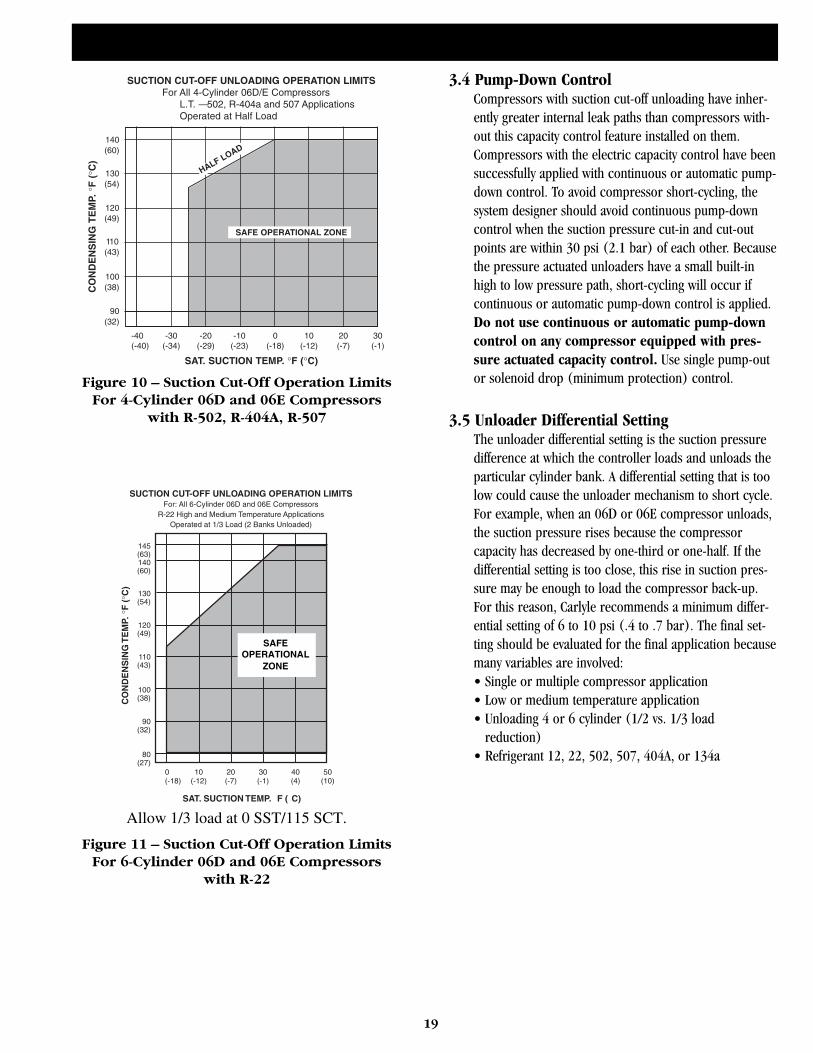
19
3.4 Pump-Down ControlCompressors with suction cut-off unloading have inher-ently greater internal leak paths than compressors with-out this capacity control feature installed on them.Compressors with the electric capacity control have beensuccessfully applied with continuous or automatic pump-down control. To avoid compressor short-cycling, thesystem designer should avoid continuous pump-downcontrol when the suction pressure cut-in and cut-outpoints are within 30 psi (2.1 bar) of each other. Becausethe pressure actuated unloaders have a small built-inhigh to low pressure path, short-cycling will occur ifcontinuous or automatic pump-down control is applied.Do not use continuous or automatic pump-downcontrol on any compressor equipped with pres-sure actuated capacity control. Use single pump-outor solenoid drop (minimum protection) control.
3.5 Unloader Differential SettingThe unloader differential setting is the suction pressuredifference at which the controller loads and unloads theparticular cylinder bank. A differential setting that is toolow could cause the unloader mechanism to short cycle.For example, when an 06D or 06E compressor unloads,the suction pressure rises because the compressorcapacity has decreased by one-third or one-half. If thedifferential setting is too close, this rise in suction pres-sure may be enough to load the compressor back-up.For this reason, Carlyle recommends a minimum differ-ential setting of 6 to 10 psi (.4 to .7 bar). The final set-ting should be evaluated for the final application becausemany variables are involved:• Single or multiple compressor application• Low or medium temperature application• Unloading 4 or 6 cylinder (1/2 vs. 1/3 load
reduction)• Refrigerant 12, 22, 502, 507, 404A, or 134a
-40 -30 -20 -10 0 10 20 30(-40) (-34) (-29) (-23) (-18) (-12) (-7) (-1)
SAT. SUCTION TEMP. °F (°C)
SUCTION CUT-OFF UNLOADING OPERATION LIMITSFor All 4-Cylinder 06D/E Compressors
L.T. — 502, R-404a and 507 ApplicationsOperated at Half Load
HALF LOAD
CO
ND
EN
SIN
G T
EM
P. °
F (
°C)
140
130
120
110
100
90
(60)
(54)
(49)
(43)
(38)
(32)
SAFE OPERATIONAL ZONE
Figure 10 – Suction Cut-Off Operation LimitsFor 4-Cylinder 06D and 06E Compressors
with R-502, R-404A, R-507
0 10 20 30 40 50(-18) (-12) (-7) (-1) (4) (10)
145(63)140(60)
130(54)
120(49)
110(43)
100(38)
90(32)
80(27)
SUCTION CUT-OFF UNLOADING OPERATION LIMITSFor: All 6-Cylinder 06D and 06E Compressors
R-22 High and Medium Temperature ApplicationsOperated at 1/3 Load (2 Banks Unloaded)
CO
ND
EN
SIN
G T
EM
P. °
F (
°C)
SAT. SUCTION TEMP. F ( C)
Allow 1/3 load at 0 SST/115 SCT.
SAFEOPERATIONAL
ZONE
Figure 11 – Suction Cut-Off Operation LimitsFor 6-Cylinder 06D and 06E Compressors
with R-22

20
3.6 Part Load Performance FactorsTo estimate part load performance of 06D/E compres-sors, use Table 3 below. The factors can be applied tothe full load published Carlyle capacity and power datafor all refrigerants and conditions. The system designershould ensure the conditions are within the safe operat-ing range of the compressor.
The table below shows multiplication factors that applyto the compressor ratings when operating with suctioncutoff unloading.
For example: You have a 6-cylinder 06E compressorwith full load capacity = 100,000 Btu/hr (29.3 kW), fullload power = 10 kW, and full load efficiency = 10Btu/wHr (COP = 2.92). To calculate the capacity, powerand efficiency at 2/3 load (one bank unloaded) use thefactors from the table as shown.
2/3 load capacity = .67 x 100,000 Btu/Hr= (.67 x 29.3 kW)
Btu/Hr = 67,000 Btu/Hr= (19.63 kW)
2/3 load power = .71 x 10 kW= 7.1 kW
2/3 load efficiency = .94 x 10.0 Btu/wHrCOP = (.94 x 2.92)Energy Efficiency Ratio = 9.4 Btu/wHrCOP = 2.7
3.7 Location and Size of Capacity Control Head AssemblyThe capacity control head assembly cannot be installedand will not function on the center cylinder head of any06D or 06E 6-cylinder compressor. This unloader can-not be installed on Carlyle’s 2-cylinder 06D models.
Capacity control heads can be installed on either sidebank of any 6-cylinder 06D or 06E compressor.
A capacity control head can be installed on either sidebank of 4-cylinder 06E compressor.
Capacity control heads will unload either side bank ofany 4-cylinder 06D compressor but installation on theside opposite the terminal box is recommended. Thisavoids possible interference between the suction and dis-charge pressure connections on the compressor and theunloader coil assembly.
The suction cut-off unloader assembly has a cylinderhead which is slightly larger than a plain side cylinderhead. This results in a compressor which may beunloaded that is slightly wider (approximately 1/2” (1.3cm) on 06D models and 3/8” (.95 cm) on 06E models)than a compressor without unloading capability.
MULTIPLICATION FACTORFOR 1 BANK UNLOADED
ALL 4 CYLINDER MODELSALL 6 CYLINDER MODELS
CAPACITY POWER EER.49 .57 .86.67 .71 .94
COMPRESSOR MODELMULTIPLICATION FACTORFOR 2 BANK UNLOADED
CAPACITY POWER EER- - -
.32 .46 .70
Table 3 – Part Load Performance Multipliers
SUCTION PRESSURERANGE PSI (BAR)
L.T. R-502, 404A, 507M.T. R-502, 404A, 507M.T. R-12, 134aM.T. R-22 or H.T. R-22
10-25 (1.7-2.7)30-60 (3.1-5.2)10-30 (1.7-3.1)30-90 (3.1-7.2)
APPLICATION∆P REQUIRED-DISCHARGE MINUS
SUCTION PRESSURE PSI (BAR)
06D
Table 4 – Required Differential Pressure for Unloader Operation
06E
30 (2.1)40 (2.8)30 (2.1)50 (3.5)
30 (2.1)45 (3.1)35 (2.4)55 (3.8)
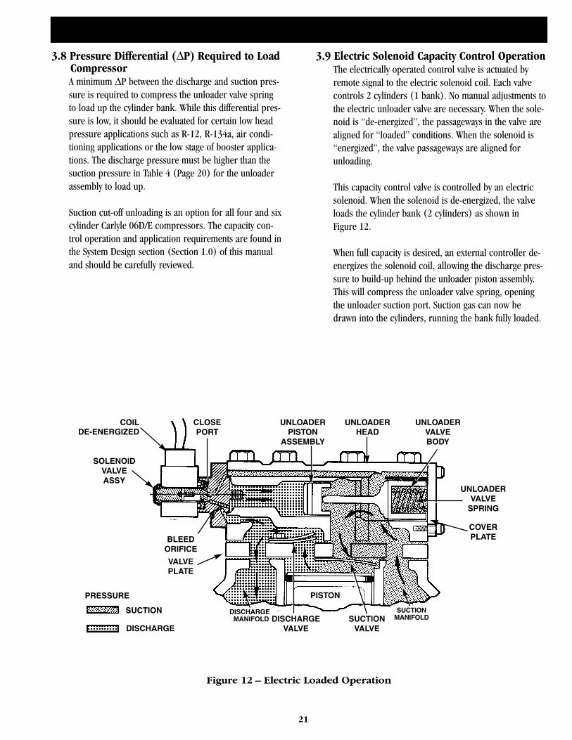
21
3.8 Pressure Differential (∆P) Required to Load CompressorA minimum ∆P between the discharge and suction pres-sure is required to compress the unloader valve springto load up the cylinder bank. While this differential pres-sure is low, it should be evaluated for certain low headpressure applications such as R-12, R-134a, air condi-tioning applications or the low stage of booster applica-tions. The discharge pressure must be higher than thesuction pressure in Table 4 (Page 20) for the unloaderassembly to load up.
Suction cut-off unloading is an option for all four and sixcylinder Carlyle 06D/E compressors. The capacity con-trol operation and application requirements are found inthe System Design section (Section 1.0) of this manualand should be carefully reviewed.
3.9 Electric Solenoid Capacity Control OperationThe electrically operated control valve is actuated byremote signal to the electric solenoid coil. Each valvecontrols 2 cylinders (1 bank). No manual adjustments tothe electric unloader valve are necessary. When the sole-noid is “de-energized”, the passageways in the valve arealigned for “loaded” conditions. When the solenoid is“energized”, the valve passageways are aligned forunloading.
This capacity control valve is controlled by an electricsolenoid. When the solenoid is de-energized, the valveloads the cylinder bank (2 cylinders) as shown inFigure 12.
When full capacity is desired, an external controller de-energizes the solenoid coil, allowing the discharge pres-sure to build-up behind the unloader piston assembly.This will compress the unloader valve spring, openingthe unloader suction port. Suction gas can now bedrawn into the cylinders, running the bank fully loaded.
COILDE-ENERGIZED
CLOSEPORT
UNLOADERPISTON
ASSEMBLY
UNLOADERHEAD
UNLOADERVALVEBODY
UNLOADERVALVE
SPRING
COVERPLATE
SUCTIONVALVE
DISCHARGEVALVE
PISTON
DISCHARGEMANIFOLD
SUCTIONMANIFOLD
VALVEPLATE
PRESSURE
BLEEDORIFICE
SOLENOIDVALVEASSY
SUCTION
DISCHARGE
Figure 12 – Electric Loaded Operation
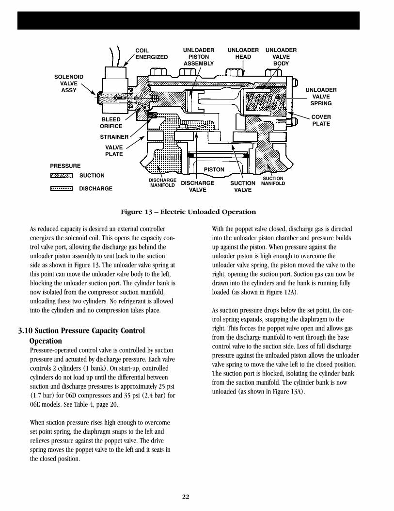
22
As reduced capacity is desired an external controllerenergizes the solenoid coil. This opens the capacity con-trol valve port, allowing the discharge gas behind theunloader piston assembly to vent back to the suctionside as shown in Figure 13. The unloader valve spring atthis point can move the unloader valve body to the left,blocking the unloader suction port. The cylinder bank isnow isolated from the compressor suction manifold,unloading these two cylinders. No refrigerant is allowedinto the cylinders and no compression takes place.
3.10 Suction Pressure Capacity Control OperationPressure-operated control valve is controlled by suctionpressure and actuated by discharge pressure. Each valvecontrols 2 cylinders (1 bank). On start-up, controlledcylinders do not load up until the differential betweensuction and discharge pressures is approximately 25 psi(1.7 bar) for 06D compressors and 35 psi (2.4 bar) for06E models. See Table 4, page 20.
When suction pressure rises high enough to overcomeset point spring, the diaphragm snaps to the left andrelieves pressure against the poppet valve. The drivespring moves the poppet valve to the left and it seats inthe closed position.
With the poppet valve closed, discharge gas is directedinto the unloader piston chamber and pressure buildsup against the piston. When pressure against theunloader piston is high enough to overcome theunloader valve spring, the piston moved the valve to theright, opening the suction port. Suction gas can now bedrawn into the cylinders and the bank is running fullyloaded (as shown in Figure 12A).
As suction pressure drops below the set point, the con-trol spring expands, snapping the diaphragm to theright. This forces the poppet valve open and allows gasfrom the discharge manifold to vent through the basecontrol valve to the suction side. Loss of full dischargepressure against the unloaded piston allows the unloadervalve spring to move the valve left to the closed position.The suction port is blocked, isolating the cylinder bankfrom the suction manifold. The cylinder bank is nowunloaded (as shown in Figure 13A).
COILENERGIZED
UNLOADERPISTON
ASSEMBLY
UNLOADERHEAD
UNLOADERVALVEBODY
UNLOADERVALVE
SPRING
COVERPLATE
SUCTIONVALVE
DISCHARGEVALVE
PISTON
VALVEPLATE
BLEEDORIFICE
SOLENOIDVALVEASSY
STRAINER
DISCHARGEMANIFOLD
SUCTIONMANIFOLD
PRESSURE
SUCTION
DISCHARGE
Figure 13 – Electric Unloaded Operation

23
Figure 12A – Pressure Loaded Operation
Figure 13A – Pressure Unloaded Operation
(7.2)
(6.5)
(5.8)
(5.2)
(4.5)
(3.8)
(3.1)
(2.4)
(1.7)
(1.0)
LOA
D —
UP
PR
ES
SU
RE
PS
IG (B
AR
)
TURNS OUT FROM BOTTOM STOP — COUNTERCLOCKWISE
0 1 2 3 4 5 6 7 8 9 10 11 12
90
80
70
60
50
40
30
20
10
0
DOTTED LINES INDICATE EXPECTEDTOLERANCE EXTREMES UNDERNORMAL R-22 OPERATING CONDITIONS
150 PSI (10.4 BAR) SYSTEM DIFFERENTIALLOAD UP PRESSURE VS NO. OF TURNS
Figure 14 – Control Set Point - Bypass & Suction Cut-Off

24
3.11 Pressure Actuated Capacity Control AdjustmentControl Set Point - The cylinder load-up point isadjustable from 0 psig to 86 psig (1 bar to 6.9 bar).Refer to Figure 14. Turn the adjustment nut clockwise tothe bottom stop. In this position, the cylinder load-uppressure is 86 psig (6.9 bar). Control set point is regu-lated to desired pressure by turning the adjustment nutcounterclockwise. The number of turns can be deter-mined from the curve in Figure 14. Each full turn coun-terclockwise decreases the load-up point by approxi-mately 7.2 psi (.5 bar). Approximately 12 turns changesthe pressure from 86 psig to 0 psig (6.9 bar to 1 bar).Pressure differential between cylinder load-up point andunload point is adjustable from6 psi to 16 psi (.41 barto 1.1 bar). Refer to Figure 15.
Turn the adjustment screw counterclockwise to theback-stop. In this position, the differential is 6 psi (.41bar). Differential is set by turning the adjustment screwclockwise. The number of turns to the desired differen-
tial can be determined from the curve. Each full turnclockwise increases the differential by approximately 0.8psi (.06 bar). Approximately 5 turns changes the differ-ential from 6 psi to 10 psi (.41 bar to .69 bar).
3.12 Variable Frequency DrivesVariable Frequency Drives (VFD’s) may be used withCarlyle 06D/E refrigeration duty compressors and pro-vide optimum capacity control while maximizing thecompressor efficiency. Some of Carlyle’s 06D air condi-tioning models may require modification of the internallubrication system to operate properly. The changesrequired for the 06D A/C models are noted in CarlyleBulletin 95T-8 or contact Carlyle Application Engineeringif additional clarification is required. VFD’s, when prop-erly applied, provide very stable suction pressure controland minimize compressor cycling. Additionally, Carlylereciprocating compressors attain their peak efficiency atapproximately 900 - 1100 rpm. Therefore, the use ofVFD’s versus simply unloading or cycling compressorswill typically result in significant energy savings. The lim-itations on the allowable speed ranges when using VFD’sare 30 to 60 hertz. Application of Carlyle 06D/E com-pressors below 30 hertz may result in nuisance oil safetyswitch trips due to reduced oil pressure levels.Operation above 60 hertz may result in increased oil cir-culation rates and compressor valve failures.
Due to the low discharge gas pulsation frequency ofreciprocating compressors (typically 30 to 180 hertz),after system start-up the operational frequency bandshould be swept to identify any high vibration areas dueto the compressor exciting frequency matching a naturalfrequency of the piping or base. Any frequency bandsthat result in excessive vibration must be programmed toskip over.
Variable frequency drives should not be selected onnominal HP but based on the maximum KW of the com-pressor motor shown in Tables 5 thru 9 on pages 25thru 28.
CONTROL SET POINT
ADJUSTMENTNUT
VALVEBODY
SEALING CAP(COVERS
PRESSURE DIFFERENTIALADJUSTMENT
SCREW)
Pressure Actuated Unloader Valve
(1.4)
(1.2)
(1.1)
(1.0)
(.83)
(.69)
(.55)
(.41)
(.28)
(.14)
20
18
16
14
12
10
8
6
4
2
LOA
D —
UN
LOA
D D
IFFE
REN
TIA
L PS
I (B
AR
)
TURNS IN FROM BACKSTOP — CLOCKWISE
0 1 2 3 4 5 6 7 8 9 10
150 PSI (10.4 BAR) SYSTEM DIFFERENTIALLOAD — UNLOAD DIFF. PRESSUREVS NO. OF TURNS
DOTTED LINES INDICATE EXPECTEDTOLERANCE EXTREMES UNDERNORMAL R-22 OPERATING CONDITIONS
Figure 15 – Differential Set Point
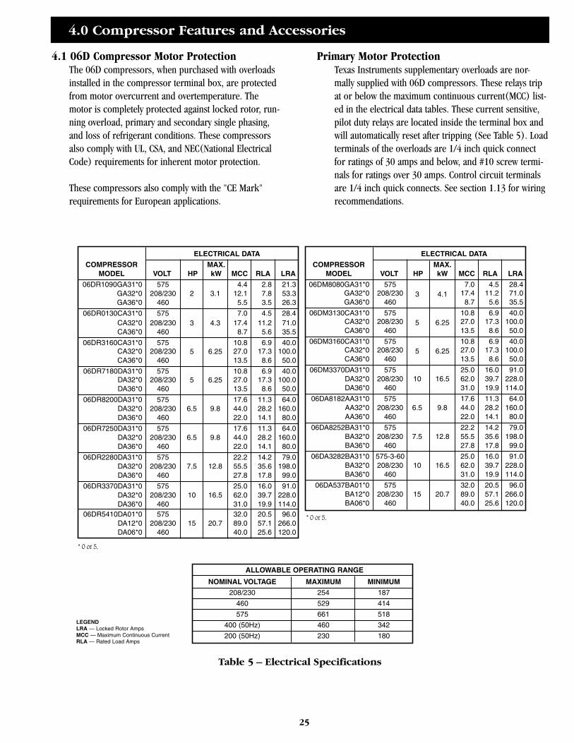
4.0 Compressor Features and Accessories
25
4.1 06D Compressor Motor ProtectionThe 06D compressors, when purchased with overloadsinstalled in the compressor terminal box, are protectedfrom motor overcurrent and overtemperature. Themotor is completely protected against locked rotor, run-ning overload, primary and secondary single phasing,and loss of refrigerant conditions. These compressorsalso comply with UL, CSA, and NEC(National ElectricalCode) requirements for inherent motor protection.
These compressors also comply with the "CE Mark"requirements for European applications.
Primary Motor ProtectionTexas Instruments supplementary overloads are nor-mally supplied with 06D compressors. These relays tripat or below the maximum continuous current(MCC) list-ed in the electrical data tables. These current sensitive,pilot duty relays are located inside the terminal box andwill automatically reset after tripping (See Table 5). Loadterminals of the overloads are 1/4 inch quick connectfor ratings of 30 amps and below, and #10 screw termi-nals for ratings over 30 amps. Control circuit terminalsare 1/4 inch quick connects. See section 1.13 for wiringrecommendations.
ELECTRICAL DATA
COMPRESSOR MAX.MODEL VOLT HP kW MCC RLA LRA
06DR1090GA31*0 575 4.4 2.8 21.3GA32*0 208/230 2 3.1 12.1 7.8 53.3GA36*0 460 5.5 3.5 26.3
06DR0130CA31*0 575 7.0 4.5 28.4CA32*0 208/230 3 4.3 17.4 11.2 71.0CA36*0 460 8.7 5.6 35.5
06DR3160CA31*0 575 10.8 6.9 40.0CA32*0 208/230 5 6.25 27.0 17.3 100.0CA36*0 460 13.5 8.6 50.0
06DR7180DA31*0 575 10.8 6.9 40.0DA32*0 208/230 5 6.25 27.0 17.3 100.0DA36*0 460 13.5 8.6 50.0
06DR8200DA31*0 575 17.6 11.3 64.0DA32*0 208/230 6.5 9.8 44.0 28.2 160.0DA36*0 460 22.0 14.1 80.0
06DR7250DA31*0 575 17.6 11.3 64.0DA32*0 208/230 6.5 9.8 44.0 28.2 160.0DA36*0 460 22.0 14.1 80.0
06DR2280DA31*0 575 22.2 14.2 79.0DA32*0 208/230 7.5 12.8 55.5 35.6 198.0DA36*0 460 27.8 17.8 99.0
06DR3370DA31*0 575 25.0 16.0 91.0DA32*0 208/230 10 16.5 62.0 39.7 228.0DA36*0 460 31.0 19.9 114.0
ELECTRICAL DATA
COMPRESSOR MAX.MODEL VOLT HP kW MCC RLA LRA
06DM8080GA31*0 575 7.0 4.5 28.4GA32*0 208/230 3 4.1 17.4 11.2 71.0GA36*0 460 8.7 5.6 35.5
06DM3130CA31*0 575 10.8 6.9 40.0CA32*0 208/230 5 6.25 27.0 17.3 100.0CA36*0 460 13.5 8.6 50.0
06DM3160CA31*0 575 10.8 6.9 40.0CA32*0 208/230 5 6.25 27.0 17.3 100.0CA36*0 460 13.5 8.6 50.0
06DM3370DA31*0 575 25.0 16.0 91.0DA32*0 208/230 10 16.5 62.0 39.7 228.0DA36*0 460 31.0 19.9 114.0
06DA8182AA31*0 575 17.6 11.3 64.0AA32*0 208/230 6.5 9.8 44.0 28.2 160.0AA36*0 460 22.0 14.1 80.0
06DA8252BA31*0 575 22.2 14.2 79.0BA32*0 208/230 7.5 12.8 55.5 35.6 198.0BA36*0 460 27.8 17.8 99.0
06DA3282BA31*0 575-3-60 25.0 16.0 91.0BA32*0 208/230 10 16.5 62.0 39.7 228.0BA36*0 460 31.0 19.9 114.0
06DA537BA01*0 575 32.0 20.5 96.0BA12*0 208/230 15 20.7 89.0 57.1 266.0BA06*0 460 40.0 25.6 120.0
ALLOWABLE OPERATING RANGE
NOMINAL VOLTAGE MAXIMUM MINIMUM
208/230 254 187
460 529 414
575 661 518
400 (50Hz) 460 342
200 (50Hz) 230 180
* 0 or 5.
* 0 or 5.
LEGENDLRA — Locked Rotor AmpsMCC — Maximum Continuous CurrentRLA — Rated Load Amps
06DR5410DA01*0 575 32.0 20.5 96.0DA12*0 208/230 15 20.7 89.0 57.1 266.0DA06*0 460 40.0 25.6 120.0
Table 5 – Electrical Specifications
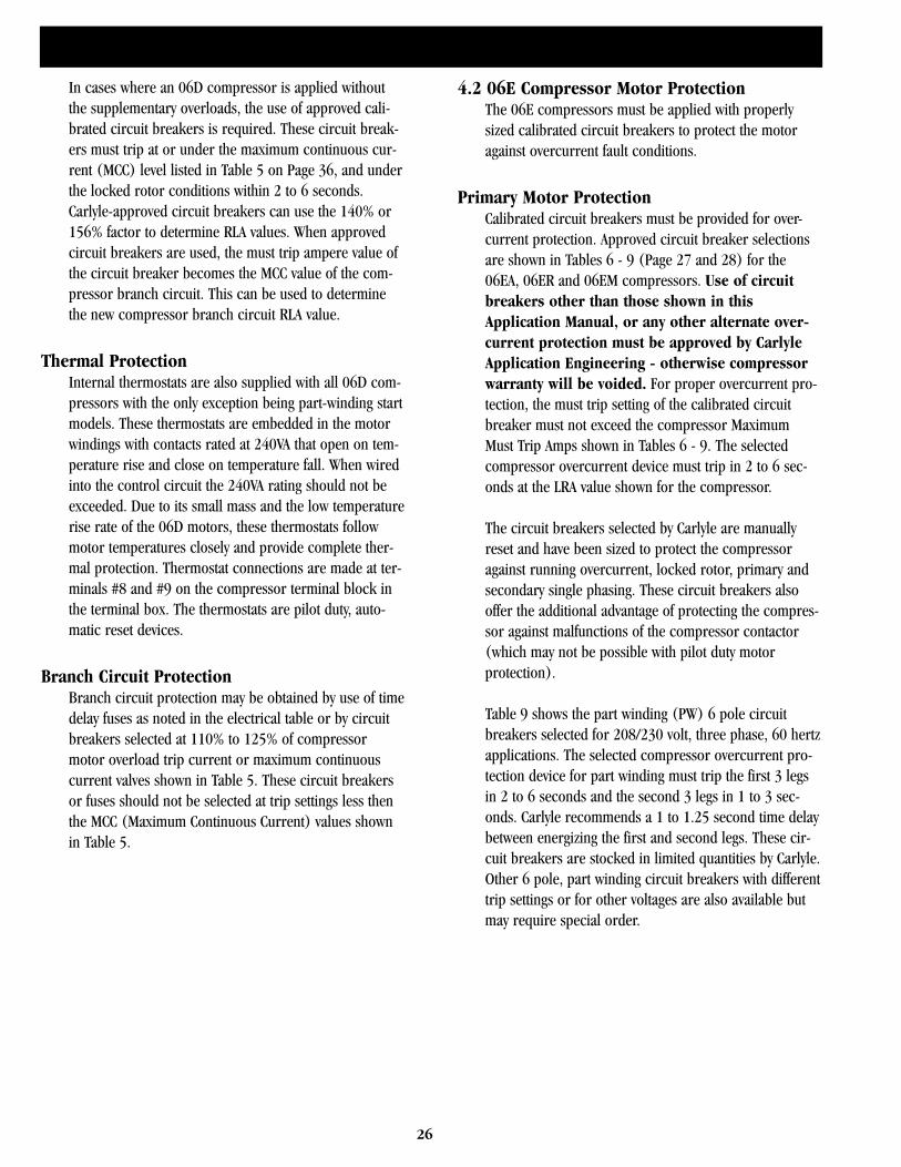
26
In cases where an 06D compressor is applied withoutthe supplementary overloads, the use of approved cali-brated circuit breakers is required. These circuit break-ers must trip at or under the maximum continuous cur-rent (MCC) level listed in Table 5 on Page 36, and underthe locked rotor conditions within 2 to 6 seconds.Carlyle-approved circuit breakers can use the 140% or156% factor to determine RLA values. When approvedcircuit breakers are used, the must trip ampere value ofthe circuit breaker becomes the MCC value of the com-pressor branch circuit. This can be used to determinethe new compressor branch circuit RLA value.
Thermal ProtectionInternal thermostats are also supplied with all 06D com-pressors with the only exception being part-winding startmodels. These thermostats are embedded in the motorwindings with contacts rated at 240VA that open on tem-perature rise and close on temperature fall. When wiredinto the control circuit the 240VA rating should not beexceeded. Due to its small mass and the low temperaturerise rate of the 06D motors, these thermostats followmotor temperatures closely and provide complete ther-mal protection. Thermostat connections are made at ter-minals #8 and #9 on the compressor terminal block inthe terminal box. The thermostats are pilot duty, auto-matic reset devices.
Branch Circuit ProtectionBranch circuit protection may be obtained by use of timedelay fuses as noted in the electrical table or by circuitbreakers selected at 110% to 125% of compressormotor overload trip current or maximum continuouscurrent valves shown in Table 5. These circuit breakersor fuses should not be selected at trip settings less thenthe MCC (Maximum Continuous Current) values shownin Table 5.
4.2 06E Compressor Motor ProtectionThe 06E compressors must be applied with properlysized calibrated circuit breakers to protect the motoragainst overcurrent fault conditions.
Primary Motor ProtectionCalibrated circuit breakers must be provided for over-current protection. Approved circuit breaker selectionsare shown in Tables 6 - 9 (Page 27 and 28) for the06EA, 06ER and 06EM compressors. Use of circuitbreakers other than those shown in thisApplication Manual, or any other alternate over-current protection must be approved by CarlyleApplication Engineering - otherwise compressorwarranty will be voided. For proper overcurrent pro-tection, the must trip setting of the calibrated circuitbreaker must not exceed the compressor MaximumMust Trip Amps shown in Tables 6 - 9. The selectedcompressor overcurrent device must trip in 2 to 6 sec-onds at the LRA value shown for the compressor.
The circuit breakers selected by Carlyle are manuallyreset and have been sized to protect the compressoragainst running overcurrent, locked rotor, primary andsecondary single phasing. These circuit breakers alsooffer the additional advantage of protecting the compres-sor against malfunctions of the compressor contactor(which may not be possible with pilot duty motorprotection).
Table 9 shows the part winding (PW) 6 pole circuitbreakers selected for 208/230 volt, three phase, 60 hertzapplications. The selected compressor overcurrent pro-tection device for part winding must trip the first 3 legsin 2 to 6 seconds and the second 3 legs in 1 to 3 sec-onds. Carlyle recommends a 1 to 1.25 second time delaybetween energizing the first and second legs. These cir-cuit breakers are stocked in limited quantities by Carlyle.Other 6 pole, part winding circuit breakers with differenttrip settings or for other voltages are also available butmay require special order.
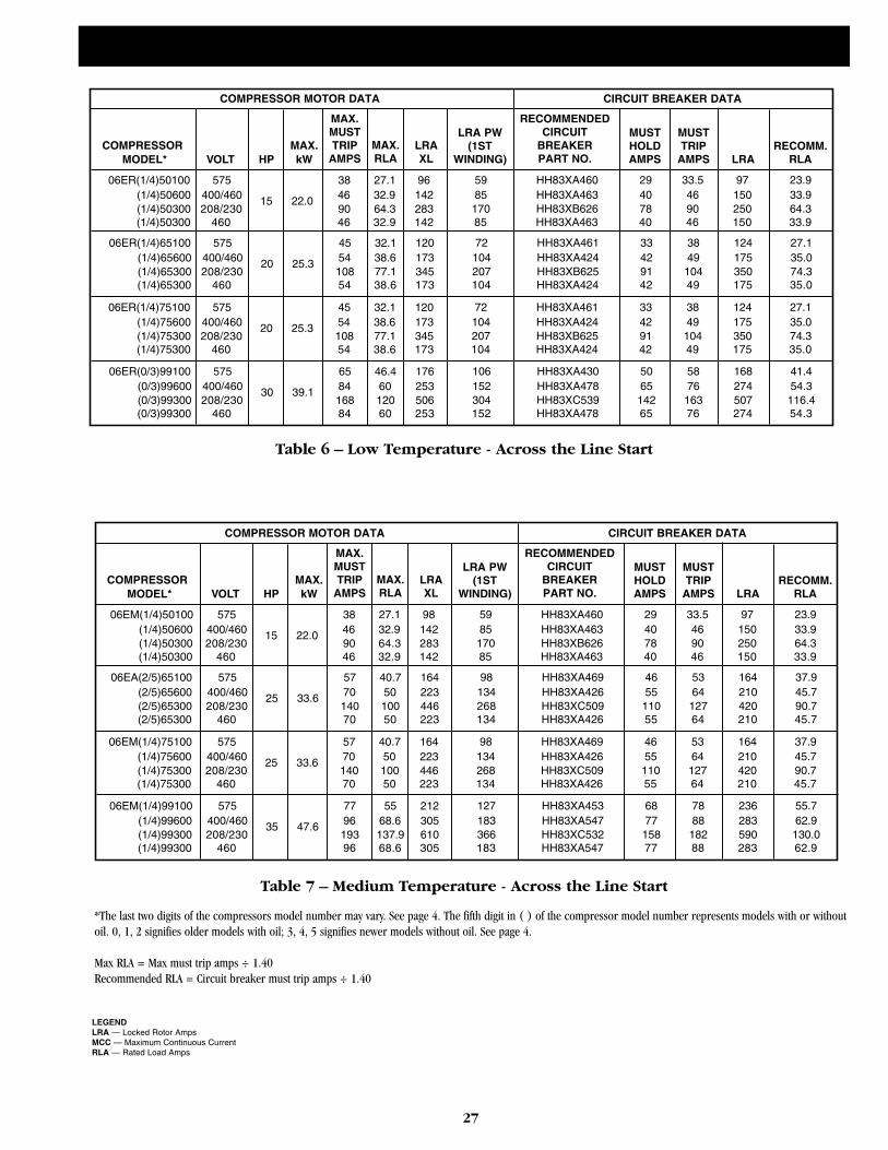
27
COMPRESSOR MOTOR DATA
COMPRESSOR MAX.MODEL* VOLT HP kW
MAX.MUSTTRIP
AMPSMAX.RLA
RECOMMENDEDCIRCUIT
BREAKERPART NO.
06ER(1/4)50100 575 38 27.1 96(1/4)50600 400/460 15 22.0 46 32.9 142(1/4)50300 208/230 90 64.3 283
LRAXL
LRA PW(1ST
WINDING)
CIRCUIT BREAKER DATA
MUSTHOLDAMPS
MUSTTRIP
AMPS
LRA
RECOMM.RLA
(1/4)50300 460 46 32.9 142
5985
17085
HH83XA460HH83XA463HH83XB626HH83XA463
29407840
33.5469046
97150250150
23.933.964.333.9
06ER(1/4)65100 575 45 32.1 120(1/4)65600 400/460 20 25.3 54 38.6 173(1/4)65300 208/230 108 77.1 345(1/4)65300 460 54 38.6 173
72104207104
HH83XA461HH83XA424HH83XB625HH83XA424
33429142
3849
10449
124175350175
27.135.074.335.0
06ER(1/4)75100 575 45 32.1 120(1/4)75600 400/460 20 25.3 54 38.6 173(1/4)75300 208/230 108 77.1 345(1/4)75300 460 54 38.6 173
72104207104
HH83XA461HH83XA424HH83XB625HH83XA424
33429142
3849
10449
124175350175
27.135.074.335.0
06ER(0/3)99100 575 65 46.4 176(0/3)99600 400/460 30 39.1 84 60 253(0/3)99300 208/230 168 120 506(0/3)99300 460 84 60 253
106152304152
HH83XA430HH83XA478HH83XC539HH83XA478
5065
14265
5876
16376
168274507274
41.454.3
116.454.3
Table 6 – Low Temperature - Across the Line Start
COMPRESSOR MOTOR DATA
COMPRESSOR MAX.MODEL* VOLT HP kW
MAX.MUSTTRIP
AMPSMAX.RLA
RECOMMENDEDCIRCUIT
BREAKERPART NO.
06EM(1/4)50100 575 38 27.1 98(1/4)50600 400/460 15 22.0 46 32.9 142(1/4)50300 208/230 90 64.3 283
LRAXL
LRA PW(1ST
WINDING)
CIRCUIT BREAKER DATA
MUSTHOLDAMPS
MUSTTRIP
AMPS
LRA
RECOMM.RLA
(1/4)50300 460 46 32.9 142
5985
17085
HH83XA460HH83XA463HH83XB626HH83XA463
29407840
33.5469046
97150250150
23.933.964.333.9
06EA(2/5)65100 575 57 40.7 164(2/5)65600 400/460 25 33.6 70 50 223(2/5)65300 208/230 140 100 446(2/5)65300 460 70 50 223
98134268134
HH83XA469HH83XA426HH83XC509HH83XA426
4655
11055
5364
12764
164210420210
37.945.790.745.7
06EM(1/4)75100 575 57 40.7 164(1/4)75600 400/460 25 33.6 70 50 223(1/4)75300 208/230 140 100 446(1/4)75300 460 70 50 223
98134268134
HH83XA469HH83XA426HH83XC509HH83XA426
4655
11055
5364
12764
164210420210
37.945.790.745.7
06EM(1/4)99100 575 77 55 212(1/4)99600 400/460 35 47.6 96 68.6 305(1/4)99300 208/230 193 137.9 610(1/4)99300 460 96 68.6 305
127183366183
HH83XA453HH83XA547HH83XC532HH83XA547
6877
15877
7888
18288
236283590283
55.762.9
130.062.9
Table 7 – Medium Temperature - Across the Line Start
LEGENDLRA — Locked Rotor AmpsMCC — Maximum Continuous CurrentRLA — Rated Load Amps
*The last two digits of the compressors model number may vary. See page 4. The fifth digit in ( ) of the compressor model number represents models with or withoutoil. 0, 1, 2 signifies older models with oil; 3, 4, 5 signifies newer models without oil. See page 4.
Max RLA = Max must trip amps ÷ 1.40 Recommended RLA = Circuit breaker must trip amps ÷ 1.40
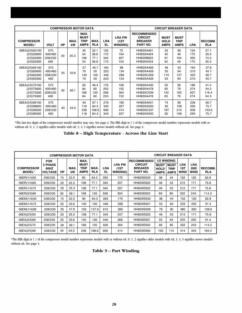
28
COMPRESSOR MOTOR DATA
COMPRESSOR MAX.MODEL* VOLT HP kW
MAX.MUSTTRIP
AMPSMAX.RLA
RECOMMENDEDCIRCUIT
BREAKERPART NO.
06EA(2/5)50100 575 45 32.1 120(2/5)50600 400/460 20 25.3 54 38.6 173(2/5)50300 208/230 108 77.1 345
LRAXL
LRA PW(1ST
WINDING)
CIRCUIT BREAKER DATA
MUSTHOLDAMPS
MUSTTRIP
AMPS
LRA
RECOMM.RLA
(2/5)50300 460 54 38.6 173
72104207104
HH83XA461HH83XA424HH83XB625HH83XA424
33429142
3849
10449
124175350175
27.135.074.335.0
06EA(2/5)65100 575 57 40.7 164(2/5)65600 400/460 25 33.6 70 50 223(2/5)65300 208/230 140 100 446(2/5)65300 460 70 50 223
98134268134
HH83XA469HH83XA426HH83XC509HH83XA426
4655
11055
5364
12764
164210420210
37.845.790.745.7
06EA(2/5)75100 575 65 46.4 176(2/5)75600 400/460 30 39.1 84 60 253(2/5)75300 208/230 168 120 506(2/5)75300 460 84 60 253
106152304152
HH83XA430HH83XA478HH83XC539HH83XA478
5065
14265
5676
16376
188274507274
41.454.3
116.454.3
06EA(2/5)99100 575 94 67.1 276(2/5)99600 400/460 40 54.0 118 84.3 345(2/5)99300 208/230 236 168.6 690(2/5)99300 460 118 84.3 345
165207414207
HH83XA551HH83XA550HH83XC537HH83XA550
7492
18792
85106215106
236295636295
60.775.7
153.675.7
*The fifth digit in ( ) of the compressor model number represents models with or without oil. 0, 1, 2 signifies older models with oil; 3, 4, 5 signifies newer modelswithout oil. See page 4.
COMPRESSOR MOTOR DATA
COMPRESSOR MAX.MODEL*
FOR 3 PHASE
60HZVOLTAGE HP kW
MAX.MUSTTRIP
AMPSMAX.RLA
RECOMMENDEDCIRCUIT
BREAKERPART NO.
06ER(1/4)50 208/230 90 64.3 283
06ER(1/4)65 208/230 108 77.1 345
06ER(1/4)75 208/230 108 77.1 345
LRAXL
LRA PW(1ST
WINDING)
CIRCUIT BREAKER DATA
MUSTHOLDAMPS
MUSTTRIP
AMPS
LRA1ST
WIND
RECOMM.RLA
06ER(0/3)99 208/230 168 120 506
170
207
207
304
HH83XE633
HH83XE622
HH83XE622
HH83XE652
38
46
46
69
44
53
53
80
152
212
212
332
62.8
75.8
75.8
114.2
06EM(1/4)50 208/230 90 64.3 283
06EM(1/4)75 208/230
15 22.0
140 100 446
06EM(1/4)99 208/230 193 137.9 610
06EA(2/5)50 208/230 108 77.1 345
170
268
366
207
HH83XE633
HH83XE621
HH83XE609
HH83XE622
38
55
78
46
44
64
90
53
152
255
380
212
62.8
91.4
128.6
75.8
06EA(2/5)65 208/230 140 100 446
06EA(2/5)75 208/230 168 120 506
06EA(2/5)99 208/230 236 168.6 690
268
304
414
HH83XE621
HH83XE652
HH83XE660
55
69
100
64
80
115
255
332
414
91.4
114.2
164.2
20 25.3
30 39.1
20 25.3
15 22.0
25 33.6
20 25.3
25 33.6
35 47.6
30 39.1
40 54.0
LRA2ND
WIND
120
171
171
243
120
205
300
171
205
243
345
1/2 WINDING
Table 9 – Part Winding
*The last two digits of the compressors model number may vary. See page 4. The fifth digit in ( ) of the compressor model number represents models with orwithout oil. 0, 1, 2 signifies older models with oil; 3, 4, 5 signifies newer models without oil. See page 4.
Table 8 – High Temperature - Across the Line Start
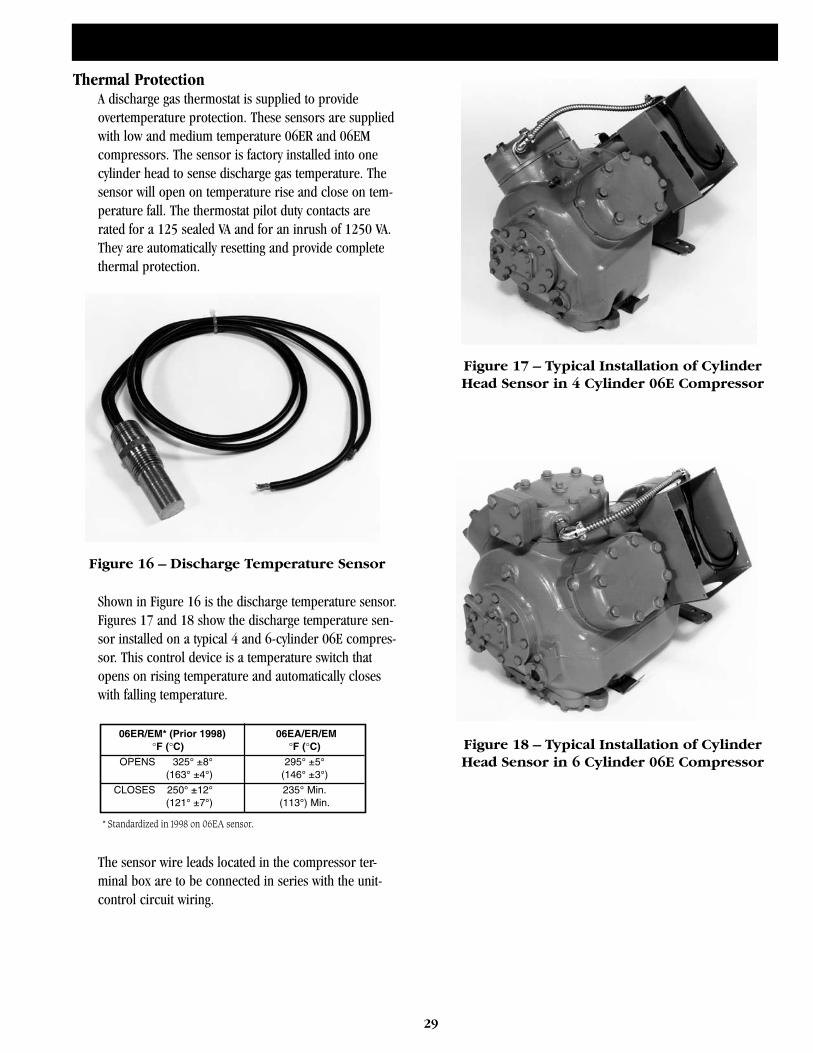
29
Thermal ProtectionA discharge gas thermostat is supplied to provideovertemperature protection. These sensors are suppliedwith low and medium temperature 06ER and 06EMcompressors. The sensor is factory installed into onecylinder head to sense discharge gas temperature. Thesensor will open on temperature rise and close on tem-perature fall. The thermostat pilot duty contacts arerated for a 125 sealed VA and for an inrush of 1250 VA.They are automatically resetting and provide completethermal protection.
Shown in Figure 16 is the discharge temperature sensor.Figures 17 and 18 show the discharge temperature sen-sor installed on a typical 4 and 6-cylinder 06E compres-sor. This control device is a temperature switch thatopens on rising temperature and automatically closeswith falling temperature.
The sensor wire leads located in the compressor ter-minal box are to be connected in series with the unit-control circuit wiring.
Figure 16 – Discharge Temperature Sensor
* Standardized in 1998 on 06EA sensor.
06ER/EM* (Prior 1998) 06EA/ER/EM°F (°C) °F (°C)
OPENS 325 8 295 5(163 4 ) (146 3 )
CLOSES 250 12 235 Min.(121 7 ) (113 ) Min.
Figure 17 – Typical Installation of CylinderHead Sensor in 4 Cylinder 06E Compressor
Figure 18 – Typical Installation of CylinderHead Sensor in 6 Cylinder 06E Compressor
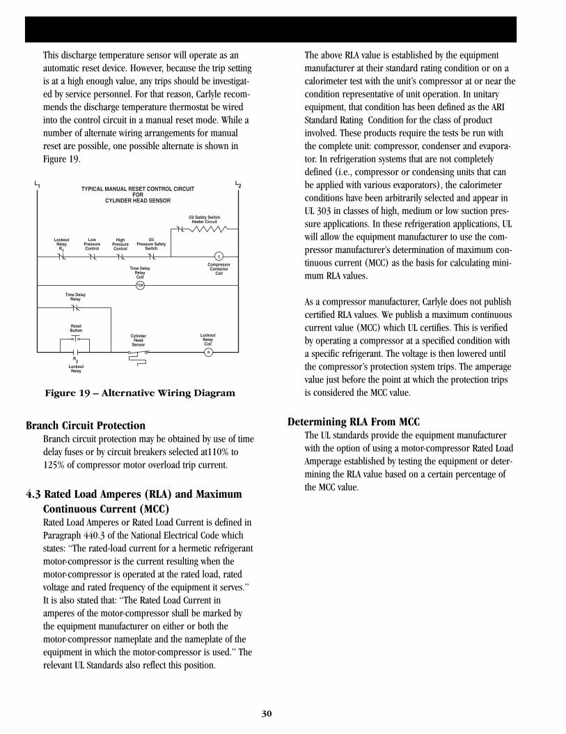
30
This discharge temperature sensor will operate as anautomatic reset device. However, because the trip settingis at a high enough value, any trips should be investigat-ed by service personnel. For that reason, Carlyle recom-mends the discharge temperature thermostat be wiredinto the control circuit in a manual reset mode. While anumber of alternate wiring arrangements for manualreset are possible, one possible alternate is shown inFigure 19.
Branch Circuit ProtectionBranch circuit protection may be obtained by use of timedelay fuses or by circuit breakers selected at110% to125% of compressor motor overload trip current.
4.3 Rated Load Amperes (RLA) and MaximumContinuous Current (MCC)Rated Load Amperes or Rated Load Current is defined inParagraph 440.3 of the National Electrical Code whichstates: “The rated-load current for a hermetic refrigerantmotor-compressor is the current resulting when themotor-compressor is operated at the rated load, ratedvoltage and rated frequency of the equipment it serves.”It is also stated that: “The Rated Load Current inamperes of the motor-compressor shall be marked bythe equipment manufacturer on either or both themotor-compressor nameplate and the nameplate of theequipment in which the motor-compressor is used.” Therelevant UL Standards also reflect this position.
The above RLA value is established by the equipmentmanufacturer at their standard rating condition or on acalorimeter test with the unit’s compressor at or near thecondition representative of unit operation. In unitaryequipment, that condition has been defined as the ARIStandard Rating Condition for the class of productinvolved. These products require the tests be run withthe complete unit: compressor, condenser and evapora-tor. In refrigeration systems that are not completelydefined (i.e., compressor or condensing units that canbe applied with various evaporators), the calorimeterconditions have been arbitrarily selected and appear inUL 303 in classes of high, medium or low suction pres-sure applications. In these refrigeration applications, ULwill allow the equipment manufacturer to use the com-pressor manufacturer’s determination of maximum con-tinuous current (MCC) as the basis for calculating mini-mum RLA values.
As a compressor manufacturer, Carlyle does not publishcertified RLA values. We publish a maximum continuouscurrent value (MCC) which UL certifies. This is verifiedby operating a compressor at a specified condition witha specific refrigerant. The voltage is then lowered untilthe compressor’s protection system trips. The amperagevalue just before the point at which the protection tripsis considered the MCC value.
Determining RLA From MCCThe UL standards provide the equipment manufacturerwith the option of using a motor-compressor Rated LoadAmperage established by testing the equipment or deter-mining the RLA value based on a certain percentage ofthe MCC value.
TYPICAL MANUAL RESET CONTROL CIRCUITFOR
CYLINDER HEAD SENSOR
Oil Safety SwitchHeater Circuit
OilPressure Safety
Switch
L1 L2
R2
HighPressureControl
LowPressureControl
LockoutRelay
R1
Time DelayRelayCoil
Time DelayRelay
TDR
C
ResetButton
CylinderHead
Sensor
LockoutRelayCoil
R
CompressorContactor
Coil
LockoutRelay
Figure 19 – Alternative Wiring Diagram
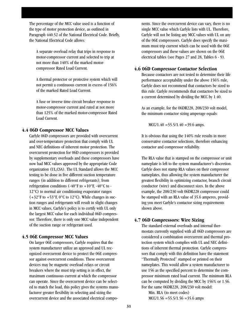
31
The percentage of the MCC value used is a function ofthe type of motor protection device, as outlined inParagraph 440.52 of the National Electrical Code. Briefly,the National Electrical Code allows:
A separate overload relay that trips in response to motor-compressor current and selected to trip at not more than 140% of the marked motor-compressor Rated Load Current.
A thermal protector or protective system which will not permit a continuous current in excess of 156% of the marked Rated Load Current.
A fuse or inverse time circuit breaker response to motor-compressor current and rated at not more than 125% of the marked motor-compressor Rated Load Current.
4.4 06D Compressor MCC ValuesCarlyle 06D compressors are provided with overcurrentand over-temperature protection that comply with ULand NEC definitions of inherent motor protection. Theovercurrent protection for 06D compressors is providedby supplementary overloads and these compressors havenow had MCC values approved by the appropriate Codeorganization (UL,CSA). The UL Standard allows the MCCtesting to be done in five different suction temperatureranges (in addition to different refrigerants); fromrefrigeration conditions (-40°F to +10°F, -40°C to -12°C) to normal air conditioning evaporator ranges(+32°F to +53°F, 0°C to 12°C). While changes in suc-tion ranges and refrigerants will result in slight changesin MCC values, Carlyle’s policy is to certify with UL onlythe largest MCC value for each individual 06D compres-sor. Therefore, there is only one MCC value independentof the suction range or refrigerant used.
4.5 06E Compressor MCC ValuesOn larger 06E compressors, Carlyle requires that thesystem manufacturer utilize an approved and UL rec-ognized overcurrent device to protect the 06E compres-sor against overcurrent conditions. These overcurrentdevices may be magnetic overload relays or circuitbreakers where the must trip setting is in effect, themaximum continuous current at which the compressorcan operate. Since the overcurrent device can be select-ed to match the load, this policy gives the systems manu-facturer greater flexibility in selecting and sizing theovercurrent device and the associated electrical compo-
nents. Since the overcurrent device can vary, there is nosingle MCC value which Carlyle lists with UL. Therefore,Carlyle will not be listing any MCC values with UL on anyof the 06E compressors. Carlyle does specify the maxi-mum must trip current which can be used with the 06Ecompressors and these values are shown on the 06Eelectrical tables (see Pages 27 and 28, Tables 6 - 9).
4.6 06D Compressor Contactor SelectionBecause contactors are not tested to determine their lifeperformance acceptability under the above 156% rule,Carlyle does not recommend that contactors be sized tothis rule. Carlyle recommends that contactors be sized toa current determined by dividing the MCC by 1.40.
As an example, for the 06DR228, 208/230 volt model,the minimum contactor sizing amperage equals:
MCC/1.40 =55.5/1.40 =39.6 amps.
It is obvious that using the 140% rule results in moreconservative contactor selections, therefore enhancingcontactor and compressor reliability.
The RLA value that is stamped on the compressor or unitnameplate is left to the system manufacturer’s discretion.Carlyle does not stamp RLA values on their compressornameplates, thus allowing the system manufacturer thegreatest flexibility in optimizing contactor, branch circuitconductor (wire) and disconnect sizes. In the aboveexample, the 208/230 volt 06DR228 compressor couldbe stamped with an RLA value of 35.6 amperes, provid-ing you meet Carlyle’s contactor sizing requirementsshown above.
4.7 06D Compressors: Wire SizingThe standard external overloads and internal ther-mostats currently supplied with all 06D compressors areconsidered a combination overcurrent and thermal pro-tection system which complies with UL and NEC defini-tions of inherent thermal protection. Carlyle compres-sors that comply with this definition have the statement“Thermally Protected” stamped or printed on theirnameplates. This would allow a system manufacturer touse 156 as the specified percent to determine the com-pressor minimum rated load current. The minimum RLAcan be computed by dividing the MCC by 156% or 1.56.For the same 06DR228, 208/230 volt model:
Min. RLA (to meet codes)MCC/1.56 =55.5/1.56 =35.6 amps
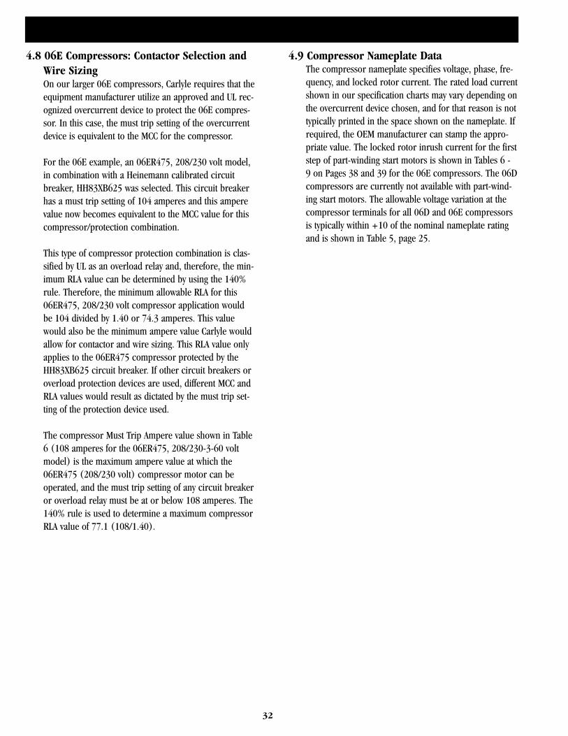
32
4.8 06E Compressors: Contactor Selection andWire SizingOn our larger 06E compressors, Carlyle requires that theequipment manufacturer utilize an approved and UL rec-ognized overcurrent device to protect the 06E compres-sor. In this case, the must trip setting of the overcurrentdevice is equivalent to the MCC for the compressor.
For the 06E example, an 06ER475, 208/230 volt model,in combination with a Heinemann calibrated circuitbreaker, HH83XB625 was selected. This circuit breakerhas a must trip setting of 104 amperes and this amperevalue now becomes equivalent to the MCC value for thiscompressor/protection combination.
This type of compressor protection combination is clas-sified by UL as an overload relay and, therefore, the min-imum RLA value can be determined by using the 140%rule. Therefore, the minimum allowable RLA for this06ER475, 208/230 volt compressor application wouldbe 104 divided by 1.40 or 74.3 amperes. This valuewould also be the minimum ampere value Carlyle wouldallow for contactor and wire sizing. This RLA value onlyapplies to the 06ER475 compressor protected by theHH83XB625 circuit breaker. If other circuit breakers oroverload protection devices are used, different MCC andRLA values would result as dictated by the must trip set-ting of the protection device used.
The compressor Must Trip Ampere value shown in Table6 (108 amperes for the 06ER475, 208/230-3-60 voltmodel) is the maximum ampere value at which the06ER475 (208/230 volt) compressor motor can beoperated, and the must trip setting of any circuit breakeror overload relay must be at or below 108 amperes. The140% rule is used to determine a maximum compressorRLA value of 77.1 (108/1.40).
4.9 Compressor Nameplate DataThe compressor nameplate specifies voltage, phase, fre-quency, and locked rotor current. The rated load currentshown in our specification charts may vary depending onthe overcurrent device chosen, and for that reason is nottypically printed in the space shown on the nameplate. Ifrequired, the OEM manufacturer can stamp the appro-priate value. The locked rotor inrush current for the firststep of part-winding start motors is shown in Tables 6 -9 on Pages 38 and 39 for the 06E compressors. The 06Dcompressors are currently not available with part-wind-ing start motors. The allowable voltage variation at thecompressor terminals for all 06D and 06E compressorsis typically within +10 of the nominal nameplate ratingand is shown in Table 5, page 25.
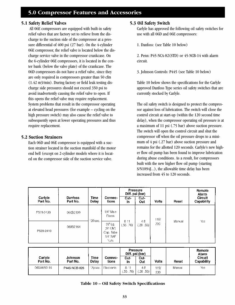
5.0 Compressor Features and Accessories
33
5.1 Safety Relief ValvesAll 06E compressors are equipped with built-in safety
relief valves that are factory set to relieve from the dis-charge to the suction side of the compressor at a pres-sure differential of 400 psi (27 bar). On the 4-cylinder06E compressor, the relief valve is located below the dis-charge service valve in the compressor crankcase. Onthe 6-cylinder 06E compressors, it is located in the cen-ter bank (below the valve plate) of the crankcase. The06D compressors do not have a relief valve, since theyare only required in compressors greater than 50 cfm(1.42 m3/min). During factory or field leak testing dis-charge side pressures should not exceed 350 psi toavoid inadvertently causing the relief valve to open. Ifthis opens the relief valve may require replacement.System problems that result in the compressor operatingat elevated head pressures (for example – cycling on thehigh pressure switch) may also cause the relief valve tosubsequently open at lower operating pressures and thusrequire replacement.
5.2 Suction StrainersEach 06D and 06E compressor is equipped with a suc-tion strainer located in the suction manifold of the motorend bell (except on 2-cylinder models where it is locat-ed on the compressor side of the suction service valve.
5.3 Oil Safety SwitchCarlyle has approved the following oil safety switches foruse with all 06D and 06E compressors:
1. Danfoss: (see Table 10 below)
2. Penn: P45-NCA-82(STD) or 45-NCB-14 with alarmcircuit.
3. Johnson Controls: P445 (see Table 10 below)
Table 10 below shows the specifications for the Carlyleapproved Danfoss Type series oil safety switches that arecurrently stocked by Carlyle.
The oil safety switch is designed to protect the compres-sor against loss of lubrication. The switch will close thecontrol circuit at start-up (within the 120 second timedelay), when the compressor operating oil pressure is ata maximum of 11 psi (.75 bar) above suction pressure.The switch will open the control circuit and shut thecompressor off when the oil pressure drops to a mini-mum of 4 psi (.27 bar) above suction pressure andremains for the allotted 120 seconds. Carlyle’s new high-er flow oil pump has been found to improve lubricationduring abuse conditions. As a result, for compressorsbuilt with the new higher flow oil pump (startingS/N1094J...), the allowable time delay has beenincreased from 45 to 120 seconds.
P529-2410
Table 10 – Oil Safety Switch Specifications
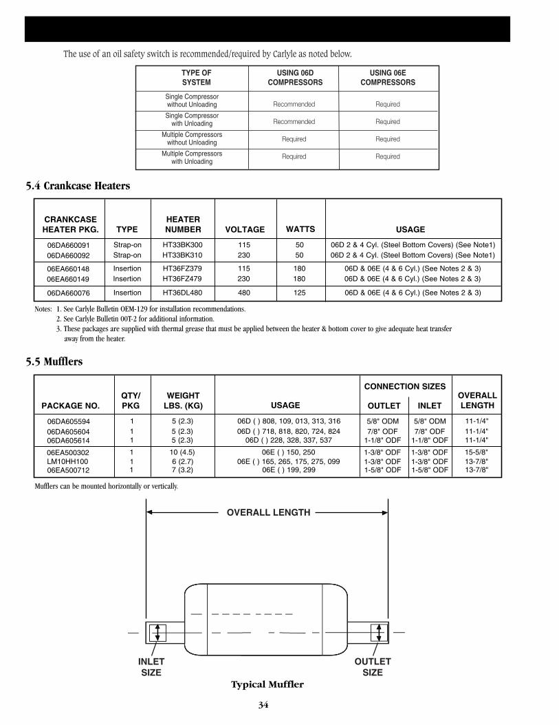
34
5.4 Crankcase Heaters
5.5 Mufflers
OVERALL LENGTH
INLETSIZE
OUTLETSIZE
Typical Muffler
The use of an oil safety switch is recommended/required by Carlyle as noted below.
TYPE OF USING 06D USING 06ESYSTEM COMPRESSORS COMPRESSORS
Single Compressorwithout Unloading
Single Compressorwith Unloading
Multiple Compressorswithout Unloading
Multiple Compressorswith Unloading
Recommended Required
Recommended Required
Required Required
Required Required
CRANKCASEHEATER PKG. VOLTAGETYPE
HEATERNUMBER WATTS
06DA66009106DA660092
06EA660148
USAGE
06EA660149
06DA660076
Strap-onStrap-on
InsertionInsertion
Insertion
HT33BK300HT33BK310
HT36FZ379HT36FZ479
HT36DL480
115230
115230
480
5050
180180
125
06D 2 & 4 Cyl. (Steel Bottom Covers) (See Note1)06D 2 & 4 Cyl. (Steel Bottom Covers) (See Note1)
06D & 06E (4 & 6 Cyl.) (See Notes 2 & 3)06D & 06E (4 & 6 Cyl.) (See Notes 2 & 3)
06D & 06E (4 & 6 Cyl.) (See Notes 2 & 3)
PACKAGE NO. USAGEQTY/PKG
WEIGHTLBS. (KG) OUTLET
06DA60559406DA60560406DA605614
INLET
06EA500302
06EA500712
111
1
1
5 (2.3)5 (2.3)5 (2.3)
10 (4.5)
7 (3.2)
11-1/4"11-1/4"11-1/4"
15-5/8"
13-7/8"
06D ( ) 808, 109, 013, 313, 31606D ( ) 718, 818, 820, 724, 824
06D ( ) 228, 328, 337, 537
06E ( ) 150, 250
06E ( ) 199, 299LM10HH100
CONNECTION SIZESOVERALLLENGTH
13-7/8"1 6 (2.7) 06E ( ) 165, 265, 175, 275, 099
5/8" ODM7/8" ODF
1-1/8" ODF
1-3/8" ODF
1-5/8" ODF1-3/8" ODF
5/8" ODM7/8" ODF
1-1/8" ODF
1-3/8" ODF
1-5/8" ODF1-3/8" ODF
Notes: 1. See Carlyle Bulletin OEM-129 for installation recommendations.2. See Carlyle Bulletin 00T-2 for additional information. 3. These packages are supplied with thermal grease that must be applied between the heater & bottom cover to give adequate heat transfer
away from the heater.
Mufflers can be mounted horizontally or vertically.
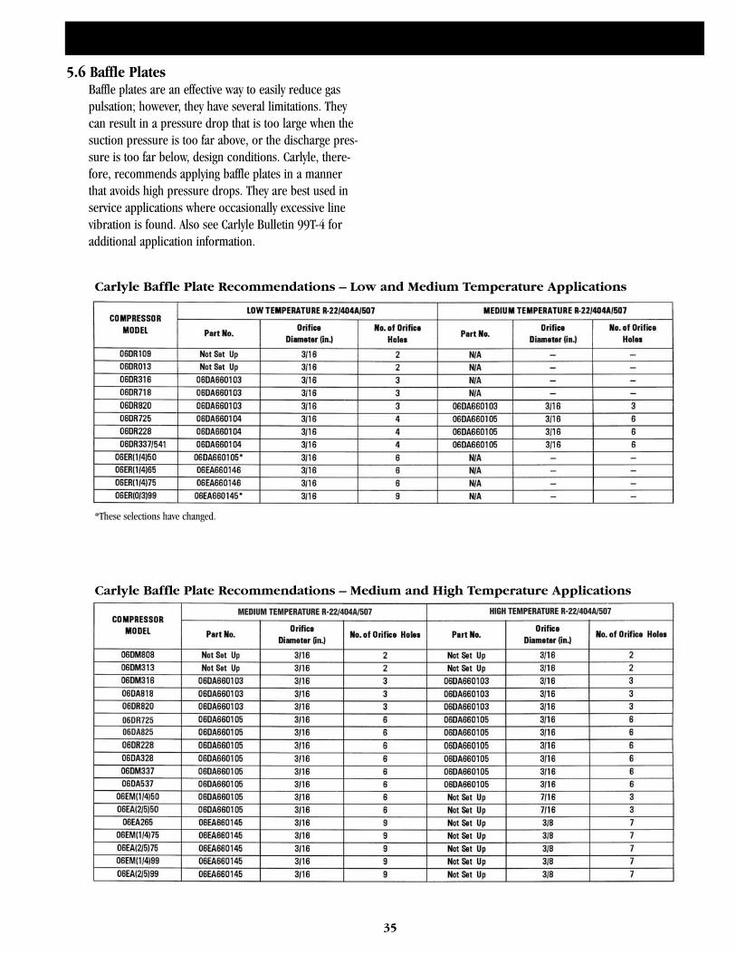
35
5.6 Baffle PlatesBaffle plates are an effective way to easily reduce gaspulsation; however, they have several limitations. Theycan result in a pressure drop that is too large when thesuction pressure is too far above, or the discharge pres-sure is too far below, design conditions. Carlyle, there-fore, recommends applying baffle plates in a mannerthat avoids high pressure drops. They are best used inservice applications where occasionally excessive linevibration is found. Also see Carlyle Bulletin 99T-4 foradditional application information.
Carlyle Baffle Plate Recommendations – Low and Medium Temperature Applications
MEDIUM TEMPERATURE R-22/404A/507 HIGH TEMPERATURE R-22/404A/507
06DR72506DA825
Carlyle Baffle Plate Recommendations – Medium and High Temperature Applications
*These selections have changed.
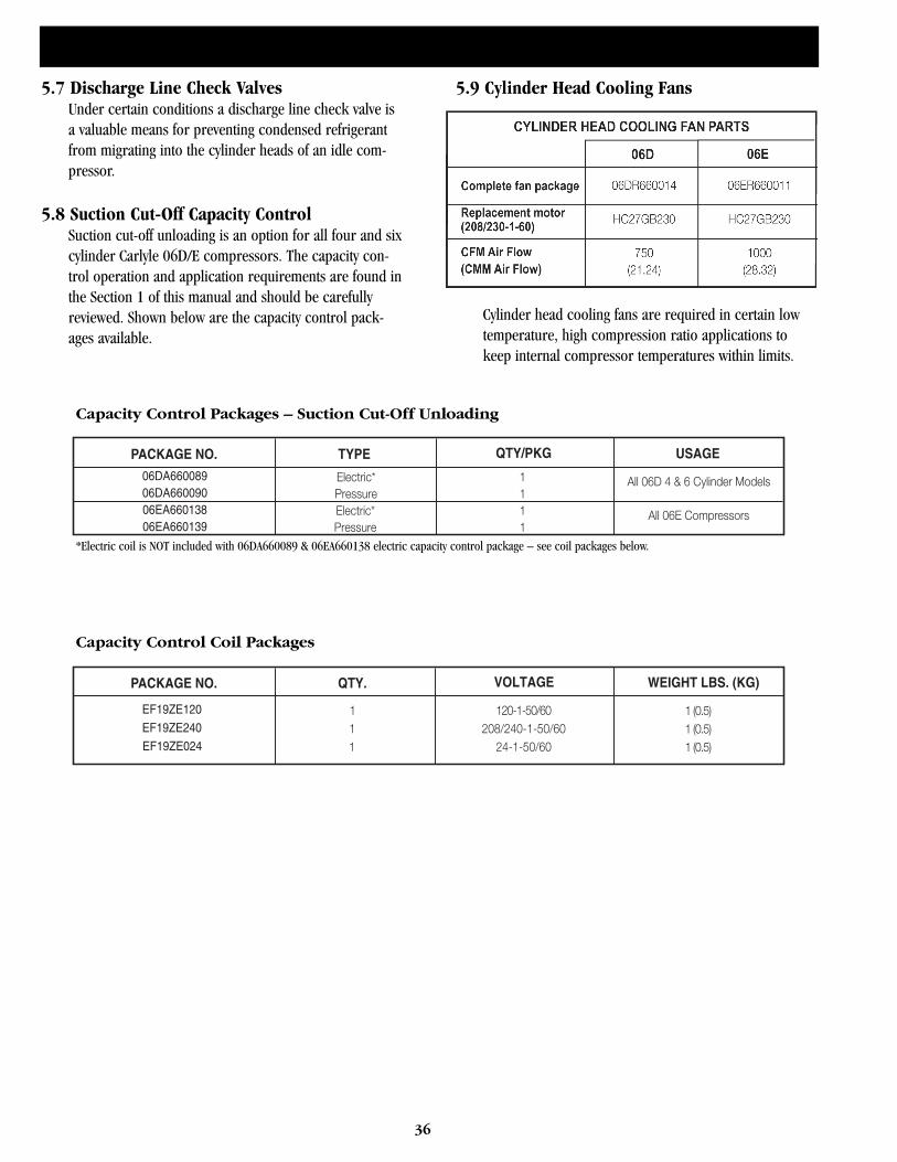
36
5.7 Discharge Line Check ValvesUnder certain conditions a discharge line check valve isa valuable means for preventing condensed refrigerantfrom migrating into the cylinder heads of an idle com-pressor.
5.8 Suction Cut-Off Capacity ControlSuction cut-off unloading is an option for all four and sixcylinder Carlyle 06D/E compressors. The capacity con-trol operation and application requirements are found inthe Section 1 of this manual and should be carefullyreviewed. Shown below are the capacity control pack-ages available.
5.9 Cylinder Head Cooling Fans
Cylinder head cooling fans are required in certain lowtemperature, high compression ratio applications tokeep internal compressor temperatures within limits.
PACKAGE NO. TYPE
06DA66008906DA66009006EA66013806EA660139
Electric* 1Pressure 1
1
QTY/PKG USAGE
All 06D 4 & 6 Cylinder Models
All 06E CompressorsElectric*Pressure 1
Capacity Control Packages – Suction Cut-Off Unloading
*Electric coil is NOT included with 06DA660089 & 06EA660138 electric capacity control package – see coil packages below.
PACKAGE NO. QTY.
EF19ZE120
EF19ZE240
EF19ZE024
1 120-1-50/601 208/240-1-50/60
24-1-50/60
VOLTAGE WEIGHT LBS. (KG)
1
1 (0.5)1 (0.5)1 (0.5)
Capacity Control Coil Packages
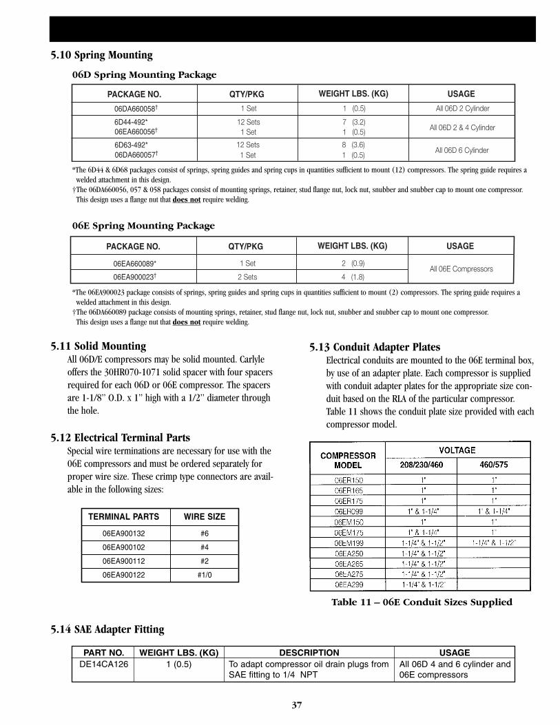
37
5.10 Spring Mounting
5.11 Solid MountingAll 06D/E compressors may be solid mounted. Carlyleoffers the 30HR070-1071 solid spacer with four spacersrequired for each 06D or 06E compressor. The spacersare 1-1/8” O.D. x 1” high with a 1/2” diameter throughthe hole.
5.12 Electrical Terminal PartsSpecial wire terminations are necessary for use with the06E compressors and must be ordered separately forproper wire size. These crimp type connectors are avail-able in the following sizes:
5.13 Conduit Adapter PlatesElectrical conduits are mounted to the 06E terminal box,by use of an adapter plate. Each compressor is suppliedwith conduit adapter plates for the appropriate size con-duit based on the RLA of the particular compressor.Table 11 shows the conduit plate size provided with eachcompressor model.
PACKAGE NO. QTY/PKG
6D44-492*
6D63-492*
WEIGHT LBS. (KG) USAGE
All 06D 2 Cylinder
All 06D 2 & 4 Cylinder
All 06D 6 Cylinder
1 Set
12 Sets1 Set
12 Sets1 Set
1 (0.5)
7 (3.2)1 (0.5)
8 (3.6)1 (0.5)
06D Spring Mounting Package
*The 6D44 & 6D68 packages consist of springs, spring guides and spring cups in quantities sufficient to mount (12) compressors. The spring guide requires a welded attachment in this design.
†The 06DA660056, 057 & 058 packages consist of mounting springs, retainer, stud flange nut, lock nut, snubber and snubber cap to mount one compressor. This design uses a flange nut that does not require welding.
PACKAGE NO. QTY/PKG
06EA660089*
WEIGHT LBS. (KG) USAGE
All 06E Compressors1 Set
2 Sets
2 (0.9)
4 (1.8)
06E Spring Mounting Package
*The 06EA900023 package consists of springs, spring guides and spring cups in quantities sufficient to mount (2) compressors. The spring guide requires a welded attachment in this design.
†The 06DA660089 package consists of mounting springs, retainer, stud flange nut, lock nut, snubber and snubber cap to mount one compressor. This design uses a flange nut that does not require welding.
TERMINAL PARTS WIRE SIZE
06EA900132 #6
06EA900102 #4
06EA900112 #2
06EA900122 #1/0
5.14 SAE Adapter Fitting
PART NO. WEIGHT LBS. (KG) DESCRIPTION USAGEDE14CA126 1 (0.5) To adapt compressor oil drain plugs from All 06D 4 and 6 cylinder and
SAE fitting to 1/4 NPT 06E compressors
Table 11 – 06E Conduit Sizes Supplied
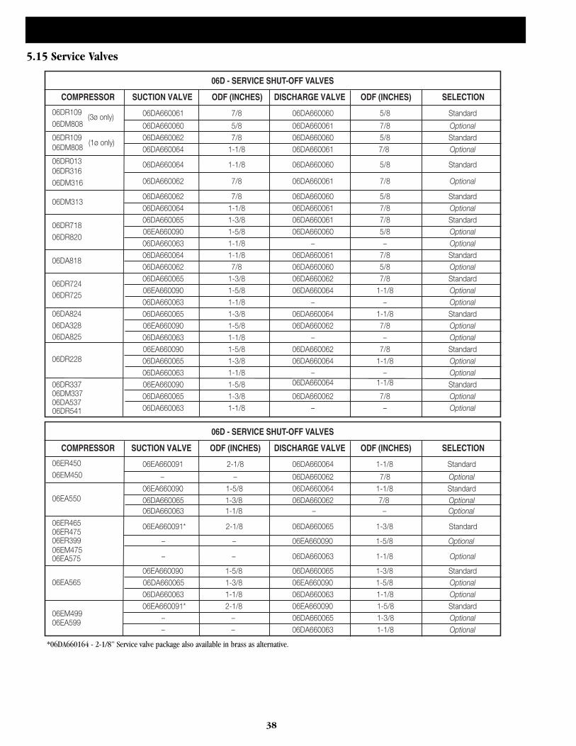
38
5.15 Service Valves
06D - SERVICE SHUT-OFF VALVES
COMPRESSOR SUCTION VALVE ODF (INCHES) DISCHARGE VALVE ODF (INCHES) SELECTION
06ER450 06EA660091 2-1/8 06DA660064 1-1/8 Standard06EM450 – – 06DA660062 7/8 Optional
06EA660090 1-5/8 06DA660064 1-1/8 Standard06EA550 06DA660065 1-3/8 06DA660062 7/8 Optional
06DA660063 1-1/8 – – Optional
06ER465 06EA660091* 2-1/8 06DA660065 1-3/8 Standard06ER475
06EM475– – 06DA660063 1-1/8 Optional
06EA660090 1-5/8 06DA660065 1-3/8 Standard06EA565 06DA660065 1-3/8 06EA660090 1-5/8 Optional
06DA660063 1-1/8 06DA660063 1-1/8 Optional
06EM49906EA660091* 2-1/8 06EA660090 1-5/8 Standard
– – 06DA660065 1-3/8 Optional
06D - SERVICE SHUT-OFF VALVES
COMPRESSOR SUCTION VALVE ODF (INCHES) DISCHARGE VALVE ODF (INCHES) SELECTION
06DR109 06DA660061 7/8 06DA660060 5/8 Standard06DM808 06DA660060 5/8 06DA660061 7/8 Optional06DR109 06DA660062 7/8 06DA660060 5/8 Standard06DM808 06DA660064 1-1/8 06DA660061 7/8 Optional06DR013 06DA660064 1-1/8 06DA660060 5/8 Standard06DR316
06DA660062 7/8 06DA660061 7/8 Optional06DM316
06DM31306DA660062 7/8 06DA660060 5/8 Standard06DA660064 1-1/8 06DA660061 7/8 Optional
06DR71806DA660065 1-3/8 06DA660061 7/8 Standard
06DR82006EA660090 1-5/8 06DA660060 5/8 Optional06DA660063 1-1/8 – – Optional
06DA81806DA660064 1-1/8 06DA660061 7/8 Standard06DA660062 7/8 06DA660060 5/8 Optional06DA660065 1-3/8 06DA660062 7/8 Standard
06DR72406EA660090 1-5/8 06DA660064 1-1/8 Optional06DA660063 1-1/8 – – Optional
06DA824 06DA660065 1-3/8 06DA660064 1-1/8 Standard06DA328 06EA660090 1-5/8 06DA660062 7/8 Optional
06DA660063 1-1/8 – – Optional06EA660090 1-5/8 06DA660062 7/8 Standard
06DR228 06DA660065 1-3/8 06DA660064 1-1/8 Optional06DA660063 1-1/8 – – Optional
06DR337 06EA660090 1-5/8 06DA660064 1-1/8 Standard06DM337 06DA660065 1-3/8 06DA660062 7/8 Optional06DA537
06DA660063 1-1/8 – – Optional
(3ø only)
(1ø only)
06DA825
06DR725
06DR541
06ER399
06EA575
– – 06EA660090 1-5/8 Optional
06EA599– – 06DA660063 1-1/8 Optional
*06DA660164 - 2-1/8” Service valve package also available in brass as alternative.
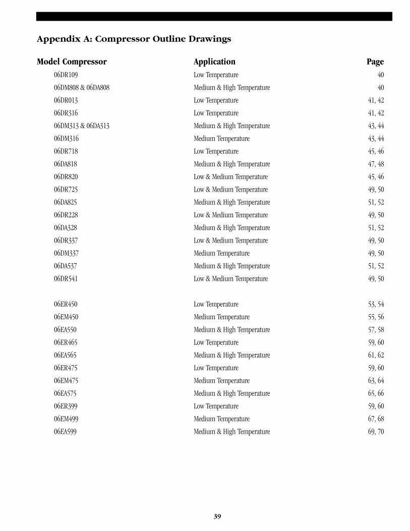
39
Appendix A: Compressor Outline Drawings
Model Compressor Application Page06DR109 Low Temperature 40
06DM808 & 06DA808 Medium & High Temperature 40
06DR013 Low Temperature 41, 42
06DR316 Low Temperature 41, 42
06DM313 & 06DA313 Medium & High Temperature 43, 44
06DM316 Medium Temperature 43, 44
06DR718 Low Temperature 45, 46
06DA818 Medium & High Temperature 47, 48
06DR820 Low & Medium Temperature 45, 46
06DR725 Low & Medium Temperature 49, 50
06DA825 Medium & High Temperature 51, 52
06DR228 Low & Medium Temperature 49, 50
06DA328 Medium & High Temperature 51, 52
06DR337 Low & Medium Temperature 49, 50
06DM337 Medium Temperature 49, 50
06DA537 Medium & High Temperature 51, 52
06DR541 Low & Medium Temperature 49, 50
06ER450 Low Temperature 53, 54
06EM450 Medium Temperature 55, 56
06EA550 Medium & High Temperature 57, 58
06ER465 Low Temperature 59, 60
06EA565 Medium & High Temperature 61, 62
06ER475 Low Temperature 59, 60
06EM475 Medium Temperature 63, 64
06EA575 Medium & High Temperature 65, 66
06ER399 Low Temperature 59, 60
06EM499 Medium Temperature 67, 68
06EA599 Medium & High Temperature 69, 70
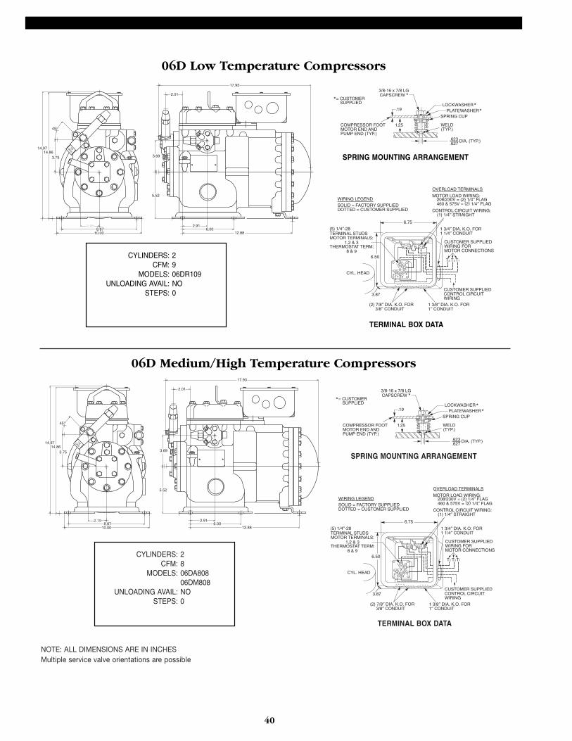
40
7/8ODS14.8614.97
3.75
45°
2.192.198.87
10.00
2.01
17.93
3.69
5.52
12.886.00
2.91
SPRING MOUNTING ARRANGEMENT
TERMINAL BOX DATA
CYLINDERS: 2CFM: 9
MODELS: 06DR109UNLOADING AVAIL: NO
STEPS: 0
7/8ODS14.8614.97
3.75
45°
2.198.87
10.00
2.01
17.93
3.69
5.52
12.886.00
2.91
COMPRESSOR FOOTMOTOR END ANDPUMP END (TYP.)
= CUSTOMERSUPPLIED
1.25
.19
3/8-16 x 7/8 LGCAPSCREW
LOCKWASHERPLATEWASHER
SPRING CUP
WELD(TYP.)
.623 DIA. (TYP.).627
**
**
SPRING MOUNTING ARRANGEMENT
TERMINAL BOX DATA
CYLINDERS: 2CFM: 8
MODELS: 06DA80806DM808
UNLOADING AVAIL: NOSTEPS: 0
COMPRESSOR FOOTMOTOR END ANDPUMP END (TYP.)
= CUSTOMERSUPPLIED
1.25
.19
3/8-16 x 7/8 LGCAPSCREW
LOCKWASHERPLATEWASHER
SPRING CUP
WELD(TYP.)
.623 DIA. (TYP.).627
**
**
NOTE: ALL DIMENSIONS ARE IN INCHESMultiple service valve orientations are possible
06D Low Temperature Compressors
06D Medium/High Temperature Compressors
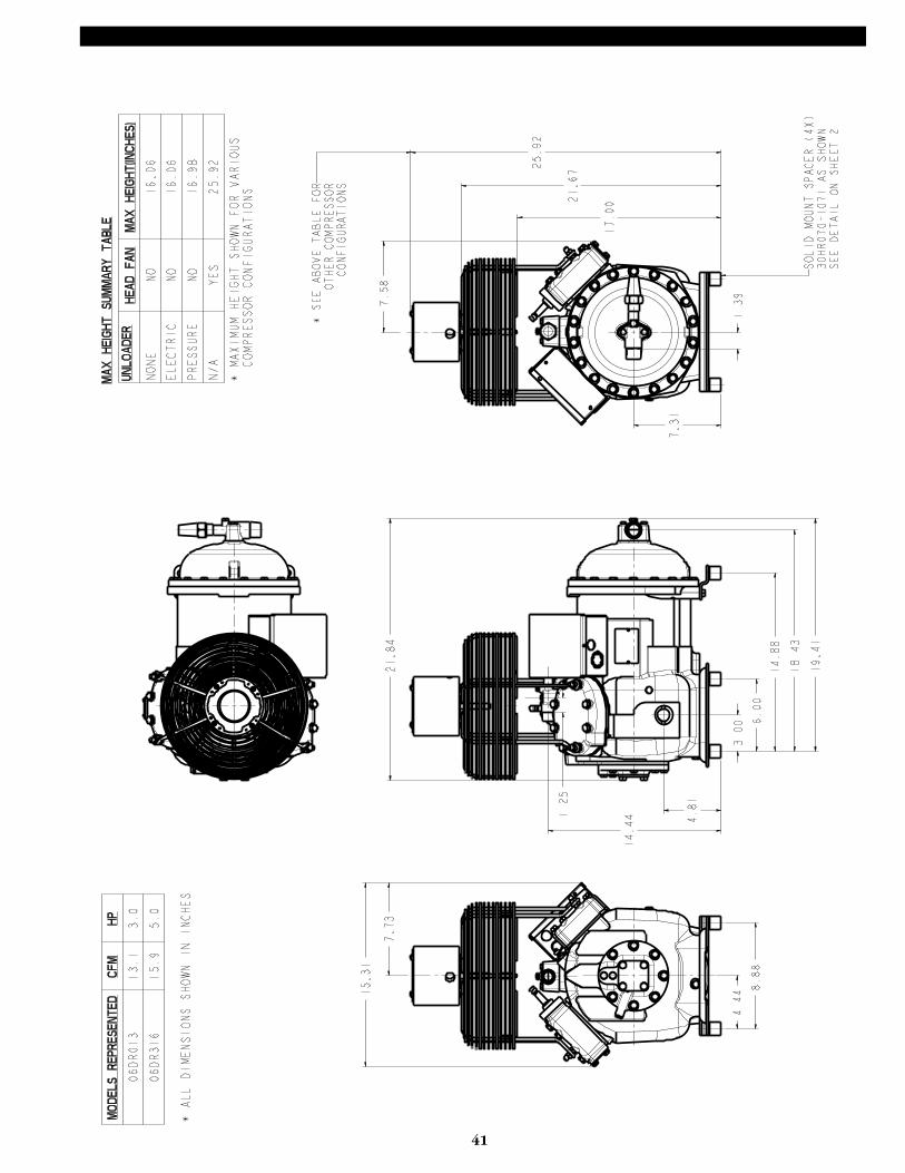
41
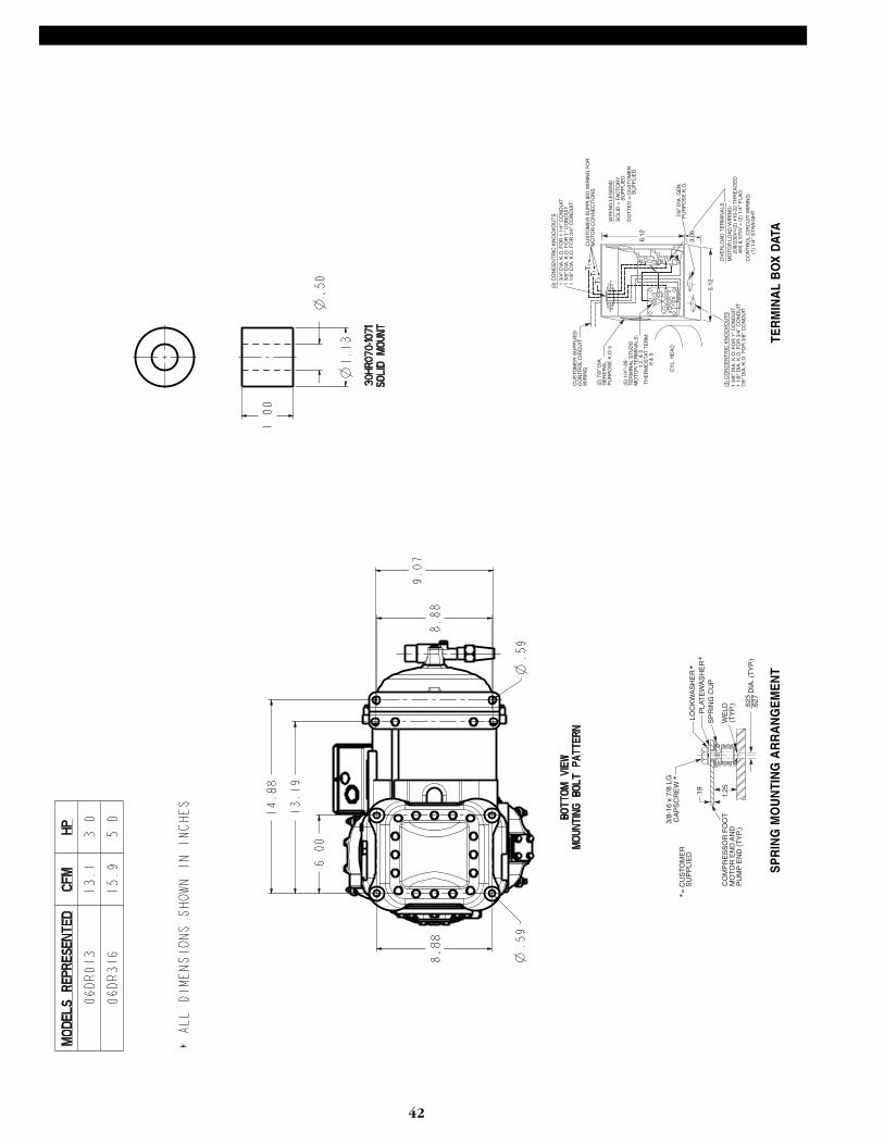
42
CO
MP
RE
SS
OR
FO
OT
MO
TO
R E
ND
AN
DP
UM
P E
ND
(T
YP.
)
= C
US
TO
ME
RS
UP
PLI
ED
1.25.19
3/8-
16 x
7/8
LG
CA
PS
CR
EW
LOC
KW
AS
HE
RP
LAT
EW
AS
HE
RS
PR
ING
CU
P
WE
LD(T
YP.
) .623
DIA
. (T
YP.
).6
27
**
**
SP
RIN
G M
OU
NTI
NG
AR
RA
NG
EM
EN
TTE
RM
INA
L B
OX
DAT
A
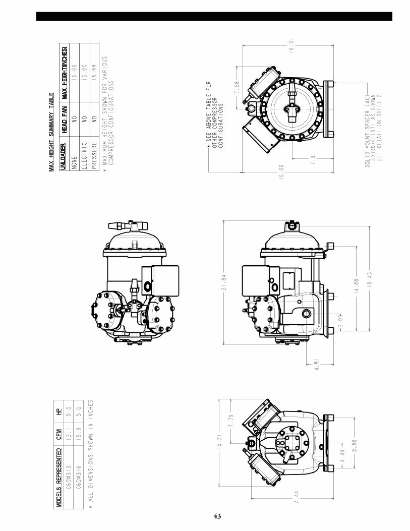
43
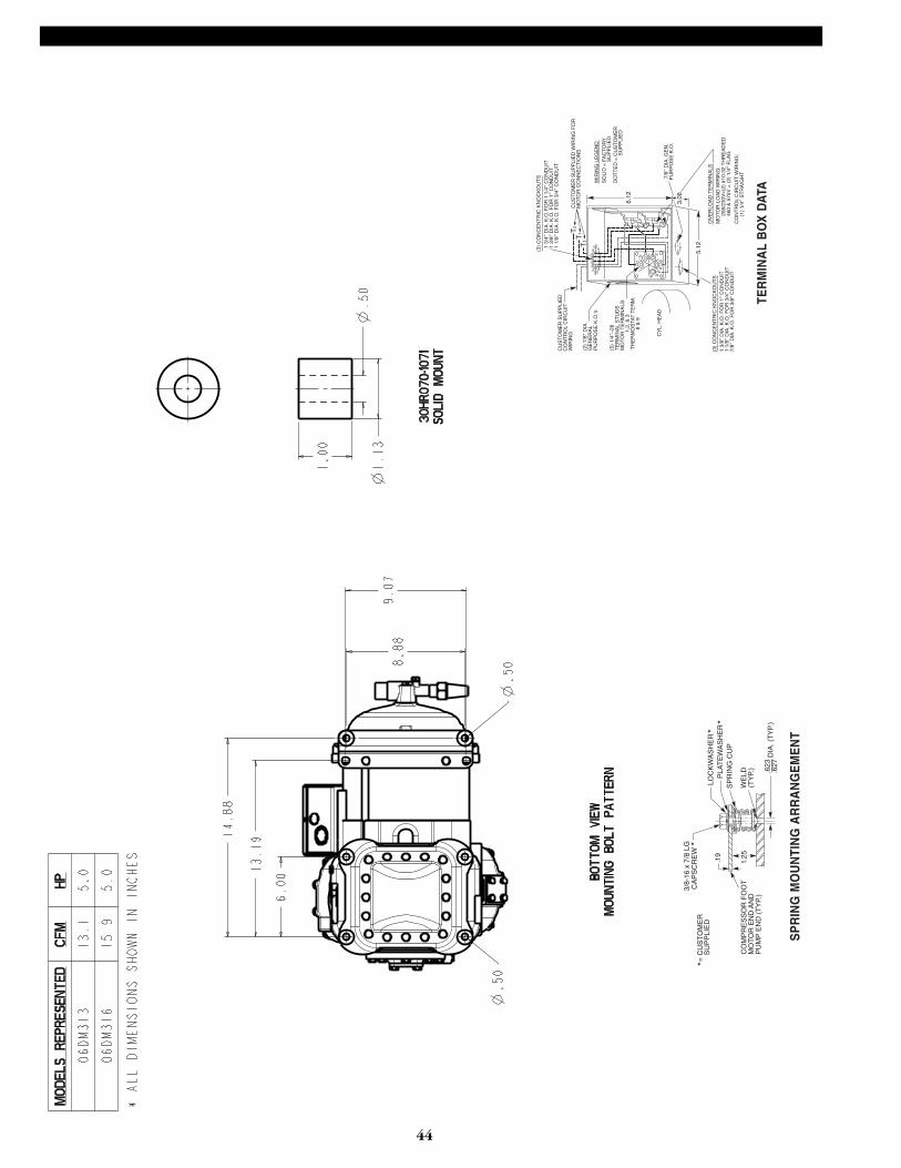
44
CO
MP
RE
SS
OR
FO
OT
MO
TO
R E
ND
AN
DP
UM
P E
ND
(T
YP.
)
= C
US
TO
ME
RS
UP
PLI
ED
1.25.19
3/8-
16 x
7/8
LG
CA
PS
CR
EW
LOC
KW
AS
HE
RP
LAT
EW
AS
HE
RS
PR
ING
CU
P
WE
LD(T
YP.
) .623
DIA
. (T
YP.
).6
27
**
**
SP
RIN
G M
OU
NTI
NG
AR
RA
NG
EM
EN
T
TER
MIN
AL
BO
X D
ATA
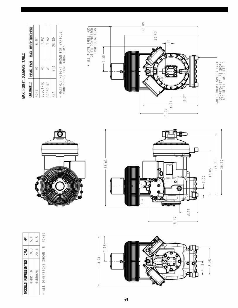
45

46
1.25
CA
PS
CR
EW
3/8—
16 x
1.5
0 LG
CO
MP
RE
SS
OR
EN
D F
OO
TM
OT
OR
EN
D F
OO
T
CA
PS
CR
EW
3/8—
16 x
7/8
LG
= C
US
TO
ME
R
S
UP
PLI
ED
PLA
TE
WA
SH
ER
LOC
KW
AS
HE
RW
ELD
(TY
P)
.623
.627
DIA
.(T
YP.
)
.19 1.31
**
*
*
*
SP
RIN
G M
OU
NTI
NG
AR
RA
NG
EM
EN
TTE
RM
INA
L B
OX
DAT
A
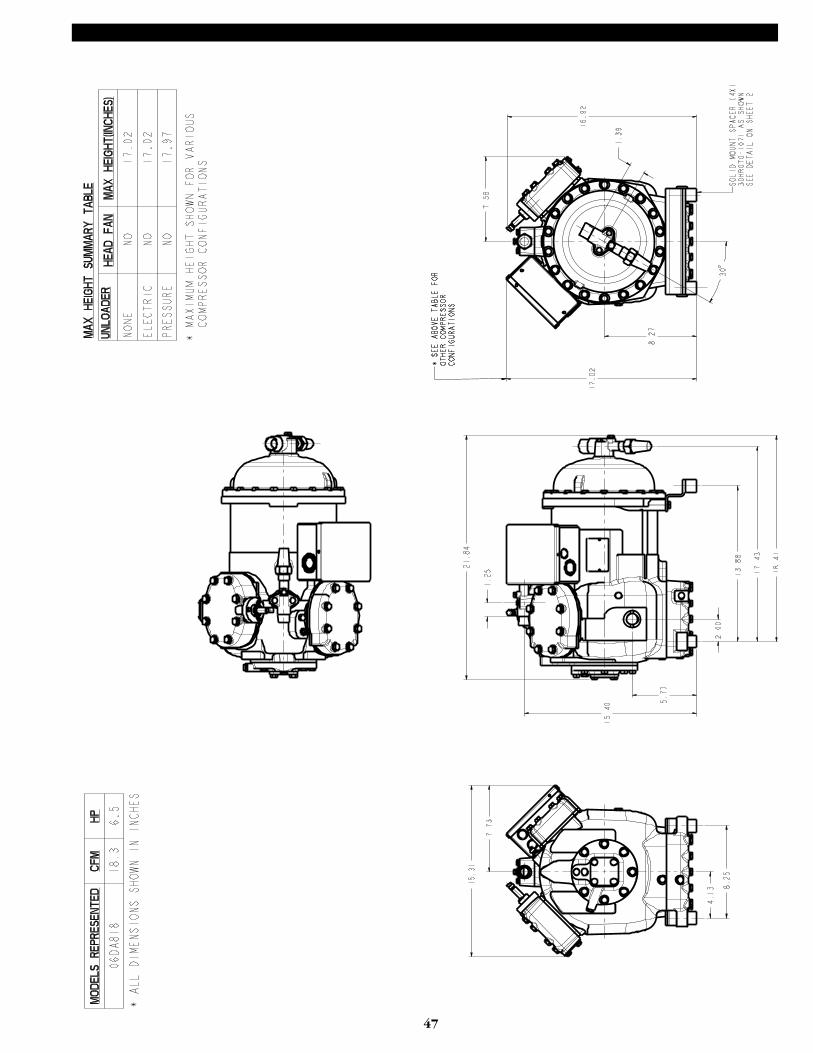
47

48
1.25
CA
PS
CR
EW
3/8—
16 x
1.5
0 LG
CO
MP
RE
SS
OR
EN
D F
OO
TM
OT
OR
EN
D F
OO
T
CA
PS
CR
EW
3/8—
16 x
7/8
LG
= C
US
TO
ME
R
S
UP
PLI
ED
PLA
TE
WA
SH
ER
LOC
KW
AS
HE
RW
ELD
(TY
P)
.623
.627
DIA
.(T
YP.
)
.19 1.31
**
*
*
*
SP
RIN
G M
OU
NTI
NG
AR
RA
NG
EM
EN
TTE
RM
INA
L B
OX
DAT
A
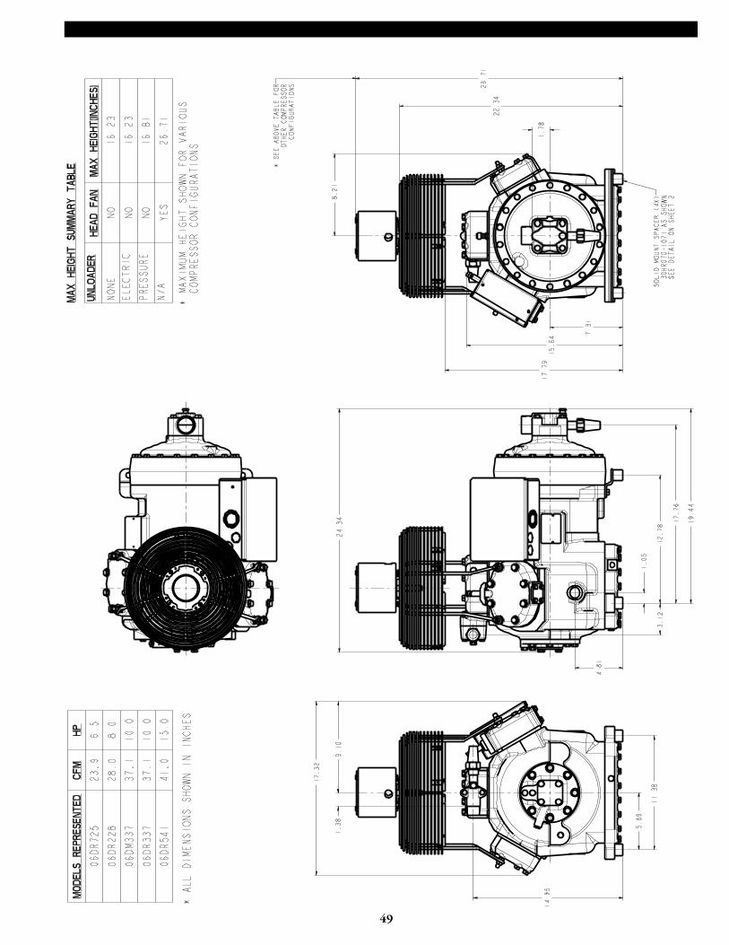
49
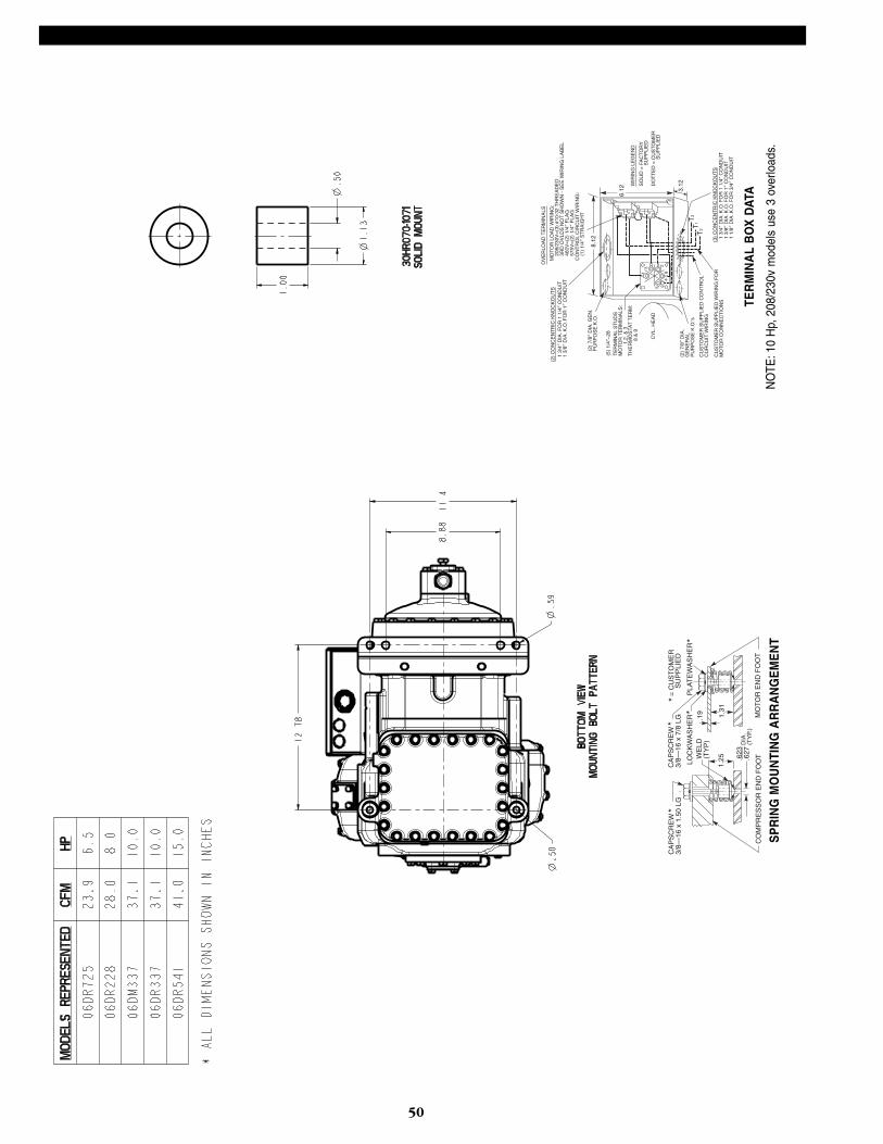
50
1.25
CA
PS
CR
EW
3/8—
16 x
1.5
0 LG
CO
MP
RE
SS
OR
EN
D F
OO
TM
OT
OR
EN
D F
OO
T
CA
PS
CR
EW
3/8—
16 x
7/8
LG
= C
US
TO
ME
R
S
UP
PLI
ED
PLA
TE
WA
SH
ER
LOC
KW
AS
HE
RW
ELD
(TY
P)
.623
.627
DIA
.(T
YP.
)
.19 1.31
**
*
*
*
SP
RIN
G M
OU
NTI
NG
AR
RA
NG
EM
EN
TN
OTE
:10
Hp,
208
/230
v m
odel
s us
e 3
over
load
s.
TER
MIN
AL
BO
X D
ATA
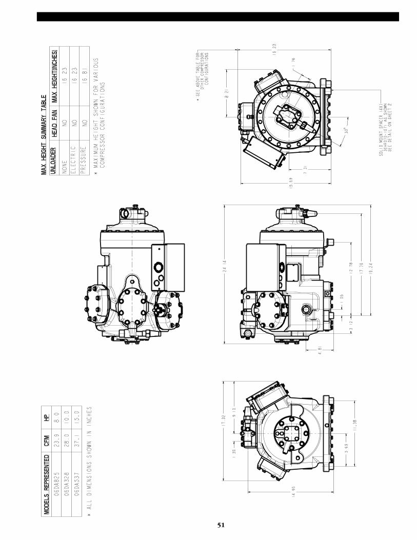
51

52
1.25
CA
PS
CR
EW
3/8—
16 x
1.5
0 LG
CO
MP
RE
SS
OR
EN
D F
OO
TM
OT
OR
EN
D F
OO
T
CA
PS
CR
EW
3/8—
16 x
7/8
LG
= C
US
TO
ME
R
S
UP
PLI
ED
PLA
TE
WA
SH
ER
LOC
KW
AS
HE
RW
ELD
(TY
P)
.623
.627
DIA
.(T
YP.
)
.19 1.31
**
*
*
*
SP
RIN
G M
OU
NTI
NG
AR
RA
NG
EM
EN
TTE
RM
INA
L B
OX
DAT
A
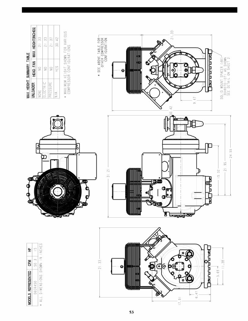
53

54
MO
UN
TIN
GW
AS
HE
R
NY
LOK
CA
PS
CR
EW
3/8-
16 x
1.7
5 LO
NG
1.38
PU
MP
EN
D F
OO
TM
OT
OR
EN
D F
OO
T
SP
RIN
GG
UID
E
SN
UB
BE
R
SP
RIN
GG
UID
E
SP
RIN
GC
UP
SN
UB
BE
R
NY
LOK
CA
PS
CR
EW
3/8-
16 x
2.0
0 LO
NG
1.31
.25
SP
RIN
G M
OU
NTI
NG
AR
RA
NG
EM
EN
TTE
RM
INA
L B
OX
DAT
A
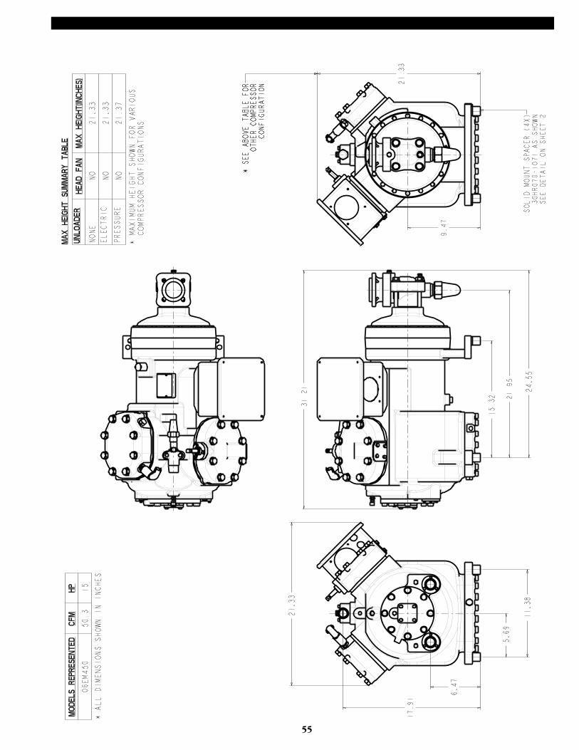
55
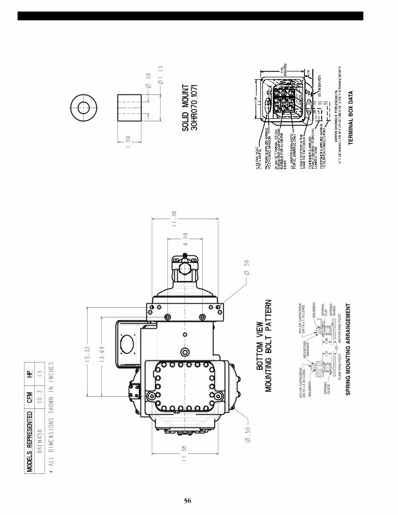
56
MO
UN
TIN
GW
AS
HE
R
NY
LOK
CA
PS
CR
EW
3/8-
16 x
1.7
5 LO
NG
1.38
PU
MP
EN
D F
OO
TM
OT
OR
EN
D F
OO
T
SP
RIN
GG
UID
E
SN
UB
BE
R
SP
RIN
GG
UID
E
SP
RIN
GC
UP
SN
UB
BE
R
NY
LOK
CA
PS
CR
EW
3/8-
16 x
2.0
0 LO
NG
1.31
.25
SP
RIN
G M
OU
NTI
NG
AR
RA
NG
EM
EN
TTE
RM
INA
L B
OX
DAT
A
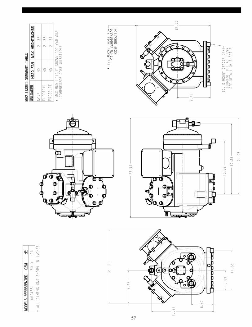
57
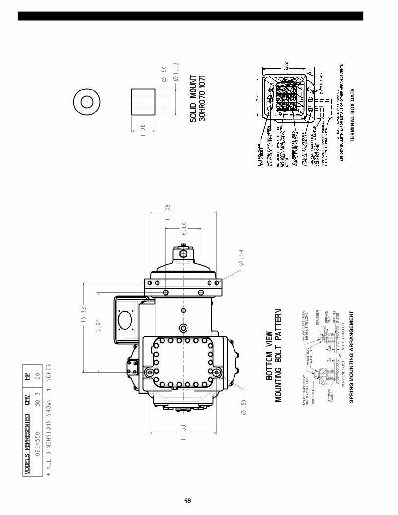
58
MO
UN
TIN
GW
AS
HE
R
NY
LOK
CA
PS
CR
EW
3/8-
16 x
1.7
5 LO
NG
1.38
PU
MP
EN
D F
OO
TM
OT
OR
EN
D F
OO
T
SP
RIN
GG
UID
E
SN
UB
BE
R
SP
RIN
GG
UID
E
SP
RIN
GC
UP
SN
UB
BE
R
NY
LOK
CA
PS
CR
EW
3/8-
16 x
2.0
0 LO
NG
1.31
.25
SP
RIN
G M
OU
NTI
NG
AR
RA
NG
EM
EN
TTE
RM
INA
L B
OX
DAT
A

59
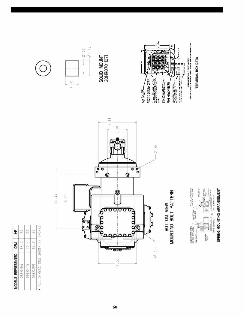
60
MO
UN
TIN
GW
AS
HE
R
NY
LOK
CA
PS
CR
EW
3/8-
16 x
1.7
5 LO
NG
1.38
PU
MP
EN
D F
OO
TM
OT
OR
EN
D F
OO
T
SP
RIN
GG
UID
E
SN
UB
BE
R
SP
RIN
GG
UID
E
SP
RIN
GC
UP
SN
UB
BE
R
NY
LOK
CA
PS
CR
EW
3/8-
16 x
2.0
0 LO
NG
1.31
.25
SP
RIN
G M
OU
NTI
NG
AR
RA
NG
EM
EN
T
TER
MIN
AL
BO
X D
ATA
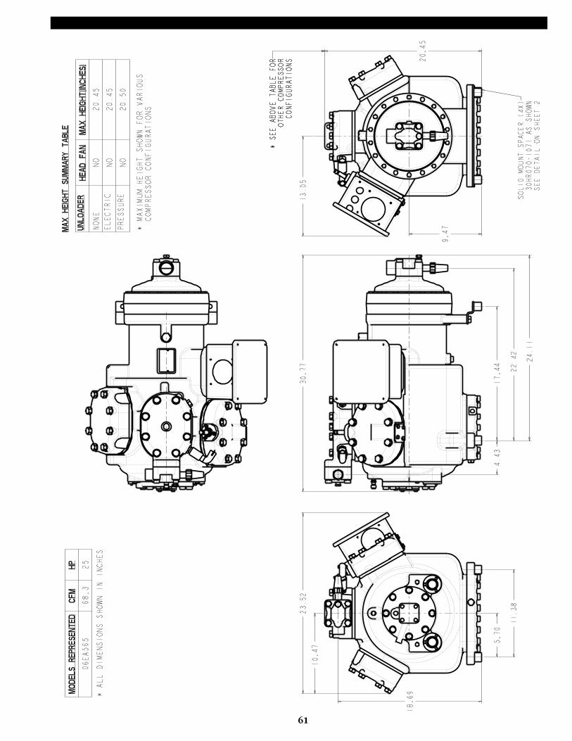
61
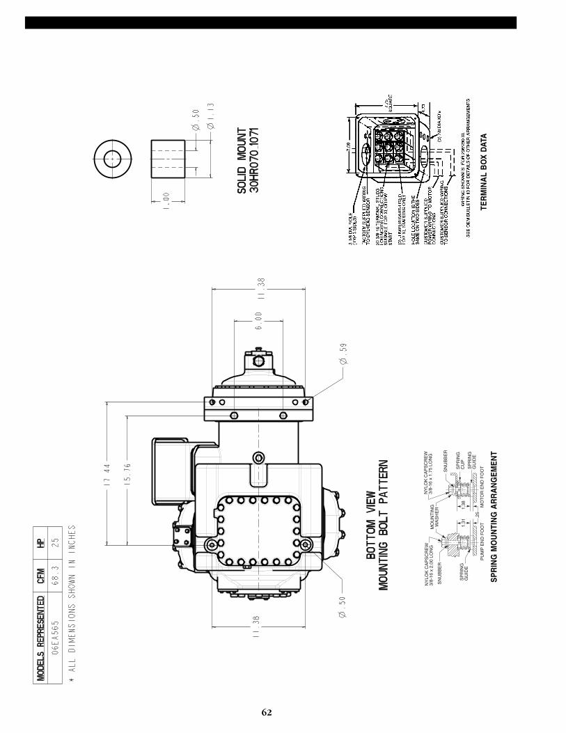
62
MO
UN
TIN
GW
AS
HE
R
NY
LOK
CA
PS
CR
EW
3/8-
16 x
1.7
5 LO
NG
1.38
PU
MP
EN
D F
OO
TM
OT
OR
EN
D F
OO
T
SP
RIN
GG
UID
E
SN
UB
BE
R
SP
RIN
GG
UID
E
SP
RIN
GC
UP
SN
UB
BE
R
NY
LOK
CA
PS
CR
EW
3/8-
16 x
2.0
0 LO
NG
1.31
.25
SP
RIN
G M
OU
NTI
NG
AR
RA
NG
EM
EN
TTE
RM
INA
L B
OX
DAT
A
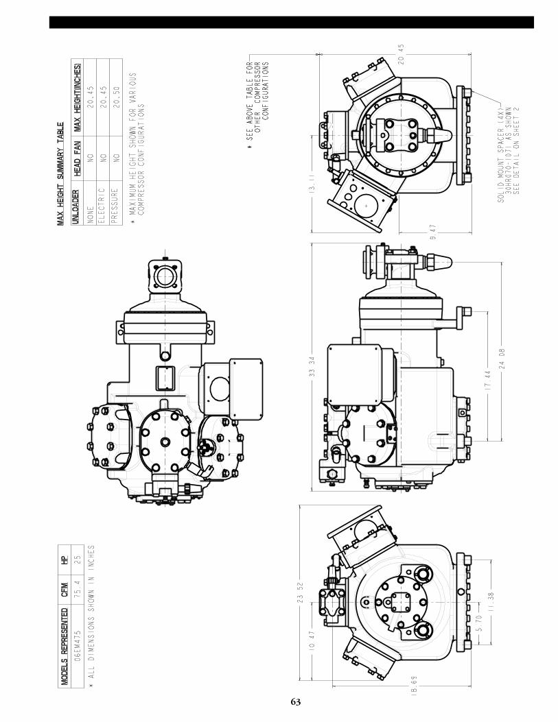
63
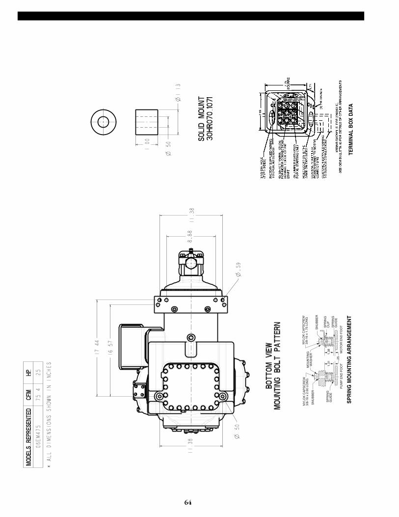
64
MO
UN
TIN
GW
AS
HE
R
NY
LOK
CA
PS
CR
EW
3/8-
16 x
1.7
5 LO
NG
1.38
PU
MP
EN
D F
OO
TM
OT
OR
EN
D F
OO
T
SP
RIN
GG
UID
E
SN
UB
BE
R
SP
RIN
GG
UID
E
SP
RIN
GC
UP
SN
UB
BE
R
NY
LOK
CA
PS
CR
EW
3/8-
16 x
2.0
0 LO
NG
1.31
.25
SP
RIN
G M
OU
NTI
NG
AR
RA
NG
EM
EN
TTE
RM
INA
L B
OX
DAT
A
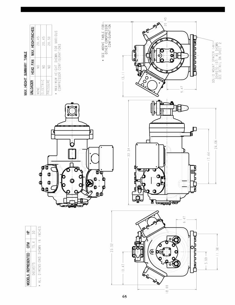
65
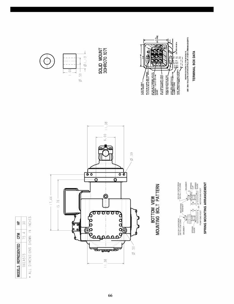
66
MO
UN
TIN
GW
AS
HE
R
NY
LOK
CA
PS
CR
EW
3/8-
16 x
1.7
5 LO
NG
1.38
PU
MP
EN
D F
OO
TM
OT
OR
EN
D F
OO
T
SP
RIN
GG
UID
E
SN
UB
BE
R
SP
RIN
GG
UID
E
SP
RIN
GC
UP
SN
UB
BE
R
NY
LOK
CA
PS
CR
EW
3/8-
16 x
2.0
0 LO
NG
1.31
.25
SP
RIN
G M
OU
NTI
NG
AR
RA
NG
EM
EN
T
TER
MIN
AL
BO
X D
ATA
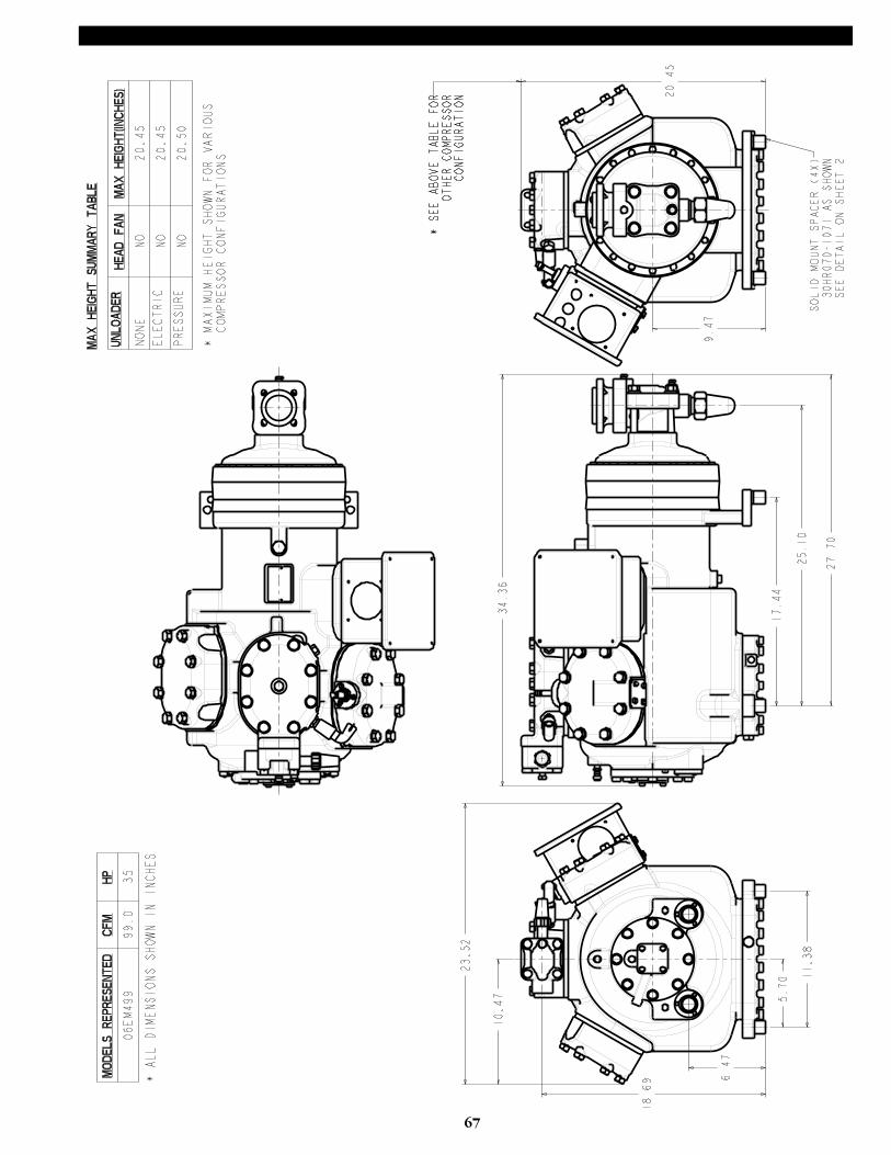
67

68
MO
UN
TIN
GW
AS
HE
R
NY
LOK
CA
PS
CR
EW
3/8-
16 x
1.7
5 LO
NG
1.38
PU
MP
EN
D F
OO
TM
OT
OR
EN
D F
OO
T
SP
RIN
GG
UID
E
SN
UB
BE
R
SP
RIN
GG
UID
E
SP
RIN
GC
UP
SN
UB
BE
R
NY
LOK
CA
PS
CR
EW
3/8-
16 x
2.0
0 LO
NG
1.31
.25
SP
RIN
G M
OU
NTI
NG
AR
RA
NG
EM
EN
T
TER
MIN
AL
BO
X D
ATA
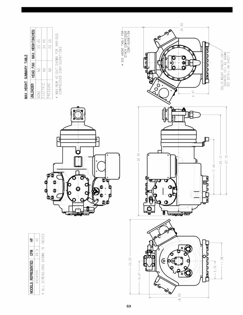
69
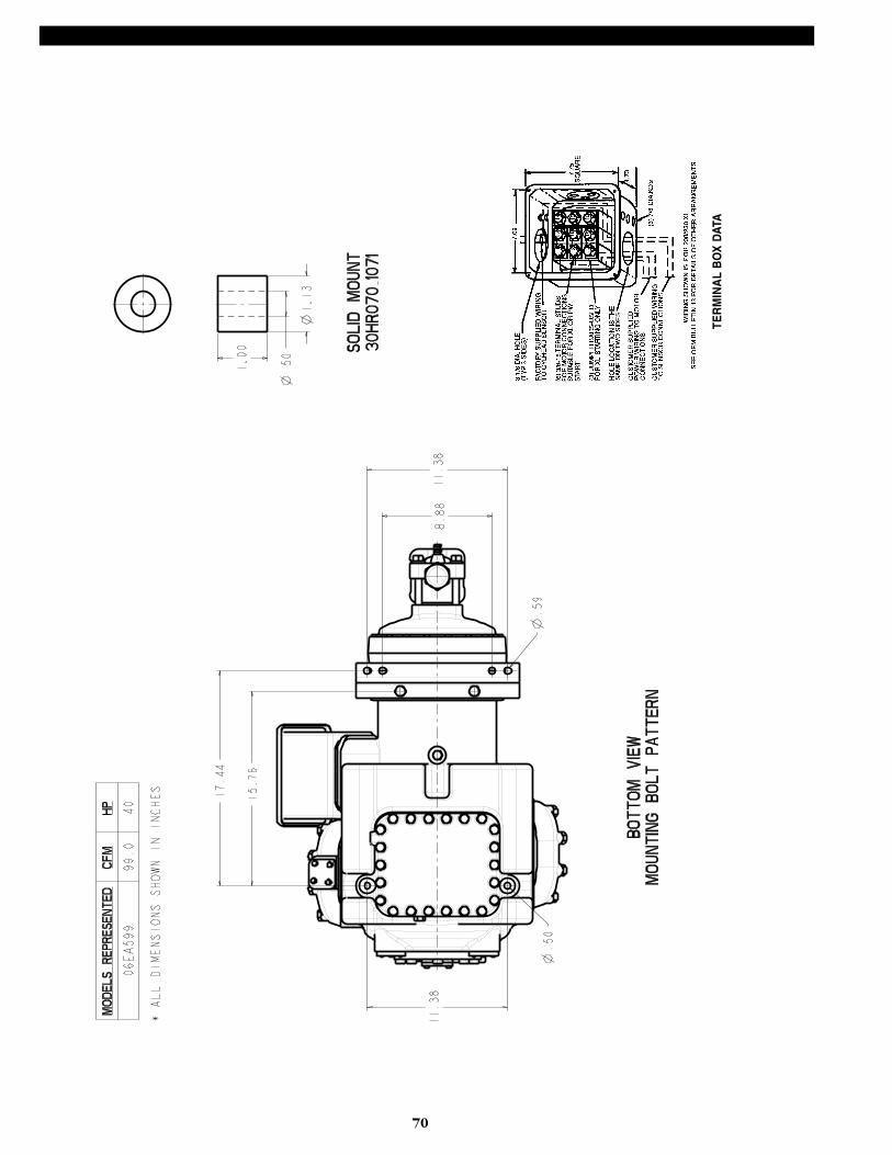
70
TER
MIN
AL
BO
X D
ATA

Manufacturer reserves the right to discontinue, orchange at any time, specifications or designs andprices without notice and without incurring obligations.
CARLYLE COMPRESSOR COMPANY • © CARRIER CORPORATION 7/95P.O. Box 4808 • Syracuse, New York 13221In USA & Puerto Rico 1-800-GO-CARLYLE • In Canada 1-800-258-1123 • In Mexico: 95-800-GO-CARLYLE
Lit. No. 574-069Rev B 6/04