

Nuts and Volts - June 2012
84
U.S. $6.50 CANADA $7.50
-
Upload
khangminh22 -
Category
Documents
-
view
2 -
download
0
Transcript of Nuts and Volts - June 2012

Vol. 33 N
o. 6N
UT
S &
VO
LTS
4G •
BEAGLEBONE PA
SSWORD CRACKING •
iPHONE M
OISTURE SENSOR
June 2012
0 71486 02421 7
0 6
$6.50US $7.50CANU.S. $6.50 CANADA $7.50
CoverNews_Cover.qxd 5/9/2012 1:27 PM Page 1

Full Page_Full Page.qxd 5/7/2012 4:16 PM Page 3

HAVE A GREAT PROJECT IDEA?Design an electronics project at ClubJameco.com, identify thecomponents, write step-by-step instructions, and that’s it.We’ll do everything else!
!
Imagine,
Design,
EARN!
.W ’ !
Copyright © 2012, Jameco Electronics. All Rights Reserved. 1355 Shoreway Rd., Belmont, CA 94002 USA [email protected]
iggiamma
ngi,eni
E
gammaIIm
!NRAE
,ngisesD
W
s
WW
anngisAeD
GAEVAH
’WW
RGrAT
c atcejorpsciiTnortt
Rcele
TCEJORPTAAATATAATEERG
dimococemaJbulCt?AEDI
ehtyfitned
!.
e veodll’em
Wnenopm
soc
anngiseD
2102©thgirypoC
!
o
!peslegnihtyrev
pets-yb-peectsetirw,stn
atcejorpscinorrtcele
531.devreseRsthgiRllA.scinortcelEocemaJ,2
htdan,snoitcurtsnipdi,moc.ocemaJbulCt
ofnIASU20049AC,tnomleB,.dRyawerohS55
!
.tis’taehtyfitned
moc.ocemaJbulC@o
Full Page_Full Page.qxd 5/7/2012 4:20 PM Page 4

#1053: Sub-Micro Servo 3.7g
#1354: Mini Maestro 18-Channel USB Servo Controller with native USB interface and internal scripting control. Also available - 12 and 24 channel Maestros.
Hobby/RC Servo Controllers:Micro and Mini Maestros
#1351: Micro Maestro 6-Channel USB Servo Controller
#2251: Rechargeable NiMH Battery Pack - 4.8 V, 200 mAh, 4x1 1/3-AAA Cells
Custom Laser Cutting:Design Your Own Chassis
#1415: Pololu 22T Track Set - also available in 30T
#749: Custom Laser Cutting Service - great for making custom parts quickly and economically
#1086: Pololu Micro Metal Gearmotor Bracket Pair
#1093: 30:1 Micro Metal Gearmotor HP
Find these products and more at www.pololu.comEngage Your Brain
Finding the right parts for your robot can be difficult, but you also don’t want to spend all your time reinventing the wheel (or motor controller). That’s where we come in: Pololu has the unique products - from actuators to wireless modules - that can help you take your robot from idea to reality.
#1002: Rechargeable NiMH AAA Battery
Robots and Robot Kits:Pololu 3pi and m3pi
#975: 3pi Robot - high-performance, C-programmable with ATmega328P MCU
#2151: m3pi Expansion Kit - enables use of the mbed Dev. Board with the 3pi Robot. Also available fully assembled (#2152).
#2150: 32 bit ARM mbed Dev. Board
#1336: Wixel USB Programmable Wireless Module
Motor Drivers:Item #2502: Dual VNH5019 Motor Driver Shield for Arduino
Easy to use with an Arduino (#1616 shown)
Logic connections for use without an Arduino
VNH5019 motor driver - 5.5-24 V, 12 A continuous output (30 A peak)
Reverse-voltage protection

Departments0088 DEVELOPING
PERSPECTIVES0099 READER FEEDBACK3300 NEW PRODUCTS3333 SHOWCASE
6644 NV WEBSTORE6677 ELECTRO-NET7777 CLASSIFIEDS7788 TECH FORUM8811 AD INDEX
Nuts & Volts (ISSN 1528-9885/CDN Pub Agree #40702530) is published monthly for $26.95 peryear by T & L Publications, Inc., 430 Princeland Court, Corona, CA 92879.PERIODICALS POSTAGE PAID AT CORONA, CA AND AT ADDITIONAL MAILING OFFICES.POSTMASTER: Send address changes to Nuts & Volts, P.O. Box 15277, North Hollywood, CA91615 or Station A, P.O. Box 54,Windsor ON N9A 6J5; [email protected].
Columns10 TechKnowledgey 2012
EEvveennttss,, AAddvvaanncceess,, aanndd NNeewwssThis month, there’s a spotlight on bacteria, a scanner that features Wi-Fi memory, a big telescope for the big bang, plus some other interesting stuff.
14 PICAXE PrimerSShhaarrppeenniinngg YYoouurr TToooollss ooff CCrreeaattiivviittyyInterfacing the DS18B20 Digital Thermometer.
24 Q & A RReeaaddeerr QQuueessttiioonnss AAnnsswweerreedd HHeerreeSolar converters, speaker protectors, and transformerless power supplies are just some of the topics discussed this time.
52 Smiley’s WorkshopPPrrooggrraammmmiinngg •• HHaarrddwwaarree •• PPrroojjeeccttssPersistence of Vision Wand.
60 Open CommunicationTThhee LLaatteesstt iinn NNeettwwoorrkkiinngg aanndd WWiirreelleessss TTeecchhnnoollooggiieessWhat is 4G Wireless? 3G/4G ... Does it really matter?
68 The Design CycleAAddvvaanncceedd TTeecchhnniiqquueess ffoorr DDeessiiggnn EEnnggiinneeeerrssSome IEEE 802.15.4 Transceiver Magic.
2012Junewww.nutsvolts.com
34 Cracking PDF File Passwords With a BeagleBone BoardInstead of installing third-party software to crack passwords of encrypted files, try this inexpensive off-the-shelf embedded system that you don’t have to connect to your computer. By Nuno Alves
42 Turn Your iPhone into a Plant Moisture SensorConvert an iPhone or iPad into a quadcorder and use it to “scan” for intel, like how wet or dry your plant soil is. By Mike Westerfield
Projects & Features
6 June 2012
FUNdamentals For Beginners7766 Build a Morse Code Oscillator
PPaaggee 4422
PPaaggee 5522
TOC Jun12.qxd 5/9/2012 12:18 PM Page 6

www.Globalspecialties.comPhone: 1-800-572-1028
Whether you’re new to designing with FPGA, need to train others about FPGA, or new to implementing microcontrollers in FPGAs, this trainer will accelerate your design process.
The DL-030 Microprocessor Design Trainer
Our courseware offers many options to aid in electronics training and lab instruction.
RDB-10 Resistance Decade BoxA compact, convenient tool for aiding in engineering design and testing as well as calibration of test equipment.
8-Pin SOP to Through - Hole Prototyping Adapter
44-Pin PLCC to Through - Hole Prototyping Adapter
GSPA-K1
GSPASOP-8B
Offer Selection of Over 18 DIY Educational Kits
GSPAPLCC-44
GSPATSOP-48S48-Pin TSOP to Through - Hole Prototyping Adapter
5-pin DIN connector housed on a PC board
PB-503 Analog & Digital Design Workstation
Courseware
A robust electronics trainer suitable for all levels of electronics instruction and design.
PRO-S LabBreadboard with External Power & Jumper Wires
8S
The set includes 11 tools commonly used for working with surface mount components
Surface Mount Device Soldering & Re-Work Tool Kit
Basic Fixed Test Leadsmodel# CT3737
Provides users with the basic connection leads to begin using one’s digital multimeter (DMM)
June 2012 7
Full Page_Full Page.qxd 5/7/2012 4:24 PM Page 7

by Bryan Bergeron, Editorby Bryan Bergeron, Editor
DEVELOPINGNNuuttss && BBoollttss
In most of the descriptions of DIYelectronics projects that I come
across, the fasteners used inconstruction are merely mentioned inpassing, if at all. However, the size,composition, and configuration ofthe nuts, bolts, and other fastenerscan be just as important as theelectronic components. Skimping onfastener hardware isn’t limited toenthusiasts on a shoestring budget.The practice extends to companiesthat assemble thousands of devices aday.
In my work with teardowns, Ioften have a good idea of the qualityof components and wiring in adevice by the time I remove the firstscrew from the case. Companies thatcut corners on nuts, screws, andother fasteners cut corners oncomponents as well, which typicallyresults in a product that failsprematurely because it can’t stand
up to normal use. Similarly, your choice of fastener
hardware can significantly affect theperformance and longevity of yournext electronic project. Let me give afew examples. Let’s say you need tofasten a sheet of 1/4” thick plastic —an acrylic faceplate with countersunkholes — to a metal enclosure. Let’sassume you want a nice flat finish,with no protruding hardware. Thebest fastener for the job is probably aflat-head machine screw — eitherPhilips or slotted — and a matchinghex nut. There are still severalvariables to define including size,composition, and length of the screwand the type of nut. There is also theissue of English vs. Metricmeasurements. For simplicity, let’sstay with the more common Englishstandard.
Given an acrylic faceplate isn’tgoing to put a great stress on thescrew, a 1” stainless steel screw with#4-40 threads should do, paired with
a hex lock nut with nylon inserts. The1” refers to the total length of themachine screw, from the surface ofthe flat head to the tip of thethreaded end. Note that themeasurement of screw length isdetermined by the headconfiguration. A non-countersunkscrew would be measured along thelength of the thread, and not includethe height of the head.
The #4 refers to the diameter ofthe screw, including the threads; #4screws are approximately 1/10th ofan inch in diameter. Larger diameterscrews have correspondingly largersize designations. I use #8 screwswhen I need something a little moresecure than #4 screws. In addition, Ilike to use lock nuts in my projectsinstead of fumbling with lock washersand standard hex nuts.
Now, let’s say we need to fastena 1/8” thick metal arm to a piece ofhardwood, with the proviso that thearm should be easily removed andreplaced as needed. Let’s say it’s ametal support attached to thehardwood body of a guitar. Assumingthe metal bar has countersunk holes,you might be tempted to use acommon flat-head wood screw witha 1/2” clean shank. In fact, I’ve seenthis combination.
The idea of using a wood orother screw with a clean shank is thatit presents a clean, friction-freepassage for the first material, but thatit’s in full contact with the underlyingwood when the screw is fullyengaged. Unfortunately,manufacturers often cut corners bystocking only one size machinescrew, and use excessively long cleanshanks resulting in defective joints.
In our example, the clean shankextends into the wood by over a1/4”. The clear shank is too long andextends into the wood, providing a
PERSPECTIVES
8 June 2012
DevPerspec - Jun 12.qxd 5/8/2012 2:19 PM Page 8

Published Monthly ByTT && LL PPuubblliiccaattiioonnss,, IInncc..
430 Princeland Ct.Corona, CA 92879-1300
((995511)) 337711--88449977FAX ((995511)) 337711--33005522
Webstore orders only 11--880000--778833--44662244wwwwww..nnuuttssvvoollttss..ccoomm
SubscriptionsToll Free 11--887777--552255--22553399
Outside US 11--881188--448877--44554455P.O. Box 15277
North Hollywood, CA 91615
FOUNDER/ASSOCIATE PUBLISHERJack Lemieux
PUBLISHERLarry Lemieux
ppuubblliisshheerr@@nnuuttssvvoollttss..ccoomm
ASSOCIATE PUBLISHER/VP OF SALES/MARKETING
Robin Lemieuxddiissppllaayy@@nnuuttssvvoollttss..ccoomm
EDITORBryan Bergeron
tteecchheeddiitt--nnuuttssvvoollttss@@yyaahhoooo..ccoomm
CONTRIBUTING EDITORSJeff Eckert Russ KincaidJoe Pardue Fred EadyMike Westerfield Nuno AlvesRon Hackett Lou Frenzel
CIRCULATION DEPARTMENTssuubbssccrriibbee@@nnuuttssvvoollttss..ccoomm
SHOW COORDINATORAudrey Lemieux
MARKETING COORDINATORWEBSTORE
Brian Kirkpatrickssaalleess@@nnuuttssvvoollttss..ccoomm
WEB CONTENTMichael Kaudze
wweebbssiittee@@nnuuttssvvoollttss..ccoomm
ADMINISTRATIVE ASSISTANTDebbie Stauffacher
PRODUCTION/GRAPHICSShannon Christensen
Sean Lemieux
Copyright © 2012 by T & L Publications, Inc.All Rights Reserved
All advertising is subject to publisher’s approval. Weare not responsible for mistakes, misprints, or typographical errors. Nuts & Volts Magazine assumesno responsibility for the availability or condition of advertised items or for the honesty of the advertiser.The publisher makes no claims for the legality of any item advertised in Nuts & Volts. This is the soleresponsibility of the advertiser. Advertisers and theiragencies agree to indemnify and protect the publisherfrom any and all claims, action, or expense arising fromadvertising placed in Nuts & Volts. Please send all editorial correspondence, UPS, overnight mail, and artwork to: 443300 PPrriinncceellaanndd CCoouurrtt,, CCoorroonnaa,, CCAA 9922887799.
Printed in the USA on SFI & FSC stock.
EVERYTHING FOR ELECTRONICS
less secure hold than would be possible with a screw with threads that engagealong the entire depth of the wood. This not only puts excess stress on thewood, but ruins the threads in the wood for repeated assembly anddisassembly.
If you’re working on a project in which metal or plastic is repeatedlyattached and detached from a hardwood surface, consider using E- LOKthreaded inserts. Simply drill a hole in the wood, screw in the insert, and thenuse a standard machine screw to fasten another surface to the wood. I keep asupply of 6-32 brass inserts on hand for working with my electric guitarprojects. The inserts take #6 machine screws which are thicker in diameter than#4 screws, with 32 threads per inch. Amazon sells the inserts, as well as theoptional insertion tool.
As with electronic devices in general, you can develop an intuitive feel forfasteners by tearing down commercial equipment. Note the depth and anglesof the countersunk holes in different materials, the thread count, andcomposition of fasteners. In addition, take a look at online catalogs andsources of information on fastener selection and use.
My favorite source for supplies and information on common nuts and boltsis Bolt Depot (www.boltdepot.com). The prices are reasonable and selection isgood, but they don’t carry what I consider miniature hardware — somethingwith a smaller diameter than a #4 screw. For specialized, miniature, and exotichardware — from brass to titanium and ceramic — I usually turn to McMaster-Carr (www.mcmastercarr.com). If you can’t find it there, it probably doesn’texist. Even if you don’t order anything from the company, the site is worthvisiting for the hundreds of nicely laid out images of the various types offasteners, including screws and head styles.
The most economical approach to acquiring a library of fasteners is to teardown every discarded electronic device you can get your hands on. Considerinvesting in one of those plastic compartmentalized containers for small parts.It’ll save time later when you’re looking for just the right fastener for the job.NV
It’s History
Iliked the article "The Edison Cell" in the Feb issue. I find historical articlescombined with experiments very interesting. Mr. Noon mentions that they
were popular in niche markets, but not for widespread use. One of the nichemarkets that I find interesting is in electric lighting for railroad passenger cars,where they are widely used. A generator is coupled to one wheel whichprovides power for lights when the car is moving. It also charges the batterieswhich powers the lights when the car was stopped.
— Bill Stiles
Part Number MIA
The article in the Jan issue called "The Radio Whisperer" showed a receivercircuit and a parts list but it doesn’t have any information on U1 — the
programmable oscillator. I need a part number for this if I am going to build it. Ihave spent several hours trying to locate this part. So far, I have not been ableto find a DIP8 programmable oscillator. Is there any way U1 can be identified?
— John
Most any programmable oscillator will work for U1. I used Digi-Key SGR-8002DC-SHB-ND. It should be programmed for center of the WSPB band. For example, for 30M WSPR it would be 10.138700 MHz.
READER FEEDBACK
Continued on page 49
June 2012 9
DevPerspec - Jun 12.qxd 5/9/2012 12:55 PM Page 9

NO GUNPOWDER REQUIRED
The concept of the railgun has been around since the early 1900s, whena French inventor patented a design for his "electric apparatus for
propelling projectiles." It's basically a linear motor in which two parallel rails areconnected to a power supply, upon which is placed a conductive projectilethat acts as an armature. This completes the circuit, resulting in a powerfulLorentz force that propels the projectile along the rails and sends it towarda target. Railguns are promising as weapons because the projectiles travel atsuch high velocities that they don't need to contain explosives to do seriousdamage. They have a few practical problems, however, as they eat up a lot of current and generate huge amounts of heat.Plus, the rails tend to disintegrate quickly. Early models essentially self-destructed in the process of firing a single round.Nevertheless, the US Office of Naval Research (www.onr.navy.mil) has spent the better part of a decade working on designsthat hold together long enough to be practical. They recently tested the first of two commercially-built models, and it looks likea major step forward. The system — built by BAE Systems (www.baesystems.com) — has been run through a series of lowenergy shots in preparation for upcoming full-scale testing. The amazing thing about this weapon is that we're talking about32 megajoules of power which can expel large objects at speeds of 4,500 to 5,600 mph. By comparison, an M16 riflegenerates a muzzle velocity of a little over 2,000 mph.) One megajoule is enough energy to toss out a one ton object at 100mph. The Navy's short-term goal is to demonstrate a weapon that shoots a distance of 50 to 100 nautical miles. Thenext goal is "to develop thermal management systems for both the launcher and pulsed power to facilitate increased firingrates of up to 10 rounds per minute." To see it in action, just search for "BAE electromagnetic railgun" on YouTube.
TECHKNOWLEDGEYEVENTS, ADVANCES, AND NEWS 20
12
BY JEFF ECKERT
The US Navy's new railgun, built by BAE Systems.
ADVANCED TECHNOLOGY
SPOTLIGHT ON BACTERIA
It almost sounds like one of those junk-science gadgets like laser hairbrushes and magnetic water conditioners, butsome Chinese and Australian scientists working at the Commonwealth Scientific and Industrial Research Organisation
(CSIRO, www.csiro.au) have come up with a handheld, battery-powered plasma flashlight that instantly kills bacteria. Inexperiments detailed in a recent issue of the Journal of Physics D: Applied Physics, the device inactivated a slew of ahighly antibiotic- and heat-resistant bacteria — Enterococcus faecalis — which often infects the root canals during dental
treatments. As explained by Prof. Ken Ostrikov, "The bacteria form thick biofilms whichmakes them enormously resistant against inactivation. High temperatures are commonlyused, but they would obviously burn our skin. In this study, we chose an extremeexample to demonstrate that the plasma flashlight can be very effective even at roomtemperature. For individual bacteria, the inactivation time could be just tens of seconds."
The biofilm specimen treated consisted of 17 different layers of bacteria, 25 m inthickness. After a five minute treatment, it was observed that the flashlight not onlykilled off the top layer of cells, it penetrated deep enough to kill the bottom of thelayers of bacteria, as well. The device emits a plume of plasma at between 68°F and74°F (20°C and 23°C), so it cannot harm the skin. The exact antibacterial mechanismis not known, and one might surmise that UV radiation present in the plume couldaccount for it, but the UV content is actually very low. It is therefore believed that thereaction between the plasma and surrounding air creates "a cocktail of reactive speciesthat are similar to the ones found in our own immune system." According to itsdevelopers, the device should prove useful in such applications as ambulanceemergency calls, natural disaster sites, combat operations, and pretty much wherevertreatment is required in remote locations. Best of all, a commercial version should costless than $100.
10 June 2012
CSIRO's plasma flashlightis deadly, but only tobacteria.
Tech2012 - Jun 12.qxd 5/7/2012 1:20 PM Page 10
T E C H K N O W L E D G E Y 2 0 1 2
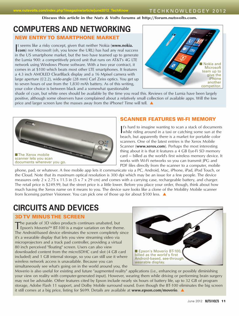
NEW ENTRY TO SMARTPHONE MARKET
It seems like a risky concept, given that neither Nokia (www.nokia.com) nor Microsoft (oh, you know the URL) has had any real success
in the US smartphone market, but the two have teamed up to generatethe Lumia 900: a competitively priced unit that runs on AT&T's 4G LTEnetwork using Windows Phone software. With a two year contract, itcomes in at $100 which beats most other LTE smartphones. It featuresa 4.3 inch AMOLED ClearBlack display and a 16 Mpixel camera withlarge aperture (f/2.2), wide-angle (28 mm) Carl Zeiss optics. You get upto seven hours of use from the 1,830 mAh battery. As of this writing,your color choice is between black and a somewhat questionableshade of cyan, but white ones should be available by the time you read this. Reviews of the Lumia have been largelypositive, although some observers have complained about a relatively small collection of available apps. Will the lowprice and larger screen lure the masses away from the iPhone? Time will tell.
www.nutsvolts.com/index.php?/magazine/article/june2012_TechKnow
Discuss this article in the Nuts & Volts forums at http://forum.nutsvolts.com.
COMPUTERS AND NETWORKING
June 2012 11
SCANNER FEATURES WI-FI MEMORY
It's hard to imagine wanting to scan a stack of documentswhile riding around in a taxi or catching some sun at the
beach, but apparently there is a market for portable colorscanners. One of the latest entries is the Xerox MobileScanner (www.xerox.com). Perhaps the most interestingthing about it is that it features a 4 GB Eye-Fi SD memorycard — billed as the world's first wireless memory device. Itworks with Wi-Fi networks so you can transmit JPG andPDF files directly from the scanner to a computer, mobile
phone, pad, or whatever. A free mobile app lets it communicate via a PC, Android, Mac, iPhone, iPad, iPod Touch, orthe Cloud. Note that its maximum optical resolution is 300 dpi which may be an issue for a few people. The devicemeasures only 2 x 2.75 x 11.5 in (5 x 7 x 29 cm) and comes with a carrying case, rechargeable battery, and charger.The retail price is $249.99, but the street price is a little lower. Before you place your order, though, think about howmuch having the Xerox name on it means to you. The device sure looks like a clone of the Mobility Mobile scannerfrom licensing partner Visioneer. You can pick one of those up for about $100 less.
The Xerox mobilescanner lets you scandocuments wherever you go.
CIRCUITS AND DEVICES3D TV MINUS THE SCREEN
The parade of 3D video products continues unabated, butEpson's Moverio™ BT-100 is a major variation on the theme.
The Android-based device eliminates the screen completely sinceit's a wearable display that lets you view streaming video viamicroprojectors and a track pad controller, providing a virtual 80 inch perceived "floating" screen. Users can also viewdownloaded content from the microSDHC card slot (4 GB cardincluded) and 1 GB internal storage, so you can still use it wherewireless network access is unavailable. Because you cansimultaneously see what's going on in the world around you, theMoverio is also useful for existing and future "augmented reality" applications (i.e., enhancing or possibly diminishingyour view on reality with computer-generated input). However, wearing them while driving or performing brain surgerymay not be advisable. Other features cited by Epson include nearly six hours of battery life, up to 32 GB of programstorage, Adobe Flash 11 support, and Dolby Mobile surround sound. Even though the BT-100 eliminates the big screenit still comes at a big price, listing for $699. Details are available at www.epson.com/moverio.
Epson's Moverio BT-100,billed as the world's firstAndroid-based, see-throughwearable display.
Nokia andMicrosoft
team up togive theiPhone
anothercompetitor.
Tech2012 - Jun 12.qxd 5/7/2012 1:20 PM Page 11

FLEX DISPLAYS IN PRODUCTION
After years of hearing about future flexible displays —known as e-paper — it appears that the future is finally
here. In late March, LG Display (www.lgdisplay.com)announced that it was starting mass production of "theworld's first plastic electronic paper display (EPD) for usein e-books." The device is a six inch extended graphicsarray (XGA) screen (1024 x 768 resolution) that has aflexible design that allows it to bend as much as 40° fromthe center of the screen, is only 0.027 in (0.7 mm) thick,and weighs just 0.49 oz (14 g). In addition to the flexibilityand weight reduction, the display will be more durablethan current rigid ones which often are damaged byaccidentally dropping or hitting them with an object. LG'stests showed that with repeated drop tests from five feet(1.5 m) above the ground, no damage occurred.Furthermore, whacking it with a "small urethane" hammercreated no scratching or breakage. LG wasn't very specificabout how it has accomplished this feat, but it was
revealed that the company "developed a unique technique to utilize the high TFT process, typically employed in generalLCD manufacturing and with temperatures exceeding 350°, in the production of its plastic EPD ... overcoming theobstacles associated with applying the existing production process to heat-susceptible plastic." The displays will bemade available to original design manufacturers (ODMs) in China immediately, with completed products to be availablein Europe first. Presumably, we will begin to see them here shortly thereafter.
BIG TELESCOPE FOR THE BIG BANG
In case you haven't heard about it, the folks atthe Square Kilometre Array (SKA) Organisation
(www.skatelescope.org) are working on theworld's largest and most sensitive radiotelescope, to be completed in 2024. Uponcompletion, the telescope will be used toexplore evolving galaxies, dark matter, and eventhe very origins of the universe, dating backmore than 13 billion years. The scope willactually be made up of millions of antennas,forming a collection area equivalent to a squarekilometer but actually spread out over an areamore than 3,000 km wide. This will give theworld a device that's 50 times more sensitive and 10,000 times faster than any previous one. The catch, however, is thatit will generate a few exabytes (i.e., 1,000,000,000,000,000,000 bytes) of data every day — equivalent to double whatpresently goes over the Internet. This will take some pretty gritty processing power, plus enough storage for between300 and 1,500 petabytes of processed data per year. Never fear, though, since the Netherlands Institute for RadioAstronomy (ASTRON) and IBM (www.ibm.com) have teamed up in the "design, engineering, and manufacturing ofcustomized, high performance, low power analog and mixed signal processing chips for an SKA prototype system."With an initial grant of 32.9 million Euros, the five year collaboration will end up with a new supercomputer based inDrenthe, Netherlands at a newly established ASTRON and IBM Center for Exascale Technology. To keep up to date onthe project, visit www.astron.nl. NV
INDUSTRY AND THE PROFESSION
LG's electronic paper display is only 0.7 mm thick and bends up to 40°.
12 June 2012
A few of the millions of antennas required for the SKA.
CIRCUITS AND DEVICES CONTINUED
Tech2012 - Jun 12.qxd 5/9/2012 12:58 PM Page 12

www.digilentinc.com/analog
The lowest cost, highest performance USB2-powered test and measurement instrument in its class.
Two Oscilloscopes
±
Two Waveform Generators
±
Digital I/O
Power Supplies±
Great for engineers and hobbyists: Experiment with real analog circuits anytime, anywhere - you only need a PC.
FREE educational materials, including “first-touch” labs for new users, a complete college-level textbook, lab projects and more.
Developed with:
Full Page_Full Page.qxd 5/7/2012 4:58 PM Page 13

Before we get started, there’s anissue that we need to discuss. As
you know, Panasonic hasdiscontinued production of thePNA4602 IR receiver that we haveused in all our earlier IR projects.Therefore, if you don’t already haveaccess to a PNA4602, you will needa suitable replacement. Essentially,
what’s required is an IR receiver thatoperates at 38 kHz, is pin-compatiblewith the PNA4602, and doesn’t requireany additional parts for its operation.(Pin compatibility is only necessary ifyou want to use the device in any ofthe IR boards on my site.)
I have been testing Vishay’sTSOP34338 device which meets all
three of my requirements, and I’vebeen able to consistently use it withreliable results at distances up to 30feet indoors. So, I plan to add theTSOP34338 to the parts on my site.Of course, you can also use anyother IR receiver that works reliablywith the PICAXE irin command.
IMPLEMENTING USERINPUT ON THE LED-2X7 BOARD
As I also mentioned last time,we’ve already discussed IR input inprevious installments of the Primer(Oct and Dec ‘08, Feb ‘09, and Aug‘10), so we won’t rehash all thedetails again. If there’s anything that’snot clear this month, you may wantto review the relevant N&V articles.Also, if you have a copy of PICAXEProjects for the Evil Genius, Chapter8 focuses on the use of a TV remotewith M2-class processors.
The first task we need toaccomplish is to make sure the LED-2x7 board is correctly receiving ourIR input. We’re going to use two
INTERFACING THE DS18B20DIGITAL THERMOMETER
BY RON HACKETT
As I mentioned last time, we still have more features of the LED-2x7 board to explore.This month, we’re going to use a TV remote control to add thecapability of user input to our LED-2x7 project, and then move on to exploringsome of the details of implementing the temperature measurement featuresof the PICAXE-20M2 processor. Everything we’ll be discussing this month isapplicable to any M2-class processor; so you don’t really need an LED-2x7 forour experiments. A simple 20M2 breadboard circuit will suffice for all ourexperiments this month. I’ll include two versions of each program we use:one for the LED-2x7, and one for a breadboard circuit without an LED display.
PICAXEPRIMER
14 June 2012
Discuss this article in the Nuts & Volts forums at
http://forum.nutsvolts.com.
FIGURE 1. Hardwaresetup for CountdownTimer program.
SHARPENING YOUR TOOLS OF CREATIVITY
PicaxePrimer - Jun 12.qxd 5/7/2012 11:10 AM Page 14

different programs for this purpose(IRtest.bas and LED2x7-IRtest.bas)because I also want to demonstratehow to use the sertxd command ifyou are using a breadboard circuitrather than the LED-2x7 board. Thesetwo programs — along with the otherprograms we will be using this month— are available for downloading fromthe article link.
So, let’s begin with the simplerprogram, IRtest.bas. Download it toyour LED-2x7 board or yourbreadboard circuit. If you are using abreadboard circuit with an M2processor other than the 20M2, youwill first need to modify the #picaxedirective (and possibly the symbolIRpin = C.6 instruction, as well).Whenever you press a key on yourSIRC-compatible TV remote, youshould see a number displayed in theterminal window. You can refer to thedocumentation for the irin commandin Section 2 of the PICAXE manual tocheck that the correct value is beingreceived for each key press.
If the program doesn’t work foryou, try pressing the “TV” button onthe remote to configure it for theSIRC TV codes. If that doesn’timprove the situation, you will needto debug your circuit. If you are usingan LED-2x7 board, you can alsodownload and run the LED2x7-IRtest.bas program. In this case, theirin values will be shown on theboard’s display.
When your setup (breadboard orLED-2x7) is functioning correctly,we’re ready to move on to our nextprogram (CountdownTimer.bas orLED2x7-CountdownTimer.bas) whichis where the fun really begins! We’regoing to implement a simplecountdown timer that’s settable viathe TV remote. Of course, any self-respecting countdown timer needsan annoying beeper to tell the userwhen the selected time period hasexpired, so we’re going to add apiezo beeper to our hardware setup.
Any piezo you have on handshould work; there’s also oneavailable on my website. Since wearen’t using the DS18B20 yet, the20M2’s C.7 pin is available, so that’swhere I have connected the positive
terminal of the piezo, with itsnegative terminal connected toground.
Figure 1 is a photo of myhardware setup for the timer. I used afew more jumpers than necessary inorder to make all the connectionsclearly visible. As you can see, I haveconnected my AxMate-FTprogramming adapter to theappropriate pins on the right-sidebreadboard connector of the LED-2x7. (I didn’t connect ground at thatpoint because it’s already connectedto the left-side breadboardconnector.) Of course, you can alsouse the programming adapterconnector at the upper-right cornerof the LED-2x7 if you prefer.
In the Countdown Timerprogram, I have assigned five of theremote’s keys to implement thefollowing functions:
• CHAN+: Add 10 to the secondcounter
• CHAN-: Subtract 10 from thesecond counter
• VOL+: Add 1 to the secondcounter
• VOL+: Subtract 1 from the secondcounter
• MUTE: Start the timer/Stop thealarm
If you look at Figure 2 (which isa photo of the TV remote that I’musing — available at the HomeDepot), you can see why I chose thekeys and functions that way. On myremote, the CHAN and VOL keys arearranged in a diamond-shapedpattern that’s fairly common onremote controls. In addition, theMUTE key is in the center of thediamond. As a result, I can easilyprogram my countdown timerwithout looking at the remote at all.
If your TV remote has a differentlayout, you may want to reassignsome of the keys. Before you do that,it would be a good idea to make surethat the program functions correctlywith your setup.
The countdown program isthoroughly commented, so it doesn’trequire much clarification. However, Ithink this is the first time we have
used the PICAXE exit command(even though it’s been around for awhile), so that may require a bit of anexplanation. The exit command onlyfunctions inside two specificstructures: a do/loop and a for/nextloop. Its purpose is to immediatelyterminate the execution of either ofthese structures, and to continueprogram execution at the nextinstruction. Sometimes this can be alittle confusing. For example, in thecountdown program, the exitcommand is inside the select casestatement, so it would be reasonableto think that it’s the select casestatement that’s being terminated. Ifso, the gosub displayValue statementwould be executed next. However,it’s the do/loop that contains the exitcommand that is actually beingterminated, so the program moves onto the time = 0 statement, and beginsthe countdown.
The second do/loop in the
www.nutsvolts.com/index.php?/magazine/article/june2012_PICAXEPrimer P I C A X E P R I M E R
June 2012 15
FIGURE 2. Typical universal TVremote control.
PicaxePrimer - Jun 12.qxd 5/7/2012 11:10 AM Page 15

program implements the countdown,and the third do/loop is responsiblefor the annoying alarm that persistsuntil the user presses the MUTE keyon the remote. When you’re ready,download the program to your setupand run it. You should be able to set thecountdown timer with the VOL andCHAN keys, start it running with theMUTE key, and silence the alarm whenit occurs by pressing the MUTE key.
MEASURING TEMPERATURE WITH APICAXE M2 PROCESSOR
PICAXE BASIC includes thefollowing three built-in temperaturemeasurement commands that greatlysimplify the tasks of temperaturemonitoring and data collection:
• Readtemp - Read eight-bittemperature from a DS18B20digital temperature sensor
• Readtemp12 - Read full 12-bittemperature from a DS18B20
• Readinternaltemp - Read internaltemperature of an M2-classprocessor
The first two commands areavailable on all PICAXE processors,including the older M-class chips; thereadinternaltemp command is onlyavailable on M2-class processors.
Readtemp is the simplest of thethree commands, so let’s begin there.It requires the Dallas SemiconductorDS18B20 digital temperature sensor.As indicated above, readtemp obtainsthe eight-bit digital temperature from–55ºC (-67ºF) to +125ºC (257ºF), andis accurate within ±0.5ºC, from–10ºC (+14ºF) to +85ºC (+185ºF).(Celsius is fine for most of thewestern world, but we’re stilldragging our feet in the US, so wewill soon be punished by having toconvert the result to Fahrenheit!)
There are three details of thereadtemp command that areimportant to keep in mind. First,readtemp requires up to 750 mS toobtain the temperature which ismuch longer than most other PICAXEBASIC commands. Second, duringthe measurement cycle, thecommunication between the PICAXEprocessor and the DS18B20 is bi-directional which means that thesensor must be connected to a bi-directional I/O pin. On the 20M2, forexample, pin C.6 cannot be usedbecause it’s fixed as an input.
Finally, readtemp only works at aprocessor speed of 4 MHz.
Fortunately, all X1, X2, and M2processors automatically switch to 4MHz when a readtemp command isexecuted, and then switch back towhatever speed had been in effectbefore the command was executed.If you use an older M-class processor,however, your program will need toadjust the speed up or down as needed.
If you’re interested in more ofthe details of the readtempcommand, you can refer to Section 2of the PICAXE manual, but we’reready to try out our first temperatureprogram. For this one, we’ll keep itsimple by using the default Celsiusreading, and just displaying it in theterminal window. Before we get toour program, however, let’s take alook at how to connect an 18B20 toa PICAXE processor.
The hardware requirements areminimal; the only requirement is thatthe 18B20’s data pin must be pulledhigh by a 4.7K resistor. (Figure 3presents the DS18B20 pin-out, aswell as the complete I/O circuit.) Wehave already included the necessaryresistor on the LED-2x7 board, but ifyou’re using a breadboard circuit justconnect it as shown in Figure 3.
Before we get to the software forour first temperature experiment, Iwant to mention a little problem Ihad along the way. I was using theLED-2x7 board, so I just plugged the18B20 into the three-pin I/Oconnector at the top-left corner ofthe board. I was careful to insert the18B20 with its flat side to the back,because the three-pin connector hasits +V pin on the left and its groundpin on the right, so the 18B20 has tobe inserted with its rounded surfacefacing front. (Warning: Accidentallyreversing the +V and groundconnections on the 18B20 can damageor destroy the sensor, and possiblythe PICAXE processor, as well!)
When I ran my first program, theresults were a bit odd. Usually, I gotthe temperature reading I expected(around 22ºC, which is about roomtemperature), but occasionally aresult of 0ºC would show up in thedata as the program looped. It turnedout that the problem was caused bythe fact that the pins of the 18B20
16 June 2012
FIGURE 4. DS18B20 mounted on a small stripboard.
FIGURE 3. DS18B20 pinout and I/O circuit.
PicaxePrimer - Jun 12.qxd 5/7/2012 11:11 AM Page 16

are too thin to make a reliablecontact with the pins of the femaleheader on the LED-2x7 board.
The solution was simple. I madea very small stripboard circuit (threerows of six holes each) and solderedthe 18B20 (again, rounded side tothe front) and a three-pin by two-rowmale header to the stripboard (seeFigure 4). I had planned to use astripboard anyway, because I want tobe able to locate the 18B20 somedistance from the board. (We’ll seewhy shortly.) The reason I used a 3x2male header is that I want to be able touse a piece of ribbon cable with 3x2IDC connectors on each end to connectthe 18B20 to the LED-2x7 board.
If you’re using a breadboardcircuit, none of this is necessary; the18B20 can be plugged directly intothe breadboard. On the other hand,if you’re using the LED-2x7 board,you may want to construct thestripboard circuit before going further.
My hardware setup for our firsttemperature program is shown inFigure 5. The back row of three pinson the18B20 stripboard is insertedinto the three-pin connector on theLED-2x7. (There’s ample room for thefront row of pins to fit between theLED-2x7’s two stripboards withoutcoming into contact with anything.)The program we’ll be using is simpleenough that you can just type it intothe Programming Editor or AXEpad:
symbol temp = w0
#terminal 4800
do
readtemp C.7, temp
sertxd (#temp, CR, LF)
wait 1
sertxd (CR, LF)
wait 1
loop
In the first instruction in the loop,we get the temperature (in Celsius)from the 18B20 that’s connected topin C.7 and store the obtained valuein the temp variable. Next, we sendthe value (digit by digit), followed bya carriage return, and a line feed tothe terminal window that we openedwith the initial directive. The secondsertxd instruction may seem odd, but
when you run theprogram you will seehow it scrolls the datain the terminal windowso that it’s clear whena new line is beingprinted. (Try theprogram with andwithout the secondsertxd instruction andyou will see thedifference it makes.)Finally, the two waitinstructions simplyslow things down a bit.
When you run theprogram, you shouldget a readingsomewhere near 22ºC,assuming you’re in a typical indoorenvironment. If you hold the 18B20an inch or so from your mouth andexhale directly on it, you should seethe temperature rise by a couple ofdegrees or more.
When everything is workingcorrectly, we’re ready to take thenext step: converting Celsius toFahrenheit. For our first attempt,we’re going to simplify things andignore temperatures below freezing.(We’ll correct for that later.) If we dothat, it’s really a simple exercise. Incase you don’t remember theformula for this purpose, it’s F = 9/5 *C + 32. All we need to do is programthe three operations in the sameorder that we would do thecalculations. The only caveat is thatwe need to use a word variable forthis purpose, because we’re going tobe multiplying by 9. So, if the startingpoint is 29ºC or greater, multiplyingby 9 would overflow a byte variableand produce incorrect results. Here’sa little code snippet thataccomplishes the task:
symbol temp = w0
temp = temp * 9
temp = temp / 5
temp = temp + 32
That’s all there is to it. In fact, wecan make it even simpler by takingadvantage of the fact that PICAXEBASIC performs calculations strictlyfrom left to right in an instruction.
Therefore, we can combine our threecalculations into one program line:
temp = temp * 9 / 5 + 32.
In the code snippet we just ran,change temp to a word variable, addthis program line right after thereadtemp instruction, and run theprogram again. This time, you shouldget temperature readings somewherenear 72ºF.
In the first LED-2x7 Primercolumn (Feb ‘12), I mentioned that Ihad been working on three differentprojects that ultimately led to thecreation of the LED-2x7. One of theprojects is a temperature alarm forthe freezer in my basement. This wasmotivated by an accidental unpluggingof the freezer that resulted in thespoilage of a large amount of frozenfood, and a considerable mess.
Determined to avoid any similarproblems in the future, I decided todedicate a PICAXE circuit tomonitoring the temperature of thefreezer, and warning me if it everbecomes greater than 20ºF. Ofcourse, in order to accomplish thisgoal, the circuit had to functioncorrectly when the measuredtemperature was below freezing. So, Icould no longer use the simple one-line conversion that we just discussed.
Naturally, the final conversionroutine to handle temperatures belowfreezing functions analogously to theway we humans would do it. For
P I C A X E P R I M E R
June 2012 17
FIGURE 5.Hardware setupfor Temperatureprogram.
PicaxePrimer - Jun 12.qxd 5/7/2012 11:12 AM Page 17

example, if the measuredtemperature were –5ºC, we wouldtake the following three steps:
-5 * 9 = -45
-45 / 5 = -9
-9 + 32 = 23
These are the same three stepswe just discussed with positivetemperatures, except that when weadd –9 and 32, we actually subtracttheir magnitudes. Therefore, ourconversion routine needs to havethree distinct steps:
1. Determine (and remember) whetherthe measured value (in Celsius) is
below 0.2. Multiply the measured value by 9
and then divide the result by 5.3. If the original value was above 0,
then add the converted value to32; if not, subtract the originalvalue from 32.
Fortunately, PICAXE BASICprovides a simple way to accomplishStep 1: If the measured temperatureis below 0, bit 7 is set to 1. In otherwords, the compiler adds 128 to themagnitude of negative temperatures.For example, if the measuredtemperature is –5ºC, readtemp willobtain a value of 133 (i.e., 5 + 128),so we can use an if/then/else
statement to determinewhether a value isnegative or positive,and set a negFlagvariable for negativetemperatures or clearnegFlag for positivetemperatures. Wealready know how toaccomplish Step 2(temp = temp * 9 / 5),and Step 3 justrequires anotherif/then/else statement— if negFlag is clear,then add thetemperature to 32; ifnot (below freezing),subtract thetemperature from 32.
Our next program(Temp.bas or LED2x7-Temp.bas) implementsthe above approach tohandling negativetemperatures. Examinethe C2F subroutine in theprogram to see one waythat the above steps canbe implemented insoftware. Of course, youwon’t be able to testhow the programhandles temperaturesbelow freezing until youconstruct a cable for the18B20 so that you can
actually place it in a freezer.You can use the same ribbon
cable setup that I mentioned earlier,or any other three-wire cable youmay have handy. (The advantage ofthe ribbon cable is that it’s thinnerthan most other cables, so the rubberinsulation on the freezer door canstill seal effectively with the cable inplace.) Now would be a good time toconstruct a cable, because you willneed one to test our final programthis month, which implements thefreezer alarm I mentioned earlier.
AN LED-2X7 FREEZER ALARM
At this point, we have alreadydiscussed most of the featuresneeded for an effective freezer alarm;all that remains to be accomplished isto configure the “danger”temperature that we want to use, andto implement the alarm itself.Configuring the danger temperatureis easy, but implementing the alarm isa bit more of a challenge. A blinkingLED simply won’t do; we need amore attention-getting output — likethe annoying sound of a piezobeeper. The problem is that we seemto have already used all of the20M2’s remaining I/O resources. PinC.6 is dedicated to the IR receiver,and pin C.7 is used for our 18B20temperature sensor.
18 June 2012
FIGURE 7. Improvedpiezo circuit for freezeralarm. FIGURE 6. Hardware
setup for freezer alarm.
FIGURE 8. Hardwaresetup for freezer alarm
(Revised).
PicaxePrimer - Jun 12.qxd 5/7/2012 11:13 AM Page 18

Of course, we don’t need the IRreceiver for a freezer alarm, but pinC.6 is fixed as an input, so it wouldn’thelp us anyway; all that’s left is pinA.0. As you may remember from theFeb ‘12 article, we discovered thatwe could use the 20M2’s A.0“pseudo” output to blink an LED bywriting a sequence of appropriateinstructions (e.g., high A.0 : wait 1 :low A.0 : wait 1). It occurred to methat we might be able to toggle theA.0 output fast enough to produce ausable sound with a piezo beeper.
To test this idea, I removedjumpers J6 and J7 from the LED-2x7board, disconnecting the discreteLED and the decimal point from theA.0 output pin, so it can be used foranother purpose. As you may alsoremember, the A.0 pin is available atpin 3 of the J4 breadboard connector(see the LED-2x7 schematic in theFeb ‘12 Primer), so I added thebeeper between that pin and groundon my breadboard (see Figure 6).
The breadboard in the photo is
attached to a small project box thatcontains a nine volt battery, a simple+5V regulated supply, and an on-offswitch that controls power to thebreadboard. In addition, there’s afemale stereo jack mounted on theside of the box, and the PICAXEprogramming interface is also inside
the box. The green and yellowjumpers near the middle of the leftedge of the box are connections to theserin and serout lines (respectively)from the programming adapter.
I used this setup because Iwanted to avoid the hassle ofconnecting to an external power
FIGURE 9.Freezer alarm in action.
June 2012 19
P I C A X E P R I M E R
PicaxePrimer - Jun 12.qxd 5/7/2012 11:14 AM Page 19

supply every time I moved the setupback and forth between mycomputer and my freezer. If youdon’t have a battery-powered setup,you could easily accomplish thesame thing by attaching the batteryto the breadboard with a rubber bandand wiring the supply componentsdirectly on the breadboard (but abattery-powered setup is a simpleproject that’s easy to construct).
Using this setup, I experimented
with several variations of an alarmroutine. My goal was to mimic thealarm on my kitchen timer, and thefinal version comes pretty close (seeAlarm20M2.bas).
Two points are worth mentioning.First, the program runs at 16 MHzbecause I couldn’t produce beeps thathad a sufficiently high frequency atlower speeds. As I mentioned earlier,this isn’t a problem for the 18B20because the compiler automatically
slows the processor to 4 MHz for eachtemperature reading, and then returnsit to 16 MHz after each reading.
The second point is moreimportant. I discovered that I wasn’table to download the program to theLED-2x7 with the piezo in the circuit.For some reason, the ProgrammingEditor thought the processor was a20X2 when the piezo was present,and refused to download theprogram. (Don’t forget, A.0 is alsothe serout pin which is used in theprogramming process.)
Therefore, I had to remove thepiezo each time I downloaded a newversion of the alarm routine. Thisquickly became a nuisance, so Iisolated the piezo from the serout pinby buffering it with a KSP2222A NPNtransistor. The revised I/O circuit isshown in Figure 7; Figure 8 is a photoof the final breadboard setup. Thisarrangement made the ProgrammingEditor happy; downloads proceededwithout a problem.
In addition, there was a secondmajor benefit. The piezo was muchlouder because it was being drivenby the transistor, so there’s nochance of my not hearing it if myfreezer has another problem.
The final program (LED2x7-FreezerAlarm.bas) incorporates manyof the features we have discussedthis month, plus one that I addedafter testing the program a few times.My freezer usually operatessomewhere between 5ºF and 10ºF,and I wanted to set the alarmtemperature at 20ºF. As I was testingthe program (see Figure 9), Idiscovered that, if I opened thefreezer for more than a few seconds,the alarm would sound.
The only way to shut it off was topower-down the program and restartit, so I added a couple of lines ofcode that exits the alarm do/loop ina situation like that. Now when I shutthe freezer door, the alarm shuts offin a few seconds.
Well, we’re out of space again,so we’ll continue our investigation ofthe DS18B20 next time. In addition,we’ll experiment with the new M2-class readinternaltemp command. Inthe meantime, have fun! NV
20 June 2012
PicaxePrimer - Jun 12.qxd 5/7/2012 11:14 AM Page 20

70MHz...200MHz 2/4 Channel Mixed Signal OscilloscopeHMO72x | HMO102x | HMO152x | HMO202x
HAPRO ElectronicsTel: +1-516-794-40 80 · www.hameg.us
2 GSa/s Real Time, Low Noise Flash A/D Converter (Reference Class)
from
$ 1,773
FrontPanelExpress.com1(800)FPE-9060
Cost effective prototypes and production runsPowder-coated finish and panel thickness up to 10mm now available
Choose from aluminum, acrylic or customer provided material
1, 3 and 5-day lead times available
Custom Front Panels & Enclosures
Sample price $57.32 + S&H
FREE Software
Designed by you using our FREE software, Front Panel Designer
3:04 PM
Noritake Co., Inc.2635 Clearbrook Drive, Arlington Heights, IL 60005Color Filters Available
Features
LCD v.s. GU128X64E-U100
° ° C GU128X64E-U100
LCD graphic compatible VFD module
June 2012 21
Page 21 Jun12_Page 21 Jun12.qxd 5/9/2012 3:03 PM Page 21

Ahh!!... the conveniences of today's technology in our modern world!Voice recognition, LED's instead of incandescent bulbs, on-board comput-ers, on-board hard drives, automatic parallel parking, automatic radar cruisecontrol, and of course, wireless remote controls! They make it so simple,just have the "key" (called a key fob) somewhere in your pocket or purse, getnear the vehicle, it knows that you are there! Touch the door handle and the vehicleunlocks. Get in and touch the start button and the vehicle starts. You have yet to use akey through the whole process! And don't forget all the wireless controls for your houselights, building access and entertainment systems. They're so great… until they don'twork!
Just like the days of "plugs, points, and condenser" are over, so are the days of having thehardware store grind out a spare key for your car! Now when your keyless access systemdoesn't work, you need to accurately detect what part of the system is malfunctioning. This could be anythingfrom a dead battery in the key fob, a "brain-dead" key fob, to malfunctioning sensors, antennas, or other systemcomponents in the vehicle. The WCT3 is designed for both the car dealer service shops as well as the consumer.Until now there was no way to determine where the system was failing. Please note that the WCT3 simply veri-fies the generation of the control signals. Indication of signal presence is not an indication the encoded data isvalid, nor is it a reader of that code, so don’t worry, this will not help anyone steal your car!
First, let's cover a few basics about vehicular keyless entry. In general, (not all systems are created equal), thevehicle itself generates a signal at 125 kHz or 20kHz. This is the signal that is used to "talk" to your individualkey fob. Upon receiving the signal, your key fob "returns" a 315MHz signal uniquely encoded with an identifica-tion code and unlock command. If the embedded codes of the vehicle and your key fob match, you're in! Onceyou have "unlocked" the vehicle, and are inside the vehicle, the presence of your key fob is detected in the sameway when the "start" button is pressed. If the codes match, the vehicle can be started. Some manufacturersalso use Infrared (IR) signals in their key fobs to add additional user control functions to the vehicle. In thatcase, the key fob generates a modulated IR signal that is received by the vehicle's IR detectors placed through-out the perimeter of the vehicle.
Testing your system is easy. To test the complete 125 kHz/315 MHz communications path just stand close tothe vehicle with the WCT3 and your key fob in hand. Press the test button and the WCT3 will detect and displaythe presence of the vehicle's 125kHz/20KHz signal and, if they "handshake", will also detect and display thepresence of your key fob's 315MHz return signal. You can independently test key fob only signals (panic, lock,trunk, etc.) by holding the key fob near the WCT3, pressing the test button, and pushing the function button onthe key fob. The same functionality testing can be done with IR key fobs. The modulated IR signal is detectedand will illuminate the IR test LED on the test set. If you know a few "secrets" you can also see if the tire pres-sure sensors/transmitters are generating signals or the built-in garage door opener in your rear view mirror istransmitting a signal! But the WCT3's uses go beyond the automotive world. The majority of building wirelessaccess systems also utilize 125 kHz. Just hold the test set near the building access sensor and the WCT3 willdetect the 125 kHz signal. That will help you troubleshoot door access locations that are not working. It getseven better... you can use the WCT3 to test virtually any other 315 MHz, 433 MHz, 125kHz, 20kHz and IR wire-less control system to verify generation of a signal. We should rename this "the handy-dandy,universal, wireless remote control tester"!
The WCT3 test set is housed in a compact 2.25" x 4.6" x 9" case and is powered by a stan-dard 9VDC battery. The test set is available as a do-it-yourself hobby kit or factory assembledand tested. For the kit builder, the WCT3 contains both SMT and through-hole components,with 170 solder points. If you're a car dealer, independent service shop, or simply an ownerof a newer vehicle with keyless entry, or have wireless entertainment controls you can't affordnot to have a WCT3!
Troubleshoot vehicular keyless entry and wireless remote control systems!
Detects and verifies key fob to vehicle signals as well asvehicle to key fob signals!
Separate visual indicators for the presence of 315/433MHz, 125kHz, 20kHz and IR signals!
Can also test virtually any wireless IR/RF control and buildingaccess systems!
Can even test household and home entertainment IR remote controls for the presence of IR signal output!
WCT3 Four-Mode Keyless Entry Test Set Kit $59.95WCT3WT Four-Mode Keyless Entry Test Set, Factory Assembled & Tested $99.95
Electrocardiogram ECG Heart Monitor
Use the ECG1C to astound your physician with your knowledge of ECG/EKG systems.Enjoy learning about the inner workings of the heart while, at the same time, covering thestage-by-stage electronic circuit theory used in the kit to monitor it. The documentation withthe ECG1C covers everything from the circuit description of the kit to the circuit description ofthe heart! Multiple “beat” indicators include a bright front panel LED that flashes with theactions of the heart along with an adjustable level audio speaker output that supports both mono and stereohook-ups. In addition, a monitor output is provided to connect to any standard oscilloscope to view the tradi-tional style ECG/EKG waveforms just like you see on ER... or in the ER! 10 hospital grade re-usable probe patch-es are included together with the matching custom case set shown. Safe 9V battery operation.
Four-Mode Keyless Entry Test Set
Beginners To Advanced... It’s Fun!
For over 3 decades we’ve become famous for makingelectronics fun, while at the same time making it agreat learning experience. As technology has changedover these years, we have continued that goal!
PL130A Gives you 130 different electronic projectstogether with a comprehensive learning manualdescribing the theory behind all the projects.
PL200 Includes 200 very creative fun projects andincludes a neat interactive front panel with 2 controls,speaker, LED display and a meter.
PL300 Jump up to 300 separate projects thatstart walking you through the learning phase of digitalelectronics.
PL500 The ultimate electronics lab that includes500 separate projects that cover it all, from the basicsall the way to digital programming.
SP3B Whether young or old, there’s always aneed to hone your soldering skills. Either learn fromscratch or consider it a refresher, and end up with aneat little project when you’re done!
SM200K Move up to Surface Mount Technology(SMT) soldering, and learn exactly how to solderthose tiny little components to a board!
AMFM108K We not only take you through AM and FMradio theory but we guide you through IC’s. Whenyou’re done you’ve built yourself an IC based AM/FMradio that works great!
KNS10 With a reversible PEM fuel cell that com-bines electrolysis and power conversion into a singledevice you end up building your own fuel cell car!Learn tomorrows technology today!
KNS11 Learn alternative fuel technology whileyou build your own H-Racer car and refueling station!
KNS13 Convert ethanol alcohol to run a PEM fuelcell and watch it all work in front of your eyes!
KNS1 A great beginner’s kit for the dinosaurenthusiast in the family, young and old! A woodenhobby kit that teaches motor and gear driven opera-tion that requires no soldering.
PL130A 130-In-One Lab Kit $39.95PL200 200-In-One Lab Kit $84.95PL300 300-In-One Lab Kit $109.95PL500 500-In-One Lab Kit $249.95SP1A Through Hole Soldering Lab $9.95SM200K SMT Practical Soldering Lab $22.95AMFM108K AM/FM IC Lab Kit & Course $34.95KNS10 Fuel Cell Car Science Kit $82.95KNS11 H-Racer & Refueling Station Kit $144.95KNS13 Bio-Energy Fuel Cell Kit $129.95KNS1 Tyrannomech Motorized Kit $17.95
Learn and build! 130, 200, 300, & 500 in one electronic labs! Practical through hole and SMT soldering labs! Integrated circuit AM/FM radio lab! Fuel Cell, Solar Hydrogen, and Bio-Energy labs! Beginner’s non-soldering kits!
The LearningCenter!
PL300
PL200
PL130A
AMFM108K
SP3B
SM200K
KSN10
KNS13KNS1 KNS11
Build It! Learn It! Achieve It! Enjoy It!
Follow Us and SAVE $$Follow us on your favorite network site andlook for a lot of super deals posted frequently...exclusively for our followers!
For Dads and Grads!We Put The FUN In Electronics!
Visible and audible display of your heart rhythm! Bright LED “Beat” indicator for easy viewing! Re-usable hospital grade sensors included! Monitor output for professional scope display Simple and safe 9V battery operation
ECG1C Electrocardiogram Heart Monitor Kit With Case & Patches $44.95ECG1WT Electrocardiogram Heart Monitor, Factory Assembled & Tested $89.95ECGP10 Electrocardiogram Re-Usable Probe Patches, 10-Pack $7.95
Where Electronics...
Is Always Fun!
201206_201206.qxd 5/7/2012 5:02 PM Page 22

Digital Controlled FM Stereo Transmitter
For over two decades we’ve been the leader in hobbyist FM radio transmitters. We told our engineers we want-ed a new technology transmitter that would provide FM100 series quality without the advanced mixer features.They took it as a challenge and designed not one, but TWO transmitters! The FM30 is designed using through-hole technology and components and is available only as a do-it-yourself kit with a 25mW output very similar toour FM25 series. Then the engineers redesigned their brand-new design using surface mount technology (SMT)for a very special factory assembled and tested FM35WT version with 1W output for our export only market!
All settings can be changed without taking the cover off! Enter the setup mode from the front panel and stepthrough the menu to make all of your adjustments. A two line LCD display shows you all the settings! In addi-tion to the LCD display, a front panel LED indicates PLL lock so you know you are transmitting. Besides frequen-cy selection, front panel control and display gives you 256 steps of audio volume (left and right combined) aswell as RF output power. A separate balance setting compensates for left/right differences in audio level. Inaddition to settings, the LCD display shows you “Quality of Signal” to help you set your levels for optimum soundquality. And of course, all settings are stored in non-volatile memory for future use! Both the FM30 and FM35WToperate on 13.8 to 16VDC and include a 15VDC plug-in power supply. The stylish black metal case measures5.55"W x 6.45"D x 1.5"H. Call for FM35BWT export information. (Note: After assembly of this do-it-yourself hobbykit, the user is responsible for complying with all FCC rules & regulations within the US, or any regulations of their respec-tive governing body. FM35BWT is for export use and can only be shipped to locations outside the continental US or validAPO/FPO addresses or valid customs brokers for end delivery outside the continental US.)
FM30B Digital Controlled FM Stereo Transmitter Kit, 0-25mW, Black $199.95
Ultimate 555 TimersThis new series builds onthe classic UT5 kit,but takes it to awhole new level!You can configureit on the fly with easy-to-use jumper settings, driverelays, and directly interface all timer functions withonboard controls or external signals.
All connections are easily made though terminalblocks. Plus, we've replaced the ceramic capacitor ofother timer kits with a Mylar capacitor which keepsyour timings stable over a much wider range of volt-ages! Available in through hole or surface mount ver-sions! Visit www.ramseykits.com for version details.UT5A Through Hole 555 Timer/Osc Kit $24.95UT5AS SMT 555 Timer/Osc Kit $26.95
RF PreamplifierThe famous RF preamp that’s beenwritten up in the radio & electronicsmagazines! This super broadband preampcovers 100 KHz to 1000 MHz! Unconditionally stablegain is greater than 16dB while noise is less than 4dB!50-75 ohm input. Runs on 12-15 VDC.
SA7 RF Preamp Kit $19.95
Retro Nixie Tube ClocksGenuine Nixie tubes popular inthe 50's brought back in the theneatest digital clocks aroundtoday!
Enjoy yesterday's high tech mar-vels today with our complete lineof Nixie Tube Clocks! 6-digit hand-crafted teak hardwood base, 12/24hour format, soft fade-out, auto-dim, and a crystal time base at20ppm! Or a mini 4-digit version ina similar hand rubbed teak base, afill size 6-digit clock with face mounted Nixies in amodern aluminum enclosure, or the mini in a hightech plexiglass enclosure. Visit our web site for detailsand specs on all models plus a video of the display!
NIXIE Nixie Tube Clock Kits from $139.95
Touch SwitchTouch on, touch off, or momentarytouch hold, it’s your choice with thislittle kit! Uses CMOS technology.Actually includes TWO totally separate touch circuitson the board! Drives any low voltage load up to100mA. Runs on 6-12 VDC.
TS1 Touch Switch Kit $9.95
Doppler Direction FinderTrack down jammers and hiddentransmitters with ease! 22.5 degreebearing indicator with adjustabledamping, phase inversion, scan andmore. Includes 5 piece antenna kit.Runs on 12VDC vehicle or battery power.
DDF1 Doppler Direction Finder Kit $169.95
Laser Light ShowJust like the big concerts, youcan impress your friends withyour own laser light show!Audio input modulates thelaser display to your favorite music!Adjustable pattern & speed. Runs on 6-12VDC.
LLS1 Laser Light Show Kit $49.95
4-Channel USBRelay Board with6-Channel A/DInterface
This professional quality USB relay controller and dataacquisition module allows computer controlled switch-ing of external devices, plus full bi-directional commu-nication with the external world using the USB port ofyour computer. The controller is very flexible and canbe used for a wide range of custom applications,including weather stations, temperature monitoring,logging and control, etc.
It is compatible with both Windows and Apple OS X,as well as various Linux flavors. When you plug it intoyour computer, it appears as a USB CDC device thatcreates a Virtual Serial (COM) port allowing easy com-munication with the board through any programminglanguage that supports serial communications (VB,VB.NET, C#, C, C++, Perl, Java, etc).
The controller features four onboard relay outputs witha current rating of 10A each. Also onboard is a 6-channel Input/Output interface, with each channelindividually configurable as Digital Input, DigitalOutput, Analog Input (10-bit Resolution), or DS18B20series Temperature Sensor. In Digital Input/Outputmodes, each channel can support a TTL compatible orST input or a 5V output signal. In Analog Input mode,each channel can convert a voltage of between 0 to5V into a 10-bit digital representation. Finally, inTemperature Sensor mode, each channel can be con-nected to a DS18B20 series Digital Temp Sensor.
USB PIC ProgrammerFinally, a compact USB PICProgrammer with a 20 pin ZIFsocket for easy programming of mostMicrochip PIC Flash devices that does notrequire low voltage programming. Plus it uses USBtherefore no more RS232 compatibility blues!
CK1301 USB PIC Programmer Kit $34.95
HV Plasma GeneratorGenerate 2” sparks to a handheldscrewdriver! Light fluorescent tubeswithout wires! This plasma genera-tor creates up to 25kV at 20kHz from asolid state circuit! Build plasma bulbs fromregular bulbs and more! Runs on 16VAC or 5-24VDC.
PG13 HV Plasma Generator Kit $64.95
Air Blasting Ion GeneratorGenerates negative ions along with ahefty blast of fresh air, all without anynoise! The steady state DC voltagegenerates 7.5kV DC negative at400uA, and that’s LOTS of ions! Includes7 wind tubes for max air! Runs on 12-15VDC.
IG7 Ion Generator Kit $64.95
Passive Aircraft MonitorThe hit of the decade! Our patented receiverhears the entire aircraft band without anytuning! Passive design has no LO, thereforecan be used on board aircraft! Perfect for air-shows, hears the active traffic as it happens!Available kit or factory assembled.
ABM1 Passive Aircraft Receiver Kit $89.95
Tickle-Stick ShockerThe kit has a pulsing 80 volt tickleoutput and a mischievous blink-ing LED. And who can resist ablinking light and an unlabeledswitch! Great fun for your desk,“Hey, I told you not to touch!” Runs on 3-6 VDC.
TS4 Tickle Stick Kit $12.95
Digital LED ThermometerThis handy thermometer readsCelsius or Fahrenheit on an eye-catching .56” LED display! Based onthe DS18B20 sensor and controlled by aPIC, it has a range of -67°F to 257°F (-55°Cto 125°C) with a wired remote range of 325 feet!
CK127 Digital LED Thermometer Kit $29.95
UT5AUT5AS
3-In-1 Multifunction LabThe handiest item for yourbench! Includes a RoHScompliant temp controlledsoldering station, digital mul-timeter, and a regulated lab power supply! All in onesmall unit for your bench! It can’t be beat!
LAB1U 3-In1 Multifunction Solder Lab $134.95
Sniff-It RF Detector ProbeMeasure RF with your standardDMM or VOM! This extremely sensi-tive RF detector probe connects toany voltmeter and allows you tomeasure RF from 100kHz to over 1GHz! So sensitive itcan be used as a RF field strength meter!
RF1 Sniff-It RF Detector Probe Kit $27.95
Broadband RF PreampNeed to “perk-up” your counter orother equipment to read weak sig-nals? This preamp has low noise andyet provides 25dB gain from 1MHz to wellover 1GHz. Output can reach 100mW! Runs on12 volts AC or DC or the included 110VAC PS. Assmb.
PR2 Broadband RF Preamp $69.95
PLL synthesized for drift free operation Front panel digital control and display of all set
tings and parameters! Professional metal case for noise-free operation EMI filtering on audio and power inputs Super audio quality, rivals commercial broadcasts Available in domestic kit or factory assembled
export versions
TEAK BASE!
Individually configurable I/O channels! Compatible with DS18B20 temp sensors! USB control for your custom applications!
RAMSEY ELECTRONICS®590 Fishers Station Drive
Victor, NY 14564(800) 446-2295(585) 924-4560
Prices, availability, and specifications are subject to change. We are not responsible for typos, stupids, printer’s bleed, or missinggraduation caps! Someone tell Robin next month’s ad copy will be late, I’ve got some fishing to do!
Visit www.ramseykits.com for the latest pricing, specials, terms and conditions. Copyright 2012 Ramsey Electronics®... so there!
800-446-2295www.ramseykits.com
UK1104 4-Ch USB Relay Interface Kit $59.95
PATENTED!
GET THE DISCOUNT!Mention or enter the coupon
code NVRMZ12 and receive 10%off your order!
201206_201206.qxd 5/7/2012 5:03 PM Page 23

Speaker Protector
Transformer and Heatsink Info
Remote Control Project
SOLAR CONVERTER
QI was going to try buildinga solar converter andhaven’t seen this particulardesign concept before. My
idea was to use 12V solar panelswhich are readily available forportable construction equipment.Most put out 12 to 16 VDC inmoderate to full sun, and are 45 to75 watts. You run them in series sothe DC voltage is between 160 and190 volts (to exceed the peak voltageof the AC line). Then, take sometriacs — or more likely IGBTs — and
gate them to the AC line in phasewith the incoming voltage. When thesolar voltage falls due to clouds ornight fall, the IGBTs will turn off andthe house reverts to line power. Whatis your opinion?
— George Bernius
AA 75 watt solar panel willprovide 6.25 amps; 6.25Aat 120V = 750 watts. Ilooked at my electric bill
and figure I use 1,000 watts daily onaverage; so 750 watts is not to besneezed at. If the house is not using750 watts, the excess will flow
through thewattmeter andrun it backward;thus saving onthe monthly bill.
I talked tothe local electricpower company,and it will bemore expensiveto build your owninverter than tobuy an approvedunit. The inverterthat you buy willhave to beIEEE/ULapproved, andthat inverter willhave the safetyfeature that if theoutside powergoes down, theinverter will shutdown within twoseconds. That is
probably not a feature you wouldwant, but that is the way it has towork.
If you go to your powercompany website, you should beable to download the requirementsfor generating your own power andconnecting to the grid. In NewHampshire, the power company willinstall a special meter that will keeptrack of the excess power generatedand will “bank it” so you can drawon it later. You can opt for thecompany to pay you for the excesspower, but the rate is low, so it isbetter to bank it. Check outwww.grid-tie.com/sma.html.
For a low cost solution, I suggestthat you run the DC from the solarsystem to your electric hot waterheater. The hot water heater has twocoils: an upper for instant hot waterand a lower to heat the entire tank.You can leave the upper connectedto AC power for when the sun is notshining and connect the lower to thesolar system.
MODIFICATIONS TO A SIMPLE RADIO
QI have this simple radio thatI’d like to build (see Figure1, Ed.). Although I found avariable capacitor rated 0-
365 pF on the Internet, I also havetwo on hand: one rated at 20 pF andanother rated at 59 pF. Can youindicate what modifications I shouldmake for each of the two variablecapacitors in order to get the most
Q&A WITH RUSSELL KINCAID
WHAT’S UP:Join us as we delve into thebasics of electronics as appliedto every day problems, like:
In this column, I answer questions about allaspects of electronics, including computer hardware,software, circuits, electronic theory, troubleshooting,and anything else of interest to the hobbyist. Feelfree to participate with your questions, comments, or suggestions. SSeenndd aallll qquueessttiioonnss aanndd ccoommmmeennttss ttoo::Q&[email protected]
24 June 2012
FIGURE 2.
FIGURE 1.
Q&A - Jun 12.qxd 5/7/2012 1:59 PM Page 24

out of it, so I would basically get therecommended 50-400 pF variablecapacitor?
— Michael Williams
AMy first thought was: 59 pFis not useful; but afterdoing some calculations, itturns out that only four
coils are needed to cover 520 kHz to68 MHz. The schematic (Figure 2)shows a tapped inductor, but I amproposing four separate coilsbecause the small tuning capacitancerequires a larger inductance. Ibasically re-drew the schematic thatyou sent, but changed R6 by addinga 100K pot because that kind of bias
is not stable and will have to betrimmed.
The speaker or earphones shouldbe high impedance; eight ohm unitswill not work very well. For a speaker,Mouser #254-DR150-RO ($1.36)should work. The minimumcapacitance is never zero; I used 5 pF minimum. The low frequencycoil will be wound on a ferrite rod,available from www.Bytemark.comfor $22.95. If I were you, I would tryto salvage the loopstick antenna froman old AM radio.
For best results, the coil shouldbe space wound to cover the lengthspecified. For the other coils, I used asmall pill bottle 1.275 inches in
diameter. The length is adjusted togive an even number of turns. Youcan stretch or compress the turns toget the frequency range you want,and then anchor the wire with tape.The coils are as follows:
• L1: 520 kHz to 1.78 MHz; 180 turns #30 on ferrite core;R-050750-61, 7.5 inches long.
• L2: 1.7 MHz to 5.84 MHz; 55 turns #30 on ferrite core; R-050750-61, 7.5 inches long.
I think L2 could be a tap on L1,but the number of turns you mightneed would be greater.
Alternately:
QUESTIONS & ANSWERS
June 2012 25
Discuss this article in the Nuts & Volts forums at http://forum.nutsvolts.com.
MAILBAG Dear Russell: Re: Photo Transistor Amplifier, Mar ‘12,
page 24/25. In his question “Phototransistor Amplifier,” JoshBensadon asked about the polarity of speaker wires. If thereis only one speaker, the polarity does not really matter. If youadd a second speaker, then you have a REALLY different animal.
Speakers operate by the magnetic field-producedcurrent flowing in the speaker’s voice coil pushing andpulling against the magnetic field of a permanent magnet tomove the speaker’s diaphragm. The phase of multiplespeakers must be the same or there will be some waveinterference (cancellation and reinforcement) of the soundpressure waves within the speaker’s environment. Thisinterference results in distortion of the sound beingbroadcast by the speakers.
The same thing happens if multiple microphones do nothave the same phase. Microphone connections via the XLRconnectors are standardized, so this usually is not aproblem. Often, however, someone will inadvertentlyreverse the phase on a mic connector and will have manyheadaches trying to find the problem.
—— TTiimm BBrroowwnn PPhhDD EEEE,, PPEE
Response: I got a lot of feedback on that, so I think it ispretty well known. Thanks for writing.
Dear Russell: Re: Lithium-ion Battery Charger, Mar ‘12,page 23. You show the highest rating of SW1 asthree amps, and the rating of T1 as 24V @ 3A. T1will be overloaded when the DC output current isthree amps! The current rating of transformers isfor a resistive load, where the current is a sinewave in phase with the voltage. In rectifier/filterpower supplies, the transformer current is neither asine wave nor in phase with the voltage. For a full-wave bridge capacitor-input rectifier, thetransformer current rating should be 1.8 times theDC output current; in this case, 5.4 amps. (For a full-wave center-tap capacitor-input circuit — asused on page 23, Figure 2 — the DC current shouldbe multiplied by 1.2.)
—— BBiillll SSttiilleess
Response: You are right! I sometimes forget thatthe I2*R of pulses is a greater loss than the DC I*R.
Dear Russell: Re: Lithium-ion Battery Charger,Mar ‘12, page 23. What is the purpose of the“Legends” Li-ion, NiCAD, NiMH, lead-acid,rechargeable alkaline at the left side of Figure 2?
I may have missed something, but from the
description as I read it, the cell voltage will max at four voltsalthough the implication is that it can be adjusted. If I place a‘standard’ NiCAD or NiMH cell with a nominal 1.2 volt rating,will this circuit try to charge it to four volts?
—— RRoonn HHaanndd
Response: Oh, you are right. My bad! I originallyintended to have a table of values for the other cell types but ran out of time. This circuit only does Lithium-ion cells,as you deduced.
Dear Russell: Re: LED Dimmer Circuit, Feb ‘12, page 27. I breadboarded the LED dimmer circuit and all I get fromsection 1 of the 556 are narrow pulses on my ‘scope. Section2 does not dim the LEDs. I have tried all pot positions but itdoes not change the pulse width or LED brightness. I havebeen checking the circuit all afternoon and am sure I have itwired correctly according to the diagram. I even tried several556 timers. Is there something that I am missing?
—— FFrreedd KKrraauussss
Response: You are not missing anything, C2 (.1 µF) ismissing from the schematic; my apologies. I simulated thecircuit, added R7, and changed the value of R3 for betteroperation. If the voltage on the CV pin exceeds 3/4 of VCC,the circuit will divide by two which screws up the duty cycle.So, if you find that when R6 is fully CW, the duty cyclesuddenly changes, R7 needs to be increased slightly. See FFiigguurree AA. Thanks for writing.
FIGURE A.
Q&A - Jun 12.qxd 5/7/2012 2:00 PM Page 25

• L2: 1.7 MHz to 5.84 MHz; 98 turns #30 on a 1.275 inchform, 2.1 inches long.
• L3: 5.8 MHz to 19.9 MHz; 22 turns #30 on a 1.275 inchform, 1.0 inches long.
• L4: 20 MHz to 68 MHz; six turns #30 on a 1.275 inchform, 0.8 inches long.
SPEAKER PROTECTOR
QI’m building a speakerprotector for stereo testspeakers. In the past, I builtmy own but due to a time
restriction, I decided to purchase two boards.
My question is on thetransformer. I have a few choicesand I want to do it right. The boards require AC power for eachchannel.
The requirement is for 12 0 12VAC. Using a transformer with a CT is an option. The wiring diagramdoesn’t list the volt amps, so Idecided to spec it on the mA current of the relay coil; around 40 mA.
Is there an advantage to using atransformer for each channel? Whatabout using a transformer with acenter tap?
I’m kind of leaning towardpurchasing four transformers 250 VA24 VAC with a CT. Is one transformerfor each channel overkill?
I thought the easiest thing to dois send you the link to my purchase. Ivalue your opinion and I just want tomake sure that I’m buying the correcttransformers (www.ebay.com/itm/260905709010?ssPageName=STRK:MEWNX:IT&_trksid=p3984.m1439.l2649).
— Jeff Miller
AI got areply fromChina; thecurrent
requirement is 300mA, so a transformerof 10 VA is needed.Two Mouser partnumbers will fit:#553-F45X which is aflange mount with
wires; or #655-4900-9024RD63which is a PC mount. You could useone 250 VA transformer for bothboards, but separate transformers willavoid the possibility of a groundloop. You don’t need fourtransformers; I don’t understand thecenter tap being optional. Either youneed it or you don’t.
COMPUTER CONTROLLEDAC SWITCH
QI would like to have acircuit to power cyclerouters, hubs, and variousother devices remotely
from my computer. I have a DAQcard which provides enough digitalI/O lines to control up to five relays.The relays should be opto-isolated toprevent damage to the DAQ cardand to be able to handle 120 VAC at five amps. My idea was to usetransistors to switch the relays, butshould I use solid-state or mechanicalrelays? Do you have any other circuitideas? I am sure your other readerscould benefit from this type of circuit also.
— Mike Taber
AMechanical relays will becheaper, but a driver andpower supply will beneeded because five volt
relays are hard to find and willrequire more current than TTL cansupply. The solid-state relay will onlyrequire a driver, but also dissipatesconsiderable power. With a voltagedrop of 1.3 volts at five amps, thepower lost is 6.5 watts. I would gowith the solid-state relay because ithas better reliability and the circuit issimpler.
The TPS12 is a dual non-invertingdriver that works at five volts VCC or,TPS15 is a dual inverting NANDdriver. For a solid-state relay, Mouser#558-CWD2410 operates with fourvolt control and switches 0.15A to10A at 280 VAC max. Triac type ACsolid-state relays require a minimumload current for reliable operation.The circuit in Figure 3 is prettysimple.
REMOTE CONTROLPROJECT
QI need to learn how to usea TV remote to send abinary value to a computervia the USB. Is there a back
issue of N&V, or can you point me toa website that documents the stepsand hardware needed? I am juststarting to learn hardware fromreading the magazine, and I havebeen into software. The article in theJan ‘12 issue by Richard Dzjoba gaveme the idea, but since I do not haveInternet access, I am lost as tohardware.
— Ron Riva
AEvery TV remote is different— as you probably know —so you will need to analyzethe output of the IR
receiver (a storage oscilloscope willbe handy) and use a lookup table toconvert it to a binary number.Gyration’s GYAM5600 RF IR receiverplugs into the USB, so all you needto do is write some software. Youcould also use a remote keyboard todirectly access the PC through the2.4 GHz RF link. Since you do nothave Internet access, I am sendingyou some screen prints of availablehardware. Let me know if you needmore help.
TRANSFORMERLESSPOWER SUPPLY
QI need a transformerlesspower supply and Iremember you addressedthis issue in the Tech Forum
26 June 2012
FIGURE 3.
Q&A - Jun 12.qxd 5/7/2012 2:00 PM Page 26

column back in May ‘04. I liked yourreply because it doesn’t containpolarized plugs, but I’d like to use itat a different mA value; 12 VDC @80 mA and 3 VDC @ 10 mA. Pleaseindicate what modifications I shouldmake to the schematic.
— Anonymous
AA polarized plug was notused because no part ofthe circuit or load can begrounded. The entire circuit
and load must be considered live andenclosed such that no one can gettheir fingers on it.
The revised circuit is shown inFigure 4. The total current at theinput is 80 mA + 10 mA + zenercurrent = 100 mA. The currentlimiting impedance (C1, C2, and R1)is calculated as below:
The peak input voltage is: 120*1.41 = 169VThe voltage at the diode bridge is: diode drop + zener voltage = 1V + 15V = 16VZ = (Xc2 + R12).5 = (169V – 16V)/100 mA = 1,530 ohmsSquaring to remove the square root: 2.34 meg = Xc2 + .462 meg Xc = 1.37KAt 60 Hz, C = 2 µF.
I could not find a 78L03 throughhole part nor TL431, so I used anLM431 in a TO-92 package. Idoubled up on the zener because ifthe outputs are not loaded, onezener will have to take all the currentwhich is greater than its rating.
REQUEST FORTRANSFORMERAND HEATSINKINFORMATION
QReally appreciated youranswer about the LM317Tregulator chip in the Mar‘12 issue. It was one of the
best tutorials I’ve ever seen on thesubject. Would you please expand itjust a little to cover the selection of
transformers and heatsinks?Transformers come in discrete outputvoltages. The most common I’ve seenin the catalogs are six, 12, and 20volts. If you are building a 12 VDCregulator, can you use a 12 VACtransformer or do you have to go tothe 20 VAC model?
Also, is there some rule of thumbfor how many square inches ofheatsink you need to provide perwatt? We can easily calculate thepower dissipated in the chip bymultiplying the voltage across thechip by the output current. The resultcould easily get to be several watts. Itwould seem that the lowestvoltage transformer would beadvantageous to reduceheating of the chip.
— Don Hicke
AYou are right thatkeeping thedifference betweenthe rectified output
of the transformer and therequired input of theregulator low will minimizethe power dissipation.
Transformer specsgenerally don’t tell you theregulation, just the outputvoltage at a specific current.For example: 12.6 VAC @1.6A. The no-load output willbe higher due to I2*R andmagnetic losses. Since thecapacitor charges to thepeak of the AC waveform,
the rectified output of the 12.6 volttransformer will be about 17 or 18 volts with a 1.6 amp load. The no-load DC output could be as highas 26 volts.
If you wanted 12.6 VDC at oneamp and used a 10 VAC transformerrated at one amp, the DC out of therectifier/filter will be 14.1 volts, andwould be enough to run an LDO(low drop-out) regulator. The problemis that the current from thetransformer is not DC; it is pulses atthe peak of the sinewave.
The I2*R of the pulse is naturallygreater than the I*R of DC. If the
QUESTIONS & ANSWERS
FIGURE 5.
June 2012 27
FIGURE 4.
Q&A - Jun 12.qxd 5/7/2012 2:00 PM Page 27

transformer is conservativelydesigned, that may not matter. To be
safe, however, choose ahigher rated transformer.The next higher rating is twoamps, and the size and costof the two amp transformeris the same as the 12.6VAC, 1.6A transformer inthis case, but the power isless. See Figure 5 for ananalysis using LTspice.
You will need a filtercapacitor to keep the ripplevoltage under one voltpeak/peak or else the LDOwill run out of head room.The capacitor is charged topeak voltage every 8.3milliseconds and mustsupply the one amp load inthe meantime. Choose aripple of 0.5 volts peak topeak; the filter cap is thencomputed from:
dV/dT = I/CC = I*dT/dV = one amp*8.3 mS/.5V= 17 mF = 17,000 µF
Use the next higher standardvalue: 22 mF. This capacitor (Mouser#661-ESMH250VNN223MR) has anESR (Equivalent Series Resistance) of .023 ohms and you can see inFigure 5 it has a considerable effecton ripple voltage.
In Figure 5, the bottom of theripple is near 12 volts, so mycalculation was not sufficientlyconservative. I have to go to the 12.6 volt transformer, rated at 1.6amps. Note that in Figure 5, the firstpulse is over 70 amps. That is a goodreason to use an inrush currentlimiter and a reason that slo-blo fusesare needed.
Figure 6 is the same circuit withthe 12 volt transformer. The bottomof the ripple voltage is about 16volts, so there is plenty of headroomfor the LDO. The ripple is 0.5 voltsand part of that is due to the nineamp current pulse flowing throughthe 0.023 ohm ESR.
One way of reducing theamplitude of the current pulses is to
FIGURE 6.
www.nutsvolts.com/index.php?/magazine/article/june2012_QA
28 June 2012
Q&A - Jun 12.qxd 5/7/2012 2:01 PM Page 28

put an inductor between therectifier and the filter cap. Thiswas routinely done in thevacuum tube era, and theinductance was in henries.
A smaller inductance canmake a big difference,however. In Figure 7, a 1 mHinductor is introduced and the peakinrush current is reduced from 90 amps to 50 amps; the steady statecurrent pulses are three amps insteadof nine amps. The ripple voltage ismuch lower, and the DC voltage isabout one volt lower.
Commercial heatsinks are ratedin degrees C per watt. If yourtransistor is dissipating five watts andyou want to limit the temperature riseto 25 deg C, choose a heatsink rated5 deg C/watt or lower. If you want tomake your own out of sheetaluminum, I didn’t find a rule ofthumb on the Internet, so I madesome measurements.
A thick sheet will have morethermal lag (the time it takes to reach
thermal equilibrium), but thefinal temperature will dependon the surface area. If thesheet is vertical, you cancount both sides. If it ishorizontal — to be safe —only count the upper side.My test used 1/8 inch thickaluminum held vertically withan aluminum-cased resistor(rated 30 watts) mounted inthe middle. The results areshown in Table 1.
You can see the data isnon-linear, but with onlythree data points. I can’tdraw a good curve.
Also, the resistor area is a largerpart of the 2 x 4 sheet than the
7.4 x 11.5 sheet, so that skews thedata. NV
HHeeaattssiinnkk ssiizzee((iinncchheess)) WWaattttss TTeemmppeerraattuurree
rriissee ddeegg CC
2 x 4 14 60
5.6 x 9 28 60
7.4 x 11.5 31 60
TTaabbllee 11..
FIGURE 7.
June 2012 29
QUESTIONS & ANSWERS
www.pcb-pool.com
FREE Stencilwith every prototype order
PCB-POOL® is a registered trademark of
Call Tyler: 1 707 447 [email protected]
EAGLE order button on your first order 20% off!
pcb-pool.com/download-button
Q&A - Jun 12.qxd 5/7/2012 2:02 PM Page 29

P R O D U C T SNEW
HHAARRDDWWAARREE SSOOFFTTWWAARREE GGAADDGGEETTSS TTOOOOLLSS
32-CHANNELLOGIC ANALYZER WITHUSB INTERFACE
Global Specialties has justintroduced its new and
improved state-of-the-art 32-channellogic analyzer, now with zoom in andzoom out, and data search features.
The Model 3600 logic analyzeraccurately analyzes, validates, anddebugs digital signals whileoutperforming higher pricedcompetitors in both features andvalue. The Model 3600 operates as astand-alone unit or can connect tothe computer via the USB interface.The 3600 also includes current-limitand over-voltage protection, andcomes complete with software, datapods, and logic grabbers.
Some of the features of theModel 3600 logic analyzer include:
• Thirty two general inputchannels in four groups, witheight channels for each group.
• Four groups can be combinedin three different logicalconfigurations.
• Current-limit protection andover-voltage protectionfunction.
• Name can be defined for eachchannel.
• Programmable thresholdvoltage for each channel.
• Internal/external clockselection to sample data.
• Convenient data searchfunction.
• Zoom in and zoom outfeature.
• Cursor feature.• Simulation feature.• RS-232 interface.• USB device interface.• Keyboard operation and
sequence adjusting with knob.
NEW, LOW-COST I2C RTCCDEVICE
Microchip Technology, Inc.,announces the expansion of
its stand-alone Real Time Clock/Calendar (RTCC) family with the I2C™MCP7940M RTCC device.
This new device is designed forthe price-competitive consumerproducts market, and includes 64bytes of SRAM as additionalscratchpad memory, as well as adigital trimming circuit that cancompensate up to 11 seconds perday for crystal error. The MCP7940Mdevices provide accurate timekeepingat a low cost for applications in homeappliances (e.g., microwaves, washingmachines, dryers, ovens,thermostats); audio/video (e.g.,radios, televisions, set-top boxes,digital recorders); and consumerelectronic markets (e.g., printers,network routers, cameras), amongothers.
The MCP7940M device has asimple feature set that meets theneeds of the high volume segment of
the RTCC device market. Microchipnow has stand-alone RTCC devicesfor the low-, mid-, and upper-midranges of this market. The on-chipdigital trimming circuit has a widetrimming range of ±127 PPM,enabling users to select lower qualitycrystals for their designs to reduceoverall system costs.
The MCP7940M RTCC isavailable in eight-pin MSOP, PDIP,SOIC, TSSOP, and 2 mm x 3 mmTDFN packages.
WIRELESSAPPLICATIONMODULES
New instant wireless applicationmodules from RF Digital enable
users to build wireless applicationsinstantly, just by writing code for theirfavorite controller with their existingdevelopment environment. Wirelessapplications can be up and runningwithin minutes since everything isincluded in one small size package,ready to use.
The modules work with theAtmel ATMEGA164, the MicrochipPIC18F44K22, the Texas InstrumentsMSP430F55, and the Silicon LabsC8051F586.
There’s no need for additional
30 June 2012
For more information, contact:Global Specialties
Web: www.globalspecialties.com
For more information, contact:Microchip
Web: www.microchip.com
Jun12 - NewProducts.qxd 5/9/2012 11:38 AM Page 30

development tools or specialconnectors. No wiring or soldering isneeded and RF knowledge is notnecessary. You can reuse existingcode, and there is no need tofabricate PCBs. All bypass caps areincluded and the modules plug intoany breadboard. They are alsocompliance approved and fullytested.
Sample code is supplied forAtmel, Microchip, Texas Instruments,and Silicon Labs controllers.
Users simply output serial bytes(using their favorite controller) andthe module takes care of the rest. Itwill seamlessly transfer data over theair up to 500 feet (150 meters).
AFFORDABLE PROTOTYPING 3D PRINTER
Saelig Company, Inc., announcesthe availability of the Replicator™
— an affordable, personal 3D printeroffering one- or two-color "printing"of solid objects. The Replicator runsopen source 3D printing code and iscompact enough to fit on a desktop.Ready within minutes to start printingright out of the box, the Replicatorfabricator turns raw feedstock — suchas ABS or PLA — into instant
prototypes as large as a loaf of bread. The Replicator is a precision-
made parts fabricator built with linearball bearings and precision-ground 8mm shafts. It’s ideal for personalizedmanufacturing or prototyping,providing a new way to fabricatedesigns and variants quickly, as largeas 225 x145 x150 mm (8.9" x 5.7" x5.9"). The Replicator is available withsingle or dual extruders, facilitatingsimultaneous two-color printing.
The Replicator features a 4x20character LCD panel and multi-directional control pad. The LCDscreen provides build data as well asmonitoring information, and fullmachine control is possible withoutthe use of a computer.
Using an SD card slot or USBconnection, model designs can beloaded and built directly from controlpad commands. Professionalengineers can now quickly fabricatesolid objects using tools likeAutoCAD and SolidWorks, producingSTL or gcode files. ReplicatorGsoftware provided (Linux, Windows,and OSX compatible) enables rapidprototype production.
Layer thickness may be selectedfrom 0.2-0.3 mm with the stock 0.4mm nozzle; parts are built at a speedof 40 mm/s, with positioningprecision of 2.5 microns (Z axis) and11 microns (X-Y axes).
Sized for almost any desktop(320 x 467 x 381 mm; 12.6" x 18.4"x 15"), the Replicator weighs 26-29lbs (single/dual).
MOISTURE METERSAND DATALOGGERHobby Boards has recently
launched two new moisturemeters, expanding their range of highquality, affordable weather andenvironment monitoring equipment.
The redesigned moisture meter($62.50) replaces their earlier 1-Wireboard design. This board reads inputfrom Watermark soil sensors and leafwetness sensors, and is designed toconnect directly to a 1-Wire network.Enhanced features include calibratedreadings from up to four Watermarksoil sensors (with a range of 0-199centibars) and/or leaf wetnesssensors (with readings from 0-100%wet), as well as field-upgradeablefirmware.
Also newly introduced is HobbyBoards’ moisture meter datalogger($85.00). Designed at the request ofan agricultural customer, thedatalogger can be installed at remotelocations and will read data from soilsensors and/or leaf wetness sensorsat user-specified intervals, loggingresults to Flash storage. With lowpower usage for months of logging, 1MB of Flash storage for thousands ofdata records, and using readily-available AA batteries, this practicaldevice greatly expands moisturemonitoring capabilities.
Like the moisture meter, thedatalogger version supports up tofour sensors and has field-upgradable
For more information, contact:RF Digital
Web: www.rfdigital.com
June 2012 31
For more information, contact:Saelig
Web: www.saelig.com
Jun12 - NewProducts.qxd 5/9/2012 11:39 AM Page 31

firmware. It additionally features anonboard temperature sensor, andsupports an additional externaltemperature sensor if desired. Thedatalogger connects to a 1-Wiremaster for setup and log retrieval.
THOUGHT-PROVOKING ESP LAMP
The ESP Lamp from Images Co. isa thought-provoking tool that
allows the user to perform their ownPSI experiments. The lab qualityRandom Number Generator (RNG)inside the ESP lamp provides aplatform to test and verify currentresearch results found inparapsychology journals and texts.
The ESP lamp provides anESP/PSI testing platform. The heart of
the RNG is a miniature Geigercounter whose detection ofradioactive particles triggers thegeneration of true random numbers.Each random number generated willlight one of four different color LEDs:red, green, blue, and yellow. Whilethis setup might appear trivial, it isnot. True random numbers may beused to accurately test for differentaspects of ESP.
ESP Lamp Applications
Precognition: Predict the colorof the LED that will light next andtrack the results.
Psychokinesis (PK): Use yourmind to influence the color outputfrom the ESP lamp.
Telepathy: Two people are inseparate rooms; one is a sender, theother is a receiver. The senderobserves the ESP lamp and tries totransmit the color changes when theyoccur to the receiver.
Fortune Telling: Use the randomcolor generated to indicate answersto questions.
Mood Lamp: The changing LEDcolor output of the ESP lamp isunpredictable both in time and color.You can look at it as a sophisticatedmood lamp.
Radioactive Fallout Detector:Since the ESP lamp has a built-inGeiger counter, excessive radiation(from radioactive fallout) would causethe LEDs to blink rapidly.
CTA28APP BOARDSThe CTA88 chip from Lemos
International is a simpleencoder/decoder for use with ISMband telemetry modules. It permits asimple, one-way wireless link to beestablished for simple remote controlapplications, with a minimum ofeffort and no customer softwareinput.
These TX and RX applicationboards are designed to allow easyevaluation of the CTA88 device inelementary jobs. They provide simpletwo-channel implementations, usingeither LMT/LMR or BiM footprintradio modules.
The CTA28 app board featuresan eight-bit address and two-bit dataselect switches. It offers two relays tocontrol mains powered devices ratedup to 8A 250 VAC/30 VDC, and hasa visual indication of valid codereceived and active relays. It has RFmodule range testing, a pushbuttonfor momentary control of relays,momentary latched outputs, dynamicrelay state changes, and setup is plug-and-play with RF remote controldemonstrations.
Ideal applications for the CTA28app boards are wireless security andalarm systems, emergency assistancecall systems, status reporting, andmonitoring systems, along with RFremote control systems. They canalso be used for industrial controls,HVAC controls, simple on/offswitching, and long range telecontrolwith narrow band FM radios.
SNAP-IN AND HYBRIDCYLINDRICALULTRACAPACITORS
32 June 2012
For more information, contact:Images Co.
Web: www.imagesco.com
For more information, contact:Lemos InternationalWeb: www.lemosint.com
For more information, contact:Hobby Boards
Web: www.hobbyboards.com
Jun12 - NewProducts.qxd 5/9/2012 11:42 AM Page 32

Cornell Dubilier Electronics, Inc.,announces the release of Type
CDLC, CarbonCap double layercapacitors, and Type CDHC hybridultracapacitors. Cornell Dubilier’slineup of large cell cylindricalultracapacitors spans 1,200 to 3,000farads, snap-in style ultracapacitorsfrom 100 to 600 farads, and higherenergy hybrid capacitors from 220 to1,000 farads.
CDHC hybrid capacitors are halfultracapacitor and half Lithium-ionbattery. These hybrid capacitors storemore than twice the energy of typicalultracapacitors and have high cyclelife capability compared to batteries.Hybrid capacitors have more powerthan Lithium-ion batteries, but lessenergy storage.
By comparison, ultracapacitorshave a cycle life capability of amillion cycles or more; batteries havea cycle life of around 1,000 cycles;and hybrid capacitors, more than20,000 cycles. While theultracapacitors have a usual workingvoltage range of 1.3V to 2.7V, hybridcapacitors operate from 1.0V to 2.3V.The higher energy of hybridcapacitors makes them especiallysuitable for use in LED lighting andemergency pulse applications (e.g.,operation of electric doors andwindows).
Type CDLC CarbonCapultracapacitor cells are available withaxial, M12 threaded mounting studson both ends, as well as additionalmounting options. The new snap-inunits are available in two- and four-pin versions, and are well suited forwind turbine blade pitch control.
The large ultracapacitors handleback-up and pulse powerapplications such as grid stabilization.They also excel in transportationapplications like automotivesubsystems, rail system power, andutility vehicles. They provideextended power allowing criticalinformation and functions to remainavailable during dips, sags, andoutages in the main power source.
These cells can relieve batteriesof burst power functions, therebyreducing costs and maximizing space
June 2012 33
Continued on page 77
ARDUINO MEGA 2560ARDUINO ADK for AndroidFREEDUINO - SEEEDUINO
DSO Nano / QuadARDUINO Shields - Ethernet
RGB LCD - XBee
USB Logic AnalyzerZeroplus LAP-C 160326-channel - 100MHz - USB 2.0
SPI - i2c - UART - 7-segment
30 free additional protocols
DUINO MEG
ZZ16
Digital Storage OscilloscooppeeOWON SDS7102V
100MHz - up to 1GSa/s
10 M points deep memory
8" TFT LCD 800x640 pixels
USB - LAN - VGA
Large selection of ARDUINO products
Special price for distributors
SHOWCASE
Jun12 - NewProducts_Jun12 - NewProducts.qxd 5/9/2012 3:29 PM Page 33

BeagleBone?
The BeagleBone shown in Figure 1 isa new low power open source hardwaresingle-board computer developed byTexas Instruments (TI). The internals ofthis $85 embedded system areimpressive: an OMAP3530 processorrunning at 720 MHz, 256 MB of RAM,two 46-pin expansion connectors, on-chip Ethernet, a microSD slot, and a USBhost port. Some of the pins in Expansion
I am a strong proponent of customized embedded systems aimed at performing a single task. If we have a software program that is time-intensive, difficult to run, and a mess to configure, I believe it is probably best to execute it in a customized “single-serving” system. For example, let’ssay we have an encrypted PDF file and we are trying to figure out its password. A quick Googlesearch provides us with plenty of downloadable programs — some even free — that promise us thedesired outcome. Is downloading and installing a third party tool the best approach? Hardly.
In general, I am very wary of installing software in my computer, even if I have access to itssource code. Who knows what is happening behind the scenes, deep inside some obscureassembly function. Sure, the program may be trying to find the password for my encrypted PDFfile, but at the same time it may be sending all my computer passwords and credit card numbersto some shady folks. Even if the password cracking program comes from a “reputable” softwarehouse, installing software always leaves something extra behind which inevitably bloats our harddisks and slows down our systems.
Instead of installing a piece of software on my PC, I wondered if I could crack a PDF filepassword using an inexpensive off-the-shelf embedded system not connected to any computer. My system of choice was BeagleBone.
PDF FilePasswords With a BeagleBone Board
By Nuno Alves
FIGURE 1. Top view of the BeagleBone.
Cracking
www.nutsvolts.com/index.php?/magazine/article/june2012_AlvesDiscuss this article in the Nuts & Volts forums at http://forum.nutsvolts.com.
34 June 2012
Alves - PDF Cracking.qxd 5/7/2012 9:26 AM Page 34
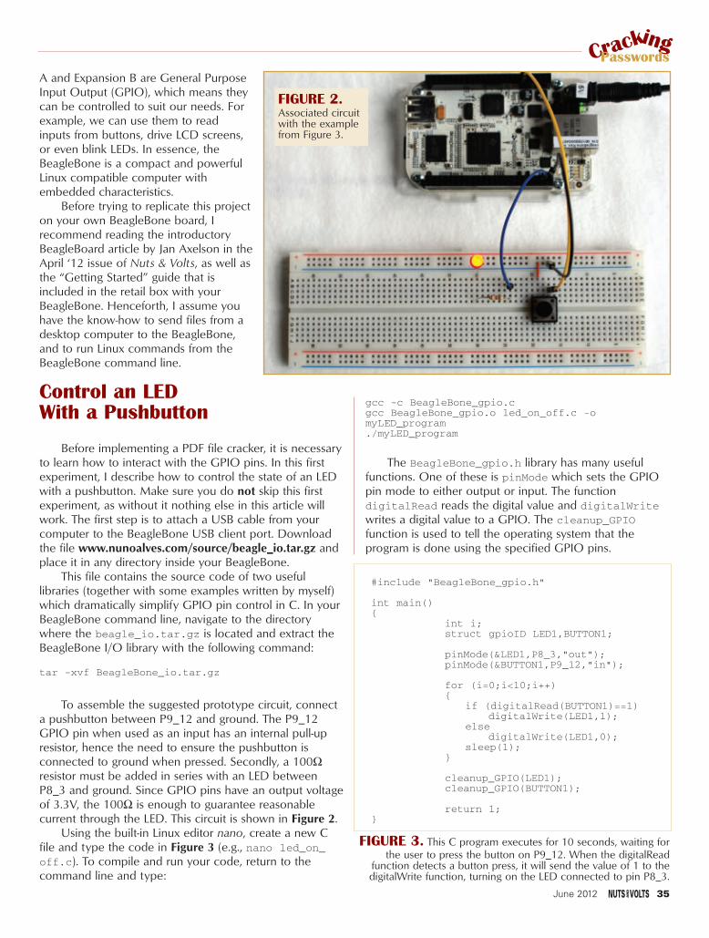
A and Expansion B are General PurposeInput Output (GPIO), which means theycan be controlled to suit our needs. Forexample, we can use them to readinputs from buttons, drive LCD screens,or even blink LEDs. In essence, theBeagleBone is a compact and powerfulLinux compatible computer withembedded characteristics.
Before trying to replicate this projecton your own BeagleBone board, Irecommend reading the introductoryBeagleBoard article by Jan Axelson in theApril ‘12 issue of Nuts & Volts, as well asthe “Getting Started” guide that isincluded in the retail box with yourBeagleBone. Henceforth, I assume youhave the know-how to send files from adesktop computer to the BeagleBone,and to run Linux commands from theBeagleBone command line.
Control an LED With a Pushbutton
Before implementing a PDF file cracker, it is necessaryto learn how to interact with the GPIO pins. In this firstexperiment, I describe how to control the state of an LEDwith a pushbutton. Make sure you do not skip this firstexperiment, as without it nothing else in this article willwork. The first step is to attach a USB cable from yourcomputer to the BeagleBone USB client port. Downloadthe file www.nunoalves.com/source/beagle_io.tar.gz andplace it in any directory inside your BeagleBone.
This file contains the source code of two usefullibraries (together with some examples written by myself)which dramatically simplify GPIO pin control in C. In yourBeagleBone command line, navigate to the directorywhere the beagle_io.tar.gz is located and extract theBeagleBone I/O library with the following command:
tar -xvf BeagleBone_io.tar.gz
To assemble the suggested prototype circuit, connecta pushbutton between P9_12 and ground. The P9_12GPIO pin when used as an input has an internal pull-upresistor, hence the need to ensure the pushbutton isconnected to ground when pressed. Secondly, a 100Ωresistor must be added in series with an LED betweenP8_3 and ground. Since GPIO pins have an output voltageof 3.3V, the 100Ω is enough to guarantee reasonablecurrent through the LED. This circuit is shown in Figure 2.
Using the built-in Linux editor nano, create a new Cfile and type the code in Figure 3 (e.g., nano led_on_off.c). To compile and run your code, return to thecommand line and type:
gcc -c BeagleBone_gpio.cgcc BeagleBone_gpio.o led_on_off.c -omyLED_program./myLED_program
The BeagleBone_gpio.h library has many usefulfunctions. One of these is pinMode which sets the GPIOpin mode to either output or input. The functiondigitalRead reads the digital value and digitalWritewrites a digital value to a GPIO. The cleanup_GPIOfunction is used to tell the operating system that theprogram is done using the specified GPIO pins.
FIGURE 2.Associated circuitwith the examplefrom Figure 3.
#include "BeagleBone_gpio.h"
int main()
int i;struct gpioID LED1,BUTTON1;
pinMode(&LED1,P8_3,"out");pinMode(&BUTTON1,P9_12,"in");
for (i=0;i<10;i++)
if (digitalRead(BUTTON1)==1)digitalWrite(LED1,1);
elsedigitalWrite(LED1,0);
sleep(1);
cleanup_GPIO(LED1);cleanup_GPIO(BUTTON1);
return 1;
FIGURE 3. This C program executes for 10 seconds, waiting forthe user to press the button on P9_12. When the digitalRead
function detects a button press, it will send the value of 1 to thedigitalWrite function, turning on the LED connected to pin P8_3.
CrackingPasswords
June 2012 35
Alves - PDF Cracking.qxd 5/7/2012 9:27 AM Page 35

Functions for ControllingMultiple GPIOs and Pulse Pins
With the provided library, controlling multiple LEDs isnot much harder. For this second experiment, place fivedistinct LEDs in serial with a 100Ω resistor; each pair isconnected to pins P8_3, P8_4, P8_5, P8_11, and P8_12as shown in Figure 4. The code in Figure 5 shows how toselect which pins you would like to turn on. It requires youto convert the binary position of the selected pins in thepinID[] array from binary into decimal. For example, thepositions for pins P8_3 and P8_5 are 0 and 2, respectively.Converting these two binary positions into a decimal value is 20 + 22 = 5. The variable data_to_write
containing this decimal representation is then used as aparameter to the digitalWrite_multiple functionwhich controls the respective LEDs.
As the name indicates, the delayms function halts theprogram execution for a certain number of milliseconds.Finally, pulsePin pulses a logic value (initially high, thenlow) in a particular pin. The fourth parameter on thispulsePin function is the pin position in the pinID[]array (e.g., P8_4 is pin number 1), while the last parameter(e.g., 1000). is the pulse delay in milliseconds. The twopulsing lines in Figure 5 blink the connected LED twice,for a period of one second.
Using an HD44780 Compatible LCD Display
The goal of this project is to assemble a stand-aloneprototype. This means we need to find another way tovisualize data from the BeagleBone without it beingconnected to a computer through a USB cable. Mychoice: an Hitachi HD44780 compatible LCD. I am a bigfan of these screens, mainly because they are extremelycheap, widely available, and easy to program. In fact,displaying data on a HD44780 can be done by sendingcarefully chosen bits to each of the LCD screen inputs justusing SPDT switches1.
In this section, I’ll describe the steps necessary tointegrate a HD44780 LCD with the BeagleBone board.First of all, you need a display. From my Arduino days, Ihad a couple of them laying around my lab; in particular, I used the fairly inexpensive Microtivity LCD module1602. Because this LCD requires a 5V source and theBeagleBone GPIO pins only provide 3.3V, you need to getpower from other sources. Either connect a 5V DCadapter to the BeagleBone and use P9_5 which provides+5V, or use any external adapter to deliver the appropriatevoltage with the help of a voltage regulator.
If you opt for the voltageregulator route, I recommendusing the breadboard powersupply 5V/3.3V kit fromSparkFun (PRT-00114). Don’tforget to ensure the ground ofyour external voltage supply isconnected to the ground pin(P8_1) of the BeagleBone. Ofcourse, you can bypass all theseproblems by getting a +3.3VLCD display, which unfortunatelytend to be pricier.
Once you have acquired theLCD, establish the connectionsshown in Table 1.
The code in Figure 6demonstrates how to print asimple message to the LCD
#include "BeagleBone_gpio.h"int main()
int pinID[]=P8_3,P8_4,P8_5,P8_11,P8_12;
int nbr_selectedPins=sizeof(pinID)/sizeof(*pinID);struct gpioID selectedPins[nbr_selectedPins]; pinMode_multiple(selectedPins,pinID,nbr_selectedPins,"out");
unsigned int data_to_write;
//turning ON P8_3 and P8_5 data_to_write=5;digitalWrite_multiple(selectedPins,nbr_selectedPins,data_to_write);delayms(2000);
//pulse pin P8_4 twice with 1 second delaypulsePin(selectedPins,data_to_write,nbr_selectedPins,1,1000);pulsePin(selectedPins,data_to_write,nbr_selectedPins,1,1000);
cleanup_multiple(selectedPins,nbr_selectedPins);
return 1;
FIGURE 5. Controlling multiple GPIO pins with a single function: digitalWrite_multiple.
CrackingPasswords
FIGURE 4. Associated circuit withthe code example outlined in Figure 5.
36 June 2012
Alves - PDF Cracking.qxd 5/7/2012 9:27 AM Page 36

display. Save this code on a file (e.g., nanotest_HD44780.c) and type the following four commandsto compile and run this example:
gcc -c BeagleBone_gpio.ogcc -c BeagleBone_hd44780.ogcc BeagleBone_gpio.o BeagleBone_hd44780.o
test_HD44780.c -o myProgram./myProgram
PDF File Cracking SoftwareNow that I’ve introduced basic I/O with the
BeagleBone, let’s focus on the PDF file cracking part. Forthis design, I would like to have a stand-alone box with anLCD display and a button. I would like the user to insert aUSB disk with the encrypted file and press a button to seeit being decrypted in real time. This box is to run until thePDF file password has been found.
The first step is to acquire a program that searches forall possible alpha-numeric combinations and see if aspecific key is the correct PDF file password. In technicallingo, this type of exhaustive decryption method is calledbrute-force attack. Through Google, I reached the opensource project “PDFCrack - A Password Recovery Tool forPDF Files” (http://pdfcrack.sourceforge.net) which doesexactly what I was looking for. To run this program in theBeagleBone, follow these steps:
1) Create or obtain an encrypted PDF file and place iton a USB disk. For convenience, the followingencrypted file — www.nunoalves.com/source/encrypted.pdf — is available online with “meta” asits password.
2) From the project website, downloadthe file pdfcrack-0.11.tar.gz.
3) Place pdfcrack-0.11.tar.gz onsome directory inside theBeagleBoard. Build and uncompressit with the following commands:tar -xvf pdfcrack-0.11.tar.gz
cd pdfcrack-0.11
make
4) Insert the USB disk with theencrypted file into the BeagleBone.
5) In order for you to read the contentsof a USB disk, first you need tomount it into a Linux directory (e.g.,/mnt/usbdisk). This can be donewith the commands:mkdir -p /mnt/usbdisk
mount /dev/sda1 /mnt/usbdisk
6) To start cracking the encrypted file,run the executable pdfcrack with:./pdfcrack /mnt/usbdisk/
encrypted.pdf
Figure 7 shows the output of eachof these steps.
7) Once you are done cracking the
password, you must unmount the USB disk beforeyou remove it. Failure to do so may damage the filecontents.umount /dev/sda1
Attaching the HardwareNow that we know how to run the pdfCrack program
to brute-force passwords, we need to modify it such thatwe can start the program with a button and visualize the
#include "BeagleBone_gpio.h"#include "BeagleBone_hd44780.h"
int main()
//specifies the pins that will be usedint selectedPins[]=P8_14,P8_12,P8_11,P8_5,P8_4,P8_3;
struct gpioID enabled_gpio[6];
initialize_Screen(enabled_gpio,selectedPins);
//clear screenclear_Screen(enabled_gpio);
//types "hi" to the screenstringToScreen("hi",enabled_gpio);
//enable blinking cursorenableBlinkingCursor(enabled_gpio);
//types " there"stringToScreen(" there",enabled_gpio);
//wait for 3 second and disable blinking cursorsleep(3);disableBlinkingCursor(enabled_gpio);
//don't forget to terminate the screen... or you may getterminate_Screen(enabled_gpio,selectedPins);
return 1;
FIGURE 6. Interfacing the HD44780 with the BeagleBone.
LLCCDD PPiinn ## LLCCDD PPiinn DDeessccrriippttiioonn LLCCDD PPiinn CCoonnnneeccttss ttoo
1 VSS Ground
2 VDD +5V
3 VO Adjust contrast with apotentiometer
4 Register Select (RS) BeagleBone pin P8_4
5 Read/Write (R/W) Ground
6 Clock Enable (E) BeagleBone pin P8_3
7 Data Bit 0 Unconnected
8 Data Bit 1 Unconnected
9 Data Bit 2 Unconnected
10 Data Bit 3 Unconnected
11 Data Bit 4 BeagleBone pin P8_5
12 Data Bit 5 BeagleBone pin P8_11
13 Data Bit 6 BeagleBone pin P8_12
14 Data Bit 7 BeagleBone pin P8_14
15 Backlight Anode (+) +5V (or lower)16 Backlight Cathode (-) Ground
TTAABBLLEE 11..
CrackingPasswords
June 2012 37
Alves - PDF Cracking.qxd 5/7/2012 9:28 AM Page 37
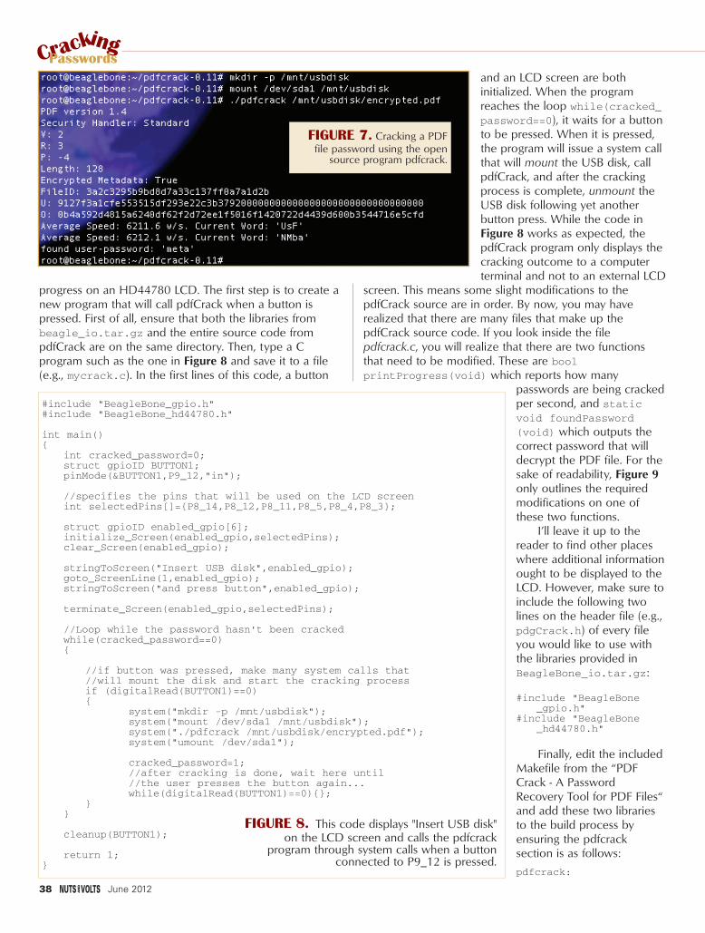
progress on an HD44780 LCD. The first step is to create anew program that will call pdfCrack when a button ispressed. First of all, ensure that both the libraries frombeagle_io.tar.gz and the entire source code frompdfCrack are on the same directory. Then, type a Cprogram such as the one in Figure 8 and save it to a file(e.g., mycrack.c). In the first lines of this code, a button
and an LCD screen are bothinitialized. When the programreaches the loop while(cracked_password==0), it waits for a buttonto be pressed. When it is pressed,the program will issue a system callthat will mount the USB disk, callpdfCrack, and after the crackingprocess is complete, unmount theUSB disk following yet anotherbutton press. While the code inFigure 8 works as expected, thepdfCrack program only displays thecracking outcome to a computerterminal and not to an external LCD
screen. This means some slight modifications to thepdfCrack source are in order. By now, you may haverealized that there are many files that make up thepdfCrack source code. If you look inside the filepdfcrack.c, you will realize that there are two functionsthat need to be modified. These are boolprintProgress(void) which reports how many
passwords are being crackedper second, and staticvoid foundPassword(void) which outputs thecorrect password that willdecrypt the PDF file. For thesake of readability, Figure 9only outlines the requiredmodifications on one ofthese two functions.
I’ll leave it up to thereader to find other placeswhere additional informationought to be displayed to theLCD. However, make sure toinclude the following twolines on the header file (e.g.,pdgCrack.h) of every fileyou would like to use withthe libraries provided inBeagleBone_io.tar.gz:
#include "BeagleBone_gpio.h"
#include "BeagleBone_hd44780.h"
Finally, edit the includedMakefile from the “PDFCrack - A PasswordRecovery Tool for PDF Files“and add these two librariesto the build process byensuring the pdfcracksection is as follows:
pdfcrack:
#include "BeagleBone_gpio.h"#include "BeagleBone_hd44780.h"
int main()
int cracked_password=0;struct gpioID BUTTON1;pinMode(&BUTTON1,P9_12,"in");
//specifies the pins that will be used on the LCD screenint selectedPins[]=P8_14,P8_12,P8_11,P8_5,P8_4,P8_3;
struct gpioID enabled_gpio[6];initialize_Screen(enabled_gpio,selectedPins);clear_Screen(enabled_gpio);
stringToScreen("Insert USB disk",enabled_gpio);goto_ScreenLine(1,enabled_gpio);stringToScreen("and press button",enabled_gpio);
terminate_Screen(enabled_gpio,selectedPins);
//Loop while the password hasn't been crackedwhile(cracked_password==0)
//if button was pressed, make many system calls that//will mount the disk and start the cracking processif (digitalRead(BUTTON1)==0)
system("mkdir -p /mnt/usbdisk");system("mount /dev/sda1 /mnt/usbdisk");system("./pdfcrack /mnt/usbdisk/encrypted.pdf");system("umount /dev/sda1");
cracked_password=1;//after cracking is done, wait here until //the user presses the button again...while(digitalRead(BUTTON1)==0);
cleanup(BUTTON1);
return 1;
FIGURE 8. This code displays "Insert USB disk"on the LCD screen and calls the pdfcrack
program through system calls when a buttonconnected to P9_12 is pressed.
CrackingPasswords
FIGURE 7. Cracking a PDFfile password using the open
source program pdfcrack.
38 June 2012
Alves - PDF Cracking.qxd 5/7/2012 9:28 AM Page 38

BeagleBone_gpio.oBeagleBone_hd44780.o main.o rc4.o \ md5.o pdfcrack.o pdfparser.o passwords.o common.o benchmark.ogcc $(CFLAGS) -o $@ $+strip $@
Now, we are ready tocompile and run the modifiedpdfCrack and also theprogram that will launch thecracking application (codefrom Figure 8). This is doneover the next three lines:
gcc BeagleBone_gpio.o BeagleBone_hd44780.o myCrack.c -o myCrack
make ./myCrack
In these commands, thefirst line will build theprogram entry point(myCrack), the second linewill build the modifiedpdfCrack with LCD support,while the third line will startthe cracking program. Attacha five volt power supply tothe BeagleBone, disconnectthe USB cable that links theBeagleBone to thecomputer, and you are readyto run the password crackingprogram without anyexternal computer. Figure 10 shows my final prototype,completely disconnectedfrom a host computer andrunning off a 5V powersupply. As shown in theimage, the password for theencrypted file inside the USBdisk is “rock.”
With So Many CodeModifications, IThink I am Lost
So many code changescan be overwhelming,especially for new Linux andC language users. I includeda file (www.nunoalves.com/
/** Prints out the password found */static voidfoundPassword(void)
char str[33];int fin_search;size_t pad_start;
memcpy(str,currPW,currPWLen);str[currPWLen] = '\0';printf("found %s-password: '%s'\n", workWithUser?"user":"owner", str);
//[ENABLING LCD SCREEN]============================================int selectedPins[]=P8_14,P8_12,P8_11,P8_5,P8_4,P8_3;struct gpioID enabled_gpio[6]; initialize_Screen(enabled_gpio,selectedPins); clear_Screen(enabled_gpio);stringToScreen("found password!",enabled_gpio);goto_ScreenLine(1,enabled_gpio);stringToScreen(str,enabled_gpio);terminate_Screen(enabled_gpio,selectedPins);//[ENABLING LCD SCREEN]============================================
/** * Print out the user-password too if we know the ownerpassword.* It is placed in password_user and we need to find where the pad* starts before we can print it out (without ugly artifacts) **/
if(!workWithUser) fin_search=-1;pad_start=0;
do fin_search = memcmp(password_user+pad_start, pad, 32-pad_start);pad_start++;
while (pad_start < 32 && fin_search != 0);
memcpy(str, password_user, pad_start);if(!fin_search)
str[pad_start-1] = '\0';printf("found user-password: '%s'\n", str);
FIGURE 9. Modifying the static void foundPassword(void) function inside
pdfcrack.c, such that the final password is displayed on the LCD screen.
CrackingPasswords
FIGURE 10. Prototype thatcracks PDF file passwords usinga BeagleBone.
June 2012 39
Alves - PDF Cracking.qxd 5/7/2012 9:28 AM Page 39

source/final_pdfCrack.tar.gz)containing all the steps outlinedin this article, as well as someadditional cracking statistics suchas the number of passwords thatthe BeagleBone is brute-forcingper second. After downloadingthe file to a directory inside yourBeagleBone, type the followingto build the entire project:
tar -xvf final_pdfCrack.tar.gz
make./myCrack
Is This Practical? In theory, this system looks
promising but how long does itactually take to crack apassword? From myexperiments, the BeagleBonewas able to brute-force testabout 6,200 words per second. As acomparison, I also compiled thesame exact code on my 2 GHz Corei7 Macbook Pro which could test (onaverage) 25,500 words per second.Both systems sound impressive, buthow fast can they both crack areasonably sized password?
A good password is generallylong and contains at least oneuppercase character, one lowercasecharacter, and a digit. This meansthere are (26+26+10)n distinct wordswith n characters. If the BeagleBoneis able to test 6,200 words persecond, then it will take 39.7 minutesto test every single four letter wordcombination. Unfortunately, thissystem does not scale very well, asthis brute-force method requires 41hours to exhaustively test five letterwords, and 106 days to process sixletter words. Obviously, there isplenty of room for improvementhere, such as a dictionary basedoption instead of brute-force, or evencustomized multi-core architectureswith many BeagleBone CPUs.
This last option is the mostinteresting one. While theBeagleBone prototype system costsaround $85, the CPU itself (TIAM3359) sells for around $5. Withsome clever engineering, we couldpotentially have a dedicated 10 core
system for less than $300. However,for any password with more thanseven characters — even if we have10 CPUs all working in parallel — itwould take 10 days to brute-force allsix character words and 657 days forseven character words.
The graph in Figure 11 clearlyshows that using a multi-CPUBeagleBone as a brute-forcepassword recovery system is far frombeing the ideal approach. In fact,brute-force password decryptionmethods are rarely the best method.However, if you are seriouslyinterested in this method of passwordcracking, I recommend you delveinto highly parallel computerarchitectures such as FPGAs andGPUs. Unfortunately, developingprototypes in these two architecturesis far from trivial, but as the oldsaying goes, “anything easy is moretrouble than its worth.”
Regardless of the practicality ofthis implementation, this article is agood showcase of doing heavy dutycomputation on low power ARMdevices, and another evidence thatthe BeagleBone can do pretty mucheverything a standard desktopcomputer can. NV
1 - Julyan Ilett, “How to Use IntelligentLCDs,” Everyday Practical Electronics,February 2007.
FIGURE 11. As we increase the number ofCPUs, the theoretical number of passwords we
can test per second dramatically increases, but it still takes an unreasonably long time to
brute-force a seven character password.
40 June 2012
Alves - PDF Cracking.qxd 5/7/2012 9:29 AM Page 40
Most people who read a magazine like Nuts & Voltsknow a fair amount about electrical engineering,
mechanical engineering, and programming, but few of usare really expert at all of them. That’s what I find soenticing about the combination we’ll work with here tobuild our moisture sensor. All of the components — eventhe software — are off-the-shelf. That lets us concentrateon the part of the project we’re best at or — for those ofus perverse enough to think this way — the part we’reworst at, so we can improve. The whole project can betossed together in a matter of minutes. Later, we’ll dealwith my area of expertise, and develop a much coolerimplementation of the software so our quadcorder’smoisture meter is easier to use.
Parts ListThe first component is an iPhone or iPad. Depending
on the model, this can give us an accelerometer,magnetometer, and gyroscope.
Next, we add the HiJack AD converter. This littledevice is just one inch square and 3/8 inches thick. Itplugs into the headphone jack, drawing power from theaudio output to provide 7.4 mW without the need of anexternal power supply. It reads a voltage drop, translatingzero volts to a value of zero, and 2.75 volts to a value of
I was always a little jealous when Spock pulled out his tricorder on Star Trekand began measuring practically every physical value you could imagine. It’sstaggering how far technology has come, though. I carry a tricorder aroundin my pocket all the time now! Mine measures acceleration, rotation, andmagnetic fields, giving both the strength and direction of each. It’s not quiteas sophisticated as Spock’s, but it’s also not so large and clunky. In thisarticle, we’ll look at a way to convert an iPhone or iPad into a quadcorder,hanging a HiJack AD converter off of the end, then using techBASIC™ toread it. As a sample project, we’re going to build a moisture meter from off-the-shelf parts.
Turn Your iPhoneinto a Plant
Moisture Sensor
42 June 2012
FIGURE 1. Our moisture sensor.
By Mike Westerfield
Westerfield - Moisture Sensor.qxd 5/7/2012 9:56 AM Page 42

255, with a linear responsebetween those values. A cleverelectrical engineer can connectpretty much any sensor to theiPhone using HiJack.
I bought the HiJackdevelopment kit which comeswith the HiJack module, twoprototype boards, a USBconnector for updatingfirmware, and several wiringharnesses.
I used a Grove moisturesensor which attaches directlyto the HiJack harness. Be sureand check out the other Grovecomponents on the SeeedStudio site, though. You may besurprised at the number ofcomponents that are available,and most plug directly intoHiJack.
The last component is software to tie it all together.techBASIC is an implementation of Basic for the iPad andiPhone that is designed for collecting, analyzing, anddisplaying information. It comes with sample programs toread and display information from the accelerometer,gyroscope, and magnetometer, giving you your basictricorder. The Byte Works’ website (www.byteworks.us)has an introduction to HiJack; at the end is the sourcecode for a program that will read the HiJack sensor anddisplay the results more or less like an oscilloscope.
Assembling the Moisture SensorFigure 2 shows exploded and assembled views of the
hardware. All of the parts except the moisture sensorcome with the HiJack development kit. It really is assimple as it looks — just plug the components together asshown, then insert the headphone jack into an iPhone.
To use HiJack, you’ll need to have some softwareinstalled. After downloading techBASIC from the appstore, the next step is to install the HiJack software. Go tothe HiJack blog on the Byte Works website, scroll to thebottom, and click the download button. You’ll get a filecalled HiJack.bas. Follow these steps to move HiJack.basto your iPhone or iPad:
1. Run iTunes and plug in your iPhone or iPad likeyou are going to sync it.
2. Select the iPhone or iPad from the list of devices inthe left column.
3. Select Apps along the top button bar.4. Scroll down until you see the File Sharing section.5. Scroll down in the Apps section until you see
techBASIC. Click on techBASIC.
6. Drag the HiJack.bas file to the techBASICDocuments section.
With everything connected, run techBASIC and tapon the HiJack program from the Programs list to run theHiJack app. Now run around the house, sticking theprongs of the moisture sensors in various plants, and youwill see responses like the one in Figure 3.
June 2012 43
FIGURE 2: Exploded and assembled views of the hardware.
www.nutsvolts.com/index.php?/magazine/article/june2012_WesterfieldDiscuss this article in the Nuts & Volts forums at http://forum.nutsvolts.com.
FIGURE 3: HiJack software and hardware with the Grove moisture sensor.
Westerfield - Moisture Sensor.qxd 5/7/2012 9:56 AM Page 43
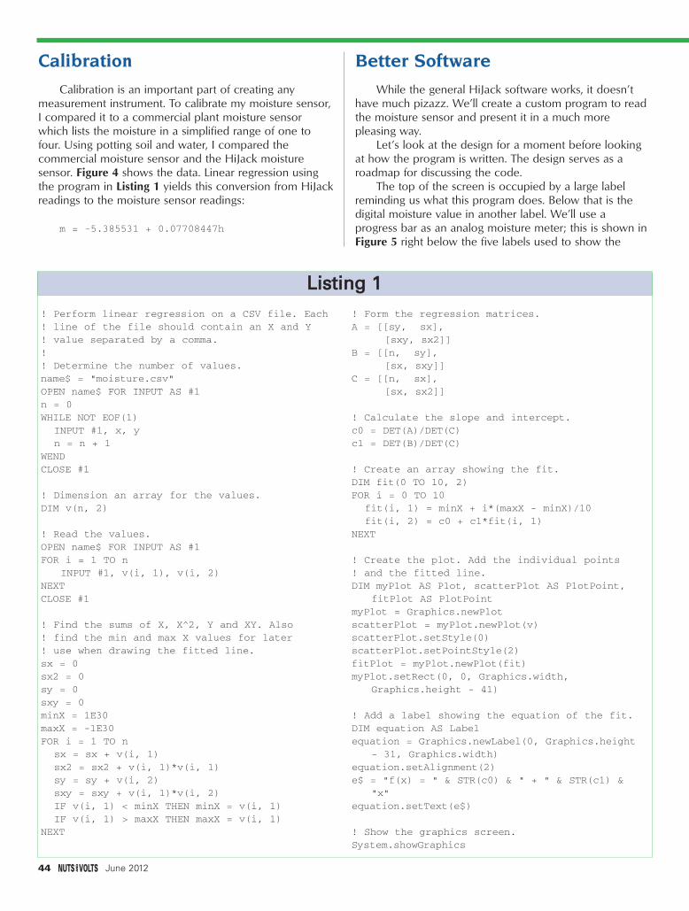
Calibration
Calibration is an important part of creating anymeasurement instrument. To calibrate my moisture sensor,I compared it to a commercial plant moisture sensorwhich lists the moisture in a simplified range of one tofour. Using potting soil and water, I compared thecommercial moisture sensor and the HiJack moisturesensor. Figure 4 shows the data. Linear regression usingthe program in Listing 1 yields this conversion from HiJackreadings to the moisture sensor readings:
m = -5.385531 + 0.07708447h
Better Software
While the general HiJack software works, it doesn’thave much pizazz. We’ll create a custom program to readthe moisture sensor and present it in a much morepleasing way.
Let’s look at the design for a moment before lookingat how the program is written. The design serves as aroadmap for discussing the code.
The top of the screen is occupied by a large labelreminding us what this program does. Below that is thedigital moisture value in another label. We’ll use aprogress bar as an analog moisture meter; this is shown in Figure 5 right below the five labels used to show the
! Perform linear regression on a CSV file. Each! line of the file should contain an X and Y ! value separated by a comma.!! Determine the number of values.name$ = "moisture.csv"OPEN name$ FOR INPUT AS #1n = 0WHILE NOT EOF(1)
INPUT #1, x, yn = n + 1
WENDCLOSE #1
! Dimension an array for the values.DIM v(n, 2)
! Read the values.OPEN name$ FOR INPUT AS #1FOR i = 1 TO n
INPUT #1, v(i, 1), v(i, 2)NEXTCLOSE #1
! Find the sums of X, X^2, Y and XY. Also! find the min and max X values for later! use when drawing the fitted line.sx = 0sx2 = 0sy = 0sxy = 0minX = 1E30maxX = -1E30FOR i = 1 TO n
sx = sx + v(i, 1)sx2 = sx2 + v(i, 1)*v(i, 1)sy = sy + v(i, 2)sxy = sxy + v(i, 1)*v(i, 2)IF v(i, 1) < minX THEN minX = v(i, 1)IF v(i, 1) > maxX THEN maxX = v(i, 1)
NEXT
! Form the regression matrices.A = [[sy, sx],
[sxy, sx2]]B = [[n, sy],
[sx, sxy]]C = [[n, sx],
[sx, sx2]]
! Calculate the slope and intercept.c0 = DET(A)/DET(C)c1 = DET(B)/DET(C)
! Create an array showing the fit.DIM fit(0 TO 10, 2)FOR i = 0 TO 10
fit(i, 1) = minX + i*(maxX - minX)/10fit(i, 2) = c0 + c1*fit(i, 1)
NEXT
! Create the plot. Add the individual points! and the fitted line.DIM myPlot AS Plot, scatterPlot AS PlotPoint,
fitPlot AS PlotPointmyPlot = Graphics.newPlotscatterPlot = myPlot.newPlot(v)scatterPlot.setStyle(0)scatterPlot.setPointStyle(2)fitPlot = myPlot.newPlot(fit)myPlot.setRect(0, 0, Graphics.width,
Graphics.height - 41)
! Add a label showing the equation of the fit.DIM equation AS Labelequation = Graphics.newLabel(0, Graphics.height
- 31, Graphics.width)equation.setAlignment(2)e$ = "f(x) = " & STR(c0) & " + " & STR(c1) &
"x"equation.setText(e$)
! Show the graphics screen.System.showGraphics
LLiissttiinngg 11
44 June 2012
Westerfield - Moisture Sensor.qxd 5/7/2012 9:57 AM Page 44

scale. There are four TextView objects below the progressbar. Color is used to show the relative moisture, startingwith light blue for dry soil and moving to darker blue forwet soil. A few common plants are listed in each group;when the soil’s moisture is at or below the level shown,it’s time to water the plant. Finally, there is a Quit buttonat the bottom of the screen to stop the program.
The complete program is in Listing 2, which isavailable at the article link since it’s too large to print.Instead, let’s walk through it chunk by chunk.
! HiJack Moisture Meter
! Get the size of the graphics
! screen
width = Graphics.width
height = Graphics.height
We’ll use the size of the graphics screen to calculateappropriate values for the position and size of controls. To save some typing, the program starts by placing thesevalues in local variables.
! Paint the background light gray
bg = 0.9
Graphics.setColor(bg, bg, bg)
Graphics.fillRect(0, 0, width, height)
The default screen is white, and that just won’t do.techBASIC has a built-in class called Graphics that is usedto draw on the graphics screen. setColor and fillRect paintthe entire screen a light gray.
! Create a Quit button
DIM quit AS Button
quit = Graphics.newButton(width/2 - 36,
height - 57)
quit.setTitle(“Quit”)
quit.setBackgroundColor(1, 1, 1)
quit.setGradientColor(0.7, 0.7, 0.7)
Our program will be an event-driven program, so itwill run until it is stopped. These lines create a Quit buttoncentered near the bottom of the screen. Rather than thedefault white button, we’re using a gradient to create ashadowed button.
To make the Quit button function, we’ll need to add a subroutine that handles button clicks. Here’s the one inour program, found near the bottom of the completelisting. It checks to make sure it was the Quit button thatwas tapped, then stops the program.
! Handle a tap on a button
!
! Parameters:
! ctrl - The button tapped
! time - When the button was
! tappedFIGURE 5: Moisture sensor GUI.
June 2012 45
FIGURE 4: HiJack vs.a moisture sensor.
Westerfield - Moisture Sensor.qxd 5/7/2012 9:57 AM Page 45

SUB touchUpInside(ctrl AS Button, time AS
DOUBLE)
IF ctrl = quit THEN
STOP
END IF
END SUB
This is enough code to produce a working program.When you run it, you should see a Quit button on a graybackground, and tapping the Quit button should exit theprogram.
! Put the name of the program at
! the top of the screen
DIM mmLabel AS Label
mmLabel = newLabel(0, 10, width, 40, 40,
“Moisture Meter”)
mmLabel.setBackgroundColor(bg, bg, bg)
This code creates a label. We’ll be creating a lot oflabels with various positions, sizes, and text, so this code isactually calling a subroutine in our program to do some ofthe repetitive work, followed by setting the backgroundcolor for the label so it matches our screen background.Here’s the subroutine that is called to create the label; itappears a bit later in the complete program listing.
! Create a label
!
! Parameters:
! x - Horizontal location
! y - Vertical location
! width - Label width
! height - Label height
! fontSize - Point size for the
! font
! text$ - Label text
!
! Returns: The label
FUNCTION newLabel (x, y, width, height,
fontSize, text$) AS Label
DIM nl AS Label
nl = Graphics.newLabel(x, y, width, height)
nl.setText(text$)
nl.setBackgroundColor(1, 1, 1, 0)
nl.setAlignment(2)
nl.setFont(“Sans_Serif”, fontSize, 0)
newLabel = nl
END FUNCTION
This subroutine creates a variable called nl — short fornew label — to hold the label, then calls Graphics.newLabelto create the actual label. nl.setText sets the text for thelabel.
nl.setBackgroundColor sets the background color usingthe normal three red, green, and blue components whichrange from 0 to 1, but in this case, it also sets the alpha
level. The alpha level controls how opaque the color is. Bysetting the background alpha level to 0, we’re setting it tobe completely transparent so anything under the labelshows through. This means we don’t have to set thebackground color for each label to the background screencolor. Wait. Isn’t that exactly what we did after creating themmLabel a moment ago? Well, yes — but that was aspecial case. It turns out techBASIC puts a control on thegraphics screen to give you some options for dealing withplots. We cover up this control by setting the backgroundfor the title label to an opaque color.
The next two lines center the text and set the font size.Finally, we set the return value and return the new label tothe caller.
! Create a large label to show
! the moisture level
DIM value AS Label
value = newLabel(0, 60, width, 40, 50, “0”)
The same newLabel subroutine is used here to create alarge label that will display the digital readout for themoisture meter. We’ll see the subroutine that actually setsthe value later. For now, we start with a reading of 0.
! Add 5 small labels to show the
! moisture scale along the top of
! the moisture bar
DIM nums(5) AS Label
plantLabelWidth = (width - 40)/4
FOR i = 0 TO 4
x = i*plantLabelWidth
nums(i + 1) = newLabel(x, 115, 40, 20, 16,
STR(i))
NEXT
Our newLabel subroutine is getting quite a workout!Here, we use it again to create five labels (0 to 4) thatshow the scale for the analog readout. The variouscalculations evenly space the five labels across an area ofthe screen that extends from 20 pixels from the left edgeto 20 pixels from the right edge. This is the size we’ll use ina moment for the progress bar we’ll use as an analogmeter.
! Create the strings that will
! name the plants in each
! moisture group
DIM plants(4) AS TextView, plants$(4)
addPlant(“Aloe”, plants$(1))
addPlant(“Geranium”, plants$(1))
addPlant(“Jade Plant”, plants$(1))
addPlant(“Orchid”, plants$(1))
addPlant(“Wandering Jew”, plants$(1))
addPlant(“African Violet”, plants$(2))
addPlant(“Cacti”, plants$(2))
addPlant(“Hibiscus”, plants$(2))
addPlant(“Wax Plant”, plants$(2))
46 June 2012
Westerfield - Moisture Sensor.qxd 5/7/2012 9:57 AM Page 46

addPlant(“Begonia”, plants$(3))
addPlant(“Flowering Maple”, plants$(3))
addPlant(“Peppers”, plants$(3))
addPlant(“Spider Plant”, plants$(3))
addPlant(“Azalea”, plants$(4))
addPlant(“Ferns”, plants$(4))
addPlant(“Melons”, plants$(4))
addPlant(“Peace Lily”, plants$(4))
addPlant(“Tomatoes”, plants$(4))
We’re going to add four text views now; each ofwhich will have a background color that indicates therelative moisture level and a list of common plants thatshould be watered when the soil is at or below theindicated level. The text views will slightly overlap theprogress bar, so we want to create them first so theprogress bar is drawn on top. This makes them look likean integral part of the analog meter, rather than anafterthought sitting below it. This first chunk of code setsup the text that will appear in each text view. It calls theaddPlant subroutine that appears later in the listing.
! Add a plant name to a string
! containing plant names
!
! Parameters:
! newPlant$ - New plant name
! plant$ - Current plant names
SUB addPlant (newPlant$, BYREF plant$)
IF LEN(plant$) <> 0 THEN
plant$ = plant$ & CHR(10) & CHR(10)
END IF
plant$ = plant$ & newPlant$
END SUB
This subroutine checks to see if the list of plants isempty. If not, it adds two new line characters to the string,then adds the new plant name.
! Add colored labels below the
! moisture bar showing the plants
! in each group
plantLabelHeight = 150
FOR i = 1 TO 4
x = 20 + (i - 1)*plantLabelWidth
color = 1 - i/5
plants(i) = newTextView(x, 145,
plantLabelWidth, plantLabelHeight, 11,
color, plants$(i))
NEXT
Next, we create the four text views. There’s a bit ofalgebra to make them fit evenly across the screen and toset the color, but most of the work is done in thenewTextView subroutine. The color we’re setting isactually the white level for the background of the textview, so it’s brighter for the low moisture text views. We’ll
see how this is used as we work through the newTextViewsubroutine, again collected here from later in thecomplete program listing.
! Create a text view to show a
! list of plants
!
! Parameters:
! x - Horizontal location
! y - Vertical location
! width - TextView width
! height - TextView height
! fontSize - Point size for the
! font
! color - White level for
! background; the color will
! be blue, lightened by this
! amount
! text$ - TextView text
!
! Returns: The text view
FUNCTION newTextView (x, y, width, height,
fontSize, color, text$) AS TextView
DIM ntv AS TextView
ntv = Graphics.newTextView(x, y, width,
height)
ntv.setText(text$)
ntv.setEditable(0)
ntv.setBackgroundColor(color, color, 1, 1)
IF color < 0.5 THEN
ntv.setColor(1, 1, 1)
END IF
ntv.setAlignment(2)
ntv.setFont(“Sans_Serif”, fontSize, 0)
newTextView = ntv
END FUNCTION
Most of the newTextView subroutine should lookfamiliar, since it’s very similar to the newLabel subroutinewe looked at earlier. Other than returning a text viewinstead of a label, there are really only two differences.The first is ntv.setEditable, which tells the control that theuser can’t edit the text. The other difference is the way thecolor is set. In this case, we set the red and greencomponents of the background color to the value passedas the color parameter, then set the blue component tobright blue. If the color parameter has a high value — as itdoes for the control that appears to the left — the red andgreen components are fairly bright, too, giving a whitish-blue color. For controls towards the right where themoisture is higher, we dim the red and green color tomake the control a deeper blue.
! Create the moisture bar
DIM moisture AS Progress
moisture = Graphics.newProgress(20, 140,
width - 40)
June 2012 47
Westerfield - Moisture Sensor.qxd 5/7/2012 9:57 AM Page 47

The last control is the progress bar used as an analogmoisture meter.
! Set HiJack to sample 10 times
! per second
HiJack.setRate(10)
The HiJack hardware has a variable sample rate. Wecan leave it at the default of about 42 Hz, but highersampling rates use more power. Lowering it to 10 Hzsaves power and — let’s face it — even 10 samples persecond is overkill for a moisture meter.
! Show the graphics screen
System.showGraphics
Finally, we tell techBASIC we want to see the graphicsscreen rather than the default, which is the text consolescreen. So far, we’ve done everything except actually readthe HiJack sensor and display the results. We want to dothat on a regular basis for as long as the program runs.The nullEvent subroutine is called repeatedly when theprogram is not doing something else, so it’s the perfectplace to read the HiJack device.
! Read and process HiJack values
!
! Parameters:
! time - Event time
SUB nullEvent (time AS DOUBLE)
v = HiJack.receive
m = -5.385531 + 0.07708497*v(1)
IF m < 0 THEN m = 0
IF m > 4 THEN m = 4
moisture.setValue(m/4)
value.setText(STR(INT(m*10)/10))
END SUB
Each time this subroutine is called, it starts by callingHiJack.receive. This fetches a two-element array from theHiJack sensor. The first element is the 0-255 valuereturned by the AD converter, while the second is a timestamp indicating when the data is collected.
The next line converts the HiJack value to a moisturereading from 0-4, using the fit we got from calibrating themoisture sensor earlier. The following two lines pin thevalue to the desired range, discarding values that areabove or below the supported range.
Finally, we set the analog moisture meter (dividing by4 because progress bars expect a value between 0 and 1)and the digital readout (using the INT function to strip offall but one decimal point from the result).
Now, get out there and check your soil! NV
48 June 2012
RReessoouurrcceessHere are some links to resources and locations
where the parts can be purchased.
HiJack Development Kit$79.00 US
wwwwww..sseeeeeeddssttuuddiioo..ccoomm
Grove Moisture Sensor$4.99 US
wwwwww..sseeeeeeddssttuuddiioo..ccoomm
techBASIC$14.99 US
wwwwww..bbyytteewwoorrkkss..uuss//BByyttee__WWoorrkkss//tteecchhBBAASSIICC..hhttmmll
Apple App Store hhttttpp::////iittuunneess..aappppllee..ccoomm//uuss//aapppp//tteecchhbbaassiicc//
iidd447700778811886622??llss==11&&mmtt==88
HiJack Source Code for techBASICwwwwww..bbyytteewwoorrkkss..uuss//BByyttee__WWoorrkkss//BBlloogg//EEnnttrriieess//22001111//1122//77__
HHiiJJaacckk__HHeelllloo__wwoorrlldd!!__PPrroojjeecctt..hhttmmll
Westerfield - Moisture Sensor.qxd 5/7/2012 9:58 AM Page 48

A crystal filter for 30M would be1,500 Hz higher or 10.140200 MHz.WSPR kits, as well as ready-to-gounits, for 20M and 30M are availableon eBay. Search for WSPR.
George Steber
Poor Man ProblemsThere appears to be an error in
the calculations Ron used in his PoorMan’s Seismograph article in the May’12 issue. He used the equation forthe period of a simple pendulum; aweight suspended from a masslessrod. His device is based on a uniformrod pendulum. The correct formulafor the period of such a pendulum is2 pi * sqrt(2 * length / 3g). As aresult, the period of Ron's pendulumis approximately 0.816 seconds, notone second.
Phil Polstra
Thank you for your constructivecriticism. Ahh, the joy of being awriter! You are right in yourassessment that the pendulumdescribed was not a simplependulum. It started off as one usingfishing line and a sinker; however, Icould not get enough deflection ofthe piezo sensor. Therefore, I went tousing a bar and didn't think aboutthat I had changed it to a rodpendulum. You are correct in yourcalculations. Fortunately, the period ofoscillation does not change the natureof the instrument to measureearthquakes. I also discovered there is
June 2012 49
Need high-quality audio in a miniature package? The A8520 Anaren Integrated Radio (AIR) module offers:
> Uncompressed wireless digital audio/full CD quality (44.1/48KHz/16 bits)
> Robust RF protocol – with virtually no RF engineering experience necessary
> Tiny 11 x 19 x 2.5mm form factor
> Integral antenna
> Pre-certifi ed/compliant: FCC, IC, ETSI (pending)
To learn more, write [email protected], visit www.anaren.com/air, or scan the QR code with your smart phone.
800-411-6596www.anaren.comIn Europe, call +44-2392-232392
Available from:
Lowlatency.
One, tiny wireless audio
module.
Continued from page 9
Continued on next page
Pages 49-50.qxd 5/9/2012 4:45 PM Page 49

50 June 2012
RS485/422/232/TTL
w w w . r s 4 8 5 . c o m
Converters / RepeatersMulti-Repeaters / HubsFiber Optics / Isolators
Extended Distance UnitsSerial to Digital I/O
Large Multi-Drop NetworksCustom Units & Smart UnitsIndustrial, 3.0 KV Isolation
Call the RS485 Wizards513-874-4796
IBS485HV5 Port Isolated RS485 Repeater
ASC24T RS232<=>RS485 ATE Converter
$45.00 board only
$349.00
Enclosures, Cables,Power Supplies
and other Accessories
RES R.E. Smith Inc.
an error in the schematic. The seismic detector should go to ground and not pin 2 of the MP601. The corrected schematicis shown here. The Express PCB files on the N&V website are correct as are the boards sold by N&V.
Ron Newton
Pages 49-50.qxd 5/9/2012 4:46 PM Page 50

Order on l ine : www. jaycar.com
Post & Packing ChargesOrder Value Cost$25 - $49.99 $7.50$50 - $99.99 $20$100 - $199.99 $40$200 - $499.99 $60$500+ $75Note: Products are dispatched from Australia,so local customs duty & taxes may apply.Prices valid until 30/6/2012
Max weight 12lb (5kg).
Heavier parcels POA.
Minimum order $25.
WEB: www.jaycar.comPHONE: 1-800-784-0263*FAX: +61 2 8832 3118*EMAIL: [email protected]: P.O. Box 107, Rydalmere NSW 2116 Australia
• ALL PRICING IN US DOLLARS • MINIMUM ORDER ONLY $25
*Australian Eastern Standard Time (Monday - Friday 09.00 to 17.30 GMT + 10 hours)Note: 10-14 days for air parcel delivery
HOW TO ORDER
ARDUINO - Simple to Advanced Projects
OLED Display Module for Arduino
H-Bridge Motor Driver Shield for ArduinoXC-4264 $21.75 plus postage & packingDirectly drive DC motors using your Arduinocompatible board and this shield, which providesPWM (Pulse-Width Modulation) motor output on 2H-bridge channels to let your board control thespeed, direction and power of twomotors independently. Perfect for robotics and motor control projects.
• Drives up to 2A per motor channel• All outputs are diode and
back-EMF protected
Light Sensor Module for ArduinoXC-4228 $7.25 plus postage & packingThis silicon light sensor outputs a voltageproportional to incoming light. Perfect for measuringlight levels both indoors and out, security sensingand human feedback like waving a hand over the sensor.
• +/-60° field of view• Supply voltage: 3.0 to 5.5VDC
IR Temperature Sensor Module for ArduinoXC-4260 $25.25 plus postage & packingConnect this to your board and point it at a surfaceor heat source to remotely measure itstemperature. This is our special version of theindustrial infrared remote thermometer unitswith an onboard power supply,communication support and a softwarelibrary and examples supplied.
• 3.3 to 5V operation• -33 to +220°C measurement
range, 1 second response time
ProtoShield Basic XC-4214 $3.25 plus postage & packingA prototyping shield for the Eleven (XC-4210) andUSBDroid (XC-4222) both featured above. Providesplenty of space to add parts to suit any project,keeping everything neat and self-contained.Includes dedicated space to fit a powerLED and supply decoupling capacitor.
• Gold-plated surface
ProtoShield ShortXC-4248 $3.75 plus postage & packingA dedicated short version prototyping shield forEtherTen and EtherMega. This special prototypingshield is designed to fit neatly behind the RJ45Ethernet jack, allowing you to stackyour Ethernet-based projects righton top with standard headers.
• Pads available to fit a reset button• Gold-plated surface for maximum
durability
ARDUINO DEVELOPMENT KITS
USB Droid, Arduino-compatible with USB-host support XC-4222 $50.50 plus postage & packing This special Arduino-compatible board supports the Android Open AccessoryDevelopment Kit, which is Google’s official platform for designing Androidaccessories. Plugs straight into your Android device and communicates withit via USB. Includes a built-in phone charger.
• ATmega328P MCU running at 16MHz• USB host controller chip• Phone charging circuit built in• 14 digital I/O lines (6 with PWM support)• 8 analog inputs• MicroSD memory card slot EtherMega, Mega sized Arduino compatible with Ethernet
XC-4256 $85.75 plus postage & packingThe ultimate network-connected Arduino-compatible board: combining anATmega2560 MCU, onboard Ethernet, a USB-serial converter, a microSD cardslot for storing gigabytes of web server content or data, Power-over-Ethernetsupport, and even an onboard switchmode voltage regulator so it can run on upto 28VDC without overheating.
• ATmega2560 MCU running at 16MHz, large Flash memory• 10/100base-T Ethernet built in• 54 digital I/O lines• 16 analog inputs• MicroSD memory card slot• Prototyping area• Switchmode power supply
“Eleven” Arduino-compatible development boardXC-4210 $29.00 plus postage & packingAn incredibly versatile programmable board for creating projects. Easily programmedusing the free Arduino IDE development environment, and can beconnected into your project using a variety of analog and digital inputsand outputs. Accepts expansion shields and can be interfaced withour wide range of sensor, actuator, light, and sound modules.
• ATmega328P MCU running at 16MHz• 14 digital I/O lines (6 with PWM support)• 8 analog inputs
EtherTen, Arduino-compatible with Ethernet XC-4216 $50.50 plus postage & packing This Arduino-compatible development board includes onboardEthernet, a USB-serial converter, a microSD card slot forstoring gigabytes of web server content or data, andeven Power-over-Ethernet support.
• ATmega328P MCU running at 16MHz• 10/100base-T Ethernet built in• Used as a web server, remote monitoring and
control, home automation projects• 14 digital I/O lines (6 with PWM support)• 8 analog inputs
Arduino is an open-source electronics prototyping platform based on flexible, easy-to-use hardware and software. It can be used to develop interactive objects, takinginputs from a variety of switches or sensors, and controlling a variety of lights, motors, and other physical outputs (includes Jaycar stepper motors). Arduino projectscan be stand-alone, or they can be communicated with software running on your computer. These Arduino development kits are 100% Arduino compatible. Designedin Australia and supported with tutorials, guides, a forum and more at www.freetronics.com. A very active worldwide community and resources are available withmany projects, ideas and programs available to freely use.
Getting Started with Arduino
BM-7131 $20.75 plus postage & packingThis book explains what Arduino is, how itworks and what you can do with it. It alsoincludes a project to build, complete withhow to write the code to make it work.
• Softcover, 118 pages. 216 x 140mm
Arduino ModulesWe have a huge range of simple toadvanced add-ons that provide input foryour Arduino projects. Visit our websitefor our full range and more details.
N-MOSFET Driver & Output Module XC-4244 $5.25Logic Level Converter Module XC-4238 $5.25Shift Register Expansion Module XC-4240 $5.25Light Sensor Module XC-4228 $7.25Sound & Buzzer XC-4232 $7.25Microphone Sound Input Module XC-4236 $7.25Hall Effect Magnetic & Proximity Sensor Module XC-4242 $7.25Full Colour RGB LED Module XC-4234 $7.25Temperature Sensor Module XC-4230 $12.253-Axis Accelerometer Module XC-4226 $14.50Humidity & Temperature Sensor Module XC-4246 $14.50
XC-4270 $36.00 plus postage & packingHigh resolution, full colour OLED display module! Perfect for graphics, gauges, graphs, even make your own videogame or interactive display.
• 16,384 full colour RGB pixels in a 128 x 128 format
• Active display area 28.8 x 26.8 mm, (1.5 inch diagonal)
Page 1
Full Page_Full Page.qxd 5/7/2012 5:09 PM Page 51

52 June 2012
RecapLast month, we finished up with C pointers (whew!)
and we built a chaser light marquee frame using theSimple Chaser Lights kit available from Nuts & Volts. Thismonth, we will study a C topic related to pointers: arrays.As a reward for our patience with the theory, we will buildanother project using the chaser lights kit: a POV(Persistence Of Vision) wand.
As before, this Workshop is split between some Ctheory and a tangentially related (but more fun) labexercise that uses LEDs. We are nearing the end of the Ctheory, and soon will just use it and refer back to thesearticles when we show the C code. So, save your backissues! They might come in handy some day when youneed a refresher on some arcane C concept.
Figure 1 shows the chaser lights board tied down ona stick and swung madly about in a dark room where youcan just see NUTS & VOLTS spelled out in the air. In thelab section this month, we will look at some of theprinciples behind the phenomenon of POV and will buildthe actual thing next month.
Theory: ArraysLast month, you probably got good and sick of
hearing about pointers. I hope that you also got howthey work, because they are critical to serious use ofthe C programming language. After all that, we are nowgoing to look at arrays that do many of the same thingsyou’d do with pointers, but are a lot easier tounderstand. You might wonder why we didn’t look at
arrays first if they are easier. The reason isthat you’d tend to skim over pointers ifyou learned arrays first. You’d think, ‘Oh Ican do that with arrays, no need to learnpointers!’ Well, not exactly. Pointers andarrays are very closely related but notidentical, and you will run into pointers alot in C, so best learn them now ratherthan when your boss is standing over youwith a whip.
ArraysAn array is a C data type that
represents a sequence of memorylocations. Think about that for a moment.Memory is where data is located and eachof these locations has an addressbeginning at 0 and increasing all the wayto the end of memory (okay, there areexceptions but they are not relevant here).When you create an array of size x, C willassign x contiguous locations in memoryto that array. Say, for instance, you create
#47
by Joe Pardue
Follow along with this
series! Joe’s book & kits
are available at
wwwwww..nnuuttssvvoollttss..ccoomm
FFIIGGUURREE 11.. SSlliinnggiinngg tthhee ssiimmppllee cchhaasseerr lliigghhttss bbooaarrdd..
Discuss this article in theNuts & Volts forums at
http://forum.nutsvolts.com.
Persistence ofVision Wand
Smileys Workshop 47 - Jun 12.qxd 5/7/2012 2:32 PM Page 52

‘char myArray[10]’ — the C compilation process will find10 contiguous locations in memory that are not in use. Itwill then assign the address of the first location to the 0element of the array.
If the first memory location is the 12,718th byte in theAVR data memory, then the address of the first element(element 0) in myArray[0] is 12,717 and the addresselement 9 of myArray[9] is 12,727. Some folks getconfused on counting since both memory and arrays startcounting at 0 not 1. So, for a 10 member array the lowestlocation is 0 and the highest location is 9. Fortunately, younever have to know the address of myArray[0] since Cuses the ‘myArray[0]’ as the alias for that address (you seemyArray[0]; C sees 12717). It is also legal to just use thearray name (“myArray”) without the brackets as theaddress of (pointer to) the first element of the array. If wedo the following:
myArray[4] = ‘1’;
we are storing the ASCII code value for ‘1’ which is thedecimal number 49 at the memory location formyArray[4]. Remember that [4] refers to the fifth memorylocation since we start counting at 0, so that in ourexample 12,717 + 5 = 12,722. This means that when youwrite myArray[4], the C compiler generates the memoryaddress 12,722. To repeat: myArray[4] is the data locatedat memory location 12,722 which is ‘l’ which is decimal49. So, the operation shown above (myArray[4] = ‘1’)stores an eight-bit byte with a value of 49 at the memorylocation 12722.
One of the most useful aspects of arrays is that theaddress of the first element of the array can be used as aparameter to a function to tell that function where thearray is located. This gives you the ability to pass the fullarray of 10 values to a function by sending only theaddress of the first location in the array as a parameter.You can see the value of this since topass the entire array as parametersmeans that 10 bytes would have to bepushed on the stack using valuableRAM. Using the address of the first byte,however, you only have to pass theaddress which — in our case — is aninteger and two bytes long. Thus, we usetwo bytes for the address pointer versus10 bytes for the data. If the array was100 bytes long or a thousand byteslong, the address for the first element inthe array would still be the same two-byte size.
Let’s look at a simple program toillustrate this. The following code is foran AVR, but now would be a good timefor you to test your knowledge and portthis to Pelles C like we used last month.You’d eliminate the usart.h include and
calls to the usart. The code should then output the datashown to the Console Program Output rather than Bray’sTerminal:
#include <stdio.h>#include“c:\avrtoolbox\libavr\source\driver\usart\usart.h”
void load_array(char *);
// We do this so that it is easy for us// to change the array size in one place#define MAX_SIZE 10
int main()
// Initialize usart for printfusart0_init_baud(57600);
int i = 0;
// Create an empty arraychar myArray[MAX_SIZE];
// Initialize myArray to all 0for(i = 0; i < MAX_SIZE ; i++)
myArray[i] = 0;
// Show the data on the console before // loading itprintf(“Before loading:\n”);for(i = 0; i < MAX_SIZE ; i++)
printf(“myArray[%d] = %d\n”,i,myArray[i]);
// Send it to a function to load it with dataload_array(myArray);
// Show the data on the console after // loading itprintf(“After loading:”);for(i = 0; i < MAX_SIZE ; i++)
printf(“myArray[%d] = %d\n”,i,myArray[i]);
June 2012 53
SMILEY’S WORKSHOP
FFIIGGUURREE 22.. XX iinn ccoonnssoollee..
Smileys Workshop 47 - Jun 12.qxd 5/9/2012 12:57 PM Page 53

54 June 2012
void load_array(char *thisArray)
int i = 0;
for(i=0;i<MAX_SIZE;i++)
// load it with ASCII codes for ‘0’ to ‘9’thisArray[i] = i + 48;
Results in Bray’s Terminal:Before loading:myArray[0] = 0myArray[1] = 0myArray[2] = 0myArray[3] = 0myArray[4] = 0myArray[5] = 0myArray[6] = 0myArray[7] = 0myArray[8] = 0myArray[9] = 0After loading:myArray[0] = 48myArray[1] = 49myArray[2] = 50myArray[3] = 51myArray[4] = 52myArray[5] = 53myArray[6] = 54myArray[7] = 55myArray[8] = 56myArray[9] = 57
Multi-dimensional Arrays as Function ParametersYou can have arrays of arrays, known as multi-
dimensional arrays. For instance, you might havea two dimensional array where one dimension isthe alphabet and the other is the graphic data toshow a given character. So, for instance,alpha[3][5] might represent the third character‘d’ and have five bytes associated with it toshow it on a 5 x 7 LED matrix. In avrtoolbox,you’ll find font_5x7 which uses a two dimensionalarray to store the characters for the ASCII codes
from 0x20 (space) to 0x73 (~). Since only 95 charactersneed to be used at 5 x 7 say, five bytes per ... that’s 475bytes. Not a lot. That can be stored in program memoryas shown:
Const char font[][5] PROGMEM = 0x00,0x00,0x00,0x00,0x00,
// 0x20 320x00,0x00,0x6f,0x00,0x00,
// ! 0x21 330x00,0x07,0x00,0x07,0x00,
// “ 0x22 34
[a bunch of data left out to save space]
0x41,0x41,0x36,0x08,0x00,// 0x7d 125
0x04,0x02,0x04,0x08,0x04,// ~ 0x7e 126
;
[NOTE: PROGMEM was discussed in Smiley’sWorkshop 25 in the Aug ‘10 Nuts & Volts.]
We use this data to map out the lighted LEDs thatgive a specific character. For example, the character ‘X’ is:
0x63,0x14,0x08,0x14,0x63, // X 0x58 88
When we look at this in binary and charactergraphics, we see:
0x63 01100011 _**___**0x14 00010100 ___*_*__0x08 00001000 ____*___0x14 00010100 ___*_*__0x63 01100011 _**___**
The first set of brackets in thefont array are left blank because weinitialize the array with data, and Cwill count up the number ofelements we are creating and thenallocate memory for it. Beside eachcharacter in the array, you see thecomment line. For instance, // !0x21 33 — this shows the character,the hexadecimal, and the decimalASCII value for that character. Notethat the first element in the fontarray is ASCII character number 32,and that the rest of the charactersare sequential. This allows us to
FFIIGGUURREE 33.. CCoonnssoollee ppooiinntteerr ddeemmoo..
FFIIGGUURREE 44.. TThhaauummaattrrooppee ffrroomm tthhee mmoovviiee SSlleeeeppyy HHoollllooww..
Smileys Workshop 47 - Jun 12.qxd 5/7/2012 2:33 PM Page 54
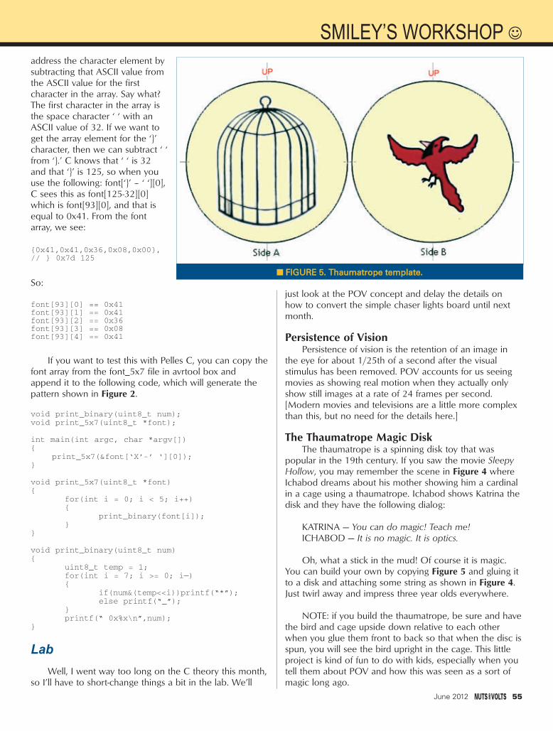
address the character element bysubtracting that ASCII value fromthe ASCII value for the firstcharacter in the array. Say what?The first character in the array isthe space character ‘ ‘ with anASCII value of 32. If we want toget the array element for the ‘’character, then we can subtract ‘ ‘from ‘.’ C knows that ‘ ‘ is 32and that ‘’ is 125, so when youuse the following: font[‘’ – ‘ ‘][0],C sees this as font[125-32][0]which is font[93][0], and that isequal to 0x41. From the fontarray, we see:
0x41,0x41,0x36,0x08,0x00,// 0x7d 125
So:
font[93][0] == 0x41font[93][1] == 0x41font[93][2] == 0x36font[93][3] == 0x08font[93][4] == 0x41
If you want to test this with Pelles C, you can copy thefont array from the font_5x7 file in avrtool box andappend it to the following code, which will generate thepattern shown in Figure 2.
void print_binary(uint8_t num);void print_5x7(uint8_t *font);
int main(int argc, char *argv[])
print_5x7(&font[‘X’-’ ‘][0]);
void print_5x7(uint8_t *font)
for(int i = 0; i < 5; i++)
print_binary(font[i]);
void print_binary(uint8_t num)
uint8_t temp = 1;for(int i = 7; i >= 0; i—)
if(num&(temp<<i))printf(“*”);else printf(“_”);
printf(“ 0x%x\n”,num);
LabWell, I went way too long on the C theory this month,
so I’ll have to short-change things a bit in the lab. We’ll
just look at the POV concept and delay the details onhow to convert the simple chaser lights board until nextmonth.
Persistence of VisionPersistence of vision is the retention of an image in
the eye for about 1/25th of a second after the visualstimulus has been removed. POV accounts for us seeingmovies as showing real motion when they actually onlyshow still images at a rate of 24 frames per second.[Modern movies and televisions are a little more complexthan this, but no need for the details here.]
The Thaumatrope Magic DiskThe thaumatrope is a spinning disk toy that was
popular in the 19th century. If you saw the movie SleepyHollow, you may remember the scene in Figure 4 whereIchabod dreams about his mother showing him a cardinalin a cage using a thaumatrope. Ichabod shows Katrina thedisk and they have the following dialog:
KATRINA — You can do magic! Teach me!ICHABOD — It is no magic. It is optics.
Oh, what a stick in the mud! Of course it is magic.You can build your own by copying Figure 5 and gluing itto a disk and attaching some string as shown in Figure 4.Just twirl away and impress three year olds everywhere.
NOTE: if you build the thaumatrope, be sure and havethe bird and cage upside down relative to each otherwhen you glue them front to back so that when the disc isspun, you will see the bird upright in the cage. This littleproject is kind of fun to do with kids, especially when youtell them about POV and how this was seen as a sort ofmagic long ago.
June 2012 55
SMILEY’S WORKSHOP
FFIIGGUURREE 55.. TThhaauummaattrrooppee tteemmppllaattee..
Smileys Workshop 47 - Jun 12.qxd 5/7/2012 2:33 PM Page 55

56 June 2012
NUTS & VOLTS Out of Thin Air!The simple chaser lights board (available from the NV
webstore) shown in Figure 7 has several POV messagesprogrammed into it that can be selected using the leftmostfive switch positions as follows:
Dipswitch Setting for POV Patterns:10111xxx (23): pov_smiley_micros11000xxx (24): pov_nutsvolts11001xxx (25): pov_help11010xxx (26): pov_stop11011xxx (27): pov_ I_love_you11100xxx (28): pov_ taxi
11101xxx (29): pov_right_arrows11110xxx (30): pov_left_arrows
When I attacked the problem of making an LEDPOV wand, it attacked back. At first, I built one of thosehand waving wands that you sweep back and forth todisplay a message, and I quickly found that this conceptdoesn’t work as well as I thought. First off, if you aredisplaying the message to others, then you are standingbehind the wand and have no way of knowing how themessage looks other than to stand in front of a mirror.Doing so lets you get an idea about how fast you need towave the wand and lets you change the waving so thatthe message starts at the beginning of a sweep andfinishes at the end of the sweep. Having a mirroravailable is a bit of a stupid requirement. So, I decidedthat instead of all the hand waving, I’d just attach thechaser lights to a board with a handle on it and swing it ina circle. The results shown in Figure 1 arewith me slinging with my right hand and trying to take apicture with my left. (It took a lot of pictures to get onethat had all the text in the frame.) The slinging techniquerequires less finesse in your timing, though you will wantto practice in front of a mirror to get an idea of how fastto swing it.
Then, there is that problem that you might get thetiming right, but the message will be showing at the
bottom of the swing andappearing upside down. Ibuilt the device shown inFigure 1 by cutting out atwo foot length ofStyrofoam, fastened thechaser lights board andbattery box to it with arubber band, and thenjammed a pencil in oneend for a handle to swingit with. No need to showit since it looks as bad asit sounds.
Okay, I get it now —the reason POV wandsaren’t more popular isthat they require you tobe in the dark, standing in
FFIIGGUURREE 77.. SSiimmppllee cchhaasseerr lliigghhttss bbooaarrdd..
www.nutsvolts.com/index.php?/magazine/article/june2012_SmileysWorkshop
FFIIGGUURREE 66.. TThhaauummaattrrooppee ssppiinnnniinngg..
Theory is all well and good, but to reallylearn this stuff you have to get your hands onsome tangible items that blink, whirr, andsometimes detonate. As a service for the readersof the Smiley’s Workshop articles, we havesimple and inexpensive projects kits availablethat can help you make it real. You can find thesekits (and some darn good books) at the Nuts &Volts Webstore.
Smileys Workshop 47 - Jun 12.qxd 5/7/2012 2:34 PM Page 56

front of a mirror to make them workright. (Some lessons can only belearned by building something andafter seeing it in action, realize that itwas a stupid idea.) Yeah, soundedgreat on paper, but the reality issomewhat less than great.Technically, you could mount thechaser lights board on a motor andset the timing like one of thosepropeller clocks, and it would workjust fine. You could also use anaccelerometer and have software thatsenses direction change and speed.Who knows, I might decide one daythat is a good project. So, let’sdeclare that this whole POV wandwas a great experiment and welearned a lot. Let’s just move on tothe next thing and hope not toembarrass ourselves again. NV
Questions? Nuts & Volts ishosting forums for its writersand you can find mine athhttttpp::////ffoorruumm..sseerrvvoommaaggaazziinnee..ccoomm/. If you want a reallyquick response — especiallyto a question not directlyrelated to an article — youcould put on your biohazardsuit and start a thread onwwwwww..aavvrrffrreeaakkss..nneett. Read myblog entry first that will tellyou why you need thebiohazard suit at hhttttpp::////ssmmiilleeyymmiiccrrooss..ccoomm//bblloogg//22001111//0011//2244//uussiinngg--aann--iinntteerrnneett--ffoorruumm/.
Nuts & Volts now carriesthe entire line of SmileyMicros books and kits. Someare shown in the magazineand others in their web shop.If you just can't wait and wantto get a leg up on real Cprogramming for the AVR(while helping support yourfavorite magazine andtechnical writer), then buy myC Programming book andButterfly projects kit, or if youare a complete novice try TheArduino Workshop andprojects kit.
June 2012 57
Smileys Workshop 47 - Jun 12.qxd 5/7/2012 2:34 PM Page 57

7540 Colbert Drive • Reno • Nevada 89511 1 (800) 759-7535 | www.PanaVise.com775757577554040404040 CCColololollbbebebebertrtrtrtr DDDDriririr vevevev •• RReReRReeennnnnonoonon ••• NNNNeveveevvvvaddadadadadaaaa 88989898989515151
Innovative Holding SolutionsVISIT US ONN
MONTHLY CONTESTVisit us on Facebook® to post a photo of your creative PanaVise project for a chance to win a PanaVise prize package.
TESTTEST
Our line of Circuit Board Holders add versatility & precision to your DIY electronics project. Solder, assemble & organize with ease.
World's Most Versatile VVeerrssaattiilllee t ld ss MMoosst
C i rc u i t Board HOLDERS
Model 201
Model 324
58 June 2012
Page 58 Jun12.qxd 5/9/2012 12:54 PM Page 58

#"# !%+74*-)5+&!!$" !)//%4.6+24)8'# !"
$%#$#+#%(( K::%@23@A/<36/@532B=,7A/#/AB3@1/@2;3@71/<F>@3AA=@7A1=D3@K6319A/<2#=<3G%@23@A113>B320G#/7:K%@23@A3:7D3@327<B63)B/B3=4/:74=@<7/;CAB7<1:C23/:74=@<7/)B/B3)/:3A*/FK$%L%K)67>>7<5/<2/<2:7<54=@B63=<B7<3<B/:+<7B32)B/B3A""%*()7<1:C27<5:/A9//E/77&(/<2/</2/#CAB&/GC::)67>>7<5K'C/<B7B73A"7;7B32K&@713A)C0831BB=16/<53E7B6=CB<=B713
!" !
%: !#"& :
% 9 )//*243)//*243*20
-23 888'//*/*(6421.(5(20 "
#"')465!"!-.33.1,
!#"4.*.1,$!%24+24'3',*('6'/2,
765.)*6-*" 5*1)3256',*
!
3/16
;;E7@3:3/2A!
+24 J *'(-
("
" &@GAB/:4=<BH .. *F 16/@/1B3@".3::=E@33<"/19:756B)*$&=A7B7D3*@/<A4:31B7D307B=@07B>/@/::3:7<B3@4/13<2CAB@GAB/<2/@21=;>/B70:31=<B@=::3@ II#=2C:3A7H3F F;;,73E7<5/@3/F;;6/@/1B3@A7H3 F;;(=)=;>:7/<B!
3/16+24 *'(-
$
"%!" &
&=E3@:31B@717AB@70CB7=< (3D,2153/@;=B=@$=:=/2@/B7<5(&#,21;-=@9AE3::2=E<B=,21 (&#;;"F ;;;;27/;3B3@F;;4:/BB32A6/4B ;;:3/2AE7B6 >7<43;/:31=<<31B=@!
$ "
3/16+24 *'(-
=@0/19:756B7<527A>:/GA1=<B@=:>/<3:A/<2;=23::756B7<5:3F70:3>@=2C13A>@/1B71/::G<=63/B%>3@/B3A=< ,/17<D3@B3@=@AB/<2/@26=CA33:31B@717BG)/:;=<1=:=@7<=44AB/B3:=EAE67B3E63<3<3@57H32)=:23@/0:3>7<A!:
3/16+24*'(-
% ! "7B3%<"*"*<#@32:/A3@27=23 ,=>3@/B7=<;;27/;3B3@1/A3E7B6:3<A;;27/;3B3@5=:2>:/B3263/BA7<90/A3=:2>:/B32:3/2A! 3/16
%$! )3/:32B=E7B6AB/<26/7:A<=E/<2E7<2#C:B71@GAB/::7<3A7:71=<A=:/@13::A7</63/DG2CBG/<=27H32/:C;7<C;4@/;3756B@/<A>/@3<1G:=E7@=<B3;>3@325:/AAFF;; C<1B7=<0=FE7B6A1@3E=@A=:23@B3@;7</:A)>31A#/F&=E3@-%>3<7@1C7B,=:B/53 ,%>3@/B7<5,=:B/53,%>3@/B7<5C@@3<B)6=@B7@1C7BC@@3<B !:
3/16
#" %" !!""" #/B7<5E3/B63@@3A7AB/<B>=:/@7H321=<<31B=@A @32/<20:/195/C53AB@/<232E7@3:3/2A!:
3/16+24 *'(-
$" '
3:B/- F F ;; ,210@CA6:3AA1==:7<54/<*6@33 :3/2A+"),! 3/16
)9G)$!& ,%6;1=7:&*1=<B/1BA:3/@>=:G1/@0=</B32CAB1=D3@ F F;;67563F1:C27<5B3@;7</:A#7<7/BC@3>7<0/A3)=:23@?1=@A=193B;=C<B+"!&
$!%"% !#'&676=<5#=23:&)+ <>CB ,H %CB>CB ,*/0:3B=>;=23:F F=CB>CB1=@2BE=43@@7B303/2#AC>>@3AA=@A>7<;7<7$1=<<31B=@3B/16/0:35@=C<232>=E3@1=@21+"CA*+,!
3/16+24*'(-
+24*'(- 3/16 "" ')/<G=3<3:==> ,;6@316/@53/0:30/BB3@G*6393G/2D/<B/53=4B633<3:==>1=;>/@32B=1=<D3<B7=</:@316/@53/0:30/BB3@73A7A7BA3FB@3;3:G:=EA3:427A16/@53)>317/:>C@16/A3!
3/16+24 *'(-
( )3/E7A3<2CAB@7/:"B2#=23:)-<>CB ,/1%CB>CB!,H*63;/7<1=;>=<3<B7</6=CA36=:27=<7H/B7=<C<7B FFB6719+"@31=5<7H32! $ 3/16$9&9! @756BAB@=03/AA3;0:GE7B66=@A3A6=34:/A6BC03>>@=F7;/B3:G4:/A63A>3@;7<CB3 ,21=>3@/B7=<F;;!
3/16
June 2012 59
Full Page_Full Page.qxd 5/7/2012 5:11 PM Page 59

60 June 2012
THE GENERATIONSThe first generation cell phones that showed up in the
late 1980s were simple phones using analog frequencymodulation (FM). They were not much more than two-wayradios or walkie-talkies. They worked well, and were sopopular that the available radio spectrum was
overwhelmed by too many subscribers. The cellularcompanies wanted the extra income from moresubscribers, but were up against the spectrum shortage.Very quickly, a second generation (2G) cell phone systemwas invented. This 2G technology used digital voice andother digital methods to add more subscribers to theexisting spectrum. Figure 1 shows a snapshot view of the
evolution of these generations.There were actually
several 2G technologiesdeveloped. Three of themused time division multipleaccess (TDMA) to letthree to eight moresubscribers use a givenchannel. Another onedesignated IS-95A used whatwe call code division multipleaccess (CDMA) to put up to64 subscribers into a larger1.25 MHz channel. Onlyone of the TDMA systems(GSM) survived and is stillused today. GSM is short forGlobal System for Mobilecommunications, which was
You probably have a cell phone, and chances are it is a smartphone. Thatmeans it uses either 3G or 4G technology. But what the devil does that reallymean? And do you really care? Furthermore, does it really matter? We uselots of different technologies every day and don’t really understand them.Nevertheless, those of you who are interested in communications technologymay wish to have a better understanding of what those designations mean.Here is a crash course in cellular wireless.
WHAT IS 4G WIRELESS?3G/4G ... Does it really matter?
OPEN BY LOUIS E. FRENZEL W5LEF
COMMUNICATIONTHE LATEST IN NETWORKING AND WIRELESS TECHNOLOGIES
FIGURE 1. A summary of thecell phone generations with themany standards and variations.Also shown on the right are thegenerations of Wi-Fi local areanetwork standards.Courtesy of Agilent Technologies.
OpenComm - Jun 12_OpenComm - Jun 12.qxd 5/9/2012 4:30 PM Page 60

developed in Europe and originally called GroupeSpécial Mobile. It puts eight users in a 270 kHz widechannel. CDMA assigns each user a special digital codewhich can be used to distinguish it from all other userssharing the same channel. Both are still used todayworldwide. You still use one or the other for voice inyour current phone.
During the second generation, the idea of transmittingdata was implemented. Texting and email becamepossible by cell phone. These new technologies wereoften referred to as 2.5G. The GSM phones implementedsomething called General Packet Radio Service (GPRS),and later a faster version called Enhanced Data rates forGSM Evolution (EDGE). CDMA phones implemented1xRTT (Radio Transmission Technology). Both were veryslow but did get the data capability into phones withminimum expense.
The third generation (3G) phones came along inthe late 1990s. Again, multiple standards weredeveloped. The Third Generation Partnership Project(3GPP) and the International Telecommunications Union(ITU) created a wideband CDMA (WCDMA) systemusing 5 MHz channels called Universal MobileTelecommunications System (UMTS). Qualcomm — thedevelopers of CDMA — created cdma2000. Both offereddata rates to 2 Mb/s, although that rate was rarelyachieved in practice.
With texting and mobile email becoming a must andas more users demanded mobile Internet access, 3Gbecame popular. The 3G technology was for data only, asvoice was still by 2G methods. Various upgrades and newstandards emerged forming 3.5G technologies making 3Gdata faster and more reliable. The WCDMA technologyadded high speed packet access (HSPA) and cdma2000added Evolution-Data-Only (EV-DO).
Today, we are still basically in the 3G world. Mostcellular systems are 3G. Most smartphones use 3G. Thefourth generation (4G) is still in development, althoughthere is some 4G deployment. The big question is, justwhat is 4G? It appears to have several definitionsdepending on who you talk to or what cellular carrieryou use.
WHAT IS 4G?The term 4G has multiple meanings. To the 3GPP and
the ITU, it is not here yet and is still in a developmentstage. Others say that 4G is something called Long TermEvolution (LTE). LTE is indeed a 3GPP and ITU standardbut they still call it 3G. Their definition of 4G is LTEAdvanced — an even more improved version of LTE. Yet,the cellular carriers don’t agree.
Some carriers generally mean that LTE is 4G, but notall. AT&T and Verizon call LTE 4G. Sprint implementedanother technology called WiMAX that they call 4G.However, Sprint plans to change over to LTE in the nearfuture. T-Mobile doesn’t have LTE yet. In the meantime,they call their advanced HSPA network 4G. The general
consensus is that LTE is the real 4G. LTE was originally developed to be the follow-on to
the GSM, UMTS, and HSPA technologies. However, thoseoffering cdma2000 are also following the LTE path. LTEuses a completely different radio technology calledorthogonal frequency division multiplexing (OFDM). It is adata-only technology designed for very high speedwireless access. What OFDM does is take a high speedserial data signal and divide it into many slower speedsignals, then transmits them simultaneously over manydifferent carriers in different channels. LTE takes itsbandwidth (that can be 1.4, 3, 5, 10, or 20 MHz wide)and divides it up into many 15 kHz channels. Twelve ofthese carriers are bundled into 180 kHz wide resourceblocks, forming a fundamental data unit. Each of the 15kHz channels is then modulated with the subdivided data.Standard modulation types include QPSK, 16QAM, and64QAM, depending on the desired data speed that canbe achieved.
LTE also features something called MIMO for multipleinput multiple output. MIMO uses multiple transmitters,receivers, and antennas to further boost the data rate andprovide improved signal reliability. The high speed data isagain divided up into multiple signals and each is sent to aseparate transmitter and antenna. Then, the multiplesignals are received by multiple antennas and receiversresulting in higher speeds. For example, a 2 x 2 MIMOsystem uses two transmitters and antennas, and tworeceive antennas and receivers. Various otherconfigurations are possible, like 2 x 1, 4 x 2, and 4 x 4.
Using 64QAM modulation and 4 x 4 MIMO, amaximum downlink data speed of 100 Mb/s andmaximum upload speed of 50 Mb/s is possible. Maximumconfigurations are not typical. Today, most MIMO systemsare 2 x 1. It is not easy to put two receivers in each cellphone, however, it is possible to put two or four antennasat the cell tower. Generally today, the typical LTE cellphone can get 15 to 20 Mb/s or so downloads, which isgenerally faster than most home high speed Internetservices.
Not all the cellular carriers have LTE yet. Verizon wasthe first and has the most LTE towers. They currently serve38 cities. AT&T has LTE but has fewer towers, serving 31cities. Both carriers are continually adding more LTEtowers. Sprint will begin LTE later this year in a gradualtransition from WiMAX. T-Mobile will eventually get LTEbut in the meantime, have upgraded most of their systemsto HSPA+ — a super 3G service that delivers speedscomparable to LTE (and even better in some cases). WhatT-Mobile’s cute girl in the magenta dress is telling you isthat they offer 4G “speeds.”
While most people want the latest technology, theydon’t necessarily care what it is or how it works, just aslong as the service and cell phone does what they want.Today, that includes not only texting and email, but alsovideo, games, and fast Internet access. Most smartphonesare still 3G and do a decent job of video and games. Plus,it’s available in almost all US cities and worldwide. LTE is
June 2012 61
Discuss this article in the Nuts & Volts forums at http://forum.nutsvolts.com. O P E N C O M M U N I C A T I O N
OpenComm - Jun 12.qxd 5/7/2012 10:11 AM Page 61

still in its rollout stage. That is expected to continue in thecoming years as carriers find the capital to build more LTEcell sites.
One nagging problem for most carriers is the shortageof radio spectrum. They are using what they have and aretrying to acquire more, but it is in short supply and veryexpensive. LTE uses very wide bandwidth channels, so itneeds more spectrum than 3G. It will take time for theFCC to find more spectrum and auction it off to solve thisproblem.
WHAT TECHNOLOGY DO YOU HAVE?
The cellular technology you usedepends on what carrier you use. Ifyou have AT&T or T-Mobile service,you are using GSM, WCDMA, HSPA,and in the case of AT&T, LTE isavailable in some places.
If you get your service fromSprint, Verizon, or MetroPCS, youhave the cdma2000 technology.Verizon has some LTE and Sprint hastheir WiMAX 4G service.
Incidentally, even if you do haveHSPA, EV-DO, or LTE, the voice service
is still 2G GSM or cdma. Ultimately, LTE is expected tocarry voice but not soon, until the technology is worked outand the service is more widespread.
If you have a smartphone, you probably have 3Gservice. All Apple iPhones are 3G with most using HSPA+,including the latest 4S model. Apple has its own operatingsystem called iOS. Other smartphones from Motorola,Samsung, HTC, LG, and others either have HSPA or someversion of EV-DO. These phones use Google’s Androidoperating system. Android smartphones predominate in
www.nutsvolts.com/index.php?/magazine/article/june2012_OpenCommunication
62 June 2012
FIGURE 3. Apple's third iterationof its popular iPad has an improveddisplay and is available with LTE 4Gservice from Verizon or AT&T.
FIGURE 2. The Lumina 900 isNokia's attempt to get into thesmartphone market. It is a majorcontender thanks to the use ofMicrosoft's Windows Mobile 7.5operating system with its unique tile touch user interface. It is an LTE4G phone.
OpenComm - Jun 12.qxd 5/7/2012 10:11 AM Page 62

numbers, with Apple iPhone next. Research in Motion(RIM) used to be the dominant smartphone vendor withtheir BlackBerry line but lost the lead to Apple andAndroid (although they are still a major vendor playingcatch-up). They have their own OS.
One of the newest and most interesting smartphonesis Nokia’s Lumina 900 (Figure 2). Nokia is still the worldleader in total cell phone volume, just not smartphones.They are trying to make a comeback with the help ofMicrosoft. Using the latest version of Microsoft’s WindowsMobile operating system, they are offering a unique look.Instead of the usual icons on the screen, the Nokiasmartphones with Mobile Windowsdivide the screen into many tiles,each representing one of the manythings that the phone can do. Thebrowser is Internet Explorer and thesearch engine is Bing.
The Lumina 900 is an LTE phone.It is available in the US from AT&T,but it may soon be available fromothers. Like all smartphones, it hastwo cameras: one eight megapixel,and the other one megapixel. Thephone includes Wi-Fi 802.11n forconnections to hot spots and otheraccess points, and it has a Bluetoothconnection for headsets. It also playsaudio and video. The screen measures4.3 inches diagonal using AMOLEDtouch technology. The resolution is800 x 480 pixels. The Qualcommprocessor runs at 1.4 GHz.
OTHER 4G PRODUCTSIf you need cellular coverage on
your laptop, you can get a 3G or 4GUSB dongle from most carriers. It is ablessing to have this when you justcannot find a hot spot to connect viaWi-Fi. LTE USB dongles are also nowavailable. Another product gettingLTE is Apple’s latest iPad version (seeFigure 3). All iPads include Wi-Fi butLTE is an option. No other tabletshave LTE yet, but look for that tochange in the near future.
BOTTOM LINEDo you really need 4G? Most of
us do not; 3G works perfectly wellfor most. Now you know how thetechnology works. Ultimately, 3G willbe replaced by 4G LTE, but not for awhile. That is why most phones aremultimode, meaning that if you have
LTE but there are no LTE towers nearby, you fall back to3G with either HSPA or plain old WCDMA, or GSM forvoice only. It’s the same with other phones. If LTE is notavailable, you fall back to 3G cdma2000.
LTE Advanced will become available at some pointwith even faster data rates and other features, and thewhole process will continue as the carriers have toupgrade their networks again. It will also take time for thehandset vendors to come up with LTE-A phones. By thetime that happens, the next standards will be indevelopment so you can probably look forward to 5Gphones within the next decade. NV
June 2012 63
O P E N C O M M U N I C A T I O N
OpenComm - Jun 12.qxd 5/7/2012 10:12 AM Page 63

The Nuts & Volts WEBSTORE
GREAT FOR DIYers!
For comple te pr oduct de t ai ls , v is i t our webs tore!!
HHTTMMLL:: AA BBeeggiinnnneerr''ss GGuuiiddeeby Wendy Willard
Create highly functional, impressive websites inno time. Fully updated and revised, HTML:ABeginner's Guide, FourthEdition explains how tostructure a page, placeimages, format text,create links, add color,work with multimedia,and use forms.You'll alsogo beyond the basics andlearn how to save yourown web graphics, useCascading Style Sheets(CSS), create dynamicweb content with basic JavaScript, and uploadyour site to the web. By the end of the book,you'll be able to build custom websites usingthe latest HTML techniques.$$2299..9955
PPrrooggrraammmmiinngg PPIICCss iinn BBaassiiccby Chuck Hellebuyck
If you wanted to learnhow to program microcontrollers, thenyou've found the rightbook! Microchip PICmicrocontrollers arebeing designed into electronics throughoutthe world and none ismore popular than the eight-pin version. Nowthe home hobbyist can create projects with these little microcontrollers using a low cost development tool called the CHIPAXE system and the Basic softwarelanguage.Chuck Hellebuyck introduceshow to use this development setup tobuild useful projects with an eight-pinPIC12F683 microcontroller. $$1144..9955
BBeeggiinnnneerr''ss GGuuiiddee ttoo ......PPrrooggrraammmmiinngg tthhee PPIICC2244//ddssPPIICC3333
by Thomas KibaloKibalo takes youstep by stepthrough the fundamentals of programming thePIC24H which canequally be appliedto the dsPIC33.His clear explanation of theinner workingsmake learning thePIC24H/dsPIC3316-bit architecture easy. His code examplesdemonstrate how to perform the functionsmost applications require.The hardware isshown in a simple breadboard setup soeven a beginner can build it, along withvery few extra components needed.$$3399..9955**
SStteeaammppuunnkk GGeeaarr,, GGaaddggeettss,, aanndd GGiizzmmooss
by Thomas WillefordA Maker's Guide
to CreatingModern Artifacts
Welcome to thewondrous world ofThomas Willeford(a.k.a., LordArchibald "Feathers"Featherstone) inwhich he shares hisclosely guardedsecrets of Steampunkery. Filled with do-it-yourself projects, Steampunk Gear,Gadgets, and Gizmos: A Maker's Guide toCreating Modern Artifacts shows you how tobuild exquisite, ingenious contraptions on abudget.$$2244..9955
PPrrooggrraammmmiinngg AArrdduuiinnoo GGeettttiinngg SSttaarrtteedd wwiitthh SSkkeettcchheess
by Simon MonkProgram Arduinowith ease! Using clear,easy-to-follow examples, ProgrammingArduino: Getting Startedwith Sketches revealsthe software side ofArduino and explainshow to write well-crafted sketchesusing the modified Clanguage of Arduino.No prior program-ming experience is required! The down-loadable sample programs featured in thebook can be used as-is or modified to suityour purposes.$$1144..9955
EElleeccttrroonniiccss AAnn IInnttrroodduuccttiioonnby Jim Stewart
This book isdesigned as an in-depth introductionto important concepts in electronics.Whileelectronics can behighly mathematical,this text is notabout calculations.It is about howelectronic equipment is able to extract, process, and present information held in electrical signals. If you are in — or studying to be in— a profession that requires the use ofelectronic equipment, then this book willprovide the insight necessary to use suchequipment effectively.$33.95*
HHooww ttoo DDiiaaggnnoossee aanndd FFiixxEEvveerryytthhiinngg EElleeccttrroonniiccby Michael Jay Geier
Master the Art of Electronics Repair!In this hands-onguide, a lifelong electronics repairguru shares his testedtechniques andinvaluable insights.How to Diagnose andFix EverythingElectronic shows youhow to repair andextend the life of allkinds of solid-statedevices, from moderndigital gadgetry to cherished analog productsof yesteryear. About the Author: MichaelJay Geier began operating a neighborhoodelectronics repair service at age eight thatwas profiled in The Miami News.$$2244..9955
MMaasstteerr aanndd CCoommmmaanndd CC ffoorr PPIICC MMCCUUss
by Fred Eady Master and Command Cfor PIC MCU,Volume 1aims to help readersget the most out ofthe Custom ComputerServices C compilerfor PIC microcontrollers.The author describes some basic compileroperations that will help programmers par-ticularly those new to the craft create solidcode that lends itself to easy debugging andtesting.As Eady notes in his preface, a sin-gle built-in CCS compiler call (output_bit)can serve as a basic aid to let programmersknow about the "health" of their PIC code.$$1144..9955
BBuuiilldd YYoouurr OOwwnn EElleeccttrroonniiccss WWoorrkksshhoopp by Thomas Petruzzellis
BUILD YOUR OWN DREAM
ELECTRONICS LAB!This value-packedresource provideseverything needed toput together a fullyfunctioning home electronics workshop!From finding space tostocking it with components to putting the shop into action — building, testing, and troubleshooting systems.This great bookhas it all! And the best part is, it shows youhow to build many pieces of equipmentyourself and save money, big time! RReegg PPrriiccee $$2299..9955 SSaallee PPrriiccee $$2266..9955
64 June 2012
NV Webstore June 2012 working.qxd 5/9/2012 11:55 AM Page 64

CD-ROM SPECIALBOOK & KIT COMBOS
Or CALL 1-800-783-4624 today!Order online @ www.store.nutsvolts.com
June 2012 65
NV Webstore June 2012 working.qxd 5/9/2012 11:56 AM Page 65

Order online @ www.nutsvolts.comCALL 1-800-783-4624 today!
PROJECTSBBaatttteerryy MMaarrvveell KKiittSSeeiissmmooggrraapphh KKiitt 33DD LLEEDD CCuubbee KKiitt
TTrraannssiissttoorr CClloocckk KKiitt
The 32-Bit Micro Experimenter isthe fastest way tolearn 32-bitmicrocontrollers.
The kit includes onboard 46 programmable I/O and USB, free software,
carefully documented step-by-step experiments for USB, embedded web
server, graphics and audio, wireless, RTOS,and file I/O. User pushbuttons, LEDs, and 32kHz clock crystal. Can be used in solderless
breadboard environment or stand-alone.
Subscriber’s Price $$8899..9955Non-Subscriber’s Price $$9933..9955
As seen in the November2011 issue.Battery Marvelhelps protectcars, trucks,motorcycles,boats, and anyother 12V vehicles from sudden battery failure. Thiseasy-to-build kit features a single LED thatglows green, yellow, or red, indicating battery health at a glance. An extra-loudpiezo driver alerts you to any problems.
For more info,please visit our website.Subscriber’s Price $$1188..9955
Non-Subscriber’s Price $$1199..9955
As seen in the May 2012
issue.Now you canrecord your
own shaking, rattling,
and rolling.The Poor Man's Seismograph is a greatproject /device to record any movement inan area where you normally shouldn't haveany.The kit includes everything needed tobuild the seismograph.All you need is yourPC, SD card, and to download the freesoftware to view the seismic event graph.
Subscriber’s Price $$7799..9955Non-Subscriber’s Price $$8844..9955
SSoorrttiinngg CCoouunntteerr KKiitt 3322--BBiitt MMiiccrroo EExxppeerriimmeenntteerr BBooaarrdd
Sorting counters have many uses — keepingscore, counting parts, counting people — itis just a handy gadget to have around.Thisis a very simple project for those who wantto learn to solder or are interested in usingmicroprocessors and how they function.No special tools are needed, just a small tipsoldering iron. It has no box as it standsalone, therefore there is no drilling.
Subscriber’s Price $$3333..9955Non-Subscriber’s Price $$3399..9955
If you like electronic puzzles, then this kitis for you! There are no integrated
circuits; all functionality is achieved using discrete transistor-diode logic.The PCB is
10”x11” and harbors more than 1,250components! For more info, see the
November 2009 issue.RReegg $$222255..9955
SSaallee PPrriiccee $$119999..9955PCBs can be bought separately.
This kit shows you how to build a reallycool 3D cube with a 4 x 4 x 4 monochromatic LED matrix which has atotal of 64 LEDs. The preprogrammedmicrocontroller that includes 29 patternsthat will automatically play with a runtimeof approximately 6-1/2 minutes.Colors available: Green, Red,Yellow & Blue
Subscriber’s Price $$5577..9955Non-Subscriber’s Price $$5599..9955
As seen in theJuly 2011 issue.
66 June 2012
FOR BEGINNER GEEKS!
The labs in this series — from GSS Tech Ed — show simple and interesting experiments and lessons, all done on a solderless circuit board.
As you do each experiment, you learn how basic components work in a circuit, and continue to build your arsenal
of knowledge with each successive experiment.
For more info and a promotional video, please visit our webstore.
$$5599..9955 $$4499..9955 $$3399..9955
NeNeww
LoLowerwer
PrPr ice!ice!
NV Webstore June 2012 working.qxd 5/9/2012 12:53 PM Page 66

WWW.POLOLU.COM
www.dlpdesign.com
Add USB to your next project--It's easier than you might think!USB
USB-FIFO USB-UART USB/Microcontroller BoardsDesign/Manufacturing Services AvailableRFID Readers
Absolutely NO driver software development required!
AM/FM Broadcasters • Hobby KitsLearnng Kits Test Equipment...AND LOTS OF NEAT STUFF!
GET THE DISCOUNT!Mention or enter coupon code NVRMZ12
and receive 10% off your order!
ELECTRONET
For the ElectroNet online, go to
www.nutsvolts.comclick Electro-Net Electronic Parts & Supplies
Since 1967
Chip Adapters
www.EZPrototypes.com 10% Off Adapters with Coupon Code: NVEZ101210% Off Adapters with Coupon Code: NVEZ101210% Off Adapters with Coupon Code: NVEZ1012
June 2012 67
w w w . A t r i a T e c h n o l o g i e s . c o m ATRIA Technologies Inc
Microcontroller Boards GREAT for Breadboards, Home Projects, Experi-ments, Test Fixtures, Prototypes, Labs and more. Microcontrollers, Communications, Display, Power.
BASIC ON BOARD Eliminates development tools
w w w
Microcontroller B
o m c.c h n o l o g i e s a T eir t A.
soardMicrocontroller B
Electronet Jun12_Electronet Jun12.qxd 5/9/2012 8:49 AM Page 67
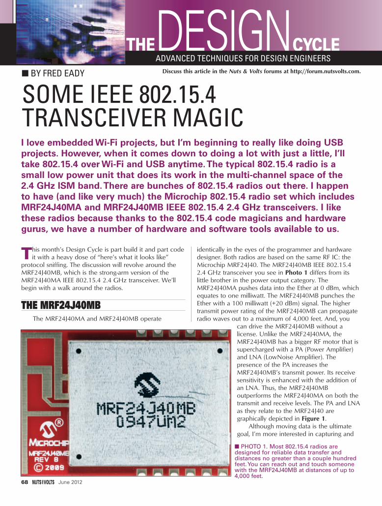
68 June 2012
This month’s Design Cycle is part build it and part codeit with a heavy dose of “here’s what it looks like”
protocol sniffing. The discussion will revolve around theMRF24J40MB, which is the strong-arm version of theMRF24J40MA IEEE 802.15.4 2.4 GHz transceiver. We’llbegin with a walk around the radios.
THE MRF24J40MBThe MRF24J40MA and MRF24J40MB operate
identically in the eyes of the programmer and hardwaredesigner. Both radios are based on the same RF IC: theMicrochip MRF24J40. The MRF24J40MB IEEE 802.15.42.4 GHz transceiver you see in Photo 1 differs from itslittle brother in the power output category. TheMRF24J40MA pushes data into the Ether at 0 dBm, whichequates to one milliwatt. The MRF24J40MB punches theEther with a 100 milliwatt (+20 dBm) signal. The highertransmit power rating of the MRF24J40MB can propagateradio waves out to a maximum of 4,000 feet. And, you
can drive the MRF24J40MB without alicense. Unlike the MRF24J40MA, theMRF24J40MB has a bigger RF motor that issupercharged with a PA (Power Amplifier)and LNA (LowNoise Amplifier). Thepresence of the PA increases theMRF24J40MB’s transmit power. Its receivesensitivity is enhanced with the addition ofan LNA. Thus, the MRF24J40MBoutperforms the MRF24J40MA on both thetransmit and receive levels. The PA and LNAas they relate to the MRF24J40 aregraphically depicted in Figure 1.
Although moving data is the ultimategoal, I’m more interested in capturing and
DESIGN BY FRED EADY
CYCLETHEADVANCED TECHNIQUES FOR DESIGN ENGINEERS
SOME IEEE 802.15.4 TRANSCEIVER MAGICI love embedded Wi-Fi projects, but I’m beginning to really like doing USBprojects. However, when it comes down to doing a lot with just a little, I’lltake 802.15.4 over Wi-Fi and USB anytime.The typical 802.15.4 radio is asmall low power unit that does its work in the multi-channel space of the 2.4 GHz ISM band.There are bunches of 802.15.4 radios out there. I happen to have (and like very much) the Microchip 802.15.4 radio set which includesMRF24J40MA and MRF24J40MB IEEE 802.15.4 2.4 GHz transceivers. I likethese radios because thanks to the 802.15.4 code magicians and hardwaregurus, we have a number of hardware and software tools available to us.
Discuss this article in the Nuts & Volts forums at http://forum.nutsvolts.com.
PHOTO 1. Most 802.15.4 radios aredesigned for reliable data transfer anddistances no greater than a couple hundredfeet. You can reach out and touch someonewith the MRF24J40MB at distances of up to4,000 feet.
Design Cycle - Jun 12.qxd 5/7/2012 3:17 PM Page 68

analyzing the packets that carry the data. As for mykindred bit detectives out there, that’s all well and goodfor us. However, on the other hand, it is important for allof us to understand how the MRF24J40MB interface ismanipulated to allow transmission and reception of thosebits within the data packets.
Keep your eye on Figure 2 as we shuffle around theMRF24J40MB package. The MRF24J40MB active-lowRESET pin is aptly named as it functions as a radio resetinput. Any 802.15.4 radio worth its salt can hibernate likea fat bear in winter. The WAKE input drags a sleepyMRF24J40MB out of hibernation. The MRF24J40MB is aworld class 802.15.4 radio module that can be put tosleep to conserve power.
Today’s typical microcontroller is fast enough toforego interrupts and poll external communicationsresources like the MRF24J40MB. However, those fast PICsare designed that way to allow them to get more work outof those quick CPU cycles. It is advantageous for amicrocontroller to use its compute power as muchas possible, and only be drawn off its mainprocessing activity to service a device whenrequired to do so. That’s where the MRF24J40MB’sINT (interrupt) output pin shines. The INT pin is anoutput that can be tied to one of the PIC’s externalinterrupt inputs. When the MRF24J40MB needs toperform data I/O or do something the hostmicrocontroller needs to know about, theMRF24J40MB activates its INT pin. The activation ofthe INT output forces the host microcontroller torun an interrupt handler routine to service the INT-initiated request.
The MRF24J40MB’s four-wire SPI portal iscomprised of the SDO, SDI, SCK, and CS I/O pins.If you’re old school, that’s MOSI (Master Out SlaveIn), MISO (Master In Slave Out), Master Clock, andChip Select, respectively. There is only one correct
way to interface a Master SPI portal to the MRF24J40MBslave portal signals. If you build your application andhardware using one of the wireless protocol examplesincluded in the MAL (Microchip Application Libraries), theSPI portal, INT, and I/O connections shown in Figure 3are already defined for you.
SOME BASIC 802.15.4 HARDWAREIt doesn’t take much hardware to send and receive
802.15.4 packets. All we need is an SPI-enabled PIC and an MRF24J40MB. The bulk of the circuitry you see in Schematic 1 is mounted on an EDTP Electronics,
June 2012 69
D E S I G N C Y C L Ewww.nutsvolts.com/index.php?/magazine/article/june2012_DesignCycle
FIGURE 1. The MRF24J40MB is simply an MRF24J40MAwith a PA and LNA between the MRF24J40 802.15.4
IC and antenna.
FIGURE 2. The pinouts of the MRF24J40MA andMRF24J40MB are identical. The MRF24J40MB
comes in a larger and wider package.
Design Cycle - Jun 12.qxd 5/7/2012 3:17 PM Page 69

Inc., carrier board specifically designed for thePIC18F46Jxx/PIC18F47Jxx microcontroller families.Everything except the MRF24J40MB is mounted on thisspecially-designed printed circuit board (PCB) you see inPhoto 2.
One of the best debugging tools is a serial port. So, I configured the PIC18F46J50 to supply a 19200 baudserial stream via I/O pin RC6. The associated serial receive
pin is placed on I/O pin RD2. Normally, the serialport I/O pins are assigned to RC6 and RC7.Some of the PIC18F46J50’s I/O pins that doubleas peripheral pins allow differing peripherals tobe assigned to them. The Microchip term for thisresource assignment process is Peripheral PinSelect (PPS). In this case, I assigned thePIC18F46J50’s second EUSART to the RC6/RD2I/O pin pair. Here’s how I assigned the EUSARTI/O pins:
EECON2 = 0x55;EECON2 = 0xAA;PPSCONbits.IOLOCK = 0; //unlock PPSRPINR16 = 19; //RX2 to RP19RPOR17 = 5; //TX2 to RP17EECON2 = 0x55;EECON2 = 0xAA;PPSCONbits.IOLOCK = 1; //lock Peripheral
//Pin Select
70 June 2012
FIGURE 3. This configuration works for everyPIC. The pin numbers of the SPI portal, INT, and I/O pins are dependent on the particularmicrocontroller. Regardless of the pin locations,the SPI interface shown here operates identicallyon each PIC.
SCHEMATIC 1. It may be a bare-bonesdesign, but it's more than enough to form
half of an 802.15.4 two-node network.
Design Cycle - Jun 12.qxd 5/7/2012 3:18 PM Page 70

All of the PPS peripheral functionscan be found in the Peripheral Pin Selectsection of the PIC18F46J50 datasheet.Instead of lashing up a discrete RS-232portal, I turned to Digilent. The DigilentPmodUSBUART can be seen in Photo 3.Using a six-pin inline Berg socket, I tiedthe PmodUSBUART’s pin 2 to thePIC18F46J50’s RP17 and thePmodUSBUART’s pin 3 to RP19. TheUSB serial port was completed by tyingthe PmodUSBUART’s GND pin to theGND pin on the PIC18F46J50 carrierPCB.
Now that we have a superiordebugging port, the next step is toelectrically install the MRF24J40MB.Check back with Schematic 1 and you’llfind that the SPI portal used by the MRF24J40MB is nativeto the PIC18F46J50. So, no PPS code is needed. However,we do need to invoke some PPS magic for theMRF24J40MB’s INT pin. This won’t take long:
RPINR1 = 4; // INT1 to RB1
The rest of the MRF24J40MB I/O pins that don’trequire PPS code are assigned and connected perSchematic 1. Let’s not get too excited about thePIC18F46J50’s USB capability just yet. We want to get theradio working first.
MICROCHIP 802.15.4 DEVELOPMENT TOOLS
If you’ve ever worked with Microchip’s applicationlibraries, you’ve probably done someconfiguration coding by way of aspecialized include file. This is commonpractice in the various stacks thatMicrochip offers. It is a very efficientway to add and delete firmwarefeatures of the stack you’re workingwith.
We are going to employ a variantof Microchip’s proprietary MiWi stackwhich is based on the 802.15.4protocol. Instead of a meshingnetwork, we’ll deploy a peer-to-peer —
or P2P — network. Our starting point will be theconfiguration area of the Microchip WirelessDevelopment Studio. The network configuration processbegins in Screenshot 1. As you can see, we’ve elected toconfigure a MiWi P2P network using an MRF24J40-basedradio. The radio setting will work with both theMRF24J40MA and MRF24J40MB.
Every check box you see in Screenshot 2 represents a#define statement in the MiWi P2P ConfigApp.h file. Sincewe’re configuring a P2P network, there are nocoordinators. End devices are considered RFD (ReducedFunction Devices) in a MiWi mesh network. There are noRFD devices in our P2P network topology.
Each P2P node must have a unique 64-bit identifierwhich is referred to as an EUI-64 (Extended UniqueIdentifier) node address. The EUI is the MAC — orhardware — address in the 802.15.4 world. The EUI-64node address is built on an EUI-48. The most significant
D E S I G N C Y C L E
June 2012 71
PHOTO 3. This little Pmod has savedme tons of time. All you have to do to
use it is hook up the TXD, RXD, and GNDpins. The PmodUSBUART gets its power
from the USB host portal.
PHOTO 2. This is one handy tool! Any44-pin TQFP PIC with the same MCLR,
power pin, and crystal layout can bemounted on this board.
Design Cycle - Jun 12.qxd 5/7/2012 3:18 PM Page 71

24 bits of an EUI-48 are actually a 24-bit OUI(Organizationally Unique Identifier). A 24-bit EI (ExtendedIdentifier) is appended to the 24-bit OUI to form a EUI-48.The EUI-48 is the basis for the EUI-64. An EUI-64 is simplya 24-bit OUI followed by 0xFFFE (or 0xFFFF), followed bya 24-bit EI. The EUI is not a built-in part of theMRF24J40MA or MRF24J40MB. Like Ethernet, these MAC
addresses must be purchased from the IEEE. Microchip hasmade the MAC address procurement process easier byoffering an EEPROM that contains a non-volatile EUI-48that can be converted to an EUI-64. The synthesis of anEUI is explained in Figure 4. The EUI-64 entered inScreenshot 1 is totally bogus in the real 802.15.4 world,but it will work for our on-the-bench 802.15.4 P2Pnetwork. On the other hand, our PAN ID is perfectly valid.
In that we’re communicating using MiWi P2P,many of the MiWi mesh features are not supported.Basically, we can secure our P2P packets and see anyapplication-generated text via the MiWi stack’s built-inconsole. The console will operate through thePmodUSBUART. This particular P2P node has 40-bytetransmit and receive buffers, and can connect to amaximum of 10 nodes. The Enable Handshake beforecommunication check box directly affects theENABLE_HAND_SHAKE definition in the ConfigApp.h file.Checking this box allows this node to automatically pairwith a peer node. Failing to turn on theENABLE_HAND_SHAKE feature will limit the node to theuse of broadcasting messaging only.
By adding one octet of additional node ID size, aprogramming space is reserved for anything we want toput into it. This extra octet means nothing to the MiWistack, but it can be used by the application.
The power behind the check boxes is generated byMiApp and MiMAC. MiApp and MiMAC are APIs(Application Programming Interfaces). The idea behind
MiApp and MiMAC is transparency.From an application standpoint,MiApp supports MiWi P2P andMiWi Mesh in the same manner. Inaddition to being a set of functioncalls, MiApp is a set of protocolconfiguration parameters defined ina configuration file. Using MiApp,the MiWi protocol can be alteredwith little change to the applicationcode.
MiMAC is to radios what MiAppis to application code. MRF49XA andMRF24J40 transceivers can beinterchanged with little or no effecton the application code. MiApp andMiMAC function calls are easilyidentified. MiApp_SetChannel(myChannel) is a MiApp functioncall, while MiMAC_SetChannel(BYTE
72 June 2012
SCREENSHOT 1. Although you can manually edit theConfigApp.h file, this interface is an easier alternative ifyou're new to the MiWi stack and 802.15.4.
SCREENSHOT 2. Pretty slick, huh?We eliminate a bunch of finger workby using the check boxes in this viewto do our P2P network configurationwork.
Design Cycle - Jun 12.qxd 5/7/2012 3:19 PM Page 72
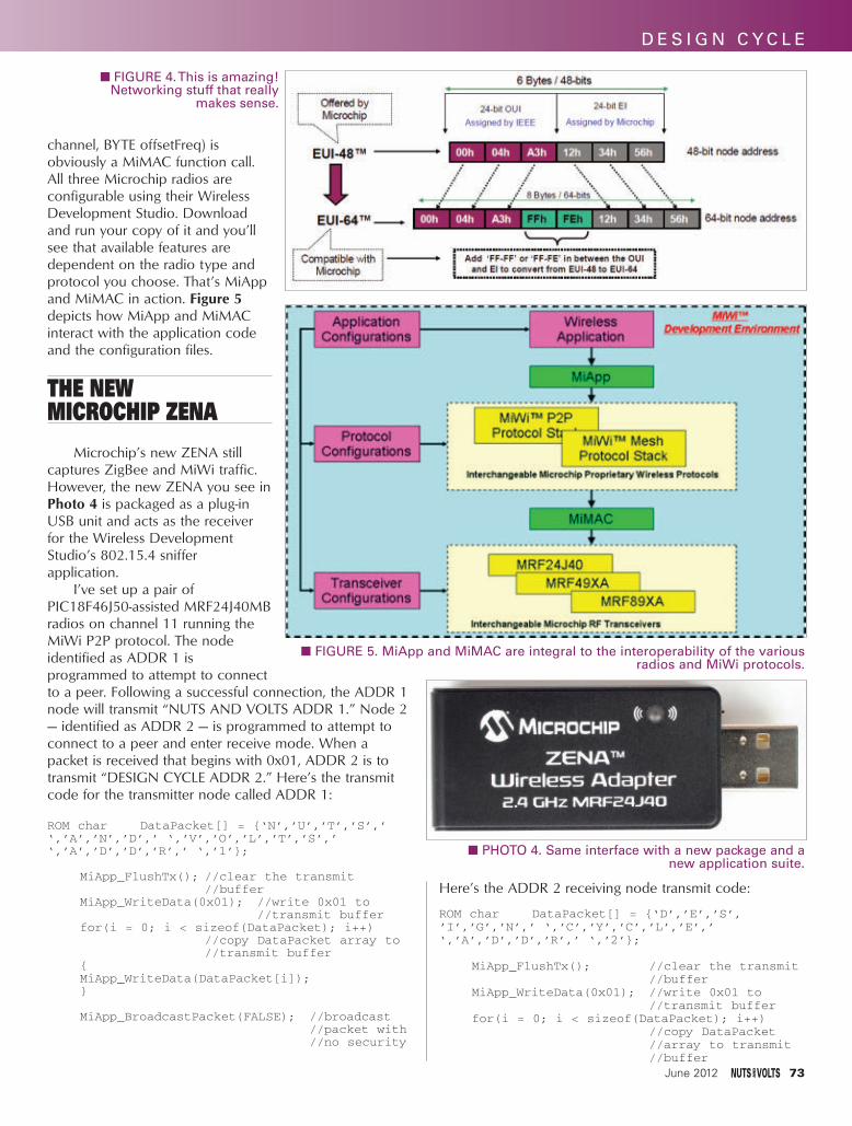
channel, BYTE offsetFreq) isobviously a MiMAC function call.All three Microchip radios areconfigurable using their WirelessDevelopment Studio. Downloadand run your copy of it and you’llsee that available features aredependent on the radio type andprotocol you choose. That’s MiAppand MiMAC in action. Figure 5depicts how MiApp and MiMACinteract with the application codeand the configuration files.
THE NEW MICROCHIP ZENA
Microchip’s new ZENA stillcaptures ZigBee and MiWi traffic.However, the new ZENA you see inPhoto 4 is packaged as a plug-inUSB unit and acts as the receiverfor the Wireless DevelopmentStudio’s 802.15.4 snifferapplication.
I’ve set up a pair ofPIC18F46J50-assisted MRF24J40MBradios on channel 11 running theMiWi P2P protocol. The nodeidentified as ADDR 1 isprogrammed to attempt to connectto a peer. Following a successful connection, the ADDR 1node will transmit “NUTS AND VOLTS ADDR 1.” Node 2— identified as ADDR 2 — is programmed to attempt toconnect to a peer and enter receive mode. When apacket is received that begins with 0x01, ADDR 2 is totransmit “DESIGN CYCLE ADDR 2.” Here’s the transmitcode for the transmitter node called ADDR 1:
ROM char DataPacket[] = ‘N’,’U’,’T’,’S’,’‘,’A’,’N’,’D’,’ ‘,’V’,’O’,’L’,’T’,’S’,’‘,’A’,’D’,’D’,’R’,’ ‘,’1’;
MiApp_FlushTx(); //clear the transmit //buffer
MiApp_WriteData(0x01); //write 0x01 to //transmit buffer
for(i = 0; i < sizeof(DataPacket); i++)//copy DataPacket array to //transmit buffer
MiApp_WriteData(DataPacket[i]);
MiApp_BroadcastPacket(FALSE); //broadcast //packet with //no security
Here’s the ADDR 2 receiving node transmit code:
ROM char DataPacket[] = ‘D’,’E’,’S’,’I’,’G’,’N’,’ ‘,’C’,’Y’,’C’,’L’,’E’,’‘,’A’,’D’,’D’,’R’,’ ‘,’2’;
MiApp_FlushTx(); //clear the transmit //buffer
MiApp_WriteData(0x01); //write 0x01 to //transmit buffer
for(i = 0; i < sizeof(DataPacket); i++)//copy DataPacket //array to transmit //buffer
June 2012 73
D E S I G N C Y C L E
FIGURE 4. This is amazing! Networking stuff that really
makes sense.
FIGURE 5. MiApp and MiMAC are integral to the interoperability of the variousradios and MiWi protocols.
PHOTO 4. Same interface with a new package and anew application suite.
Design Cycle - Jun 12.qxd 5/7/2012 3:20 PM Page 73

MiApp_WriteData(DataPacket[i]);
MiApp_BroadcastPacket(FALSE);//broadcast packet with no security
The 802.15.4 sniffer capture you see in Screenshot 3details the connection initialization. I powered up thereceiver (ADDR 2) first, allowed it to attempt aconnection, and let it settle into receive mode. Then, Ifired up the transmit node (ADDR 1). ADDR 1 sent a P2PConnection Request just as ADDR 2 had done.
However, ADDR 2 was waiting for a connectionrequest which, in this case, came from ADDR 1. ADDR 2acknowledged the connection request, a peer-to-peersession was established, and ADDR 1 transmitted itsmessage. ADDR 2 received the broadcast message andresponded with its message. I figure you want to see theADDR 2 receiver code:
if(MiApp_MessageAvailable())//if a good packet was received
if(rxMessage.Payload[0] == 0x01)
//check for 0x01 at start of data
MiApp_DiscardMessage();//clear the receive buffer
MiApp_FlushTx();//clear the transmit buffer
MiApp_WriteData(0x03);//write a 0x03 to the transmit //buffer
for(i = 0; i < sizeof(DataPacket); i++)//copy DataPacketarray to transmit //buffer
MiApp_WriteData(DataPacket[i]);
MiApp_BroadcastPacket(FALSE);//transmit packet with no security
Just a walk in the park. The gravy is that bothnodes now know each other’s EUI-64 MAC address.Using the specific EUI-64 addresses, each radio nodecould switch over to Unicast mode and speak directly toeach other.
The Wireless Development Studio sniffer applicationbreaks down the 802.15.4-based MiWi P2P packet into bitfields. Each bit field yields information about the packet.This is a great way to learn about the mechanics of the802.15.4 protocol and study the differences introduced bythe MiWi P2P protocol.
LET’S SEE THAT AGAINThis time, I’ll use the Exegin Q51 PANalyzer
hardware you see in Photo 5 in conjunction with theWireshark network analyzer to grab P2P packets out ofthe air. The Exegin Q51 PANalyzer is designed to sniffZigBee and 802.15.4 networks at remote sites.
The sniffed data can then be transferred via TCP/IPover the Internet to a Wireshark network analyzer runningat the central monitoring station. The PANalyzer caninteroperate with Wireshark to monitor the followingprotocols:
• 802.15.4• ZigBee 2007• ZigBee PRO• ZigBee SCoP (ZIPT)• 6LoWPAN• Generic ZigBee Cluster Library
The Wireshark PAN protocol dissectors are opensource. So, you can write your own dissector to sniff yourunique profiles.
The PANalyzer contains an integral web server and aTelnet interface. Eitherinterface can be usedfor network andPANalyzer configurationtasks. Networkstatus and PANalyzeroperational parameterscan also be gleanedfrom these userinterfaces. Access to thesecure web server and
SCREENSHOT 3. Theprevious version ofthe ZENA captureapplication was graphicaland a bit hard to follow.The new WirelessDevelopment Studiosniffer application ischocked full of packetinformation that iseasily flushed out andunderstood.
74 June 2012
Design Cycle - Jun 12.qxd 5/7/2012 3:20 PM Page 74

Telnet services is gained through anapplication called Gecko that shipswith the PANalyzer.
Screenshot 3 is a PANalyzercapture of the connection anddata transfer packets exchangedbetween our pair of MRF24J40MBnodes. Note that ADDR 1 andADDR 2 are not real addresses.
The real hardware addresses canbe found in the PANalyzer andZENA sniffer captures. You caneasily pick out the 64-bit addresseswe assigned to each node in theScreenshot 3 sniff. Everything fromthe Ethernet frame down to the 802.15.4 data is shown inthe Wireshark/PANalyzer capture.
ONE MORE TIMEAlright already. We’re out of paper. You will definitely
see the ZENA and PANalyzer ZigBee/802.15.4 sniffersagain. We’ll have to figure out how to get that 802.15.4PAN data to the face of my DROID. Until then, add theMRF24J40MB, 802.15.4, ZENA, and PANalyzer to yourDesign Cycle. NV
PHOTO 5. This tricky piece of802.15.4 hardware can sniff remote
802.15.4 networks and send thesniffer captures home via the
Internet.
SOURCES
MMiiccrroocchhiippMRF24J40MAMRF24J40MB
ZENAWireless Development Studio
PIC18F46J50 MiWi
Microchip Application Libraries wwwwww..mmiiccrroocchhiipp..ccoomm
EExxeeggiinn TTeecchhnnoollooggiieessExegin Q51 PANalyzer
Geckowwwwww..eexxeeggiinn..ccoomm
June 2012 75
PICBASIC PRO™ Compiler
PBP3Experimenter - $49.95Silver Edition - $119.95Gold Edition - $269.95
Download a FREE trial version now.
www.PBP3.comwww.melabs.commicroEngineering Labs, Inc. 888-316-17533
The industry-standard BASIC compiler for Microchip PIC® microcontrollers.
PICBASIC and PICBASIC PRO are trademarks of Microchip Technology Inc. in the USA and other countries. PIC is a registered trademark of Microchip Technology Inc. in the USA and other countries.
Multi-Seat Licensingfor Educational Institutions
Upgrade fromPICBASIC™ Compiler (PBC)
D E S I G N C Y C L E
Design Cycle - Jun 12.qxd 5/7/2012 3:21 PM Page 75

Build a Morse Code OscillatorFUNDAMENTALS CIRCUITS ANDBASICS FORTHE BEGINNER
Try your hand at an “old school” communicationsmethod that is still practiced today.
Build the Circuit. Using the schematic along with the pictorialdiagram, place the components on a solderless breadboard asshown. Verify that your wiring is correct.Do the Experiment. Theory: This project uses the 555 timer IC toemit pulses which are sent to a transistor to drive a speaker. R1, R2,and C1 control the duty cycle and therefore the frequency of thepulses coming from pin 3 of the 555 time. (The duty cycle is thepercentage of time the output waveform is on compared to onecomplete cycle of on-off time. The formula for duty cycle is DC = TimeOn/ [time on + time off].) By interrupting the power to the circuit withswitch S1, you can turn the sound on and off. Procedure: Connect anine volt battery to the battery snap and press switch S1. You shouldhear a tone. (If you don’t, recheck yourwiring.) Use S1 to send Morse Codesignals. If you wish, replace thepushbutton switch with a Morse Codekey. Many ham radio operators still like touse Morse Code to communicate.
AA kkiitt ffoorr tthheessee eexxppeerriimmeennttss ccaann bbee ppuurrcchhaasseedd ffrroomm tthhee NNuuttss && VVoollttss WWeebbssttoorree aatt
wwwwww..nnuuttssvvoollttss..ccoomm oorr ccaallll uuss aatt 880000--778833--44662244..
Resistors, 1/2 watt 5%GK01065 1,000 ohms (R1)GK01115 120,000 ohms (R2)GK01049 220 ohms (R3) GK01017 10 ohms (R4)
SCHEMATIC
PICTORIAL DIAGRAM
76 June 2012
You can order parts for this experimentfrom their website
as follows:
These experiments are provided by GSSTechEd atwww.gssteched.com
GK35002 Nine volt battery snapGK14004 555 timer ICGK02012 0.01 µF capacitorGK45010 Six 4” solid wires, stripped endsGK18001 2N3904 NPN transistorGK27002 1/4” round speakerGK25006 NO pushbutton switch with wires
WIRESW1 = 8c and 30aW2 = 21a and 30bW3 = 18g and 21dW4 = 20g and 19dW5 = 21i and 30iW6 = 7j and 30j
Beg Experiments Jun12.qxd 5/9/2012 1:22 PM Page 76

and energy efficiency. Units with an axial cylindricaldesign enable low ESR and high peak currents with anelectrostatic storage capability that can cycle a millioncharges and discharges without performance degradation.
Type CDLC can work in parallel with batteries forapplications that require both a constant power dischargefor continual function and a pulse power for peak loads.The CDLC delivers the peak power thus reducing the peakcurrent from the battery, and extending battery life andreducing battery size and cost.
Both series are available now with prices starting at$10 each.
DESIGN/ENGSERVICES
SURPLUSKITS/PLANS
ENERGY SOLUTIONS
COMPONENTS
uM-FPU6464-bit Floating Point Coprocessor
www.micromegacorp.com
DIP-28, SOIC-28,TQFP-44
64-bit and 32-bit IEEE 754 compatibleSPI or I2C interface, 3.3V Supply, 5V Tolerant I/O
Extensive floating point support, FFT, matrix operationsGPS input, local device support, Flash functions, IDE
RoboticsNavigation
Sensor ModulesEmbedded Systems
Additional products... uM-FPU V3.1 32-bit FPU uM-PWM1 Servo Coprocessor
New
The HRLV- MaxSonar Sensors
$34.95 (MSRP)
www.MaxBotix.com
ROBOTICS
LIGHTING
CLASSIFIEDS
DEC EQUIPMENTWANTED!!!
Digital Equipment Corp. and compatibles. Buy - Sell - Trade
CALL KEYWAYS 937-847-2300or email [email protected]
HARDWAREWANTED
June 2012 77
For more information, contact:Cornell Dubilier Electronics
Web: www.cde.com
OSCILLOSCOPES
Looking for robotstuff and kits?www.servo
magazine.com
Continued from page 33
Jun12 - NewProducts_Jun12 - NewProducts.qxd 5/9/2012 3:12 PM Page 77

>>> QUESTIONSSolar LED Illumination
For several years, we have used asolar yellow LED deck lamp as a"Welcome Light" for our camper — the12V "patio light" is just too bright, andruins the moment.
I would like to have a simpleNiMH/NiCad amber LED light thatwould be charged via solar, but alsofrom the 12V onboard power whenavailable. I also need an on/off switchfor the LED.#6121 William Hogan
West Lafayette, IN
VHF Receiver Does anyone know of a VHF
receiver that will tune in AM/SW signals after they've been frequencyshifted up to the 216-302 MHz range?I would like to isolate the 500 kHz - 22MHz band from a directional AM/SWantenna and use a local oscillator toraise them to 216-237.5 MHz. Then,I'd like to do the same for three otherdirectional antennas to end up withfour intermediate frequencies rangingfrom 216-302 MHz. I'm worried that atypical VHF tuner will only look forFM signals, of the wrong channelwidth, within the VHF band. Thesefour new intermediate frequencies willnow be high enough to make itthrough amplifiers (usually limited to54-894 MHz) on our local cable sys-tem. I know that a local oscillatorcould be used at the receiver to bringthem back down to their originalrange for use with a regular AM/SWradio, but I'm looking for an off-the-shelf solution without a hardwaremodified receiver. Can the "UnidenHome Patrol" or "GRC PSR-800"receivers have their Flash memorystored software modified to do this?The four separate intermediate fre-quencies will give the end user accessto their choice of signals from four different directions. Something low
cost, with an internal power supply(no wallwarts), and include Digital orSSB would be ideal. Thanks. #6122 Sam Grauman
via email
Digital Technology?I am a senior citizen plagued with
hearing loss. I have been using hearingaids for about 30 years!! The vendorskeep touting "digital" technologyalthough none of them can explainhow "digital" amplifiers work. I amfamiliar with analog amplifiers. Cansomeone give an explanation of this"digital" technology? #6123 William Porter
Porter, OK
Compressor StarterI am looking for a positive
temperature coefficient motor starterfor a compressor. Or, I need helpusing different parts such as a singlepole contactor/relay for a hard start.
The part I want to replace has thefollowing number: RF-6850-18, andconsists of a PTC starter and an over-load protector. Can I replace this witha hard starter contacter?
I can photocopy the schematicsand email anyone who can help me.#6124 Michael Farley
Cincinnati, OH
Generator ConversionI’m considering converting an old
car with manual steering to electric.However, DC motors about 10
HP or more are expensive. I saw thatthe Northern Tool catalog has a 10 kwgenerator head with brushless tech-
nology (Item 165928). Is this a 13 HPbrushless DC motor I could modify?#6125 Peter Vickers
Hope Hull,AL
Thermostat SchematicI need a simple schematic
diagram which shows how the homethermostat controller is connected to the gas heater and to the air conditioning at the same time.#6126 Sam
via email
FFT Audio Spectrum AnalyzerHow can I implement FFT in
microcontrollers so that I can do a frequency analysis of incoming audiosignals that I have sampled through theA/D converter? I am not getting justwhere to start, though I know mathe-matical techniques of FFT. I want todeploy a cool audio spectrum analyzerfor my audio system using matrix LEDs.#6127 Abhishek Kumar
Meerut, Uttar Pradesh, India
DTMF EncoderWhere can I find a schematic or
kit for a 16 button keypad encoder,without having to program a PIC?That's a regular telephone keypad plusA - D on the right side.#6128 Terry Arnall
Hayward, CA
BJT Transistors How do you measure BJT hybrid
parameters HF, HI, HO, and HR?#6129 Jose Perez
Guaynabo, PR
All questions AND answers are submittedby Nuts & Volts readers and are intendedto promote the exchange of ideas and pro-vide assistance for solving technicalproblems. Questions are subject to edit-ing and will be published on a spaceavailable basis if deemed suitable by thepublisher. Answers are submitted
by readers and NO GUARANTEES WHATSOEVER are made by the publisher.The implementation of any answer printedin this column may require varying degreesof technical experience and should only beattempted by qualified individuals.
Always use common sense and goodjudgment!
78 June 2012
R E A D E R - T O - R E A D E R TECHFORUM
TechForum.qxd 5/9/2012 1:27 PM Page 78

[#5121 - March 2012]
Display AdviceI need to build a high visibility
display unit that consists of 15 1” x 1-1/2” display units. I've consideredLEDs, Electrolum panels, and more. Icannot seem to find a display unit thatcan properly display true black andtrue white. I also need them to do atleast 256 colors as well — nice, richhigh resolution colors.
Is there such a thing? I believe I'veseen them but am not sure wheresince I go to a lot of places displayinga lot of stuff.
Good luck finding a display thatactually displays black. About the onlything that would come close is an"electronic ink" display as used on anAmazon Kindle.
Most displays — whether CRT,LED, incandescent, etc. — generatelight. Black is the absence of light andwith a CRT (picture tube) or LED display, the blackest black you're goingto get is with the display off. It onlyseems "black" in the presence of allthe contrasting colored light around it.Look at your TV with power off. That's
its blackest black. Really! It doesn'tseem that your "256 colors" is a gooddefinition of "nice, rich, high-resolutioncolors." Your local paint store hasmore color chips than that by far andit's certainly not "high resolution."
Dean HusterHarviell, MO
[#5122 - March 2012]
LED ChaserI need a schematic for an LED
chaser for an atomic model my class isbuilding. I will be using about eight to16 LEDs. They need to be adjustable incycling and speed. Could this circuit beexpandable from, say, four to 40 LEDs?
By "LED chaser," I assume youmean a circuit that will light a series ofLEDs one at a time in a sequential andcyclic progression. You can accom-plish this using the MC14017 DecadeCounter IC (download a datasheetfrom www.onsemi.com). A singleMC14017 will provide 10 LED outputs. Figure 3 in the datasheet illustrates how to wire together several MC14017s (with the help ofMC74HC08 AND gates) for obtainingmore outputs (40 LEDs will require fiveMC14017s). You can drive the LEDs
directly from the MC14017 outputswith a series resistor (~ 470 ohms).You'll also need an oscillator source,and an LM555 is the easiest way to do this. A convenient calculator for determining component values is avail-able at www.coolcircuit.com/tools/ne555_calculator/index.php. You canuse a potentiometer to make the oscillator frequency variable. If youmake the frequency 10 Hz, for exam-ple, each LED will light for 0.1 seconds,and it will take one second to cycle through all 10 LEDs. All the com-ponents you will need can be orderedfrom Jameco (www.jameco.com). Youcan use the 74HC4017, 74HC08, andLM555, and any size/color LED youlike. Figure 1 is a basic schematic diagram to get started.
Bob Stewartvia email
[#5124 - March 2012]
Bird Sound CircuitAbout 40 years ago, I built a bird
sound kit and put it in a Sucrets®metal box (same size as an Altoids®tin). I don't remember the name of thecompany, but the circuit was a block-ing oscillator. I believe it had a minia-ture audio transformer; one side had a
>>>YOUR ELECTRONICS QUEST IONS ANSWERED HERE BY N&V READERS
Send all questions and answers by email to [email protected] at wwwwww..nnuuttssvvoollttss..ccoomm for tips and info on submitting to the forum.
>>> ANSWERS
June 2012 79
Values for R2, R3, and C1 produce ~ 10 Hz
+5 VDC +5 VDC
U1 74HC4017
14
13
15
3
2
4
7
10
1
5
6
9
11
12
16
8
CLK
CKE
RST
Q0
Q1
Q2
Q3
Q4
Q5
Q6
Q7
Q8
Q9
CO
VC
C
GND
D8
LED
R2 47 K
D4
LED
D9
LED
R3 47 K
D5
LED
D10
LED
D1
LED
C1
1 uF
D6
LED
D2
LED
U2
LM555
3
4
8
5
2
6
7
1
OUT
RST
VCC
CV
TRG
THR
DSCHG
GNDD7
LED
R1
470
C2
0.01 uF
D3
LED
Figure 1
TechForum.qxd 5/9/2012 12:09 PM Page 79

R E A D E R - T O - R E A D E R TECHFORUM
80 June 2012
center tap. I think it only had one transistor and ran on a single AA cell. Iused a 1" speaker with a clear plasticdiaphragm. You switched it on and itmade a realistic repeating bird chirp.Better yet, if you lightly touched thespeakercone, the sounds changed toother types of birds because of thechange in reactance of the speaker. Itwas quite loud. Does anyone remem-ber this and have a schematic?
#1 I remember using a SN76488N'sound generator' to build 'sound' circuits, such as train whistles, crowdscheering, birds chirping, and sirens,etc., for electronic games and otherprojects, but then I started to thinkabout producing sounds as realistic aspossible but in a less complicated way.
Here's a possible solution that youmight want to consider.
I went to RadioShack and purchased a few of those handheldvoice recorders [available at www.tmart.com] that allowed about a 10 to15 second recording time. Pressingone button allowed recording, andpressing another button allowed audi-ble playback. Removing a few screws,I simply wired a micro-switch in paral-lel with the playback switch and, whenpressed, could instantly and repeated-ly hear what I had recorded until Irecorded over it with something else. Iwired the output of the recorder tothe input of a small audio amplifier[using an LM386 IC circuit] for a clearand loud output.
I wanted a crowd cheer eachtime a hit was made and a trumpetblare every time a man crossed homeplate in my electronic baseball game. Iwas fortunate enough to have theserealistic recorded sounds already programmed on my Technics keyboard. I simply pressed the recordbutton, recorded the sounds, and thenwired the recorders into the game.You can easily record real bird soundsfor your project. You can store all birdcalls into a memory chip and then playback, record, and use as needed.
John Mastromoro
#2 The schematic and parts listshown below is from the three pagearticle “The Solid-State Bird,” by JohnSimonton, Jr. It appeared in PopularElectronics Spring 1973 “ElectronicsExperimenters Handbook.” (A scannedPDF of the entire article can be viewedor downloaded at the NV website.)
The foil pattern measures 2 7/16"x 1-3/4", or 71 x 44 mm.
While searching, I also ran
across two additional "bird sound" circuits: Dec. 1981 Radio Electronics"Electronic Bird Chirper" — four transis-tors, total 25 parts; and 1993 PopularElectronics Electronics Handbook "HotCanaries" two LM324s, one transistor,two 1N914 diodes total 54 parts (nocritical parts; parts count includes 9Vbattery, switch, and speaker).
Edwin HamptonMattoon, Il
TThhee 22001111 NNuuttss && VVoollttssCCDD--RROOMM iiss aavvaaiillaabbllee NNOOWW iinn oouurr ssttoorree!!
GGoo ttoo hhttttpp::////ssttoorree..nnuuttssvvoollttss..ccoommaanndd oorrddeerr yyoouurrss ttooddaayy!!
PARTS LIST Bl — 6 volt battery (four AA cells in series)Cl — 30 µF, six volt electrolytic capacitorC2,C3 — 0.01 µf disc capacitor C4 — 100 µF 6V electrolytic capacitor C5 — 2.2 µF 6V electrolytic capacitor QI — 2N5129 transistor Q2 — 2N2712 transistor RI — 33,000 Ω, 1/2 watt resistor R2, R3, R6 — 82,000 Ω, 1/2 watt resistorR4 — 1,000 Ω, 1/2 watt resistor R5 — 330 Ω, 1/2 watt resistor R7 — 50,000 Ω trimmer PC potR8 — 1.8 Ω, 1/2 watt resistor SI — SPST slide or toggle switch
Tl — 10K:2K driver transformer(Lafayette TR-98, 99F61269, or simiIar)T2 — 500Ω CT: eight ohm outputtransformer (Lafayette TR-116,99F61293, or similar)Misc. — Eight ohm speaker, plasticcase, battery clips, wire solder, etc.
Note — At the time the article waswritten (1973), a PCB and complete kitwere available from PAiA Electronics(www.paia.com). However, it appearsthey are no longer available. The foilpattern is included in the article scanon the NV website.
This circuitis not as simple as itlooks. Besides
a multivibrator, there is also ablocking oscillator.
All components are part ofone time constant or another,so changing the value of onewill alter the final sounds. Notethe speaker damping (R8) thatkeeps speaker acoustic loadingfrom altering the oscillator.
$24.95
TechForum.qxd 5/9/2012 12:51 PM Page 80

AADDvveerrttiisseerr IINNDDEEXX L O O K F O R S E A R C H F O R F I N D
Find your favorite advertisers here!
Abacom Technologies ...........29
All Electronics Corp. ..............59
Anaren ...................................49
AP Circuits ............................58
Bitscope ................................49
Cana Kit Corp. ......................57
Chaney Electronics ...............41
Circuit Specialists, Inc. .....82-83
Command Productions .........57
Cunard Associates ................33
Digilent ..................................13
Dimension Engineering ............8
Electronic Design Specialists.63
Elkins Training........................19
ExpressPCB ..........................20
Front Panel Express LLC ......21
Fun Gizmos ...........................33
Global Specialties ...................7
GSS Tech Ed ........................58
HAPRO Electronics................21
Hobby Boards ........................58
Jameco ....................................4
Jaycar Electronics ..................51
Lakeview Research................33
Lemos International Co., Inc. 19
Lynxmotion, Inc. ....................28
Meteor Instruments ................33
microEngineering Labs ..........75
MikroElektronika ......................3
NetBurner ................................2
NightFire Electronics ..............63
NKC Electronics ....................33
Noritake .................................21
PanaVise ...............................58
Parallax, Inc. ...........Back Cover
PCB Pool ..............................29
Pololu Robotics & Electronics ..5
Poscope .................................40
QKITS ....................................33
Ramsey Electronics, Inc. .22-23
R.E. Smith Inc. ......................50
V-Module ...............................50
Weirdstuff Warehouse ...........33
1-WIREHobby Boards ..........................58
AMATEUR RADIO AND TVNightFire Electronics................63
Ramsey Electronics, Inc. ...22-23
V-Module .................................50
BATTERIES/CHARGERSCunard Associates ..................33
BUYING ELECTRONICSURPLUSJaycar Electronics....................51
Weirdstuff Warehouse ............33
CCD CAMERAS/VIDEOCircuit Specialists, Inc. ......82-83
Ramsey Electronics, Inc. ...22-23
CIRCUIT BOARDSAP Circuits ..............................58
Cunard Associates ..................33
Digilent ....................................13
Dimension Engineering..............8
ExpressPCB ............................20
Front Panel Express LLC .......21
PCB Pool ................................29
R.E. Smith Inc. ........................50
V-Module .................................50
COMPONENTSAnaren ....................................49
Cana Kit Corp. ........................57
Chaney Electronics .................41
Fun Gizmos ............................33
Jameco .....................................4
NightFire Electronics................63
Noritake ...................................21
V-Module .................................50
COMPUTERHardware
Noritake ...................................21
Weirdstuff Warehouse ............33
Microcontrollers / I/O Boards
Abacom Technologies .............29
Bitscope ..................................49
Fun Gizmos ............................33
microEngineering Labs ............75
MikroElektronika .......................3
Parallax, Inc. ............Back Cover
Pololu Robotics & Electronics....5
DESIGN/ENGINEERING/REPAIR SERVICESCana Kit Corp. ........................57
ExpressPCB ............................20
Front Panel Express LLC .......21
PCB Pool ................................29
EDUCATIONBitscope ..................................49
Command Productions ...........57
Digilent ....................................13
Elkins Training..........................19
Global Specialties .....................7
GSS Tech Ed ..........................58
NKC Electronics ......................33
Poscope ...................................40
EMBEDDED TOOLSNetBurner ..................................2
ENCLOSURESFront Panel Express LLC .......21
KITS & PLANSCana Kit Corp. ........................57
Chaney Electronics .................41
GSS Tech Ed ..........................58
Hobby Boards ..........................58
Jaycar Electronics....................51
NetBurner ..................................2
NightFire Electronics................63
NKC Electronics ......................33
QKITS ......................................33
Ramsey Electronics, Inc. ...22-23
MISC./SURPLUSAll Electronics Corp. ...............59
Chaney Electronics .................41
Front Panel Express LLC .......21
Weirdstuff Warehouse ............33
MOTORSJameco .....................................4
OPTICSNoritake ...................................21
PROTOTYPING & TRAINERSGlobal Specialties .....................7
PUBLICATIONSLakeview Research..................33
PROGRAMMERSmicroEngineering Labs ............75
MikroElektronika .......................3
RF TRANSMITTERS/RECEIVERSAbacom Technologies .............29
Anaren ....................................49
ROBOTICSDigilent ....................................13
Fun Gizmos ............................33
GSS Tech Ed ..........................58
Jameco .....................................4
Lemos International Co., Inc. ..19
Lynxmotion, Inc. ......................28
Pololu Robotics & Electronics....5
SATELLITELemos International Co., Inc. ..19
TEST EQUIPMENTBitscope ..................................49
Circuit Specialists, Inc. ......82-83
Dimension Engineering..............8
Electronic Design Specialists...63
Global Specialties .....................7
HAPRO Electronics..................21
Jaycar Electronics....................51
Meteor Instruments ..................33
NKC Electronics ......................33
Poscope ...................................40
TOOLSMikroElektronika .......................3
NetBurner ..................................2
PanaVise .................................58
Poscope ...................................40
WEATHER MONITORINGHobby Boards ..........................58
WIRELESS PRODUCTSAnaren ....................................49
June 2012 81
TechForum.qxd 5/9/2012 12:03 PM Page 81

An SMT rework station & solderingstation in one handy unit! Perfect forshops & labs dealing with todaysSMT board designs.O.E.M. manu-factured just for Circuit SpecialistsInc., so we can offer the best pricepossible! This multi-purpose stationis perfect for all your surface mountand thru-hole requirements. Thesoldering iron has a grounded tip for
static sensitive parts and uses a ceramic heating element for fastheat up and stable temperature control. A seperate aluminum con-structed soldering iron holder is included.
What every shop or lab needs todeal with todays SMT designed cir-cuit boards. O.E.M. manufacturedjust for Circuit Specialists Inc., so wecan offer the best price possible! Amulti-technology assembly andrepair station. The heater and aircontrol system is built-in and adjust-ed by the simple touch of the frontkeypad for precise settings.
Temperature range is from 100°C to 480°C / 212°F to 896°F, and theentire unit will enter a temperature drop state after 15 minutes ofnon-use for safety and to eliminate excessive wear.
www.CircuitSpecialists.com/DM620
60 W60 Watt Digitatt Digital Soldering Sal Soldering SttationsationsFor use with traditional or Lead Free Soldering
CCCCiiiirrrrccccuuuuiiiittttSSSSppppeeeecccciiiiaaaallll iiiissssttttssss....ccccoooommmm1111000000000000’’’’ssss ooooffff IIII tttteeeemmmmssss OOOOnnnnllll iiiinnnneeee!!!! 1111--888800000000--555522228888--1111444411117777 FFFFaaaaxxxx:::: 444488880000--444466664444--5555888822224444 SSSSiiiinnnncccceeee 1111999977771111
CCCCiiii rrrrccccuuuuiiii tttt SSSSppppeeeecccciiiiaaaallll iiiissssttttssss,,,, IIIInnnncccc....PPPPhhhhoooonnnneeee:::: 888800000000--555522228888--1111444411117777 //// 444488880000--444466664444--2222444488885555 //// FFFFaaaaxxxx:::: 444488880000--444466664444--5555888822224444
$720.00$720.00
www.CircuitSpecialists.com/CSI-Station-3DLF
$49.00$49.00Item#
CSI-SCSI-Sttation-3DLFation-3DLF
Programmable DC Electronic LoadProgrammable DC Electronic Load0~80V / 0~40A0~80V / 0~40A
The 3721A Programmable DC Electronic Load providesexcellent performance with sophisticated features found onmuch more expensive units. This 400 watt, 40 Amp, 0~80volt Programmable DC Electric Load can be used to testall sorts of DC power sources including power supplies andis especially helpful to battery manufacturing processes.This DC load features constant voltage, constant resist-ance, constant current and constant power settings. Theend user can design programs that control precisely all ofthe load values and time durations for each step of a testsequence. Up to nine 10 step programs can be internallystored in the 3721A Programmable DC Load.
• 4 basic functions: CC, CV, CR & CP
• 8 basic test modes: CCL, CCH, CV, CRL, CRM, CRH, CPV & CPC
• Minimum operating voltage is less than 0.6v at the load’s fullrated current.
• High-speed sequence, high-speed transient, short circuit,battery discharge and other functions.
• Programable current slew rate.
• Multiple groups of parameters and lists can be saved & recalled.
• Supports SCPI and LabView with included software.
• Current Rating: 0~40A• Voltage Rating: 0~80V• Power Rating: 400W at 40oC
Item#CSI3721ACSI3721A
www.CircuitSpecialists.com/CSI3721A
Programmable DC Electronic LoadsProgrammable DC Electronic Loads
Thease devices can be used with supplies upto 360VDC and 30A. It features a rotaryselection switch and a numeric keypad usedto input the maximum voltage, current andpower settings. These electronic DC loadsare perfect for use in laboratory environmentsand schools, or for testing DC power suppliesor high-capacity batteries. It also featuresmemory, and can also be connected to a PC,to implement remote control and supervision.
360V/150W (CSI3710A) $349.00www.circuitspecialists.com/csi3710a
360V/300W (CSI3711A) $499.00www.circuitspecialists.com/csi3711a
The CSI-Station-3DLF is a powerful 60 watt soldering system.The fast heat recovery provided by a 60 watt system like thisallows the user to solder both traditional solder and lead freesolder. This system features a grounded tip to protect delicatecircuits from static charge. Specific system temps can also beset with an easy to use push button up/down button AND whenyou turn off this station, the unit keeps the last used tempera-ture in memory & automaticly returns to that setting the nexttime the user turns the system on.Also included is a seperateiron holder. Circuit Specialists stocks a large supply of tips forthis station.
Features:
• 60 watt dual core ceramic heater• 150 to 450 degree Celsius Temperature range• 302 to 896 degree Fahrenheit Temperature range• Versatile easy to read liquid crystal display • 3 preset & user definable temperature settings.• Automaticly remembers previous temperature setting • Display in Celsius or Fahrenheit scale• 3 foot cord length from station to iron tip• Broad selection of replacement tips available
Here is another 60 Watt soldering iron at a price thatcan't be beat. This is the "little brother" of our over-whelmingly popular CSI-STATION-3DLF except wehave removed the Digital Display & Digital controls. Butat 60 watts of power, this unit heats up extremely fastand is suitable for soldering lead free solder or tradi-tional solder containing lead. The analog control knobis calibrated in Celsius (200deg to 480 deg) &Fahrenheit (392 deg to 896 deg). A front panel led lightswhen the system is heating up and a front panel cali-bration port is also available. Circuit Specialists stocksreplacement soldering handles & a large selection oftips for this model. It may be viewed in greater detail atour web site.
Features:
• 60 watt dual core ceramic heater• 200 to 450 degree Celsius Temperature range• 392 to 896 degree Fahrenheit Temperature range• 3 foot cord length from station to iron tip• Broad selection of replacement tips available
Item#CSI-SCSI-Sttation-60Wation-60W $37.95$37.95
www.CircuitSpecialists.com/CSI-Station-60W
Item#CSI906CSI906 $109.00$109.00www.CircuitSpecialists.com/CSI906
SMD Hot SMD Hot Air Rework SAir Rework Sttationationwith Suction Pick-Up Wwith Suction Pick-Up Wandand
Item#CSI825ACSI825A $109.00$109.00www.CircuitSpecialists.com/CSI825A
SMD Hot SMD Hot Air Rework SAir Rework Sttationationwith Soldering Ironwith Soldering Iron
DatData Logging Ta Logging True RMSrue RMSDigitDigital Multimeteral Multimeter
The DM620 data-logging meter features auto ranging and has an auto shutdown feature that extends battery life when the unit is left powered up. It alsofeatures Range Hold, Data Hold, and an audible continuity function. Besidesthe True-RMS AC and DC measurement modes for both voltage and current,it also features Resistance, Capacitance, and temperature measurements,along with a diode test function and the ability to measure the Frequency,Period, and Duty cycle of signals up to 10 Mhz.
• Data Logging: 18,000 Points & 50,000 Counts without attaching to a PC• USB Interface (USB Cable & USB AC Charger Included)• Basic Accuracy: 0.05% DC V• True RMS• Auto Calibration • Trend Plot• Real Time Clock • 10 MHz Frequency Counter • Record, Relative, Compare & Period Modes
Item#DM620DM620$139.00$139.00
Full Page_Full Page.qxd 5/7/2012 5:17 PM Page 82

Step Up/Down Transformers2 outlets: 1 for 110/120VAC
1 for 220/240VAC
Provides:110/120VAC to 220/240VAC
or 220/240VAC to 110/120VAC
Heavy duty transformer designfor safety & reliability
With either 110VAC or 220VAC input
300 Watt Step Up/Step Down TransformerItem # STST-300 -300 $17.95$17.95www.circuitspecialists.com/ST-300
1500 Watt Step Up/Step Down TransformerItem # STST-1500 -1500 $53.00$53.00www.circuitspecialists.com/ST-1500
Step Up transformers Allows users to acquire 220 VACoutput with 110 VAC input.
Reliable heavy duty lineartransformer design.
Universal 3 pronged style 220VAC receptacles.
Integrated wire carry handlesfor added convenience.
200 Watt Step Up TransformerItem # TS-200 TS-200 $9.95$9.95www.circuitspecialists.com/TS-200
1000 Watt Step Up TransformerItem # TS-1000 TS-1000 $29.95$29.95www.circuitspecialists.com/TS-1000
Hantek 5000B Series DigitalHantek 5000B Series DigitalStorage OscilloscopesStorage Oscilloscopes
Introducing the Hantek 5000B Series Digital StorageOscilloscopes. Available in 60MHz, 100MHz and 200MHzBandwidths. Each one provides a 1GSa/s real-time sample rate.In addition, they have a 1M memory depth for better observationof waveform details. The 7 inch color TFT LCD Display withWindows-style interface and menus provide easy operation.
Abundant menu information and easy-to-use buttons give youplenty of measurement information:
The multifunctional knobs and the powerful shortcut keys helpsave time during operation.
The Autoset function lets you detect sine and square wavesautomatically.
The Probe Check Wizard guides you to adjust the probecom-pensation and set the Probe option attenuation factor.
Three help methods (context-sensitive, hyperlinks, and anindex).
You can quickly master all functions to greatly improve yourefficiency in production and development.
Features:60, 100 or 200 MHz bandwidth1GSa/s Real Time sample rate25GSa/s Equivalent sample rateLarge (7.0-inch) color display,WVGA(800x480)Record length 1MTrigger modes: edge/pulse width/line selectable
video/slop/overtime etc.USB host and device connectivity, standardMultiple automatic measurementsFour math functions, including FFTs standardProvides software for PC real-time analysis
3 Models to choose from
DSO5062BDSO5062B60MHz60MHzDigitDigitalal
SStoragetorageOscilloscopeOscilloscope
wwwwww.circuit.circuitspecialistspecialists.com/dso5062b.htmls.com/dso5062b.html
DSO5102BDSO5102B100MHz100MHzDigitDigitalal
SStoragetorageOscilloscopeOscilloscope
wwwwww.circuit.circuitspecialistspecialists.com/dso5102b.htmls.com/dso5102b.html
DSO5202BDSO5202B200MHz200MHzDigitDigitalal
SStoragetorageOscilloscopeOscilloscope
wwwwww.circuit.circuitspecialistspecialists.com/dso5202b.htmls.com/dso5202b.html
Includes1 Year USAWarranty
You get both a 200 MHzOscilloscope and a multi func-tion digital multimeter, all inone convenient lightweightrechargeable battery poweredpackage. This power packedpackage comes complete withscopemeter, test leeds, twoscope probes, charger, PC soft-ware, USB cable and a conven-ient nylon carrying case.
• 200MHz Handheld Digital Scopemeter with integrated DigitalMultimeter Support
• 200MHz Bandwidth with 2 Channels• 500MSa/s Real-Time Sampling Rate• 50Gsa/s Equivalent-Time Sampling Rate• 6,000-Count DMM resolution with AC/DC at 600V/800V, 10A• Large 5.7 inch TFT Color LCD Display• USB Host/Device 2.0 full-speed interface connectivity• Multi Language Support• Battery Power Operation (Installed)
www.circuitspecialists.com/DSO1200
60MHz Hand Held Scopemeter60MHz Hand Held Scopemeterwith Oscilloscope & DMM Functionswith Oscilloscope & DMM Functions
• 60MHz Handheld Digital Scopemeter with integrated Digital Multimeter Support
• 60MHz Bandwidth with 2 Channels• 150MSa/s Real-Time Sampling Rate• 50Gsa/s Equivalent-Time Sampling Rate• 6,000-Count DMM resolution with AC/DC
at 600V/800V, 10A• Large 5.7 inch TFT Color LCD Display• USB Host/Device 2.0 full-speed interface
connectivity• Multi Language Support• Battery Power Operation (Installed)
www.circuitspecialists.com/DSO1200
60MHz Hand Held Scopemeter60MHz Hand Held Scopemeterw/Oscilloscope, DMM Functions &w/Oscilloscope, DMM Functions &25 MHz Arbitrary Waveform Generator25 MHz Arbitrary Waveform Generator
• All the features of the DSO1060 plus a 25 MHz ArbitraryWaveform.Generator.
• Waveforms can be saved in the following formats: jpg/bmp graphic file,.MS excel/word file
• Can record and save 1000 waveforms • DC to 25 MHz Arbitrary Waveform Generator
www.circuitspecialists.com/DSO-8060
CCCCiiiirrrrccccuuuuiiiittttSSSSppppeeeecccciiiiaaaallll iiiissssttttssss....ccccoooommmm1111000000000000’’’’ssss ooooffff IIII tttteeeemmmmssss OOOOnnnnllll iiiinnnneeee!!!! 1111--888800000000--555522228888--1111444411117777 FFFFaaaaxxxx:::: 444488880000--444466664444--5555888822224444 SSSSiiiinnnncccceeee 1111999977771111
CCCCiiii rrrrccccuuuuiiii tttt SSSSppppeeeecccciiiiaaaallll iiiissssttttssss,,,, IIIInnnncccc.... 222222220000 SSSS.... CCCCoooouuuunnnnttttrrrr yyyy CCCClllluuuubbbb DDDDrrrr.... ,,,, MMMMeeeessssaaaa,,,, AAAAZZZZ 88885555222211110000PPPPhhhhoooonnnneeee:::: 888800000000--555522228888--1111444411117777 //// 444488880000--444466664444--2222444488885555 //// FFFFaaaaxxxx:::: 444488880000--444466664444--5555888822224444
We carry a LARGE selection of Power Supplies, Soldering Equipment, Test Equipment,Oscilloscopes, Digital Multimeters, Electronic Components, Metal and Plastic Project Boxes,
Electronic Chemicals, PC Based Digital I/O Cards, Panel Meters, Breadboards, DeviceProgrammers, and many other interesting items. Check out our website at:
www.CircuitSpecialists.com
•Up to 10 settings stored in memory •Optional RS-232, USB, RS-485 adapters•May be used in series or parallel modeswi th addi t ional supplies.
•Low output ripple .& noise •LCD display with .backlight•High resolution at .1mV
Programmable DC PowerProgrammable DC PowerSuppliesSupplies
Model CSI3644ACSI3644A CSI3645ACSI3645A CSI3646ACSI3646ADC Voltage 0-18V 0-36V 0-72VDC Current 5A 3A 1.5A
Power (max) 90W 108W 108WPrice $199.00$199.00 $199.00$199.00 $199.00$199.00
Item #DSO1200DSO1200 $589.00$589.00
Item #DSO1060DSO1060 $429.00$429.00
Item #DSO-8060DSO-8060 $519.00$519.00
200MHz Hand Held Scopemeter200MHz Hand Held Scopemeterwith Oscilloscope & DMM Functionswith Oscilloscope & DMM Functions
New Low Price!
New Low Price!
New Low Price!
$385.00$385.00
$499.00$499.00
$599.00$599.00
NewNew
LowerLower
Introductory
Introductory
Prices!Prices!
$399.00*
$369.00*
$499.00*
*Discount does not apply to prior sales.
DigitDigital Multimeteral Multimeterwith Mechanically Protected Inputwith Mechanically Protected Inputss
This is a terrific low cost digital multimeter from Circuit Specialists.IDEAL for students and technicians with a broad selection of meas-urement ranges and features. The Inputs are mechanically protect-ed to PREVENT incorrect test lead placement ( the leading cause ofdamage to digital multimeters). As the user moves the range selec-tor, the inputs that are not appropriate to the set range are blockedwhile the appropriate inputs are opened. This makes it impossible tomis apply the test lead settings and makes using this digital multi-meter easier and safer.
• 3 1/2 LCD display• Overload protected• Auto power off function• data hold function• Shock Resistant Case• mechanicaly protected Inputs• 2000uF test function• Transistor test
www.circuitspecialists.com/CSI2012L
Item #CSI2012LCSI2012L
$18.95$18.95
Step Up/Down TransformersStep Up/Down Transformers
www.circuitspecialists.com/csi-power-supplies
Full Page 2_Full Page 2.qxd 5/7/2012 5:19 PM Page 83

Learn all about the Board of Education Shield for Arduino at www.parallax.com/BOEShield. Order online or call us toll-free at 888-512-1024 (Mon-Fri, 8 AM - 5 PM, PDT).
Friendly microcontrollers, legendary resources.™
Prices are subject to change without notice. Board Of Education is a registered trademark of Parallax Inc. Parallax and the Parallax logo are trademarks of Parallax Inc. Arduino is a registered trademark of Arduino, LLC.
“ParallaxInc” on Twitter, Facebook, and YouTube
backcvr_backcvr.qxd 5/7/2012 4:12 PM Page 84