NS xxxx-2-x: 2018 - Nepal Bureau of Standards & Metrology
19
NEPAL STANDARDS NS xxxx-2-x: 2018 Household and similar electrical appliances – Safety – Part 2-x: Particular requirements for induction hobs Nepal Bureau of Standard and Metrology Balaju, Kathmandu, Nepal May 2018
-
Upload
khangminh22 -
Category
Documents
-
view
1 -
download
0
Transcript of NS xxxx-2-x: 2018 - Nepal Bureau of Standards & Metrology

NEPAL STANDARDS
NS xxxx-2-x: 2018 Household and similar electrical appliances – Safety – Part 2-x: Particular
requirements for induction hobs
Nepal Bureau of Standard and Metrology
Balaju, Kathmandu, Nepal
May 2018
2 | P a g e
CONTENTS
1 Scope ................................................................................................................................................. 5
2 Normative references.......................................................................................................................... 5
3 Terms and definitions.......................................................................................................................... 5
4 General requirements ......................................................................................................................... 7
5 General conditions for the tests ........................................................................................................... 7
6 Classification ...................................................................................................................................... 7
7 Marking and instructions ..................................................................................................................... 7
8 Protection against access to live parts ................................................................................................ 8
9 Starting of motor-operated appliances ................................................................................................. 8
10 Power input and current .................................................................................................................... 8
11 Heating ............................................................................................................................................. 9
12 Void ................................................................................................................................................ 10
13 Leakage current and electric strength at operating temperature ...................................................... 10
14 Transient overvoltages .................................................................................................................... 10
15 Moisture resistance ......................................................................................................................... 10
16 Leakage current and electric strength ............................................................................................. 11
17 Overload protection of transformers and associated circuits ............................................................ 11
18 Endurance ...................................................................................................................................... 11
19 Abnormal operation ........................................................................................................................ 11
20 Stability and mechanical hazards .................................................................................................... 12
21 Mechanical strength ........................................................................................................................ 12
22 Construction ................................................................................................................................... 13
23 Internal wiring ................................................................................................................................. 14
24 Components ................................................................................................................................... 14
25 Supply connection and external flexible cords ................................................................................. 15
26 Terminals for external conductors ................................................................................................... 15
27 Provision for earthing ...................................................................................................................... 15
28 Screws and connections ................................................................................................................. 15
29 Clearances, creepage distances and solid insulation ....................................................................... 15
30 Resistance to heat and fire ............................................................................................................. 15
31 Resistance to rusting ...................................................................................................................... 15
32 Radiation, toxicity and similar hazards............................................................................................. 16
Annexes ................................................................................................................................................ 18
Bibliography .......................................................................................................................................... 19

3 | P a g e
Figure 101 – Vessel for testing induction hob elements .......................................................................... 17
Figure 102 – Probe for measuring surface temperatures ........................................................................ 17
Table 101 – Quantity of liquid in the vessel .............................................................................................. 6

4 | P a g e
Household and Similar Electrical Appliances—Safety Part 2.x: Particular
requirements for portable Induction hobs.

5 | P a g e
1 Scope
This clause of Part 1 is replaced by the following.
This Standard deals with the safety of induction hobs for household use, their rated voltage being not more
than 250 V for single-phase appliances connected between one phase and neutral, and 440 V for other
appliances.
As far as is practicable, this standard deals with the common hazards presented by appliances that are
encountered by all persons in and around the home. However, in general, it does not take into account
– persons (including children) whose physical, sensory or mental capabilities; or lack of experience
and knowledge prevents them from using the appliance safely without supervision or instruction;
– children playing with the appliance.
NOTE 102 Attention is drawn to the fact that
– for appliances intended to be used in vehicles or on board ships or aircraft, additional requirements may be necessary;
– in many countries, additional requirements are specified by the national health authorities, the national authorities
responsible for the protection of labour, the national water supply authorities and similar authorities.
NOTE 103 This standard does not apply to
– appliances intended for commercial catering;
– appliances intended to be used in locations where special conditions prevail, such as the presence of a corrosive or
explosive atmosphere (dust, vapour or gas);
– grills, toasters and similar portable cooking appliances (IEC 60335-2-9);
– microwave ovens (IEC 60335-2-25).
2 Normative references
This clause of Part 1 is applicable except as follows.
Addition:
IEC 60584-1, Thermocouples – Part 1: EMF specifications and tolerances
IEC 60068-2-6:2007, Environmental testing – Part 2-6: Tests – Test Fc: Vibration (sinusoidal)
IEC 60068-2-27:2008, Environmental testing – Part 2-27: Tests – Test Ea and guidance: Shock
IEC 60068-2-52:1996, Environmental testing – Part 2-52: Tests – Test Kb: Salt mist, cyclic (sodium chloride
solution)
3 Terms and definitions
This clause of Part 1 is applicable except as follows.
3.1.6 Addition:
Note 101 to entry: For appliances having more than three heating units per phase, a diversity factor is
applied to the rated current or rated power input when determining the current used to establish the size of
the terminals and the nominal cross-sectional area of the supply cord. The diversity factor F is calculated
from the following formula, where N is the number of heating units per phase that can be energized together:
𝐹 = 0.35 +0.65
√𝑁

6 | P a g e
3.1.9 Replacement:
Normal operation
operation of the appliance as specified in 3.1.9.101 to 3.1.9.107
3.1.9.101 Induction hob are operated with vessels as specified in Figure 101 that contain cooking oil at
room temperature. Thermal controls are adjusted to their highest setting until the oil temperature reaches
180 °C ± 4 °C and then adjusted so that this temperature is maintained. The oil temperature is measured
10 mm above the centre of the bottom of the vessel.
The diameter of the bottom of the vessel is approximately equal to the diameter of the cooking zone and
the quantity of liquid is specified in Table 101. The vessel is positioned centrally on the cooking zone.
NOTES:
1. If several cooking zones are marked for one hob element, the most unfavourable cooking zone is used for the test.
2. For non-circular cooking zones, the smallest noncircular vessel is used which will cover the cooking zone as far as possible, taking into account the hob rim and the other vessels. The quantity of liquid is determined on the basis of the minor diameter
of the cooking zone.
Table 101 – Quantity of liquid in the vessel
Diameter of cooking zone (mm) Quantity of oil (l)
≤ 110 0.6
>110 and ≤ 145 1.0
>145 and ≤ 180 1.5
>180 and ≤ 220 2.0
>220 and ≤300 3.0
3.101
Induction hob element
Hob element that heats metallic vessels by means of eddy currents
Note 1 to entry: The eddy currents are induced in the vessel by the electromagnetic field of a coil.
3.102
Induction hob
A portable appliance equipped with at least on induction hob element.
3.103
cooking zone
Area marked on a hob surface where the vessel is placed for heating food
Note: When a hob element protrudes above the hob surface, its surface is the cooking zone.
3.104 pan detector
Device incorporated in a hob element that prevents its operation unless a vessel is placed on the cooking
zone
3.105
touch control
Control actuated by contact or proximity of a finger, with little or no movement of the contact surface

7 | P a g e
3.117
temperature-sensing probe
Device that is inserted into the food to measure its temperature and which is a part of an oven control
4 General requirements
This clause of Part 1 is applicable.
5 General conditions for the tests
This clause of Part 1 is applicable.
6 Classification
This clause of Part 1 is applicable except as follows.
6.1 Modification:
Appliances shall be class I, class II or class III.
6.2 Addition:
Ovens for open deck use shall be IPX6.
7 Marking and instructions This clause of Part 1 is applicable except as follows.
7.1 Addition:
The total rated power input or rated current of each induction generator unit shall be marked.
7.6 Addition:
[symbol IEC 60417-5010 (2002-10) ] ON/OFF (push-push)
[symbol IEC 60417-6059 (2011-05)] Caution, possibility of tilting
[symbol IEC 60417-6060 (2011-05)] Anti-tip restraints
7.10 Addition:
The off position of touch controls for hobs shall be marked by the figure O and the on position by the figure
I. If there is no touch control for the hob, this requirement applies to the touch controls for each hob element.
NOTE 101- If the same touch control is used for switching on and off, symbol IEC 60417-5010 (2002-10) can be used.
7.12 Addition:
If the hob surface is of glass-ceramic or similar material and protects live parts, the instructions shall include
the substance of the following:

8 | P a g e
WARNING: If the surface is cracked, switch off the appliance to avoid the possibility of electric shock.
The instructions for induction hob incorporating a pan detector shall include the substance of the following:
After use, switch off the hob element by its control and do not rely on the pan detector.
The instructions for induction hobs shall also include the substance of the following:
1. ‘Metallic objects such as knives, forks, spoons and lids should not be placed on the hob surface since they can get hot.
2. Danger of fire: Do not store items on the cooking surfaces.
CAUTION: The cooking process has to be supervised. A short-term cooking process has to be supervised continuously.
WARNING: Unattended cooking on a hob with fat or oil can be dangerous and may result in a fire.
7.12.3 Addition:
If a cooking range does not have a supply cord, the instructions shall state the type of cord to be used,
taking into account the temperature of the rear surface of the appliance.
7.101 The cooking zone of hob surfaces shall be identified by appropriate marking unless it is obvious.
Compliance is checked by inspection.
WARNING: In order to prevent tipping of the appliance, this stabilising means must be installed. Refer to the instructions for installation.
NOTE Commonly available fixing hardware, such as screws and bolts, need not be marked or delivered with the appliance.
– the appliance shall be marked with symbol IEC 60417-6059 (2011-05) or in lettering at least 3 mm
high, at the point of supply entry and at least one other point to draw the attention of the user to the
need to stabilise the appliance.
– If symbol IEC 60417-6059 (2011-05) or IEC 60417-6060 (2011-05) are used, their meaning shall
be explained in the instructions and their height shall be at least 30 mm.
– Compliance is checked by inspection and measurement.
8 Protection against access to live parts
This clause of Part 1 is applicable.
9 Starting of motor-operated appliances
This clause of Part 1 is not applicable.
10 Power input and current
This clause of Part 1 is applicable except as follows.
10.1 Addition:
For induction hob elements, the heat up time for the oil to reach a temperature of 180°C ± 4°C with the
controls adjusted to their highest setting is a representative period. If the power input is reduced during the
heat up time for the oil to reach a temperature of 180°C ± 4°C, then the representative period is taken as
the time until the first reduction of the power input.

9 | P a g e
The power input of induction hob elements is measured for each induction generator unit separately and
the tolerances for motor-operated appliances apply.
10.2 Addition:
Socket-outlets are not loaded during the test, however the current is considered to be 1 kW divided by the
rated voltage.
For induction hob elements the heat up time for the oil to reach a temperature of 180°C ± 4°C with the
controls adjusted to their highest setting is a representative period. If the current is reduced during the heat
up time for the oil to reach a temperature of 180°C ± 4°C, then the representative period is taken as the
time until the first reduction of the current.
The current of induction hob elements is measured each induction generator unit separately and the
tolerances for motor-operated appliances apply.
11 Heating
This clause of Part 1 is applicable except as follows.
11.1 Addition:
Compliance is also checked by the test of 11.101.
11.2 Addition:
For appliances intended to stand on the floor, a closed rectangular box is placed as close as possible to
the free side of the appliance and against the rear wall of the test corner. The box is made of dull black
painted plywood 10 mm thick. It has a width of 150 mm, its top being level with the hob surface and its front
flush with the front surface of the appliance.
11.3 Addition:
The temperature rises of the surface are determined using the thermocouples specified for the walls of the
test corner.
If the magnetic field of an induction hob element unduly influences the results, the temperature rises can
be determined using platinum resistances with twisted connecting wires or any equivalent means.
During the test of 11.101, if the front and side surfaces are flat, temperature rises are measured using the
probe of Figure 104.
The probe is applied with a force of 4 N ± 1 N to the surface in such a way that the best possible contact
between the probe and the surface is ensured. The probe is applied for a period of at least 5 min before
the final temperature reading is taken.
The probe can be held in place using a laboratory stand clamp or similar device.
For flat front and side surfaces, any measuring instrument giving the same results as the probe can be
used.
11.4 Addition:
Induction hub elements are supplied separately and operated as specified for motor-operated
appliances.

10 | P a g e
11.7 Replacement:
Appliances are operated for the duration specified in 11.7.101 to 11.7.106.
NOTE 101 Steady conditions are considered to be established if the temperature does not rise by more than 1 K in 15 min.
11.7.101 Induction hob elements are operated for 30 min. Other hob elements are operated for 60 min.
or 11.7.107 If the appliance incorporates a socket-outlet, an appropriate plug identified in IEC/TR 60083 is
engaged. The plug is connected to a 1 kW resistive load by means of an ordinary polyvinyl chloride
sheathed flexible cord (code designation 60227 IEC 53) having a cross-sectional area of 0,75 mm2. The
temperature rise of the plug is determined during the last 30 min of the test.
12 Void
13 Leakage current and electric strength at operating temperature
This clause of Part 1 is applicable except as follows.
13.1 Addition:
Induction hob elements are tested as specified for motor operated appliances.
13.2 Modification:
After the appliance has been operated for the duration specified in 11.7, the controls are adjusted to their
highest setting and the leakage current is measured within 10 s of it attaining its highest value.
For stationary class I appliances, the leakage current shall not exceed the following values:
– for other appliances 1 mA, or 1 mA per kW rated power input with a limit of 10 mA, whichever is
higher.
– If there is earthed metal between live parts and the surface of glass-ceramic or similar material of
hobs, the leakage current is measured between live parts and each vessel in turn connected to the
earthed metal. If there is no earthed metal, the peak value of the leakage current, measured, using
the circuit described in Figure 4 of IEC 60990, between live parts and each of the vessels in turn,
shall not exceed 0.21 mA.
13.3 Addition:
If there is earthed metal between live parts and the surface of glass-ceramic or similar material of hobs, a
test voltage of 1 000 V is applied between live parts and all the vessels connected to the earthed metal. If
there is no earthed metal, a test voltage of 3 000 V is applied between live parts and the vessels.
14 Transient overvoltages
This clause of Part 1 is applicable.
15 Moisture resistance
This clause of Part 1 is applicable except as follows.
15.2 Addition:

11 | P a g e
Induction hobs are positioned so that the hob surface is horizontal. A vessel having the largest diameter
shown in Figure 101, that does not exceed the diameter of the cooking zone, is completely filled with the
spillage solution and positioned centrally over the cooking zone. A further quantity of 0.5 l of the spillage
solution is poured steadily into the vessel over a period of 15 s. The test is carried out on each cooking
zone in turn, after removing any residual spillage solution from the appliance.
.
16 Leakage current and electric strength
This clause of Part 1 is applicable except as follows.
16.1 Addition:
For hobs, the tests are carried out with a vessel filled as specified in 3.1.9.101 placed on each cooking
zone.
Induction hob elements are tested as specified for motor operated appliances.
16.2 Modification:
For stationary class I appliances, the leakage current shall not exceed the following values:
– for other appliances 1 mA, or 1 mA per kW rated power input with a maximum of 10 mA, whichever
is higher.
– If there is earthed metal between live parts and the surface of glass-ceramic or similar material of
hobs, the leakage current is measured between live parts and each vessel in turn connected to the
earthed metal. If there is no earthed metal, the leakage current, measured between live parts and
each of the vessels in turn, shall not exceed 0.21 mA.
16.3 Addition:
If there is earthed metal between live parts and the surface of glass-ceramic or similar material of hobs, a
test voltage of 1 250 V is applied between live parts and all the vessels connected to the earthed metal. If
there is no earthed metal, a test voltage of 3 000 V is applied between live parts and the vessels.
17 Overload protection of transformers and associated circuits
This clause of Part 1 is applicable.
18 Endurance
This clause of Part 1 is not applicable.
19 Abnormal operation
This clause of Part 1 is applicable except as follows.
19.1 Addition:
Compliance is also checked by the tests of 19.101, 19.102 and 19.103, but 19.2, 19.3 and 19.4 are not
applicable.
19.2 Addition:
Induction hob elements are operated without a vessel, pan detectors being rendered inoperative.
12 | P a g e
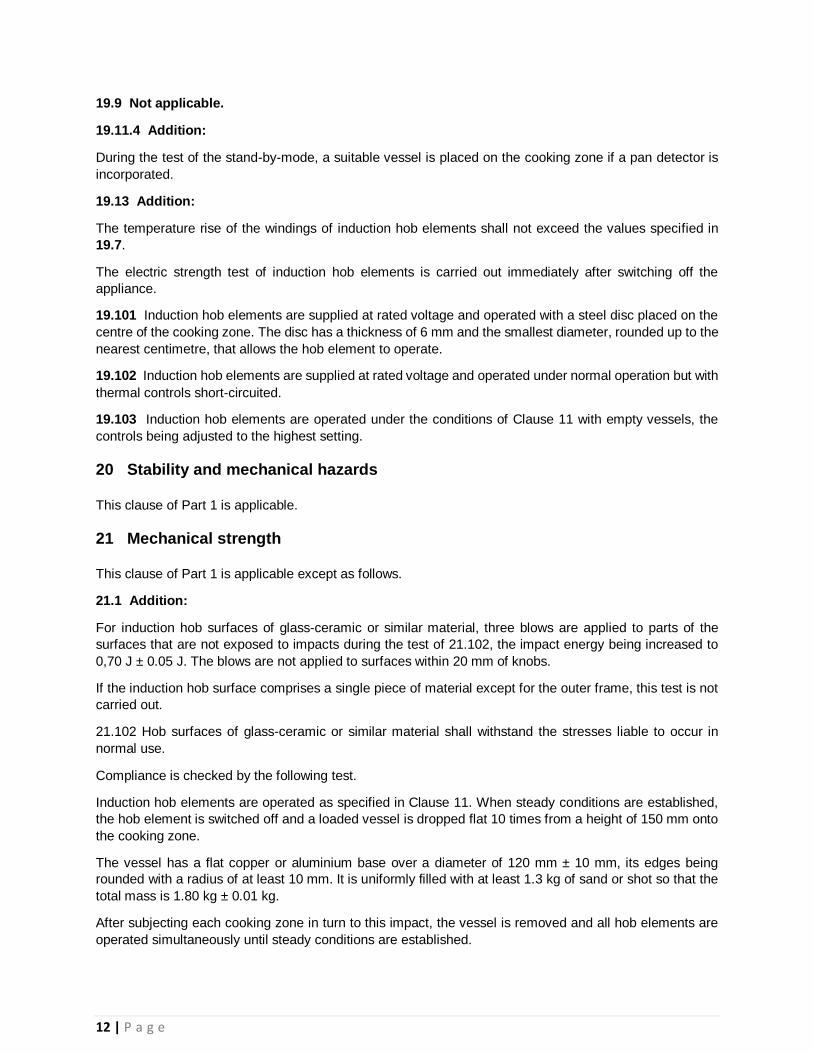
19.9 Not applicable.
19.11.4 Addition:
During the test of the stand-by-mode, a suitable vessel is placed on the cooking zone if a pan detector is
incorporated.
19.13 Addition:
The temperature rise of the windings of induction hob elements shall not exceed the values specified in
19.7.
The electric strength test of induction hob elements is carried out immediately after switching off the
appliance.
19.101 Induction hob elements are supplied at rated voltage and operated with a steel disc placed on the
centre of the cooking zone. The disc has a thickness of 6 mm and the smallest diameter, rounded up to the
nearest centimetre, that allows the hob element to operate.
19.102 Induction hob elements are supplied at rated voltage and operated under normal operation but with
thermal controls short-circuited.
19.103 Induction hob elements are operated under the conditions of Clause 11 with empty vessels, the
controls being adjusted to the highest setting.
20 Stability and mechanical hazards
This clause of Part 1 is applicable.
21 Mechanical strength
This clause of Part 1 is applicable except as follows.
21.1 Addition:
For induction hob surfaces of glass-ceramic or similar material, three blows are applied to parts of the
surfaces that are not exposed to impacts during the test of 21.102, the impact energy being increased to
0,70 J ± 0.05 J. The blows are not applied to surfaces within 20 mm of knobs.
If the induction hob surface comprises a single piece of material except for the outer frame, this test is not
carried out.
21.102 Hob surfaces of glass-ceramic or similar material shall withstand the stresses liable to occur in
normal use.
Compliance is checked by the following test.
Induction hob elements are operated as specified in Clause 11. When steady conditions are established,
the hob element is switched off and a loaded vessel is dropped flat 10 times from a height of 150 mm onto
the cooking zone.
The vessel has a flat copper or aluminium base over a diameter of 120 mm ± 10 mm, its edges being
rounded with a radius of at least 10 mm. It is uniformly filled with at least 1.3 kg of sand or shot so that the
total mass is 1.80 kg ± 0.01 kg.
After subjecting each cooking zone in turn to this impact, the vessel is removed and all hob elements are
operated simultaneously until steady conditions are established.

13 | P a g e
A quantity of 1 +00.1 l of water having a temperature of 24 °C ± 5 °C and containing approximately 1 %
NaCl is poured steadily over the hob surface. The appliance is then disconnected from the supply. After 15
min, all excess water is removed and the appliance allowed to cool to approximately room temperature.
The same quantity of the saline solution is poured over the hob surface after which excess water is removed
again.
The induction hob surface shall not crack and the appliance shall withstand the electric strength test of
16.3.
22 Construction
This clause of Part 1 is applicable except as follows.
22.113 Hobs shall be constructed so that inadvertent operation of touch controls is unlikely if this could
give rise to a hazardous situation due to
spillage of liquids, including that caused by a vessel boiling over; – a damp cloth placed on the control
panel.
Compliance is checked by the following test, the appliance being supplied at rated voltage. The test is
carried out with each hob element energized in turn and then without energizing any hob elements.
Sufficient water to completely cover the control panel to a depth not exceeding 2 mm, with a minimum of
140 ml, is poured steadily over the control panel so that bridging occurs between combinations of touch
pads.
A white cloth having a mass between 140 g/m2 and 170 g/m2, and dimensions approximately
400 mm × 400 mm, is folded four times into a square pad, saturated with water and placed over the control
panel in any position.
In case of doubt, different coloured cloths can be used.
There shall be no operation of any hob element for longer than 10 s.
During the test, it shall be possible to switch off the energized hob element by operating the touch controls,
unless it switches off automatically.
22.114 Induction hobs having touch controls shall incorporate visual means to indicate when each hob
element is energized.
Compliance is checked by inspection and by manual test.
22.115 Induction hob elements shall be constructed so that the hob element can only be operated when a
vessel is placed on the cooking zone.
Compliance is checked by the following test, the appliance being supplied at rated voltage.
An iron bar 2 mm thick having dimensions approximately 100 mm × 20 mm is placed in the most
unfavourable position on each cooking zone in turn. The controls are adjusted to their highest setting.
The temperature rise of the bar shall not exceed 35 K.
22.116 Induction hob elements incorporating a pan detector shall be constructed so that the hob element
is not switched on by the vessel if it has been removed for more than 10 min.
Compliance is checked by manual test.

14 | P a g e
22.117 In appliances incorporating a pan detector, a visual means shall indicate when the control for the
hob element is not switched to the off position.
Compliance is checked by inspection.
22.123 Appliances incorporating at least one hob element shall be designed so that it is possible to switch
off any energized hob element in the case of failure of any electronic component.
Compliance is checked by the following test:
The appliance is operated under the conditions specified in Clause 11 but supplied at rated voltage.
The fault conditions in a) to g) of 19.11.2 are then considered and, if necessary, applied one at a time to
the electronic circuit.
It shall be possible to switch off any energized hob element during the test.
NOTE If a pan detector is incorporated, a suitable vessel is placed on the cooking zone.
22.124 Appliances incorporating at least one hob element shall be designed so that the hob element does
not become energized unintentionally in case of any electronic component being rendered inoperative.
Compliance is checked by the following test:
The appliance is operated under the conditions specified in Clause 11 with all individual hob elements
switched off, the appliance being supplied at rated voltage.
The fault conditions in a) to g) of 19.11.2 are then considered and, if necessary, applied one at a time to
the electronic circuit.
There shall be no operation of any induction hob element for longer than 10 s.
NOTE If a pan detector is incorporated; a suitable vessel is placed on the cooking zone.
22.134 For induction hob element controlled by an electronic circuit, safety shall not be impaired in the
event of a fault in the electronic circuit.
Compliance is checked by the following test:
The appliance is operated under the conditions specified in Clause 11 but supplied at rated voltage.
The fault conditions in a) to g) of 19.11.2 are applied one at a time to the electronic circuit controlling the
duty cycle for each hob element in turn.
The control setting shall not change to a higher setting for longer than 2 min.
23 Internal wiring
This clause of Part 1 is applicable.
24 Components
This clause of Part 1 is applicable except as follows.
24.1.3 Addition:
Switches controlling induction hob elements are subjected to 30 000 cycles of operation.
24.1.4 Addition:

15 | P a g e
– energy regulators
• for automatic action 100 000
• for manual action 10 000
– self-resetting thermal cut-outs
25 Supply connection and external flexible cords
This clause of Part 1 is applicable.
26 Terminals for external conductors
This clause of Part 1 is applicable.
27 Provision for earthing
This clause of Part 1 is applicable.
28 Screws and connections
This clause of Part 1 is applicable.
29 Clearances, creepage distances and solid insulation
This clause of Part 1 is applicable except as follows.
29.2 Addition:
The microenvironment is pollution degree 3 unless the insulation is enclosed or located so that it is unlikely
to be exposed to pollution during normal use of the appliance.
30 Resistance to heat and fire
This clause of Part 1 is applicable except as follows.
31 Resistance to rusting
This clause of Part 1 is applicable except as follows.
Addition:
For ovens intended for use on board ships compliance is checked by the salt mist test Kb of IEC 60068-2-
52,
– for open deck use severity 1 is applicable;
– for dayrooms use severity 2 is applicable.
The coatings of metal parts are prepared for the test as follows:
Five scratches are made at least 5 mm apart and at least 5 mm from the edges of the relevant parts to be
tested.

16 | P a g e
The test pin of Subclause 21.2 is used for the test. The pin is held at an angle of 80° to 85° to the horizontal
and loaded so that the force exerted to its axes is 10 N ± 0,5 N. The scratches are made by drawing the
pin along the surface at a speed of approximately 20 mm/s.
After the test, the appliance shall not have deteriorated to such an extent that compliance with this standard,
in particular with Clauses 8 and 27, is impaired. The coating shall not be broken and shall not have detached
from the metal surface.
32 Radiation, toxicity and similar hazards
This clause of Part 1 is applicable.

17 | P a g e
Key:
A wall thickness, 2 mm ± 0.5 mm C maximum concavity d diameter of the flat area of the base thickness of base
d <145, 2mm± 0.5 mm d = 145 to 240, 3mm± 0.5 mm d >240, 5mm± 0.5 mm
The vessel is made of low carbon steel having a maximum carbon content of 0,08 %. It is cylindrical without metallic handles or protrusions. The diameter of the flat area of the base of the vessel is to be at least the diameter of the cooking zone. The maximum concavity of the base of the vessel is 0,006 d. The base of
the vessel is not to be convex.
Figure 101 – Vessel for testing induction hob elements
Key
A adhesive
B thermocouple wires 0,3 mm diameter to IEC 60584-1 Type K (chrome alumel) C handle arrangement permitting a contact force of 4 N ± 1 N
D polycarbonate tube: inside diameter 3 mm, outside diameter 5 mm E flat tinned copper disc: 5 mm diameter, 0,5 mm thick
Figure 102 – Probe for measuring surface temperatures
A
C
d
B A
E
D C /

18 | P a g e
Annexes
Annex R
(normative)
None

19 | P a g e
Bibliography
The bibliography of Part 1 is applicable except as follows.
Addition:
IEC 60335-2-9, Household and similar electrical appliances – Safety – Part 2-9: Particular requirements
for grills, toasters and similar portable cooking appliances
IEC 60335-2-25, Household and similar electrical appliances – Safety – Part 2-25: Particular
requirements for microwave ovens, including combination microwave ovens