
November 10-13, 1982 DE83 011369 - International Atomic ...
402
DISCLAIMER This report was prepared as an account of work sponsored by an agency of the United States Government. Neither the United States Government nor any agency thereof, nor any of their employees, makes any warranty, express or implied, or usomes any legal liability or responsi- bility for the accuracy, completeness, or usefulness of any information, apparatus, product, or process disctosed, or represents that its use would not infringe privately owned rigbts. Refer- ence herein to any specific commercial product, process, or service by trade name, trademark, manufacturer, or otherwise does not necessarily constitute or imply its endorsement, recom- mendation, or favoring by the United States Government or any agency thereof. The views and opinions of authors expressed herein do not necessarily state or reflect those of the United States Government or any agency thereof. INTERNATIONAL WORKSHOP ON BISMUTH GERMANATE Princeton Univers t. Department of Physi'r ; November 10-13, 1982 CONF-821160- DE83 011369 Sponsored by the U. S. National Science Foundation and Department of Energy • NOTICE PORTIONS Of WHS BEPOBT ABE ilUBIBUE. It has been reproduced from the best available copy to permit the broadest. i possible availability. ^?^^ Chairman: 0. G. Coyne, Princeton University Co-chairs: S. E. Derenzo, Lawrence Berkeley Laboratory (Nuclear Medicine) JXK A. E. Evans, Los Alamos Scientific Lab fp (Nuclear Physics) ™. T «muTiflM OF THIS OOCU»E« »S C. Newnan Holmes, Princeton University Mmm » ima «* (High Energy Physics) Proceedings Editor: C. Newman Holmes
-
Upload
khangminh22 -
Category
Documents
-
view
3 -
download
0
Transcript of November 10-13, 1982 DE83 011369 - International Atomic ...

DISCLAIMER
This report was prepared as an account of work sponsored by an agency of the United StatesGovernment. Neither the United States Government nor any agency thereof, nor any of theiremployees, makes any warranty, express or implied, or usomes any legal liability or responsi-bility for the accuracy, completeness, or usefulness of any information, apparatus, product, orprocess disctosed, or represents that its use would not infringe privately owned rigbts. Refer-ence herein to any specific commercial product, process, or service by trade name, trademark,manufacturer, or otherwise does not necessarily constitute or imply its endorsement, recom-mendation, or favoring by the United States Government or any agency thereof. The viewsand opinions of authors expressed herein do not necessarily state or reflect those of theUnited States Government or any agency thereof.
INTERNATIONAL WORKSHOP ON BISMUTH GERMANATE
Princeton Univers t .Department of Physi'r ;
November 10-13, 1982 C O N F - 8 2 1 1 6 0 -
DE83 011369
Sponsored by the U. S. National Science Foundationand Department of Energy
• NOTICEPORTIONS Of WHS BEPOBT ABE ilUBIBUE.It has been reproduced from the bestavailable copy to permit the broadest.
i possible availability. ^ ? ^ ^
Chairman: 0. G. Coyne, Princeton University
Co-chairs: S. E. Derenzo, Lawrence Berkeley Laboratory(Nuclear Medicine) JXK
A. E. Evans, Los Alamos Scienti f ic Lab fp(Nuclear Physics) ™.T«muTiflM OF THIS OOCU»E« »S
C. Newnan Holmes, Princeton University Mmm » ima «*(High Energy Physics)
Proceedings Editor: C. Newman Holmes
Foreword
This International Workshop gathered an interdisciplinary group of
scientists and industrialists interested in the Bismuth Germanate
scintillator - its theory, development and applications.
In this Departmental Report, we include all available contributions to
the Workshop in whatever form they were submitted, with an aim of producing
quickly a useful handbook of the state of technology. This is to be followed
by a formal publication of some fraction of these contributions.
The Workshop originated from the suggestions of Prof. Marcus McEllistrem
(University of Kentucky) and Dr. David Berley (NSF) that such a gathering, if
conducted in a timely way, might prove useful for their consideration of
major projects linked to this technology. We are grateful to them for this
motivation, as well as fiscal support from NSF and DOE.
I wish to thank my co-chairs for their organizational help and
suggestions for workshop format. In particular, Catherine Holmes has served
double-duty as co-chair and Proceedings manager. Finally, three people bore
the brunt of the logistical organization: V. R. Boscarino and Lois Smith of
the Princeton Physics Department, and Regina Johnson of SLAC. I am indebted
to these people for their fine efforts and to their organizations for the use
of their time.
Donald Coyne,
Chairman
m

TABLE OF CONTENTS
SESSION A INTRODUCTION AND MATERIAL PROPERTIESChair: F. Rosenberger
Conference PreviewU. b. Coyne 2
Discovery of the Sc in t i l l a t ion Properties of BGO: UnderlyingPrinciples
H. J. Weber 3
Bi<,Ge30iz(BGO) - A Sc in t i l la to r Replacement for Nal(T«)M. R. Farukhi 21
Improvements in the Sc in t i l l a t ion Response of BuGeaOizM. R. Farukhi 39
Bismuth Si l icate (BSO) as a Sc in t i l l a t ing Material for Electro-Magnetic Shower Detectors
5. Sugimoto 48
Radiation Damage of BUDH. Kobayashi 62
The Short-term Response of BGO to UV Light and x-RadiationM. Cavalli-Sforza 79
SESSION B PRODUCTION QUALITY AND COSTSChair: ,,. Cavalli-Sforza
The Present Status of the Research and Development of BismuthGermanate in China
Y. F. Gu 96
Growth and Defects of Bismuth Germanaie (BiiiGe3 O12) Single CrystalsFan S h i j i , Liu Jiancheng, and He Chongfan 103
Growth of Bi<< Gea O12 Crystals by the Heat Exchanger Method (HEM)F. Schmid and C. P. Khattak I l l
Influence of Surface Roughness and Crystal Shape on Sc in t i l l a t i onPerformance of Bismuth Germanates
H. Ishibashi, S. Akiyama, and H, Isht i 114 _
Progress in BGO Quality Improvements at Hitachih. l sh i t , S. Akiyama, and H. Ishibashi 135
SESSION C OPTIMIZATION AND ALTERNATIVESChair: D. Besset
Light Output Optimization From Various Geometries of BGO Crystals5. Anderson and M. Salomon 158
Effect of Crystal Shape, Absorption and bubbles on Light OutputS. E. Derenzo 163
Optical Measurements of the Substructure of BbOW. P. Unruh 168
An Alternative to 8G0D. F. Anderson
Outstanding Problems With BGO GrowthF. Rosenberger 203
SESSION D READOUTChair: i. Tompkins
Conventional Readout of Large 3G0 Arrays and CalibrationT. Matsui 210
Photodiode Readout and Related ProblemsE. Lorenz 229
Sil icon Photodiode Detection of Bismuth Germanate Sc in t i l l a t i onLight
D. E. Groom : 256
SESSION E MORE READOUTChair: P. Pjroue'
Low Noise Readout SystemsL. B. Levit 268
A New Approach to the Readout System For a Very Large BismuthGermanate Calorimeter
R. L. Sunner 273
A Novel Radiation Detector Consisting of an Hgl2 PhotodetectorCoupled to a S c i n t i l U t o r
J . G. Iwanczyk, J . B. Barton, A. J. Dabrowski, J. H. Kusmiss, andW. H. Szymczyk 286
A Si l icon Photocell for Sc in t i l l a t i on DetectionA. Kurahashi 290
SESSION F SPACE PHYSICS APPLICATIONSChair: A. E. Evans
Application of BGO to a Space Shuttle ExperimentA. C. Hester, R. B. Piercey, F. Giovane, P. S. Haskins,H. A. Mott i t t I I , J . L. Weinberg and F. E. Uunnam 296
BliO in Several Satell ite-Borne ApplicationsR. W. Klebesadel • 306
J'%'/

SESSION G NUCLEAR PHYSICS APPLICATIONS; Chair: rt. E. Evans
A 4u Bismuth Germanate (BGO) Detector Array for Heavy Ion Physics and thePrompt Response of BGO to Fast Neutrons
0. Hausser, M. A. Lone, T. K. Alexander, J . Gascon, and E. Hagberg. . . 327
Study of the Performance Characterist ics of a High Resolution M u l t i -Detector Array for Gamma Ray Spectroscopy
J. X. Saiadin, F. Avignone I I I , R. S. Moore, C. Baktash and I . Y. Lee. . 357
Fast Neutron-Capture Reactions With BGO DetectorsS. A. Wender 376
App l icab i l i t y of BGO to Continuum Gamma-ray Measurements of Heavy-Ion ReactionProducts
P. J . Horrissey and 5. H. Wernig 393
The Use of BGO in State-of-the-Art Nuclear SpectroscopyK. M. Lieder 408
Total Energy Suppression Shield Array (TESSA)P. J . Nolan 425
Unfolding Bismuth Germanate Pulse-Height Dist r ibut ions to DetermineGamma-Ray Flux Spectra and Dose Rates
C. E. Moss, M. E. Haimi, A. E. Evans, M. C. Lucas, E. R. Shunk andE. J . Dowdy 433
SESSION H NUCLEAR MEDICINE APPLICATIONSChair: C. Burnham
Ideal Crystal Sizes for Use in Positron Emission TomographyC. Nahmias 476
Dynamic Positron Emission Tomography In Man Using Small Bismuth GermanateCrystals
S. E. Derenzo, T. F. Budinger, R. H. Huesman, and J . L. Cahoon 467
Hiyh Resolution Detection Syst™ for Positron TomographyE. J . Hoffman 198
A One Dimensional Posit ion Sensitive BGO Detector for EmissionComputerized Tomography
C. Burnham, J. 8radshaw, D. Kaufman, D. Chesler, J . Correia andG. L. Brownell 514
SESSION I HIGH ENEkbY EXPERIMENTAL TESTS
Test of An Array of Seven Hexagonal BGO Crystals for High Energy Gammakay Spectroscopy
L. Tauscher et al 52B
Test of a BGO Calorimeter With Photodiode Readout Between 0.5 and10 GeV
H. Vogel 534
Linear i ty and Resolution of Photod'odesM. A. van Oriel and J. C. Sens 551
Test of BGO-Bars For Electromagnetic Shower Calorimeter";S. Sugimoto et al 568
SESSION J PROPOSED DEVICES FOR HIGH ENERGY APPLICATIONSChair: C. Newman Holmes
Plans for BGO Use in e+e" Experiments at DESYH. Spitzer 584
An Improved E. M. Calorimeter for the CUSB Detector Using BismuthGermanate
P. M. Tuts and P. Franzint 596
Proposed Use of BbO in a Small Angle Detector at the Stanford SLCDavid Koi t ick and L. Kasturi Rangan 620
A BGO Ball for the Stanford Linear Collide*-F. C. Porter 634
A BGO Shell Upgrade for an Existing Calorimeter at StanfordG. Loh 665
Some Projects fo r BGO Calorimeters in High Energy PhysicsF. Pauss 672
SESSION K INDUSTRIAL APPLICATIONSChair: u. G. Coyne
BGO Detectors Improve Spatial Resolution of Nuclear Fuel ScannersS. Untermeyer 68b
BbO in Oil Well LoggingJ. S. Schweitzer 696
BGO in Well LoggingD. Stromswold 698
SESSION L PARALLEL SESSIONS AND CONCLUSION
Improving the Longitudinal Uniformity in the Response of Long BGODetectors
M. Kobayasiii, S. Sugimoto, M. Ueda and H. Yoshida 702
Conference Summary: Where Do We Stand With BGO? Where Do We GoFrom Here?
M. Cavalli-Sforza 722
PMllCIP/tNTS 745
vii

PREVltW
Session A
INTRODUCTION AND MATERIAL PROPERTIES
BGO is d i f f e ren t things to d i f ferent users:
An object of study in i t s e l f .
A f inished product to be used without modif icat ion.
A panacea for experimental problems or pract ica l appl icat ions.
A new technique with d i f f e ren t constraints than cornpetinq ones.
A standard by which to judge a l ternat ive tecbninues--a challenne
to go beyond.
We hope to use th is in te rd isc ip l ina ry workshop to ..illuminate our own region of
interest f o r BGO by sharing in the experience of i t s other uses.
Wed. Standard/Controversial Properties o f past & future
mater ia ls.
Thurs. Readout
Thurs . /Fr i . Applications
Sat. Paral le l sessions
Provocateur's Talk

DISCOVERY OF THE SCINTILLATION PROPERTIES
OF BGO: UNDERLYING PRINCIPLES
M. J. Weber
Livennore Livermore National Laboratory
University of CaliforniaLivermore, CA 94550
Introduction
Tnere are several crystalline phases of the bismuth oxide-germanium oxide
system including one discovered recently and not noted in earlier phase
diagrams U,2J. Reported crystalline compounds are summarized in Table 1;
structural determinations are given in references [2-6]. In this workshop we
are concerned with the 2:3 compound of the Bi-Oo-GeO,, system: Bi^Ge-jO^-
This material has the most efficient fluorescence at ambient temperatures.
Table I
BISMUTH GERMANIUM OXIDE CRYSTALS
Formula
Bi2GeO5 !1Bi2O3 • lGeO,)
Bi 2Ge 30 9 (1Bi2O3 • 3GeO2)
Bi 4 Ge 3 0 1 2 (2Bi2O3 • 3GeO2)
(60i2O3 • 1GeO2J
Structure 1(P2BiA:m3
Orthorhombic —
Hexagonal 0.97
Cubic 1.38
Cubic 2.29
Table 11
HISTORY OF Bi 4 Ge 3 0 1 2
Structure -Menzer (19311 [x-rayl- Segal et tl. (1966) (neutron diffraction)
• Synthesis - Durlf (19571 [calcination]
- Liebcrt* (1969) ICzochralskil
• Electro-optic - Nitiche (1365!
• L«m -Johmon/BillnMn{1969)//V<f"/
• Luminescence -Webvr/Monchwnp (1973)
• Scintiilitor - Ntttor/Humg (1975)
ft capsule history of some important milestones in the development and
application of ei^GejO^ is presented in Table II (the dates listed are
those of relevant publications). Bismuth germanium oxide (BGO) is isomorphous
with the naturally occurring mineral eulytine, Bi^SijO^. The eulytine
structure was originally studied by Menzer L3J and later refined by Segal et al.
(.5J. BGO was'first synthesized in the late 1950s [7] and in the 1560s was
grown by a number of workers for studies of its electro-optic properties and
as a laser host material. Nitsche [3] grew crystals for Itis studies using a
crucible-less method. The Czochralski technique was subsequently perfected to
grow both undopecj L^.H)] and rare-earth doped (.11,12] crystals. The latter
led to the observation of stimulated emission from several different rare-earth
ions and transitions [11,13,14]. A list of laser ions and operating conditions
is given in Table III. The refractive indices of BGO were also measured
L15J. Reference L'3J contains a tabulation of additional physical properties
of BGO.
Discovery of BGO Luminescence
It was as part of a solid-state laser project at the Research Division of
Raytneon CompJiiy tnat Koch Monchamp began growing BGO crystals and 1 began
investiydtniy their spectroscopic properties. Because the x-ray tube division
wai interested in the x-ray intensifier screens and another division of the

T a b l e I I I
Si4Ge3O1 2 LASERS
Ion
Nd3 +
Ho3+
Tm 3 +
Yb 3 +
Transition Wavelength (ym) Temperature (K)
r3l2F3/2"
l
'i3/2
1.063-1.0671.342
2.087
295295
77
0.8531.558-1.664
1.850
1.030
7777
77
77
company was developing a gamma-ray camera and hence was interested in
scintillator materials, I nad concurrently set up an x-ray-excited
fluorescence spectrometer to search for improved scintillators. When present
as a dilute impurity, Bi was a known activator for various phosphor
materials L'6j. However, at high activator concentrations, such as that
existing for Bi in BGO, fluorescence from many ions becomes quenched due
to nonradiative decay by ion-ion interactions. In spite of this negative
prospect, I examined an undoped sample of BGO since it was a simple experiment
and - eureka - oDserved an intense luminescence at room temperature under both
optical and x-ray radiation. After studying the luminescence spectrum and
decay properties as a function of temperature and comparing them with those of
anotner compound, Bi^GeO^ 1.2,17,18], we published a paper in 1973 [19]
summarizing these results. This paper was submitted shortly before I left
Raytneon to join tne laser fusion program at the Lawrence Livermore Laboratory.
Because of tne nign effective atomic number of BGO, its intense
luminescence at room temperature, and its good physical properties, I
commented at the end of our paper L19J about the possible use of BGO for
Figure 1
CRYSTAL STRUCTURE - Bi4Ge3C12
Viewed along [111]
• GermaniumO,® Oxygen
0 Bismuth
sc in t i l l a t o r applications. Included was a plot of the x-ray absorption
coeff ic ient of Bi.Ge.O,, which demonstrated i t s superior absorption compared
to that of a commonly used sc in t i l l a to r screen material, CaW04, and a
sc in t i l l a t o r c rys ta l , NaI:Tl. Nestor and Huang [20] followed up on th is
suggestion and examined the sc in t i l l a t i on characteristics of BGO for several
detection applications. Subsequent work [21,22] confirmed the promise of BGO
and led to a pro l i ferat ion in the use of this material for the detection of
high energy radiation and charged particles which is the raison d'etre for
tnis conference. 1 won't review these developments further here since they
w i l l be reviewed by others in the course of these proceedings.
Structure
IlliO lias the cubic eulytine structure [3 .5J ; the lat t ice constant is
lu.<tyb k. The local structure at tne Bi 3 + s i te is i l lus t ra ted in Fig. 1.

Bismuth ions are surrounded by six GeO. tetrahedra. One oxygen of each
tetrahedron (shaded circles in Fig. 1) combines to form a distorted octahedral
nearest-neighbor coordination shell about Bi with three oxygens at a
distance of 2.19A and three more at a distance of 2.67». Many luminescence
compounds have been found to possess the eulytine structure [23]. These
include Ca3Bi(P04)3,H3Ln(P04)3, l y P O ^ S O , . ™ d M ^ L n ^ P O ^ f S i O ^ ,
where M = Sr or Ba, L" = Ls, Nd, Gd, Lu, Y, Sc, In, Bi, and 0 < x < 1.
Origin of Bi Luminescence
Trivalent bismuth is one of a number of post-transition-group filled-shell
ions L24J which luminesce. Its electronic configuration consists of filledo
shells tnrough the outer 6s shell. Several ion groups, their ground state,
and states of excited configurations ire given in Table IV. Other filled
snell ions, transitions, and excited configurations not included in the table
are of the type 4d * 4d 4p. Of the various post-transition-group ions, Bi
is the hignest Z, non-radioactive ion and therefore attractive for
scintillator applications.
The free-ion electronic energy levels of Bi arise from the combined
electrostatic and spin-orbit interactions and are shown at the left of Fig. 2;
Table IV
CLOSED SHELL IONS
CanflgurMlon-lon:
M . . S b . T .
. . . 6»2 - Hg°. T l \ Pt>2\ BI3*. Po4*
Ground ««• : m2 - 'So
Excited fUtn: mnp — 3P0 1 , ,
f igure 2
ENERGY LEVELS OF Bi'*
Fiwion Cryit.1 (iild
optical transitions are indicated by vertical arrows. The S_- P. transition
is an allowed electric-dipole transition and is very intense. Because of the
spin-orbit interaction, the Russell-Saunders state labels in Fig. 2 are no
longer pure spin states and S transitions are also possible via
this admixing. Both of these transitions have a large oscillator strength.
In contrast, the S_- P_ transition is strongly forbidden and very
weak.
when Bi ions enter a crystal, the electronic shell expands
(nephelauxetic effect) which reduces the electrostatic and spin-orbit
interactions and decreases the separation between the ground and excited
states as indicated in Fig. 2. In addition, depending upon the point group
Symnetry of the the crystal field at the Bi site, the 2J+1-fold degeneracy
of the free-ion states is reduced. Several examples of this are included in
Fig. z. Uue to the crystal-field interaction, J states are admixed and
additional electric-dipole transitions become possible. In BGO the Bi site
has C, symmetry. Of the 6s post-transition-group ions, the S n - Pn energyt ?+ 1+
separation decreases in the order Tl , Pb , Bi .
liecduse the interaction of Bi with its surroundings depends upon
whether it is in the ground or excited states, a simple configuration
coordinate diagram is useful in explaining the origin of the excitation and

Figure 3
CCMHGURATIONAL COORDINATE MODEL OF Bi3*
Coordinate Q -
emission spectra. Such a diagram showing the different potential curves and
equilibrium positions of the ground and excited electronic states in terms of a
generalized nuclear coordinate Q is shown in Fig. 3. Consider excitation
by an optical transition such as Sn * P, or P,. This absorption is
followed in BGO by a rapid (<10 ns) nonradiative ^ecau to the 0Pj and P.
states indicated by tne wavy transitions in Fig. i. s noted earlier, the
SP0is vel"y weaK. However, if tne energy
difference a£ is < kT, tnere will be a significant thermal population in the ^P^
stale wnicn lias a mucn greater probability for radiative decay. As evident
from the transitions depicted in Fig. 3, there will be a large Stokes shift
cetween absorption and Mission wavelengths. This is illustrated by the
spectra for UGO [19J in Fig. 4 which exhibit no spectral overlap.
The description of the luminescence of Bi given thus far is
appropriate to an isolated Bi ion in a crystal and accounted for the spectral
properties ouse.-ved in numerous materials [25.26J. The crystal field at Bi 3 +
sites in BGO nave also be.jn analyzed based on the spectra of substitutional
trivalent rare-earth ions 127J. An alternative description of the luminescence
of BGO has been given by considering BiO, complexes. Molecular orbital
Figure 4
Excitstion
200 400 500
Wavelength (nm)
600
calculations of the associated energy levels and transition probabilities are
reported in reference [28J.
Temperature Dependence of Bi Luminescence
At low temperatures [T « aE(3P, - 3P0).l. only the PQ excited state is
populated and the emission intensity is very weak because of the forbiddeness
of the •'Py •» 's0 transition. The associated radiative lifetime is very long,
typically >lo"4s. At higher temperatures, levels of the Pj state become
thermally populated and because of the greater probability for radiative decay
to S.., the luminescence lifetime decreases. At still higher temperatures,3 3 1depending upon the crossover energy AE 1 of the P«, P. and S_ potential
curves in Fig. 3, excited Bi ions may also decay by nonradiative processes.
Tnis accounts for the onset of a further rapid decrease in lifetime with
increasing temperature. This overall lifetime behavior is shown for the
luminescence of BGO in Fig. 5 based on data from references L19] and [29].
Also shown in Fig. 5 is the integrated emission intensity which decreases at
higher temperature due to the reduced radiative quantum efficiency.

Figure 6
TEMPERATURE DEPENDENCE OF Bi3* LUMINESCENCE
10 30 100
Temperature (K)
300 600
The temperature dependence of the Bi luminescence in solids can be
described by a simple relaxation model shown in Fig. 6 [26,29,30]. Here the
crystalline Stark splitting of the Pj state is omitted and only the lowest
level or, at high temperatures, all levels with an appropriate degeneracy
factor are considered. Radiative transition probabilitios are denoted by A
and nonradiative transition probabilities by M; the latter are temperature
dependent. The p and p. states are in rapid thermal equilibrium described by
the detailed balance relation at the ;op right of Fig 6. For a three-level
system, the relaxation kinetics following pulsed excitation is given by a sum
of two exponential terms with fast and slow rate constants included in Fig. 6.
Hie various transition probabilities A and M and the average P, - P., energy
separation aE are obtained by fitting data such as shown in Fig. 5 with this
model.
Energy Transfer
In addition to the radiative and nonradiative transitions discussed
auove, excitation moy also De transferred between ions due to ion-ion
Figure 6
RELAXATION MODEL FOR Bi3*
'P, 2-
A20
'S,, 0 -
A.n W.,
T w,.2. •*
1 • Mp(-AE/kT>
interactions. This constitutes another relaxation process for Bi activated
materials if energy migrates spatially between Bi *ions, which act as donors
(D), until it reaches an acceptor (A), which serves as an energy sink and
fluorescence quencher. Alternatively, the acceptor could be another
fluorescence ion which might be utilized to shift the Bi to a more
spectrally favorable region. (An example of this is mentioned ,n reference
y'£2\.) Donor-donor migration and donor-acceptor transfer are illustrated in
Fiy. 7, where an asterisk denotes an excited ion. The ion-ion interaction
involved may arise from electric-inultipole or exchange coupling. In either
case, the rate constants depend on the strength of the interaction and the
spectral overlap integral of the line shape function g(E) of the transitions
in m e two ions. In many Bi 3 + activated materials, the Stokes shift of the
lowest eneryy ausorption and emission transition is very large. This reduce?
the specti dl overlap and makes energy migration to quenching centers less
proiMUle. It also slows the rate of migration to other activators. Thus in
lit.0, which exhibits a large Stokes shift, migration to other activator ions or
quenching centers ib expected to be inhibited.
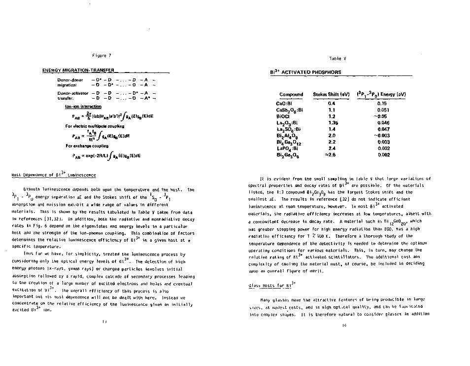
Figure 7
ENERGY MIGRATION-TRANSFER
Donor-donor - D» - D - . . . - D - Amigration: - D - D" - . . . - D - A
Donor-activator - D - D - . . . - D* - Atransfer: - D - D - . . . - D - A*
Ion-ion interaction
For electric multipot* coupling
For exchange coupling
P A B ct exp(-2R/u/gA(E)8B(E)dE
Host Dependence of Bi Luminescence
Bismuth luminescence depends both upon the temperature and the host. The
P| - PQ energy separation &E and the Stokes shift of the 's Q - 3P,
absorption and emission exhibit a wide range of values in different
materials. This is shown by the results tabulated in Table V taken from data
in references [31.32J. In addition, both the radiative and nonradiative decay
rates in Fig. 6 depend on the eigenstates and energy levels in a particular
host ami tlie strength of the ion-phonon coupling. This combination of factors
determines the relative luminescence efficiency of Bi 3 + in a given host at a
specific temperature.
THUS far we have, for simplicity, treated the luminescence process by
considering only the optical energy levels of Bi . The detection of high
energy photons (x-rays, gamma rays) or charged particles involves initial
absorption followed uy a rapid, complex cascade of secondary processes leading
to tne creation of a large number of excited electrons and holes and eventual
excitation of lit . The overall efficiency of this process is also
important but its host dependence will not be dealt with here. Instead we
concentrate^on tne relative efficiency of the luminescence given an initially
excited Bi ion.
Table V
Bi 3 + ACTIVATED PHOSPHORS
Compound Stokes Shift (eV) (3P, - 3 P 0 ) Energy (aV)
CaO:BiCaSb2O6:BiBiOCILa2O3:BiLa2SO6:BiBi2AJ4O9
Bi 4 Ge 3 0 , 2
LaPO4:BiBi 2 Ge 3 0 9
0.41.11.21.351.42.02.22.4
=2.5
0.150.051
-0.050.0460.047
-0.0030.0030.0020.002
It is evidenr from the small sampling in Table V that large variations of
spectral properties and decay rates of 61 are possible. Of the materials
listed, the 1:3 compound Bi26e,Og has the largest Stokes shift and the
smallest AE. The results in reference [32] do not indicate efficient
luminescence at room temperature, however. In most Bi activated
materials, the radiative efficiency increases at low temperatures, albeit with
a concomitant decrease in decay rate. A material such as Bi GeO , which
lias greater stopping power for high energy radiation than BGO, has a high
radiative efficiency for T ? 100 K,. Therefore a thorough study of the
temperature dependence of the detectivity is needed to determine the optimum
operating conditions for various materials. This, in turn, may change the
relative rating of 8( 3 + activated scintiUators. The additional cost and
complexity of cooling the material must, of course, be included in deciding
upon an overall figure of merit.
Gj[assHostsfor j
Many glasses Have the attractive features of being producible in large
i izes, at modest costs, and in High opt.cat qual i ty , and can be fabiicated
into complex shapes. I t is therefore natural to consider glasses in addition
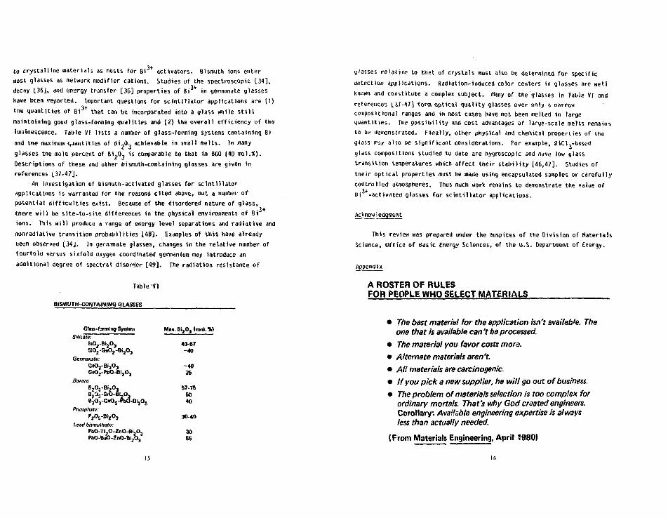
to crystalline materials as hosts for Bi3+ activators. Bismuth ions entermost glasses as network modifier cations. Studies of the spectroscopic [34],decay I.35J, and energy transfer [36] properties of Bi in germanate glasseshave Dcen reported. Important questions for scintillator applications are 11)the quantities of Bi that can be incorporated into a glass while s t i l lmaintaining good glass-forming qualities and (2) the overall efficiency of theluminescence. Table VI lists a number of glass-forming systems containing Biand trie maximum Cjjantities of bii,0, achievable in small melts. In manyglasses the mole percent of iiipO, is comparable to that in BGO (40 mol.i).Descriptions of these and other bismuth-containing glasses are given inreferences L37-47J.
An investigation of bismuth-activated glasses for scintillatorapplications is warranted for the reasons cited above, but a number ofpotential difficulties exist. Because of the disordered nature of glass,there wil l be site-to-site differences in the physical environments of Biions. This wil l produce a range of energy level separations and radiative andnonradiative transition probabilities [48). Examples of this have alreadyoeeci observed [34J. In gemmate glasses, changes in the relative number offourfold versus sixfold oxygen coordinated germanium may introduce anadditional degree of spectral disorder [-49]. The radiation resistance of
.3+
Table VI
BISMUTH-CONTAINING GLASSES
Gfiss-fornring SyitamSilicate:
Si02-Bl20jSi02-G«02-Bij0j
Germanate:GeO2-Bi2O3
GeOj-PbO-BijO,
Borne:B2O3-Bi,O3
BjC*3-SfO-BizO3
BjOj-GtO.-PbO-GijO,
Phosphate:P 2 O 6 - B i 2 O 3
l e j { / bismulhate:PbO-TLO-ZnO-BljO,PbO-BaO-ZnO-BUO,
Mtt.Bi20jlnm1.%)
40-57-40
-4026
57-reBO40
30-40
3055
15
glasses relative to th;>>. of crystals must also be determined for specificdetection applications. Radiation-induced color centers in glasses are wellknown and constitute a complex subject. Many of the glasses in Tibie VI andreferences L37-4?] form optical quality glasses over only a narrowcompositional ranges and in roost cases have not been melted in largequantities. The possibility and cost advantages of large-scale melts remainsto be demonstrated. Finally, other physical and chemical properties of theglass mzy also Be significant considerations. For example, 8iCl3-basedglass compositions studied to date are hygroscopic and have low glasstransition temperatures which affect their stabil ity [46,47}. Studies oftheir optical properties must be made using encapsulated samples or carefullycontrolled atmospheres. Thus much work remains to demonstrate the value ofBi +-activated glasses for scintillator applications.
This review was prepared under the auspices of the Division of MaterialsScience, Office of Basic Energy Sciences, of the U.S. Department of Energy.
A ROSTER OF RULESFOR PEOPLE WHO SELECT MATERIALS
• The best material for the application isn't availab'e. Theone that is available can't be processed.
• The material you favor costs more.
• Alternate materials aren't.
• All materials are carcinogenic.
• If you pick a new supplier, he will go out of business.
• The problem of materials selection is too complex forordinary mortals. That's why God created engineers.Corollary: Available engineering expertise is alwaysless than actually needed.
(From Materials Engineering, April 1980)

REFERENCES
2.
3.
4.
5.
6.
7.
8.
9.
10.
11.
12.
13.
14.
E. J. Speransfcaya and A. A. Arshakjmi, "The bismuth oxide-germanium
dioxide system," Russ. J. Inorg. Chem. 9, 226 (1964).
E. M. Levin and R. S. Roth, "Polymorphism of bismuth sesquioxide, II.
Effect of oxide additions on the polymorphism of BiJ) ," J. Res.
Natl. Bur. Std. 68A, 197 (1964).
G. Henzer, "Die kr is ta l ls t ruk tur von eu ly t in " , Z. K r i s t . A78, 136 (1931).
8. Aur iv i l lus , C. I . Lindblom, and P. Stenson, "The crystal structure of
Bi2Ge05", Acta Chem. Scand. J8, 1555 (1964).
0. J. Segal, R. P. Santoro, and R. E. Newnham, "Neutron-diffraction study
of B i 4 Si 3 0 1 2 " , Z. Kr i s t . _I23, 73 (1966).
B. C. Grabmaier, S. Haussuhl, and P. KlUfers, "Crystal growth, structure,
and physical properties of Bi2Ge30y", I. Kr is ta l logr . J49, 261 (1979).
A. Durif, "Sur quelques composes isomorpher> de Eulyt ine," Compt. Rend.
224, 2815 (1957).
R. Nitsche, "Crystal growth and electro-optic effect of bismuth
germanate, B i ^ G e O ^ y , J. Appl. Phys. 36, 2358 (1965).
J. Liebertz, "Einkristallztichtung von wisfflutgermanat [Bi4(Ge04)3]",
J. Cryst. Growth 5, 150 (1969).
H. Philipsborn, "Croissance d'eulytine Bi.SI.O.- et des composes
substitues 6i4Ge30j2 par la methode Czochralski", J. Cryst. Growth
U, 348 (1971).
L. F. Johnson and A. A, Ballman, "Coherent emission from rare-earth ions
in electro-optic crystals", J. Appl. Phys. 40, 297 (1969).
1. K. Dickinson, R. M. Hilton, and H. E. Lipson, "Czochralski synthesis
and properties of rare-earth doped bismuth germanate (Bi .Ge,0,,),"
Mat. Res. Bull, h 181 (1972).
A. A. Kaminskii, D. Schultze, B. Hermoneit, S. E. Sarkisov, L. Li, J.
tfohm, P. Reiche, R. Ehlert, A. A. Mayer, V. A. Lomonov, and V. A.
Ualaskov, "Spectroscopic properties and stimulated emission in the
r3/24 3+
' l3 /2 1 ( " a n s ' t | o n s of Nd ions from cubicBi4Ge30)2 crystals," Pnys. Stat. Sol, A. 33, 737 (1976).
A. A. Kaminskii, S. E. Sarkisov, T. I . Butaeva, G. A. Oenisenko,
B. Hermoneit, J. Bohm, W. Grosskreutz, and D. Schultze, "Growth,
spectroscopy, and stimulated emission of cubic BiaGe,0,, Crystals Doped
witl i Dy
(1979).
3 + Ho3* Er3* Tm3 +
or Yb3+ ions"
17
Phys. Stat. Sol. A. 56, 726
lb.
1t>.
17.
IB.
19.
20.
21.
22.
23.
24.
2b.
ih.
L). P. Bortfeld and H. Meier, "Refractive indices and electro-optic
coeff icients of the euli t ines Bi4Ge30)2 and B i 4 Si 3 0 ) 2 " , J . Appl. Phys.
43, 5110 (1972).
G. Blasse and A. B r i l , "Investigations on Bi -activated phosphors", J .
Chem. Phys. 4a, 217 (1968).
A. A. Ballinan, "The growth and properties of piezoelectric bismuth
germanium oxide 8i,,GeO,0", J . Cryst. Growth J,37 (1967).
R. B. Lauer, "Photoluminescence in Bij^SiO^g and Bi^GeO^Q11,
Appl. Phys. Le t t . V,, 178 (1970).
M. J . Weber and R. R. Monchamp, "Luminescence of Bi.Ge,0,.,:
spectral ar.d decay prope t i e s " , J . Appl. Phys. 44_, 5496 (1973).
0. H. Nestor and C. t . Huang, "B1sm>;lii germanate: a hioh Z gamma-ray and
charged part ic le detector", IEEE Trans. Nucl. Sci . , NS-22, 68 (1975).
Z. H. Ctio and H. R. Farukhi, "Bismuth germanate as a potential
sc in t i l l a t o r detector in positron cameras," J . Nucl. Med. j f i , 840 (1977).
See, for example, M. R. Farukhi, "Recent developments in sc in t i l l a t i on
detectors for x-ray CT and positron CT applications", IEEE Trans. Nucl.
Sc i . NS-29, 1237 (1982) and references c i ted therein.
G. Blasse, "New compounds with eulytine structure: crystal chemistry and
luminescence", J . Solid State Chem. 2, 27 (1970).
B. Jacquier, "Luminescence Spectra of Solids: Fi l led-Shell Ions" in
Luminescence of Inorganic Solids, ed. B. DiBartolo (Plenum, New York and
London, 1978).
G. Boulon, "Processus de photoluminescence dans les oxydes et les
orthovanadates de terres rares po lycr is ta l l ins actives par 1'ion Bi + " ,
J . Physique 32, 3J3 (1971).
G. Boulon, C. Peu. isi i , H. Guidoni, and Ch. Pannel, "Etude de lu cinetique
des centres luminogenes Bi
(I975).
3+ dans les rristaux", J. Physique 36, 262
3+il. C. A. Morrison and R. P. Leavitt, "Crystal field analysis of Nd and
Er 3 + in Bi4Ge30)2", J. Chem. Phys. T4, 25 (1981).
211. R. Moncorge, B. Jacquier, G. Boulon, F. Gaume-Hahn, and J. Jamin,
"Electronic structure and photoluminescence processes in Bi4Gej0)2
single crystals", J. Lumin. 12/13, 467 (1976).
M. It. Moncorge, B. Jacquier, and G. Bouion, Temperature dependent
luminescence of Si^GeJ)^. Discussion on possible models", J.
Lumiii. ] ^ , 337 (1976).
18

30.
31.
32.
33.
35.
36.
37.
38
39.
40.
41.
42.
See, for example, A. C. van der Steen, J. J. A. van Hesteren, and A. P.
SloK, "Luminescence of the Bi ion in compounds LiLnO^ and NaLnO.,
(in = be, Y, La, Gd, Lu)", J. Electrochsm. Soc. J28, 1327 (1981) and
references cited therein.
G. Blasse and A. C. van der Steen, "Luminescence characteristics of
Bi 3 + activated oxides," Solid State Commun. 3±, 993 (1979).
C. W. M. Tiirenermans, 0. Boen Ho and G. Blasse, "The luminescence of
Bi,GeA Solid State Commun. 42, 505 (1982).
D. P. Neikirk and R. C. Powell, "Laser time-resolved spectroscopy studies
of host-sensitised energy transfer in Bi^GejO^: Er * crystals",
J. Lumin. 20, 261 (1979).
34. G. Boulon, B. Moine, and J. C. Bourcet, "Spectroscopic properties of3Pj and 3 P Q excited states of Bi
3t Ions in gennanate glass", Phys. Rev. B
22, 1163 (1980).
G. Boulon, B. Moine, J. C. Bourcet, R. Reisfeld and Y. Kalisky, "Time
resolved spectroscopy about Pj and P levels in Bi doped
germanate glasses", J. Lumin. 18/19, 924 (1979).
Y. Kalisky, R. Reisfeld, and J. S. Bodenheimer "Concentration dependence
of energy transfer from Bi to N(T in germanate glass", J. Non.
Cryst. Solids 44, 249 (1981).
H. Rawson, Inorganic Glass-Forming Systems, (Academic Press, London and
New York, 1967).
A. Bishay.andC. Maghrab), "Properties of bismuth glasses in re la t ion to
structure," Pnys. Cnem. Glasses J£, 1 (1969).
J. A. Topping, N. Cameron, and M. K. Murthy, "Properties and structure of
glasses in the system Bi.,O,-SiO,,-GeO " , J. Am. Ceram. Soc. 5£, 519
(1974).
by andF. Riebling, "Alteration of amorphous B
J. Hater. Sci. JO, 156b (1975).
S. b. Kasymova, S. P. Lun'kin, and E. M. Milyukov, "Glass-forming region
and optical properties of lead(ll) oxide-bismuth oxide-germanium(IV)oxide glasses", iov. J. Glass Phys. Chem. 2, 503 (1976).
w. H. Uunmauyn, "Lead uismuthate glasses", Phys. Chem. Glasses _l£i '?'
(1978).
t. M. Milyukov, S. P. Lun'kin, and 2. S. Mal'tseva, "Glass-forming
regions and the optical properties of some borate and germanate glass
systems containing Bi.,03 or PoO", Sov J. Glass Phys. Chein. b_, 551
( 1 9 7 9 ) .
19
44. K. Nassau and 0. L. Chadwick, "Glass-forming systems involving GeO,
with Bij/Jj, T12O, and PbO," J. Am. Ceram. Soc. 65, 486 (1982).
4b. K. Nassau and D. L. Chadwick, "Glass formation in the system
Ge0.,-6i203-Tl20, J. Am. Ceram. Soc. 65, 197 (1982).
4b. C. A. Angel 1 and 0. C. Ziegler, "Inorganic chloride and mixed halide
glasses wir.i IOW maximum phenomenon frequencies," Hat. Res. Bull. J<[, 279
(1981).
M. J. HFoer, 0. C. Ziegler, and C. A. Angell, "Tailoring stimulated
emission cross sections of Nd laser glass: observation of large
cross-sections for BiCl^ glasses," J. Appl. Phys. 53 4344 (1982).
H. J. Weber, "Laser Excited Fluorescence Spectroscopy in Glass," in Laser
Spectroscopy of Solids, eds. W. M. Yen and P. M. Selzer (Springer,
Berlin, 1981), p. 189.
49. M. I;. Murthy (pr ivate communication).
47
4B.

(BGO) - A Sclntlllator Replacement for Nal(Tl)
H. *.. FarukhiDarshaw Chemical Company, 6801 Cochran » d . , Solon, Ohio 44139 DSA
ABSTRACT
Scintillation performance of recent (21) grown BGO Is studied- Result*Indicate BGO to perform better than 81 l*'Ca 7WHM Nal(Tl) at energies 2.6 Hevand higher. Even the low energy performance of BGO la suitable for consideringIt In lieu of Nal(Tl) for many apectroacoplc appllcatioaa.
INTRODUCTION
The history of Nal(Tl) as a useful sclntlllator started withQofstadter'a observstlon ID 1948:
"In tests made by placing crystals of Nsl, RX, snd nsphtalene onphotographic platea much greater light output waa observed from Nal thanfrom naphtalene samples of comparable site..."
Phy*. Rev. 7«sl00 (1948)
Hofstadter [21 then added a "pinch of thallium halide" to Nal and since 1948,Nal(Tl) became the primary scintillation detector of choice for application*It: [3]
1. Geophysical *nd environmental (clenc*2. Nuclear fuel cycle3- Nuclear medicine4. Space science5- High energy phyalc*
KI snd KI(T1) were grown flrat and investigated for scintillationdetection but lta use was limited due to It* Inherent radioactivity ifld•omewhat poor light output compared to Hal(Tl). Scintillating alternatea suchas CsI(Tl), LlI(Zu), Cal(Na) and CsFj(Eu) made their debut* at vaiious time* inthe chronological history of inorganic *clntlllatln« crystalline phosphor*, buteach one of these sclntlllstors found their awn niche for particularapplications requiring their unique characteristic*. Nsi(Tl) ha* continued tooccupy the malnate? pcaltlon to date-
Luminescence of BGO to x-ray excitation vas first observed and studied byWeber and Honchsmp [4) In 1973. A year later, Nestor and Huang [5] presenteddsts on the scintillation response to gamma rays from *7Co, l*'C», "N» and2*'Am-alpha particle*. The scintillation response compared to Nal(Tl) did notel ic it anything more than a curious interest for spectroscoplc appllcstlons-(See Tabl* 1).
Table 1Scintillation Properties o£ BGO snd N*I(T1)
•J'cs- Decay Wave LengthPulse Height Resolution Constant Emax DensityRelative Unlta g TWHM naec nm g/cc
BGONal(Tl)
8100
is 300230
480415
7.133.67
21
The acceptance of BGO for commercial and research applications atemmedfrom a property (afterglow) that had not been recignlted *a significantlyimportant to measure- Indeed for spectroscoplc applications it is not ofprlrary concern as evidenced by the wide variation in afterglow lp Nal(Tl).The x-ray CT instrument manufacturers atartlng from AS and E and Ohio Nuclear(uow Technlcare) adopted the use of BGO due to ltx high (topping power, oon-hygroscoplc nature and most Importantly, a lack or any measurable aftergloweven to very high incident x-ray flux- It become the detector of choice from1975-1978 replacing HaX(Tl) the flrat scintillation detector used byBounefield^ in the discovery of the x-ray CT technique.
Development* 1 75 - 1982
Afterglow studies in BGO and other aclntlllatora vere conducted In 1977by Farukhi 17) In collaboration with Cho and Mattson* BGO demonstrated thelowest value for afterglow with CdtfO^ having * comparable value* A value ofleas than 0.0051 at 3 ma for x-rays generated in the range of 60 - ISO Kev Isa commonly accepted value. More exact studlea are needed and will moBt prob-ably be forthcoming as present CT scanners approach the sub-^llllaecond scantimes for medical diagnostic Imaging.
C4W04 has replaced BGO for x-ray CT application* due to It* higher lightoutput and emission In the longer vavelengtha (540 nm) providing for betterspectral <aatch and performauc* to •lllcon-dlodes. The increasing u*e of CdVO{in XCT scanning forebode the and of BCO as • useful aclntillator vere it notfor Its possible use In spectroscoplc applications. Consequently, problems Inmaterial purification and cryatal growth perfection were addressed at Hsrshawleading to what is colloquially termed "spsctroscoplr grade" or "twice" (2X)or "thrice" (35) ciystalllied llfcGajOH-
Specttoscoplc applications for BGO atarted with its use In positron CTimaging. Cho and Farukhl (8] reported on the potential use of BGO forpoaltron CT imaging baaed on coincidence resolving times of 7.0 n« FWHM for111 kev annihilation gammas and a four-fold photofractlon advantage overNal(Tl). Baaed on these observations alone, Thompson, Tamamoto and Meyer [9]In collaboration with ratuMil and the technical staff at Barshaw took the beldstep In contracting to have the latter build the first BGO positron tomographfor installation at the Hontresl Neurological Institute. This machine hastaken over 3500 scans to data. Several commercial and research scannere arepresently ia existence undergoing continuing improvements In Imaging and fuac-tlonal parameter*.
The iapaaae with Nal(Tl) was overcome and BCO has replaced Hal(Tl) forpoaltron CT application* *nd in particular In tho»e *ystem* striving for highefficiency «nd high resolution. C*F and Bar^ * r e viable *ltern*tivea to BGO b7virtue of their fast decay m£ coincident reaolving time*. These and someother aclntillator* [10J offer the possibility of using time-of-flight infor-mation in the reconstruction to yield a factor of 2 Itiprovement in the image •contrast. But none of these alternatives offer the general appeal of BGO forspectroscoplc applications.
Table 2 tracks the chronological hlatory of coincidence resolving time*(CRT) for BCO in the poaltron CT field and indicates certsln trends:
1. The BGO-BGO resolving time* have continued to improve and are directlytraceable to the quality of the cryatal aa reflected by light outputwhich In turn minimise* the Jitter. (See Table 3 for light outputimprovement.)
22

TABLE 2
CCIMCIDEHCE RESOLVING TIKES (Sll KaV) TOR SCO WITHCHRONOLOGICAL IMPROVEMENT IH CRYSTAL QUALITY AHD PERFOMAMCE
Tear
1976
1977
1579
1980
1981
1981
1981
1982
1982
Start/Stop
BGO-BGO
BGO-BGO
BGO-BGO
BCO-BGO
BGO-BGO
BGO-BGO
BGO-BGO
BGO-BGO
BGO-BGO
FWRU_Si.
7.0
15-20
5.0
5.2
5-10
3.6
2.1
2.9
2.0
Thrcahold_ZeV
100
350
300
350
100
350
350
330
- 350
PUTTrpe
RCA 8575
HTV 1213
Aapx. PN 1910
Aapx. PH 1910
HTV R647
HTV R1362
HTV M362
HTV R1S48
HTV R329-2
Dla. In.BCD Sit*CM Reference
2 2.0 x 3.8 Cho and Farukhl (8)
0.75 1.8/2.2 x 3 x 3 Thoapaon, Taaaaoto and Merer '.9)
0.75 2.0 x 3.8 Carroll, Rendry and Currl'. (11)
0.75 1.2 x 2.0 x 2.6 Nohera, Tanaka, Toaltaal e t . a l . (12)
C.5 0.8 x 2 x 3 Farukhl (13)
1.125 1.5 x 2.4 x 2.4 Murayaaa, Hohara, Tanaka acd Hayaahi (14)
1.125 1.5 x 2.4 x 2.4 Takaal, Ishlaatau, Hayaehi et. al (15)
Dual 1.2 x 2.4 x 2.4 Taaaahlta, I to «nd Hayashl (16)
2 1.5 x 2.4 * 2.4 Ofcajlaa, Takaal, Deda at. al. (17)
1979
1979
1981
1982
1982
CaF-BGO
CaF-BGO
CaF-EGO
HE104-BGO
NE104-BG0
HE104-BGO
3.2
2.4
2.1
2.3
1.6
1.4
100
250
100
350
350
3 SO
Aapx. XP2020
RCA S575
C 31024
HTV R1548Reet.
HTV R1326
HTV R329-2
2
2
2
Dual0.47x 0.94
1.125
2
2 x 3.2 Alleaand, Graaaet and Vacher (181
2.5 Cuba tiullanl, Flcke, Ter-Pogoaalaa (19)
2 x 3.2 Moazynaki, Greaaet, Vacher et. al. (20)
1.2 x 2.4 x 2.4 Uchlda, Taaashlta et. al. (21)
U 5 x 2.4 x 2.4 Takaal, Iahlaatau, Hayaahl et. al. (16)
1.5 x 2.4 x 2.4 Okajlaa, Takaal, Ueda at. al. (IB)
SB «fm nM 9
3s
IIo. AIS
S3p* »
3- 5
si
I
• 8 s
rt •
3• 9*
ssp- A
•d o i OQ o* * Ht »* 1 On • o BIf N • O »
0 Hi A
c* rt 00 * - B O
5^°.S"'S-S"8f . S*i rt C Of t £ O* P* A M>• tt 1 i) 1 •
n Z m " SirsriSA n a. • p*i M 3"
rt m MO » w Aft M> w — 1 3
• S 1 I 2rt ^SI• H> rt ft to <»
P • 3" • »*H> P* t j » nn •
ft O O C B P* » 3"7 ! ""S'2. S o.«»1 t* 3* A t * A
M n A "a »
^ o f i s s • an " 3 " S * S M 0pt Ot e o A w n
rr p> ft v rt O» H> ft r* r*. it flp* • e » o • • o» A ft • 0 0m 9 n p*
MI &• O* • 0 9 9
H • * A » » P* iif-» r-i •* a r> c
w§ffh i l l
*-* *-N en
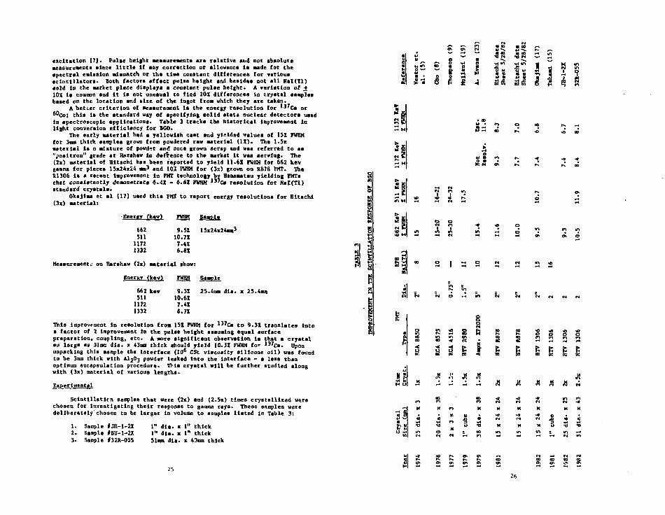
excitation 17). Pulae height aeaaureaenta ara relative and not absolutemeasurements since little If any cottectlon or allowance la Bade for thespectrsl emission aisaatch or the time conatant differences for varlouasclntillatora* Both factor! affect pulae height and beeldee not all Hal(Tl)aold ID the aarket place displays a constant pulae height* A variation of -f10X It common and it la not unuaual to fled 20X differences In crystal aaapTesbaaed on the location and tlze of the Ingot from which they are taken.
A better criterion of measurement la the energy resolution for I3'Ca or°"co; thla ia the standard way of specifying solid state nuclear detectora usedin speccroscaplc applications* Table 3 tracks the historical Improvement inlight conversion efficiency for BGO.
The early aateris). had a yellowish caat and yielded valuea of 1SZ FWHMfor 3mm thick samples grown fron powdered raw material (1X)> The l-5xmeterlal Is a mixture of powder and one* grown scrap and was referred to as"positron" grade at Hsrehaw in d*f£eace to the Market it was serving. The(2x) material of Hitachi haa been reported to yield 11.61 FUHH for 662 kevganna for pieces 15x24x24 aa3 and 101 PWHM for (3a) grown on R878 PHT. TheXI306 is a recent iaprovemsnt in PUT technology by Baaaaatsu yielding FMTachac consistently desontttrats 6.AX - S-6X FWHH )3'C» resolution for Nal(Tl)standard crystals*
OkaJlM et al [17] uaed this PHI to report energy resolutions for Hitachi(3x) material:
i I I 1si % I I i
S inIA
8 - -i °.
8 " ^ * "* *•
•Ener«T
66251111721332
sw <2x)
Energy
66251111721332
9.5X10.7X7.4X6.81
material sho
(kev)
kev
FWHH
9.3J10.6X7.4X6.7X
FWHH Sample
Sample
25.4mm dla. x 25.4aua
Thla Improve meat in reeolutlon from 15Z FWHM for '"cs to 9.3Z translates Intoa factor of 2 Improvement in the pulse height assuming equal surfacepreparation, coupling, etc* A more significant obaervation la that a cryatalan large a> 51mm dla. x 43oa thick should yield 10.51 FWHM for 137C«. Uponunpacking this .ample the Interface (10° CSt viscosity sllicone oil) was foundto be 3am thick with AI2O3 powder leaked Into the interface - a less thanoptimum encapsulation procedure* Thla crystal will be further studied alongwith (3x) material of various lengths*
Experimental
SclntllUtlrn samples that were (2x) and (2.5x) times crystallised werechosen for investigating their response to gamma rays. These samples weredeliberately chosen to be larger in volume to samples Hated in Table 3:
1 , n
soN
R 3 S ftS 3 S *
s a t 1OL. fC PS <
s£
s g sli
J?^ •« ^
1. Sample IJH-1-2X 1" dla. x 1" thick2. Saople #BU-1~2X 1" dla. x 1" thick3. Sample »32R-055 51am dla. x 43mn thick
CO CO
K K n aK
2526

The end facea were polished and the sides were roughned with #240 Emerypaper. One end face was coupled to the PHT face with optical coupling greaaeC-688 and packed with A12O3« Hethyleoa Iodide waa also uaed aa a high indexcoupling fluid but was abandoned »• It turned brown.
Signal procesalng electronics conalsted of a Harehaw NB-11 preamplifier.NA-24 linear amplifier aee to 2 /it time constant and * Tracor TNI705 MCA • ,eh1024 conversion gain. Several HTV HI306 FIRS were tested and the reeult.' are1024 conversion gaintabulated below
Saaplo
JB-l-JtJB-1-2XJH-1-2XJH-1-2X
BU-1-2S
32R-05532R-055
PUT S/H
CE4237CE454CE4195CE4509
CE4237
CE4237R1307**
Hlah Voltage
700800700700
700
700900
»37C. U s .IFWHM
9.39.5
9.39.7
9.6
10-5
10.7
Low/BlghBalf-Wldth
37/3738/3837/3938/39
37/40
46/4541/45
»"c B Res.*NaKTl)
6.36.46.46.4
6.3
6.46.4**
•Measured at Ramamatau TV Co (Japan) on Mal(Tl) standard reference crystal(2"dla. x 2" thick) Type 81)8 S/H LW 674 supplied by Earahaw Chenlcal Company.
**R1307 Is a 3" PHT developed lntlally by Haaaaatau specifically for RarahawHeavy-Ion aplo "crystal ball" apectrosjeter supplied to HP I (Beldelburg).
The number ol utmples and PHT'a tested ware to insure that the result*reported were not an Isolated case and really repreaent the atate-of-art.
Ganma ray spectra for '37Ca and 60Co is displayed la Figure 1 and 2 Jrrsimple JH-1-2X. Notice the clear separation of the "°Co peaks- Saaple 32^-055is larger than Evans' (23) crystal but sutler than Drake'* (25).
38m. dla. x 38m> < 5ITO dla. z «3na < 76mm dla. x <76mnEvans (23) < 32R-055 < Drake <25)
Gamma ray spectra tor 137Cs and *^Co Is displayed in figures 3,4,5 and 6,respectively. Dote the significant improvement in resolution for the *°Copeaks vhen compared to Rarshaw sample of Evans (23) ("...not quite good enoughto resolve the 1.17- and 1.33 Hev photopeaka").
Evaca (23) pioneering work in extending the use of BGO for largerdetectors and higher energies compared the performance of a 81 FWHM 662krvNal(Tl) to an equivalent size BGO detector. The following Improvement In theBGO response to date nay be noted:
1. (9.3X Cs) - BGO yieli*:. a 60Co resolution almllar to (6X Cs)-NsI(Tl).Table 3 saaple JH-1-2I
I. (10.51 Cs) BGO yields s 5.71 resolution for 2.62 Hev compared to5.8X for 2.75 Hev. (BZCs) Hal(Tl)
3- A (7.2XCS) 2" dia. x 2" Integral line standard Mal(Tl) unit displayed5. IX for 2.62 Hev.
Data from theae Investlgatloo la compared In Figure 7. If a linearprojection la Bade, the sample 32R-055 should yield 21 FWHM for 20 Hev. Evenbetter results can be anticipated for (3x> material and will be the subject ofa later Investigation.
The growth of crystal from a solution of lta constituents Is by its verynature a purification proceaa. The iapurltlea have a-higher solubility la theliquid and generally remain there while the solid crystal is frozen out.Succeslve growth of crystals la such akin to tone refining and hence it is notsurprising to find that (2x) or (3x) material to be auperlor In crystal purityto singly grown material. Takagl et al (25J have Investigated BGO with respe:tto successive growth and the addition of lapurltlea to atudy void formation.Recrystslllzatioa of more than three times was found not to yield anyappreciable Improvements.
This study Indicates that raw material purity constderatlona are not wellunderstood but can be offset by successive growth. Thla !• not a fullyacceptable process from an economic viewpoint. Haterlal quality of (2x) and(2.5x) will yield small cryatala which could match the performance of Nal(Tl)In the region of 2 Hev and up; but larger crystals still have Inclusions due tonon-stochloaetry and this problem needs to be solved.
Energy resolutions between 9-101 FHHM for "'cs are certainly Interesting«noug'.. for BGO to be conaldered In lieu of MaKTl) for many applicationsInvolving low energy x-and gamma ray excitation. The 81-9X range la goal forfuture lmprovfme.it In BGO. Recent Investigations of BGO (26, 13, 20) haveshown that the proceaa la not a simple one node mechanism. There appear to be3, decay times and at lesst 3 emission maxima (480, 530, 570 on) and possibly a4th one at 610 nm. Understanding and optimizing theae features are the nextlogical step In the development of BGO.
The fining and photofairacttoa advantage* of BGO for poaltron annihilationganma rays have caused it to replace Hal(Tl) in posl'ron CT Imaging.Analytical formulae for Image forming a* well a* coapsrlelon of BGO to otherdetector materials in positron tomograph* have been studied by Derenzo 1271.The use of BGO In other spectrocoplc applications hsa been initiated and it lareplacing NaKTl) by virtue of providing cleaner spectra, ease of handling andhigher detection efficiency for similar alzes. References sre noted below:
Geophysical Exploration
1. Conpai'.alon of sodium Iodide, ceslua Iodide snd bismuth germanatescintillation detectors for borehole genma-ray logging.
D. C. Stronswold. IEEE NS-28, 290 (1981)
2- A comparison of blanuth gemmate, ceslua Iodide and aodlua iodide
scintillation detectors for gamma ray spectral logging In small diameter
boreholes.J. C. Convoy,P. G. Kllleen, and H.G. Hyatt. Current resesrch, part B,Geological Survey of Canada, paper 80-1B, p. 173-177 (1980)
BGO otters a reduction of more than 501 in statistical errors io uranlua
deteralruiCtons to Nal('fl).
28

REFERENCES
1. 8. Bofatadter: Phya. Rev. _74. 100 (1948).
2. R- Boatadter: IEEE Traoa. Nucl. Scl. 21. 13-35 (1975).
3. R. h. Heath, R. Hofetadter and E. B. Hughe a: Duel. In«tr. Method*, 162:
431-476 (1979)'.
4.
5.
6.
7.
10.
11.
12.
13.
14.
15.
16.
17.
18.
19.
20.
21.
H. T. Keber and R. R. Monchanp J. Appl. Fhy, . 44, 5496 (1973).
0. H. Nestor and C. T. Huang: IEEE Trana. Nucl. Scl . NS-22. 68 (197S).
G. N. Houo.field: Br. T. Radial, 46, 1916 (1973).
M. R. Farukhl: Proc. Workahop on Trana. and Emlaalon CT. Korea 1978.
Z. H. Cho and M. R. F.rukhl: J. Kucl. Hed. IS, 840 (1977).
C. T. Thoapaon, 1» L. Yanatnoto and E. Mayer: Poaltoae I I . (Abatract)J. Cozput- Aaslat Toaogr. 2, Ho. 5 (1978).
H. R. Farukhl: Proc. Workahop Tiae-of-f l ight Aadated Tomography.Washington Univ. St. toula 1982.
!•• R. Carroll, G. 0. Hendry -md T. D. Currln: IEEE Trana. Nu.l.NS-27, 1128 - 1136 (1980).
Scl.
N. Hohara, E. Tanaka, T. Toaltaal et al: IEEE Trana. Nucl. Scl. NS-27, 1126 - 1136 (1980).
H. *.. Farukhl: IEEE Tint, thicl. Scl. HS-29, 1237-1251 (1982).
B. Murayaaa, N. Nohara, E. Tanaka and T. Hayaihl: Nucl* Inatr. andHeth. 192, 501 - 511 (1982).
K. Takaal, K. Ishlaatau, T. Bayathl cc al: IEEE Trana. Nu:l. Scl.NS-29, 334 - 538 (1982).
T. Taaaahlta, H. Ito and T. Bayaahl: Proc. Intl. Workahop on Phyalcnand Engineering In Medical laaglng, Pacific Grove, Calif. 1982.
K. Ok.jlma, K. Takanl, K. Deda at alt Rev. Scl. Inatr. 53, 12B5(1982).
R. Allenand, C. Greaaet, J. Vacher: J. Nuc'.. Med. 21, 153 (1980).
N. A. Hullanl, D. C. Flcke, M. H. Ter-Pogoaalan, IEEE Trana. Nucl.Scl. HS-22, 572 (1979).
M. Moszyoskl, C. Gresaet, J. Vachar, R. Ordu Nucl. Inatr. and Methoda188, 403 (1981)-
B. Uchlda, I. Tamaehlta, T. Tanaahlta, T. Hayaahl Proc. 1982 Nucl. Scl.Syap. Waahlngton, D.C. 1982.
29
22. H. Hoazynakl, J. Vacher, R. Ordu. To be published In Nucl. Inatr. and
Methoda.
23. A. E. Evana, Jr. IEEE Trana. Nucl. Scl. NS-27, 172-175 (1980).
24. V. M. Drake, t. R. Xllsaon, 1. Tancett. Duel* Inatr. and Methoda 188,
313-317 (1981).
25. X. Takagl, T. 01, T. Pukuzawa et a l . J. Cryatal Growth .52, 5?4-587
(1981).
26. H. Plltingsrud J. Nucl. Med. 20. 1279-1285 (1979).
27. S. E. Derenzo J. Kucl. Med. 2 1 , 971-977 (1981).

BGO ax CRYSTALLIZED
1" D1A. X 1" THICK
»MT t/N: CI 4397
SAMPLIt JH-1-2XMIT: HTV 1306-01SOURCE: C»-137
3900 et*/»«e
BOO 2X CRYSTALLIZED
PMTS/Nt CE4»»T
JH-1-BX l i ra k«v
1**2 k«V
U 137c «ad «>co .p«ctr« £or BGO (1"TOT 1306 S/H « *237
1" thick). JH-1-2X
662 k»VBQO XX CRYSTALLIZED
1* DIA. X 1" THICKPUT S/Ni CE 464
SAMPLE: JH-1-2XPMT: HTV 1S0S-01SOURCE: C»-1*TRATEt 2«00 eta/»««
SQO 2X CRYSTALLIZED
PUT «/Ni CB 464
1172 k«V
1*92 k*V
Figure 2. V37C» »ad 6 0 Q » fpectr. for BGO repeated on S/H Cl *5* •*•• «««pl« «•Figure 1.

197C« - SPECTRA POR SGO « • « )
SAMPLE* SIR-OS*
DIMENSION! 1.1 • » DIA,
RATIt
R1»O« C I 4 t t 7
sea k«v
Figure 3. 137C» .pectn {or SCO (2.5S1 uapU 32 B-055. Slat dla. x i3thick oo BTV R1306 PMT.
*>Co - SPECTRA FOR RQO <2'6X)
1172
1332 k«V
SAMPLE # SIR-OSS
DIMENSION: •.1«"» »>A. X4.9 en
PEAK/VALLEY:
4. for 32i-O55 SCO.

- SPECTRA FOR 9 0 0 (3-§X)
X1C
• 1 1 k*V
SAMPLE * 33H-O65
DIMENSION: 5.1 en DIA. X 4.9cm
6G3JNT RATE: 1400 «ps
" • • * PMT: R1JOC CB4997
1.274
xsSUM
Figure 5. 2 2N« «pectr» for 32E-055 BGO.
.893.238* 2 2 8 Th - SPECTRA FOR SOO
SAMPLE # 93ft-0««
DIMENSIONS C.I cm OIA. X 4.9 «m
PMTt 111 90S CE4237
2.6 ISM* V
.7%
Figure 6. 228n, ip« c t r» for 32K-O55 BGO

so4 0
SO
a»
•
3 ,OHI 0
4
a
i
VA
EVANS (SS)- 1STS
1«SX CRYSTALLIZED
/+++V ts?
" • T I .
t '
* SI
1 1 1 1 1
A EVANS S S N N DIA. X SSiMi
• DRAKE l%mm DIA. X SSiMN
• SAMPLE SOO ( f S X )
S1IMH DIA. X 4Smn
^/ >c^ * ^ ^ | C ^ ^ DRAKE (24) • 1SS1
i^ " ^ " ^ yT%'KH CRYSTAbUBW
8X CRYSTALLIZED ^*>.^ROCS ***'*•
l i l t i i
.1 .4 .« .« 1 2 4 0 • 10
OAMMA RAY ENERQY CM*V)
4 0
Figure 7. Energy caaolution of 321-055 BGO »•• | i n i r«y «n«rgy.nv»r«n 1rnnrnv#i«#nt over (1.5T) Rroun aneerlal*
Hsele* the

IMPROVEMENTS IN THE SCINTILLATION RESPONSE OF
M. R. FARUKHI
Harshaw Chemical Co., 6801* Cochran, Solon, Ohio, U.S.A.
Chronological milestones In the Improvement of (8G0) as a scinttllator are identified asg 32It continues to replace Nal(Tl) for many spectroscopic applications. An energy resolution of H.for 137Cs 662 Kev gamma rays is the best reported value on material that has been (3>i) grown.Response to 22Na, °"Co and 23?Th are examined and compared to comparable sizes of Nal(Tl)crystals. Above 2 Mev, BGO offers a clear choice for both spectroscopy and size considerations.Improvment is considered to be intrinsic to the sclnt lllator.
F»HM
1. Introduction
Luminescence to x-ray excitation inBi^GejO^ (SCO) was rirst measured in 1973by Weber and Monchamp [1] and a year later Nestorand Huang [2] reported on the scintillationresponse of BGO to gamma ray and alpha particleexcitation from radioisotopic sources. Energyresolution of 15%F»HM for 662 kev Cs-gamma rayswas measured for a BGO disc 25 mm diameter x 3 mmthick; neither the response (a factor of 2 worsethan NaI(H))nor the sizes available Initiatedwidespread investigation of BGO for spectroscopicapplications. However, BGO has practically noafterglow even unrt<?r strong x-ray flux in contrastto Nal(Tl) and otn<.. commercial scintlllators [3].Since small pieces [10 x 20 x 3mm^] are notgreatly influenced by light attenuation due tocolor, BCO found ready acceptance as an x-raydetector operating In the current mode coupled tosmall diameter photomultlpllers In commercialx-ray CT instrumentation. It became the detectorof choice from 1975 - 1978 and colncldentallyreplaced Nal(Tl), the first scintltlator to beused in commercTa1 scanners.
The rapid growth In the technology of x-rayCT Instrumentation necessitated smaller andsmaller detector/sensor packages In the samepacking volume In order to Increase the number ofdetectors and hence improve the spatial resolutlorof the image. Cd*O^ and low afterglow CsI(Tl)coupled to silicon photodiodes have replaced8C0/PMT combinations in present day scanners.Thus, with the Impeding end of the BGO productlife cycle. Improvements in quality and other useswere sought by crystal manufacturers. The firstspectroscopic application envisaged the use of BCOIn positron CT imaging by virtue of Its superiorphotofractlon (4-fold) and acceptable coincidenceresolving times [*]. BGO overcame the Impasse ofpoor efficiency and spatial resolution faced withNal(Tl) scintlllators in positron CT (PCT)systems. It Is presently considered as thedetector to use In both commercial and researchPCT systems. Recently, fast scintlllators withsub nanosecond coincidence resolving times such asCsF have been considered in research prototypetime-of-flight assisted PCT systems [5]. BaF2
and ether fast scintlllators could offer alternatechoices to BGO [6].
The continued development in PCT systemstechnology have caused Improvements in the crystalquality and correspondingly in the scintillationresponse of BCO so that It can now be consideredfor broader use In apectroscopy and as areplacement for NaI(Tl)[7]. This Investigationpresents an update to recently published BGOspectroscopic data [7] and provides the bestspectra for gamma excitation.
2. Historical Improvements
Chronological improvement milestones areIllustrated in Table 1. Improvement inscintillation light conversion efficiency has fcsenattributed to successive regrowth of thecrystalline material. Crystal growth itsetf isa purification procedure since the Czochralskitechnique calls for pulling a pure crystal fromthe melt leaving behind the Impurities which havea higher solubility In th; liquid than in thesolid. This "pure" crystal is then used as thestarting material In a fresh crucible and theprocedure is repeated. This process is akin tozone refining uti1tzed in the growth of siliconand qermanlum semiconducting crystals. Our (?.x)grown material indicated comparable if notmarginally better performance than (3x) grownHitachi material [7]. Current (3x) material showseven better performance and the data is discussedIn the next section. In either event, (3x) yrowimaterial is economically disadvantageous toproduce and It Is necessary to address the rawmaterial purity question to circumvent repeatedgrowths.
3. Experimental
Superior photomulttpllers are essential foroptimizing the performance of BCO. HamamatsuR1306 Is a 2 Inch diameter, 8-staye tube that canbe selected and purchased in limited quantities togive 6.3 - 6.6% resolution for 137Cs onstandard 2" dla. Mal(Tl) crystals [7 ] . S/N CE*237 was used for measurements and has beenpreviously evaluated along with representativesamples from a normal population [7 ] . It yieideu6.3% Cs-resolution for 25mm dia. x 25mm and 6.4%Cs-resolutlon for 50mm dia. x 50mm Nal(Tl)standards.
39
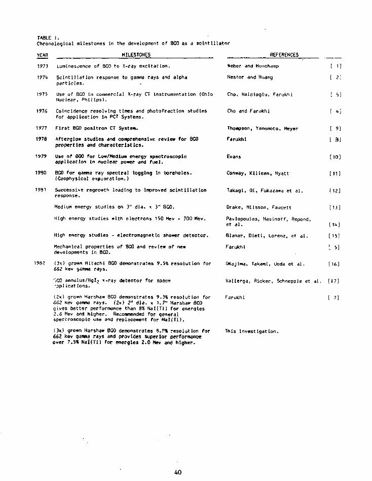
TABLE I.Chronological milestones In the development of BCO as a sclntlllator
YEAR
1973
1974
1975
1976
1977
1978
1979
1980
1981
MILESTONES REFERENCES
198?
Luminescence of BCO to X-ray excitation.
Scintillation response to gamma rays and alphaparticles.
Use of 8G0 In commercial X-ray CT Instrumentation (OhioNuclear, Philips).
Coincidence resolving times and photofractlon studiesfor application in PCT Systems.
First 8G0 positron CT System.
Afterglow studies and comprehensive review for 8C0properties and characteristics.
Use of BCO for Low/Medium energy spectroscopicapplication in nuclear power and fuel.
BCO for qamma ray spectral logging in boreholes.(Geophysical exploration.)
Successive regrowth leading to improved scintillationresponse.
Medium energy studies on 3" dia. x 3" BGO.
High energy studies with electrons 150 Mev - 700 Hev.
High energy studies - electromagnetic shower detector.
Mechanical properties of BCO and review of newdevelopments in BCO.
(3s) grown Hitachi BGO demonstrates 9.5% resolution for662 kev tj&mma rays.
:",G0 annulus/Hglj x-ray detector for space'Pplicatlons.
(2x) grown Harshaw BGO demonstrates 9.3% resolution for662 kev gamma rays. (2x) 2" dia. x 1.7" Harshaw BCOgives better performance than 8* Nal(Tl) for energies2.6 Mev and higher. Recommended for generalspectroscopic use and replacement for Nal(Ti).
(3x) grown Harshaw BGO demonstrates 8.?» resolution for662 kev qamma rays and provides superior performanceover 7.5* N a i r n ) for energies 2.0 Hev and higher.
Weber and Monchamp [ 1 ]
Nestor and Huang [ 2 \
Cho, Nalcloglu, Farukhi [ 5]
Cho and Farukhi [ u]
Thompson, Yamamoto, Meyer
Farukhi
Evans
Conway, Killeen, Hyatt
Takagi, Oi, Fukaiawa et al.
Drake, Nilsson, Faucett
[ 9]
L 3J
[10]
[11]
M2 J
[13]
Pavlopoulos, Hasinoff, Repond,et al. I 1n]
Blanar, Dietl, Lorenz, et al. [15]
Farukhi [ 5]
Okajlma, Takami, Ueda et al. [16]
Vallerga, Flicker, Schnepple et al. [17]
Farukhi [ 7]
This Investigation.
40

Signal processing electronics consisted of aHarshaw NB-11 scintillation preamplifier, NA-25linear amplifier set for 3u sec time constant,NV-25 high voltage power supply and a Tracor TN1705 MCA set to 102<* conversion gain. In altcases the measurements were made with the aid ofthe cursor and the data displayed by an analog X-Yplot for illustration. Counting rates were keptbetween 3000 - 5000 counts per sec. and theanalyzer zero setting was calibrated before takingmeasurements. Each resolution measurement wastaken several times with peak coLits in the 4000 -5000 range and sufficient time was allocated toprevent any initial tube drift due to onset ofsudden high voltage application. The samples werekept in the dark at 70'C for 16 hours to preventany deleterious effect due to exposure to roomlight.
Background subtraction was employed but anyImprovement was negligible and hence discontinued.All measurements were taken at room temperature(20*C).
4. Results
4.1 Best Energy Resolution
The best reported energy resolution for BCOto date is 9.3% FWHH for 662 Kev gamma rays on(2x) grown material [7]. *e now report a betterresolution of 8.9% FWHM (662 kev gamma rays) onOn) grown BCO for samples 36R-002 and 36R-003.(See Figure 1 for analog display on 36R-002.) Thesample dimensions are 25mm diameter x 25mm lengthand the goal now is to extend this quality to 50mmD x 50mm L whfle addressing the purity of thestartInq material. These steps are fundamental tocrystal growth and we may be approaching theasymptotic limit of performance improvement. Anunderstanding of the various mechanisms involvedin decay and emission components of thescintillation light [7] may provide the innovativestep to a major improvement in the scintillationHoht conversion efficiency and will form thebasis for further studies.
4.2 Comparative Measurements (Same Size Crystals)
Comparative measurements on similar sizeNal(Tl) crystal are given by the spectra in Figure2. The 60Co and 252Th spectra provide abetter understanding of the relative merit of BCOas a spectrometer:
1. The higher photoelectric attenuationcoefficient of BGO results in "cleaner"spectra with better peak-to-total or peakto compton ratios. The low energy sideof the 1.172 Mev peak Is not fullyresolved for the (8.3*-Cs) Nai(Tl) andthe peak/valley ratio Is poor even for(6.3%-Cs) Nal(Tl) as shown in Figure 3.The peak-to-comptcn and peak/valleyratios for 1.172 peaks are:
TABLE 2.
60Co Response for BGO and Nal(Tl)
P/CP/V
36R-002
5.15.9
Nal(7l)(6.3%-Cs)
1.04.0 15
The back-scatter peak and the comptoncontinuum dominate the 60Co spectrafor (8.3S-CS) Kal(Tl) [Figure 2 lowertrace] and with better resolution thesituation is somewhat reduced as shown b>the upper trace In Figure 3 for (6.3*-Cs)Nal(Tl) . However, in both c.ises mult iplecompton events are a prominent featureand In the case of FN25-63 (Figure 2)degrade the photopeak such that the lo*energy half-maximum point merges with thecompton events and the resolution for1.17 Mev peak has to be estimated orcalculated. Multiple compton events arenot easily discernible in BGO spectra andone needs to use a Nal(r i ) crystal thatis 3-4 times larger in a l l dimensions toduplicate the BCO spectra.
The photopeak - efficiency advantage ofBGC is even more apparent at higherenergies as evident in the energyresolution for the 2.62 Mev peak in232Th spectra (Figures 2-5). Oatais summarized in the Table 3.
Fiqure 1. Energy Resolution for 1^7CSgamma excitat ion (3x) BGO.
41

4.3 Comparative Measurements (25mm BGO, 50mmNal(Tl)
Figure 2. Upper trace Is 60Co and 232rhspectrum, for (3x) BGO. Lower trace isfor Nal(Tl) of comparable size andslightly better performance at lowerenergies.
Figure 3. fi0Co and 232fh spectrum fromthe best Nal(Tl) crystals studied.Energy resolution for "'Cs was6.3 - 6.MS.
The peak-compton ratio for the 2.62 Mev peakis the highest for the 25mm BCO crystal and itsvalue of 4.5 is at least a factor of 2 better thanthe best Nal(Tl) crystal. It is obvious thathigher peak-compton ratios are obtained for thesame size sclntillators with better energyresolution performance. The energy resolution of6.4-% FwHM for 662 kev gammas is premium amongcommercially supplied crystals. The best reportedresolution for a 50mm Nal(Tl) crystal is 5.6% FwHMfor 662 kev gamma rays for a crystal/PMTcombination selected from a large sample of thesane [18]. Even such a crystal would Improve theratio by approximately 10*.
Energy resolution of the 2.62 Mev peak forNal(Tl) crystals Is affected by compton scatter forthe sizes studied. The "6.3% Cs" crystals show animprovement from 3.9% to 3.7% as the size doubles.The "9.3% Cs" crystal performance Is too poor toexperimentally resolve the peak and the "7.5% Cs"crystal exhibits a value of 5.1% F*HM. The 25mmBCO sample is clearly superior with a value of 4.8%FwHM.
Comparison of energy resolutions between a25mm D x 25mm L BGO and 50mm D x 50mm L Nal(Tl) isdetailed in Table 4. Granted that the results havenot been confirmed on a large batch of crystals toinsure statistical validity, the trend indicatesthat:
. (9%-Cs) BCO will perform better than(7.5%-Cs) Nal(Tl) at energies of 2 Mev andhigher.
. Where size Is a determinant factor, theuse of (9%-Cs) BGO over Nal(Tl) even forlow energies may be Inescapable.
4.4 Resolution vs. Energy
The pulse height resolution data forrepresentative samples used in this study is givenin Table 5. The resolution versus energy data forBGO and Na(Tl) Is displayed by a family of lines inFigure 6. By definition,
Resolution = FWHM
where.FwHM
Pm
1.0
full width at half-maximum of thefull energy peak (abscissa unitseither volts or channel #)mean pulse height corresponding tothe sane peak (channel I)
If we take the logarithm on each side ofequation 1.0:
In R = lnK - 1/2 In E 2.0
42

TABLE 3.
2 3 2 Th response for EGO and N a l ( T l )
Crystal fl
BGO 36R-OO2
N a K T l ) FN25-83
NaKTl) FN25-63
NaKTl) FN5O-75
Nal(Tl) FN50-64
Size (mm)Ola. x Length
25 x 25
25 x 25
25 x 25
50 x 50
50 x 50
1 3 7Cs(662kev)% Res.
8.9
8.3
6.3
7.5
6.4
2.615 Hev% Res.
4.8
N.R.
3.9
5.1
3.7
Peak/ComptonRatio
4.5
0.7
0.9
1.8
2.2
TABLE 4.
Energy resolution for 25mm D x 25mm L BCO and 50mm 0 x 50mm L Nal(Tl)
Sample
BGC 36R-002
N a K T l ) FN5O-75
BGO - N a K T l )
N a K T l ) FN50-64
BGO - N a K T l )
22Na0.511
10.1
8.4
1.7
6.9
3.2
137Cs
0.662
8.9
7.5
1.2
6.4
2.5
* Resolution FWHM
60 C o
1.17
6.9
6.7
0.2
5.3
1.6
for Energy
60Co
1.33
6.S
6.1
0.4
4.8
1.2
(Mev)
228Ac1.59-1.64
10.5
12.1
-1.6
9.7
0.8
2 0 8 n
2.62
4.8
5.1
-0.3
3.7
1.1
43

1 9 * M.WI1 ' * » » !
Figure 4. 232Th spectra for Ox) grown 25mmsize 8G0.
Figure 5. 232fh spectra for 50mm size Nal(Tl)
TABLE 5.
PHR for 8G0 and Nal(Tl)
Crystal
BGOBGO
BGOBCO
BGOBGO
I.D.
Hitachi*Okajlma [16]
3H-1-2x36R-002
Evans (10]32K-O55
Size (mm)dta. x L
15x24x24
25x2525x25
33x3851x43
TiroesGrown
23
23
1.52.0
511
10.7
10.1
17.511.9
% FftHM
662
9.5
9.38.9
15.410.5
for Energy1172
9.37.4
7.'v6.9
12.88.4
(kev)1332
8.36.8
S.76.5
11.88.1
2615
4.8
8.15.7
Mal(Tl) FN25-63Nal(Tl) FN25-7SNal(Tl) FN25-83
Nal(Tl)Nal(Tl)Nal(Tl)Nal(Tl)
FN50-64FM5O-75Evans [10]Farukhl [7]
25x2525x2525x25
50x5050x5038x382" Integral RCA PMT
6,
6.8.
9
9
6.37.38.3
6.47.58.07.2
5.36.97.0
5.36.7
4.85.96.5
4.96.16.6
3.9
NR
3.75.15.85.1
Hi tachi Data Sheet
44
• i :_:••?
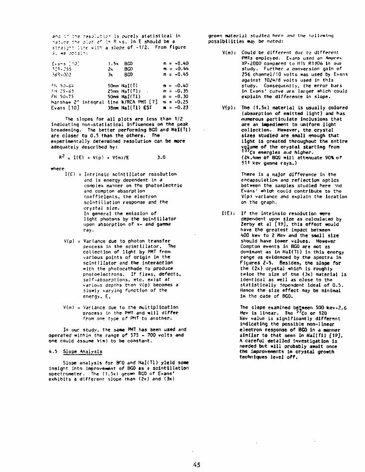
: - f rsso" . - t :o" ! is ?urel> s t a t i s t i c a l In:*>? ?'.cc o' In S vs. In E should be a: '. i - f «:*« a slope of - 1 / 2 . From f igure
1.5x BGO2x BCO3x 8G0
m = -0.40m = -0.44m = -0.45
•!. 50-64 50mm NaKTl' m = -0.40-N 25-63 25mm NaKTlJ . m = -0.35Fu 50-75 50mm Nal(Tl) m = -0.30Harshaw 2" inteqral line VRCA PUT [7] m = -0.25Evans [10] 33mm Nal(Tl) EST m = -0.23
The slopes for all plots are less than 1/2indicating non-statist leal Influences on the peakbroadening. The better performing BGO and Nal(Tl)are closer to 0.5 than the others. Theexperimentally determined resolution can be moreadequately described by:
I(E) * V(p! + V(m>/E 3.0
whereI(E) = Intrinsic sclntlllator resolution
and is energy dependent In acomplex manner on the photoelectricand compton absorptioncoefficients, the electronscintillation response and thecrystal size.In general the emission oflight photons by the sclntlllatorupon absorption of x- and gammaray.
V(p) = Variance due to photon transferprocess in the sclntlllator. Thecollection of light by PMT fromvarious points of origin In thesclntlllator and the Interactionwith the photocathode to producephotoelectrons. If flaws, defects,self-absorptions, etc. exist atvarious depths then V(p) becomes aslowly varying function of theenergy, E,
V(m) = Variance due to the multiplicationprocess In the PMT and will differfrom one type of PMT to another.
In our study, the saae PMT has been used andoperated within the range of 575 - 700 volts andone could assume V(») to be constant.
4.5 Slope Analysis
Slope analysis for B^0 and Mal(Tl) yield someInsight into Improvement of BGO as a scintillationspectrometer. The (1.5x) grown BCO of Evans1
exhibits a different slope than (2x) and (3x)
grown material studied herr ami the tolh>*l"<]possibilities IM> be noted:
V(m): Could be different due to differentPMTs employed. Evans us«1 an •Vmpre*XP-2000 compared to HTV R1J06 In ourstudy. Further a conversion gain of256 channel/*0 volts was used by Evansagainst 1024/8 volts used in thisstudy. Consequently, the error barsin Evans' curve are larger which couldexplain the difference in slope.
V(p): The (1.5x) material is usually colored(absorption of emitted light) and hasnumerous part leulate inclusions thatare an impediment to uniform lightcollection. However, the crystalsizes studied are small enough thatlight Is created throughout the entirevolume of the crystal starting from1 3 C s energies and higher.(24.4mm of BGO will attenuate 90% of511 kev gamma rays.)
There Is a major difference in theencapsulation and reflection opticsbetween the samples studied here -ndEvans1 which could contribute to theV(p) variance and explain the locationon the graph.
I(E): If the Intrinsic resolution weredependent upon size as calculated byZerby et al [19], this effect wouldhave the greatest impact between400 kev to 2 Mev and the small sizeshould have lower values. HoweverCompton events in BGO are not asdominant as in NaKTl) in this energyrange as evidenced by the spectra inFigures 2-5. Besides, the slope forthe (2x) crystal which is roughlytwice the size of the (3x) material isIdentical as well as close to thestatistically dependent Ideal of 0.5.Hence the size effect may be minimalin the case of BGO.
The slope examined between 500 kev-2.6Mev Is linear. The 57Co or 120Kev value is significantly differentindicating the possible non-linearelectron response of BCO in a mannersimilar to that seen in Nal(Tl) [19].A careful detailed investigation isneeded but will probably await oncethe improvements in crystal growthtechniques level off.
45
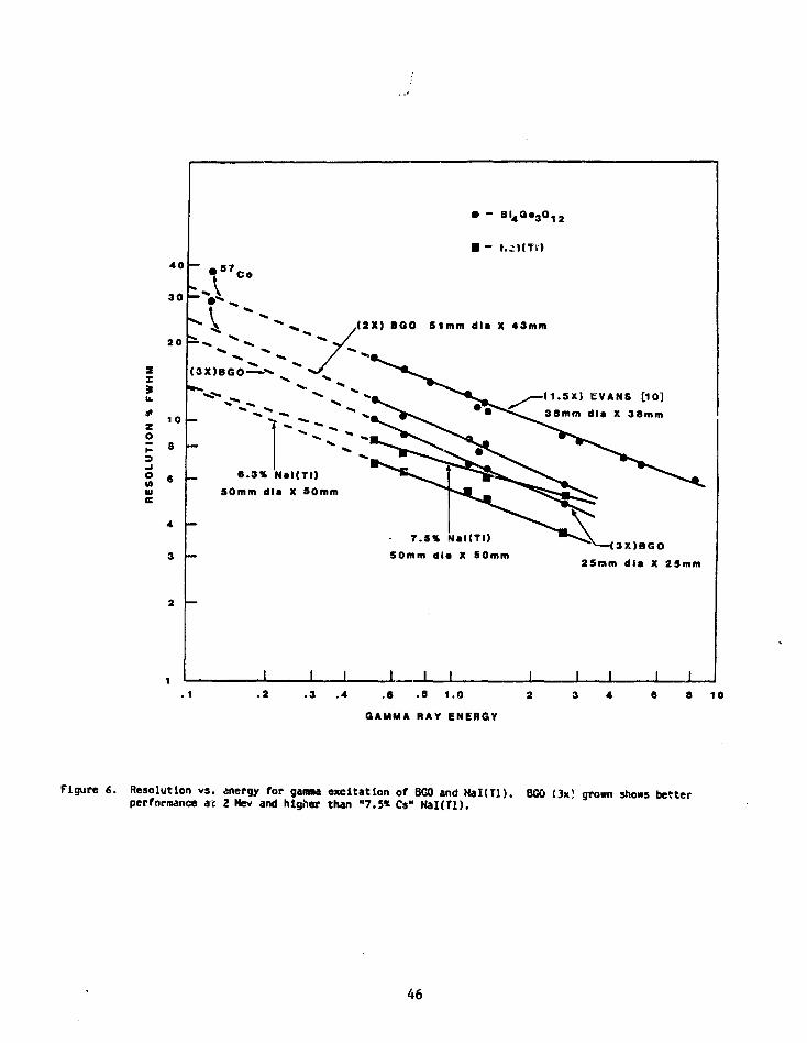
sX
s
40
30
20
1 0
B
ouuc
5 7Co
• - B I 4 G. 3 O 1 2
• ~ I.CJ(TL')
,<2X) BGO 51mm dla X 43mm
<3X)BG0-
(1.SX) EVANS [10]dla X 38mm
6 . 3 * Nal(TI)50mm dla X 5omm
7.5% Nal(TI)50mm dla X 50mm
3X)BGO25nm dla X 25mm
I J I. 1 .2 .3 .4 .8 .8 1.0
GAMMA RAY ENERGY
10
Figure 6. Resolution vs. energy for gamma excitation of BGO and N a K U ) . BGO (3x> grown shows betterperformance at 2 Hev and higher than "7.5* Cs" Hal(Tl).
46

It is tempting to speculate that thephysical locations of (2x) and(3x) lines in Figure 6 are due tosome basic improvement that iscausing more light photons tobe emitted per event in the (3x) overthe (2x) and hence is statisticallycontrolled especially since the slopeof m = -0.45 is eliise to ideal of-0.5 assuming Polsson statistics.
In the case of Nal(Tl), only the larger andthe best performing crystal, (FN 50-64, 6.4%-Csresolution) shows a reasonable slope which Is notovertly Influenced by statistically independent
5. Concluding Remarks
In an earlier Investigation [7], improvementsin (2x) grown 8G0 were reported with 9.3% energyresolution for 662 leev gamma rays and thepossibility of replacing Nal(Tl) for manyspectroscopic applications was examined.Continued improvement in the scintillationperformance of BGQ is detailed here with 8.9%resolution for '"Cs as being the bestreported to date. Comparisons with Nal(Tl)performance indicate the preference for BGO wheresize and space are determinant factors and forenergies higher the 2 Hev, BGO offers analternate choice for cleaner spectra undercomplex excitation.
Improvement in the Intrinsic resolution ofBGO due to multiple regrowth Is offered forconsideration, but clearly needs to becorroborated with further studies.
6. Acknowledgements
3. Hietanen provided the crystals togetherwith helpful discussions on the subject matter.G. Bastlen's help in sample preparation Is greatlyappreciated and the valuable assistance of V.Berner in the experimental set-up isacknowledged.
7. References
[ 1 ] M. T. *eber and R. R. Monchamp, 3. Appl.Phys. 44 (1973) 5496
[ 2] 0. H. Nestor and C. Y. Huang. IEEETrans. Nucl. Sci. NS-22 (1975) 68
[ 3] H. R. Farukhi. Proc. Workshop onTransmission and Emission CT Seoul,Korea (1978)
[ 4] Z. H. Cho and M. R. Farukhi, a. Nucl.Med. 18 (1977) 840
[ 5] M. R. Farukhi, IEEE Trans. Nucl. Sci.NS-29 (1982) 1237-1251
L 6] M. R. Farukhi, Proc. Workshop onTIme-of-Flight Assisted Tomography, St.Louis (1982) To be published IEEEComput. Soc.
[ 7] M. R. Farukhi, Proc. MRS 1982 AnnualMeeting, Boston, Mass. (1982)
[ 8] Z. H. Cho, 0. Nalcloglu and H. R.Farukhi, IEEE Trans. Nucl. Sci. NS-25(1978) 952
[ 9] C. T. Thompson, Y. L. Yamamoto and E.Mayer, 3. Comput. Assist. Tomogr. 2(1978) No 5.
[10] A. E. Evans, IEEE Trans Nucl. Sci. NS-27(1980) 172-175
[11] 3. C. Conway, P. G. Killeen and ». G.Hyatt, Current Research, Part B Ceol.Survey of Canada, paper 80-IB, (1980)173-177
[12] K. Takagi, T. 01, T. Fukazawa et al., 3.Crystal Growth 52 (1981) 584-587
[13] 0. H. Drake, L. R. Nilsson and 3.Faucett, Nucl. Instr. and Meth. 188(1981) 313-317
[14] P. Pavlopoulos, M. Hasinoff, 3. Repondet al., Nucl. Instr. and Meth. 197(1982) 331-334
[15] C. Blanar, H. Diet l , E. Lorenz et a l . ,Proc. EPS I n t l . Conf. on High EnergyPhysics, Lisbon (1981)
[16] K. Okajima, K. Takaml, K. Ueda et a l . ,Rev. Sci. Instr. 53 (1982) 1285
[17] 3. Vallerga, C. R. Ricker, * . S.Schnepple et a l . IEEE Trans. Nucl. Sci.NS-29 (1982) 151-U4
[18] D. E. Persyk and T. E. Hoi. IEEE. Trans.Noel. Sci. NS-25 (1978) 615
[19] 3. B. Blrks, The Theory and Practice ofScintil lation Counting, The HacMillanCompany (1964) Sec. 5.4.6
47

ismuth Silicate (BSOJ
r
as g SctotiUiti** Material,(7
M. kol><Ky(k$k t if.
5.5.
Co. )
Sh On
S. St/G/'M&TO <8 $e&/0A/ CA1

CM
^ t . ,
vs
i
5
I
g
r
i
I
i d
V
1
1
.3
V ' • ' \
5
-I1
I1
•V-
5

B50
SaJ
i—I—i I I—I I I i | (—i—i—i—|—i—r-
EXCITATION
EMISSION
200 300 400
WAVELENGTH /nm
500
'Ml
I I I

1
BSO
in
• uCO
1
i 1
CSICDCD t ' "
O
... * •" '*
I I
1 i
2s?
goU. fl r,7
-
( jjun - AifSN31Nf
8CN
UJ
<
Q.
( nun - A1ISN31NI

13NNVHD VHd
009
V%
V
WHMJ
099
00*' 1 '
. &$
'/ " \
i
- /i
• i " .• . •
399*0
i
i
'>!•••
1
003*i i i i i
* \ **•/7| S i ! 1 "* * * * . '
1 1 1 1 1
Z m
P*CD
1
• o
•- O- U- o. to
: . . • . • « • • • •
i
i
i
i i
> °°• ^ • " • - * ' » •
i
-
-
|
CM
ooen
|
Q.
(;iun -qjB) A11SN31NI

n
tfflf
XN .
#
Llq.
*
4
OnO
§ 5' 573
po
eno
m
m>"HI
cm
o
pp
250
FLUORESCENCE LIFETIME / jusLIGHT INTENSITY (arb . unit )
pCJ! P
enO
( 1 1 1
-
I i J t
' l ' i 1 i i i i
" ^ f
, d '•o
t i l l
/ /
* ^ ^
-
•-
UJ

-
C X S>
3 s
r
a o
* Io
a
tf
A
ii ^{
N
5
<Ji
CN»"
«•
I1
•5 * *"k 5
5 * V*
I I,

'0
t i l l .«Si i; J? « K
i 3:
ill
ui
o-oot

Eco~ 7 0 -
UJo
<
'on
50 100FLUORESCENCE
INTENSITY(relative)
IOX IP * 3° >*""
63
(a) Transmission Measurement
(LampHGrating Ref,
, . . , Sample <><>*
(b) Excitation and Emission Measurementin
SampleSp's
ectre-

T 1 1 1
0
1 1 1 1 1 1 1 1 1-
30 hours afterIrradiation
-1 I I I . • I
300 400 500
WAVELENGTH /nm
600
65
mzcr
60,Co-d 3.6 x 10⁶ R
1 st GradeBGO
400 500
WAVELENGTH/nm
600

12GeV p<—I (—i—i—i r-
1.5 hours afterIrradiation
o
~ 0.5
<
ffif
400 500WAVELENGTH /nm
67
12 GeV p 1.2 x 10⁶ rad
300
1 st GradeBGO
400 500
WAVELENGTH /nm600
68

i—i 1—i—i—i—i—i—-)—i—i—i
Fast n U hours afterIrradiation
U
c/5<
i—I—I—I I I I I I I I I0300 A00 500
WAVELENGTH /nm600
69
400 500
WAVELENGTH /nm
600
70

-i ! r- i
Fast n 3.6 xlO6 rad
1st GradeBGO
I ' • ' ' 1 I L.
300 400 500 600
WAVELENGTH/nm
71
Co tnewt r»n,S
Six tkys after x
A.C. Ueat
O M.
n

Theat tie su.rfa.ce
— 2 fi /A
tive)
(re
la
>-
TEN
SIT
•z
6
4
2
1 ~T
a- i>•a ^
- <S u
I *
\
1 L
3.
v"1i
ZP-/H' > 1
I
1 1 1
«•*" / . 2. jr /
1 1 1—
BGO
50- « in
X
"-'V:v:r-
i ' '
»' raj—i ^ 1 1 1 1 - j — i
Irradiated with 12 GeV p -
Hours after Irradiation
Co
o'J*Z¥
PMT
li i
Baa
I 1 i . . . i . i i 1 i
0.5 ' 1.0
PHOTON ENERGY / MeV
1.5
10
•E 6
1/1
LU
a* re.teAbove o.sr M*Va beve I -o MeV
— Z . x x i O / s /re— /p. px (O^/s / -
• 1—
I K
. < > •
'•}
1 «s
I1
BGO
i-
1 1
Irradiatec
- x 10
.
-\ r
with
162
•— x iO
r1.: ...-r.:,."
—-—i —I
12 GeV p ;
Days after
1I
i 1 1 1
1.2 x10 5 rad
Irradiation
— - i _ _ irradiO-teot
} 1
ENERGY / MeV

10
£ 6
ID
iff. ^
,.o M*V — 73Jffou/s /l 1 1 1 1 1 1 1 1 1 1 1 r-
BGO Irradiated with Fast n ; 3.6 x 10⁶ rad
91 Days after Irradiation
• x l O O
1" B&O
ENERGY / MeV
I
J |
rt.
*
^
f
vi 5-
^

<y '2
\
<
•c
i
v» 3.2 i^
SJ
o
4-
C
0
A|
X
U
3
2 i
0!s .5 V 4?
1«
S
^
2v
^
«
5!
4t
o <?
111

INTERIM REPORT ON THE SHORT-TERM RESPONSE OF BGO TO UV LIGHT ANDY-RADIATION
Matteo Cavalli-SforsaPhysics Department
Joseph Henry LaboratoriesPrinjeton UniversityPrinceton, NJ 08544
International Workshop on Bismuth Gennanate - Princeton UniversityNovember 10-13, 1982
1. INTRODUCTION
I will report in the following the results of a series of experiments
showing that the transmittance and the light output of BGO crystals de-
crease when they are exposed to UV or gamma radiation. In both cases for
the radiation doses applied crystals return to their original state in
times ranging from a few hours to ~ 100 hours.
Both effects, as well as the recovery from them, have been observed
previously. Kobayashi et al.'1' observed that crystals exposed for a few
minutes to a pencil beam of 308 nn UVs would visibly darken where hit by
the beam. The same authors conducted a very detailed and systematic study
of the effects on BGO of Co 6 0 gammas, high-energy protons and fast neutrons
using doses up to several Mrads; their study concentrates on the recovery
of the crystals over periods of several days to several weeks. An earlier
study'2' reports light output losses after an X-ray dose of lbOO R, disap-
pearing in a few hours.
Our experiments differ from the previous ones in that transmittance or
light output were monitored from the first few minutes after irradiation.
79
We establish the presence of at least two time constants in the recovery
process and measure the relative amplitude of the two recovery components.
He also observe an unexpectedly high sensitivity of crystals to relatively
low (100 to 1000 rad) doses of t-radiation. While this result requires
further experimentation, it does suggest that radiation resistance is a
parameter to be carefully investigated in view of future large BGO detec-
tors to be used at nuclear or high energy physics machines.
Z. UV EFFECTS ON TRANSMITTANCE OF VISIBLE LIGHT
We came upon the realization of such effects quite unexpectedly. When
testing the first 20 cm long BGO crystals we obtained, we observed two
obviously related phenomena:
(a) the pulse height from nuclear Y-sources would increase by 10% to 20%
for a few days after mounting a crystal on a photomultiplier tube
(PMT);
(b) the uniformity of pulse height (PH) vs. position of the source along
the crystal would at the same time Improve by a few percent.
Changes in optical coupling and in PUT response in time were ruled out as
possible causes by air-coupling the crystals to the PMT and by monitoring
the PMT response with an LEO. We finally realized that PH decreases and
uniformity worsens every time that crystals were exposed to room lights.
The effect on the uniformity of PH strongly suggests that a decrease 1n
transmittance rather than In scintillation efficiency occurs. We estab-
lished that the effects are enhanced by .xposing crystals to UVs from a UV
lamp, while red lights as used in photographic work produce no measurable
effect.
We directly verified that UVs decreese the transmittance of 8G0 by a
simple ad-hoc experiment. A He-tie laser beam (X-o33nm) was sent through
the long axis of a 20 cm crystal; the transmitted intensity was read out
with a photometer. The crystal was Illuminated from the side with a porta-
ble UV light (UV(jL-20) emitting mainly at 254 im, with secondary lines at
313 nra and 3b2 run. Fig. 1 shows the observed decrease in transmitted power
(in db) from the time the W s were turned on: light transmission decreases
to a stationary loss of ~ -10%; UVs were then turned off, and transmission
then went back to the original value in a few hours. The changes in
transmission seem to be characterized by more than one exponential time
constant; we did not try to express this quantitatively because of drifts
in the photometer that make precise measurements difficult.
Followup experiments showed that a similar, yet stronger effect 1s seen
with UVs peaking at 365 nm (but with a spectrum extending from 300 to 40S
ran); and that a larger loss of transmittance is seen when propagating
through the crystal a 442 nm beam from a He-Cd laser.
The presence of these effects raises several questions that would
require a full-fledged investigation of atomic and solid state issues to be
fully answered. Here, we only wish to draw two consequences, one practical
and the other «o,-e speculative:
(1) Long crystals must be shielded from UV sources (including neon
lights) for a few days before doing measurements for which stability
and good uniformity are important. Work on crystals must be done in
red lights if measurements are to be done immediately afterwards.
(2) BGO exhibits very strong absorption between 250 nm and 300 run ap-
proximately, with absorption depths of ~25u at the most^3'. The
effects seen with the 2S4 nm and 365 rm UV sources take place at a
81
depth in the crystal of -0.6 cm, where the laser beam passes; they
are thus probably due to the spectral range from 300 to 350 nm sam-
pled by both sources. In contrast, the observed losses of uniform-
ity of PH ar> presumably mostly due to darkening of the crystals
crystals only near the surface. This effect is too small for the
naked eye, but would be well visible in uniformity measurements
because in long, thin crystals light undergoes several reflections
before reaching the PHT.
The time dependence of the effects and their recovery were particularly
intriguing to us, and suggested to us that in the radiation tests we had
planned we should monitor the light output of crystals beginning as soon as
practical after irradiation.
GAMMA RADIATION TESTS: DESCRIPTION
We chosp to expose our samples to Co 6 0 T-radiat'on because of the
ready availability of a 650 rad/hr source at SLAC, where all our
measurements were performed, and the immediate access to the crystals just
after exposure. The Irradiated samples are:
(a) a 1x1x10 cm3 parallepipeda) crystal
(b) two 1.27 cm diameter x 1,27 cm long cylindrical crystals.
All three were made by the Harshaw Chemical co. and are of excellent opti-
cal quality.
Radiation effects were monitored by measuring Hip PH in each crystal
with C s " 7 r-rays (ty = 0.662 MeV) at several times al' ••• Pxposure. While
this method do<_s not separate effects on transmittance am: scintillation
efficiency, it measures the quantity of interest in an actual pxperiment;

also, it coincides with one of the commonly used methods to intercalibrate
and monitor many-crystal arrays.'"1' Crystals were grease-coupled to a PMT
(Hamamatsu R1306) previous to the radiation exposure and the PH was recorded.
They were then detached from the PMT, exposed to Co 6 0 gammas, and regreased
on the PMT within 10 minutes from the and of the exposure. Mount-to-roount
repeatability of the PH was checked to be ~ 1% previous to exposures.
Drifts of the PMT and associated electronics were calibrated out by also
coupling to the PMT a Nal (Tt + Am21"1) light pulser with a gamma equivalent
energy of 1.6 MeV in Nal (T£) and a FMHH of 6%. The temperature dependence
of PH for both the Nal (TI + An2111) pulser and the BGO crystal was separ-
ately measured and the results used to temperature-correct each observed
PH. The corrected pulse-heights for C s 1 3 7 were seen to be stable to better
than IX. The electronics consisted of a Canberra 2005 integrating pream-
p'ifier, a Canberra 2021 spectroscopy amplifier, and a Lecroy 3500 multi-
channel analyzer system.
The parallelepipedal crystal was irradiated with 27.5 rad, 200 rad and
50 rad in this order; both smaller crystals were irradiated with 500 rad
and 1000 rad.
Pulse height spectra were taken 10 minutes after the end of the expo-
sure, then every few minutes for the first few hours, then at larger inter-
vals until each crystal had returned to ~ 99X of its original pulse height.
RESULTS AND DISCUSSION OF RADIATION TESTS
Figs. 2,3,1 and 5 display the results of a few of the radiation tests.
The quantity plotted vs. time is the pulse height loss AP in MCA channels.
This is the difference between the pulse height observed at the end of the
experiment and the pulse height at time t, with t=0 coinciding with the end
of the Co 6 0 exposure. The percentage PH loss at t=0 is given for each
figure. The lines through the experimental points in the figures represent
the fits of AP(t) to a sum of two exponentials:
-t/T, -t/T
AP=A$e +ALe c
where i,, T. are the shorter and the longer time constants ad A-, A. are
the associated amplitudes.
All observed pulse height recovery cycles fit thii. form very well; the
fit parameters, however, vary significantly from exposure to exposure such
that it is not possible to give only one T,. or T. for all crystals and
exposures, nor to establish a rigorous proportionality between A,., A. and
the radiation dose. There are, however, several common features in the
tests:
1. For all three crystals and all irradiations but one we observe
2 hr < ts<5hr and 50hr<tL<60hr. The exception is the 27.5 rad test
of the parallelepipedal crystal, where both time constants are
shorter.
2. The relative magnitude of the two amplitudes A , A. is the same
within 120X, except for one of the tests on the smaller crystals
where A - 2 A .
3. AP(O) increases with dose, although less than linearly.
4. As said before, all crystals return to the PH observed before irra-
diation within the mount-to-mount repeatability error in < 10 days.
It is particularly interesting to compare our results to those of the au-
thors quoted in tne introduction. Most of the measurenents by Kobayashi et
al. were taken much longer after exposure than ours, and thus cannot detect
the short time constant we see. Also, most of their measurements are only
of the transmittance of crysta ls, while our observed PH loss may combine
effects on transmittance ^nd_ sc in t i l l a t i on eff ic iency. There i s , however,
a measurement of the above authors that is d i rect ly comparable to ours: a
l ight output loss of 4.3% is reported after i r radiat ing 3 x 1 x 1 cm3
crystals with 7.5 x 10b R(=6.6xlO5 rad in BGO). This was .measured 144
hours after i r radiat ion; the figure is not corrected for transmission los-
ses. Our 1.27 cm crystals are of opt ical qual i ty equivalent to the above
and were observed to have a pulse-height loss of 1.0 ± 0.5* 143 hours after
being exposed to 1000 rad. The effect we observe appears much larger than
that seen by Kobayashi et a l . unless such effects saturate strongly above
103 rad.
The obvious differences between the measurements of the two groups are
(a) the method used to induce and measure fluorescence: the above
authors used 308 ran UV and a spectrofluorometer, while we used Cs137
gammas and a PMT.
(b) the materials: crystals used by the Japanese group were grown by
Hitachi Chemical Co., while ours were grown by Harshaw.
More experiments are c lear ly needed, d i rec t ly comparing crystals from the
two (and possibly other) manufacturers. I t would not be surprising i f d i f -
feri-nt impurities in the samples used by the two groups were responsible
far the difference in resul ts .
PERMISSIBLE CONTINUOUS RADIATION DOSES
The re lat ive ly large sensi t iv i ty seen in our tes ts , together with the
long times needed for recovery, raise the issue of what continuous doses of
Y-radiation can be allowed on BGO detectors for their response to degrade
by a specified amount.
For a sample exposed to a radiation rate of 0 rad/hr from t=0, with a
recovery time constant T, the pulse height loss in time w i l l be
- t / i
AP(t) = aOT (1-e )
where a = aP(0)/b is the pulse height loss per rad at t=0 after an instan-
taneous dose D. Asymptotically tS'^-tOt from which one can obtain the rate
D that w i l l cause a PH loss aP^if the time constant and the proport ional i ty
constant are known.
For two recovery time constants one has
where a,- .= P,- , (0)/0 can be measured or extrapolated f; om the time-depen-
dance of pulse height recovery.
We can use the results from the 10 cm crystal i r radiat ion to 50 rad
(Fig.3) to calculate the rate that w i l l give a stationary pulse height loss
of, say, 1%. For *s=4hr, iL=60hr, AP(0) = 11.5% = ZPS(O) = 2PL(U) we
obtain
0 = 0.14 rad/hr =3.3 rad/day.
This estimate assumes proport ional i ty between dose and PH loss at t=0; i t
thus neglects saturation effects which are obvious comparing for instance
Figs. 3 and 4. Even with this caveat, this permissible rate is quite low
and could easily be exceeded. For instance, the Crystal Ba l l , a large
solid angle Nal(H) detoctor currently taking data at the DORIS I I e+e"
storaye ring in Hamburg, is presently exposed to a few'rads/day of electro-
magnetic radiation with energies of a few MeV per quantum.

Our estimate of a permissible close is three orders of magnitude lower
than the estimate by the KEK group of Ref. 1 and i t re f l ec ts the large
factor between the effects observed by the i r group and ours.
CONCLUSIONS
In summary, we have shown that
(1) room l i g h t s decrease the transmittance of BfiO c rys ta ls ; t h i s effect
disappears in a few days and suggests a few simple pract ica l ru les
in handling c rys ta ls .
(2) a few tens of rads of y radiat ion can lower the l i gh t output of BGO
crysta ls by a few percent or more. This e f fect too decays in time;
we c lea r l y ident i fy two time constants in the recovery of the pulse
height, one of a few hours and the other of 50 to 60 hours, of ap-
proximately the same amplitude. We estimate a permissible rate of
radiat ion on a BGO detector that Is dangerously close to rates ob-
served in exist ing detectors at present e+e" machines.
More work must be done to reach quant i ta t ive conclusions over a larger
range of rad iat ion doses, especial ly in view of the fac t that resu l ts from
KEK from Nrad doses would lead to expect ef fects much smaller than those we
observed.
Issues to be addressed by future work include;
(a) Hght output loss versus dose, to explore the importance of
saturat ion ef fects .
(b) dependence of pulse height loss on previous doses.
(c) sample-to-sample va r ia t i on ; a comparison between crystals grown by
d i f fe ren t manufacturers is pa r t i cu la r l y important
(d) what impuri ty, i f any, is responsible for the rad iat ion effects that
are observed
(e) the p o s s i b i l i t y of rapid ly annealing out radiat ion damage, as done
with Nal (T i )
( f ) the p o s s i b i l i t y of ef fects that decay too fast to be observed in our
experiments ( T<1 minute) should also bt checked.
ACKNOwlEOGEMENTS
The work described in t h i s report was mostly done by Richard
Sonnenfeld, John Hawley and Jan Segert of the Princeton group. R.
Sonnenfeld in pa r t i cu l a r was the f i r s t to hypothesize and observe the UV
ef fec ts on crys ta l t ransmit tance; J . Hawley and J . Segert d id careful and
ingenious work that assured the s t a b i l i t y of the measurements i i . y - rad ia-
t i on t e s t s , besides doing a l l of the measurements.
REFERENCES
1. M. Kobayashi et a i . , KEK Preprint 82-9, July 1982, also submitted to
Nucl. Inst r . and Meth. in Phys. Research.
2. K. Takagi et a . , J. Crystal growth, 52 (1981) SB6.
3. M.J. Weber and R.R. Monchamp, J . App). Phys. 41 ('973) 5495.
4. Ses T. Matsui, ta lk given at th i s Conference,
b. See H. Sens, ta lk given at t n i s Conference.

Nil
J_X
±
Ot:i
l>-
Ul
-ion
H-r<
X
o
-
I
/•
//
//
///f
/
/
/
f/
•//
•
«- 3
o
T »v
-«*>
-O"

P.M. CHArtfrC VS. " t
10 c*v» X+*l , 2 00
<t© Co co |oo
091 o)\ on eor Oi « > ' • ' . • % . o *
05
[««oH]> f * e ^ T- 'A_<>V+ ^
•SA
( • * •
0^

Session B
PRODUCTION, QUALITY AND COSTS
The Present Status of Research and Development
of Bismuth Germanate in China
V.F. Gu
Institute of High Energy Physics
Academia Sinica
Beijing, China
1. Raw Materials
China is r ich in germanium deposits. This provides favorable conditions
for bismuth germanate crystal research and development in th is country. The
germanium industry had i t s beginning in mid 1950's. As an example, in the Huize
mines o f the Yunnan province, Ge-concsntrate with over 10% content of germanium is
extracted from the lead-zinc ore. Ge-concentrate can also be obtained frcin the
coal. The following process is then completed in the factories which was f i r s t
realized by the Genera) Research Inst i tute of Non-ferrous Metals. By d i s t i l l a -
t ion germanium tetrachloride is produced from Ge-concentrate, and is then
pur i f ied chemically to high puri ty (7-8 N). By hydrolysis, high purity germanium
tetrachloride turns into germanic oxide with 6N pur i ty. The product is part ly
exported via China Metallurgical Import and Export Corporation.
2. Crystal Growth
Bismuth germanate crystal growth in China began in I9?0's. Bi^GeO^
crystals were f i r s t grown by Z.J. Shi et a l . in 1974 at Physics Ins t i tu te , Aca-
demia Sinica. The raw materials used were bismuth oxide (B^Oj ) and germanium
oxide (GeO?) with pur i ty of 99.9999% and 99.999%, respectively. The crystal
was cjrown from a 6:1 stoichiometric mixture by the Czochralski method. The
growth orientation of crystal was along the <110> axis. Crystals ranging up to
95
25 x 25 100 nmJ were pulled at rates of 6-8 mm/hr with seed rotat ion rates of
32-52 rpm.
Using a similarmethod, bismuth germanate crystals with molecular formula
Bi^GejO,- (referred to as BGO) were grown afterwards at the Shanghai Inst i tu te
of Ceramics, Academia Sinica. The raw materials used were 99.99% pure Bij,O.
and 99.99S pure GeO2- The pull ing rate and crystal rotation rate were 2.5-3.5
mm/hr and 20-50 rpm, respectively. Single crystals with 25-35 mm in diameter
and 30 mm length were grown. In June of this year, a long crystal of
20 x 20 x 200 mm3 were f i r s t grown at the same i ns t i t u t e .
Bismuth germanate crystals are also grown at the Inst i tu te of Piezoelectric
and Acoustic-Optical Technology in Yongchuan, Sichu.n province. For Bi ] ?Ge0?0,
some 45 x 45 x 200 mm crystals were grown. They are about 2.5 kg each. For
Bi^GejO,,, crystals 50 mm long were grown with a diameter of 30 to 50 mm.
Both Shanghai and Yongchuan inst i tu tes are making ef forts to grow large
crystals, to reduce cost and to realize large-scale production.
3. Property Studies
We began property studies of Chinese made BGO only very recently. Basic
experimental apparatus for measuring the general physical and chemical proper-
t i es , the fluorescence characteristics and the nuclear radiation detection
performance has been bu i l t and preliminary data were obtained.
The results obtained by C.F. He and his co-workers of the Shanghai Ins t i tu te
of Ceramics on the general physical and chemical properties on the i r crystal
sample are summarized in Table 1.
J.f l . Zhao et a l . of Quinghua University measured the fluorescence, absorp-
t ion and ref lect ion spectra of Chinese made BGO. They see the maximum in the
fluorescence spectrum at about 4800A. From the absorption curve they observed
that the absorption edge l ies around 3000A, and in the ref lect ion spectrum there
are two features at about 2650A and 3070A. They also studied the influence of
the crystal defects upon the fluorescence and found strong correlat ion between
97
the defectsand the emission of the f luarfM.em I- I r, \;i.n i r ^ i o i - .
S.J. Fan and his colleagues have studied the growth >)i-r<-> i t ..r I-J/I
Various kinds of defects have been observed (see ',..). U n ' i (JOIIH /
I and my colleagues at Ins t i tu te of High Enerqy I'hy.u-. h.wc >i',rke<] W
an experimental program of three stages to study the nuc.W-.ir r e l a t i o n .icif. ti.,«
performance of BGO. The three stages are:
1) tests with small BGO crystals;
2) tests with long BGO crys ta ls ;
3) tests wi th a crystal array.
The results of measurements on small BGO pieces are summarized in Table ?.
T.B. Zhang and H.W. Tang have measured the time characteristics of BGO
crystals. The l i gh t pulse shape of BGO was studied by the single photon method.
As is seen from the i r resul ts, the decay curve of BGO may be resolved into two
components with time constants T . = 52ns and i . = 310ns, and relat ive inten-
s i t i es I . = \U and Ij, = 86*, respectively. In the case of Nal(Tl) which was
measured as a comparison, a much slower i n i t i a l decay precedes the well-known
decay with a time constant 230ns.
The time resolution of BGO has ajso been measured. The results obtained
with the BGO sample are l i s ted in Table 3 together with that of Nal(Tl) crystal
as comparison.
4. Applications
The applications of BGO crystal in China have as yet o-.ly a few years'
h istory. BGO has just entered the area of nuclear medicine. A brain CT scan-
ning system has been bu i l t by CO. Lou et a l . at the Shanghai Inst i tu te of
Medical Instruments and Apparatus by using the crystals produced at the Shanghai
Ins t i tu te of Ceramics. As compared with the Hitachi product, the qual i ty is
about the same. A plan to construct a whole body scanning system has been con-
sidered. Other applications of BGO have progressively opened up. For instance,
98

J.A. Zhao et ai. of Qinghua University are studying the possible applications of
BGO in petroleum exploration and continuous ingot casting.
The proposal to build BEPC (Beijing Electron Positron Collider) at the
Institute of High Energy Physics has been approved and is part of the national
construction program. In designing a general purpose detecting system for
particle physics experiment at BEPC, Y.F. Gu et al. studied the possibility to
adopt BGO crystal as a shower counter. They concluded that it does not seem
practical at the present time because of the cost. A barrel shower counter like
that in the MARK III detector at SPEAR or in the ARGUS detector at DORIS is
typically about 2.5m inner radius, 3.5m length and 12.5 radiation length thick-
ness. This would require over 30 tons of BGO. If the price of BGO is $1.7/g,
the total cost would be about $5u,000,000.
In the light of the successful experience of the Crystal Ball experiment
at SPEAR, V.F. Gu et al. proposed to build a non-magnetic neutral particle
detector by using BGO crystals. Its main part is a hollow BGO crystal ball
with an inner radius of 25 cm. The thickness of the shell corresponds 12.5 to
22 radiation lengths and is segmented Into 2880 elements. The final parameters
will be decided depending on the actual funding. The whole system including the
endcap part provides a solid angle coverage of about 98% of 4n steradians. The
total weight of BGO is about 1.5 tons if the shell is 12.5 radiation lengths
thick. In the spherical cavity of the ball, rigidly mounted about the beampipe,
there will be a central tracking chamber system using drift tube chambers to
detect charged particles and to measure their directions. The proposed detector
puts the stress on the detection of photons and those neutral particles decaying
into photons and is expected to bring about a considerable improvement upon
similar equipment now existing. It will play a unique role in further studies
of charmed mesons, charmed baryons, etc.
99
As a prototype of the BGO crystal ball detector, a crystal array will be
built to study the response to higher energy photons, the angular resolution
and the hadron detection/separation performance as well as the practicality
of large detector. The possiblity to utilize this array for specific particle
physics experiments and high energy astrophysics experiments is also under
consideration.
100

Table 1
General physical and chemical properties
Molecular formula
Structure (space group)
Constant of crystal ce l l
Color
Density (g/cm )
Hardness (Mho)
Melting point (°C)
o(A)
of Chinese made BGO
8i4Ge3°12
l?3d
10.52
colorless
7.13*
5
1050
Latent heat of crystallization(kcal/mol) 44.6
Ref rac t ive index X = 0.4861A = 0.6728
Thermal expansion c o e f f i c i e n t(x 10" 6 "C/cm/cm)
Hygroscopic
S o l u b i l i t y
unium
2.1492.098
7.5
no
HC1
*remeasured by Inst i tu te of Piezoelectric and Acoustic-OpticalTechnology in Yonghcuan
Table 2
NuicJ_eaj-_rad|iation detection performance of Chinese made BGO
Relative l igh t output (to Nal(Tl))
Energy resolution (*2 HeV)
Linearity (*2 HeV)
(dE/dx) min
Temperature coeff icient of l igh t output(20° to AO°C)
Temperature coeff icient of energyresolution for O.bll MeV y of "Na (4° to 60°C) +1?.5"7"C
.14"
'£/£ ,, t?.5"/VE
excellent
8.4 HeV/cin
-O.a'.yTof pulse height at 24°C
Temperature coeff icient of flourescencel i fet ime (4° to 60°C) -5.5ns/°C
Table 3
Time resolution measured with BGO and Nal(Tl) for different ranges of »-ray
energy by using a Co source
Scintillator Energy (HeV) Time Resolution (ns)
BGO
Nal(Tl)
0.5 + 0.1
•0.1
•1
-0.1
rWHM
0 . 7 0
1.03
1,13
0 . 6 3
1.22
FWTM
1.43
2.21
3.44
1.13
2.4R
101

Growth awl Dafects of Blsnuth Gern<ui*te (B Single Crystal
Fan Sh i j l . Li» Jlancheng, He Chongfan
Shanghai Institute of Ceramics, ACadenia Slnlca
IHTBOHUCT1OM
Single crystal Bl Ge O12(BGO), as a scintillation aaterlal, ha3
attracted nore attention because of lta superior qualities and applica-
tions in the fields of aedlclne and high energy phyalcs. Although BGO
crystals in saall sice cae bo easily grows, I t i s difficult to grow
BOO crystala in large slxe. In resent years, the researchers have
node efforts to grow large BOO crystala, to alialaate the crystal
defects and to iaprove the crystal quality. la this paper, we will
briefly discuss SOBS results of oor investigation.
EXPERIMENTS
BGO s ingle c r y s t a l s were grown by Ccochrslski Method. The dlaneter
of the crystal Mas autoaat lca l ly contro l l ed . BljO, and GeO., with
p u r i t i e s of 99-99i "ere used as the ran a a t e r i a l s . The s eed c r y s t a l
or ienta t ion was along flOO) . The ro ta t ions ra te of the p u l l i n g rod
ranged froa 20 to 50 r . p . n . The pul l ing rate was 2 . 5 to 3 . 5 • » per hour.
The crys ta l i s shorn i n r i g . 1 . The exhibited faces and growth face t s
were aeasured by means of X-ray back r e f l e c t i o n s Lane ae t tod and
The ather part ic ipants! Shen Blngfu, Llao J ingying , Kong Huashuang,
Shen Guanshun, Van LIJ in , Zhao P e l f a .
Zhou Loping, Kong Lingzhong, Pujig Zhaujian
103
stereographlc project ion . The gronth de fec t s have been otraei.se- ..,
means of transparent l i g h t birefringence topography and optlca 1
•Icrography.
RESULTS AMD DISCUSSION
1. Crystal Fora and Growth of Facets
BCO s i n g l e c r y s t a l s grown along [lOO) have approxlnately tetragonal
pr l sna t l c shape (F ig . 2 ) . The four large exhibited faces on four s i d e s
of the prlsii were determined to be the { l i o } faces by X-ray Laue
• e t h o d .
The s o l l d - l l q u l d lnterfaca under the condit ion of lower crys ta l
rotating rats i s often convex Into the »elt in the beginning of the
crystal growth. Four syuetric facets so»eti«e3 appear on this convex
Interface (Fig. 2) . According te their X-ray back reflectlone laue
patterns (Fig. 3) and atereographlc projection (rig. >*), the facets
are the {l l2} feuse. In case of the convex solid-liquid interface,
the bubbles, holes and other Inclusions occur easily in the crystals.
If the teaperature field atsd the rotating rate are changed, the
aolld-liquid interface (tail to flat say be nade so that the growth
facets do not appear. However, the increase of the rotating rate nay
cause the deformation of the crystal for» so that the crystal, growth
difficultly continued.
2. Forms of Coustltut! onal Supercooling defects
The change of teapsrature field aay cause obvious constitutional
supercooling in BGO single crystals grown by pulling nethod. Tlje
silk-shaped defects appear in the constitutional supercooling region
104

-f the crystals, besides a great number of the Inclusions of liquid
Dhase and the holes in various shapes. A part of then consists of
discontinuous spot-shaped defects (Fig. 5)- The runs of the sllk-
shaped defects are Indefinite, but often change along right angle.
In the constitutional supercooling region of the crystal, the
Inclusions with regular geometric patterns caji al30 be observed (Fig.6).
They may be natal particles (for example, Pt).
The region of opalescence has been observed on the edge of cons-
titutional supercooling part )n BGO crystal. It io fomed by scattering
Light from very fine particles under extreaely high density. The
naturo of the fine particles 1B not clear yet.
Obviously, the constitutional supercooling defect can be eliminated
by stabilization of temperature field and decreasing growth velocity
of the crystal, control of ttu stolchlometry of melt and Improvement
of purity of the ra« materials.
3. Stress condition ot the spherical inclusion
Because of the solidification of liquid inclusion and tho complex
distribution of various inclusions, the complex stress condition Is
fomed in the region of constitutional supercooling so that the undu-
late extinction appears confusely in the crystal under cross polarised
light. The four-petaled stress pattern around separated spherical
Inclusion distributes along the (110J andf.1107 directions (Fig. 7.
a.single polarized light, b. cross polarised light). In fact, the
3tress condition of single spherical inclusion Is stereoscopic. The
stress pattern shows that the region of stress distributes mainly In
105
( 1 1 0 ; , ( n o / and (lOOj f a c e s .
I t Is worth n o t i c e tha t the l o n g s t r e s s zones connect j i l h tlic
spherical Inclusions. The stress zones do not start from thp 3pherlcal
Inclusions but end at them (Fig. 8). The reason of their formation
have yet to be examined.
'*. Transparent Light Birefringence Images of Dislocations and
Subboundarles and Their Distribution
The transparent light birefringence Images of dislocation and
the rank of dislocations In subboundles have been clearly observed
In the slides of BGO crystal xlth perpendicular to pulling direction
(100) (Fig. 9 and 10). These dislocations distribute densely near
the Blde3 or the crystal (Fig. 11). The Ian of distribution of dis-
location in BGO single crystal i s Just the same as that of other
crystals grom by Czochralskl method. The dislocations not only can
originate fro» heat stress of the crystal but also can stretch from
the prlntary dislocations In the seed, therefore, the density of dis-
location can be eliminated by the selection of the perfect seed.
REFERENCES AHE OMITTED

FIGURE CAPTIONS
Fig. I- BGO 3ingle crystal .
Fig. 2 . BGO s ing le crystal form and growth facets .
Fig. ")• The typical X-ray Laue pattern of BGO single crystal (112) face.
Sig. b. The stereographlc projections of BCO crystal (112) face.
Fig. 5- Fora of constitutional supercooling defect in BCO crystal .
Fig. 6. The Inclusions with regular geometric patterns in BGO crystal .
Fig . 7 . Stress patterns around separated spherical Inclusions,
a. s ingle polarized l i g h t b. cross polarized l i g h t .
Fig. 8 . Stress aones ended ?.t the sphericJ£ '-".el'iainrj.
Fig. 9. Transparent l ight birefringence Images of dis locat ions in BGO.
Fig. 10. Transparent l i gh t birefringence Image of subboundary in BCO.
Fig. 11 . Dislocations d is tr ibut ion near the side of BGO crysta l .
Qio)
»,.».
107
' ' .'• 1108

1
\
\F
'•••v.5#vl*f'Jf;V'#;.:.;.'"-.-.' " ' • • 4 v ; - i ' ' ; - - - " K - : ' ; i i ' ! - ' V . - : ; : ' . . . . ' • ; • , •

GROWTH OF Bl Ga 0 J 2 CRYSTALS BY THE HEAT EXCHANGER METHOD (HEM)
F. Sehmld and C. P. KhattakCrystal SystemsSalem, MA 01970
A new crystal growth technique—Che Heat Exchanger Method (HEM) —has been developed to directionally solidify large high-quality crystals-It is being used for commercial production of sapphire and silicon.This motionless technique appears promising for producing Bi.Ge.O.^ (BGO)crystals. The salient features of the process are shown inFigure 1. The crucible, loaded with the charge, is placed on top of theheat exchanger. After evacuation, heat Is supplied by the resistanceheater and the charge is melted. During this stage a minimal gaseoushelium flow Is forced through Che heat exchanger to allow seed melt-in.Heat is extracted by increasing the flow of helium through the heat ex-changer to cause the solid interface to expand.
This technique is unique in that the liquid temperature can be con-trolled independently of the solid gradient without moving the crucible,heat zone or ingot. The most significant feature is the submerged inter-face which is stabilized by the surrounding liquid* as shown in Figure 2.It is protected from hot spots, mechanical vibration and convectioncurrents. From an economic point of view, HEM is a low-cost process.The furnace is simple, automated and we 11-insulated, which results inlow equipment, labor and energy cost. Another factor that affects theeconomics is the crucible cost. Experiments were performed to determine ifBGO could be grown in a vacuum or Inert environment in low-cost molybdenumor tungsten crucibles. The experiments indicate that an oxidizing en-vironment Is required to suppress decomposition of the bismuth oxide.Under oxidizing conditions crucibles resistant to oxidation, such asplatinum, must be used and the heat zone of the furnace must be made ofstable refractory oxides.
further experiments will be conducted in the near future todetermine if BOO adheres to the crucible wall after directional solidi-fication. If the crystal can be easily removed from the platinum cru-cible, HEM will be an ideal technique for growing large hlgh-qu3lityBGO crystals at low cost.
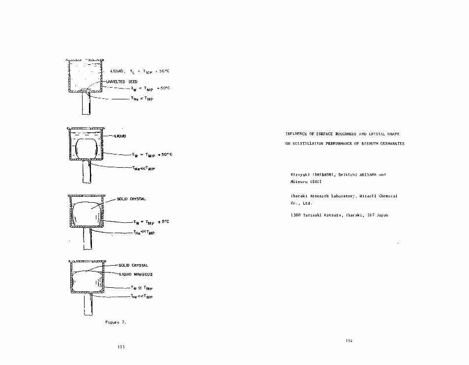
LIGUIO, TL
UNMELTED SEED
THe < T M P
Figure 2.
INFLUENCE OF SURFACE ROUGHNESS AND CRYSTAL SHAPE
ON SCINTILLATION PERFORMANCE OF BISMUTH CERMANATES
Hlroyuki ISHIBASHI, Seikichi AKIYAMA and
Mitsuru ISHII
Ibarak i Research Laboratory, Hi tachi Chemical
Co. , Ltd.
1380 Tarasakl Ka t su ta , I ba rak i , 312 Japan

Abstract
In order Co improve the scintillation performance of bismuth germanate
scintillaturs, the influence of surface roughness and crystal shape uj on
the light output has been studied experimentally. Through this study, it
was found that sctntillator surfaces optimizing the light output have
their awn optimum values in the ratio of the longitudinal-direction length
"h" co the shorter length "a" (h/a). In other words, if h/a is greater
than 6 a higher scintillation performance can be obtained in rough surfaces;
while in polished surfaces, ic can be obtained when h/a is smokier than 6.
Further, if scinl^ilator surfaces are provided with reflective coating,
the light output is markedly improved. Regarding relationship between
the light output and the surface state or crystal shape,it was discussed
from the viewpoint of transmission loss inside the scintillator and re-
flection loss on the surface.
115
1. Introduction
Bismuth germanate (BGO) scintillatars Uave excellent characteristics,
such as a nigher stopping power, smaller afterglow and nonhygroscopi-
city, as compared with Nal(Tl), but the light output of EGO is only
12 - 15% of that of Nal(Tl)"3?
Neverthless, great expectations have been held by such fields-as medi-
cal equipment, nuclear physics and high energy physics for the use of
BGO as radiation detectors for X and Y ~ rays-
The light output of BGO scincillators is remarkably influenced by crys-
tal defects, such as impurities and bubble voids of BGO crystals^ ;
besides, it is affected by the state of scintillator surfaces and the
reflective coating . The surface treatment of BGO scintiliators
varies depending on the crystal shape. For example, in positron emi-
ssion tomography, the size of coupling face of the scintillator Is 5 '
15 x 15 - 25 mm and the length is 25 - 40 nan, where all the scintil-6)
lator surfaces except the coupled one being rough. In the scintiX-
lator used *or high energy physics research, 20 - 50 mm square and
hexagonal faces are used and the length is 200 nan, all the surfaces
being polished
For the improvement of scinti l lator performance, it is important to
treat properly the crystal surfaces according to the geometrical shape
of scincil lators, as described in several reports *
Derenr.o took up BGO crystals as the detectors for position emission
tomography and performed the Monte CarLo calculations of optical coup-
ling between BGO crystals and photonuiltipl ier tubes. The abject of
tuts work is to establish experimentally the optimization of the shapes
.itul siirl'ji't'b o{ BGO crystals as scintil lators •
2. Experiment
A piei-e of »GO crystal used in this pxperiment was a 58 mm diameter &nd
150 lung boule thjt had been made to grow by t\\e Gzochralski process
in Hit.-irhi Chemu-jl, jnd th.tt was cat into 25 mm cubes JS test specimen.
The r.le.iv wiitt-r-wliite crystal prepared as the r.tw material had no
bubbles .ind w,-is of high quality in optical properties.

The shape of each type of scinti l lators was prepared from the starting
block according to the cutting procedure shoun in Fig. lj and the light
output of each scinitllator was measured. All the scinti l lator faces
coupled to photomuUiplier tubes were polished. The scinti l lator sur-
faces excepc the coupled faces were provided with two types of surface
treatments — polished and rough (about 5 u). As the reflector, BaSO
containing a small arount of an organic binder was used and applied
to the scintil lator to a film thick of about 0.5 mm.
Each scintil lator was coupled to the cathode center of a 2" photomul-tuba
t iplier (Hamamatsu TV), using an optical grease (Dow Corning. Q2-3067).
Electronic devices used for testing included an ORTEC 356H photomulti-
plier base, an 0RTEC113 preamplifier, a NORLAND/lno-tech spectroscopy
and an ORTEC shaping amplifier with 3 psec shaping time. The photo-
multiplier tube was operated at 800V. Data were accumulated in a
NORAND/ino-tech 5400 multichannel analyzer. The light output of the
prepared BGO sint i l lators was measured for, mainly, 662 KeVy -ray for
" c s source.
Fig. 2 shows the typical energy spectra in starting scint i la tors . The
energy resolution (fwhm) of BGO was 9.1% and the scint i l la tor performance
value was satisfactory.
Fig. 3 shows the dependence of light output on energy in the sc in t i l -
lator having a typical surface treatment. The linearity of light
output against energy Is entirely satisfactory.
3. Results
3.1 Relationship between Light Output and Crystal Shape of BGO Scinti-
11jtors.
Fig. 4 shows the variation in light output of BGO scinti l lators
when the size of coupled face is 12 x 25 mm and the scinti l lator
length "h" is changed. Regardless of surface roughness and re-
flective coating, the light output increases as scinti l lator
117
length becomes shorter. Generally, reflective coating allows
the light output to increase by as big aj 5U - lot and is effec-
tive especially when scint i l lator surfaces are rough.
Fig. 5 demonstrates the variation in light output of BGO scinti l-
lators when the scintil lator width "a" is changed under the con-
ditions that scintilator length is 25 mm and one side of the coupled
face is 25 mm long. The light output decreases as scintil lator
width becomes 15 mm or shorter, and i t s tendency is remarkable in
rough surfaces. The influence of surface roughness and refelctive
coating upon the light output is the same with the test results
of Fig. 4.
Fig. 6 shows all the measured light output expressed as a function
of crystal shape parameter h/a of BGO scint i l la tors . As shown
in the figure, the light output decreases as h/a gets smalier.
When h/a is smaller than 6 t a higher light output can be
obtained in polished surfaces. Conversely, when h/a i s greater
than 6, a higher light output can be obtained in polished eufaces,
3.2 Light Output of Prac t i ca l -S ize S c i n t i l l a t o r s .
Based on the experimental r e s u l t s so far obtained, i t was examined
through the experiment whether or not the l ight output of p r a c t i c a l -
s i z e s c in t l l l aCor s could be improved.
Fig. 8 shows the energy spec t ra of a ** x 25 x iO mm s c i n t i l l a t o r .
The s c i n t i l l a t o r face Is 4 x 25 mm and the shape parameter h/a
is 7.5. When a l ! the s c t n t i l l a t o r surfaces are pol ished, the
l igh t output increases by 60% and the energy resolut ion (fwhm)
is improved from 18.2% to 13.0% with c e r t a i n t y .
Fig. 9 shows the uniformity in the l ight output o( .i 10 x 10 x
100 mgi (h/.i =10> s . i n t i l l.itor by longitudinal spinning. The 10
x 10 mm f.u-e of the s c i n t i l l a t o r was coupled to .i photomult ipl ler
tube , and other surfaces we re cove red wi th a 1 min i zed my le r .
'It it? iiiufnrmiiv was examined with coll imated hh2 KeV \ rays from137,*Cft- It r.in be i-onM rmed that tlie light out put,

resolution (fwhm), uniformity and other performances of all polished
scintillators have been considerably improved as compared with
rough treated scintillators.
A. Discussion
The influence of geometrical shape and surface roughness on the light
output of BGO scintillators can be briefly explained from the two points
of transmission loss inside the crystal and reflection loss on the sur-
face.
Generally, light intensity inside a substance can be defined by Eq(l),
if the input is denoted as lo and the output as la.
where (j represents the absorption coefficent and £ is the average light
passage. The reflection loss on the surface can be expressed by Eq(2),
if the output is denoted as Ir.
Io (1 - v) (2)
where n represents the number of reflections and v does the coefficient
of reflection loss for each time. The light loss Inside BGO scintillators
can be considered due to the factors expressed by Eq (1) and Eq (2).
Therefore, the total scintillation light output "I" is defined by Eq(3).
, IO (1 - (3)
Fig. 7 shows two typei of typical light routes when the scincillator
widch "a" or the length "h" varies.
In case of the same surface condition of scintillators
n - n1 hho
(5)
119
where no represents the reflection frequency constant of standard
scitillators (25 x 25 x 25 mm) and lo represents the light path
constant.
Accordingly, Eq(3) can be expressed as follows:
- - J ^ "I = In (1 - no\>)
a e h o l 6 )
Using log I - hand log I - I/a relations, "ov and p . ° can be obtainedn o
froo EqC6). Table 1 shows the results of calculating the reflection
loss constant and the transmission loss constant, based on che light
outputs of all the measured sclntillators. The ourvee of Pig.
5 and 6 show the values of the light output calculated using the these
Constants.
The values of light output calculated by the equation (6) are in good
agreement with the experimental values.
In Table 1, as Io is a material constant, it must have the same value
theorttlcally. Equation (6) has been derived, taking into consideration
the loss in four side surfaces of the sclntillator. Therefore, it is
throught that the different Io value depending on the surface is due
to the light loss on the top surface. As for n..u, its value in rough
surfaces is about 5 times that of polished surfaces. The cause of this
difference can not be said to result from either of n0 and v,
but it is presumed, to be attributable to mainly V .
The transmission loss constant "y ° " is essentially related to scin-no
dilator material, so that the value of p is always constan't. Accord-
ingly, in polished surfaces, the value of u- . ° is 2.5 times as largeno
as that in rough surfaces. It means that the mean light path of polished
surfaces Is 2.5 times as long as that of rough surfaces.
The above discussion has been done on the scintillators having a size
of 25 mm cubic or smaller. The conclusion derived from this work is
applied, further, Co large-sized scintil lators. The experimental veri-
fication is shown in Figs. 7 and 8. The high-performance BCO scintl-
ll.itors can be obtjined even through the surface treatment suitable
for the geometrical shape.
120

Summacy
yThe scintillatioiroerformance of BGO crystals is influenced by crvstal
defects, surface condition and crystal shape. In order to optimize die sc
scintillation performance, study was made on the relationship between
the light output and the surface or 3ize of the sclncillator. As for
the shape of the scintillator. If the ratio of the longitudinal length
"h" to the shorter length "a" of the scintillator face (h/a) is used
as a parameter, a high-scintillation light output can be obtained in
the rough surface when h/a <6 and in Che polished surface when h/a
> 6. The basic experiment results obtained through this work was
applied to the practical-size scintil lators, and the improvement of
scintillator performance was experimentally verified.
Acknowledgements
The authers express sincere thanks to Dr. M. Kobayashi of National
Laboratory for High Energy Physics, Dr. S. Sugimoto of Osaka University
and Dr. K. Takarai of Central Research Laboratory, Hitachi Ltd., for
their interest in this work and helpful discussions.
Thanks are also given to Dr. S. Noguchl of Hitachi Chemical Co., Led.
for his support during this work.
121
Reference
1) 0,H. Nestor and C. Y. Huang ; IEEE Trans. Mucl. Sci., NS-22
(1975), 68-71.
2) M. Ishii etal ; Bismuth dermanate (BOO) single crystal for
scinti l lation detectors. Hitachi Hyoron, 62 (1980), 797-802.
3) K. Okajima, K. Takami, K. Uada and F. Karaguchi ; Rev. Sci.
Inst. , 53 (1982), 1285-1286.
4) K. Takagi, T. Fukaiawa, H. iBhii and S. Akiyama ; J. Crystal
Orowth. £2 (1981), 584-586.
5) R. A. BrookB etal ; IEEE Trans. Biom. Eng., BME-28 (1981), 158-I77.
6) K. Takami etal . , IEEE Trans. Muol. Sci . , NS-29 (1981), 534-538.
7) H. Kobayasbi e ta l . , Nucl. Ir.st. Meth., 182 (I98 l ) i 629-632.
8) 0. Blanar etal . , Bismuth Qeraanate, A Novel material for
electromagnetic shower detector. Contributed pr.per to the EPS
International conference on High Energy Physics, Lisbon,
(July 1981)
9) P. Pavlopoulos e t a l . , Nucl. Inst. Meth., 1J9J (1982), 331-33*1.
10) H. Klein and H. Scholermannj IEEE Trans. Hucl. Sci., NS-26
(1979), 373-377.11) S. E, Derenzo and J. K. Riles ; ibid. , VS-pg, (1981), l??-l't.

List of
Fig. 1
Fig. 2
Fig. 3
Fig. 5
Fig. 6
Fig. 7
Fig. 8
Fig. 9
Figures
The crystal shapes of BGO scintillators used-
137A typical energy spectrum as a function of C B source for 25 mm
cubic BGO crystal.
The scintillator surface is rough (5 p) and provided with reflective
coating.
The light output versus y -ray energy for a standard BGO crystal,provided with various types of surface treatments.
Relation between the light output and the scint i l lator length h.The scintil lator face is 12 x 25 ran.
Relation between the light output and the scintillator-face widtha. One example of longitudinal cross section. 25 x 25 mm.
The light output as a function of the shaping parameter h/a of
the scint i l lators .
Schematic light path In various types of scinti l lator shapes.
Energy spectra for Ca of 30 mm length andA mm by 20 mm face scint i l lator .
The longitudinal uniformity on the light output of 10 mm squareface and U)l> mm length scint i l la tor .
Table 1 Constants of Eq. (6)
\Surface
Const. ^\
Io
ivv
ho
Rough Surface
WithoutCoating
250
0.0739
0.0211
Coating
380
0.0557
0.0050
Polished Surface
WithoutCoating
213
0.0141
0.0130
Coating
330
0.0106
0.0095
123

Dimension h (mm)CD
h D5
10
=f
- D-D
IS)
ta;
•
\
1
\
ro
\
800
£60005
6if)
• * - •
C
400
200
0
CrystalSource
*•
\Size::137Cs
1
25x25x25 (mm)
o c c rZDOC
•* v
»
10.5%-/
1
—
^ Roughn 312 ch
]• \,
* •0 100 200 300
Channel Number400

800
1.0 1.5 2.0Energy (MeV)
2.5
8en
300
200
100
n
I
o
o
-
1
1 1
Crystal
O
1 1
1
Size :
1
1
12x25xh(mm)
0 10 15 20 25Dimension h (mm)
30
127

300 -
o
Q.
O200 -
100 -
0
1
/
1 D
r"
i
i i i
Crystal Size: a
Polished and
Polished
^ - " " • *~~"~~Rough
i i i
i
x25x25(mm)
CoatedPI
-
— •
i
400
0 5 10 15 20Dimension a (mm)
25 30
129
300
1-200ox:en
100
00
Polished and Coated
^SurfaceSize (mm).12x25x h3x25x hax25x25ax25x 3
Rough Polished
• o
A A '
• a
• O
Shape Parameter h/a10
Fig. 6 Influence of Crystal Shape and its Surfaceon the Scintillation Light Output no

7
2
A
Do
— 2ao-cto —
I"
no-1
NPMT
no Rough Polished
Fig. 8
50 100 150 200 250Channel Number
Crystal Size: .4x20x30 (mm)
Energy Spectrum Compared withPolished and Rough Surface
131
132 fyr

300
-c 200
O
§,100
0
Unit. = ±41%
—7fwhm=16.9%
f whrn = 26.2%
0 20 40 60 80 100Source Position from PMT(mm)
Crystal Size: 10x10x100 (mm)with Aluminized MylarSource: 137Cs
Fig. 9 Light Output Uniformity Comparedwith Polished and Rough Surfaces
A;.f 114

PROGRESS tN BOO QUALITY IMPROVEMENT AT HITACHI
Mltsuru ISHII, S e i k i c h i AKIYAMA and Hiroyuki ISHIBASHI
Ibaraki Research Laboratory , H i t a c h i Chemical C o . , Led.
I>'JO Tarasakl Katsuca , I b a r a k i , 312 Japan
Gen MIMURA
Ishigami Works, Hitachi Chemical Co., Ltd.
1380 Tarasaki Katsuta, Ibaraki, 312 Japan
Tetsu 01, Kazumasa TAKAGI and Tokuumi FUKAWAZAWA
Central Research Laboratory, Hitachi Ltd.
Higashi-Koigakubo Kokubun)i, Tokyo, 185 Japan
Submitted to International Workshop on Bismuth Germanate at Princeton
University.
1)5
Abstract
Hitachi DGO scintillators have been produced from crystal boules of typi-
cally 3" in diameter by 9" in length. The typical BCO scinillator used
for Positron Emission Tomography has a working energy resolution of about
10%. The energy resolutions of 2" in diameter by 2" long and 3" in dia-
meter by 3" long scintillators are 132 and 20%, for 0s , respectively.
For crystal growth of BGO, further research will be made for development
of larger and higher quality scintillators to be utilized In every field
such as Nuclear physics and high energy physics.

1, Introduction
In Hitachi, the study of Bismuth Germanate (BGO) was started at its
Central Research Laboratory in 1977, and BGO has been manufactured at
Ishigami Works ol Hitachi Chemical Co., Ltd. The technology on crystal
growth of Hitachi BGO is based on the preceding study on crystal growth
of Gadolinium Gallium Garnet (GGG) for magnetic bubble domain devices
' , The characterization o£ BGO crystals as a radiation detector and
their application was carried out in collaboration with Research and
Development Group f°r nuclear medical equipments.
Lately, BGO has become of interest not only in the field of nuclear
medicine but also in the fields of nuclear physics and high energy
physics. In Hitachi, the development of a BGO crystal of 3" diameter
by 9" in length has been conducted.
The quality of BGO crystals produced by Hitachi may need a little more
improvements to be accepted by all the applicable fields, but, on this
opportunity, the quality improvement of Hitachi BGO is described below.
2. Production Techniques of BGO
Although the BGO sciJtillator has such advantages as a high stopping
power and nonhydroscopic properties, its light output is only 12% of
that of Nal(Ti). For high-performance BGO scintillators, it is very
important that they should be highly transparent without color and free
from crystal defects such 2s voids and precipitates.
2.1 Raw Materials
High-quality BGU crystals can be obtained by using high-purity
raw materials and conducting purification on crystallization.
Wi- h.ive used 99.999% pure (5N/J) Bi2 Oj and GeOz as raw materials.
In urdyr to Eeed the materials to a platinum crucible, they are
mixed1 in ^tnic.diometric composition and pre-sintering is conducted
inside ,i platinum vessel to obtain polycrystal BibGejOj,*.
The processing of tlie feed material must be done undt-r .i i-H'.m
• -oiiuitinn WUM.H-L cmitamination with impurities.
137
2.. 2. Crystal Growth by Czochralski Technique
Fig, 1 shows the pul l ing furnace used for BOO c rys t a l s in Hitachi-
This furnace i s able to conduct automatic diameter control by the
crysta l weighing method. The feed mater ials inside the platinum
crucible with 100 mm or 150 ram dia. are heated inductively under
an oxygen atmosphere and then melt. This is to prevent the vapo-
r iz ing of Bi2O3 by decomposition of the melt and corrosion of the
platinum c ruc ib l e . The growth d i rec t ion of the c rys ta l boule i s
< 100 > .
The pul l ing ra te and c r y s t a l ro ta t ion ra te are 1 - 2 mm/h and 25-
40 rpm, respect ively . These conditions are very important for the
growth of high-quali ty c r y s t a l s . Therefore, the pul l ing rate
should be low, while the rotat ion r a t e should be high. However,
if the ro ta t ion rate exceeds the c r i t i c a l value, the section of a
crysta l boule turns from c i r c l e to deformed ^Car-shape and no more
growth of the crysta l can be continued.
Figs 2 and 3 show the grown BGO c r y s t a l s having diameters of 58
mm and 78 mm, respect ive ly . In the grown c r y s t a l , general ly,
the top side has no color nor void3, but the bottom side has a pale
yellow color and voids.
3. Sc in r i l l a t i on Troperties of 200
Fip. U showu tes t r e s u l t s of the improved energy resolut ion (fwhm)
of purifiorf c rys ta l s through crvs ta l 11 zation. PF-I '-hows the c ry -
s ta l Prepared from raw material throuph the f i r s r c r v s t a l J i z a r i o n .
PF-TT and PP— ITT shown tb«? c rys ta l s prepared through the sorond and
thi rd c rys t a l Hzat ions, rer-per.tlvol" .
No analysis has been made on the difference In impurity concentra-
tion but ween the toi and the bottom pcriUitt:, of cryr.inly. and on the
J,,.j]t o: eaci, crystul l i? .a t lo . i , birnur.c \.\\c am.vi.t rr. t L-r. i:; lower
t:,,i'i Hie detect ion l imit of emission sport rorhomii-nl an.ilvsis.

However, as shown in Fig. 5, the influence of impurities can be
known from Che relation between optical transmission and light
output.
3.2 Crystal Defects
The light output of a BGO crystal and its uniformity are markedly
influenced by bubble voids of the crystal boule. In Fig. 6 is
shown the photograph of a 78*x 230 mm long boule surface polished
in d lengthwise and parallel manner. Fig. 7 is an another photo-
graph showing the polished top and bottom sides of a bouie differ-
ent f r ora t he a bo ve one.
For the bubbles of a crystal, many of them are found in the center
of the boule and appear in parallel with growth interfaces of the
crystal.
The bubbles in the crysta l markedly occur in the following cases :
(1) Melt composition ^ v i a t e d from stoichiomecry.
(2) A great amount of impuri t ies included in the melt .
(3) Crystals made to grow at low rotat ion r a t e and at high pul-
ling r a t e .
(A) Sudden change in the temperature of growth f ron t .
The above cases take place due to the following mechanisms:
The generation of shrinkage voids due to cons t i tu t iona l super~
cooling jn<| nelluor growth mechanisms on growth of BGO c r y s t a l s ,
and the generation of capture mechanism against gass bubbles re-
leased from ti»e melt on s o l i d i f i c a t i o n .
•ccnr^Hglv, i t Is thought that those defects of the B n c rys ta l
^nul J He r^piar'^^ly reduced by makin? Che c rys t a l grow at low growth
growth r.ite and at high rota t ion r a t e . In the 3". c r y s t a l s pro-
duced by Hitachi, such voids are found in the central jni) lower
pure ions of cue bottles. Therefore, every e f for t will bo mntio to
imp rt.'vt1 our pnxJui' t s by el iminat ing SUCH de f ec ts .
139
3.3 Optimization of Crystal Shape and its Surface
BGO scintillators have been widely used as radiation detectors
in various fields from medical equipment to high energy physics,
and the shape of the scintillator varies depending on its application.
In order to maximize the scintillation performance of the BGO
scintillator, the optimization on the crystal shape and its surface
was conducted.
Fig. 8 shows the relationship between the shape parameter h/a and
the light output. This experiment was made by cutting 25 trm cubic
crystals into various shapes of the crystal. In the shape para-
meter, "h" represents the length of a scintillator and "a" represents
the length of short side of a scintillator face. As h/s is large
or the scintilator is longer, light output becomes lower. Ln
scintillator surfaces, as h/a is smaller than 6, light output or a
rough surface is larger than that of a polished one. However, if
h/a is 6 or more, light output of a polished one is larger than that
of a rough one.
Fig. 9 shows Che results of surface optimization on practical two
scintilators based on the results of the above experiment. In a
U x 20 x 30 mm scintillator, energy resolution of a rough surface
is 18.2%, but it is improved to 13% after the rough surface is
changed into a polished one through the treatment. Fig. 10-shows
the uniformity of light outpur in lengthwise direction of a 10 x
10 x 100 mm Long scintillator. In uniformity of light output,
that of a rough surface is ±46%, but is improved Co ±4.1% in case
of a polished surface.
4. Typical Scintillator Performances
Typical scintillation performance of Hitachi BGO is shown in Table 1.
These results were obtained thror^h the crystal growth technique and
surface optimization, as already mentioned above.
140

Fig. 11 shows some scatter of energy resolutions of BGO scintillacors
used as the detector of Positron Emission Tomography.
5. Summary
Hitachi Chemical has studied and developed BGO crystals in collaborationwith Hitachi Ltd. and Hitachi Medico Co.We have also engaged in Che development of CdWOi* as Che dececcor of X-rayTransmission Tomography and a new oxide sclntillator having a decay cimeuf 60 nsec. in addi:ion to BGO.Hitachi BGO has excellent characteristics in the crystal size up to15 cm. For crystal growth of BGO, further research will be made toobtain excellent scintillacors to be used In every field of the nuclearphysics and Che high energy physics.
Acknowledgements
We thank Dr. K. Takami of Central Research Laboratory, Hitachi Ltd, andDr. K. Ishimatsu of Hitachi Medico Co., Ltd. for helpful discussionsrelating to this work.
Reference
1) Y. Takagi , T. Fukazawa and M. iBhii; J . Crystal Growth,
32(1976), 89-94.
2) K. Takagi, T. Ikeda, T. Fukazawa and H. I sh i i ; ibid, 38
(1977). 206-212.
3) K. Takami et a l • IEEE Trans. Hucl. So i . , NS-29 (1982),
534-538.
4) K. Okajima, T. Takami, K, Ueda and F. Kawaguchi ; Rev. Sci.
Ins*., 53 (1982), 1285-1286.
5) K. Takagi, T.. Fukazawa, H. Ishii and S. Akiyama; J. Crystal
Growth, 5_2 (1981), 584-588.
6) M. Ishii etal, Bismuth Carmanate (BOO) single crystals Tor
scintil lation detectors, Hitachi Hyoron , 62 (1980), 797-802.
141 142

Figure Captions
Fig. I Growth furnace by C2ochralski technique for BGO crystals.
Fig. 2 A groun BGO crystal (58 mm dia.x 150 mm 1)
Fig. 3 A grown BGO crystal ('3 mm dia.x 250 mm 1)
Fig. I* Improvement of scintillation performance with rouitl-crystallization<;.
Fig. 5 Relations betueen the scintillation performance and optical trans-
mlssivity.
Fig. 6 The bubbles voids in BGO crystal.
Crystal surface were polished along the growth axis.
Fig. 7 The view from longitudinal direction of 120 tun length BGO boule .
Fig. 8 Influence of crysLal shapes and i ts surface on the scintillation
light output, h and a are crystal lengch and shorter iength of the
scintillation face respectively.
Fig. 9 Energy spectrum compared with polished and rough surfaces of a
4 x 20 x 30 mm scinti l lator . ( l^da )
Fig. 10 Light output uniformity compared with polished and rough surfaces
of a Id x 10 x 100 mm scintillacor.
Fig. H The distribution of energy resolution (fwhm) on 200 sample
-sc int ii ialors.
Table I The Sr.int il lation Performance of Hitachi BCO.^^Og)
141 I.',/,

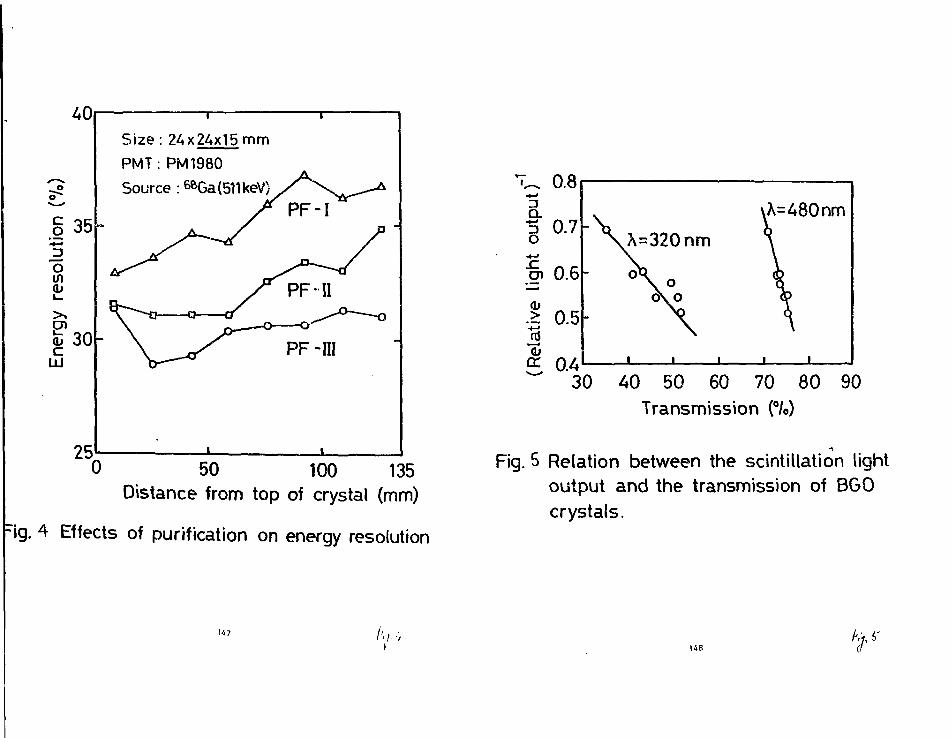
35
o
25
Size : 24x24x15 mm
PMT: PM1980
Source : 6BGa(511keV)
"0 50 100 135Distance from top of crystal (mm)
rig. 4 Effects of purification on energy resolution
0.8
A=480nm
40 50 60 70 80 90Transmission (°/o)
Fig. 5 Relation between the scintillation lightoutput and the transmission of BGOcrystals.
147 A;.-, <r

1

400
300
a. 200o
100
0
Polished and Coated
SurfaceSizefrnmX12x25x h3x25x hax25x25ax25x 3
Rough Polished
• o
A A
• a
• o
0 2 4 6 8Shape Parameter h / a
Fig.e Influence of Crystal Shape and its Surfaceon the Scintillation Light Output
10
- 2 0 0 0
I6w 1000
0
Rough Polished113ch Ifflch
i i' • • * * *
* • . * *
% ; \ / -13.0%
Fig. 9
0 50 100 150 200 250Channel Number
Crystal Size: 4x20x30 (mm)
Energy Spectrum Compared withPolished and Rough Surface
151 A 152

300
^ 2 0 0
Q .*->
o
^ 100
0
i r
Unit = ±41%
1fwhm=16.9%
Unit = ±46%
fwhm=26.2%
0 20 40 60 80 100Source Position from PMT(mm)
Crystal Size: 10x10x100 (mm)with Aluminized MylarSource: 137Cs
Fig.K) Light Output Uniformity Comparedwith Polished and Rough Surfaces
153
60
inc3 20
0
Q'tity:200pcsSource :137CsPMT:R878
HAfvlAMATSU
8 9 10 11 12 13Energy Resolution (%)
1A
Crystal 5ize:12x 24x24(mm)
Fig. H The Distribution of Energy ResolutionUsed for PCT

Table / The Scintillation Performance of Hitachi BGO
Size (mm)
12x24x24
4x20x30
1*25x125
*50x150
*75xt75
10x10x100
10x10x200
EnergyResolution
10.5 7c
13%
11 7o
13%
20%
16-17%
28-33%
PMT
R878
R878
R878
R878
R1250-03
R878
R878
Remarks
Rough Surface
Polished Surface
Rough Surface
Rough Surface
Rough Surface
Uniformity: ±4.17oPolished SurfaceUniformity: i 18%Polished Surface
7*1. u i

Contributed paper given at the InternationalWorkshop on Bismuth Geraanate, PrincetonUniversity Physics Dept., Nov. 10-13, 1982.
TRI-PP-82-44NDV 1982
Session C
OPTIMIZATION AND ALTERNATIVtS
LIGHT OOTPOT OFTIHIZATION FROM VARIOUS GEOMETRIES
OF BGO CRYSTALS
Sam Anderson and Hart In Salomon
TRIUMF, WOU Wesbrook Mall, Vancouver, B.C., Canada V6T 2A3
Abstract
The different geometrical effects that determine the light output
of BGO crystsls are Investigated. Several bulk shapes, attenuation
lengths and reflectors are compared. The highest light output is ob-
tained from trapezolds with specular reflecting walls.
157158
The Monte Carlo technique has been used successfully in the past
(1,2) to determine the fate of photons Inside sclntillators and light
guides. In this paper we Investigate the effect of the shape of blEmuth
gennanate (BGO) sclntlllators on the amount oi: light collected by a
photomultlpller coupled to It.
Two disadvantages of BGO crystals, compared for Instance with
Nal(Tt), are the reduced scintillation efficiency and the large Index
of refraction (n-2.15), which decreases significantly the critical
angle. Consequently, In order to obtain good energy rebolutlon one
must optimize carefully the collection of light from the crystal to the
photomultlpller.
We have developed a Monte Carlo program that simulates the propa-
gation of photons inside the crystal until they are either absorbed,
lost or collected by the photomultlpller* The following properties are
Included In the program.
a) Random or localized photon origin.
L: A variable absorption probability during transmission
through the crysto! (attenuation length).
c) Reflection or refraction on the W J J I E (specular or
random) with adjustable indices of refractions at each
wall and adjustlble reflectivity.
d) Several possible shapes, Including cylinders, cubes and
trapezolds.
e) The crystal was presumed uniform, without Internal
scattering.
The program will simulate the fate of H photons (~105) and will
calculate the number of them absorbed, trapped, lost or collerted by a
159
photomultlpller. It will also calculate the average distance travelled
by a photon and the average number of reflections. The program relia-
bility was tested using several limiting cases where the results could
be evaluated independently. For Instance no attenuation, where all
photons are collected with probability equal to the area of the face*
Results: Comparison of three chapes
We compared cylinders, cubes and trapezoids with the same surface
area and two absorption lengths, 30 en and 50 cm. We used linear
dimensions of 10 cm and determined the light collected In one face
where we assumed an optical contact with relative Index of refraction
of 1.36 and all other faces with n-2.15. Specular and random reflectors
were considered, and in all cases the source of light was randomly dis-
tributed over the whole volume.
The results are shown In table 1. The conclusions are that in all
circumstances the trapezoidal shape collects more photons, and that
specular surfaces are better •'or trapezolds but not for cylinders and
cubes where random reflectors collect more light.
We Investigated further the trapezoidal shape by using specular
surfaces, an attenuation length of 50 cm (a height of 10 en), and vari-
able angle of the wallB as given by a defined as the angle between the
central axis of the trapezold and one aide. The total surface was kept
constant. The photons collected in the larger area wall as a function
of a are shown in fig. 1. These results show the following effects.
Fcr r.-0 the photons collected are the sane as In a cube, as it should
be. For small Increasing a the number of collected photons increases
linearly with a up to about »8° where It saturates. The amount of
photons collected almost doubles (from 21% to 38%). External reflecting
160

wrapping will Increase this number even further.
Conclusions
A trapezold with specular vails end a»8° Is the most efficient
shape to maximize the light collection In a ECO crystal.
References
[1] T. Maseain, CEWJ report EPD, 76-21 (1976).
[2J S.E. Derenzo, this Workshop.
Table 1. Percentage of collected photons for different
shapes, reflectors and attenuation lengths.
Shape
Trapezold
Cube
Cylinder
Reflector
specularrandom
specularrandom
specularrandom
Collected photonsattenuation length(50 cm) (30 cm)
35X27*
21?25Z
21Z25X
28123*
18Z20*
lBX2U
Figure caption1. The fraction (In per cent) of light collected on the larger square
face as a function of the trapezoid angle.
161 162

• \
O O
O O
ft
t.
oor-.oooLO CMO O O O '
Off*
O O
CMOO -i
OO '. do
00 03
O O
ooooO O
co enCOO3O O
CM f> CM CM •'CM r>- 10 O ,CM c\» CM CM
O O O ,O ,'- O O O O
CO_ooo:
d oddOOOOoooo
ooooodd d
;o oo o:'©" odd
ooooOQO O
dodo-, d do dCM CM CM
8 Is; i O> O
QpOO '.OOOO OOQO
agSSoo
; • • • •
OOOOO OOf*> »"•
8*•' o•\ o
ooooo
i • 'S
I
* \
|5
$
3
i
* S
f *<"
I
S
«. s
H CD
0'* "
••}.
S i *• *••
if? I^B 7^ J>
1
_ . " - f c >
*-I t
^i fir? O ««• N 9

fcjce t— CM
_i . >- .in
dX
JOUJCl ' (fl Q LU
O LU —> O CM
mr»»i-1 CM VO COLOIO VOVO
"=J-O coco " - * co CM CM ro r^CMCMOOCM HHHO
r-« ooOo oooo oopio 0006 oooo
do'pd
o o '
OOOO. O O O O
cnooi^- O CM ro-io«*• vo in v©. « r « - "
_ _ •—i o en orOCMCMCM .—Ir-H O •—<
O O O O
CM ro m «a-CM CM CM CM
oooo- oooo oooo
OOOO
•—< o o ododo
O O Q•—• < I X UJ
< go.
-JO O
k- < sz o: a:>—»t— x o<J 2 I—(y^ LU S tJ
LU, LL. i—
O © OUJ
MM O
02 =>
oo
O CO AS- s f
d dcS d
fM
d do d
^ oto o
8 f.
CM ro1 o »-t <—i r~.^^^ ^^^ ^^ ) ^O ^O
i—i ro ro roCM CM CM CM
oooo oo a'o ooooO i—i O O
d do d
co u> in LO L. _ .
CM *3; in ID. CM ro <
d dei d a dd<~>
CT> i—i r o r ot-H CM CM CM
co c?* co r .oooo
ao oo o
oooro
ooo
oooo oooo
O O Q
8gS2oooo o ooro ^
oo
FATES OF 'SCINTILLATION PHOTONS--AS A FUNCTIONOF CRYSTAL DEPTH- FOR A 10'. mm X Id mm BGO CRYSTAL
: Lint = Lbub " 1 00° Depth Collected Absorbed /Absorbed(turn) '.;' on Reflectors!' in Crystal
2102050100200
0.420.41o.io0.380.340.2?
0.160.16O'»160^160.170-18 •
'. •
• -at —
0.420.430.440.460.490.55

FRACTION OF SCINTILLATION PHOTONS COLLECTED.AS A FUNCTION OF ENTRANCE FACE SLOPE, L
FOR A 10 ram* 10 ram x 100 nm BGOPHOtODETECTeR COUPLED WITH INDEX 3.0
bub
irbub[mm]
CD
1000300100
03
1000300100
001000300100
""oo1000300100
001000300100
0.0.0.0.
0.0.0.0,
0,600
"I?000
0000
0
758182
68.71.78.75
.58.
.62
.61
.62
M".39.37.33
.13
.12
.11'
.10
0.1
0.820.830.83
...vP'#-«-.0.740.770.760.76
0.610.630.630.62
0.430.400.400.31
0.160.150.130.10
SLOPE0.2
0.810.82.0.86
0.740.770.760.75
. Q..600.670.660.65
0.390.390.400.36
0.180.150.120.11
0.5
0.810.840.86
0.750.780.790.78
0.650.670.650.65
0.450.450.420.35
0.180.170.140.11
1.0
0.870.850.87
0.780.800.810.76
0.680.670.680.63
0.450.440.460.34
0.1;80.180.160.13
167
Optical Measurements of the Substructure of BCJO
W. P. Unruh
Physics Uept., Univ. of Kansas
Lawrence, KS 6604 5
Several of the previous speakers hrve shown that BCO properties vary
from sample to sample. In fact, the phase diagram we have seen indicates
that stuichiometry is likely to be a problem even in the best crystals.
This circumstance makes a materials study difficult , since sample variability
will certainly be a problem. In the case of BGO one might view this
variability as an opportunity rather than as a problem, because i t may allow
one to understand the substructure of a material wliicli crystallizes at a
temperature very near that at which i t decomposes.
I want to describe some preliminary optical observations of BGO. Since
I have had the opportunity to look au only two crystals of BGO, rhe slides
will visually represent some of the characteristics of these particular
samples. These crystals were sent to me from SLAC by Dr. Coyne. They are
1 cm. square cylinders, of total mass 39 grams, and both have some very clear
regions. In the cloudy volume, the inclusions are bot'i random 1 y arranged
(in the smaller crystal) and deposited on layers (in the larger).
Although these inclusions look opaque in transmitted light, illumination
from the side shows them to be transparent (Figs. 1 and 2). Reasonably
detailed examination of these particular samples has not turned up any
opaque (and presumably metallic) inclusions of the type seen in the ear l ier
pictures of the crystals grown in China. The inclusions I have seen fall
into several types: a) spheroidal bubbles, clearly gaseous inclusions;
b) irregular shapes, usually showing angular (often hexaftonal-^ilce) surfaces;
and t:) sheets of very much smaller particulates. The f i rs t two types are
typically 10 - 50 microns in diameter, while the last type is from 1 to 3
few microns in diameter. None of the bubbles (type a) are bireffingent,
while most o r the type b) and i ) inclusions -ire biref r ingent, n clear indi-
calion of symmetry lower than cubic.
As Dr. Ucbor showed this morning, (hero are two pluses of the bismuth
oxicU'- i'rm.'inium oxide system which are hexagonal, and the observed hire-
fruinviuc shows that such phases are present as inculsiuns in tUeso crystals .
Such ^ tou-hinmetric difficulties can clearly be seen in those slides which
168
show L-onil>ini'ii crystal l ine and gaseous inclusions, where the pha-st1 sep.irat ion
tint-in*; growth has led to thu simultaneous growth of a low-symtnet rv region
.ind the evolution of gas, forming a bubble attached to a birofr indent
c r y s t a l l i t e . Viewed in transmitted t ight through crossed polar izers , the
crysla) i t se l f exhibits s t ra in birefringence in the regions where tUo inclusions
are dense, us one might expect (Fig. 2). One sees the s t ra in f ie lds assuciacej
with individual misfitt ing inclusions as well as the general s t r a in resulting
from the precipitated layers .
The surprising fact i s that the very clear par ts of these samples are
also badly biretr ingent (Fig. 2c, d ) . In fact , the birefringence i s no
worse in the heavily precipitated regions than i t i s in the inclusion-free
volume. Superficially the charac ter i s t ic size scale of this hiref rJ agent
pattern is a few tins of microns in each dimension. But of course the t rans-
mi teed-light micrographs sum the rotat ion of the polarizat ion through the
entire sample (a pat'i length of 1 cm.) so no charac ter i s t ic s ize information
can be obtained from *:he birefringence patterns in the clear regions. This
observation of strain in the clear regions raises the poss ibi l i ty of s toichio-
mecry variations in even the best parts of these c rys t a l s . Such stoichiomelric
problems would be. accompanied by density variations and associated index of
refraction variations in tUese clear regions.
Light scat ter ing methods provide a way of studying these e f fec t s , since
any index variations in these samples would e l a s t i c a l l y scat ter l ight just
as from dunsity fluctuation scattering in a fluid. The microscopic examination
of such simreos of scat ter ing is very conveniently made in an '"ul tramicroseope,"
which is simply a laser-illuminated microscope. Light from a laser (we use
10 mw at 442 nm from a He-CJ laser) is focussed to the diffraction limit in the
crystal just under the micro-scope object ive. This beam can be scanned across
the field of vie", and the light scattered at 90 degrees into the microscope
provides a visualization of the sources of scat ter ing in just the thin s l ice
of crystal illuminated (typically 15-20 microns thick in our system). Alterna-
tively, if (.lit- beam is nut scanned, one sees the sca t te r ing .sources within jus t
the diffraction-ltmitud beam. Because of the intensi ty of this illumination
scattering 1 rcm individual par t ic les as smalt as .05 microns can un.siiv be
seen. This technique has been of great u t i l i t y in our studies nt pn-i ipi tat ed
169
sy^ti-ms (such ns refractory oxides) , in which tlu' rumplt-u- substructure of
prec ip i ta tes , sub-grain boundaries and dislocations tan be imaged. I'hoto-
[;r.iphs taken before and after each anneal in a series of hual treatments
allow tme to direCLly see changes in such samples as ihe substructure evolves
i n response to nucleat ion and diifus ion of imptir i l ies .
For purposes of comparison with BGO, one ran examine typical crystal
sca t te r ing seen with this device. U-V grade sapphire from Linde, which is
Czochralski-grown as is BGO, shows layers of precipi ta tes decorating polygonal
boundaries arranged in planes perpendicular to the r-,ixis of the c rys t a l .
Notice, however, that the l a t t i c e i t se l f s ca t t e r s mi l i g h t . Sapphire {row
Cryst.i 1 Systems, grown by the method just desc ribed by Mr. Schmidt, Is
essent ia l ly tree of scat ter ing when viewed in the ultramicroscope.. But
nei ther the Linde nor the Crystal Systems samples art1 stoicliiometrir. In the
case of the precipi ta ted samples, the non-stoichiometry is direct ly v is ib le
as scat ter ing pa r t i c l e s , and in the sca t te r ing - free samples i t Is present
as a uniform dis t r ibut ion of point defects (which can be seen speetroscopically).
In contrast to these c rys ta l l ine samples, one can look at scat ter ing
from a sample of Supracil, a very homogeneous gl;iss (Fig. 3d). Here the beam
is strongly visualized by the e l a s t i c sca t te r ing from density fluctuations
frozen into the glass s t ruc ture . Of course, a t tuid sample would show the
same resul t , with even more intense sca t t e r ing .
We can d i rec t ly compare the scat ter ing from Linde U-V grade sapphire
(Czocbralski-grown) to BGO viewed in the very clearest region of one of these
samples. Equal exposures show that the scat ter ing is (for <> nominal crysta l )
exceptionally strong from BGO (Fig. 3b), We also notice that there is no
evidence of large-scale prec ip i ta t ion , ;)S in the Linde s; pphire, the beam
profi le resembling exactly that seen in the Supnicil (Fig. 3a). The scatteriif>
intensity is larger in the BGO than in the Supraril , ,is wt*ll. (In bmh these
images the laser beam diameter is about 20 microns.)
This uniform scat ter ing can be the result of ei ther relatively long
r.utge density fluctuations within the nominal cM'Sl.il s t ructure (a.s in .1
>;1.ISH) or he cause of scattering from an «sstMitialiy uniform dis t r ibut ion *>1
very small prei- ip i lated p a r t i c l e s . The s- .- etc* rinR from the lut ler e;i.,u would •
170

described very well by tilt usual Rayleigh-Debye approximation to Mie
scattering. If the lifiO la l l ice Incorporates density fluctuations, the
scattering is not easy to describe. In particular, no description is avail-
able of tilt relationship between fluctuations in the melt and resultant
fluctuations in the crystal after it has been pullerf. A reasonable starting
description of this unusual circumstance, i . e . , diffuse scattering from a
crystal la t t ice , would be Ornsteln-Zernike scattering from fluid fluctuations.
In either case, one can hope to obtain a full description of the nature
of this BGO substructure from measurements of the angular distribution of the
light scattered from these samples. In our laboratory, such measurements are
made on the goniometer system shown in the Fig. 4. Several points are worth
comment. The index of refraction of BGO i s relatively high (we measure 2.2
at 422 nm), so the wavelength in the medium is only 200 an. This high index
creates relatively intense surface scattering (even though the crystal is
immersed in a fluid), and the telescope Imaging system is essential in removing
this surface scattering from the field of view of the detector. The system of
apertures and f i l ters allows one to measure the absolute scattering intensity
and thus make calibrated Rayleigh-ratio determinations. Uniortunately, the
square cross section of these samples makes i t difficult to measure the
angular distribution in the vicinity of the comer angle (since there is no
way to match the high index), so some of the angular distribution is unavail-
able. Subsequent measurements should be made on polished cylindrical samples.
The angular distributions measured in this way can be fi t , using modifications
of our Mie scattering programs, to either Rayleigh-Debye (R-D) or Ornstctn-
Zernike (0-i!) functions. In a Bayleigh-Debye fit one obtains a distribution
of size parameters (particle circumference in wavelengths of light in the
medium), from which une gets the number, total volume, and average diameters
of the precipitated particles responsible for the scattering. Ornsten-Zernike
fits , .ve tin- correlation length for the fluctuations in density responsible
fur the scattering, and the compressibility <f the "fluid" (Fig. i ) . In
the context uf n<;o, one can guess that these parameters would be related
to the compressibility and correlation length In the melt. But without
an understanding of the crystal growth process on a microscope scale- ii
is difficult to interpret these parameters. The form of the 0-Z function
sh.iws that the existence of the compressibility term is directly reoo>>ni/..ib lo
as an asymmetry nf tliu scattering around 90 degrees. In both ruses, the
171
angular distributions are monotonically decreasing with increasing angle in
the forward scattering region, an important point to notice.
Since the two functions are different, ir is worth asking whether the
experimental angular distribution itself can he used to decide which type of
scattering is occuring. Plots of these two functions, shown in Ftfi. 6,
demonstrate that R-D scattering from a collection of polydisperse particles
is indistinguishable from O-Z scattering. This forces us to consider both
alternatives. One needs some electron microscopy on these crystals to
sett le the issue.
We have taken three angular distributions in clear sections of the two
crystals. Each can be fi t by either R-D or 0-2 functions, since the data is
not particularly precise and the corner angles arp missing (as can be seen
in the example of Fig. 7). All three angular distributions taken so far (and
other data, as well) show that the angular distrib"tion may rise ini t ia l ly
with angle, in direct contradiction to both the R-D and 0-Z functlinal forms.
Backscattering angular distributions are rarely observed. They occur
when there Is some sort of phase separation or internal structure associated
with the scattering entity. For example, in our work in oxides, t"he solute
depletion layer surrounding precipitates provides partial phase cancellation
of the forward scattering wave, wnich leads to a mild rise in scattering
intensity with angle. Another very important instance of this type of behavior
occurs in phase separation of glasses, a situation thoroughly studied theoreti-
cally by Goldstein and experimentally by Hammel and Ohlberg. In that sltuaticn
the phase-separated regions are of comparable volume and the forward cancella-
tion is mort complete. The essential point to be made is that even partial
forward cancellation requires that there be index-of-refraction fluctuations
which are well correlated, since the phase cancellation takes place on a local
scale.
If this phenomenon Is appreciable in BCO, the interpretation to be drawn
in either case, H-D or 0-Z, is similar. If the scattering is due to a homo-
geneous collection of quite small particles, e.u-h will be surrounded by a
volume which is eompositionally different frott the bulk crystal. If the
icallcring is from density fluctuations due to spatial non-uut furmi ty in hulk
stoii luomelry, these fluctuations consist of <-,>rrclaied regions of both higher
.md lower index of refraction with respect to the basic la t t ice . In either
• -.i.si-. "in- WIMJII! b.ivr to conclude that minor phase reparation has taken place
during the growth of the crystal.
172
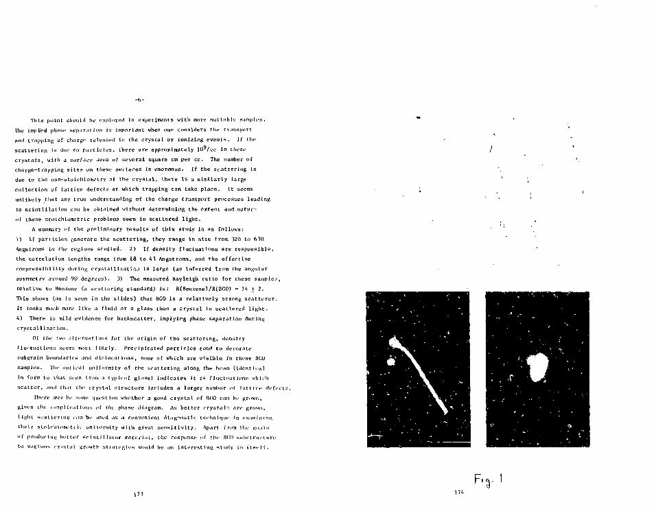
-b-
Tliis point should he explored in experiments with more su i tab le nnniptos.
The implied phase aepcirmion Js important when one considers the transport
and trapping of charge rel\ias«d in the crys ta l by ionizing even t s . If the
sca t t e r ing is due to p a r t i c l e s , there are approximately ]O9/cc in these
c rys t a l s , with a surface area of several square cm per cc. The number of
charge-trapping s i t e s on these surfaces i s enormous. If the sca t t e r ing i s
due to the non-stoichlometry of the c rys t a l , there i s a s imi la r ly large
col lec t ion of l a t t i c e defecta a t which trapping can take p lace . I t seems
unlikely that any true understanding of the charge transport processes leading
to s c i n t i l l a t i o n can be obtained without determining the extent and natur-
of these scotch Lome trie problems seen in sca t te red l i g h t .
A summary of the preliminary r e s u l t s of t h i s study ia as follows;
1) If p a r t i c l e s generate the s c a t t e r i n g , they range in s i ze from 320 to 630
Angstroms in the regions studied, 2) If density f luctuat ions are responsible ,
the cor re la t ion lengths range from 18 Co 43 Angstroms, and the e f fect ive
compressibili ty during c r y s t a l l i z a t i o n is large (as inferred from the angular
asymmetry around 90 degrees) , 3) The measured Rayleigh r a t io for these sampler,
re la t ive to Benzene (a sca t te r ing standard) i s : R(Benzene)/R(BC0) = 1 4 + 2 .
This shows (as is seen in the s l i de s ) that BGO i s a r e l a t ive ly strong s c a t t e r u r .
It looks much more l ike ;i fluid or a glass than a crys ta l in scat tered l i g h t .
4) There is mild evidence for backscat ter , implying phase separation during
crystal 1Ization.
Of the two alternatives for the origin of the sca t t e r ing , density
fluctuations seems must l ike ly . Precipi ta ted p a r t i c l e s tent1 to decorate
subgrain boundaries and d i s loca t ions , none of which are v i s i b l e in these BGO
samples. The optit1')) uniformity of the sca t t e r ing along the beam ( ident ica l
in form to that sv-on fmro A typical glass) indica tes i t Is f luctuat ions which
s c a t t e r , anil th.it the crysta l s t ruc tu re Includes a larger number of l a t t i c e defects .
There iwiy be .smne question whether a good c rys ta l of \\C,Q can be grown,
given the romp I tc-.it ions of the phase diagram. As be t t e r rrysNil:s are grown,
t ight sca t t e r ing ran be used as a convenient diagnostic tecUntqvu1 (n exatniniiu;
thei r sioirliiometr U- uniformUy with Rreat s e n s i t i v i t y . Apart frnm the nu.Hx
of prodiK'tiiK hel ler sr int 11 lator mater ia l , the respenaf of thr n(;o subst r m t u r e
to v.irUuis crvst.il growth s t r a t eg ie s would be an in te res t ing study in I t s t - l l .
F.,. I

O0)
cs/

o
177
i.jk. - De !>••}«.
Pfl.i I ePfl.ro. me 4
u. =
I'S) = £-' -nc.su) ]1
For vAt
a
. 5
178

(ZO)I (ZO)I
o «
II II
ino03
(au)i (aa)i
aa-zo

AN ALTERNATIVE TO RCO
AN ALTF.RNATIVP TO BGO
Tt. F. Anderson
v i s i t o r at CFRN,
Geneva, Switzer land
T). F. Anderson
CERN
Geneva, Swi tzer land
(viri tor)
Paper presented at
The? International Workshop on Bismuth Germanate,
Princeton University,
November 10-13, 1Q82
We feel that for some applications, the scintillating crystal RaF2
may he preferable to BGO. The application that we will address is that
of colarlmetry In high energy physics. For this we hope to demonstrate
that, when coupled to a liquid TMAR photocathode and wire chamber, PaF^
offers the posslbility oF an order of magnitude better timing resolu-
tion, ease of operating in strong magnetic f ieJcfs, greater flexf M Mty
of design, and more information. There is even the hope of substan-
tially reduced cost.
View graph No. 1 (VG1) shows a comparison of some of the important
properties of BGO and BaF^.1"5 The radiation lenRth of BOO (1.1 cm) is
almost a factor of 2 shorter than for BaF2 (2.1 cm), traking it a much
more compact calorimeter. An interesting feature of the emIsslon spec-
trum of BaFj is i.'iat it is two spectra with the hard spectrum peaked at
225 mm, having 20* of the light and a decay constant of only 600 ps-
The decay constant of BGO is almost 600 times longer. There Is some
uncertainty of the light yield of BaF2 with the estimates varying from
1.3 to 2.ft that of BGO.
vTl2 shows another comparison of BGO and BaF2t the cost. Tt should
he remembered that since the radiation length of RaF^ Is twlcp that of
RCO, the price should he doubled for a linear geometry (I.e., same solid
angle hut twice the depths). Of couse, this correction is even larger
for cylindrical and spherical geometries. At present the cost of RaFp,
Is half th.it of BOO. The cost of I ton of RaF-j (a ?-foot cube) in now
ahnut nne-baK the cost, ner cm', of th^r which Is hoped for RCO in the
f urur*». As Interesting point is that unpttrl f led BHn costs abou^ $2 per
cm3 w M 1 P nnnurifiod RaF2 costs only $0.03. This cortflInly places some
UI nd of lower limits on the cost of RGO ,-ind RaF?. Tt should al so ho
161 182

pointed out that the cost of BRO has come dos- because of the pressure
7>ut on the manufacturers bv the physics community* RaF2 has not had
this advantage vet .
One strong noint of BaF2 lfl Its timing resolution* Vfi3 shows a
comparison of the performance of a Vcra thick RGO crystal and a two BaF2
crystals i cm and 1 cm t h i c k . 5 ' 6 The variation with thickness Is due to
t'ut? greater fluctuation in liftht travel distance In the thicker crys-
t a l . For 'ill keV y-rays the resolution of BGO Is 1900 ps (FUHM) while
for the 4 cm and I cm RaFj crystals . It Is 160 and 110 ps (FWHM), re-
spectively. For the V-rays from Co6o (threshold >1000 keV), the FUHM
resolutions for the three crystals are 1050 pa, 115 ps, and BO ps. Thus
the timing resolution of BaF2 Is about 10 times better than for RGO.
VG4 shows the timing spectrum for a Cofio source using a BaF2 crystal 10
mm thick. V05 shows the variation in tf.mlnR resolution of BaP2 for dif -
ferent energies, thresholds, and crystal thicknesses.
For some clme there has been an Interest In the detection of l ight
with photosensitive gases In proportional counters (VG6). But, unt i l
recently the detection thresholds have been too high to detect the l ight
from solid s c i n t i l l a t o r s . The gases of most interest are the tetra-
amlnnethylenes which have the lowest photoionlzatlon potent ia l s . 7 In
particular the compound TMAE with a photoionlzatlon potential of 5.36 eV
(?M nm), has found use In Imaging CerenVov detectors and the detection
of light from gas sc int i l la t ion proportional counters. I t haa also heen
know that In an organic solution, TMAK has a threshold of about 3.5 eV
(^50 nm), which overlaps the emission spectrum of BaFn.
To u t i l i z e the low threshold of Houfd TMAE, we have bui l t an
Instrument O'O7) that couples a liquid photocathode (LPC) to a low
pressure wire chamher.8 A thin layer of THAR has condensed on a cooled
cooper plate. Ahove this cathode is an anode plane made of 10 uro wires
with a 1-mm spltrh. The anode to cathode spacing i s 1 mm. The Instru-
ment has a IIV quartz entrance window. The gas f i l l ing Is 3 Torr of pure
Ifiohutane.
VC.fi Rives the general characteristics of low pressure counters. '
Their mxln advantages h 'e high gain ( lO^- lo ' i , fast timing (lnD-IDO ns
FWITM), and ROOH position resolut'on. They have been operated in f ie lds
183
as high as ln gauss. Also, from work.we have done with solid photo-
cathoHes In gas, we Vnow that high pressure means low col lect ion e f f i -
ciency of the photoelectrons.
• 'sing a pulsed Xenon lamp and f i l ters we showed that the threshold
of our I,PC Is at about 4.3 eV (290 nm). Thus, wl t'l the I.PC we are
sens i t ive primarily to the fast component of BnF- (VG9). From our early
work we feel that the efficiency of this photocathode to the HaF? l ight
i s on th'i order of IT. VG10 shows a s ingle photoelectron rpectrum
produced with a small BaFj crystal and an AM ?.4l source. The crystal
was nonrefjector on the top surface, so only the light from one surface
was measured. After calibrating the source and crvstal combination with
a PMT, we measured a detection efficiency of the 'PC ( i . e . , the fraction
of AM241 events detected) of 0 .1* . We are thus In a position to e s t i -
mate the number of photoelectrons that would he detected with this
systen per GeV, (VG11). Our estimate in 3.3 x in3 photoeloctrons per
GeV from one face of the crys ta l . This number should probably be
doubled If the f i r s t surface i s aluralnlzed and the Intermediate quartz
window i s removed. In our test set-up the quartz window was kept warm
with a hear lamp which also heated the BaF2 crystal . Tt was later
discovered that at 33n°K there Is no sc in t i l l a t ion from BaF.,. We may
find an additional Improvement ln the future by keeping the BaFg cool .
VR12 shows the pulse height apectra of AM 241 if-ra, j on a email
soectroscoplc BaF2 crystal (black spectrum) and the spectrum of Cs 137
(white spectrum), using a large but poor quality BaF2 crys ta l .
Vf.13 shows the next generation of IPC detectors coupled to a BaF2
crys ta l , currently tinder construction. The crystal i s 130 mm in dia-
meter and 26 mn thick. Some of the improvements of this denign are the
removal of the quartz window, reflector on the first surface of the RaF2
better temperature control, and more f l e x i b i l i t y of grid design, By
mid-npeember we hope to put th is chamber ln a 1 C.eV electron test hejiir»
it HFRN (Vf.l<.). Dnrlnfl the run, lead plates of equivalent radiation
length will he put Inlo the beam. Thus wp will he aM» to map the
response as a functtn of radiation length. The sum of the means wil l
irlve th<> number of detected photons per "e".
.84

VH15 shows one possible design of a BaF£ calorimeter using a LPO.
ffeing imaging nroporttonal counters th i s calorimeter wi l l Rive the x, v,
and z prof I le of the shower, fast time and work in a magnet Ic f i e l d .
The radiation length of the ent i re system is 3.1 cm, though other
schemes can bring this number closer to the 2.1 cm rad ia t ion length of
"G16 shows the advantages and disadvantages of BGO and BaF2* For
RGO i t s main advantage Is I t s radiat ion length and i t s disadvantages are
c o s t , timing, and d i f f icu l ty of t<se In a magnetic . e ld . The main
advantages of RaFo are i t s timing, the ease of working In a magnetic
f ield with a wire chamber* the f l e x i b i l i t y of design, and greater in for -
mation out. I t s disadvantages are cost and i t s rad ia t ion length .
Although BaF2 has i t s own shortcomings, coupled to a LPC i t has some
unique s trengths that we feel make I t a viable a l t e r n a t i v e to BGO in
some appl icat ions of calorimetry in high energy physics .
185
.H. Nestor and G.Y. Huang, "Bismuth Germanate: A Mlfth-7. Gamma-Rayand Charged Par t ic le Detector," IKF.F. Trans. Nucl. S e t . , NS-22,(I97S), 60.
. Blanar, H. Die t l , E. Lorens, F. Paus, and H. Vogal, Max-Planck-Tnstl tute Report MPI-PAF./Exp. F.L94, Sept. 19R1; "H"«s'>uthfiermanate, a Novel Material for ElectromagnetIc show Detec-to r s , " presented at EPS Internat ional Conference on High FnergyPhysics, Lisbon, July 9-15, 19ftl.
.H. Farukhi and C.F. Swinehart, "Barium Fluoride as a Gamma-Pay andCharged P a r t i c l e Detector ," IEEE Trans. Nucl. S c l . , KS-1A,1971.
. Al leniand, M, Laval, J . Vacher, M. Moszynsk J, F. Cormoreche, andR. Odru, Centre d'Etudes Nucleaires de Grenoble, reportl.T-TI/MCTR/«2-2'il>, "New Developments In Fast Timing with BaF2S c i n t i l l a t o r » " prepr in t .
1. T^aval, M. Moszynoskl, R. All em and, E. Corraoreche, P. Guinet ,B. Odru, and J . Vacher, Centre d'Ktudes Nucieaires de Grenoble.,report LF.T1/MCTE/R5X, "Barium Fluoride, Inorganic S c i n t t l l a t o rfor Subn^nosecnnd TlmlnR," submitted to Wiicl._ Instrum. Methods.
. Moszynoski, C. Gresset , J . Vacher, and R. Odru, "Timing Propert iesof BGO S c l n t i l l a t o r , " Nucl. Instrum. Methods, 188 (1981), 403.
.F . Anderson, "A Photoionlzatlon Detector for the Detection of XenonLight," IEEE Trana. Nucl. S c l . , NS-28 (l^ft l) , M2.
.F . Anderson, "Extraction of Electrons for a Liquid Photocathode intoa Low-Pressure Wire Chamber," submitted to Physics Le t t e r s .
. Breskin, "Process in Low-Pressure Gaseous Detectors," Nuj;l. tns_trum.Methods, 196 (1982), 11.
186

PROPERTIES
mo
I
t.t
MISS/OV
be CAY (ov(7i set)
YttELH
N08X 2 , / r
A/o
8
LET i/mere J 8*-v/f
*•*jsee
P. 13 MS8
3,1
< azr1310co.u
t.s?
/0**
COSTS
COS
B60 Bate
ft3.GO
-?.O3
THAT ap- 1360.
1B7 188

o
o01
• o
oo
£EcoCM
IIQ
"to CO
E£r-
11
ro LU
w Z
E 'Eo
H o |*~ CM
o T~£A\ SLX U J CM
E TP A»__——•
n aJ-T^—*-
O fo CMo OT IICM
aUJJuJ
XUJ<II
1
VJ
a.
— — * - —
~ ~ * ~ — • -»_toa^.CM
I
i
agi-
llszo
^ — — — — " *
oCMcooT—
ooCO
oCD
oCO
moin
oCDi n
DC
CO^>
z1
zXo
N V
S1N0OD U30!AiniSI
CO
a
g^ ^^
o•s.
o
o
^»
oo
1
M•v-
1
o
oo
009
o
?
o0Q
i!* MV
6 "*8 or

vsCRYSTAL
25G
200
150
(A
a
X100
so
, 6 8Ga
E y =511 keV, 6 8Ga
MeV, 60 Co
0 = 2.4 cm
h [cm]
'91
THE rerRAHMMQErHYL£N£S
COMPoUA/n
TMAETMBITMABTMPD
TfM
2295.60 ZZ1Lto Zoo
eV
3.5V3.453.85
3 SO3 fo
azz
L I Q U I D souo
£« 2 a
loo 3oo
192
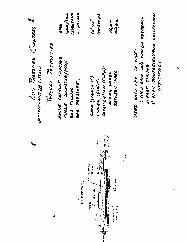
i00E
^
ft.
11
I-4
v
IMi
iCO
till1
V,
^38»3
V3
k\\
3§5go

IJ5
5:
SI-o
-130] A1ISN31NI

t> o *
8I
Iv
si
V
m
M 5
> S
k
V;

45
Ift?
I*
va V u &
^ 5; SS . 3 %a. * ,c K
t> k s *» ^ «
Q^ *^S ^ ^ 4^\ '' N " ^ ^
si

s
O
o
k
I
C
IV)
3
^ 1I
itK(41
U.O

11
"iV

& '.-:

g ^

aitlVKNTIOHAL READOUT OF LARCE BOO ARRAY:'. AIII' CALIBRATION*
Takayuki Matsui
(Representing the BOO Ball Coll.ibnr-it, i
High Energy Physics Laboratory
Stanford UniversityStanford, California all VIS
Session D
READOUT ABSTRACT
A scenario of a conventional readout (photomult.iplier tubps-integrate and hold modules - ADC) and calibration nyst.em for a BHOCrystal Ball is presented. The outline of the irliene ind the directionof improvements are based on the data and exppri '-•nn&s of the JJal CrystalPoLl now oper3tinE in DORIS at DESY. Also the -nnopt of a RCO proto-type array under construction is presented.
Invited Talk presentr Iat the
f n te rna f . i ona l Workshop on Rinmuth J'-F r i n c ^ t o n , i'lew Terr-ey, Novpmbi jf l i t - 1 •
209210
INTRODUCTION
We have made •* proposal for a BGO Ball detector at the Stanford
Linear Collider (SLC, / s = 100 GeV). The physics motivation and
overall design of the BGO call is contained in a Letter of Intent for
the SLC and also the talk by F. Porter in this workshop. The BGO
Ball is basically a non-magnetic detector which is optimized for detec-
tion of photons and electromagnetically showering particles. A summary
of its design parameters is given in Table 1. In this report we present
a readout and calibration scheme for the BGO crystals and discuss design
resolution.
For the BOO Ball, the readout requirements are as follows:
1) Linearity and high stability from 20 KeV to 50 GeV. The upper limit
is due to the fact that roughly 80% of an electron energy is in a
sinrie crystal in our segmentation. The lower limit is set by our
o.-ilibr tion scheme which will be discussed in a later section.
2) Frequent absolute energy calibrations of each crystal and inter-
calibrations of each readout channel to a precision of < 1 - 2%
3) Fast analog triggers over a large number of independent detector
3eTnent3,
r.inc vf- !iiw 'mi :n .-nrr-ile •< U.-rs number (?200) of sirniUs, it i s impor-
t-int i-o '!.>• yi»n .in<ierstoo<1, reliable existing designs where nossible. The
r»n,nir»ri>;nt..- ; i -' *••! iuove .-in be realized by i conventional phot.nmul t. ipl ier -
interrat" ml !io 1 i - ADr ;-,yntpm.
211
READOUT SYSTEM
Table 2 shows a comparison of the readout system proposed for the
Bno Ball with tha t used for the Kal Crys ta l Bal l . ' For the Mai Crystal
Bal l , a s tandard Bialkal i photocathode has almost complete spec t r a l matching
for the peak wave length of U20 ran. Although R00 has a longer wave length
or U80 run at the peak of the s c i n t i l l a t i o n l ight and be t te r matching could
be found with other photocathode m a t e r i a l s , the Bia lka l i photocathode s t i l l
has acceptable spec t ra l matching t o BGO to get the designed r e so lu t i on .
The end face of each hexagonal BGO crys ta l has a diameter of about
2.6 cm and can be coupled t o e i t he r a 3/1"" or a 7/B" photomul t ip l ier . I f
we couple a Hamamatsu R1213(3/V') tube to a 1" diam x l"length BGO crys ta l
with grease (Dow Corning Q2-306T, n - 1.146), the observed reso lu t ion (FWHM)
at the Cs peak i s -20S. If we ex t rapo la te t h i s value to higher energies
(assuming i t i s dominated by photoelectron s t a t i s t i c s ) , the contr ibut ion
to the reso lu t ion above 100 MeV region i s less than ?" (FVHM). The spectrum
on th is 3 /V photomult ipl ier i s shown in Fig. 1. For detai led enerra measure-
ments over the range ,?0 KeV to 50 GeV, we wil l n n l i t '>ne photomult ipl ier
sicnnl to 3- in tegra te and hold channels . Each channel corre.-nonis to the
''n^rripr. l i s t e d in Tnble 2. To obta in -i l i n e a r i t y ovfr Mie in n n r e
mnuiriM. low /.Tin operat ion of the phot.nmu) Upl i ••]• (10 - 10 ) \;; .lecessary
imi iiecmrip il" t li i :•• we require amp] i f i c i t ion in t ho lower-t "nfrry rhannel. To
i n t i r n t e ini noM the -malon s ignals an<1 t.n . l i r i i i r . e t.hom, uf intend to use
Mi.- .•I,Ar-.i.>v.*lone'1 .'HAM ind BADf?1'' syst.™n whirli u-r> opt imise! for
h-indlinr ( ' 'i niunh*ar nf innlog Hign
212

CALIBRATION OF THE SYSTEM
Attainment, of the resolution expected for the BGO Ball ultimately
depends on the quality and stability of the inter-calibration of the
crystals.
Generally, "is shown in Pig. 2, the readout system of each channel
would be iivided into three major components, and these should be inter-
calibrated individually.
a) the system from the integrate and hold module to the ADC can
be calibrated by well understood test pulses.
b) The system from the photcmultiplier to the ADC can be calibrated
optically usinfi LED's or optical fibers. If light is fed into
the system from the extreme end of the crystal, light trans-
mission through the crystal allows us to monitor the crystal
quality.
In addition to this system, we will also use the source calibration
scheme of the Hal Crystal Ball. We now discuss the calibration system of
the "laI t'rysi.'il I all and indicate possible improvements.
'i) P-irlio'ict i •/!=» " o u r c e
"ft- -Ivtr I in*j:, it' C.3 (E ' 662 KeV) cnn tie 'lawn t.he ."ili-
!>'••!T. i in rvir-une'.-'r:; >n i "rystal-by-oryr.t-.a] h:\i-, i 3. Fi,:. : -iinu.-.
•in --.t-inr h.1 of t hi.i .inectrum. The source .-alibratitm in Ion*1 roughly
• n •- 'i V*="»K i:; 1 .-,r»*v ifil en li brat ion luta run by ol u- \nr 1 ::t vmr
;oi]rr< -ti Mi*- -"nT'-r of t,hp Ball.
213
For the BOO Ra i l , j e would encapsulate f h** / m r p " in each c rys ta l
n.-u- f.hc photomult ipl ier end, rAz>»i in -.t r^nrth .in .is nnt to i n t e r -
fere with real data taking. The •"•ilibr'iM m iat-'i will be taken
••'jntinuousiy between beam cross inF .
b) Van de r.rnn.fr
The second calibration point of the N'i I ^ryntal Rail i :> t.uken by
uninn; the y-rays from the following rr>-n'tinn.
p + F l" , N e?0* . „ + o 1 6 *
* *• y l h . l 1 ) *• n .
The proton beam i s generated by a stiall V;in -le 'Iraaff (l»00 KeV)
machine and the 6.13 MeV* y ' s a re i so t r^p ion l ly radiated from the
t a r g e t at the center of the Bal l to the c r y s t a l s . Fip;. h shows
the a pec t rum of the 6.13 MeV l i n e . Also, higher energy y-i'ays7 - * 8
are possible by the reaction of p + Li -"Re •* y(!T.6) + B^ ,
The small c ross -sec t ion for the reaction makes i t d i f f i c u l t to
perform a c a l i b r a t i o n in a short period nf Mme, but some improve-
ments in target and beam flux may make Uiir. useful for the BOO
Bal l . The Van de Graaff c a l i b r a t i on is -lnne once ^v^ry two weeks.
• •) Bhabha sca t te r ing
Fvr>m the -'vent >lata, the Bhabha ('andid-tt-.-':- -ir^ innl-itoil -itvi \r?
n;;."i \'ov -\ final c a l i b r a t i o n . Tin* >!.habin •] ' •" ' • HIP i r .-.hown in
-i.--. i. ^ r the Hal Crystal -VU1 it u:*u-ii ly ' 'ikp;; ib«tiit. t.wn w.-oks
».i tiM-uniuLit.e enough data for a Bhahln •••ililM"!t i MI ' lie* iono nn
11 Mi n imum i'ini ziniK p a r t i ch?p
At Mil- ML'T:.V r'p"-ion '"T t|> or T, t In- «|nNn n i r i :• hir l i ->nourh
214
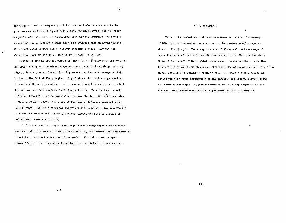
for a calibration of adequate precision, but at higher enerKy the Bhabha
rate becomes small ind frequent calibration for each crystal can no longer
be performed. Although the Bhabha data remains very important for overall
normalization, we reouire 'inother source of interealibration amoru; modules.
W(= are motivated to make Uoe of minimum ionizing signals (-180 MeV for
20 X RGO, -300 MeV for 16 X Hal) in real events or cosmics.o o
Since we have no special cosmic triggers for calibrations in the present
Nal Crystal Ball data acquisition syLtem, we show here the minimum ionizing
signals in the events of <p and i^1. Figure 6 shows the total energy d is t r i -
bution in the Ball at the ty region. Fig. 7 shows the track energy spectrum
in events with particles after a cut on energy deposition patterns to reject
interacting or electromagnetic showering particles. Then the two charged
particles from the ty are predominantly u's(from the decay I|I •* w u") and show
a clear peak at 200 MeV. The width of the peak with Landau broadening is
U0 KeV (FWKM). Figure 8 shows the energy deposition of a l l charged particles
with similar pattern cuts in the I|I' region. Again, the peak is located at
200 MeV with a width of !i0 MeV.
Although a precise study of the longitudinal energy deposition is neces-
sary to apply this nethod to the intercalibration, the minimum ionizing signals
from both cosmirr. in<l hadrons could be useful. We will provide a special
.•osmic trirjx^r u' u' - contained in a single crystal between bpam crossing.
215
PROTOTYPE ARRAYS
To test the readout and calibration schemes ay well as the response
of BOO crystals themselvesT ve are constructing prototype riQO arrays as
shown in FiR. 9«a, b. The array consists of 37 crystals and each crystal
has a dimension of 2 cm x 2 cm x 20 cm as shown in VIP. 9.a, and the whole
array is surrounded by Nal crystals as a showrr leakage monitor. A further
fine grained array, in which each crystal has a dimension of 1 cm x 1 cm x 20 cm
in the central 61* crystals is shown in Fig. 0-b. Such a highly segmented,
device can also yield information on the position and lateral shower spread
of impinging particles. Systematic studies of the array response and the
nputral track reconstruction will be performed at various energies.
216

SUMMARY
We have described the scenario of the conventional readout and
calibration scheme for the BOO Ball. The readout system will allow us
to set the designed resolution (f/E - 2% above 100 MeV) over the full
energy range up to -50 GeV. We will calibrate the system by usinp real
particles (radioactive sources, Y' s generaged by the Van de Graaff, Bhabha
electrons, u's in cosmic rays and hadrons in event data). In addition,
the system will be monitored by a stable light source. Work vith the proto-
type array will give us valuable information towards meeting these goals.
217
REFERENCES
1. Tho BOO Ba l l C o l l a b o r a t i o n : C a l i f o r n i a I n s t i t u t e of Technology -F. C. P o r t e r ; P r ince ton U n i v e r s i t y - R. <\ Cabenda, M. C a v a l l i -S fo rza , D. G. Coyne, C. Newman-Holmes; S tanfo rd U n i v e r s i t y -D. Bes se t . A. L i t k e ; S t an fo rd U n i v e r s i t y (HEPL) - n . I . K i r k b r i d e ,T. Ma t su i , J . C. Tompkins.A l e t t e r of I n t e n t for SLCSLC-8 (SLAC, S t a n f o r d ) .
2. Proceedings of the SLC Workshop on Experimental Use of the SLACLinear Co l l ide r . SLAC-report 2U7 (1982).
3. F. C. P o r t e r , Tfi&k in t h i s BGO workshop, to he publ ishes .
•*. J . C. Tompkins, in Proceedings of the Summer I n s t i t u t e on P a r t i c l ePhysics, July 9 - 30, 1979, ed. by Anne Mosher, SLAC-22'i (1980)p. 556-56U; M. Oreglia, Ph.D. Thesis , SLAC-??f> (1980); M. Oregliaet a l . , Phys. Rev. D25., 2259 (1982).
5. Y. Chan et a l . , IEEE Tran. on Nucl. S c i . , Vol. NS-25, Ho. 1, 333(1978).
6. E. L. Cisneros et a l . , SLAC-PUB-l81il>.
7. M. Breidenbach et a l . , SLAC-PUB-2032.
8. 0. I . (Cirkbride et a l . , IEEE Tran. on Nucl. S n i . , Vol. NS-26, No. 1,
1535(1979).
218

10
TABLE AND FIGURE CAPTIONS
Table 1. Characteristic parameters of the BGO Ball.
2. A comparison of the readout system for the BOC Ball with thatused for Nal Crystal Ball.
Figure 1. Spectrum of Cs obtained with a 1" dia x l"length BGO crystalcoupled to a Hamamatsu R1213 (3/l»") tube.
2, Block diagram of a conventional readout system.
3. Typical peak spectrum obtained with Cs by the Nal Crystal Ball.
U. Typical peak spectrum obtained with fMisirine by the Nal CrystalBall.
5. Typical spectrum of Bhabha electrons.
6. Total energy distribution in the Nal Crystal Ball at Ecm = 3097 MeV.
7. Energy spectrum of two charged particles after a cut on showerpatterns (Ecm = 3097 MeV).
8. Energy spectrum of hadrons after a cut on shower patterns(Ecm = 3686 MeV).
9-a. Prototype array.<?-b. Fine grained prototype array.
219
Sol id Angle Covered 95% oi hvCrys ta l Subdivis ions 9200Thickness oi Crys ta l Shel l 2 •'•Energy Resolut ion above 100 MeV 21/. CFH1IH)Photon Angular Resolut ion 'a =6-IOmrCharged P a r t i c l e Angular Resolut ion "„ =2-5mr
Table 1
Have LengthPhotocathodeCrystal FacePUTLinear RangeContact to crstal
Resolution(FUHM)at 137Cs (662KeV>
Total Ho. ofCrys talsNo. of energychannels ioreach crystal
Integrate(SamplelC HoldIntegral linearity
ADC
Hal-Ball
120 n»Biatkali5.6" TriangleSRC LSOBO 2"- 80 »AAir gap* glass uindou* air gap
18X
732
2Lou 200MevHigh 3700MeV
I C H9 channel/nodule< IX
Tracor-Northen1213(13-Bit)
BGO-Bali
480 nitBialkali1" HexagonalHamamatsu R1213 3/<4"~ 30 atGrease (or cookies)
2 OX
9200
3Lou 80MeVMed. 2500MeVHigh SOGeV
SHAM36 channel/nodule< 1 . IV.
BADC( 12-Bit)
Table 2
220
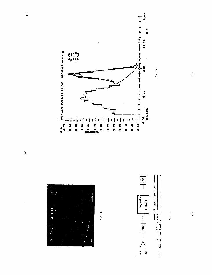
82
U<Ufr*

ENKRGY(VDG//24) - ALL EVENTS
~i—i—i—I-
20000
15000
10000
5000
0 ! - L ' • • ' • ' -
Pig. k
Bhobho ENERGY 113 CRYSTALS SUMMED)10000
8000
V
6000
4000
2000
0
FIT TO CORRECTED DATA:PEAK * 1842.8 MeV
o- «36.8FWHM»4.7%
= 6.131 MeVVon de Groof fCALIBRATION
"CORRECTEO BYBhabho
1400 1600 1800
ENERGY (MeV)
2000
221224

2500
TOTAL ENERGY - ALL EVENTS
3000 4000
*. 6
225
17
LN(E) TRACKS - 2 CR.NMOD < 4. P.C.
2000 -
1500 -
1000 -
500 -
0 -
1 ' ' r ' U N 1 T 1 ,
Ecn*3097
— i — i i ' i n ! . - ' i
L
1 Lmm
\V
~T r~"l—TT
1
1
'10 r,<) 100 200 400G00 1000 T3000 4000000
226

ooon
o§
ooo

PIPTOPIODE READOUT AND RELATED PROBLEMS
Eckart Lorenz
Mai-Planck I n s t i t u t fur Physik
MUnchen, Vest Go many
ABSTRACT
The use of photodiode readout for s c i n t i l l a t i n g cry $ t i l l s of EGO and
N a K T l ) w i l l be d i s c u s s e d . This ne thod of readout i s p a r t i c u l a r l y
i n t e r e s t i n g for large c a l o r i m e t e r s y s t e n s i n h i g h energy p h y s i c s
experiments.
229
Page 2
INTRODUCTION
This report mainly f o c u s s e s on the use of the photodiode readout in
large calorimeter s y s t e m for high energy physics experiments. It
complements an original study aiade by Blanar ct al . ( r e f . l ) , therefore some
t s p e c t s are only discussed b r i e f l y . Snip has i s is put on pract ica l
applications.and for that reason sone theoretical calculations are replaced
by empirical approaches.
The highest resolution y calof i twttrs consist of fully active materials
like Hal or BGO. In these auteriat* a certain fraction of the in i t ia l energy
is converted into fluorescent l l$ht which can be detected by l ight sensitive
elements. The l ight yield for Nal i s relatively well known (ref .2) while the
yields for BGO can only bo estimated rsthsr coarsely. As the technology for
growing high purity BGO continue s to iuprove, higher l i g h t y i e lds i re
expected in the future.
The l ight yields are:
NaKTl) - 4 . 1G« photons/MeV <X>-420nn. at room temperature
BGO -(0.5-1.5)10'- photons/MeV O.>-500nm, at room temperature
The l ight yield has a strong temperature coeff ic ient , and l ight emission is
isotropic .
The standard technology to record the l ight signal is the readout with
photomultipliers (PM). Why does one want to replace photomultiplicrs with
photodiodes (PD) despite some drawbacks? In the Tollowing I will discuss
reasons for the replacement of PM's by PD's, PD principle and the readout
chain, signal to noise relations and rite e f f ec t s , area matching problems
between diodes and crystals and sone practical examples.
2 30

Page 3
REASONS FOR TIE REPLACEMENT OF PH'S gX PP'S
Operation in Magnetic f i e l d s , Today* physic» experiments require the study
of complex reactions with precise Beasnrementa of both charged part ic les and
7 quanta. This condition in turn requires in nost cmses the Instal lat ion of
r calorimeters inside magnetic f i e lds . FMs are eltremely sensi t ive to weak
fields in the Gauss range and cannot he shielded above a few hundred Gauss,
while PDs are completely insensit ive.
Spaca requirements. The general tendency in high energy phys ics are
experiments perforated at storage rings with detectors covering nearly 4n of
the space angle . The she l j type construct ion of various detector
sub-elements iatplies a s ize and cost increase with ~ r' - r* of the radius-
Space ia therefore < premium. (Thi$ i s also • reason why BGO with i t s short
radiation length is superior to other r calorimeter aiaterial i) . Replacement
of the PH by a PD cuts substantially the calorimeter thickness and in turn
the s ize and COM of encapsulat ing e lements . (A typica l example: a
calorimeter of 20 r . l . Nal with PH readout is sbont 60-65 c« deep while a 20
r . l . BGO c a l o r i m e t e r with PD readout has a depth of ~ 23 cm) .
PJtli Are. flat &ract)ca_l I s i very lata.c avitems. The technology for PH readout
in well advanced. They require a highly stabil ized high voltage system (HV)
with permanent adjustment of the PH g»in. Various gain stabi l izat ion systems
h»ve beon proposeu and successfully bu i l t but the electronics overhead is
s ignit icant . particularly Jn large system involving si«ny thousands of
elements. In addition the IIV and the guin s tabi 1 it a t < on system are
themselves sources of fa i lures , and bookkeeping of breakdowns over a long
time is rather demanding. (For a system of 10000 elenents and a mean time
between f a i l u r e of 10' hours both for the high voltage and the gain
stabi l izer , one expects about 33 failures per s e e l ) .
PJtU JXS uai t ibJ i i PH's have both short terai and long term d r i f t s . While the
231
long term dri f ts can be tracked or compensated with gain s teb i l i zers , short
term drifts over a few siinutes at the 1-5 % level and overload effects after
high light bursts are very d i f f i c u l t to track or to correct. PD's as unity
gain devices are inherently s table even af ter many years of operat ion
( r e f . 3 ) . Recovery even after exposure to full room l ight is very short.
P r i c e : PH's are s t i l l p a r t i a l l y hand made and show large unit to unit
variations. The production of PD's i s fu l ly automated. For the tine being
the price for a PD readout system <PDr charge s e n s i t i v e preaaipl i f i e r ,
sfi-ping amplifier) ia about half that for a PN readout (I'M, stabil ized HV.
base) . The rapid progress in semiconductor technology wil l certainly cut the
price of PD readout substantial ly. The other aspect of the price due to the
element thickness has already been mentioned in the discussion of the space
requirements.
In table 1 soate further comparisons between PM's and PD's *re made.
THE PD PRINCIPLE AND TIE READOUT CHAIN
Before describing soaie practical applications le t aie briefly discuss
the PD principle and the basic readout chain. Fig.l ,shows a simplified cut
through a diode. At the present time PIN diodes of 10-100 mm1 area are
commonly used. They ars aade from high res i s t iv i ty s i l i c o n Olkilcm). The
diode has a very thin p Cypo diffusion front layer and an n type diffusion
into the back of the wafer. Applying a reverse bias voltage of a few tens of
vo l t s wi l l generate a depletion layer over nearly the full depth of a 100|i
thick diode. When a photon i s absorbed in the diode an electron-hole pair is
crested. In the depletion layer the electron-hole pai.s are separated by the
e lec tr i ca l f ield and a photo-vurrent i s generated, while pairs in the p
front layer and the n rear layer recoaibine.
232

Page S
Fig.2 shows the absorption constant in silicon «s a function of
wavelength together with the light emission spectrum of BGO. Below 500 na
the absorption length becomes very short, therefore very a thin p layer
(0.2-0.5 micron) is necessary in order to conserve a high quantum
efficiency. Unfortunately a thin p layer hai a high sheet resistance which
affects both the rise time and the noise (for detailed discussions on the
diode series resistance contribution to the systeai noise ice following
report by D. Groom). For the reduction of the frost layer resistance a fine
metallic grid such as on solar cells it evaporated onto the P layer. The
long wavelength part of the BGO emission spectrum is completely absorbed in
the depletion layer of >10 micron, thus i high quantum efficiency of over 70
% can be obtained. The remaining inefficiency comeu primary froai surface
reflection. Silicon has a nigh refractive index, thus high surface
reflection is observed. Replacement of silicon oxide (n=1.48) by silicon
nitride <n=2,05) for surface passivation is particularly appealing due to
the better match with the refractive index of 2.15 for BGO, provided some
high refractive index coupling grease or |lue can be found. Fig.3 shows the
excitation and emission spectrum of BGO together with the quantum efficiency
of high quality PIN diodes and PH photocrthodes, denonstrating the superior
spectral matching between BGO and the PD (ref.4).
The basic system for the readout is shown in Fig.4 and resembles very
much the technique used in nuclear semiconductor detectors. The PD is
coupled optically to the scintillating crystal with a coupling medium
(transparent grease, oil or glue) that matches as close as possible the
spectral parameters of the scintillators and the diode. The diode is reverse
biased to a few tens of volts via a vory high ohmic resistor ( > 50 110) and
connected to a low-noise charge-sensitive preamplifier and filter amplifier.
Page 6
For optimum noise conditions and minimal pickup the preamplifier must be
located as close as possible to the PD. In order to calibrate the readout
chain, a precision voltage pulse can be used to inject a well defined charge
into the preamplifier input via a small capacitance (1-3 pf) . For trigger
purposes signals can be branched off after the shaping amplifier or the
preamplifier. The branch off after the preamplifier needs reshaping but can
be used to generate a fast timing signal between 30 and 100 nsec.
SIGNAL TO NOISE RELATION AND RATE EFFECTS
For a high resolution y calorimeter the signal to noise ratio i s of
otmost importance. PM'i are one of the host low noise dev ices and the
resolut ion of the calorimeter i i no re determined by the intr ins ic naterial
resolut ion, photoelectron s t a t i s t i c s and gain variat ions . PD's have no
i n t e r n a l a n p l i f i c a t i o n . Because of the very small i n i t i a l s ignal high
qoa l i ty , low-noise charge-sensit ive aatplifiers are needed. Both the PD and
the preamplifier are sources of noise. The standard technology for noise
suppression i s the use of a f i l t er ing (shaping) amplifier. An increase in
the shaping tine constant wi l l iaprove the signal to noise ratio but in turn
reduce the mtximum possible counting rate. D. Groom wi l l report about a
detai led noise analysis in the following report. therefore I wil l only
br ie f ly discuss some typical nunbers. The best charge-sensitive amplifier^?
have a FET in the input stage. For PD's with low leakage currents (< 10 nA)
the equivalent noise charge (ENC) of a i t i f of the art diode - preamplifier
- shaping amplifier combination i s approximated by
ENC = 1/Vc {A + B C D I 0 D E + . . . ) + e (1)
where A.B are s y s t e m c o n s t a n t s i n nuatber of p h o t o c l e c t r o n s
(typical A: 300-900, B:15-4>
254

Page 7
T is in (isec
C i s in picofarad
ENC is in number of photoelectrons
and e i s the eiternal noise contribution, generally small
The f irst tern (A) notes the noise contribution of the preamplifier without
inpnt load and the second tern (B) i s the slope for the noise increase as a
function of the input capacitance. The constants A and B are mainly given by
the transconductance and gate-source capacitance of the FET, F ig .5 shows
typical exanples for FET's with low and high transconductanre. Tn general a
low transconduttance (low ga te - source capac i tance ) w i l l decrease the
constant A but increase the slope parameter B and vice v e n a , therefore by
carefully se lect ing the input FET some optimization of the S/N ratio is
poss ible .
Equfttion (1) also gives a guideline for noise reduction. An increase of
the shaping t ine constant T wi l l improve the S/N rat io by llVz but at the
sane time reduce the naiinun operation frequency. The Uni t ing rate i s
defined by the i n t e r a c t i o n rate of the experiments to be perforned.
Another approach to reduce the noise i s to reduce the diode capacitance
C. which is again a function of both the diode area F and deplet ion layer
thickness d
CD •= 10« F/d (2)
where C is in picofarad
F is in cm1
d is in microns
(typical ly C=100pF for 1 cm* and 100 nicrons)
Any change in F will also change the s ignal . For a signal proportional to
the area F one can deduce from tq(l> that the S/N ratio would actually
235
Page 8
improve slowly with an increase in F. T e signal-area correlation is atore
complex and wi l l be discussed in the next chapter.
The other approach to reduce the diede capacitance i s to increase the
depletion layer thickness &
d = 0.5 VpO (3)
where d i s In micron
p is the material r e s i s t i v i t y , in Bern
0 is the bias voltage, in V
(typical ly p *• lk0c», D = 40 V. d •= 100u)
Fifi.6 shows a nostograu (ref .6 ) correlating the bias voltage, depletion
depth, naterial r e s i s t i v i t y and specif ic capacitance. In principle by using
very high r e s i s t i v i t y material and a high bias voltage, d can be made very
large and in torn C smal l . Beside cos t and safe ty c o n s i d e r a t i o n s an
additional effect has to be considered. The diode acts a l so *s a nuclear
counter and any pass ing charged p a r t i c l e w i l l crea te a s i g n i f i c a n t
backgronnd signal . (For detai led measurements and discussions see r e f . l ) ,
This nuclear counter effect requires to reduce the depletion layer as much
> poss ib le . Practical experience shows that a depletion layer of SO to ISO
micron thickness i s a good conpronise. Figs .7s .7b show exanples of noise
reduction as a function of the bias voltage for a set of selected diodes and
o randomly selected set .
TIE AREA HATCIUNO PROBLEM BETWEEN DIODE ANP CRYS'rtL
Commercial PIN diodes are only avai lable up to 1 co> area. In nost
pract ica l cases the crys ta l s to be viewed have much larger areas, so one is
faced with the dec i s ions to s e l e c t the proper number of diodes per c r y s t a l .
The main parameter i s the S/N r a t i o , but p r i c e , r e l i a b i l i t y and the nuclear
236
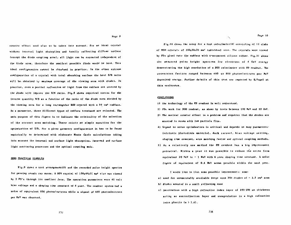
Page 9
counter effect need also to be taken into account. For an ideal crystal
without internal l ight absorption and totally reflecting diffuse surface
(except the diode coupling area), a l l l ight can be extracted independent of
the diode area, therefore the smallest possible diode would be best. This
ideal configuration cannot be obtained in practice. In the other extreme
configuration of a crystal with total absorbing surface the best S/N ratio
will be obtained by maximum coverage of the viewing treM with diodes. In
practice, even a partial reflection of light from the endface not covered by
the diode wil l improve the S/N ratio. Fig.$ show* empirical curves for the
inverse quantity N/S as a function of the ratio of the diode area divided by
the viewing area for * long rectangular BGO crystal with a 10 cm3 rodface.
As a parameter, three different types of endface treatment are selected. The
main purpose of this figure is to indicate the c r i t i c a l i t y of the selection
of the correct area matching. There ex i s t* no simple equation for the
optimization of S/N. For a given geometry configuration it has to be found
empirically or determined with elaborate Monte Carlo calculations taking
into account the internal and surface light absorption, internal and surface
light scattering processes and the optical coupling node.
SOME PRACTICAL EXAMPLES
F i g . 9 shows a t e s t arrangeuent(8) and the recorded pulse he ight spectra
for passing cosmic ray muons. A BGO c r y s t a l of 150x44x20 mm1 s i z e was viewed
by 3 PD's through i t s smallest f ace . The operat ion parameters were 40 v o l t
bias vo l tage and a shaping t ine constant of 6 u s e c . The readout system had a
noije of equivalent 950 photoe lectrons while a s igna l of 850 photoe lec trons
per HeV was observed.
237
Page 10
F i g . 1 0 shows the setup for a t e s t ca lor imeter(8) c o n s i s t i n g of 12 s labs
of BGO c r y s t a l s of 200x30x30 an* individual s i z e . The c r y s t a l s were viewed
by PDs glued onto the endface wi th transparent s i l i c o n rubber. Fig .11 showc
the measured p o i s e h e i g h t s p e c t r u e f o r e l e c t r o n s of 4 GeV energy
demonstrating the high r e s o l u t i o n of a BGO calorimeter with P0 readout. The
c o n v e r s i o n f a c t o r s ranged between 400 to 800 p h o t o e l e c t r o n s per MeV
deposited energy. Further d e t a i l s of t h i s t e s t are reported by U.Vogel at
t h i s conference.
CONCLUSIONS
1) the technology of the PD readout i s we l l understood.
2) PDs work for BGO readout, M» shown by t e s t s between 100 MeV and 10 GeV.
3) The nuclear counter e f f e c t i s a probleai and requires that the diodes are
counted in areas with low p a r t i c l e f lux .
4) Signal to noise opt imisat ion i s c r i t i c a l and depends on many parameters:
i n t r i n s i c photodlode m a t e r i a l * dark c u r r e n t , b i a s v o l t a g e s e t t i n g ,
shaping time constant, area matching fac tor and o p t i c a l coupling nethods.
5) As a r e l a t i v e l y new method the PD readout has a big improvement
p o t e n t i a l . Within a year i t was poss ib l e to reduce the noise fiom
equivalent 30 MeV to - 1 M<sV with 6 usec shaping time constant. A noisa
figure of equivalent of 0.1 MeV teens possible within the next year.
I would like to l i s t some possible improvements: some:
a) need for commercially available large area PIN diodes of - 2.5 en1 area
b) diodes counted in » small reflecting case
c) passivation witb a high refractive Index layer of 100-200 nm thickness
act ing as anti reflection layer and encapsulation in a high refractive
index plast ic (n > 1.6),
238

Page 11
d) increased quantum e f f i c i e n c y of > 70 % at 500 na wavelength
e) wafer material of ~ 100|i thickness
f) low dark currents of < 20 nA at 30 Volt bias. i . e . guard <*ing or stopper
ting construction
|) a low series resistance of ~ 20 0
h) the charge sensit ive preanplifier should undergo laproveaents, in
particular the Input FET where ne« types with high transcomfactsnce (> 40
auoho at lj.g of 10 nA), low gate soarc« capacitance of < 30 pf and low
noise currents arc needed.
Obviously the iaiprovements have to be balanced with the cost increase.
I would Hie to than!: my colleagues froa the DPI group and the L3-LEP
collaboration for contributions to the aeasureaents and discussions. I would
also like to thank D. Groosj for siany useful suggestions and the engineers of
the Bananattu cocporation, in particular J . McCoriaiok for their quick
response to technical sndificitiont.
239
Page 12
TABLE 1
COMPARISON OF PHOTOMJLTIPLIER VS PHOTODIODF. READOUT OF BGO
ITEM PBOTOD1OBE
technical experience yes
sensitive area round* say diaaeter
<quaatua efficency> 12%
internal amplification yes
stabilized (FT yes
post anplificatioli aisjpl^ (not necessary)
noise equivalentr.snt error
- 20-50 leV
typical dynamics1 10«range
short tera stsbility >1 <.3)*b)
long tera stability >1 (.3)%b)
teaiperature . . < .2 * /"C
rise ti«w 5-50 nsec
rate
sije (height)
oagn. shield
noise istmunity
price d)
high
l i n e )
conplicated.iaipossible forhigh fields
high
> USD 50
any shape
< 3 c»>
60*
no
not necessary
high qualityanplifieTnecessary1.15 HeV fordeacrlbed testpossible a)
10> a)
<.O1 *
<.l *
<.2 * fi.
> 10 nsec(ares dep.)
low
< 1 CO
unnecessary
low
USD- 10
240

Page 13
price of amplifier USD 5 USD 15
accidental ligbt possible nodamage
No of photoelectrons few tens d) - 100/nicronfor pissing tracks depletion layer
a) special preamplifiers requiredb) for selected high stabi l i ty P»f«c) htmtmitsu R 1569Xd) due to Cerenkov l ight in glass window
Page 14
REFERENCES
1) G.Blanar et a l . . Nuc. I m t .Heth. 203 (1982) , 213
2) G.F.Knoll . Radiation Detec t ion and Measurements. John Wiley and Sons,
1979
3) A.Tuzzol in i . Nuc. lust .Meth. 204 (1982) , 161
4) Radiation damage in BGO a f f e c t t at f i r s t the transmission on the short
wavelength p a r t . The PD readout w i l l very l i k e l y sho* l e s s e r e f f e c t s
compared to PM readout when radiat ion damage occur, due to the d i f ferent
spectral matching,
5) H.J.Weber. R.R.Honchazp. Journal Appl .Fliy».44 (1973)5495
6) Ihnaaiatsu cata log 1981
7) J .L.Blankenship. IRE Trans .Nuc l .Sc i . NS-7, N o . 2 - 3 , ( 1 9 6 0 ) , 190
8) BGO supplied by Hanhav Cheat. Co. .photodiodes S1337 BR 1010 and S 1790
supplied by Raaiaiutin Co. The S 1790 ia an improved vers ion of the S1337
BR 1010, mounted on • infi l l white substrate without rim and very thin
plastic coating.
2', 2

Page 15
FIGURE CAPTIONS
F i ( . ] Isometric cut through • PIN pho tod lode (s implif ied)
Fig.2 Optical absorption constMBt in s i l i c o n a> * function of wave length
and the emission spectua of BGO.
Fig.3 Excitation and ea i ss ion spectral) for BGO (rof .S) and the quantum
efficiency of Si l icon photodiodes «nd photoaml t ipUer» with b i i l k a l i
pfcotocathodes ( r e f . 6 ) .
Fig.4 Basic readout system
F i t . 5 Examples of the equivalent n o l l e charge Cot charge s e n s i t i v e
preamplifiers with capacitative Inpat loftd. Bxa-aplea ace shown for
input FET's with low and high trantconductance. Typical shtping tine
constant of Ipsec.
Pit.6 Noncgram correlating diodes paraaeters.
F i ( . 7 t ,b Correlation of noise, diode capacitance and leakage current for a
set of 3 selected $1337 diodes and a randoaly selected sacple.
F i | . 8 Enoiplc of the S/N rat io as a function of the area Bitching factor for
a long rectangular crystal with 10 ca' viewing endface. Parasieters:
endface surface treataent.
Fig.9 Test setup for a DGO crystal readout by PO'S and observed pulse height
243
Page 16
spectrum for passing cosaic ray anons.
F i j . 1 0 Set up of a BGO test caloriaeter exposed to a part ic le beaa at the
CERN PS.
F i g . 1 1 Pulse h e i g h t spectrum for 4 OeV e l e c t r o n s with showers f u l l y
contained in the calorimeter.

Ioo
ABSORPTION CONSTANT (cm"1)
ARBITRARY UNITS

~ 80
w 60
z< 20
- EXCITATION FLUORESCENCE(BGO)
SILICON -jPHOTODIODE
200 300 400 500 600 700WAVELENGTH (nm) 1260283-002
Fig.3
LIGHT
uBiAS
N
LIGHT DIODE
SIGNAL'- ^SIGNAL'-
CHARGESENSITIVE
PREAMPLIFIER
SHAPINGAMPLIFIER
CHARGE•* RECORDING/PULSE HEIGHTNV ANALYSER ;
1260283-006
Fig.4

r - " = o
J £ 2 e s
o . . ^ •
n D -
- o S S S o S S
- • - - : •
D - o . « . - * - • -
, I 1 i 1 , . , 1 1
Mini"
o>
O_J
Eo»
^ \ O
o03<n=Lii
1-
-
ooto
ooO
oo
o SSI
oID
ooCJ —
o
oo
0N3

Noise - [# of electrons]
ooo
ooo
oooo
ooooo
oooo
Noise — [ # of electrons]•b oi CD Oo o o oo o o oo o o o
cX5"ni
Vol
o
o
ui
-i
8o
\• \
\
xA/ /
7 /
/ /
/ /
1/i
1000-1
y
//
I\
C-[pF]
i !H
2OO
0H
1 "iN
oiseD
iodeD
ork
?"IpO
Crent
\ §\ *
\
\ •
'dark-
NOISE /SIGNAL (ARBITRARY UNITS)

— _ • I ' 'M Bias
-"""-1/ yy
<40> MeV
1
» >.
Pedestal
cosmics
*\
7.5
•
t• 10* e
850 photo electrons/MeV
Q» T » 20° C
253

Proceedings of theInternational Workshop on Bismuth GermanatePrinceton University, 10-13 November 1982
UU7HEP83-8
r s
SILICON PH0T0DI0DE DETECTIONOF BISMUTH GERMANATE SCINTILLATION LIGHT
Donald E. GroomPhysics Department, Universi ty of Utah
Salt Lake City , UT 84112
Abstract
We have used silicon photodiodes for the readout of bismuth germanatecrystals (BGO), with the eventual achievement of a noise-limited resolution(standard deviation) of 320 KeV, referred to energy deposition in the crystal.One thousand to 1S00 electron-hole pairs are produced per MeV of energy depo-sition in the BGO. The study has focussed on noise limitations In the photo-diode/amplifier combination. A dramatic noise reduction occurred when, withthe cooperation of the manufacturer, an Internal series resistance 1n thephotodiode was virtually eliminated.
1. INTRODUCTION
While silicon photodiodes are a new and unfamiliar device for most high-energy physicists, they have been used for more than two decades by spacescientists. A.J. Tuzzolino1 has described the construction and operation ofthe devices, and they have been flown on Pioneers 10' and 11, Mariner 10,several of the IMP satel l i tes, and other space missions. In many cases (e .g .on the Pioneer spacecraft) they continue to function without measurable gainchange after more than a decade. Ms>st commonly, the diodes detected the l ightfrom a CsI(Td) veto shield around a semiconductor cosmic ray telescope. Theuse of such devices ceased about a decade ago when larger solid state detectorsbecame available. In the same era Bateman3*" also pioneered the development ofphotodiode readout of inorganic scinti l lation for nuclear physics applications.He reported a standard deviation of less than 1 MeV for 50 MeV protons stoppingin CsI(Tl).
The present work was motivated by our desire to instrument a Urge(1Q1* channel) BGQ array for use in a detector at an e+e" colliding beam machine,where operation in a ~I0 KG magnetic field would be highly desirable. A similarstudy has been reported by Blanar et aK 5 Our approach differs from theirs inthat we have focussed almost entirely on noise characteristics of the photodiode-amplifier combination and on the attributes of this new (to us) device. Wehave paid l i t t l e attention to optimum lighf collection, optimized amplifiers,low-temperature operation, and other areas where further gains might be made.
A silicon photodiode 1s not a direct replacement for a photomultipler,any more than a transistor is a direct replacement for a vacuum triode; thedevice must be understood in i ts own right. Accordingly, in the followingsections we discuss the properties of an amplifier with a capacitor attached toits input, the DC properties of photodiodes, the behavior of the preamplifier/amplifier wit!) the photodiode attached, and f inal ly how the system behaves withBGO coupled to the photodiode.
255
256

2. CHARGE-SENSITIVE AMPLIFIER WITH CAPAC1TIVE INPUT
Photodiodes have no gain, and a typical event might produce only a fewthousand electron-hole pairs (e-h pairs) in the device. Accordingly, a verylow-noise charge-sensitive amplifier Is required. Stated differently, a photo-diode Is a solid-state particle detector, and one must use the electronicscomnonly employed by nuclear physicists.
Conventionally and for reasons of convenience, one uses a charge-sensitivepreamplifier which produces a very slowly decaying exponential output when a6-function of charge 1s Injected. The output 1s then AC-coupl1ed to a shapingamplifier whose output 1s 1n turn given by some f ( t ) . The width of the outputpulse is characterized by a time constant t. Device properties are such thatnoise Is minimized for x In the (is range. For our application, f ( t ) is asmooth unipolar pulse which peaks at a time tp.
Fig. 1.
Photodiode | Preamplifier
Equivalent circuit for noise analysis of a preamplifier withphotodiode Input.
A photodiode may be modeled as a s l i g h t l y leaky c a p a c i t o r wi th (poss ib le )se r ies res is tance , as shown 1n F i g . 1 . , where a modei of the p r e a m p l i f i e r fornoise analysis purposes 1s a lso shown. According to standard treatments o fthe s u b j e c t , » • ' the variance of the noise ( t h e square of the equiva lent noisecharge, ENQJ i s given by
[Rp
e l p (1)
The three bracketed terms represent contributio 'S due to parallel noise,series noise, and 1/f noise. The leading terms 1n the parallel noise termarise from thermal noise and shot noise In the parallel resistance. Quantititesnot defined 1n Fig. 1 are as fo'lows:
a! = (1/t) J ( f ( t ) P d t / ( f ( t p ) ) 2
a2 = T / ( f ( t ) ) 2 d t / ( f ( t p ) ) s
a3 = 1/f noise coefficient
kT = 25.85 mV * e at 300° K
Rp = Total parallel resistance, In our case eq^al to several GQ exceptnear photodiode breakdown
Ip = Parallel current in the JFET and photodiode; in our case, photodiodeleakage dominates
257
"s - Req + Rds = total series resistance. Req Is a reflection of thechannel resistance, and Is defined as l/gm . The quantityen
2 = 4kTReq = 4kT/gm 1s the square of the "rms spot noise" of the JFET.
Cjn = Total input capacitance. I .e . the sum of photodiode, JFET gate, andparasitic capacitances. The last two contributions total ab'bjut 30 pFfor a typical good JFET.
The coefficients ai and a2 are defined so that they are unity for an Ideal("exponential cusp ) response and near unity for realistic pulse shapes. Forthe typical "RC-CR" response where f ( t ) • t exp(-t /x), aj = a2 = t ' / 4 ,where e = 2.718.. . . I t should be evident that aj and a; are minimial for asmooth, unipolar response, and that In the absence of serious leakage effectsnoise 1s minimized with small Input capacitance and long shaping time constant.For the present work, only the terms proportional to I p and Cfn are Important.
For purposes of this investigation,an Ortec 142B preamplifier and anOrtec 571 amplifier were used. Acapacitance-coupled Input permits theInjector of a known charge Into the sys-tem with a pulser, permiting both calibra-tion and (from the width) noise measure-ment. Noise results obtained in this waywith capacitors attached to the Inputare shown In Fig. 2. (Note that thefull width at half maximum (Q) is usedrather than standard deviation (ENQ)here and in the following). As expected,Q Is linear in C for large C, and theslope dQ/dC scales as l / / t . The slopedQ2/dC2 if. linear in l/x, with a slopewhich yields en
2 and an intercept whichassures us that 1/f noise is not signif-icant. I t 1s evident from Fig. 2 thatImportant terms have been neglected inEq. 1; Intercepts at C = 0 (or, better,C~ -30 pF) change slightlv with T , but do not scale with t 1n any way describ-able by Eq. 1. V. Radeka8 has suggested that preamplifier noise sourcesbeyond the Input JFET are responsible.
We regard Fig. 2 as showing the "ideal" response of the electronics, 1nthe sense that no better can be done with an input of given capacitance tothese particular electronics.
3. PHOTOOIODES
Photons with energies not much in excess of 1 eV produce e-h pairs withnearly 100% efficiency. If the photon has penetrated the surface p-layer toreach the depleted region, these pairs can be collected to provide a signal.Since the penetration depth Increases with wavelength, photodiodes are mostefficient for red l ight . As can be seen In Fig. 3, the quantum efficiency ofone of our samples (as measured by the supplier, Hamamatsu) Increases from 60%to 80% in the region \ = 500 nm to 900 nm; the decrease at smalle.- wavelenghts
F1g. 2. Equivalent noise charge(fwhm) for an Ortec 142B preamplifieras a function of capadtive loadfor various Ortec 571 amplifiershaping time constants.
258

is attributed to the effect of smaller penetration depth coupled with thethickness of the p-layer. Nonetheless, the quantum efficiency and bandDass arelarge compared with those of a photomultiplier.
Electrically, a photodiode 1s roughly a parallel plate capacitor with areaA and plate separation d. For a silicon dielectic, i ts capacitance Is given by
(2)
(3)
and the depletion depth d by1
d = 0.54 vim * /plQ-cml«lVd + Vo)
where V,i is the reverse bias and Vo the usual diode offset. Combining theserelations, we see that 1/C§ should be linear In Vj, with a slope proportionalto the bulk resistivity of the silicon from which the photodiode Is made.
- BGO Quantum \\ Yield (Arbitrary Scoft)
SOO «OO 500 600 700 BOO 900 1000 »O0 (200Wovetenglh |nm)
10 20 30 40 50 £C 7D eov, (Volls)
Fig. 4. 1/CJ versus bias voltagefor three photodiodes used In thestudy. H4 was the only stock diodewhich couli be totally depletedbefore avalanche breakdown occurred.Silicon resistivities given In thefigure are calculated from the slopesin the linear region. I . e . before theonset of complete depletion.
This behavior is shown for representative l-cm2 Hamamatsu silicon photo-diodes* (one stock S1337-1O1OBR and two experimental diodes) In Fig. 4. At the
Fig. 3. A comparison of the BGOquantum yield ' with the quantumefficiency for sample #458 asobtained by Hamamatsu.
*A11 measurements reported 1n this study were made using HamamatsuS1337-101OBR silicon photodiodes, or modifications thereof. The diodes havea 1 cm2 active area, 1n a package 1.5 cm » 1.7 cm, about 2 mm thick.
259
onset to full depletion deviation from Eq. 3 occurs, as expected. Two experi-mental Hamamatsu photodiodes showed extremely nonlinear behavior on such a plot.Both exhibited extreme noise behavior and could not be used. We regard lineardependence of 1/Cjj upon Vj as an essential characteristic for our purposes.
A photodiode also exhibits leakagecurrent which increases with the biasvoltage. For most diodes it Increasesgradually (usually slower than linearly)until some threshold is reached; weassociate the rapid increase beyond thispoint with avalanche breakdown. Thebehavior below breakdown is understoodto be a "surface dirt" effect, havingnothing to do with the bulk propertiesof the device.10 Leakage behavior 1sshown in Fig. 5 for seven Hamamatsudiodes. As can be seen, behavior variesconsiderably from sample to sample.
The time constant range spanned inFig. 1 is a good match to photodiodecapacitances of ~80 pF/cm', and also agood match to the repetition times ofpresent and planned colliders- Thepenalty 1s that a corresponding leakagecurrent limit 1s Imposed via Eq. (1),which, depending upon detailed choicesof time constant and the permissiblenoise contribution, is 5 nA to 10 nA.Such leakage current maxima at fulldepletion seem readily achievable byHamamatsu, although they are loath toguarantee them.
«0
II10
s13
10
0
— - " " / ^
- / '
/
J
\,,l
•
-
. i • . i > > . iK>
V , (VOlU)
Fig. 5. Leakage current as afunction of bias voltage for repre-sentative photodiodes. Diodeslabeled HI, HZ, and H4 are unsel-ected stock diodes. #377 is a testunit made with 4 KO-cn silicon.#457 and #451 are "type A" and"type B" modifications.
He also tested photodiodes obtainedfrom EGSG and from Gentronic. All showedcomparatively high leakage currents, and
none could be depleted deeply enough to be useful. In addition, the air gap inthe large glass-windowed packages prevented useful optical coupling.
4. PHOTOOIODE PLUS AMPLIFIER
Noise widths obtained with photodiodes attached to the preamplifier areshown in Fig. 6. For comparison, the t = 2 us curve is copied from Fig. 2.Since noise is proportional to capacitance and capacitance decreases withapplied bias voltage, noise decreases with Increased bias voltage until leakagecurrent takes over ss the chief noise source. For sample H2 this occurs atabout 12 V, as may be seen from Fig. 5, corresponding to about 170 pF. Thedotted circles far below the divergent part of the H2 curve are calculatedincluding the leakage current; <n the case of avalanche breakdown actual noiseshould be much higher. H4 was a stock diode obtained at a later time. As canbe seen from Figs. 4 and 5, i t could be fully depleted before breakdown occured.

F1g. 6. Equivalent noise chargeversus capacitance for four photo-diodes- For comparison, the curveobtained with capacitors for thesame time constant Is copied fromFig. 1.
Fig. 7. The effect of series resis-tance on noise for a capacitor and twophotodiodes biased to the samecapacitance.
HA's capacitance when fully depleted was 70 pF, permitting a resolution gainover HZ of about a factor of two.
The main feature of these curves, however, 1s that 1n spite of the expectedlinear behavior (when series noise dominates) the slope Is about ZA times theexpected slope, i.e. that obtained with capacitors. A photodiode 1s evidentlydifferent than a leaky capacitor. At the suggestion of V. Radeka, we measuredthe rise tine of the photodiodes when exposed to a fast LED light pulse. We foundan exponential rise, corresponding within the accuracy of the crude measurementto an RC time constant with R • 300 0 over the available range of C. Such anInternal series resistance would effectively add to the OFET's R e q = l/gm toproduce a much larger Rs 1n Eq. 1. The factor of 2.4 is roughly the squareroot of (Rds * Req)/Req with R,js = 300 B.
As a further check, we measured noise widths with series resistance addedto a capacitor, and then repeating the measurement with resistor in serieswith the photodiode, carefully biased to the same capacitance. These data areshown In F1g. 7. From Eq. I we should expect a linear dependence of Q2 uponthe added R5, with an intercept at Q = 0 at Rs = - Req. We observe this in thecapacitive case, when R6q - 60 0 was expected. The data taken with the photo-diode yield an equivalent series resistance of ~35O Q, consistent with the LEDresults end, more Importantly, with the slopes dQ/dC shown for samples HZ andH4 In Fig. 6. We conclude that the anomalous noise Is produced by the seriesresistance of the photodiode.
It was our conjecture that most of the resistance was that of the conductingfilm associated with the p-layer, through which the light must enter the diode-One possible solution would be to use a more finely divided grid of conducting
261
lines to collect the charge. The problem was discussed with representatives ofthe Hamamstsu Corporation, who within three weeks delivered samples of two kindsof experimental diodes ("A" and "B"), modified in different ways to correct theproblem11. Measurements with samples #457 ("type A") and #481 ("type B") areshown in Figs. 4, 5, and 6. None of four modified diodes which we testedexhibited any evidence of breakdown, even when biased well beyond total depletion.
As shown in Fig. 6, lower noise was obtained with the "type B" sample whenoperating at a given capacitance. However, the maximum depletion depth of the"type B" modification was 90 nm, or C = 120 pF, while the "type A" diodes reached143 (im, or C = 74 pF. The "type A" modification could thus reach lower noisefigures In spite of an evidently slightly greater series resistence. The diodeseries resistance s t i l l contibutes 202 or so to the ENQ, but we regard thisresidual problem as minor. With the 1 cm2 area "type A" modified diode #457biased to C = 74 pF, we obtained a no'se fwhm of 0.17 fc, or o = 450 electron-hole pairs, for T = 2 us at room temperature.
5. BISMUTH GERHANATE PLUS PH0T0DI0DE/AMPLIF1ER
Measurements were made using two high-quality BGO crystals. The f i rs t ofthese was a 3 cm « 5 cm * 0.8 cm rectangular crystal lent to us by the HarshawCorporation for the purpose. The crystal was clear with several barelydfscernable veils. The second, a 1 cm * 1 cm * 17 cm crystal with no visitH-d-'scoloration, vei ls , or other Imperfections, was also obtained form Harshaw.Light output comparisons were made with a high-quality 1.3 cm cylinder, withan unpolished curved surface, using a Ha22 source and a 5-cm Amprex photo-multiplier with a bialkali photocathode. With the small ends coupled to thephotocathode window with optical grease, the 3 cm « 5 cm rectangle produced0.55 the pulse height observed In the small cylinder, and the long rectangle0.36 of the small cylinder's pulse height. We cannot explain the difference ongeometrical grounds, and unfortunately such crystal-to-crystal variations seemtypical at the moment. Some degree of correlation with the presence of scatter-ing centers (e.g. the veils) 1s suggested.
With a photodiode coupled with optical grease to the smallest end of the3 cm * 5 cm crystal, only 80* of the photodiode's active area -was in contactwith BGO, and 33% of the crystal end was in contact with photodiode active area.The optical coupling is thus far from optimal. The crystal was placed betweentwo 5 cm * 5 cm scintillators with 5 cm vertical separation. The geometry wassuch that no particle passing through both scintillators could pass throughthe photodiode i tse l f . The coincidence between the scintillators was used togate a pulse height analyzer observing the spectroscopy amplifier output.Under these ;onditions cosmic ray muons deposited 7.2 MeV in the BGO abouthalf the time; those which missed gated the analyzer to provide a convenientpedestal measurement. As usual, the electronics were calibrated and the resolu-tion measured using a pu'ser which injected known charges into the preampliffer.
The cosmic ray peak observed using samples H2 and H4 corresponded to 1070electron-hole pair/MsV of energy deposition 1n the BGO. Data were taken nearthe resolution minima shown in Fig. 6. The resolution (standard deviation)obtained under these conditions for H2 corresponded to 1.0 MeV, while the laterdata for H4 yielded 610 KeV.
262

8
Results for the experimental "type A" diodes were obtained with a similarsetup, but with the photodiode coupled to the 1 cm2 end of the long crystal.The light collection geometry was thus Improved, but as mentioned above thiscrystal evidently scintillated with only 66% of the efficiency of the rectangularcrystal. A typical spectrum Is shown In Fig. 8. The sharp peak was producedby 4.0 fC calibration pulses; its width corresponds t o o ' 450 electronhole pairs, as mentioned In Section 4. The pedestal 1s due to muons whichmiss the BGO, and the 9.0 MeV cosmic ray peak corresponds to 1500 e-h pairs/HeV.The observed calibration peak width thus corresponds to an energy resolutionof 320 KeV 1n the BGO.
With the low noise levels achieved with the modified photodiodes. I t becamemarginally possible to observe Co60 y-rays on an oscilloscope. After someeffort , H. Cavalli-Sforza obtained self-triggered Co60 spectra, an example ofwhich is shown In Fig. 9. The peak at 2/3 of full scale 1s from the calibrationpulser. The blend of the 1-17 MeV and 1.33 MeV lines shows up as the highershoulder on the Gaussian noise peak, while the sum peak shows up ss a secondshoulder. Results look more familiar after subtracting the noise peak, butthe results as presented here show both the problems and the promise of themethod. Smaller photodiodes with a greater depletion depth would permit cleanself-triggering on even a 0.511 MeV annihilation photopeak.
I MIV7I
MJ1B
•
otsc n *H ' 1
- S o "
F ig . 8. Pulse height spectrum forcosmic ray muons passing through1 cm of BGO.
6 . DIRECT PARTICLE OETECTIOH
* • 3I7O13
Fig. 9. Self-triggering noise and Co60
spectra for photodiode sample #457observing a 1 cm * 1 cm * 17 cm clearBGO crystal; note logrithmic verticalscale.
The fact that photodiodes are in themselves efficfent solid state detectorshas been flagged as a problem for their use as scintillation light detectors.We are convinced that no serious problem exists unless photodiodes are locatednear an electromagnetic shower maximum.
Minimum dC/dx is 3.74 HeV/cm for silicon, arid an e-h pair is produced forevery 3.62 eV of energy loss. We thus expect to collect 103 e-h pairs/um oftrack length In the depleted region for a minimum Ionising particle, or 101*
263
e-h pairs for a typical depletion depth of 100 urn. Since we produce ~ 1000e-h pairs/MeV of energy loss 1n the BGO, we also produce lO* e-h pairs when aminimum ionizing particle penetrates one radiation length of BGO (1.13 cm at9.0 MeV/cm). As a rule of thumb, then, a relativistic charged particle producesa signal of the same size In penetrating the photodiode as i t does in traversing1 Xo Of BGO.
A typical BGO crystal for an electromagnetic calorimeter Is 1.6 Xo to 20Xo long. One may differentiate typical slower development curves to learn thatleakage electrons contribute a tiny fraction of 1% to the total signal. Indeed,the direct signal in part compensates for leakage fluctuations.
Similarly, muons penetrating the photodiode produce signals about 53; largerthan those which miss. For pions, this effect Is lost in the tai l produced byinteracting pions.
In order to measure the size of the direct signal, we replaced the BGObetween the cosmic ray trigger sdnti l lators with a horizontally orier dphotodiode (H», depleted to 143 pn). The observed signal correspond!.- w 130e-h pairs/i«m, about 25* higher than the number reported above but consistentwithin uncertainties In the measurement.
7. A "THEOREM"A photodiode with sensitive area a
Is coupled to the end of a scintillatorwfth drea A. To some crude approximation,the amount of light collected is propor-tional to a/A. The noise is proportionalto the photodiode's capacitance ( i f weneglect the intercept), and the capaci-tance 1s proportional to £. The ratio ofnoise to signal is thus proportional toA, Independently of the size of thephotodiode: I t does not matter whatsize photodio'tte is used; the relevantcapacitance tor noise calculations isthat of a diode of area M The theorem,of course, is not true, since Internalreflection modifies the f i rst assumptionand the non-zero Intercepts shown in
Fig. 2 modify the second, (e-h statistics are not relevant for diode areas assmall as a few urn2.) I t is true that a should be as large as possible, buti t is also true that there Is very UTtle sensitivity to a.
Fig. 10. Geometry for light col-lection by a photodiode.
8. CONCLUSIONS
Given the lack of control of BGO geometry and scintillation efficiency,our stated best resolution cannot be converted 1n any easy way to a differentdevice. We can conclude, however, that (a) we have obtained photodiodes whichperform nearly as well as equivalent capacitors, (b) such photodiodes, biasedto reach a capacitance of 74 pF/cra2, y*?1d o - 420 e-h pairs per cm2 of acuvearea at room temperature using off-the-shelf electronics, and (c) that weobtain 1000 to 1500 e-h pairs per MeV of energy loss In the BGO. There are
264

10
further gains to be made; these are probably to be traded o f f to other compro-mises 1n bui lding a large array. We bel ieve 300-350 KeV w i l l be a typicals ingls-crystal resolut ion . Given the s t a b i l i t y 1 2 , p r i c e , magnetic f i e l dimmunity, and other character is t ics of photodiodes, and the ease of c a l i b r a t i o nand general management of the e lec t ron ics , we see no reason whatsoever not touse photodiodes for the readout of the large BGO arrays under development.
9. ACKNOWLEDGEMENTS
The author has been Introduced to the arcane worlds of s i l i c o n photodiodesand low-noise ampli f iers through many helpful discussion with A. J . Tuzzolino(who makes his own photodiodes!) and V. Radeka. BGO crystals were generouslylent to us by B. Gorby of Harshsw Corporation. Photodiode evaluat ion sampleswere gratui tously supplied by the companies Involved. In p a r t i c u l a r , R. Fisherof Hamamatsu was most h e l p f u l , and K. Yamamoto of tha t company was both helpfuland ingenious In solving the series resistance problem In a very short t ime.Discussions with E. Lorentz, H. Vogel, 0 . Coyne, and H. Cavall1-Sforza aregrate fu l ly acknowledged. M. Cavall 1-Sforza and E. C. Lot) have a t various timespart ic ipated In the measurements. The work was car r ied out a t the StanfordLinear Accelerator Center, where the author was pr iv i leged to spend a two-yeari n t e r v a l .
10. REFERENCES
1 . A .J . Tuzzolino, J . Appl. Phys. 33 , 148 (1962) .
2. J.A. Simpson, e t a l ^ , O.G.R. 7 9 , 3522 (1974) .
3. J .E . Bateman, Nucl. I n s t r . and Heth. 67, 92 (1969 ) .
4 . J .E . Bateman, Hucl. Ins t r . and Heth . 71_, 261 (1969) .
5. G. Bianer et a l . , Max Planck I n s t i t u t e Munich, Internal ReportMPI-PAE/Exp7ET7~99; to be published In Nucl. I n s t r . Methods.
6 . C.F.G. Delaney, Electronics for the Physic ist , John Wiley * Sons, 1980.
7. W.J. W i l l i s and V. Radeka, Nucl. I n s t r . and Heth . 120, 221-236 (1974) .
8. V. Radeka, private communication (1982) .
9. M.J. Weber and R.R. Monchamp, J . Appl . Phys. 4 4 , 5495 (1973) . The datagiven i n F ig. 3 were used, assuming an RCA S-'ZO" response curve.
10. A .J . Tuzzolino, pr ivate communication (1982) .
11 . A t h i r d type ("C") was received about a month l a t e r . I t has not yet beenpossible to test I t , but i t Is constructed for to ta l deplet ion at ar e l a t i v e l y small depth and hence I s probably more l imi ted than "type A".The Hamamatsu Corporation has since announced these modif ications as newproducts; S1723 is our "type A", while S1723-O1 Is "type B".
12. A.J. Tuzzolino, "Long-Term Photo and Charge P a r t i c l e Response of SiSurface-Barrier Photodiodes," to ba published In Nucl. I n s t r . Meth.
265 266

LOW NOISE READOUT SYSTEMSL. B. LEV1T, LeCROY RESEARCH SYSTEMS
NOVEMBER 10, 1982
The purpose of this article is to present a heuristic explanation of theoperation of low noise detector amplifier electronics. No attempt is made toprovide rigorous formalism. Rather, the concepts are presented to allow theexperimenter to use the electronics, being aware of the trade offs required toachieve optimum performance.
Figure 1
T
Session E
MORE READOUT
A diagram of a general detector preamplifer is shown in figure 1. It consistsof a high gain amplifier with feedback. Thermal noise in the feedbackresistor is a source of parallel noise by
This noise, shown in figure 1, as a current source is the dominant generatorof noise for most amplifier designs unless R >IMSI This component choiceleads to an amplifier which has a slow fall time. Stray capacitance of 1 pF(due to the resistor geometry and trace capacitance) results in an RC timeconstant > 1 (Bee. As a result, the amplifier has an integrating response,i.e., charge-to-voltage. Use of such a large resistor value precludes the useof a bipolar transistor as an input device. Only an FET may be used. Theseveral uA bias current of the bipolar transistor would causa such a largevoltage as to misbias the whole circuit.
A second source of parallel noise is the shot noise in the input device i.e.,the input transistor or FET. This noise consists of the quantum fluctuationsin the current. An FET draws such a small gnte current that this noisesource may be ignored. If a bipolar transistor is used, base shot noise oftenis significant.
The remaining noise source is series noise. The scries resistance of the inputdevice is one source. Any series resistance in the detector itself alsocontributes to the series noise. The shot noise arising from the currentstanding in the input device (FET or bipolar transistor) produces a series noisent the input. This source of noise is minimized by employing nn input devicewith a large transoonductance. Lower voltage noise can be achieved using agood bipolar front end thun with a good FET front end.
267268
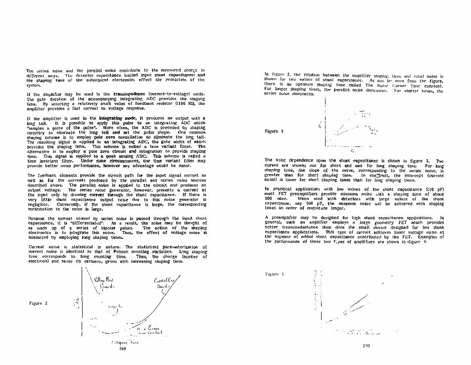
The series noise and the parallel noise contribute to the measured charge indifferent ways. The detector capacitance (called input shunt capacitance) andthe shaping time of the subsequent electronics effect the resolution of thesystem.If the amplifier may be used in the transimpedance (currer.t-to-voltage) mode.The gate duration of the accompanying integrating ADC provides tile shapingtime. By selecting a relatively small value of feedback resistor K100 KSJ, theamplifier provides a fast current to voltage response.
If the amplifier is used in the integrating mode, it produces an output with along tail. It is possible to apply this pulse to an integrating ADC which"samples a piece of the pulse". More often, the ADC is preceded by shapingcircuitry to eliminate the long tail and set the pulse shape. One commonshaping scheme is to employ pole zero cancellation to eliminate the long tail.The resulting signal is applied to an integrating ADC, the gate width of whichprovides the shaping time. This scheme is called a time variant filter. Thealternative is to employ a pole zero circuit and integration to provide shapingtime. This signal is applied to a peak sensing ADC. This scheme is called atime invariant filter. Under some circumstances, the time variant filter mayprovide better noise performance, however any advantage would be minor.
The feedback elements provide the circuit path for the input signal current aswell as for the currents produced by the parallel and series noise sourcesdescribed above. The parallel noise is applied to the circuit and produces anoutput voltage. The series noise generator, however, presents a current atthe input only by drawing current through the shunt capacitance. If there isvery little shunt capacitance output noise due to this noise generator isnegligible. Conversely, if the shunt capacitance is large, the correspondingcontribution to the noise is large.
liecause the current caused by series noise is passed through the input shuntcapacitance, it is "differentiated". As a result, the noise may be thought ofas made up of a series of bipolar pulses. The action of the shapingelectronics is to integrate this noise. Thus, the effect of voltage noise isminimized by employing long shaping times.
Current noise is statistical in nature. The statistical parameterization ofcurrent noise is identical to that of Poisson counting statistics. Long shapingtime corresponds to long counting time. Thus, the charge (number ofelectrons) and hence its variance, grows with increasing shaping time.
\\
Figure 2
269
In figure 2 the relation between the amplifier shaping time and total noise isshown for two values of shunt capacitance. As cin bo seen from the figure,there ,s an optimum shaping time called The Noiso Corner Time constant
Figure 3
The noise dependence upon the shunt capacitance is shown in figure 3. Twocurves are shown; one for short and one for long shaping time. For longshaping time, Che slope of the curve, corresponding to the series noise, isgreater than for short shaping time. In contrast, the intercept (currentnoise) is lower for short shaping times than for long shaping times.
In practical applications with low values of the shunt capacitance (<10 pF)most FET preamplifiers provide minimum noise with a shaping time of about500 nsec. When used with detectors with large values of the shuntcapacitance, say 500 pF, the minimum noise will be achieved with shapingtimes an order of magnitude longer.
A preamplifier may be designed for high shunt capacitance applications. Ingeneral, such an amplifier employs a large geometry FET which providesbetter transconductance than does the small device designed for low shuntcapacitance applications. This type of circuit achieves lower voltage noise atthe expense of added shunt capacitance contributed by the FET. Examples ofthe performance of these two tjpes of amplifiers are shown in-figure i.
270

These amplifiers, both in design at LeCroy ere FET front end devices. Assuch, they are not suitable for manufacture as integrated circuits. Presenttechnology does not provide for circuits incorporating both high performanceFETs and also bipolar devices. Thus the amplifiers above will bemanufactured us eight-channel hybrids and referred to as the HQV series.
As can be seen from the curves, the high transconductance version providessignificantly better noise performance at source capacitance of 23 0" P'r-Even lower noise can be achieved with long shaping time.
When fast (< 50 nsee) response time is an important consideration, a smallvalue of feedback- resistor must be employed. fn this case, the associatedcurrent noise is often sufficiently large as to make the shot noise of abipolar input transistor negligible in comparison. Use of a bipolar deviceoffers the advantage of low power dissipation. A savings of 50-100 miv iscommon. This can be important for multichannel applications. Because thesebipolar amplifiers have large current noise, they are optimized for shortshaping times. For example, the LeCroy TRA4Q3 amplifier is a fasttransimpedance amplifier with a bipolar front end. This device achieves thebest noise performance with a shaping time of 20 nsec at low values ofsource capacitance. The performance of this device is shown in figure 5.
Figure 5
• ' • v i i V ! ; ;i * ne & u
As the demands for low noise readout systems continues to grow, the need fornew ADC systems grows correspondingly. LeCroy is in an advanced stage ofdevelopment of a new component intended for use in ADC systems. Thecomponent takes advantage of the simplicity of a sample-ana iold scheme aswell as the linearity and immunity to crosstalk of a current integrating chargeADC. A diagram o the part is shown in figure 6. The device, called thecharge multiplexer (QMUX) accepts inputs from four detectors. Each of thefour inputs lias a linear gate and built in integrating capacitors. Eachchannel has both a high sensitivity (about 50 fc resolution) and low sensitivity(about 400 fC resolution) integrator. This high/low scheme provides forextended dynumic range, operation (about 15 bits equivalent).
271
To readout the QMUX, the four channels are sequentially addressed. TheQJIUX returns the integrated charge via the high and low level output ports.The charge is delivered os a current pulse, eliminating crosstalk caused by RCeffects. QMUX chips may have their output ports gouged. This allows thecharge signals from up to approximately 100 detectors to be seriallytransmitted to an ADC over a single line (two lines if both the high and lowoutputs are used). LcCroy intends to package the QMUX-based ADC systemin 1'ASTBUS, The plans call for a 96 channel ADC ivith 15-bit equivalentdynamic range. The introduction of the product is expected in early 1983.
Figure 6
I •_ 1
— ——•
Another format which the device lends itself to is a system involving chambermounted QMUX circuits to sample the detector signals. The integratedsignals can be serially transmitted to an ADC vin coaxial "table. Chargemultiplexing minimizes the amount of cable strung from the detector to thereadout electronics, saving cable costs and optimizing detector solid angleconsiderations. The chamber mounted approach is not well suited to fixedtarget experiments owing to the need to establish u delay per channel toaccount for the trigger decision time.
A product based upon the chamber mounted scheme is presently underconsideration. LeCroy is concerned, however, that geometrical constraintsimposed by eueli experiment will make universality difficult. If this is thecase, LeCroy will promote the QMUX component.
272

A New Approach To The Readout System For A Very Large
Bismuth Germanate Calorimeter
R. Sumner, Princeton University
November, 1982
This note presents a possible solution to the problem of dataacquistion and control -for a very large array of BGO crystals. Thearray is a total energy calorimeter, which is a part of a detectorbeing designed <or LEPC. After a brief description of theenvironment- we present a working definition of the calorimeter,followed by a statement of the desirable characteristics of thereadout system. After a discussion of some alternatives, acomplete system is described.
273
I. flit? envi ronmont
LEPC 1= thr? Larqe Electon Positron Co.'lidcr, which is beingbuilt at HERN, to be ready for experiments by 1989. A large arrayof bismuth rermanate crystals will be part of one of the firstexperiments to be installed, rtn overall view of the experiment isshown in figure I. At the center is the intersection region, wherean electron beam and a positron beam, with energies up to ll:U:i Geveach, will pass thru each other. Thio will happen every 12microseconds, more than 80,000 time-i per second. However, theparticles themselves are so small that the rate of real collisionsof an electron and positron is expected to be only a few persecond.
The resulting particles (including photons) will be identifiedand measured in the surrounding detector, which consists ofseveral different detectors, one inside the othc-jr. At the centeris a tracking device to observe the trajectories of all of thecharged particles. Next is the BGD array, used as a calorimeter,which will measure the energy of electrons and photons, from a fewMeV to 100 Gev. This is surrounded by the hadron calorimeter, anassembly of uranium and copper plates interspersed with ionieationmeasuring and tracking detectors. This will measure the energy ofall hadrans, charged or neutral, just as the BGO does forelectrons and photons. The muons sre analyzed usinq a very largeset of tracking chambers. The entire system is in a solenoidalmagnetic field of 5 fcilogauss, which provides the bending tomeasure the momenta of the charged particles, both in the verte>:chambers, and in the muon chambers. Notice that the BGO is deep inthe detector, and must operate in a magnetic field. Figure 2 is amore detailed look at the inner part of the detctor.
27 i.
II. A working definition of the EK3O calorimeter
The complete detector is still in the desiqn process. Theexact configuration and dimensions will change as the total designis optimized. However, the general performance requirements andapproximate dimensions have been established.
Physical dimensions of the calorimeter:
BGO surrounds the vertex detector as completely as possible.The BGO is a barrel shape, the inside is 1M diameter and 111 long.The BGO is 24cm thick, and the endcaps e::tend down to about 50 cmdiameter. This opening contains the beam pipe, and since the BGOis continuous everywhere else (or would like to be), it is alsothe access route for cables to the vertex detector. The volume ofBBO for these dimensions is 1.3 cubic meters, about 60'/. in thebarrel section, and 207. in each endcap. For a crystal 2cm x 2cm atthe inside end, there are about 8000 in the barrel, 2000 in eachendcap, for a total of 12000 individual detector elements. The BGOcalorimeter is itself surrounded by the hadron calorimeter, whichstarts as soon as possible after the BGO. Since the hadroncalorimeter should also be as continuous as possible, all of theBGO cables should pass through the endcap openings ot the hadroncalorimeter, which are also of order 50cm diameter, and alreadycontain the cables from the vertes; chambers.
BGO Readout channel requirements:
12000 total energy channels1.07. resolution at 100 Mev0.1V. resolution, 1.0 Bev to 100 Gev
Siqnal levels:
Since we have a magnetic field, and limited space,conventional photomultipiiers are not considered. Instead we planto use a solid state photon detector, probably a siliconphotodiode. This will worl; in a magnetic field, and is More stablethan a photomultiplier. but it has no gain. The signal is just theelectrons produced by photons absorbed in the depletion layer ofthe diode. This puts a large demand on low noise performance ofthe following amplifier. The measurements should have a noiselevel comparable to the precision, 0.17. of the signal, and noworse than 17. at the lowest signal level. We assume lMev produces10013 electrons at the output of the photodiode. Then:
UMMev = 16 femtocoulombs (fc)lfel0Gev = 16 picocoulombs (pc)
The desired noise level is less than lMev = 1000 electrons = 0.16fc.
275
III. Functional requirements of the readout system:
In addition to recording the signal with the neccessaryprecision and low noise, other things are important tDo, whenthere are 12000 detectors to keep working.
1) Electronics calibration: The calibration of the gain,pedestal, and non-linearity should be all under computercontrol. The calibration of the scinti3laticn light output ofthe BGO is a separate problem.
2) Reliable design: This means the ability to test in place, andgraceful degradation, without catastrophic failure. The systemmust work even if not all of the detectors do.
3) Dead time: All data should be in hand, and the system readyto respond to the next triggrr in a few hundred microseconds,comparable to the rest of the detector systems. Actual readoutto the counting room, can take longer, but must not prevent moretriggers, nor unduly delay next level trigger decisions. Thisrequirement really depends on the first level trigger rate.
4> Data supplied to the first level trigger: This must beavailable within a few microseconds, since the first decisionmust be known by all detectors within 12 microseconds. Analogsum5 of the signals in several segments of the detector seem tobe the only possibility.
S> Other parameters to be measured: The temperature of the BGO,and the power supply voltages are two examples. Everythingnecessary to ensure that the system is working must bemeasurabie.
6) Power consumption: Everything that goes in must come out, ifwe temperature stabilize the BGO. The cooling fluid and thevolume of flow are a problem in any case, and it just gets worseas we put more of the electronics close to the BGO. If we use 1watt per crystal, that's 12 kilowatts that must be removed(about 50K BTU/hr).
7> The electronics near the BGO must be small. The innerdimensions of the hadron calorimeter are determined by the spaceused by the electronics. & reasonable distance to allow is 1/2of the BGO length, 10cm. Any unnecessary space increases theweight and cost of the hadron calorimeter (by about 1 ton foreach extra cm).
8) Everything inside of course has %o worl; in a 5kg magneticfield, and not be affected by the radiation level.
276

IV. Organization of readout electronics, options:
1) Simply bring 12k raw signals from the photodiodes to theoutside. However, 121: RGB cables have a cross section greaterthan 1 square mr<ter. Twelve thousand shielded twisted pairs iss t i l l greater than . 5M square. The entire BGO calorimeter isabout l.SM diameter. The raw signal from the photodiode is .16microvolts/Mev, for 1000p+ detector capacitance. Moving thissignal very far is probably not practical.
2) Put the preamplifiers inside, bring out amplified ix2&0 orso) signals. This may be possible, the signal level is now 30microvo) ts/Mev (the e>:act value depends on the shaping timeconstant). However, there are s t i l l 12k cables to worry about,and find room for. Note that even quite dense connectors i.linch spacing) s t i l l require about .3M square for 12k.
3) Put the preamplifier, gating and integr-ator inside, thenmultiples: D.C. analog signals to the outside. This can reducethe number o-f cables by a factor of ten Dr pDreF probably at thecost of speed (digit izing must be done ser ia l ly ) . There ares t i l l problems. The signal is s t i l l small, and analog switchingwi l l introduce errors (noise). The analog sums for the f i r s tlevel trigger must be created inside, which reduces f l e x i b i l i t y .There is now a substantial amount of electronics inside,including multiplexing, so re l i ab i l i t y becomes very important.Even so, th is is probably the f i r s t feasible option.
4) Put an ADC for each channel inside too. Multiple:: onlydigital signals to the outside. All low level analog signalsstay inside, in one place, near the photodiode. Now a l l of theelectronics is inside. The outside electronics is justmultiplexed digital readout and control. Rel iabi l i ty is evenmore important, since al l of the signal electronics i si naccessi ble.
Option 4 is certainly the most ambitious, but it may also bethe only practical solution to the performance requirements. Manyof the problems (such as calibration and adjustment) compounded byhaving the electronics inaccessible Can be resolved by puttingeven more electronics inside!
277
V. The total E'GO readout system:
To SI?Q if this approach (option 4) ir, reasonable, and if ithas a chance of reaching the goals outlined above. He have t-ieato design a system usinq only components currently available, andestimate it s performance and cost.
Tho design of a module which satisfies the functionalrequirements is shown in figure 3. This module is repeated 12000times, there i ;s one on each crystal. These can be grouped invarious ways for analog sums in the trigger and for readout andcontrol. Consider a longitudinal slice. With 2cm square crystals,and Stfcm inner radius, There are 157 such slices, with 80 crystalseach! Si? crystals in the barrel portion, and 15 in each end cap.This could be one readout and control group, with the B0 crystalsmultiplexed to one set of digital control cables. This could besubdivided into 2 groups for the trigger analog sums (40 in each).
1) The preamplifier, integrator, and sample and hold. Thisamplifies the signal from the photodiode to the level of 30microval ts/Mev (converting the charge to a voltage), and storesit for later processing (llillilGev = 3 volts). The stored outputsignal is sent to the analog sum bus line (after converting backto a current), and is available to the ADC. There sre two timinginputs, a reset just before the beam crossinq, and a sample/holdsignal a few microseconds after. In addition there is a d.c.level input for offset adjustment and gain calibration.
2) If the external trigger logic (which mates use of the ~-00 orso analog sums) decides to keep the event, the samplR/holdsignal will stay in the hold state at the next beam crossing,and a signal will appear at the interrupt of the microcomputer(HO. The Motorola MC146805G2 is one possible choice for themicrocomputer. This is an 8 bit CMOS (complementary MOS, verylow power) single chip computer with 32 i/o lines, and 20013bytes of mask programmed ROM. The program is specified beforemanufacture, and cannot be changed. This MC is. however, fast (1microsec cycle time) and cheap. It can be a very smari^"component".
3) The MC then begins a program to digitize the stored analogsignal. The method is basically successive approximation, usinga 12 bit digital to analog converter (DAC), but with a choice ofamplified signals to digitize. This produces 5 overlapping 12bit (1 part in 4076) ADC's, only one of which is used. Thisresults in an ADC with 10 bit (1:1024) resolution 'they overlapby 2 bits) and 20 bit (1:1048574) dynamic ranae. The 5comparators are supplied with the reference from the 12 bit DAC,and a signal, either the stored voltage or one from the chain ofX4 amplifiers (choices: XI, X4, X16. X64, X256). The programfirst selects the correct comparator (the highest gain which isless than full scale), and then digitizes the signal to 12 bits.The result is the 12 bit number plus 3 bits to identify the gainused. It is ba-ically a floating point ADC. If the 1:1U48576dynamic raciqe? sounds execessive, rpniembcr tlnit there may not be;.n ea5v w,.y to adjust the gain. There is no high voltaqe (.-non ona phcitoriinde, unlile a photumul t ipl i er.
278

4) The resulting data is stored inside the MC. The 12 bit DAC.which is also used to adjust the input offset of the preanip. isset to the correct value for that function (the determination ofthe offset adjustment can be done automatically, by the I1C) . Themodule is now ready to accept another trigger.
5) After returning from the interrupt, the background program inthe MC then discovers the new data, and sends it to the outsideworld via the 8 bit rommunications bus. This comes from amanagement microcomputer (MMC), as shown in figure 4., and isshared by all Df the crystals in the group <of 60 or socrystals). There are about 15-20 signals which are bussed to allthe crystals in a group. The MMC (there is one for each group,157 in all) is responsible for sending the data co the outsideon the serial link. It can subtract the pedestal and suppressnull data (if that wasn't already done by the MC on thecrystal), and add the crystal I.D. If the MC's are identical,and don't know where they are, the MMC mus.t be able to tell themapart. The MMC can be a single chip processor similar to the MC,but should be a more powerful one, with much more storage space,
6) Other MC functions are calibration and temperaturemeasurement. If the preamp design allows, the DAC can supply avariable offset current, which when integrated during thesampling period (reset, sample/hold), can measure the gain ofthe preamp. This signal can be digitized by the normal route, orif only one module in the group is being calibrated, also by anexternal flDC, using the analog sum output (thereby testing theDAC, toe). The temperature of the BBO can be just anothercomparator choice for the ADC, given a suitable transducer.
7) Cables. The power and timing signals can be common to severalgroups, so we will allow an average of 1 per group far thesefunctions (although this does compromise reliability). Theanaloq sum requires 1 cable for Each 40 crystals, 2 per group ofB0. For serial readout and control we need 2 cables per group(unless we resort to bidirectional use). This results in 5cables per crystal group, for a total of about 800 cables, 300of which are the analog sums ior the trigger.
279
VI. F'erformance estimates:
1) Noise: This is dependent on the preamp, integrator andsample/hold. The performance requirement is at the state of theart. Wf? assume that it can be done, and merely note that it mustbe designed as an integral part of the overall system.
2) Speed: The MC chosen executes instructions in 2-5microseconds. We estimate that the ADC function will take 2190microseconds. This is the system dead time. The HMC should haveall the data in 2(30-500 more, with sparse scanning. The outsideworld gets the data in another millisecond or two. These datatransfers can be bufferred, and will not contribute to the deadtime if the average throughput is sufficient.
3) Power: The MC (CMOS) uses only 15 milliwatts. The rest of thelogic (also mostly CMOS, but probably not all) mioht consume afew hundred milliwatts, certainly less than 1 watt.
4) Size: The basic module, using standard packages, willprobably fit in 60cc (4 cubic inches) or less. Using hybridtechniques, special packages (i.e. chip carriers), and/or customI.C.'s, it could be as small as IScc (but probably moreexpensi ve).
5) Cost: The MC costs «12. in quantities of 10K. A suitable DACis about *8. The rest of the logic is another 410 or so. Theseare today's prices, for real components. The total module costis about $40. for parts, exclusive of photodiodes end preamps.
6) Future prospects: The price of CMOS VLSI chips will probablygo down, and the performance will go up. In two years (when we
, should be ready to start building 12000 channels) we mightreasonably expect a factor of 2 on both counts. More functionswill certainly be available in low power CMOS. It may not beunreasonable to expect a power requirement of only 0.1 watts percrystal.
VII. Caveat Emptor;
The system just described has not yet been completelydesigned. We are now in the process of buildinq prototypes of thevarious parts, and preparing a detailed design. Mthouqh it looksvery promising, many details are still to be sorted out. and thedesired performancB may be difficult to achieve.
280

aphoto diode
HADRONCALORIMETER
HADRONCALORIMETER
%UJaUJ
UJa
CENTRAL TRACKINGOETECTOR
-100 -50 50 100 150 200
z—[cm]
282
281

I—W'
r
VJ
ci
i
'
d.ul
1I
ill
o
«£
vj
4
sill
iUiV
IK
11
i

A NOVEL R A D I A T I O N D E T E C T O R C O N S I S T I N G OP ANH g l 2 PHOTODETECTOK C O U P L E D TO A S C I N T I L L A T O R *
J . S . I w a n c z y k , J . B . B a r t o n , A . J . D a b r o w a k i , J . H . K u e m i a s , a n d W . H . S z y a c z y k
University of Southern CaliforniaInst i tute for Phyaica and Imaging Science
4676 Admiralty Hay, Suite 932Marina del Key, CA 90291
Hgl* photodetectora have been uacd in conjunctionwith Cal(Tl) and BCO to detect the light pulaaa froaigamma raya and alpha particlea. The photocurrentreiponte to light of * typical Hgl2 photodetector iapreaenced and discussed. The apectral rtaponaa iaappropriate for most important acintil latora, whichha^e their maxiaua eaiiaaion between 400 and 560 nai.Energy spectra obtained with an Hglj photodetectorcoupled to a CsI(Tl) scintillator crystal are presentedfor gamma rays froa 3 Cs, a Sa positron source,2UAm, and " B T c , as well as for the It x-rays froa Pb.The photopeak energy resolution value for 511 keVannihilation gamma rays with the CmI(Tl)-HgI2combination was about 102. Spectra obtained with anHglg phot ode tec tor coupled to a BCO scint i l latorcrystal are presented for the annihilation gamma rayafrom a Ga positron source (19Z photopealr resolution)and the alpha particles from a 2**Cm source. Estimatesof the quantum efficiencies for an Hglj photodetectorcoupled to CsICTl) and SCO scinti l lator crystala givevalues in excess of 701. A brief discuaaion ia givenof the l imi t s on energy resolution set by theelectronic noise. Potential applications of this novelradiation detection device and the advantages overphotonultiplier-based devices are diacussed.
Introduction
This paper presents results obtained using a noveldevice for detecting ionizing radiation which consist*of an Uglj photodetector coupled to • sc int i l lat ioncrystal to detect the light therefroa. Atteapts havebeen made over the last fifteen years or so to developa combined ficintiLlator and solid-state photodetectordevice for the detection of individual light pulaesfrom charged particles or gamma radiation, but theresults have been of rather limited applicability andusefulness, primarily because the photodetectors havehad only very small active areas to insure Chat thenoise was low enough in coapariaon with the signalwhich could be obtained. Small active areas haverestricted the size of the scintillator crystal whichcould be coupled to the photodetector, and the saallvoluae of the scinti l lator has severely l ia i ted theeff ic iency of detect ion for g t s a i rays. Hgl*photodetectorw with reasonably large active areas anolow noise have become poasible* as an outgrowth of theextensive research program on the development of Hgl2detector technology for x-ray spectroaecry which hasbeen carried out for several yaara. Many reaulta froathat research have been aade use of in obtaining Cheresults which are presented in this paper.
*Thia work was supported by the U.S. Departmentof Energy under Contract No. DE-AM03-76SFOOU3and by NASA under Contract No. NSG-7535.
The principle of operation of the acinti l lator-Hglg device used to obtain the reaulta reported in thispaper ia aa follows: light produced by a acintil latorand having enough energy ia traneaitted through theseaitransparent electrode of a pbotodatector to createelectroo-hole pairs in a tbin leyer of the detectornear the electrode. When the biaa applied to theentrance electrode ia negative, the signal pulse isent ire ly due to the aotion of e lectrons in thedetector. Two factora which favor Ugl2 as a rooa-teaperature detector material are i ts energy bandgap ol2.13 eV, which insures a very low dark current, and thegood electron transport characteristics of singlecrys ta l s which have been grown. The low-noisppreaaplification electronica which haa been developedfor Uglo x-ray detectors opersting at room temperatureis also essential in being able to detect scintillationpulses above the background noice.
Apart from the l io i tnt ion on the the active arecwhich can be achieved, aolid-state light-aensitivtdevicea auch as Che Hgl2 photodetector do not havecertain lioitations which photomultipliers have. Forexample, the highest quantum ef f ic iency for .photoaultipl ier tube ia usually leaa than 301, oftoiconaiderably leas. Solid-atate photodetectors have th<potential for having a quantum efficiency close Co 1001at wavelengtha for which the light output froa the mostwidely used acintillators i s maximum. They thereforepreaent the possibi l i ty of achieving better energyreaolution than can be obtained with a photomultiplertube. Solid-atate light-sensitive elements draw ver>saall currents. Unlike the photoaultiplier tube, theydo noC have • structurally complicated interior and dcnot need to be ahielded from magnetic f ie ldsThe possibility of ultimate miniaturization of the Hgl.photodetector opena up entirely new perspectives in ttndesign of scintillator-based systems in situation;where apace is at a premiua.
Mercuric Iodide Photodetectora
Photodetectora were fabricated from Hgl? singlicryatala. The entrance electrode was made b>evaporating Pd to fora a thin seaitransparent film orthe surface of Che crystal. Eaciaates of the thicknessof Che evaporated film were aade independently fronres is t iv i ty and light absorption measurements. Thethickness of the evaporated contacts wss kept below 10CAngstroms. The area of the entrance electrode w»;typically between 16 and 100 ma2. The back electrodewaa made by painting carbon on an area aatcbing chtares of the top electrode. The detector wes mounted ors ceramic substrate of aluminum oxide .025 inch thickThe dark current of selcctod photodetectors wasmeasured to be below 100 pA even for biases up to 150'Volts.
285

Spectral Reaponse of Hgl^ Photode
The spectrsl response characteristics of a typicalphocodetector vere studied in the wavelength regionfrom 300 to 600 nn by aeasuring the detectorphotocurrent due Co light from a Besochroastoriapinging on the entrance electrode. Corrections weremade to the intensity of the light coving from thesource. Figure 1 gives the photocurrent as a functionof wavelength for two different bias voltages on atypical Hglj photodetector. The aaxinua pbotocurreotoccur* at • wavelength of. about 570 na and the long-wavelength cutoff i s «- roughly 600 am. Thephotocurrenc response was found to saturate at about900 Volts, indicating that moat of the carriersgenerated by photon absorption in the active region ofthe detector are being collected. Previously reported
f H ig
aeeaureaenta of the photoreSDonsc of Hglj have givensoaewhat s i a i l a r re su l t s . The peak in Chephotocurrent response wbich is usually seen has beenvariously explained in terms of exciton creation andd i s soc ia t ion 6 or a high surface recombinationvelocity.7
300 SAOWAVELENGTH IN nm
Figure 1. Plot o f photocurrent versus wavelength foran Hgl2 photodetector at two different bit* volcagee.
The majority of acinti l lators emit the aaxiauaamount of light in the region from 400 to 560 na, sothst the spectral respome of Hgl- i s quits favorablefor the detection of s c i n t i l l a t i o n l ight . Ameasurement of the optical absorption coefficient ofHglj in Che wavelength range from 475 nm to 540 nm at4.2 K and 77 K which has been reported8 indicates thstthe absorption length for scint i l lat ion light iaprobably of the order of 0.1 pa or less. This can becompared Co the penetration of x rays below 1 keV inenergy in Hglj (mean penetration depth of 0.2 us for a1-keV x ray in Hglj).
For very soft x rays a "window" effect has beenobserved with Ugl, detectors having Fd front contacts,*connected with tne loss of a fraction of the chargecarriers created near the surface. The effect can begreatly reduced by using higher bias voltages en Chedetector to produce a stronger electric field. With x-ray detectors the use of • painted carbon entranceelectrode increasas Che e l e c t r i c f i e ld near theelectrode and improves the charge collection9 at loverbins voltages, but the use of painted carbon contactswith photodetectors i s aade difficult by the need for»eo!transparency of the entrance contact Co light.Other types of contact aaterial which behave similarlyto carbon but are aore tranaparent will be sought.Other methods of surface preparation wil l also betried.
Scintillation Spectra Using Ht l ; Photodetoctors
Gsaaa-ray and alpha-particle spectra have beenobtained using a roon-tcaperature Ugl2 photodecector todetect the l ight froa ei ther a CsI(Tl) or BGOscinti l letor crystal. The CsI(Tl) crystal aeaaured 3ma X 9 am X 5 mm and the BGO crystal measured 3 us X 10mm X 2 am. The flat surface of the scintil lacorcrystsl placed in contact with the photodetector waspolished beforehand and the other surfsces were firstpolished and Chen painted white. The contact are* fthe Hgl, detector wai typically around 30 as ' , and thebias voltage spplied to the cntrence electrode was-1000 V.
Figures 2 and 3 present pulse height spectra t*fcenwith the CsKTD-Hgl, combination for l J / Cs and G«sources, respectively. The energy resolution valuesare approxiaately 10* for the 662-keV gaaaa ray froa"7Cs, and 10X tot Che Sll keV annihilation line from68Ca. In Figuraa 2 and 3 other details of the spectraare also clearly eeen, such ** the Coapton edge andbackscettcr peaks. More spectre obtsined with * CoI(Tl)
. Backacatter*• peak
Holj-CUtTu" T Cs source
Campton082 keV
75 ISO
CHANNEL NUMBER
Figure 2. Spectrum of gaaaa rays from s Cs source(662 keV) taken wichanHgl.phocodetector coupledto a CaHTl) scinti l lacor crystal. The resolutionof the photcpeak ia approximately 10Z.
Backscatterpeak
Hgl,-Csl(TU**Gs source
511 ksV
. Comoton . ,' . edge
CHANNEL NUMWH
Figure i. Spectrum of annihilation gaaaa rays(511 keV) froa a bDCa positron source teken withsn Hglj photodetector coupled to a Cal(Tl) scin-til letor crystsl. The resolution of the photopeakis approxiaately 101.
286
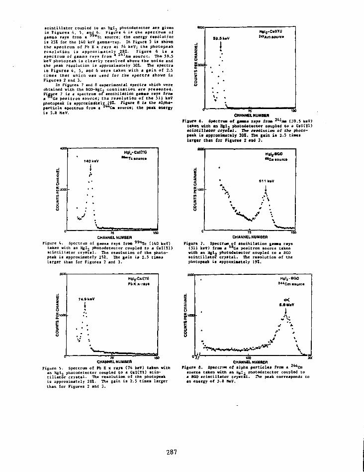
sc int i l la tor coupled to an Hgl, photodetector are givenin Figurci U, 5, and 6. f igure 4 i* the spectrum ofgamma rays tram a "mTc source; Che energy resolutioni t 25! for Che 140 keV gamma-ray. In Figure 5 i s •hdvnthe spectrum of Pb K > rays at 74 keV; the photopeakreso lu t ion i s approximately 28Z. Figure 6 i s aspectrum of gamma rays from * Am source. The 59.5keV photopeak i s c l e a r l y resolved above the noiac andthe peak resolution i s approximately 30!. The spectrain Figures 4, 5, and 6 were taken with a gain of 2.5times chat vhich was used for the spectra shown inFigures 2 and 3.
In Figures 7 and 8 experimental apectra which wereobtained with the BGO-Hgl, combination are presented.Figure 7 i s a spectrum of annihilation gamma raya froma Ga positron source; the reso lut ion of the 511 keVphocopeak i s approximately 1W. Figure 8 it the alpha-particle spectrum from a Cm source; the peak energyi s 5.8 MeV.
NN
EL
5Uj2000a
CO
UN
140 deV
I
• • •
Vm.
**mTc»ourc»
76 ISO
CHANNEL NUMBER
Figure 4. Spectrum of gamma rays fron " " l e (140 keV)taken with an Hglj phocodececcor coupled to a CsI(Tl)sc int i l la tor cryatal. The reaolution of the photo-peak i s approximately 252. The gain it 2.5 timeslarger Chan for Figures 2 and 3.
muu
NN
EL
50
PER
at1-
OU
N
U
59.9 keV
j••
•• *
HSlj-CstCTl)'<'Am sourcs
T8 ISO
CHANNEL NUMBER
Figure 6. Spectrum of gasmia raja from 241Am (S9.5 keV)taken with an Hgl2 pdotodatector coupled to « CsI(Tl)jciatilltcar cry nil. The resolution of the pbotc-peak i s approximately 30Z. The gein i s 2.5 timeslarger than for Figures 2 and 3 .
o
"*Ga source
511 keV
IK)CHANNEL NUMBER
Figure 7. Spectrux of annihilation gamma raya(511 keV) frosi a *GB positron source takenwith an Hglj photodetector coupled to a BOO•cintillator crystal. The resolution of thephotopeak is approximately 19Z.
Pb K x-ra»»
74.9 keVz<xu
ou
CHANNEL NUMBER
Figure 5. Spectrua of Pb K x rays (74 keV) taken withan Hgl, photodetector coupled to a Cal(Tl) acin-tillator crystal. The resolution of the photopeakis approximately 28X. The gain is 2.5 times largerthan for Figures 2 and 3.
ion
0
•
•
m
Ml ICO
Hglj-BGO2 4 4Cm source
6.8 MeV
»• * *
J20
CHANNEL NUMBERFigure 8. Spectnm of alpha particles fro» a *^Cm
aource taken with an tiglj photodetector coupled toa BGO acintillator cryatal. The peak corresponds toan energy of 5.8 MeV.
287
Heaaureaent of Light Output from Scintillatora
One olE the unique features of Hgl.% aa a aolid•tate detector, in comparison to a photoaultipliertube, is that beaides ita ut i l i ty aa a light detectorit can alto be uaed aa an x-ray detector. This featurecan be nude use of to determine in a very convenientway the amount of light from a Bcintillator which istransmitted through the entrance electrode of thedetector and absorbed ia the active region, bycomparison with the direct interaction of x rays in thedetector. For Hglj it ia known that 4.2 eV ia the e>eanenergy required to produce an electron-hole pair by theionigstion resulting from che interaction of an x rayin the material. In the case of scinti l lat ion ligntimpinging on an Hgl2 photodetector, fcr every photonvhich ia absorbed in the active region an electron-holepair will result and contribute to the current pulae,assuming that the electron lifetime is long compared tothe transit time. This i s actually the case, as ha«been shown for x-ray detectors,1 0 where Che chargecollection efficiency is usually over 99Z for electroncollection. In other words there ia a one-to-onecorrespondence between the number of sc int i l lat ionphotona absorbed in the Ugl2 and the number ofelectron-hole pairs produced, ao that th* position ofthe scint i l lat ion photopcak can be coupared with theposition of the peak from an x-ray of known energy, andin this way the number c-f scintillation photona cap becalculate.!. The 5.9 keV Hn K-slphs line from a 55Fesource was used co make the energy calibration. Reiultafor the positions of the 511 keV photopeak from Figures3 and 7 for Csl(Tl) and BCO correspond to 8300 photonsand 1850 photona, respectively.
Efficiency of_ Light Collection
To find the efficiency of the system consisting ofen Ugln photodetector coupled to a acinti l lator fceatimate was made for the production of light photonaby NaKTl), Csl(Tl), and BCO for the particular case ofan annihilation gamma-ray (511 keV) giving rise to thescintillation light pulse. The relationship betweenthe energy per photon of light and the wavelength ofthe light ia given by E - 1.24 / X, where E i* in keVand X is in no. For scintillation light of wavelength410 DI from NaKTl) the energy per photon ia 3.02 eV.The conversion efficiency for a Nal(Tl) acincillator inchanging incident gamma-ray energy to acinti l let ionlight energy at the coupling surface of the cryatal i»1 5 J 11,12 Becauae only a fraction of the light fromthe scintLILator is collected, thia number dependa onthe size and shape of the crystal and on the treatmentof i t s nontransnitting surfaces (usually paintedwhite), and on internal abaorption and scatteringcenters.13 The production of a 3.02 eV light photoncorresponds approximately to the deposition of a meanenergy of 20 eV by the gamma ray in the crystal.Therefore an annihilation gamma-ray with an energy of511 keV s i l l prodi- about 25,400 scintillation photonsin Nal(Tl) which exit through the coupling aurface.The scinti l lat ion light output froc CsI(Tl) is about451 and from BCO ia about 10* of tint from Nal(Tl), 1
ao that a 511 keV gamma ray will produce 11,400 photonsin CsKTl) and 2540 photona in SCO, each of which cancreate an electron-hole pair in an Hjlj detector if allthe light ia collected. The experimentally obtainedvaluea (aee "Measurement of Light Output fromScintillatora") for the number of photona from CaKTl)and BOO detected by the Hgl, photodetector arc ovar 70*of the calculated valuea. It can be immediately aaenthat the quantum efficiencies are much higher Chan theusual quantum efficiency which can be obtained with aphotomultiplier tub3. With eolld-state photodetcctora aquantum efficiency of close to 1001 can be attained by
minimizing light reflection at the coupling interfacebetween the scintillator cryatal and the photodetectorcontact, minimising l ight absorption in thephotodetector entrance contact, and ltaxiaizing thecharge collection efficiency near the surface of thephotodetector. The rat io of the experimentallydetermined numbers of photons for CaKTl) and BCO is4.4, in good agreement with the ratio rotten frommeasurements uaing a photomultiplier tube."
Electronic Moiae
The signal from an Hgl2 solid atate detector isnot internally amplified and therefore can be non-negligibly affected by electronic noise. On the otherhand problems connected with the apread in gain of anyi n t e r n a l - a m p l i f i c a t i o n dev ice (auch as thephotomultiplier tube or avalanche diode) practically donot cxisc.
* dstailed analysis of electrpnic noise hao beengiven for Hglj x-ray detectors. A very similaraaalyaia would apply alao to Bglj photodetectors. Atpresent Che preamplificatioo electronics used forpbatodetectors i s similar to cbe electronics used forx-ray detectors, employing a 2N4416 input FET. Thedifferences becween Hg^ x-ray detectoro andpbotodetectora include
1) larger active areas for photodetectors whichresult in larger capacitance. Perhapa an input FETwith higher tranaconductance than the 2H4<.16 will berequired.
2) higher leakage current for photodtteccors dueto larger aurfaces and higher bias voltages. Bigh biasvoltages are neceaaary at present with Fd frontcontacts to get good charge collection near the aurfaceof the detector.
The electronic noise level has been determined asthe full-width-at-half-maximua (FWHM) of the artificialpeak in the energy spectrum generated by a pulser. Thisnoise level corresponds to 240 electron-hole pairs.
The aystem has not been optimized and it may bepossible Co lower the noise level of 240 electron-holepairs which has been obtained. The aoiae level setsthe limit for energy resolution. For 511-keV gamna rsys240 electron-bole pairs (FWHH) should correspond toabout 13Z (FWHM) in cbe case of BGO and about 31 (FWHM)for CsI(Tl). Fluctuationa in the number of photonsgenerated in the scintillator and in the percentage ofthose transmitted to the photodetector cause theexperimentally observed energy resolution values cc behigher (compare Figures 3 and 7). It can be seen thatelectronic noise does not limit the energy resolutionobtained with CsKTl). In the case of BCO the • • •Heramount of light available to the photodetector makesthe noiae a more important factor.
The electronic noiae level is alao related tothe pulae coincidence timing performance. For adiacuaaion aee the paper by J.S. Berton e_£ e l .preaented at this Conference.
Conclusions
It ia concluded that Hgl, photodetectors can beuaad to decoct scintillation light pulses produced bygamma rays and slpba particles with energy resolutioncomparable to that of < photomultiplier and with aquantum ef f i c i ency (at high aa 70X) which i saignificantly higher than the beat obtained withpnotomultiplier tubas. Inergy spectre obtained with anUgl2 photodetector coupled to a CsKTl) scinti l latorc t n u l have frees prceented for gamma .ray* Irom 137C«,a 0BGa poaitron aource, '"Am, end " " l e , as well asfor the K at-rays from Pb. Energy resolution valuea of19Z and 102 have been obteined for 511-keV annihilationgamma rays uaing Hgl, pbotodetectora in combinationwith BCO and CsKTl) sc int i l lators , respectively.
p. 50^ .
288
Improvements in both cn«rgy resolution and quantum 4.efficiency are expected Co follow froa optimization ofthe design and fabrication of Hgl? photodetector*, MMwell as optimisation of the coupling between thephotodetector and the scinti l lator. In particular, 5.efforts in Hglo photodetector technology technologywill be focused on improving the surface flatness ofChe crystal, the transparency of the entrance contact, 6.and on enhancing the electric field in the surfaceregion. The use of a nonreflective coating on top ofthe photodetector entrance electrode would decrease theLight loss at the interface with the scintillator. 7.
The possible applications for an all solid-stateroom-temperacure acincill*tor-photodetector deviceemploying Hgl* are numerous, embracing most presentapplications in which photomultiplier tubes are usedwith acintil lators. There are several significantadvantages over photoaultiplier tubes. First, there isthe greatly reduced space requireaent. The importanceof reduction in size of the detector can be appreciatedfroa considering the exaaple of positron emissiontomography, where a aore coapact detector arraogcaentmay allow the attainaent of the ultimate .spatialresolution that is theoretically possible.1 4 Otherapplications in which detector size is a cri t icalfactor might include personal radiation doaiaetry andprobe-like detection arrangements in nuclear medicine.Second, the need for a high-voltage power supply whichwill deliver relatively large currents is eliminated. 11.The necessary power consumption is drastically reducedand also the circuit design possibilities become muchwider and attractive from the standpoint of stability 12.and cost. Portable and self-contained instrument* fordiverse applications now become feasible through theuse of battery operated power supplies. The current 13.drawn by Hgln phot ode tec tors id so extremely low thatthe lifetime of the battery would essentially beequivalent to its shelf Life. 14.
Acknowledgements
The authors are grateful to Wayne F. Schnapple andhis co-workers at EG&G, Sante Barbara, for helpfuldiscussions and for supplying the Hgl2 single crystalsused in this work. They also wish to thank Dr. GeraldC. Huth, Director of the USC Institute for Physics andImaging Science, for interesting discussions. Dr.Daniel R. Do iron of the USC Medical School for his aidin making the photoresponse measurements, and W. JanChecinski for valuable technical assistance.
J.S. Ivaoccyk, A.J. Dabrowski, G.C. Huth.A. Del Duct, and H. Schnepple, IEEE Trans,on Huclear Eci. HS-28. Dumber 1, (1981) 579.
R.H. Bube, Physical Seview 106, Dumber 4,(1957) 103.
C. De Blasi , S. Gslaasini, C. ManfredoCCi,G. Micocci, L.Buggiero, and A. Tepore, DuclearInstruments and Methods _15£. (1978) 103.
F. Adduci, A. Cingolani, N. Ferrars, M. Lugara,and A. Minafra, Journal of Applied Physics 48,Dumber 1, (1977) 342.
8. X. Kantaki and I . Iaai, Journal of Che PhysicalSociety of Japan 32, Number 4, (1972) 1003.
9. A.J.Dabrowski,J.S. Iwaocryk, J.B. Barton,G.C. Huth, CHbited , C.Ortale, T.E. Economou,and A.L. Turkevich, IEEE Trans, on NuclearScience HS-28, Number 1, (1981) S36.
10. J.S. tvanctyk, J.H. Kusmiss, A.J. Oabrowski,J.B. Barton, G.C.Huth,T.E. Economou, andA.L. Turkevich, Nuclear Instruments and Methods193, (1982) 73.
"Harahav Scincillacion Phosphors," Third Edicion,The Harshaw Chemical Ccspany (1978).
F.J. Lynch, IEEE Transactions on NuclearScience MS-13. (1966) 140.
S. Derenno end J.K. Riles, IEEE Transactionson Nuclear Science NS-29, (1982) 191.
"High Resolution Detection System for PositronTomography," J.B. Barton, E.J. Hoffman,A.J. Dabrowski, J.S. lwanczyk, and J.H. Kumiss,IEEE 1982 Nuclear Science Symposium,IEEE Transactions on Nuclear Science, thissame Volume.
3.
References
R. Verdant, BibliographieCEA-BIB-169, Centred'Etudes Nucleaire de Saclay, Departetnentd*Electronique Generates Service d'Eleccroniquedee Reacteurs, Aou 1969.
"Scinti l lat ion Spectromecry with Hgl-Photodetector," J .S . Iwanccyk, J.B.
As theBarton,
A.J. Dabrowski, J.H. Kusaiss, W.M. Srymciyk.C.C. Huth, J. Harkakis, W.F. Schnepple, andR. Lynn, submitted to the Fifth InternationalWorkshop on Hglj Nuclear Radiation Detectorsheld ac Che Hebrew University of Jerusalem,June 7 and 8, 1982 (Co be published in NuclearInacrumenca and Methods).
A.J. Dabrowski, Advances in X-Rsy Analysis,Vol. 25, Edited by John C. Ruts, Charles S.Barrett, Paul K. Predecki, and Donald E.Leyden (Plenum Publishing c'orporacion, NewYork, 1982).
289
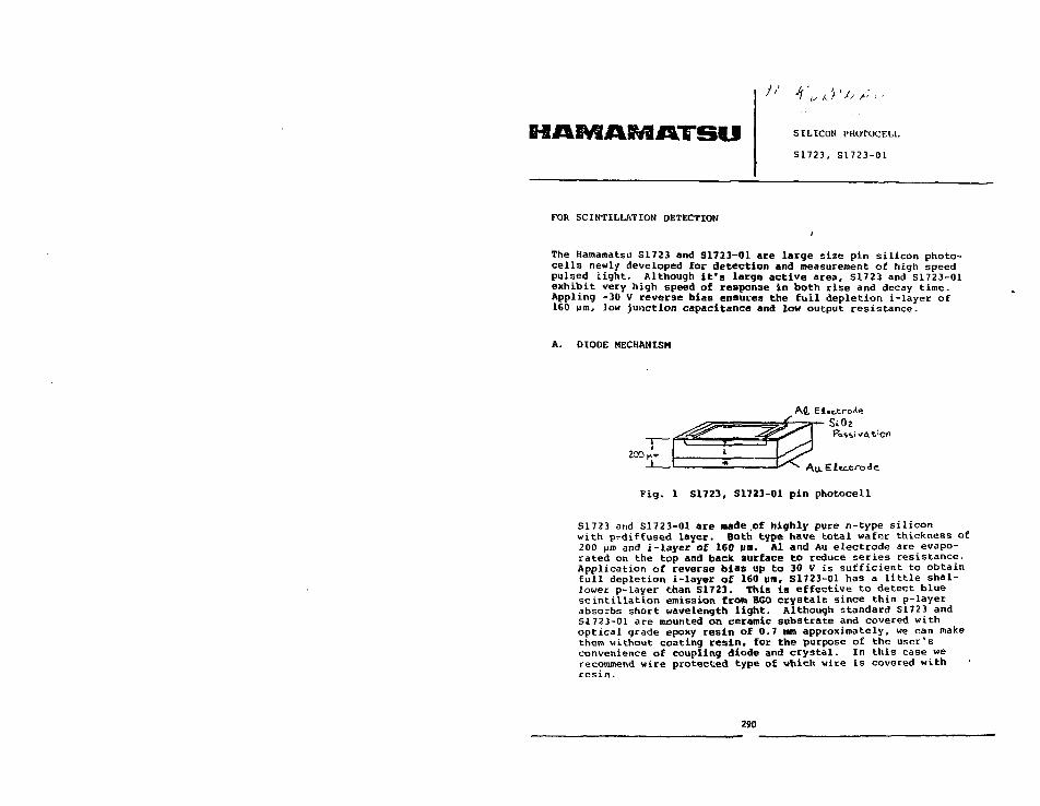
SILICON PHOTOCELL
S1723, S1723-01
FOR SCINTILLATION DETECTION
The Hamamatsu S1723 and S1723-01 are large size pin silicon photo-cells newly developed for detection and measurement of high speedpulsed light. Although It's large active area, S1723 and S1723-01exhibit very high speed of response in both rise and decay time.Appling -30 V reverse bias ensures the full depletion i-layer of160 Mm, )ow junction capacitance and low output resistance.
A. DIODE MECHANISM
At Ei.ctro.li}
S^\ A
SiOi
Fig. 1 S1723, S1723-01 pin photocell
S1723 and S1723-01 are made .of highly pure n-type siliconwith p-diffused layer. Both type have total wafer thickness of200 urn and i-layer of 160 um. Al and Au electrode are evapo-rated on the top and back surface to reduce series resistance.Application of reverse bias up to 30 V is sufficient to obtainfull depletion i-layer of 160 um, S1723-O1 has a little shal-lower p-layer than S1723. This is effective to detect bluescintillation emission from BG0 crystals since thin p-layerabsorbs short wavelength light. Although standard S1723 andS1723-01 are mounted on ceramic substrate and covered withoptical grade epoxy resin of 0.7 mm approximately, we can makethem without coating resin, for the purpose of the user'sconvenience of coupling diode and crystal. In this case werecommend wire protected type of which wire is covered withresin.
290

D . DARK CURRENT
~i^r<—i 1~
I L.Fig. 2 S1723, S1723-01 I-V Curve
The dark current of the diode is a combination of surfaceleakage and bulk leakage. Although S17Z3 and S1723-01 arenot provided with any guard ring mechanism, surface leakageof tha diode is much smaller than bulk leakage. As the samewich typical Si diode leakage, S1723 and S1723-01 dark currentdoubles for every 10°C increase in operating temperature.The uniform p-i-n construction does not introduce any ava-lanche break down all over the active area at -30 V which isenough high bias to achieve full depletion width.
C. JUNCTION CAPACITANCE AND TIME RESPONSE
Junction capacitance of Si photocell is dependent of activearea, bias voltage and resistivity of Si wafer. Applingreverse bias between p and n layer causes smooth reduction ofjunction, capacitance until the diode is fully depleted.S1723 and S1723-01 become this condition airound -20 V andhigher than this specific bias does not cause any significantreduction of the capacitance.
I COO
100
0.1 I 10
REVERSE VOLTAGE - V100
Fig. 3 S1723, S1723-01 Junction Capacitance vs. nios
291
I-'or the fully depleted photocell, the key factor to determiirresponse time are carrier drift velocity .and C x R time con-stant. S1723 and S1723-01's response time is limited byjunction capacitance and load resistance product. When loadresistance is small such as 50 (!, we must take series resist-ance of the diode into account. S1723 and S1723-01 have aslow series resistance as 20 ii on smaller when they are fullydepleted. If series resistance is significantly larger thanload resistance, the decay time of the response waveformbecomes much longer than rise time. S1723 and S1723-O1 showalmost the same rise and decay time with 50 fi load and -30 Vbias. '
Fig. 4 S1723 Time Response
SPECTRAL RESPONSE
Like other Si photocells, S1723 and S1723-O1 have wavelengthrange between 300 to 1150 nm. The difference of both versionis the p-layer depth. Generally the deeper the p-layer thelower the blue sensitivity. At peak wavelength of BGO emis-sion, 480 nm, S1723-O1 is about 45* more sensitive than S1723and has 67% quantum efficiency. But at the same time, wemust note that S1723 has significantly lower dark current athigh bais resion.
SPECTRAL RESPONSE , ..,, .
!
..... L .1.
Fig. 5 S1723, S1723-01 Spectr.il Response
pnqo 3 of
292

ELECTUO-OPTICAI. SPECIFICATIONS
S1723, S1V23-02 ELECTRO-OPTICAL SPECIFICATIONS
SENSITIVE AREA
SPECTRAL RESPONSE
REVERSE VOLTAGE
OUTPUT CURRENT AT -30 V
SENSITIVITY S1723
AT 480 NM S1723-01
SERIES RESISTANCE AT -30V
DAHK CURRENT S1723
AT -30 V S1723-01
JUNCTION CAPACITANCE
AT -30 V
OPERATING TEMPERATURE
STORAGE TEMPERATURE
LOO (10 x 10)
3 2 0 •>• 1 1 5 0
50
5
;200
250
10
5
10
70
-20 t +60
-20 i< +80
MM J
NM
V MAX.
MA MAX.
MA/W TYP
MA/W TYP
a TYP.NA TYP.
NA TYP.
pF TYP.
°C
°C
F. SPECIAL CONFIGURATIONS
Although standard S1723 and S1723-01 are mou.-ted in blackceramic package and covered with epoxy resin, we are open toaccept the special order such as different packaging, activearea and output lead form based upon the electrical perform-ance of S1723 and S1723-01.
(a) PCB package for low profile(b) Diode without cover resin(c) Multi element array; one or two dimensions(d) Large active area, upto 30 x 30 mm2
(e) Smaller substrate for maximum aperture ratio(f) Flexible output leads(g) White ceramic substrate(h) Pre-amp circuit on diode back(i) Higher blue sensitivity
293 [J . iqe o f •? 294

Application of BGO to a Space Shuttle Experiment
A.C. Rester, 8.B. Piercey, F. Giovane, P.s. llaskins,H.A. Hoffitt II, J.L. Veinberg and F.E. Dunnam
Space Astronomy laboratoryUniversity of Florida
1810 NW 6th St.Gainesville, FL 32601
Session F
SPACE PHYSICS APPLICATIONS
295 296

1. Introduction
At the Space Astronomy Laboratory we have developed a Gamma-Ray Advanced
Detector (GRAD) Experiment for early flight on -. space shuttle mission. This
experiment has the following objectives: 1) tests of the performance in
space of two new gamma-ray detector elements bismuth gerroanate (BCO) and
n-type, high-purity germanium (nGe), 2) an investigation of the background
of gamma radiation induced in the orblter by exposure to the radiation belts,
and 3) the acquisition of high energy-resolution spectra of the sun and the
galactic center.
Shortly after the flight of the OSS-1 pallet of scientific experiments
on the third Space Shuttle mission (STS-3) in March of 1982 It came to our
attention that the chamber inside the Thermal Cannlster Experiment (TCE)
might become available for a new experiment on a proposed reflight of the
OSS-1 pallet on the STS-5 mission. NASA officials decided later not to re-
fly OSS-1j however our original plan to fly inside the TCE forced certain
constraints on the design of GRAD. In the first place it was necessary that
the gamma-ray spectrometer mechanically resemble the dummy experiment (a
cylinder of water with thermal sensors) It was to replace inside the TCE.
Furthermore it had to make use of existing power connections and resemble
the TCE to the OSS-1 avionics unit. Finally, the severe time constraint of
meeting a June, 1982 delivery deadline in order to make the November launch
date for STS-5 required that we use an axially-symmetiic, open-ended geometry
rather than a more efficient ossymetric design for the BGO shield, as the
technology of working with BGO was not sufficiently developed for the manu-
facturer to guarantee delivery of a shield of the latter type within the
time allotted. In spite of these limitations, the GFAD shield is the most
advanced BCO anticompton shield to have been fabricated to date.
297
The two types of gamma-ray detection elements of which the present spec-
trometer is composed, B&O and nGe, have not yet been tested by actual use for
the acquisition of spectra in space. That BGO has the highest stopping power
of any commercially available sclntillator, Is non-hygroscopic and relatively
infragile make it potentially a very useful material for astronomical appli-
cations. That nGe may be at least 25 times more resistant to radiation damage
than conventional pGe makes It potentially of great usefulness for high reso-
lution work. Hence answers to the questions of how well these detectors will
withstand the rigors of launching and operation In orbit, how well they func-
tion as detectors In the environment of space, and how susceptible they are
to radioactlvation and degradation from radiation damage are of considerable
Importance for the development of a new generation of gamma-ray telescopes.
2. The GRAD Spectrometer
2.1 The Detector System,
The major element) of the detector system are shown In Figure 1. The
central detector is a nGe detector (ORTEC GAMMA-X model) having a crystal
diameter of 55.6 mm and length of 53.2 mm, enclosed in a specially designed
cryostat having a beryllium window which Is 0.5 mm thick. In operation with-
out the BGO shield the nGe detector has a resolution of 1.99 keV FWHM at
1.332 MeV, a peak-to-corapton ratio of 53 and a photopeak counting efficiency
of 30% relative to that of a standard 3" x 3" Nal detector. A matrix of
activated charcoal Inside the special 30-llter dewar holds the liquid nitro-
gen together for operation in zero gravity.
The BGO anticompton shield, manufactured by the Harshaw Chemical Company,
consists of six trapezoidal segments (14.6 cm long bv 2.74 cm thick) arranged
in a hexagonal configuration axlally about the nCe detector can, as shown in
li^uri' 2. These segments are polished on all sides nnd joined together with
298

optical ly transparent epoxy cement having an Index of refraction of 1.5A. The
base of each segment Is then coupled to a Hammamatsu R1213-O7 photomultiplier
tube.
At the base oE the germanium detector housing, inserted between the BCO
photomultipliers, i s a small calibration probe consisting of a plastic s c i n t i l -
lator which has been doped with a weak imbedded source of Co and optical ly
coupled to a photomultiplier tube. Beta rays associated with the emission offiO
Co gamma rays are detected in the plast ic s c l n t l l l a t o r , resulting in the gen-
eration of a pulse which i s used to switch the output of the germanium detector
to a region of the multichannel analyzer reserved for calibration spectra,
2.2 The Electronics Configuration.
Figure 3 i s a block diagram of the electronics c ircuitry . An energy s ig -
nal from the nGe detector i s f i r s t preamplifled and then routed to three linear
amplifiers which supply 6-gs shaped signals to three separate 4096-chantiel
analog-to-digital converters (ADC's) through three independent single-channel
analyzers (SCA's). These c i rcu i t s are adjusted such that the f i r s t ADC covers
the range 30-500 keV in 4096 channels; the second covers the range 30 keV to
2 MeV; and the third, the entire range from 30 keV to 10 MeV. This redundancy
reduces the probability of fai lure and provides adequate keV/channel resolution
across the entire spectrum.
The timing between the nGe detector and the BGO shield i s determined with
fast timing signals from the sh ie ld photomultipliers and the nGe preamplifier
timing output routed into constant fraction discriminators (CFD's). The nCe
CFD has lower- and upper-level discriminators set to cover the rsnge 30 keV to
10 MeV. The BGO CFD has two se t s of lower- and upper-level discriminators:
one to span the ranjte 30 keV to 10 MeV and the other to define a window around
the 511-keV line in the B';0 spectrum. Pulses passed through the 511-keV window
299
are used to overrule the veto in the third (full spectral range) ADC l ine , so
as to prevent the vetoing of pair escape peaks from high-energy gamma rays.
The fast timing signals from the two CFD's are routed into a fast coincidence
circuit , which then emits stretched pulses to control the gates of the ADC's.
Gamma-ray spectra are accumulated for a preset time in one of two memories.
At the end of the preset Interval, accumulation i s switched to the second mem-
ory while data from the f i r s t are read into the orbiter's data transfer and
telemetry system. On the ground the spectral data are stripped from the telem-
etry stream and transferred into a LeCroy system 3500 multichannel analyzer
system for further handling.
When a nuclear disintegration occurs in the calibration probe, the fast
coincidence logic sends an Interrupt to the microprocessor to flag the arrival
of a calibration signal from the second ADC, which Is then stored in the c a l i -
bration spectrum.
2.3 Integration into the Orbiter
The GRAJ> spectrometer w i l l be mounted in a fixed position in the cargo bay
of the orbiter. The 66° FWHM fie ld of view of the instrument i s large enough
that pointing wil l be done by orientation of the spacecraft. The present plan
cal l s for mounting on the s i l l of the cargo bay on a special carrier designed to
bolt onto the Getaway Special (GAS) can beam. The concept i s depicted in Figure 4.
It i s with pleasure that the authors acknowledge the enthusiastic cooper-
ation of EG & G ORTEC, The Harshaw Chemical Company and Canberra Industries in
al l phases of the design and construction of the germanium detector, BGO shield
and nuclear e lectronics . The engineering support of Dr. John D. Hendricks in
cryogenics and Berle D. Berson in electronics i s a lso gratefully acknowledged.
The project is supported by 8 grant from the Defense Advanced Research Projects
Agency, monitored by the Air Force Office of Sponsored Research under Crant No.
AFOSR-82-0060.
300

List of Figures
1. Overview of the GRAD spectrometer
2. Detail of the BGO shield
3. Electronics configuration for the GRAD spectrometer
4. Conceptual Drawing of a possible GRAD Shuttle Flight Configuration
301
HP Ge Detector-BGO Crystal
Annuius
-MountingBracket
PMTs(6>
-CalibrationProbe
-LN2 Dewar
-Vacuum
-LM2
-Cold Finger
302

Q_iin
I
o•o
OOa
OOCO
(
4)
oa.X I
1
b.
oue>
1 Q"ooCO
z:CCUJ
G<
104

GRADBGO In Several Satellite-Borne Applications
Ray Wn. Klebesadel
Los Alamos National Laboratory
Los Alaraos, New Mexico
Abstract
An experiment is being prepared to be flown on a NASA/NOAA TIROS
satellite. darned DOEE-1 (Department of Energy Experiment), it will carry a
segmented 2.7" x 3" BGO sclntlllator. Sufficient telemetry will be provided to
evaluate the performance exhaustively during a long exposure In space. Another
Instrument Including a BGO sclntillator; named SEE (Spectrometer for Energetic
Electrons), has been operating at synchronous altitude since 1979, providing
measurements of electron fluxes at 2.5 < E < 9 meV. Unfortunately, the data
are not suitable for a critical evaluation of the Bfc'O scfntillator performance,
since 3clntlllator response is not directly monitored.
305 306

-2-
Introductlon
Los Alamos maintains an Interest in detecting nuclear gamma radiation
(E - 1 MeV) in space. Presently, scintillation detectors are the most
effective Instrument In this application, providing high sensitivity and
long-terra reliability coupled with reasonably good resolution. Bismuth
geraanate (BGO) is especially promising for the detection of gamma radiation at
energies of 1 MeV and greater.
The DOEE-1 Experiment
In order to evaluate the performance of BGO in a long-duration exposure to
a space environment, a developmental instrument, named DOEE-I (Department of
Energy Experiment), is being prepared to be flovm on a NASA/NOAA TIROS
satellite. The VIROS orbit will provide periodic exposure to high energy
electrons (In the polar horns of the radiation belt) and to high-energy protons
(in the Sourh Atlantic anomaly). The Instrument is to replace an existing
TIROS Instrument, thus the design is United by the constraints (configuration,
weight, and telemetry resources) imposed by the previously defined Interface
requirements. A photograph of partially completed BGD (Bismuth Germanate
Detector) sensor assembly Is shown (with covers removed) as figure 1.
The sensor is based upon a right-circular cycllnder of BCO 2,7" diameter x
3.0" length. The cylinder is formed of four elements generated by dividing
each of two 1.5" thick discs into two "D" shaped segments. The ends of the
cylinder are beveled to facilitate supporting the assembly. A hole Is bored
through the center of and transverse to the axis of the cylinder and (at the
intersection between the discs) to accept a small energetic-particle detector,
and each element Is machined on the cylindrlc surface so as to accept the
spherical ulndnw oF ,in RCA type C7O132 photomultlpller tube, k plastic nu.Jel
of the BCO scintlllnt»r assomhly Is shown In figure 2.
307
-3-
An "exploded" view of the components that make up the sensor Is shown in
figure 3. The BGO scintlllator assembly Is positioned and supported within the
housing between a pair of beveled plastic retainers, held by a compression
preload exerted by the screw-In cover. A transparent sllicone pad will provide
a resilient coupling between the individual sclntlllator elements and the
photomultiplier (PM) tubes. The base of each PM and the associated bleeder
circuit are supported by a two-piece molded collar which also Is utilized to
transmit a compressive force holding the PM firmly against the sclntlllator.
The conventional end-window PM tube in the left foreground Is Included only to
illustrate an example of the thick-film hybrid bleeder to be employed. The
small cylindrical housing Is to contain a 3/4" PM tube and plastic sclntlllator
to be used to monitor the charged particle environment In which the Instrument
Is operating. '
The charged particle monitor Is Ir.tended to monitor the environment which
may contribute to the response In the primary (BGO) sensor. These data will
also be used to automatically disable the BGO sensors (by removing the high-
voltage) during passages through the most Intense region of the South Atlantic
anomaly. Furthermore, the particle monitor has been buried between the BGO
elements In order to allow identification of positrons, by establishing
coincident detection of one or both of the 0.5 MeV annihilation gamma rays by
the BGO sensors. This will extend a positron survey to regions of the
magnetosphere not sampled by similar Instruments on 0C0-1 and OG0-3 (Cllne and
Hones, 19&8).
The analog electronics are to be stacked on bosses provided on the
photoinultIplier housings, and also within the cavity remaining within the box
TormlnR tlit- base of the sensor housing, shown In figure U. The five
cnmpartmi-nted enclosures shown mounted In this box will house the five
308
steppable (5-bit or 32-level) hlgh-voitage supplies powering the
photomultlpller tubes. Logical electronics and a magnetic bubble memory are to
be housed separately. In the DPM (Data Processing Module) Internally mounded
within the spacecraft. Logical electronics and a magnetic bubble memory are to
be housed separately, In the DPM (Data Processing Module) internal to the
spacecraft.
A block diagram of the analog electronics Is shown In figure 5. Each of
the four BGO sensors will be served by identical electronics, including a
preamplifier, amplifier, and a 5-blt (32-level) linear A/D converter. It Is
intended that this channel span the range 40 < E < 700 keV, with provision for
raising the threshold to 100 keV by command. Higher level signals, derived
from the four individual preamps, are added In a summing amplifier and analyzed
by a single 7-bit (123-level) nonlinear A/D converter. This was felt to be
desirable because responses at higher energies will be often distributed
between several of the elements. This channel will cover a range 0.6 < E < 20
meV.
The charged-partlcle detector respor.se is analyzed by a 4 bit (16 level)
A/D channel. Two additional bits of Information Included with each analysis
Indicate whether none, one, two, or more BGO sensors responded in coincidence
within an energy window around 0.5 MeV. This window interval is defined by a
hybrid analog/logical circuit for both technical and practical reasons.
The results of the analyses performed on the outputs of the individual
sensors are assembled In a shift register (FIFO, ftrst-in/flrst-out) to be
transmitted to the logical electronics and memory. A block diagram of the
system is shown in figure 6. The dashed line Indicates the division of the
circuitry between the BCD and DPM. The logical functions of data handling are
largely performed by a microprocessor, and are not readily descrihed by n block
309
-5-
dlagram. Data input to the logics, however, is provided by a direct-memory-
access (DMA) unit.
The microprocessor functions are programmed through software stored in a
programmable read-only memory PROM. It provides for real-time data handling,
formatting for the telemetry a full set of spectral data on a 64 s period. It
also identifies rapidly-rising transient events, storing high-resolution
records of these events in the bubble memory (with a capacity of a half-million
bits). Upon termination of an event record, these stored high-resolution data
are formatted for telemetry, replacing the real-time data. Configuration
commands are processed by the nlcroprocessor, then loaded into dedicated
registers in both the DPM and the BCD. State-of-health functions arc presented
upon dedicated lines through the DPM at the spacecraft Interface. The
microprocessor also performs logical tests of the bubble memory and the RAM,
and a statistical test of sensor response. The results of these tests are
presented as a part of the digital status Information.
This Instrument is being prepared on a schedule which will allow delivery
In early June 1983. The schedule for spacecraft testing provides for a launch
in 1985. This schedule is, however, tentative and may be cither accelerated or
retarded depending upon program requirements.
The Spectrometer for Energetic Electrons (SEE)
An instrument employing a BGO sclntillator is currently operating at
synchronous orbit. This instrument Is an electron spectrometer monitoring
electrons In the energy range 2.5 < E < 9 MeV. A plan view of the Instrument
ts shown in figure 7. The spectrometer Is based upon n BGO sclnt11lator, In
which the energetic electrons are absorbed. BGO was chosen as the scintlllator
because It allowed a compact design, necessary to accommodate the Instrument as
3)0

-6-
a direct replacement for one of a different type, without modifying either the
mechanical or electrical Interface.
The sclntlllator la shielded (by a thick aluminum case and a glass
llghtplpe) from direct penetration of electrons to 15 MeV. A colliroated
entrance aperture Is defined by tantalum and copper elements. Electrons
entering through the colliraator are identified by the response Chey produce in
a silicon solid-state detector (2 element) immediately in front of the
sclntlllator. Electrons within the range of the measurement are
minimum-Ionizing particles, and thus deposit a uniform energy in the silicon
detectors. Other minimum-ionizing particles usually are rejected because they
deposit excessive energy in the sctntlllator.
Data from the scintillation spectrometer is analyzed in only four
differential intervals (because of telemetry limitations), between nominal
levels of 2.5, 4, 6, 9, and 15 MeV. The analysis Is performed only when
coincident response in the silicon detector Is observed* The silicon detector
counts in the "window" energy interval are also telemetered. Unfortunately,
these data do not allow a critical evaluation of the performance of BGO In this
environment because response in the sclntillator Is not monitored independently
of response in the silicon detector.
The capability to measure high-energy electrons was developed because of a
concern that the then-current AE-4 model of the energetic electron population
at synchronous alcltude did not adequately describe the contribution of
electrons at energies greater than 2 MeV. These higher energy electrons are of
importance Co spacecraft operating In this regime since they could produce:
1) Cable charging and deep dielectric charging.
2) Logics upsets and anomalies.
3) DOHC effectH from the penetrating electrons which are difficult
111
-7-
to shield against.
The first Instrument of this type was placed In synchronous orbit in 1979, and
monitoring has been provided nearly continuously since that time. Preliminary
data from the instrument have been reported (Klebesadel et al. 1982) and have
been published as a part of a synoptic data set which Includes analyses of
lower-energy electrons and protons (Baker et al. 1982),
During this extended period of operation, a number of periods of unusual
activity have been observed. Spectral distributions of the energetic electrons
during the first of these, occurring in June 1980, is shown in figure 8. These
spectra represent daily averages, as indicated. Also shown is the AE-4 model
spectrum, which is seen to be deficient at higher energies as compared to these
measurements. Of course, these data are unusual, and not representative of
average conditions*
These times of unusual activity appear to be periodic, occurring at
Intervals of about 13 months. There is some evidence that these correspond to
times when the sun's twisted magnetic field connects the earth and the planet
Jupiter, as shown in figure 9. Electrons emitted from the Jovian magnetosphere
may then be confined by the solar magnetic field and ducted to the vicinity of
the earth. Such a mechanism was first suggested by Teegarden et al. (1974).
Conclusions
Although BGO has already beep employed successfully in an application In
space, the performance of that BGO spectrometer can not he critically evaluated
based upon the data which are available. The DOEF.-l instrument being prepared
to he flown aboard a TIROS satellite will provide n comprehensive analysis of
the perfocvicifice of a SCO aptctrometeT. This satellite vili hrt "Inrpd into an
orbit which will subject the instrument to a long-duration exposure to a wide
rnngp of radiation environments. Thus, data returned from this Instrument will
312

be useful In assessing the suitability of BGO In other anticipated satellite-
borne applications.
313
-9-
References
Baker, D. N., Hlgbie, P. R., Bellan, R. D., Hones, E. W., and Klebesndel, R.
W., The Los Alamos Synchronous Orbit Data Set, . . .
Cllne, T. L., and Hones, E. W.f Search for Low-Energy Interplanetary Positrons,
Canadian Journal of Physics, 4£, p. S527, 1968.
Klebesadel, R. W., Baker, D. N., Higble, P. R., and Bellan, R. D., Ver£ High
Energy Electrons In the Outer Magnetosphere (Abstract) EOS, 62-45, p. 993,
1981.
Teegarden, B. J., McDonald, F# B., Tralnor, J. H., Webber, W. R., and Roelof,
E. C , Interplanetary HeV Electrons of Jovian Origin, J. Geophys. Res.,
79-25, p. 3615, 1974.
314

It:
Figure Captions
Figure 1 - A photograph of the base housing for the DOEE-1 sensor.
Figure 2 - The BGO sclntlllator assembly for the DOEE-1 instrument.
Figure 3 - An exploded view of the DOEE-1 sensor components.
Figure 4 - A view of the DOEE-1 sensor housing showing the electroni- s
enclosure provided In the base structure. The five small
compartmented enclosures will have H.V. converters powering
photomultipller tubes.
Figure 5 - A block diagram of the sensor analog electronics included in the
DOEE-1 instrument.
Figure 6 - A block diagram of the complete DOEE-1 instrument including the
sensor (BCD) and the data processor (DPH).
Figure 7 - A plan view of Spectrometer for Energetic Electrons (SEE); which has
been flown at synchronous altitude.
Figure 8 - Spectral data describing the high-energy electron population nt
synchronous altitude during a particularly active period observed
June 1080.
315
1!
-yt.Figure 9 - A schematic representation of a possible mechanism introducing
high-energy electrons Into the earth's magnetosphere via a duct in
the solar magnetic field. The magnetic duct provides a connection
between the earth and the planet Jupiter, which is the proposed
source of the electrons.
316

LI
Ls 5
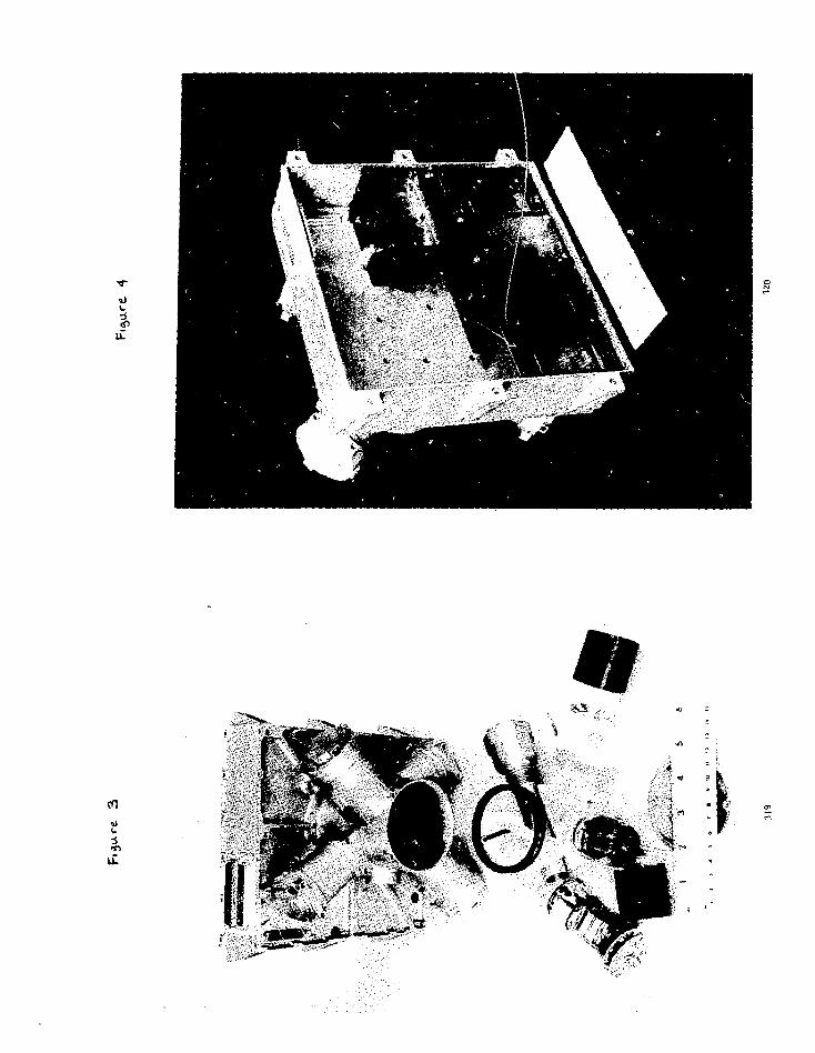
V
cO
Ti

ANALOGSIGNAL
PD
SUMMINGENABLE
SUMMINGENABLE
ANALOG ELECTRONICS
321
A/D
0.5 MeVWINDOW
g
1 SiQ- - I—
1
3
ISs
322

N03I1IS- |Zlo V i a ) "iviSAdo 3ivNvwy39 Hinwsia
re
10
1 10 'Iuw
w
o
10
10'
10"
1 0 '
10'
S/C 1979-053: 6.6 R,
JUNE 10, 1980JUNE 12, 1980JUNE 15, I960
;—AE-4
2000 4000 6000 8000 10000Electron Energy (keV)
TI
(GO.

solar windstream interaction regions'
interplanetarymagnetic
fieldline
Jupiter(and Jovian
magnetosphere)
Earth(and terrestrial
magnetosphere I

* « i i BISMUTH GERMANATE (BGO) DETECTOR ARRAY FOR HEAVY ION
P H Y S I C S ADD THE PROMPT RESPONSE OF K O TO FAST NEUTRONS
M.A. Lone, 0. HSusser, T.K. Alexander
Atomic Energy of Canada U n i t e dChalk River Nuclear Laboratories
Chalk River, Ontario, KCJ 1J0, Canada
J. Gascon
Laboratoire de Physique Nucle*aire
Vnlversite de MontrealMontreal, P.Q. Canada H3C 3J7
E. Hagberg
queen's University, Kingston, Ontario, Canada
and
University of Toronto, Ontario, Canada
327
ABSTRACT
The properties of a gamma-ray facility proposed for the Chalk
River HP tandem superconducting-cyclotron accelerator Is
described. The target is surrounded by a multi-segmented 4i BGO
detector that determines, for each event, the y-ray multiplicity,
the spin orientation, and the total energy of the entry state in
a y-ray cascade. A snail fraction of the y-rays Is detected
outside the 4* array In up to eleven intrinsic Ge detectors, each
of them inside a EGO Conpton suppressor. The facility will allow
high-resolution spectroscopy of discrete lines, with low Compton
background and with strong enhancement of high-multiplicity
events. Results of Monte Carlo calculations on the gamma-ray
response of the facility are described.
We have measured the prompt response of a 7.6 * 7.6 cm BGO
detector to fast neutrons In the energy range from 0.4 to 10 MeV,
using pulsed proton beaaB and tlme-of-flight methods. Both mono-
energetic neutrons from the Ll(p,n) reaction, and continuous
neutron energy distributions from the 197Au(p,n) reaction were
employed. The observed energy spectra in the BCO detector are
dominated by y-rays from the (n,n'y) reaction from Bi and Ge.
Compared with a Nal(Tl) detector of the sanre volume, the neutron
response of BCO is much smaller below £„ = 2 MeV because of the
low density of levels in 209Bi, whereas above 3.5 MeV the neutron
efficiencies are roughly the same. These results Imply that a An
detector made of BCO has a ganme-to-neutron detection ratio much
superior to that of Nal(TJ).
328

- 1 -
Introduction
The study of nuclei at high angular momentum is as yet
possible only via the y-radlatlon following fusion evaporation
type reactions (HI,xn) or via nultlple Coulonb excitation using
heavy ion beams. The type of interaction between the projectile
and target is determined by Che relative kinetic energy and the
impact parameter. The de-excitation of the compound nucleus can
proceed by emission of neutrons and/or charged particles, or by
fission. Ihe (HI,xny) reactions lead to high spin f-ray emitting
states, since the neutrons carry, because of the centrifugal
barrier, low angular momentum. The shape of the spectrum of the
emitted y-rays depends strongly on the position of the entry
point in the (Eexc.J) plane after the nucleon emission. If
this point Is located far above the yraat line, the high level
density will result in a predominantly stat is t ical y-decay
process and consequently in a s tat is t ical y-ray distribution.
Close to the yrast line details of the nuclear structure become
observable in the shape of the y-ray spectra. Sotne levels are
populated so strongly that the de-excltlng y-rays are represented
by sharp peaks superimposed on the continuous background in the
Y-ray spectra.
For nuclear studies of states that are accessible with
(Hl.xny) reactions it Is highly desirable to identify the entry
point (E e x c , J) . This requires simultaneous measurements of
the total energy of the y-cascades and the y-ray multiplicity.
329
- 2 -
In addition one requires spectrometers with high resolution and
large full-energy fraction for identification of weaker discrete
transitions. For this purpose use of multi-array An crystal
balls and Cciapton suppressed high resolution y-ray detectors are
becoming increasingly important at heavy ion accelerators.
2* Proposed CKNL y-E»y Facil ity
At the CRliL HP tanden superconducting-cyclotron heavy-ion
accelerator we are proposing a y-ray facility of the type shown
in Fig. 1. The target is surrounded by a 62 segment 4TI BGO
detector (inner radius > 6 en, outside radius ^ 16 cm, see Fig.
2) that determines, for each event the y-ray multiplicity, the
spin orientation, and the total energy of the entry state In a
y-ray cascade. A snail fraction of the y-rays is detected
outside the 4n array in up to eleven intrinsic Ge detectors, each
of then inside a EGO Coapton suppressor. The facility will
allow high resolution spectroscopy of discrete lines, with low
Compton background and with strong enhancement of high
multiplicity events.
3. Ga—a-R»y Re»pon«e
The design criteria for the proposed y-ray facility have
been to combine good energy resolution, high Compton suppression,
large solid angle for Gs detectors and adequate resolution of sum
energy and ,-ray multiplicity. The y-ray response of this 4» BGO
detector was investigated by tonte Carlo calculations. Figure 3
shows the calculated line shapes of the sum energy, E8, from
events producing 10, 20 and 30 y-rays, each of 1 MeV
330

- 3 -
energy. In these calculations we Ignored the f i n i t e resolution
of the BGO detector and the 0.11 a reduction In the solid angle
of the- multl segmented BGO detector arising from openings for
beam line and Ge detectors. Figure 4 gives the probability of
mill e l -
trigger events as a function of the Tf-ray mult ip l ic i ty . These
results demonstrate Che excellent resolution of a 4n EGO detector
for sum energy and f-ray mult ip l ic i ty .
The calculated response of the Intrinsic Ge detector
(100 en3) inside the BGO Compton suppressor Is given in Fig. 5.
These calculations are for an idealized Ge detector and Ignore
dead-layers in Che Ge, i t s mounting arrangement, cold finger e t c .
The Compton reduction factors Chat are experiaentally obtainable
are probably inferior to those calculated below. The top curve
(dot dashed) shows Che linestiape of single events from 1 HeV
7-ray interactions In the Ge detector. The photo peak area i s
22.6% and the ta i l area Is 52* of the nunber of the well
colllmated y-rays incident on the Ge detector. The solid curve
gives the. llneshape with a Coropton suppressor of the type shown
in the Inset. The t a i l area i s reduced by a factor of >. 10 when
compared Co the unsuppressed t a l l area. The dashed curve shows
Che effecc of removing the entrance window from the Compton
suppressor.
4 . Neutron Response Hea«ure»ent»
The BGO scincl l lacor i s sensit ive not only tc Y-rays but
also to neutrons which are Inevitably present l.i (Hl,xny)
331
- 4 -
reactions. Neutron-induced scintillation pulses can be separated
Into two components, one that Is emitted within a few nano-
seconds, and another that occurs at a nuch later time after
thermallzatlon of the neutron and its subsequent radiative
capture. The prompt component can be selected, elthci- by time
correlation with the arrival tine at the target of a pulsed
particle bean, or by a coincidence with radiation observed In a
second detector. However, due to the compact size of a An BGO
detector and its relatively poor time response, separaclon of
neutron-induced scintillation pulses by time-correlation would be
difficult and the contribution of these pulses to the coincident
events will have to be calculated.
For assessment of the neutron sensitivity, the prompt
response of a 7.6 en x 7.6 ca BGO detector to fast neutrons, in
the energy range from 0.4 to 10 HeV, was measured' using pulsed
proton beams and tlne-of-flight methods. For comparison Che
prompt response of a 7.6 en x 7.6 cm Nal(Tt) deteccor was also
measured for the same energy neucruns.
Pulsed beams of protons from the Chalk River MP tandem
accelerator were used at energies between 4.2 and [6 MeV. The
beam pulses had a width of less than 3 ns, and the separation
between adjacent beam pulses was 1.6 us or longer. A small
plastic sclntlllaCor mounted close to the target was used to
monitor and stabilize the beam arrival time. The experimental
arrangement Is shown schematically in Fig. 6. The proton beam
passed through a thin metallic target of 7L1 and was stopped
downstream in a thick gold stopper. The beam tube containing
target and beam dump was Insulated from the preceding beam line,
and secondary elecCrons were suppressed with a long cylindrical
332

- 5 -
electrode biassed at -0.5 keV.
Neutron beams from the Li(p,n) Be reaction were monitored
at a scattering angle of 20° with a 13.2 cm3 cubical stilbene
detector, mounted 10 cm below the proton beam height at a
distance of 3 m from the target. Standard tlme-of-flight and
pulse shape discrimination techniques were used to determine the
neutron energy and to separate neutron and Y^ray events cleanly.
The effective electron-energy threshold of 0.05 HeV was monitored
frequently with 21<1An and 22Na gaaraa-ray sources. The
corresponding neutron energy threshold was 0.4 MeV (see Ref. 3).
The neutron detection efficiency of the stilbene detector was
established with ± 10% uncertainty In an earlier work .
Concurrently with data from the stilbene detector, evants
were recorded from one of the 7.6 en diameter by 7.6 long
detectors of SCO and Nal(Tfc). The latter scintlll' s were
mounted 10 cm above beam height, at th* same ar.gle and distance
as the stilbene detector. The energy threshold for BGO and
Nal(Ti) scintlUatocs were 0.18 MeV and 0.13 MeV, respectively.
Special care was taken to determine the background of
Y-rays and neutrons In the tlme-of-flight spectra. Both neutron
and y-rays scatter from solid material surrounding the detectors
to produce a strongly time-dependent background. We use the
method of U>ne et al.1* to measure the time-dependent rooo
background, A 60 cm long block of lron-iaasonite (50Z iron) was
placed midway between target and detectors to absorb the direct
333
- 6 -
neutrons. After applying the measured deadt'. me correction
factors the background corrected spectra we-e obtained by
subtracting the 'block In' from the 'block out' spectra. The
effectiveness of this technique. In cleanly removing the
background, i s demonstrated in Fig. 7, where the lowor curve
shows e f fect ive ly zero counts in time-of-flight channels
corresponding to neutron energies below the detector threshold.
A second Iron-oasonite block near the beam dump was used to
shield the detectors against neutrons and Y-rays from the gold
beam dump.
Figure 8 shows background-corrected tlme-of-fl ight (TOF) '
spectra, obtained with the three sc lnt f l la tors at Ep = 4.2 MeV
(En = 2.3 MeV). No pulse-shape discrimination was applied to
the stl lbsne data so that both neutron and Y~ray peaks appear in
the TOF spectrum. The peaks labelled »o and n t correspond to the
population of 7Be ground state and f i r s t excited state (AE =•
0.429 MeV). From the width of the n0 group the target thickness
was estimated to be 5.9 ag .c»" 2 . In a l l three TOF Bpectra the
background below and above the (ng, nj) groups has been removed
very e f f ec t ive ly . In the BGO spectrum there Is no significant
observable contribution of delayed events from the decay of the
lsomeric s tates In Ge which are populated by (n,n') reactions
( e . g . the 691 keV 0+ s tate in 72Ge, T[/2 - 0.42 us). In a
small Ge detector the electric-monopole conversion-electron peak
froir. the decay of the 691 keV 0+ state la v^ry pronounced due to
hlRher detection eff ic iency as compared to full energy f-ray
334

- 7 -
peaks. However, in a BGO detector the y~Tay detection efficiency
is much higher a.id the relative contribution of ths d-'^yed
events Is less significant. Furthermore In a TOF spectrum these
delayed events are spread over aany channels. From known
Ge(n.n') cross sections5"7 we estimate that the total
contribution of the delayed events in TOF channels 200 to 300 In
Fig. 7 Is <O.SX oi the area of the no peak.
The neutron flux incident on the BCO or Nal(Tl) was
calculated from the observed neutron events in the stllbene
sclntlllator and the efficiency determined in an earlier
experiment-1. As an Independent check the neutron flux was also
calculated, making use of the integrated beam current, the known
target thickness, and the differential ctoss sections for the
7Ll(p,n) reaction8-9. Between En - 2.3 and 6.03 MeV both
neutron fluxes agree to better than ±61. In the following, the
neutron efficiencies of the BGO and the Nal(Ti) are given
relative to that of the stllbene.
The neutron efficiencies at low energies were obtained
utilizing evaporation neutrons from the 197Au(p,n) reaction at
Ep ° 16 MeV. For these measurements the thick gold beam stop
was used as the target, and the neutrons were detected at 8 l a b •
n
0°, at a flight path of 4 m.
The numbet of triggers per Incident neutron for SCO and
Nal(TJ) detectors are shown in the middle and the upper panels of
Fig. 9, respectively. The solid l ines are a smooth rep.y ,<_,ii.a -
335
tion of the data, and the dashed lines show calculated
efficiencies, explained in the next section. The ratio of the
two efficiencies is shown in the bottom panel of Fig. 9. It Is
Been that, for detectors of equal dimensions, BGO is less
sensitive to neutrons than Nal(Tt) at low energies (E,, < 3
MeV), whereas BGO is slightly sore efficient than Nal(Ti) above
E n - 4 MeV.
Figures 10 and II show the pulse height distributions
produced in the sclntlllators for various energies of the
incident neutrons. The abscissa in these figures give the
equivalent t-tay energy. The distributions are generally below
the Incident neutron energy. For E,, £ 6 MeV there are very few
counts in the 6 - 1 0 MeV region, indicating negligible
contributions froa the (n,y) reaction. The energy spectra are
consistent with the (n.n'y) reaction providing tha bulk of the
pulses. At low neutron energies several discrete states are
strongly excited by the (n,n') reactions which give rise to
Identifiable de-excltation Y-™y». The broad group near 0.6 MeV
in the BGO epectra is attributable to several transitions in Ge
isotopes, whereas the peaks at 0.9 and 1.6 MeV arise mainly from
the decay of the first and second excited states in 2 O 9B1.
Figure 12 shows the centroids of the observed energy
distributions versus incident neutron energy. From the
statistical theory of nuclear reactions °, tho average energy,
<E >, of the scattered neutrons following the (n,n*) reaction,
is expected to be between 1-1.6 MeV, corresponding to an average
nuclear temperature between 0.5 - 0.8 MeV. However, as seen in
336

- 9 -
Fig. 11, the average energy deposited In the scintillator is
considerably smaller than <EX> - B,, - <£„'>, especially for
large values of <EX>. At the highest neutron energy (10 MeV)
only about 35JS and 22% of the calculated <^> Is observed in
the BGO and Nal(Ti) detectors, respectively.
5. Neutron Response Calculations
An accurate description of the neutron response functions
of BGO requires the knowledge of a large variety of differential
cro83 sections for elastic and non-elastic processes, e.g.
(n,n'), (n,p), (n,a), (n,2n) and in, if) reactions for the
constituent atoms of the scintillator. If these reactions
populate excited states the Intensities of the de-excltatlon
Y-rays have to be known to estimate the probability that these
ir-rays interact with the scintillator. Ideally, the neutron
response can be calculated from such a complete data set by Moiite
Carlo methods. However, in the absence of such a complete data
set, the neutron response can be estimated with a simpler
approach that uses only angle-Integrated cross sections. In the
following the neutron response Is described by an approximate
analytical expression which can be rather easily applied to
scintillators of any volume or shape.
If the neutron is assumed to Interact only once along the
length L of the scintillator and interactions involving Y-ray
production doroln/tte, the neutron detection probability can be
written as
337
- 10 -
t o c a l (1)
In this expression c - ^elastic'^total1
where E is the linear attenuation coefficient for the neutron
reaction processes Indicated by the subscript. PC(E^,MY)
is the probability that at least one of the M cascade y-raya
Pc(W " ' " H " W (2)
Since 1-Eelastic l ! o f t n e o t d e r °f unity for large
scintillators, corrections to Eq. 1 arising from multiple elastic
collision become Important. With the simplifying assumptions
that the neutron does not lose energy after each elastic
collision, and that the collision probability is independent of
the preceding number of elastic collisions, the correction can be
evaluated, resulting In
"c) Pc(V V
Here Pc(En) is the average collision probability of neutrons
with energy En and an isotroplc distribution over the
sclntillator volume (I.e. Pc(En) » 1 - (/P(r)dV)
where P(r) is the probability of a neutron at r escaping the
detector).
To evaluate the neutron efficiency the linear attenuation
coefficients shown In Fig. 13 were calculated from neutron
338

- 11 -
cross sections compiled by Howercon10. Hie sharp
resonances In the elastic and total cross sections for BGO arise
from the 16O(n,n) elastic channel. Many such resonances In
23Na(n,n) have been averaged. The collision probabilities Pc
were obtained fcooi tabulated values H for a volume equivalent
sphere. The -(-ray multiplicities and the average r-ray energy
from de-excitation of states populated In the (n,n') reactions
were calculated1 from statistical theory.
The results of the calculations of Pn(En) from Eq. 3
are shown in Fig. 8 as dotted curves, the agreement with the
measurements Is surprisingly good considering the many
simplifying assumptions. The calculations overeatinate
Pn(En) at low energies, possibly because the effects of the
energy threshold are not Included. Che calculations confirm the
observed decrease of the neutron sensitivity with decreasing
neutron energy for both BGO and Nal(Tt). The reported Increase
in neutron sensitivity below £„ " 2 MeV reported by Van
Ruyven12 is probably caused by their (incorrect) assumption of a
time Independent background in the data analysis. At higher
neutron energies their neutron response function for Nal(Tl) is
similar to ours.
6. Conclusion
Monte Carlo calculations of the y~ray response of the 62
element, I>T\ BGO crystal ball (Inner radius > 6 cm and outer
radius ^ lfc cm) proposed for the CRHL HP tandem
339
- 12 -
superconducting-cyclotron heavy Ion accelerator show respectable
sura energy and multiplicity resolution. The ball has a small
enough outer radius to allow a reasonable solid angle for the
surrounding Ge detectors Inside BGO Compton suppressor shie lds .
The axial geometry of the anti-Coopton spectrometer provides high
suppression ratio and high effective sol id angle for the Ge
detectors. At i t s full capacity this y-tay f ac i l i t y will
provide, on an event-by-event basis, the spin, the spin
orientation,and the total energy of the entry s ta te , and at the
same time allow hlgh-resoluton soectroacopy of discrete l ines ,
with low Conpton background and with strong enhancement of
high-ault ip l ic l ty cascades.
For detectors of equal shape and volume, BGO exhibits a
considerably lower sens i t iv i ty than Nal(Tl) to neutrons with
energies below 2 MeV. The neutron responses become about equal
at E,, = 3.5 MeV, and at the higher ene glee SCO Is s l ight ly ( =
20!) more sens i t ive . If we take accoj'.t of the fact that the
linear attenuation coeff icient for - rays, i, Is typically a
factor of approxia,,. :.., ~.^ »arger for BGO than for Hal(Tz) (see
Fig. 13) BGO has a much superior y-ray-to-neutron detection
rat io . At energies below 0.5 HeV the (n,y) capture cross
sections for BGO are very low, making BGO at least an order of
magnitude l e s s sensitive to neutrons than ttol(Te) and there w)'"
be no long lived neutron activation of the cryscal as happen -
the case of Nal(TJl).
340

- 13 -
References
(1) 0. Hausser, M.A. Lone, T.K. Alexander, S.A. Kuehnerluk and
J. Gascon. Submitted to Nucl. Instr. and Heth. (1982).
(2) C M . Clalella and J.A. Davanney, Nucl. Instr. and Meth. 60
(1968) 269.
O ) M.A. lone, A.J. Ferguson and B.C. Robertson, Nucl. Instr.
and Meth. 189 (1981) 515.
(4) M.A. Lone, C.B. Bighan, J.S. Fraser, H.R. Schneider, T.K.
Alexander, A.J. Ferguson and A.B. McDonald, Nucl. Insrr.
and Meth. 143 (1977) 331.
(5) K.E. Chung, A. Hlttler, J.D. Brandenberger and M.T.
McElUstrem, Phys. Rev. C2 (1970) 139.
(6) D. Lister and A.B. Snlth, Phys. Rev. 183 (1969) 954.
(7) D.L. Smith, Nucl. Instr. and With. 102 (1972) 193.
(8) H, Llsklen and A. Faulsen, Atomic Data and Nucl. Data
Tables, 15 (1975) 67.
(9) C.H. Foppe, J.D. Anderson, J.C. Davis, S.M. Grimes and C.
Wong, Phys. Rev. C14 (1976) 438.
(10) R.J. Houerton, Semi-Emperical Neutron Cross Section,
University of California Report UCRL-5351, 1958.
(11) K.M. Case, D. de Hoffmann, G. Placzek, B. Carlson and M.
Goldstein, Introduction to the Theory of Nentron
Diffusion, Volume 1, Los Alamos, Scientific Laboratory,
Los Alamos, New Mexico, 1953..
(12) J.J. van Ruyven, Gomaa Spectrscoplc Studies of Some
Neutron Deficient Even Te and Pb Isotopes, thesis, Free
University of Amsterdam, The Netherlands (1982).
341
- 14 -
Figure Captions
Fig. I Schematic view of the 4n BGO detector array and Compton
suppressed high resolution Ge spectrometers proposed for
the CRNL super-conducttng-cyclocron heavy-ion accelerator.
Fig. 2 Vertical section through the spectrometer shown ,n Fig. 1.
The scale factor Is shown In the figures.
Fig. 3 The line shapes of the SUB energy pulses, EB, for
various trigger nultlpliclties H. In the calculations
the finite resolution of the BGO detectors is Ignored.
Fig. 4 The probability distribution of multi-coincident pulses
calculated for various trigger aulclpllcltiet, "1.
Fig. 5 Calculated line shapes for 1 MeV *r~rays Incident on a Ge
detector; daBh-dot curve without Compton suppression; dash
curve with veto signals fron the BGO Compton suppressor
with no entrance window and solid curve with a Cotapton
suppressor as shown in the inset.
Fig. 6 Schematic view of the experimental arrangement for
measurements of the neutron efficiency.
Fig. 7 Tlme-of-fllght spectra; (a) y-rays (block out) minus
(block In)
(b) neutrons observed without the Iron masonite block in
the flight path;
(c) neutrons detected with the block in place, and
(d) the difference between (b) and (c).
Fig. 8 Background corrected tlme-of-fllght spectra from three
scintlllators used In the experiment. The y-rcy events
near time T « 0 have been scaled down by a factor of ten.

- 15 -
No pulse-shape discrimination was applied to the s* \-
bene events
Fig. 9 The top two panels show the neutron detection probabi-
lity for 7.6 cm diameter by 7.6 a long selntlllators of
(Jal(Tt) and BGO, respectively. The solid lines ate
smooth representations of the data. The dashed lines
are the results of calculations described in section S.
The bottom panel ahovo the ratio of sensitivities, BGO
divided by Nal(Ti).
Fig. 10 Pulse height energy distributions observed after inter-
action of mono-energetic neutrons «lth Nat(Tt) (top
panels) and BGO (lower panels). ,The energies of the
incident neutrons are indicated by arrows.
Fig. 1) Pulse height energy distribution observed after inter-
action of low-energy neutrons with a BGO scintillator.
Fig. 12 Centroids of the pulse height energy distribution shown
In Figs. 10 and 11, shown versus Che energy of the inci-
dent neutron. The solid lines are drawn to guide the
eye.
Fig. 13 Calculated linear attenuation coefficient for y-rsys ( i )
and neurrcns (£) in BGO ( lef t panel) and Nat(T«) (right
panel).
343
BISMUTHGEHMANATE
GERMANIUMPHOTOMULTIPLIER TUBESLOCATED WHERE SHOWNBY DOTTED CIRCLES
TOBEAM STOP
Ovamll dj*m#t*r 6i em vppros.THE W
SPECTROMETER

3700B
THE '8-ir1 SPECTROMETER
VERTICAL SECTION - NORMAL TO BEAM
345
09
tf>
6 6( S 3 )
<*•6A l l
to CJ —o d diigvaoud
346

Ofr
02 SIA3W I = X3 )c
SUOJL0313Q 098 29
-o3D
to oCD
r20 3
p
5
4
> 3C£
OCHCDCC< 2inh-
oo
1
; 1
: CRYST I
" Vj HM1—1
PMT
0 5 to 15 20cm
1
1 I =
COMPTON SUPPRESSEDi :" » WITHOUT WINDOW INO SUPPRESSION |
X
- /;ii
II -
"T"
•' '< > I I\
I--
i J _.275 550
PULSE HEIGHT <KeV)
825 100
n
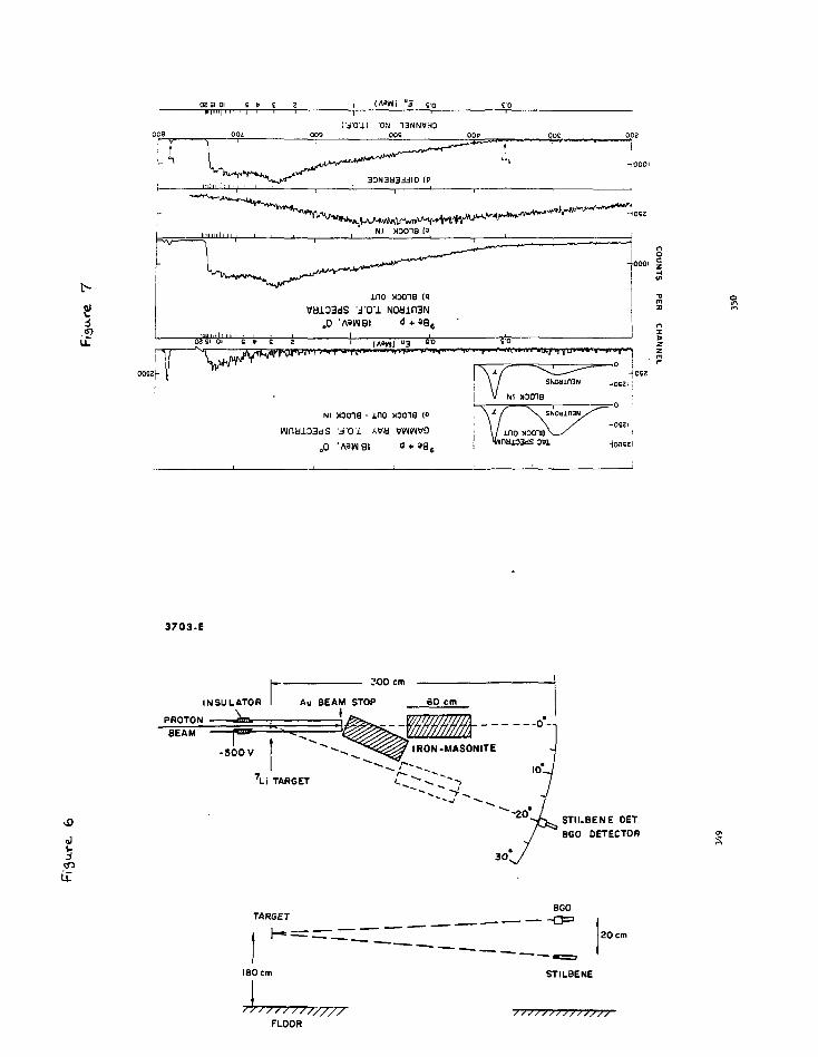
s
02 SI 01 S t> £ 2PIMM | I I I I | 1 T 1 -
"3 to
( jTOJ.) 'ON 13NNWHD009 OPS goe
OOSZ|-
ino >ooieV«103dS J-OU N0Min3N
O0 'A»W8I <) + S9
3703-E
300 cm
J
INSULATOR
'Li TARGET
STIUBENE OETBGO DETECTOR
TARGETBGO
20 cm
180 cm STILBENE
FLOOR

01 V
A.
001•
\ . 'u
, .
002 00£
3N391I1S r.
li
ro* |I
97. 09a
II OX I
V
\ t
» 001 OS 02 0 1
A3W A9W3N3 N0din3N
Joos
0002
ooc
m
oi
m
"t- = d3
so0052
i
00
RATIO OF EFFICIENCIES TRIGGERS PER INCIDENT NEUTRON
p o o p — — — — o P p o P Pu f o * ( i i i i 0 f o * » 0 — ro w O :_ ro i*i
mH
O
mzmCD
( J
ro
0)
co
o
1 1 1 1 1 I 1 1
\o
zQ*~?t v
CDcno •
o
-
1 1 1 1 1 1 1 1
i i
"V
•
• CDCD
. O
ino3
i I I I
V
Ar\\
•
\
i
•
-
Q
ino3
i i i i
0 •
\ 2 S
V\ o 5
\ isr ii
c H
i|
I

COUNTS (arbitrary units)
O - MO - NO -
<3
COUNTS PER CHANNEL
mzmCD
CD<

9SC
LINEAR ATTENUATION COEFFICIENT [cm"1]
pbo
pb
mzpi3)o
A
o -
1 1 1 1 Kill
_
-
- 38
- o'I
i i I 11 nil
1 1 1 1 Mi l l 1
Mtotal
M
v S \ yitic J
X ft1 1 1 1 Hill 1
1 1 1 11 III
/
J
/ o
J "
\i i i inn
i i i 11 II II i
^ ^
oOl
_p
I i i i mi: I
_ • I _
00
w TT
T
MU
T
X ;
a ~
t> -_
m z• i
5SC
A9d3N3 NOdXfl3N01 8 9 b 2
~\ r
• ' '
r r
099
0omz
! HO
O
m
"i 1 \ 1 1 1 1 r 10 <
Ui
BJO
c
(fl)a>

STUDY OF THE PERFORMANCE CHARACTERISTICS OF A
HIGH RESOLUTION MULTI-DETECTOR ARRAY FOR GAMMA RAY SPECTROSCOPY*
J. X. SaladinUniversity of Pittsburgh
F. Avignone H Iand
R. S. MooreUniversity of South CarolinaC. Baktash and I. Y. Lee
Oak Ridge National Laboratory
Abstract
The performance characteristics of a multidetector array for the
investigation of high spin phenomena Is studied. The array consists of
6 high purity n type Ge-detectors each surrounded by a BGO anti-Compton
shield 14 BGO detectors which serve as a multiplicity and sum spectrometer.
The performance of the anti-Compton shielded detectors is studied by means
of Monte Carlo calculations. The characteristics of the sum and multi-
plicity spectrometer are predicted by means of iterative calculations.
357
-1-
In many frontier areas of nuclear physics, like for instance, the
physics of high spin states, one is confronted with the need for detection
systems which must meet new standards of performance. In the example
mentioned, the events to be explored are characterized by decay cascades
of large multiplicity, involving typically 30-40 gamma rays per event, and
to make matters worse, there are large numbers (perhaps hundreds) of
competing cascades which eventually feed down into a single path. This
is illustrated in F1g.l. A typical single spectrum from such an experi-
ment is shovm in Fig.Z. It Is clear that the intensity and the separation
between individual y-rays decreases rapidly with increasing energy.
In order to investigate such phenomena, one must resort to a variety
of experiments and strategies, which Include:
(a) Discrete line spectroscopy with detectors having both, high
resolution and a large peak-to-total ratio P/T (defined as the ratio of
the number of counts in the full energy peak to the total number of counts).
353

-2-
(b) Energy correlation spectroscopy In the continuum. Fig.3 shows
a typical example1 of a two-fold E ^ vs E 2 correlation). Even though
Individual gamna rays, due to their large density can no longer be resolved,
there are nevertheless distinct features In the correlation spectrum which
require high resolution detectors. Here a large P/T Is even more
Important than in singles spectra. A high purity germanium detector
typically has a P/T equal to .15 at an energy of about 1.5 MeV. Thus
1n a two-fold correlation experiment the ratio of the number of photo-
photo events to the total number of events Is equal to (P/T) = .02.
These kinds of considerations show that it 1s necessary to develop
new detector systems which are capable of high resolution and which at
the same time have a large P/T. At the present time these requirements
are best met by n-type high purity germanium detectors surrounded by
an anti-Compton shield made from Bismuth Germanste (Bi^GejO,,). Bismuth
Germante (BGO) is characterized by a density of 7.13 grams per cubic
centimeter, more than twice that of the conventionally used sodium
iodide. Its absorption coefficient is on the average about 2.2 times
that of Nal, permitting, therefore, a much more compact design for high
efficiency detectors. The light output from BGO crystals is typically
only about \Q% that of Hat, resulting, particularly at low energies, in
a poorer resolution (approximately 11% at 1.2 MeV); the decay constant
is -OOpsec (that of Nal Is *..23usec). The use of BGO for the anti-Compton
shields allows for a very compact design resulting in large solid angles
359
-3-
(approximately IX of 4ir). Fig.4 shows a proposed detector array consisting
of six anti-Compton shielded high-purity Germanium detectors. Thfe target
is furthermore surrounded by 14 BGO detectors in the shape of hexagonal
prisms in order to measure the multiplicity of events and to deduce the
total amount of gamma-ray energy released. The use of high-purity
n type Ge detectors Is Important, since the amount of inactive material
is minimized. The outer Ion implanted contact is only .3 microns thick
and the central region has been drilled out, leaving a contact only 300
microns thick. The geometry of the anti-Compton assemblies is dictated
by the fact that the Compton scattering cross section is forward peaked.
Forward scattered Y-rays also have the highest energy requiring more
material (BGO) for effective absorption.
The performance of the anti-Compton shielded Ge-detectors has been
investigated by means of Monte Carlo calculations using a code written
by F. Avignone. In this code, up to ten Compton scattering events are
considered, as well as pair production and events following it (no escape,
single, double escape, etc.). The fate of Ge-X-rays following photo
absorption is also followed. The total amount of energy deposited in the
Ge-detector is calculated and smeared out according to a specified de-
tector resolution. For gamma-rays escaping the Germanium crystal the
likelihood of absorption In the BGO anti-Compton shield Is determined
considering up to 5 scattering events and the energy deposited is cal-
culated. If this energy exceeds a certain level (50 keV in the calculations
shown "below) the corresponding event in the Ge-detector Is rejected as
360
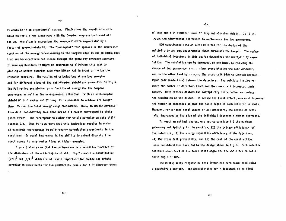
-4-
it would be 1n an experimental set-up. Fig.5 shows the result of a cal-
culation for 1.5 MeV gamma-rays with the Compton suppression turned off
and on. One clearly recognizes the average Compton suppression by a
factor of approximately 20. The "quasi-peak" that appears In the suppressed
spectrum at the energy corresponding to the Compton edge Is due to gamma-rays
that are backscattered and escape through the gamma ray entrance aperture.
In some applications it might be desirable to eliminate this peak by
placing an active absorber made from BGO or Hal In front or Inside the
entrance aperture. The results of calculations at various energies
and for different sizes of the anti-Compton shield are summarized In Fig.6.
The P/T ratios are plotted as a function of energy for the Compton
suppressed as well as the un-suppressed situation. With an anti-Compton
shield 6" in diameter and 8" long, it Is possible to achieve P/T larger
than .65 over the total energy range considered. Thus, in double correla-
tion data, considerably more than 42% of all counts correspond to photo-
photo events. The corresponding number for triple correlation data still
exceeds 27*. Thus It is evident that this technology results in order
of magnitude improvements in multi-energy correlation experiments in the
continuum. Of equal Importance is the ability to extend discrete line
spectroscopy to many weaker lines at higher energies.
Figure 6 also shows that the performance is a sensitive function of
the dimensions of the anti-Compton shield. Fig.7 shows the quantitative
(P/T)2 and (P/T)3 which are of crucial importance for double and triple
correlation experiments for two geometries, namely for a 6" diameter times
361
-5-
8" long and a 5" diameter times 6" long anti-Compton shield. It illus-
trates the significant difference in performance for two geometries.
BGO constitutes also an Ideal material for the design of the
multiplicity and sum spectroineter which surrounds the target. The number
of individual detectors In this device determines the multiplicity reso-
lution. The resolution can be improved, on one hand, by reducing the
chance of two gamma-rajr. fir,- r given event h'ttinq the same dstector,
and on the other hand bi .xSuzix-j tfie cross talk (due to Comp'cm scatter-
ing or pair production) between the detectors. The multiple hittinq re-
duces the number of detectors fired and the cross talk increases their
number. Both effects distort the multiplicity distribution and reduce
the resolution of the device. To reduce the first effect, one must increase
the number of detectors so that the solid angle of each detector is small.
However, for a fixed total volume of all detectors, the chance of cross
talk increases as the size of the Individual detector elements decreases.
To reach an optimal design, one has to consider (1) the maximum
gamma-ray multiplicity In the reaction, (2) the trigger efficiency of
the detectors, (3) the energy deposition efficiency of the detectors,
(4) the cross talk probability, and (5) the cost of the construction.
These considerations have led to the design shown in Fig.2. Each detector
subtends about 5.7% of the total solid angle and the whole device has a
solid angle of BOX.
The multiplicity response of this device has been calculated using
s recursive algorithm. The probabilities for K-detectors to be fired
362

-6-
(K-fold coincidence) in a multiplicity H event are plotted for several
H values in Fig.8. The multiplicity resolution (FWHH) of the distribution
ranges from 35* of M for M = 10 to 27* for H = 25.
The total energy response of the device has been calculated in a
similar way and illustrated in Fig.9. The total energy distribution is
shown for several H values. The FWHH of these distributions changes
from 40X of E at H = 5 to 20* of E at H • 25. A determination of the
true total energy from the measured energy 1s relatively straight-forward.
The resolution of the total energy detection is mainly dependent on the
total efficiency and the peak-to-total ratio of the detector and has
little dependence on the resolution of tha photo peak. Therefore, BGO
which has a peak-to-total ratio twicf that of Hal is a better total energy
detector.*Partially supported by National Science Foundation.
References
1. I.Y. Lee, C. Baktash, J.X. Saladin, to be published.
2. F. Avignone, III, Nuci. Instr. and Meth. \J±, (1980) 55.
363
Fig. I :
Fig. 2:
Fig. 3:
F1g. 4a:
Fig. 4b:
Figs. 5a
Fig. 6:
Fig. 7:
Fig. 8:
-7 -
Figure Captions
Schematic bandstructure In nuclei and possible decay ' iths.
Gamma ray spectrum resulting from the reaction 1MSm(26Mg,4n)176W
reaction at EQ » 117 HeV. The numbers beside the peaks
indicate the angular momentum of the state from which the
transition originates.
Energy-Energy correlation spectrum from the reaction
154Sm(26Hg,4n)176W reaction.
Horizontal section of a proposed gamma ray faci l i ty .
Vertical section of a proposed gamma ray faci l i ty .
and Sb: Unsuppressed and Comptor. suppressed spectrum predicted
by means of Monte Carlo calculations for a detector of the
design shown In Fig. 4.
P/T ratios for ar.ti-Coropton shields of various sizes as a funccion
of gamma ray energy.
(P/T)2 and (P/T)3 for two different anti-Compton geometries.
Fold coincidence probabilities for various multiplicities H
ranging from H = 5 to H = 30.
Fig. 4: Total energy response for events of varying multiplicity M.
364

Several HundredBands
Figure 1
(65
CD
cUJ
co
uX
LJ
IO59h
912 I-
765 h
618 h
471 h
324h
550 750Channel
950
Ftqur

125 1125
keV79
65
I51
38
24
10
p
10J-12
30 5 0Chonnel
70 90
Figure 3
36?
55
Swn«ptcli«nel(fMulilpllclly Flltat7 Hfiogonal PrlimfEach Top and Boltom
Figure 4s
368

-MultiplicityspectrometerSumspectromeier
Side
-I.25V- l"-j 2.5"-—|
Forward
iCfCOUNTS
•? • . i . . • . i r i i i i i 111r
8-UP.00
CDO"oo
g-.00100.
1.0
LlIsiP's2 -p£-
oo
O §oo
1J en
; sI a.I <
cppr
fl>o.
»**.
?*$&
* »
re<

O'£I
(A3IAI)
O'Z 01
09 ID JOJDUWUUDSJO 0 9 8
0
S'O
o-1•/d
>a>
» »
* t
* i I
1L
a>
a>Q.
a.
in- §
SINROO

m
373
oO
0.001
> 1
NdPt = 14 € = 0.057
0.01 -
4 8
Fold Coincidence12
Figure 837«

i 1 1 r
t Nde|=l4 €=0.057
0.1
noo
QL
0.01
0.001
P/T=0.6Ey= I MeV
30
X X X X0 8 16 24
Total Energy (MeV)
Figure 9
375
Fast Neutron-Capture Reactions With BCD Detectors
S. A. Wender
Los Alamos National Laboratory
Los Marios, NM 87545
Introduction
Previous Investigations of the giant resonance region in nuclei using
fast neutron capture have been performed using Van de Graaff accelerators
and large volume Hal detectors. The data on these reactions ace relat ively
sparse due mostly to low data rates. We are presently constructing and
test ing a detector system for fast neutron-capture experiments using a
white neutron source and an array of BCO detectors. This system would have
an advantage over previous techniques in being able to simultaneously
measure the excitation function and the angular distribution of the
reaction gamma rays.
The incident neutron-energy range of Interest for these experiments i s
from 1 to 20 MeV. The corresponding gamma-ray energy range Is froa
approximately 5 to 25 UeV. The requirements of the detector are that i t
have good energy resolution (5% for 10-MoV p,anna rays), good time
resolution ( 1 ns for 10-MeV gamma rays), hi^h eff iciency and lou
sens i t iv i ty to neutron backgrounds. In this paper I wi l l describe our
experiences with BCO with regard to their energy resolution, tino
resolution and efficiency for gaoma rays in tlie energy range fron 5 to 20
Jle\l. The previous speaker (Lone) has described the response of BCO to
neutrons, and tus shown that ECO is much less sensitive to neutrons than a
similarly eff ic ient flal detector.

-2-
Energy ^solution
Ui? have measured the energy resolution if a 7.6- by 7.A-cm unshielded
and uncolUnated BGO crystal coupled to a 9-cm-diam EMI 9531
photomultiplier tube (PMT) using Daw Corning Q-2 1067 optical coupling
grease. Figure I show* the pulse height spectrum of the 4.43-MeV gamma ray
from a Pu-Be radioactive source. The two peaks correspond to the full
energy and single escape radiation. The ratio of the single escape
Intensity to the total intensity is 0.36. If both peaks are fit to
gausslans, the full width at half aaxioua (FHHH) of the full energy peak is
6.5 X. Figure 2 shows the pulse height spectrum oE the 17.7-HeV gamma ray
from the l2C(t,f) rea.tion at an Incident tritium energy of 3.5 HeV. In
this case the escape radiation is not resolved from the full energy peak
and causes the low energy tailing seen la Fig. 2. If the entire peak is
fit to a gaussian line shape, the FHHM is approximately 5.5 I. Figure 3
shows a summary of the energy resolution data. The solid dots are for the
BGO crystal. In the energy range below 4 Mev, pair production is not
important, and the FWHM was obtained by fitting to a single gaussian. The
energy resolutions at 4.4 and 6.1 MeV, where the escape radiation is
resolved fron the full energy peak, were obtained by fitting to two
gausslnns. In those car.es the plotted results are the FWI1M of the full
energy peak. For the points with energies greater than 6.1 MeV, the
resolution is dominated by the unresolved escape radiation. In the energy
range belou b MeV the energy dependence oE the energy resolution decreases
approximately as the square root or the energy. The open circles are data
.for a slail.-,r HGO crystal with an anticoincidence shield to reject escape
radiation. For cnnp.irison the dashed line Is for a 25.4- by 25.4-c.7i-MaI
detector with an ant icolncldenci' shield.
377
-3-
Ticie Resolution
The time resolution of the BGO detectors M s miMsured by observing the
time structure of the Los Alamos Meson Physics Facility (LAMl'K) 800 HeV
proton beam. The LAflPF beam pulse consists of macropulses approximately
700 s wide with a repetition rate of 80 Hz. Each aiacropulse consists of
micropulses that are less than 300-psec wide and are separated by 5 ns.
Figure 4 shows the time spectrum tor various energy gamma rays obtained
using a 5.1-cm-dlaa and 7.6-cm-long BGO coupled to an RCA 8850 PUT.-* Figure
5 shows a similar time spectrum for a 7.6- by 7.6-cai BCO coupled to a
12.7-cm-dtara Hamaraac.su R-1250 PMT for gamma rays between 10 and 24 HeV.
Figure 6 shows a summary of results of the time resolution measurements on
both crystals. The time resolution of the 5.1-cm-dtam BGO decreases
approximately as the square root of the energy. The tine resolution of the
7.6-cm-diam crystal is independent of energy and is probably limited by
factors other than the inherent timing of the BGO crystal.
Absolute Efficiency
The absolute efficiency of an unshielded and uncollimated BCO was
measured at 15 MeV using the C(p, ) reaction4 with protons of around 14.2
MeV.' The pulse height spectrum of the 15.1-MoV g.inma ray Is shown in Fig.
7. Since the measured efficiency depends on the region of the peak that is
summed, we sunned the peak two ways. First, we fit the peak to a gaussian
3nd integrated the fit. Second, we summed the region shown tn Fig 7. The
yield as a function of incident neutron energy Is plotted in FIR 8. Using
tlu' Riven number of gamma rays/proton, prolintnary results give the
efficiency to be 40"i and 48 X for the two summing techniques.
378

Cosnlc Ray Response
An additional quality that ts important In hi^h-energy g.nrr.:M-ray worfe
Is the response of the crystal to cosnlc ray events. Figure? 9 shous the
pulse height spectrum of events tn a 7.6- by 7.6-cra BGO crystal at Los
Alanos (alt. 2200 m). The peak at approximately 60 MeV corresponds to the
energy loss of relatlvistic rauons in the BGO. The second plot uas obtained
by placing a 12.7- by 12.7- by 0.3-cm paddle on top of the BGO and
rejecting coincident events.
Preliminary Experimental Results
For inirii! tests of the system, the yield of the 4.43-NeV gamma ray
from the C(n,n') reaction was neasured. Figure 10 shows the gamma ray
yield of this state from threshold up to 45 MeV. These results agree well
with previously measured data on this reaction. We are presently acquiring
data on th? Ca(n, ) reaction In Che neutron energy range from 5 to 20
HeV.
379
References
1. D. H. Drake, Lief R. tlilsson, and J. Faucett, Mucl. Instr. and Meth.
188 (1981) 313.
2. H. R. Heller and N. R. Roberson, Trans. Nucl. Scl. 28_ (1981) 1268.
3. S. S. Wender, G. F. Michampaugh, and N. W. Hill, Nucl. Instr. and
Meth. 19]_ (1982) 591.
4. N. R. Roberson, S. A. Mender, and D. M. Drake, to be published.
5. R. E. Harrs, E. G. Adelbecger, K. A. Snover, and M. D. Cooper, Phys.
Rev. Letc. 35 (1982) 202.
380

- 6 -
Figure Captions
Fig. I. Pulse height spectrum of the 4.43-MeV gamma ray from a Pu-Be
radioactive source in a 7.6- by 7.6-cm BCD crystal. The FW1IH of the full
energy peak is 6.5 7..
Fig. 2. Pulse height spectrum of the 17.7-HeV gamma ray from the C(t, )
reaction, at £,.=• 3.5 MeV. The FHMH is 5.5 X.
Fig. 3. The energy resolution of a 7.6- by 7.6-cra unshielded and
uncolltmdted SCO detector is shorn by the solid dots. The open circles are
for a 7.6- by 7.6-co BGO with an anticoincidence shield to reject escape
radiation. The dashed line Is for a 25.4- by 25.4-cm No I detector ulth an
anticoincidence shield.
Fig. it. The cine spectrum of the LAMPF proron bean In a 5.1-cn-diam by
7.6-cn-long BGO ietector for ganma rays In the energy ranges a) 1.8 to 2.4
MeV; b) 3.0 to 6,0; and c) 15.0 to 24.0 MeV . The peaks are separated by 5
Fig. 5. Tiio ti™ spectrun of the LV.If proton bean In a 7.6- by 7.6-cn RCQ
for gamma rays between 10 and 25 MeV. The peaks are separated by 5 ns.
Fig. 6. Tine resolution as a function of ganrca-ray enerqy. The open
circle; ore for tin? 5.1-cn-dtna and 7.6-cn-long SCO. The closed circles
are for tit.; 7.Cj- by 7 j-cn BOO.
3S1
-7-
Fi^. 7. !*ulsr> height spectrum of the 15.1-MeV gamma ray from eht? ^C(p, >
reaction. Thi? region sunned is indicated by the bar .-ihove the peak.
Fig. ST. The thick target yield of the l2C(p, ) reaction as a function of
incident proton energy. The upper curve corresponds to summing the peak;
the lower curve corresponds to the gausslan Eit.
Fig. 9. The high-energy ganma-ray spectrum in a 7.6- by 7.6-cm BCO
crystal. The peak is at 60 MeV and corresponds to the energy loss of
relativistic muons. The Lower spectrum is obtained using a thin plastic
anticoincidence paddle on top of the BGO.
Fig. 10. The 90- degree yield curve for the 4.43-MeV gamma ray from Che'
*^C(n»n' ) reaction. The upper graph is the data to 45 MeV. The 1oui>r
graph is the lov-energy portion of the yield curve on an expanded scale.
382

Figure
6001
soo
400
300
zoo
- I I ' 1
Pu-8e Source
EY - i.U MeV
100 ISO '00 ZSO 300 360 <08 <S0 SOO SSO (00
383
20
01ISO
t» 3.5 HeV
17.7 KeV
3S0 «00 '•SO
384

PERCENT RESOLUTION
o ~~
COUNTS
8 8 8 0 g 8i i i i r ^ f i i i
! o V cr
\ 1 1 r
frn
m i {mlo
I i i i ( I ' l l I I I f I

COUNTS
T |
TIME RESOLUTION (NS)

00

1
<S~)
SINftOS

lippl.irahi.litv <-,f nco to rv->timmp '"•npna-r'"'' ripani'r
of I'enwv-ion "oactiop Products
D. J. Porrinse" and s . n. '-'ernig
national Puperconductinn Cvclotron Laboratory
and Penartnent of Chenistry
Michigan State University
Fast Lanninn, lil 4^074-1321
The study of continuun qanna-rays enitted di»rino hiavv—ions has nade erten&ive tis? o* laroe volume PaJ(Tl)
detectors. Those studies have contributed the huJV of theinformation currently available on the role n ' annular "ionentunin these reactions, and recently have indicate*1 an additionalconponent of relativ«>lv hinh eneny aann»-r;»ys (ar">roxinate!v 15fieV). The studies ha"o been hanpered hv th«* n e o s s i t yunfnlrtinn tho rosponur- function o* t><> ^ a I ( >the nnnnitivitv of t.be dntectors to nontronnnuclear roaction. nrJ0 dptnetor** offer tMc adraf5ponnt> function (noak to total ratio) an* a l<i"wr <M5iT>itiwitvto slow neutrenp. i'ow<»wer, PPO detectors aloo brinn thedi3a^vnnt»nes of pnoror renol'ition and poorer fcininn.Piscrinination aiainr.t neutrons nnnnonlv <"r>r>i.o"s time-of-f J inhttechninno" pn the tradeoff of tininrr anainpt. nnutron sens i t i v i tyif crucial. "one r«">nltr, of i n i t i a l comparisons o ' thescnBiti"ity e>* "nl'Tj) no* T O icti-trtorn to 'aft nnutrnns wi l l He
•'etcctorn an* i™^iirinn th**o f ^ better
393
in tho n««rnl'
* r v '-,",~r
oanna-ravp *="ittnd »v t>r reaction nrc'i^t';. T'V.O'-F- rpsjrt'ion''
croat^ nunloi vbich tvpical l" havo \fici fiov o f nyritntinn Annrnv
anr] 5" h of spin anrular ponentun. fl'jrh nuclei have nytrcneiu
hinh level donpities and thus follow a sini)<-rl" larop nvim i r of
dr-»-citation pathwavr- toward their ni-omid ot-.ato". •"IO oarlv
trannitionn arc unrn«o)«ablp hecause of thei>- ]»rw "nriet" and
ar<» duhhed continmiM oa^na-rays. Ruch onnnn-rnyr; nrr orod in
nuclear structure physics as tri<yers rnr ^inr-rpti? ) ip"
detectors, i.o.. aernaniu*^, \*hich follov^ t ir» nnclpi. thrnunh th/»
lattnr r,tat"?f of thr deexcitation cascade £11. Thnrr* are «owral
contri^utiops to thip conference dealing w*th nurh *i]tor or
trianor devices and I wil.7 not BP'Ja1: on that ?ubic»rt. Tr» wclenr
reaction nochaniuro (?tudies we ere inter^^t^d in thn hiohiv
exoit"'1 nuclei at the top of the cascade Wv-au.°e thnv should ho
KVJO to t o l l HE sopethinn a>>out how they sro i ro ' i i c ' ' . Thu'. '•">
ntrot wor!: with the continunp fampa-ray«i.
Tho letieral tochnin>ie requires the dot.rctinn <~»f a r^aotlon
product in coincidence i'ith the narma-ravc. T><ira aJlowp ur, to
sppr-i'v the rorctioi in tcrnn of variahiep liVo Irippt-ic cner^v
trflnf^T in'1 the product nurloar charoo o1*. 'InX> 5CT dofino t>i«
rcatt^rjnn piano. in a*r]<r rjvnprinentn th^ nnr^rr o^ coinoi<»pnt
narna-rr'"- var ror^r^e" in ^imnln ftrrnvr o c nnai I wnlimo O" y
?") TT^Tf1'3) ^tfnt.nrr T01- In pore recent r»in'*ri'1i'1ntp lnro-r»r
vo?npo MaI(T\) ootnet-or': (?>" y n") ha«e Hoon n'-o. to record t\*n
ntO «-.r ••\oi'-'ht nra vio!l n:\ *;ho nunltpr oF o?inrvi-i-,t>m r^T, Thi«?
394

allowed a o'ocnnvo'ution of the two najor oonoonrnt"*? in thn
nrvctrur>» a.? rcho'-'n in f\nv*rr> 1^. Oner t.Y"* rc*t.* t i pna i
trannitionf-, cenfr"'' n«ar f,5 I'eV, "ere separate'1 frr" th." o t w
statiptical trnn^itionr a nuch *w»tter fea^ur^'ipnt of t>o
fr3*T*ent.3' rplnp cnu] J h«» ohtnineo*. Alno v»ncJii]!='! thp t"*-»o tv"1****
of transition*-, h^vo ''iffprent nnltipolariti***; thp angular
/distribution?" o e the coitjiiuin "anna-ravs contain information an
the ovnr*ne orirntationr of the fraomenfc1*1 snin vertnrs. In
fimire lb the 'Hffprnno? between the mmbers uf rotational
transitions ohser"!1^ in-r>lane anrt ont-of-nlane can he pasi'v
seen.
Pocontly a thir^ oomprincnt in the continuum spectra cron
heavy-ion in^unnri reactions has been i^entifiefl at about 15 HPV.
These eventr have ho^n t-.pntatively i^ontifiefl ?n niant ^l
tranr.itionf Mhich r>ny yiel-1 infornation in tho sbancs o* thn
onittin" nuclei. T"o exa^plrp of '•xnerinentpl flata froni pnf-b
stU'Jipf: arc Cimii in <=ifiir«s ?» [51 anrt ?b Tfii. I'ith the
cxintoncp of n-ic transition" oit^bl ishefl, further wnrV. on thin
oubjpet "111 rpiuirn riotootori! tbat have eufficiont rrpo'm-.ion to
stu^y t^r-ta trPn"iUrn<! in ''"tail . Thp indorsation on tho «ihanP
of the enitt in" niiflnj j ^ nontiinc4 in the shar><> of thn n^nna-rair
diPtrihutiori sroi.n^ \c f.o\, ,-,n/i rPr,olvtinr> .ihoiil'' b» on »:>i<? nr^t
of ) rioV or bettor for ''o*inii-.iv<» 'rorh.
A na«nin" rroh] frn in t-Vie* ?+tirTir of nfw"prqte Gnrf"' continii'"-!
nariP.i-rr-">5! (^ Po,; rr\M ir t*n broari rr?"pon e fonotiop o* »^T(™1).
TOP ran nijir.r h~ir,ht siwctrn, inch ar tho«e rbovn in ci"i.ir<^" 1
i.r>coi-'iation r.in bn rxtrsrto'i. ii^ ir
395
"*iy biirnt'i ""risriat? Irro) detectors "->a« hrm.™ u j j ^ h l r . "inn-
h ir • oint-.r'' out. that t-.hr r»?i.itivo fr.T?tiop of iin".»-rjv ovnfn
that lie* in thn full enemy PP-TH ir. far larr^r c^r n n^o <-iot«?ctnr
than for a n'iT(Tl) ''otertor o* the sane 'Oluno T7T. -Tn** nrirep
one hap to pa" for th is ful1 e»ner<ry abrorot-irn rn"« in rprolntinn
anfl in t.ininf rbaract<»ri8ticR. The fact that tbp rp^oiution in
BOO ir poorpr than in na.T(Tl) i s reJnti'"»lv uni"-"<->rtant in
continuun st"^j.p<! whr>n oonpare'' to th» innriv^ fi'll on»fry
rfiaponfjft, eP^nciallv at hioher enernies. "n"pi>er, thn tj- inr?
r«sponsc of the PCO will be cri t ical in .-Ir-fer'-iii'-in" itp
usefulness in heavy-ion reaction ptu^ios.
Th^ inportancp of the timinn charantori ^ticn of th*>
qanp>a-ray Hetoctors in a heavy-ion rmrtinn in n.iov to
iin<'crstan''. Tho excited reaction products wil' nnit neutrons a"
well as nanma-ray**-, an^ the beat i**ethor" to dincrininntp .betv-tor»p
the neutrons •in'i the aanno-ray? relies on the ^if'crenf!O in thpj r
tines o* flinht (over a constant fl ight path). Jf tho noo
flotpctorr are as sensitive to neutrons an NnllTJ) detectors ani1
i f the tinin" properties of RGO are poorer, then loncir fl ioht
pathn wi l l bp require^. Tvpinnl tinino ro«nl»-.r "or « p.-<T(7l
detector are nhm-ip in fiai'r" 3. At tho bottom a calibration of
thp t-.in.ina with a r.f flonrce (alpha partic]" p) 11" ^r- Uo« i-P""-n)
ip nhovm. . tinp s'-'ortrnr- cor i> MiI(Tl) ir *nwn ip H>n nri""rirn
of w i i i r i ^ n t nnntronr an* thp intorPlfv bPt"c"n r"'!olotion sn-'
tirto-of-rlinht ir rO-vioup, T1**? tl^e nnortrnt- rf^taii'"1 ui th *\ Cr
^pt-ont.o"' in^'ir <-.ini>nr oirrnnfjtancpp in -ilrr c»rv.n for rofpro**co.
In tbir- r-,T-» thn nootronr am not rcw'vi^. Rt rrrsont nno
ripl/rtoT 1 in inbpti'pon thP lattej two nurvp--.
396

An we "nsv<? hfi-ar ?.t th i s conference the tinirir- n m n e r t i c i of
the P'.GO riatrriol are nort lv heyonn1 the control of thr* ^n^ u^or o c
tho cintectorf . Mowpvnv-, the optimisation of thp photnrm]tinlier
tube n=iyvio in the m a i n of contro l . Up t o the rrespnt. two
'liffprcnt PiiT'o have bpen user! with BOO, one optinir.efl for tinipn
(llananatr.n '••-3?'?-?), *>T-I •another optir-iKe'' for eorrcy rconlution
(Harifinatfn R-J316). This i s an unacceptable s i tuat ion sn>i WP arc
in the proci.-ir o 1 obtaining r.oo c r y s t a l s couple^ to Anoorox-?31?B
PI'.T'n "hich shnuXri provide both noon1 tinincr an^ noort enerny
resolut ion.
"a ho.v> just hoarri the resu l t s of sons neaBurenent" of the
neutron ronni t iv i ty of. BOO obtained at ChalV. River T83 vfliirh
sii'rfjefit thrt thore i . only a ninor difference between Mal(Tl) am1
COO. Thip i s consiEtent l/ith tha r e s u l t s wo obtained in a
sonnuhat pirpler ennnarir-on of fne two nater ia ln . A 7.6 y 7.fi tin
HGO detector integral ly mounted to a Hananatsu P.-13O7 PUT wan
obtained forn the I'arnhaw ChRPical Co. The eneray resolut ion nnrl
ronponna function o* the ' 'stector were ncaeurcc* bv car.cn-'e
ijanna-roy rnurces. Thir. tcchnifjue requires a coinciflonna hetvocn
a narrow rate in 3 ''ef.nctor 5or one of the cascade* rprma-rnys' .->n
any sipn&l fro^ t')o <»«tnctor bpinn caliHratnt'. This conoratos a
3pectnm fr,r ,i nnroonrr'Ttic source that i s 'rep £rotn KncVTounr".
The rosnJtr for tho cal ibrat ion of the pp-ik to tota l rorponnn of
th«; SCO onr" r 7.r- ;: 7.6 r- Hal(Tl) are rhoim in 'inurn In . Tl'r;
ful>-wi/)th .-it ••-!.! F-Misin'ii. ( r w ) of the two dfttectnrs nrc nlmwn
in finurr /"h. rio pif> 'Vtnctor can h 0 o,nnn ,.„ rontain -i
Tho hirhTt t:n-:r^y rt.ita point IMP. nnsnnroi with ,i "u-Pf; nourrn, n
397
nRiitron-<-anpp onit tor (neutron ^etf-etp^ ip "'•'-? 13 with rinlr"
shflnn <1iir:ripi»-*'.t^ on) . Tii ^ i f ^prnnc in ^nl i «ni"rr.v ph-iorp*: i on
tvtwr?on the tvo natnrialn i s qnitr f 'nn^t ir for thn ^.4 »<\ 7
n?riTPf\-reyr £orni th ir pourco as shown in finurr c .
''f11 turnn^ t^p ta*»lo nn th<* Pu-Po «onrr<? rnliSrnfr.jon in or^or
to obtain an ei*tirv>te of the reaponnp of t.hr •q»tcftnrn to 'ac t
neutron*;. If we ob^on'p a 4 .4 f'eV nariri&-r*v in t>> M^I'Tl^
detector thnre i«= a nnutron enitted irot.ropirrii i ^ in nrnr.pt
coincidence. For referpnc? the unnateH neutron Rrprtrnn frnn a
Pu-tle source i s shown in fiourp 6a [•»]. iiownvor, whop »r<> require
the 4 .4 I'eV oanra-ra« ( i . e . renuire n rpoc i f i c pyritat ion of the
C react ion product) only a l initef l ranne o* neutron oneroiPR ir
•"a i lab le . This i ? in^icatert schenat ical !v bw the hntche-' arsa
of f igure On. neutrons with eneroies in ti>° "nnf of 4 to 0 HeV
are exact ly the sor t that w i l l be created in hp.T'v-ionrc.iction--.
Thus the Pu-P-p snurce nivos us a rtirert chrc1: of thp rPlati^'f
s e n e i t i v l t v to neutrons o? the appropriate "nrmy.
Thp rpfsijif of t*>« neutron t e s t s are shown in f?.pui-o 7. The
pulse hcioht of the owent i s shown as a function of nrob^hil jt.y,
nnrns] ir.<?>' to the t o t a l nwiber o* neutrons o»n»ctp-' to ntrivp
each detector . Thp curves are ver« ^.inj^1" in P'I»P** nfr1
nar-nititi'^o, r.hn onlv lariri- 'lj.*ferenrp i s .it >«•»; i ivl i" hp.i"vt"
niirrr t'"* t'.-tf"" ) ir i ' m » r , If ''P irt"nr.-*f «-'>p -"»ctr^ "™r
pulno hPioht, th"p. «'p 'inr1 that tho probes i j j tv of =n »"nnt in
the I'ni("-H i" ".<!••' and in the P.CO i" n.l?., 'or thp wnc unit
volimp. ":iipsr ropults are nonnistont with t<>n r'Ti'lto that Lono
pt. ,-i1 . iurt n.pirtt"! [r<l. Ttius, v;p can not ignore th« <TPPPOP"P
t o in ostir'.->t.inn
398

character! <*t f cp nf any n w hna^'y-i.pn rp^rtion rirnr'nct
sport-rnri.-t.f»r nvstot-". Rather, •'<• i>hrmj«i t..->:o if to Ho t^p <-->i-n sp
that. o f l 'al(Tl) rtetcctor of the sane volime.
The conclnri-inr. fron onr stu^y of the app) icnhi1h.it" of RGO
t o heavy-ion continuum m m i - r s v rrsctrfscpny arc s inple an*
straightforward. The tininct "ronorties of the of f-the-sh^J. f
fletectorp are unacceptable. We neeii, f i r s t , to fin* a PMT that
can ont inize both the finer^y resolution nnr" fast ti^inn
character i s t i c s (a p o s s i b i l i t y i s the Hnrv>r<2r:-?312*<1. »P^,
sBcnra1, we nunt attn"int to »irina tbo ff»st tinjr." chirpcteripticr.
o»f nic) into tbp ran*iR of thoso o f larno i»olu»if» 'fat^TJ* ^r*prtnrR.
•lo liave foun'i that "OO i s nearly as sennit ivo to '«•=<•. ne«<*.rons as
'Jal(Tl) and so t i n e - o f - ' l i o h t ftenaraticn of ne'jtrnns *rc*
nanpa-rayr, v i l l »v noe^p^ in any device tbat T-°r<lannj= "-iI(TJ)
"ith PCO (o* tbe sane volume) • Hovfevcr» i f one rpoJooes ^Tal(Tl)
v/it-b PCO of t*io raie ston^in" po*'er thpn the ovornjl npntron
nepBitiwity " i l l he low«r.
This ••'or!-, was supported in nart bv the Motional RciRnco
Fo'in-iation unt'er r.rant Ho. PHY m-17firl5.
399
1. n. [1. Dianon'' F.
2-
An"l . Part.
Y. vanreferoncos therein.
"erf, Wucl. Inst . Ivth . 153
3- A- J- Pacheco, (1. J. "o7.niaV:, P. j . r'cnonsl'', I). ti.Diamond, C. C. Hsu, L. G. l loretto, D. J . Mnrrirspv, L. ".SobotkB, an'' F. S. Stephens, Mud. ph-rr.. A ( l o n 2 ) , in r>rr-s*.
4. J. 0 . Nelson, n. flornMinrt, P. f. Pianon'', P. L. Dines, J.F. Draper, K. !». Unrienberapr, C. rmuel;, n. Phib., anrt P. n.Stephens, ,Phys. Rev. Let t . «6 (1991) 13R3.
5. J . K. Draper, J. 0. fe^ton, L. O. r,oKotv.a, I1. LlnrtpnhPrnRr,r.. j , ' iio?niai!, r,. r.. Moretto, r. r.. itnnbonp, S. M.Diaron^, an*1 R. J. Mcnonajfl, obvi . "oV. Lett . 4"
6. 0. H. Donell , C. Fel^nyn, anH r. A. "nover, I'nj.v.Wanbinfton Annl. Popt. (1°G?(, n.3n, unpuhi.ishci.
7. A. <=:. Fvans, J r . , TWr. Trans. »'unl. "r> .
<!. f. A. Lone, contirhiition P-l to t b i s ron'on . D. Slaunhtor an<* P. ntrout, 1'ncl . Inst . i
17?.
400

3r*. * i
r*i-»0
':•
•j*
rr
t tl j -73I *
O
In3
-,
.T
"?
r*
"A
i i
]5n5
H-
£
-a3
H-;»).-+
M-J
• . •
0
. .-i
j "
n»+3
Q
oM0
*J •
t l >
o :
2) "T 15 .
1
7
-J
H0
-3
|
:>•
I-H
j
03f th*
J
• t
J
01 Ji f
3
i
H-
Tronjt|ion$ per MeVo tj
r ^ T — —
Trarsitions Mr MeV
yi o o O
5 a s
.3 . - - *J
dN/dE,
T 3 3
I
" m12
O
—°s
" ' " I '
2
ItCM
b» /
< I;
fF•
1
Tm
n •
3.94
5
,l
as
(0
oo
Ol
I I
wMeV
a
roOi.23 V
n>
il ,
-
to
/
xw
(0
—'
• i . . . . I
Transitions /MeV-nuC'eus
5,
1 —

f I I
r.'iat note o'-it.aipo^ with arc alphn-fa-r'ft r o n r c -?n'"R!'O /n. ? Irr. snr rf^f<nrnnr^ 1h«? t.j.nin'* c iU'rr.rtcri '"i n t r i n s i c fio 'irt.'sf;t.r'r r.b*:^infi'i in-V'^o'i r-.t* •<! r.f; r.
o* an
1.03
100,MSUX-82-370
I'u.
m
BGONal
• • •
I . . . . I
K)2:,"("keV)
Cal ib ra t i on r s s u H : for 7.6 x 7.ft en rrro nnri n n l ( T l )flvtvctair.. In " a r t (a) t h e peeV-to-tot.f-1 ra t io" , (in " o r c - n t larc cc.iincroi?. t\n<* in rxart (^t) t!ie c i^ r^v r<;rol"t ion of tt***fu l l r.nrrry DCiiVr art' conpsro'-'!.

I t .
! Cc
.0
C *) Vt i c oc CJ X
•H t;
c cc
5
eflf C P.u
U 0
u .z

MSUX-B2-37I
2 3 4PULSE HEIGHT (MeV)
7. er.(,rtrd;ir;I{T.). TVtr ^t? iri«r> >«c»n nof't-lir-Oi'1 to thoof nci i trrnr, iim' thp POC curve 'ifir. hrfjn -sliiftfr'nf ? for c.'nrif•••
i " "f'r' ,v>r.ot.-'J "*J ^'ir
407
The use of BGO in state-of-the-art nuclear spectroscopy
R.H. Lieder
Institut fiir Kernphysik, Kernforschungsanlage Jiilich
Postfach 1913, 0-5170 Jiiiich, W. Germany
In the spectroscopy of discrete Y rays emitted after a nuclear reaction a
large improvement of the experimental technology has been achieved in the last
couple of years. The problems shall be discussed considering f ig . 1 where the
deexcitation mechanism of a compound nucleus is depicted ' . In a heavy-ion in-
duced reaction a considerable angular momentum and excitation energy is trans-
ferred to the nucleus. The nucleus deexcites by the evaporation of neutrons
until the excitation energy becomes smaller than the neutron binding energy.
Subsequently the nucleus decays by y-ray emission. A "rain" of high-energy Y
rays (statistical decay) brings the nucleus in a reyion of low temperature,
called the yrast region, and the nucleus deexcites then within many parallel
bands (collective decay) which eventually decay into the yrast band. Finally
all intensity flows through the low-spin yrast levels until the ground state
is reached.
To study the band structure of nuclei produced by heavy-ion induced reactions
and to establish their high-spin members i t is necessary to detect Y transitions
of small intensity. An efficient Y-Y coincidence spectrometer should have the
following features:
1. A large energy resolution
2. A large detection efficiency
3. A reduction of the y-ray background
4. A reduction of the n background
408

- 2 -
The best energy resolution is obtained by the use of Ga detectors. They have a
rather small detection efficiency, however, since they car, be produced only in
sizes of typically 50 mm diameter and 50 ran length. To obtain a large detection
efficiency i t is therefore necessary to use an array of several Ge detectors.
The number of two-parameter coincidence combinations is N(N-l) i f N is the num-
ber of Ge detectors in the array. The -y-ray background under the photo peaks
consists of the Cumpton background and of the quasicontinuous background of the
statistical decay. The Corapton background results from events for which a Com-
ton effect takes place in the Ge detector and the scattered v ray escapes. For
such events only part of the y energy is deposited in the detector. The Compton
background has a continuous energy distribution. The Compton events can be
suppressed using an anti-Compton shield (ACS). This is a large scintil lation
detector surrounding the Ge crystal measuring the escaping radiation. I f a y ray
is detected simultaneously in both detectors the event can be rejected using an
anti-coincidence circuit. The quasicontinuous background results from the sta-
tistical decay and is in true coincidence with the y rays of interest. I t can
be reduced i f an inclusive measurement is made, i . e . i f a i l y rays of a decay
chain are detected. For such a measurement a 4n-scintillation detector ( f i l t e r )
subdivided in many small detectors is necessary. In this way the total energy
(sum ensrgy) of the decay chain and the number of emitted y rays (multiplicity)
can be determined. The multiplicity is proportional to the angular momentum. By
setting yetes on these spectra a subset of levels in the E vs. I plane (cf.
f ig. 1) can be chosen and their decay can be studied selectively. The neutron
background results from the fact that their interaction cross section with y-ray
detectors is not negligible. Such events can be accounted for in Ge detectors by
the spectrum analysis. However in scintillation detectors as used for AC5's or
fi l ters a reparation of neutrons and y rays is only possible by time-of-flight
measurements. TJiis requires a sufficiently large distance between the detector
and the source of radiation. 409
- 3 -
Hitherto various attempts have been made to build a y-y coincidence spectro-
meter for which some of the above requirements were fu l f i l l ed . A multi-detector
array consisting of five Ge detectors each surrounded by an Nal ACS was set up
by the University of Liverpool - Niels Bohr Institute collaboration2'. A 4n
spectrometer consisting of a large number of Nal detectors was used in connection
with bare Ge detectors in Oak Ridge3' and Heidelberg'1'.
In order to optimize a y-y coincidence spectrometer, BGO is the appropriate
scinti l lator material since i t allows to reduce the size of the ACS and the f i l -
ter so that a reasonably large solid angle can be obtained for the Ge detectors.
We made a design study for a spectrometer consisting of a BGO f i l te r and 12 Ge
detectors surrounded by an BGO ACS each. The layout is shown in the figs. 2 and 3.
The BGO f i l ter has a diameter of 20 cm and consists of 38 hexagonal detectors of
38 mm width from face to face. The 12 Ge detectors surrounded by ACS's can have
a solid angle of n = 0.4B % each i f they are placed as close as possible. They
are arranged in two rings of six detectors. The ACS is of the asymmetric type.
In our study we have compared the features of symmetric and asymmetric ACS's.
The symmetric ACS has a cylindrial configuration as shown in f ig . 4 for a system
set up by the Miels Bohr Institute. The Ge detector is surrounded by a BGO ring
of 2 cm thickness. In front a Pb shield is placed so that the ACS is shielded
against direct radiation from the source. In f i g . 5 the unsuppressed and sup; ressed
y-ray spectra measured with this ACS ,for a Co source are shown. These data were
taken immediately after the delivery of the ACS when i t was not working satis-
factorily. Therefore, only a rather small Compton-suppression factor (CSF) of
% 2 was obtained. Nevertheless the characteristic features of a cylindrical ACS
can be seen, viz. that the CSF is small for low y-ray energies and at the Compton
edge. This is caused by the fact that backward and forward scattered y rays are
not suppressed since the ACS does not cover the front and back parts of the Ge
detector, respectively (cf. f i g . 4 ) . This disadvantage can be avoided in
410

- 4 -
an asymmetric geometry as shown in f ig . 6. The front face of the ACS has a square
shape. This is required by the rectangular cross section of the Ge detector in
the present arrangement in which the Y radiation enters from the side. A special
feature of this design is that the front part of the ACS conists of Nal. In this
way the detection probability for backward scattered Y rays, which have small
energies, may be enhanced since the light output of Nal is % 10 times larger than
that of BGO.
In order to optimize the design of the ACS with respect to the length and
width,character!zed by B and A, respectively*(cf. f i g . 6} Monte Carlo calculations
using the ESG code have been carried out by C. Michel at the GSI Darmstadt ' .
This program allows to specify the geometry of the ACS in detai l , taking into
account the Ge crystal, its dead layers and its aluminium cryostat, the Nal and
BGO parts of the ACS as well as a passive U shield in front of the detector
system. The Ge detector was assumed to have a efficiency of 30 % of a 3"x3" Nal
detector. First results of the calculations can be seen in figs. 7 and 8. In
Fig. 7 °Xo spectra obtained in calculation # I (A = 3 cm, 8 = 10 cm) are shown.
The unsuppressed and suppressed spectra are plotted in the left- and right-hand
portions, respectively. The ratio of these spectra corresponds to the Compton-
suppression factor CSF, the energy dependence of which is given in f ig . 8.
This figure contains also results of the calculations % 2 (A • 3 cm, B = 8 cm),
# 3 (A = 3 cm, B = 6 cm) and # 4 (A = 2 cm, B = 10 cm). In al l calculations CSF
is smallest at the Compton edge due to the fairly large entrance hole for the
Y radiation and largest at low energies indicating that forward-scattered
events are detected efficiently in the ACS. I t can be seen that a reduction of
the length of the ACS, characterized by B, causes a decrease of CSF only below
400 keV. CSF decreases over almost the entire energy range, however, i f the
width of the ACS, determined by A, is reduced. I t may be concluded, therefore,
that for Y-ray energies below % 1,5 MeV i t is more important to make the width
- 5 -
large enough than the length. The conclusion may be different for high energy
Y rays. More calculations are necessary to finalize the design.
Li t t le information about the neutron sensitivity of BGO exists in the l i t e -
rature. Lone ' reported in the present workshop about a detailed study of the
n sensitivity of BGO and Hal as function of n energy. We measured the n sensi-
t ivi ty of BGO as well . Our aim was not as ambitious, however, as 'hat of Lone
et a ! . . The purpose of our study was to measure the n sensitivity for a n spec-
trum characteristic for a charged particle induced reaction. We bombarded a
181Ta target with 90 MeV a particles. The n sensitivity of a 3"x3" BGO detector
was investigated relative to that of a 3"x3" Hal detector. Time spectra have
been measured with respect to the beam burst in forward (33°) and backward (130°)
directions. The angles are measured'relative to the beam direction. The detectors
were placed at a distance of 50 cm from the target. The results of the experiment
are shown in f ig . 9. The time spectra taken in forward direction (ful l circles in
f ig. 9) show two peaks. The peak at t - 0 is due to the Y rays. The peak at
t S; 9 ns results front the neutrons which travel more slowly and arrive later at
the detector. The n peak vanishes almost at backward angles (open circles in
f ig. 9) since the n are emitted predominantly in forward direction. The dif fe-
rence between both spectra (open squares in f i g . 9) represents the net time
spectra of the neutrons. An integration of the respective peaks for the BGO and
Nal detectors indicate that the n sensitivity is about the same for both materials
for the given energy spectrum of neutrons. Considering that BGO detectors are by
a factor of % 8 smaller than Nal detectors of same efficiency i t can be conclu-
ded that the use of BGO allows to reduce the n background, as well.
In conclusion i t can be stated that the use of BGO in the construction of a
Y-Y coincidence spectrometer allows for a considerable step forward in experi-
mental technology. Considering the requirements discussed in the beginning,
significant improvements in a!) demands are possible with respect to the existing
equipment. 4 1 2

- 6 -
I want to acknowledge the large contribution of H.H. J'ager to the technical
design of the y-y coincidence spectrometer. I am especially grateful to C. Michel
who carried out the Monte Carlo calculations. ! would like to express my grati-
tude to A. Neskakis, G. Sietten and T. Venkova for the excellent collaboration
during the experiments. Furthermore 1 want to thank P. von Brentano, H. Hubel,
K.H. Maier and P. Twin for many fruitful discussions on this subject.
References
1) O.L. Hi l l is , et a l . , Nucl. Phys. A325 (1979) 216
2) P. Nolan, contribution to this workshop
3) M. Jaaskelainen et a l . , Proc. 1982 INS International Synposiur on Dynamicsof Nuclear Collective Motion, At the Foot of Mt. Fuji (19?:), ed. by K.Ogawa and K. Tanabe (Inst. of Nuclear Study, Tokyo, ia82) p. 51
4) R.S. Simon et a l . , ib id. , p. 35
5) C. Michel et al., preprint, Darmstadt, 1982
6) 0. Hausser, M.A. Lone, T.K. Alexander, S.A. Kushnerink and J. Gascon, pre-print, Chalk River, 1982
413
- 7 -
Figure captions
Fig. 1: Statistical-model predictions for the dee<citation of the compound
system Er formed at an excitation energy of 53.8 MeV with an ' "W
beam of 147 MeV incident on Sn. The population of ^ E r is given as
a function of angular momentum in the top portion of the figure. The
calculated population distributions are indicated for the system after
the emission of 1 to 5 neutrons. The hatched areas represent the re-
gions in which y-ray emission competes. Their intensity profiles with
respect to excitation energy and angular momentum are indicated, res-
pectively, to the left side and at the bottom of the figure. Taken from
ref. 1.
Fig. 2: Top view of a y-y coincidence spectrometer consisting of a sum-energy
and y-multiplicity f i l t e r (BGO Filter) and an array of Ge detectors
surrounded by anti-Compton shields (ACS) each.
Fig. 3: Side view of the y-y coincidence spectrometer. The target is labelled
by T. The other labels have the same meaning as in f i g . 2.
Fig. 4: Symmetric anti-Compton spectrometer of the Niels Bohr Institute (NBI),
Copenhagen. The anti-Compton shield (ACS) consists of a cylinder made
of BGO.
Fig. 5: Unsuppressed and suppressed Co spectra measured with the anti-Comp-
ton shield of the Niels Bohr Institute.
Fig. 6: Design of an anti-Compton spectrometer of asymmetric type.
Fig. 7: Monte-Carlo calculation of unsuppressed and suppressed 60Co spectra for
the anti-Cow con spectrometer shown in f ig . 6. The calculation was
carried out by C. Michel.
414

- 8 -
Fig. 8: Compton-suppression factor as function of energy for Co as obtained
in Monte-Carlo calculations for the anti-Compton spectrometer shown
in f i g . 6. Its length and width, determined by B and A, respectively,
have been varied.
Fig. 9: Results of a neutron-sensitivity measurement as represented by time
spectra taken with Nal and BGO detectors, respectively, at angles of
33° and 130° with respect to the beam direction. The difference spectra
(open squares) represent the net time spectra of the neutrons.
D. L. HILLIS el ai.
STATISTICAL MODEL CALCULATIONS
Input AngularMomentum
124Sn(40A r /xn)166 'xErE(Ar) = U7 MeVE* =53.8 MeV
416

L OSIRIS
BCOFilter
• OSIRIS
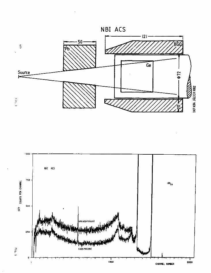
NBI ACS
NBl ACS
soo -
aso -
60,to
CHANNEL NUMBER2000

ANTI COMPTON SHIELD
A=30B=100
i
- OSIRIS Isu
Monte-Carlo calculation for asymmetric ACS (A = 3 cm, B = 10 cm)
Simulation of Co source
1
unsuppressed suppressed
ie'ooCHANNELS

20
:|5
CO
o
10
CALCULATION FOR 60Co
CQIC. A (cm) B(cm)
1 3 102 3 83 3 6
2 10
0.2 0.4 a6 0.8ENERGY (MeV)
1.0 L2
181-
100
g
33'3x3 Hal deh
130"neutrons 5.6 ns
3x3 B60 det
6.9 ns
5
20 20TIME (ns)

UNIVERSITY OF LIVERPOOL
Total Energy Suppression Shield Array (TESSA]
Introduction
Tha Total Entrgy Suppression Shield Array has developed over the
past two years from tha highly successful array mounted at N.B.I., Risd,
Denmark by the Liverpool/NBI collaboration. It la plannad to have two
versions of TESSA operational over tha Initial period of operation of
tha NSF. These versions hava been tanned TESSA 1 and TESSA 2. The
aim of this document is to briefly describe the layout and -facilities
available in both versions.
2. TESSA 1
TESSA 1 is the system at present operational at N.B.I.. Rise". It
consists of:-
(a) Four Nal suppression shields and a tunistan alloy central colllmator
mounted in a vertical plane through the beam line. '
(b) Germanium detectors can b* mounted in each suppression shield. Th«
centre of aach detector is 20 cm from the target and Its collimatcd
solid angle is 0.3 4. The detector angles are •52i°. 21421°.
2.1 fifth Suppression Shield
A fifth suppression shield and associated Germaniun dstector can be
installed. This shield i s the spacial Oaresbury shield and i t gives
poorer suppression than the 4 standard systems. The detector angle i»
90°. again at a distance of 20 cm from the target.
2.2 14 Oetector BGO Array
The 14 detector BGO array can be installed instead of the fifth
suppression shield. It consists of 14 hexagonal Bismuth Germanate CBGOJ
. 2 .
crystal assemblies placed inside the tungsten collimator. The crystals
subtend approximately equal solid angles at the target and they have been
operated at a total event rate in excess of 200 K. The BGO system has
an efficiency of 0.6 for detection of a Y~ray energy of D.9 MeV with a
peak to total ratio of 0.9 at a resolution of 20'.. In -the standard
experimantal set-up analogue signals of both sum energy and fold (tha
number of detectors contributing to the sum energy)are available.
2.3 Plunger
A second target"chembsr is available which incorporates a plunger
for recoil distance lifetime measurements. The plunger -fits into the
tungsten collimator an" It is designed for minimal absorption of frays
at the standard Germanium detector angles of «52J° and 1421°. which
correspond to holes in ths tungsten collimator. It Is possible to umm
one half of the BGO array as an additional sum energy or multiplicity
filter, or install the fifth suppression shield.
2.4 Gas Counter •
A third target chamber has'been built so that the t«ss counter can
be used in conjunction with the standard array. It Is possible to us*
either half of the BGO array or install the fifth suppression shield.
3. TESSA 2
TESSA 2 consists of:
a) Six Nal suppression shields mounted in a vertical plane through the
Beam line,
bl Germanium detectors can be mounted in each suppression shield. The
centre of each dstector 1* 27 em from the target end subtends a
coUimated (set section (d)) solid angle of 0.154. The detector

. 3 . 5 A/C Array
engles are ^30°, ^90°, ^150°.
c) A Nal backscatter detector is mounted on the y - rey entry port of
the U.K. suppression shields. This is an addit ional suppression
detector to reduce the contribution from baeKscoftered y-reys to
the Compton background.
d) A 8G0 active collimator is mounted in front of thei backscatter
detector. Structurally i t is part of the BGO " b a l l ' . This i s
the third veto detector far the germanium detector I n the shield-
I t eliminates 9 lot of the Comptan scattering from collimators
being recorded as f u l l energy peak signals In the germanium
detector.
e] A BGO 'bal l * surrounds the target. Over EO BGO crysta ls of hexa-
gonal cross-section era incorporated In this system t o produce an
effective SO detector sum energy and mult ip l ic i ty device. In the
standard experimental set-up analogue signals of sum energy end
fold w i l l be available, together with a 64 b i t r e g i s t e r incorporat-
Ing details of which detectors contributed to ths sum energy, plus
the fold and other user defined information.
TESSA 2 is expected to yield Improved peak to t o t a l ra t ios for t h e
germanium detectors in the suppression shields, approaching 70% for 6OCo
compered with SO* in TESSA 1 . The consequent Increase I n the proportion
of peak-peak events in y-y experiments is from 25% to SO*.
TESSA 2 w i l l enable y-y experiments to be performed which include
meaningful selection of both sum energy K25% overall resolution) end'
fold ( 30% overall resolution).
TESSA 2 wi l l enable the determination of the spin direct ion of the
T-ray emitting f inal nucleus for high multipl icity events.
427
N a l suppression shield
Plan
Filth suppression shield
Figure 1 TESSA 1 : schemitic showing the fifth crystal in the plan view
428

naniutn:ctor
Figure 2. Scheinatic of TESSA 2 Onl_y
Z of the 6 suppression shields are .s.hovin.,
A side view of a vertical plane through
the beam axis.
•t>»ir
BGO Active
collimator
Nal Suppression Shield
Nal backscatterdetector
Figure 3. Enlargement of part of BGO 'ball
and one suppression shield showing positions
of planes perpendicular to original vertical plane
AZ9 430

BGO CrystalsNal Crystals
re 4. section through crystals shown ,„ figure 3 on the 30°
Figure 5.- Section through crystals shown in figure 3 on the ID0 plane.

UNFOLDING BISMUTH-GERMAN ATE PULSE-HEIGHT DISTRIBUTIONSTO DETERMINE GAMMA-RAY FLUX SPECTRA AND DOSE RATES
C. E. Moss, M. E. llamm, A. E. Evans, M. C. Lucas,E. R. Shunk, and E. J. Dowdy,
Los Alamos National LaboratoryLos Alamos, New Mexico 87545 USA
ABSTRACT
We describe our procedure for obtaining gamma-rayflux spectra and dose rates at multiple space pointsfrom gamma-ray pulse-height distributions acquired withbismuth-germanate detectors. Our system consists of aLeCroy 3500 data acquisition and analysis system andeight bismuth-germanate scintillation detectors 7.62 cmin diameter and 7.62 cm long. We calibrated andcharacterized the system from 0.12 to 8.29 MeV usinggamma-ray spectra from a variety of radioactivesources and from the 14N(p,Y)15O reaction produced ina Van de Graalf target. By fitting these pulse-heightdistributions with a function containing 17 parameters,we determined theoretical response functions and usedthem to obtain the gamma-ray flux spectra at multiplespace points from a variety of radioactive objects ofinterest to nuclear safeguards. We used two flux-spectrum-to-dose-rate conversion curves to obtain doserates. For a composite source, consisting of severalsources with accurately known strengths, the result ofour procedure agreed with the expected value to withinless than 10%. Direct use of measured spectra and theflux-spectrum-to-dose-rate curves to obtain dose ratesavoids the errors that can arise because of spectrumdependence in simple gamma-ray dosimeter instruments.
433
INTRODUCTION
Bismuth-germanate (BGO) scintiliators are replacing Nal(TH) scintiliators
in many applications for several reasons. The photopeak efficiency of BGO
scintiliators is larger than that of Nal(Tfc); thus, measurements can be
performed faster with a BGO scintillator than with a Nal(Tti) scintillator of
similar size. A comparison of a pulse height distribution from a BGO
scintillator, 38 mm in diameter by 38 mm long, with a pulse height distribution
from a Nal(TJ) scintillator of similar size1 shows that the photofraction from
BGO is larger (Fig. 1). Because of their larger photofmction, the gamma-ray
pulse-height distributions resulting from BGO scintillators are easier to
analyze. Three other advantages of BUO are that it is mechanically and
chemically more stable than NoI(Tt) and is highly insensitive to low-energy
neutrons.2
The A (vanced Nuclear Technology Group of the Los Alamos National
Laboratory chose BOO for its system to measure gamma-ray spectra from
containers of radioactive material that are of interest io nuclear safeguards.
This paper describes how we unfold these pulse height distributions to
determine gamma-ray flux spectra and dose rates.
434

Hardware
Our system consists of an array of eight BGO seiritillators that are used
in acquiring pulse-height distributions (Fig. 2) and a LeCroy 3500 data
acquisition system that analyzes the data (Fig. 3). By means of a disposable
grid taped to the floor, we can position the eight detectors relative to the
radioactive material placed at the middle of the grid and perform
simultaneous measurements of pulse height distributions- The LeCroy 3S00 is
equipped with a CRT display and light pen, dual-drive floppy disk unit, printer,
plotter, and CAMAC crate for data acquisition. All system equipment is
designed for measurements in the field and is packaged for easy shipment.
Calibration t qd Analysis
We calibrated the system from 0.12 to 8.29 MeV using 11 different
radioactive sources and the '*N(p,Y)l5O reaction produced in a Van de Grasff
target (Fig. 4). The detector resolutions at 662 keV ranged from 13.2% to
19.1% (Fig. 5). High resolution is not needed for our safeguards application.
The calibration extends above the energies available from iootopie sources
because some materials of interest emit 4,439-MeV gamma rays from the
reaction 9Be(a,n)12C. High-energy neutron-capture gamma rays are also often
present, but weak. The pliotopeak efficiency curve (Fig. 6) has been
calculated using a polynomial fit to the measured data. A pulse height
distribution from the "1N(p,Y)15O reaction Uken with a BUO scintillator
38 mm in diameter and 38 mm long (Fig. 7) is an example of the response ol
BGO to an 8.29-MeV gamma ray.1
(.35
To determine the detector response as a function of energy, we fitted an
analytical curve containing 17 parameters to pulse-height distributions from
some of the sources using a generalized least-squares program called LSMFT3
on a Control Data Corporation 7600 computer. As indicated in Fig. a, the
photopeak, first and second escape peaks, and the backsoatter peak were
approximated by energy-dependent Qaussians. The Compton distribution was
approximated by an energy-dependent Gaussian plus a term of the form
1 - exp(-x *). We were not able to fit simultaneously all the source pulse
height distributions we measured because of limited computer memory.
Figures 9 and 10 show fits to the s'Mn and the "°Y pulse height distributions,
respectively. Mangnnese-54 only emits 835-keV gamma rnys; >aY emits 898-,
1836-, and 2734-keV gamma rays.
We determined the flux pulse height distribution by using a stripping
procedure. Starting with the highest channel in the pulse height distribution,
we assumed that all of the counts in that channel were in a photopeak. The
energy for that channel could be determined from the energy calibration curve
for the pulse height distribution. Using the photopeak efficiency curve and
the experiment live-time, we calculated the corresponding flux in
photons/cmVs at the photopeak energy. We also calculated the tail
corresponding to this photopeak and subtracted it from all the lower channels
in the pulse height distribution. Next we considered the second highest
channel in the pulse height distribution and assumed thnt all of the counts in
thnt chnnnel were in a photopeak because the tail from the highest channel
had been subtracted. The procedure wns repeated until the lnwest chnnnel
wns reached.

We tested our procedure with a pulse height distribution from several
calibration sources. Figure 11 shows a linear plot of this pulse height
distribution and Fig. 12 shows a ssmilog plot of the same pulse height
distribution. Figure 13 shows the corresponding flux spectrum obtained with
our procedure. We converted this flux spectrum to a dose-rate spectrum using
the ANSI flux-to-dose-rate curve (Fig. 14).* Figure 14 also shows a curve,
recently adoptee! by the Lawrence Liverraore National Laboratory, based on
the work of Dimbylow and Francis at Harwell-5 Figure It- shows the dose-rate
spectrum for the calibration sources. The integral of this spectrum agrees
with the dose rate calculated from the Mnovun source strengths to within 10%.
The variation of the analytical response function with energy is shown in
Figs. 16-26. At 100 keV only a single peak can be seen. At 300 keV the
backscatter peak begins to separate from the photopeak. The Compton
distribution is clearly visible at S0O keV. The escape peaks are visible at
20G0 keV and continue to grow with energy.
A pulse height distribution from a sample containing uranium and
Plutonium is shown in Fig. 27. Note the 2615-keV line from the " 'Tt
contaminant, the 1001-keV line from 2 " m Pa that is a daughter of "*U, and
the 414-keV line from 2S9Pu. Figure 28 shows the corresponding flux spectrum
and Fig. 29 shows ihe corresponding dose-rate spectrum.
A pulse height distribution from a sample containing uranium, plutonium,
and beryllium is shown in Fig. 30. Alpha particles incident on the beryllium
produced 4439-keV gamma rays in the reaction 9Be(a,n'!ifC. Figure 31 shows
the corresponding flux spectrum and Fig. 32 shows the corresponding dose-rate
spectrum.
•53?
CONCLUSIONS
Our method for parameterizing 8GO response functions makes BUO
detectors useful in many applications- The resulting analytical functions can
be used to analyze BGO pulse height distributions as well as to perform
theoretical studies of proposed systems containing BGO detectors. As the
resolution of BGO detectors continues tp improve and the cost of BGO
continues to drop, we expect the use of BGO detectors to increase. The need
for good response functions will then be even more important than it is now.
ACKNOWLEDGMENTS
R. A. Pederson assisted in acquiring some of the data, E. T. Jurney made
many helpful suggestions regarding the response functions and the analysis
procedures, and E. Tisinger assisted with the data analysis.
438
REFERENCES
1. A. E. Evans, "Gamma-Hay Response of a 38-mm Bismuth GermanateScintillator," IEEE Transactions on Nuclear Science (1) NS-27 (Februe-y1980).
2. O. Hausser, M. A. Lone, T. K. Alexander, J. Gascon, and E. Hagberg, "A4it Bismuth Germanate (BGO) Detector Array for Heavy ion Physics: Andthe Prompt Response of BGO to Fast Neutrons," Proceedings of theInternational Workshop of Bismuth Germanate, Princeton University,Princeton, New Jersey, November 10-13, 1982, to be published.
3. J. H. Trussell, "Generalized Least Squares Package LSMFT," ComputingInformation Center, Los Alamos Program Library Write-Up G7AA (1979).
4. American Nuclear Society Standards Committee Working Group,"American National Standard Neutron and Gamma-Hay Flux-To-Dose-Rate Factors," American Nuclear Society publication ANSI/ANS-6.1.1(1977).
5. P. J. Dimbylow and T. M. Francis, "A Calculation of the PhotonDepth-Dose Distributions in the 1CRU Sphere for a Broad Parallel Beam,A Point Source, and An Isotrople Field," National Radiological ProtectionBoard, Harwell, England (November 1979).
439
FIGURE CAPTIONS
1. Pulse-height distributions from 38-mm by 38-mni BGO and NallTj)scintillators for gamma radiation from 2*N a .
2. Array of eight BGO scintiUators, 7.62 cm in diameter and 7.62 cm long,supported on tripods around a drum that contains radioactive material.The disposable grid taped to the floor is used for positioning thedetectors.
3. LeCroy 3500 data acquisition system and NIMBIN electronics.
4. Radioactive sources used to calibrate the system.
5. Resolutions of the BGO detectors.
6. Photopeak efficiency of a BGO scintiU&tor, 7.62 cm in diameter and7.62 cm long. The curve is a polynomial fit to the data.
7. Response of a BGO scintillator, 38 mm in diameter and 38 mm long, togamma rays from the 1.058-MeV resonance of the " IN(P,Y) 1 5O reaction.
8. Components of the response function.
9. Fit of the analytical response function (curve) to the measuredgamma-ray pulse height distribution (points) from s\vln.
10. Fit of the analytical response function (curve) to the measuredgamma-ray pulse height distribution (points) from "Y.
11. Linear plot of a pulse height distribution from the calibration sources"Mn, "Co, "Y, *>Hg, "*Th,distribution was used to test our stripping procedure.
2Na. This pulse height
12. Semilog plot of the same pulse height distributionthe calibration sources 5"Mn, "Co, MY, "'Hg, «"Na.
shown in Fie"Th, '"Ba,^
11 from7Cs, and
13. Flux spectrum resulting from the application of our stripping procedureto the test pulse height distribution shown in Figs. 11 and 12.
14. Gamma-ray flux-to-dose-rate curves. The American National StandardsInstitute curve* was used in this peper to convert flux spectra todose-rate spectra. The curve labeled LLNL was recently adopted by theLawrence Livermore National Laboratory and is based on some work atHarwell.*
15. Dose-rate spectrum resulting from applying the ANSI flux-to-dose-rateprocedure to the flux spectrum shown in Fig. 13.
440

16. Calculated response function for a 100-keV gamma ray.
17. Calculated response function for a 300-keV gamma ray.
18. Calculated response function for a 500-keV gamma ray.
19. Calculated response function for a 700-keV gamma ray.
20. Calculated response function for a 1000-keV gamma ray.
21. Calculated response function for a 1500-keV gamma ray.
22. Calculated response function for a 2000-keV gamma ray.
23. Calculated response function for a 2500-keV gamma ray.
24. Calculated response function for a 3000-keV gamma ray.
25. Calculated response function for a 4000-keV gamma ray.
26. Calculated response function for a 5000-keV gamma ray.
2?. Pulse height distribution from a sample containing uranium and plutonium.
28. Flux spectrum resulting from the application of our stripping procedureto the pulse height distribution shown in Fig. 27.
29. Dose-rate spectrum resulting from the application of the ANSI flux-to-dose-rate procedure to the flux spectrum shown in Fig. 28.
30. Pulse height distribution from a sample containing uranium, plutonium,and beryllium.
31. Flux spectrum resulting from the application of our stripping procedureto the pulse height distribution shown in Fig. 30.
32. Dose-rate spectrum resulting from applying the ANSI flux-to-dose-rateprocedure to the flux spectrum shown in Fig. 31.
! 1 1 1 1 r
(a) B60 38 mm x 38 mm
24Na
2.754 MeV
n k I I I I I I Io 50 100 150
I15
10
1.369 MeV(b) No! (TO 38mm x 38mm
24.
2.754 MeV
J I I »
44 J
50 106 150 200Channel Number
250 300
442

r;
, • . • i " - * • ;

CALIBRATION SOURCES
NUCLIDE OR REACTION GAMMA-RAY ENERGIES (keV)
5 4 Mn 8356OCo 1173, 13338 8 Y 898, 1836, 2734
2 0 3 Hg 2792 0 8 Tl 2615, others1 3 3 Ba 276. 3C3, 356, 38413?Cs 662
2 2Na 611, 127524 Na 1369, 27545 7 Co 122, 136
9 Be(a ,n ) 1 2 C 443914N(p,y) 1 5 0 8284. 5241. 3043
RESOLUTIONS OF BGO DETECTORS
PERCENT RESOLUTIONID
AT 662 keV
N1 13.2
N2 15.4
1 18.6
2 19.1
3 16.4
4 14.6
5 16.0
6 16.3
7 , 15.28 15.5

y 4 0 -u.hi
1000 2000 3000 4000
GAMMA-RAY ENERGY (keV)
5000
101 I 1 I I I I I I i I I I I I I I I I I I
yN{p,y)l50
3.04(8.28 — 5.24)
8.28-0
j i I I I I I I 1 1 1 I I I I I I i I20 40 60 80 100 120 140 160 180 200 220
Channel Number
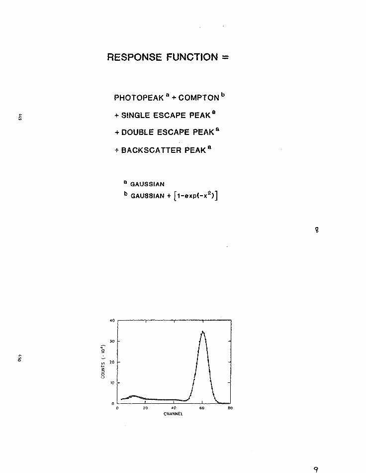
RESPONSE FUNCTION =
PHOTOPEAK a + COMPTON b
+ SINGLE ESCAPE PEAKa
+ DOUBLE ESCAPE PEAK a
+BACKSCATTER PEAK8
a GAUSSIANb GAUSSIAN + [i-exp(-x2)]

100 ISO
CHANNEL
200 250
to
500 1000 1500 2000 2500 3000
ENERGY (keV)
U

PHOTONS/cm2/s/BIN
CSV
COUNTS/BIN

mrem/h/BIN
O
o
>
I5,
mzmo
CONVERSION FACTOR(mrem/h) / (photons/cm2/s)
T £»i—i "i i i pro

O
X
IO
CO
UN
T
25
20
15
10
5
n
1
I
I
-
-
-
-
-
1000 2000 3000 4000
ENERGY (keV)
5000 6000
ife,
1000 2000 3000 4000
ENERGY ( k e V )
5000 6000
n

1000 2000 3000 4000ENERGY (keV)
5000 6000
1000 2000 3000 4000
ENERGY (keV)5000 6000
.'9

100
1000 2000 3000 4000
ENERGY (keV)5000 6000
•LO
60
40
20
n
i I i i i
-
-
-
i i i i
0 1000 2000 3000 4000
ENERGY (keV)5000 6000

oX
oo
ou
60
40
20
n
1 I
1_
AjI i
i
i
I
-
-
-
i
0 1000 2000 3000 4000 5000 6000
ENERGY (keV)
3-2-
1000 2000 3000 4000ENERGY (keV)
5000 6000

1000 2000 3000 4000
ENERGY (keV)
5000 6000
1000 2000 3000 4000
ENERGY (keV)
5000 6000

o
X
GO
t—r>oo
1000 2000 3000 4000
. ENERGY (keV)5000 6000
500 1000 1500 2000 2500 3000ENERGY (keV)
27

1000 2000ENERGY (keV)
3000
1000 2000ENERGY (keV)
3000

0 1000 2000 3000 4000 5000ENERGY (keV)
1000 2000 3000 4000ENERGY (keV)
5000

OOOS OOOfr OOOf 0 0 0 3 0001

Session H
NUCLEAR MEDICINE APPLICATIONS
475
T n z | \ L C P Y ' - T A L n i z r . r F e n ur.E I ' i pnr .TTU••• :
Clnude Hnhmias,
Unclear ".?dioinp,
r.->ction of Rr"l tolo.",y ,
'icM. stor Univrrsity,
'!TIi 1 ton , Ontnrio.
476

I 'JIviL rPYIT.'.L " p '.'••!; I N ! F'1T'-O.TO.M T " 1 " !?." I"! V
1 . \n'. roiuvt.ion
P o s i t r o n n n i s s i o : i -tome. ; raphy , a p rocedu re t h a t combines t h->
use o f s p e c i f i c -no! " e u l r»s 1 ^ p U e d w i t h p o s i t r o n p q i t t e r r . m l
computerize"! to ' io >r,ip!iic. t echn iques , i s r a p i d l y ".ainine, acceptance
ns n proven -nethoi Tor the d i r e c t r e g i o n a l neasurc ! ! i?nt o f b l o o d
f l ow T.I : I •nct.-ibol i o r o t e s i n t h e i n t a c t human body M l . These
measurements - i houH a l l o w an i n c r e a s e ! u n d e r s t a n d i n g o f many
processes occu r r i ng i n the human body in h e a l t h and d i sease .
Jdv.-msi 'S i n litsstor t e c h n o l o g y h a v e r e s u l t e d i n nn
i n c r e a s i n g v.-. r i o t y o f s c i n t i l l a t o r s [ ~ 1 and t h e r e l a t i v e
• s u i t a b i l i t y of t v ' . ; s " l e t e c t o r s f o r p o s i t r o n e m i s s i o n tomography
should lio e i - i l i i . i t» ! i n an " f f o r t to i m p r o v e i m a g i n g s y s t e m s
fun : : .mon ta l l y . i n ^ i f t.'ie requ i rements i s f o r the bes t a t t a i n a b l e
spati .- i l r e s o l u t i o n . Tho b r a i n , f o r e x a m p l e , i s a h e t e r o g e n e o u s
ori.jn i n w'ii •'• t h " .-)nn!.onionl s i r e o f most s t r u c t u r e s va r i es from
,-i few o - i ' t o •• rc.i Mn . Another impor tan t f a c t o r i s s r j n s i t i v i t . y .
Because, in '."n"r--i l , the f r n ^ t i o n o f t h e dose o f r a d i o a c t i v i t y
thn t rcn""i ;-s *.,<:•; t i r - - . - ; t or:',,n and i s rpt=<ine,1 i s S ! n a \ l , t in* V)"SV
^ t t i i n i b ] ^ I; i L •'.' • L :. j n " f f i - j i e n o y i s nlso a r e q u i r e m e n t .
?. i>-l !- •',._- .n- l - r i i l
TI-. Tir-M " ' ' i . , - , , - . t j '.j - ;ii ic i s th.nt o f so int. i 1 \ it->r . ' I f t h "
t h r " •> s : i n l i 1 1 i . j r . ; :'ir r T I 11 y b" in" , usod i n p o s i t r o n o"i i -, r. i > I
tono : r ; ip i i y , ' L-. •.!!!.'. " - r ' i : , i - i t > < " T ^ l i s to tor p r n f r r r - i t o •',o'1 i i i-i
Jo Mi in ( " i I ' T M ' --r , ->s iu i i 7 1 » o r i ' l o (r.;f>, r i i !i •, - i...,,,
477
i i v 'i n t. i ; r -. : 1 1\ .s -i I, o p p i n r D o w o r , o r 1 i •; . r- ;% t 1 ^ n t, : *. i n n
co.- ' f f i " i c t i t , t r.n.^ ' :«v i s To re t h a n t w i c e t.h i t i f " i ' . ' i o r " i T ( T l ^
or ' ' ;F ( T ; i b l , - t ) , a l l o w i n g f o r i n c r c a s p d d " t " - t : -y\ r f f i M r n o y ; i ^
i s a l s o n - j n r i y . » r o s c o p i c a n l t h e r e f o r . " 1 ' )"- , n o t ri -• -? i t o he
?ne.- ips ' j l j t e o i n .in »\irniniun c a n , l u r i c e a l l . i w i : v a 'u : " .hor p : i c k i n »
f r a c t i o n .
Th'.- one d i s a d v a n t a g e o f POO i s t h a t i t j l i - ' . h t d " = ny t i m e i s
r e l a t i v e l y l o n . i . T h i s l i m i t s t h e t i m i n g r e s o l u t i o n . T t t s i n n b l n
w i t h p.-nrs o f d e t e c t o r s o p e r a t i n g i n c o i n o H ^ n ^ r ( T n b l s 1 ) . i n
t h a t r e s p e c t , CsF , w i t h i t s much s h o r t e r decay t i m e , a l l o w s f o r •>
n a r r o w e r c o i n c i d e n c e t i m i n g w i n d o w . T h i s n a r r o w eo i ne i f | r n : - »
t i m i n " , window w o u l d d e c r e a s e t h e n u m b e r o f " - - n j o -n e o i nc i - l o n c s
a c c e p t e d . The r ? j e n t i o n o f random c o i n o i d e n e . e s h o c o i i ^ s i " i p o r t n n t
o n l y i n v e r y h i ^ h c o u n t r a t e a p p l i c a t i o n s . F o r e x a ' i p l o , i n o u r
' " F f l u o r o d e o x y B l u c o s r s t u d i e s o f t h e b r a i n , t ' i « i o s e . ^ i v n t o tDe
p a t i e n t i s 1 t o 1 mCi and t h e random c o i n c i - ] e n e - - s c o n t r i b u t e l * s s
t h n n 17 t o t h e t o t a l number o f e v e n t s r e c o r d e d . Tn t h ? m a j o r i t y
o f , : p p l i c a ( . i o n s , t h e r e s t r i c t i o n s i m p o s e d by t h e r . ' i i . - i t i o n t h - i t
can be .^ iven t o p a t i e n t s o r t h e t i m e t a k e n f o r o h - ^ m i c i l s y n t h e s i s
l i m i t t h » n u i b e r o f p h o t o n s n v a i l r b l e so t h i t nax i-num d n t c e t i o n
r f f i r i o n c y i * -nuch m o r e i m p o r t a n t t h . i n r e ' i . i n - n c o i nc i ' I en;">
r e j e c t i o n . V u j t h e r p o s s i b l e u s e o f r s F i s t i - r - n f f i t " . l i t
to 'no. ' . rnphy ' '• 1 . ' l o w - v e r , *. lm f a s t e s t c o i n - ' v l ' i ' ' 1 M" i \n ' 1 , p i i s i M ' '
w i t h pi- ' •icnt. ( i y -1 e ? t - o n i c - ; i n s t i l l n o t r-,-.t - ^ D I I T ' I h t i p r . i v o
.-,uh'-.1 v i ' i '1 i y i n:. v i l l r " - o 1 u t i on . T v , ™ r o n r " , p u r e l y f r o i i
!• i r i ' t i m • r r i ' i o n o v p o i n t ->r v i e w , " i n i •-. t ' i -> s M n t i l H I o - . i f

c h o i c e f o r most p'loLon l i m i t e d a p p l i c a t i o n s us i s t h e ense i n
s t u d i e s of the b r i i n : in i -nost s t u d i o s o f the h e a r t .
1 . Detector s ize
Tn or ler t o Ip t er-ain e the i i o s t s u i t a b l e d e t e c t o r s i i " , w?
acquire.) n M o d : of T v i , - cm u i d e , "" cii hie,1! an:! •> cm I o n " , , We
c u t i t seqii»n'_ i . - i l l y i n t o s i i n l l e r nnd s a a l l e r p i t c s u 5 i n» r\
r o t a t i n g iinvoni v' leel i n n Vrrosene atmosphere. We i /ere ab le t o
denonst rn to t i n t ^r"'" 'noro coun ts were r e c o r d e d w i t h a S en lonp,
c r y s t a l .es o o n i p ^ r r i t o ,•> ' en l o n g c r y s t a l , k e e p i n g t h p o t h e r
dimensions const-nnl. f'11 (T. ' fbl f ,?) . These r e s u l t s were o b t a i n e d
w i t h a bron.1 sourco i f ' F c o l l i m a t e d down t o t h e d i m e n s i o n s o f
the exposed nrys l .n l f ice .
Pecans? s p n t i a l r e s o l u t i o n i s u l t i m a t e l y governed by t h e
w i r t t h o f U i c i n - l i v i d I I 3 l d e t e c t o r s , we s t u d i e d t h e e n e r g y
r e s o l u t i o n , t h? phatop^ak f r n c t i o n and the r e l H t i v i ? e f f i c i e n c y o f
BGO c r y s t a l s i f / M f f " r : * n t d imens ions . M though enprgy r e s o l u t i o n
I M S n.'iint-.inr? I in s r y s t . i l s ns smal l as 0.5 cm wide and ? en h i f . h ,
photopen1 : " T f i f i o n - y " n d p h o t o p e a k f r a c t i o n was r p d l ined i n
c r y s t a l s i - r r a T T t •: m i.". -i-n f T ^ b l c 1 ) . We c o n c l u d p d t h a t
c r y s l ' i l s \r, n l m v . •• •• 1 . " i-n : J T » p r a c t i c a l s i n c e they • x h i h i t e d
no loss of ^ >l.' *t ioti • f f i - ; i « n n y nnd t h a t c r y s t a l s TS narrow "is n.r>
c-n were i | i o s ' ' i ! i i ' i t v n v n t h o u g h t h e y TI i " , h t n x h i b l t - n
apprec i n b l " 1 j s r . in i"f!>:: ' . ion - f f i c i e n c y .
' I . ' I S T I ' J
Tn e f'irt". r-r- . L !. '- i j '{. f.o inor^nse "Jetoot lon ' f f i o i ^ n ^ y v;i I.'I-IM',
nppr-.-f i il>l •> I-- T •> I-:' ion .if . i ; v i t n l r e s o l u t i o n , w> s t u l i " ! t h " n - - t
479
f o r h i ; 1 ! " s~pV.-. p i " " 1 b - ' t u ' s n n d j a c - n t ^ r y s t . i l s . Th«r," - i r?
u s u - 1 l y u s " ! t o l i n i i i J c e r o s s t a l i : nnd -;o i -nprovr- s p n t i . i l
r e s o l u t i o n . " he= " i n s e r t s aro used in a l l to-no.' r -iphr. exeept t h e
Donnor l.nb ? n c r y s t a l tomo^.r . i ph . The a rs . i o c c u p i o d by i n s e r t s
can be s u b s t a n t i a l . For examp le , i t r e p r » s » i l s ?-?-„ o f t he n r»n
a v a i l n b l o f o r d e t e c t o r s i n t h e S c a n d i t r o n i « r io .1" l PC 5 i i | - 7 r
Tomograph. Our r e s u l t s i n d i c a t e t h a t t h e r e w.-s l i t t l e dop,r;i'.lation
i n s p a t i a l r e s o l u t i o n lot t h e o r d e r o f I T . f o r t h e FWffM) when
i n s e r t s were o m i t t e d from between 0 . ^ cm wide nGn c r y s t a l s f i , ^ ! .
A l l o f these r e s u l t s were l p t c r co r robo ra ted Sy Deronzo us in" ,
Monte C a r l o s i m u l a t i o n s \T\.
S. The McMaster p o s i t r o n emiss ion tomograph
Rased on t h i s s e r i e s o f e x p e r i m e n t s , u" h " » des igned and
b u i l t a p o s i t r o n emiss ion to-no^raph w i t h which to s tudy the b r a i n .
Tt comprises 1 'in nGri d e t e c t o r s c l o s e l y pack1? I on i r i n 1 , , r ) ^ . r . en
i n d i a m e t T . A d j a c e n t c r y s t a l s a re n o t s e p a r a t e d hy h i c .h 7.
i n s e r t s . "nch c r y s t i l i s t r a p e z o i d a l i n shape, 1 em w i d o , ' . ^ cm
h i ijh an.1 i l . r> om l o n ^ , and o n l y coa ted w i t h r e f l e c t i v e p n i n t ,
proviJin-?, for ;\ t y p i c a l s e p a r a t i o n between n rys - f . l s o f ').""> .urn an I
hence n p . ' ek in ; f r a c t i o n o f 9ri". Each c r y s t a 1 i s l i r e c t l y coupled
t o a 1.."1? en pl iotomul i t i p l i c r t u b e . An annul. . r co l 1 i " i ; i tT r , ° "* <vn
T . P . , r>? m o . n . , j r, p i noc l between the fnen ••> f ' h • ? r y s t . . ' l s -in.!
t.ho f^ 'c ien tVs ' i e ' ' 1 . TMis ""^ ei) opening - i l lows ' h n m ^ i ' v i t f 5 h^.M
to b" " i . . i -it :>in"1 e Tnf o r t nhl y i t n v a r i e t y or • , n ' l 1 - T I '. pr.>vi-1os
" 'ion : h ' > 1 t f •! 11 i i n !. o r i' I uc •-> t h ~ n i n ' ^ ' r i f a " c i d " n I. i 1
e i i n- i 1 ft1 -• >s . ' . " i " T p ^^V'.ieen the two no 1 1 i i.i *" c" " i s ^ en, T h "
A80
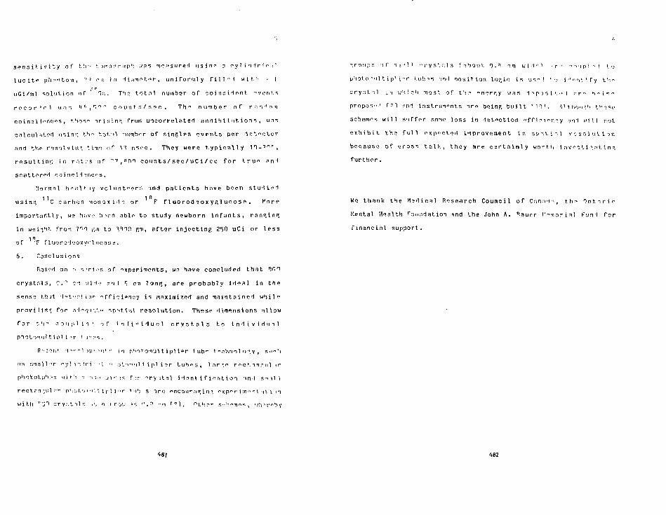
s ^ n s i t i ' / i t y o f l ! i - f. o rc r j . " r i p M ; i a s " i ^ . t s u r e c l u s i n ^ D o y H i H r i c : ! 1
l u c i t » p h . ' n t o n , "• ~> en i n 1 i f i - n e t ^ r , u n i f o r m l y f i l l ' M w i t . ' i ' !
- p
uGi/ tnl s o l u t i o n o f T; i . T'lr: t o t n l number o f o o i n c i ^ n t -"vents
r f c o r ! H w ; n II ft , r, " i c o u n t s / s e c . The n u m b e r o f r I T 1 n n
c o i n ^ i lences, t . ' ios" i r l s i n * from u n c o r r e l n t e d a n n i h i l a t i o n s , i n s
c n l c u l iitert us in 1 ; t ' i " t o t - i l : i i imbT o f s i n g l e s " v e n t s per d e t e c t o r
nnd t h r r i s i l ' j l u - " , t ii\e o f 1 nsoo . They were t y p i c a l l y n - ° T ,
r e s u l t i n g , i n r . i t r s o f 77,1101 e o u n t s / s e c / u C i / c c f o r t r u e n n i
sca t tn re ' t co i no i 1 ^ncs .
! !o ' ' ! in l h";:!1* ly v c l u n t " o r r . i n d p a t i e n t s have boen s t u d i n d
us in?, C s a r h o n -nonox idn or F f l u o r o d i ? o x y g l u o o s < » . Ko rc
i m p o r t a n t l y , we ^IHVI;' b^rn oblo to s tudy newborn i n f a n t s , ranp,in.(5
i n w e i i ^ t f r o n 7r>0 i;.n to Vn!1 Rf, a f t e r i n j e c t i n g 260 uCi or I P S S
1 o f F f luoro- iooxyr . lncoss .
6 . Conclusions
P.nsM or\ .-• " . T i o s of " xper iT ien ts , w? hav<? concluded t h a t RfiO
c r y s t f i l s , 0."1 oo '.li-i? ? T I S CTI l on< ; , are p r o b a b l y i d e a l i n the
sense fchJt I'- 't-.Tlion r> f f i ^ ip r iny i s maximized and u a i n t a i n o d w h i l e
prnvi lief. Cor a1«'\<MV- ';p->t.\nl r e s o l u t i o n . These dimensions n l low
f o r t 'i •" o ?, u p 1 i -i • •> f i n t i " i <J u n 1 c r y s t a l s t o I n 1 t v i ri i n 1
photTnul t i pi i T t J ' I : 'S .
R^^n*. 1 ^ " 1 5|r-. ••<]* •- in ph i * onul t i p l if»r t u b ^ t" chnol o-", y , su^' i
ns :vnn\ 1 '"r ^ y 1 i i ir i -: 11 -> ' O ' . T ^ I I 1 \ pi i ?r t ub*> 3 , 1 nr :e r < c t -inr,n 1 i r
phototu'i.'-s w j t ! i -, ••!-.•• , i i f ; s r->r - r y i t n l i den t i f i e . i t i on m i s - i - i l l
rect?n.M;l ••r p'i ^ t.-j • • 11'.. i ]• 1 i '• r ' •'': s i r o encour a» i n ', " x p " r i :r. -> n I i\. i i n
w i t h r j T I r y.". 111:; .!. i . r r o i : i», ».? -n ' ' 1 . ^LV.pr r. •? h«-n««••, ' i h T " h v
481
-rcv.ips o f s n-'M. - : ryr . ! . : : ls C r ^ o u t 0. ' I ". m w i I •• i • r •• : T I P 1 - I t ,
p!ioto-"nl t ip1 i - r t u b ' s i i ' l p o s i t i o n l o c i c i s u->" ! ' •.< i ' ' " i ^ i r y th->
o r y G t : l L :i w ' l ie ' i most, o f th.^ "nerr .y was d -> p -> -, i '. " I :• r " h - i n n
propos- i l r n i nnd ins t ru-n^nts nr» being b u i l t ' I I 1 , M t .nouV f ? s < -
schemes w i l l s u f f p r sono loss i n d e t e c t i o n e f f i i ' i ^ p . ^ y .-jnd w i l l not
e x h i b i t the? f u l l e x p e c t e d i t i p rovemen t i n s p ' i t i i l f . - s o l u t i o n
because o f c r o s s t a l k , t h e y are c e r t a i n l y w o r t h i nvf j t i " , . ->t . i n " ,
f u r t h e r .
We t h a n k the M e d i c a l Research C o u n c i l o f C a n n d i , t h " O n t i r i o
Mental Hea l th f o u n d a t i o n and the John A. n.auer r-"«or i , - ) l Fun l f o r
f i n a n c i a l suppor t .
482

Table- 1
sicr . i p r o p e r t i e s of ! l a T ( T ^ , C s F , nrvt
LinoarAttenuationroefficient:it. "500 >(eV
Coincident.Timin",
ResolutionDensity
r.ointil latlon
CsF ' I . ' ' •I n ;c 'n"
m " 1
m"1
1.OT. em"
!n risen ?-\ nsec
ri nsec .S nsec
10 nsec ri-pi nsec
483
' • :rf :-cts or r o i u c i n - ; t i l1* Ipn j t th o f P r , i c r y . ' . ' . i l u'i i 1 .-> i - i i n t - u n l n »" t .h " i~xpos?1 T i c ^ o n s t n n t .
Crystal L^n^t.ticm
r->nits inTtop--*:!1' (
1 x
x 3
0.3 x 2
m
7r>
0177
(,ii Counts in window 360-700 keVcounts recorded tn longest erystTl .
percent!)?:? of

• P h i t o p i ' '< i T f i i i - n - v , i< l io top<--n ' i< T r a c t i o n a n d o n c r i ' . y r e s o l u t i o n o f
n m !<••! . 'v-i o r " , i f " • t i o u r . s i z e s .
1
„
CrD i n
. 0 X
. 1 x
. '"t X
.r. X
y:st a•Tision
t X T
I X 1
-> x i
Puot.opp.ikrffloien=y
(..1
i.nn
0.06
i.°fi
0.?)
PhotopeakFraction
(b)
n.73'1
0.691
0.6'^
r, ico
Rpsolutlon(c)
?!.*
25.1
3?.1
70.0.
(:)) Count:', of face expressed as a percentas*> of area ofl.ir-",«'.l. fn"".(h> FncVion or counts In window 50-irm0 kpV that f a l l inwin- low • " • " - 7 m •<•>'.'.
185
M l " . F . S - ' i c l o , B r a n R e s e a r c h P ^ v i ^ i : 1 i i " n i n .
i 0 1 . I . 1 ' , S . i n - i r r s an-'l f!. H . S p y r o u , , M u - l , I n s i r . i n I " n t h .
I " 1 ! n . M l e i i M n d , C . O r e s s e t a n d J . V i c ' v - r , I . M u » i . M o d . 5 1
( 1 < ) 0 T ) 1 5 3 .
I ' l l C . M a n n i T S , D . B . K e n y o n a n d E . S . r ; n r n - t t , TF.PR T r r n s . » u n l .
? . c i . H S - ? 7 ( 1 0 S O ) - S 2 9 .
[ 0 1 C . H a h m i a s , D . n . K . e n y o n , E . S fiarn^tt. m l K. K o u r l s , i » r o c .
T A E A / K I I O T n t . S y m p . o n H e d i c n l P - I i o n u c l i t ? t n i ^ H i n j ,
l l e i d e l b e r r ; , j g 1 ! " , I A E A , V i e n n a ( l ^ M .
[<<) C . N a h m i a s , D , B . K e n y a n a n d E . S . r i . - i r n o t t , f ^ T F T r m s . ' l u c l .
S c i . H S - 2 9 (1<)?!2) 5 « 8 .
f 1 S . i : . D e r o n z o , I E E E T r a n s . H u c l . T o i . M r 1 - ? 0 M ^ n 1 ? 1 .
f l " . F . t l e r o n z o , T . F . 1 u < 1 i n E e r a n H T . V n l c v i c h , ' f r i : T r a n s .
M u o l . S c i . S S - 3 T ( 1 9 3 3 ) , i n p r e s s .
[ 0 1 A . R . D i c o l , E . . I . H o f f m a n , V.F.. P h e \ p s , r .C. M t n n r , , r>. P i u m m e r
•in-1 I!. C - . > - s o n , I E E E T r a n s . H u e I . R c l . ' I ^ - ^ O ( 1 1 ° ? ) >>'••'>.
\'\Q'\ r . f l . n u r n h . T n , J . R r a d s h a w , 0 . K q<i r-n->n, n . C h ^ f r - irH n . L .
n r o w n ? n , TTER T r n n s . N u e l . F o i . " c - . . i » r i ( I " 1 " ! , i n pr«>>5S.
486

Proceedings of the Sixth InternationalConference on Positron Annihilation,Fort Worth, Texas, April 3-7, 1982North-Holland Publishing Company
DYNAMIC POSITRON EMISSION TOMOGRAPHY IN MANUSING SHALL BISMUTH GERMANATE CRYSTALS*
S.E. Derenzo, T.F. Budinger, R.H. Huesman, and J.L. Cahoon
Lawrence Berkeley Laboratory and Conner LaboratoryUniversity of California, Berkeley CA 94720, U.S.A.
Primary considerations For the design of positron emission tomographs for medicalstudies in humans are the need for high imaging sensitivity, whole organ coverage,good spatial resolution, high maximum data rates, adequate spatial sampling with mini-mom mechanical motion, shielding against out of plane activity, pulse height discrimi-nation against scattered photons, and timing discrimination against accidental coinci-dences. We discuss the choice of detectors, sampling motion, shielding, and electron-ics to meet these objectives.
1. INTRODUCTION
For the past 50 years, since the pioneering workof Von Hevesy, the radioactive tracer techniquehas been used with considerable success in thebiological sciences to measure fundamental bio-chemical processes in plant: and an'mals. Inthis spirit Positron Emission T">mogr,;jhy (PET)is being vigorously developed become it appearsto be the best high resolution technique for thequantitative regional measurement of tracer com-pounds in the human body after a simpleinjectkn.
Table 1 lists a few of the positron labeled com-pounds that have been recently developed and thebiochemical processes upon which their biodis-tribution depends. We believe that many morewill be developed in the years to come so thatvirtually any metabolic process can be measurednon-invasively.
Z± HISTORY OF PET INSTRUMENTATION
Historically, positron emission tomography forthe three-dimensional imaging of positronlabeled compounds in the human body has evolvedthrough five stages (Figure I):
[1] Limited angle tomography using pairs ofAnger scintillation cameras,^"8 parallelplanes of scintillation crystals9"13 orwire chambers with converters I1** 2? (Figurela). Full angular coverage requiresrotation.
[2] A single circular array of closely packedscintillation '-rystals.'6"1'1' To obtain mul-tiple transverse sections axtal translationis required.
'This work was supported by the Office of Healthand Environmental Research of the U.S. Depart-ment of Energy under Contract No. 0E-ACO3-76SF00098 and also by the National Institutes ofHealth, National Heart, Lung, and Blood Insti-tute under grant No. P01 HL2584O-02.
TABLE 1. EXAMPLES OF POSITRON LABELED COMPOUNDSAND THE PROCESSES THAT THEY MEASURE
TRACER
Heart:
ionic 92Rb
M C palmitate
18F deoxyglucose
"C or I3N aminoacids
Brain:
150
llC bioamines
ionic 92Rb
l8F deoxyglucose
"C methionine
"C, 13N. or >3Fpsychoactivecompounds
PROCESS MEASURED
muscle perfusion
fatty acid oxidation
tissue demand for glucose
muscle regeneration andmetabolism
blood flow and oxygenutilization
blood flow and receptorsites
blood brain barrierbreakdown
tissue demand for glucose
blood brain barriertransport
receptor sites
[3] Hexagonal or octagonal arrays of scintilla-tion crystals that are both translated androtated for full linear, angular, and axialcoverage (Fig l c ) . * 3 " "
[4] Multiple layers of configurations [2] and[3] above (Figs Id and l e ) . 5 J " "
487

fully described in previous
dr<ov« Wirn0) • Plight I TO Ft
Figure j ^ Evolution of detector geometries forpositron emission tomography.
'5] Multiple circular arrays of fast scintilla-tion crystals coupled to moderately Urgehigh-speed ohotQiriul t ipl ier tubes for local-ization by differential time-of-flightmeasurement <Fiq If).6"1"'5
Fundamental considerations in positron emissiontomography for medical imaging show the advan-tages of high density scinti llators ove' wirechambers and converters in terms of detectionefficiency, time resolution, sensitivity, andmaximum useful event rates.7* Contemporarydesigns and the trend for the near future arefocussed on tie multilayer approaches (FiguresLe and If) which provide the highest dose effi-ciency and useful event rates.
3± MEDICAL OBJECTIVES
We sumuriie below the primary requirements forthe quantitative imaging of Flow and metabolismusing positron emission tomography. These points
have been morepapers.".79
[1] The highest possible dose efficiency, whicnrequires both a large solid angle and highdetection efficiency. Time-of-f1ight infor-mation can substantially reduce the numberof events needed for a given statisticalaccuracy (especially for large emissionregions).
[2] A resolution of S m FWHH or better, capa-ble of quantitative measurements of regions10 MI in size. The requirement far dynamic,gated imaging means that this resolutionmust is* achieved with little or no mechani-cal sampling motion.
[3] The ability to measure the arterial Inputfunction of the tracer to the organ beingimaged and to follow its subsequent accumu-lation and clearance. This requires theability to collect sufficient dita in typi-cally 10 second time frames and permitsvery little sampling motion.77.7'
[4] A sufficient number of transverse sectionsto cover the volume of interest which isusually more than 5 cm axially.
[5] Discrimination against background events byshielding, an<t by timing and pulse heightdiscrimination.
[6] Ability to correct data for accidental andprompt scatter backgrounds and for imagedistortions.
[7] Ability to tilt at Uast 15°.
[8] A patient port of at least 50 cm for bodyimaging and 25 cm for head imaging.
f^ DESIGN CONSIDERATIONS
Design considerations for positron emission tom-ographs have been previously described m somedetail. "'•'•'• " . a " - " primary differences amongdesigns occur in the choice of detector mate-rial, the depth of the shielding, and the sam-plmg employed.
4.1 Detector Materials
Table 2 lists the three detector materials usedin positron tomographs, Ha[(TI), CsF, and bis-muth qermanate (8G0). Na!(Tl) leads in photonyield and pulse height resolution, CsF leads inspeed, and BGO leads in detection efficiency. An"ideal detector" with the best properties of allthree would be very useful.
While solid state detectors have been suggestedfor positron emission tomc-ijr i»ny,"•-•• theirdetection efficiency is relatively tow. Thedevelopment of a semiconductor with the density
488
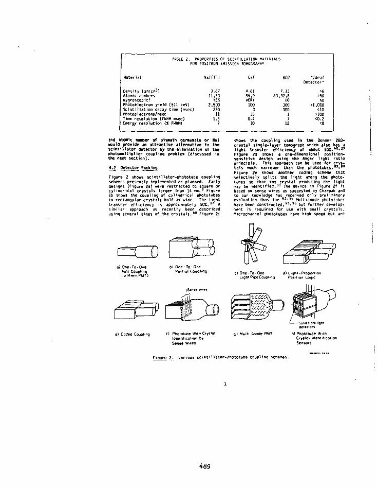
TABLE 2. PROPERTIES OF SCINTILLATION MATERIALSFOR POSITRON EMISSION TOMOGRAPHY
Material
Density (gm/ctn^)Atomic numbersHygroscopic?Photoelectron yield (511 kev)Scintillation decay time (nsec)Photoelectrons/nsecTime resolution (FWHM nsec)Energy resolution (X FUHM)
Nal(Ti)
3.6711.53YES
2.50023011
1.57
CsF
4.6155,9VERY100335
0.430
BGO
7.1383.32.8
NO300300
17
12
"idealOetector"
>6
>aoNO>1.000
<10>100<o.z<8
and atomic number of bismuth gernanate or Halaou1d provide an attractive alternative to thescintillator detector by the elimination of thephotOflNiitiplier coupling problem (discussed inthe nenC section).
4.2 Detector Packing
Figure 2 shows scintillator-nhototube couplingschemes presently implemented or planned. Earlydesigns (Figure 2a) were restricted to square orcylindrical crystals larger than 14 nut.9 Figure2b shows the coupling of cylindrical phototubesto rectangular crystals half as wide. The lighttransfer efficiency is approximately 50%. 8' Asimilar approach as recently been describedusing several sides of the crystals.88 Figure 2c
shows the coupling used in the Oonner 280-crystal single-layer tomograph which also has alight transfer efficiency of about 50X.* 0'"Figure 2d shows a one-dimensional position-sensitive design using the Anger light ratioprinciple. This approach can be used for crys-tals much narrower than the phototubes.89>'°Figure 2e shows another coding scheme thatselectively splits the light among the photo-tubes so that the crystal producing the lightmay be identified." The device in Figure 2f isbased on sense wires as suggested by Charpak andto our knowledge has received only preliminaryevaluation thus far.'2-'1" Mu Hi anode phototubeshave been constructed,95-96 but further develop-ment is required for use with small crystals.MicroChannel phototubes have high speed but are
o) One-To-OneFull CouplingIjIdmmPMT)
bl One-To-One
Porttol Coupling ctOne-To-One d) Light-ProportionLightPipeCoupimq Position Logic
e) Coded Coupling I ) PhoioiuD9 Witn CrystolIdentiticotion by
Sense Wires
) Multi Anode PMT
Solid state liqnrdetectors
h) Phoioiuee WithCrystal identificationSensors
F1 gure 2: Various scintiHator-pholotube coupling schemes.
489

(a) (b) (c)
f'9ure 3: Various sampling schemes: (a) Stationary ring26-"'1 (t>) Scan-rotate1"5-52
(cj wobbTe32.83.'03-'06 (d) positology".'°7 ie) dichotomic108.lo' (f) clamshell11".'"
limited by loo packing density, high price, anda relatively short useful lifetime.'7-'00 Theconcept shown in Figure 2h usis a high qualitysingle-anode square phototube for timing andpulse height selection. Separate light sensorsart used to determine iMch crystal produced thelight. The use of photodiode sensors to identifycrystals has been suggested by others aswell.101 The requirement for this design is thatthe crystal identifier must reliably detect soneof the scintillation photons available from the511 keV photon interaction in the scintiilstor.
4.3 Spatial Resolution
A system with a resolution similar to or coarserthan one-half the dimension of the quantitat ionvolume will necessarily give erroneous quantita-tive information.80-"'2 Selow we list the fac-tors that determine the spatial resolution inthe reconstructed tomographic images:
Rapid or, ideally, instantaneous complete spa-tial sampling is needed for <:>ose studiesrequiring rapid imaging. Stationary circular
positron emission tomographic systems uiingclosely packed detectors give optimum sensitiv-ity but the spatial resolution is limited bv thelinear sampling to approximately the distancebetween the detector centers and is not uniformthroughout the image space.J5.»«,«i Systems thatemploy large crystals have both limited linearand angular samltng, so that notion of thedetector array is required for good spatial res-olution. The use of lead apertures to improvespatial resolution results In a significant lossin sensitivity and an increased nunter of sam-pling positions. Several approaches employed toovercome these limitations are shown in Figure3. The most commonly employed method Is the cir-cular wobble motion which has been shown to bequite effective.J2.5S,83,loi-io6 A pure rotationof a nonuniformly spaced array ("positology")has been proposed, "• 1 0 7 as well as theoscillation of half-rings about the axis of thesystem ("dichotomic").1"*.""
The only method we know that can improve thesampling at all angles with only two mechanicalpositions is the "clamshell" motion (Figure4).110. Ill Fi g u r e 4j shows a circular array withlines connecting opposing groups of crystals.
.- v i
(8I.802-3II3
lure A_ Clamshell method for improving linear samgling with only two mechanical positions,a circular array with sampling rings 1'? apart, where d is the distance betweeni. In position (b) the halves of the detector ring are hinged open to produce aand the sampling rings have been shifted by d/4. The combination (c) providesI inn r innc t\f cn^^vnn A f A
defector centers.gap of width d and the sampling ringsconcentric Sampling rings of spacing d/4
490

TABLE 3.
IsotopeHalf-Li fe
Max Energy (MeY)[Abundance]
POSITRON RANGE
18f
110 min
0,64[97l]
Projected point spread function in water:FWHM (mm) 0.13FW(0.1)H (rm) 0.38rms (mm) 0.23
radius(mm) for SOX*radius(im) for 75%ra<Mus(im) for 90*
Line spread function in waterFWHH ( I M )FW(0.1)M (mo)rm {m)
'table entry gives the radiusdilation points projects
0.310.580.88
0.221.090.38
of the circle
DISTRIBUTIONS IN WATER
" C20.4 min
0.96[99t]
0.130.390.39
0.601.061.6
0.213l.Si0.69
withir. which
'«Ga68.3 min
L.90[90t]0.82[ 1*]
0.311.61.2
1.62.73.7
1.355.921.60
"Rb76 sec
3.3S[83»]2.57[L2%1
0.121.92.6
3.86.28.8
2.613.23.8
the stated percentage of anni-
The pattern of lines forms "sampling rings" in
the imaging field that are d/2 apart, where d is
the distance between detector centers. Figure 4b
shows the two halves of the detector array
hinged open to produce a gap of width d. The
sampling rings have been shifted by d/4. Figure
4c shows the combination of the two positions
which provides concentric sampling rings of
spacing d/4.
[Z\ Positron Range
By using the Donner 280-Crystal positron tomo-
graph, we have imaged thin positron sources in
[lOlyurethane foam (density 0.02 to 0.05 gm/cm3)
ind performed a precision measurement of the
positron end point distribution for 1 8F, " C ,6 8Ga, and 8 JRb which have maximum positron ener-
gies of 0.64 MeV, 0.96 MeV, 1.90 MeV, and 3.35
MeV, respectively.11^ The results are summarized
in Table 3.
[3] Deviations from 180°
The measurements of Colombino 1 1 3 for positron
annililation in water at 20°C show that the
deviations from 180° emission have a distribu-
tion that is nearly Gaussian <ith FWHM= 5.7
mrad. Note that for a detector ring of diameter
0, the positional deviation a at the center of
the ring corresponding to w angular deviation o
is given by /l= (0/1) • P.
[4J Detector scattering and detector penetration
for angles > 0"°"
Compton scattering and a subsequent secondinteraction in another detector can be a sourceof position error for afiy detector material, butis least with bismuth germanate.' "• The use of a
pulse height threshold en each detector is
effective in reducing these errors but cannot be
employed for the coupling schemes shown in Fig-
ures 2d onu 2e.
Detector penetration for off-axis sources causes
a radial elongation of the reconstructed point
spread function. This is a much smaller effect
for bismuth germanate than for N a K T l ! . * 0
[5] Reconstruction filter
The process of reconstructing the projection
data taken by the detector array will generally
smooth the resulting image to an extent deter-
mined by the reconstruction filter. 1 1 5 Our phi-
losophy has been to use a filter such as that
described by Shepp and Logan 1 1 6 that achieves
nearly the resolution of the tomograph. Other
workers have advocated smoothing the statistical
fluctuations of the data during the reconstruc-
tion with the intention of improving the appear-
ance of the image, but this causes a smearing of
data from one region to the next. We prefer to
sum over regions of interest which provides a
more accurate estimate of the activity in the
regions of interest and also averages over the
statistical fluctuations. Use of a sharper fil-
ter such as that described by Pamachandran and
Lakshminarayanan117 will provide siightly better
resolution but also can cause ringing (aliasing)
artifacts.
iji
The primary backgrounds in positron emissiontomography are accidental coincidences of unre-lated annihilation photons 1 1 8- " ' and true coin-cidences of photon pairs where one or both haves c a t t e r e d . " . 2 ' . 1 "
491

Extensive shielding is used both to define thetransverse sections being imaged and to shieldthe detectors from activity outside those sec-tions. Increasing the depth of the shieldingdecreases the sensitivity for good coincidentevents but also decreases the fraction of acci-dental and prompt scatter events. Proper tomo-graph design requires a choice of shielding thatmaximizes the signal to noise ratio in thereconstructed images.76-121>122
4.5 Quantitation
Ideally, the reconstructed images should providea quantitative measurement of the amount of pos-itron emitter in each volume element. This idealcan be closely approached If: [1] the systemresolution is at least a factor of too finerthan the quantitation volume. 1 0- 1 0 2 [2] the tis-sue attenuation has been corrected,1'3 [3] scat-ter and accidental backgrounds have beensubtracted, [4] deadtime losses have been cor-rected, and [S] a sufficient number of eventshave been collected such that the statisticaluncertainties are acceptably small. l21l-l2s
4.6 Electronics
All portions of the electronics, the detectorpreamplifiers, the coincidence and address cir-cuits, the data storage and reconstruction mustbe designed for low deadtime and high speed.127
Electronics for tiire-of-f 1 ight data acquisitionand storage ire presently under development andadd another level of complexity to the overallproblem.?1. ",126,128, 129
The display of three-dimensional data accumu-lated from multilayer positron emission tomogr-aphs is an important issue with no clear solu-tion as yet. 1 3 0
5^ CONCLUSIONS
The trend in the design of positron emissiontomogrjnhs designs for medical imaging is towardmultilayer circular detector arrays with highdose efficiency, good spatial resolution, highimaging rates, and very little mechanicalmotion. The major instrumentation challenge iscentered about the development of small, effi-cient detectors that can be closely packed toachieve a resolution in the reconstructed imageof 5mm FUHM or finer. Solutions include multi-anode phototubes, supplementary light sensorsfor crystal identification, and a semiconductorwith high detection efficiency for 511 keV pho-tons. Achieving a resolution much below 2 TinFWHM wiil be difficult due to other factors suchas positron range and deviations from 180°emission.
The realization of the great potential of time-of-flight imaging wilt require the developmentof a very fast scintillator with good detection
efficiency, and a very fast phototube that cancouple to small crystals for high resolutionimaging.
REFERENCES
1. Anger HO and Rosenthal DJ: Scintillationcamera and positron camera. In MedicalRadioisotope Scanning, IAEA, Vienn , 1959,pp 59-82
2. Kenny PJ: Spatial resolution and countrate capacity of a positron camera: someexperimental and theoretical considera-tions. Int J Appl Radiation and Isotopes22:21-2871571 1~
3. MuehHehner 6: Positron camera withextended counting rate capability. J NuclMed 16: 653-657. 1975
4. Kuehllehner G, Such in HP, and Dudek JH:Performance parameters of a positron imag-ing camera. IEEE Trans Nucl Sci NS-23: No1, 528-537, 1575
5. Huehllehner G, Atkins F, and Harper PV:Positron camera with longitudinal andtransverse tomographic ability. In MedicalRadionuclide Imaging. Vol !, IAEA, Vienna,19/7, pp 291-307
6. Huehllehner G: Effect of crystal thicknesson scintillation camera performance. JNucl Wed 20: 992-993, 1979
7. Atkins FB. Harper PV, Scott S, et <si:Analysis of coincident scatter for posi-tron cameras using large area detectors. JNucl Med 20: 635. 1979 (Abstract)
8. Silverstein EA, Fordnam EW, Chung-Bin A,et al: Positron imaging witn the Angertomographic scanner. J Nucl rted 22: P52,1981 (Abstract)
9. Burnham CA and Browne 11 GL: A multi-crystal positron camera. IEEE Trans NuclSci NS-19: No 3. 2OI-2OS. W!T
10. Browne! 1 GL, Burnham CA, Chesler OA, etal: Transverse section imaging of radionu-clide distributions in heart, lung, andbrain. In Reconstruction Tomography _mDiagnostic Radiology and Nuclear MedicineTTer-Pogossian MM, Phe'ps ME, Browne I I GL,et al, eds., Baltimore, university Park,1977. pp 293-307
11. BrowneII GL, Correia JA, Zamenhof RG: Pos-itron instrumentation. In Recent Advancesin Nuc1 ear Medicine. Lawrence T H an?SiTdinger TF, eds.. Vo 1 5, 1978, pp 1-50
492
12. Carroll LR: Design and performance charac-teristics of a production model positronimaging system. IEEE Trans Mud Sci NS-25:No l, 606-614, 1978
13. Browneli G.Burnham C, Correia J, et al:Transverse section imaging nith the MGHpositron camera. [EEE Trans Nucl SciNS-26: NO 2, 2698-27TJ2~Tl97g
14. Perez-Mendez V, Kaufman I, Price DC, etal: Multiwire proportional chambers innuclear medicine: present status and per-spectives. First World Congress of NuclearMedicine. Japan, 1974, pp 143-345
15. Jeavons AP, Charpak G, and Stubbs: Thenigh-density multiwire drift chamber.Nucl Instr Meth 124: 491-503, 1975
16. Urn CB, Chu 0, Kaufman L, et al: Initialcharacterization of a nultt- wire propor-tiontl chanter positron camera. IEEE TransNucl Sci NS-22: No 1, 388-394, 1975
17. Chu 0, Tan KC, Perez-Mendez V, et al:High-efficiency collimator- converters forneutral particle Imaging with MUPC. IEEETrans Nucl Sci NS-23: No 1. 634-639, 1976"
18. Jeavons AP and Cate C: The proportionalChamber gamma camera. IEEE Trans Nucl SciNS-23: No 1, 640-644, 1575
19. Perez-Mendez V, Lim CB, Ortendahl 0, etal: Two-detector MWPC positron camera withhoneycomb lead converters for medicalimaging: performance ar.d developments. JComput Assist Tomogr 2: 652-653, 1978
20. Jeavons AP, Townsend OW, Ford NL, et al: Ahigh-resolution proportinnal chamber posi-tron camera and its applications. IEEETrans Nucl Sci NS-2S: No 1. 164-173, 1778"
21. Tan KC, Perei-Mendez V and Macdonald B:3-0 object reconstruction in emission andtransmission tomography with limited angu-lar input. IEEE Trans Nucl Sci NS-26: No2. 2797-280577979'
22. Jeavons A: The CERN proportional chamberpositron camera. Proceedings of the 5thInternation,:* Conference on Positron Anni-hilation, Sendai, Japan, The Japan Instit-ute of Metals, 1979. pp 355-370
23. Jeavons A, Kull K, lindberg B, et al: Aproportional chamber positron camera formedical imaging. Nucl Instr Meth 1980
24. Lum GK, Green Ml, Parez-Mendez V, et al:Lead onide glass tubinq converters forgamma detection in MWPC. IEEE Trans NuclS o NS-27: No 1, 157-165, HST
25. Townsend 0. Schorr B, and Jeavons A:Three-dimensional image reconstruction fora positron camera with limited angularacceptance. IEEE Trans Nucl Sci NS-27: Noi, 463-470. lwr ~
26. Robertson JS, Marr RB, Rosenblum B, et al:Thirly-t«o crystal positron transversesection detector. In Tomographic Imaqinq2n Nuclear Medicine, Freedmjn GS (Ed), NewYork, Society of Nuclear Medicine, pp 142-153. 1973.
27. Oerenzo SE, ZakUd H, and Budinger TF-.Analytical study of a high-resolution pos-itron ring detector system for transaxialreconstruction tomography. J Nucl Hed 16:1166-1173, 1975
28. Cho ZH, Cohen MB. Singh H, et al: Perform-ance and evaluation of the circular ringtransverse axial eos'.tron camera (CRTA?C).IEEE Trans Nucl Sci NS-24: Wo 1. 532-543.T57T
29. Oerenzo SE. Budinger TF", Cahoon JL, Hues-man RH, and Jackson HG: High resolutioncomputed tomography of positron emitters.IEEE Trans Nucl Sci NS-24: No 1. 544-558.TS77"
30. Derenzo SE: Positron ring cameras foremission-computed tomography. IEEE TransNucl Sci NS-24: No 2, 881-885, f977~
31. Oerenzo SE, Banchero PG, Cahoon JL, Hues-man RH, Vuletich T, and Budinger TF:Design and construction of the Donner 280-crystal positron ring for dynamic trans-verse section emission imaging. Proceed-ings of the IEEE Conference on Decisionand Control, IEEE 77CH1269-0CS, Vol 1,1977
32. Bohm C, Eriksson (., Bergstrom H. et al: Acomputer assisted ring detector positroncamera system 'or reconstruction tomogra-phy of the brain. IEEE Trans Nucl SciNS-25: No 1. 624-637, 1978
33. Thompson CJ, Yamamoto Yl, and Meyer E:Po5*tome II: a Siigh efficiency PET devicefor dynamic studies. J Comput AssistTomogr 2: 650, 1978 ~
34. Ermsson i., widen I. Bergstrom, et al:Evaluation of a high resolution ringdetector positron camera. J Comput AssistVoirogr 2: 649, 1978. "
35. Oerenzo SE, Budinger TF, Cahoon JL, Green-berg WL, Huesaan RH, and Vuletich T: TheOonner 280-Crystal high resolution posi-tron tomograph. IEEE Trans Nucl Sci NS-26:No 2. 2790-2/93.T9T9
493

36. Derenzo SE. Budinger TF, Cahoon JL, Green-berg WL, Huesman RH, and Vuletich T: TheDonner laboratory 260-crystal high resolu-tion positron coincidence tomograph. Pro-ceedings of the 5th International Confer-ence on Positron Annihilation, Sendai,Japan. The Japan Institute of Metals,1979, pp 409-411
37. Thompson CJ, Yamarooto Yl, and Meyer E:Positome II: a high-efficiency positronimaging device for dynamic brain studies.IEEE Trans Hud Sci NS-26: No I, 583-589,T379"
38. Eriksson L, Bohm C, Bergstrom H, et al:One year experience with a high resolutionring detector positron camera system:present status and future plans. IEEETrans Nucl Sci NS-127: No I, 435-444, T555
39. Nohara H, Tanaka E, Tomitani T, et al:Positologica: A positron ECT device with acontinuously rotating detector ring. IEEETrans Hud Sci NS-Z7: No 3, U28-1T357T58B
40. Oerenzo SE, Budinger TF, Huesman, RH,Cahoon JL and Vuletich T: Imaging proper-ties of a positron tomograph with 280 8G0crystals. IEEE Trans Nucl Sci NS-28: No 1,81-89, 1981
41. Tanaka M, Hirose Y, Koga K, et al: Engi-neering aspects of a hybrid emission com-puted tomograph. IEEE Trans Nud SciNS-28: No. 1. 137-H7TT981
42. Kanno [, Uemura K, Miura S, et al: Head-tome: A hybrid emission tomograph for sin-gle photon and positron emission imagingof the brain, j Comput Assist Tomogr 5:216-226. 1981
43. Uemura K, Kanno I, Miura Y, et al: Ahybrid emission CT — headtome II. IEEETrans Nucj So_ NS-29. 1982 (in press)
44. Takanti K, [shimatsu K, Hay ash i T, et al:Design considerations for a continuouslyrotating positron computed tomograph. IEEETrans Nucl Sci NS-29: No 1. 534-538, T9TS?
45. Phelps HE, Hoffman £J, Huang SL, et al:Effect of positron range on spat'jl reso-lution. J Nud_ Med 16: 649-652, 1975
46. Ter-Pogossian MM, Phelps ME, Hoffman EJ,et al: A positron-emission trans<M)altomograph for nuclear imaging (PErr).Radiology 114: 89-98, 1975
Hoffman EJ. Phelps ME. Mullani HA, et al:Design and performance characteristics ofa whole-body positron transaxial tomo-graph. J Nucl Med 17: 493-502. 1976
48. Phelps ME, Hoffman EJ, Mullani NA, et al:Design considerations for a positron emis-sion transaxial tomograph (PETT III). IEEETrans Nud Sci NS-23: No 1, 516-522. T976"
49. Ter-Pogossian MM, Mullani NA, Hood J, etal: A multislice positron emission com-puted tomograph (PETT IV) yielding trans-verse and longitudinal images. Radiology128: 477-484, 1978
50. Mullani NA, Higgins CS, Hood JT, andCurrie CM: PETT IV: design analysis andperformance characteristics. IEEE TransNucl Sci NS-25: No 1, 180-183. 1973"
51. Phelps HE, Hoffman EJ, Huang SC, et al:ECAT: A new computerized tomagraphic imag-ing system for positron-emitting radfo-pharmaceuticals. J Nucl Ned 19: 635-647,1978
52. Williams CU, Crabtree MC, and Ourgiss SG:Design and performance characteristics ofa positron emission computer axialtomograph— ECAT-II. IEEE Trans Nucl SciNS-26: NO 1, 619-627, "1573
53. Cho ZH, Nalcioglu 0, and Farukhi MR: Anal-ysis of a cylindrical hybrid positron cam-era with bismuth germanate (6G0) scintil-lation crystals. IEEE Trans Hud SciNS-25: NO. 2, 952-9STT1978
54. Ter-Pogossian MM, Mullani NA, Hood JT, etal: design considerations for a positronemission transverse tomograph (PETT V) forimaging of the brain. J Comput AssistTomogr 2: 539-544, 1978 ~
55. Ter-Pogossian MM, Mullani NA, Higgins CS,et al: The performance of PETT V: a posi-tron emission tomograph for fast dynamicstudies. J Nucl Med 20: 628 (Abstract),1979
56.
57.
58.
59.
Mullani NA, Ter-Pogossian MM, Higgins CSet al: Engineering aspects of PETT V. IEEETrans Nucl Sci NS-26: No 2. 2703-27567T57T" '
Carroll LR, Hendry GO, and Currin JO:Design criteria for multi- slice positronemission-computed tomography detector sys-tems. IEEE Trans Nucl Sci NS-27: No.l.
I9
Hoffman EJ. Phelps ME, Huang SC. et al: Anew tomograph for quantitative positronemission computed tomography of the brain.IEEE Trans Nucl Sci NS-28: No. 1, 99-103,T98T
Ficke DC, Beecher OE, Hoffman GR, et al:Engineering aspects of PETT-VI. IEEE TransNucl Sci NS-29: No 1. 474-478, 1581
494

60. Hoffman EJ, phelps ME, Huang SC, et al :Evaluating the performance of multiplanepositron tomographs designed for brainimaging. IEEE Trans Hue I Sci NS-29: Ma I,469-173, 1937"
61. Eriksson L, Bohm c, Kesselberg M, et Jl: Afour ring positron camera system for emis-sion tomography of the brarn. IEEE TramMucJ Sci NS-29: * '• 539-543, 13B7
b<\ Z.H. Cho, personal communication on spher-ical positron emission tomograph, 1982.
63. famamoto N, Ficlee DC, Ter-Pogossian MM. et»\: Performance study of PETT VI. a posi-tron computed tomograph with 288 cesiumfluoride detectors. t£££ Trans Nuci SciNS-29: Mo J. SJ9-533, T587
64. Anger HO: Survey of radio isotope cameras.15* Trans 5: 3UI-334, 1966
65. (tickles AJ and Meyer HO: Design of athree-dimensional positron camera fornuclear medicine. Phys Med Biol 23: 686-695, 1978
66. Allemand R, Gresset C, and vacher J:Potential advantages of a Cesium FluorideSCinCiilator for a time-of-ftight positroncamera. J Nuj2 Med ?1: 153-155, 1980
67. Mullani NA, Ficke DC, and Ter-PogossianMM: Cesium fluoride: a new detector forpositron emission tomography. IEEE TransHucl Sci NS-27: No.l, 572-575, f5SB
68. MulUni NA, Markhm J, and Ter-PogossianMM: Feasibility of time-of-f1ight recon-struction in positron emission tomography.J Nuci Med 21: 1095-1097. 1980
69. Atkins F8: Limited time-of-flight tomogra-phy -- will it help? 0 Nuci wed 22: P39,1981 (Abstract)
70. Ter-Pogossian MM, Mullani NA, Ficke 0C, etal: Photon time-of-flighi-assisted posi-tron emission tomography. J Comput AssistTomogr 5: 227-239, 198V
71. Snyder 01, Thomas LJ and Ter-PogossUn MM:A mathematical model for positron-emissiontomography systems having t\me-of-fIightmeasurements. IEEE Trans Nuci Sci NS-2S:No 3, 3575-35837TT8I
72. Snyder DL: Some noise comparisons of data-collection arrays for emission tomography-systems having time-of-fIight measure-ments. tEEE Trans Nuci Sci NS-29: NO 1,1029-1O33TT9B?
73. MulUni NA, Ficke DC, Hartz R, et a l : Sys-tem design of fast PET scanners u t i l i z ingt ime-of - f l ight . IEEE Trans Wucl Sci NS-28:
- No. 1, 104-107. T58T
74. Macdonald 8 and Perez-Mendez V:Contribution of time-of-flight informationto limited angle positron tomography. IEEETrans Nuci Sci NS-29: No 1, 516-519. T9TS?
75. Mullani N, Wong w, Hartz R, et al: Sensi-tivity improvement of TOFPET by the utili-zation of the inter-slice coincidences.IEEE Trans Nuci Sci NS-29: No 1, 479-483,T5S?
76. Dereitto S: Method for optimizing sideshielding in positron emission tomographsand for comparing detector materials. JHud Med 21: 971-977. 8980
77. Budinger TF, Derenzo SE, Huesman OH andCahoon JL: Medical criteria for the designof a dynamic positron tomograph for heartstudies. IEEE Trans Hud Sci NS-29: No 1.488-492. 1955
78. Budinger TF, oerenzo SE, Huesman RH, andCahoon JL: Postron emission tomography:instrumentation perspectives. Proceedingsof the International Workshop on Physicsand Engineering in Medical Imaging, Asito-mar, CO., March 15-18, 198?
79. Bassingthwaighte J8: Physiology and iheoryof tracer washout techniques for the esti-mation of myocardial blood flow: Flowestimation from tracer washout. Prog inCardiovascular Diseases 20: 165-18TTl977
SO. Sudinger TF: Instrumentation trends innuclear medicine, [n Seminars in HuelearMedicine 7: 285-297. 1977
81.
82.
Budinger TF, Oerenzo SE, Gultberg GT, andHuesman RH: Trends and prospects for cir-cular ring positron cameras. IEEE TransNuci Sci NS-26: No 2, 2742-274rT>
Phelps ME, Hoffman EJ, Huang SC, et al:Design considerations in positron computedtomography IPCT). IEEE Trans Nuci SciNS-26: No 2, 2746-275171979 ~ ~
83. Brooks RA. Sank VJ, Friauf WS, et al:Oesign considerations for positron emis-sion tomography. IEEE Trans Roomed EngBME-28: No 2, 158-177"T"19'5!
"4. Kjufman L, Williams SH, Hosier K, et al:An evaluation of semiconductor detectorsfor position cameras. J Comput AssistTomogr 2: 651, 19'B
495

85. Levi A, Roth H, Schieber M, et al: Thedevelopment of mercuric iodide gamma*radiation detectors for applications innuclear medicine. IEEE Trans Nucl SciNS-29: No 1. 457-460rT582
86. Ortendah! 0, Kaufman L, Hosier K. et al:Operating characteristics of smallposition-sensitive mercuric iodide detec-tors. IEEE Trans Nucl Sci NS-29: No I,
rreB87. Derenzo SE and Riles J: Monte Carlo calcu-
lations of the optical coupling betweenbismuth germinate crystals and photomulti-plier tubes. [EEE Trans duel Sci NS-29: No1. 191-195, 19B2
88. Ricci A. Hoffman E, Phelps M, et al:Investigation of a technique for providinga pseudo-continuous detector ring for pos-itron tomography. )££E Trans Hue! SciNS-29: No I, 45Z-456,"T9BZ
89. Burnham C, Bradshaw J, Kaufman D, et al:One dimensional scintillation cameras forpositron ECT ring detectors. IEEE TransHue! Sci HS-28: No. 1, 109-113.1951
90. Burnham C, Bradshaw J, Kaufman 0, et a):Application of a one dimensional scintil-lation cxnert in i positron tomographicring detector. IEEE Trans Nucl Sci NS-29:No 1, 461-461, 1952
Nucl Instr Metii 192:91. Murayama H et al.501, 1982
92. Charpak S: The localization of the posi-tion of light impact on the photocathodeof a photomultiplier. Nucl Instr Meth 48:151-153,1967
93. Charpak G: Retardation effects due to thelocalized application of electric fieldson the photocathode of a photomultiplier.Nucl Instr Heth 51: 125-128, I9a7
94. Boutot JP and Pietri G: Photomultipliercontrol by a clamping cross-bar grid. IEEETrans Nucl Sci NS-19: No 3. 101-106, 197?
95. Persyk OE, Morales J, McKeighen fi, et al:The quadrant photomultiplier, IEEE TransNucl Sci NS-25: No 1, 364-367. 1 379
96. ramashita T, Ito M, and Hayashi T: Newdual rectangular photomultiplier tube forpositron CT". Proceedings of Che Interna-tional Workshop on Physics and Engineeringin Medical Imaq'ng, Asi'omar, CA, March15-18, 1982
97. Bateman JE, Apsimon RJ and Barlow FE: Anew photomultiplier tube utilising channelplate electron multipliers as the gainproducing elements. Nucl Instr Meth 137:61-70, 1976
98. • Lo CC and Leskovar B: Studies of prototypehigh-gain microchannel plate photomulti-pliers. IEEE Trans Nucl Sci NS-26: No 1,388-394, "1579 "
99. Lo CC, Leskovar 8: Performance studies ofhigh gain photomultiplier havingZ-configjration microchannel plates. IEEETrans Nucl ScJ NS-28: No 1, 698-70*. T9BT
100. Nieschmidt EB, Lawrence RS, Gentilion CO,et al: Court rate performance of a micro-channel plite photomultiplier. IEEE TransNucl Sci HS-29: No 1. 196-199, 19ST"
101. Phelps and Hoffman, personal communica-tion, 1982
102. Hoffman EJ, Huang SC. and Phelps HE: Quan-titation in positron emission tomography:1. Effect of object size. J Comput AssistTomogr 3: 299-308, 1979
103. Herman GT: The mathematics of wobbling aring of positron annihilation detectors.If EC Trans Hud Sci NS-26: No 2, 2756-1759, T97T
104. Huang SC, Hoffman EJ, Phelps ME, et al:Sampling requirements of emission computedtomographic (ECT) scanners, d Nucl Med20:609 (Abstract), 1979
105. Brooks RA, Sank VJ, Talbert AJ, et al:Sampling requirements and detector motionfor positron emission tomography. IEEETrans Nucl Sci NS-26: No 2, 2760-27617T9"79~
106. Colsher JG and Muehllehner G: Effects ofwobbling motion on image quality in posi-tron tomography. IEEE Trans Nucl SciNS-28: No 1. 90-93. T98T
107. Tanaka E, Nohara N, vamamoto M, et al:"Positology" - the search for suitabledetector arrangements for a positron iZJwith continuous rotation. !££E Trans NuclSci NS-26: No 2, 2728-2731.T979
108. Hong KS: Oscillatory dichotomic ring posi-tron camera. Multidimensional digitalimage processing- application to the 3-dimage reconstruction, restoration, andenhancement, Cho ZH, £d., Imaging SystemScience Laboratory, Korea Advanced Inst-itute of Science, Seoul, Korea, 1979.
10
496
109. Cho ZK. Hong KS. Ha JB, et jl: A new sam-pling scheme for the ring positron camera-dichotomic ring sampling. IEEE Trans Hue ISci NS-28: (,'o 1, 94-98. 1931
110. Huesnwn RH, Derenzo SE, Gull berg GT, andBudinger TF: Novel two-position samplingscheme for dynamic positron emissiontomography. J Nucl Med 22: P38-P39, 1981(Reviewed Abstract)
111. Huesman RH, Derenzo S£ and Budinqer TF: Atwo-position sampling scheme for positronemission tomography. Proceed ings of theWorld federation of Nuclear Medicine &Biology for the Third World Congress Meet-ing, Paris, Aug 29- Sept 2, 1982
112. Oerenio S: Precision measurement of inni-hlUtlon point spread distributions formedically important positron emitters.Proceedings of the Sth International Con-ference on Positron Annihilation, Sendti,Japan, The Japan Institute of Metals,1979, pp 819,823
113. Co 1 ombino p. Fisceila 8, Trossi L: Studyof positronium in water and ice from 22 to-144 °C by annihilation quantum measure-ments. Nuovo Ctmento 38: 707-723, 1965
114. Oerenzo SE: Monte Carlo calculations ofthe detection efficiency of arrays ofNal(Tl), BGO, CsF, Ge, and plastic detec-tors for 511 keV photons. IEEE Trans NuclSci NS-23: No. 1, 131-136, T5ST
115. Budinger TF, Gullberg GT, and Huesman RH:Emission computed tomography. In Topics inApplied Physics. Vol 3jh, Image Reconstruc-tion from Projections; Implementation andApplications, ed Herman ETT Berl in,Sprtnger-verlag, 1979, pp 147-246
116. Shepp LA and Logan 8F: The Fourier Recon-struction of a head section. IEEE TransNucl Sci NS-21: No 3, 21-43, 1973
117. Ramachandran GN and Lakshminarayanan AV:Three-dimensional reconstruction fromradiographs and electron micrographs:application of convolutions instead ofFourier Transforms. Proc Nat Ac ad Sc_i US68: 2236-2240, 1971
118. Burnham CA, Alpert NM, Hoop B, Jr., et al:Correction of positron scint'grams fordegradation due to random coincidences. JNucl Med 18: 604 (Abstract), 1977
119. Hoffman EJ, Phetps ME, Huang SC, et al:Effect of accidental coincidences in posi-tron emission computed tomography. J WucIMed 20: 624-635 (Abstract), 1979
120. Pang SC and Genna S: The effect of Comptonscattered photons on emission computerizedtr^nsaxial tomography. IEEE Trans Nucl SciNS-26: No 2, 2772-2774,"T579
121. Oeremo SE: Opt 'raizat ion of shieldingdepth for circular positron tomographs. JNucl Med 20: 635, 1979 (Reviewed Abstract}
Ueda K, Tanaka E, Takami K, et al: Evalua-tion of slice shield collimators formulti-layer positron emission computedtomographs. IEEE Trans Nucl Sci NS-29: No1, 563-566, 1981
Huang SC, Hoffman EJ, Phelps ME, and KuhlDE: Quantitation in positron emission com-puted tomography: ?. Effects of inaccurateattenuation correction. J Coaput AssistTomogr 3: 804-814, 1979 ~
Huesman RH: The effects of a finite numberof projection angles and finite lateralsampling of projections on the propagationof statistical errors in transverse sec-tion reconstruction. Phys Med Biol 22:511-521. 1977
Budinger TF, Osrenza SE, Greenberg WL,Gullberg GT, and Huesman RH: Quantitativepotentials of dynamic emission computedtomography. J Nucl Med 19: 309-315, 1978
Tomitani T and Tanaka E: [mage reconstruc-tion and noise evaluation in photon time-of-flight assisted positron emissiontomography. IEEE Trans Nucl Set NS-28: No6, 4582-4589,-1551
Huesman RH and Cahoon JL: Oata acquisi-tion, reconstruction and display for theOonner 280-crystal positron tomograph.IEEE Trans Huci Set NS-27: No.l, 474-478,
12?.
123.
124.
125.
126.
127.
128. Phi'ippe EA, Mullani N, Hartz E, et al:Real-time multi-processor image recon-structor for time-of-flight positron emis-sion tomography (TOFPET). IEEE Trans NuclSci NS-29: No 1, 524-527, 1952
129. Blaine J, Ficke 0, Hitchens R, et al: Oataacquisition aspects of super-PETT. IEEETrans Nucl Sci NS-29: No 1, 544-547, 1957
130. Budinger TF: Three-dimensional displaytechniques: description and critique ofmethods. Proceedings of the World Federa-tion of Nuclear Medtcine & Biology for theThird World Congress Meeting, Paris, Aug29- Sept 2, 1982
11
497

HIGH-RESOLUTION DETECTION SYSTEM FOR POSITRON TOMOGRAPHY
EDWARD J. HOFFMAN
SUMMARY
The resolution in positron tomography had been limited by thestopping power of the detectors, primarily Nal(Tl), which had beenunable to stop the 5 11 keV annihilation photon in a narrow enoughcrystal to give the desired localization. An analysis of how BGOprovides a solution to this problem and a proposed solution to thereadout problem of very narrow crystals at the relatively low lightyield 3een for 511 keV is presented in the attached reprint and twopreprints. The material presented and slides shown at theconference were a summary of this material.
498

ILtL' <•'" Nueleai Science. Vol. NS-2V, No. I. I-Vhruary ItHZ
INVESTIGATION OF A TECHNIQUE FOR PROVIOINC A PSEUDO-CONTINUOUSDETECTOR RING FOi* POSITRON TOMOGRAPH*
A.R. Ricc l , b'.J. (toffcnnn, M.h. Plielps, S.C. Huang, D. Pluramer and R. Carson
Divisions of Biophysics and Nuclear Medicine,Department of Radiological Sciences , School of Medicine and
Laboratory of Nuclear MedicineUniversi ty of Cal i forn ia
Los Angeles, Ca l i fo rn ia 90024
SUMMARY
The use of iinall bismuth gerraanate (SCO) detectors(2.5-4.5 ma wide) and a simple coding technique forIdentification of the crystal of interaction with theimpinging gaaaa-ray was investigated in terns of atechnique for providing a positron toaography systemof the highest possible intrinsic resolutio with theadditional capability of providing an af'ifacc fr«eimage la a stationary «*««»• The t«cho ju« eaploysone photoaultiplier par two BGO crystt' <n a sehaaaof alternating single PMT/crystal _ sharedPMT/cry»cal coablnadons to font a pseudo-continuousring. Problems at crosstalk between detectors, non-unlforn sensitivities and variable resolution arcshown to ba alnialzad once discrlalnttor thresholdsate clearly abova the enargy of tha bisauth x-raysinduced In the BGO crystals by the 511 keV gaaoas fromthe positron annihilations.
A stationary circular system employing 4.5 mm wideBCO detectors can provide transverse sampling «,qual to1/2 the center to center crystal distance or 2.5 mosampling. The measured Intrinsic resolution of abench top version of this system Is 5 to 6 am FWHM fora 30ca diameter field of view for a 100 ca systeadiameter. The 2.5 aa sampling with reconstructionfilter of appropriate frequency response should pro-vide a high resolution image on the order of 7 to 8 mmFWHM with good signal to noise characteristics whichIs free of significant aliasing ar t i facts .
I. Introduction
Artifacts due co heart and diaphragm notion havebeen a continuing problem In x-ray CT. Because oflower stat is t ical quality and resolution of positrontomogriphy, artifacts due to such motion have gener-ally been minimized. But as the axial resolution andcontrast of the ECAT II (1) system were Increased,artifacts due Co diaphragm motion becaae readilyapparent In transmission scans, as hexagonal or ringartifacts (Fig 1). Init ial ly the emission images were
TRANSMISSION IMAGES
DIAPHRAGM MOTION ARTIFACTS
Figure I. Hexagonal and ring artifacts caused bydiaphragm motion in transmission scans. These are dueto Che fact that the count time per position in Chetransmission scir. Is on the order of the same time asche period of che breaching cycle.
CARDIAC GATING ARTIFACTS
Figure 2. Emission scan of C-H-palmitic acid in adog. Ungated Image shows heart uptake as donut shapedand liver uptake below the heart. Gated image of saaelevel shows artifacts that occur when slaple gatingwith saall clae periods are attempted.
artifact free whenever the transmission images werealso artifact free. However, when attempts were mad/to produce simple gated Images with very short cir-eperiods, the resultant artifacts essentially destroyedthe image (Fig 2).
A stationary system presents a possible solutionto the problem. Such a systea could be a continuousring with analog positioning logic or a system whichemploys very small discrete crystals. In addition tostatlonarlty, use of small discrete crystals with highIntrinsic resolution have been shown In investigationsat UCLA to be able to yield high resolution imageswith higher than expected signal to noise ratios(2.3).
A technique for providing a stationary pseudo-continuous detector ring for positron tomography ispresented In this work. Ic utilizes thin BisauthGeraanate (BGO) crystals coupled to photomultipliertubes and' a staple coding scheme for crystal identifi-cation. Tha resolution and efficiency of this systeaware measured as functions of d«t«cr,or size, physicalenvlronaent, dactccor crosstalk, and energy thres-hold. Tha problaas of scatter, Intrinsic resolutiondua to physical properties of positron annihilationand practical prcJieas of systea design are alsoaeaaurad and discussed.
Conclusions are drawn as to che advantages as wellas the problem of this technique.
Z. System Description
The basic concepc of che syscem under Investiga-tion is Illustrated in Figure 3. Each adjacent set ofthree BCO crystals is coupled to one (3/4") photonul-tiplier tube with the cencral crystal viewed by onlythat PUT while each outride crystal Is also sharedwith an adjacent PMT. The simple coding scheme shownIn Figure 3 could be used to identify which detector
452 <X)l8-(M99/82/O20O-O452H».75<?>l982 IEEE
499

COOMO lOOC 'O« OtwIVCMKM O* «T|CtO»»
Figure 3- Brsic crystal/PMT configuration is ahoun attop with coding logic for daceccor Identificationshown at hot ton. Each PHT Is coupled to a set of 3crystals with outer crystals of each set shared withadjacent orthogonal PHT's.
has absorbed the gamma ray.In order to study this system, a snail section of
a system was simulated by two opposing sets of 7detectors; each set coupled to 4 PHIs. The data werecollected using the UCLA tomographtc simulator (4).Figure 4 illustrates the general system configurationused to make the measurements in this study- It Isnot unlike the data collection seen in positron tomo-graphs. The detector signals from each set t'e ampli-fied, routed into constant fraction discriminators,"ORed" together, and coincidence gated to produce aprompt coincidence strobe. One of the "ORed" signalsis delayed and placed In coincidence with the "ORed"signal from the other set of detectors to produce theaccidentals strobe. The outputs of the constantfraction discriminators on both sides, along with theaccidentals strobe are routed to the Inputs of thecoincidence latch; which, when strobed by the "OR" ofthe prompt and accidental coincidence strobes, fora anaddress to the CAMAC memory which is incrementedappropriately. The data stored in memory givesdetailed information about the physical characteris-tics of the thin BGO detectors as well as the codingconcept- Unlike usual tomographic systems that dis-card errors such as triple or quadruple coincidences,these multiple crystal Interactions were stored toprovide a detailed picture of data lass due to crystalto crystal scatter.
The configuration shown in Figure 4 is for the 14detector system described above. However In ourtesting of detector physics, we at tines Isolated thedetectors optically In order to study the physic* ofIndividual crystals without artifacts of the encodingscheme.3. Measurements and Results
Physical Environment. In the consideration ofcrystal placement In a ring geoaetry, the lnterde-tector material and what effect this physical environ-ment has on the resolution of the Individual detectorsshould be determined. The effects of three differentinterdeteccor materials on resolution were measured.Their line spread functions (LSF's) are shown InFigure 5. As a point of reference for each of theseplots, the LSF of a pair of 4.S mm BGO crystals incoincidence sandwiched between two 1/4" thick piecesof lead is shown as the solid narrow line In thefigure. The LSF on the left Is that of BGO detectorswith 1/2 ma lead between each of the adjacent detec-tors. There Is a negligible change in FWHM and a 12Z
G t N M A l •YITCW CONflQUNATIOM
Figure 4. General systaa configuration used to col-lect data from representative subset of detectors.Both random and proapt coincidence strobes are genera-ted and 'ORed' together to strobe constant fractiondiscriminator outputs at the coincidence latch. Thisfonts an address to the CAMAC aeaory which is thenIncremented appropriately. Multiple crystal Interac-tions are also stared with this technique for erroranalysis. Detectors at tlaes were optically isolatedin order to study individual crystals without arti-facts of the encoding scheme.
change in FWTM. The center LSF In Figure 5 isobtained when BGO detectors are only separated by thereflective paint on the crystals. Here again there isa negligible change in FWHM and a 17Z broadening atthe FWTM. The LSF to the right was obtained when 1/2on plastic was used as the interdetector material.This is what would be expected if a low Z materialwere used between detectors as a supporting structurefor the crystals in a tomograph. There is a seriousdegradation to the resolution due to scatter from theplastic and neighboring crystals. The FWHH is broa-dened by 182 while the FWTM Is increased by 472.
LSr* AS * FUNCTION Of INTEHOeTECTOa tfATCMAlS
OWTANCI (UM)
Figure 5. Effects of 3 different Interdetectormaterials on resolution shown as LSF's. The solidline reference In each plot is the coincidence LSF ofa pair of 4.5 mm BGO crystals sandwiched between two1/4" thick pieces of lead. The central LSF on theright i s that of BGO detectors separated by 1/2 mmplastic, and is lndictive of what would be expected ofany low Z material that might be used between detec-tors as supporting structure for the crystals in atomograph. The left and central LSF's give negligiblechange in FWHM, while that on the right producesbroadening of 18Z in FWHM, and 47Z at FWTM, relativeto the reference.
453
500

These results Indicate the best configurationwould be to pack the BCO detectors as close as possi-ble la order to gain the Increased efficiency ofadditional BCO without suffering a loss In resolution.
Angulatlon Effect. Because of the non-zero momen-tum of the positron at annihilation with an electron,the resultant velocity causes some sl ight deviationfrom the 180* path of the two 511 keV photons pro-duced. This has the effect of degrading resolutionwith distance from the source. In Figure 6 we haveplotted the LSF's of a Z.S mm BGO crystal pair takenwith a Cu-64 line source at detector separations of30. 66 and 100 cm. From these data we estimate thatfor a proposed system configuration with a 100 cmfield of view, the degradation due to this effectwould be 2.8 ma FWHM. This would define Che resolu-tion H a l t for lower energy positron emitters such asF-18 and C-ll while the higher energy positron emit-ters such as 0-15, 8b-82m, and Ca-68 would have addi-tional resolution losses due to the effect of thepositron range (5).
l«P"« At A riMCTION Or OCTfCTO* UPA*ATIO«
• 30 CM SEPARATION
" <• CM SEPARATION
* 100 CM SEPARATION
4.5F
? WITHOUT
C * • CRO3STAL
1 ••" ' : f
2 » i MM
. FWTM
~ I ." • * * ' •*
' * H
ovcm*io
•A,/ / / * 1*
MSTAMCe (IMI)
••LUSCMOSST*L .
FHHM
1 43
FMlyS«
Figure 7. The effect that crosstalk could have on theLSF's of detectors la our configuration. The LSP onthe l e f t I s that of • s ingle 4.5 SB crystal/PMT In oursystem. The crosstalk between adjacent crystals IsIndistinguishable In our system. By optical i so lat ionof adjacent crys ta l s , crosstalk was aeasured andplotted as solid l ines underneath the center LSF whichi s the sane as that on l e f t . If there were no opticali so la t ion , the LSF on the right would be aeasured withthe crystals with shared PMT's since the crosstalkwould be simply added onto the single crystal data.
thicknesses; 2 .5 , 3.5, and 4.5 on. We see that at lowthresholds which Include the Bismuth s-rays we get asmuch as 80-100Z crosstalk, but there i s a fairly rapiddropoff as we move above Bismuth x-ray energies toapproximately 10Z at high threshold.
The alternate crystal crosstalk i s always reason-ably low, starting at 10Z and dropping very low,especial ly for the thicker crysta ls .
Figure 6. Angulatlon effect with distance froa thesource Is plotted as LSF's of a Cu-64 line sourceplaced midway between two detectors having separationsof 30, 66, and 100 en. The estimated degradation dueto this effect at a 100 cm detector separation wouldbe 2.8 mo FWHM.
Crosstalk. The usual configuration of one PMTcoupled to a single crystal eliminates crosstalk byrejecting events Involving adjacent or near adjacentcrystals In coincidence (6 ) . The LSF on the l e f t InFigure 7 shows the resolution without crosstalk forour system with 4.5 ma crys ta l s . This i s the resolu-tion of our system for these crystals coupled to onlyone PMT. In our arrangement, crosstalk between twoadjacent crystals would not be dist inguishable.However by optically i so lat ing the two crysta l s adja-cent to the central one, we were able to measure thecrosstalk from adjacent crys ta l s . The center LSF i sthe same as the one on the l e f t , with the crosstalkfrom adjacent crystals plotted as sol id l ines under-neath.
If there were no optical i so la t ion , the LSF on theright wocld be measured with the crystals with sharedPMT's, since the crosstalk would be simply added ontothe single crystal data. There i s a 16Z difference In,FWHM and a 25* difference at the FWTM in this parti-cular case. The LSF on the rlghc then i s that whichcould be obtained with the odd or shared detectors Inour scheme. Since crosstalk i s due to energy beingshared by 2 crysta l s , i t oust be a function of energydiscrimination. Figure 8 shows the percent crosstalkbetween adjacent crystals and between alternatecrystals ( i . e . 2 crystals apart) as a function ofenergy threshold. These are shown for 3 crystal
454
too•oc
• >.S MM OETECTONS
» 1.S MU DETECTORS
• 4 4 MM OEtECTORt
^ ADJACENT CRYSTALCROSSTAU
K 10 0
< to
s
APPWOXMATE THMftHOLD
Figure 8. Percent crosstalk as a function of energythreshold is plotted for 3 crystal thickness and forboth adjacent and alternate crystals. For adjacentcrystals at low thresholds that Include the Bismuth x-rays, as ouch as 80-100Z crosstalk was aeasured. Thisdropped rapidly however to below 10Z at high thres-holds. Alternate crystal crosstalk is always reason-ably low, especially for thicker crystals.
501

Resolution vs Energy Threshold. The effects ofer.ergy threshold settings are also apparent in Figure9 where the resolution of three different sizedcrystals are plotted as a function of energy thres-hold. Those lines designated as 'with crosstalk1
refer to tlie shared or odd detectors In our configura-tion and those designated 'without crosstalk" refer tothe detectors with single PMTs or even detectors.
Ic can be seen chac at lower thresholds, theshared detectors have broader line widths than thesingle detectors, which ac lower thresholds alsosuffer a loss In efficiency. But as the energy thres-hold is Increased, the shared and single detectorsapproach the same resolution both at FWHM and FWTM,and for each detector size.
1 0 f 9 l¥Mk Mnk>Ulk
I • Wiiltowl Cr«»tt*
fNMW
i i i ; •: i J ; i i i ' i. . - .
Figure 9. Resolution as a function of energy thres-hold Is plotted for three crystal thicknesses for bothsingle (without crosstalk) and shared crystals (withcrosstalk). At lower thresholds the shared detectorshave braoder line widths than single detectors. Butat higher thresholds the shared and single detectorsapproach the same resolution.
Efficiency vs Energy Threshold. Figure 10 illu-strates the effect of energy threshold on the effi-ciency of both single and shared detectors In oursystem. At lower thresholds the shared crystals whichdetect a large amount of crosstalk have, higher effi-ciency than the single detectors, and again as theenergy threshold is raised, the shared and singledetector efficiencies approach coanon values. This isprimarily due to the discrimination against theBismuth x-rays, which are the major sources of cross-talk at low energy thresholds.
Figures 8 through 10 emphasize the importance ofenergy threshold in such a system. However, undulyhigh threshold settings are not required, allowingreasonable efficiency and resolution per detectorelement with good discrimination against crosstalk.
5 •
I*s
• WITH cwtlwa• WITHOUT CA0S31M.K
3.* MM OCTKCTOn*
Figure 10. Efficiency as a function of energy thres-hold is plotted for three crystal thicknesses for bothsingle (without crosstalk) and shared crystals (withcrosstalk). At lower thresholds the shared crystalshave higher efficiency than the single detectors duemainly to the higher crosstalk caused by Bismuth x-rays. However as the energy threshold Is raised aboveBismuth x-ray effects, the shared and single detectorefficiencies approach common values.
Effects of Scatter. A potential problem of thiscoding technique i s the regular variation in eff i -ciency due to alternating high and low efficiencycaused by unequal coupling of detectors to PMT's.There is the possibility that a regular pattern ofhigh and low efficiencies will impress an alternatingor zebra pattern on the image. Detector efficienciesin a system are calibrated for true coincidences in alow scatter environment, when the system is exposed tothe higher scatter environment of clinical Imaging, asubstantial difference in Che detection efficiency ofscatter coincidence vs true coincidence as a functionof energy threshold can cause regular discontinuitiesIn the data profiles, leading to serious artifactproblems (7) .
In this system there is a potential discontinuitybetween each detector. In order to measure: the magni-tude of the discontinuity, 3 BGO crystals (4.5 amwide) ucre tested with widely varying energy thres-holds (Figure 11). The detector efficiencies werecalibrated with a thin plane source (no scatter). Thecount rat* was Matured and normalization factorsobtained by setting the detector efficiencies to 1.The right side of Figure 11 shows the energy spectrumin coincidence of the detector with the lowest thres-hold. Then a large scattering medium (water, 26 cmthick x 30 ca wide x 30 cm deep) was placed around thesource. The coincident detectors (40cm apart) were ina geometry which provided a scatter to time ratioworse than would normally be seen in an actual tomo-graph.
1?01102 1 0
9 *VlttMSCATTER
Figure 11. Potential problem of regular disconti-nuities in data profiles caused by substantial diffe-rences In Che detection efficiency of scatter vs truecoincidences as a function threshold energy was testedfor detectors In our system. Three BOO crystals (4.5mm) were tested with widely varying energy thres-holds. The detector efficiencies were calibrated weina thin plan* source (no scatter). The right side offigure shows the energy spectrua in coincidence of thedetector with the lousst threshold. Detector eff i -ciencies were then obtained for Che source in a scat-tering aediw and then for a scaccer only situation.Detector efficiencies for the 190 and 250 ketf thres-holds are in good agreement for both the true plusscatter coincidences and the scatter coincidences onlysituation. The detector efficiency at the low 120 keVthreshold i s significantly different. The energyspectrua for rhe scatter shows chat the detectorefficiencies should be relatively insensitive to smallchanges in threshold in the neighborhood of 150-200keV thresholds, since the primary component of coinci-dent scatter is from small angle scatter, sufferingl i t t l e loss In energy, and giving an Incident energypredominantly within 100-200 keV of che 511 keV photo-peak.
502

The detector ef f ic iencies with scatter for the 190and 250 koV thresholds are essent ial ly the same whileChat for the 120 keV threshold Is s ignif icantly dif-ferent. This i s probably duq to che larger fractionof lower energy scattered gamma rays producing moreBismuth and Lead x-rays In coincidence.
The normal iza c ion source was then moved to theside, and so the detectors were looking at scatteronly, no true coincidences. It can be seen that inthis configuration, the detector ef f ic iencies at 190and 2 50 keV thresholds are s c i l l in good agreementwith each other, while che dececcor efficiency at th.>low 120 keV threshold is s ignif icantly different.From the energy spectrum for the scatter, one can seet'-.at the dececcor e f f ic ienc ies should be re lat ivelyinsenslcive to small changes In threshold In theneighborhood of 150-200 keV thresholds. This i s dueto the fact that the primary component of coincidentscatter i s from snail angle scatter , which suffersvery l i t t l e loss In energy giving an Incident energypredominantly within 100-200 keV of the 511 keV photo-peak. Because of the lnsens l t iv l ty of the scatter andtrue coincident efficiency to the energy threshold, i tIs unlikely that detector to detector discont inuit ieswil l have a significant effect on image quality inthis systeis.
System Resolution. Table 1 l i s t s the resolutionsmeasured In a small mock-up of the proposed system.This system consisced of 2 sets of 7 detectors and 4PMT's each. The resolution was measured at variouspoints In che cencral 30 era of a 100 cm field ofview. Resolution figures are given for the center, 15cm radial o f f se t , and 15 cm tangencial o f f se t . The 15en radial offsec is analogous Co looking at a point onche periphery of the inner 30 cm field of view whenthe detectors are coaxial . The 15 cm tangentialoffsec measurement ref lects the resolution at a pointon the periphery of the inner 30 cm field of view asseen by 2 detectors that arc no longer coaxial . Theluss In resolution with the radial offset i s duemainly to geometric considerations of the detectors;namely, che source being at a dlscance of 35 ca fromone detector and 63 cm away from i t s coincident detec-tor. In the tangential offset measurement, the factthat the coincident deteccors are noc coaxial leads tosmall asymmetries in che shape of the LSF wich possi-ble broadening effects..
These resolution effeccs however are not severe asshown by the data; namely, the resolution Is abouc 5mm FWHM in che center and averaging about 6 mm FWKIIfor the tangential o f f se t , giving t 10% for the inner30 cm f ie ld of view.
These measurements were made before che effeccs ofenergy threshold and incerdetector materials wereappreciated. The thresholds vere re la t ive ly low,allowing significant crosstalk, and 1/2 an plasticinserts ware used between detcccors. It i s a n t i c i -pated that an improvement of from 1/2 to 1 as resolu-tion wil l occur with proper choice of threshold andincerdetector material.
4. Conclusions
The results of these studies Indicate that theproposed coding scheme i s feas ible . With appropriatechoice of threshold most of the problems of crosstalk,resolution nonunirormlty and nonunlform sens i t iv i tyare minimized. Problems are primarily those of prac-t ica l implementation of the system- The best l ightcoupling Is that shown with the orthogonal placementof PMT's. This l imits the system to two planesbecause of the geometry. Additional planes requirestaggered positioning 3f PMT's along che back of thecrystals which would cause some loss In light co l l ec -tion with a concomitant loss in systea performance.
An additional problem is the fact that thecrystals are shared in a continuous ring geometry.
456
This configuration docs not lend Use If easily tomodularity, a necessary feature for che rapid replace-ment of defeccive components. This could be dealtwich by using a number of soft opcical couplings tojoin smaller ring segments that would make up thering. lc i s cr i t i ca l chat rapid replacement of defec-tive P.MT's be Implemented in this system because etieloss of one PMT affects five adjacenc crystals . Thethreu crystals attached to the PMT will be effect ivelylose and che crystals adjacenc to those crystals wil lbe asslsgned a l l Che events of the shared crystal .
The physical abi l i ty of BGO dececcors Co e f f i -c ient ly dececc and localize annihilation radiation hasbeen shown to be very effect ive for quite small decec-cors (2 .5 - 4.5 oo wide). The primary problem inuti lz ing this abi l i ty i s the physical size of goodquality PHT's. The technique described here reducesche crystal s ize a factor of two per PMT. The primarydi f f i cu l ty of the technique i s predicated on thefai lure rate of PMT's. An adequate method of re l i a -b i l i t y and easi ly replacing the Individual PMT's InChe sytem, would make chls technique an effective wayof handling the problem of using saal l BOO crystals Ina positron tomograph.
Table I. Resolution of Cu-64 Line Scurceat Detector Separation of 100 cm
Line Source
Centered
13 cmRadialOffset15 cmTangentialOffset
FUHM
FWTMFWHM
FWTMFUHM
FWTM
M e a n(mm)4.95
10.244.80
10.566.02
12.32
± S0.
0.0.
0.0.
0.
. 0 .49
9062
7838
73
0.
1.0.
1.0.
1.
Range
85
7278
1838
02
0.
0.I .
0.0.
0.
65
9211
8958
67
Acknowledgements
We would like to express our appreciacion Co G.Low and K. Meadors for technical asslscance, M.uriswald for the i l lustrat ions and M. Kinney Torpreparation of the manuscript. This work wassupported in part by the Department of Energy ContractL)E A.M06-76-SF000012 and SIH grans USPHS57-ROI-CM24839and 1-PO1NS 15654.
REFERENCES
1. Phelps ME, Hoffman EJ, Huang SC, Kuhl UE: A NewComputerized Tomographic Imaging System for P o s i t r o nEmitt ing RadiopharmaceutIcals . J . Nucl . Med. 1 9 : 6 3 5 -647, 1978.2 . Phulps ME, Huang SC, Hoffman EJ, Plumper D, KuhlDE: A New Signal A m p l i f i c a t i o n Technique forImproving Reso lu t ion in Po; i t r o n Computed Tomography(PCT). J . Nucl . Med. 22: P 6 7 , 1981 (ABSTRACT).3 . Phelps HE, Hoffman EJ, Huang SC, Kuhl DE:Pos i t ron Computed Touoyraphy - Presenc and FutureDesign A l t e r n a t i v e s . Medical Radlonucl ide Imaging1980, Vol. I , IAEA-SM-24 7 / 2 0 3 , 199-230 , 1981.4. R l c c i AR, Hoffiisn r j , PHelpa ME, Low GC, KuhlDE: Emission Computed Tomography S imulator . IEEETrans . Nuc l . S e t . NS-27:479-484 , 1980.5. Phelps HE, Hoffman EJ, Huang SC, Ter-Pogoss lanMM: E f f e c t of P o s i t r o n Range on S p a t i a l R e s o l u t i o n .J. Nucl. Med. 1 6 : 6 4 9 - 6 5 2 , 1975.6. Derenzo SE, Budlnger TF, Cahoon JL, Huesman RH,Jackson HF: High Reso lu t ion Computed Tomography ofP o s i t r o n Eralcters. IEEE Trans. Nucl . S c i . NS-24-544-558, 1977.7. Hoffuan EJ, Huang SC, Phelps ME, Kuhl Dt:Quant l ta t lon In Pos i t ron Emission Computed Tooography:4. Ef fect of Acc identa l C o i n i c d n e c e s . J. Comput.A s s i s t . Tomogr. 5 :391-400 , 1981.
503

ECAT III -- BASIC DESIGN CONSIDERATIONS
E.J. Hoffman, A.R. Ricci, L.M.A.M. van rfer Stee and K.E. Phelps
Division of BiophysicsDopt. of Radiological Sciences
School of Medicineand
Laboratory of Nuclear MedicineLaboratory of Biorcsdical and Environmental Sciences
Un ivers i t y of C a l i f o r n i a , Los AngelesLos Angeles, Ca l i f o rn ia
INTRODUCTION
The ECAT III is a whole body positrontomograph which has been designed in acollaborative effort between investigators atUCLA and ECSG/Ortec (Oak Ridge, Tennessee).The primary emphasis in the design has beenon the problems of imaging the heart. In ourexperience with the ECAT ll (1) st UCLA, theprimary problems in heart imaging were: 1}qated studies of the heart would have seriousimage artefacts if the scanning period wastoo short (2), and 2) the resolution of thesystem made quantitative measurementsdifficult (3,4), particularly in those casesin which there was significant activity inthe blood pool. In this communication, wewill briefly describe the ECAT III and thenpresent some of the theoretical andexperimental data which influenced thedesign.
jECAT III
The ECAT III consists of one to four 100cm dieiveter circular arrays of 512 BismuthGermanate (BGO) detectors. Each detector is5.6 rcm wide, 30 mm high and 30 mm deep. Thecenter-to-center spacing is 6.1 mm, whichallows 3.05 mm sampling for a stationarysysterr, if averaged data fron adjacent anglesare used. The system viill also be capable of"wobbling" to achieve the higher resolutionpossible with finer sampling. Each detectorring consists of 15 modules of 32 detectorseach, which are easily replacable forservicing. The modularity allows the systemto be readily expanded up to 4 detectorpianes.
The system employs interplane septa whichare interchangeable to allow either very highcontrast, imaging or high sensitivity Imagingutilizing the interplane data, whichever isrequired by the particular study. The septadesign will also allow adjustment in theslice thickness. The gantry will tilt androtate vertically to allow the' investigatorto choose the optimum imaging angle for eachstudy.
Gating and Heart Motion
As we have shown previously (25, theasyncbrnny between the notion of the heartand the scanning motion of the ECAT II (1) ina gated study can lead to inconsistent datain a scan and serious artefacts in the image,which become worse as the scan period isshortened. In order to test the performance
of a circular tomograph in this area,computer simulations of gated scans wereperformed. The design simulated is typicalof most circular systems. The system•wobbles" with 16 "wobble points" wit!) databinned in 3 mm wide bins and one completecycle takes 1 sec. The object simulated is acircular "liver" 8 cm in diameter, which islarge enough to be quantitatively imaged withno partial volume effect and an 8 en ciiar-etar"heart" with a $ en diameter chamber, heartand liver having the same concentration ofactivity. The original object is shown asthe undated linage In figure 1. Iho intrinsicresolution of the tomograph is 12 M and theactivity level in the heart is seen to beonly 50 % of that seen in the liver due tothe partial volume effect in the 1 cm thickmyocardial wall.
It was found that, if the heart rate wasfixed relative to the wobble period, anartefact free image was produced only everysixteenth cycle, it was impossible to get anartefact free Image, or in some cases anartefact free Image would evolve after anunber of cycles. This phenomena is due tothe fact that each of the wobble point;, r.ustoverlap the gated period of the cardiaccycle. If the tomograph cycle matches or isa constant fraction of the cardiac cycle,there can be artefact free images alnostimmediately or some parts of the cycle maynever be sampled and no artefact frca inagesproduced. In order to avoid this problem,the simulation allowed the heart rate to varyrandomly in a ten percent range.
The simulation does not simulate themotion of the heart, it simulates theswitching on and off of the tomorraph withthe gate. The image artefacts seen are onlythe artefacts of the data collection schema.Actual cardiac motion may cause the artefactsto be worse. The ir-ages 1n figure 1 show theresults of a simulation that uses a gatingperiod of one eighth of the cardiac cycle asa function of scan period. It can bo seen inthis example, that very short scans areessentially destroyed by artefacts ar.J evenlonger scans have residual artefacts.
Thes* type of artefacts can be reduced by-using less motions in the scan. Also, bymeasuring the amount of tine spent within agate for each wobble point, the dota can becorrected at each point. However, until som»data is collected in each wobble point, thesoftware correction will also require
504

f ' f =••-'.
' . . • _ - . - .
LENGTHOF
SCAN
1 SEC
5 SEC
20 SEC
: : • ' . » :
1 MIN
5 MIN
UNGATED
Figure 1 . A simulation of artefacts whichcan. occur in a c i rcu lar tomograph performingqated heart imaging. The objects beingsimulated are an 8 cm diameter " l i ve r " and an3 cm diameter "heart" with a 6 cm diameterchamber. Heart and l i ve r have sameconcentration of ac t i v i t y . The wobblediameter is equal to one detector pairseparation. There are 16 wobble points andthe data sorted into 3 mm wide bins. Thewobble cycle time is 1 sec. The i n t r i n s i cdetector* resolution is 12 mm FWHM. Ho noisewas simulated for the data. The gate is oneeighth of the heart cycle and the heart cycle1s allowed to vary randomly in a ten percentrange. There is no actual notion of the"heart" , the a r t i fac ts are generated by their regular overlap of wobble posit ions andtime the gate is open during a heart cycle.
interpolat ion for missing data, not justsimple corrections. Because of the aboved i f f i c u l t i e s , i t was required that the F.CATI I I be capable of producing artefact freefmages while stat ionary. A stationary systemIs viewing a l l the object a l l the time, thus,a Single cardiac cycle is adequate to obtainartefact free gated studies, provided ofcourse, that there are enough countsavai lable. The key points are, that with astationary system, the minimum scan t ine isl imi ted only by counting s ta t i s t i cs andproblems associated with gated studies w i l lonly result in resolution loss and notartefacts which can to ta l l y inval idate aStudy.
A primary d i f f i c u l t y with stationarysystems, is that the l inear spatial samplingi s re la t ive ly course and can cause problemsdue to al iasing artefacts (5 ,6) . Aliasingartefacts are due to incompletely sampledhigh frequency components in the data. Thesecomponents can be suppressed by usingreconstruction f i l t e r s with re la t i ve ly lowcutof f frequency. Using the Shepp f i l t e r forreconstruction of simulations of closelyspaced bar patterns shows mild al iasingartefacts for the stationary ECAT I I I . Usinga f i l t e r , which yields an inage resolution of6 mm FKHM, reduces the artefacts to less thana 2 % r ipple on the sane bar pattern. Thein t r i ns i c resolution of a detector pair i s 4mm FWKM, thus the cost for ar tefactsuppression is s ign i f i cant . However, thelower resolution f i l t e r 1s also reducings ta t i s t i ca l noise in the image.
RESOLUTION
While the necessity of high resolution isgenerally accepted, the magnitude of theproblem in heart imaging is not alwaysclearly perceived. To put the problerr, intoperspective, a computer simulation wasperformed of a tysical sequence of imagesobtained in a k inet ic study of aradiopharnaceutical in the heart. Thesimulation used an S cm rftaneter heart with a6 cm dianeter chamber and a 6 cm diar.eterblood pool with 10 % of the blood pool valuein the vascular space of the myocardium. There la t ive values in blood and tissue werevaried as they might be in an actualmeasurement. The simulations were of an ECATI I with 18 mm in t r i ns i c resolution and anECAT I I I with 4 nn» i n t r i ns i c resolut ionoperated in i t s stationary data co l lec t ionmode. The triages are shown in f igure " alongwith histograms of the ac t i v i t yconcentrations through the center of theImages.
The dotted l ines in f igure 2 are theh;stograas throuqh the im*ge data £Td thes i l i d l ines indicate the ac t i v i t y due to theu' take in the nyocsrdi uni. I t is obvious thatb ood pool contamination or spi l lover cf thea : t i v i t y into the nyocardiurn w i l l alwsjs be a? .'rious problem early in a study. For thef;AT I I the d i f f i c u l t i e s with sp i l lovercontinue unt i l ac t i v i t y is largely clearedfrom the blood. The ECAT I I I inege clear lyhas a good signal to noise rat io for thetissue vs. blood as early as the t ine the
505

concentrations are eqjal in both blood ant!tissue. At 6 mm resolution the ECAT IIIrecovers better than §5 % of the trueactivity in the myocardium; the ECAT IIrecovers only about 35 %.
In figure 3 the relationship between theobject size cincl the injge size is plotted forthe ECAT III operated in its stationary mode.The image size is insen-itvp to the objactsize for thicknesses less than the FWHH ofthe tomograph, however, the curve in figure 3is a reasonable- calibration curve formeasuring the wall thickness of ir,yocardiur-igreater than one FWHH thick. We have shownpreviously that if one knows the thickness ofthe myocardium one can calculate the isotope
BLOOD
TISSUE
10010
60•O
2675
10
100
. 1" ' • • * } O;
r\
O• •'Vftiiy"'. KW'J
--
« ~ " - • ' - - - - - • - • • » • • . . « •
DISTANCE
Figure 2. Simulation of a typical kineticstudy of a radiopharmaceuticai 1n myocardium.The simulation consists of a 8 cm diameterheart with a 6 cm diameter chamber and ablood pool consisting of the 6 cm diameterchamber with a blood concentration 1n themyocardium of 10 % of that In the blood pool.The activity 1n the blood progressivelydecreases in concentration from 100 to 10 andthr activity in the myocardium increases from10 to 100 during the course of the study.The simulation assumes 18 ram intrinsicresolution for the ECAT II and 4 mm intrinsicresolution for the ECAT III. The dotted linein the histocrans corresponds to the dottedlines on the images. The solid linescorrespond to the activity extracted by themyocardium.
concentration fro^ the recovery coefficient(3,4). Thus, being able to determine thewall thickness down to 6 nci extends thequantitative capabilities of the ECAT IIIdown to 6 r,i wall thicknesses. In thosecases in v/hich t U activity remainj in tt.tmyocsrdi ur. long enough to allow gated irsgingin the scanning rode, wall thicknesses couldbe determined to less than 5 mm.
24
18
12
- IMAGE SIZE (Y.y.)
-XX
12
OBJECT SIZE (KM)
Il~8~
Figure 3. Plot of image size vs. objectsize for the ECAT III. The line of identityis shown by the +'s and the response of tneECAT III is indicated by the X's.
SIGNAL TO KOISE RATIO
The value of very high Intrinsicresolution in the improvement of the signalto noise ratio was recently Investigated bycomputer simulation in our laboratory (7). Aseries of measurenants was performed on theUCLA Tomoqraphic Simulator (8) toexperimentally confirm these results, andsome of the images obtained are shown infigure 4. All scans on the imulator wereperformed with 4.5 RCI wide BGJ detectors andthe data in each scan profile smoothed togive the 4 mn FWKX intrinsic resolution ofthe ECAT III. The simulator scans wereperformed with 1.5 T I linear sampling and 1.8degree angular sampling.
Three phantons here chos,:n for the study.First, the Derenzc chantom (6) v/as used toclearly demonstrate the resolving power or aparticular intrinsic resolution plusreconstruction filter in a complex extendedobject. Secondly, a 16 cm diameter uniformcylinder was inaged to evaluate the noise 1n
506

IMAGE
RESOLUTION
0 ,HM)
STANDARD
DEVIATION
IN
C Y L i N D E R
4.4 mm 25.6 %
DERENZO
PHAMTOM5 00K
v • j iUNIFORM
CYLINDER
1000K
«*.-••%_ x '
6.4 mrn 12.2 c/.
8.5 mm 7.9 %
BRAIN
PHANTOM
1 0 0 0 K
Figure 4. Images of Derenzo phantom, uniform cylinder and brain phantotn obtainc-d with theUCTA Tomographic Siraniator. The o r ig ina l s arc a conputer simulation of the Dfenzo phentonassiisning 4 r;m FWHM i n t r i n s i c resolut ion and a d ig i t ized te lev i s ion fnagf of t!ie brainphantom. The i n t r i n s i c resolu t ion of the detect ion system was 4 ma Fh'MM. The data weretaken <it 1-5 mm l inea r sampling In te rva l s every 1.8 degrees.
terms of the standard deviation of the meanpixel value of a large region of i n t e r e s t Inthe center of the Image. Thi rd ly , a brainphanton was constructed to provide an Imagetypical of of those seen fn posi t rontomograDhy. The phanton was constructed bymil l ing a l i f e size tracing of the simulatedfluorodeoxyglucose scan simulated Inreference 7 one quarter Inch deep Into al u c i t e p l a t e , milling a mirror Itnege in toanother l u c i t e p l a t e , and cutt ing the wholeou t l ine of the brain from a one eighth Inchp l a t e . The three pieces are glue together ,providing a chamber that i s 1/8" thick in theregior. o"f whit* matter and 5/8" thfck in theregion rt the gray matter. . Since thedetector response f a l l s off with distancefrom the image plane, the apparent gray towhite r a t i o 1n the Image was 4 to 1.
Each of these phantoms was imaged andprocessed with a number of reconstruct ionf i l t e r s (Shepp f i l t e r s with various cutofffrequencies) and image smoothings (numbers oftwo-dinensionai 3-point srocothings 1.25, . 5 ,. 2 5 ) } . In f igure 4 , the resolu t ion andstandard deviation of the mean pixel valuefor the uniform cyl inder i s l i s t e d with seasexamples of the image qual i ty of thesophantoms. In in t e rp re t ing these values, i tshould be remembered that the uniformcylinder i s one of the worst cases forevaluating the noise in an imago. There isno area of concentration of signal as is spenin the brain phantom. In the brain phsntcn,1/3 to 1/2 the area has most of the signal*reducing the percent standard cfc-viation inthose areas , and in add i t ion , wh;n a nunberi s derived from an Image, i t is averaged overa number of p i x e l s , further reducing thes t a t i s t i c a l e r ror .
507
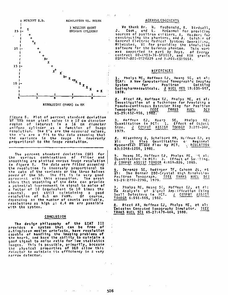
25
20
15
10 |
4
I PERCENT S.
j _ X
! +x
5
D.
X+X
x+
16
RESOLUTION VS. KOISK
1 MILLION' COURTUMrOBH CVLIKDEP.
xv
X + X
17
X „* + X
8
RESOLUTION (FWHM) in MM
Figure 5. Plot of percent standard deviationof the nean pixel value in a 12 cm disasterregion of interest in a 16 cm diameteruniforci cylinder as a function of Imagoresolution. The X's are the measured values,the + 's are a fit to tha data assuming thatthe variance in the image is inverselyproportional to the Inage resolution.
The percent standard deviation (SD) forthe various corcbinations of filter andsmoothing are plotted versus image resolutionin figure 5. The data were fitted assumingthe resolution is inversely proportional tothe cube of the variance or the three halvespower of the SD. The fit 1s in very goodagrees*? rit with this assumption. The oraphshows that smoothing of the data can providea potential improvement in signal to noise ofa factor of 10 (equivalent to 10 times thecounts), yet still maintaining a goodresolution of 8.5 mm FWHM. Of course,depending on the number of counts available,resolutions as high «s 4.4 mm are possiblewith the system.
COHCLUSIOH
The design philosophy of the ECAT IIIprovides a system that can be free ofgating/scan notion artefacts, have resolutioncapable of handling the imaging problems ofthe heart, and have the ability to maintain agood signal to noise ratio for low statisticsimages. This is possible, primarily, bocauiethe physical properties of 8G0 allow thisdetector to maintain its efficiency in a verynarrow detector.
ACKHO»LEOGCi!E»TS_
We thank Dr. N. KacDonald, R. B i r d s a l l ,J . Cook, and L. tfcConnel fo r p rov id ingsources of pos i t r on e m i t t e r s , A. Heedori f o rcons t ruc t i ng the phantons, and J . Colsh. r c fGeneral E l e c t r i c Hedfcal Systems Operat ions,Milwaukee, VI f o r p rov id ing the s i m u l t t i o nsof tware f o r the Derenzo phantom. This workwas supported i n p a r t by Dept. of Eferqycon t rac t DE--AMO3-76-SFOO12, and HIH grantsUSPH57-R01-G*:24S39 and 1 -POl-f iS! 5554.
REFERENCES
1. Phelps ME, Hoffman EJ, Huang SC, et a l :TCAT: A Hew Computerized Tomograph*c InagingSystem for Positron EmittingRadiopharmaceuticals. J HUCl HEP 19:635-6*7,1978.
2. Ricci AR, Hoffman EO, Phelps HE, et a l :"Investigation of a Technique for Providing aPseudo-continuous Detector Ring for PositronTomography. IEEE TRAMS tlUCl SCINS-29:452-456,
3. Hoffman EJ, KuanjTJuanti ta t ion in PCT: 1 .Size. J COV.PUT ASSIST1979.
SC, Phelps K t :Ef fec t of Object
T0I10GP. 3:2S9-3fJf:,
£ . Wisenberg G, Schelbert HR, He'fman EJ, e tal : In Vivo Quant isat ion c RegionalHyocardTal FTood Flow by PCT. v .-.RCULATIOa63:1248-1258, 1981. "
5. Huang SC, Hoffman EJ. Phelps KE, t al :I Juant i ta t ion in PCT: 3. E f fec t of Sav - l i ng .J_ COHPUT ASSIST TOMOGR 4:819-826, 1S80.
£ . Derenzo SE, 8udinger TF, Cahoon JL, etal : The Donner 280-Crystal High Resolut ionPos i t ron Tonograph. I f EE TRAMS HUCt SCIMS-26:2790-2796, 1979.
7. Phelps KE. Huang SC, Hoffman EJ, et e l :A~n Analysis of S fgn i l Amp i i f i ca t i on UsingSmall Detectors in PCT. J COMPUT ASSISTTOHOGR 6:551-565, 1982. ~ !
8. Ricci AR, Hoffman EJ, Phelps ME. et a l :tnrission Computed Tomography Simulator. IEEETRAKS NUCL SCI HS-27:479-484, 1980.
508

A HIGH RESOLUTION DETECTION SYSTEMFOR POSITRON T0M06RAPHY
J.B. Barton, E.J. Hoffman
Divisions of Biophysics m d Muclear MedicineDepartment of Radtological Sciences, School of Medicine
end Laboratory of Nuclear MedicineUniversity of California, Los Angeles
J.S. Iwanczyk. A.J. Dtbrowski, J.H. Kusaiss
University of Southern CaliforniaInstitute for Physics and Imaging Science
4674 Adntraity Hay, Suite 932Marina Del Key. CA 90291
SUMMARY
The f e a s i b i l i t y of using a hybriddetect ion system, consist ing of a u l t t p l enarrow bismuth germanate (BGO1 crysta lscoupled to one pho tonu l t ip i i e r forcoincidence t i d i n g , and indiv idual nercurtc'iodide (Hgl2) photodetsctors coupled to eachBGO crystal to I d e n t i f y c rys ta ls ofI n t e r a c t i o n , was Invest igated for appl icat ionto positron tomography. The match betweenthe emission spectrum of B60 and thephotoresponse spectrun of HgI2 In cogioinationwith r e c m t l y developed HqI2 s-ray detectorand low noise preampl i f ie r technologyprovided the appropriate high s e n s i t i v i t y ,low noise environment required to detect thelow leve ls of s c i n t i l l a t i o n l i g h t produced Intiie absorption of 511 keV gaaaa-rays in BSO.Energy resoluton of 241 for 511 keV wasobtained with the BGO-HglZ detector , comparedto 181 for BGO with a PMT. Coincidenceresolving time for the HgtZ-BGO detector wasmeasured" to be 105 nanoseconds. Thisperformance of a non-opt1«ized detectorsystem I s nominally adequate forappropr iate ly designed tomographs.
INTRODUCTION
The spat ia l resolut ion achieved withcurrent positron tomographs 1s l i m i t e d to agreat extent by the intr insic resolution ofthe detector. Ultimately, at detectorIntrinsic resolution Is Improved, the effectsof positron range and noncollInearity ofannihilation radiation wi l l l im i t spatialresolution. This l imi t is about 2.B ma FNHHfor a 100 cm detector separation for positronemitters with a low endooint energy such asF-18 (1 ) . For positron emitters of higherendpoint energy, the positron range addsadditional width to the highest achievableresolution (2 ,3 ) . In order to approach thesephysical Un i ts to spatial resolution, theIntrinsic resolution of the dftector must beless than the contributions due to thephysical properties of positron decay.Bismuth germanate (BGO) detectors are able tomaintain high detection efficiency In a verynarrow or high resolution element (1 ,41 , and
are currently the detector of choice for highresolution tomography In systems 1n which noattempt Is aad* to ut i l ize t1me-of-fl IghtInformation.
The laportanc* of Intrinsic resolution 1nPCT has been reeaphasized In recent work Inwhich computer simulation studies showed thatnot only does high Intrinsic resolution givehigh Image resolution, but with theappropriate reconstruction f i l t e r , highIntr insic resolution allows one to reducenoise 1n the Image while s t i l l maintainingmuch of the Improved resolution Inherent In avery narrow detector (5 ,6 ) . Additionally,narrow detectors allow the construction of acircular tomograph that has adequate spatialsampling, to il low images to be free ofaliasing art-facts ( 7 ) , while the systemremains stationary.
Even with the smallest photonuitipl ler(PUT) currently available (Htnaraatsu R1635X,10 mm diao. ) , multiplane systems withreasonable slice thickness can havecenter-to-center spacing of adjacentdetectors no closer than about 6 mm when onePMT Is used per detector. In this work wereport preliminary results on the use ofmercuric Iodide (HgI2) for the detection ofscint i l la t ion l ight from the interaction ofannihilation radiation with BGO. I t Isproposed, that the use af HgI2 l ightdetectors for the Identification of thecrystal of Interaction combined with the useof PMTs for coincidence t ining, wi l l allowthe construction of a positron tomograph withBGO crystals tt narrow *s 2 aa.
SOLID STATE PHOTODETECTORS ASSCINTILLATION LIGHT DETECTORS
The use of a solid-state device Inconjunction with a scfntillator for nuclearradiation detection was first reported byTuzzoHno et al (8). Subsequently, resultshave been reported using HaliTl). plastic andCsI(Tl) scintillators with silicon surfacebarrier diodes, cryogenically cooled SKL1)detectors, and Si avalanche diodes (9-15).While most efforts focused on the detectionof high energy charged particles ( E>5MeV ),Keil investigated the use of a CsI(Tl)
509

jcfntn la tor-Si photodiode device for gamiaaspeetrometry. The 662 KeV photopeak ofCs-137 was resolved with 191 energyresolution. The low energy Unit forphotopeak resolution with this device wasestimated to be about 180 KeV. SI avalanchediodes could potentially provide asubstantial Improvement In sensitivity oversurface barrier devices due to their Internalgain, but the full potential of these deviceshas not ytt been demonstrated.
REQUIREMENTS FOR DETECTION OF 511 KEV WITH BSO
The Integrated light output of BSO Is 101relative to KaKTt) *nd 121 relative toCsI(Tl) (16). In order for a photodetectorto resolve the light poises resulting fro*the Interaction of a 511 KeV photon fn B60,It Bust have at least three tiaes thesensitivity of the device described by Keilfor light in the region ef the emissionspectrtm o,f BSO (Ca. 480 nil). The emissionspectrum of CsI(Tl) Is aore closely Hatchedto the photoresponse of silicon photodtodesthan the emission spectrua fron BGO.
The low energy Unit for photopeakresolution of a scintlliator-photodlodespectrometer is set by the electronic noiselevel of the system which Is determined bythe detector leakage current, detectorcapacitance, components at the input stage ofthe preaapl Ifier, and the anplifiar pulseshaping network (17). The problem Isanalogous to low energy x-ray detection withsolid state detectors with the additionalrequirement that the photodetector spectralresponse be well Hatched to the scintillatoremission spectrum.
Figure 1. Comparison of the Missionspectrua of BGO and. the photocurrent of anHgI2 photodetector as a function efwavelength of incident light. The emissionspectrua of BGO is centered at 480nanometers; the photoresponse of this Hgl2photodetector is maximum at 575 nanoaeters.Photons of wavelength greater than 580nanometers do not generate significantphotocurrent since they have insufficentenergy to excite electrons to the conductionbond. The valve of the bandgap energy Is2.15 eV for Hgl2.
HgI2 AS A PHOTODETICTOR
Although HgI2 had not sreviously beenconsidered as a photodetector. the recentresults obtained with roaa tenperature x-raydetectors (18-21). ultra-low noisepreamplIfication electronics (17) and thegood aatch between the HgI2 spectralphotoresponse and the eaiss'an spectrum of660 (22). figure 1. indicates that HgI2 Bightalso serve well as a sensitive photodetector.As an a-ray detector, HgI2 has bee* used toresolve energies below I fceV. Thiscorresponds to charge signals of less than250 electron*. The photon yield In BSO hasbeen quoted as 4/KeV (4) whid corresponds to2044 photons generated In BSD for 511 KeVabsorbed. If a reasonably efficient HgI2photodetector could be fabricated. It wouldbe expected to be capable cf resolving the511 keV photopeak when used with BGO. Adetailed description -ut the Hg!2photodetector construction «:d operation isgiven by Iwanczyk, et al (23).
EXPERIMENTAL
HgI2 detectors were fairieited to measurethe photoresponse of these devices and toassess their potential as detectors ofscintillation photons. The detectors werefabricated froa 300-1000 micron slices ofdetector grade Hg!2 grown *roa the vapor.Seal transparent entrance e'ectrodes wereprepared by evaporation of t thin layer ofPd, and rear electrodes were of acarbon-epoxy compound. The active area ofthese devices ranged from 15 to 100 squaremm.
A 4X4X4 am BGO crystal was coupled to thesemi transparent entrance electrode of an H9I2photodetector with 4X4 am active *re*. Thedetector was irradiated with 511 KeVgamma-rays fron a positron s:-irce. The Hg 12detector bias voltage was -1-30 volts and tnepreamplifier was of the resistor feedbacktype used with HgI2 x-ray detectors (17). Acommercial spectroscopy a»:'1f1er designedfor use with semiconductor «::ectors was usedalong with a multichannel am'yzer to measurethe pulse height distributer!. The energyspectrua of the positron soiree as recordedby the 8G0-HgI2 detector is shown In F1g.2.The energy resolution obta^ed was 24. andthe photopeak is well s»:irated from toenoise. The 24S energy resolution obtained isnot substantially worse than the 18-201 valuewhich Is typically obtiined .ten 860 is usedwith a PUT. The coincidence resolving tiaefor the Hg!2 photodetector kts aeasured to be105 nanoseconds, and the tiling spectrua forthe aeasureaent is shown in "lg.3.
DISCUSSION
The coincidence tioe resor t Ion obtainablewith a sciRtill«tor-sem1co>i:iCtor radiationdetector can be shown to be cit»ra1/ied by thescintniator decay time constant. theintegrated l ight output of ft scintt i lator ,the l ight transport eff1c:an<?y froa thescintillates- to the phot:Selector, thephotodetector quantua e'ficiency, t*eelectronic noise level of tie systea, and thecharge carrier transport time In tnesemiconductor. The theory zf leading ed;e
510

Figure 2. Energy spectrum of 511 keVqamma-rays from a positron source as recordedhy a prototype HgI2-9G0 spectrometer. TheBGO crystal measured 4X4X4 • « . the Hal2photodetector had a 4X4 «•" sensitive area.The electronics consisted of * low noi&echarge sensitive, resistor feedbackoreampHrier designed for use »ith HgI2 n-rtydetectors. tn<l standard linear amplifier foruse with solid state detectors. The energyresolution Is 24T, *nd the photopelk 1s wellseparated from the noise.
Sit
EV
E»
u.r>
NU
MB
ER
TIME RBSOUJTION
or MERCURIC IODIOC
l • •••
• '
FWKM
f 105 NSEC)
• i—J
ODELAY TIME t MICROSECONOS >
Figure 3. Tine resolution of prototypeHg!?-BGO detector «a* measured to be 105nanoseconds FWHH. The detector electronicswere the *ame as used to obtain the spectrumof figure 2.
photodetector quantum efficiency to be 60S,the light transport efficiency to be 30*, aniusing the value of electronic noise «easure4for the prototype Hg!2-BG0 spectrometer, thepredictions of figure * trt obtained. This•akes the tota? efficiency of the pair about18% and a predicted tine resolution of about12S nanoseconds. Derenzo (25) h«s calcualtedthat light collection efficiencies of 47* naybe obtained with partially coupled, narrow•GO crystals by shaping, and solid-statsphotodetector quantum efficiency approaching100X has been obtained with commerciallyavailable photodetectorj using u'tra-thlnentrance electrodes and/or antireHectivecoatings (26). It Is not unlikely that anOptimized entrance contact structure willalso yield quantum efficiency approachinjIQOt for HgI2. Using 100% fcr photodetectorquantuns efficiency and 471 for lighttransport efficiency^ coincidence timeresolution of better than 50 nanoseconds ispredicted as the limit for this device baseion figure 4. Additional Improvement In tin;
TOTAL EFFICIENCY
Figure 4. Prediction of modified leadinjedge theory of time resolution with solidstate detectors emphasizing the improvementto be expected xith Improved totalefficiency, where total efficiency. 1s theproduct of photodetector quantum efficiencyand l ight transport efficiency.
timing for solid state detectors (24). hasseen modified to account for the fact thatthe charge signal Is developed over the decaytime of the s d n t i l i a t o r . The thsoi-yIndicates that the charge carrier transittime has a relatively minor effect on thetime resolution. For a given scint i l iatorthe light yield is fixed, and the timeresolution depends on the electronic noiselevel and tire total efficiency of theBG0-HgI2 p^ir, where the total efficiency IsJust thi product of the l ight transportefficiency and the photodetector quantumefficiency. Estimating the HgI2
resolution Is predicted to accompanyImprovements In system electronic noise. Thenoise level assumed 1n calculating figure 4was based on the value measured foe one ofthe f i r s t successful devices, and since thattime lower values have been observed.
Although the prediction of better than SOnanoseconds coincidence timing resolution maybe adequate for systems limited to 'io»count-rite studies. I t is desireahle to havebetter time resolution, especially i f thecapability of dynamic studies with astationary ring 1s desired. * design «h1ck
uti l izes both the high spatial resolutioncapabilities of the BG0-HgI2 detsctor arid thehigh temporal r'.soluton capabilities of th*
511

BGO-PMT detector Is shown in tne conceptualdrawing of figure 5. Tne detector consistsof a relat ively large PMT coupled to « numberof BGO crystals (probably through * l ightpipe to provide uniform timing response).Each BGO crystal 1s connected to anIndividual HgI2 detector and preamplifier toIndicate which element of the detector wasInvolved In a coincidence event Indicated bythe PMT. A positron tomograph Mil l consistof perhaps <0 to BO of these units per r ing.
In this configuration the relevantcoincidence resolving time Is between theHgI2 detector and the PMT on the sane BGOcrysta l . Since the fast tilling Is performedbetween PHT's. the HgI2 timing need only befast enough for the relat ively low totalcount rate for the group of detectors on thecoincident PHT's. The primary concern forthis timing Is that , in a coincidence,Instead of two detectors being ident i f ied ,three or more would be Identif ied because ofaccidental overlap of unrelated addressstrobes wf-th the coincidence strobe, leavingthe identity of the true crystals ambiguous.In the ECAT I I (27) and Keuro?CAT (28 ) . onesixth and one eighth of a l l events aremultiplexed through single coincidencecircuits anil the width of the address strobestre ion nanoseconds and the loss of data dueto t r ip le events Is low. In this system. I fno Improvement In BGO-Hgl2 time resolutionwere obtained, 200 nanoseconds addressstrobes would be required, but each latchwould only be handling 1/80 of the dataInstead of 1/8 of the data.
Improvements 1n the Hgl2 photodetectorsensit iv i ty and timing characteristics lireexpected to accompany development of detectorfabrication technology and electronics forthis applicaton. An optimized entrancewindow can yield a substantial Improvement Inthe Hg 12 signal. The optical couplingbetween Hg 12 and BGO has not been optimized.Studies are bsing performed to find the bestmethod of preparing a f l a t , uniform Hgl?surface for coupling to BGO. Thescint t l la ter may be shaped to optimize thel ight transfer tc both the PMT and the HgI2photodetector. The best optical couplingmaterial for the Hgl? photodetector must befound within the constraints imposed by thechemical reactivity of HgI2.
CONCLUSION
These preliminary data show that the HglZphotodetecetor Is capable of detecting thesc in t i l l a t ion l ight from 511 keV interactionsin BGO and that the timing Is adequate forfdent i f icat lon of the crystal of Interactionthough not adequate for direct coincidencetiming. The technique offers the possibi l i tyof reducing the detector width to theresolution l imits Imposed by the propertiesof positron decay and annihilation. A largefraction of the expense of HgI2 Is in thefabrication of the detectors and not in thecost of raw materials, thus i t is possiblethat, with development, the technique couldbecome cost effective.
Figure 5. Conceptual drawing of hybridHgI2-PHT-BG0 detector. This design combinesthe high spatial resolution capabil i t ies ofthe HgU-BGO detector with the high temporalresolution capabil i t ies of the BGO-PMTdetector.
ACKNOWLEDGEMENTS
This wort was supported in par t byDepartment of Energy contractsDE-AM03-76-SF00012 (UCLA). andDE-AM03-76-SF00113 (USC). The HgI2 c rys ta lsfor t h i s work were supplied by EG&G advancedmeasurement: group, Santa Barbara,California.
REFERENCES
. Riccl AR, Hoffman EJ, Phelps ME, Huang SC, PlummerD, Carson R: Investigation of a Technique forProviding a Pseudo-Continuous Detector Ring forPositron Tomography. IEEE Trans Nucl SciNS-29:452-456, 1982.
. Phelps HE, Hoffman EJ, Huang SC, Ter-Pogoss1an MM:Effect of Positron Range on Spatial Resolution. JNucl Hed 16:6*9-652, 1975.
. Derenzo SE: Precision Measurement of AnnihilationPoint Spread Distributions for Medically ImportantPositron Emitters. Proceedings ofthe 5thInternational Conference on Positron Annihilation,U k t Yamanaka, Japan, 1979, pp 819-824.
. Rerenzo SE: Monte Carlo Calculations of theDetection Efficiency of Arrays of NaKTl ) , BGO.r.sF, Ge. and Plastic Detectors for 511 keV Photons.1IEEE Trans Nucl Sci HS-28:131-136. 1981.
, Phclps HE. Hoffman EJ, Huang SC: Positron ConfutedTomography-Present and Future Design Alternatives.Medical Rjdionucllde Imaging 19B0, Vo l .1 , IAEA-SH-247/203:193-230.
> Phelps HE, Huang SC, Hoffman JJ, Plummer D, CarsonR: An Analysis of Signal Mmplificaton Using SmallDetectors 1n Positron Tomography. J Comput AssistTomogr 6:551-565. 1982.Huang SC, Hoffman EJ. Phelps ME, Kuhl OE:Quantitation In Positron Tomography: 3. Effect ofSampling. J Comput Assist Tomogr 4:819-826, 1980.
512
8. Tuzzolino AJ. Hub bard EL, Perkins MA, Fan CY:Photoeffects In Silicon Surface-Barrier Diodes. JApp Phys 33:143-155. 1962.
9. Blami res NG: Combination of a Scintil lator and aSemiconductor Photodiode for Nuclear ParticleDetection. Nucl Inst Heth 24:441-444. 1963.
10. Fan CY: Detection of Sclntillaton Photons withPhotodiodes. Rev Set Instr 35:158-163, 1963
11. Keil G: Gamma-Ray Spectrranetry with *Sc'ntniator-Photoriiode Combination. Nucl InstMsth 66:167-172, 1966.
12. Batman JE: Some K M Scinttliator-PhotodtodeDetectors for High Energy Charged Particles. Nueltnst Meth 67:93-102, 1969.
13. Batenan JE: A Solid State Scintillation Selectorfor High-Energy Charged Particles. Nucl tnst Meth71:261-268, 1969.
14. Bateman JE: Some Recent Results with aPhotodiode-Organic Scintllator Combination Used asa Detector for High Energy Charged Particles. NuclInst Meth 71:269-272, 1969.
15. Bateman x JE, Ozsan FE: A CryogenicScintiilator-Photodtede Detector for PenetratingCharged Particles. Nucl Inst Meth 108:403-407.
1C Farvkhi MR: Scintillaton Detectors for CTApplications an Overview of the History andState-of-the-Art. Presented at Korea Atomic EnergyInstitute Workshop on Transmission and EmissionComputed Tomography. July 14, 1978. Seoul, Korea.
17. Iwanczyk JS, Dabrowski U , Huth GC. Del Duca A,Schnepple V): A study of Low-Noise PreamplifierSystems for use with Room Tesperature MercuricIodide (Hgl2) X-Ray Detectors. IEEE Trans Hue SciNS-28:S79-S82, 1981.
18. Oabrcwski AJ, Iwanczyk JS, Barton JB, Huth GC,United R, Ortale C, Eco»onu TE, Turkevich AL:Performance of Room Temperature Mercuric Iodide(HgI2) Detectors In the Ultralow-Energy X-RayRegion. IEEE Trans Nuc Sci NS-28:536- 540. 1931.
19. Iwanczyk JS, Kusniss JH. Dabrowski AJ. Barton JB,Huth GC. Econorou TE, Turkevich AL:Rocm-Temperature Mercuric Iodide Speetrometry forLow Energy X- Rays. Hud Inst Meth 193:73-77,1982.
20. Dabrowski AJ: Sol Id-State Room-Temperature EnergyDispersive X-Ray Oetectors. In: Advances In X-RayAnalysis V.2S, ed. by JC Russ, CS Barrett, FKPredeckt and OE Leyden: Plenum Publishing Canpany,1982. pp 1-30.
21. Barton JB, Dsorowski AJ, Iwanczyk JS, Kusmiss JH.Ricfcer G, Vailerga J , Varren A, Squillante MR. LisS, Entire G: Performance of Room-Temperature X-Ray Detectors Made From Mercuric Iodide (HgI2)Platelets. In: Advances in X- Ray Analysis V.25.t d . by JC Russ. CS Barrett. PK Perdecki. and OELeyden: Plenum Publishing Conpiny. 1982. pp 31-37.
22. Nestor OH. Huang CT: Bismuth Gernanate: A Hjgh-2Gaama-Ray and Charged Particle Detector. IEEETrans Nuc Set NS-22:68-71, 1975.
23. Iwanczyk JS, Barton JB, Dabrowski AJ. Xusariss JH.Szjnczyk MM: A Novel Radiation Detector Consistingof an Hgl2 Photodetcctor Coupled to • Scintniator.IEEE Trans Nuc Sci NS-30. 1983.
24. Bertolini B: Pulse Shape and Time Resolution. In:Semiconductor Detectors, ed. by G Bertolini, ACoche: North-Holland Publishing Company, 196B, pp243- 276
25. Derenzo SE. Riles JK: Monte Carlo Calculation ofthe Optical Coupling Between Bismuth GernanateCrystals and Photomiitiplier Tubes. IEEE Trans NucSci NS-29:191-19S. 1982.
26. Sze SM, Physics of Semiconductor Devices. JohnWiley and Sons, 1981.
27. Phelps ME, Hoffman EJ, Huang SC. et a l . : ECAT: AHew Computerized Topographic Imaging System forPositron Emitting Radipharnaceuticais. J Nuc Med19:635-647, 1978.
28. Hoffman EJ, Phelps HE, Huang SC. et a ! . :Evaluating the Performance of Multiplane Tomograph:Designed for Brain Imaging. IEEE Trans Nuc SciNS-29:469 -473, 1982.
513

* One Dimensional Pos i t ion Sens i t ive BGO Detector for Emission
Computerized Tomography
C. Eurnham, J. Bradshaw.D. Kaufman, D. Chesler, J. Correia and
G.L. Brownell
Physics Research Laboratory
Massachusetts General Hospital
Boston, HA 82114
Introduction
The availability of BGO as a detector material for PET
imaging allows a factor of three improvement in both sensitivity
and spatial resolution over Nal detector designs. Attempts to
develop a position sensitive PET detector based on technology used
in the Anger Scintillation caaera, a device for lower energy ganna
ray imaging have to date not been acceptable. Presently, positron
cameras employ detectors with designs in which small detector
elements act independently in determining the path of
annihilation quanta ^f2'3'*. The concept of a scintillation camera
ring detector with analog position detection logic offers an
opportunity to overcome many of the problems of present designs
and to achieve both high sensitivity and resolution with a
stationary instrument 5» 6» 7. These are desirable features from an
applications standpoint.
Several different position sensitive detector designs have
been evaluated by computer simulation. Detection efficiency,
Compton scattering effects, optics, position sensing and
514

reconstruction artifacts have been studied. As a result of these
studies, we have developed a position sensitive detector design
consisting of an array of very thin crystals viewed through a
light guide by an array of PM tubes (Fig. 1) . The space between
detector elements is small and contains no shielding. It avoids
problems of a continuous crystal designs,i.e. low sensitivity,
dead time and edge effect.
In summary, the characteristics exhibited by this detector
are the following. The number of elements used in fabricating the
pseudo-continuous detector does not affect the sensitivity.
Events in which there is Compton scattering between crystals are
not discarded, rather the center of brightness is found; the
photofraction is that of a relatively large detector, a result
that enhances both sensitivity and stability.
The spatial resolution is determined by the stopping power of
the detector material, the position sensing logic and the optical
design. The use of many narrow elements rather than a continuous
crystal results in excellent optical properties. However, a
resolution constraint is imposed by the crystal width. Each
scintillation event is viewed through the light guide by an
effectively large PM tube (i.e., 2 or 3 small PH tubes). Nearly
all the light is collected so that little position accuracy is
lost and the coincidence resolving time is not greatly degraded.
515
Studies
Dptectioi) Efficiency and He.solut.inn
The detection efficiency was investigated using a Monte-Carlo
simulation program that modeled the interaction of photons
impinging on the crystal surface. Detectors of cross-section S
(wide) x T (high) were modeled to establish sensitivity and
spatial resolution bounds (Fig. 2). Only photo-fraction events
were recorded. Although a continuous ring detector allows unity
packing density and near total detection of incident photons, the
limiting sensitivity is less than unity because of Compton photons
that escape from the detector. The position logic finds the center
of brightness of multiple interaction events. The loss in
positional information resulting from Compton scattering within
the detector is also shown in Fig. 2. Angle of incidenced effects
contribute an addition resolution loss and are discussed below.
In order to simulate various crystal design configurations we
studied the light collection using the Monte-Carlo method6, under
the following assumptions:
1. The site of interaction is a point source isotropic
emitter.
2. Photons obey Snells law and Fresnel reflection at
boundaries.
3. Diffuse surfaces reflect uniformly into a cone, usually
516

/2 radians.
4. Spectral surfaces reverse the component of a photon's
direction.
Good agreement between measured and calculated light
distributions were achieved when 80 » of t.ie optical window
between the crystal and light guide was a diffuse surface. A large
fraction of spectral reflective surface decreased the average path
length rays. The light spread function is approximately of the
form . l/(l+x2), where x is the position coordinate.
Position Sensing
The limiting spatial resolution of the device has been
calculated for the position sensing logic based on a maximum
likelihood estimator of event location. The variance of the
position is given by;
2 _ S'(x)2/S(x) dx
where S(x) is the measured light distribution. Losses in
resolution due to sampling have also be.en studied. If the light
spread function (LSF) becomes smaller than the sampling distance,
usually defined by the photomultiplier tube diameter, the
resolution is degraded.
A calculation including phototube noise and assuming a LSF
with FWHH equal to the phototube diameter gives the following
relation for detector resolution, R:
517
RFWHM = <PHR> x (DIAM) X (.6)
where: PHR is the pulse height resolution, FWHH, DIAH is the PH
tube spacing and a l/(l+x2) LSF is assumed.
CoiintratR Considerations
The maximum count rate for detectors with equivalent
geometries will be proportional to the quotient of the detector
efficiency squared and the coincidence resolving time. The
detector's near unity packing density and high photofraction
enhance the detection efficiency. Collecting a large fraction of
the light from a scintillation reduces the coincidence resolving
time. A narrow LSF minimizes any positioning errors due to pulse
pileup but as discussed above, the LSF must be a photomultiplier
diameter in extent. There are pile up errors when simultaneous
events appear with in 2.5 PHTube spacings of each other. It is
expected that random coincidence events will limit the countrate
before deadtime.
Detector Development
A detector employing a pseudo-continuous ring of BGO and analog
type position sensing has been constructed. It was fabricated
using 360 x 2 x 3 x B.4cm BGO detector elements, a light guide 1
cm thick x 1.6 cm wide x 52cm ID and 90 2cm diameter PH tubes. The
position of a scintillation event is identified using logic based
518

on the maximum likelihood estimator. A stationary, high spatial
resolution high detection efficiency tomograph is achieved using
this approach.
Detector Construction
Fig. 3. shows details of the technique used tu fabricate the
detector. The principal structure - the annular shaped light
guide, is fabricated from a single piece of U.V. transmitting cast
acrylic and is polished on all sides. The outside face is made
with 90 facets to receive the PH tubes, the inside face is
circular. The PH tubes are RCA Type S8S012E. The BGO detector
elements were supplied by the Harshaw Chemical Company. Theit
137Cs energy resolution ranged between 17 and 21».
The electronics package is shown in Fig. 4. A preamplifier
board is mounted near each PH tube. There are three outputs from
each preamp, a timing signal and positive and negative linear
signals.
Detection Logic
A block diagram of the detector logic is shown in Fig. 5.
The three principal aspects are: optical, coincidence
determination and crystal position identification.
Optics- The purpose of the optics is to allow sensing the position
of a large number of detector elements using a smaller .lumber of
519
photo-sensors and further to find the center of brightness of
multiple interaction events and thus to minimiEe their effect.
The light guide spreads the light between several PH tubes in a
predictable way so that the resultant PH signals can be analyzed
to find the correct position.
Coincidence frogic- When a scintillation occurs the light is spread
out into 2-3 adjacent phototubes. The sum and difference of
signals from the adjacent phototubes is use<2 to derive a single
timing signal for each scintillation event. Tnis provides a timing
signal for the coincidence logic and a coarse estimate of position
so that only a small fraction of the detectors need be examined to
identify the particular crystal. The position of the coincidenct
pair is found and used by the crystal position sensing logic.
The positions of the particular crystal pair are found arid then
encoded using clockwise and counter-clockwise priorities. The sum
and difference of these codes is used to find the angle snd radius
of the coincident pair. Data are accumulated as 180 consecutive
views with 142 lines per view or 25,560 pairs.
t.ocation of Scintillating Crystal-We have developed a technique
for determining which crystal produced the light detectedby the
phototubes. The technique is simple to implement and optimum in
the sense that it chooses the most likely crystal, given the
detected light distribution.
In this detection procedure there is an amplifier circuit
520

associated with the boundary between each pair of adjacent
crystals, as shown in Fig. 6. Each amplifier output is the
weighted sum of the nearest 2 or 3 phototube outputs. The
weightings 7 differ from each crystal position, but are repeated
for each phototube around the ring.
Each amplifier circuit is designed so that its output will be
positive when it is more probable that the light was emitted by
the crystal to its right than by the crystal to its left.
Similarly the amplifier output will be negative when the crystal
to its left is more likely than the crystal to its right. The
most likely crystal is the one who >e adjacent amplifier output on
the right side is negative.
This logic is inherently stabile and simple to implement.
Because the signals at the output of the amplifiers are both
positive and negative going RC coupling to the comparator may be
used to avoid DC drift problems. The total complexity is
equivalent to one IC per detector element.
Measurements were made using a 3 PH tube section of the
ring to evaluate the position sensing logic. A block diagram of
the logic used is shown in Fig. 6.
The intrinsic resolution of the position sensing electronics
is shown in Fig. 7. Referring to figure 6, this data shows the
distribution of E m and E p for a pair of 4.5 mm wide crystals whose
junction is centered on m and p and for a single 4.5mm BGO crystal
centered at m and p. Em, the amplifier output is proportional to
the crystal position near zero. This data demonstrate^ an
intrinsic resolution of less than 4 mm and uniformity of
resolution for a crystal over and between PM tubes.
The corresponding limiting spatial resolution was calculated6
to be 4mm using a PH tube spacing of 1.9cm and an energy
resolution of 35%. There is good agreement between measured and
calculated resolution. The uniformity of resolution was achieved
by selection of the appropriate light quide thickness. The major
effect of improving this resolution would be improved stability.
The probability of error in detecting a particular detector
element was measured using a signal detector element. Typical data
is shown in Fig. 6
Preliminary measurements with the assembled detector show the
time resolution to be 9nsec, FWHM single pair of PM tubes. The
energy spectrum has the high photofraction expected, and the
central position line source resolution is 4 mm.
The calculated image resolution is shown in Fig. 9 includes
angle of incidence pffects and crystal identification errors.
522

Reference.1.:
1.
3.
4.
5.
6.
7.
Derenzo, S.li., Hudinger, T.F., Huesman, R.H., Cahoon, J.L. andVuletich, T.: "Imaging Properties of a Positron Tomograph with280 BGO Crystals," IEEE Transactions on Nuclear Science, Vol. US-20, Ho. 1, February, 1901.
Eriksson, L., liohm, Chr., Kesselberg, M., Blomqvist, C , Litton, J.,Widen, L., Uerystrom, II., Ericson, K., and Greitz, T.: "A FourRing Positron Camera System for Emission Tomography of the Brain,"IEEE Transactions on Nuclear Science, Vol. HS-29, No. 1 February1982.
Brooks, R.A., Sank, V.J., Friauf, W.S., Leighton, fi.n., Cascic, H.E.and DiChiro, G.: "Design Considerations for Positron EmissionTomography," IEEE Transactions on Biomedical Engineering, Vol.BML-2E, No. 2, February 1981.
Takami, K., et al: "Design Consideration for a Continuously RotatingPositron Computed Tomography," IEEE Transactions on Nuclear Science,Vol. ME-29, Ho. 1, February, 1982.
Muehllehner, G., Colsher, J.G.: "Use of Position Sensitive Detectorsin Positron Imaging," IEEE, NS-27, (1) 1980.
Burnham, C.A., Bradshaw, J., Kaufman, D., Chesler, D.A., andBrownell, G.L.: "One Dimensional Scintillation Cameras for PositronECT Pxincj Detectors," IEEE Transactions on Nuclear Science, Vol.NS-20, No. 1, February 1981.
Burnham, C.A., Bradshaw, J., Kaufman, D., Chesler, D.A., and Brownell,G.L.: "A Positron Tonograph Employing A One Dimension BGOEcintiallation Camera", IEEE Transactions on Nuclear Science, Vol.NS-30, No. 1, February, 1903.
— — - — ija,,
/ HIIDf
Fit.
momKUCTOR
E£
*-0Q0
l.tao .
Fig, 2 BCIO detector characteristics computed with a Monte-Carlosimulation program. Left: Sensitivity vs. detector thickness fora continous section of crystal with cross section L x Tcm thick.Right: Loss in positional information due to Compton scatteringin above crystal T=3cra center brightness for rays uniform dis-tributed across detector at 0, 10,000 photo fraction events.
Bia'jr.ii.iatic drawing showing die desing concept for a stationary mulU-rinj I'LT cii.ici'd ,uiu a suitable one-dimensional position sensitiveuetootor.
Fig, 3 View of the analog ring detector under construction. Startingat the aperature there are three rings. The first two are foam rubberlight shields; the third is the fiOO Detector. The 3uO eJ.emnnts arcclose packed and appear as a continuous ring. Next Is the clear liphtRuiJe and 90 phototubes, both the phototubes and detoctor elements areattached to the light puide with nn adhesive optical coupling. TheJiRht f.utJc is held to the base plate by 10 support brackets. Thevolt-ipL' divider networks from a MTV- outside the phototubes.
52 J

Fig, 5 View of Che analog ring detector under construction. Starting at tde aperturethere are three rings. The first two are foam rubber light shields; the third is theBGO Detector. The 360 elements are close packed and appear as a continuous ring. Nextis the clear light guide and 90 phototubes, both the phototubes and detector elementsare attached to the light guide with an adhesive eptical coupling. The light guide isheld to the base plate by 10 support brackets. The voltage divider netvorhs from aring outside the phototubes.
525
Fig. 6 Simplified schenicic of the position sensing logic. For eech detectorelements there is a corresponding summing amplifier, RC coupling network,comparator, and gate and D type flip-flop. WeiRhtitiR resistor': are chosen.men that ai* amplifier would provide a null output if a scintillating crystalwere at the corresponding boundaries, i.e., Ev.n,p, A polarity reversal fit theoutput of adjacent amplifiers identifies the particular crystal*
= A-B A-C
Fig. 7 Intrinsic resolution of the Doo^ion sensing electronic*. Referring tofigure 6, this data shows the distribution of E j and Ep for a pair of <t.5tnm videcrystals whose junction is centered on m and p and for a single 4.5mm liCO crystalcentered at si and p. The ampllfitr output is proporC.lonai to the crystal posi-tion near zero. The resolution is uniform and less than 4mm.
PDSniDH OF
BntCTOR ttEKDIT3 Z 3
gPO
SIT
i
VEIIT
S
1 -
1
2
3
ll
1*
4
84
11
0
0
0
0
11
•73
JO
D
0
0
9
SO
10
0
0
0
0
12
82
5
OF
KKCIOP. turctn
Fip,. H Accuracy of Identifying asingle detrctor element; placed atposition. 1,?,3 mid 4 in Kljj. ft.
toss c« smim ssouraen M «
•i •• •»
Fij>. 9 Calculated resolution in the rndlal (R)and tanpr.ntial (T) direction. Che crystal widthin 4mm and the crystal thickness is 3cm. PE isthe probability of error in ^Qtermlninp thescintillating ciystaJ, A Nanninft weighting isused in the reronstruction algorithm.
S26

TEST OF AN ARRAY OF SEVEN HEXAGONAL BGO CRYSTALSFOR HiGH ENERGY GAMMA RAY SPECTROSCOPY
Session I
HIGH ENERGY EXPERIMENTAL TESTS
L. Adiels5, G. Backenstoss1, I. Borgstrom', S. Carius' ,S. Charalambous1, K. Fransson1, Ch. Findeisen1, D. Hatzifotiadou3,
H. Kaspar\ A. Kerek", P. Psvlopoulos1, T . Meyer1, J . Repond1,P. G. Seiler', L. Tauscher1. D. Trb'ster1, K. Zioutas3
Basel1 - Stockholm* - Thessaloniki1 CollaborationCERN, Geneva, Switzerland
A set-up of seven hexagonal BGO blocks has been tested with pions and elec-trons of energies up to 300 MeV. Each block is 15 cm long and 4.33 cm wide(between parallel faces), and equipped with a photomultiplier*. The system'was provided by the end of 1981.
Before measuring in the particle beam, the seven modules were Individuallychecked with the 681 koV f-radiation o f a " 7 C s source. The resolution(FWHM) was found to be about 25%.
The uniformity' of the light output was measured with a coMimsted (6.3 mmhole in 10 cm thick Pb) beam of a * " C s source. The peak position P(x) wasmeasured as a function of the source position x along the crystal. A furthermeasurement of the uniformity of light output was done using minimum ioniz-ing (400 MeV/c) negative plons, shot through the crystal perpendicularly toits axis, and triggered with a small (2x3)mm" plastic scintillator. The energydeposited by ionization was about 30 MeV, yielding a peak of about 16% FWHMin all modules.
The uniformity of light output was found to vary drastically as a function ofdistance from entry into the crystal, and to be quite different from module tomodule. Ths homogeneity ( * [P(x) - P(5cm)] / P(5cm) ) is plotted in Fig. 1a% a function of distance from entry into the crystal, for the best module(#1) and the worst one («6).
4 ) SIN, Villigen, Switzerland.' ) Hamamatsu R980.•) Provided by Harshaw, Solon, USA.
1 -
527528

Axial posiHon(cm)
Figure 1. Homogeneity for the best and the worst of the seven mo-dules as measured with a 400 MeV/c pion beam and a colli-mated Cs source. The photomultiplier is mounted at an axi-al position of 15 cm.
It is first observed that the homogeneity measured with a radioactive sourcefollows closely the one measured with pions, except for the last two centime-tres in front of the photomultiplier. This is expected, since the light pro-duced by the source comes from the crystals lateral surface and is more total-ly reflected at the photomultiplier face of the crystal the closer the lightsource is placed to this face. The steep rise of homogeneity in this regionwhen measured with pions is due to the increasing importance of direct light.
It is secondly observed, that the inhomogeneity can be as high as 30%, and isbelow 5% only within the first seven centimetres of the crystals. This is pro-bably due • ' the poor optical quality of the crystals and/or due to insuffi-cient compe. >n.
The resolut-. the system of seven modules for electromagnetic showerswas measured by shooting electrons into the system along the axis of the cen-tral crystal. The electron beam Wits again triggered by a (2x2)mm* plasticscintillator. Data was taken event by event. The energy was reconstructedoff-line after proper intercalibration of the modules. The result is shown inFig. 2. The mesured points follow an energy dependence of the form
AE 4.1%[FVVHM] =
E E°-5a[GeV]
529
2520
10
8
6
L
—r—i 1—1
-
-
II ... I
~l—t—nr
T1
1 f t t
T 1
i
*
~I
0
9
V .-o-•
T r~1 1 1 1 1 1 1-
Measurements
EGS-Calculations
-6 A
I I I i i i f i i
50 100 250Energy (MeVl
500
Figure 2. Energy resolution measured with an electron beam and cal-culated with ECS for a system of seven hexagons (IS cmlength). The beam Is shot into the centre of the centralmodule.
Comparison with EGS calculations show, that from 200 MeV upwards the mea-sured resolution is almost in agreement with the calculation. Below ISO MeV,however, the discrepancies are important.
As crystal growing techniques improved, a now hexagonal crystal of 20 cmlength and 5.1 cm width, and of good optical quality, equipped with a 2 in.photomultiplier" was provided' In July 1982. Homogeneity tests as describedabove were carried out. The results are shown in Fig. 3. The homogeneityis excellent over the first 17 cm, and then deteriorates for reasons discussedabove. It should be noticed that this crystal was also surface compensatedfor light output uniformity.
>) Hamamatsu RI-306.') Provided by Harshaw, Solon, USA.
S3Q

o
o
12
10
8
6
4
0
— i — | — i — i — r ~
o n",800
• Cs 1 3 7
-i—i—i—i—i—•—i
MeV/c
• : : .
i—i—i—i—i—'—i—i
T
t
-
30
-5 2°
FWHM
('
10
e
1 I
/E(GeV)
i
-
•
k
i i
0.2 0.5 1.0 2.0 3.0Energy (MeV)
5 10Axial position (cm)
15 20Figure 4. Energy resolution of the 20 cm long hexagonal BGO as mea-
sured with radioactive sources.
Figure 3. Homogeneity for the 20 cm long hexagonal crystal.
The resolution was then measured with a series of radioactive sources, andfound to be
AE-(FWHMJ =-
0.49%
(see Fig. 4). In this energy region photon statistics dominate the resolution.It should be noted that the resolution at 661 keV is 19%. Compared to the re-solution obtained with the shorter (and optically worse) hexagons above (25%with a 1.5 in. phototube) the improvement could be explained by the in-creased photocathode surface alone (2 in. phototube). The resolution wasthen measured with electrons as described above. Since only one module wasused, the resolution is to a great extend determined by energy leakage. Theresult is shown in Fig. 5. Comparison with EGS calculations show that themeasured resolution is systematically larger than the c. culated one. Thisdeviation may be explained quantitativaly by the momentum resolution of theelectron beam.
20
15—
i a6
-
•
-
i
T
t
|
•
i I
i i 1 | 1
o Measurement.EQS
>
t *T
1 1
T
1
ft
1 1
-
-
-
-
100 250 500
Energy IMeV)
1000
Figure 5. Energy resolution of the 20 cm long hexagonal BGO as mea-sured with electrons, shot into the crystal centre. EGS cal-culations are shown for comparison.
531
532

The final resolution for a system of seven such crystals is expected to be3.2V*VE[GeVJ, and thus comparable with or even better than that for largemodular Nal(TI) detectors.
From these investigations we conclude, thatin order to achieve good energy resolution below 200 MeV, the individualmodules of a modular detector have to have good homogeneity;
- at energies above 200 MeV other factors, such as the intercalibration ofthe modules, become just as important as the uniformity of the crystals;poor optical quality of a crystal does not necassarly lead to a much inferi-or performance.
533
T : r c r .' \rr. e/iri'.IITTF.r '..TIT IMt'TCI i " 1 '
••!T! :•::! o .s A;T> IO rev *"
p r e s e n t e d by
l e l c m t Voptl
I 'a i - I ' lancV. - Ins t i tu t fur I h y s i l . D-ROOO V.unich <t<:. V'.-fierrany
ABSTRACT
fif-'f* cniorirctcr arrays consist ing of up to 1<> slabs of 30x30x700 i.r*with photodiodc (ITl) readout have been tested at the CM'J1 V?, in the enerpyrange fro.? 0,5 to 10 CeV. The energy resolution for electrons above 1 CVVpliteaus at o(l')/n ~ 1 *". . This i s consistent with tt.e internal resolutionof the ItCC material being n e g l i g i b l e after taking into account slov-crlccl-.ape and I'F1 noise. Tlio electron/hadron separat ion v:us 1>eI tor thar. 1:500over tlic ful l energy range, and further inprovetl to better thai; 1:1000 nftera prinit ive shepe cut. The energy deposition of t!<e showers, both laterallyami longituitinMly (rear leflk&gc) was found in u^recrxjit, at the O.I1 level ,with " ontc Carlo calculations using SLAC-F.d'S.
*" * wi«r.. sij-^rrleu in part by lie •'utiricsralnistcrit:r.* 1'Ui i'orsctiHnj1 win'"iVtrl i.».<--:-iv '!"'"!'•• ol V.-Ccri-nny
534

Ifco les t £sis±
Tiiis i s at i i i t c r i i re ; .ort on r e s u l t s obta ined with a "I "i.
e l e c t routine t ic ! c , r / c« lorir.c ter read out by photodiodes f IT'S ? . Thi.
experiment v.r.5 p c r f o n c d at the '1W te s t bean of tlie C;:rl' Pf, ilurin?.
/•ujust/KentcirlTer, I'JT?.. The ccrbors of the collaboration are l isted tclmv
11). The calorinctcr consisted of BfiC slabs of s i tes 30x30*200 r,imJ (21. As
arrangements ivcrc used: ( i ! 3x3 crystals and ( i U i '3x3+3' array uliicb i s
sliov.T. in l i f . l . In each case the EfiO «•» surrounded by Icad-scinti1 la tor
shower counters except rot the front side facinc the incident beam. There,
an apcrturc-iicfinir.E sc int i l la tar with a lx l co central hole was used as
veto. A snail sc int i i la tor in front served for triggering. Tile available
beat; r».-:cnta rauced froi 0.5 to 10 GeV. Table 1 l i s t s the electron fraction
of the bear, as function oi Eorccntur:. The Bomcntua; spread &p/p of t i e beam
was l;nowti to be less tJ.sn one percent for p>>l GeV. Vor lower moiienta. Ap/p
vas onV.r.ov!n. *n:c two refci:!;ov counters were used for triggering on an£/or
ta^gin^ electrons vs . pions. To avoid baseline shifts the particle flux v.'as
restricted to ciiout IICO f cr burst of 300 r.sec. A compilation of the test
conditions is ; ivcr in table 2, It can be seen that a number of parameters
>,ss far IIOT,' loinc optirizei:. Tor instance, the bias voltccc at the VVs was
not varied to iiu'ivtt.u.t I ly ninirizc r.oise frotr. the different channels (a
channel consist i;i.' oi I. 2, or -I )'!'s Kired in ]iaraljcl) . In addition. Die
distance 1:el-.;cer i':"« tur rrccrrs had to te as loil|! as 30 cr. thereby r.cliinc
the systci:. i.ore s c r s i t i v c to pickup noise am! adding iiiiv/untcd stray
capacitafcu.
535
I'ai'.c 3
"it..?, shows a |:locl; dicjjraii of the readout systur . flic I'l'j Eire
ccni.L'clo! to ioi. r.oisc cl.erite sensit ive prcarps. I'lic output sipr.iis i.-erc
hrincl'ed for online suwiinj and data recording onto r.trnctiu l,i]ic via peel:
sensin; A'iPs and a C.'.i'.t.V. link to a IT-60 cori'ulcr. T!,c sir.r.i.ls l.tre fi ltered
and shared it 2 si (or noise reduction.
I'or cnlforation, ire used ninimuoi ionizinc beer,' particles wliich deposit
about 100 TcV in 20 en of WO. Basical ly, the calibration procedure is
s traightforward. I'ovever. oith PDs operated at large dep le t i on layers
(caused by large reverse bias voltage) , there is a substantial addition.il
sifttal (~ 10 ,''cV equivalent)' for part ic les traversing tl'c I'Ms. I'ccausc of
the incomplete area i?atchifi(> of r>(iO end surface and l'Ifs, the calibration
spcctrim in practice cons is ts of a superposition of t^o f.ar.dau distributions
sh i f t ed by that 'nuc lear counter* e f f t c t . ?n deducing thcrcfrot> t
calibration factor arpropriate for e.ai. stioiier rcaswren.cnts. for lonj rro
crystals ( i . e . ^ lft r . l . ) the unshif^ed peak valve is tic optirun choice
whereas for inch shorter slabs it would be the shifted yen*..
l-incnritv
'1:e crt.;-le<i> readout systec, includinf tl.c 11(1.1 yield fror t!c !'("(•
rrray, v:as linear over two ortiers of EM\$nitude (r.ce fif..*) in encrry. The
daia rointp vcrc oVtuineu fror the online sui1. cf t ic " t-tiKr.m-ls in t ic '3.V31
firr,';'. M'l.<* 1 p1.. i- s I ertrjry t'Oint v/as taker froi. \ c pcnl; ol ll>c l.amlau
i: i si r ilwit ion ni rinir.ut. ionizinc prirticlcs (see nlovt*. Tin- hir.hur vpcrpy
- v i 1.1 u are i roi olectror spectra. The s l icht devintion fror. liiu-nrity at tie
, i-li | . - c r " c;<' ii; consistcrt t'itli tJ:c sbcvur le.T':-nt c.t;it'cted fron (onto
536

C a r l o (! . ( ' ) c a l c u l a t i o n s i : u i n r l ' ' T 1 3 ) .
'-i! i i i IlUiLfciisi' r
The cncr,~) rcsnlul ion of the I"CC' «rr>y« Kith PI1 readout m i assured lo
Ic icscrihei' tv the I'nl louinr. contribution!.
( o / D 3 l i« !")21 • (C.5/VF • O.3)2 * o r , 2 + o | ) c2 * o,,,,2 * % c i r : ,
2
where
1st tcrr intrinsic resolution due to photon s t a t i s t i c s
?.nd tcrr constant due to I>GO nonunifornity and electroric*
o fluctuations in shower leakage
c,,( contribution from charted particle* traversing the
depletion leyer nf the l*Ps. This nuclear counter effect
'sec above) was neglected in tht analysis since it is
srcll lor Ion* slabs.
tf,,|. I ' :oisc
a\)i..t, r.«u-vr>Lui- reread of i n c i d e n t bean
l o r a r iver se tup nf ' ' t l n l i s , l i e l a s t tv.o torus arc t r r c s M c by t i t user-
'i! II.L t e s t ticscrilu-L1 i.c re • re I i ab le nui:.lcrs cr.n be f.ivcn on ly lor
encrr i c ' / ! ; 1 *'t\' 11 ere t1 c i. o r t r t u r spread \;Q% i:rcwu. To v i s t m l i z e t i c
food r t s u l n l ioi ot tn irct ! , t !ic sv.cctmr. 'ohtainci! l or ^ f"cV c l e c t i o r s iv t i c
'."*7?fc.T array i s si t*vv it. l i n . < ! . >-c r c c s u r c d ; . 9 • , c ( r re s;-oi;(: i :r
to a I .;' ' . ' I.c iH>*.'tr.'!l slut* rlnnc a lready p i v e s • 1:.5 ' i i i .Ari. Tuv
irprovcricnl <H rest; lu i iii!> -iy \ c t o i n r cvunts v.itli 11 s i r t u t in t;i- «;ii!r > > i v i r
537
en toi lers i s t.'cr.-.onst ra ted in f i R . 5 a , b . f 'nccr icol v: ,Inci fur i l c r e s o l u t i o n
o'.taii ' i i i i or var ious m i s are f.ivcn in t a b l e ? . The c s s c r l i a l r e s u l t i s t l a t
the Cfcrgy r c s u t u l i o n p l a t e a u ; at n - 1 ' tor !' * 1 ^eV. After mifo|Uii;<> the
!;iuiv,i. L o u l r i l a i t i u p s ol lcal-npc, IT n o i s e , am' been SITCIX', at t l c s c e n e m i e s
llic i i . t crnnl r e s o l u t i o n o i the \ C,r, n a t c r i a l i t s e l f i s c n n s i s t c n t »it!> z e r o .
F.lcctron/hadroii
To demonstrate q u a l i t a t i v * l y the c l ean s e p c r a t i o n of e l e c t TOPS fror-
hadrons ( i . c . p i o n s in t h i s c o n t e x t ) . a pulse hr-ipbt s p e c t r u r of ( 5 0 TT- *
S'f e - ) at 1 TcV in the ' 3 x 3 ' array i s shown in lifl.r>. in lo f . s c a l e . Tor a
q t i c n t i t a t i v c c i m l y s i s o f the nion backfround under tl:c e l e c t r o n peel:, an
energy vindoi* of +2a was def ined around the c - i^eal., Thei*. spectrn were
recorded v;ith the e l e c t r o n s 'removed' by t i ) f erenknv ve to or < i i ) placinf,
a f'-J'- en t h i t l l ead absorber i n t o the bear, l i n e a t an upstrean d i s t a n c e of
If! B-. The nml'cr of c o u n t s u i t h i n the ±2a window v.ns talien as tl c pion
tiackc.rour.d (in the s p e c t r a taken w i t h the lead nb5Orlu<r, »r of iset o f tltc
window due to energy l o s s was taken in to accoui t ?. ;!u:-bcrs arc r iven in
tnble 4 . <c HRd a e / r r e j e c t i o n r a t i o of b e t t e r tnar i:5()0 o v e r the whole
crurpy rar.-.c. I'rpi:- the c e n t r a l s l a b o n l y , that rr.t iu i s even b e t t e r tl an
l:i(i('O, tiue tr the f a c t tlmf in c a s e o f a nuclear i n t e r a c t ior of the r i o n , a
s«l r.t;n 1 i o l i 'r^cticn of the encrpy r e l e n t e d i s <)ci*<isttvd o u t s i d e l!'-c c c n i r n l
rl.;li. ! incc the co<.:i)arison of c e n t r a l s lab v s . v.|oU> artav i s c r i : i v a l e n t to
;i ; t 11 i t i \ c s]ipv.*cr Slmpe c u t . t h e r e c e r t a i n l y i s roor l o r f u r t h e r
si'1-star t ir. I i r ; r o v c r e i t s by apply in* no re sophis t i ca tud r.bape cut s .
538

I'nr.e C
The method described rcre crucially depends on knowin? t i c rorontun of
the incident pert i d u to a precision comparable to the encrr.y re so In t ion of
the MX. In a rea l i s t i c tie lector for e+e- storage rir.ns. therefore, tl c
trading device ir front of the e .IT., calorimeter v/ill TLOIC l ikely be t i e
l i m i t i n g f a c t o r i r clecnov./hadror. discriminttiov th*n the VCV itself.
Comparison ••vjtli .'.qntc Carlo fPp.fi.) Calculations
The data purp.it a sensitive test of theoretical predictions for nigh
energy e.n. si over developments. the most advanced of the correspondinp MC
routines boinp. the KI.*C-FCP f3J. For the '3x3+3' array, the f o l l o v i n f
quantities were defined.
S12 cr.crj'y sui.r.cd over all 12 crystals
Central eve try deposited in central crystal only
F(adj) , sm over the A slabs feeing the central slob
"(corner) sur. t-ver the A corner slabs
P(rcar) sur over 3 rear vertical slabs
Fip.7 sl.cv/s the :'<' prediction lor the 'S(rear)' spcctrun in conparison
will: tic ta 1'ror a 5 f'eV rur. Tl.e spectra agree to ti.e level ol rt.l r of the
init ia l crerr.y. Table 5 e ives a cor parisor of the neek value s oi tl.e above
defined tii stribut ion:, as oltaint-t1 f ror Pfif (col urn II ami e:t;ierir ci tal t'.s ta
/col 2) ii-i.crc the iff ttahr, J.nri |*ecn irVividuatl;- t.'raprci! in viiito rarer,
^pain v;« t int1 e>f c l ien I afreet, er.t v?i thin the s ta t i s t i ca l errors .
539
1'aj.e 7
i n order to stiiily optical crosstalk betwecr. cr;. s t a l s , data were taJ;cn
^i 5 'cV with no ratcrial in between the crystals Uhe viiolt front V-x5 array
s t i l l In;inr *vrnj:i.ed in wl:i te p^pcr). Hie corrcspont! in? tiurters arc si ov.n in
the last col urn of table 5. A pronounced shift oi 1 ir.ht intensity froi,-, the
centra I slab to the surrounding ones i s ot served. 71:c effect ecu at least
partial ly be cxpl aincti by the following process. The transversely er-ittcti
1 ipht fror the central slab can enter adjacent slabs and be scattered by
crys ta l imperfect ions in the d i r e c t i o n of the Pi's. Y'e conclude that
reflectors or optical separators are needed between individual crys ta l s .
A sc^n.cntcd FCC caloriircter with photodiodc rcaOout has been tested in
beams of pions and electrons of 0,5 to 10 OeV, i . e . , at tl'.c highest energies
up t i l l now.
The measured energy resolution plateaus at o-l1 \.IiicI is corsistcnt
'.vith the theoretical l i c i t .
The t'nt a on energy resolution confirrr, the opt i i . i s t ic suf.f cst ions fror;.
previous t e s t s at lover energies, perforii.cd by other rrovps.
l.'lcctrcr/licdror. sera rat ion of better than ) : ft;w v ;.s obtained over the
whole encrpy r;M!co. Apply inf. e primitive shower sb.v, e cut rave further
iiiprpvcr'iM'.L to better than 1:1000,
";!;i! spatial ili*,t rihut ion ol encrcy for mil t i-f c*" u.r.. sluuvcrs vas found
in cNcclIert ai-rtctcnt \/itt 'otito Carlo calculations b.isei: on l'Vi'.
SAO

Pare
1'ci'ercnces
[1] Collaborat ir.i1 no I'be r s anil ins t i tu t ions :r.Lorcr.:. l . i H c t l , J.iiobhins, P.Pauss, l .Vopcl,I'nx-l'lnr.ct-inst itut fur fhysi!:, I'unichi V'.-Ocrt.anyI'.I.cbcau. l-'/assoni.ct, . .Vivarpent. L.A.P.F. . Annecy-lc-Vicux, Francei'.Jlteuer. Austrian Acui!. - ' c i . . I1:FI. Vienna. AustriaC.!)ore, r.V.cil l . l . / c i d l c r , I'niversite de Lausanne, Switzerlandi'.i'iroue, n.Kt icl.lsr.d, •!. Suniner, l'rincctor University. Princeton. V..J.l*.l.econ>tc, V.T.i"., Zurich, Switzerland
(21 larshew t'hccicol <'<>.
(31 !M..Fori! at.d V.l\t'el son. SI.AC-210 report .Stanford 197f!
Figure Captions
Fi i - . l . The test setup Tor the '3x3+3' array of lifio slabs in the OKIJI PS bean
FIR.?- . TIIC readout schcrc
Fir . 3 . Linearity curve. The nurbers next to the data points denotethe no. of AIT counts of the peel: of each aptctruu and, theattenuation factor used to avoid ADC overflow at 4 and 10 GeV.Further description see tex t .
Ei£_..'t. I'ulsc hcir.lit sneciruii of 4 (:oV e l e c t r o n s in the '3x3*3' array .fa) ucntral crystal only, (b) sixtr of e l l 12 c r y s t a l s .
Fiaj.5 . I'ulsc he i el-1 spectrur.' of 4 CeV c - in the ' 3 x 3 ' a r r a y ,(a) ratr cata , <bi sic^c vuto ar-plied.
Pulse height svcctrur.t for a 1 (IeV beaui composed of50"a- • 501'-c- in lor.aritiinic scale . The dashed l ine indicatesthe c::trarolutc<! pion bachgrouncl under tLe electron spectmn.
Sun of excrry i!c;>ositc<! in the rear 3 vert ical I'Ri: slabs of t i c'3x3-i3' array, for incident 5 tieV c- (data points ) , in cor..|inrisonv.ith the IT prediction usinr tl:c SI,*r-IK;.': code Oiistorr.11.-i
541
Table J . *-" 1 c«trr>r. content of Tfi ' n - ' tes t bean at ('!.!'! I1:
l'ar.c
l.UcV/c) 0.5 1.0 4.0 Jl.C
r.n - 4 0? ? < 1 ; i
Table 2+ Test conditions
[00 slab sizeno. of slabsdepth of calorimeterphotodiode type
alze
no. of PH/slabnoise equiv. »ifn«l
" . S Xtlabias voltagotemperaturecalibration
30x30x200 tun3x3, 3x3+318.5 r.l., 20.5 r.l.I'anainatau S1337, finonl x l cm2
3, 2 , 1~ 2 - 4 MeV~ 13 HeV- 10oV for a l l Pi's"- 22 , monitored f»otr.inicium ionizing n-
Table 3 . Tesulls on enorfy resolution
rfficV/c) n ; ! 1 . o(obs) o+ o
r j + o'noisc) o(ljcai-) c(unl'oli'cd) ton»r,t
4 4.1 1.75 1.30 O.f! 0.4 £ .1 1.05 '3j3 '*. 4 2.2 .!>5 .95 - .4 2.1 '3x3' <
•) 2 . 9 1 .25 .90 .7 . 410 ?..? 1 . 1 0 .90 . 8 .2
1 f.S 3 .S ! . n 1 .4 1.5o . s v..'- ' . . n < . n 2 . 0 2 . n
•3x313' * *.'M
r.fi
") su!>stnrtial at'ount of material in front ol cr.lorirctcr'""! '.>cttL-r "is
542

UJUJ E PS *9 l
UJUJ i
«U|(3
+y.
in
oe
rtw
•a
o
L
oc
cc
c. c«-; c.
: O C O© O w.
2 c
woo"J
s
u1
( J
p
~lti \i v. e:C; rr n -
i •--. c- '»- c
•, a o y u a gI I I I I 1 Tv: i ; K t i K u r:
*o *o « "o "o "o "St . W <- «- - w *
^ - »-t ^ -J- C • •
4
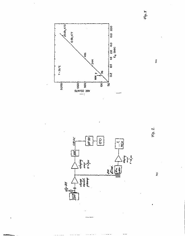
aav
cs)
IP
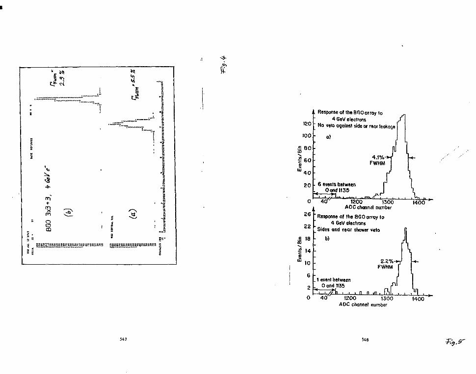
• s
nrf
oCD
I!
- I
IF
120
100
I 8 0
20
0
26
22
.£ 18m
Response of the BOO array to4 GeV electrons
No veto against side or rear leakage
a)
6 events between<__Oondll35
40"
FWHM
1200 1300AOC channel number
Response of the BGO array to4 GeV electrons
Sides and rear shower vetob)
2.2%FWHM
1 event betweenPond 1135
h
1400
• • n n4 0 " 1200 1300
AOC channel number1400
547 548
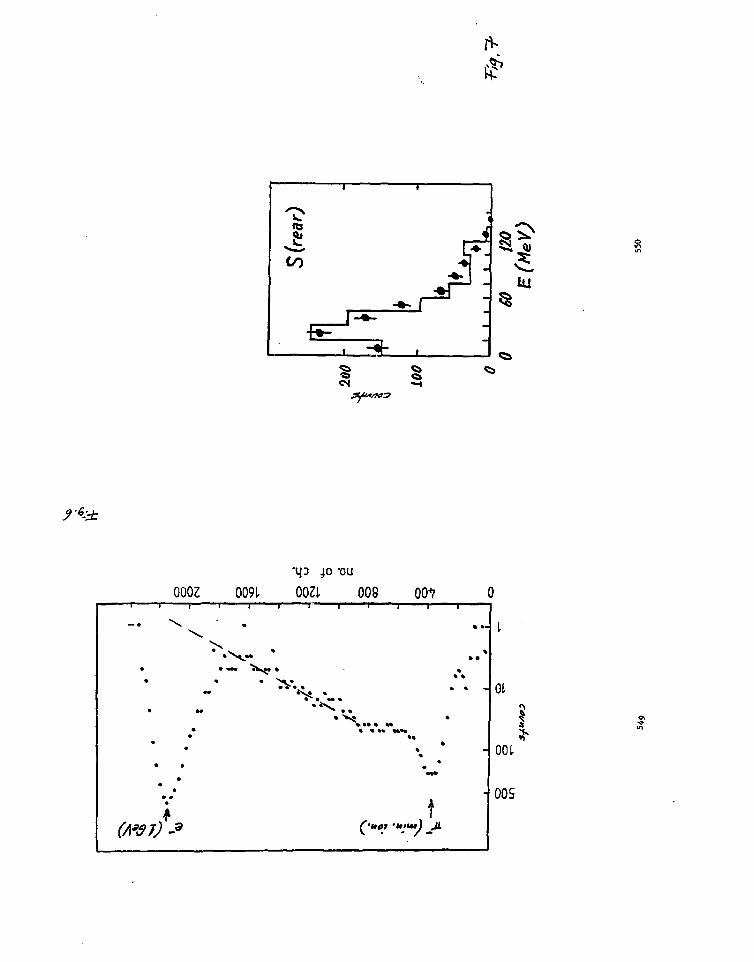
rt-
40 -ou0002
\
••
• ••
•* •
• •
(A*$7) -9
0091.
•
0031
' * * • ? * •
008
* • •
* * •
00^7 C
...
* -
••*
tit •it'u*) JL
- I
- 001
- oos

p£P-9/TG-286/NaI-0ll
LEF3 Internal NoteJ. C. Sens
M. A. van DrielJanuary 14, 1983
LINEARITY AND RESOLUTION OF PHOTOD1ODES
H. A. van Driel* and J. C. Sens*Stanford Linetr Accelerator Center''
A 52-cm-long Nal crystal with 150 ca1 hexagonally shaped cross section
was equipped, at one end, with a phatowiltlpller (AMPEREX X22O2B) and with
4 HANAHAT5U S1337 - 1010 BR 1 x 1 cm1 photodlodes. The setup is shown In
Fig. 1. The diodes were connected In parallel to a preamplifier and a
Canberra 1410 main amplifier with adjustable tiae constants for 'differentia-
tion and integration. The dependence of nolle and dark current on detector
voltage is shown in Fig. 2. The average energy deposited in the crystal by
cosmic rays, signalled by sclntlllatora above and below the crystal (Fig. 1)
was 70 HeV. The width of the distribution shown In Fig. 3 is due in part to
the spread in angle, in parr, to the landau tall.
The purpose of the measurement was to aake a comparison, on an event-to-
event basis, between the response of • photoaultiplier (PM) and a photodlode
(PD), when exposed to varying aaounts of light. For cosalc ray triggers
this comparison is shown in Fig. 4, where the pulseheight seen in the FH and
In the PD are conpared. For energy deposits up to 700 HeV the relation be-
tween PM and FD pulseheight* Is linear.
In the period November 5-7, 1982, the Nal was placed In Beaallne 19 and
exposed to positrons of 10 and 20 CeV. The beaa was defined with a single
sclntillator. Operating conditions were LINAC 180 pps, beamline 10 pps.
Every 100 msec the beam is gated on for times in the range 0.4-1.4 usec to
permit the passage of RF buckets at the rate of % 3 buckets/nsec. At 1.4
lisec the flux is 9 x 10' e'/mA, converted to 1-2 e+/mA. Typically, the LINAC
current was 300 UA
At 10 GeV the PD response was optimized by setting the bias voltage at
6V, and the tine constants for differentiation and integration to 0.7 and
1.0 usec respectively.
''Contribution to the First International Workshop on BGO, Princeton,November 10-13, 1982.
Permanent address: National Institute for Nuclear and High EnergyPhysics, Amsterdam, The Netherlands.
551
Data were taken uith the beamllne set for 0 and 20 GeV and for gate
lengths of 0.4, 0.8 and 1.4 psec. For n positrons in the gate, the energy
deposited per 100 asec cycle Is then n x 10, resp. n x 20 GeV. The number
n is Polsson distributed around it* mean value in which is proportion '1 to
the LINAC current.
Fig. 5 shows, event by event, the PM pulseheight versus the PD pulse-
height, with the bea» set for 10 GeV and H approximately equal to 2. Fig. 6
shows the projections on the PH and the PD axes. One observes a discrete
spectrun corresponding to n - 1, 2, 3, A, 5 and 6 positrons per bunch. At
each energy 10, 20, 30. . . GeV there is a sharp peak (encircled in Fig. 5)
and a lower energy tail.
Similar seta of data were obtained for different LINAC currents,
different gate lengths and for 20 GeV beaa energy. Fig. 7 shows the distri-
bution of positions over the different energies for TT - 3, in comparison
with the expected Poisson distribution. The agreement is good, except at
the bean energy (10 GeV), where there Is an excess of events.
Fig. 6 shows, with the beaa at 20 GeV, the 20 GeV pulseheight spectra
of the PM and the PD with higher gain. Both spectra again show a sharp
peak and a lower energy tall. The width of the PD peak is approximately
twice that of the FM peak. Fig. 9 shows the width (1 s.d.) of the PD and
the PH peaks for n • 1, 2, 3 and 4 corresponding to 20, 40, 60 and 80 GeV
for the 20 GeV beaa setting. The widths of the PM and PD signals are seen
to converge as the energy Increases.
In Fig. 10 we compare the weighted average pulseheights in the PD and
the PM for 10, 20, etc., GeV energy deposits in the crystal. This is an ex-
tension of the (continuous) cosmic ray data of Fig. 4 towards higher light
yields In the PM and PD. We observe that there is approxiaate linearity
and that at higher light yields the average pulseheight of the FD Increases
faster than that of the FM. Injecting known amounts of charge into the PD
preamplifier, we find that aost of this increase 1B due to non-linearity of
the electronics. Fig. 10 also shows the relation between the energy deposited
in the crystal and the amount of charge delivered by the FD. Here the
"electronic" non-linearity has been eliminated and we appear to be left with
a linear relation between electron energy and light yield in the PD. At
100 GeV the residual non-linearity is less than IX.
552

DISCUSSION
The data obtained In this test show that photomultipliers nay be
replaced by inexpensive, less bulky, magnetically insensitive photodlodes
without serious loss of resolution or linearity up to relatively high ener-
gies. An obvious disadvantage is the slowness of the response comnon to
all solid state detectors, and the relatively high noise. This Implies the
need for preamplifiers and pulseshaplng and Halts the application to in-
herently "slow" detectors: Nal', BCO and Pb glass.
At a sore quantitative level, some caution Is required in Interpreting
the results of this test. The results are effected by 3 factors:
1. Shower containaent calculations Indicate that •»> 90Z of the energy of a
10 GeV electron is deposited In the 20-rad-length-long, ISO cm2 Nal
crystal.
2. The light reaching the end face either fall* on the PH or on the PD's.
The end face is covered with reflecting ptjer with a 10 « diameter
hole to natch the PH. Assuming uniform illumination and 100Z absorp-
tion of the light falling on the PH, the ratio of the area Batching
factors of the PD's and the PH is 5.*X, sec Table I. The PD's are in
direct contact with the Mai; the PH views the crystal through •». 2 ca
air, a quartz window, i< 1/2 cm air and a *v> lb-ca-long light pipe. The
optical transmission coefficient has * large uncertainty; from reflec-
tions at the different windows we estimate tt to be SOX. The Hal
spectrum peaks at 410 nm. At W O na the ratio of the quantum efficien-
cies of the I'D and the PH Is 2.6. The ratio of the number of photo-
electrons (p.e.) seen by the PB and the PH Is thus 0.27. The effective
energy scale applicable to the PD data is thus shifted downwards by this
factor.
3. Since shower containment varies non-llnearly with energy, the response
of the crystal to n showers, each of energy E, differs from that to one
shower of energy nE. For exanpl* the rear laakage of a 20 GeV shower con-
tained in 20 rad lengths is-M.K, while that of two 10 GeV showers is 2 * 1.5*.
With these caveats we conclude:
a) From the observed linear relationship between the PH pulseheight
and the incident energy (nee Fig. 10), it follows that the fraction
553
of the energy deposited in the crystal is Independent of energy.
The linearity observed in the PD data suggests that the distribu-
tion of the light reaching the end fact does not vary significantly
vith energy.
b) At a given amount of energy deposited in the crystal, there is an
apparent difference In resolution between the PM and the PD spectra.
As pointed out In 2. above, this is due to the combined effect of
differences In area-matching, optical transmission and in wave
length matching (quantum efficiency) between the detector and the
Nal crystal. Plotting the data against the number of photoelecr.rons
and electron-hole pairs seen In the PM and the PD respectively, we
obtain the dotted line In Fig. 9. We observe that, scaled to equal
numbers of photoelectrons (e-h pairs), the PD and the PH curves be-
come roughly continuous suggesting that the resolution is dominated
by Che p.e and e-h pair statistics and not by systematic effects in
the detectors. This conclusion is necessarily sonewhat crude, in
particular since the optical transmission to the PM is not well-
known.
c) Both the PH and PD spectra show sharp peaks followed by lower energy
tails extending over several GeV. Fig. 5 shows that the tails are
strongly correlated and are thus not due to differences in response
of the detectors or the electronics, but, instead, have their origin
in variations in the amount of light deposited in the crystal. The
tails become longer at higher energies. A possible source is the
combined effect of <100X shower containment and the fact that, e.g.
for the 10 GeV beam setting, the total energy deposited Is made up
out of n x 10 GeV (n - 1, 2, 3 . . ) showers, each with a \ 903;
probability for full containment.
APPLICATION TO BGO
In LEP3. one of the experiments approved fo* LEP, an E.H. calorimeter Is
under consideration consisting of 12000 BGO crystals with photodiode read-
outs. These cryttala will detect electrons and photons with l ^ E ^ 50 CeV.
The size of the crystals is approximately 3 x 3 cm2 x 20 rad lengths. Ve
554
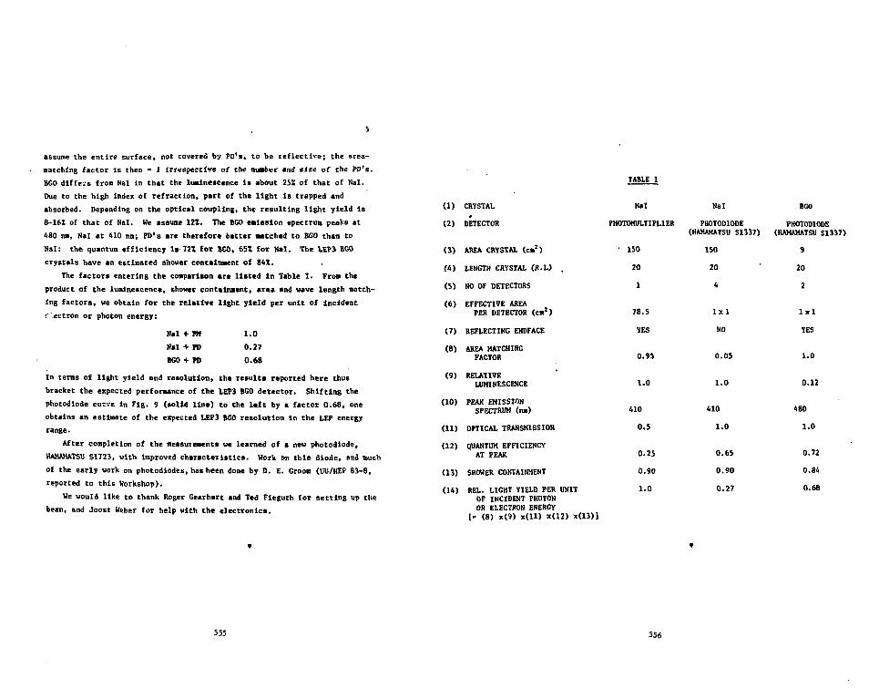
assume the entire surface, not covered by PD's, to be reflective; the area-
Batching factor Is then • 1 irrespective of the number and size of the PD's.
BGO differs from Nal in that the luminescence is about 25X of that of Nal.
Due to the high index of refraction, part of the light is trapped and
absorbed. Depending on the optical coupling, the resulting light yield is
8-16Z of that of Hal. He assume 12Z. The BGO emission spectrua peaks at
480 na, Nal at 410 nn; FD's are therefore better matched to BGO than to
Nal: the quantun efficiency is-721 fox BGO, 65X for Hal. The LEP3 BGO
crystals have an estimated shower containment of 841.
The factors entering the comparison are listed In Table I. From the
product of the luminescence, shower containment, area and wave length match-
ing factors, we obtain for the relative light yield per unit of Incident
r'ectron or photon energy:
Nal 4
Nal -1
BGO i
i- m
i- rov ro
1.0
0.27
0.68
In terns of light yield and resolution, the result* reported here thus
bracket the expected performance of the 1.EP3 BGO detector. Shifting the
photodlode curve in Fig. 9 (lolid line) to the left by a factor 0.6B, one
obtains an estimate of the expected LEP3 BGO resolution in the LEP energy
range.
After completion of the measurement* we learned of a new photodiode,
HAMAMATSU S1723, with improved characteristics. Work on this diode, and much
of the early work on photodiodes, has been done by D. E. Groom (UU/HEP 83-8,
reported to this Workshop).
We would like to thank Roger Gearhart and Ted Fieguth for setting up the
beam, and Joost Weber for help with the electronics.
(1) CRYSTAL
(2) DETECTOR
(3) AREA CR1STAL (cm2)
( 4 ) LENGTH CRYSTAL (R.L) .
(5) HO OF DETECTORS
(6) EFFECTIVE AREA
PER DETECTOR (cm1)
(7) REFLECTING ENDFACE
(8) AREA HATCHINGFACTOR
(9) RELATIVELUMINESCENCE
(10) PEAK EMISSION
SPECTRUM (na)
(11) OPTICAL TRANSMISSION
(12) QUANTUM EFFICIENCY
AT PEAK
(13) SHOWER CONTAINMENT
(14) REL. LIGHT YIELD PER UNIT
OF INCIDENT PHOTONOR ELECTRON ENERGY
I- (8) x(9) x(ll) x(12)
TABLE I
Nal
PHOTOMULTIPLIER
• 150
20
1
78.5
YES
Nal
PHOTODIODE(HAMAMATSU S1337)
150
20
4
lxl
NO
BGO
PHOTODIODS(HAMAMATSU SI
9
20
2
lxl
YES
0.9S
1.0
0.05
1.0
1.0
0.12
410
0.5
0.25
0.90
1.0
410
1.0
0.65
0.90
0.27
480
1.0
0.72
0.84
0.6B
555 556

FIGURE CAPTIONS
1. Assembly of Nal crystal, photoaultlpller and phoiodiode for testswith cosmic rays and LINAC (Beamllne 19) positrons at SLAC.
2. Noise and dark current versus blaa voltage for a S1337 diode.
3. Spectrum of cosnlc raya Incident transversely to the Nal axis.
4. Comparison of relative linearity of FH and PD response for incidentcosaic rays.
5. Conparlson of relative linearity of PH and PD response for LINACpositrons. Beanllne set to 10 GeV.
«5 V,
6. Projections of the data of Tig. S.
7. Distribution of positron intensity over nE, n » 1, 2, 3 . .GeV, compared with a Polsson distribution for n • 3.
8. Comparison ef the 20 GeV spectra In th* FH and the PD.
, E - 10
9. Resolution (1 s.d.) of Che PM and FD versus deposited energy. Th*dashed curve indicates th* resolution the photodlode would have If, fora given energy deposited, the number of *-h pairs would equal the numberof photoelectrons produced in the photoanltlplicr.
10. Response of the S1337 photodiode. • • Matured pulaehelght (ADCchannels) of the PD versus energy deposited in the Hal crystal.Curve (a): best fit to these data. Curve (b): pulseheight output ofthe presapllfier + aapllfier + ADC chain for given amounts of charge in-jected into the preaapllfler. Curve (c), derived from Curves (a) and(b): charge delivered to the preamplifier at various amount* of Inci-dent energy. Curve (d): pulaeheight (ADC) of the PH versus energy. Afit shows that the FH response Is linear. The PH is directly connectedto an ADC. +: measured PH data. The curves show that both the PH andPD response is linear, but that th* PD electronics Is non-linear.
\
3
J
r
3 ,* s
1 i7 *
557
Ftf,558

3
a.V)
d
d£
0
aa.
o• o
z o
a IN
5S(
Q
£ •
H
mm tt • « *
XCL
on•0 •
-IO
i&
t-UI
i
COCO
H
• • *• • • * —
»»*«»ss«ssssssss
10
i - S
£J- .1- o

Vr.
S R S -
J F(O US
««-;"•
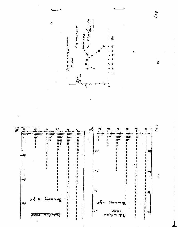
^ 4
I*
\
H : Oh
• 00/
•f M M
»»»a
* , ; • •
•<£
»e
"•••a
i.

04SI S"Zt in,
oi
O/J
I
4
'"••I1"" •«• liNWiuHiiummil•!» •« • • • «••»•» I l l l l l
•o ' taa•••I1C4
•ti'aaa*»ra»tat«>aaalsa
•aaaaaat«ara«aaiista
aaitattaav • t sa«at»«i» aaata«atva«# aaaaa«taa*at«a 0 a maaa'aaaja* • • m w i • tfuttsiu* MMW aa«« a a a aaaaaaaoa aa< ««• a •« <a aa> tat aa ta a a
aaattaaat M • 9 9 w aasaaaaat a aaataraaa a
attaaaaaaat<i:aa
tawata
aaaataaaataaaaa
•a.

DDL!!! 82-5Il .E.SXP. R3- 01
I . I
PP.KPRIl!T(JAH.2C',03)
TB£T OF BCO-BAP.S FOP. ELECTP.OMAGHETIC S11OVER CAL0r.IMF.TERE
".. B o i . T. O n o r i . S. Sus i r to to . !!. Her!.-, and Y, Yana^uchi
Department of P h y s i c s ; Osa!:a U n i v e r s i t y * ToyoncUa. OsaV.a. Jr.pcr.
!!. l 'obayashi
n a t i o n a l Laboratory Cor High. Cr.orjy Phys ic ! ! ,
Ol io-nac l i i t Tsukubst IbarAlci* Japan
!1. Yoshida
Faculty of Engineering! Ful-.ui Univenity. BunUyo, Fuiuiii Jnp.-.n
::. Unnazaua and U. Okuno
Institute for nuclear Study. Tanaciii. To!:yo. Japan
Abstract
'!e have tested 20 en long fcCO bars, to bo employed in n
position sensitive cilorineter, uiing *3'Cs source and 200 - 5S0
I!cV electrons. The spatial resolution of 6" x= 3.1 en "f.s
obtained for 550 iieV electrons incident on n BRO bar of 10 :: 10 ::
200 mi3, The effective attenuation lenRtl: of light in the E60
bar wnr. as long as 137 en • including the intornr.l tranonitt.Tnce
as well as the reflection on the surface. The HOC ot thin layers
of "GO bars as an active converter in front of tlic tin in Ii00
bloc'.s l.'as tested uiih respect to the obtainable er.oi.ty
resolution. Ilo sizable dejradat ion OCCITB in the oi.cr£y
resolution after suntiing up all the aigr.i'.lc.
/7f to
567
568
OSAKA UNIVERSITY LA!)OP.ATOr.Y OF M'CLEAR
TovoitAr..1., nr.A';.1. 5 0 0 , J A P A I :

0UL11S 02-5H.E.EXP. 83-01
Page
1. Introduction
In l*iy,h energy exper inents • precise ineasurencnt s of energy
am! position of photons (and electrons) are frequently required
1)* They are usually nade with electromagnet ic sV-ower
cjloriactcrs. SCO is a very attractive material for the
caloriueter because of iti good energy resolution and s]art
radiation length ( XQ= 1.1 en ) .
We aro presently constructing a BGD calorimeter as sketched
in Fin; 1« aiming the good energy resolution* good resolution of
the injecting position, good electron / pion separ tion by the
longitudinal sampling* compactness and flexibility for various
configurations. Four layer* of EGO bar horoscopes are placed
just in front of hexagonal BGO blocks. The injection point of n
photon is Measured with the hodoicope thet plnys a role of an
active converter. The spatial resolution i» expected to be
better than 1 CM. The total energy is measured by sunning up the
output signals of the hodoccopec and the hexagons! blocks.
Moreover electron / pion separation can be done by observing the
longitudinal shower dcvelopnent in the four layers of horoscopes
= mt tl'.o hexagonal blocks behind.
For the construction of the DGO colorimeter, there exist the
following problems to be solved:
(a) So far Elie commercial 20 cm long crystals aro not yet
perfectly transparent because of the existence of voids or
inpur i t ics.
(b) As a result of (a), the signal fron a DGO bar has a strong
var in tion as a function of the source position along the
crystal longtl;. A suitable compensation for the signal
variation has to be nadc.
(c) The sensitive crca of photo-sensor is an important factor
for not only the energy resolution but also the signal
uniformity in the bar. Therefore the best fit sensitve
area of pkoto-senaor hoc to be chosen.
This p.:per describes test results of RGO bars: the sip.nr.l
variation in r.GO bars, the position Measurement of injecting
569
0UV.1S S2-5ll.H.EXP. O J - 0 1 Pane
particles, and the total energy measurement vith the DGO bars and
Nal(Tl) blocks placed behind the bars.
2. Signal variation in a BGO bar
Each of BGO bar* it optically polished all over the surface
and wrapped with an alutuinized nylar. A RGO bar Uo.l, undo by
HICK (Japan Optical Crystal Co.). has a volurie of 10 " 10 X 200
nn • The internal transtiittnnce of light is roughly 93 *>/CM at
470 nm if measured for a «mall sample uith n spectro-photonet:r .
The variation of signal output in the bar is shovn in Tig 2 oj r
function of the source position. The output nigna) was e::a*jine0
uith tuo photonultiplier tubes of different diameters: a tuo inc'
tube (I'.ananatau 111161) and a half inch tube (llaraanatsu n.6's7-GO,
The photonultiplier output va« analyzed by a pulse height
analyser (Canberra 30 or LeCroy 2249W) in a charge node. The
variation of the signal is 31 % over 10 to 190 run from the tube
if the tuo inch tube itai used. On the other hand* the si^ncl
variation decreases to 22 7, over the sane rnnge if the ht.lf inch
tube tias used.
Similar result is presented in Fig 3. Another BGO bar '.'o.
3, also made by 11KK, hat a volurie of 12.4 X 12.A !". 205 mu and
the tronsnittance of 96 2/cm at 470 nm. The si(;n = l variation?
aro 46 5 and 21 5 with a two inch and a half inch tut.o,
r cspectively•
Referring to Fig 'i. let us suppose that !' phota^n are
produced by an incident particle and that they ire ncaauroi! "it*1
pV.otonul t ipl ier tubes A and C mounted on both eni'a of n BCO v-?v *
On a simple assumption that the photons reach \v ttn-
photonult iplicrs after an attenuation according to u velaticsv.
r.iven in Fig k, H is proportional to the geonetricnl neon of »A
and !!.. where 1!. and !!„ are the nunber of photonn wia»wr«(! v^U':
the tube A and B, respectively. In otlii-r word*, the !;B«V\P<
iiean of t!, ar.d !!. should be independent of the «u«fts pw*A U
a l o n « t h e c r y s t a l l e n g t h . The d a t a g i v e n i n »'i(l 1 w l F » ^ 3
t h r t t h e l o n g i t u d i n a l u n i f o r m i t y i s m u c h i t) | tVRV^4 i f570

OOLIIS S2-5H.E.EXP. 33-01
Page 4
is taken. Moreover the energy
resolution i> also improved by a factor of 1.3 to be compered
with 1.41 expected for the ideal case.
3. Position noasurenont
The position of an incident particle. X, can be determined
by the relation shown in Fig 4, The variation of ln(K /H )13 7 ••* A B
obtained uith Cs J rays is shovn in Fig 5 as a function of the
source position. These data points havt been fitted by the
equation. X: -aln(UA/HB)+L/2 uith an adjustable parameter. The
attenuation lengths of the BCO bar Ho.l and No.3 have been found
to be 32 en and 137 cm, respectively. The corresponding
transmit tancc-s are 93,1 X/cm one1 99.3 2/csw respectively. For•v* 1 " 7
0.662 HeV T rays from Co, th« spatial resolution is as large
as 15 en. The poor resolution seeds to cona from the poor photon
statistics.
At higher energies much better resolution may be expected.
To see the spatial resolution at high energies, the BGO bar via
exposed to electrons uith the energies up to several hundred UeV.
Tin 6 gives a spectrum of the energy deposit in BCO bar No.3 for
350 CcV electrons injected at X: 14 en. We can see two peaks in
it: the sharp peak coning fron the aininun ionization energy, 10
MeV, and the broad one coning fron an elcctronagnctic sitover.
The distribution of ln(l!A/HB) for the data set of Fig 6 is given
in Fif; 7. The center value of the distribution as i/ell nt its
anbiguity is plotted in Fig 0 as n function of nominal injection
position. The spatial resolution i s ( T K = 3.1 en. which is roughly
independent of the injection position. If the data of Fig 8,
ln(l!A/lip) versus nominal injection position, is fitted by a
straight line expected, the attenuation length is 141 en and the
trensnittnnce of light io 99.3 7,/ea, which agrees we 11 with the
previous one measured by l 3 7 C s source but is not consistent i.-ith
th<> value of 96 "/en measured with a optical device.
The difference between 99.3 %/cn and 96 Z/cn. however, neod
not be taUen seriously, becauer the former is a nunber obtained
571
OUL:I5 02-5
ll.E.EXP. H3-01Past
for the SCO viewed by snsll dianeter photonultipliors. The use
of small disneter photonultipliers can apparently improve ^ ' tl:c
uniformity at a sacrifice of the light intensity, thereby giving
an apparently high trsninittance of light.
The energy dependence of the spatial resolution io chcun in
Fig 9. The horizontal axis indicates the energy deposit in the
CGO bar. having the depth of 1.24 cti. For incident electrons of
200 to 550 lleV, the energy deposit is Mostly between one to tvo
nininun ionization one as seen, for example, in Fig ft. 0~:: is,
however, plotted in Fig 9 simply at the uininuri ionisatior. i'r.int,
ss the difference fron the average of the energy deposit is not
large. Although we have only two data points, the line r.ono
through the origin. This indicates that the photost. tistics i.;ay
govern tlie spatial resolution. If this conjecture should be
correct, a spatial resolution could become better than 1 en vher
the nunber of electrons fron the shoi'cr should reach'20 i:i the
relevant 1 en thick BGO bar.
4. Total energy neosuronent with a BGn bar and nine disci's
of I'.iI(Tl)
Since the BCO cnlorinctcr, Fig 1, consists of five B O
layers alonf, the bean direction, all sijnals fron the layers have
to be sur.ined to give the total shoi'er energy. It is inportart to
nininize the deterioration of tV.c energy resolution in suite.inr, <'i'
tl'.c signals* The resolution t.'cs c:<aniticf! for a set of one I5G0
i £ r atul nine blocks of Pal(Tl) plncei! ju = t behind the bar. The
"al(Tl) blocUi not! used inoteai1 of proper he::ar,oiir. 1 BGO blocks
i.-liicl: :rc currently being tinntifacturcd. lincV. 1 ! J I ( T 1 ) bloc!'. I.as s
front face of 43.7 " 94 m i 2 , a hnc!'. face of 110 X 94 nn 2 one' n
J. it!: of 373 r.n. The nine blocks arc st.ickcd an shown in Fis 1".
The uccsurci.iont ''as nade iisin;; 200 !!eV and 400 IleV
electrons. Fife 11 oliovo a scatter plot between the cr.cr:',y
Joposits in the EGO br.r am' that in the CRgresatc of nine IlaKTl)
!iloeV.s. A clear correlation exists between then, that is. t'.'.c
sur. of the both signals corresponds to the incident electron572

0UL1IG 52-5
U.E.E::P. S3-OI
Psje
energy* The deterioration in the energy resolution "as
investigated by comparing the energy resolution vith ant! vitliout
the BGO bar in front of the nine llal(Il) blocks. Table 1 gives
t'.-.e result that the energy and resolution is recovered by sur.ir.inf;
up all tlic signals and that Che deterioration ia not severe.
5. Conclusions and discussions
Our test is summarized as follows: (a) Good transparency is
essential for long EGO bars to obtain a sood output uniformity ss
a function of source position. (b) Even if the transmittancc of
light is not perfect, an excellent uniformity of the sir,"-=l
output can be obtained by tutuiing up the signals of photo-sensors
on both ends of the ECO bar. Other possible aethods to i:ij>rovc
the longitudinal uniformity *re described in another report'
(c) Position rieasurezaent by the photon division netitod ( usins z.
sicn.il asyru.ietry of left and right signals ) ii promising .
The spatial resolution obtained vitli 1 C M thick SCO bar ,-.t tVi•>
entrance of the calorimeter i» C x = 3.1 en for 550 t'.eV electrons.
The resolution could be iuproved uith the increasing energy nnu
"it! the increasing depth of the BGO bar. because the resolution
nny ho determined by the photoclectron statistics. Or tlic
contrary to Clio c.-.se of inproving the unifornity of the si(;iw;l
output. it is recensnry for obtaining a high sensitivity ir. tlio
position i-.casurenor t that the trantmittance is loos than 100 "
•ai:<i that the lif.nt output is high, (d) Even if a ealor irieter is
longitudin.-.lly divided into thin layers of RGO bnrs ant! the
rc-iicininf, blochs of CGO, the total energy and the or.fir;;y
resolution, which is obtained tiithout such division, c.-.r. lm
essentially recovered after turning up all t'ue signals. That
£nc?ic£tcs a possibility of using flGO bttrs as active converter?
for incident p h t o r. s •
573
Ol'LIir 82-58583-01
Acknoi: lodgement s
P a,", r
'!c uould lilie to express sincere tlu-nl.s to Profs. V.
"or;.aohina ant! R.Ozaki for their interest art! support for the
present '.;orh. and the Ills synchrotron crcv for their machine
operation during the exper iment. This wor!: tias partially
supported by a grant-In-aid for developmental scientific resenrch
fron che Ministry of Education.
n e j o r e n c e s - - - - - - -
1) G.r . lancr , l l . D i e t l i E . L o r e n t z . F .Paucs and i:.Voi>cl; l!c::
Plane!; I n s t i t u t e r e p o r t , HPI-PAE/E:tp. Cl.O'i. 1 9 S 1 .
G.Blar.ar, l l . D i e t l . A .Kabe l tchacht H.Lorcr . tz . F .Pause and
K . V o g e l ;
"A Design Study for c Corjpact LEP D e t e c t o r " 2nd Workshop ; o r
D e t e c t o r s and E x p a r i n e n t s for e e at 100 GcV» Cornel l Uni.*r.
J a n . 1901 .
E.C.Loh; "A Modif ied l iagr .e t ic C a l o r i n e t e r " P r o c . 2nd TRIBT/:'
P h y s i c s '.!ork«hop, KF,:; 8 2 - 1 . p . 4 9 6 .
n . IKcdct l l .Kobayoohi . S . ! :«roha"i . y.lias'ishir.ia > S .SugiuotOt
and l l . V o s h i d o ; "A Conpaet BCO D e t e c t o r for TP.ISTAr", i b i d .
p .207
; : . C a v a l l i - S f o r x n and P.(5,Coyne; SIX VorV.shop I'otcP Cl ' -34 .10"l
C.J .3oboU. M . G . n . G i l c h r i e o e , S . l l erb , r.. I n l a y . C L e v n g n .
I f . i f c tco l f • V . S r e c l h c r . l I . D i e t l , .1 .r:.?be).selacl: t , E.Loi ect . ' . .
F.Pnuas and II.VOROI-! "A Design Study of UPGTAT" in the
i'ort'i Area at CF.SP>",1982.
2) V . " o b t y . i s h i i D .Suis i i io to . II.Vodaf l l . Y c s h i d a ; " I n p r o v l n j t!-.c
L o n g i t u d i n a l Dnifarni tJ ' in the KesponDe of l.on,-; T.CO D o t e c t r r s
Contr ibuted paper to the I n t e r n a t i o n a l Workshop or< BOO•
P r i n c e t o n . ! lov. 19E2.
3) B, Basos l l o c l i o t a l . i " T - s t l i c i u l t fron a P o a i t i o u S o n n i i i v c
I ' a K l l ) B o t e c t o r " . T."!IU!-F note TRl-i'P-?1)-1 .
bTt

SET UP
VITH OHLY
i!lt!K t!aI(Tl)
stocr.s
WITH
A P.GO SAP.
OUTPUTS
FRO!!
11 J l
IiGO
« . I
BGO + l i s l
EKEr.GY
RESOLUTION
4.0V. 6 . 7 S
6 . 6 , . . .or.
4 . 7 Z , 6.AX
TOTAL
KBERGV
ACO, 200!lcV
3 9 S , J96!!eV
TA5LE 1 TOTAl E11F.P.CY KBASURSIIEHT
Figure Captions
FiR 1 POSITION SENSITIVE HGO CALOSIIIETER .
Four layers of BGO hodoscopes ate placed in
front of hexagonal blocV.c to dctcmine. the pos i t ion
of an injected, photon end s l s o to separate on
eloctron/pion •
Fig 2 SIGNAL VARIATION IH A BGO BAR.
The output sinnal (BGO I'D.3) Mai meesured tilth
Cc source.
Fi E 3 SIGiliM VAr.IATIOlI IH A CGO DAR.
The output s ignal (BGO iTo.l) was measured with137^
,?i^ 4 RI;:PLC AnstniPTion or HOOT TRMISIIISSIOII
Fi f i 'j Vf.P.If.TIO'.' OF Lll(HA / l ! . ) ODTAIHED WITH 1 3 7 Cc / rays
F i s 6 SPECTRUM Or THE FEKERGV DEPOSIT III !1GO bar Ho.3 .
lloesuieil i .ith i>ell c o l l i n c t e d e l e c t r o n s . S50 l'-cV,
pass ing through the middle of the BGO bsr ( X - 1 4 c n ) .
Fig 7 DISTnlBUTlOll OF Ll'.Ol./llg)
Tig " U!(n A / l l B ) VEKSUD UOMIIfAL INJECTION POSITION
FiR 9 EIIKRGV DEPENDENCE OF THE SPATIAL RESOLUTION
Horizontal a x i s i n d i c a t e s the energy d e p o s i t in the
CCO bar . The v e r t i c a l as:is indicator, the s p a t i a l
r e s o l u t ion .
Tip. 1" SF.T UP For. T1!F. TOTAL EflERCY 1'BAEUREIIBNT
Fif, 11 SCATTER PLOT BETUBEI! THE OUTPUTS OF BGO A1ID : 575
BGO CALORIMETEROS»K»-KEKFUKUI
FIG. 1
Position Dependence of Output Signal from BGO-BAR
BGO SAMPLE «1 ( l c mxl c mx2O e m )
1.0
0.5
o Mean Output of Two 1/2" PMTs
Mounted on ' I ' and 'R' Respectively
• Output of a 1/2"PMT Mounted on'L'
• 2" PMT
5.0
576
10.0X (CM)
15.0 20.0
FIG.2

Position Dependence of Output Signal
1.0 r—
3
ao
til
cc
0.5 -
BGO SAMPLE # 3 (1.2 »1.2x20.5)
5.0
0
•
—-o—o—
Mean
Output
1
-o—o—e
Output of
of a 1/2"
2"
« a •
TWO1/2"PMTSCL'&'R')
PMT Mounted on L'
PMT
1 I
100
X(CMJ
15.0 200
FIG. 3
-LN(N A /N B )
0.5
-0.5
POSITION DEPENDENCE OF LN{NA / N a )
BGO SAMPLE I 1= 26.2, T =0.981
- SAMPLE > 3
« =68.3. T=0.993
INCIDENT SEAM : ' 3 ' C S ( f >
T-A(N7|( VI2<=&
-4f=9>HI2 BGO-BAB ||Na)PMT-a
10 15
F16.5
20 X (CM)
T x
WHERE T= EXP( - ( / « . ) = Transmittanc«
A • Attenuation Length
»t
!R
& '<miMI HIM! It.
N = Const, y N A - N B
NA /NB= T2 X"L = EXP(-(2X-L)/«.)
X =(L- A . ln (N A /N B ) ) /ZFIG.
5?7
"i . )..,• ,i ca ," i « n II in 'i ' ««>«
- , ' Mil !
i n 1
!'K.: J;!
FIG. 6

ENERGY DEPOSIT VS SPATIAL RESOLUTION
- I N ( N A / N B )
0.10 —
0.0S
•0.05
•0A0
, .... ....»!!
" " "S*
0 10 20
FIG. 7
POSITION DEPENDENCE OF LN(NA /Ng)
(<• 10.5
T* 0993
'ff' 0.045
INCIDENT SEAM: 550 M*V ELECT SON
BGO SAMPLE t 3 (I.2XI.2X2O5)
IS_J
10 X (CM)
FIG. 8
579
<CM)
15
10 -
0 J
0.2
O.\
E.IO M»V 0.662 MeV
0.5 1.0 '•5
FIG. 9
SETUP FOR TOTAL ENERGY MEASUREMENT
Nal
ELECTRON BEAM
BGO- BAR
FIG. 10
580

I
: • . :
I Jli:n-:' 2
(AaW) IVNO IS !DN
-•si
< i
om IT
I I
O

Plans for BGO use
In e*e" experiments at OESY
H. SpHzer "University of Hamburg,
Federal Republic of Germany
Session J
PROPOSED DEVICES FOR HIGH ENERGY APPLICATIONS
Abstract
Plans for upgrading the ARGUS and the CELLO detector by new electron tagging sys-
tems are discussed. The new counters will be made of finely segmented BGO crystals.
Talk given at the International Workshop on Bismuth Germanate,
Princeton, N.J., USA, Nov. 10 - 13, 1982
** Partially supported by the BHFT, Germany
583 584
!*•.

1. Introduction
Currently two projects for using Bismuth Germanate (BGO) In e+e" experiments at
OESY are being pursued. The scope of the projects Is less ambitious than the BGO
4ir detectors discussed at CESR, SIX and LEP. He rather aim at exploiting the fa-
vourable properties of BGO for a dedicated purpose, namely the tagg-
ing of small angle electrons from two photon processes. The tagging devices are
planned for the ARGUS detector at DORIS and for the CELLO detector at PETRA. In
this talk i first outline briefly the physics objectives of the projects. Then 1
explain why and how we plan to use BGO.
2. The physics objectives
Hadron production In e+e" collisions is governed by two basic mechnisms. One isthe well known annihilation process
(1) e+e" •» hadrons
Here the electron and positron annihilate to a photonlike 'fireball" of veryhigh energy density. The high energy density allows for unple production of heavyparticles like c and b mesons.
The second mechanism 1s the two photon process
(2) e+e" •» hadrons vHere both the electron and positron radiate a photon. The radiated photons inter-
act and produce the final state hadrons. We are Interested in the latter process.
One signature of the two photon process is the existence of an electron and posi-
tron In the final state. This can be used for identifying two photon processes.
The radiation of photons Is an electromagnetic process which occurs preferentially
at small angles of the order £s . Fig. l shows the angular distribution of the
scattered electron from reaction (2) at electron beam energies of 15.5 GeV1. The
distribution peaks sharply at angles close to 0° and has dropped by two orders of
magnitude at 100 mrad (6 degrees).
585
In order to detect two photon processes we hence need electron detectors which
operate at very small angles (typically 0 to 6°) relative to the beam. The two
projects cover the following angular and energy range of the scattered electron.
a) ARGUS: 6 = 0 — 1 0 mrad*, Ee'» 3 - 5 GeV. Here one has the advantage ofvery high rates. It is possible to detect both electrons in coincidencewith reasonable efficiency (double tagging). The average Q8 of the photonsis small (< Ql > « 0.0006 GeV*).
b) CELLO: e • 50 - 110 Brad, E e'- 4 - 2 0 GeV. In this range the rate is lower.Usually only one electron is detected whereas the other one travels alongthe beam(single tagging). The larger scattering angles however provide virtu-al photons with Q* values of about 1 - 5 GeV1.
Fig. 2 shows the double tigging efficiency of the proposed ARGUS tagging system z'.The system yields tagging efficiencies well above 5 % for c m . energies of theYY system between 1 and 4 GeV. This is much better than 1n any other runningtwo photon experiment. By detecting both electrons the kinematics of the rr sys-tem is fixed. The total hxdronic Y Y cross section at Q2 = 0 can be measuredwith great precision.
3. Why BGO?
Before we answar this question, we examine the environment of the proposed de-tectors. Fig. 3 shows • cross section through the CELLO detector. The cylindri-cal coil produces an axial f ie ld of 1.35 T.Charged particles are measured in theInner track chambers, electrons and photons In the liquid argon calorimeters whichcover angles from 130 mrad upwards.
The new BGO counter has to f i l l a cylinder ring of only 10 cm height
inside the liquid argon end cap counters. Space 1s limited. The
field at the position of the counter is 0.5 - 1 . T. The readout has ^_^
to natch the bnch crossing time of PETRA (4 us). Also the counter has to sur-
vive a considerable level of background radiation.
In the past, severe radiation damage has occurred In the tagging counters of
TASSO and JADE. These counters were nade of lead glass. A region of about 5 en
W i t M n p o 1 a r
586

dtpth next to the beam has turned brown after running PETRA above 16 GeV with
t<ic mini B- optics. The damage 1s probably due to off momentum beam halo parti-
cles, which hit the vacuum chmaber under a glancing angle. An electromagnetic
shower is initiated.The shower propagates almost parallel to the beam through
the adjacent material. The depth of 5 cm corresponds to the transverse width of
a shower In lead glass ( 2 Xo).
We have performed a qualitative check of the radiation resistance of BGO. A
BGO piece from Karshaw, USA was put on the beam pipe near the electron tagging
counters of the PLUTO experiment from October - December 1981. No browning was
observed. The same piece was exposed from March til July 1982 at the end of
the PETRA North-East straight section where the radiation level is much higher.
Only a slight yellowing occurred. The measurements will be repeated in the next
months on a more quantitative level. He expect from present experience that the
proposed counters will function adequately In the radiation environment of
PETRA 3'. The radiation level at the position of the ARGUS counters 1s less
well known.
Both systems have to provide good energy and spatial resolution for the de-
termination of Q*. ARGUS needs o£/E • 2 % In order to resolve W to 100 - 200 MeV.
4. Solutions
4.1. The CELLO project
Presently two alternatives are being studied which match the above requirements.
a) Lead-scintillator sandwich
Fig. 4 shows a view of a sandwich counter. The counter consists of 30°
segments of lead scintil lator. I t 1s 30 cm long and has about 17.4 radiation
lengths. The light 1s read out by two layers of wave length shifter. This
solution 1s cheap and radiation resistant. However the light readout Into
a f ield free region Is quite complicated. The counter provides an energy res-
olution of o ^ M = 0.17 and a coarse shower position resolution (o. by seg-
mentation, o r = 1 cm).
b) BGO array
Alternatively an array of BGO crystals 1s being considered.
587
Fig. 5 shows the array, made of segments sized 1x1x20 cm3. This corresponds to
17.9 radiation lengths. Each segment 1s readout by a silicon photodiode attached
to its end. The photodiodes work well in magnetic fields. The counter provides
very good spatial resolution (o « 2 - 3 m ) 4 h The energy resolution oE/E will
be on the 3 % level above 1 GeV. It Is limited by transverse leakage. Due to the
small radiation length of 1.1 cm the transverse leakage in BGO Is smaller than 1n
the above scintillator sandwich which has an effective radiation length of 1.72 cm.
The main disadvantage is the currently high price of BGO.
4.2. The ARGUS counters
The ARGUS counters are designed for tagging electrons at-\. 0°. The scattered
electrons travel along the bean but are degraded in momentum. A magnetic spectro-
meter is needed for separating the degraded electrons from the beam. The DORIS
ring happens to have a bending magnet In the long straight section at a distance
of about 14 m from the Interaction point. This magnet bends the beam upwards by
about 20 cm. Degraded electrons are deflected higher and can be detected in a
tagging device.
Fig. 6 shows the device. It consists of 7x10 BGO blocks of the size 2x2x18 cm .
The crystals will be readout by photomiltipliers. This 1s an appropriate solu-
tion since the surrounding magnetic field 1s small. Photomultipliers also match
the bunch crossing time of DORIS (1 |is) better than a photodiode readout with
low noise charge sensitive amplifiers. * A three layer scintillator hodoscope in
front of the BGO counter provides fast trigger Information and background rejec-
tion.
5. Status
a) CELLO project
The project was started early this year. The first crystals from Harshaw,
Holland arrived in June 1982. At present the standard readout uses a phcto-
diode Hamamatsu S1337 together with a preamplifier and shaping amplifier
designed at DESY for a liquid ergon counter.
* Currently available low noise amplifiers are Inherently slow (typical shapingtimes between 1 and 10 us).
588

Using this setup signals from cosmic ray muons traversing a 1 cm thickcrystal (dE/dx = 8 HeV/cm) can be separated from the noise '. A furtherreduction of the noise level is expected when the recently released photo-diode Hamamatsu S1723 will be used 6)
We are currently testing a matrix of 40 crystals {1x1x15 cm ) 1n an elec-tron beam at DESY. The main objectives are to learn how to run and tocalibrate a multichannel system. The tests will be continued next year.
b) ARGUS project
Recently one crystal of the size 1x1x18 cm3 and several small crystalswere acquired. The first goal are radiation measurements at the DESYLinac and the DORIS ring. A remote controlled support hasto be designed. The BGO will cone as close as 1 cm to the DORIS bean andhas to be removed during Injection. The target date for the installationof the complete system 1s end of 1983.
BGO is well suited for electron detection close to the beam In e e " storagerings. BGO counters are compact. They operate in magnetic fields and givs ex-cellent space and energy resolution. If topponium is found at PETRA the use ofBGO for Y spectroscopy will also become attractive '.
Acknowledgment: I thank Or. D. Coyw for arranging a very informative and wellrun workshop. In the last year I profited a lot from stimulating discussionswith Dr. E. Lorenz and Dr. T. Teeling. I thank Mr. A. Philip and Dr. L. Joenssor)for information on the ARGUS project. I enjoy the BGO work with group F14 atDESV.
589
References
1) I thank W. Wagner for providing the calculat ion.
2) ARGUS Collaboration, A proposal to study y-f interactions with the detector
ARGUS at DORIS, draft version, October 19BZ
3) M. KobayasM e t a l . have demonstrated that BGO of 99.999 % purity has more
than 100 times higher resistance against low energy photon radiation than
SF5 lead g lass . Most of the observed radiation damage due to photons re -
covers by I t s e l f (KEK Preprint 82-9, Ouly 1982). This evidence was chal-
lenged by preliminary results o f H. Cavalli-Sforzs a t t h i s workshop.
4) M. CavalH-Sforza e t a l . , Procedings of the International Conference on
Instrumentation for Colliding Beam Physics, Stanford, Feb. 17-23, 1982,
Report SLAC-250 (UC - 34d)
5) The use of a photodiode readout of BGO counters was f i r s t reported by
G. Rianar e t a l . , Max-PUnck-InstUut, MUnchen, MPI-PAE/Exp. El. 99
6) Compare the talks of D. Groom and A. Kurahashi at this workshop.
7) This was f i r s t proposed by the HARK J Collaboration to the Physics Research
Commitee of DESV in February 1982.
590

e»e--»e*e- hodronsWhad>1GeV
one electron tagged
Double tagging efficiency
«• ••«li"l • * • ! • . - i . U , n , ,»,i<»» ugftitf lyua-dectccor
10 I0 20 (.0 60 80 100
tagging angle 6(mradJ
Angular distribution of one of the scattered electrons from reaction(2).The direction of the second electron Is required to be smaller than 23mrad. The calculation was done for a simple limited trans-verse momentum model of hadron production, requiring a total energy ofthe hadronic system Wha() > 1 GeV. Events with energies of the virtualphoton between 0.016 and IS.478 GeV are Included.
Fig. 2 Double tagging efficiency of the proposed 0° tagging system for ARGUSas a function of the total energy of the Y Y system W .
Upper curve: both electrons tagged near 0°.
Lower curve: one of the electrons 1s tagged In the inner shower counters(at angles 16° < e < 164°).
591 592
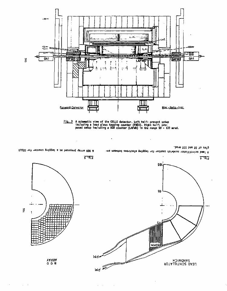
Fnrword-Oetector Mini -Rpta-Inst
g- 3 A schematic view of the CELLO detector. Left half: present setupincluding a lead glass tigging counter (FHO3). Right half: pro-posed setup including a BGO counter (LAFWO) in the range 50 - 110 mrad.
01133 •">} £UL£6B) e ss pasodojd <C«JJB 038 V -UB
0 0 9

LIGHT GUIDE j. .
LIGHT CUIDt
F1g. 6
The BGO tagging device proposed for ARGUS.
595
AM IMPROVED E.H. CALORIMETER FOR TIE CUSI)USING CISK1ITII GERI1ANATE
P. H. Titi
S.D.N.Y. at Stony Brook
Stony Crook. Ne> York 11794
P. Franiini
Columbia Univeraity
Hn York. New York 10027
ABSTRACT
We describe an upsrade for the present CUSD detector at CESK.
An array of 110 EGO cryitals (-12 liters) vill bt inserted in the
space presently occupied by inner trtckinj ehuibers. We present
Monte Carlo result* on the iaprovtxtnt in resolution expected team
this array (oE/E~3r» at 100 MeV>. A brief description of the
calibration syttesi is incladed.
INTRODUCTION
In this report we discuss the improvement of the present
Ct.'i®3 detector at CF.SH. Defore «e continue vith a detailed
description of the BOO upgrade^, «t will present a brief introduction
to cr.SK, CUStl and the physics that we do there. The Cornell Electron
596

Storage Ring (CP.SR) at Wilson Laboratory i s an c*e~ col l iding b e m
f a c i l i t y with two intersc t ion tejions for experiments, «i o n bt seen
in F i t . »•
Fig . 1 Schematic
layout of the
Cornell Elect ion
Storage rlnf (CESR)
with the two
experiments CLF.O
and COSB indicated.
The dianeter of the
r l n | i s 250a.
We hive l i s t e d tone of the relevant CESR ch»racter i i t ic» in tjic
lollowinc t t b l e .
Storage Kingc.a>. EnergyUeaai £ spread (a)Peak I.utiinosUy
l-rotsing Tice
9-12 CcV.O43zE2 (KtY) E ia GeVl.S x 1 0 " c»-2 s«c-»500 nb-'/day12.56 iisec
- Nor»»i CUSD- South CLEO
Table I . Souc CESK cjchine characte i i s t i c s
The CUSC detector i i located in the North experimental area at
CESR. In Table II we have l i s t e d soste of the important CUSI)
c h » t a c t c i i s t i c « ; a schenatic v i e* of the detector i s shown in Fig.
2 .
<Mtt chamber*
mtionU.nttflet CUSB COLUMBIA
STONY BROOKLOUISIANA STATEMPI MUNICH
Fig. 2 The present CUSB detector, with the major elenents indicated.
Note that the front ruon identifier drift chambers have been left out
for clarity.
597598

LOCATION CF.r.I: c + e ~ t i n oV.'ilsoi: Laboratory* C o r n e l l U n i v e r s i t y * I t ) :ac« , MY
CCIXATOliATJMfi Columbia U n i v e r s i t y , SUMY at Stony Brook, "tx PlanckINSTITUTES I n s t i t u t a t Munich, Louis iana S t a t e U n i v e r s i t y .
TRACKING Proportional chambers with cathode strip (9 «n.)readout (inner strip chambers).
lfr chambers in 4 planes. 47°<A9<132O.A»s2n,2 trad: ef f iciency>95Tj, o, io n g ¥ ire=- 8 4 n m-
CENTRALCALORIMETER
END CAPS
HUOtl
1,111 IJICSITYIWITCS:
Segmented NaHTl) array with interspersed stripcharters (not shown) surrounded by lead {lass array.
332 NaKTl) crystals (580 l i t ers ) . 9X0, in 5 radiallayers, 32 ^ sectors. 2 6 sectors
16 proportional chanbers with cathode strip (leu)readout located in 4 planes between NaKTl) layers,4P=6<1T». o l l o n ( ( w i r , - . 6 c»
256 lead glass blocks in four 8x8 arrays surroundingthe tlal(TI) array, 7XO
4P-60T.. oE/E=4T./*E
Seeciented KaHTl) array with interspersed scintillatorhodoscope.
I62I6 B-ff scintillator bodoscopes in etch emlcap
168 Hal(Tl) crystals (70 1.iters). 8XO, in J radial_layers. <oE/E>=12r., AP.-28S. oe=g0surad. oe=3 5rr.il/Vi;
Dir.uun identification with 35 acintillation counterssurrour.dine lead ( lass arrays, Aft-42%
Single ruon identifier2 ir.ar,nctiscd (IS Kgauss) iron toroids (60 and SO cmthick) with scintillator trigger in middle of eachtoroid, 2 planes of drift chambers in front and 1planes in bad: of each toroid (400 wires)Ar-25".. I'ctoff^l CeV, Op/p-25r..
2 scintillators and iead-scintillator shower counters15 r.rad<AH<90 mrad. AP=«1T. of 2n
Table I I . Prcscnl CIDiP detector paraaieters.
599
The discovery^ of the 1 at Per«ilab in 1977 greatly enhanced the
field of heavy quark spectroscopy. The X and X' were first observed
as resolved states* at the DOBIS t+«- facility. A detailed study of
the 1 systen (including the discovery of several new states) has been
undertaken by the CUSB and CLFO trocpi5. begining in 1979. The
understanding of the bb syite., which is the bound state of the
heaviest (a^-5 GeV/c2) known quark (b) and its ami quark (b) (where
b stands for beauty or bottoa) will provide constraints on the
leading candidate for the theory of strong interactions. Ouantuai
droKodynaftics (OCD). The exact positions of the bound states
provides a awant by which to »tudy the intarquark potential. The I.
X'. X" • and X"' states that kave beta observed in the eross section
IS
/isib
leo
5
1
V
t
f 1
} |
CUSB
1
_
-
f-r»-l-|-r
9.6 10.0 10.4 10.8
MASS(GeV/c2)
11.2 11.6
I ' ig . 3 The observed c r o s s s e c t i o n for e*e~ -) hadrons for CIISII d a t a ,
e x p r e s s e d a s " v i s i b l e * o v j , ( e + e " - > h a d r o n s ) / o ( e * e " - > | i + | i~)
600

for the reaction e*e~->hadrons (Fig. 3 shows this cross section for
CUSn diti) are the 1 3 S J . 23S], 33Klp and 43Sj states of the bound
(bb) system. Although these arc the only states that *.re able to be
directly produced in e+e~ collisions (because they carry the sane
quoDtuc nuKbers as the photon)* a rich spectru'n of states (as
indicated in the level scheaic diagraa of Fi|. 4) in accessible to
the quark spectroscopist via the Ml and El radiative transitions of
th< f and X" states. In addition there are hadronic transitions
between excited states (not shown on Fit. 4). The first evidence of
the existence of some of these other states hat recently been
obtained by CUSD. They have discovered the 23Fo,l,2 states by
observing a quasinonochronatic photon signal in the inclusive photon
spectrum6 from the El radiative transition I(33Si> -> r+23Po,1.2 »B<
in the exclusive two step transitions^
——> e*e" or
One of the limitations of the present CUSI1 Nal(Tl) detector is that
we have insufficient photon resolution to separate the three expected
lines of the 23P().1,2 states which claster at -100 MeV. The tbree
lines are separated by about IS Mev eachi and our resolution for
photons beinp. O|:/I>B", at -100 KeV they appear as a single bucp in the
subtracted photon spectrum which is shown in Figure Sa. Although the
positions of the three lines can be inferred by fitting the excess
with the expected resolution shape (as has been done in Fig. 5b),
the observation of 3 separate lines will have to await the addition
601
of a ncO array within the present CU5I1 detector. The expected
ir.iprovcrjeut in resolution to a|-/F.~3?> at 100 !>V v.'ill allow this
measurement. V.'e should also be able to see the radiative transitions
MeV
800
600
400
200
'S'O- sS=f
Pig. 4 Schematic representation of tore F.I and III transitions for
the I system. The P state levels and splittings arc not to scale.
602

100 1000
PHOTON ENERGY (GeV) .
Fig. 5a) The subtracted inclusive photon spectrun for X"->y+2^
from CUSIt, and b) the same spectruc f i t ted to three l ines for J=0,
with the error bars left off for c larity .
603
of the as yet unobserved singlet states, i.e. 1JPj -> y +
determination of the level splitting 4f!(l(13SI>-11S0>, which is
expected to be between 30-100 MeV aiay provide an accurate n.casurcitent
of the strong coupling constant* as, because the theoretical
corrections are better understood for this case.
Besides the nore complete spectroscopic picture of the X system
that would emerge froaj the use of * BCO quadrant (which would help in
differentiating between the cany potential, OCD and phenozenological
models that presently «rist). we will also be able to use the
improved calorimeter In jearchei for etotic particles auch as I'isjt'.
•lions, glueballt, tluinos, icalars, ate. The searches take two
forms: one is to use the inprovad photon resolution to search for
a»i,ochro»atic photon$ («.|. ]£->rm. the other is to »se the detector
as a total energy caloriaeter to look for aliasing energy as in gluino
searches (e.g. 3Pj->gU, wher« j=|luon and X=gluino). In aiany of
these later casas an enlargement of th« quadrant to a full cylinder
would be highly desirable (and for uac as a total energy calorimeter,
absolutely necessary) in order to obtain higher statistics and thus
improved limits. Finally a large sasiple of tagged v"->T 3 P j e v e n ts
would provide a unique laboratory in which to study el»°>>
fragmentation (since the 3I*0,2 states would decay into two
back-to-bncl; Bluon jets). A rich field of high energy physics awaits
the RGO detector!
604

Til) lifiO CALOnillRTER
There were several constraints on an improved resolution
detector that lead to our selection of BCO as the detector material.
CUSB Detector• nd vi»w cut away «id« viiw
rrrn HD a
11111 rn
(HlghRctolutiMiQuadrant)
beam pipe NPM'» not(hown
t1 I 1 1 1 \Fig. 6 View ot th( IXC 'quadrant' ia relation to the CUSB detector.
They are sumnarised belov:
1)conpict detector to f i t in the space now occupied by the inner
strip chacber»>
2)»mall radiation length to allow for such a coaipact detector.
3) improved (relative to MaKTD) mechanical and cheaiical
properties to allow for 'gapless' construction, and easy
installation.
4)i»proved intrinsic resolution over Mal(Tl) between 10 and
S00 HeV.
The need for s compact detector is demonstrated in Fig. 6 which
shows the nfio 'quadrant' in relation to tfce present CUStl detector.
605
The properties of r.fio suit the bill quite adequately (sorcc of the
latest measurements on BGG presented at this conference indicate that
the pulse height resolution is approaching that of Nal(Tl) for
13'Csl). The rcajor disadvantage, as has been stressed repeatedly at
this conference, is the high cost. Perhaps some of the new
production techniques that we have heard about here mill allow [or
significant cost reductions.
The basic design of the 1)00 'qnadrant' follows the CU!>n design
for the present central detector (a aiore detailed view of the ItfiO
qutdrant is shown id Figs. 1 and ») . together with some improvements
in design inspired by out experience with the CUSB detector. The
basic segmentation scheu of the CUSB detector was kept. in
particular we have found that tke radial segmentation (together with
azinuthal and polar segmentation) plays a crucial role in the
following:
Dtrigeering, because the inner layers shield the outer triggering
layers.
2)n/e separation, because the 5 energy samplings allow for an
accurate determination of nininum ionizing tracks.
3)hadronic event selection, because of the ability to recognise
tracks in the radially segnented detector.
The RGO 'quadrant' consists of -12 liters of CGO in 110 crystals
arranged in five radial layers, two polar sectors, anil 11 azir.uthal
sectors formed from 10° wedges in 0. The coverage in 8 is fron
'450 t 0 1 3 5o,
606

p:t*%nt CUSB dtttctar
Fit. 1 An end on view
of tkt BGO 'quadrant*.
the circles represent
I e pfcotoawltiplier tube
li ies .
SchnililarPM'anot ih*a»
Fi«. t Side vie* of
half of tlie DGO
'quadrant', also
Indicated is the
scintillator hodotcope
•nd veto.
607
The irprovenent over the present COST! design comes Iror. the close
packing of the array (Pig. 9 shout a detailed vie* of a tingle EGO
sector). In this way ve do not inffer from the degradation in
resolution caused " inactive material betveen the radial layers which
is 15TJ of • radiation lenjth in the CUSD detector. Tn addition since
there is no need for heriutlc sealing of individual crystals, we can
closely pack the crystals in the 0. t and r distensions «ith
redaction of the anount of inactive uterial resultint again in
improved resolution. The shorter radiation ienftti <sf TCM keeps the
transverse shower spread snill laaditt to ixproved separation betveen
neighbouring iho»er». We have iacladed scintillator strips in front
of the innernost BGO layer (arranged in 22 0 strips that cover the
22 sectors) to provide a chsrjed particle veto. As an added note ve
point out that a smaller beam pipe than the present 6" diameter one
«ODld tllo* the installation of tone tracking chambers. Two
additional sets of 2 m . teintitlatort are located behind the firit
and second layer* of BGO in polar 9 strips (8 for the first layer
and 10 for the second layer), to provide finer 6 loforaiation. The
basic crystal array parameters ara inmarised in Table III and
illustrated in Fi» 10. which shows the trapezoidal shape of the 1100
crystals.
608
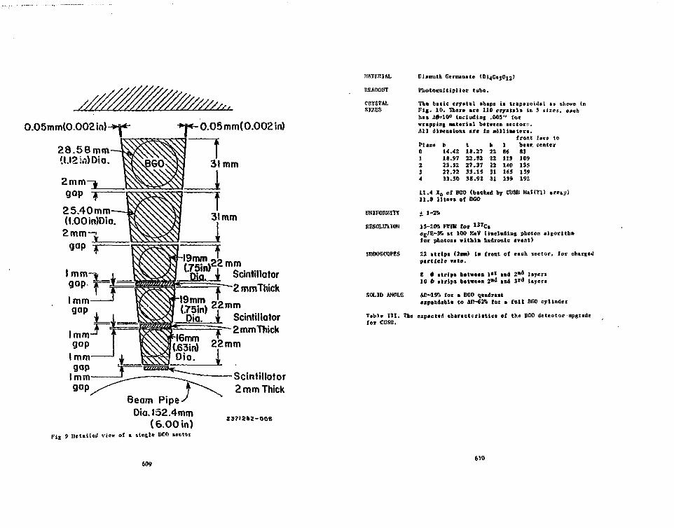
V/////,,.O.O5mm(O.OO2in)^K-
28.58mm
25.40 mm(I.OOin)Dio.2mm
i.O5 mm( 0.002 in)
SciniiUatorj . 2mmThick
19mm OU__
Dia. JL ScintiHator2mmThick
22 mm
1 .Scintiltotor2 mm Thick
Beam Pipe-Dia. 152.4 mm
(6.00 in)Fig 9 Detailed view of » single BOO sector
23712*2-006
MATERIAL
UEAnOUT
CRYSTALSJ7.ES
RESOLUTION
KODOSCOPES
SOLID ANCLE
Eismuth Germtnate
Miotorultiplier tube.
The bttic crystal thape it trapezoidal as shown inFi|. 10. There are 110 crystals in S sizes, eachhas iff=10° including .005" forvrappini Material between sectors.M l distensions are in nilliiteters.
front face toPlane0]234
b14.4218.9723.5227.7233.50
t18.2722.8227.3733.1S38.92
k2222223131
18«1131401651»9
best-, center83109135159192
11.4 Jo of BGO <bsck«d by CDSD NaKTl) arrt;)11.« liter* oC BGO
15-2W FB1W for 1 3 7CsaEIZ~i<i at 100 K*V (iaclaAinf photon algorith»for photons »ithi» nsdronlc event)
22 strips (2sa> in front of each sector, for charted
particle veto.
8 # strips between 1 " a*d Zni layers10 6 strips between 2*4 and 3 t 0 layers
An -IST) for a BGO qnadraatexpilioibl* to A(!-6M for a {nil 0(!0 cylinder
Table t i l . lite expecttti chtractcrittlct of the BCO detector upgradelor CUSB.
609610

PERFORMANCE
BGO SPECTROMETER-CUSB
MATERIAL: BGODIMENSIONS IN MILLIMETERSTOLERANCES : ± .025mm (±.005 INCH)
DETAIL1-PLANE 02-PLANE 13-PLANE 24-PLANE 35-PLANE 4
b14.4218.9723.5227.7233.50
t18.27
22.8227.3733.1538.92
h22222 23131
I86113140165199
2371282-OOS
11 Shape and tiles for UGO crystals.
611
Unfortunately, we have not yet built inch > M O detector, and
therefore we can only present the results of Monte Carlo simulations.
It is relevant to note here that the tan calculations perforated for
the present CUSP detector fully explain our present resolution, and
therefore confirm the results presented in the following. We have
generated hadronic events free the radiative X" ->y+23Pj decays in
the nGO quadrant by using the LUND Monte Carlo8 with Field and
Feyncian fragmentation'. The electrosagnetic shower development in the
EGO is simulated by the ECS Monte Carlo10.
• 10
Z.4
2.
1 6
1 2
o.a
o.*
o.
-
-
-
-
1.I ' I f
P .,}
K
// v
/so
/
/
V
-
-A
\ iH. fi i!
120 14OPHOTON ENEROt <WEV)
Fig. 11 The subtracted photon spectrun from 5ilO5 I" decays,
showing a clear separation of the J"=0.1,2 lines. Full »C0 cylinder
coverage has been assumed.
612

Fix. 11 sho»« the f.'onte Carlo calculation remit for 5x10* 1"
decays (after background subtraction and assailing a full BOO cylinder
coverate). and Fig. 12 a similar plot for 5xlOs f decays. Recall
that Fig. 5a) sltows the same decay for 5x10* %" decays in our
present detector.
Fig. 12 The subtracted photon spectrun from 5ilO5 I' decays. The
full angular coverage of a conplete cylinder has been assumed. The
three J-0,1,2 lines arc well separated.
613
Vi'c have been conservative in the intrinsic HfiO resolution that
we have assumed: Figure 13 shows soae measured resolution points
together with our assucption for the Monte Carlo studies. The value
we have assumed i s
for E<100 HeV
10 for E>100 KeV
which i s about twice as poor *t the measured values of Fig 13.
-i 1 —r-CmoUl tl oi. RtsofcHion vs. E
o BGO (prttMoory)
a Nal (Tl) Crystal Ball,duster of 54
Moktc Cork auMnf t iM
30 SO 100
1 3 f e a t u r e d PGO r e s o l u t i o n v a l u e s f rom R e t . 1 1 -
614

In kecpinc with our desire for t detector thit can be assembled,
tested and KOrtinr. in less than • yoar, we have chosen conventional
photoamltiplier tube (I'M) readout (or i l l 110 BGO crys ta l s . In
addition it would appear that the present state of the art in
photodiode (PP) readout i t would be impossible to have a 137cj source
calibrations because of the Pl> noise. The proposed PM's are l i s t ed
in the following Table.
PMPlane Dianieterdan) Type0 16 TaaiaaiatSB 8647-011 19 Kanaawtsn 1112132 19 nansMtsa R12133 25 n s u m t s a R1535
4 29 i:»«Mtt« RZ6S
Table IV. The photonultipliers for the D0O array.
Using PM's requires accurate Konitorlng of the gilns. which we can
achieve using the same calibration systee that is presently used for
the Clisn Nal(Tl) crystal array which Monitors 448 PJI's (etsinly
l.'ansnatsu R268's). This system will be disenssed in greater detail
below. The snail size of the DCC 'quadrant' sake* the design of the
support' stand very easy. The total anoint of BGO is -V0 kilograms.
We propose to house the complete 110 crystal array in a single light
tight unit (inclurfinc PJI's). with a this fil» (.005") separating BGO
crystals for optical isolation. Provision for lead shielding on the
support stand would be included.
CAMREATIW SYSTEM
A crucial problem to be faced in high resolution tpectrotcopy
with lsrce crystal arrays is the fbility to sccurttely caintain or
ronitor gains. In tfio present Mai array of the CUSI! detector the
615
response of each crystal-PM-electronics chain is monitored
continuosly to an accuracy of <.5?>. This is obltained by observing
the 1 3 7Cs line for ill crystals in the «rr«y. tnd is done
concurrently with data taking. Since the source signals are so SBtall
(~.66 MeV> relative to our *dtt»* signals, the calibration system
requires a separate high gain signal path for the source signals. A
schesiatic view of the present CD SI) calibration system is presented in
Fif. 14.
I6chADC
(IS bit)
IOO'IE pairtwisted-pair
(Boons)
to" dota"«oc'tnon-loading (low gain)
di.cnminotor P I W - O M
Fig. 14 A schematic representation of the present CHSH calibration
systeri.
The rain elements of the systeia. starting at tlic I'l:. »re:
D p r o n p l i f i c c t i o n and signal control within the l'N base assembly, 2)
differential drivers and receivers for the signal transport from the
detector to the APC system, 3) non-loading differential pickoffs for
616

the high gain source calibration path. 4) Bultiplexers and ADC. and
S) a mini or nicrocoirputer controller for finding and recording
source peak positions, and setting high voltage power supplies. The
PFI's are operated at -low peak anode currents (.5 uA) to reduce
non~lincarity effects. In additon, since the naxicum continuous peak
anode current is veil below raiiamai ratings, the PM's can and are
left on at all tines (including injection), ensuring better gain
stability. We have built our own low noiie-low power (because of the
high density) preanplifiers for the PH'l. The equivalent noise input
of the whole electronic chain is ~2fC. where full scale is -50 pC. A
complete calibration cycle through ill 110 DGO crystals could be
completed in well under a 1/2 hour. * significantly mailer tiiae
scale than any long tern: crystal PM drift** As an exanple of the
gain stability of the present Nal(Tl) array, we have plotted the
average ?• change in gain per week for a few selected crystals vs.
day in Fig. 15. As can be seta, the drifts are Halted to a few
percent per month at the cost, fun to n o calibration can monitor
the gains to better than O.OSTi. Siace bo.l DGO and Nal(Tl) have a
temperature dependent gain, the cnviroaeatal temperature cust be
controlled and monitored. Therefor* the present detector is housed
in a teaperature and humidity controlled building. The tenperature
of the system is ronitored. tnd mints ined to +1°C during running
periods.
617
IS 115 '55 195JULIAN DAY
Fig. IS The drifts in the CDSB Nal(Tl) detector crystals for a
randon selection of five crystals. The vertical aits is the % chsnge
relative to an arbitrary tir.e in weekly Intervals, snd the horizontal
axis is the tine in Julian day.
CONSTRUCTION TIME SCALE
Since we arc using the basic CUSB design for all the
electronics, the longest lend tine iten is the l'CO itscn. Vs linvc
been assured of complete delivery of all crystals in f r,otitl.s.
Testing, nssenbly antt final counting of the crystals could be
completed in an additional 3 months. Thus the total detector could
be running in 9 months or less, providing us with a valuable new tool
618

with which to study the spectroscopy of the t systen. and test OCD.
1. The present members and institlttions of the CUSB collaboration• re: P. Pranzini. ].'. I'm. S. V.1. Herb, D. Son, S. Youssef - ColunbiaUniversity; J . I!, l or j t to t tc , C. Klopfenstein. J Lee-Franzini.E. n.SchairJberp,cr J r . . !!. Sivertz. L. 1. Spencer. P. M. Tuts - SUNY atStony Krook; I'. Dictl , C. Tisen. E. Lorenz, G. ffageras, F. Piuss,1'. Vogtl - t in «t Munich; R. Imlay. «. levnan, W. !>etcalf,V. Srcedhtr - I.SH.
2 . The Columbia University and SUMY «t Stony Brook groups arcproviding the nr,0 quadrant upgrade foi CllSlt.
3 . S. V. I'crb ct a l . t 'hyi . Rev. L « t t . J ? , 252 ( 1 9 7 7 ) .
4 . Ch. Rergcr et «1, Vkyt. Lett. 22£. lit (1918), C. V. Dardtn c t• 1. Phys. Lett . 7PR, 36A (1978). J . K. Ble&iein et a l . Fhys. Lett7sn. 360 (1978).
5. P. Pranzini and J. Lee-Fr.niini. Phys. Rep. £]. . 241 (1982) andreferences therein.
6 . !C. !'«n e t a l . P h y i . Pev. L e t t . 4 J , 1611 ( 1 9 8 2 ) .
7 . fi. F i s c n i t « 1 , Phy*. Key. L e t t . 4_9_, 1616 ( 1 9 8 2 ) .
8 . T. Sjoitran*. WniveMity of Lund LB TP79-8 (1979). tnd LV W80-3O(1980).
9. .R. I). Field >xd P. P. Peynnn. Nucl. Phys., B136. 1 (1978).
1 0 . R. Ford and « . N e l s o n , SLAC-210 UC-32. June ( 1 9 7 8 ) .
11. II. Cavalli-Sforza. Detector and Experiaients for e+e~ at 100 GeVVfortshop, Cornell Preprint CLWS P.l-490 (J981).
619
]1S£ St KS£ 111 A SHAli AHSiE
DETECTOR AX IOC 8T»wr<>HB
David Koltiok and L. Xafturi R«ngan
Purdu* University
We have designed a (Ball angle luminosity Monitor aid*
of BGO (Bisauth Ccraanata) lor us* at the Stanford Linear
Collider. The aiin design paraacters oi the Monitor
resulted iron the physical constraints iaposed by the
Collider and the characteristics oi the other detector
elements, and are listed belou:
1) The •onitor's total length has to be less than 25 ens.
2) The Monitor has to be capable of Measuring
electromagnetic shouers uith energies up to SO GeV.
3) The aonitor has to be capable oi surviving the
radiation enviroment 1 eentlMeter auay froM a 500
joule, 50 CeV electron beam.
4) The monitor has to operate in a 16 kilogauss Magnetic
iield.
» paper presented at the International Workshop onBismuth Geraanate> Princeton University. 1982. Worksupported by the U. S. Department oi Energy underContract DE-HCO2- 76EMM28 Task k.
620

PAGE 2
Using BGO crystals and a photodioda readout systea. ue
ara easily able to satisfy all the design constraints.
BGO is available in single crystal lengths of 20 ca ;
such crystals having a radiation length of 1.12 ca uill
give excellent performance in the SO GeV energy range.
The radiation hardness of the crystals is also
impressive. A single SLC beaa) directed into the Monitor
uould result in an average dose of 100 rads. BGO crystals
recover froai such doses uith a tine-constant of about 50
hours . BGO is capable of receiving doses in the atega-
rad range before peraanent daaage results . Finally
because the aonitor uill be operating deep inside a 16
kilogauss Magnetic field a photodiode readout systea uill
be used. Diodes such as the Haaaaatsu S1723 have high
quantum efficiency (60X) for detecting the scintillation
light froa BGO. Ue expect to operate such a readout
systea uith an equivalent noise level of 1 MeV per
channel3 .
For these reasons ue propose a coapact luminosity
aonitor. shown in Figure 1. The tuo detectors, one on
either side of the interaction region and each
surrounding the beaa pip*, consist of IS radiation
lengths of BGO and cover the angular region betueen MO
and 250 ailliradians. Each of thu 256 cells of the
aonitor systea is a truncated pyramid uith a base 1.8 ca
x 1.S ca. On the base of each' cell is a photodiode uith
1 square centiaeter active area and a fiber optic
621
PAGE 3
coupling ior a laser calibration systea. In iront of each
array is a three layer uire chaaber systea uhich uill
locate charged particles to better than 100 microns. This
uill allou the angular acceptance of the aonitor to be
accurately defined, yielding luainosity aeasureaents to
IX.
In order to understand the response of the BGO
crystals to electrons and photons in a segaented
geometry, the SLAC Monte Carlo prograa EGS uaz used to
siaulate electroaagnetic shouers in a siaplified aodel of
the aonitor. The aodel consists of a seai-infinite BGO
crystal (X:Y>Z:s °> i • 120ca) in uhich an electron or
photon is incident along the Z-axis. This voluac uas
subdivided into overlapping truncated pyraaidal
subvoluaes syaaetric about the Z-anis, and having base
sizes 1 x 1 ca2 .1 x 3 oa2 , 5 x 5 ca2 ,7 x 7 ca2 , 9 x 9
ca ,as shoun in Figure 2.
A sample event of a shower initiated by a 10 GeV
electron is shoun in Figure 3. Qualitatively, the figure
shous that the energy is aostly contained in a narrou
region around the shouer core and the leakage consists
alaost totally of photons. In the EGS siaulition.
electrons uith a total energy less than 1.5 tlev and
photons uith energy less than 0.1 HeV uere considered to
be absorbed in the crystal.
622

PAGE 1
Figure 1 shout a plot of the ihoutr energy deposited
in the itibvolimes as a function ol the incident electron
energy. Energy leakage through the back and backscatter
into the subvoluaes ussre accounted lor. It should be
noted that the fraction oi energy deposited in any
pyramid is alaost independent of the incident electron
energy. Results for incident photons are the sane uithin
the errors. Uhen a particle is incident in the center of
a single Monitor crystal, the amount oi energy deposited
in that crystal is about 72X. The upperaost curve oi
rigure 4 shous the saount oi energy absorbed in the
infinite crystal slab* so that its complement gives the
leakage out the back, which is about 6X at 50 GeV. The
leakage tnetgy is almost entirely aad« u» of photons.
Their energy spectrua for 50 GeV incident electrons is
shoun in Figure 5.
Figure 6 shous the average nuaber oi leakage electrons
and positrons as a function oi incident energy. As can be
seen, the number exiting the back of the aonitor is saall
and is spread out over a large area. He can expect
1100 photoelectrons in the photodiode per HeV absorbed in
a BGO crystal '* . »n electron passing through the ~ 100
aicron depletion layer oi the photodiode uill produce
approxiaately 10 electron* . Hence a leakage electron
can produce an equivalent noiae oi ~ 10 HeV. The EGS
calculation predicts 20 leakage electrons tor 50 Gev
incident energy. This uill give at aost a 0.M X
623
PAGE 5
uncertainty to the energy aeasureaent and so can be
neglected.
The resolution obtainable for variuut sized truncsted
pyraaids is shoun in rigure 7. Because the Bhsbha
scattering cross section falls very rapidly with angle ,
aost oi the events uill hit only the crystals closest to
the beaa line. Even so, using a ainglc aonitor crystal,
resolutions oi 2.5 X should b« obtainable for angles
greater than 60 ailliradians. Such high resolution is not
typical in luminosity aeaiureaents and aay seea overly
accurate, lut it aust be reaeabered that the SLC machine
uill run on the Z° resonance and hence the physics uill
be totally dominated by ueak interaction effects. The
only QED cross section essentially free of the Z° and
capable of calibrating it is the Bhabha scattering at
saall angles. Hence we leol it is essential to measure
the Bhabha cross section as accurately as possible.
He also ieel that the case oi working uilh BGO and ita
radiation hardness acan that obtaining such high reso-
lution is no aore difficult than uorking uith techniques
uhich yield louer resolution results.
In conclusion. the aonitor we have designed uill be
capable oi measuring the differential Bhabha scattering
cross section between 10 and 25t ailliradians. as uell as
beaa polarization efiects uith precision at SLC energies.
624
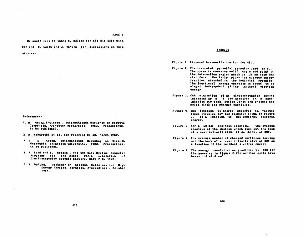
PAGE 6
Uc uould like to thank It. Nelson lor all hi* help with
EGS and D. teith and J. Va'Vra lor discussions on this
problem.
References:
1. H. Cavejli-Siorza . International Uorkthop on lismutliGermanate. Princeton University. 1962, Proceedings,to be published.
2. n. Kobayashi et al, KEK Preprint 81-28, March 1*82.
3- 0- E. Croon, International Horkshop on BismuthGerminate, Princeton University. 1982. Proceedings,to be published.
1. It. Ford and ft. Helson . The EGS Code Systeai ComputerProgram for the Mont* Carlo simulation oiElectromagnetic Cascade Shouert, St»C 210, 1978.
5. V. Radcka. Workshop on Silicon Detectors ior HighEnergy Physics. Ferailab, Proceedings , October1981.
625
FIGURES
Figure 1. Proposed Luminosity Monitor lor SLC.
Figure 2. The truncated pyramidal geometry used in EG.:.The pyramids conserve solid angle and point tothe interaction region which is 25 cm from theslab face. The table gives the average energyfraction absorbed in the indicated pyramids.The fractional energy absorbed is found to bealmost independent of the incident electronenergy.
Figure 3. EGS simulation of an electromagnetic shouerinitiated by • II fieV electron in a semi-infinite 160 slab. Dotted lines are photons andsolid lines are charged particles.
Figure 1. The fraction of tnargy absorbed in varioussized pyramids ior the geometry shown in Figure2, as a function oi the incident electronenergy.
Figure 5. For a St GeV incident electron. the averagespectrum of the photons uhich leak out the backol a semi-infinite slab. 2* cm thick, oi 160.
Figure 6. The average number of charged particles talkingout the back of a semi-infinite slab of BGO asa function of the incident electron energy.
Figure 7. The energy resolution as predicted by EGS forthe geometry in Fifure 2.The monitor cells havebases 1.8 Ml.8 cm2 .
626

LOCATION OFLUMINOSITY MONITOR
WireChambers
BGOCrystals
Photodiodes
/
^InteractionPoint
10 20 30cm
40 50
BGOCrystal
SINGLE CELL OFLUMINOSITY MONITOR
12-82
1cm —i _
1t1
it
BGOCrystals
FRONT VIEW OFLUMINOSITY MONITOREACH CELL 1cm x 1cm
4428AS
FIGURE 1
627
TABLE I
E A (0.053)E3 B (0.022)
Pyramid
12345
BaseOimentionIxJcm2
3x35x57x79x9
EnergyFraction0.4720.7550.8470.8930.919 12-82
4428A4
FIGURE 2
628

\-
I I I I I I I I
00.2
12-82
* - * • -o—-e—•
0.5FIGURE
n©X
20i3
2E
xoo]x |x3]
e
1 „crrr1i i i i
5(GeV)
+•
on!10
579
x5)x7 [cmx9)
i i
20 504428A3
M
£ 3Un9I-|

LLJ>LU\CO
IoXQ_LUCD
3 h
2 h
w I h
0
(CHARGED PARTICLES)
02-82
1 2 3 4PHOTON ENERGY (MeV)
FIGURE 5
54428A6
men
_ O CJIp
i
om
m
35CD-<
* • — —
1
-•
;Lr
iE.t
11
1 i i
i
—O1
I
1
8o3CDCDO
1
K)O
1
Fro
3 -m *CD :CO _
c.CO
-
LLL
—
-
1 -5 O
631632

r — roinh-cr)x x x x x
CALT-68-971DOE RESEARCH ANDDEVELOPMENT REPORT
A BGO Ball for the Stnnford linear Collider'
f. C. Porter(Rtpnsmting (hi BGO Ball Collaboration,)1
C*Ufornia Jn»titute of Technology, Puadena, California 91125
ABSTRACT
The Nal(Tl) Cryita) Ball has proved to be a very successful
detector at SPEAR, capable of dotn( a wide range of physics, com-
plementing the kind! of physio accenlble to detector* optimized
for charged particle measurement. Band on our experience with
this detector, we are proposing a tecond-generalion "cryittd ball"
which, among other thlngi, l i a much belter match to the high par-
ticle multiplicities expected in •*•" collisions at Ecm - 100
GeV. BGO Is the material of choice fi. "-i! new detector--the
improvements rrcr the Nat Crystal Boll are largely possible
because of the much shorter radiation length in BGO.
Wort njpporwd in put b j the U.S. IXjwtnett oJ Enerjj iindtr conirui 0E-AC0WI-ERtMBO.
(Invittd Ulk pKMMed >t iht InttrMtlond Workfhop on Bumuth Germwte, Princeton,Nrw linef. Novembtr 10-13, ItBZ).
633 634

As ii well-known in the field of hlf h energy physics, the Nal(TI) Crystal Bail
has made several important contributions In the study ot «*•" interactions at
SPEAR (fen - 3 to 7.5 CeV). These contributions cover a wide range of physics,
complementing (and overlapping) (he kinds of physics accessible to detectors
optimized for charged particle measurement. While detectors optimized for neu-
tral particle detection are typically characterized as "special purpose", the Cry-
stal Bell has provided the counterexample. However, the limitations of the Cry-
stal Ball become -more severe as one goes to higher energies and multiplicities,
and we are proposing a second-generation device with much-improved capabili-
ties tor high center-ot-mass energies. BCO (BtjGejOu Bismuth Germanate) is the
scintillation material ot choice tor this new detector. In this paper I attempt to
provide some intuition Into the characteristics «nd performance of this "BGO
Ball" by using the Nal Crystal Ball as a comparative milestone.
While it is not the emphasis ot this workshop to go Into details on the phy-
lics one intends to do with such a device. 1 should at least give an idea ot the
context. Our proposal currently exists as a 'letter of Intent"!" for an experi-
ment at the Stanford linear Collider (SIC). The SIC (see Fig. 1) is an e»»- col-
liding beam machine to be built at SIAC, expected to be completed in late 19B8
or early 198?.''" It is not a storage ring, howsver. Instead It Is intended as a
prototype for a new variety of i * r machine -where the two beams (t* and e~)
are collided ]ust once and then discarded. The Idea it to save on the enormous
amount ot power required to store such beams in a ring of reasonable size al
high energies. The center-of-mass energy of the SI£ will be ~ 100 GeV, which
makes it a very promising piece to produce and study the neutral weak vector
boson (Z°).
Before discussing the proposed BGO Ball, lei ui quickly review the com-
ponents of the Nal Crystal Ball "I Figure 2 ihows a cut-away view ot the principal
635
- 2 -
components ot the Crystal Ball as it existed at SPEAR. The Crystal Ball is now at
the DORIS storage ring at DESY. and several changes have been made, but none
that are ot much concern to our discussion. The primary piece ot the detector
is. of course, the "ball" of crystals itself: 872 truncated triangular pyramidal
Nal(Tl) crystals arranged In two separable hemispheres around the interaction
point. As Nal Is both hygroscopic and delicate, each hemisphere of crystals is
sealed Inside a container which Is kept at an underpressure tor structural rea-
sons. Except tor a number of wires tor support, there is no structural material
between the crystals-only a minimum ot material (paper and aluminized
material) for reflection and optical isolation exists between the crystals. The
03% of i n solid angle covered by this main array ot crystals is extended to 9BX
by hexagonal crystals in the "cndcap" regions around the t V beamplpe. In the
center ot the main array is a cavity (25.4 cm radius) where chambers tor
charged particle Identification and tracking are placed around the beam pipe.
As we shall see below, the proposed BGO Ball has a similar design concept.
We turn now to the geometry of the Crystal Ball, and its extension to the
new BGO Ball, figures 3 and • describe the means for arriving al the final
geometries. Starting with an icosahedron, we proceed by dividing each face into
4 equilateral triangles. The new vertices are then projected to the surface ot the
sphere defined by the icosahedral vertices. Each face ot this 80-sided figure is
further divided into 9 smaller triangles, which are again projected to the spheri-
cal surface. This results in a 720-sided figure, which, upon removal of 48 cry-
stals for the beam pipe to go through, gives the 672-crys.tal geometry ol the N&i
Crystal Ball
To arrive at the BGO Ball geometry, two further subdivisions by nine are
made. This produces an object with 58320 triangular sides. These triangles are
combined together m groups of six (five, at the 12 icosehedron vertices) to
636
- 3 -
produce the BGO Ball geometry with 9710 lix-iided crystals and 12 five-aided
crystals. Five percent of these crystals are removed to allow the beam pipe to
pass through the center. The subdivision Into crystals for one icosahedron face
is shown in Fig. 5 for both the Crystal Ball and the BGO Ball. The BGO Ball is seg-
mented approximately 13)4 times more finely than the Crystal Ball. A com-
parison ot the relative sizes and shapes ot a single Crystal Ball crystal and a BGO
crystal is shown in Fig. 6.
At this point, 1 should comment briefly on the philosophy behind this choice
of geometry. There are basically two principal competing types of geometry for
a large solid-angle BGO device such as w* ara proposing. One is the highly sym-
metrical, nearly spherical design as in our choice. This has a roughly spherical
Inner cavity and outer dimensions. Tbt second Is built to surround a cylindrical
inner cavity, and has a nearly cylindrical outer shape. The motivation for this
second choice is the desire to most efficiently match the cylindrical geometry of
central chambers (in the cavity) and a solenoldal magnet outside the BGO.
After consideration, we opted for the spherical design, based on the atti-
tude that we didn't wish to compromise the first priority ot the detector as a
flrsl-class device for neutrals measurement. There ara two, somewhat related,
principal reasons for preferring the spherical geometry. First, the crystals are
all at the same distance from the interaction point and are all nearly identical
(the biggest exception being the 12 pentagonal crystals). This means that each
crystal subtends the same solid angle, mud presents the same area transverse to
a developing shower Thus, the angular resolution and the development ot
showers are the same independent of the direction of the showering particle.
Second, this high degree ot symmetry simplifies the design ot triggers, calibra-
tion schemes, and, most substantially, analysis software. It is probably no exag-
geration to say that the ability ot the Crystal Ball to produce physics results
637
- 4 -
very quickly after the first data was taken was very much a benefit of the
simplifications resulting from the inherent symmetry of the detector.
The largest drawback to the spherical geometry is that we give up the abil-
ity to use the full volume of the Inner cavity for charmed-particle tracking
chambers, limiting the lever arm available. Fortunately, the short radiation
length of BGO make* it practical to build a detector with a fairly large inner cav-
ity (45 cm radius in our design) compared to the Nal Crystal Ball (35 cm radius),
and enough chambers can be fit ID to comfortably satisfy the requirements of a
non-magnetic detector. While our initial plan Is to build a non-magnetic detec-
tor (the Crystal Ball, of course, is non-magnetic), we do not wish to rule out the
possible eventual addition ot a magnetic fleld. In such a case, the requirements-
tor the central tracking chamber become more severe, because one then wishes
to measure sagittal in addition to directions from the Interaction paint. One
then must consider high precision chambers and large magnetic fields (I.e.,
superconducting magnets) to help offset the small lever arm available. Cylindri-
cal BGO array designs must ot course face the same considerations-while the
cylindrical cavity offers a belter match to typical chamber designs, the cavity
radius is still limited by BGO cost and by the tradeoff that such a geometry
makes tess efficient use ot BGO than a spherical geometry (the amount of BGO
used per unit solid angle is not constant, as It is in the spherical design). Thus,
despite the existence ot drawbacks, a strong c u e exists tor the use ot a spheri-
cal geometry.
A few more remarks about magnetic fields are in order before we move on.
First, the existence of a magnetic fleld means that charged particlei will no
longer enter the BCO array radially, and will continue to follow curved trajec-
tories inside the BGO. While it is possible to imagine some benefits o ' ' his fact, it
probably is mostly a nuisance. The recognition of minimum ionizing particles is
638

- 5 -
oo longer at simple or reliable u Cor the radial caie. Charged hadrons (e.g.. rr1)
will have a longer path length in the BGO. and thus are more likely to undergo
itrong interaction!.'4' Second, sbowars that develop in the BGO will be distorted
to some extent from the simple circular symmetry (around the radial direction)
by the presence of the magnetic field. Presumably this effect is not large, but it
it conceivable that algorithms which make use of the lateral shower patters will
hare to be more complicated, and possibly less •fficlent. We have not yet per-
formed a Monte Carlo calculation to check this speculation. Third, the presence
of a magnetic Deld surrounding the BGO array implies that conventional pho-
tomulUpliers are no longer usable for scintillation light detection."1 The most
attractive solution to this difficulty it the use of solid state photodiodes.'*' How-
ever, the higher noise figure hi current photodlode readout prototypes has two
undesirable consequences: 1) Calibration with sources (e.g., Cs"7. as used with
the Nal Crystal Ball) is no longer possible: ii) The contribution of the readout
system noise to the energy resolution will be important up to higher energies
(up to gamma energies of a 100 MeV for BGO, depending on how many photo-
diodes are added together in the energy measurement).'*) For these reasons,
and because the photodiode readout technology is still immature.1'1 we have
opted for photomultiplier readout for the non-magnetic BGO Ball. Of course, if
we found it desirable to include a magnetic field in a later upgrade, then we
would change to a photodiode readout technology (unless something even better
were to appear!). Fourth, and finally, the existence of a magnet presents logisti-
cal problems: The Crystal Ball and the BGO Ball are both designed as two hemi-
spheres which may be easily separated to ~ ±1 meter distance from the beam-
line in the vertical direction. Such motion would no longer be possible in most
reasonable magnet designs. How important is this ability? For the Crystal Ball,
it has been crucial as a means of protecting the Nal from high radiation levels
639
- 8 -
(during machine physics and synchrotron radiation running at high currents).
As BGO is much more resistant than Nal to permanent damage by high radiation
levels.'*1 this need is much less pressing. However, the ability to separate the
hemispheres has also been extremely useful with the Crystal Ball as a means of
access to the central chambers. This desire tor access remains in the BGO
detector, and an adequate solution will have to be found if a magnetic field is
seriously contemplated.
Let us turn now to one of the chief advantages that the BGO Ball has over
the Nal Crystal Ball in an environment of high particle multiplicity events. Fig-
ures 7, 3. and 9 show event displays of three progressively more complicated
events in the Crystal Ball at SPEAR. As a first simple example, Fig. 7 shows a
Bhabha event (e*e~ •* »*e~ elastic scattering). It can be seen that each of the
showers (about 3.3 GeV each) spreads over several crystals. A heavy line indi-
cates the 13 crystals around and including the central crystal of each shower.
These crystals are used in the moat successful (for typical events) algorithm for
the determination of a y or e* energy. This algorithm basically consists in sum-
ming the energy observed in these IS crystals, applying a 2.SX correction for
lateral leakage'10' to surrounding crystals, and an additional factor to account
for the dependence of the observed energy on the position of the particle in the
central crystal.
Figure B shows a still simple, but less so, event where there are six elec-
tromagnetically showering particles In the final state. Figure 9 is a more-or-less
"typical" hadronic event at Ecm = S.SBGeV {f resonance) In this case, a total
of nine particles from the e 4 t - interaction were found by the analysis software.
Some of the showers produced are most likely from hadronic (strong) interac-
tions with a nuclei in the crystals rather than from the electromagnetic shower
of a 7 or • . Clearly, the showers produced In such events can easily overlap and
640

-7-
cause difficulties in the analysis. Among t h e n difficulties are the following: i)
Overlapping showers make pattern recognition difficult, and often it is not possi-
ble to determine with much confidence how many particles there are. Thus, the
determination of charged and neutral particle multiplicity distributions is seri-
ously handicapped, il) The efficiency tor finding n*'s (either for the purpose of
removing their decay ft from an inclusive photon study, or to study the n*'s
themselves) is reduced because one (or both) at the decay 7'« can overlap with
another shower in the event and either be lost", or have Its apparent momen-
tum modified so much as to no longer reconstruct to a n* with the other 7. In
addition, for IT'S with energy % 800 HeV, it it possible for the shower from the
two decay ?'s from a single n* to ovarlap with each other In the Crystal Ball.
When this occurs It ic still possible, with Uw UM of a sophisticated algorithm and
enough computer time, to distinguish a "merged-ir"' shower from a tingle 7
thower up to an energy of ~ 2 CeV. ill) When showers overlap, the energy resolu-
tion is degraded. Obviously, this problem gett worse the lower the energy of the
particle that one is Interested in. iv) Often In Crystal Ball physics analyses, cuts
are applied on the nearness of particles to alleviate the problems of overlapping
showers. This reduces further the efficiency tor the process under study,
becoming more severe for higher multiplicities.
When we start to consider particle multiplicities at £ . „ . S 100 GeV which
are, on the average, several limes higher than at SPEAR, we see that the Crystal
Ball becomes inadequate for much beyond simple event counting and rough
"energy-flow" measurements. The BGO Ball it a much better match to these
high multiplicities. Four teatures of the BGO detector combine to produce this
improvement: 1) The MolMre radius In BGO (2.24 cm) is half that in Nal (4.4 cm).
Thus, an electromagnetic shower is contained In • roughly 4 times smaller
transverse area of crystal material, li) The BGO starts at 45 cm from the
641
-8 -
interaction point, compared with 35.4 for the Nal Ball. Thus, showers (hadronic
and electromagnetic) start at a larger radius, on the average. Ill) The nuclear
absorption length in BGO (-23 cm) is almost half that in Nal (~41 cm). As both
the BGO Ball and the Crystal Ball shells are one absorption length thick, this
means that the relevant distance for the lateral development of hadronic
showers is also roughly a factor of two smaller in the BGO Ball. Iv) The segmenta-
tion of the BGO Ball if ~13fc times that of the Crystal Ball. To some extent, the
flner segmentation it simply a requirement In order that points i)-iii). above, be
taken advantage of. However, it la alto relatively finer than the Crystal Ball seg-
mentation in the tense that the lateral thower development of electromagnetic
and hadronic showers can be examined in more detail.
The combined effect of points i) and II) If that we expect a given fraction of
an electromagnetic thower to be contained In roughly a 5 times smaller solid
angle In the BGO Ball than for the Crystal Ball. likewise, the solid angle "con-
taminated" by hadronic showers will be greatly reduced (points il, ili, and lv all
help here; point I also helps because n*'s may be produced In high energy
hadronic showers. The actual gain it difficult to quantify in the absence of a
realistic Monte Carlo calculation.) Thus, the several problems already men-
tioned from overlapping showers arc much alleviated in the BGO detector. This
implies not only that multipltclUti expected at E,,m. - 100 GeV can be accom-
modated (assuming particle densities are not beyond expectation), but also that
the 7T* measurement range Is extended up to £*• ~ B GeV.
The fine segmentation relative to the shower size (electromagnetic and
hadronic) also suggests that we may be able to use various pattern recognition
"tricks" with greater success than permitted with the Crystal Ball segmentation.
The recognition of minimum ionizing particles will be jutt as obvious as it was .1
the Crystal Ball-very few crystals will contain energy from the passage of such a
662

-9 -
particle. However, it might alto turn out to be possible to unscramble hadronic
•hovers to some extent, by techniques such as searching lor "strings" of cry-
stals connecting secondary interactions in the BGO. Even if such an approach is
not tried, the distinction between hadronic showers and electromagnetic
showers should be easier to see-implying improved ir/t separation, as well as
better discrimination against charged-particla "punch-through" contamination
in photon studies.
Finally, a very important Improvement from the finer segmentation, com-
bined with the larger lever arm and smalier shower spread, ts a much better
angular resolution on particle directions. For y'a and •'( , we expect roughly a
factor of four better angular resolution than obtained by the Crystal Ball.
Among other things, this implies improved yy mass resolution, hence, improved
n* -• 77 reconstruction. In fact, we could (till gain further In angular resolution
(and in shower pattern analyzing ability) by even finer segmentation However,
et some point the crystals become unattractively narrow and numerous, and
other potential problems begin to look considerable, so the chosen segmenta-
tion appears to be reasonably optimal.
Another very important advantage of the BGO Ball desigo, which we obtain
almost as a "by-product" of the short radiation length, is the much larger inner
cavity than in the Crystal Ball. The dashed line superimposed on the Crystal Ball
diagram in Fig. 3 shows the boundary of the BGO Ball inner cavity, a radius of 45
cm, compared with 25 cm for the Nal Ball. This hrge inner cavity provides much
more space for central tracking chambers, allowing for greater redundancy,
greater lever arm, and measurements over greater path length. Thus, the
charged particle tracking will also be improved to a level consistent with the
higher angular resolution and multiplicity capabilities of the BGO crystal
array Fig. 10 shows the central chamber configuration as we have proposed it.
643
- 1 0 -
Note that all chambers, including the outermost one at a radius of 31.5 cm.
cover at least B5X of 4TT steradians (for the Crystal Ball, the outer chamber, at
14.S cm radius, covers 75X). If desired (such as in an "upgrade" to include a
magnetic field), the lever arm could be extended to a radius of 38 cm and still
cover 75/5 of the solid angle at that distance.
A comparison of the design parameters of the BGO Ball with the Crystal Ball
is given in Table I. which summarizes and quantifies much of the discussion up to
this point. There are several more (pacific remarks to be made concerning the
entries In this Table:
1) The number of radiation lengths is Increased to 20 in the BGO Ball, com-
pared to 16 in the Crystal Ball. This reduces the contribution to the resolu-
tion for high energy showers due to fluctuations in shower leakage from
the rear of the crystals. Because of the shorter. BGO radiation length, the
outer radius of the BGO shell is only 1 cm greater than for the Nal array,
even with the larger inner cavity and the 85% increase in radiation lengths.
In fact, when one considers that toe Crystal Ball has two ~ 1" air gaps and a
({"-thick window between crystal and photomultipu'er, and that smaller pho-
tomultiplien will be used In the BGO Ball, the new detector actually turns
out to be smaller than the Crystal Ball!
2) The hexagonal single crystal geometry (s a much better match to circular
photomultipliers than the triangular geometry of a Crystal Ball module. 11
also means that the edges of the crystal are relatively less important.
3) The radius of a circle with the same area as a crystal cross section is about
a factor of two smaller at the inner face for the BGO crystal than for the Nal
crystal (at its considerably smaller inner radius) Naively, this suggests
that both crystals have similar lateral dimensions as tar as showers are con-
cerned, since the Moliere radius is also about a factor of two smaller for
644

- 1 1 -
BGO. However, there are two counteracting elTects which can modify this
conclusion somewhat. First, the hexagonal geometry will tend to contain
more of the energy from a particle's shower than a triangular geometry of
comparable crois-sectional area. Second, the divergence angle of the Nal
crystal (with circumscribed and inscribed cone half angles of B.B* and 3.5°.
respectively) is larger than for the BGO crystal (circumscribed and
inscribed cone half angles of 1.33* and 1.16'). which means that the lateral
size of the Nal crystal growl somewhat faster with depth than for the BGO
crystal. Thi» divergence, coupied with the fact that the showers develop to
greater depths in the Nal because of its long radiation length, is actually a
very significant effect in the Crystal Ball in ternu of shower containment
within a given number of crystals.
4) The large dynamic range desired (from sources to ~ 50 GeV), coupled with
the contemplated use of 12-bit ADCs, implies the requirement of 3 ADC
channels per BGO crystal (overlaps between channel* of greater than 100
counts are necessary, of course, to Insure that leait-count effects don't
deteriorate resolution).
5) The angular resolution expected for clectromagneUcally showering parti-
cles in the BGO Ball should be roughly a factor of four better than for the
Crystal Ball, simply from geometry (and the Moliere radii).Thus, while the
Crystal Ball number in the Table is the practically observed value, the
expectation lor the BGO Ball is based on this experience and should be
readily attained.
B) The energy resolution for sources (e.g., Csm), of interest for calibration
purposes should be comparable between the BGO and Nal detector, in spite
of the greater light output from Nal(Tl). This is because the Crystal Ball low
energy resolution is substantially degraded from the optimal Nal(TI)
645
resolution. principally became of light collection inefficiency (large air gaps
between crystal and photo-multiplier, poor match between circular PMT and
triangular crystal, etc.). As BGO is not hygroscopic, and not as fragile as
Nal, it is a simpler task to provide good optical coupling with the PMTs for
an array of crystals Note that the resolution we hope to achieve on Cs1*7 is
•till a factor of two worse than that which has so far been possible with BGO
under optimal conditions.111!
7) The energy resolution at higher anargies, such at typically encountered in
e*«~ experiments should be better in the BGO detector than in the Crystal
Ball. The light output is no longer of primary concern-instead. Important
factors are fluctuations in shower leakage and contamination from overlap-
ping ihowers. Leakage out the rear is reduced by the increase to 20 radia-
tion lengths. The fluctuations In leakage from the sides of the crystals can
be reduced by including more of the shower In the crystals summed over.
In addition, according .to the discussion given earlier, the contamination
from overlapping showers is alto reduced in the BGO Ball. The empirical
J.relation for the resolution lr.i the Crystal Ball (« 1/ E<) takes into account.
to some extent, the effects of shower leakage.However, Monte Carlo simula-
tions Indicate that the resolution does not continue to improve in this way
above a tew GeV. The resolution quoted for the BGO Ball is based on the
observed prototype measurements at CERN."*I which demonstrated such a
resolution (2.25! FWHM) at 4 GeV, and Monte Carlo calculations which sug-
gest that the leakage effects give a roughly flat resolution above some
energy, perhaps as low as 100 HeV. However. It is probably optimistic to
expect 33 resolution all the way down to 100 MeV in a realistic mulUparticle
environment-small, large angle fluctuations in other showers (hadronic and
electromagnetic) in the avenl will very likely deteriorate the resolution in
646

-13-
this region lome. Finally, to actually achieve a reiolution this good to an
•'dual experiment, we will have to deal very carefully with the technical
problem of inter-calibration error*.'"' Thii ii one of the reasons we are «o
loathe to give up the ability to measure nuclear sources.
I have diicusied, by comparison with the Crystal Ball milestone, the design
and philosophy o( the proposed BGO Ball detector, and its merits as a second-
generation device ol the "Crystal Ball" genre. It is dear that the short radiation
length is responsible (or the current BGO bandwagon among high energy physi-
cists. However, It is not Just a tad-tbis is a serious reason which has many desir-
able consequences. The greatest uncertainty tor the future of BGO appears to
be cost-i? it can be bought in large quantities at an acceptable price, then It will
provide th< opportunity for substantial Improvements tn high energy physics
detector technology While a BGO detector's capabilities are essentially a
requirement for good neutrals measurement* at very high center-of-mass ener-
gies, it is Interesting, but slightly frustrating, to reattz* that such a detector
would have produced substantially improved results ovar the Na] detector even
at SPEAR.
Acknoirletyemenl
1 would like to thank my colleagues on the BGO Ball collaboration tor many
stimulating discussions in which I became educated not only concerning BGO,
but also on much of the intuition that 1 have tried to present in this paper.
647
- 1 4 -
Refenences
[1] The BGO Ball Collaboration (SLC Utter of Intent SLC-B): California Insti-
tute of Technology-F. C. Porter; Princeton Universlty-R. C. Cabent, M.
Cavalli-Sforza. D. G. Coyne. C. Newman-Holmes; Stanford Universlty-D.
Besset, A. Iitke; Stanford University (HEPL)-G. I. Kirkbride. T. Matsui, J. C.
Tompklns.
12] SLAC Linear Collider Conceptual Design Report, SUC-229 (I960); Proceed-
ings of the SLC Workshop on Experimental Use or the SLAC linear Collider.
SLAC-Z47 (1882); B Kichter. SLAC-PUB-3004 (19B2). presented at the Ele-
mentary Particle Physics and Future Facilities Summer Study, University
of Michigan.
[3] J. C. Tompkins. ID Proceedings of the Summer Institute on Particle Phy-
sic*. July 9-20,197V. ed. Anne Kosher, S1AC-224 (I960) pp. 556-584; VI. Ore-
gtts. Ph.D. Thesis. SLAC-Z2S (I960), H Oreglia *t at. Phys. Rev. fi2&. 2259
(1662)
[4] These difficulties are most relevant at fairly low particle energies ($ 1000
UeV). Assuming a 10 KG field, then a particle at 90° <to the beam) with
1000 MeV momentum will usually deposit energy in more than one crystal
(even neglecting energy lots). The angle with respect to the radial direc-
tion that such a particle enters the BGO Ball is 3.9°.
[5] Note that it doesn't make much sense to try to put the solenoid inside, the
BGO array, because of the material this adds between the interaction point
and the BGO, and because of the added BGO cost in making the array large
enough to surround a magnet.
648

- l o -
ts] E. Lorenz. this BGO workshop: D. Groom, this BGO workshop. G. Blanar tt
al. in Proceedings ot the International Conference on Instrumentation tor
Colliding Beam Physics. February 17-23. 1962. SLAC-250, pp. 221-224
(1982).
[?] For Z* physics, superior energy resolution (compared to the Crystal Ball)
in the 100 MeY region Is. perhaps, not crucial. However, even if this turns
out to be the case, it Is wisest to get the best resolution possible anyway,
because such a detector would likely be called upon to do other physics as
well, beyond its lifetime as an SLC experiment. An example Is heavy quar-
konium spectroscopy. where good resolution at 100 HeV is very Important.
[8] An unknown is the susceptibility of a photodiode system to damage in a
radiation environment. Also a potentially serious problem is the fact that
the passage of a charged particle through the photodiode can cause a sig-
nal corresponding to an energy of 10 MeV or so (see ret. [6]).
[8] H. Kobayeshi. this BGO workshop; H. Cavalli-Sforea, this BGO
workshop. Note that the short-term effects ot radiation on BGO (and Nal!)
are not yet well-understood.
[10] Energy lost due to shower leakage from the ends of the crystals is
automatically corrected for, on the average, in the calibration procedure.
[11] MR Farukhi. this BGO workshop; M. lihii, this BCD workshop.
[12] H Vogel, this BGO workshop.
[13] T. Matsui. this BGO workshop.
649
- 1 6 -
TAfltEl
Comparison of Crystal Ball and BGO Ball Detector
Characteristics
Parameter
Number of crystals
Solid angle covered
Inner cavity radius
Outer radius of shell
Scinlillator volume
ScinttUator weight
Shell thickness:
Radiation lengths
Nuclear absorption lengths
Single crystal parameters:
Solid angle subtended
Crystal cross-section
Size of crystal side
at inner face
Radius of circle with
same area (inner face)
ADC channels/crystal
Crystal Ball'"'
[Nal(Tl)]
6721"
93X of 4 ir*>
25 cm
86 em
1.03 m"»»
3800 Kg")
16
1.0
1.4K tO"9 of 4 IT
triangular
5.3 cm
2.0 cm
2
< 320 HeV
< 6400 MeV
BGO Ball
9200
957. o ! 4 n
45 cm
67 cm
0.86 m8
6100 Kg
20
1.0
1.0xlO"*of4»r
hexagonal1''
1.0 cm
0.95 cm
3
< 60 MeV
< 2500 MeV
<50GeV
650

- 1 7 -
TABLZI (continued)
Parameter
Angular resolution for
7's and e's
Energy resolution for
7«andei(rWHH)
863 KeV
i 100 HeV
Tracking chambers for
charged particles in
inner cavity
Chamber dimensions
Innermost:
radius
length
0 of wires
solid angle
Outermost:
radius
length
f of wires
•olid angle
Crystal Ball
(Nal(TI)]
20-35 mrad
(observed)
IBS
6X/lE(GeV)]U
(observed In
hadronic e»ents)
3 double layer.
of tube chamber.
with charge
division
0.4 cm
66 cm
ieo
887 of 4 it
14.5 cm
33 cm
320
75% of 4 n
BGO Ball
6-10 mrad
(expected)
203
~8-4X
(expected)
3 double layer.
proportional tube.
B layers proportional
wire chamber.
all layer, with
charge division
6 5 cm
B0 cm
200
> 983 of 4 n
21 5 cm
72 cm
450
BB55 of 4 n
651
- 1 8 -TAOZ1 (continued)
<•' Numbers for the Crystal Ball are for It* configuration at DORIS. The
differences witb Its configuration at SPEAR are unessential for our pur-
poses.
(*> These number, are tor the main array of Nal crydals only There .re addi-
tional arrays of hexagonal crystals (40 crystals in all) In the "endcap"
regions around the Heampipe
(c) There are 12 pentagonal crystal, of BGO corresponding to the Icosahedron
vertices.

-18 - . .
FIGURE CAPTIONS
1. The proposed Stanford Linear Collider «*«" colliding beam machine")
2. Cut-away diagram of the Nal(Ti) Cryital Ball detector as It existed at
SPEAR. The «*«" interaction point 1* at the center, with the beams enter-
ing from the sides. Inside the spherical array of Nal crystals are chambers
for tracking charged particles. There are additional hexagonal crystals
covering some of the solid angle which the main array does not reach
because of the necessity of allowing (or the beam pipe (not shown) to pass
through the center. At DORIS the main Nal array is the same, but there
are differences in the central chambers and in the endcap region The
dashed line on the main crystal array Indicates the radius of the inner cav-
ity for the proposed BGO ball detector. The outer radius, of the BGO array
Is roughly the same as the outer radius of the N»I array.
3. Pictorial description of the Crystal Ball geometry, plus its extension for
the proposed BGO Bait.
4. Details of the algorithm by which the BGO Ball segmentation Is arrived at
(via ai! intermediate step through the Crystal Ball geometry).
5. Comparison of the segmentation of the Crystal Ball and the EGO Ball detec-
tors. In each case, one face of the icosahedron Is shown, i.e., a portion of
each detector covering 55S of 4 is steradians.
8 Shapes and relative sizes of: (a) a single Crystal Ball Nal crystal: and (b) a
single BGO Ball crystal.
653
-20-
7. Display of a Bhabha (e »• ~ -»« •« ~) event in the Crystal Ball. Each small tri-
angle represents a single crystal in the Ball. The numbers in the triangles
are the observed energies (in MeV) In the crystals. The crystals at the
centers of the two showers each have energies greater than 1000 lieV-
these energies are shown to the upper right of the diagram. The heavy
lines surrounding the 13 crystals at the shower center indicate the cry-
stals which are used In the most successful Crystal Ball algorithm for
determining the particle energy.
B. Display of an event from the reaction t**~ *if -> n'ifj/f •* Ay •*•" in
the Crystal Ball. Note that all six final state particles In this event are
electromagnetlcally showering.
0. Display of an •*•"•• hadrons event (more-or-less typical) in the Crystal
Ball at SPEAR. Nine particles w e n found by the Crystal Ball software in
this event.
10. Diagram of the prop ted chamber layout in the inner cavity of the BGO
Ball. The «*t" interaction point Is Indicated by "IP" The three chambers
labeled "PT" are double-layer proportional tube chambers. The eight
chambers labeled "PWC" are proportional wire chambers. Ml chambers
have charge-division readout.
654

Positron Booster
Positron Torget
Transport from Linac
Existing Linoc
Pulse Compressors (2)
Domping Rings (2 )
Existing Linoc
Electron Booster
Electron Gun
Fig. 1 655Fig. 2
656

GEOMETRY AND JARGON
"MAJOR TRIANGLE" 30
"MINORTRIANGLE"
80
-INDIVIDUAL "MODULES"OR "CRYSTALS"
'* 720
ICOSAHEDRONUNFOLDED TO SHOW THE 20MAJOR TRIANGLES
(20) MAJORTRIANGLES
EQUATOR
SECOND SUBDIVISION (9)
"MT2*(CRYSTAL BALL SEGMENTATION)
MINOR TRIANGLESFIRST SUBDIVISION (4)
"MT1"
(b)
"MT2
BGO HEXAGONFORMED BY 6"MT4"TRIANGLES
THIRD SUBDIVISION (9)"MT5"
FOURTH SUBDIVISION (9)MT4"
(d)
Fig. 3
657Fig.
558

NalCRYSTAL BALL
BGO BALL
Fig. 5

RUN * 2516 EVENT * 340 ET0T=BHABHA EVENT: • + • - - • t*f
6695 ECM= 6630
ALL ENERGIES > 0.S MeVARE DISPLAYED
104? |N 358
F i g . 7
RUN #1074 EVENT #7219 ETOT = 3583 ECM=3683
*nn II <>4
Fig. 8

RUN #1169 EVENT # 1 ETOT = 3038 ECM = 3683HADRONIC EVENT
Fig. 9
TRACKING CHAMBER LAYOUT _ _ -COS 5*0.75
PWC«PROPORTIONAL WIRE CHAMBERS 8 LAYERS /
PT-PROPORTIONAL TUBES, 5DOUBLE LAYERS y
L i-
I.P.
0 2 4 6 8 10 cm
Sm-Co p QUAD
Fig. 10

i3 i
41
.5
o.5
oV*
i(4
o£0

V.
V
o
I
u1
!
'*1
t
O,
•3
S/k
sI
V
0
I4-
3:
£
o
J -^ 3 +
t I t '^ P V >5 <J)
« J "i) 1 *»
r-
I
5
s iis:
3 H

- 38 -
ADDED KUOH LtYCK © '
ou«a uvoHMlM tVSTIM
Fig. 9. MAC it Singe 2. The central and enlcap shover detectors have been replaced bya system of BGO crystals with photodlo-fe readout. This systea Is placed lntidethe solenoid coll, requiring a larger coli and smaller central detector than atStage 1.
*DDto NUOII L«rt«
\
669 670

§Oim PROJECTS FOR M O CALORIMETERS
It! Hid! ENERGY PJjVSICS
Felicitas Pauss
Hax-Planck Institut fur Phyiik
Munchen, Vest GerKany
ABSTRACT
V.'e present two high energy pbynict projects usinr large arrays of fGO
crystals for measuring slectroragnetic sbover energies, line is designed for
detailed studies of the T (it. ~ 10 CeV) particles at rnf<R. i.e. for e+c-
physics around 10 GcV. The second detector will be build for the I.! I' storage
rlnf for definitive studies of the neutral vector boson 7." (rv,o ~ 93 ReV)
and to investigate physics in the ICO (ieV range.
672
Page 2
inTr.omicnoh!
The excellent properties of RCO ( i . e . shorter radiation length ( r . l . ) ,
comparable or even better energy resolution than Nal(Tl)) pake this fully
a c t i v e calorimeter lr-aterial very a t t r a c t i v e for high energy physics
experiments ( r c f . l ) . The poss ib i l i ty of photodiode (PD) readout allows to
build a calorimeter inside a magnetic f i e ld ( r e f . 2 ) . The advantage cf such a
device i s that e x c e l l e n t calorimetry together with prec i se momentum
measurement of charged part ic les becosies possible.
First results of test measurements obtained with a BGO calorimeter and Pn
readout in the OeV energy range has been reported on this conference (see
I'.Vogel these proceedings). V.'c are going to report on applications of I'.GO
with PP readout in high energy physics c+e- experiments.
Since t'pvcnbor 1579 the Cornell Electron Storage Ring (CliSR) is an
excellent place to study the T states and B mesons. The T resonances are
interpreted as bound states of the heavy quark b and i t s antiquark b (cy ~
5 CJeV). where the b r.uarl is a member of the third quark doublet. Exploiting
the T system is a very important task because it i s as fundamental for
testinr OCIi as the I-Atore in quantum mechanics. The T syster. nay prove to be
one of the best testing grounds for our understanding of the qq potent ials ,
due to the rich spectrun of states which are experimentally accessible.
Although nuch bes been leurned cbout the T family in the past two and a half
years the l i s t of o|>=n questions is long. For example, the theoretically
highly desired precise rcosureucnts of the strong coupling constant i: is
673
Page 3
bcyoncj the present detector capabi l i t i e s .
On the other hand, strong efforts are made to inprove the luminosity of
CHNP. It is therefore absolutely necessary to have a detector which makes
optimal use of the high luminosity.
There e x i s t s a proposal for upgrading the present north area detec tor
(CUSI1), inser t ing several l ayers of BOO into thn present de tec tor
conf igurat ion to improve the photon r e s o l u t i o n (see P.M.Tuts th*sc
proceedings). We report on a completely new design using a EfiO calorineter
with PD readout inside a magnetic f i e ld .
Design cons iderat ions Ifi£ a. n.£w north t r e t £e_t££lor (UPSTATE) a.t CESR
The primary physics goals for the new detector are to do the best
possible study of photon and hadron transit ions, clean single-electron,
multi-electron and muon detection over the maximum solid angle. Flg.l 'shows
the transverse cut of the new north area detector.
The basic elements are:
- a cocipact tracking detector with high tracking efficiency and a oorentur.
resolution Ap/p - lc.*p
- a h i g h l y segmented CGO c a l o r i n e t e r wi th pfcotoiiiodc readout
- a superconducting solenoid of l . S T
- a muor. detection system consisting of - 90 cm iron, time-of-flight (TO)
counters and large drift chambers
The r.>nin enp7.-c$is it put on:
- e x c e l l e n t phrton reso lu t ion in the energy rar.fc of 40 KtV to 5 <:cV
- very l;irh y $hov.-i;r detection efficiency over al«<osl '1"
* UUDI! cluclror. acceptance snd c/h separation (> 1:1000)

Vat.e A
- trai l tt-« decay volute and Urge solid ingle for union identif icat ion
In Fig.3 tfcc transverse view of t i e ECO lect ion together with the
central tracking chamber Is shown. The calorimeter c o n s i s t s of - 5400
elcnents. Each element has 16 f . l . <18 CB long and at i t s ciiiplone a cross
section of about 2.7*3.7 e n ' ) . Fach crystal covers a solid angle of - 4°i4° .
The total itiout of TOO used i s - 600 l i t e r s .
As an exanple of t'.ie importance of good v resolution the transition T' '
—> f% h«s been chosen. Fig.3b shows the measured inclusive photon spectrum
froci the T " decay, a recent result from CUSB (Fig.3a) . Pig.4 shows the same
spectrum ts obtained from a llonte Carlo simulation for the proposed highly
segmented EGC calor imeter . The seasured enerty re so lu t ion for 100 lieV
photons was o - S y. (CUSH) while we expect « o ~ 3 T> (UPSTATE). In our
cstir-its for the energy resolution we included PO noise, e lectronics noise,
and crystal imperfections to the intrinsic EGO resolution (P.Vogcl, these
proceedings). The ' c i r c l e cut' spectrum in Fig.4 includes the cuts £ot
ir.iniKuu< angular separation between pnotons and other part ic les in a j e t
( i . e . 7, e, < . nonintctacting and interacting hadrons). The 'n° subtraction'
further includes the subtraction of photos pairs whose reconstructed nass i s
within i t . S o of the n c mass. The e f f e c t of the f i n i t e shower width i s
included in the equation for the photon resolution, i . e . the summation over
5x5 crysta l s .
Obviously the new detector design gives a substantial improvement in signal
over background and it also allows the observation of the s p l i t t i n ; of the
three •*!• states .
675
I'age 5
The cost of the DGO calorimeter i s es t i t .a tcd to be about <2.5U,
compared to the total cost of the detector of about tSI-. Lor det»iled
information about the UPSTATE detector see r e f . 3 .
•£_ I'l-VSlCS AT LEP
The Vfeinberj-Salam model which unifies the elcctroaiaunttic and weak
interactions. Rakes predictions of remarkable experimental importance for
energ i e s of around 100 Gey. A crucial t e s t of the theory wi l l be the
thorough study of the neutral intermediate vector boson. 7.°. which couples
d irect ly to electron-positron pairs . The mass of the Z° i s expected to be at
around 93 CcV. It should be seen as a dramatic increase (by a factor of 103)
of the e+e- annihilation cross section.
To study the production and decay tiechanisu of the Z° in c*e-
interactions, a large e+e- storage ring (LF.D is under construction at tie
Uyropcin Center for Nuclear Research (CF.RM), and should be finished in 19E7.
There e x i s t several d e t e c t o r proposals for \.V.V. V.'e are presenting one
p a r t i c u l a r des ign where a F(?0 barrel i s used for electromagnetic
caloriinetry.
Hcsir.ii Considerations for the L2 Detector 31 UvP
The i-c.in emphnsis of the I.? detector i s put on tliu ir.easurer:tnt on decay
channels invulvitip. e lect ions , unions or pliotons. The aivi is to detect t^crt
over Il.c raxii.'Ur: possible solid ftnflc and to measure then with nbout 1T>
resolution over nearly the ful l energy range. Additional requirements are
676

Page 6
extreme high signal to background separation.
The detector concept deviates fro*! most standard ones actually funning
or proposed lor etc- storage rings. All elements are build inside ti huge
conventional Jvognct of .S T field. The Kajn elements are shown in Fig.5:
- a corpsct hicli precision central tracking detector with high cmltitrick
resolution
- a highly segmented Pfio calorimeter with PI) readout
* a hadron caloric.cter Kith tower structure and best possible energy
resolution, the calorimeter acting also ts efficient uuor. f i lter
- a very high resolution spectroneter for muons onobscured by hadrons.
rip.6 shows a closeup of the COO barrel. The calorimeter consists of
-12000 elements of 22 r.l . (25 en) tach. The total amount of BOO used i»
-150D l i t e r s . In addition to the barrel, there are three DGO ring
calorimeters, essential to study two-photon interactions (for a discussion
of a BfiO tagginp device, see I.Spltzer, these proceedings and ret.41. This
device consists ot ~»00 slabs of 22 r. l . each <~20 l iters). The proposed
readout scheric for the - 120C0 PGO elencnts has Been discussed in the talk
by R.Rur.ncr (these | rocccJin-s).
The cost of the IX* ctloriirctcr is estimated to be about ft.SM. compared to
the total cost of the the detector of about ftn-35ff. For core detailed
information about the 1.3 rictcctor sec ref.6.
The ir.jiortar.cc of e x c e l l e n t photor. e f f i c i e n c y i s demonstrated by t i e
cxanplcs wl:crc rcther small branchin; r a t i o s fr .P.s> are expected.
1) 7° - ) t° -t y : Kccrci; for J'ipfs Kcson, );,K, - 2J10"*
2 ) t t -> l-° t y: 'icorefc for r i t g t mesor.. i i . n . ~ 1 '., for r <(].<>:I t
677
Page 7
3) tt spectroscopy: sirall fine and hyperfine splitting
and lor P.ft. for radiative transitions
41 e+e- -> 2° -> r vv: Neutrino faaily counting
Essential to both dt tec tor designs is the use of HOC with PI> readout in
a magnetic field. Such a j caloriueter is very powerful for quarkoniuai
spectroscopy (tb.tt) sad 7." pliysics.
In table I a cottparison is given {or both detectors if one uses Hal (TO
instead of I'm. The first striking fact is the increase in wsirjit and'Vite
of the whole detector due to the larger radiation length of Nal(Tl). In
addition, NaKTll is inferior i> the 2y separation. To compensate for that
one has to increase the inner radius of the NxI(Tl) barrel which results in
even rare Kil'Tl). The volume of th« whole detector will increase even more.
Any increase of the y calorimeter thicka«M by 1 c» kill increase the cost
of the surrounding element* by <501-100k.
678

I'O£C P Page 9
T a b l e Xi Comparison b c t v c c n N a l ( T l ) and PGO c a l o r i m e t e r s
UPSTATE
length of crystaltotal calori. ireifhtnagnet iron
PGO
1.1 cai- 4 ton<
- 200 toni
length of crystal 25 cmtotal calori. weight - 11 tonsh;tdron calorimeter -400 tonscagnet iron - 7500 tons
Nal
43 CB- 11 tons
- 600 tons
57 on- 25 tons-800 tons
-8500 tons
EiEfi££ Captions
Fi j . l Km! vievi of the LTSTATE detector
Fig.2 Section of the UTSTATE DGC calorimeter shoring approximate
segmentation and arrangement of crystals .
Pig.3a The CUS1S detector at CESR.
3b Observed inclusive photon spectrnn from T''—>yX.
FiG<4 "onte Ctrlo calculation for inclusive y spectrum froir T* '-> -yX usinp
the UPSTATE design (see t e x t ) .
Pig.5 Ride and end viev of the L3 detector.
Pig .6 1:GO calorimeter and forward tagging sys ten of the L3 d e t e c t o r .
References
1) (i.nianar et a l . :HPI-PAT./Fip.D1.94, Sept.81
2) G.Hlanar et al.:MPI-PAE/Exp.C1.99. Dec.81
3) C.J.Rcbck et al.: A Design for in Upsilon State Detector (UPSTATE) in the
North Arcc at CHRn.
4) C.Planar et al. .KI'I-PAK/F.ip.El .100, l!arch 62
5) .'-3 - Proposal for I.FP
679 680
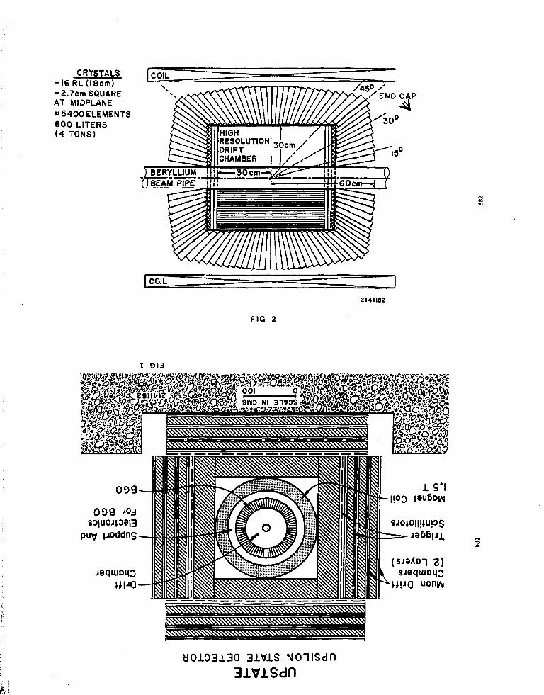
CRYSTALS-l6RL( l8cm)-2.7cm SQUAREAT MIDPLANE«5400ELEMENTS600 LITERS(4 TONS) HIGH /
RESOLUTIONDRIFTCHAMBER I /
2I4II8Z
FIG 2
3ivis31VlSdn

IO
o
^
§oxu.O
£EUJCD
100
120
80
40
I06 MC-EVENTS38% qq + 42% ggg + 20%X STATESCTE = ( (0 .9%/yE) 2 + ( 0.3 %) 2 + ( I MeV)2) l / 2
ALL PHOTONS
20
7T° SUBTRACTION
100 200LOG E 7
500 1000I 26 II 8 2
FIG 4
O O o O
8 8 £ fiA9M3N3 NOiOHd %fi / SNOlCHd
CDm

I I... IRON; ! - ^
SIDE VIEW OF THE DETECTOR END VIEW
FIG 5
HADRON.CALORIMETER
HADRONCALORIMETER
CENTRAL TRACKINGDETECTOR
HADRONCALORIMETER
-100
FIG 6

S • U rt f-e r m e y e
KSI10P_pi BISMUTH GERMANAHNovember 13, 1982
JHPROVE. SPATIALJESOLUTJON_OF_ NUCLEAR fUEL SCANNERS
National Nuclear Corporation Is a manufactuer of specialized equipment for the
assay and test of nuclear materials. One of our principal products is the high
speed fuel rod scanner shown on slide I . These scanners are used by fuel manu-
facturers throughout the world to inspect nuclear fuel rods and detect deviations
from specifications. We have built about 10 of these systems usino BGO. Serious
defects include localized variations in pel let enrichment and gaps between pel lets.
In our scanners, both these measurements are made using BGO detectors, since each
measurement requires high spatial resolution.
Session K
INDUSTRIAL APPLICATIONS
A nuclear fuel rod normally 'consists of a thin waited zirconium tube, about 1 cm
in diameter and 4 meters long. This tube is f i l l e d with sintered uranium oxide
pellets about 1 cm in diameter and length. These pellets are enriched to about
3* » 5 U .
Slide 2 shows a schematic view of a fuel scanner. Only the functions which use
BGO are detailed. Fuel rods are automatically loaded from racks at the input
side of the scanner onto a belt which passes through the entire scanner system.
Rods are carried by this bel t at a speed of about 9 meters per minute.
Before entering the i r radiator , rods pass through a densitometer where they are
inspected to detect interpel let gaps and to measure variations in fuel column
length. This is done by measuring the transmission of a col lima ted beam of
662 keV gamma rays from a 137Cs source. The configuration of this densitometer
Is indicated in slide 3, which compares the size of the MS detector with the
size of the Nal detectors formerly used. Slide 4 shows an analogue trace of a
fuel rod bui l t with known interpel let gaps. The high resolution with which
narrow gaps can be detected may be largely attributed to the narrow profile of
the BGO detector. Both the high density of BGO and i ts freedom from moisture
deterioration contribute to the feas ib i l i ty of this improved design.
687 6S8

After passing through the densitometer, the fuel rod enters the irradiator.
This is a 2 meter right cylinder shield containing a Z mg J H C f neutron source
in a neutron moderator. Fissions occur in the fuel rod as i t passes through
the irradiator, resulting in delayed emission of fission product gamma rays.
These delayed gammas are detected by an array of 4 BGO "doenut" detectors
arranged in tandem near the outlet side of the Irradiator. Thsse detectors
are approximately 7.5 cm diameter, 3 cm long and they were among the largest
BGO detectors In use at the time they were f i rs t used in 1979,
Delayed ganmas ranging from 500 to 2000 keV in energy are detected and counts
ere processed by a computer to accommodate the displacement between the detectors.
Slide 5 shows an analogue display of a record from a fuel rod containing known
off-spec pellets. Also indicated are the relative sizes of the BGO detectors
and of the Nal detectors which they replaced. For the same counting efficiency,
the BGO delayed gamma detectors are about half the linear dimension, while
because of their high transparency, only a single photomultiplier is needed for
BGO, compared to 3 or 4 tubes used with Nal. Also, because of their smaller
site, mere BGO detectors can be used, catching more of the delayed gammas before
they decay.
Slide 6 summarizes the improvement in rod scanner performance over the years.
Much of this improvement is attributable to BGO. The properties of BGO which
make the improvements possible are shown on slide 7.
6fi9
hi
c>.... o
7.5 en .'
Si \<-
690

Ooo_»
.00
i- 50
40
Si- 30
ooo_ 20.
.000
,000
000
000
CPS
CPSI
CPS
CPS
2 ^ 10,000 CPS
oo
END OF FUELSTAC!'.
2.5 m
' SLIDE *
OENSITOHETER SCAN AT 15 m/m OF FUEL ROD
CONTAINING KNOWN INTERPELLET GAPS
1.25 urn
.5 mm
40 00 80.00 120.00 160.00 200.00 340.00 ?83.00 320.00
cm ALONG ROD
3SC.0C
SLIDE 3
OENSITOHETER
' " C s
C11/ .' 'II
A PH.OTOHULTIPLIER j L
BGODETECTOR
15 mil OIA.1 inn THICK
U02
/
PELLET
J
uINTERPELLET
GAP
NalDENSITOHETERDETECTOR

SLIDE 5
-15X in -101
.A. .„
-13S
UNIFORM ROD PROFILE UNDER SAME CONDITIONS FOR COMPARISON
29?.
— lxlO6 CPSOELAVEO GAMMA PROFILE ROD CONTAINING KNOWN PELLETS OFOFF-SPEC ENRICHMENT. VALUES INDICATE PERCENT RELATIVEENRICHMENT ERROR.
SCAN SPEED - 15.5 METERS PER MINUTECOUNT RATE - 1.6xlO6 CPS PER DETECTOR
6.5xlO6 CPS TOTAL 4 DETECTORS
•— O.SxIO6 CPS
i.OO >i3.00 80.00 ;20.00 ISC.00 20C.00 2«0.00 2'K.ZZ
SCAN SPEED - METERS PER MINUTE

SLIDE 7
*P*MTAGLLq[ FOB ROD SCANNER DETECTORS
PROPERTY
High Stopping Power
Not Hydroscopic
DEHSITOHETEK
ADVANTAGE
Snail size; hence less background.better spatial definition
Eliminates encapsulation for smallersize to be shielded
DELAYED GArHA
PROPERTY
High Stopping Power
High Transparence, High Index
ADVANTAGE
Small size; hencs better spatialdefinition
Shorter length allowing more detectionsbefore gammas decay
Shorter optical path allowing use ofsingle photomultipller
Hit?) short optical path, allows useof single photormiltiplier
695
BGO IN OIL WELL LOGGING
Jeffrey S. Schweitzer
Scblumberger-DoU ResearchRidgefleld, Connecticut 06877
INTRODUCTION
When wells are drilled for the discovery of hydrocarbons, it is necessary to seal thewalls of the borehole so that no fluids can enter from Ibe surrounding rock. To deter-mine if hydrocarbons are present, their amount, and if they can be extracted from therock, it Is necessary to provide ae In situ analysis of the geological formations thathave been drilled through. These data, obtained with different instrument packages,are referred to as oil well logs, and the process of obtaining the data is known as oilweii lo ' . ' jg . Io3trtuaeal packages are typically restricted to maximum diameters of 7.6«•" uust withstand temperatures of i5O-175°C, transmit data acd obtain electrical>ower through a cable typically 6 km long, and ftttotm all analyses as rapidly as possi-ble. While non-nuclear measurement* are also made, the implication of these con-straints for nnclear logging techniques requires maximum detection efficiencies, highcount rale capabilities, and thermal and mechanical ruggedoess.
Nuclear measurements currently being made use detectors In applications whichrange from gross counling to elemental analysis of complex samples which requiresthe best possible energy resolution for gamma rays with energies roughly between 100keV and 10 MaV. Currently, these applications sake use of NaKTI) detectors whichcan operate over the required temperature range, have a crystal light output time con-stant of ~ .25 ftsec (at room temperature), have typical energy resolution of ~ 7%for l )TCs (662 keV), and have reasonable detection efficiency for stopping Ibe gammarays of interest when crystal diameters are restricted to no more than about 6.4 cm.Therefore tbe use of BOO in oil well logging will be governed by its performance rela-tive to NaKTI).
ADVANTAGES OF BGO
The primary advantage of BOO is Its higher stopping power. If it were possible tosubstitute a BOO crystal for an equal size Nal(TI) crystal, higher counling rates wouldresult In applications such as monitoring natural activity, where gamma ray flux isfixed and the observed counting rate 1* not limited by the lime response of the detec-tor. In addition, the improved photopeak response i f BGO relative to Nal(TI) couldlead lo reduced cross-correlations between spectral s'aadards in the spsctral analysis ofmulti-element spectra which would result in improv/l precision for the same numberof detected gamma rays.
The properties of BOO as a crystal material ,d provide significant advantages rela-tive lo Nal(TI). Us greater resis!an^ ' . i.ock and nonhygtoiccpic nature reduces thedemands on packaging and shock mounting which could result in greater reliabilityduring fleM operations.
696

• 2 -
DISADVANTAGE8 OF BGO
Currently, tbe most significant problem with BOO involves its inability to operateat etevated temperatures because of the rapid decrease in light output above roomtemperature. While it is always possible to maintain a BOO crystal near room tempera-ture by using cooling techniques in a dewar, tuch a system invariably leads to a reduc-tion in the maximum crystal diameter which can then be used. Thus in most applica-tions the comparison is not between BOO and Nal(TI) detectors of equal diameters,but ratber between a Nal(T') detector of a given diameter and a BOO detector ofsignificantly smaller diameter. The latter comparison can eliminate much of the gainfrom the snorter absorption length of BOO.
The energy re/solution which can be obtained with BOO detectors (currentlybetween 9 and 10*) is not yet as good as can be obtained with UtltTl) detectors. Forapplications where energy resolution is important, at in tbe analysis of complex spec-tra, the poorer resolution results in a poorer precision for a given number of detectedgamma rays. However, tbe continuing improvement recently obtained in BOO detec-tor resolution as better crystals have been grown may result in tbe energy resolutionbeing only a temporary problem.
Finally, in applications where maximum detector counting rates are necessary, the20% longsr light decay time constant of BOO re'ative to that of NaI(Tl) must be con-sidered. Wbile this is not always a dominant factor, it can be significant where it isalso necessary to maintain the best possible energy resolution.
8UMMABY
BOO has some definite advantages over Nal(Tl) for use as a gamma ray detectorin well logging applications. Its shorter absorption length, improved photopeakefficiency, and roggedness as a material could result in its displacing NaI(TI) detectorsin many applications. Improvements in BOO detector resolution and a reduction inthe light output decay time constant would enhance the utility of BOO detectors inwell logging. However, tbe inability to use BOO detectors much above room tempera-ture MmiSs their widespread use, since the requirement for keeping the BOO detectornesr room temperature results in a dewar system that reduces tbe maximum detectordiameter and eliminates much of the gain from the reduced absorption length of BOO.
BGO in Well Logging
Why
1.
2.
E : 10 keV -<• 10 MeV
Quali ty: countinq
good nuclear spectroscopy
Size: Maximum diamster—2.5"
BGO
Stopping Power
a. peak/total
b. counting rate
Ruggedness?, non-hydroscopic?
Disadvantages
1.
2.
3.
Temperature
Resolution
Countinq rate
697 698

WELL LOGGING SYSTEM
Cable (-15,000 feet)
Scintillation Detector
Neutron Generator(optional)
Temperature -100*C
COUNTS COUNTS
m::Vr- aoo
oo
om•n•nOmo•<oo•o955O

Improving the Longitudinal Uniformity in the Response
of Long BGO Detectors
Masaakl KOBAYASHI
National. Laboratory for High Energy Physics,
Oho-machi, Tsukuba-gun, Ibaraki, Japan
Shojiro SUGIHOTO and Masahiko UEDA
Department or Physics, Osaka University,
Toyooaka-city, Osaka, Japan
Session L
PARALLEL SESSIONS AND CONCLUSION
Hajime YOSHIDA
Faculty of Engineering, Fukui University,
Bonkyo, Fukul-city, Fukui, Japan
Abstract
Painting black the crystal close to the photoraultipliet end sig-
nificantly improves the uniformity. Vae of a photomultiplier whose
photocathode is slightly narrower than the cross section of the crystal
also improves the uniformity. Both results may be interpreted in terms
of the important role of the total internal reflection of light at the
crystal surface. If the above two techniques are employed, che tmi~
forroity of the signal output in a typical BGO crystal of 10 * 10 * 200
ran is ±10% over 10 to 190 mm from the photoraultlplier end and t2.2!S
over 50 to 190 mm.
701
702

1. Introduction
In recent years, requirements have increased for bismuth
germsnate (Bi^Ge ( • BGO) single crystals as rad.'ators in electro-
magnetic calorimeters for high energy experiments. BGO calorimeters
under design studies1 are typically segmented into thousands of BGO
blocks, each block having a length of about 20 radiation lengths and a
cross section of a few to several en2. Each BGO block will be read-out
through the smallest face by a photomultiplier or photodiodes.
The crystal quality achieved up to date is noc yet perfectly
satisfactory for the above purpose. Though crystals can be groan with
the size larger than 220 tun length and 70 am diameter , they have
layers of voids in them. As a result, the signal output from a thin and
long EGO block has a significant variation as a function of the source
position along the crystal length.
The variation of signal output increases empirically with the
longitudinal to lateral size ratio of the crystal. For example we have
obtained a small variation within ilZ along the whole length of 84 mm in
8)a BGO crystal of 78 mm diameter . In a cylinder of 58 mm diameter and
120 mm length, the variation was within ±1.5% . In a nearly perfect
crystal of 150 cm length and a cross section of 20 * 44 me: , the vari-
ation was within il" . For a thin and long crystal of 10 « 10 x 200
mm , however, the variation becomes as large as ±(10 "-*20)Z.
The signal output could be nearly independent of the source position
if che cransmittance of light in BGO could be 100Z and If the total
internal reflection at the surface could be perfect. In parallel to thti
efforts toward the above goal underway by crystal growing companies,
another effort could be made by the users of BGO calorimeters to reduce
the variation of signal output to a tolerable level at a slight sacrifice
703
of light intensity.
The aim of this paper is to describe our test results to reduce the
variation of signal output as a function of source position. The
following section describes the improvement of the uniformity obtained
by painting black the ci^jtal close to the photomuitlpller end. Tne
mechanism of the surface coopenaation is discussed in Section 3,
Section 4 describes another improvement of the uniformity obtained by
the use of a photomultiplier whose photocathode is slightly narrower
than the cross section of the crystal. The final section summarizes the
result.
2. Surface Treatment
BGO crystals of 10 » 10 x 200 aa were mostly used in the present
test. The longitudinal to lateral size ratio of 20 has been adopted
because chis_ seams one of the largest realistic values for actual calori-
meters, i.e. the worst cases from the view-point of the uniformity. The
crystals were optically polished all over the surface because the
polished surface gives better uniformity than the rough surface with or-
without reflector paint so far as the longitudinal to lateral size ratio'
of the crystal is much larger than unity. The BGO crystal was viewed on
the smallest face by a two inch photomultiplier (Hamamatsu, R329) through
an optical contact with silicone oil.
The variation of signal output in a BGO block No. 1 Is shown In
Fig. 1 as a function of the source position. Open circles show the*case
of wrapping the crystal with an aluminized mylar. Collimated Cs y
rays were injected at the distance L from the photomultiplier end of the
crystal. The collimator was made of 50 mo thick lead with a hole of 7
mm diameter. The output signal was analyzed by a pulse height analyzer
704
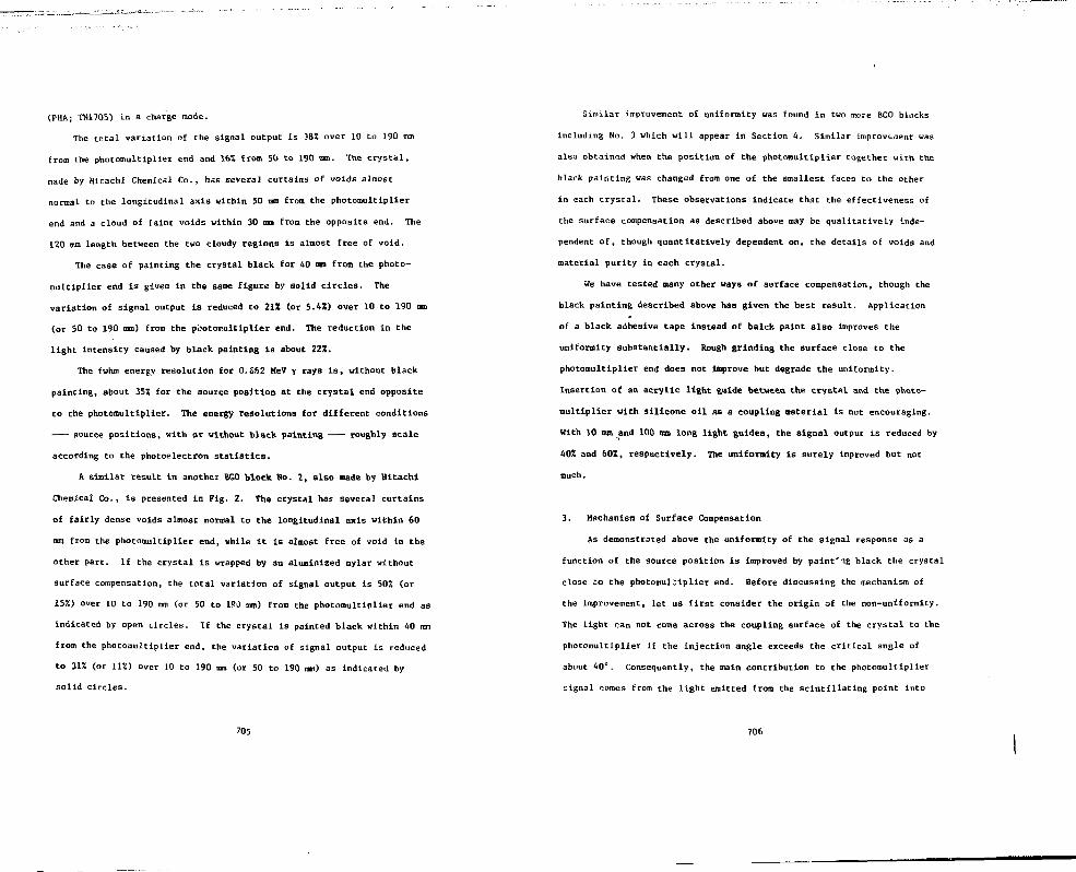
(PHA; TN17O5) In a charge node.
The total variation of the signal output is 385! over 10 to 190 mm
from the photomultiplier end and 16% from 50 to 190 mm. The crystal,
made by Hitachi Chemical Co., has several curtains of voids almost
normal to the longitudinal axis within 50 mm from the photomultipller
end and a cloud of faint voids within 30 ran from the opposite end. The
120 mm length between the two cloudy regions is almost free of void.
The case of painting the crystal black for 40 ran from the photo-
multiplier end is given in the same figure by solid circles. The
variation of signal output Is reduced to 21X (or 5.450 over 10 to 190 mm
(or 50 to 190 mm) from the pbotomiltlplier end. The reduction In the
light intensity caused by black painting Is about 22%.
The fwhm energy resolution for 0.652 MeV y rays is, without black
painting, about 35Z for the source position at the crystal end opposite
to the photmnultiplier. The energy resolutions for different conditions
source positions, with or without black painting roughly scale
according to the photoelectron statistics.
A similar result in another EGO block No. 2, also made by Hitachi
Chemical Co., is presented in Fig. 2. The crystal has several curtains
of fairly dense voids almost normal to the longitudinal axis within 60
ma from the photomultipller end, while it is almost free of void in the
other part. If the crystal is wrapped by an aluninized mylar without
surface compensation, the total variation of signal output is 502 (or
15"/.) over 10 to 190 mm (or 50 to lPd mm) from the photomultiplier end as
indicated by open circles. If the crystal is painted black within 40 mm
from the photomultiplier end, the variation of signal output is reduced
to 31% (or 11%) over 10 to 190 mm (or 50 to 190 nm) as indicated by
solid circles.
705
Similar improvement of uniformity was found in two more BGO blocks
including No. 3 which will appear in Section 4. Similar improvement was
also obtained when the position of the photomultiplier together with the
black painting was changed from one of the smallest faces to the other
in each crystal. These observations indicate that the effectiveness of
the surface compensation as described above may be qualitatively inde-
pendent of, though quantitatively dependent on, the details of voids and
material purity in each crystal.
We have tested many other ways of surface compensation, though the
black painting described above has given the best result. Application
of a black adhesive tape instead of balck paint also improves the
uniformity substantially. Rough grinding the surface close to the
photomultiplier end does not improve but degrade the uniformity.
Insertion of an acrylic light guide between the crystal and the photo-
multiplier with sllicone oil as a coupling material is not encouraging.
With 10 mm and 100 ma long light guides, the signal output is reduced by
40% and 60Z, respectively. The uniformity is surely improved but not
much.
3. Mechanism of Surface Compensation
As demonstrated above the uniformity of the signal response as a
function of the source position is improved by paintJ'\g black the crystal
close £o the photomu]riplier end. Before discussing the mechanism of
the improvement, let us first consider the origin of the non-uniformity.
The light can not come across the coupling surface of the crystal to the
photomultipller if the Injection angle exceeds the critical angle of
about 1)0°. Consequently, the main contribution to the photomultiplier
signal comes from the light emitted from the scintillating point into
706

two cones, which are situated opposite to each other with SO degrees
opening angle per each cone around the axis of the crystal length (see
Fig. 3). We denote as H the total light intensity emitted into both of
the cones. We can roughly write the dependence of the signal response
on the source position as
(1)
where I Is the crystal length, a the effective transmission efficiency
of light per unit longitudinal length including both the total internal
reflection and the internal attenuation, and B the reflection efficiency
at the crystal end opposite to the photomultiplier.
The quantity (1) is Independent of the source position If a equals
unity. It, however, decreases monotonously with the increasing L because
a is actually smaller than unity due to non-ideal crystal surface, the
existence of voids In the crystal, etc.
Then, how can painting black the crystal close to the photomulti-
plier end compensate the non-uniformity? The light is partially absorbed
by the paint even when the condition of the total internal reflection is
satisfied, because the light may cone out of the surface by as much as
the wavelength. The probability that the light should hit this absorb-
ing painted surface will qualitatively increase as the scintillating
point approaches It. Consequently, larger portion of light may be lost
as the scintillating point approaches the photomultiplier. This will be
a main mechanism of the observed surface compensation.
The role of the crystal surface is very important in a thin crystal.
If we assume that the scintillating point is uniformly distributed in
the plane perpendicular to the axis or the crystal length, the average
707
distance of the scintillating point to the cryBtal surface is only a/6
2for the square cross section a of the cryscal. The distance is only
1.7 mm in the present crystal. As much as half of the total lighc
emitted into the two cones described above may experience the total
internal reflection on the surface close to the scintillating point.
Though black painting may also change the critical angle from 40°
to roughly 28°, this change will not much affect the efficiency of the
total internal reflection. This Is because any light rcust already have
an angle smaller than 40° with respect to the side surface of the
c ystal in order to cross over the coupling plane between the crystal
and the photomultiplier.
Besides the dominant light component described above, for which the
total internal reflection is important, another contribution to the
photomultiplier signal comes from th:: light which is emitted at large
angles with respect to the axis of the crystal length. A part of the
light once comes out of the crystal and may be reflected back into the
crystal again after somewhat distorted or diffused reflection at the
aluminized mylar wrapping the crystal. Again a part of such light may
reach the photomultiplier. As the painted surface completely absorbs
the light component of the above category, a qualitatively similar
compensation mechanism may work as was discussed for the light component
of the total internal reflection. The degree of the resultant improve-
ment of the uniformity can be estimated by wrapping the relevant part of
crystal with a sheet of black paper instead of painting black. The
pulse height was reduced by more than 10X for the source position close
to the photomultiplier end and about 5£ close to the opposite end,
thereby improving the uniformity roughly by 531.
708

4. Photomultiplier Diameter
Besides the surface treatment, anocher important factor which
affects the uniformity of signal response is the relative size of the
sensitive area of the photomultiplier with respect to the cross section
of the crystal.
In Fig- 4 are compared the position dependences of signal output in
a BGO block No. 1 for different sensitive areas of the photomultiplier.
A 2-inch photomultiplier was originally coupled Co the crystal on its
smallest face. Different sensitive area were ralized by restricting the
viewing window by black masking tapes.
If no restriction is applied on the viewing window, open and solid
circles in Fig. 4, the same as in Fig. 1, give the variation of signal
output without and with painting black the 40 aa depth close to the
photomultiplier end, respectively.
If the viewing window is restricted to 7 x 7 am within the 10 * 10
mm face of the crystal, corresponding data are given by triangles and
crosses, respectively. The variation of the signal output without the
surface compensation is 29% (or 13Z) over 10 to 190 mm (or 50 to 19r
from the photomultiplier end. With black painting, the variation 'a
reduced to 19% (or 4.3SI) over 10 to 190 mm (or 50 to 190 mm).
A similar result for another BGO block So. 3 with the size of 12.4 x
12.4 x 205 mm , made by NKK (Japan Optical Crystal Co.), is given in
Fig. 5. Without the surface compensation, the variation of the signal
output was 49% (or 24%) over 10 to 190 xm (or 50 to 190 ran) from the
photomultiplier end. If the viewing window is restricted to 9 * 9 mm2,
thr variation is reduced to 25% (or 12Z) over 10 to 190 mm (oi 50 to 190
Dmi). Effect of the surface compensation is also shown in Che figure.
Corresponding data for the same crystal viewed by a 1/2-inch
709
photomultiplier (Hataamatsu R647) are given in Fig. 6. The variation of
the signal output without the surface compensation is 31% (or 177.) over
10 to 190 mm (or 50 to 190 mm) from the photomultipHer end. With black
painting, the variation is reduced to 25% (or 9%) over 10 to 190 mm (or
50 to 190 mm). The obtained uniformity is similar to that obtained with
a 2-inch photomultiplier by restricting the viewing window to 9 * 9 mm .
Why the photomultiplier of a sensitive area smaller than the cross
section of the crystal gives an improved uniformity? If the photo-
multlpller diameter is small, Che light reflected with glancing angles
from the crystal surface close Co the photomultiplier may fall outside
the photocathode and may be lost (see Fig. 7). As the reflection point
approaches the photomultiplier, the loss of light will increase. This
situation indicaces that the use of a photomultiplier of a small diameter
i" iitatively, equivalent to the preparation of an absorbing surface
close to the phocomultiplier. Consequently, che use of a phocomulci-
plier of a small diameter nay give a similar improving effect on the
uniformity as the surface condensation discussed In the previous sections.
5. Conclusions and Discussions
The above result may be sunnarized as follows:
1) Fainting black che crystal dose to the phocomultiplier
end significandy improves the uniformity.
2) Significantly better uniformity is obtained wich a
photomulciplier whose phococachode is narrower than
Che cross section of the crystal.
3) By employing the above two techniques, the variation
ot the signal output in a typical BGO block of
10 x 10 x 200 mm is tlOZ over 10 to 190 mm ftom the
710

photomultiplier end and +2.2% over 50 to 190 mm.
It should be noted that the procedure of painting black is simple
and reliable enough. In the present experiment, a spray can of acrylic
paint, widely used for general purposes, was employed. The thickness of
paint is negligibly small. The depth of 40 or 50 on for painting is net
critical to the obtained uniformity. If the BGO crystals are of the
sane size and of a similar quality, a fixed compensation procedure seems
applicable to all the crystals.
Acknowledgements
We would like to express sincere thanks to Frofs. T. Nishikawa, S.
Ozaki and K. Takahashi for their interest and support for the present
work, and Prof. Y. Nagashima and Dr. J. Iwahori for helpful discussions.
We are thankful to Dr. M. Ishii, Messrs. H. Iehibashi and S. Akiyama of
Hitachi Chemical Co. for useful discussions ard cooperation in the
measurement. Some of the BGO crystals used in the present experiment
were loaned for us by Hitachi Chemical Co. and Japan Optical Crystal Co.
711
References
1) 0. Blanat, H. Dietl, E. Loventz, F. Pauss and H. Vogelj Max Planck
Institute report, MPI-PAE/Exp. El. 94, 1981.
2) G. Blanar, H. Dietl, A. Kabelschacht, E. Lorentz, F. Pauss and
H. Vogel: "A Design Study for a Compact LEP Detector" 2nd Workshop
for Detectors and Experiments for e+e~ at 100 GeV, Cornell Univ.
Jan. 1981.
3) B.C. Loh: "A Modified Magnetic Calorimeter" Proc. 2nd TRISTAN
Physics Workshop, KEK 82-1, p. 496.
4/ H. Ikeda, M. Kntayashi, S. Kurokawa, Y. Nagashima, S. Sugimoto
and H. Yoshida: "A Compact BGO Detector for TRISTAN", ibid, p. 267.
5) M. Cavalll-Sforza and D. G. Coyne: SLC Workshop Notes CN-34, 1981.
6) C.J. Bebek, M.G.D. Gilchriese, S. Herb, R. Imlay, G. Levman,
H. Metcalf, V. Sreedhar, H. Dietl, A. Kabelschacht, E. Lovenz,
F. pauss and H. Vogel: "A Design Study of UPSTATE in the North
Area at CESR", 1982.
7) M. Ishii of Hitachi Chem. Co.: a private communication.
8) The crystal was made by Hitachi Chen. Co.
9) M. Kobayashi, S. Kurokawa, S. Sugimoto, Y. Yoshimura, H. Chiba,
H. Yoshida, M. Ishii, S. Akiyama and H. Ishibashi: Nucl. Instr.
Meth. 189 (1981) 629
712

Figure Captions
Fig. 1 Longitudinal scans of BGO block Ho. 1 with collimated 0.662
HeV y rays of Cs. An effect of painting black Che crystal
within 40 nun from the photomultiplier end can be seen by
comparing solid circles with open circles. PMT denotes
a 2-inch photomultiplier. The fwtra energy resolution for
Cs Y rays -njected at L « 190 nm is also indicated with
an under line -
Fig. 2 Longitudinal scans of BGO block No. 2. Notations and symbols
are the same as in Fig. 1
Fig. 3 A s^kecch of the two cones with the opening engle of 26c.
Here, dc is the critical angle for the total internal
reflection at the bottom plane of BGO. Dominant contribution
to the photomultiplier. signal comes from the light emitted
into the above two conei (see text).
Fig. 4 Longitudinal scans of BGO block No. 1. Open circles taken
without and solid circles with the surface compensation are
the same as in Fig. 1 and only duplicated for comparison with
the corresponding data of triangles and crosses, respectively,
which were obtained by restricting the viewing window of the
ph">tomultiplier to 7 * 7 mm . Notations and symbols are the
same as in Fig. 1.
Fig. 5 Lognitudinal scans of BGO block No. 3. Notations and symbols
are similar as In Fig. 1. For triangles and crosses, the
viewing window was restricted to 9 * 9 mm .
Fig. 6 Longitudinal scans of BGO block No. 3 measured with a 1/2-inch
photomultiplier. The notations and symbols are the same as
in Fig. 1.
713 •
Fig. 7 A sketch of the configuration when the photomultiplier diameter
is slightly smaller than the cross section of the crystal.
If light is reflected with glancing angles at the crystal
surface close to the photomultiplier, the reflected light may
fall outside the photomultiplier and may be lost (see text).
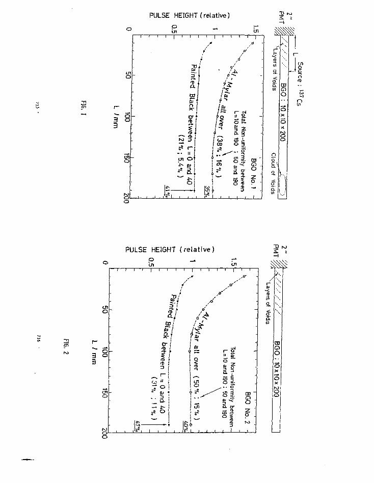
PULSE HEIGHT (relative) 3
2.• <oid
i/>
no"c \
<O
5."
CDG)O
oX
5X
}1t1
-
n
OU1
PULSE HEIGHT (relative)
P"1
IVJ
O
o
oo
cjio
r - 1
Q
"eni i i 'i I > i i i
»
5'/
siflJ i
s-jI f <«D i
i—
— * • ( U
o
• • '
If;-5 . I-S» i 1 l 1 l iS—
r
/ s i
n.ill over
o
U l
°
I*
1 1
1 1
y
p*ii
o
1o
50 and190
Ln1
I8Cnifo
rmity b
2
f i
a -
-
-
BGO
No.
N >
I
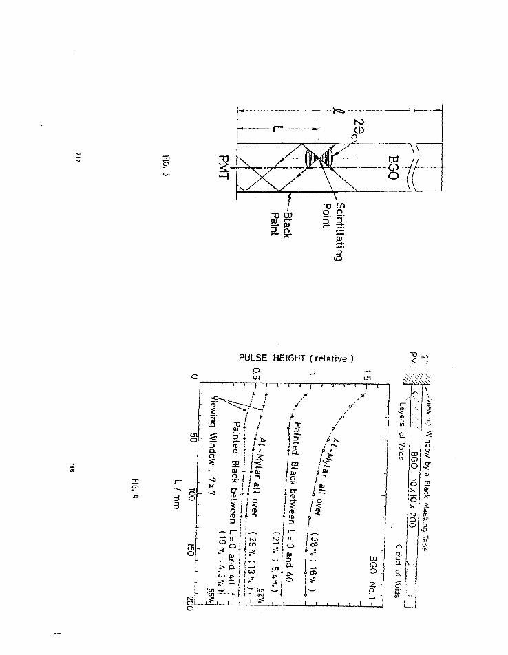
3.
f
o
Poir
\Scin
5'
PULSE HEIGHT (relative )
p
3

PULSE HEIGHT ( relative )
33
PULSE HEIGHT (re la t ive)
en
en
o
s
100
O
8
1 '
-
-
-
-
Pini i I i
i i 1 i
i i l
5"
sio> Tn
betv
t>
to r—
^ °i""' QJCO 3
o5 °- ,^^ Ol
o
}
•
1 1 1
1 1 1 >
•
4 •
*' P
>/ /
' •"''•$•
1 »
I at
?!i
i5
6 5 s
i
1 «T: i i
—"CJI
1 1
-
I •
CD "CTO "
CO
1 f

BGO
ScintillatingPoint
PMT
FIG. 7
CONFERENCE SUMMARY:
WHERE DO WE STAND WITH BGO?
WHERE DO WE GO FROM HERE?
Hatteo Cavalli-Sforza
Physics Department, Joseph Henry Laboratories
Prii.ceton University
Princeton, New Jersey 08544
1 cannot attempt to Ac justice to the many and very interesting con-
tributions we have heard from fieldB as far apart as Material Science,
Crystallography, Nuclear Medicine and many more during this conference;
attempting to do so would stretch intolerably not only the time limits but
also the limits of my coapetence. It has become clearer to me, both frora
the talks and from the lively questioning that always followed them, :;hat
workers in essentially all fields represented here are interested in BGO
for the same reasons and encounter problems that span across the different
fields. Therefore, I will first review the reasons why we find BGO an
attractive detector, with the aim of bringing out the main problems whose
solutions would benefit us all in our not-so-disparate applicatiop.fi. 1
will then review a number of technical issues, all of which have been dis-
cisped during the conference, that bear directly on the construction and
operation of large, multisegmented BGO detectors. This constitutes the
main body of the talk; I apologize in advance for my own high energy
physicist's bias. I believe however, that much of what I have to say on
721
722

the issues addressed - crystal quality, energy resolution, interestibra-
tions within large arrays, readout techniques, position resolution and
radiation effects - are of importance to moat applications of BGO. What
seems to distinguish high-energy physics U that it puts significant de-
mands on most parameters of a BGO detector; thus, while high-energy physi-
cists have only lately turned to BGO, the fallout of the developments trig-
gered by them will hopefully benefit other fields too.
Finally, I ask the (nor.-rhetotical) question: are we looking at the
right material for what we want? The answer, as will be seen, is "ye«",
but not entirely because of intrinsic inferiorities of the ^Ifrnate mater-
ials discussed at the conference.
1. WHAT WE A U LIKE ABOUT BGO.
Obvious as some of the positive features of BGO may be, repeating
them will help in bringing the general subject to focus. 1 will often
compare BGO to Nal(TI) because the foraer is likely to replace the
latter in several applications.
(a) BGO is a fairly efficient ncintillator• This entails good (<10X)
FWHM energy resolution for photon energies >0.5 MeV. The term
"good" is, of course, somewhat tautological in this context, in
that the energy resolution defines the lower energy Limit for
useful applications.
(b) BGO has a high absorption coefficient for low energy photons as
well as a short radiation length (1.1cm) and a short Molie're
radius (2.frcm). These parameters (all due of course, to the high
effective Z) determine a very compact e.ra. energy-absorption pro-
file both along the direction of the incident particle and trans-
723
versely to i t . All of our f ie lds benefit from these properties:
- in Nuclear Medicine, better ^-'dimensional resolution of images
can be obtained than with Nal(Tt)
- in Nuclear Physics, two benefits seem to arise: BGO anti-Compton
shields around Ge detectors become approximately 4 times smaller
in area, allowing a higher density of Ge detectors at a given
distance from the target than if Nal(Tt) were used as an anti-
Compton shie ld; and large-solid angle multiplicity counting
arrays can be nade more compact, allowing in turn to place the
the high-resolution Ge detectors closer to the target.
- In High-Energy Physics, large solid angle arrays of BGO crystals
provide superb electromagnetic calorimeters. The chief advan-
tage with respect to NaI(Tt) is the reduced transverse develop-
ment of e.m. showers, that allows greatly increased revolving
power in nuit ipart ic le final s ta tes . '
(c) BGO is aechanically and chemically very rugged; in particular, it
has none of the fragi l i ty and hygroscopicity of Nat(Tt). How
formidable this advantage i s will only be realized ful ly , I
suspect, when the f irst BGO arrays wi i i be used in actual experi-
ments. Some obvious consequences are that:
- The material does not need air tight packaging so there 's less
insensitive material in arrays - or, alternatively, arrays can
be built with fewer mechanical constraints.
- Multi-ton detectors should be easier to build and maintain than
their Nal(Tl) equivalents.
- The surface of individual crystals can be in direct contact with
readout elements. As a consequence it is easi?r to couple oot
72.1

light; more generally, BGO should allow more readout tricks than
are practical with Nal(Tl). One such trick, exploiting in
addition the high refractive index of this material, has been
proposed by E. Lorenz; it allows to optically separate a crystal
in two parts without mechanical interruptions. 2
2. COST: THE CHIEF PROBLEM
Ac the risk of belaboring an issue that we are all well aware of,
I will discuss this matter at some length because it appears to set the
limit on the size and the analyzing power of the detectors for nuclear
and particle physics.
Over the last year, several groups have started work on arrays of
10 to 100 crystals with crystal size ranging from 1x1x20 en3 to 3x3x20
era3. I only consider here crystals that are 20 cm long because this
sets the tightest constraint on crystal quality. The prices actually
paid or agreed on for such crystals range from 14 $/cc to 37 $/cc.
Even the lower unit price would make detectors of the size presently
considered for particle physics financially prohibitive. Can we expect
the price for large quantities of crystals to be significantly lower,
and by how much? Like other groups interested in large detectors, our
group has spent some tinre on this issue. Here are our estimates - with
the caveat chat we ace neither crystal growers nor industrial
managers.
Raw Materials Cost: This has been hailed sometimes as the main
component of the cost of the finished product. Assuming (a) that only
50% of the initial raw materials wind up in the finished crystals (b)
that GeO2 at the required 99.999? purity cannot be obtained at less
than the current cost of 600 $/kg (c) that Bi2O3 can be obtained in the
725
required degree of purity for 40 $/kg, we estimate that material cost
is 2.5 $/cc of finished crystals.
Crystal Croth Costs: tt is hard to be very precise here» since the
manufacturers have understandably been rather tight-lipped on some
crucial details. The driving factor, however, appears to be the pull
rate for Czochralski grown crystals, that is about I tntn/hr for boules
from which crystals of the sizes quoted above are cut. The growth rate
sets the number of pullers, furnaces and platinum crucibles necessary.
We estimate an overall growing cost of 2.5$/cc of finished crystals -
in which we have included the manpower and the cutting and polishing
costs - for a production scale of a few tons. This estimate is in
agreement with independent information from oxide crystal manufacturers
that do not produce BGO, who state that material and growth costs
should be approximately equal.
Overheads, profits, etc.: We cannot influence this pert of the cost of
the crystals except for encouraging competition among manufacturers.
Perhaps because I an not an industrial manager myself, £ cannot see why
this component should be more than 100X of the material plus growth
costs.
Even with this perhaps generous allowance far the manufacturers
hidden costs and the profits, crystal cost to users would be 10 $/cct
significantly less than the low end of today's costs.
What can we expect for the future? Much will depend on what
growth techniques will be used for large (5 to 10 ton) detectors.
The Czochrateki method is the only one used (as far as I know) for
crystals that can be purchased at present. Besides being slow, it
seems to suffer from the presence of "veils" - that is, layers of de-
726

creased transparency - extending perpandicularly to the pull direction
typically across most of the boule diameter. 1 will return to veils
when discussing crystal quality. If faster growth methods will become
practical, we should expect this component of crystal coBt to decrease,
perhaps dramatically.
The latter is one reason why Schnid's proposed Heat-Exchanger
method is so interesting. In this nettled, growth occurs in fill three
spacial directions, and no moving parts are involved; thus it holds the
promise to be faster #nd cheaper. In addition, if impurities in the
melt tend to float rather than sink, and if optical discontinuities
tend to be associated with the highest tenperature gradients, this
method might allow for crystals of better optical quality to be grown
because, unlike the Czochralski •ethod, growth does not occur close to
the surface of the melt, where gradients should be harder to control.
Of course, all these hopes rest on a thin foundation until Mr. Schtnid
and Crystal Systems show us some good BGO crystals. 1 an sure that many
of us will be eager to test such crystals when they become available.
We have also heard -• at this conference and outside - that several
manufacturers in Japan and Europe are interested in other growth
methods - the Bridgman, the Floating Zone and Verneuil techniques. I
know too little of these techniques to be able to comment on them - but
I can see that our small community eeema to have triggered quite a bit
of activity over the last year amongst crystal growers. A quick his-
torical comparison can be instructive: Nal(Ti) was discovered here by
Hofstadter in 1948; yet it was not until 19/1 that Nal(Tt) crystals of
a size sufficient to contain high-energy showers were available to
Hughes et al.(3) for measuring the energy resolution with U GeV elec-
727
trons. The development of Harshaw's Polyscin - and the "fortruded"
ingots that made Nal(Tt) Crystal Balls practical followed; that was
partially motivated by particle physics. The point I want to make is
that we are at the beginning of the same process that has taken place
for Nal(T£): it appears that both manufacturers and physicists are
moving faster, yet I am convinced that a lot of progress has yet to
occur in crystal growth techniques (and quality).
It might be interesting for the delegates of the manufacturers who
are present to see the auat of the possible future demands of BGO crys-
tals fronuhe three fields that have expressed most interest in BGO.
(a) Nuclear Medicine: the amount of material per PET scanner does not
seem large ("20 liters). I cannot estimate how many scanners will
be built over the next few years worldwide - but the total
could be attractive to manufacturers.
(b) Nuclear Physic*: we have heard of about a half dozen large solid
angle detector*, either proposed or under construction: The "8*"
detector, the Pittsburgh, Berkeley and Julich detectors, the Tessa
II detector )* Overall, depending on how many of these detec-
tors will be funded, a total demand of 100 to 1000 liters of BGO
might come from Nuclear Physics alone.
(c) Particle Physice: we have seen descriptions of several large de-
tectors, all of them to be operational, if approved, in or before
the next 6 years: the LEP3 detector for the CERN LEP machine,1*
the Stanford SLC BGO ball* "AIM! the Cornell CESH Upstate pro-
posals, and the BGO ball proposed for the Chinese e e machine
to be built in Beijing.^ In addition, studies are being con-
ducted at KEK towards a BGO ball for TRESTAN, and if the top quark
728

were found at PETRA in the near future* it is almost inevitable
that at least one of the existing detectors would be upgraded with
BGO for spectroscopy studies of the top-antitop system. If all of
these detectors were built, there would be a demand of 4xlO3 to
5x10^ liters of BGO from high-energy physics alone, spread outt
say, over the next four years. I want to stress again, though,
that few or none of these detectors will be built if the price
will not go substantially belo* 14 $/cc for these large amounts of
material.
I will turn next to a review of several technical issues that have
been discussed at the Conference. The first issue is a problem area that
in my opinion is second only in magnitude to the cost problem; it ia crys-
tal quality.
3. CRYSTAL QUALITY
The two parameters immediately relevant to the user are light
output (or, equivalently, single crystal energy resolution) and
uniformity of light output from different parts of a crystal. The
former will be touched upon in the next section, the latter is
obviously correlated with optical uniformity of crystals or, more
prosaically, with the already mentioned "veils".
Several speakero_have addressed this issue - in particular, F. Rosen
berger and V.F. Gu (presenting the work of the Shanghai Institute of
Ceramics Crystal Growth Group) have discussed how scoichioroetry,
crystal growth conditions and material purity may influence the
formation of voids or precipitates; W.p, Unruh has reported on a
729
fascinating series of experiments he is conducting that show unexpected
optical features suggesting phase separation within a crystal. The
only thing that is clear to me at this stage is that we have barely
scratched the surface of this problem. Rosenberger's view that non-
uniform regions nay correspond to stoichioraetries other than
2Bi903"3Ce02 seems to be reinforced (as Rosenberger pointed out) by a
bit of knowledge imparted to us by H. Weber,6 i .e . that there are
two further forms of BGO, i .e . Bi2Gej09 and BijGeOj, that are close
to Bi^GejOjj in the Bi20g-Ce02 system's phase diagram. Unruh's
findings strongly reinforce this view. The problem of impurities and
their effects will require much aiore investigation; it is not even
clear (again, ? repeat a consent of Rosenberger) that all impurities
are necessarily harmful; some night even increase the transparency of
crystals.
Taking the practical view: is crystal quality satisfactory as of
today? My personal answer i s : probably so for email crystals such as
used in Nuclear Medicine; certainly not for long (20cm) crystals as
needed in Particle Physics. We have seen too few crystals without
veils to believe that they can be grown in a fail-safe mode - indeed,
typical demonstration crystals shown by Harshaw, Hitachi and workers
from the Shanghai Institute show several varieties of such
disuniformitiesl One interesting exception are the crystals shown by
the representatives of a newcomer in the field -Japan Optical Crystals.
Their samples have no veils - but they are darker than comparable
samples.
Can we live with veils? The experience of our Princeton group has
been that one can obtain uniformities (defined as peak-to-peak
percentual variation of light output over a crystal) better than 3£ for
730

2.5x2.5x20 cm3 crystals, even with veils. With thinner crystals
(1x1x20 cm3) we find instead that total absence of veils visible to the
naked eye is necessary to obtain uniformities better than 5%. M.
Kobayashi reported in a parallel session that the uniformity of imper-
fect crystals can be improved using light absorbing surface coatings;
our group has seen similar effects. These techniques, however, will
vary crystal to crystal; applying them, with some amount of trial and
error, to each of the 3000 to 20,000 crystals contained in some of the
proposed detectors would require an enormous amount of work. I think
that the efforts of crystal nanufacturers would be better spent eli-
minating veils rather than trying to iuprove the uniformity of crystals
in spite of them. He have seen a good deal of inproveraents in long
crystal uniformity over the last year and I as confident that we will
see more of that in the near future.
An amusing case of geometry-dependent non uniformity arises in
tapered crystals; for instance, modules in a 4« multisegmented detector
would have some kind of truncated-pyranid shape. Assuming that readout
is from the larger (outer) base, light generated at the other end of the
module would be focussed around the axis at the readout end'" thus a
greater fraction of the light originating far from the readout element
would be transmitted into it than of the light originating close to the
readout element. This non-uniformity can probably be eliminated by
judiciously chosen surface coatings. 1 mention it here because in my
opinion it strengthens the case for optically uniform crystals in this
geometry.
It. ENERGY RESOLUTION
At incident quantum energies where no energy leakage occurs for a-
731
substantial fraction of the incident quanta, E<1 MeV, one expects photo
electron statistics to determine the energy resolution. Then o(E)/E »
(number of photo electrons) ^, and this equality seems to hold quite
accurately for BGO, as several workers has verified. As for Nal(Tl), it
haB become customary to use as a figure of merit for energy resolution
the FWHM of the photopea : of Cs 1 3 7 gannas (ET=0.662 MeV). BGO available
up to about 2 years ago typically had FWHM (Csl37)=15X to 18%. We have
heard at this conference of nuch improved resolutions from the Harshaw
and Hitachi representatives: the forner quote FWHM (Cs"7)=9!S (without
specifying the statiscical staple7); the latter, on a sample fo 200,
measure FWHM (CS'37)-10.51 with a apread of about IX. Both manufac-
turers clearly have greatly improved the light output of their pro-
ducts.
All trc.-e numbers, however, are measured with a perfect match of
the area of the readout element (a PMT here) to the coupled face of the
crystal, and for crystals of <2.5 cm in the longest dimension. When
using 20 cm long modules, we observe FWHM(Cs)"16X to 18%, indicating a
reduction of light output of 2 to 3 times with respect to smaller crys-
tals; this light loss is surprisingly large and for the most part not
understood. Also, it should be borne in mind that in multisegmented
detectors one cannot couple to the whole crystal face with the readout
element. Realistic area matches for this situation are probably from
0.5 to 0.8, and FWHM(Cs137) for long crystals degrade up to 25X. Such
resolutions are still satisfactory at the much higher energies for
which large detectors are designed because of the following consi-
derat ions.
The statistical limit on energy resolution, leading to an expected
732

AE/E = KE~l l, breaks dovm at energies greater than a few MeV due to
shower leakage and leakage fluctuations. The leakage limit persists
even for full solid angle detectors because of the need to limit the
volume over which the signal is summed; thus shower Leakage fluctua-
tions limit the practical resolution of any device. Empirically it has
long been known - that large Nal(Tt) arrays have AE/E - KE~' "*; this
agrees with Hontecarlos studies of leakage. We should thus expect BGO
to behave similarly in the high energy region. A Hontecarlo study by
our group for a 15x15x20 cm* volume of BGO shows that FWHH resolution
stays stationary at "Z.5X for an incident electron's energy 50
MeV<E<300 MeV, (see fig. 1) and then decreases like E"1'1* up to 10
CeV. Beyond this energy showers leak more and more from this volume
and the fraction of the primary energy detected becomes appreciably <1.
Until a few months ago we only had Montecarlos to substantiate our
claims of very good energy resolutions of BGO crystal arrays above a
few hundred MeV. The beautiful results froa the MPI group of Munich,
presented by H. Vogel, B now extend the range of measurements to elec-
tron energies of lOGeV. Their array of BGO crystals has an effective
volume of 9x9x23 cm3, so they need to veto events with leakage of more
chan a few MeV to get a realistic measurement of resolution. For leak-
age - vetoed 4 GeV electrons they directly measure FWHM/E » 2.218, an
impressive Jesuit. Subtracting the photodtode noise, the resolutions
they calculate are very close to the shower Hontecarlo predictions.
An additional interesting feature of the MPI measurements, that I
mention here although it is unrelated to energy resolution, is that
even with a relatively coarse array of 3x3x20 cm modules and the
simplest algorithm they obtain pion-electron separations ot better than
733
1/1000 from 1 GeV upwardb.
Last, I want to mention that in practice the energy resolutions of
large arrays will also be limited by interestibration errors. This
issue is somewhat dependent on the readout scheme used, so it will be
discussed following the section on readout.
5. READOUT SYSTEMS
Photomultipliers (PUT) and silicon PIS photodiodes (PD) are the
choices available at the moment. While PMTs have been used for a long
time and their strong points and limitations are well known, PDs have
been used for BGO only over the last year and rouch of the discussion on
readout has focussed on then. Huch progress has been done largely
because of the work of the MPI group, the single-handed and penetrating
investigation of Don Croon of the sources of noise, and che prompt and
effective response of Hamaaatsu to Don's diagnoses. E. Loren£z gave a
very comprehensive comparison of PHT Bud PD properties, which I repro-
duce in table 1. 1 have little to add to it, except for two comments:
(a) The results from the MPI group show that PDs are not only attrac-
tive on paper but practical to work with; it seems certain that
PDs will find use in BGO arrays placed within intense magnetic
fields - like many future detectors will be.
(b) There is still a possible problem with the calibration of BGO-PD
modules in a large array. As described by T. Matsui 9 , module
intercalibrations at high energies (E>IOO MeV) uses as convenient
starting point a low-energy nuclear source calibration. The lat-
ter is not possible with the presently reached PD rms noise limit,
1.15 MeV for coicsercially available photodiodes.10 Even the low
noise of 320 KeV of the improved photodiodes developed by Hamn-
734

malou for D. Groom is not sufficient fot a source calibration.
This problem wiLl disappear if PD noise will be brought down by
another factor of 10 in the next year as advocated by E. Lorenz.
Should we look at other readout techniques too? We hava heard
DeRenzo's report on Hgl2 - that offers low noise and high quantum effi-
ciency, as seen from an observed Cs137FWHM of 19% with BGO. The disad-
vantages are (I) one needs a bias voltage of 700V (2) mercuric iodiode
detectors are not yet available commercially. These are also the dis-
advantages of another potentially proaiaing technique, silicon ava-
lanche photodiodes (APD) that have not been discussed at this confer-
ence and that I will briefly mention. APDs of a few mo2 area have been
available for some time; a recent development is that a small research
company, Radiation Monitoring Devices of Salem, Mass. has made 1 1/4
inch diameter APDs with which they observe FWHM(Csl37)-9X on with
Nal(Tl). I do not know what resolution one would observe with BGO; the
obvious advantage here is the gain (50x to 200x) of the avalanche
process, while the dangers are gain stability versus high voltage as
well as (perhaps) linearity. Haybe the ri*e of PDs will make such
alternatives uninteresting, at least for high-energy experiments, but
it seems to me worthwhile to do some supplementary investigation ot
these techniques.
6. INTERCALIBRATION OF BGO ARRAYS
This is a very technical problem, yet it warrants serious discus-
sion because vast amounts of hardware, software and manpower will un-
doubtedly be invested in it in future Urge BGO arrays. To extract the
total energy deposited by a particle in a cluster of crystals one
needs to measure from time to time:
735
(a) The absolute energy-to-signal conversion scale of each module -
subject to variation module-to-module and, in real life, to possi-
ble changes in time. (The latter can be due to changes in crystal
response.)
(b) The linearity of the electronics that must be known (and good!)
over a dynamic range of 105 to IO€ for high-energy physics
detectors.
Measuring (a) and (b) allows to compensate drifts in each channel. In
principle, one could separate parts (a) and (b). This could be practi-
cal for PD readout, if the advertised stability of PD response is as-
sumed. One could envisage a charge injection system calibrating PD
electronics, and an initial calibration of the BGO-PD package with a
test beam if nuclear source calibration remains unpractical. This
would still leave possible changes of crystal response and crystal-to-
pO coupling uncovered. With PMTe, one has the additional problem of
the time drift of PMT gain; nuclear sources calibration, on the other
hand, allow to keep this drift under control, while also checking for
crystal response to a well-known and (of course) perfectly stable
energy input.
Ideally, one would like to have a particle beam that would scan
the whole detector often enough in time to catch all drifts, and with a
known energy spectrum extending over the whole dynamic range. The
closest approxiraetion to such an ideal and non-existent calibration
system is a pulsed light source (a flasher or a laser) distributing
Light to each individual crystal in such a way that the light collected
by each PD or PMT would have to pass through the crycial itself. The
relative intensity of the light pulses could be varied over the
736

required dynamic range in a very repeatable manner by a moving system
of f i l t e r s - as done in the Nal(Tt) Crystal Ball . Thus the optical
propert ies of the crysta l and the whole system response would be
monitored. The energy scale reference would be establ ished and the
d r i f t s in absolute light output of the l ight source ca l ib ra ted out by
coupling a few opt ica l fibers to an addi t ional c rys ta l on which a
source is permanently mounted. ( I t can be seen that d r i f t s of th is
addit ional element would not affect the desired l ight- to-energy
ca l ib ra t ion of the l ight pu lses . ) Even euch fl system would probably
need nuclear sources as an added check.
This ca l ib ra t ion concept is described in a proposal to build a BGO
Ball for physics at the Stanford Linear Collider * and has received a
nice additional touch by M. Weber at t h i s conference. Ideal ly one
would like to use an optical l igh t source to monitor the transparency
of the c rys t a l s , and a UV source to produce s c i n t i l l a t i o n l igh t . Woer
pointed out that a Laser with a frequency doubler could give both op-
t ions in one.
7. POSITION (OR ANGULAR) RESOLUTION
This is of great in teres t to a l l users from Nuclear Medicine,
Nuclear Physics and Par t ic le Physics a l i ke . Due *o my ignoiance of the
techniques used in fields other than mine, 1 must limit myself to Par-
t i c l e Physics and i t s energy range. The issue of posi t ion resolution
has hardly been discussed by pa r t i c l e phys ic i s t s at th i s conference;
yet I feel it should be given more thought.
No data have been shown yet on posi t ion resolution on *an electrc*.
or photon entry point in a BGO array. Montecarlo s tudies have been
performed, to ray knowledge, by the MPl g r o u p ( u ) a n d by the Princeton
737
group . The resul t s of our ca lcula t ions show t h a t :
(a) The posi t ion resolut ion for energies around 100 MeV is dominated
by straggled photons in the 10-20 MeV range t h a t , being close to
the minimum in the Y-BGO to ta l cross sec t ion , can travel out to a
subs tan t ia l dis tance form the shower axis and thus s ign i f i can t ly
spread the reconstructed incidence point. At energies in the GeV
range, the effect on the resolu t ion of these photons of course
decreases drast ically,
(b) The position resolution can be markedly improved if the incidence
point is determined by fitting to observed energy distribution in
BGO modules from a shower Lo the Montecarlo - predicted average
distribution of energy between modules parametrized as a function
of incidence point in the central module "struck" by a shower.
This method was borrowed from existing Hal Crystal Ball algo-
rithms .
Typically, we obtain mm position resolutions 4aim>o >0.8 mm for
100 MeV <E<l0GeV in an array of modules with cross section of lxl cm2;
the analogous numbers for a 3x3 cro^ array are 9.5 mm >o> 2mm,
The reason for quoting these numbers is that particularly for the
low energy end they are not so good. Indeed, for detector arrays at a
distance of, say, 40 cm from the part icle origin these figures trans-
Late into angular resolutions of the order of the degree at the lower
energy - where the physics to be done could use much better resolu-
tions. I find it frustrating that, with all the light made m BGO by
minimum ionizing par t ic les , one should not be able to measure with
greater precision an electron's entry point or a photon's first conver-
sion's coordinates. My feelings arise from the history of our entry
738

into the BGO field, that began with an idea of Don Coyne to manufacture
BGO crystal fibers of ~lmm diameter, to be read out by an image inten-
sifier and a CCD array. We have not been able to this date to obtain
BGO crystal fibers, (which of course does not prove the impracticallity
of the concept) - we got interested in bigger pieces instead. I
mention this story here in the hope that someone else will have an
elegant idea to get better positron resolution from modules that are
not too small and at a less than prohibitive cost.
8. Radiation Effects
I have nothing to add in writing Co what was said by M.
Kobayashi 13 and by myself, except for publicizing the remark made by
F. Rosenberger that radiation hardness could be enhanced by certain
impurities. I hope that other groups will repeat the measurements that
have been done up to the present; in any case, the multitude of small
BGO arrays being assembled either for Keating purposes or for special
physics projects will scon provide additional information on this im-
portant issue.
9. ALTERNATE MATERIALS
As expected at a conference on an item of ins t rumenta t ion , we have
heard raore than one voice proposing to use souething e l se than BGO to
measure photon or electron energ ies .
(a) Bismuth S i l i c a t e (Bi^Si ^ 0 ^ ) , a s c i n t i l l a t o r isomorphic to BCO i s
an obvious a l t e rna t i ve that is made a t t a c t i v e by the lower poten-
t i a l cost of the caw m a t e r i a l s ; in £act , I know of several group?
that have considered BSO at one t ime. Sugiraoto's report u shows
that BSO yields approximately 30% of the l ight of BGO. This pro-
bably means that i t does not hold much in te res t for Nuclear Medi-
739
cine or Nuclear Physics, but does not diminish much of its poten-
tial 'for Particle Physics. We have seen, however, that manufac-
turers have spent a good deal of time and effort to improve BGO
parameters, and that long crystals of good optical quality are
still a challenging project. Umess growing large BSO boules
proves to be easier than for BGO, I suspect that the present roo-
toentuiD accumulated by BCD, together with the investment in it by
physicists and manufacturers alike will keep BSO in the backstage
for some time.
(b) Barium fluoride (BaF2) has been eloquently defended by Ander-
(15)son, who pointed out that BaF2 has many features that BGO
lacks: excellent time resolutin (lOOps), a readout scheme with
excellent position resolution, and the potential for low cost. On
the other hand it is definitely inferior to BGO in photon statis-
tics, particularly for fast emission component; and the radiation
length (2.1 en) makes it ill Suited for the very compact designs
that are made possible by BGO. Overall, I would not be surprised
if BAF, were Co find an ecological niche orthogonal to that of BGO
in future detectors.
(c) Last, I would like to spend a few words on Bismuth Glasses. Hav-
ing observed how similar BGO crystalline material is to glass,
both Don Groom and I conjectured at one time that a Bismuth -
loaded scintillating glass uight scintillate. Glasses are usually
easier to make than crystals; and may, although not necessarily,
be cheaper. It turns out that several workers, M, Weber among
them, had already looked at Bismuth-loaded glasses. At the pre-
sent time no one has observed appreciable amounts of scintillation
740

light from glasses containing more Chan a few percent of Bismuth.
There may be some fundamental reason why Bismuth glasses will not
s c i n t i l l a t e , but if do, it would be interesting to find i t . H.
Weber is not yet pessimistic on this issue. It would be particu-
larly interesting for cost reasons i f & s c in t i l l a t ing glass with a
Large mass fraction of Bisnuth and l i t t l e or no Germanium could be
found.
10. Acknowledgements
t would like to thank Don Coyne for organizing this very l ively
and pleasant conference; I aLeo want to express «y gratitude to Don
Coyne, Eckart Lorenz and Don Crooa for sharing with me their insights
on BGO research over the last two yearm; and to the members of the
Crystal Ball collaboration (several of then at this conference) who
have taught me most of the things about electron and photon detectors
that I have talked about.
741
REFERENCES
( 1 ) See F. Porter's ta lk , session J.
(2) E. Lorenz, talk at Crystal Ball Workshop, Nov. 1981, unpublished.
(3) E.8. Hughes et a l . , IEEE Transactions of Nucl. Sci . : N5-19, No. 3, 126
(1972).
(4) See F. Fauss's talk, session J.
(5) See Y.F. Gu's talk, session B.
(6) See M.J. Weber's talk, session A.
(7) See M.R. Farukhi's talk, session A.
(8) See H. Vogel's ta lk , session I .
(9) See T. Matsai's ta lk , session D.
(10) See E. Lorenz's ta lk , session D.
(11) G. Blanar et a l . , Max-Plank Inst i tut Munich, MPl-PAE/Exp El.94, (1981)
(12) H. Caval'.i-Sforza et a l . , Proc. Int. Coat, on Instrumentation for
Colliding Bean Physics, SLAC (1982) p. 216.
(13) See M. Kobayashi's talk, session A.
(14) S. Sugitnoto, session A.
(15) D.F. Anderson, session C.
(16) See W.P. Unruh's talk, session C.
(17) Also see M, Salomon's tclfc, session C.
742

Table 1. Comparison of properties of PDs vs. PKTs(from E. Lorenz's table)
item PM PD
sensitive area
<quantum efficiency^
int. amplification
stabilized HV
noise immunity
pri e d)
price of amplifier
ace idental Iightdamage
radtat ion damage
#photoelectronsfor passing tracks
round t anydiarceter
12X
yea
impossible forhigh fields
high
> USD 50
USD 5
possible
not known
few tens e)
any shape <3cm2
60%
no
not necessary
post amplification
noise equivalentr.m.s. error
typical dynamicalrange
Short term stability
long term stability
temperature coeff.
rise time
rate
size (height)
magn. shield
s imple(not necessary)
~20-50keV
10"
1 C.3)Xb)
1 (.3)3*)
< .2 X / *C
5-50 nsec
high
< 6 en c)
complicated.
high qualityamplifier
1.15 MeV fordescribed te
10B a)
<.01 X
< . l X
< . 2 X 1 "C
> 100 nsec(area dep.)
low
< 1 en
unnecessary
low
USD- 10
USD 15
no
100/niicron ofdeplecion layer
a) special preamplifer requiredb) for selected high stability FH'sc) Hamamatsu R 1569Xd) estimate for large quantitye) due to Cerenkov light in glass window
743
r8 -7 -6
5
<
s
i
EI*RGY RESOLUTION (FWHM/PEAK)FOR 15x15x20cm> B6O ARRAY
20 cm
10 MeV 100 MeV I GeV
ELECTRON ENERGY
Fig. 1 Calculated resolution (EGS Mantecarlo) of themeasured energy of a pencil electron beam Ina BGO voluae as shown; only photoelectronstatistics and leakage are considered.
744

1

Participants
Or. 0. Anderson - CERN
Dr. Cyrus Baktash - Oak Ridge National Lab
Or. J. Ballam - S.L.A.C.
Dr. D. fieriey - National Science Foundation
Dr. D. Besset - Stanford University
Mr. Joe Betts - Hitachi Magnetics Corp.
Dr. 0. Bownan - Los Alamos Lab
Or. R. Bucahara - S.L.A.C.
Dr. Lewis Carroll - The Cyclotron Corporation
Dr. L. CastelH - Crystal Technology
Dr. M. Cavalli-Sforza - Princeton University
Dr. C.Y. Chang, - University of Maryland
Or. Georges Charpak - CERN
Or. Z.H. Cho - Korea Advanced Institute of Science
Prof. H.E. Chongfan - Crystal Growth Lab
Dr. Roger Coombes - S.L.A.C. (MAC)
Dr. John A. Correia - Massachusetts General Hospital
Or. D.G. Coyne - Princeton University/S.L.A.C.
Mr. Rod Dayton - Bicron Corporation
Prof. Ken Deffeyes - Princeton University
Mr. J.P. Denis - La Pierre Synthetique Baikowski
Or. S.E. Oerenzo - LBL, Oonner Lab
Dr. William Dodge - National Bureau of Standards
Dr. A, Evans - Los Alamos Scientific Lab
747
Participants Continued
Or. Farukhi - Harshaw Chemical Co.
Dr. 0, Fossan - S.U.N.Y.
Dr. J.P. Franzini - Columbia University
Ms. Barbara Gorby - Harshaw Chemical Co.
Dr. Donald Groom - University of Utah
Dr. Russell Heath - EG&G, Inc.
Dr. D. Heinz - National Science Foundation
Mr. Fred Helvy - RCA Corporation
Or. B. Hildebrand - Department of Energy
Dr. C. Hoffman - Los Alamos National Lab
Dr. Carvel Hoffman - Bethlehem Steel Company
Dr. Edward J. Hoffman - U.C.L.A.
Prof. C. N. Holmes - Princeton University
Or. Eric Hopkinson - Dresser-Atlas
Dr. M. Ishil - Hitachi, Ltd.
Or. Jan Iwanczyk
Or. Jan Jansen - Harshaw Chemie B.V.
Dr. Leif Oonsson - University of Lund
Mr. C.P. Khattak - Crystal Systems
i)r. J. Kirkbridge - Stanford University
Dr. Kay Klebesadel - Los Alamos National Laboratory
Or. A. Klovning - University of Bergen and Ovar tfraaten
Or. Tnvid Koltick - Purdue University
Dr. Bob Kramer - Carnegie - Mellon Inst.
Dr. M. Lebeau - L.A.P.P.
748

Participants Continued
Or. Pierre Lecomte - CERN
Dr. I.Y. Lee - Oakridge National Lab
Dr. L. Levit - LeCroy Research Systems
Dr. Kainer Lieder - University of Julich
Dr. Alan Litke - Stanford University
Prof. G. Loh - University of Utah
Or. M.A. Lone - Atomic Energy of Canada Ltd.
Prof. E. Lorenz - Cornell liniversity/HPI
Mr. Steve Haloney - Bicron Corporation
Dr. Louis Massonnet - L.A.P.P.
Dr. T. Matsui - Stanford University
Dr. J.K. McCormack - Hammaniatsu
Prof. Harchus McEHistrem - University of Kentucky
Ur. Andreas Mel as - Alpha Products
Prof. Ronald Ms'rmod - University of Geneva
Or. Warren Killer - Spex, Inc.
Dr. David J. Morrissey - Michigan State University
Dr. Calvin Moss - Los Alamos National Lab
Or. H.K. Nurthy - Dent, of Metals, Glass, & Ceramics
Dr. Claude Nahmias - Chedoke/McHaster Hospital
Or. Paul Nolan - University of Liverpool
Mr. K. tlumano - Ninon Kessho Kocgaku Co. Ltd
Or. Brian Pape - University of British Colunbia
Or. Kelecitas Pauss - Cornell University
Prof. C. Peck - CALTECH
749
Participants Continued
Dr. (tennis Persyk - Siemens Gattmasonics, Inc.
Prof. P. PirouS - Princeton University
Dr. F. P o r t e r - CALTECH
M. Raaynakers - NIKHEF/Nigmegen
Dr. K. Rangan - Purdue University
Dr. Carl Rester - Space Astronomy Lab
Prof. F. Rosenberger - University of Utah
Or. Michael kousseau - Rutherford Appleton Laboratory
Prof. J.H. Saladin - University of Pittsburgh
Dr. Martin Salomin - University of bt itish Colunbia
Dr. A. Sandorfy - Brookhaven National Lab
Dr. U. Schmettow - Seitenmetail
Mr. Schmidt - Crystal Systems
Ur. 0. Schmitz - Physical Institute, Aachen
Dr. Jeff Schweitzer - Schlumberger-Doll Res. Lab
Dr. J.C. Sens - N1KHEF/Amsterdam
Or. Lee Shiozawa - Cleveland Crystals, Inc.
Prof. Frank Shoemaker - Princeton University
Dr. W. Silva - Crystal Technology
Dr. M. Singh
Prof. A.J.S. Smith - Princeton University
Dr. H. Spitzer - University of Hamburg
Ur. Frank Stephens - Berkeley Lab
Prof. D. Stickland - Princeton University
Dr. R. Strand - Brookhaven Lab
750
Participants Continued
Or. D. Stromswold - Mobil Field Research Lab
Dr. Shojiro Sugimoto - Osaka University
Dr. Richard Sunner - Princeton University
Prof. Hsio-Wei Tang - Institute of High Energy Physics
Dr. Ludwig Tauscher - CERN
Dr. T. Teeling - Harshaw Chemie B.V.
Dr. Christopher Thompson - Montreal Neurological Institute
Prof. S.C.C. Ting - M.I.T.
Dr. J. Tompkins - Stanford University
Or. H. Tuts - Columbia University
Dr. Peter Twin - University of Liverpool
Prof. W. Unruh - University of Kansas
Or. Samuel Untermeyer - National Nuclear Corp.
Dr. R. Van Dreil - NIKHEF/Amsterdam
Dr. Marcel Vivargent - CERN/LAPP
Dr. Helmut Vogel Cornell University/KPI
Dr. Z. Wang - University of Maryland
Dr. H. Weber - Lawerence Livermore Lab
Dr. Raynond taeill - University of Lausanne
Dr. Stephen Wender - Los Alamos National Lab
Dr. Charles W. Williams - EG&G Ortec
Mr. M. Yamada - Nihon Kessho Koogaku Co., Ltd.
Or. K. Yamamoto - Hamrnamatsu
Dr. Gu Yifan - Institute of High Energy Physics
751