
Three-level inverter configuration cascading two two-level inverters
Novel View Synthesis by Cascading TrilinearTensorsShai Avidan Amnon ShashuaInstitute of Computer ScienceThe Hebrew UniversityJerusalem 91904, Israelfavidan,[email protected] present a new method for synthesizing novel viewsof a 3D scene from two or three reference images in fullcorrespondence. The core of this work is the use and ma-nipulation of an algebraic entity termed the trilinear tensorthat links point correspondences across three images. For agiven virtual camera position and orientation, a new trilin-ear tensor can be computed based on the original tensor ofthe reference images. The desired view can then be createdusing this new trilinear tensor and point correspondencesacross two of the reference images.I. introductionThis paper addresses the problem of synthesizing a novelimage, from an arbitrary viewing position, given two orthree reference images (registered by means of an optic- ow engine) of the 3D scene.The most signi�cant aspect of our approach is the abil-ity to synthesize images that are far away from the viewingpositions of the sample reference images without ever com-puting explicitly any 3D information about the scene. Thisproperty provides a multi-image representation of the 3Dobject using a minimal number of images. In our exper-iments, for example, two closely spaced frontal images ofa face are su�cient for generating photo-realistic imagesfrom viewpoints within a 60 degrees cone of visual angle{ further extrapolation is possible but the image qualitydegrades.We propose a new view-synthesis method that makes useof the recent development of multi-linear matching con-straints, known as trilinearities, that were �rst introducedin [43]. The trilinearities provide a general (not subjectto singular camera con�gurations) warping function fromreference images to novel synthesized images governed di-rectly by the camera parameters of the virtual camera.Therefore, we provide a true multi-image system for viewsynthesis that does not require a companion depth map,nor the full reconstruction of camera parameters amongthe reference cameras, yet is general and robust.The core of this work is the derivation of a tensor oper-ator that describes the transformation from a given tensorof three views to a novel tensor of a new con�guration ofthree views. Thus, by repeated application of the operator0An on-line demo can be found on the World-Wide-Web in the follow-ing address http://www.cs.huji.ac.il/labs/vision/demos/demo.html. A.Swould like to acknowledge US-IS BSF contract 94-00120and the EuropeanACTS project AC074.
on the seed tensor of the reference images with a sequenceof desired virtual camera positions (translation and orien-tation) we obtain a chain of warping functions (tensors)from the set of reference images (from which the seed ten-sor was computed) to create the desired virtual views. Wealso show that the process can start with two referenceviews by having the \seed" tensor be comprised of the ele-ments of the fundamental matrix of the reference views. Ashorter version of this paper appeared in [4].A. Novelty Over Previous WorkThe notion of image-based rendering systems is gain-ing momentum in both the computer graphics and com-puter vision communities. The general idea is to avoid thecomputational-intensive process of acquiring a 3D modelfollowed by rendering, and instead to use a number ofreference images of the object (or scene) as a represen-tation from which novel views can be synthesized directlyby means of image warping.The work in this area can be roughly divided into threeclasses: (i) image interpolation, (ii) O�-line (Mosaic-based)synthesis, and (iii) On-line synthesis. The �rst class, im-age interpolation, is designed to create \in-between" im-ages among two or more reference images. This includesimage morphing [8], direct interpolation from image- ows(\multi-dimensional morphing") [10, 38], image interpola-tion using 3D models instead of image- ow [12], and \phys-ically correct" image interpolation [41, 42, 57]. All but thelast three references do not guarantee to produce physicallycorrect images, and all cannot extrapolate from the set ofinput images | that is, create novel viewing positions thatare outside of the viewing cone of the reference images. ForExample, Seitz and Dyer [42] have shown that one can in-terpolate along the base-line of an image pair and obtainphysically correct images (unlike ow-based interpolation[10, 38]). Their approach proceeds by �rst rectifying theimages, interpolating along the epipolar lines (which areparallel after the recti�cation) and then inverting the rec-ti�cation for the �nal rendering. Unfortunately, only im-ages along the line connecting the two model images can begenerated in this way and the user is not allowed to movefreely in 3D space.Instead of ow-�eld interpolation among the referenceimages, it is possible to interpolate directly over the plenop-tic function [1] | a function which represents the amountof light emitted at each point in space as a function ofdirection. Levoy et al. [32] and Gortler et al. [19] interpo-

late between a dense set of several thousands of exampleimages to reconstruct a reduced plenoptic function (un-der an occlusion-free world assumption). Hence, they con-siderably increase the number of example images to avoidcomputing optical ow between the reference images.In the second class, the o�-line (mosaic-based) synthe-sis, the synthesis is not created at run time | insteadmany overlapping images of the scene are taken and then\stitched" together. The simplest stitching occurs whenthe camera motion includes only rotation | in which casethe transformation between the views is parametric anddoes not include any 3D shape (the transformation beinga 2D projective transformation, a homography). This wascleverly done by [13] in what is known as \QuickTime VR".Szeliski and Kang [53] create high-resolution mosaics fromlow-resolution video streams, and Peleg and Herman [36]relax the �xed camera constraint by introducing the projec-tion manifold. A drawback of this class is that one cannotcorrectly simulate translational camera motion from theset of reference images.The major limitations of the aforementioned techniquesis that a relatively large number of reference images is re-quired to represent an object. The third class, on-line syn-thesis, along the lines of this paper reduces the numberof acquired (reference) images by exploiting the 3D-from-2D geometry for deriving an on-line warping function froma set of reference images to create novel views on-the- ybased on user speci�cation of the virtual camera position.Laveau and Faugeras [31] were the �rst to use the epipolarconstraint for view synthesis, allowing them to extrapo-late, as well as interpolate, between the example images.Epipolar constraints, however, are subject to singularitiesthat arise under certain camera motions (such as when thevirtual camera center is collinear with the centers of thereference cameras) and the relation between translationaland rotational parameters of the virtual camera and theepipolar constraint is somewhat indirect and hence requiresthe speci�cation of matching points. The singular cameramotions can be relaxed by using the depth map of the en-vironment. McMillan and Bishop [34] use a full depth map(3D reconstruction of the camera motion and the environ-ment) together with the epipolar constraint to provide adirect connection between the virtual camera motion andthe reprojection engine. Depth maps are easily providedfor synthetic environments, whereas for real scenes the pro-cess is fragile especially under small base-line situationsthat arise due to the requirement of dense correspondencebetween the reference images/mosaics [20]. The challengesfacing an \optimal" on-line synthesis approach are there-fore:Implicit Scene Modeling: to reduce as much as possible thecomputational steps from the input correspondence �eldamong the reference images to useful algebraic structuresthat would su�ce for generating new views. For example, itis likely that the base-line between reference views would bevery small in order to facilitate the correspondence process.Thus, computing the full set of camera parameters (or,equivalently, the depth map of the scene) is not desirable
as it may produce unstable estimates, especially for thetranslational component of camera motion (the epipoles).It is thus desirable to have the camera parameters remainas much as possible implicit in the process.Non-singular Con�gurations: to rely on warping functionsthat are free from singularities under camera motion. Forexample, the use of the fundamental matrix, or concatena-tion of fundamental matrices, for deriving a warping func-tion based on epipolar line intersection (cf. [18]) is unde-sirable on this account due to singularities that arise whenthe camera centers are collinear.Driving Mode: the speci�cation of the virtual camera posi-tion should be intuitively simple for the user. For example,rotation and translation of the camera from its current po-sition is prevalent among most 3D viewers.None of the existing approaches for on-line synthesis sat-isfy all three requirements. For example, [31] satisfy the�rst requirement at the cost of complicating the drivingmode by specifying control points; using depth maps pro-vide an intuitive driving mode and lack of singularities butdoes not satisfy the implicit scene modeling requirement.We propose an approach relying on concatenating trilin-ear warping functions that leave implicit the scene and thecamera parameters, does not su�er from singularities, andis governed by the prevalent driving mode used by most3D viewers. II. Cascading TensorsThe view synthesis approach is based on the followingparadigm. Three views satisfy certain matching constraintsof a trilinear form, represented by a tensor. Thus, giventwo views in correspondence and a tensor, the correspond-ing third view can be generated uniquely by means of awarping function, as described below in more detail. Wethen derive a \driver" function that governs the change intensor coe�cients as a result of moving the virtual camera.We begin with basic terminology, more advanced detailscan be found in the Appendix.A. NotationsA point x in the 3D projective space P3 is projected ontothe point p in the 2D projective space P2 by a 3�4 cameraprojection matrix A = [A; v0] that satis�es p �= Ax, where�= represents equality up to scale. The left 3� 3 minor ofA, denoted by A, stands for a 2D projective transforma-tion of some arbitrary plane (the reference plane) and thefourth column of A, denoted by v0, stands for the epipole(the projection of the center of camera 1 on the imageplane of camera 2). In a calibrated setting the 2D projec-tive transformation is the rotational component of cameramotion (the reference plane is at in�nity) and the epipoleis the translational component of camera motion. Sinceonly relative camera positioning can be recovered from im-age measurements, the camera matrix of the �rst cameraposition in a sequence of positions can be represented by[I; 0].In the case of three views we adopt the following conven-tion. The relationship between the 3D and the 2D spaces is2

represented by the 3�4 matrices, [I; 0], [A; v0] and [B; v00],i.e., p = [I; 0]xp0 �= [A; v0]xp00 �= [B; v00]xwhere p = (x; y; 1)>, p0 = (x0; y0; 1)>, p00 =(x00; y00; 1)> are matching points with image coordinates(x; y); (x0y0); (x00; y00).We will occasionally use tensor notations as describednext. We use the covariant-contravariant summation con-vention: a point is an object whose coordinates are spec-i�ed with superscripts, i.e., pi = (p1; p2; :::). These arecalled contravariant vectors. An element in the dual space(representing hyper-planes | lines in P2), is called a co-variant vector and is represented by subscripts, i.e., sj =(s1; s2; ::::). Indices repeated in covariant and contravariantforms are summed over, i.e., pisi = p1s1+p2s2+ :::+pnsn.This is known as a contraction. An outer-product of two1-valence tensors (vectors), aibj, is a 2-valence tensor (ma-trix) cji whose i; j entries are aibj | note that in matrixform C = ba>.A vector can be represented by its symbol, say p0, or byits tensor form p0j (the range of the index is assumed knownby context). An element of a vector can be represented bytheir designated symbol (if exist), say p0 = (x0; y0; 1)>, orby its tensor form p0j = (p01; p02; p03). Likewise, a matrixcan be represented by its symbol, say B, or by its ten-sor form bki , and its elements by designating values to theindecis: b32 is a scalar, and bk2 is the k'th row of B.B. The Trilinear TensorThe trilinear tensor is a 3 � 3 � 3 array of 27 entriesdescribed by a bilinear function of the camera matricesA;B: T jki = v0jbki � v00kaji (1)where aji ; bki are the elements of the homographies A;B,respectively and v0; v00 are the epipoles of the �rst imagein the second and third images respectively (see Appendixfor derivation).The Fundamental matrix F = [v0]xA, where []x is theskew-symmetric matrix de�ning the cross-product opera-tion, can also be embedded in a trivalent tensorFjki = v0jaki � v0kaji = �ljkFli (2)where Fli are the elements of F , and �ljk is the cross-product tensor �ljkujvk = u � v. Further details can befound in the Appendix.A. The Trilinear Tensor for ReprojectionLet sj be any line coincident with p0, i.e., sjp0j = 0, for ex-ample the horizontal (�1; 0; x0) and vertical lines (0;�1; y0)span all other lines coincident with p0. Let rk be any linecoincident with p00. Then, the tensor acts on the triplet ofmatching points in the following way:pis�j r�kT jki = 0 (3)
pi
Image 1
Image 2 Image 3
Prk
1
p" rk2
p’
sj1
sj2
Fig. 1. Each of the four trilinear equations describes a matching be-tween a point p in the �rst view, some line s�j passing through thematchingpoint p0 in the second view and some line r�k passing throughthe matching point p00 in the third view. In space, this constraint isa meeting between a ray and two planes.where s�j are two arbitrary lines (s1j and s2j ) intersectingat p0, and r�k are two arbitrary lines intersecting p00. Sincethe free indices are �; � each in the range 1,2, we have 4trilinear equations (unique up to linear combinations), ascan be seen if Figure 1.The tensor consists of 27 coe�cients and since eachmatching point contributes four linearly independent equa-tions, one needs at least seven matching points across threeimages to linearly recover the trilinear tensor. Once re-covered the tensor can be used for reprojection becausegiven two reference images and a tensor, the third imageis uniquely determined and can be synthesized by meansof a warping function applied to the two reference images,as follows. Let p; p0 be given, then since pis�j T jki is a pointthat coincides with all lines passing through p00, thenpis�j T jki �= p00k (4)which provides a set of 4 equations for p00 (i.e., a redun-dant set). This process is referred to as \reprojection" inthe literature. There are alternative ways of performing re-projection without recovering a 3D model, such as by inter-secting epipolar lines using the Fundamental matrix [18],however those are sensitive to degenerate situations (likewhen the three camera centers are collinear). The tensorreprojection approach is free from singularities of camerapositions and is therefore a preferred choice. Comparativestudies of various approaches for reprojection using alge-braic invariants can be found in [7, 43] where [7] concludesthat all approaches do well under \favorable" viewing ge-ometry (low amount of noise and camera centers are farfrom being collinear) | and in challenging situations thetensor reprojection approach performs the best.In image-based rendering we would like to obtain thetensor (the warping function) via user speci�cation of lo-cation of virtual camera, rather than by the speci�cationof (at least) seven matching points. If one knows (or recov-ers) the full relative orientation (rotation and translation)between the �rst two views 1,2, then insertion of relative3

BBBBBBBBBBBBBBBBBBBBBBBBBBBBBBBBBBBBBBBBBBBBBBBBBBBBBBBBBBBBBBBBBBBBBBBBBBBBBBBBBBBBBBBBBBBBBBBBBBBBBBBBBBBBBBBBBBBBBBBBBBBBBBBBBBBBBBBBBBBBBBBBBBBBBBBBBBBBBBBBBBBBBBBBBBBBBBBBBBBBBBBBBBBBBBBBBBBBBBBBBBBBBBBBBBBBBBBBBBBBBBBBBBBBBBBBBBBBBBBBBBBBBBBBBBBBBBBBBBBBBBBBBBBBBBBBBBBBBBBBBBBBBBBBBBBBBBBBBBBBBBBBBBBBBBBBBBBBBBBBBBBBBBBBBBBBBBBBBBBBBBBBBBBBBBBBBBBBBBBBBBBBBBBBBBBBBBBBBBBBBBBBBBBBBBBBBBBBBBBBBBBBBBBBBBBBBBBBBBBBBBBBBBBBBBBBBBBBBBBBBBBBBBBBBBBBBBBBBBBBBBBBBBBBBBBBBBBBBBBBBBBBBBBBBBBBBBBBBBBBBBBBBBBBBBBBBBBBBBBBBBBBBBBBBBBBBBBBBBBBBBBBBBBBBBBBBBBBBBBBBBBBBBBBBBBBBBBBBBBBBBBBBBBBBBBBBBBBBBBBBBBBBBBBBBBBBBBBBBBBBBBBBBBBBBBBBBBBBBBBBBBBBBBBBBBBBBBBBBBBBBBBBBBBBBBBBBBBBBBBBBBBBBBBBBBBBBBBBBBBBBBBBBBBBBBBBBBBBBBBBBBBBBBBBBBBBBBBBBBBBBBBBBBBBBBBBBBBBBBBBBBBBBBBBBBBBBBBBBBBBBBBBBBBBBBBBBBBBBBBBBBBBBBBBBBBBBBBBBBBBBBBBBBBBBBBBBBBBBBBBBBBBBBBBBBBBBBBBBBBBBBBBBBBBBBBBBBBBBBBBBBBBBBBBBBBBBBBBBBBBBBBBBBBBBBBBBBBBBBBBBBBBBBBBBBBBBBBBBBBBBBBBBBBBBBBBBBBBBBBBBBBBBBBBBBBBBBBBBBBBBBBBBBBBBBBBBBBBBBBBBBBBBBBBBBBBBBBBBBBBBBBBBBBBBBBBBBBBBBBBBBBBBBBBBBBBBBBBBBBBBBBBBBBBBBBBBBBBBBBBBBBBBBBBBBBBBBBBBBBBBBBBBBBBBBBBBBBBBBBBBBBBBBBBBBBBBBBBBBBBBBBBBBBBBBBBBBBBBBBBBBBBBBBBBBBBBBBBBBBBBBBBBBBBBBBBBBBBBBBBBBBBBBBBBBBBBBBBBBBBBBBBBBBBBBBBBBBBBBBBBBBBBBBBBBBBBBBBBBBBBBBBBBBBBBBBBBBBBBBBBBBBBBBBBBBBBBBBBBBBBBBBBBBBBBBBBBBBBBBBBBBBBBBBBBBBBBBBBBBBBBBBBBBBBBBBBBBBBBBBBBBB
CCCCCCCCCCCCCCCCCCCCCCCCCCCCCCCCCCCCCCCCCCCCCCCCCCCCCCCCCCCCCCCCCCCCCCCCCCCCCCCCCCCCCCCCCCCCCCCCCCCCCCCCCCCCCCCCCCCCCCCCCCCCCCCCCCCCCCCCCCCCCCCCCCCCCCCCCCCCCCCCCCCCCCCCCCCCCCCCCCCCCCCCCCCCCCCCCCCCCCCCCCCCCCCCCCCCCCCCCCCCCCCCCCCCCCCCCCCCCCCCCCCCCCCCCCCCCCCCCCCCCCCCCCCCCCCCCCCCCCCCCCCCCCCCCCCCCCCCCCCCCCCCCCCCCCCCCCCCCCCCCCCCCCCCCCCCCCCCCCCCCCCCCCCCCCCCCCCCCCCCCCCCCCCCCCCCCCCCCCCCCCCCCCCCCCCCCCCCCCCCCCCCCCCCCCCCCCCCCCCCCCCCCCCCCCCCCCCCCCCCCCCCCCCCCCCCCCCCCCCCCCCCCCCCCCCCCCCCCCCCCCCCCCCCCCCCCCCCCCCCCCCCCCCCCCCCCCCCCCCCCCCCCCCCCCCCCCCCCCCCCCCCCCCCCCCCCCCCCCCCCCCCCCCCCCCCCCCCCCCCCCCCCCCCCCCCCCCCCCCCCCCCCCCCCCCCCCCCCCCCCCCCCCCCCCCCCCCCCCCCCCCCCCCCCCCCCCCCCCCCCCCCCCCCCCCCCCCCCCCCCCCCCCCCCCCCCCCCCCCCCCCCCCCCCCCCCCCCCCCCCCCCCCCCCCCCCCCCCCCCCCCCCCCCCCCCCCCCCCCCCCCCCCCCCCCCCCCCCCCCCCCCCCCCCCCCCCCCCCCCCCCCCCCCCCCCCCCCCCCCCCCCCCCCCCCCCCCCCCCCCCCCCCCCCCCCCCCCCCCCCCCCCCCCCCCCCCCCCCCCCCCCCCCCCCCCCCCCCCCCCCCCCCCCCCCCCCCCCCCCCCCCCCCCCCCCCCCCCCCCCCCCCCCCCCCCCCCCCCCCCCCCCCCCCCCCCCCCCCCCCCCCCCCCCCCCCCCCCCCCCCCCCCCCCCCCCCCCCCCCCCCCCCCCCCCCCCCCCCCCCCCCCCCCCCCCCCCCCCCCCCCCCCCCCCCCCCCCCCCCCCCCCCCCCCCCCCCCCCCCCCCCCCCCCCCCCCCCCCCCCCCCCCCCCCCCCCCCCCCCCCCCCCCCCCCCCCCCCCCCCCCCCCCCCCCCCCCCCCCCCCCC
666666666666666666666666666666666666666666666666666666666666666666666666666666666666666666666666666666666666666666666666666666666666666666666666666666666666
666666666666666666666666666666666666666666666666666666666666666666666666666666666666666666666666666666666666666666666666666666666666666666666666
Image 1 Image 2
Image 3Image 4
<1,2,3><1,2,4> D,t
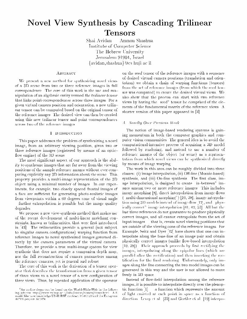
Fig. 2. We generate tensor < 1;2; 4 >, that relates images 1;2 withsome novel image 4, from the seed tensor < 1;2;3 > and the virtualcamera motion parameters [D; t] from image 3 to image 4. Tensor< 1;2; 3 > relates images 1;2 and 3 and is computed only once at thepre-processing stage. Tensor < 1;2;4 > is computed every time theuser speci�es a new [D; t]. We use tensor < 1;2;4 > to render thenovel image (image 4) from reference images 1;2.orientation between views 1 and the desired view 3 in thetensor equation (1) would provide the desired tensor forwarping views 1,2 onto 3 (see, for example, [14]). One can,however, create the desired tensor without knowing the fullmotion between views 1,2 by introducing the \tensor oper-ators" described next.C. The Basic Tensor OperatorThe basic tensor operator describes how to modify(transform) a tensor so as to represent a new con�gura-tion of three cameras. We are particularly interested inthe case where only one camera has changed its positionand orientation. Thus, by repeated application of the op-erator on a seed tensor with a sequence of desired virtualcamera positions (translation and orientation) we obtaina chain of warping functions (tensors) from the set of ac-quired images (from which the seed tensor was computed)to create the desired virtual views (see Fig. 2).Consider 4 views generated from camera matrices[I; 0]; [A; v0]; [B; v00] and [C; v000], i.e., the 3D projective rep-resentation of the object space remains unchanged, or inother words, the homography matrices A;B;C correspondto the same reference plane � (if at in�nity, then A;B;Care the rotational component of camera motion). The ten-sor of views 1,2,3 is T jki and we denote the tensor of views1,2,4 as Gjki , Gjki = v0jcki � v000kaji (5)We wish to describe G as a function of T and the incre-mental camera motion from camera 3 to 4. Let the motionparameters from camera 3 to 4 be described by a 3 � 3homography matrixD (from image plane 3 to image plane4) and translation t. Due to the group property of ho-mography matrices (since the reference plane � is �xed),C = DB and hence we have:Gjki = v0j(dkl bli)� v000kaji= dkl T jli + (dkl v00k � v000k)aji ;
and since t = Dv00 � v000, we have the following result:Gjki = dkl T jli + tkaji (6)Given a \seed" tensor T jki and a user speci�ed camera mo-tion D; t from the last view to the desired view which iscompatible with the projective representation of the objectspace (i.e., the matrix D and A are due to the same ref-erence plane), then the formula above will generate a newtensor Gjki that can be used to reproject the �rst two modelviews (views 1,2) onto the desired novel view. The seedtensor can be a trilinear tensor of three views, or the ten-sor embedding Fjki of the Fundamental matrix. In otherwords, the process can start with two model views or withthree model views | once it has started, the subsequenttensors are of three views (the �rst two views and the novelviews).What is left to consider is how to ensure that the homo-graphies A and D are due to the same plane. There couldbe two approaches. One approach is to have the user spec-ify where some physical plane seen in the two model viewsshould be in the novel view. A possible algorithm can beas follows:1. Compute the seed tensor T .2. Accept from the user four coplanar points de�ningsome (virtual or physical) plane � and use them tocompute the homography matrix A from the systemof linear equations Ap �= p0 for each pair of matchingpoints.3. Accept from the user the translation vector t and theprojections of four coplanar points from the plane �on the novel view. The four points, are enough toconstruct the homography D and, as a result, recoverthe new tensor G from equation 6.4. Use the new tensor G together with the dense corre-spondence between the two model images to synthesize(reproject) the novel view.This algorithm has the advantage of avoiding the needto calibrate the cameras at the expense of assuming the ex-istence of a plane in the 3D scene and a somewhat indirectuser interface. Similar methods for specifying the novelcamera position by means of specifying few image controlpoints were suggested by [31, 42].The second alternative, which is the one we preferred, isto try and estimate the plane at in�nity, i.e. the rotation,between the two model images (to be described later). Asa result, the homography matrixD becomes the rotationalcomponent of camera motion and the process of specifyingthe position of the novel image is simpli�ed and more intu-itive for the user. Our assumptions of the internal cameraparameters are mild (The principal point is assumed to beat the center of the image and the focal length is assumedto be the image width), yet the algorithm is robust enoughto produce \Quasi-Euclidean" [35] settings which result inplausible novel views.To summarize, we start with the seed tensor of the ref-erence images and modify it according to the user speci�ed4

position D; t of the virtual camera position. The modi�edtensors together with the dense correspondence betweentwo of the model images are used for rendering the novelimages, as can be graphically seen if Figure 3.It is worth noting that in the case of zero translation (t =0 above), the tensor operator equation (eqn. 6) becomes thestandard transformation rule of the contravariant index kof the tensor. III. ImplementationTo implement the method presented in this paper oneneeds several building blocks:� Dense correspondence between a pair of images.� Robust recovery of the seed tensor. (either the tri-linear tensor for three reference images or the funda-mental matrix, in its tensor form, for two referenceimages).� A correct reprojection mechanism.� Handling Occlusions.A large body of work is devoted to the problem of �nd-ing dense correspondence between a pair of images [33, 9],recovery of the trilinear tensor [43, 49, 17, 54, 25, 15] andrecovery of the fundamental matrix [16, 24]. Any of themethods described there can be used with our algorithm.Here we give our implementation.A. Dense CorrespondenceWe obtain dense correspondence using a Lucas-Kanadestyle optical- ow [33] embedded in a hierarchical frame-work [9]. For every pixel we estimate its motion (u; v)using the well known equation:� Ix2 IxIyIxIy Iy2 � � uv � = � �IxIt�IyIt �where Ix; Iy; It are the sum of derivatives in the x; y-directions and time respectively in a 5 � 5 window cen-tered around the pixel. We construct a Laplacian pyramid[11] and recover the motion parameters at each level, usingthe estimate of the previous level as our initial guess. Ineach level we iterate several times to improve the estima-tion. This is done by warping the �rst image towards thesecond image, using the recovered motion parameters, andthen repeating the motion estimation process. Typicallywe have 5 levels in the pyramid and we perform 2 to 4iterations per level. The initial motion estimation at thecoarsest level is 0.B. Robust Recovery of the Seed TensorThe seed tensor is recovered from the reference imagesand since the number of reference images may be eithertwo or three, slightly di�erent algorithms are needed. Wedescribe the procedure for recovering the Fundamental ma-trix and inform the reader when it deviates from the algo-rithm for recovering the trilinear tensor. The steps forcomputing the Fundamental matrix/tensor are:� Find Matching Points
The method we use is a variant of Harris corner detec-tor [21]. For every pixel in the �rst image we computethe \optic- ow" matrix� Ix2 IxIyIxIy Iy2 �where Ix; Iy are the sum of derivatives in the x� andy�directions respectively in a 5 � 5 window centeredaround the pixel, and extract its eigenvalues. We se-lect points with their smaller eigenvalue above someprede�ned threshold (Usually we set the threshold tobe about 7 gray-level values. Since we sum the squarevalues over a 5 � 5 window, we require the smallesteigenvalue to be larger than 1225 = 72 � 5 � 5). Wetrack them from the �rst image to the second imageand back to the �rst image (In case of three model im-ages, we track the points from the �rst image to thethird, via the second image and vice-versa). Pointsthat return, at the end of the loop, to their originalposition (up to distance of one pixel) are accepted.� Robust Estimation of the Trilinear Ten-sor/Fundamental Matrix The previous stage usu-ally produces several hundreds points, refered to as\good" points, which are then normalized to ensuregood numerical solution [24]. This normalization con-sists of applying a similarity transformation, so thatthe transformed points are centered at the origin andthe mean distance from the origin is p2. The normal-ized \good" points are used for computing the tensorin a robust statistics manner [37], to avoid the e�ectsof outliers. The robust estimation is done by a repet-itive lottery of a subset of 7 \good" points (in caseof three model images) or 8 \good" points (in case oftwo model images), recovering the fundamental ma-trix (trilinear tensor, for three model images), andverifying the quality of the fundamental matrix (trilin-ear tensor) on the remaining set of good points. Thequality of the fundamental matrix is measured by thedistance of the points in the second image from theirepipolar line. (for three model images, the quality ofa tensor is measured by the distance of the projectedthird point and the actual third point). Only pointswith error of less than a speci�ed threshold (typicallyone pixel) are considered. The best fundamental ma-trix (trilinear tensor) is the one with the largest num-ber of supporting points and we compute it again ina usual least-squared manner using all the points thatsupported it.Finally, in case of only two model images, we needto convert the recovered fundamental matrix into atensor form as described in the Appendix.C. Recovering the RotationWe recover the small-angles rotation matrix between twomodel images directly from the tensor, under the assump-tion that the principal point is in the center of the imageand that the focal length is equal to the width of the image.This assumptions proved to be su�cient for our method to5
Pre−Processing
Image 1 Image 2
Compute Dense Correspondance
Recover Tensor <1,2,3>
Image 3
Rendering
Render Novel View
Tensor <1,2,3>
Compute newTensor <1,2,ψ>
New CameraParams:D,t
Three Model Images
Pre−Processing
Image 1 Image 2
Compute Dense Correspondance
Recover Tensor <1,2,2>
Rendering
Render Novel View
Tensor <1,2,2>
Compute newTensor <1,2,ψ>
New CameraParams:D,t
Two Model Images
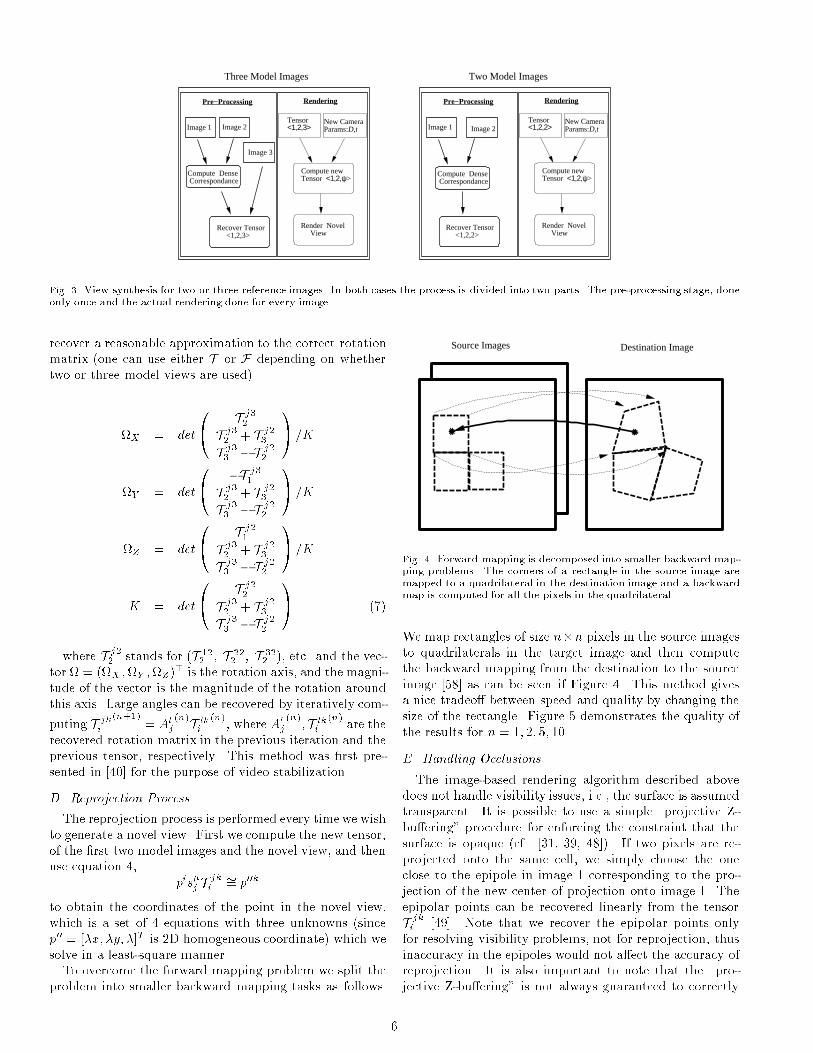
Fig. 3. View synthesis for two or three reference images. In both cases the process is divided into two parts. The pre-processing stage, doneonly once and the actual rendering done for every image.recover a reasonable approximation to the correct rotationmatrix (one can use either T or F depending on whethertwo or three model views are used).X = det0@ T j32T j32 + T j23T j33 � T j22 1A =KY = det0@ �T j31T j32 + T j23T j33 � T j22 1A =KZ = det0@ T j21T j32 + T j23T j33 � T j22 1A =KK = det0@ T j22T j32 + T j23T j33 � T j22 1A (7)where T j22 stands for (T 122 ; T 222 ; T 322 ), etc. and the vec-tor = (X ;Y ;Z)> is the rotation axis, and the magni-tude of the vector is the magnitude of the rotation aroundthis axis. Large angles can be recovered by iteratively com-puting T jki (n+1) = Alj(n)T lki (n), where Alj (n); T lki (n) are therecovered rotation matrix in the previous iteration and theprevious tensor, respectively. This method was �rst pre-sented in [40] for the purpose of video stabilization.D. Reprojection ProcessThe reprojection process is performed every time we wishto generate a novel view. First we compute the new tensor,of the �rst two model images and the novel view, and thenuse equation 4, pis�j T jki �= p00kto obtain the coordinates of the point in the novel view,which is a set of 4 equations with three unknowns (sincep00 = [�x; �y; �]T is 2D homogeneous coordinate) which wesolve in a least-square manner.To overcome the forward mapping problem we split theproblem into smaller backward mapping tasks as follows.
Source Images Destination Image
Fig. 4. Forward mapping is decomposed into smaller backward map-ping problems. The corners of a rectangle in the source image aremapped to a quadrilateral in the destination image and a backwardmap is computed for all the pixels in the quadrilateral.We map rectangles of size n�n pixels in the source imagesto quadrilaterals in the target image and then computethe backward mapping from the destination to the sourceimage [58] as can be seen if Figure 4. This method givesa nice tradeo� between speed and quality by changing thesize of the rectangle. Figure 5 demonstrates the quality ofthe results for n = 1; 2; 5; 10.E. Handling OcclusionsThe image-based rendering algorithm described abovedoes not handle visibility issues, i.e., the surface is assumedtransparent. It is possible to use a simple \projective Z-bu�ering" procedure for enforcing the constraint that thesurface is opaque (cf. [31, 39, 48]). If two pixels are re-projected onto the same cell, we simply choose the oneclose to the epipole in image 1 corresponding to the pro-jection of the new center of projection onto image 1. Theepipolar points can be recovered linearly from the tensorT jki [49]. Note that we recover the epipolar points onlyfor resolving visibility problems, not for reprojection, thusinaccuracy in the epipoles would not a�ect the accuracy ofreprojection. It is also important to note that the \pro-jective Z-bu�ering" is not always guaranteed to correctly6

(n = 1) (n = 2)(n = 5) (n = 10)Fig. 5. Performing forward mapping with rectangles of size n � npixels. The larger n is, the faster the reprojection performs. See textfor more details.resolve visibility problems, as a more rigorous treatment isneeded for the general case [30], nevertheless, the procedureis fairly robust in practice.IV. ExperimentsA. Capturing the ImagesIn the examples below we followed the following guide-lines. The two images were taken with a single camera thatwas moving a few centimeters between shots. The motionof the camera is designed to avoid creating occluded ar-eas between the images. The object is placed at about 50cm. from the camera and �lls most of the viewing area.We found that short base-line between the images greatlyenhance the quality of the correspondence and that ourmethod is robust enough to generate synthesized imagethat are far away from the original viewing cone. Light-ing conditions are normal and include either daylight oreven uorescent light. The camera types used varied fromthe standard indy-cam to scanned images from a 35mmcamera.
B. Experimental Results with Real ImagesThe tensor-based rendering method was implemented onreal images of both arti�cial and natural objects. In eachexample, a \movie" was created by specifying a set of keyframes, each by a rotation and translation of the virtualcamera from one of the model images. The parametersof rotation and translation were then linearly interpolated(not the images, only the user-speci�ed parameters) to thedesired number of frames. Also, we handled visibility prob-lems, to obtain better results. In all the cases presented weassumed the principal point of the camera to be at the cen-ter of the image and the focal length to be the width of theimage. In the �rst example two images of an African statue(260�480 pixels each) were captured using a standard indy-cam without calibration procedure or controlled light. Theobject is about 10 cm. in height and was placed some 30cm in front of the camera. We ran the pre-processing stage,which takes about 30 seconds on a SGI Indy machine, andthen de�ned a set of key frames by moving the virtualcamera in 3D space. Next, we interpolated between theparameters of the key frames to obtain the parameters forthe entire \movie". We computed the novel trilinear tensorfor each novel image and then reprojected the virtual im-age. The reprojection process takes about 5 seconds withrectangle size of 1� 1 pixels for the warping stage. Someof the generated images can be seen in Fig. 6. We repeatedthe process with two human subjects. For the �rst sub-ject, the camera was at about 80 cm from the subject andthe size of the captured images was 576�576 We repeatedthe same procedure described for the African statue andpresent the result in Figure 7. For the second subject, thecamera was at about 50 cm from the person and the cap-tured images were of size 230�288. The results can be seenin Fig 8. In another test we have down loaded a pair ofimages from the CMU/VASC image database (The imagescourtesy of Ho� and Ahuja [29]). No information about thecamera internal or external parameters is known or used.The images are 512� 512 pixels each and an example fora synthesized image can be seen in Figure 9.We have also measured the sensitivity of the reprojec-tion process to errors in correspondence. This was doneby adding increasing levels of noise to the correspondencevalues. The noise was added independently to the x andy-components of the correspondence and was uniformlydis-tributed in the range [�n; n] where n goes up to �ve pixels.Figure 11 presents the results | from which we notice agraceful degradation of the rendering process despite thefact the distance between the model views is very small. Inother words, the robustness of the synthesis method allowsus to extrapolate considerably from the original viewingcone.We extended our approach to handle dynamic scene aswell, by treating it as a series of static scenes in time. Apair of synchronized, stationary cameras captured a exibleobject (in this case facial expressions). Since the camerasare stationary, we compute the seed tensor only once. Forevery pair of images we compute dense correspondence,generate a novel tensor from the seed tensor and the user7

(a) (b) (c) (d)(e) (f) (g) (h)Fig. 6. An example of image synthesis using optic- ow and a tensor. The original images are ((a) and (e)), the rest of the images are takenfrom the generated movie. They should be seen left to right, top to bottom.speci�ed parameters and reproject the novel view. Theresult is a y-through around a \talking head" as can beseen in Fig 10. Notice that in all the examples contain aconsiderable degree of extrapolation (i.e., views that areoutside the viewing cone of the original two model views).V. SummaryWe have shown the use of the trilinear tensor as a warp-ing function for the purpose of novel view synthesis. Thecore of this work is the derivation of a tensor operator thatdescribes the transformation from a given tensor of threeviews to a novel tensor of a new con�guration of threeviews During the entire process no 3D model of the sceneis necessary, nor is it necessary to recover camera geome-try or epipolar geometry of the model images. In addition,the synthesis process can start with only two model viewsand their fundamental matrix, but the later steps followthe trilinear tensor machinery which ensures lack of sin-gular con�gurations and provide a natural driving mode.Experiments have demonstrated the ability to synthesizenew images from two closely-spaced model images, where
the viewing range of the synthesized images far exceed theviewing cone of the model images (extrapolation of viewingposition, rather than interpolation).The limitations of the technique are mainly concernedwith the correspondence problem. The fact that ourmethod accepts closely spaced images (typically the cam-eras are few centimeters apart) greatly enhances the qual-ity of the optical- ow procedure. In addition, we currentlyinvestigate methods for automatically extracting the focallength directly from the trilinear tensor, thus removing theneed to assume some prede�ned value for the focal length.Indeed, the view synthesis problem can be solved bymeans of 3D reconstruction using the epipolar geometryof a pair of images. Basically, there are two issues at hand.First, why use the tensor formulation rather than Funda-mental matrices? Second, why not use depth maps as anintermediate step? Regarding the use of Tensors, the ten-sor formulation on one hand does not su�er from singularmotions and generalizes the formulation of the Fundamen-tal matrix (see Section A.B on the tensor embedding of theFundamental matrix). On the other hand, the collection8

(a) (b) (c)(d) (e) (f)Fig. 7. The original two images ((a),(d)). Novel views of the face ((b),(c),(e),(f)).(a) (b) (c)Fig. 8. The original images (a),(b) are used to synthesize the novel view (c).9

(a) (b) (c)Fig. 9. The original images (a),(b) are used to synthesize the novel view (c).of Fundamental matrices do not always contain the fullrepresentation of the 3D-from-2D geometry (like when thecamera centers are collinear [28]), and preliminary workon degeneracy indicates that the family of \critical (am-biguous) surfaces" is at most a curve or a �nite set ofpoints under the tensor formulation, compared to ambigu-ous surfaces under Fundamental matrix formulation [47].Furtheremore, as was mentioned in the Instroduction, thetensor formulation satis�es the three requirements neces-sary for an on-line synthesis system such as intuitively sim-ple \driving mode" and singular-free motions. Therefore,even though the complete story of the 3D-from-2D geom-etry is still unfolding, the tensor formulation appears as aviable alternative for representing 3D manipulations fromcollection of views.Regarding the use of depth maps, we simply show thatone can do without them, and moreover, one can do with-out recovering explicitly the camera translation betweenthe model views (which is the most error sensitive com-ponent of motion estimation). Thus, having most of theunnecessary elements (camera translation, depth maps) re-main implicit we stand a better chance to focus only onthe relevant elements. We have included a sensitivity testto demonstrate the robustness of the rendering process inthe presence of added noise to the image correspondences.The results show that even with the small base-line we haveworked with, the process degrades very gracefully.In addition, we believe that by working in the imagedomain, and avoiding depth maps, one can extend current2D image morphing techniques with the aid of the trilineartensor. An example for such a combination appeared in [2],where we combine non-rigid facial transformations usingclassic view morphing techniques with our trilinear-tensorapproach to handle rigid transformations. For example,we show in Figure 12 an example of combining rigid andnon-rigid transformations in a single framework.Finally, we are currently working [6] on an extension ofthe method to handle an arbitrary number of images, byconstructing a consistent camera trajectory between all themodel images and using the recovered tensor parameters
for view synthesis. References[1] E.H. Adelson and J.R. Bergen. The plenoptic functionand the elements of early vision. In Michael Landy andJ. Anthony Movshon, editors, Computational Modelsof Visual Processing. The MIT Press, Cambridgem,Mass., 1991. Chapter 1.[2] S. Avidan, T. Evgeniou, A. Shashua, and T. Pog-gio. Image-based view synthesis by combining trilineartensors and learning techniques. In VRST, 1997.[3] S. Avidan and A. Shashua. Tensorial transfer: Onthe representation of n > 3 views of a 3D scene. InProceedings of the ARPA Image Understanding Work-shop, 1996.[4] S. Avidan and A. Shashua. Novel view synthesis intensor space. In Proceedings of IEEE Conference onComputer Vision and Pattern Recognition, 1997.[5] S. Avidan and A. Shashua. Unifying two-view andthree-view geometry. In ARPA, Image UnderstandingWorkshop, 1997.[6] S. Avidan and A. Shashua. Threading fundamentalmatrices. In Proceedings of the European Conferenceon Computer Vision, June 1998.[7] E.B. Barrett, P.M. Payton, and G. Gheen. Robustalgebraic invariant methods with applications in ge-ometry and imaging. In Proceedings of the SPIE onRemote Sensing, July 1995.[8] T. Beier and S. Neely. Feature-based image metamor-phosis. In SIGGRAPH, 1992.[9] J.R. Bergen, P. Anandan, K.J. Hanna, and R. Hingo-rani. Hierarchical model-based motion estimation. InProceedings of the European Conference on ComputerVision, 1992.[10] D. Beymer, A. Shashua, and T. Poggio. Examplebased image analysis and synthesis. Technical report,A.I. Memo No. 1431, Arti�cial Intelligence Labora-tory, Massachusetts Institute of Technology, 1993.[11] P. J. Burt and E. H. Adelson. The laplacian pyra-mid as a compact image code. IEEE Transactions on10
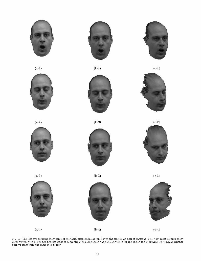
(a-1) (b-1) (c-1)(a-2) (b-2) (c-2)(a-3) (b-3) (c-3)(a-4) (b-4) (c-4)Fig. 10. The left two columns show some of the facial expression captured with the stationary pair of cameras. The right most column showsome virtual views. The pre-process stage of computing the seed tensor was done only once for the upper pair of images. For each additionalpair we start from the same seed tensor. 11

Fig. 11. We measure the sensitivity of the reprojection process to errors in the correspondence by adding increasing levels of noise to thecorrespondence values. (a),(b) and (c) show an extrapolated view of the statue with noise levels of 0;1:5 and 5 pixels, respectively.Fig. 12. Reprint from [2]. On the left are the four input images. For every expression we have a pair of images from di�erent view points.We combine classical techniques of image morphing to handle the non-rigid transformation of the model and our tensor-based approach togenerate novel view points.Communication, 31:532{540, 1983.[12] S.E. Chen and L. Williams. View interpolation forimage synthesis. In SIGGRAPH, 1993.[13] Shenchang Eric Chen. QuickTimeVR - an image-based approach to virtual environment navigation. InSIGGRAPH, 1995.[14] T. Evgeniou. Image-based rendering using algebraictechniques. Master's thesis, MIT, June 1996.[15] O. Faugeras and T. Papadopoulo. A nonlinear methodfor estimation the projective geometry of 3 views. InProceedings of the International Conference on Com-puter Vision, 1998.[16] O.D. Faugeras. What can be seen in three dimensions
with an uncalibrated stereo rig? In Proceedings of theEuropean Conference on Computer Vision, 1992.[17] O.D. Faugeras and B. Mourrain. On the geometryand algebra of the point and line correspondences be-tween N images. In Proceedings of the InternationalConference on Computer Vision, 1995.[18] O.D. Faugeras and L. Robert. What can two imagestell us about a third one? In Proceedings of the Euro-pean Conference on Computer Vision, 1994.[19] S.J. Gortler, R. Grzeszczuk, R. Szeliski, and M. Co-hen. The lumigraph. In SIGGRAPH, pages 43{54,1996.[20] W.E.L. Grimson. Why stereo vision is not always12

about 3D reconstruction. Technical report, A.I. MemoNo. 1435, Arti�cial Intelligence Laboratory, Mas-sachusetts Institute of Technology, 1993.[21] C. Harris and M. Stephens. A combined corner andedge detector. In Proc. 4th Alvey Vision Conf. Intel-ligence, pages 189{192, 1988.[22] R. Hartley. Lines and points in three views - a uni�edapproach. In ARPA, Image Understanding Workshop,1994.[23] R. Hartley. Projective reconstruction from line corre-spondences. In Proceedings of IEEE Conference onComputer Vision and Pattern Recognition, Seattle,WI, June 1994. IEEE Computer Society Press.[24] R. Hartley. In defence of the 8-point algorithm. InProceedings of the International Conference on Com-puter Vision, 1995.[25] R. Hartley. Minimizing algebraic error in geometricestimation problems. In Proceedings of the Interna-tional Conference on Computer Vision, 1998.[26] R.I. Hartley. Lines and points in three views and thetrifocal tensor. International Journal of Computer Vi-sion, 22(2):125{140, 1997.[27] A. Heyden. Reconstruction from image sequences bymeans of relative depths. In Proceedings of the Inter-national Conference on Computer Vision, 1995.[28] A. Heyden and K. Astrom. Algebraic varieties in mul-tiple view geometry. In Proceedings of the EuropeanConference on Computer Vision, April 1996.[29] W. Ho� and N. Ahuja. Surfaces from stereo: Integrat-ing feature matching, disparity estimation, and con-tour detection. IEEE Transactions on Pattern Analy-sis and Machine Intelligence, 11(2):121{136, Feburary1989.[30] S. Laveau and O. Faugeras. Oriented projective ge-ometry for computer vision. In Proceedings of the Eu-ropean Conference on Computer Vision, 1996.[31] S. Laveau and O.D. Faugeras. 3-d scene representationas a collection of images. In Proceedings of the Inter-national Conference on Pattern Recognition, 1994.[32] M. Levoy and P. Hanrahan. Light �eld rendering. InSIGGRAPH, pages 31{42, 1996.[33] B.D. Lucas and T. Kanade. An iterative image reg-istration technique with an application to stereo vi-sion. Proceedings IJCAI, pages 674{679, Vancouver,Canada, 1981.[34] Leonard McMillan and Gary Bishop. Plenoptic mod-eling: An image-based rendering system. In SIG-GRAPH, 1995.[35] A. Zisserman P.A. Beardsley and D.W. Murray. Se-quential updating of projective and a�ne structurefrom motion. International Journal of Computer Vi-sion, 23(3):235{260, 1997.[36] S. Peleg and J. Herman. Panoramic mosaic by mani-fold projection. In Proceedings of the IEEE Conferenceon Computer Vision and Pattern Recognition, 1997.[37] Torr P.H.S., Zisserman A., and Murray D. Motionclustering using the trilinear constraint over threeviews. Workshop on Geometrical Modeling and In-
variants for Computer Vision, 1995.[38] T. Poggio and R. Brunelli. A novel approach to graph-ics. Technical report, A.I. Memo No. 1354, Arti�-cial Intelligence Laboratory, Massachusetts Instituteof Technology, 1992.[39] Michal Irani Rakesh Kumar, P. Anandan, JamesBergen, and Keith Hanna. Representation of scenesfrom collections of images. IEEE Workshop on Rep-resentation of Visual Scenes, 1995.[40] B. Rousso, S. Avidan, A. Shashua, and S. Peleg. Ro-bust recovery of camera rotation from three frames. InProceedings of IEEE Conference on Computer Visionand Pattern Recognition, 1996.[41] Steven M. Seitz and Charles R. Dyer. Physically-validview synthesis by image interpolation. IEEE Work-shop on Representation of Visual Scenes, 1995.[42] Steven M. Seitz and Charles R. Dyer. View morphing.In SIGGRAPH, pages 21{30, 1996.[43] A. Shashua. Algebraic functions for recognition. IEEETransactions on Pattern Analysis and Machine Intel-ligence, 17(8):779{789, 1995.[44] A. Shashua. Trilinear tensor: The fundamental con-struct of multiple-view geometry and its applications.In G. Sommer and J.J. Koenderink, editors, AlgebraicFrames For The Perception Action Cycle, number1315 in Lecture Notes in Computer Science. Springer,1997. Proceedings of the workshop held in Kiel, Ger-many, Sep. 1997.[45] A. Shashua and P. Anandan. The generalized trilinearconstraints and the uncertainty tensor. In Proceedingsof the ARPA Image Understanding Workshop, 1996.[46] A. Shashua and S. Avidan. The rank4 constraint inmultiple view geometry. In Proceedings of the Euro-pean Conference on Computer Vision, 1996. Also inCIS report 9520, November 1995, Technion.[47] A. Shashua and S.J. Maybank. Degenerate n pointcon�gurations of three views: Do critical surfaces ex-ist? Technical Report TR 96-19, Hebrew Universityof Jerusalem, November 1996.[48] A. Shashua and S. Toelg. The quadric reference sur-face: Applications in registering views of complex 3dobjects. In Proceedings of the European Conference onComputer Vision, 1994.[49] A. Shashua and M. Werman. On the trilinear tensorof three perspective views and its underlying geome-try. In Proceedings of the International Conference onComputer Vision, 1995.[50] M.E. Spetsakis and J. Aloimonos. Structure from mo-tion using line correspondences. International Journalof Computer Vision, 4(3):171{183, 1990.[51] M.E. Spetsakis and J. Aloimonos. A uni�ed theory ofstructure from motion. In ARPA, Image Understand-ing Workshop, 1990.[52] G. Stein and A. Shashua. Model based brightnessconstraints: On direct estimation of structure. In Pro-ceedings of IEEE Conference on Computer Vision andPattern Recognition, 1997.[53] R. Szeliski and S.B. Kang. Direct methods for visual13

scene reconstruction. IEEE Workshop on Representa-tion of Visual Scenes, 1995.[54] P.H.S. Torr and A. Zisserman. Robust parametriza-tion and computation of the trifocal tensor. Image andVision Computing, 15:591{607, 1997.[55] B. Triggs. Matching constraints and the joint im-age. In Proceedings of the International Conferenceon Computer Vision, 1995.[56] J. Weng, T.S. Huang, and N. Ahuja. Motion andstructure from line correspondences: Closed form so-lution, uniqueness and optimization. IEEE Transac-tions on Pattern Analysis and Machine Intelligence,14(3), 1992.[57] T. Werner, R.D. Hersch, and V. Hlavac. Renderingreal-world objects using view interpolation. In Pro-ceedings of the International Conference on ComputerVision, 1995.[58] G. Wolberg. Digital Image Warping. IEEE ComputerSociety Press, Los Alamitos, CA, 1992.I. AppendixA. The Trilinear Tensor of Three ImagesConsider a single point x in space projected onto 3 viewswith camera matrices [I; 0];A;B with image points p; p0; p00respectively. Note that x = (x; y; 1; �) for some scalar �.Consider A = [A; v0] where A is the 3 � 3 principle minorof A and v0 is the fourth column of A. Consider p0 �= Axand eliminate the scale factor:x0 = a>1 xa>3 x = a>1 p+ �v01a>3 x+ �v03 (8)y0 = a>2 xa>3 x = a>2 p+ �v02a>3 x+ �v03 ; (9)where ai is the i'th row of A. These two equations can bewritten more compactly as follows:�s0>v0 + s0>Ap = 0 (10)�s00>v0 + s00>Ap = 0 (11)where s0 = (�1; 0; x) and s00 = (0;�1; y). Yet in a morecompact form consider s0; s00 as row vectors of the matrixs�j = � �1 0 x00 �1 y0 �where j = 1; 2; 3 and � = 1; 2. Therefore, the compactform we obtain is described below:�s�j v0j + pis�j aji = 0; (12)where � is a free index (i.e., we obtain one equation perrange of �).Similarly, let B = [B; v00] for the third view p00 �= Bxand let r�k be the matrix,r�k = � �1 0 x000 �1 y00 �And likewise, �r�kv00k + pir�kbki = 0; (13)
where � = 1; 2 is a free index. We can eliminate � fromequations 12 and 13 and obtain a new equation:(s�j v0j)(pir�kbki ) � (r�kv00k)(pis�j aji ) = 0;and after grouping the common terms:pis�j r�k(v0jbki � v00kaji ) = 0;and the term in parenthesis is a trivalent tensor we call thetrilinear tensor:T jki = v0jbki � v00kaji : i; j; k = 1; 2; 3 (14)And the tensor equations (the 4 trilinearities) are:pis�j r�kT jki = 0 ; (15)Hence, we have four trilinear equations (note that �; � =1; 2). In more explicit form, these trilinearities look like:x00T 13i pi � x00x0T 33i pi + x0T 31i pi � T 11i pi = 0;y00T 13i pi � y00x0T 33i pi + x0T 32i pi � T 12i pi = 0;x00T 23i pi � x00y0T 33i pi + y0T 31i pi � T 21i pi = 0;y00T 23i pi � y00y0T 33i pi + y0T 32i pi � T 22i pi = 0:Since every corresponding triplet p; p0; p00 contributesfour linearly independent equations, then seven corre-sponding points across the three views uniquely determine(up to scale) the tensor T jki . Equation 14 was �rst intro-duced in [43] and the tensor derivation leading to Equa-tion 15 was �rst introduced in [45].The trilinear tensor has been well known in disguise inthe context of Euclidean line correspondences and was notidenti�ed at the time as a tensor but as a collection of threematrices [50, 51, 56] (a particular contraction of the tensorknown as correlation contraction). The generalization toprojective lines was derived later by Hartley [23] and thelink between lines and points in [22]. Additional work inthis area can be found in [49, 17, 55, 27, 46, 3, 4, 52]. Foroverview and additional references see [44, 26].B. Tensor Embedding of the Fundamental MatrixWe return to Equation 14 and consider the case wherethe third image coincide with the second. The camera ma-trices for both images are A = [A; v0] and this special ten-sor can be written as:Fjki = v0jaki � v0kaji (16)which is composed of the elements of the fundamental ma-trix, as the following lemma shows.Lemma 1 The two-view-tensor Fjki is composed of the el-ements of the fundamental matrix:Fjki = �ljkFliwhere Fli is the fundamental matrix and �ljk is the cross-product tensor.14

Proof: We consider Equation 14 with Fjki = �ljkFli toderive the following equalities:pisjrkFjki =pisjrk(�ljkFli) =pi (sjrk�ljk)| {z }p0l Fli = 0 (17)The two-view-tensor is an admissible tensor that embod-ies the fundamental matrix in a three-image-framework.Algorithm that works with the trilinear tensor of threeviews can work with this tensor as well. Further detailscan be found in [5].
15
Copyright © 2022 FDOKUMEN