Notes on Firmata
25
Notes on Firmata Peter Elsea 2/19/12 1 Notes on Firmata Firmata is an Arduino library that simplifies communication over the USB serial port. Firmata can be added to any Arduino project, but the "Standard Firmata" sketch provides functions that will let you interact with all Arduino functions right out of the box. With standard firmata running, you can use either Max or Processing to initiate: • Control of pin modes (digital out, digital in, analog in, PWM control, Servo control) • Reading digital inputs (all pins) • Setting digital output (all pins) • Reading analog input (pins 14-19) • Pulse width control (pins 3 5 6 9 10 11) • Servo control ( pins 9 and 10) The pin restrictions are a limitation of the Atmega 328 chip. Earlier chips are more restrictive, but presumably new models will have more functions. Communication Protocol Firmata talks to the host computer via the USB connection and looks like a serial device to the host application. This means Max will communicate via the serial object and Processing with serial library routines. Serial communications was
-
Upload
khangminh22 -
Category
Documents
-
view
4 -
download
0
Transcript of Notes on Firmata

Notes on Firmata
Peter Elsea 2/19/12 1
Notes on Firmata Firmata is an Arduino library that simplifies communication over the USB serial port. Firmata can be added to any Arduino project, but the "Standard Firmata" sketch provides functions that will let you interact with all Arduino functions right out of the box. With standard firmata running, you can use either Max or Processing to initiate:
• Control of pin modes (digital out, digital in, analog in, PWM control, Servo control)
• Reading digital inputs (all pins) • Setting digital output (all pins) • Reading analog input (pins 14-19) • Pulse width control (pins 3 5 6 9 10 11) • Servo control ( pins 9 and 10)
The pin restrictions are a limitation of the Atmega 328 chip. Earlier chips are more restrictive, but presumably new models will have more functions.
Communication Protocol Firmata talks to the host computer via the USB connection and looks like a serial device to the host application. This means Max will communicate via the serial object and Processing with serial library routines. Serial communications was

Notes on Firmata
Peter Elsea 2/19/12 2
originally designed for transmitting characters, so it is byte oriented. Bytes are sent or received one after another on a single pair of wires. This is very old tech and quite reliable once the system is properly set up. The firmata communication protocol1 is loosely based on the MIDI protocol. Most messages are three bytes long. They begin with a status byte (a number higher than 127) and have two additional data bytes. There are also system exclusive style messages for things that are too complex for a simple message. In many cases the status byte is the sum of two items-- a base value that determines the meaning of the message plus either pin number or port number to which the message applies. Table 1 summarizes the simple messages: Message Status data 1 data 2 Pin Mode 2442 Pin# Mode Enable digital in 208 + port Disable/enable 0 Digital data 144 + port LSB of bitmask MSB of bitmask Enable analog in 192 + pin Disable/enable 0 Analog data 224 + pin LSB of value MSB of value Table 1. Simple firmata messages
Using Firmata with Max You can explore firmata and Max with the firmataPatch.maxpat. The heart of the patch is shown in figure 1. Communications with that arduino are done through the serial object. The serial settings used are 57600 baud, 8 data bits, 1 stop bit and no parity. With some Arduino boards it is necessary to send the message DTR 1 to wake up the board.
Figure 1.
1 A protocol is a set of rules for communications. It defines the meanings of the bit patterns that make up all transmitted data. 2 I have taken the liberty of translating numbers from hexadecimal.

Notes on Firmata
Peter Elsea 2/19/12 3
This part of FirmataPatch is modeled on the Arduino2Max patch by Daniel Jolliffe and Seejay James. (That patch and Arduino sketch are fine for quick and dirty reading of inputs, but do not support output.) The arguments in the serial object match the settings in Firmata. Note that I am distributing the data from serial via a send object to any receives named fromSport, and any [send toSport] will channel data to the Arduino. The trick to getting serial communications to work in Max is connecting the proper port to the serial object. (You will see other ports for things like Bluetooth mice.) The print command to the serial object provides a list of currently active ports from the right outlet. These show in the Max window with their port letters, and can be assigned by "port a" etc3. The sorter subpatch nicely organizes this list for a dropdown menu, as shown in figure 2. All that is necessary to connect is to choose the proper port on the menu.
Figure 2. Converting the serial port list to a menu. Once the connection is made, sending data to the Arduino board is simply a matter of giving the serial object lists of numbers. The numbers are restricted to be 0-255. When the serial object is banged, it reports all data received since the last bang. Data is reported as a stream of numbers, not a list. Since there is no way to know when the Arduino has sent any data, the metro bangs continually, every 15 milliseconds. This is called asynchronous reading, and may result in firmata messages being broken in two. The code that processes input will have to deal with that somehow.
Pin Mode The first task is to set up the Arduino board to match your requirements. This is mostly setting the mode and direction of the I/O pins. Firmata defines pin function as a number for pin mode. There are 5 possible pin modes: 0 digital in 1 digital out 2 analog in 3 PWM 4 servo
3 Port a is usually the top of the list, but you can't count on the list being the same each time.

Notes on Firmata
Peter Elsea 2/19/12 4
To set a pin's mode, send the message [244 pin# mode]. It's easy enough to make a patch that allows arbitrary setting of any pin, but usually there is a definite design in mind, and simple lists will do the job. Figure 3 shows a common setup.
Figure 3. These setups must be sent a little while after the serial port is set, and every time you reset the Arduino. Firmata has defaults, but it's best to keep these settings under your control.
Digital Output We can get instant gratification by lighting an LED. There's one connected to pin 13 that will light when pin 13 goes high. Unfortunately, you can't just address pin 13. The digital set (and read) messages address a group of pins called a port: port 1 is pins 2-7 (0 and 1 are stolen for communications), port 2 is pins 8-13, and port 3 is pins 14-19. To set a port we have to build the data up from the values of each bit. Figure 4 shows how to do this for port 2 with an expr object. The button object at the left triggers output when any pin is changed. If everything is working right, toggling box 13 will turn on the LED.
Figure 4. It's important to understand the difference between bit numbers and pin numbers. The bits of a byte are numbered from 0-7, with bit 0 indicating the least significant bit. Each bit adds a power of two to the byte value. Bit 0 represents 20 or 1, bit 5 represents 25 or 32. The inlet numbering scheme of expr adds a bit of confusion because the left inlet is labeled $i1. Pin numbers are the numbers printed on the Arduino board. The board numbering adds its own layer of mystery because the port 3 pins are called 14 - 19 for digital operations, but 0 to 5 when used for analog input. The patch of figure 4 will set the analog port (if it is in digital output mode) when the number 146 is substituted for 145 in the message object.

Notes on Firmata
Peter Elsea 2/19/12 5
Port 1 is slightly more complicated because it has active pins on bits 2 - 7. Figure 5 shows two things- how to set that 8th bit, and the use of byte (one of my lobjects) to replace the expression.
Figure 5. Setting port 1. The byte object has an inlet for each bit with bit 0 at the right (the standard position for binary numbering). If the message [immediate 1] has been received, changing any inlet will trigger output. Pin 7 has to be handled separately. The data bytes of the firmata message are limited to a maximum value of 127, or 1111111 in binary. Pin 7 is therefore coded with bit 0 of the second byte of the message. Since only one pin is handled that way all we need to do is replace the message object with a pak.
Digital Input Reading digital pins requires three steps. The pins must be put into digital input mode (see figure 2), the port must be enabled for input, and data received must be decoded. Enabling port input is simple. The message [208 1] will enable port 1, the magic number for port 2 is 209 and for port 3 it's 210. Figure 5 illustrates.
Figure 6. Once port read is enabled, the Arduino board will begin sending values for the appropriate pins. It only sends the values when they change. The values are sent in messages identical to the messages used to set digital output. The challenge is to separate incoming messages, a process called parsing. There are many approaches to parsing, but I favor a system that uses Lchunk, my version of zl group. Lchunk gathers data until a desired length is reached, then the data is output in a list. The data can be reported early with a bang or deleted with a clear message. (It can also detect end of message values, which we will use later.) Parsing of Firamta port read messages is illustrated in figure 7.

Notes on Firmata
Peter Elsea 2/19/12 6
Figure 7. Decoding digital input The data coming in is a stream of numbers. Each is tested to see if it is greater than 127 and therefore a status byte. Sending the clear message on a status byte will ensure the Lchunk object is empty to begin gathering the message. (You sometimes get partial messages-- this happens if anything interferes with serial operations, and often on reset.) Lchunk will count data bytes and send complete messages along. Since each message begins with a unique status, it is easy to separate them with route. Digital read messages will have status 144, 145 or 146 for ports 1 2 or 3. The bit Lobject is handy for breaking bytes down. The arguments assign specified bit numbers to the outlets. (No arguments produces 8 outlets with bit 0 on the right.) Note how bit 7 on port 1 is handled.
Analog Input Parsing analog input messages is similar to digital parsing. The pins (14-19) should be set to analog in mode, desired pins are enabled, and incoming data is parsed. Enabling analog input is done pin by pin, with status numbers starting at 192. Figure 8 illustrates a method for doing this with the label Lobject. (Label is the opposite of route. Data applied to an inlet gets the appropriate label tacked in front and is sent as a list.) Note that in this operation the analog pins are labeled 0-5.
Notes on Firmata
Peter Elsea 2/19/12 7
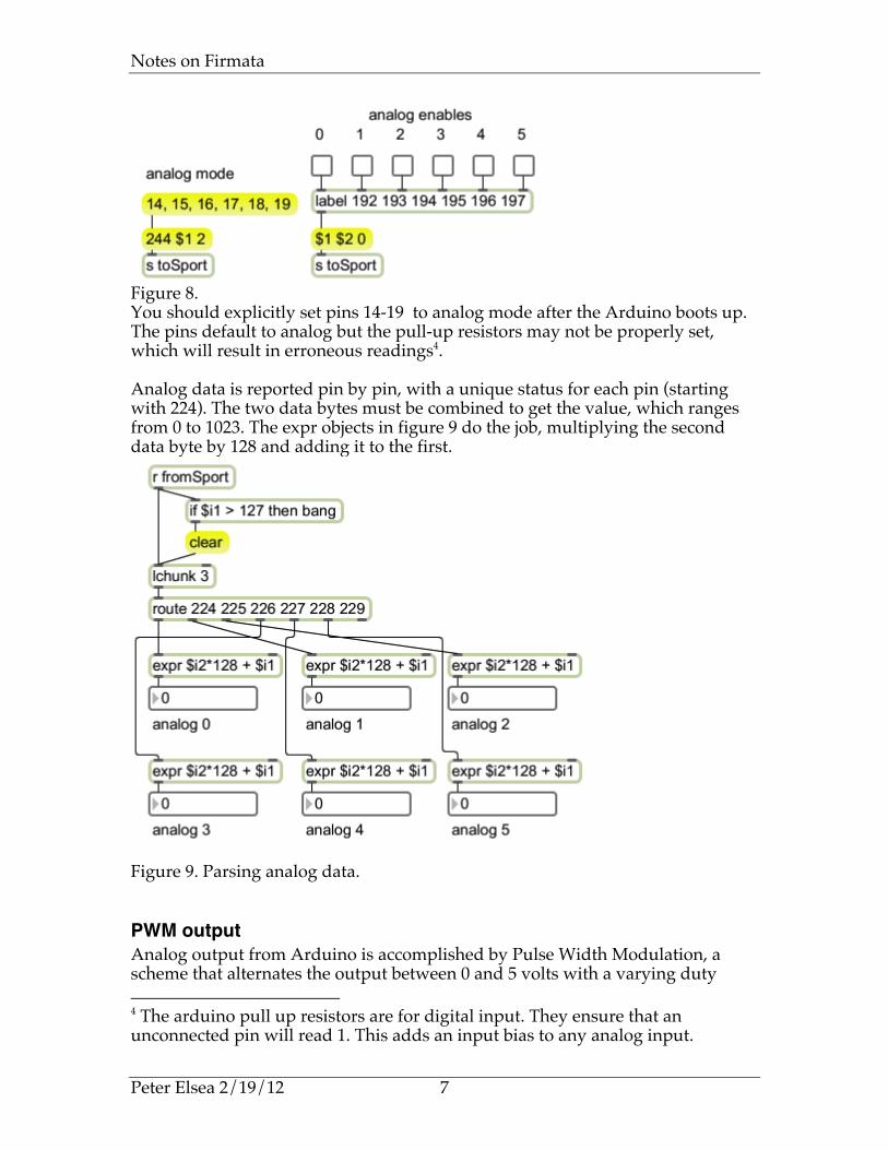
Figure 8. You should explicitly set pins 14-19 to analog mode after the Arduino boots up. The pins default to analog but the pull-up resistors may not be properly set, which will result in erroneous readings4. Analog data is reported pin by pin, with a unique status for each pin (starting with 224). The two data bytes must be combined to get the value, which ranges from 0 to 1023. The expr objects in figure 9 do the job, multiplying the second data byte by 128 and adding it to the first.
Figure 9. Parsing analog data.
PWM output Analog output from Arduino is accomplished by Pulse Width Modulation, a scheme that alternates the output between 0 and 5 volts with a varying duty 4 The arduino pull up resistors are for digital input. They ensure that an unconnected pin will read 1. This adds an input bias to any analog input.

Notes on Firmata
Peter Elsea 2/19/12 8
cycle. There is no reason you couldn't do this with any pin, but the Atmega chip has counter circuits attached to certain pins that will generate a steady wave with no additional code. These pins are 3, 5,6,9,10 and 11. Once a pin is in PWM mode, it can be set to maintain a particular pulse width by sending a message with a status of 224 plus the pin number. Figure 10 illustrates PWM on pin 11.
Figure 10. PWM pins respond to values from 0 to 255. The duty cycle will be value/255, and the value to send is duty cycle * 255. The value must be split into two 7 bit numbers. This is easily done by the remainder and integer divide operators. For example, the value 128 is transmitted as the numbers 0 and 1. That would set the duty cycle to 50% on. Figure 11 shows some examples. (The frequency of the pulse wave is 490 Hz.)
Figure 11. The effect of a pulse wave is different on different devices. It will control the speed of motors and the brightness of LEDs, but that speed or brightness will not necessarily map from 0 to 255. For instance, a motor will probably stall with a duty cycle around 10% Your patch should include a means of scaling the control input and adjusting the scale for specific components.
Servo Control RC servo devices are also controlled by the pulse width of a square wave, but they require more precision than the basic PWM counter provides. The counters connected to pins 9 and 10 of the Arduino have 16 bit precision and are up to the job. Setting up servo control is a bit more complex than other output modes. The enabling command is a string of data formatted like a MIDI system exclusive command. The specification is listed in table 2. /* servo config * -------------------- * 0 START_SYSEX (0xF0 or 240) * 1 SERVO_CONFIG (0x70 or 112)

Notes on Firmata
Peter Elsea 2/19/12 9
* 2 pin number (9 or 10 on the Uno or Duemilanova) * 3 minPulse LSB (bits 0-6) * 4 minPulse MSB (bits 7-13) * 5 maxPulse LSB (bits 0-6) * 6 maxPulse MSB (bits 7-13) * 7 angle LSB (bits 0-6) * 8 angle MSB (bits 7-13) * 9 END_SYSEX (0xF7 or 247) */ Table 2. The servo configuration message, translated from the documentation. Since the message is modeled after the MIDI sysex message, the Lsx Lobject is perfect for managing it. Lsx offers two important features: it supports hexadecimal notation, so format strings can be copied directly from documentation5, and it can automatically convert numbers into strings of 7 bit values. To see that feature in action, look at figure 12. The value 700 was labeled with the name mnP. Since this appears twice in the Lsx arguments, it is automatically broken into least significant byte and most significant byte, labeled LSB and MSB in the format. The message in the right of figure 12 shows how the data input was converted for pin 9. Once you have determined the correct message for your servos, you can just copy the message and send that.
Figure 12. Controlling the servo is just like controlling PWM, except the value sent is the desired pulse width in microseconds. This typically falls between 1000 and 2000 µs, with the so-called neutral position at 1500. The Parallax servos with a 180° range take a value from 700 to 2300. It's important not to send values outside of that range-- doing so can overheat the servo and eventually damage it. That's why the configuration message has slots for minimum and maximum pulse, and the board will enforce these limits. (The angle value in the configuration code
5 More precisely, it will leave hex numbers in hex. Max accepts hex in the format 0xFF, but converts that to decimal automatically, which makes it difficult to for me to check my work. I had to use a different hex format (FFh) to make this work.

Notes on Firmata
Peter Elsea 2/19/12 10
doesn't actually do anything-- I suspect some future revision will take advantage of it.)
Figure 13. Controlling a servo on pin 9.
Controlling a Stepper Motor6 Stepper control is probably the most complex output task we will encounter. Steppers require the simultaneous setting of four pins, one for each winding of a unipolar motor or each end of the windings of a bipolar motor. Figure 14 shows the waveforms required:
Figure 14. Stepper pulses-- low energizes windings. The patterns in figure 14 may be easier to read if they are in a table of 0s and 1s. In this example, the motor is attached to port 2 with the A winding on pin 11.
Table 3. Pin states for unipolar low power stepping.
6 For hardware requirements of stepper motors, see "Electronics for Contraptions."
Step A (p11)
B (p10)
-A (p9)
-B (p8)
port value
1 0 1 1 1 7 2 1 0 1 1 11 3 1 1 0 1 13 4 1 1 1 0 14

Notes on Firmata
Peter Elsea 2/19/12 11
Table 3 shows the pattern required on each step. Since setting port 2 requires a single value to cover all of the pins, the last column shows the decimal equivalent of the bits. Figure 15 shows an easy way to generate these patterns:
Figure 15. Stepper control The heart of figure 15 is unlist, an Lobject that will cycle through a list reporting one value at a time. The lists illustrated will turn the motor in either direction using any of the modes described in the electronics tutorial. You can vary the metro rate to determine the fastest rate of reliable rotation. The looping rate in standard firmata7 is going to limit this to 50 pulses per second. You can change this with a sysex message as shown in figure 16. The practical lower limit is probably around 5. If you want steppers to move faster than that, you will have to write your own Arduino code. There are examples in the Arduino website.
Figure 16. Changing the sampling interval of Firmata.
Position Control The main point of a stepper motor is to point something in specific directions. This requires counting pulses and stopping motion when a desired count is obtained. The Patch in Figure 17 does this.
7 How often the Arduino board looks for new messages.

Notes on Firmata
Peter Elsea 2/19/12 12
Figure 17. Stepping to a target. Rotation is controlled directly by a counter object. This counts from 0 to 47 to operate the 48 step motor (7.5°/step) I am using. A step code is derived from this output by the % 4 object, which produces a pattern of 0,1,2,3 as the counter counts. The Llist Lobject stores lists, and the command "get $1" will report the list item stored at the desired location8. The list stores the same pattern of values we used in figure 15 for clockwise stepping. The if statement [if $i1 == $i2 then 0 else 1] will start and stop the motor by toggling the metro. All you need to do is enter a new target value and the counter will count until the output (which I call the pointer) matches the target. As the counter counts up, the motor turns clockwise, restarting at 0 after count 47. The counter can also count down, and the motor will turn the other way with a smooth transition. The subpatch called direction controls direction, ensuring that the motor will move the minimum number of steps to the target. This is shown in figure 18.
8 The first item in a list is in location 0.

Notes on Firmata
Peter Elsea 2/19/12 13
Figure 18. Direction control When the target is set, the current pointer is subtracted from it to get the number of steps the motor would have to move clockwise to reach the target. If this turns out to be a negative number, 48 is added to it. This fixes the problem that arises when the rotation would cross the 47 to 0 transition. (Imagine the pointer was at 47 and the target is 1. 1 minus 47 is -46, but the actual number of steps is 2.) If the result is greater than 24 steps, the shortest distance is counter-clockwise, so a 1 is sent to the counter direction inlet. The last problem is setting the zero point. When this patch is first started the motor will jump to the nearest A pole, and that will become the 0 point by default. Unless the motor is mechanically lined up at the start, the actual angle will be unpredictable. We need a function to designate any arbitrary position as 0. The subpatch illustrated in figure 19 does this in conjunction with some send and receive objects in the main patch.
Figure 19. Setting the motor angle to 0.

Notes on Firmata
Peter Elsea 2/19/12 14
The [receive state] object relays the last port setting, which indicates the current position of the motor within the four step cycle. Lmatch reports the position of its input within a stored list-- the illustrated value of 13 would report 2. This goes no further until the subpatch inlet is banged. Then the position is used to rotate9 the state list so the current state is first. The value reported by Lmatch is multiplied by -1 because Lror rotates right, and a left rotation is needed here. The rotated list is sent to the Llist object in the main patch. After this the counter is cleared, which will cause a 0 to be output. However, since the current state was just moved to the 0 position in Llist, the motor will not move. Finally, the target value is also cleared, but there will be no movement, because the counter is at 0. The zero procedure is two steps-- move the motor to the desired point with the target controls, then set that the current location as 0.
Receiving System Exclusive Messages Occasionally Firmata has something to say to the host application. These message are rare, in response to a query or inappropriate pin setting. The format used is MIDI sysex. Even if you see no need to display these messages they should be kept out of the basic parsing mechanism, so the first stage of dealing with sysex is to filter it from the main data stream. The subpatcher illustrated in figure 13 will divert any sysex type messages to a destination name toSysex. This should be included right at the outlet of the serial object.
Figure 20. Sysex filter. The grabSysex filter is built around a Leftgate Lobject. Leftgate differs from gate in two respects. First the data goes in the left inlet and the control in the right inlet. This simplifies many applications where a decision as to where to send 9 Rotation is to rearrange a list by moving the last item to the front. 0 1 2 3 4 becomes 4 0 1 2 3.

Notes on Firmata
Peter Elsea 2/19/12 15
something has to be made as it is sent. Secondly, the left outlet is on by default. This avoids the loadbangs associated with most uses of gate. The select object in figure 20 will bang when the start of sysex value (240 decimal, 0xF0 in hex) is received. This will change the gate to send data from the right outlet to an Lchunk object. When Lchunk has two arguments, the first is a value that will cause output of the accumulated list. 247 (0xF7) is the end of Sysex marker and will send the complete message out. Sending this list also restores Leftgate to normal operation. Figure 21 shows a way to decode the sysex messages. The Like Lobject is similar to route, except it will pass lists based on the first several bytes, and it passes the list along intact.
Figure 21. The Lswap Lobject rearranges lists. The arguments determine what members to keep-- the code 2 * -2 produces a list starting with the third item and continuing to the next to last. The messages coming from Firmata are encoded as two byte values. The MSBs are all 0 when ASCII characters are transmitted. Lfilt 0 removes these extra 0s The itoa object converts numbers into their ascii equivalents, providing a readable message.

Notes on Firmata
Peter Elsea 2/19/12 16
Reading a Switch Matrix
Figure 22. Figure 22 shows a switch matrix as developed in the Electronics for Contraptions tutorial. It uses the schematic in figure 23.
Figure 23. Reading these switches is a simple routine:
• Bring test A low. • Read sense 0. If it is low A0 is closed. • Read sense 1. If it is low A1 is closed. • Read sense 2. If it is low A2 is closed. • Read sense 3. If it is low A3 is closed. • Set A high and bring B low. • Test the sense wires again, this time for B0, B1, B2 and B3. • And so on....

Notes on Firmata
Peter Elsea 2/19/12 17
The patch that reads this has two parts. Figure 24 shows the row driver.
Figure 24. The essence of this patch is in the numbers in llist: 14 13 11 7 represent the values that have to be sent to bring one pin low at a time—this follows from the binary representation of each of the numbers; 14=1110 13=1101 11=1011 7 = 0111 Lcount with the get message pops one value at a time from llist. The count value is also sent over to the read section. The values 0 or 31 (100000) are sent in between the read values. This strobes pin 13. A connection between pins 13 and 7 forces the firmata software on the Arduino to send update messages each time the read clock changes. Otherwise it tends to miss button releases. (Firmata only sends data messages when a port changes. If a button is released while another row is being read, firmata will not necessarily catch it.) The read side of the patch is shown in figure 25.

Notes on Firmata
Peter Elsea 2/19/12 18
Figure 25. The top of this patch is just the data parser from figure 7. Readings from port 1 will have the heading 144 and come from the left outlet of route. The two data values are unpacked and the first decoded by bit. (The right outlet of unpack would show the strobing action on pin 7.) Any button pressed on the current row will show a 0. The rest of the patch processes this data for display on the matrixctl. The bits are packed into a list, inverted by the ! (lnot) object so pressed button will show a 1, then the count value is tacked on the end. The message with all of the $ tokens formats the data to set and clear the matrixctl. Firmata is not the best way to read matrix arrays, especially large ones. This patch will probably work on a 5x5 array, but for anything larger I would code the Arduino directly or change to a 4051 based circuit.
Firmata and the 4051 The CD4051 chip is probably the most widely used CMOS logic chip ever. It is an 8 by 1 switch that can be used in either direction: the 8 addressable pins may be inputs and the sense pin (pin 3) an output, or a bit written to pin 3 distributed to any of the 8 addressable pins. It can even be used as an analog switch for routing signals. In addition, the address logic and switching circuitry are independent, so up to 18 volts can be switched by an Arduino. A circuit for switch detection is shown in figure 26.

Notes on Firmata
Peter Elsea 2/19/12 19
Figure 26.
This circuit manages 8 switches with four Arduino pins—three to select the switch to read and one to read the state. The same three address pins can control as many 4051s as you like, so adding 8 switches only requires one additional pin. A single Arduino could read 128 switches. Figure 27 shows a patch to read one chip.
Figure 27. This is the same as figure 26, except the address and data read are formatted to display in a jit.cellblock. This patch can easily manage 4 chips. Again, for more complex systems it may be easier to program the Arduino directly.

Notes on Firmata
Peter Elsea 2/19/12 20
A 4051 configured for output is shown in figure 28.
Figure 28. This circuit only lights one LED at a time. The trick is to sweep through the 8 LEDs fast enough that they all seem to be on at once. (This results in greatly extended battery life, since the current draw is 1/8th what it would be.)
Figure 29. In figure 29, an lcount lobject is generating address data, which will be written to pins 8, 9 and 10. The state of pin 11 will depend on what value the address fetches from the llist—note that setting any toggle at the top changes the contents of the llist. The ! (lnot) object inverts the list, because a 0 state lights the LED.

Notes on Firmata
Peter Elsea 2/19/12 21
Using Firmata with Processing Firmata can be used for Arduino control with Processing sketches. Processing has an Arduino library, but I find it easier to work directly with the serial commands. This requires the definition of a serial object: import processing.serial.*; Serial myPort; And then a connection in setup: void setup() { println(Serial.list()); size(470, 280); myPort = new Serial(this, Serial.list()[0], 57600); } Serial.list() provides a list of active serial ports. If the port the Arduino is connecting to is at the top of the list, Serial.list()[0] will connect up. If not, you can change the number or enter the full name of the port into the new Serial arguments.
Writing to the Arduino We first need a way to send data to the Arduino. Since everything is sent in three byte packets, the following will work fine: byte output[] = new byte[3]; // holder for output to board void writeOut(int stat, int dat1,int dat2){ output[0] = (byte) stat; output[1] = (byte) dat1; output[2] = (byte) dat2; myPort.write(output); } I use a global variable to hold the data for the write routine. I don't know if this is necessary in Processing, but I've worked with so many systems that require it that I always do so. Notice the explicit conversions from int data type to bytes. This is because a byte in Processing is a signed byte-- the values we need for the status bytes would have to be entered as negative numbers. A few conversions make that chore unnecessary. Once the writeOut routine is working, it's not much of a trick to set all the pin modes turn pins on and off. To set a mode all you need is something like writeOut(244,9,3); // set pin 9 to pwm Then you can write data to the pin like so:

Notes on Firmata
Peter Elsea 2/19/12 22
writeOut(233,value%128,value/128); // write value to pin 9 It is tempting to put the pin modes in the setup routine of your Processing sketch, but that won't work. It seems the serial connect process takes several seconds, during which any data sent to the board is lost. You will need to create a function to set the pin modes and call it once the Arduino is sorted out.
Reading Data from Firmata Reading the data from the Arduino board is a bit more complicated. Serial data that comes from the board is collected until your code asks to see it. The function myPort.available() will return the number of bytes waiting to be read. The usual approach is to write a port checking routine and call it from the Draw() function. The data is collected in some global arrays: int message[] = new int[3]; // gather status messages here int messagePtr; // next byte of message byte sysex[] = new byte[64]; // gather sysex messages here int sysexPtr; // next byte of sysex The check routine starts out with a while statement and sorts out the message types. void checkPort(){ while(myPort.available() > 0){ int inByte = myPort.read(); if(inByte == 0xF0) { // start of sysex sysexMode = true; // following bytes are part of the sysex message sysexPtr = 0; // start at the beginning of the sysex buffer continue; } if(inByte == 0xF7) { // end of sysex sysexMode = false; // stop collecting sysex bytes String printthis = new String(sysex); // and deal with them println(printthis); // just throw it in the text area continue; } if(inByte > 127){ //anything else should be a status message sysexMode = false; // stop collecting sysex bytes message[0] = inByte; messagePtr = 1; // prepare to receive data bytes continue; } if(sysexMode == true){ // ordinary bytes get gathered into sysex sysex[sysexPtr++] = (byte) inByte; continue; }

Notes on Firmata
Peter Elsea 2/19/12 23
message[messagePtr++] = inByte; // or the status message if(messagePtr > 2){ // once the status message is complete parseMessage(); // deal with it messagePtr = 1; } } // end of while loop } Bytes come in one at a time from the myPort.read() function. These are tested with a string of if statements. Status bytes ( bytes greater than 127) determine how the following data is handled. Each if block ends with a continue statement to prompt a return to the beginning of the while loop. Sysex begin (0xF0 or 240) sets sysexMode to true. That will divert the following bytes to the sysex buffer. It also sets the sysexPtr to the beginning of the buffer. End of sysex (0xF7 or 247) turns off sysexMode and calls a routine to display the sysex message in the print area. If more elaborate sysex handling is required, it should be in a separate function. Any other status byte will be copied to the beginning of the message buffer. I turn sysex mode off here because status bytes aren't allowed in a sysex message. Receipt of one means that the end of sysex byte got lost somehow10. The messagePtr is set to the second item in the message buffer, in case the previous message only had one data byte. Data bytes are routed to one buffer or the other depending on the sysexMode. When the message buffer is full, parseMessage() is called to finish processing. Then the messagePtr is reset. It is pointed at location 1 in case Firmata implements running status. Running status is part of the MIDI protocol-- once a status message has been sent, more pairs of data bytes can be sent with the same status. The Firmata documentation doesn't mention it, but the messagePtr has to be reset to something11.
Parsing Messages Once status messages are complete, they are parsed and the data is used to set more global variables: int inPort1, inPort2, inPort3; //data from card int analog[] = new int[6];
10 Serial communications code must always be prepared to deal with lost data with minimum damage. If sysexMode were not turned off by a new status, the sysex buffer would fill up and the program would crash. 11 Otherwise lost status bytes would cause the message buffer to overflow.

Notes on Firmata
Peter Elsea 2/19/12 24
The parsing code is a long switch statement based on the status byte. A more compact format is needed to deal with the dozens of pins on an Arduino mega, but this is fine for the ATmega328 boards. void parseMessage(){ switch(message[0]){ case 144: // port 1 inPort1 = message[1] + 128*message[2]; break; case 145: // port 2 inPort2 = message[1] + 128*message[2]; break; case 146: // port 3 inPort3 = message[1] + 128*message[2]; break; case 224: // analog 0 analog[0] = message[1] + 128*message[2]; break; case 225: // analog 1 analog[1] = message[1] + 128*message[2]; break; //............................................................ (repetitive code skipped) case 229: // analog 5 analog[5] = message[1] + 128*message[2]; break; case 249: // version is reported after card has booted up initPins(); break; } } The status 249 is used to send the Firmata version number. This is transmitted at the end of the boot up process, so it can be used to call the pin mode setup routine. This code will keep the input variables up to date. As global variables, they are available to the draw routine for anything you might want to do. Here's a bit of code to just draw circles for pin inputs, solid if the pin is 1 and empty f the pin is 0. for(int i = 2;i<8;++i){ if((inPort1 & (1 << i)) > 0) // detect state of pin i fill(on); else fill(off); ellipse(235+ 30*i, height/2, 10,10);

Notes on Firmata
Peter Elsea 2/19/12 25
} Notice how the left shift and bitwise AND functions together detect the state of a pin. The following code uses an analog value to control a pin in PWM mode: int value; value = analog[0] / 4; writeOut(233,value%128,value/128); Servo code is not much different: void setServoMode(int pin){ writeOut(244,9,4); byte [] servoInit = {(byte)0xf0, 112, (byte)pin, 60, 124, 17, 51, 1,(byte) 0xF7}; myPort.write(servoInit); } void doServo(){ int value; value = analog[0]*2 +700; writeOut(233,value%128,value/128); } This pretty much covers the capabilities of Firmata. To explore these capabilities, I suggest you build a basic contraption with some pots, switches and lights. (See Electronics for Contraptions.) Use this to control some basic displays and effects, then branch out to more complex devices powered by the Arduino board.